/


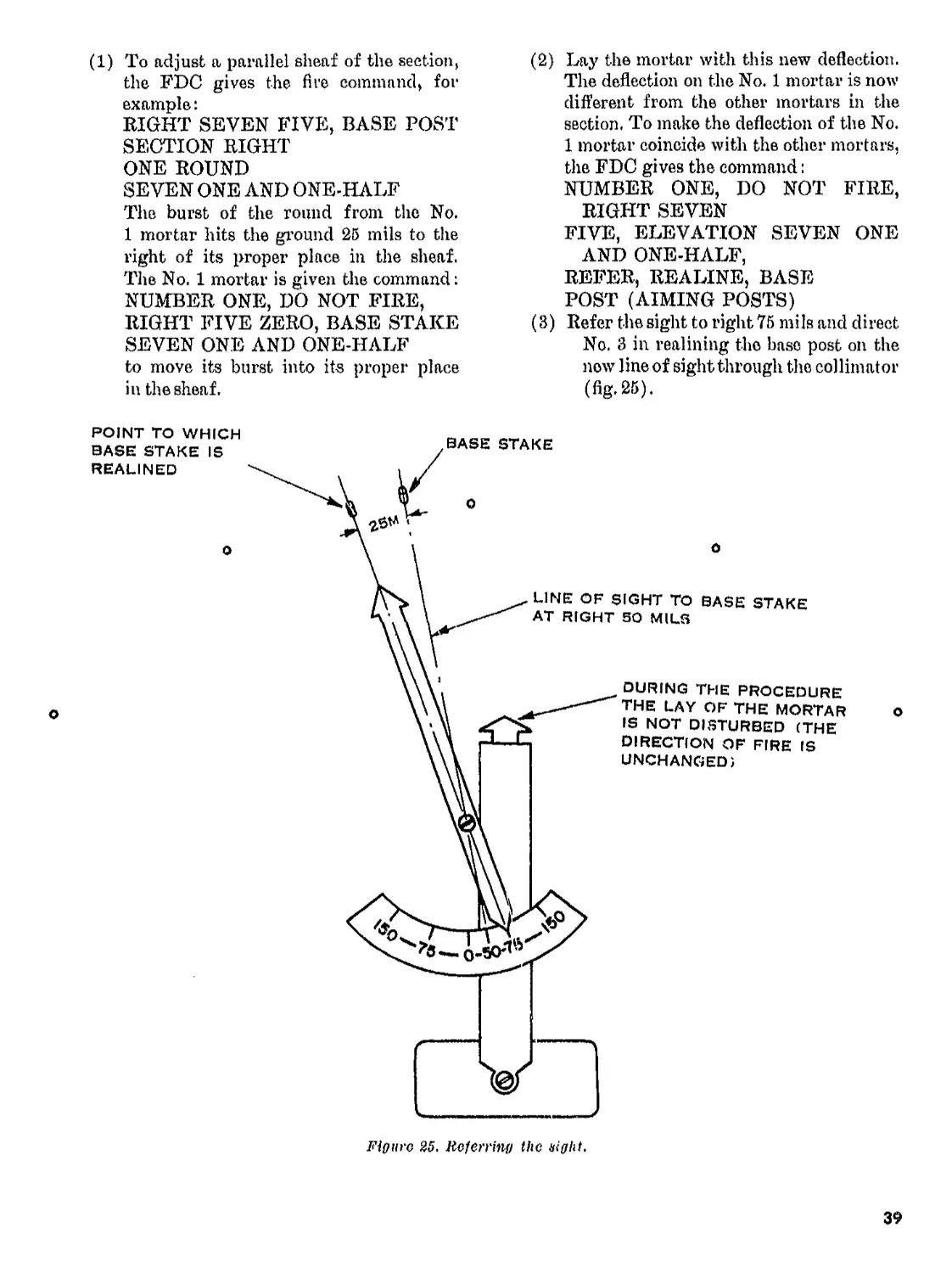
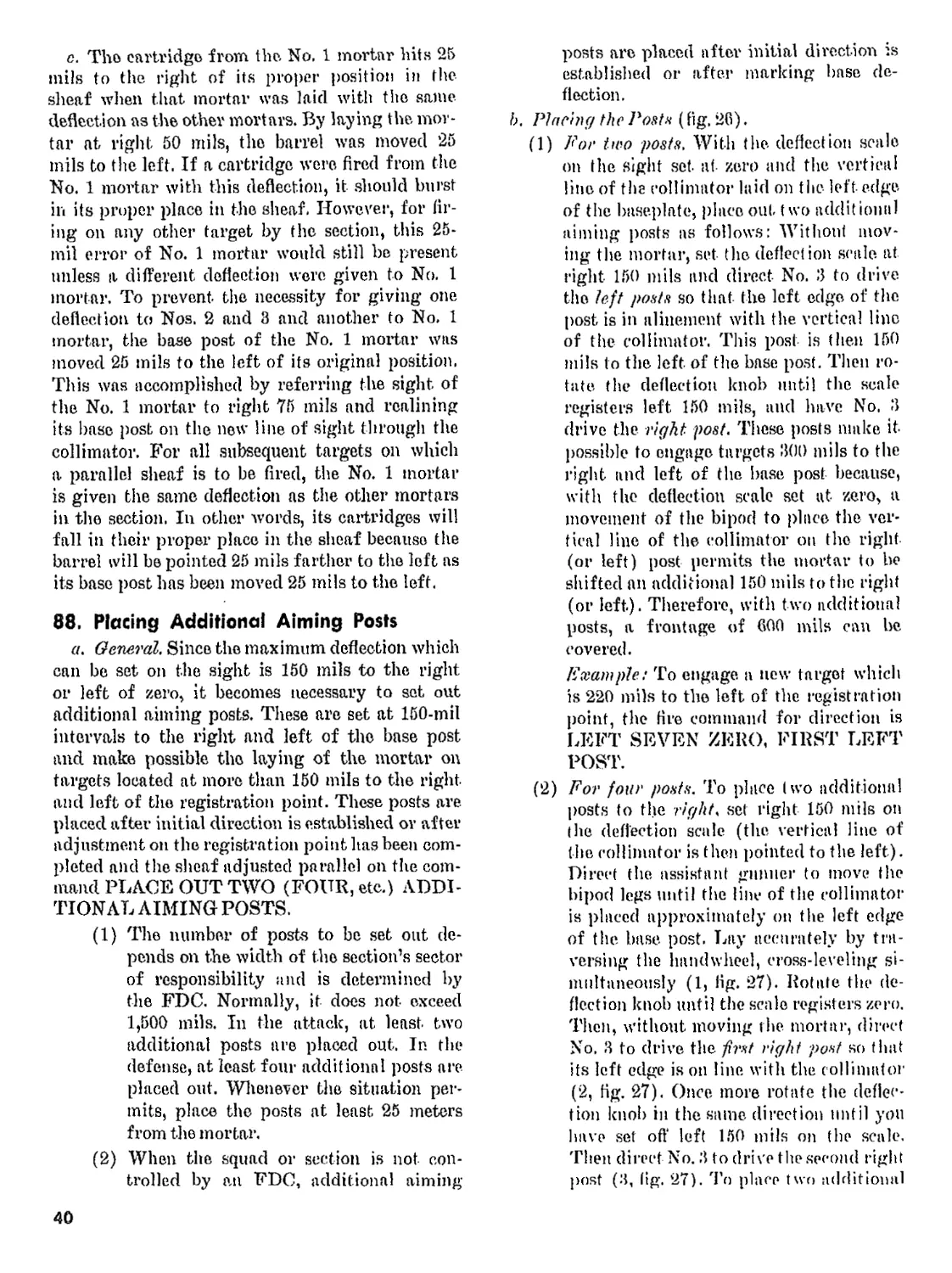
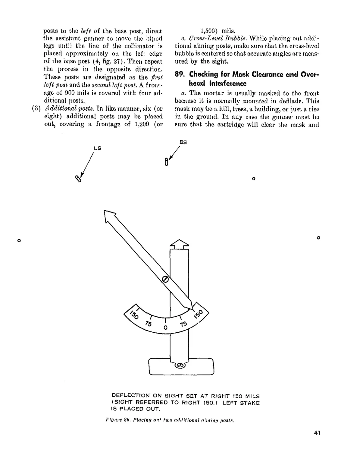


Text
DEPARTMENT OF THE ARMY FJELD MANUAL
^з.-.5М
60-MM MORTAR, Ml 9
HEADQUARTERS, DEPARTMENT OF THE ARMY
FEBRUARY 1007
TH 23-85
Field Manual
No. 23-85
HEADQUARTERS
DEPARTMENT OF THE ARMY
Washington, D.C., 2 February 1967
60-MM MORTAR, Ml9
Parnernplis Page
Chapter I. INTRODUCTION__________________________________ 1,2 3
2. MECHANICAL TRAINING
Section I. Description, nomenclature, and functioning__- 3-8 -I
II. Disassembling, assembling, mounting, and dismounting-- 9-14 7
III. Care, cleaning, and inspection____________________ 15-30 10
IV. Sighting equipment, spare parts, and accessories- 31-43 1G
Chapter 3. AMMUNITION AND BALLISTICS
Section I. Ammunition______________________ . _______________ 44-65 24
II. Ballistics_______________________________________ 66-68 30
III. Destruction of ordnance materiel in event of imminent
capture____________________________________________ 69-75 30
Chapter 4. GUNNER DRILL__________________________________ 76-90 33
5. SQUAD AND SECTION DRILL
Section I. Squad drill_________________________________ 91-100 47
II. Placing handheld mortar in action__________________ 101-103 55
III. Section drill___________________________________ 104-106 59
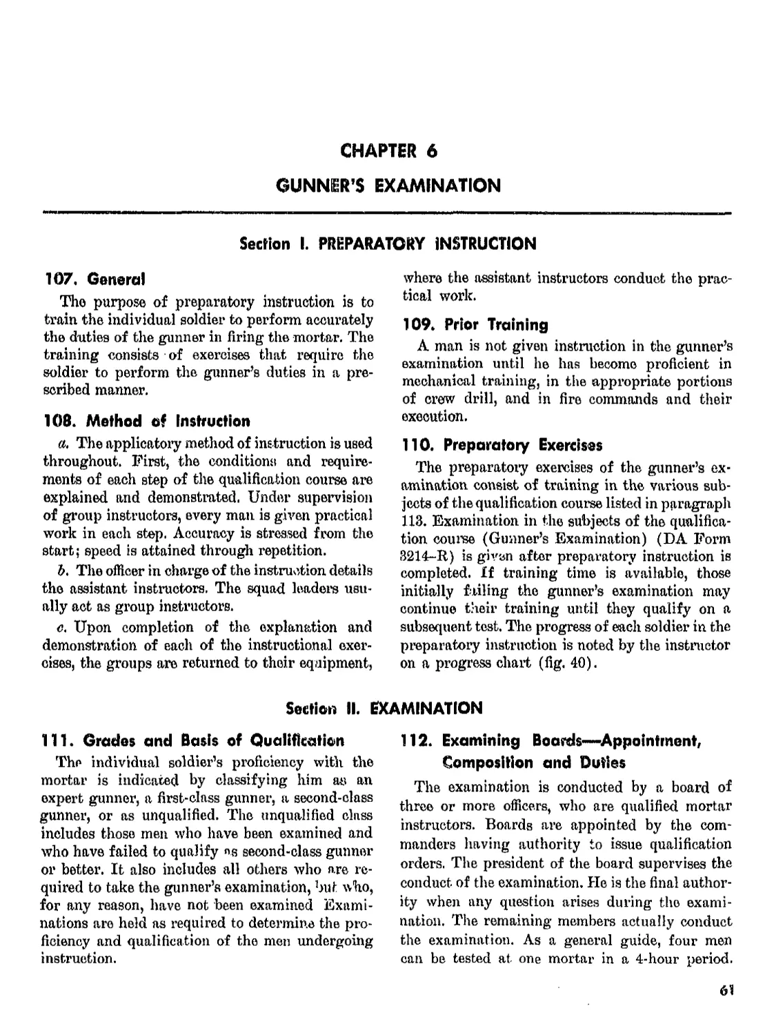
Chapter 6. GUNNER’S EXAMINATION
Section I. Preparatory instruction______________________ 107-110 61
II. Examination---------------------------------------- 111-115 61
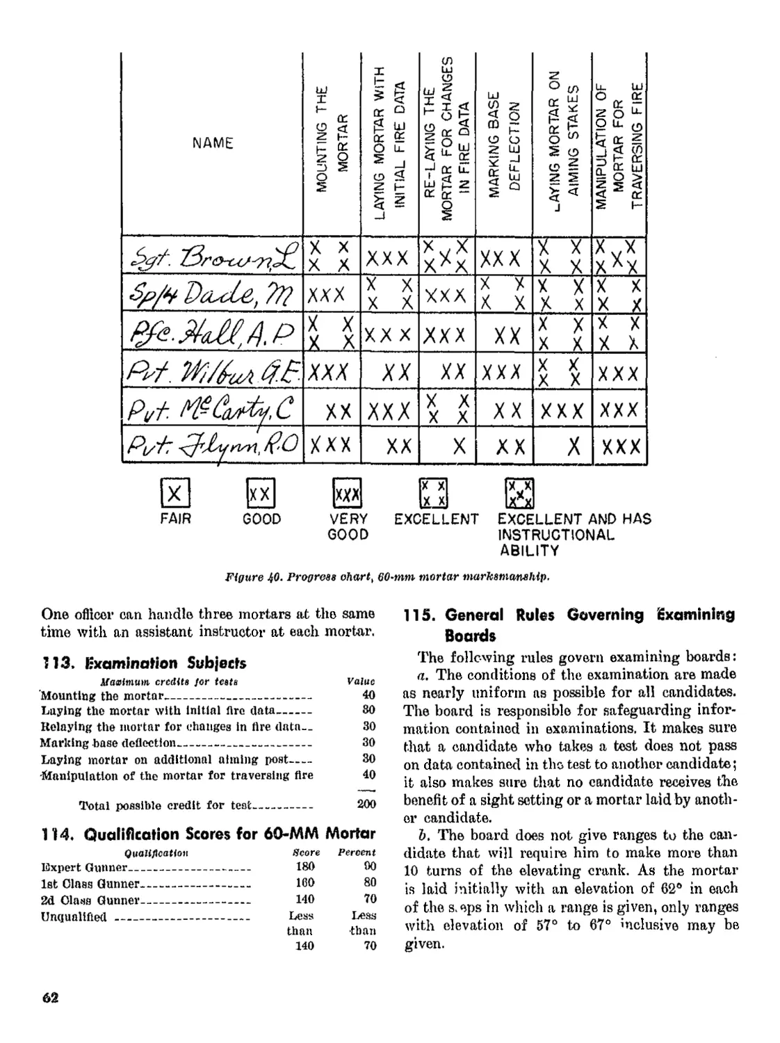
III. Qualification course___________________________ 116-122 63
Chapter 7. ELEMENTS OF INDIRECT FIRE
Section I, General_________________________________________ 123-125 69
II. Targets___________________________________________ 126-130 70
Chapter 8. TECHNIQUE OF FIRE WITHOUT A FIRE DI-
RECTION CENTER
Section I. General________________________________________ 131, 132 75
II. Determination of initial data____________________ 133-137 73
III. Range estimation__________________________________ 138-141 80
IV. Forward observation------------------------------ 142-145 84
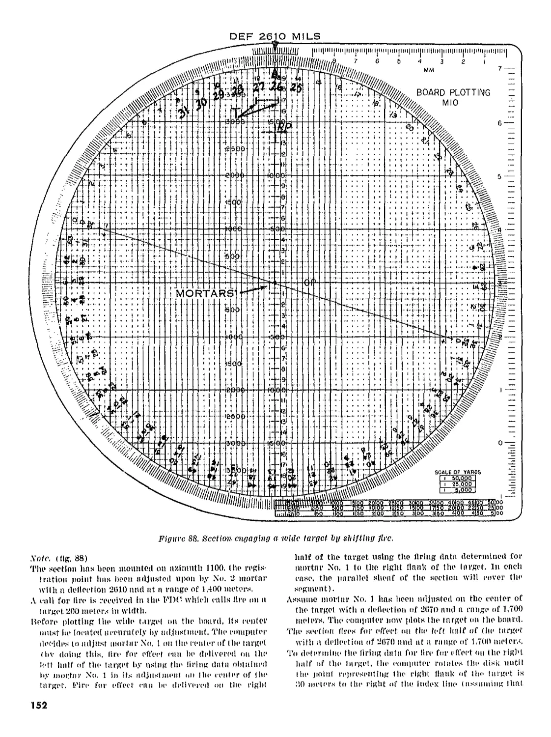
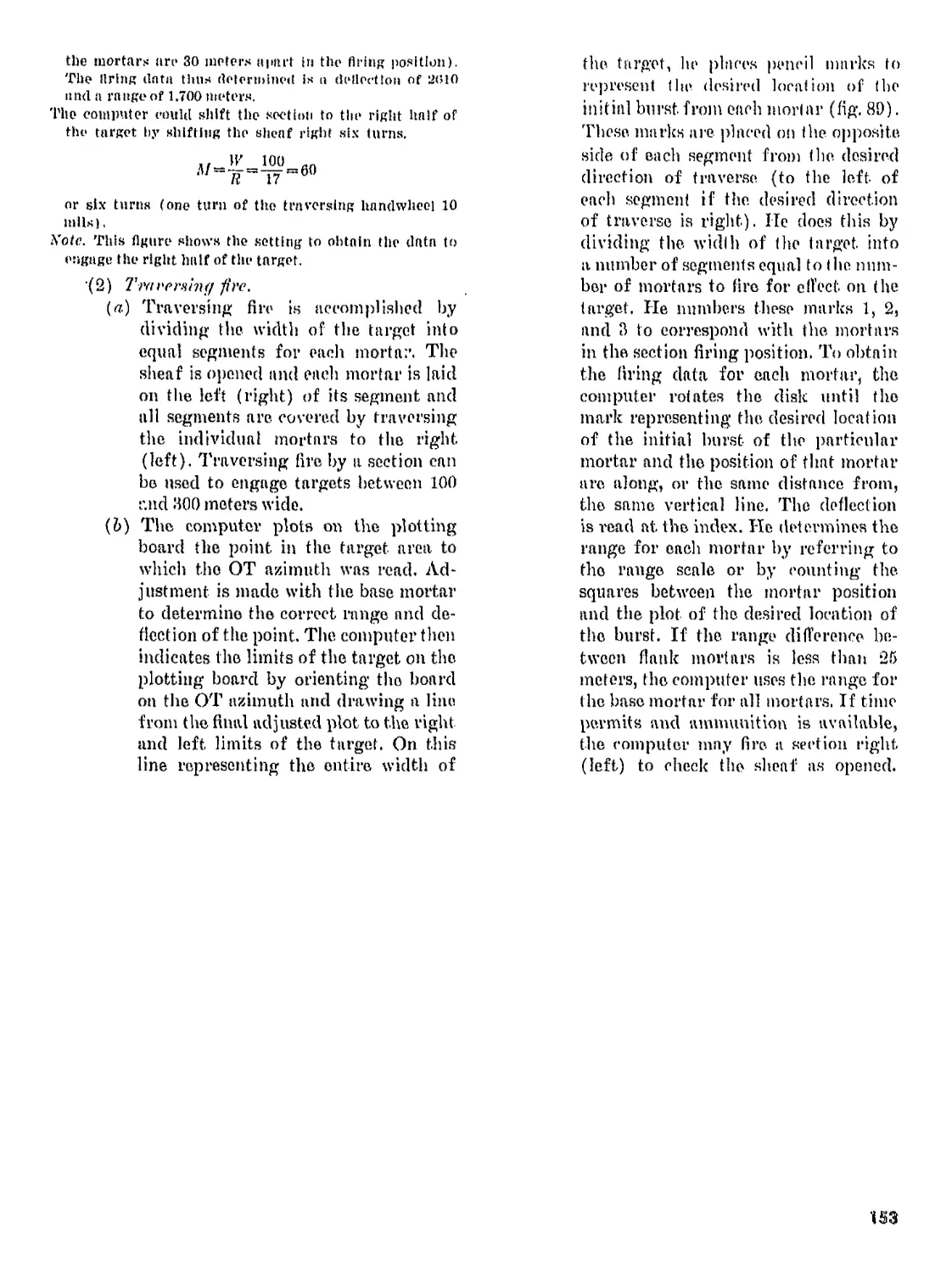
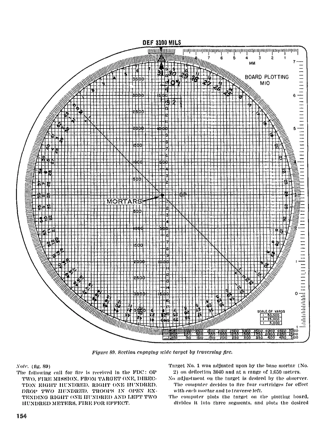
V. Fire commands_____________________________________ 146-154 86
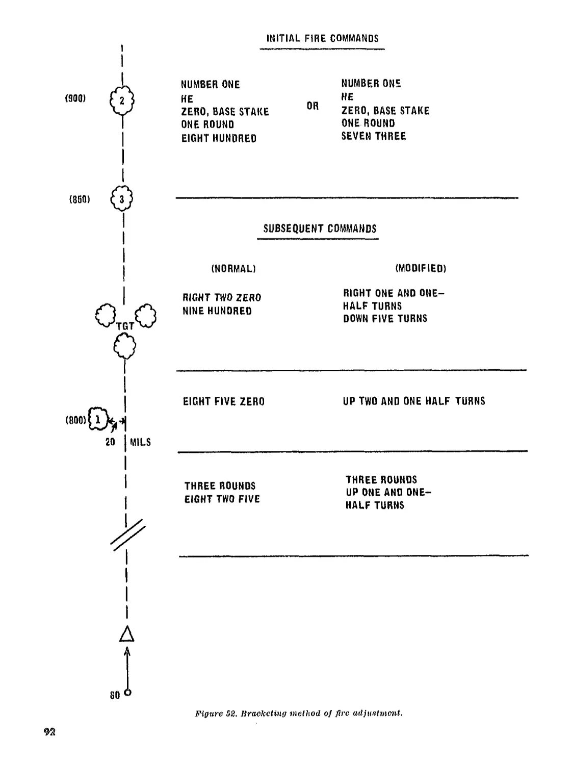
VI. Squad conduct of fire_____________________________ 155-162 90
VII. Technique of firing handheld mortar______________ 163, 164 100
Chapter 9. FORWARD OBSERVER PROCEDURE______________________ 165-179 102
10. CONDUCT OF FIRE ADJUSTMENT________________________ 180-190 112
11. FIRE DIRECTION CENTER PROCEDURE
Section I. Organization and function of FDC________________ 191-212 118
II. M10 and M17 plotting boards________________________ 213,214 127
III. M16 plotting board_____________________________ 215-218 129
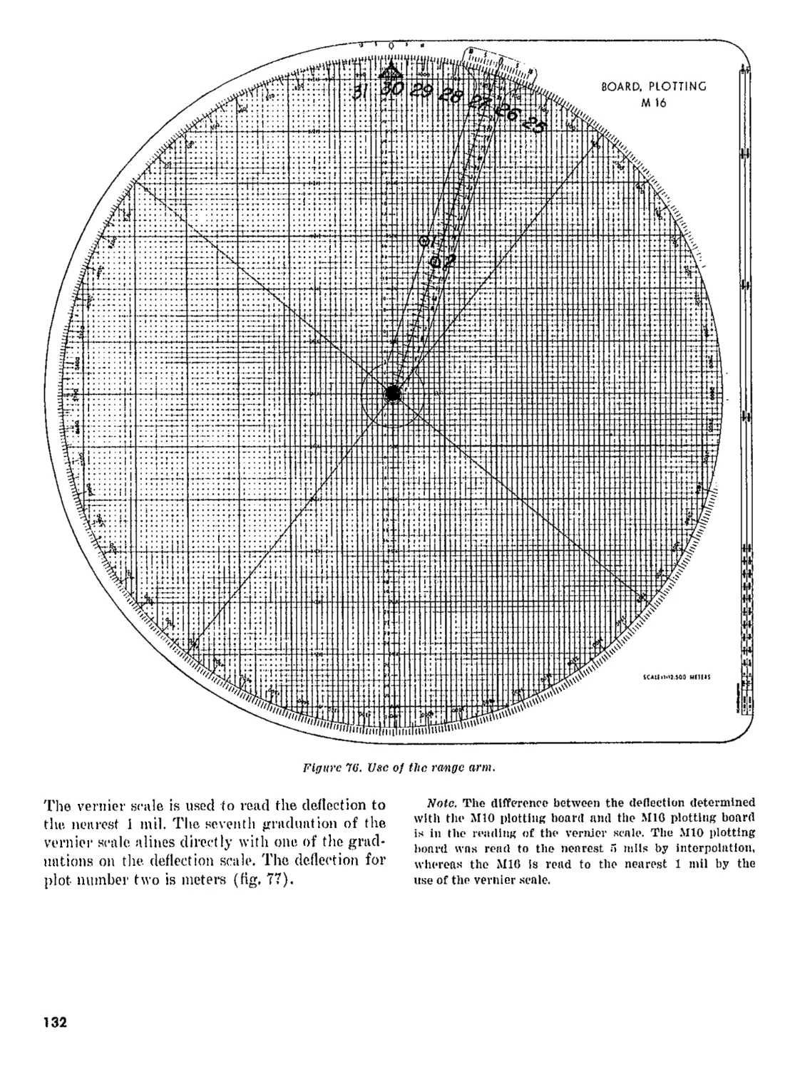
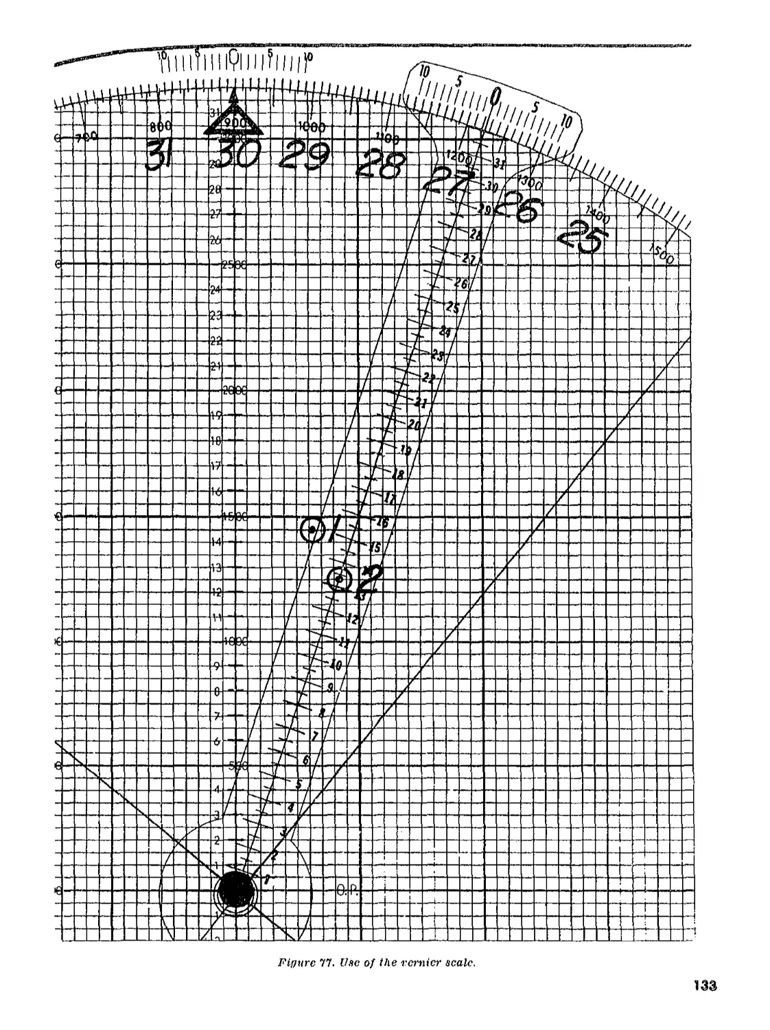
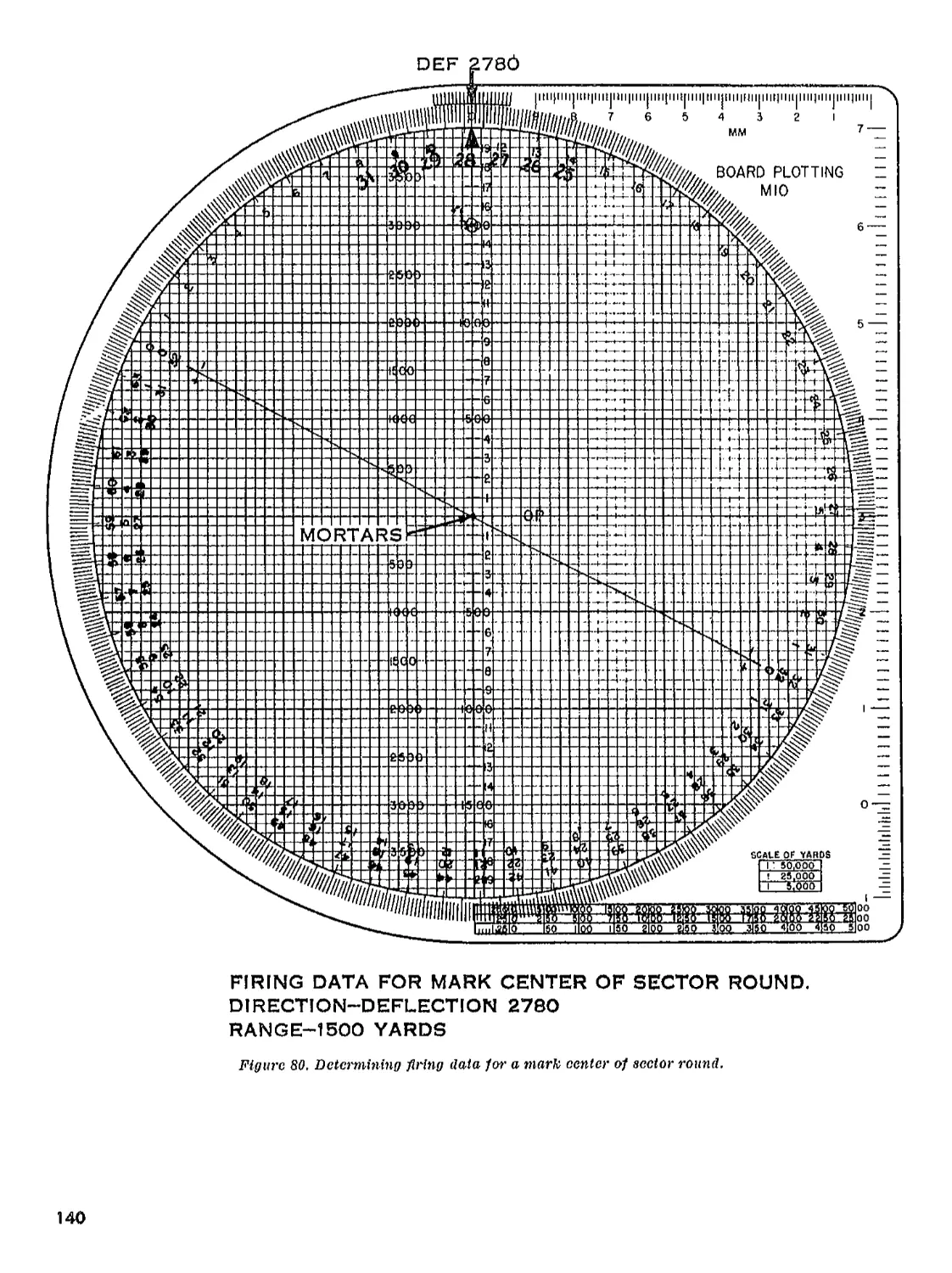
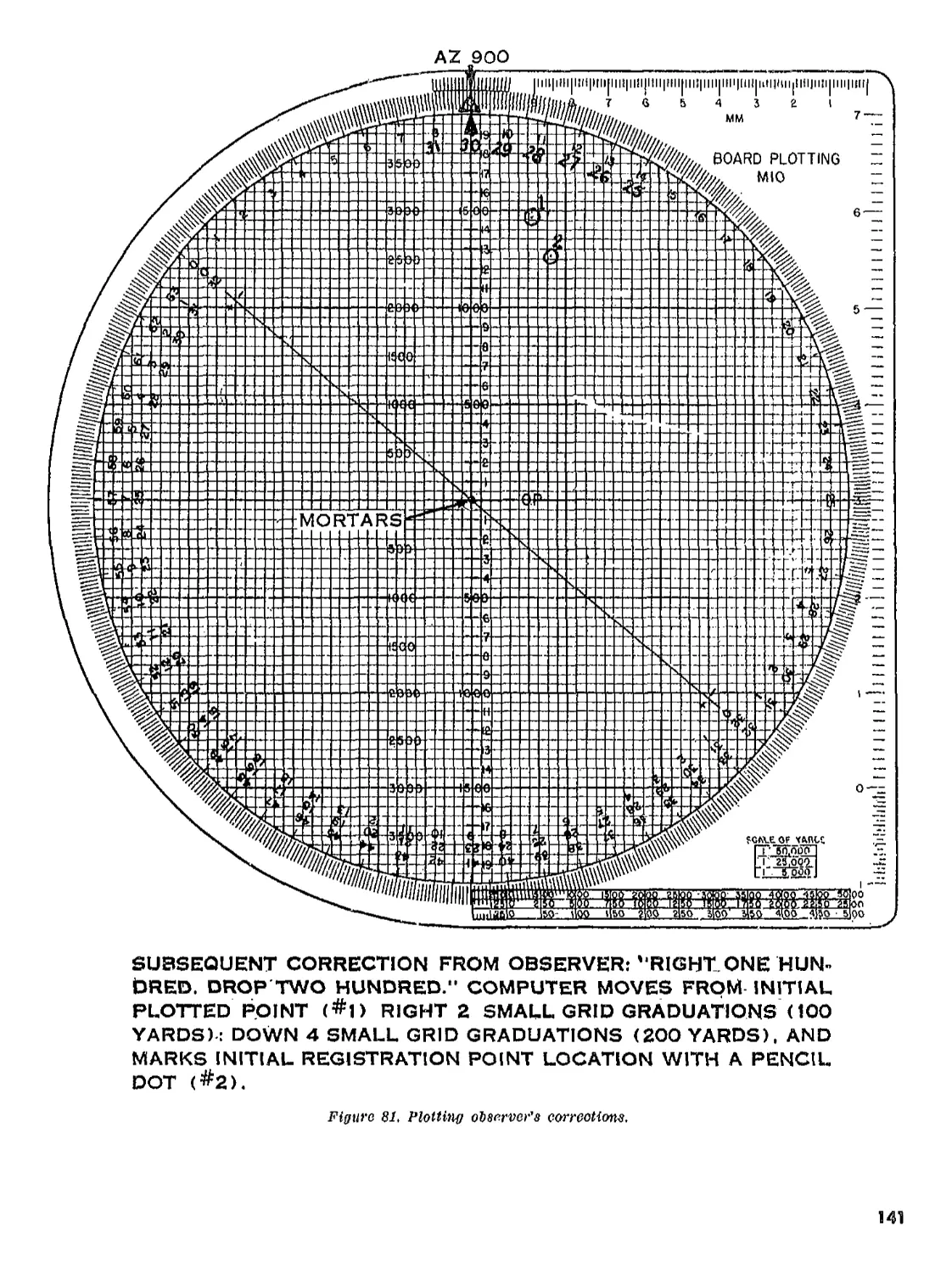
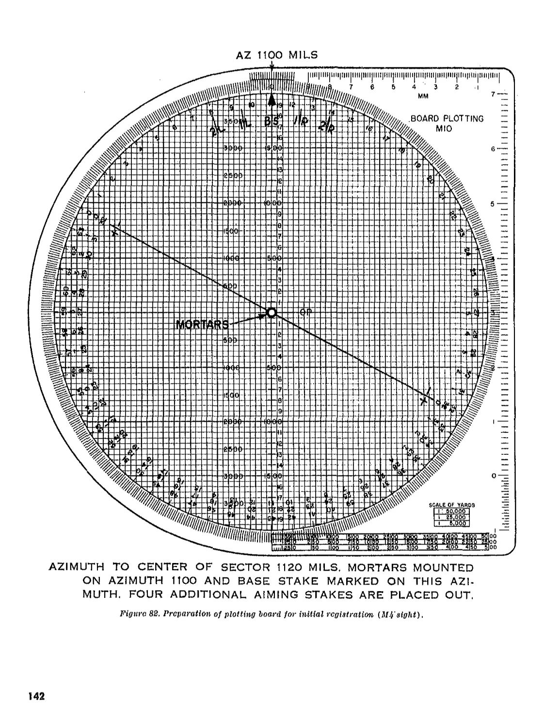
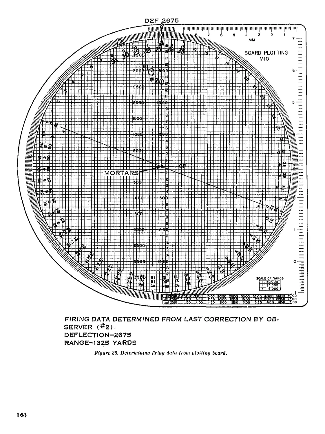
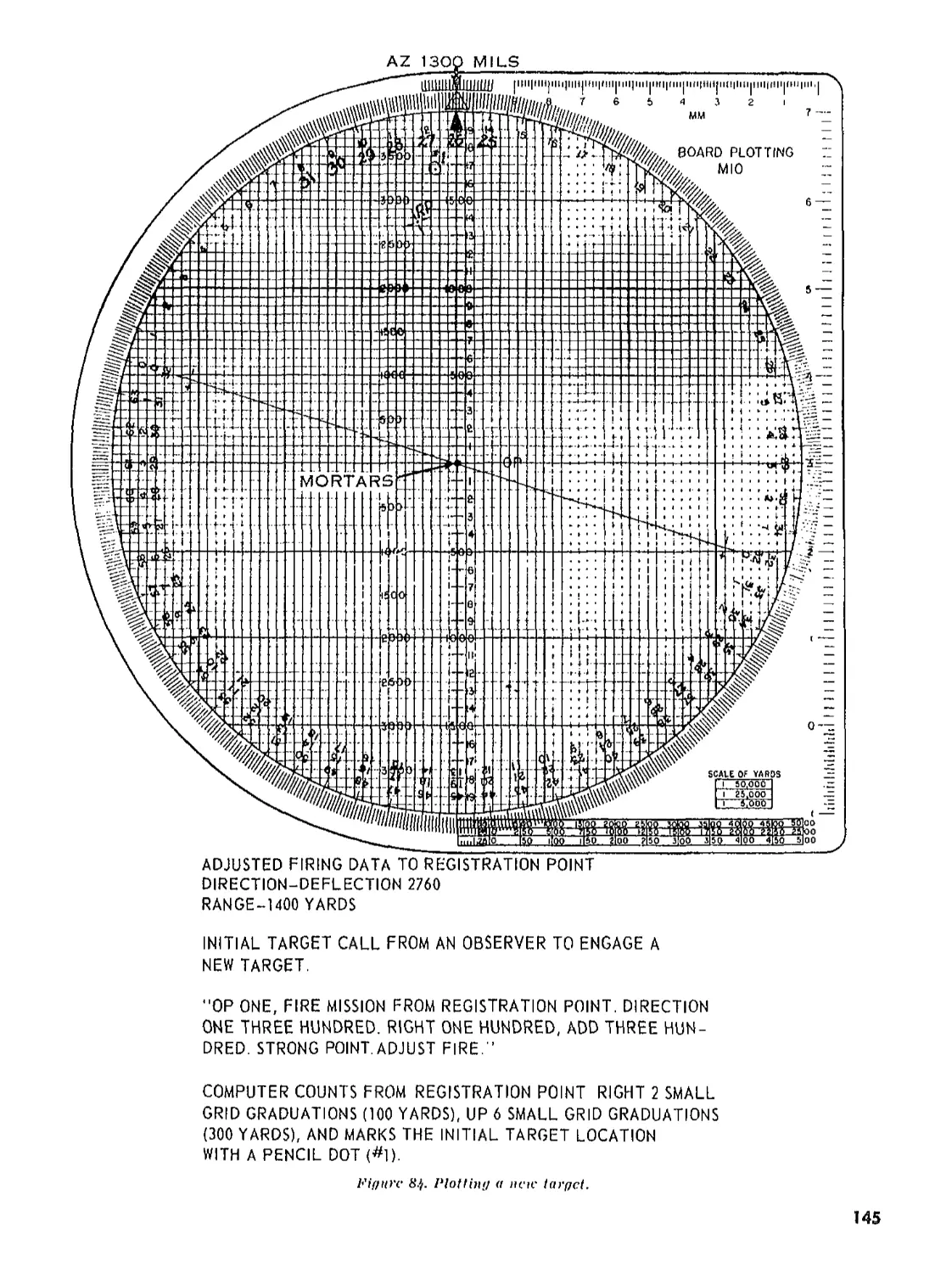
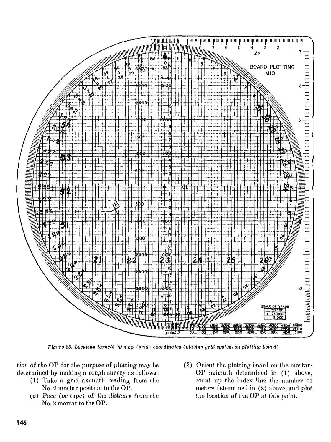
IV. Operations with plotting board___________________ 219-250 134
Appendix A. REFERENCES_________________________________________ ____ 162
B. FIRE CONTROL INSTRUMENTS__________________________ . ...... 163
Index__________________________________________________________ ____ 170
’’'This manual supersedes FM 23-85, 29 November 1950, including C 1, 16 October 1951, C 2, 22 August 1952, and C 3,
21 September 1956.
1
CHAPTER 1
INTRODUCTION
1. Purpose and Scope
a. This manual is a. guide for personnel con-
ducting training with the 60-nim mortar. It con-
tains detailed information on mechanical train-
ing, crew drill, technique of fire, and fire control
procedures.
7л Most of the equipment discussed is available
in two or more different models; where there are
substantial differences in the operation of two
similar items, the differences are covered
separately.
e. Crewmembers and commanders should be-
coine thoroughly familiar with the details on
firing the 60-mm mortar. Proper care and main-
tenance of the weapon, careful handling of the
ammunition, and correct and precise firing pro-
cedures are most essential to the safety of the
mortar crew. For references, see appendix A.
d. The material contained herein is applicable
without modification to both nuclear and non-
nuclear warfare.
2. Recommended Changes
Users of this manual are encouraged to submit
recommended changes and comments to improve
the manual. Comments should be keyed to the
specific page, paragraph, and line of the text in
which the change is recommended. Reasons will be
provided for each comment to insure understand-
ing and complete evaluation. Comments should
be forwarded direct to the Commandant, United
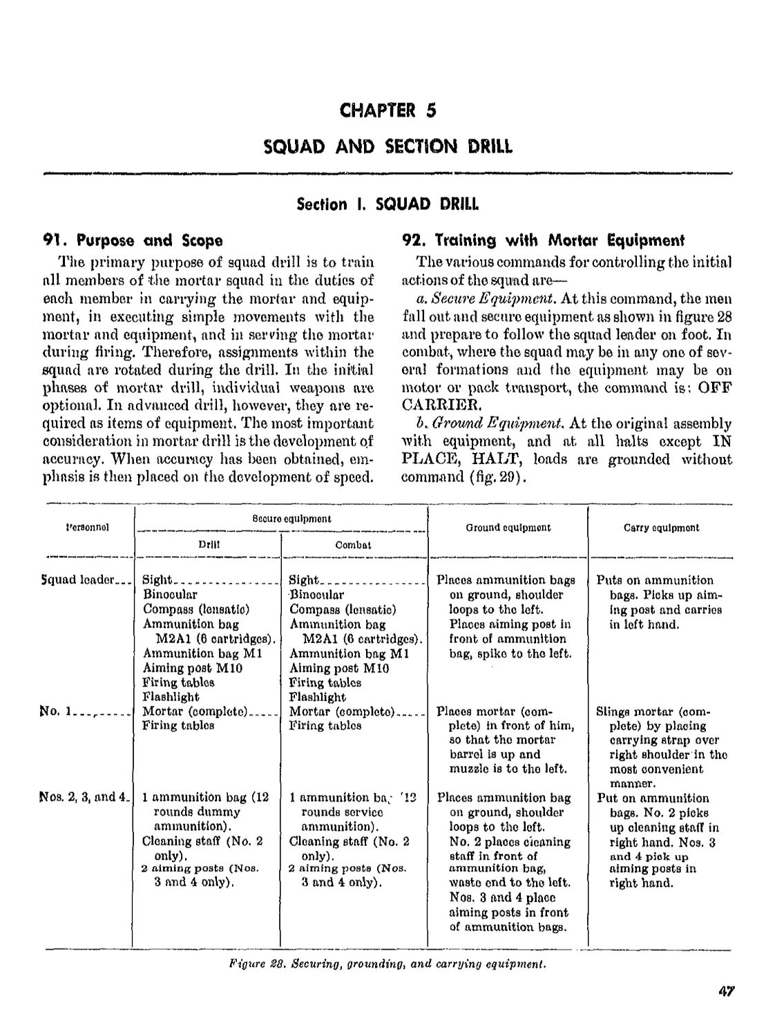
States Army Infantry School, Fort Benning, Ga.
31905.
3
CHAPTER 2
MECHANICAL TRAINING
Section I. DESCRIPTION, NOMENCLATURE, AND FUNCTIONING
3. Characteristics and General Data
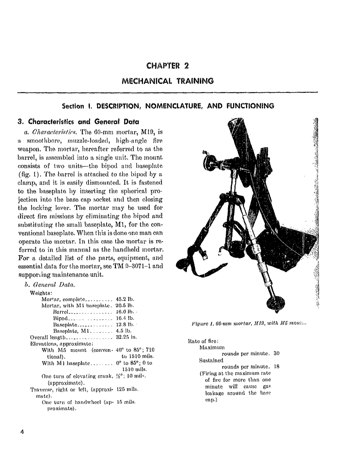
a. G'haracter?*7icn, The 60-mm mortar, Ml9, is
a smoothbore, muzzle-loaded, high-angle fire
weapon. The mortar, hereafter referred to as the
barrel, is assembled into a single unit. The mount
consists of two units—the bipod and baseplate
(fig, 1). The barrel is attached to the bipod by a
clamp, and it is easily dismounted. It is fastened
to the baseplate by inserting the spherical pro-
jection into the base cap socket and then closing
the locking lever. The mortal’ may be used for
direct fire missions by eliminating the bipod and
substituting the small baseplate, Ml, for the con-
ventional baseplate. When this is done one man can
operate the mortar. In this case the mortar is re-
ferred to in this manual as the handheld mortar.
For a detailed list of the parts, equipment, and
essential data for the mortar, seeTM 9-3071-1 and
supporting maintenance unit.
b. General Data,
Weights:
Mortar, complete_______________ 45.2 lb.
Mortar, with Ml baseplate. 20.5 lb.
Barrel_________________ 16.0 lb.
Bipod________ _________ 16.4 lb.
Baseplate_______...... 12.8 lb.
Baseplate, Ml..________ 4.5 lb.
Overall length___________ _. .... 32.25 in.
Elevations, approximate:
With M5 mount (conven- 40° to 85°; 710
tional). to 1510 mils.
With Ml baseplate_____.... 0° to 85°; 0 to
1510 mils.
One turn of elevating crank, 10 miN.
(approximate).
Traverse, right or left, (nppi'oxi- 125 mils,
mate).
One turn of handwheel (ap- 15 mils,
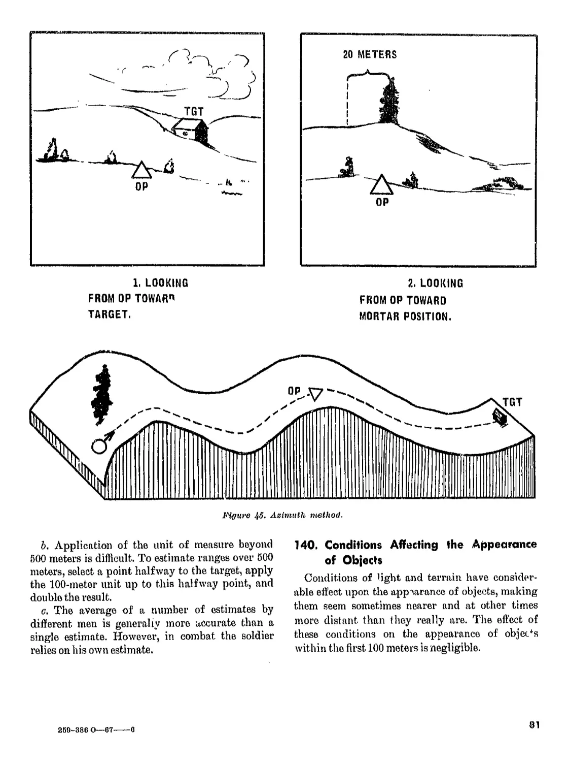
proximate).
Figure J, mortar, M19, with M5 nioim..
Rate of fire:
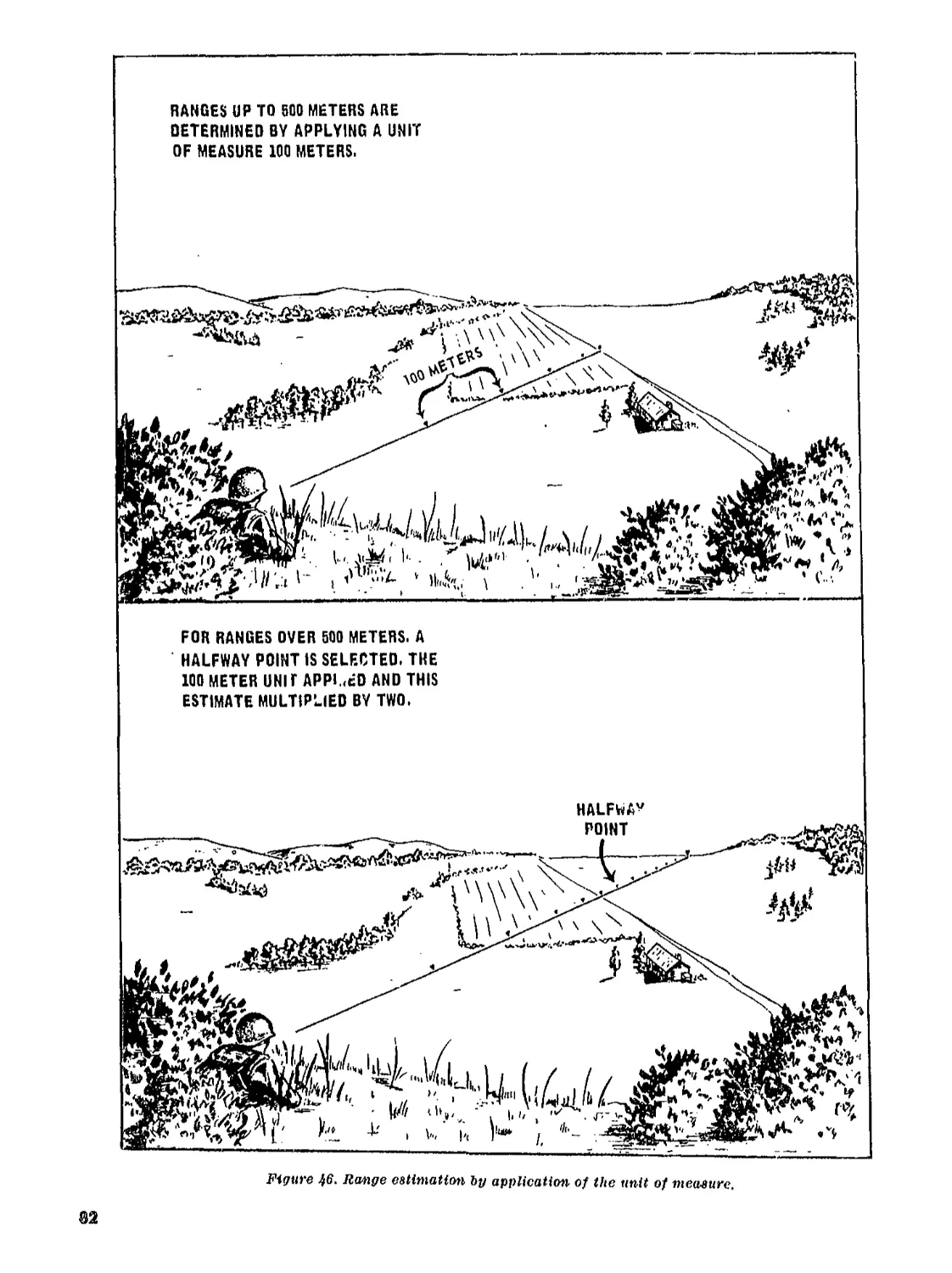
Maximum
rounds per minute. 30
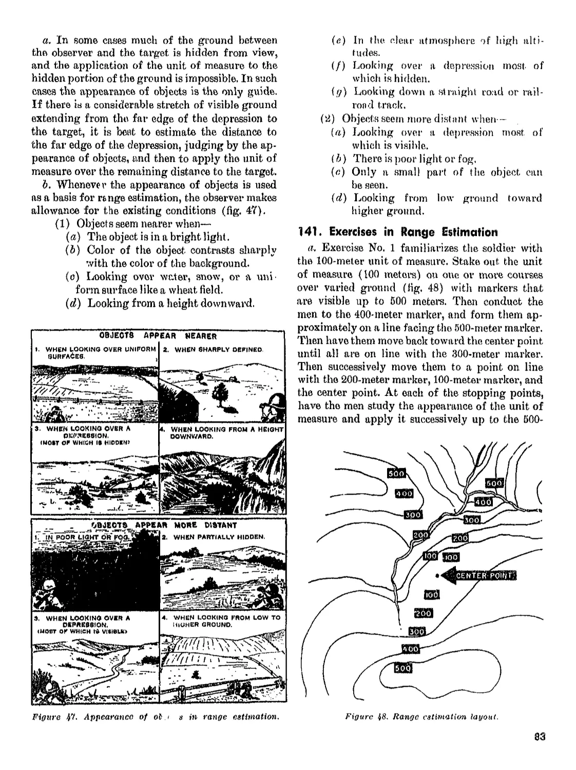
Sustained
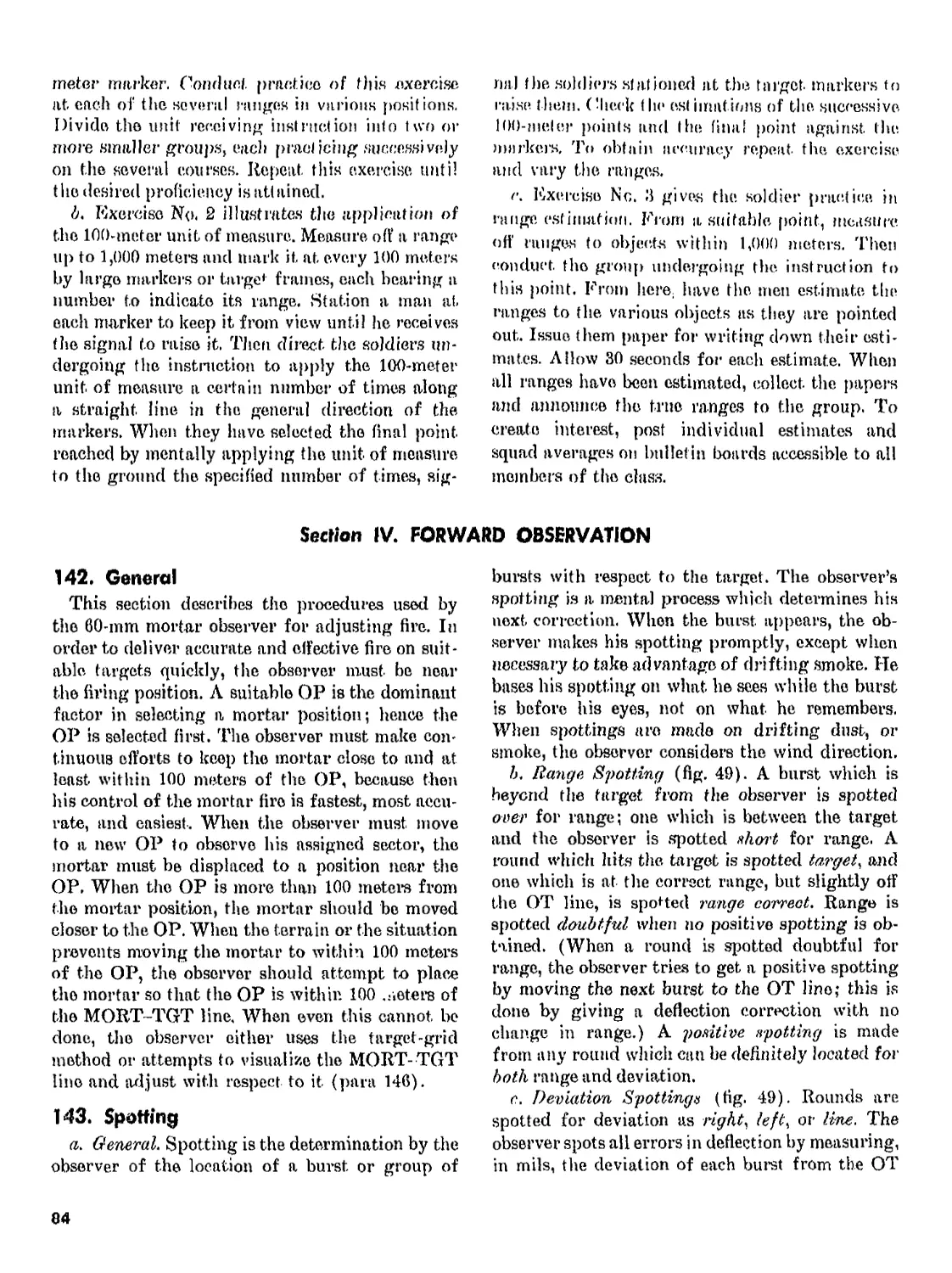
rounds per minute. 18
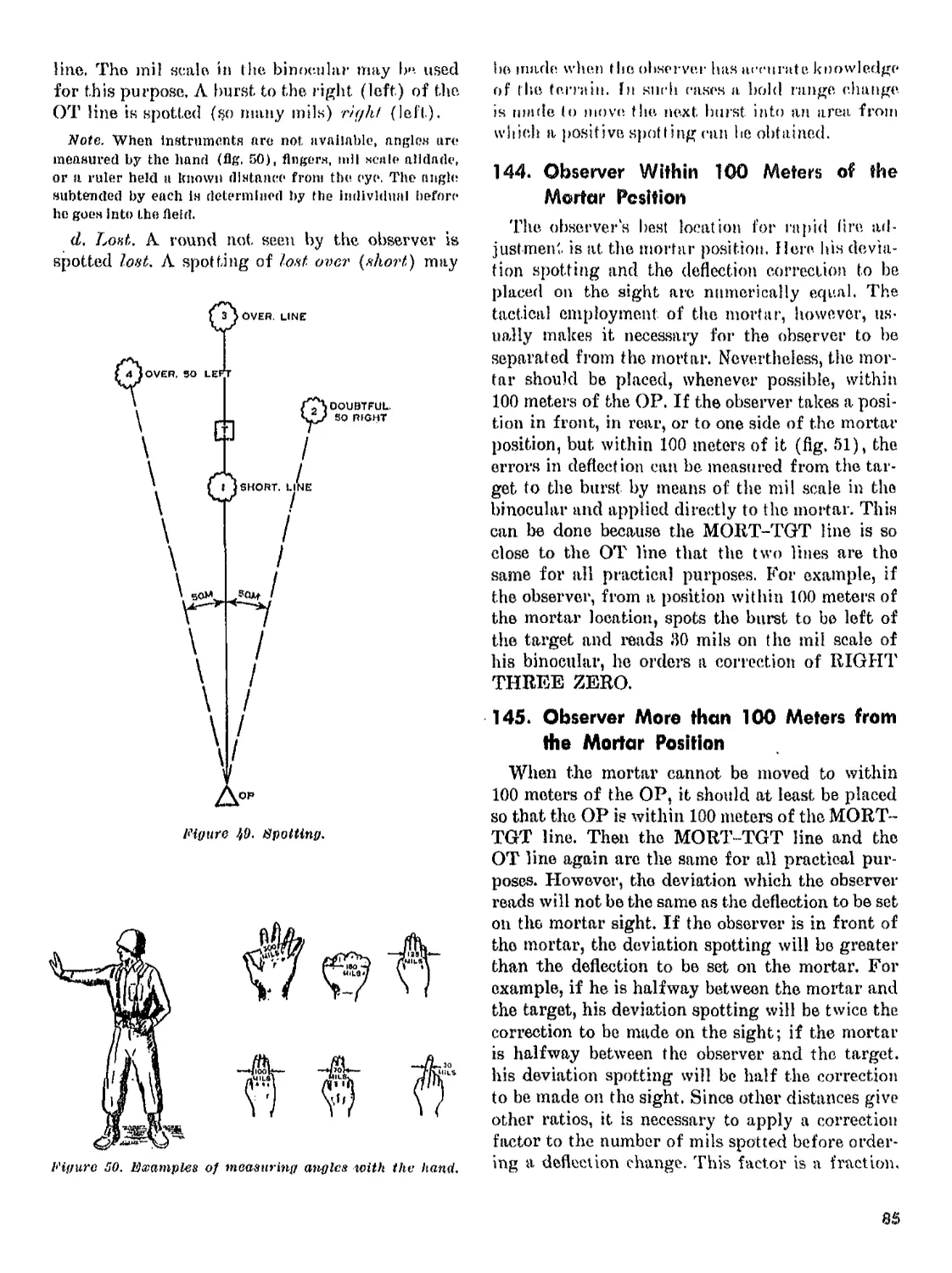
(Firing at the maximum rate
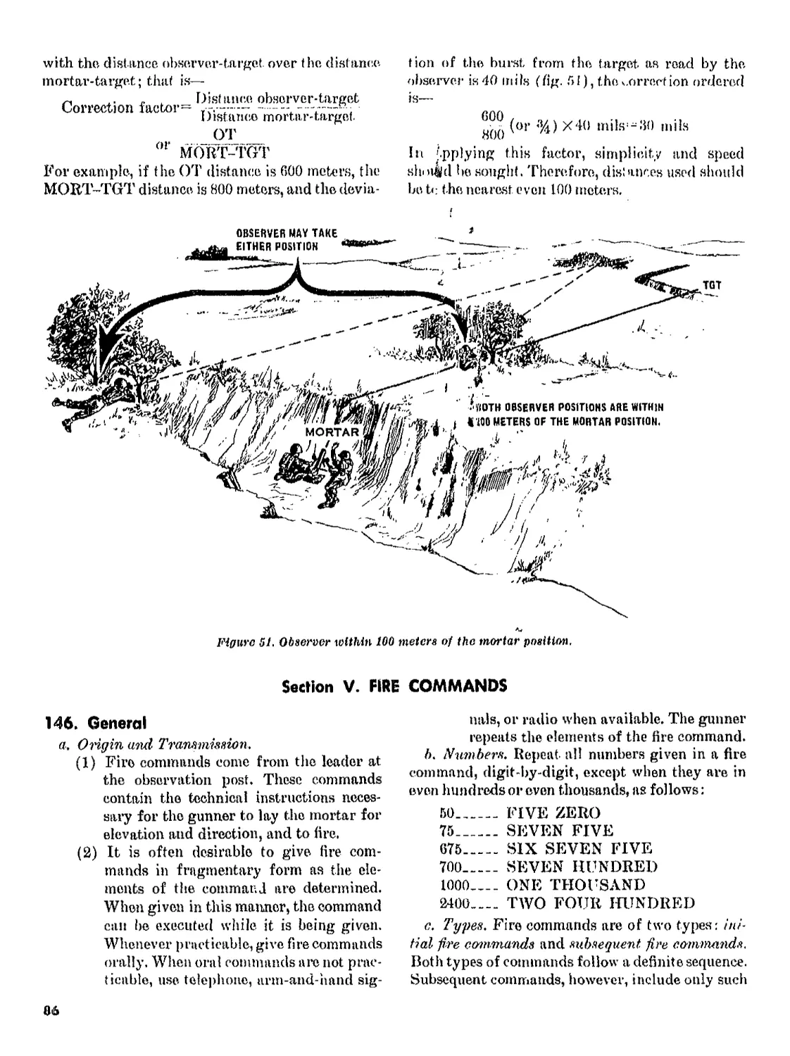
of fire for more than one
minute will cause gas
leakage around the base
cap.)
4
Range
Maximum, approximate:
HE, М49Л2__________________ 1,790 metera
Smoke (WP), M302___________ 1,450 meters
Training practice, М50Л2. 1,790 meters
Training round, M09_______ 225 meters
Illumination, M83A1 and 1, 000 meters
Л2.
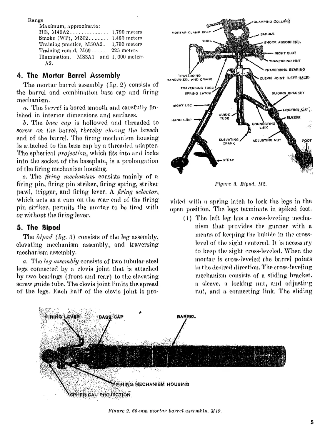
4. The Mortar Barrel Assembly
The mortar barrel assembly (fig. 2) consists of
the barrel and combination base cap and firing
mechanism.
a. The barrel is bored smooth and carefully fin-
ished in interior dimensions and surfaces.
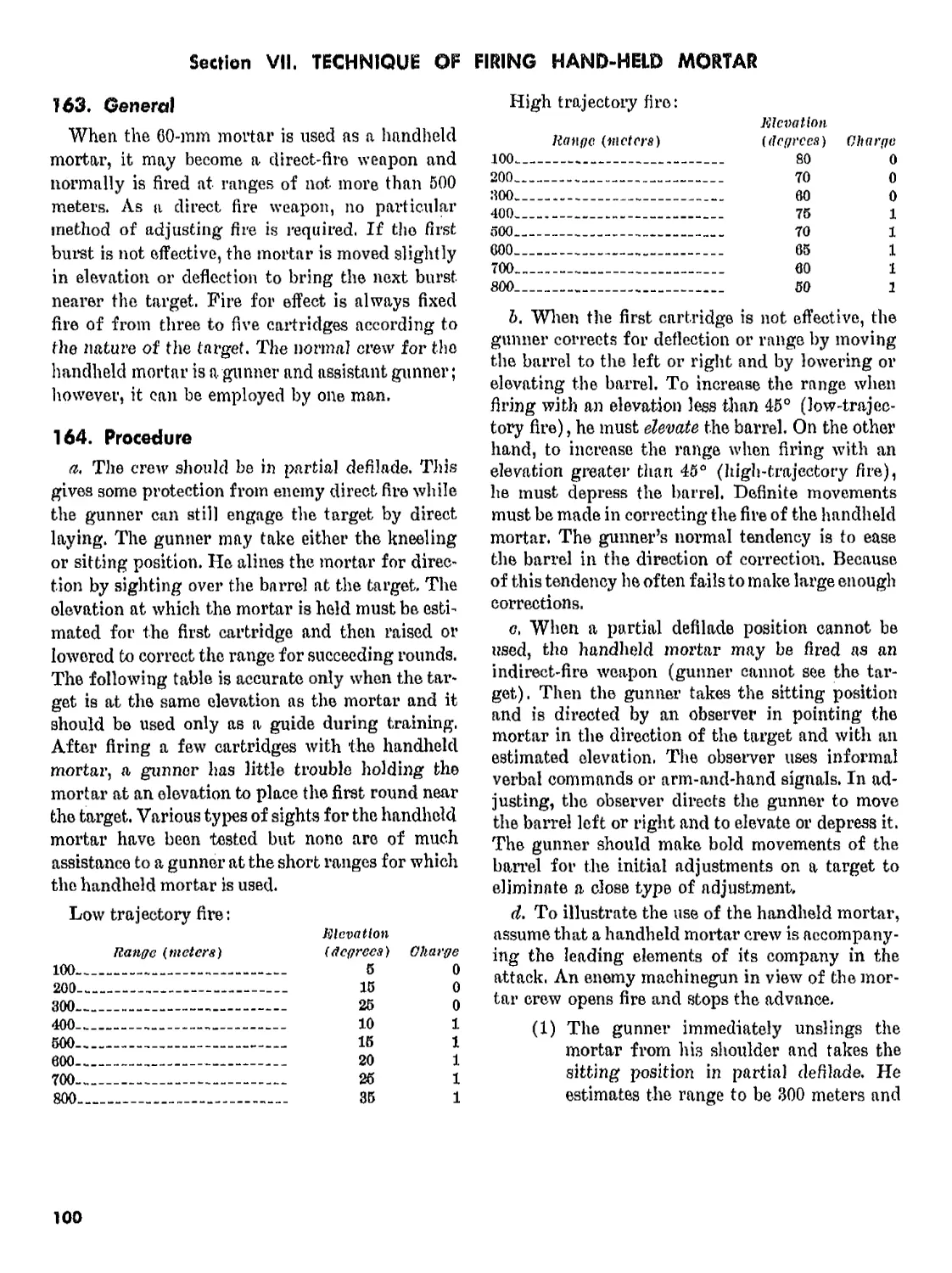
1) . The banc cap is hollowed and threaded to
screw on the barrel, thereby closing the breech
end of the barrel. The firing mechanism housing
is attached to the base cap by a threaded adapter.
The spherical projection^ which fits into and locks
into the socket of the baseplate, is a prolongation
of the firing mechanism housing.
a, The -firing mechanism- consists mainly of a
firing pin, firing pin striker, firing spring, striker
pawl, trigger, and firing lever, A firing selector^
which acts as a cam on the rear end of the firing
pin striker, permits the mortar to be fired with
or without the firing lever.
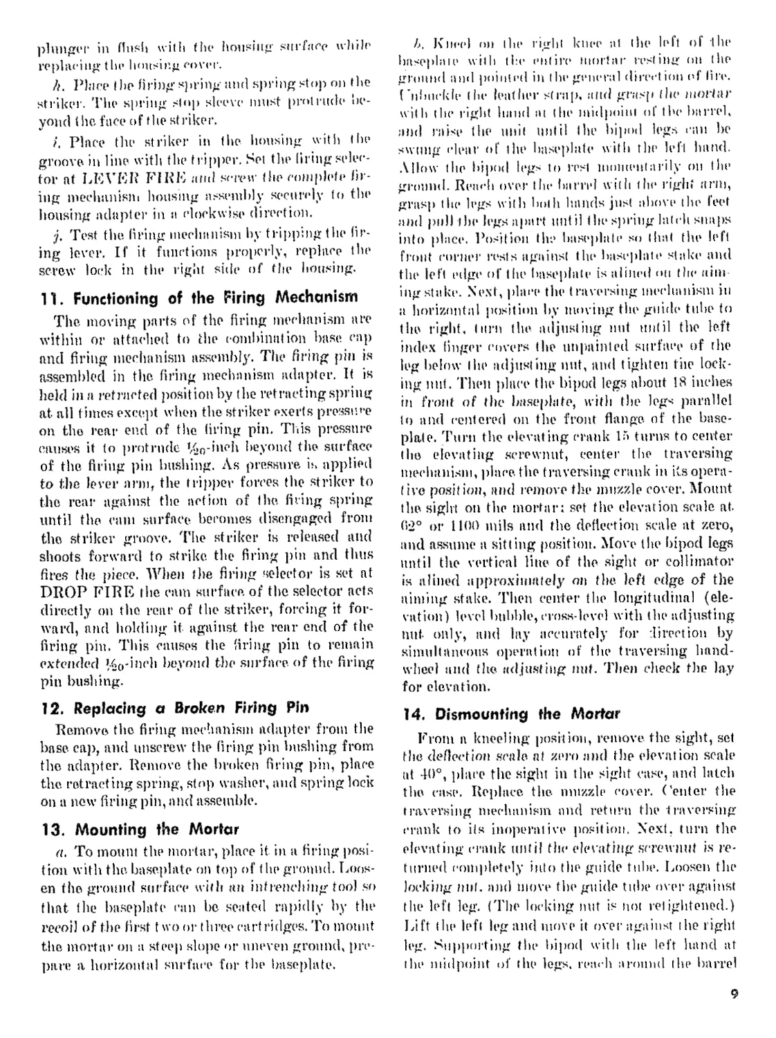
5. The Bipod
The bipod (fig. 3) consists of the leg assembly,
elevating mechanism assembly, and traversing
mechanism assembly.
a,. The leg assembly consists of two tubular steel
legs connected by a clevis joint that is attached
by two bearings (front and rear) to the elevating
screw guide tube. The clevis joint limits the spread
of the legs. Each half of the clevis joint is pro-
Fifpire 3. IJipod. Л/2.
vided with a spring latch to lock the legs in the
open position. The legs terminate in spiked feet.
(I) The left leg has a cross-leveling mecha-
nism that provides the gunner with a
means of keeping the bubble in the cross-
level of the sight centered. It is necessary
to keep the sight cross-leveled. When the
mortar is cross-leveled the barrel points
in the desired direction. The cross-leveling
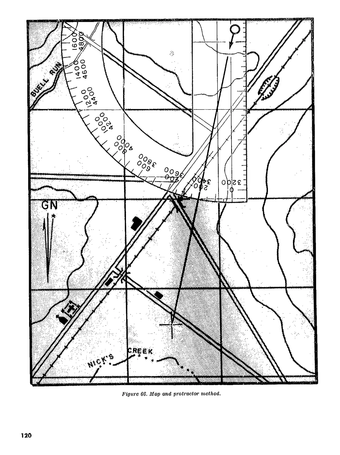
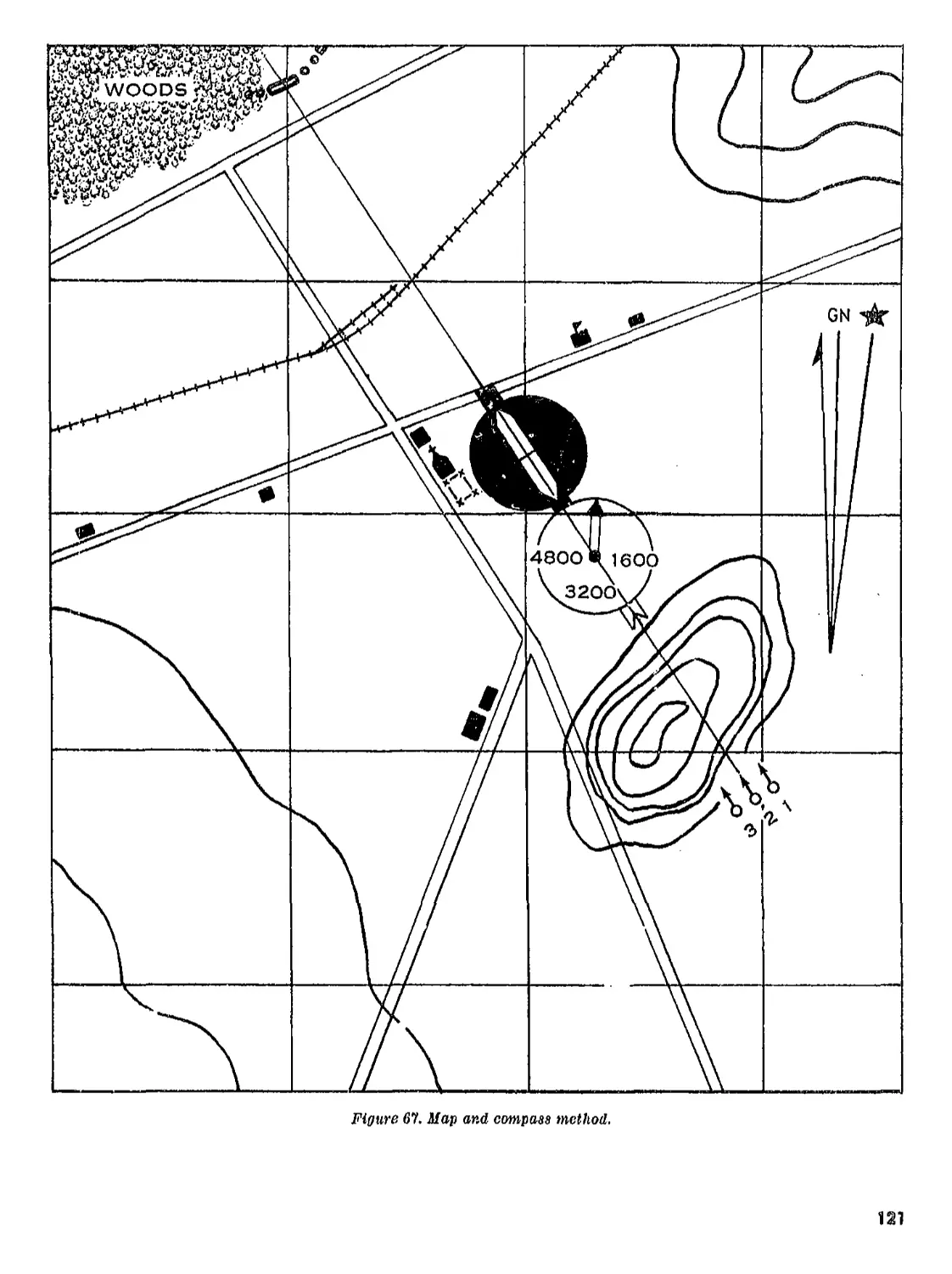
mechanism consists of a sliding bracket,
a sleeve, a locking nut, and adjusting
nut, and a connecting link. The sliding
Figure 2. 60-mm mortar barrel assembly, MID.
5
bracket is mounted on the sleeve and
locked in the desired position on the
sleeve by the. locking nut. The sliding
bracket is also connected (o the guide
tube by the connecting link, The adjust-
ing nut moves the sleeve up or down the
left, leg and transmits movement through
the sliding bracket, connecting link, and
guide tube to the yoke on which the sight
is mounted. Thus, the bubble in the cross-
level of the sight, may oe centered by
moving the adjusting nut.
(2) The right leg contains no moving parts.
On the lower part of the right, leg is a
leather handgrip and a strap to secure
the legs to the barrel when the mortar
is carried.
Ъ. The elevating mechanism assembly consists
of an elevating screwnut that moves vertically on
a screw within the guide tube. The elevating
screw is turned by the crank attached to its lower
end. The upper end of the elevating screw fits into
the lower end of the traversing bearing and is
locked to it by a pin, The elevating screw remains
within the guide tube when the elevating crank
is turned. The elevating sercwnut appears above
the guide tube when the mortar is elevated.
o. The traversing mechanism assembly consists
of the traversing mechanism, shock absorbers, and
clamp,
(1) The traversing mechanism is a telescop-
ing type of mechanism and consists of a
tube and nut. Turning the handwheel
causes the nut to move back and forth
within the tube, thus moving the yoke
and traversing the mortar. The yoke pro-
vides the bearings for the traversing
mechanism and connects the mortar clamp
and the elevating mechanism. The sight
bracket fits into a dovetail slctr fifth©
yoke.
(2) The shock absorbers stabilize the mortar
and mount during firing. They permit
movement between the yoke and the
clamp assembly and are countered by the
resistance of two coil compression
springs, which are mounted in the shock
absorber retainers of the saddle.
(3) The clamp is in two sections and clamps
the barrel to the bipod. The lower half
is called the saddle and includes two
shock absorber retainers with locking
screws. The upper half of the clamp is
called the clamping collar. The two halves
of the clamp are hinged and can be locked
tightly together by the. clamp bolt. When
secured about the barrel, they lock it
firmly to the. bipod. The clamping collar
is placed around the barrel so that 10
inches of the barrel extends in front of
the collar.
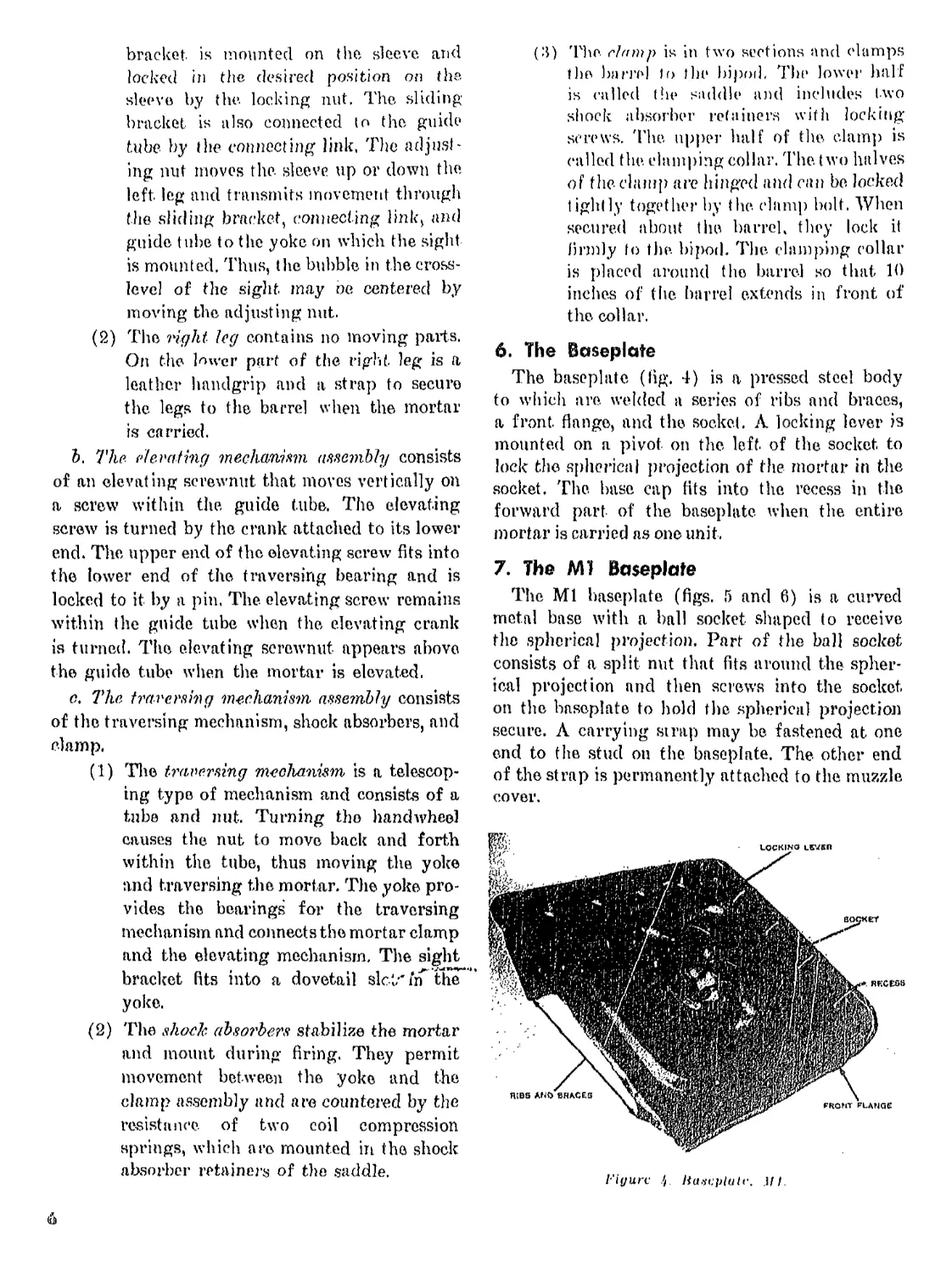
6. The Baseplate
The baseplate (lig. 4) is a pressed steel body
to which are. welded a series of ribs and braces,
a front, flange, and the socket. A locking lever is
mounted on a pivot on the left of the socket to
lock the spherical projection of the mortar in the
socket. The. base cap fits into the recess in the
forward part of the baseplate when the entire
mortar is carried as one unit,
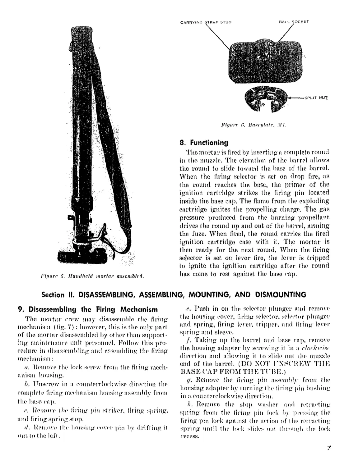
7. The Ml Baseplate
The Ml baseplate (figs. Г) and 6) is a curved
metal base with a ball socket shaped to receive
the spherical projection. Part of the ball socket
consists of a split nut that fits around the spher-
ical projection and then screws into the socket
on the baseplate to hold the spherical projection
secure. Л carrying strap may be fastened at one
end to the stud on the baseplate. The other end
of the strap is permanently attached to the muzzle
cover.
Figure p iiaxt:plult\ Mi
i-'iyurc в. Handheld mortar axxcmbled.
CARRYING strap stud
BA| (. SOCKET
— SPLIT NUT
Fif/ttrr fi. lia.4fi>hilr. Ml.
8. Functioning
The mortar is fired by inserting a complete round
in the muzzle. The elevation of the barrel allows
the round to slide toward the base of the barrel.
When the firing selector is set on drop fire, as
the round reaches the base, the primer of the
ignition cartridge strikes the firing pin located
inside the base cap. The flame from the exploding
cartridge ignites the propelling charge. The gas
pressure produced from the burning propellant
drives the round tip and out of the barrel, arming
the fuze. When fired, the round carries the fired
ignition, cartridge case, with it. The mortar is
then ready for the next round. When the firing
selector is set on lever fire, the lever is tripped
to ignite the ignition cartridge after the round
has come to rest against, the base cap.
Section II. DISASSEMBLING, ASSEMBLING, MOUNTING, AND DISMOUNTING
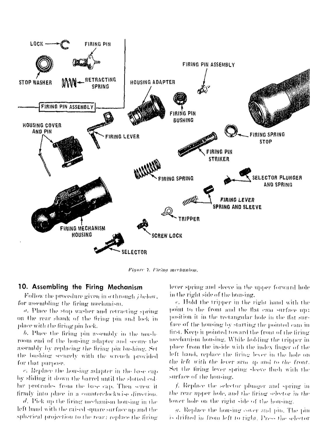
9. Disassembling the Firing Mechanism
The mortar crew may disassemble the firing
mechanism (fig. 7) ; however, this is the only part
of the mortar disassembled by other than support-
ing maintenance unit personnel. Follow this pro-
cedure in disassembling and assembling the firing
mechanism :
a. Remove* the lock screw from the firing mech*
anisin housing.
I). Unscrew in a counterclockwise direction tin1
complete firing mechanism housing assembly from
the base cap.
e. Remove the firing pin striker, firing spring,
ami firing spring st op.
(I. Remove* the housing cover pin by drifting it
out. to the left.
e. Push in on the selector plunger and remove
the housing cover, firing selector, selector plunger
and spring, firing lever. tripper, and firing level-
spring and sleeve.
/. Taking up the barrel and base cap. remove
the bousing adapter by screwing it in a (-loe-kwim
direction and allowing it to slide out the muzzle
end of the barrel. (DO NOT UNSCREW THE
ВЛSE ('АP FRОM TH E TU ВE.)
g. Remove the firing pin assembly from the
housing adapter by turning the firing pin bushing
in a counterclockwise direction.
Л, Remove, the stop washer and retracting
spring from the firing pin lock by pressing the
firing pin lock against the action of the retracting
spring until the lock slides out through the lock
recess.
FIRING PIN
HOUSING ADAPTER
FIRING LEVER
LOCK
STOP WASHER
FIRING PIN ASSEMBLY
HOUSING COVER
ANO PIN
FIRING PIN ASSEMBLY
FIRING PIN
STRIKER
FIRING SPRING
STOP
FIRING PIN
BUSHING
FIRING SPRING
SCREW LOCK
SELECTOR
Fiijiirr 7. (‘iriti)! mrrlianiiw.
FIRING MECHANISM
HOUSING
FIRING LEVER
SPRING ANO SLEEVE
SELECTOR PLUNGER
AND SPRING
TRIPPER
10. Assembling the Firing Mechanism
Follow t lie procedure gi vet i in a ( h r< nig'l i / below,
foi' usseuibliiig the firing liivrliani-fii.
<f. Place the slop washer and rrl ing spring
(Hi the rear shank of the liiing pin and lock in
place ti lth the firing pin lock.
Л, Place the firing pin assembly hi the inn-b-
rooiii end of (he Innwing adapter and -eeurr ihr
;ts.-rinhlv by replacing ihr firing pin biwhing. >*'(
the hushing -'Ci ) i re I v with (lie w rein'll provided
for i hat purpose.
>. Ileplart* 11»* hon-iiin' adaplrr in the ba-e rap
by sliding it down the barrel until (lie shilled •<>!
lai' protrude- ITohi I he ha^r t ap. Then -crew it
firndy into place in a rmiBterelnr к и i-p >|1iprel ion.
d. Pirk up (hr lirilliC llierli;(ni"IH holl-iilg Hi 1 In’
left hand w it к । lie ra wed -tpiare -nrt’acr up and i hr
spIn’Dru I pl'oji’rlion (nllir rear; replace (hi* firing
lever spring and sleeve in Hie upper forward holt1
in (hr right side oft he lunwing.
c. Hold l hr 1 ripper in the right hand with the
point Io tin* from and the Hal cani *nrl'are up:
position i( in tlie rectangular holr in the (Lit sur-
face of the housing hv starting the pointed cam in
lirsl. Keep it pointed toward the from of the tiring
nii'chanisiu hou.-iug. While holding the iripper in
place Г ruin the in-ide wiih (he index linger of tlie
lel( hand, replace 1 he lil'tii” Icier to (lie hole on
the It'I't with tlie lever err и ср and to the front.
Sei (lie firing lever spring -h-rve lln-h wiili tin1
-iirfare of i he hon<iitg.
/, Replace (he .-elector plunger niid -priilg ill
I hr гг.чг upper hole, and the firing -rfrcior in I hr
lower hole on (lie right -it|r 'd tin* ! i' a I -111 g.
<1. Replace 1 hr hon-ing i‘i\rr and pili, T he pin
I- drilled Ih ll'inn left Io High) . Pie-- the ч'||,',П»Г
plunger in Hush with the housing surface while
replacing the housing cover.
Л. Place I bp firing spring and spring stop on the
striker. 'Fhe spring slop sleeve must protrude be-
yond t he face of the striker.
A Place the striker in the housing with the
groove in line with the tripper. Set the tiring selec-
tor at LEVER FIRE ami screw the complete fir-
ing mechanism housmg assembly securely to the
housing adapter in a clockwise direction.
j. Test the firing mechanism by tripping the fir-
ing lever. If it functions properly, replace the
screw lock in the right side of the housing.
11. Functioning of the Firing Mechanism
The moving parts of the firing mechanism are
within or attached to the combination base cap
and firing mechanism assembly. The firing pin is
assembled in the firing mechanism adapter. It is
held in a retracted position by the retracting spring
at all times except when the striker exerts pressure
on the rear end of the firing pin. This pressure
causes it to protrude %0-inch beyond the surface
of the firing pin bushing. As pressure, is applied
to the lever arm, the tripper forces the striker to
the rear against the action of the firing spring
until the cam surface becomes disengaged from
the striker groove. The striker is released and
shoots forward to strike, the firing pin and thus
fires the piece. When fhe firing selector is set at
DROP FIRE the cam surface, of the selector acts
directly on the rear of the striker, forcing it for-
ward, and holding it against the rear end of the
firing pin. This causes the firing pin to remain
extended R>0-inch beyond the surface of the firing
pin bushing.
12. Replacing a Broken Firing Pin
Remove the firing mechanism adapter from the
base cap, and unscrew the firing pin bushing from
the adapter. Remove the broken firing pin, place
the. retracting spring, stop washer, and spring lock
on a now firing pin, and assemble.
13. Mounting the Mortar
ct. To mount the mortar, place it in a firing posi-
tion with the baseplate on top of the ground. Loos-
en the ground surface with an intrenching tool so
that fhe baseplate can be seated rapidly by the
recoil of the first t wo or three cartridges. To mount
the mortar on a steep slope or uneven ground, pre-
pare a horizontal surface for the baseplate.
Л, Knurl ni) (lie right knee al the left of I he
haseplaie with the entire mortar resting on the
g rum id and pointed in the general direction of fire.
1 h)I>urkle the leather strap, mid grasp the mortar
with the right hand at (lie midpoitu of the barrel,
and raise the unit until fhe bipod legs can be
swung e]p}ir of ।he baseplate with the left hand.
Allow the bipod legs to rest momentarily on the
ground. Rvik-Ii over the barrel with f hr right arm,
grasp the legs with both hands just aliovr the feet
and pull the legs apart mit il the spring hiteli snaps
into place. Position the baseplate so I lint the left
front corner rests against the baseplate stake and
the left edge of the baseplate is alined ин the aim
ing stake. Next, place the traversing mechanism in
a horizontal position by moving the guide* tube to
the right, (urn the adjusting nut until the left
index finger covers (he unpainted surface of the
log below fhe adjusting nut, and tighten the lock-
ing nut. Then place the bipod legs about 18 inches
in front of the baseplate, with the legs parallel
to and centered on the front flange, of the base-
plate. Turn the elevating crank 15 turns to center
the elevating screwnut, center the traversing
mechanism, place, the traversing crank in its opera-
(ive position, and remove the muzzle cover. Mount
the sight on the mortar; set the elevation scale at.
(>2° or 1100 mils mid the deflection scale at zero,
and assume a sitting position. Move the bipod legs
until the vertical line of the sight or collimator
is alined approximately on the left edge of the
aiming stake. Then center the longitudinal (ele-
vation) level bubble, cross-level with the adjusting
nut only, and lay accurately for direction by
simultaneous operation of the traversing hand-
wheel and the adjusting nnt. Then check the lay
for elevation.
14. Dismounting the Mortar
From a kneeling position, remove, the sight, set
the deflection scale, at zero and the elevation scale
at 40°, place the sight in the sight case, and latch
the case. Replace the muzzle cover, ('enter the
traversing mechanism and return (he traversing
crank to its inoperative position. Next, turn the
elevating crank until the elevating srrewnut is re-
turned completely into the guide tube. Loosen the
locking nut. and move the guide tube over against
the left leg. (The locking nut is not relightened.)
Li ft l he lefl leg and move it over against the right
leg. Supporting the bipod with the left hand at
the midpoint of the legs, viau-h around the barrel
9
with the right hand mid lift the right front edge
of I ho baseplate until the recess li‘s around the
base- cm p. Then position I lie legs of the bipod under
the baseplate, and allow the entire mortar to rest
on the1 ground. Then fasten the leather st raj) Io
secure the bipod anti the baseplate to the mortar
Section III. САНЕ, CLEANING, AND INSPECTION
15. Care and Cleaning
ff. The crew performs the care mid cleaning
of the mortar and its accessories. Experience has
shown that this weapon becomes unserviceable
through hick of rare rather than from use,
b. Dirt and grit acrumuhrle in I raveling or from
the blast of the mortar in firing and form cutting
compounds. Powder foulings settle between and
on operating parts and attract moisture, prevent,
proper operation of moving parts, and hasten
the formation of rust, (dean dirt, grit, and powder
foldings from all parts at frequent intervals, de-
pending upon use and service. If rust should accu-
mulate, remove it from bearing surfaces carefully
so that the clearances are not unduly increased.
Use crocus cloth. The use of coarse obrrydves h
strictly forbidden. When the mortar is not in use,
oil it. properly and place it under cover.
16. Lubricants, Cleaning Agents, and Rust
Preventives
<z, The materials authorized and issued for
cleaning and lubricating the mortar are—
(1) Optical lens cleaning compound.
(2) Cleaning compound, solvent: rifle bore
cleaner.
(3) Abrasive doth, al-oxide.
(4) Abrasive cloth, crocus,
(5) Petroleum corrosion preventive com-
pound.
(6) Olive drab-green enamel.
(7) Technical ethyl alcohol.
(Я) Automotive and artillery grease.
(9) General purpose lubricating oil.
(10) Lens paper.
(11) Mineral spirits paint thinner (used in
lieu of drycleaning solvent).
(12) Synthetic, resin enamel thinner.
b. Rifle bore cleaner is issued for cleaning the
bore of the. mortar after firing. This material pos-
sesses rusr preventive properties and provides tem-
porary protection against rust. For better protec-
tion. however, dry the bore immediately after
cleaning with rille bore cleaner and coat the metal
iightly with special preservative lubricating oil.
When frozen, thaw it out and shake it up well
before using. During freezing weather, till closed
containers not more, (han three-fourths full, be-
cause full containers burst when the contents
freeze.
c. I'sr a soap solution, for cleaning the bore
when rifle bore cleaner is not available, 'Го pre-
pare, this solution, chip up uno-quarter pound of
issue soap and dissolve it in one gallon of hot
water. This solution is better when used hot, but
it cun be used cold,
d. Special presprvafire lubricating oil has rust-
preventive. as well as lubricating properties, but it
cannot be depended upon to provide protection
from rust for long periods. Use. it to lubricate (in
norma) temperatures) all moving parts and for
short term protection of the bore against rust. Pre-
servative action results partly from the oily film
on the metal parts and partly from chemical com-
bination of inhibitors in the oil with the metal.
It protects the metal surfaces from rust though no
appreciable film of oil is present on the metal
parts. When used on moving parts it is necessary to
maintain n thin film of oil tn provide the necessary
lubrication.
e. Lubricating oil for aircraft instruments and
machineguns is the proper lubricant to be used in
temperatures below 0° F. It is an extremely light
oil that relies entirely upon maintenance, of the oil
film to protect metal surfaces from rusting. When
it is used ns a preservative, inspect the metal parts
daily for rust. When rust is found, clean and coat,
them lightly with the oil.
f. Light rust pre rent ire compound is issued for
the protection of metal parts for long periods of
time while the parts are boxed and in storage. It
can be applied with a brush at temperatures above
60° F. However, the best method is to apply it hot.
either by brushing or dipping.
g. Drgeletuuiig sol rent is a noncormslve petro-
leum solvent that removes grease, oil. or rust, pre-
ventive compound. It is highly inflammable. Do
not use it near open flames. Smoking is prohibited
where drycleiining solvent is used. Apply it with
rag swabs to large parts and use if as a bath for
10
small parts. Dry the surfaces thoroughly with
clean rags immediately after using the solvent.
Wear gloves when handling the parts after clean-
ing to avoid leaving fingermark's, which arc or-
dinarily acid and induce corrosion. Drycleaning
solvent attacks and discolors rubber.
17. Cleaning Equipment
a. The equipment authorized and issued for
cleaning and lubricating the mortar are—
(1) Chamber cleaning brush, MG.
(2) Cleaning st a if, MO.
(3) Hand trigger operated oiler.
b. The M6 chamber cleaning bruxh consists of
a steel wire core with bristles, This core is twisted
in a spiral to hold the bristles in place. Use it to
clean small holes and threads found in the firing
mechanism assembly.
a, The, Ml) cleaning к faff is a rod with a handle
at one end and a slotted tip at the other end. The
slotted tip provides a means for securing cotton
waste or rags to the staff for cleaning and oiling the
bore of the mortar.
d, The hand trigger operated oiler is used to
lubricate and apply oil to flat surfaces that require
oil but have no fittings. By adding the special
adapter to the oiler, it can be used to apply oil
to the flush-type fittings located on the bipod.
18. Care and Cleaning When No Firing is
Done
This includes the care to preserve the condition
of the mortar during the time when no firing is
being done. Mortars and accessories in the hands
of troops are inspected daily to check their con-
dition and cleanliness. Training schedules should
allow time for supervised cleaning on each day
the mortars are used.
a. To clean the bore, attach rags to the cleaning
staff and insert the rags into the bore at the muzzle
end. Move the staff forward and backward several
times and replace the rags. Then push the staff for-
ward until the rags touch the bottom of the bore,
and twist the staff several times to the right. This
cleaning removes accumulations of dust, dirt, and
oil in the bore. Repeat until the rags come out
dean'. After the bore has been thoroughly cleaned,
saturate, clean rags with oil and push it through
(iie bore.
b. To clean the firing mechanism, disassemble,
and clean all parts thoroughly with rags. When
cleaning the firing mechanism housing, make sure
that all the Imles and slo(s arc denned. I'sc t he MG
brush nr a small stick wrapped with rags to dean
the screw threads, holes, and crevices. A ftvr denn-
ing purls, saturate- dean rags with oil and apply я
thin coat of oil to every part of the firing mecha-
nism. Inspect the threads on the firing mechanism
adapter and the firing pin bushing to make- sure
that no lint is present. Then assemble the firing
mechanism to the. barrel.
e. Keep all parts of the bipod and baseplate
dean and free from foreign matter. Keep all mov-
ing parts and polished surfaces coated with oil.
To clean the screw thieads and crevices, use a
small brush or small stick. To dean the meta) sur-
faces, rub them with a dry cloth to remove mois-
ture, perspiration, and dirt. Then wipe them with
a cloth wet with a small quantity of oil. Maintain
this protective film at all times. For oiling the bi-
pod, use. the. oiler with adapter to apply special
preservative lubricating oil to the five flush-type
fittings: left log clevis, traversing bearing, sight
slot on Hie yoke, and left and right shock
absorbers.
19. Preparatory to Firing
Before firing—
a, Disrrcunt the main groups.
I) . Clean the bore and firing mechanism with
clean, dry rags. Do not apply any oil to the bore
before firing.
c. Clean and oil lightly all metal moving parts
with oil. Do not use grease.
d. Mount the mortar for firing.
20. After Firing
Clean the mortar bore thoroughly by the eve-
ning of the day on which it is fired, because firing
causes powder and primer fouling to collect in the
boro and on the firing pin. This fouling absorbs
and retains moisture from the air, thereby causing
rust. Remove these deposits by cleaning with rifle
bore cleaner, soap solution, or water,
a. Cleaning Procedure After Firing.
(1) Clean the bore, firing mechanism and all
working parts on the mount. If this can-
not- be done at once, apply oil carefully to
prevent, rust.
(2) At the first opportunity, dean, oil, and
inspect all partsand make needed repairs
and replacements.
11
(3) On assembly, check the operation of the
Bring mechanism and bipod to make sure
that functioning is correct.
Ъ. Cleaning the Bore With Bijic Bow ('honor.
(1) Remove the firing mechanism and adap-
ter.
(2) Attach clean rags to the cleaning staff,
saturate the rags with rifle bore clraner.
and push it back and forth through the
barrel with the cleaning staff.
(3) Repent the operation with clean rags
two or throe times. Be sure the rags go
all the way through the bore before, the di-
rection is changed.
(4) Continue to swab the bore with quanti-
ties of clean, dry rags until the rags come
out clean and dry.
(5) Examine rhe boro carefully for clean-
liness. If it is not free of all residue, re-
peat the cleaning process.
(G) Secure a small piece of rag saturated
with rifle bore cleaner, and thoroughly
clean the threaded adapter recess in the
base cap.
(7) When the bore and adapter recess are
both thoroughly clean and dry, apply oil
to them with rags.
л Cleaning the Bore With Coop Solution.
(1) If rifle bore cleaner is not available, use
soap solution or plain water.
(2) Clean the bore and adapter recess using
a liberal quantity of soap solution in place
of the rifle bore cleaner.
(3) Rinse the barrel with clean water to re-
move the washing material.
(4) Dry the barrel by using clean rugs. Swab
the bore thoroughly until it is dry and
clean.
(Й) When the bore and adapter recess arc
clean and dry, saturate rags with oil and
push it through the bore. Oil the adapter
recess, but make sure, that но lint is left
on the threads.
d. Cleaning the Firing Mechanism,
(1) Disassemble the entire bring mechanism
(para. 9).
(2) Clean the firing mechanism adapter and
firing pin with rifle bore cleaner, or
whichever cleaning agent is available to
remove the primer and powder fouling.
(3) Clean all other parts of the firing mech-
anism with drycleaning solvent, using the
AfG brush oi' a small stick covered with
rags to remove dirt from the recesses.
(I) After ali parts have, been cleaned and
dried, saturate (dean rags with oil and
apply a thin coat of oil to every part of
the firing mech-anism.
(5) Assemble. the firing mechanism, being
sure that no lint remains on the thread
of the firing mechanism adapter or on
the firing pin bushing.
.Vote. The heat from tiring dries the oil on
tin* working parts of tin* ftrtijjx ntechauism and
may cause the mechniiism to become sluggish
or fail to function during tiring, When this-
happens take tlie mechanism apart, and clean
and oil it.
r. Cleaning the Mount.
(1) Wipe the bipod clean, taking care to re-
move dirt from all crevices. Clean all
moving parts with drye.leaning solvent.
Use the cleaning brush or л small stick
covered with rags to remove dirt from all
recesses.
(2) Dry all parts,
(3) Wipe all moving parts and polished sur-
faces with a c loth wet with oil.
(4) Apply oil to the five lubrication fittings,
(5) Operate the. handwheel and cranks to dis-
tribute the oil ovei the. working surfaces.
f. Cleaning Exterior Surfaces. To clean the ex-
terior surfaces, wipe off the mortar with a dry
cloth to remove dampness, dirt, and perspiration.
g. Caring for Accessories. Inspect, clean, and oil
the accessories.
h. Cleaning the Mortar. Olean the mortar com-
pletely as soon as possible after firing. When the
mortar is not to be fired on 'the following days, re-
peat the cleaning procedure as outlined for 3 days.
21. On the Range or in She Field
For maximum efficiency, observe the, following
points:
a. . Do not fire a mortar with any dust, dirt, mud,
or snow in the bore,
Ъ. Keep the bore free from oil and dirt when
firing.
e. Do not leave rags or other obstructions in the
bore.
d. Keep the firing mechanism clean and well
oiled at all times. When the firing mechanism, or
bipod shows a lack of lubrication and excessive
friction, apply additional oil where needed.
12
e. Oil nil sliding surfaces frequently and freely
to insure, perfect functioning of the mount.
/. If in an emergency and the prescribed lubri-
cant is not available, use lubricating oil, or any
clean, light, mineral oil simil it to engine oil.
22, Preparation for Storage
a. Special preservative lubricating oil is the
most suitable oil .for short time protection of the
mortar mechanism. It is effective for storage for '2
to 6 weeks, depending on climatic, conditions. How-
ever, inspect mortars in short time storage every
5 days, and renew the preservative film, if neces-
sary. For longer periods protect them with light
rust, compound. This is a semisolid material. If pre-
serves the polished surfaces and the bore for 1 year
or less, depending upon climatic and storage con-
ditions.
6. Clean the mortar and prepare it for storage
with particular care. Clean the bore, all parts of
the firing mechanism, and the exterior of the mor-
tar with drycleaning solvent. Dry them completely
with clean cloths. Do not touch a metal part with
your bare hands after drying it. Coat all metal
parts with either special preservative lubricating
oil or light rust preventive compound, depending
on the length of storage required. Apply the rust
preventive compound to the bore by dipping rags
in the compound and running it through the bore
two or three times with the staff. Disassemble the
firing mechanism, then thoroughly coat it with
rust, preventive compound and reassemble it. Do
not place a mortar in storage under any circum-
stances while it is contained in a cloth or other
cover, or with the bore plugged. Covers collect
moisture, which causes the weapon to rust.
c. Paint, the wooden supports of the packing
box with rust preventive compound before storing
the mortar. Place the mortar in the wooden pack-
ing box, handling it with oiled rags.
23. Cleaning Weapons Received from
Storage
Weapons that have been stored according to the.
previous paragraphs are coated either with spe-
cial preservative lubricating oil or with light rust
preventive compound. Weapons received from sup-
porting maintenance unit storage are generally
coated with rust preventive compound. Use dry-
cleaning solvent to dissolve and remove all traces
of this compound or oil. Clean all small parts and
springs thoroughly. Failure to do this causes stiff
or slow act inn because of the congealing of the
rust- preventive compound at low temperatures.
This may possibly curtail proper I’nncl inning even
at mn-rnal lem pent In res. After using this cleaning
solvent, be sure to dry all parts by wiping them
with dry cloths; then follow the instruct ions in
paragraph 18. When dryeleaning solvent is not
available, remove the rust, preventive compound by
placing the mortar in boiling water for 12 minutes.
Dry all parts thoroughly, and follow (he- instruc-
tions in paragraph 18,
24. Care and Cleaning in Cold Climates
Keep the-moving parts of the weapon absolutely
free from moisture. Lubricants or rust preventive
compounds used in the, temperate zones solidify
in cold climates to the extent that they cause slug-
gish operation or complete failure.
m To winterize the mortar, first remove all old
lubricants and rust preventive compounds. Dis-
assemble the mortar mid use dryeleaning solvent
to clean all parts.
6. For lubrication, use lubricating oil for air-
craft instruments and machineguns.
c. Before tiring a mortar that has been used in
deep snow, carefully cheek the bore to see that it
is not clogged with snow, ice, or other foreign
matter.
б/. After firing, clean the bore with rifle bore
cleaner in an alcohol solution.
e. The colder the climate, the less lubricant is
used as there is less moisture in the air. In ex-
tremely cold climates, the lack of moisture in the
air limits the possibility of the mortar misting or
corroding. However, exercise care to prevent snow
or ice from collecting on the working parts.
f, Do not apply a lubricant to the mortar bore
before operating the mortar in extreme cold. Cover
all moving parts and machined surfaces other than
the bore with a fine coating of lubricating oil.
After firing, clean the mortar to make sure that
ice and snow has not formed in any of the moving
parts. Swab the bore with dry rags only to remove
any snow or ice from the bore, particularly around
the firing pin.
г/. A heavy condensation forms on the mortar
when it is taken from the extreme cold into any
type of heated shelter. When brought indoors, first
allow time for the mortar to come to room tem-
perature. Then, disassemble it, wipe it completely
dry of the condensed moisture, and clean and oil
13
it thoroughly as described in paragraph ‘2(1. I se
lubricating oil.
Л. To avoid condensation, keep the mortar out-
doors or store it. in a lean-to after tiring. However,
if the weather changes abruptly (if it thaws sud-
denly or rains) use the normal cleaning methods.
25. Care and Cleaning in Tropical Climates
a. Where temperature and humidity are high,
or where salt is present, and during rainy seasons,
thoroughly inspect the weapon every day, and
keep it oiled when not in use.
7л Кее}) unexposed parts and surfaces clean mid
oiled.
e. Use special preservative lubricating oil for
lubrication.
26. Care and Cleaning in Hot Dry Climates
a. Tn hot, dry climates, where sand and dust are
likely to get into the mechanism and bore, wipe
the weapons clean daily, or more often, if neces-
sary.
Ъ. When using the weapons in sandy terrain,
wipe off all lubricants. This prevents the sand from
sticking to the lubricant and forming an abrasive
compound, which ruins the mechanism.
c. Immediately upon leaving sandy terrain, re-
lubricate the weapon with light preservative lubri-
cating oil.
d. Frequently wipe the metal parts dry, because
sweat from the hands contains acid and causes
rust.
e. During sandstorms or duststorms, keep the
muzzle covered whenever possible.
27. Care During Gas Attack
a. It is important to prevent the chemical agents
used in a gas attack from getting in or on the
mortar and ammunition. Therefore, when a gas
attack is anticipated, take steps to cover and pro-
tect the mortar, ammunition, spare parts, and
accessories.
b. Put oil on the surfaces of all parts of the
weapon, ammunition, and spare parts.
c. If the mortar is not used during the gas at-
tack, cover the oiled weapon with covers, or place
it in a container so that it cannot come into con-
tact with any contaminating chemical agents.
d. After the. attack, if the weapon has not been
contaminated, clean it with drycleaning solvent.
e. Prepare it for use as described in paragraphs
18 or 19.
28. Deconta mi nation
u. When performing emergency decontamina-
tion, wear the issue protective mask' and apply pro-
tective ointment to the hands and exposed skin
surfaces, If permeable protective clothing is
available, wear the standard sot provided and the
protect ive mask. Impermeable protective suits and
rubber gloves are required only when handling
heavy contaminated material.
Л, Dccont<imimite morliir, accessories, ami nni-
inunitimi by blotting all liquid agents with rags
and paper, wiping off grease and nil, and applying
protective ointment to al) areas that must be
touched or handled when firing the- weapon. To
prevent corrosion, oil the moba) surfaces (except,
for ammunition). When the tactical situation per-
mits, carry out thorough decontamination. Use
warm water and soap, solvents, and military decon-
taminants like- DANC* solution and bleaching
material as prescribed in TM 3--220.
29, Painting
fi. Retouch the mortar as needed, because rust
forms on the mortar where, the paint is worn away.
b. After u certain amount of retouching, the
whole mortar needs repainting. To repaint, remove
the old paint and primer with paint remover or by
scraping. Smooth over all rust, spots with emery
cloth.
c. Clean and dry the parts thoroughly before
repainting.
d. Apply two coats of primer on the bare metal
as a base coat for the paint. Apply the primer by
brushing or spraying; thin the primer for spray-
ing. Let each coat dry ‘24 hours.
r. Apply two coats of lusterless, olive drab paint.
Allow each coat to dry 24 hours.
/. 'fhe using units apply paint (and primer) to
the following parts only ;
(1) Entire baseplates.
(2) Barrel (except bore).
(3) Feet and right leg of bipod.
(4) Ordnance paintsail other parts.
30. Inspection
When inspecting the mortar, observe the follow-
ing points:
u. Jiurrrl. ('heck general appearance and cleanli-
ness of the bore.
b. b'irinff Mechanism. Examine for fouling, rust,
or foreign substance on any of the parts. Trip the
firing lever so that the striker moves forward and
strikes the base of the firing pin when the selector
is on LEVER EIRE. The firing pin should pro-
trude V^o’bwh beyond the surface of (he firing pin
bushing when the firing selector is on DROP
FIRE.
c, Bipod., Check general appearance and see that
nil moving parts are lubricated.
(1) Elevating mechanism, Elevate and de-
press the mortar to see that the mech-
anism operates without binding, excess
play, or undue looseness.
(‘2) Tra versing mechanism. Traverse the
mortar to see that the mechanism operates
smoothly without binding or undue
looseness.
(3) Cross-leveling mechanism. Operate the
mechanism to see that it functions cor-
rectly without excess play. Check the in-
dex marks (for centering the bubble) to
see that they are distinct.
d. Baseplate. Check general appearance. Ex-
amine the locking lever to make sure that it op-
erates easily and locks the spherical projection
securely to the baseplate.
e. Sight and Mounting. Cheek to see if the op-
erating condition of the sight, or rigidity of its
mounting has been impaired.
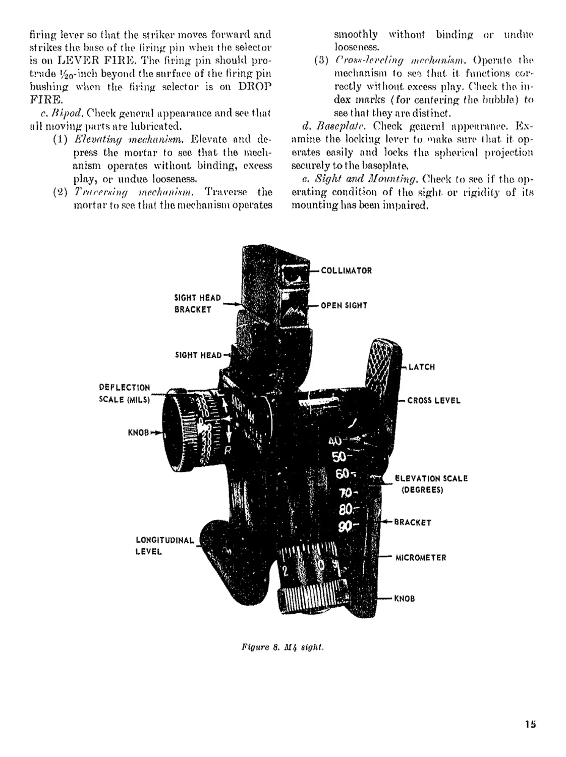
Figure 8. sight.
15
Seetion IV. SIGHTING EQUIPMENT, SPARE PARTS A№ ACCESSORIES
3L M4 Slgk
a. The M4 sight (fig. 8) is the standard sight
for laying the mortar for elevation and direction.
The sight includes a collimator, elevating and lat-
eral deflection mechanisms, and longitudinal and
cross-levels. All are supported by a bracket with
a dovetailed base that fits into a slot in the mortar
yoke and latches in place. An open sight is also
provided, but is only used when the collimator is
broken. The micrometer knobs and the deflection
and elevation scales indicate deflection and ele-
vation when the bubbles in the levels are centered.
The collimator is the direction sighting device of
the sight and consists of a vertical white line in
an opaque field, all inclosed within a rectangular
tube. When the sight is level, the white line of the
collimator measures the same deflection between
the line of sight and the direction of fire as is indi-
cated on the deflection scale of the sight. The
bracket upon which the collimator and open sight
are mounted can be depressed or elevated so that
the assembly can be moved in elevation to bring
the aiming point into the field of view. This
motion has no effect on elevation settings.
S. The deflection scale has 60 graduations, each
representing 5 mils. The graduations arc numbered
every 10 mils from 0 to 150 on each side of the 0
position. Directions for turning the knobs for left
and right deflections are indicated by the letters
L and R and arrows near the index. When a de-
flection of 0 is placed on the sight, the line of
sight is parallel to the direction of fire. The eleva-
tion scale is graduated into 6 divisions, each one
representing 10°. The graduations are numbered
from 40 to 90. The elevation micrometer is grad-
uated into 40 divisions, each one representing %0.
The graduations are numbered every 4 divisions
(1°) from 0 to 10. The collimator and the open
sight directly below it have vertical reference
lines and can be placed as desired in elevation.
When the sight head bracket is tilted to its ex-
treme upward (rear) position and an elevation
of 40° is placed on the sight, the elevation of the
overhead portion of the open sight is 2° below
the axis of the mortar barrel. This is an impor-
tant feature when determining the approximate
minimum elevation for clearing nearby objects.
32. Operation of M4 Sighf
u. Attaching Sight. See paragraph for
procedure for attaching the sight.
16
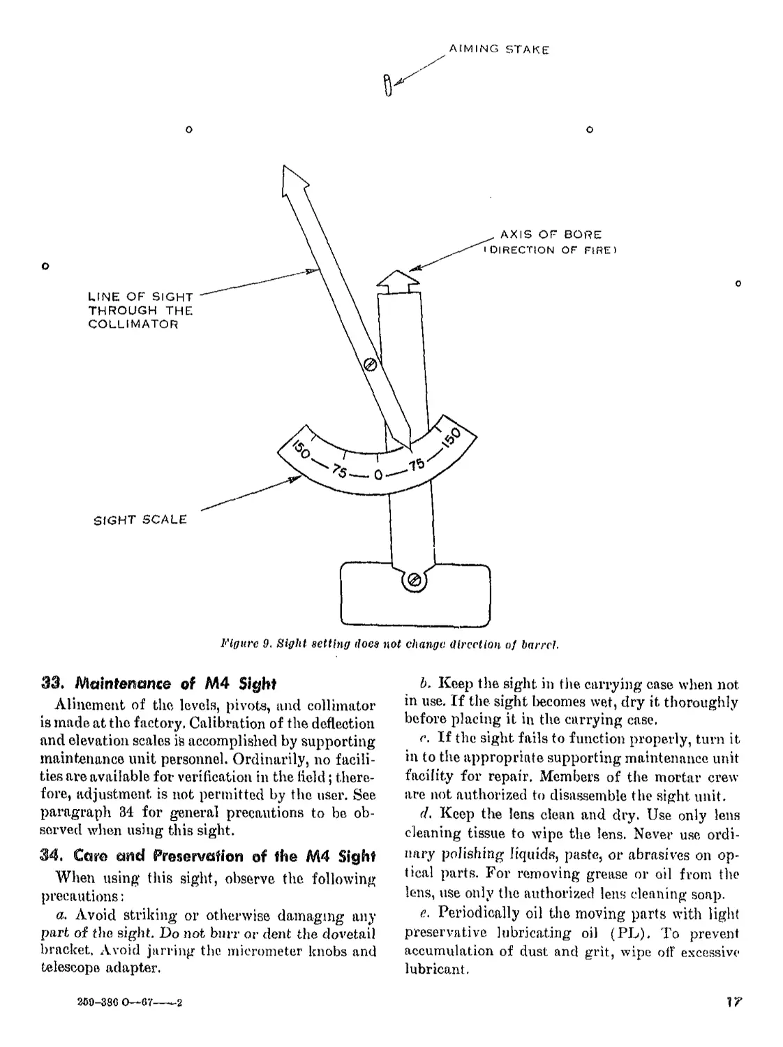
b. Se t Z ing Sigh t for Defleet io n.
(1) Deflection is placed on the sight before
elevation. To place a right deflection on
the sight, pull the. deflection knob (in
the direction of the arrow pointing to-
ward R) until the arrow pointing at the
scale, is opposite, the. selected deflection.
To place a left deflection on the. sight,
push the knob (In the direction indicated
by the arrow pointing toward L) until
the arrow pointing toward the scale is
opposite the selected deflection. Setting a
deflection on the deflection scale (for ex-
ample, a left, deflection) moves the ver-
tical line of the collimator in the opposite
direction (right) (fig. 9).
Note. Figure ft is a drawing of the Williams
Sighting and Laying Device, It is a simple
training aid that can be easily constructed by
mortar units and used in gunner training to
Illustrate such points as ihe relationship
between the line of sight and the direction of
fire, referring the sight, placing additional
aiming stakes, etc.
(2) The deflection placed on the sight is the
deflection announced in the fire command.
For example, the sight, is set at left 10.
The deflection is announced as RIGHT 50
in the fire command. The gunner places
right 50 on the sight.
c. Setting Sight for Elevation. Place elevation
on the sight after the deflection if there is a de-
flection change. To set the sight for elevation, turn
the elevation knob which, in turn, operates both
the elevation and micrometer scales. Thus both
scales must be set correctly to obtain the desired
elevation. For example, to place an elevation of 65°
on the sight, turn the elevation knob until the
arrow opposite the elevation scale is midway be-
tween the 60° and 70° marks and the 5° on the mi-
crometer scale is opposite the micrometer scale in-
dex arrow, Use care to prevent making a 10° er-
ror: for instance, setting the elevation scale at. 55°
or 75° in the above example.
(1. Honoring Sight. To remove the sight, de-
press the latch to release the bracket and withdraw
the sight. For traveling, set the elevation scale a(
40° and place the sight in the carrying case.
AIMING STAKE
О
О
33. Maintenance of M4 Sight
Alinement of the levels, pivots, and collimator
is made at the factory, Calibration of the deflection
and elevation scales is accomplished by supporting
maintenance unit personnel. Ordinarily, no facili-
ties are available for verification in the field; there-
fore, adjustment is not permitted by the user. See
paragraph 34 for general precautions to be ob-
served when using this sight.
34. Caro and Preservation of the M4 Sight
When using this sight, observe the following
precautions:
a. Avoid striking or otherwise damaging any
part of the sight. Do not burr or dent the dovetail
bracket. Avoid jarring the micrometer knobs and
telescope adapter.
b. Keep the sight in the carrying case when not
in use. If the sight becomes wet, dry it thoroughly
before placing it in the carrying case.
r. If the sight fails to function properly, turn it
in to the appropriate supporting maintenance unit
facility for repair. Members of the mortar crew
are not authorized to disassemble the sight unit.
d, Keep the lens clean and dry. Use only lens
cleaning tissue to wipe the lens. Never use ordi-
nary polishing liquids, paste, or abrasives on op-
tical parts. For removing grease or oil from the
lens, use only the authorized lens cleaning soap.
e. Periodically oil the moving parts with light
preservative lubricating oil (PL). To prevent
accumulation of dust and grit, wipe off excessive
lubricant.
17
250-386 O—-67----2
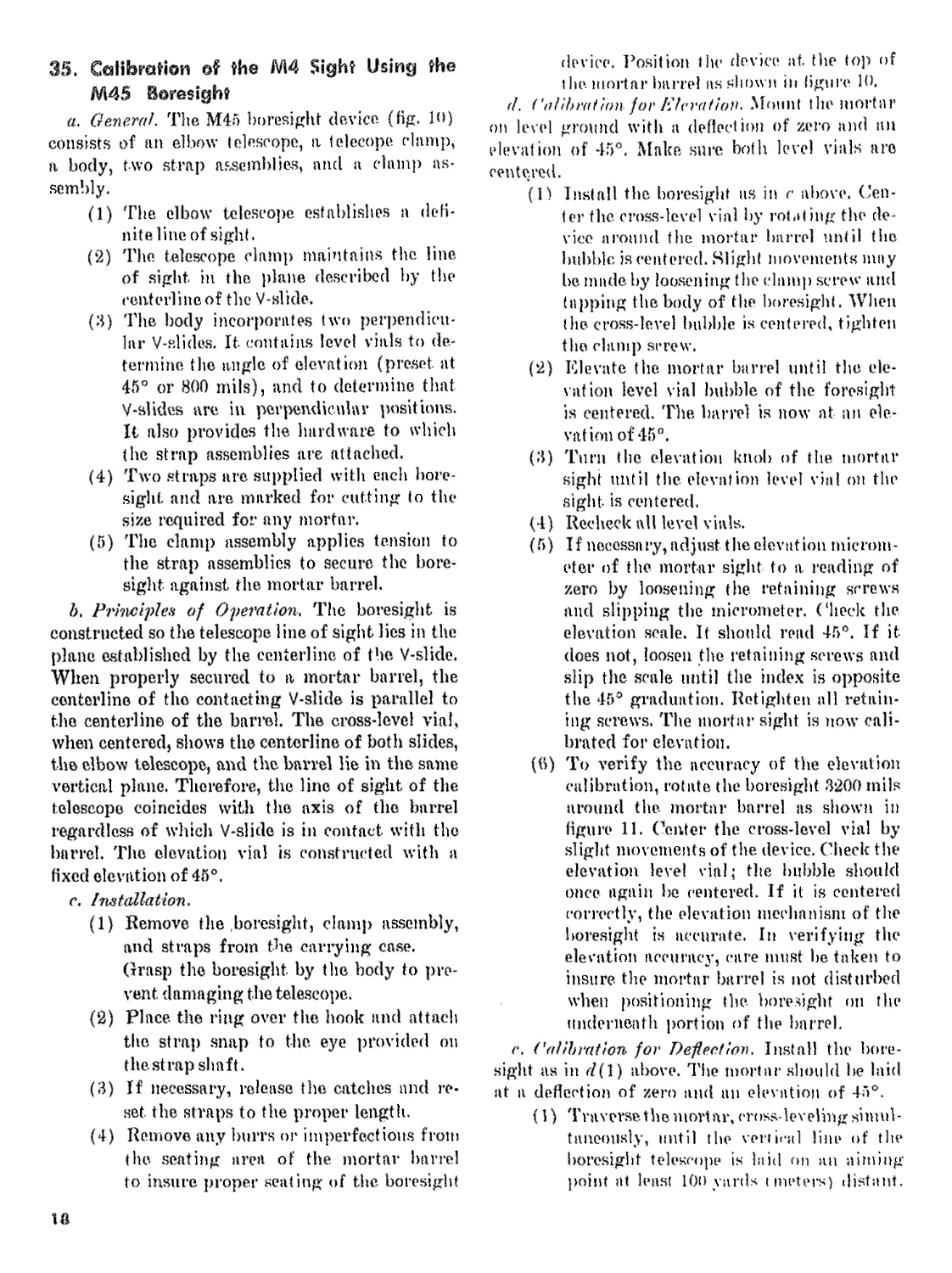
35. Calibration of the M4 Sight Using the
M45 foresight
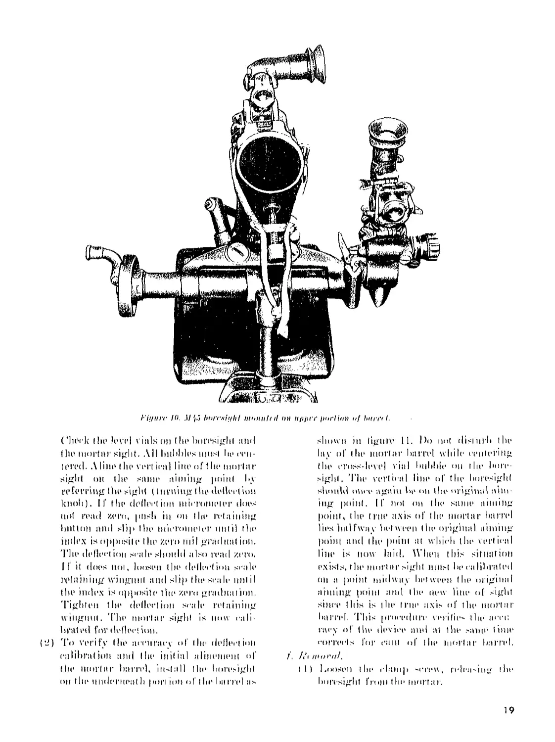
a. General. The M45 boresight device (fig. 10)
consists of an elbow telescope, a felecope. chimp,
a body, two strap assemblies, and a clamp as-
sembly.
(1) The elbow telescope establishes a defi-
nite line of sight.
(2) The telescope clamp maintains the line
of sight in the plane described by the
renterlineof the V-slide.
(3) The body incorporates two perpendicu-
lar V-slides. It contains level vials to de-
termine the angle of elevation (preset at
45° or 800 mils), and to determine that
V-slides are in perpendicular positions.
It also provides the hardware to which
the strap assemblies are attached.
(4) Two straps are supplied with each bore-
sight and are marked for cutting to the
size required for any mortar.
(5) The clamp assembly applies tension to
the strap assemblies to secure the bore-
sight against the mortar barrel.
b, Principles of Operation. The boresight is
constructed so the telescope line of sight lies in the
plane established by the centerline of the V-slide.
When properly secured to a mortar barrel, the
centerline of the contacting V-slide is parallel to
the centerline of the barrel. The cross-level vial,
when centered, shows the centerline of both slides,
the elbow telescope, and the barrel lie in the same
vertical plane. Therefore, the line of sight of the
telescope coincides with the axis of the barrel
regardless of which V-slide is in contact with the
barrel. The elevation vial is constructed with a
fixed elevation of 45°.
c. Installation.
(1) Remove the boresight, clamp assembly,
and straps from the carrying case.
Grasp the boresight by the body to pre-
vent damaging the telescope.
(2) Place the ring over the hook and attach
the strap snap to the eye provided on
the st rap shaft.
(3) If necessary, release the catches and re-
set the straps to the proper length.
(4) Remove any burrs or imperfections from
the seating area of the mortar barrel
to insure proper seating of the boresight
device. Position tlie device at the lop of
l lie. mortar barrel as shown in figure 10.
d. Calibration. for Elevation. Mount the mortar
on level ground with a deflection of zero and an
elevation of 45°. Make sure both level vials are
centered.
(1) Install the boresight us in c above. Cen-
ter the cross-level vial by rotating the de-
vice around the mortar barrel until the
bubble is centered. Slight movements may
be made by loosening the chimp screw and
tapping the body of the boresight. When
the cross-level bubble is centered, tighten
the clamp screw.
(2) Elevate the mortar barrel until the de-
lation level vial bubble of the foresight
is centered. The, barrel is now at an ele-
vation of 45°.
(3) Turn the elevation knob of the mortar
sight until the elevation level vial on the
sight, is centered.
(4) Recheck all level vials.
(5) If necessary, adjust the elevation microm-
eter of the mortar sight to a reading of
zero by loosening the retaining screws
and slipping the micrometer, (‘heck the
elevation scale. If should read 45°. If it.
does not, loosen the retaining screws and
slip the scale until the index is opposite
the 45° graduation. Retighten all retain-
ing screws. The mortar sight is now cali-
brated for elevation.
(tt) To verify the accuracy of the elevation
calibration, rotate the boresight 3200 mils
around the mortar barrel as shown in
figure 11. Center the cross-level vial by
slight movements of the device. Check the
elevation level vial; the bubble should
once again be centered. If it is centered
correctly, the elevation mechanism of the
boresight is accurate. In verifying the
elevation accuracy, care must be taken to
insure the mortar barrel is not disturbed
when positioning the boresight on the
underneath portion of the barrel.
e. Calibration for Deflection. Install the bore-
sight as in d(1) above. The mortar should be laid
at a deflection of zero and an elevation of 45°.
(1) Traverse the mortar, cross-leveling simul-
taneously, until the vertical line of the
boresight telescope is hi id on an aiming
point at leas! 100 yards t meters) distant.
13
l-'ii/iiff K>. ,1/p bwxitthf Diuiitilf il <>u nj>)>rf iHirli<tn uf Imrt'fl.
(‘heck I hi’ level vials гм) I he boresight and
f hr mortar sight. All bubbles niusl hr cen-
tered. ЛIiin» (lie vert ical line of t hr mortar
sight он (lie siinir niiidng point by
referring (he sight (I nrnmg (he dvllvrt urn
knob). If fhe deflection micrometer dors
not read zero, push in on the retaining
button and slip Ihr micrometer until the
index is opposite t he zero mil gradual ion.
'I'lte deflect ion scale should also read zero.
If it does iiol, loosen the deflection scale
retaining wiiigitnl and slip the scale nnt iI
the index is opposite thr zero graduation.
Tighten tin* deflect ion scale retaining
wingnut. 'I'hr mortar sight is now cali-
brated for define! ion.
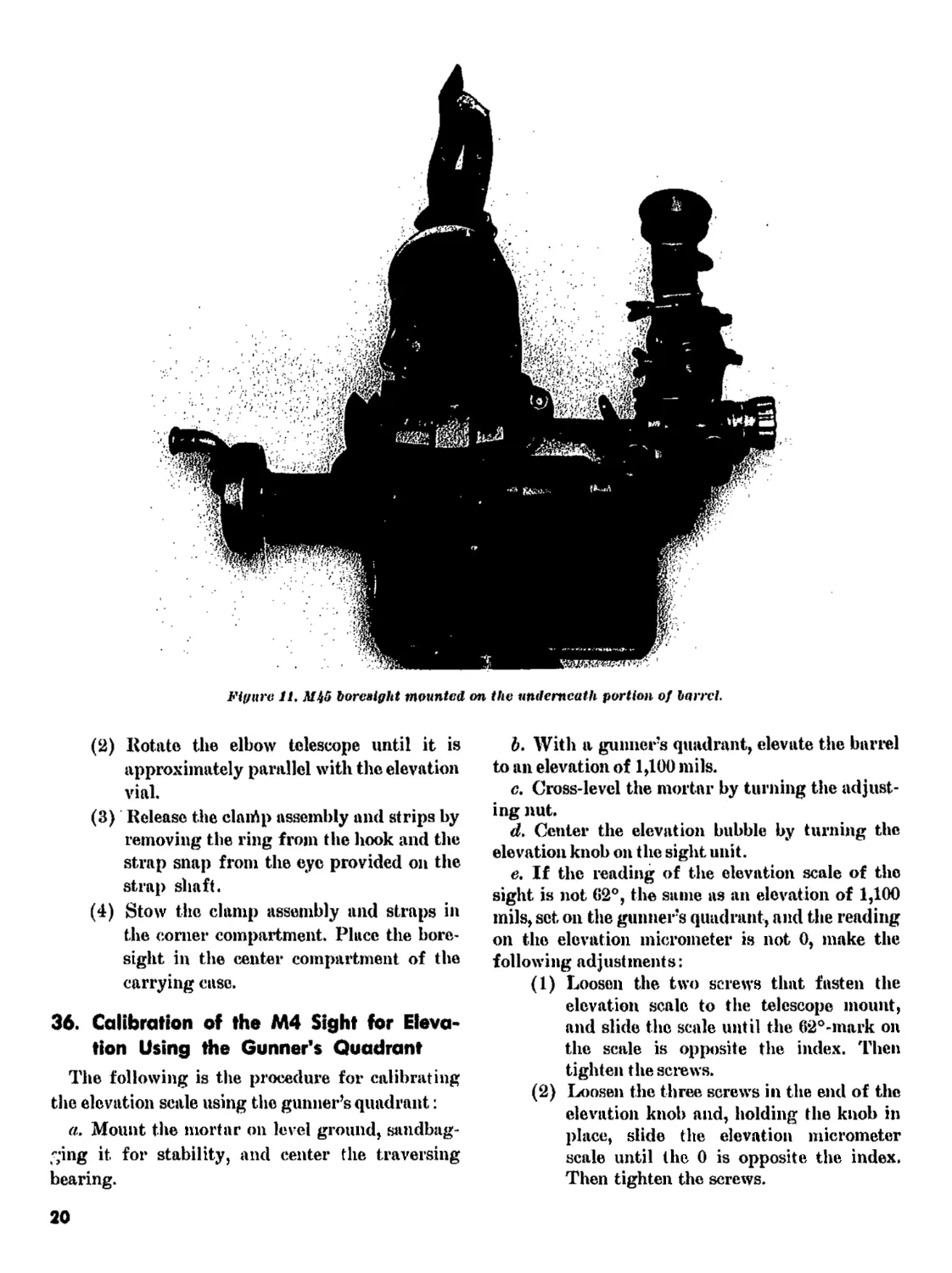
(*2) 'Го verify the acriiracv of the deflection
calibration and the initial alitiemimt of
(he mortar barrel, install (he boresight
on the nndrrnrat h port ion of I hr ha rrrl as
shown in figure 11. Do not disturb the
lay of the mortar barrel while centering
the cross-level vial bubble on the bore-
sight. 'I’he vertical line of the boresight
shoidd oiivv agam be on (he original aim-
ing point. If not on the same aiming
point, the t rtte axis of the mortar barrel
lies halfway between the original aiming
point and the point at which the vertical
line is now laid. When this situation
exists, tin1 mortar sight must be calibrated
on a point midway between the original
aiming point and the new line of sight
sima* this is the true axis of the mortar
barrel. This procedure vrrifir- the ;uti;
racy of the device and ai the same time
corrects for cant of the mortar barrel.
/. /Л HHH'lfl.
tl) I.oosen t hi* clamp "creu, ndea-iu2 the
boresight from tlie mortar.
19
Figure 11. Mi5 boresight mounted on the underneath portion of barrel.
(l2) Rotate the elbow telescope until it is
approximately parallel with the elevation
vial.
(3) Release the clairtp assembly and strips by
removing the ring from the hook and the
strap snap from the eye provided on the
strap shaft.
(4) Stow the clamp assembly and straps in
the corner compartment. Place the bore-
sight in the center compartment of the
carrying case.
36. Calibration of the M4 Sight for Eleva-
tion Using the Gunner's Quadrant
The following is the procedure for calibrating
the elevation scale using the gunner’s quadrant:
a. Mount the mortar on level ground, sandbag-
ging it for stability, and center the traversing
bearing.
b. With a gunners quadrant, elevate the barrel
to an elevation of 1,100 mils.
c. Cross-level the mortar by turning the adjust-
ing nut.
d. Center the elevation bubble by turning the
elevation knob on the sight unit.
e. If the reading of the elevation scale of the
sight is not 62°, the same as an elevation of 1,100
mils, set on the gunners quadrant, and the reading
on the elevation micrometer is not 0, make the
following adjustments:
(1) Loosen the two screws that fasten the
elevation scale to the telescope mount,
and slide the scale until the 62°-mark on
the scale is opposite the index. Then
tighten the screws.
(2) Loosen the three screws in the end of the
elevation knob and, holding the knob in
place, slide the elevation micrometer
scale until the 0 is opposite the index.
Then tighten the screws.
20
/. Ker heck the readings of the gunners quad-
rant and the sight. If the readings are not identi-
cal, repeat the procedure outlined above.
37. Calibrating the M4 Sight for Deflection
Using the Aiming Circle Method
There are. two methods for calibrating the sight
for deflection—the aiming circle method, and the
distant aiming point method. To calibrate the de-
flection scale by the aiming circle method—•
«, Set up the aiming circle'25 meters in rear of
the mounted mortar.
b. With the azimuth scale and micrometer of
the aiming circle at 0, aline the center of the reticle
on the center of the base plug of the mortar.
c. Depress the mortar barrel to its lowest
elevation.
d. Traverse and cross-level the mortar until the
center axis of the barrel from the base plug to the
muzzle is alined with the vertical line of the aiming
circle telescope reticle.
et Turn the deflection knob of the sight until the
vertical line is centered on the lens of the aiming
circle and read angle A, opposite the fixed index.
f. Turn the azimuth knob of the aiming circle
until the vertical line of the telescope is laid on
the center of the sight lens and read angle B, op-
posite the azimuth scale index. If the sight is in
calibration, the angles will be equal. If they are
not equal, the sight is adjusted as follows:
(1) With the deflection knob held in place,
push in on the micrometer knob retain-
ing button and slide the deflection mi-
crometer scale until the last two digits of
angle В are set at the micrometer index.
Belock the retaining button.
(2) If the vertical line of the sight has moved
off the center of the lens of the aiming
circle telescope, repeat the steps outlined
above.
(3) After the deflection, micrometer has been
corrected, check the setting on the de-
flection scale to see if it corresponds to
the first two digits of angle B. If the
digits do not correspond, loosen the de-
flection scale retaining wingnut and
slide the scale to the approximate correct
position.
(4) To obtain exact synchronization between
the deflection micrometer and the de-
flection scale, turn the deflection knob
forward to a setting of zero. Slide the de-
flection scale to zero and tighten the
wingn ut.
38. M34A2 and M53 Sight Units
'fhe М34Л2 and M53 sight units can also be
used for laying the 60-mm mortar for deflection
and elevation. The same sight should always be
used with the same mortar. The sight units con-
sist of a telescope mount, an elbow telescope, and
a telescope adapter. For a detailed explanation of
the. operation of these sights, see. FM 23-4)0 or FM
23-92.
39. Aiming Posts
Two Ml Al aiming posts are provided for the
mortar. When placed out properly, these posts
establish a reference line enabling the gunner to
lay the mortar in the desired direction of fire. In
addition, the unit may be equipped with the M7
or MIO aiming post for use as a direction post. In
an emergency, any clearly defined object such as
a tree trunk or the corner of a building can be used
as an aiming point for a single mortar.
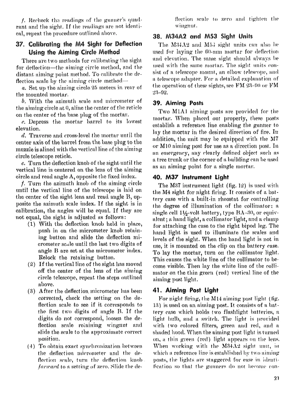
40. M37 Instrument Light
The M37 instrument light (fig, 12) is used with
the M4 sight for night firing. It consists of a bat-
tery case with a built-in rheostat for controlling
the degree of illumination of the collimator: a
single cell 1^-volt battery, type BA-30, or equiv-
alent ; a hand light, a collimator light, and a damp
for attaching the case to the right bipod leg. The
hand light is used to illuminate the scales and
levels of the sight. When the hand light is not in
use, it is mounted on the clip on the battery case.
To lay the mortar, turn on the collimator light.
This causes the white line of the collimator to be-
come visible. Then lay the white line of the colli-
mator on the thin green (red) vertical line of the
aiming post light.
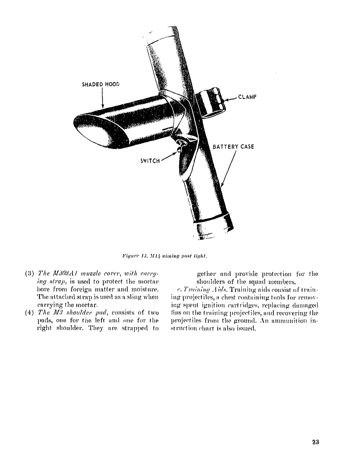
41. Aiming Post Light
For night firing, the Mil aiming post light (fig.
13) is used on an aiming post. It consists of n bat-
tery case which holds two flashlight batteries, a
light bulb, and a switch. The light is provided
with two colored filters, green and red, and a
shaded hood. When the aiming post light is turned
on, a thin green (red) light appears on the lens.
When working with the M34A2 sight unit, in
which a reference line is established by two aiming
posts, the lights are staggered for ease in identi-
fication so that the gunners do not become con-
21
fused us to which posts are theirs. Each alternating
mortar would have the red light on the far post
to accomplish this effect.
42. Sight Extension
The sight extension is designed to permit the
gunner to take up a prone position while laying
the mortar. The extension has a bracket that fits
into the sight slot on the mortar yoke, and a latch
that, holds it securely in place. When the extension
is attached to the mortar, the M4- sight is inserted
into a slot at t he bottom of the extension. It is held
in place by the sight, latch. This slot is similar to
the sight slot of the mortar, The overall length of
the extension is approximately 8 inches.
43. Spare Parts and Accessorie.
a. Spare Parts. Parts will become unserviceable
through breakage or wear. For this reason, spare
parts are provided for replacement purposes. Sets
of ’.pare parts are kept complete a't all times. The
only spare part carried by the squad is an extra
firing pin. 'Пн* remaining spare pads are kept in
t he company arms or supply room.
b. Arccxxorirft. Accessories include the tools used
for the. maintenance of the mortar. tool rolls,
chests, and other equipment necessary for storage
and protection when the mortar is not in use or
when traveling. l*se the accessories for prescribed
purposes only. When not in use. store them in the
places or receptacles provided. Their names and
general characteristics indicate their uses or ap-
plication, Therefore, no detailed description or
method of use is outlined in this manual. Acces-
sories having special features or having special
uses, however, are included as follows:
(1) The M1 ammunition- bag consists of a sin-
gle pouch and a shoulder currying strap.
It can lie used to carry ammunition or the
tool roll, firing tables, and flashlight.
(’2) The M%A1 am munition bag is a rein-
forced strip of canvas with pockets in the
front and rear for the ammunition.
Fiffiirc 12. instrument lif/hf.
22
I-'if/tcri' 13. Ml.'/ (dminn post liykf.
(3) 77te M308A1 muzzle coi'ei\ with curry-
ing strap, is used to protect the mortar
bore from foreign matter and moisture.
The attached strap is used as a sling when
carrying the mortar.
(4) The М3 shoulder pad, consists of two
pads, one for the left and one for the
right shoulder. They are strapped to
get her atid provide protection for the
shoulders of the squad members.
r. Training .1 ids. Training aids consist of train-
ing projectiles, a chest containing tools for remov-
ing spent ignition cart ridges, replacing damaged
fins on the training projectiles, and recovering the
projectiles from the ground. An ammunition in-
struction chart is also issued.
23
CHAPTER 3
AMMUNITION AND BALLISTICS
Section ! AMMUNITION
44, General
This section covet*s information on the complete
cartridges of semifixed ammunition authorized for
use in the 60-mm mortar, Ml9. It includes a de-
scription of the cartridge, means of identification,
and care and use.
45. Classification
Based upon use, the principal classifications of
ammunition for the 60-mm mortar are—
a. High-explosive (HE), for use against per-
sonnel and light materiel targets.
Ъ. Smoke (white phosphorous), for use as a
screening, signaling, casualty producing, or in-
cendiary agent.
c. Practice, fortraining.
d. Training, for training in limited areas.
e. illuminating, for use in night missions requir-
ing illumination for assistance in observation.
46. Ammunition Lot Number
The ammunition lot number is a code number as-
signed to each lot of ammunition when it is manu-
factured. This lot number is stamped or marked on
every loaded complete cartridge, on packing con-
tainers, and on the accompanying ammunition data
card. In making out records, including reports on
condition, functioning, and accidents, refer to par-
ticular items of ammunition by lot number.
47. Identification
it. Marking onFiber Containers. Ammunition is
readily identified by the markings on the fiber
containers in which it is packed. Additional data
pertaining to 'the cartridges are included on the
ammunition data card packed with them. The tape
on the fiber containers is colored to provide a
means of identification as to the type of cartridge.
b. Color of Cartridge. Each cartridge is
painted to prevent rust and, by means of t lie color,
to provide a ready means for idenlification as to
type. The colors under the old and newer NATO
systems are—
(1) Old system.
(a) High-explosire: dive drab (markings
in yellow).
(Z>) Smoke: (WP) gray with yellow band
(markings in yellow).
(c) Practice: blue (markings in white).
(d) Illuminating: gray (markings in
white),
(2) NATO system.
(a) Chemical.
1. Persistant gas: gray with two green
bands and marking in green.
.?. Nonpersistant gas: gray with one green
band and marking in green.
J. Smoke (NS) : Light green with mark-
ing in black.
4- Smoke (WP or PWP) : Light green
with marking in light red.
(6) Illuminating, White with marking in
in black.
(c) Training. Blue with marking in white.
c. Markings on- ('artridge. When removed from
its container the cartridge is identified by the fol-
lowing information stenciled on it:
(1) Caliber of mortar in which fired.
(2) Kind of filler.
(3) Model ofcartridge.
(4) Ammunition lot number.
48. Care, Handling, and Preservation
a. Ammunition is made and packed to with-
stand all conditions ordinarily encountered in the
field. Nevertheless, since ammunition is adversely
affected by moisture and high temperature, give
24
consideration to its protect ion front these condi-
tions.
b. Complete cartridges, being fuzed, are han-
dled ^'ith care. The explosive, elements in primers
and fuzes aic particularly sensitive to strong
shock and hightempenitiire.
e. Do not break the moisture-resistant seal of
the fiber container until the ammunition is to be
used. When a large number of cartridges ( la or
more per squad) are prepared before a combat
mission, the cartridges may be removed from the
containers, and the propelling increments ad-
justed. 'Phen reinsert the tin assembly of each into
the container to protect the propelling charges.
d. Do net attempt to dDuxxcmble any fuze.
e. Protect the ammunition carefully from mud,
sand, dirt, and water. Sec that the cartridges are
free of such foreign mutter before firing. When
ammunition gets wet or dirty, wipe it off at once.
/. Do not allow the ammunition, particularly
the powder increments, to be exposed to direct
rays of the sun for any length of time. More uni-
form firing is obtained when the cartridges are
at the same temperature.
g. Remove, the safety irire from the fuze just
before firing.
h. Reinsert the safety wires into all cartridges
that have been prepared for firing, but not used.
Replace the powder increments that have been re-
moved. Then return the cartridges to their original
packing and mark them appropriately. Use these
cartridges first in subsequent firing to keep opened
stocks at a minimum.
i. Do not handle duds. Duds are cartridges that
have been fired but. did not explode. They are ex-
tremely dangerous because the fuza is armed and
any movement, of the cartridge may cause it to
explode. In training areas, locations of duds are
marked by signs and reported to the range officer
for destruction.
49. Storage
a. When practicable, store ammunition under
cover. When it is necessary io leave the ammuni-
tion in the open, raise it nt least fl inches from
the ground and cover the pile with a double thick-
ness of tarpaulin. Dig trenches around the pile to
prevent waler from flowing under it.
** b. In arctic weather, leave the ammunition in
wooden boxes or crates when placed in storage.
Plata1 b ini pallets and cover it with a double t hick-
nrss of tarpaulin.
.*. Store, white phosphorous carl ridges with the
fuze end up whenever there is a possibility of the
temperature rising above 1<X)° F. (para 5’2).
50. Aulhorized Cartridges
Ammunition anthorized for use in (his mortar
is listed in paragraph 45. Because of its stabilizing
fins this ammunition even though fired from a
smoothbore mortar, is stable in flight and strikes
nose end first. The propelling charge, consisting
of an ignition cartridge and propelling incre-
ments, is attached to the fin assembly shaft or
within the tin blades. The ignition rail ridge is in-
serted in the base of the fin shaft. The increments
are removable. When fired, the round carries the
fired ignition cartridge case with it. The mortar is
then ready for I he next round. Because the com-
plete cartridge is loaded into the mortar as a unit
and provision is made for adjusting the propelling
charge, (io-rnm mortar ammunition is classified as
semifixed.
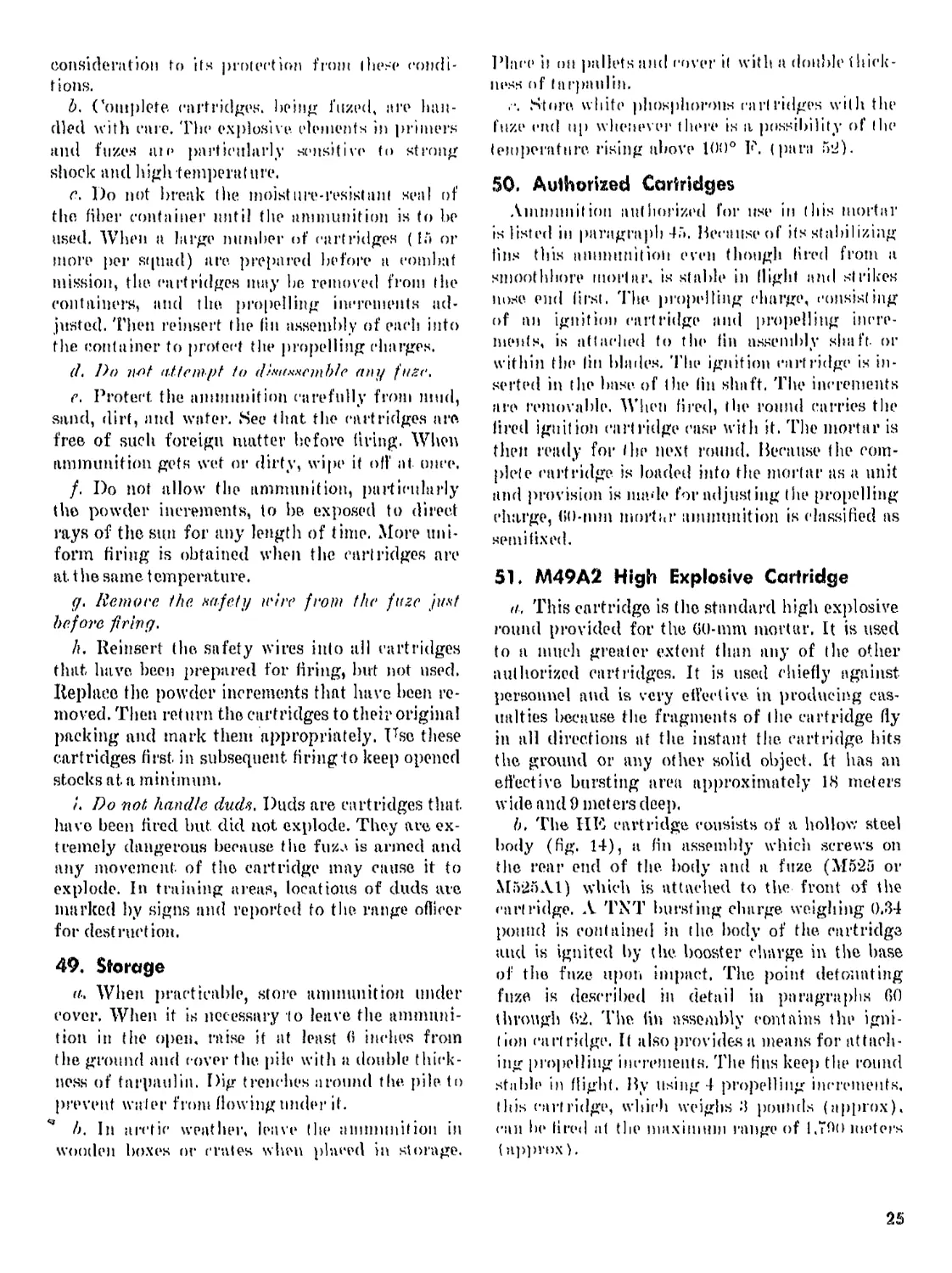
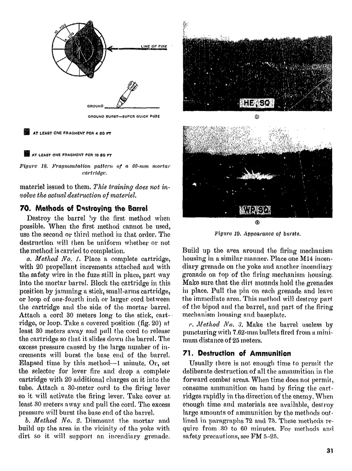
51. M49A2 High Explosive Cartridge
a. This cartridge is the standard high explosive
round provided for the GO-mm mortar, It is used
to a much greater extent than any of the other
authorized cartridges. It is used chiefly against
personnel and is very effective in producing cas-
ualties because the fragments of the cartridge fly
in all directions at the instant the. cartridge hits
the ground or any other solid object. It has an
effective bursting area approximately 18 meters
wide and 9 meters deep.
b. The HE cartridge consists of a hollow steel
body (fig. 14), a fin assembly which screws on
the rear end of the body and a fuze (M525 or
M525Al) which is attached to the front of the
cartridge. A TXT bursting charge weighing 0.34
pound is contained in the body of the cartridge
and is ignited by (he. booster charge in the base
of the fuze upon impact, The point detonating
fuze is described in detail in paragraphs 60
through (V2. The fin assembly contains the igni-
tion cartridge. It also provides a means for attach-
ing propelling increments. The fins keep the round
stable in flight. By using 4 propelling increments,
(his cartridge, which weighs 3 pounds (approx),
can he fired af the maximum range of 1.790 meters
(approx).
25
Pigitrc Ц. ЛЦ9А2, ИН cartridge, icilh MuS,"i jusr.
52, M302 Smoke Cartridge
The smoke cartridge, is used as a screening,
signaling, casualty-producing or incendiary agent.
This cartridge (fig. 15) is similar in design to
the HE cartridge. It has a longer body, a thinner
body, and a filler of white phosphorous. The
bursting charge is designed to burst the cartridge
casing and scatter the white phosphorous which
igm'es when exposed to air. The cartridge has a
casualty producing radius of 10 meters and a
maximum range of 1,450 meters. It comes equipped
with an M82 super-quick fuze. 'Fhe white phos-
phorous filler liquefies at temperatures of 100° F.
or greater. As the white phosphorous does not
entirely fill the space provided for it, a hollow
space develops in the upper part of the filler
cavity in the cartridge, causing it to he imbalanced
and therefore unstable in flight. When stored at
temperatures of 100° F. or greater, stack the smoke
cartridges with the fuze up so I hat the hollow space
is in the top of the filler cavity and uniform with
respect to the axis of the cartridge. ('artridge, GO
millimeter: smoke, WP, МЗП2Е1. w fuze, PI)
M527BI, will soon he issued to replace the M302
cart ridge.
26
Figure 1H. M302Ki awoke cartridge, iviHi MJ<i7 1ttzr.
Warning: Short rounds may result when this
round is fired at temperatures below 0° F.
53. M50A2 Practice Cartridge
The practice cartridge differs from the HE
cartridge only in color, bursting charge, and
casualty effect. It is used in training, and is just
as effective as the HE cartridge for this purpose
because of identical ballistic qualities. The car-
tridge has a small, black powder spotting charge
as the filler in place of TNT.
54. M83A3, M83A2, or M83A1
Illuminating Cartridge
a. The illuminating cartridge is used in night
missions to assist ground troops in observation. It
is made up of four major parts: a body tube
assembly, an illuminant assembly, a parachute
assembly, and a tai] assembly. The cartridge is
also equipped with four propelling charges.
6. The illuminating cartridge is equipped with
the MG5A1 or M65 time fuze. The fuze ignites
the quick match (after the safety wire is removed
and the cartridge is fired), and the quick match
then ignites the black powder charge. This black
powder charge expels the parachute and illmni-
nant charge assemblies from the cartridge in
approximately 14.5 seconds and, at the same time,
ignites the. illuminant charge. The M83A3 car-
tridge burns for at least- 25 seconds with a mini-
mum of 330,000 candlepower. The М83Л1 ilhi-
minant charge burns with a minimum of 145,000
candlepower. While in the air, the illuminant
charge drops at a rate of 3 meters per second.
c. The illuminating cartridge weighs approxim-
ately 4.15 pounds and has a maximum range of
1,000 meters (approx). In common with other
pyrotechnics, this cartridge is marked with the
type and model of cartridge, mortar from which
fired, filler, and lot. number.
55. №69 Training Cartridge
The M69 training cartridge (fig. 16) has a solid
cast iron body and a standard fin assembly. It
weighs 4.4 pounds, and is propelled by an ignition
cartridge only. Its maximum range is 225 meters.
A firing table for the training shell comes with
each container. A hook is also provided with which
to recover the shell in the event that it becomes
imbedded in soft earth. This shell is valuable as
a training aid.
56. Loading Ignition Cartridges
a. The ignition cartridge, M4, is slightly over-
size at the base to insure that the cartridge remains
in the fin assembly during loading and firing the
mortar. The tight fit of the ignition cartridge
makes it difficult to fully seat the cartridge in the
fin assembly by hand. The cartridges may be easily
and safely loaded with the loading device (fig.
17). The cartridge chamber in the fin assembly
must be thoroughly cleaned before reloading.
b. Care must be taken while seating the car-
tridge fully in the fin assembly to avoid tapping
or striking the primer. If the primer is pressed
against a surface or if it is tapped, or struck, it
may detonate (he cartridge and cause serious
injury.
27
Figure 1в. MG9 training cartridge.
57. Removing Expended Ignition Cartridges
a, The following modification of the fin of the
training cartridge is helpful in removing expend-
ed ignition cartridges: Bore a hole %-incli in
diameter completely through the outer thread of
the fin assembly, parallel with the longer axis of
the fin assembly. This permits the insertion of a
large nail or spike through the length of the fin
assembly to force out the expended ignition car-
tridge.
6. To remove an expended ignition cartridge,
unscrew the fin assembly from the base end of
the round. Then place the fin assembly on a block
of wood, 4 inches by 8 inches by 2 inches, with the
base end of the fin assembly over a hole 1 inch in
diameter bored through the centers of the block
of wood. Place a nail or spike through the open
(bored) end of the outer thread of the fin assembly.
TOP VIEW
। SIDE VIEW , ।
NOTES
L MATERIAL! WOOD BLOCK.
2. DRILL TO DIAMETER OF FIN.
3.DRILL I/Й* DIAMETER.
«PARTIALLY SEATED CARTRIDGE.
e.TO USE! INSERT IGNITION
CARTRIDGE IN AN AS FAR AS
POSSIBLE BY HAND. PLACE
FIN IN LOADER ANO PRESS
SHELL STRAIGHT DOWN.
Figure 11. Loading device for training cartridge.
Drive this nail through the fin assembly forcing
the ignition cartridge from its seat. Then remove
the ignition cartridge from the fin assembly with
the extractor.
c, Before replacing the fin assembly in the
round, see that the shoulder and outer threads of
the fin assembly, and the shoulder and inner
threads of the cartridge, are free from any foreign
material. If there are any particles left on the
shoulders and threads, the fin assembly will not
seat properly in the base end of the round. This
causes a rupture in the base of the cartridge when
fired. When this rupture occurs, the cartridge can-
not be used.
58. Preparation for Firing
xVnmunition is issued as semifixed complete car-
tridges. Prepare it for firing by adjusting the pro-
pelling charge for the zone to be fired and by re-
moving the safety wire from the fuze.
59. Propelling Charges
Propelling charges for mortar ammunition con-
sist of square powder increments and an ignition
charge. The full charge consists of an ignition car-
tridge and four equal propellent increments (bun-
26
dies of sheet powder) assembled to tlie hasp of the
cartridge as issued. 4'1 ie increments are attac hed
to the Hu assembly by increment holders. To pre-
pare the charge for firing, it- is only necessary to
remove those increments not required. Short
rounds result when increments are wet. Although
a waterproof cellophane bag rovers the increments,
they should be protected from rain and moisture
as much ns possible.
Note, Destroy unused jiiereinea!s after firing by burn-
ing them. Do not allow excexs hicretnontx to accumulate
near the mortar positions. Move them at least ПО meters
from inortnr positions, parked vehicles, and nmmmiltion
piles. Clear off grass or brush for at least 10 meters from
the burning area to prevent starting range tires. Do not
burn fke increment x in рПсп. Spread them in a train of
the following depth and width: 2 inches to 3 inches deep,
6 Inches wide and ns long as necessary. Ignite the powder
train by lighting a starting train consisting of not less
than 1 foot of inert material (dry grass, leaves, news-
papers). Prohibit smoking or bitildinff fires around nmniN-
nitimi or piles о/ rare#» increments except when actually
destroying them ns described above.
60. M525A1 or M525 Fuze
These fuzes are the super-quick (S.Q.) type,
and they are identified by PDF (point, detonating
fuze) МЙ25А1 or M525 stamped on the body.
These fuzes are designed to function before any
penetration occurs, permitting the maximum
surface effect of fragmentation of the cartridge.
For use in the field, it is issued assembled to the
cartridge as a part of the complete cartridge. To
prepare for firing it is only necessary to remove
the safety wires.
61. Safely Features of M525A1 or
M525 Fuzes
a. These fuzes are classified as bore-safe. They
are equipped with safety devices that keep the
bursting charge from exploding while the car-
tridge is in the barrel—even should the primer or
detonator malfunction.
b. A safety wire passes through the body of the
fuze and the setback pin, thereby locking all mov-
able parts in their original safe position. Pull the
safety wire just before firing. If a cartridge is
fired without pulling the safety wire, it may or
may not explode upon impact. The safety wire
is designed to lock the setback pin in place only
during normal handling of the cartridge, before
firing.
62. Functioning of the M525A1 and
M525 Fuzes
Upon firing (after removal of the pull wire and
safety wire) setback causes the setback pin to re-
lease the boreriding pin, which moves outward to
contact, the bore of the mortar and is ejected as the
cartridge leaves the mortar. Setback also frees the
pallet, and escape pinion wheel which begins to ro-
tate a center gear of the dislodged arming mech-
anism. This causes the firing pin to act as a detent
to prevent the slider from moving the detonator
into line with the firing pin. This causes a 3 sec-
ond arming delay. Upon impact, the striker is
driven against the firing pin spring, which forces
the firing pin into the detonator, which detonates
in turn the tetryl lead charge, tetryl booster, and
main bursting charge of the cartridge. A detailed
discussion of the functioning of these fuzes is
contained in TM 9-1300-205.
63. M65 and M65A1 Time Fuzes
Functioning of these fuzes is discussed in detail
in TM 9-1300-205.
64. M527 Fuze Series
These fuzes are identical with the M52 except
that they contain a smaller booster charge and an
intrusion. They a.re used on the smoke cartridge
only. The M527 and the M527A1 have a plastic,
body, and the M527B1 and the M527A1B1 have
an aluminum body.
65. Firing Tables
a. To convert ranges in yards or meters into
elevations in degrees or mils and number of pro-
pellent increments (referred to as charges), use
the firing tables that arc packed with each bundle
of ammunition. These tables include a deflection -
conversion table. Firing tables for instructional
use may be obtained on requisition.
b. Tables applicable to the various types of 60-
inm cartridges are as follows:
(1) FT 60-L-% (abridged).—For firing: HE
cartridge, M49A2 W/PD Fuze, M52
Practice cartridge, M50A2, W/PD Fuze,
M52 Smoke cartridge, WP, M302, W/PD
Fuze, M82.
(2) FT OO-C-% (abridged).—For firing:
Training cartridge, M69.
c. For example of current firing tables, see FT
B0-Tv-2.
29
d, Uses,
(1) As mortar fire is usually adjusted fire
(para 157), select a charge zone for the
initial range that permits a subsequent
increase or decrease in range without
changing the charge. Where two ehva-
tions and two charges are available for
selection, select the charge that will give
the greatest latitude without changing
the charge. For example, using the HE
cartridge for an initial range of 650
meters, use 72°, charge 2. When there is
a choice between two charge zones, equal
latitudes in firing being provided in both,
select the leaver charge because less dis-
persion results with the lower charge.
(2) It is undesirable during adjustment of
fire to change to a different charge zone.
Fire adjustment is less accurate where
there is a shift between charge zones dur-
ing adjustment.
(3) In firing on targets involving searching
fires select the elevation in degrees that
will permit the use of the same charge
throughout. For example, using the HE
cartridge for zone 800 to 900 meters, use
charge 2 with the corresponding eleva-
tions.
(4) In firing on targets involving close fire,
select the elevation in degrees that will
permit the use of the lowest charge. For
example, using the HE cartridge for an
initial range of 650 meters, use 56°,
charge 1,
Section II. BALLISTICS
66. General
An understanding of ballistics or the forces
that act on a projectile enables a mortar crew to
minimize the adverse forces and obtain more effec-
tive fire on a target. Many conditions affect mor-
tar fire and the probability of obtaining identical
trajectories is remote. That is, if a number of
cartridges are fired from a mortar laid each time
at the same elevation and deflection, all of these
cartridges do not fall on the same point. Some of
the conditions affecting the motion of the round
that can be controlled partially by the mortar
crew are—muzzle velocity, elevation and direc-
tion, forces acting on round during flight, and dis-
persion. For a detailed discussion on these items,
see FM 23-92.
67. Ground Burst
Of primaiy interest to the observer is the fact
that more of the fragments of the burst of the
60-mm cartridge fall to the rear of the point of
impact than to the front (fig. 18). A cartridge
falling just over the target, therefore, is more
effective than a cartridge falling just short of the
target.
68. Appearance of Bursts
An observer familiarizes himself with the ap-
pearance of the bursts of different types of car-
tridges (fig. 19) so that he can identify the bursts
of the typo requested in an area where different
types of fire are being delivered.
a. HE Oart-ridge^ Super-Quick Fuze, The black
smoke is discolored by dirt and spreads both up-
ward and laterally.
b. WP Smoke Cartridge, Flying particles of
burning white phosphorus are first observed.
White phosphorus burns rapidly and at once
forms a cloud of white smoke which tends to rise
because of the heat generated by the burning
phosphorus,
Se ction III. DESTRUCTION OF ORDNANCE MATERIEL IN EVENT OF IMMINENT CAPTURE
69. General Principles
Tactical situations may arise when, owing to
limitations of time or transportation, it becomes
impossible to evacuate all equipment. To prevent
its capture intact and its subsequent use by the
enemy, in such situations, destroy all materiel
that cannot be evacuated. When thorough destruc-
tion of all parts cannot be completed, destroy those
part? essential for using the mortar, Ruin or re-
move the other parts that cannot be duplicated
easily by the enemy. Destroy the same essential
parts on ‘all like units to prevent the enemy from
constructing one complete unit from the several
damaged ones by consolidating the serviceable
parts. All units should be trained to destroy the
30
Щ AT LEAST ONE FRAGMENT PER Л SO FT
HI AT LEAST ONE FRAGMENT PER tO SO FT
Figure 18. Fragmentation patient- of а 60-mtn mortar
cartridge.
materiel issued to them, This training does not in-
volve the actual destruction of materiel.
70. Methods of destroying the Barrel
Destroy the barrel by the first method when
possible, When the first method cannot be used,
use the second or third method in that order. The
destruction will then be uniform whether or not
the method is carried to completion.
a. Method No. /. Place a complete cartridge,
with 20 propellant increments attached and with
the safety wire in the fuze still in place, part way
into the mortar barrel. Block the cartridge in this
position by jamming a stick, small-arms cartridge,
or loop of one-fourth inch or larger cord between
the cartridge and the side of the mortar barrel.
Attach a cord 30 meters long to the stick, cart-
ridge, or loop. Take a covered position (fig. 20) nt
least 30 meters away and pull the cord to release
the cartridge so that it slides down the barrel. The
excess pressure caused by the large number of in-
crements will burst the base end of the barrel.
Elapsed time by this method—1 minute. Or, set
the selector for lever fire and drop a complete
cartridge with 20 additional charges on it into the
tube. Attach a 30-meter cord to the firing lever
so it will activate the firing lever. Take cover at
least 30 meters away and pull the cord. The excess
pressure will burst the base end of the barrel.
b. Method No. 2. Dismount the mortar and
build up the area in the vicinity of the yoke with
dirt so it will support an incendiary grenade.
©
Figure ID. Appearance of bursts.
Build up the area around the firing mechanism
housing in a similar manner. Place one M14 incen-
diary grenade on the yoke and another incendiary
grenade on top of the firing mechanism housing.
Make sure that the dirt mounds hold the grenades
in place. Pull the pin on each grenade and leave
the immediate area. This method will destroy part
of the bipod and the barrel, and part of the firing
mechanism housing and baseplate.
e. Method No. Make the barrel useless by
puncturing with 7.62-mm bullets fired from a mini-
mum distance of 25 meters.
71. Destruction of Ammunition
Usually there is not enough time to permit the
deliberate destruction of all the ammunition in the
forward combat areas. When time does not permit,
consume ammunition on hand by firing the cart-
ridges rapidly in the direction of the enemy. When
enough time and materials are available, dest roy
large amounts of ammunition by the methods out-
lined in paragraphs 72 and 73. These methods re-
quire from 30 to 60 minutes. For methods and
safety precautions, see FM 5-25.
31
l''i(/u>'e 20. Dcmoltlimb of mortar iisiiiy excess increments.
72. Destruction of Unpacked Ammunition
Follow the procedure in a. and b below:
a, Stack ammunition in small piles. Stade or
pile most of the available gasoline in cans and
drums around the ammunition. Throw onto the
pile all available inflammable materials such as
rags, scrap wood, and brush. Pour the remaining
gasoline over the pile. Use enough inflammable
material to insure a very hot fire. Ignite the gaso-
line and fa/ce cover.
b. Mortar rounds can be destroyed by sym-
pathetic detonation, using TNT. Stack the ammu-
nition in two stacks, about 3 inches apart, with the
fuzes in each stack toward each other. Place TNT
charges between the stacks, using a minimum of
1 pound of TNT for every 10 rounds of ammuni-
tion. Detonate all TNT charges simultaneously
from cover.
73. Destruction of Packed Ammunition
Follow the procedure in н through c below:
a. Stack the bundled ammunition in small piles.
Cover with all available inflammable materials,
such as rags, scrap wood, brush, and gasoline in
drums or cans. Pour gasoline over the pile, Ignite
the gasoline and take corer. (Before burning
smell-arms ammunition, break it out of (he boxes
or cartons.)
b. The destruction of packed ammunition by
sympathetic detonation with TNT is not advo-
cated for use in forward combat zones. Satisfac-
tory destruction involves putting the TNT in alter-
nate bundles of mnmnnition. which is a time-
consuming job.
c. In rear areas or fixed installations, sym-
pathetic detonation may be used to destroy large
ammunition supplies when destruction by burn-
ing is not feasible. Stack the bundles. In each row
place sufficient TNT blocks to have 1 pound of
TNT for every 10 cartridges of GO-mm ammuni-
tion, Place the TNT blocks at the fuze end of the
cartridges. Detonate all 'ENT charges simultane-
ously. For details of demolition planning and pro-
cedure, see FM 5-25.
74. Destruction of Fire-Control Equipment
Fire-control equipment, including sights and
binoculars, is difficult to replace. Destroy fire-con-
trol equipment last. When evacuation is not possi-
ble, burn inflammable items like firing tables and
improvised mil scales and alidades, and smash all
optical equipment like sights, binoculars, and
compasses.
75, Destruction of Captured
Enemy Materiel
Destroy captured enemy materiel that is not suit-
able for repair and issue to troops in the same way
as the equivalent United States equipment. Destroy
it before destroying United States equipment.
32
CHAPTER 4
GUNNER DRILL
76. Introduction
This chapter covers the training and exercises
for the gunner. In this phase of training all mem-
bers of the mortar crew are trained in the duties
of each member.
77» General
This section covers the instruction and training
for the gunner. The M4 sight is used in the de-
scription, but the techniques used are the same
with the M34 and MSB sights, except for the tech-
niques concerned with setting data on the sight.
All squad members should receive the progressive
sequence of training, The unit to be trained is or-
ganized into small groups or squads, and an as-
sistant instructor is assigned to each group to
supervise its training. The assistant instructors
demonstrate each operation as it is being ex-
plained. Then each group or squad is given prac-
tical work in the exercise just explained and dem-
onstrated. Mounting the mortar is covered in
paragraph 13.
78. Checking Seat of Sight and Correct
Removal Procedure
a. The gunner automatically checks the seating
of the sight in the slot every time he places it on
the mortar. His failure to do this may cause a seri-
ous waste of time and ammunition during lire for
adjustment, because true angles of elevation, cor-
responding to the elevations set on the sight, can
only be laid on the mortar when the sight is latched
securely. The following procedure is used in check-
ing to see that the sight is properly seated (fig.
21)—the gunner mounts the sight, on the mortar
and then places his left index finger against the
sight slot, and underneath the body of the sight;
with his left thumb extending over the cross-level
and the remaining fingers of his left hand grasping
the under portion of the sight body, he attempts to
lift the sight out of the slot; when the sight has
been properly inserted, the hook on the latch con-
tinues to engage the notch in the sight slot.
b. To prevent damage to the sight by recoil of
the mortar before the baseplate is thoroughly
seated, the sight is removed before firing the first,
three cartridges. The gunner removes the sight
carefully to avoid disturbing the laying of the
mortar.
c. To remove the sight, follow this procedure
(fig. 22)—from a standing position, the gunner
places the fingers of his left hand on the sight in
the same manner as for cheeking the seating of
the sight; with his right thumb, he exerts pressure
on the knurled portion of the latch and places the
remaining fingers of his right hand on top of the
yoke; the upward pressure of his left hand is coun-
teracted by the pressure exerted on the yoke with
the fingers of his right hand. This method causes
the least disturbance in the laying of the mortar.
79. Laying for Elevation
After the gunner sets the sight, he lays the mor-
tar. Laying the mortar is putting the proper angle
Fijjtirc 21. Checking the seat.
259-380 0—07-----3
33
of elevation on the barrel and sighting the mortar
in the proper direction. The sight is only an angle
measuring instrument on which deflection and ele-
vation settings are made without affecting the
axis of the bore. To lay the mortar for elevation,
the gunner obtains the elevation from the firing
table and sets it on the sight. He then elevates or
depresses the barrel by turning the elevating crank
until the bubble in the longitude level is centered.
80. Laying for Direction
a, Only those techniques that pertain to using
the M4 sight are discussed in this section. For a de-
tailed explanation on using the M34A2 and M53
sights, see FM 23-90 or FM 23-92.
b. Accurate firing is possible only when the ver-
tical line of the collimator is laid on exactly tlie
same position of the aiming point for each car-
tridge fired at the same target, with the mortar ac-
curately cross-leveled. When an aiming post is
used, the gunner lays the mortar so that the ver-
tical line of the collimator is made to coincide with
the left edge of the post (fig, 23). When an aiming
point other than a stake is used, the gunner selects
a clearly defined point or vertical edge on which to
lay. In aiming, he holds his eye 3 to 10 inches from
the lens of the collimator and in such a position
that both the aiming point and the vertical line of
the collimator are visible. He disregards the open
sight unless the collimator is broken.
c\ When the gunner sets the sight for deflection,
the verticle line of the collimator moves off to one
side of the aiming post (1 and 2, fig. 24). To place
Fig hit 22. Removal vf the sight.
the vertical line of the collimator back on the left
edge of the aiming post he traverses the mortar
(right or left) with the traversing handwheel,
cross-leveling simultaneously with the adjusting
nut. A deflection set on the deflection scale of the
sight (for example, a left deflection) moves the
vertical line of the collimator in the opposite direc-
tion (right) and requires him to manipulate the
traversing handwheel (to the left) to bring the
vertical line back on the left edge of the aiming
post. The two movements of traversing and cross-
leveling are combined in a simultaneous operation.
In travel's!ng and cross-leveling, the gunner oper-
ates the traversing handwheel with his right hand
and, at the same time, operates the adjusting nut
with his left hand. He turns both hands in the
same relative direction to keep the cross-level
bubble centered during traverse. To keep the mor-
tar cross-leveled, one turn of the adjusting nut is
taken to approximately nine turns of the travers
ing handwheel. (This ratio varies slightly with
different mortars,)
d. Before the gunner begins to traverse back
to the aiming stake, he checks the cross-level bubble
to see that it is centered. If it is not, he centers it
with the adjusting nut. During the traverse
back to the aiming stake, he watches the cross-
level bubble to keep it centered. He looks at the
collimator from time-to-time to determine how
much more traverse ::s needed. However, while
traversing the mortar, he does not watch the
collimator.
e. Whenever it is impossible to place the de-
flection on the mortar by the traversing handwheel
(the limit of traverse is reached before the sight
is on the aiming post)-, the mortar is laid for de-
flection by moving the bipod legs. This is necessary
because there are only 350 mils of traverse pos-
sible on the traversing mechanism; however, a
deflection of 150 mils on either side of zero (a
total of 300 mils) can be set on the M4 sight; and
the deflection capacity is 6400 mils on the M34
and M53 sights. In these cases the gunner sets
the sight for the announced deflection, centers the
traversing bearing, and moves the bipod legs until
the vertical line of the sight is alined approxi-
mately on the left edge of the aiming post. The
gunner then makes the final small shift to the
stake with the traversing hand wheel and th^ ad-
justing nut. Whenever, a new aiming post is indi-
34
cated in the fire command, the gunner lays the
mortar by moving the bipod legs.
SI. Cross-Leveling
Cross-leveling is that operation by which you
keep the traversing mechanism horizontal. Cross-
level by turning the adjusting nut until the bubble
in the cross-level assembly is centered. Follow the
procedure as for centering the elevation level
bubble; however, the cross-level bubble is even
more sensitive to adjusting nut movements than
the elevation bubble is to the elevating crank. Do
not attempt to center the cross-level bubble by
turning the traversing handwheel.
82, Laying for Direction by Azimuth
a. As the mortar is normally located in defilade,
it is laid by compass azimuth when the direct
alineinent method cannot be used (para 80).
Ъ. The procedure for laying the mortar on a
given azimuth is as shown in (1) and (2) below:
(1) The squad leader indicates the position
for the mortar, and the gunner drives a
stake in the ground to mark the position
of the baseplate. Making sure that the
mortar and other metallic equipment are
at a distance of not less than 10 meters
from the position, the gunner rests his
compass on the stake and rotates it until
the azimuth announced by the squad
leader is laid off on the mil scale. Sight-
ing through the compass, he then directs
the assistant gunner to drive an aiming
post on this azimuth at a distance of
about 25 meters.
(2) The mortar is mounted at the position of
the compass stake as described in para-
graph 13. With the initial setting placed
on the sight, the gunner shifts the bipod
until the vertical line of the collimator is
approximately on the left edge of the
aiming post. He lays for elevation, cross-
levels, and then lays for direction.
83. Procedure for Laying Mortar
a. With the mortar mounted, you receive the
following fire command: for example, NUMBER
ONE, HE QUICK, LEFT FOUR ZERO, BASE
STAKE, ONE ROUND, CHARGE ONE, SIX
FIVE AND ONE-QUARTER, Repeat the com-
mand.
b. Immediately set the deflection left 40 on the
deflection scale with your left hand and set. 6514°
on the elevation scale. At this point, level both
bubbles. Since the angles of deflection and eleva-
tion have been measured on the sight, you next
turn the elevating crank and traversing hand wheel
in the proper direction to lay the mortar, Center
the elevation level bubble and rotate the adjust-
ing nut until the cross-level assembly bubble is
centered. Check (he vertical line of the sight and
simultaneously turn the adjusting nut and
traversing handwheel in the same direction until
the vertical line is laid on the left edge of the
aiming post. Again check the elevation level bubble
to insure that it is still centered. Then command
FIRE.
84. Procedure for Laying for Large
Deflection Shifts
a. Whenever it is impossible to place the deflec-
tion by the traversing hand wheel (the limit of
traverse is reached and the sight is still not laid
on the aiming post), lay for direction by moving
the bipod legs. (There are only 95 mils of traverse
possible on either side of the center of the travers-
ing mechanism (a total of 190 mils), while a de-
flection of 150 mils on either side of zero (a total
of 300 mils) can be set on the sight.)
b. With the sight set for deflection and eleva-
tion, center the traversing bearing on the travers-
ing nut with the traversing handwheel.
c. Direct No. 2 to move the bipod until the verti-
cal line *of the sight is alined approximately on
the left edge of the near aiming post. (If two
postscan be seen, use the far aiming post.)
d. Center the elevation bubble with the elevating
crunk.
e. Cross-level with the adj listing nut.
/. Make the final small adjustment for deflec-
tion with the traversing handwheel and the adjust-
ing nut to obtain the proper compensated sight
picture,
y. Check again to insure that the elevation
bubble is still centered, and command FIRE.
h. Whenever a new aiming post is indicated in
the five command, lay the mortar by moving the
bipod as indicated above.
85. Manipulation for Traversing Firr
a. To distribute fire laterally across a target in
width, use traversing fire. Fire is adjusted on the
target. Lay the mortar with the firing data (de-
35
AIMING POINT (STAKE)
№
$
VERTICAL WHITE
LINE OF THE
COLLIMATOR LAID-
ON LEFT EDGE OF
STAKE
OPAQUE LENS
OPEN SIGHT
(NOT USED WITH
COLLIMATOR)
Figure 8S. Correct sig lit picture.
flection and elevation) for the last cartridge fired
in the adjustment or the data to fire the first
cartridge on its portion of the target. You receive
a subsequent fire command as follows:
FOUR ROUNDS
TRAVERSE RIGHT THREE TURNS
CHARGE TWO
SIX THREE AND ONE-HALF
b. Repeat each element of the command. As no
deflection is included in this fire command; you
do not place any new deflection on the deflection
scale of the sight. Then set the elevation scale at
6З1/20 and repeat CHARGE TWO (para 86c).
86. Manipulation for Searching Fire
a. To distribute fire over a target in depth, use
searching fire. Fire is adjusted on the target. Lay
the mortar with the firing data for the last car-
tridge fired in the adjustment or the data to fire
the first cartridge on its portion of the target. You
receive a subsequent fire command as follows:
RIGHT SIX ZERO, BASE POST (AIM-
ING POST)
FOUR ROUNDS
SEARCH DOWN TWO TURNS
CHARGE TWO
SEVEN ONE AND ONE-HALF
b. Repeat the fire command. Then set a deflec-
tion of right 60 on the deflection scale of the sight
and an elevation of Tll/2° on the elevation scale
and repeat CHARGE TWO.
0. Then check the traversing mechanism to see
whether or not there is enough space on the tra-
versing tube to allow you to traverse right a total
of six turns (the number of turns announced in
the fire command times the number of intervals
between cartridges). If there is not, prepare the
mortar to traverse right by turning the traversing
handwheel until the traversing bearing is posi-
tioned all the way to the right side of the yoke
(barrel to the left). Then turn the traversing
handwheel back one and one-half or two turns
to allow for some latitude for the final adjust-
ment on the aiming posts. Direct the assistant
gunner to move the bipod legs until the vertical
line of the sight is laid on the left edge of the
aiming posts. Then center the bubble in the eleva-
36
AIMING STAKE
DEFLECTION SCALE OF SIGHT SET ЛТ О AND THE
VERTICAL WHITE LINE OF THE COLLIMATOR LAID
ON THE LEFT EDGE OF THE AIMING STAKE
0
SETTING A RIGHT 7S ON THE DEFLECTION SC .LE
OF THE SIGHT
Figure 24. Laying for direction.
37
AIMING STAKE
О
о
MORTAR HAS BEEN TRAVERSED (AND CROSS-
LEVELED) TO THE RIGHT SO THAT THE VERTI-
CAL LINE OF THE COLLIMATOR IS LAID BACK
ON THE LEFT EDGE OF THE AIMING STAKE. THE
MORTAR BARREL IS NOW POINTING 75 MILS
TO THE RIGHT OF THE AIMING STAKE (AN AN-
GLE OF 75 MILS HAS BEEN MEASURED TO THE
RIGHT)
Figure 24—Continued.
tion level, cross-level, and lay accurately for
deflection with the traversing handwheel while
keeping the mortar cross-leveled with the adjust-
ing nut. Check the elevation bubble to insure that
it is still centered. When you are satisfied with
the lay of the mortar, command FIRE ONE.
87. Referring Sight
a. Referring the sight is making a deflection
change on the sight without disturbing the lay
38
of the mortar. To refer the sight, turn the deflec-
tion knob until a given deflection is set on the
sight scale. Referring the sight is done to estab-
lish an aiming line on which to place an aiming
post,
b, Referring the sight is necessary when ad-
justing a parallel sheaf (para 189 and 190) for the
section which is being controlled by an FDC. The
procedure is as follows:
(1) To adjust a parallel sheaf of the section,
the FDC gives the fire command, for
example:
RIGHT SEVEN FIVE, BASE POST
SECTION RIGHT
ONE ROUND
SEVEN ONE AND ONE-HALF
The burst of the round from the No.
1 mortar hits the ground 25 mils to the
right of its proper place in the sheaf.
The No. 1 mortar is given the command:
NUMBER ONE, DO NOT FIRE,
RIGHT FIVE ZERO, BASE STAKE
SEVEN ONE AND ONE-HALF
to move its burst into its proper place
in the sheaf.
(2) Lay the mortar with this new deflection.
The deflection on the No. 1 mortar is now
different from the other mortars in the
section, To make the deflection of the No.
1 mortar coincide with the other mortars,
the FDC gives the command:
NUMBER ONE, DO NOT FIRE,
RIGHT SEVEN
FIVE, ELEVATION SEVEN ONE
AND ONE-HALF,
REFER, REALINE, BASE
POST (AIMING POSTS)
(3) Refer the sight to right 75 mils and direct
No. 3 in realining the base post on the
new line of sight through the collimator
(fig. 25).
о
POINT TO WHICH
BASE STAKE IS
REALINED
О
О
39
c. The cartridge from the. No. 1 mortar hits 25
mils to the right of its proper position in the
sheaf when that mortar was laid with the same
deflection as the other mortars. By laying the mor-
tar at right 50 mils, the barrel was moved 25
mils to the left. If a cartridge were, fired from the
No. 1 mortar with this deflection, it should burst
in its proper place in the sheaf, However, for fir-
ing on any other target by the section, this 25-
mil error of No. 1 mortar would still be present
unless a different deflection were given to No. 1
mortar. To prevent the necessity for giving one
deflection to Nos. 2 and 3 and another to No. 1
mortar, the base post of the No. 1 mortar was
moved 25 mils to the left of its original position,
This was accomplished by referring the sight, of
the No. 1 mortar to right 75 mils and rcalining
its base post on the new line of sight through the
collimator. For all subsequent targets on which
a parallel sheaf is to be fired, the No. 1 mortar
is given the same deflection as the other mortars
in the section. In other words, its cartridges will
fall in their proper place in the sheaf because the
barrel will be pointed 25 mils farther to the left as
its base post has been moved 25 mils to the left.
88. Placing Additional Aiming Posts
a. General. Since the maximum deflection which
can be set on the sight is 150 mils to the right
or left of zero, it becomes necessary to set out
additional aiming posts. These are set at 150-miI
intervals to the right and left of the base post
and make possible the laying of the mortar on
targets located at more than 150 mils to the right
and left of the registration point. These posts are
placed after initial direction is established or after
adjustment on the registration point has been com-
pleted and the sheaf adjusted parallel on the com-
mand PLACE OUT TWO (FOUR, etc.) ADDI-
TIONAL AIMING POSTS.
(1) The number of posts to be set out de-
pends on the width of the section’s sector
of responsibility and is determined by
the FDC. Normally, it does not exceed
1,500 mils. In the attack, at least two
additional posts are placed out. In the
defense, at least, four additional posts are
placed out. Whenever the situation per-
mits, place the posts at least 25 meters
from the mortar.
(2) When the squad or section is not con-
trolled by an FDC, additional aiming
posts are placed after initial direction is
established or after marking base de-
flection.
b. Placing the Posts (fig. 26).
(1) For tiro posts. With the deflection scale
on the sight set at zero and the vertical
lino of the collimator laid on the left edge
of the baseplate, place out two additional
aiming posts as follows: Without mov-
ing the mortar, set the deflection scale at
right 150 mils and direct No. 3 to drive
the left posts so that the loft edge of the
post is in alinement with the vertical line
of the collimator. This post is then 150
mils to the left of the base post. Then ro-
tate, the deflection knob until the scale
registers left 150 mils, and have No. 3
drive the right post. These posts make it
possible to engage targets 300 mils to the
right and left of the base post because,
with the deflection scale set at zero, a
movement of the bipod to place the ver-
tical line of the collimator on the right
(or left) post permits the mortar to be
shifted an additional 150 mils to the right
(or left). Therefore, with two additional
posts, a frontage of 600 mils can be
covered.
Example: To engage a new target which
is 220 mils to the left of the registration
point, the five command for direction is
LEFT SEVEN ZERO, FIRST LEFT
POST.
(2) For four posts. To place (wo additional
posts to the right, set right 150 mils on
the deflection scale (the, vertical line of
the collimator is then pointed to the left).
Direct the assistant gunner to move the
bipod legs until the line of the collimator
is placed approximately on the left edge
of the base post. Lay acctirately by tra-
versing the handwheel, cross-leveling si-
multaneously (1, fig. 27). Rotate the de-
flection knob until the scale registers zero.
Then, without moving the mortar, direct
No, 3 to drive the first right post so that
its left edge is on line with the collimator
(2, fig. 27). Once more rotate the deflec-
tion knob in the same direction until yon
have set oft* left 150 mils on the scale.
Then direct No. 3 to drive the second right
post (3, fig. 27). To place two additional
40
posts to the left ot the base post, direct
the assistant gunner to move the bipod
legs until the line of the collimator is
placed approximately on the left edge
of the base post (4, fig. 27). Then repeat
the process in the opposite direction.
These posts are designated as the first-
left post and the second left post. A front-
age of 900 mils is covered with four ad-
ditional posts.
(3) Additional posts. In like manner, six (or
eight) additional posts may be placed
out, covering a frontage of 1,200 (or
1,500) mils.
c, Cross-Level Bubble. While placing out addi-
tional aiming posts, make sure that the cross-level
bubble is centered so that accurate angles are meas-
ured by the sight.
89. Checking for Mask Clearance and Over-
head Interference
a. The mortar is usually masked to the front
because it is normally mounted in defilade. This
mask may 'be a hill, trees, a building, or just a rise
in the ground. In any case the gunner must bo
sure that the cartridge will clear the mask and
о
о
DEFLECTION ON SIGHT SET AT RIGHT 150 MILS
(SIGHT REFERRED TO RIGHT 150.) LEFT STAKE
IS PLACED OUT.
Flffttrc 26. Placbtf/ out two additional tiioiinf/ posts.
о
41
DEFLECTION SIGHT SET AT LEFT 150 MILS (SIGHT
REFERRED TO LEFT 150). RIGHT STAKE IS
PLACED OUT
Fipm'e 26—Continued.
will not strike it. Also, he must be sure that there
is no overhead interference by overhanging
branches of trees,
b, When selecting the exact mortar position, the
squad leader checks quickly by eye for mask clear-
ance and overhead interference. After the mortar
is mounted, the gunner makes a more thorough
check.
c. When an elevation of 40° is set on the sight
and the collimator is tilted to its extreme upward
(rear) position, the line of sight through the open
sight is 2° below the axis of the bore. To deter-
42
mine whether it is safe to fire a cartridge at any
elevation, the procedure is as shown in (1) through
(3) below:
(1) The gunner sets his sight at the desired
elevation and then lays the mortar at that
elevation,
(2) He then sets the sight at an elevation of
40°, tilts the collimator to the extreme
rear position, and looks through the open
sight. If the line of sight through the
open sight clears the mask, it is safe to
fire; if it does not, it is unsafe to fire.
The gunner may still fire at the desired
range by selecting a charge zone that has
a higher elevation for that particular
range. When the line of sight does not
clear the mask and no higher elevation is
available, the mortar is moved to another
position.
(3) The gunner makes a careful check to see
that the cartridges will not pass through
the branches of trees.
d. The gunner can usually determine mask
clearance more quickly by sighting along the top
of the barrel with his eye placed near the base cap.
When it is not safe to fire, he so announces.
90. Night Firing
The M41 aiming post light and the M37 instru-
ment light arc used in laying the mortar at night.
Laying. To fire the 60-mm mortar at night,
use an MIO aiming post with an M41 aiming post
light as an aiming point. (When the aiming post
light is turned on, a thin green vertical light filters
through the lens.) Sot the sight and level the bub-
bles by the light from the hand light of the M37
instrument light. To lay the mortar, turn on the
collimator light. This causes the white lino of the.
collimator to become visible. Then lay the white
line in the collimator on the thin green vertical
line of the aiming post light,
о
о
о
DEFLECTION SET ON SIGHT AT RIGHT 150 MILS.
MORTAR IS RELAID ON BASE STAKE.
Flynre Ptaeinff out font’ <i<l<litional aiiuinp posts.
43
о
BS
о
о
®
DEFLECTION OF ’ZERO SET ON SIGHT (SIGHT RE-
FERRED TO ZERO.) FIRST RIGHT STAKE IS
PLACED OUT.
Figure 57—Continued,
44
___/
Q)
DEFLECTION OF LEFT 150 MILS SET C
SECOND RIGHT STAKE PLACED OUT
Figure 27—Continued.
о
WITH DEFLECTION OF LEFT 150 MILS SET ON
SIGHT. MORTAR IS RELAID ON BASE STAKE BY
MOVING BIPOD.
Figure 27—Continued.
1 ST
RIGHT STAKE
2ND
RIGHT STAKE
b, Improvised Devices. Night firing devices may
be improvised when the M41 aiming post light,
the M37 instrument light, or the MIO aiming post
are not available. For example, cover the lens of a
flashlight with black paper and cut a thin vertical
slit in the paper, Fasten the flashlight securely to
the aiming post so that the lens is facing toward
the mortar. When the flashlight is turned on, it
illuminates the slit in the black paper covering the
flashlight lens, To see the vertical line of the colli-
mator (or the open sight), use another shaded
flashlight. Prepare this light by covering the lens
with black paper and piercing the paper Avith a
small pin. Hold it just above the front of the colli-
mator and at a slight angle so that the light falls
on the front of the collimator. With a flashlight in
this position, the white line of the collimator shows
as clearly at night as in daylight. Alsu use the
flashlight to see the sight scales and the level
bubbles. An improvised aiming post may be used
instead of the MIO aiming post.
c. Data. Firing data is prepared during day-
light and recorded on a firing data sheet. When
the mortar position is to be occupied at night with-
out an opportunity to prepare data in advance,
base night firing on data prepared from an aerial
photograph or map. These data are only as ac-
curate as the aerial photograph or map and the
reader’s skill and accuracy in reading the photo
or map.
46
CHAPTER 5
SQUAD AND SECTION DRILL
SecHon I. SQUAD DRILL
91. Purpose and Scope
The primary purpose of squad drill is to train
all members of the mortar squad in the duties of
each member in carrying the mortar and equip-
ment, in executing simple movements with the
mortar and equipment, and in serving the mortar
during firing. Therefore, assignments within the
squad are rotated during the drill. In the initial
phases of mortar drill, individual weapons are
optional. In advanced drill, however, they are re-
quired as items of equipment. The most important
consideration in mortar drill is the development of
accuracy. When accuracy has been obtained, em-
phasis is then placed on the development of speed.
92. Training with Mortar Equipment
The various commands for controlling the initial
actions of the squad are—
a. Secure Equipment. At this command, the men
fall out and secure equipment as shown in figure 28
and prepare to follow the squad leader on foot. In
combat-, where the squad may be in any one of sev-
eral formations and the equipment may be on
motor or pack transport, the command is; OFF
CARRIER.
Ъ. GtowmI Equipment. At the original assembly
with equipment, and at all halts except IN
PLACE, HALT, loads are grounded without
command (fig. 29).
Personnel Securo equipment Ground equipment Cany equipment
Bril! Combat
Squad loader No. l_..r Sight Sight Places ammunition bags on ground, shoulder loops to the left. Places aiming post in front of ammunition bag, spike to the left. Places mortar (com- Puts on ammunition
Binocular Compass (lensatlo) Ammunition bag М2 Al (6 cartridges). Ammunition bag Ml Aiming post M10 Firing tables Flashlight Mortar (complete) Binocular Compass (lensatic) Ammunition bag М2 Al (6 cartridges). Ammunition bag Ml Aiming post MIO Firing tables Flashlight Mortar (complete) bags. Picks up aim- ing post and carries in left hand. Slings mortar (com-
Nos. 2, 3, and 4. Firing tables 1 ammunition bag (12 Firing tables 1 ammunition baj '12 plete) in front of him, so that the mortar barrel is up and muzzle is to the left. Places ammunition bag plete) by placing carrying strap over right shoulder in the most convenient manner. Put on ammunition
rounds dummy ammunition). Cleaning staff (No. 2 only). 2 aiming posts (Nos. 3 and 4 only). rounds service ammunition). Cleaning staff (No. 2 only). 2 aiming posts (Nos. 3 and 4 only). on ground, shoulder loops to the left. No. 2 places cleaning staff in front of ammunition bag, waste end to the left. Nos. 3 and 4 place aiming posts in front of ammunition bags. bags. No. 2 picks up cleaning staff in right hand. Nos. 3 and 4 pick up aiming posts in right hand.
Figure 28. Securing, grounding, and carrying equipment.
47
I'i'/nf'f Ц>. iiO itfiti )цчг1нг .4<fnmf
it'ilh t f/niftuir-iii
f. Cm су Ау'м/wui/. I hi" I'omhttttit| is given
before starlin'g any movements oti fool, I ,inuh iin’1
I alien U" show xiii Iigure -“>n.
93, Use of Packboprds
t/, Paekbunrds are |t|'t)\ idrd for гаrryiitg I he
t>'> him morta r a nd miiHimiil ion I’m' long’ 11i^[;t j11ri>-.
TIlV park I It ill ft 14 st fap oh (hr lilifli" of lilt* 111(41 Ulld
ilir mortar or 12 i':ir! ridges иге carried tut each
pirnkboard. Each |nickhti;irtI !> equipped wiihlHo
1111 i wr<a I a l (Il I ] 11 Heil t > ami three (111 ic к • rt1 lease
"t raps ( 1. lig. :’d ).
( 1 ) To MViirr 11te nmrlar to lhi‘ piiek’lionrd
(«/I Lay I he parkboa rd oh I hr ground with
I lie :it t in'liinenl < ill i and I. iihd with
file quirk release >1 t‘:ip> extending from
the sides <1. lig. ;’>H. 1 )l"fii(Hi!!l 1 he
и к >r( и r, following' i hi1 normal procedure
up io the point where tin* left leg i-
moved nviT ;tg:iiii"l the right leg. Turn
the bampla! e 11 round oh i[> >oekel otic
half turn J pa J anti Jay it tint nga 11i"t
the lithe on the "ide away from the
I upod,
(/<1 Piner tin1 iiioi’i:i r on l lie parkhoard so
I hat fin’ lower edge of tlie Jia-epJale
rests ttii the boilom iHlih'btmml and fin1
legs lit in I hr renter recesses' of the
lipper al taehmenl.
t r) Tighten the tpiirk release straps (2,
lig..bl).
121 ’Го secure the ammunition to the pack-
boa rd
t >i I I’larr the tt11achntenls ;u 2 and !.
(A) Urtiiovr (he animmiitioit from I he
parking crates and leave it in tlie card'
hoard containers.
(r) Place.two piles of six cartridges eiieh
on tile paekboard | •’>, lig. ol 1,
|7) Pest tlie lioitom pile againsi the lower
a(larh11ient cd' the piirkboard and the
lop pile against the upper atliiehmeiit,
so that the «ariridges eamioi slide
downwind during Iran-pitriulmm.
U) liind the atnnilinil ion -eeiire.ly to the
paelihuard with the upper and lower
(p!)rk-re|ra>r >t rap-.
A, Examine all pa<-k< for lotr-e ч raps or shi ft rd
loads each time (hey are shouldered. To unpack
the loads lay the paelis on the ground near the
tii.u'iar position, and then rai-r the levers of die
clamping hiiekles of (he strap chd- in free the
"traps.
48
/•’if/iii't' .'1'1. tifhttiiH Htui'titr NtftfKil it'ilh hittilN.
94, Movements for the Squad and
individuals
if. /‘(t.l/w^/f, The sqmid hit ving taken rtjiiip-
nirnl, I he l(4i(|(4! ft hi i п in tn Is or signals.
SQ1 ’ Al) COLl’MN. The men form hi an irregular
eoluniB behind I be squad leader, tn this I'orma-
ihm. ibe squad follows (hr stpind lender <H his
rinnniiiiitL I*"( )I J A )\V M E,
Л. 7'n <'htin<ir .Vifnilh'i'fi. Al any lime during
drill, I hestpiad Iriidrr may command: ГА LLC И ’T
ONE, ,\i I his comma nd, No, flakes the position
of No. I and all oilier mmiberrd mrinhers of I hr
squad iiiiii'i’ tip our number. ’['his rotalioti is made
(hiring drill Hi I rain, rar]i member of the stpind in
I hr dnl ies of ni her members.
95. Placing the Mortar in Action
и, The squad ht'ing in any formalion. Io pre-
pare the mortar to lire tai a largct. I he command
is—ACTION. I ke subsequent movements of I he
squad simulnle. ns much ns possible, actions under
roinbai emidi!ions,
Л. All members of I hr sqmid except the squad
lender ground I heir loads.
e. The stptad leader iinlicaies I hr mortar's ap-
proximate posit ion by placing I he sighl rase oti the
ground. Hr ihrn moves in his OP nml gives t lie
tlirrei itm of ficc by placing out an aiming post
and directing the placing, of а ha-e]>1 alr stake
tdireclion by the tlirecl aliiivjiirnl method), or by
animimcing the magnclie azimuth ((lirreiitm by
( hr nzinml b method) (para Ido and PIT).
(/. When ihe lir>i nirihod i- ii>ed. No. *J drives a
slake at (hr po-ilimi imliraird by i hr sight case
ami as alined I>y I he squad lender. When (hr sec-
ond mt’lhod is used. No. I receives the compass
front I he squad leader ami drive.- a baseplate -take
at thv indiriiird loriuinii. No. I. н-ing ihr'-ompass.
I hpit directs No. 2 in placing an aiming pnsi lo
r?>i a Id i> h (h e direct ion. of li re.
250-.l,Sf> O— (>7--------1
49
б. As soon as the direction of fire is established,
the rnortar is mounted with the left front corner
of the baseplate against the baseplate stake and
with, the left edge of the baseplate alined on the
aiming post.
/. The squad members then take their posts as
follows:
(1) Gunner, No, 1—Sitting, on the left side
of the mortar in a position convenient to
to the elevating and traversing mecha-
nisms.
(2) Assistant gunner, No. Prone, on the
right side of the mortar, in a position
from which he can load.
(3) Nos. 3 and 4—Echeloned, to the right and
left rear, where they can supply am-
munition to No. 2 and provide local se-
curity (fig. 32).
96. Safety Checks
a. Before Firing.
(1) No. 1 sees that—
(a) There is mask and overhead clearance.
(&) The mortar is locked to the baseplate,
(c) The mortar clamp bolt is secure.
UNIVERSAL ATTACHMENT
1 Packboard for GO-mm mortar loads
Figure SI. 60-mm mortar.
2 Packboard with 60-mm mortar loads
Figure 31—Continued.
(d) The locking nut is tight.
(e) The legs are fully spread and locked
in that position by the spring latch.
(2) No. 2 sees that—
(a) The bore is clean.
(&) Each cartridge is clean—particularly
the gas check band (fig. 14).
(e) The safety pin and striker spring of
each cartridge are present.
b. During Firing.
(1) No. 1—
(a) From time to time checks the clamp
bolt and locking nut to see that they are
tight.
(6) Checks frequently to see that the base-
plate and bipod positions are safe for
firing.
(2) No. 2—
50
3 Packboard with 60-mai mortar ammunition load
Fiffure >31—Continued.
Swabs the bore after every fire for effect or
after every ten cartridges,
97. To Fire the Mortar
ft. Nqwtd Leader. The leader gives an initial
fire command.
b. Gunner No.l.
(1) Repeats the fire command.
(2) Sets the deflect ion on the sight.
(3) Looks up the elevation and charge and
announces (he correct charge to No. 2.
(4) Sets the elevation on the sight.
(5) Lays for elevation (fig. 33).
(fi) Lays for direction and cross-levels simul-
taneously.
(7) Removes the sight, before firing the first
three cartridges, or until the baseplate is
firmly seated.
(8) Checks the firing selector to see that it is
set on DROP FIRE.
(9) Places his left hand on the left leg of the
bipod and his right hand around the base
cap to steady the mount and assist the
seating of the baseplate during the firing
of the first three cartridges (fig, 34).
(10) Commands:FIRE.
c. Assistant Gunner (No. %).
(1) Repeats command designating charge,
Figure 32. Disposition of the GO-mm mortar squad in action.
51
Figure 33. (limner's position at mortar.
Figure 3fy. Assistant gunner inserting cartridge.
52
(2) Secures an unpacked cartridge, and checks
for the presence of the safety pin. If it is
not present, the cartridge is not fired.
(3) Holds the cartridge in the vertical posi-
tion with the fuze end up. Withdraws the
safety wire and tests the tension of the
safety spring by pressing and releasing
the safety pin with his thumb. If the
safety pin becomes unseated, the car-
tridge is armed; such cartridges are
placed in a safe location to he destroyed
by supporting maintenance unit per-
sonnel.
Caution: Do not fire armed car-
tridges because they may detonate in
the mortar barrel. Armed cartridges
must be handled with care because
they might be detonated by pressure on
the striker.
(4) Tests for pressure of .m? fuze striker
spring by pressing the si,-rcr head with
the thumb of his loft d.
(5) Removes the necessary number of powder
increments to leave the announced charge
in place.
(6) Places his right hand on the right leg of
the bipod to steady the mount during the
firing of the first three cartridges,
(7) At the gunner’s command FIRE, he
grasps the cartridge with his left hand
around the gas check band and inserts
the cartridge, fuze end up, in the muzzle
of the mortar (fig, 34). Upon releasing
the cartridge, he immediately withdraws
his hand to the rear and lowers his head
away from the muzzle of the mortar.
d. Nos. 3 and 4, Remove the cartridges from the
ammunition bags and containers and pass the car-
tridges to No, 2 as he directs, and then take posi-
tions to afford local security for the gunner and
assistant gunner.
98. Misfires
a. General, A misfire occurs when a cartridge
is loaded into the barrel but fails to fire. Usually,
the cartridge strikes the firing pin but fails to func-
tion, In rare cases, the cartridge may hang in the
barrel without striking the firing pin. Frequently
during mortar drill, when the squad is simulating
firing with dummy cartridges, the squad leader
should announce MISFIRE and order the mortar
crew to remove the misfire.
b. llcmoval of Cartridge After Misfire.
(U No, 1 kicks the barrel with his heel. This
may dislodge a cartridge that is stuck in
the barrel; if the cartridge is fired, the
mortar is relaid and firing is continued.
If the cartridge is not. fired, No. 2 then
sets the firing selector on LEV ICR FIRE
and trips the lever three times. If the
mortar still fails to fire, the crew waits
at least 1 minute before removing the
cartridge to avoid an accident caused by
a possible delayed action of the propel-
ling charge. During this period, No. I
tests the barrel for heat. If the. barrel is
cool at the end of 1 minute, the cartridge
is removed as described below. If the bar-
rel is hot, pour water on the outside of
the barrel until it is cool. If no water is
available, all personnel stand clear of the
mortar until it is cool,
(2) No. 1 rises to a kneeling position and
unlocks the mortar from the baseplate,
braces the bipod by placing his left arm
in front of the legs, and grasps the right
leg at the handgrip. He places his right
hand around the base cap. He is careful
to keep his head and shoulders from in
front of the muzzle. No. 2, from a kneel-
ing position, places his right hand, palm
up, under the barrel, and his left hand,
palm down, on top of the barrel. He
places his thumbs alongside the forefin-
gers. He is careful to keep every part of
each hand from in front of the muzzle.
No. 1 lifts the base of the barrel until the
barrel is horizontal (fig. 35). Under no
circumstances does he again lower the
base of the mortar below a horizontal
position- until the cartridge has been re-
moved from the barrel. As soon as the
barrel has reached the horizontal posi-
tion, and not before. No. 2 places the
thumb of each hand over the muzzle and
stops the cartridge as the point of the fuze
reaches the muzzle. He then removes the
cartridge from the barrel, and inspects
it for the presence of the safety pin. If
the safety pin is not present, he places
the cartridge to one side for disposal by
the supporting maintenance unit. If the
safety pin is present, he replaces the safety
wire. He then determines rhe cause of mis-
53
У 1gиrc 35. Removal of a misfire.
fire for this cartridge. If the ignition
cartridge is dented the cartridge is placed
aside for destruction. If the primer is
undented, the cartridge may be retired
after the mortar is remounted. No. 1
raises the base of the barrel well above
the muzzle and shakes the barrel to dis-
lodge any remnants from the last car-
tridge fired.
(3) Then No. 1 lowers the mortar and locks
the spherical projection in the socket. He
sets the selector on DROP FIRE and fir-
ing is resumed. If another misfire occurs.
No. 1 inspects the firing pin to see that it
is clear and protruding beyond the sur-
face of the firing pin bushing. If the fir-
ing pin is found to be faulty, the firing
mechanism is disassembled and the de-
fect corrected.
г. Саилея of Л/iafire. The propelling charge
may not function because of—
(1) Defective primer or ignition cartridge,
(2) Defective or damaged firing pin or other
parts of firing mechanism.
(3) Loose firing pin bushing.
(4) Firing pin fouled or obstructed by rem-
nants from previous cartridges.
(5) Fouled boro.
(6) Excess oil or water in hore.
(7) Cartridge not fully inserted in fin assem-
bly.
(8) Misalined stabilizing fin.
(9) Foreign matter or excess paint on the gas
check band.
99. Out of Action
The normal method of tailing the mortar out
of action is to leave the basepair attached to the.
54
mortar, so that the mortar can be carried as one
unit and be placed in action again quickly.
a. The squad leader commands: OUT OF AC-
TION. The gunner hands the sight to the squad
leader and dismounts the mortar.
Ъ. All squad members secure their equipment
and form as the squad leader directs.
c. When the mortar is to be carried a consider-
able distance, the squad leader may command:
OUT OF ACTION, TWO-MAN LOAD. The
gunner removes the baseplate so that it can be car-
ried by any member of the squad designated by the
squad leader.
d. The squad is trained in the rapid occupation
of alternate firing positions. The gunner leaves
the baseplate and the sight attached to the mortar
and carries it in the most convenient manner to
the new firing position.
100. Exercises in Squad Driil Without a FDC
a. To control the initial actions of the squad in
squad drill, the squad leader commands:
SECURE EQUIPMENT, CARRY EQUIP-
MENT, SINGLE (TWO-MAN) LOAD,
SQUAD COLUMN, FOLLOW ME.
To prepare the mortar to fire on a target, the
squad leader commands: ACTION, The squad
goes into action making the prefiring safety checks.
When the mortar is mounted and ready for action,
the gunner announces: NUMBER ONE UP.
c. The squad leader issues a series of commands
as would be issued in an actual situation. The squad
uses dummy (wooden) ammunition (with a string
attached for ease in removing the cartridge), and
executes the commands in the manner outlined in
paragraph 97. (These commands are prepared in
advance and written on cards.) The squad leader
checks the lay of the mortar before issuing the
next fire command. Here is an example of a series
of fire commands:
NUMBER ONE
HE
ONE ROUND
ZERO, BASE STAKE
EIGHT SEVEN FIVE
RIGHT ONE FIVE
SIX SEVEN FIVE
LEFT ONE ZERO
SEVEN SEVEN FIVE
LEFT FIVE
EIGHT TWO FIVE
THREE ROUNDS
EIGHT HUNDRED
d. After the first problem is completed, the
squad leader orders the squad to mark base deflec-
tion and to place out additional aiming posts by
commanding; MARK BASE DEFLECTION
PLACE OUT ADDITIONAL AIMING
POSTS. The gunner moves the bipod legs until
the line of the collimator is placed approximately
on the left edge of the base aiming post. He lays
accurately by traversing and cross-leveling simul-
taneously, He rotates the deflection knob until the
scale registers zero. Then, without moving the
mortar, he directs No. 2 to drive the right post,
so that its left edge is on line with the collimator.
He once more rotates the deflection knob in the
same direction until he sets left 150 mils on the
scale. No. 2 then drives the second right post. To
place two additional posts to the left of the base
post' the gunner, with a sight setting of left 150
mils, moves the bipod legs until the line of the
collimator is approximately on the left edge of
the base post. He then repeats the process in the
opposite direction. These posts are designated as
the first left post and the second left post. A front-
age of 900 mils can be covered with four additional
aiming posts.
Section II. PLACING HANDHELD MORTAR IN ACTION
101. General
Since the mortar may be used as a direct fire
weapon by attaching the small Ml baseplate to
the barrel, each squad member is trained in the
procedure for placing it in action and the correct
firing positions. The handheld mortar is normally
manned by a crew of two men. The equipment re-
quired for the drill with the handheld mortar is
the mortar, complete with carrying strap, clean-
ing staff, and two ammunition bags, one loaded
with 12 cartridges of dummy ammunition and
one loaded with 6 cartridges (fig. 36).
102. Placing the Mortar in Action
rt. Kneeling Position. The kneeling position is
used for low trajectory fire (whenever the mortar
is held at 45° elevation or less).
55
r'iyrtt't'-iti. IItUHfhvhl mtirhir Irani irilh Itintlx.
(1) (riii/iicrA'a, /. At the command ACTION
(ho gunner mislings the mortar from his
shoulder and places if on the ground at
(he designated site with the muzzle
pointed in the direction of tire. He then
removes (lie ammunition hag (containing
six cartridges) and places it to Hie right
of tlie mortar. I’irkitig up ! he mortar wit h
the tiring lever up and to the left, the
gunner removes the muzzle (“over and
seats the baseplate by lifting the mortar
and jamming the baseplate into (he
ground 2 or 3 times. He estimates the
range to the target and announces
CHARGE ONE (ZERO) to No, 2. (See
para 1(55 for the method of determining
the elm ion and charge.) He then as-
sumes the correct kneeling position (tig.
37) by kneeling on his left knee, placing
his right foot on the baseplate, and sup-
porting the mortar with his right hand
approximately halfway up (he barrel. IГе
then (“hecks the firing selec'or to see that
it is set on LEVER FIRE. He announces
LOAD to No. 2 and as sooon as the car-
tridge has slid down to the bottom of
the barrel, he alines (he barrel for direc-
tion by sight ing over the barrel and raises
or lowers the barrel to the estimated ele-
vation to hit the target. With his left
thumb he presses the lever and tires.
(2) . bvos'M»/1 (/umier .Vo. At the command
ACTION, the assistant gunner places the
(“leaning staff beside the ammunition bag
which was placed to the right of (he mor-
tar by the gunner. He does not remove
his own ammunition bag which contains
12 cartridges. lie takes a position lying
mi his right side facing the mortar and
removes three cartridges from the gmi-
ner*s ammimilimi bag. He removes ex-
cess powder ineremenls according to the
56
charge announced by the gunner, removes
the safety wire and tests for the presence
of a safety pin and striker spring. Upon
the command LOAD from the gunner, he
places one cartridge in the mortar barrel
fin end first (fig. 38), and gives it a slight
push to help it slide down the barrel.
b. Sitting Position. The sitting position is used
for high trajectory fire (whenever the mortar is
held at an elevation of more than 45°). The drill
for placing the mortar in action for the sitting
position is the same as for the kneeling position
with the exception that the gunner, instead of
kneeling, sits with the mortar between his legs
(fig. 39). Either DROP or LEVER fire may be
used when holding the mortar in this position,
When drop fire is used, the gunner may load the
piece himself.
c. Removal of Cartridge After Misfl,re.
(1) The gunner raises the mortar to a higher
elevation and jars the barrel with his free
hand. He then sets the firing selector on
lever fire, if it is not already set on lever
fire, and trips the lever several times. If
the mortar still fails to fire he waits at
least 1 minute before removing the
cartridge.
(2) To remove the cartridge, the gunner
places his right hand around the base
cap and his left hand around the barrel
about halfway between the muzzle and
the base cap, With the assistance of No.
2, he proceeds with the removal of the
misfire as explained in paragraph 997; (2).
103. Safety Checks
Before and during firing the handheld mortar—
a. No. 1 sees that—
(1) The firing selector is set correctly. (Lever
fire for low angle firing.)
(2) The area directly in front of the mortar
is clear of brush, weeds, and limbs.
b. No. 2 sees that—
(1) The bore is clean.
(2) Fuze safety wire and pin are present.
(3) Each cartridge is clean—particularly the
gas check band.
Figure 37, Kneeling position, handheld mortar.
57
Figure 38. Loading the handheld mortar from the kneeling position.
Figure 39. Sitting position handheld, mortar.
53
Section III SECTION DRILL
104. General
The section leader conducts section drill. In
general, this drill differs from squad drill only
in that more than one mortar is used, and they
are laid parallel for direction. Normally, the en-
tire section of 00-mm mortars (three squads)
participates in section drill. The fire commands
are prepared in advance and written on cards.
New sets of commands are prepared from time-
to-time to prevent the squads from anticipating
commands and to vary the drill. The main duty
of the section and squad leaders during the drill
is to detect and correct incorrect procedures and
errors in laying,
105. Laying Hie Section Parallel
<z. The sheaf of fire of a section is the pattern
that a round fired from each mortar at the same
time makes on the ground. A parallel sheaf is
desired for the section. In a parallel sheaf the
interval between bursts is the same as the interval
between mortars. The first requirement in obtain-
ing a parallel sheaf is to lay all mortars parallel
initially.
b, Initial direction for the base mortar (nor-
mally No. 2) is obtained by the azimuth method
using a compass to aline the mortar on the desired
azimuth. For establishing initial direction with
a compass, see paragraph 82.
c. The remaining mortars of the section are
mounted parallel to the base mortar by laying
them in the desired direction of fire using the same
compass used to lay the base mortar.
d. The mortars are located on a G0-70 meter
front, 30-35 meters between mortal’s. In a section
firing position, the mortars are numbered from
the right to left, facing the direction of fire, irre-
spective of their regular squad members,
106. Exercises in Section Drill Without a FDC
Tlie section is in any formation to the rear of
the firing position. Each squad carries equipment
as indicated in figure 29.
a. The section leader, having received or deter-
mined the desired direction of fire and selected
the exact firing position for each mortar, initiates
the drill by commanding: SQUAD LEADERS
AND NUMBER TWO’s FORWARD.
b. The section leader moves immediately to the
position selected by him for the base mortar. On
the above command, the squad leaders and num-
ber two’s move to positions to the rear of the
section leader.
c. The section leader indicates (by pointing) the
general direction of fire and commands: SQUAD
LEADER, SECOND (BASE) SQUAD, DRIVE
YOUR BASEPLATE STAKE HERE (point-
ing). While the squad leader drives the baseplate
stake into the ground, number two of the base
squad moves 25 meters to the front and faces in
the direction of the section leader.
d, The section leader places his compass on the
baseplate stake for the base mortar, orients his
compass on the desired azimuth, and directs No.
2 in placing the aiming post (base stake) to estab-
lish the, direction of fire. (He makes sure that no
metallic equipment is within 10 meters of the
position,)
e. As soon as the direction of fire for the base
mortar is established, the section leader commands:
NUMBER ONE, FOLLOW ME, and the squad
leader and No, 2 of the first squad move with the
section-leader to the position selected by the sec-
tion leader for the first squad. The section leader
then establishes the direction of fire for No. 1 in
the same manner ns for the base mortar. Simul-
taneously the squad leader of the second squad
commands: ACTION, and the mortar is placed
into action as described in paragraph 102.
/. The section leader moves to the position he
select xl for the third squad and establishes the di-
rection of fire in the same manner as for the base
mortar. As soon as the direction of fire has been
established, each squad leader commands:
ACTION.
g, When each mortar is mounted, each squad
leader checks the lay of his mortar and when satis-
fied announces to the section leader: NUMBER
(ONE) (TWO) UP.
A. The section leader then issues a series of com-
mands (prepared in advance), Dummy (wooden)
ammunition is used by each squad, if available.
During the adjustment, the crews of the nonfiring
mortars follow the commands (place the deflection
and elevation announced in the fire commands on
the mortal’s but do not simulate firing). All mor-
59
tars designated by the section leader simulate fire
for effect. An example of such a series of fire com-
mands is os follows:
SECTION
HE
NUMBER TWO
ONE ROUND
LEFT FOUR ZERO, BASE STAKE
EIGHT HUNDRED
LEFT TWO ZERO
SEVEN HUNDRED
RIGHT FIVE
SEVEN FIVE ZERO
SECTION
FIVE ROUNDS
SEVEN SEVEN FIVE
FIRE
i. After the first problem is completed, the sec-
tion leader orders the section to mark base deflec-
tion and to place out additional aiming stakes by
commanding: MARK BASE DEFLECTION
PLACE OUT TWO (FOUR) ADDITIONAL
AIMING STAKES. Tho section leader continues
the drill by issuing additional series of fire com-
mands. He designates another mortar as the ad-
justing mortar for each new series of fire
commands.
60
CHAPTER 6
GUNNER'S EXAMINATION
Section I. PREPARATORY INSTRUCTION
107. General
The purpose of preparatory instruction is to
train the individual soldier to perform accurately
the duties of the gunner in firing the mortar. The
training consists of exercises that require the
soldier to perform the gunner’s duties in a pre-
scribed manner.
108. Method of Instruction
a, The applicatory method of instruction is used
throughout. First, the conditions and require-
ments of each step of the qualification course are
explained and demonstrated. Under supervision
of group instructors, every man is given practical
work in each step. Accuracy is stressed from the
start; speed is attained through repetition.
&. The officer in charge of the instruction details
the assistant instructors. The squad leaders usu-
ally act as group instructors.
c. Upon completion of the explanation and
demonstration of each of the instructional exer-
cises, the groups are returned to their equipment,
where the assistant instructors conduct the prac-
tical work.
109. Prior Training
A man is not given instruction in the gunner’s
examination until he has become proficient in
mechanical training, in the appropriate portions
of crew drill, and in fire commands and their
execution.
110. Preparatory Exercises
The preparatory exercises of the gunner’s ex-
amination consist of training in the various sub-
jects of the qualification course listed in paragraph
113. Examination in the subjects of the qualifica-
tion course (Gunner’s Examination) (DA Form
3214-R) is given after preparatory instruction is
completed. If training time is available, those
initially failing the gunner’s examination may
continue their training until they qualify on a
subsequent test. The progress of each soldier in the
preparatory instruction is noted by the instructor
on a progress chart (fig. 40).
Section II. EXAMINATION
111. Grades and Basis of Qualification
The individual soldier’s proficiency with the
mortar is indicated by classifying him as an
expert gunner, a first-class gunner, a second-class
gunner, or as unqualified. The unqualified class
includes those men who have been examined and
who have failed to qualify ns second-class gunner
or better. It also includes all others who are re-
quired to take the gunner’s examination, but who,
for any reason, have not been examined Exami-
nations are held as required to determine the pro-
ficiency and qualification of the men undergoing
instruction.
112. Examining Boards—Appointment,
Composition and Dufies
The examination is conducted by a board of
three or more officers, who are qualified mortar
instructors. Boards are appointed by the com-
manders having authority to issue qualification
orders. The president of the board supervises the
conduct of the examination. He is the final author-
ity when any question arises during the exami-
nation. The remaining members actually conduct
the examination. As a general guide, four men
can be tested at one mortar in a 4-hour period.
61
NAME MOUNTING THE MORTAR LAYING MORTAR WITH INITIAL FIRE DATA RE-LAYING THE MORTAR FOR CHANGES IN FIRE DATA MARKING BASE DEFLECTION i_AY1NG MORTAR ON AIMING STAKES MANIPULATION OF MORTAR FOR TRAVERSING FIRE
X X X X XXX X^X XXX X x X X xyx xxx
7?? XXX X X X X XXX X X X X x X X x X X x x
Р/еМДР X X X x XX X XXX xx_ X X X X X X X X
РЛ. ШиА ftP XXX XX XX XXX X X X X XXX
Pvt. PftftaAp, C XX XXX X X X X XX XXX XXX
Pi/h XXX XX X XX X XXX
X
•AIR
[xx|
GOOD
VERY
GOOD
[x"7]
|x X]
EXCELLENT
EXCELLENT AND HAS
INSTRUCTIONAL
ABILITY
Figure Progress ohartt 60-mm mortar marksmanship.
One officer can handle three mortars at the same
time with an assistant instructor at each mortar,
113» Examination Subjects
MaaitnuHi credits Jor tests Value
'Mounting the mortar------------------------------------ 40
Laying the mortar with initial lire data--------- 30
Relaying the mortar for changes in fire data— 30
Marking base deflection--------------------------------- 30
Laying mortar on additional aiming post---------- 30
•Manipulation of the mortar for traversing fire 40
Total possible credit for test------------ 200
114. Qualification Scores for 60-MM Mortar
QuaB/tca(io»t Score Percent
Expert Gunner----------------------------- 180 90
1st Class Gunner-------------------------- 160 80
2d Class Gunner--------------------------- 140 70
Unqualified------------------------------ Less Less
than than
140 70
115. General Rules Governing Examining
Boards
The following rules govern examining boards:
a. The conditions of the examination are made
as nearly uniform as possible for all candidates.
The board is responsible for safeguarding infor-
mation contained in examinations, It makes sure
that a candidate who takes a test does not pass
on data contained in the test to another candidate;
it also makes sure that no candidate receives the
benefit of a sight setting or a mortar laid by anoth-
er candidate.
&. The board does not give ranges to the can-
didate that will require him to make more than
10 turns of the elevating crunk. As the mortar
is laid initially with an elevation of 62° in each
of the s.eps in which a range is given, only ranges
with elevation of 57° to 67° inclusive may be
given.
62
c. Should any candidate fail in any trial through
the fault of an examiner or an assistant, or because
of the failure or malfunction of the sight or other
instrument used, that trial is disregarded and the
candidate is given another trial.
d, The candidate selects the assistants he is
authorised.
e. Each candidate is given the tests in the order
in which they are described in paragraphs 117
through 122.
/. In any test requiring the candidate to lay for
elevation or to cross-level the mortar, the board
considers the position of the bubble in either the
longitudinal or cross-level vial to be correct if
the bubble is inside or tangent to the outside
etched lines on the glass tube.
g. When, because of excess play, a mortar has
failed to maintain the lay after the candidate has
called UP or FIRE, a member of the board twists
the mortar (taking up the play without manipula-
tion) until the vertical line of the collimator is
again alined on the stake. If the ei’oss-level bubble
is correct at this point, the candidate is given full
credit for that trial, provided the other conditions
are correctly fulfilled.
K, The board makes sure that no unauthorized
assistance is given the gunner during the examina-
tion. The gunner has been trained for combat per-
formance of his duties and is tested with this
thought in mind.
i. If the examination is given using either the
M34A2 or M53 sight units, see FM 23-90 or FM
23-92 for a full explanation.
Section ill. QUALIFICATION COURSE
116. General
This section gives the requirements of the quali-
fication course (Gunner’s Examination) (DA
Form 3214-R). The test is divided into six steps as
listed in paragraph 113. Each step is run twice.
DA Form 3214-R will be reproduced locally in
by 8" paper (fig. 41).
117. Step I—Mounting the Mortar
a, Equipment.
(1) For candidate. Complete mortar with
sight and two aiming posts.
(2) For testing officer. Stopwatch and DA
Form 3214r-R.
b. Conditions,
(1) Two stakes are driven about 25 motel’s
apart; one designates the mortar posi-
tion and the other indicates the direction
of fire.
(2) The mortar is laid out on the ground at
the position where it is to be mounted
(indicated by a stake). The baseplate is
attached to the spherical projection and
the legs are strapped to the barrel. The
sight, in a latched case, is placed near
the mortar. The candidate takes up a
kneeling portion to the left of and on
line with the mortar.
(3) Each candidate is given two trials.
GUNNER’S EXAMINATION 60 - mm Mcrtet (FM 23-85)
“"/Ш, f.S Grade <7//
Date У ^4 Unit $ do.
. ... Time Points Score
Ma anting Mortar 2 J/ /к J /
J 0
Laying With 1 Initial Data /J 30
Re-laying For I Changes In Firing Dala 2 c?1/ 0 /J
Marking I Base Deflection 2 Jo /У Jo
, л I Laying On Additional Stake 2 4o_ // 4 I
//
Manipulation I For Traversing Fire 2 и Jo fa
fa J 0
TOTAL SCORE /77
Qualification /о/ 6 U r
DA FORM 3214-R, 1 Feb 67
Figure ^1. Scorecard, 6(Птт mortar qualification course.
63
c. Procedure,
(1) The candidate executes the premounting
check to see that—
(a) There is one finger clearance on the un-
painted surface of the left leg below
the adjusting nut*
(&) The locking nut is not tight (or too
loose).
(c) The traversing bearing is centered.
(d) The binding strap is not entangled.
(2) When the candidate is ready to mount the
mortar, a member of the board gives the
command for mounting the mortar. For
example, TO YOUR FRONT, ACTION.
(3) At this command, the mortar is mount-
ed, with the sight attached, .and laid on
the left edge of the aiming post,' as pre-
scribed in paragraph 13.
(4) As soon as the mortar is mounted and
laid, the candidate calls UP.
(5) Time is taken from the command AC-
TION to the announcement UP by the
candidate.
d. Scoring,
(1) No credit is given if the—
(a) Time exceeds 75 seconds.
(&) Sight is not set correctly for deflection
(zero) and elevation (62°).
(<?) Mortar is not correctly laid for eleva-
tion (longitudinal level bubble not cen-
tered).
(d) Mortar is not cross-leveled (cross-level
bubble not centered).
(e) Vertical line of the collimator is more
than 5 mils off the left edge of the aim-
ing post.
(/) Traversing mechanism (bearing) is
more than two turns to the left or right
of the center position.
(2) When the mortar is found to be correctly
laid within the limits prescribed, credit
is given as follows:
Time In seconds- 50 51-55 56-00 61-65 66-70 70-75
or
less
Credits_______20 18 16 14 12 10
Total possible score (two trials)_______40
И 8. Step II—Laying the Mortar with Initial
Fire Data
a, Equipment.
(1) For candidate. Complete mortar with
sight, one aiming stake, and firing table.
(2) For testing officer. Stopwatch and DA
Form 3214-R.
b. Conditions,
(1) The mortar is mounted as described in
paragraph 12 with a base stake placed ap-
proximately 25 meters from the mortar
position. The mortar is laid on the aim-
ing post with the sight set at zero deflec-
tion and the traversing mechanism (bear-
ing) approximately centered. The eleva-
tion scale is set at 62° and the longitudinal
and cross-level bubbles are centered.
(2) For each trial, the candidate takes the
gunner’s position on the left of the mor-
tar and checks to see that it is mounted
correctly and laid as described. If the
candidate desires, he may start this test
with his left hand on the deflection knob
of the sight.
(3) The amount of deflection given does not
exceed 60 mils and the range given does
not require an elevation less than 57° or
greater than 67°.
(4) Each candidate is given two trials.
c. Procedure,
(1) When the candidate is ready to receive
the command, an initial fire command is
announced by the testing officer. For ex-
ample: NUMBER ONE, HE, ONE
ROUND, RIGHT FIVE ZERO, BASE
POST, EIGHT HUNDRED.
(2) The candidate repeats each element of
the fire command, sets the sight with the
given deflection, looks up the elevation
and charge for 800 meters, announces the
correct charge, lays the mortar for ele-
vation, and relays on the left edge of the
aiming stake, cross-leveling simultane-
ously. As soon as the mortar is laid, the
candidate commands: FIRE.
(3) Time is taken from RANGE in the fire
command to the command FIRE by the
candidate.
d. Scoring,
(1) No credit is given if the—•
(a) Time exceeds 40 seconds.
(6) Sight is set incorrectly for elevation or
deflection,
(c) Mortar is not correctly laid for eleva-
tion.
(d) Mortar is not cross-leveled.
(e) Vertical line of the collimator is more
than 5 mils off the left edge of the aim-
ing post,
(2) When the mortar is found to be laid cor-
rectly within the limits prescribed, credit
is given as follows:
Time in seconds____ 25 26-28 29-31 32-34 86-37 38-40
or
less
Credits____________15 18 11 9 7 6
Total possible score (two trials)-------30
119. Step Relaying the Mortar for
Changes in Firing Data
a. Equipment.
(1) For candidate. Complete mortar with
sight, one aiming post, and firing table.
(2) For testing officer. Stopwatch and DA
Form 3214-R.
b. Conditions.
(1) The mortar is mounted as described in
paragraph 13 with a base post placed
approximately 25 meters from the mor-
tar position. The mortar is laid on the
post with.... deflection of less than 75 mils
set off on the sight and the traversing
mechanism (bearing) approximately cen-
tered. The elevation scale is set at 62°
and the longitudinal and cross-level bub-
bles are centered.
(2) For each trial, the candidate takes the
gunner’s position on the left of the mor-
tar and checks to see that it is mounted
correctly and laid as described. If the
candidate desires, he may start this test
with his left hand on the deflection knob
of the sight.
(3) The amount of deflection given does not
exceed 60 mils and the range given does
not require an elevation less than 57° or
greater than 67°.
(4) Each candidate is given two trials.
e. Procedure.
(1) When the candidate is ready to receive
the command, a subsequent command is
announced by the testing officer. For ex-
ample: LEFT FOUR ZERO, EIGHT
HUNDRED.
(2) The candidate repeats each element of the
fire command, sets the sight with the cor-
rect deflection (announced deflection
added algebraically to the previous de-
flection setting), looks up the elevation
and charge for 800 meters announces the
correct charge, lays the mortar for ele-
vation, and relays on the left edge of the
aiming post, cross-leveling simultane-
ously. As soon os the mortar is laid, the
candidate commands: FIRE.
(3) Time is taken from RANGE in the fire
command to the command FIRE by the
candidate.
d. Scoring.
(1) No credit is given if the—
(a) Time exceeds 40 seconds.
(5) Announced charge it) incorrect or
omitted.
(<?) Sight is set incorrectly for elevation
or deflection.
(c?) Mortar is not correctly laid for eleva-
tion.
(e) Mortar is not cross-leveled.
(/) Vertical line of the collimator is more
than 5 mils off the left edge of the
aiming post.
(2) When the mortar is found to be laid cor-
rectly within the limits prescribed, credit
is given as follows:
Time In Seconds.. 25 26-28 29-31 32-34 35-37 88-40
or
less
Credits______ 15 13 11 9 7 6
Total possible score (two trials)_____ 80
120. Step IV—-Marking Base Deflection
a. Equipment.
(1) For ca/ndidate. Complete mortar with
sight and three aiming posts.
(2) For testing officer. Stopwatch and DA
Form 3214-R.
b. Conditions.
(1) The mortal1 is mounted as described in
paragraph 13 with the base post placed
approximately 25 meters from the mortar
position. A deflection (not less than 40
mils or more -than 60 mils) is set off
on the sight and the mortar is relaid on
the base post by traversing. The elevation
scale is set at 62° and the longitudinal
and cross-level bubbles are centered. The
conditions set forth are checked by the
candidate before his first trial.
(2) The candidate is allowed one assistant
to place out aiming posts.
(3) Each candidate is given two trials.
65
25&-<JaS O—07------б
e. Procedure.
(1) When the candidate is ready, a member
of the board issues the following com-
mand: MARK BASE DEFLECTION,
PLACE OUT TWO ADDITIONAL
AIMING POSTS.
(2) The candidate repeats the command, sets
the sight with a deflection of zero, and
without changing the lay of the mortar
directs his assistant in realining the base
post. The assistant cannot move out from
the vicinity of the mortar until the an-
nouncement of the first element of the
command. He realines the base post by
moving it in line with the white line of
the collimator as directed by the candi-
date. The candidate then centers the tra-
versing bearing and relays the mortar
on the base post with zero mils deflec-
tion by moving the bipod legs. As soon
as the mortar is relaid on the base post
the candidate places left and right
150 mils on the sight and directs the
assistant in placing out the first right
and left posts. He then resets the deflec-
tion scale at zero and announces UP.
(3) Time is taken from the first word,
MARK, of the command to the announce-
ment UP by the candidate.
Scoring.
(1) No credit is given if—
(a) Time exceeds 75 seconds.
(5) Traversing handwheel is turned before
the base post is realined.
(c) Sight is set incorrectly for deflection.
(d) Mortar is not cross-leveled.
(й) Angle between the base post and the
additional aiming posts is in error
more than 5 mils.
(/) Vertical line of the collimator is more
than 5 mils off the left edge of the
aiming post.
(g) The traversing bearing is more than
two turns off center.
(2) When the mortar is found to be laid
correctly within the limits prescribed,
credit is given as follows:
Timo in
seconds ___ 60 61-03 64-66 67-69 70-72 73-75
or
less
Credits______ 15 13 11 9 7 5
Total possible score (two trials)_30 points
66
121. Step V—Laying Mortar on Additional
Aiming Stake
a-. Equipment,
(1) For candidate. Complete mortar with
sight, three aiming posts, and firing table.
(2) For testing officer. Stopwatch and DA
Form 3214-R scorecards.
b. Conditions.
(1) Three aiming posts are set out approxi-
mately 25 meters from the mortar in
such position that the angular distance
between the center post and each of the
flank posts measured at the mortar posi-
tion is 150 mils. The posts are designated
as base post, first left post, and first right
post.
(2) The mortar is mounted with the elevation
scale set at 62°, and the longitudinal and
cross-level bubbles are centered. The de-
flection scale is set at zero and the travers-
ing mechanism (bearing) is approxi-
mately centered. The mortar is laid in-
itially on the base post and checked by the
candidate before each trial is begun,
(3) The amount of deflection given does not
exceed 60 mils and the range given does
not require an elevation less than 57° or
greater than 67°.
(4) Each candidate is given two trials.
c. Procedure.
(1) The candidate in the gunner’s position on
the left of the mortar may place his left
hand on the deflection knob of the sight if
he so desires. The testing officer gives the
fire command for laying the mortar on
either of the other two posts. For ex-
ample: NUMBER ONE, HE, ONE
ROUND, LEFT TWO FIVE, FIRST
RIGHT POST, SEVEN FIVE ZERO.
(2) The candidate repeats each element of
the fire command, sets the sight with the
given deflection, looks up the elevation
and charge for 750 meters, announces the
correct charge, sets the sight with the
elevation, moves the bipod legs, lays the
mortar for elevation, and relays on the
left edge of the designated aiming post
with the announced deflection and with
the elevation corresponding to the an-
nounced range. As soon as the mortar is
laid, the candidate commands: FIRE,
(3) Time is taken from the announcement of
the range in the fire command, to the com-
mand FIRE by the candidate.
(4) For the second trial, the mortar is relaid
on the base post. A different deflection,
range, and aiming post are given.
d. Scoring.
(1) No credit is given if the—
(a) Time exceeds 50 seconds.
(6) Sight is set incorrectly for elevation or
deflection,
(c) Announced charge is incorrect or
omitted.
(б?) Mortar is not correctly laid for eleva-
tion,
(e) Mortar is not cross-leveled.
(/) Vertical line of the collimator is more
than 5 mils off the left edge of the
proper aiming post.
(g) Traversing mechanism (bearing) is
more than two turns off the center
position,
(2) When the mortar is found to be laid cor-
rectly within the limits prescribed, credit
is given as follows:
Time in
seconds____ 35 86-38 36-41 42-44 45-47 48-50
OD
less
Credits______ 15 1Э 11 9 7 5
Total possible score (two trials)__30 points
122. Step VI—Manipulation of the Mortar
for Traversing Fire
a. Equipment.
(1) For candidate. Complete mortar with
sight, one aiming post, and firing table.
(2) For testing officer. Stopwatch and DA
Form 3214-R.
Ъ. Conditions.
(1) The mortar is mounted as prescribed in
paragraph 13 with a base stake set out
approximately 25 meters from the mortar.
The mortar is laid on the stake with the
deflection scale set at яего and the travers-
ing bearing approximately centered. The
elevation scale is set at 62° and the
longitudinal and cross-level bubbles are
centered.
(2) When the mortar has been laid, the
testing officer directs the gunner to
PREPARE TO TRAVERSE RIGHT
(LEFT). The candidate then moves the
traversing mechanism so that the bearing
is positioned all the way to the right (or
left). Ho then traverses back two turns
to allow for laying the muxtar exactly
on tho aiming post. He does not relay on
the aiming post until the fire command is
issued.
(3) The number of cartridges specified in the
fire command is always four.
(4) The amount of traverse between car-
tridges fire is either two or three turns.
(5) The range given does not require an ele-
vation of less than 57° or greater than 67°.
(6) Each candidate is given two trials.
c. Procedure.
(1) When the candidate is ready, a fire com-
mand is announced by the testing officer.
For example: FOUR ROUNDS, TRA-
VERSE RIGHT THREE TURNS,
NINE HUNDRED.
(2) The candidate repeats each element of
the fire command, looks up the elevation
and charge for the announced range, an-
nounces the correct charge, sets the eleva-
tion on the sight, checks the deflection
scale on the sight to make sure it is set at
zero, moves the bipod legs, lays the mor-
tar for elevation, relays on the left edge of
the aiming post, commands FIRE ONE;
traverses the required number of turns,
cross-leveling at the same time, com-
mands FIRE THREE; traverses end
cross-levels, and commands FIRE
FOUR.
(3) Time is taken from RANGE in the fire
command to the command FIRE FOUR
by the candidate,
d. Scoring.
(1) No credit is given if the—
(a) Time exceeds 80 seconds.
(S) Announced charge is incorrect or
omitted.
(c) Candidate fails to command FIRE for
each cartridge.
(<Z) Sight is set incorrectly for elevation.
(e) The candidate makes no attempt to
cross-level before firing each cartridge.
Mortar is not cross-leveled after firing
the last cartridge.
67
(^) Vertical line of the collimator is more
than 20 mils off the left, eoj of the
aiming post a*ter the mortar has been
traversed and cross-leveled in the op-
posite direction (by the testing officer)
the total number of turns required by
the fire command. The total number of
turns is equal to the number of car-
tridges fired less one, times the number
of turns between cartridges as specified
in the fire command. For example, in
the above sample fire command issued
by the testing officer, the candidate is
required to traverse right a total of nine
turns. To check the manipulation, the
mortar is traversed nine turns to the
loft, cross-leveled, and checked to see
that the vertical line of the collimator
is within 20 mils (right or left) of the
left edge of the aiming post.
(2) When the mission has been fired cor-
rectly within the limits prescribed, credit
is given as follows:
Error in mils--------------------------- 10 or 11-20
less
20 10
10 12
12 9
40
Credits:
Time in seconds 60 or less____________
Time between 51 and 65 seconds- —
Time between 06 and 80 seconds________
Total possible score (two trials)--
68
CHAPTER 7
ELEMENTS OF INDIRECT FIRE
Section I. GENERAL
123. Emplacement of Mortars
«. In the attack, the mortar section is normally
employed as a squad, fired as a squad, and sup-
plied as a squad. However, section employment
can and should be used whenever possible. The
mortars are placed in firing position in proximity
to the platoon to which they are attached. Posi-
tions are selected with regard to communication
between mortars, cover, concealment, and defilade.
When emplaced in a section firing position, the
mortars are separated approximately 30 meters
laterally unless the terrain and the situation dic-
tate otherwise. Less dispersion increases the
danger from enemy mortars or artillery; greater
separation necessitates closing the sheaf to obtain
the same volume of fire and complicates control
and ammunition supply. Normally, the mortars
are laid on the same azimuth so that the fire of
any one or all mortars can be placed on a single
target. When possible, they are placed on line so
that the same elevation can be placed on all mortars
when engaging a target.
Ь. The section may or may not be employed as
a unit in the defense. It may be emplaced as a unit,
or it may be emplaced with the squads widely
separated. When emplaced as a unit, the squads
may all have the same sector of fire or each squad
may have a different sector of fire. In either case,
however, the fire is controlled by the FDC. When
the squads are widely separated, the squad com-
puter controls the fire.
124. Communications
a. General.
(1) Communication between the forward ob-
servers and the FDC is by radio, wire,
messenger, and prearranged signals.
Communication between the FDC and the
mortar positions is by voice or by tele-
phone.
(2) The FO parties take telephones and ra-
dios with them as they go forward. A
switchboard is set up at or near the
FDC. When the distance between the
FDC and the firing position i3 such that
voice communication is impossible, wire
lines are laid to the mortar positions.
When all mortars are in one position, one
wire line is laid to the position. When the
section is widely dispersed in one position,
one or more telephones may be placed on
a party line. When the mortars are lo-
cated in one position under section control
and are firing by squad, a separate line is
laid to each squad position. When the
mortars are located by squad but still
under section control, a separate line is
laid from the switchboard to each squad
firing position.
(3) Asa second means of communication, the
observers and the FDC are equipped with
voice radios operating on the same
frequency,
b. Numbers. When numbers are given as part of
a message or command, whether by voice, by tele-
phone, or by radio, exact hundreds and thousands
are so announced; in other numbers, each digit is
given separately. The decimal point is stated as
POINT.
Example
Numbers Numbers as stated
5.5 FIVE POINT FIVE
10 ONE ZERO
25 TWO FIVE
800 THREE HUNDRED
1,400 ONE FOUR HUNDRED
2,925 TWO NINE TWO FIVE
4,000 FOUR THOUSAND
Note. Fire commands hi subsequent paragraphs show
arabie numerals, but in each case the;? are to be stated as
above.
69
125. Factors Affecting Trajectories of Mortar
Cartridges
fl?. The trajectory is the path followed by the
mortar cartridge in its flight to the point of im-
pact or burst.
b. An understanding of the forces that act on
a projectile enables a mortar crew to minimize
the adverse forces and obtain more effective fire
on a target. A great number of conditions affect
mortar fire, and the possibility of obtaining identi-
cal trajectories in firing is improbable; that is, if
a number of cartrnlges are fired at the same eleva-
tion and deflection, all of them will not fall on
the same point. Some of the conditions affecting
the motion of the projectile which can be par-
tially controlled by the mortar crew are listed
below.
(1) Muzzle velocity. Differences in muzzle
velocity may be caused by variations in
the weights of the projectiles, amounts of
propellant, rate of burning of the pro-
pellant, and variations in the space be-
tween the cartridge and the inner surface
of the bore. There is little that a mortar
crew can do to equalize further the
weights of cartridges other than to use
the same type and lot number during any
single adjustment and fire for effect. The
crew can help standardize the muzzle
velocity by being very careful that the
correct number of powder increments are
firmly attached to the cartridge when it
is fired and that they are kept’dry prior
to firing. The amount of friction between
the projectile and the bore is kept ap-
Section II.
126. General
a. Mortar targets must be carefully selected.
When direct fire weapons can accomplish the job,
mortar fire should not bo used.
b. Ammunition resupply is an important factor
in mortar fire. A rifle bullet weighs only a few
ounces, while a mortar round weighs several
pounds. Do not use a mortar cartridge when a rifle
bullet will do the job. But do not hesitate to call
for mortar fire when it is needed. As a guide, the
following is a partial list of appropriate mortar
targets:
proximately constant by making sure
that each projectile is free of burrs, sand,
or other foreign matter; and by keeping
the bore free of powder fouling. Each
cartridge is carefully inspected before
firing. The bore of the mortar is swabbed
clean after every 10 cartridges, or after
firing for effect.
(2) Elevation and (lirectuyn. Some of the con-
ditions which affect the elevation and
direction of the barrel are play in the
mechanism of the mount, degree of ac-
curacy of the sight, settling of the base-
plate while the first few cartridges are
being fired, and the accuracy with which
the gunner lays and relays the mortar, ?’\e
gunner can minimize errors caused by
these factors by accurately laying the
mortar between each cartridge, by choos-
ing a level, firm spot for the baseplate,
and by requiring the loader to load the
piece without applying any pressure on
the barrel of the mortar. Correct main-
tenance and care of the mount and sight
reduce to a minimum the introduction of
mechanical play or inaccuracy.
(3) Forces on projectile during flight. Pro-
jectiles are affected by air density, tem-
perature, and irregular movements of the
air in the form of head, tail, cross, or
oblique winds. The mortar crew can do
nothing to correct for changes in air
density or v xiperature, but it can do
somethin^ t о eliminate unfavorable effects
of the win i,
TARGETS
(1) Troops in the open or dug in.
(2) Machineguns,
(3) Heavy weapons such as mortars or
artillery.
(4) Assembly areas.
(5) Truck columns and parks.
(6) Tanks accompanied by infantry.
(7) Supply or ammunition dumps.
(8) Reverse slopes and defiladed areas behind
buildings or embankments.
(9) Observation points.
(10) Areas to be smoked to deny hostile ob-
servation.
70
(11) Areas to be illuminated during hours of
darkness.
127. Sources of Targets
Targets may be located and reported by organic
observers by supported troops, by mortar liaison
personnel with those troops, by field artillery
ground or air observers, by higher headquarters
(from air and ground reconnaissance agencies),
by analysis of photos and knowledge of enemy
activity, and through interrogation of prisoners of
war and civilians. The search for targets must be
vigorous and continuous.
128. Attadc
a. Mortar fire must conform to the scheme of
maneuver of the supported unit. Once action is
started, the section maneuvers its fire to continue
the support in accordance with reports of liaison
personnel and forward observers.
b. When the location of a target and the time of
attacking it are known, the commander must,
within the time available, consider the following
pertinent points:
(1) Nature of the target (type, mobility,
cover, importance).
(2) Results desired.
(3) Registration and survey control available.
(4) Area to be attacked.
(5) Rate of fire.
(6) Amount of ammunition available.
(7) Units to give desired coverage.
(8) Technique of attack.
c. To determine the proper type of cartridge
and necessary ammunition expenditure, the nature
of the target is carefully considered. The target
itself is a guiding factor in determining the size
of bracket sought, the type of adjustment, and
the speed of attack. A study of enemy methods and
equipment will also assist in the selection of the
best method of attacking the target.
d. The method of attacking a target is influ-
enced by the results desired from the fire. In gen-
eral, these results are of four types.
(1) Destruction. Fire delivered to destroy
material objects. Usually a great amount
of ammunition and time are required.
Observation is essential.
(2) Neutralisation. Fire of great intensity on
a target with the object of causing severe
losses, preventing movement or action,
causing limited destruction of materiel,
and in general, destroying the combat
efficiency of the enemy,
(3) Harassing. Fire of less intensity than
neutralization, designed to inflict losses
or, by the threat of losses, to disturb the
enemy troops, to curtail movement, and
to lower morale.
(4) Interdiction. Fire, usually of less inten-
sity than neutralization, laid down on
lines of communication to disrupt or in-
termittently deny their use to the enemy.
e. With adequate registration or survey data,
the mortar can deliver effective unobserved fire.
/. The area to be attacked may be determined
by the octv.al size of the target or by the area in
which the target is known to be.
g, Sur prise fire delivered with maximum density
creates the greatest demoralization and destruc-
tion. In the event, the section is employed in sepa-
rate positions, allowances are made for time of
flight. This causes all the cartridges to strike the
target simultaneously (time-on-target method).
In such cases, because of the limits to the rate of
fire (maximum rate of 30 cartridges the first
minute and 18 cartridges per minute for sustained
fire) density is best secured by massing the fires of
all mortars on appropriate targets. Offsetting the
great initial effect of surprise massed fires is the
fact that the number of weapons may give a beaten
zone larger than the target and therefore waste
ammunition. Effective massed fires cannot be
sustained without extravagant ammunition ex-
penditure. These factors may require the use of
one mortar even though the entire section can be
massed,
h. The amount of ammunition available is the
first consideration in the attack. The available
supply rate of cartridges per morta1' per day may
not be exceeded except by authority of higher
headquarters. When the available supply rate is
as small as 10 to 20 cartridges per mortar per day,
missions should be limited to those which can be
observed and which immediately affect friendly
troops and operations. When the avai’able supply
rate is larger (20 to 100 cartridges per mortar per
day) missions may include those which affect
planned or future operations, as well as those
which will require some massing of fires without
adjustment. For operations against a strong hos-
tile force, as much as 100 to 300 cartridges per
mortar per day may be available.
71
г, If the rectangle of dispersion of the unit to
fire is larger than the target area, ammunition may
be wasted. Qn the other hand, if the unit can cover
only a small part of the target area at a time,
surprise is lost during the shifting of fire, and the
rate of fire for the area as a whole may be insuffi-
cient to obtain the desired effect.
y. When the area covered is too large to be cov-
ered by a single target, it is attacked in parts. If
a section is available for each part and its fire is
deemed sufficiently dense, the entire area may be
attacked at one time. Otherwise, the parts are at-
tacked successively by the section.
7c. Normally, the section is located in one firing
position with the fire of the entire section under
the control of the FDC (ch 11). Whether to have
one or two mortars fire a few volleys, or the sec-
tion fire many volleys, is often a critical decision.
The factors affecting this decision vary with every
situation and are listed below.
(1) Availability of mortars. When the mor-
tars cannot cover the same sector of fire
or a large part of the same sector of fire,
each mortar will have to attack a larger
number of targets alone.
(2) Size of area to be covered, Two mortars
employed on a target cover a larger area
than a single mortar, no matter how care-
fully corrections are applied. The attack
of a small target with the fire of the sec-
tion increases density of fire on the target.
This fire density, however, does not in-
crease as rapidly as the expenditure of
ammunition. It increases the certainty of
some effect by covering an area larger
than the target area.
(3) Surprise. Against certain targets, short
bursts from many pieces are preferable
to sustained fire from a few pieces. To
secure surprise, the method of attack must
be constantly varied.
(4) Accuracy of target location. Certain im-
portant targets are so indefinite as to
size and location as to justify the fire of
of the entire section to insure coverage.
(5) Critical targets. The emergency nature
of certain targets (sirh as enemy coun-
terattack formations) may justify the
use of all available mortar fire without
regard to economy of ammunition.
(6) Dispersion. Coverage at long ranges is
less dense and requires more ammunition.
У2
If the section is employed in separate
firing posit ions, firing at long ranges may
require the selection of the mortar which
cun most nearly fire along the long axis
of the target to obtain the maximum effect
from dispersion.
(7) Maintenance of neutralization, interdic-
tion^ and harassing fires. This may require
the use of one squad to leave the remain-
der of the section free for other missions.
(8) Vulnerability of targets. Some targets,
like truck narks, should be attacked with
massed fire to insure immediate effect and
to release the mortars for other missions.
(9) Available ammunition.
(10) Effect on enemy personnel. A strong
demoralizing effect can be achieved by
smothering a hostile position with fire.
I, Large targets offer a wide choice in methods
of distributing the fire of units selected to fire on
them. Great care must Ьв exercised in firing on
area targets close to supported troops.
m. The technique of attack is determined by a
careful analysis of the capabilities of the weapons
and ammunition available, the terrain of the tar-
get area, and the most effective method of attack-
ing the target. Within the limitations of the fuze,
time fire may be used most effectively against
personnel.
129. Typical Targets and Methods of Attack
a. Tanks and Combat Vehicles in Assembly
Area, Rendezvous, or Park. The area may be at-
tacked with any or all available weapons, using
either observed or unobserved fires, for the pur-
pose of neutralization. HE cartridges fired with
a quick fuze are effective.
Ь. Tanks and Combat Vehicles in Attack. Tanks
usually advance by bounds, using available def-
ilade and keeping dispersed. Tank attacks fre-
quently can be broken up by concentrations of HE
cartridges if the mortar fire is violent and all
available weapons are used, Tanks in the approach
march will be forced to button up with very light
fire using HE cartridges. Caution should be used
in firing WP as it may obscure the tanks and pre-
vent adjustment of fire. WP may also prevent ef-
fective fire by direct fire weapons.
c. Mortars, Light Artillery.
(1) When these weapons are in position, in
hasty emplacements, or under light cover
and are firing, the mortar objective us-
ually is to neutralize them. If the weapons
can be seen, destruction fire is used.
(2) Weapons having an unusual degree of
mobility, such as certain rocket guns,
often are brought from concealment and
fired in the open. The crews load, fire,
and rapidly move to new positions. Sur-
prise fire (with registration corrections
applied) and speedy bracketing adjust-
ment, using HE cartridges with a quick
fuze, is appropriate against these weap-
ons.
(3) Light weapons are not considered sepa-
rately as their neutralization is effected
by neutralization of personnel. Their
mobility is such that precision methods
against them usually are not practicable,
and a certain amount of destruction is
incidental to fire for neutralization.
</. Vehicles Such as Trucks^ Prime Movers, and
Personnel Carriers,
(1) Vehicles in bivouac or a park may be
attacked as an area target by observed
and unobserved fire. HE cartridges with
quick fuzes are appropriate. If combus-
tible material can be ignited, WP is
effective.
(2) When vehicles are moving along a road,
observed fire must be used. The objec-
tives are twofold— to stop the column;
and to destroy the material. A deep
bracket is sought initially. When the road
can be identified on the firing chart, a
section or several sections may file simul-
taneously, the fire of the sections being
fitted to the road. Columns of widely
spaced units have been attacked success-
fully by first registering on a defiinite
point (usually a point at which vehicles
cannot leave the road, as at a defilade or
culvert), then timing volleys to reach that
point simultaneously with each vehicle.
The HE cartridge with a quick fuze is
very effective when a hit or near hit is
obtained.
(3) Landing craft may be attacked with any
or all available weapons.
e. Personnel.
(1) In open. Personnel in the open usually
are dispersed and able to take advantage
of available cover and concealment. Per-
sonnel forced to abandon their activity
and seek cover are neutralized. In neu-
tralization, surprise is not an essential
factor. Effective fragmentation is re-
quired against seasoned troops to pro-
duce neutralization. HE cartridges with
a quick fuze are effective. Repeated short
bursts of fire at irregular intervals have a
cumulative effect and are far more effec-
tive than the same amount of ammuni-
tion expended in one long target. If the
object is to produce casualties, surprise
is essential. It is obtained by the use of
accurate data, surveillance, and massed
sections delivering time-on-target (TOT)
fire.
(2) In trenches or foxholes. Personnel in
trenches, lightly constructed emplace-
ments, or foxholes usually are dispersed,
concealed, relatively immobile, and pro-
tected against all but vertically descend-
ing fragments. Surprise usually is not
essential. The superquick fuze on the HE
cartridge is most effective. In order to
produce casualties, many cartridges are
required; hence, either many weapons or
many cartridges per weapon must be used.
WP is effective in driving personnel out
of foxholes into the open where HE car-
tridges can be used more effectively.
(3) With light, overhead cover. Impact bursts
crush light overhead cover. Some neu-
tralization and casualty effects result
from any suitable method of attack.
/. Buildings. Buildings of frame and other light
construction are attacked with the HE cartridge
with a quick fuze or with a WP cartridge (for
incendiary effect).
g. Defensive Works: Bunkers. For bunkers of
composite construction, such as earth and logs,
sand-filled oil drums, and sand bags, the HE car-
tridge with a superquick fuze is required. Several
direct hits generally are necessary.
h. Supply Installations, Harassing or neutraliz-
ing fires (the distinction depending principally
on the amount of fire) are employed. They con-
sist of observed or unobserved fires with ammuni-
tion suitable for use against personnel in the open.
The object is to hamper operations at the installa-
tion. Some destruction usually results. If destruc-
73
tion is sought, HE cartridges and quick fuzes are
used.
г. ft ridges and Lines of (J ommuni cation. Where
it is desired to effect interdiction without exten-
sive damage to or destruction of lines of com-
munication and associated material, ns when
intact capture and subsequent use of these facili-
ties by friendly troops is contemplated, the ИЕ
cartridge with a superquick fuze is extremely
effective. Excessive damage to bridges, railroads,
and material is avoided both in registration bursts
and mortar targets; and at the same time, the use
of these facilities is denied enemy personnel.
130. Fire for Effect
Fire for effect is started when a satisfactory
adjust inent has been obtained. Fire for effect is
delivered by firing a number of cartridges as
rapidly as accuracy in laying the mortar permits.
The FDC determines tlie number of rounds to be
fired. This fire is based on the size and nature of
the target and available ammunition. When an
FDC is not used, (he observer determines the num-
ber of cartridges. Upon completion of the fire for
effect, the observer terminates the mission and
reports observed results.
74
CHAPTER 8
TECHNIQUE OF FIRE WITHOUT A FIRE DIRECTION CENTER
Section I.
131. Introduction
a. This chapter gives the procedures and tech-
niques for conduct of squad and section fire. The
normal employment of 60-mm mortars is by in-
dividual squads controlled directly by the squad
leaders. The squad leader observes the target area
iiom an observation post (OP) and controls the
fire by issuing fire commands directly to the mor-
tar crews.
5, Throughout this chapter, the M4 sight is
used with the mortar. If the M34A2 or M53 sight
is to be used, see FM 23-90 or FM 23-92.
132. Mil Relation
a. Definitions. For computing firing data, the
unit of length or distance is the while the
unit of angular measure is the mH (m). One mil
is equal to 1/6400 of a circle. Therefore, since 360°
equal 6400 mils, 1° equals approximately 17.8 mils.
For practical use a mil may be defined as the angle
which subtends a width of approximately one unit
at a distance of 1,000 units. In other words, a mil
is an angle that is approximately 1 meter wide at
a distance of 1,000 meters, or 3 meters wide at a
distance of 3,000 meters (fig. 42). For angles less
than 400 mils, the mil relation is accurate enough
for use in computing firing data.
Ъ. Use of the Mil Formula.
(1) The mil relation may be expressed in the
mil formula, W/RM^l. This formula is
easy to remember as the WORM formula,
W Over RM:
W represents width in meters.
M represents angular measure in
mils.
R represents the range or distance in
thousands of motel's.
(2) Example (fig. 43). An observer desires to
know the distance between two objects
GENERAL
(Л and B). He estimates the range to be
1,200 meters, and with his binoculars he
reads the angle AOB to be 40 mils.
R —1200/1000—1,2 (thousands of me-
ters) ;
M~40 m; W==? Substituting in the for-
mula И7/ЛЛ/ = 1 (or W = RM)
W~ 1,2X40—48 meters.
Any one of the three elements of the for-
mula may be determined when the other
two are known (fig. 43).
c. Use of Deflection Conversion Table (table I).
It is often necessary in preparing and conducting
fire to convert, at various distances, meters of de-
flection to mils or mils to meters. Table I may be
used for this purpose.
(1) Example 1. To determine the equivalent
in mils for 100 meters at a distance of
1,200 meters, read horizontally on the line
marked 1,200 to the column headed 100.
The number of mils is 85.
(2) Example ii. To determine the equivalent
in meters for 95 mils at a distance of 800
meters, read horizontally on the line
marked 800 until 95 mils is found. Then
look up that column to determine the
number of meters which is 75.
(3) Exanvple 3, To determine the equivalent
in meters for 65 mils at a distance of
700 meters it is necessary to interpolate.
Reading in the 700-meter line, note that
there is no 65 mil number. It falls about
halfway between the numbers 58 and 73.
At a distance of 700 meters, 58 mils equal
40 meters and 73 mils equal 50 meters. As
65 is approximately halfway between 58
and 73, r.t 700 meters 65 mils equal 45
meters.
75
A
Figure № relation.
w
FORMULA^ = 1
W=WIDTH IN METERS
R-RANGE IN THOUSANDS OF METERS
X-ANGLE IN MILS
76
THE TARGET AREA IS MEASURED TO BE
60 MILS IN WIDTH AT A DISTANCE OF 1500
METERS, WHAT IS THE WIDTH OF THE TARGET
IN METERS’
M-60 MILS: R - = 1.5: w = ’
SUBSTITUTE IN FORMULA 1
W = RM=1.5 X 60=90 METERS
(1)
A TARGET HAS A KNOWN WIDTH OF 80 METERS.
THE MORTAR POSITION IS 800 METERS FROM
THE TARGET. THE AZIMUTH TO THE LEFT EDGE
OF THE TARGET IS 2050 MILS. WHAT IS THE
AZIMUTH FROM THE MORTAR TO THE RIGHT
EDGE OF THE TARGET?
W=80 METERS. "-8: M = ’
W 80
M= у = у = 100 MILS
2050 MILS PLUS 100 MILS = 2150 MILS
(AZIMUTH TO RIGHT EDGE OF TARGET)
(2)
FROM THE OP A LINE OF TELEPHONE
POLES IS OBSERVED IN THE TARGET
AREA INTERVAL BETWEEN POLES IS 60
METERS. FROM THE OP THE POLES
APPEAR TO BE 120 MILS APART. HOW
FAR ARE THE TELEPHONE POLES FROM
THE OP’
W = 60 METERS. R“’: M=120 MILS
— = .5 (THOUSANDS OF METERS OR 500 METERS)
Figure 43, Problems involving the mil formula.
77
Table I. Deflection Conversion Table
(Deflection in mils)
Range (meters} Deflection In meters
1 10 20 30 40 50 75 100 125 150 176 200 300 400 600
500 2. 0 20 41 61 81 102 152 201 250 297 343 388 550 687 800
fWC)_ 1. 7 17 34 51 68 85 127 168 209 250 289 328 472 599 708
700 1. 5 15 29 44 58 73 109 145 180 215 250 284 412 529 632
800 1. 3 13 25 38 51 64 95 127 158 189 219 250 365 472 569
900 1. 1 11 22 34 45 57 85 113 141 168 195 223 328 426 517
1,000 1. 0 10 20 31 41 51 76 102 127 152 176 201 297 388 473
1,100 . 93 9 18 28 37 46 69 92 115 138 161 183 271 355 435
ijSQO . 85 8 17 25 34 42 64 85 106 127 148 168 249 328 402
1'300 . 79 8 16 23 31 39 59 78 98 117 136 155 231 304 374
1400 . 73 7 15 22 29 36 55 73 91 109 127 145 215 283 349
1,500.. .68 7 14 20 27 34 51 68 85 102 118 135 201 265 328
1,600 . 63 6 13 19 25 32 48 64 80 95 111 127 189 250 309
l*700_ . 60 6 12 18 24 30 45 60 75 90 104 119 178 235 291
1’gOO . 57 6 11 17 23 28 42 57 71 85 99 113 168 223 276
1,900 . 54 5 11 16 21 27 40 54 67 80 94 107 160 211 262
2,000„ . 51 5 10 15 20 25 38 51 64 76 89 102 152 201 250
Section II. DETERMINATION OF INITIAL DATA
133. General
a. The information needed when determining
initial firing data is—
(1) Initial direction of fire.
(2) Initial range.
b, When the squad or section leader is required
to prepare initial data, he usually must do so in
the shortest time. Consequently, he uses methods
that are quick and simple. To provide the neces-
sary data with minimum delay, the vantage point
is selected so the observer can see both the target
and the mortar position whenever possible.
c. To protect the mortar crew, the mortar is
normally located in defiladt From this location,
the gunner can neither see the target nor lay the
vertical line of the collimator directly on the
target. Therefore, it becomes necessary to estab-
lish an aiming point on which to lay the mortar
to engage the target. This aiming point may be an
aiming post or some clearly defined object, such
as the trunk of a tree or the corner of a building.
The method selected to establish this aiming point
78
depends on whether the leader who is determining
the initial direction is on the mortar-target line
or off to one side of this line. Several methods of
determining initial direction of fire are described
in the following paragraphs with the choice of
method left to the leader determining the initial
direction. This method applies to one mortar.
When additional mortars are to be laid in the
same direction (parallel), the same method is ap-
plied to each mortar.
134. Direct Alinement Methods
These methods are applicable only when the
leader determining the initial direction is on or
near the mortar-target line.
a. Mortar Position Not Fixed. The leader indi-
cates the approximate (base) mortar position,
moves forward to a point where he can see the
target, places himself on the MORT-TGT line,
and drives the MIO aiming post on this line. He
turns the alidade until it forms a crosspiece on
the aiming stake and tightens the wingnut. He
sights along the alidade alining the straightedge
on the target, (fig. 44). Without disturbing the
position of the alidade, he moves around the aim-
ing post and sights back along the same straight-
edge to the mortar position and directs that the
baseplate stake be driven on this line of sight. The
No. 2 man drives the baseplate stake. The gunner
mounts the mortar and alines the left edge of the
baseplate with the stake-aiming post. When the
aiming post is at. such a distance or in such a posi-
tion that it cannot be seen clearly from the mortar
1. SIGHTING 2. SIGHTING
FROM OP TO TARGET. BACK FROM OP TO
MORTAR POSITION,
79
position, No. 2 drives a second stake to be used as
an aiming post, on the MORT-TGT line about 25
meters from the baseplate stake.
b. Mortar Position Fixed. Where the baseplate
has been seated by previous firing or when the
terrain limits the mortal1 position to a definite
spot, the leader may establish a new direction of
fire by the direct alinement method. He repeats
the procedure as in a above to include sighting
back to the mortar position. If the aiming post, is
oft’ the MORT-TGT line, he moves it in the re-
quired direction and repeats the procedure until
the aiming post is on the MORT-TGT line.
с, M10 Aiming Post Not Available. A stake is
driven into the ground and any suitable straight-
edge (stake, a ruler, or a pencil) is placed on it to
improvise an alidade.
135. Direct Laying Method
There may be situations where no defila.de is
available or where speed in destroying a target,
is more essential than cover. In such a situation,
the leader points out the target and directs that the
mortar be mounted immediately without aiming
posts. Usually such a position is a temporary one
and is evacuated as soon as the target is destroyed.
When the target is indistinct and the leader has
indicated only its direction, he lays the mortar
himself as soon us it is mounted. The mortar is
laid and fired in the same manner as described for
indirect laying except that one clearly defined
edge or point of the target is used as the aiming
point. When it is apparent that bursts may ob-
scure the target from observation, any suitable
aiming point in the target area may be used. Then
the leader measures tIm deviation between the aim-
ing point and the target and includes it in the
initial fire.command.
136. Azimuth Method
The- leader uses this method when he cannot
see the mortar position from his vantage point or
OP which is on or near the MORT-TGT line. He
indicates the mortar position and accompanied by
a messenger moves to his vantage point or OP
(fig. 45). He places himself approximately on the
MORT-TGT line (to help establish this line, he
selects a landmark at or near the mortar position
before moving to his OP). He reads the magnetic
azimuth in mils to the target and then sends the
messenger back to the mortar position with the
compass and a written notation of the azimuth.
The gunner drives a stake to support the compass,
lays oft the recorded azimuth, and directs No. 2 to
place an aiming post on the line of sight of the
instrument, (During this operation, the compass
is kept at least. 10 meters from the mortar and
mount to reduce magnetic disturbance.) The
compass support stake can then be used as a base-
plate stake to aline the baseplate for direction.
137. Range Determination
The squad leader or observer usually estimates
the range by eye. However, he may determine the
range from a map or aerial photograph. No matter
how he first, determines the MORT-TGT range, it
is usually necessary to determine the exact range
to the target by adjustment before firing for
effect.
Section III. RANGE ESTIMATION
138. General
The purpose of training in range estimation is
to teach the soldier how to estimate ranges by eye
with the minimum amount of error. In combat,
ranges are usually estimated by eye; therefore, all
soldiers should be trained in this method. Stress is
placed on estimating rangec between 200 and 1,500
meters. Eye estimation by untrained men is little
better than a guess, and the average error of such
men is at least 20 percent of the range. A definite
system of range estimation frequently practiced
is the only way to make estimation by eye reliable.
139. Unit-of-Measure Method
a. Estimation by eye is a method of measuring
the range by applying to it a uni* of measure 100
meters long. This method is the same as that used
in measuring the length of л board with a ruler
(fig. 4G). The only difference is that the unit of
measure is applied mentally. Thorough familiar-
ity with the 100-meter unit and its appearance on
different, types of terrain and at different distances
enables the estimator to apply it with a fair degree
of accuracy.
80
TARGET.
MORTAR POSITION.
Figure J}5. Aeimuth, method.
b. Application of the unit of measure beyond
500 meters is difficult. To estimate ranges over 500
meters, select a point halfway to the target, apply
the 100-meter unit up to this halfway point, and
double the result.
c. The average of a number of estimates by
different men is generally more accurate than a
single estimate. However, in combat the soldier
relies on his own estimate.
140. Conditions Affecting the Appearance
of Objects
Conditions of light and terrain have consider-
able effect upon the appearance of objects, making
them seem sometimes nearer and at other times
more distant than they really are. The effect of
these conditions on the appearance of objects
within the first 100 meters is negligible.
269-386 0—67-—6
@1
RANGES UP TO 500 METERS ARE
DETERMINED BY APPLYING A UNIT
OF MEASURE 100 METERS.
FOR RANGES OVER 500 METERS. A
HALFWAY POINT IS SELECTED. THE
100 METER UNH APPLcD AND THIS
ESTIMATE MULTIPLIED BY TWO.
HALFWAY
Figure Range estimation by application of the unit of measure.
@2
a. In some cases much of the ground between
the observer and the target is hidden from view,
and the application of the unit of measure to the
hidden portion of the ground is impossible. In such
cases the appearance of objects is the only guide.
If there is a considerable stretch of visible ground
extending from the far edge of the depression to
the target, it is best to estimate the distance to
the far edge of the depression, judging by the ap-
pearance of objects, and then to apply the unit of
measure over the remaining distance to the target.
b. Whenever the appearance of objects is used
as a basis for range estimation, the observer makes
allowance for the existing conditions (fig. 47).
(1) Object s seem nearer when—
(л) The object is in a bright light.
(6) Color of the object contrasts sharply
with the coloi’ of the background.
(c) Looking over water, snow, or a uni'
form surface like a wheat field.
(d) Looking from a height downward.
OBJECTS APPEAR NEARER
Figure J7. Appearance of ot .< s in range estimation.
(e) In the clear atmosphere of high alti-
tudes.
(/) Looking over a depression most, of
which is hidden.
(y) Looking down a straight road or rail-
road track.
(2) Objects seem more distant when—
(a) Looking over a depression most of
which is visible.
(b) There is poor light or fog,
(c) Only a small part of the object can
be seen.
(d) Looking from low ground toward
higher ground.
141. Exercises in Range Estimation
a. Exercise No. 1 familiarizes the soldier with
the 100-meter unit of measure. Stake out the unit
of measure (100 meters) ou one or mote courses
over varied ground (fig, 48) with markers that
are visible up to 500 meters. Then conduct the
men to the 400-meter marker, and form them ap-
proximately on a line facing the 500-meter marker.
Then have them move back toward the center point
until all are on line with the 300-meter marker.
Then successively move them to a point on line
with the 200-meter marker, 100-meter marker, and
the center point. At each of the stopping points,
have the men study the appearance of the unit of
measure and apply it successively up to the SOO-
83
meter marker. Conduct. practice of this exercise
nt each of the several ranges in various posit ions.
Divide the unit receiving instruction into two or
more smaller groups, each practicing successively
on the several courses. Repent this exercise until
the desired proficiency is attained.
b, Exercise No< 2 illustrates the application of
the 100-meter unit of measure. Measure off a range
up to 1,000 meters and mark it at every 100 meters
by large markers or targe1 frames, each bearing a
number to indicate its range. Station a man at.
each marker to keep it from view until he receives
the signal to raise it. Then direct the soldiers un-
dergoing the instruction to apply the 100-meter
unit, of measure a certain number of times along
a straight line in the general direction of the
markers. When they have selected the final point
reached by mentally applying the unit of measure
to the ground the specified number of times, sig-
nal fhe soldiers stationed at the target markers to
raise them, ('heck flu1 estimations of the successive
100-ineler points and the final point against the
markers. To obtain accuracy repeat the exercise
and vary the ranges.
c. Exercise No. 3 gives the soldier practice in
range estimation. From a suitable [mint, measure
off ranges to objects within 1,000 meters. Then
conduct, the group undergoing the instruction to
this point. From here; have the men estimate the
ranges to the various objects us they are pointed
out. Issue them paper for writing down their esti-
mates. Allow 30 seconds for each estimate. When
all ranges have been estimated, collect the papers
and announce the true ranges to the group. To
create interest, post individual estimates and
squad averages on bulletin boards accessible to all
members of the class.
SecHon IV. FORWARD OBSERVATION
142. General
This section describes the procedures used by
the 60-mm mortar observer for adjusting fire. In
order to deliver accurate and effective fire on suit-
able targets quickly, the observer must, be near
the firing position. Л suitable OP is the dominant
factor in selecting a mortar position; hence the
OP is selected first. The observer must make con-
tinuous efforts to keep the mortar close to and at
least, within 100 meters of the OP, because then
his control of the mortar fire is fastest, most accu-
rate, and easiest. When the observer must move
to a new OP to observe his assigned sector, the
mortar must be displaced to a position near the
OP, When the OP is more than 100 metal’s from
the mortar position, the mortar should be moved
closer to the OP. When the terrain or the situation
prevents moving the mortar to within 100 meters
of the OP, the observer should attempt to place
the mortar so that the OP is within 100 meters of
the MORT-TGT line, When even this cannot bo
done, the observer either uses the target-grid
method or attempts to visualize the MORT-TGT
lino and adjust with respect to it (para 146).
143. Spotting
a,. General. Spotting is the determination by the
observer of the location of a burst or group of
bursts with respect to the target. The observer’s
spotting is a mental process which determines his
next correction. When the burst, appears, the ob-
server makes his spotting promptly, except when
necessary to take advantage of drifting smoke. He
bases his spotting on what he sees while the burst
is before his eyes, not on what he remembers.
When spottings arc made on drifting dust, or
smoke, the observer considers the wind direction,
Z>. Range Spotting (fig. 49). A burst which is
heyend the target from the observer is spotted
over for range; one which is between the target
and the observer is spotted short for range. A
round which hits the target is spotted target, and
one which is at the correct range, but slightly off
the ОТ line, is spotted range correct. Range is
spotted doubtful when no positive spotting is ob-
tained. (When a round is spotted doubtful for
range, the observer tries to get a positive spotting
by moving the next burst to the ОТ line; this is
done by giving a deflection correction with no
change in range.) A positive spotting is made
from any round which cun be definitely located for
both range and deviation.
r. Deviation Spottings (fig. 49). Rounds are
spotted for deviation us right, left, or line. The
observer spots all errors in deflection by measuring,
in mils, the deviation of each burst from the ОТ
84
line, The mil scale in the binocular may be used
for this purpose, A burst to the right, (left) of the
ОТ line is spotted (so many mils) right (left).
'Note. When instruments are not available, angles are
measured by the hand (flg, 50), Angers, mil scale alidade,
or a ruler held u known distance from the eye. The angle
subtended by each is determined by the individual before
he goes into the fleid.
d, Lost,. A round not seen by the observer is
spotted lost. A spotting of lost over (short) may
OVER. LINE
Niyure spotting.
Figure 50. Examples of measuring angles with the hand.
be made when the observer has accurate knowledge
of t lie terrain. In such eases a bold range change
is rmide to move the next burst, into an area from
which a positive spotting cun He obtained.
144. Observer Within 100 Meters of the
Mortar Position
The observers best location for rnpid lire ad-
justment is at the mortar position. Here his devia-
tion spotting and the deflection correction to be
placed on the sight arc numerically equal. The
tactical employment of the mortar, however, us-
ually makes it necessary for the observer to be
separated from the mortar. Nevertheless, the mor-
tar should be placed, whenever possible, within
100 meters of the OP. If the observer takes a posi-
tion in front, in rear, or to one side of the mortar
position, but within 100 meters of it (fig. 51), the
errors in deflection can be measured from the tar-
get to the burst by means of the mil scale in the
binocular and applied directly to the mortar. This
can be done because the MORT-TGT line is so
close to the ОТ line that the two lines are the
same for all practical purposes. For example, if
the observer, from a position within 100 meters of
the mortar location, spots the burst to be left of
the target and reads 30 mils on the mil scale of
his binocular, he orders a correction of RIGHT
THREE ZERO,
145. Observer More than 100 Meters from
the Mortar Position
When the mortar cannot be moved to within
100 meters of the OP, it should at least be placed
so that the OP is within 100 meters of the MORT-
TGT line. Then the MORT-TGT line and the
ОТ Vine again are the same for all practical pur-
poses. However, the deviation which the observer
reads will not be the same as the deflection, to be set
on the mortar sight. If the observer is in front of
the mortar, the deviation spotting will be greater
than the deflection to be set on the mortar. For
example, if he is halfway between the mortar and
the target, his deviation spotting will be twice the
correction to be made on the sight; if the mortar
is halfway between the observer and the target,
his deviation spotting will be half the correction
to be made on the sight. Since other distances give
other ratios, it is necessary to apply a correction
factor to the number of mils spotted before order-
ing a deflection change. This factor is a fraction.
85
with the distance observer-target over the distance
mortar-target; that is—
Correction factor
Г)ist nnc.e observer-target
Distance mortar-target.
ОТ _
or m6rt~tgt
For example, if the ОТ distance is 000 meters, the
MORT-TGT distance is 800 meters, and the devia-
tion of the burst from the target as read by the
observer is 40 mils (fig. 51), the correction ordered
is—
qoo (or %) X4« mils’ - 30 mils
otJU
In applying this factor, simplicity and speed
sir n||d be sought. Therefore, distances used should
be tc the nearest even 100 meters.
Figure 51. Observer within 100 meters о/ the mortar position.
Section V. FIRE COMMANDS
146. General
a. Origin and Transmission.
(1) Fire commands come from the leader at
the observation post. These commands
contain the technical instructions neces-
sary for the gunner to lay the mortar for
elevation and direction, and to fire,
(2) It is often desirable to give tire com-
mands in fragmentary form as the ele-
ments of the command are determined.
When given in this manner, the command
can be executed while it is being given.
Whenever practicable, give fire commands
orally. When oral commands arc not prac-
ticable, use telephone, arm-and-hand sig-
nals, or radio when available. The gunner
repeats the elements of the fire command.
Л. Numbers. Repeat all numbers given in a fire
command, digit-by-digit, except when they are in
even hundreds or oven thousands, as follows:
50____FIVE ZERO
75____SEVEN FIVE
675___SIX SEVEN FIVE
700___SEVEN HUNDRED
1000__ONE THOUSAND
2400— TWO FOUR HUNDRED
e. Types. Fire commands are of two types: inn
tial fire commands and subsequent fire commands.
Both types of commands follow a definite sequence.
Subsequent commands, however, include only such
86
elements as are changed, except that the range or
elevation is always announced.
147. Initial Fire Commands
«. Sequence.
(1) Initial fire commands contain the data to
lay the mortar and fire the first round.
The sequence for transmission of fire
commands is—
Mortar to follow command
Type of ammunition
Mortar to fire
Methods of fire (and restrictions)
Direction
Range (change and elevation)
(2) All fire commands follow this sequence;
however, unnecessary elements are
omitted.
b. Elements.
(1) The martaT'tO’foU&ii^coiib'trumd element
serves two purposes; it alerts the mortar
crews and it designates the mortars which
are to follow commands. When the three
mortars are operating as a unit, the com-
mand SECTION means that all mortars
are to follow command. If the fire of only
one mortar is desired, the number of that
mortar is substituted for SECTION; that
is, No. 1 and only that designated mortar
crew follows the commands.
(2) The type of amni/unition to be used is
specified in the fire command as HE,
SMOKE, or PRACTICE.
(3) The nwrtardo-fire element designates
the specific mortar or mortal’s which fire.
The command to fire all mortars is SEC-
TION. The command to fire a single
mortar in a section firing position is
NUMBER ONE (TWO). A squad leader
leaves this element out of his fire com-
mand to his individual squad.
(4) The method-of-flre element designates
the number of rounds and the manipula-
tion to cover the target. Typical com-
mands are: ONE ROUND; THREE
ROUNDS; TRAVERSE RIGHT
(LEFT) THREE TURNS; SEARCH
EIGHT HUNDRED—SEVEN TWO
FIVE; LADDER; and RIGHT
(LEFT) ONE ROUND. In section fire
to execute volley fire, each mortar fires
the specified number of rounds regardless
of the other mortars and as fast as ac-
curacy permits. In section fire to execute
RIGHT (LEFT) ONE ROUND, the
mortars fire successively from right to
left (left to right) at a designated time
interval. For example, RIGHT AT
FIVE SECOND INTERVALS. If no
time is designated it is understood that
the interval between rounds will be
5 seconds.
(5) The direction element, gives the deflection
and the aiming point. It is announced as
ZERO (RIGHT, LEFT-), BASE
(FIRST RIGHT, FIRST LEFT)
POST, depending on the relation between
the aiming point and the MORT-TGT
line. The announced deflection is the exact
total deflection to be placed on the sight.
Although the aiming point may be any
point that the gunner can lay his sight
on, it is usually an aiming post. The aim-
ing point may be given as BASE POST
or ns a numbered post to the right or left
of the base post. For example, FIRST
RIGHT POST, or SECOND LEFT
POST (para 87), The deflection always
precedes the aiming point. The nearest
post is given as the aiming point in all
initial fire commands, using 75 as the
dividing line. When the direction is ex-
actly halfway between two aiming posts
(75 mils from both), the base post or the
post nearest to the base post is used as the
aiming point. It is desirable (but not
always possible) to use the same aiming
post throughout an adjustment. For ex-
ample, for a target which is determined
ns 70 mils left of the base post, the direc-
tion sent to the gunner is LEFT SEVEN
ZERO, BASE POST. For a target which
is determined as 100 mils to the right of
the base post, the direction sent to the
gunner is LEFT FIVE ZERO, FIRST
RIGHT POST. For a target which is
determined as 230 mils to the left of the
base post the direction sent to the gunner
is RIGHT SEVEN ZERO, SECOND
LEFT POST.
(G) The range is usually given in meters.
For example, NINE FIVE ZERO. If the
leader has a firing table he may give the
charge and elevation. This is the control
87
element of every fire command, unless
special instructions or restrictions have
been given previously in the method of
fire elements.
148. Examples of Initial Fire Commands
a. For a Single Mortar.
Mortar to, follow NUMBER ONE
command: Type of ammuni- HE
tion : Mortar to fire: Method of fire: ONE ROUND
Direction: ZERO, BASE POST
Range: EIGHT HUNDRED
For a Section. Mortars to follow SECTION
commands: Type of ammuni- HE
tion : Mortars to fire: NUMBER TWO
Method of fire: ONE ROUND
Direction: LEFT FOUR ZERO,
FIRST RIGHT POST
Range: SEVEN FIVE ZERO
149. Subsequent Fire Commands
Subsequent fire commands include only elements
that are changed, except that the range or eleva-
tion is always announced, When a change is made
in the mortars to fire or in the method of fire.
include both elements in the subsequent command.
a. Corrections in Direction. Give corrections in
direction in mils as: RIGHT ONE ZERO: LEFT
TWO FIVE. When the direction is correct, this
element is omitted in the subsequent, fire command.
The gunner must apply the deflection correction
algebraically to the previous deflection setting on
the sight. For example, the gunner has a deflec-
tion on his sight of RIGHT FIVE ZERO and
receives a deflection correction of LEFT THREE
ZERO. His new sight setting should be RIGHT
TWO ZERO.
b. Correction in Range. Always include this
element in the subsequent fire command. For
example, SIX FIVE ZERO. If the range does not
change, give the command (same range or eleva-
tion) EIGHT HUNDRED or SEVEN FIVE
ZERO.
e. Cease Firing and Suspend Firing.
(1) CEASE FIRING is announced when an
emergency condition arises and it. is im-
perative that firing be discontinued im-
mediately. (’ease fire may be announced
by any one that discovers such a con-
dition. Firing may be resumed as soon
as the emergency condition has been elim-
inated.
(2) SUSPEND FIRING indicates a tem-
porary pause in firing and allows it to
be resumed with the same data by the
use of the command RESUME FIRING.
d. Termination of Alert. The end of the alert
is announced as: END OF MISSION. This allows
the mortar crew to relax between fire missions so
that they can respond to subsequent alerts more
completely. The gunner automatically lays on the
base post with a deflection of zero and an eleva-
tion of 62° or, in a defensive situation, with the
elevation and deflection for the barrage.
15C. Examples of Subsequent
Fire Com mands
a. For a Single Mortar:
Method of fire:
Direction:
Range:
b. For a Section:
Mortars to fire:
Method of fire:
Direction:
Range;
FOUR ROUNDS
RIGHT TWO ZERO
SEVEN FIVEZERO
SECTION
FOUR ROUNDS AT
MY COMMAND
LEFT ONE ZERO
EIGHT HUNDRED
151. Modified Fire Commands
a. Modified subsequent commands differ from
normal subsequent commands only in that the
deflection and range changes in modified subse-
quent commands are given as turns of the travers-
ing handwheel and turns of the elevating crank.
The advantages of modified fire commands are
speed and simplicity of execution by the gunner-
One turn of the traversing handwheel is equal
to about. 15 mils of deflection while one turn of
the elevating crank is equal to about y2° change
in elevation. All commands given for deflection
or elevation changes are given to the nearest, half
turn.
b. The gunner lays the mortar for direction and
elevation as in the initial fire command. He does
not. need to refer to a firing table. After the initial
fire command, he makes no attempt to aline the
sight on the aiming point or to level the longi-
88
tudinal bubble. He makes (he corrections by taking
the turns given in the subsequent roinnimnls and
keeping the cross-level bubble centered.
e. In computing the number of turns of the
elevating crunk between two elevations in degrees
(taken from the firing table), it is necessary to
subtract the. smaller elevations from the larger mid
then multiply this difference by two (two turns
of the elevating crank being equal to 1° of eleva-
tion). All fractions of degrees are disregarded
when making this computation.
d. When the squad leader-observer intends to
employ modified subsequent commands, he should
express the range element of the initial command
in terms of charge and elevation rather than in
meters.
152. Examples of Fire Commands
Initial fere
NUMBER ONE
HE
ONE ROUND
ZERO» BASE POST
NINE HUNDRED
Normal fire commands
RIGHT SIX ZERO
SEVEN HUNDRED
LEFT THREE ZERO
EIGHT HUNDRED
RIGHT ONE FIVE
EIGHT FIVE ZERO
THREE ROUNDS
EIGHT TWO FIVE
command*
NUMBER ONE
HE
ONE ROUND
ZERO, BASE POST
CHARGE THREE
ELEVATION
SEVEN ZERO
Mod' 'led fire command*
RIGHT FOUR
TURNS
UP TEN TURNS
LEFT TWO TURNS
DOWN FIVE TURNS
RIGHT ONE TURN
DOWN TWO AND
ONE-HALF
TURNS
THREE ROUNDS
UP ONE AND ONE-
HALF TURNS
Note. In the example, the elevation element in the ini-
tial fire command is given in degrees and charge (70°,
charge 3). This first round bursts beyond the target.
Assume that the next round is to bo fired at a range of 700
meters. The elevation for 700 meters, using charge 3, is
75°. To compute the number of turns of the elevating crank
needed to elevate the mortar from 70° to 75°, the loader-
observer subtracts 70° from 75° (dropping all fractions).
The difference is 5° or 10 turns (since two turns of the ele-
vating crank are equal to 1° of elevation). The ele-
vation change In his next command is UP TEN TURNS.
Assuming that this second round bursts between the
observer and the target and so makes a bracket of the
target, the observer desires to split the bracket (para
168). He merely commands DOWN FIVE TURNS (one-
half the number of turns that he had previously given to
bracket the target). Assuming that this burst is still be-
tween the observer and the target, he has a fi-turn (100-
meter) bracket of the target, Splitting the bracket, the
observer rmnninndx DOWN TWO AND ONE-HALF
TURNS. Assuming tlint this burst is beyond (over) the
target, the observer now Ims a 3-turn (60-ineter) bracket
of the target. The adjustment is completed by splitting
the number of turns of elevation -three. The next com-
mand then is UP ONE AND ONE-HALF TURNS.
153. Armband-Hand Signals
There may he (jcensmns when it is necessary to
control mortar lire by iirm-tind-hand signals. The
observer gives his nrm-and-bnnd signals while fac-
ing the mortar position. He. gives the. deflection
signals in the direction the correction is to be taken
regardless of which arm he uses. As there are no
prescribed signals for indicating the elements of
an initial fire command, the following may be used :
a. Are You Ready? This is the first signal in
any series. The observer extends one arm toward
the gunner, his hand raised, fingers extended and
joined, palm toward the gunner. The gunner gives
his reply I AM READY in the same way.
b, Commands. For the mortars to follow com-
mands in section fire, all mortars follow commands
unless otherwise indicated. To designate a partic-
ular mortar, the observer points to that mortar.
c. Type. For type of ammunition, HE is under-
stood unless otherwise indicated. For smoke, the
palms of both hands are placed over the eyes.
d. Zero Deflection. Zero deflection is used un-
less otherwise indicated.
e. Deflection Right (Left}. The observer faces
the mortar, extends one arm toward the gunner,
and swings that hand and arm horizontally in the
direction in which the fire is to be shifted, palm
turned in that direction. The first sweeping hori-
zontal movement of his hand and arm represents a
5-iuil change in deflection. Each subsequent move-
ment of his hand and arm, after return to the start-
ing position, representsan additional 5-mil change
in deflection.
f. Aiming Point. The base stake is used as the
aiming point unless otherwise indicated. The
observer faces the mortar, and with his arm and
hand extended, points in the desired direction (left
for right posts, etc.). One such movement of the
arm and hand indicates the fii-st post. Each subse-
quent movement, after he returns his arm to his
side, indicates an additional post in the direction
pointed.
69
g. Mortars to Fire (in section fire). The ob-
server designates the mortar to fire by pointing at
the mortar or mortars.
h. Nwmber of Cartridges. For each cartridge to
be fired, tlie observer extends one arm above his
head, palm toward the gunner, and cuts his hand
sharply downward.
Range or Change in h'levation. Facing the
mortar, the observer raises one arm laterally until
horizontal, arm extended and fist closed. For each
range increment, of 100 meters, he raises his arm,
fully extended, to an overhead position and returns
it to the horizontal. For each 25-meter increase,
he thrusts his fist upward, vertically, from his
shoulder to the full extent of his arm and returns
it, For a range of 750 meters, he raises his arm
seven times and his fist twice. He gives the complete
range in each command.
y. Cowvmand to Fire. The observer raises one
arm fully extended, to an overhead position. For
the signal to commence firing, he sweeps his arm
quickly down through an arc to the front, all the
way to the relaxed position of the arm with hi?
hand by his thigh.
k. Failure to Understand Command. If the
gunner does not understand any part of the com-
mand, he raises both arms to their full extent over
his head and crosses them several times. On this
signal the observer repeats the entire command.
154. Repeating and Correcting Commands
a. Repeating Commands, When the gunner fails
to understand any element of the fire command,
he requests a repetition of that element by an-
nouncing, “Suy again the deflection (elevation).”
When any crewmember asks that any element be
repeated, avoid a misunderstanding by prefacing
the repeated element with the phrase THB COM-
MAND WAS_—________________
Ъ. Corrections. In all initial fire commands, cor-
rect an incorrect element by announcing: COR-
RECTION, and giving the correct element. For
example, to correct an erroneous range of SIX
HUNDRED to a correct range of SEVEN HUN-
DRED, announce the following command: COR-
RECTION, SEVEN HUNDRED. When an
erroneous element is given in a subsequent fire
command, the procedure is as follows: announce
CORRECTION and then give the entire com-
mend.
Section VI. SQUAD
155. General
a. Conduct of fire includes all operations in the
preparation and application of fire on a target.
It includes the squad leader’s (observer’s) ability
to open fire when he desires, to adjust fire, to deter-
mine the distribution of fire upon the target, to
shift fire from one target to another, and to regu-
late the kind and amount of ammunition expended.
It involves the action and teamwork of all mem-
bers of the unit.
b. The normal sequence of training in squad
conduct of fire is: First, training on the 1,000-
inch range; next, training on the training car-
tridge range; and hist, training in the field with
practice and combat ammunition.
c. For maximum efficiency, eveiy member of
the squad learns the technique of fire for each type
of adjustment and fire for effect. Frequent rota-
tion of duty insures complete understanding of
this technique of fire by all the squad members.
The observer is trained in all the methods and
mechanics used to bring effective fire on a target
in the least time.
90
CONDUCT OF FIRE
156. Fire Adjustment
The observer adjusts fire to obtain correct fire
data with which to fire for effect. By watching the
bursts, he makes his spottings and gives subsequent
corrections to place the next burst where he wants
it. Since positive spottings are most readily ob-
tained when bursts are on the ОТ line, he brings
the burets to the ОТ line and keeps them on that
line. Thi> observer makes his corrections for range
and deflection so that the center of impact is on
or near the target. Depending upon the nature of
the target, speed with which fire for effect is de-
sired, and the position of the target with respect
to friendly troops, the observer will adjust fire
by one of three methods: bracketing, creeping, or
ladder.
157. Bracketing Method of Adjustment
a. The basic method of adjusting mortar fire is
by bracketing the target for range. A target is
bracketed for range when one round bursts be-
tween the observer and the target and one round
bursts beyond the target. The purpose of bracket-
ing is to inclose the target within a range bracket,
of suitable depth, with correct deflection. The area
containing the target can then be covered by fire
for effect. This is done by establishing an initial
range bracket and, thereafter, successively split-
ting the brackets formed by the last over and the
last short.
&. After a round has been spotted as over or
short of the target, the observer makes the first
range change large enough to insure a bracket for
the target. It is better to overestimate the correc-
tions than to underestimate them because in this
way a bracket is more quickly obtained. The ob-
server makes the size of the initial range change
in hundreds of meters. Unless there is a definite
indication of the amount of range error, the size
of the initial range change depends on the distance
from the observer to the target. As a general rule,
the minimum range change to get a bracket is 100
meters when the estimated ОТ range is less than
1,000 meters, and 200 meters when the ОТ range
is greater than 1,000 meters. The reason for this
rule is that at the shorter distances observation of
the target and the burst is easier and range esti-
mation is more accurate. At greater distances, tar-
get observation, spotting, and range estimation are
more difficult.
c. Make the subsequent range changes in hun-
dreds of meters until a 60-meter bracket has been
established. Start fire for effect at the center of
the 60-meter bracket. If during adjustment a tar-
get hit is obtained, start fire for effect immediately.
When a bracket has been established but a subse-
quent round is obviously erratic, because of faulty
ammunition or other causes, fire another cartridge
with the same data.
d, Experience has proved that the bracketing
method of adjustment is the most economical in
ammunition.expenditure and, except where time
is the governing factor, the most effective under
normal combat conditions. Attempts to estimate
accurately the distance between the burst and the
target ar-> seldom successful because of human in-
ability to estimate accurately the distance between
two points, in depth. The bracketing method makes
it unnecessary to do this. The observer merely de-
termines whether the burst is between himself and
the target or beyond the target. This method works
in practically all situations. Even when firing at a
target on the crest of a hill, the bursts between the
observer and the target can be observed as short
and all unobserved rounds are spotted as over.
e. Example—
(1) A squad leader sees a target and desires
to adjust fire on it by the bracketing
method, He estimates the MORT-TGT
range to be 800 meters, determines the
MORT-TGT azimuth, directs that the
mortar be mounted on this azimuth
(para 137), and issues the following ini-
tial fire command:
NUMBER ONE
HE
ONE ROUND
ZERO, BASE STAKE
EIGHT HUNDRED
(2) The gunner, upon receiving this fire com-
mand, repeats it, consults his firing table,
checks the elevation corresponding to a
range of 800 meters (73°), sets the eleva-
tion in degrees on the sight, and an-
nounces the charge (charge 3) with which
the cartridge is to be fired. He then lays
the mortar as described in paragraph 83
and commands FIRE. This round bursts
between the observer and the target and
20 mils to the left as shown in figure 52.
(3) The observer senses this burst and issues
a subsequent fire command correcting the
deflection and increasing the range to get
a burst beyond the target, thereby obtain-
ing a bracket. Since the ОТ range is less
than 1,000 motel’s and the range error
appears to be small, he makes an initial
range change of 100 meters.
Vofe. If the baseplate has not been already
settled, and the burst of the first round is on
or near the target, the next cartridge fired at
the same elevation usually results in a burst
beyond the target. In such cases, when the tac-
tical situation permits, a confirming cartridge
is fired and a more definite spotting obtained.
If this confirming cartridge bursts on the tar-
get, fire for effect is delivered immediately;
otherwise, the observer continues the bracket-
ing adjustment.
(4) Continuing the example illustrated in
figure 52, the subsequent fire command
RIGHT TWO ZERO
NINE HUNDRED
The gunner sets a deflection of right 20
mils on the sight, places the elevation on
his sight, lays the mortar, and commands
FIRE. The second cartridge bursts be-
9?
INITIAL FIRE COMMANDS
NUMBER ONE
HE
ZERO,BASE STAKE
ONE ROUND
EIGHT HUNDRED
NUMBER ONE
HE
0R ZERO, BASE STAKE
ONE ROUND
SEVEN THREE
SUBSEQUENT COMMANDS
(NORMAL) (MODIFIED)
RIGHT TWO ZERO NINE HUNDRED RIGHT ONE AND ONE- HALF TURNS DOWN FIVE TURNS
EIGHT FIVE ZERO UP TWO AND ONE HALF TURNS
THREE ROUNDS EIGHT TWO FIVE THREE ROUNDS UP ONE ANO ONE- HALF TURNS
Figure 52. Bracketing method of fire adjitnlmcnt.
80 о
92
yond the target and on the ОТ line as
shown in figure 5*2. The defleet ion is now
correct and a 100-meter bracket has been
obtained. The next subsequent fire com-
mand issued by the observer is-
EIGHT FIVE ZERO
The gunner places the elevat ion in degrees
on the sight, relays the mortar, and fires
the next cartridge. The round bursts be-
yond the target and on the ОТ line (fig.
52). The observer has now spotted a burst
over at 850 meters and a burst short
at 800 meters. This establishes a 50-meter
range bracket. His next fire command
combines fire for adjustment with fire for
effect.
THREE ROUNDS
EIGHT TWO FIVE
(5) The bursting of these three rounds and
their normal dispersion covers the target,
area with casualty-producing fragments.
When fire for effect fails to cover the tar-
get adequately, the observer orders any
necessary changes in deflection and range
and again orders fire for effect. Where the
target is near the outer limit of the burst-
ing area of most of the rounds, and where
a 25-meter range change is too great, a
small change in elevation such as down
one turn (up one turn) may be given be-
fore fire for effect is repeated.
Note. This adjustment can be fired using
modified fire commands (fig. 62).
158. Creeping Method of Adjustment
a. . When friendly troops are within 300 meters
of the target the creeping method of adjustment
is used. Fire delivered on targets within 100 meters
of friendly troops may cause casualties among
those friendly troops. When the target is more
than 300 meters from our own troops, the bracket-
ing method is used.
b. The procedure for the creeping method is as
follows: The observer estimates the MORT-TGT
range and then adds 100 meters as a safety factor.
The first cartridge is fired at a range equal to the
estimated MORT-TGT range plus the safety fac-
tor (100 meters). The MORT-TGT range for each
subsequent cartridge of the adjustment is de-
creased by one-half the estimated range error
(overage) of each burst from the target, until a
correct range is obtained. The observer does not
make a range change of less than *25 meters. When
a target hit is obtained, he orders fire for effect.
If a round falls short of the target after a 25-
meter range decrease, the observer orders fire for
effect at the range of whichever of the hist two
cartridges seemed closer to the target. If a short
round results from a decrease in range of more
than 25 meters, the observer has a bracket and con-
tinues the adjustment, with the bracketing proce-
dure (para 157).
e. Example—
(1) An observer determines the MORT-TGT
range to be 800 meters. Friendly frontline
troops are within 300 meters of the target.
Therefore, he adds a safety factor of 100
meters to the MORT-TGT range. His
initial fire command is—
NUMBER THREE
HE
ONE ROUND
ZERO, BASE STAKE
NINE HUNDRED
The first cartridge is fired and it bursts
beyond the target and to the left of the
ОТ line (fig. 53). The observer estimates
the burst to be 100 meters beyond target
and measures a deflection error of left 20
mils, His subsequent fire command is—
RIGHT TWO ZERO
EIGHT FIVE ZERO
(2) The MORT-TGT range of 850 meters is
obtained by taking one-half of the esti-
mated overage, or 50 meters, as a range
change for the next cartridge. Thus, the
second cartridge is fired at a range of 850
meters. This round bursts as shown in
figure 53, five mils to the left of the ОТ
line, and the observer estimates the dis-
tance to be 50 meters beyond the target.
His subsequent fire command is—
RIGHT FIVE
EIGHT TWO FIVE
(3) In determining the MORT-TGT range
for the third cartridge, the observer again
uses one-half of the estimated overage, or
25 meters. Therefore, the third cartridge
is fired at a range of 825 meters. The de-
flection setting on the sight at this time
is right 25 mils (20 plus 5). The third
cartridge bursts beyond the target and
on the ОТ line (fig. 53). The observer
estimates that this burst is 25 meters be-
93
ОТ LINE
T(900)
20 'MILS
100 METERS
NORMAL FIRE COMMANDS
NUMBER THREE
HE
ONE ROUND
ZERO, BASE STAKE
NINE HUNDRED
RIGHT TWO ZERO
EIGHT FIVE ZERO
RIGHT FIVE
EIGHT TWO FIVE
EIGHT HUNDRED
FIVE ROUNDS
REPEAT RANGE
MODIFIED FIRE COMMANDS
NUMBER THREE
HE
ONE ROUND
ZERO, BASE STAKE
CHARGE THREE
ELEVATION SEVEN ZERO
RIGHT ONE AND ONE HALF TURNS
UP TWO TURNS
RIGHT ONE HALF TURN
UP ONE TURN
UP ONE TURN
FIVE ROUNDS
REPEAT ELEVATION
Figure 53. Creeping method of fire adjustment.
yond the target. Since 25 meters is the
smallest range change made with the mor-
tar, the next cartridge is fired at a range
of 800 meters (a range change of 25 me-
ters). His next subsequent fire command
is—
EIGHT HUNDRED
The observer continues to decrease the
range 25 meters at a time until he secures
a target hit or a short. If a round falls
short of the target, he has obtained a
25-meter bracket of the target and to fire
for effect selects the range of the bracket -
94
ing round which seemed closer to the
target.
Note. This adjustment can be fired using
modified coinu'. rls (fig. 5c).
159. Ladder Method of Adjustment
a. As surprise is an important factor in placing
effective fire on a target, any form of adjustment
which reduces the time interval between the first
round for adjustment ar.d fire for effect is worthy
of study and use. The ladder method of adjust-
ment is a modification of the bracketing method of
adjustment which permits fire for effect to be de-
livered more rapidly. Knowledge of the bracket-
ing method of adjustment .s necessary for the
effective use of the ladder method of adjustment.
A base point which has already been established by
firing is desirable to assist the observer in deter-
mining the range to the new target.
Ъ, For a mental picture of the ladder method
of adjustment, imagine a giant ladder with rungs
50 meters apart, lying on the ground near the
target It is easy to figure the exact range to the
target, if the range to each of the rungs near the
target is known. Instead of rungs on a ladder,
substitute round bursts placed in the vicinity of
the target, at 50-meter intervals. Three cartridges
fired at 50-meter range intervals would make rungs
of a huge ladder on the ground, provided they fell
a few seconds apart so that all rounds could be
observed at the same time. This actually is the
ladder method of adjustment. There are 50 meters
between bursts in a 100-meter ladder and 100 me-
ters between bursts in a 200-meter ladder. A 100-
ineter ladder is used with the 60-mm mortar when
the MORT-TGT range is 1,000 meters or less. A
200-meter ladder is used whenever the range is
greater than 1,000 meters.
c„ The ladder adjustment is used on terrain
which, from previous firing, is familiar to the
observer, The saving in time is the most important
advantage of this method of adjustment; however,
its success is limited by accurate range estimation.
The target must be bracketed between two rungs
of the ladder. Il none of the three rounds bracket
the target, but all burst beyond the target or
between tho target and the observer, ammunition
is wasted because it is necessary to fire another
ladder or to continue the adjustment using the
normal bracketing method. When the center of
impact of the cartridges fired for effect is off the
target any appreciable distance, another correction
has to be made and fire for effect repeated.
d. For most accurate results, the baseplate of
the mortar must be settled before firing a ladder.
A baseplate can be firmly seated by firing one car-
tridge at a relatively high angle of elevation, using
charge 3 or 4.
e. Example—
(1) The observer obtains the initial direction
by any of the methods prescribed in para-
graphs 134 and 135. He estimates the
range MORT-TGT (assume 800 meters),
adds 50 meters to this estimated range to
establish one range limit for the ladder,
and subtracts 50 meters to establish the
other limit (100-meter ladder). This
should result in a ladder which straddles
the target. To help in spotting, the car-
tridges are fired in the order: far, middle,
and near. Fired in this order, no burst is.
obscured by the dust and smoke from a
preceding burst. The following is an ini-
tial fire command for the ladder method
of adjustment:
NUMBER TWO
HE
LADDER, SEARCH UP FOUR
TURNS
RIGHT ONE ZERO, BASE POST
CHARGE FOUR
ELEVATION SEVEN SEVEN
Note. The method of fire element in the normal
initial fire command for the ladder contains tlie
word LADDER and manipulating instructions
for tho gunner to take between cartridges. The
charge and elevation given correspond to the
range of the first (far) cartridge.
(2) To calculate the turns which the gunner
must, take between cartridges, the observ-
er must determine the total number of
degrees between the extreme ranges of
the ladder by consulting the firing tables.
Disregard all fractions while computing
the total degrees.
(3) Convert the total degrees of the ladder
into turns of the elevating crank. This
is accomplished by multiplying the total
degrees by two (one turn of the elevating
(‘rank will elevate or depress the tube
(4) Divide the total turns of the elevating
95
crank by the number of intervals between
cartridges in the ladder. The answer will
be the number of turns between
cartridges.
/. EwMVplb—
(1) Estimated range 800 meters. The ladder
is fired at ranges 850, 800, and 750. To
calculate turns between cartridges: Range
850, chg 4, elev 76° (disregard fractions).
Range 750, chg 4, elev 77° (subtract
smaller from larger: 77° minus 76° = 1’).
This indicates TOTAL DEGREE(S).
Convert degrees to turns of the elevating
crank—1X2=2. This is total turns.
Divide intervals into total turns—2
divided by 2=1. This indicates the turns
between cartridges for the gunner.
Nate. The number of intervals will always
be less than the number of cartridges to be
fired,
(2) The gunner sets his sight for deflection
at right 10 mils and an elevation of 76°.
He lays the mortar and fires the first
cartridge. He then relevels the longitudi-
nal bubble, searching up one turn, cross-
levels, and fires the second cartridge. He
searches up one more turn, cross-levels
and fires the third cartridge. The three
cartridges are fired as rapidly as possible.
(3) These rounds burst as shown in figure
54. Note that the average deflection error
of the three cartridges fired is 15 mils.
This must be converted to a deflection
correction to be applied to the mortar.
This is done by dividing the deflection
of 15 mils by 15 (one turn of the tra-
versing handwheel is equivalent to
approximately 15 mils) with the resulting
correction being announced to the gunner.
The three cartridges, falling almost
simultaneously, have straddled the tar-
get, and, from their position with respect
to the target, indicate to the observer
that the target is between the bursts of
the second and third cartridges. The
observer now has a 50-meter bracket of
the target. He splits the bracket by
taking one-half the number of turns
between the two bursts and applying it
to the mortar, moving the tube in the
opposite direction. His next fire com-
mand, correcting for deflection and
splitting the 50-mcter bracket is—
FIVE ROUNDS
RIGHT’ ONE TURN
DOWN ONE-HALF TURN
Note. In computing the deflection correction,
the observer makes sensing for each cartridge
fired and determines the average by dividing
the total deflection error by the number of
cartridges fired (v,dd algebraically where
necessary). He then converts this to turns of
the traversing handwheel and announces his
correction to the nearest one-half turn. To make
a correction for range when the target is
bracketed within the ladc^r, the mortar must
be moved in the opposite direction (down).
The conditions for flret, for effect tire the
same as outlined In paragraph 160.
160. Fire for Effect
a. Fire for effect is used to destroy a target or
to accomplish a desired tactical result. First, adjust
mortar fire for deflection and range. Then start
fire for effect at the center of the selected bracket,
However, in the creeping method of adjustment,
fire for effect when the adjustment is satisfactory.
Here the observer combines fire for adjustment
with fire for effect,
&. The observer determines the number of car-
tridges to be fired for effect according to the size
of the target, the nature of the target, and the
ammunition available. The sizes of targets for
fixed and distributed fires, paragraphs 161 and
162, are given as a guide only in determining the
number of cartridges to bo fired f. г effect. For
example, troops or weapons in foxholes require
more fire for neutralization than troops or weapons
in the open.
161. Fixed Fire
The 60-rnm mortar is normally used against
definitely located point or small area targets such
as crew-served weapons and small groups of enemy
personnel, particularly those in defilade. Three
cartridges, fired from a single mortar at the same
elevation and deflection, cover an area approxi-
mately 35 by 35 meters with casualty-producing
fragments, When more than three cartridges are
fired for effect on a point target, such as final
protective fire, the area covered by casualty-pro-
ducing fragments is approximately 50 by 50
meters. This results from the dispersion and the
bursting area of the rounds. The gunner checks
the lay of the mortar for elevation and deflection
96
ОТ LINE
(850)
MODIFIED FIRE COMMANDS
1 !? TURNS (50
METER)BRACKET
NUMBER TWO
HE
LADDER, SEARCH UP FOUR TURNS
RIGHT ONE ZERO, BASE STAKE
CHARGE TWO
ELEVATION SEVEN SIX
FIVE ROUNDS
RIGHT ONE TURN
DOWN ONE AND ONE HALF TURNS
TARGET | >
(750)
1 ’? TURNS (50
METER)BRACKET
OP
Figure 5i. Ladder method of fire adjustment.
during firing for effect. If the center of impact
of the rounds fired for effect is not on or near the
target, fire for effect may be repeated with slight
adjustments made for range and deflection.
162. Distributed Fire
The 60-mm mortar may occasionally be used
against targets that extend laterally or in depth,
or both, by traversing or searching fire. Areas to
be covered with 60-mm mortar fire are often
limited by the traverse of the weapon (approxi-
mately Й50 mils) and the inability of the weapon
to neutralize large areas without a great expendi-
ture of ammunition. On the other hand, when a
large amount of ammunition is available, area tar-
gets can be covered effectively with 60-mm mor-
tars. A single 60-mm mortar, firing four cartridges
properly distributed in width or depth, covers a
target approximately 75 meters in width or depth
with casualty-producing fragments. An area tar-
get approximately 75 by 75 meters can be covered
with a single mortar by a series of traversing or
searching fires. A section of 60-mm mortars,
mounted parallel with 75 meters between flank
mortars and firing four cartridges per mortar
properly distributed in width or depth, can ef-
fectively cover ЙЙ5 meters with casualty-produc-
ing fragments. This section can cover an area tar-
get approximately 2Й5 meters by 75 meters by
executing a series of traversing or searching fires.
858-386 0-67-7
97
As targets of this size require a large amount of
ammunition, they are not assigned normally to a
60-mm section.
a-. Traversing Fire.
(1) The width of a target for a single mortar
should not exceed 75 meters. (Targets
which are 75 meters in width cannot be
engaged effectively at ranges less than 500
meters because of the mortar’s limited
travel’s©.) Four cartridges equally dis-
tributed across such a target cover it with
casualty-producing fragments. When a
heavier concentration of fire is desired,
the number of cartridges may be in-
creased. After each cartridge is fired, the
gunner traverses the mortar the number
of turns or fractions of turns (never
less than a half turn) of the handwheel
specified in the command.
(2) The observer determines the number of
turns of the traversing handwheel be-
tween cartridges as follows:
(a) Measure the width of the target in
mils,
(Л) Divide the mil width of the target by
15 to measure the width of the target
in turns of the traversing handwheel.
(c) Divide the total number of turns by
the number of intervals between car-
tridges (one less than the total number
of cartridges to be fired). Compute the
turns to the nearest half. In other
words, when four cartridges are to be
distributed across the target for effect,
divide the mil width of the target by 45
since each turn of the traversing hand-
wheel is equivalent to 15 mils and there
are three intervals between the four
bursts (fig. 55).
THE OBSERVER DETERMINES THE WIDTH OF THE TAR-
GET TO BE 76 MILS.
HE COMPUTES THE WIDTH OF THE TARGET IN TURNS
OF THE TRAVERSING HANDWHEEL BY DIVIDING 76
MILS BY 15 (THE NUMBER OF MILS IN ONE TURN OF
THE TRAVERSING HANDWHEEL) AND FINOS IT TO BE
5 TURNS,
HE DIVIDES THE TOTAL NUMBER OF TURNS BY 3 (THE
NUMBER OF INTERVALS BETWEEN ROUNDS) AND
FINDS THE NUMBER OF TURNS BETWEEN ROUNDS TO
BEl'i TO THE NEAREST li TURN.
THE COMMAND FOR FIRE FOR EFFECT IS:
FOUR ROUNDS
TRAVERSE LEFT ONE AND ONE-HALF TURNS
NINE HUNDRED
Figure 55. Traversing fire.
98
(3) When a target is not completely covered
in depth by a single traverse across its
width, the fire may be repeated, chang-
ing only the direction of traverse and the
range.
b. Searching Fire.
(1) The depth of a target for a single mortar
should not exceed 75 meters. Use the
same method in distributing fire over a
target in depth as in delivering travers-
ing fire, the gunner depressing (or elevat-
ing) the mortar, after each cartridge, the
proper number of turns of the elevating
crank which he determines from the
ranges given in the command.
(2) The mortar is first laid with an elevation
corresponding to the range of either the
far or near limits of the target depend-
ing upon which range is indicated first in
the command. The number of turns of the
elevating crank between cartridges is
determined as follows:
(a) Look up the elevations for the ranges
to the far and near limits of the target,
and subtract the smaller from the
larger after dropping all fractions.
(Z>) Multiply the difference between the
elevations by 2 to get the total number
of turns of the elevating crank neces-
sary to elevate or depress the mortar
from one limit of the target to the
other.
(c) Divide the total number of turns of the
elevating crank by the number of in-
tervals between cartridges (one less
than the total number of cartridges to
be fired). See figure 56 for method of
computing the number of turns be-
tween two elevations in degrees.
(3) When a target is not completely covered
in width by a single searching action over
its length, the fire may be repeated, chang-
ing only the direction of search and the
deflection.
(775 METERS)
(700 METERS)
THE OBSERVER DETERMINES THAT THE TARGET IS
APPROXIMATELY 75 METERS DEEP AND ISSUES THE
FOLLOWING SUBSEQUENT FIRE COMMAND.
FOUR ROUNDS
SEARCH 775-700
THE GUNNER LOOKS UP THE ELEVATIONS FOR BOTH
RANGES INDICATED IN THE FIRE COMMAND AND
FINDS THEM TO BE 77 AND 78 RESPECTIVELY. HE
DETERMINES THE DIFFERENCE BETWEEN THESE ELE-
VATIONS AFTER DROPPING FRACTIONS TO BE 1°.
HE MULTIPLIES 1 ° X 2 AND DETERMINES THE TOTAL
NUMBER OF TURNS OF THE ELEVATION CRANK NEC-
ESSARY TO ELEVATE THE MORTAR FROM THE FAR
LIMIT OF THE TARGET TO THE NEAR LIMIT TO BE 2
TURNS.
HE THEN DIVIDES 2 X 3 (NUMBER OF INTERVALS BE-
TWEEN ROUNDS) AND FINDS THE NUMBER OF TURNS
BETWEEN ROUNDS TO BE!4 TO THE NEAREST l/i
TURN, HE ELEVATES THE MORTAR 4 TURN BETWEEN
ROUNDS TO DECREASE THE RANGE.
Figure 56. Searching fire.
Section VII. TECHNIQUE OF
763. General
When the 60-mm mortar is used as a handheld
mortar, it may become a direct-fire weapon and
normally is fired at ranges of not more than 500
meters. As a direct fire weapon, no particular
method of adjusting fire is required. If the first
burst is not effective, the mortar is moved slightly
in elevation or deflection to bring the next burst
nearer the target. Fire for effect is always fixed
fire of from three to five cartridges according to
the nature of the target. The normal crew for the
handheld mortar is a gunner and assistant gunner;
however, it can be employed by one man.
164. Procedure
a. The crew should be in partial defilade. This
gives some protection from enemy direct fire while
the gunner can still engage the target by direct
laying. The gunner may take either the kneeling
or sitting position. He alines the mortar for direc-
tion by sighting over the barrel at the target. The
elevation at which the mortar is held must be esti-
mated for the first cartridge and then raised or
lowered to correct the range for succeeding rounds.
The following table is accurate only when the tar-
get is at the same elevation as the mortar and it
should be used only as a guide during training.
After firing a few cartridges with the handheld
mortar, a gunner has little trouble holding the
mortar at an elevation to place the first round near
the target. Various types of sights for the handheld
mortar have been tested but none are of much
assistance to a gunner at the short ranges for which
the handheld mortar is used.
Low trajectory fire:
Elevation
Range (meters) (degrees) Charge
100________________________ 5 0
200--___________________________________ 16 0
300_____________________________________ 25 0
400-_________________-__________ 10 1
500_____________________________________ 15 1
000_____________________________________ 20 1
700_____________________________________ 25 1
800_____________________________________ 35 1
FIRING HAND-HELD MORTAR
High trajectory fire:
Elevation
Range (meters) (degrees) Charge
100-___________________________ 80 0
200_____________________________________ 70 0
300_____________________________________ 00 0
400_____________________________________ 75 1
500_____________________________________ 70 1
000_____________________________________ 65 1
700_____________________________________ 60 1
800_____________________________________ 50 1
6. When the first cartridge is not effective, the
gunner corrects for deflection or range by moving
the barrel to the left or right and by lowering or
elevating the barrel. To increase the range when
firing with an elevation less than 45° (low-trajec-
tory fire), he must elevate the barrel. On the other
hand, to increase the range when firing with an
elevation greater than 45° (high-trajectory fire),
he must depress the barrel. Definite movements
must be made in correcting the fire of the handheld
mortar. The gunner’s normal tendency is to ease
the barrel in the direction of correction. Because
of this tendency he often fails to make large enough
corrections.
о, When a partial defilade position cannot be
used, the handheld mortar may be fired as an
indirect-fire weapon (gunner cannot see the tar-
get). Then the gunner takes the sitting position
and is directed by an observer in pointing the
mortar in the direction of the target and with an
estimated elevation. The observer uses informal
verbal commands or arm-and-hand signals, In ad-
justing, the observer directs the gunner to move
the barrel left or right and to elevate or depress it.
The gunner should make bold movements of the
barrel for the initial adjustments on a target to
eliminate a close type of adjustment,
d. To illustrate the use of the handheld mortar,
assume that a handheld mortar crew is accompany-
ing the leading elements of its company in the
attack. An enemy machinegun in view of the mor-
tar crew opens fire and stops the advance.
(1) The gunner immediately unslings the
mortar from his shoulder and takes the
sitting position in partial defilade. He
estimates the range to be 300 meters and
100
announces CHARGE ZERO to the as-
sistant gunner. He checks to see that the
firing selector is on lever fire and an-
nounces READY. The assistant gunner
places a cartridge in the barrel. Upon re-
leasing the cartridge, he immediately
withdraws his hand to the rear arm re-
mains clear of the muzzle of the mortar
until the cartridge has been discharged.
The gunner alines the mortar barrel in
the direction of the target, lowers or
raises it until he has about 60° of eleva-
tion, and trips the firing lever. While
waiting for the burst, the assistant gun-
ner places another cartridge in the barrel.
(2) The first burst is slightly beyond the tar-
get. and about 10 mils to the right. The
gunner moves the barrel slightly to the
left, raises it a small amount, and trips
the firing lever. The second burst is effec-
tive and the gunner fires two more car-
tridges nt the same direction and eleva-
tion to eliminate the enemy machinegun
crew.
101
CHAPTER 9
FORWARD OBSERVER PROCEDURE
165. Target-Grid Method of Adjustment
(t. Using the target-grid method of adjustment,
anyone who has a means of communication with
cither an infantry or artillery ^DC and who can
read an azimuth can adjust fire on any target he
can see. From the observer’s viewpoint, this
method is much simpler than previous methods be-
cause he docs not have to know the location of the
guns and he does not. have to compute any data.
It makes no difference how far he is off the gun-
target line, because the FDC makes adjustments to
keep the bursts on the observer-target line. To get
fire on the target, the observer follows three sim-
ple steps.
(1) He establishes communication with an
FDC.
(2) He reports the azimuth from his position
to the target and attempts to locate the
target for the FDC. To locate the target,
he can use coordinates, the shift method,
or any of the other methods that will
inform the FDC where to fire the initial
cartridge(s).
(3) If the initial round(s) misses the target,
he sends corrections in meters to the FDC
that will cause the subsequent, round (s) to
hit the target.
b. It is not necessary to be a trained FO or a
communication expert to observe and adjust mor-
tar or artillery fire. However, the adjustment of
indirect fire is greatly facilitated by a knowledge
of communication procedures and the methods of
conducting fire explained in this chapter.
166. Advantages of Target-Grid Method of
Adjustment
The target-grid method of adjustment has tlie
following advantages:
a, The FO enjoys gveatoi freedom of movement
on the battlefield since he is no longer concerned
with the location of the mortar and the MOBT-
102
TGT line. This enables him to accompany the rifle
unit he is supporting, thereby giving it close and
continuous lire support.
b, One observer can mass the fires of all mortar
and artillery units within supporting range on a
given target.
e. The combat soldier can fill any gaps in the
forward observer's field of view, thus giving bet-
ter indirect fire support to infantry units.
d, It. simplifies the work of the observer and
places the burden of computation on personnel of
the FDC who can usually work under better
conditions.
c. It eliminates the need for ranging rounds
which can be back-plotted by the enemy to locate
the gun positions.
/, It eliminates the necessity of training a large
number of observers to compute correction factors
and requires only relatively few trained computer's
at. the FDC.
</. The system does not depend entirely on the
accuracy of the observer’s azimuth to the target.
Errors as great as 100 mils can bo made without
having any appreciable effect on the adjustment.
Larger errors throw the bursts off the observer-
target line; however, such errors arc easily de-
tected by the computer and the correct azimuth
can bo quickly determined by connecting two on-
line bursts on the plotting board find reading the
azimuth of this line,
167, FO Procedure
a, When an FDC controls the fire of mortars
emplaced in battery, any one of the forward ob-
servers can be used to adjust fire for the unit.
Each observer is accompanied by a radiotelephone
operator who curries and operates a voice radio.
The observer also carries a telephone.
b. Each FO is assigned to observe and conduct
fires for a particular rifle unit in the company
sector or zone of action. He is also charged with
maintaining contact with the supported unit and
keeping himself and the FDC completely in-
formed of the tactical situation. His primary mis-
sion is to watch the movements of the supported
unit and to adjust mortar fire on those targets
interfering with the mission of that unit. He does
this through observation and correction of pre-
arranged fires and by adjusting fire on targets of
opportunity which he observes or which are iden-
tified to him by others.
c. The relative position of the ОТ line with
respect to the MORT-TGT line does not affect the
observer procedure in the adjustment of observed
fires. The observer makes his spottings and gives
his corrections with respect to the ОТ line as de-
scribed in paragraph 180. Ho determines errors in
meters and sends corrections to the FDC, The
FDC converts these corrections to appropriate
fire commands. This is done by plotting the ob-
server’s corrections on a plotting board and deter-
mining graphically the deflection and range cor-
rections so that the mortars can place the next
burst at the point designated by the observer. If
an observer becomes confused or forgets the steps
in adjusting fire, he can ask FDC personnel for
assistance. If necessary, the FDC can coach the
observer through his adjustment step-by-step and
bring fire upon the target. This is obviously a slow
process. To assist in the reporting of targets, each
FO may be given a freehand sketch or я suitable
map showing the registrat ion point and any other
reference points whose chart locations are known
at the FDC.
d. Terminology used by forward observers has
been standardized throughout the Army, Navy,
and Air Force. Therefore, the FO of a mortar sec-
tion who is familial’ with the basic principles of
forward observer procedure is capable of adjust-
ing the fire of any type of indirect fire weapon.
To adjust the fire of indirect weapons of units
outside his own company, he establishes communi-
cation with the firing unit and maintains it
throughout the adjustment.
e. For a detailed study on forward observation
and advanced techniques on the subject, see FM
6-40.
168. Methods of Locating Targets
The observer has five methods he may use to
accomplish his mission of locating targets.
a. Shift. The observer frequently uses this
method of reporting the location of a target. He
gives the shift as a correction in meters, usually
to the nearest 10 meters in deviat ion and 25 meters
in range from the reference point specified in the
third element of the call for fire. The shift from a
reference point includes the following elements in
sequence: DEVIATION, AND RANGE COR-
RECTION. The observer determines the shift as
follows:
(1) Deviation. He measures the deviation in
mils from the reference point to the tar-
get with binoculars, and estimates the
distance to the reference point. Then he
determines the correction in meters from
the reference point to the ОТ line by use
of the mil relation (or the deflection con-
version table) and the observer-reference
point distance. He includes the deviation
correction in his call for fire; for ex-
ample, FROM REFERENCE POINT,
RIGHT (LEFT) (so many meters) (1
and 2, fig. 57).
(2) Range. The observer estimates the dis-
tance along the ОТ lino to this target
from the point where the perpendicular
line from the reference point intersects
the ОТ line. This distance is the range
correction, and he includes it in the call
for fire as ADD (DROP) (so many
meters). (When designating targets for
adjustment which are within 300 meters
of friendly forward troops, he applies
a 100-meter safety factor to the range
correction. This safety factor is to allow
for any possible error in range estima-
tion that might cause the first round of
the adjustment to fall among friendly
troops.)
(3) Accuracy. This method gives accurate re-
sults for shifts of 40 mils or less and
acceptable results for shifts up to 600
mils. For greater shifts in direction, the
deviation error and the difficulty of esti-
mating the distance to the intersection
with the perpendicular increase rapidly,
For this reason, the observer selects and
adjusts on other registration points so
that (the large) shifts to any likely tar-
gets can be kept to a minimum.
103
Figure 57. Determining (Leuiatia* and range corrections, shifting from reference point.
range
CORRECTION
104
(4) Rapid plotting. The observer may deter-
mine the shift from a reference point by
using the plotting board for a rapid plot.
The deviation in mils from the reference
point to the target is measured with bin-
oculars and distances to the reference
point and to the target are estimated.
This data is plotted on the plotting board
and the initial shift in meters and the
range correction are measured from the
plot. When using the plotting board for
this purpose, the center of the plotting
board represents the observer’s location.
Й. Coordinates. The observer can use any grid
system known to him and the FDC (fig. 68).
e. Polar Coordinates.
(1) When the observer’s location is known
by the FDC, the initial location of a tar-
get may be reported by polar coordinates
(fig, 59), The FDC plots the target on
tl.o . zJmuth and at the distance from the
observer’s location as reported by the
observer, This method is particularly de-
sirable in the case of large lateral shifts
and short observing (ОТ) distances. In
locating the target by use of polar co-
ordinates, the observer omits the third
element of the call for fire (reference
point or target coordinates) and in the
fifth element (location of target-shift)
informs the FDC of the range from his
position to the target; for example, DIS-
TANCE ONE FIVE HUNDRED.
With this range and the observer-target
azimuth (fourth element of the fire re-
quest) the FDC can plot the location
of the target from the known location of
the observer.
(2) The observer can determine his location
in several ways. He may measure the
azimuth to the firing position, a known
point, or to a burst, and estimate the dis-
tance to same, The FDC then plots the ob-
server’s location on its firing chart (plot-
ting board) according to this data. When
he has a map, he sends the map coordi-
nates of his location to the FDC. He may
measure the azimuth to three (not less
than two) points whose firing chart loca-
tions are known by the FDC or to two
bursts. His location is then determined
by resection.
d. Intersect Ion. When the locution of two ob-
servers is known by the FDC, the initial location
of a target may be reported by intersection (fig.
60). The FDC plots the target by drawing the
azimuth from the observers' locations as reported
by the observers. These azimuths intersect each
other at the locution of the target. In locating the
target by use of intersection, both observers must
be abletoseethe target.
e. Marking Round. The observer may call a
marking round from which he can shift to his tar-
get (fig. 61).
Examples; MARK HILL JC401
MARK REGISTRATION
POINT
MARK REGISRATION
POINT NUMBER THREE
MARK CENTER OF SECTOR
MARK TARGET NUMBER
BK101
To help him identify the burst, the observer may
call for a smoke round.
169. Call for fire
a. The call for fire is a communication (fire mes-
sage) sent by the FO to the FDC calling fire on a
target, It is not a fire command. The call for fire
sent by the FO includes those elements appropriate
to the fire mission. The FDC may fire the called
mission or it may decide that there are more im-
portant fire missions which should receive priority.
b. The same general sequence is employed by
all indirect fire units that utilize the target-grid
method of fire control. By following this sequence
it is possible for the observer to obtain fire from
any mortar or artillery unit with the least amount
of confusion and in the shortest time.
c. The following elements are considered when
calling a fire mission and are transmitted in the
following sequence;
(1) Identification of observer,
(2) Warning order.
(3) Location of target.
(a) Reference point or target coordinates.
(6) ОТ azimuth (nearest 10 mils).
(c?) Shift.
(4) Description of target.
(5) Method of engagement (see note).
(a) Type of adjustment.
(Z>) Trajectory (omitted for mortar gun-
nery).
105
The observer sends the location of the road junction as
GRID ALFA YANKEE
SIX ZERO SEVEN ZERO
Figure 58. Designating the location of a target by grid coordinates.
106
(б) Ammunition.
1, Type of projectile.
£. Fuze action.
(^) Distribution of fire (see note).
(6) Method of fire and control.
tfote. Used when adjusting naval gunfire.
Ommitted from normal call for fire (FM
6-40).
170. identification of Observer
When necessary, the observer identifies himself
to the unit from which he is calling fire, usually by
use of a code word or an OP number.
171. Warning Order
The observer sends FIRE MISSION to alert
the FDC. It indicates that call for fire follows.
172. Location of Target
The observer completes his location of the target
in this element of the call for fire.
a. Reference Point or Target Coordinates In
this element, the observer partially or completely
Figure 59. Locating a target by polar coordinates.
locates the target for the FDC by using or pro-
viding a basis for one of the five methods of
locating a target; for example, GRID ALFA
YANKEE SIX ZERO SEVEN ZERO or FROM
RP (as used in a shift).
b. Azimuth From Observer to Target. The
observer determines the azimuth to the target from
his position by use of a compass, other azimuth
measuring instruments, or a map. To eliminate
the necessity of taking a compass reading each
time a target is to be engaged, he obtains accurate
azimuth readings to the registration point and
several other points well distributed in the target
area. Then by measuring a deviation with his
field glasses from one of these points and apply-
ing it to the known azimuth to that point, he can
easily and quickly determine the azimuth to his
target. For example, the azimuth to the regis-
107
о
о
К)
NI
<
LOCATING TARGETS BY USE OF
MARKING ROUND
Figure 61. Locating a target using a marking round.
tration point from the observer’s position has been
measured with a compass and found to be 4,130
mils. A target appears 200 mils to the right of the
registration point as measured in the Held glasses.
The azimuth to the new target is 4,330 (4,130 +
200), In the call for fire, the azimuth is announced
as direction to the nearest 10 mils; for example,
DIRECTION FOUR THREE THREE ZERO.
108
When no azimuth measuring instrument is avail-
able, the observer must estimate the azimuth. If
the announced azimuth is greatly in error, the
orientation of the plotting board is corrected at
the FDC during the course of the adjustment.
The observer must send the ОТ azimuth to the
FDC for each fire mission he requests, It is along
this azimuth that the FDC will plot all of the
corrections and shifts which the observer
transmits.
c. Shift. The observer may locate the target by
a shift from a reference point, which may be the
registration point, a numbered target, or any
other point whose (chart) location is known at
the FDC. It is here that he tells the FDC where
he is shifting from; for example, LEFT FIVE
ZERO, DROP ONE HUNDRED.
173. Description of Target
The description of the target is given as a
description of the enemy installation, personnel,
equipment, or activity which is observed. This
description is brief, but informative enough to
indicate to the FDC the relative importance of
the target and the best manner of attack. When
a screening mission or fire on a wide target is
desired, the description includes the extent or width
of tho target. When zone fire is desired, the depth
of the target is given. Information of an intelli-
gence nature is reported promptly but does not
delay fire missions.
174. Method of Engagement
When fires are classified as close, the creeping
method of adjustment is used when they are within
300 meters of friendly troops. When fire is not
close, it is classed as deep. Danger close is included
in the call for fire, while deep is omitted.
a. Types of Adjustment. The type of adjust-
ment is given only when the observer has special
requirements or has information that will assist
the FDC in firing the mission, This element may
include—
(1) J/ethod of fire. When the observer desires
to adjust with a specific number of mor-
tars, he specifies the desired number; for
example, SECTION RIGHT, or NUM-
BER THREE.
(2) Volume of fire. The observer may indi-
cate the desired volume of fire for effect;
for example, SECTION: SIX
ROUNDS, FIRE FOR EFFECT.
b. Trajectory. Omitted in mortar gunnery.
c. Types of Ammanition and Тп'гс Action, 'rhe-
observer may request the type of cartridge and
fuze action desired. When no specific1 type of am-
munition or fuze action is requested, the HE car-
tridge and superquick fuze are used.
d. Distribution of Fire. The observer may speci-
fy the type of sheaf he desires; for example,
CONVERGE. Or he may give the extent of a
special sheaf to fit a particular target.
175. Method of Fire and Control
The observers designation of control consists
of one of the following:
a. Adjust Fire. This indicates that the accuracy
of the observer’s location of the target is such that
an adjustment is considered necessary, that the
observer can adjust the fire, and that he will send
corrections after each round, or volley. If obser-
vation is difficult or intermittent, the observer
may send AT MY COMMAND, ADJUST FIRE.
In this event, the observer transmits FIRE after
receipt of READY from the FDC and when he
is in a position to observe. This procedure remains
in effect until a subsequent correction is followed
by the command WHEN READY.
b. Fire for Effect. When transmitted as part of
the call for fire, this indicates that the observer
considers his location of the target to be accu-
rate, no adjustment necessary, and surprise fire
desirable.
c. Cwnnot Observe. This indicates that the ob-
server is unable to adjust the fire, but that he has
reason to believe that a target exists at the given
location and that it is important enough to justify
firing upon it without adjustment. The FDC makes
the decision to fire the mission.
176. Examples of Call for Fires
a. Locating a target by use of a marking round
(fig. 61).
OP ONE
FIRE MISSION
MARK CENTER OF SECTOR
DIRECTION THREE ONE HUNDRED
REGISTRATION
ADJUST FIRE
b. Locating a target by shifting from a reference
point (fig. 57).
OP ONE
FIRE MISSION
FROM REGISTRATION POINT
DIRECTION ONE ONE FOUR ZERO
RIGHT TWO HUNDRED
ADD TWO HUNDRED
MACHINEGUN SECTION
FIRE FOR EFFECT
c. Locating a target by coordinates (fig. 58)..
OP ONE
FIRE MISSION
GRID NINE SEVEN ZERO EIGHT
THREE ZERO FIVE FOUR
DIRECTION ZERO EIGHT TWO ZERO
TROOPS IN FOXHOLES
SECTION RIGHT
AT MY COMMAND
ADJUST FIRE
d. Locating a target close to friendly troops by
shifting from a reference point (fig. 62).
OP ONE
FIRE MISSION
FROM TARGET ALFA BRAVO SEVEN
FIVE TWO
DIRECTION FOUR TWO SIX ZERO
LEFT ONE HUNDRED
DROP TWO HUNDRED
TROOPS IN OPEN EXTENDING RIGHT
ONE HUNDRED AND LEFT ONE
HUNDRED
DANGER CLOSE
ADJUST FIRE
e. Locating a target to be screened.
OP ONE
FIRE MISSION
FROM REGISTRATION POINT
DIRECTION FOUR TWO HUNDRED
RIGHT TWO HUNDRED
ADD FOUR HUNDRED
DEFENSIVE POSITIONS
NUMBER ONE
WP
ADJUST FIRE
f. Locating a target by polar coordinates (fig.
OP ONE
FIRE MISSION
DIRECTION TWO ONE EIGHT ZERO
ОТ DISTANCE NINE HUNDRED
ANTITANK GUN
ADJUST FIRE
Note. Observer'» location is known by the FDC.
W
LEFT 100
LOCATING TARGET CLOSE TO FRIENDLY
TROOPS BY SHIFTING FROM A REFERENCE
POINT
Figure 62. Locating a target close to friendly troops by shifting from a reference point.
110
177. Correcting Errors
When the observer finds that he has made an
error in one of (he elements of his call for fire,
he sends CORRECTION, followed only by the
information pertaining to the entire element in
error. He does not retransmit the correct elements
of his call for fire. If any element of the call lias
been omitted erroneously, he sends that element
to the FDC as a separate transmission without
repeating his entire call for fire.
178. Information Sent Observer
a. The FDC gives certain information to the
observer to assist him in firing the mission. This
information is informal in nature and the follow-
ing sequence is given as a guide only:
(1) Adjusting mortar(s)_______NUMBER TWO
ADJUSTING
(2} Method of adjustment______ONE ROUND
(3) Cartridge and fuze_________HE
(4) Time of opening fire______WHEN READY
(when the
mortar crew is
ready)
(6) Mortars to fire for effect_SECTION
(G) Method of fire for effect_ SIX ROUNDS
(7) Target number assigned-----TARGET NUM-
BER NINE
6. The first four elements are given to the ob-
server before the adjustment begins. The remain-
ing elements are given before firing for effect.
л When the FDC cannot fire ft mission, it noti-
fies the observer WILL NOT FIRE, and gives
him the reason for not firing.
d. As each cartridge or volley is fired, the FDC
informs the observer SHOT. The time of flight
may be given the observer if an unabridged firing
table is available in the FDC. As the unit starts
fire for effect, the FDC informs the observer, for
example, SECTION FIRING FOR EFFECT.
When the observer has sent AT MY COMMAND,
the FDC transmits READY to indicate that the
mortal’s are ready to fire. They are fired upon re-
ceipt of FIRE from the observer. The FDC noti-
fies the observer when all cartridges have been
fired; for example, ROUNDS COMPLETE,
179. Corrections
a. General. Corrections are made in any firing
data after an adjustment has started. The observer
sends the corrections that he wants applied for the
next firing. The corrections the observer sends to
the FDC are based on his spotting of the previous
round.
b. Subsequent Corrections.
(1) Subsequent corrections are transmitted
to the FDC in the following sequence:
(a) Distribution (sheaf) correction.
(&) Change in any special requirements
(for example, to change from single
mortar to section fire during adjust-
ment) .
(c) Change in number of rounds to be fired.
(d) Change in ammunition (for example,
to change from HE to smoke).
(e) Deviation correction (in motel’s).
(/) Height-of-burst correction.
(q) Range correction.
(Л) Change in control.
(Й) Terminology.
(a) Deviation corrections are sent to the
FDC as RIGHT (LEFT) (so many
meters).
(&) Height-of-burst corrections are sent to
the FDC as UP (DOWN) (so many
meters).
(c) Range corrections are sent to the FDC
as ADD (DROP) (so many meters).
(3) The observer omits any element of the
subsequent corrections, when no change
in that element is desired. When some ele-
ment is to be corrected, he sends the cor-
rection for that element. When he desires
to fire with the same data as the last
round, he requests REPEAT.
(4) The observer ends his subsequent correc-
tions with a correction for range if there
is one, except when a change in control is
given. In this case, he gives a correction
for range, followed by the method of fire
and control, for example, ADD TWO
FIVE, FIRE FOR EFFECT.
Ill
CHAPTER 10
CONDUCT OF FIRE ADJUSTMENT
180, General
In observed fire, the object of fire for adjustment
is to determine from the observed bursts the firing
data with which to fire for effect. Tlie observer
makes his spottings and determines his corrections
with respect to the ОТ line. Due to the inability
of the average FO to locate targets accurately for
the FDC, and the dispersion inherent in mortal’s,
a first cartridge hit on the target is not normal.
The FO follows established principles in forward
observation in adjusting on the target.
181. Fire Adjustment
a. The FO adjusts fire by the bracketing or
creeping methods. He makes his spotting and gives
his corrections with respect to the ОТ line. An off-
line burst is brought to the ОТ line by applying a
correction which is determined by multiplying the
observed deviation in mils by the estimated ОТ
distance in thousands of meters (the deflection con-
version table may also be used to determine this
correction) (para 132). The deviation correction
in meters so determined is sent to the FDC ns
RIGHT (LEFT) (so much). Bursts are kept on
the ОТ line graphically by the FDC. Range cor-
rections in meters are sent to the FDC by the FO.
Range corrections are determined along the ОТ
line by. seeking an initial range bracket and there-
after successively splitting the bracket until the
correct range is determined.
J. Normally, fire is adjusted on a target before
fire for effect is delivered. However, it is not al-
ways necessary to adjust fire on area targets which
can be located accurately with reference to a point
upon which an adjustment has previously been
completed. As a general rule, new area targets
which require a shift of less than 200 meters in
range or deviation or both (from a reference point
already adjusted upon), do not require a complete
adjustment prior to fire for effect. When there is
Ш
any doubt in the forward observer’s mind as to
his ability to locate accurately such a new target,
he should adjust fire on it. An adjustment for a
shift of less than 200 meters may consist of only
a confirming round or section one cartridge, For
shifts of greater than 200 meters, it. is usually de-
sirable to make a complete fire adjustment,
182. Spotting
a. General. A spotting is a mental process
wherein the FO determines the location of the
burst or group of bursts with respect to the target.
The observer attempts to make positive spottings
for range and deviation. He then uses this data to
determine his correction. Spottings are divided
into three categories: Range, deviation, and mis-
cellaneous. The FO, in order to obtain positive
spottings, must carefully study the terrain and
take into consideration weather conditions, par-
ticularly wind and its effects on the burst. He must
be trained to make positive spottings rapidly and
accurately.
Ъ. Range Spottings. There are five spottings for
range—over, short, target, doubtful, and range
correct. If the cartridge bursts between the target
and observer, it is spotted as short; one which ap-
pears beyond the target is spotted as over. If the
cartridge hits any portion of the target, it is
spotted as target. A range correct spotting is ob-
tained when tlie round is slightly left or right of
the target and the observer determines that it is
at the correct range. If the round is left or right
and the observer cannot make a positive range
spotting he spots the round as doubtful.
c. Deviation Spottings. There are three spot-
tings for deviation—left, right, or line. When
spotting for deviation, the observer measures the
mil deviation using the horizontal mil scale of
his binoculars. He makes his spotting and records
it as right or left (so much), He makes no correc-
tion for a spotting of 10 mils or less unless this
deviation error persists throughout the adjustment,
(fig. 63).
Note, When instruments are not available, measure
angles by the hand, fingers, mil scale alidade, or a ruler
held a known distance from the eye. Determine the angle
subtended by each before yon go into the field. These
angles may vary from the angles shown in figure 50.
d. Miscellaneous Spottings,
(1) If the FO has been adjusting fire on a
given target and a round suddenly bursts
out of the normal dispersion pattern,
either for range or deviation, this round
is spotted as erratic. An erratic round
may be caused by faulty ammunition,
errors within the FDC, or errors in laying
the mortar. After spotting a round as
erratic, the FO notifies the FDC so a
check can be made to determine the cause
before firing another cartridge.
(Q) The FO may neither see nor hear the
round that was fired. He may only hear
the cartridge and might possibly make a
positive spotting for range or deviation
on this basis. When he cannot make a
positive spotting, he spots the round as
lost. In such cases he may either make a
bold change or have the next cartridge
fired with the same data.
183. Deviation Corrections
a, General. A deviation correction is the dis-
tance in meters required to move a subsequent
burst, or the center of a subsequent group of bursts,
right or left to place it on the ОТ line, The ob-
server computes deviation corrections to the near-
est 10 meters.
b. The ОТ Factor. The number expressing ob-
server-to-target distance in thousands of meters
is called the ОТ factor. The ОТ factor is carried
out to one decimal place, An ОТ factor of L5
represents an ОТ distance of 1,500 (1,451 to 1,549)
meters. ОТ distance can be measured on a map or
estimated.
c. Computation of Deviation Correction. The
observer uses the mil relation to compute a devia-
tion correction. He multiplies the observed devia-
tion spotting in mils by the ОТ factor to obtain
the required correction in meters. This amount is
rounded off to the nearest 10 meters. The correc-
tion is given in the direction opposite the spotting.
Deviation correction is announced in meters as
LEFT (KIGHT) (so much). The following are
examples of computation of deviation corrections:
O71 d/aiaiic» OT factor Spot Hag Deviation correction
700 meters . 7 40R LEFT 30
1,500 meters 1. 5 50L RIGHT 80
2,500 meters 2. 5 100L RIGHT 250
3,000 meters 3.0 20R LEFT 60
d. Correcting Erroneous ОТ Factor. During the
adjustment, the observer may find that his initial
estimate of the ОТ distance was in error. In such
a case, he must adjust his ОТ factor in accordance
with a new estimate of the ОТ distance.
184. Bracketing
For the bracketing method of adjusting mortar
fire with a fire direction center, see paragraph 157.
185. Adjustment of Fire Close to
Friendly Troops
For the creeping method of adjusting mortar
fire, see paragraph 158.
186. Adjustment of Sheaf
It may be necessary for the observer to adjust
the sheaf of a section to correct for any errors made
in laying the section parallel or to obtain a special
sheaf. The front covered by any sheaf is the width
of the sheaf plus the width of a burst. The types of
sheaves which may be required to adjust are par-
allel and special. A special sheaf may be converged,
open, or closed (fig. 64),
187. Parallel Sheaf
Following a registration, the FDC may tell the
observer to adjust a parallel sheaf to correct for
any errors made in laying the section parallel,
Whenever possible, organic FO’s are used to adjust
a parallel sheaf. The sheaf adjustment is started
after the correct range has been determined by the
adjusting mortar. The FDC fires section right
(left) and the observer sends individual correc-
tions to place each burst approximately 30 meters
apart. This gives a sheaf width of approximately
60 meters and a sheaf front of approximately 00
meters, (These figures are based on a normal sec-
tion width of approximately 60 meters. If the
section width is not approximately 60 meters, the
FDC tells the observer to adjust a sheaf width
equal to the section width.) The observer does not
correct the range of individual bursts, but if nec-
essary he corrects the range of the center of impact
113
259-386 0—67-----8
TGT
SPOTTING:
NO. 1 SHORT, LINE.
OP
Figure 63. Spotting.
•60 M
NO. 2 DOUBTFUL, 80 MILS RIGHT.
NO. 8 OVER, LINE.
NO. b OVER, 60 MILS LEFT.
80 M
114
of the section if in error. (The base mortar is ad-
justed on the registration point and the bursts of
the other mortars are also adjusted with respect to
the registration point.) The observer does this by
determining the width in mils necessary between
each burst using the mil formula: M equals W
over A. When the sheaf is fired, he reads the devia-
tion of each burst from the place where it should
be; and using the mil formula again, he gives
corrections in meters to place the burst in the
proper position in the sheaf; for example, NUM-
BER ONE, RIGHT TWO ZERO: NUMBER
THREE, LEET THREE ZERO: END OF
MISSION.
188. Special Sheaves
Fire for effect is normally delivered with a par-
allel sheaf. In situations where the FO calls for
a special sheaf, the FDC makes the necessary
computations and then fires for effect with the new
data. When firing on targets of special shape, the
observer may decide to request a confirming volley
and correct the sheaf, if necessary, prior to firing
for effect. When adjusting a sheaf of any type, the
observer notes the direction of the wind and then
requests the sheaf be fired from left or right so
the rounds, as they burst, will not obscure the spot-
tings of subsequent rounds.
189, FO Procedure in Use of Smoke
(fig. «5)
a. After careful evaluation of the terrain and
weather, the observer locates a point on the ground
where he wishes to place one flank of his screen.
For example, if a flanking wind prevails, the ob-
server normally locates the point of impact in front
of the target and upwind. If necessary, the ob-
server adjusts fii'e to determine the correct location
of this point. For a screening mission, splitting a
100-meter bracket is normally sufficient. In the call
for fire the observer should call for either No. 1
or No. 3 mortar as the adjusting mortar, depend-
ing on the direction of the wind. If a tail wind (a
wind from 6 o’clock) or a headwind (a wind from
12 o’clock) prevails, the observer’s choice for the
adjusting mortar depends on the flank from which
he desires to open the sheaf. An example of a
screening mission call for fire is given in para-
graph 176.
b. After the flank adjustment is completed, the
observer calls that the sheaf be opened (right or
left) to cover the target as desired and that a
section (right or left) be fired. (An example of n
subsequent correction to open the sheaf following
the establishment of a 100-meter bracket is LEFT
TWO ZERO, OPEN SHEAF LEFT (RIGHT)
TWO HUNDRED METERS, SECTION LEFT
(RIGHT), SMOKE, ADD FIVE ZERO.
Note, In section fire, the FDC will always Are SEC-
TION RIGHT unless the observer specifies SECTION
LEFT in his subsequent correction.
<?. The observer uses these rounds to adjust the
smoke on the area to be screened and to conform
to the wind direction and velocity. The observer
sends his corrections (in meters) to the FDC for
each mortar which needs to be corrected; for
example, NUMBER ONE, RIGHT FIVE
ZERO. Based on the observer's corrections, the
Figure 65. Smokescreen placement.
116
initial screen is established. The observer requests
the necessary cartridges to maintain the screen
and sends corrections to the FDC for individual
mortars to fill in any gaps which occur, Based on
the tactical requirements of the mission and the
effectiveness of the screen, the observer may call
for a certain rate of fire.
190. Ю Procedure in Adjustment
of Illumination
The point of burst of the illuminating round
is placed so as to provide the maximum illumina-
tion. of the target area in such a posit ion that the
final traverse of the flare is not between the
observer and the target.
CHAPTER И
FIRE DIRECTION CENTER PROCEDURE
Section I. ORGANIZATION AND FUNCTION OF FDC
191. Prearranged Fires
In the defense, detailed preparations can be
made for the effective delivery of fire. Fires for
which detailed and exact data are prepared before-
hand are known as prearranged fires, In the attack,
however, especially in «?. fast-moving situation,
60-mm mortars are limited in the amount of prep-
aration possible.
192. Organization
a. The FDC enables the leader to control and
quickly mass the fires of his entire unit. The FDC
is located at or very near the firing positions so
that fire commands may be transmitted to the
mortar crew by voice.
b. Calls for fires are reported from all sources
directly to the FDC where the targets are plotted
on the firing chart (M16 plotting board), From
this chart, firing data is prepared by the computer
and announced to the mortar crews as fire com-
mands. The FDC can be operated by the computer
alone; however, it. is desirable to include a radio-
telephone operator so the computer can concen-
trate on his primary duties of computing firing
data and issuing commands.
g. The term “Chief Computer” as used
throughout this manual refers to the individual
who is responsible to the commander for the con-
duct of the mortar section. He may be referred
to as chief computer or section leader; the current
TOE will designate his title.
193. General Duties of Personnel
a-. Determine Mounting A&hnut-h. There are
several ways of determining the mounting
azimuth. The most generally used way is by a
map. The computer or chief computer determines
that location of the section on the map and then
locates the registration point. In case the regis-
118
tration point cannot be readily identified on the
map, he draws a line from the mortal’ location to
the approximate center of the sector. By using a
protractor, he can then determine the azimuth
to the general area or exact location.
Note. When a plotting board is being used to control
the Are of the mortars, they are mounted on the closest
50-mll azimuth to the azimuth actually determined.
For a detailed explanation of the methods of
detemining the mounting azimuth, see paragraph
104. After the mounting azimuth has been estab-
lished by one of the several methods, the squad
leaders supervise the mounting of the mortars
on the announced azimuth. The computer then
determines the initial firing data.
b. Determine Initial Firing Data, Initial firing
data consists of the deflection and range to fire the
first cartridge in a registration, or the mark center
of sector round. The deflection is determined by
using the plotting board, based on the mounted
azimuth. A range is determined which is suffi-
cient to place the first round in a position in the
target area where the observer cun see it and begin
his adjustment.
e, Enforce Priorities of Fire. In many cases, the
commander (company or platoon) may assign
priorities of fire for the rifle units of the company.
The computer must be aware of the tactical situa-
tion and priorities of fire. He can then inform the
observers whether or not their missions can be
fired.
d, Determine Number of Mortars and Car-
tridges to be Fired, A target can be engaged with
one mortar, two mortars, or three mortars. Then
there is the question of how many cartridges the
section must use to fire for effect. These decisions
are made at the FDC, based upon the known tacti-
cal situation and the amount of ammunition
available.
e. Compute Firing Data. Ono of the most
important tasks of the FDC is to receive the ob-
server's calls for fire and from these calls deter-
mine the firing data for the section, using the plot-
ting board. This is usually the job of the computer,
but he can be relieved in this capacity by the
chief computer who would spell him in a round-
the-clock operation.
/. Z,s‘.S'Wf? Fire Commands. From the data deter-
mined from the plotting board, the computer
determines the fire command and issues it to the
firing unit. The fire command relays pertinent in-
formation relative to the type of fire to be deliv-
ered and the direction, elevation, and charge to be
used.
g, Maintain Firing Record, It is important for
the FDC to record all firing data, for in many
cases various targets are fired on again. If the
firing data has been previously recorded, it will
preclude the adjustment on targets already en-
gaged. There is the possibility that a unit may be
relieved on line, In such a case, the relieving unit
will have a record of all targets in their sector of
fire.
h. Maintain Ammunition Record. The FDC
should be aware of the amount of ammunition the
section has on hand so that it can determine how
many cartridges to use in engaging a target, When
it is evident to the chief computer or computer
that the ammunition supply is low, a request can
be made for resupply.
194. Determining Mounting Azimuth and
Firing Data
a. General. The following information is
needed in the preparation of initial firing data:
(1) Mounting azimuth. All azimuths used in
mortar gunnery are normally grid azi-
muths. The use of grid azimuths facili-
tates the exchange of information
between indirect fire units.
(2) Referred deflection.
(3) Initial deflection.
(4) Initial range.
b. Determining Mounting Azimuth, To protect
the crew, the mortar is located in defilade. From
this location, the gunner is not able to lay the
vertical lino of the sight directly on the target.
Consequently, it becomes necessary to establish an
aiming point to lay the mortar(s). The method
selected to establish this aiming point depends on
whether the leader who determines the mounting
azimuth is on the line MORT-TGT or off to one
side of this line. Several methods of determining
the mounting azimuth are described in paragraphs
195 through 197.
195. Map Method
The mounting azimuth may be obtained from
a map, a photomap, or an aerial photograph.
First, locate both the mortar position and the tar-
get. position on the map or photo. Next, draw a line
between the mortar and the target. This is the
MORT-TGT line.
a. When a protractor is used, extend the
MORT-TGT line until it intersects a vertical grid
line. Lay the protractor on the map or photomap
with its index at this intersection and the straight-
edge along the vertical grid line. Read the azi-
muth from the mortar to the target. Then convert,
this map (grid) azimuth into a mounting azi-
muth and send it to the. mortar position (fig. 66).
Ъ. When a compass is used, orient the map or
photo with the compass. Place the line of sight of
the compass along the MORT-TGT line drawn
on the map or photo. Then read the azimuth indi-
cated by the compass index. This is the magnetic
azimuth from the mortar to the target that is
sent to the mortar position as the mounting
azimuth (fig. 67).
c. When no north-south line has been placed
on an aerial photograph, determine this line by
first locating your position accurately on the
photo. Then pick out some prominent terrain fea-
ture which can bo located on both the ground and
the photo. Draw a line on the photo from your
location to the terrain feature. By use of a compass
or an aiming circle, read the magnetic azimuth
to the terrain feature. With the index of the pro-
tractor on the point which indicates your location
on the photo, rotate the protractor around its index
until the azimuth of the line of your position-ter-
rain feature is indicated by its proper reading on
the protractor scale. Without moving the protrac-
tor, draw a line along the straightedge of the
protractor. This line is the magnetic north-south
line of the aerial photo.
196. Azimuth Method
The leader uses.this method when he cannot see
the mortar position from his vantage point or
observation post on or near the MORT-TGT line.
He indicates the mortar position and moves to his
vantage point or observation post. He is accom-
119
Figure 66. Map and protractor method.
120
Figure 67. Map and compass method.
121
panied by a messenger. The leader places himself
approximately on the MORT-TGT lint (to aid
in establishing this line, he selects a landmark at
or near the mortar position before moving to his
observation post) and reads the magnetic azimuth
in mils to the target (fig. 68). He then sends the
messenger back to the mortar position with a writ-
ten notation of the azimuth. The gunner drives a
stake to support the compass, lays off the recorded
azimuth, and directs No. 2 to place an aiming post
on the line of sight of the instrument. During the
operation, the mortar and mount, are removed at
least 10 meters from the compass to reduce mag-
netic disturbance. The compass support stake can
then bo used as a baseplate stake to aline the base-
plate for direction.
197. Direct Alinement
The leader indicates the approximate mortar
position, moves forward to a point where he can
see the target, places himself on the MORT-TGT
line, and positions the M10 aiming post on this
line. He turns the alidade until it forms a cross-
piece on the aiming post and tightens the wingnut,
lie sights along the alidade, alining the straight-
edge on the target (fig. 69). Without, disturbing
the position of the alidade, he moves around the
aiming post, sights bad; along the same straight-
edge to the mortar position, and directs that the
baseplate st'dre be driven on this line to mark the
location of the baseplate. The gunnei drives the
baseplate stake. No, 3 alines the sighting line of
the baseplate on the line, baseplate stake—aiming
post.
198. Plotting Board Method
The mounting azimuth can be determined
graphically using the plotting board as indicated
in paragraph 235.
Figure 68. Azimuth method.
122
1. SIGHTING TO TARGET 2. SIGHTING BACK
FROM OP TO MORTAR POSITION
FROM OP
199. Determining Initial Deflection When
Mortar is Mounted
a. When mortars are already mounted and aim-
ing posts placed out, initial deflection to- new tar-
gets is determined as a deflection in mils with refer-
ence to the aiming posts established.
b. When a plotting board is being used to con-
trol the fires of the mortars, target-grid methods of
fire control), the deflection to the new target is
determined with reference to the aiming posts that
have been placed out by the mortar crews in a
direction specified by the FDC.
200. Determining Initial Range
a. Several methods of determining initial range
are possible, with the choice of method to be used
left to the leader determining the initial range.
No matter what methods are used initially, it is
usually necessary to determine the exact range by
adjustment before firing for effect.
6. Initial range may be determined by—
(1) Esti mation by eye.
(2) Plotting board (para 235).
(3) Map, photomap, or aerial photograph.
Place the straightedge along the graph-
ical scale of the map or photo and read
the distance between the marks (between
the mortar and the target).
(4) Field glasses and mil formula.
(л) Select at the same range as the target
an object the width of which (in
meters) is known or approximately
known,
(6) Read the width of the object in mils
with the field glasses.
(<?) Knowing the width of the object in
meters W, and the width of the ob-
ject in mils Л/, solve the mil formula
for I?, The result is in thousands of
meters.
(5) Intersection (para 232).
(6) Pacing.
123
(7) Taping or use of wire marked with tags
or knotted at 50- or 100-meter intervals.
'Note. The last two methods are normally used
to determine distances such as from the OP to
the mortar positions or from one mortar posi-
tion to another.
201. No Immediate Target
When there is no target to be engaged immedi-
ately, an azimuth from the mortar position to a
registration point or center of the unit sector is
determined and the mortars are mounted on this
azimuth. Firing data is then determined to register
the mortars on the registration point. When regis-
tration is complete, both the FDC and forward
observer have a common point of reference. It is
possible to shift from the registration point (com-
mon point of reference) and engage other targets
throughout the unit sector.
202. Firing Data
The information necessary to point (lay) mor-
tars is termed firing data and includes direction,
distribution, and range. This data may be obtained
by computation, estimation, or graphical means
based on locations obtained by observation or by
map or photographic analysis. The computer con-
verts firing data to fire commands, which are trans-
mitted to the mortars. All numbers given in fire
commands and FDC commands are repeated digit-
by-digit except when they are in even hundreds
or thousands.
203. FDC Command
The fire direction center command contains the
information, usually delivered informally by the
chief computer to the computer, which the com-
puter must have to compute the firing data to be
placed on the mortars.
204. Fire Commands
a. Origin. Fire commands originate with the
computer at the FDC, or when mortars are em-
ployed without an FDC, with the leader at the
observation post. These commands contain the
technical instructions which enable the gunners
to lay the mortars for elevation and direction.
&. Transmission. It is often desirable to issue
fire commands in fragmentary form as the elements
of the command are determined. When issued in
this manner, the command can be executed while
it is being issued. Whenever practicable, fire com-
mands are given orally. When voice commands are
124
not practicable, telephone, radio, or arm-and-hand
signals may be used. The gunners repeat the
dements of every fire command as they receive
them.
c. Types. Fire commands are of two types—
Initial fire commands and subsequent fire com-
mands, The elements of both follow a definite
sequence. However, subsequent commands include
such elements as are changed, except that eleva-
tion is always announced.
205. Initial Fire Commands
Initial fire commands contain the necessary data
to lay the mortars and fire the first round. The
sequence for transmission of the initial fire com-
mand is—
a. Mortars to follow commands.
b. Cartridge and fuze,
c. Mortars to fire.
d. Method of fire.
e. Deflection.
/, Charge.
g. Time setting.
h. Elevation.
206. Elements of Initial Fire Commands
a. Mortars to Follow Commands. This element
serves two purposes—it alerts the firing unit, and
it designates those weapons of the firing unit which
will execute all but the loading and firing instruc-
tions. An example of this element is SECTION.
The command for a single mortar or a combination
of mortars is NUMBER ONE or SECTION.
This element definitely establishes which pieces
of the firing unit will follow the command.
b. Cartridge and Fuze. The type of round is
determined by the FDC with regard to the cull
for fire from the FO and the amount and type
of ammunition available, as HE QUICK, WP, or
ILLUMINATING.
Note. Elevations and charges used in this manual are
based on round, HEQ, M40A2.
c. Mortars to Fire. This element designates the
specific mortar or mortars which will fire. The
command to fire a single mortar is NUMBER
TWO, NUMBER ONE, etc. This element is omit-
ted if the mortar or mortars to fire are the same
as those announced in the first element (mortars
to follow).
d. Method of Fire. Mortal’s designated to fire
are notified as to the number of rounds that will
be used and special instructions as to manipulation
or control required by the FDC. Examples of
methods of fire are—
(1) Volley fire, when each designated mortar
fires the specified number of rounds os
rapidly as consistent with accuracy with-
out regard to other mortars; for example,
FIVE ROUNDS or FIVE ROUNDS
AT MY COMMAND.
(2) Section fire, when mortars are fired suc-
cessively from a designated flank at regu-
lar intervals (normally 10 seconds); for
example, SECTION RIGHT (LEFT)
ONE ROUND.
(3) Continuous fire, when a series of sections
are desired; for example, CONTINU-
OUS FIRE FROM THE RIGHT AT
TWENTY SECONDS.
(4) Searching fire, when a target in depth is
engaged; for example, FIVE ROUNDS,
SEARCH UP TWO TURNS.
(5) Traversing fire, when a target in width
is engaged; for example, FOUR
ROUNDS, TRAVERSE RIGHT
THREE TURNS, AT MY COMMAND.
e. Deflection. The FDC designates direction by
announcing the deflection to be placed on the
sight; for example, DEFLECTION TWO
EIGHT EIGHT ZERO.
f. Charge. A charge consistent with the required
elevation is announced; for example, CHARGE
TWO.
g. Elevation. The FDC announces the elevation
to be placed on the sight as obtained from the
firing table; for example, ELEVATION ONE
TWO THREE ONE. Note that the FDC does not
announce a control clement at the end of the fire
command. The elevation element is the command
to fire unless the FDC specified otherwise in the
method of flre element.
207. Examples of Initial Fire Commands
a. For a section (base mortar conducting ad-
justment when ready, section to fire for effect) —
SECTION
HE QUICK
NUMBER TWO
ONE ROUND
DEFLECTION TWO SEVEN FOUR
FIVE
CHARGE THREE
ELEVATION ONE ONE EIGHT SEVEN
b. When the section is ready to fire, the section
leader notifies the FDC that the section is UP.
The FDC then commands FIRE.
208. Subsequent Fire Commands
ct. General. Subsequent fire commands include
only such elements as are changed, except that the
elevation is always announced.
b. Corrections in Deflection. Corrections in de-
flections are given in mils—DEFLECTION TWO
EIGHT EIGHT FIVE; DEFLECTION TWO
SIX FOUR ZERO, etc. When the deflection is
correct, this element is omitted in the subsequent
fire command. The exact deflection to be placed on
the sight is announced each time the deflection
element is given.
c. Corrections in Elevation. This element is al-
ways included in the subsequent fire command.
The elevation is given in mils—ELEVATION
ONE TWO THREE ONE. When the elevation
element, is unchanged, repent the announced
elevation.
d. Cease Firing and Suspend- Firing.
(1) CEASE FIRING is announced when a
fire mission is completed. It indicates that
the mortar crew will remain on the alert
and that additional instructions are to
follow. Firing is renewed by announcing
a new fire command.
(2) SUSPEND FIRING indicates a tem-
porary cessation of firing and allows
firing to be resumed with the same data
by use of the command RESUME
FIRING, or by a subsequent command.
e. End of Alert. The end of the alert is an-
nounced as END OF MISSION. This allows the
mortar crew to relax between fire missions. The
gunner automatically lays on the center of sector
with an elevation of 1100 mils or, in defensive
situations, lays with the deflection and elevation
for the final protective fires.
209. Examples of Subsequent
Fire Commands
a. For the adjusting mortar of a section—
DEFLECTION TWO SEVEN SIX ZERO
ELEVATION ONE ONE EIGHT TWO
b. For a section (base mortar has completed ad-
justment and the FDC wants the section to fire
for effect when ready)—
SECTION
FIVE ROUNDS
12S
DEFLECTION TWO SEVEN FOUR
ZERO
ELEVATION ONE ONE EIGHT TWO
210. Repeating and Correcting Commands
a. Repeating Commands. When the gunner fails
to understand any element of the fire command,
he may request a repetition of that element, by
announcing: SAY AGAIN THE DEFLECTION
(ELEVATION), When any crewmember asks
that any element be repeated, misunderstanding is
avoided by prefacing the repeated element with
the phrase THE COMMAND WAS
b, Corrections.
(1) Initial fire command, When the computer
has issued his initial fire command to the
gunners and finds that he has made an
error in one of the elements, he sends
CORRECTION, followed only by the in-
formation pertaining to the entire ele-
ment in error. The remaining elements of
the initial fire command need not be
reissued.
(2) Subsequent fire com/mands. When the
computer issues erroneous data in the sub-
sequent commands, he corrects it by say-
ing CORRECTION, followed by the
entire corrected command. The word
“correction” in this case cancels the entire
subsequent fire command.
211. Firing Data Records
Firing data records are maintained by the com-
puter and consist of the computer’s sheet (DA
Form 2399-R) (fig. 53, FM 23-90) and DA Form
2188-R (Firing Data Sheet) (fig. 70) which will
be reproduced locally on lO1/^ by 8 inch paper.
a. The DA Form 2399-R is used to record—
(1) The call for fire or the FDC command.
(2) Subsequent corrections reported to the
FDC.
(3) The fire commands announced to the fir-
ing mortars.
(4) Adjusted data.
(5) Firing corrections (if any).
(6) Data for replot (applicable only when
firing corrections have been determined).
(7) The amount of ammunition expended.
b. When no firing corrections have been deter-
mined, the firing correction and data for replot
are disregarded on the DA Form 2399-R. When
no firing correction has been determined, the ad-
justed data and data for roplot are the same. The
computer uses one DA Form 2399-R for each now
fire mission. He may destroy this form after com-
pleting the fire mission, transferring the pertinent
data to the firing chart and the DA Form 2188-R.
c. The computer records the firing data on a
DA Form 2188-R for the targets that have been
fired on. He uses it in conjunction with the plot-
ting board so that he does not have to include the
detailed information for each target on the plot-
ting board. After a mission 1ms been fired, he
records the following on the DA Form 2188-R:
target number (or final protective fire number),
MORT-TGT range, MORT-TGT azimuth, de-
scription, total deflection from registration point,
direction (deflection and aiming point), elevation
and charge, and firing corrections determined after
reregistration. For prearranged fires, he includes
the mortal’s to fire and methods of fire.
212. Operation of FDC for Larger Indirect
Fire Weapons
For a study of the operation of FDCs of the
larger indirect fire weapons, to include 4.2-inch
mortars and large caliber artillery, see FM 23-90,
FM 23-92, and FM 6-40.
126
FIRING DATA SHEET (FM 23-90) DATE / /Ум/ £>£,
ORGANIZATION LOCATION MOUNTED AZIMUTH REFERRED DEFLECTION "2^00
FIRING CORRECTION; DEFLECTION RANGE —-
TGT NO. DESCRIPTION AND COORDINATES CARTRIDGE AND FUZE MORTARS ' FIRED METHOD OF FIRE DEFLECTION RANGE CH TIME SETTING ELEVATION
/ZfQ, ИXV. 3 Ros /3 7< 2- fOOc1
PlTDi& in WILIS'/ S ) #£\TS$71 to RDS 5 <16 X /¥<>o 7 / 2/d
W'lS'l G -(Mortal b) № rm a 7^5" /3^< X / o
5 Cd- (26 H 7£3/) 2 ViO / t OU 3 /tit
/?8 7Я HfiQ, МЫ St'C & R £>> 3 О /266 X ft l о
ЛВ7Г¥ МЗЬХ.РЙЬ* Sfr-d. 1 6 ЙР$ Э*7б 2260 Г 111)9
@0, Мъьъ, PRo*. 5 t‘C iSTRK 3 7^^ 3 о ь G /0^3
DA Form 2188-R, 1 NOV 58REPLACES DA AGO FORM R-5656, 1 MAR 51
Figure VO. Suggested, firing data sheet.
Section II. MIO AND M17 PLOTTING BOARDS
213. General
The MIO and M17 plotting boards are fire-con-
trol instruments designed to help the operator in
computing and plotting firing data. They consist
of a transparent, rotatable disk attached to a flat
base (fig. 71). They are sturdy, simple to operate,
accurate, and easily adapted to use in the field.
They are carried in a durable canvas case.
a. Base.
(1) The base (fig. 72) is square on one side
and semicircular on the other, Printed
on the base and directly under the disk
is a circular area marked with a rec-
tangular grid printed in red (green with
the M17). Note the red base index line-
with the arrow. This index line is gradu-
ated outward from the center (pivol
point) from 0 to 20 in hundreds of meters.
These numbers are spaced at every second
horizontal fine line. Each small grid
square is, therefore, 50 meters on u side. To
the left of the index line are figures giving
double values for the grid squares. At
this scale, each small grid scale is 100
meter's on a side. However, any value may
Ье assigned to the small grid square which
best suits the problem- at hand.
(2) The red arrow of the base index line
points to a red “0” and a fine red line
which extends to the edge of the plotting
board (through the center of the vernier
scale). This fine red line is the index
mark on the base at which all deflections
or azimuths are read. The base is oriented
when the red arrow of the index line is at
the top (pointing away from the oper-
127
ator) and the square side is to the oper-
ator’s right. The pivot point, designated
by the letters OP, represents the location
of the observation post, or of a firing
position, as desired.
(3) Besides the grid scales, there are printed
on the base three scales for measuring and
a vernier scale for greater accuracy in
using the mil scale on the disk. These
scales are—
(a) At the bottom of the base is a triple
map scale in yards (meters with the
M17) with its legend above it, with
representative fractions of 1/50,000;
1/25,000; and 1/5,000. These repre-
sentative fractions refer respectively
to the top, middle, and lower scales.
Use these scales to transfer data to or
from a map or firing chart which has
one of these scales.
(b) At the right side is a scale of incites
in lOths, numbered from 0 to 7 inches
and having an extension divided into
20ths.
(o) At the top is a scale in centimeters, di-
vided into millimeters, and numbered
from 1 to 9.
(d) Opposite the red arrow of the index
line is a vernier scale for use with the
mil scale on the disk. This scale is
Figure 71. M10 plotting board.
figure 7Й. Пазе,
helpful in reading azimuths accurately
to one mil, when the index on the base
is not directly under one of the gradu-
ations on the mil scale.
b. Plotting Disk. The disk (fig. 73) is made of
a plastic material which is roughened on the upper
surface to receive pencil marks. Four scales and a
fine black line are printed on the disk as follows:
(1) A complete mil scale (referred to later
as the mil scale) is printed in black,
running around the outer edge in a clock-
wise direction to conform to the compass
for plotting azimuth angles. This scale
is divided in 10-mil increments and num-
bered in hundreds of mils from 0 to
6400.
(2) A supplementary scale (the middle
scale) is printed in red, running counter-
clockwise from 0 to 3200 and 3200 to 500.
This middle scale is numbered in hun-
dreds of mils. It is used in computing
angles of site for weapons other than
mortal's.
(3) A second supplementary mil scale (the
inner scale) is printed in black and runs
clockwise. The 0 of this scale appears
under the 3200 on the mil scale. This scale
is numbered in hundreds of mils from 0
to 3200. It is used in computing angles of
site for weapons other than mortars.
128
Pigtiro 73, Rotatable plotting disk-
(4) A fine black line, referred to as the center-
line, is printed across the diameter of the
disk from 0 to 3200 on the mil scale. Plus
and minus signs are printed in red at.
both ends of this centerline for use in
computing angles of site for weapons
other than mortars.
214. Care and Preservation
a. In handling the plotting board, be careful to
avoid bending, scratching, or chipping it. Do not
use pencils harder than 211 or gritty erasers on
the transparent, plotting surface.
Ь. To clean the disk or base, wipe with lens
tissue paper (or soft cloth) moistened with lens-
cleaning liquid soap. When clean, dry carefully
by gently rubbing with lens tissue paper (or soft
cloth). Do not clean the disk or live base with
gasoline, drycleaning solvent, alcohol, acetone, or
other solvents.
Section III. Ml 6 PLOTTING BOARD
215. General
The M16 plotting board is a fire control instru-
ment designed to assist the operator in comput-
ing firing data by providing the range and direc-
tion from the mortar position to the target. It is
sturdy, easy to operate, accurate, and suitable for
use in the field under adverse atmospheric condi-
tions. It is carried in a durable nylon case (fig.
74). Throughout this chapter, the MIC plotting
board may be referred to as a “firing chart” or
a “board.”
216. Description of Ml 6 Plotting Board
The plotting board consists of a pivoted disk of
transparent plastic and a removable range arm at-
tached to a fiat base.
a. Base, The base is a white plastic sheet
securely bonded to a magnesium alloy backing
(fig. 75). On the base is a rectangular grid printed
in red, at a scale of 1:12,500. Note the red base
indetn line with the arrow. This index line is grad-
uated and numbered outward from the center
(pivot point) from 0 to 31 in hundreds of meters.
The numbers are spaced every second fine hori-
zontal line. Each small grid square represents 50
meters on a side. To the left of the index line are
figures giving the same 1:12,500-meter scale num-
bered from the bottom of the base each 500 meters
from 0 to 6,000 inclusive. This scale facilitates
range determination when the mortars are plotted
below the pivot point.
(1) The red arrow of the base index line
points to a fine black line extending
through the center of the vernier scale to
the edge of the plotting board. This line
is the index on the base at which defec-
tions or azimuths may be read. The oper-
ating position of the board is with the
red arrow of the index line at the top
of the board and the straight side of the
base to the operator’s right. The pivot
point represents the location of the firing
position when using the range arm.
(2) In addition to the grid pattern, a vernier
scale is printed on the base. It is used to
obtain greater accuracy when reading the
mil scale on the disk. The vernier scale
permits the operator to read azimuths ac-
curately to the nearest 1 mile when the
index mark is between one of the 10-mil
graduations on the scale of the disk.
(3) On the straightedge of the base, a double
map scale in meters with representative
fractions of 1: 50,000 and 1:25,000 is
available for use in transferring data to
and from a map that has one of these
scales.
129
359—386 О—-67...P
Piffuro 7/f. Ilf 16 plotting board and carrying case.
6. Transparent Plotting Disk. The rotatable
disk is made of plastic. It is roughened on fhe
upper surface-to receive pencil marks. A scale on
the outer edge (mil scale) runs clockwise to con-
form to the azimuth scale of a compass and is
used for plotting azimuths and angles. The scale is
divided into 10-miI increments from 0 to 6400 and
is numbered in 100 mils. In addition, the disk has
two black linos referred to as centerlines. They are
printed across the center of the disk from 0 to 3200
and from 1600 to 4800 mils. They serve no purpose
in mortar gunnery other than to assist in orienting
the disk.
a. Range Arm. The range arm is used when
the mortars are located at the pivot point, It is
made of plastic and can be plugged into the pivot
point. On the arm are a range scale, an index,
and a vernier scale. The arm eliminates the need
for rotating the disk away from the ОТ azimuth
to read deflections.
217, Care and Preservation of the Ml 6
Plotting Board
a. Handling. Handle the plotting board with
care to prevent bending, scratching, or chipping.
Avoid excessive heat or prolonged exposure to the
sun, both of which may cause the board to warp.
When storing the board, place it base down on a
flat, horizontal surface, Do not place the plotting
board on end or store other equipment on it.
b. (.-leaning, (’‘leaning can normally be accom-
plished with a nongritty (art gum) eraser. If the
board is excessively dirty, a damp cloth may be
used, (’leaning the contact surfaces of the disk and
base should be done frequently. Remove the disk
by pushing a blunt instrument such us the range
arm pin through the pivot point from the rear of
the base. Do not attempt to remove the disk by
lifting its outer edges. Do not use cleaning fluids,
solvents, or gritty substances on the plastic portion
130
INDEX VERNIER SCALES
Figure 75. M16 plotting board.
of the plotting board. Cleaning solvents or paint
thinner may be used on the metal surfaces.
218. Determining Firing Data from the Ml 6
Plotting Board
Firing data can be determined with the M16
plotting board as outlined in paragraph 227. The
addition of the range arm, however, eliminates
the necessity of rotating the plot to the index line.
a. Determining Range With the Range Arm.
Rotate the range arm until the index line of the
range arm is directly over the number two plot.
The range is then determined to the nearest 25
meters (fig. 76).
h. Determining Deflection With the Range
Arm. Deflection is determined using the index and
vernier scale on the range arm. The index of the
range arm falls between deflection 2670 and 2680.
131
Figure 7в. Use о/ the range arm.
The vernier scale is used to read the deflection to
the nearest 1 mil. The seventh graduation of the
vernier scale alines directly with one of the grad-
uations on the. deflection scale. The deflection for
plot number two is meters (fig. 77).
Note. The difference between the deflection determined
with tlie MIO plotting board and the MIG plotting board
is in the reading of the vernier scale. The MIO plotting
board was read to the nearest 5 mils by interpolation,
whereas the MIG Is read to the nearest 1 mil by the
use of the vernier scale.
132
10
Figure 77. Vac о/ the rmiier scale.
133
Section IV. OPERATIONS WITH PLOTTING BOARD
219. General
The theory of operation of the plotting board is
basically simple, and the accuracy of the results
obtained is limited by the exactness of the opera-
tor. The plotting board is used to plot accurately
the relative positions of the mortal’s, registration
points, and targets, and to determine the direction
and distance between these points. Since the size
of the dots placed on the board affects the accuracy
of the data determined, dots must be made as small
as possible. To make it easier to locate these small
dots, they may be encircled. In computing the
data, be careful to use the dot and not the circle.
a. Any arbitrary point on the disk may be se-
lected as the mortar position or the observation
post. Whenever possible, the center (pivot point)
of the board is used to represent the mortar
position.
b, To plot a point with a given azimuth and dis-
tance from another point, proceed as follows:
(1) Select an arbitrary point on the disk as
location of the first point and place a
pencil dot. (If the pivot point is selected
as the arbitrary point, it is not possible
to make a pencil dot.)
(Й) Rotate the disk until the stated azimuth
is indicated over the index.
(3) To determine the distance on the plotting
board from the first point to the second
point, divide the stated distance by 50
or 100, depending on which scale on the
base is used. The result is the number of
squares on the base between the two
points. Count off the number of squares
or fractions of squares thus determined
from the first point toward the top of the
plotting board) and plot the second point.
(The second point may be plotted also
by measuring off the stated distance from
the first point toward the top of the plot-
ting board using the range scales on the
base.)
o. When two or more points have been placed
on the plotting board in this manner, it is possible
to determine the distance between any two given
points and the azimuth from one point to the other.
d. To determine the azimuth between two
plotted points, the operator must remember that
all parallel lines have the same azimuth. There-
fore, when a particular azimuth is rotated over
the index, every vertical line on the grid is point-
ing along that same azimuth. This means also that
the azimuth of any of the vertical lines of the grid
is read at the index mark. To find the azimuth of
a given point with respect to another, rotate the
disk until the two pencil dots lie along one of the
vertical lines on the grid base or until they are the
same distance from the same vertical line with the
given dot (target) toward the top of the plotting
board. The azimuth may then be read on the mil
scale at the index on the base.
e. Determine the range between the dots in
meters by counting the number of small grid grad-
uations separating them when in this position and
multiplying this number by 50 or 100, depending
on which scale on the base is used. The range can
also be determined by measuring the distance, us-
ing one of the range scales on the base.
220. Sample Problems
a. Determining the azimuth and range from a
new mortar firing position to the target.
(1) Given i Mortar position
at the center
(pivot point)
of the disk.
Mortar position Azimuth 4150
to new mortar mils; dis-
position: tance 550
meters.
Mortar position Azimuth 5750
to target: mils; dis-
stance 1,500
meters.
(2) Procedure, To determine the azimuth
and range from the new mortar position
to the target, using the range scale along
the index line (where the smallest grid
graduation represents 50 meters), pro-
ceed as follows:
(a) Rotate the disk until 4150 mils is read
over the index on the base. Mark the
disk with a pencil dot over the index
line at the 550-meter graduation. This
dot represents the location of the new
mortar position.
(b) Rotate the disk until 5750 mils is read
over the index on the base. Mark the
disk with a pencil dot over the index
134
line at the 1,500-meter graduation. This
dot represents the location of the target.
(c) Rotate the disk until an imaginary line
connecting the two pencil dots becomes
parallel with the index line. Rotate it
in such a direction that the dot repre-
senting the location of the target
(TGT) is toward the top of the board.
(d) The azimuth MORT-TGT is then read
at the index mark on the base as 6110
mils. The total number of meters be-
tween the pencil dots when in this
parallel position (1,400 meters above
the horizontal grid line passing through
the pivot plus 200 meters below) is the
range MORT-TGT, 1,600 meters.
b. Problem involving the solving of survey
notes.
(1) Given. A mortar section is placed in posi-
tion by squad) each squad in a different
location. The first squad is plotted at the
pivot point of the plotting board. The
second squad is located (surveyed) with
reference to the first squad by compass
and pacing. A traverse of two legs is made
to the second squad from the first squad
as follows:
First leg—azimuth 4800, distance 200
meters.
Second leg—azimuth 5400, distance 250
meters.
(2) Procedure. To plot the location of the
second squad with reference to the first
squad, proceed as follows;
(a) Use the range scale along the index
line.
(6) Rotate the disk until azimuth 4800 is
at the index. Count up 200 meters along
the red index line and make a pencil
dot.
(c) Rotate the disk until azimuth 5400 is
at the index. From the pencil dot just
plotted, count up 250 meters and make
a pencil dot. This is the location of the
second squad. (The same procedure
would be used to locate the third
squad.)
Note. To determine the azimuth and direc-
tion from the first squad to the second squad,
rotate the disk until the plotted location of
the second squad is toward the top of the
plotting board and is on the same vertical line
or the same distance from the same vertical
line as the first squad plot (in this case on
the red index line). The azimuth Is 5120 mils
and the distance is 425 meters.
221. Other Uses for Plotting Board
In addition to the examples illustrated above,
the plotting board can be used to compute angles
of site, to make simple sketches which require azi-
muths and pacing, to follow azimuths for various
paced distances, to indicate the friendly frontline,
and as a firing chart to compute firing data for one
or more indirect fire weapons.
222. Observed Firing Chart (Plotting Board)
a. The plotting board is used at the FDC as an
observed firing chart on which the locations of
the registration points are plotted in relation to
the firing position from date obtained by registra-
tion firing (fire adjustment).
b. The pivot point of the plotting board is ar-
bitrarily selected as the location of the base mortar
(usually the No. 2 mortar) in the firing position.
The registration data (MORT-TGT range and
corrected magnetic azimuth) determined by ad-
justing on the registration point are then used to
plot the location of the registration point with re-
spect to the firing position. New targets reported
by FO’s are plotted on the firing chart with re-
spect to the registration points or other reference
points (such as numbered targets previously ad-
justed upon, marking rounds, or FO locations)
whose chart locations are known at the FDC, An
observed firing chart permits accurate firing at
night or under conditions of poor visibility on any
target whose chart location is known at the FDC.
c. The observed firing chart is used to—
(1) Plot the location of the registration point
with respect to the firing position (base
mortar).
(2) Plot the location of forward observers
when their location is Im own or desired.
(3) Plot new targets reported by FO’s with
respect to reference points (such as ref-
erence points, numbered targets, or mark-
ing rounds) whose chart locations are
known at the FDC,
(4) Plot new targets by polar coordinates
when the observer’s location is known at
the FDC.
(5) Plot new targets by grid coord inates when
the observer has a map.
(6) Determine the MORT-TGT range and
135
direction (deflection) for each cartridge
fired during an adjustment.
(7) Determine special corrections for each
mortar to fit a target of special shape.
(8) Mass fires of the unit on any target whose
chart location is known at the FDC.
(9) Plot the. location of friendly forward
elements (frontline troops).
d. Frequently the FO does not have a map to
determine coordinates. His target designation is
usually made with reference to a point whose
chart location is known at the FDC. When a new
target is reported with reference to a target previ-
ously fired upon and plotted on the firing chart,
the firing data (range and direction) is deter-
mined with the plotting board for each cartridge
fired during the adjustment and fire for effect.
When the lire mission is completed, the target, is
replot tod using the adjusted fire data (data for
replot). However, if too many targets are plotted
on the plotting board, the chart (plotting board)
becomes so cluttered with detail that it hampers
the conduct of subsequent fire adjustments. There-
fore, it is desirable to plot on the plotting board
only those targets which are likely to be used by
FO’s as reference points for reporting the location
of new targets.
e. If a new target is reported with reference to
a previous target whose chart location is known
at the FDC and whose plot has been removed from
the plotting board, the latter target (reference
point) is replotted on the plotting board for this
particular fire mission. The data for replotting this
target (reference point) on the plotting board is
obtained from the firing data sheet.
/. Maps and photomaps may be used to plot tar-
gets on the firing chart which are located and re-
ported by map or photomap coordinates.
g. Firing data (range and deflection) is deter-
mined on the plotting board with respect to the
previously plotted point. A protractor and ruler or
coordinate senile are used in determining initial fir-
ing data from a map.
223. Preparation of Plotting Board for
Initial Registration
rt. Whenever possible, select the pivot point of
the plotting board as the location of the firing
position. Actually, the pivot point represents the
base mortar.
b. Rotate the disk until the aziniuth read over
the index on the base is the same as the azimuth
on which the mortars are laid (initial azimuth to
I he registration point or azimuth of center of sec-
tor determined to the nearest 50 mi/я),
e. Since it is impossible for the gunner to place
an azimuth reading on the- sight, the computer
must convert azimuths to deflections. He does this
by superimposing a deflection scale over the appro-
priate. position on the azimuth scale. The referred
deflection used to place out the aiming stakes is
the deflection marked underneath the. mounted
azimuth. For example, if aiming posts are placed
out on a referred deflection of 2800 mils, the com-
puter enters 28, representing 2800 mils, underneath
the center of sector azimuth. Since deflection in-
creases in a counterclockwise direction (to the
left), the remainder of the deflection scale is
marked below the azimuth scale with increasing
100-mil deflections to the left of 2800 mils and de-
creasing 100-mil deflections to the right, of 2800
mils, spaced every 100 mils (fig. 78). As many 100-
mil deflections may be marked as needed, depend-
ing on the sector of fire of the mortar unit.
(I. As soon as the observer’s call for fire is re-
ceived, the computer marks with an OP symbol
(A) (he graduation on the mil scale of the plotting
board which corresponds to the ОТ azimuth re-
ported by the observer in his call for fire. For
example, the FDC receives the following call for
fire from an observer: OP NUMBER ONE, FIRE
MISSION, MARK CENTER OF SECTOR, DI-
RECTION NINE HUNDRED, REGISTRA-
TION, ADJUST FIRE, He marks the 900-mil
graduation on the mil scale with an OP symbol to
indicate that it is the ОТ azimuth (fig. 79).
e. The direction in which the cartridge is to be
fired is the azimuth to the center of the sector
(determined by map to be 1120 mils, rounded off to
1100 mils). The range is selected to insure that the
round will clear the friendly forward battle area
and burst in an area where the observer can see it.
When the location of friendly forward troops has
been obtained, the computer draws a line on the
plotting board to represent the location. The com-
puter plots fhe cartridge on the plotting board
with the direction and range as determined above
(fig. 80). He determines and issues the fire com-
mand to the firing position.
136
AZ 1100 MILS
11il iblilihh II 11 I Illi HliliiHi II Hi i Ш 1111 I I l!ll II III III I I I II III I I llllll I I I I I I I III I I
AZIMUTH TO CENTER OF SECTOR 1120 MILS. MORTARS
MOUNTED ON AZIMUTH 1Ю0 AND AIMING STAKES
PLACED OUT ON A REFERRED DEFLECTION OF 2800
MILS
1'Чцагс 7H. Plottiny board prepared for initial, repintraliwi,
137
224. Orientation of Plotting Board
on ОТ Azimuth
Before information reported to the FDC by the
FO is plotted, the plotting board is oriented by
rotating the disk until the azimuth read over the
index on the base is the same as the ОТ azimuth
reported by the observer in his call for fire.
225. Plotting Observer’s Subsequent Correc-
tions on Plotting Board
After orienting the plotting board on the ОТ
azimuth, the computer plots subsequent corrections
reported by the FO by moving right or left so
much from the previous plot along a grid line
perpendicular to the index line on the base (target
grid) and adding or dropping so much along the
index line or one of the grid lines parallel to it.
Figure 81 shows the computer's plot of the
observer’s subsequent, correction, RIGHT ONE
HUNDRED, DROP TWO HUNDRED. In this
manner, the initial target (or registration point)
location is plotted with respect to the ОТ line by
shifting from the initial plot (initial round mark’
ing center of sector). Subsequent corrections
throughout un adjustment are plotted in a similar
manner for each round, volley, or salvo to be fired,
moving from the location of the previously plotted
point (target location).
226. Use of Plotting Board with M4 Sight
a. The plotting board is operated in the same
manner with the M4 sight as with the M34A2
sight unit. In preparing the plotting board for
firing, the M4 sight deflection scale replaces the
aiming stake system used with the М34Л2 sight
unit.
b, The computer prepares the plotting board in
the following manner: The plotting board disk
is rotated until the azimuth read over the index
on the base is the same ns the azimuth on which
the mortars are laid. The deflection at which the
aiming stakes are placed out is marked on the
plotting board opposite the azimuth on which
the mortars are laid. The deflection scale is con-
tinued on the plotting board every 150 mils, corre-
sponding to the deflection scale of the M4 sight
(fig. 82).
c. To determine the deflection, shift from the
nearest aiming stake. If the index is less than half-
way (75 mils) to the additional stake from the
base stake, determine the defleet ion from the base
stake.
Example: LEFT 40 FROM BASE STAKE.
If the index is over halfway (75 mils) to the next
additional stake, determine the deflection to that
stake.
Example; RIGHT 50 FIRST LEFT STAKE.
Deflections are. determined to the nearest 5 mils.
227. Determining Firing Data from
Plotting Board
After plotting the forward observer’s correc-
tions, the computer rotates the disk of the plotting
board until the pencil dot representing the last
correction from the observer is directly over the
index line on the base. The direction (deflection)
to be announced to the adjusting mortar is then
read at the index on the base. The range ut which
the round is fired is determined by referring to
the range scale along the index line (fig. 83).
228. Preparation of Observed Firing Chart
The fin.d target (registration point) plot, made
on the plotting board during the registration be-
comes the permanent plot and is labeled.
The OP symbol and all other plots made during
the registration are removed. Data determined
from this final registration point, plot (adjusted
MORT-TGT range and corrected grid azimuth)
are recorded on the firing data sheet. The computer
then directs the observer to adjust a parallel sheaf
of the unit on the registration point.
229. Plotting New Targets on Observed
Firing Chart
a. After orienting the plotting board on the ОТ
azimuth, the computer plots the initial target
location given in the observer’s call for fire, mov-
ing right or left so much front the reference point
(registration point or numbered target} along a
grid line perpendicular to the index line on the
base, and adding or dropping so much along the
index line or one of the grid lines parallel to it
(fig. 84).
5. Subsequent corrections throughout an adjust-
ment are plotted in a similar manner (board
oriented on ОТ azimuth) for each round, volley,
or salvo to be fired, moving from the location of
the previously plotted point (target location).
The computer determines the firing data by
rotating the disk until the plotted correction is
139
FIRING DATA FOR MARK CENTER OF SECTOR ROUND.
DIRECTION-DEFLECTION 2780
RANGE-1500 YARDS
Figure 80. Determining firing data for a marie center о/ sector round.
140
AZ 900
SUBSEQUENT CORRECTION FROM OBSERVER: '‘RIGHTLONE HUN-
DRED. DROP TWO HUNDRED.” COMPUTER MOVES FROM INITIAL
PLOTTED POINT (#1) RIGHT 2 SMALL GRID GRADUATIONS (100
YARDS) : DOWN 4 SMALL GRID GRADUATIONS (200 YARDS). AND
MARKS INITIAL REGISTRATION POINT LOCATION WITH A PENCIL
DOT (#2).
Figure 81, Plotting observer's corrections.
141
AZIMUTH TO CENTER OF SECTOR 1120 MILS. MORTARS MOUNTED
ON AZIMUTH 1100 AND BASE STAKE MARKED ON THIS AZI-
MUTH. FOUR ADDITIONAL AIMING STAKES ARE PLACED OUT.
Figure 82. Preparation of plotting board for initial registration (M4‘sight).
142
яайившш1 • |я»щщ80й®
over the index line. After fire for effect, when
the observer informs the FDC that the mission
is accomplished, the computer removes the OP
symbol and the plots for all the observer’s correc-
tions except the final one. This, he labels as target
numberЛВ 750 (or AB 751,etc.).
230. Plotting New Target on Observed
Firing Chart by Map Coordinates
a. When the FDC is controlling the fires of the
mortar unit with the plotting board, targets lo-
cated by map coordinates can be transferred to
the plotting board when the registration point or
numbered target (which has been identified on
the map) is plotted on the board. With the map,
the computer determines the azimuth and distance
from the registration point or numbered targets
to the target. The computer rotates the disk until
this grid azimuth appears over the index and,
marking off the proper distance, plots the loca-
tion of the target. The computer can now deter-
mine the firing data to this target from the mortar
position, Before fire for effect is delivered on the
target, the latest correction factors are applied
to the firing data.
6. In first moving situations, the above methods
of locating targets by map coordinates may be too
slow and inaccurate for delivering fire on selected
targets. This would be especially true for moving
targets or troops digging in, when fire for effect
must be placed on the target as quickly as possible.
An alternate method is as follows (fig. 85).
(1) Orient the plotting board so that the azi-
muth 0 (Grid North) is at the index.
Note. In this example, the map scale is
1/25,000 meters Each small square measures
100 meters and each large square 1,000 meters
(the size of each grid square on the map).
(2) Number the grid coordinates on the plot-
ting board. (When placing the grid sys-
tem on the board, make sure that the
mortar position will fall below the pivot
point when oriented on the mounted azi-
muth, This insures that all expected tar-
gets can be plotted on the board for range
and that the entire company sector will
be covered.)
(3) Plot the location of the mortar position
(by grid coordinates). Coordinates of
mortar position 21505135.
(4) Place in the deflection scale. (Mortal's
are mounted on grid azimuth 1200 m.
(5) When targets are called in by grid co-
ordinates, the computer can plot the tar-
get location on the plotting board, just
as he would on a map. After the target
has been plotted, the computer deter-
mines the firing data by rotating the disk
so that the mortar position and the target
plot are along the same vertical line
(parallel line principle), with the mortar
position toward the bottom of the board.
The computer reads the deflection to the
target at the index mark and determines
the range using the range scale. He com-
pletes the fire command and fire is then
placed on the target.
Note. Correction factors are applied when
necessary (para 249).
231. Plotting Location of Observer on
Firing Chart
a. By Resection. The computer directs the ob-
server to give the azimuth from his OP to two ref-
erence points whose locations are plotted on the
plotting board. The computer then orients the
board on the azimuth to one reference point. He
draws a line from this reference point along a
vertical grid line or parallel to the nearest vertical
grid line toward the bottom of the board. He does
the same for the other reference point. The point
of intersection of the two lines is the location of
the observer. For greater accuracy, the angle of
intersection should be between 500 and 2700
mils.
b. By Pacing Ргопъ Mortar Position. If the OP
is close enough to the mortar position, the loca-
143
FIRING DATA DETERMINED FROM LAST CORRECTION BY OB-
SERVER (#2):
DEFLECTION-2675
RANGE-1325 YARDS
Figure 88. Determining flring data from plotting board.
144
ADJUSTED FIRING DATA TO REGISTRATION POINT
DIRECTION-DEFLECTION 2760
J T I . • < •! 14 i 11111S s 11 i i11 I
liiihiilihhlilihl II 11 I I I I ll I I i I 11 ! 1 I 11 I I I И 11 III I I I । I И I i H in
RANGE-1400 YARDS
INITIAL TARGET CALL FROM AN OBSERVER TO ENGAGE A
NEW TARGET.
’'OP ONE, FIRE MISSION FROM REGISTRATION POINT. DIRECTION
ONE THREE HUNDRED. RIGHT ONE HUNDRED, ADD THREE HUN-
DRED. STRONG POINT.ADJUST FIRE."
COMPUTER COUNTS FROM REGISTRATION POINT RIGHT 2 SMALL
GRID GRADUATIONS (100 YARDS), UP 6 SMALL GRID GRADUATIONS
(300 YARDS), AND MARKS THE INITIAL TARGET LOCATION
WITH A PENCIL DOT (#1).
l<'iоurr 8.1/. Plotting a jicic target.
145
Figure 85. Locating targets by map (grid) coordinates (placing grid system on plotting board).
Hon of the OP for the purpose of plotting may be
determined by making a rough survey as follows:
(1) Take a grid azimuth reading from the
No. 2 mortar position to the OP.
(2) Pace (or tape) oft’ the distance from the
No. 2 mortar to the OP.
(3) Orient the plotting board on the mortar-
OP azimuth determined in (1) above,
count up the index line the number of
meters determined in (2) above, and plot
the location of the OP at this point.
145
232. Plotting New Target on Observed
Firing Chart by Intersection
When rhe location of two observers is known
and plotted on the plotting board, the computer
may plot the initial location of a new target by
intersection. The procedure is as follows:
a. The chief computer plots the location of two
observers with respect to the mortar position, and
then directs each observer to read the azimuth
from his OP to the new target, and to report the
azimuth read.
b. The computer rotates the, disk to the azi-
muth read by one observer. He draws a line from
this observers location along one of the vertical
grid lines or parallel to the nearest vertical grid
line toward the top of the plotting board.
c, He follows the same procedure for the azi-
muth reported by the other’ observer.
(I, The point of intersection of the two lines
is the location of the target. For greatest accuracy,
the angle of intersection should be between 500
and 2700 mils.
233. Plotting New Target on Observed
Firing Chart by Polar Coordinates
When the chart location of an FO is known
and plotted on the firing chart, the initial location
of a new target may be plotted by polar coordi-
nates, This method is particularly desirable in the
case of large lateral shifts and short observing
(ОТ) distances. The computer plots the new target
on the azimuth and at the distance from the ob-
server’s plotted location us reported by the ob-
server in his call for fire (fig. 86).
234. Correcting Misorientation of Plotting
Board (Target Grid)
The observer may send the FDC an ОТ azi-
muth which is in error. The resulting error in
orientation of the plotting board (target-grid) on
the ОТ azimuth should be corrected if it is large
enough to cause the observer difficulty in
adjustment.
Example: The observer’s first correction results
in a burst which is short and on the ОТ line (plot
No, 1) (fig. 87). His next correction is ADD TWO
HUNDRED. The computer moves 200 meters (4
small grid graduations) up to the ОТ line (index
line or grid line parallel to it which passes through
the target plot) from plot 1 mid marks the cor-
rected location with a pencil dot (plot 2). A round
is fired with the data obtained from this plot
(plot 2). The observer's next correction of RIGHT
ONE HUNDRED indicates that the reported ОТ
azimuth is in error. The computer moves right
11)0 meters (2 small grid graduations) from plot 2
and marks with a pencil dot. (plot 3) the position
of the constructed line shot on the firing chart
(plotting board). If this round (data from plot
3) bursts on the ОТ line (observer's correction for
the cartridge is DROP ONE HUNDRED) the
computer rotates the disk until mi imaginary line
connecting plots 1 and 3 is parallel to the index line
or any grid line parallel to the index line. The plot-
ting board is now oriented correctly on the ОТ azi-
muth and the corrected ОТ azimuth is read over
the index on the base. The OP mark on the mil
scale is moved to the corrected ОТ azimuth grad-
uation. The plot for the next round (DROP ONE
HUNDRED) is made with the disk oriented on
the corrected ОТ azimuth.
235. Determining Initial Data by Use
of Plotting Board
a, This method of determining initial data
(mounting azimuth and range for MOS round)
will normally bo used when the platoon leader or
the FO can sec both the target (center of sector)
and the mortar position from the OP, and maps
are not available.
Example: From his location at the OP, the
platoon leader picks a terrain feature to use as
a registration point in or as near as possible to
the center of the sector. He reads the azimuth
(compass or aiming circle) to the target as 4900
mils and estimates the observer-target range to
be 1,500 motel’s. Looking back to the mortar posi-
tion (or to a terrain feature which he knows to
bo located at or near the mortar position), he reads
the azimuth to be 500 mils and estimates the range
from the OP to the mortar position to he 400
meters.
b. The platoon leader sends this information to
the chief computer and instructs him to have the
mortars mounted. In determining the initial data,
the chief computer locates the OP at the pivot
point. Ho rotates the disk so that an azimuth of
4900 mils is at the index. This is the ОТ azimuth.
Ho then goes up the index line to a range of 1,500
meters and places in a dot, which locates the target
on the plotting board.
c. He rotates the disk so that an azimuth of 500
mils is at the index. He locates the mortar position
by going up the index line a distance of 400 meters
and placing a cross (mortarsymbol).
147
LhhlihhhlililJ II 11 IIII I 11 I I I I I I i
OBSERVER AT OP 1 REPORTS THE AZIMUTH FROM HIS OP TO THE
REGISTRATION POINT AS 900 MILS AND THE ESTIMATED DISTANCE
AS 1000 YARDS. COMPUTER ORIENTS PLOTTING BOARD ON AZIMUTH
900. BACK PLOTS 1000 YARDS, PLACES A DOT AND LABELS IT "OP 1.”
CALL FOR FIRE IS RECEIVED FROM OP1: "OP ONE, FIRE MISSION,
DIR SIX HUNDRED. ОТ DISTANCE SEVEN HUNDRED. MACHINE GUNS.
ADJUST FIRE."
COMPUTER ORIENTS PLOTTING BOARD ON AZIMUTH 600, PLOTS
700 YARDS (14 SMALL GRID GRADUATIONS) FROM OP'l TOWARD
THE TOP OF THE PLOTTING BOARD ON A LINE PARALLEL TO
THE NEAREST VERTICAL GRID LINES. HE THEN MARKS THE INI-
TIAL TARGET LOCATION WITH A PENCIL DOT ( *D-
Figure 86. Plotting нею target on plotting board by polar coordinates.
143
ORIGINAL DIRECTION CORRECTED DIRECTION
OF GRID OF GRID
Fipure 87. Correcting misorientation of plotting board.
d. The chief computer rotates the disk until a
line between the dot representing the target and
the cross representing the mortar position is paral-
lel to the index line. Ho reads the azimuth at the
index to be 4670 mils. The chief computer would
order the mortars to be mounted on an azimuth
of 4650 mils, since mortars uro mounted to the
nearest 50-mil azimuth for easier reading of the
deflection scale.
Note, in performing this operation, the cross represent-
ing the mortar must be kept nt the bottom of tlie board.
The computer desires to read the azimuth from the mortar
to the target at the index.
в. To obtain the range from the mortar position
to the target, the computer counts the grid squares
between the cross and the dot (each square 50
meters), and determines a range of 1,700 meters
between the mortar position and the target. This
then is the range to fire the mark center of sector
cartridge.
/. When he has determined the initial data by
this method, the chief computer erases these plots
on the plotting board so that ho can now prepare
it for use as a, firing chart.
236. Targets Less Than 100 Meters Wide
Targets loss than 100 meters wide arc engaged
with 1 or 2 mortars, depending on the width. To
engage point targets, one mortar is usually suffi-
cient. Converging or opening the sheaf of the sec-
tion is not normally executed because it slows the
delivery of fire for efl'ect by necessitating individ-
U9
uni corrections for each mortar rather than firing
all mortars with the same data (parallel sheaf).
237. Adjustment of Parallel Sheaf
a. After the registration by 'the base mortar is
completed, the computer directs the observer to
adjust the sheaf. Although fhe mortars are laid
parallel with a compass, the sheaf produced on the
ground in the target, area is usually not exactly
parallel. This is caused by human error in using
the compass, inability to calibrate the M4 sights
with the mortar barrels, and the differences in the
settling of the baseplates of the individual
mortars.
b. There are two methods used in adjusting the
sheaf. The method used depends on the location of
the observer with respect to the mortar position-
registration point line (whether angle T is more or
less than 600 mils). (Angle T is equal to the differ-
ence between the azimuth, base mortar-registra-
tion point, and the azimuth, observer-registration
point.)
o. Whenever possible, the computer selects an
observer located near the mortar position-registra-
tion point line (angle T less than 500 mils). If both
organic observers are located so that angle T is
less than 500 mils, the one closer to that line is
selected. Adjustment of the sheaf when the ob-
server is well off the mortar position-registration
point lino (angle T more than 500 mils) is diffi-
cult, time consuming, and expends a large amount
of ammunition. It is avoided whenever possible.
238. Adjustment of Parallel Sheaf When
Observer Is Near Mortar Position-
Registration Point Line (Angel “T" Is
Less Than 500 Mils)
a. The computer issues a fire command to the
section to fire a section right (or left) with the
same adjusted deflection and range obtained by
the base mortar. The observer sends back individ-
ual deviation corrections in meters for any burst
that needs correcting to place it in the proper posi-
tion in the sheaf. Using the mil formula
R /
the computer changes these corrections in meters
into mils. These corrections are then applied
(LARS) to the deflection on the mortars. The
mortal’s are relaid with this deflection. Another
section right (or left) may be fired to recheck the
150
sheaf if necessary. When a parallel sheaf is ob-
tained, the computer notifies the gunners to refer
all mortar sights to a common deflection and to
realine aiming posts. This common deflection is
the deflection for the base mortar to hit the regis-
tration point. The computer disregards small
range errors when adjusting the sheaf. The range
determined for the base mortar is used by all mor-
tars in the section.
A To adjust the sheaf parallel, the section fires
a section right with all mortars using the firing
data determined by the base mortar in the initial
registration, a deflection of 2850 (aiming posts
have been placed out on a referred deflection of
2800 mils), and a range of 1,200 meters. The ob-
server's corrections are—
NUMBER ONE, LEFT THREE ZERO
END OF MISSION
SHEAF ADJUSTED
(1) Mortars No. 2 (base mortar) and No.
3—Since no correction was reported by
the observer for these mortars, they are
correct in the sheaf. The computer
determines the correct deflection for
mortar No. 1 ns in (2) below.
(2) Mortar No, 1—The observer’s deviation
correction of LEFT THREE ZERO (in
meters) is equal to left 25 mils at a range
of 1,200 meters (using the deflection con-
version table or the mil relation formula).
The left 25 mils added to the deflection
setting of 2850 becomes 2875 mils. The
computer issues the command NUMBER
ONE, DO NOT FIRE, DEFLECTION
TWO EIGHT SEVEN FIVE, ELEVA-
TION ONE TWO ONE SIX. The gun-
ner of mortar No. 1 lays his mortar with
the announced deflection. When the mor-
tar is laid, the computer issues the follow-
ing command:
SECTION
DO NOT FIRE
DEFLECTION TWO EIGHT
FIVE ZERO
ELEVATION ONE TWO ONE
SIX
REFER
REALINE AIMING STAKES
The gunner of mortar No. 1 refers his
sight to a deflection of 2850 mils and
directs the No. 3 man in his squad to
realine the aiming posts. All mortars are
then laid parallel with a common deflec-
tion с' *2850 mils. Thereafter, to lire a
parallel sheaf on any target, each mortar
of the section is given the same deflection,
the deflection determined for the. base
mortar.
239. Adjustment of Parallel Sheaf When
Observer is Well Off Mortar Position-
Registration Point Line (Angle “T” is
More Than 500 Mils)
The procedure used under this condition is
described in FM 23-90.
240. Attacking Wide Targets
Targets that are wider than the effective front
of the section parallel sheaf (90 meters) are not
normally assigned to the mortar section becaus.
they require largo amounts of ammunition. How.
ever, targets as wide as 300 meters can be engage i
When it is necessary to engage targets that at
wider than the effective front of a section parallel
sheaf, one of the following methods is used:
a. The parallel sheaf of the section is shifted
successively to engage portions of the target
(shifting fire).
Ъ. The sheaf is opened and the individual mor-
tars cover the target by traversing.
(1) Shifting
(a) Shifting fire is accomplished by divid-
ing the target into segments of approx-
imately 100 meters and placing fire on
each segment, one at a time. Shifting
the fire of the section normally should
not be done more than twice in engag-
ing any one target. Overlapping fire
on each segment, is desirable. There-
fore, targets between 100 and 200
meters wide can be engaged by shifting
fire.
(6) The computer plots on the plotting
board the point in the target- area to
which the ОТ azimuth was read.
Adjustment on this point is made with
one mortar to determine the correct
range and deflection to the point. When
the FIX' plans to engage a target by
shifting fire, often a Hank mortar is
used to adjust. In such cases, the point
of adjustment, may be the. center or one
flank of the target. (In computing
firing data for other than the No. 2
mortar, the computer rotates the disk
until the plot, for each correction and
the position of the particular mortar
concerned are along, or the same dis-
tance from, the same vertical line.)
After this adjustment, the computer
indicates the limits of the target on the
plotting board by orienting the board
on the ОТ azimuth and drawing a line
from the final adjusted plot to the right
and left limits of the target (fig. 88).
On this line representing the entire
width of the target, he marks the divid-
ing point between segments. The com-
puter determines the firing data for the
•section to engage each segment of the
target by using the data obtained for’
the adjusting mortar to each segment.
After fire for effect is delivered on the
first segment, the sheaf of the section
is shifted to the second segment and
fire for effect is delivered on that seg-
ment. The amount of shift to the
second segment is determined from the
plotting board or by the mil formula
and may be given as total deflections;
or, to speed delivery of fire for effect
on the second segment, it may be given
in number of turns of the traversing
handwheel.
151
DEF 2610 MILS
Figure 88. Section engaging a wide target by shifting fire.
Xotc. (fig. 88)
The section has been mounted on a'zimiith 1100. the regis-
tration point has been adjusted upon by No. 2 mortar
with a dellection 2010 and nt a range of 1.400 meters.
A call for lire is received in I he FIX’ which calls lire on n
target 200 meters in width.
Before plotting the wide target on the board, Its center
must he located areiiriileiy by adjust nteitt. The runiptlter
decides to adjust mortar No, 1 mi the ['enter of I he large!
(bv doing tills, lire for effect can be delivered on the
Jett half of the target by using the firing data olilained
by mortar No. 1 ii> its adjustличи on the renter of lhe
target. Fire for effect ran be delivered он the right
half of the target using the firing data determined for
mortar No, 1 to the right tlaidc of the target. In each
case, the parallel sheaf of the section will cover tin*
segment).
Assume mortar No. 1 has been adjusted on the center of
the target with a deflection of 2(170 mid a range of 1,700
meters. The computer now plots the target mi the board.
The seel ion fires for effect on the left half of (he target
with a dellection of 2070 and nt a range of 1,700 meters.
To determine the tiring data for lire fur effect on lhe right.
half of the* target, (he computer rotates tin1 disk until
tin1 point representing lhe right flank of ltn> target is
30 meters tn lhe right of the index Гик» (assuming that.
152
л/
the mortars arc 30 motors apart in the firing position).
The firing data thus dolermincd is a delloetlon of 2(510
n nd a ra nge of 1.700 meters.
The computer could shift the section to the right half of
the target by shifting the sheaf right six turns.
>’,_100_яп
R~I7=OT
or six turns (one turn of the traversing handwheel 10
lulls).
Note. This figure shows the setting to obtain the data to
engage the right half of the target.
(2) T'та re ruing fire.
(a) Traversing fire is accomplished by
dividing the width of the target into
equal segments for each mortar. The
sheaf is opened and each mortar is laid
on the left (right) of its segment and
all segments are. covered by traversing
the individual mortars to the right
(left). Traversing lire by a section can
be used to engage targets between 100
mid 300 meters wide.
(6) The computer plots on the plotting
board the point in the target area to
which the ОТ azimuth was read. Ad-
justment is made with the base mortar
to determine the correct range and de-
flection of the point. The computer then
indicates the limits of the target on the
plotting board by orienting the board
on the ОТ azimuth and drawing a line
from the final adjusted plot to the right
and left limits of the target. On this
line representing the entire width of
the target, he places pencil mark's to
represent the desired location of the
initial burst from each morlar (fig. 89).
These marks are placed on the opposite
side of each segment from fhe desired
direction of traverse (to the left of
each segment if the. desired direction
of traverse is right). He docs this by
dividing the width of the target, into
a number of segments equal to the num-
ber of mortars to fire for effect on the
target. He numbers these marks 1, 2,
and 3 to correspond with the mortars
in the section firing position. To obtain
the firing data for each mortar, the
computer rotates the disk until the
mark representing the desired location
of the initial burst of the particular
mortar and the position of that mortar
are along, or the same distance from,
the same vertical line. The deflection
is read at the index. He determines the
range for each mortar by referring to
the range scale or by counting the
squares between the mortar position
and the plot of the desired location of
the burst. If the range di (Terence be-
tween flank mortars is less than 25
meters, the computer uses the range for
the base mortar for all mortars. If time
permits and ammunition is available,
the computer may fire a section right
(left) to check the sheaf as opened.
153
DEF 3100 MILS
Figure 8f), Section engaging wide target by traversing fire.
.Vote. (fig. 80)
Tile following villi for fin* is received in the FDC: OP
TWO. FIRE MISSION. FROM TARGETONE, DIREC-
TION EIGHT HUNDRED, RIGHT ONE HUNDRED.
DROP TWO HUNDRED. TROOPS IN OPEN EX-
TENDING RIGHT ONE HUNDRED AND LEFT TWO
HUNDRED METERS, FIRE FOR EFFECT.
Target No. 1 wns adjusted upon by tlie base mortar (No.
2) on deflection 3040 and at a range of 1.650 meters.
No adjustment on tlie target is desired by the observer.
The computer decides to tire four cartridges for effect
with eacli mortar and to traverse left.
The computer plots the tnrget on the plotting board,
divides it into three segments, and plots the desired
154
location of the initial cartridge from each mortar. He*
determines the Oring data by rot nt (ng the disk until
the desired location of the initial cartridge for the
particular mortar and the mortar position are along,
or the same distance from, the same vertical line.
The computer determines the number of turns itetweeu
cartridges for each mortar,
. o/., ™ WO / , 65 65 \
As2f -^ = — (approx) =65; ^^^=^ = 2 turns )
He issues the following (ire command :
SECTION
HE QUICK
NUMBER ONE, DEFLECTION TWO NINE ONE FIVE
NUMBER TWO. DEFLECTION TWO NINE SIX
ZERO
NUMBER THREE, DEFLECTION THREE ZERO
ONE ZERO
FOUR ROUNDS, TRAVERSE. LEFT TWO TURNS,
AT MY COMMAND
CHARGE THREE
ELEVATION ONE ONE EIGHT TWO
241. Attack of Targets 100 Meters in Depth
a. A section laid parallel with a 60-meter front-
age, firing 3 cartridges from each mortar, can be
expected to cover an area approximately 7b meters
wide by 25 meters deep with casualty-producing
fragments, By liring five or more cartridges from
each mortar, this depth can be expected to increase
to 50 meters due to greater dispersion. Targets
that are more than 100 meters deep are not nor-
mally assigned.
b. Targets 100 to 300 meters wide that are 100
meters deep may be covered by opening the sheaf
and assigning each mortar one-third of the target
Each mortar then engages its portion of the target
by—
(1) A series of traversing fires with 25 to 50
meters difference in range between each
line of traverse.
(2) A series of searching fires with 3()-ineter
intervals between each line of search.
242. Split Section Fire
a. When the mortars are operating independ-
ently or displacing (located in separate firing
positions), a computer accompanies each mortar
and operates an FDC for that mortar. The section
may be located in three different mortar positions
or in two positions (two mortars in one position
area). In cases where the section is displacing,
the chief computer should accompany the first
mortars to displace in order to establish the sec-
tion FDC in thenew firing position.
b. When (he mortars are located in a section
firing position but have been assigned different
sectors of fire, the chief computer computes firing
data for one mortar, and the two computers deter-
mine firing data for the others.
c. When the mortars are located in three sep-
arate firing positions but have the same sector of
fire, or when a portion of the sector of fire of
each overlaps, the chief computer controls the fire
of all mortars. When more than one fire mission
is requested, the chief computer determines the
priority of missions. When two or three fire mis-
sions are of equal importance, he assigns a fire
mission to each mortar. Using a plotting board, he
then computes the firing data for one mortar, and
the computers determine the firing data for the
others.
л?. When the mortars are located in different
firing positions but are under section, control, one
firing position may be plotted at the pivot point
of the plotting board. The other mortars are plot-
ted on the board using the firing data required to
hit the registration point (or any other concen-
tration already plotted), or using the survey data
(azimuth and distance) from the first mortar al-
ready plotted on the plotting board.
243. Plotting Mortar Location by Survey
(Azimuth and Distance!
a. When the azimuth and distance from a mor-
tar already plotted on the plotting board to an-
other mortar is known, the location of that mortar
can bo plotted. The computer rotates the disk un-
til the azimuth from the mortar plotted on the
plotting board to the other mortar is at the index.
He plots the location of this mortar by counting
up the range scale along the index line the distance
determined between the mortars, and placing a
dot at that point.
EwaMvple: In figure 90 the magnetic azimuth
from the No. 2 mortar (plotted at the pivot point)
to the No. 1 mortar is 2800 mils and the distance
is 600 meters, The computer rotates the plotting
board until the azimuth 2800 is over the index,
counts up 600 meters from the pivot point, along
the index line, and plots the position of the No. 1
mortar (fig. 91). He then pencils in the deflection
scale for this mortar (in this case, mounted on. a
magnetic azimuth of 750 mils).
15S
ел
Figure 91. Plotting location of target.
157
b. When the final adjusted deflection and range
for the No. 1 mortar to hit the registration point
is not the same as was determined from the plot-
ting board, the computer replots the No. 1 mortar
firing position using the final adjusted data.
244, Alternate and Supplementary Positions
a-. When time and the situation permit, the base
mortar (No. 2) is moved to both the alternate and
supplementary positions and is adjusted on the
registration point, final protective fires (in the
defense), and as many targets as possible.
b. When time or the situation does not permit,
such registration, the alternate and supplemen-
tary positions are surveyed in, with respect to the
location of the base mortar at the primary position,
by pacing on a compass (aiming circle) azimuth.
The alternate and supplementary positions arc
then plotted on the plotting board,
c. Firing data can be determined from these
positions to the registration point and targets
which were fired upon by the unit while in the
primary position. This is done by rotating the
disk until the alternate (or supplementary) posi-
tion and the target to be engaged are on the same
vertical line (or the same distance from the same
vertical line) on the base of the plotting board.
245. Prearranged Fires
Prearranged fires are fires for which detailed
and exact data are prepared before their execution.
They are used in the support of an attack or de-
fense and for firing during periods of poor visibil-
ity or darkness. Prearranged fires may be unob-
served fires. In the attack, especially in a fast-
moving situation, the mortar section is limited in
the amount of preparation which can bo made to
engage targets effectively. In the defense, however,
detailed preparations can bo made for the effective
delivery of fire.
246. Target Areas in Defense
*7. Target areas arc assigned orally (by ground
designation) or by overlay, map, photomap; or
aerial photograph. These targets are known as
final protective fires and targets. Examples of such
targets are small areas not adequately covered by
the final protective fires of other weapons, defi-
laded areas of departure for small units, and
avenues of approach or communication.
b. Normally, each mortar is assigned one final
protective fire (35 meters wide by 35 motel's deep).
That, final protective fire is the squad’s principal
fire mission. The mortar is ready to fire on this
target at all times and fires the final protective
fire on signal or call from the fire direction center.
Normally, a final protective fire is fired at near
maximum rates for as long as required. A final
protective fire may be repeated on call as often
as required.
e. Targets are planned forward of the battle
position to engage the enemy during his approach
and attack, and within the battle position to limit,
penetrations and to support counterattacks. The
section normally fires targets, although a squad
(one mortar) may fire them.
(l> Fire is adjusted on the registration point and
the final protective fire areas when friendly troops
are not situated in or dangerously near those tar-
gets. When time is available, fire is also adjusted
on the targets.
247. Methods of Preparing Data In Defense
<(. Firing data is prepared for each assigned sec-
tor of fire. When the section is employed as a unit,
each squad is given the data to fire on its assigned
final protective fire as soon as this data is prepared
by the FDC, Data is normally obtained initially
by range estimation and by the use of the compass
at the observation posts. In some cases, initial
data may be obtained from a map of aerial photo-
graph, Upon occasion, it is practical to determine
data may be obtained from a map or aerial photo-
on the ground. Ranges and azimuths are obtained
from maps and aerial photographs after accu-
rately plotting the mort ar posi tion and the various
targets. Initial data is confirmed by firing, if pos-
sible. If firing is for any reason restricted, adjust-
ments are made in this sequence: registration point
adjustment; final protective fire adjustment; and
target adjustments. When adjustment is limited
to the registration point, corrections obtained from
the registration point adjustment are applied to
data for the final protective fires and targets.
Within range and deflection limitations, all mor-
tars are prepared to fire on any of the final protec-
tive fires. Furthermore, us time is made available
they arc prepared to engage any target within
range.
b. When possible, using the DA Form ‘2188-R
(fig. 70). the prepared data is verified by firing.
r, Immediately upon assignment of target areas
and a sector of fire, the. FDC (or the squad leaders,
depending on who is controlling the fire) prepares
the DA Forms 2188-R. Since the DA Forms 2188-
158
R form a part of the record turned over to the
relieving mortar crews and are considered a part,
of the special orders for a mortar position, they are
prepared for alternate and supplementary posi-
tions as well as for primary positions.
d. When the section is employed as a. unit,
firing data is prepared for all targets (including
the final protective fire for each mortar) and re-
corded on a single DA Form 2188-R. The base
mortar is used to adjust on the registration point
and to confirm the firing data for the targets.
When possible, each mortar in the section is ad-
justed on its final protective fire. Rach squad is
given the data to fire its assigned final protective
fire as soon as the data is prepared by the FDC,
When a mission is not being fired, each mortar is
laid on its assigned final protective fire. This is
especially true at night or when visibility is poor.
e. When each squad is given a sector of fire, the
computer accompanying the mortar, or squad
leader, prepares the DA Form 2188-R for his
mortar. To simplify the numbering of targets,
each computer precedes his target numbers by the
number of his mortar, For example, No. 1 mortar
uses numbers 11, 12, 13, etc.; No. 2 mortar uses
numbers 21, 22, 23, etc. A copy of the completed
DA Form 2188-R for each mortar is given by the
computer to the. platoon leader or the chief
computer.
248. Procedure After Preparing Firing Data
From the information on the DA Forms2188-R,
the FDD prepares a sketch (or over-lay when a
cap is used) showing the prearranged fires of the
unit. The overlay or sketch includes the location
of the primary, alternate, and supplementary posi-
tions, the sector of fire, the final protective lives,
and targets (fig. 1)2). The FDC retains a copy of
the sketch or overlay and sends a copy to the com-
pany commander. When an overlay is used, the
actual location of (he targets (crossroads, ravines,
etc.) are plotted on a map, without regard to the
adjusted firing data, and then transferred to the
overlay.
249. Correction of Adjusted Data
a. Although a target has been adjusted upon
once, it may be necessary to place different firing
data on the mortar to hit the same target at a
later date. This is caused by changes in weather
and materiel.
Ь. This firing correction is determined by firing
on the registration point, (or other targets already
adjusted upon). Both range and defied ion are
corrected. The correct ion factors—range and de-
flection—are applied when tiring on any targets
which have already been fired upon and for which
data has been obtained. Readjustment on the regis-
tration point is made several times each day, par-
ticularly after any weather change, to determine
the firing correction factors.
c. Techniques for determining and apply ing this
data arc covered in FM 23-90.
250. FDC Procedure in Use of Smoke, Time
Fire, and Illumination
Although the fundamental principles of the
target-grid method of fire control and the tiring
chart remain unchanged, certain additional con-
siderations must be given to the conduct of smoke,
time fire, and illumination missions.
h. Use. of Smoke.
(1) If the call for fire for the screening mis-
sion indicates that an adjustment is neces-
sary to locate one flank of the screen ac-
curately, that, adjustment is conducted.
The sheaf is then opened on the plotting
board as requested by the forward ob-
server. To accomplish this, the computer
indicates the limits of the target on the
plotting board by orienting the board to
the ОТ azimuth and drawing a line from
the final adjusted plot to the right or left
limit of the target area, as indicated by
the observer correction. On this line, rep-
resenting the entire width of the target,
he places pencil marks to indicate the
desired location of the initial burst from
each mortar. Normally, the two flank
mortars are designated to fire at the
flanks of the target, while the remaining
mortar spaces the fire an equal distance
from the flanks. Firing data for each
mortar is then obtained by paralleling
each mortar position plot with its re-
spective target plot.
(2) The FDC may cause a section right (left)
to be fired to allow the observer to adjust
the rounds on the area to be screened and
to confirm the wind direction and veloc-
ity. The FDC informs the observer of
the method of engaging the target, so that
he will have a basis for corrections. From
159
LEGEND
PRIMARY POSITION
ALTERNATE POSITION
SUPPLEMENTARY POSITION
TARGET(1 TO 3 MORTARS)
FINAL PROTECTION FIRE (1 MORTAR)
Figure 92. Mortar section overlay.
the available information, the chief com-
putc»r decides the number of cart ridges
to establish the initial screen. The ob-
server maintains the screen by requesting
the necessary cartridges and by filling in
any gaps which appear by sending in-
dividual corrections for the mortars. The
computer converts these corrections in
meters to mils of deflection and mils of
elevation and sends them to the mortar
position. Changes of data are applied so
as not to break the continuity of the fire.
(The correction may be sent in turns of
the traversing handwheel and the, elevat-
ing crank so as not to delay the mission
by requiring the mortar to relay.)
b. Use of Illuniination,
(1) The correct, relative position of the flare
to the target depends upon the wind and
terrain. The point of burst is so placed as
to give the most effective illumination on
the target and to make sure that the final
t ravel of the flare is not between the ob-
server and the target. In the case of a
strong wind, this necessitates placing the
point of burst some distance upwind from
the target so the flare drifts to the target,
location. Generally, the flare should be
slightly to one flank of the target and at
approximately the same range. When the
target is on a forward slope, (he flare is
placed on the flank and at n slightly
shorter range. For adjustment on a very
prominent target, better visibility is ob-
tained by placing the flare beyond the
target to silhouette it and prevent adjust-
ment on the target’s shadow. When firing
continuous illumination a strong wind
may decrease the time interval between
rounds. For maximum illumination, the
flare is adjusted to burn out shortly be-
fore reaching the ground.
(2) The burst, of the illuminating cartridge
is adjusted only until it is within 200
meters of the target. The wind velocity
and direction al the point- of burst must
he considered.
(3) After the FDC determines the. direction
and range, at which (o place (he flare, fir-
ing fable G0--L--2 is used lo find the ap-
propriate charge, and elevation.
(4) Two or more cartridges set to burst
simultaneously should bp used when ob-
servation conditions are poor because, of
range. Such a pair of cartridges fired
from separate, mortars permit better ob-
servation than two cartridges from the
same, mortar bursting at the same posi-
tion. 'Го illuminate a large area, car-
tridges properly located to cover flic area
should be fired simultaneously.
(5) The, rate of fire for ideal continuous
illumination is 1 cartridge per 10 seconds.
This provides one round bursting, one
halfway down and one just burning
out. A rate of 1 cartridge per 25 seconds
provides for 1 round bursting ns the pre-
ceding burns out. Continuous illumina-
tion fire requires a large expenditure of
ammunition which must be, stocked prior
to the mission.
(6) When the tactical situation requires,
night adjustment of high explosive fire
can be accomplished using the illuminat-
ing cartridges to aid observation. With
one or more mortars providing continu-
ous illumination of the target area, an
FO can adjust the fire of other mortars
on the target.
(7) The illuminating cartridge should not be
fired to burst in rear of nr above friendly
forces except in emergencies. Such flares
aid the enemy in observing our positions;
in addition, each cartridge ejects parts
which can produce casualt ies through free
fall.
(8) For advanced techniques in the use of
illumination, see. FM 6-40 and FM 20-60.
161
269-380 0—07—11
APPENDIX В REFERENCES
AR 320-6 AR 320-50 AR 735-35 DA PAM 108-1 DA PAM 310-1 DA PAM 310-3 Dictionary of United States Army Terms. Authorized Abbreviations and Brevity Codes. Supply Procedures for TOE and TDA Units or Activities, Index of Army Films, Transparencies, GTA Charts, and Recordings. Military Publications: Index of Administrative Publications. Military Publications: Index of Doctrinal, Training, and Organizational Pub- lications.
DA PAM 310-4 Military Publications: Index of Technical Manuals, Technical Bulletins, Supply Manuals, Supply Bulletins, Lubrication Orders, and Modification Work Orders.
DA PAM 310-6 FM 5-25 FM 6-40 FM 7-11 FM 20-60 FM 21-5 FM 21-26 FM 23-90 FM 23-92 TC 6-1 TM 3-220 TM 9-1300-205 TM 9-1535 TM 9-1900 TM 9-3071-1 Military Publications: Index of Supply Catalogs and Supply Manuals. Explosives and Demolitions. Field Artillery Cannon Gunnery. Rifle Company, Infantry, Airborne, and Mechanized. Battlefield Illumination. Military Training Management. Map Reading. 81-mm Mortar, M29. 4.2-inch Mortar, M30. Field Artillery Observation. Chemical, Biological, and Radiological (CBR) Decontamination. Ammunition for Mortars. Ordnance Maintenance: Sights M4 and M6. Ammunition General. Field Maintenance: 60-mm Mortars М2 and M19; 60-mm Mortar Mount M5; 60-mm Baseplate Ml; 81-mm Mortars Ml and M29; and 81-mm Mortar and Mounts M4, M23A1, M23A2, and M23A3.
162
APPENDIX В
FIRE CONTROL INSTRUMENTS
1. М2 Compass
The М2 compass (1, 2, and 3, fig. 93) is used
to measure azimuths or angles of site. It measures
magnetic azimuths or, when the instrument has
been decimated for the locality, grid azimuths.
2. Description
The principal parts of the М2 compass are—
a. C&nvpasa Body Assembly. This assembly con-
sists of a circular glass window which covers and
keeps dust and moisture from the interior of the
instrument. This protects the compass needle and
angle-of-site mechanism. A hinge assembly holds
the compass cover in position. A holo in the cover
coincides with a small oval window in the mirror
on the inside of the cover. A sighting line is etched
across the face of the mirror.
b. Angle-of-Site Mechanism. The angle-of-site
mechanism is attached to the bottom of the com-
pass body. It consists of an actuating (leveling)
lever located on the back of the compass, a leveling
assembly with a tubular elevation level, and a
circular level. The instrument is leveled with the
circular level to read azimuths, and with the eleva-
tion level to read angles of site. The elevation
(angle-of-site) scale and the four points of the
compass, represented by three letters and a star,
are engraved on the inside bottom of the compass
body. The elevation scale is graduated in two direc-
tions. In each direction it is further graduated
from 0 to 1200 mils in 20-mil increments, and num-
bered every 200 mils.
e. Magnetic Needle and Lifting Mechanism.
The magnetic needle assembly consists of a mag-
netized needle and a jewel housing which serves
as a pivot. The north-seeking end of the needle
is white. On some compasses a thin piece of copper
wire is wrapped around the needle for counter-
balance. A lifting pin projects slightly above the
top rim of the compass body. The lower end of
the pin engages the needle-lifting lever. When the
cover is closed, the magnetic needle, is automati-
cally lifted from its pivot and held firmly against
the window of the compass.
d. Azimuth Scale and Adjuster. The azimuth
scale is a circular dial geared to the azimuth scale
adjuster. This permits the azimuth scale to bo
rotated approximately 900 mils in either direc-
tion. The azimuth index provides a means of
orienting the azimuth scale at 0 or the declination
constant, of the locality. The azimuth scale is gradu-
ated from 0 to 6400 in 20-mil increments, and
numbered at 200-mil intervals.
e. Front and Rear Sight, The front sight is
hinged to the compass cover and may be. folded
into its bracket when not in use. The rear sight
is made in two parts: a rear sight and a holder.
When the compass is not. being used, the rear
sight and holder are folded across the compass
body and the cover is closed.
3. Use of the М2 Compass
The compass should be held as steadily as pos-
sible to obtain the most accurate readings. The use
of a sitting or prone position, a rest for the hands
or elbows, or a solid nonmetallic support will help
to eliminate unintentional movement of the instru-
ment. When being used to measure azimuths, the
М2 compass must not be near metallic objects.
a. To measure a magnetic azimuth—
(1) Zero the azimuth scale by turning the
scale adjuster.
(2) Place the cover at an angle of approxi-
mately 45° to the face of the compass so
the scale reflection wifi be viewed in the
mirror.
(3) Adjust the sights to the desired position.
Sight the compass by any of these
methods:
(a) Raise the rear sight holder approxi-
mately perpendicular to the face of the
compass. Sight on the object through
163
FRONT SIGHT-
REAR SIGHT—►
REAR SIGHT
HOLDER
AZIMUTH SCALE ADJUSTER
1. SIDE VIEW
Figure 93, М2 compose.
164
the opening in the rear sight holder and
through the window in the cover. The
compass is correctly sighted when it is
level and when the black centerline of
the window bisects the object and the
opening in the. rear sight.
(6) Fold the rear sight holder out paral-
lel with the face- of the compass, with
the rear sight perpendicular to its
holder. Sight through the window in
the cover. If the object sighted is at a
lower elevation than the compass, raise
the rear sight holder as needed. The
compass is correctly sighted when it. is
level and the black centerline of the
window, the rear sight, and the object
are alined.
(c) Raise the front sight, and the rear sight
perpendicular to the face of the com-
pass (3, tig. 93). Sight over (he tips of
the. roar and front sights. The compass
is correctly sighted when it is level and
the tips of the sights and the object, nve
alined.
(4) Hold the compass in both hands nt eye
level with the arms braced against, the
body and with the roar sight near the eyes.
For very precise measurements, rest the
compass on a uonmctallic. stake or other
object.
(5) IjOvcI the instrument by viewing the cir-
cular level in the. mirror and moving the
compass until the bubble is centered.
Sight on the object, look in (he mirror,
and read the azimuth indicated by the
black end of the magnetic, needle.
CIRCULAR LEVEL
ELEVATION SCALE
2. TOP VIEW
Figure —Continued.
165
Э. USER'S VIEW, MEASURING AN AZIMUTH
Figure 93—Continued.
166
Ъ. То measure и grid azimuth—
(1) Index the known declination constant on
the azimuth scale by turning the azimuth
scale adjuster,
(2) Measure the azimuth as described in a(Q)
through (;») above. The azimuth meas-
ured is a grid azimuth.
c. To measure an angle of site, or a vertical
angle from the horizontal—
(1) Hold the compass with the left side down
(cover to the left) and fold the rear sight
holder out parallel to the face of the com-
pass with the rear sight perpendicular to
the holder. Position the cover so you see
the elevation vial reflected in the mirror
when looking through the rear sight and
the aperture in the cover.
(2) Sight on the point whose angle of site
is to be measured.
(3) Center the bubble in the elevation level
vial (reflected in the mirror) with the
level lever.
(4) Read the angle on the elevation scale
opposite the index mark. The section of
the scale graduated counterclockwise
from 0 to 1200 mils measures phis angles
of site. The section of the scale graduated
clockwise from 0 to 1200 mils measures
minus angles of site.
4. Lensatic Compass
a. Types. The lensatic compass is standard for
use with the 60-mm mortar. Several models of this
typo are in service, all of which are quite similar.
Other typos include the prismatic compass and
the watch compass. The watch compass is unsuit-
able for use as a fire control instrument.
b. Description., One type of lensatic1 compass is
shown in figure 94. The carrying case is made of
plastic. The hinged eyepiece contains a magnifying
lens and is slotted on the end for sighting. The
compass din], pivoted in the center, is doubly grad-
uated, the outer scale reading in mils, the inner
scale in degrees. The compass is filled with oil,
which dampens or slows down the movement of
the dial, causing it to come to rest quickly. The
hinged cover is slotted and contains a wire for
sighting. This wire is marked at each end by a
luminous dot. The crystal is movable and has a
luminous line for use at night.
c. Use.
(1) The chief use of the lensatic compass in
mortar units is to measure magnetic azi-
muths. It can be used as a inarching
compass.
LINE
MIL
270*DOT
180*DOT
COMPASS
CARO —
PIVOT
DEGREE
SCALE
PLASTIC
CASE
SIGHTING
WIRE
LUMINOUS
SIGHTING
DOTS
LUMINOUS
ON FACE
90*DOT
LENS
.HOLDING
RING
MOVABLE
BRASS RIM
MOVABLE
GLASS FACE
HINGED
EYEPIECE
HINGED
COVER
STATIONARY
INDEX
Figure tty. Lensatio compass.
49* LUMINOUS
INE ON FACE
RIM
HOLDER
(2) To take readings, place the compass on
a level surface, when possible, or on a
flat-topped aiming post. By using the
holding ring for support, it can be read
while held in the hand. Hold the compass
with the dial as nearly level as possible
to permit the needle to swing freely.
fl. Operation.
(1) To measure an azimuth, raise t he eyepiece
and cover; sight through the slot in the
eyepiece and the sighting wire on the
cover. Rotate the compass until the line
of sight bisects the object. Without alter-
ing the position of the compass, look
through the eyepiece lens, and read the
azimuth on the scale.
(2) To determine back azimuth-, read the azi-
muth to the object. If the azimuth is less
than 3200 mils, add 3200 mils; if greater,
subtract 3200 mils.
(3) To determine the horizontal angle be-
tween two points, read the azimuth to
each point and subtract the smaller read-
ing from the larger. The difference is the
167
angle. In the event magnetic north lies
between the two points, the. resulting dif-
ference must be subtracted from f>400. The
dilference then will be the angle desired.
(4) To lay off an azimuth at nighty place, the
compass under some type of shield (rain-
coat or shelter half), and use a flashlight,
or other light to illuminate it. Then turn
the compass until the desired reading on
the dial is opposite the stationary index.
Move the luminous line on the crystal to
coincide with the north arrow on the com-
pass dial. Then, without using a light,
move to the position from which the azi-
muth is to be determined. Hold the com-
pass level and rotate it until the north
arrow on the compass dial coincides with
the luminous line on the crystal. The sta-
tionary index and the luminous sight dots
on the hinged cover then point in the
desired direction.
e. Care and Preservation, Although the instru-
ment is strongly constructed, protect the needle
pivot bearing and its jeweled support against
shocks. To lock the needle, close the compass cover.
Always close the cover when the compass is not
in use.
5. Binocular M13A1
a. Description. The M13A1 is the standard
binocular used for observation and approximate
measurement of small angles (fig. 95). It has a
six-power magnification and an objective pupil
diameter of 30-mm. It consists of two compact
prismatic telescopes pivoted about a hinge. This
hinge permits the telescopes to be adjusted to the
width between the observer’s eyes, The left tele-
scope contains the reticle.
(1) The reticle (fig. 9'6) has a horizontal mil
scale graduated and numbered at 10-mil
intervals from 50 mils right to 50 mils left
of the center of the field of vision. Above
the horizontal line are two series of ref-
erence marks. These marks are spaced
5 mils apart for convenience in observing
fire. The vertical scale has no application
to mortar firing.
(2) The neck strap, secured to the strap loops
of the instrument, prevents accidental
dropping and keeps the instrument within
easy reach. A russet leather carrying case
with a carrying loop and shoulder strap
protects the instrument when it is not in
use. The. instrument is carried in the case
with the eyepiece up. When replacing the
binocular in the case, the diopter scale,
setting need not be disturbed but (hehinge
163
Ъ. О peration.
(1) XeHhttj hihrpHpillary dixfanee. 'Го sot.
(he binocular so t hat t he eyepieces аге the.
Siiiiie. distance :ipiirl as the observer's eyes,
first, look throng;]i the glass at some fairly
distant object; then open or close, the
glasses at the hinge until the field of vision
ceases to be1 separate or overlapping (’ir-
ides and appears to be one sharply defined
circle.
(2) 7го силен//. book through the eyepieces,
both eyes open, a( a fairly distant object.
Place a hand over the front of one tele-
scope and screw the focusing mil of the
other in or out until (he object is sharply
defined. Repent for the other eye. Then
check (lie diopter scale reading on each
eyepiece. This is helpful in making a
similar setting on the eyepieces of other
held glasses, Do not touch any optical
surface.
(3) Obxcrviutf, Hold the binocular in both
hands, and press the eyepieces lightly to
the eyes (o avoid transmission of body
tremors to the instrument. The hands may
be cupped around the eyepiece and touch-
ing the face in order to eliminate light,
coming in between the eyepieces and the.
eyes. When possible, use a rest for the
binocular or elbows.
(4) ZZw of the reticle. The. mil scales are seen
superimposed on the observed objects.
The horizontal and vertical angles may be
read from the mil scales.
e. C-are and Preservation, The binocular is
rugged in construction but. do not subject it to
rough handling. Do not disassemble or lubricate it,
but refer all repairs involving disassembly or
painting to ordnance. The binocular is resistant to
moisture. However, during wet weather carefully
wipe, the binocular dry before returning it to the.
carrying cast1. Wipe the optical sniTarrs carefully
wit h lens t issue paper.
6. Mil Scale Alidade
и, Pxr of Mil Xctde Alidade an Mill Aiming
Post. When I he M 10 aiming post is not used as an
aiming post, the. observer may use the mil scale
alidade io obtain (hi* initial direction of fire. De
may also use. t he. mil scale on I hr a lidade i о measure
horizontal angles. 'Го use the mil scale, which base
200-mil field, (he observer pivots the alidade, nt
right angles to the post, lightens the wingnut,
places the spike of the post against his cheek, and
sights across the alidade.
6. 7m-prorixed Л//7 Seale Alidade.
(1) An improvised mil scale alidade (fig. !)0)
may bo used to measure horizontal angles
if (ho М13Л1 binocular is not available.
A scale placed on the alidade with ap-
proximately yin-iiich graduations meas-
ures 10 mils between markings when hold
18 inches from the eye, A total of 40() mils
may be measured with this scale.
(2) To fasten a cord to the alidade, place a
hook at. each end or drill two small holes
through it. Place these holes 2 inches
apart, with the. 200-mil graduation half-
way between the boles. Then insert the
cord through (he hooks or holes and tie
it at a length so that when the cord is
looped around the neck and drawn taut,
the scale is 18 inches from the eye. When
measuring a horizontal angle, place the
zero of the scale on the burst or target,
whichever is farther to the left.
flff. Improi-tecd tn if всяк' alidade.
169
INDEX
Pnragraplj Poro
Adjustment of parallel sheaf____________ 237 15(1
Adjustment of parallel sheaf when ob-
server is near mortar position-regis-
tration point line (angle T is less than
500 mils)__________________________________ 238 150
Adjustment of sheaf________________________ 186 113
Aiming post light__________________________ 41 21
Aiming posts________________________________ 39 21
Alternate and supplementary positions___ 244 158
Ammunition:
Authorized cartridges-................. 50 25
Care, handling, and preservation___ 48 24
Classification_________________________ 45 24
Firing tables......................... 65 29
Functioning of the M525A1 and
M525 fuzes___________________________ 62 29
Identification........................ 47 24
Loading ignition cartridges____________ 56 27
Lot number_____________________________ 46 24
М49Л2 high explosive cartridge----- 51 25
М50Л2 practice cartridge_______________ 53 27
M65 and M65A1 time fuzes___________ 63 29
M69 training cartridge_________________ 55 27
M83A3, M83A2, M83A1 illuminating
cartridge-----------------------— 54 27
M 302 smoke cartridge.................. 52 26
M525AI or M525 fuze...............- 60 29
Preparation for firing_________________ 58 28
Propelling charges..................... 50 28
Removing expended ignition car-
tridges ______________________________ 57 28
Safety features of the M525A1 or
M525 fuzes______________________________ 61 29
Storage________________________________ 49 25
Assembling the firing mechanism......... 10 8
Attack of targets 100 meters in depth--- 241 155
Attacking wide targets_____________________ 240 151
Authorized cartridges. ................... 50 25
Azimuth method of determining initial
data................................... 136,196 80,119
Ballistics_______________________________ 66-68 30
Barrel_______________________________________ 4 5
Base cap_____________________________________ 4 5
Baseplate__________________________________ 6,7 6
Binocular M13A1.................... 5, app В 68
Bipod________________________________________ 5 5
Bracketing method of adjustment------------ 157 90
Calibrating the M4 sight for deflection
using the aiming circle method-.........- 37 21
Calibration of the M4 sight for elevation
using the gunner's quadrant------------- 36 20
Paragraph Pago
Calibration of the M4 sight using the M45
boresight_______________________________ 35 18
Call for fire________________________________ 169 115
Caro and cleaning:
After firing______________________________ 20 11
Cleaning equipment----------------------- 17 11
Decontamination___________________________ 28 14
During gas attack------------------------ 27 14
Hot, dry climates________________________ 26 14
In cold climates. _______________________ 24 13
Inspection............................... 30 14
In tropical climates............_,. 25 14
Lubricants, cleaning agents, and rust
preventatives........................... 16 10
On the range or in the field______________ 21 12
Painting.--------------------------------- 29 14
Preparation for storage_________•--- 22 13
Preparatory to firing--------------------- 19 11
Received from storage.................... 23 13
When no firing is done................... 18 11
Care and preservation of the M4 sight___ 34 17
Care, handling, and preservation of am-
munition ..................................... 48 24
Characteristics and general data_______________ 3 4
Checking for mask clearance and over-
head interference............................. 89 41
Checking seat of sight and correct removal
procedure._____________________________________ 78 33
Clamp........................................ 5 5
Classification of ammunition,................ 45 24
Cleaning equipment--------------------------- 17 11
Cleaning procedure after firing_______________ 20 11
Conditions aiTccting the appearance of
objects............................. — 140 81
Conduct of fire adjustment:
Adjustment of sheaf___________________________ 186 113
Bracketing------------------------------ 184 113
Deviation corrections____________________ 183 113
Fire adjustment-------------------------- 181 112
FO procedure in adjustment of illu-
mination._____________________________ 190 117
FO procedure in use of smoke-------- 189 116
Parallel sheaf--------------------------- 187 113
Special sheaves......................... 188 116
Spotting_________________________________ 182 112
Correcting errors in call for fire......- - 177 111
Correcting misorientation of plotting
board (target grid)-------------------------- 234 147
Correction of adjusted data__________________ 249 159
Corrections in firing data------------------- 179 111
Creeping method of adjustment---------------- 158 93
Cross-leveling________________________________ 81 35
170
Paragraph Pago
Paragraph Pagn
Description, nomenclature, and func-
tioning;
Baseplate------------------------- <>. 7 6
Bipod_________________________________ 5 5
Characteristics------------------------ 3 4
Functioning-..............-............. 3 7
General data-------------------------- 3 4
Mortar barrel assembly —........ 4 5
Description of target........ ............ 173 108
Destruction of ordnance materiel in
event of imminent capture:
Ammunition------------------------------ 71 31
Barrel-------------------------------- 70 31
Captured enemy materiel---------------- 75 32
Fire-control equipment--------• - - 74 32
General principles-------------------- 69 30
Packed ammunition.-------------------- 73 32
Unpacked ammunition. ................. 72 32
Determining:
Firing data from the M16 plotting
board_______________________________ 218 131
Initial data by use of plotting board. 235 147
Initial deflection when mortar is
mounted___________________________ 199 123
Initial range____________________ 200 123
Mounting azimuth and firing data.. 194 110
Deviation corrections----------------- 183 113
Direct alinement methods of determining
initial data__________________________ 134, 197 78, 122
Direct laying method of determining
initial data-------------------------- 135 80
Disassembling, assembling, mounting and
dismounting:
Assembling the firing mechanism ,... 10 8
Disassembling the firing mechanism-. 9 7
Dismounting the mortar----------------- 14 9
Functioning of the firing mechanism.. 11 9
Mounting the mortar-------------------- 13 9
Replacing a broken firing pin----- 12 9
Disassembling the firing mechanism---- 9 7
Dismounting the mortar____________________ 14 9
Distributed fire_______________________ 162 97
Elements of indirect fire:
Communication____________________... 124 69
Emplacement of mortars___________ 123 69
Factors aflecting trajectories of mor-
tar cartridges-------------------- 125 70
Targets:
Attack--------------------------- 128 71
Fire for effect----------— 130 74
Sources...------------------- 127 71
Typical targets and methods of
attack_______________________— 129 72
Elements of initial fire commands_____ - . 206 124
Elevating mechanism assembly__________ 5 5
Examples:
Arm-and-hand signals... .............. 153 ,49
Call for fires__________________ 179 109
Initial fire commands_........ 148, 207 88, 125
Subsequent fire commands........ 150,209 88,125
Exercises in range estimation ......... 141 83
FDC command------------........._____ 203 124
FDC procedure in use of smoke, time fire,
and illumination............... . ... 250 159
Fire adjustment---------------------- 156,181 90,112
Fire commands:
Examples:
Arm-and-hand signals... .... 153 89
Initial fire commands_____ 148 88
Subsequent fire commands____ 150 88
Initial______________________________ 147 87
Modified---------------------------- 151 88
Repeating and correcting_____________ 154 90
Subsequent------------------------ . 149 88
Fire control instruments:
Binocular M13A1............... 5, арр В 168
Lensatic compass________________ 4, арр В 167
М2 compass---------------------- 1, app В 163
Mil scale alidade_______________ 6, арр В 169
Fire for effect--------------------------- 160 96
Firing:
Data_________________________________ 202 124
Data records.......................... 211 126
Mechanism_______________________________ 4 5
Tables________________________________ 65 29
Fixed fire_________________________________ 161 96
FO procedure in adjustment of illumina-
tion------------------------------------- 190 117
Forward observation:
Observer more than 100 meters from
the mortar position___________________ 145 85
Observer within 100 meters of the
mortar position----------------------- 144 85
Spotting------------------------------- 143 84
Forward observer procedure:
Advantages of target-grid method of
adjustment___________________________ 166 102
Call for fire------------------------- 169 105
Correcting errors_____________________ 177 111
Corrections____________________________ 179 111
Description of target------------------ 173 108
Examples of calls for fire_____________ 176 109
Identification of observer_____________ 170 107
In adjustment of illumination..... 190 117
Information sent observer-_____________ 178 111
In use of smoke________ ______________ 189 116
Method of engagement................. 174 108
Method of fire and control_____________ 175 109
Methods of locating targets......... 168 103
Target-grid method of adjustment. _. 165 102
Warning order_________________________ 171 107
m
Paragraph Pago
Functioning— ________ _________________ 8 7
General data___________________________ 3 4
Gunner drill:
Checking for mask clearance and
overhead interference_____________ 89 41
Checking sent of sight and correct
removal procedure_____________________ 78 33
Cross-leveling______________________ 81 35
Laying for;
Direction_______ ________________ 80 34
Direction by azimuth-------------- 82 35
Elevation________________________ 79 33
Manipulation for ;
Searching fire—------------------ 86 36
Traversing fire-_----------------- 85 35
Night firing_________________________ 90 43
Placing additional aiming posts___ 88 40
Procedure for laying for largo de-
flection shifts_____________________ 84 35
Procedure for laying molar------------ 83 35
Referring sight--------------------- 87 38
Gunner's examination:
Examination subjects--------------- 1 IS 62
Examining boards—appointment,
composition, and duties______________ 112 61
General rules governing examining
boards------------------------------ 115 62
Grades and basis of qualification__ 111 61
Method of instruction_________________ 108 61
Prior training________________________ 109 61
Qualification course:
Step I—Mounting the mortar..- 117 63
Step П—Laying the mortal’ with
initial fire data________________ 118 64
Step Ш—Relaying the mortar
for changes in firing data____ 119 65
Step IV—Marking base deflec-
tion_____________________________ 120 65
Step V—Laying mortar on addi-
tional aiming stake........... 121 66
Step M—Manipulation of the
mortar for traversing fire---- 122 67
Identification of ammunition_______________ 47 24
Identification of observer_________________170 107
Information sent observer_________________ 178 111
Initial fire commands_________________ 147,205 87,
124
Inspection________________________________ 30 14
Ladder method of adjustment--------------- 159 95
Laying for:
Direction______________________________ 80 34
Direction by azimuth------------------- 82 35
Elevation______________________________ 79 33
Lonsatic compass___________________ !. app В 167
Loading ignition cartridges................ 56 27
Location of target------------------------ 172 107
Lubricants, cleaning agents, and rust pre-
ventives------------------------------- 16 10
М2 compass_________________________ 1, app В 163
M4 sight_______________________________ 31 16
PnrnRrapft f'ngn
M10 and M17 plotting hoards _________ . 213, 127,
214 129
M16 plotting board:
Caro and preservation_______________ 217 130
Description____________________ .. 216 129
Determining firing data.____________ 218 131
M34 and M53 sight units________...______ 38 21
M37 Instrument light____________________ 40 21
M42 instrument light_______________.... 41 21
М49Л2 high explosive cartridge..... .. 51 25
M50A2 practice cartridge_________.... 53 27
M52 fuze_________________________________ 64 29
M69 training cartridge___________ .... 55 27
M83A1 illuminating cartridge________________ 54 27
M302 smoke cartridge_______________________ 52 26
M527 fuze scries.__________________... 64 29
Maintenance of the M4 sight-..____________ 33 17
Manipulation for:
Searching fire---------------------- 86 36
Traversing fire--------------.------ 85 35
Map method of determining mounting
azimuth_________________________________ 195 119
Method of:
Engagement--------------------------, 174 108
Fire and control----------------------- 175 109
Methods of;
Destroying the barrel_______________.. 70 31
Locating targets______________________ 168 103
Preparing data in defense______________ 247 158
Mil relation_____________________________ 132 75
Mil scale alidade................... 6, app В 169
Misfires___________________________________ 98 53
Modified fire commands_____________________ 151 88
Mortar barrel assembly_______________________ 4 5
Mounting the mortar------------------------- 13 9
Night firing_____________________________ 90 43
Observed firing chart (plotting board)__ 222 135
Operation of the M4 sight -................ 32 16
Operations with plotting board:
Adjustment of parallel sheaf________ 237 150
Adjustment of parallel sheaf when
observer is near mortar position—
registration point line (angle T is
less than 500 mils)________________ 238 150
Alternate and supplementary posi-
tions________________________________ 244 158
Attack of targets 100 meters in depth. 241 155
Attacking wide targets_________________ 240 151
Correcting misorientation of plotting
board (target grid)-------------------- 234 147
Determining firing data from plotting
board__________________________________ 227 139
Determining initial data______________ 235 147
FDC procedure in use of smoke, time
fire, and illumination_________________ 250 159
General_______________________________ 219 134
Observed firing chart (plotting
board)________________________________ 222 135
Orientation of plotting board on ОТ
azimuth---------------------------- 224 139
172
РлгаягарН
Operations with plotting hoard—Continued
Plotting location of observer on
firing chart________________________ 231
Plotting now target on observed
firing chart_____________________-. 229
Plotting new target on observed
firing chart by intersection________ 232
Plotting new target on observed
firing chart by map coordinates— 230
Plotting new target on observed
firing chart by polar coordinates,,, 233
Plotting observer's subsequent cor-
rections on plotting board________ 225
Preparation of observed firing chart,. 228
Preparation of plotting board for
initial registration............... 223
Sample problems_______________________ 220
Split section fire____________________ 242
Use of plotting board with M4 sight,. 220
Organization and function of FDC:
Determining initial deflection when
mortar is mounted__________________ 199
Determining initial range__________ 200
Determining mounting azimuth and
firing data________________________ 194
Determining mounting azimuth:
Azimuth method_____________________________ 19G
Direct alincmcnt method----------- 197
Map method_______________________ 195
Plotting board method__________ 198, 235
Elements of initial fire commends- 206
Examples of initial fire commands— 207
Examples of subsequent fire com-
mands_____________________________ 209
FDC command__________________________ 203
Firo commands________________________ 204
Firing data-------------------------- 202
Firing data records_________________ 211
General duties of personnel__________ 193
Initial fire commands---------------- 205
No immediate target__________________ 201
Organization________________________ 192
Repeating and correcting commands, 210
Subsequent fire commands_____________ 208
Orientation of plotting board on ОТ
azimuth-------------------------------- 224
Parallel sheaf___________________________ 187
Placing additional aiming posts,---------- 88
Placing handheld mortar in action:
Placing mortar in action_____________ 102
Safety checks--------------------- 103
Plotting:
Board method of determining mount-
ing azimuth_____________________ 198, 235
Location of observer on firing chart,. 231
Mortar location by survey (azimuth
and distance)___________________- 243
New targets on observed firing chart, 229
l'0R 143 f’arag riijif t Plol(ing--Continued New targets on observed firing chart by: I'ORO 147
Intersection 232
139 Map coordinates 230 143
Polar coordinates. 233 117
147 Observer’s subsequent corrections op
plotting board 225 139
143 Prearranged fires 245 158
Preparation for firing . 58 28
147 Preparation of observed firing chart 228 139
Preparation of plotting board for initial
139 registration . . 223 136
139 Procedure after preparing firing data 248 159
Procedure for laying for large dcllection
136 shifts 84 35
134 Procedure for laying mortar .. 83 35
155 Propelling charges 59 28
139 Range determination ... 137 80
Range estimation:
Conditions affecting the appearance
123 of objects 140 81
123 Exercises . 141 83
Unit-of-mensurc method _ 139 80
119 References app A 162
Referring sight 87 38
119 Removing expended ignition cartridges.,. 57 28
122 Repeating and correcting commands 154, 210 90,
119 122 Replacing a broken firing pin 12 126
147 Safety checks 96 9
124 Safety features of М525Л1 or M525 fuzes. 61 50
125 Section drill: 29
Exercises without a FDC 106 59
125 Laying the section parallel,,. 105 59
124 Shock absorbers 5 5
124 Sight, extension 42 22
124 Sighting equipment, spore parts and
126 accessories:
118 Aiming post light 41 21
124 Aiming posts 39 21
124 Calibrating the M4 sight for dcficc-
118 tion using the aiming circle method. 37 21
126 Calibration of the M4 sight for clc-
125 vation using the gunner's quadrant- 36 20
Calibration of the M4 sight using the
139 M45 boresight 35 18
113 Care and preservation of the M4
40 sight 34 17
M4 sight 31 16
55 M34A2 and M53 sight units 38 21
57 M37 instrument light 40 21
Maintenance of M4 sight 33 17
Operation of M4 sight 32 16
122, Sight extension 42 22
147 Sparc parts and accessories,, 43 22
143 Special sheaves 188 116
Split section fire 242 155
155 Spotting 143, 1S2 84,
139 112
173
Paragraph Pago
Squad nonduct of fire:
Bracketing method of fire adjust-
ment________________________________ 157 90
Creeping method of adjustment______ 158 93
Distributed fire-------------------- 162 97
Fire adjustment______________________ 156 90
Fire for effect---------------------- 160 96
Fixed fire__________________________ 161 96
Ladder method of adjustment________ 159 95
Squad drill:
Exercises in squad drill without FDC. 100 55
Misfires______________________________ 98 53
Movements for the squad and indi-
viduals..---------------------------- 94 49
Out of action______________________ 99 54
Placing the mortar in action_______ 95 49
Safety checks------------------------- 96 50
To fire the mortar_____________________ 97 51
Training with mortar equipment-____ 92 47
Use of packboards---------------------- 93 48
Storage of ammunition_____________________ 49 25
Subsequent fire commands___________ 149, 208 88,
125
Target areas in defense................. 246 158
Target-grid method of adjustment_______ 165 102
Technique of fire without a fire direction
center:
Determination of initial data:
Azimuth method__________________ 136 80
Direct allnemcnt methods______ 134 78
Direct laying method____________ 135 80
Range determination.......... 137 80
Fire commands:
Arm-and-hand signals__________ 153 89
Examples---------------------- 152 89
Examples of initial fire com-
mands. _................... — 148 88
Рпгакгпрн Pogo
Technique of fire, etc,—Continued
Fire commands—Continued
Initial__________________________ 147 87
Modified_________________________ 151 88
Repeating and correcting.. 154 90
Subsequent----------------------- 149 88
Forward observation:
Observer more than 100 meters
from the mortar position________ 145 85
Observer within 100 meters of
the mortar position.___________ 144 85
Spotting_________________________ 143 84
Mil relation_________________________ 132 75
Range estimation:
Conditions affecting the appear-
ance of objects_________________ 140 81
Exercises....................... 141 83
Unit-of-measnre method________ 139 80
Squad conduct of fire:
Bracketing method of adjust-
ment......................... 157 90
Creeping method of adjustment. 158 93
Distributed fire................. 162 97
Fire adjustment_________ 156 90
Fire for effect_________ 160 96
Fixed fire____________________ 161 96
Ladder method of adjustment.. 159 95
Technique of firing handheld mortar_ 163, 164 100
Traversing mechanism assembly_________ 5 5
Unlt-of-mcasure method of range estima-
tion____________________________________ 139 80
Use of packboards___________________— 93 48
Use of plotting board with M4 sight___ 226 139
Warning order........................... 171 107
By Order of the Secretary of the Amy:
Official:
KENNETH G. WICKHAM,
Major General^ United States Army,
The Adjutant General.
HAROLD K. JOHNSON,
General^ United States Атъу)
Chief of Staff.
Distribution:
To be distributed in accordance with DA Form 12-11 requirements for 60-mm Mortar, M19.
174
U.S, GOVERNMENT PRINTING OFFICE: 1967
259-366