/


Text
RESTRICTED
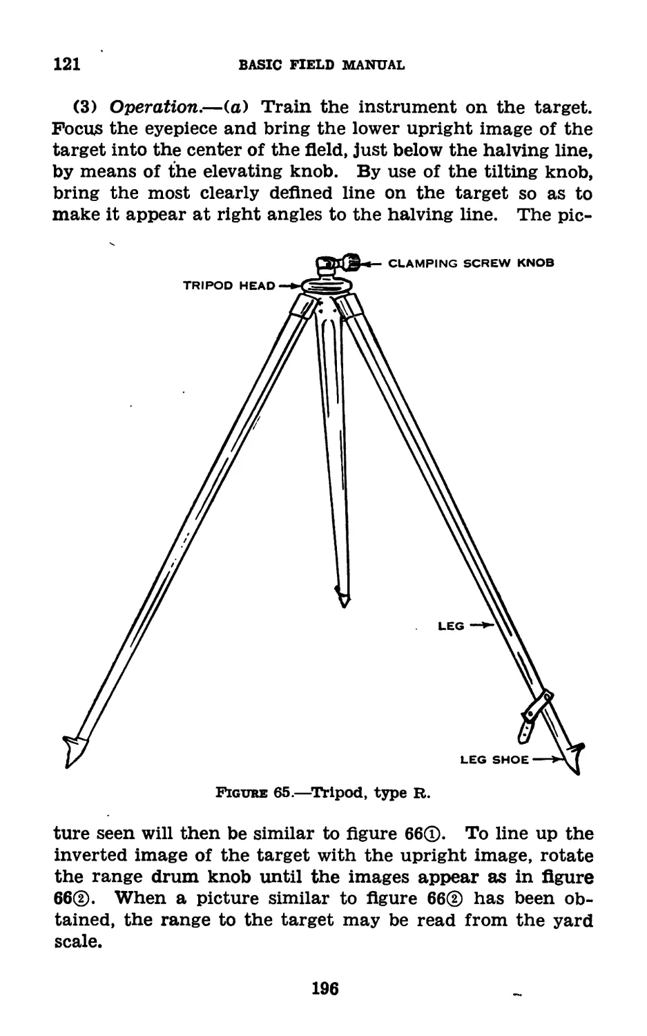
FM 23-90
WAR DEPARTMENT
BASIC FIELD MANUAL
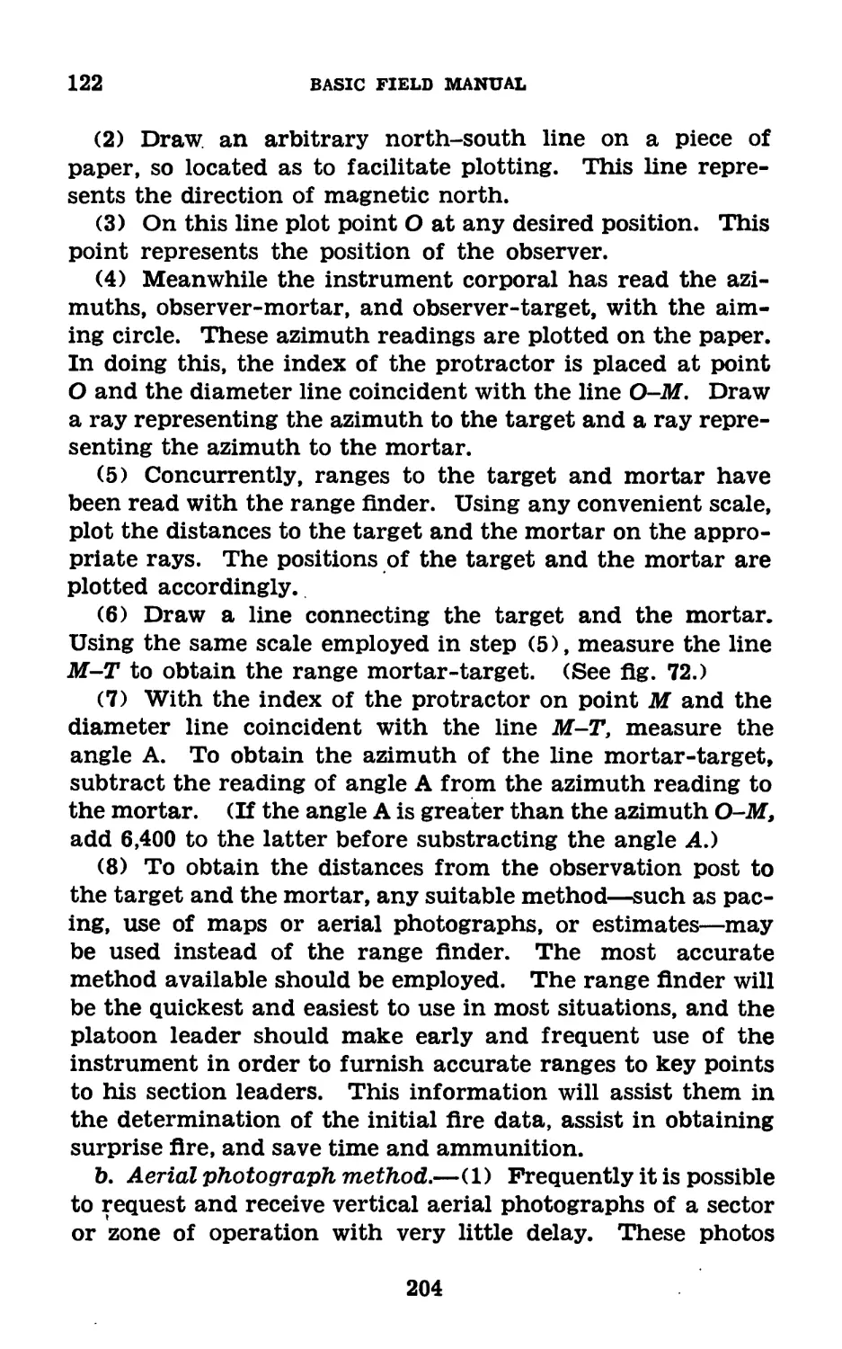
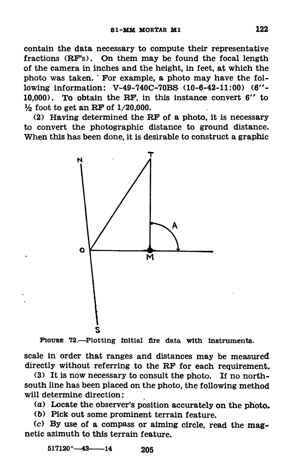
&
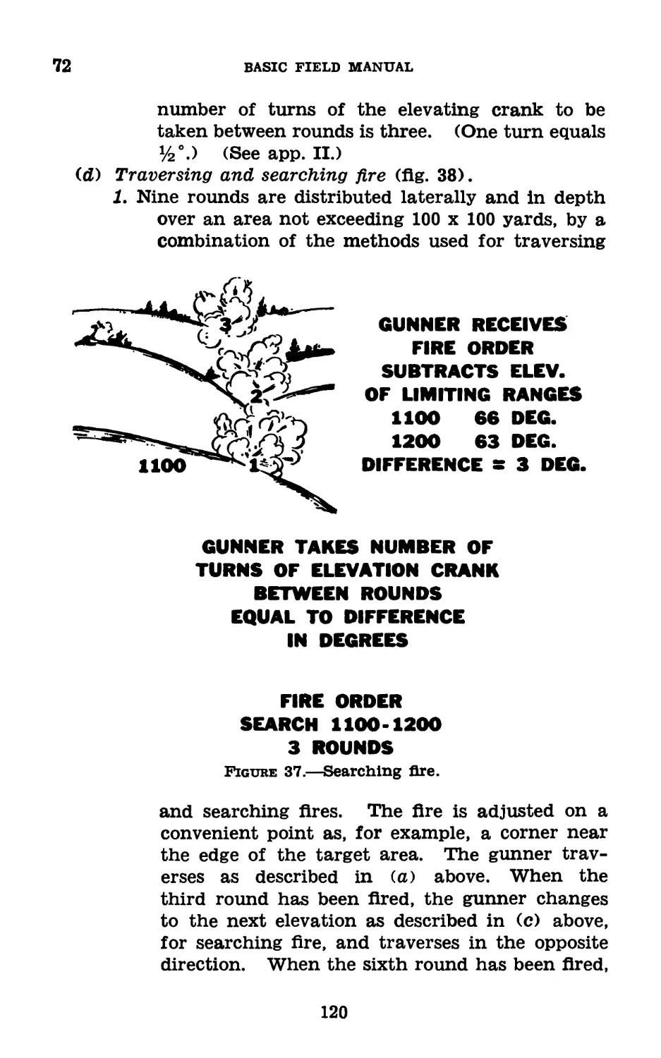
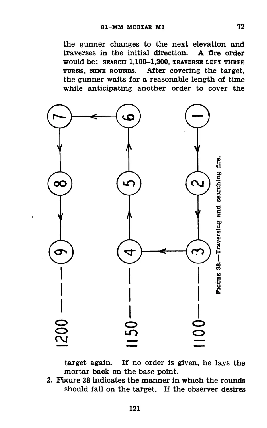
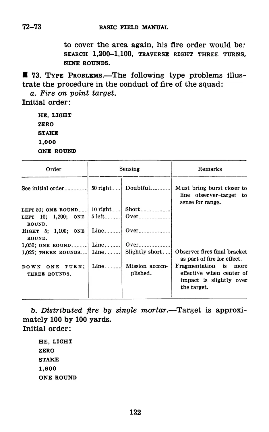
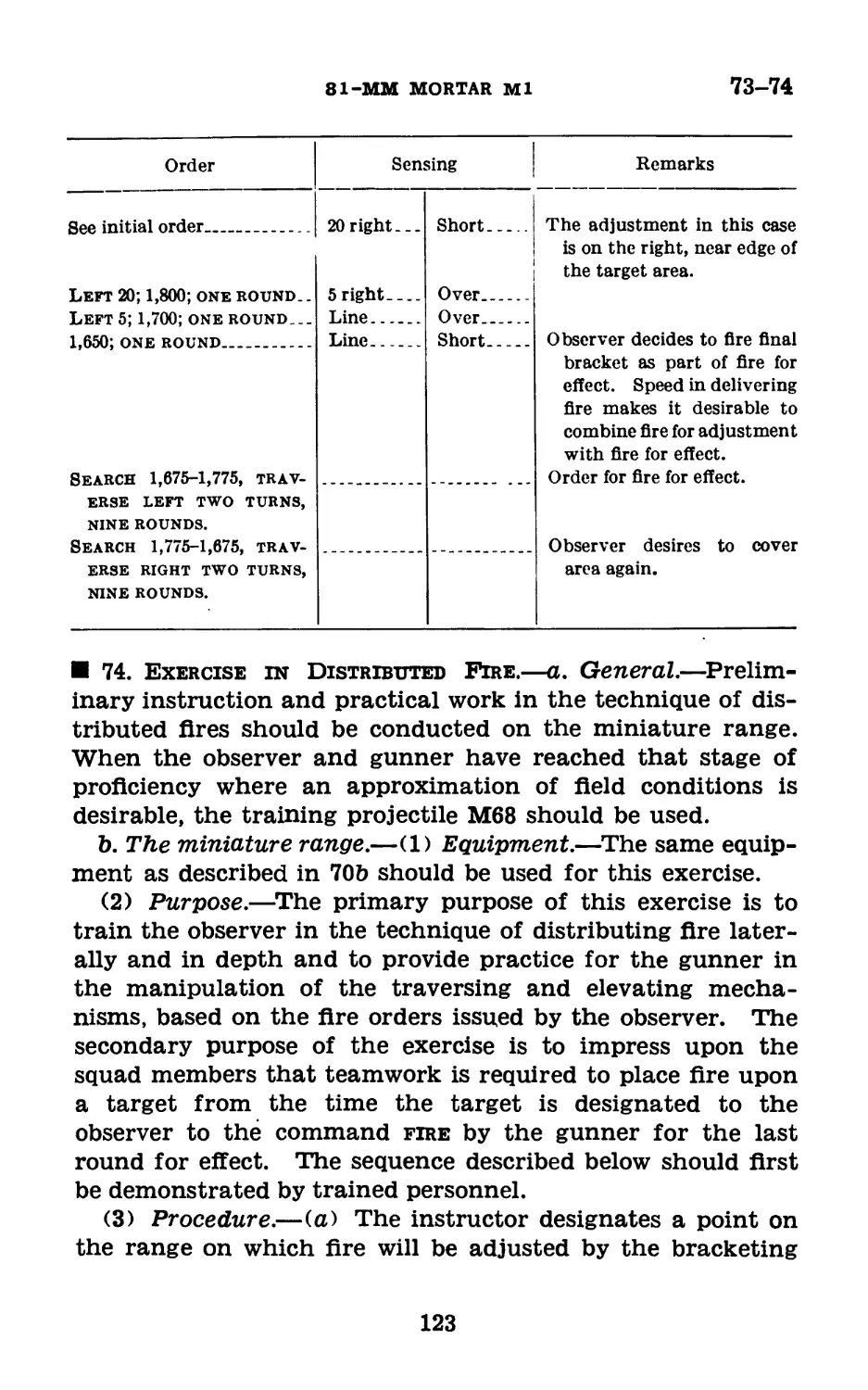
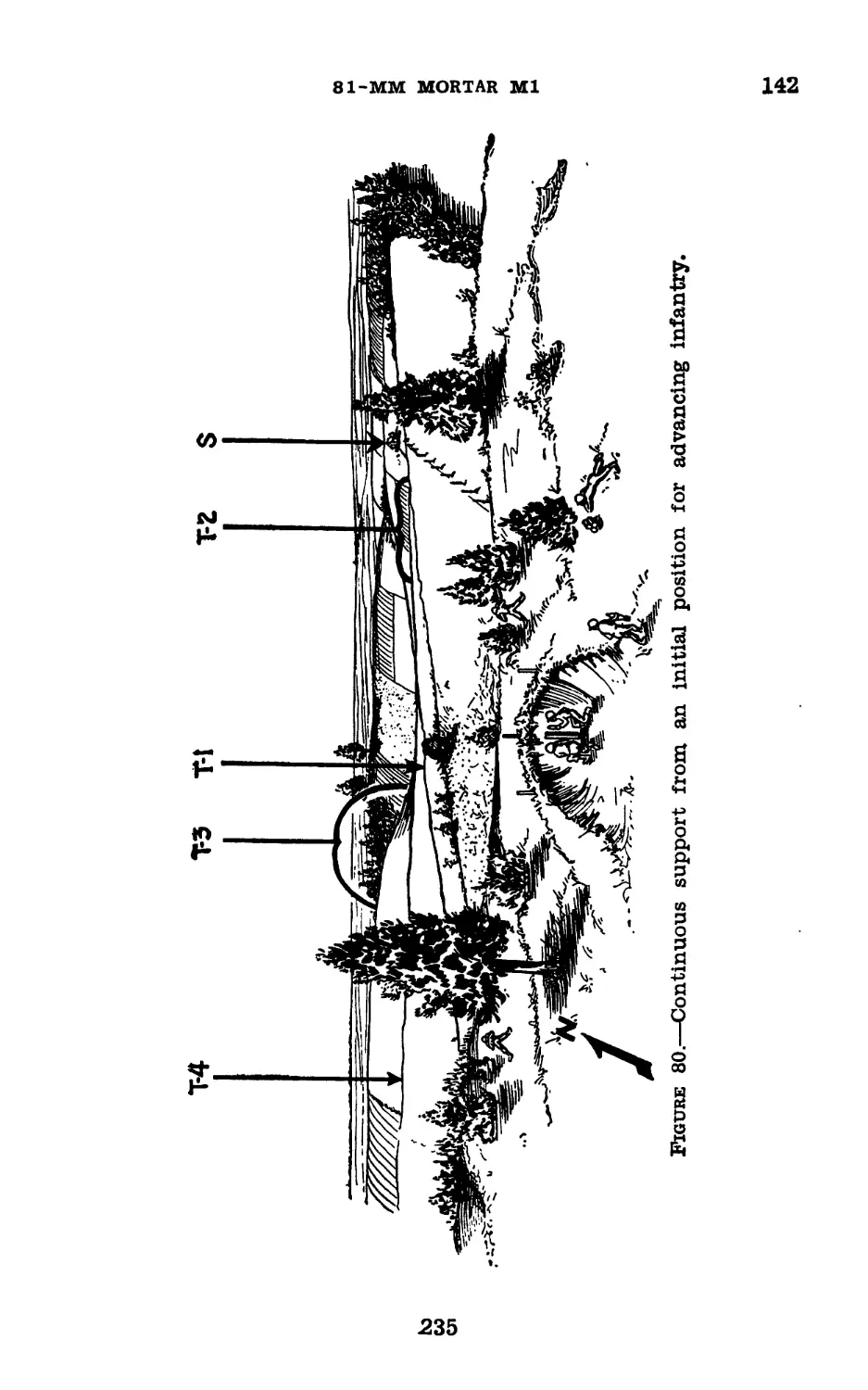
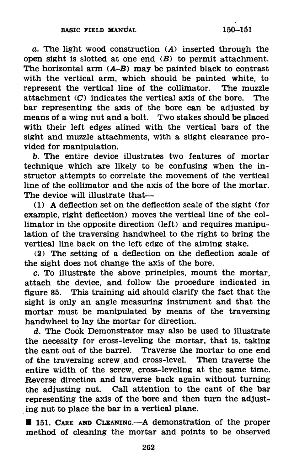
81-MM MORTAR Ml
April 22, 1943
RESTRICTED
FM 23-90
BASIC FIELD MANUAL
81-MM MORTAR Ml
UNITED STATES
GOVERNMENT PRINTING OFFICE
WASHINGTON : 1943
WAR DEPARTMENT,
Washington, April 22, 1943.
FM 23-90, 81-mm Mortar Ml, is published for the informa-
tion and guidance of all concerned.
[A. G. 062.11 (2-24-43).]
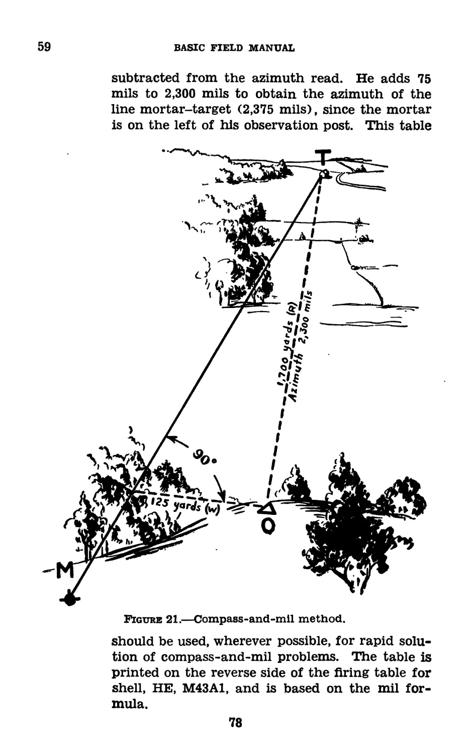
By order of the Secretary of War:
G. C. MARSHALL,
Chief of Staff.
Official :
J. A. ULIO,
Major General,
The Adjutant General.
Distribution:
В and H 2, 7, 17 (3); R 2, 7, 17 (5); Bn 2, 7, 19 (3); IC
2, 7, 17, 19 (10); C and H 9 (2).
(For explanation of symbols see FM 21-6.)
TABLE OF CONTENTS
Paragraphs Page
Chapter 1. Mechanical training.
Section I. Description_________________________ 1-3 1
П. Disassembling, assembling, mount-
ing, and dismounting____________________ 4-5 6
П1. Care, cleaning, and inspections-- 6-17 10
IV. Sighting equipment----------------18-19 21
V. Ammunition----------------------- 20-32 25
VI. Destruction of ordnance matdriel
in event of imminent capture in
combat zone______________________ 32.1-32.5 34
Chapter 2. Training of gunner.
Section I. General---------------------------- 33 39
II. Compass_____________________________ 34 39
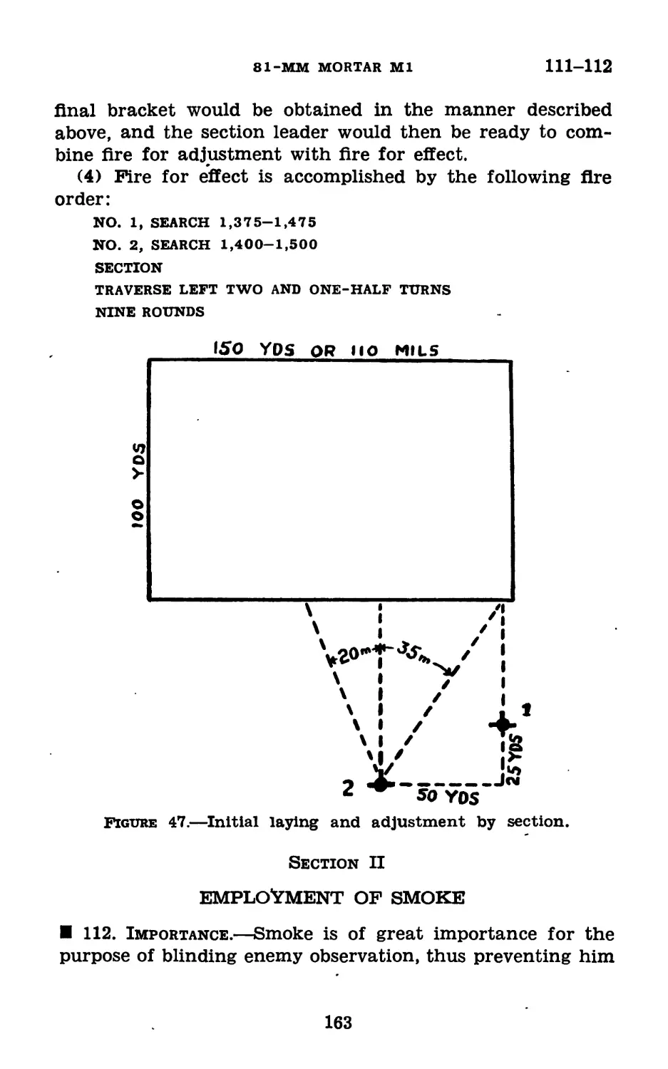
III. Spare parts and accessories_____ 35-36 42
IV. Training exercises_______________ 37-44 45
V. Additional training______________ 45-49 50
Chapter 3. Training for placing mortar in action. 50-56 58
Chapter 4. Training of observer.
Section I. Preparatory instruction_____________ 57-64 71
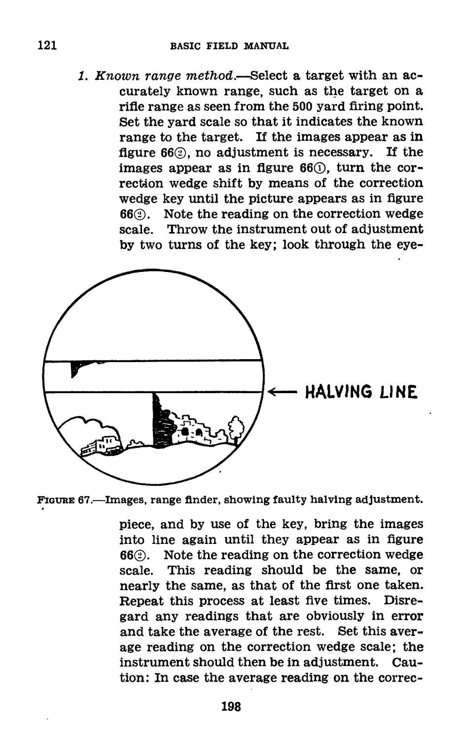
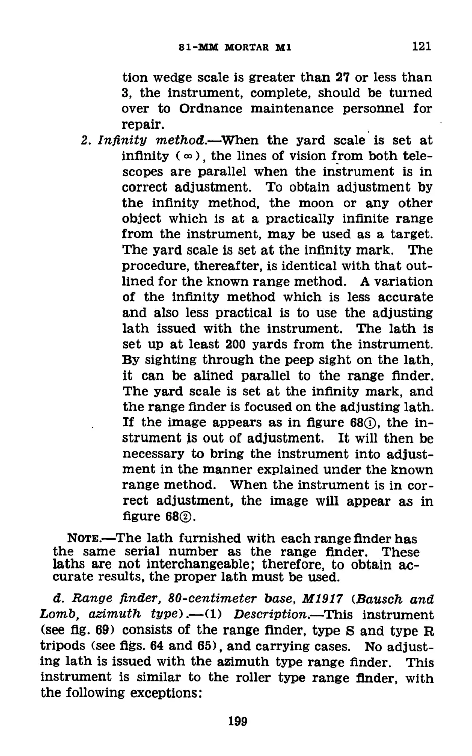
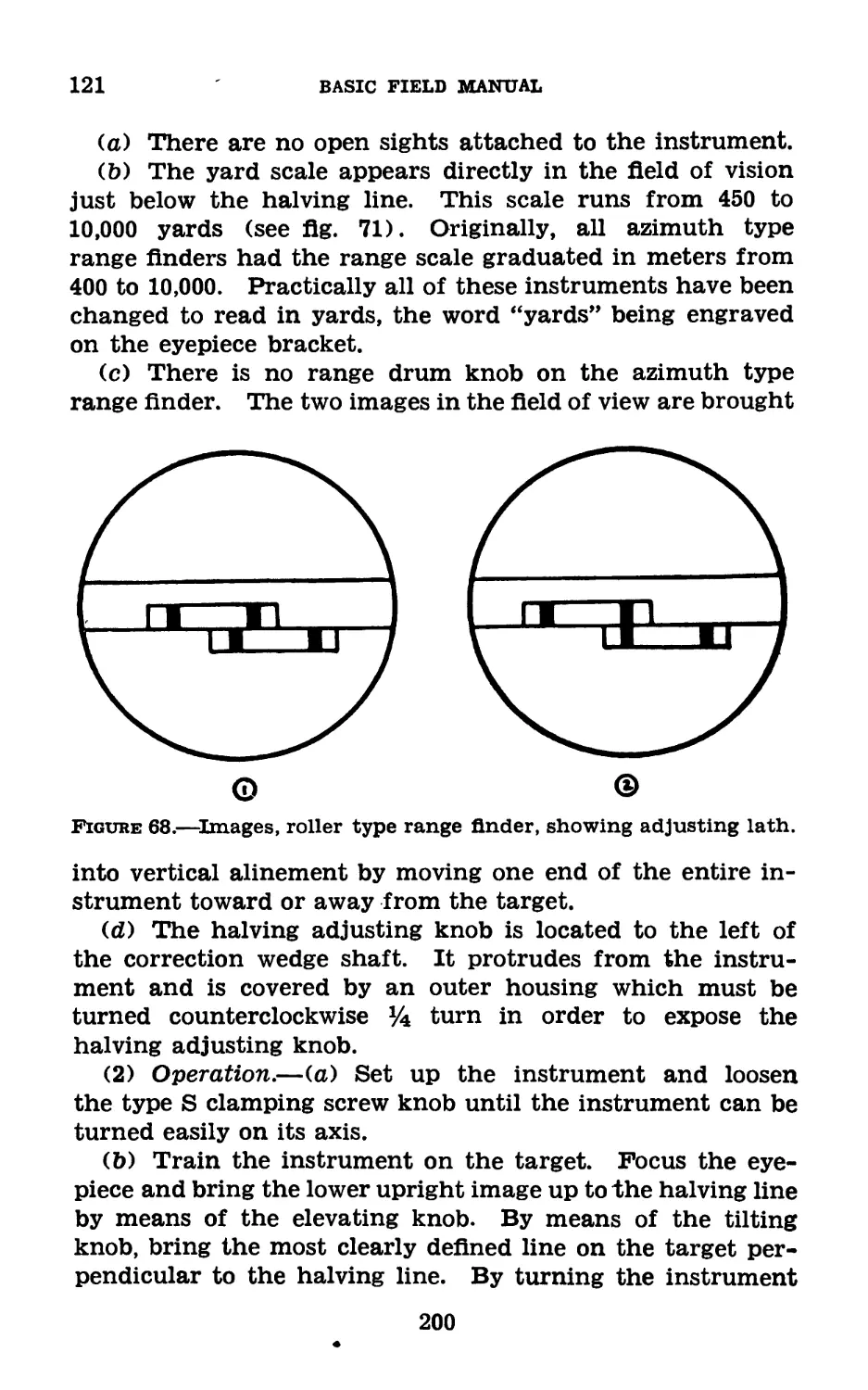
II. Squad conduct of fire___________ 65-74 95
П1. Combat expedients—rapid adjust-
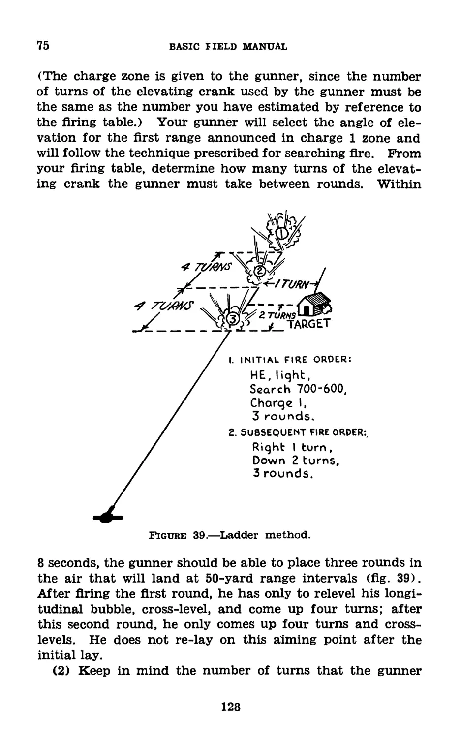
ment of fire_____________________________ 75 125
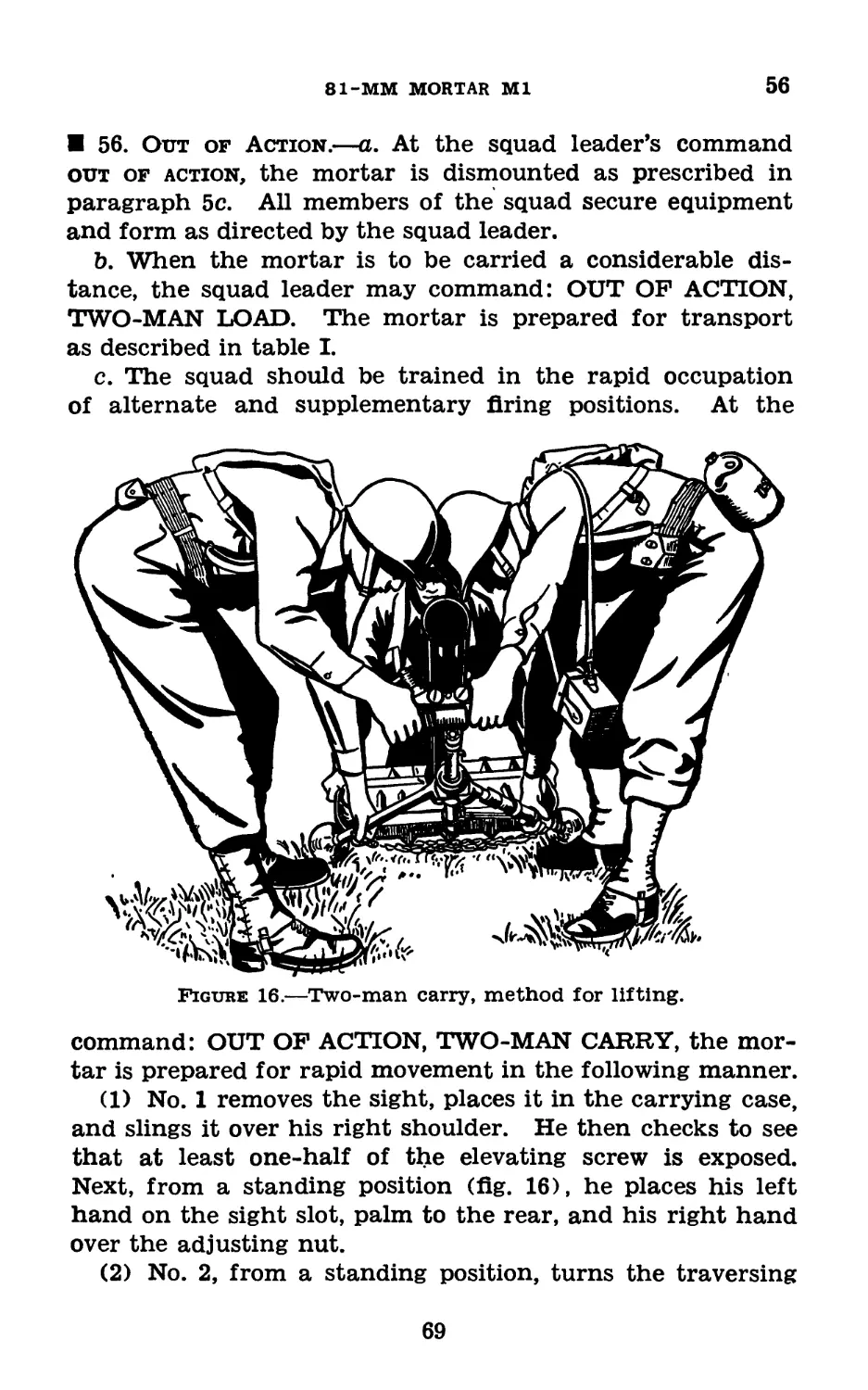
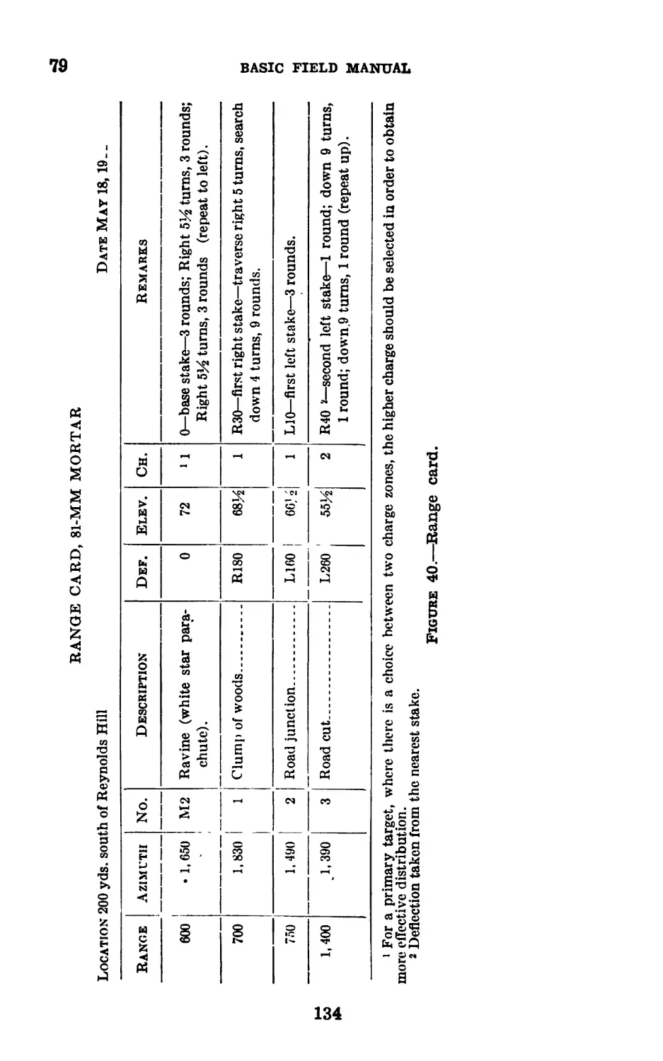
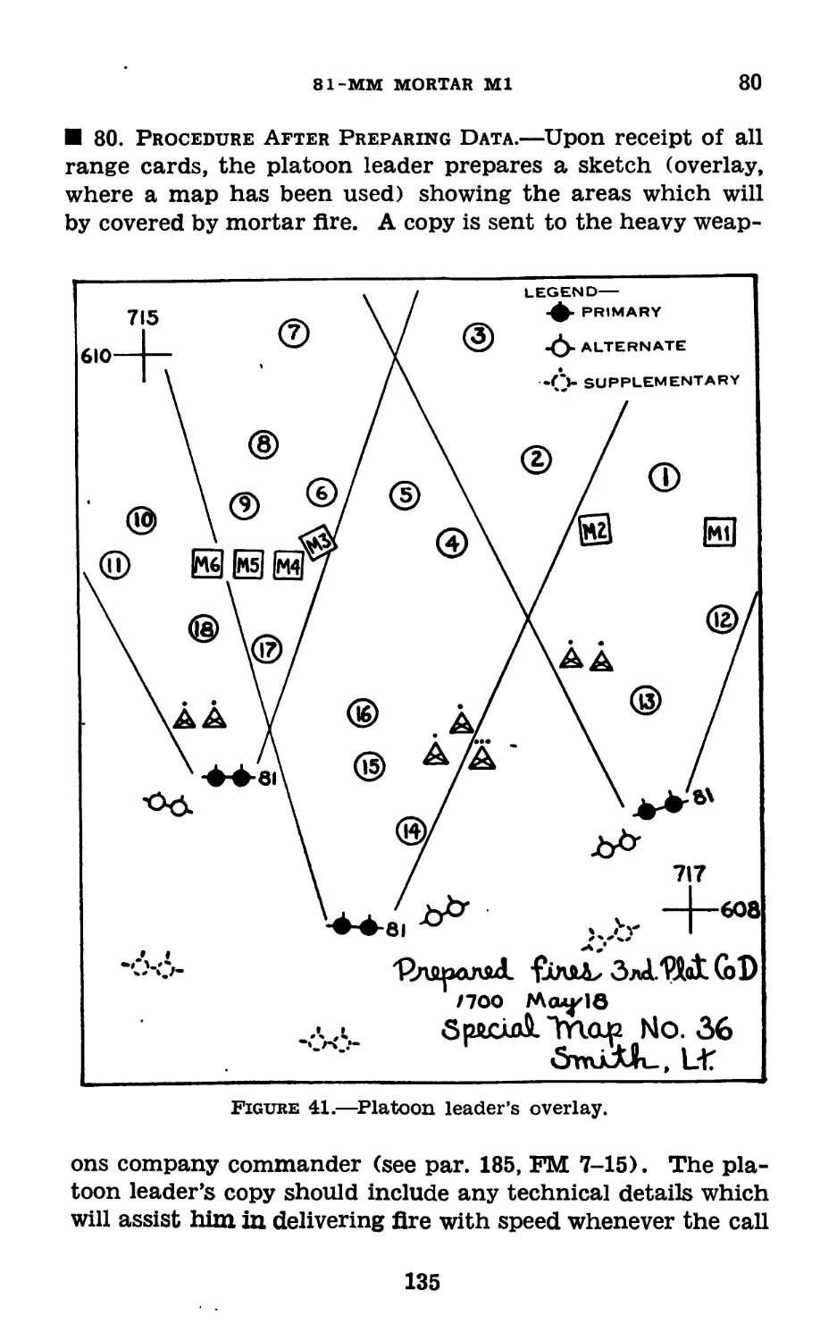
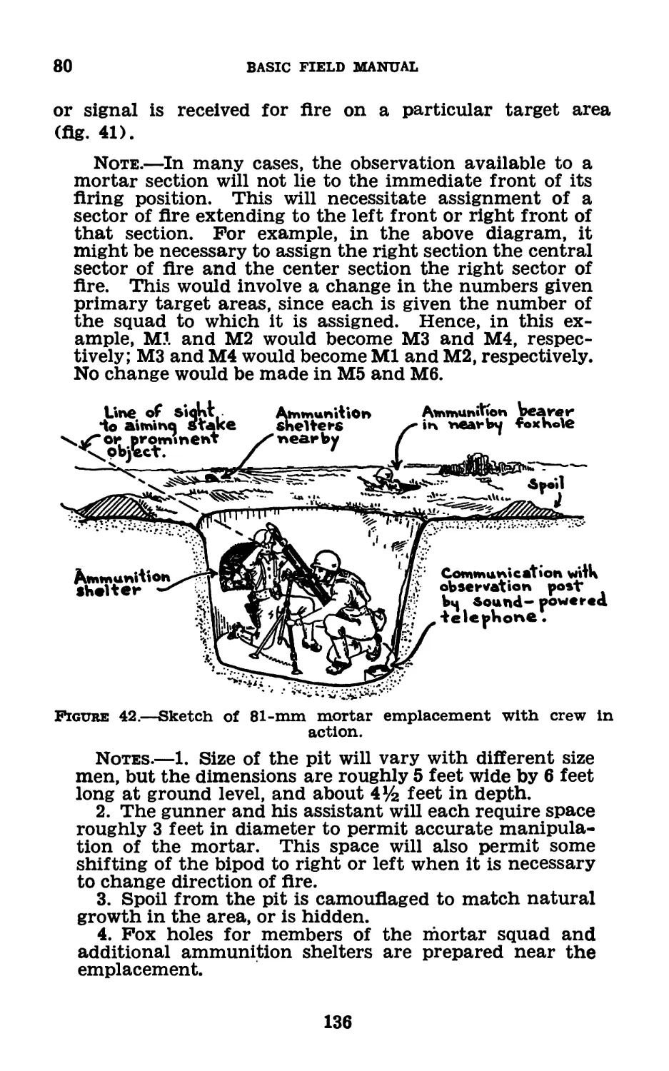
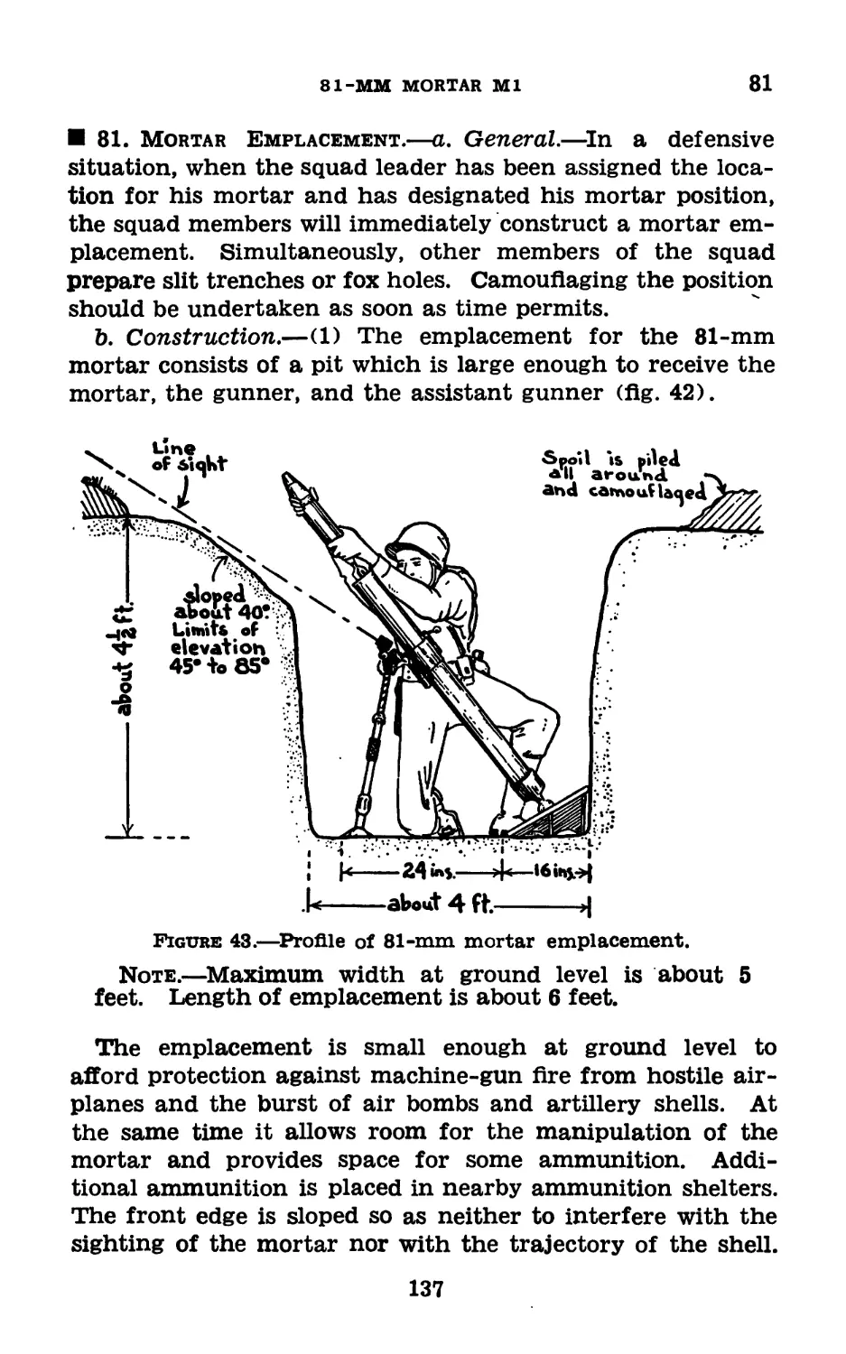
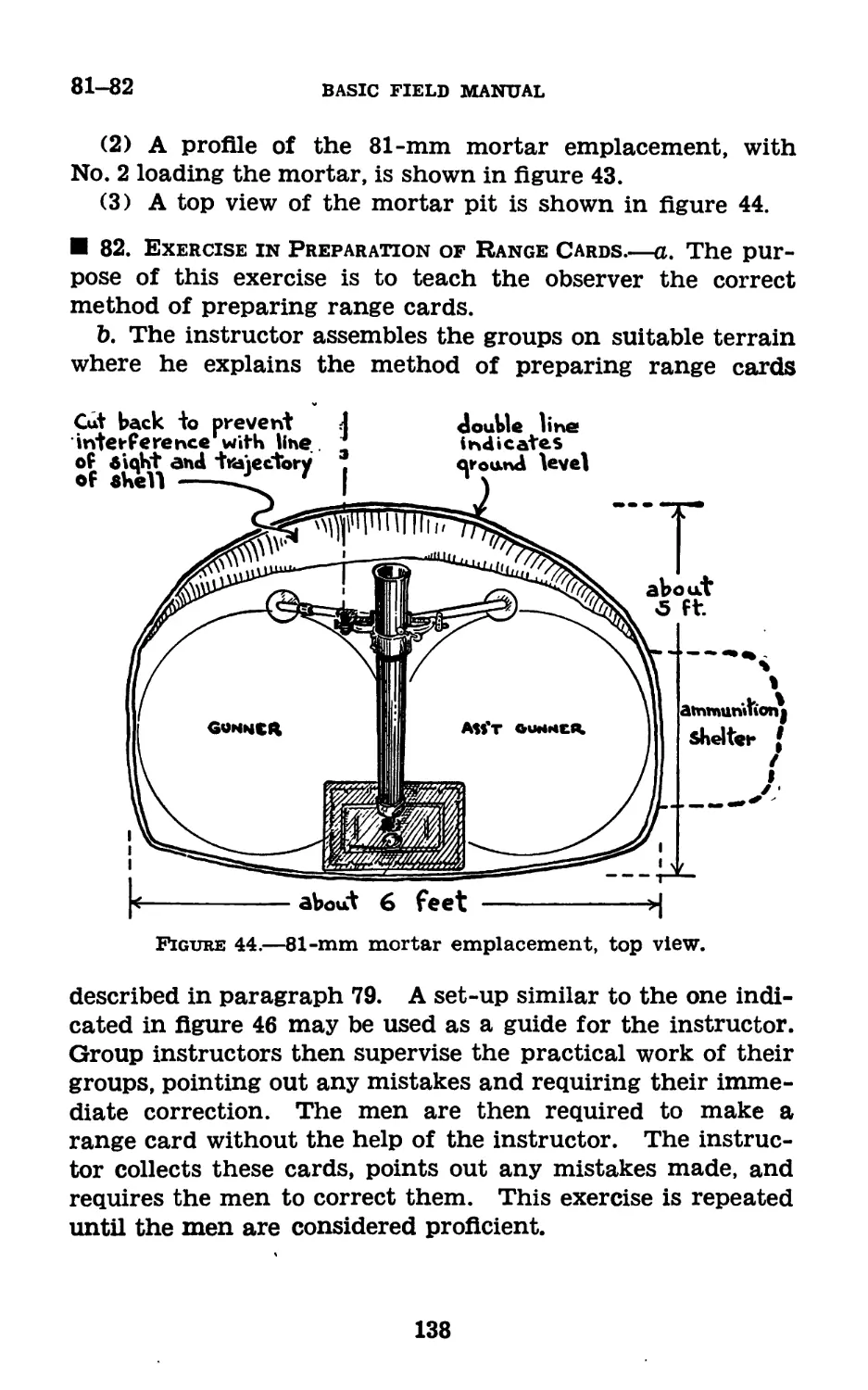
IV. Prearranged fires_________________ 76-82 131
Chapter 5. Marksmanship.
Section I. Preparatory instruction______________ 83-86 139
II. Examination______________________ 87-90 141
III. Qualification course, gunner’s test. 91-98 142
IV. Qualification course, expert’s test. 99-104 151
V. Targets, ranges, and range pre-
cautions _________________________ 105-107 158
Chapter 6. Advanced training.
Section I. Section conduct of fire_____________108-111 159
II. Employment of smoke_____________112-119 163
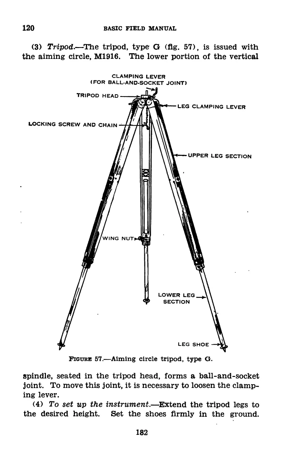
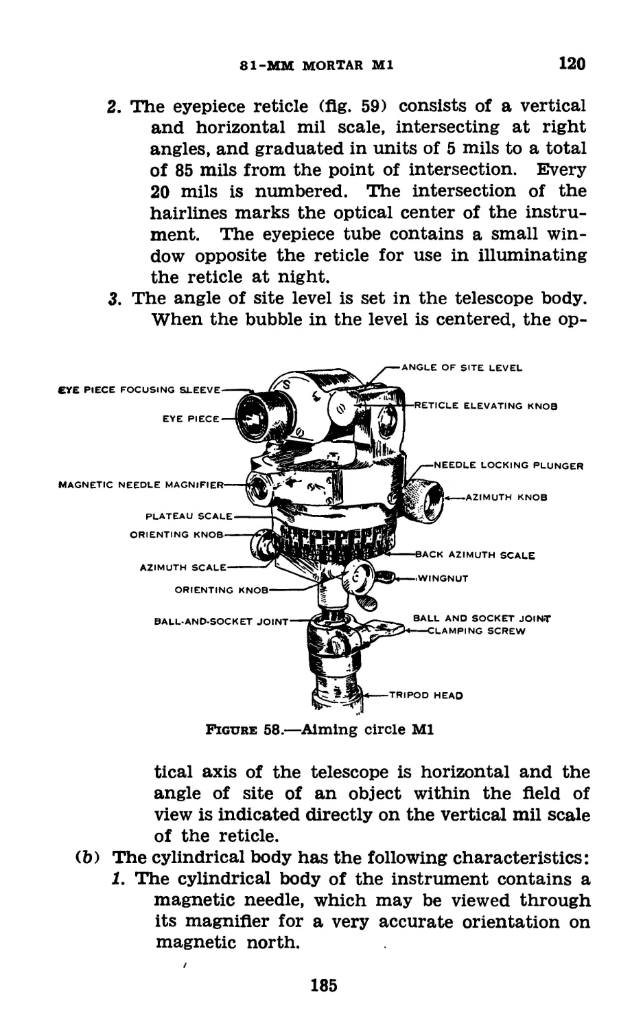
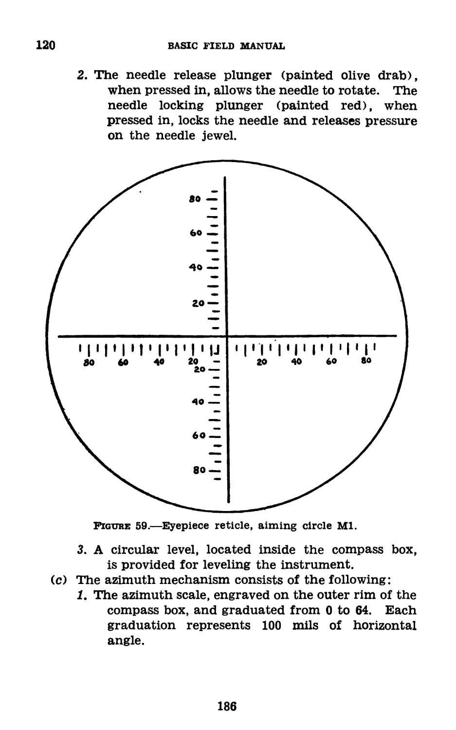
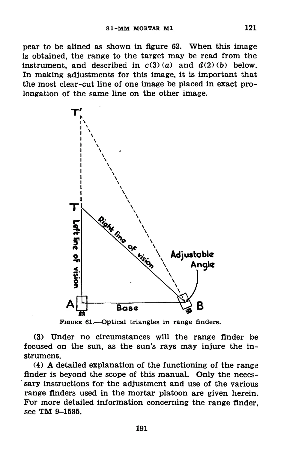
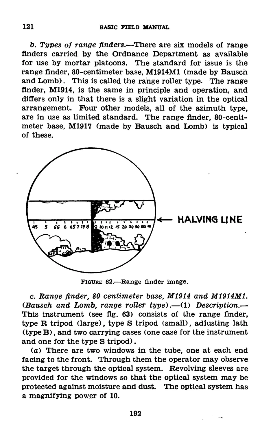
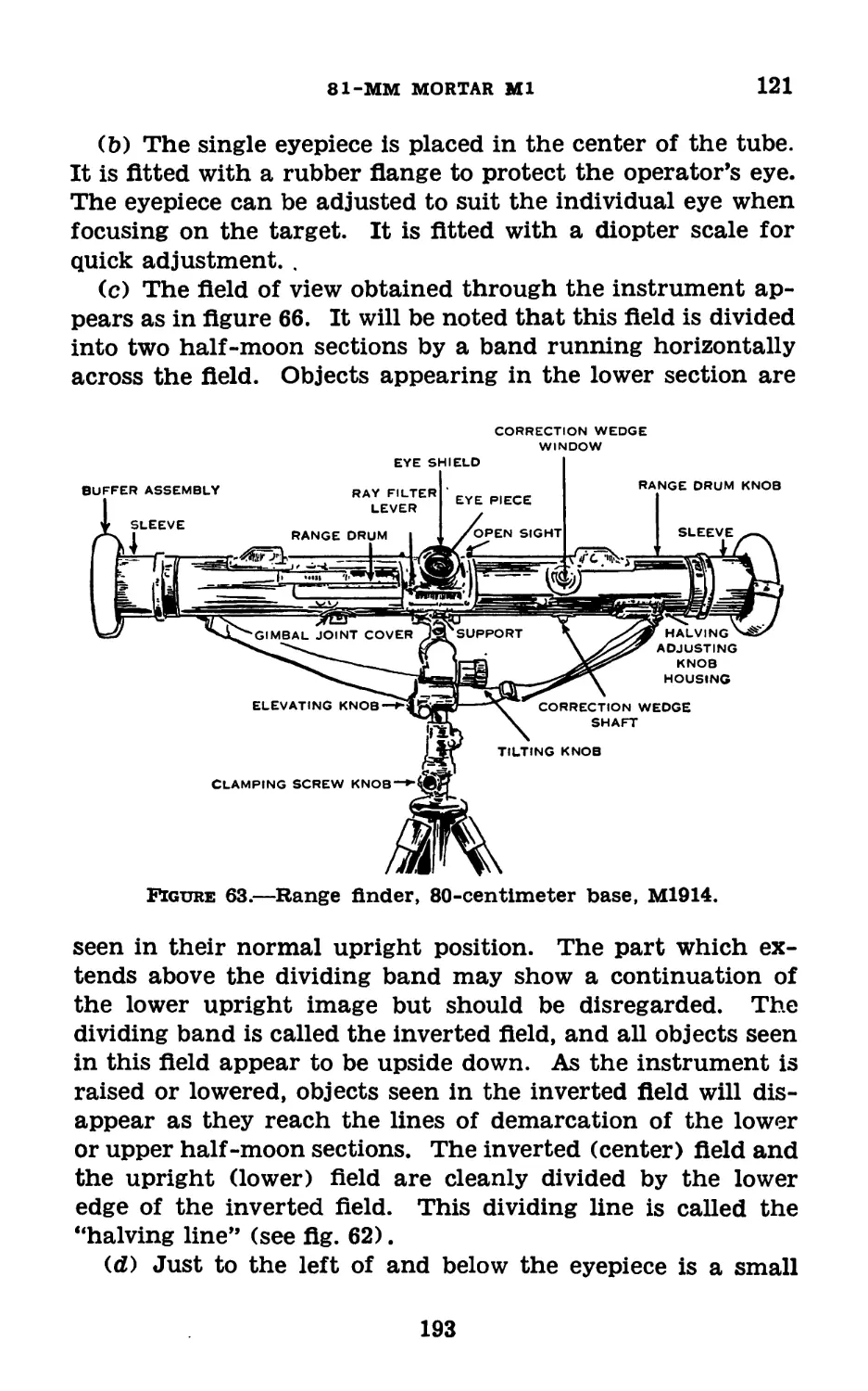
III. Fire control instruments________120-121 179
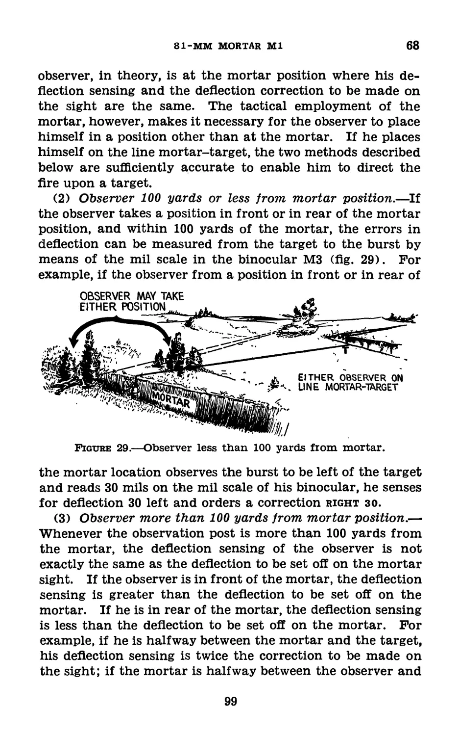
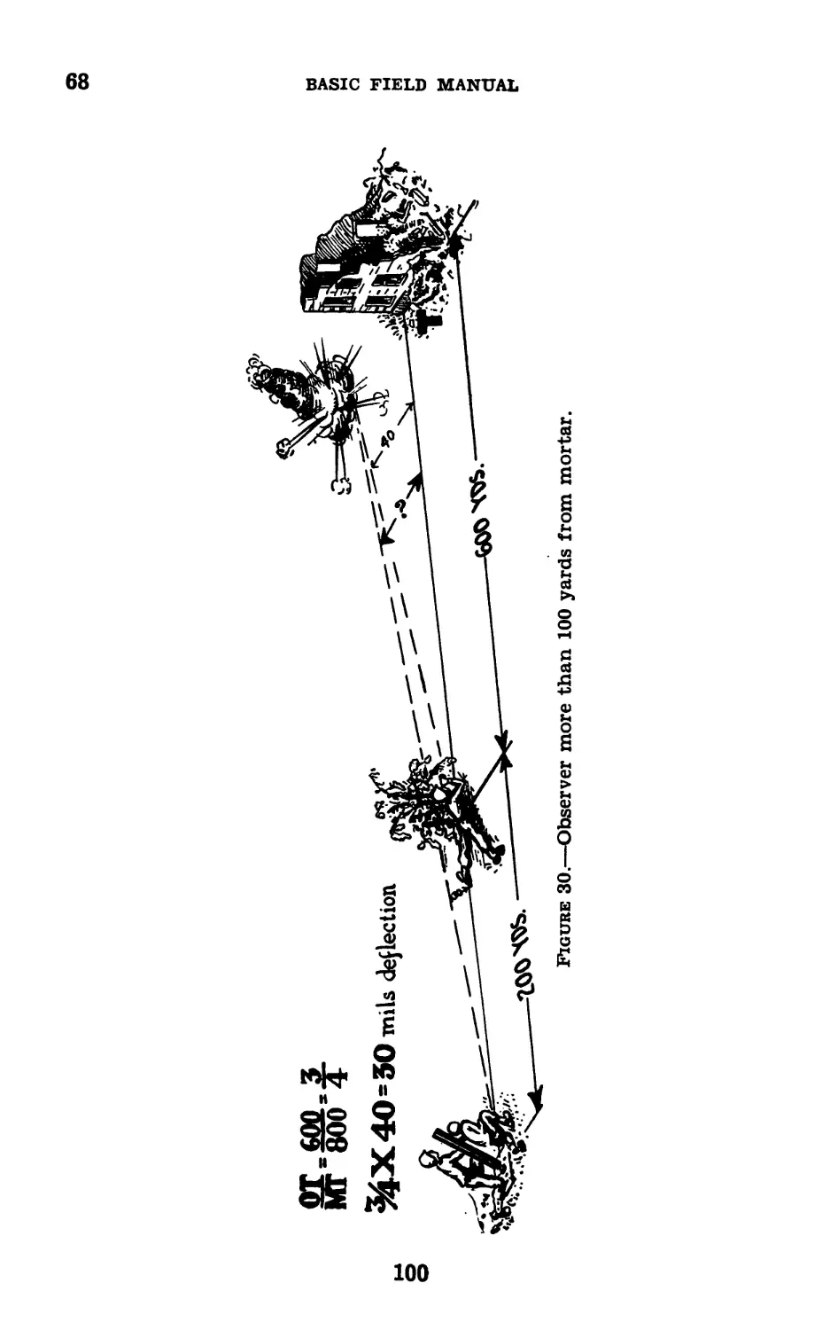
IV. Use of fire control instruments_ 122-123 203
Chapter 7. Field training.
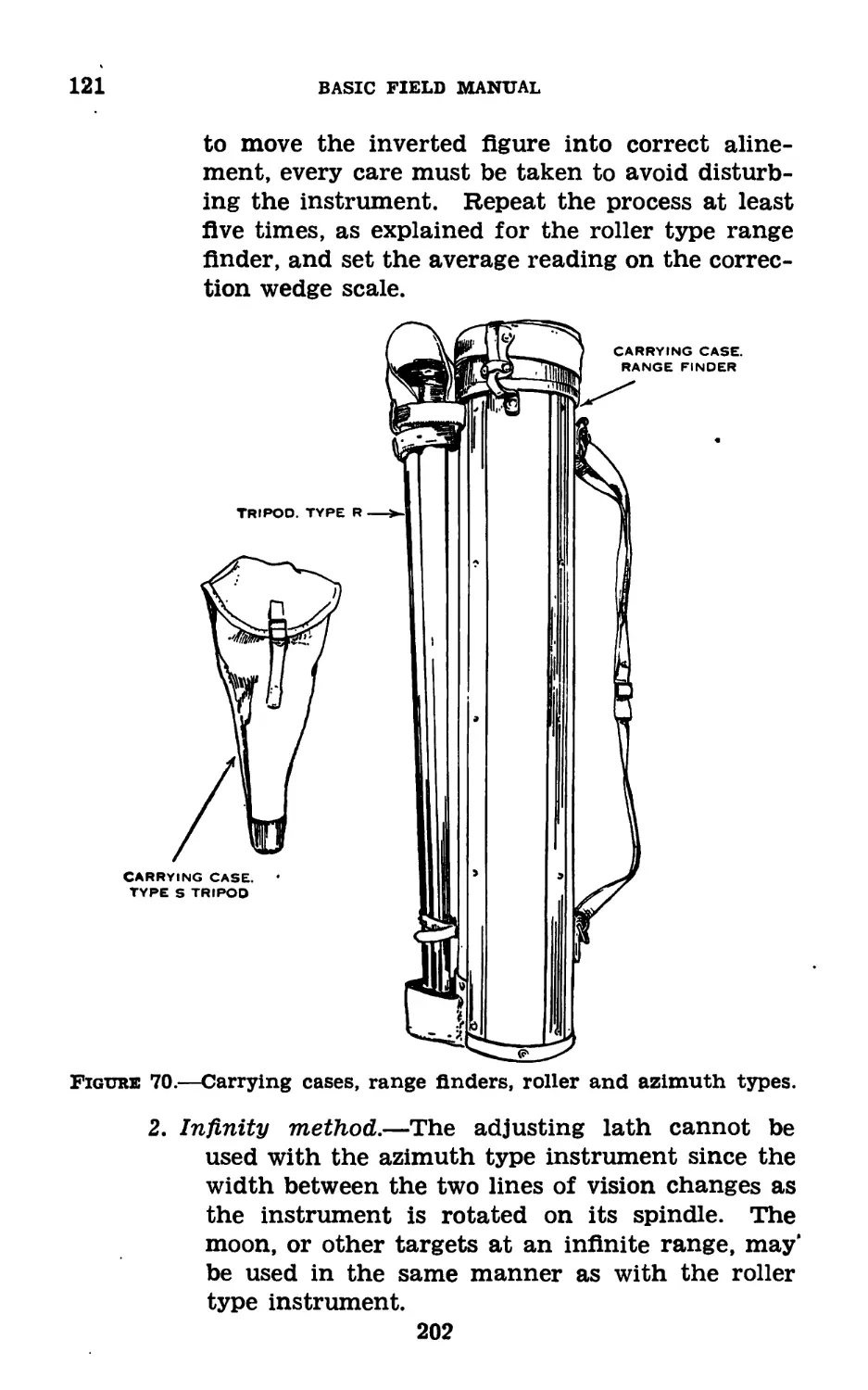
Section I. General____________________________ 124-126 208
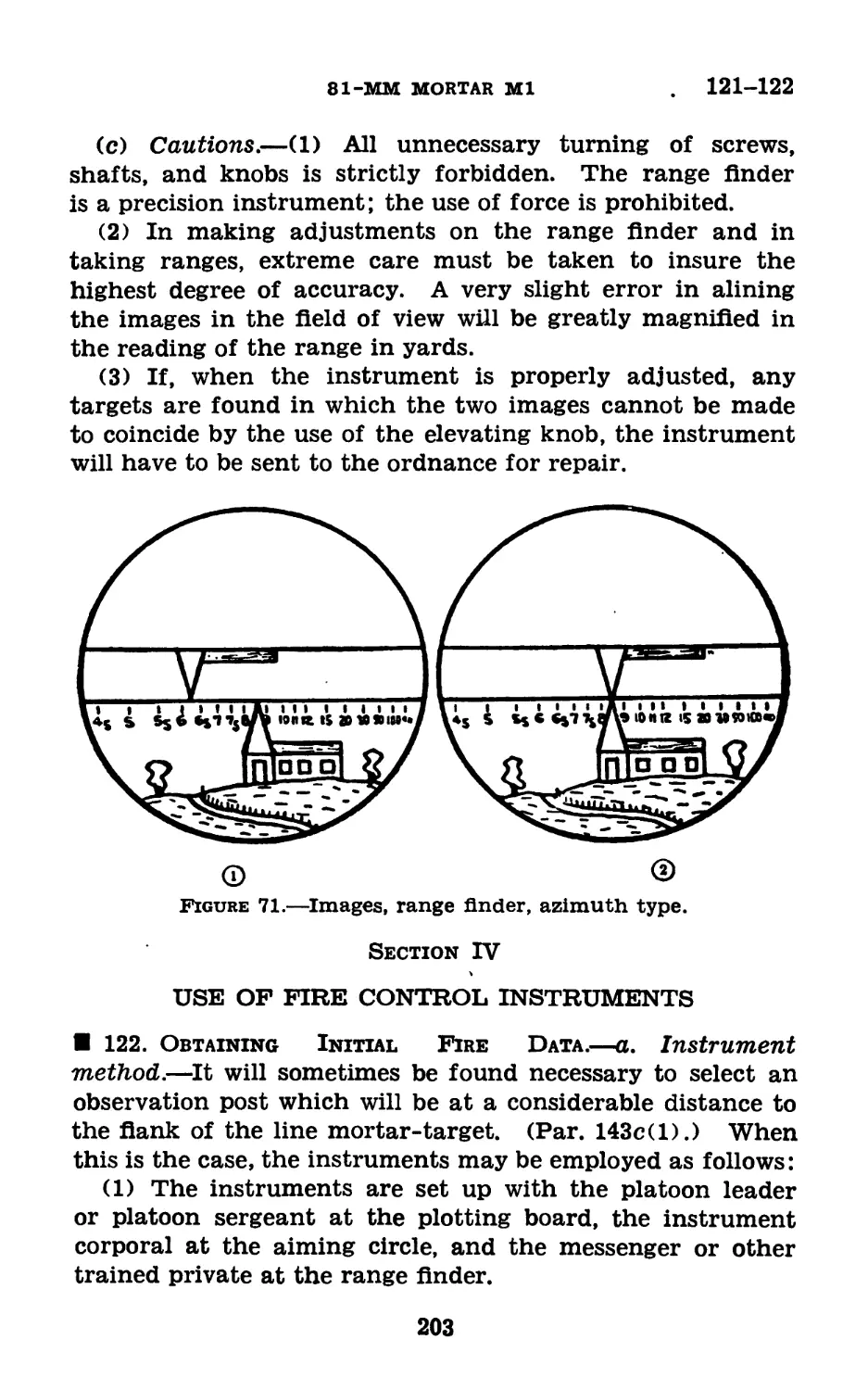
II. Preparatory exercises__________ 127-130 208
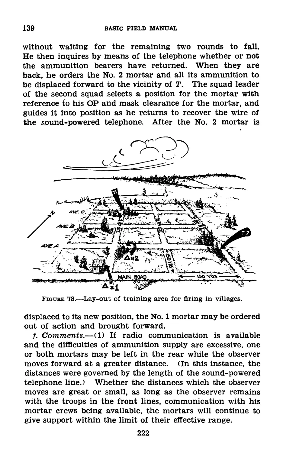
III. Elementary firing exercises_____ 131-137 211
IV. Advanced training exercises_____ 138-143 218
Chapter 8. Advice to instructors.
Section I. General____________________________ 144-146 259
II. Mechanical training____________ 147-152 259
П1. Training of gunner and observer. 153 265
IV. Training for placing mortar in
action_________________________________ 154 265
V. Markmanship___________________ 155-156 266
VI. Field training----------------- 157-159 267
VII. Instruction on sand table______ 160 268
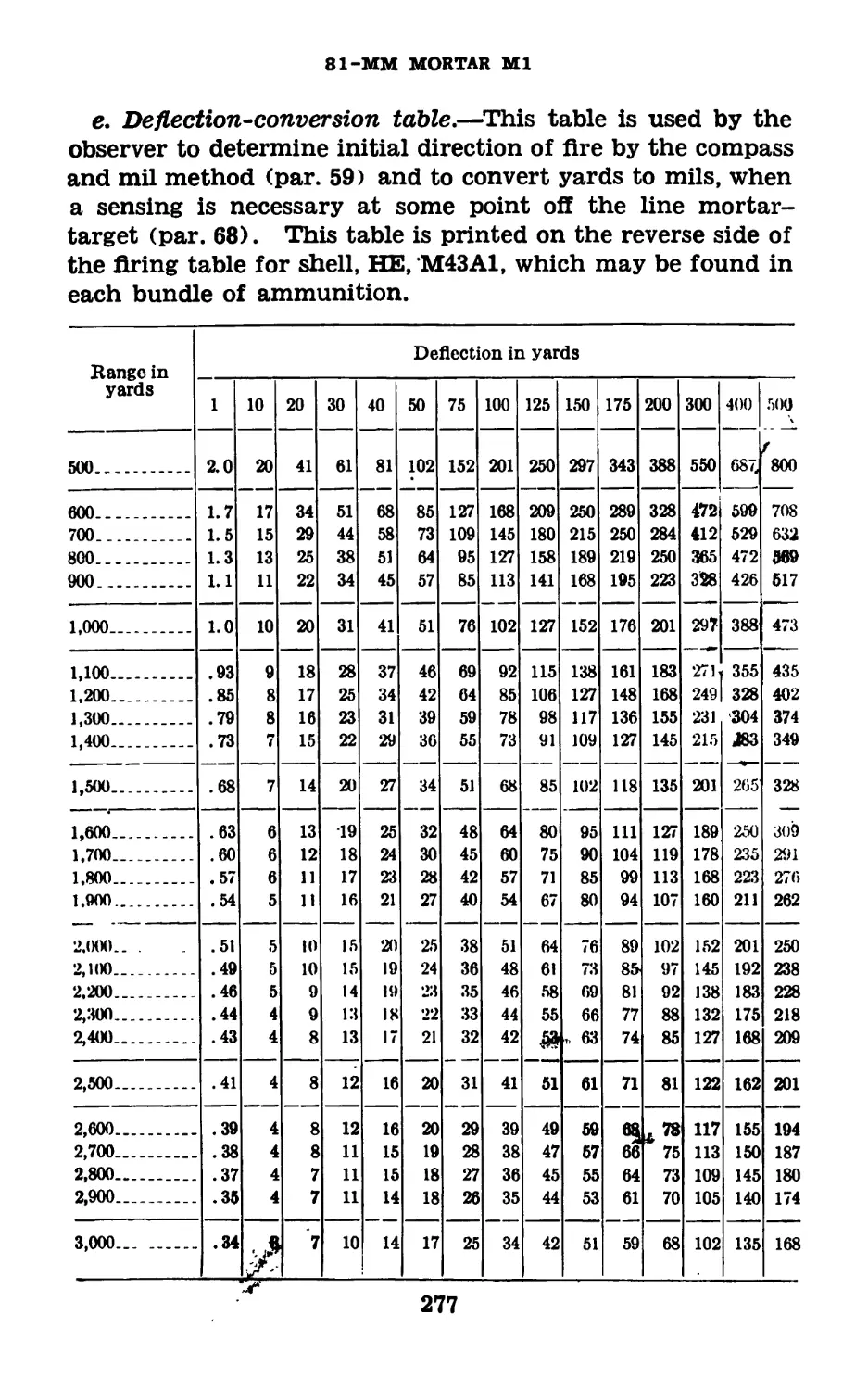
Appendix I. Firing tables and deflection-conversion table. 270
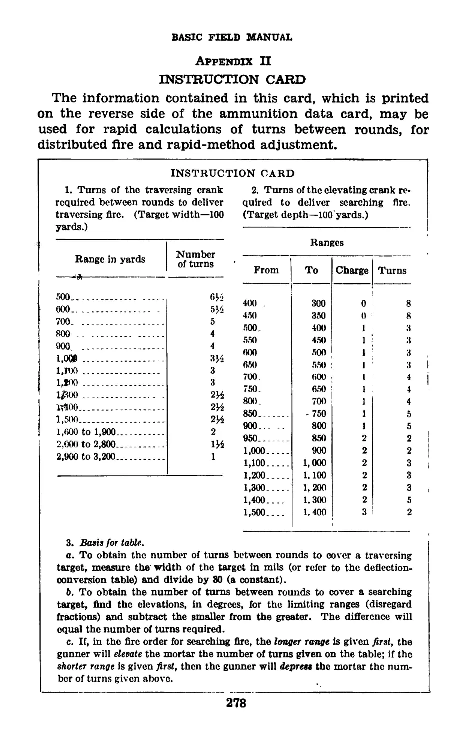
Appendix II. Instruction card_________________________ 278
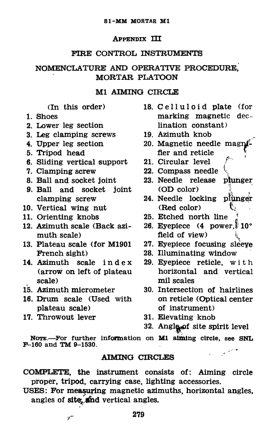
Appendix III. Fire control instruments: Nomenclature
and operative procedure, mortar platoon. 279
Index__________________________________________________ 283
III
RESTRICTED
FM 23-90
BASIC FIELD MANUAL
81-MM MORTAR Ml
(This manual supersedes FM 23-90, May 7, 1942, including С 1,
Jan. 12, 1943.)
Attention is directed to FM 21-7 for details as to how appropriate
Training Films and Film Strips are intended to be used and how
they are made available for use during training with the 81-mm
mortar Ml.
CHAPTER 1
MECHANICAL TRAINING
Paragraphs
Section I. Description____________________________________ 1-3
II. Disassembling, assembling, mounting, and dis-
mounting___________________________________________ 4-5
III. Care, cleaning, and inspections______________ 6-17
IV. Sighting equipment__________,_________________18-19
V. Ammunition___________________________________ 20-32
VI. Destruction of ordnance materiel in event of im-
minent capture in combat zone__________________ 32.1-32.5
Section I
DESCRIPTION
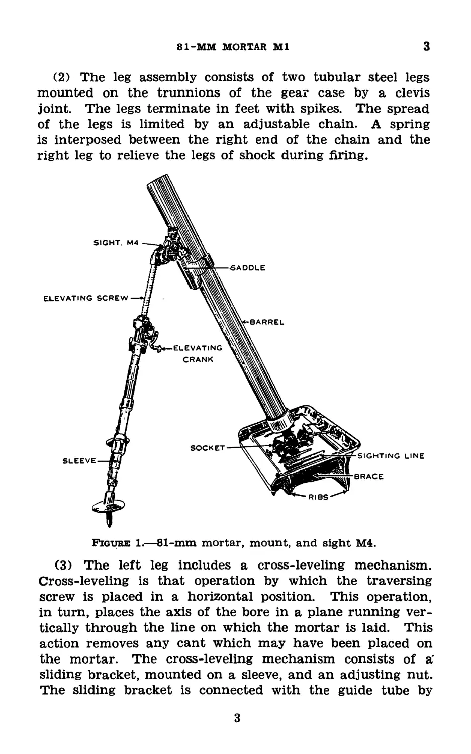
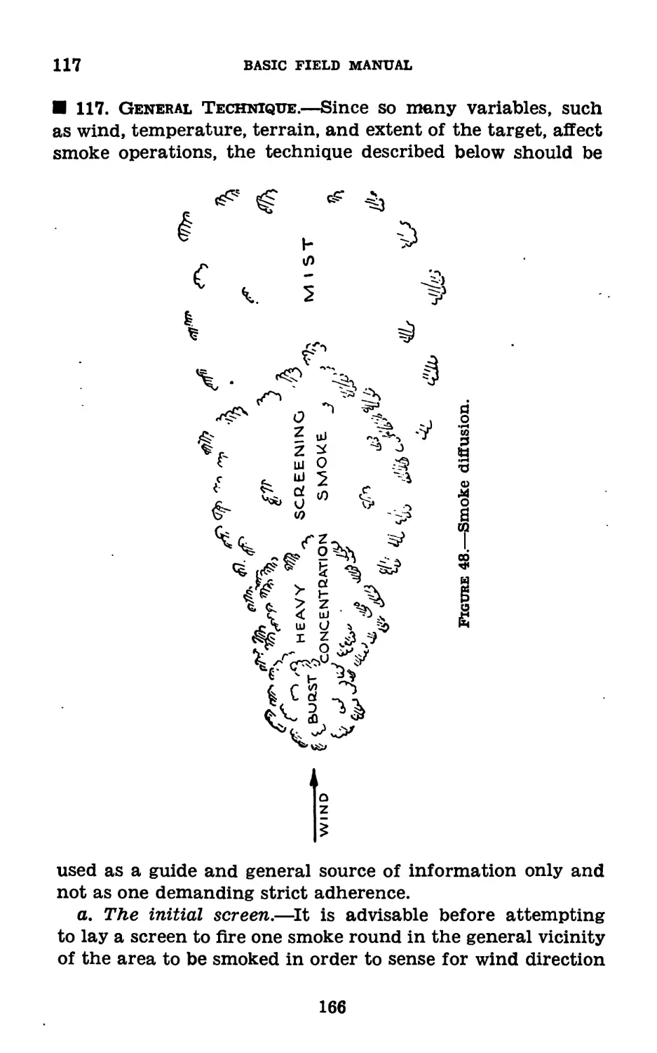
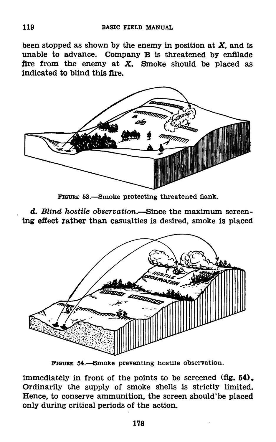
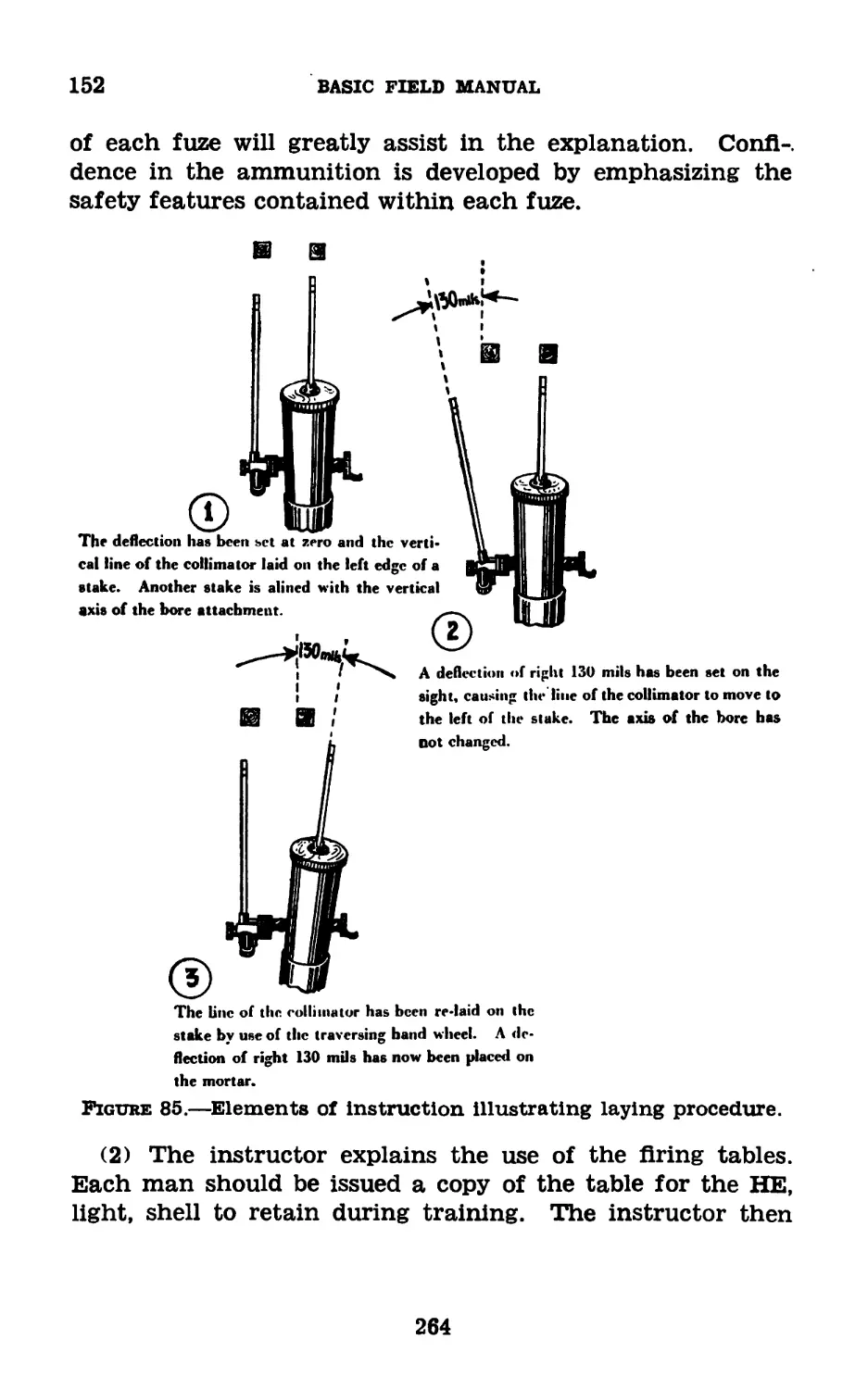
1. Characteristics.—The 81-mm mortar (fig. 1) is a
smooth bore, muzzle loading, high angle fire weapon. The
mortar is assembled into a single unit, while the mount
consists of two units—the bipod and base plate. These three
units—mortar, bipod, and base plate—form separate loads,
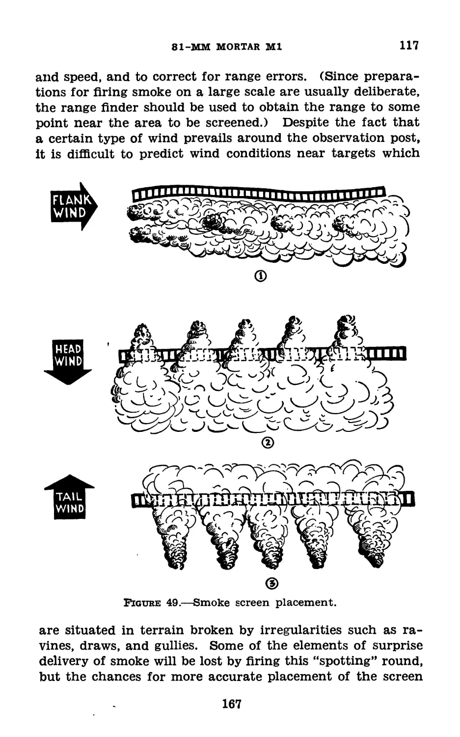
each of which is light enough to be carried by one man. The
mortar is attached to the bipod by means of a clamp and can
be readily dismounted. It is fastened to the base plate by
inserting the spherical projection of the base cap into one of
the three seats of the socket and rotating the mortar 90°.
A detailed list of the parts and equipment for the 81-mm
mortar and mount may be found in Standard Nomenclature
List A-33.
1
2-3
BASIC FIELD MANUAL
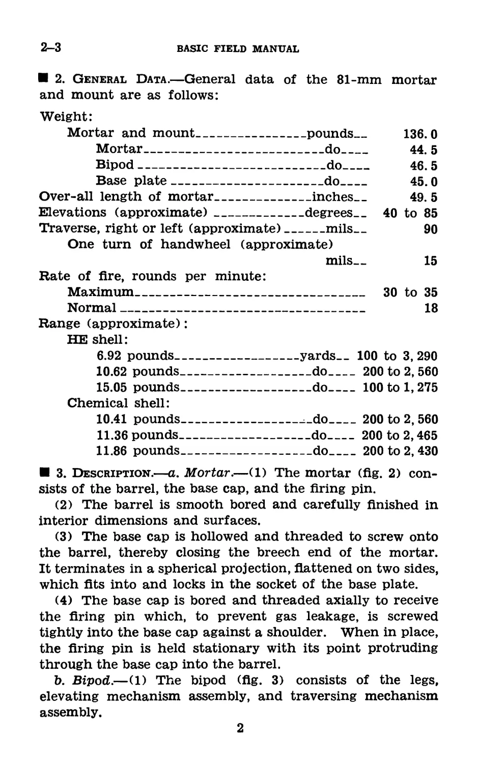
2. General Data.—General data of the 81-mm mortar
and mount are as follows:
Weight:
Mortar and mount________________pounds___ 136. 0
Mortar_________________________do___ 44. 5
Bipod--------------------------do___ 46. 5
Base plate_____________________do___ 45.0
Over-all length of mortar___________inches. _ 49. 5
Elevations (approximate)_____________degrees_40 to 85
Traverse, right or left (approximate)__mils— 90
One turn of handwheel (approximate)
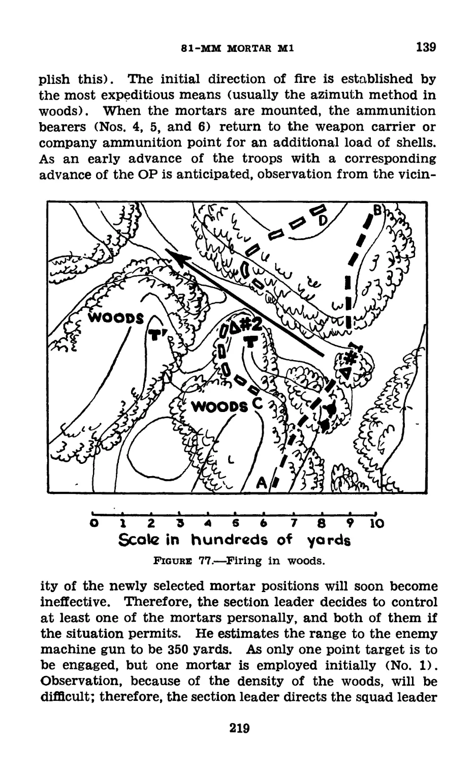
mils— 15
Rate of fire, rounds per minute:
Maximum_________________________________ 30 to 35
Normal__________________________________ 18
Range (approximate):
HE shell:
6.92 pounds_________________yards._ 100 to 3, 290
10.62 pounds_________________do_____ 200 to 2, 560
15.05 pounds_________________do_____100 to 1, 275
Chemical shell:
10.41 pounds__________________do____ 200 to 2, 560
11.36 pounds-----------------do----- 200 to 2,465
11.86 pounds_________________do_____ 200 to 2, 430
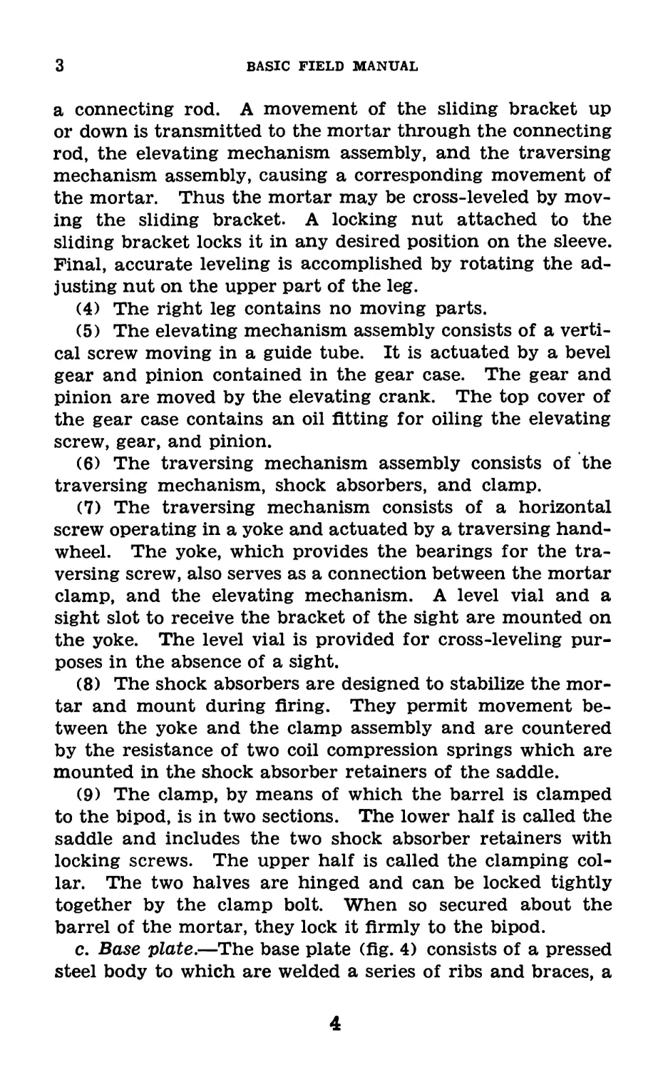
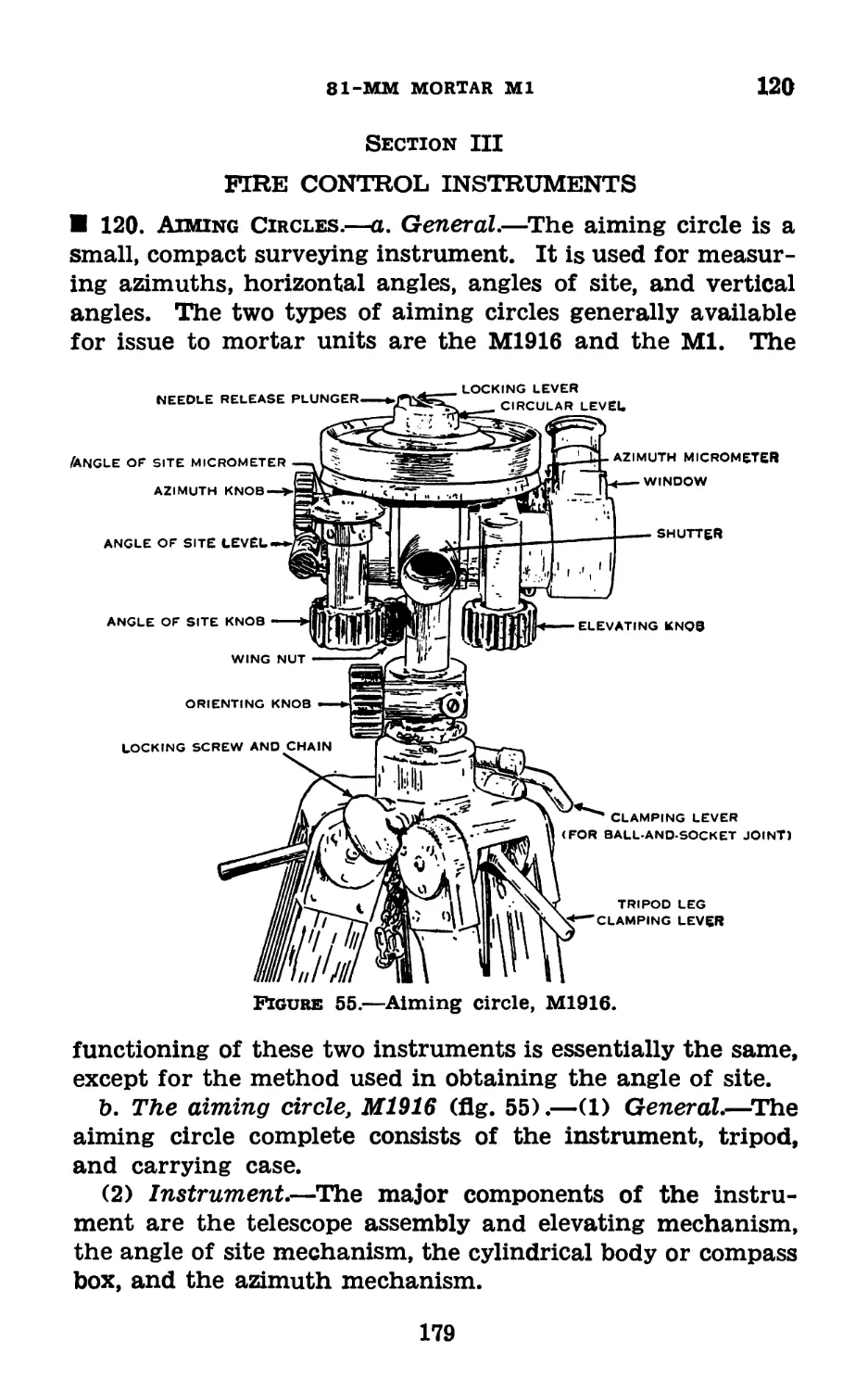
3. Description.—a. Mortar.—(1) The mortar (fig. 2) con-
sists of the barrel, the base cap, and the firing pin.
(2) The barrel is smooth bored and carefully finished in
interior dimensions and surfaces.
(3) The base cap is hollowed and threaded to screw onto
the barrel, thereby closing the breech end of the mortar.
It terminates in a spherical projection, flattened on two sides,
which fits into and locks in the socket of the base plate.
(4) The base cap is bored and threaded axially to receive
the firing pin which, to prevent gas leakage, is screwed
tightly into the base cap against a shoulder. When in place,
the firing pin is held stationary with its point protruding
through the base cap into the barrel.
b. Bipod.—(1) The bipod (fig. 3) consists of the legs,
elevating mechanism assembly, and traversing mechanism
assembly.
2
81-MM MORTAR Ml
3
(2) The leg assembly consists of two tubular steel legs
mounted on the trunnions of the gear case by a clevis
joint. The legs terminate in feet with spikes. The spread
of the legs is limited by an adjustable chain. A spring
is interposed between the right end of the chain and the
right leg to relieve the legs of shock during firing.
Figure 1.—81-mm mortar, mount, and sight M4.
(3) The left leg includes a cross-leveling mechanism.
Cross-leveling is that operation by which the traversing
screw is placed in a horizontal position. This operation,
in turn, places the axis of the bore in a plane running ver-
tically through the line on which the mortar is laid. This
action removes any cant which may have been placed on
the mortar. The cross-leveling mechanism consists of a'
sliding bracket, mounted on a sleeve, and an adjusting nut.
The sliding bracket is connected with the guide tube by
3
3
BASIC FIELD MANUAL
a connecting rod. A movement of the sliding bracket up
or down is transmitted to the mortar through the connecting
rod, the elevating mechanism assembly, and the traversing
mechanism assembly, causing a corresponding movement of
the mortar. Thus the mortar may be cross-leveled by mov-
ing the sliding bracket. A locking nut attached to the
sliding bracket locks it in any desired position on the sleeve.
Final, accurate leveling is accomplished by rotating the ad-
justing nut on the upper part of the leg.
(4) The right leg contains no moving parts.
(5) The elevating mechanism assembly consists of a verti-
cal screw moving in a guide tube. It is actuated by a bevel
gear and pinion contained in the gear case. The gear and
pinion are moved by the elevating crank. The top cover of
the gear case contains an oil fitting for oiling the elevating
screw, gear, and pinion.
(6) The traversing mechanism assembly consists of the
traversing mechanism, shock absorbers, and clamp.
(7) The traversing mechanism consists of a horizontal
screw operating in a yoke and actuated by a traversing hand-
wheel. The yoke, which provides the bearings for the tra-
versing screw, also serves as a connection between the mortar
clamp, and the elevating mechanism. A level vial and a
sight slot to receive the bracket of the sight are mounted on
the yoke. The level vial is provided for cross-leveling pur-
poses in the absence of a sight.
(8) The shock absorbers are designed to stabilize the mor-
tar and mount during firing. They permit movement be-
tween the yoke and the clamp assembly and are countered
by the resistance of two coil compression springs which are
mounted in the shock absorber retainers of the saddle.
(9) The clamp, by means of which the barrel is clamped
to the bipod, is in two sections. The lower half is called the
saddle and includes the two shock absorber retainers with
locking screws. The upper half is called the clamping col-
lar. The two halves are hinged and can be locked tightly
together by the clamp bolt. When so secured about the
barrel of the mortar, they lock it firmly to the bipod.
c. Base plate.—The base plate (fig. 4) consists of a pressed
steel body to which are welded a series of ribs and braces, a
4
81-MM MORTAR Ml
3
FIRING PIN
Figure 2.—Mortar.
5
3-5
BASIC FIELD MANUAL
front flange, three loops, two handle plates, and the socket.
The socket carries three seats for the spherical projection of
the base cap of the mortar. Normally, the spherical projec-
tion is placed in the center seat. However, as a result of
firing, it may become necessary to move the spherical projec-
tion either to the forward or to the rear seat of the socket, in
order to permit the base plate to be seated in the ground in
an approximately horizontal position.
Section II
DISASSEMBLING, ASSEMBLING, MOUNTING, AND
DISMOUNTING
4. Disassembling and Assembling.—The only part of the
mortar, exclusive of the bipod and base plate, which may be
removed by company personnel is the firing pin. This pin
has a slotted head and is threaded into the base cap. The
screw driver provided in the accessories chest should be used
to unscrew the firing pin from the base cap. The firing pin
is replaced by screwing it tightly into position after oiling
the threads lightly. It should not be necessary to remove
any parts of the bipod in the field for cleaning. If the work-
ing parts become inoperative because of wear and dirt, they
should be repaired by ordnance personnel.
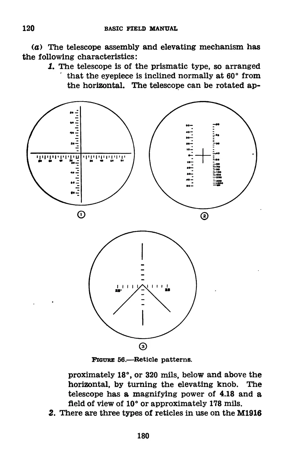
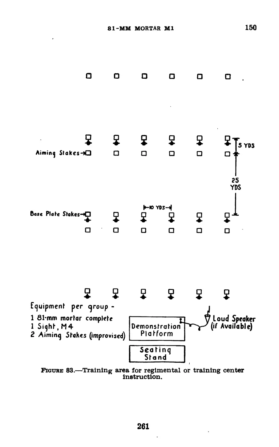
5. Mounting and Dismounting.—a. Base plate position.—
Prior to mounting the mortar, the direction of fire must be
established by the placing of an aiming stake and a base
plate stake to mark the location of the base plate. These
two stakes are placed about 25 yards apart. The mortar may
be fired, usually without impairing its accuracy, by placing
the base plate on top of the ground so that its front edge is
against the base plate stake and its long axis perpendicular to
the direction of fire. The relative position of the base plate
and the two stakes is indicated in figure 5.
The base plate will be firmly seated in average soil by the
recoil of the first two or three rounds. However, when the
mortar is to be mounted on a steep slope or on uneven ground,
it may be necessary to prepare a horizontal surface upon
which the base plate can be placed. The base plate is placed
and alined by No. 3 man of the mortar squad.
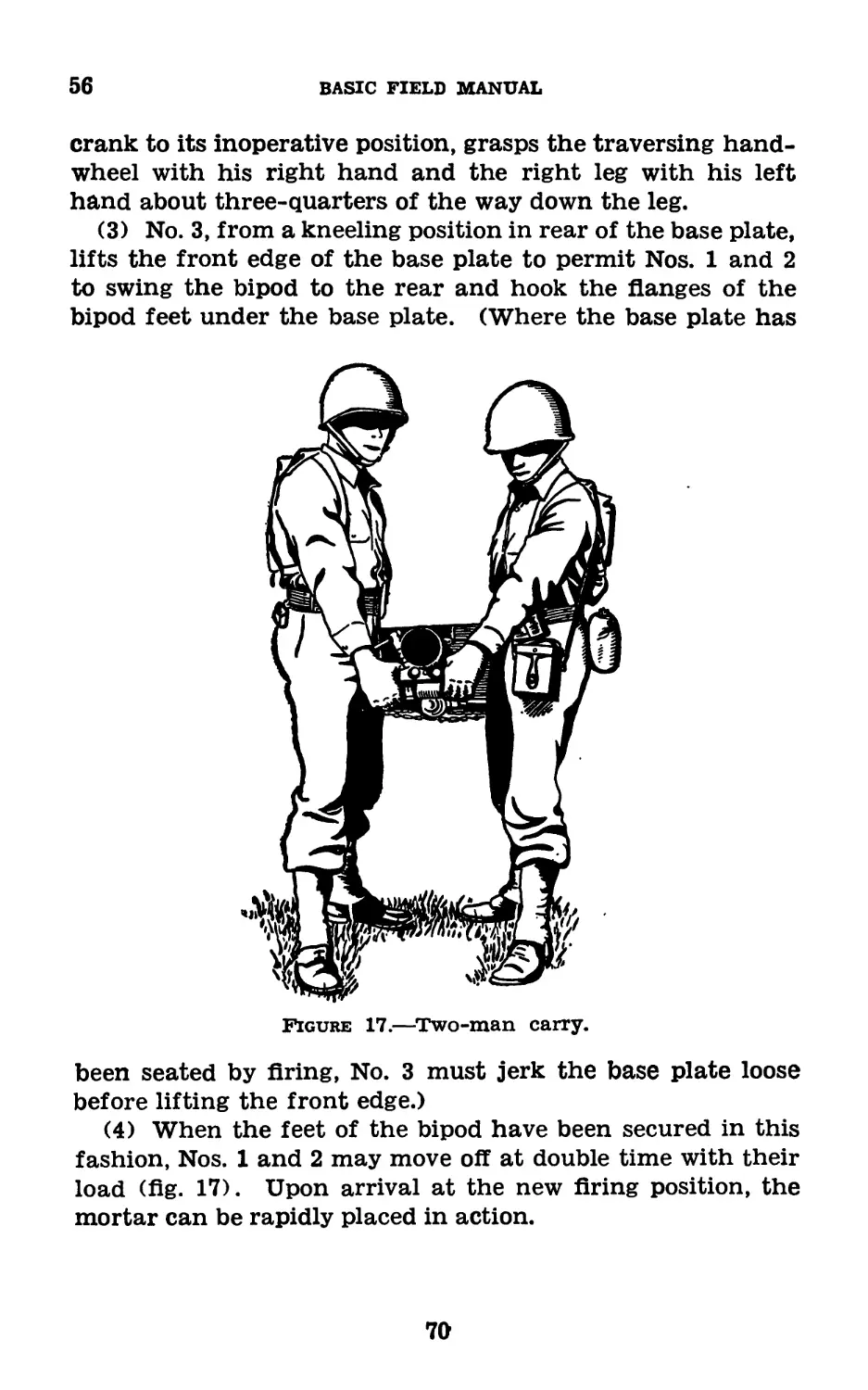
b. To mount the mortar.—(1) After the direction of fire
6
81-MM MORTAR Ml
5
is established and the base plate alined, the gunner (No. 1),
lifts the bipod by placing his left hand on the traversing hand-
wheel and his right hand on the sight slot. He moves to the
front, faces the base plate, and positions the legs approxi-
mately 2 feet in front of the front flange of the base plate.
He does this in such a manner that an extension of the right
edge of the base plate would bisect the interval between the
closed legs. Then, kneeling on his right knee in front of the
bipod and supporting it with his left hand on the gear case,
he unhooks the chain from its hook on the left leg and un-
winds it from the legs. With his right hand, the gunner
selects the end link of the extended chain and rehooks it on
7
5
BASIC FIELD MANUAL
Figure 5.—Alinement of base plate.
8
81-MM MORTAR Ml
5
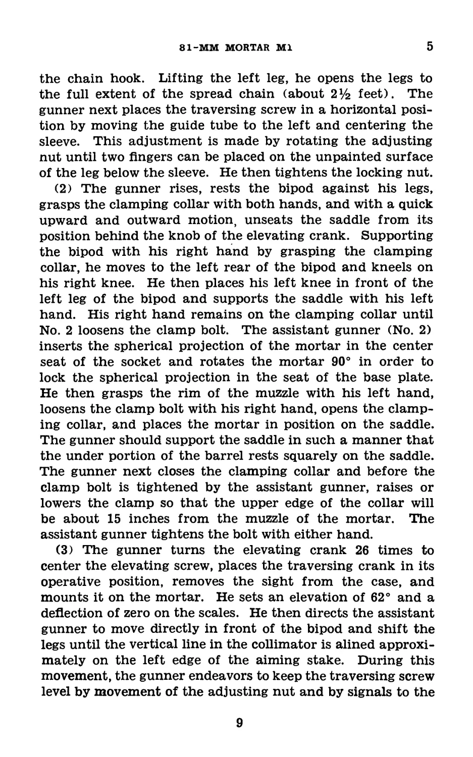
the chain hook. Lifting the left leg, he opens the legs to
the full extent of the spread chain (about 2У2 feet). The
gunner next places the traversing screw in a horizontal posi-
tion by moving the guide tube to the left and centering the
sleeve. This adjustment is made by rotating the adjusting
nut until two fingers can be placed on the unpainted surface
of the leg below the sleeve. He then tightens the locking nut.
(2) The gunner rises, rests the bipod against his legs,
grasps the clamping collar with both hands, and with a quick
upward and outward motion, unseats the saddle from its
position behind the knob of the elevating crank. Supporting
the bipod with his right hand by grasping the clamping
collar, he moves to the left rear of the bipod and kneels on
his right knee. He then places his left knee in front of the
left leg of the bipod and supports the saddle with his left
hand. His right hand remains on the clamping collar until
No. 2 loosens the clamp bolt. The assistant gunner (No. 2)
inserts the spherical projection of the mortar in the center
seat of the socket and rotates the mortar 90° in order to
lock the spherical projection in the seat of the base plate.
He then grasps the rim of the muzzle with his left hand,
loosens the clamp bolt with his right hand, opens the clamp-
ing collar, and places the mortar in position on the saddle.
The gunner should support the saddle in such a manner that
the under portion of the barrel rests squarely on the saddle.
The gunner next closes the clamping collar and before the
clamp bolt is tightened by the assistant gunner, raises or
lowers the clamp so that the upper edge of the collar will
be about 15 inches from the muzzle of the mortar. The
assistant gunner tightens the bolt with either hand.
(3) The gunner turns the elevating crank 26 times to
center the elevating screw, places the traversing crank in its
operative position, removes the sight from the case, and
mounts it on the mortar. He sets an elevation of 62° and a
deflection of zero on the scales. He then directs the assistant
gunner to move directly in front of the bipod and shift the
legs until the vertical line in the collimator is alined approxi-
mately on the left edge of the aiming stake. During this
movement, the gunner endeavors to keep the traversing screw
level by movement of the adjusting nut and by signals to the
9
5-7
BASIC FIELD MANUAL
assistant gunner. He then centers the longitudinal level
bubble, cross-levels with the adjusting nut only, and then
lays accurately for direction by simultaneous operation of
the traversing hand wheel and the adjusting nut. He finally
checks the lay for elevation.
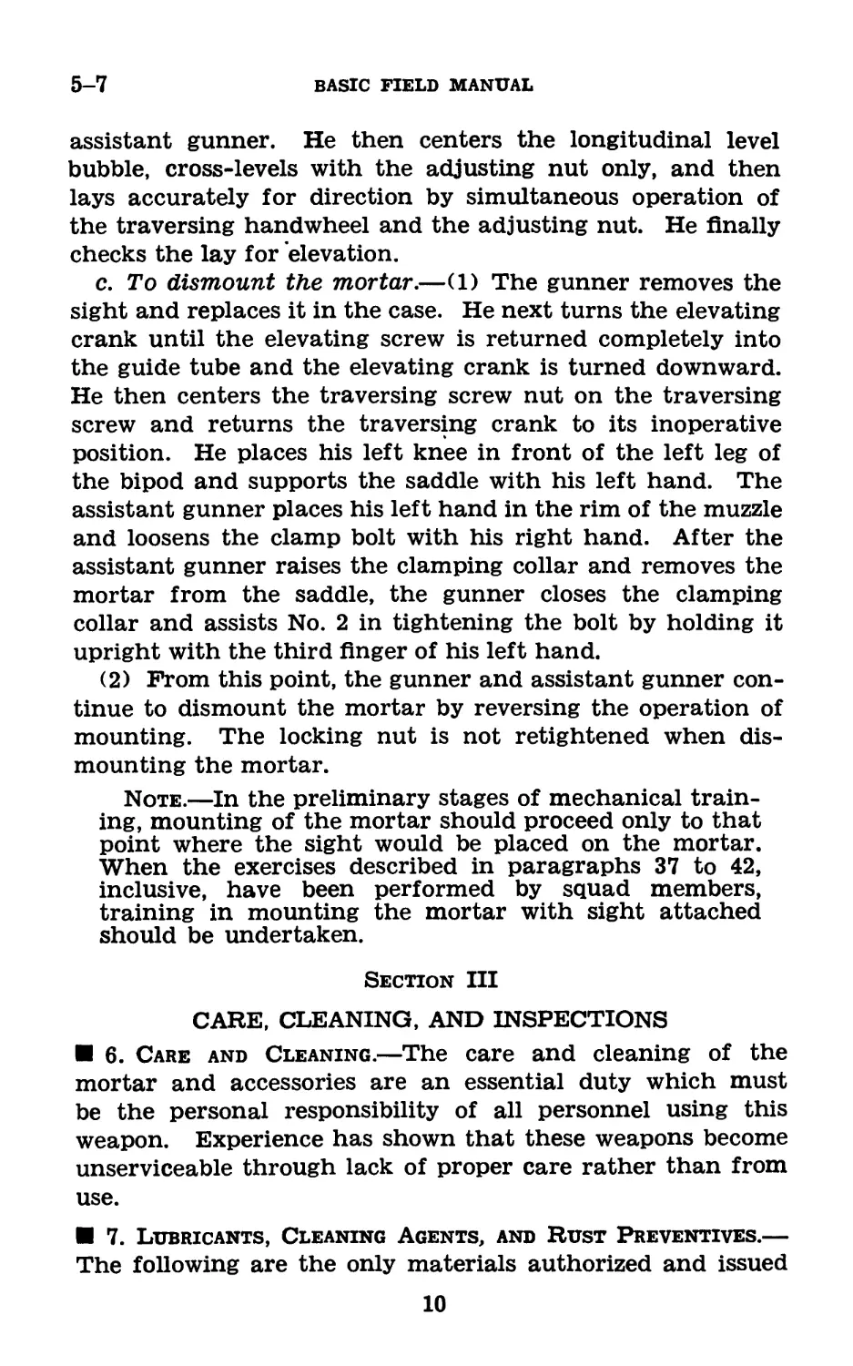
c. To dismount the mortar.—(1) The gunner removes the
sight and replaces it in the case. He next turns the elevating
crank until the elevating screw is returned completely into
the guide tube and the elevating crank is turned downward.
He then centers the traversing screw nut on the traversing
screw and returns the traversing crank to its inoperative
position. He places his left knee in front of the left leg of
the bipod and supports the saddle with his left hand. The
assistant gunner places his left hand in the rim of the muzzle
and loosens the clamp bolt with his right hand. After the
assistant gunner raises the clamping collar and removes the
mortar from the saddle, the gunner closes the clamping
collar and assists No. 2 in tightening the bolt by holding it
upright with the third finger of his left hand.
(2) From this point, the gunner and assistant gunner con-
tinue to dismount the mortar by reversing the operation of
mounting. The locking nut is not retightened when dis-
mounting the mortar.
Note.—In the preliminary stages of mechanical train-
ing, mounting of the mortar should proceed only to that
point where the sight would be placed on the mortar.
When the exercises described in paragraphs 37 to 42,
inclusive, have been performed by squad members,
training in mounting the mortar with sight attached
should be undertaken.
Section III
CARE, CLEANING, AND INSPECTIONS
6. Care and Cleaning.—The care and cleaning of the
mortar and accessories are an essential duty which must
be the personal responsibility of all personnel using this
weapon. Experience has shown that these weapons become
unserviceable through lack of proper care rather than from
use.
7. Lubricants, Cleaning Agents, and Rust Preventives.—
The following are the only materials authorized and issued
10
81-MM MORTAR Ml
7
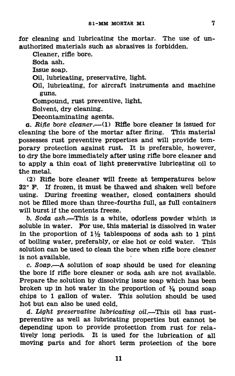
for cleaning and lubricating the mortar. The use of un-
authorized materials such as abrasives is forbidden.
Cleaner, rifle bore.
Soda ash.
Issue soap.
Oil, lubricating, preservative, light.
Oil, lubricating, for aircraft instruments and machine
guns.
Compound, rust preventive, light.
Solvent, dry cleaning.
Decontaminating agents.
a. Rifle Ъогё cleaner.—(1) Rifle bore cleaner is issued for
cleaning the bore of the mortar after firing. This material
possesses rust preventive properties and will provide tem-
porary protection against rust. It is preferable, however,
to dry the bore immediately after using rifle bore cleaner and
to apply a thin coat of light preservative lubricating oil to
the metal.
(2) Rifle bore cleaner will freeze at temperatures below
32° F. If frozen, it must be thawed and shaken well before
using. During freezing weather, closed containers should
not be filled more than three-fourths full, as full containers
will burst if the contents freeze.
b. Soda ash.—This is a white, odorless powder which is
soluble in water. For use, this material is dissolved in water
in the proportion of IV2 tablespoons of soda ash to 1 pint
of boiling water, preferably, or else hot or cold water. This
solution can be used to clean the bore when rifle bore cleaner
is not available.
c. Soap.—A solution of soap should be used for cleaning
the bore if rifle bore cleaner or soda ash are not available.
Prepare the solution by dissolving issue soap which has been
broken up in hot water in the proportion of % pound soap
chips to 1 gallon of water. This solution should be used
hot but can also be used cold.
d. Light preservative lubricating oil.—This oil has rust-
preventive as well as lubricating properties but cannot be
depending upon to provide protection from rust for rela-
tively long periods. It is used for the lubrication of all
moving parts and for short term protection of the bore
11
7-8
BASIC FIELD MANUAL
against rust. Preservative action results partly from the
oily film on the metal parts and partly from chemical com-
bination of inhibitors in the oil with the metal. It will
protect the metal surfaces from rust though no appreciable
film of oil is present on the metal parts. When used on
moving parts it is necessary to maintain a thin film of oil
to provide the necessary lubrication.
e. Lubricating oil for aircraft instruments and machine
guns.—This oil may be used for lubricating the mortar
materiel when light preservative lubricating oil is not avail-
able. It is an extremely light oil which relies entirely upon
maintenance of the oil film to protect metal surfaces from
rusting. When it is used as a preservative, the metal parts
must be inspected daily for rust. They should then be
cleaned and again coated lightly with the oil.
f. Light rust-preventive compound.—This compound is
issued for the protection of metal parts for long periods
of time while the parts are boxed and in storage. It can
be applied with a brush at temperatures above 60° F., but
the preferred method is to apply it hot, either by brushing
or by dipping.
g. Dry-cleaning solvent.—This noncorrosive, petroleum
solvent will remove grease, oil, or rust-preventive compound.
Dry-cleaning solvent is highly inflammable and should not
be used near open flames. Smoking is prohibited where dry-
cleaning solvent is used. It is generally applied with rag
swabs to large parts and used as a bath for small parts.
The surfaces must be thoroughly dried with clean rags im-
mediately after use of the solvent. Gloves should be worn
by persons handling such parts after cleaning to avoid leav-
ing finger marks, which are ordinarily acid and induce cor-
rosion. Dry-cleaning solvent will attack and discolor rubber.
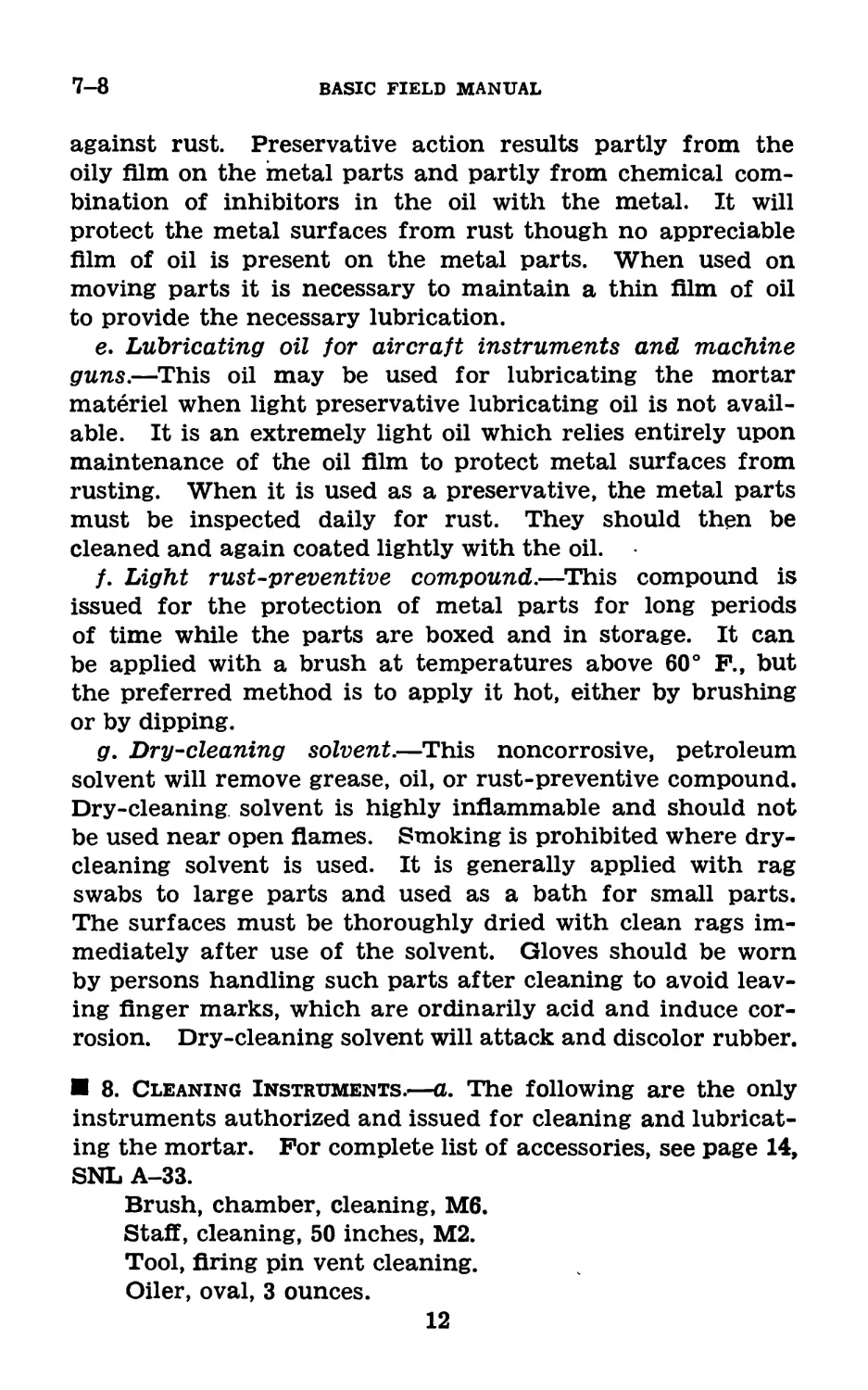
8. Cleaning Instruments.—a. The following are the only
instruments authorized and issued for cleaning and lubricat-
ing the mortar. For complete list of accessories, see page 14,
SNL A-33.
Brush, chamber, cleaning, M6.
Staff, cleaning, 50 inches, М2.
Tool, firing pin vent cleaning.
Oiler, oval, 3 ounces.
12
81-MM MORTAR Ml
8-9
Gun, lubricating, pressure, pistol grip, flush type, 5
ounces.
Staff, cleaning, 6 feet 6 inches, M4 (aluminum). (Staff,
cleaning, 6 feet 6 inches, M8 (wooden) may be issued
in lieu of this item.)
b. See paragraph 36 for description of these instruments.
9. Care and Cleaning When No Firing Is Done.—a. Gen-
eral.—(1) This includes the care necessary to preserve the
condition of the mortar and mount during the time when
no firing is being done.
(2) Mortar materiel in the hands of troops should be
inspected daily to insure proper condition and cleanliness.
Training schedules should allow time for supervised cleaning
on each day this materiel is used.
b. Bore.—(1) To clean the bore, attach cotton waste to the
cleaning staff and insert the waste into the bore at the muz-
zle end. Move the staff forward and backward several times
and replace with clean waste. This cleaning removes ac-
cumulations of dust, dirt, and thickened oil in the bore.
(2) Repeat until the waste comes out clean.
(3) After the bore has been thoroughly cleaned, saturate
clean waste with light preservative lubricating oil and push
it through the bore.
(4) Wash the outside of the barrel with soap solution,
rinse with clean water, and dry.
Caution: When cleaning the bore, be careful not to foul
the waste on the firing pin.
c. Firing pin.—(1) Remove the firing pin.
(2) Wrap cotton waste around the chamber cleaning brush
and insert into the firing pin vent. Clean the vent by moving
the waste back and forth through the vent. Make sure that
the waste goes all the way through the vent. Repeat with
clean waste until the waste comes out clean.
(3) After the vent has been thoroughly cleaned, saturate-
clean waste with light preservative lubricating oil and push
it in the out of the vent.
(4) Clean the firing pin with waste.
(5) Oil the firing pin with clean waste which is wet with
light preservative lubricating oil.
13
517120°—43---2
9-11
BASIC FIELD MANUAL
(6) Check the threads in the base cap and on the firing
pin to make sure that no lint is present.
(7) Assemble the firing pin to the base cap.
d. Mount.—(1) All parts of the bipod and base plate must
be kept clean and free from foreign matter. All moving
parts and polished surfaces must be kept coated with oil.
(2) To clean the screw threads and crevices, use a small
cleaning brush or small stick.
(3) To clean the metal surfaces, rub with a dry cloth to
remove moisture, perspiration, and dirt. Then wipe with a
cloth wet with a small quantity of light preservative lubricat-
ing oil. This protective film must be maintained at all times.
(4) For oiling parts of the bipod, seven flush-type lubri-
cating fittings have been provided. They are found as
follows:
One on connecting rod bracket.
One on gear case.
One on rear half of the left leg clevis.
One on leg clevis, retainer, rear.
Three in yoke.
When oiling is required, apply light preservative lubricating
oil to these points by means of the lubricating gun.
10. Preparatory to Firing.—Before firing, take the follow-
ing steps to insure .efficient functioning of the mortar:
a. Inspect the three units.
b. Clean the bore and firing pin with clean, dry waste.
Do not apply any oil to these parts before firing.
c. Thoroughly clean and lightly oil all metal moving parts
with light preservative lubricating oil. Do not use grease.
d. Mount the mortar for firing.
11. After Firing.—a. General.—(1) The bores of all mor-
tars must be thoroughly cleaned by the evening of the day
in which they are fired. They should be cleaned in the
same manner for the next 3 days.
(2) Firing the mortar causes powder and primer fouling
to collect in the bore and on the firing pin. This fouling
.absorbs and retains moisture from the air, thereby causing
rust. These deposits can be removed by cleaning with rifle
hore cleaner, soda ash solution, soap solution, or water.
14
81-MM MORTAR Ml
11
b. Cleaning procedure after firing.—(1) Clean bore (c or
d below) and all working parts. If this cannot be done at
once, apply oil carefully to prevent rust.
(2) At the first opportunity, clean, oil, and inspect all
parts and make needed repairs and replacements.
(3) On assembly, check operation of the bipod to insure
that functioning is correct.
c. Cleaning bore with rifle bore cleaner.—(1) Remove the
firing pin.
(2) Assemble clean cotton waste to the cleaning staff and
saturate the waste with rifle bore cleaner. Insert the waste
into the muzzle and push it back and forth through the
bore of the barrel by means of the cleaning staff.
(3) Repeat the operation with clean waste two or three
times. Care should be used to insure that the swab goes
all the way through the bore before the direction is changed.
(4) Follow this with dry waste until it comes out clean
and dry.
(5) Examine the bore carefully for cleanliness. If it is not
free of all residue, repeat the cleaning process.
(6) Clean the firing pin with a rag saturated with rifle bore
cleaner. Dry the firing pin.
(7) Wrap cotton waste around the chamber cleaning brush
and saturate it with rifle bore cleaner. Clean the vent by
pushing the waste back and forth through the vent. Repeat
with clean waste several times. Follow this with dry waste
until it comes out clean and dry.
(8) When the vent and bore are both thoroughly clean and
dry, apply light preservative lubricating oil to them by means
of waste.
(9) Make sure no lint is on the firing pin threads, oil the
pin, and replace it in the base cap.
d. Cleaning the bore with soda ash or soap solution.—(1)
Use soda ash solution if rifle bore cleaner is not available, and
soap solution or plain water if neither of these is available.
(2) Clean the vent and firing pin as described in c (9)
above, using a liberal quantity of the soda ash or soap solu-
tion in place of the rifle bore cleaner.
(3) Rinse the parts with clean water to remove the wash-
ing material.
15
11-12
BASIC FIELD MANUAL
(4) Dry the parts by using clean waste. Thoroughly swab
barrel until it is perfectly dry and clean.
(5) When the bore, vent, and firing pin are clean and dry,
saturate waste in light preservative lubricating oil and push
it through th? bore. Oil the vent and firing pin and assem-
ble the pin to the base cap.
e. Mount.—(1) Wipe the bipod clean, taking care to re-
move dirt from all crevices. Thoroughly clean all moving
parts with dry-cleaning solvent, using a small stick covered
with waste to remove dirt from all recesses.
(2) Dry all parts thoroughly.
(3) Wipe all moving parts and polished surfaces with a
rag wet with light preservative lubricating oil.
(4) Apply light preservative lubricating oil to the seven
flush-type lubricating fittings.
(5) Operate the handwheel and cranks so as to distribute
the oil over the working surfaces.
f. Exterior surfaces.—Wipe off exterior of the mortar with
a dry cloth to remove dampness, dirt, and perspiration.
g. Accessories.—Inspect, clean, and oil the accessories.
h. Complete cleaning.—Complete cleaning should be ac-
complished as soon as possible after firing. If the mortar
is not to be fired in the next few days, repeat the procedure
outlined above for 3 days.
12. On the Range or in the Field.—The mortar must be
kept clean and properly lubricated. To obtain its maximum
efficiency, the following points must be observed:
a. Never fire a mortar with any dust, dirt, mud, or snow
in the bore.
b. Keep the bore free from oil and dirt when firing.
c. Never leave waste or other obstruction in the bore or
on the firing pin.
d. If the bipod gives indication of lack of lubrication and
excessive friction, apply additional oil to the parts subjected
to this friction.
e. All sliding surfaces should be oiled frequently and freely
to insure perfect functioning of the mount.
f. In general, it should not be necessary to remove any
of the parts of the bipod in the field for cleaning. However,
16
81-MM MORTAR Ml
12-13
if the mechanism of the bipod becomes very dirty, it should
be disassembled for the necessary cleaning and lubrication
by ordnance personnel.
g. In emergencies when the prescribed lubricant is not
available, use lubricating oil for aircraft instruments and
machine guns or any clean, light mineral oil such as engine
oil.
13. Preparation for Storage.—a. Light preservative lubri-
cating oil is the most suitable oil for short-time protection
of the mechanism of the mortar. It is effective for storage
for periods of 2 to 6 weeks, depending on climatic conditions.
However, mortars in short-time storage must be inspected
every 5 days, and the preservative film should be renewed if
necessary. For longer periods of time, they will be protected
with light rust-preventive compound.
b. Light rust-preventive compound is a semisolid material.
It is efficient for preserving the polished surfaces and the
bore for a period of 1 year or less, depending upon climatic
and storage conditions.
c. The mortar should be cleaned and prepared for storage
with particular care. The bore, all parts of the bipod, and
the exterior of the mortar should be thoroughly cleaned with
dry-cleaning solvent and then dried completely with clean
rags. In damp climates particular care must be taken to
see that the rags are dry. After drying a metal part the
bare hands should not touch that part. All metal parts
should then be coated with either light preservative lubricat-
ing oil or light rust-preventive compound, depending on the
length of storage required. Application of the rust-preven-
tive compound to the bore is best done by dipping waste in
the compound and running it through the bore two or three
times by means of the staff. The firing pin and base cap
should be removed, thoroughly coated with rust-preventive
compound, and then reassembled. The wooden supports of
the packing box must be painted with rust-preventive com-
pound before storing the mortar. Place it in the wooden
packing box, handling it with oiled rags. Under no circum-
stances will a mortar be placed in storage while contained
in a cloth or other cover, or with a plug in the bore. Such
covers collect moisture, which causes the weapon to rust.
17
14-15
BASIC FIELD MANUAL
14. Cleaning Weapons Received From Storage.—Weapons
which have been stored in accordance with the preceding
paragraphs will be coated either with light preservative lu-
bricating oil or with light rust-preventive compounds.
Weapons received from ordnance storage will in general be
coated with rust-preventive compound. Use dry-cleaning
solvent to dissolve and remove all traces of the compound or
oil. Take particular care that all small parts and springs
are cleaned thoroughly. Failure to do this may cause stiff
or slow action at normal temperatures and will certainly do
so when the rust-preventive compound congeals at low
temperatures. After using this cleaning solvent, be sure to
dry all parts by wiping with dry cloths. Then follow the
instructions in paragraph 9.
15. Care and Cleaning Under Unusual Conditions.—a. In
cold climates.—(1) It is necessary that the moving parts of
the weapon be kept absolutely free from moisture. It also
has been found that excess oil or rust-preventive compound
on the working parts will solidify to such an extent as to
cause sluggish operation or complete failure.
(2) Clean all parts thoroughly with dry-cleaning solvent
before use in temperatures below 0° F. The working sur-
faces or parts which show signs of wear may be lubricated
by rubbing with a cloth which has been saturated with light
preservative lubricating oil and wrung out.
(3) When brought indoors, the materiel should first be
allowed to come to room temperature. It should then be
wiped completely dry of the moisture which will have con-
densed on the cold metal surfaces and oiled thoroughly with
light preservative lubricating oil.
(4) If possible, such condensation should be avoided by
providing a cold place in which to keep the mortar when
not in use, for example, a separate cold room, or when in the
field, proper cover set up outdoors.
(5) If the mortar has been fired, it should be thoroughly
cleaned and oiled. The bore may be swabbed out with oily
waste, and when the weapon reaches room temperature,
thoroughly cleaned and oiled as described in paragraph 11.
18
81-MM MORTAR Ml
15-16
(6) Before firing, the weapon should be cleaned and oiled
as described in paragraph 10.
(7) The bore and firing pin should be entirely free of oil
before firing.
b. In tropical climates.—(1) In tropical climates where
temperature and humidity are high, or where salt air is
present, and during rainy seasons, the weapon should be
inspected thoroughly every day and kept lightly oiled when
not in use.
(2) Care should be exercised to see that unexposed parts
and surfaces are kept clean and oiled.
(3) Light preservative lubricating oil should be used for
lubrication.
c. In hot, dry climates.—(1) In hot, dry climates where
sand and dust are apt to get into the mechanism and bore,
the weapons should be wiped clean daily, or oftener if
necessary.
(2) When the weapon is being used under sandy condi-
tions, all lubricant should be wiped from the mat£riel. This
will prevent sand carried by the wind from sticking to the
lubricant and forming an abrasive compound which will ruin
the mechanism.
(3) Immediately upon leaving sandy terrain, the weapon
must be relubricated with light preservative lubricating oil.
(4) Perspiration from the hands is a contributing factor
to rust because it contains acid. Consequently metal parts
should be wiped dry frequently.
(5) During sand or dust storms, the muzzle should be kept
covered whenever possible.
16. Care During Gas Attack.—a. (1) It is important to
prevent the chemicals used in a gas attack from getting in
or on the mortar and ammunition. When a gas attack is
anticipated, steps will be taken to cover and protect the
mortar, ammunition, bipod, spare parts, and accessories.
(2) Apply oil to the surfaces of all the parts of the weapon,
ammunition, and spare parts.
(3) If the mortar is not to be used during the gas attack,
the oiled weapon should be covered or placed in a container
so that it cannot come into contact with any contaminating
chemicals.
19
16-17
BASIC FIELD MANUAL
(4) After the attack, if the materiel has not been con-
taminated, it should be cleaned with dry-cleaning solvent.
(5) Prepare for use as described in paragraph 9 or 10
according to requirements.
b. Decontamination.—(1) A complete suit of impermeable
clothing and a service gas mask must be worn for decon-
tamination.
(2) Materiel contaminated with chemicals other than mus-
tard or lewisite must be cleaned as soon as possible with dry-
cleaning solvent or denatured alcohol.
(3) Do not allow the chemical agents to come into contact
with the skin. Always burn or bury all rags or wiping ma-
terials used for decontamination. Extreme caution should
be taken to protect men against fumes created by burning.
(4) If the surface of the materiel is coated with grease or
oil and has been in a mustard or lewisite attack, first remove
the grease or oil by wiping with rags saturated with dry-
cleaning solvent.
(5) Decontaminate unpainted metal surfaces with a solu-
tion of agent, decontaminating, noncorrosive. Prepare this
by mixing 1 part of agent, decontaminating, noncorrosive, to
15 parts solvent (acetylene tetrachloride) by weight.
(6) Decontaminate painted surfaces with a bleaching solu-
tion. Prepare this by mixing equal parts by weight of agent,
decontaminating (chloride of lime) and water.
(7) After decontamination, clean the materiel thoroughly
and prepare for use as described in paragraph 9 or 10 accord-
ing to requirements.
c. References.—Detailed information on decontamination
is contained in PM 21-40, TM 9-850 and 3-220.
17. Inspection.—The following instructions with reference
to inspection will be carefully observed by all concerned:
Points to be inspected
in order of inspection Points to observe
a. Mortar. a. Note general appearance and clean-
liness of the bore.
b, Firing pin. b. Examine for fouling, rust, or for-
eign substance on the point.
20
81-MM MORTAR Ml
17-19
Points to be inspected
in order of inspection Points to observe
c. Bipod. c. Note general appearance. Oil fit- tings should be encircled by a red ring. All moving parts should be properly lubricated.
(1) Elevating mechanism. (1) Elevate and depress the mortar. The mechanism should operate without binding, excess play, or undue backlash.
(2) Traversing mechanism. (2) Traverse the mortar. The mech- anism should operate smoothly without binding or undue backlash.
(3) Cross-level- ing mech- anism. (3) Operate the mechanism. It should function properly without excess play. The level vial should be clear, and index marks for centering the bubble should be distinct.
d. Base plate. d. Note general appearance. The edges of the free recesses in the socket should be smooth and without bur.
e. Sight and its mounting. e. Note whether the operating condi- tion of the sight or rigidity of its mount- ing has been impaired. (See TM 9-60.)
Section IV
SIGHTING EQUIPMENT
18. Aiming Posts.—a. Aiming posts are supplied with the
81-mm mortar Ml as follows:
1 aiming post M7, 3 feet 10 inches long, for pack trans-
port only.
1 aiming post M9, 2 feet long, for all uses.
1 aiming post M8, 6 feet long, for other than pack
transport.
b. In addition to the issued aiming posts, it is advisable
to have available with the squad equipment at least three
improvised wooden aiming stakes. These may be prepared
locally with approximately the following dimensions: 2 inches
x 1 inch x 3 feet.
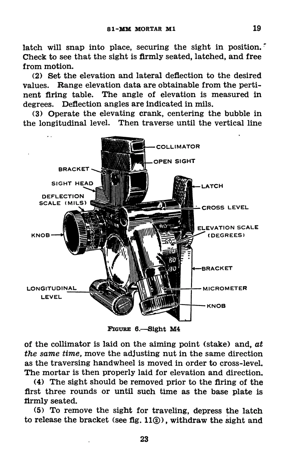
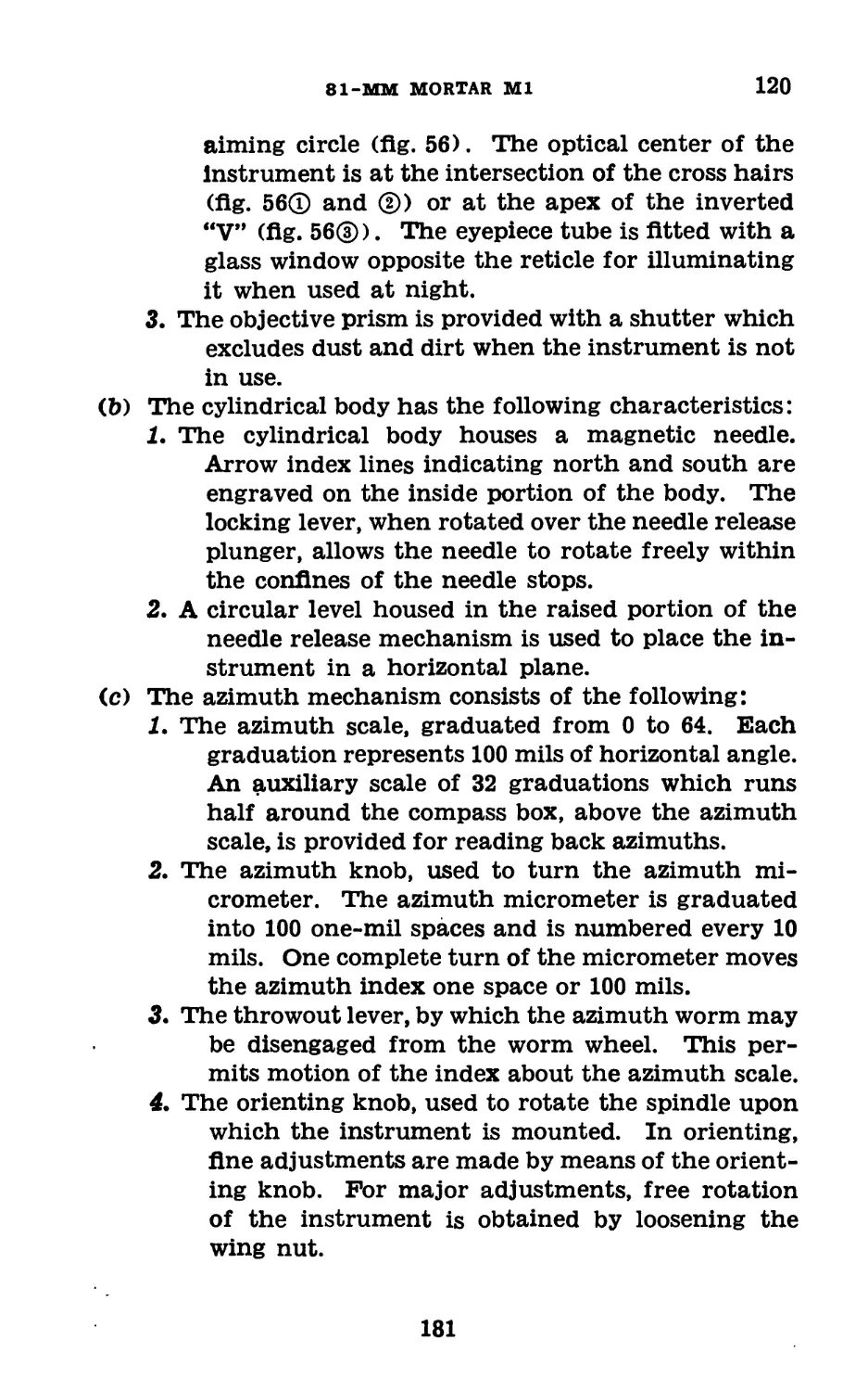
19. Sight M4 (fig 6).—a. General description.—The sight
M4, provided with the 81-mm mortar for laying in elevation
21
19
BASIC FIELD MANUAL
and direction, is likewise the standard sight for the 60-mm
mortar. The sight includes a collimator, elevating and
lateral deflection mechanisms, and longitudinal and cross
levels, all supported by a bracket with a dovetailed base which
fits in a slot in the mortar yoke and latches in place. The
levels when centered indicate the elevation and deflection
angles, respectively, to be measured in true vertical and hori-
zontal planes. The longitudinal level also provides a datum
line for elevation settings. The collimator, the direction
sighting device of the sight, consists of a vertical translucent
line in the opaque field of the eyepiece, inclosed within a
rectangular tube. When the sight is level, the collimator
establishes a vertical line in the field of view, the line of
sight with a normal lateral deflection setting being parallel
to the plane of fire. The bracket upon which the collimator
and open sight are mounted can be pivoted so that the assem-
bly may be moved in elevation as required to bring the aiming
point into the field of view; this motion has no effect on
elevation indications. The sight is removed for traveling,
and a carrying case for it is provided.
b. Detailed description, sight M4.—This sight (fig. 6) is
now furnished with the 81-mm mortar Ml. Elevation in
degrees is indicated on the elevation scale, graduated in 10°
steps, supplemented by a micrometer graduated in 14° steps.
Deflection in mils is indicated on the deflection scale, which
is graduated in 5-mil steps. Directions of motion for left
and right deflections are indicated by the letters L and R and
arrows near the index. Deflection is limited to ±150 mils,
and a zero indication corresponds to the normal setting (line
of sight parallel to the plane of fire). The collimator and
the open sight directly below it have vertical reference lines
and may be placed as desired in elevation. With the col-
limator moved to the extreme rear and an elevation setting
of 40°, the elevation of the overhead portion of the open
sight is 2° below the axis of the mortar tube, a feature of
service in determining the approximate minimum elevation
for clearing nearby objects.
c. Operation.—(1) Remove the sight from the carrying
case and insert the dovetailed base of the bracket in the slot
of the mortar yoke. When the sight is fully inserted, the
22
81-MM MORTAR Ml
19
latch will snap into place, securing the sight in position.r
Check to see that the sight is firmly seated, latched, and free
from motion.
(2) Set the elevation and lateral deflection to the desired
values. Range elevation data are obtainable from the perti-
nent firing table. The angle of elevation is measured in
degrees. Deflection angles are indicated in mils.
(3) Operate the elevating crank, centering the bubble in
the longitudinal level. Then traverse until the vertical line
Figure 6.—Sight M4
of the collimator is laid on the aiming point (stake) and, at
the same time, move the adjusting nut in the same direction
as the traversing handwheel is moved in order to cross-level.
The mortar is then properly laid for elevation and direction.
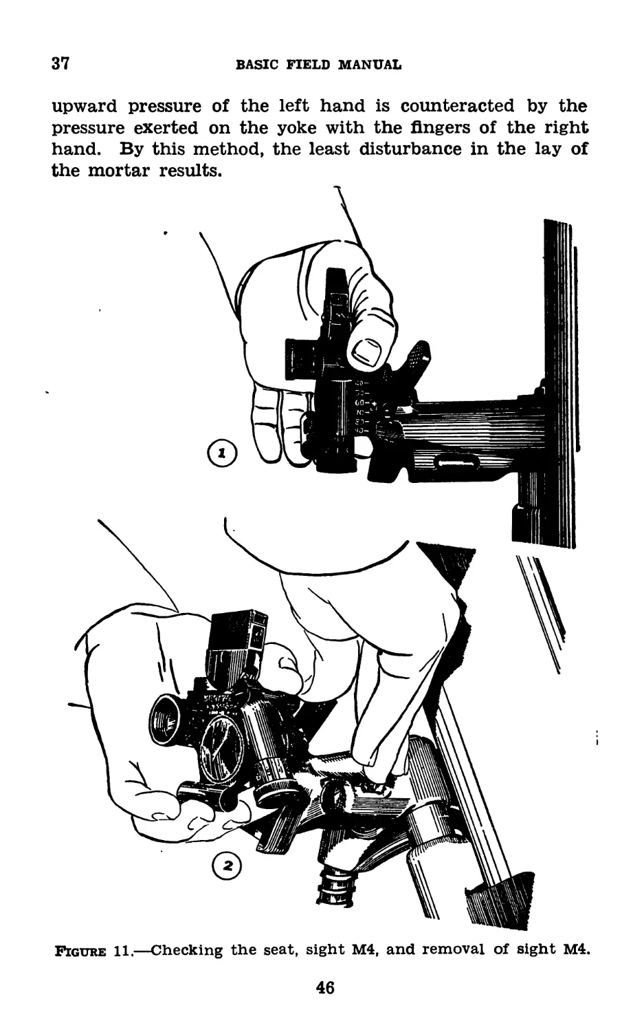
(4) The sight should be removed prior to the firing of the
first three rounds or until such time as the base plate is
firmly seated.
(5) To remove the sight for traveling, depress the latch
to release the bracket (see fig. 11®), withdraw the sight and
23
19
BASIC FIELD MANUAL
place it in the carrying case provided, with the elevation
scale set at 40°.
d. Tests and adjustments.—Proper alinement of the levels,
pivots, and collimator is accomplished at the factory. No
facilities are ordinarily available for verification in the field,
and no adjustment by the using arm is permitted.
e. Care and preservation.—(1) The sight is a rugged in-
strument but will not stand abuse or rough handling. Inac-
curacy of malfunctioning will result from such mistreatment.
Care must be taken to avoid striking or otherwise injuring any
part of the sight—particularly burring or denting the locating
surface of the sight bracket and mortar yoke.
(2) When it is not in use, the sight should be kept in the
carrying case provided. It is essential that the sight be kept
as dry as possible and that it is never placed in the carrying
case while wet.
(3) Any sight which fails to indicate or function correctly
is to be turned in for repair by competent ordnance personnel.
(4) No painting of the sight by the using arm is permitted.
(5) Elevation and deflection mechanisms have stops limit-
ing their motion. Do not attempt to turn the knobs beyond
these limits.
(6) No disassembly of the sight by the using arm is per-
mitted.
(7) Keep the optical parts of the collimator clean and dry.
For wiping these parts, use lens tissue paper. The use of
polishing liquids, pastes, or abrasives is prohibited for polish-
ing optical parts.
(8) Occasionally oil the exposed moving parts of the sight
with a small quantity of light preservative lubricating oil or
lubricating oil for aircraft instruments and machine guns.
Keep the dovetailed surface of the bracket and the mating
surface of the mortar yoke thinly coated with light pre-
servative lubricating oil or light rust-preventive compound.
To prevent accumulation of dust and grit, wipe off excess
lubricant that seeps from moving parts.
24
81-MM MORTAR Ml
20-23
Section V
AMMUNITION
20. General.—The information in this section pertaining
to several types of semifixed complete rounds authorized for
use in the 81-mm mortar Ml includes a description of the
round, means of identification, care, use, and ballistic data.
21. Classification.—Based upon use, the principal classi-
fications of ammunition for the mortar are—
a. High explosive, light, for use against personnel (fig.
7®).
b. High explosive, heavy, for demolitions against shelters
and accessory defenses (fig. 7®).
c. Smoke, for blinding enemy observation (similar in con-
struction and appearance to the shell, M56).
d. Practice, for training purposes.
22. Ammunition Lot Number.—When ammunition is man-
ufactured, an ammunition lot number, which becomes an
essential part of the marking, is assigned in accordance with
pertinent specifications. This ammunition lot number is
stamped or marked on every loaded complete round, on pack-
ing containers, and on the accompanying ammunition data
card. It is required for all purposes of record, including
reports on condition, functioning, and accidents in which the
ammunition might be involved.
23. Identification.—a. Marking on fiber containers.—The
contents of fiber containers are readily identified by the
markings. Additional data pertaining to the round con-
tained therein are included on the ammunition data card
packed with the round in the fiber container.
b. Color of projectiles.—All projectiles are painted to pre-
vent rust and, by means of the color, to provide a ready
method of identification as to type. The color scheme is
as follows:
(1) High explosive projectiles, yellow.
(2) Smoke projectiles, gray with narrow yellow band.
(3) Practice, blue.
(4) Training, black.
25
23-24
BASIC FIELD MANUAL
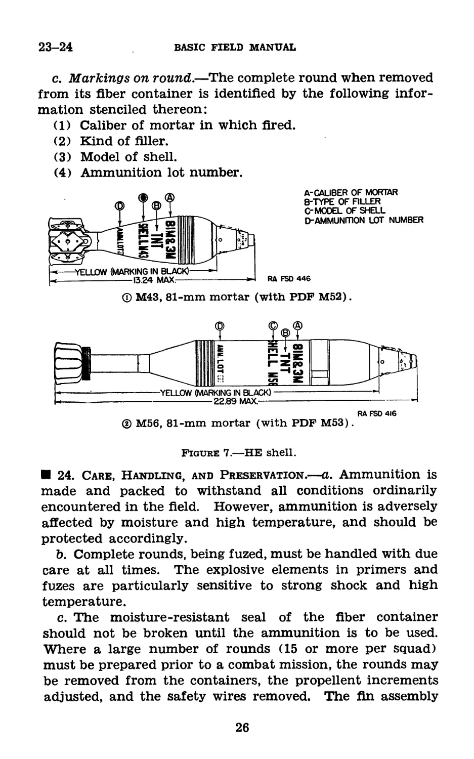
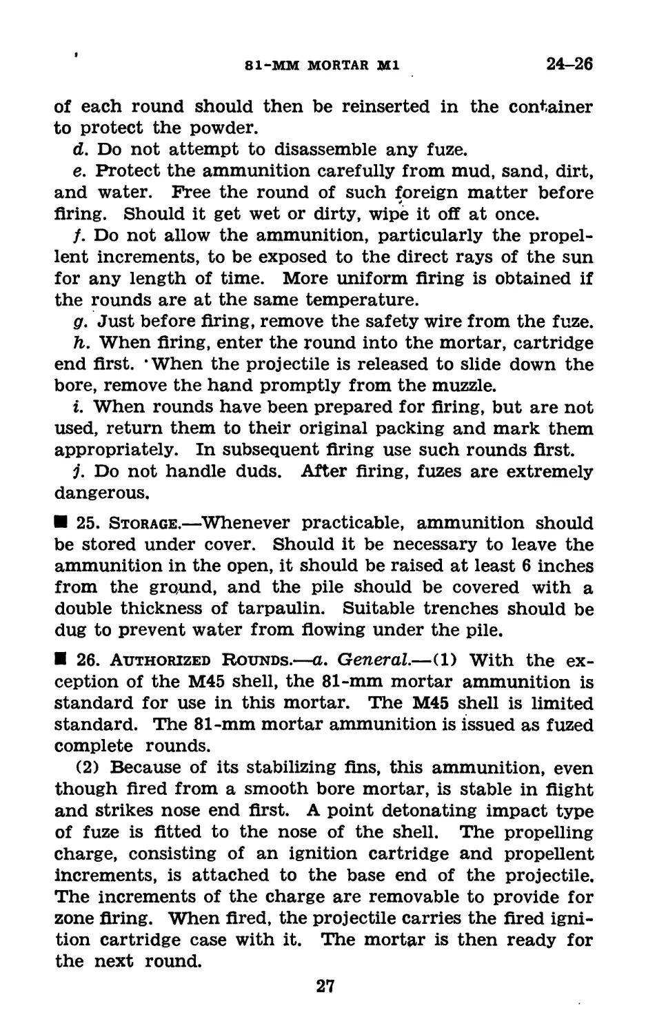
c. Markings on round.—The complete round when removed
from its fiber container is identified by the following infor-
mation stenciled thereon:
(1) Caliber of mortar in which fired.
(2) Kind of filler.
(3) Model of shell.
(4) Ammunition lot number.
A-CAUBER OF MORTAR
B-TYPE OF FILLER
C-MODEL OF SHELL
□"AMMUNITION LOT NUMBER
RA FSO 446
ф M43, 81-mm mortar (with PDF M52).
RAFSD4I6
(2) M56, 81-mm mortar (with PDF M53).
Figure 7.—HE shell.
24. Care, Handling, and Preservation.—a. Ammunition is
made and packed to withstand all conditions ordinarily
encountered in the field. However, ammunition is adversely
affected by moisture and high temperature, and should be
protected accordingly.
b. Complete rounds, being fuzed, must be handled with due
care at all times. The explosive elements in primers and
fuzes are particularly sensitive to strong shock and high
temperature.
c. The moisture-resistant seal of the fiber container
should not be broken until the ammunition is to be used.
Where a large number of rounds (15 or more per squad)
must be prepared prior to a combat mission, the rounds may
be removed from the containers, the propellent increments
adjusted, and the safety wires removed. The fin assembly
26
81-MM MORTAR Ml
24-26
of each round should then be reinserted in the container
to protect the powder.
d. Do not attempt to disassemble any fuze.
e. Protect the ammunition carefully from mud, sand, dirt,
and water. Free the round of such foreign matter before
firing. Should it get wet or dirty, wipe it off at once.
/. Do not allow the ammunition, particularly the propel-
lent increments, to be exposed to the direct rays of the sun
for any length of time. More uniform firing is obtained if
the rounds are at the same temperature.
g. Just before firing, remove the safety wire from the fuze.
h. When firing, enter the round into the mortar, cartridge
end first. ’When the projectile is released to slide down the
bore, remove the hand promptly from the muzzle.
i. When rounds have been prepared for firing, but are not
used, return them to their original packing and mark them
appropriately. In subsequent firing use such rounds first.
j. Do not handle duds. After firing, fuzes are extremely
dangerous.
25. Storage.—Whenever practicable, ammunition should
be stored under cover. Should it be necessary to leave the
ammunition in the open, it should be raised at least 6 inches
from the ground, and the pile should be covered with a
double thickness of tarpaulin. Suitable trenches should be
dug to prevent water from flowing under the pile.
26. Authorized Rounds.—a. General.—(1) With the ex-
ception of the M45 shell, the 81-mm mortar ammunition is
standard for use in this mortar. The M45 shell is limited
standard. The 81-mm mortar ammunition is issued as fuzed
complete rounds.
(2) Because of its stabilizing fins, this ammunition, even
though fired from a smooth bore mortar, is stable in flight
and strikes nose end first. A point detonating impact type
of fuze is fitted to the nose of the shell. The propelling
charge, consisting of an ignition cartridge and propellent
increments, is attached to the base end of the projectile.
The increments of the charge are removable to provide for
zone firing. When fired, the projectile carries the fired igni-
tion cartridge case with it. The mortar is then ready for
the next round.
27
26—27
BASIC FIELD MANUAL
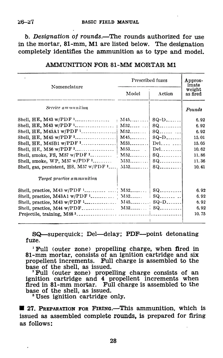
b. Designation of rounds.—The rounds authorized for use
in the mortar, 81-mm, Ml are listed below. The designation
completely identifies the ammunition as to type and model.
AMMUNITION FOR 81-MM MORTAR Ml
Nomenclature Prescribed fuzes Approx- imate weight as fired
Model Action
Service a m m n n it ion Pounds
Shell, HE, M43 w/PDF > , M45 SQ-D 6.92
Shell, HE, M43 w/PDF i । M52 SQ 6.92
Shell, HE, M43A1 w/PDF i M52 SQ ... 6.92
Shell, HE, M45 w/PDF 2 M45 SQ-D 15.01
Shell, HE, M45B1 w/PDF 2 M53 Del 15.05
Shell, HE, M56 w/PDF 2 M53 . Del 10. 62
Shell, smoke, FS, M57 w/PDF 2 M52 SQ 11.86
Shell, smoke, WP, M57 w/PDF 2 M52 SQ 11.36
Shell, gas, persistent, HS, M57 w/PDF 2— SQ 10.41
Target 'practice ammunition । M52
Shell, practice, M43 w/PDF 1 ; M52 SQ 6.92
Shell, practice, M43A1 w/PDF 1 ; M52 i SQ 6.92
Shell, practice, M43 w/PDF 1 M45 . SQ-D 6.92
Shell, practice, M44 w/PDF M52 ; sq 6.92
Projectile, training, M68 3 — 1 10. 75
SQ—superquick; Del—delay; PDF—point detonating
fuze.
1 Full (outer zone) propelling charge, when fired in
81-mm mortar, consists of an ignition cartridge and six
propellent increments. Full charge is assembled to the
base of the shell, as issued.
2 Full (outer zone) propelling charge consists of an
ignition cartridge and 4 propellent increments when
fired in 81-mm mortar. Full charge is assembled to the
base of the shell, as issued.
3 Uses ignition cartridge only.
27. Preparation for Firing.—This ammunition, which is
issued as assembled complete rounds, is prepared for firing
as follows:
28
81-MM MORTAR Ml
27-29
a. Adjust propelling charge for the zone to be fired
(par. 28).
b. Remove safety wire from fuze (par. 54).
28. Propelling Charges.—a. General.—The propelling
charges for mortar ammunition are divided into parts to pro-
vide for zone firing.
Ъ. M43 shell.—The full (outer zone) charge consists of an
ignition cartridge and six equal increments (bundles of sheet
powder or capsules of granular powder) assembled to the
base of the round as issued. One increment is fitted into
each of the spaces between the blades of the fin. To pre-
pare the charge for firing inner zones, it is only necessary
to remove those increments not required. This shell is
limited standard.
с. M45 shell.—The full (outer zone) charge consists of
an ignition cartridge and four equal propellent increments
(bundles of sheet powder or capsules of granular powder)
assembled to the base of the round as issued. One incre-
ment is fitted into each of the four spaces between the blades
of the fin. To prepare the charge for firing inner zones it is
only necessary to remove those increments not required.
d. M56 and M57 shell.—The full (outer zone) charge con-
sists of an ignition cartridge and four propellent increments
(bundles of sheet powder) assembled to the base of the
round as issued. The increments are held against the for-
ward edge of the fin by means of a propellent holdfer. To
prepare the charge for firing inner zones it is only necessary
to remove those increments not required.
Note.—Unused increments will be destroyed at the
firing line by burning. Because of high combustibility,
extreme care should be taken in igniting the increments.
e. M68 training projectile.—An ignition cartridge is the
only propelling charge provided for this projectile.
29. Fuzes M52 and M53.—a. General.—Fuzes used on
81-mm shells are classified as bore-safe (detonator-safe),
that is, they are fitted with safety devices by which the ex-
plosive train is so interrupted that prior to firing and subse-
quent to firing, while the projectile is still in the barrel of the
517120°—43-
-3
29
29
BASIC FIELD MANUAL
mortar, premature action of the bursting charge is prevented
should any of the more sensitive elements, the primer or det-
onator, malfunction.
b. Types.—(1) The superquick fuze (M52) is designed to
function before any penetration occurs, permitting the maxi-
mum surface effect of fragmentation of the shell.
(2) The delay fuze (M53) is designed to allow penetration
of targets before detonating, thereby producing a demolition
effect.
c. Safety features and functioning of fuze M52 (fig. 8).—
(1) Safety features.—(a) The safety wire inserted through
the body of the fuze and the set-back pin, thereby locking all
moveable parts in their original safe position. The safety
wire is pulled just prior to firing.
(b) The set-back pin, held in place by the safety wire, in
turn locks the safety pin in position. The set-back pin is sup-
ported by a spring and is positioned in a recess of the safety
pin. Until the set-back pin moves out of this, recess, the
safety pin is locked in the body of the fuze.
(c) The safety pin, held in place by the set-back pin, is the
main locking device of the fuze. It holds the slider (which
contains the primer and detonator) in its retracted position
and prevents premature alinement of the various elements of
the powder train.
(2) Functioning.—(a) The fuze M52 is not armed until the
primer and slider detonator are alined with the firing pin
and booster lead. The first step in the arming of the fuze
is the removal of the safety wire just before firing. The
shell, when inserted in the barrel, slides down until the
primer of the ignition cartridge strikes the firing pin of the
mortar. The combined forces of the shell striking the breech
of the mortar and the blow delivered to the shell by the pro-
pelling charge gases cause the inertia of the set-back pin to
overcome the resistance of the set-back pin spring and per-
mit the set-back pin to move toward the base of the fuze.
‘This movement withdraws the shank of the set-back pin
from the recess of the safety pin. The safety pin, now being
released by the set-back pin, is thrown outward by the action
of the safety pin spring, but is prevented from leaving the
.fuze by striking and bearing against the bore of the mortar.
30
81-MM MORTAR Ml
29
At this time, the safety pin has not moved far enough to
disengage the slider, and the slider remains locked in its un-
armed position.
(b) When the shell leaves the muzzle and the restraint on
the safety pin is released, the pin and spring fly out of the
fuze, thereby releasing the slider. Under the action of the
slider spring, the slider is forced to the opposite end of its
chamber. The slider locking pin, pressed upward by its
spring and guided by a groove in the lower surface of the
slider, is lined up with a recess in the slider. The spring
forces it into the recess, locking the slider in position and
completing the powder train. At this time, the fuze is
completely armed.
(c) When the shell hits the ground, the striker is com-
pressed and drives the firing pin into the primer of the slider.
The flash from the primer ignites the detonator, which in
31
29-30
BASIC FIELD MANUAL
turn explodes the booster lead and the booster. The explo-
sion of the booster detonates the TNT filler in the body of
the shell.
d. Safety features and functioning of fuze M53 (fig. 9) —
The fuze is constructed with the three safety features of
the fuze M52 and an additional feature called the shear wire.
The shear wire hold the striker and firing pin unit away
from the primer. This wire will resist a severe blow, so
Figure 9.—Fuze M53.
that even when the fuze is armed it will be comparatively
safe.
The fuze M53 has a different striker and a separate primer
(not part of the slider) but is otherwise similar in con-
struction and functioning to the fuze M52.
30. Fuze, PDF, M45.—a. Description.—This limited stand-
ard fuze is a combination superquick and short delay type
identified by “PDF, M45” stamped on the body. For use in
the field, it is issued assembled to the shell as a component
of the complete round. The fuze is set by rotating the head
32
81-MM MORTAR Ml
30-32
assembly to bring either the knurled button SQ or the en-
graved line D into alinement with the common reference
point (knurled button and line) on the body. Two concealed
spring-actuated pins aid in locating the exact position of
alinement and hold the head in the position as set. The
setting may be changed before firing, although the setting
should be made before the cotter pin has been removed.
Since the knurled buttons and the engraved line can be felt
by the fingers, the setting can be made in the dark.
b. Preparation for firing.—(1) Superquick action.—Since
the superquick fuze is set for superquick action before ship-
ment, it is only necessary to remove the cotter pin to prepare
the fuze for firing. The strip of adhesive tape which holds
the ring against the fuze is removed first; then the ring is
pulled to withdraw the cotter pin.
(2) Delayed action.—To prepare the delay fuze for action,
the head assembly is rotated so that the engraved reference
lines are in alinement; the cotter pin is removed before firing.
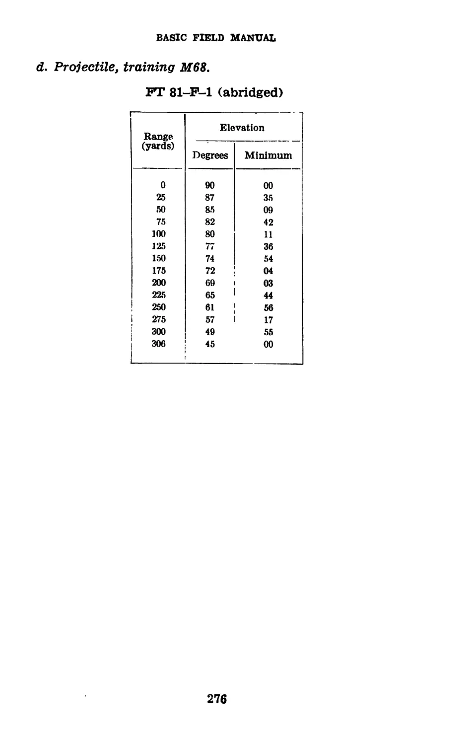
31. Training Projectile M68.—This projectile has a solid
cast body, a standard fin assembly, weighs approximately
10.75 pounds, and is propelled by an ignition cartridge only.
The projectile contains no bursting charge and, due to the
increased weight, has a maximum range of about 330 yards.
Extra fin assemblies come in containers and serve as replace-
ments in the event the assembly used with the projectile
becomes unserviceable. There are furnished with each
bundle a firing table for the training projectile, a hook with
which to recover the projectile in the event that it becomes
embedded in soft earth, and an extractor to remove fired
cartridges. This projectile is of considerable value as a
training aid (pars. 70 and 74).
32. Firing Tables.—a. For the purpose of converting
ranges in yards into elevations in degrees, firing tables are
provided. These tables, printed on convenient cards, include
a deflection-conversion table (see app. I) and instructions
as to their use. In each bundle of ammunition a pertinent
firing table will be found. Firing tables for instructional use
may be obtained on requisition.
b. Tables applicable to the various types of 81-mm shell
are as follows:
33
32—32.1
BASIC FIELD MANUAL
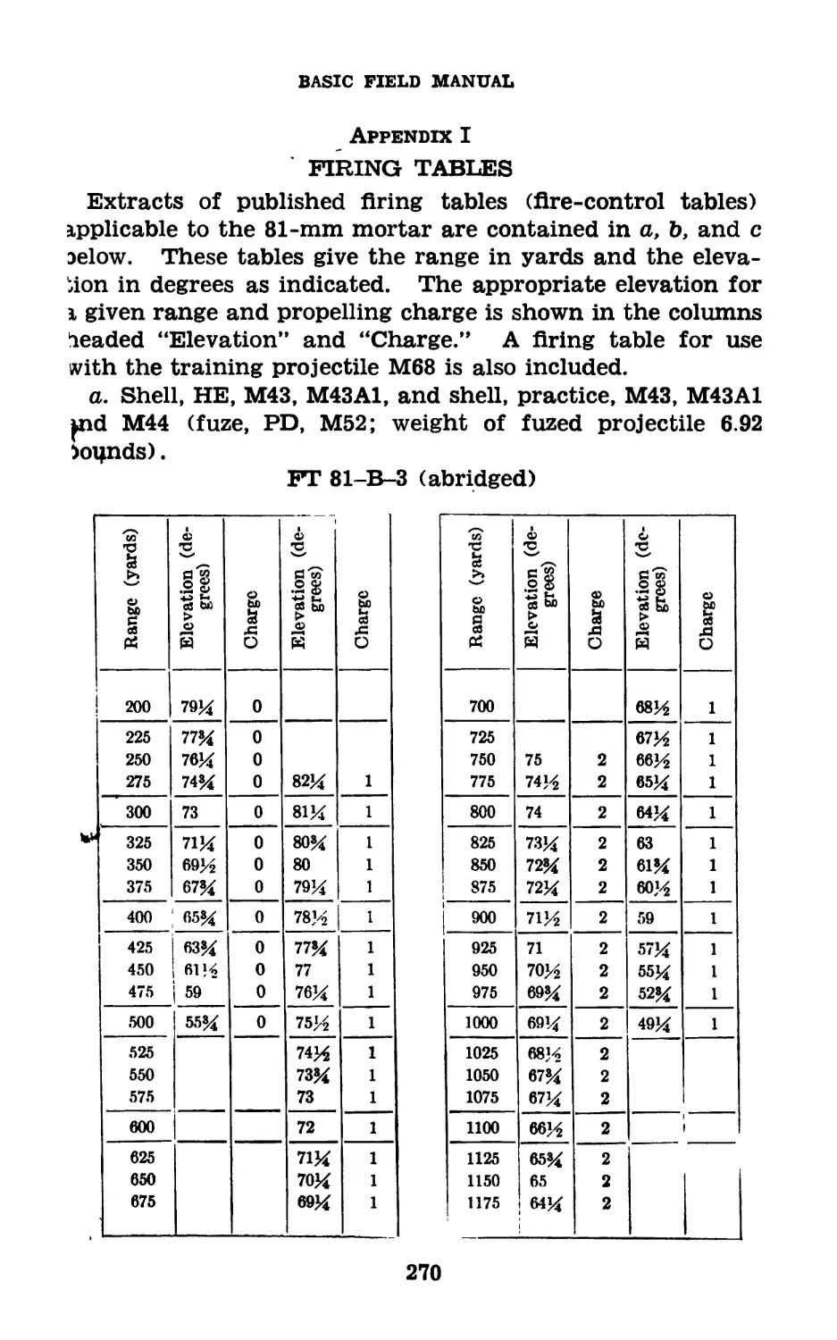
FT-81-B-3 (abridged): For firing shell, HE, M43, M43A1,
and practice shell, M43, M43A1, and M44.
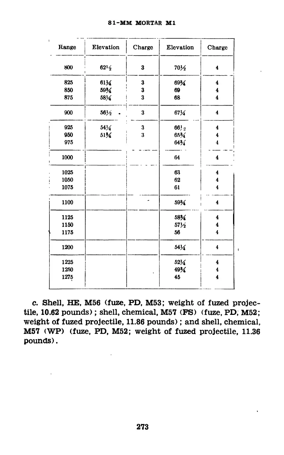
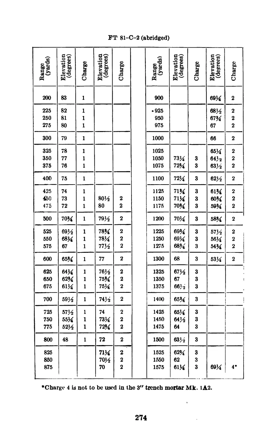
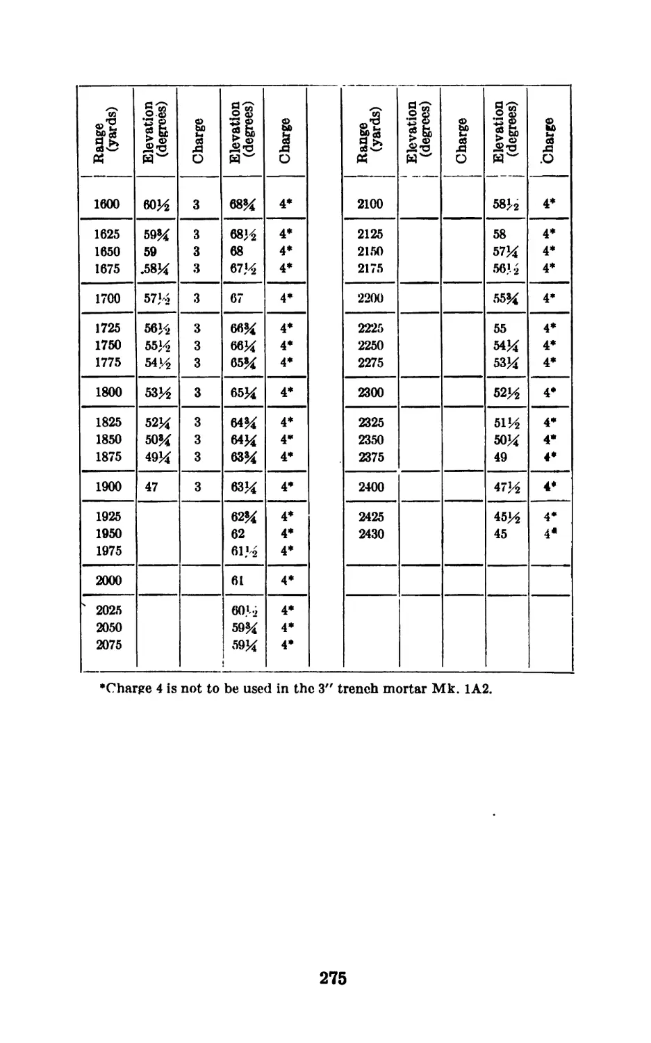
FT-81-C-2 (abridged): For firing shell, HE, M46, and
shell, chemical, M57 (FS), and M57 (WP).
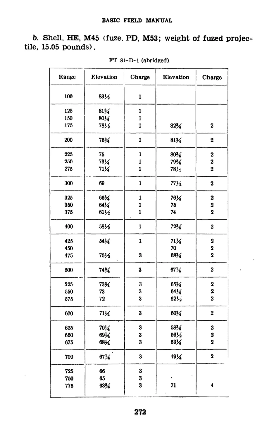
FT—81—D—1 (abridged): For firing shell, HE, M45.
FT-81-F-1 (abridged): For projectile, training, M68.
c. Extracts of current firing tables are contained in appen-
dix I.
d. Use.—(1) Since mortar fire is usually adjusted fire (par.
69), the gunner should select for his initial round a charge
zone which permits a subsequent increase or decrease in
range without changing the charge. The zone selected should
be such that fire for adjustment and fire for effect can be
completed without changing to another charge. Where the
gunner has a choice bet wen two charge zones, latitude in
firing being provided in both, he will select the lower charge
(see par. 66b(3)), since less dispersion results with the lower
charge.
(2) It may be necessary (though undesirable), in subse-
quent adjustment of fire, to change to a higher elevation and
charge. In such a case, the gunner will continue to use the
higher charge until fire for effect has been delivered on that
particular target. Fire adjustment is less accurate where
there is a shift between charge zones during adjustment.
Section VI
DESTRUCTION OF ORDNANCE MATERIEL IN EVENT OF
IMMINENT CAPTURE IN COMBAT ZONE
M 32.1 General Principles.—a. Tactical situations may arise
when, owing to limitations of time or transportation, it will
become impossible to evacuate all equipment. In such situ-
ations it is imperative that all materiel which cannot be evac-
uated be destroyed to prevent—
(1) Its capture intact by the enemy.
(2) Its use by the enemy, if captured, against our own
troops.
b. (1) Methods for the destruction of mortars, their acces-
sories, and ammunition, subject to capture or abandonment
in the combat zone must be adequate, uniform, and easily
followed in the field.
34
81-MM MORTAR Ml
32.1-32.2
(2) Destruction must be as complete as the available time,
equipment, and personnel will permit. If thorough destruc-
tion of all parts cannot be completed, those parts essential
for the use of the mortar should be destroyed. Other parts
which cannot easily be duplicated by the enemy should be
ruined or removed. The same essential parts must be de-
stroyed on all like units to prevent the enemy's constructing
one complete unit from several damaged ones by consolida-
tion of serviceable parts,
(3) The destruction of materiel is a command decision
and will be ordered and carried out only on authority dele-
gated by the division or higher commander. The standing
operating procedure of the division may prescribe the con-
ditions under which unit commanders will be authorized to
destroy materiel.
c. To accomplish adequate and uniform destruction of
materiel, it is essential that—
(1) All echelons prepare plans for the destruction of
materiel in the event of imminent capture. Variations in
the time available in which to effect the required destruc-
tion, and in the amount and nature of the materiel to be
destroyed, as well as variations in the number of men avail-
able with whom to effect this destruction, dictate consid-
erable flexibility in the preparation of plans.
(2) All echelons be trained to effect the desired destruc-
tion of materiel issued to them. Training will not involve
the actual destruction of materiel,
32.2. Methods.—a. The destruction procedures outlined
are arranged in order of effectiveness. Destruction should
be accomplished by method No. 1, if possible. If method
No. 1 cannot be used, destruction or disposition should be
accomplished by one of the other methods outlined, in the
priority shown.
b. The sequence outlined should be adhered to, whichever
method is used. Uniformity of destruction will then be ob-
tained, whether or not the method is carried to completion.
c. Certain of the methods outlined require special tools
and materials, such as TNT and incendiary grenades, which
may not normally be items of issue. The issue of such spe-
cial tools and materials, and the conditions under which
35
32.2
BASIC FIELD MANUAL
destruction will be effected, are command decisions in each
case.
d. Mortar.—(1) Sight.—Detach the sight. If evacuation
is possible, carry away the sight; if evacuation is not possible,
thoroughly smash the sight.
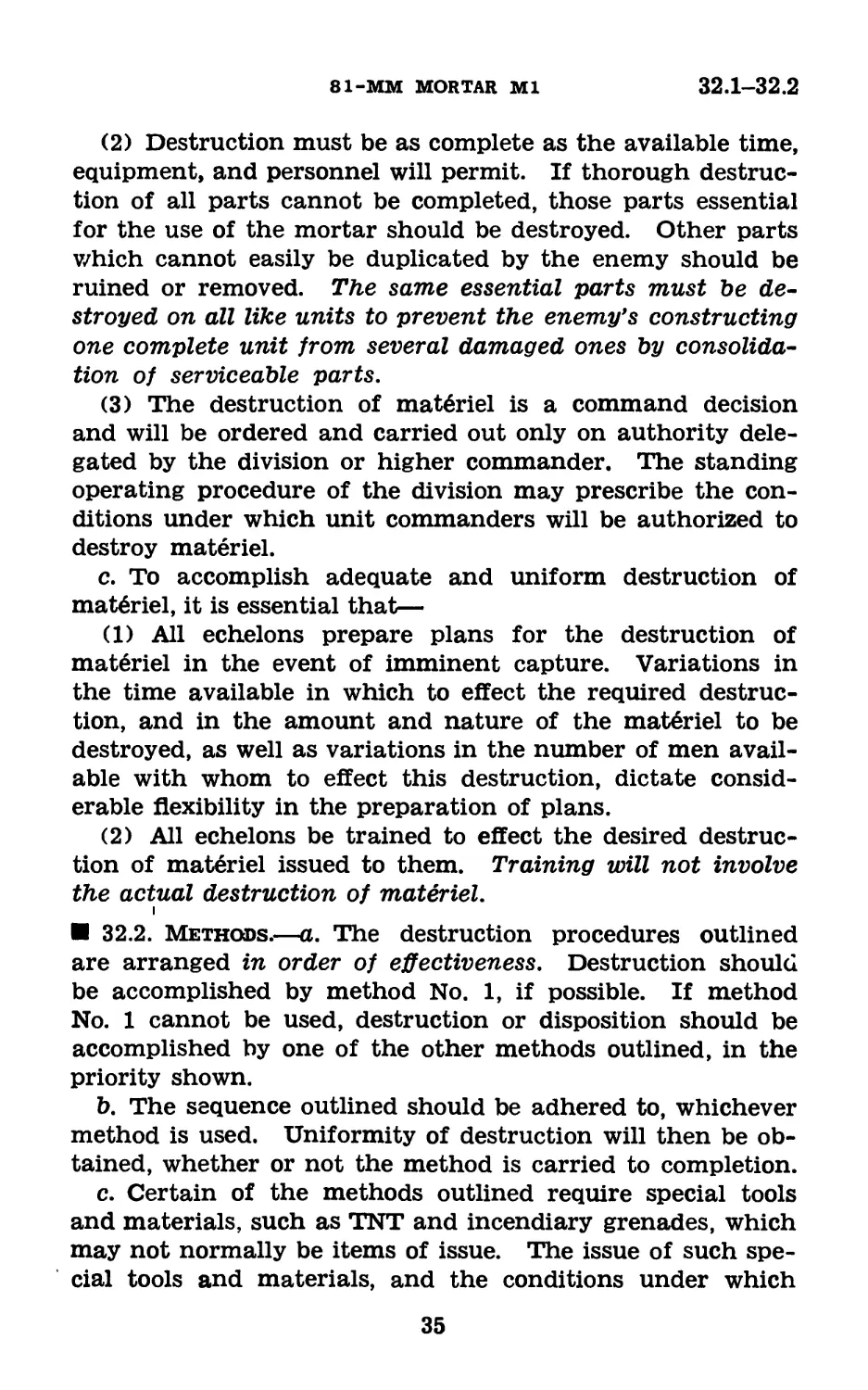
(2) Barrel.—(a) Method No. 1.—Place a complete round,
With 24 propellent increments attached, and with the safety
Figure 9.1—Demolition of mortars, using excess increments.
wire in fuze not withdrawn, part way into the mortar barrel.
Block the round in this position by jamming a stick, small-
arms cartridge, or loop of ^-inch or larger cord between the
round and the side of the mortar barrel; a cord (or rope)
100 feet long is attached to the stick, cartridge, or loop. Take
a covered position (see fig. 9.1) and pull the cord (or rope)
to cause the round to slide down the barrel and be fired. The
excess pressure caused by the large number of increments
will burst the base end of the barrel. The danger zone is at
least 100 yards. Elapsed time by this method: 1 minute.
(b) Method No. 2.—Drop two M14 incendiary grenades into
the tube and ignite. One of the grenades should be equipped
36
81-MM MORTAR Ml
32.2-32.3
with a 15-second Bickford fuze, if available; otherwise the
standard Buchon fuze may be used. Elapsed time by this
method: 1 minute.
32.3 Ammunition.—a. General,—Time will not usually
permit the deliberate destruction of all the ammunition in
forward combat areas. When time permits, ammunition on
hand may be destroyed by firing the shells rapidly in the
direction of the enemy. Large amounts, when sufficient time
and materials are available, may be destroyed by the follow-
ing methods, which will require from 30 to 60 minutes, within
the regiment. (For methods and safety precautions, see ch. 4,
TM 9-1900.)
b. Unpacked ammunition,—(1) Stack ammunition in small
piles. Stack or pile most of the available gasoline in cans
and drums around the ammunition. Throw onto the pile
all available inflammable materials such as rags, scrap wood,
and brush. Pour the remaining available gasoline over the
pile. Sufficient inflammable material must be used to in-
sure a very hot fire. Ignite the gasoline and take cover.
(Small-arms ammunition may be heaped.)
(2) HE shells can be destroyed by sympathetic detonation,
using TNT. Stack the ammunition in two stacks, about 3
inches apart, with the fuzes in each stack toward each other.
Place TNT charges between the stacks, using a minimum of 1
pound of TNT for every 10 rounds of ammunition. Detonate
all TNT charges simultaneously from cover.
c. Packed ammunition.—(1) Stack the bundled ammuni-
tion in small piles. Cover with all available inflammable
materials, such as rags, scrap wood, brush, and gasoline in
drums or cans. Pour gasoline over the pile. Ignite the
gasoline and take cover. (Small-arms ammunition must
be broken out of the boxes or cartons before burning.)
(2) (a) The destruction of packed ammunition by sympa-
thetic detonation with TNT is not advocated for use in for-
ward combat zones. To insure satisfactory destruction in-
volves putting TNT in alternate bundles of ammunition, a
time-consuming job.
(b) In rear areas or fixed installations, sympathetic deto-
nation may be used to destroy large ammunition supplies
37
32.3-32.5
BASIC FIELD MANUAL
if destruction by burning is not feasible. Stack the bundles.
In each bundle of each row, place sufficient TNT blocks to
insure the use of 1 pound of TNT for every 10 rounds
of 81-mm ammunition. Place the TNT blocks at the fuze
end of the rounds. Detonate all TNT charges simultane-
ously. See PM 5-25 for details of demolition planning and
procedure.
32.4. Fire-Control Equipment.—All fire-control equip-
ment, including optical sights and binoculars, is difficult to
replace. Fire-control equipment should be the last equip-
ment to be destroyed, if there is any chance that personnel
will be able to evacuate it. If evacuation of personnel is not
possible, inflammable items such as firing tables, drawing
boards, mil scales, and alidades (improvised) will be burned;
all optical equipment such as compasses, binoculars (М3,
and type EE), aiming circles, and range finders will be
thoroughly smashed.
32.5. Destruction of Captured Enemy Materiel.—Cap-
tured enemy materiel which is not suitable for repair and
issue to troops may be destroyed, in general, in the same
manner as for equivalent United States equipment. In
general, it should be destroyed before our own equipment.
38
81-MM MORTAR Ml
33-34
CHAPTER 2
TRAINING OF GUNNER
Paragraphs
Section I. General___________________________________________ 33
II. Compass__________________________________________ 34
III. Spare parts and accessories____________________35-36
IV. Training exercises______________________________37-44
V. Additional training_____________________________45-49
Section I
GENERAL
33. General.—The purpose of this chapter is to provide
instruction and training for the gunner in the form of in-
structional material and exercises. The subject matter is
restricted to that which pertains to the training of the
gunner. The method of instruction will be as outlined in
chapter 8. The sequences of instruction are progressive.
Section П
COMPASS
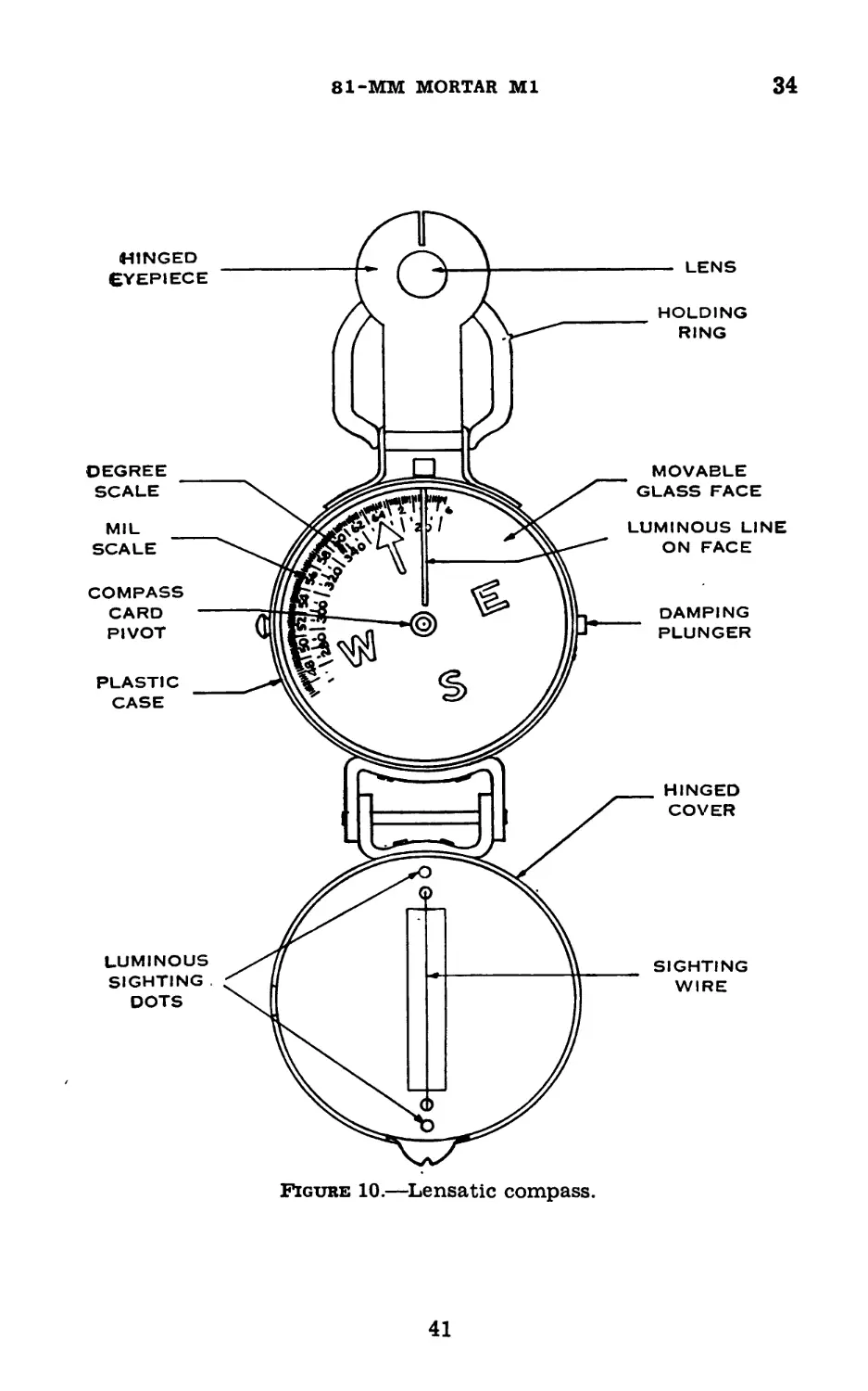
34. Lensatic Compass.—a. Types.—The lensatic compass is
standard for fire control use with the 81-mm mortar; several
similar models are issued. The prismatic compass may be
used for fire control, but the watch compass is unsuitable for
such use.
b. Description.—The latest type of lensatic compass is
shown in figure 10. The carrying case, to which is attached
a brass holding ring, is made of plastic. The hinged eyepiece
contains a magnifying lens and is slotted on the end for
sighting. The raising of the eyepiece releases the compass
card. The compass card, pivoted in the center, is doubly
graduated, the outer scale reading in mils, the inner scale
reading in degrees. A compass stop plunger is provided on
the side of the case. The hinged cover is slotted and con-
tains a vertical wire for sighting. This wire is marked at
39
34
BASIC FIELD MANUAL
each end by a luminous dot. The glass cover of the compass
box is movable and is provided with a luminous line for use
at night.
c. Use.—(1) In mortar units the lensatic compass is used
primarily for measuring magnetic azimuths. It may also be
used as a marching compass.
(2) If practicable, in order to obtain an accurate mil scale
reading, the compass should be rested on a level surface, or
on a flat-topped aiming stake. It may, however, be read
when held in the hands, using the holding ring for support.
The index line in some of the newer instruments is exces-
sively broad. To obtain uniform readings, the left edge of
the index should be consistently read whenever broad index
lines are noted.
(3) The instrument must be held with the card as nearly
level as possible to permit the needle to swing freely.
d. Operation.—(1) To measure azimuth.—Raise the eye-
piece and cover; sight through the slot in the eyepiece and
sighting wire on cover. Rotate the compass until the line of
sight bisects the object to which azimuth is desired. Without
altering the position of the compass, read the azimuth desired
on the proper scale, looking through the eyepiece lens.
(2) To lay off azimuth from observer's position.—Rotate
the compass until the given azimuth is opposite the index.
Without disturbing the position of the compass, have an
aiming stake placed on the line of sight of the compass.
(3) To read back-azimuth from given object to observer.—
Proceed as in (1) above. If the azimuth thus determined is
less than 3,200 mils, add 3,200 mils; if it is 3,200 mils or more,
subtract 3,200 mils. The result is the back-azimuth desired.
(4) To place observer on given azimuth from given point.—
The observer places himself approximately on the required
line and reads the azimuth to the point as in (1) above.
Holding the line of sight on the point, he moves to the right
or left as required until the desired azimuth is opposite the
index. A movement to the right decreases the reading; to
the left increases it.
(5) To determine horizontal angle between two points from
position of observer.—Read the azimuth to each point and
40
81-MM MORTAR Ml
34
Figure 10.—Lensatic compass.
41
34-36
BASIC FIELD MANUAL
subtract the smaller reading from the larger. The difference
is the required angle.
(6) To lay off azimuth at night.—(a) Using a flashlight or
other source of illumination when in a covered position, turn
the compass until the desired reading on the dial is opposite
the fixed luminous index.
(b) Move the luminous line on the crystal to coincide with
the north arrow on the compass dial.
(c) Without using a light, move to the position from
which the azimuth is to be determined. Hold the compass
level and rotate until the north arrow on the compass dial
coincides with the luminous line on the crystal. The lumi-
nous index and the luminous sight dots on the hinged cover
then point in the desired direction.
e. Care and preservation.—Although the compass is strongly
constructed, the needle pivot bearing and its jewelled support
must be protected against shocks.
Section Ш
SPARE PARTS AND ACCESSORIES
35. Spare Parts.—a. General.—Parts become unserviceable
through breakage or through wear resulting from continuous
usage. For this reason, spare parts are provided for replace-
ment purposes. These parts are divided into two groups,
spare parts and basic spare parts. They should be kept clean
and lightly oiled to prevent rust.
b. Spare parts.—These are extra parts provided with the
mortars and mounts for replacing those most likely to fail
and are employed by the using arms in making minor repairs.
Sets of spare parts should be kept as complete as possible.
The allowances of spare parts are prescribed in pertinent
Standard Nomenclature Lists (SNL A-33).
c. Basic spare parts.—These are sets of spare parts pro-
vided for use by ordnance maintenance companies. These
spare parts are of ho interest to line troops except that, in
an emergency, a part may be drawn from the maintenance
company.
36. Accessories.—Accessories include tools required for
assembling and disassembling, supplies for the cleaning and
42
81-MM MORTAR Ml
36
preservation of the materiel, and covers, tool rolls, chests,
etc., necessary for storage and protection when the mortars
and mounts are not in use or when traveling. Accessories
should not be used for purposes other than those prescribed
and when not in use should be stored in the places or recep-
tacles provided. There are a number of accessories listed
in SNL A—33, the names or general characteristics of which
indicate their uses or application. Therefore, no detailed
description or method of use is outlined herein. However,
accessories embodying special features or having special uses
are described below:
a. Bag, ammunition, М2.—The ammunition bag is a rein-
forced strip of canvas with a central opening which admits
the head of the ammunition carrier. Pockets are provided
in front and rear to carry the ammunition.
b. Brush, chamber cleaning, M6.—The bristle brush having
a twisted wire body is used to clean fouling from the firing
pin vent of the mortar.
c. Chest, accessory, М3.—The steel accessory chest is a
commercial-type chest provided for the storage and protec-
tion of equipment, cleaning material and small stores, and
miscellaneous spare parts.
d. Cover, muzzle, M307.—The leather muzzle cover is used
for protection of the mortar bore from foreign matter and
moisture. This cover is not used when the mortar is pack
transported.
e. Cover, traversing screw, M505.—The cylindrical leather
cover is used to cover the traversing screw mechanism when
the bipod is to be manhandled.
f. Pad, shoulder, М2.—The shoulder pad consists of two
pads, one for the left and one for the right shoulder. They
are strapped together and provide protection for the shoul-
ders of the members of the squad.
g. Staff, cleaning, M4 (aluminum).—The cleaning staff has
a four-prong fork fastened at one end to hold rags or waste
with which the firing pin and bore of the mortar may be
cleaned.
h. Staff, cleaning, M8 (wooden).—This item is similar to
the M4 cleaning staff.
i. Strap, carrying, Ml.—The carrying strap, Ml, consists
of a V-shaped strap and a pad. The strap is fastened to the
43
36
BASIC FIELD MANUAL
link and loops of the base plate and slipped over the shoul-
ders. The pad eases the load on the carrier’s back.
j. Tool, firing pin vent cleaning.—The round steel tool has
a flattened, pointed cleaning end by which the firing pin vent
of the mortar may be cleaned.
k. Oval oiler.—The oval oiler is used to lubricate and apply
oil to flat and exposed surfaces that require oil but have no
fittings. A cap is provided to protect the tip of the oiler
and prevent loss of oil when the oiler is not used.
I. Flush-type pressure lubricating gun.—This lubricating
gun is used to apply oil to the flush-type, lubricating fittings
located on the bipod.
m. Camouflage net.—The camouflage net is a woven net-
ting, 12 feet by 12 feet, issued to the squad for the purpose
of camouflaging a mortar position against air observation.
n. Accessories for pack transport.—(1) Cinch, M7.—The
cinch has an olive-drab cotton duck body with a steel loop
at one end and a two-bar loop for adjusting purposes at the
other. Adjustable leather straps are attached at either end
for securing the cinch to the pack saddle to prevent the
bundled ammunition from slipping.
(2) Cinch, M12.—This cinch is similar to the cinch, M7,
but it has a leather facing on its body which is slotted to
permit the center brace of the base plate to enter when being
secured.
(3) Cover, muzzle, М310.—This cover will be used only
when the mortar is pack transported.
(4) Frame, ammunition, M4.—The frame, composed of
rear, center, and front braces held together by longitudinal
bars, is secured to the pack saddle by screws and nuts. The
three extension bars assembled to the frame are adjustable
to suit the bundled ammunition.
(5) Hanger, mortar, Ml.—The braces and brackets of the
mortar hanger Ml are shaped and located to form a con-
venient arrangement for transporting the base plate and
accessory chest. Two straps secure the hanger to the near
side of the pack saddle.
(6) Hanger, mortar, М2.—The components of the hanger,
М2 are constructed so that there are three compartments,
one each for the mortar, bipod, and cleaning staff, М2. The
44
81-MM MORTAR Ml
36-37
hanger is secured to the offside of the pack saddle by two
straps.
(7) Staff, cleaning, MIO.—The wooden cleaning staff has
a four-prong fork fastened at one end to hold the rags or
waste with which the firing pin and bore of the mortar may
be cleaned. It is shorter than the cleaning staff M9.
Section IV
TRAINING EXERCISES
37. Checking Seat of Sight and Correct Removal Proce-
dure.—a. The purpose of this exercise is to teach the gunner
the procedure for checking the seating (latching) of the
sight in the slot on the mortar yoke and the method of re-
moving the sight without disturbing the lay of the mortar.
b. The instructor explains that the gunner automatically
checks the seating of the sight in the slot every time he
places it on the mortar. He emphasizes the fact that failure
to check the seating of the sight may cause a serious waste
of time and ammunition during fire for adjustment, since
true angles of elevation, corresponding to the elevations set
on the sight, can only be laid on the mortar when the sight
is securely latched. He demonstrates the procedure as fol-
lows (fig. 11®): He mounts a sight on the mortar, appar-
ently latched in place, then places his left index finger
against the sight slot and underneath the body of the sight.
With his left thumb extending over the cross-level and the
remaining fingers of the left hand grasping the under por-
tion of the sight body, he attempts to lift the sight out of
the slot. If the sight has been properly inserted, the hook
on the latch will continue to engage the notch in the sight
slot.
c. The instructor explains that, to prevent damage to the
sight while the first three rounds are being fired, the sight is
removed before firing the rounds. To avoid disturbing the
lay of the mortar, the gunner removes the sight with care.
The instructor demonstrates the method as follows (fig.
11®): From a standing position, he places the fingers of his
left hand as in b above. With his right thumb, he exerts
pressure on the knurled portion of the latch and places the
remaining fingers of his right hand on top of the yoke. The
517120°—43--------4 45
37
BASIC FIELD MANUAL
upward pressure of the left hand is counteracted by the
pressure exerted on the yoke with the fingers of the right
hand. By this method, the least disturbance in the lay of
the mortar results.
Figure 11.—Checking the seat, sight M4, and removal of sight M4.
46
81-MM MORTAR Ml
37-39
d. For practice, the instructor has the class divided into
small groups, each reporting to a previously trained assistant
who supervises the practical work.
38. Sight Setting.—a. The purpose of this exercise is to
teach the gunner to operate the sight.
b. Holding the sight in his hand, the instructor names
the principal parts of the sight and describes their functions
to the assembled groups. He explains how to determine
and set off deflections as described in paragraph 19.
c. He then explains how to set off elevation and deflection
as described in paragraph 19, illustrating this by several
examples. He explains that to place a right deflection on
the sight, the gunner pulls the knob toward him; to set a
left deflection on the scale, the knob is pushed away from
him.
d. To demonstrate the group method of conducting this
exercise, the instructor uses two trained men, one to act as
gunner and the other as group instructor. He requires the
gunner to set off a given deflection and elevation and to
explain the operation as he performs it. The group in-
structor checks each detail and points out any errors made.
39. Laying for Elevation.—a. The purpose of this exer-
cise is to teach the gunner to determine the angle of eleva-
tion and the charge for any given range, to lay the mortar
in elevation, and to check for mask clearance.
b. The instructor explains the use of the firing table and
the way in which to find the correct angle of elevation and
charge for any required range (par. 32). He then explains
the method of laying for elevation as follows: The gunner,
having determined the correct charge, informs No. 2 of
the charge requirements in the fire order; for example,
charge 2, or charge zero. No. 2 then prepares the round.
After setting an angle of elevation on the sight, the gunner
lays for elevation by manipulating the elevating crank until
the bubble in the longitudinal level is centered.
c. The instructor explains that mask clearance is deter-
mined as follows: When an elevation of 40° is set on the sight
and the bracket on which the collimator is mounted is tilted
to its extreme upward position, the line of sight through the
open sight will be 2° below the axis of the bore. Accordingly
47
39-40
BASIC FIELD MANUAL
if the line of sight clears the mask, the mortar shell will like-
wise clear it. A careful check must be made to see that the
path of the projectile will not pass through overhead
branches of trees. Mask clearance and overhead interfer-
ence can usually be determined more quickly by sighting
along the top of the barrel with the eye placed near the base
cap. If it is not safe to fire, the gunner announces, “Not safe
to fire.”
d. To demonstrate the method of conducting this exercise,
the instructor has two trained men act as gunner and group
instructor, respectively. The group instructor announces a
range and requires the gunner to determine the correct angle
of elevation, announce the charge, lay the mortar for eleva-
tion, and determine mask clearance. The group instructor
checks each operation and explains any errors made.
40. Cross-Leveling.—a. The purpose of this exercise is to
give the gunner necessary training and practice in cross-
leveling. Continuous practice is essential for the gunner to
obtain the required manual dexterity in this important
operation.
b. The instructor stresses the fact that the two movements
of traversing and cross-leveling are combined in a simul-
taneous operation; this is necessary in order to avoid delay
in laying the mortar and in manipulating the mortar for dis-
tributed fire. He points out that, in traversing and cross-
leveling, the right hand operates the traversing handwheel
and the left hand the adjusting nut at the same time; both
hands are turned in the same relative direction in order to
keep the cross-level bubble centered during traverse. Ap-
proximately four turns of the traversing handwheel should
be taken to one-half turn of the adjusting nut. (This ratio
may vary with different mortars.)
c. To demonstrate this exercise, the instructor has a trained
gunner position the traversing screw nut on one side of the
yoke and cross-level by means of the adjusting nut. The
gunner then demonstrates traversing the full width of the
traversing screw, keeping the mortar cross-leveled at all times
by watching the cross-level bubble of the sight.
d. For practice, the instructor has the class divided into
small groups, each reporting to a previously trained assistant
48
81-MM MORTAR Ml
40-41
who supervises the practical work. This exercise should be
repeated at various times during the course of the training.
e. When the gunner becomes more proficient in this exer-
cise, the instruction may be varied by having the gunner
watch the white line of the collimator during traverse and
attempt to keep it in a vertical plane at all times. Upon
completing the entire amount of traverse, he can check his
estimate of a vertical position against the cross-level bubble.
/. The gunner, while laying for direction (par. 41), keeps
the white line of the collimator in a vertical position. In this
way he keeps the mortar approximately cross-leveled while
traversing. When the mortar is sighted on the left edge of
the aiming stake, a slight movement of the adjusting nut
will complete the cross-leveling.
41. Laying For Direction.—a. The purpose of this exer-
cise is to teach the gunner to lay accurately for direction.
b. The instructor makes the following explanation to the
assembled groups: accurate firing is possible only if the
vertical line of the collimator is laid exactly the same for
each round fired at the same target, with the mortar accu-
rately cross-leveled. If an aiming stake is used, the gunner
must lay so that the vertical line of the collimator is made
to coincide with the left edge of the stake. If an aiming
point other than a stake is used, the gunner must select a
clearly defined vertical edge on which to lay. To place the
vertical line of the collimator on the aiming point, the mortar
must be traversed and cross-leveled simultaneously. In aim-
ing, the eye should be held at a distance of 3 to 10 inches from
the lense of the collimator and in such a position that both
the aiming point and the vertical line of the collimator are
visible. No attempt is made to look through the collimator,
since this is impossible.
c. To demonstrate the method of conducting this exercise,
the instructor has two trained men act as gunner and group
instructor, respectively. The group instructor lays the mor-
tar, repeats the explanation described above, and requires
the gunner to observe the aim. He then requires the gunner
to relay on the same aiming point several times. After each
laying the instructor checks the gunner’s aim and the cross-
49
41-42
BASIC FIELD MANUAL
leveling of the mortar. He then traverses the mortar to the
right or left to disturb the aim (par. 150).
42. Laying For Elevation and Direction.—a. The purpose
of this exercise is to teach the gunner to follow a chronological
procedure from the issuance of the initial fire order to the
moment when the gunner orders fire.
b. The instructor emphasizes the fact that a standardized
procedure for setting the sight and laying the mortar for ele-
vation and direction is necessary in order speedily and accu-
rately to prepare the mortar for firing. He explains that the
sight is an angle measuring instrument on which setting of
deflections and elevations may be made without affecting the
axis of the bore. Therefore, the mortar barrel must be laid
(pointed) by manipulating the traversing hand wheel (to
bring the vertical line of the collimator back on the aiming
stake) and by manipulating the elevating crank (to center
the bubble in the longitudinal level). The mortar must also
be cross-leveled during this process (par. 40).
c. To demonstrate the method of conducting this exer-
cise, the instructor has two trained men (a squad leader and
a gunner) demonstrate the procedure described in (1) and
(2) below, while he explains each step of the operation.
(1) The mortar is mounted as prescribed in paragraph 5b.
The squad leader issues an initial fire order, for example,
he, light, left 40, stake, 800, one round. The gunner, hold-
ing the firing table in his right hand, repeats the elements
of the fire order. He immediately sets the deflection “left
40” on the deflection scale of the sight with his left hand,
then looks at the firing table to find the angle of elevation
and the charge required for the range of 800 yards. He
announces the charge and sets the elevation scale of the
sight at the required angle.
(2) Since the angles of elevation and deflection have been
measured on the sight, the elevating crank and traversing
handwheel must be turned in the proper direction to lay
the mortar correctly. Therefore, the gunner turns the ele-
vating crank until the longitudinal level bubble is centered
and rotates the adjusting nut until the cross-level bubble is
centered. He checks the vertical line of the collimator and
simultaneously turns the adjusting nut and traversing hand-
50
81-MM MORTAR Ml
42-43
wheel in the same direction until the vertical line is laid on
the left edge of the aiming stake. Again he checks the
cross-level bubble and the longitudinal level bubble. When
the gunner has accurately laid the mortar, he orders: FIRE.
(3) The instructor may have the squad leader issue a sub-
sequent fire order and require the gunner to follow the pro-
cedure described above. Upon completion of the explanation
and demonstration, the groups return to their squad equip-
ment where the squad instructors conduct the practical work.
Note.—When the deflection in an initial fire order
exceeds 60 mils, the gunner does not attempt to lay off
the deflection with the traversing handwheel. He sets
the deflection on the scale of the sight, directs No. 2
to move the bipod until the vertical line of the collima-
tor is approximately on the left edge of the stake, and
re-lays accurately with the handwheel. For subsequent
adjustments for deflection, a maximum traverse to the
right or left may now be obtained on the screw.
43. Laying for Direction by Azimuth.—a. The purpose of
this exercise is to teach the gunner to lay the mortar on a
given azimuth.
b. The instructor explains how to read azimuths, using the
lensatic compass. He points out that when the vertical wire
in the cover is alined with the aiming point, the azimuth of
the line compass-aiming point appears opposite the index.
He then explains that because the mortar is normally located
in defilade it may be necessary to lay it by compass azimuth
when the direct alinement method cannot be used (par. 59).
c. To demonstrate the method of conducting this exercise,
he has a group of three trained men (a gunner, No. 2, and
No. 3) demonstrate the method described in (1) and (2)
below, while he explains each step of the operation.
(1) After the squad leader has indicated the position for
the mortar, No. 1 drives a stake in the ground to mark the
position of the base plate. Making sure that the mortar
and other metallic equipment are at a distance of not less
than 10 yards from the position, the gunner rests his com-
pass on the stake and rotates it until the azimuth announced
by the squad leader is laid off on the mil scale. He then
directs No. 2 to drive an aiming stake on this azimuth at a
distance of about 25 yards. No. 3 alines the base plate for
direction.
51
43-44
BASIC FIELD MANUAL
(2) As soon as the base plate is in position, the mortar
is mounted as described in paragraph 5b. With the initial
setting placed on the sight, the gunner directs No. 2 to shift
the bipod until the vertical line of the collimator is approxi-
mately on the left edge of the aiming stake. He lays for
elevation, cross-levels, and then lays accurately for direction.
44. Manipulation of Mortar for Traversing and Searching
Fire.—a. The purpose of this exercise is to teach the gunner
the coordination required for simultaneous use of the travers-
ing hand wheel and the adjusting nut; determination of the
necessary number of turns of the elevating crank; and the
sequence necessary to engage targets that require a combina-
tion of distributed fire called traversing and searching fire.
b. The instructor first explains the technique of distribut-
ing fire laterally (traversing) and in depth ((searching) by
manipulation of the mortar. He then explains that it may
be necessary to combine these two types of fire and that a
definite operating sequence must be followed.
c. To demonstrate the method of conducting this exercise,
he has a group of three trained men, a squad leader (ob-
server), a gunner (No. 1), and an assistant gunner (No. 2)
demonstrate the method described below while he explains
each step of the operation.
d. The mortar is mounted as prescribed in paragraph 5b,
with an aiming stake set at a convenient distance. The,
mortar is laid on the left edge of the stake, with the deflec-
tion scale set at zero and the traversing screw approximately
centered. The elevation scale is set at 62° and the longi-
tudinal level centered.
(1) The squad leader gives a fire order, for example:
SEARCH 900-1,000.
TRAVERSE RIGHT FOUR TURNS.
NINE ROUNDS.
(2) The gunner repeats each element of the fire order and,
upon hearing the words “Search 900-1,000,” places his thumb
opposite the’ range of 900 yards on the firing table* and se-
lects the lowest charge zone which will include the extreme
range (1,000 yards) as given in the fire order. He then notes
that the elevation for the range 900 is 59°; he sets his eleva-
♦ Abridged Firing Table, 81-mm Mortar, Ml, Shell, HE, M43A1.
52
81-MM MORTAR Ml
44-45
tion on the elevation scale of the sight and announces,
“Charge 1.” He next reads the difference in degrees between
the limiting ranges (app. I) and translates the number of
degrees (disregarding fractions) to the number of turns
of the elevating crank between range bounds, and announces,
“Down 10 turns.” (If the limits are given with the greater
range first, that is, 1,000-900, the command would be: up
10 TURNS.)
(3) With the traversing handwheel, the gunner turns the
traversing screw off center enough to allow him to traverse
twice the number of turns announced in the fire order. He
directs No. 2 to move the bipod legs until the white line of
the collimator is approximately laid on the left edge of the
aiming stake. He then centers the bubble in the longi-
tudinal level, cross-levels, and lays accurately with the
traversing handwheel while keeping the mortar cross-
leveled. When he is satisfied with the laying of the mortar,
he commands: FIRE. He then executes the remainder of
the operation as ordered, in the following manner: After
firing the first round (simulated), he traverses right 4 turns,
keeping the mortar cross-leveled, and commands: FIRE for
the second round; he traverses right 4 more turns and com-
mands: FIRE for the third round; for the fourth round he
turns the elevating crank down 10 turns, checks the cross-
level, and commands: FIRE; then he traverses left 4 turns
and commands: FIRE for the fifth round; he traverses left
4 more turns and commands: FIRE for the sixth round;
again he turns the elevating crank down 10 turns, checks the
cross-level, and commands: FIRE for the seventh round;
traverses right 4 turns and commands: FIRE for the eighth
round; he traverses right 4 more turns and commands: FIRE
for the ninth round, and announces, “Rounds complete.”
Section V
ADDITIONAL TRAINING
45. Marking Base Deflection.—In order to facilitate rapid
adjustment on new targets and to mark accurately targets
already engaged, it is necessary to establish an origin of
shift as early as possible. This origin of shift for the squad
is usually the first target engaged or any clearly defined
53
45-46
BASIC FIELD MANUAL
point in the target area. It is called the “base point,” and
the deflection of this point is called “base deflection.” Base
deflection is marked on the ground as soon as adjustment
is completed upon the base point, or in case the base point
is the initial target, as soon as fire for effect on the target
is completed, so as not to interfere with the fire. When the
immediate engagement of another target is not anticipated,
the observer establishes the direction to the base point by
commanding: MARK BASE DEFLECTION. After firing the
last round for effect (in drill, after the last practice shift
in elevation and deflection), the mortar is checked for
cross-level and resighted on the stake which marks the di-
rection to the target now to be established as the base point.
This alinement on the base point is marked by setting up
a stake on the established line. This is done by turning the
deflection scale to zero, taking care not to disturb the lay
of the mortar. No. 3 resets the stake on which the mortar
was first alined so that the stake will now be alined with
the vertical line of the collimator. After being reset, this
stake is known as the base stake. The deflection of the base
point is now zero. When base deflection is marked, the
gunner centers the traversing screw, directs No. 2 to move
the bipod and re-lays on the stake. Space is now provided
on the screw for deflection corrections to the right or left
when new targets are engaged.
46. Placing Additional Aiming Stakes.—a. General.—
Since the maximum deflection which can be set on the
sight is 150 mils to the right or left of zero, it becomes
necessary to set out additional stakes. These are estab-
lished at 150-mil intervals to the right and left of the base
stake and make possible the laying of the mortar on targets
located at more than 150 mils to the right and left of the
base point. In the attack these stakes are placed, without
further command, immediately after marking the base de-
flection. At least two additional stakes should be placed.
In a defensive position, they should be placed immediately
after the direction to the base point has been established.
At least four additional stakes should be placed. Whenever
the situation permits, the stakes should be driven at least
15 yards from the mortar.
54
81-MM MORTAR Ml
46-47
b. Procedure.—(1) For two stakes.—With the deflection
scale at zero and the mortar cross-leveled, the base deflec-
tion is marked. Without moving the mortar, the gunner
sets the deflection scale at right 150 mils and directs No. 2
in the driving of the left stake so that the left edge of the
stake is in alinement with the vertical line of the collimator.
This stake is then 150 mils to the left of the base stake. The
gunner then rotates the deflection knob until the scale regis-
ters left 150 mils and has No. 2 drive the right stake. These
stakes now make possible the engagement of targets 300 mils
to the right and left of the base stake, because, with the
deflection scale set at zero, a movement of the bipod to place
the vertical line of the collimator on the right (or left) stake
will permit the setting of an additional 150 mils on the deflec-
tion scale of the sight. Therefore, with two additional
stakes, a frontage of 600 mils can be covered. Example: To
engage a new target which is 225 mils to the left of the base
point, the observer’s fire order, so far as it concerns direction,
would be: left 75, left stake.
(2) For four stakes.—Having established the base stake, to
place two additional stakes to the right, the gunner sets
right 150 mils on the deflection scale (the vertical line of the
collimator is then pointed to the left) and directs No. 2 to
move the bipod legs until the line of the collimator is placed
approximately on the left edge of the base stake. He lays
accurately with the traversing hand wheel, cross-leveling
simultaneously. The gunner rotates the deflection knob
until the scale registers zero. Without moving the mortar,
he directs No. 3 to drive the first right stake, so that its left
edge is on line with the collimator. He once more rotates
the deflection knob in the same direction until he has laid
off another 150 mils left. No. 3 is then directed to drive the
second right stake. To place two additional stakes to the
left of the base stake, the gunner repeats the process in the
opposite direction. These stakes are designated as the first
left stake and the second left stake. A frontage of 900 mils
can be covered with four additional stakes. For employment
of these stakes, see paragraphs 141 and 142.
47. Night Firing.—a. Laying.—When it is necessary to
fire the 81-mm mortar at night, an aiming stake with a night
55
47-48
BASIC FIELD MANUAL
firing device attached (b below) is set up and used as an
aiming point. Sights are set by the light of a shaded flash-
light. In order to see the vertical line of the collimator (or
the open sight), a shaded flashlight, produced by covering
the lens with black paper pierced with a small pin, is held just
above the front of the collimator and at a slight angle so that
the light will be placed on the front of the collimator. With
a flashlight in this position, the white line of the collimator
shows as clearly at night as in daylight. Additional methods
of laying the mortar at night are described in paragraph 143/.
b. Devices,—Night firing devices may be improvised. For
example, a cross-shaped slit is cut in the end of a tin can and
covered with a thin white cloth to keep the glare out of the
gunner’s eyes; or the lid of the can is removed, a heavy black
cross is marked on a sheet of paper, and the paper is fastened
over the open end. Several holes are punched in the other
end of the can. In one side of the can a rough cross-shaped
slit is cut and the edges are bent inward to admit and hold a
candle. Several nail holes are punched above and on each
side of the point where the flame of the candle will be. A
lighted candle is inserted in the can, which is then attached
to the aiming stake. A flashlight may be used instead of a
candle for illumination of the aiming stake.
c. Data.—Firing data should be prepared during daylight
and recorded on a range card, as described in paragraph 79.
If the mortar position is to be occupied at night and there has
been no opportunity to prepare data in advance, any night
firing must be based on data prepared from an aerial photo-
graph or map. Such data are only as accurate as the aerial
photograph or map and the skill and accuracy of the com-
puter (par. 123).
48. Firing Without Sights.—The mortar is not rendered
useless because of loss or destruction of the sight or the
dovetail slot.
a. Direction.—The gunner lays the mortar in direction,
from a position in rear, by having No. 2 shift the bipod legs
until the left edge of the barrel is alined on the aiming stake.
b. Elevation.—With the elevating screw centered, the gun-
ner must estimate the angle of elevation announced in the
initial fire order of the squad leader. Placing himself to one
56
81-MM MORTAR Ml
48-49
side of the mortar, the gunner directs No. 2 to move the bipod
legs or the position of the clamping collar so that the desired
angle of elevation will be obtained. No. 2 may make small
changes with the elevating crank, but it is important that the
elevating screw be as nearly centered as possible. The laying
of the mortar for direction should be checked.
c. The observer announces changes in deflection and eleva-
tion in terms of number of turns of the traversing handwheel
and elevating crank; the gunner manipulates both mecha-
nisms in the direction indicated by the observer in his fire
orders (par. 71). The gunner cross-levels by means of the
bubble located on the yoke.
49. Direct Laying.—Since the mortar is usually located in
defiladed positions, it is rarely possible to lay directly on the
target. There may be situations, however, where no defilade
is available or where speed in destroying a target is more
essential than cover. Usually such a position is a temporary
one and will be evacuated as soon as the target is destroyed.
In such a situation, the squad leader should point out the
target or its direction to the gunner and direct that the mor-
tar be mounted immediately and without stakes. If the
target is indistinct and the squad leader (observer) has indi-
cated only its direction, he should lay the mortar himself as
soon as it is mounted. The mortar is laid and fired in the
same manner as described for indirect laying except that
one clearly defined edge or point of the target should be used
as the aiming point. If it is apparent that the bursts may
obscure the target from observation, any suitable aiming
point in the target area may be used. Its deflection should
be measured by the observer from a position near the mortar
and announced as initial deflection.
57
50-51
BASIC FIELD MANUAL
CHAPTER 3
TRAINING FOR PLACING MORTAR IN ACTION
50. Training With Mortar Equipment.—a. The primary
purpose of mortar drill is to teach all members of the mortar
squad the duties of each member in carrying the mortar
and equipment, in executing simple movements with the
mortar and equipment, and in serving the mortar during
firing. In the initial phases of mortar drill, individual
weapons need not be carried. However, upon entering ad-
vanced drill, they should be required as items of equipment.
b. The most important consideration is the development
of accuracy. When accuracy has been obtained, emphasis
is placed on the development of speed. The various com-
mands for controlling the initial actions of the squad are
listed below:
(1) Secure equipment for mortar drill.—At the appropriate
command, the men fall out and secure equipment as listed
in table I. In combat, where the squad may be in any
one of several formations and the equipment may be on
motors, carts, or packs, the command will be: OFF TRUCKS
(OFF CARTS; OFF PACKS).
(2) Ground equipment.—At the original assembly with
equipment, and at all halts except in place, halt, loads are
grounded without command as indicated in table I and
figure 12.
(3) Carry equipment.—This command is given before
starting any movement on foot, with loads taken as de-
scribed in table I and figures 13 and 14.
51. Movements for the Squad and Individuals.—a. To
move off.—The squad having taken equipment, the squad
leader commands or signals: SQUAD COLUMN. The men
form an irregular column behind the squad leader. In
this formation the squad follows the squad leader at his
command: FOLLOW ME.
58
ел
со
Figure 12.—81-mm mortar squad.
81-MM MORTAR Ml
51
BASIC FIELD MANUAL
SL
Figure 13.—81-mm mortar squad with single load.
SL
Figure 14.—81-mm mortar squad with two-man load.
60
Table I.—Securing, grounding, and carrying equipment
517120
Personnel SECURE EQUIPMENT GROUND EQUIPMENT CARRY EQUIPMENT
Drill Combat Single load (fig. 13) Two-man load (fig. 14)
Squad leader. Sight Compass (lensatic).... Firing pin and screw driver. Firing tables 1 aiming post M9 1 flashlight Sight Compass (lensatic) Firing pin and screw driver. Firing tables 1 aiming post M9 1 flashlight
No. 1 Bipod Shoulder pads 1 aiming stake (im- provised). (1 ammunition bag for two-man load.) Bipod Shoulder pads 1 aiming stake (im- provised). (1 ammunition bag for two-man load.) Places bipod in front of him, legs to the right, and elevating crank up. Aiming stake in front of the bipod, point to the right. Places bipod on right shoulder, feet to front and clamping collar down. Carries aiming stake in left hand. Carries bipod sus- pended on cleaning staff, assisted by No. 4. Carries six rounds of dummy or 81-mm, M43A1, ammuni- tion.
No. 2 Mortar Shoulder pads 1 aiming post M8 (1 ammunition bag for two-man load.) Mortar... Shoulder pads 1 aiming post M8 (1 ammunition bag for two-man load.) Places mortar in front of him, spherical projection to the right; aiming post in front of the mortar, point to the right. Places mortar on his right shoulder, spherical projection to the front. Aiming post held in left hand. Carries mortar sus- pended on aiming post M8, assisted by No. 5. Three aiming stakes placed in bar- rel. Carries six rounds of dummy or 81-mm, M43A1, am- munition.
Ml
Table I.—Securing, grounding, and carrying equipment g
Personnel SECURE EQUIPMENT GROUND EQUIPMENT CARRY EQUIPMENT
Drill Combat Single load (fig. 13) Two-man load (fig. 14)
No. 3 Base plate 1 aiming stake (im- provised). Base plate 1 aiming stake (im- provised). Places base plate in front of him, handle to the rear. Aiming stake in front of the base plate, point to the right. Lifts the base plate with his right hand. Aiming stake held in left hand. Carries base plate strapped to his back, by means of the carrying strap Ml.
No. 4 0> N3 Shoulder pads Cleaning staff 1 ammunition bag . (Six rounds dum- my). Shoulder pads Cleaning staff 1 ammunition bag (Six rounds 81-mm, M43A1, or 4 rounds 81-mm, M56 or M57). Places the ammuni- tion bag on ground in front of him, shoulder loop to the left. Places cleaning staff in front of bag, waste end to the right. Puts on the ammuni- tion bag and carries cleaning staff in right hand. Assists No. 1 in carry- ing the bipod. Car- ries six rounds of dummy or 81-mm, M43A1, ammuni- tion.
No. 5 Shoulder pads 1 ammunition bag (Six rounds dum- my). 1 aiming stake (im- provised). Shoulder pads 1 ammunition bag (Six rounds 81-mm, M43A1, or 4 rounds 81-mm, M56 or M57). 1 aiming stake (im- provised). Places ammunition bag on ground, shoulder loop to the left. Aiming stake in front of bag, point to the right. Puts on ammunition bag. Aiming stake held in right hand. Assists No. 2 in carry- ing mortar. Carries six rounds of dummy or 81-mm, M43A1, ammunition.
BASIC FIELD MANUAL
No. 6 Shoulder pads 1 ammunition bag (Six rounds dum- my). Same as No. 6 (except for aiming stake). Same as No. 6 (except for aiming stake). Same as No. 5 (except for aiming stake). Carries six rounds of dummy or 81-mm, M43A1, ammunition.
No. 7 Usually remains with truck. May participate in drill. Compass (watch).... May carry additional ammunition.
0>
со
81-MM MORTAR Ml
51-52
BASIC FIELD MANUAL
b. To change numbers.—At any time during the drill, the
squad leader may command: FALL OUT ONE. At this
command, No. 1 takes the position of No. 6, and all other
numbered members of the squad move up one number. This
rotation in drill is made in order to train all members of
the squad in the duties of other members.
52. Action.—a. The squad being in any formation, to pre-
pare the mortar to fire upon a target, the command is:
ACTION.
b. All members of the squad except the squad leader
ground their loads.
c. The squad leader indicates the approximate position for
the mortar by placing the sight case on the ground and gives
the direction of fire by—
(1) Placing an aiming stake and directing the placing of a
base plate stake (direction by the direct alinement method
described in par. 59).
(2) Announcing the magnetic azimuth (direction by the
azimuth method described in par. 59).
d. If the first method (c(l) above) is used, No. 1 drives
a stake at the position indicated for the base plate and as
alined by the squad leader. If the second method (c(2)
above) is used, No. 1 receives the compass from the squad
leader and drives a base plate stake at the indicated loca-
tion. No. 1, using the compass, then directs No. 2 in placing
an aiming stake to establish the direction of fire.
e. The squad leader moves to a position from which he can
observe and control the fire.
/. As soon as the direction of fire is established, the mortar
is mounted as prescribed in paragraph 5.
g. Members of the squad then take posts as follows:
(1) No. 1 kneels on his right knee on the left of the mortar
in a position convenient to the sight M4 and the traversing
and elevating mechanisms (fig. 15).
(2) No. 2 stands or kneels on the right side of the mortar
near the muzzle and facing it.
(3) No. 3 posts himself where he can supply ammunition
to No. 2.
64
81-MM MORTAR Ml
52-53
(4) Nos. 4, 5, and 6 are echeloned to the right and left
rear where they can supply ammunition to No. 3.
53. Precautions.—a. Before firing.—See that—
(1) The mortar is properly mounted (par. 5).
(2) The mortar is locked to the base plate.
(3) The clamp bolt is secure.
(4) The locking nut is secure.
Figure 15.—81-mm mortar squad at posts.
(5) The chain is adjusted to limit the spread of the bipod
legs.
(6) The bore is clean.
(7) Each shell is clean—particularly the bourrelet.
(8) The fuze safety pin of each shell is in place.
b. During firing.—(1) From time to time check to be sjire
that the clamp bolt and locking nut are tight.
(2) Swab the bore after every ten rounds.
65
53-54
BASIC FIELD MANUAL
(3) Check frequently to see that the base plate and bipod
positions are safe for firing.
(4) If it is not clearly apparent from observation that the
shell will clear the mask, check the clearance as prescribed
in paragraph 39.
54. To Fire Mortar.—a. Squad leader.—The squad leader
gives an initial fire order as described in paragraph 61.
b. Gunner.—(1) Consults the firing table after checking or
resetting the deflection on the sight (par. 42).
(2) Announces the charge to be used, for example, “Charge
1.”
(3) Sets the elevation on the sight for the range an-
nounced.
(4) Lays for elevation.
(5) Lays for deflection and cross-levels simultaneously.
(6) Removes the sight during the firing of the first three
rounds or until the base plate is firmly seated.
(7) Orders: FIRE.
(8) Places his left foot on the base plate to assist seating
during the firing of the first three rounds.
c. Ammunition handler No. 3.—(1) Removes the round
(dummy) from the ammunition bag or container.
(2) Hands the round to No. 2.
(3) When the gunner announces the charge, No. 3 repeats
the command and withdraws the necessary number of incre-
ments from the metal fins in order to leave in place the
announced charge.
(4) No. 3 extracts the safety wire, when this has not been
previously done, while No. 2 holds the round.
d. Assistant gunner No. 2.—(1) Takes the shell from No. 3
in both hands; right hand, palm up, around the fuze; left
hand, palm down, grasping the lower part of the shell body
near the fin assembly.
(2) Holds the shell firmly while No. 3 removes the neces-
sary number of increments in order to leave the announced
charge in place and pulls out the safety wire. No. 2 will
test the tension of the safety pin spring by pressing and
releasing the pin with his thumb. If the safety pin becomes
unseated, the round will not be fired but will be placed in a
safe location for destruction by ordnance personnel.
66
81-MM MORTAR Ml
54-55
(3) Upon the gunner’s command fire, he starts the shell
into the muzzle, fuze end up, both hands retaining their grasp
(fig. 15). He is careful not to disturb the lay of the mortar
during the loading process.
(4) Releases the shell so that it slides down the bore. In
releasing the shell, he instantly withdraws the hands, head,
and upper part of the body from the muzzle in order to avoid
the blast which occurs as the round is discharged. In with-
drawing the hands, the right hand is moved under the
muzzle and the left hand directly away from the muzzle so
that they do not pass in front of it. The head and upper
part of 'the body are turned to the left. He places his right
foot on the base plate to assist in seating it during the firing
of the first three rounds.
55. Misfires.—a. General,—(1) Frequently during mortar
drill when the squad has simulated firing the mortar, using
a dummy round or training projectile with the ignition car-
tridge removed, the squad leader announces “Misfire” and
requires the mortar crew to remove the misfire as prescribed
in b below.
(2) A misfire occurs when a round is loaded into the barrel
of the mortar but fails to fire. The round may hang in the
barrel without striking the firing pin, or it may strike the
firing pin and fail to function.
b. Removal of round after misfire.—(1) When any doubt
exists as to whether or not the round has struck the firing
pin, No. 1 will kick the barrel with his heel. Under training
conditions, or when battle conditions permit, the mortar
crew should wait at least 1 minute before removing the
round in order to avoid an accident caused by a possible
delayed action of the igniting cartridge. If the barrel is
kicked at any time during the removal process, No. 1 will
make sure that no person is in front of the muzzle of the
barrel. During this period, No. 1 tests the barrel for heat.
If the heat of the barrel is excessive, No. 1 should use an
ammunition bag to protect his hands. No. 2 then places his
right leg behind and bracing the right leg of the bipod and
unscrews the clamp bolt far enough to allow the mortar to
be rotated. No. 1 rotates the mortar until it is unlocked
from the base plate. No. 2 then reclamps the mortar and
67
55
BASIC FIELD MANUAL
places his right hand, palm up, under the barrel near the
muzzle, and his left hand, palm down, on top of the barrel.
The thumbs of both hands should be placed alongside the
forefingers. Care is taken that no part of either hand is
in front of the muzzle.
(2) No. 1 lifts the base of the mortar until the round
slides slowly toward the muzzle. Under no circumstance
will the base of the mortar be lowered again below a horizon-
tal position until the round has been removed from the bar-
rel. As soon as the round has started forward, and not
before, No. 2 places the thumb of each hand over the muzzle
and stops the round as the point of the fuze reaches the
muzzle. He then passes the round to No. 3, who inspects it
to determine the cause of the misfire. If the primer of the
ignition cartridge is dented, the round, with the safety wire
replaced, should be laid to one side and later destroyed. If
the primer is undented, the gunner should invert the mortar
and shake it to dislodge any remnants from the last round
fired which may have remained in the barrel.
(3) No. 1 lowers the mortar to insert the spherical projec-
tion in the socket. No. 2 unscrews the clamp bolt, and No. 1
rotates the mortar to lock it into the base plate. No. 2
tightens the clamp bolt, and firing is then resumed. If
another misfire occurs, No. 1 inspects the firing pin to see
that it is clean and tightly screwed into the base cap.
Note.—If the extremely unlikely situation exists where
the safety pin springs clear of the fuze body, the
round should be carefully placed in a safe location for
destruction by Ordnance personnel.
c. Causes.—The propelling charge may not function be-
cause of—
(1) Defective primer or ignition cartridge.
(2) Defective, damaged, or loose firing pin.
(3) Firing pin fouled or obstructed by remnants from
previous rounds.
(4) Fouled bore.
(5) Excess oil in bore.
(6) Cartridge not fully inserted in container.
(7) Misalined stabilizing fin.
(8) Foreign matter or excess paint on bourrelet.
68
81-MM MORTAR Ml
56
56. Out of Action.—a. At the squad leader’s command
out of action, the mortar is dismounted as prescribed in
paragraph 5c. All members of the squad secure equipment
and form as directed by the squad leader.
b. When the mortar is to be carried a considerable dis-
tance, the squad leader may command: OUT OF ACTION,
TWO-MAN LOAD. The mortar is prepared for transport
as described in table I.
c. The squad should be trained in the rapid occupation
of alternate and supplementary firing positions. At the
Figure 16.—Two-man carry, method for lifting.
command: OUT OF ACTION, TWO-MAN CARRY, the mor-
tar is prepared for rapid movement in the following manner.
(1) No. 1 removes the sight, places it in the carrying case,
and slings it over his right shoulder. He then checks to see
that at least one-half of the elevating screw is exposed.
Next, from a standing position (fig. 16), he places his left
hand on the sight slot, palm to the rear, and his right hand
over the adjusting nut.
(2) No. 2, from a standing position, turns the traversing
69
56
BASIC FIELD MANUAL
crank to its inoperative position, grasps the traversing hand-
wheel with his right hand and the right leg with his left
hand about three-quarters of the way down the leg.
(3) No. 3, from a kneeling position in rear of the base plate,
lifts the front edge of the base plate to permit Nos. 1 and 2
to swing the bipod to the rear and hook the flanges of the
bipod feet under the base plate. (Where the base plate has
Figure 17.—Two-man carry.
been seated by firing, No. 3 must jerk the base plate loose
before lifting the front edge.)
(4) When the feet of the bipod have been secured in this
fashion, Nos. 1 and 2 may move off at double time with their
load (fig. 17). Upon arrival at the new firing position, the
mortar can be rapidly placed in action.
70
81-MM MORTAR Ml
57-59
CHAPTER 4
TRAINING OF OBSERVER
Paragraphs
Section I. Preparatory instruction______________________57-64
II. Squad conduct of fire________________________65-74
Ш. Combat expedients—rapid adjustment of fire_____ 75
IV. Prearranged fires_____________________________76-82
Section I
PREPARATORY INSTRUCTION
57. General.—To perform his duties efficiently, the ob-
server (squad leader) must first learn and master the
mechanical requirements of his training in order that the
technical phases, involving judgment and initiative, may
receive his undivided attention. Experience in combat indi-
cates that the ability of the observer is the most vital single
factor in the effective delivery of fire.
58. Preparation of Initial Data.—a. Usually the require-
ments in the preparation of fire data make it necessary that
this information be computed in the shortest time. Conse-
quently, the methods employed must be quick and simple.
To provide the necessary data with a minimum delay, the
observation post should, wherever possible, be close enough
to the mortar position to permit the observer to see both the
target and the mortar position.
b. The information needed in the preparation of initial
fire data is—
(1) Initial direction of fire (par. 59).
(2) Initial range (par. 60).
59. Determination of Initial Direction of Fire.—In order
to protect the mortar crew, the mortar usually is located in
defilade. From this location, the gunner will neither be able
to see the target nor to lay the vertical line of the collimator
directly on the target. Consequently, it becomes necessary to
71
59
BASIC FIELD MANUAL
establish an auxiliary aiming point in order to lay on the line
mortar-target and on the initial direction of fire. This
auxiliary aiming point may be an aiming stake or some
clearly defined object, such as the trunk of a tree or the
corner of a building. The method selected to establish this
aiming point depends on whether the observation post is on
the line mortar-target, or to one side of this line.
a. Observation post on line mor tar-tar get.—When the ob-
servation post is on the line mortar-target, the observer may
determine the direction of fire by either of two ways: he may
aline aiming stakes directly on the line mortar-target, or
he may first determine the magnetic azimuth of that line
and direct the gunner to aline the stakes. These two
methods are described as follows:
(1) Direct alinement method.—This method is preferable
when both the mortar and target can be seen from a point
Figure 18.—Direct alinement method.
72
81-MM MORTAR Ml
59
very near the mortar position (within about 50 yards).
Under such conditions it is usually the simpler and more
accurate method.
(a) Mortar position not fixed (fig. 18).
1. Normal method.—The observer moves forward to a
position from which he can see both the mortar
position and the target. He places himself on the
line mortar-target and drives an aiming stake on
this line. He then places an alidade on the stake
and alines the edge of it on the target. (The
alidade may be any suitable straightedge, that is,
another stake, a ruler, or a pencil.) Without
disturbing the position of this improvised alidade
and using the same edge, he sights back to the
mortar position and directs that the base plate
stake be driven on this line of sight to mark the
location of the base plate. If the first stake is
at such a distance or is in such a position that it
cannot be clearly seen from the mortar position,
a second stake, to be used as an aiming stake, is
driven on the line mortar-target about 25 yards
from the base plate stake. The mortar is then
mounted and laid on the aiming stake.
2. Expedient.—Where the tactical situation does not
permit the alinement of stakes and the mortar
must be placed in action rapidly, the observer
may establish initial direction of fire as follows:
Select some object situated in the general direc-
tion of fire and direct the gunner to mount and
lay the mortar on this object with the deflection
scale set at zero. The observer may even direct
the gunner to lay the mortar on a distant object,
such as a gap in a stand of trees or on an odd-
shaped tree, provided the mortar crew is par-
tially defiladed from hostile fire. By using the
object upon which the mortar is laid as a refer-
ence point, the mortar may be laid on a target
to the right or left of this point by reading the
angle in mils between the object and the target
73
59
BASIC FIELD MANUAL
and laying the corresponding deflection on the
mortar. After the mortar is laid on a reference
point, additional aiming stakes may be placed for
engaging targets located more than 150 mils to
the right or left of the reference point.
(b) Mortar position fixed.—Where the base plate has been
seated by previous firing and a new direction of fire must be
established, the observer may order the placement of addi-
tional aiming stakes (par. 46), or he may aline the mortar
as follows:
I. Repeat the procedure in (a)l above, to include the
point where the observer sights back to the mor-
tar position. Note the position of the stake with
respect to the line mortar-target. If the stake
is off the line, move it in the required direction and
repeat the procedure outlined above until aline-
ment has been secured.
2. If necessary, a second stake may be placed about 25
yards from the mortar position to facilitate
laying.
(2) Azimuth method (fig. 19).—(a) This method is used
when the observer cannot see the mortar position at his
observation post. This may be due to terrain features such
as intervening woods, intervening masks, tall underbrush,
or scrub growth which prevent the establishment of stakes
as described in (1) above.
(b) The observer indicates the mortar position, moves to
his observation post (in front or in rear of the mortar),
being accompanied by a member of the squad as messenger.
The observer places himself approximately on the line
mortar-target (to aid in establishing this line, the observer
should select a landmark at or near the mortar position
before moving to his observation post), reads the magnetic
azimuth in mils to the target. He then sends a messenger
back to the mortar with the compass and a written notation
of the azimuth. When the compass is returned to the mortar
position, the gunner drives a stake to support the compass,
lays off the recorded azimuth, and directs No. 2 to place
an aiming stake on the line of sight of the instrument.
During this operation, the mortar and mount must be re-
74
81-MM MORTAR Ml
59
moved at least 10 yards from the compass to reduce magnetic
disturbance. The compass support stake can then be used
as a base plate stake to aline the base plate for direction.
(3) Exercise in determining direction.—(a) The purpose
of this exercise is to teach the observer the method of
establishing the direction of fire of the mortar when the
observation post is on the line mortar-target.
1. LOOKING 2.L00KING
TOWARD TARGET TOWARD MORTAR
FROM 0 P POSITION FROM
OP
Figure 19.—Azimuth method.
(b) The instructor explains and demonstrates the exercise
as follows: Using a qualified man as observer, he explains
to the assembled groups the direct alinement method of
establishing direction, as described in a(l) above, and re-
quires the observer to demonstrate each step as it is ex-
plained. The groups are then returned to their equipment
and required to go through the exercise as demonstrated,
each man in turn acting as observer.
75
59
BASIC FIELD MANUAL
(c) The groups are then assembled, and the instructor ex-
plains the azimuth method of determining direction, as
described in a (2) above. Each step is demonstrated, and
upon completion, each group instructor will require every
man to go through the prescribed exercise.
Ъ. Observation post to flank of line mortar-target.—To
determine the direction of fire when the observation post is
to the flank of the line mortar-target, the observer must
76
81-MM MORTAR Ml
59
first determine the azimuth of this line. Two methods are
described below:
(1) Parallel line method.—This method is simple, rapid,
and accurate enough for field use. The observer estimates
the shortest distance from his position (observation post)
to the line mortar-target. He selects an object on the
ground which is on the same side of the line mortar-target
and at the same distance from this line as himself. With
a compass, he reads the magnetic azimuth from his position
to the selected object. This is the azimuth of the line
mortar-target. For example, in figure 20, the observer at
point О estimates the shortest distance to the line mortar-
target as 125 yards. He then selects some object to his front
which is 125 yards from the line mortar-target. Such a
point in this case would be on the line O-X. The azimuth
of the line O-X, therefore, is the same as the azimuth of the
line mortar-target.
(2) Compass-and-mil method.—(a) The observer at his
observation post computes, for example, the following data
(fig. 21):
The azimuth 0-T=2,300 mils.
The range O-T= 1,700 yards.
The distance O-AfT=125 yards.
(b) He then obtains the correction angle in mils by refer-
ence to the deflection-conversion table, or by using the mil
formula.
(c) He next adds or subtracts the mil correction from the
azimuth read. The word MOLARS (mortar on left, add;
right, subtract) may aid the observer in remembering the
correct procedure in making the mil correction.
1. By use of deflection-conversion table.—Using the
data in (2) (a) above, the observer refers to his
deflection-conversion table (app. I), reads down
the left column headed range in yards to 1,700
and then reads across the top line headed deflec-
tion in yards to column 125. Reading right from
1,700 and down from 125, he finds the figure 75
at the junction of the two columns. This 75 is
the correction angle in mils to be added to or
517120°—43-
-6
77
59
BASIC FIELD MANUAL
subtracted from the azimuth read. He adds 75
mils to 2,300 mils to obtain the azimuth of the
line mortar-target (2,375 mils), since the mortar
is on the left of his observation post. This table
Figure 21.—Compass-and-mil method.
should be used, wherever possible, for rapid solu-
tion of compass-and-mil problems. The table is
printed on the reverse side of the firing table for
shell, HE, M43A1, and is based on the mil for-
mula.
78
81-MM MORTAR Ml
59
Note.—a. The mil.—The unit of angular measure is
the mil. Ordinarily, angles are measured in degrees,
but in computing firing data for mortars and certain
other weapons, a unit of measure called a mil is used.
A mil may be defined as the angle measured by an arc
the length of which is %ooo of its radius. Thus, if the
distance from О to A is 1,000 units of any designated
measure (shown as yards in sketch below), and the dis-
1000 YDS.
tance from A to В measured along the arc AB, drawn
with О as the center, is 1 unit (shown as 1 yard in sketch
below), then the angle AOB is 1 mil. Similarly, at 500
yards 1 mil subtends an arc the width of which is &
yard; and at 2,000 yards, 1 mil subtends an arc the width
of which is 2 yards. An angle of 1 mil is very small, for
the difference in direction between lines forming such an
angle is slight. For example, imagine two strings 1,000
yards long drawn taut so that they lie straight along the
ground. Suppose these strings are tied together at one
end and at the other end are separated by an arc of
just one yard' The angle thus formed is a true mil.
Suppose another mil is measured off in the same way
next to the first mil, and that this operation is con-
tinued until the entire circle is completed. It would be
found that it would take 6,283 (1,000 times 2П) angles
of 1 mil each to complete the circle.
b. As 6,283 is an inconvenient number to use in making
calculations for firing data, 6,400 is used instead. Thus
the circle is divided into 6,400 equal angles; and, in
military parlance, each of these angles is called a mil.
The difference between this mil and the true mil is so
very small that the error is negligible in computing
firing data.
2. By use of mil formula.—Where the deflection-con-
version table is not available, or where ranges are
less than 500 yards, the mil formula,
R
must be used. The observer, using the data in
(2) (a) above, substitutes in the formula as
follows:
l:000 x 125
1,700
79
59-60
BASIC FIELD MANUAL
M represents mils (the correction angle to be
found);
W represents the unit of width; and R the unit
of lehgth. The result is 73.6 (or 75 mils, to
the nearest 5), which is added to the original
azimuth.
(3) Exercise in determining direction.—(a) The purpose
of this exercise is to teach the observer the method of de-
termining the azimuth of the line mortar-target from an
observation post which is to the flank of this line.
(b) For this exercise, a number of simulated mortar posi-
tions and targets are selected in advance. It is desirable to
have as many set-ups as there are groups to be instructed.
Each should include a mortar position designated by a flag
or marker, a well-defined target, and an observation post.
Paragraph 59b (1) and (2) may be used as a guide in arrang-
ing set-ups. Each should have a carefully checked solution
previously prepared and should be numbered so that the
groups under instruction may be rotated.
(c) To the assembled groups, the instructor explains the
methods of determining the azimuth of the line mortar-
target as described in 59b(l) and (2). To do this, he uses a
blackboard or chart illustrating figures 20 and 21 and works
out several examples similar to the one contained in (1)
and (2) above.
(d) Each group is then assigned to a set-up in which the
group instructor requires each man to solve the problem and
to turn in his individual solution. The group instructor cor-
rects any mistakes in the solution, allowing a 15 percent error
in range estimation. The groups are rotated through the
different set-ups.
60. Determination of Range.—a. General.—As soon as the
direction of fire is established, the observer determines the
initial range to the target. To do this, he uses the most effi-
cient method available. However, since a range finder, map,
or other means is rarely available, he must usually estimate
the range by eye.
b. Exercises in range estimation.—The purpose of exercises
in range estimation is to teach the observer to estimate
80
81-MM MORTAR Ml
60
ranges by eye with the minimum of error. As estimation by
eye must be depended upon in combat, all men should be
trained in this method. Stress should be laid on estimating
ranges between 200 and 1,500 yards. The estimation by eye
of untrained men is little better than a guess, and the
average error of such men is at least 15 percent of the range.
A definite system of range estimation, frequently practiced,
is the only way to make estimation by eye sufficiently reliable.
c. Method of estimation by eye.—(1) Estimation by eye
consists in measuring the range by applying to it a unit of
measure 100 yards long. The method is the same as that
employed in measuring the length of a board with a ruler.
The only difference is that the soldier’s unit of measure is
applied mentally. Thorough familiarity with the 100-yard
unit and its appearance on different kinds of ground and at
different distances will enable the estimator to apply it with
a fair degree of accuracy.
(2) Knowledge of terrain, life in the open, and training
in scouting and patrolling are helpful in range estimation.
(3) Application of the unit of measure beyond 500 yards is
difficult. For this reason, in ranges over 500 yards, it is
better to select a point halfway to the target, apply the 100-
yard unit up to this halfway point, and multiply the esti-
mated distance by two (fig. 22).
(4) The average of a number of estimates by different men
is generally more accurate than a single estimate. However,
in combat the unit leader must usually rely on his own
estimation.
d. Conditions affecting the appearance of objects.—(1)
Conditions of light and terrain have considerable effect upon
the appearance of objects, making them appear sometimes
much nearer and at other times much more distant than
they really are. The effect of these conditions on the appear-
ance of the first 100 yards is negligible.
(2) In some situations, much of the ground between the
observer and the target is hidden from view, and the appli-
cation of the unit of measure to the hidden portion of the
ground is impossible; the appearance of objects is the only
guide.
(3) If there is a considerable stretch of visible ground ex-
81
во
BASIC FIELD MANUAL
PAN6E5 UP TO SOO YARDS ADE
DETERMINED BY APPLYING A
UNIT OF MEASURE IOO YDS
FOP RANGES OVER SOO YDS. A
HALFWAY POINT IS SELECTED,
THE 100 YD UNIT APPLIED
AND THIS ESTIMATE MULTI-
PLIED BY TWO
Figure 22.—Range estimation, application unit of measure,
82
81-MM MORTAR Ml
60
tending from the far edge of a depression to the target, it is
best to estimate the distance to the far edge of the depres-
sion, judging by the appearance of objects, and then to
apply the unit of measure over the remaining distance to
the target.
(4) Whenever the appearance of objects is used as a basis
for range estimation, the observer must make allowances
for the effects noted below (fig. 23).
(a) Objects seem nearer when—
1, Looking over water, snow, or uniform surface like
a wheat field.
2. The color of the object contrasts sharply with the
color of the background.
3. Looking over a depression, most of which is hidden.
4. Looking from a height downward.
5. The object is in a bright light.
6. In the clear atmosphere of high altitudes.
(b) Objects seem more distant when—
1. There is a poor light or fog.
2. One object is partially hidden.
3. Looking over a depression, all of which is visible.
4. Looking from low ground toward higher ground.
e. Exercises.—(1) The unit of measure, 100 yards, is pre-
viously staked out over varied ground, using markers that
are visible up to 500 yards. The men are required to become
thoroughly familiar with the appearance of the unit of
measure at various ranges. They do this by moving away
from and in prolongation of the lines staked out and study-
ing the appearance of the unit from distances of 100, 200,
300, and 400 yards (fig. 24).
(2) Ranges up to 900 yards are measured accurately and
marked at every 100 yards by large markers or target frames,
each bearing a number to indicate its range. Men under-
going instruction are then placed about 25 yards to one side
of the prolonged line of markers and directed to place a card,
hat, or some other object before their eyes so as to cover from
view all of the markers. They are then directed to apply the
unit of measure five times along a straight line in the general
direction but slightly to one side of the markers. When they
have selected the final point reached by mentally applying
83
60
BASIC FIELD MANUAL
OBJECTS APPEAR HEARER.
/.When looking over uniform
surfaces
?.When sharply defined
OBJECTS APPEAR FIORE DISTANT
l In POOR LIGHT OR FOG 2. V/ЙЕП PARTIALLY HIDDEN
л When looking over a depression
(AU Of W/CH a
4. When looking from low to
HIGHER GROUND
Figure 23.—Range estimation, appearance of objects.
84
81-MM MORTAR Ml
60
the unit to the ground five times, the eye cover is removed
and the estimations of tl\e successive 100-yard points and the
final point are checked against the markers. Accuracy .is
gained by repeating the exercise.
(3) Ranges greater than 500 yards are then considered.
With the markers concealed from view in the same manner
as explained in (2) above, men estimate the ranges to points
which are obviously over 500 yards distant and a little to one
Figure 24.—Range estimation, lay-out.
side of the line of markers. As soon as they have announced
each range, they remove their eye covers and check the range
to the target and to the halfway point by means of the
markers.
(4) From a suitable point, ranges are previously measured
to objects within 2,000 yards. The instructor conducts the
class to the point, where the men are required to estimate the
ranges to the various objects that are pointed out by the in-
structor, writing their estimates upon paper previously issued.
85
60-61
BASIC FIELD MANUAL
Thirty seconds are allowed for each estimate. When all
ranges have been estimated, the papers are collected and the
true ranges are announced to the class. Individual estimates
and squad averages are posted on bulletin boards accessible
to all members of the class.
61. Fire Orders.—a. General.—(1) The observer causes
his squad to open fire on a target and controls the fire after
it has been opened by his fire orders. These orders contain
necessary data to enable the squad to lay the mortar correctly
and to fire at the proper range and with the proper ammuni-
tion. The elements of a fire order are given in a definite
sequence in order to accustom the squad to execute them in a
definite routine. Whenever practicable, fire orders are given
orally. When oral orders are not practicable, arm-and-hand
signals, messengers, or sound-powered telephone may be used.
The elements of oral fire orders and the arm-and-hand
signals are repeated by the gunner.
(2) Deflections and ranges are announced as illustrated in
the following example:
10-------------------------------one zero
25______________________________ two five
300____________________________ three hundred
875____________________________eight seven five
1,400____________________________one four hundred
2,000____________________________two thousand
1,925____________________________one nine two five
2,050____________________________two zero five zero
(3) Fire is begun at the gunner’s command fire, after he
has received the last element of the observer’s fire order. If
the observer desires the mortar to be fired at his command,
he includes the words upon command as the next to the last
element of his fire order. Fire is stopped at the observer’s
command cease firing, but in an emergency anyone present
may give the command cease firing.
(4) Fire orders are classed as initial fire orders and sub-
sequent fire orders.
b. Initial fire orders.—(1) The initial fire order, which con-
tains the data necessary to lay the mortar and fire the first
86
81-MM MORTAR Ml
61
round, includes the elements listed below in their correct
sequence:
(a) Type of shell.
(b) Deflection.
(c) Aiming point.
(d) Range.
(e) Number of rounds.
(2) The type of shell is announced as “HE, light (heavy);
practice (smoke).”
(3) If the initial direction of fire has been marked by an
aiming stake, the deflection setting is announced as “Zero.”
If the initial direction of fire has been determined with refer-
ence to a base point (par. 45) or another target, the setting
is announced as “Right (left) so much.” The word “deflec-
tion” is not used in the order. The gunner sets the deflection
scale of the sight immediately.
(4) The aiming point is announced as stake when only
one aiming stake is used. When more than one stake is
used, this element is announced as “Right stake,” “Left stake,”
or “Base stake.”
(5) The initial range to the target is announced as a num-
ber of yards ending with a multiple of 25 and without the
words “range” and “yards,” as, for example, 1,600. The
gunner sets the sight at the corresponding elevation shown
in the firing table (app. I).
(6) The number of rounds is the last element of the initial
fire order, and it is the squad leader’s command to the gunner
to fire the mortar when laid.
(7) The following are examples of initial fire orders:
HE, LIGHT HE, LIGHT
ZERO RIGHT 20
STAKE RIGHT STAKE
1,000 850
ONE ROUND ONE ROUND
c. Subsequent fire orders.—(1) Subsequent fire orders con-
tain only the data which are to be changed and the number
of rounds to be fired. The elements, listed in their correct
sequence, are as follows:
(a) Deflection correction (if any).
87
61
BASIC FIELD MANUAL
(b) Range (if changed).
(c) Number of rounds.
(2) In subsequent fire orders, the number of rounds is
always announced, since this element is the observer’s com-
mand of execution. Only such other elements as differ from
the initial fire order are announced.
(3) The elements of a subsequent fire order for fire on a
point target may be expressed as follows:
(a) Fire for adjustment.
left 50 left 30 950
1,200 ONE ROUND ONE ROUND
ONE ROUND
(b) Fire for effect.
1,225
THREE ROUNDS
d. Arm-and-hand signals.—(1) When the distance be-
tween the squad observation post is so great or battle noises
are such that' the observer cannot make his fire orders
heard, and when more accurate means of communication
are not available, arm-and-hand signals are used. Arm-and-
hand signals are given by the observer while facing the mor-
tar position for which the signals are intended. Deflection
signals are executed in the direction toward which the cor-
rection is to be made, regardless of which arm is used. The
signal indicating the number of rounds automatically becomes
the command of execution. Since the elements of the fire
order for effect on area targets are not transmitted easily by
arm-and-hand signals, they are transmitted usually by voice
or messenger.
(2) As there are no prescribed signals for indicating the
elements of an initial fire order, the following are suggested
as a guide:
(a) For type of ammunition, HE, light, is understood un-
less otherwise indicated; for HE, heavy, a closed fist may be
placed under the chin; for smoke, the palms of both hands
may be placed over the eyes.
(b) Zero deflection is understood unless otherwise indi-
cated.
88
81-MM MORTAR Ml
61-62
(c) The aiming point will be known by the gunner, or will
have been previously indicated by the observer. Hence, no
signal need be given.
(3) The arm-and-hand signals essential for use in mor-
tar firing are given below.
(a) Are you ready?—The first signal in any series is, “Are
you ready?” Extend the arm toward the gunner, hand
raised, fingers extended and joined, palm toward the gunner.
(b) Deflection right (left).—Facing the mortar, extend
one arm toward the gunner; swing the hand and arm hori-
zontally in the direction in which the fire is to be shifted,
palm turned in that direction. The first sweeping horizon-
tal movement of the hand represents a б-mil change in
deflection. Each subsequent movement of the hand, after
return to the starting position, represents an additional 5-mil
change in deflection.
(c) Range or change in elevation.—Facing the mortar,
raise one arm laterally until horizontal, arm extended and
fist closed. For each range increment of 100 yards, swing
the arm, fully extended, to an overhead position and return
to the horizontal. For each 25-yard increase, the fist is
thrust upward, vertically, from the shoulder to the full ex-
tent of the arm and returned. For each subsequent fire
order, a complete signal sequence, including the range re-
quirements, is given.
(d) One round.—Extend one arm above the head, palm
toward the gunner; cut the hand sharply downward.
(e) Three rounds.—Extend one arm above the head, hand
open; flex the wrist, making a quick, choppy, lateral move-
ment with the hand.
62. Exercise in Fire Orders.—a. The purpose of this exer-
cise is to teach the observer to give rapid, accurate, and
complete oral fire orders.
b. The instructor assembles the men who are to receive
this instruction. He explains that the observer controls the
fire of his mortar by fire orders which contain the firing data
to be used. He also explains that such orders must be brief
and accurate and must include all the essential data shown in
paragraph 61. He further explains that there are two classes
of fire orders as follows:
89
62-63
BASIC FIELD MANUAL
(1) Initial fire orders, which contain the data for firing
the first round on each target; and
(2) Subsequent fire orders, which continue the fire on the
target and which contain only the data to be changed in
correcting errors in range and deflection of the preceding
round.
c. He illustrates this explanation by various examples of
fire orders. He then requires one or more members of the
group to give a fire order, calling on others to point out any
errors made. The group is then divided into smaller groups
and the exercise is continued under group instructors.
d. When the groups have become proficient in the issuance
of oral fire orders, the instructor explains that because of
noises, distances, and other factors, arm-and-hand signals
are frequently necessary to transmit firing data. The sig-
nals are first demonstrated by two trained assistants; group
instructors then conduct the practical instruction.
63. Binocular М3 (fig. 25).—a. Description.—(1) This is the
standard binocular used for observation and approximate
measurement of small angles. It has six-power magnifica-
tion and an objective pupil diameter of 30 mm. (The binoc-
ular, type EE (fig. 26) is a field glass with characteristics
basically the same as those of the binocular М3.)
(2) The binocular М3 consists of two compact prismatic
telescopes pivoted about a hinge which provides adjust-
ment for interpupillary distances varying between 56 and 74
mm. The left telescope contains the reticle.
(3) The reticle (fig. 27) has a horizontal mil scale grad-
uated at intervals and numbered from 50 mils right to 50 mils
left of the center of the field of view. Above the horizontal
line are two series of reference marks. These marks are
spaced 5 mils apart for convenience in observing fire. The
vertical scale, graduated in hundreds of yards, with the
1,800-yard indication in line with the horizontal mil scale,
is used by infantry organizations in indirect firing at long
ranges and at indistinct field targets. Although this scale
has no general application to mortar firing, it may be of
value under certain conditions as stated in b(4)(b) below.
(4) The neck strap secured to the strap loops of the instru-
ment prevents accidental dropping and keeps the instru-
90
81-MM MORTAR Ml
63
Figure 25.—Binocular М3.
91
63
BASIC FIELD MANUAL
Figure 26.—Binocular, type EE.
92
81-MM MORTAR Ml
63
Figure 27.—Reticle patterns.
517120°—43---7 93
63
BASIC FIELD MANUAL
ment within easy reach. A russet leather carrying case with
a carrying loop and shoulder strap protects the instrument
when it is not in use. The instrument is carried in the case
with the objective end up. When replacing the binocular
in the case, the diopter scale setting need not be disturbed
but the hinge may need adjusting.
b. Operation.—(1) Setting interpupillary distances.—To
set the binocular so that the eyepieces are the same distance
apart as the observer’s eyes, first look through the glass at
some fairly distant object; then open or close the glasses
at the hinge until the field of view ceases to be separate
or overlapping circles and appears to be one sharply defined
circle.
(2) Focusing.—Look through the eyepieces, both eyes
open, at a fairly distant object. Place a hand over the front
of one telescope and screw the focusing nut of the other
in or out until the object is sharply defined. Repeat for
the other eye. Then note the diopter scale reading on each
eyepiece. A similar setting on the eyepieces of any other
field glass will accommodate the observer’s eyes. Avoid
touching the objective lens.
(3) Observing.—Hold the binocular in both hands, eye-
pieces pressed lightly to the eyes to avoid transmission of
body tremors to the instrument. When possible, use a rest
for the binocular or elbows.
(4) Use of reticle.—(a) The mil scales are seen superim-
posed on the observed objects. The horizontal and vertical
angles may be read between the mil scales.
(b) The stadia (vertical) scale is used to secure range set-
tings on sharply defined auxiliary aiming points when the
target is not clear enough for direct aiming. The target must
be visible and its range known for the observer to determine
these range settings. In use, the graduation marking the
known range is laid on the true target. Any sharply defined
object which coincides with a graduation on the vertical scale
may be selected as an auxiliary aiming point.
c. Care and preservation.—(1) The binocular is rugged in
construction but should not be subjected to rough handling.
(2) The instrument is not to be disassembled by the using
94
81-MM MORTAR Ml
63—65
arm. Repairs involving disassembly or painting are to be
referred to ordnance maintenance personnel.
(3) The instrument should be carefully
wiped dry immediately after use in wet
weather and returned to the carrying case.
Optical surfaces are to be carefully wiped
with lens tissue paper.
(4) The binocular should not be lubri-
cated by the using arm.
64. Improvised Alidade and Mil Scale.—
a. This device is a field expedient which
may be used to assist the observer in ob-
taining initial direction of fire (par. 59)
and also to measure horizontal angles in
the event the binocular М3 is not avail-
able. The general construction of the de-
vice is shown in figure 28. A scale placed
on the alidade with x%o-inch graduations
will measure 10 mils between markings
when held 18 inches from the eye. A total
of 400 mils may be measured with this
scale.
b. A hook at each end or two small holes
drilled through the alidade are necessary
for fastening a cord. These holes should
be 2 inches apart, with the 200 mil gradua-
tion halfway between the holes. This
cord is inserted through the hooks or holes
and tied, and is of such length that when
the cord is looped around the neck and
drawn taut, the scale will be 18 inches
from the eye. When measuring a hori-
zontal angle, the zero of the scale is placed
on the burst or target, whichever is
farthest to the left.
Section П
SQUAD CONDUCT OF FIRE
65. General.—a. Conduct of fire implies the ability of
the observer to open fire when he desires, to adjust fire, to
95
65-66
BASIC FIELD MANUAL
determine the distribution of fire upon the target, to shift
fire from one target to another, and to regulate the kind and
amount of ammunition expended.
b. Fire may be conducted either by squad, section, or pla-
toon. The squad is the normal fire unit. Fire is conducted
by the platoon as hereafter described for the section (pars.
108 to 111, incl.). Usually the observer conducts the fire of
the squad from an observation post which is on or near
the line mortar-target and close enough to the mortar posi-
tion to enable him to transmit fire orders to the mortar crew
by voice or arm-and-hand signals. When auxiliary means
of communicaion are available, such as the sound-powered
telephone or radio, the distance observer-mortar may be in-
creased when necessary to obtain good observation of the
target.
c. Only by experience and a practical knowledge of the
dispersion of the mortar under various conditions can the
observer accurately and promptly adjust the fire of a mortar
and accomplish the tactical mission assigned to his squad.
To acquire this experience, his squad must fire the weapon
with combat ammunition. There are training aids which
are of value in preparing the squad and observer for this
training, but none is a satisfactory substitute for combat
firing.
66. Dispersion.—a. General.—A great number of condi-
tions affect mortar fire, and the obtaining of identical
trajectories in firing is improbable. If a number of rounds
are fired from a mortar laid each time at the same elevation
and deflection, the rounds will not fall on the same point.
This dispersion is caused by the conditions listed below.
(1) Conditions affecting ammunition.—Muzzle velocity is
affected by variations in the weight of the shells and the
amount of powder put in the propellant increments. Varia-
tions in the bourrelet, which is machined to fit closely the
diameter of the bore, may permit the escape of a portion of
the powder gases when the propellant increments are ignited,
thereby reducing the muzzle velocity. Exposure of the pro-
pellant increments to moisture prior to firing may result in
incomplete ignition of the powder and a consequent lower
muzzle velocity.
96
81-MM MORTAR Ml
66
(2) Bore.—A bore fouled by powder residue, particularly
in wet weather, will reduce muzzle velocity to a certain degree.
(3) Mount.—Elevation and direction are affected by play
in the mechanism of the mount and the degree of accuracy
of the sight. The settling of the base plate while the first
few rounds are fired may cause the rounds to fall slightly
short of the true range at which the mortar is laid.
(4) During flight.—Trajectories are affected by air density
and temperature, and irregular movements of the air in the
form of head, rear, cross, or oblique winds. Gusty winds
are an important factor.
b. Dispersion.—(1) When firing under apparently identical
conditions, trajectories differ because of the foregoing con-
ditions. This difference causes a scattering of rounds, called
dispersion. The area covered by a number of rounds fired
from a single mortar with fixed firing data is assumed to be
rectangular, the long axis being along the line of fire. The
area is called the rectangle of dispersion.
(2) An elementary knowledge of dispersion is essential for
the observer, particularly when he determines the center of
impact, in order that fire for effect will be more effective.
A study of the table below indicates that it is desirable to
reduce the time of flight so that adverse atmospheric condi-
tions have less time to affect rounds fired, thereby reducing
dispersion to a minimum.
DISPERSION TABLE
Range (yards) Elevation (degree) Charge Time of flight (seconds) Rectangle of disper- sion (yards)
500 55?i 0 11.9 64x 8
500 75И 1 19.3 80 x 32
1,000 49 И 1 15.1 96 x 24
1,000 69И 2 23.3 112 x 56
1,500 46И 2 17.9 128 x 40
1,500 66^ 3 26.6 152 x 72
2,000 51 3 22.6 168 x 64
2,000 63^ 4 29.1 192 x 88
97
66-68
BASIC FIELD MANUAL
(3) It is apparent from this table that the gunner should
select the lower charge whenever possible (par. 32).
67. Sensing.—a. Sensing is the determination, from ob-
servation of the burst of a shell, whether the point of strike
is right or left, over or short of the target. If the burst is
visible, but its location with respect to the target is not suffi-
ciently definite for the observer to be sure that it is over or
short, it is sensed as doubtful for range. For example, where
the initial round fired in adjustment bursts too far to the
left or right of the target to permit accurate sensing for
range, the observer should sense the round as doubtful for
range. In such a case, the observer orders a correction for
deflection (the distance of the burst in mils from the line
mortar-target) and orders the next round fired at the same
range as the previous round.
b. The observer studies the terrain around the target so
as to locate any hidden hollows or ravines. He notes any
woods, or other cover near the target location which might
hide the burst of a round. If a round bursts in a hollow or
ravine (the location of which, with respect to the target has
already been noted by the observer), the round is sensed as
doubtful for deflection in order to save time and eliminate
probable erroneous sensing due to drifting of smoke before
it rises into view. The observer immediately senses for range
and makes his deflection sensing on the next round. A round
is said to be lost when the observer sees no indication of the
burst.
c. The observer should base his sensing on what he sees
and not on what he remembers. Therefore, his sensing
should be prompt except when a short delay is to his advan-
tage, such as the sensing of a range by drifting smoke. He
should locate the burst first with the naked eye and then
apply the binocular. The principal reason for this is that
the burst may be outside the field of view of the binocular
and may cause the observer to sense the round as lost. An-
other reason is that eye fatigue will be reduced to a minimum.
68. Sensing of Observer.—a. Sensing when observer is on
line mortar-target.—(1) General.—The best location for the
98
81-MM MORTAR Ml
68
observer, in theory, is at the mortar position where his de-
flection sensing and the deflection correction to be made on
the sight are the same. The tactical employment of the
mortar, however, makes it necessary for the observer to place
himself in a position other than at the mortar. If he places
himself on the line mortar-target, the two methods described
below are sufficiently accurate to enable him to direct the
fire upon a target.
(2) Observer 100 yards or less from mortar position.—If
the observer takes a position in front or in rear of the mortar
position, and within 100 yards of the mortar, the errors in
deflection can be measured from the target to the burst by
means of the mil scale in the binocular М3 (fig. 29). For
example, if the observer from a position in front or in rear of
Figure 29.—Observer less than 100 yards from mortar.
the mortar location observes the burst to be left of the target
and reads 30 mils on the mil scale of his binocular, he senses
for deflection 30 left and orders a correction right зо.
(3) Observer more than 100 yards from mortar position.—
Whenever the observation post is more than 100 yards from
the mortar, the deflection sensing of the observer is not
exactly the same as the deflection to be set off on the mortar
sight. If the observer is in front of the mortar, the deflection
sensing is greater than the deflection to be set off on the
mortar. If he is in rear of the mortar, the deflection sensing
is less than the deflection to be set off on the mortar. For
example, if he is halfway between the mortar and the target,
his deflection sensing is twice the correction to be made on
the sight; if the mortar is halfway between the observer and
99
Figure 30.—Observer more than 100 yards from mortar.
BASIC FIELD MANUAL
81-MM MORTAR Ml
68
the target, his deflection sensing is half the correction to be
made on the sight. Since other distances give other ratios,
it is necessary to apply a correction factor to the number of
mils sensed before ordering a deflection change. This factor
is a fraction, the numerator of which is the distance observer-
target and the denominator of which is the distance mortar-
target; that is
Distance observer-target
Distance mortar-target
For example, if the distance observer-target is 600 yards, the
distance mortar-target is 800 yards, and the deflection read
by the observer is 40 mils (fig. 30), the correction ordered is
600
—— (or %) X 40 mils=30 mils
800
In applying this factor, simplicity and speed should be
sought. Therefore, distances used should be to the nearest
even 100 yards.
b. Sensing when observer is off line mortar-target.—(1) It
may be necessary for the observer to take a position to the
flank, to the flank and forward, or to the flank and rear of
the mortar position. In each of these situations, an addi-
tional error is introduced because the deflection sensing
varies as the observer moves to right or left; that is, the posi-
tions of the target and the point of impact with relation to
each other seem to change as the observer changes his
position.
Example: In figure 31, the observer at A (the mortar posi-
tion) reads the actual deflection which should be set off on
the sight. If he moves to B, he sees the burst as if it were
directly in line with the target. If he moves to C, he reads a
deflection that is much greater than the correction to be set
off on the sight. Since the distances an observer will move off
the line mortar-target vary according to terrain and tactical
situations, two general methods of sensing for deflection when
the observer is to the flank are described below.
(2) Where the shortest distance between observation post
and line mortar-target is less than one-tenth the distance
observation post-target errors in deflection are measured
from the target to the burst by means of the mil scale in the
101
68
BASIC FIELD MANUAL
binocular М3. Errors in deflection thus measured are not
great enough to require specific corrective measures (fig. 32).
(3) Where the shortest distance between the observation
post and the line mortar-target is greater than one-tenth the
Figure 31.—Deflection sensings from flank positions.
distance observation post-target, the observer.first determines
on the ground by inspection what he believes to be the line
mortar-target. Deflection sensings are then made in yards
with reference to this line.
102
СлЭ
81-MM MORTAR Ml
104
Figure 33.—Sensing when distance from OP to line mortar-target is
greater than one-tenth distance OP-target.
BASIC FIELD MANUAL
81-MM MORTAR Ml
68-69
Example: In figure 33, it will be assumed that the ob-
server has transmitted by sound-powered telephone, voice,
arm-and-hand signals, or other means an initial fire order
to the gunner at the mortar position as follows:
HE, LIGHT
ZERO
STAKE
800
ONE ROUND
The first round is fired, and the observer senses that it is 50
yards left of the mortar-target and short. In order to con-
vert deflection in yards to mils, he examines the deflection-
conversion table (app. I) under the column headed 50, at a
range of 800 yards and finds that the number of mils is 64.
To correct the errors in deflection and range, his subsequent
fire order will be:
RIGHT 65
900
ONE ROUND
The second round is fired, and the observer senses that it is
25 yards right of the line mortar-target and over. Again
looking at the deflection-conversion table, he interpolates
(takes the average) between figures listed in column 20 and
30 at a range of 900 (range at which the round was fired)
and computes 28 mils. His next fire order will be:
LEFT 30
850
ONE ROUND
Subsequent errors in deflection and range are corrected by
the procedure described above until the observer is satisfied
with fire for adjustment.
69. Fire for Adjustment.—a. General.—The object of fire
for adjustment is to determine, from the observed positions
of the bursts and the target, the firing data to begin fire
for effect. During fire for adjustment, the necessary cor-
rections for range and deflection are made in order to place
the center of impact on or near the target.
b. Adjustment for range.—(1) Bracketing method.—(a)
The bracketing method is a system of range changes based
on observation whereby fire is adjusted on a target. When a
105
69
BASIC FIELD MANUAL
round is fired at the estimated range to the target, the
observer determines whether the round is over or short of
the target. He then makes an initial range change to estab-
lish a bracket. A target is said to be bracketed when one
short and one over have been obtained. The amount of the
initial range change will vary with the range. As a general
rule, for all ranges under 1,000 yards the initial range change
should be 100 yards; for ranges of 1,000 yards and over, the
change should be 200 yards. The principal reason for this
rule is that, at the shorter ranges, more favorable observation
of the target and the relative position of the burst can be
obtained. At the greater ranges, sensing and target observa-
tion are more difficult, especially under combat conditions.
(b) The range to the target is estimated as accurately as
possible, and the initial round is fired at the elevation corre-
sponding to the range. If the burst is observed to be an over,
the range setting is decreased 100 yards for ranges under
1,000 yards and another round is fired with this new setting.
If this round is a short, the third round is fired with a range
setting which is the mean or average of the two previous
range settings. Subsequent rounds are fired with range set-
tings which are the mean of the last short and the last over.
If the first burst is a short, the range setting is increased 100
yards, and another round is fired in order to establish the
bracket. After the bracket is obtained, the range is increased
or decreased in steps of 50 and 25 yards, according to the
desired size of the final bracket. Where the range is over
1,000 yards, the initial bracket of 200 yards is used, with
subsequent ranges increasing or decreasing in steps of 100,
50, and 25 yards.
(c) Experience has proved that the bracketing method is
the most economical in the matter of ammunition expendi-
ture and except where time is the governing factor the most
effective under normal combat conditions. Attempts to esti-
mate the distance between a burst and the target are seldom
successful because of the inability of observers to estimate
accurately the distance between two points of the line mor-
tar-target. The bracketing method eliminates the necessity
for doing this. The observer merely determines whether a
burst is a short or an over. The method is applicable to
106
81-MM MORTAR Ml
69
practically all situations. Even when firing at a target on
the crest of a hill, the shorts can be observed and all unob-
served bursts are treated as overs.
(d) The following example illustrates the procedure in
fire for adjustment as described in (b) above.
Example: The range to the target is estimated to be 800
yards and the first round is fired with this setting. The burst
is sensed a short. The range setting is increased 100 yards,
and the next round is fired with a setting of 900 yards. The
burst is sensed an over. The bracket is now established. The
range setting for the third round is the mean of the short
(800) and over (900) and is fired with a setting of 850 yards.
The third round is fired and sensed as over. Since the target
is between the ranges of 800 and 850, adjustment of fire
and fire for effect should be combined, and three rounds
should be fired at the range of 825. The effective bursting
radius of the shell (25 yards) and the dispersion of the
rounds will cover the target.
(e) Where a round fired in adjustment on a point target is
so nearly correct for range that the observer is uncertain
that the target is beyond the effective bursting radius of the
shell, he makes a deflection change where necessary and
commands: THREE ROUNDS. If these three rounds fail to
cover the target adequately, the observer should give the
necessary change in range (within the bracket) and again
commands: THREE ROUNDS. Where a round is sensed as
slightly short or over for range so that it appears to be near
the outer limit of the bursting radius, a small change in
elevation is given before fire for effect is ordered, such as,
DOWN ONE TURN (UP ONE TURN), THREE ROUNDS. A Change Of
one-half turn, or of two turns may be indicated. The total
change should amount to less than 25 yards. (Exception:
When the first round is fired, causing the base plate to settle,
and the round is a near, short, or a hit, the next round will
usually be over for range. Hence, if the tactical situation
permits, a confirming round should be fired and a more posi-
tive sensing made. If this confirming round includes the
target within the effective bursting radius of the shell, fire
for effect can proceed without delay; otherwise the observer
will use a 50-yard bracket to adjust fire. Where the tactical
107
69
BASIC FIELD MANUAL
situation requires speedy fire for effect and where the first
round fired falls about 25 yards short for range, the base
plate not being settled, the command: THREE ROUNDS is
given. (Usually, these rounds will fall about 25 yards farther
than the first.) If the three rounds fail to cover the target,
the necessary change in turns is given and three more
rounds are fired.)
(/) When the first round is obviously nearer the target
than the amount of initial change in range which the ob-
server would normally give in his subsequent fire order to
obtain a bracket (100 or 200 yards), the observer should use
the next smaller bracket (50 or 100 yards). Then, if he ob-
tains a bracket with the second round, one round is con-
served. If he fails to obtain a bracket with the second round,
he should make the same change in range between the second
and third rounds as he made between the first and second.
He would then obtain a final bracket with the same expendi-
ture of ammunition as would occur by following the general
rule in b(l) (a) above. (In rare cases where a second round
fails to establish a bracket but is fairly close to the target,
it may be regarded as being the first round, and the smallest
initial range change to obtain a bracket may be selected.)
(g) When a bracket has been established but a subsequent
round is obviously erratic because of faulty ammunition or
other causes, another round should be fired with the same
elevation to prevent erroneous sensing. The order in this
instance is simply one round.
(2) Creeping method.—(a) When a target is close to
friendly troops, firing should be opened with a range which is
manifestly over. Subsequent changes in range should be
such that the shells do not burst so short of the target that
friendly troops are endangered. Therefore, the bracketing
method cannot always be used. The method employed when
the target is dangerously close to friendly troops and when
the mortar is relatively far behind the front line is called the
creeping method. (Should the observer be certain that the
nearest round for adjustment by any other method will fall
at least 200 yards ahead of the friendly troops, that method
may be used instead of the creeping method.) For the
108
81-MM MORTAR Ml
69
creeping method, the observer uses a combination of the
principles of adjustment without sights (par. 71) and of
searching fire (par. 72).
(b) The following illustrates the procedure: The observer
estimates the range to the target (assume 600 yards), adds
200 yards for safety, and issues an initial fire order:
HE, LIGHT
72° (800 YARDS)
CHARGE 1
ONE ROUND
The gunner lays the mortar and commands: FIRE. The ob-
server immediately commands: UP EIGHT TURNS (the dif-
ference in degrees between elevation for 800 and 600 yards)
and makes a mental note that, since eight turns represent
100 yards at this range, a 50-yard change can be made with
four turns, or a 25-yard change with two turns. He mean-
while awaits the fall of the first round. If the observer’s
initial estimate of range was reasonably accurate, the round
should fall over the target anywhere between 100 and 200
yards. The observer merely determines whether the round
is at least 100 yards over and, if so, reads the deflection
(assume left 30 mils) and completes his fire order:
RIGHT TWO TURNS
1 ROUND
Note.—The observer, after ordering the mortar to be
elevated eight turns, expects the second round to land 100
yards shorter than the first round. Each succeeding
order is modified so as to take but one-half of the turns
of the elevating crank ordered for the preceding round.
When this second round is fired, the observer immedi-
ately commands: UP FOUR TURNS, and awaits the fall
of the second round. Again he determines whether this
round is at least 50 yards over the target and, if so,
orders any necessary deflection correction and com-
mands: ONE ROUND. He then commands: UP TWO
TURNS and awaits the fall of the third round. Based on
the fall of this round, the observer decides whether it
will be safe to fire three rounds for effect at the elevation
then placed on the mortar or whether the mortar should
be depressed a turn or a fraction of a turn before firing
for effect.
617120°—43---8
109
Figure 34.—Creeping method, sensing first burst. (Note that the
terrain shown in ®, ®, and ® is not identical and that each
sketch is for a separate problem.)
O)
co
BASIC FIELD MANUAL
81-MM MORTAR Ml
69
(c) As a general rule, if a round falls short of the expected
overage, the observer orders the mortar to be depressed ex-
actly one-half of the preceding number of turns, before firing
the next round, in order to minimize the chance of obtaining
a round short of the target. The following figure illustrates
three principles to be applied when the first round falls as
indicated in this discussion. In figure 34©, since the first
round had landed about 150 yards over the target, the ob-
server is correct in giving the subsequent fire order shown.
Suppose, however, that the first round, fired in pursuance
to an initial order as given in (2) (b) above, bursts as indi-
cated in figure 34©, since the round has not fallen with at
least a 100-yard clearance beyond the target, the observer
must order the mortar depressed one-half of the original
number of turns taken on the elevating crank in order to
avoid a short on the second round. In figure 34®, since the
round has fallen only slightly beyond the target, the ob-
server must modify his order so as to bring the mortar back
to the sight setting at which the last round was fired. Having
done this, he fires a confirming round with the sight setting
as for the last round fired.
(d) General safety rule.—81-mm mortar fire should be
at least 200 yards from friendly troops. Where our own
troops are within 400 yards of the target, the creeping method
of adjustment will be used. (Exception: Where the range
from the mortar to our front line is definitely known, the
observer may safely use any method of adjustment so long
as he never fires at a range less than the range from the
mortar to the front line, plus 200 yards.) Where the target
is at a range greater than 400 yards from our own troops,
other methods of adjustment should be used.
(e) Adjustment for deflection.—Adjustment for deflection
proceeds simultaneously with adjustment for range. The
observer, in most situations, measures the horizontal angle
between the target and the burst by means of the mil
scale of the binocular. Other means of measuring this angle
would be with an improvised mil'scale or by the use of fingers
(every observer should know the mil calibration of his
fingers). Having applied the necessary corrections, he orders
the deflection applied to the mortar in the proper direction.
Ill
69-70
BASIC FIELD MANUAL
Note.—Since the HE, heavy shell M56 constitutes only
a small percentage of the ammunition available for the
squad, and since it is necessary to make a very fine
adjustment for range to obtain a direct hit, the follow-
ing should be used as a guide:
a. First obtain a bracket with the HE, light, shell,
M43A1, preferably with a range change of 100 yards.
Then fire the intermediate ranges with the HE, heavy,
shell to complete the adjustment.
b. Where a 200-yard range change is needed to estab-
lish a bracket, fire the first intermediate range (plus or
minus 100 yards) with the HE, light shell and, after
sensing the round, fire all subsequent rounds within the
bracket with the HE, heavy shell.
70. Exercise in Conduct of Fire.—The best and most
direct method of teaching the observer the conduct of
fire is by firing combat ammunition. However, ammunition
allowances and range limitations often restrict training by
this method and it becomes necessary for the instructor to
supplement such training by work on a miniature (1,000
inch) range, and by use of the training projectile M68
(par. 31). The observer should receive progressive instruc-
tion, first on the miniature range, next with the training
projectile, and last in field training with combat ammunition.
The following methods of instruction are suggested for
miniature range work and firing of the training projectile:
a. Miniature range.—(1) Equipment.—The equipment is
set up as shown in figure 35. Ranges in hundreds of yards
are indicated by stakes numbered from 5 to 10. (On this
range, since the distance from the observation post to the
stake numbered 10 is 1,000 inches, the binocular М3 or other
means should be used to measure deflection errors.) Bursts
are represented by the instructor using a pointer with a
ball of cotton or waste attached to the end of the pointer.
Targets may be small stakes, sight cases, toy weapons, and
like items. The red stake is the observation post for the
observer. The mortar is mounted about 25 yards in rear
of the red stake. One range should be provided for each
mortar squad with trained assistants for each range. The
training projectile M68 (or an improvised wooden replica),
should be available to provide training in loading. No
ignition cartridges will be used. Squares of leather or
112
81-MM MORTAR Ml
70
other material should be prepared to
represent propellent increments.
(2) Purpose.—The purpose of these
exercises is to provide training for the
observer in computing initial direction
of fire, sensing, the issuance of fire
orders, and the adjustment of fire.
They also serve to give the gunner ad-
ditional training in sight setting and
laying of the mortar and to train No.
2 in the proper method of loading the
round. The sequence described below
should first be demonstrated by trained
personnel.
(3) Procedure.—(a) The instructor
designates a target, directs the observer
to obtain initial direction of fire by the
direct alinement method, and an-
nounces that the bracketing method of
fire adjustment is to be used. When
the mortar has been mounted and the
safety precautions checked, the obser-
ver issues an initial fire order as, for
example:
HE, LIGHT
ZERO
STAKE
900
ONE ROUND
(Range indicators are used for the ini-
tial range estimates.) The gunner an-
nounces the charge, lays the mortar on
the aiming stake, and checks for mask
clearance. He then removes the sight,
places his left foot on the base plate,
and commands: FERE. Nos. 2 and 3
follow the procedure indicated in para-
graph 54 for preparing and loading the
ammunition.
<л
Figure 35.—Miniature range lay-out.
113
70
BASIC FIELD MANUAL
(b) When the round has been loaded, the instructor mo-
mentarily places his pointer over the target (it is unnecessary
to place the pointer at the point on the range corresponding
to the range given in the initial fire order). The observer
in this instance sees that the burst is an over and issues his
subsequent fire order:
800
ONE ROUND
The gunner lays the mortar and orders the second round
fired. The instructor places his pointer in front of and to
the right of the target; the observer reads the error in de-
flection, observes that the burst is a short, and issues his
next fire order:
LEFT 10
850
ONE ROUND
After this round is fired, the instructor places his pointer in
front or in rear, right or left of the target, depending on
the point he desires to bring out. Should the observer give
an incorrect fire order, such as right deflection instead of
left deflection, the instructor places the burst as called for
in order to bring out the error in the instruction.
(c) After fire for effect has been ordered, the instructor
should cause the base deflection to be marked, additional
aiming stakes placed (the required procedure after marking
base deflection), and then he should indicate a new target
to the observer. Fire is adjusted on the second target in a
manner similar to that just described. Instruction may be
varied in the following manner: obtain initial direction of
fire by the azimuth method; use an initial range change of
200 yards for the bracketing method; use the creeping method
of adjustment; require a misfire to be removed during ad-
justment of fire; and similar problems.
(d) During inclement weather, conduct of fire may be
taught on a sand table (par. 160) in much the same manner
as that used on the miniature range.
b. Training projectile M68.—With a few exceptions, the
training conducted on the miniature range can be applied
to training with the projectile M68.
(1) Range lay-out.—The range indicators should be at
114
81-MM MORTAR Ml
70-71
least one foot square. They should be placed at 100-foot
intervals from the mortar position and should be numbered
from 2 to 10. The impact area should be visible only to the
observer, and the mortar should be placed in defilade. Since
it is difficult to sense the fall of a round because of the inert
construction of the projectile, bursts may be indicated by
placing a small marker (flag, waste, etc.) at the point of
strike immediately upon impact of the shell. An alternate
method of indicating the burst is to sprinkle a heavy coating
of ashes in a rectangle surrounding the target. A puff of
dust from the ashes caused by the fall of the projectile will
permit a brief sensing of the round for deflection and range.
(2) Purpose and procedure.—The purpose of this instruc-
tion is to train the squad in the application of principles
learned and to apply these principles under conditions ap-
proximating those met with in the field. The procedure and
sequence of instruction is very similar to that described for
the miniature range. Although the range column of the
firing table for this shell is graduated on the basis of feet,
the observer should consider all ranges to be yards when
issuing fire orders. Therefore, the range is scaled from 200
to 1,000 yards in order to simulate field conditions.
71. Adjustment Without Sights.—a. When the observer
has established the initial direction of fire, he estimates the
range to the target, determines the angle of elevation by
reference to the firing table (par. 48), and issues his initial
fire order, for example:
HE, LIGHT
69° (675 YARDS)
CHARGE 1
ONE ROUND
Note.—It is important that the charge zone selected
will permit completion of fire for adjustment and fire for
effect. Fractions of degrees should be disregarded in all
calculations.
b. The first round falls 45 mils left of the line mortar-
target and short. To correct for deflection, the observer
mentally divides 45 mils by 15 mils (number of mils in one
turn of the traversing hand wheel) and obtains 3 turns. In
115
71-72
BASIC FIELD MANUAL
order to bracket the target for range, the observer calculates
the difference in degrees between the ranges of 675 and 775,
multiplies the difference in degrees by 2 (one turn of the
elevating crank equals % degree) to determine the equivalent
number of turns for the elevating crank, and issues his sub-
sequent fire order:
RIGHT THREE TURNS
DOWN EIGHT TURNS
ONE ROUND
(The gunner should be given the deflection before the ob-
server establishes the number of turns in elevation that are
required. This procedure saves time in laying the mortar.)
The second round is fired and falls 15 mils left of the line
mortar-target and over. Still following the bracketing
method for range, the observer’s fire order would be:
RIGHT ONE TURN
UP FOUR TURNS
ONE ROUND
The third round falls close to the target and, by issuing
minor or fractional changes for deflection and range errors,
the observer can complete fire for adjustment and order fire
for effect.
c. Once a bracket has been established, for all subsequent
changes in elevation, the observer should take one-half of
the number of turns used for the last round, in the required
direction. Fractional degrees of elevations should be dis-
regarded when the initial number of turns of the elevating
crank is being figured.
72. Fire for Effect.—a. Definition.—Fire for effect is that
fire delivered on a target to accomplish a desired tactical
result. Mortar fire must first be adjusted for deflection and
range. The final bracket for range adjustment need not
always be fired before fire for effect is delivered. The ob-
server may, therefore, combine fire for adjustment with fire
for effect, particularly where speed in destroying or neutral-
izing a target is essential. Fire for effect is delivered by
firing a number of rounds, each round being fired at the
command of the gunner as rapidly as accuracy in laying the
mortar permits.
116
81-MM MORTAR Ml
72
b. Types.—(1) Fixed fire.—A volley of three rounds is
usually fired on a point target or a small area not to exceed
50 by 50 yards. Three rounds will normally accomplish the
mission, provided the center of impact is on or near the
target. If the observer judges that the rounds have not de-
stroyed the target, because of inaccurate adjustment, he may
order three additional rounds fired with slight adjustments
made for range and/or deflection. Five rounds may be fired
for effect on a target located at an extreme range where
three would be ineffective because of dispersion factors. The
gunner should check the lay of the mortar for elevation and
deflection before firing each round.
(2) Distributed fire.—For distributed fire, the rounds are
distributed laterally or in depth, or both, by—
Normal traversing fire
Alternate traversing fire
Searching fire
Traversing and searching fire
(a) Normal traversing fire (fig. 36).
1. Three rounds are distributed laterally across a
target not over 100 yards wide. After each
round, the gunner traverses the mortar the num-
ber of turns of the handwheel specified. The
mortar should be cross-leveled before each suc-
ceeding round is fired. A fire order would be:
1,100
TRAVERSE LEFT THREE TURNS
THREE ROUNDS
(Range would not be repeated where there is
no change from the previous round fired in
adjustment.)
2. The number of turns of the traversing hand wheel
is determined by the observer, who measures the
width of the target in mils with the binocular and
divides by the constant 30. The result will be
the number of turns between rounds. The turns
calculated should be to the nearest half. (The
constant 30 is used since there are 15 mils per
turn of the traversing handwheel and there are
two intervals between the three bursts. The
117
72
BASIC FIELD MANUAL
number of turns may be determined, using a
longer process, by dividiing the width in mils by
15 and then dividing the result by 2. Example:
Width of target in mils at a range of 1,100
yards for a width of 100 yards, equals 92 mils.
92-^30=3 turns, or 92^-15=6^-2=3 turns.) (See
Appendix II.)
OBSERVER MEASURES WIDTH OF
TARGET IN MILS AND THEN
DIVIDES BY 30
U = 3 TURNS
FIRE ORDER
TRAVERSE RIGHT (LEFT) 3 TURNS,
3 ROUNDS
Figure 36.—Normal traversing fire.
(b) Alternate traversing fire.—Another form of travers-
ing fire may be used where a heavier concentration of fire
is desired on a target, as, for example, on a primary target
in a defensive situation (par. 78). The width of the target
should not exceed 100 yards. The same technique is used
118
81-MM MORTAR Ml
72
as stated above, but a volley of three rounds instead of one
is fired at each point. The fire order for this type of fire is:
THREE ROUNDS
LEFT FIVE TURNS, THREE ROUNDS
LEFT FIVE TURNS, THREE ROUNDS
(The fire order may be given in its entirety or separately
after each volley is fired.)
Note.—For all targets requiring lateral distribution
of rounds, the observer must, during the adjustment
of fire, inform the gunner as to the direction of even-
tual traverse. In most cases, the traversing screw nut
must be so positioned that the gunner can traverse twice
the number of turns announced in the fire for effect
order. Having been forewarned as to the direction of
traverse, the gunner determines by a glance at the tra-
versing screw nut whether or not its position will allow
the required manipulation. If not, he turns the travers-
ing screw off center, directs No. 2 to move the bipod, and
lays accurately again on the stake. For a right traverse,
the traversing screw nut should be positioned on the
right side of the yoke; for traverse to the left, the
traversing screw nut should be positioned on the left
side of the yoke.
(c) Searching fire (fig. 37).
1. Three rounds are distributed in depth over a tar-
get not over 100 yards deep by firing at three
successive ranges. After each round, the gun-
ner depresses (or elevates) the mortar the num-
ber of turns he has calculated by reference to
the firing table. A fire order would be search
1,100-1,200, 3 ROUNDS.
2. The number of turns of the elevating crank for
each range change of 50 yards is equal to the
number of degrees of difference between the
angles of elevation corresponding to the range
limits of the target. All rounds must be fired
within the same charge zone. The mortar should
be cross-leveled between rounds. For example,
if the range limits are 1,100-1,200, the corre-
sponding angles of elevation are 66%° and бЗУг0,
respectively. The difference is 3° (disregard
fractions in all calculations). Therefore, the
119
72
BASIC FIELD MANUAL
number of turns of the elevating crank to be
taken between rounds is three. (One turn equals
% °.) (See app. II.)
(d) Traversing and searching fire (fig. 38).
1. Nine rounds are distributed laterally and in depth
over an area not exceeding 100 x 100 yards, by a
combination of the methods used for traversing
GUNNER RECEIVES
FIRE ORDER
SUBTRACTS ELEV.
OF LIMITING RANGES
1100 66 DEG.
1200 63 DEG.
DIFFERENCE = 3 DEG.
GUNNER TAKES NUMBER OF
TURNS OF ELEVATION CRANK
BETWEEN ROUNDS
EQUAL TO DIFFERENCE
IN DEGREES
FIRE ORDER
SEARCH 1100-1200
3 ROUNDS
Figure 37.—Searching fire.
and searching fires. The fire is adjusted on a
convenient point as, for example, a corner near
the edge of the target area. The gunner trav-
erses as described in (a) above. When the
third round has been fired, the gunner changes
to the next elevation as described in (c) above,
for searching fire, and traverses in the opposite
direction. When the sixth round has been fired,
120
81-MM MORTAR Ml
72
the gunner changes to the next elevation and
traverses in the initial direction. A fire order
would be: search 1,100-1,200, traverse left three
turns, nine rounds. After covering the target,
the gunner waits for a reasonable length of time
while anticipating another order to cover the
1200
target again. If no order is given, he lays the
mortar back on the base point.
2. Figure 38 indicates the manner in which the rounds
should fall on the target. If the observer desires
121
72-73
BASIC FIELD MANUAL
to cover the area again, his fire order would be:
SEARCH 1,200-1,100, TRAVERSE RIGHT THREE TURNS,
NINE ROUNDS.
73. Type Problems.—The following type problems illus-
trate the procedure in the conduct of fire of the squad:
a. Fire on point target.
Initial order:
HE, LIGHT
ZERO
STAKE
1,000
ONE ROUND
Order
Sensing
See initial order____________
LEFT 50; ONE ROUND._.
LEFT 10; 1,200; one
ROUND.
Right 5; 1,100; one
ROUND.
1,050; ONE ROUND_______
1,025; THREE ROUNDS...
DOWN ONE TURN;
THREE ROUNDS.
50 right Doubtful
10 right Short
5 left Over
Line Over
Line Over
Line Slightly short...
Line Mission accom-
plished.
Remarks
Must bring burst closer
line observer-target
sense for range.
S’ S’
Observer fires final bracket
as part of fire for effect.
Fragmentation is more
effective when center of
impact is slightly over
the target.
b. Distributed fire by single mortar.—Target is approxi-
mately 100 by 100 yards.
Initial order:
HE, LIGHT
ZERO
STAKE
1,600
ONE ROUND
122
81-MM MORTAR Ml
73-74
Order Sensing | Remarks
See initial order 20 right. 5 right Line Short The adjustment in this case
Left 20; 1,800; one round. . Left 5; 1,700; one round... 1,650; one round Over Over is on the right, near edge of the target area.
Line Short Observer decides to fire final
Search 1,675-1,775, trav- erse LEFT TWO TURNS, NINE ROUNDS. Search 1,775-1,675, trav- erse RIGHT TWO TURNS, NINE rounds. bracket as part of fire for effect. Speed in delivering fire makes it desirable to combine fire for adjustment with fire for effect. Order for fire for effect.
Observer desires to cover
area again.
74. Exercise in Distributed Fire.—a. General.—Prelim-
inary instruction and practical work in the technique of dis-
tributed fires should be conducted on the miniature range.
When the observer and gunner have reached that stage of
proficiency where an approximation of field conditions is
desirable, the training projectile M68 should be used.
b. The miniature range.—(1) Equipment.—The same equip-
ment as described in 70b should be used for this exercise.
(2) Purpose.—The primary purpose of this exercise is to
train the observer in the technique of distributing fire later-
ally and in depth and to provide practice for the gunner in
the manipulation of the traversing and elevating mecha-
nisms, based on the fire orders issued by the observer. The
secondary purpose of the exercise is to impress upon the
squad members that teamwork is required to place fire upon
a target from the time the target is designated to the
observer to the command fire by the gunner for the last
round for effect. The sequence described below should first
be demonstrated by trained personnel.
(3) Procedure.—(a) The instructor designates a point on
the range on which fire will be adjusted by the bracketing
123
74
BASIC FIELD MANUAL
method. The instructor informs the observer that he will
place traversing fire on a target outlined by two stakes. The
observer obtains data for initial direction of fire to either
limit of the target area. When the mortar is mounted, the
observer issues the necessary fire orders to adjust fire on the
designated limit of the target area. The burst pointer is
used to indicate the fall of the rounds. During adjustment
of fire, the observer forewarns the gunner as to the direction
of eventual traverse. The observer also measures the mil
width of the target to determine the number of turns of the
traversing handwheel to be taken between rounds for fire
for effect. When the final 25-yard range change is reached,
the observer combines fire for adjustment with fire for effect
and issues his subsequent fire order, for example:
925
TRAVERSE RIGHT (LEFT) THREE AND ONE-HALF TURNS
THREE ROUNDS
(b) When the gunner has completed the required manipu-
lation of the mortar, he is instructed to wait a reasonable
length of time in order to permit the observer to sense the
rounds fired. If the observer desires to reverse the direc-
tion of fire and fire three additional rounds, he issues the
necessary order, and the gunner can fire the rounds without
delay. When the observer gives no subsequent order, the
gunner automatically re-lays on the aiming point.
(c) When the traversing fire problem is completed, the
observer commands: OUT OF ACTION. Successively, prob-
lems are worked involving the use of alternate traversing
fire, searching fire, and traversing and searching fire. Prac-
tical work in these types of fire should be progressive. To
insure maximum efficiency in combat, every member of the
squad should be thoroughly acquainted with the principles
and technique involved in each type of fire. Frequent rota-
tion of duties is not only desirable but necessary to insure
complete understanding of the technique of fire.
c. The training projectile, M68.—Essentially the same type
of training as indicated in (b)3 above, can be conducted
with the training projectile. Terrain selected for this type
of firing should contain small irregularities to simulate in
124
81-MM MORTAR Ml
74-75
miniature as much as possible areas where hostile weapons
would normally be located. The actual target area may be
invisible to the observer; in such a case a clearly defined
reference point should be available for adjustment of fire.
For example, a traversing target might be designated as
follows:
LEFT FRONT
REFERENCE: ;BLACK STUMP ON RIDGE
LEFT, 35
TARGET: MACHINE GUNS IN DEFILADE JUST OVER RIDGE, EX-
TENDING RIGHT, 90
LAY NORMAL TRAVERSING FIRE ON AREA INDICATED
This type of designation will require the observer to adjust
fire on some observable point and will necessitate a change
in data to place fire for effect on the target area.
Section III
COMBAT EXPEDIENTS—RAPID ADJUSTMENT OF FIRE
75. For the Squad Leader.—Now that you, corporal, have
a basic knowledge of the principles of fire for adjustment
and have trained the various members of your squad to act
as a team, you should be told about some short-cuts in tech-
nique which can be used in battle. As you well realize, a
most important factor in adjustment of fire is the time inter-
val between the fall of the first round for adjustment and
the first round for effect. The enemy will know, before many
rounds have fallen, that he is the object of your adjustment
and will attempt to move out of range before your fire for
effect falls on him. You must surprise him by speedy adjust-
ment. To attain this end, some “combat expedients” will be
described which you and your squad should be familiar with
and practice before you ever reach the combat areas.
a. You are well acquainted with the principles of the
bracketing method. Take a few minutes, however, and re-
view paragraphs 48 and 71 (firing and adjustment without
sights), as we are going to combine bracketing principles
with some of the principles laid down for adjustment with-
out sights. We call this expedient the “bracketing method,
modified.”
517120°—43---9 125
75
BASIC FIELD MANUAL
(1) First of all, your gunner will have a sight mounted on
the mortar. To determine initial direction of fire, use any
of the methods described in paragraph 59. While the mor-
tar is being mounted, you estimate the range to the target
to be, say, 700 yards. When your gunner is ready, you issue
the following initial fire order:
HE, LIGHT
68°
CHARGE 1
ONE ROUND
Suppose this round falls over the target and you read it
to be 15 mils to the left of the line mortar-target. By ob-
servation of the bursts and its relation to the target, you feel
that a decrease of 100 yards in range will establish a bracket
on the target. This is entirely a matter of judgment. (In
some cases, you may use a 50-yard range change at the
shorter ranges, or you may be forced to use a 200-yard range
change at the longer ranges.) Having established this dis-
tance in your mind, all you have to do is to refer to your
firing table, multiply the difference in degrees between the
ranges of 700 and 600 yards (4°) by two, and give your sub-
sequent fire order:
RIGHT ONE TURN
UP EIGHT TURNS
ONE ROUND
This round should be short of the target. Once you have
established a bracket, the only thing to remember for range
adjustment is to take one-half of the number of turns used
for the preceding round and order the correction in the
proper direction (down or up). Adjustments for deflection
should be made simultaneously with the correction for range.
(2) You can readily see that with this method the gunner
can lay the mortar quickly, since he does not need to set
elevation and deflection angles on the sight and then place
the corresponding angle on the mortar. Only after the first
round (which causes the base plate .to settle) does he center
his longitudinal bubble and cross-levels before going up eight
turns. Thereafter, he only cross-levels as he makes each
change. He does not take up time looking at the firing table
126
81-MM MORTAR Ml
75
for angles of elevation; you tell the gunner exactly what to
do from your observations.
(3) Now, assemble your squad, inform them about the
bracketing method, modified, and practice on the miniature
range what you have just been taught. Rotate the duties so
that any member of your squad can take over your duties in
the event that you become a casualty.
b. Here is another expedient for rapid adjustment of fire.
Imagine a giant ladder with the rungs of the ladder 50 yards
apart resting on the ground between the mortar position and
the target. It would be easy to figure the exact range to the
target if you knew the range to one of the rungs near the
target, and if it were possible to count the number from that
rung to the target. Instead of rungs on a ladder, substitute
shell bursts placed in the vicinity of the target at 50-yard
range intervals. Three rounds fired at 50-yard range inter-
vals would make rungs of a huge ladder on the ground, pro-
vided they fell a few seconds apart so that all bursts could
be observed at the same time. Apply these thoughts to
another combat expedient for rapid adjustment of fire.
This will be called the ‘‘ladder method.”
(1) For a few minutes, review that part of paragraph 72
which pertains to searching fire. For this expedient
searching fire technique will be used to place a ladder on the
ground in the vicinity of the target. Assume that you have
obtained initial direction of fire by any of the prescribed
methods (par. 59), that your mortar is ready to fire, and
that you have estimated the range to the target to be 650
yards. Since your estimate is just as likely to be over as
short, you would give your fire order in such a manner that
the second round will be fired at the estimated range. The
first round should consequently be fired at 700 yards and
the third round at 600 yards. Your initial fire order, to en-
gage the target would be only slightly different from the
normal searching fire order:
HE, LIGHT
SEARCH 700-600
CHARGE 1
THREE ROUNDS
127
75
BASIC FIELD MANUAL
(The charge zone is given to the gunner, since the number
of turns of the elevating crank used by the gunner must be
the same as the number you have estimated by reference to
the firing table.) Your gunner will select the angle of ele-
vation for the first range announced in charge 1 zone and
will follow the technique prescribed for searching fire. From
your firing table, determine how many turns of the elevat-
ing crank the gunner must take between rounds. Within
Figure 39.—Ladder method.
8 seconds, the gunner should be able to place three rounds in
the air that will land at 50-yard range intervals (fig. 39).
After firing the first round, he has only to relevel his longi-
tudinal bubble, cross-level, and come up four turns; after
this second round, he only comes up four turns and cross-
levels. He does not re-lay on this aiming point after the
initial lay.
(2) Keep in mind the number of turns that the gunner
128
81-MM MORTAR Ml
75
had to take between rounds (four turns in this case) and
await the bursts. Suppose that the first round is over, the
second round is over, and the third round is short. Your
target is bracketed half-way between the second and third
bursts. Suppose that you measure the error in deflection for
the last burst to be 15 mils to the left of the line mortar-
target. You immediately give your subsequent fire order:
RIGHT ONE TURN
DOWN TWO TURNS
THREE ROUNDS
This should bring the three rounds squarely on the target.
If the center of impact of this volley is off in range or deflec-
tion, you can order minor corrections and have three addi-
tional rounds fired.
(3) If you and your squad work as a team, you can attain
maximum speed and efficiency by use of this method, which
requires not more than 60 seconds from the fall of the first
round for adjustment to the last round for effect. Using
this method, firing missions may be completed in considerably
less time if the technique has been perfected with practice.
The method can be used at any range requiring the use of
charge 3 or less.
c. Assuming that you are proficient in the ladder method,
let us examine a modification of the method. It is called
the “modified ladder.” In this method we fire only one round
initially and, after the round bursts, order necessary cor-
rections before firing the last two rounds of the ladder.
(1) The initial direction of fire is obtained in the usual
manner. The range to the target is estimated as accurately
as possible. We refer to the firing table, select the angle of
elevation for the estimated range (assume 750 yards), and
issue an initial fire order:
HE, LIGHT
66°
CHARGE 1
ONE ROUND
The gunner lays the mortar for these data and orders the
first round fired. After it is fired, he centers his longitudinal
level bubble, and cross-levels without re-laying on his aiming
129
75
BASIC FIELD MANUAL
point. This round falls short and 30 mils to the right of the
line mortar-target. We next determine whether we want
to fire the remaining two rounds of the ladder at 25-, 50-,
or 100-yard intervals. In other words, we are going to select
the smallest initial range change to bracket our target.
Assume that our judgment tells us in this case that we
should fire the next two rounds so that they will fall 50 yards
apart. We judge that one of the rounds will fall over, to
establish the bracket.
(2) We refer to the firing table, read the difference in
elevation between the ranges of 750 and 850 yards to be 4°,
and give our subsequent fire order:
LEFT TWO TURNS
DOWN FOUR TURNS
ONE ROUND
The gunner makes only the change in turns as ordered, cross-
levels, and commands: FIRE. As soon as this round has
left the muzzle of the mortar, we immediately give this order.
DOWN FOUR TURNS
ONE ROUND
The gunner has only to go down four turns, cross-level, and
fire. Suppose that the second round happens to fall correct
for range and deflection and that the third round is over.
By the time the third round is fired, the gunner will have
placed eight turns on the mortar. To place fire for effect on
the target, our fire order is:
UP FOUR TURNS
THREE rounds
The gunner merely comes up four turns, cross-levels, and
commands: FIRE. He cross-levels after the first round and
commands: FIRE, then cross-levels again and once again
commands: FIRE. He ignores the aiming point throughout,
after laying the mortar for the first round.
d. On unfamiliar terrain, we advise the use of the modified
ladder because you have a choice of the range intervals
(rungs) which may be placed out in the vicinity of the target.
Where you have been on the same terrain for some time
and know the approximate ranges to certain landmarks, the
130
81-MM MORTAR Ml
75-76
ladder method can be used with tremendous surprise effect.
The main point to keep in mind is that we always want to
bracket the target, if possible, with two of the three rounds
fired in order to place effective fire on the target with the
next round. If none of the three rounds bracket the target
but all are over or short, you will have to estimate the num-
ber of turns needed before delivering fire for effect. In such
a situation, however, you see the ground pattern of a 50-yard
(sometimes 25 or 100) range change, and by projecting this
yardstick (rung) to the target, you can reasonably estimate
the number of additional turns needed.
e. Whenever you use the ladder or modified ladder, it is
advisable to have the base plate fully seated if you wish to
obtain accurate results. To seat a base plate, where the
tactical situation permits, fire one round in the general direc-
tion of the enemy at a range requiring the use of charge
5 or 6. This round is wasted, as far as calculated casualty
effect is concerned, but it has served a useful purpose.
Section IV
PREARRANGED FIRES
76. General.—Prearranged fires are supporting fires for
which the firing data have been prepared in advance and
which are delivered on call or prearranged signal. Pre-
arranged fires are frequently distributed fires, since the tar-
gets selected are areas which the enemy is most likely to
occupy. Prearranged fires are nearly always used in defen-
sive situations, since time for securing data is usually avail-
able in the defense. In the attack, each 81-mm mortar may
fire on suitable point targets or areas requiring distributed
fires. In the defense, each 81-mm mortar is assigned a
sector of fire and must be prepared to fire on any target
which may appear within its sector. Computation of fire
data consumes time which may be limited at the moment
the fire is needed. Hence, in either attack or defense, the
securing of fire data in advance is a continuous process,
limited only by the time and opportunities available. In the
attack the observer, whenever the situation permits, continu-
ally selects possible targets (key localities), and computes
131
76-78
BASIC FIELD MANUAL
and records data for them. This is imperative, if he is to
deliver immediate fire on surprise targets.
77. Target Areas in Defense.—One or more target areas
within the sector of fire will be assigned to the squad leader
through the chain of command. Examples of such areas are
gaps in the final protective fires, defiladed areas of departure
for small units, and critical avenues of approach or com-
munication. This is particularly important during periods
of low visibility. Target areas are assigned orally (by ground
designation) or, at times, by overlays, aerial photographs, or
maps. Each mortar is assigned one primary target and,
depending on the time available and the tactical requirements
of the situation, one or more secondary targets. (See FM
7-15, pars. 178 to 187 incl.) The primary target is the prin-
cipal fire mission of the squad, and the mortar must be ready
at all times to fire on this target. A base stake should be
placed to mark the direction to this target. If time is avail-
able, and provided friendly troops are not situated in the
target areas, fire should be adjusted on the primary target
(base point), and data for ranges and deflections to sec-
ondary targets should be estimated and measured from the
base point.
78. Methods of Preparing Data in Defense.—Having been
assigned a sector of fire, a primary target, and one or more
numbered secondary target areas, the squad leader prepares
firing data for his mission by range estimation and the use
of instruments on the ground. In rare cases, these data are
prepared from a map or aerial photograph (par. 122b). For
ground data, the range to the target is obtained by adjust-
ment, if possible by estimation, or by use of the range finder
or aiming circle. Direction to the primary target may be
obtained by means of a compass. For secondary targets,
ranges will be estimated and deflections calculated from the
base point (par. 123). Upon occasion, it will be practicable
to determine data by reconnaissance and actual measurement
on the ground. When reconnaissance of the foreground is
possible, this may be done by pacing and compass direction.
For map or aerial photograph data, ranges and azimuths
132
81-MM MORTAR Ml
78-79
are obtained after accurately plotting the mortar position and
the various target areas.
79. Range Cards.—a. The prepared data should be recorded
on a range card, which should include not only the data
for setting the scales of the sight but also data for the ma-
nipulation of the mortar. Primary target areas are desig-
nated by the letter M (mortar squad) followed by the numer-
ical designation of the squad, as for example М2, which indi-
cates the primary target area of the second squad. Secondary
targets are designated by numbers only and are numbered
serially from right to left. Times for firing or signals for
fires are included under the column “Description.” The
“Remarks” column should indicate the type of fire to be
employed and the required manipulations of the mortar.
Normally, a type of traversing fire is used in firing on the
primary target. Secondary target areas are engaged with
the type of fire best suited for each particular target. It may
be fixed fire or any of the types of distributed fire. A copy
of the range card prepared by each squad leader is given to
the platoon leader (fig. 40).
b. Range cards should be prepared by squad leaders im-
mediately upon assignment of target areas. Since the range
cards form a part of the record turned over to the relieving
mortar crews and are considered a part of the special orders
for a position, they should be prepared as soon as possible
for alternate and supplementary positions. It greatly facili-
tates the preparation of the cards in the field if some basic
form such as that shown in figure 40 is made up beforehand
and issued to squad leaders.
133
RANGE CARD, 81-MM MORTAR
Location 200 yds. south of Reynolds Hill Date May 18,19 __
Range Azimuth No. Description Def. Elev. Ch. Remarks
600 • 1,650 М2 Ravine (white star para- chute). 0 72 11 0—base stake—3 rounds; Right 5Ц turns, 3 rounds; Right 5И turns, 3 rounds (repeat to left).
700 1,830 ГТ 1 Clump of woods R180 68И 1 R30—first right stake—traverse right 5 turns, search down 4 turns, 9 rounds.
750 1,490 1 2 Road junction L160 66} o 1 1 L10—first left stake—3 rounds.
F* W 1,400 J, 390 3 Road cut L260 । &>y2 2 R40 2—second left stake—1 round; down 9 turns, 1 round; down.9 turns, 1 round (repeat up).
BASIC FIELD MANUAL
* For a primary target, where there is a choice between two charge zones, the higher charge should be selected in order to obtain
more effective distribution.
2 Deflection taken from the nearest stake.
Figure 40.—Range card.
81-MM MORTAR Ml
80
80. Procedure After Preparing Data.—Upon receipt of all
range cards, the platoon leader prepares a sketch (overlay,
where a map has been used) showing the areas which will
by covered by mortar fire. A copy is sent to the heavy weap-
Figure 41.—Platoon leader’s overlay.
ons company commander (see par. 185, FM 7-15). The pla-
toon leader’s copy should include any technical details which
will assist him in delivering fire with speed whenever the call
135
80
BASIC FIELD MANUAL
or signal is received for fire on a particular target area
(fig. 41).
Note.—In many cases, the observation available to a
mortar section will not lie to the immediate front of its
firing position. This will necessitate assignment of a
sector of fire extending to the left front or right front of
that section. For example, in the above diagram, it
might be necessary to assign the right section the central
sector of fire and the center section the right sector of
fire. This would involve a change in the numbers given
primary target areas, since each is given the number of
the squad to which it is assigned. Hence, in this ex-
ample, Ml and М2 would become М3 and M4, respec-
tively; М3 and M4 would become Ml and М2, respectively.
No change would be made in M5 and M6.
Figure 42.—Sketch of 81-mm mortar emplacement with crew in
action.
Notes.—1. Size of the pit will vary with different size
men, but the dimensions are roughly 5 feet wide by 6 feet
long at ground level, and about 4У2 feet in depth.
2. The gunner and his assistant will each require space
roughly 3 feet in diameter to permit accurate manipula-
tion of the mortar. This space will also permit some
shifting of the bipod to right or left when it is necessary
to change direction of fire.
3. Spoil from the pit is camouflaged to match natural
growth in the area, or is hidden.
4. Fox holes for members of the mortar squad and
additional ammunition shelters are prepared near the
emplacement.
136
81-MM MORTAR Ml
81
81. Mortar Emplacement.—a. General.—In a defensive
situation, when the squad leader has been assigned the loca-
tion for his mortar and has designated his mortar position,
the squad members will immediately construct a mortar em-
placement. Simultaneously, other members of the squad
prepare slit trenches or fox holes. Camouflaging the position
should be undertaken as soon as time permits.
b. Construction.—(1) The emplacement for the 81-mm
mortar consists of a pit which is large enough to receive the
mortar, the gunner, and the assistant gunner (fig. 42).
к------about 4 ft.-------d
Figure 43.—Profile of 81-mm mortar emplacement.
Note.—Maximum width at ground level is about 5
feet. Length of emplacement is about 6 feet.
The emplacement is small enough at ground level to
afford protection against machine-gun fire from hostile air-
planes and the burst of air bombs and artillery shells. At
the same time it allows room for the manipulation of the
mortar and provides space for some ammunition. Addi-
tional ammunition is placed in nearby ammunition shelters.
The front edge is sloped so as neither to interfere with the
sighting of the mortar nor with the trajectory of the shell.
137
81—82
BASIC FIELD MANUAL
(2) A profile of the 81-mm mortar emplacement, with
No. 2 loading the mortar, is shown in figure 43.
(3) A top view of the mortar pit is shown in figure 44.
82. Exercise in Preparation of Range Cards.—a. The pur-
pose of this exercise is to teach the observer the correct
method of preparing range cards.
b. The instructor assembles the groups on suitable terrain
where he explains the method of preparing range cards
Figure 44.—81-mm mortar emplacement, top view.
described in paragraph 79. A set-up similar to the one indi-
cated in figure 46 may be used as a guide for the instructor.
Group instructors then supervise the practical work of their
groups, pointing out any mistakes and requiring their imme-
diate correction. The men are then required to make a
range card without the help of the instructor. The instruc-
tor collects these cards, points out any mistakes made, and
requires the men to correct them. This exercise is repeated
until the men are considered proficient.
138
81-MM MORTAR Ml
83-85
CHAPTER 5
MARKSMANSHIP
Paragraphs
Section I. Preparatory instruction________________________ 83-86
II. Examination----------------------------------- 87-90
IH. Qualification course, gunner’s test------------ 91-98
IV. Qualification course, expert’s test----------- 99-104
V. Targets, ranges, and range precautions--------105-107
Section I
PREPARATORY INSTRUCTION
83. Object and Scope.—The purpose of preparatory in-
struction is to teach the individual soldier to perform accu-
rately the duties of gunner and squad leader in the delivery
of fire. The instruction consists of a series of exercises which
require the soldier to perform in a prescribed manner each
of the duties of gunner and squad leader.
84. Method of Instruction.—a. The applicatory method
of instruction is used throughout. The conditions and re-
quirements of each subject of the qualification course are
first explained and demonstrated to the men undergoing
instruction. Each man is then given practical work in the
subject under supervision of the group instructors. Accuracy
is stressed at first; speed is attained through repetition.
b. The officer in charge of the instruction should detail
such assistants as he requires. The squad leaders usually
act as group instructors.
c. Upon completion of the explanation and demonstration
of each of the instruction exercises, the groups return to
their squad equipment where the assigned squad instructors
conduct the practical work.
Я 85. Prior Training.—Before receiving instruction in mor-
tar marksmanship, the soldier should be proficient in
mechanical training (ch. 1), the training of the gunner
(ch. 2), the appropriate portions of training for placing the
mortar in action (ch. 3), and the training of the observer
(ch. 4).
139
86
BASIC FIELD MANUAL
86. Preparatory Exercises.—a. The preparatory exercises*,
of the mortar marksmanship course consist of training in
the various subjects of the qualification course as prescribed,
in sections III and IV. The soldier will first perform the
exercises without regard to time. Once the habit of exact-
ness is attained, he will practice for speed until he is able
to perform each test with the required accuracy in the
allotted time.
b. If desired, examination in the subjects of the gunner’s,
test may be started immediately after preparatory instruc-
tion in those subjects is completed, following which the
preparatory exercises of the expert’s test may be given.
Those initially failing the gunner’s test will continue their
training until they qualify on a subsequent test. Upon
completion of the latter exercises, examination in the ex-
PROGRESS CHART, 81-MM MORTAR PREPARATORY EXERCISES.
X X
X
X X
Fair
Good
Very Good
Excellent
Excellent and
has instruc-
tional ability
Figure 45.—Progress chart, 81-mm mortar marksmanship.
140
81-MM MORTAR Ml
86-89
pert’s test may be given. Instruction for the expert’s test
will be continued for those failing to qualify until they have
attained proficiency in the subject matter of this test.
c. The progress of each soldier in the preparatory instruc-
tion is noted by the instructor on the progress chart as shown
in figure 45.
Section II
EXAMINATION
87. Grades and Basis of Qualification.—The proficiency of
individual soldiers with the mortar is indicated by classi-
fying them as expert gunner, first-class gunner, second-
class gunner, and unqualified. The unqualified class includes
those men of an organization who have been examined and
who have failed to qualify as second-class gunner or better,
and all others who for any reason have not been examined.
Examinations will be held as required to determine the pro-
ficiency and qualification of personnel undergoing instruc-
tion.
88. Examining Boards; Appointment and Constitution.—
The examination is conducted by a board of three or more
officers not more than one of whom is a member of the
same company as the man being tested. Boards are ap-
pointed by the commanders having authority to issue quali-
fication orders.
89. Subjects of Examination.
a. Gunner's test. Value
(1) Mounting mortar------------------------------- 40
(2) Laying mortar with initial fire data___________ 30
(3) Re-laying the mortar for changes in fire data__ 30
(4) Laying the mortar on aiming stakes_____________ 30
(5) Establishing direction by azimuth______________ 30
(6) Manipulation of mortar for traversing and search-
ing fire------------------------------------------- 40
b. Expert's test.
(1) Preparation of range cards_____________________100
(2) Computation of firing data_____________________100
(3) Individual field firing________________________100
517120°—43---io 141
90-91
BASIC FIELD MANUAL
90. General Rules Governing Examining Boards.—The fol-
lowing rules govern examining boards:
a. The conditions of the examination will be made as nearly
uniform as possible for all candidates. The board will be
responsible that no data obtained by a candidate during a
particular test are transmitted to any other candidate who is
to take that test under identical conditions; also, that no
candidate receives the benefit of any sight setting or laying
of the weapons, as left by a previously tested candidate.
b. Only ranges that are listed in the firing table available to
the candidate will be ordered.
c. Should any candidate fail in any trial through the fault
of an examiner or any assistant, or because of the failure or
malfunction of the sight or other instrument used, that trial
will be disregarded and’ the candidate will immediately be
given another trial of the same nature.
d. The candidate may select the authorized assistants.
e. Each candidate will be given the tests in the order in
which they are described herein.
/. In any test requiring the candidate to lay for elevation
or to cross-level the mortar, the board will consider the posi-
tion of the bubble in either the longitudinal or cross-level vial
to be correct if the bubble is more than half inside the two
short center lines on the glass tube.
g. When because of a loose condition the mortar has failed
to maintain the lay after the candidate has called “Ready”
or “Fire,” a member of the board will twist the mortar until
the vertical line of the collimator is again alined on the
stake. If the cross-level bubble is centered at this point, the
candidate will be given full credit for the trial of the test,
provided the other conditions are correctly fulfilled.
Л. The board will see to it that no unauthorized assistance
is given the gunner during the examination. The gunner has
been trained for combat performance of his duties and should
be tested with this thought in mind.
Section HI
QUALIFICATION COURSE, GUNNER’S TEST
91. Scope.—This section prescribes the requirements of
142
81-MM MORTAR Ml
91-92
the gunner’s test. The gunner’s test is divided into six sub-
jects as listed in paragraph 89.
• 92. Mounting the Mortar.—a. Equipment.—(1) For candi-
date.—Mortar, complete, and two aiming stakes.
(2) For board.—Stop watch and score card.
b. Conditions.—(1) Two stakes will be driven about 25
yards apart, one of which will be designated as the base plate
stake and one as the aiming stake.
(2) The base plate, bipod, and mortar will be laid out on
the ground about 15 yards from the base plate stake.
(3) Each candidate will have two trials in this subject.
(4) Each candidate will be allowed two assistants to per-
form the duties of Nos. 2 and 3, as described in paragraph 5.
c. Procedure.—(1) The sight, in a latched case, is placed
2 feet to the left of the base plate stake by a member of the
board. When the candidate is ready to receive orders for
mounting the mortar at the base plate stake, a member of
the board will give the command for mounting the mortar,
for example, to your front, action.
(2) At this command, the mortar will be mounted and laid
on the line established by the aiming stakes as prescribed
in paragraph 5, the candidate performing the duties of the
gunner (No. 1).
(3) As soon as the mortar is mounted and laid as pre-
scribed in paragraph 5, the candidate will call “Ready.”
(4) Time will be taken from the announcement of the
command by the board to the announcement of “Ready” by
the candidate.
d. Scoring.—(1) No credit will be given if the—
(a) Time exceeds 80 seconds.
(b) Sight is not set correctly for deflection (zero) and
elevation (62°).
(c) Mortar is not correctly laid for elevation.
(d) Mortar is not cross-leveled.
(e) Vertical line of the collimator is more than 3 mils off
the left edge of the aiming stake.
(/) Traversing screw is more than two turns to the left or
right of the center position.
143
92-93
BASIC FIELD MANUAL
(2) If the mortar is found to be correctly laid within the
limits prescribed, credit will be given as follows:
Time in seconds exactly or less than______________ 60-65-70-75-80
Credits______________________________________20-18-16-14-12
Total score possible (two trials)_________________ 40
93. Laying Mortar With Initial Fire Data.—a. Equip-
ment.—(1) For candidate.—Mortar, complete, one aiming
stake, and firing table (for shell, HE, M43A1). -
(2) For board.—Stop watch and score card.
b. Conditions.—(1) The mortar will be mounted as de-
scribed in paragraph 5 with an aiming stake set at a con-
venient distance. The mortar will be laid on the stake with
the sight set at zero deflection and the traversing screw
approximately centered. The elevation scale will be set at
62°, and the longitudinal and cross-level bubbles will be
centered.
(2) The amount of deflection given must not exceed 60
mils; that is, it must not require a movement of the bipod.
The range must not be more than 2,500 or less than 700
yards.
(3) Each candidate will have two trials in this subject.
(4) For each trial the candidate will take the gunner’s
position on the left of the mortar and check to see that
it is properly set up and laid as described in (1) above. The
candidate may start this test with his left hand on the
deflection knob of the sight if he so desires.
c. Procedure.—(1) When the candidate is ready to re-
ceive the order, an initial fire order will be announced by
a member of the board, for example:
HE, LIGHT
LEFT 40
STAKE
1,600
ONE ROUND
The candidate will repeat each element of the order, set
the sight with the data as ordered, announce the correct
charge, and re-lay on the left edge of the aiming stake,
144
81-MM MORTAR Ml
93-94
cross-leveling simultaneously. As soon as the mortar is
laid, he will command: FIRE.
(2) Time will be taken from the announcement of the
first element of the order by the board to the command
fire by the candidate.
d. Scoring.—(1) No credit will be given if the—
(a) Time exceeds 35 seconds.
(b) Charge announced is incorrect.
(c) Sight is set incorrectly for elevation or deflection.
(d) Mortar is not correctly laid for elevation.
(e) Mortar is not cross-leveled.
(/) Vertical line of the collimator is more than 3 mils off
the left edge of the aiming stake.
(2) If the mortar is found to be correctly laid within the
limits prescribed above, credit will be given as follows:
Time in seconds exactly or less than___________ 20-22-25-28-32-35
Credits____________________________________ 15-13-11-9-7-5
Total score possible (two trials)______________ 30
94. Re-laying Mortar for Changes in Fire Data.—a.
Equipment.—(1) For candidate.—Mortar, complete, one aim-
ing stake, and firing table.
(2) For board.—Stop watch and score card.
b. Conditions.—(1) A mortar is mounted as described in
paragraph 5, with an aiming stake set at a convenient dis-
tance. The mortar will be laid on the stake with a deflec-
tion set off on the sight and the traversing screw approxi-
mately centered. The elevation scale will be set at 62°, and
the longitudinal and cross-level bubbles will be centered.
The conditions set forth above will be checked by the candi-
date before his first trial is begun. The second trial may
begin with the mortar as laid by the candidate at the end of
the preceding trial.
(2) The amount of deflection given must not exceed 60
mils; that is, it must not require a movement of the bipod.
The range must not be more than 2,500 yards or less than
700 yards.
(3) Each candidate will have two trials in this subject.
(4) The candidate will take the gunner’s position on the
145
94-95
BASIC FIELD MANUAL
left of the mortar and note the elevation and deflection
recorded on the sight. He may start this test with his left
hand on the deflection knob of the sight, if he so desires.
c. Procedure.—(1) When the candidate is ready to receive
a fire order, a new range and a deflection change will be
announced, for example:
RIGHT 50
1,800
ONE ROUND
(2) The candidate will repeat each element of the order,
set the sight with the data as ordered, announce the charge,
and re-lay on the left edge of the aiming stake, cross-leveling
simultaneously. When the mortar is laid, he will command:
FIRH.
(3) Time will be taken from the announcement of the first
element of the order by the board to the command fire by
the candidate.
d. Scoring.—(1) No credit will be given if the—
(a) Time exceeds 35 seconds.
(b) Charge announced is incorrect.
(c) Sight is set incorrectly for elevation or deflection.
(d) Mortar is not correctly laid for elevation.
(e) Mortar is not cross-leveled.
(/) Vertical line of the collimator is more than 3 mils off
the left edge of the aiming stake.
(2) If the mortar is found to be correctly laid within the
limits prescribed above, credit will be given as follows:
Time in seconds exactly or less than___________ 20-22-25-28-32-35
Credits___________________________________ 15-13-11-9-7-5
Total score possible (two trials)______________ 30
95. Laying Mortar on Aiming Stakes.—a. Equipment.—
(1) For candidate.—Mortar, complete, three aiming stakes,
and firing table.
(2) For board.—Stop watch and score card.
b. Conditions.—(1) Three aiming stakes will be set out in
such a manner that the angular distance between each stake,
measured at the mortar position, is 150 mils. The stakes
will be designated as base stake, left stake, and right stake.
146
81-MM MORTAR Ml
95
(2) The mortar will be mounted with the elevation scale
set at 62°, and the longitudinal and cross-level bubbles will
be centered. The deflection scale will be set at zero, and the
traversing screw will be approximately centered. The mortar
will be initially laid on the base stake, as described above, and
will be checked by the candidate before each trial is begun.
(3) The candidate will be allowed to choose one assistant
whose duty during the test will be to move the legs of the
bipod.
(4) Each candidate will have two trials in this subject.
c. Procedure.—(1) With the candidate in the gunner’s
position on the left of the mortar and his left hand on the
deflection knob of the sight, a member of the board will give
the fire order for laying the mortar on either of the other
two stakes, for example:
HE, LIGHT
LEFT 25
RIGHT STAKE
1,000
ONE ROUND
(2) The candidate will repeat each element of the fire order,
set the sight with the data as ordered, announce the correct
charge, direct the movement of the bipod, and re-lay on
the left edge of the designated stake with the announced
deflection and elevation. As soon as the mortar is laid, the
candidate will command: FIRE.
(3) Time will be taken from the announcement of the
first element of the fire order by the board to the command
fire by the candidate.
(4) For the second trial, the mortar will be re-laid on
the base stake as in b(2) above. A different range, deflec-
tion, and aiming stake will be ordered.
d. Scoring.—(1) No credit will be given if the—
(a) Time exceeds 55 seconds.
(b) Charge announced is incorrect.
(c) Sight is set incorrectly for elevation or deflection.
(d) Mortar is not correctly laid for elevation.
(e) Mortar is not cross-leveled.
147
95-96
BASIC FIELD MANUAL
(/) Vertical line of the collimator is more than 3 mils
off the left edge of the proper aiming stake.
(g) Traversing screw is more than 2 turns off the center
position.
(2) If the mortar is found to be correctly laid within the
limits prescribed, credit will be given as follows:
Time in seconds exactly or less than___________ 35-38-42—46-50-55
Credits------------------------------------ 15-13-11-9-7-5
Total score possible (two trials)______________ 30
96. Establishing Direction by Azimuth.—a. Equipment.—
(1) For candidate.—Lensatic compass, two aiming stakes,
and entrenching ax.
(2) For board.—Stop watch and score card.
b. Conditions.—(1) A stake is driven to mark the position
of the base plate.
(2) Each candidate will have two trials in this subject.
(3) Each candidate will be allowed one assistant for the
sole purpose of placing and driving the stake.
c. Procedure.—(1) When the candidate is ready to re-
ceive orders, a member of the board will announce an azi-
muth as, for example, “Magnetic azimuth 2,200.”
(2) The candidate will direct his assistant to move out
about 25 yards in the approximate direction of the azimuth
ordered. He will then place his compass on the stake which
marks the position of the base plate, lay off the required
azimuth, and direct the assistant to drive an aiming stake
along the line of sight of the instrument. As soon as the
candidate is satisfied with the line thus established, he will
call “Ready.”
(3) Time will be taken from the announcement of the
magnetic azimuth by the member of the board to the an-
nouncement of “Ready” by the candidate.
(4) The board will then check the azimuth from the base
plate stake to the aiming stake. The candidate’s compass
will be used.
d. Scoring.—(1) No credit will be given if the line estab-
lished by the two stakes is more than 40 mils off the correct
azimuth.
148
81-MM MORTAR Ml
96-97
(2) If the line is established within the allowable errors
described in (1) above, credit will be given as follows:
Time in seconds exactly or less than_______________ 55-60-65-70-75
Credits:
Error of 0-20 mils_________________________ 15-13-11-9-7
Error of 21-40 mils________________________ 11-9-7-3-1
Total score possible (two trials)------------------ 30
97. Manipulation of Mortar for Traversing and Search-
ing Fire.—a. Equipment.—(1) For candidate.—Mortar, com-
plete, and firing table.
(2) For board.—Stop watch and score card.
b. Conditions.—(1) The mortar will be mounted as pre-
scribed in paragraph 5 with an aiming stake set at a con-
venient distance. The mortar will be laid on the stake with
the deflection scale set at zero and the traversing screw
approximately centered. The elevation scale will be set at
62°, and the longitudinal and cross-level bubbles will be
centered.
(2) Ranges announced must not be less than 700 yards nor
more than 1,200 yards. (Requires gunner to position trav-
ersing screw right or left center so that he can traverse
twice the number of turns announced in the fire order.
Ranges given should be even hundreds of yards.)
(3) The candidate will be allowed to choose one assistant
whose duty during the test will be to move the legs of the
bipod.
(4) Each candidate will be given two trials.
c. Procedure.—(1) When the candidate is ready, a fire
order will be announced by a member of the board, for
example:
SEARCH 1,000-1,100
TRAVERSE right three turns
NINE ROUNDS (TARGET WIDTHS ASSUMED TO BE 100 YARDS)
(2) Time will be taken from the announcement of the first
element of the order by the board to the command fire for
the ninth round by the candidate.
(3) The candidate will determine the initial elevation and
announce the charge and number of turns for the elevating
149
97
BASIC FIELD MANUAL
crank (fractions of turns should be disregarded). He will
direct his assistant in the movement of the bipod legs for the
initial laying of the mortar with the new data announced.
d. Scoring.—(1) No credit will be given if the—
(a) Time exceeds 2% minutes.
(b) Elevation scale is not set initially at the proper eleva-
tion and the longitudinal level bubble is not centered.
(c) Candidate fails to give the correct charge.
(d) The candidate fails to order fire for each round.
(e) The difference in elevation measured on the sight at
the end of the ninth round varies by more than iy2° from the
elevation prescribed in the firing table opposite the limit set
by the fire order. (Example: The limiting range for the sam-
ple fire order being 1,100 yards, the elevation should be 66°
(whole number) and by turning the elevation knob of the
sight until the longitudinal bubble is centered, the tolerance
of V/20 from 66° can be measured.)
(/) The number of mils necessary to bring the vertical line
of the collimator back on the left edge of the aiming stake at
the end of the ninth round, with the mortar cross-leveled, is
greater than 20 mils added to or subtracted from the product
of the multiplication of the number of turns of the traversing
handwheel by the constant 30. (Example: In the sample
fire order, the number of turns announced was three. This
three is multiplied by 30 to obtain the basis from which to
determine the limits of tolerance of 20 mils. The limits would
be 70-110.)
(2) If the task is found to be correct within the limits pre-
scribed, credit will be given as follows:
Error in mils exactly or less than-----------------------10-15-20
Credits:
Time less than V/2 minutes--------------------------20-16-12
Time between iy2 and 2 minutes______________________16-12-10
Time between 2 and 2% minutes_______________________ 12-8-6
Total score possible (two trials)________________________ 40
' 150
81-MM MORTAR Ml
98-101
98. Maximum Credits for Gunner's Test.
Mounting the mortar__________________________________________ 40
Laying the mortar with initial fire data_____________________ 30
. Re-laying mortar for changes in fire data__________________ 30
Laying mortar on aiming stakes_______________________________ 30
Establishing direction by azimuth____________________________ 30
Manipulation of mortar for traversing and searching fire_____ 40
Total possible credit for gunner’s test_________________200
Section IV
QUALIFICATION COURSE, EXPERT’S TEST
99. Scope.—This test is divided into three subjects as fol-
lows:
a. Subject No, 1.—Preparation of range cards.
b. Subject No, 2,—Computation of firing data.
c. Subject No, 3.—Individual field firing.
100. Selection of Terrain.—The examining board selects
the terrain upon which the tests in subjects Nos. 1 and 2 are
to be conducted so that the various ranges used are not
familiar to the candidates.
101. Preparation of Range Cards.—a. Equipment.—(1) For
candidate.—Firing table, binocular, pencil, and blank range
card (fig. 40).
(2) For board.—Lensatic compass, range card ruled as il-
lustrated in figure 40, stop watch, firing table.
b. Conditions.—(1) The candidate will be tested in the
preparation of a range card for a defensive position, as pre-
scribed in section IV, chapter 4.
(2) The position and sector will be selected by the exam-
ining board. The lay-out for the test and some of the re-
quirements thereof are as indicated graphically in figure 46.
(3) The board will prepare a correct solution, using the
same compass the candidate will use. Ranges and magnetic
azimuths will be determined to a particular point in each
target area, which point will be announced to the candidate.
(4) The same stake positions and target areas will be used
for all candidates examined on any one day. If practicable,
151
101
BASIC FIELD MANUAL
Figure 46.—Lay-out for range card examination.
152
81-MM MORTAR Ml
101
all candidates serving at the same post or in the same regi-
ment will be examined in this subject on the same day.
Notes.—1. Traversing fire target, 75 to 100 yards wide,
the primary target.
2. Traversing and searching fire target, not over 100
by 100 yards, a secondary target.
3. Fixed fire target, less than 50 by 50 yards, a sec-
ondary target.
4. Observation post for candidate. Targets must be
visible from this point. Compass support stakes driven
on approximate line mortar-target.
5. Mortar position indicated by a mortar properly
mounted.
c. Procedure.—(1) A member of the board will furnish
the candidate with a compass, point out the location of the
target areas and designate the primary target area, indicat-
ing the point in each target area to which ranges and azi-
muths will be taken. He will inform the candidate that a
stake has been driven on the line mortar-target for the three
target areas and that azimuth readings will be taken from
these stakes. He will also point out the mortar position in
rear of the points from which azimuths will be read. When
the candidate states that he identifies all targets and under-
stands the procedure involved, the board will call “Time.”
(2) The candidate will read the azimuths, estimate the
ranges to all targets, and enter these in their appropriate
places on the card. He will fill out the column ‘‘Description’*
for each target. He will then compute and enter the de-
flection (deflection for the primary target is always zero).
From the firing table the candidate will then record the
correct elevation and charge for each range that he has
estimated. The “Remarks** column will be completed in the
manner outlined in paragraph 79, to include all the firing
data necessary to engage the particular targets designated.
(3) The board will require the candidate to submit his
range card within 20 minutes.
d. Scoring.—(1) No credit will be given if the range card
is not submitted within 20 minutes.
(2) If the candidate’s range card is submitted within the
prescribed limit, credit will be given as follows:
153
101
BASIC FIELD MANUAL
(a) Percentage of error in range for each target—
Exactly or less than___________________________15-20-30
Credit______________________________________ 5-4-2
Total score possible (three targets)-------------- 15
(b) Error in azimuth for each target—
Exactly or less than (mils)____________________10-20-30
Credit_____________________________________ 5-4-2
Total score possible (three targets)______________ 15
(c) For recording, computation, and legibility of each of
the following on the range card:
Score
Each possible
1. Numbering of primary target___________ 4 4
2. Numbering of secondary targets_______ 2 4
3, Suitable “description” of targets---- 2 6
4. Correct deflection--------------------- 3 9
5, Correct elevation (based on the ranges
actually estimated by the candidate) 3 9
6. Correct charge-------------------------- 2 6
Total score possible (three targets)__ 38
(d) For computation of firing data in “Remarks” column,
as follows:
Score
Each possible
1. Deflection (no deduction will be made if
a deflection is listed for which a prior
deduction was made in (c) 4 above) 3 9
2. Aiming point_________________________ 2 6
3. Turns of the traversing handwheel or
elevating crank to distribute fire
properly (within one turn of the solu-
tion determined by board)_________________ 4 8
4. Number of rounds_______________________ 2 6
5. Correct sequence----------------------- 1 3
Total score possible (three targets) _ — 32
(e) Total possible for range card_____________ — 100
154
81-MM MORTAR Ml
102-103
fl 102. Computation of Firing Data.—a. Equipment.—(1)
For candidate.—Lensatic compass, binocular, pencil and
paper, and deflection-conversion table.
(2) For board.—Stop watch and score card.
b. Conditions.—(1) The board will select an observation
post from which the target and the mortar position are
both visible. The observation post must be between 100
and 200 yards from the mortar position and at least 100
yards to one flank of the line mortar-target. The target
and mortar positions will be designated to the candidate
from the observation post, and he will not be allowed to
move from this post.
(2) The correct data will be determined beforehand by
the board, using each of the compasses to be used by the
candidates. The solution and compass number for each
compass will be recorded by the board. These data will be
used to check the candidate’s solution.
c. Procedure.—(1) The candidate will determine and
record the following:
(a) Range (mortar to target).
(b) Magnetic azimuth of line mortar-target.
(2) Time will be taken from the announcement of ‘‘Time”
by a member of the board. When three minutes have
elapsed, “Time” will be announced again, and the candidate
will be required to cease work and turn in his solution.
d. Scoring.—(1) No credit will be given for any data not
submitted within 3 minutes.
(2) Data submitted within the prescribed limit will be
graded as follows:
(a) Magnetic azimuth, line mortar-target.
Error in mils exactly or less than___________ 20-25-30-35
Credits_________________________________50-45-40-35
(b) Range, mortar to target.
Percentage of error in range exactly or less
than_______________________________________ 15-20-25-30
Credits_________________________________50—45-40-35
103. Individual Field Firing.—a. Personnel and equip-
ment.—(1) For candidate.—Mortar crew; mortar, complete
for firing; binocular; and individual ammunition allowance
as prescribed in AR 775-10.
155
103
BASIC FIELD MANUAL
(2) For board.—Record form for individual field firing
(see sample form in d below), binocular, and score card.
b. Conditions.—Individual field firing will be conducted by
the bracketing method on a point target as described in para-
graph 69 and under the following conditions for each
problem:
(1) The candidate will compute the initial firing data and
give the gunner the necessary orders to enable him to lay the
mortar and open fire upon the target.
(2) After firing has commenced, the candidate will order
the proper corrections until fire is adjusted upon the target
or his ammunition allowance is expended. If adjustment is
completed, fire for effect will be ordered by the candidate,
but the fire will not be delivered.
(3) The actual range to the target must be not less than
500 yards nor greater than 1,500 yards.
(4) The authorized individual ammunition allowances
must not be exceeded.
(5) The target will be clearly designated to the candidate
but must not be visible from the mortar position.
(6) The observation post must be not more than 50 yards
from the mortar position.
(7) If practicable, all members of the platoon except those
who are yet to take this test will be permitted to witness the
firing.
(8) No person will correct or coach the candidate at any
time during firing, and no one except an official conducting
the examination will communicate or in any way interfere
with any person connected with the firing.
c. Procedure.—When the target has been clearly desig-
nated to the candidate by a member of the board, the candi-
date will give his initial fire order to the mortar crew.
Thereafter he will give the necessary fire orders to correct
the errors sensed. When fire has been adjusted to the point
where the last 25-yard range change would be included in
the candidate’s next fire order, he will combine adjustment
of fire with fire for effect. His fire order will include the
element of three rounds. Since fire for effect will not
be delivered, the board will terminate the problem when he
has progressed this far.
156
81-MM MORTAR Ml
103
d, Scoring,—If the problem is fired without error, the can-
didate will receive a credit of 100 points. If errors are made,
his score will be the difference between 100 points and the
number of points deducted by reason of the following errors:
Deduction
Error points
Initial fire order:
Type of ammunition incorrect or failure to indi-
cate________________________________________ 1
Deflection incorrect or failure to indicate_____ 3
Aiming point, failure to indicate------------------ 1
Range, failure to indicate_________________________ 3
Range, error in range for each 100 yards greater
than 200 yards------------------------------- 5
Number of rounds incorrect or failure to indi-
cate_________________________________________ 2
Subsequent fire orders:
Each correction ordered more than У2 minute
following a burst---------------------------- 3
Each deflection correction ordered which is in
error more than 10 mils______________________ 3
Each failure to order correct range_____________ 10
Each failure to order number of rounds__________ 2
Each repetition of unnecessary elements_________ 1
EXPERT’S TEST, FIELD FIRING PROBLEM, 81-MM MORTAR
Problem No._______Date______________Candidate-----------------_
Organization_______________
Initial fire order
Elements Candidate's order Deductions
Type of shell------------------ ----------------- ------------
Deflection--------------------- ----------------- ------------
Aiming point___________________ —---------------- ------------
Range__________________________ _________________ ____________
No. of rounds------------------ ----------------- ------------
Deductions, initial fire order_________
517120°—43---11 157
103-107
BASIC FIELD MANUAL
Candidate’s fire order
Board’s fire order
Round
No.
Deflec-
tion
Range
Number
of rounds
Deflec-
tion
Range
Number
of rounds
Deduc-
tions
1.
2.
3.
4.
5.
6.
(See above.)
Deductions, subsequent orders.
Deductions, initial fire order.
Initial credit_______________
Total deductions—............
Credit.
President.
Recorder.
104. Maximum Credits for Expert’s Test.
a. Subject No. 1.—Preparation of range cards_______100
b. Subject No. 2.—Computation of firing data-------100
c. Subject No. 3.—Individual field firing----------100
Total score possible for expert’s test---------------300
Section V
TARGETS, RANGES, AND RANGE PRECAUTIONS
105. Targets.—Targets for 81-mm mortar firing are nat-
ural features of the terrain. Artificial targets, such as panels
and silhouettes, should be used only when the terrain avail-
able for firing is not varied enough to furnish reference points
or targets.
106. Ranges and Range Precautions.—Range areas and
safety precautions for 81-mm mortar firing must conform
to the instructions set forth in AR 750-10.
107. Additional Safety Precautions.—Individual safety
precautions to be observed by the mortar crew are described
in paragraph 53.
158
81-MM MORTAR Ml
108-109
CHAPTER 6
ADVANCED TRAINING
Paragraphs
Section I. Section conduct of fire__________________108-111
II. Employment of smoke______________________112-119
III. Fire control instruments_________________120-121
IV. Use of fire control instruments___________122-123
Section I
SECTION CONDUCT OF FIRE
108. General.—a. The conduct of fire by section includes
all situations in which the fire of one or both mortars is
initiated and controlled by the section leader. The normal
method used by the section leader in engaging one or more
targets is to assign each target as a separate mission to a
squad, so that the squad leaders may conduct their own fire.
Exceptionally, lack of observation in the vicinity of the mor-
tar positions may make it impossible to use this method and
it may be necessary for the section leader to control the fire
of both mortars. Usually the requirements of cover and the
necessity for providing mortar support at different places in
the battalion zone make platoon concentrations impracti-
cable. Mortars are not usually emplaced in battery to per-
form artillery missions.
b. The conduct of fire by the section includes the same
elements as described for the squad; that is, preparation of
initial data, fire orders, sensing, fire for adjustment, and fire
for effect. These elements, as described in this section, con-
tain only the points wherein they differ from the squad. The
preparation of initial data and sensing are the same as for
the squad.
109. Fire Orders.—a. Fire orders differ chiefly in the neces-
sity for conducting the fire of two mortars instead of one.
b. Origin and transmission.—Fire orders originate with the
159
109-110
BASIC FIELD MANUAL
section leader who transmits them to the squad leaders. The
squad leaders repeat the orders to the mortar squads by voice,
converting elements, when necessary, into proper orders for
their particular squad.
c. Following orders.—A fire order is followed by both mor-
tars, unless it includes the element: no. (so and so). This
may be given as the first element of a fire order for the
purpose of requiring the mortar not specified to remain on
its particular mission, and the one specified to follow sub-
sequent orders. When firing both mortars, a change for an
individual mortar is preceded by the order: no. i (or no. 2)
(so and so). Subsequent elements of the fire order which
apply to both mortars are preceded'by the command section.
To fire the mortars successively, the command is: SECTION
RIGHT (LEFT). From the mortar position, the mortar
which is mounted on the flank corresponding to the direction
designated in the order is the first to fire. The base mortar,
usually, fires first.
Examples:
no. 1, right 20; no. 2, right 35 (both mortars set dif-
ferent deflections).
section, 850 (both mortars use same range).
one round (each mortar fires when ready).
section, right 25 (both mortars use same deflection).
no. i, 850; no. 2, 8oo (each mortar uses different range).
section right, one round (mortars fire successively
from the right at 5-second intervals).
110. Fire for Adjustment.—Fire for adjustment by section
is begun with a single mortar, the base mortar. When a
bracket has been established by the base mortar, the range
thus found is corrected by any difference in depth between
the two mortars and applied to the second mortar.
a. Both mortars are usually laid for initial direction by
means of a base azimuth; that is, they are laid parallel. It
is rarely necessary to fire both mortars on a point target.
For an area which is large enough to require the fire of both
mortars, No. 2 mortar may be adjusted directly on that por-
tion of the target on which it is desired to begin fire for
effect.
160
81-MM MORTAR Ml
110-111
b. Any deflection correction found by firing No. 1 mortar
should be applied to No. 2 in firing its initial round, in addi-
tion to a correction for the interval between mortars. The
initial round fired from the No. 2 mortar, using the data
obtained from the base mortar, as described above, should
be fairly accurate, and only a small adjustment in range
and deflection should be necessary. The section leader may,
therefore' establish a 50-yard bracket at once, instead of the
100- or 200-yard bracket prescribed for a single mortar.
If it is desired to assign a section to fire on an area too
large for a single mortar (more than 100 by 100 yards), the
section leader may divide the area and assign one mortar
to cover each half. Each mortar is adjusted on a corre-
sponding point in its own half of the area before beginning
fire for effect. For example, No. 1 may be adjusted on the
near left corner and No. 2 on the center of the near edge.
Any deflection correction for the interval between mortars
may be quickly determined by the section leader by referring
to the deflection-conversion table.
111. Fire for Effect.—a. The mortars having been prop-
erly adjusted to begin for effect, the procedure for each
mortar is the same as described for the squad. Each mortar
fires on the target, or its portion of the target, as if it were
firing on an individual target.
b. Example: Distributed fire (see fig. 47).—(1) Both mor-
tars are mounted on an azimuth of 3,200 mils to place the fire
of No. 1 mortar on the right corner. No. 2 mortar is 50
yards to the left and 25 yards in the rear of No. 1 mortar.
(2) The initial fire order of the section leader is:
SECTION
HE, LIGHT
ZERO
STAKE
1,425
NO. 1
ONE ROUND
Mortars Nos. 1 and 2 lay for elevation and direction but
only No. 1 mortar fires the initial round. (The mortar
which is to fire is always designated before the number of
161
Ill
BASIC FIELD MANUAL
rounds is given.) The section leader senses the round to
be an “over” and left of the line mortar-target. His sub-
sequent fire order might be:
SECTION
RIGHT 20
1,225
NO. 1
ONE ROUND
Again the same data are applied to both mortars, but only
No. 1 fires the second round. The section leader senses
this round to be a “short” and on the line mortar-target.
Since a bracket has now been established, No. 2 mortar can
be adjusted almost simultaneously with No. 1. The next
fire order would be:
NO. i
1,325
NO. 2
LEFT 20
1,350 (25-YARD DIFFERENCE IN DEPTH)
SECTION RIGHT
ONE ROUND
(The deflection for No. 2 mortar is calculated as follows:
The section leader has measured the width of the target
to be 110 mils, or 55 mils for one-half of the target width.
Since No. 2 mortar is laid parallel and at an interval of 50
yards to the left of No. 1, the section leader can determine
the number of additional mils necessary to place the initial
round of No. 2 in the center of the near edge of the target
by means of the deflection-conversion table; that is, a width
of 50 yards at a range of 1,400 yards is equivalent to 36 mils.
The figure 35 is used to make the process easier. Since the
interval measures 35 mils, 20 additional mils will place the
first round more or less in the center of the near edge of the
target.)
(3) The words, “Section right,” indicate that No. 2 mortar
fires a round 5 seconds later than No. 1 to permit the sec-
tion leader to sense each round. In adjusting No. 2 mortar,
an initial bracket of 50 yards may be used in view of the
previous adjustment for range made by No.-l mortar. The
162
81-MM MORTAR Ml
111-112
final bracket would be obtained in the manner described
above, and the section leader would then be ready to com-
bine fire for adjustment with fire for effect.
(4) Fire for effect is accomplished by the following fire
order:
NO. 1, SEARCH 1,375-1,475
NO. 2, SEARCH 1,400-1,500
SECTION
TRAVERSE LEFT TWO AND ONE-HALF TURNS
NINE ROUNDS
ISO YDS Off HO MILS
Figure 47.—Initial laying and adjustment by section.
Section II
EMPLOYMENT of smoke
112. Importance.—Smoke is of great importance for the
purpose of blinding enemy observation, thus preventing him
163
112-114
BASIC FIELD MANUAL
from observing tactical movements and delivering aimed Are
on advancing friendly troops. It may also be used to screen
an advance, to protect an exposed flank, to screen a with-
drawal, or to support a counter attack. (For details see
FM 3-5.) As smoke will attract hostile attention, it may be
desirable to lay down smoke, in several places simultaneously,
in order to deceive the enemy as to the location of the actual
attack. In the employment of smoke, observation is desirable
for accurate placement and maintenance of the screen. The
location of forward elements of friendly troops should at
least be known at the time smoke is being placed on hostile
positions. By the correct use of smoke, nighttime conditions
are imposed upon hostile elements while friendly troops
retain daytime maneuverability. The basic consideration in
the use of smoke is that it must accomplish the mission for
which it is intended without impeding the action of friendly
troops or interfering with the elements of command.
113. Materiel.—The smoke shell WP, M57 comprises a
relatively small per cent of the total ammunition normally
carried with the 81-mm mortar. This shell weighs 11.36
pounds and is filled with white phosphorus. When the shell
is exploded by its bursting charge, the solid phosphorus is
shattered and broken into small fragments. These frag-
ments are scattered into the air and, upon coming in contact
with the air, ignite due to the chemical action of the air on
the phosphorus. The burning phosphorus particles produce
the smoke cloud. In addition to its smoke-producing effect,
phosphorus causes serious burns if the particles come in
contact with the human body. For this reason, the shell M57
is classed as - casualty producing. It also serves as an
incendiary.
114. Influence of Weather and Terrain.—a. Weather.—
Favorable weather conditions for the employment of smoke
include the following:
(1) High humidity.
(2) Cool temperature.
(3) Cloudy skies.
(4) Steady winds of less than 10 miles per hour velocity.
b. Terrain.—Smooth open terrain is most favorable for the
164
81-MM MORTAR Ml
114-116
use of smoke. Deep valleys and sharp ridges tend to cause
wind variations which dissipate the smoke cloud.
115. Characteristics of the Smoke Cloud.—Smoke moves
with the wind, becoming diluted as it travels from its source
(see fig. 48). For this reason, to maintain a smoke cloud on
a given line, continued production of smoke on the desired
line is necessary. The movement of a smoke cloud is char-
acterized by lateral spread, vertical rise, drag effect, and
settling out. Under average conditions, the lateral spread of
the cloud is about 20 percent of the distance traveled. Ver-
tical rise depends upon temperature and ground conditions.
The drag effect is caused by the motion of the upper cloud
which is more rapid than the part nearest the ground. This
motion is caused by wind action. The drag is greater on ter-
rain covered with vegetation than on open ground. For this
reason, where there is a choice between placing a smoke
screen slightly in rear or slightly in front of the edge of woods,
the shells should be placed slightly in rear of the woods line.
The drag effect on the cloud, caused by trees and underbrush,
is considerable and increases the persistency of the smoke.
As the smoke cloud moves along, the smoke particles also
gradually settle out on the ground and vegetation. The result
of all of these factors is that the cloud produced from a
single shell becomes too thin to be effective after it has
traveled about 200 yards. Therefore, for a wind parallel to
the front to be screened, 200 yards is the maximum frontage
which can be screened from a fixed point.
116. Position of Screen.—The smoke screen is placed, as
nearly as possible, directly on the hostile position so as to
envelop it in the forming cloud. The purpose of this is to
prevent enemy observation and to prohibit him from deliver-
ing aimed fire. Those shells which fall directly among the
enemy troops will cause casualties, confusion, and disorgan-
ization. In the absence of good natural cover along the
entire front of the enemy position, it is desirable that screens
be laid beyond the actual flanks so that hostile forces are
prevented from observing the terrain from those directions.
By placing smoke upon an enemy firing line, our troops are
given a fire superiority of approximately four to one.
165
117
BASIC FIELD MANUAL
117. General Technique.—Since so many variables, such
as wind, temperature, terrain, and extent of the target, affect
smoke operations, the technique described below should be
о
z
2
used as a guide and general source of information only and
not as one demanding strict adherence.
a. The initial screen.—It is advisable before attempting
to lay a screen to fire one smoke round in the general vicinity
of the area to be smoked in order to sense for wind direction
166
81-MM MORTAR Ml
117
and speed, and to correct for range errors. (Since prepara-
tions for firing smoke on a large scale are usually deliberate,
the range finder should be used to obtain the range to some
point near the area to be screened.) Despite the fact that
a certain type of wind prevails around the observation post,
it is difficult to predict wind conditions near targets which
Figure 49.—Smoke screen placement.
are situated in terrain broken by irregularities such as ra-
vines, draws, and gullies. Some of the elements of surprise
delivery of smoke will be lost by firing this “spotting” round,
but the chances for more accurate placement of the screen
167
117
BASIC FIELD MANUAL
are increased, and the chances of wasting a number of smoke
rounds before a satisfactory initial screen is laid are mini-
mized. When the observer has had an opportunity to note
the dispersion of the smoke cloud, he places succeeding
rounds on the terrain after consideration of the following
factors:
(1) For a flank wind (see fig. 49®) with a velocity of less
than 15 miles per hour, more rounds should be fired on the
upwind points of impact than are fired on successive points
downwind. If, as the rounds begin to fall on the upwind
flank, it appears to the observer that the entire target will
soon be screened because of a favorable wind, it is better to
place no rounds on the downwind half (or third, with less
wind) of the target. The ammunition thus conserved may
be used to maintain the concentration on the upwind flank.
The initial rounds fired on the upwind flank should be placed
far enough upwind from the flank of the target so that when
the wind has spread the cloud the heaviest concentration
(fig. 48) will be settling over that flank of the target. The
interval between bursts*for the rounds fired on the downwind
side will vary somewhere between 25 and 50 yards, depending
on the sensing the observer made on the spotting round. For
screening purposes only, the center of impact for range
should be placed from 25 to 75 yards in front of the position
to be smoked. For screening and casualty effect, a consider-
able proportion of the shells must be placed directly on the
hostile position.
(2) For a head wind (fig. 49®), the rounds must be placed
rapidly in rear of the position to be screened with an even
lateral distribution. As a general rule, the interval between
bursts should be about 25 yards, since the lateral spread of a
smoke round is about 20 percent of the distance traveled.
For screening purposes only, the center of impact for the
rounds should be placed not more than 75 yards in rear of
the position to be smoked. For screening and casualty
effect, a majority of the shells must be placed directly on the
hostile position.
(3) For a tail wind (fig. 49®), the rounds must be placed
in front of the position to be screened in the same manner
as for a head wind.
168
81-MM MORTAR Ml
117
b. Maintenance of the screen.—(1) Since it is difficult to
predict the action of a smoke screen, even after the initial
round has been fired, any attempt to compute the effect of
the smoke laying in advance of the firing, as to exact method
of laying and of maintaining it, is a waste of time. The
observer must study the screen carefully after he has estab-
lished it in order to decide when, where, and how many
additional rounds need to be fired. If there is no cross wind,
he may space the next rounds at the same interval as for
the first laying. If there is a strong cross wind, he may
place many rounds near the upwind flank of the target, a
few in the center, and none at all on the downwind half.
With a more gentle wind, his action will lie somewhere
between these extremes. He may have to increase or de-
crease his range, because of head or tail winds springing up
after the screen is built. As a painter is free to place daubs
of paint on a canvas in any place he desires,’ the observer
must be able to daub the terrain with smoke shells as the
situation requires. To be able to do this, he controls the fire,
round by round. He avoids giving orders for traversing fire,
since the net effect would be to place the rounds haphazardly
on the ground. He observes for that part of the screen which
appears to need reinforcement. He determines the change
in turns necessary to lay his mortars (or, occasionally only
one mortar) in the direction necessary to increase the smoke
density at the required location and gives the necessary or-
ders to have the rounds fired at that spot. He pays partic-
ular attention to the upwind flank and orders two or three
rounds fired at a time on the extreme flank when the smoke
begins to thin out.
(2) In some cases, the maximum screening effect of the
initial cloud may persist for as much as five minutes, with
favorable terrain, low wind velocity, or high humidity, before
reinforcement is necessary. In other situations, the initial
screen must be reinforced, in whole or in part, one or two
minutes after it has been laid. Where the screen needs
partial reinforcement only, the observer may double the
initial interval between bursts. For example, where the initial
rounds were placed 25 yards apart, rounds for maintenance
may be placed 50 yards apart.
169
117-118
BASIC FIELD MANUAL
(3) The length of time the screen is maintained will be
governed by the amount of ammunition available for the
mission and the tactical requirements imposed by higher
authority. Generally, more ammunition is required for a
mission involving a head or tail wind, and less where a cross
wind is prevailing.
c. Unit to fire,—Ordinarily, a section of mortars is assigned
a smoke mission. However, a single mortar may be assigned
a special mission of Screening an isolated point, or a front of
250 yards or less. A section of mortars can effectively screen
an area of 500-yard frontage.
d. Ammunition supply.—The combat load of ammunition
is small; therefore, its use requires pooling or prearranged
supply.
118. Technique of Firing Smoke.—Since the actions of
the observer .and the gunner (s) must be well coordinated,
the procedure for manipulating the mortar should be simple
and readily understood by all concerned. Two methods are
indicated. Other methods may be devised to meet special
situations, but complicated ones are to be discouraged, par-
ticularly where they tend to nullify the element of fire control
* by the observer.
a. Method 1.—(1) Situation.—Firing unit: a section.
(Assume that it is impracticable to have each mortar fire
independently with its own squad leader as observer.)
Range: 800 yards
Target width: 400 yards
Wind: light, apparently from 3 o’clock
Time: screen is to be maintained 5 minutes, beginning
at 0530
Effect: screening only
(2) Planning and initial actions of the leaders.—(a) The
section leader directs the squad leaders to obtain initial direc-
tion of fire for their mortars to designated points in the
target area (fig. 50). While initial direction of fire is being
obtained by the squad leaders, the section leader calculates
the total number of turns of the traversing handwheel that
each mortar must traverse to cover separate halves of the
target area.
170
81-MM MORTAR Ml
118
1. Since the target area at a range of 800 yards meas-
ures about 470 mils (the section leader can obtain
this angle with the binocular, by an improvised
mil scale, or by reference to the deflection-
conversion table), each mortar must cover 235
mils. The section leader knows that the total
Figure: 50.—Initial alinement to lay smoke.
number of mils traverse on the entire traversing
screw is about 180 mils. Subtracting 180 from
235, he obtains 55 additional mils for each mortar
to traverse. He decides tentatively to space the
smoke shells at intervals of 50 yards.
2. By reference to his deflection-conversion table, the
section leader finds that a width of 50 yards
171
118
BASIC FIELD MANUAL
measures 64 mils at a range of 800 yards. He
divides 64 by 15 (number of mils for one turn
of the traversing handwheel) and obtains four
turns. He knows that there are a total of twelve
turns on the traversing screw (exactly 11%, but,
for ease of calculation, twelve turns are used as
a basis). Twelve turns on the traversing screw
cover an interval of 180 mils. Since 64 mils, or
four turns, must still be covered, an additional
stake must be placed by the gunner.
(b) When the mortars are mounted, the squad leaders are
told to supervise the placing of the additional aiming stake
as follows:
1. The gunner positions the traversing screw nut on
the left side of the yoke and directs No. 2 to move
the bipod legs until the vertical line of the col-
' limator is laid on the left edge of the base stake,
with the mortar cross-leveled. The gunner then
traverses the entire width of the screw, cross-
levels, and directs No. 3 to place a left stake on
the line of sight of the collimator.
2. When this has been done, the gunner again posi-
tions the traversing screw nut on the left side of
the yoke, directs No. 2 to move the bipod, and
lays accurately on the base stake. The ammuni-
tion loader and the ammunition handler for each
mortar prepare the ammunition in advance of
firing, since the laying of the initial screen requires
rapid loading.
(c) The section leader now informs the squad leaders
about his plans for creating the initial screen. He also in-
forms them of an alternate plan for placing the initial screen
in the event the wind direction shifts before firing is begun.
After the initial rounds are fired, he explains that he may
delegate maintenance of the screen to each squad observer.
One reason for this might be that, because of a favorable
wind the fire of both mortars need only be concentrated on
the upwind fiank of the target for maintenance of the screen.
To avoid confusion, the squad leader of the mortar originally
172
81-MM MORTAR Ml
118
assigned the downwind half of the target would control the
fire of his mortar. Another reason might be that, whereas
one mortar may have laid a good screen in its half of the
target, another mortar may need assistance in plugging gaps
in the initial screen laid on its half of the target.
(3) Firing phase.—(a) At the prpper time, the section
leader issues the initial fire order as follows:
SECTION
SMOKE
ZERO
BASE STAKE
800
ONE ROUND
Assume that when the rounds are fired the section leader
senses that they are slightly short for range and believes
that the wind direction and speed are such that he can
lay the initial screen as planned. Immediately, he com-
mands: SECTION, 850, TWO ROUNDS. (For about the first
five rounds, the gunner must relevel the longitudinal bubble
after each round is fired because of the settling of the base
plate. The sight is removed for the first round only. The
basis for this exception to the normal practice of remqving
the sight for the first three rounds lies in the fact that smoke
must be laid without delay and also because one round of
smoke settles the base plate as effectively as several rounds
of HE, light (par. 54b (6))). As soon as the rounds are fired,
he commands: LEFT FOUR TURNS, TWO ROUNDS. When
these rounds are fired, he commands: LEFT FOUR TURNS,
TWO ROUNDS, and after these rounds are fired, he
orders: LEFT FOUR TURNS, ONE ROUND. When the
rounds are fired, he commands: RIGHT FOUR TURNS, LAY
ON LEFT STAKE. (Since four more turns must be taken
to the left to cover the target, the gunner must turn the hand-
wheel to the right, direct No. 2 to move the bipod until the
vertical line of the collimator is laid on the left edge of the left
stake, and relevel before the next order of the section leader
can be executed.) When the mortars have been re-laid on
the left stake, the section leader commands: LEFT FOUR
TURNS, ONE ROUND. After the rounds are fired, he com-
mands: RIGHT TWELVE TURNS, LAY ON BASE STAKE.
517120°—43---12 173
118
BASIC FIELD MANUAL
He is now ready to place more rounds on the windward flank
and reinforce the screen where he deems necessary.
(b) Assuming that a satisfactory initial screen has been
laid, the section leader starts to reinforce the screen when
the smoke cloud begins to dissipate and thin out. His fire
orders might be section, two rounds (it is usually necessary
to place two rounds on the up wind flank each time the
smoke is reinforced); left four turns, one round; left four
turns, one round, etc. Upon completion of the laying re-
quirements at the end of the order, the mortars are again
laid on the base stake.
(c) It may happen that the section leader’s decision to
place smoke shells at 50-yard intervals is in error, as proved
by the firing. To correct this, he reinforces and maintains
the screen by reducing the interval to 25 yards and gives
the following orders: SECTION, TWO ROUNDS; LEFT TWO
TURNS, ONE ROUND; LEFT TWO TURNS, ONE ROUND,
etc. When the target has been re-covered, the mortars are
relaid on the base stake.
(d) Suppose that after the section leader has prepared
the mortars for firing as described in (2) above, and, upon
firing the spotting rounds, he discovers that the wind at
the target is from 9:00 o’clock rather than from 3:00 o’clock.
The initial screening of the area from left to right, rather
than from right to left, is obtained in the following manner:
The section leader commands: SECTION, LEFT FOUR
TURNS, LAY ON LEFT STAKE, 850, TWO ROUNDS. When
the rounds are fired, he commands: LEFT EIGHT TURNS,
LAY ON LEFT STAKE, TWO ROUNDS; after the rounds
are fired, he orders: RIGHT FOUR TURNS, TWO ROUNDS;
when the rounds are fired, he commands: RIGHT FOUR
TURNS, ONE ROUND; and later, RIGHT FOUR TURNS,
ONE ROUND. When the last rounds of the initial screen
are fired, he commands: LEFT FOUR TURNS, LAY ON
LEFT STAKE and is ready to reinforce the screen.
b. Method 2.—(1) Situation.—Same as in a(l) above.
(2) Planning and initial actions of the leaders.—(a) The
section leader calculates the total number of turns of the
traversing handwheel in the same manner as for method 1.
174
81-MM MORTAR Ml
118
However, for this situation, two additional aiming stakes
must be placed by each gunner (fig. 50).
(b) When the mortars are mounted, the squad leaders
are told to supervise the placing of additional aiming stakes
as follows:
1. The gunner positions the traversing screw nut on
the left side of the yoke and directs No. 2 to move
the bipod legs until the vertical line of the colli-
mator is laid on the left edge of the aiming stake,
with the mortar cross-leveled. The gunner then
traverses the entire width of the traversing screw,
cross-levels, and directs No. 3 to place a first left
stake on the line of sight of the collimator. He
next turns the traversing handwheel at least five
turns to the right, directs No. 2 to move the bipod
until the vertical line of the collimator is ap-
proximately on the left edge of this stake, and
lays accurately with the traversing handwheel,
cross-leveling simultaneously. He then rotates the
traversing handwheel four turns to the left, and
directs No. 3 to drive a second left stake on the
line of sight. (According to the requirements of
the situation, a number of extra stakes may be
placed at fixed intervals by following the proce-
dure indicated above.)
2. When this has been done, the gunner again posi-
tions the traversing screw nut on the left side
of the yoke, directs No. 2 to move the bipod, and
re-lays accurately on the base stake.
(3) Firing phase.—(a) The initial rounds are fired in ex-
actly the same manner as in Method 1. When the gunner
reaches the end of the traversing screw, the section leader
commands: LAY ON SECOND LEFT STAKE, ONE ROUND.
The gunner directs No. 2 to shift the bipod in order to place
the vertical line of the collimator on this stake, levels the
longitudinal bubble, and commands: FIRE. The section
leader then commands: RIGHT TWELVE TURNS, LAY ON
BASE STAKE. This is done preparatory to reinforcing the
screen.
(b) Where the initial interval between bursts is reduced
175
118
BASIC FIELD MANUAL
from 4 to 2 turns and the gunner has reached the end of the
traversing screw, the section leader commands: LAY BE-
TWEEN STAKES, ONE ROUND. The gunner directs No. 2
to move the bipod legs until the vertical line of the collimator
is halfway between the first left and second left stake, checks
the lay for elevation, and commands: FIRE. The section
leader then commands: LAY ON SECOND LEFT STAKE,
ONE ROUND. After the round is fired, the section leader
orders: RIGHT TWELVE TURNS, LAY ON BASE STAKE.
(c) Where the initial screening must take place from left
to right, rather than from right to left as originally planned,
the section leader commands: SECTION, LEFT TWELVE
TURNS, LAY ON SECOND LEFT STAKE, 850, TWO
ROUNDS. When the rounds are fired, he commands: LAY
ON FIRST LEFT STAKE, TWO ROUNDS; subsequently, he
commands: RIGHT FOUR TURNS, TWO ROUNDS; RIGHT
FOUR TURNS, ONE ROUND; RIGHT FOUR TURNS, ONE
ROUND; and LEFT TWELVE TURNS, LAY ON SECOND
LEFT STAKE.
c. (1) It has been found that the section leader exercises
more control over the section and can place the smoke shells
where he desires if he gives separate commands for all move-
ments of the traversing handwheel. If this system of fire
orders is followed, the section leader knows at any given
moment the exact position of the traversing screw nut and
can daub the terrain with a certain degree of flexibility.
(2) At ranges of 1,400 yards or over, additional aiming
stakes need not be placed, since a 250-yard front for each
mortar at that range measures 180 mils. For certain other
ranges, where the target width for each mortar is less than
250 yards, additional aiming stakes are unnecessary for com-
plete coverage of the target. Frequently the extra stakes will
not be used after having been set out. After they are placed
out and firing has begun, it may be found more satisfactory
in a cross wind of more than 10 miles per hour to cover the
upwind two-thirds of the target and to allow the wind to
carry smoke over the remaining third. At ranges where they
might be needed, however, additional stakes should always
be placed out in advance.
176
81-MM MORTAR Ml
119
119. Examples of Employment.—a. Small unit attacking
isolated resistance.—Platoon A (fig. 51) has been stopped by
hostile fire from X. Smoke is placed on X to enable
Platoon В to envelop the hostile position.
Figure 51.—Smoke assisting advance of rifle platoon.
b. Company in attack.—The right company (fig. 52) has
a good covered route of approach. The left company must
advance over open ground. Thus the objective of the left
Figure 52.—Smoke assisting advance of rifle company.
company is smoked during its advance. The possibility of
employing smoke for successive objectives is constantly
considered.
c. Protection of exposed flank.—Company В (fig. 53) has
advanced to the position indicated, while company A has
177
119
BASIC FIELD MANUAL
been stopped as shown by the enemy in position at X, and is
unable to advance. Company В is threatened by enfilade
fire from the enemy at X. Smoke should be placed as
indicated to blind this fire.
Figure 53.—Smoke protecting threatened flank.
d. Blind hostile observation.—Since the maximum screen-
ing effect rather than casualties is desired, smoke is placed
Figure 54.—Smoke preventing hostile observation.
immediately in front of the points to be screened (fig. 54).
Ordinarily the supply of smoke shells is strictly limited.
Hence, to conserve ammunition, the screen should*be placed
only during critical periods of the action.
178
81-MM MORTAR Ml
120
Section III
FIRE CONTROL INSTRUMENTS
120. Aiming Circles.—a. General,—The aiming circle is a
small, compact surveying instrument. It is used for measur-
ing azimuths, horizontal angles, angles of site, and vertical
angles. The two types of aiming circles generally available
for issue to mortar units are the M1916 and the Ml. The
functioning of these two instruments is essentially the same,
except for the method used in obtaining the angle of site.
b. The aiming circle, №1916 (fig. 55).—(1) General,—The
aiming circle complete consists of the instrument, tripod,
and carrying case.
(2) Instrument.—The major components of the instru-
ment are the telescope assembly and elevating mechanism,
the angle of site mechanism, the cylindrical body or compass
box, and the azimuth mechanism.
179
120
BASIC FIELD MANUAL
(a) The telescope assembly and elevating mechanism has
the following characteristics:
1. The telescope is of the prismatic type, so arranged
that the eyepiece is inclined normally at 60° from
the horizontal. The telescope can be rotated ap-
Figttre 56.—Reticle patterns.
proximately 18°, or 320 mils, below and above the
horizontal, by turning the elevating knob. The
telescope has a magnifying power of 4.18 and a
field of view of 10° or approximately 178 mils.
2. There are three types of reticles in use on the M1916
180
81-MM MORTAR Ml
120
aiming circle (fig. 56). The optical center of the
Instrument is at the intersection of the cross hairs
(fig. 56® and ®) or at the apex of the inverted
“V” (fig. 56®). The eyepiece tube is fitted with a
glass window opposite the reticle for illuminating
it when used at night.
3. The objective prism is provided with a shutter which
excludes dust and dirt when the instrument is not
in use.
(b) The cylindrical body has the following characteristics:
1. The cylindrical body houses a magnetic needle.
Arrow index lines indicating north and south are
engraved on the inside portion of the body. The
locking lever, when rotated over the needle release
plunger, allows the needle to rotate freely within
the confines of the needle stops.
2. A circular level housed in the raised portion of the
needle release mechanism is used to place the in-
strument in a horizontal plane.
(c) The azimuth mechanism consists of the following:
1. The azimuth scale, graduated from 0 to 64. Each
graduation represents 100 mils of horizontal angle.
An auxiliary scale of 32 graduations which runs
half around the compass box, above the azimuth
scale, is provided for reading back azimuths.
2. The azimuth knob, used to turn the azimuth mi-
crometer. The azimuth micrometer is graduated
into 100 one-mil spaces and is numbered every 10
mils. One complete turn of the micrometer moves
the azimuth index one space or 100 mils.
3. The throwout lever, by which the azimuth worm may
be disengaged from the worm wheel. This per-
mits motion of the index about the azimuth scale.
4. The orienting knob, used to rotate the spindle upon
which the instrument is mounted. In orienting,
fine adjustments are made by means of the orient-
ing knob. For major adjustments, free rotation
of the instrument is obtained by loosening the
wing nut.
181
120
BASIC FIELD MANUAL
(3) Tripod.—The tripod, type G (fig. 57), is issued with
the aiming circle, M1916. The lower portion of the vertical
CLAMPING LEVER
(FOR BALL-AND-SOCKET JOINT)
Figure 57.—Aiming circle tripod, type G.
spindle, seated in the tripod head, forms a ball-and-socket
joint. To move this joint, it is necessary to loosen the clamp-
ing lever.
(4) To set up the instrument.—Extend the tripod legs to
the desired height. Set the shoes firmly in the ground.
182
81-MM MORTAR Ml
120
Place the aiming circle on the vertical spindle of the mount
and clamp it by means of the wing nut. (See fig. 55).
Move the ball-and-socket joint until the bubble in the circu-
lar level is centered; then tighten the clamping lever.
(5) Operation.—(a) To orient on magnetic north.—Ro-
tate the locking lever so as to allow the needle to swing free.
Set the azimuth micrometer and scale at zero. Loosen the
wing nut and rotate the instrument until the north index of
the body approximately coincides with the needle. Tighten
the wing nut and rotate the orienting knob to bring the
needle and index to coincide exactly. This orients the in-
strument; that is, the instrument is directed at magnetic
north with an azimuth reading of zero.
(b) To read the azimuth to an object.—By use of the
throwout lever, turn the telescope until the optical center of
the reticle is approximately on the object. Bring the optical
center exactly upon the object by rotating the azimuth knob
and the elevating knob. The azimuth to the object is then
indicated on the scale and the micrometer.
(c) To declinate.—Set up the aiming circle over a point
from which several points of known map azimuth can be
seen. These points should lie in different quadrants of the
compass. Read the azimuth to each point selected. Check
the readings a second time; if the second readings differ
by more than one mil, the measurements are discarded and
the readings repeated. Subtract the reading to each of the
points from its known map azimuth (grid). The average
of the differences of these readings is the declination constant
of the instrument. A new declination constant must be de-
termined for each new locality.
(d) To orient on grid (У) north.—Orient the instrument
on magnetic north (see (5) (a) above), then measure the
angle to some auxiliary point. To this reading add the
declination constant and place the resulting angle on the
azimuth scale and micrometer. Then, by means of the ori-
enting knob, bring the line of sight back on the auxiliary
point. The zero on the azimuth scale is then oriented on
grid (Y) north. (In order to orient on true north, the gise-
ment or grid declination is added to the declination con-
stant.)
183
120
BASIC FIELD MANUAL
(e) To measure the horizontal angle between two points.—
Set the azimuth micrometer and scale at zero. Loosen the
wing nut and rotate the instrument until the optical center
of the telescope is approximately on the left-hand object.
Tighten the wing nut and bring the optical center exactly on
the object by rotating the orienting knob. By use of the.
throwout lever, turn the telescope in a clockwise direction
until the optical center is approximately on the right hand
object. Then, bring the optical center exactly on the object
by turning the azimuth knob. The horizontal angle between
the two objects can be read directly from the azimuth scale
and micrometer.
(/) To obtain the angle of site reading.—The angle of
site reading is not used in firing the mortar, and its employ-
ment need not be considered.
(6) Adjustments.—The aiming circle will be adjusted only
in an ordnance shop.
(7) Care and preservation.—Before inserting the instru-
ment in its carrying case, cover the objective prism by turn-
ing the shutter downward. Raise the compass needle from
the pivot by rotating the locking lever. Avoid denting or
marring the vertical spindle.
c. Aiming circle, Ml (fig. 58).—(1) General.—The aiming
circle, Ml, consists of the instrument, tripod, lighting acces-
sories, and carrying case.
(2) Instrument.—The major components of the instru-
ment are the telescope assembly and elevating mechanism,
the cylindrical body or compass box, and the azimuth
mechanism.
(a) The telescope assembly and elevating mechanism has
the following characteristics:
1. The telescope is of the prismatic type, so arranged
that the eyepiece is normally horizontal. It is
provided with an eyepiece focusing sleeve. The
telescope can be rotated approximately 8° or 142
mils, below and above the horizontal, by turning
the elevating knob. The telescope has a magni-
fying power of 4 and a field of view of 10° or
approximately 178 mils.
184
81-MM MORTAR Ml
120
2. The eyepiece reticle (fig. 59) consists of a vertical
and horizontal mil scale, intersecting at right
angles, and graduated in units of 5 mils to a total
of 85 mils from the point of intersection. Every
20 mils is numbered. The intersection of the
hairlines marks the optical center of the instru-
ment. The eyepiece tube contains a small win-
dow opposite the reticle for use in illuminating
the reticle at night.
3. The angle of site level is set in the telescope body.
When the bubble in the level is centered, the op-
tical axis of the telescope is horizontal and the
angle of site of an object within the field of
view is indicated directly on the vertical mil scale
of the reticle.
(b) The cylindrical body has the following characteristics:
1. The cylindrical body of the instrument contains a
magnetic needle, which may be viewed through
its magnifier for a very accurate orientation on
magnetic north.
185
120
BASIC FIELD MANUAL
2. The needle release plunger (painted olive drab),
when pressed in, allows the needle to rotate. The
needle locking plunger (painted red), when
pressed in, locks the needle and releases pressure
on the needle jewel.
Figure 59.—Eyepiece reticle, aiming circle Ml.
3. A circular level, located inside the compass box,
is provided for leveling the instrument.
(c) The azimuth mechanism consists of the following:
1. The azimuth scale, engraved on the outer rim of the
compass box, and graduated from 0 to 64. Each
graduation represents 100 mils of horizontal
angle.
186
81-MM MORTAR Ml
120
2. A back azimuth scale, graduated from 0 to 32, which
is below the 32 to 64 portion of the azimuth scale.
This scale is not used by mortar units.
3. The plateau scale, just above the azimuth scale.
This scale is not used by mortar units. The ar-
row under the 0 on the plateau scale is used as
the index for the azimuth scale.
4. The azimuth knob, used to turn the azimuth mi-
crometer and the plateau azimuth micrometer.
The plateau azimuth micrometer is not used by
mortar units. The azimuth micrometer is the
outer scale and is graduated into 100 one-mil
spaces, numbered every 10 mils. One complete
turn of the micrometer moves the azimuth index
one space, or 100 mils.
5. The throwout lever, which when depressed permits
free motion of the index about the azimuth scale.
6. The orienting knob, used to rotate the instrument
upon the spindle, upon which it is mounted. In
orienting, fine adjustments are made by means of
the orienting knob. For major adjustments, free
rotation of the instrument is obtained by loosen-
ing the wing nut.
(3) Tripod.—The tripod, M5 (fig. 60) is issued with the
aiming circle, Ml. It is constructed of nonmagnetic material
throughout.
(a) The sliding vertical support passes through the tripod
head. It may be extended and clamped at the desired height
by means of the clamping screw.
(b) The spindle, seated in the spindle socket assembly of
the tripod support, forms a ball-and-socket joint. To move
this joint, it is necessary to loosen the ball-and-socket joint
clamping screw.
(4) Liffhtinff accessories.—The instrument light, М2, pro-
vides the electrical illumination of the reticle of the telescope.
This light includes a battery case which is connected by
flexible cords to the reticle unit and to a hand light. When
not in use, the hand light is held in place by a spring clip.
The battery case may be clamped to a tripod leg. It has a
187
120
BASIC FIELD MANUAL
switch for controlling both lamps. The reticle unit fits in
a dovetailed slot over the reticle window on the telescope.
(5) Carrying case, M6A1.—A lightweight, metal carrying
case is provided (fig. 60). The aiming circle remains assem-
Figure 60.—Aiming circle Ml, tripod M5, and carrying case M6X1.
bled to the tripod when placed in the case. In the head of
the case a compartment is provided for the illuminating
equipment.
(6) To set up the instrument.—Extend the tripod legs and.
clamp them at the desired height. Set the shoes firmly in the:
188
81-MM MORTAR Ml
120
ground. Level the instrument by means of the circular level
and the ball-and-socket joint.
(7) Operation.—(a) To orient by known azimuths.—Set
the azimuth scale and micrometer to indicate the known
azimuth of a selected point. Loosen the wing nut and lay
generally on the selected point. Place the optical center of
the instrument accurately on the selected point by means of
the orienting and elevating knobs. The instrument will then
be oriented.
(b) To orient on magnetic north.—Set the azimuth
micrometer and scale at zero. Release the needle by pressing
in the needle release plunger. Loosen the wing nut and lay
approximately on magnetic north. Tighten the wing nut
and aline the needle accurately on the north index by means
of the orienting knob. For a more accurate orientation, look
through the magnetic needle magnifier and aline the south
end of the needle exactly on the middle hairline by using the
orienting knob.
(c) Other operations.—The following operations are per-
formed with the aiming circle, Ml, in the same manner as
prescribed for the aiming circle, M1916:
1. To read the azimuth to an object (see par. 120
b(5)(a) and (b)).
2. To declinate (see par. 120 b(5)(c)).
3. To orient on grid (Y) north (see par. 120b(5)(d)).
4. To measure the horizontal angle between two points
(see par. 120 b(5) (e)).
(8) Adjustments.—The aiming circle will be adjusted only
in an ordnance shop.
(9) Care and preservation.—(a) When the tripod legs are
collapsed preparatory to encasing the instrument, the leg
clamping screws must be turned to the outside to avoid dent-
ing the sliding vertical support.
(b) The magnetic needle should always be locked except
when in use.
(c) When setting the leg shoes in the ground, avoid putting
undue pressure on the legs, as the hollow tubing bends easily.
(d) The aiming circle should be oiled by Ordnance per-
sonnel only.
517120°—43-
13
189
120-121
BASIC FIELD MANUAL
(e) The ball-and-socket joint should be loosened slightly
when placing the instrument in the case to avoid undue
strain on the tripod.
121. Range Finders.—a. General.—(1) The range finder
is an instrument used to measure distances. It operates on
the principle that if one side and two angles of a triangle are
known, the other angle and sides can be determined. The
range finder is so constructed that when an operator looks
through the single eyepiece, his vision is split into two chan-
nels so that he looks through two telescopes at the same time,
cne at each end of the instrument (see fig. 61). In this way,
when both telescopes are directed at the target, the instru-
ment itself provides the triangle needed to determine a dis-
tance. The base of the triangle is formed by the instrument
tube, using the distance between the two windows which
serve as telescopes. Each line of vision forms a side of the
triangle. The angles formed by the lines of vision with the
base line supply the necessary “known angles,” since they can
be measured within the instrument. In principle, only one
telescope moves; the other is fixed at a 90° angle to the base.
The length of the base never changes. However, the angle
between the movable telescope and the base does change; it
is different for different ranges. Reference to figure 61 will
show that, for targets nearer the instrument, this angle
(ABT) is smaller; for targets farther from the instrument
this angle (ABT') is larger. From this figure, it can also be
seen that the angle (ABT) will always be the same for targets
at the same range. Thus, for any range, there is a corre-
sponding angle formed by the movable telescope. The scale
of the range finder indicates changes in this angle for targets
at different ranges. Instead of indicating the angular meas-
urement in mils or degrees, however, it shows the range cor-
responding to that angle in yards.
(2) When both telescopes of the range finder are pointed
directly at the target, thus completing the triangle, as shown
in figure 61, a picture is formed in the field of view. In this
picture, one telescope shows an upright image of the target
while the other telescope presents an upside down or inverted
image of the target. The two images of the target will ap-
190
81-MM MORTAR Ml
121
pear to be alined as shown in figure 62. When this image
is obtained, the range to the target may be read from the
instrument, and described in c(3) (a) and d(2) (b) below.
In making adjustments for this image, it is important that
the most clear-cut line of one image be placed in exact pro-
longation of the same line on the other image.
Figure 61.—Optical triangles in range finders.
(3) Under no circumstances will the range finder be
focused on the sun, as the sun’s rays may injure the in-
strument.
(4) A detailed explanation of the functioning of the range
finder is beyond the scope of this manual. Only the neces-
sary instructions for the adjustment and use of the various
range finders used in the mortar platoon are given herein.
For more detailed information concerning the range finder,
see TM 9-1585.
191
121
BASIC FIELD MANUAL
b. Types of range finders.—There are six models of range
finders carried by the Ordnance Department as available
for use by mortar platoons. The standard for issue is the
range finder, 80-centimeter base, M1914M1 (made by Bausch
and Lomb). This is called the range roller type. The range
finder, M1914, is the same in principle and operation, and
differs only in that there is a slight variation in the optical
arrangement. Four other models, all of the azimuth type,
are in use as limited standard. The range finder, 80-centi-
meter base, M1917 (made by Bausch and Lomb) is typical
of these.
HALVING LINE
Figure 62.—Range finder image.
c. Range finder, 80 centimeter base, M1914 and M1914M1.
(Bausch and Lomb, range roller type).—(1) Description.—
This instrument (see fig. 63) consists of the range finder,
type R tripod (large), type S tripod (small), adjusting lath
(type B), and two carrying cases (one case for the instrument
and one for the type S tripod).
(a) There are two windows in the tube, one at each end
facing to the front. Through them the operator may observe
the target through the optical system. Revolving sleeves are
provided for the windows so that the optical system may be
protected against moisture and dust. The optical system has
a magnifying power of 10.
192
81-MM MORTAR Ml
121
(b) The single eyepiece is placed in the center of the tube.
It is fitted with a rubber flange to protect the operator’s eye.
The eyepiece can be adjusted to suit the individual eye when
focusing on the target. It is fitted with a diopter scale for
quick adjustment. .
(c) The field of view obtained through the instrument ap-
pears as in figure 66. It will be noted that this field is divided
into two half-moon sections by a band running horizontally
across the field. Objects appearing in the lower section are
seen in their normal upright position. The part which ex-
tends above the dividing band may show a continuation of
the lower upright image but should be disregarded. The
dividing band is called the inverted field, and all objects seen
in this field appear to be upside down. As the instrument is
raised or lowered, objects seen in the inverted field will dis-
appear as they reach the lines of demarcation of the lower
or upper half-moon sections. The inverted (center) field and
the upright (lower) field are cleanly divided by the lower
edge of the inverted field. This dividing line is called the
‘‘halving line” (see fig. 62).
(d) Just to the left of and below the eyepiece is a small
193
121
BASIC FIELD MANUAL
lever that controls a ray filter holder. An amber and a
smoked glass filter are provided for moderating exceptionally
bright daylight or to cut down the glare of a searchlight or
the reflection of the sun over water.
(e) Open sights mounted on the tube over the eyepiece
permit rapid training of the instrument on the target.
(/) The yard scale, just to the left of the eyepiece, is
covered by a sliding metal strip. The range is read from the
column of figures nearest the index line. Although the yard
scale runs from 400 to 10,000 yards, ranges above 5,000 yards
may be considered only as approximate. This is because of
the short base of the instrument. At the extreme right of
the yard scale, infinity is indicated thus (00); this symbol is
used in adjusting the instrument. The range drum on which
the yard scale appears is turned by rotating the range drum
knob. The range drum knob (actually a roller) is located
near the right end of the tube.
(g) On the lower side of the tube, under the yard scale,
is the gimbal joint cover; it should be removed only by an
ordnance repairman.
(7z) To the right of the eyepiece is a small glass window
about the size of a dime. This is the correction wedge win-
dow. Inside the window is the correction wedge scale, grad-
uated in 30 equal spaces. This scale is used only in making
the range adjustment. The scale is turned by means of a
key inserted over the square shaft, protruding from the
housing below the correction wedge window.
(0 To the right of the correction wedge shaft is a small
slide on which are etched the words, “halving adjuster.”
This slide covers the halving adjusting knob.
(;) The triangular-shaped piece of metal carrying two
hooks and a stud, mounted on the tube opposite the eyepiece,
is called the adapter. It is used to attach the instrument to
the small tripod.
(fc) Two tripods are provided with the range finder (see
figs. 64 and 65). Both tripods are interchangeable among the
M1914, M1914M1, and the azimuth type, M1917. The small
tripod, type S, has a spindle that divides into three legs and
can be used when a low mount is desired for the instrument.
It has an elevating knob, used to elevate or depress the field
194
81-MM MORTAR Ml
121
of vision, and a tilting knob, used to tilt the ends of the
instrument up or down on its vertical axis. On top of the
small tripod is the support on which the adapter is locked
when the instrument is attached to the tripod. The large
tripod, type R, is provided for use when a higher mount is
desired for the instrument. When in use, the spindle of the
type S tripod is inserted into the head of the type R tripod
Figure 64.—Tripod, type S.
and clamped by means of the type R tripod clamping screw
knob.
(2) To set up the instrument.—Select the tripod to be used
and set it up on the ground. Remove the range finder from
its case, rotate the sleeves to expose the two objective win-
dows, and mount the instrument on the tripod by fastening
the adapter to the support.
195
121
BASIC FIELD MANUAL
(3) Operation.—(a) Train the instrument on the target.
Focu3 the eyepiece and bring the lower upright image of the
target into the center of the field, just below the halving line,
by means of the elevating knob. By use of the tilting knob,
bring the most clearly defined line on the target so as to
make it appear at right angles to the halving line. The pic-
ture seen will then be similar to figure 66®. To line up the
inverted image of the target with the upright image, rotate
the range drum knob until the images appear as in figure
66®. When a picture similar to figure 66® has been ob-
tained, the range to the target may be read from the yard
scale.
196
81-MM MORTAR Ml
121
(b) Ranges to horizontal objects such as roads, trenches,
or skyline, may be measured by removing the range finder
from the mount and placing it vertically on one end. This
method is comparatively inaccurate and should be used only
when there is no vertical object near the target.
(4) Adjustments.—Because of unavoidable jolts and bumps
incident to transporting the range finder, the mechanism is
frequently shaken out of true adjustment. When this occurs,
the instrument will need readjustment. This may be done as
explained below.
(a) Halving adjustment.—When the halving line (see
(1) (c) above) is out of adjustment, the inverted image may
Figure 66.—Images, range finder, roller type.
appear misplaced vertically as in figure 67, or it may not be
visible at all. To make the halving adjustment properly,
first bring the upright image into contact with the halving
line by means of the elevating knob. Then aline the inverted
image, with that of the upright figure (see fig. 66®), by
rotating the halving adjusting knob. While making this
adjustment, the upright image must be kept in its correct
position.
(b) Range adjustment.—When the instrument is out of
adjustment for range, so that the true range is not indicated
on the yard scale when the correct picture is obtained, the
instrument may be readjusted as follows:
197
121
BASIC FIELD MANUAL
1. Known range method.—Select a target with an ac-
curately known range, such as the target on a
rifle range as seen from the 500 yard firing point.
Set the yard scale so that it indicates the known
range to the target. If the images appear as in
figure 66®, no adjustment is necessary. If the
images appear as in figure 66®, turn the cor-
rection wedge shift by means of the correction
wedge key until the picture appears as in figure
66®. Note the reading on the correction wedge
scale. Throw the instrument out of adjustment
by two turns of the key; look through the eye-
HALVING LINE
Figure 67.—Images, range finder, showing faulty halving adjustment.
piece, and by use of the key, bring the images
into line again until they appear as in figure
66®. Note the reading on the correction wedge
scale. This reading should be the same, or
nearly the same, as that of the first one taken.
Repeat this process at least five times. Disre-
gard any readings that are obviously in error
and take the average of the rest. Set this aver-
age reading on the correction wedge scale; the
instrument should then be in adjustment. Cau-
tion: In case the average reading on the correc-
198
81-MM MORTAR Ml
121
tion wedge scale is greater than 27 or less than
3, the instrument, complete, should be turned
over to Ordnance maintenance personnel for
repair.
2. Infinity method.—When the yard scale is set at
infinity (co), the lines of vision from both tele-
scopes are parallel when the instrument is in
correct adjustment. To obtain adjustment by
the infinity method, the moon or any other
object which is at a practically infinite range
from the instrument, may be used as a target.
The yard scale is set at the infinity mark. The
procedure, thereafter, is identical with that out-
lined for the known range method. A variation
of the infinity method which is less accurate
and also less practical is to use the adjusting
lath issued with the instrument. The lath is
set up at least 200 yards from the instrument.
By sighting through the peep sight on the lath,
it can be alined parallel to the range finder.
The yard scale is set at the infinity mark, and
the range finder is focused on the adjusting lath.
If the image appears as in figure 68®, the in-
strument is out of adjustment. It will then be
necessary to bring the instrument into adjust-
ment in the manner explained under the known
range method. When the instrument is in cor-
rect adjustment, the image will appear as in
figure 68®.
Note.—The lath furnished with each range finder has
the same serial number as the range finder. These
laths are not interchangeable; therefore, to obtain ac-
curate results, the proper lath must be used.
d. Range finder, 80-centimeter base, M1917 (Bausch and
Lomb, azimuth type).—(1) Description.—This instrument
(see fig. 60) consists of the range finder, type S and type R
tripods (see figs. 64 and 65), and carrying cases. No adjust-
ing lath is issued with the azimuth type range finder. This
instrument is similar to the roller type range finder, with
the following exceptions:
199
121
BASIC FIELD MANUAL
(a) There are no open sights attached to the instrument.
(b) The yard scale appears directly in the field of vision
just below the halving line. This scale runs from 450 to
10,000 yards (see fig. 71). Originally, all azimuth type
range finders had the range scale graduated in meters from
400 to 10,000. Practically all of these instruments have been
changed to read in yards, the word “yards” being engraved
on the eyepiece bracket.
(c) There is no range drum knob on the azimuth type
range finder. The two images in the field of view are brought
Figure 68.—Images, roller type range finder, showing adjusting lath.
into vertical alinement by moving one end of the entire in-
strument toward or away from the target.
(d) The halving adjusting knob is located to the left of
the correction wedge shaft. It protrudes from the instru-
ment and is covered by an outer housing which must be
turned counterclockwise У* turn in order to expose the
halving adjusting knob.
(2) Operation.—(a) Set up the instrument and loosen
the type S clamping screw knob until the instrument can be
turned easily on its axis.
(b) Train the instrument on the target. Focus the eye-
piece and bring the lower upright image up to the halving line
by means of the elevating knob. By means of the tilting
knob, bring the most clearly defined line on the target per-
pendicular to the halving line. By turning the instrument
200
81-MM MORTAR Ml
121
from side to side about the spindle, bring the two images
together until they appear as in figure 71®. Note the read-
ing on the yard scale which appears immediately below the
point on the target that has been used to aline the images.
(Example: the range to the church steeple in figure 71® is
850 yards.)
(3) Adjustments.—Like the roller type range finder, the
azimuth type may need frequent adjustment to correct mal-
adjustments resulting from unavoidable shocks and jars
incident to use.
Figure 69.—Range finder M1917, 80-centimeter base, azimuth type E.
(a) Halving adjustment.—This adjustment is made on the
azimuth type range finder exactly as for the roller type range
finder.
(b) Range adjustment.—Adjustments for range may be
made as follows:
1. Known range method.—The procedure used in
making this adjustment on the azimuth type in-
strument is the same as that employed with the
roller type range finder, except that the selected
line on the upright image of the target is lined up
opposite the graduation on the yard scale which
corresponds to the known range distance to the
target. While the correction wedge key is used
201
121
BASIC FIELD MANUAL
to move the inverted figure into correct aline-
ment, every care must be taken to avoid disturb-
ing the instrument. Repeat the process at least
five times, as explained for the roller type range
finder, and set the average reading on the correc-
tion wedge scale.
Figure 70.—Carrying cases, range finders, roller and azimuth types.
2. Infinity method.—The adjusting lath cannot be
used with the azimuth type instrument since the
width between the two lines of vision changes as
the instrument is rotated on its spindle. The
moon, or other targets at an infinite range, may*
be used in the same manner as with the roller
type instrument.
202
81-MM MORTAR Ml
121-122
(c) Cautions.—(1) All unnecessary turning of screws,
shafts, and knobs is strictly forbidden. The range finder
is a precision instrument; the use of force is prohibited.
(2) In making adjustments on the range finder and in
taking ranges, extreme care must be taken to insure the
highest degree of accuracy. A very slight error in alining
the images in the field of view will be greatly magnified in
the reading of the range in yards.
(3) If, when the instrument is properly adjusted, any
targets are found in which the two images cannot be made
to coincide by the use of the elevating knob, the instrument
will have to be sent to the ordnance for repair.
Figure 71.—Images, range finder, azimuth type.
Section IV
USE OF FIRE CONTROL INSTRUMENTS
122. Obtaining Initial Fire Data.—a. Instrument
method.—It will sometimes be found necessary to select an
observation post which will be at a considerable distance to
the flank of the line mortar-target. (Par. 143c (1).) When
this is the case, the instruments may be employed as follows:
(1) The instruments are set up with the platoon leader
or platoon sergeant at the plotting board, the instrument
corporal at the aiming circle, and the messenger or other
trained private at the range finder.
203
122
BASIC FIELD MANUAL
(2) Draw, an arbitrary north-south line on a piece of
paper, so located as to facilitate plotting. This line repre-
sents the direction of magnetic north.
(3) On this line plot point О at any desired position. This
point represents the position of the observer.
(4) Meanwhile the instrument corporal has read the azi-
muths, observer-mortar, and observer-target, with the aim-
ing circle. These azimuth readings are plotted on the paper.
In doing this, the index of the protractor is placed at point
О and the diameter line coincident with the line O-M. Draw
a ray representing the azimuth to the target and a ray repre-
senting the azimuth to the mortar.
(5) Concurrently, ranges to the target and mortar have
been read with the range finder. Using any convenient scale,
plot the distances to the target and the mortar on the appro-
priate rays. The positions of the target and the mortar are
plotted accordingly.
(6) Draw a line connecting the target and the mortar.
Using the same scale employed in step (5), measure the line
M—T to obtain the range mortar-target. (See fig. 72.)
(7) With the index of the protractor on point M and the
diameter line coincident with the line M-T, measure the
angle A. To obtain the azimuth of the line mortar-target,
subtract the reading of angle A from the azimuth reading to
the mortar. (If the angle A is greater than the azimuth O-M,
add 6,400 to the latter before substracting the angle A.)
(8) To obtain the distances from the observation post to
the target and the mortar, any suitable method—such as pac-
ing, use of maps or aerial photographs, or estimates—may
be used instead of the range finder. The most accurate
method available should be employed. The range finder will
be the quickest and easiest to use in most situations, and the
platoon leader should make early and frequent use of the
instrument in order to furnish accurate ranges to key points
to his section leaders. This information will assist them in
the determination of the initial fire data, assist in obtaining
surprise fire, and save time and ammunition.
b. Aerial photograph method.—(1) Frequently it is possible
to request and receive vertical aerial photographs of a sector
or zone of operation with very little delay. These photos
204
81-MM MORTAR Ml
122
contain the data necessary to compute their representative
fractions (RF’s). On them may be found the focal length
of the camera in inches and the height, in feet, at which the
photo was taken. ’ For example, a photo may have the fol-
lowing information: V-49-740C-70BS (10-6-42-11:00) (6"-
10,000). To obtain the RF, in this instance convert 6" to
% foot to get an RF of 1/20,000.
(2) Having determined the RF of a photo, it is necessary
to convert the photographic distance to ground distance.
When this has been done, it is desirable to construct a graphic
Figure 72.—Plotting initial fire data with instruments.
scale in order that ranges and distances may be measured
directly without referring to the RF for each requirement..
(3) It is now necessary to consult the photo. If no north-
south line has been placed on the photo, the following method
will determine direction:
(a) Locate the observer’s position accurately on the photo*
(b) Pick out some prominent terrain feature.
(c) By use of a compass or aiming circle, read the mag-
netic azimuth to this terrain feature.
517120°—43----14 205
122-123
BASIC FIELD MANUAL
(d) With the index of the protractor on the point which
indicates the observer’s location, move the protractor until
the azimuth of the line, observer position-terrain feature is
indicated by its proper reading on the protractor scale. The
line established by the diameter line of the protractor will
then indicate the magnetic north-south line.
(4) Having established the direction of magnetic north,
the range and azimuth of any point on the photo may be
read directly by use of the graphic scale and protractor.
c. Use of the photo with observer off line mortar-target.—
When the observer is a considerable distance off the line
mortar-target, the range and azimuth to the target may be
obtained directly from the sector photo by use of the graphic
scale and protractor.
d. Map method.—When a fire control map, either topo-
graphical or mosaic, is available, fire may be conducted from
it in a manner similar to that used with the aerial photo.
Maps, other than fire control, are not recommended for this
purpose.
e. Adjustments.—(1) In the methods just outlined, it will
be necessary, whenever possible, to use data which have been
corrected as a result of fire for adjustment on the base point.
In order to obtain the most accurate range to new targets,
the fraction: (adjusted range to base point) should be
(map range to base point)
applied.
(2) The adjusted deflection used to register on the base
point should be applied as a plus or minus constant on any
subsequent azimuth readings.
(3) The corrections referred to are applicable only to
targets that are within a range of 3/4 to 4/3 of the range
distance to the base point and within a deflection bracket of
300 mils to either side of the base point.
123. Obtaining Fire Data for Prearranged Fires.—a.
Where prearranged fires are being prepared, the instrument
corporal should measure the ranges to prominent terrain
features to assist squad leaders in determining ranges to
assigned target areas. This is particularly advisable when
fire cannot be adjusted on base points because of the disposi-
tion of friendly troops, or where other aspects of the tactical
206
81-MM MORTAR Ml
123
situation, such as secrecy or surprise, will not permit adjust-
ment of fire.
b. The aiming circle can be employed to determine accu-
rately the azimuths on which mortars are to be laid, and to
measure deflections.
207
124-127
BASIC FIELD MANUAL
CHAPTER 7
FIELD TRAINING
' Paragraphs
Section I. General______________________________________124—126
II. Preparatory exercises_______________________127-130
III. Elementary firing exercises_________________131-137
IV. Advanced training exercises_____i____________138-143
Section I
GENERAL
124. Purpose.—The purpose of this phase of training is to
instruct leaders in the control of their units under simulated
battle conditions and to instruct the individual soldier in the
performance of his duties as a member of a fighting team so
as to secure the maximum fire efficiency.
125. Place in Training.—Before a unit receives training
in firing at field targets, all men should be given instruction
in mechanical training, training of the gunner, training
for placing the mortar in action, marksmanship, and training
of the observer.
126. Scope.—Training in firing at field targets includes
instruction in the selection and occupation of observation
posts and mortar positions, range estimation, the use of cover
and concealment, communication between observation posts
and mortar positions, ammunition supply, technique of fire,
and firing exercises.
Section П
PREPARATORY EXERCISES
127. General.—a. Before a unit is given a field training
exercise, it should receive preparatory instruction by means of
conferences, demonstrations, and practical work, using non-
firing exercises. These exercises are valuable because they
eliminate to a great degree the problem of safety and allow
the troops to give undivided attention to the instruction.
208
81-MM MORTAR Ml
127-129
b. Officers who cofiduct preparatory exercises receive valu-
able experience. They learn quickly to present and conduct
exercises, to judge solutions, and to conduct critiques. They
can give their entire attention to these important points
since they need not concern themselves with the safety pre-
cautions that must be enforced when live ammuniton is used.
c. Each of the following exercises should be conducted
as if it were the last phase of training in the use of the weapon
before going into combat. For this reason, it is important
that each exercise be repeated until every member of the
squad becomes highly proficient in all duties within the squad.
During this process, every phase of training should come
into play. Targets and observation posts should be varied
so that initial direction of fire will be obtained by each
method, so that all types of fire adjustment will be used, and
so that both point targets and area targets will be engaged.
d. All of this is necessary in order to develop that state
of proficiency which will insure skillful use of the mortar
in combat.
e. Frequently in these exercises it may be desirable to dis-
regard more usual means of communication such as radio,
sound-powered telephone, or mesenger in order to provide
training in arm-and-hand signaling. Radio and telephone
equipment may be ruled out of use by designating them
to be “out of order.” To provide training in the use of
“chain signaling,” members of the squad may be stationed
at intervals between the observer and the mortar position.
/. Ammunition for this firing will be taken from the
combat allowance.
128. Range Determination.—In the firing exercises, time
and ammunition are greatly conserved by correct range de-
termination. It is therefore advisable during this phase
of instruction to review the methods of range estimation
described in paragraph 60. Where tactical considerations
indicate, appropriate use is made of the range finder.
129. Selection of Positions.—a. Mortar position.—(1)
Since a suitable observation post is the dominant factor in
the selection of a mortar position, the observation post is
located first. The mortar position selected must permit the
accomplishment of the assigned mission. There must be
209
129-130
BASIC FIELD MANUAL
a suitable observation post within the range of the available
means of communication, as much cover and concealment
from ground and aerial observation as possible, and a good
route of approach from the rear for ammunition supply.
The reverse slope of a hill or ridge usually offers a satisfac-
tory mortar position. Alternate and supplementary posi-
tions should also be selected.
(2) These factors are pointed out in a demonstration
showing several different positions. The favorable and un-
favorable points of each position are discussed.
(3) This should be followed by exercises in which the men
are required to select a number of possible mortar positions
and to state the reasons for their selection. The advantages
and disadvantages of each position are discussed to insure
that all of the important factors governing the selection of
a mortar position enumerated in a above have been con-
sidered.
b. Observation posts.—The observer must be able to see
the target, or the area in which probable targets may appear,
well enough to observe the accuracy and effect of his fire,
and he must be able to control the fire of his mortar. If
possible, the observation post should be located in the imme-
diate vicinity of the mortar position or approximately on
the line mortar-target.
c. Communication.—In order to control the fire of the
mortar, the observer must be able to communicate with the
personnel at the mortar position. This is done by sound-
powered telephone, oral fire orders, arm-and-hand signals,
or by radio.
130. Use of Natural Cover and Concealment.—a. When a
mortar can be definitely located by the enemy, either from
the ground or air, an attempt will soon be made to put it
out of action. It is necessary, therefore, that the crew take
advantage of all natural cover and concealment available,
both in approaching and in occupying the mortar position.
b. During training in the use of cover and concealment,
the unit should be divided into a number of small groups.
Two groups should work together as a team—one group
selects the observation post and moves the mortar into posi-
tion while the other group acts as observers. On completion
210
81-MM MORTAR Ml
130-133
of the exercises, the observers discuss the actions of the men
of the group that occupied the positions and point out the
errors that were made.
c. When an exercise is finished, the groups change places
and another exercise is solved.
d. In training men in the use of cover and concealment,
the following points are stressed:
(1) The observer should be concealed from enemy view
and if possible should have cover from hostile fire.
(2) Positions should be concealed from enemy view and if
possible should have cover from hostile fire.
(3) Shiny articles and sharply contrasting colors will not
be worn.
(4) Steel helmets will be camouflaged so as to break the
regular curved outline of the helmet.
(5) When crawling into a position in sight of the enemy,
move straight toward hiq. Do not move sideways or zigzag.
(6) When crawling, keep the body well down. Do not let
the arms and legs wave around.
(7) Avoid quick or jerky movements.
(8) All paths leading to the position must be carried past
it for at least 100 yards in order to confuse air observation.
Section III
ELEMENTARY FIRING EXERCISES
131. Units To Fire.—Each mortar squad and section
engages in field firing exercises when local facilities permit.
132. Terrain.—a. The availability of ground and the con-
siderations for safety determine the selection of terrain for
field firing. Where possible, varied ground suitable for the
employment of mortar fire should be selected. It is a great
advantage from the instructional viewpoint to use ground
that is unfamiliar to the unit to be trained.
b. In the absence of other facilities, a known-distance
range may be used by arranging the exercises so that they
begin off the range and require the delivery of fire on the
range and in a safe direction.
133. Targets.—a. Targets for mortar firing exercises will
be located with respect to the terrain in places corresponding
211
133
BASIC FIELD MANUAL
as nearly as possible to those in which mortar targets may be
expected to be found in combat. (For location of mortar
targets in combat situations, see par. 3d, FM 7-15.)
b. A simple tactical situation should be given with each
exercise in order that the exercise may approach combat
conditions as much as possible. For example, the location
of our own front lines on the ground should be given, and
some of the targets selected should be so close to our own
front lines that the creeping method of adjustment is clearly
indicated.
c. Artificial targets such as panels and silhouettes should
be used only when the terrain suitable for firing is not varied
enough to furnish reference points or natural terrain fea-
tures. The silhouettes are most effective in establishing
fragmentation density when they are constructed and set up
as shown in figure 73®.
d. Targets may be outlined for scoring purposes in the
following manner:
(1) Point target (fig. 73®).—Three of the intersecting sil-
houette targets (fig. 73®) are placed within a circle of 1-yard
radius. An outer circle with a 25-yard radius is then outlined
by stakes driven at intervals along its circumference. The
stakes should be invisible to the observer. Any rounds fall-
ing within the large circle are scored as hits.
(2) Target area for traversing fire- (fig. 74).—A rectangle
150 by 75 yards may be marked off by driving stakes at the
corners. This area may be divided into three segments, each
segment 50 yards wide. The center of either of the end
segments may be given as one end of a 100-yard traversing
target. Then the target may be scored for hits and for dis-
tribution of the hits. The target may be designated to an
observer as follows:
Front.
Reference: Lone tree on crest of ridge.
Left 150.
Target: Enemy group 50 yards beyond crest, extending
left 100 yards.
212
81-MM MORTAR Ml
133
Figure 73.—Silhouette and scoring circle for point target.
213
133
BASIC FIELD MANUAL
Where the terrain permits, the target area should be defiladed
from the observer in order to train him in engaging targets
of that nature. The long axis of the target should extend
Figure 75.—Organization of searching target area.
generally perpendicular to the line of fire. Intersecting sil-
houettes scattered throughout the target area will indicate
the effect of the bursts.
214
81-MM MORTAR Ml
133-134
(3) Target area for searching fire (fig. 75).—The target is
laid out, designated, and scored in the same manner as for
the traversing target, except that the long axis should extend
generally along the direction of fire.
(4) Target area for traversing and searching fire (fig.
76).—The square 150 by 150 yards may be marked by driving
stakes at the corners. The exact point of adjustment should
be inside any designated corner and 25 yards from each of
the adjacent sides (see point P in fig. 76). The rounds
Figure 76.—Organization of traversing and searching target area.
should fall generally as indicated in the figure. Each burst
in the area is scored as a hit.
134. Safety.—The individual safety measures to be ob-
served when firing combat ammunition will be those con-
tained in paragraph 53. Prior to any firing exercise, the
officer in charge will establish, by reference to definite objects
on the terrain, lateral safety limits and will inform all leaders
concerned as to the limits of the area. The officer will de-
termine the maximum range and propelling charge needed to
conduct the exercise. He will then direct that as soon as a
bundle of ammunition is opened, all propellent increments
in excess of those established as the maximum requirement
for the exercise will be removed from the six rounds and laid
215
134-135
BASIC FIELD MANUAL
aside. At the conclusion of the exercise, the officer will re-
quire all personnel to segregate for disposal any parts of the
ammunition, particularly the propellent increments, before
leaving the area. Discarded powder increments will be
burned in the area. When duds occur, they will be located,
marked, and reported to the range officer at the conclusion
of the exercise.
135. Firing Exercise No. 1.—a. Purpose.—(1) For the
squad leaders.—Practice in the control of the fire of their
units by fire orders in order to engage properly the various
types of mortar targets.
(2) For the men.—The application of factors which govern
the selection of positions, the use of individual cover and con-
cealment, operation of available communication, ammunition
supply, and technique of fire.
b. Unit.—One mortar squad.
c. Situation.—The squad is deployed under cover. A sec-
tor of fire with safety limits and the general location for the
mortar are indicated to the squad leader, who is now directed
to place his mortar in a suitable location and to fire on any
targets that are designated within the sector.
d. Method.—(1) The squad leader locates his observation
post, definitely locates the mortar position, issues the neces-
sary order for placing the mortar in position, and obtains
initial direction to a base (reference) point in the sector of
fire. When the squad leader has reached his observation
post, a target is indicated. He issues his fire order, opens
fire on the target, and adjusts his fire. Fire for effect is not
a part of these exercises. As soon as fire for adjustment has
been accomplished, the positions of the crew are changed, a
new target is selected, and the exercise is repeated.
(2) With regard to the manner of adjusting fire, targets
will be of two types:
(a) Those requiring adjustment by the creeping method
to avoid endangering friendly troops.
(b) Those upon which adjustment may be made by the
bracketing method without endangering friendly troops.
Initially, each type of target is presented in a separate exer-
cise. When the men have completed a simple exercise en-
216
81-MM MORTAR Ml
135-136
gaging each type of target, exercises are conducted of a
similar type in which one or more surprise targets appear so
that it is necessary to shift the fire of the squad to engage
them.
136. Firing Exercise No. 2.—a. Purpose.—(1) For the
leaders.—Practice in the selection of observation posts, firing
positions, conducting the unit forward by covered routes, is-
suing orders for the occupation of the initial firing positions,
fire orders, and fire control.
(2) For the men.—Movement into and occupation of initial
firing positions with the minimum of exposure and appli-
cation of the fundamentals of fire technique.
b. Unit.—One mortar section.
c. Situation.—The section is in approach march formation,
halted under cover.
d. Method.—(1) The platoon leader indicates the initial
targets to the section leader. The section leader then
determines the general location of each squad observation
post and the general location of each firing position in the
designated area. (For selection of observation posts, see par.
199 and 207, FM 7-15.) He brings his section to a point
near the mortar positions, where he issues his orders to the
squad leaders. These orders will normally be concerning
targets, the general location of observation posts, and the
general location for the mortars. The squad leaders then
reconnoiter for exact locations of observation posts and
firing positions, lead their squads to the selected positions,
and order the men into action. From this point on, the
problem is conducted in a manner similar to that described
in paragraph 135.
(2) The targets selected for this exercise should be of
such a nature that distributed fire is clearly indicated. To
permit the engagement of several types of targets through
repetition of the exercise, fire for effect should not be de-
livered. However, for instructional purposes, the squad
leaders should require their crews to “dry run” the neces-
sary manipulations of the traversing handwheel or elevating
crank.
217
137-139
BASIC FIELD MANUAL
137. Critique.—At the completion of all exercises, the
instructor should conduct a critique covering the following
points:
a. Reconnaissance by section leader and squad leaders.
b. Actions and orders of section and squad leaders in
getting their units on the ground without delay.
c. Suitability of observation posts.
d. Suitability of firing positions.
e. Suitability of alternate positions.
/. Use of cover and concealment.
g. Fire action of unit (all elements of technique used in
delivering fire).
Section IV
ADVANCED TRAINING EXERCISES
138. General.—The purpose of this section is to present
type problems which will furnish varied field training. The
exercises are presented in such a manner as to provide guid-
ance to the instructor in their preparation and to give a
solution as to the mortar technique which may be used.
Herein, technique is of primary importance. The exercises
may be fitted to any tactical situations desired. Combat
ammunition should be fired whenever available. Exercises
may be conducted in miniature by using the M68 training
projectile.
139. Firing in Woods.—a. Purpose.—The purpose of this
exercise is to teach the technique required to provide close
continuous support of a rifle unit by a section of mortars
firing in dense woods.
b. First phase.—The forward elements of the supported
infantry units are shown by broken line A-В (fig. 77). The
direction of attack is indicated by the arrow. The disposition
of the mortars is as shown by the mortar symbols. The
observer is at an observation post in the front line (A No. 1).
A hostile machine gun (point target) has been located
near T.
c. A solution.—(1) The section leader instructs the mortar
crews to select positions and set up the mortars where they
will have mask clearance (trees may have to be cut to accom-
218
81-MM MORTAR Ml
139
plish this). The initial direction of fire is established by
the most expeditious means (usually the azimuth method in
woods). When the mortars are mounted, the ammunition
bearers (Nos. 4, 5, and 6) return to the weapon carrier or
company ammunition point for an additional load of shells.
As an early advance of the troops with a corresponding
advance of the OP is anticipated, observation from the vicin-
o x 2 3 i 6 6 7 8 9 10
Scale in hundreds of yards
Figure 77.—Firing in woods.
ity of the newly selected mortar positions will soon become
ineffective. Therefore, the section leader decides to control
at least one of the mortars personally, and both of them if
the situation permits. He estimates the range to the enemy
machine gun to be 350 yards. As only one point target is to
be engaged, but one mortar is employed initially (No. 1).
Observation, because of the density of the woods, will be
difficult; therefore, the section leader directs the squad leader
219
139
BASIC FIELD MANUAL
of the second mortar squad to assist him in observing and
sensing. They so place themselves, in separate locations,
that each can observe the target. They are near enough to
each other to communicate by voice or signals. They en-
deavor to place themselves so that one of them can observe
to the right and the other to the left of the target in order
to insure that the first rounds fired for adjustment will be
visible to one of them. Both observers are practically in
the front line. The section leader then commands:
NO. 1
HE, LIGHT
SEARCH 375-325
CHARGE 0
THREE ROUNDS
(2) No. 1 mortar fires, and the squad leader of the second
squad, from his place of observation, notes that the three
rounds have fallen to the right of the target (the section
leader could not observe the hits from his location). The
section leader now instructs his assistant to give the subse-
quent fire order (each is carrying a sound-powered tele-
phone). The squad leader sensed the bursts to be 30 mils
to the right; the first round over, the second round correct
for range, and the third round short. He therefore orders:
LEFT TWO TURNS
DOWN THREE TURNS
THREE ROUNDS
(3) No. 1 mortar fires. The section leader is able to see
these bursts and notes that they have neutralized the target.
(If the target is not hit, it is now easy for the section leader
to correct the laying and fire three more rounds.) His mis-
sion completed, he commands:
NO. 1
MARK BASE DEFLECTION
He directs that two additional aiming stakes be placed at
150-mil intervals to the left and right of the base stake.
For future reference, he notes the azimuth in which No. 1
mortar has fired.
d. Second phase.—The forward elements of the rifle units
220
81-MM MORTAR Ml
139
are moving forward. The section leader and the squad
leader, each with a sound-powered telephone (or radio),
move forward parallel to each other until they reach the
vicinity of the point marked T on the sketch (fig. 77) where
the hostile machine gun previously was located. The for-
ward elements of the supported unit are now as shown by
the broken line C~D. Again an OP (Д No. 2) is established
in the front line. A new target appears at T'.
e. A solution.—The section leader estimates the distance
from his OP (A #2) to Tf to be 275 yards. He estimates
that he is about 75 yards forward of T, placing him 425 yards
ahead of the mortar. Adding his two estimates (275 and
425 yards), he obtains 700 yards. He has noted, however,
that T' is off to one side of the line mortar-T and the range
to T' would therefore be less than 700 yards. He estimates
that this correction would indicate a range of 650 yards.
He recalls that No. 1 mortar required an azimuth of 4,550
mils to hit the target at T. He now reads the azimuth from
his OP (A #2) to T’ and finds it to be 3,800 mils. He sub-
tracts 3,800 from 4,550 and obtains 750 mils. This is his
change in deflection as calculated from the OP. To give the
proper amount of shift to the mortar, he multiplies 750 mils
by the factor OT/MT. The factor 275/650 is approximately
% and so, taking % of 750 mils, a deflection of 300 mils is
obtained. He now issues the following order (It will be re-
called that additional aiming stakes were set out at his
direction):
NO. i
HE, LIGHT
ZERO
SECOND LEFT STAKE
SEARCH 675-625
CHARGE 1
THREE ROUNDS
The section leader and the leader of the second squad observe
as before. The section leader observes that the first round
hits the target. He now orders:
DOWN FOUR TURNS
THREE ROUNDS
517120°—43-
15
221
139
BASIC FIELD MANUAL
without waiting for the remaining two rounds to fall.
He then inquires by means of the telephone whether or not
the ammunition bearers have returned. When they are
back, he orders the No. 2 mortar and all its ammunition to
be displaced forward to the vicinity of T. The squad leader
of the second squad selects a position for the mortar with
reference to his OP and mask clearance for the mortar, and
guides it into position as he returns to recover the wire of
the sound-powered telephone. After the No. 2 mortar is
Figure 78.—Lay-out of training area for firing in villages.
displaced to its new position, the No. 1 mortar may be ordered
out of action and brought forward.
/. Comments.—(1) If radio communication is available
and the difficulties of ammunition supply are excessive, one
or both mortars may be left in the rear while the observer
moves forward at a greater distance. (In this instance, the
distances were governed by the length of the sound-powered
telephone line.) Whether the distances which the observer
moves are great or small, as long as the observer remains
with the troops in the front lines, communication with his
mortar crews being available, the mortars will continue to
give support within the limit of their effective range.
222
81-MM MORTAR Ml
139-140
(2) If the observer moves a considereable distance ahead
of his mortar position without firing, it may become neces-
sary to fire a smoke shell, which will serve as a spotting
round, because of difficulty of observing HE, light, in dense
woods. If, however, the new OP is near a target on which
fire has already been adjusted, it becomes an easy matter for
the observer to adjust on any other target within several
hundred yards of that OP.
140. Firing in Villages or Towns.—a. Purpose.—The pur-
pose of this exercise is to teach the technique of controlling
mortar fire in areas containing buildings or similar masks.
b. An arrangement of target areas.—A portion of the
firing range is laid out with cleared areas representing village
streets, as shown in figure 78. Targets may be so placed
with respect to existing trees or high brush that misses will
be difficult to sense, as would be the case in a town with
buildings on either side of the streets. A small mock-up
of a building to mask the mortar and to furnish an OP will
add realism.
c. First phase.—Assume that the forward elements of a
rifle unit are near A #1 prepared to attack up First Street.
A mortar squad is under cover near the building, with the
mortar dismounted. The leader of the rifle unit which is
being supported requests fire on a hostile machine gun behind
a street barricade at T1 (fig. 78). The squad leader, in his
reconnaissance, has estimated that the length of a city block
in this part of the town is about 150 yards.
d. A solution.—The mortar squad leader selects an OP near
the buildings, reads the azimuth to Tl, and orders the mortar
mounted on that azimuth in a covered position, defiladed
behind a building. He estimates the range to the target
to be 450 and gives the following fire order:
he, light
zero.
STAKE.
SEARCH 475-425.
CHARGE 0.
THREE ROUNDS.
223
140
BASIC FIELD MANUAL
He notes in his firing table that in charge zero (Charge 1 may
have to be used in order to obtain mask clearance) the eleva-
tion for 475 is 59° (disregarding fractions) and the elevation
for 425 is 63°, making a difference of 4е. Therefore, the
gunner will have to elevate the mortar four turns between
rounds. Assume that these rounds fall 15 mils to the right
of the target and that the second round is observed to be
correct for range. The squad leader now orders:
LEFT ‘ONE TURN.
DOWN FOUR TURNS.
THREE ROUNDS.
These rounds should cover the target effectively. He then
orders MARK BASE DEFLECTION and sends Nos. 4, 5, and 6
back to the company ammunition point for additional
ammunition.
e. Second phase,—Assume that T1 (fig. 78) has been neu-
tralized, friendly riflemen have reached the corner of First
Street and Avenue A, and that the squad leader, having
moved to A No. 2 with his sound-powered telephone, has
communication with the mortar position. The rifle unit
commander asks for fire on another street barricade located
at Г2 (fig. 78).
/. A solution.—The squad leader realizes that to engage
the new target, he will have to shift more than 900 mils, thus
necessitating movement of the base plate. To save time
that would be lost in computing the azimuth of the line
mortar-T2 and in returning his compass to the mortar
position for the squad to use in mounting the mortar on
the computed azimuth, he orders No. 1 by means of the tele-
phone to mount the mortar facing right on a line parallel
to Main Road and to place out three additional aiming
stakes to the left. To obtain the value of the angle T2-
mortar-east on Main Road, he uses the mil formula. For
simplicity, he substitutes distances in city blocks for dis-
tances in yards. That is, in the formula he sub-
stitutes one block for W and two blocks for JR and finds that
M equals one-half of 1,000 or 500 mils. The squad leader
is informed by means of the telephone that the mortar has
224
81-MM MORTAR Ml
140
been mounted as ordered and that the three additional stakes
have been placed at 150-mil intervals to the left of the new
aiming stake. Judging from the city blocks, he estimates
the range to be 325 yards and orders:
HE, LIGHT
LEFT 50
THIRD LEFT STAKE
SEARCH 350-300
CHARGE 0
THREE ROUNDS
The squad leader senses these rounds, as he did in the first
instance, orders the necessary adjustment to be made in
turns, and requires the fire for effect to be delivered in the
same manner as in the first phase. He marks the base de-
flection and determines whether or not the ammunition
bearers have returned to the mortar.
fir. Comments.—(1) As far as observation is concerned, the
technique of firing the mortar in towns is similar to that of
firing in woods. The observers must be in the front lines
to be certain of the location of the leading elements. The
mortar must be moved frequently to cover targets at short
ranges, with correspondingly wide angles of shift, and to
keep up with the observer. In this connection, suitable
mortar positions may be hard to find where streets are
paved. Mattresses taken from houses and jammed against
a curbstone will help solve the problem. Marks on a wall
or pavement will serve as a substitute for aiming stakes.
(2) This type of problem, as presented, is only workable
in an area where streets are parallel and blocks are square.
Where streets are curved and have irregular blocks, the
compass will be needed for orientation, as in woods. It must
be borne in mind that the compass tends to be unreliable in
towns because of the frequent proximity of iron and elec-
tricity. Each problem may have several solutions. The most
obvious and simple method should be employed.
(3) With ranges less than 500 yards (those most used in
street fighting), use of the mil formula is frequently neces-
sary, since the deflection-conversion table gives no data for
those ranges. Because of the large fractions which result
225
140
BASIC FIELD MANUAL
when values in yards are substituted for the symbols W and
R, many mortar men consider this formula impracticable
unless paper and pencil and the necessary time to use them
are available. It should be borne in mind that substitution
of any linear unit of measure may be made and will give
correct results, provided the same unit of measure is used
for W and R. When the mortar is fired at targets located
at close ranges, a relatively large error in deflection computed
for the initial fire order will result in only a minor error in
the result of the strike. Hence, approximations may be
used more freely than at longer ranges. An example to
illustrate the point in question may be helpful. An observer
at a range of 300 yards estimates the amount of the required
shift (W) to engage a new target to be about one-third of the
range. He makes this deduction by comparing the two dis-
tances on the ground. Therefore, for his initial shift to the
new target, he takes one-third of 1,000 or 335 (to the nearest
5) mils. Suppose, because of his hasty estimation, the
observer incorporates what appears to be an enormous error,
80 mils. Even with this error, at this range, he will miss the
target by less than 25 yards, keeping the target within effec-
tive bursting radius. As the ranges become greater, more
accuracy will be required. However, the observer may use
any convenient unit of measure in order to simplify the
mental calculation of M in the mil formula, provided he
applies this same unit to W and to R alike.
(4) The use of a 50-yard ladder for adjustment is suitable
in the problem presented in (/) above. As the range is short,
corrections may be readily made by observation and sensing.
Besides making adjustment simple, this method should result
in at least one—perhaps all—of the rounds producing effec-
tive fire as they fall at 25-yard intervals. Until the base plate
is settled, the gunner must relevel his longitudinal as well as
his cross-level bubbles between rounds. If the base plate does
not become settled by the time the third round is fired, as
sometimes happens in firing in charge zero, the gunner should
inform the observer of this fact before fire for effect is
ordered. The squad leader can then increase his range one
or two turns when firing for effect and in this way overcome
the effects of further settling of the base plate.
z
226
81-MM MORTAR Ml
141
141. The Mortar Section in Support of a Rifle Company
in the Attack.—a. Purpose.—The purpose of this exercise is
to train the mortar section in the technique of delivering fire
in support of a rifie company in the attack.
b. First phase.—Prepare a situation along the following
lines: The rifle company is reorganizing on one of its attack
objectives preparatory to resuming the attack, and the mortar
section has displaced to new firing positions in rear of the
company (fig. 79). The section leader, staying as close to
the rifle company commander as control of his section and
its fire will permit, has given instructions to his section for
its reorganization and is now en route to establish contact
with the rifle company commander. Prior to his departure,
he has directed the senior squad leader to be prepared to
engage, on his own initiative, any surprise target which may
require the fire of one or both of his mortars.
c. A solution.—The senior squad leader selects an observa-
tion post as near the mortars as practicable from which he
can observe the area in which targets most probably will
appear. (If there were two such areas, he would also select a
supplementary observation post and station an observer
there.) He then establishes initial direction for the mortars,
by the most convenient method, on any clearly defined refer-
ence point near the center of the area in which mortar fire
most probably will be required. (If there were an actual
target already located in the area, he would establish initial
direction on that target.) He next mounts the mortars so
that they are laid in the direction he has established. (If he
has a supplementary observation post, he may lay one mortar
initially in the direction established from that observation
post.) In this problem, he checks his ammunition and
assures himself that he has enough to fire at each mortar
position. He checks the camouflage and cover at the posi-
tions and leaves the other squad leader in charge of the
mortars while he takes his position at the observation post.
d. Second phase.—The rifle company commander outlines
to the section leader the company plan of attack. He points
out the company’s next objective (fig. 79®) and tells the
section leader to be prepared to engage suitable targets on
the ridge A-В, particularly any heavy weapons which might
227
141
BASIC FIELD MANUAL
Figure 79.—Figures to accompany exercise: mortar section in
support of a rifle company.
228
81-MM MORTAR Ml
141
interfere with the continued attack of the company. He in-
forms the section leader that his company will attack in 30
minutes and desires the section leader or his representative
to remain near him during the attack.
e. A solution.—The section leader makes a brief recon-
naissance, selects an initial observation post near the com-
pany command post from which he can observe the area over
which the rifle company is to attack, and returns to the
mortar positions. There, he learns that the squad leader
in charge of the mortar positions has obtained direction on
a reference point, a large tree near the center of the rifle
company’s next objective (fig. 79). Since this point is satis-
factory for future needs, there is no need to change it. He
explains any changes in the situation to the squad leaders.
The section leader and both squad leaders estimate the range
to the reference point and take the average of their esti-
mates (in order to obtain the most accurate initial data
possible). Assume that they estimate this range to be 800
yards. For future reference, the section leader paces the
distance between mortars (assumed to be 40 yards). He then
leaves one squad leader in charge of both mortars at the
mortar position and takes the other squad leader forward
with him to his observation post in the vicinity of the rifle
company commander. Each carries a sound-powered tele-
phone and sufficient wire to reach the next objective. In
laying their wires, they endeavor to place the two lines so
far apart that a single shell cannot break both wires. Before
going forward, the section leader assures himself that one
telephone is connected at each mortar and that there will be
some one listening on each telephone at all times. This will
insure that fire from both mortars will be instantly available
at all times. After his arrival at the forward observation post
which is near the rifle company commander, he informs the
latter that either he or the squad leader with him will be
available to bring mortar fire on designated targets. He in-
structs the squad leader to remain at such distance from him
that both cannot become casualties from one shell. He di-
rects the squad leader to observe the area near the company
objective to the left of the reference point, to select in that
area probable locations for targets, and to compute the initial
229
141
BASIC FIELD MANUAL
fire data for each of these locations in order that fire may
be delivered with minimum delay when needed. He com-
putes similar data for target locations to the right of the
reference point, and each makes a simple range card con-
taining the data prepared by both. (This card may be a
memorandum in a notebook referring to four or five probable
targets. A sample notation would be: “Bushes near fence—
No. 3-R95-base stake-800.” This would give the observer
data required to fire his initial round at that target.)
/. Third phase.—Assume that the attack progresses with
slight resistance until the left leading elements reach the
vicinity of point Z (see fig. 79®), where they are subjected
to machine-gun fire from B. The company commander
requests 81-mm mortar fire on В from the section leader, who
is following him forward, reeling out wire as he goes. (The
squad leader assisting the section leader is also advancing
with his wire and is within signalling distance of the company
commander and the section leader.)
g. A solution.—Assume that fire data for the target selected
is not recorded on the section leader’s range card. (For
training in the use of the mil formula, deny the section leader
his deflection-conversion table.) The section leader esti-
mates the target to be 75 yards to the right of the tree
(reference point) on which his mortars now are laid and
estimates the range mortar-target to be 800 yards. Mentally
he multiplies 1,000/800 (5/4) x 75, and finds that an angular
shift of 95 mils is necessary to shift from the tree to the
target. He telephones the order:
NO. з
HE, LIGHT
RIGHT 95
BASE STAKE
800
ONE ROUND
He continues with subsequent fire orders, adjusts on the
target, and fires for effect, using only the No. 3 mortar. After
completion of fire for effect, he directs that this target be
used as the base point (for, having adjusted fire thereon, it
is more accurately located than the tree originally used as
a reference). He directs that the mortars be paralleled,
230
81-MM MORTAR Ml
141
with No. 3 as base mortar. To accomplish this, the squad
leader left in charge of the mortars looks at the deflection
setting on the sight of No. 3 mortar in order to obtain the
final angle through which that mortar was shifted when
registering on target B. Assume this angle to be 100 mils.
He then gives the command to No. 3: MARK BASE DEFLEC-
TION. He is now ready to compute the angle of shift which
will be necessary in order to parallel No. 4 with No. 3. This
angle is measured from the tree as reference point. He knows
the distance between mortars to be 40 yards. He reasons that,
since No. 4 mortar is still laid on the tree, to make it parallel
to No. 3 it will have to shift so that it will be laid on a point
40 yards to the left of B. He notes the range used to fire on В
for effect. Assume it is 800 yards. Glancing at his deflection-
conversion table, he notes that an angular width of 40 yards
at a range of 800 is 50 mils. Since the No. 3 mortar shifted
100 mils from the tree to target B, he need only shift the
No. 4 mortar 100 minus 50 mils, or 50 mils, to parallel the
mortars. Hence, he orders: NO. 4, RIGHT 50, and has the
mortar mark base deflection. When this has been completed
and additional aiming stakes are moved, the squad leader at
the mortar positions informs both the section leader and
the squad leader assisting him as to how the mortars are
laid, so that they may change their range cards.
Л. Fourth phase.—Assume that the rifle company captures
the ridge A-В and is reorganizing preparatory to attacking
the high ground C-D (fig. 79®). The section leader and one
squad leader are forward with the rifle company commander.
The section leader learns at this time that one weapon carrier
is at the mortar position and that the other weapon carrier
has been sent for ammunition but has not returned.
i. A solution.—The section leader takes advantage of this
reorganization and orders No. 4 mortar displaced forward
at once by hand along a covered route to the left of the
zone of action (fig. 79®). He leaves the No. 3 mortar (its
base plate is settled) in position to cover the reorganiza-
tion of the rifle company. After the No. 4 mortar arrives
with its ammunition, its squad leader selects an observation
post and sets up the mortar, obtaining initial direction to
a convenient reference point on the next ridge to the front.
231
141
BASIC FIELD MANUAL
The section leader then orders the No. 3 mortar brought
forward on the carrier with the remaining ammunition.
He directs that one private from the third squad remain at
the old position to guide the other weapon carrier forward
upon its return. He sends two privates back with the reels
to pick up the wire. Upon the arrival of the No. 3 mortar
at the new position, it is set up and paralleled with No. 4
by mounting it on the same azimuth. Sufficient ammunition
is placed at each mortar position for current needs.
Fifth phase,—Assume that the attack on the crest C-D
(fig. 79®) has been resumed and that the section leader
and the squad leader who is assisting him are forward with
the rifle company commander. The latter points out to
the section leader the draw, X-Y, the visible portion of which
extends about 200 yards into the enemy position. The rifle
company commander indicates that the leading elements of
the rifle company are held up by fire of automatic weapons
which are generally located along the sides of the draw.
Our forward elements are about 250 yards north of the
ridge A-В (fig. 79®), and are unable to advance. The com-
pany commander calls for immediate fire down the length
of the draw in order to neutralize the fire of the automatic
weapons located there. «(To conserve ammunition, simulate
fire with one mortar, but actually fire with the other.)
k, A solution,—The section leader has No. 3 mortar adjust
by the creeping method, enabling him to lay on the mouth
of the draw located at X. (No. 4 mortar follows this pro-
cedure without firing. Thus, No. 3 adjusts, No. 4 is always
parallel to No. 3.) Suppose No. 3 adjusts on this point
with a range of 650 and that the mortars are 80 yards apart.
The section leader wishes to search 650-750 with the right
mortar and 750-850 with the left in order to cover the draw
(simulating fire with the left mortar). (Deny the section
leader the use of the deflection-conversion table.) To shift
No. 4 mortar 80 yards to the right at a range of 750, he
computes the angle by means of the mil formula. He reasons
that since 1000 is % of 750, he must shift the No. 4 mortar
(right) % x 80, or 105 mils. Therefore, he orders (a
subsequent fire order, since he has been adjusting):
232
81-MM MORTAR Ml
141
NO. 4
RIGHT 105
NO. 3, SEARCH 650-750 ,
NO. 4, SEARCH 750-850
NO. 3
THREE ROUNDS.
I. Comments.—(1) It is necessary only to parallel the
mortars when the use of fire by section can be foreseen. A
method of paralleling them when the range to the target
(or a reference point) is known was shown in phase three
(/ above).
(2) Although in the majority of cases the use of the de-
flection-conversion table is simpler than that of the mil
formula, cases will occur where the fraction l,000W/.R can
be readily simplified mentally, and the final result obtained
in less time than would be normally consumed in referring
to the table. Another reason familiarity with the mil formula
and its use may be necessary is that a deflection-conversion
table may not be available.
(3) The use of two observers is stressed for these reasons:
With only one observer, the support of the entire mortar
section becomes ineffective should the observer become a
casualty; and in the event that individual mortars are re-
quired to engage separate targets simultaneously, one of the
two observers can control each mortar. As two lines of
communication are needed for this, the two wires have been
laid. (Also, two wires double the chance of maintaining
communication.)
(4) When mortars are laid on a reference point, a base
stake and additional aiming stakes may be placed out, even
though no firing is done for registration. These will serve to
simplify the execution of fires on targets located more than
150 mils from the reference point.
(5) Most of the close-support fire in the attack will be
adjusted of necessity by the creeping method. Delivery of
fires on targets which are 200 or 300 yards in front of the
leading elements of friendly troops requires that the mortars
be as near the front line as possible. While firing at closer
ranges, the dispersion is not only kept to a minimum but
also the possibility of incurring errors in range estimation
233
141-142
BASIC FIELD MANUAL
is greatly reduced. While no fixed rule is laid down for the
maximum range at which fires may be placed on targets
which are located within ranges of from 200 to 300 yards
ahead of the leading troop elements, field experience has
indicated that such fires should be undertaken only at ranges
of less than 1,200 yards. Even then, the rifle company com-
mander will feel more confident if he knows the observer
to be well qualified and that the observer is available to him
near the front lines, where the fall of the shell can be
clearly observed and the location of the leading elements of
friendly troops accurately determined. The training of mor-
tar observers in the technique of such fires should be con-
ducted in conjunction with the training of rifle units they
may have to support in combat. In this way mutual con-
fidence and teamwork will be developed.
142. Continuous Support From an Initial Position for
Attacking Troops.—a. Purpose.—The purpose of this exercise
is to provide training in furnishing close mortar support
when for some reason the mortars cannot closely follow the
advancing units. This exercise provides training for firing
at medium and long ranges; also, for training of an advanced
observer using radio communication. The exercise as pre-
sented may be broken down into a progressive series of
smaller exercises.
b. Arrangement of target area.—A scoring circle for a
point target (fig. 73) is placed in defilade at T-l (fig. 80);
a scoring area for a traversing target (fig. 74) is placed at
T-2; a scoring area for a searching target (fig. 75) is placed
at T-3; and a scoring area for a traversing and searching
target (fig. 76) is placed at T-4.
c. First phase.—It is assumed that two sections, while af-
fording close support to the attacking rifle units, have just
crossed a stream. Their ammunition supply is limited to
the section load. A third section, with an ample supply of
ammunition, has been left on the near bank and is prepared
to fire on targets designated by the platoon leader. The No.
1 mortar (fig. 80) actually fires; No. 2 mortar is in position
50 yards to the left (not shown) where it simulates fire for
purposes of training. All of the smoke ammunition initially
234
Т-4 Т-3 Т-1 T-Z S
235
Figure 80.—Continuous support from an Initial position for advancing infantry.
81-MM MORTAR Ml 142
142
BASIC FIELD MANUAL
carried by the other two sections has been dumped near the
positions, downwind, under cover. The battalion commander
has assigned several radios SCRr-536 to the heavy weapons
company—one is with the mortar platoon leader and one is
with this mortar section. All men are familiar with the situa-
tion except for information as to the location of the targets.
The instrument corporal, before going forward with the
platoon leader, set up the range finder, determined the range
to prominent landmarks on each ridge in the zone of action,
and passed on that information to the section leader. The
platoon leader, in a fragmentary attack order issued before
his departure, included primary and alternate observation
posts and firing position areas. He indicated the initial target
to the section leader with instructions to open fire as follows:
“To your front, range 1,200, reference: large rock on ridge
at head of draw, left three zero, target: machine gun con-
cealed in draw (see T-l, fig. 80). Open fire at 0815. Use
rapid adjustment, knock out the gun, then be prepared to
switch to targets of opportunity as they appear. I am going
to follow the leading rifle echelon, which is now about 150
yards to the front. My route will be generally along that
row of trees on the right front. Кёер a man on your radio
so that I can get your fire when I need it. It is now 0701.”
Before leaving the section, the platooh leader noted the gen-
eral line No. 1 mortar-base point (since No. 1 is the base
mortar) and observes terrain features in extension of that
line for future reference.
d. A solution.—(1) The section leader assigns sectors of
fire, squad observation posts, and firing positions areas, and
directs both squad leaders to select their OPs, their exact
mortar positions, to establish initial direction of fire on T-l
(fig. 80) individually, and to mount their mortars. When
this is done, each squad leader selects alternate OPs and at
least two alternate firing positions in the areas assigned,
directs digging of slit trenches, and supervises camouflage of
his position. In addition to computing fire data to his initial
target, the section leader computes and records data to such
other possible target or locations as time permits. Just
before 0815, the section leader orders:
236
81-MM MORTAR Ml
142
SECTION
HE, LIGHT
ZERO
STAKE
63 DEGREES
CHARGE 2
NO. 1
UPON COMMAND
Then, at 0815:
ONE ROUND
Immediately after firing this round, the gunner of mortar No.
1 replaces his sight, re-levels his longitudinal level bubble,
cross-levels without re-laying on his stake, and again removes
the sight. He does not replace the sight until after the next
two rounds for adjustment have been fired. To save time, he
cross-levels with the bubble in the yoke.
(2) Assume that the first round is on line for deflection and
is a fairly near short. The observer decides to use the equiv-
alent of a 100-yard bracket (he is adjusting with a modified
ladder for, although his base plate was not settled, his orders
were to adjust rapidly). He orders:
SECTION
DOWN THREE TURNS
NO. 1 WITHOUT COMMAND
ONE ROUND
Both gunners depress three turns and cross-level. Only No. 1
mortar fires. Immediately after that round leaves the muz-
zle, the observer orders:
SECTION
DOWN THREE TURNS
NO. 1
ONE ROUND
Both gunners depress three turns and cross-level. Only No. 1
mortar fires. Both of No. 1’s rounds are in the air at once, a
few seconds apart. Assume that they hit 15 mils to the right,
the second on the near edge of the draw and the third on the
far edge of the draw. The observer orders:
517120°—43---16
237
142
BASIC FIELD MANUAL
SECTION
LEFT ONE TURN
UP ONE AND ONE-HALF TURNS
NO. 1
THREE ROUNDS
Both gunners make the changes ordered. Only No. 1 mortar
fires. The gunner cross-elevels between each round. All
three should land squarely on the target.
Note: For scoring purposes, time may be taken be-
tween the first and last rounds to leave the muzzle. The
maximum time for full credit should be 1У2 minutes.
The second squad, which is included in this exercise for
the purpose of training in the technique of section firing,
does not fire. If the No. 2 mortar were to register, it
should be possible to adjust with a 50-yard bracket, since
it has followed the changes for adjustment which No. 1
mortar required. However, if No. 2 fires, No. 1 cannot
be scored for hits in the target areas.
After completion of the mission, the section leader, in
order to parallel the mortars, commands:
NO. 2
LEFT 40
He then orders: section, mark base deflection.
Note: Since both mortars were directed at the base
point, and since the mortars are 50 yards apart, it is
necessary to shift the No. 2 mortar so that it will be
directed at a point 50 yards to the left of the base
point so that it will be parallel to the base mortar.
Consulting the deflection-conversion table, the section
leader finds that a shift of 50 yards at a range of ap-
proximately 1,200 yards amounts to 40 mils.
(3) After this is done, gunners place out additional aiming
stakes, following required procedure. The section leader
then directs the squad leader of the first squad to level
his longitudinal level by use of the elevation micrometer
knob only, without moving the mortar, and to announce
the reading of the corresponding elevation at which fire
for effect was delivered. Assume that the squad leader re-
ports this reading to be 61°. The section leader consults
his firing table and finds that for Charge 2 the range cor-
responding to that reading is 1,225. He makes a note of
238
81-MM MORTAR Ml
142
that range for use in case he wishes to fire on that target
again.
e. Second phase.—To designate the next target, the officer
in charge of firing sets up an aiming circle with the index
line of the reticle laid on the left extremity of the tra-
versing target T—2 (fig. 80) as drawn in the figure. He
calls the section leader to the instrument to look through
the eyepiece and points out the exact flank of the target to
him. He then tells the section leader, “Imagine you see the
muzzle blast of a line of hostile automatic weapons firing
from partial defilade behind the crest of that ridge, the
left flank at the point just indicated to you, extending right
115 mils. You also see the leading elements of your own
troops attacking up the ridge about 300 yards this side of
the crest. Take necessary action.” (This action should
correspond with that taken in combat.)
f. A solution.—The section leader, assisted by the notes
covering key ranges which were determined by the instru-
ment corporal and by such fire data as he has already com-
puted, estimates the range to the ridge to be 900. He reads
the angle between the base point and the left flank of T-2
(fig. 80) with his binocular (assume he finds this reading to
be 100 mils) and decides to adjust by the creeping method
and to cover the target by using traversing fire. He directs
the squad leader of the first squad to position his traversing
screw nut near the right of the traversing screw so as to
leave space on the screw to traverse to the right (the nut
must be several turns away from the extreme right so that
the gunner can adjust for deflection). He then issues the
following order:
NO. i
HE, LIGHT
RIGHT 100
BASE STAKE
66°
CHARGE 2
ONE ROUND
(The 66° were read from the firing table, being the elevation
necessary to engage a target at a range of 1,100 yards when
firing in Charge 2 zone.) From his firing table, he finds that
239
142
BASIC FIELD MANUAL
the elevation for a range of 900 yards firing in Charge 2 is 71°
(disregarding fractions). The difference between 66 and 71
is 5, so, as soon as the first round is fired, he immediately
orders up five turns and awaits the fall of the first round.
Assume that it falls on the forward slope of the next ridge
beyond the target so that the observer is sure that it is over
between 100 and 200 yards (since tentatively he has just
decreased his range 100 yards by coming up five turns, he
does not consider it safe to fire at the present elevation of
the mortar until he is sure that the preceding round is at
least 100 yards over). He senses the round as being 20 mils
to the right and orders:
LEFT ONE AND ONE-HALF TURNS
1 ROUND
Immediately after that round is fired, he prepares to creep
50 yards nearer the target on his next round (provided the
round just fired falls at least 50 yards beyond the crest);
to accomplish this, he orders a tentative change in elevation
up two and one-half turns. Assume that the round now in
the air falls out of sight in the draw beyond the crest and
that after a few seconds he sees the dust and smoke of the
strike as it rises at a point estimated to be a good 50 yards
beyond the crest. He orders one round, and immediately
after the round is fired, orders up one turn. With this last
tentative change on the mortar, which is the equivalent of
approximately 25 yards, he intends to fire his next round in
the event the round now in the air registers at least 25
yards beyond the target. However, let us assume that the
round strikes just beyond the crest, where the machine guns
are located. The observer senses the round to be correct for
range and deflection. He therefore revokes this tentative
change in elevation and fires for effect by ordering:
DOWN 1 TURN
TRAVERSE RIGHT 4 TURNS
THREE ROUNDS
After the gunner has covered the target, he waits for a rea-
sonable length of time to give the observer an opportunity
to decide whether or not the target is to be covered again
240
81-MM MORTAR Ml
142
from the opposite direction. Receiving no word, he centers
his traversing screw and lays on his base stake ready to fire
a new mission.
g. Comments.—(1) Since a change of up five turns will
cause a 100-yard decrease from the range at which the initial
round was fired, if the initial round falls less than 100 yards
over the target, a second round fired (after the change
has been placed on the mortar) will fall short of the target.
The latter must not happen. Therefore, when the initial
round falls less than 100 yards over the target, one of two
adjustments must be made, depending on the location of the
strike with reference to the target. These adjustments are:
(а) И the round is definitely more than 50 yards over,
reduce the tentative change (up five turns, in this case) by
one-half; then fire the second round. By this procedure, the
net change in range between the initial round and the second
round is 50 yards; hence the second round should also be
over. To accomplish this, the observer orders:
DOWN TWO AND ONE-HALF TURNS.
ONE ROUND
(b) If the initial round is less than 50 yards over, the
observer removes the entire tentative change made after
firing the initial round. He fires a confirming round at the
original elevation by ordering:
. DOWN FIVE TURNS
ONE ROUND
If this round falls in the same place as the first, he creeps
back one or two turns and fires for effect.
(2) Experience has shown that the instance discussed in
0(1) (a) above occurs infrequently; and that the instance
discussed in 0(1) (b) above occurs almost never.
h. Third phase.—Assume that target T-2 (fig. 80) has been
neutralized and that forward elements of our rifle troops
have reached the crest just short of T-2. The section leader
receives a message from the platoon leader at 0900 directing
him to place a smoke screen extending from the house at
S (fig. 80) to the east 250 yards, in order to assist in an
attack on the ridge northeast of the house. Starting at 0915,
241
142
BASIC FIELD MANUAL
the screen is to be maintained for 10 minutes. There is an
8-mile wind from the west; the weather is partly cloudy
and cool.
i, A solution,—The section leader, aided by his notes on
key ranges secured from the instrument corporal, estimates
the range to S to be 1,400 yards. He decides to use only the
first squad in placing the smoke. He orders the squad leader
to register on the house with HE, light, ammunition, using
an initial range of 1,400, and to have his squad secure and
prepare 35 rounds of smoke ammunition for Charge 3. He
then consults his deflection-conversion table and discovers
that at 1,400 yards the 250-yard front measures 180 mils
across. He recalls that the traversing screw allows approx-
imately 180 mils traverse and realizes that, at this range, he
can cover the entire target without moving the bipod or
placing out special stakes. He calculates from the deflection-
conversion table that he can drop rounds at 50-yard intervals
at a range of 1,400 yards by using two and one-half turns on
the traversing handwheel for each interval, or that he can
drop them 35 yards apart with one and one-half turns. He
directs the squad leader to lay his mortar on the house at S
with the traversing screw nut positioned to the extreme right
of the traversing screw. He then orders:
no. i
SMOKE
1,400 (ASSUMED TO BE CORRECT RANGE)
UPON COMMAND
Then at 0915, he orders:
ONE ROUND
(This is a subsequent fire order, since the squad leader has
adjusted initially with HE, light.) He observes this round
to strike near S and notes that the smoke drifts slowly to the
right in the desired direction. He decides, after studying
the drift of the smoke from this round, to build up the screen
by dropping rounds at 35-yard intervals and to drop two in
the same spot, initially, on the left half of the target. He,
therefore, orders (without command):
(1) two rounds (they are fired)
RIGHT ONE AND ONE-HALF TURNS
242
81-MM MORTAR Ml
142
(2) two rounds (they are fired)
RIGHT ONE AND ONE-HALF TURNS
(3) two rounds (they are fired)
RIGHT ONE AND ONE-HALF TURNS
(4) two rounds (they are fired)
RIGHT ONE AND ONE-HALF TURNS
(5) two rounds (they are fired)
RIGHT ONE AND ONE-HALF TURNS
(6) one round (it is fired)
RIGHT ONE AND ONE-HALF TURNS
(7) one round (it is fired)
RIGHT ONE AND ONE-HALF TURNS
(8) one round (it is fired)
RIGHT ONE AND ONE-HALF TURNS.
(9) one round (it is fired)
LEFT TWELVE TURNS.
He then observes the screen for gaps which he must fill at
once. (Assume that he sees none. If he did, he would meas-
ure the mils from the left flank of the target to the gap, con-
vert mils to turns, traverse to the gap, fire one or more rounds,
then return to the starting point.) Assume that after a
lapse of 3 or 4 minutes, the smoke on the left of the target
begins to thin. He decides to maintain the screen by drop-
ping smoke at 50-yard intervals and orders:
(1) two rounds (they are fired)
RIGHT TWO AND ONE-HALF TURNS.
(2)two rounds (they are fired)
RIGHT TWO AND ONE-HALF TURNS
(3) two rounds (they are fired)
RIGHT TWO AND ONE-HALF TURNS
(4) one round (it is fired).
RIGHT TWO AND ONE-HALF TURNS
(5) one round (it is fired)
LEFT TEN TURNS.
(He need not drop any smoke on the extreme right after
building up the screen as, in this case, the wind from the left
will blow smoke over the right of the target.) After a lapse
of 3 or 4 minutes, if the section leader notes that the smoke
is beginning to thin out on the left, he repeats coverage of the
243
142
BASIC FIELD MANUAL
target at 50-yard intervals. These should last the full 10
minutes.
/. Comments.—(1) Had the range been appreciably less
than 1,400 yards, it would have been necessary for the squad
leader to put out special stakes—one on the left flank of the
target (the aiming stake used to adjust on the target will
serve for that purpose, with the necessary deflection remain-
ing on the sight) and one placed in line with the collimator
of the sight after traversing right the entire length of the
screw (par. 118). With good observation, it is more conven-
ient to fire smoke missions on wide targets at ranges greater
than 1,400 yards, since it eliminates need for special stakes
and because the entire target can be covered without moving
the legs of the bipod.
(2) Actually, while only 35 rounds of smoke were brought
to the mortar and not all of those were used, more might
well have been brought, if available. It is believed that 30
rounds will usually be more than ample for a mission of
this type—this belief being based upon experience of actual
firing—but, since wind and weather are unpredictable, it is
well to pool as much ammunition as can be collected in case
unforeseen weather conditions develop.
k. Fourth phase.—Assume that on the right of the sector
of fire, leading elements of friendly troops are seen (through
the binocular) advancing through the smoke; but that on
the left they have been stopped on a line about 500 yards in
front of the mortar. At this time, the platoon leader has
just arrived at a point near the house at S. He knows the
location of the base point of the base squad (first squad)
and knows the range to it. The umpire now shows him
the target T-4 (fig. 80), which is invisible to the section
leader with the mortars, and tells him that this target repre-
sents enemy troops preparing to counterattack. He is di-
rected to take whatever action he would take in combat.
(Exception: Fire with the No. 1 mortar only will be exe-
cuted; the other mortar will simulate fire.)
I. A solution.—Measuring the distance with his eye, the
platoon leader estimates the target to be 400 yards to the
left of the line mortar-base point. He estimates the range
mortar-target to be 300 yards greater than that to the base
244
81-MM MORTAR Ml
142
point, or about 1,500 yards. At this range, he finds from his
deflection-conversion table that to shift 400 yards to the left
of the base point he will have to shift 265 mils. He knows
that there are additional aiming stakes set out at 150-mil
intervals at the mortar, so he directs the section leader, by
means of his radio (m (2) below): “Chicago, this is Boston.
Read back. Base mortar. HE, light, Left 115, Left stake,
1,500, one round. Adjusting on right near comer, will ob-
serve. Over.” The message is repeated back. The section
leader then issues the necessary orders so that only No. 1
will fire, while No. 2 follows all other commands. When the
round is fired, he calls back, “Boston, this is Chicago. On
the way. Out.” Assume that the platoon leader senses the
round to be 150 yards (therefore, 100 mils) to the right and
a fairly near short. He directs the section leader, “Chicago,
this is Boston. Read back. Left 100-1,600, one round.
Over.” He continues to sense by this method (used when
observer is off the line mortar-target more than one-tenth
the distance observer-target) until the base mortar is regis-
tered. He then directs the section leader to deliver traversing
and searching fire on an area extending 100 yards to the
rear and 200 yards to the left and stipulates that fire on
the left half of the target will be simulated. The section
leader computes the necessary shift for the left mortar as
follows: It is now located 50 yards to the left and on line
with No. 1. It is parallel to No. 1; hence it is now directed
at a point 50 yards to the left of the right near corner of
the target. He wishes to direct it at a point 100 yards to the
left of the right near corner, or 50 yards farther to the left
than it is now. To do this at 1,500 yards (the approximate
range to the target), he consults his deflection-conversion
table and finds that he must shift the No. 2 mortar left 35.
He then orders (assuming that fire was adjusted at 1,550
for both mortars):
NO. 2, LEFT 35
SECTION
SEARCH 1,550-1650
TRAVERSE LEFT TWO AND ONE-HALF TURNS
NO. 1
NINE ROUNDS
245
142
BASIC FIELD MANUAL
m. Comments.—(1) Were this problem actually fired with
both mortars, it would be correct to register also the No. 2
mortar for range, bringing it in after establishing the in-
itial bracket with the No. 1 mortar. At the command
section right, they would be fired from right to left at
5-second intervals in order to permit the observer to sense
both rounds.
(2) When speaking over the radio (radio-telephone), al-
phabetical and numerical designations (for example AB,
AC, or AB1, AB2), the names of towns (cities), or inanimate
objects may be used as code names of individuals or sta-
tions (FM 24-9). If it is desired to have the message
repeated, the body of the message is prefaced with “Read
back” and is followed by the word “Over.” Otherwise, the
message is concluded with the word “Out.”
n. Fifth phase.—Assume that the platoon leader has fol-
lowed closely behind the advance elements, keeping to the
high ground wherever possible so as to observe. As he
proceeds, he paces the distance so that he always knows
with fair accuracy how far to his rear he has left the
target which was neutralized by his mortar section earlier
in the attack. Knowing the range from the mortar to the
neutralized target, he can, by the simple process of adding
this range to the distance paced, estimate closely the dis-
tance between himself and the mortar. Assume that the
leading elements of the left rifle company have reached a
line 800 yards short of the battalion objective—the ridge
with two tall trees on it (fig. 80) in the left center of the
zone of action—and that they are about 1,700 yards ahead
of the mortar positions. The umpire directs the platoon
leader to place heavy mortar fire on enemy machine guns
located generally in the draw at T-3. The platoon leader,
from his position near the house, can see the draw, but is
unable to see the mortar positions. He has, however, pro-
jected the line base mortar-base point along the ground and
has noted terrain features near the extension of this line.
o. A solution.—The platoon leader directs his instrument
corporal to read the range with the range finder from his
present location to the mouth of the draw. By adding this
range to the distance from his present position to the mortar,
246
81-MM MORTAR Ml
142
he estimates the range mortar-target to be 2,400 yards. He
now estimates the lateral distance from the mouth of the
draw to the nearest point on the extension of the line No. 1
mortar-base point to be 500 yards. A shift of 500 yards to
the left at 2,400 yards range he finds to be 210 mils (see de-
flection-conversion table). He 6rders, Chicago from boston,
READ BACK, BASE MORTAR, HE, LIGHT, LEFT 60, LEFT STAKE, 2,400, 1
round, over. This round is fired at the section leader’s
order. Assume it to be well over. The next round is simi-
larly ordered at 2,200, using a 200-yard bracket. Suppose the
base mortar to be finally adjusted on the mouth of the draw
at 2,275. The platoon leader orders, Chicago from boston,
READ BACK, NO. 2, RIGHT 20; NO. 1, 2,275J NO. 2, 2,325; NO. 1, 5
rounds, over. (Note that the mortars are both laid on the
draw with ranges differing by 50 yards. With normal dis-
persion at this range, the two mortars fired together would
cover the draw to a depth of 100 yards.) The platoon leader
observes the fall of these rounds. Then, in order to place
a similar concentration farther up the draw, he orders each
mortar to increase its range by 100 yards and repeats the
five rounds. This process is continued until the draw has
been completely covered.
p. Comments.—(1) Additional ammunition was available
to the section discussed in this problem, while the supply of
the other two sections not under consideration was re-
stricted to normal loads. Therefore, missions requiring large
expenditures of ammunition were given to this section.
(2) In the last solution, it appears on the surface that
searching fire is indicated, since the platoon leader has to
cover the draw leading away from him. However, it is be-
lieved that the solution given is more suitable in this case for
two reasons. First, heavy fire was ordered to be placed in
the draw. Unless searching fire were repeated, it would result
in fewer rounds being fired and so would be less effective
than the method used. Second, searching fire as normally
delivered tends to be inaccurate for range when fired with
Charge 4, 5, or 6 because with these heavy charges the base
plate continues to settle. To prevent errors in range when
firing searching fire with those charges, it is necessary to level
the longitudinal level for each round by means of the ele-
247
142-143
BASIC FIELD MANUAL
vating crank and then to make the necessary change in turns
of the elevating crank before firing the next round. This will
result in accurate fire but will cause the fire for effect to be
delivered more slowly. The method used in this problem
takes advantage of the normal longitudinal dispersion of
the weapon at long ranges to obtain the desired distribution
□f fire in depth.
(3) This problem might be continued to a logical con-
clusion by adding other phases. For example, after the
capture of the battalion objective, the mortar section might
be able to assist in protecting it against counterattack by
firing at targets beyond the objective, provided the latter
were less than 3,000 yards forward of the mortars. In cover-
ing area targets 100 by 100 yards at this range, better re-
sults will be obtained by using alternate traverse instead of
traversing and searching fire, since with the latter method
of fire, it is impossible for the gunner to level the longi-
tudinal bubble before each round is fired.
(4) The problem might be developed further by intro-
ducing a situation requiring the mortars to change to alter-
nate positions between missions. Finally, the action might
be concluded by assuming that the remainder of the platoon
had arrived in positions close behind the battalion ob-
jective, that its ammunition supply had been replenished,
and that the platoon leader had ordered this section to
move forward as a unit.
(5) A suggested method of scoring is to give a credit of
one point for every hit in a target area up to the number
of rounds authorized to be fired for effect at that target. In
segmented area targets (T-2 and T-4, fig. 80), allow one
additional point for distribution if all segments are hit.
When time is a factor, the score should be cut 10 percent
for every additional minute consumed over the maximum
time allowed, and one additional point should be credited
for every minute saved below the minimum time, in the
event the target is hit.
143. Preparation of Planned Fires on the Defense and
the Execution of Night Firing.—a. Purpose.—The purpose
of this problem is to teach technique necessary in the prep-
aration of planned fires and in night firing.
248
81-MM MORTAR Ml
143
b. Arrangement of target area.—Targets are selected with
regard to the terrain and to missions normally assigned
mortars in the defense (sec. IV, ch. 4). A scoring area
for a traversing target (fig. 74) is outlined about the
primary target. For the purpose of training in the various
methods of computing fire data, targets are chosen so that
it becomes necessary for unit leaders to use every means at
their disposal in order to compute data for the various tar-
gets. In this problem it will be assumed that each of the
targets listed below entails the difficulties of observation
as indicated (see fig. 81):
Primary Target {М3}—Its outline can be vaguely deter-
mined from either the squad or section observation
post, but its exact outline cannot be discerned from
either position.
Target No. 6—Clearly visible and easy to observe.
Target No. 7—Clearly visible but difficult to sense.
Target No. 13—Visible only from battalion observation
post or bn an aerial photomap.
Target No. 14—Visible only from battalion observation
post and from high ground in forward area.
Targets No. 17 and 18—Too far in rear of main line of
resistance to be engaged from any but supplementary
positions.
c. First phase.—(1) Assume that our troops are organizing
a prepared defensive position. The platoon leader, at the
section observation post, issues fragmentary orders to the
section leader (see par. 180, FM 7-15) which include the
following:
(a) Information that the enemy is about 5 hours away
and is being delayed by security elements of our own forces.
(b) The exact location of working parties in front of our
main line of resistance.
(c) Primary and alternate firing position areas for the
section.
(d) Location of observation posts for each squad.
(e) Sectors of fire for each squad and their primary and
secondary targets (pointed out on the ground and on
a photomap). .
249
143
BASIC FIELD MANUAL
(/) Supplementary firing position areas and supplemen-
tary missions (targets 17 and 18, for the right squad).
(gr) Instructions that the signal for firing on the primary
target should be a white star parachute fired from the bat-
talion observation post (pointing).
(ft) Instructions to emplace the mortar, to dig fox holes,
and to camouflage the primary position.
(i) Information that one and one-half units of fire (150
rounds for each mortar) would shortly arrive and be dumped
on the position with instructions that ammunition already
on hand (previously dumped) be “dug in” at the primary
positions and that additional ammunition, upon arrival, be
dug in near the alternate and supplementary positions. (Am-
munition in excess of that actually to be fired may be repre-
sented by billets of wood.)
(2) The section leader notes the location of his targets
on a sketch. The platoon leader directs the section leader
to compute data for all his targets, warns the squad leaders
of the presence of working parties to the front, and author-
izes the section leader to have each of the squads adjust
fire on a target, by the creeping method, located at a range
of at least 1,000 to 1,500 yards. He then informs the section
leader that he will return later with the instrument corporal
to assist him by furnishing a photomap and instrument data
for some of the targets. The platoon leader then departs.
(3) Assume that the section 16ader has his squad leaders
with him at the section observation post. Pursuant to the
orders of the platoon leader, he indicates the location of
those targets shown on sketch which can also be pointed out
on the ground. He points out on the ground the squad sec-
tors of fire, the squad observation posts, and the general areas
for the mortar positions. He directs each squad leader to
select his exact mortar position. (He will supervise this se-
lection and, in the event a poor choice is made, he will
instruct the squad leader as to the position he is to occupy.)
He directs the squad leaders to conduct their squads to their
primary positions, to dig mortar emplacements and fox holes,
to dig in their ammunition, to camouflage, and to prepare
their range cards. He tells them that he will compute data
to certain targets and directs them to compute data for
250
81-MM MORTAR Ml
143
the remainder. Assume that the squad leader of the right
squad is unable to register on the primary target because of
the activities of a wire party in that area. The section
leader directs this squad leader to register on target No. 6
(after warning forward elements in that vicinity), thus en-
abling him to determine the data necessary for his range
d. A solution.—(1) (For the right squad only, the solution
will include computation of data for only enough targets to
provide training in the different methods of computation.
This procedure will avoid repetition. On the ground, the
data for all targets should be computed.) The squad leader
copies the section leader’s sketch and moves to his observa-
tion post. He studies his sketch and outlines his squad sector
with a heavy black line. He notes the additional area he is
required to cover and outlines it with a heavy broken line
(fig. 81). He brings up his squad, locates target No. 6 with-
251
143
bAsic field manual
out delay, and sends a member of his squad forward to keep
friendly troops away from its vicinity. He establishes initial
direction of fire, selects the exact position for his mortar,
has the mortar mounted and, upon signal from the member
of his squad out front that all is clear, he fires for adjustment.
Assume that he adjusts at a range of 1,200 yards. He reads
and records the azimuth to target No. 6. He now reads an
azimuth to one edge of a patch of woods in the vicinity of the
ravine which is his primary target. Suppose this azimuth
to be 115 mils. He cannot tell the exact location of the edge
of the ravine from his observation post, so he directs No. 4
(or any other member of the squad) to march on an azimuth
of 115 mils and to pace the range to a point opposite the
ravine. He then tells No. 4 to pace the distance from his
line of march to the edge of the ravine. No. 4 paces off 900
yards, taking care to march on the given azimuth, and ar-
rives opposite the ravine. He then faces to his right and paces
off a 50-yard offset from his line of march to the left edge
of the target. He returns to the mortar, rechecking his pace
on the way, and reports his findings to the squad leader.
Upon receipt of these data, the squad leader consults his
deflection-conversion table and finds that an angular shift
of 50 yards at a range of 900 yards amounts to 57 mils. Since
the shift is to the right, he adds 57 mils to 115 mils and ob-
tains, to the nearest 5, 170 mils. He records this bearing on
his range card as being the azimuth to his base point (fig. 82).
Concurrently with the computation of these data, he issues
necessary orders for the digging of the emplacements for
the mortar and personnel.
(2) Upon the arrival of the instrument corporal at the
section observation post, the section leader requests him to
read the ranges to all targets visible to him from that loca-
tion. He reads the range to target 7, among others, and by
adding this range to the distance from this OP to the right
mortar position (paced off), the section leader determines
the range from the mortar to target No. 7 to be 1,750 yards.
(The leader of the right squad determines the azimuth to
target No. 7 from the squad observation post.)
(3) The section leader then has the instrument corporal
move forward to a hill to the left front, from which target
252
517120 е—43-17 253
RANGE CARD L ОС ATI AN ' If.tfff- DATE |W
RANGE AZIMUTH NO. DESCRIPTION def ELEV. CH. REMARKS
^00 no М3 0 7/& 2 О -За^е- -4йЛ* 3 fa'ttbTt/*., , Я fa
/200 3 70 6 R ZOO ЬЦ 2 З’Сй-’Г*^, %e.'4+-c£~ c£+f*rr*- 3ttZn*4, f
n^o 365 7 KI95 3
1000 5985 /4 L585 г t-Tf+**•*£-} 3 fa dr9t^t f •
Ю25 495 /3 R3I5 68| г RIF-Sec,^. CfyW- S&Jc.-
Figure 82.—Squad leader’s range card.
81-MM MORTAR Ml
143
BASIC FIELD MANUAL
No. 14 is visible, in order to determine its range and azimuth.
The corporal reads the range from the hill to the target,
using the range finder, and finds it to be 550 yards. Using
the aiming circle, he finds the azimuth to be 6,350 mils. He
determines, by pacing, that this data was read from a point
200 yards to the left of the line mortar-target and 450 yards
forward of the right mortar. By use of the deflection-
conversion table, he finds that an angular width of 200 yards
at a range of 550 yards amounts to an angle of 365 mils.
Since the mortar is on the right of his observation post, he
subtracts 365 mils from 6,350 and finds the azimuth mortar-
target to be 5,985 mils. The range (550 plus 450) he finds to
be 1,000 yards. He turns these data over to the section leader
(informing him that it has been computed to the left near
corner of the target), who turns it over to the leader of the
right squad for entry on his range card.
(4) Upon the platoon leader’s return to the section ob-
servation post, the section leader is furnished with data
taken from the aerial photomap. These data are as follows:
Target Range Azimuth
6 1,250 345
13 1,075 460
The section leader already knows the adjusted range to target
No. 6 to be 1,200 yards. Since the range to target No. 13
is between 3/4 and 4/3 the range to target No. 6, and since
its azimuth is within 300 mils of the azimuth to target No. 6,
it is sufficiently near to target No. 6 to allow the use of cor-
rected map data. To correct the photomap data to target
13 for range, he divides the adjusted range by the photo
range of target No. 6 and multiplies the quotient by the photo
range to target No. 13. He computes these data to be as fol-
lows: 1,200/1,256x1,075=1,025, to the nearest 25 yards. To
correct the photomap data to target 13 for deflection, he notes
that the difference between the compass-azimuth and the
photo-azimuth to target No. 6 is 370 less 345, or 25 mils.
He knows that the same difference will exist between the
compass-azimuth and the photo-azimuth to target No. 13;
therefore, since the photo-azimuth is the smaller, he adds
25 mils to 460 mils and obtains a magnetic azimuth of 485
254
81-MM MORTAR Ml
143
mils to target No. 13. He gives these data to the leader of
the right squad to be recorded on his range card.
(5) As target data are computed for each mortar within its
sector of fire, the section leader, where necessary, converts
these data by use of the deflection-conversion table so that
the data may be used by the other mortar if it should become
necessary to fire on the same targets. In this instance, as-
sume the mortars of the section to be on line approximately
the same distance from all targets in both sectors. The
section leader paces the distance between mortars and finds it
to be 75 yards. He has already computed the azimuth from
the left mortar to target No. 15 to be 6,150 and the range to
that target 1,150. Using the deflection-conversion table, a
shift of 75 yards at a range of 1,150 yards is found to be 65
mils, to the nearest 5. Hence, the azimuth to target No. 15
from the right mortar is 6,085.
Note.—If the mortars are staggered, instead of being
on line, the necessary correction for the difference in
range must be made.
(6) The squad leader, under the supervision and with the
assistance of the section leader, continues the computation of
data to all targets in his sector and for those targets in
adjoining sectors upon which he may be required to fire.
When the emplacement for his mortar is completed, he
mounts his mortar therein, on the azimuth to his base point,
the primary target. He then places out four additional aim-
ing stakes at 150-mil intervals on each side of his base stake
and is prepared to engage any target for which he has data
on his range card or which may appear in his sector of fire as
targets of opportunity.
(7) After work on the primary position is complete, the
leader of the right squad places his men to work on the
alternate and supplementary positions. He refigures all data
for those positions and makes out separate range cards for
each. In doing this, he employs the same method used by
the section leader to convert data for the left squad into data
for the right squad. (He finds it necessary, in addition, to
pace off the difference in range, and to make allowance for
that in his computations.) To obtain the data for the sup-
plementary position, he adds the fire data for targets No. 17
255
143
BASIC FIELD MANUAL
and 18, which were too close in to be engaged from the other
positions.
e. Second phase.—Assume that the section leader has di-
rected the squad leader to be prepared to fire on his primary
target upon signal after dark.
/. A solution.—The gunner cuts an Ve-inch strip of ad-
hesive tape, places it horizontally on the elevation scale
index, sets the sight at the proper elevation for the primary
target, and places a similar piece of tape on the scale oppo-
site the first index marker. He then places another piece
on the deflection scale index and another at the setting of 0
(the deflection setting for the primary target) on the deflec-
tion scale. He covers the glass of his flashlight with heavy
black paper and pricks the paper at one point so that only a
very small beam of light is visible. At night, when fire on
his primary target is required, he feels the edges of the tape
in order to assure himself that they are lined up (as they
will be when his sights are properly set). Then, with his
pin-point of light, he checks his bubbles. No. 2 turns on
another similar light already placed in line with the left
edge of the stake, pointing toward the mortar. Then he
checks the alinement through the open sight as the fire order
is issued.
Note.—If the night is very dark, No. 4 illuminates the
collimator of the sight by shining the point of light
through that part of the sight farthest from the gunner.
To minimize the possibility of its being seen from a
hostile position or by snipers, the light of the flashlight
must be concealed. A raincoat or other covering will
serve for this purpose.
ff. Comments.—The process of preparing and checking data
is continuous. The data which are first needed should be
prepared first. If time permits, data are rechecked by all
available methods until it is known to be accurate. Mere
estimation by eye is relatively inadequate when there is time
for pacing or for the use of the range finder.
(1) The instrument corporal might have computed the
range to target No. 14 by another method. He could have
read the azimuth back to the mortar position from his for-
ward observation post. He would then have paced off the
256
81-MM MORTAR Ml
143
distance from the observation post to the mortar or obtained
the distance with his range finder. Since he has already
determined the distance and azimuth from the observation
post to the target, he needs only to lay off a north-south line
on a piece of paper, selecting a convenient point “O” on
that line and drawing two rays from the point at angles
corresponding to the azimuths to the target and to the
mortar. Using any convenient scale, he lays off a line on
each ray proportional to the ground distance to the observa-
tion post and to the target. Then joining the ends of these
lines, he completes a triangle. The length pf the third side
of this triangle so established, measured by the same scale
as used above, will give the range mortar-target. Its direc-
tion, measured with a protractor with respect to the north-
south line on the paper will give the azimuth mortar-target.
Where distances are short, the method employed in the first
solution is more simple; where distances are long, the latter
method may prove desirable.
(2) Note tliat on the range card the point of adjustment
for all targets is on the same side—in this instance, the left
side. This procedure simplifies the delivery of fires for the
gunner, since he positions his traversing screw nut on the
same side for every target. Time is saved in this way.
(3) An alternate method which might be used to deter-
mine the range and azimuth to М3 is the following: The
leader of the right squad sends No. 4 out to stand at the
left edge of the target. The instrument corporal then reads
the azimuth to No. 4 with the aiming circle, if available, or
with the compass, which is, however, less accurate. Upon
signal (having previously been instructed to this effect),
No. 4 paces off a distance of 100 yards on a line perpendicular
to the line observation post-target and stands still. Again,
the instrument corporal reads the azimuth to where he is
standing. The difference between the azimuths read is the
angle in mils which is 100 yards wide at the unknown range.
He then looks at his deflection-conversion table in the
100-yard column under “Deflection in yards/’ He follows
this column down until he locates the mil value equal to the
difference between the two azimuths read (suppose that dif-
ference to be 113 mils, in this case). Then he looks to the
517120 е—43-
-18
257
143
BASIC FIELD MANUAL
left of the figure 113 under the column “Range in yards”
and notes the range to the target to be 900 yards. At times,
the corporal will have to interpolate when using this method,
but if the angles are accurately read, the results will be quite
accurate. In cases where the target is clearly visible, the
base line of 100 yards may be paced off from the observation
post and the azimuths read from each end of that line to
the target.
(4) A combat outpost exercise may be drawn up, following
principles outlined in FM 7-15. The technique involved in
such an exercise is similar to that used in this exercise.
258
81-MM MORTAR Ml
144-147
CHAPTER 8
ADVICE TO INSTRUCTORS
Paragraphs
Section I. General____________________________________144—146
П. Mechanical training_________________________147-152
1П. Training of gunner and observer________________ 153
IV. Training for placing mortar in action______ 154
V. Marksmanship_______________________________155-156
VI. Field training______________________________157-159
VII. Instruction on sand table___________________ 160
Section I
GENERAL
144. Purpose.—The provisions of this chapter are to be
accepted as a guide and should not be considered as having
the force of regulations. They are particularly applicable, to
emergency conditions when large bodies of troops are being
trained under officers and noncommissioned officers who are
not thoroughly familiar with approved training methods.
145. Assistant Instructors.—A sufficient number of non-
commissioned officers and selected privates should be trained
in advance for use as assistant instructors during the train-
ing of the remainder of the organization.
146. Demonstration Groups.—Small groups of men, usally
four to six, should be trained in advance to demonstrate exer-
cises while the instructor is making the explanation. They
should be rehearsed carefully in the duties they are to per-
form so that when they present a demonstration it is correct
in every detail and gives a clear picture of the work under
discussion.
Section П
MECHANICAL TRAINING
147. General.—a. The unit to be instructed should be
divided into groups of eight men each. Each group, under
the direct supervision of an assistant instructor, with its own
259
147-150
BASIC FIELD MANUAL
mortar and equipment should be assembled in a suitable
area. With a crew-served weapon of this nature, there will
not be sufficient equipment available to keep all men occu-
pied at the same time. Accordingly, they must learn much
from observing the actions of others.
b. The instruction is centralized under the unit instructor.
Explanation and demonstration are concurrent, with each
assistant demonstrating the element of the particular phase
of instruction under discussion as the instructor explains it
from the platform. For periods of practical work, the in-
struction is decentralized under the assistant instructors.
148. Nomenclature and Functioning.—a. Equipment for
each group,—Mortar, bipod, and base plate.
b. Procedure,—(1) The assistant instructor points out each
part as the instructor names it and demonstrates the function
of each part as the instructor explains the interrelation of
parts.
(2) For practical work, the assistant instructor reviews the
nomenclature and functioning of the mortar. He then places
a pointer on individual parts and requires selected men to
name the part and, where applicable, describe its function.
149. Mounting and Dismounting.—a. Equipment,—Mor-
tar, bipod, and base plate (fig. 83).
b. Procedure.—With the aid of demonstration personnel
(Nos. 1, 2, and 3), the instructor explains the mounting and
dismounting of the mortar without the sight. For practical
work, each group performs these actions under the direction
of the assistant instructor. Duties should be rotated so that
every member of the group is able to perform the duties of
Nos. 1, 2, and 3 in the prescribed manner. When the men
have received instruction in sight setting and laying exercises
(ch. 2), mounting and dismounting with the sight attached
should be demonstrated and practical work conducted by
the groups.
150. Sighting Equipment.—The following training aid for
use with the sight M4 should be constructed and explained
by the instructor in conjunction with the exercise described
in paragraph 41. It is generally known as the “Cook Demon-
strator” (fig. 84).
260
81-MM MORTAR Ml
150
□ □□□□□
г
Aiming Stakes-эО
SYDS
□ -ii-
5
г
Base Plate Slakes-*O
►“Ю YDS-H
s s s
□ □ □
25
YDS
□
□ □
2 $
Equipment per group -
1 81-mm mortar complete
1 Sight, M4
2 Aiming Stakes (improvised)
Demonstration
Platform
Loud Speaker
(if Available)
2 2
Sea tinq
Stand
Figure 83.—Training area for regimental or training center
instruction.
261
BASIC FIELD MANUAL
150-151
a. The light wood construction (A) inserted through the
open sight is slotted at one end (B) to permit attachment.
The horizontal arm (A-В) may be painted black to contrast
with the vertical arm, which should be painted white, to
represent the vertical line of the collimator. The muzzle
attachment (C) indicates the vertical axis of the bore. The
bar representing the axis of the bore can be adjusted by
means of a wing nut and a bolt. Two stakes should be placed
with their left edges alined with the vertical bars of the
sight and muzzle attachments, with a slight clearance pro-
vided for manipulation.
b. The entire device illustrates two features of mortar
technique which are likely to be confusing when the in-
structor attempts to correlate the movement of the vertical
line of the collimator and the axis of the bore of the mortar.
The device will illustrate that—
(1) A deflection set on the deflection scale of the sight (for
example, right deflection) moves the vertical line of the col-
limator in the opposite direction (left) and requires manipu-
lation of the traversing handwheel to the right to bring the
vertical line back on the left edge of the aiming stake.
(2) The setting of a deflection on the deflection scale of
the sight does not change the axis of the bore.
c. To illustrate the above principles, mount the mortar,
attach the device, and follow the procedure indicated in
figure 85. This training aid should clarify the fact that the
sight is only an angle measuring instrument and that the
mortar must be manipulated by means of the traversing
handwheel to lay the mortar for direction.
d. The Cook Demonstrator may also be used to illustrate
the necessity for cross-leveling the mortar, that is, taking
the cant out of the barrel. Traverse the mortar to one end
of the traversing screw and cross-level. Then traverse the
entire width of the screw, cross-leveling at the same time.
Reverse direction and traverse back again without turning
the adjusting nut. Call attention to the cant of the bar
representing the axis of the bore and then turn the adjust-
ing nut to place the bar in a vertical plane.
151. Care and Cleaning.—A demonstration of the proper
method of cleaning the mortar and points to be observed
262
81-MM MORTAR Ml
151-152
before, during, and after firing should be given early in the
training schedule to insure that all equipment receives proper
care.
152. Ammunition and Firing Tables.—a. Equipment.—
Shell, HE, M43A1; shell, HE, M56; shell, smoke, M57; shell,
training, M68; and pertinent firing tables. (Ammunition
chart M26 for instruction is obtainable from the Ordnance
Department.)
b. Procedure.—(1) The instructor gives a general descrip-
tion of each type of combat ammunition and complete bal-
listic data for each shell. He then explains the functioning
of the M52 and M53 fuzes. A chart showing a cross-section
263
152
BASIC FIELD MANUAL
of each fuze will greatly assist in the explanation. Confi-.
dence in the ammunition is developed by emphasizing the
safety features contained within each fuze.
The line of the collimator has been re-laid on the
stake by use of the traversing hand wheel. Л de-
flection of right 130 mils has now been placed on
the mortar.
Figure 85.—Elements of instruction illustrating laying procedure.
(2) The instructor explains the use of the firing tables.
Each man should be issued a copy of the table for the HE,
light, shell to retain during training. The instructor then
264
81-MM MORTAR Ml
152-154
announces various ranges and selects members of the class
to give the proper elevation and charge to be employed.
Section III
TRAINING OF GUNNER AND OBSERVER
153. General.—For the training of the gunner and the
observer, the exercises described in chapters 2 and 4 for each
phase of training should be followed as closely as possible.
The necessary equipment should be apparent from a reading
of the text for each exercise. The gunner or observer is
required to execute the exercise as demonstrated. Emphasis
is first placed on accuracy of execution; speed is gained as
proficiency is attained. In the training of the observer, vari-
ous types of terrain should be selected prior to each phase of
training so that the observer will be presented with a problem
requiring a solution by the method which has just been
demonstrated.
Section IV
TRAINING FOR PLACING MORTAR IN ACTION
154. Mortar Drill.—a. In the presentation of instruction
in drill, demonstrations should be freely used. A demon-
stration unit of previously selected trained men is formed.
Individuals or units to be instructed are arranged so that'
the demonstration can be plainly seen. The instructor ex-1
plains that the demonstration unit will go through the
movements very slowly, step by step, while he describes
them. He cautions the men undergoing instruction to watch
the demonstration unit and imitate the movements as
demonstrated.
b. Units (usually squads) are then formed with their
equipment by the assistant instructors, who require them to
perform the movements demonstrated. Each movement is
first executed, step by step, until the assistant instructor is
satisfied with the performance of each man. Men are fre-
quently rotated in the various squad positions.
c. The equipment necessary for each group is described
in table I.
517120°—-48-19 265
155-156
BASIC FIELD MANUAL
Section V
MARKSMANSHIP
155. General.—Preparatory instruction in marksmanship
should follow mechanical training, training of gunner and
observer, and mortar drill. In marksmanship, the element
of speed has been added to the element of exactness in the
performance of the duties of the various members of the
mortar crew covered in the instructional exercises. The
instructor must assure himself that each assistant thor-
oughly understands each exercise, is accurate in his ex-
planations, and is insistent upon the exact performance of
each sequence. The importance of exactness must be im-
pressed upon the men at all times. For example, men in
setting the sight for the sight-setting exercise are likely to
say, “That is about right.” There is no such thing as a
sight that is about right; it is right or it is wrong. Once
the habit of exactness is formed, speed follows as a matter
of course. The various set-ups and the equipment neces-
sary for each test are described in the beginning of each
paragraph relating to the subject of the test. The instruc-
tor divides the unit to be tested into groups of from four
to eight men, depending on the number of set-ups which can
be made with the equipment available and the size of the
unit undergoing instruction. When practicable, squad
leaders act as assistant instructors in charge of each group.
The groups contain the members of the squad leader’s own
squad to be tested plus a proportionate number of the unit
overhead. If it becomes necessary to use noncommissioned
officers or selected privates who are required to take the
test, they should be tested with the first group in order that
they may be free to assist in the instruction.
156. Procedure.—a. Assistant instructors require each
group to perform each of the subjects of test described in
chapter 5.
b. They check each performance in the same manner as
described for the board conducting the examination.
c. They mark the progress of each man on the progress
chart shown in chapter 5.
266
81-MM MORTAR Ml
156-158
d. They report to the senior instructor when the members
of their groups are ready to qualify.
e. The senior instructor supervises the group instruction,
notes the progress of the individuals on the progress charts,
and calls for the board to meet when a sufficient number of
men are ready to be tested.
Section VI
FIELD TRAINING
157. General.—a. Field training exercises should be care-
fully and thoroughly prepared. The requirements should
be simple and the instruction to be stressed should be
clearly brought out by the exercises. Complicated exercises
confuse the participants and do more harm than good.
b. Before preparing a field exercise, the instructor must
make a personal reconnaissance of the terrain to be used
for the exercise. In all demonstrations and exercises, em-
phasis should be placed on terrain.
158. Sequence of Training.—a. A minimum of 45 hours of
instruction should be devoted to this phase of training.
The schedule of instruction should be divided into training
periods of from 3 to 4 hours in length.
b. The following is a suggested course:
(1) First period.—Preparatory exercise—Target designa-
tion and range estimation.
(2) Second period.—Preparatory exercise—Selection of
observation posts and mortar positions.
(3) Third period.—Preparatory exercise—Occupation of
positions, use of cover and concealment, preparation of fire
data, means of communication.
(4) Fourth and fifth periods.—Firing exercises—Occupa-
tion of positions, preparation of fire data, means of com-
munication, similar to those described in paragraph 135.
(5) Sixth and seventh periods.—Firing exercises similar
to those described in paragraph 136.
(6) Eighth period.—Firing exercises similar to those de-
scribed in paragraph 139.
267
158-160
BASIC FIELD MANUAL
(7) Ninth period.—Firing exercises similar to those de-
scribed in paragraph 140.
(8) Tenth period.—Firing exercises similar to those de-
scribed in paragraph 141.
(9) Eleventh period.—Firing exercises similar to those
described in paragraph 142.
(10) Twelfth period.—Firing exercises similar to those de-
scribed in paragraph 143.
159. Critique.—a. The basis of good instruction in field
training is intelligent, tactful, and constructive criticism.
In his critique conducted after each exercise, the instructor
discusses the solution offered and makes a comparison with
other possible solutions. The critique should be given on the
ground used for the exercise.
b. The instructor should commend that which was well
done and call attention to that which was poorly or incor-
rectly done. Where errors have been committed, a correct
solution should be indicated. In making corrections, the
instructor should avoid ridicule, sarcasm, or any remarks
which might be harmful to morale or initiative or which
might lead the men to dread assuming responsibility.
c. The critique should not convey the impression that there
is but one correct method of solving the exercise. Such a
misconception is apt to lead to the adoption of fixed forms
and attempts to guess what the instructor wants with the
resulting destruction of initiative and independent thought.
Section VII
INSTRUCTION ON SAND TABLE
160. Place in Training.—The sand table offers an effective
means of teaching certain phases of technique and combat
fundamentals. Exercises in conduct of fire, selection of
mortar positions, and use of cover can be adapted readily
to the terrain of the sand table. This type of instruction is
valuable particularly during inclement weather or when
facilities do not permit the use of adequate terrain. It en-
genders an appreciation for terrain by presenting terrain
features and dispositions so that the pupil may view them
268
81-MM MORTAR Ml
160
perspectively. The various kinds of sand tables used in
teaching military subjects may be compared mainly accord-
ing to simplicity of construction. It is not necessary in
teaching small units to use elaborate models, nor is it de-
sirable. Simple reproductions can be changed easily and
frequently to present a variety of situations.
269
BASIC FIELD MANUAL
Appendix I
FIRING TABLES
Extracts of published firing tables (fire-control tables)
applicable to the 81-mm mortar are contained in a, b, and c
aelow. These tables give the range in yards and the eleva-
tion in degrees as indicated. The appropriate elevation for
i given range and propelling charge is shown in the columns
leaded “Elevation” and “Charge.” A firing table for use
with the training projectile M68 is also included.
a. Shell, HE, M43, M43A1, and shell, practice, M43, M43A1
pd M44 (fuze, PD, M52; weight of fuzed projectile 6.92
founds).
FT 81-B-3 (abridged)
Range (yards) Elevation (de- grees) Charge Elevation (de- grees) । Charge
200 79J4 0
225 77% 0
250 76% 0
275 74^ 0 82*4 1
300 73 0 81J4 1
325 71/4 0 8054 1
350 69И 0 80 1
375 6754 0 7914 1
400 : 65»4 0 78 И 1
425 I 63^4 0 77% 1
450 1 61 0 77 1
475 i 59 0 76*4 1
500 55% 0 75Ц 1
525 74*4 1
550 73% 1
575 73 1
600 72 1
625 71 % 1
650 70% 1
675 69% 1
Range (yards) Elevation (de- grees) Charge Elevation (de- grees) Charge
700 68*4 1
725 67% 1
750 75 2 66% 1
775 74J4 2 65% 1
800 74 2 64% 1
825 73% 2 63 1
850 74% 2 61% 1
875 72% 2 60*4 1
900 71*4 2 59 1
925 71 2 57% 1
950 70И 2 65% 1
975 69% 2 52% 1
1000 69% 2 49% 1
1025 68% 2
1050 67% 2
1075 67% 2
1100 66% 2
1125 65% 2
1150 65 2
1175 64J4 2
270
81-MM MORTAR Ml
Range (yards) Elevation (degrees) Charge Elevation (degrees) Charge
1200 63И 2
1225 6254 2
1250 6154 2
1275 61 2 71 3
1300 60 2 70И 3
1325 59 2 70 3
1350 58 2 6954 3
1375 5654 2 69 3
1400 5554 2 6854 3
1425 54 2 68 3
1450 52И 2 6754 3
1475 50 2 67 3
1500 4654 2 6654 3
1525 66 3
1550 65)4 3
1575 65 3
1600 64И 3
1625 6354 3
1650 63J4 3
1675 6254 3
1700 62 3
1725 eiM 3
1750 w 3
1775 6754 4 60 3
1800 6754 4 59J4 3
1825 6654 4 58И 3
1850 6654 4 5754 3
1875 6554 4 5654 3
1900 6554 4 56 3
1925 65 4 55 3
1950 6454 4 5354 3
1975 64 4 52 Уъ 3
Range (yards) Elevation (degrees) Charge Elevation (degrees) Charge
2000 63И 4 51 3
2025 63 4
2050 62И 4
2075 62 4
2100 61)4 4
2125 61 4
2150 60И 4 6654 5*
2175 60 4 6654 5*
2200 5954_ 4 66 5*
2225 5854 4 6554 5*
2250 58 4 6554 5*
2275 57H_ 4 65 5*
2300 _5W_ 4 64И 5*
2325 56 4 6454 5*
2350 5554 4 6354 5*
2375 5454 4 6354 5*
2400 53И 4 63 5*
2425 52И 4 62И 5*
2450 5154 4 6254 5*
2475 50 4 615£ 5*
2500 48 4 6154 5*
2600 64 6* 5954 5*
2700 6254 6* 5754 5*
2800 61 6* 5454 5*
2900 59И 6* 5154 5*
3000 57)4 6*
3100 5554 6*
3200 5254 6*
3290 46 6*
’Charges 5 and 6 are not to be used in the 3" trench mortar Mk. 1A2.
Notes
1. Deflection for one turn of traversing handwheel=15 mils.
2. Elevation for one turn of elevating crank = % °.
3. Where two elevations and two charges are available for selection,
select the charge which will give the greatest latitude without changing
the charge, for example. Range 1,000 use 69^ °, Charge 2 (par. 32).
4. In firing on targets involving searching Are, select elevation in
degrees that will permit use of same charge throughout, for example,
zone 950 to 1050 use charge 2 with corresponding elevations.
5. Note that for ranges greater than 2,500 yards, it is necessary to in-
terpolate to obtain elevations corresponding to ranges containing 25-yard
increments. »ni
BASIC FIELD MANUAL
b. Shell, HE, M45 (fuze, PD, M53; weight of fuzed projec-
tile, 15.05 pounds).
FT 81-D-l (abridged)
Range Elevation Charge Elevation Charge
100 83И 1
125 8154 1
150 8054 1
175 78И 1 8254 2
200 тех 1 81X 2
225 75 1 8054 2
250 7314 1 7954 2
275 7154 1 78*2 2
300 69 1 7754 2
325 6654 1 7654 2
350 6454 1 75 2
375 6154 1 74 2
400 5854 1 7254 2
425 5454 1 71 2
450 70 2
475 75J4 3 68X 2
500 7454 3 6754 2
525 7354 3 6554 2
550 73 3 6454 2
575 72 3 624 2
600 7154 3 eox 2
625 70X 3 S8X 2
650 «9Х 3 80И 2
675 «8J< 3 S3X 2
700 6754' 3 4954 2
725 66 3
750 65 3
775 6354 3 71 4
272
81-MM MORTAR Ml
Range Elevation Charge Elevation Charge
800 62Ц 3 70И 4
825 61И 3 6994 4
850 5994 1 3 69 4
875 68.4 1 3 68 4
900 1 56И • 3 67И 4
925 5494 3 664 4
950 51^4 • 3 6594 4
975 1 6494 4
‘ 1000 64 4 ;
1025 i 63 4 ।
I 1050 62 4
1075 61 4
1100 - 5994 i 4
1125 5894 4
1150 574 4
1175 56 4
1200 5494 4
1225 5294 4
1250 4994 I 4
1275 45 L4
c. Shell, HE, M56 (fuze, PD, M53; weight of fuzed projec-
tile, 10.62 pounds); shell, chemical, M57 (PS) (fuze, PD, M52;
weight of fuzed projectile, 11.86 pounds); and shell, chemical,
M57 (WP) (fuze, PD, M52; weight of fuzed projectile, 11.36
pounds).
273
•Charge 4 is not to be used in the 3" trench mortar Mk. 1A2.
00 00 00 sss § Sis о о 625 650 675 о s 525 550 575 8 о 425 4fe0 475 8 325 350 375 со о о 225 250 275 § Range (yards)
00 СЛ СЛ СЛ Ю Сл M ж s ж 2S2 о Ot 8 8 8 ЖЖ о \g» io co oJ СЛ О> М 00 сс о 2 S 8 Elevation (degrees)
M- 1- b- h- H-* H-* I-» h-» H-* 1—» I—* H-* M- M- Н-* Н-* к-» м- к* 1—» 1-» t- Charge
OOM ЖЖ to 74 73^ ; 72^ K>\ СЭТ СЛ M 00 00 к>\ ж ж ж 00 00 О О Ж Elevation (degrees)
to to to to to to to to to to to to to to to to to to Charge
1525 1550 1575 8 о 1425 1450 1475 8 1325 1350 1375 i Ш i СЛ О СЛ о о 1025 1050 1075 ! • 925 950 975 i Range (yards)
628^ 62 61И 8 \- ЬЗч 65J4 64 64 8 * o> o> o> OS M M кГ Ж 8 о» о» о» 00 co co о Ф H н \ge \ge £ X Elevation (degrees)
co co co co WWW co WWW co co co co co со со со со со со Charge
s СЛ co 2 8 5 жж ж СЛ g S 8 2 о> X о» о» о> СО rfb Сл N' . ti А А 68И 67^ 67 Ж Elevation (degrees)
1 to to to to to to to to to to to to to to to to to Charge
FT 81-C-2 (abridged)
КЗ
сл
888 2000 ю co 5 S88 i 00 00 oo 388 i 3 8 S § 1625 1650 1675 i Range (yards)
M CO О Й жжж 8 Ж £ g 8 K>\ tc\ ю\ СЛ Сл Ср сл 00 СО СО ж ж 8 Elevation (degrees)
03 WWW 00 WWW W W 00 00 00 Charge
8 g S Ж О И19 29 ^Z9 8 ж 822 8 Ж CS Q> ® сл & 5 ж ж ж О ~I 3 8 8 ж ж 8 Elevation (degrees)
*** ** *** л* ”** *** *** 4» 4' 4« **# *# *** **# *♦ 4* 4* 4* Charge
E £ 8 8 i 2325 2350 , 2375 8 s 2225 2250 2275 1 to to to s § § g 1 i Range (yards)
Elevation (degrees)
Charge
СЛ сл t4\ Ж Of HOS His g ж as a 8 Ж 58 57J4 56’ 2 a to. Elevation (degrees)
rib * **• * rft rfb >»> # * # *** **# *** **# Charge
BASIC FIELD MANUAL
d. Projectile, training M68.
FT 81-F-l (abridged)
Range (yards) Elevation
Degrees Minimum
0 90 00
25 87 35
50 85 09
75 82 42
100 80 11
125 77 36
150 74 54
175 72 04
200 69 । 03
225 65 ! 1 44
250 61 ; 56
1 275 57 1 17
i 3oo 49 55
i 306 1 ’ ! 45 00
276
81-MM MORTAR Ml
e. Deflection-conversion table,—This table is used by the
observer to determine initial direction of fire by the compass
and mil method (par. 59) and to convert yards to mils, when
a sensing is necessary at some point off the line mortar-
target (par. 68). This table is printed on the reverse side of
the firing table for shell, HE, M43A1, which may be found in
each bundle of ammunition.
Range in yards Deflection in yards
1 10 20 30 40 50 75 100 125 150 175 200 300 400 500
500 2.0 20 41 61 81 102 152 201 250 297 343 388 550 687, 800
600 1.7 17 34 51 68 85 127 168 209 250 289 328 472 599 708
700 1.5 15 29 44 58 73 109 145 180 215 250 284 412 529 632
800 1.3 13 25 38 51 64 95 127 158 189 219 250 365 472 569
900 1.1 11 22 34 45 57 85 113 141 168 195 223 328 426 517
1,000 1.0 10 20 31 41 51 76 102 127 152 176 201 297 388 473
1,100 .93 9 18 28 37 46 69 92 115 138 161 183 271 355 435
1,200 .85 8 17 25 34 42 64 85 106 127 148 168 249 328 402
1,300 .79 8 16 23 31 39 59 78 98 117 136 155 231 304 374
1,400 .73 15 22 29 36 55 73 91 109 127 145 215 283 349
1,500 .68 7 14 20 27 34 51 68 85 102 118 135 201 265 328
1,600 .63 6 13 19 25 32 48 64 80 95 111 127 189 250 309
1,700 .60 6 12 18 24 30 45 60 75 90 104 119 178 235 291
1,800 .57 6 11 17 23 28 42 57 71 85 99 113 168 223 276
1.900 .54 5 11 16 21 27 40 54 67 80 94 107 160 211 262
2,000.. . .51 5 10 15 20 25 38 51 64 76 89 102 152 201 250
2,100 .49 5 10 15 19 24 36 48 61 73 85 97 145 192 238
2,200 .46 5 9 14 19 23 35 46 58 69 81 92 138 183 228
2,300 .44 4 9 13 18 22 33 44 55 66 77 88 132 175 218
2,400 .43 4 8 13 17 21 32 42 & ,> 63 74 85 127 168 209
2,500 .41 4 8 12 16 20 31 41 51 61 71 81 122 162 201
2,600 .39 4 8 12 16 20 29 39 49 59 68 , 78 117 155 194
2,700 .38 4 8 11 15 19 28 38 47 57 6f 75 113 150 187
2,800 .37 4 7 11 15 18 27 36 45 55 64 73 109 145 180
2,900 .35 4 7 11 14 18 26 35 44 53 61 70 105 140 174
3,000 .34 I 7 10 14 17 25 34 42 51 59 68 102 135 168
277
BASIC FIELD MANUAL
Appendix П
INSTRUCTION CARD
The information contained in this card, which is printed
on the reverse side of the ammunition data card, may be
used for rapid calculations of turns between rounds, for
distributed fire and rapid-method adjustment.
INSTRUCTION CARD
1. Turns of the traversing crank 2. Turns of the elevating crank re-
required between rounds to deliver quired to deliver searching fire.
traversing fire. (Target width—100 (Target depth—100’yards.)
yards.)
Ranges
Range in yards Number of turns
From To Charge Turns
500 6И 400 . 300 0 8
000 W 450 350 0 8
700- 5 500. 400 1 3
800 4 550 450 1 3
900 4 600 500 1 3
1.0Й ЗИ 650 550 1 ! 1 3 i
1,100 3 700. 600 I 1 4 i
1Д00 3 750. 650 1 4 I
1&00 2И 800. 700 1 4
1?Ш 1,500 2JX; 2И 850 900... 750 800 1 1 5 5
1,600 to 1,900.... 2,000 to 2,800... .. 2,900 to 3,200.... 2 1И 1 950 1,000 1,100 850 900 1,000 2 2 2 2 2 3 I
1,200 1,100 2 3
1,300 1,200 2 3
1,400.... 1.300 2 5
1,500.... 1.400 3 2
3. Basis for table.
a. To obtain the number of turns between rounds to cover a traversing
target, measure the width of the target in mils (or refer to the deflection-
conversion table) and divide by 80 (a constant).
b. To obtain the number of turns between rounds to cover a searching
target, find the elevations, in degrees, for the limiting ranges (disregard
fractions) and subtract the smaller from the greater. The difference will
equal the number of turns required.
c. If, in the fire order for searching fire, the longer range is given first, the
gunner will elevate the mortar the number of turns given on the table; if the
shorter range is given first, then the gunner will depress the mortar the num-
ber of turns given above.
278
81-MM MORTAR Ml
Appendix HI
FIRE CONTROL INSTRUMENTS
NOMENCLATURE AND OPERATIVE PROCEDURE,
MORTAR PLATOON
Ml AIMING CIRCLE
(In this order) 18.
1. Shoes
2. Lower leg section
3. Leg clamping screws 19.
4. Upper leg section 20.
5. Tripod head
6. Sliding vertical support 21.
7. Clamping screw 22.
8. Ball and socket joint 23.
9. Ball and socket joint
clamping screw 24.
10. Vertical wing nut
11. Orienting knobs 25.
12. Azimuth scale (Back azi- 26.
muth scale)
13. Plateau scale (for M1901 27.
French sight) 28.
14. Azimuth scale index 29.
(arrow on left of plateau
scale)
15. Azimuth micrometer 30.
16. Drum scale (Used with
plateau scale)
17. Throwout lever 31.
32.
Note.—For further infortnation on
F-160 and TM 9-1530.
Celluloid plate (for
marking magnetic dec-
lination constant)
Azimuth knob
Magnetic needle magni-
fier and reticle j
Circular level
Compass needle \
Needle release phmger
(OD color) s
Needle locking plbnger
(Red color)
Etched north line J
Eyepiece (4 power,p 10°
field of view)
Eyepiece focusing sleeye
Illuminating window
Eyepiece reticle, with
horizontal and vertical
mil scales
Intersection of hairlines
on reticle (Optical center
of instrument)
Elevating knob
Angl^of site spirit level
Ml aiming circle, see SNL
AIMING CIRCLES
COMPLETE, the instrument consists of: Aiming circle
proper, tripod, carrying case, lighting accessories.
USES: For measuring magnetic azimuths, horizontal angles,
angles of sitc^lfod vertical angles.
279
BASIC FIELD MANUAL
TO ORIENT ON NORTH
M1916
1. Release magnetic needle.
Set azimuth scale and
micrometer at zero. Level
instrument.
2. Loosen wing nut and lay
approximately on mag-
netic north. Tighten wing
nut.
3. Aline needle accurately on
north arrow with orient-
f ing knob.
4. Loo^ through magnetic
needle magnifier and per-
fectly aline south seeking
end of needle on middle
hairline.
Ml
1. Same as for M1916
2. Same as for M1916
3. Same as for M1916
TO MEASURE AZIMUTHS
Ml 916
1. Orient on north (see
above).
2. Lay approximately on T,
by using throwout lever.
3. Complete lay with azimuth
knob.
4. Read azimuth from scale
and micrometer.
Ml
Same as for M1916
TO MEASURE HORIZONTAL ANGLES
M1916 Ml
1. Zero azimuth scale and . Same as for M1916
micrometer.
2. Loosen wing nut, lay on
left hand object, tighten
wing nut. Complete lay
with orienting knob.
3. Measure angle by means
of throwout lever and
azimuth knob.
280
81-MM MORTAR Ml
TO MEASURE ANGLES OF SITE
M1916
1. Lay optical center of in-
strument on T.
2. Level angle of site level by
means of AS knob.
3. Take reading of AS scale
and micrometer.
4. Difference between new
reading and “zero” read-
ing is AS.
5. If new reading is greater
than zero, AS is positive;
if less than zero, AS is
negative.
Ml
1. Lay on T.
2. Level angle of site level by
means of elevating knob.
3. Look through telescope.
Note on vertical mil scale
the reading to T.
4. If T. appears below hori-
zontal line, angle of site is
negative. If it is above
horizontal line, AS is po^
tive.
METHODS OF OBTAINING ZERO READING OF A&GLE
OF SITE MECHANISM ON 1916 AIMING CIRCLE
Distant horizon method
1. Lay on the distant horizon.
2. Level AS spirit level. Read AS scale and mircrometeriv
3. Repeat steps 1 and 2 three times. Use average of readinj
as Zero.
Alternate method
1. Set up 2 instruments between 100 and 200 yards apart on
sloping ground.
2. Lay optical center of each instrument on shutter of the
other.
3. Level AS spirit level and record readings of scale and
micrometer.
4. Without disturbing the tripods, switc&jpstrument heads
to opposite tripods aijd again take remfaigs to shutters of
opposite instruments.
5. The average of the two readings thus obtained, on each
instrument will be the “zero” of the AS mechanism for
each respective instrument.
281
BASIC FIELD MANUAL
RANGE FINDERS
COMPLETE, the instrument consists of: Range finder, tri-
pods (Types R & S), carrying case, adjusting lath.
USES: For determination of ranges—400 to 10,000 yards.
NOMENCLATURE: See FM 23-55.
DETERMINATION OF RANGES
M1914 and M19L'fMl (range
roller type)
1. Aline T in center of field.
Turn range drum knob
until images coincide ver-
tically.
3. Read range from range
^сА1Д
M1917 (azimuth type)
1. Select clearly defined
point on T.
2. Turn instrument in
azimuth until images co-
incide vertically.
3. Read range on scale at
point of vertical coinci-
dence.
AND M1914M1 HALVING ADJUSTMENT
M1917 (azimuth type)
Same as for M1914.
4-Rangeroller type
1. Bring top of upright image
toy halving line using ele-
vating knob.
2. Тдагп halving adjustment
inob to bring lower edge
of inverted image to halv-
ing line.
RANGE ADJUSTMENT (KNOWN-RANGE METHOD)
M1914 and М19ЦМ1 (range
roller type)
1. Lay on T with range
drum scale set at correct
range.
2. Same as for M1917.
M1917 (azimuth type)
1. Turn instrument in
azimuth until laid on T
(at known range) with
correct range.
2. Turn correction wedge
shaft until images are in
vertical coincidence. Note
correction wedge scale
reading. (Repeat 5 times.
Use average of three read-
ings for “zero”.)
Note.—Both adjustments, once made correctly, need only to be
checked occasionally, unless through accident or rough handling
the internal parts of the instruments are affected.
282
INDEX
Paragraphs Pages
Accessories----------------------------------- 36
Action, to place mortar in. (See Mortar.)
Adjustment of fire. (See Fire.)
Advice to instructors_______________________ 144-160
Aiming circle___________________________________ 120
Aiming post______________________________________ 18
Aiming stake_____________________________________ 46
Alidade__________________________________________ 64
Ammunition_________________________________ 20-32, 152
Care, handling, and preservation_____________ 24
Classification ______________________________ 21
Fuze ______________________________________29-30
Identification_______________________________ 23
Lot number___________________________________ 22
Preparation for firing_______________________ 27
Propelling charge____________________________ 28
Bounds______________________________________ 26
Storage______________________________________ 25
Training projectile__________________________ 31
Arm-and-hand signals_____________________________ 61
Assembling mortar_________________________________ 4
Assistant instructor____________________________ 145
Attack________________________________________141, 142
Azimuth_______________________________________43, 96
Base deflection___________________________________ 45
Base plate________________________________________ 3
Binocular________________________________________ 63
Bipod --------------------------------------------- 3
Board, examining_______________________________ 88-90
Bracketing method (and bracketing method
modified)_________________________________________ 75
42
259
179
21
54
95
25,263
26
53
2
90
2
141
125
Care and cleaning of the mortar----------------6-17,151
After firing_____________________________________ 11
For storage______________________________________ 13
Gas attack, during_______________________________ 16
In extreme climates______________________________ 15
In the field_____________________________________ 12
On range_________________________________________ 12
Preparatory to firing---------------------------- 10
When no ^firing is done--------------------------- 9
When received from storage_______________________ 14
Charge, propelling___________________________________ 28
Cleaning:
Agents___________________-____________________ 7
Instruments____________________________--_____ 8
Of the mortar. (See Care and cleaning of the
mortar.)
Climate effect on use of mortar___________________ 15
10, 26»
14
17
19
18
16
16
14
13
18
29
10
12
Combat expedients___________________________75-82
Commands. (See Fire orders.)
18
125
Compass___________________________________ 34
Compass and mil method____________________ 59
39
71
210
Concealment_____________________________________ 130
Conversion seal#. (See Deflection-conversion
table).
283
INDEX
Cover_____a______
Creeping method
Critique_________
Cross-leveling___
Paragraphs
130
69
137
40
Pages
910
105
218
48
Data, fire. (See Fire data.)
Decontamination------------------------------- 16 19
Defense______________________________ 77, 78, 123, 143 132, 206.
248
Deflection (see also Laying; Sight setting)____ 45 53
Deflection—conversion table________________APP-1; 59 270. 71
Demonstration group____________________________ 146 259
Destruction of ordnance materiel in event of im-
minent capture in combat zone:
General principles__________________________ 32.1 34
Methods_____________________________________ 32.2 35
Ammunition---------------------------------- 32.3 37
Fire-control________________________________ 32.4 38
Destruction of captured enemy materiel_____ 32.5 38
Dhectlaying--------------------------------------- 49 57
^Direction :
Determination of initial firing_______________ 59 71
Laying for_____________________________________ 41 49
DjsassflKibling the mortar------------------------- 4 6
Dismounting the mortar------------------------- 5,149 6, 260
Egelersion_________________________________________ 66 96
Distributed fire----------------------------------- 74 123
brit, mortar_______________________________ 50-52, 154 58. 265
Elevation____________
Ensclacement, mortar_-_
Equipment____________
Examination__________
Examining board______
Exercises____________
Conduct of fire---
________ 39,42 47,50
________ 81 137
________ 50 58
________ 87-90 141
________________ 88-90 141
37—44, 127-143_45,208
___________ 70 112
Distributed fire------------------------------- 74 123
Firing____________________________________ 136-137 217
Marksmanship___________________________________ 86 140
Preparation of range cards_____________________ 82 138
Training, for gunner------------------------ 37—44 45
Expedients, combat------------------------------ 75-82 125
Expert’s test__________________________________ 99-104 151
Field:*
Firing_________________________________103, 131-137
Targets. (See Targets.)
Training.________________________Z_ 12Ф-143, 157-159
Fire (Firing); л
Adjustment--------------_-------------- 69, 75, 100
Bracketing method (and bracketing method
modified)_________________________________ 75
Conduct of:
By section_________________________________108-111
By squad____________________ч_________65-74
155, 211
208, 267
105, 125,
151
125
159
95
284
INDEX
Fire (Firing)—Continued.
Control instruments_______________
Paragraphs Pages
Арр. Ш, 120—123 279,179
Aiming circle---------------------------- 120 179
Improvised alidade and mil scale----- 64 95
Initial fire data, obtaining with------ 121 190
Range finder_____________________________ 121 190
' Use of________________д_____________ 122, 123 203,206
Creeping method------------------------ 69 105
Data-,._________________ 58, 78, 80, 102, 122, 123 71,132,
135, 155,
203,206
Direct laying______________________________ 49 57
Direction, determination of initial_________ 59 71
Distributed
Exercises—.
_____72,74
74, 131-137
Field_________________________________________ . 103
For effect_________________________________72,
In towns____________________________________
In villages_________________________________
In woods____________________________________
Ladder method_______________________________
Mortar, to__________________________________
Night____________________________________ 47,
Orders_________________________________ 61, 62,
111
140
140
139
75
54
143
109
Positions_________________________
Prearranged-----------------------
__________ 129
76-82, 123, 143
Searching______________________________ 44, 72, 97
Tables___________________________ Арр. I, 32, 152
Technique of (see also Fire adjustment) __ 117,118
Traversing____________________________ 44, 72, 97
Without sights___________________________ 48, 71
Firing. (See Fire.)
Functioning___________________________________ 148
Fuze_________________________________________ 29, 30
116,123
123,211
155
55'248
86,
89, 159
209
131,
206, 248
s 52,
116, Д49
270.
33,263
166. rn>
52,
116»149
56,115
260
29,32
Gas, care of mortar during attack________________ 16 19
Grades___________________________________________ 87 141
Gunner______________________________________ 33-49 39
Gunner’s test________________-----------------91-98 142
Halving adjustment. (See Fire control instru-
ments.)
Improvised alidade and mil sc^Ife_____________ 64 95
Initial direction of fire—_______,____________ 59 > 71
Initial fire data. (See Fire data.)
Inspection of mortar-------------------------- 17 20
Instruction card_______________________________ Арр. II 278
Instruction, marksmanship_________________83-86, 155-156 139,266
Instructors, advice to_________________________ 144-160 259
Instruments: )
Cleaning____________________________________ 8 12
Fire control. (See Fire control instruments.)
285
INDEX
Paragraphs Pages
Ladder, method (and Ladder method modified)_____ 75 125
Laying of the mortar----------------------------- 93-95 144
Cross-leveling__________________________________ 40 48
Direct__________________________________________ 49 57
For direction________________________________ 41-43 49
For elevation_______________________________ 39,42 47, 50
Lot number of ammunition____________________________ 22 25
Lubricants___________________________________________ 7 10
Manipulation of mortar___________________________ 44,97 52,149
Marking base deflection_____________________________ 45 53
Marksmanship____________________________ 83-107,155,156 139, 266
Examinations____________________________________ 89 141
Examining boards________________________________ 88 141
Expert’s test------------------------------- 99-104 151
Gunner’s test_________________________________91-98 142
Instruction_____________________________________ 84 139
Preparatory exercises___________________________ 86 140
Qualification course_________________________91-104 142
l&sk clearance______________________________________ 39 47
Materiel___________________________________________ 113 164
Mechanical training________________________________ 1-3 1
Mil formula_________________________________________ 59 71
Mil scale___________________________________________ 64 95
Misfires____________________________________________ 55 67
Mortar, 81-mm:
Care and cleaning_______________________6-16,151 10,262
Characteristics__________________________________ 1 1
Description____________________________________ 1-3 1
Drill__________________________________________ 154 265
Emplacements____________________________________ 81 137
General data_____________________________________ 2 2
Inspections_____________________________________ 17 20
Preparation for firing-------------------------- 27 28
To fire_________________________________________ 54 66
To place in action---------------------- 50-56,154 58, 265
Carry equipment_____________________________ 50 58
Ground equipment---------------------------- 50 58
Secure equipment--------------------------- ‘50 58
Mounting mortar_____________________________ 5,92,149 6,143,260
47,143 55,248
3,148 2,260
Night firing___________________________________
Nomenclature___________________________________
Observation__________________________________________ 68
Observer______________________________________ 57-82,153
Orders. (See Fire orders.)
Out of action---------------------------------------- 56
Parallel line method----------------------------- 59
Parts, spare------------------------------------- 35
Planned fires. (See Prearranged fires.)
Positions, firing---------------------------------- 129
Prearranged fires________________________ 76-82,123,143
Preparatory exercises. (See Exercises.)
Problems. (See also exercises)______________________ 73
98
71, 265
69
71
42
209
131,
206,248
122
286
INDEX
Projectile, training. (See Ammunition.) Paragraphs Pages
Propellent increments. (See Propelling charge.)
Propelling charge 28 Qualification course 87,91-104 Range 106 Card 79, 82, 101 29 141,142 158 133, 138, 151
Determination 60,128 Estimation. (See Range determination.) Finder 121 Precautions 106, 107 Round. (See Ammunition.) Rust preventives 7 Safety 53, 106, 107, 134 80,209 190 158 10 65, 158, 215
Sand table 160 Scoring. (See Qualification course.) Screen, smoke 116 Searching 44, 72, 97 268 163 5?, 116,149
Section, conduct of fire 108-111,141 Sensing 67-68 Sequence of training 158 Sight M4 19, 37-38 Sighting equipment 18, 19, 150 Sight setting 38 Signals, arm-and-hand 61 Smoke 112-119 Spare parts 35 159,227 98 267 21,45 21, 260 47 86 163 42
Squad: Conduct of fire 65-74 Leader, combat expedients for 75 Storage of mortar 13,14 Support 141,142 Tables, firing. (See Fire.) Target areas 77 Targets 77, 105, 133 95 125 17,18 227,234 132 132, 158,211
Technique of fire. (See Fire.) Terrain 100, 114, 132 151, 164,211
Towns, firing in 140 Training. (See also Exercises.) 108-123 138-143, 153, 157-160 Field 124-143 Gunner - -33-49, 153 Mortar, to place in action л 50-56 Observer _ . 57-82 Training projectile 1 31 Traversing 72, 97 Villages, firing in 140 Weather t 114 Woods, firing in__- 139 223 159, 218 265, 267 208 39,1365 58 71 33 116, 149 223 164 218
287