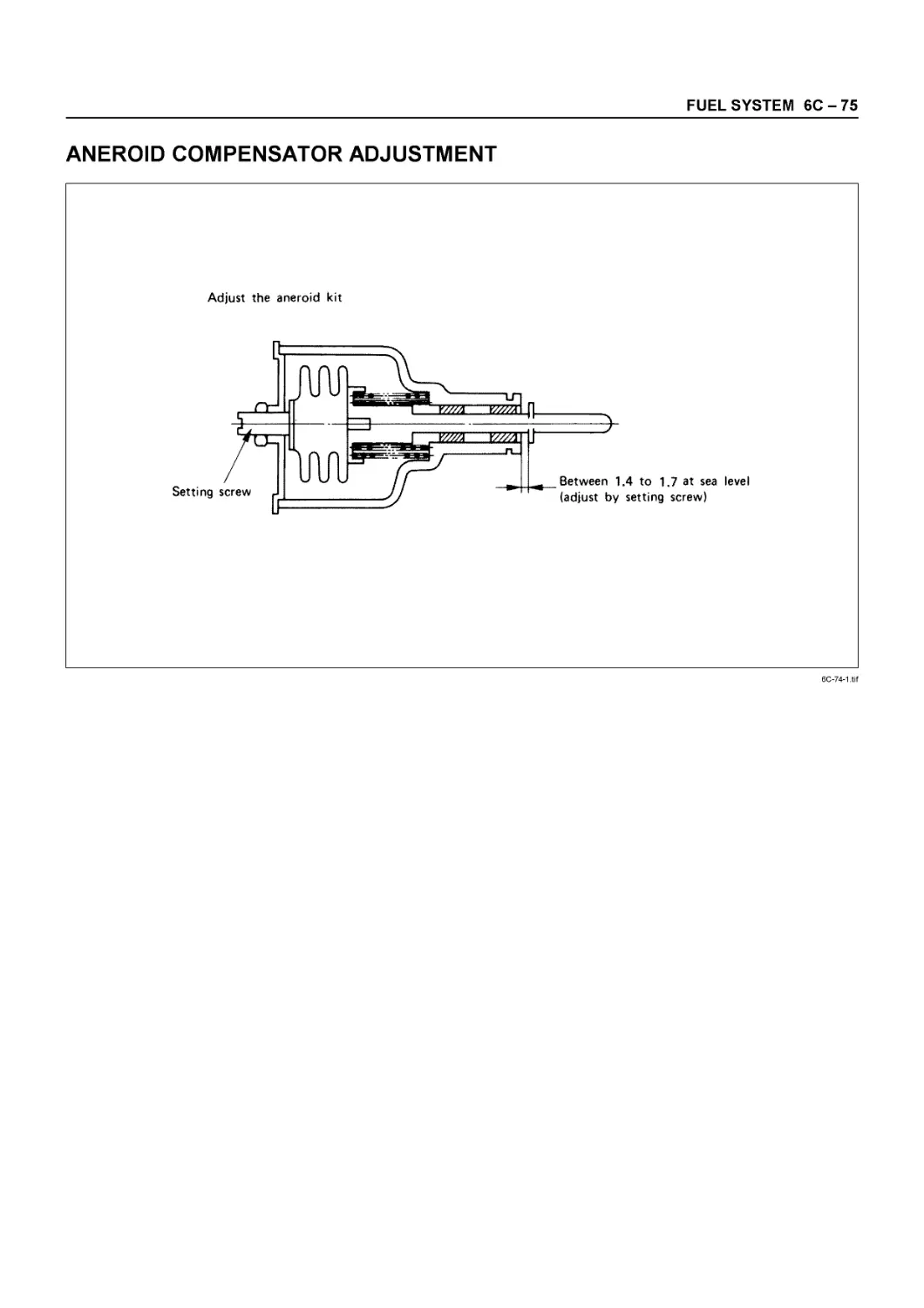
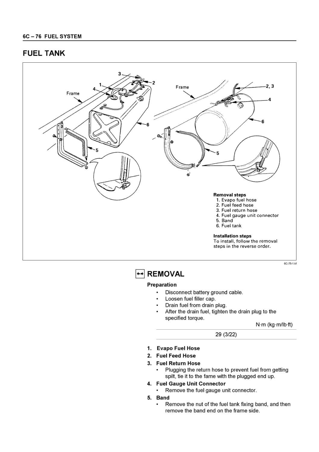
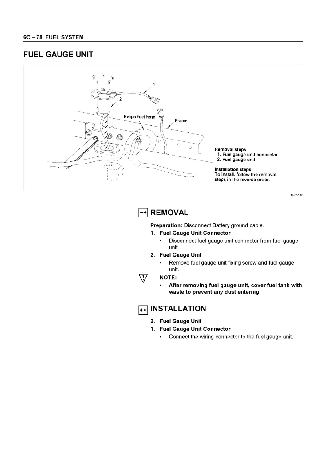
/

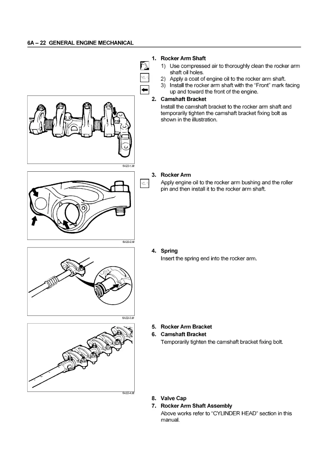


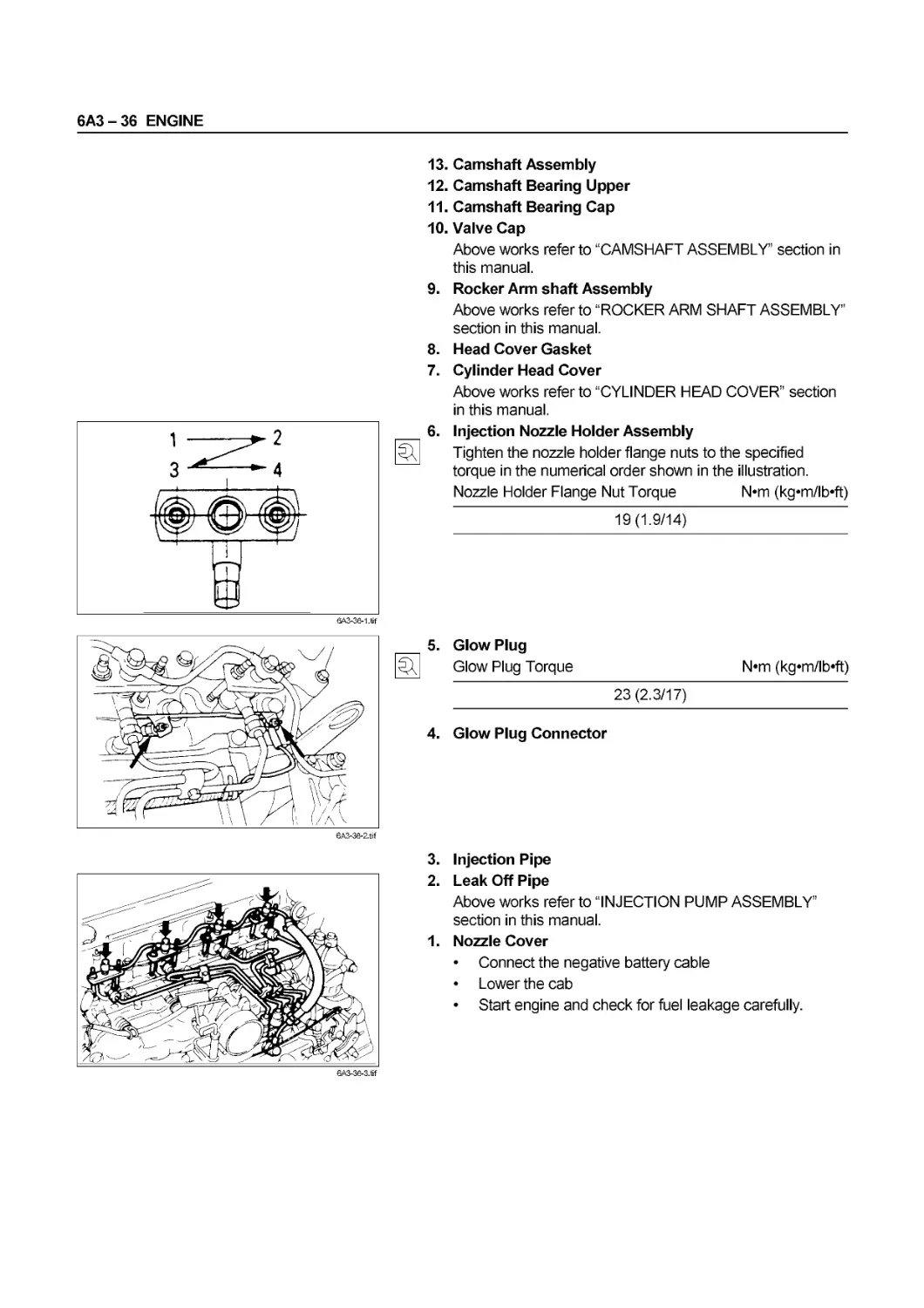

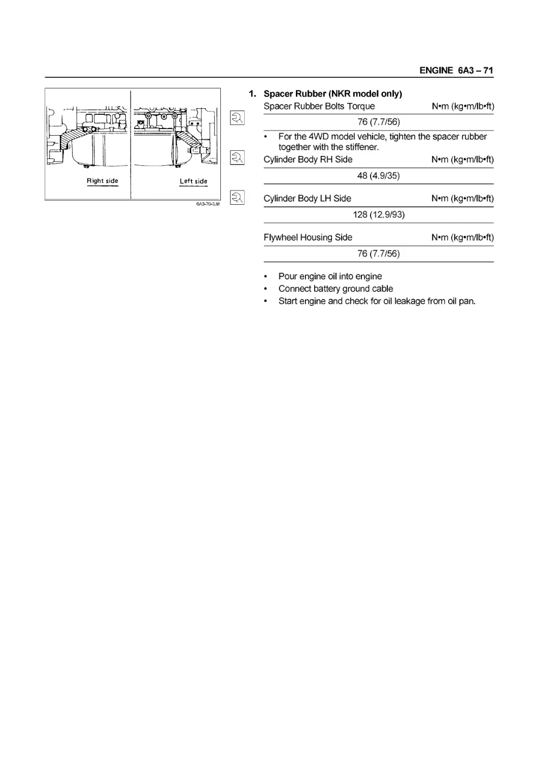
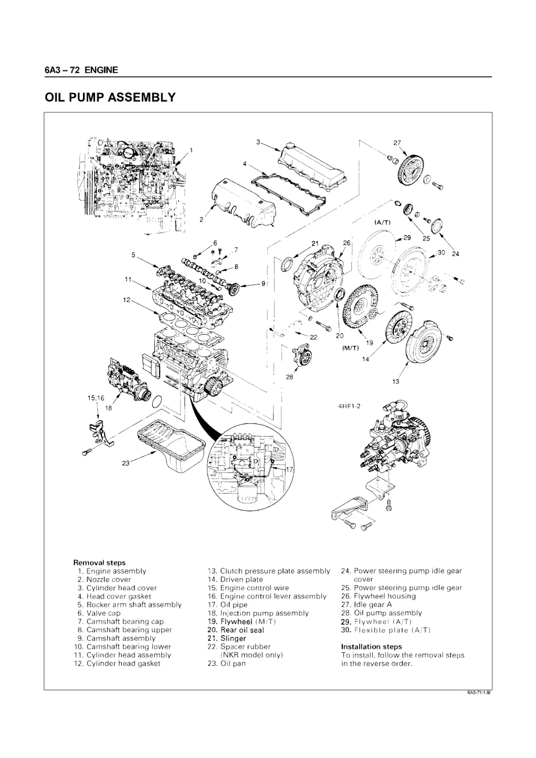
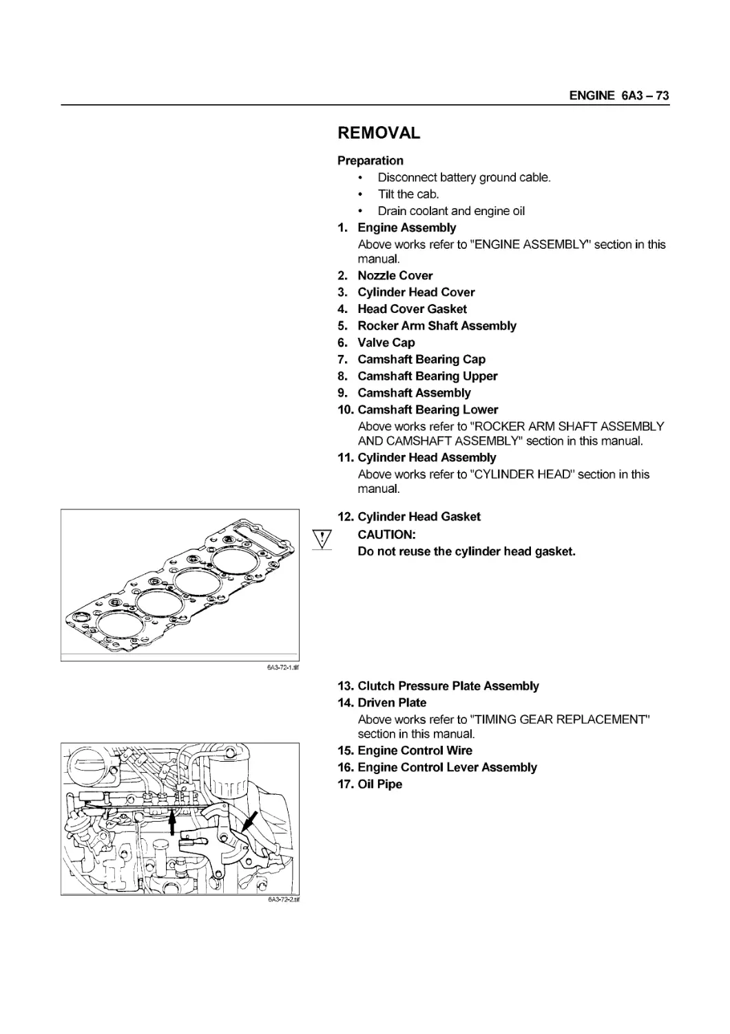
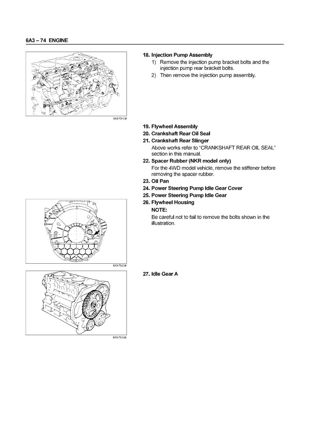

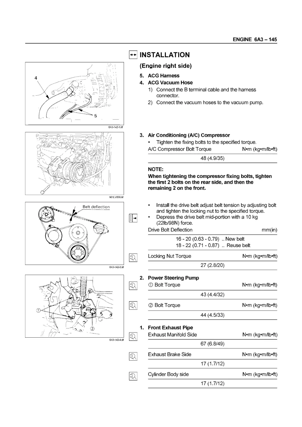

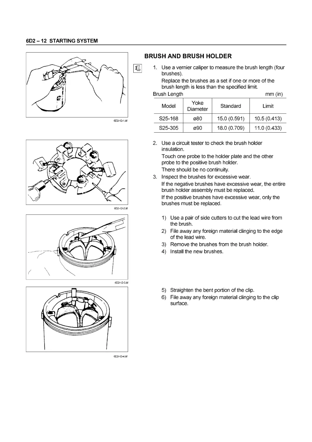


Tags: cars maintenance repair manuals
Year: 1996


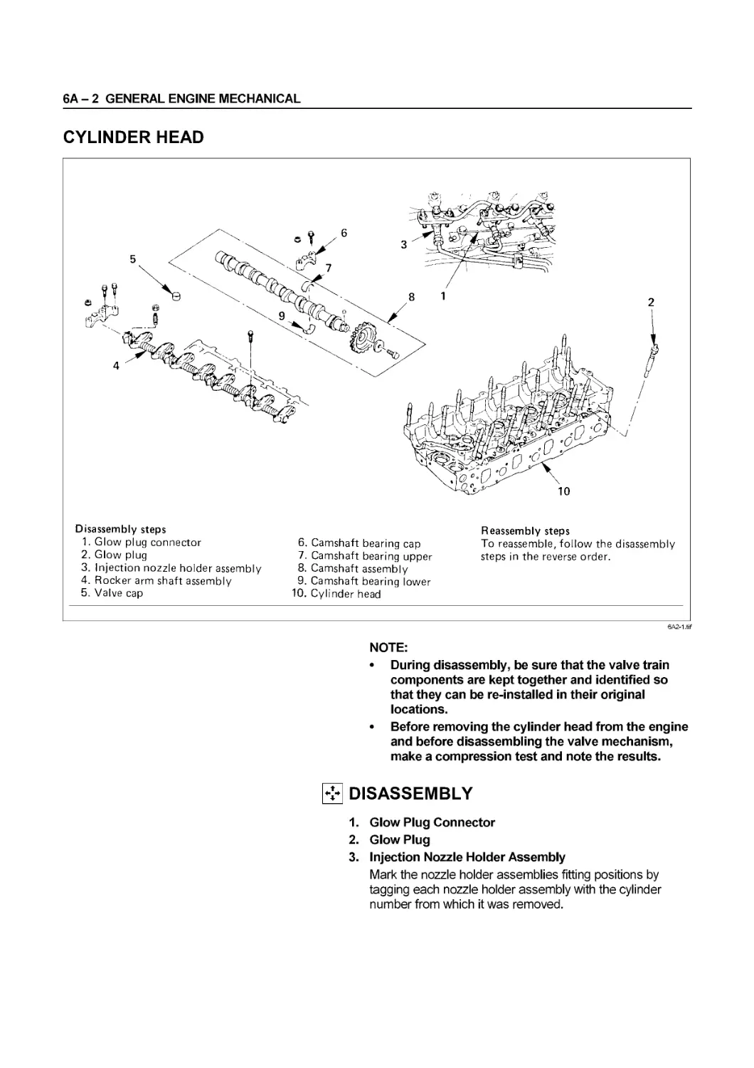
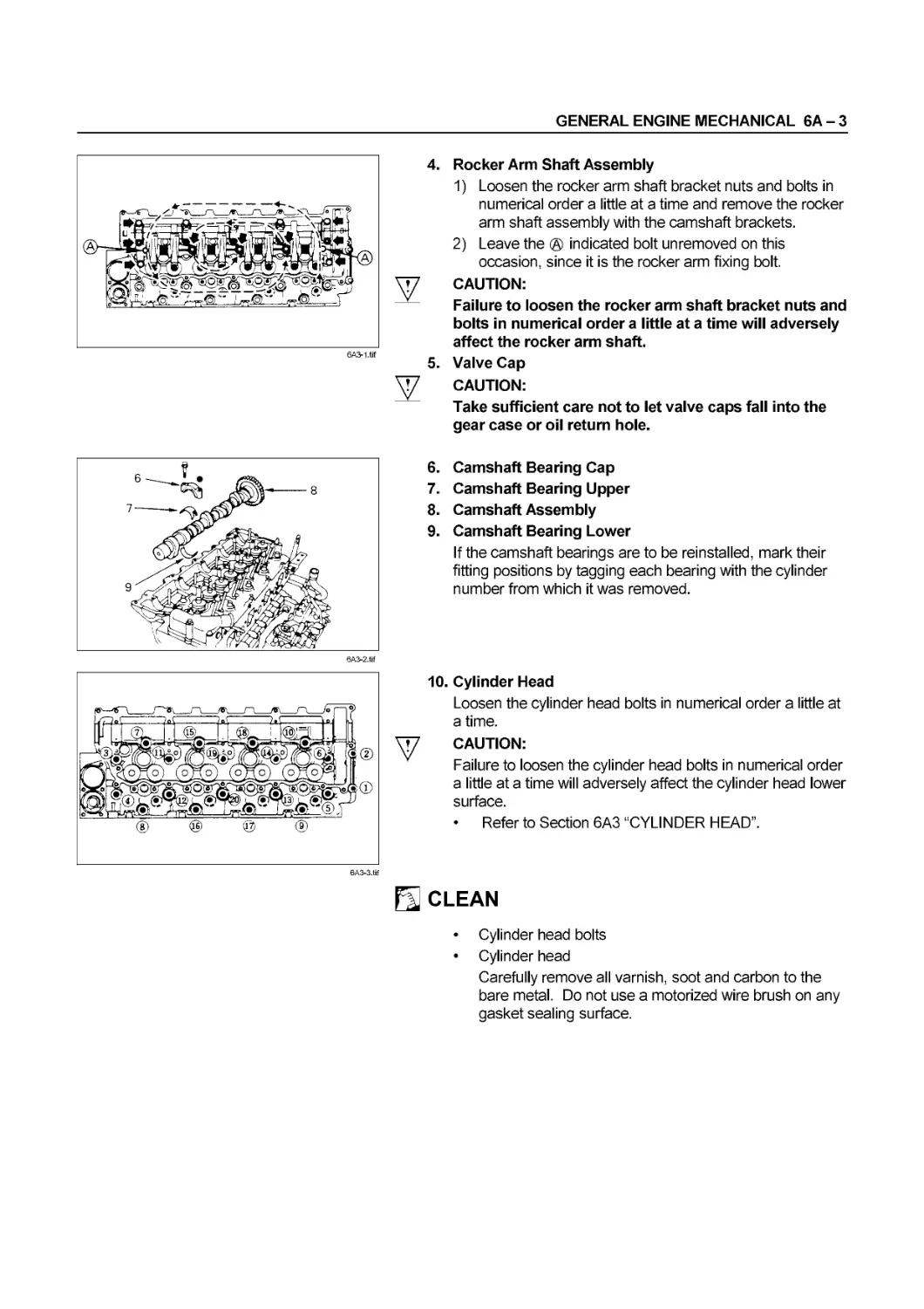
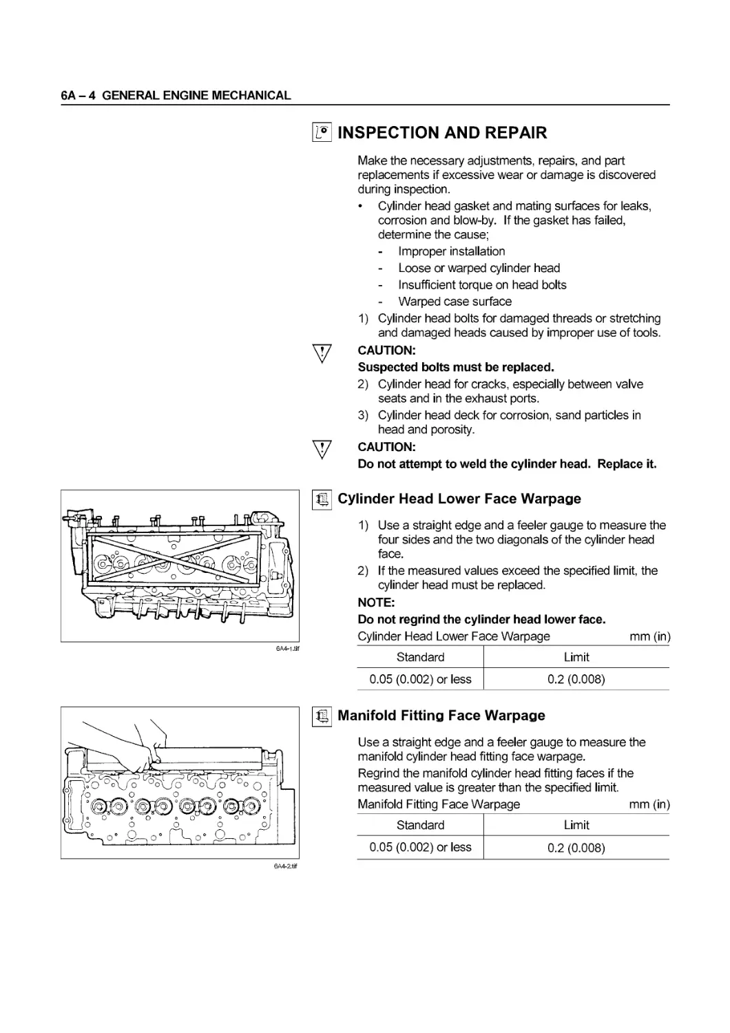
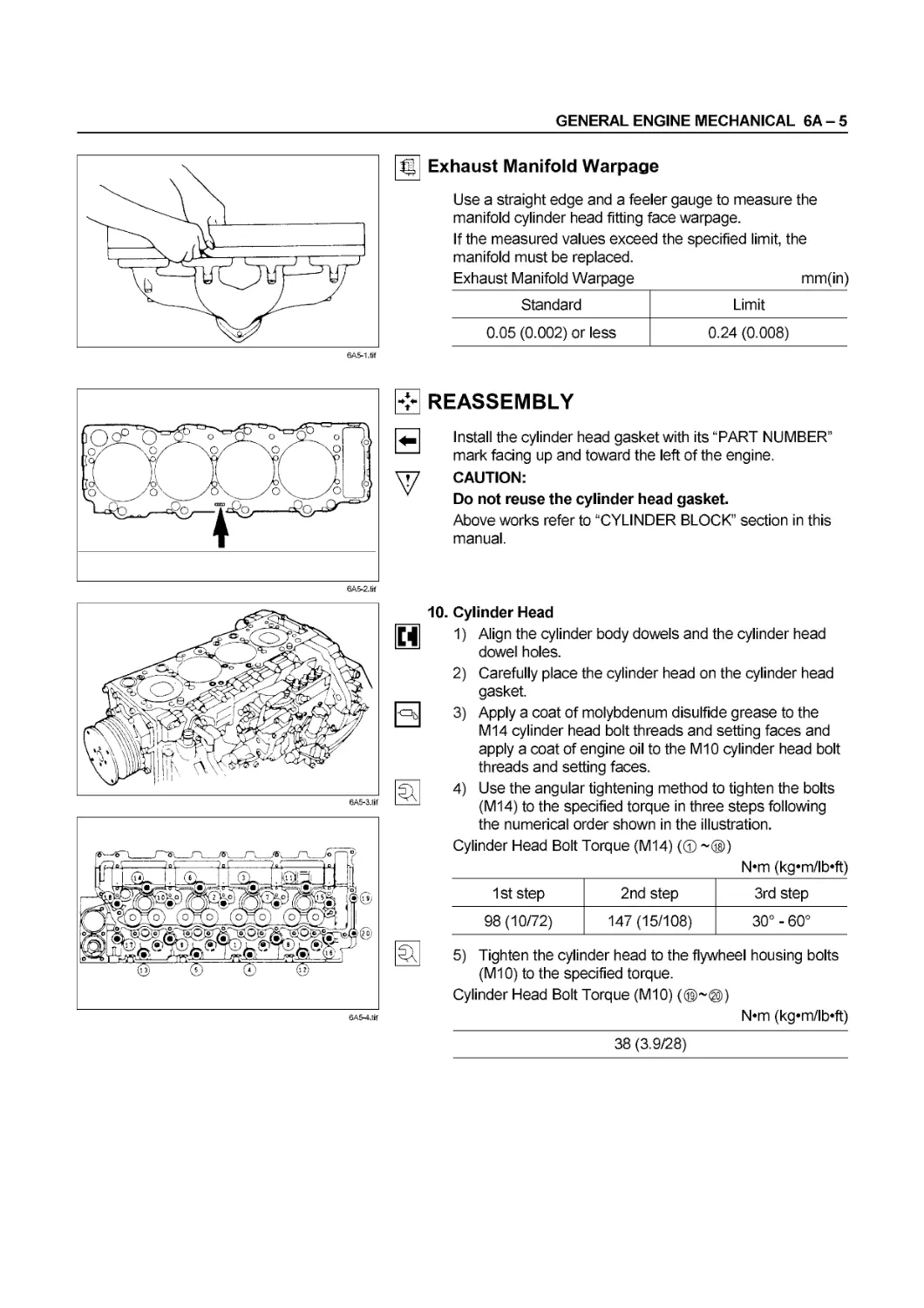
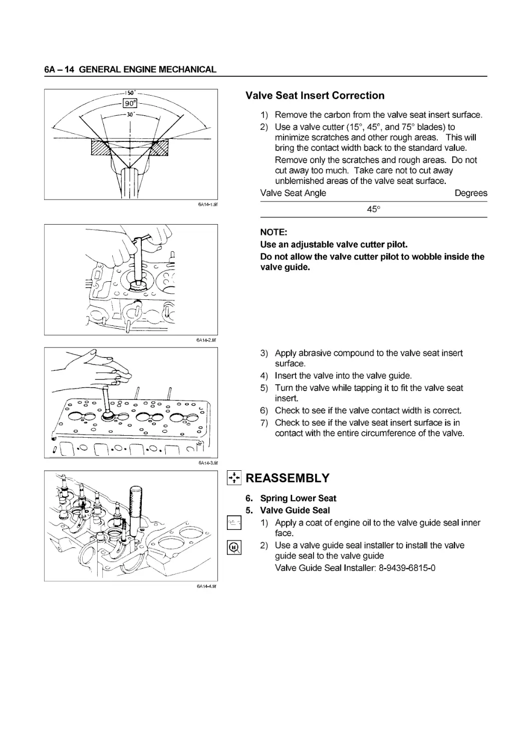
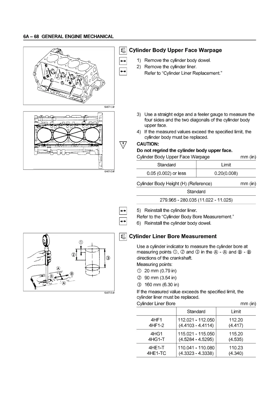
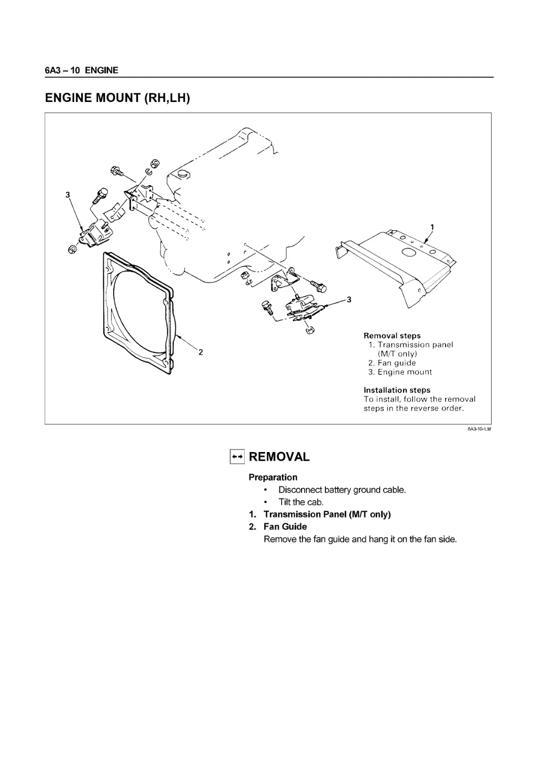
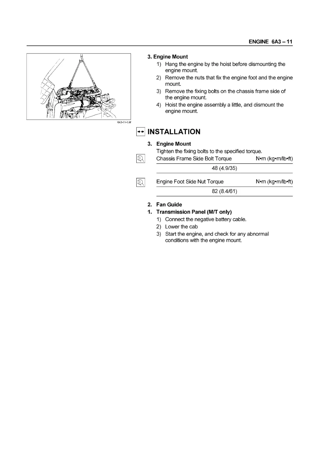
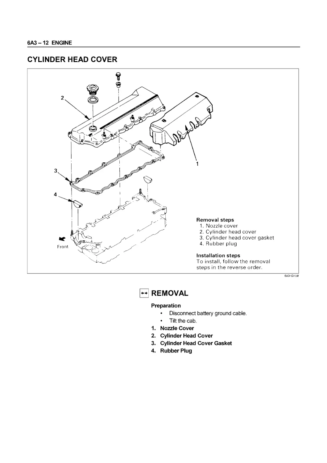
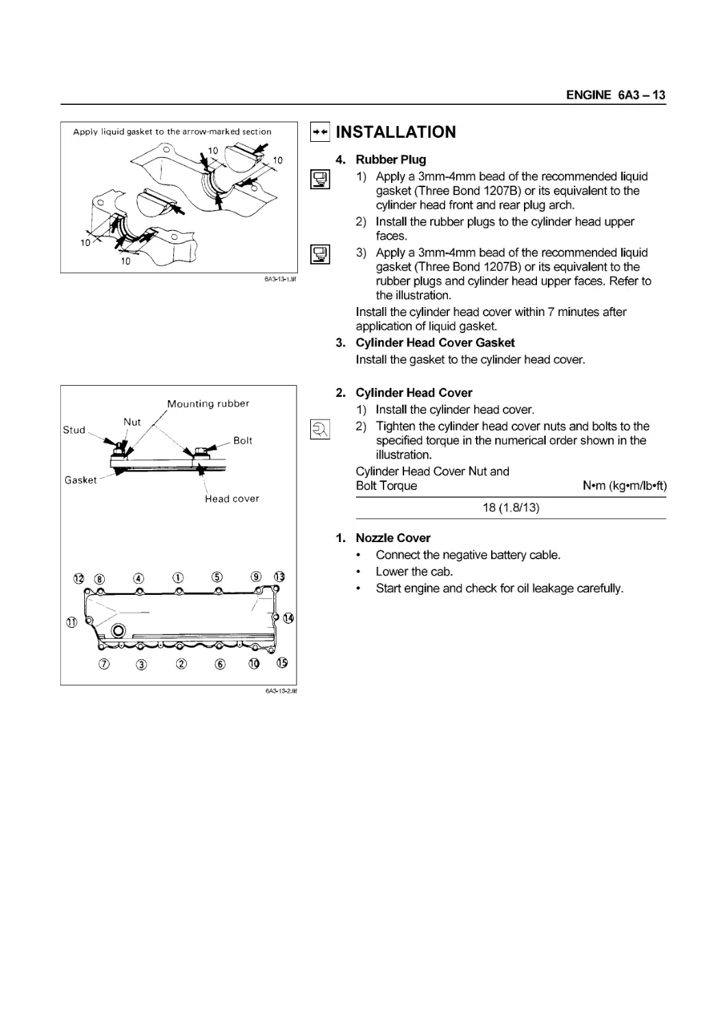
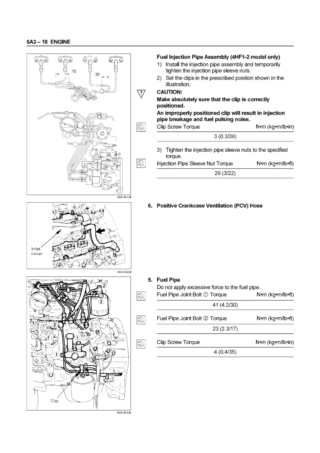
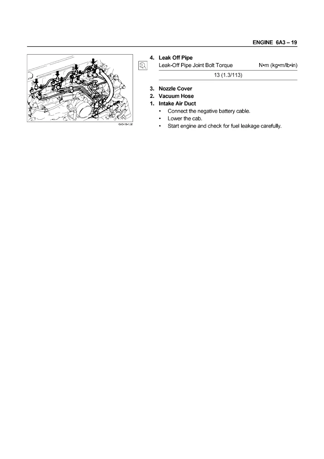
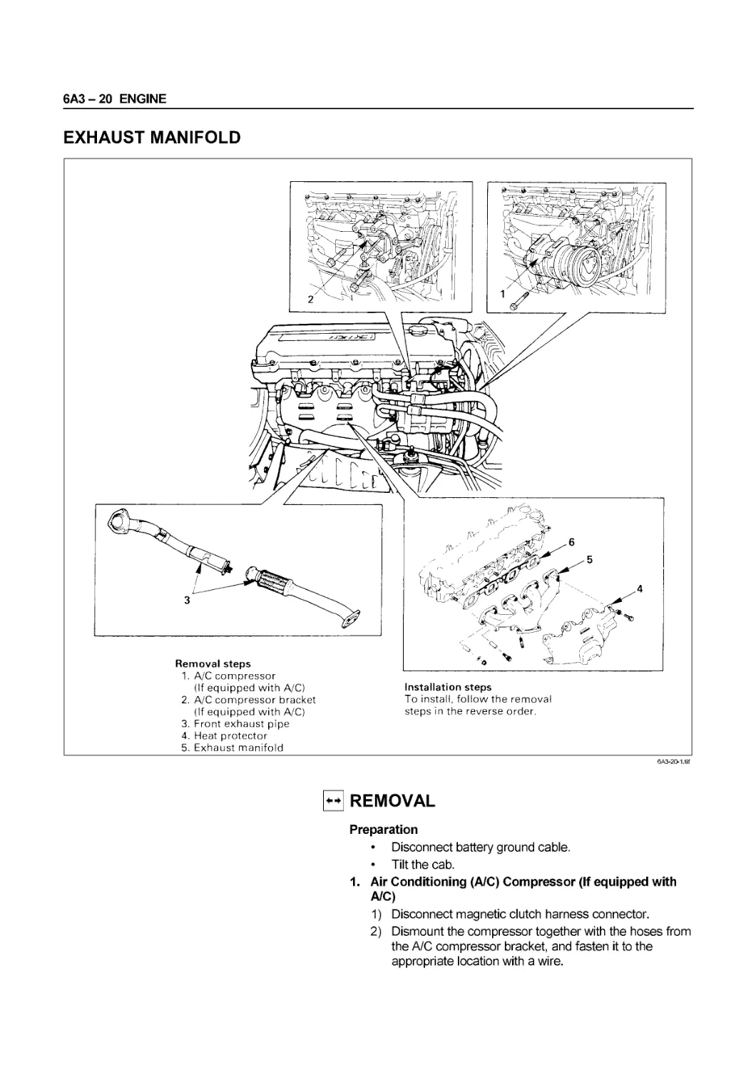
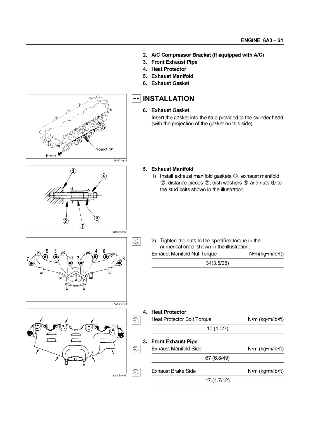
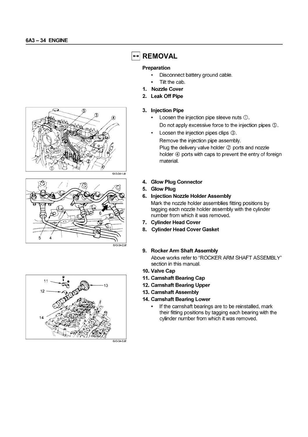
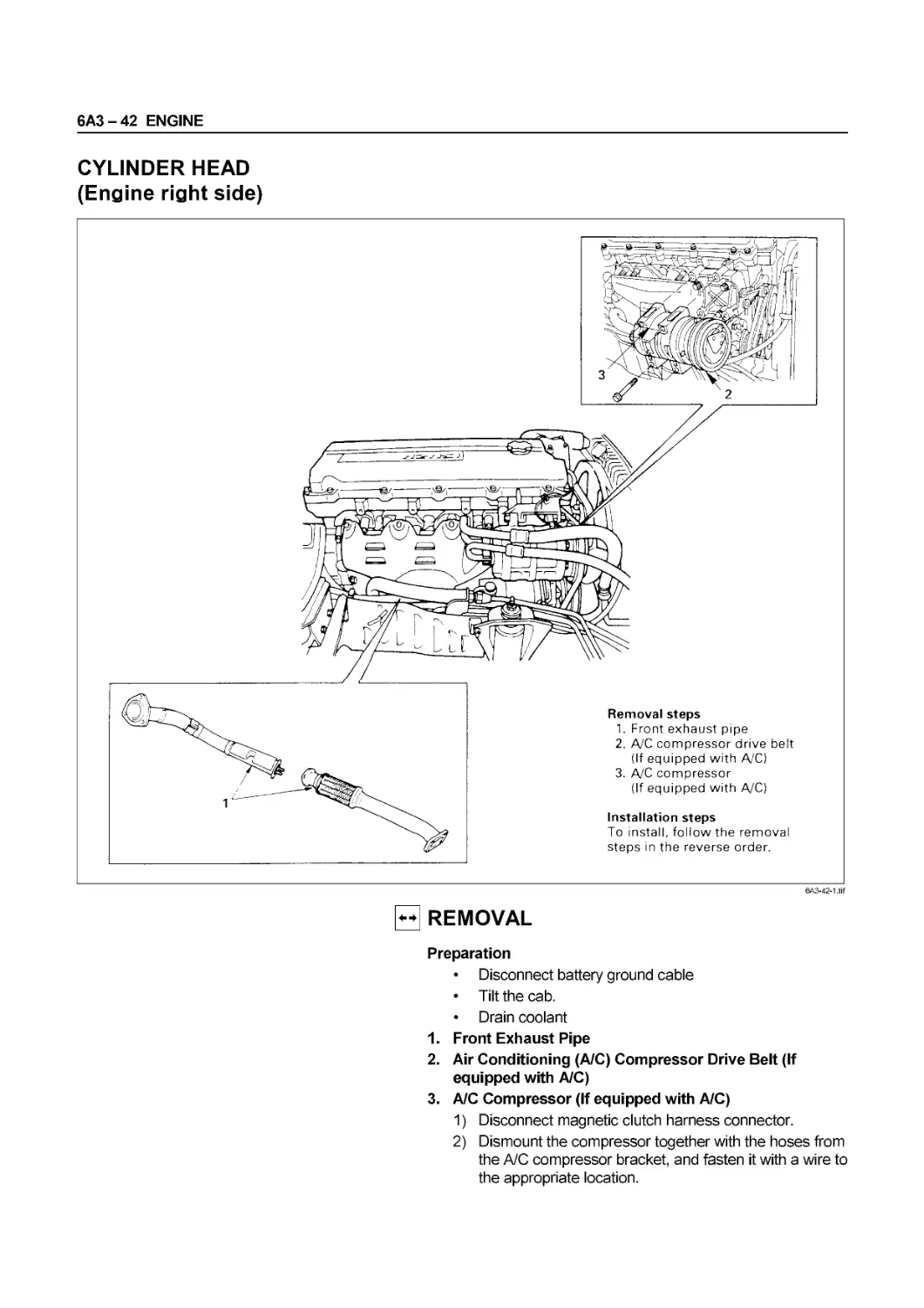
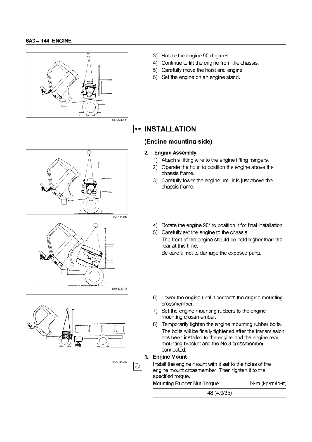
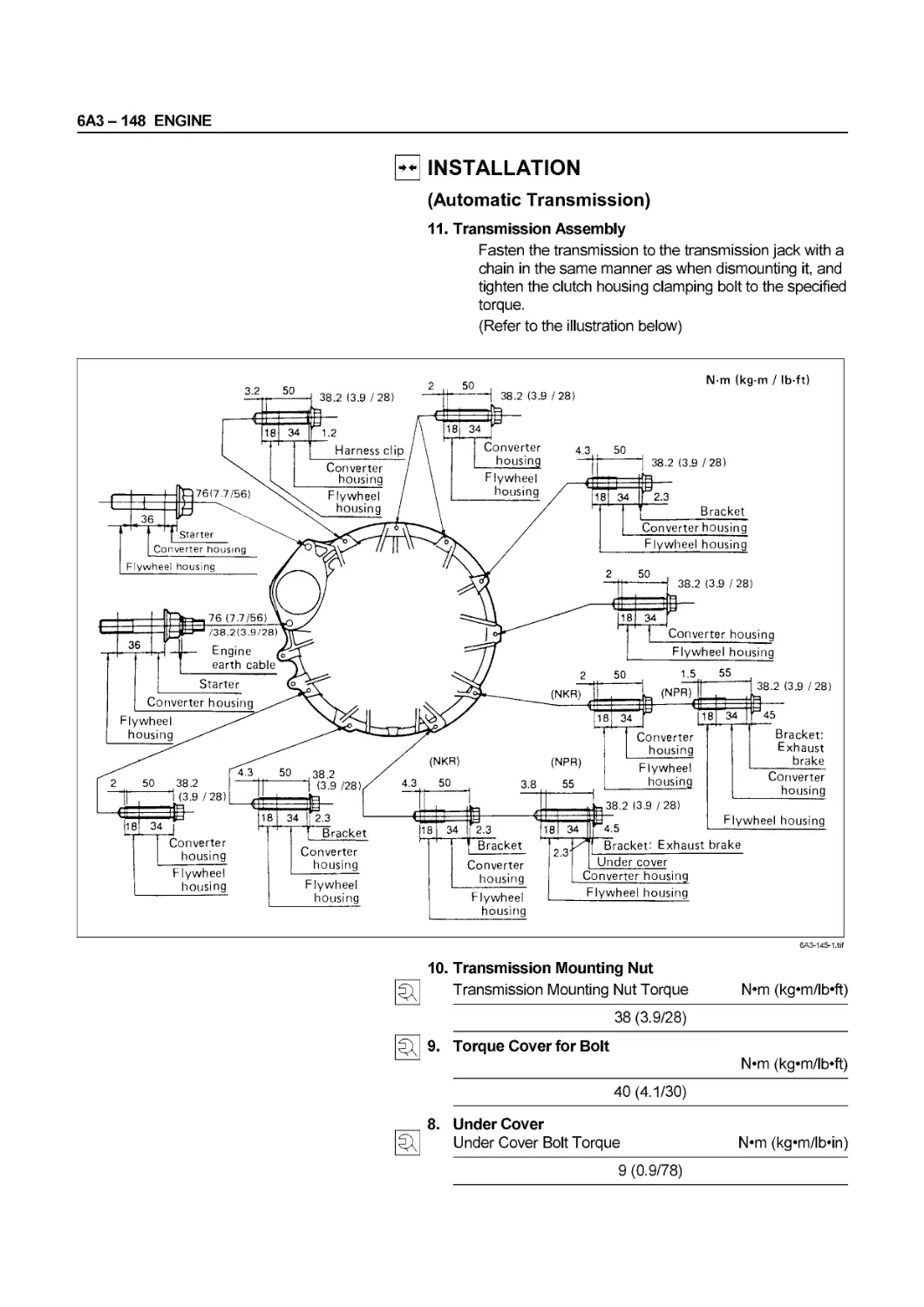
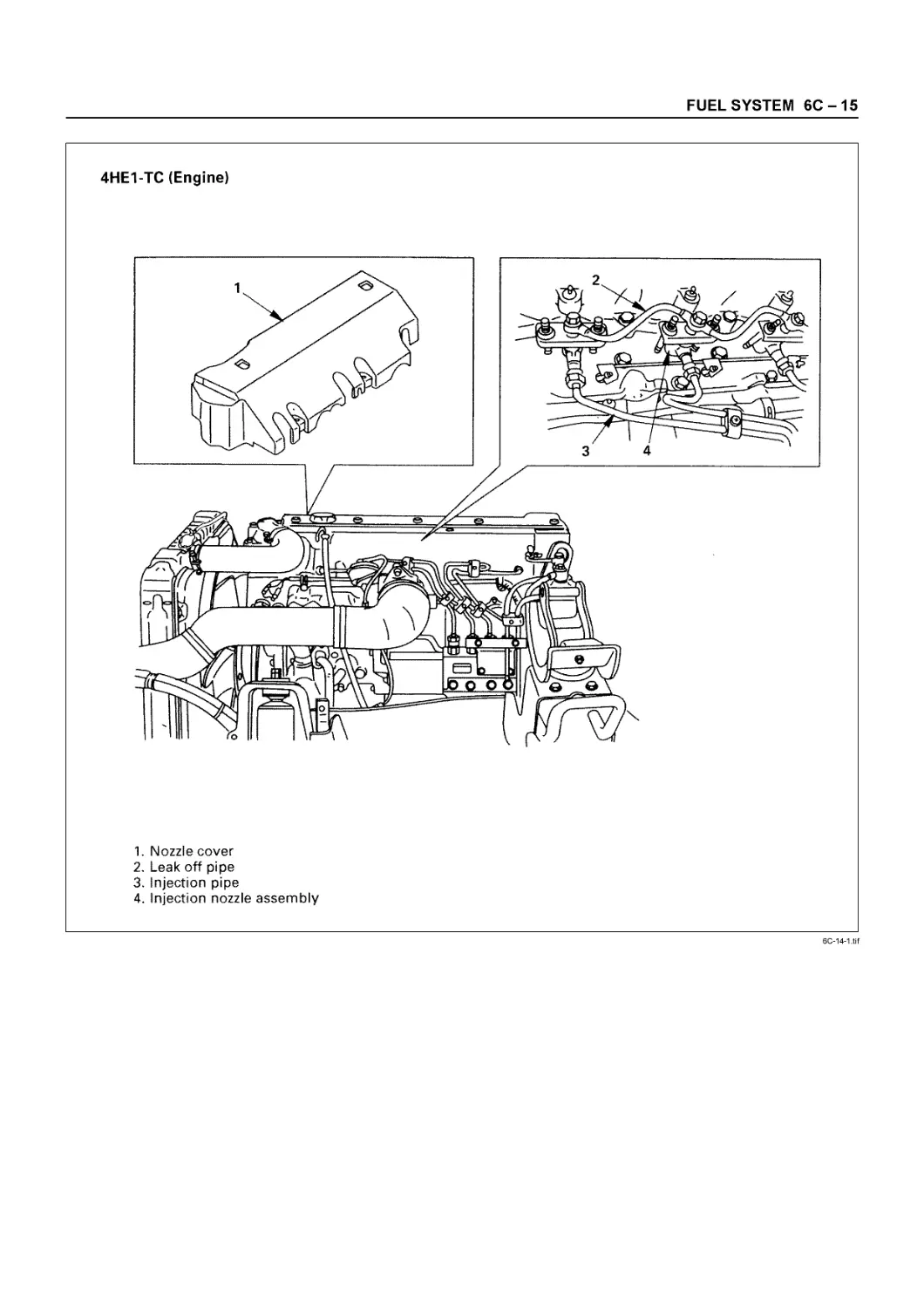
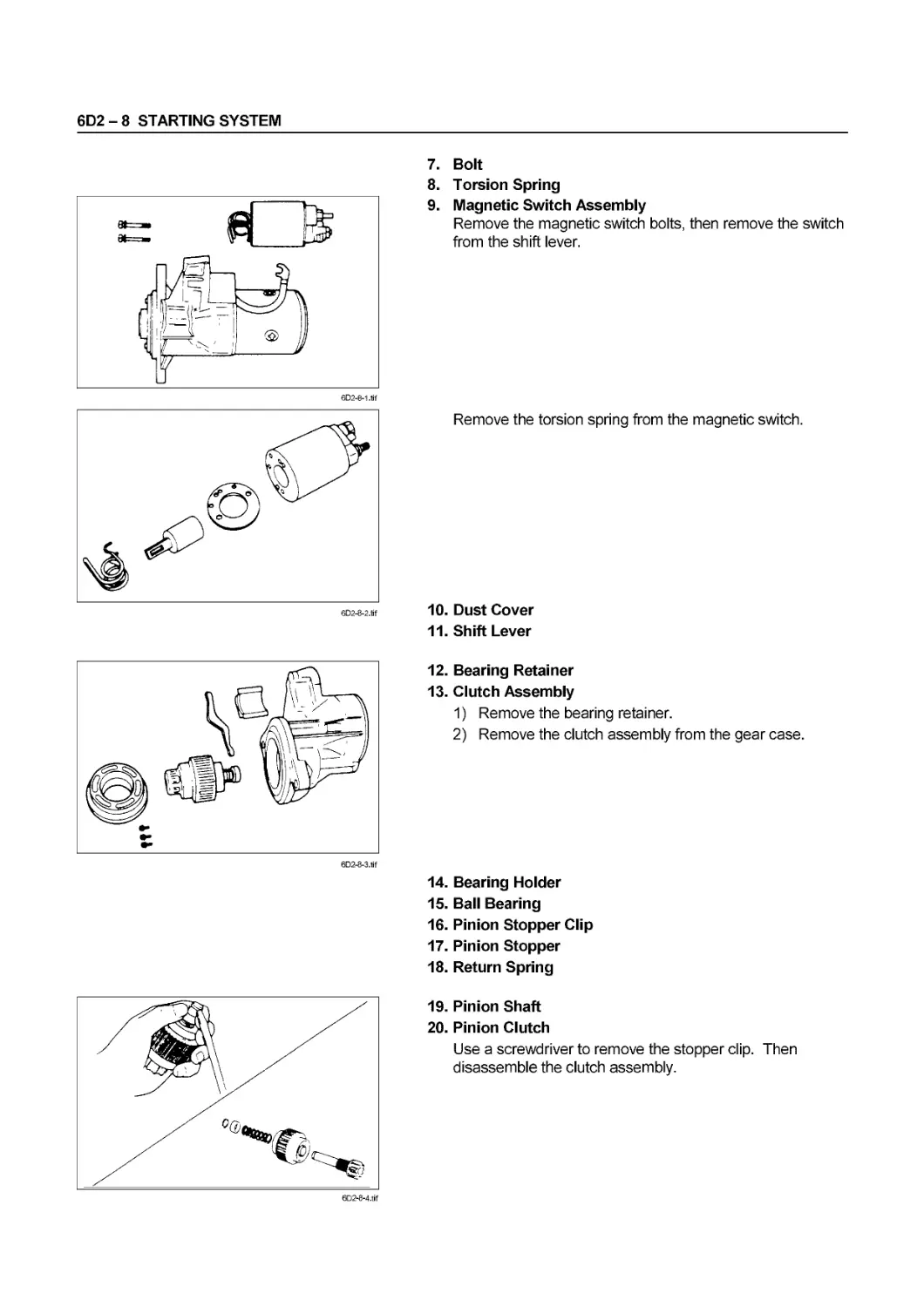
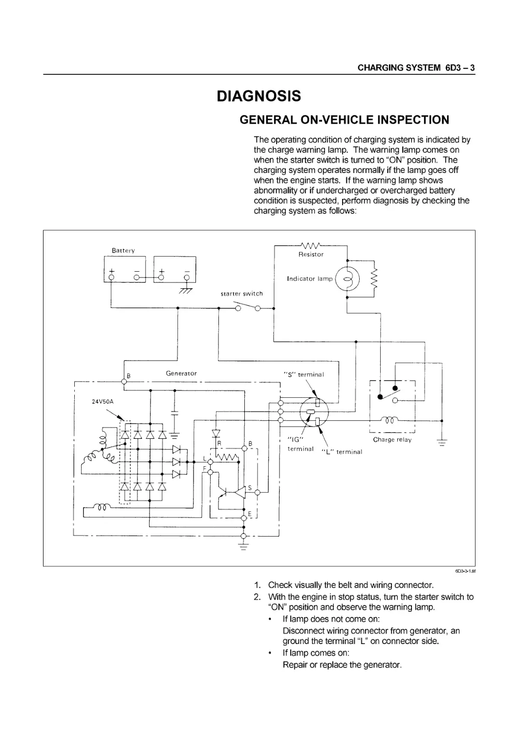
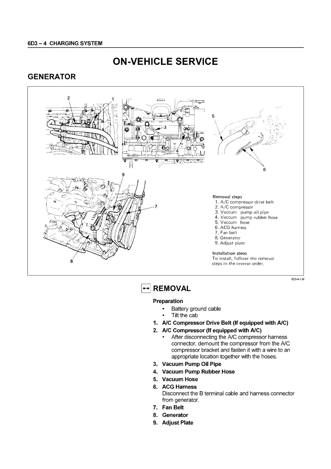
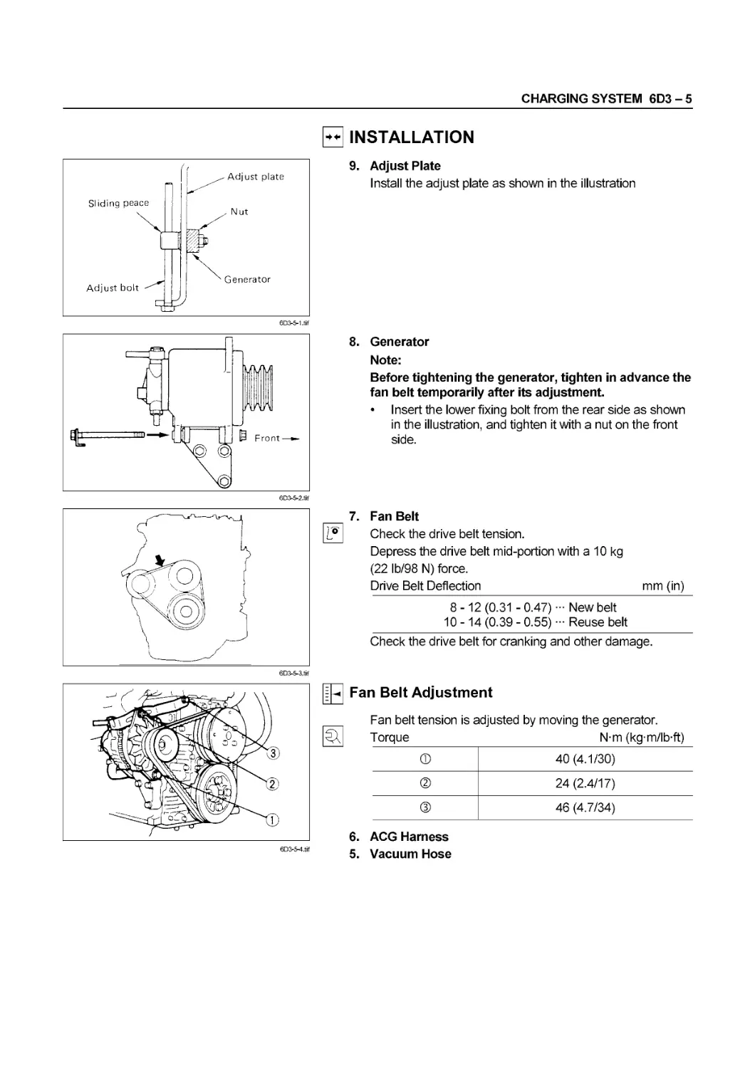
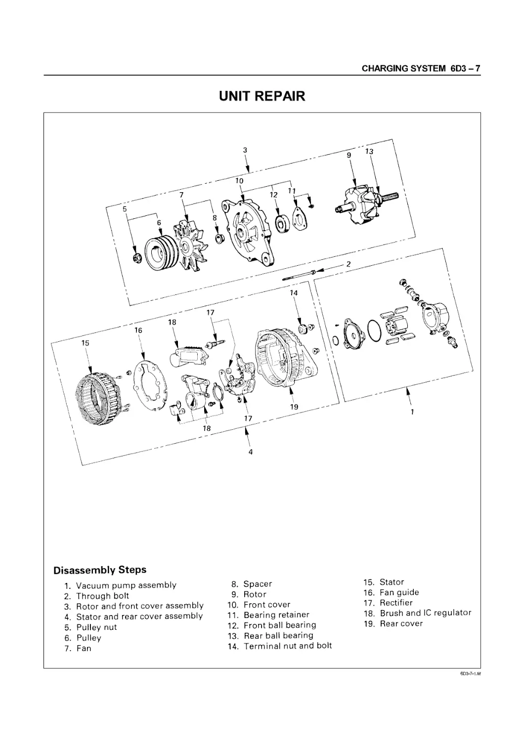
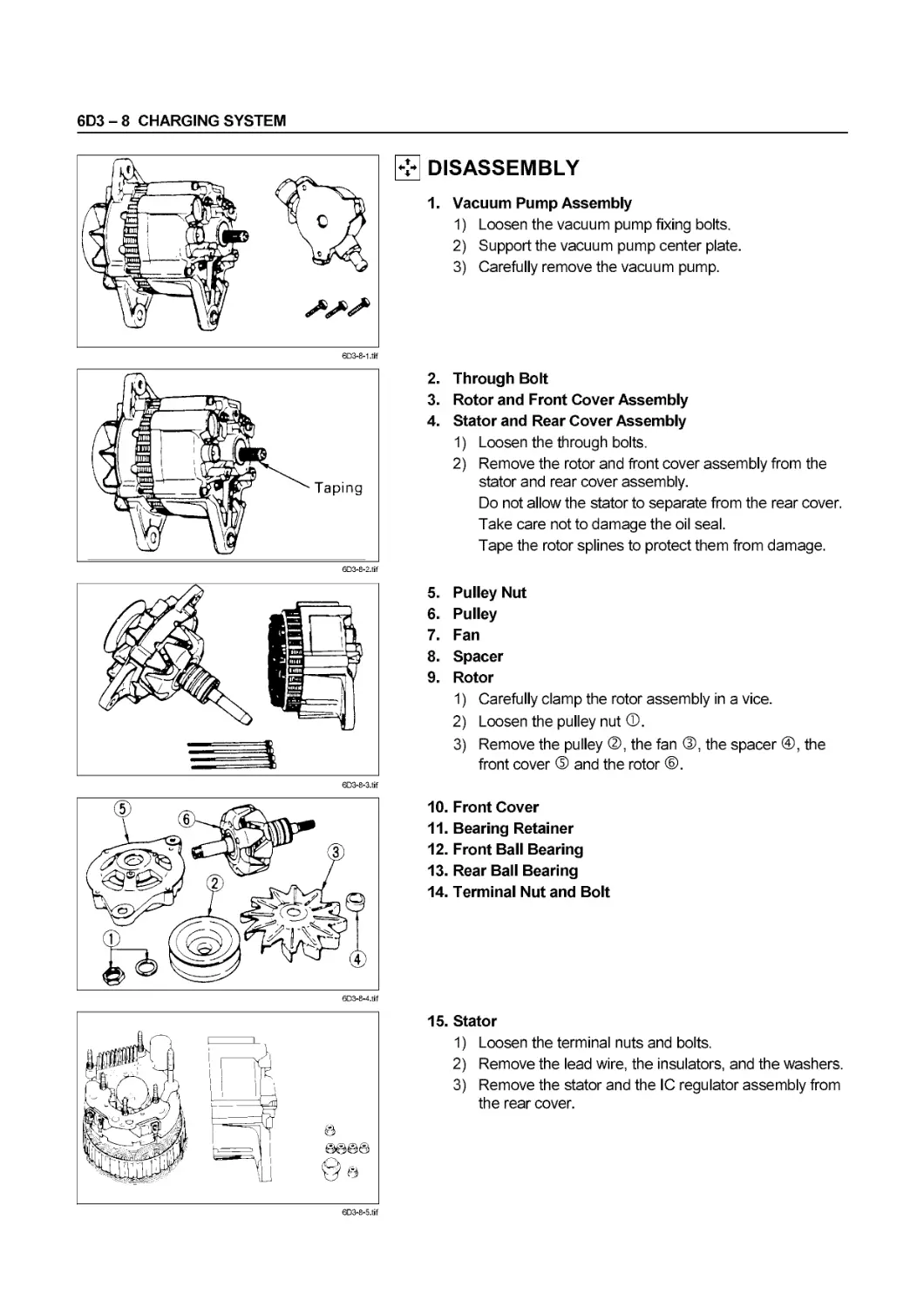
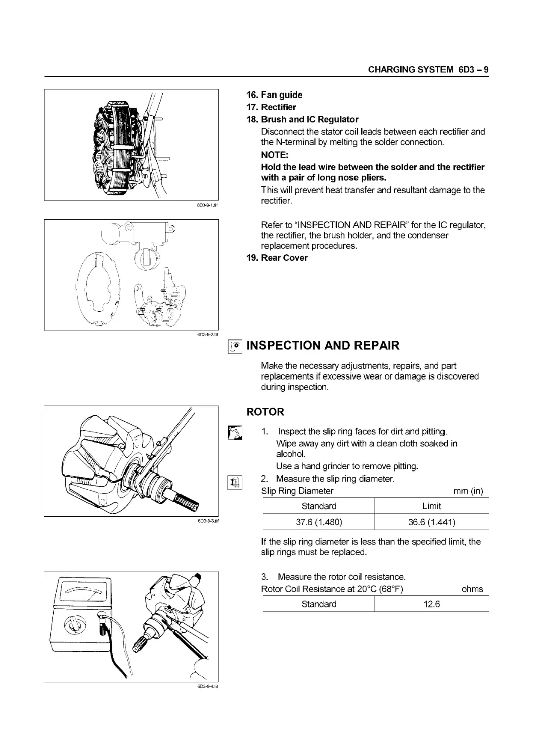
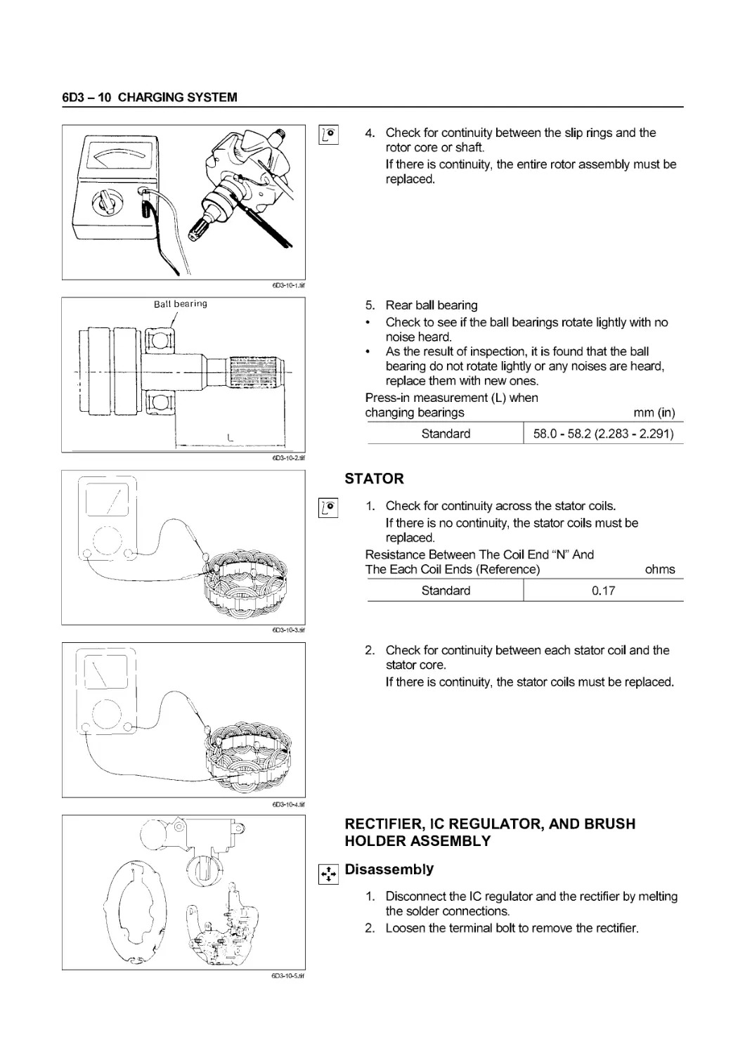
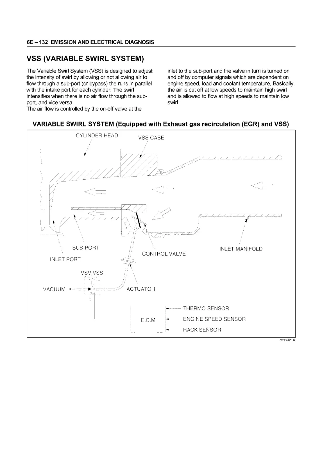
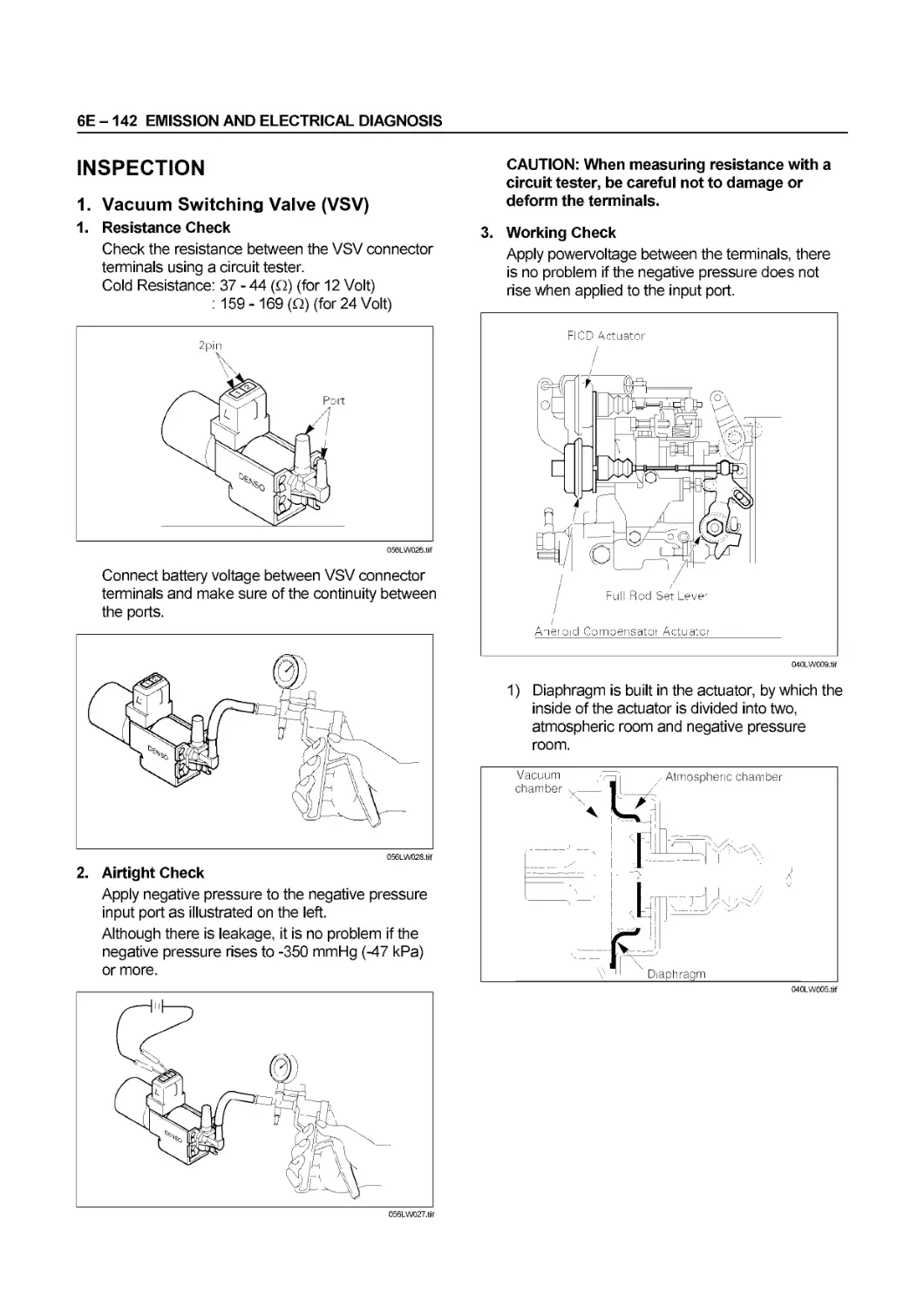
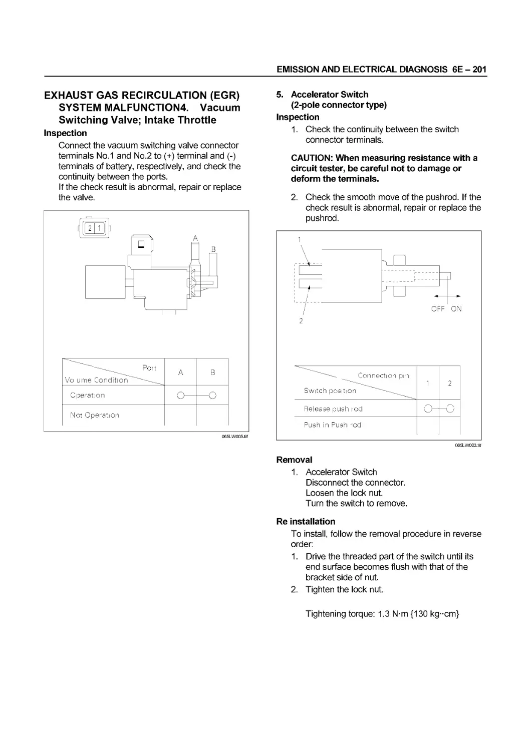
Text
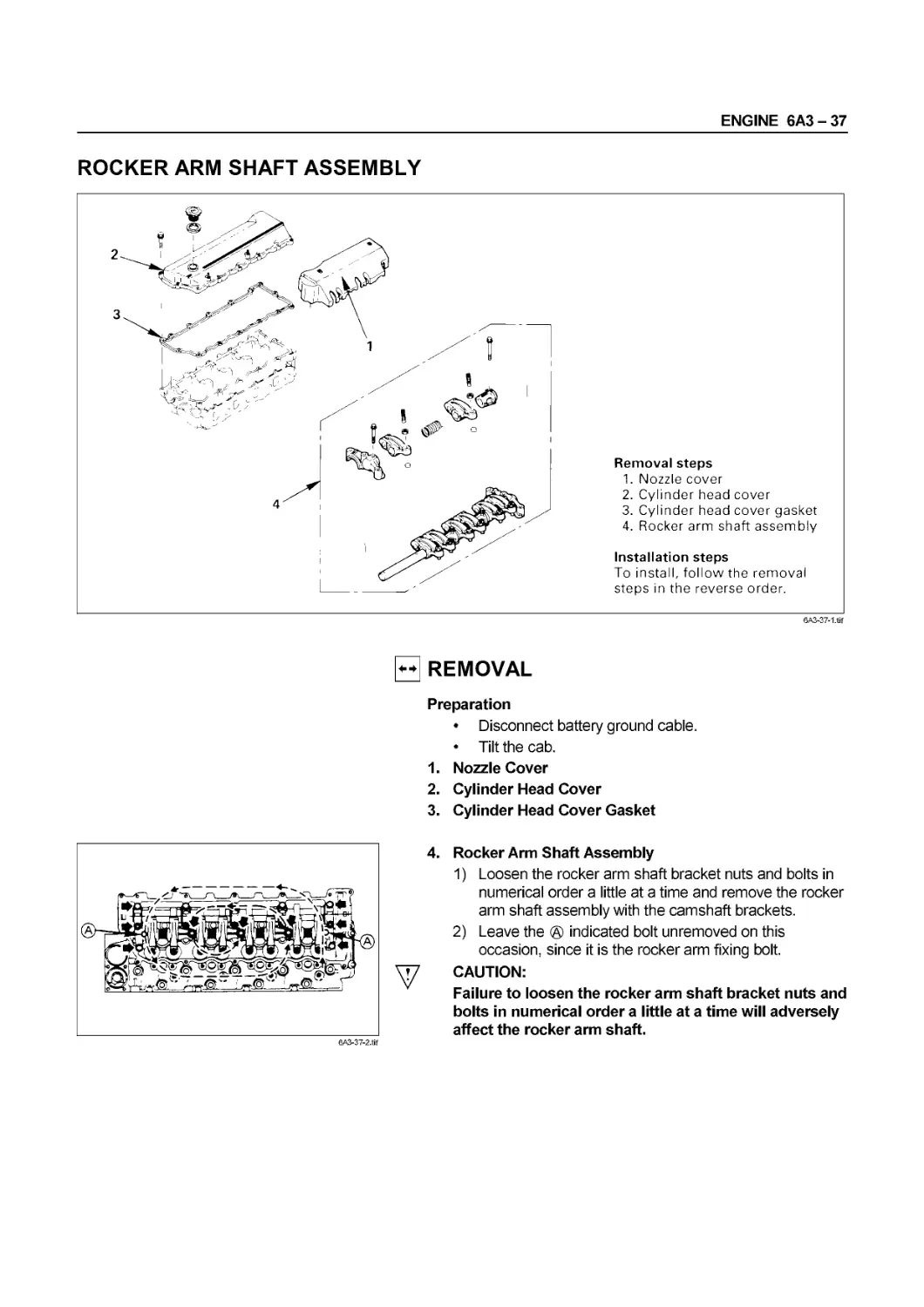
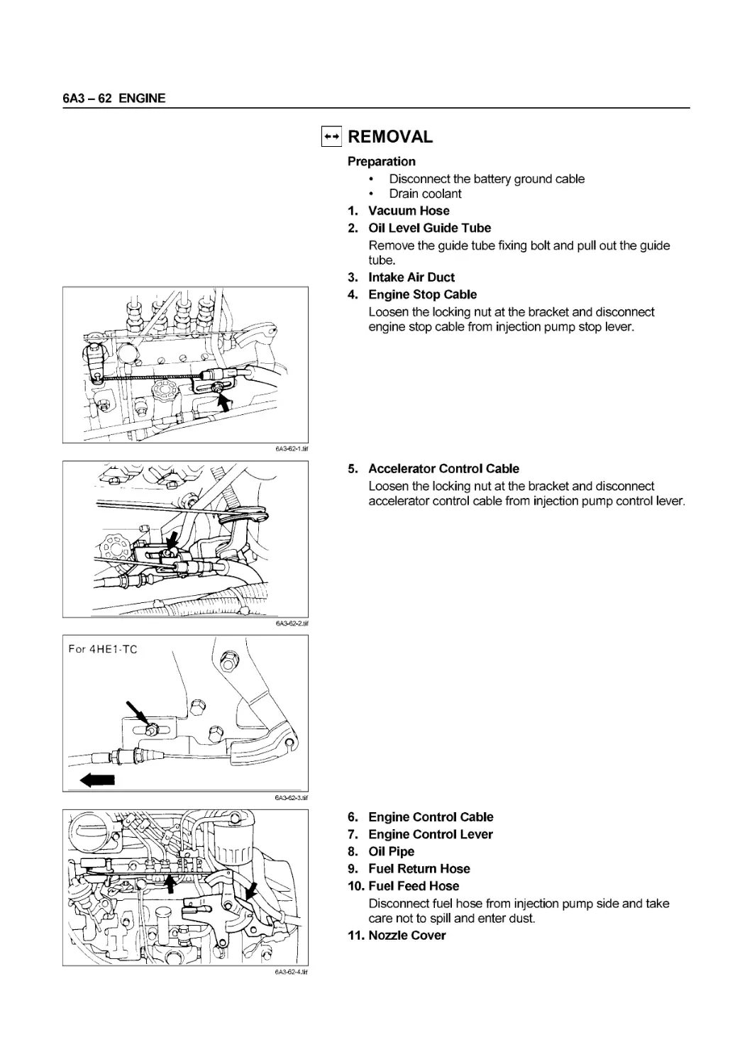
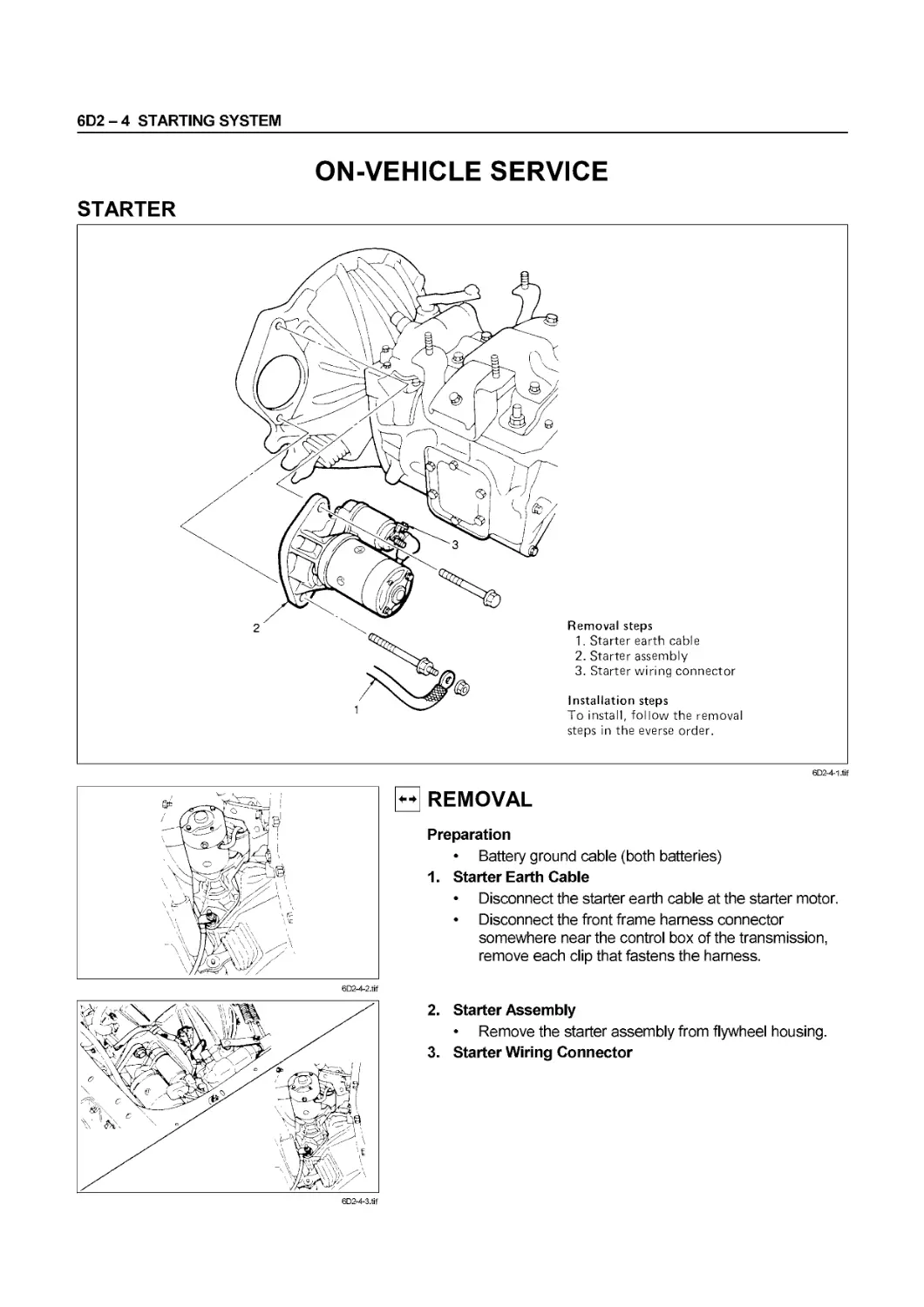
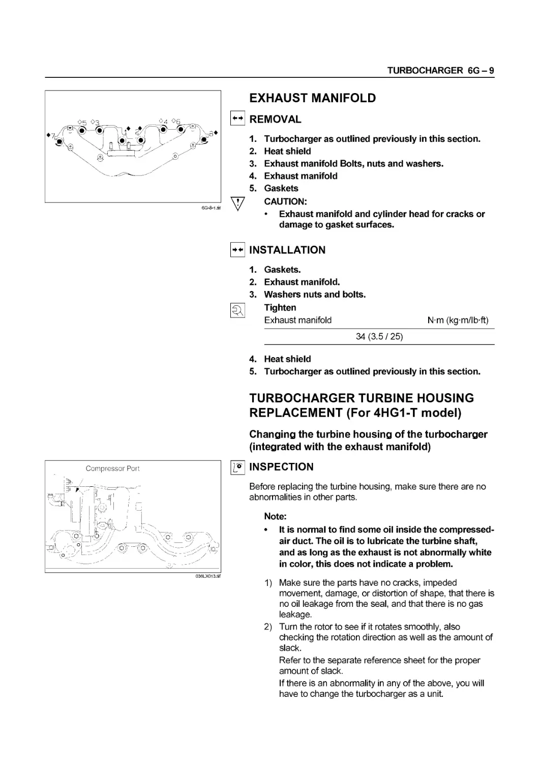
WORKSHOP MANUAL
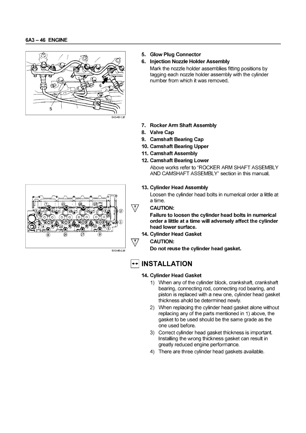
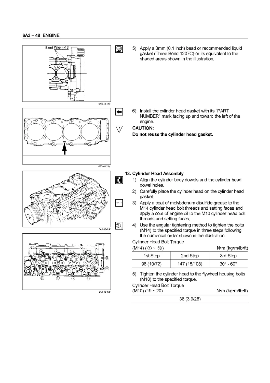
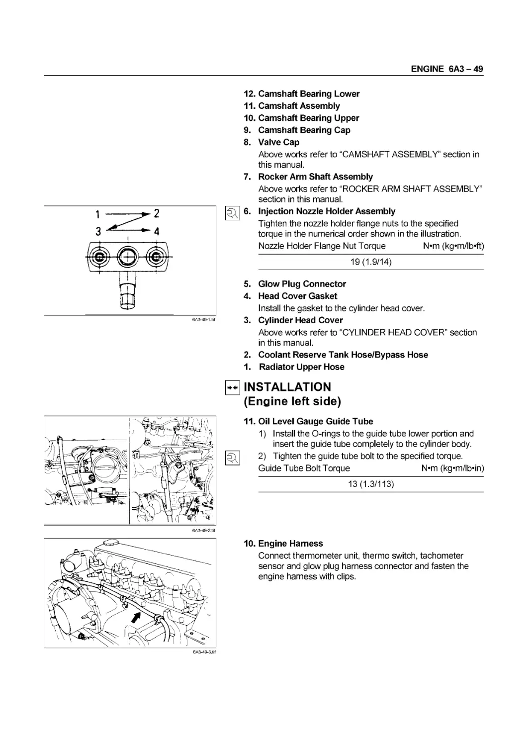
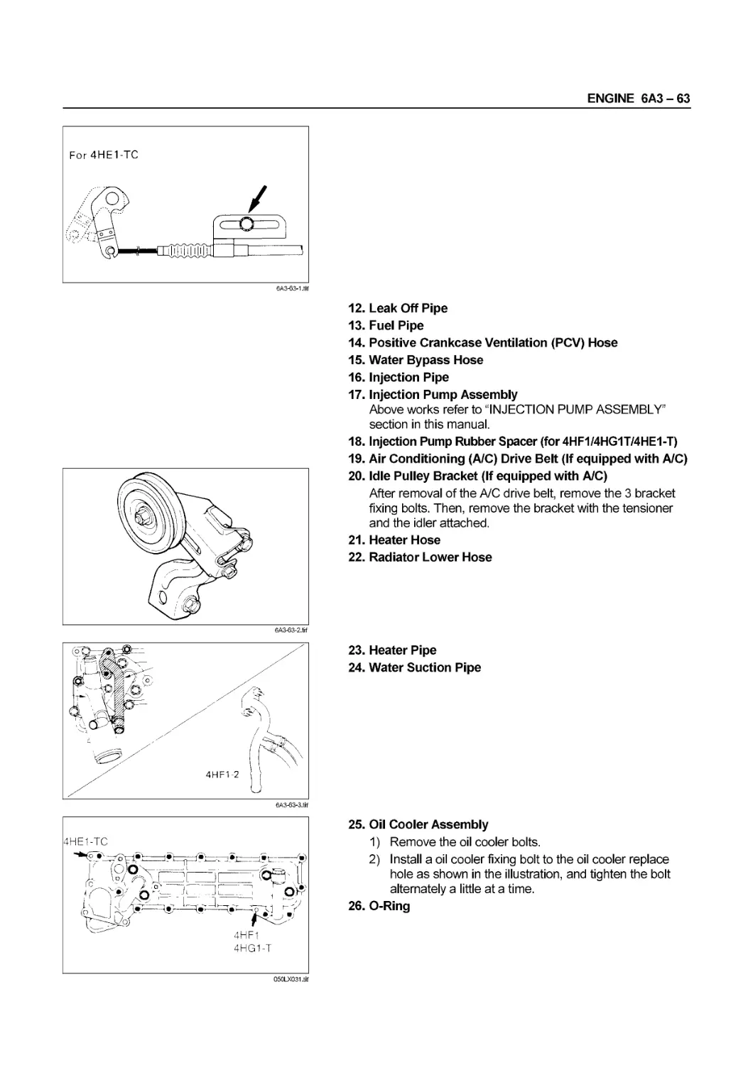
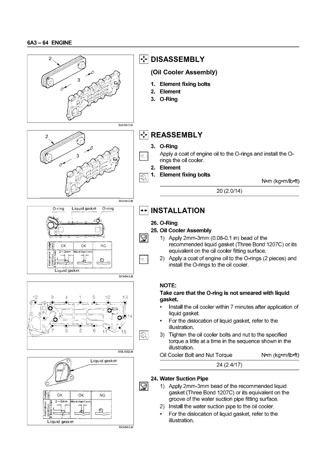
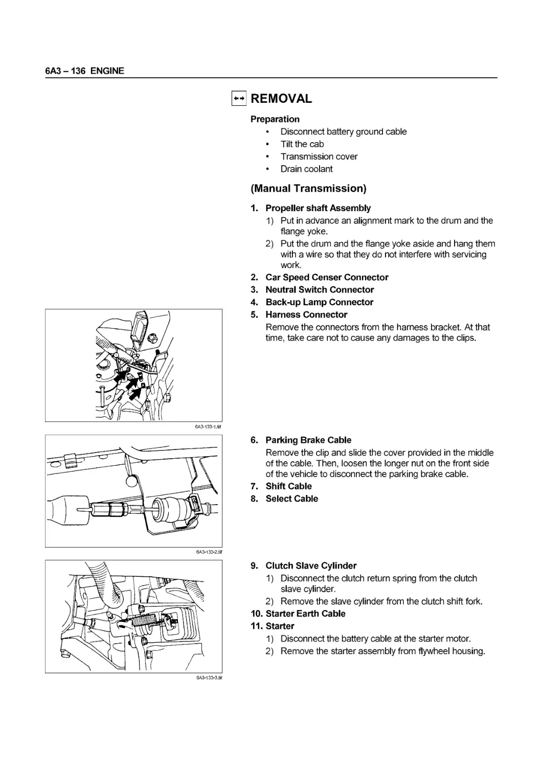
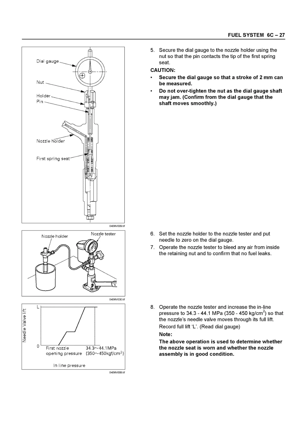
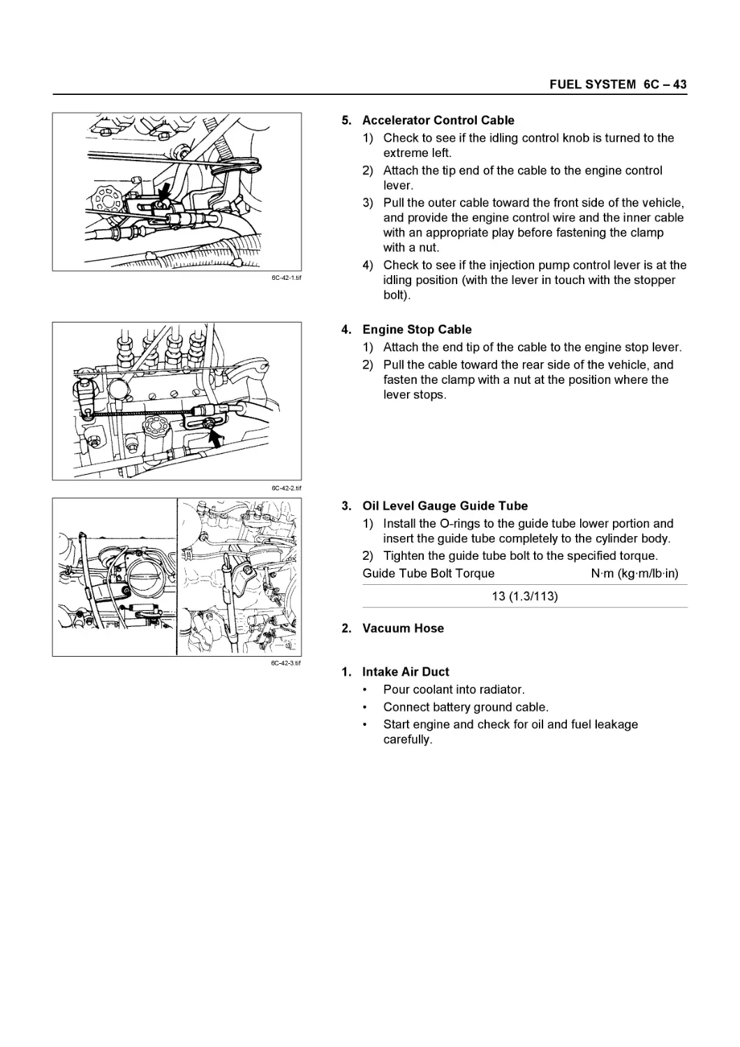
NHR • NKR • NPR
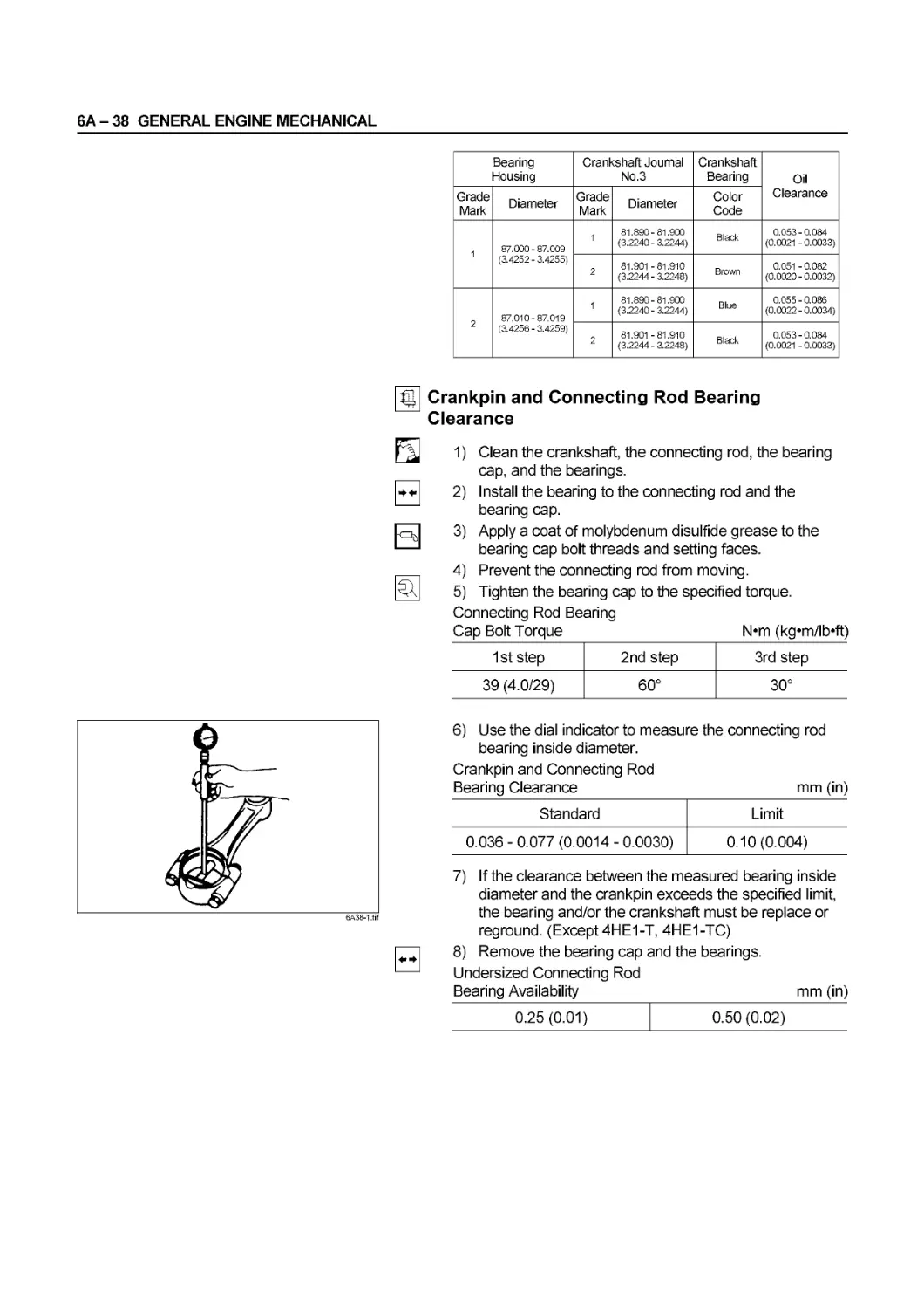
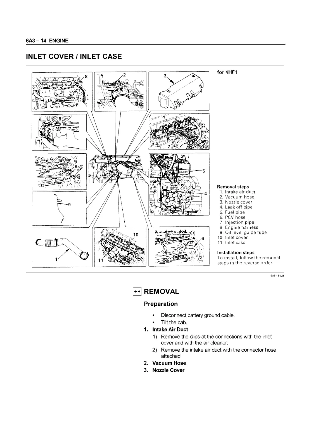
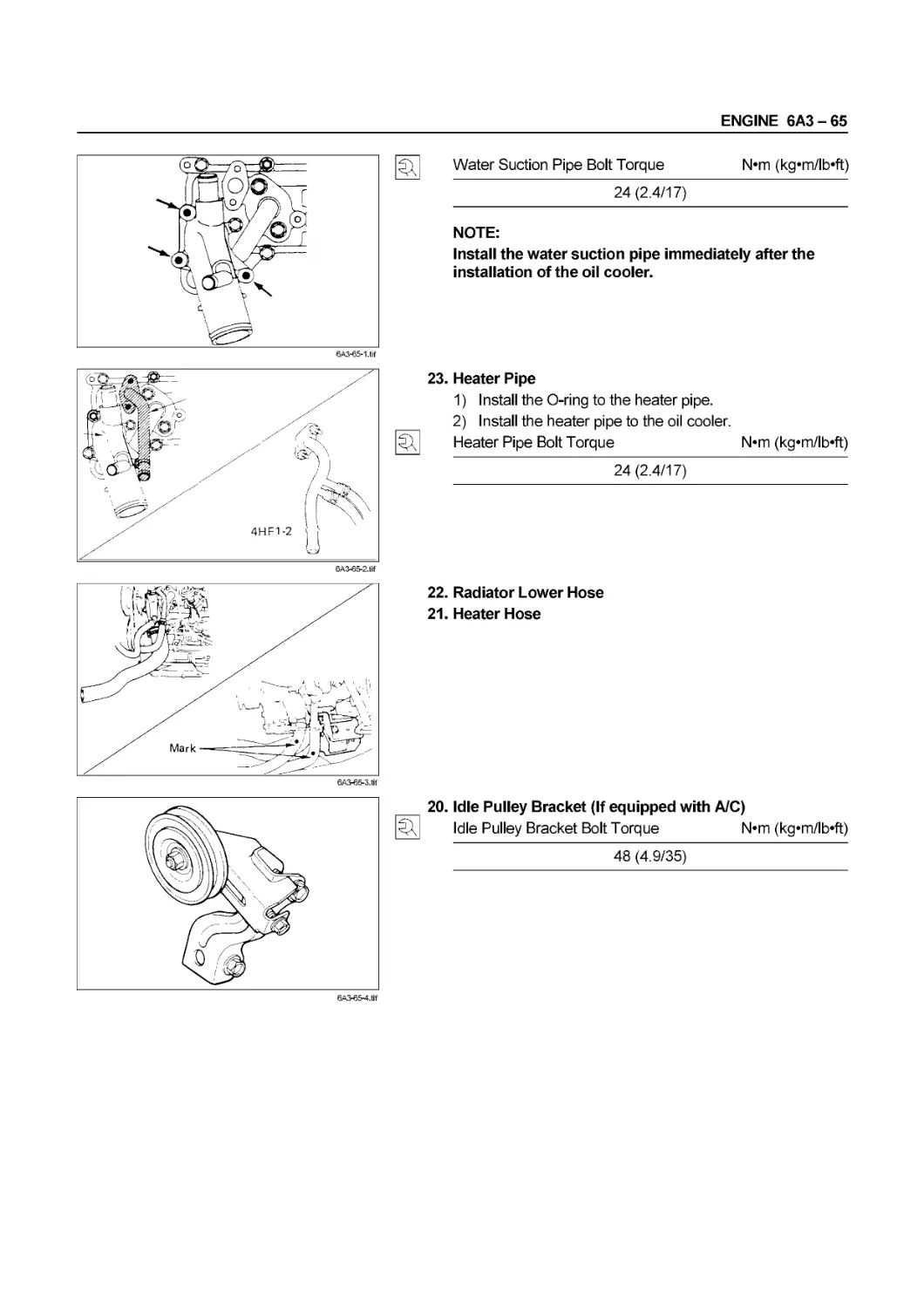
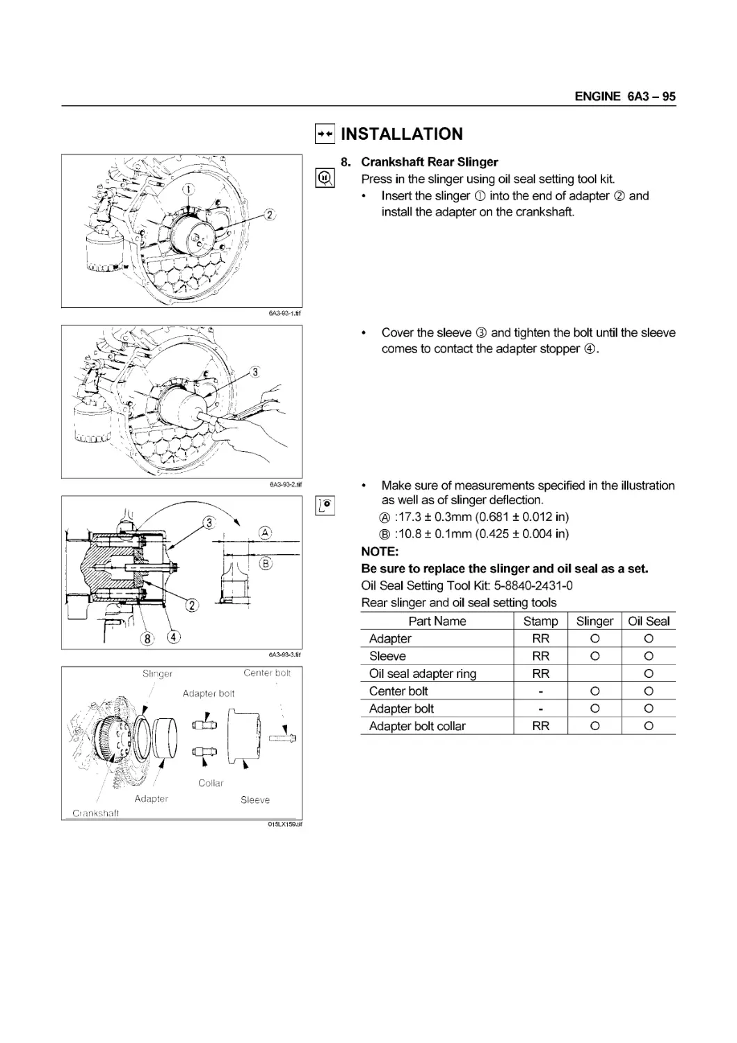
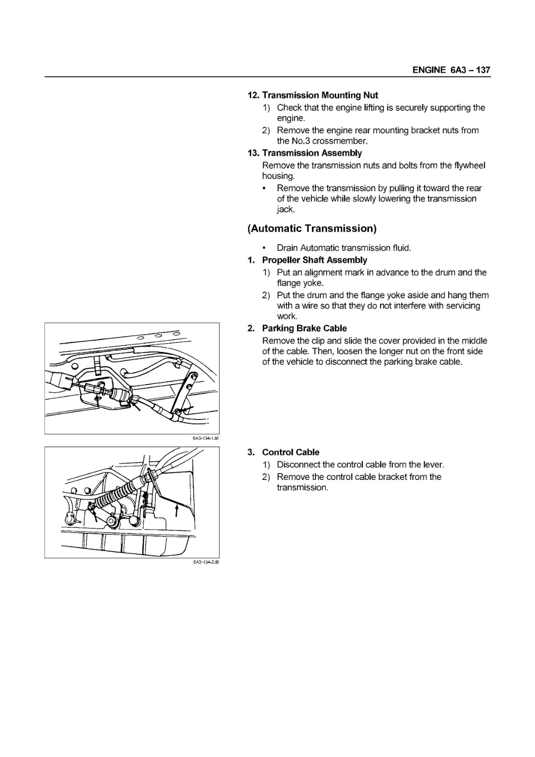
ENGINE
4H SERIES
SECTION S
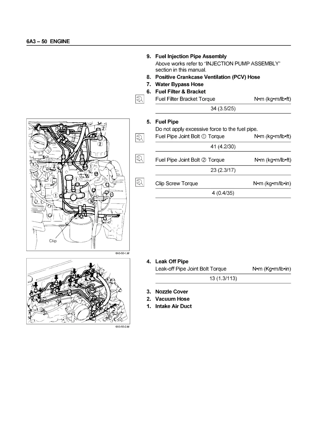
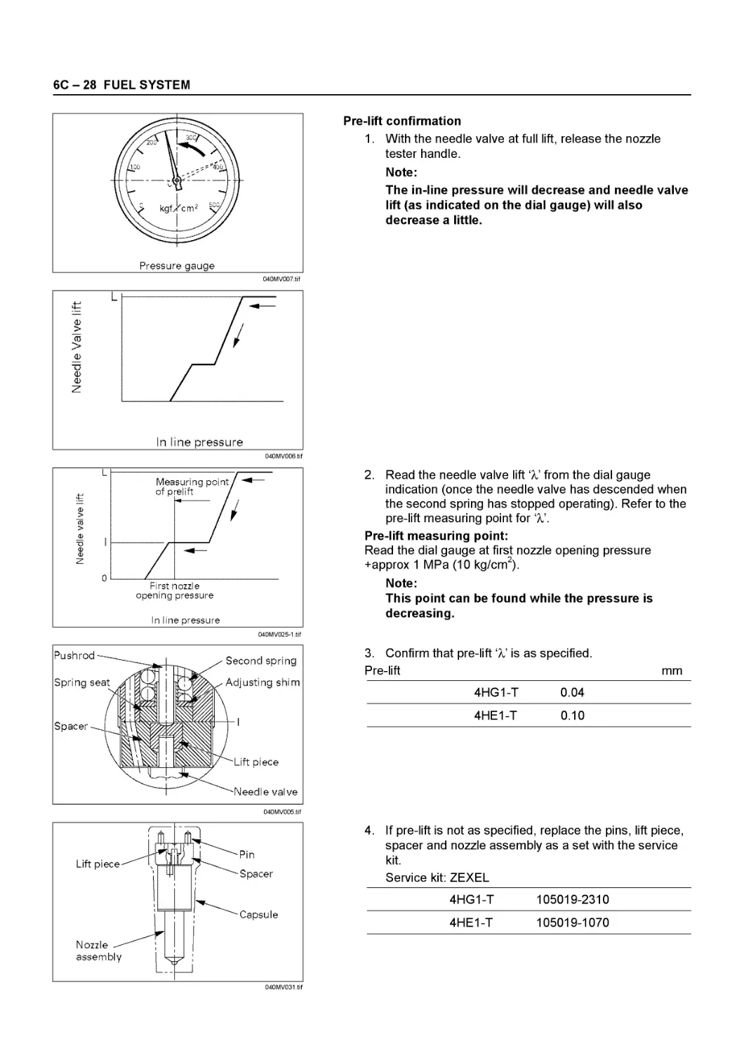
ISUZU
01Л131Л1
NOTICE
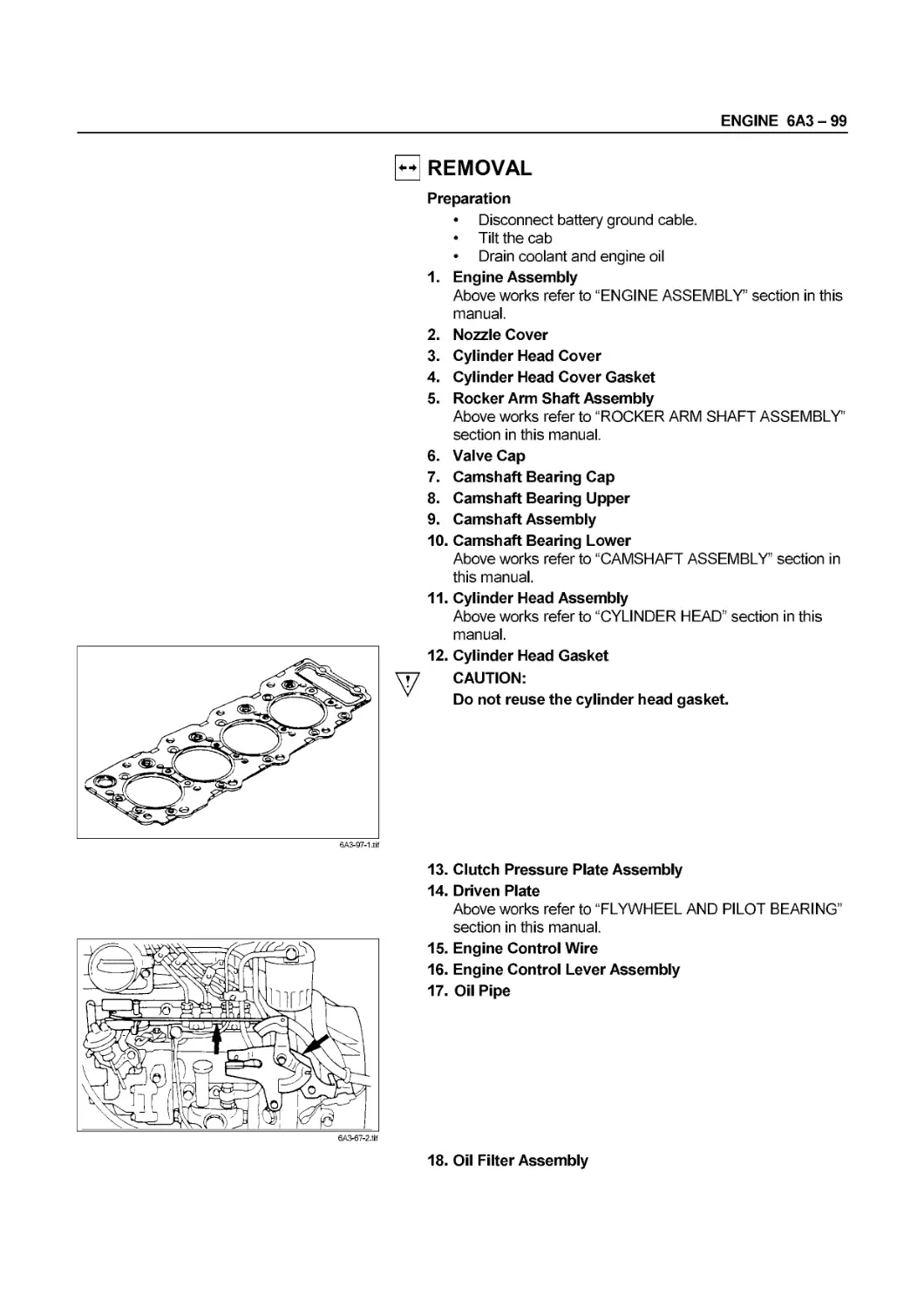
Before using this Workshop Manual to assist you in performing
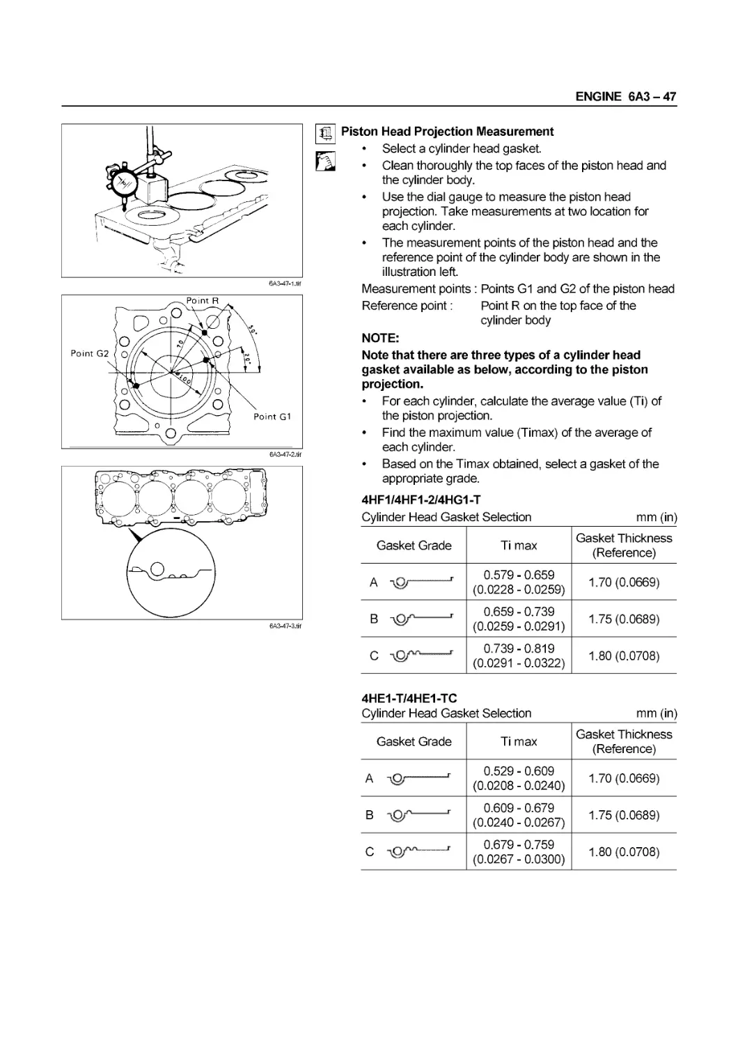
vehicle service and maintenance operations, it is recommended
that you carefully read and thoroughly understand the
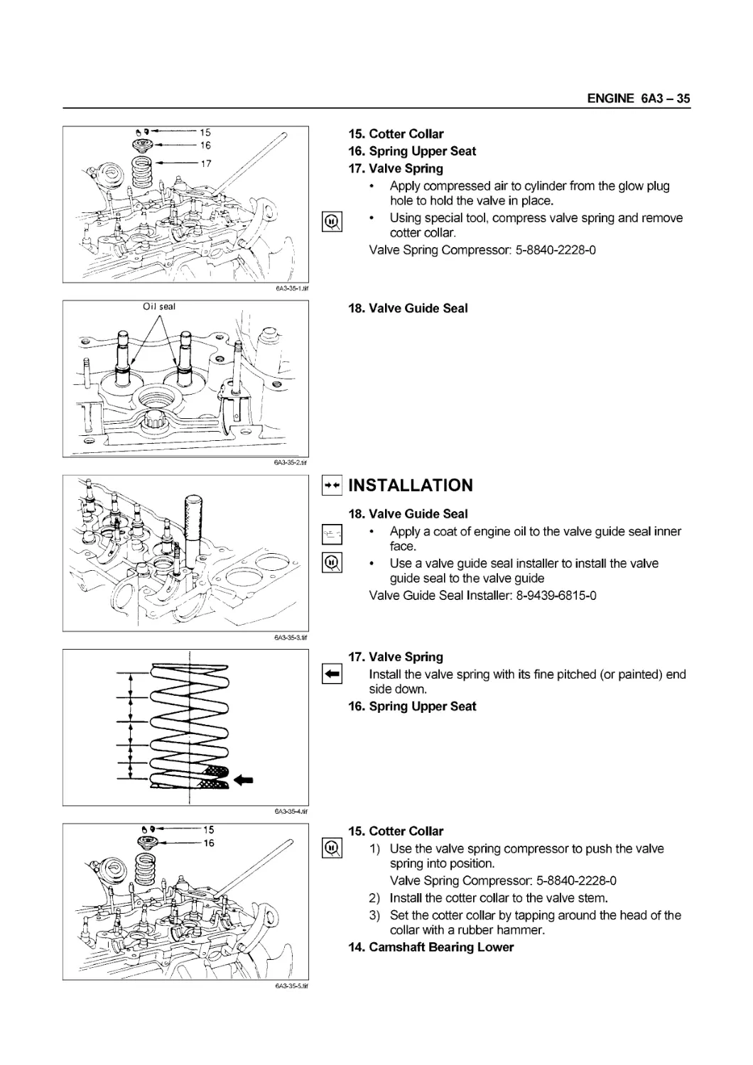
information contained in Section OA under the headings
“GENERAL REPAIR INSTRUCTIONS” and “HOW TO USE THIS
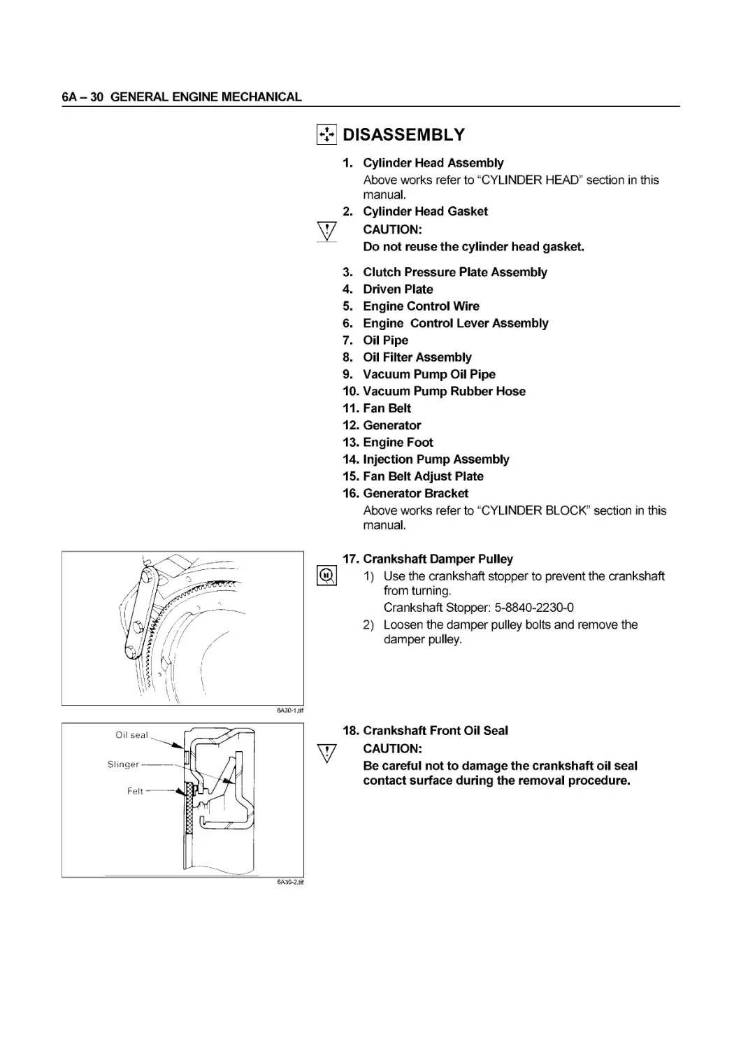
MANUAL”.
All material contained in this Manual is based on latest product
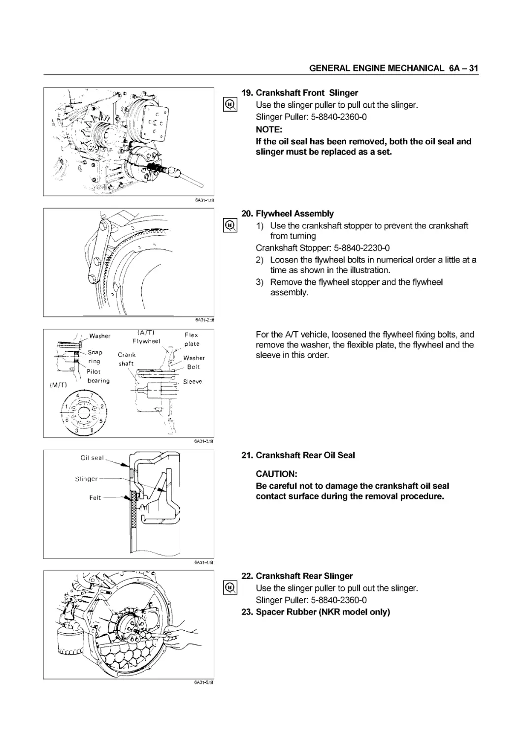
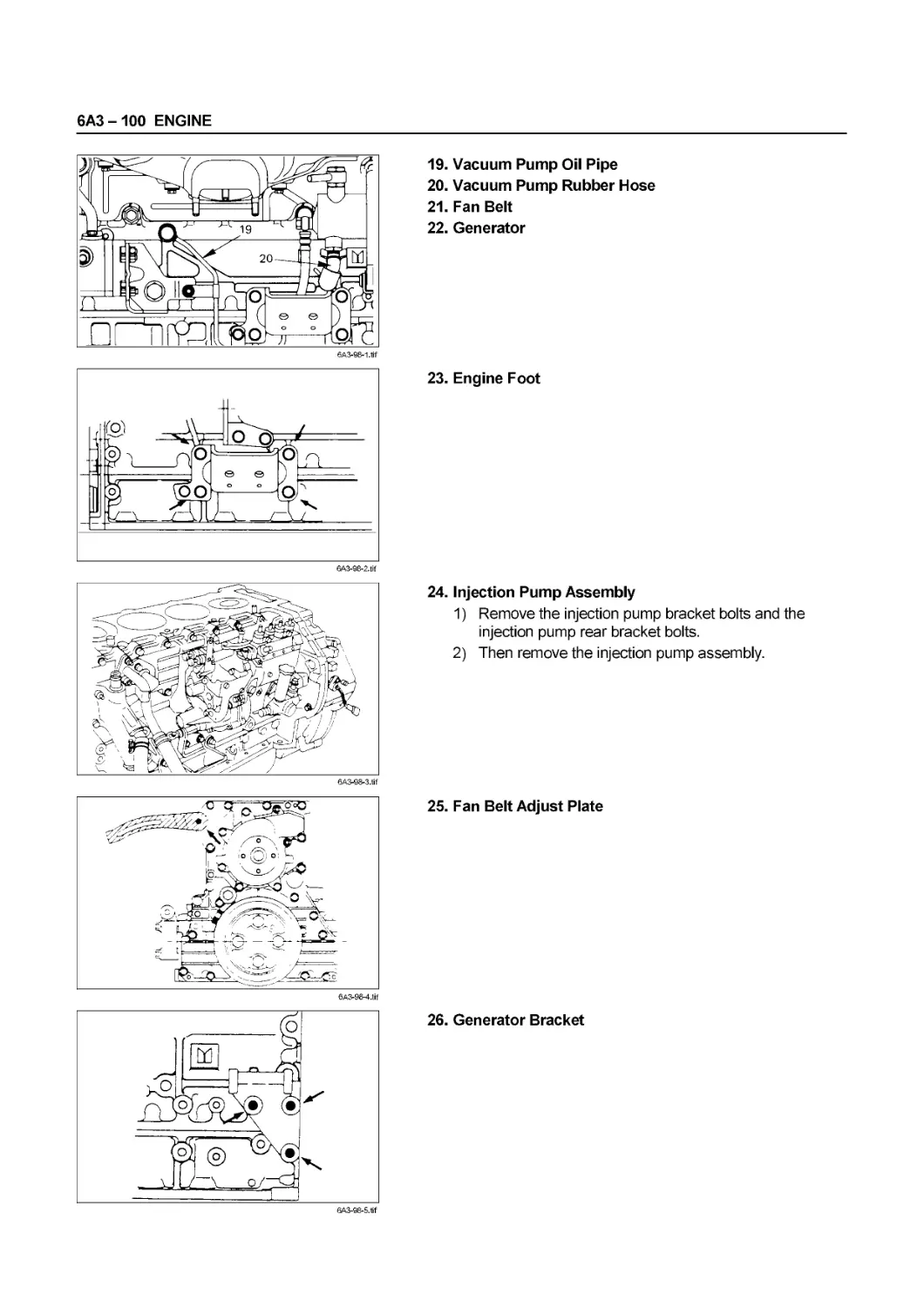
information available at the time of publication.
All rights are reserved to make changes at any time without prior
notice.
Applicable Model :
N Series
NKR66 NPR66 NPR70 NPR71 NPS66 NQR71 NPS71 NQR66 NQR70
This manual is applicable to 1996 year model and later vehicles
except those sold in the United States of America, and Canada.
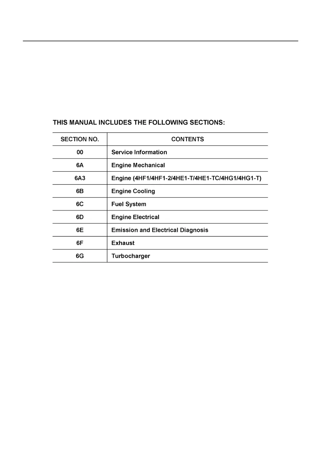
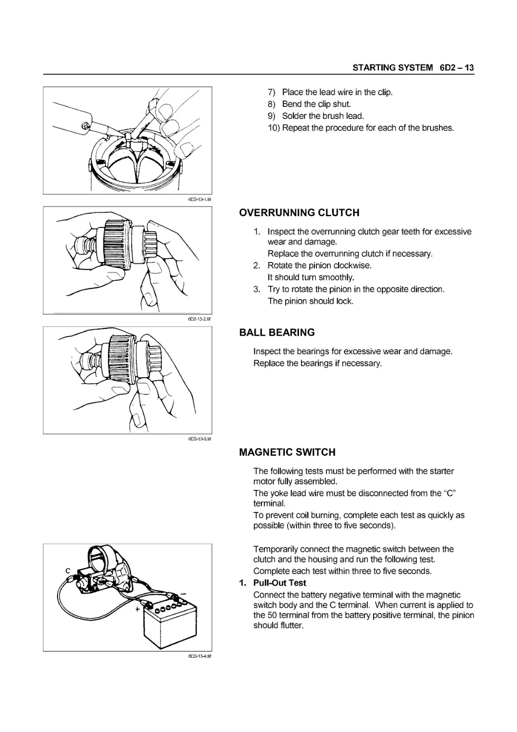
THIS MANUAL INCLUDES THE FOLLOWING SECTIONS:
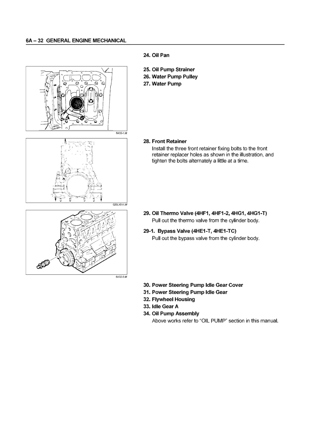
SECTION NO. CONTENTS
00 Service Information
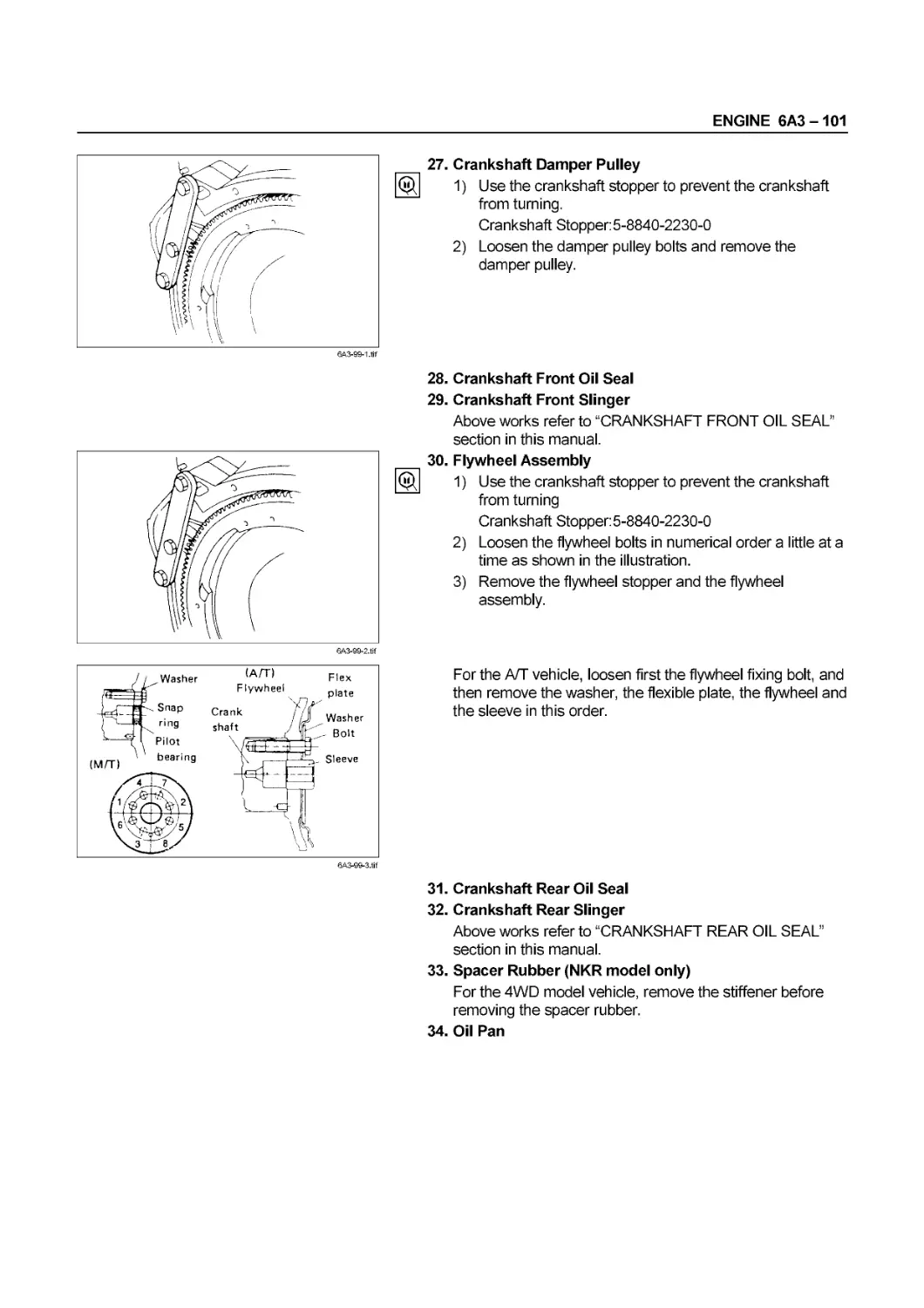
6A Engine Mechanical
6A3 Engine (4HF1/4HF1-2/4HE1-T/4HE1-TC/4HG1/4HG1-T)
6B Engine Cooling
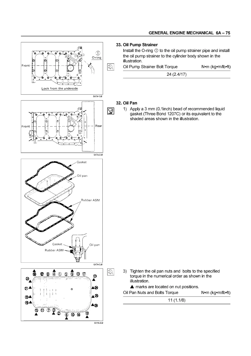
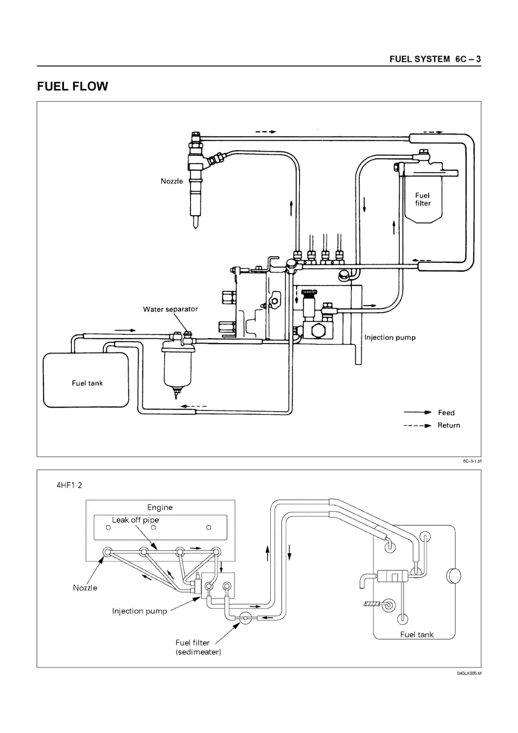
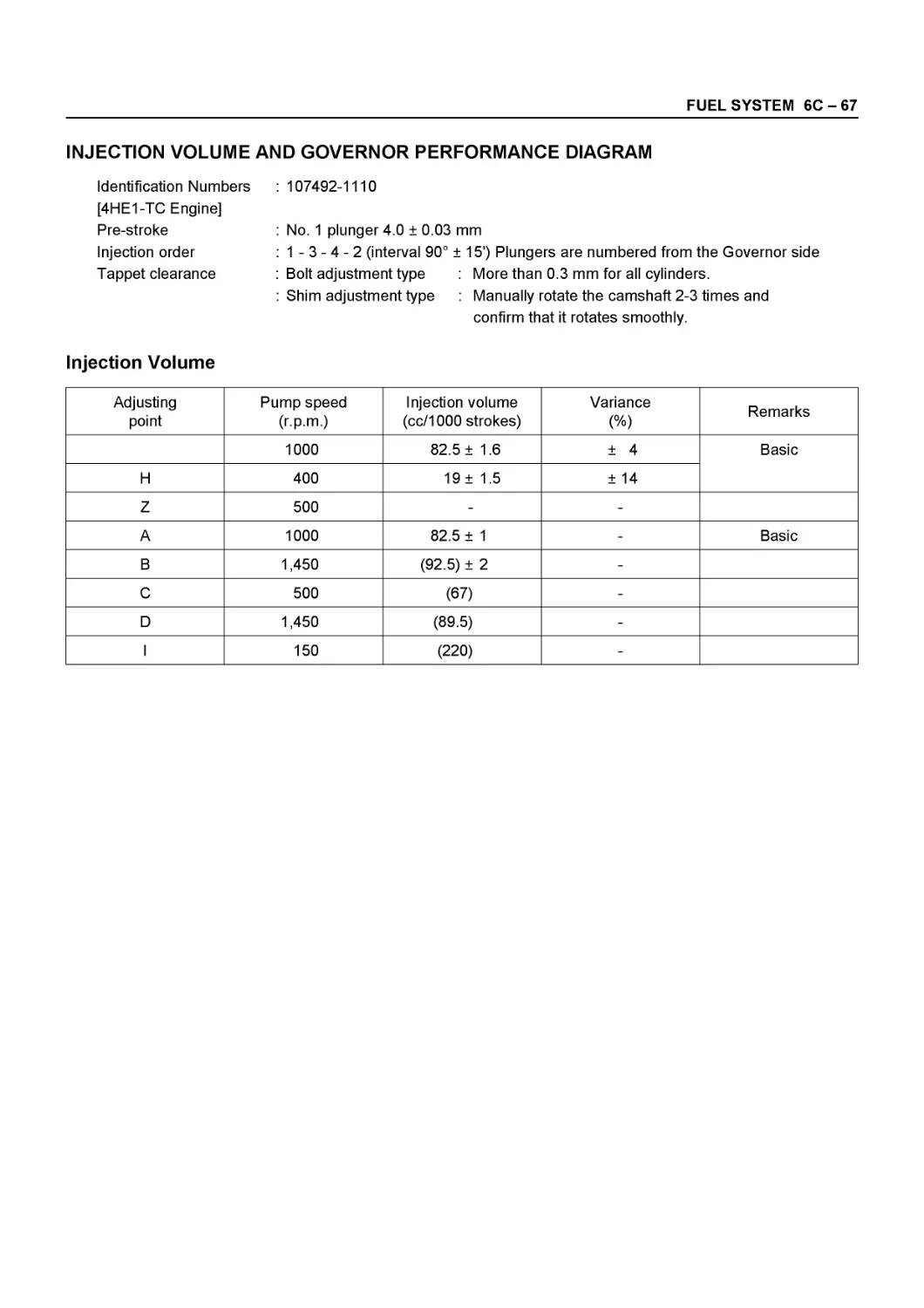
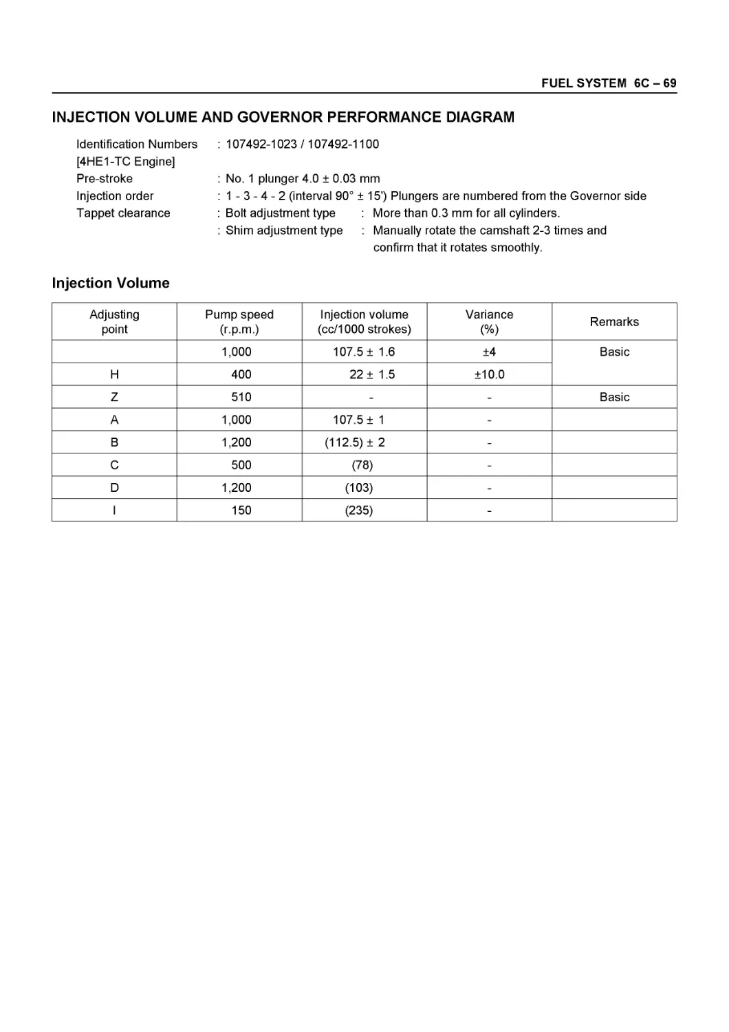
6C Fuel System
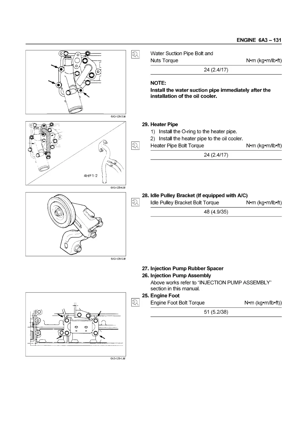
6D Engine Electrical
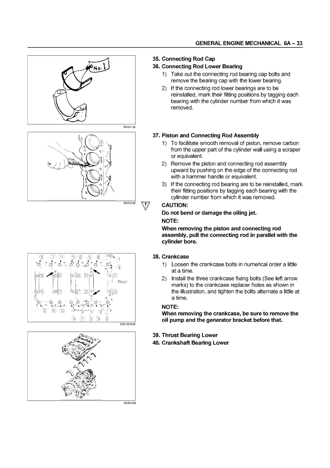
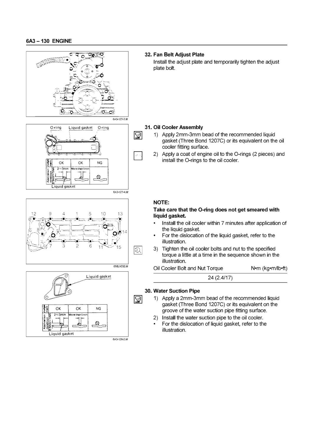
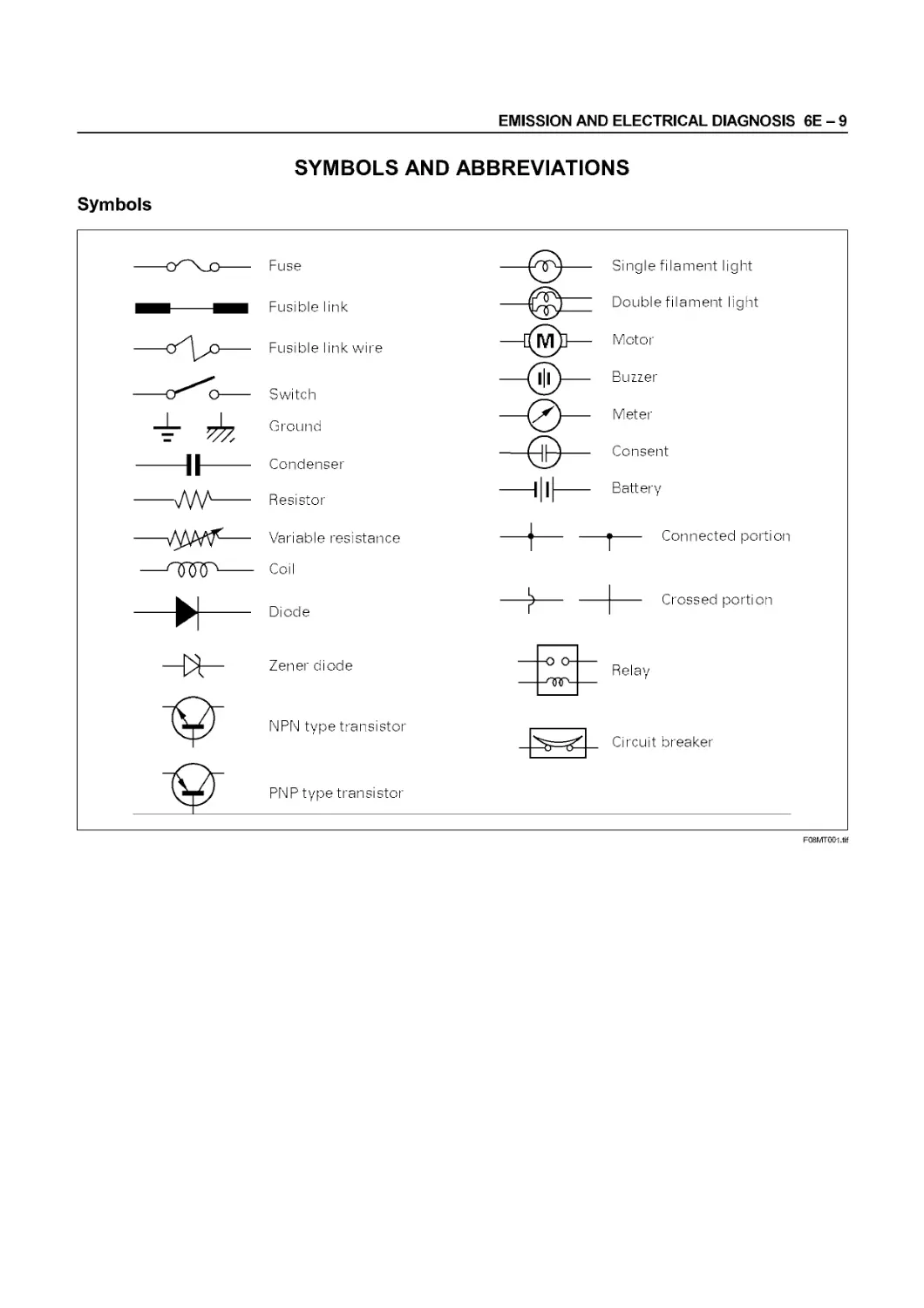
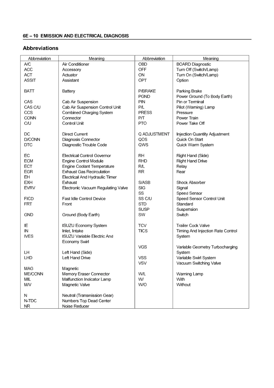
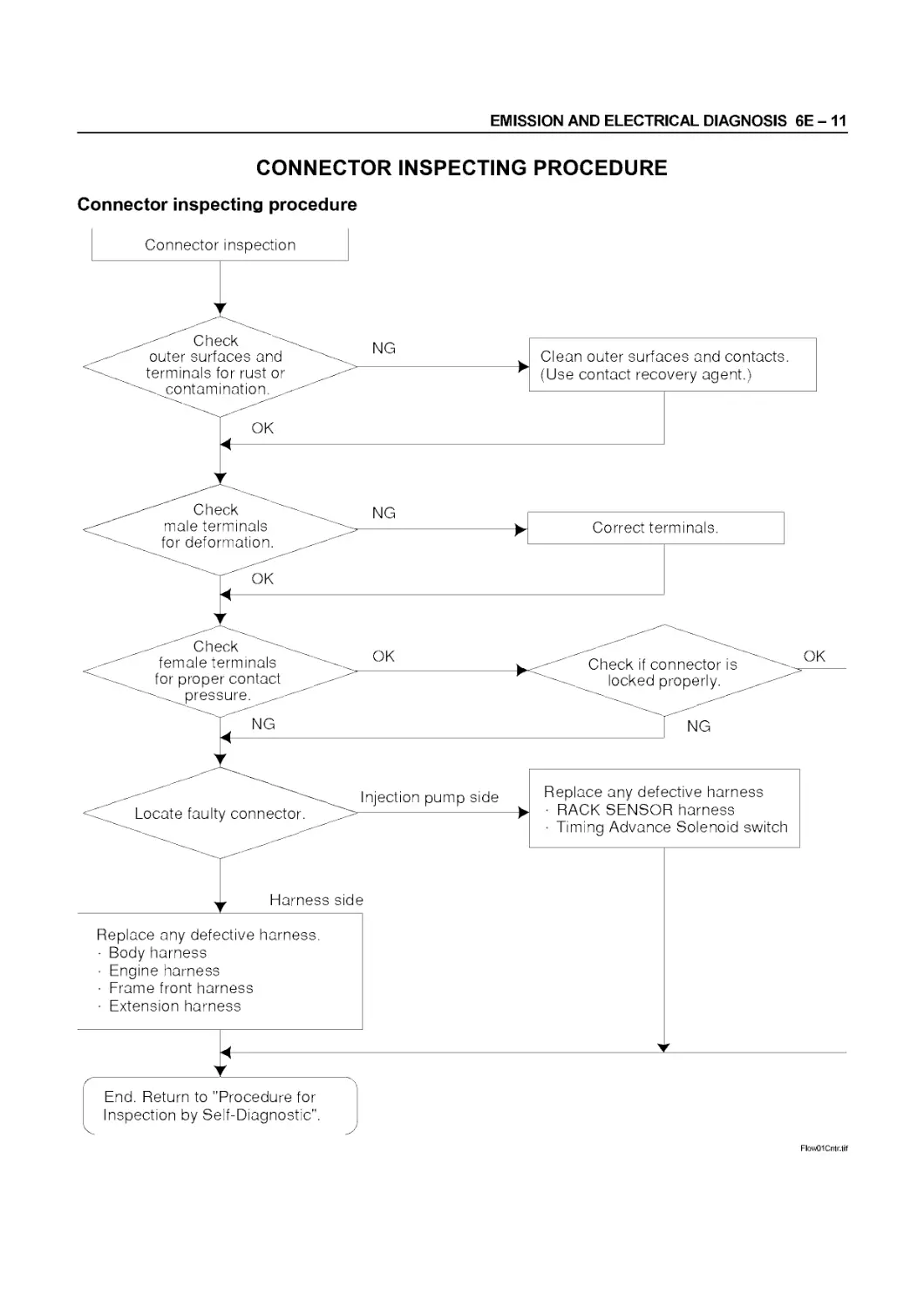
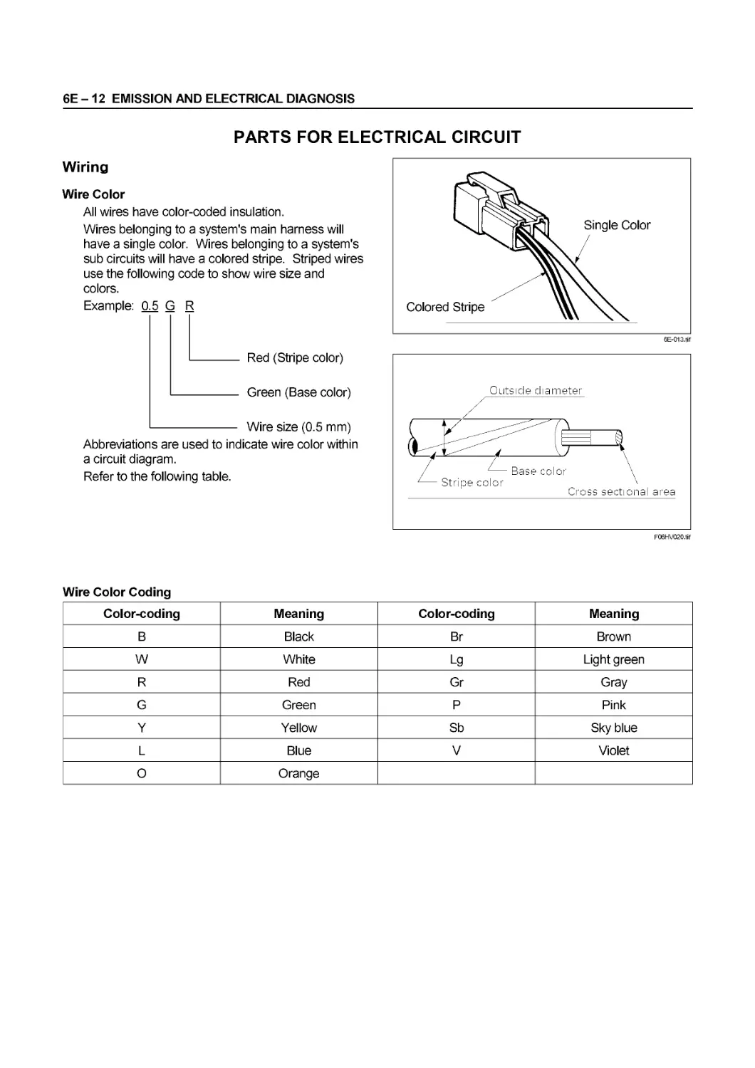
6E Emission and Electrical Diagnosis
6F Exhaust
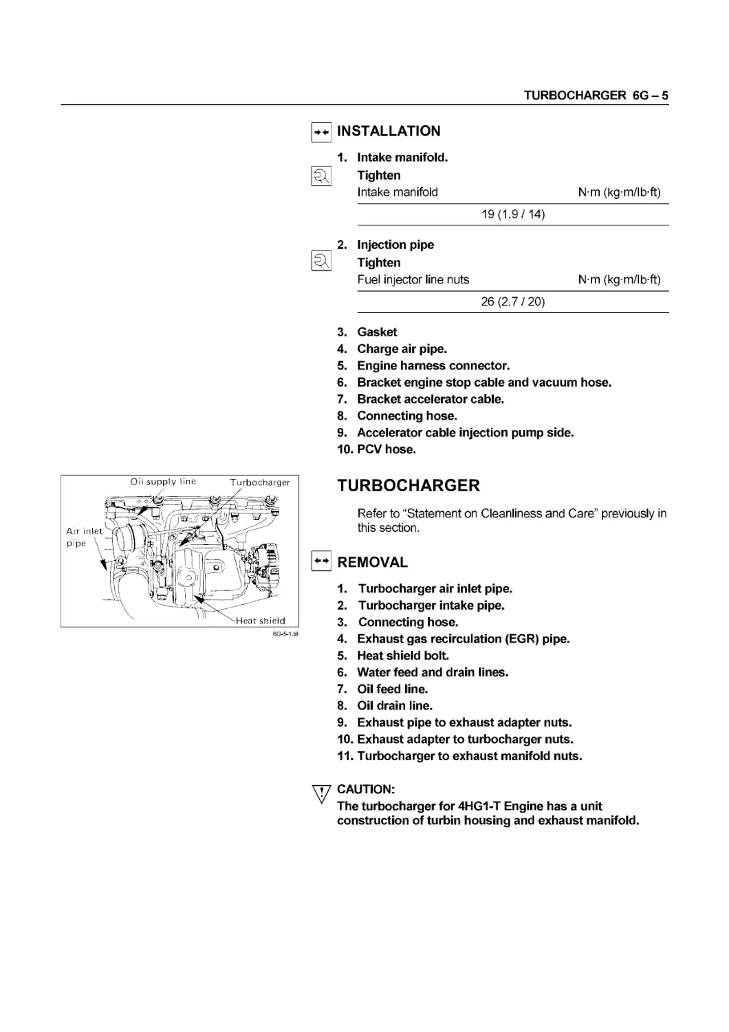
6G Turbocharger
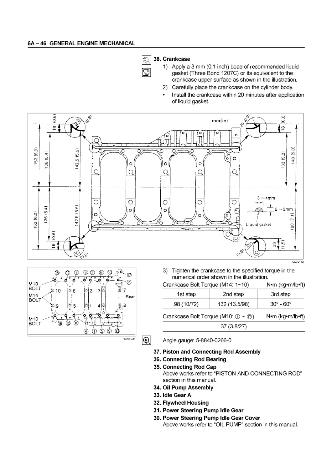
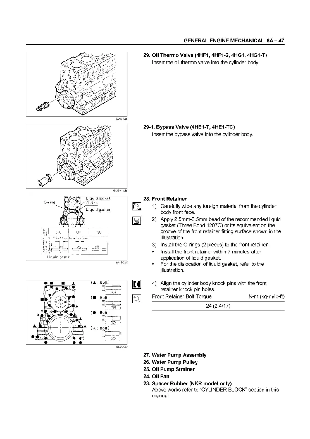
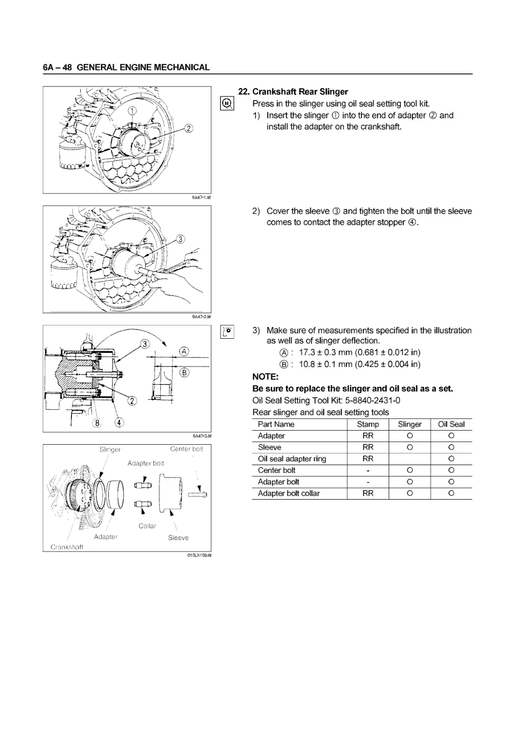
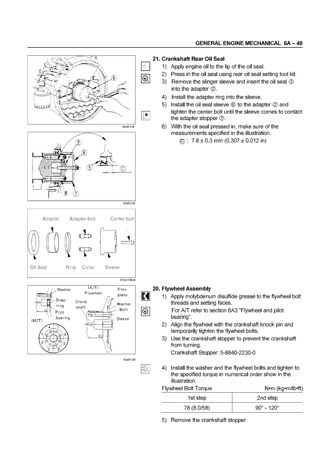
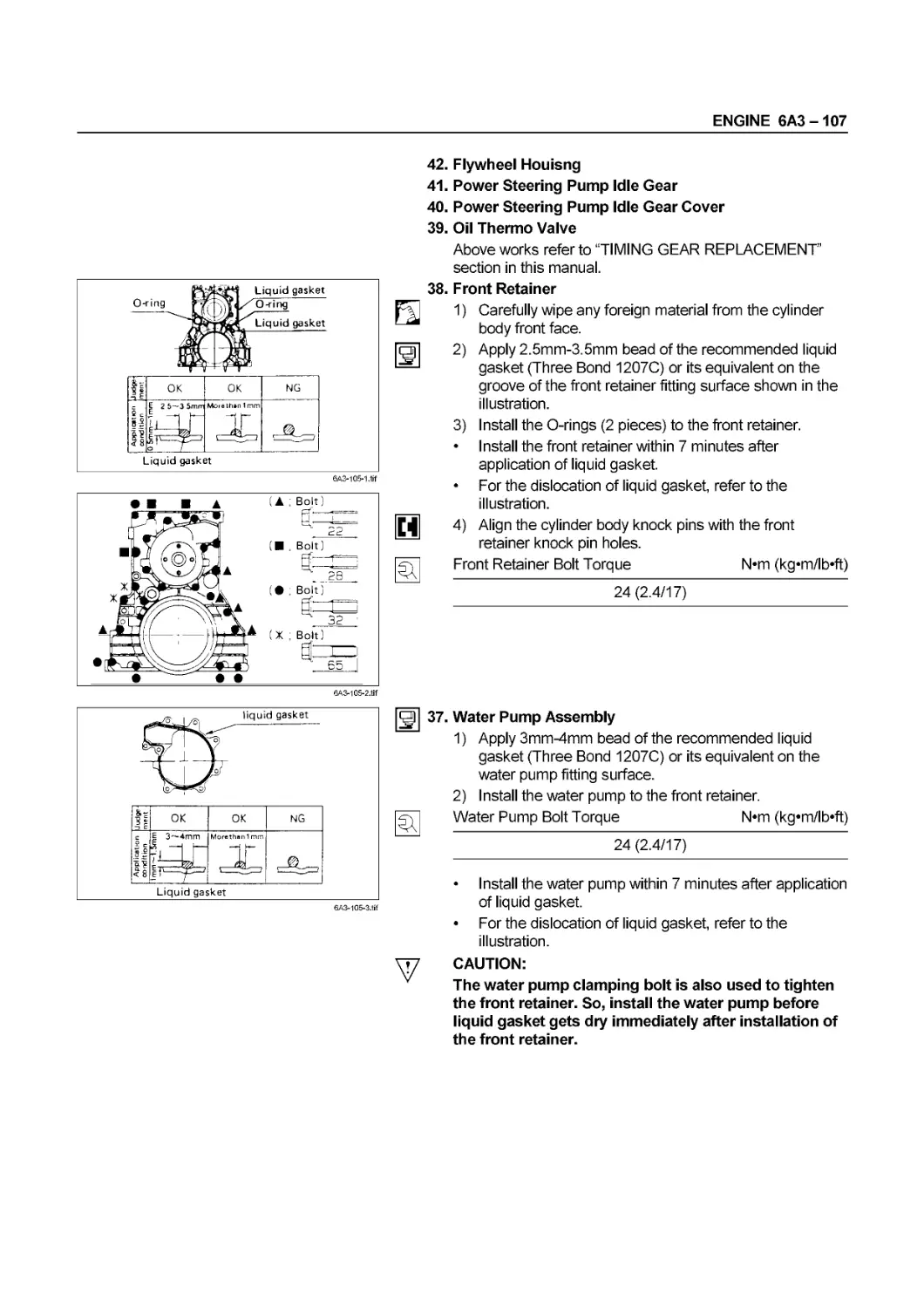
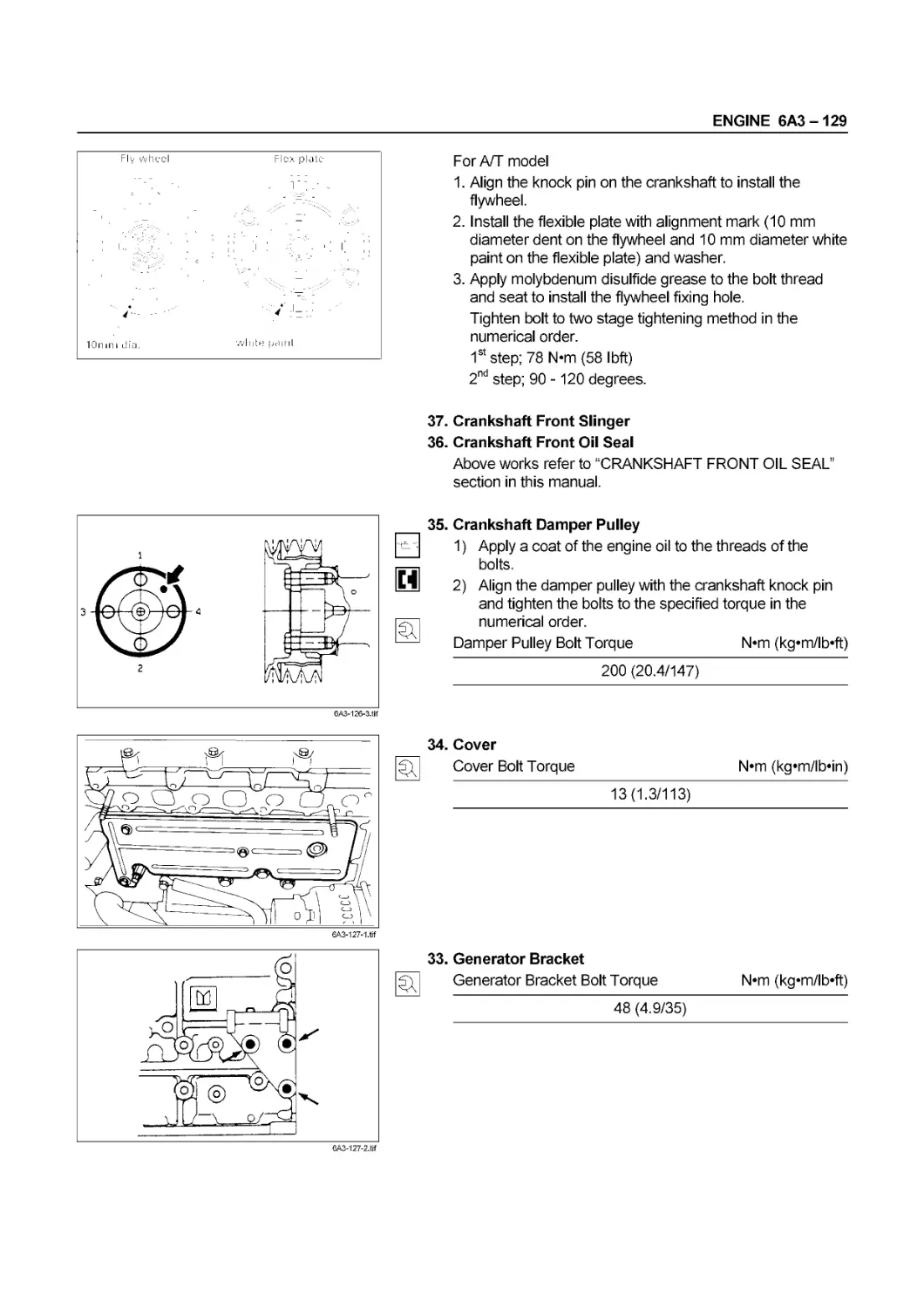
SERVICE INFORMATION 00 - 1
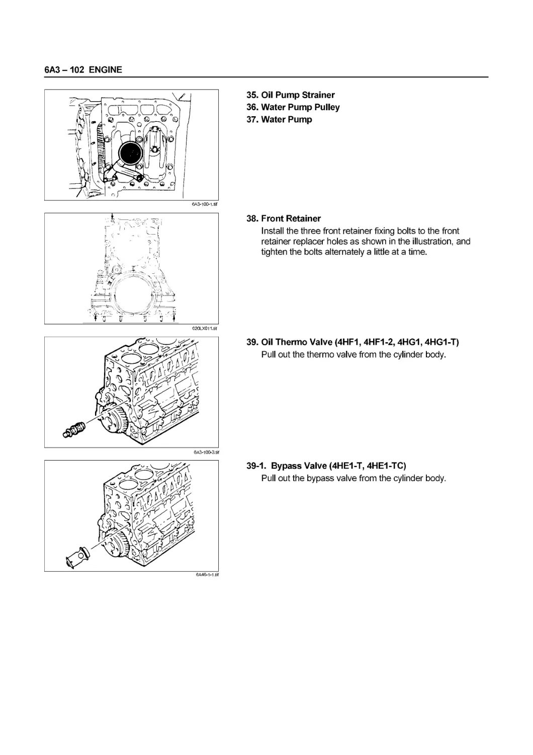
SECTION 00
SERVICE INFORMATION
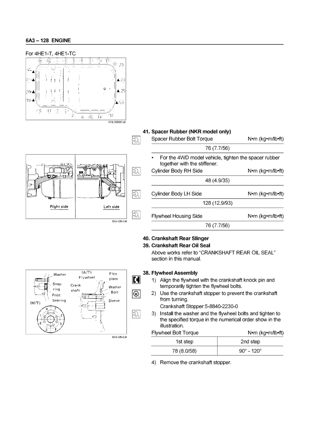
CONTENTS
PAGE
Troubleshooting.......................................................... 00 - 2
Main Data and Specifications............................................... 00-19
Service Standard......................................................... 00 - 28
Servicing................................................................ 00 - 42
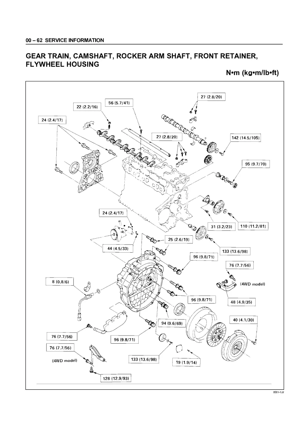
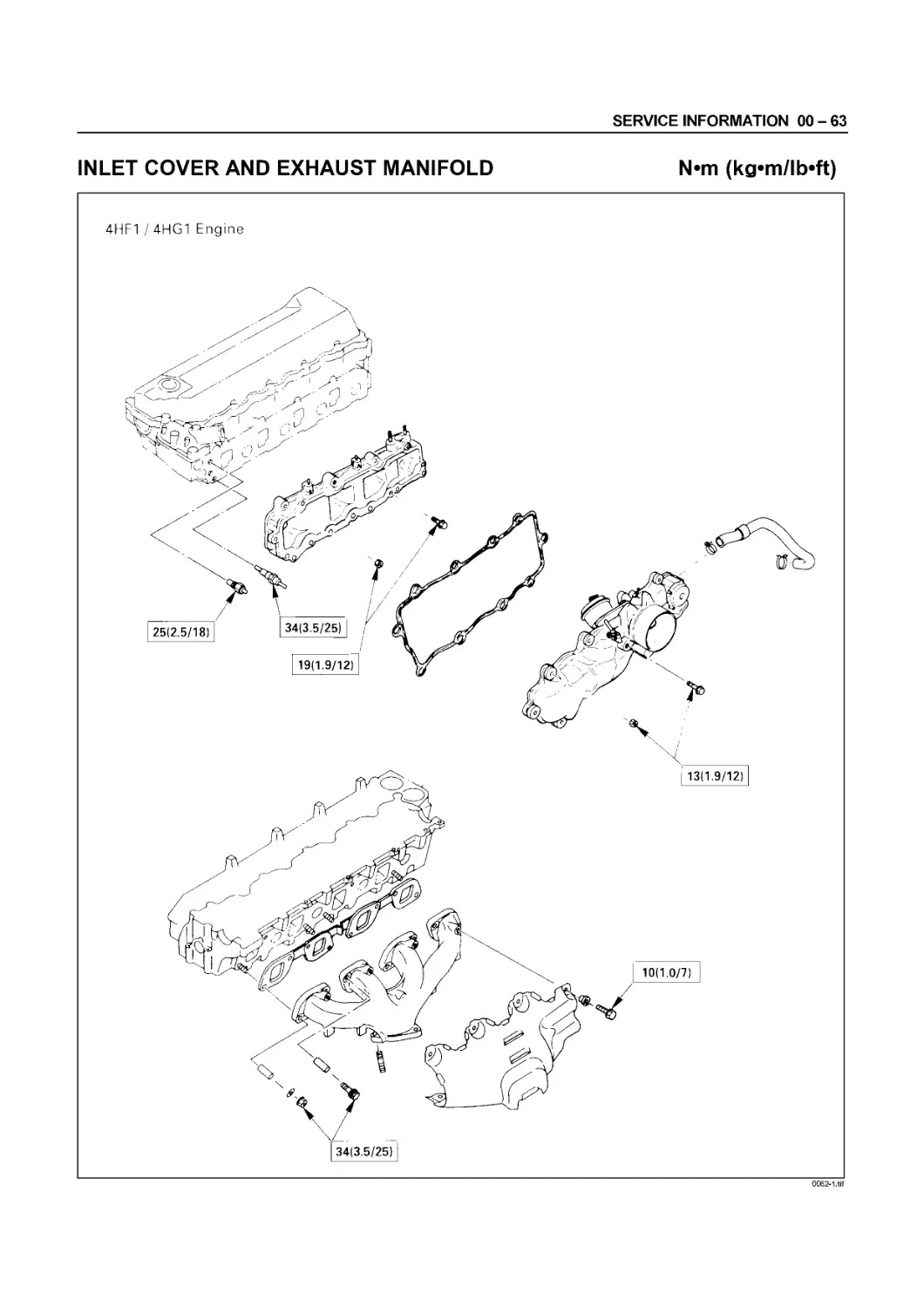
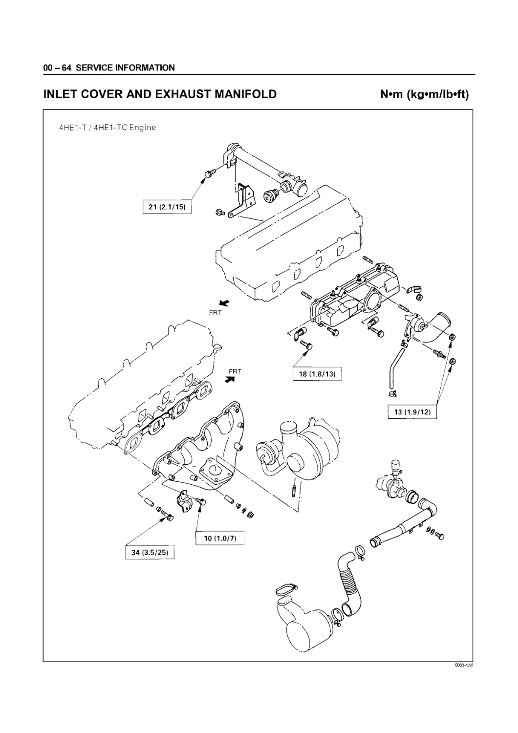
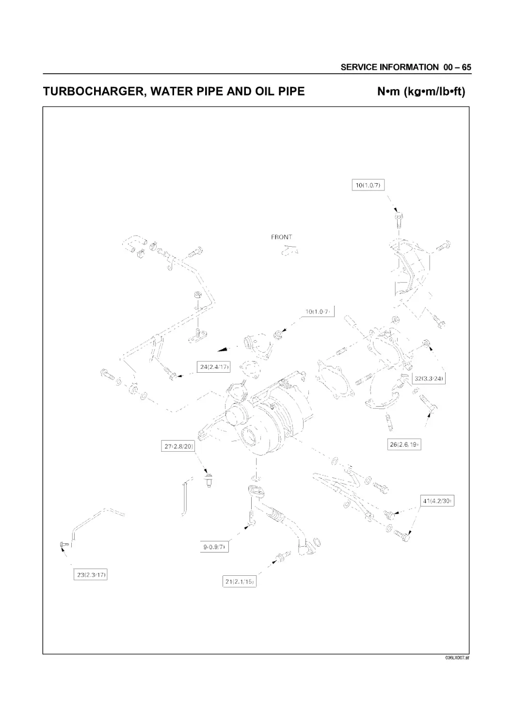
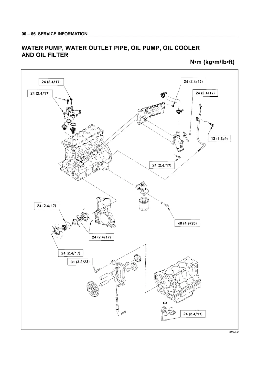
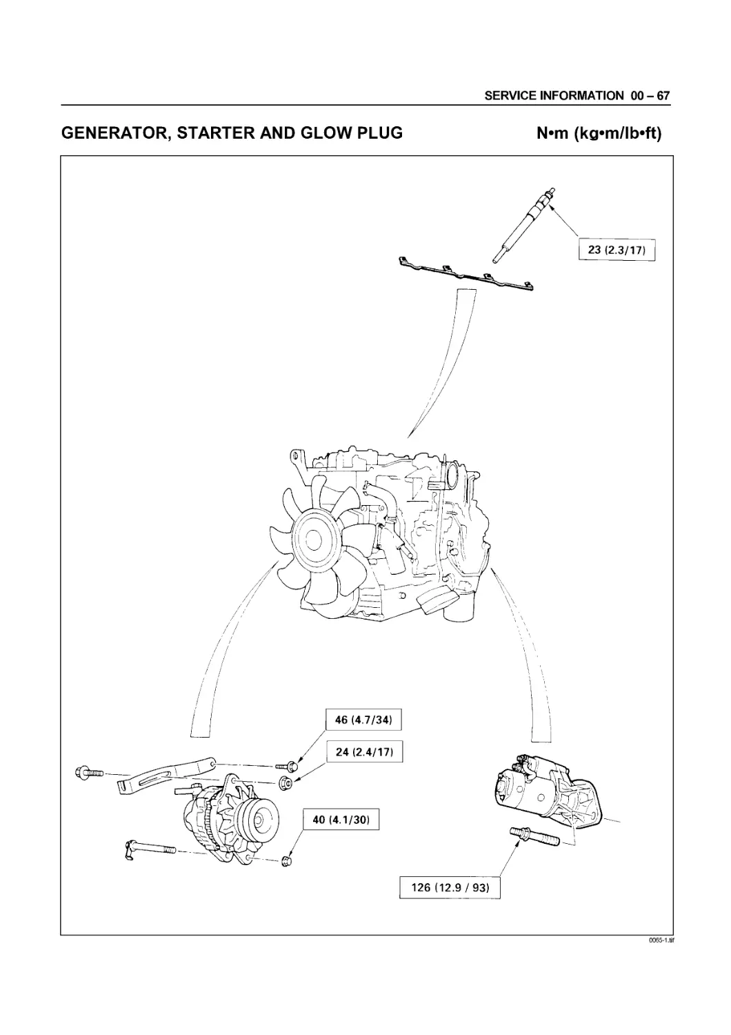
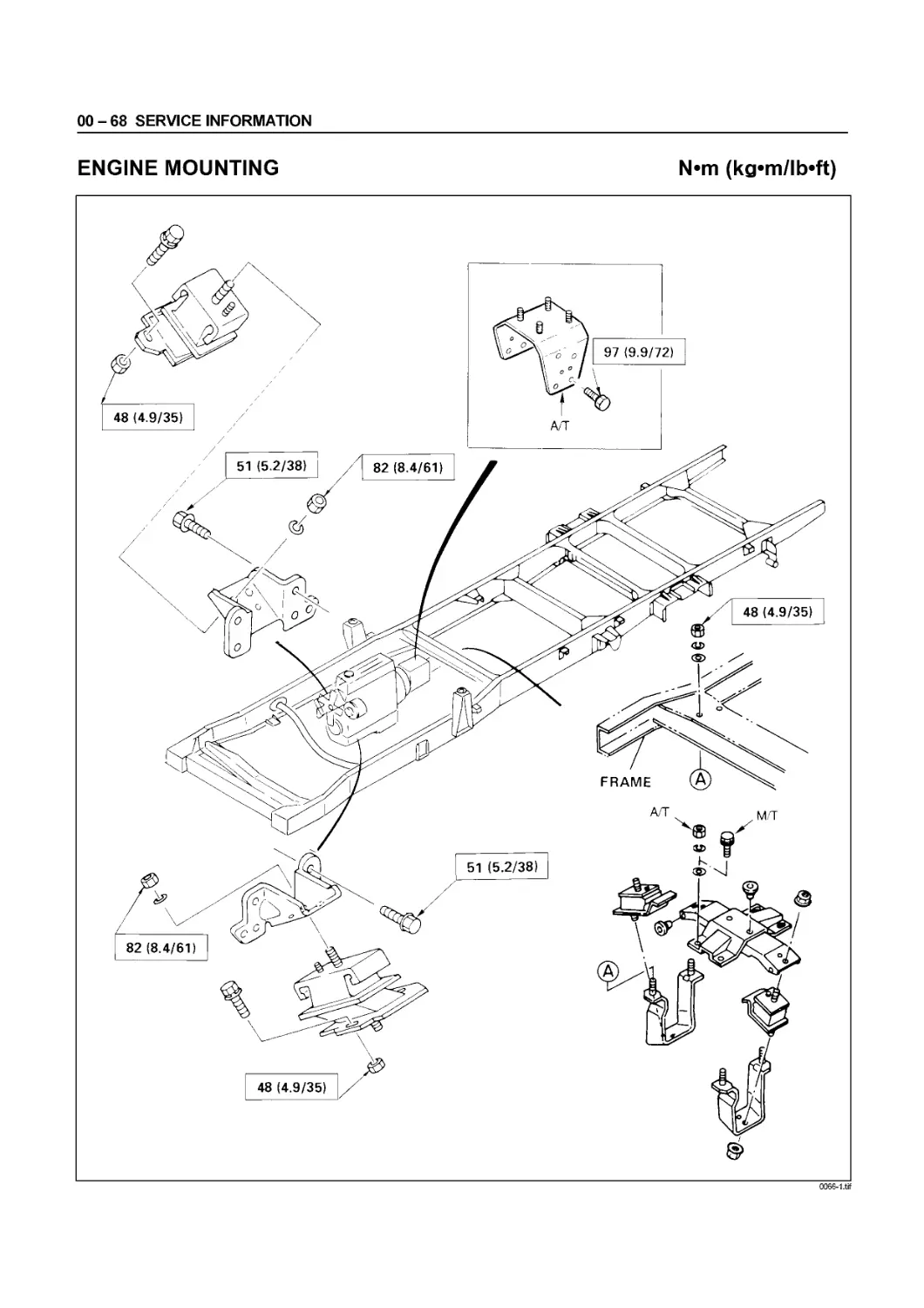
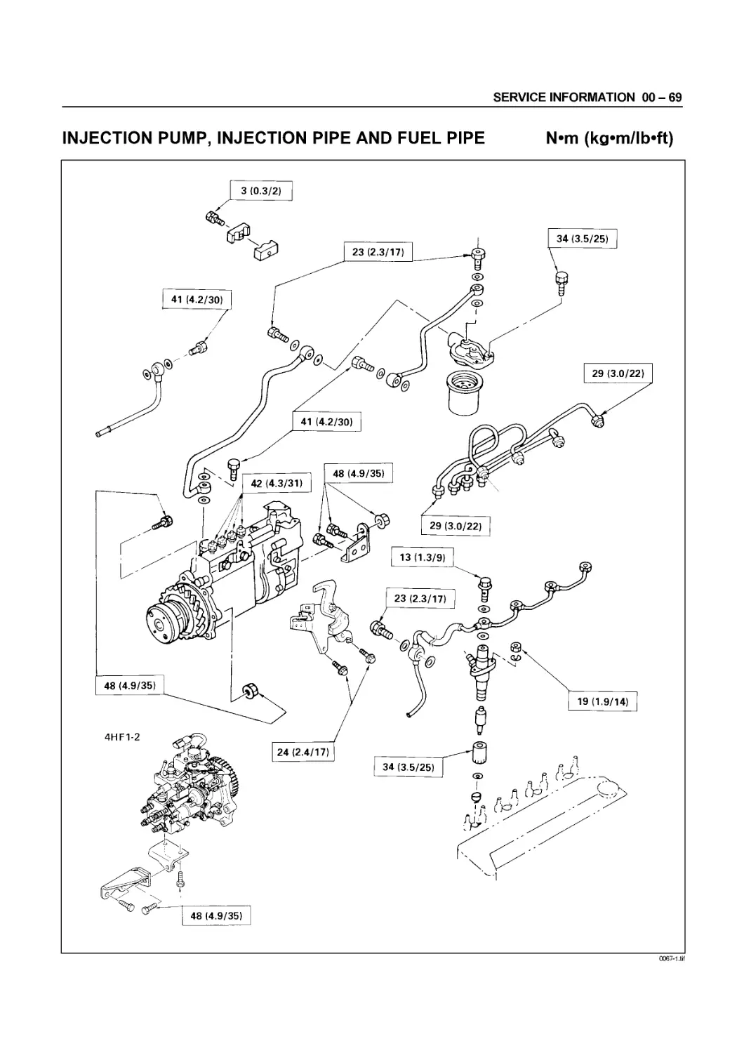
Fixing Torque............................................................ 00 - 59
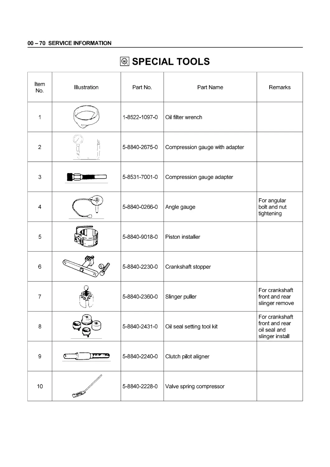
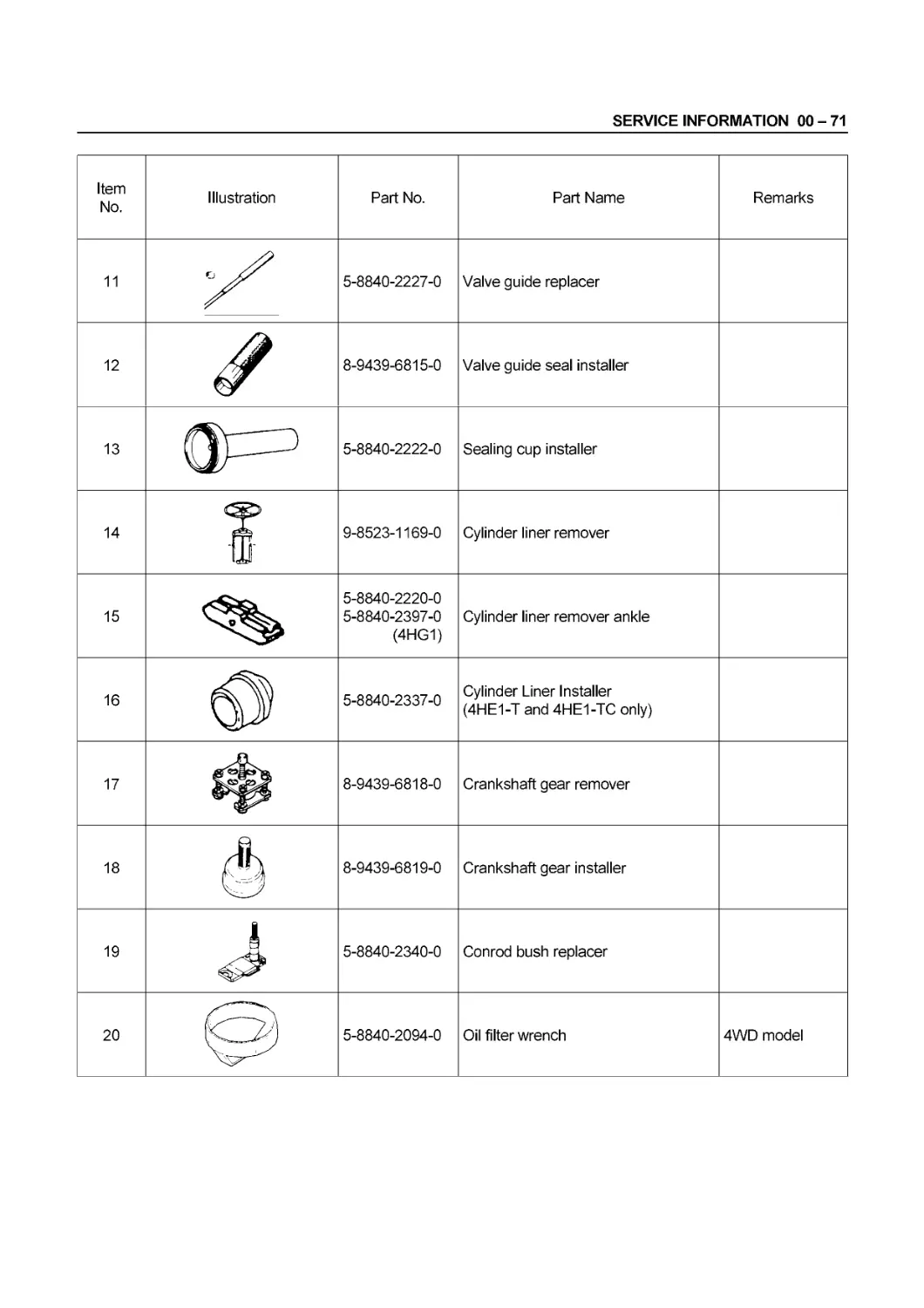
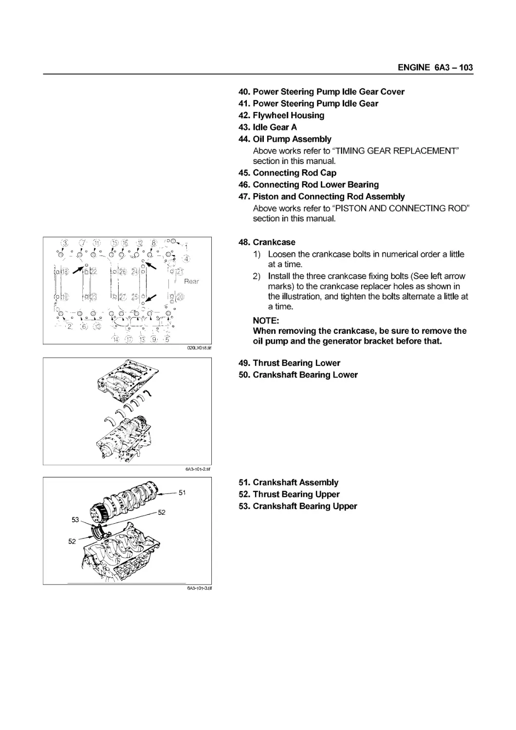
Special Tools............................................................ 00 - 70
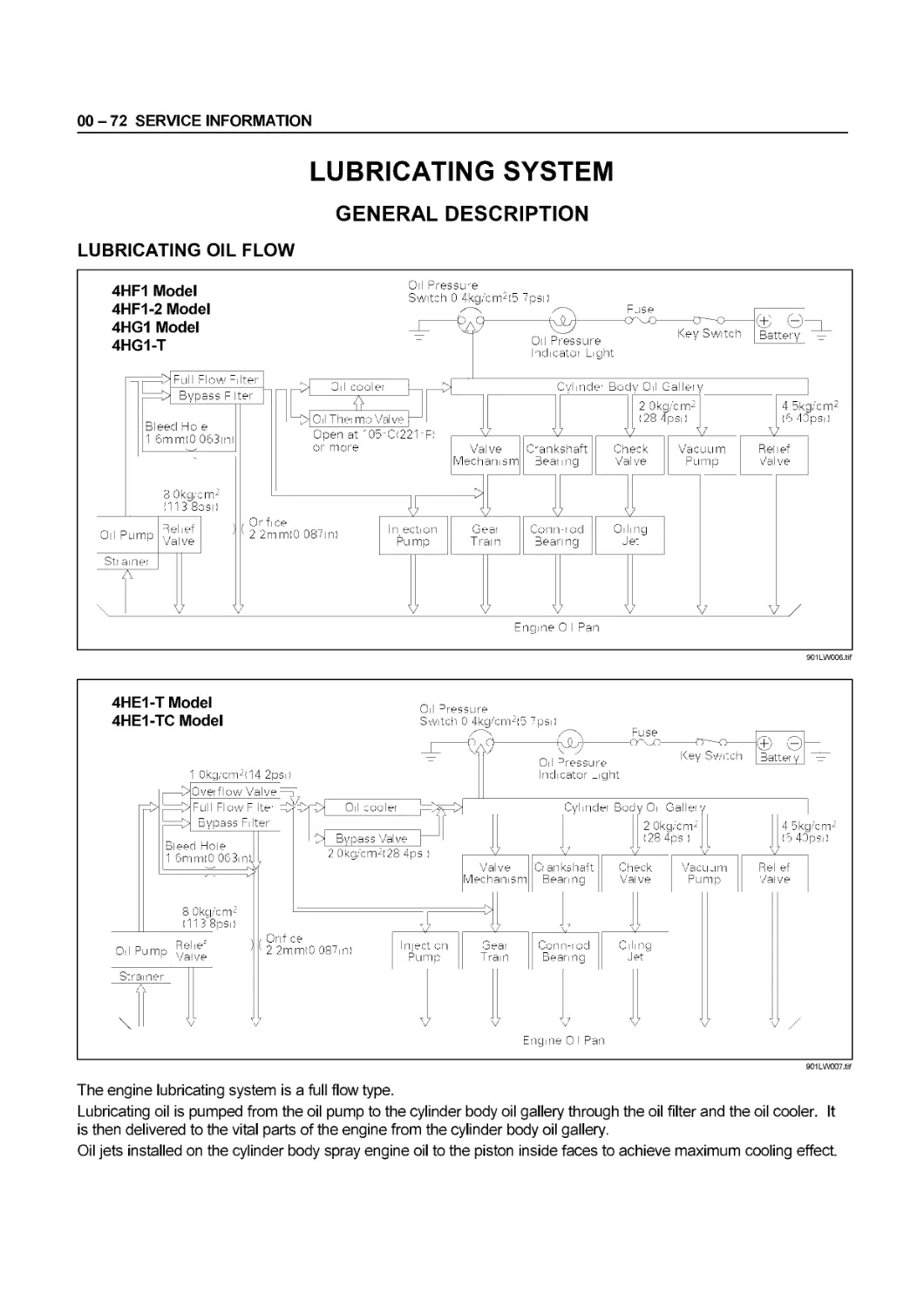
Lubricating System....................................................... 00 - 72
00-2 SERVICE INFORMATION
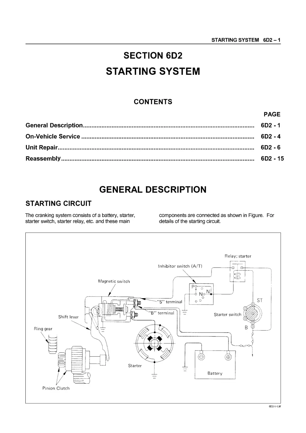
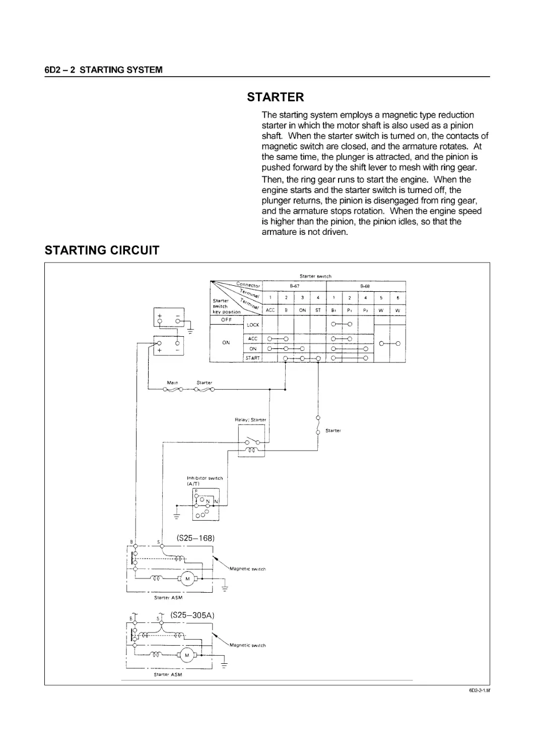
TROUBLESHOOTING
CONTENTS
PAGE
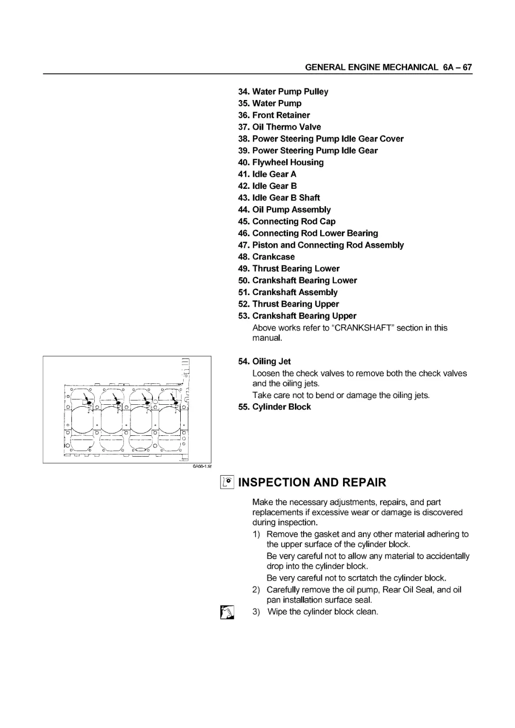
Hard Starting..................................................... 00 - 3
Starter Motor Inoperative....................................... 00 - 3
Starter Motor Operates but Engine does not turn over............ 00 - 3
Engine turns over but does not start............................ 00 - 4
Fuel is not being delivered to the injection pump............... 00 - 4
Fuel is being delivered to the injection pump................... 00 - 4
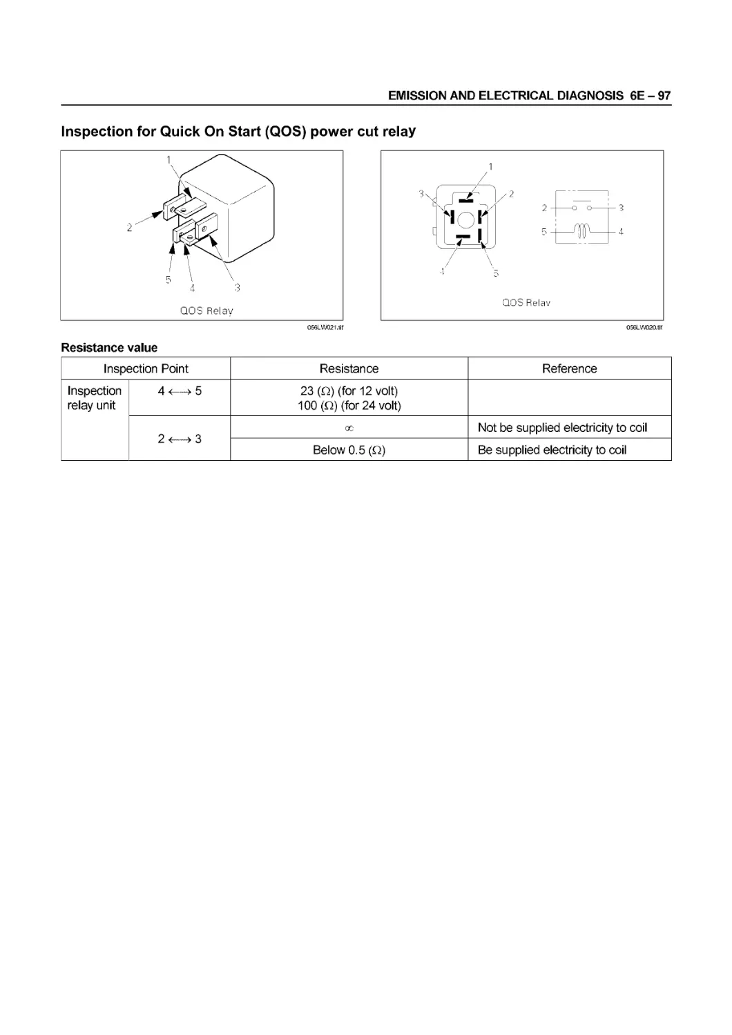
Quick-on Start System........................................... 00 - 5
Unstable Idling..................................................... 00-10
Insufficient Power................................................ 00-11
Excessive Fuel Consumption........................................ 00 - 12
Excessive Oil Consumption......................................... 00-12
Overheating......................................................... 00-13
White Exhaust Smoke............................................... 00-13
Dark Exhaust Smoke................................................ 00-14
Oil Pressure Does Not Rise........................................ 00-14
Abnormal Engine Noise............................................. 00-15
Engine Knocking................................................. 00-15
Gas Leakage Noise............................................... 00-15
Continues Noise................................................. 00 - 15
Slapping Noise.................................................. 00- 16
Engine Cooling Trouble............................................ 00 - 17
Starter Motor Does Not Stop....................................... 00-18
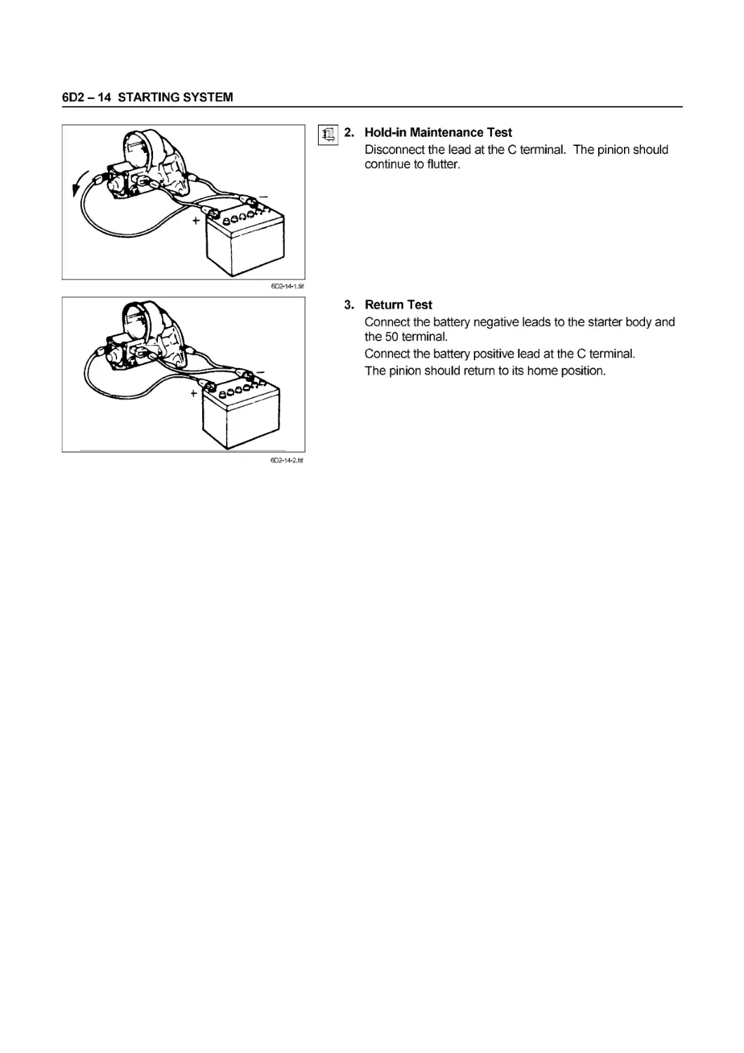
SERVICE INFORMATION 00-3
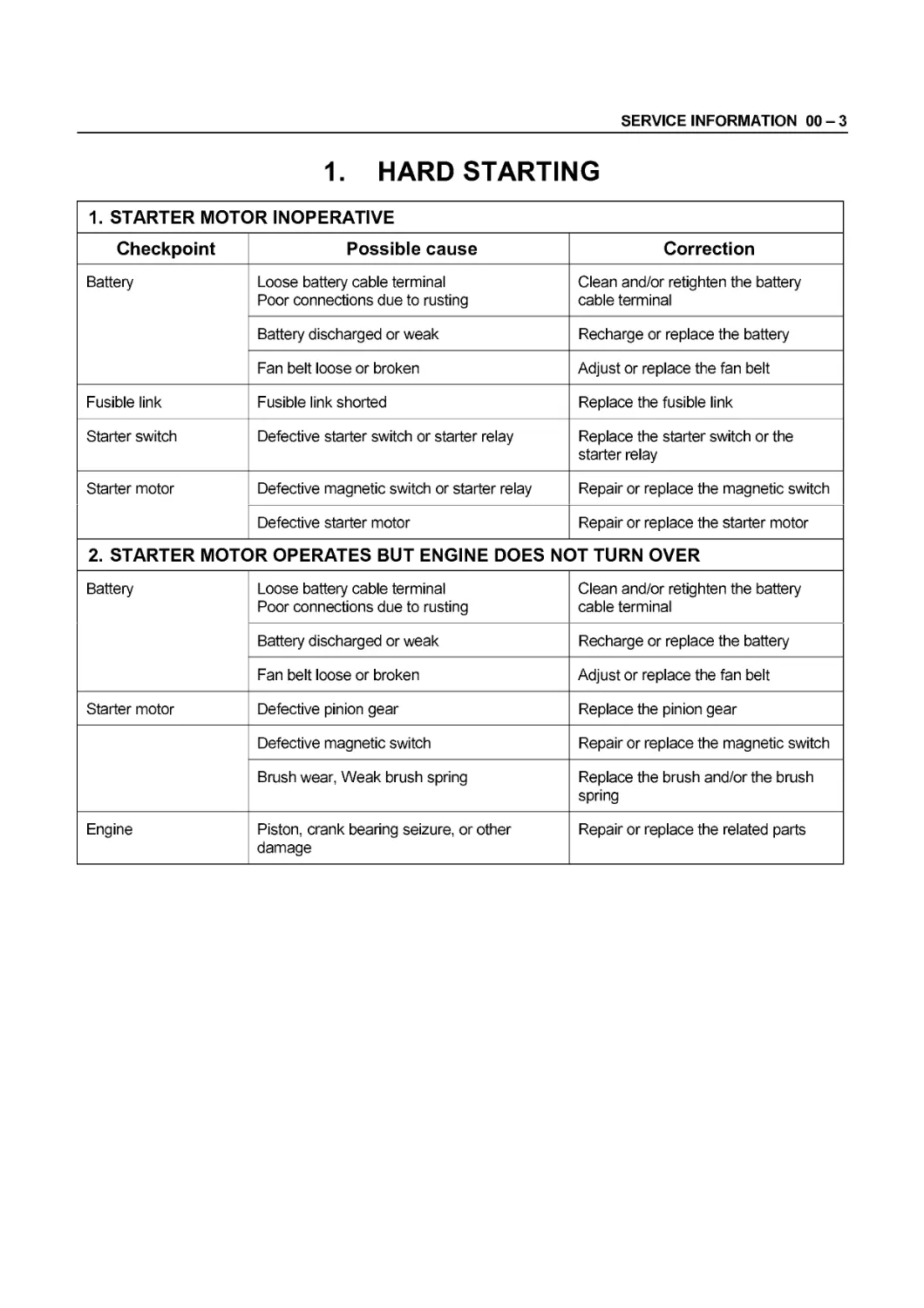
1. HARD STARTING
1. STARTER MOTOR INOPERATIVE
Checkpoint Possible cause Correction
Battery Loose battery cable terminal Poor connections due to rusting Clean and/or retighten the battery cable terminal
Battery discharged or weak Recharge or replace the battery
Fan belt loose or broken Adjust or replace the fan belt
Fusible link Fusible link shorted Replace the fusible link
Starter switch Defective starter switch or starter relay Replace the starter switch or the starter relay
Starter motor Defective magnetic switch or starter relay Repair or replace the magnetic switch
Defective starter motor Repair or replace the starter motor
2. STARTER MOTOR OPERATES BUT ENGINE DOES NOT TURN OVER
Battery Loose battery cable terminal Poor connections due to rusting Clean and/or retighten the battery cable terminal
Battery discharged or weak Recharge or replace the battery
Fan belt loose or broken Adjust or replace the fan belt
Starter motor Defective pinion gear Replace the pinion gear
Defective magnetic switch Repair or replace the magnetic switch
Brush wear, Weak brush spring Replace the brush and/or the brush spring
Engine Piston, crank bearing seizure, or other damage Repair or replace the related parts
00-4 SERVICE INFORMATION
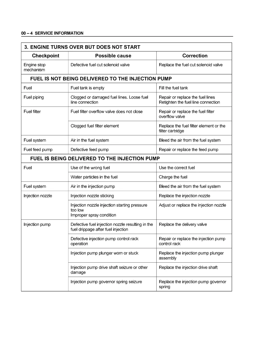
3. ENGINE TURNS OVER BUT DOES NOT START
Checkpoint Possible cause Correction
Engine stop mechanism Defective fuel cut solenoid valve Replace the fuel cut solenoid valve
FUEL IS NOT BEING DELIVERED TO THE INJECTION PUMP
Fuel Fuel tank is empty Fill the fuel tank
Fuel piping Clogged or damaged fuel lines. Loose fuel line connection Repair or replace the fuel lines Retighten the fuel line connection
Fuel filter Fuel filter overflow valve does not close Repair or replace the fuel filter overflow valve
Clogged fuel filter element Replace the fuel filter element or the filter cartridge
Fuel system Air in the fuel system Bleed the air from the fuel system
Fuel feed pump Defective feed pump Repair or replace the feed pump
FUEL IS BEING DELIVERED TO THE INJECTION PUMP
Fuel Use of the wrong fuel Use the correct fuel
Water particles in the fuel Charge the fuel
Fuel system Air in the injection pump Bleed the air from the fuel system
Injection nozzle Injection nozzle sticking Replace the injection nozzle
Injection nozzle injection starting pressure too low Improper spray condition Adjust or replace the injection nozzle
Injection pump Defective fuel injection nozzle resulting in the fuel drippage after fuel injection Replace the delivery valve
Defective injection pump control rack operation Repair or replace the injection pump control rack
Injection pump plunger worn or stuck Replace the injection pump plunger assembly
Injection pump drive shaft seizure or other damage Replace the injection drive shaft
Injection pump governor spring seizure Replace the injection pump governor spring
SERVICE INFORMATION 00-5
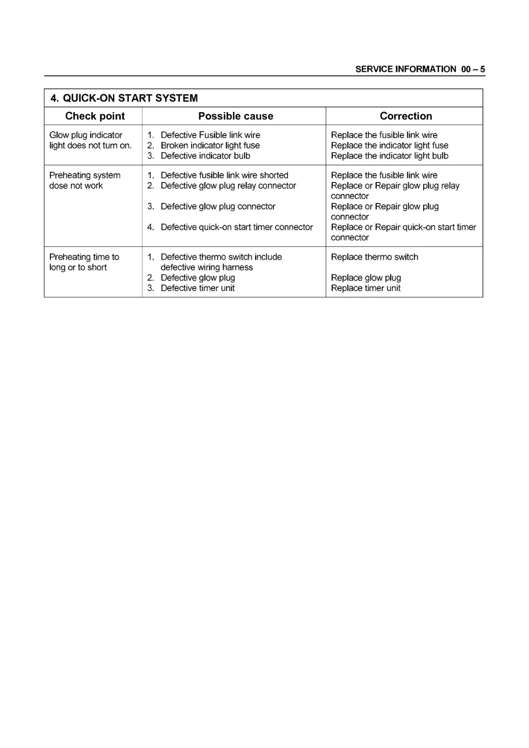
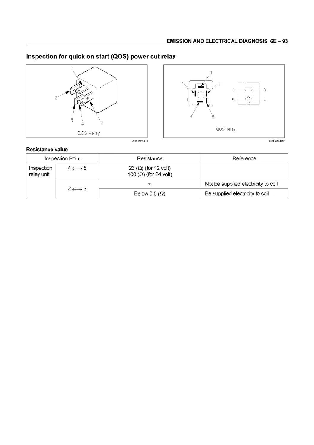
4. QUICK-ON START SYSTEM
Check point Possible cause Correction
Glow plug indicator light does not turn on. 1. Defective Fusible link wire 2. Broken indicator light fuse 3. Defective indicator bulb Replace the fusible link wire Replace the indicator light fuse Replace the indicator light bulb
Preheating system dose not work 1. Defective fusible link wire shorted 2. Defective glow plug relay connector 3. Defective glow plug connector 4. Defective quick-on start timer connector Replace the fusible link wire Replace or Repair glow plug relay connector Replace or Repair glow plug connector Replace or Repair quick-on start timer connector
Preheating time to long or to short 1. Defective thermo switch include defective wiring harness 2. Defective glow plug 3. Defective timer unit Replace thermo switch Replace glow plug Replace timer unit
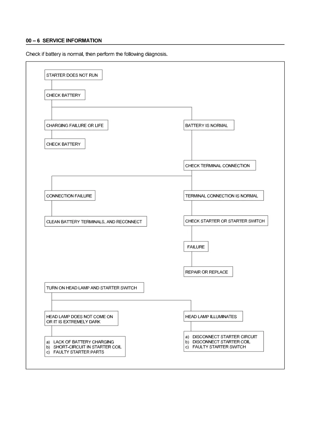
00-6 SERVICE INFORMATION
Check if battery is normal, then perform the following diagnosis.
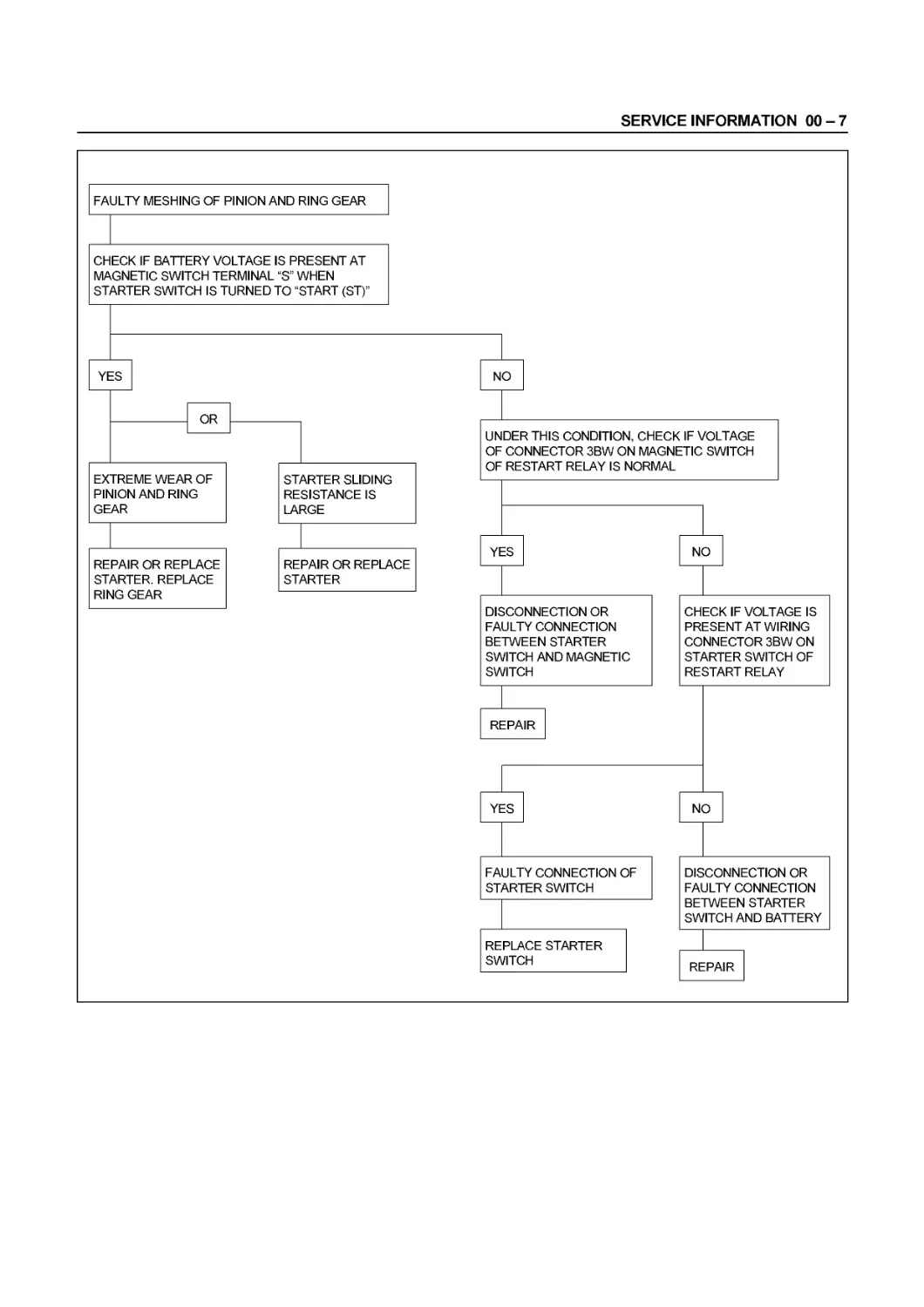
SERVICE INFORMATION 00-7
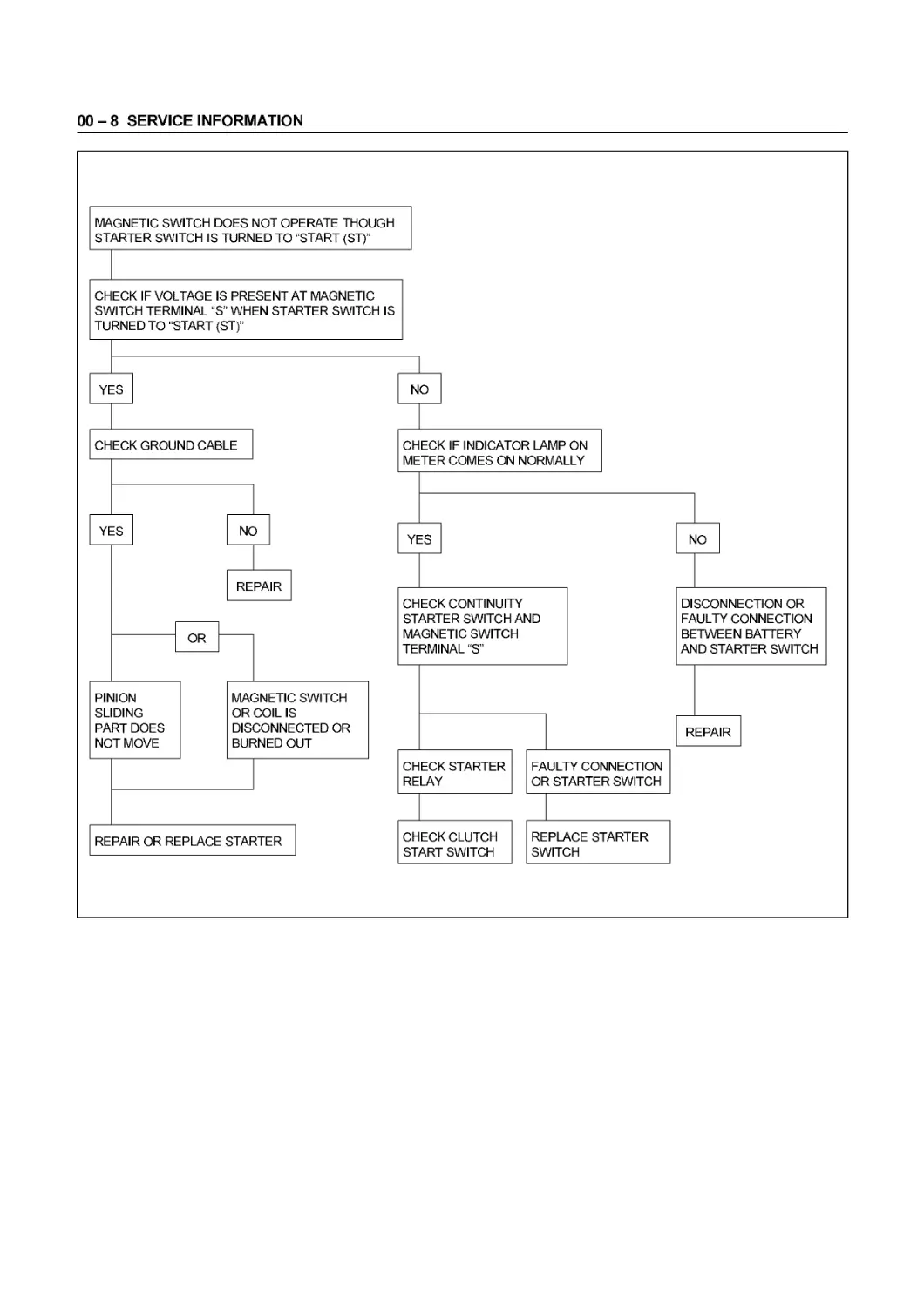
00-8 SERVICE INFORMATION
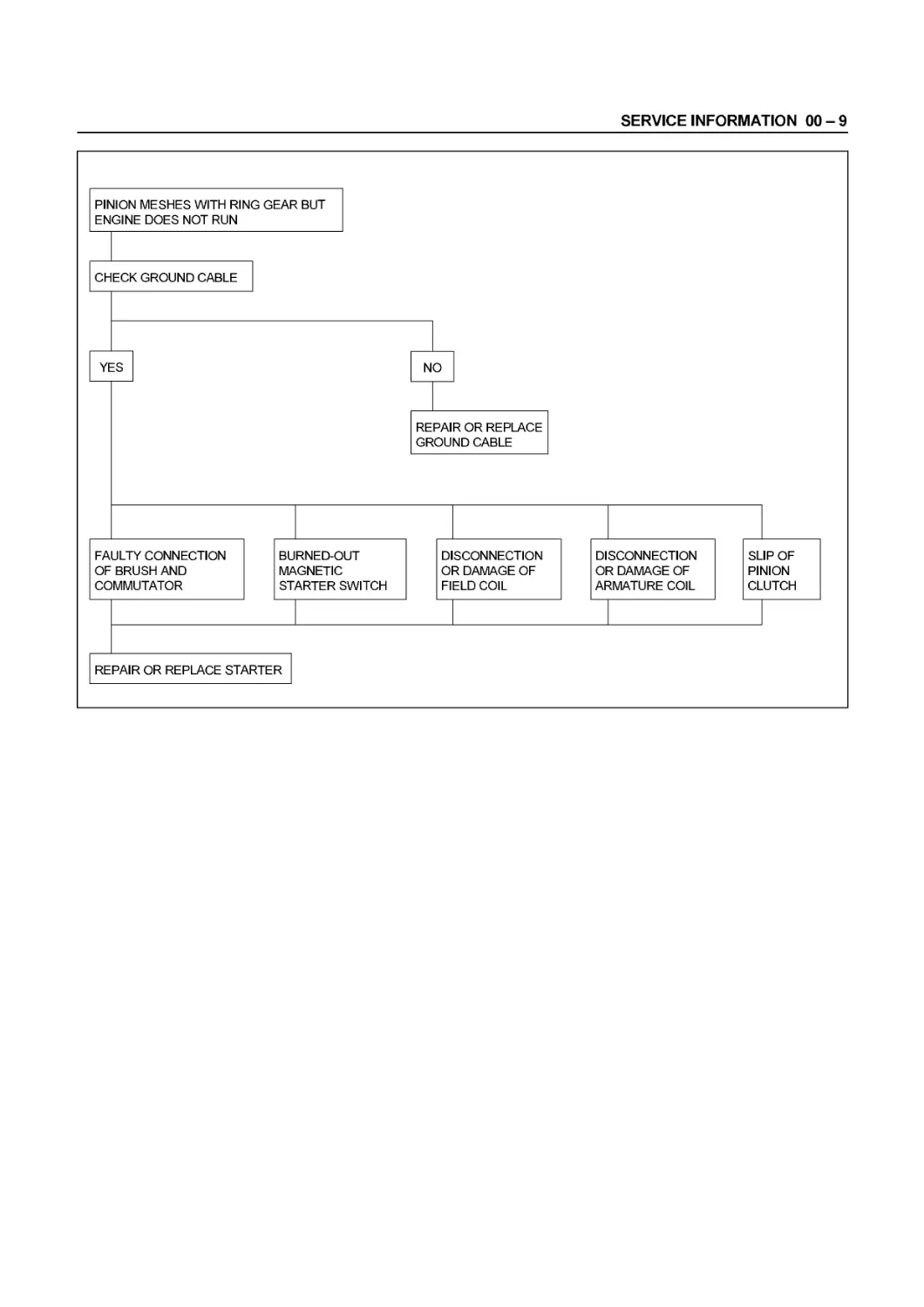
SERVICE INFORMATION 00-9
00-10 SERVICE INFORMATION
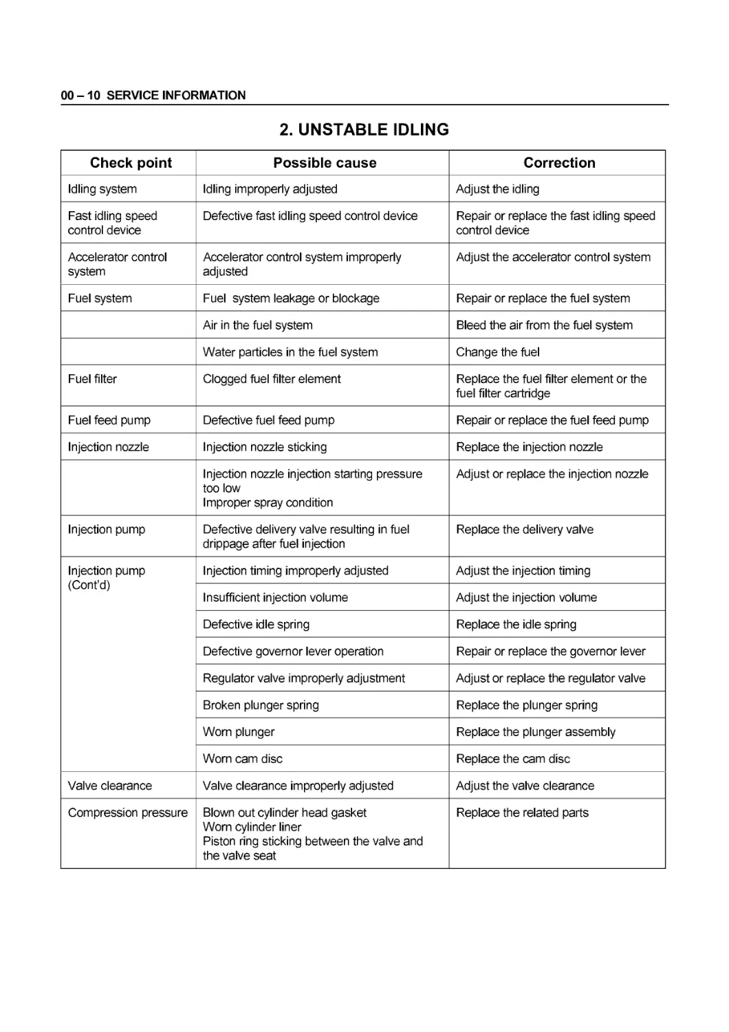
2. UNSTABLE IDLING
Check point Possible cause Correction
Idling system Idling improperly adjusted Adjust the idling
Fast idling speed control device Defective fast idling speed control device Repair or replace the fast idling speed control device
Accelerator control system Accelerator control system improperly adjusted Adjust the accelerator control system
Fuel system Fuel system leakage or blockage Repair or replace the fuel system
Air in the fuel system Bleed the air from the fuel system
Water particles in the fuel system Change the fuel
Fuel filter Clogged fuel filter element Replace the fuel filter element or the fuel filter cartridge
Fuel feed pump Defective fuel feed pump Repair or replace the fuel feed pump
Injection nozzle Injection nozzle sticking Replace the injection nozzle
Injection nozzle injection starting pressure too low Improper spray condition Adjust or replace the injection nozzle
Injection pump Defective delivery valve resulting in fuel drippage after fuel injection Replace the delivery valve
Injection pump (Cont’d) Injection timing improperly adjusted Adjust the injection timing
Insufficient injection volume Adjust the injection volume
Defective idle spring Replace the idle spring
Defective governor lever operation Repair or replace the governor lever
Regulator valve improperly adjustment Adjust or replace the regulator valve
Broken plunger spring Replace the plunger spring
Worn plunger Replace the plunger assembly
Worn cam disc Replace the cam disc
Valve clearance Valve clearance improperly adjusted Adjust the valve clearance
Compression pressure Blown out cylinder head gasket Worn cylinder liner Piston ring sticking between the valve and the valve seat Replace the related parts
SERVICE INFORMATION 00-11
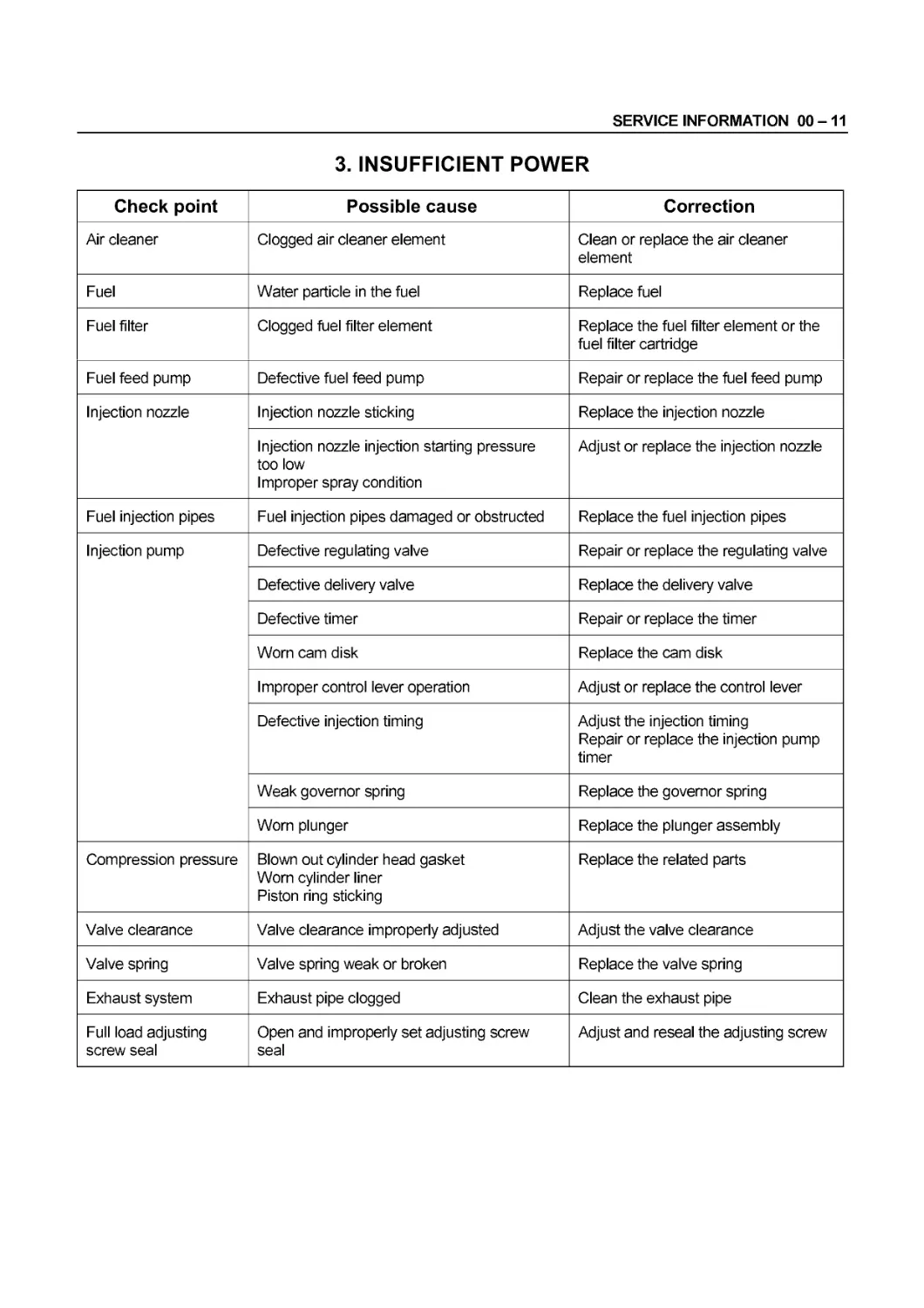
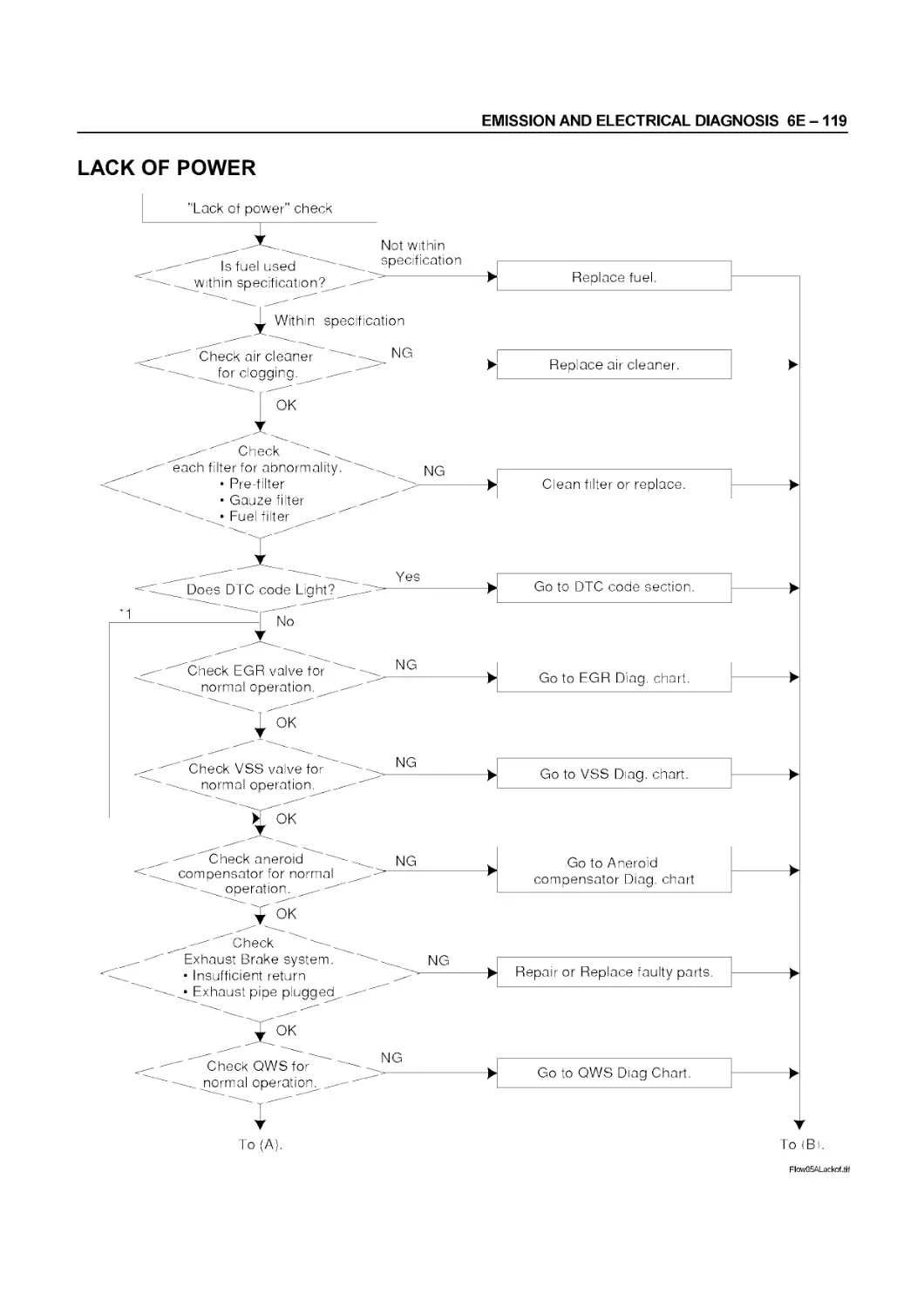
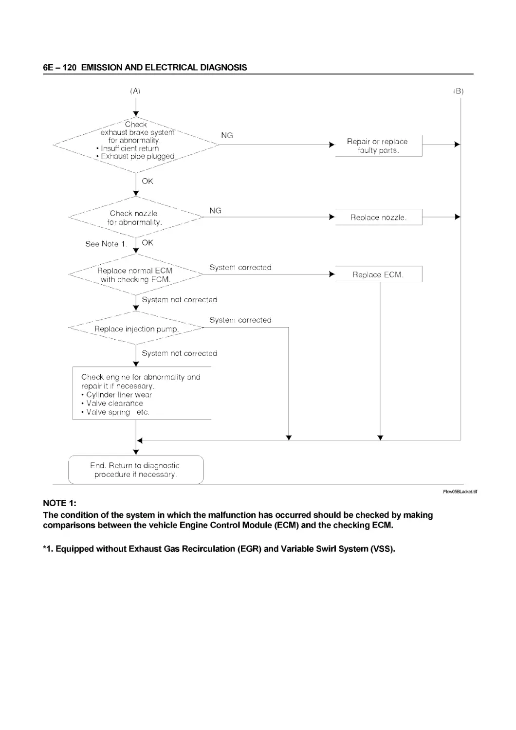
3. INSUFFICIENT POWER
Check point Possible cause Correction
Air cleaner Clogged air cleaner element Clean or replace the air cleaner element
Fuel Water particle in the fuel Replace fuel
Fuel filter Clogged fuel filter element Replace the fuel filter element or the fuel filter cartridge
Fuel feed pump Defective fuel feed pump Repair or replace the fuel feed pump
Injection nozzle Injection nozzle sticking Replace the injection nozzle
Injection nozzle injection starting pressure too low Improper spray condition Adjust or replace the injection nozzle
Fuel injection pipes Fuel injection pipes damaged or obstructed Replace the fuel injection pipes
Injection pump Defective regulating valve Repair or replace the regulating valve
Defective delivery valve Replace the delivery valve
Defective timer Repair or replace the timer
Worn cam disk Replace the cam disk
Improper control lever operation Adjust or replace the control lever
Defective injection timing Adjust the injection timing Repair or replace the injection pump timer
Weak governor spring Replace the governor spring
Worn plunger Replace the plunger assembly
Compression pressure Blown out cylinder head gasket Worn cylinder liner Piston ring sticking Replace the related parts
Valve clearance Valve clearance improperly adjusted Adjust the valve clearance
Valve spring Valve spring weak or broken Replace the valve spring
Exhaust system Exhaust pipe clogged Clean the exhaust pipe
Full load adjusting screw seal Open and improperly set adjusting screw seal Adjust and reseal the adjusting screw
00-12 SERVICE INFORMATION
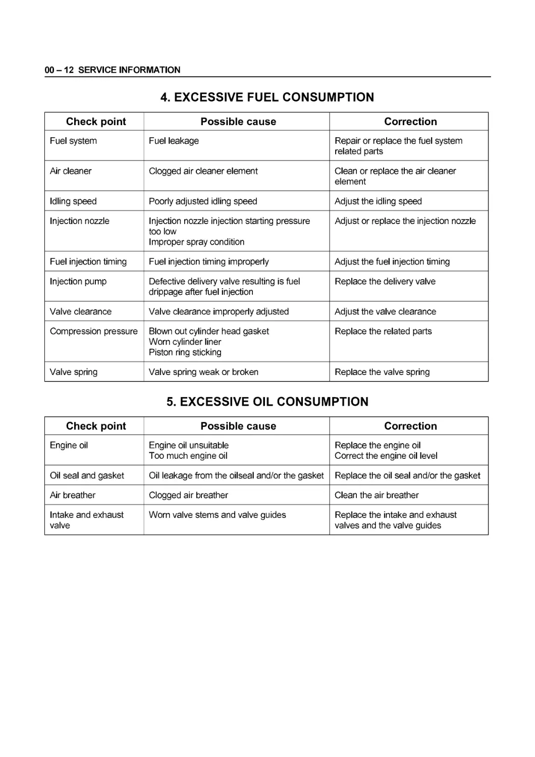
4. EXCESSIVE FUEL CONSUMPTION
Check point Possible cause Correction
Fuel system Fuel leakage Repair or replace the fuel system related parts
Air cleaner Clogged air cleaner element Clean or replace the air cleaner element
Idling speed Poorly adjusted idling speed Adjust the idling speed
Injection nozzle Injection nozzle injection starting pressure too low Improper spray condition Adjust or replace the injection nozzle
Fuel injection timing Fuel injection timing improperly Adjust the fuel injection timing
Injection pump Defective delivery valve resulting is fuel drippage after fuel injection Replace the delivery valve
Valve clearance Valve clearance improperly adjusted Adjust the valve clearance
Compression pressure Blown out cylinder head gasket Worn cylinder liner Piston ring sticking Replace the related parts
Valve spring Valve spring weak or broken Replace the valve spring
5. EXCESSIVE OIL CONSUMPTION
Check point Possible cause Correction
Engine oil Engine oil unsuitable Too much engine oil Replace the engine oil Correct the engine oil level
Oil seal and gasket Oil leakage from the oilseal and/or the gasket Replace the oil seal and/or the gasket
Air breather Clogged air breather Clean the air breather
Intake and exhaust valve Worn valve stems and valve guides Replace the intake and exhaust valves and the valve guides
SERVICE INFORMATION 00 - 13
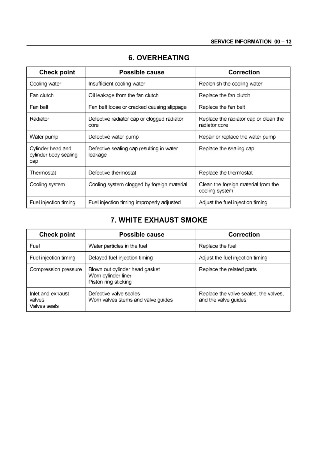
6. OVERHEATING
Check point Possible cause Correction
Cooling water Insufficient cooling water Replenish the cooling water
Fan clutch Oil leakage from the fan clutch Replace the fan clutch
Fan belt Fan belt loose or cracked causing slippage Replace the fan belt
Radiator Defective radiator cap or clogged radiator core Replace the radiator cap or clean the radiator core
Water pump Defective water pump Repair or replace the water pump
Cylinder head and cylinder body sealing cap Defective sealing cap resulting in water leakage Replace the sealing cap
Thermostat Defective thermostat Replace the thermostat
Cooling system Cooling system clogged by foreign material Clean the foreign material from the cooling system
Fuel injection timing Fuel injection timing improperly adjusted Adjust the fuel injection timing
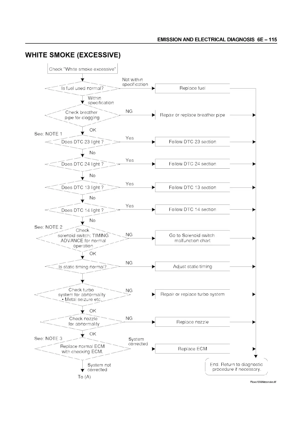
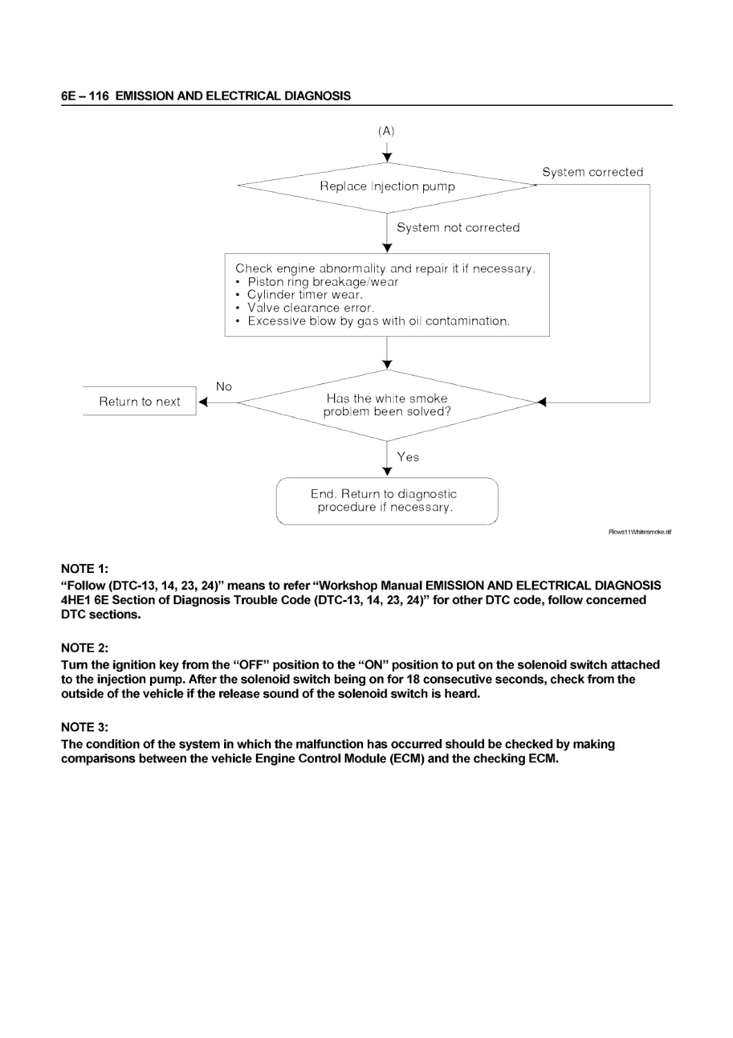
7. WHITE EXHAUST SMOKE
Check point Possible cause Correction
Fuel Water particles in the fuel Replace the fuel
Fuel injection timing Delayed fuel injection timing Adjust the fuel injection timing
Compression pressure Blown out cylinder head gasket Worn cylinder liner Piston ring sticking Replace the related parts
Inlet and exhaust valves Valves seals Defective valve seales Worn valves stems and valve guides Replace the valve seales, the valves, and the valve guides
00-14 SERVICE INFORMATION
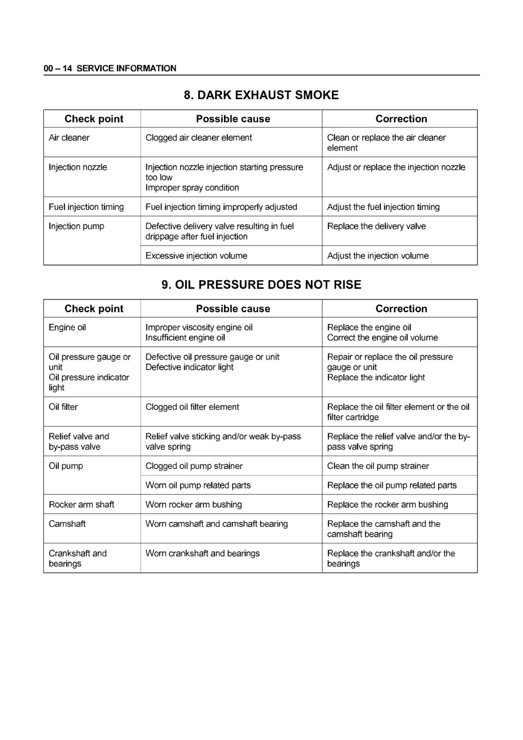
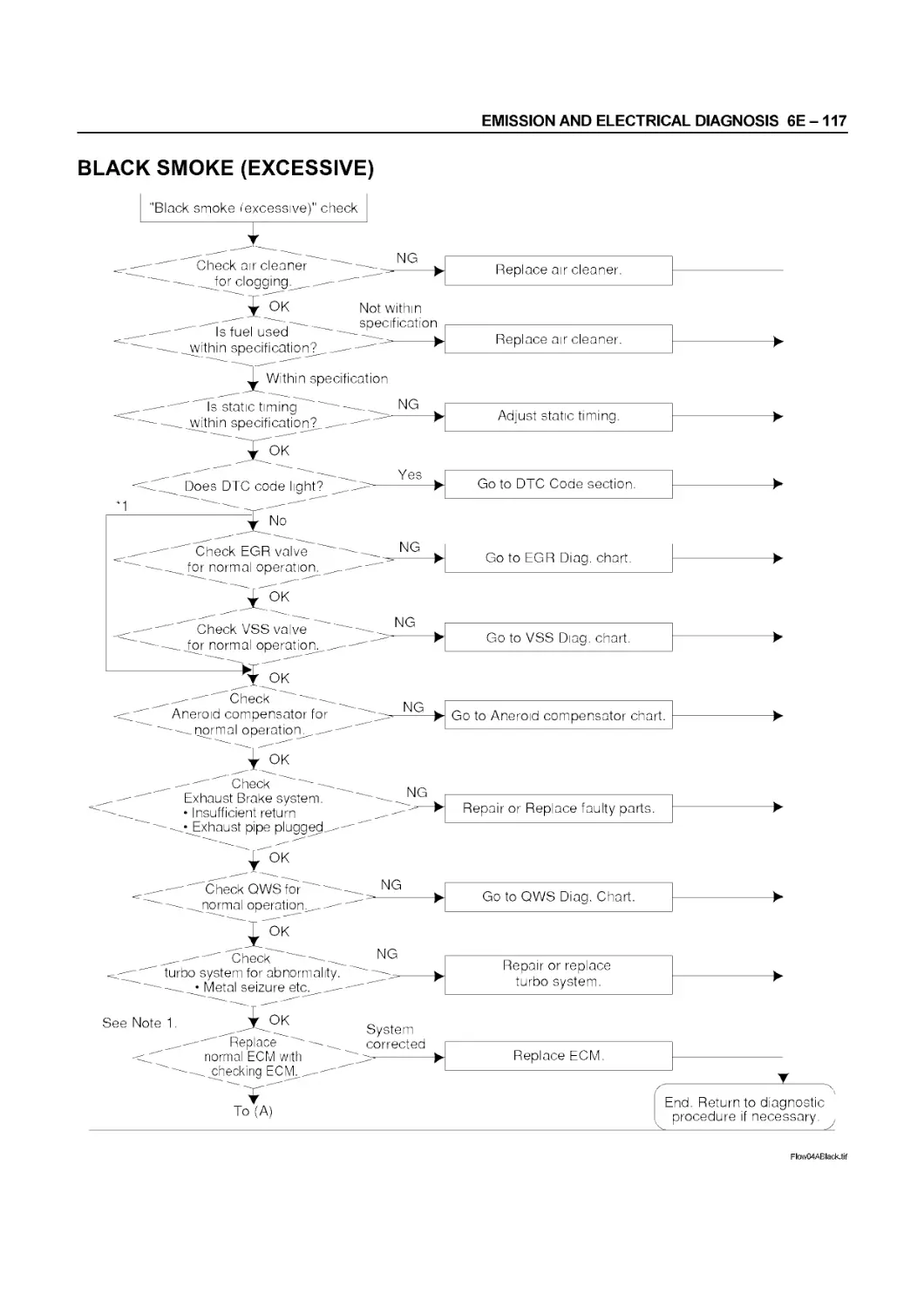
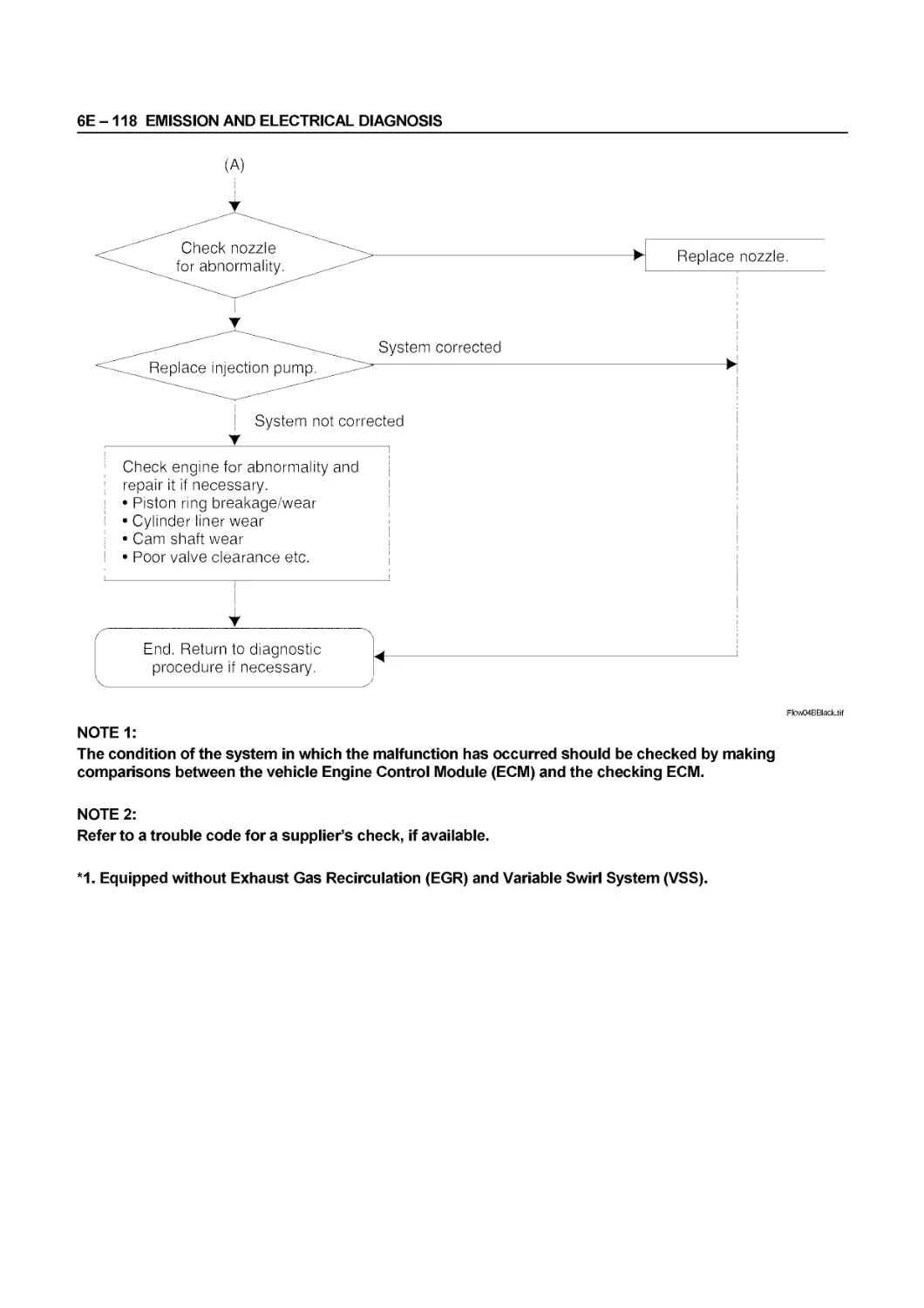
8. DARK EXHAUST SMOKE
Check point Possible cause Correction
Air cleaner Clogged air cleaner element Clean or replace the air cleaner element
Injection nozzle Injection nozzle injection starting pressure too low Improper spray condition Adjust or replace the injection nozzle
Fuel injection timing Fuel injection timing improperly adjusted Adjust the fuel injection timing
Injection pump Defective delivery valve resulting in fuel drippage after fuel injection Replace the delivery valve
Excessive injection volume Adjust the injection volume
9. OIL PRESSURE DOES NOT RISE
Check point Possible cause Correction
Engine oil Improper viscosity engine oil Insufficient engine oil Replace the engine oil Correct the engine oil volume
Oil pressure gauge or unit Oil pressure indicator light Defective oil pressure gauge or unit Defective indicator light Repair or replace the oil pressure gauge or unit Replace the indicator light
Oil filter Clogged oil filter element Replace the oil filter element or the oil filter cartridge
Relief valve and by-pass valve Relief valve sticking and/or weak by-pass valve spring Replace the relief valve and/or the by- pass valve spring
Oil pump Clogged oil pump strainer Clean the oil pump strainer
Worn oil pump related parts Replace the oil pump related parts
Rocker arm shaft Worn rocker arm bushing Replace the rocker arm bushing
Camshaft Worn camshaft and camshaft bearing Replace the camshaft and the camshaft bearing
Crankshaft and bearings Worn crankshaft and bearings Replace the crankshaft and/or the bearings
SERVICE INFORMATION 00 - 15
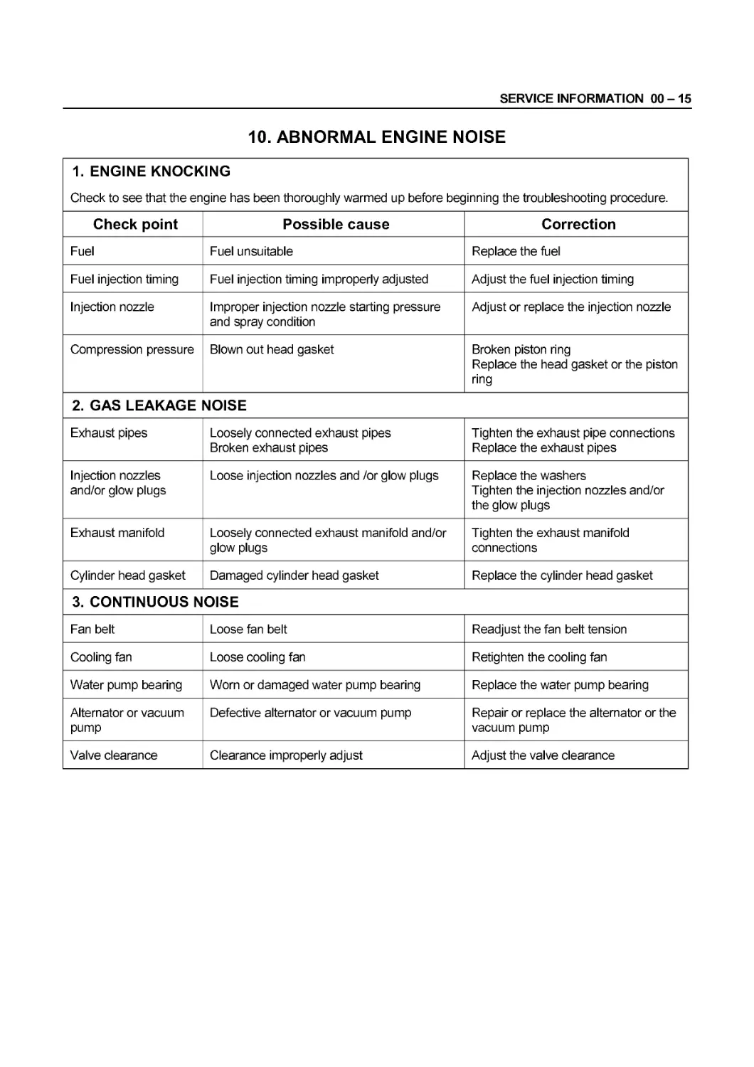
10. ABNORMAL ENGINE NOISE
1. ENGINE KNOCKING Check to see that the engine has been thoroughly warmed up before beginning the troubleshooting procedure.
Check point Possible cause Correction
Fuel Fuel unsuitable Replace the fuel
Fuel injection timing Fuel injection timing improperly adjusted Adjust the fuel injection timing
Injection nozzle Improper injection nozzle starting pressure and spray condition Adjust or replace the injection nozzle
Compression pressure Blown out head gasket Broken piston ring Replace the head gasket or the piston ring
2. GAS LEAKAGE NOISE
Exhaust pipes Loosely connected exhaust pipes Broken exhaust pipes Tighten the exhaust pipe connections Replace the exhaust pipes
Injection nozzles and/or glow plugs Loose injection nozzles and /or glow plugs Replace the washers Tighten the injection nozzles and/or the glow plugs
Exhaust manifold Loosely connected exhaust manifold and/or glow plugs Tighten the exhaust manifold connections
Cylinder head gasket Damaged cylinder head gasket Replace the cylinder head gasket
3. CONTINUOUS NOISE
Fan belt Loose fan belt Readjust the fan belt tension
Cooling fan Loose cooling fan Retighten the cooling fan
Water pump bearing Worn or damaged water pump bearing Replace the water pump bearing
Alternator or vacuum pump Defective alternator or vacuum pump Repair or replace the alternator or the vacuum pump
Valve clearance Clearance improperly adjust Adjust the valve clearance
00-16 SERVICE INFORMATION
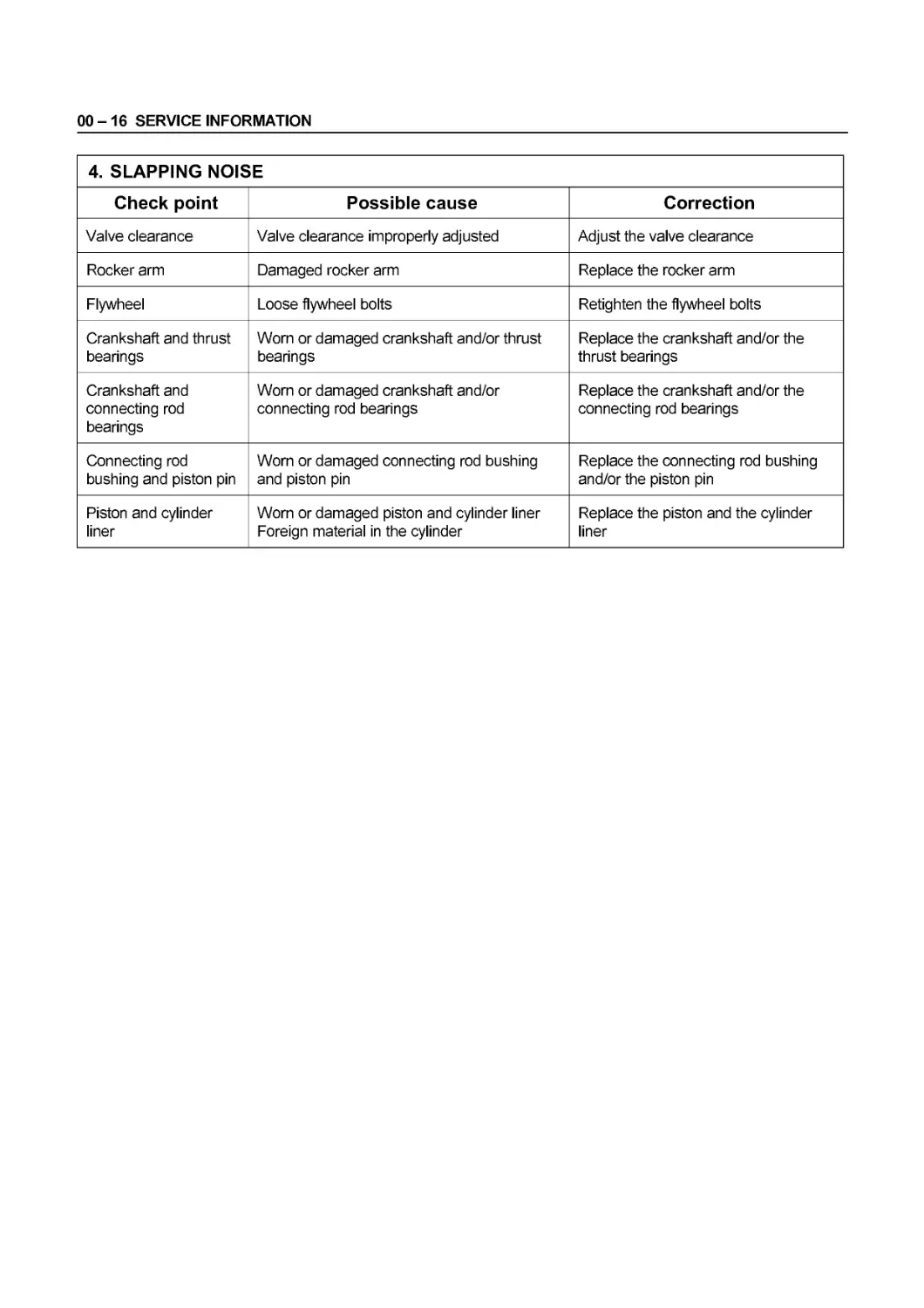
4. SLAPPING NOISE
Check point Possible cause Correction
Valve clearance Valve clearance improperly adjusted Adjust the valve clearance
Rocker arm Damaged rocker arm Replace the rocker arm
Flywheel Loose flywheel bolts Retighten the flywheel bolts
Crankshaft and thrust bearings Worn or damaged crankshaft and/or thrust bearings Replace the crankshaft and/or the thrust bearings
Crankshaft and connecting rod bearings Worn or damaged crankshaft and/or connecting rod bearings Replace the crankshaft and/or the connecting rod bearings
Connecting rod bushing and piston pin Worn or damaged connecting rod bushing and piston pin Replace the connecting rod bushing and/or the piston pin
Piston and cylinder liner Worn or damaged piston and cylinder liner Foreign material in the cylinder Replace the piston and the cylinder liner
SERVICE INFORMATION 00-17
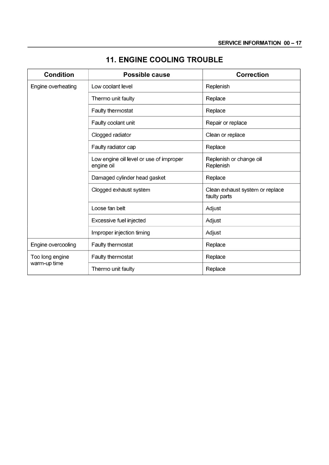
11. ENGINE COOLING TROUBLE
Condition Possible cause Correction
Engine overheating Low coolant level Replenish
Thermo unit faulty Replace
Faulty thermostat Replace
Faulty coolant unit Repair or replace
Clogged radiator Clean or replace
Faulty radiator cap Replace
Low engine oil level or use of improper engine oil Replenish or change oil Replenish
Damaged cylinder head gasket Replace
Clogged exhaust system Clean exhaust system or replace faulty parts
Loose fan belt Adjust
Excessive fuel injected Adjust
Improper injection timing Adjust
Engine overcooling Faulty thermostat Replace
Too long engine warm-up time Faulty thermostat Replace
Thermo unit faulty Replace
00-18 SERVICE INFORMATION
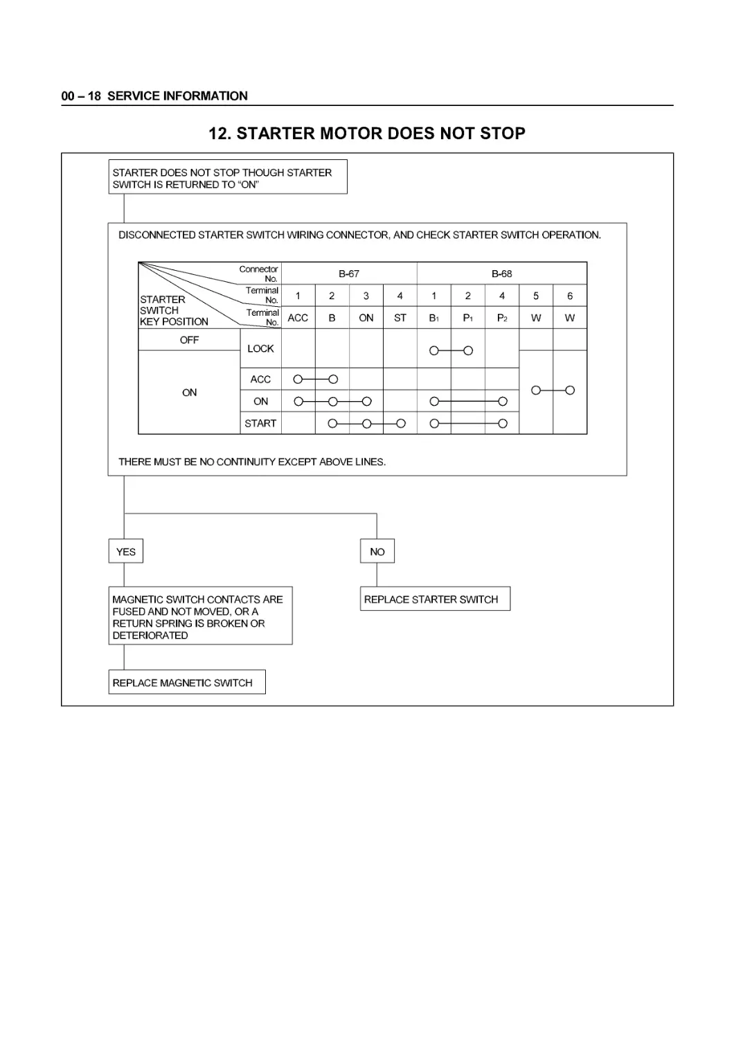
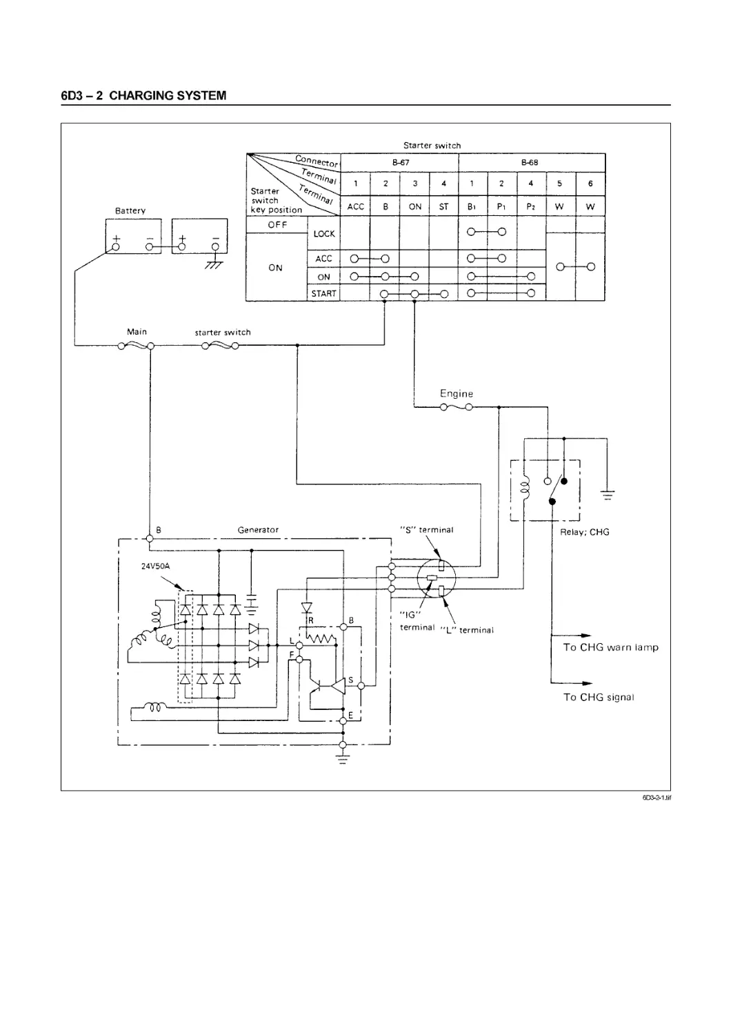
12. STARTER MOTOR DOES NOT STOP
STARTER DOES NOT STOP THOUGH STARTER
SWITCH IS RETURNED TO “ON”
DISCONNECTED STARTER SWITCH WIRING CONNECTOR, AND CHECK STARTER SWITCH OPERATION.
Connector No. B-67 В-68
Terminal STARTER SWITCH Terminal KEY POSITION 1 2 3 4 1 2 4 5 6
ACC В ON ST Bi Pi Р2 W W
OFF LOCK
ON и
ACC
{J U
ON r-\ о —f~X и— —к?
и и и и
START г\ г\
и <7 <7
THERE MUST BE NO CONTINUITY EXCEPT ABOVE LINES.
SERVICE INFORMATION 00-19
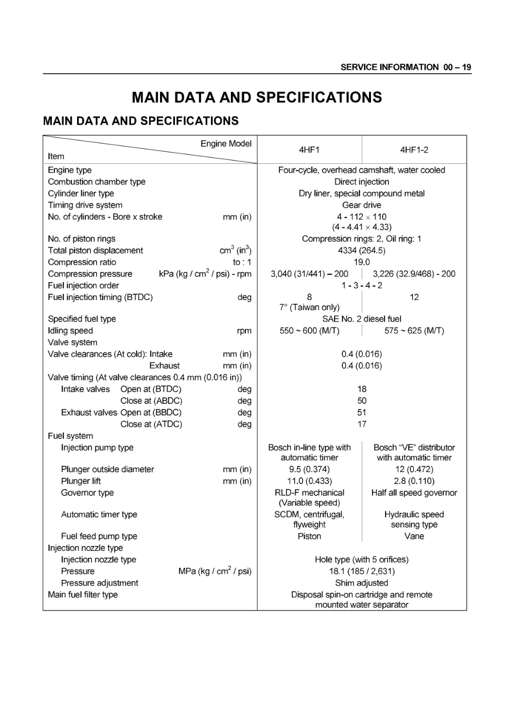
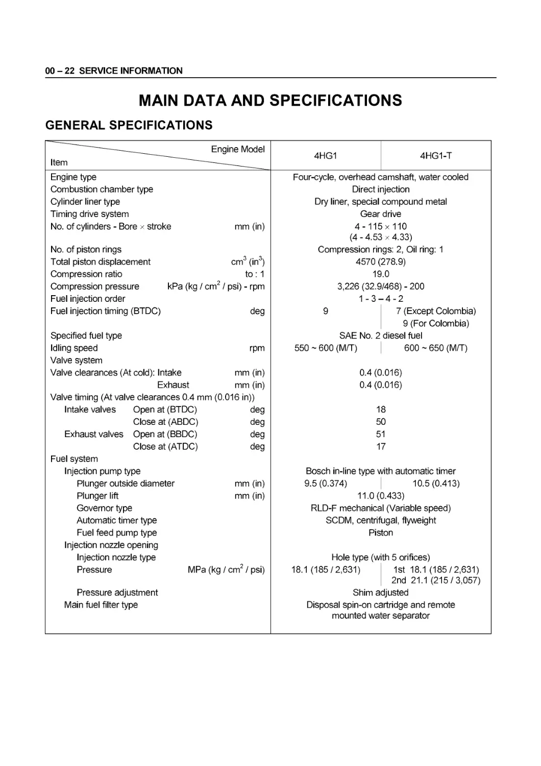
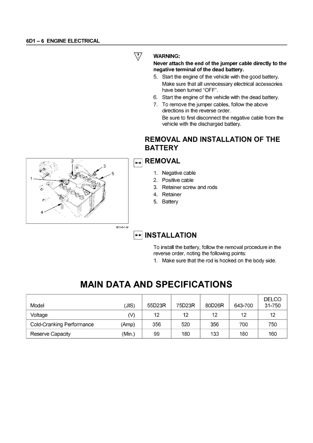
MAIN DATA AND SPECIFICATIONS
MAIN DATA AND SPECIFICATIONS
———Engine Model 4HF1 4HF1-2
Item ——
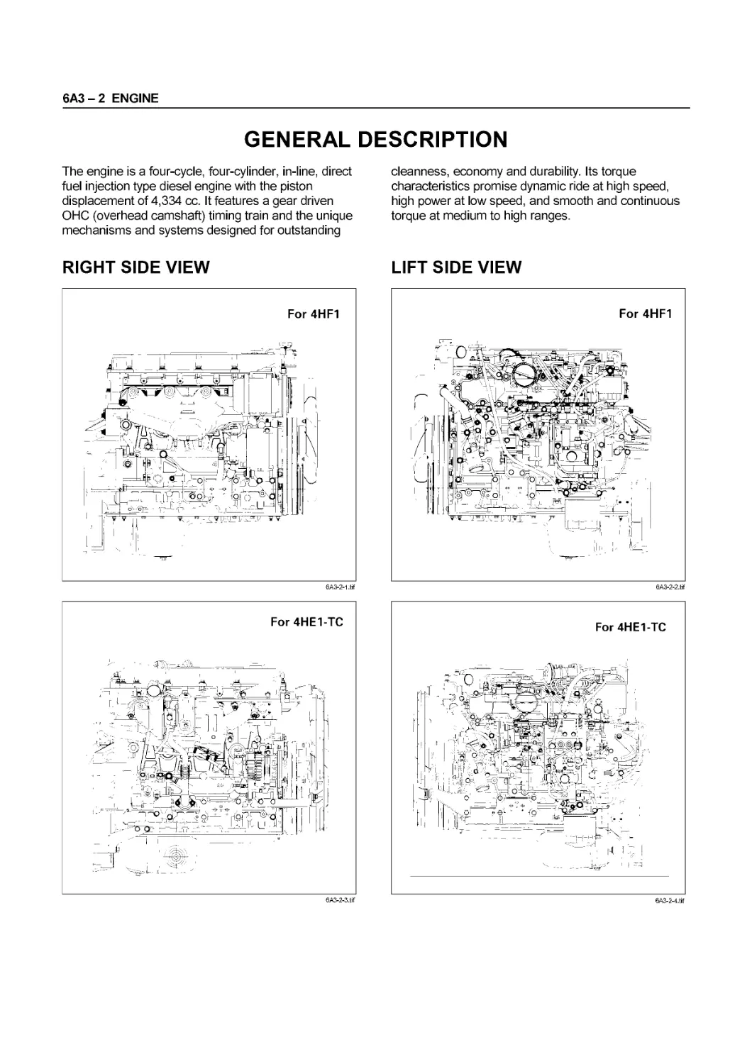
Engine type Four-cycle, overhead camshaft, water cooled
Combustion chamber type Direct injection
Cylinder liner type Dry liner, special compound metal
Timing drive system Gear drive
No. of cylinders - Bore x stroke mm (in) 4-112x110 (4 - 4.41 x 4.33)
No. of piston rings Compression rings: 2, Oil ring: 1
Total piston displacement cm3 (in3) 4334 (264.5)
Compression ratio to : 1 19.0
Compression pressure kPa (kg / cm2 / psi) - rpm 3,040 (31/441)-200 3,226 (32.9/468) - 200
Fuel injection order 1-3- 4-2
Fuel injection timing (BTDC) deg 8 7° (Taiwan only) 12
Specified fuel type SAE No. 2 diesel fuel
Idling speed rpm Valve system 550 ~ 600 (M/T) 575 ~ 625 (M/T)
Valve clearances (At cold): Intake mm (in) 0.4 (0.016)
Exhaust mm (in) Valve timing (At valve clearances 0.4 mm (0.016 in)) 0.4 (0.016)
Intake valves Open at (BTDC) deg 18
Close at (ABDC) deg 50
Exhaust valves Open at (BBDC) deg 51
Close at (ATDC) deg Fuel system 17
Injection pump type Bosch in-line type with automatic timer Bosch “VE" distributor with automatic timer
Plunger outside diameter mm (in) 9.5 (0.374) 12 (0.472)
Plunger lift mm (in) 11.0(0.433) 2.8(0.110)
Governor type RLD-F mechanical (Variable speed) Half all speed governor
Automatic timer type SCDM, centrifugal, flyweight Hydraulic speed sensing type
Fuel feed pump type Injection nozzle type Piston Vane
Injection nozzle type Hole type (with 5 orifices)
Pressure MPa (kg / cm2 / psi) 18.1 (185/2,631)
Pressure adjustment Shim adjusted
Main fuel filter type Disposal spin-on cartridge and remote mounted water separator
00 - 20 SERVICE INFORMATION
Item Engine Model 4HF1 4HF1-2
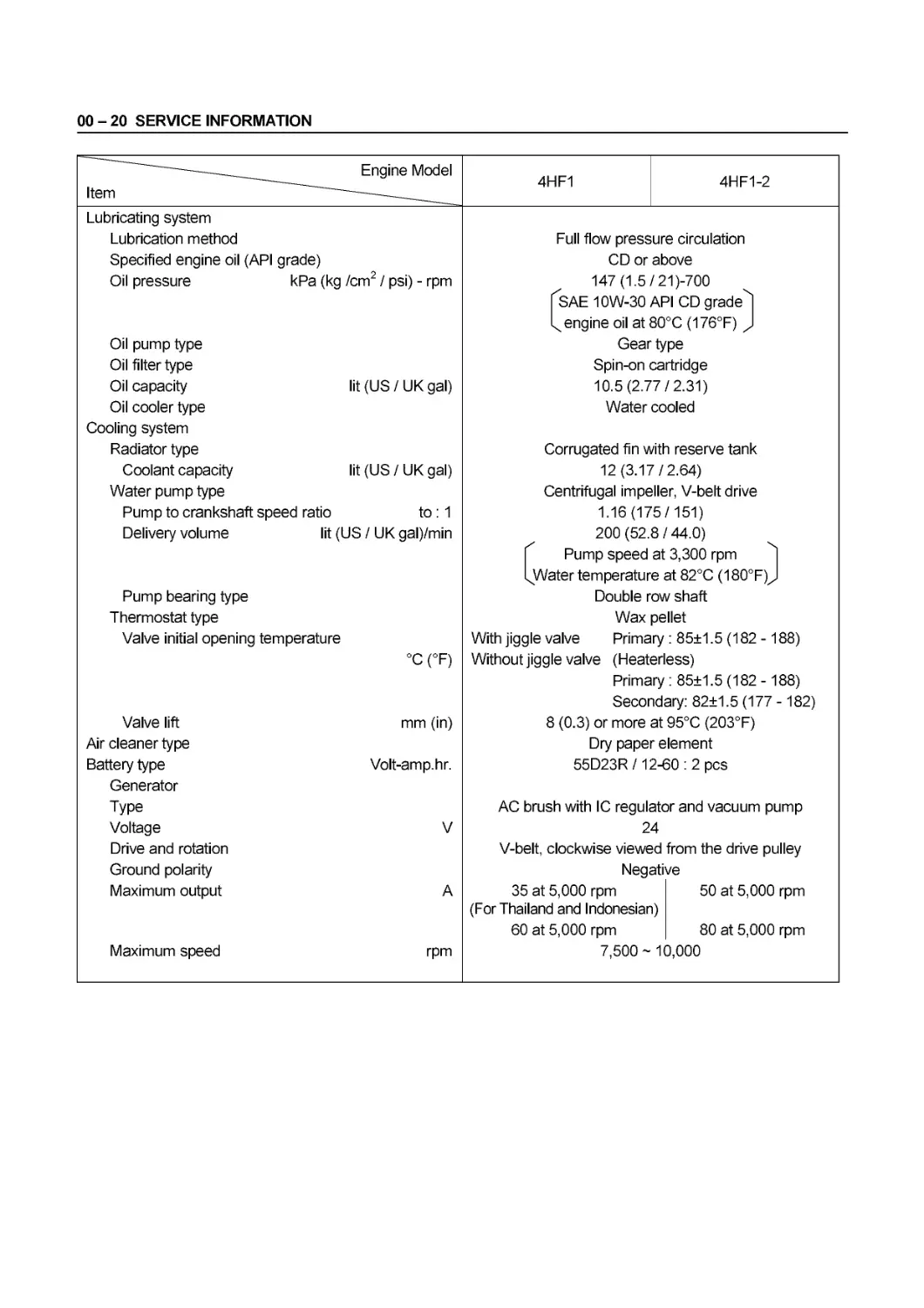
Lubricating system
Lubrication method Full flow pressure circulation
Specified engine oil (API grade) CD or above
Oil pressure kPa (kg /cm / psi) - rpm 147 (1.5/21)-700
fSAE 10W-30 API CD grade'4)
L engine oil at 80°C (176°F) )
Oil pump type Gear type
Oil filter type Spin-on cartridge
Oil capacity lit (US / UK gal) 10.5(2.77/2.31)
Oil cooler type Water cooled
Cooling system
Radiator type Corrugated fin with reserve tank
Coolant capacity lit (US/UK gal) 12(3.17/2.64)
Water pump type Centrifugal impeller, V-belt drive
Pump to crankshaft speed ratio to : 1 1.16(175/151)
Delivery volume lit (US / UK gal)/min 200 (52.8 / 44.0)
| Pump speed at 3,300 rpm ]
QA/ater temperature at 82°C (180°F)J
Pump bearing type Double row shaft
Thermostat type Wax pellet
Valve initial opening temperature With jiggle valve Primary : 85±1.5 (182-188)
°C (°F) Without jiggle valve (Heaterless)
Primary : 85+1.5 (182 -188)
Secondary: 82±1.5 (177 -182)
Valve lift mm (in) 8 (0.3) or more at 95°C (203°F)
Air cleaner type Dry paper element
Battery type Volt-amp.hr. 55D23R /12-60 : 2 pcs
Generator
Type AC brush with IC regulator and vacuum pump
Voltage V 24
Drive and rotation V-belt, clockwise viewed from the drive pulley
Ground polarity Negative
Maximum output A 35 at 5,000 rpm 50 at 5,000 rpm
(For Thailand and Indonesian)
60 at 5,000 rpm 80 at 5,000 rpm
Maximum speed rpm 7,500 ~ 10,000
SERVICE INFORMATION 00 - 21
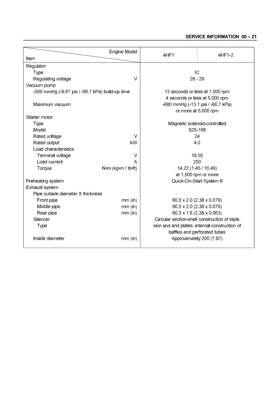
Item Engine Model 4HF1 4HF1-2
Regulator Type Regulating voltage V IC 28-29
Vacuum pump -500 mmHg (-9.67 psi / -66.7 kPa) build-up time 13 seconds or less at 1,000 rpm
Maximum vacuum Starter motor Type Model Rated voltage V 4 seconds or less at 5,000 rpm -680 mmHg (-13.1 psi / -90.7 kPa) or more at 5,000 rpm Magnetic solenoid-controlled S25-168 24
Rated output kW 4.0
Load characteristics Terminal voltage V 18.55
Load current A 250
Torque N*m (kg«m / lb’ft) 14.22 (1.45/10.49)
Preheating system Exhaust system Pipe outside diameter X thickness Front pipe mm (in) at 1,500 rpm or more Quick-On-Start System II 60.5 x 2.0 (2.38 x 0.079)
Middle pipe mm (in) 60.5 x 2.0 (2.38 x 0.079)
Rear pipe mm (in) 60.5x1.6 (2.38x0.063)
Silencer Type Inside diameter mm (in) Circular section-shell construction of triple skin and end plates, internal construction of baffles and perforated tubes Approximately 200 (7.87)
00 - 22 SERVICE INFORMATION
MAIN DATA AND SPECIFICATIONS
GENERAL SPECIFICATIONS
Item — Engine Model 4HG1 4HG1-T
Engine type Four-cycle, overhead camshaft, water cooled
Combustion chamber type Direct injection
Cylinder liner type Dry liner, special compound metal
Timing drive system Gear drive
No. of cylinders - Bore x stroke mm (in) 4- 115x 110
(4 - 4.53 x 4.33)
No. of piston rings Compression rings: 2, Oil ring: 1
Total piston displacement cm3 (in3) 4570 (278.9)
Compression ratio to: 1 19.0
Compression pressure kPa (kg / cm2 / psi) - rpm 3,226 (32.9/468) - 200
Fuel injection order 1-3- -4-2
Fuel injection timing (BTDC) deg 9 7 (Except Colombia)
9 (For Colombia)
Specified fuel type SAE No. 2 diesel fuel
Idling speed rpm 550 ~ 600 (M/T) 600 ~ 650 (M/T)
Valve system
Valve clearances (At cold): Intake mm (in) 0.4 (0.016)
Exhaust mm (in) 0.4 (0.016)
Valve timing (At valve clearances 0.4 mm (0.016 in))
Intake valves Open at (BTDC) deg 18
Close at (ABDC) deg 50
Exhaust valves Open at (BBDC) deg 51
Close at (ATDC) deg 17
Fuel system
Injection pump type Bosch in-line type with automatic timer
Plunger outside diameter mm (in) 9.5 (0.374) 10.5(0.413)
Plunger lift mm (in) 11.0(0.433)
Governor type RLD-F mechanical (Variable speed)
Automatic timer type SCDM, centrifugal, flyweight
Fuel feed pump type Piston
Injection nozzle opening
Injection nozzle type Hole type (with 5 orifices)
Pressure MPa (kg / cm2 / psi) 18.1 (185/2,631) 1st 18.1 (185/2,631)
2nd 21.1 (215/3,057)
Pressure adjustment Shim adjusted
Main fuel filter type Disposal spin-on cartridge and remote
mounted water separator
SERVICE INFORMATION 00 - 23
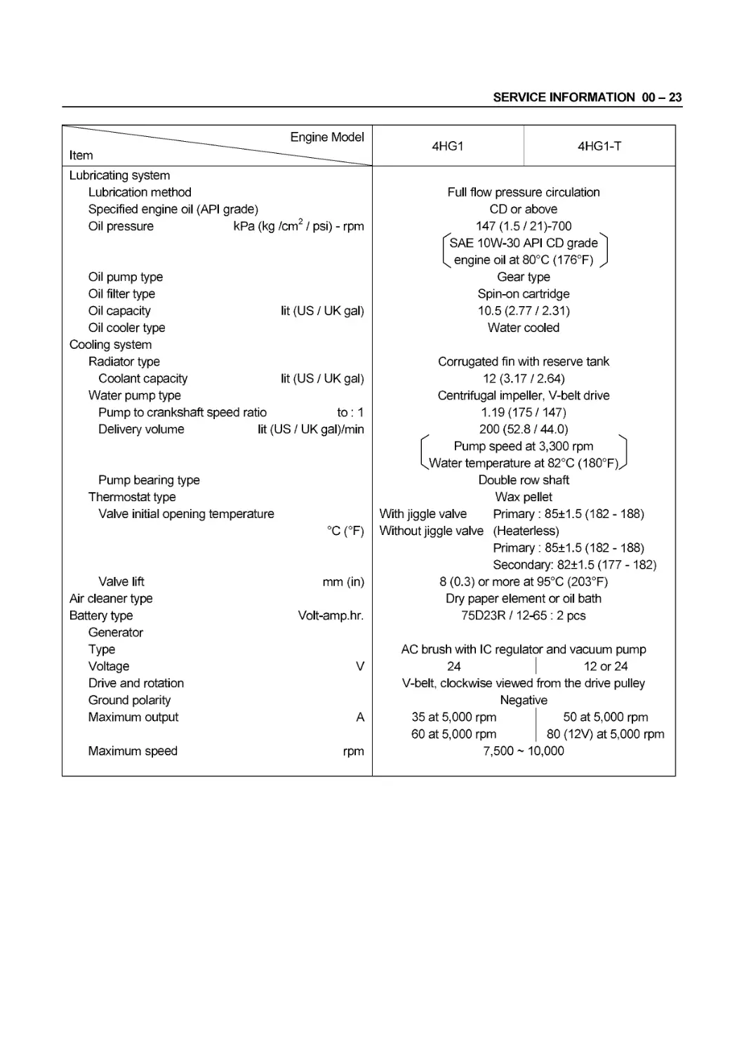
Item Engine Model 4HG1 4HG1-T
Lubricating system
Lubrication method Full flow pressure circulation
Specified engine oil (API grade) CD or above
Oil pressure kPa (kg /cm / psi) - rpm 147 (1.5/21)-700
fSAE 10W-30 API CD grade ''I
engine oil at 80°C (176°F) )
Oil pump type Gear type
Oil filter type Spin-on cartridge
Oil capacity lit (US / UK gal) 10.5(2.77/2.31)
Oil cooler type Water cooled
Cooling system
Radiator type Corrugated fin with reserve tank
Coolant capacity lit (US/UK gal) 12(3.17/2.64)
Water pump type Centrifugal impeller, V-belt drive
Pump to crankshaft speed ratio to : 1 1.19(175/147)
Delivery volume lit (US / UK gal)/min 200 (52.8 / 44.0)
| Pump speed at 3,300 rpm |
Lwater temperature at 82°C (180°F)J
Pump bearing type Double row shaft
Thermostat type Wax pellet
Valve initial opening temperature With jiggle valve Primary : 85±1.5 (182-188)
°C (°F) Without jiggle valve (Heaterless)
Primary : 85+1.5 (182 -188)
Secondary: 82±1.5 (177 -182)
Valve lift mm (in) 8 (0.3) or more at 95°C (203°F)
Air cleaner type Dry paper element or oil bath
Battery type Volt-amp.hr. 75D23R /12-65 : 2 pcs
Generator
Type AC brush with IC regulator and vacuum pump
Voltage V 24 12 or 24
Drive and rotation V-belt, clockwise viewed from the drive pulley
Ground polarity Negative
Maximum output A 35 at 5,000 rpm 50 at 5,000 rpm
60 at 5,000 rpm 80 (12V) at 5,000 rpm
Maximum speed rpm 7,500 ~ 10,000
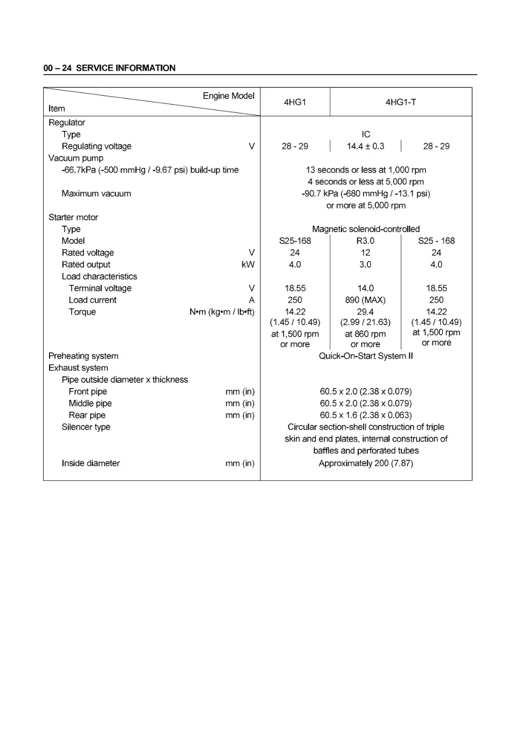
00 - 24 SERVICE INFORMATION
Item Engine Model 4HG1 4HG1-T
Regulator Type Regulating voltage V 28-29 IC 14.4 ±0.3 28-29
Vacuum pump -66.7kPa (-500 mmHg / -9.67 psi) build-up time 13 seconds or less at 1,000 rpm
Maximum vacuum Starter motor Type Model Rated voltage V 4 sect -90.7 kl c Mag S25-168 24 Dnds or less at 5,0C эа (-680 mmHg / -1 r more at 5,000 rpr letic solenoid-contr R3.0 12 0 rpm 3.1 psi) n oiled S25-168 24
Rated output kW 4.0 3.0 4.0
Load characteristics Terminal voltage V 18.55 14.0 18.55
Load current A 250 890 (MAX) 250
Torque N*m (kg«m / lb’ft) 14.22 29.4 14.22
Preheating system Exhaust system Pipe outside diameter x Front pipe thickness mm (in) (1.45/10.49) at 1,500 rpm or more Qu 60 (2.99/21.63) at 860 rpm or more ick-On-Start Syster 5 x 2.0 (2.38 x 0.0’ (1.45/10.49) at 1,500 rpm or more n II 79)
Middle pipe mm (in) 60.5x2.0(2.38x0.079)
Rear pipe mm (in) 60.5x1.6 (2.38x0.063)
Silencer type Inside diameter mm (in) Circular section-shell construction of triple skin and end plates, internal construction of baffles and perforated tubes Approximately 200 (7.87)
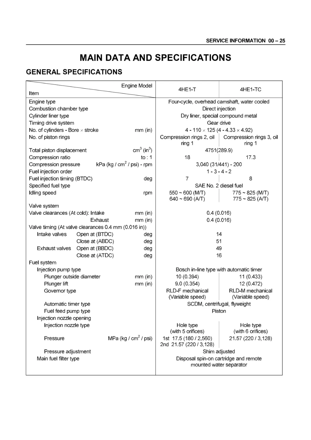
SERVICE INFORMATION 00 - 25
MAIN DATA AND SPECIFICATIONS
GENERAL SPECIFICATIONS
——— Engine Model 4HE1-T 4HE1-TC
Item ———
Engine type Four-cycle, overhead camshaft, water cooled
Combustion chamber type Direct injection
Cylinder liner type Dry liner, special compound metal
Timing drive system Gear drive
No. of cylinders - Bore x stroke mm (in) 4-110x 125(4-4.33x4.92)
No. of piston rings Compression rings 2, oil ring 1 Compression rings 3, oil ring 1
Total piston displacement cm3 (in3) 4751(289.9)
Compression ratio to : 1 18 17.3
Compression pressure kPa (kg / cm2 / psi) - rpm 3,040 (31/441)-200
Fuel injection order 1-3- 4-2
Fuel injection timing (BTDC) deg 7 8
Specified fuel type SAE No. 2 diesel fuel
Idling speed rpm Valve system 550 ~ 600 (M/T) 640 ~ 690 (A/T) 775 ~ 825 (M/T) 775 ~ 825 (A/T)
Valve clearances (At cold): Intake mm (in) 0.4 (0.016)
Exhaust mm (in) Valve timing (At valve clearances 0.4 mm (0.016 in)) 0.4 (0.016)
Intake valves Open at (BTDC) deg 14
Close at (ABDC) deg 51
Exhaust valves Open at (BBDC) deg 49
Close at (ATDC) deg Fuel system 16
Injection pump type Bosch in-line type with automatic timer
Plunger outside diameter mm (in) 10(0.394) 11 (0.433)
Plunger lift mm (in) 9.0 (0.354) 12(0.472)
Governor type RLD-F mechanical (Variable speed) RLD-M mechanical (Variable speed)
Automatic timer type SCDM, centrifugal, flyweight
Fuel feed pump type Injection nozzle opening Piston
Injection nozzle type Hole type (with 5 orifices) Hole type (with 6 orifices)
Pressure MPa (kg / cm2 / psi) 1st 17.5(180/2,560) 2nd 21.57(220/3,128) 21.57 (220/3,128)
Pressure adjustment Shim adjusted
Main fuel filter type Disposal spin-on cartridge and remote mounted water separator
00 - 26 SERVICE INFORMATION
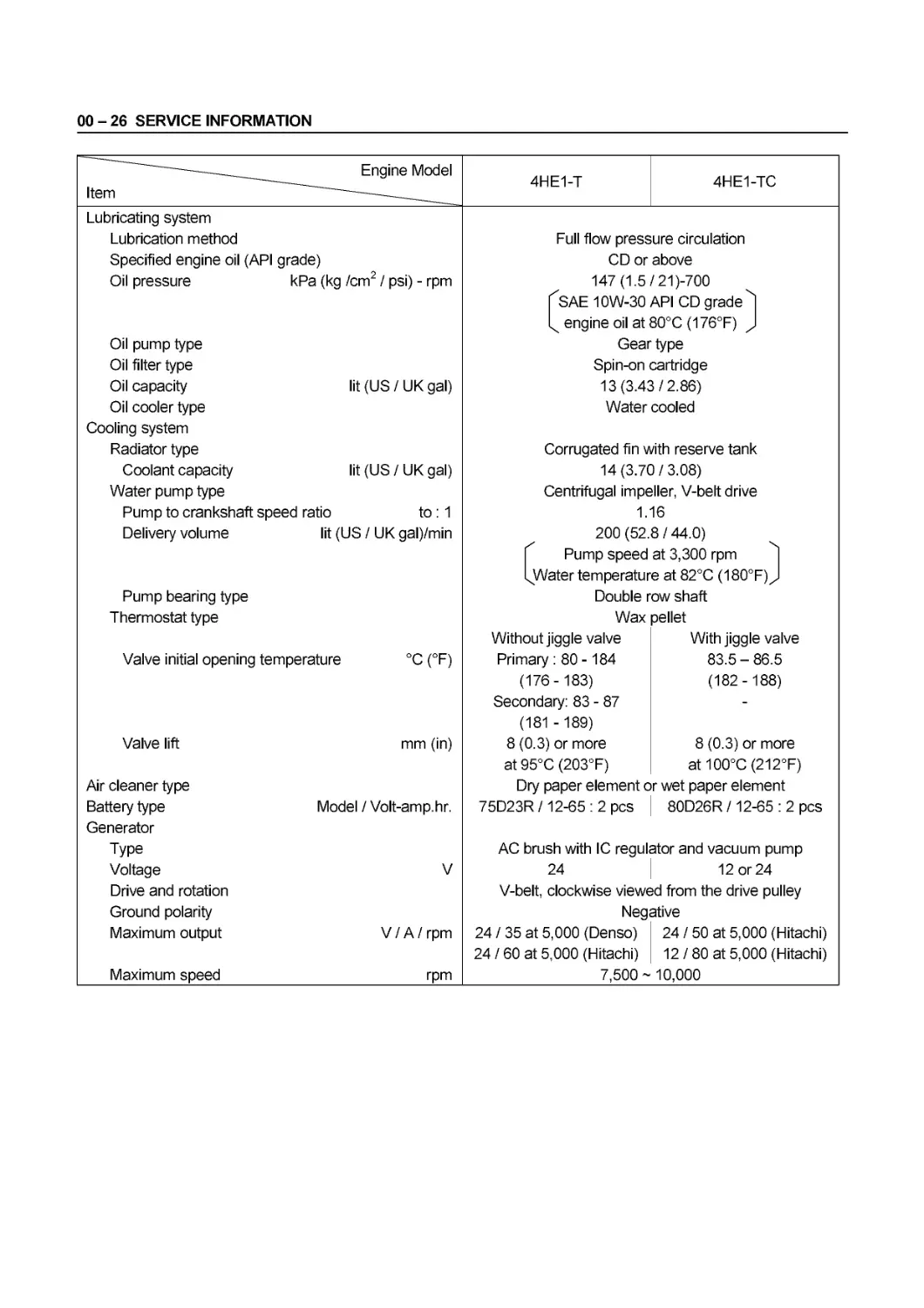
Item Engine Model 4HE1-T 4HE1-TC
Lubricating system
Lubrication method Full flow pressure circulation
Specified engine oil (API grade) CD or above
Oil pressure kPa (kg /cm / psi) - rpm 147 (1.5/21)-700
IхSAE 10W-30 API CD grade ''I
engine oil at 80°C (176°F) )
Oil pump type Gear type
Oil filter type Spin-on cartridge
Oil capacity lit (US / UK gal) 13(3.43/2.86)
Oil cooler type Water cooled
Cooling system
Radiator type Corrugated fin with reserve tank
Coolant capacity lit (US/UK gal) 14(3.70/3.08)
Water pump type Centrifugal impeller, V-belt drive
Pump to crankshaft speed ratio to : 1 1.16
Delivery volume lit (US / UK gal)/min 200 (52.8 / 44.0)
| Pump speed at 3,300 rpm |
QA/ater temperature at 82°C (180°F) J
Pump bearing type Double row shaft
Thermostat type Wax pellet
Without jiggle valve With jiggle valve
Valve initial opening temperature °C (°F) Primary : 80 -184 83.5 - 86.5
(176-183) (182-188)
Secondary: 83 - 87 -
(181 -189)
Valve lift mm (in) 8 (0.3) or more 8 (0.3) or more
at 95°C (203°F) at 100°C (212°F)
Air cleaner type Dry paper element or wet paper element
Battery type Model /Volt-amp.hr. 75D23R /12-65 : 2 pcs 80D26R /12-65 : 2 pcs
Generator
Type AC brush with IC regulator and vacuum pump
Voltage V 24 12 or 24
Drive and rotation V-belt, clockwise viewed from the drive pulley
Ground polarity Negative
Maximum output V / A / rpm 24 / 35 at 5,000 (Denso) 24 / 50 at 5,000 (Hitachi)
24 / 60 at 5,000 (Hitachi) 12/80 at 5,000 (Hitachi)
Maximum speed rpm 7,500 ~ 10,000
SERVICE INFORMATION 00 - 27
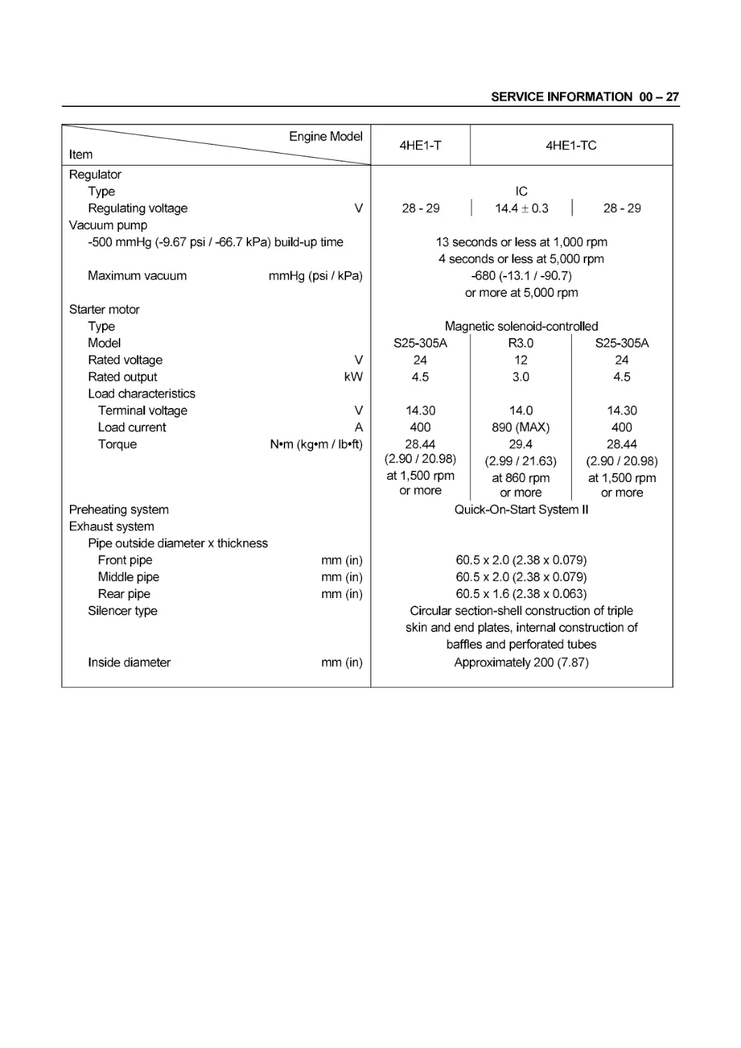
Item Engine Model 4HE1-T 4HE1-TC
Regulator Type Regulating voltage V 28-29 IC 14.4 ±0.3 28-29
Vacuum pump -500 mmHg (-9.67 psi / -66.7 kPa) build-up time 13 seconds or less at 1,000 rpm
Maximum vacuum Starter motor Type Model Rated voltage mmHg (psi / kPa) V 4 sect c Mag S25-305A 24 Dnds or less at 5,0C -680 (-13.1 /-90.7) r more at 5,000 rpr netic solenoid-contr R3.0 12 0 rpm n oiled S25-305A 24
Rated output kW 4.5 3.0 4.5
Load characteristics Terminal voltage V 14.30 14.0 14.30
Load current A 400 890 (MAX) 400
Torque N«m (kg*m / lb«ft) 28.44 29.4 28.44
Preheating system Exhaust system Pipe outside diameter x Front pipe thickness mm (in) (2.90 / 20.98) at 1,500 rpm or more Qu 60 (2.99/21.63) at 860 rpm or more ick-On-Start Syster 5x2.0(2.38x0.0’ (2.90 / 20.98) at 1,500 rpm or more n II 79)
Middle pipe mm (in) 60.5 x 2.0 (2.38 x 0.079)
Rear pipe mm (in) 60.5x1.6(2.38x0.063)
Silencer type Inside diameter mm (in) Circular section-shell construction of triple skin and end plates, internal construction of baffles and perforated tubes Approximately 200 (7.87)
00 - 28 SERVICE INFORMATION
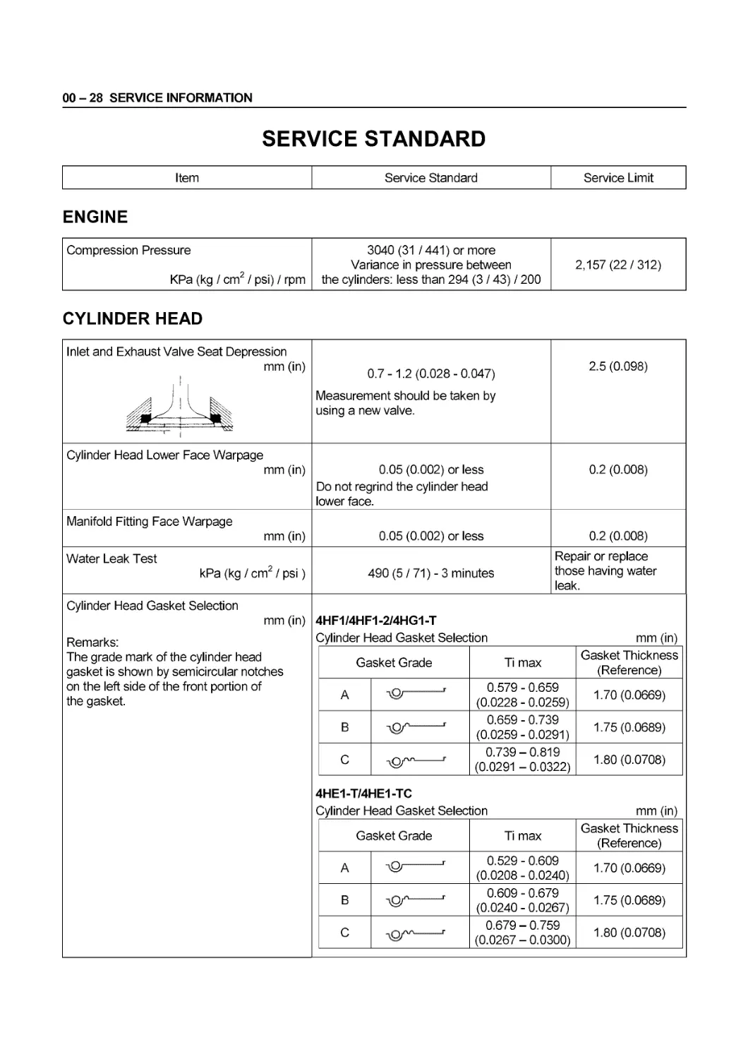
SERVICE STANDARD
Item Service Standard Service Limit
ENGINE
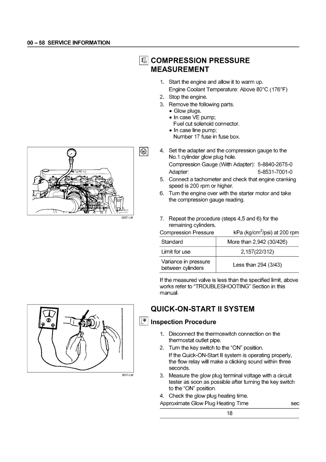
Compression Pressure KPa (kg / cm2 / psi) / rpm 3040 (31 /441) or more Variance in pressure between the cylinders: less than 294 (3 / 43) / 200 2,157 (22/312)
CYLINDER HEAD
Inlet and Exhaust Valve Seat Depression mm (in) 1 । 0.7-1.2 (0.028-0.047) Measurement should be taken by using a new valve. 2.5 (0.098)
Cylinder Head Lower Face Warpage mm (in) 0.05 (0.002) or less Do not regrind the cylinder head lower face. 0.2 (0.008)
Manifold Fitting Face Warpage mm (in) 0.05 (0.002) or less 0.2 (0.008)
Water Leak Test kPa (kg / cm2 / psi) 490 (5 / 71) - 3 minutes Repair or replace those having water leak.
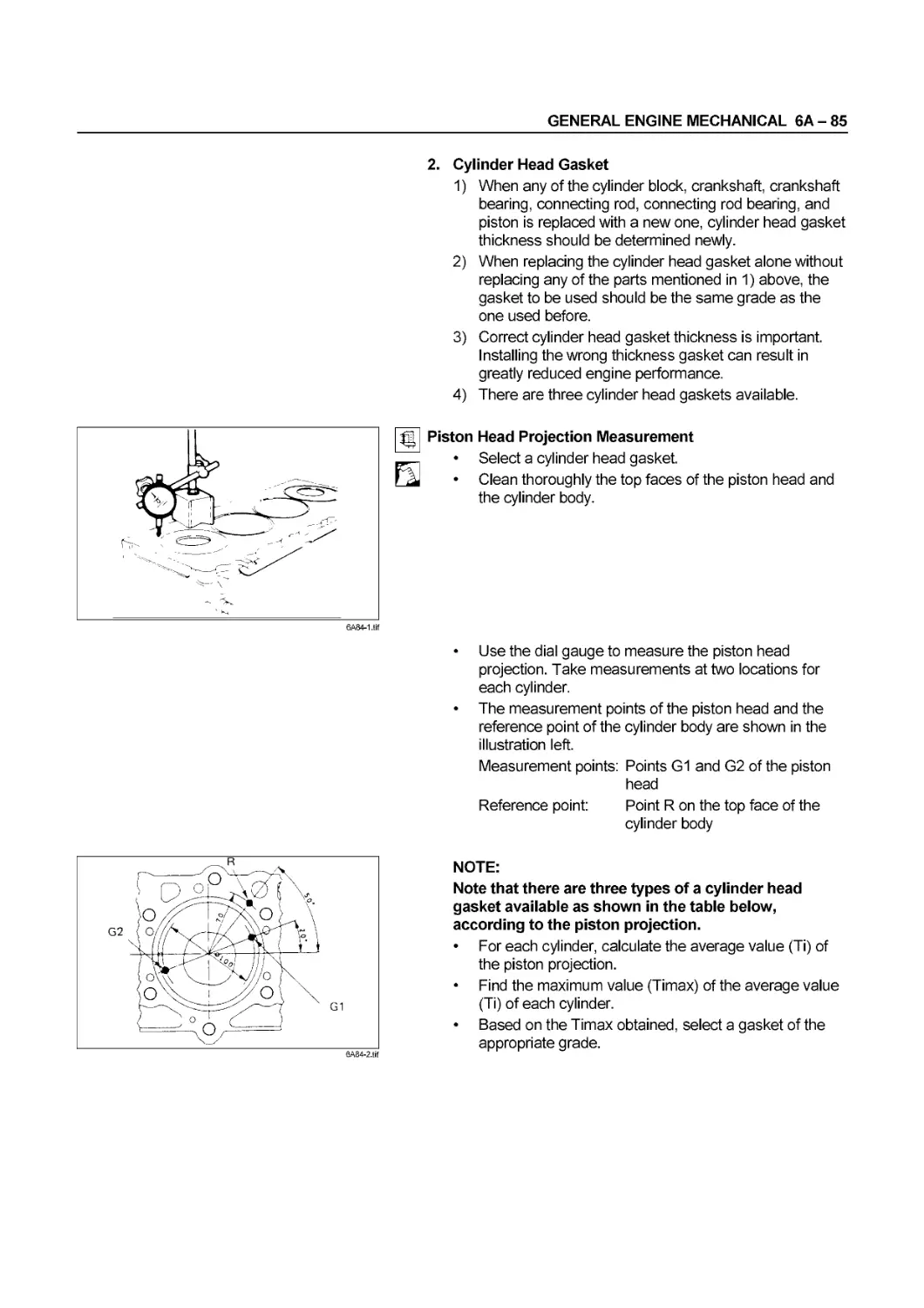
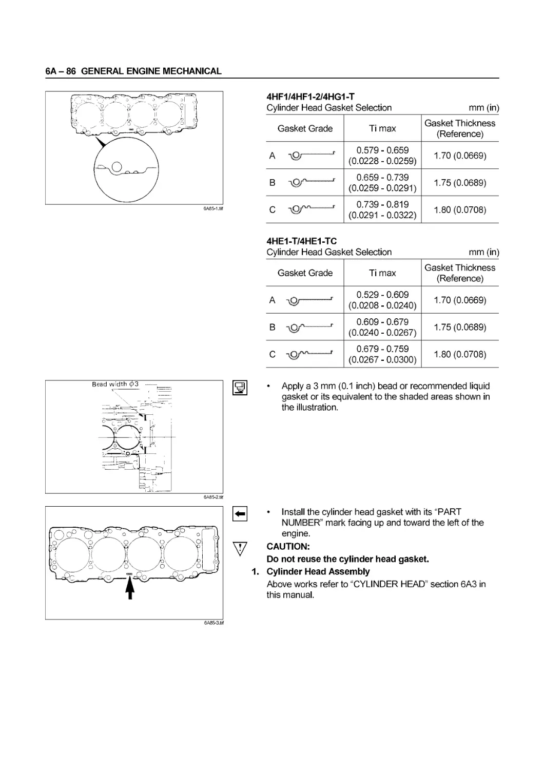
Cylinder Head Gasket Selection mm (in) Remarks: The grade mark of the cylinder head gasket is shown by semicircular notches on the left side of the front portion of the gasket. 4HF1/4HF1-2/4HG1-T Cylinder Head Gasket Selection mm (in)
Gasket Grade Ti max Gasket Thickness (Reference)
A 0.579 - 0.659 (0.0228 - 0.0259) 1.70 (0.0669)
В igr 1 0.659 - 0.739 (0.0259-0.0291) 1.75 (0.0689)
C tQ/" ' 0.739-0.819 (0.0291 - 0.0322) 1.80 (0.0708)
4HE1-T/4HE1-TC Cylinder Head Gasket Selection mm (in)
Gasket Grade Ti max Gasket Thickness (Reference)
A 1 0.529 - 0.609 (0.0208 - 0.0240) 1.70 (0.0669)
В W r 0.609 - 0.679 (0.0240 - 0.0267) 1.75 (0.0689)
C 1 0.679 - 0.759 (0.0267 - 0.0300) 1.80 (0.0708)
SERVICE INFORMATION 00 - 29
Item
Service Standard
Service Limit
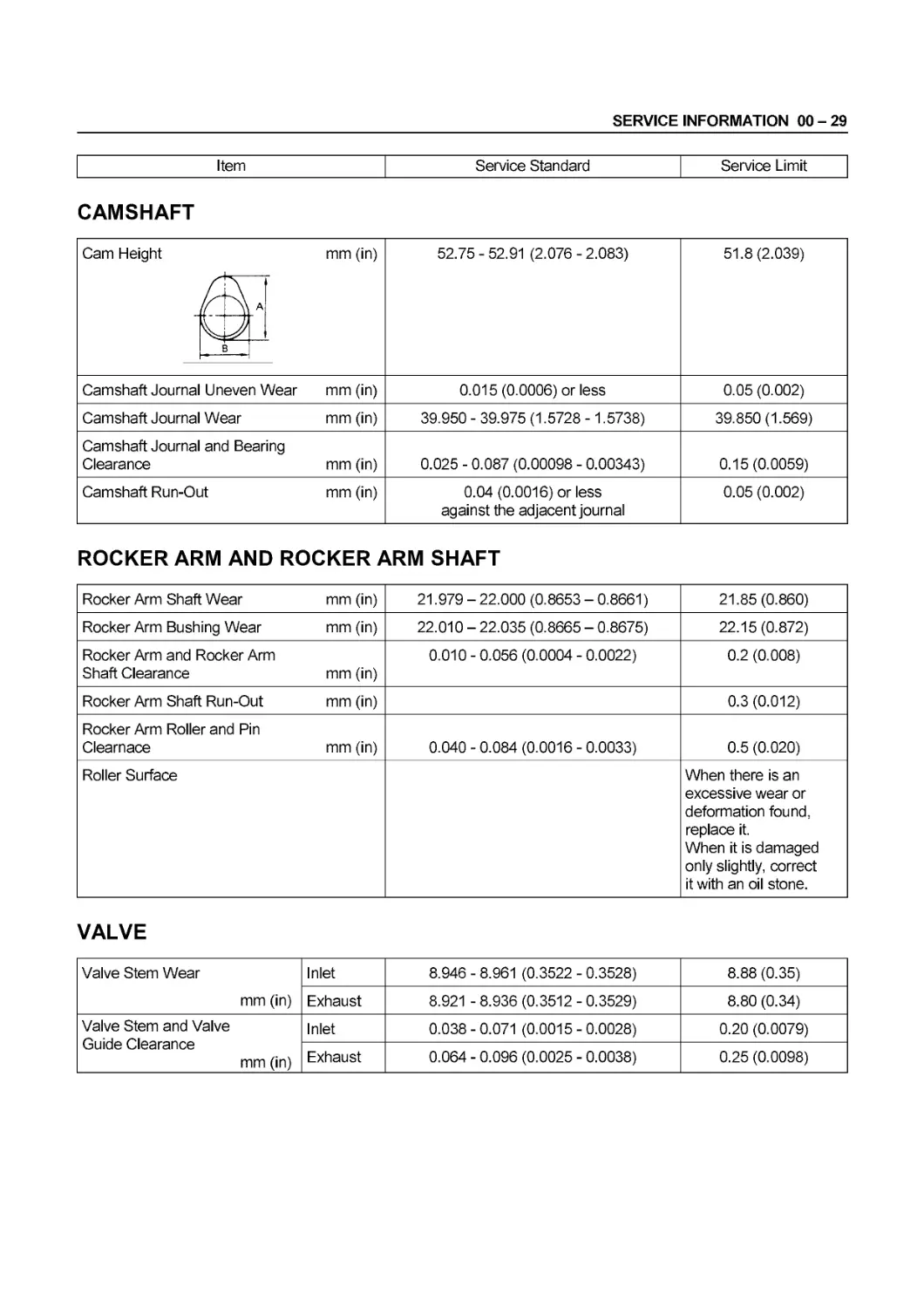
CAMSHAFT
Cam Height A mm (in) 52.75 - 52.91 (2.076 - 2.083) 51.8(2.039)
Camshaft Journal Uneven Wear mm (in) 0.015(0.0006) or less 0.05 (0.002)
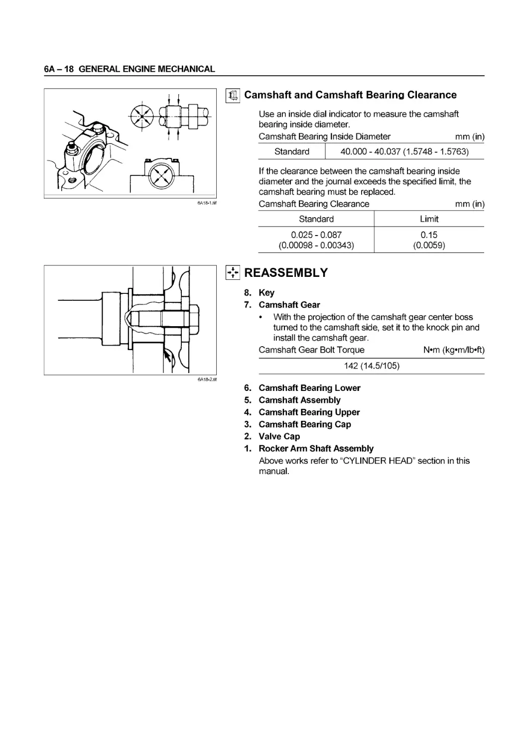
Camshaft Journal Wear mm (in) 39.950 - 39.975 (1.5728 -1.5738) 39.850(1.569)
Camshaft Journal and Bearing Clearance mm (in) 0.025 - 0.087 (0.00098 - 0.00343) 0.15(0.0059)
Camshaft Run-Out mm (in) 0.04 (0.0016) or less against the adjacent journal 0.05 (0.002)
ROCKER ARM AND ROCKER ARM SHAFT
Rocker Arm Shaft Wear mm (in) 21.979 - 22.000 (0.8653 - 0.8661) 21.85 (0.860)
Rocker Arm Bushing Wear mm (in) 22.010 - 22.035 (0.8665 - 0.8675) 22.15(0.872)
Rocker Arm and Rocker Arm Shaft Clearance mm (in) 0.010 - 0.056 (0.0004 - 0.0022) 0.2 (0.008)
Rocker Arm Shaft Run-Out mm (in) 0.3 (0.012)
Rocker Arm Roller and Pin Clearnace mm (in) 0.040 - 0.084 (0.0016 - 0.0033) 0.5 (0.020)
Roller Surface When there is an excessive wear or deformation found, replace it. When it is damaged only slightly, correct it with an oil stone.
VALVE
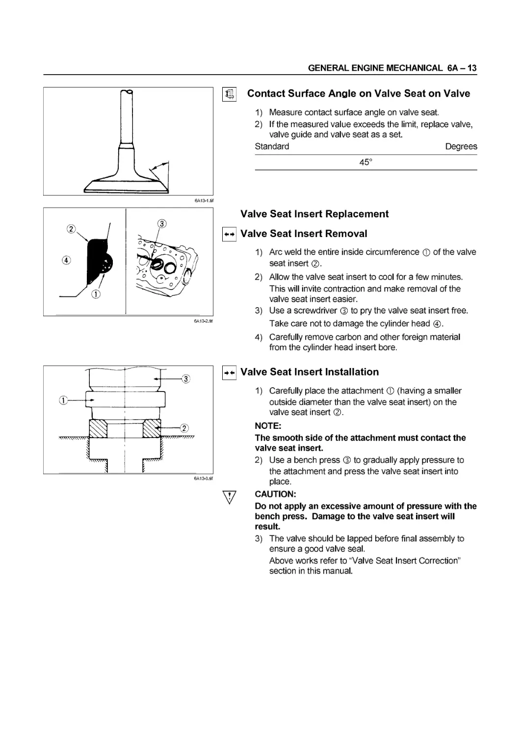
Valve Stem Wear mm (in) Inlet 8.946 - 8.961 (0.3522 - 0.3528) 8.88 (0.35)
Exhaust 8.921 - 8.936 (0.3512 - 0.3529) 8.80 (0.34)
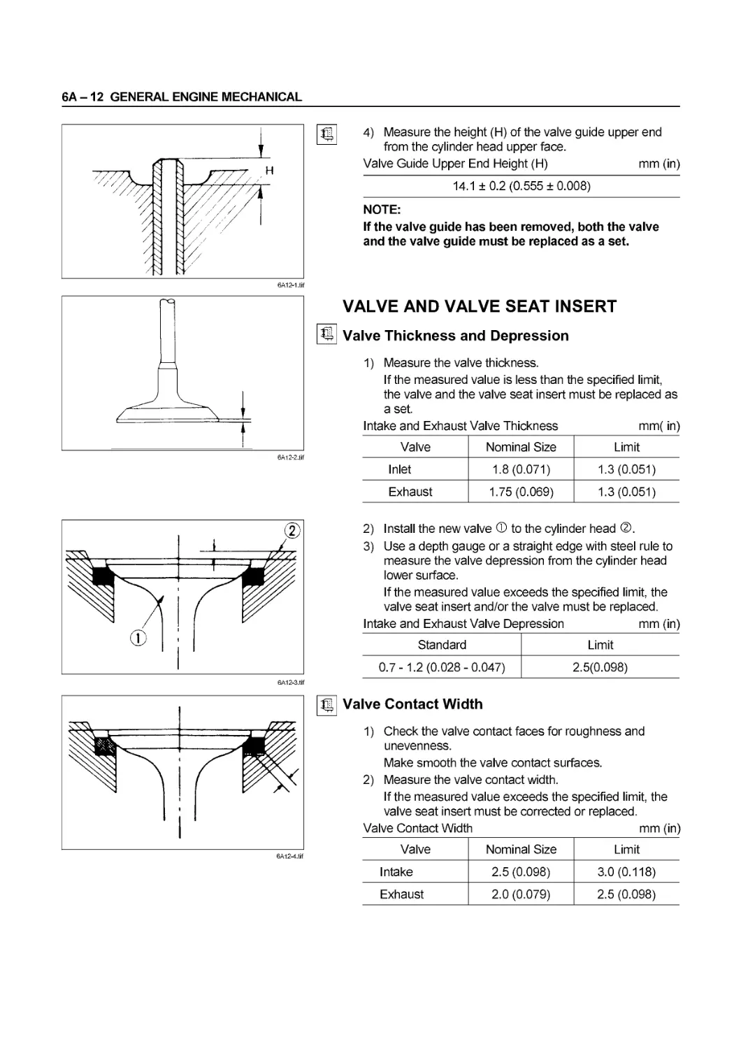
Valve Stem and Valve Guide Clearance mm (in) Inlet 0.038 - 0.071 (0.0015 - 0.0028) 0.20 (0.0079)
Exhaust 0.064 - 0.096 (0.0025 - 0.0038) 0.25 (0.0098)
00 - 30 SERVICE INFORMATION
Item
Service Standard
Service Limit
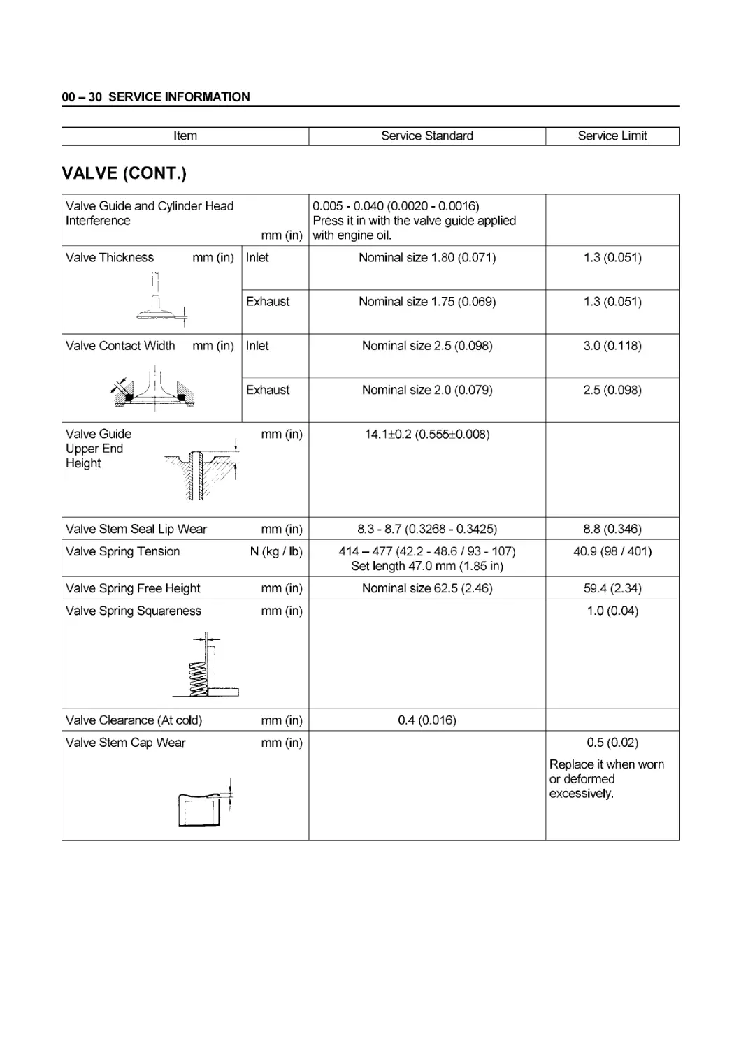
VALVE (CONT.)
Valve Guide and Cylinder Head Interference mm (in) 0.005 - 0.040 (0.0020 - 0.0016) Press it in with the valve guide applied with engine oil.
Valve Thickness mm (in) Inlet Nominal size 1.80 (0.071) 1.3(0.051)
Ж ; 1 Exhaust Nominal size 1.75 (0.069) 1.3(0.051)
Valve Contact Width mm (in) 1> Inlet Nominal size 2.5 (0.098) 3.0(0.118)
Exhaust Nominal size 2.0 (0.079) 2.5 (0.098)
Valve Guide Upper End „ Height "v- / 1 mm (in) 14.1 ±0.2 (0.555±0.008)
Valve Stem Seal Lip Wear mm (in) 8.3 - 8.7 (0.3268 - 0.3425) 8.8 (0.346)
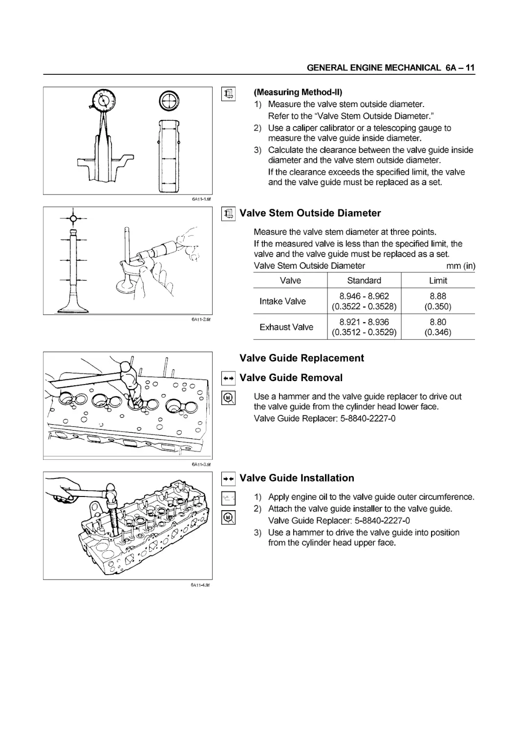
Valve Spring Tension N (kg /lb) 414 - 477 (42.2 - 48.6 / 93 -107) Set length 47.0 mm (1.85 in) 40.9 (98/401)
Valve Spring Free Height mm (in) Nominal size 62.5 (2.46) 59.4 (2.34)
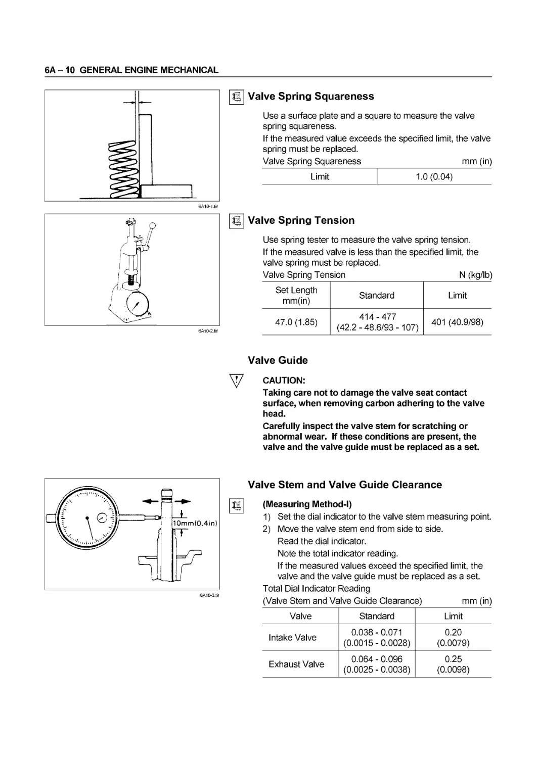
Valve Spring Squareness 3 1 mm (in) 1.0(0.04)
Valve Clearance (At cold) mm (in) 0.4 (0.016)
Valve Stem Cap Wear 1 mm (in) 0.5 (0.02) Replace it when worn or deformed excessively.
SERVICE INFORMATION 00 - 31
Item Service Standard Service Limit
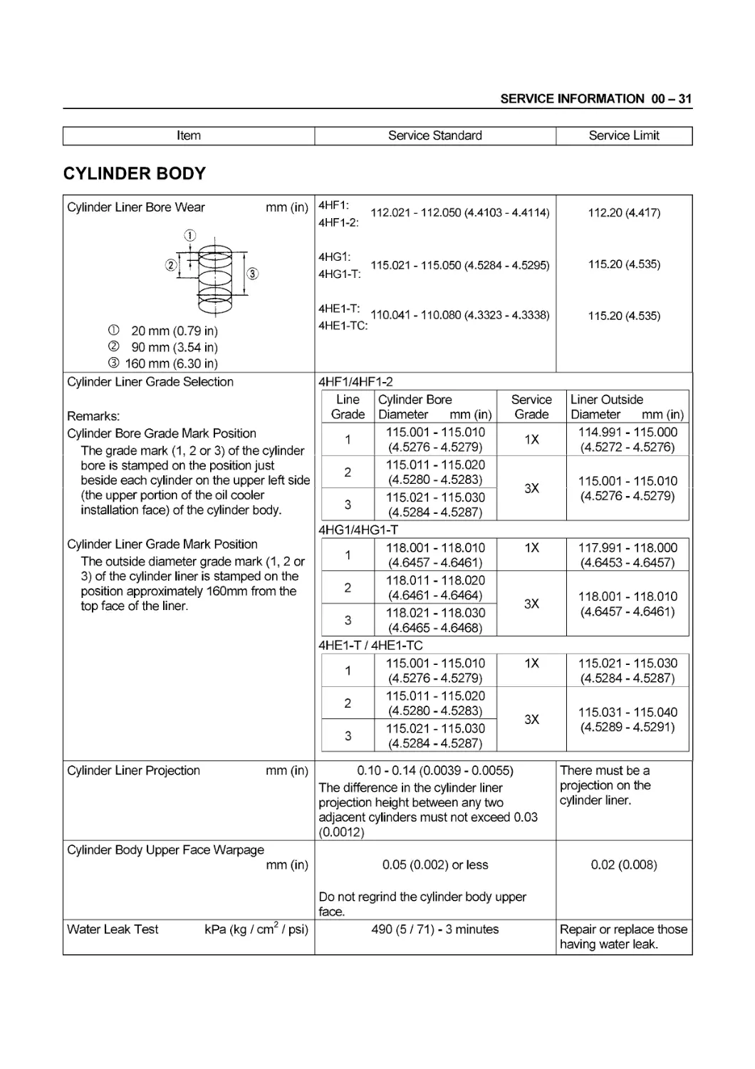
CYLINDER BODY
Cylinder Liner Bore Wear mm (in) 4HF1: 112.021 -112.050(4.4103-4.4114) 4HF1-2: 4HG1: 115.021 -115.050(4.5284-4.5295) 4HG1-T: v 4HE1-T: 11QO41 -110.080(4.3323-4.3338) 4HE1-TC: 112.20(4.417) 115.20(4.535) 115.20(4.535)
®E ® 20 mm (0.7£ ® 90 mm (3.54 ® 160 mm (6.3C in) in) in)
Cylinder Liner Grade Selection Remarks: Cylinder Bore Grade Mark Position The grade mark (1, 2 or 3) of the cylinder bore is stamped on the position just beside each cylinder on the upper left side (the upper portion of the oil cooler installation face) of the cylinder body. Cylinder Liner Grade Mark Position The outside diameter grade mark (1, 2 or 3) of the cylinder liner is stamped on the position approximately 160mm from the top face of the liner. 4HF1/4HF1-2
Line Grade Cylinder Bore Diameter mm (in) Service Grade Liner Outside Diameter mm (in)
1 115.001 -115.010 (4.5276 - 4.5279) 1X 114.991 -115.000 (4.5272 - 4.5276)
2 115.011 -115.020 (4.5280 - 4.5283) 3X 115.001 -115.010 (4.5276 - 4.5279)
3 115.021 -115.030 (4.5284 - 4.5287)
4HG1/4HG1-T
1 118.001 -118.010 (4.6457-4.6461) 1X 117.991 -118.000 (4.6453 - 4.6457)
2 118.011 -118.020 (4.6461 - 4.6464) 3X 118.001 -118.010 (4.6457 - 4.6461)
3 118.021 -118.030 (4.6465 - 4.6468)
4HE1-T / 4HE1-TC
1 115.001 -115.010 (4.5276 - 4.5279) 1X 115.021 -115.030 (4.5284 - 4.5287)
2 115.011 -115.020 (4.5280 - 4.5283) 3X 115.031 -115.040 (4.5289-4.5291)
3 115.021 -115.030 (4.5284 - 4.5287)
Cylinder Liner Projection mm (in) 0.10-0.14(0.0039-0.0055) The difference in the cylinder liner projection height between any two adjacent cylinders must not exceed 0.03 (0.0012) There must be a projection on the cylinder liner.
Cylinder Body Upper Face Warpage mm (in) 0.05 (0.002) or less Do not regrind the cylinder body upper face. 0.02 (0.008)
Water Leak Test kPa (kg / cm2 / psi) 490 (5 / 71) - 3 minutes Repair or replace those having water leak.
00 - 32 SERVICE INFORMATION
Item Service Standard Service Limit
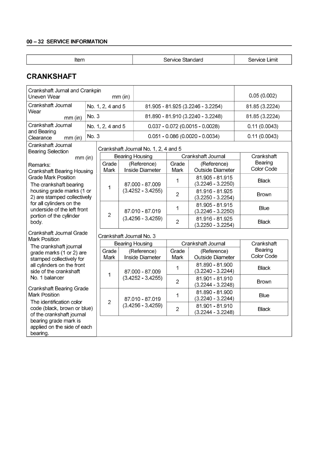
CRANKSHAFT
Crankshaft Jurnal and Crankpin Uneven Wear mm (in) 0.05 (0.002)
Crankshaft Journal Wear mm (in) No. 1,2, 4 and 5 81.905 - 81.925 (3.2246 - 3.2254) 81.85 (3.2224)
No. 3 81.890 - 81.910 (3.2240 - 3.2248) 81.85 (3.2224)
Crankshaft Journal and Bearing Clearance mm (in) No. 1, 2, 4 and 5 0.037 - 0.072 (0.0015 - 0.0028) 0.11 (0.0043)
No. 3 0.051 - 0.086 (0.0020 - 0.0034) 0.11 (0.0043)
Crankshaft Journal Bearing Selection mm (in) Remarks: Crankshaft Bearing Housing Grade Mark Position The crankshaft bearing housing grade marks (1 or 2) are stamped collectively for all cylinders on the underside of the left front portion of the cylinder body. Crankshaft Journal Grade Mark Position The crankshaft journal grade marks (1 or 2) are stamped collectively for all cylinders on the front side of the crankshaft No. 1 balancer Crankshaft Bearing Grade Mark Position The identification color code (black, brown or blue) of the crankshaft journal bearing grade mark is applied on the side of each bearing. Crankshaft Journal No. 1, 2, 4 and 5
Bearing Housing Crankshaft Journal Crankshaft Bearing Color Code
Grade Mark (Reference) Inside Diameter Grade Mark (Reference) Outside Diameter
1 87.000 - 87.009 (3.4252 - 3.4255) 1 81.905-81.915 (3.2246 - 3.2250) Black
2 81.916-81.925 (3.2250 - 3.2254) Brown
2 87.010-87.019 (3.4256 - 3.4259) 1 81.905-81.915 (3.2246 - 3.2250) Blue
2 81.916-81.925 (3.2250 - 3.2254) Black
Crankshaft Journal No. 3
Bearing Housing Crankshaft Journal Crankshaft Bearing Color Code
Grade Mark (Reference) Inside Diameter Grade Mark (Reference) Outside Diameter
1 87.000 - 87.009 (3.4252 - 3.4255) 1 81.890-81.900 (3.2240 - 3.2244) Black
2 81.901 -81.910 (3.2244 - 3.2248) Brown
2 87.010-87.019 (3.4256 - 3.4259) 1 81.890-81.900 (3.2240 - 3.2244) Blue
2 81.901 -81.910 (3.2244 - 3.2248) Black
SERVICE INFORMATION 00 - 33
Item Service Standard Service Limit
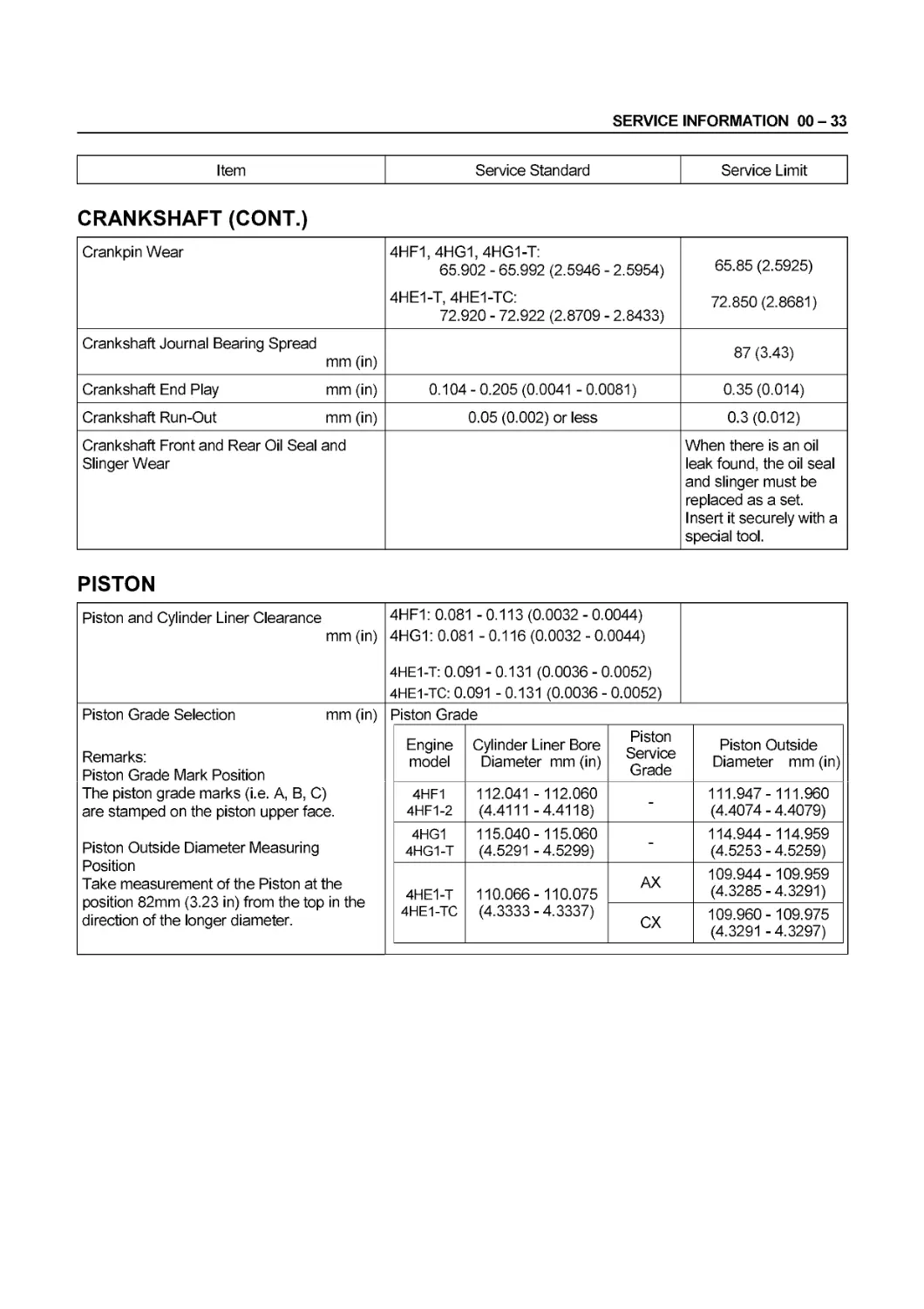
CRANKSHAFT (CONT.)
Crankpin Wear 4HF1, 4HG1, 4HG1-T: 65.902 - 65.992 (2.5946 - 2.5954) 4HE1-T, 4HE1-TC: 72.920 - 72.922 (2.8709 - 2.8433) 65.85 (2.5925) 72.850 (2.8681)
Crankshaft Journal Bearing Spread mm (in) 87 (3.43)
Crankshaft End Play mm (in) 0.104-0.205 (0.0041 -0.0081) 0.35 (0.014)
Crankshaft Run-Out mm (in) 0.05 (0.002) or less 0.3 (0.012)
Crankshaft Front and Rear Oil Seal and Slinger Wear When there is an oil leak found, the oil seal and slinger must be replaced as a set. Insert it securely with a special tool.
PISTON
Piston and Cylinder Liner Clearance mm (in) 4HF1: 0.081 -0.113(0.0032-0.0044) 4HG1: 0.081 -0.116(0.0032-0.0044) 4HE1-T: 0.091 - 0.131 (0.0036 - 0.0052) 4HE1-TC: 0.091 - 0.131 (0.0036 - 0.0052)
Piston Grade Selection mm (in) Remarks: Piston Grade Mark Position The piston grade marks (i.e. А, В, C) are stamped on the piston upper face. Piston Outside Diameter Measuring Position Take measurement of the Piston at the position 82mm (3.23 in) from the top in the direction of the longer diameter. Piston Grade
Engine model Cylinder Liner Bore Diameter mm (in) Piston Service Grade Piston Outside Diameter mm (in)
4HF1 4HF1-2 112.041 -112.060 (4.4111 -4.4118) - 111.947-111.960 (4.4074 - 4.4079)
4HG1 4HG1-T 115.040-115.060 (4.5291 - 4.5299) - 114.944 -114.959 (4.5253 - 4.5259)
4HE1-T 4HE1-TC 110.066-110.075 (4.3333 - 4.3337) AX 109.944-109.959 (4.3285 - 4.3291)
CX 109.960-109.975 (4.3291 - 4.3297)
00 - 34 SERVICE INFORMATION
Item Service Standard Service Limit
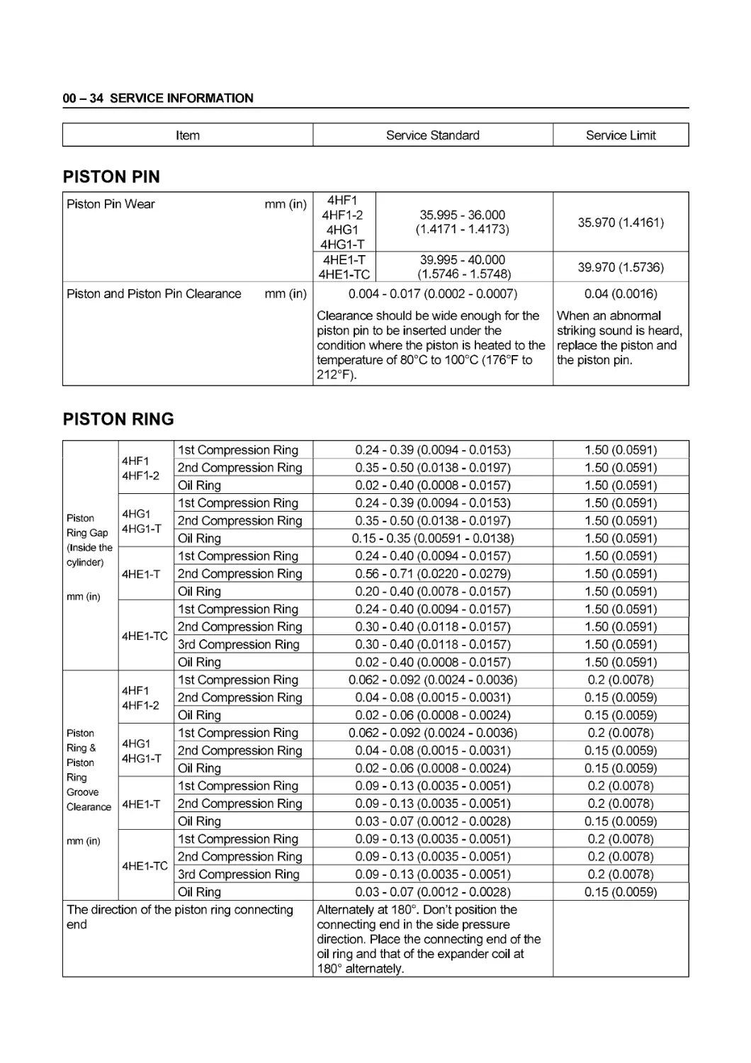
PISTON PIN
Piston Pin Wear mm (in) 4HF1 4HF1-2 4HG1 4HG1-T 35.995 - 36.000 (1.4171 -1.4173) 35.970 (1.4161)
4HE1-T 4HE1-TC 39.995 - 40.000 (1.5746-1.5748) 39.970 (1.5736)
Piston and Piston Pin Clearance mm (in) 0.004 - 0.017 (0.0002 - 0.0007) Clearance should be wide enough for the piston pin to be inserted under the condition where the piston is heated to the temperature of 80°C to 100°C (176°F to 212°F). 0.04 (0.0016) When an abnormal striking sound is heard, replace the piston and the piston pin.
PISTON RING
Piston Ring Gap (Inside the cylinder) mm (in) 4HF1 4HF1-2 1st Compression Ring 0.24-0.39 (0.0094-0.0153) 1.50 (0.0591)
2nd Compression Ring 0.35-0.50 (0.0138-0.0197) 1.50 (0.0591)
Oil Ring 0.02-0.40 (0.0008-0.0157) 1.50 (0.0591)
4HG1 4HG1-T 1st Compression Ring 0.24-0.39 (0.0094-0.0153) 1.50 (0.0591)
2nd Compression Ring 0.35-0.50 (0.0138-0.0197) 1.50 (0.0591)
Oil Ring 0.15-0.35 (0.00591 -0.0138) 1.50 (0.0591)
4HE1-T 1st Compression Ring 0.24-0.40 (0.0094-0.0157) 1.50 (0.0591)
2nd Compression Ring 0.56 - 0.71 (0.0220 - 0.0279) 1.50 (0.0591)
Oil Ring 0.20-0.40 (0.0078-0.0157) 1.50 (0.0591)
4HE1-TC 1st Compression Ring 0.24-0.40 (0.0094-0.0157) 1.50 (0.0591)
2nd Compression Ring 0.30-0.40 (0.0118-0.0157) 1.50 (0.0591)
3rd Compression Ring 0.30-0.40 (0.0118-0.0157) 1.50 (0.0591)
Oil Ring 0.02-0.40 (0.0008-0.0157) 1.50 (0.0591)
Piston Ring & Piston Ring Groove Clearance mm (in) 4HF1 4HF1-2 1st Compression Ring 0.062 - 0.092 (0.0024 - 0.0036) 0.2 (0.0078)
2nd Compression Ring 0.04-0.08 (0.0015-0.0031) 0.15(0.0059)
Oil Ring 0.02 - 0.06 (0.0008 - 0.0024) 0.15(0.0059)
4HG1 4HG1-T 1st Compression Ring 0.062 - 0.092 (0.0024 - 0.0036) 0.2 (0.0078)
2nd Compression Ring 0.04-0.08 (0.0015-0.0031) 0.15(0.0059)
Oil Ring 0.02 - 0.06 (0.0008 - 0.0024) 0.15(0.0059)
4HE1-T 1st Compression Ring 0.09-0.13(0.0035-0.0051) 0.2 (0.0078)
2nd Compression Ring 0.09-0.13(0.0035-0.0051) 0.2 (0.0078)
Oil Ring 0.03-0.07 (0.0012-0.0028) 0.15(0.0059)
4HE1-TC 1st Compression Ring 0.09-0.13(0.0035-0.0051) 0.2 (0.0078)
2nd Compression Ring 0.09-0.13(0.0035-0.0051) 0.2 (0.0078)
3rd Compression Ring 0.09-0.13(0.0035-0.0051) 0.2 (0.0078)
Oil Ring 0.03-0.07 (0.0012-0.0028) 0.15(0.0059)
The direction of the piston ring connecting end Alternately at 180°. Don’t position the connecting end in the side pressure direction. Place the connecting end of the oil ring and that of the expander coil at 180° alternately.
SERVICE INFORMATION 00 - 35
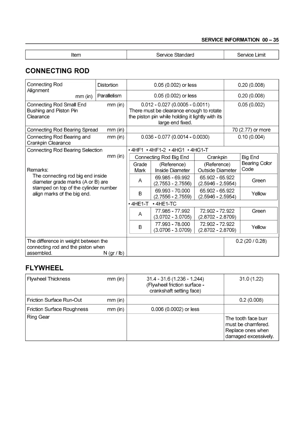
Item Service Standard Service Limit
CONNECTING ROD
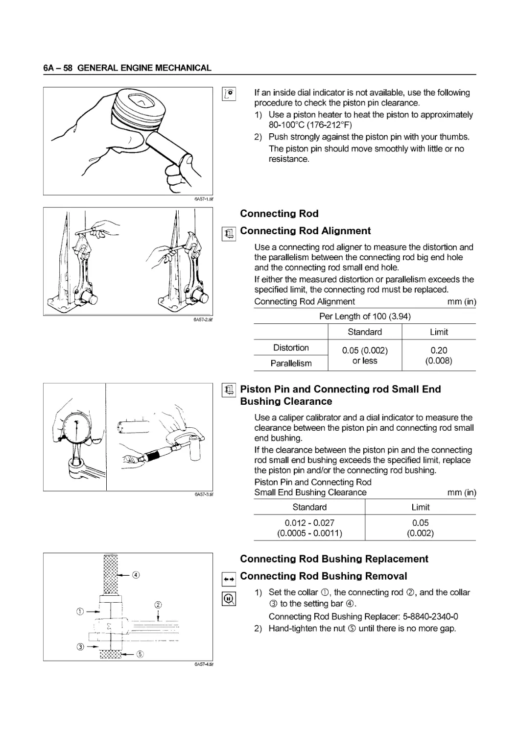
Connecting Rod Alignment mm (in) Distortion 0.05 (0.002) or less 0.20 (0.008)
Parallelism 0.05 (0.002) or less 0.20 (0.008)
Connecting Rod Small End mm (in) Bushing and Piston Pin Clearance 0.012-0.027 (0.0005-0.0011) There must be clearance enough to rotate the piston pin while holding it lightly with its large end fixed. 0.05 (0.002)
Connecting Rod Bearing Spread mm (in) 70 (2.77) or more
Connecting Rod Bearing and mm (in) Crankpin Clearance 0.036 - 0.077 (0.0014 - 0.0030) 0.10(0.004)
Connecting Rod Bearing Selection mm (in) Remarks: The connecting rod big end inside diameter grade marks (A or B) are stamped on top of the cylinder number align marks of the big end. •4HF1 «4HF1-2 *4HG1 «4HG1-T
Connecting Rod Big End Crankpin Big End Bearing Color Code
Grade Mark (Reference) Inside Diameter (Reference) Outside Diameter
A 69.985 - 69.992 (2.7553 - 2.7556) 65.902 - 65.922 (2.5946 - 2.5954) Green
В 69.993 - 70.000 (2.7556 - 2.7559) 65.902 - 65.922 (2.5946 - 2.5954) Yellow
•4HE1-T ‘4HE1-TC
A 77.985 - 77.992 (3.0702 - 3.0705) 72.902 - 72.922 (2.8702 - 2.8709) Green
В 77.993 - 78.000 (3.0706 - 3.0709) 72.902 - 72.922 (2.8702 - 2.8709) Yellow
The difference in weight between the connecting rod and the piston when assembled. N (gr / lb) 0.2 (20 / 0.28)
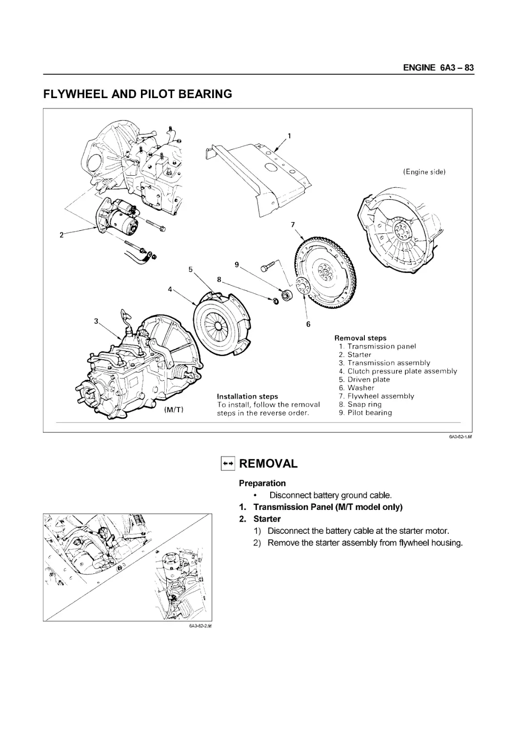
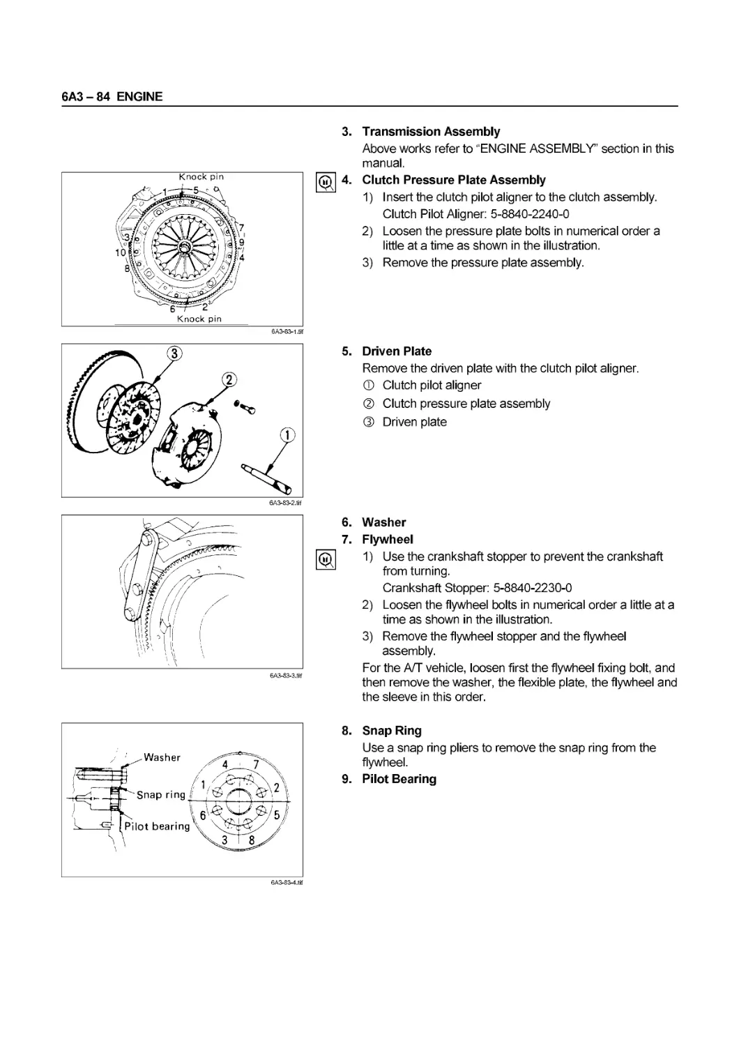
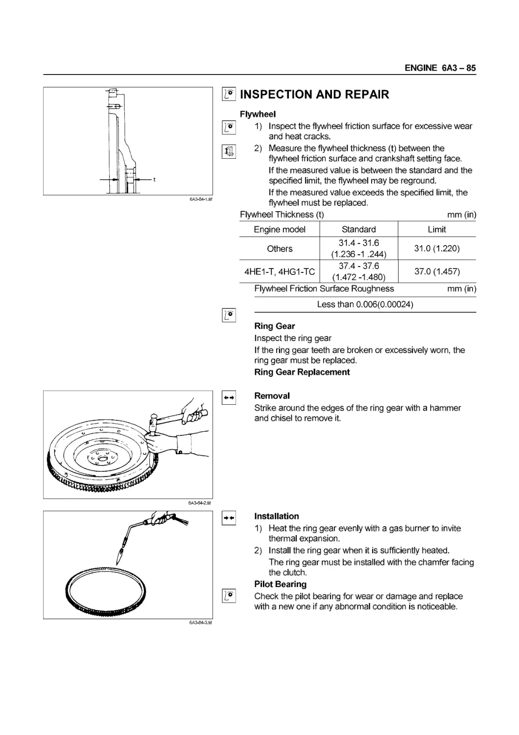
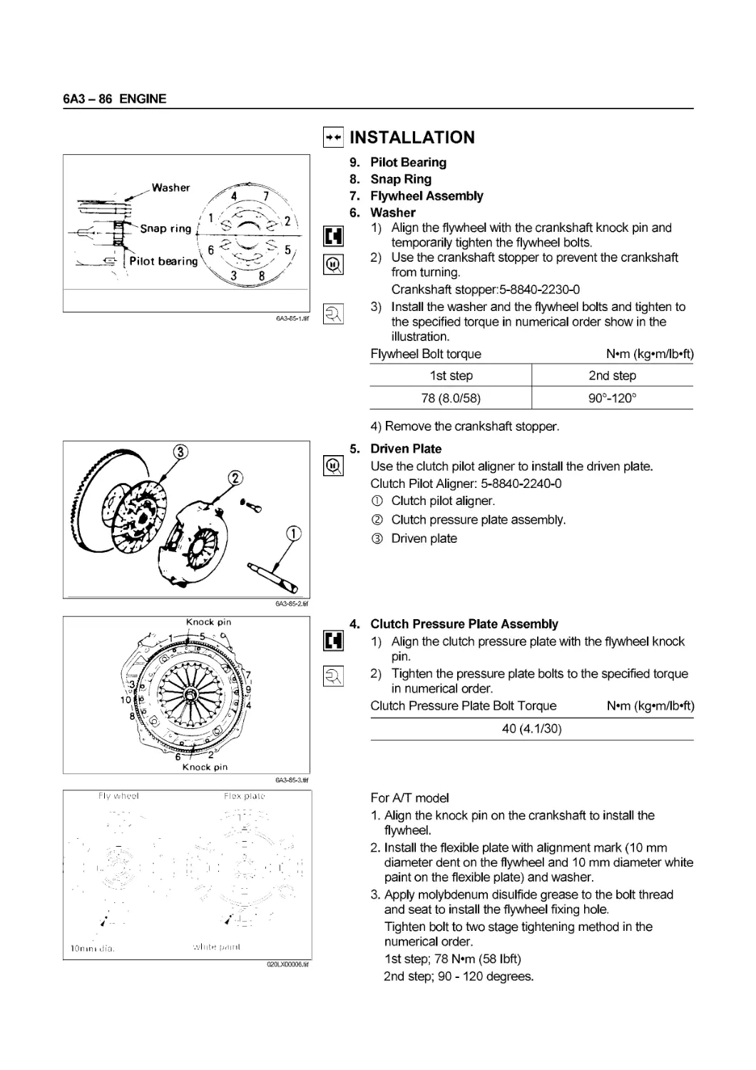
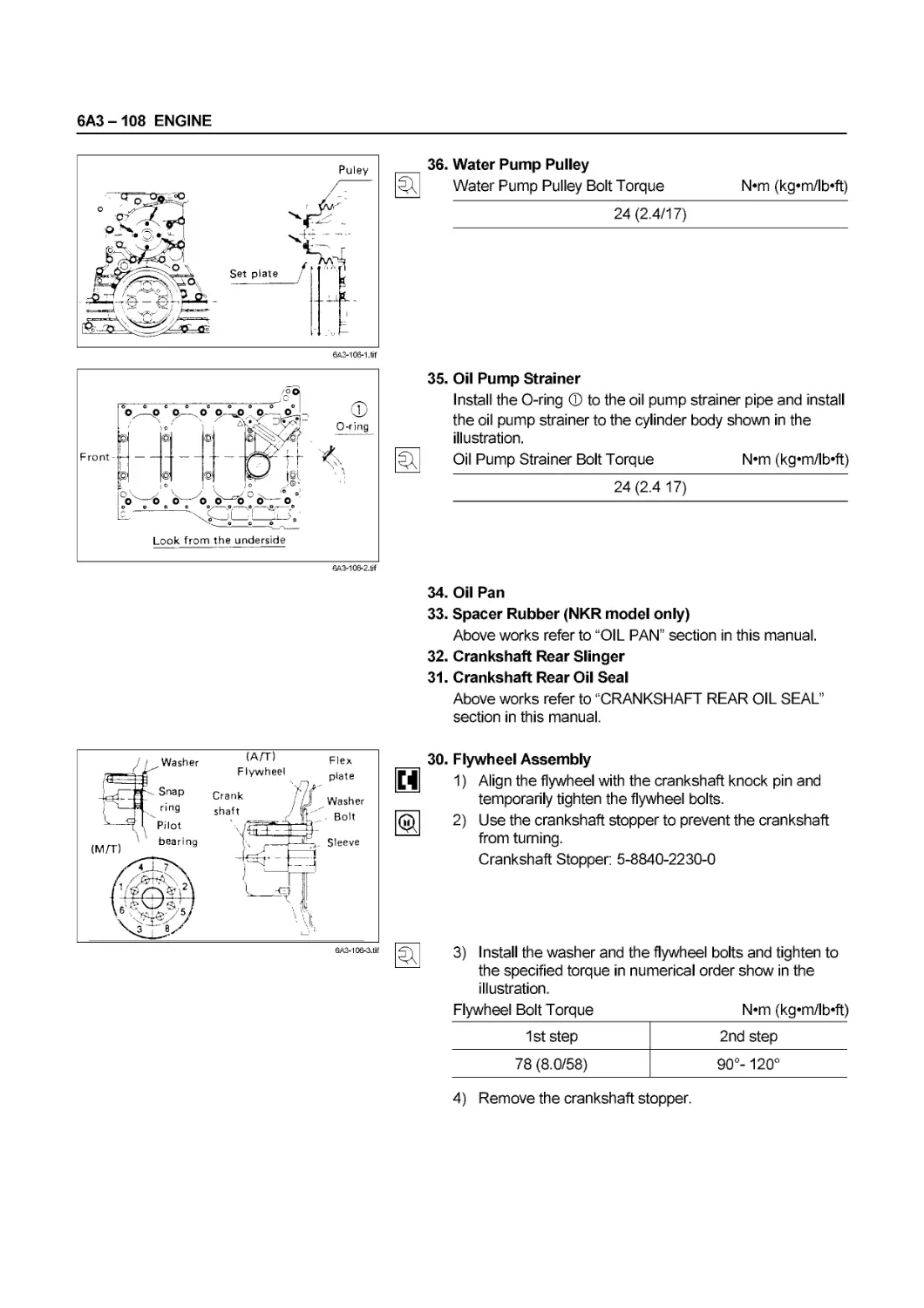
FLYWHEEL
Flywheel Thickness mm (in) 31.4-31.6(1.236-1.244) (Flywheel friction surface - crankshaft setting face) 31.0(1.22)
Friction Surface Run-Out mm (in) 0.2 (0.008)
Friction Surface Roughness mm (in) 0.006 (0.0002) or less
Ring Gear The tooth face burr must be chamfered. Replace ones when damaged excessively.
00 - 36 SERVICE INFORMATION
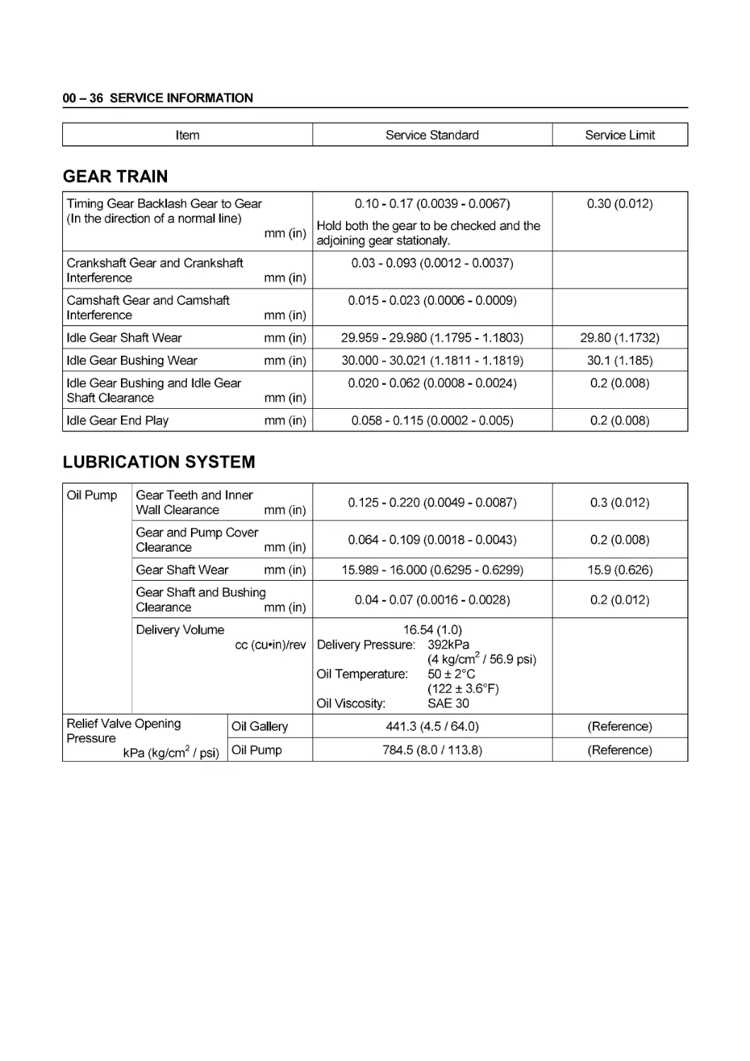
Item Service Standard Service Limit
GEAR TRAIN
Timing Gear Backlash Gear to Gear 0.10-0.17(0.0039-0.0067) Hold both the gear to be checked and the adjoining gear stationaly. 0.30 (0.012)
(In the direction of a normal line) mm (in)
Crankshaft Gear and Crankshaft Interference mm (in) 0.03-0.093 (0.0012-0.0037)
Camshaft Gear and Camshaft Interference mm (in) 0.015 - 0.023 (0.0006 - 0.0009)
Idle Gear Shaft Wear mm (in) 29.959 - 29.980 (1.1795 -1.1803) 29.80(1.1732)
Idle Gear Bushing Wear mm (in) 30.000-30.021 (1.1811 -1.1819) 30.1 (1.185)
Idle Gear Bushing and Idle Gear Shaft Clearance mm (in) 0.020 - 0.062 (0.0008 - 0.0024) 0.2 (0.008)
Idle Gear End Play mm (in) 0.058-0.115(0.0002-0.005) 0.2 (0.008)
LUBRICATION SYSTEM
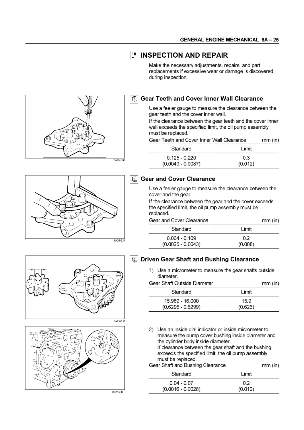
Oil Pump Gear Teeth and Inner Wall Clearance mm (in) 0.125 - 0.220 (0.0049 - 0.0087) 0.3 (0.012)
Gear and Pump Cover Clearance mm (in) 0.064 - 0.109 (0.0018 - 0.0043) 0.2 (0.008)
Gear Shaft Wear mm (in) 15.989 -16.000 (0.6295 - 0.6299) 15.9(0.626)
Gear Shaft and Bushing Clearance mm (in) 0.04-0.07 (0.0016-0.0028) 0.2 (0.012)
Delivery Volume cc (cu*in)/rev 16.54(1.0) Delivery Pressure: 392kPa (4 kg/cm2 / 56.9 psi) Oil Temperature: 50 ± 2°C (122 ± 3.6°F) Oil Viscosity: SAE 30
Relief Valve Opening Pressure kPa (kg/cm2 / psi) Oil Gallery 441.3(4.5/64.0) (Reference)
Oil Pump 784.5(8.0/113.8) (Reference)
SERVICE INFORMATION 00 - 37
Item Service Standard Service Limit
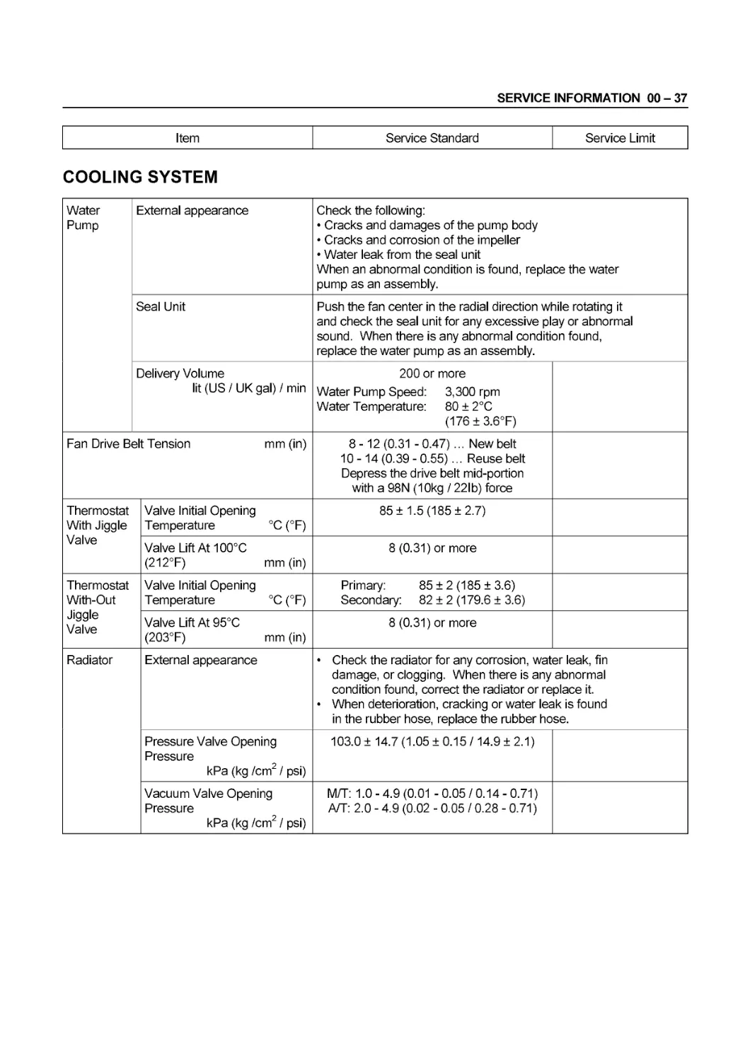
COOLING SYSTEM
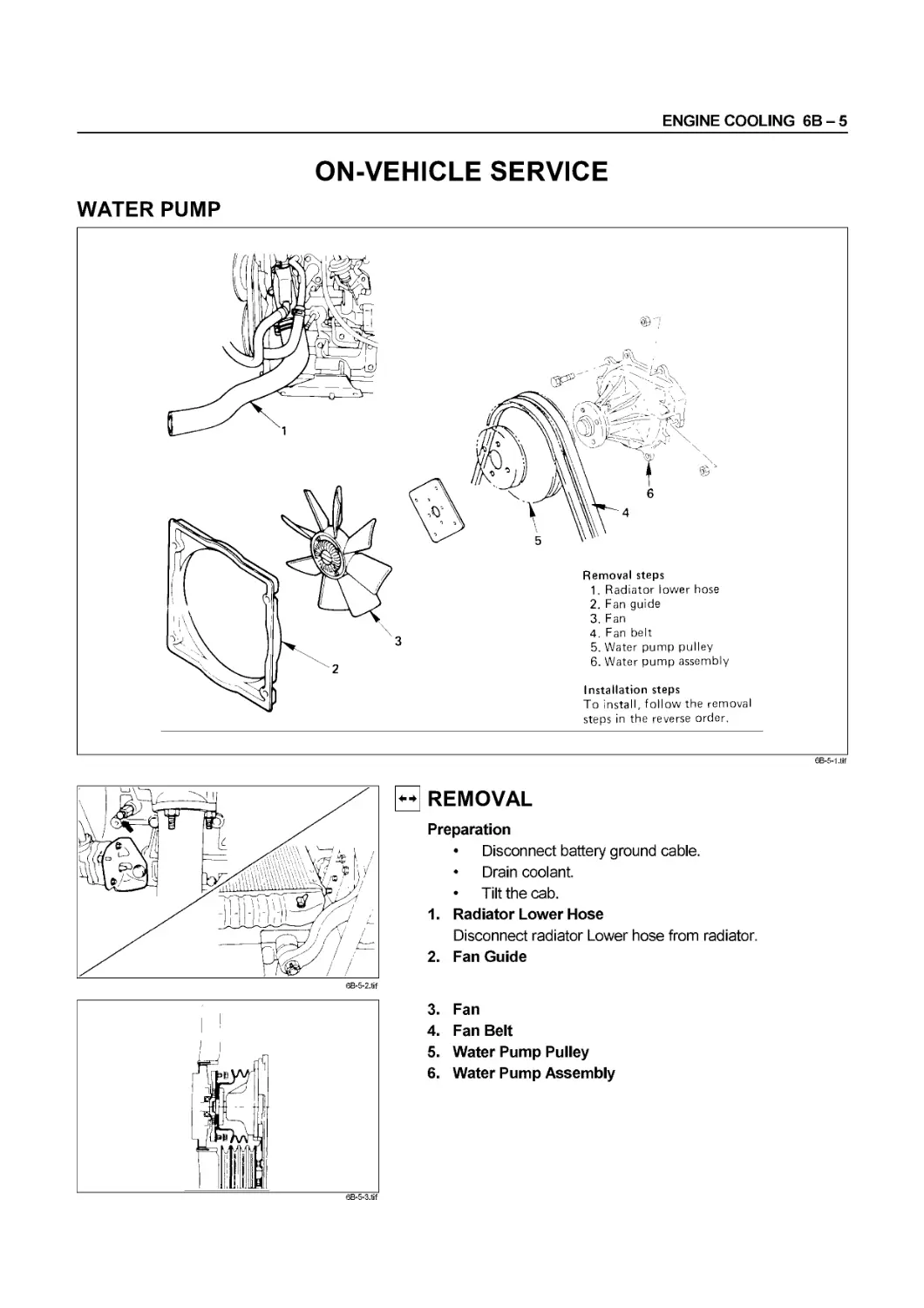
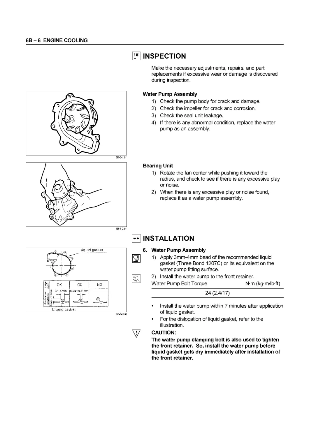
Water Pump External appearance Check the following: • Cracks and damages of the pump body • Cracks and corrosion of the impeller • Water leak from the seal unit When an abnormal condition is found, replace the water pump as an assembly.
Seal Unit Push the fan center in the radial direction while rotating it and check the seal unit for any excessive play or abnormal sound. When there is any abnormal condition found, replace the water pump as an assembly.
Delivery Volume lit (US / UK gal) / min 200 or more Water Pump Speed: 3,300 rpm Water Temperature: 80 ± 2°C (176±3.6°F)
Fan Drive Belt Tension mm (in) 8-12(0.31 -0.47)... New belt 10 -14 (0.39 - 0.55)... Reuse belt Depress the drive belt mid-portion with a 98N (10kg / 22lb) force
Thermostat With Jiggle Valve Valve Initial Opening Temperature °C (°F) 85 ± 1.5 (185 ±2.7)
Valve Lift At 100°C (212°F) mm (in) 8 (0.31) or more
Thermostat With-Out Jiggle Valve Valve Initial Opening Temperature °C (°F) Primary: 85 ± 2 (185 ± 3.6) Secondary: 82 ± 2 (179.6 ± 3.6)
Valve Lift At 95°C (203°F) mm (in) 8 (0.31) or more
Radiator External appearance • Check the radiator for any corrosion, water leak, fin damage, or clogging. When there is any abnormal condition found, correct the radiator or replace it. • When deterioration, cracking or water leak is found in the rubber hose, replace the rubber hose.
Pressure Valve Opening Pressure kPa (kg /cm2 / psi) 103.0 ± 14.7 (1.05 ± 0.15 /14.9 ± 2.1)
Vacuum Valve Opening Pressure kPa (kg /cm2 / psi) M/T: 1.0 - 4.9 (0.01 - 0.05 / 0.14 - 0.71) A/T: 2.0 - 4.9 (0.02 - 0.05 / 0.28 - 0.71)
00 - 38 SERVICE INFORMATION
Item Service Standard Service Limit
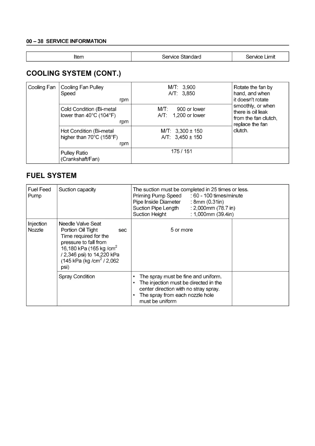
COOLING SYSTEM (CONT.)
Cooling Fan Cooling Fan Pulley Speed rpm M/T: 3,900 A/T: 3,850 Rotate the fan by hand, and when it doesn't rotate smoothly, or when there is oil leak from the fan clutch, replace the fan clutch.
Cold Condition (Bi-metal lower than 40°C (104°F) rpm M/T: 900 or lower A/T: 1,200 or lower
Hot Condition (Bi-metal higher than 70°C (158°F) rpm M/T: 3,300 ±150 A/T: 3,450 ±150
Pulley Ratio (Crankshaft/Fan) 175/151
FUEL SYSTEM
Fuel Feed Pump Suction capacity The suction must be completed in 25 times or less. Priming Pump Speed : 60 -100 times/minute Pipe Inside Diameter :8mm (0.31 in) Suction Pipe Length : 2,000mm (78.7 in) Suction Height : 1,000mm (39.4in)
Injection Nozzle Needle Valve Seat Portion Oil Tight sec Time required for the pressure to fall from 16,180 kPa (165 kg/cm2 / 2,346 psi) to 14,220 kPa (145 kPa (kg /cm2 / 2,062 psi) 5 or more
Spray Condition • The spray must be fine and uniform. • The injection must be directed in the center direction with no stray spray. • The spray from each nozzle hole must be uniform
SERVICE INFORMATION 00 - 39
Item Service Standard Service Limit
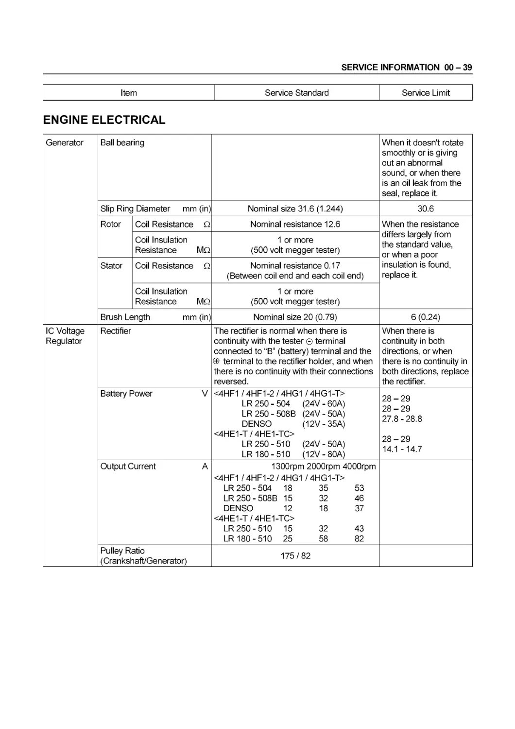
ENGINE ELECTRICAL
Generator Ball bearing When it doesn't rotate smoothly or is giving out an abnormal sound, or when there is an oil leak from the seal, replace it.
Slip Ring Diameter mm (in) Nominal size 31.6 (1.244) 30.6
Rotor Coil Resistance Q Nominal resistance 12.6 When the resistance differs largely from the standard value, or when a poor insulation is found, replace it.
Coil Insulation Resistance MO 1 or more (500 volt megger tester)
Stator Coil Resistance Q Nominal resistance 0.17 (Between coil end and each coil end)
Coil Insulation Resistance MO 1 or more (500 volt megger tester)
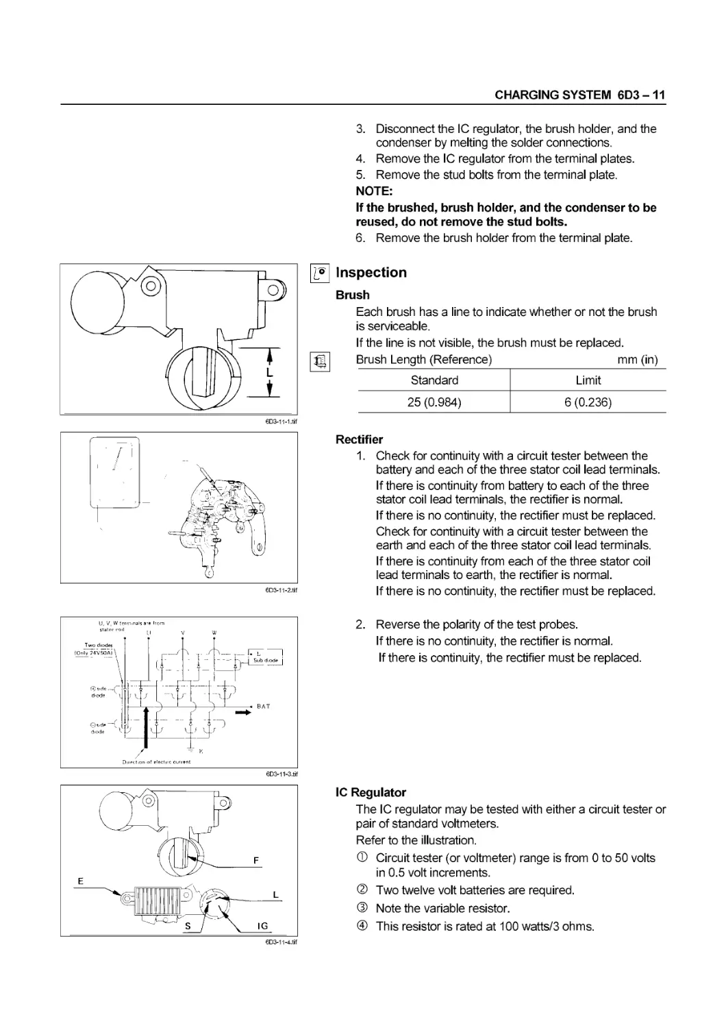
Brush Length mm (in) Nominal size 20 (0.79) 6 (0.24)
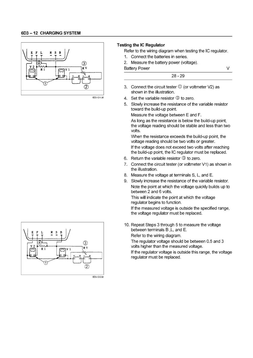
IC Voltage Regulator Rectifier The rectifier is normal when there is continuity with the tester © terminal connected to “B” (battery) terminal and the @ terminal to the rectifier holder, and when there is no continuity with their connections reversed. When there is continuity in both directions, or when there is no continuity in both directions, replace the rectifier.
Battery Power V <4HF1 /4HF1-2/4HG1 /4HG1-T> LR 250 - 504 (24V - 60A) LR 250-508 В (24V-50A) DENSO (12V-35A) <4HE1-T / 4HE1-TO LR 250-510 (24V-50A) LR 180-510 (12V-80A) 28-29 28-29 27.8-28.8 28-29 14.1 -14.7
Output Current A 1300rpm 2000rpm 4000rpm <4HF1 /4HF1-2/4HG1 /4HG1-T> LR 250 - 504 18 35 53 LR250-508B 15 32 46 DENSO 12 18 37 <4HE1-T/4HE1-TC> LR 250-510 15 32 43 LR 180-510 25 58 82
Pulley Ratio (Crankshaft/Generator) 175/82
00-40 SERVICE INFORMATION
Item Service Standard Service Limit
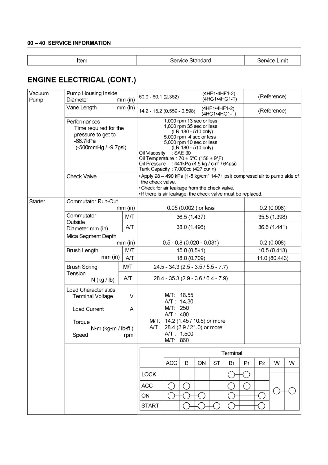
ENGINE ELECTRICAL (CONT.)
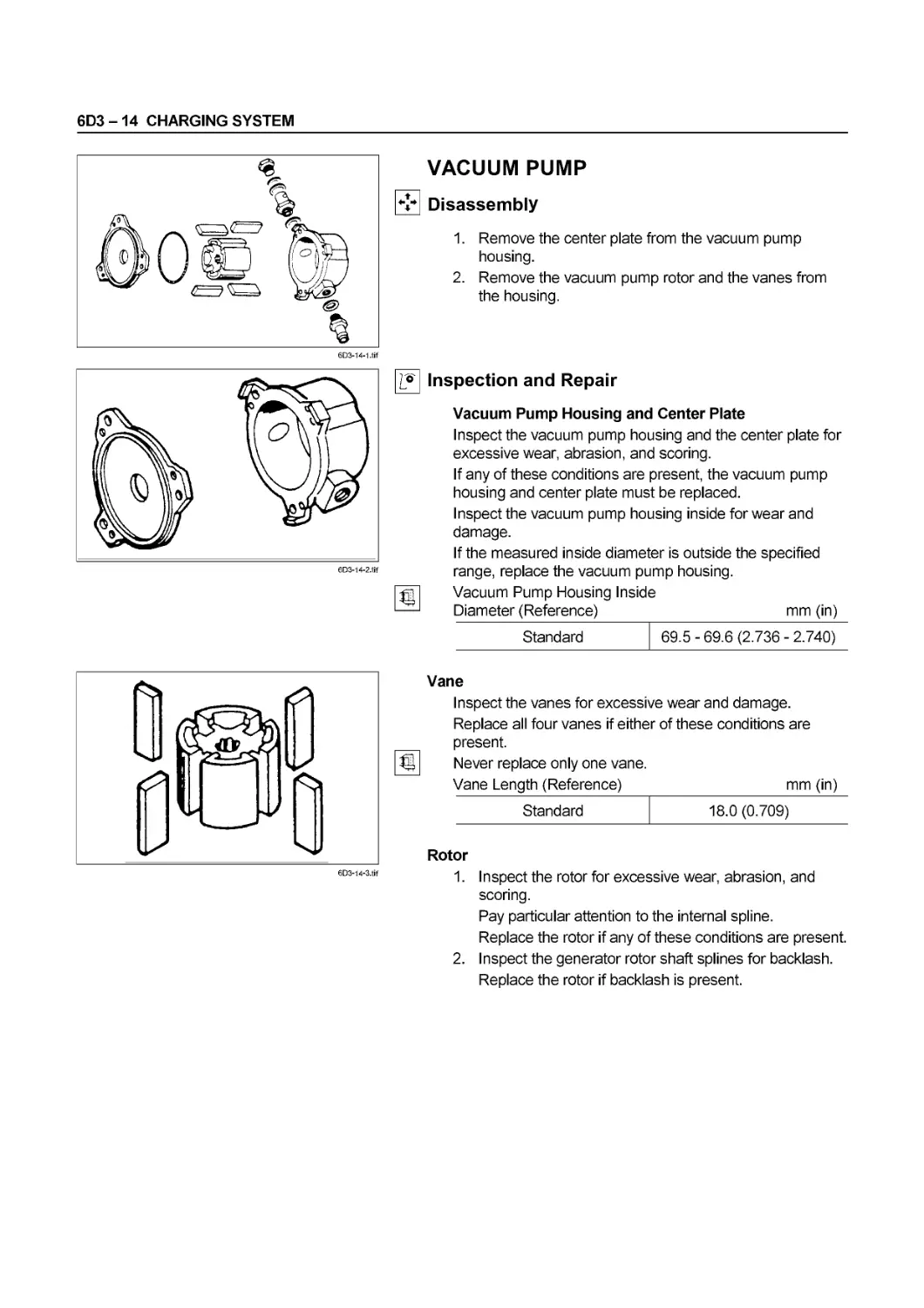
Vacuum Pump Pump Housing Inside Diameter mm (in) (4HF1MHF1-2) 60.0-60.1 (2.362) (4HG1*4HG1-T) (Reference)
Vane Length mm (in) 14 2- 15 2(0 559-0 598’) (4HF1*4HF1-2) I4.z is.z(u.ssy u.syaj (4HG1«4HG1-T) (Reference)
Performances Time required for the pressure to get to -66.7kPa (-500mmHg / -9.7psi). 1,000 rpm 13 sec or less 1,000 rpm 35 sec or less (LR 180-510 only) 5,000 rpm 4 sec or less 5,000 rpm 10 sec or less (LR 180-510 only) Oil Viscosity : SAE 30 Oil Temperature : 70 + 5°C (158 + 9°F) Oil Pressure : 441 kPa (4.5 kg / cm2 / 64psi) Tank Capacity : 7,000cc (427 cu«in)
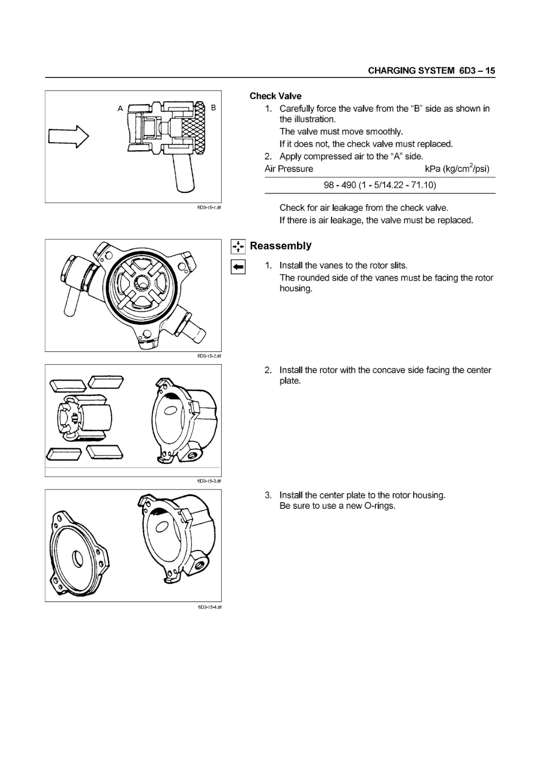
Check Valve •Apply 98 - 490 kPa (1-5 kg/cm2 14-71 psi) compressd air to pump side of the check valve. • Check for air leakage from the check valve. • If there is air leakage, the check valve must be replaced.
Starter Commutator Run-Out mm (in) 0.05 (0.002 ) or less 0.2 (0.008)
Commutator Outside Diameter mm (in) M/T 36.5(1.437) 35.5(1.398)
A/T 38.0(1.496) 36.6 (1.441)
Mica Segment Depth mm (in) 0.5-0.8 (0.020-0.031) 0.2 (0.008)
Brush Length mm (in) M/T 15.0(0.591) 10.5(0.413)
A/T 18.0(0.709) 11.0(80.443)
Brush Spring M/T 24.5-34.3(2.5-3.5/5.5-7.7)
Tension N (kg / lb) A/T 28.4 - 35.3 (2.9 - 3.6 / 6.4 - 7.9)
Load Characteristics Terminal Voltage V Load Current A Torque N«m (kg*m / lb«ft) Speed rpm M/T: 18.55 A/T: 14.30 M/T: 250 A/T: 400 M/T: 14.2 (1.45 /10.5) or more A/T : 28.4 (2.9 /21.0) or more A/T: 1,500 M/T: 860
Terminal
ACC В ON ST B1 P1 P2 w w
LOCK
ACC
ON -Q)- Q— — —(2)
START Q— — -Q)
SERVICE INFORMATION 00 - 41
Item Service Standard Service Limit
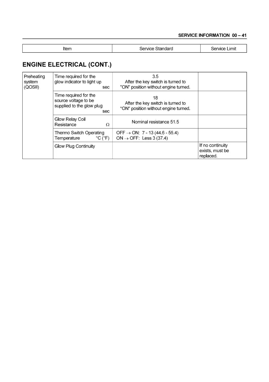
ENGINE ELECTRICAL (CONT.)
Preheating system (QOSII) Time required for the glow indicator to light up sec 3.5 After the key switch is turned to "ON" position without engine turned.
Time required for the source voltage to be supplied to the glow plug sec 18 After the key switch is turned to "ON" position without engine turned.
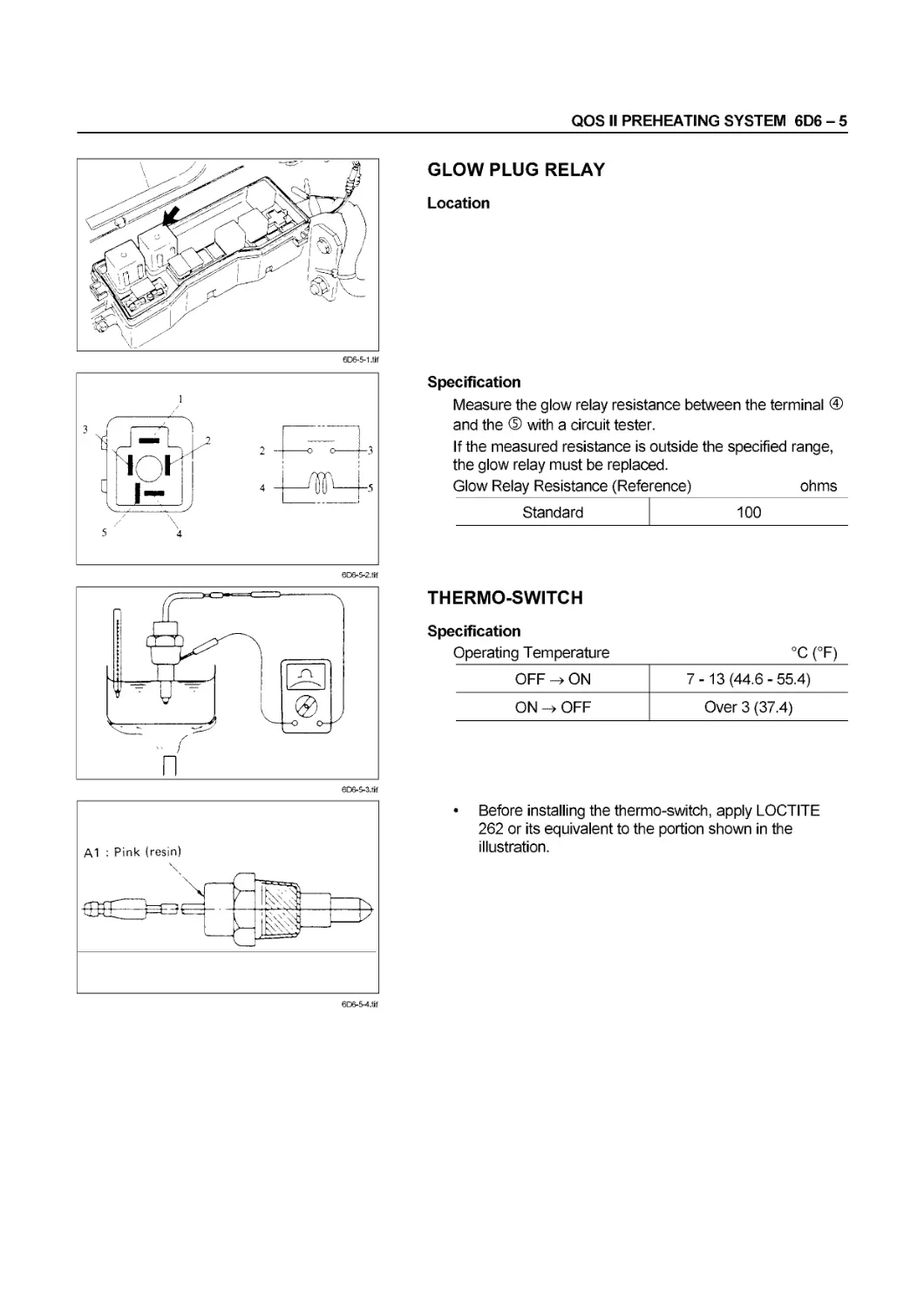
Glow Relay Coil Resistance Q Nominal resistance 51.5
Thermo Switch Operating Temperature °C (°F) OFF > ON: 7-13 (44.6 - 55.4) ON > OFF: Less 3(37.4)
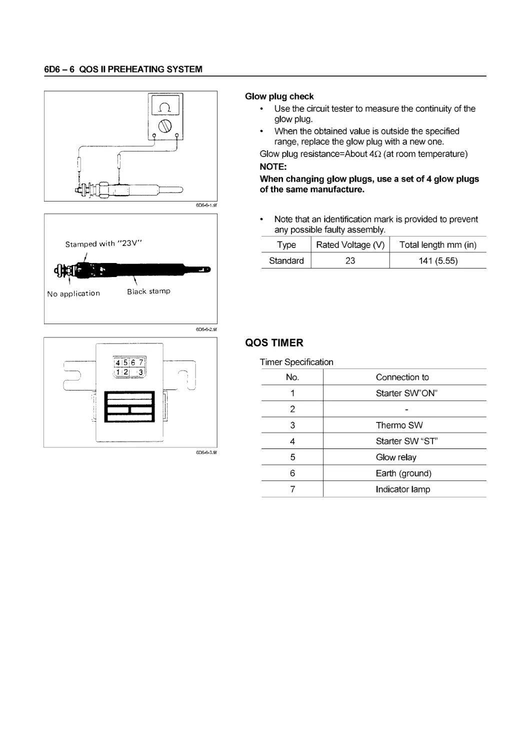
Glow Plug Continuity If no continuity exists, must be replaced.
00-42 SERVICE INFORMATION
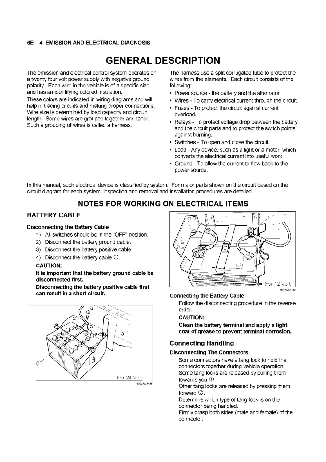
SERVICING
Servicing refers to general maintenance procedures to be performed by qualified service personnel.
0041-1.tif
0041-4.tif
MODEL IDENTIFICATION
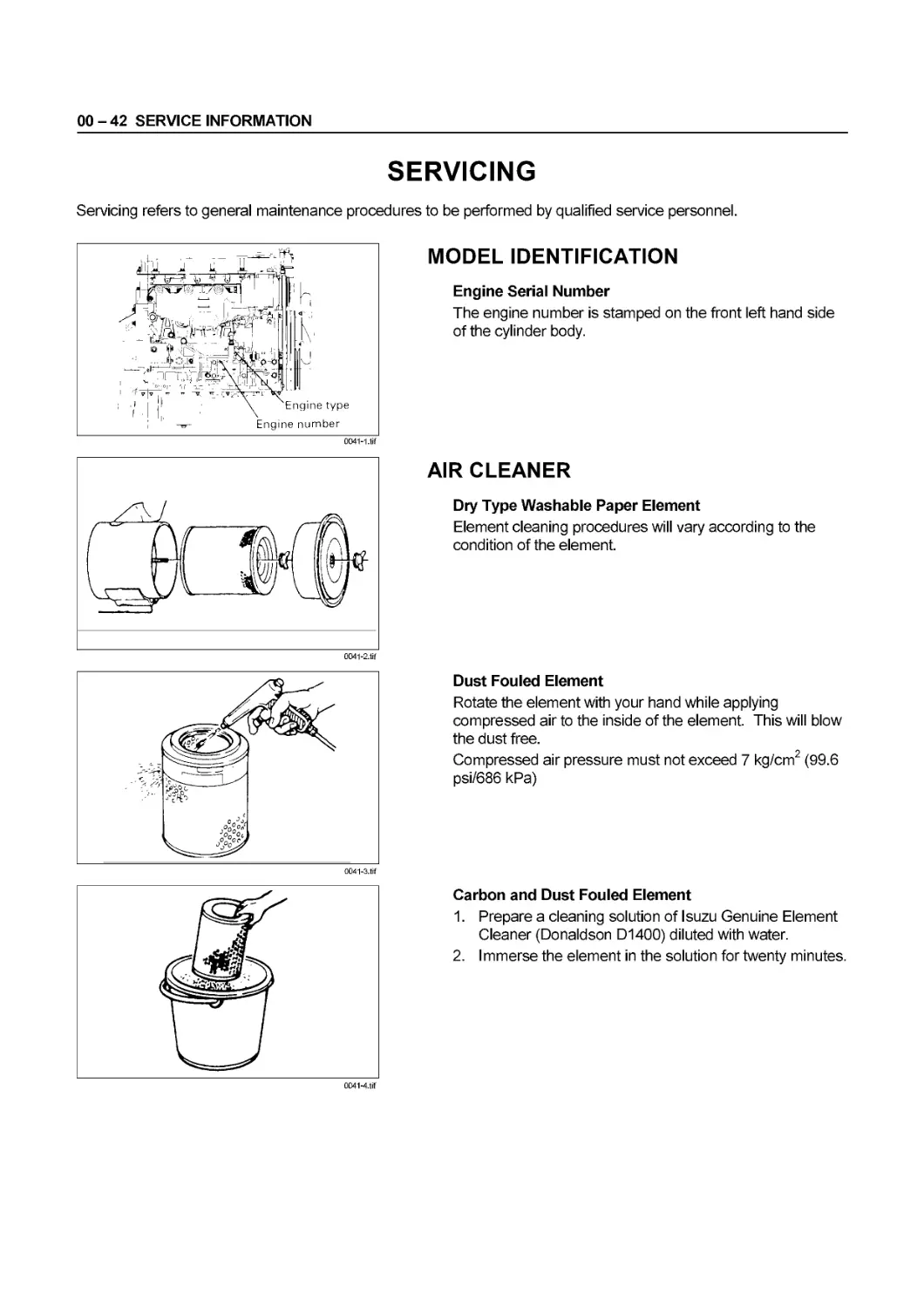
Engine Serial Number
The engine number is stamped on the front left hand side
of the cylinder body.
AIR CLEANER
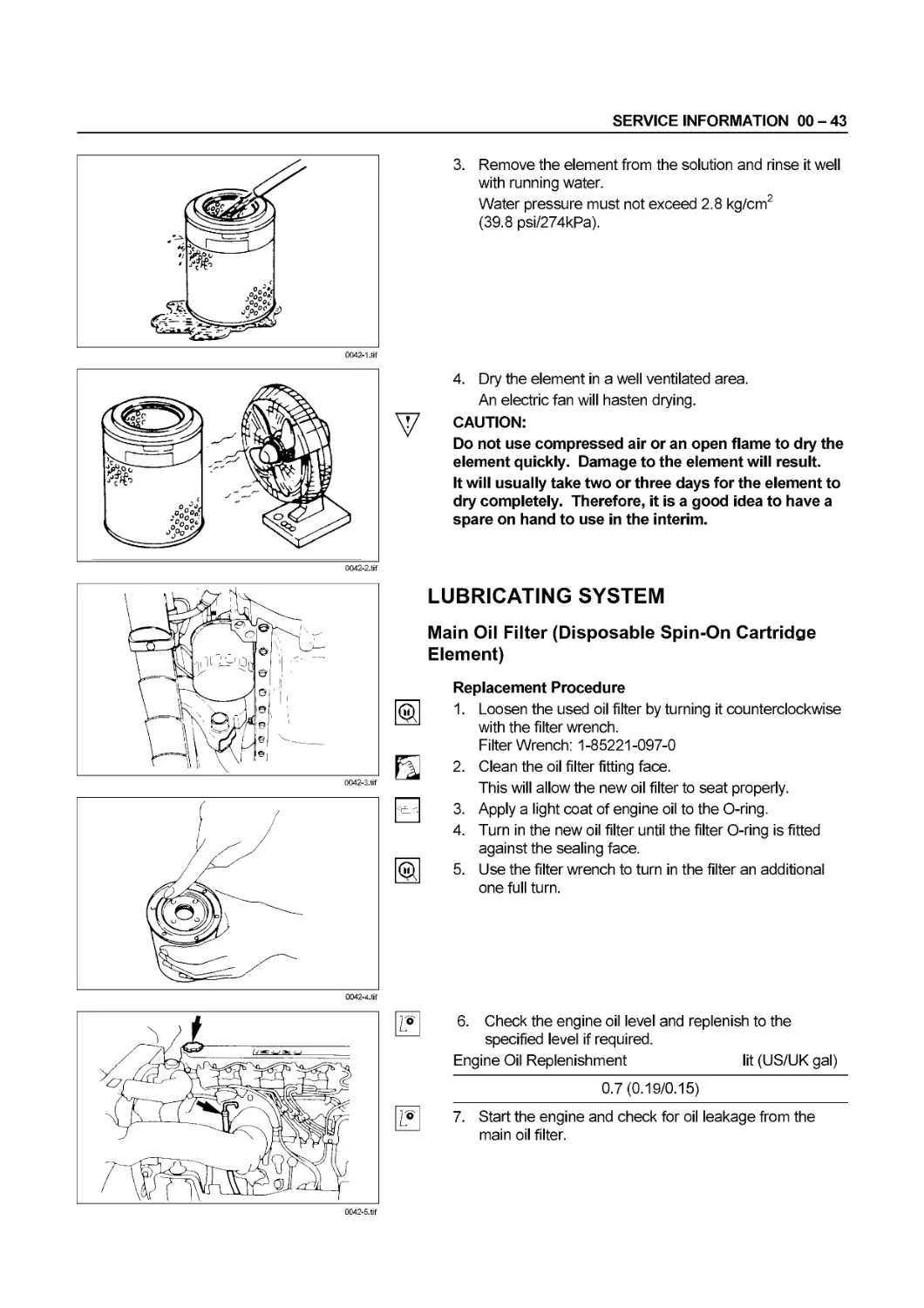
Dry Type Washable Paper Element
Element cleaning procedures will vary according to the
condition of the element.
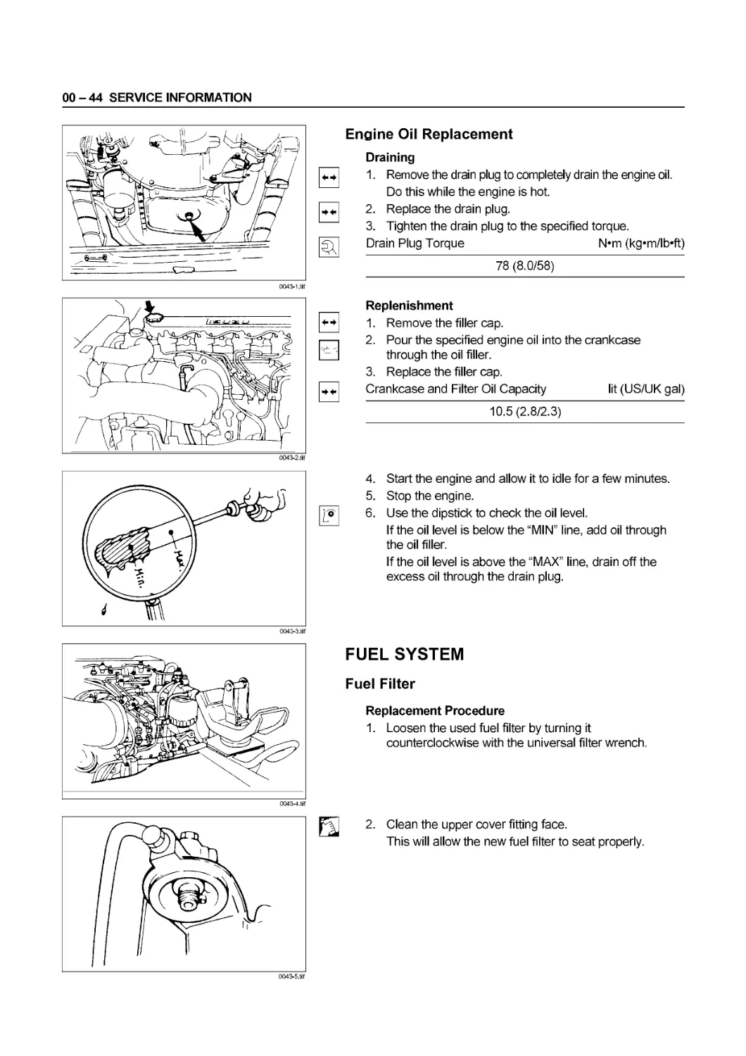
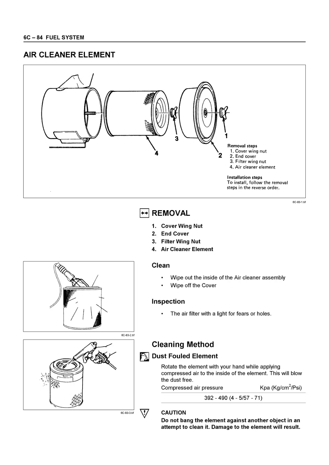
Dust Fouled Element
Rotate the element with your hand while applying
compressed air to the inside of the element. This will blow
the dust free.
Compressed air pressure must not exceed 7 kg/cm2 (99.6
psi/686 kPa)
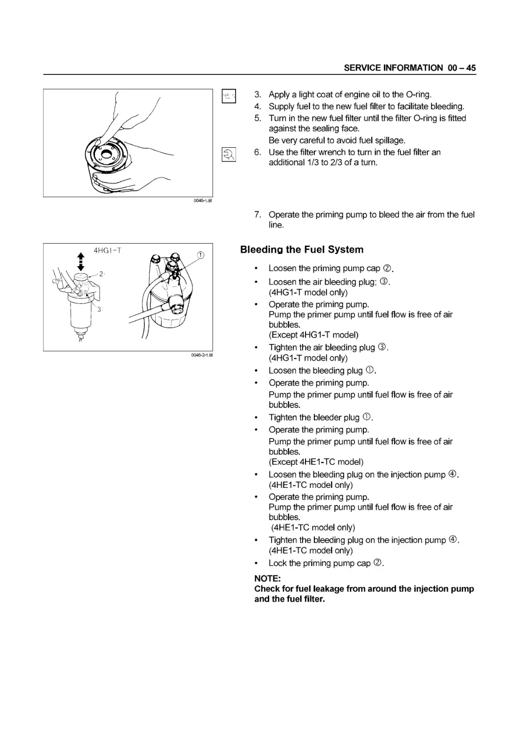
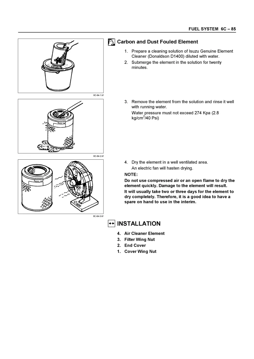
Carbon and Dust Fouled Element
1. Prepare a cleaning solution of Isuzu Genuine Element
Cleaner (Donaldson D1400) diluted with water.
2. Immerse the element in the solution for twenty minutes.
SERVICE INFORMATION 00 - 43
0042-1 .tif
0042-2.tif
0042-5.tif
3. Remove the element from the solution and rinse it well
with running water.
Water pressure must not exceed 2.8 kg/cm2
(39.8 psi/274kPa).
4. Dry the element in a well ventilated area.
An electric fan will hasten drying.
CAUTION:
Do not use compressed air or an open flame to dry the
element quickly. Damage to the element will result.
It will usually take two or three days for the element to
dry completely. Therefore, it is a good idea to have a
spare on hand to use in the interim.
LUBRICATING SYSTEM
Main Oil Filter (Disposable Spin-On Cartridge
Element)
Replacement Procedure
1. Loosen the used oil filter by turning it counterclockwise
with the filter wrench.
Filter Wrench: 1-85221-097-0
2. Clean the oil filter fitting face.
This will allow the new oil filter to seat properly.
3. Apply a light coat of engine oil to the O-ring.
4. Turn in the new oil filter until the filter О-ring is fitted
against the sealing face.
5. Use the filter wrench to turn in the filter an additional
one full turn.
6. Check the engine oil level and replenish to the
specified level if required.
Engine Oil Replenishment lit (US/UK gal)
0.7(0.19/0.15)
7. Start the engine and check for oil leakage from the
main oil filter.
00-44 SERVICE INFORMATION
0043-5.tif
Engine Oil Replacement
Draining
1. Remove the drain plug to completely drain the engine oil.
Do this while the engine is hot.
2. Replace the drain plug.
3. Tighten the drain plug to the specified torque.
Drain Plug Torque N*m (kg«m/lb*ft)
78 (8.0/58)
Replenishment
1. Remove the filler cap.
2. Pour the specified engine oil into the crankcase
through the oil filler.
3. Replace the filler cap.
Crankcase and Filter Oil Capacity lit (US/UK gal)
10.5(2.8/2.3)
4. Start the engine and allow it to idle for a few minutes.
5. Stop the engine.
6. Use the dipstick to check the oil level.
If the oil level is below the “MIN” line, add oil through
the oil filler.
If the oil level is above the “MAX” line, drain off the
excess oil through the drain plug.
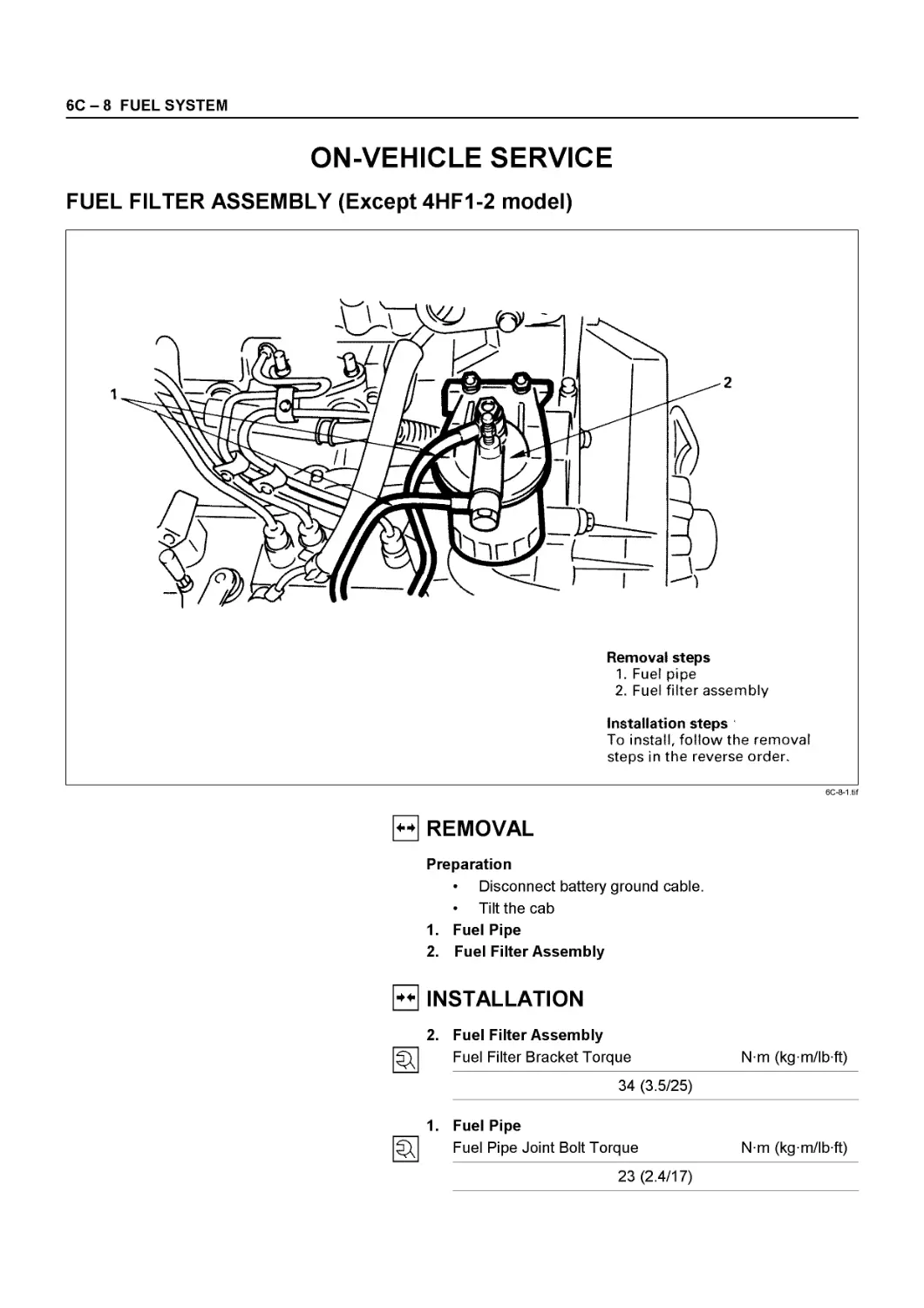
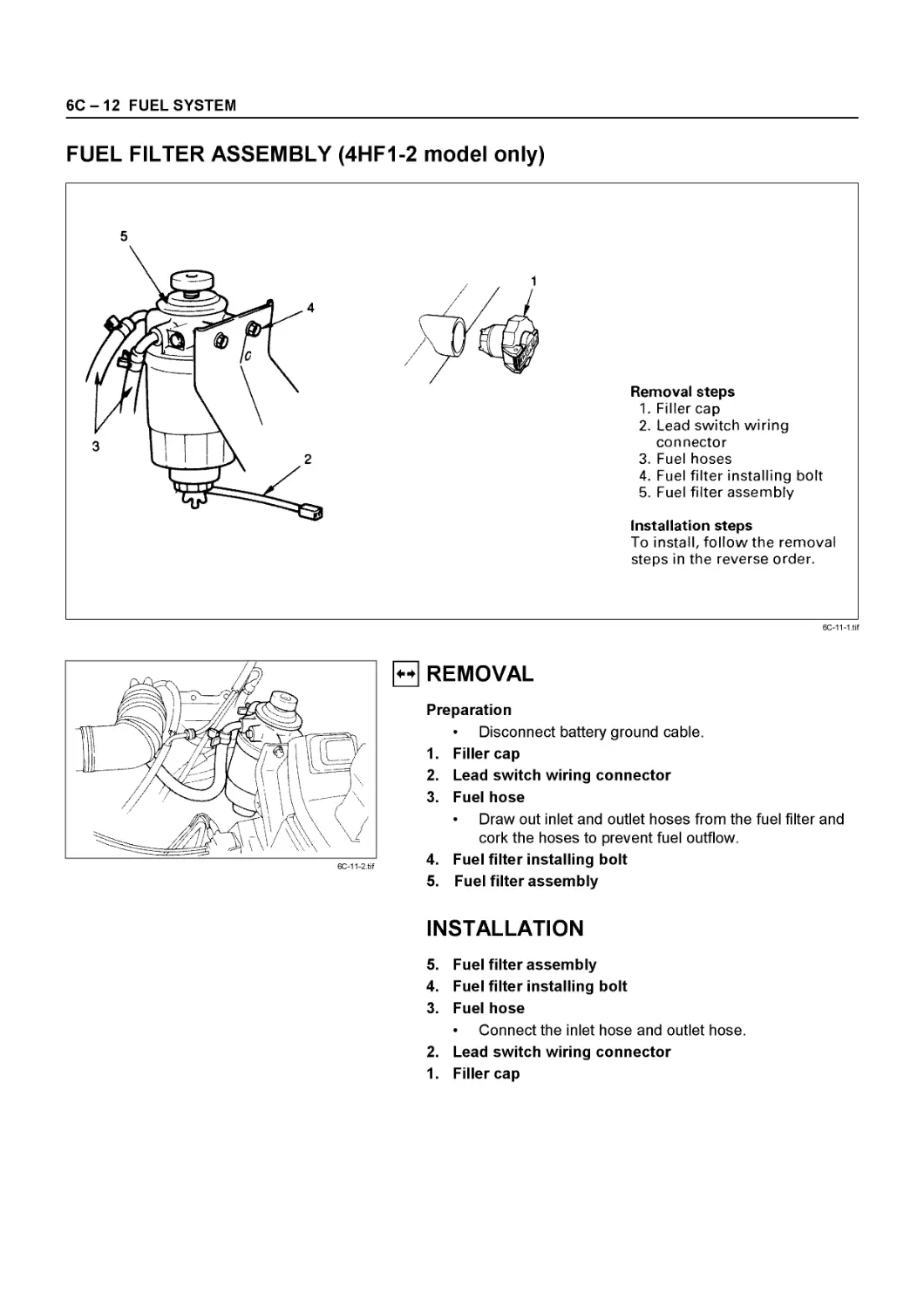
FUEL SYSTEM
Fuel Filter
Replacement Procedure
1. Loosen the used fuel filter by turning it
counterclockwise with the universal filter wrench.
2. Clean the upper cover fitting face.
This will allow the new fuel filter to seat properly.
SERVICE INFORMATION 00 - 45
0046-2-1.tif
3. Apply a light coat of engine oil to the O-ring.
4. Supply fuel to the new fuel filter to facilitate bleeding.
5. Turn in the new fuel filter until the filter О-ring is fitted
against the sealing face.
Be very careful to avoid fuel spillage.
6. Use the filter wrench to turn in the fuel filter an
additional 1/3 to 2/3 of a turn.
7. Operate the priming pump to bleed the air from the fuel
line.
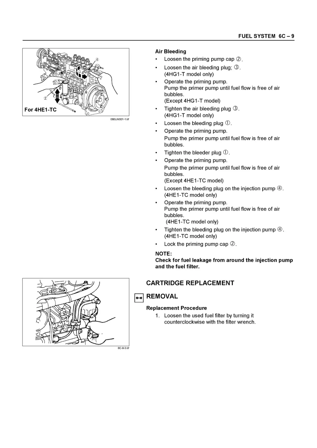
Bleeding the Fuel System
• Loosen the priming pump cap ®.
• Loosen the air bleeding plug; ®.
(4HG1-T model only)
• Operate the priming pump.
Pump the primer pump until fuel flow is free of air
bubbles.
(Except 4HG1-T model)
• Tighten the air bleeding plug ®.
(4HG1-T model only)
• Loosen the bleeding plug ®.
• Operate the priming pump.
Pump the primer pump until fuel flow is free of air
bubbles.
• Tighten the bleeder plug ®.
• Operate the priming pump.
Pump the primer pump until fuel flow is free of air
bubbles.
(Except 4HE1-TC model)
• Loosen the bleeding plug on the injection pump @.
(4HE1-TC model only)
• Operate the priming pump.
Pump the primer pump until fuel flow is free of air
bubbles.
(4HE1-TC model only)
• Tighten the bleeding plug on the injection pump
(4HE1-TC model only)
• Lock the priming pump cap ®.
NOTE:
Check for fuel leakage from around the injection pump
and the fuel filter.
00-46 SERVICE INFORMATION
080LW00l-1.tif
0046-4.tif
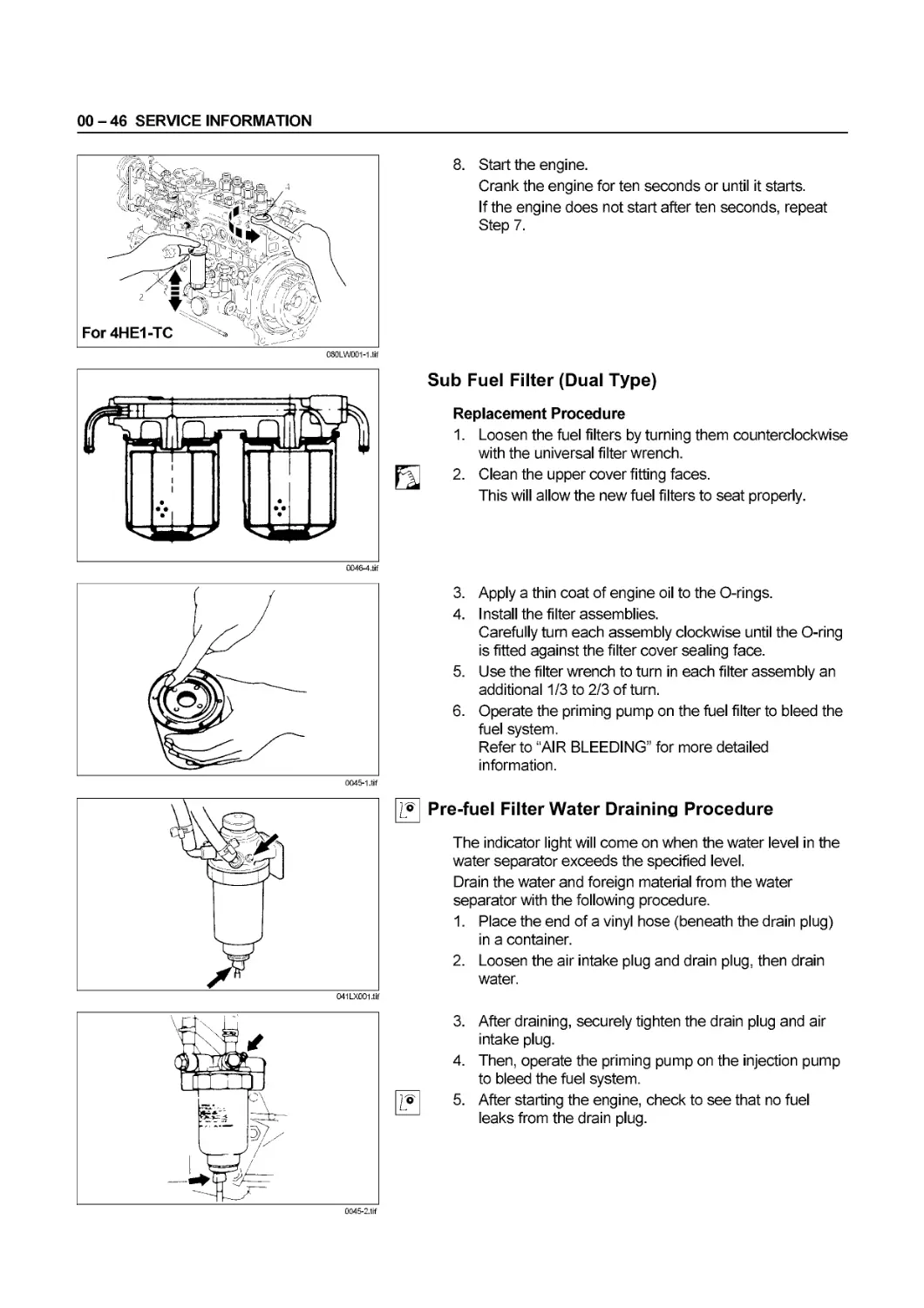
8. Start the engine.
Crank the engine for ten seconds or until it starts.
If the engine does not start after ten seconds, repeat
Step 7.
Sub Fuel Filter (Dual Type)
Replacement Procedure
1. Loosen the fuel filters by turning them counterclockwise
with the universal filter wrench.
2. Clean the upper cover fitting faces.
This will allow the new fuel filters to seat properly.
3. Apply a thin coat of engine oil to the O-rings.
4. Install the filter assemblies.
Carefully turn each assembly clockwise until the O-ring
is fitted against the filter cover sealing face.
5. Use the filter wrench to turn in each filter assembly an
additional 1/3 to 2/3 of turn.
6. Operate the priming pump on the fuel filter to bleed the
fuel system.
Refer to “AIR BLEEDING” for more detailed
information.
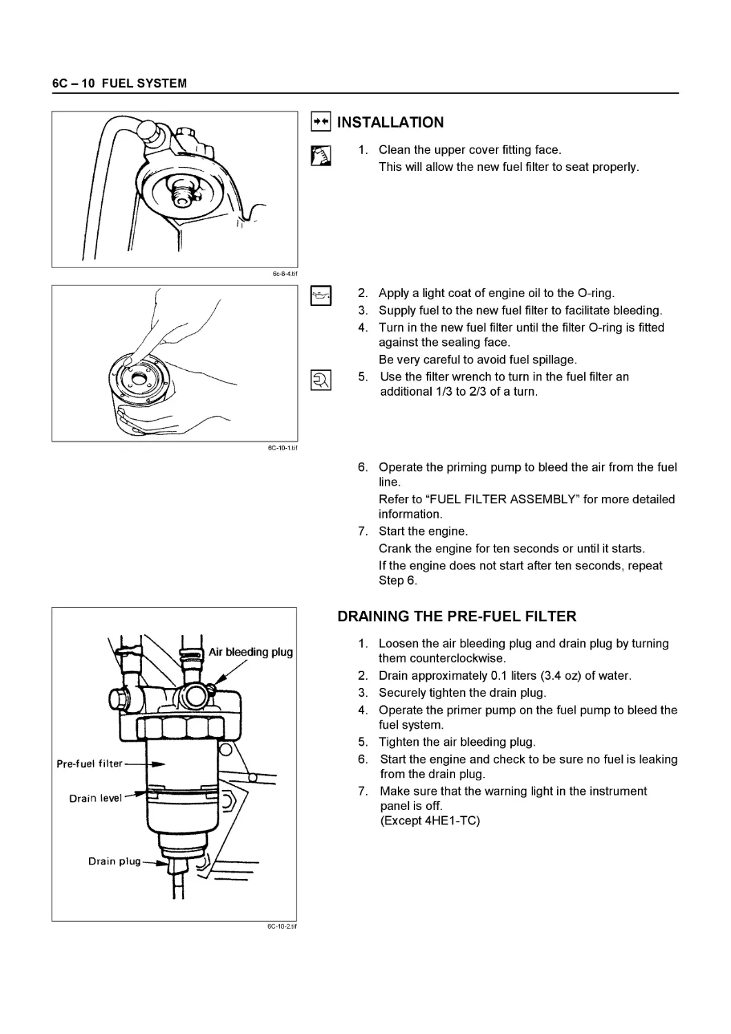
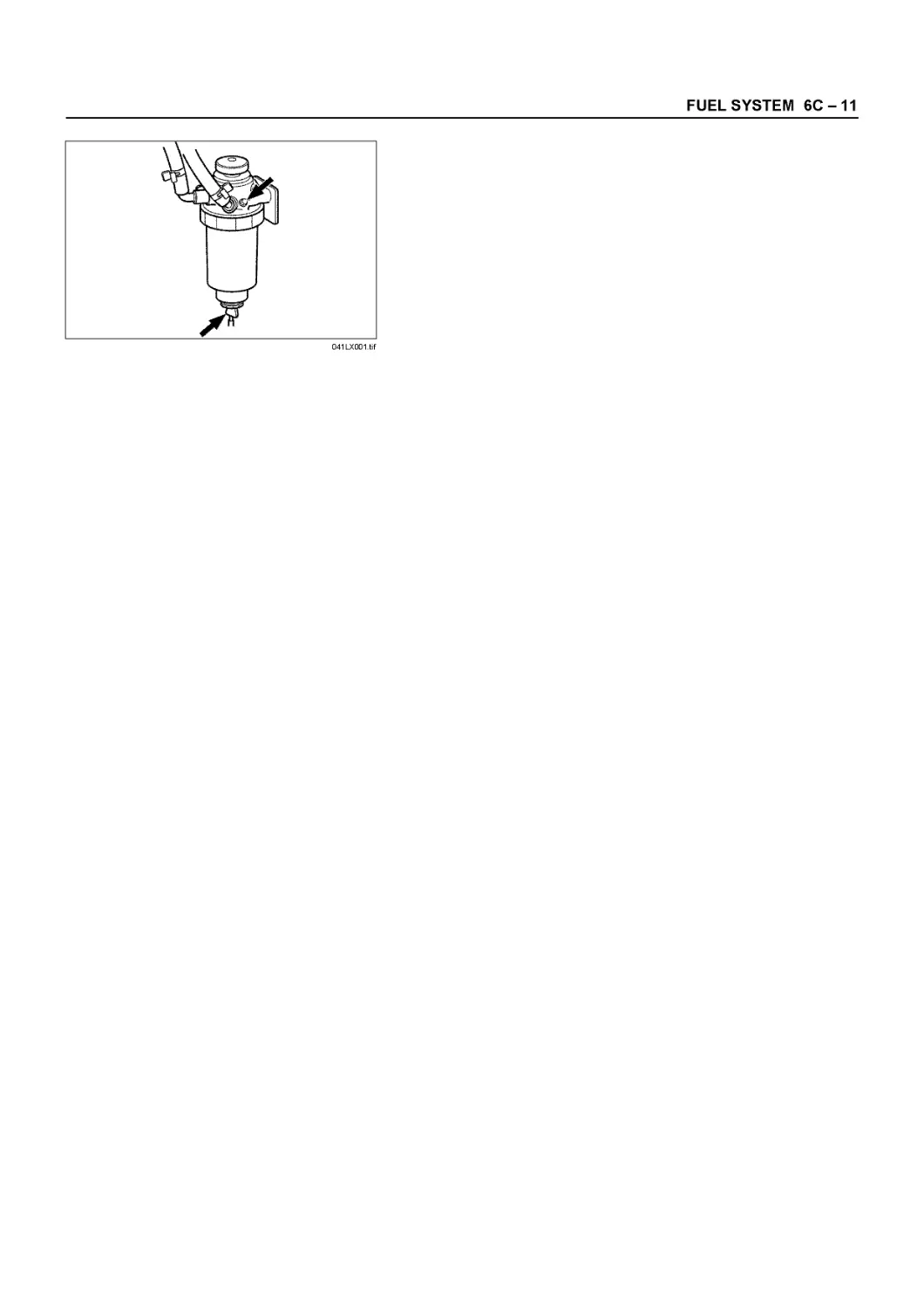
° Pre-fuel Filter Water Draining Procedure
The indicator light will come on when the water level in the
water separator exceeds the specified level.
Drain the water and foreign material from the water
separator with the following procedure.
1. Place the end of a vinyl hose (beneath the drain plug)
in a container.
2. Loosen the air intake plug and drain plug, then drain
water.
041LX00l.tif
0045-2.tif
3. After draining, securely tighten the drain plug and air
intake plug.
4. Then, operate the priming pump on the injection pump
to bleed the fuel system.
5. After starting the engine, check to see that no fuel
leaks from the drain plug.
SERVICE INFORMATION 00 - 47
0046-2.tif
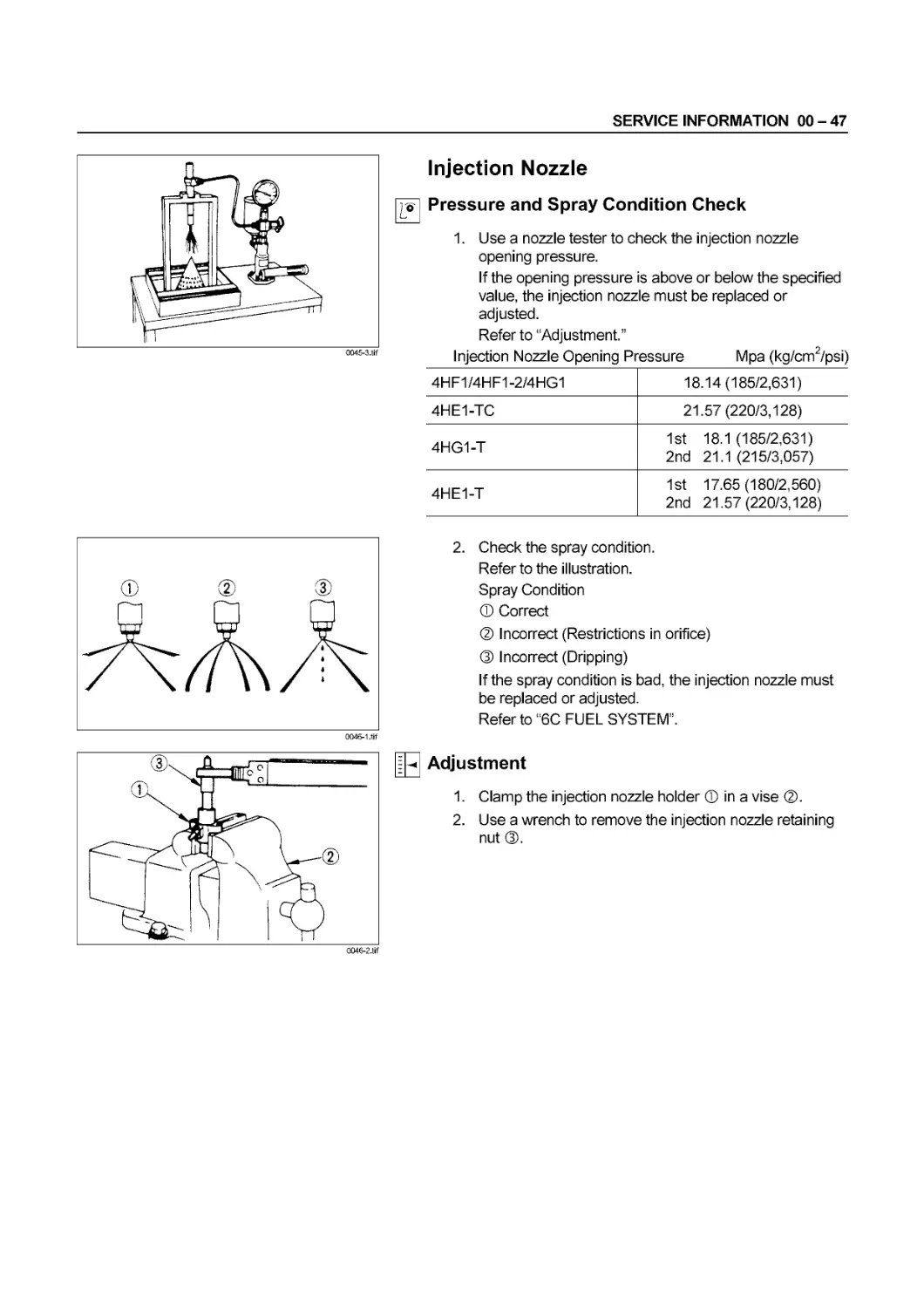
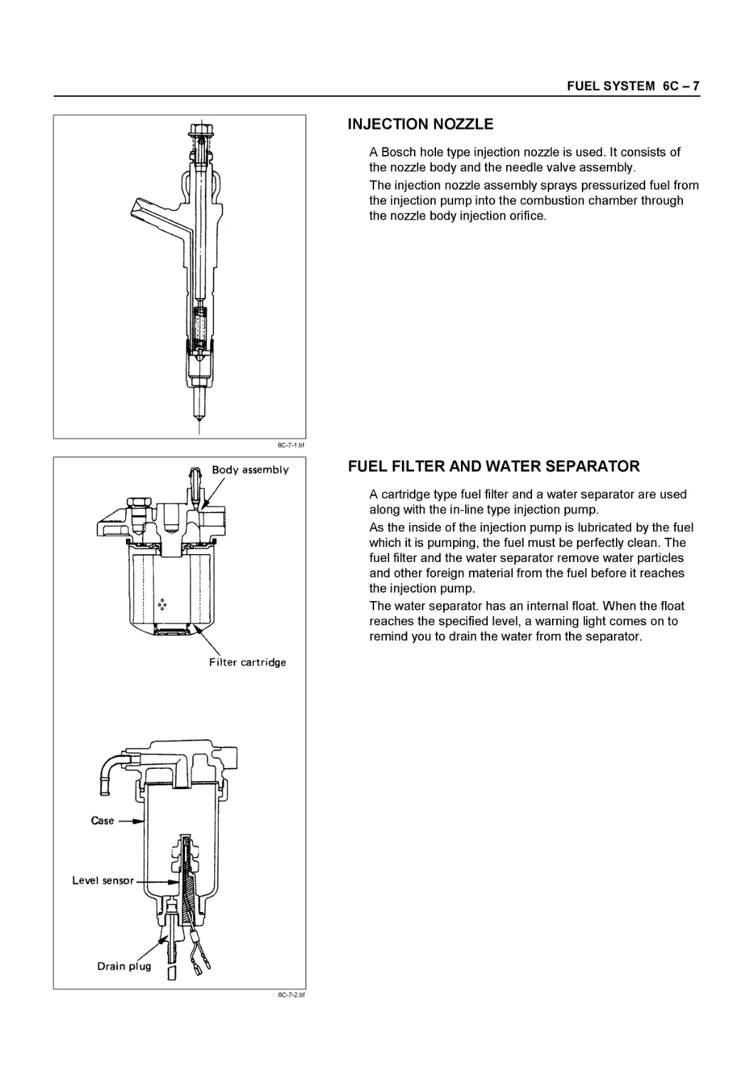
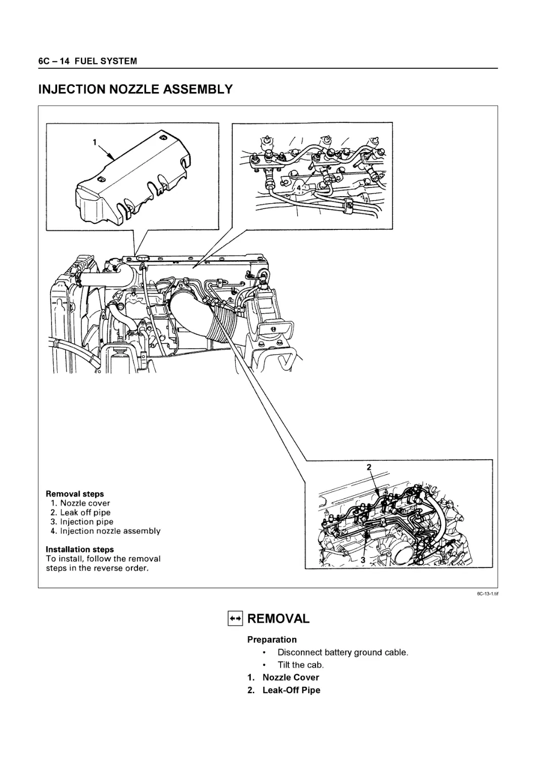
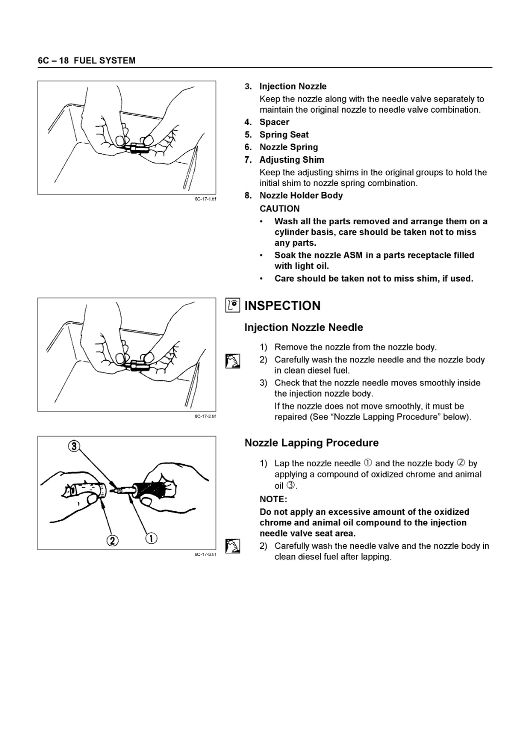
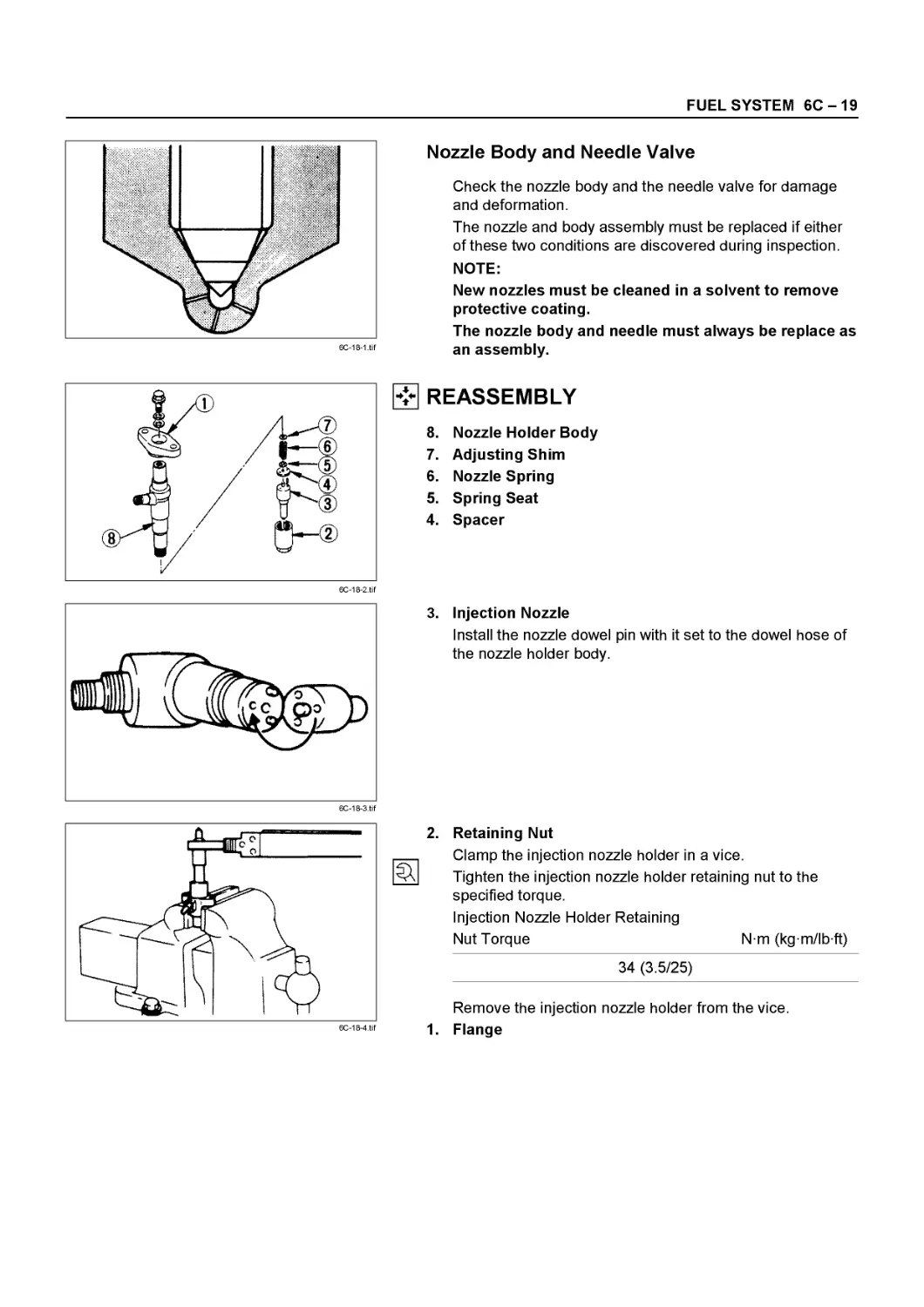
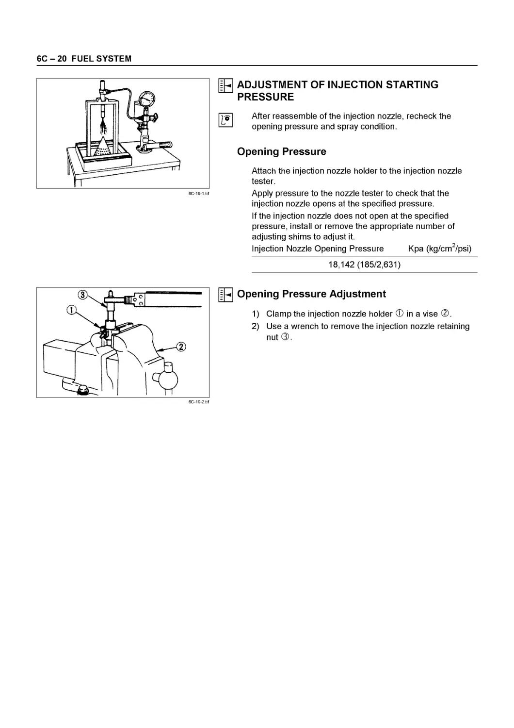
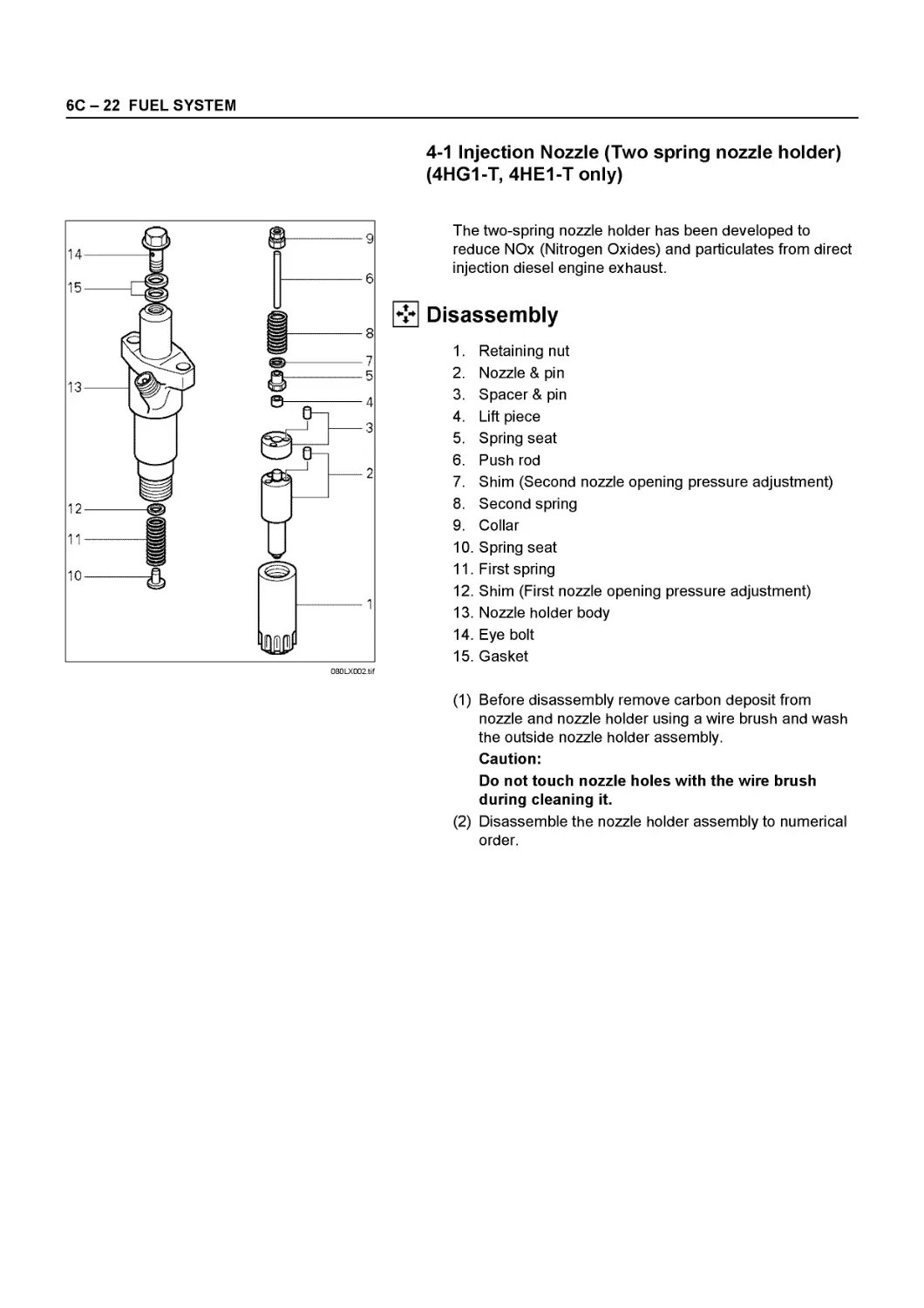
Injection Nozzle
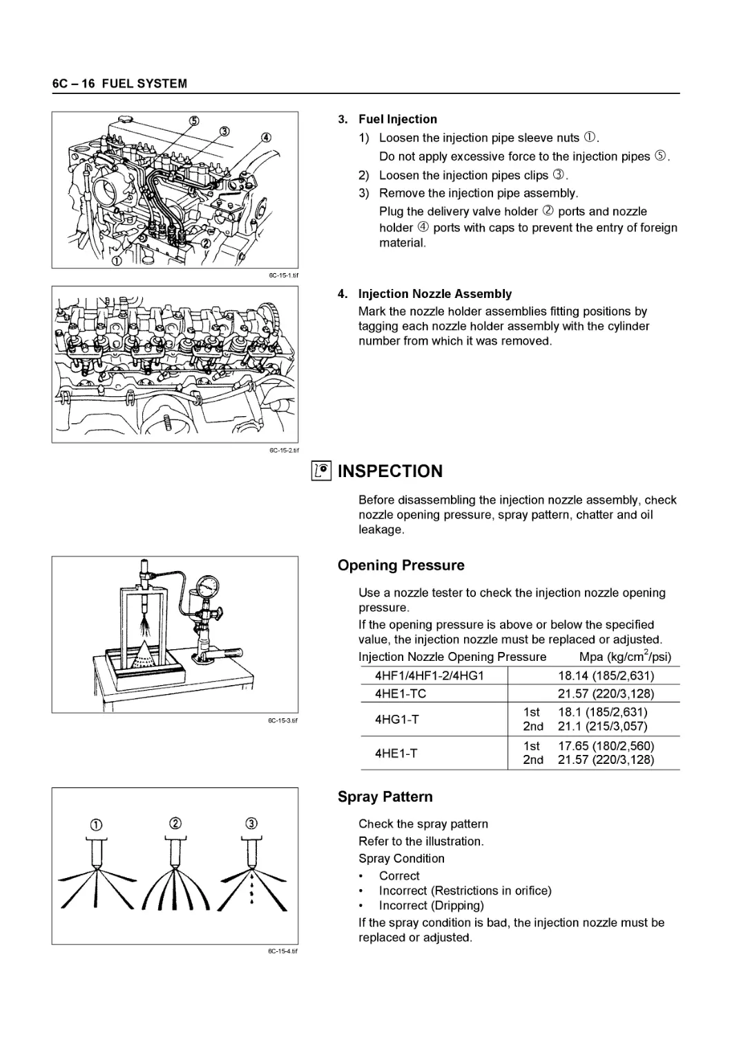
Pressure and Spray Condition Check
1. Use a nozzle tester to check the injection nozzle
opening pressure.
If the opening pressure is above or below the specified
value, the injection nozzle must be replaced or
adjusted.
Refer to “Adjustment.”
Injection Nozzle Opening Pressure Mpa (kg/cm2/psi)
4HF1/4HF1-2/4HG1 18.14(185/2,631)
4HE1-TC 21.57(220/3,128)
4HG1-T 1st 18.1 (185/2,631) 2nd 21.1 (215/3,057)
4HE1-T 1st 17.65(180/2,560) 2nd 21.57(220/3,128)
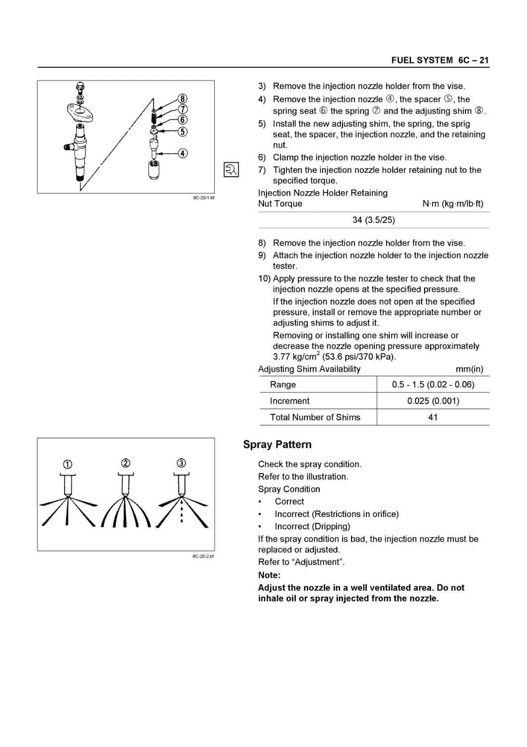
2. Check the spray condition.
Refer to the illustration.
Spray Condition
® Correct
® Incorrect (Restrictions in orifice)
® Incorrect (Dripping)
If the spray condition is bad, the injection nozzle must
be replaced or adjusted.
Refer to “6C FUEL SYSTEM”.
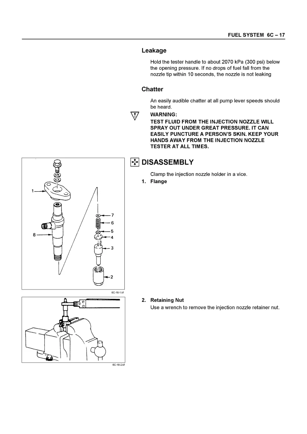
- Adjustment
1. Clamp the injection nozzle holder © in a vise ®.
2. Use a wrench to remove the injection nozzle retaining
nut ®.
00-48 SERVICE INFORMATION
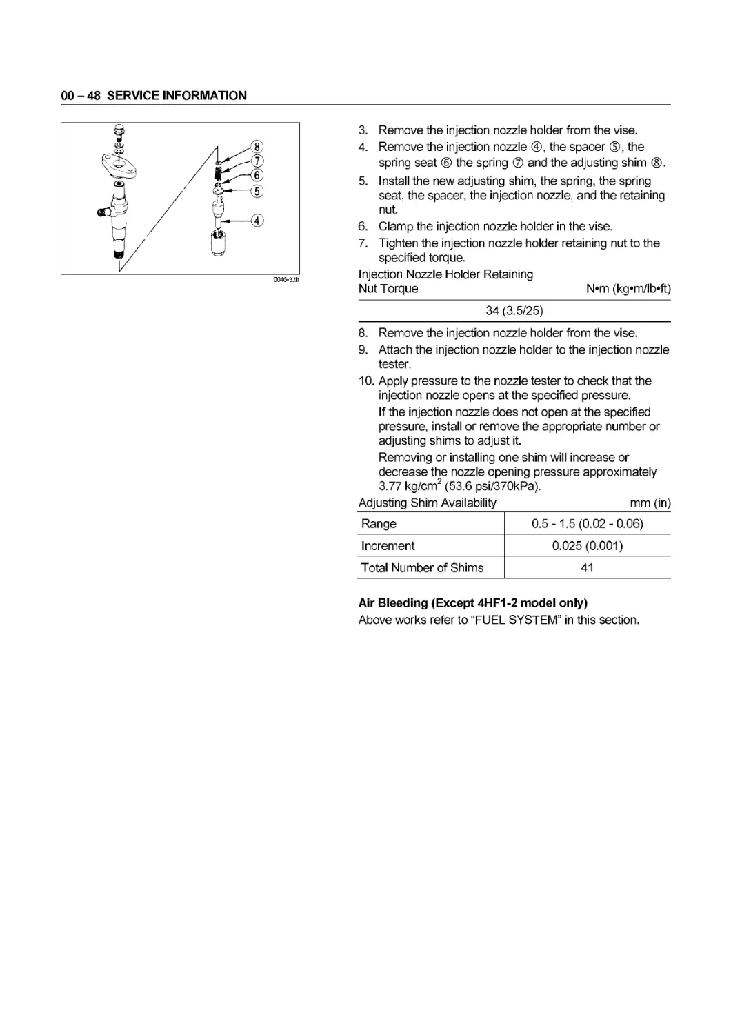
0046-3.tif
3. Remove the injection nozzle holder from the vise.
4. Remove the injection nozzle @, the spacer ®, the
spring seat ® the spring ® and the adjusting shim ®.
5. Install the new adjusting shim, the spring, the spring
seat, the spacer, the injection nozzle, and the retaining
nut.
6. Clamp the injection nozzle holder in the vise.
7. Tighten the injection nozzle holder retaining nut to the
specified torque.
Injection Nozzle Holder Retaining
Nut Torque N*m (kg«m/lb*ft)
34 (3.5/25)
8. Remove the injection nozzle holder from the vise.
9. Attach the injection nozzle holder to the injection nozzle
tester.
10. Apply pressure to the nozzle tester to check that the
injection nozzle opens at the specified pressure.
If the injection nozzle does not open at the specified
pressure, install or remove the appropriate number or
adjusting shims to adjust it.
Removing or installing one shim will increase or
decrease the nozzle opening pressure approximately
3.77 kg/cm2 (53.6 psi/370kPa).
Adjusting Shim Availability mm (in)
Range 0.5-1.5 (0.02-0.06)
Increment 0.025 (0.001)
Total Number of Shims 41
Air Bleeding (Except 4HF1-2 model only)
Above works refer to “FUEL SYSTEM” in this section.
SERVICE INFORMATION 00 - 49
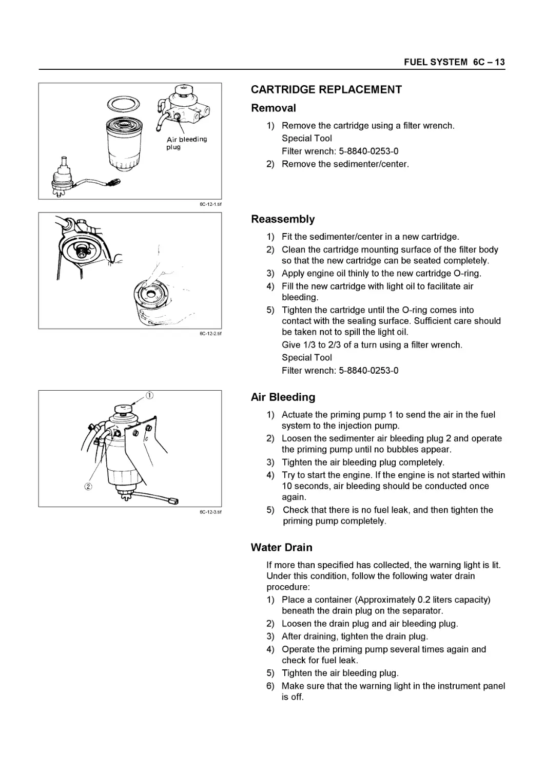
Air Bleeding (4HF1-2 model only)
1. Actuate the priming pump ® to send the air in the fuel
system to the injection pump.
2. Loosen the sedimenter air bleeding plug ® and
operate the priming pump until no bubbles appear.
3. Tighten the air bleeding plug completely.
4. Try to start the engine. If the engine is not started within
10 seconds, air bleeding should be conducted once
agian.
5. Check that there is no fuel leak ,and then tighten the
priming pump completely.
Water Drain
If more water than specified has collected, the warning light
is lit. Under this condition, follow the following water drain
procedure:
1. Place a container (Approximately 0.2 liters capacity)
beneath the drain plug on the separator.
2. Loosen the drain plug and air bleeding plug.
3. After draining, tighten the drain plug.
4. Operate the priming pump several times again and
check for fuel leak.
5. Tighten the air bleeding plug.
6. Make sure that the warning light in the instrument panel
is off. (Except 4HE1-TC model)
COOLING SYSTEM
l?l Coolant Level
Check the coolant level and replenish the radiator reserve
tank if necessary.
If the coolant level falls below the “MIN” line, carefully
check the cooling system for leakage. Then add enough
coolant to bring the level up to the “MAX” line.
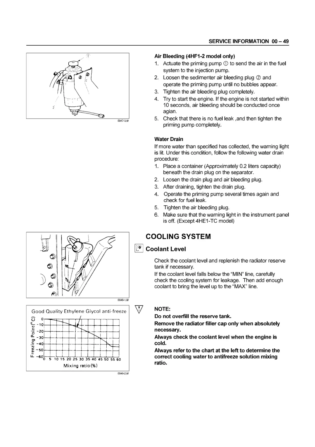
Good Quality Ethylene Glycol anti-freeze
NOTE:
Do not overfill the reserve tank.
Remove the radiator filler cap only when absolutely
necessary.
Always check the coolant level when the engine is
cold.
Always refer to the chart at the left to determine the
correct cooling water to antifreeze solution mixing
ratio.
0048-2.tif
00 - 50 SERVICE INFORMATION
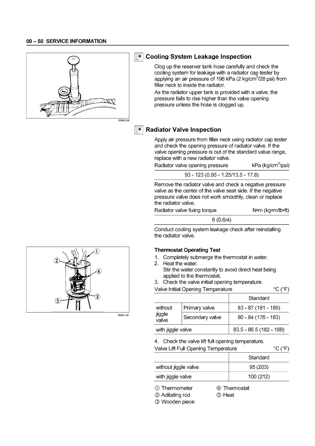
Cooling System Leakage Inspection
Clog up the reserver tank hose carefully and check the
cooling system for leakage with a radiator cap tester by
applying an air pressure of 196 kPa (2 kg/cm2/28 psi) from
filler neck to inside the radiator.
As the radiator upper tank is provided with a valve, the
pressure fails to rise higher than the valve opening
pressure unless the hose is clogged up.
Radiator Valve Inspection
Apply air pressure from filler neck using radiator cap tester
and check the opening pressure of radiator valve. If the
valve opening pressure is out of the standard value range,
replace with a new radiator valve.
Radiator valve opening pressure
kPa (kg/cm2/psi)
93 -123 (0.95 -1.25/13.5 -17.8)
Remove the radiator valve and check a negative pressure
valve as the center of the valve seat side. If the negative
pressure valve does not work smoothly, clean or replace
the radiator valve.
Radiator valve fixing torque
N*m (kg‘m/lb*ft)
6 (0.6/4)
Conduct cooling system leakage check after reinstalling
the radiator valve.
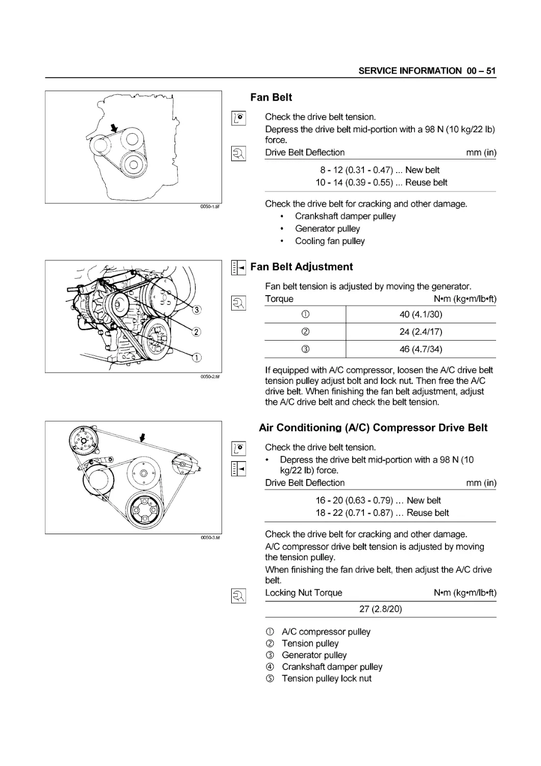
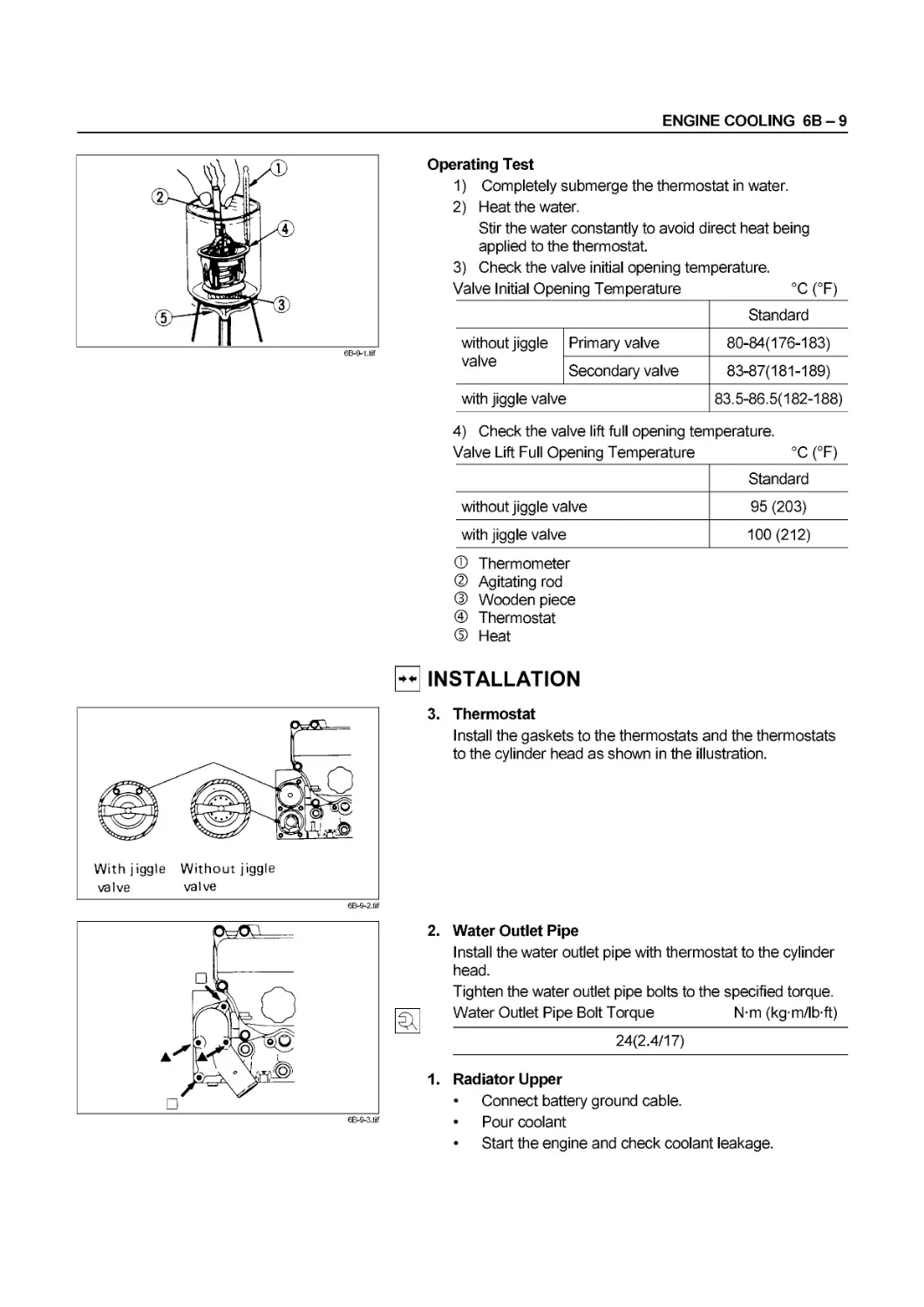
Thermostat Operating Test
1.
2.
Completely submerge the thermostat in water.
Heat the water.
Stir the water constantly to avoid direct heat being
applied to the thermostat.
Check the valve initial opening temperature.
°C (°F)
3.
Valve Initial Opening Temperature
Standard
without Primary valve 83-87(181 - 189)
jiggle „ , valve Secondary valve 80-84(176-183)
with jiggle valve 83.5-86.5(182-188)
4. Check the valve lift full opening temperature.
Valve Lift Full Opening Temperature °C (°F)
Standard
without jiggle valve 95 (203)
with jiggle valve 100 (212)
® Thermometer
® Aditating rod
® Wooden piece
@ Thermostat
® Heat
SERVICE INFORMATION 00 - 51
0050-1 .tif
0050-3.tif
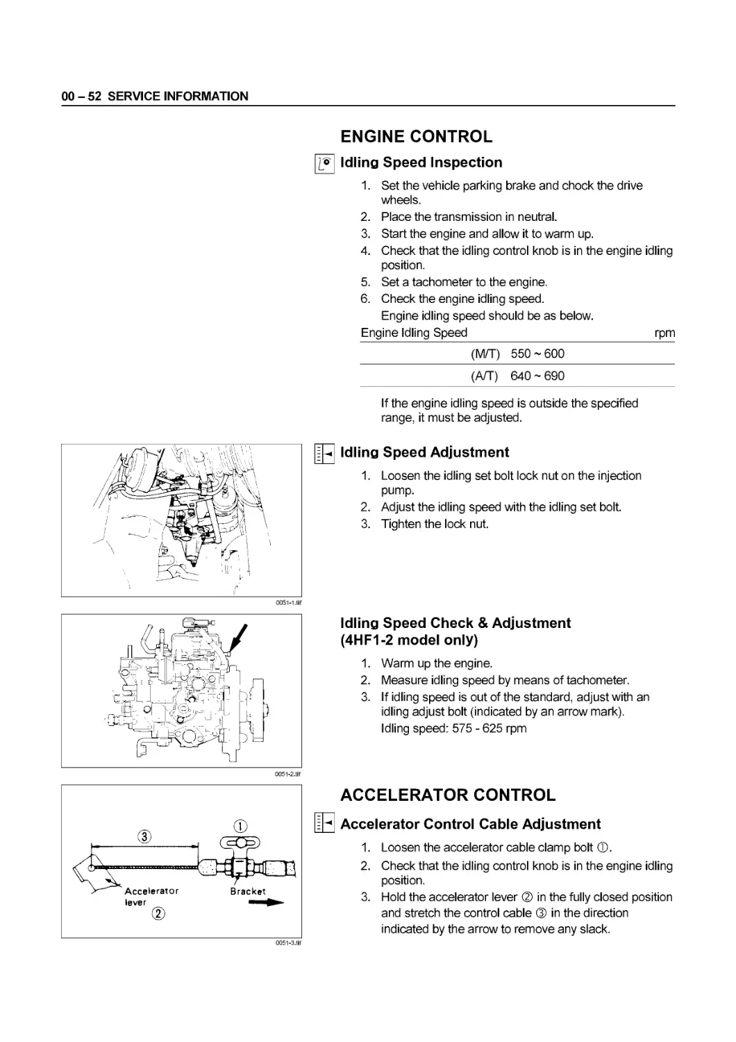
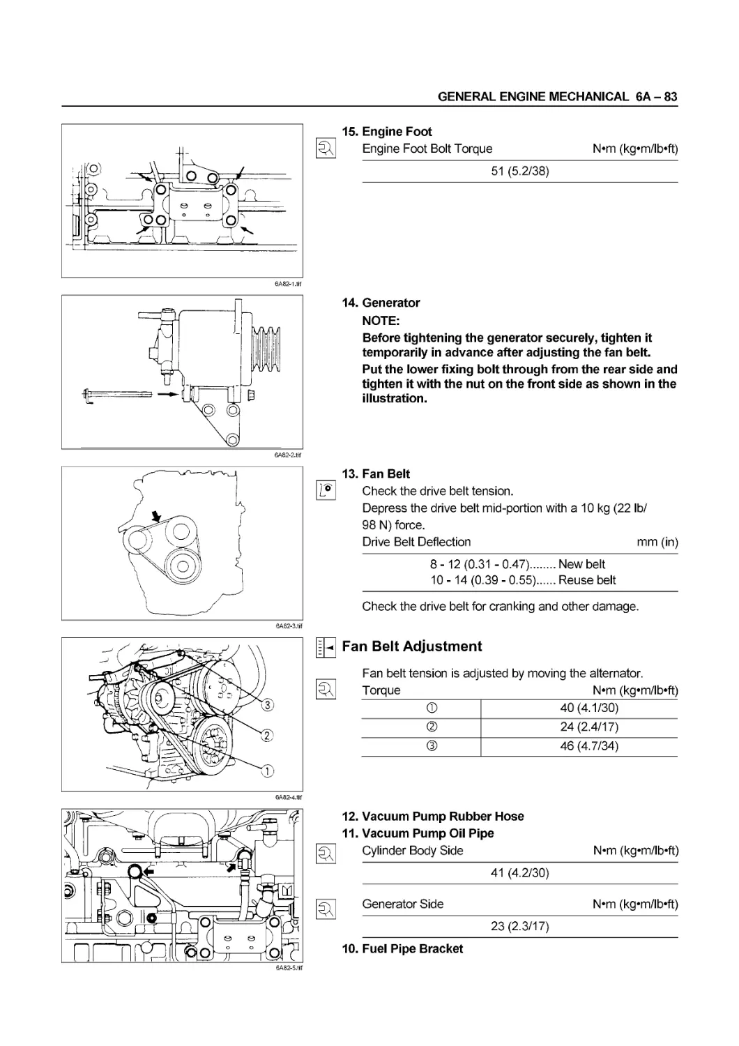
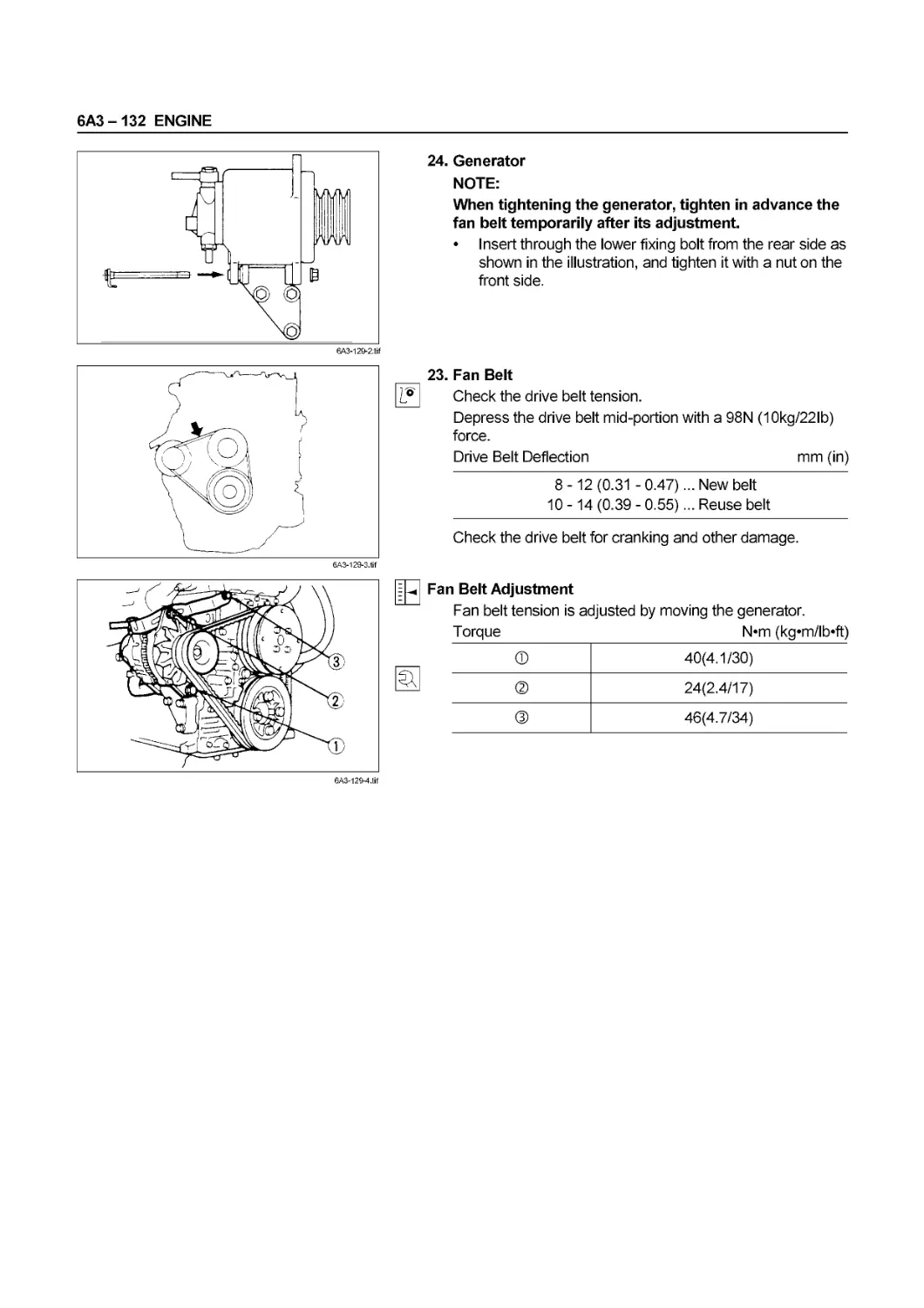
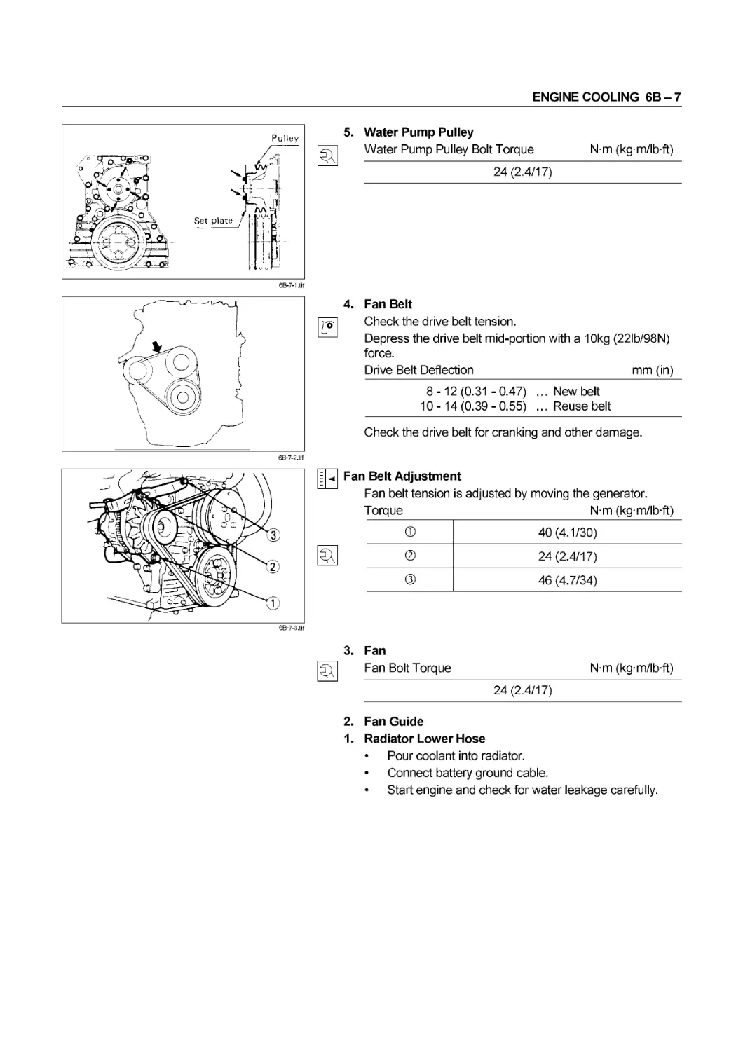
Fan Belt
Check the drive belt tension.
Depress the drive belt mid-portion with a 98 N (10 kg/22 lb)
force.
Drive Belt Deflection mm (in)
8-12(0.31 -0.47)... New belt
10 -14 (0.39 - 0.55)... Reuse belt
Check the drive belt for cracking and other damage.
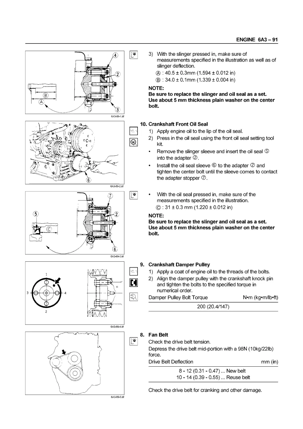
• Crankshaft damper pulley
• Generator pulley
• Cooling fan pulley
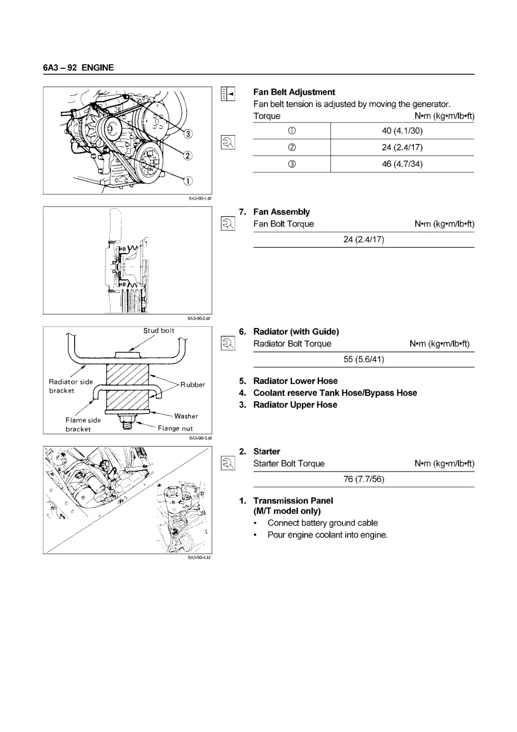
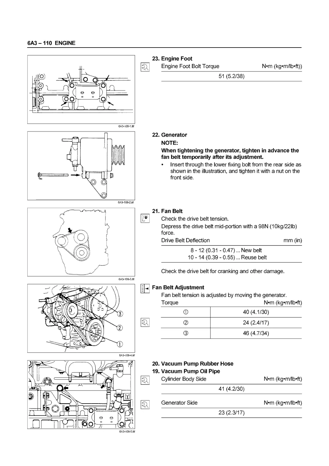
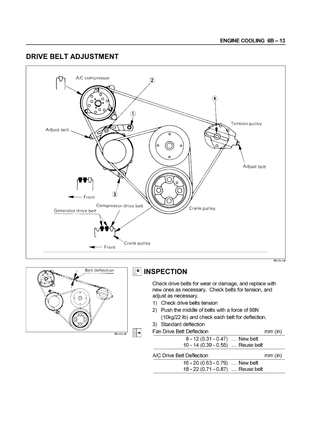
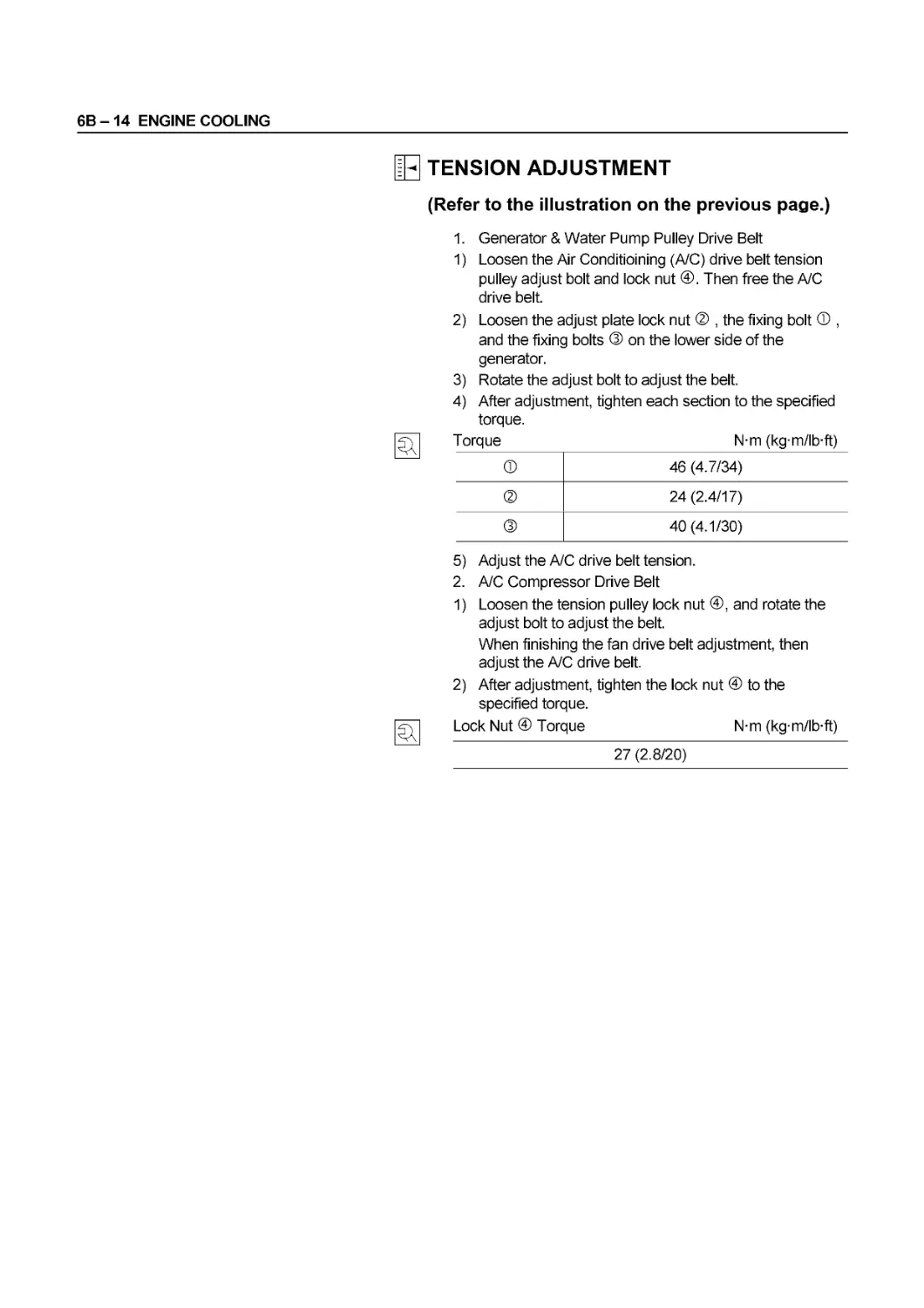
- Fan Belt Adjustment
Fan belt tension is adjusted by moving the generator.
Torque N*m (kg*m/lb*ft)
® 40(4.1/30)
® 24 (2.4/17)
® 46 (4.7/34)
If equipped with A/C compressor, loosen the A/C drive belt
tension pulley adjust bolt and lock nut. Then free the A/C
drive belt. When finishing the fan belt adjustment, adjust
the A/C drive belt and check the belt tension.
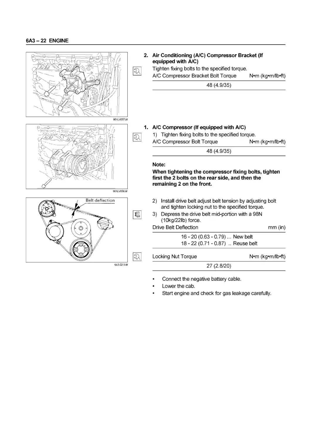
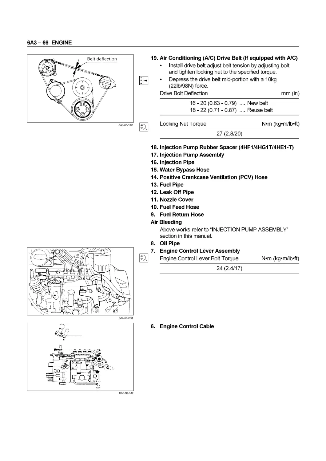
Air Conditioning (A/C) Compressor Drive Belt
Check the drive belt tension.
• Depress the drive belt mid-portion with a 98 N (10
kg/22 lb) force.
Drive Belt Deflection mm (in)
16-20(0.63-0.79)... New belt
18 - 22 (0.71 - 0.87)... Reuse belt
Check the drive belt for cracking and other damage.
A/C compressor drive belt tension is adjusted by moving
the tension pulley.
When finishing the fan drive belt, then adjust the A/C drive
belt.
Locking Nut Torque N-m (kg*m/lb‘ft)
27 (2.8/20)
® A/C compressor pulley
® Tension pulley
® Generator pulley
@ Crankshaft damper pulley
(5) Tension pulley lock nut
00 - 52 SERVICE INFORMATION
ENGINE CONTROL
Idling Speed Inspection
1. Set the vehicle parking brake and chock the drive
wheels.
2. Place the transmission in neutral.
3. Start the engine and allow it to warm up.
4. Check that the idling control knob is in the engine idling
position.
5. Set a tachometer to the engine.
6. Check the engine idling speed.
Engine idling speed should be as below.
Engine Idling Speed rpm
(M/T) 550-600
(A/T) 640 - 690
If the engine idling speed is outside the specified
range, it must be adjusted.
005f-1.tif
-« Idling Speed Adjustment
1. Loosen the idling set bolt lock nut on the injection
pump.
2. Adjust the idling speed with the idling set bolt.
3. Tighten the lock nut.
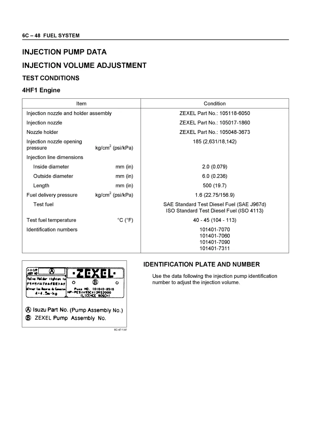
Idling Speed Check & Adjustment
(4HF1-2 model only)
1. Warm up the engine.
2. Measure idling speed by means of tachometer.
3. If idling speed is out of the standard, adjust with an
idling adjust bolt (indicated by an arrow mark).
Idling speed: 575 - 625 rpm
0051-3.tif
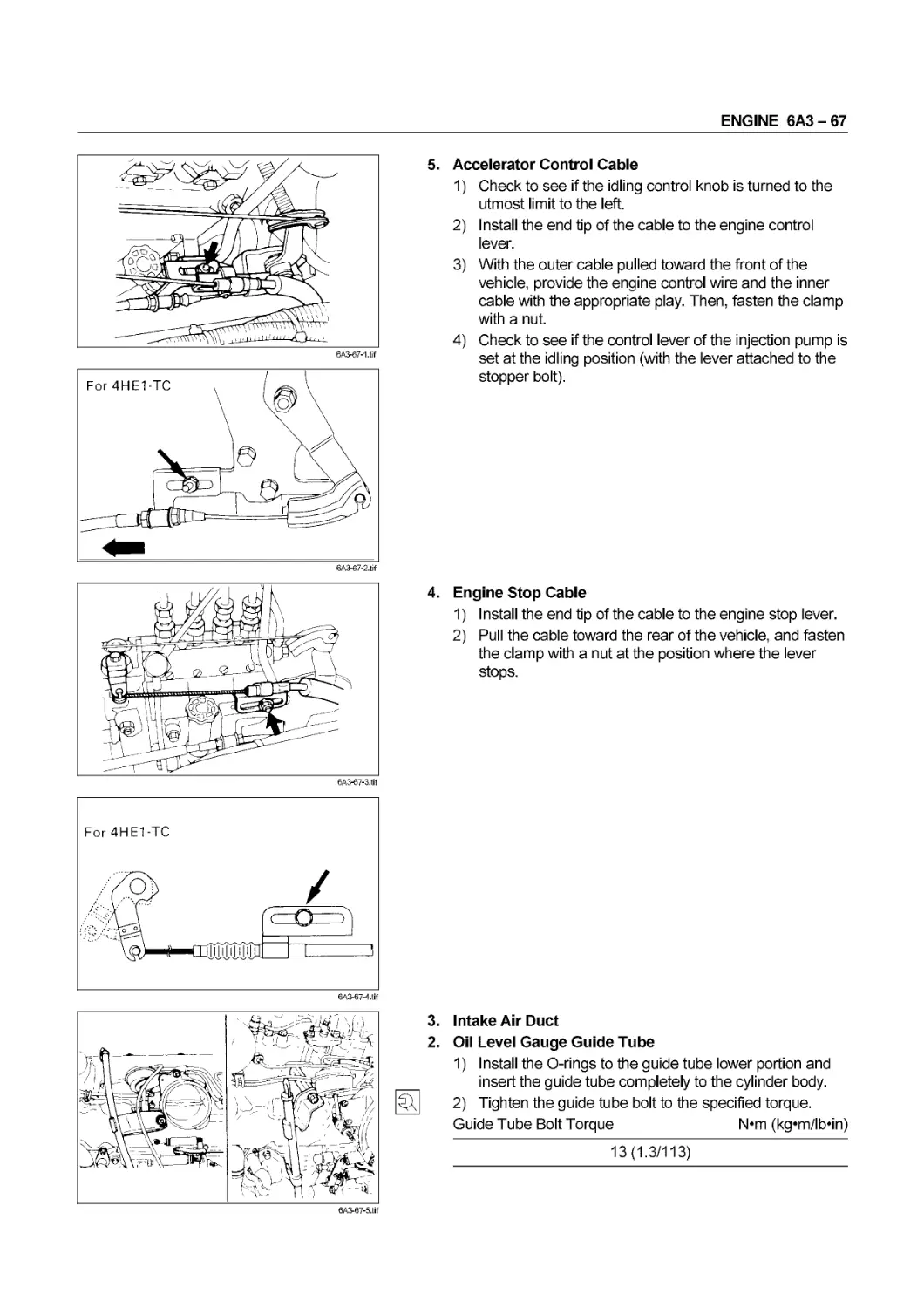
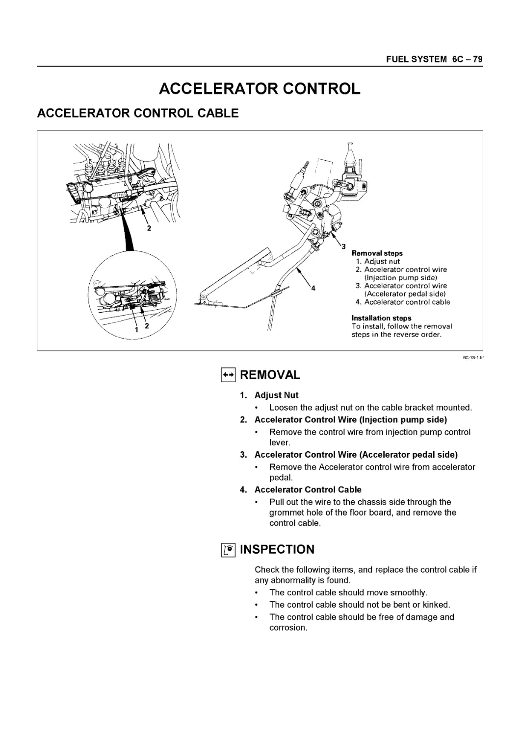
ACCELERATOR CONTROL
Accelerator Control Cable Adjustment
1. Loosen the accelerator cable clamp bolt ®.
2. Check that the idling control knob is in the engine idling
position.
3. Hold the accelerator lever ® in the fully closed position
and stretch the control cable ® in the direction
indicated by the arrow to remove any slack.
SERVICE INFORMATION 00 - 53
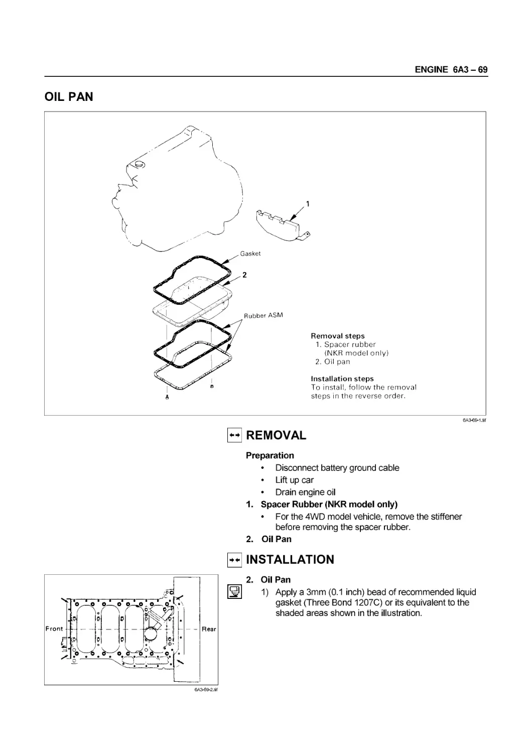
ENGINE STOP CONTROL
= Adjustment
1. Check that the key switch is either in the “LOCK”
position or removed from the engine.
2. Loosen the bolt ®.
3. Pull the fuel cut lever @ as far as possible and hold it.
4. Remove cable slackness ® by pulling the cable in the
direction of the arrow in the illustration.
5. Tighten the bolt ®.
Accelerator Pedal Adjustment
1. Press the accelerator pedal to the floorboard and hold
it.
2. Use the stopper bolt @ to adjust the clearance
between the stopper bolt end and the accelerator pedal
® lower face.
Accelerator Pedal Clearance mm (in)
0 - 2 (0 - 0.079)
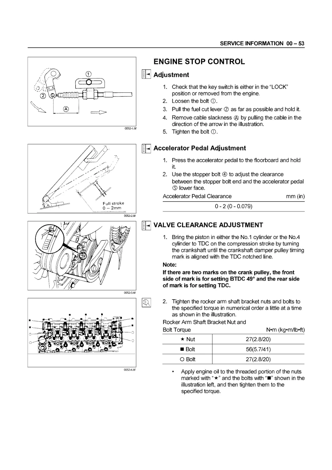
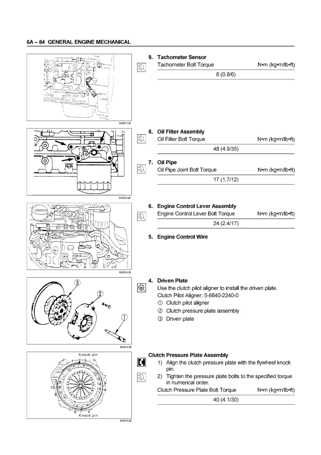
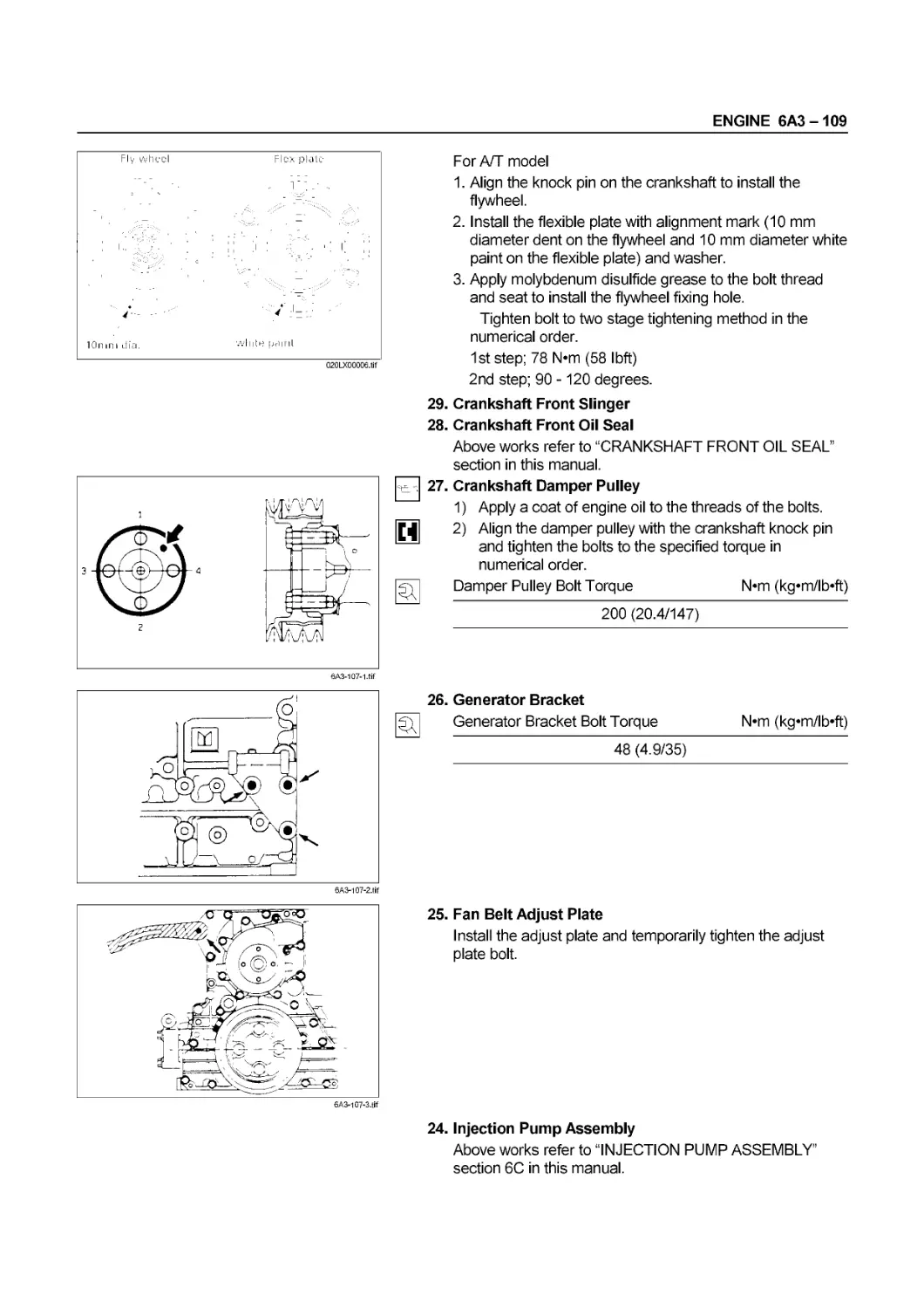
VALVE CLEARANCE ADJUSTMENT
1. Bring the piston in either the No. 1 cylinder or the No.4
cylinder to TDC on the compression stroke by turning
the crankshaft until the crankshaft damper pulley timing
mark is aligned with the TDC notched line.
Note:
If there are two marks on the crank pulley, the front
side of mark is for setting BTDC 49° and the rear side
of mark is for setting TDC.
0052-4.tif
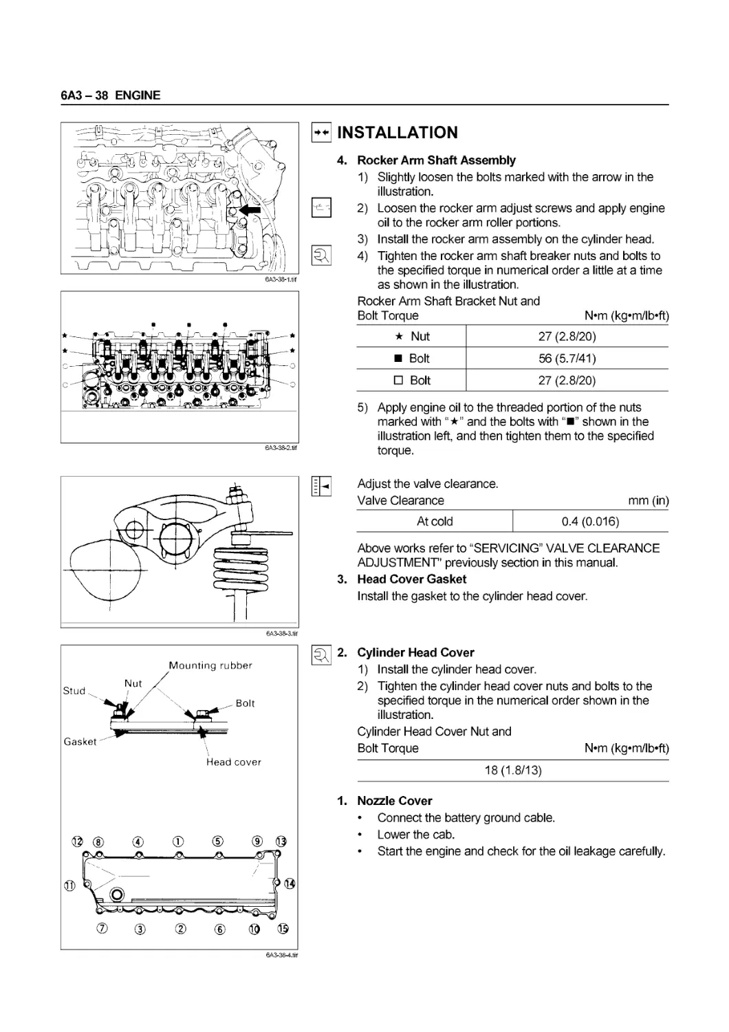
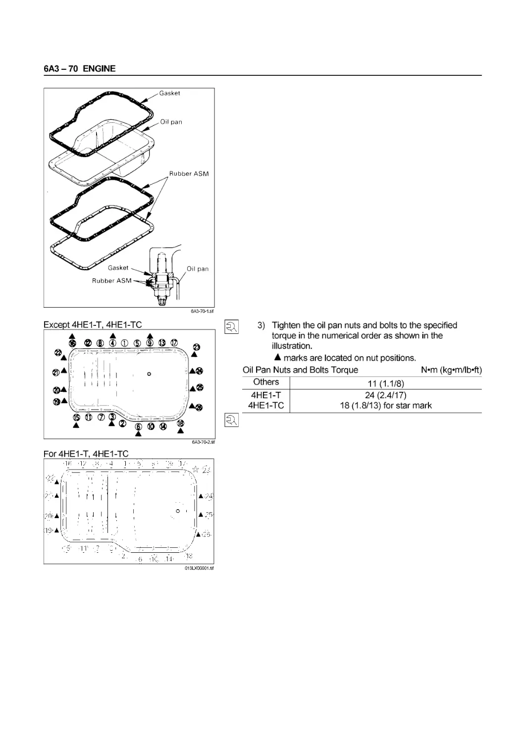
2. Tighten the rocker arm shaft bracket nuts and bolts to
the specified torque in numerical order a little at a time
as shown in the illustration.
Rocker Arm Shaft Bracket Nut and
Bolt Torque N* *m (кдтп/lb’ft)
★ Nut 27(2.8/20)
Bolt 56(5.7/41)
О Bolt 27(2.8/20)
• Apply engine oil to the threaded portion of the nuts
marked with and the bolts with shown in the
illustration left, and then tighten them to the
specified torque.
00 - 54 SERVICE INFORMATION
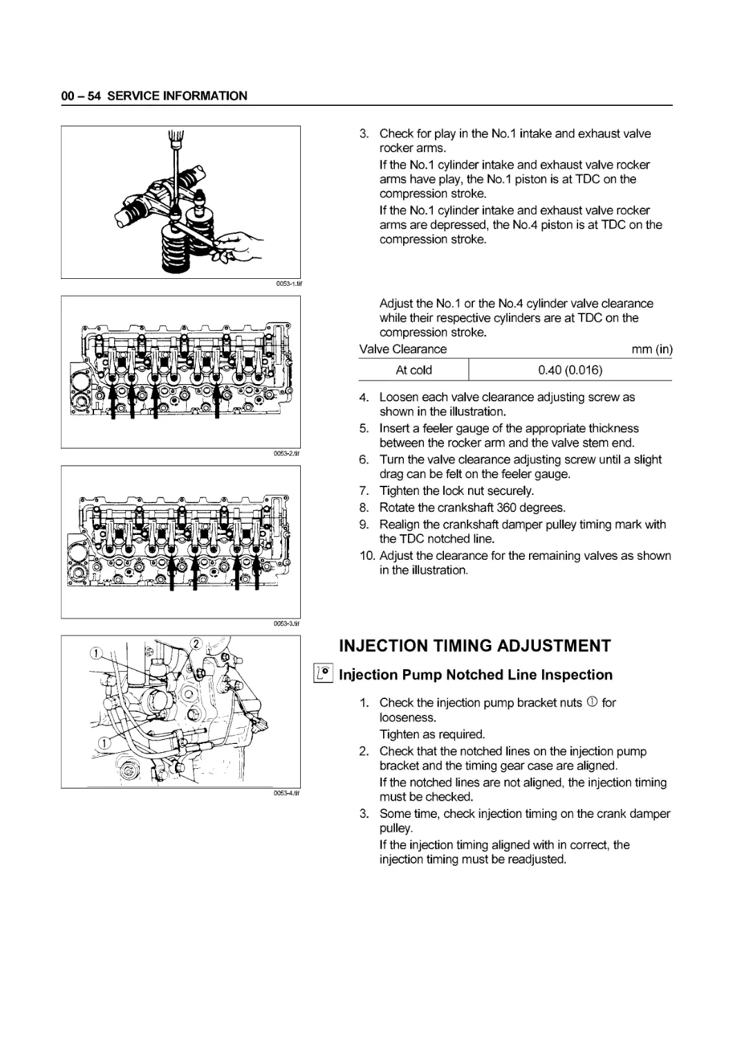
3. Check for play in the No.1 intake and exhaust valve
rocker arms.
If the No.1 cylinder intake and exhaust valve rocker
arms have play, the No.1 piston is at TDC on the
compression stroke.
If the No.1 cylinder intake and exhaust valve rocker
arms are depressed, the No.4 piston is at TDC on the
compression stroke.
0053-2.tif
Adjust the No.1 or the No.4 cylinder valve clearance
while their respective cylinders are at TDC on the
compression stroke.
Valve Clearance mm (in)
At cold
0.40 (0.016)
0053-3.tif
4. Loosen each valve clearance adjusting screw as
shown in the illustration.
5. Insert a feeler gauge of the appropriate thickness
between the rocker arm and the valve stem end.
6. Turn the valve clearance adjusting screw until a slight
drag can be felt on the feeler gauge.
7. Tighten the lock nut securely.
8. Rotate the crankshaft 360 degrees.
9. Realign the crankshaft damper pulley timing mark with
the TDC notched line.
10. Adjust the clearance for the remaining valves as shown
in the illustration.
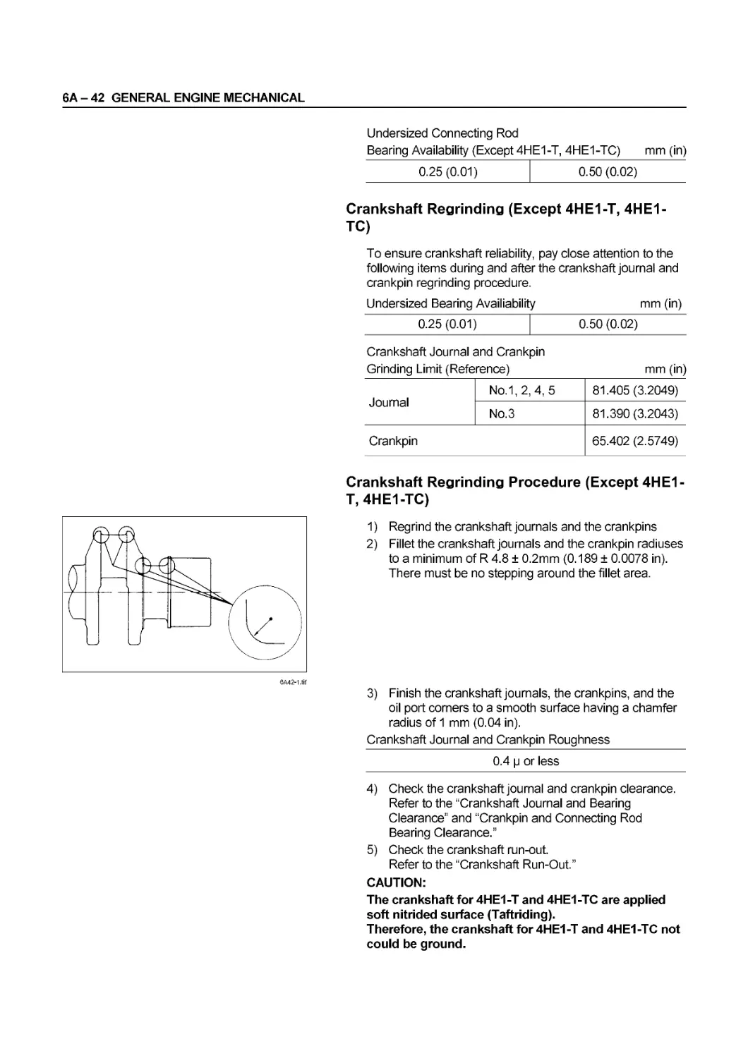
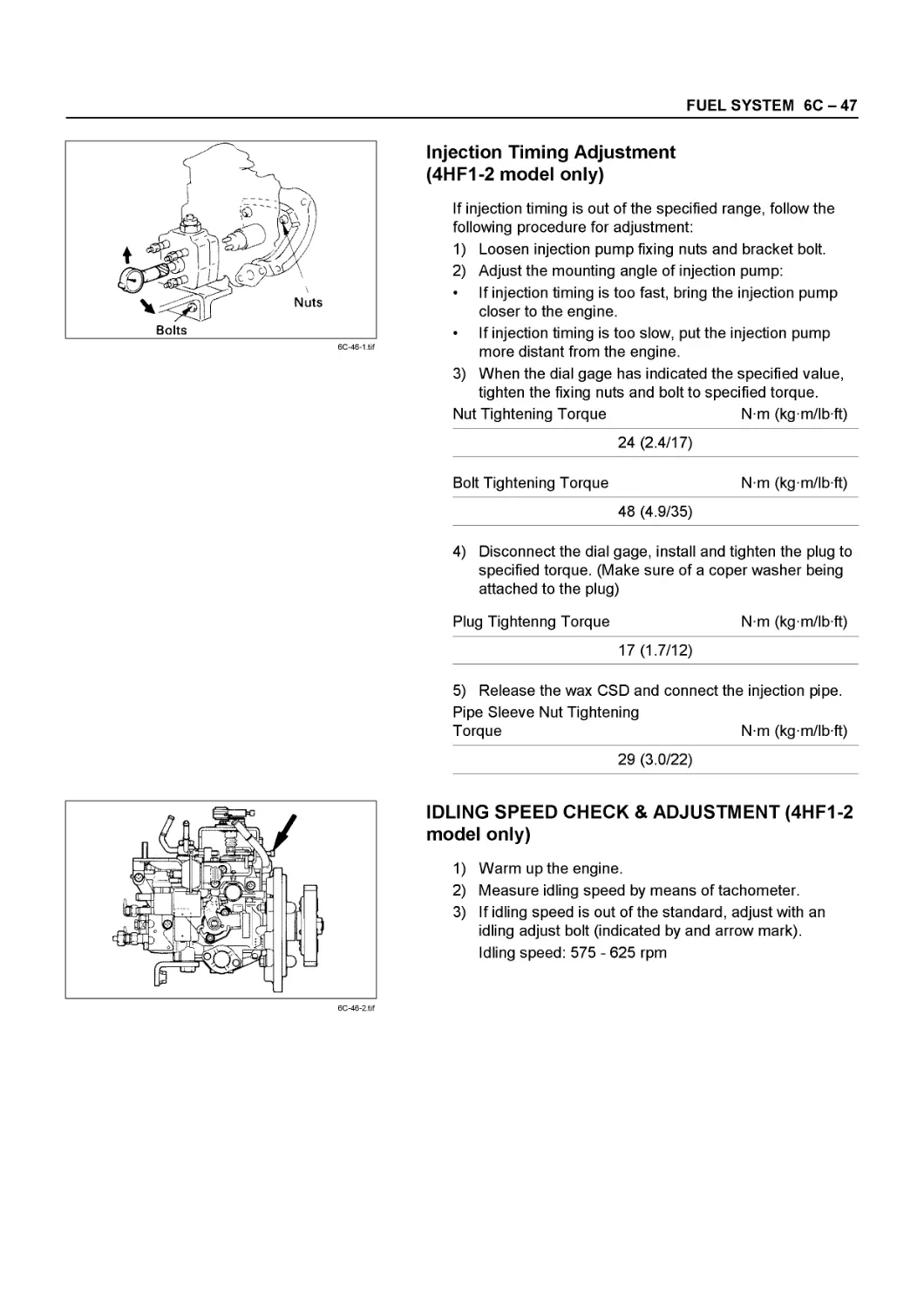
INJECTION TIMING ADJUSTMENT
L?| Injection Pump Notched Line Inspection
1. Check the injection pump bracket nuts ® for
looseness.
Tighten as required.
2. Check that the notched lines on the injection pump
bracket and the timing gear case are aligned.
If the notched lines are not aligned, the injection timing
must be checked.
3. Some time, check injection timing on the crank damper
pulley.
If the injection timing aligned with in correct, the
injection timing must be readjusted.
SERVICE INFORMATION 00 - 55
0054-1.tif
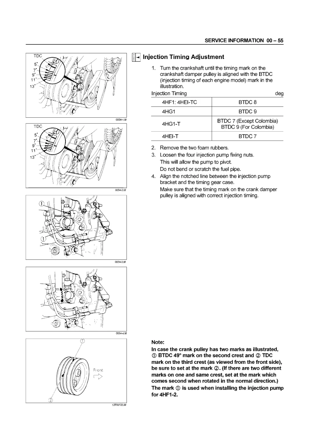
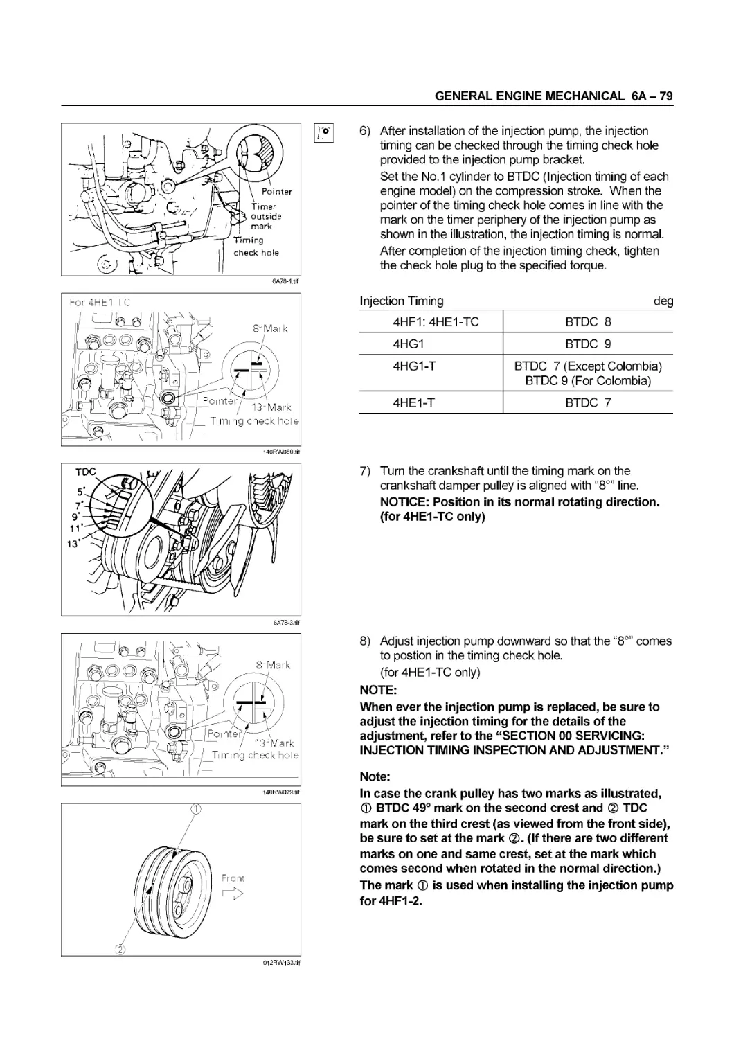
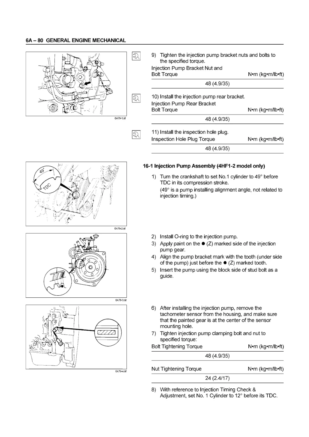
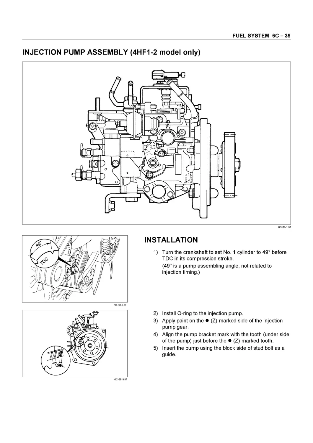
- Injection Timing Adjustment
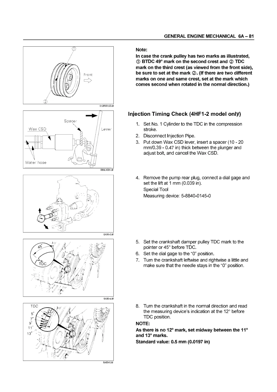
1. Turn the crankshaft until the timing mark on the
crankshaft damper pulley is aligned with the BTDC
(injection timing of each engine model) mark in the
illustration.
0054-2.tif
Injection Timing deg
4HF1:4HEI-TC BTDC 8
4HG1 BTDC 9
4HG1-T BTDC 7 (Except Colombia) BTDC 9 (For Colombia)
4HEI-T BTDC 7
0054-3.tif
2. Remove the two foam rubbers.
3. Loosen the four injection pump fixing nuts.
This will allow the pump to pivot.
Do not bend or scratch the fuel pipe.
4. Align the notched line between the injection pump
bracket and the timing gear case.
Make sure that the timing mark on the crank damper
pulley is aligned with correct injection timing.
l2RW133.tif
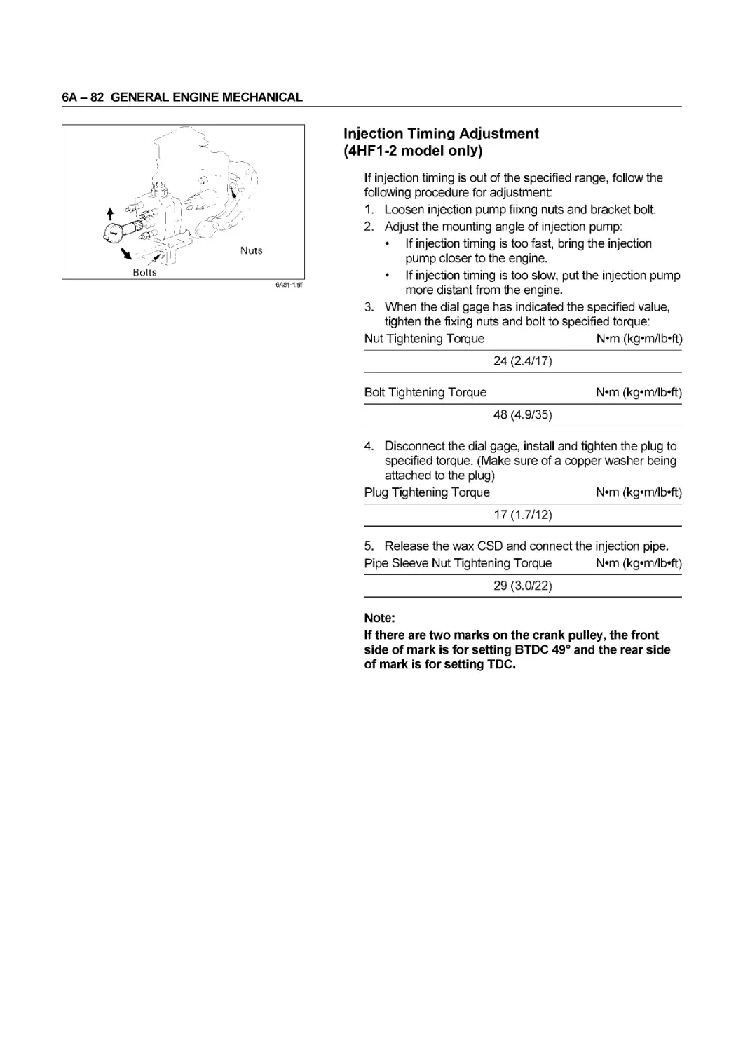
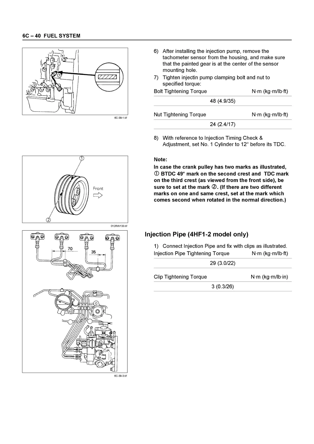
Note:
In case the crank pulley has two marks as illustrated,
Ф BTDC 49° mark on the second crest and ® TDC
mark on the third crest (as viewed from the front side),
be sure to set at the mark (If there are two different
marks on one and same crest, set at the mark which
comes second when rotated in the normal direction.)
The mark ф is used when installing the injection pump
for4HF1-2.
00 - 56 SERVICE INFORMATION
080LXQ0l.tif
5. Tighten the injection pump fixing nuts to the specified
torque.
Injection Pump Fixing Nut Torque N*m (kg*m/lb*ft)
25 (2.6/19)
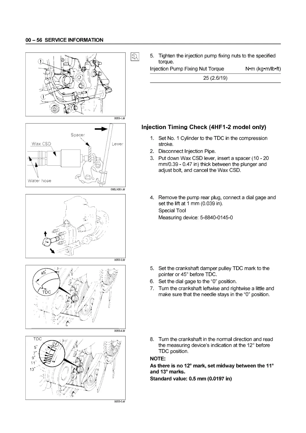
Injection Timing Check (4HF1-2 model only)
1. Set No. 1 Cylinder to the TDC in the compression
stroke.
2. Disconnect Injection Pipe.
3. Put down Wax CSD lever, insert a spacer (10-20
mm/0.39 - 0.47 in) thick between the plunger and
adjust bolt, and cancel the Wax CSD.
4. Remove the pump rear plug, connect a dial gage and
set the lift at 1 mm (0.039 in).
Special Tool
Measuring device: 5-8840-0145-0
5. Set the crankshaft damper pulley TDC mark to the
pointer or 45° before TDC.
6. Set the dial gage to the “0” position.
7. Turn the crankshaft leftwise and rightwise a little and
make sure that the needle stays in the “0” position.
0055-5.tif
8. Turn the crankshaft in the normal direction and read
the measuring device’s indication at the 12° before
TDC position.
NOTE:
As there is no 12° mark, set midway between the 11°
and 13° marks.
Standard value: 0.5 mm (0.0197 in)
SERVICE INFORMATION 00 - 57
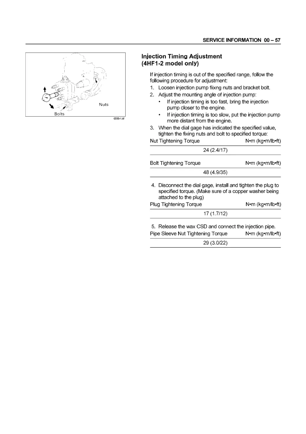
Injection Timing Adjustment
(4HF1-2 model only)
If injection timing is out of the specified range, follow the
following procedure for adjustment:
1. Loosen injection pump fiixng nuts and bracket bolt.
2. Adjust the mounting angle of injection pump:
• If injection timing is too fast, bring the injection
pump closer to the engine.
• If injection timing is too slow, put the injection pump
more distant from the engine.
3. When the dial gage has indicated the specified value,
tighten the fixing nuts and bolt to specified torque:
Nut Tightening Torque N«m (kg«m/lb*ft)
24 (2.4/17)
Bolt Tightening Torque N*m (kg*m/lb*ft)
48 (4.9/35)
4. Disconnect the dial gage, install and tighten the plug to
specified torque. (Make sure of a copper washer being
attached to the plug)
Plug Tightening Torque N*m (kg«m/lb*ft)
17(1.7/12)
5. Release the wax CSD and connect the injection pipe.
Pipe Sleeve Nut Tightening Torque N*m (kg*m/lb*ft)
29 (3.0/22)
00 - 58 SERVICE INFORMATION
COMPRESSION PRESSURE
MEASUREMENT
1. Start the engine and allow it to warm up.
Engine Coolant Temperature: Above 80°C (176°F)
2. Stop the engine.
3. Remove the following parts.
• Glow plugs.
• In case VE pump;
Fuel cut solenoid connector.
• In case line pump;
Number 17 fuse in fuse box.
4. Set the adapter and the compression gauge to the
No.1 cylinder glow plug hole.
Compression Gauge (With Adapter): 5-8840-2675-0
Adapter: 5-8531-7001-0
5. Connect a tachometer and check that engine cranking
speed is 200 rpm or higher.
6. Turn the engine over with the starter motor and take
the compression gauge reading.
7. Repeat the procedure (steps 4,5 and 6) for the
remaining cylinders.
Compression Pressure kPa (kg/cm2/psi) at 200 rpm
Standard More than 2,942 (30/426)
Limit for use 2,157(22/312)
Variance in pressure between cylinders Less than 294 (3/43)
If the measured valve is less than the specified limit, above
works refer to “TROUBLESHOOTING” Section in this
manual.
QUICK-ON-START II SYSTEM
L?| Inspection Procedure
1. Disconnect the thermoswitch connection on the
thermostat outlet pipe.
2. Turn the key switch to the “ON” position.
If the Quick-ON-Start II system is operating properly,
the flow relay will make a clicking sound within three
seconds.
3. Measure the glow plug terminal voltage with a circuit
tester as soon as possible after turning the key switch
to the “ON” position.
4. Check the glow plug heating time.
Approximate Glow Plug Heating Time sec
18
SERVICE INFORMATION 00 - 59
FIXING TORQUE
CYLINDER HEAD, HEAD GASKET AND HEAD COVER N-m (kg-m/lb-ft)
18 (1.8/13)
0058-1.tif
00 - 60 SERVICE INFORMATION
CYLINDER HEAD, HEAD GASKET AND HEAD COVER
N«m (kg«m/lb’ft)
0059-2.tif
SERVICE INFORMATION 00 - 61
CRANKSHAFT, FLYWHEEL, DAMPER PULLEY, CONNECTING
ROD AND OIL PAN
N«m (kgem/lb’ft)
1st 2nd
78(8.0/58) 90 - 120
1st 2nd 3rd
39 (4.0/29) 60° 30°
Apply with molybdenum disulfide grease
to the bolt threads and setting faces
0060-1.tif
00 - 62 SERVICE INFORMATION
GEAR TRAIN, CAMSHAFT, ROCKER ARM SHAFT, FRONT RETAINER,
FLYWHEEL HOUSING
N«m (kgem/lb’ft)
0061-1.tif
SERVICE INFORMATION 00 - 63
INLET COVER AND EXHAUST MANIFOLD N-m (kg-m/lb-ft)
4HF1 / 4HG1 Engine
| 13(1.9/12) |
[74(3.5/25) |
0062-W
00 - 64 SERVICE INFORMATION
INLET COVER AND EXHAUST MANIFOLD N-m (kg-m/lb-ft)
4НЕ1-Т/4HE1-TC Engine
0063-1.tif
SERVICE INFORMATION 00 - 65
036LX007.tif
00 - 66 SERVICE INFORMATION
WATER PUMP, WATER OUTLET PIPE, OIL PUMP, OIL COOLER
AND OIL FILTER
N«m (kgem/lb’ft)
0064-1.tif
SERVICE INFORMATION 00 - 67
GENERATOR, STARTER AND GLOW PLUG
N«m (kg«m/lb’ft)
0065-1.tif
00 - 68 SERVICE INFORMATION
ENGINE MOUNTING N-m (kg«m/lb«ft)
0066-1 .trf
SERVICE INFORMATION 00 - 69
INJECTION PUMP, INJECTION PIPE AND FUEL PIPE N-m (kg-m/lb-ft)
3 (0.3/2)
0067-1.tif
00 - 70 SERVICE INFORMATION
Ф SPECIAL TOOLS
Item No. Illustration Part No. Part Name Remarks
1 1-8522-1097-0 Oil filter wrench
2 rj 5-8840-2675-0 Compression gauge with adapter
3 5-8531-7001-0 Compression gauge adapter
4 5-8840-0266-0 Angle gauge For angular bolt and nut tightening
5 5-8840-9018-0 Piston installer
6 5-8840-2230-0 Crankshaft stopper
7 [%?'< 1 5-8840-2360-0 Slinger puller For crankshaft front and rear slinger remove
8 X® J® Q^) 5-8840-2431-0 Oil seal setting tool kit For crankshaft front and rear oil seal and slinger install
9 л *Tj 1 VrJV.TKM J J. i — J 5-8840-2240-0 Clutch pilot aligner
10 5-8840-2228-0 Valve spring compressor
SERVICE INFORMATION 00 - 71
Item No. Illustration Part No. Part Name Remarks
11 5-8840-2227-0 Valve guide replacer
12 8-9439-6815-0 Valve guide seal installer
13 zo 5-8840-2222-0 Sealing cup installer
14 Ш 9-8523-1169-0 Cylinder liner remover
15 5-8840-2220-0 5-8840-2397-0 (4HG1) Cylinder liner remover ankle
16 5-8840-2337-0 Cylinder Liner Installer (4HE1-T and 4HE1-TC only)
17 Xg'^S»'». 8-9439-6818-0 Crankshaft gear remover
18 8-9439-6819-0 Crankshaft gear installer
19 5-8840-2340-0 Conrod bush replacer
20 5-8840-2094-0 Oil filter wrench 4WD model
00 - 72 SERVICE INFORMATION
LUBRICATING SYSTEM
GENERAL DESCRIPTION
LUBRICATING OIL FLOW
Engine О I Pan
The engine lubricating system is a full flow type.
Lubricating oil is pumped from the oil pump to the cylinder body oil gallery through the oil filter and the oil cooler. It
is then delivered to the vital parts of the engine from the cylinder body oil gallery.
Oil jets installed on the cylinder body spray engine oil to the piston inside faces to achieve maximum cooling effect.
GENERAL ENGINE MECHANICAL 6A - 1
SECTION 6A
ENGINE MECHANICAL
CONTENTS
PAGE
Cylinder Head...................................................... 6A- 2
Valve Spring, Valve Guide Oil Seal, Valve, Valve Guide............. 6A - 8
Camshaft........................................................... 6A-16
Rocker Arm Assembly................................................ 6A -19
Oil Pump........................................................... 6A-23
Crankshaft......................................................... 6A-29
Piston and Connecting Rod.......................................... 6A - 53
Cylinder Block..................................................... 6A - 63
6А - 2 GENERAL ENGINE MECHANICAL
CYLINDER HEAD
Reassembly steps
To reassemble, follow the disassembly
steps in the reverse order.
Disassembly steps
1. Glow plug connector
2. Glow plug
3. Injection nozzle holder assembly
4. Rocker arm shaft assembly
5. Valve cap
6. Camshaft bearing cap
7. Camshaft bearing upper
8. Camshaft assembly
9. Camshaft bearing lower
10. Cylinder head
NOTE:
• During disassembly, be sure that the valve train
components are kept together and identified so
that they can be re-installed in their original
locations.
• Before removing the cylinder head from the engine
and before disassembling the valve mechanism,
make a compression test and note the results.
* DISASSEMBLY
1. Glow Plug Connector
2. Glow Plug
3. Injection Nozzle Holder Assembly
Mark the nozzle holder assemblies fitting positions by
tagging each nozzle holder assembly with the cylinder
number from which it was removed.
GENERAL ENGINE MECHANICAL 6A - 3
6A3-1.tif
6A3-2.tif
4. Rocker Arm Shaft Assembly
1) Loosen the rocker arm shaft bracket nuts and bolts in
numerical order a little at a time and remove the rocker
arm shaft assembly with the camshaft brackets.
2) Leave the @ indicated bolt unremoved on this
occasion, since it is the rocker arm fixing bolt.
W CAUTION:
Failure to loosen the rocker arm shaft bracket nuts and
bolts in numerical order a little at a time will adversely
affect the rocker arm shaft.
5. Valve Cap
CAUTION:
Take sufficient care not to let valve caps fall into the
gear case or oil return hole.
6. Camshaft Bearing Cap
7. Camshaft Bearing Upper
8. Camshaft Assembly
9. Camshaft Bearing Lower
If the camshaft bearings are to be reinstalled, mark their
fitting positions by tagging each bearing with the cylinder
number from which it was removed.
6A3-3.tif
10. Cylinder Head
Loosen the cylinder head bolts in numerical order a little at
a time.
V CAUTION:
Failure to loosen the cylinder head bolts in numerical order
a little at a time will adversely affect the cylinder head lower
surface.
• Refer to Section 6A3 “CYLINDER HEAD”.
H CLEAN
• Cylinder head bolts
• Cylinder head
Carefully remove all varnish, soot and carbon to the
bare metal. Do not use a motorized wire brush on any
gasket sealing surface.
6А - 4 GENERAL ENGINE MECHANICAL
° INSPECTION AND REPAIR
Make the necessary adjustments, repairs, and part
replacements if excessive wear or damage is discovered
during inspection.
• Cylinder head gasket and mating surfaces for leaks,
corrosion and blow-by. If the gasket has failed,
determine the cause;
Improper installation
- Loose or warped cylinder head
Insufficient torque on head bolts
- Warped case surface
1) Cylinder head bolts for damaged threads or stretching
and damaged heads caused by improper use of tools.
CAUTION:
Suspected bolts must be replaced.
2) Cylinder head for cracks, especially between valve
seats and in the exhaust ports.
3) Cylinder head deck for corrosion, sand particles in
head and porosity.
CAUTION:
Do not attempt to weld the cylinder head. Replace it.
6A4-l.tif
IjO, Cylinder Head Lower Face Warpage
1) Use a straight edge and a feeler gauge to measure the
four sides and the two diagonals of the cylinder head
face.
2) If the measured values exceed the specified limit, the
cylinder head must be replaced.
NOTE: Do not regrind the cylinder head lower face. Cylinder Head Lower Face Warpage mm (in)
Standard Limit
0.05 (0.002) or less 0.2 (0.008)
6A4-2.trf
Manifold Fitting Face Warpage
Use a straight edge and a feeler gauge to measure the
manifold cylinder head fitting face warpage.
Regrind the manifold cylinder head fitting faces if the
measured value is greater than the specified limit.
Manifold Fitting Face Warpage mm (in)
Standard Limit
0.05 (0.002) or less 0.2 (0.008)
GENERAL ENGINE MECHANICAL 6A - 5
Exhaust Manifold Warpage
Use a straight edge and a feeler gauge to measure the
manifold cylinder head fitting face warpage.
If the measured values exceed the specified limit, the
manifold must be replaced.
Exhaust Manifold Warpage mm(in)
Standard Limit
0.05 (0.002) or less 0.24 (0.008)
REASSEMBLY
Install the cylinder head gasket with its “PART NUMBER”
— mark facing up and toward the left of the engine.
CAUTION:
Do not reuse the cylinder head gasket.
Above works refer to “CYLINDER BLOCK” section in this
manual.
6A5-4.tif
10. Cylinder Head
1) Align the cylinder body dowels and the cylinder head
dowel holes.
2) Carefully place the cylinder head on the cylinder head
gasket.
3) Apply a coat of molybdenum disulfide grease to the
M14 cylinder head bolt threads and setting faces and
apply a coat of engine oil to the M10 cylinder head bolt
threads and setting faces.
4) Use the angular tightening method to tighten the bolts
(M14) to the specified torque in three steps following
the numerical order shown in the illustration.
Cylinder Head Bolt Torque (M14) (© ~@)
N*m (kg*m/lb*ft)
1st step 2nd step 3rd step
98(10/72) 147 (15/108) 30° - 60°
5) Tighten the cylinder head to the flywheel housing bolts
(M10) to the specified torque.
Cylinder Head Bolt Torque (M10) (@~@)
N*m (kg*m/lb*ft)
38 (3.9/28)
6А - 6 GENERAL ENGINE MECHANICAL
6A6-1 .tif
9.
8.
6A6-2.tif
Camshaft Bearing Lower
Camshaft Assembly
1) Turn the crankshaft in the direction of normal rotation
until the timing mark on the crankshaft damper pulley is
aligned with the TDC notched line. (Confirm that the
No. 1 cylinder piston comes to the compression top
dead center.)
2) Apply engine oil to the camshaft journal and the
camshaft bearing surfaces before installation.
3) Carefully align the camshaft gear “I” mark and the
cylinder head upper face shown in the illustration.
Camshaft Bearing Upper
Camshaft Bearing Cap
1) Install the bearing caps with the bearing cap head mark
(arrow) facing forward.
2) Apply a coat of engine oil to the bearing cap bolt and
stud threads.
6A6-3.tif
3) Tighten the bearing cap bolts and studs to the specified
torque.
Camshaft Bearing Cap Nut and Bolt Torque
N*m (kg*m/lb*ft)
27 (2.8/20)
6A6-4.tif
5. Valve Cap
Apply engine oil to the inside of the valve caps and install
them to the valve stem end.
у CAUTION:
Take sufficient care not to let valve caps fall into the
gear.
6A6-5.tif
4. Rocker Arm Shaft Assembly
1) Temporarily tighten the bolts marked with the arrow in
the illustration.
2) Loosen the rocker arm adjust screws and apply engine
oil to the rocker arm roller portions.
3) Install the rocker arm assembly on the cylinder head.
GENERAL ENGINE MECHANICAL 6A - 7
4) Tighten the rocker arm shaft bracket nuts and bolts to
the specified torque in numerical order a little at a time
as shown in the illustration.
Rocker Arm Shaft Bracket Nut and
Bolt Torque N*m (kg*m/lb*ft)
★ Nut 27 (2.8/20)
Bolt 56(5.7/41)
□ Bolt 27 (2.8/20)
5) Apply engine oil to the threaded portion of the nuts
marked with and the bolts with shown in the
illustration left, and tighten them to the specified torque.
6A7-2.tif
Adjust the valve clearance.
Valve Clearance mm (in)
At cold 0.4 (0.016)
Above works refer to “SERVICING” “VALVE CLEARANCE
ADJUSTMENT” previously section in this manual.
6A7-3.tif
Injection Nozzle Holder Assembly
Tighten the nozzle holder flange nuts to the specified
torque in the numerical order shown in the illustration.
Nozzle Holder Flange Nut Torque N*m (kg*m/lb*ft)
19(1.9/14)
Glow Plug Glow Plug Torque N*m (kg*m/lb*ft)
23 (2.3/17)
1. Glow Plug Connector
6А - 8 GENERAL ENGINE MECHANICAL
VALVE SPRING, VALVE GUIDE OIL SEAL, VALVE, VALVE GUIDE
Disassembly steps
1. Split collar
2. Spring upper seat
3. Valve spring
4. Intake and exhaust valve
5. Valve guide seal
6. Spring lower seat
Reassemblt steps
To reassemble, follow the disassebly
steps in the reverse order.
6A8-1.tif
* DISASSEMBLY
Preparation
• Remove all the parts only with the cylinder head
assembly left.
(Above works refer to “CYLINDER HEAD GASKET”
section 6A3 in this manual.)
6A8-2.tif
1. Cotter Collar
1) Place the cylinder head on a flat wooden surface.
jTI 2) Use the valve spring compressor to remove the cotter
— collar.
Do not allow the valve to fall from the cylinder head.
Valve Spring Compressor: 5-8840-2228-0
2. Spring Upper Seat
3. Valve Spring
GENERAL ENGINE MECHANICAL 6A - 9
6A9-1.tif
4. Intake and Exhaust Valve
If the intake and exhaust valves are to be reinstalled, mark
their installation positions by tagging each valve with the
cylinder number from which it was removed.
If the intake and exhaust valves are to be replaced, the
valve guides must also be replaced.
5. Valve Guide Seal
6. Spring Lower Seat
INSPECTION AND REPAIR
Make the necessary adjustments, repairs, and part
replacements if excessive wear or damage is discovered
during inspection.
Valve Spring Free Height
Use a vernier caliper to measure the valve spring free
height.
If the measured valve is less than the specified limit, the
valve spring must be replaced.
mm (in)
Valve Spring Free Height
4HF1: 4HF1-2: 4HG1:4HG1-T
Nominal Size Limit
62.5 (2.46) 59.4 (2.34)
4HE1-T: 4HE1-TC:
Nominal size Limit
Intake Inner 53.2 (2.094) 50.1 (1.972)
Intake Outer 55.6 (2.189) 52.5 (2.067)
Exhaust Inner 58.6 (2.307) 55.5(2.185)
Exhaust Outer 62.0 (2.441) 58.9 (2.319)
6А -10 GENERAL ENGINE MECHANICAL
Valve Spring Squareness
Use a surface plate and a square to measure the valve
spring squareness.
If the measured value exceeds the specified limit, the valve
spring must be replaced.
Valve Spring Squareness mm (in)
Limit 1.0 (0.04)
Valve Spring Tension
Use spring tester to measure the valve spring tension.
If the measured valve is less than the specified limit, the
valve spring must be replaced.
Valve Spring Tension N (kg/lb)
Set Length mm(in) Standard Limit
47.0 (1.85) 414-477 (42.2-48.6/93-107) 401 (40.9/98)
Valve Guide
CAUTION:
Taking care not to damage the valve seat contact
surface, when removing carbon adhering to the valve
head.
Carefully inspect the valve stem for scratching or
abnormal wear. If these conditions are present, the
valve and the valve guide must be replaced as a set.
Valve Stem and Valve Guide Clearance
(Measuring Method-I)
1) Set the dial indicator to the valve stem measuring point.
2) Move the valve stem end from side to side.
Read the dial indicator.
Note the total indicator reading.
If the measured values exceed the specified limit, the
valve and the valve guide must be replaced as a set.
Total Dial Indicator Reading
(Valve Stem and Valve Guide Clearance) mm (in)
Valve Standard Limit
Intake Valve 0.038-0.071 (0.0015-0.0028) 0.20 (0.0079)
Exhaust Valve 0.064 - 0.096 (0.0025 - 0.0038) 0.25 (0.0098)
GENERAL ENGINE MECHANICAL 6A - 11
(Measuring Method-ll)
1) Measure the valve stem outside diameter.
Refer to the “Valve Stem Outside Diameter.”
2) Use a caliper calibrator or a telescoping gauge to
measure the valve guide inside diameter.
3) Calculate the clearance between the valve guide inside
diameter and the valve stem outside diameter.
If the clearance exceeds the specified limit, the valve
and the valve guide must be replaced as a set.
Valve Stem Outside Diameter
Measure the valve stem diameter at three points.
If the measured valve is less than the specified limit, the
valve and the valve guide must be replaced as a set.
6Al1-3.tif
Valve Stem Outside Diameter mm (in)
Valve Standard Limit
Intake Valve 8.946 - 8.962 (0.3522 - 0.3528) 8.88 (0.350)
Exhaust Valve 8.921 - 8.936 (0.3512-0.3529) 8.80 (0.346)
Valve Guide Replacement
** Valve Guide Removal
@ Use a hammer and the valve guide replacer to drive out
the valve guide from the cylinder head lower face.
Valve Guide Replacer: 5-8840-2227-0
6A11-4.tif
4* Valve Guide Installation
t1) Apply engine oil to the valve guide outer circumference.
— 2) Attach the valve guide installer to the valve guide.
Valve Guide Replacer: 5-8840-2227-0
3) Use a hammer to drive the valve guide into position
from the cylinder head upper face.
6А -12 GENERAL ENGINE MECHANICAL
4) Measure the height (H) of the valve guide upper end
from the cylinder head upper face.
Valve Guide Upper End Height (H) mm (in)
14.1 ±0.2 (0.555 ± 0.008)
NOTE:
If the valve guide has been removed, both the valve
and the valve guide must be replaced as a set.
VALVE AND VALVE SEAT INSERT
Valve Thickness and Depression
6Al2-2.tif
1) Measure the valve thickness.
If the measured value is less than the specified limit,
the valve and the valve seat insert must be replaced as
a set.
Intake and Exhaust Valve Thickness mm( in)
Valve Nominal Size Limit
Inlet 1.8(0.071) 1.3(0.051)
Exhaust 1.75 (0.069) 1.3(0.051)
2) Install the new valve ® to the cylinder head ®.
3) Use a depth gauge or a straight edge with steel rule to
measure the valve depression from the cylinder head
lower surface.
If the measured value exceeds the specified limit, the
valve seat insert and/or the valve must be replaced.
Intake and Exhaust Valve Depression mm (in)
Standard Limit
0.7-1.2 (0.028-0.047) 2.5(0.098)
6Al2-4.tif
<0, Valve Contact Width
1) Check the valve contact faces for roughness and
unevenness.
Make smooth the valve contact surfaces.
2) Measure the valve contact width.
If the measured value exceeds the specified limit, the
valve seat insert must be corrected or replaced.
Valve Contact Width mm (in)
Valve Nominal Size Limit
Intake 2.5 (0.098) 3.0(0.118)
Exhaust 2.0 (0.079) 2.5 (0.098)
GENERAL ENGINE MECHANICAL 6A - 13
Contact Surface Angle on Valve Seat on Valve
1) Measure contact surface angle on valve seat.
2) If the measured value exceeds the limit, replace valve,
valve guide and valve seat as a set.
Standard Degrees
45°
6A13-1.tif
Valve Seat Insert Replacement
** Valve Seat Insert Removal
1) Arc weld the entire inside circumference (T) of the valve
seat insert (2).
2) Allow the valve seat insert to cool for a few minutes.
This will invite contraction and make removal of the
valve seat insert easier.
3) Use a screwdriver ® to pry the valve seat insert free.
Take care not to damage the cylinder head @.
4) Carefully remove carbon and other foreign material
from the cylinder head insert bore.
V
Ive Seat Insert Installation
1) Carefully place the attachment ® (having a smaller
outside diameter than the valve seat insert) on the
valve seat insert (2).
NOTE:
The smooth side of the attachment must contact the
valve seat insert.
2) Use a bench press ® to gradually apply pressure to
the attachment and press the valve seat insert into
place.
CAUTION:
Do not apply an excessive amount of pressure with the
bench press. Damage to the valve seat insert will
result.
3) The valve should be lapped before final assembly to
ensure a good valve seal.
Above works refer to “Valve Seat Insert Correction"
section in this manual.
6А -14 GENERAL ENGINE MECHANICAL
6A14-1.tif
6A14-2.tif
6Al4-3.tif
6Al4-4.tif
Valve Seat Insert Correction
1) Remove the carbon from the valve seat insert surface.
2) Use a valve cutter (15°, 45°, and 75° blades) to
minimize scratches and other rough areas. This will
bring the contact width back to the standard value.
Remove only the scratches and rough areas. Do not
cut away too much. Take care not to cut away
unblemished areas of the valve seat surface.
Valve Seat Angle Degrees
45°
NOTE:
Use an adjustable valve cutter pilot.
Do not allow the valve cutter pilot to wobble inside the
valve guide.
3) Apply abrasive compound to the valve seat insert
surface.
4) Insert the valve into the valve guide.
5) Turn the valve while tapping it to fit the valve seat
insert.
6) Check to see if the valve contact width is correct.
7) Check to see if the valve seat insert surface is in
contact with the entire circumference of the valve.
REASSEMBLY
6. Spring Lower Seat
5. Valve Guide Seal
t1) Apply a coat of engine oil to the valve guide seal inner
face.
2) Use a valve guide seal installer to install the valve
— guide seal to the valve guide
Valve Guide Seal Installer: 8-9439-6815-0
GENERAL ENGINE MECHANICAL 6A - 15
6Al5-2.tif
2.
6A15-3.tif
Intake and Exhaust Valve
1) Apply a coat of engine oil to each valve stem before
installation.
2) Install the intake and exhaust valve.
3) Turn the cylinder head up to install the valve spring.
Take care not to allow the installed valves to fall free.
Valve Spring
Install the valve spring with its fine pitched (or painted) end
side sown.
Spring Upper Seat
Cotter Collar
1) Use the valve spring compressor to push the valve
spring into position.
Valve Spring Compressor: 5-8840-2228-0
2) Install the cotter collar to the valve stem.
3) Set the cotter collar by tapping around the head of the
collar with a rubber hammer.
6А - 16 GENERAL ENGINE MECHANICAL
CAMSHAFT
Disassembly steps
1. Rocker arm shaft assembly
2. Valve cap
3. Camshaft bearing cap
4. Camshaft bearing upper
5. Camshaft assembly
6. Camshaft bearing lower
7. Camshaft gear
8. Key
Reassembly steps
To install, follow the disassembly
steps in the reverse order.
6A16-1.tif
* DISASSEMBLY
6Al6-2.tif
1. Rocker Arm Shaft Assembly
2. Valve Cap
3. Camshaft Bearing Cap
4. Camshaft Bearing Upper
5. Camshaft Assembly
6. Camshaft Bearing Lower
Above works refer to “CYLINDER HEAD” section in this
manual.
7. Camshaft Gear
Use the universal puller to pull out the camshaft gear.
Universal puller: 5-8840-2027-0/(5-8840-0086-0)
8. Key
GENERAL ENGINE MECHANICAL 6A - 17
INSPECTION AND REPAIR
Make the necessary adjustments, repairs, and part
replacements if excessive wear or damage is discovered
during inspection.
6A17-I.tif
Camshaft End Play
Use a thickness gauge to measure the clearance between
the camshaft gear ® and the camshaft bracket ®.
If the measured value exceeds the specified limit, the
camshaft gear or the camshaft must be replaced.
Camshaft End Play mm (in)
Standard Limit
0.085 - 0.205 (0.0033-0.0081) 0.25 (0.0098)
Camshaft Journal Diameter
Use a micrometer to measure each camshaft journal
diameter in two directions (® and ®). If the measured
value is less than the specified limit, the camshaft must be
replaced.
Camshaft Journal Diameter mm (in)
Standard Limit
39.950 - 39.975 (1.5728-1.5738) 39.850(1.569)
6Al7-3.tif
Cam Height
Measure the cam height “H” with a micrometer. If the
measured value is less than the specified limit, the
camshaft must be replaced.
Cam Height “H” mm (in)
Engine model Standard Limit
Other model 52.8 (2.078) 51.8(2.039)
4HE1-T 4HE1-TC 53.6 (2.110) 52.6 (2.071)
6Al7-4.tif
Camshaft Run-Out
1) Mount the camshaft on V-blocks.
2) Measure the run-out with a dial indicator.
If the measured value exceeds the specified limit, the
camshaft must be replaced.
Camshaft Run-Out mm (in)
Limit 0.05 (0.002)
6А - 18 GENERAL ENGINE MECHANICAL
6A18-1.tif
Camshaft and Camshaft Bearing Clearance
Use an inside dial indicator to measure the camshaft
bearing inside diameter.
Camshaft Bearing Inside Diameter mm (in)
Standard 40.000 - 40.037 (1.5748 -1.5763)
If the clearance between the camshaft bearing inside
diameter and the journal exceeds the specified limit, the
camshaft bearing must be replaced.
Camshaft Bearing Clearance mm (in)
Standard Limit
0.025 - 0.087 (0.00098 - 0.00343) 0.15 (0.0059)
REASSEMBLY
8. Key
7. Camshaft Gear
• With the projection of the camshaft gear center boss
turned to the camshaft side, set it to the knock pin and
install the camshaft gear.
Camshaft Gear Bolt Torque N*m (kg«m/lb*ft)
142 (14.5/105)
6. Camshaft Bearing Lower
5. Camshaft Assembly
4. Camshaft Bearing Upper
3. Camshaft Bearing Cap
2. Valve Cap
1. Rocker Arm Shaft Assembly
Above works refer to “CYLINDER HEAD" section in this
manual.
GENERAL ENGINE MECHANICAL 6A - 19
ROCKER ARM ASSEMBLY
Removal steps
1. Rocker arm assembly
2. Valve cap
3. Camshaft bracket
4. Rocker arm
5. Spring
6. Rocker arm bracket
7. Camshaft bracket
8. Rocker arm shaft
Installation steps
To install, follow the removal
steps in the reverse order.
6A19-I.tif
6Al9-2.tif
*| DISASSEMBLY
1. Rocker Arm Shaft Assembly
1) Loosen the rocker arm shaft bracket nuts and bolts in
numerical order a little at a time and remove the rocker
arm shaft assembly with the camshaft brackets.
2) Leave the @ indicated bolt unremoved on this
occasion, since it is the rocker arm fixing bolt.
W CAUTION:
Failure to loosen the rocker arm shaft bracket nuts and
bolts in numerical order a little at a time will adversely
affect the rocker arm shaft.
2. Valve Cap
\»7 CAUTION:
Take sufficient care not to let valve caps fall into the
gear case or oil return hole.
3. Camshaft Bracket
4. Rocker Arm
5. Spring
6. Rocker Arm Bracket
7. Camshaft Bracket
8. Rocker Arm Shaft
6А - 20 GENERAL ENGINE MECHANICAL
INSPECTION AND REPAIR
Make the necessary adjustments, repairs, and part
replacements if excessive wear or damage is discovered
during inspection.
Rocker Arm Shaft Run-Out
1) Place the rocker arm shaft on V-blocks.
2) Use a dial indicator to measure the rocker arm shaft
central portion run-out.
If the run-out is very slight, correct the rocker arm shaft
run-out with a bench press. The rocker arm must be at
cold condition.
If the measured rocker arm shaft run-out exceeds the
specified limit, the rocker arm shaft must be replaced.
Rocker Arm Shaft Run-Out mm (in)
Limit 0.3 (0.012)
Rocker Arm Shaft Outside Diameter
Use a micrometer to measure the rocker arm fitting portion
outside diameter.
If the measured value is less than the specified limit, the
rocker arm shaft must be replaced.
Rocker Arm Shaft Outside Diameter mm (in)
Standard Limit
21.979-22.000 21.85
(0.8653-0.8661) (0.8602)
6A20-3.tif
JT Rocker Arm Bushing Inside Diameter
Use either a vernier caliper or a dial indicator to measure
the rocker arm bushing inside diameter.
Rocker Arm Bushing Inside Diameter mm (in)
Standard Limit
22.010-22.035 (0.8665 - 0.8675) 22.15 (0.8720)
Rocker Arm and Rocker Arm Shaft Clearance mm (in)
Standard Limit
0.010-0.056 0.2
(0.0004 - 0.0022) (0.0079)
Check to see if the rocker arm oil port is free of
obstructions.
If necessary, use compressed air to clean the rocker arm
oil port.
6A20-4.tif
GENERAL ENGINE MECHANICAL 6A - 21
Rocker Arm Roller and Rocker Arm Pin
Pass a string through the rocker arm-roller clearance
and measure the roller protrusion while pulling both
ends of the string in the arrow-indicated directions to
push out the roller.
Mark the measuring point and draw out the string.
Measure the roller protrusion again while the roller is
pushed in.
Note the difference in the above measurements is the
standard roller-rocker arm pin clearance. Should the
clearance exceed the limit, replace the rocker arm.
Rocker Arm Roller and Pin Clearance mm (in)
1)
2)
3)
Standard Limit
0.040 - 0.084 0.5
(0.0016-0.0033) (0.02)
Valve Cap Wear
Inspect the valve cap surface contacting the rocker arm
using a dial gauge.
If wear exceeds the limit, replace the valve cap with a new
one.
Valve Cap Worn
Limit
mm (in)
0.1 (0.004)
* REASSEMBLY
6A2l-3.tif
6А - 22 GENERAL ENGINE MECHANICAL
1. Rocker Arm Shaft
1) Use compressed air to thoroughly clean the rocker arm
shaft oil holes.
2) Apply a coat of engine oil to the rocker arm shaft.
3) Install the rocker arm shaft with the “Front” mark facing
up and toward the front of the engine.
2. Camshaft Bracket
Install the camshaft bracket to the rocker arm shaft and
temporarily tighten the camshaft bracket fixing bolt as
shown in the illustration.
6A22-2.tif
3. Rocker Arm
Apply engine oil to the rocker arm bushing and the roller
pin and then install it to the rocker arm shaft.
6A22-3.tif
4. Spring
Insert the spring end into the rocker arm.
5. Rocker Arm Bracket
6. Camshaft Bracket
Temporarily tighten the camshaft bracket fixing bolt.
8. Valve Cap
7. Rocker Arm Shaft Assembly
Above works refer to “CYLINDER HEAD” section in this
manual.
GENERAL ENGINE MECHANICAL 6A - 23
OIL PUMP
Disassembly steps
1. Power steering pump idle
gear cover
2. Power steering pump idle
gear
3. Flywheel housing
4. Idle gear A
5. Oil pump assembly
6. Driven gear and shaft
7. Cotter pin
8. Spring seat
9. Oil relief valve spring
10. Oil relief valve
11. Pump cover
Reassembly steps
To install, follow the disassembly
steps in the reverse order.
6A23-1.tif
* DISASSEMBLY
6A23-2.tif
1. Power Steering Pump Idle Gear Cover
2. Power Steering Pump Idle Gear
6А - 24 GENERAL ENGINE MECHANICAL
6A24-1.tif
3. Flywheel Housing
NOTE:
Be careful not to fail to remove the bolts shown in the
illustration.
6A24-2.tif
4. Idle Gear A
6A24-3.tif
5. Oil Pump Assembly
6A24-4.tif
6. Driven Gear and Shaft
7. Cotter Pin
8. Spring Seat
9. Oil Relief Valve Spring
10. Oil Relief Valve
11. Pump Cover
6A24-5.tif
GENERAL ENGINE MECHANICAL 6A - 25
INSPECTION AND REPAIR
Make the necessary adjustments, repairs, and part
replacements if excessive wear or damage is discovered
during inspection.
Gear Teeth and Cover Inner Wall Clearance
Use a feeler gauge to measure the clearance between the
gear teeth and the cover inner wall.
If the clearance between the gear teeth and the cover inner
wall exceeds the specified limit, the oil pump assembly
must be replaced.
Gear Teeth and Cover Inner Wall Clearance mm (in)
Standard Limit
0.125-0.220 (0.0049 - 0.0087) 0.3 (0.012)
Lj Gear and Cover Clearance
Use a feeler gauge to measure the clearance between the
cover and the gear.
If the clearance between the gear and the cover exceeds
the specified limit, the oil pump assembly must be
replaced.
Gear and Cover Clearance mm (in)
Standard Limit
0.064-0.109 0.2
(0.0025 - 0.0043) (0.008)
6A25-3.tif
Driven Gear Shaft and Bushing Clearance
1) Use a micrometer to measure the gear shafts outside
diameter.
Gear Shaft Outside Diameter mm (in)
Standard Limit
15.989-16.000 15.9
(0.6295 - 0.6299) (0.626)
6A25-4.tif
2) Use an inside dial indicator or inside micrometer to
measure the pump cover bushing inside diameter and
the cylinder body inside diameter.
If clearance between the gear shaft and the bushing
exceeds the specified limit, the oil pump assembly
must be replaced.
Gear Shaft and Bushing Clearance mm (in)
Standard Limit
0.04 - 0.07 (0.0016-0.0028) 0.2 (0.012)
6А - 26 GENERAL ENGINE MECHANICAL
6A26-1.tif
REASSEMBLY
11. Pump Cover
10. Oil Relief Valve
9. Oil Relief Valve Spring
8. Sprig Seat
7. Cotter Pin
6A26-2.tif
6A26-3.tif
6A26-4.tif
Driven Gear and Shaft
Apply the engine oil to the driven gear shaft.
5. Oil Pump Assembly
1) Carefully wipe any foreign material from cylinder body
rear surface.
2) Apply the recommended liquid gasket (Three Bond
1141E) or its equivalent to the shaded areas shown in
the illustration.
CAUTION:
Be careful that no liquid gasket gets into the holes in
the arrow-marked portion in the illustration and the
inside of the oil pump cover.
3) Install the oil pump to the cylinder body.
4) Tighten the oil pump to the specified torque.
Oil Pump Bolt Torque N*m (kg‘m/lb*ft)
31 (3.2/23)
GENERAL ENGINE MECHANICAL 6A - 27
6A27-1.tif
4. Idle Gear A
КП 1) Turn the crankshaft clockwise so that the engagement
mark of the crankshaft gear faces to the shaft center of
the idle gear A and the No.1 cylinder piston comes to
the top dead center.
[J 2) Align the crankshaft gear with the engagement mark of
the idle gear and install the idle gear A.
Idle Gear A Bolt Torque N*m (kg*m/lb*ft)
133(13.6/98)
6A27-2.tif
6A27-3.tif
3. Flywheel Housing
1)
2)
Carefully wipe any foreign material from the cylinder
body rear face.
Apply the recommended liquid gasket (Three Bond
1207C) or its equivalent to the shaded areas shown in
the illustration.
6A27-4.tif
[1
3) Align the cylinder body knock pins with the flywheel
housing knock pin holes.
4) Tighten the flywheel housing bolts to the specified
torque shown in the illustration.
Flywheel Housing Bolt Torque N*m (kg*m/lb*ft)
♦: 96 (9.8/71)
★ : 48 (4.9/35)
□: 94 (9.6/69)
: 25 (2.6/19)
Д: 76 (7.7/56)
▲: 38 (3.9/28)
• Tighten the bolts marked with “ A ” or “★ ” from the
injection pump side, and those with “A” from the
cylinder body side.
Flywheel Housing Bolt Torque N«m (kg*m/lb«ft)
®: 96(9.8/71)
6A27-5.tif
6А - 28 GENERAL ENGINE MECHANICAL
6A28-2.tif
6A28-3.tif
Power Steering Pump Idle Gear
1) Apply the engine oil to the idle gear shaft.
2) Install the idle gear shaft ® with the idle gear ® to the
cylinder body “A” portion as shown in the illustration.
Idle Gear Shaft Bolt Torque N*m (kg‘m/lb*ft)
133(13.6/98)
1. Power Steering Pump Idle Gear Cover
Install the gear cover with the O-ring.
Gear Cover Bolt Torque N*m (kg*m/lb*ft)
19(1.9/14)
GENERAL ENGINE MECHANICAL 6A - 29
CRANKSHAFT
Disassembly steps
1. Cylinder head assembly
2. Cylinder haed gasket
3. Clutch pressure plate assembly
4. Driven plate
5. Engine control wire
6. Engine control lever assembly
7. Oil pipe
8. Oil filter assembly
9. Vacuum pump oil pipe
10. Vacuum pump rubber hose
11. Fan belt
12. Generator
13. Engine foot
14. Injection pump assembly
15. Fan belt adjust plate
16. Generator bracket
17. Crankshaft pulley
18. Crankshaft front oil seal
19. Crankshaft front slinger
20. Flywheel
21. Crankshaft rear oil seal
22. Crankshaft rear slinger
23. Spacer rubber
24. Oil pan
25. Oil pump strainer
26. Water pump pulley
27. Water pump
28. Front retainer
29. Oil thermo valve
30. Power steering pump idle gear
cover
31. Power steering pump idle gear
32. Flywheel housing
33. Idle gear A
34. Oil pump assembly
35. Connecting rod cap assembly
36. Connecting rod lower bearing
37. Piston and connecting
38. Crankcase
39. Thrust bearing lower
40. Crankshaft bearibg lower
41. Crankshaft assembly
42. Thrust bearing upper
43. Crankshaft bearing upper
44. Crankshft gear
45. Crankshaft
Reassembly steps
To reassemble, follow the disassembly
steps in the reverse order.
6A29-1.tif
6А - 30 GENERAL ENGINE MECHANICAL
6A30-2.tif
*| DISASSEMBLY
1. Cylinder Head Assembly
Above works refer to “CYLINDER HEAD” section in this
manual.
2. Cylinder Head Gasket
CAUTION:
Do not reuse the cylinder head gasket.
3. Clutch Pressure Plate Assembly
4. Driven Plate
5. Engine Control Wire
6. Engine Control Lever Assembly
7. Oil Pipe
8. Oil Filter Assembly
9. Vacuum Pump Oil Pipe
10. Vacuum Pump Rubber Hose
11. Fan Belt
12. Generator
13. Engine Foot
14. Injection Pump Assembly
15. Fan Belt Adjust Plate
16. Generator Bracket
Above works refer to “CYLINDER BLOCK” section in this
manual.
17. Crankshaft Damper Pulley
® 1) Use the crankshaft stopper to prevent the crankshaft
from turning.
Crankshaft Stopper: 5-8840-2230-0
2) Loosen the damper pulley bolts and remove the
damper pulley.
18. Crankshaft Front Oil Seal
V CAUTION:
v Be careful not to damage the crankshaft oil seal
contact surface during the removal procedure.
GENERAL ENGINE MECHANICAL 6A - 31
6A31-1.tif
19. Crankshaft Front Slinger
® Use the slinger puller to pull out the slinger.
Slinger Puller: 5-8840-2360-0
NOTE:
If the oil seal has been removed, both the oil seal and
slinger must be replaced as a set.
6A3l-2.tif
6A31-3.tif
6A3l-5.tif
20. Flywheel Assembly
® 1) Use the crankshaft stopper to prevent the crankshaft
from turning
Crankshaft Stopper: 5-8840-2230-0
2) Loosen the flywheel bolts in numerical order a little at a
time as shown in the illustration.
3) Remove the flywheel stopper and the flywheel
assembly.
For the A/T vehicle, loosened the flywheel fixing bolts, and
remove the washer, the flexible plate, the flywheel and the
sleeve in this order.
21. Crankshaft Rear Oil Seal
CAUTION:
Be careful not to damage the crankshaft oil seal
contact surface during the removal procedure.
22. Crankshaft Rear Slinger
Use the slinger puller to pull out the slinger.
Slinger Puller: 5-8840-2360-0
23. Spacer Rubber (NKR model only)
6А - 32 GENERAL ENGINE MECHANICAL
6A32-1.tif
24. Oil Pan
25. Oil Pump Strainer
26. Water Pump Pulley
27. Water Pump
28. Front Retainer
Install the three front retainer fixing bolts to the front
retainer replacer holes as shown in the illustration, and
tighten the bolts alternately a little at a time.
29. Oil Thermo Valve (4HF1, 4HF1-2,4HG1,4HG1-T)
Pull out the thermo valve from the cylinder body.
29-1. Bypass Valve (4HE1-T, 4HE1-TC)
Pull out the bypass valve from the cylinder body.
6A32-3.tif
30. Power Steering Pump Idle Gear Cover
31. Power Steering Pump Idle Gear
32. Flywheel Housing
33. Idle Gear A
34. Oil Pump Assembly
Above works refer to “OIL PUMP” section in this manual.
GENERAL ENGINE MECHANICAL 6A - 33
35. Connecting Rod Cap
36. Connecting Rod Lower Bearing
1) Take out the connecting rod bearing cap bolts and
remove the bearing cap with the lower bearing.
2) If the connecting rod lower bearings are to be
reinstalled, mark their fitting positions by tagging each
bearing with the cylinder number from which it was
removed.
37. Piston and Connecting Rod Assembly
1) To facilitate smooth removal of piston, remove carbon
from the upper part of the cylinder wall using a scraper
or equivalent.
2) Remove the piston and connecting rod assembly
upward by pushing on the edge of the connecting rod
with a hammer handle or equivalent.
3) If the connecting rod bearing are to be reinstalled, mark
their fitting positions by tagging each bearing with the
cylinder number from which it was removed.
6A33-2.tif yy CAUTION:
Do not bend or damage the oiling jet.
NOTE:
When removing the piston and connecting rod
assembly, pull the connecting rod in parallel with the
cylinder bore.
6A33-4.tif
38. Crankcase
1) Loosen the crankcase bolts in numerical order a little
at a time.
2) Install the three crankcase fixing bolts (See left arrow
marks) to the crankcase replacer holes as shown in
the illustration, and tighten the bolts alternate a little at
a time.
NOTE:
When removing the crankcase, be sure to remove the
oil pump and the generator bracket before that.
39. Thrust Bearing Lower
40. Crankshaft Bearing Lower
6А - 34 GENERAL ENGINE MECHANICAL
6A34-1.tif
6A34-3.tif
41. Crankshaft Assembly
42. Thrust Bearing Upper
43. Crankshaft Bearing Upper
44. Crankshaft Gear
® 1) Use the crankshaft gear remover to remove the
crankshaft gear.
Crankshaft Gear Remover: 8-9439-6818-0
2) Remove the crankshaft feather key.
45. Crankshaft
INSPECTION AND REPAIR
Make the necessary adjustments, repairs, and part
replacements if excessive wear or damage is discovered
during inspection.
Crankshaft End Play
1) Set the dial indicator to the crankshaft end and
measure the end play.
2) If the measured value exceeds the specified limit, the
thrust bearings must be replaced.
Crankshaft End Play mm (in)
Standard Limit
0.104-0.205 (0.0041 -0.0081) 0.35 (0.014)
CRANKSHAFT AND BEARING
Inspect the surface of the crankshaft journals and
crankpins for excessive wear and damage.
Inspect the oil seal fitting surfaces for excessive wear and
damage.
Inspect the oil ports for obstructions.
GENERAL ENGINE MECHANICAL 6A - 35
Crankshaft Run-Out
1) Set a dial indicator to the center of the crankshaft
journal.
2) Gently turn the crankshaft in the normal direction of
rotation.
Read the dial indicator as you turn the crankshaft.
If the measured value exceeds the specified limit, the
crankshaft must be replaced.
Crankshaft Run-Out
mm (in)
Standard Limit
0.05 (0.002) or less 0.30 (0.012)
Bearing Spread
Use a vernier caliper to measure the bearing spread.
If the measured value is less than the specified limit, the
bearing must be replaced. Bearing Spread mm (in)
Limit 87 (3.43)
IjO, Crankshaft Journal and Crankpin Diameter
1) Use a micrometer to measure the crankshaft journal
diameter across points ® - ® and ® - ®.
2) Use the micrometer to measure the crankshaft journal
diameter at the two points ® and @.
3) Repeat Steps 1 and 2 to measure the crankpin
diameter.
If the measured values are less than the limit, the
crankshaft must be reground or replaced.
Crankshaft Journal and
Crankpin Diameter mm (in)
Engine model Standard Limit
ALL No.1,2,4 and 5 Journal 81.905-81.925 (3.2246 - 3.2254) 81.85 (3.2224)
ALL No.3 Journal 81.891 -81.911 (3.2240 - 3.2248) 81.85 (3.2224)
Except 4HE1-T 4HE1-TC Crankpin 65.902 - 65.922 (2.5946 - 2.5954) 65.85 (2.5925)
4HE1-T 4HE1-TC Crankpin 72.902 - 72.922 (2.8702 - 2.8433) 72.85 (2.8681)
6А - 36 GENERAL ENGINE MECHANICAL
Crankshaft Journal and
Crankpin Diameter Uneven Wear
mm (in)
Except 4HE1-T, 4HE1-TC Limit 0.050 (0.002)
4HE1-T, 4HE1-TC 0.0050 (0.0002)
6A36-1.tif
Crankshaft Journal and Bearing Clearance
1) Clean the cylinder body and crankcase, the journal
bearing fitting surface, and the journal bearings.
2) Install the bearings to the cylinder body and crankcase.
3) Install the crankcase to the cylinder body.
6A36-2.tif
4) Tighten the crankcase to the specified torque in the
numerical order shown in the illustration.
Crankcase BoltTorque(M14: 1~10) N*m (kg«m/lb«ft)
1st step 2nd step 3rd step
98(10/72) 132 (13.5/98) 30° - 60°
Crankcase BoltTorque(M10:(T)~®) N«m (kg*m/lb*ft)
37 (3.8/27)
5) Use a dial indicator to measure the crankshaft journal
inside diameter.
6) If the clearance between the crankshaft journal and the
bearing exceeds the specified limit, the crankshaft
must be either reground or replaced.
Crankshaft Journal and
Bearing Clearance mm (in)
Standard Limit
No.1,2, 4 and 5 Journal 0.037 - 0.072 (0.0015-0.0028) 0.11 (0.0043)
No.3 Journal 0.051 - 0.086 (0.0020 - 0.0034) 0.11 (0.0043)
7) Remove the crankcase and the bearings.
Undersized Crankshaft Journal Bearing
Availability (Except 4HE1-T, 4HE1-TC)
mm (in)
0.25 (0.01)
0.50 (0.02)
GENERAL ENGINE MECHANICAL 6A - 37
Crankshaft Bearing Selection
Refer to the following table when replacing the crankshaft
and/or the crankshaft bearings.
Crankshaft bearing selection is based on the measured
diameters of the crankshaft journals and the bearing
housing.
Match the crankshaft bearing housing grade marks and the
crankshaft journal grade marks in the table below to
determine the correct crankshaft bearing size.
Crankshaft Bearing Insert Grade Mark Position
The crankshaft bearing housing grade marks (1 or 2) are
stamped collectively for all cylinders on the underside of
the left front portion of the crankcase.
Example:
12 112
.^4 .^4
No.1 Bearing No. 2 Bearing No. 3 Bearing No. 4 Bearing No. 5 Bearing
Housing Housing Housing Housing Housing
Crankshaft Journal Grade Mark Position
The crankshaft journal grade marks (1 or 2) are stamped
collectively for all cylinders on the front side of the
crankshaft No.1 balancer.
The clearance between the crankshaft journal and the
bearing must be the same for each position after
installation of the crankshaft and the crankshaft bearings.
Example:
2 1 2 2 1
T T T T T
No.1 No.2 No.3 No.4 No.5
Journal Journal Journal Journal Journal
Upper
6A37-3.tif
Crankshaft Bearing Combination (Reference) mm (in)
Bearing Housing Crankshaft Journal No.1, 2, 4,5 Crankshaft Bearing Oil Clearance
Grade Mark Diameter Grade Mark Diameter Color Code
1 87.000 - 87.009 (3.4252 - 3.4255) 1 81.905-81.915 (3.2246 - 3.2250) Black 0.039 - 0.070 (0.0015-0.0028)
2 81.916-81.925 (3.2250 - 3.2254) Brown 0.037 - 0.068 (0.0015-0.0027)
2 87.010-87.019 (3.4256 - 3.4259) 1 81.905-81.915 (3.2246 - 3.2250) Blue 0.041 - 0.072 (0.0016 - 0.0028)
2 81.916-81.925 (3.2250 - 3.2254) Black 0.039 - 0.070 (0.0015-0.0028)
6А - 38 GENERAL ENGINE MECHANICAL
Bearing Housing Crankshaft Journal No.3 Crankshaft Bearing Oil Clearance
Grade Mark Diameter Grade Mark Diameter Color Code
1 87.000 - 87.009 (3.4252 - 3.4255) 1 81.890-81.900 (3.2240 - 3.2244) Black 0.053 - 0.084 (0.0021 - 0.0033)
2 81.901 -81.910 (3.2244 - 3.2248) Brown 0.051 - 0.082 (0.0020 - 0.0032)
2 87.010 - 87.019 (3.4256 - 3.4259) 1 81.890-81.900 (3.2240 - 3.2244) Blue 0.055 - 0.086 (0.0022 - 0.0034)
2 81.901 -81.910 (3.2244 - 3.2248) Black 0.053 - 0.084 (0.0021 - 0.0033)
Crankpin and Connecting Rod Bearing
Clearance
1) Clean the crankshaft, the connecting rod, the bearing
cap, and the bearings.
2) Install the bearing to the connecting rod and the
bearing cap.
3) Apply a coat of molybdenum disulfide grease to the
bearing cap bolt threads and setting faces.
4) Prevent the connecting rod from moving.
5) Tighten the bearing cap to the specified torque.
Connecting Rod Bearing
Cap Bolt Torque N*m (kg*m/lb*ft)
1st step 2nd step 3rd step
39 (4.0/29) 60° 30°
6A38-1.tif
6) Use the dial indicator to measure the connecting rod
bearing inside diameter.
Crankpin and Connecting Rod Bearing Clearance mm (in)
Standard Limit
0.036 - 0.077 (0.0014 - 0.0030) 0.10(0.004)
7) If the clearance between the measured bearing inside
diameter and the crankpin exceeds the specified limit,
the bearing and/or the crankshaft must be replace or
reground. (Except 4HE1-T, 4HE1-TC)
8) Remove the bearing cap and the bearings.
Undersized Connecting Rod
Bearing Availability mm (in)
0.25 (0.01) 0.50 (0.02)
GENERAL ENGINE MECHANICAL 6A - 39
Connecting Rod Bearing Selection
Refer to the following table when installing or replacing the
connecting rod bearings.
Pay close attention to the size mark on the big end of the
connecting rod.
Do not confuse the size mark on the big end of connecting
rod with the alignment cylinder No. mark.
6A39-1.tif
Connecting Rod Bearing Combination
mm (in)
Engine Model Connecting Rod Big End Crankpin Connecting Rod Bearing Oil Clearance
4HF1 4HF1-2 4HG1 4HG1-T Grade Mark Diameter Diameter Color Code
A 69.985-69.992 (2.7553 - 2.7556) 65.902 - 65.992 (2.5946 - 2.5954) Green 0.036 - 0.077 (0.0014 0.0030)
В 69.993 - 70.000 (2.7556 - 2.7559) 65.902 - 65.922 (2.5946 - 2.5954) Yellow 0.036 - 0.070 (0.0014 0.0030)
4HE1-T A 77.985-77.992 (3.0703 - 3.0705) 72.902 - 72.922 Green 0.037 - 0.077
4HE1-TC В 77.993 - 78.000 (3.0706 - 3.0709) (2.8702 - 2.8709) Yellow (0.0015 0.0030)
Clearance Measurements (With
Plastigage)
U Crankshaft Journal and Bearing Clearance
1)
2)
3)
4)
Clean the cylinder body and crankcase, the journal
bearing fitting surface, and the journal bearings.
Install the bearings to the cylinder body and crankcase.
Carefully place the crankshaft on the bearings.
Rotate the crankshaft approximately 30 degrees to
seat the bearing.
6A39-3.tif
5) Place the Plastigage (arrow) over the crankshaft
journal across the full width of the bearing.
6А - 40 GENERAL ENGINE MECHANICAL
6A39-1.tif
6) Install the crankcase to the cylinder body.
6A40-1.tif
7) Tighten the crankcase to the specified torque in the
numerical order shown in the illustration.
Crankcase BoltTorque (M14: 1~10) N*m (kg»m/lb*ft)
1st step 2nd step 3rd step
98(10/72) 132 (13.5/98) 30° - 60°
Crankcase Bolt Torque (M10: ® ~ @) N*m (kg«m/lb*ft)
3.9 ± 0.7 (28 ± 5/38 ± 7)
Do not allow the crankshaft to turn during bearing cap
installation and tightening.
8) Remove the bearing beam and the crankcase with
bearings.
9) Compare the width of the Plastigage attached to either
the crankshaft or the bearing with the scale printed on
the Plastigage container.
Crankshaft Journal and Bearing Clearance mm (in)
Standard Limit
No.1,2, 4 and 5 Journal 0.037 - 0.072 (0.0015-0.0028) 0.11 (0.0043)
No.3 Journal 0.051 - 0.086 (0.0020 - 0.0034) 0.11 (0.0043)
10) If the measured value exceeds the limit, perform the
following additional steps.
• Use a micrometer to measure the crankshaft
outside diameter.
• Use an inside dial indicator to measure the bearing
inside diameter.
If the crankshaft journal and bearing clearance
exceeds the limit, the crankshaft and/or the bearing
must be reground (Except 4HE1-T, 4HE1-TC) or
replaced.
Undersized Crankshaft Journal
Bearing Availability (Except 4HE1-T, 4HE1-TC) mm (in)
0.25 (0.01) 0.50 (0.02)
11) Remove the crankshaft and bearings.
GENERAL ENGINE MECHANICAL 6A - 41
Crankpin and Connecting Rod Bearing
— Clearance
1) Clean the crankshaft, the connecting rod, the bearing
cap, and the bearings.
2) Install the bearing to the connecting rod and the
bearing cap.
Do not allow the crankshaft to move when installing the
bearing cap.
3) Prevent the connecting rod from moving.
4) Attach the Plastigate to the crankpin.
Apply engine oil to the Plastigate to keep it from falling.
5) Apply a coat of molybdenum disulfide grease to the
bearing cap bolt threads and setting faces.
6) Install the bearing cap and tighten it to the specified
torque
Do not allow the connecting rod to move when
installing and tightening the bearing cap.
Connecting Rod Bearing
Cap Bolt Torque N*m (kg*m/lb*ft)
1st step 2nd step 3rd step
39(4.0/29) 60° 30°
7) Remove the bearing cap.
8) Compare the width of the Plastigate attached to either
the crankshaft or the bearing against the scale printed
on the Plastigage container.
Crankpin and Connecting Rod Bearing Clearance mm (in)
Standard Limit
0.036 - 0.077 (0.0014 - 0.0030) 0.10(0.004)
9) If the measured value exeeds the specified limit,
perform the following additional steps.
• Use a micrometer to measure the crankpin outside
diameter.
• Use an inside dial indicator to measure the bearing
inside diameter.
If the clearance between the crankpin and the
bearing exceeds the specified limit, the cranksharft
and / or the bearing must be reground (except
4HE1-T, 4HE1-TC) or replaced.
6А - 42 GENERAL ENGINE MECHANICAL
Undersized Connecting Rod
Bearing Availability (Except 4HE1-T, 4HE1-TC) mm (in)
0.25 (0.01)
0.50 (0.02)
Crankshaft Regrinding (Except 4HE1-T, 4HE1-
TC)
To ensure crankshaft reliability, pay close attention to the following items during and after the crankshaft journal and crankpin regrinding procedure.
Undersized Bearing Availiability mm (in)
0.25 (0.01) 0.50 (0.02)
Crankshaft Journal and Crankpin Grinding Limit (Reference) mm (in)
Journal No.1, 2, 4,5 81.405 (3.2049)
No.3 81.390 (3.2043)
Crankpin 65.402 (2.5749)
6A42-1.tif
Crankshaft Regrinding Procedure (Except 4HE1-
T, 4HE1-TC)
1) Regrind the crankshaft journals and the crankpins
2) Fillet the crankshaft journals and the crankpin radiuses
to a minimum of R 4.8 ± 0.2mm (0.189 ± 0.0078 in).
There must be no stepping around the fillet area.
3) Finish the crankshaft journals, the crankpins, and the
oil port corners to a smooth surface having a chamfer
radius of 1 mm (0.04 in).
Crankshaft Journal and Crankpin Roughness
0.4 p or less
4) Check the crankshaft journal and crankpin clearance.
Refer to the “Crankshaft Journal and Bearing
Clearance” and “Crankpin and Connecting Rod
Bearing Clearance.”
5) Check the crankshaft run-out.
Refer to the “Crankshaft Run-Out.”
CAUTION:
The crankshaft for 4HE1-T and 4HE1-TC are applied
soft nitrided surface (Taftriding).
Therefore, the crankshaft for 4HE1-T and 4HE1-TC not
could be ground.
GENERAL ENGINE MECHANICAL 6A - 43
Inspection procedure for soft nitrided
(Taftriding) crankshaft (For 4HE1-T, 4HE1-TC)
1. Inspect the crankshaft following points.
Excessive wear and damage on the surface of
crankshaft journals.
Excessive wear and damage on the surface of
crankpin.
Excessive wear and damage on the oil seal fitting
surface.
Inspect the oil ports foe obstructions.
2. Inspect the crankshaft soft nitrided surface (Taftriding).
The soft nitrided crankshaft has been applied to
increase crankshaft strength.
Becase of this, it is not possible to regrind the crankshaft
surfaces.
2.1. Inspection conditions.
Remove the oil and other material on the
crankshaft inspection area.
The portion to be tested must be held horizontally
so as not let the test solution flow.
Test liquid should not be applied to the
approximately 10 mm area around the oil port (2).
2.2. Inspection method
Use an organic cleaner to thoroughly clean the
crankshaft. There must be no traces of oil the
surfaces to be inspected.
Prepare a 5 - 10 percent solution of ammonium
cupric chloride (dissolved in distilled water).
Use a syringe to apply the solution (1) to the
surface to be inspected. Hold the surface to be
inspected perfectly horizontal to prevent the
solution from running.
2.3. Judgement
Wait for thirty to forty seconds. If there is no
discoloration after thirty to forty seconds, the
crankshaft is usable. If discoloration appears (the
surface being tested will become the color
copper), the crankshaft must be replaced.
Steam clean the crankshaft surface immediately
after completing the inspection.
Note: The ammonium cupric chloride solution is highly
corrosive. Because of this, it is imperative that the
surfaces being inspected be cleaned immediately after
completing the inspection.
6А - 44 GENERAL ENGINE MECHANICAL
* REASSEMBLY
45. Crankshaft
44. Crankshaft Gear
1) Use a piston heater to heat the crankshaft gear to 170°
- 250°C (338° - 482°F).
2) With the alignment mark “S” on the side of the
crankshaft gear turned outward, align the groove on the
gear side with the crankshaft pin position and hammer
it in with a crankshaft gear installer until it hits the
bottom.
CAUTION:
When hammered in with the gear slanted, the
crankshaft gear may be caught in the middle and
cannot be hammered in fully. Hammer it inquickly
enough not to allow a shaft line along the gear and the
crankshaft to slant.
@ Crankshaft Gear Installer: 8-9439-6819-0
6A43-2.tif
43. Crankshaft Bearing Upper
When replacing the crankshaft or the crankshaft bearing
with a new one, select the crankshaft bearing according to
the respective grades stamped on the crankshaft and the
cylinder body.
Above works refer to “CRANKSHAFT” section in this
manual.
T All upper bearings have oil grooves.
1) Carefully wipe any foreign material from the upper
bearing.
у CAUTION:
Do not apply engine oil to the bearing back faces and
the cylinder body bearing fitting surfaces.
2) Locate the position mark applied at disassembly if the
removed upper bearings are to be reused.
6A43-3.tif
42. Thrust Bearing Upper
1) Install the thrust bearing upper to the front side of the
cylinder body No.5 journal. At this time, the thrust
bearing upper may be pasted to the cylinder body with
grease. However, wipe off any excessive grease
clean.
2) The thrust bearing oil grooves must be facing the
sliding faces.
GENERAL ENGINE MECHANICAL 6A - 45
41. Crankshaft Assembly
1) Apply an ample coat of engine oil to the crankshaft
journals and the crankshaft bearing surfaces before
installing the crankshaft with timing gear.
2) With the installed crankshaft pressed on to the rear
side, install the thrust bearing upper to the rear side of
the cylinder body No.5 journal.
3) The thrust bearing oil grooves must be facing the
sliding faces.
40. Crankshaft Bearing Lower
All lower bearings does not have oil grooves.
1) Carefully wipe any foreign material from the lower
bearing.
CAUTION:
Do not apply engine oil to the bearing back faces and
the crankcase bearing fitting surfaces.
2) Locate the position mark applied at disassembly if the
removed lower bearings are to be reused.
6A44-2.tif
39. Thrust Bearing Lower
1) Install the thrust bearing lower to the rear side of the
crankcase No.5 journal.
2) The thrust bearing oil grooves must be facing the
sliding faces.
6А - 46 GENERAL ENGINE MECHANICAL
38. Crankcase
1) Apply a 3 mm (0.1 inch) bead of recommended liquid
gasket (Three Bond 1207C) or its equivalent to the
crankcase upper surface as shown in the illustration.
2) Carefully place the crankcase on the cylinder body.
• Install the crankcase within 20 minutes after application
of liquid gasket.
6A45-2.tif
3) Tighten the crankcase to the specified torque in the
numerical order shown in the illustration.
Crankcase Bolt Torque (M14: 1—10) N*m (kg‘m/lb*ft)
1st step 2nd step 3rd step
98(10/72) 132 (13.5/98) 30° - 60°
Crankcase Bolt Torque (M10: @ ~ ©) N«m (kg»m/lb*ft)
37 (3.8/27)
Angle gauge: 5-8840-0266-0
37. Piston and Connecting Rod Assembly
36. Connecting Rod Bearing
35. Connecting Rod Cap
Above works refer to “PISTON AND CONNECTING ROD”
section in this manual.
34. Oil Pump Assembly
33. Idle Gear A
32. Flywheel Housing
31. Power Steering Pump Idle Gear
30. Power Steering Pump Idle Gear Cover
Above works refer to “OIL PUMP” section in this manual.
GENERAL ENGINE MECHANICAL 6A - 47
6A46-1.tif
29. Oil Thermo Valve (4HF1, 4HF1-2,4HG1,4HG1-T)
Insert the oil thermo valve into the cylinder body.
6A46-1-1.tif
29-1. Bypass Valve (4HE1-T, 4HE1-TC)
Insert the bypass valve into the cylinder body.
28. Front Retainer
1)
2)
Carefully wipe any foreign material from the cylinder
body front face.
Apply 2.5mm-3.5mm bead of the recommended liquid
gasket (Three Bond 1207C) or its equivalent on the
groove of the front retainer fitting surface shown in the
illustration.
3) Install the O-rings (2 pieces) to the front retainer.
• Install the front retainer within 7 minutes after
application of liquid gasket.
• For the dislocation of liquid gasket, refer to the
illustration.
[1
4) Align the cylinder body knock pins with the front
retainer knock pin holes.
Front Retainer Bolt Torque N*m (kg«m/lb*ft)
24 (2.4/17)
27. Water Pump Assembly
26. Water Pump Pulley
25. Oil Pump Strainer
24. Oil Pan
23. Spacer Rubber (NKR model only)
Above works refer to “CYLINDER BLOCK” section in this
manual.
6А - 48 GENERAL ENGINE MECHANICAL
6A47-1.tif
22. Crankshaft Rear Slinger
Press in the slinger using oil seal setting tool kit.
1) Insert the slinger ® into the end of adapter ® and
install the adapter on the crankshaft.
6A47-2.tif
2) Cover the sleeve ® and tighten the bolt until the sleeve
comes to contact the adapter stopper
Slinger
3) Make sure of measurements specified in the illustration
as well as of slinger deflection.
®: 17.3 ±0.3 mm (0.681 ±0.012 in)
®: 10.8 ± 0.1 mm (0.425 ± 0.004 in)
NOTE:
Be sure to replace the slinger and oil seal as a set.
Oil Seal Setting Tool Kit: 5-8840-2431-0
Rear slinger and oil seal setting tools
6A47-3.tif
Adapter bolt
Crankshaft
Collar
Center bolt
Sleeve
Part Name Stamp Slinger Oil Seal
Adapter RR О О
Sleeve RR О О
Oil seal adapter ring RR о
Center bolt - О о
Adapter bolt - о о
Adapter bolt collar RR о о
015LX159.tif
GENERAL ENGINE MECHANICAL 6A - 49
6A48-2.tif
21. Crankshaft Rear Oil Seal
1) Apply engine oil to the lip of the oil seal.
2) Press in the oil seal using rear oil seal setting tool kit.
3) Remove the slinger sleeve and insert the oil seal ®
into the adapter (2).
4) Install the adapter ring into the sleeve.
5) Install the oil seal sleeve ® to the adapter ® and
tighten the center bolt until the sleeve comes to contact
the adapter stopper ®.
6) With the oil seal pressed in, make sure of the
measurements specified in the illustration.
© : 7.8 ± 0.3 mm (0.307 ± 0.012 in)
Adapter Adapter bolt Center bolt
p W 033 [j
1 к
Oil Seal Ring Collar Sleeve
015LX158.tif
И
20. Flywheel Assembly
1) Apply molybdenum disulfide grease to the flywheel bolt
threads and setting faces.
For A/T refer to section 6A3 "Flywheel and pilot
bearing".
2) Align the flywheel with the crankshaft knock pin and
temporarily tighten the flywheel bolts.
3) Use the crankshaft stopper to prevent the crankshaft
from turning.
Crankshaft Stopper: 5-8840-2230-0
6A48-3.tif
4) Install the washer and the flywheel bolts and tighten to
the specified torque in numerical order show in the
illustration.
Flywheel Bolt Torque N*m (kg»m/lb»ft)
1st step 2nd step
78 (8.0/58) 90° - 120°
5) Remove the crankshaft stopper.
6А - 50 GENERAL ENGINE MECHANICAL
Crankshaft
Sleeve
. Slinger
Adapter Washer(Smm)
015LX160.tif
19. Crankshaft Front Slinger ® Press in the slinger using oil seal setting tool kit. Oil Seal Setting Tool Kit: 5-8840-2431-0 Front slinger and oil seal setting tools
Part Name Stamp Slinger Oil Seal
Adapter FT О О
Sleeve FT О О
Oil seal adapter ring FT о
Center bolt - О о
Adapter bolt - о о
6A49-1.tif
6A49-2.tif
6A49-3.tif
1) Insert the slinger ® into the end of adapter ® and
install the adapter on the crankshaft.
2) Cover the sleeve ® and tighten the bolt until the sleeve
comes to contact the adapter stopper @.
3) Make sure of measurements specified in the illustration
as well as of slinger deflection.
®: 40.5 ± 0.3 mm (1.594 ± 0.012 in)
®: 34.0 ± 0.1 mm (1.339 ± 0.004 in)
NOTE:
Be sure to replace the slinger and oil seal as a set.
Use about 5mm thickness plain washer on the center
bolt.
GENERAL ENGINE MECHANICAL 6A - 51
6A50-1.tif
18. Crankshaft Front Oil Seal
1) Apply engine oil to the lip of the oil seal.
2) Press in the oil seal using front oil seal setting tool kit.
3) Remove the slinger sleeve and insert the oil seal ®
into the adapter ®.
4) Install the adapter ring into the sleeve.
5) Install the oil seal sleeve ® to the adapter ® and
tighten the center bolt until the sleeve comes to contact
the adapter stopper ®.
6) Make sure of the measurements specified in the
illustration.
© : 31 ± 0.3 mm (1.220 ± 0.012 in)
Sieeve
Adapter Adapter bolt
Oil Seal Ring Washer(5mm)
015LXl57.tif
6A50-3.tif
17. Crankshaft Damper Pulley
1) Apply a coat of engine oil to the threads of the bolts.
2) Align the damper pulley with the crankshaft knock pin
and tighten the bolts to the specified torque in
numerical order.
Damper Pulley Bolt Torque N«m (kg»m/lb*ft)
200 (20.4/147)
16. Generator Bracket
15. Fan Belt Adjust Plate
14. Injection Pump Assembly
13. Engine Foot
12. Generator
11. Fan Belt
6А - 52 GENERAL ENGINE MECHANICAL
Fan Belt Adjustment
10. Vacuum Pump Rubber Hose
9. Vacuum Pump Oil Pipe
8. Oil Filter Assembly
7. Oil Pipe
6. Engine Control Lever Assembly
5. Engine Control Wire
4. Driven Plate
3. Clutch Pressure Plate Assembly
2. Cylinder Head Gasket
Above works refer to “CYLINDER BLOCK” section in this
manual.
1. Cylinder Head Assembly
Above works refer to “CYLINDER HEAD” section in this
manual.
GENERAL ENGINE MECHANICAL 6A - 53
PISTON AND CONNECTING ROD
Disassembly steps
1. Cylinder head assembly
2. Cylinder head gasket
3. Spacer rubber
4. Oil pan
5. Oil pump strainer
6. Connecting rod cap
7. Piston and connecting rod
8. Connecting rod bearing
9. Piston ring
10. Piston pin snap ring
11. Piston pin
12. Connecting rod
13. Piston
Reassembly steps
To install, follow the disassembly
steps in the reverse order.
6A52-1.tif
«> DISASSEMBLY
1. Cylinder Head Assembly
Above works refer to “CYLINDER HEAD” section in this
manual.
2. Cylinder Head Gasket
V CAUTION:
v Do not reuse the cylinder head gasket.
3. Spacer Rubber
4. Oil Pan
6А - 54 GENERAL ENGINE MECHANICAL
6A53-1.tif
5. Oil Pump Strainer
6. Connecting Rod Cap
1) Take out the connecting rod bearing cap bolts and
remove the bearing cap with the lower bearing.
2) If the connecting rod lower bearings are to be
reinstalled, mark their fitting positions by tagging each
bearing with the cylinder number from which it was
removed.
6A53-3.tif
7. Piston and Connecting Rod Assembly
1) To facilitate smooth removal of piston, remove carbon
from the upper part of the cylinder wall using a scraper
or equivalent.
2) Remove the piston and connecting rod assembly
upward by pushing on the edge of the connecting rod
with a hammer handle or equivalent.
3) If the connecting rod bearing are to be reinstalled, mark
their fitting positions by taggfing each bearing with the
cylinder number from which it was removed.
yy CAUTION:
Do not bend or damage the oiling jet.
NOTE:
When removing the piston and connecting rod
assembly, pull the connecting rod in parallel with the
cylinder bore.
6A53-4.tif
8. Connecting Rod Bearing
If the connecting rod bearings are to be reinstalled, mark
their fitting positions by tagging each bearing with the
cylinder number from which it was removed.
GENERAL ENGINE MECHANICAL 6A - 55
9. Piston Ring
1) Clamp the connecting rod in a vise.
Take care not to damage the connecting rod.
2) Use piston ring replacer to remove the piston rings.
Do not attempt to use some other tool to remove the
piston rings. Piston ring stretching will result in
reduced piston ring tension.
10. Piston Pin Snap Ring
Use a pair of snap ring pliers to remove the piston pin snap
rings.
6A54-3.tif
11. Piston Pin
12. Connecting Rod
13. Piston
Tap the piston pin out with a hammer and a brass bar.
If the pistons are to be reinstalled, mark their installation
positions by tagging each piston with the cylinder number
from which it was removed.
INSPECTION AND REPAIR
Make the necessary adjustments, repairs, and part
replacements if excessive wear or damage is discovered
during inspection.
Piston Grade Selection and Cylinder Bore
Measurement
Refer to the Section “CYLINDER BLOCK”, Item “Cylinder
Liner Bore Measurement" for details on piston grade
selection and cylinder liner bore measurement.
Piston Ring
Piston Ring Gap
1) Insert the piston ring horizontally (in the position it
would assume if it were installed to the piston) into the
cylinder liner bore.
6А - 56 GENERAL ENGINE MECHANICAL
2) Push the piston ring into the cylinder liner bore until it
reaches the point ® where the cylinder liner bore is the
smallest.
Do not allow the piston ring to slant to one side or the
other. It must be perfectly horizontal.
Measuring Point mm (in)
Approx. 150 (6)
3) Use a feeler gauge to measure the piston ring gap.
If the measured valve exceeds the specified limit, the
piston ring must be replaced.
Piston Ring Gap / 4HF1 / 4HF1-2 mm (in)
Standard Limit
1st compression ring gap 0.24 - 0.39 (0.0094-0.0153)
2nd compression ring gap 0.35 - 0.50 (0.0138-0.0197) 1.50 (0.0591)
Oil ring gap 0.02 - 0.40 (0.0008-0.0157)
Piston Ring Gap / 4HG1 / 4HG1-T_____________________mm (in)
Standard Limit
1st compression ring gap 0.24 - 0.39 (0.0094-0.0153)
2nd compression ring gap 0.35 - 0.50 (0.0138-0.0197) 1.50 (0.0591)
Oil ring gap 0.15-0.35 (0.00591 -0.0138)
Piston Ring Gap / 4HE1-T____________________________mm (in)
Standard Limit
1st compression ring gap 0.24 - 0.40 (0.0094-0.0157)
2nd compression ring gap 0.56 - 0.71 (0.0220 - 0.0279) 1.50 (0.0591)
Oil ring gap 0.20 - 0.40 (0.0078-0.0157)
Piston Ring Gap / 4HE1-TC______________mm (in)
Standard Limit
1st compression ring gap 0.24 - 0.40 (0.0094-0.0157)
2nd compression ring gap 0.30 - 0.450 (0.0118-0.0177) 1.50 (0.0591)
Oil ring gap 0.20 - 0.40 (0.0078-0.0157)
GENERAL ENGINE MECHANICAL 6A - 57
Piston Ring and Piston Ring Groove Clearance
1) Use a feeler gauge to measure the clearance between
the piston ring and the piston ring groove at several
points around the piston.
Piston Ring and Piston Ring Groove
Clearance/4HF1,4HF1-2: 4HG1,4HG1-T mm (in)
Standard Limit
1st Compression Ring 0.062 - 0.092 (0.0024 - 0.0036) 0.20 (0.0079)
2nd Compression Ring 0.04 - 0.08 (0.0015-0.0031) 0.15
Oil Ring 0.02 - 0.06 (0.0008 - 0.0024) (0.0059)
Groove Clearance / 4HE1-T: 4HE1-TC____________mm (in)
Standard Limit
1 st Compression Ring 0.09-0.13 (0.0035-0.0051) 0.20
2nd and 3rd Compression Ring 0.09-0.13 (0.0035-0.0051) (0.0078)
Oil Ring 0.03 - 0.07 (0.0012-0.0028) 0.15 (0.0059)
2) Visually inspect the piston ring grooves.
If a piston ring groove is damaged or distorted, the
piston must be replaced.
Piston Pin
Piston Pin Diameter
Use a micrometer to measure the piston pin outside
diameter at several points.
If the measured value is less than the specified limit, the
piston pin must be replaced.
Piston Pin Diameter mm (in)
Engine model Standard Limit
Except 4HE1-T 4HE1-TC 35.995 - 36.000 (1.4171.1.4173) 35.970 (1.4161)
4HE1-T 4HE1-TC 39.995 - 40.000 (1.5746-1.5748) 39.970 (1.5736)
Piston Pin Hole and Piston Pin Clearance
Use an inside dial indicator to measure the piston pin hole
(in the piston).
Piston Pin Hole and Piston Pin Clearance mm (in)
Standard Limit
0.004-0.017 0.04
(0.00016-0.00067) (0.0016)
6A56-3.tif
6А - 58 GENERAL ENGINE MECHANICAL
6A57-2.tif
If an inside dial indicator is not available, use the following
procedure to check the piston pin clearance.
1) Use a piston heater to heat the piston to approximately
80-100°C (176-212°F)
2) Push strongly against the piston pin with your thumbs.
The piston pin should move smoothly with little or no
resistance.
Connecting Rod
Connecting Rod Alignment
Use a connecting rod aligner to measure the distortion and
the parallelism between the connecting rod big end hole
and the connecting rod small end hole.
If either the measured distortion or parallelism exceeds the
specified limit, the connecting rod must be replaced.
Connecting Rod Alignment mm (in)
Per Length of 100 (3.94)
Standard Limit
Distortion 0.05 (0.002) 0.20
Parallelism or less (0.008)
6A57-3.tif
К Piston Pin and Connecting rod Small End
Bushing Clearance
Use a caliper calibrator and a dial indicator to measure the
clearance between the piston pin and connecting rod small
end bushing.
If the clearance between the piston pin and the connecting
rod small end bushing exceeds the specified limit, replace
the piston pin and/or the connecting rod bushing.
Piston Pin and Connecting Rod
Small End Bushing Clearance mm (in)
Standard Limit
0.012-0.027 0.05
(0.0005-0.0011) (0.002)
6A57-4.tif
Connecting Rod Bushing Replacement
Connecting Rod Bushing Removal
1) Set the collar ®, the connecting rod ®, and the collar
® to the setting bar @.
Connecting Rod Bushing Replacer: 5-8840-2340-0
2) Hand-tighten the nut ® until there is no more gap.
GENERAL ENGINE MECHANICAL 6A - 59
6A58-1.tif
3) Set the connecting rod bushing replacer base ® to the
bench press.
4) Set the connecting rod to the connecting rod bushing
replacer base.
5) Tighten the bolt ®.
6) Use the bench press to force the bushing from the
connecting rod.
4* Connecting Rod Bushing Installation
@ 1) Set connecting rod bushing replacer base ® to the
bench press.
Connecting Rod Bushing Replacer: 5-8840-2340-0
2) Set the connecting rod to the connecting rod replacer
base.
The connecting rod must be perfectly horizontal.
3) Tighten the bolt ® to hold the connecting rod small end
in place.
4) Install the two collars ® and the new bushing @ to the
setting bar ®.
Align the bushing clinch line and the collar setting
marks.
Tighten the nut ®.
5) Use the bench press to press the new bushing into
position inside the connecting rod.
Check that the bushing oil holes and the connecting
rod oil holes are aligned.
6) Use a pinhole grinder to finish the new bushing.
Connecting Rod Small End Bushing
Inside Diameter mm (in)
Others 36.012 - 36.022 (1.4178 -1.4182)
4HE1-T 4HE1-TC 40.012 - 40.022 (1.5753 -1.5767)
6A58-5.tif
REASSEMBLY
13. Piston
10. Piston Pin Snap Ring
Use a pair of snap ring pliers to install the piston pin snap
ring to the piston.
6А - 60 GENERAL ENGINE MECHANICAL
12. Connecting Rod
1) Clamp the connecting rod in a vise.
Take care not to damage the connecting rod.
2) Install the connecting rod so that the piston head front
mark ® and the connecting rod forging mark
(projecting) ® are set in the same direction.
11. Piston Pin
If could not be installed piston pin, it is recommended to
remove it by following procedure.
1) Use a piston heater to heat the piston to 80-100°C
(176-212Т).
2) Apply a coat of engine oil to the piston pin.
3) Use your fingers to force the piston pin into the piston
until it makes contact with the snap ring.
4) Check to see if the connecting rod moves smoothly on
the piston pin.
10. Snap Ring
9. Piston Ring
1) Use a piston ring replacer to install the three piston
rings.
Install the piston rings in the order shown in the
illustration.
® 1st compression ring
® 2nd compression ring
® 3rd compression ring (For 4HE1-TC)
@ Oil ring
NOTE:
Insert the expander coil into the oil ring groove so that
there is no gap on either side of the expander coil
before installing the oil ring.
Install the compression rings with the stamped side
facing up.
2) Apply engine oil to the piston ring surfaces.
3) Check to see if the piston rings rotate smoothly in the
piston ring grooves.
8. Connecting Rod Bearing
Carefully wipe any oil or other foreign material from the
connecting rod bearing back face and the connecting rod
bearing fitting surface.
7. Piston and Connecting Rod Assembly
NOTE:
When installing new connecting rod and/or connecting
rod bearings, refer to the selection table. Above works
refer to “CRANKSHAFT” section in this manual.
6A59-5.tif
GENERAL ENGINE MECHANICAL 6A - 61
1) Apply a coat of engine oil to the circumference of each
piston ring and piston.
012HW002.tif
6A60-2.tif
2) Position the piston ring gaps as shown in the
illustration.
® 1st compression ring
® 2nd compression ring
® 3rd compression ring (4HE1-TC only)
@ Oil ring
(5) Coil expander
3) Apply a coat of molybdenum disulfide grease to the two
piston skirts.
This will facilitate smooth break-in when the engine is
first started after reassembly.
4) Apply a coat of engine oil to the upper bearing
surfaces.
5) Apply a coat of engine oil to the cylinder wall.
6) Position the piston head front mark so that it is facing
the front of the engine.
7) Use the piston ring compressor to compress the piston
rings.
Piston Ring Compressor: 5-8840-9018-0
8) Use a hammer grip to push the piston in until the
connecting rod makes contact with the crankpin.
At the same time, rotate the crankshaft until the
crankpin is at bottom dead center.
CAUTION:
Do not bend or damage the oiling jet.
6A60-3.tif
6. Connecting Rod Cap
1) Install the connecting rod bearing caps.
2) Align the bearing cap cylinder number marks and the
— connecting rod cylinder number marks.
Ч. 3) Apply a coat of molybdenum disulfide grease to the
threads and setting faces of each connecting rod cap
bolts.
6A60-4.tif
4) Tighten the connecting rod caps to the specified
torque.
Connecting Rod Bearing Cap
Bolt Torque N*m (kg»m/lb»ft)
1st step 2nd step 3rd step
39 (4.0/29) 60° 30°
Angle gauge: 5-8840-0266-0
6А - 62 GENERAL ENGINE MECHANICAL
5. Oil Pump Strainer
4. Oil Pan
3. Spacer Rubber (NKR model only)
2. Cylinder Head Gasket
Above works refer to “CYLINDER BLOCK” section in this
manual.
1. Cylinder Head Assembly
Above works refer to “CYLINDER HEAD" section in this
manual.
GENERAL ENGINE MECHANICAL 6A - 63
CYLINDER BLOCK
Disassembly steps
1. Cylinder head assembly
2. Cylinder head gasket
3. Clutch pressure plate assembly
4. Driven plate
5. Engine control wire
6. Engine control lever assembly
7. Oil pipe
8. Oil filter assembly
9. Tachometer sensor
10. Fuel pipe bracket
11. Vacuum pump oil
12. Vacuum pump rubber hose
13. Fan belt
14. Generator
15. Engine foot
16. Injection pump assembly
17. Injection pump rubber spacer
18. Idle pulley bracket
19. Heater pipe
20. Water suction pipe
21. Oil cooler assembly
22. Fan belt adjust plate
23. Generator bracket
24. Cover
25. Crankshaft pulley
26. Crankshaft front oil seal
27. Crankshaft front slinger
28. Flywheel assembly (M,T)
29. Crankshaft rear oil seal
30. Crankshaft rear slinger
31. Spacer rubber
32. Oil pan
33. Oil pump strainer
34. Water pump pulley
35. Water pump
36. Front retainer
37. Oil thermo valve
38. Power steering pump idle gear
cover
39. Power steering pump idle gear
40. Flywheel housing
41. Idle gear A
42. Idle gear В
43. Idle gear В shaft
44. Oil pump assembly
45. Connecting rod cap
46. Connecting rod lower bearing
47. Piston and connecting
48. Crankcase
49. Thrust bearing lower
50. Crankshaft bearing lower
51. Crankshaft assembly
52. Thrust bearing upper
53. Crankshaft bearing upper
54. Piston oil jet
55. Cylinder block
56. Flywheel (A/T)
57. Flexible plate(A/T)
Reassembly steps
To reassemble, follow the
disassembly steps in the reverse
order.
6A62-1.tif
6А - 64 GENERAL ENGINE MECHANICAL
*| DISASSEMBLY
1. Cylinder Head Assembly
Above works refer to “CYLINDER HEAD” section in this
manual.
2. Cylinder Head Gasket
CAUTION:
Do not reuse the cylinder head gasket.
3. Clutch Pressure Plate Assembly
® 1) Insert the clutch pilot a sligner to the clutch assembly.
Clutch Pilot Aligner: 5-8840-2240-0
2) Loosen the pressure plate bolts in numerical order a
little at a time as shown in the illustration.
3) Remove the pressure plate assembly.
6A63-2.tif
4. Driven Plate
Remove the driven plate with the clutch pilot aligner.
® Clutch pilot aligner
® Clutch pressure plate assembly
® Driven plate
5. Engine Control Wire
6. Engine Control Lever Assembly
7. Oil Pipe
6A63-4.tif
GENERAL ENGINE MECHANICAL 6A - 65
11. Vacuum Pump Oil Pipe
12. Vacuum Pump Rubber Hose
13. Fan Belt
14. Generator
6A64-2.tif
15. Engine Foot
6A64-3.tif
16. Injection Pump Assembly
1) Remove the injection pump bracket bolts and the
injection pump rear bracket bolts.
2) Then remove the injection pump assembly.
17. Injection Pump Rubber Spacer
18. Idle Pulley Bracket (If equipped with A/C)
19. Heater Pipe
20. Water Suction Pipe
6A64-5.tif
6А - 66 GENERAL ENGINE MECHANICAL
4HE1-TC
21. Oil Cooler Assembly
1) Remove the oil cooler bolts.
2) Install a oil cooler fixing bolt to the oil cooler replacer
hole as shown in the illustration, and tighten the bolt
alternately a little at a time.
4HG1-T
22. Fan Belt Adjust Plate
6A65-3.tif
23. Generator Bracket
6A65-4.tif
24. Cover
25. Crankshaft Damper Pulley
26. Crankshaft Front Oil Seal
27. Crankshaft Front Slinger
28. Flywheel Assembly
29. Crankshaft Rear Oil Seal
30. Crankshaft Rear Slinger
31. Space Rubber (NKR model only)
32. Oil Pan
33. Oil Pump Strainer
GENERAL ENGINE MECHANICAL 6A - 67
34. Water Pump Pulley
35. Water Pump
36. Front Retainer
37. Oil Thermo Valve
38. Power Steering Pump Idle Gear Cover
39. Power Steering Pump Idle Gear
40. Flywheel Housing
41. Idle Gear A
42. Idle Gear В
43. Idle Gear В Shaft
44. Oil Pump Assembly
45. Connecting Rod Cap
46. Connecting Rod Lower Bearing
47. Piston and Connecting Rod Assembly
48. Crankcase
49. Thrust Bearing Lower
50. Crankshaft Bearing Lower
51. Crankshaft Assembly
52. Thrust Bearing Upper
53. Crankshaft Bearing Upper
Above works refer to “CRANKSHAFT” section in this
manual.
54. Oiling Jet
Loosen the check valves to remove both the check valves
and the oiling jets.
Take care not to bend or damage the oiling jets.
55. Cylinder Block
INSPECTION AND REPAIR
Make the necessary adjustments, repairs, and part
replacements if excessive wear or damage is discovered
during inspection.
1) Remove the gasket and any other material adhering to
the upper surface of the cylinder block.
Be very careful not to allow any material to accidentally
drop into the cylinder block.
Be very careful not to scrtatch the cylinder block.
2) Carefully remove the oil pump, Rear Oil Seal, and oil
pan installation surface seal.
3) Wipe the cylinder block clean.
6А - 68 GENERAL ENGINE MECHANICAL
6A67-1.tif
Cylinder Body Upper Face Warpage
1) Remove the cylinder body dowel.
2) Remove the cylinder liner.
Refer to “Cylinder Liner Replacement.”
3) Use a straight edge and a feeler gauge to measure the
four sides and the two diagonals of the cylinder body
upper face.
4) If the measured values exceed the specified limit, the
cylinder body must be replaced.
CAUTION:
Do not regrind the cylinder body upper face.
Cylinder Body Upper Face Warpage mm (in)
Standard Limit
0.05 (0.002) or less 0.20(0.008)
Cylinder Body Height (H) (Reference)
mm (in)
Standard
279.965 - 280.035 (11.022 -11.025)
5) Reinstall the cylinder liner.
Refer to the “Cylinder Body Bore Measurement.”
6) Reinstall the cylinder body dowel.
Cylinder Liner Bore Measurement
Use a cylinder indicator to measure the cylinder bore at
measuring points Ф, (?) and ® in the @ @ and ® - ®
directions of the crankshaft.
Measuring points:
ф 20 mm (0.79 in)
® 90 mm (3.54 in)
® 160 mm (6.30 in)
If the measured value exceeds the specified limit, the
cylinder liner must be replaced.
Cylinder Liner Bore mm (in)
Standard Limit
4HF1 112.021 -112.050 112.20
4HF1-2 (4.4103-4.4114) (4.417)
4HG1 115.021 -115.050 115.20
4HG1-T (4.5284 - 4.5295) (4.535)
4HE1-T 110.041 - 110.080 110.23
4HE1-TC (4.3323 - 4.3338) (4.340)
GENERAL ENGINE MECHANICAL 6A - 69
NOTE:
The inside of the dry type cylinder liner is made of thin
cast iron. It cannot be rebored or honed.
If the inside of the cylinder liner is scored or scorched,
the cylinder liner must be replaced.
6A68-1 .tif
Cylinder Liner Projection Inspection
Use a dial gauge to measure the projection of each
cylinder.
Cylinder Liner Projection mm (in)
Standard
0.09-0.14(0.0035-0.0055)
The difference in the cylinder liner projection height
between any two adjacent cylinders must not exceed 0.03
mm (0.0012 in).
6A68-2.tif
Cylinder Liner Replacement
** Cylinder Liner Removal
If could not be removed cylinder liner, it is recommended to
remove it by following procedure.
@ 1) Set the cylinder liner remover ® to the cylinder liner ®.
2) Check to see if the remover shaft ankle ® is firmly
gripping the cylinder liner bottom edge.
3) Slowly turn the remover shaft handle @ clockwise to
pull the cylinder liner free.
Cylinder Liner Remover: 9-8523-1169-0
Cylinder Liner Remover Ankle: 5-8840-2220-0
Ankle: 5-8840-2397-0 (4HG1)
CAUTION:
Take care not to damage the cylinder body upper face
during the cylinder liner removal procedure.
Cylinder Liner Grade Selection and Standard
Fitting Interference
Accurately measured fitting interference and proper
cylinder liner grade selection are extremely important.
If the cylinder liner fitting interference is too small, engine
cooling efficiency will be adversely affected.
If the cylinder liner fitting interference is too large, it will be
difficult to insert the cylinder liner into the cylinder body.
6А - 70 GENERAL ENGINE MECHANICAL
6A69-1.tif
A mark was stamped on the left side of the cylinder block
during production to indicate the correct liner. The liner
grade (i.e.1, 2, 3) is indicated in metal stamp.
Cylinder Liner Grade
4HF1 /4HF1-2
Line Grade Cylinder Bore Diameter mm (in.) Service Grade Liner Outside Diameter mm (in.)
1 115.001 -115.010 (4.5276 - 4.5279) 1X 114.991 -115.000 (4.5272 - 4.5276)
2 115.011 -115.020 (4.5280 - 4.5283) 3X 115.001 -115.010 (4.5276 - 4.5279)
3 115.021 - 115.030 (4.5284 - 4.5287)
4HG1 /4HG1-T
1 118.001 -118.010 (4.6457-4.6461) 1X 117.991 - 118.000 (4.6453 - 4.6457)
2 118.011 -118.020 (4.6461 - 4.6464) 3X 118.001 -118.010 (4.6457-4.6461)
3 118.021 - 118.030 (4.6465 - 4.6468)
4HE1-T / 4HE1-TC
1 115.001 -115.010 (4.5276 - 4.5279) 1X 115.021 -115.030 (4.5284 - 4.5287)
2 115.011 -115.020 (4.5280 - 4.5283) 3X 115.031 -115.040 (4.5289-4.5291)
3 115.021 -115.030 (4.5284 - 4.5287)
The cylinder liner grade is stamped on the outside of the
cylinder liner.
4* Cylinder Liner Installation (For 4HF1,4HF1 -2,
4HG1 and 4HG1-T Engine)
-aI 1) Use new kerosene or diesel oil to thoroughly clean the
cylinder liners and bores.
2) Use compressed air to blow dry the cylinder liner and
bore surfaces.
V CAUTION:
— All foreign material must be carefully removed from
the cylinder liner and the cylinder bore before
installation.
3) Install cylinder liner perpendicularly to cylinder bore. Do
not give any excessive force such as knocking while
inserting cylinder liner into cylinder bore.
6A69-2.tif
GENERAL ENGINE MECHANICAL 6A - 71
Cylinder Liner Installation (For 4HE1-T and
4HE1-TC Engine)
1) Cylinder Liner Installation Using The Special Tool
• Use new kerosene or diesel oil to thoroughly clean
the cylinder liners and bores.
• Use compressed air to blow-dry the cylinder liner
and bore surfaces.
CAUTION:
All foreign material must be carefully removed from
the cylinder liner and the cylinder bore before
installation.
• Insert the cylinder liner ® into the cylinder body ®
from the top of the cylinder body.
• Set the cylinder liner installer ® to the top of the
cylinder liner.
Cylinder Liner Installer: 5-8840-2337-0
• ® is directly beneath the bench press shaft center
CAUTION:
Check that the cylinder liner is set perpendicular to the
bench press and that there is no wobble.
• Use the bench press to apply a seating force of
4,900 N (500 kg/1,102.5 lb) to the cylinder liner.
• Apply a force of 24,500 N (2,500 kg/5,512.5 lb) to
fully seat the cylinder liner.
• After installing the cylinder liner, measure the
cylinder liner projection.
Refer to “Cylinder Liner Projection Inspection”.
2) Cylinder Liner Installation Using Dry Ice
If the cylinder liner is a chrome plated dry type, it is
advisable to use dry ice during the installation
procedure.
Cooling the cylinder liner with dry ice will cause the
cylinder liner to contract, thus making installation
easier.
CAUTION:
It is important that the cylinder liner be inserted to the
cylinder body immediately after it has been cooled.
WARNING:
Dry ice must be used with great care. Careless
handling of dry ice can result in severe frostbite.
6А - 72 GENERAL ENGINE MECHANICAL
PISTON GRADE SELECTION
6A71-1.tif
Measure the cylinder liner bore after installing the cylinder
liner. Then select the appropriate piston grade for the
installed cylinder liner.
1) Measure the cylinder liner bore.
Refer to the “Cylinder Liner Bore Measurement”.
Measuring Point ® 20 mm (0.79 in)
Measuring Point ® 90 mm (3.54 in)
Measuring Point ® 160 mm (6.30 in)
Cylinder Liner Bore mm (in)
Standard Limit
4HF1 112.021 -112.050 112.20
4HF1-2 (4.4103-4.4114) (4.417)
4HG1 115.021 -115.050 115.20
4HG1-T (4.5284 - 4.5295) (4.535)
4HE1-T 110.041 -110.080 110.23
4HE1-TC (4.3323 - 4.3338) (4.340)
CAUTION:
It is most important that the correct piston grade be
used. Failure to select the correct piston grade will
result in engine failure. Always measure the cylinder
bore and select the correct piston grade.
2) Measure the piston outside diameter (Reference).
Piston Measuring Point 82 mm (3.23 in)
Cylinder Liner and Piston Clearance mm (in)
4HF1 /4HF1-2: 0.081 -0.113(0.0032-0.0044)
4HG1 / 4HG1-T: 0.081 - 0.116 (0.0032 - 0.0046)
4HE1-T / 4HE1-TC: 0.091 - 0.131 (0.0036 - 0.0052)
The piston grade (i.e. А, В, C) is indicated in metal stamp
on the piston upper face.
Piston Grade
Engine Model Cylinder Liner Bore Diameter Piston Service Grade Piston Outside Diameter
4HF1 4HF1-2 112.041 - 112.060 (4.4111 -4.4118) - 111.947-111.960 (4.4074 - 4.4079)
4HG1 4HG1-T 115.040-115.060 (4.5291 - 4.5299) - 114.944-114.959 (4.5253 - 4.5259)
4HE1-T 110.066-110.075 AX 109.944-109.959 (4.3285-4.3291)
4HE1-TC (4.3333 - 4.3337) CX 109.960-109.975 (4.3291 - 4.3297)
GENERAL ENGINE MECHANICAL 6A - 73
CAUTION:
Cylinder liner kit clearances are preset. However, the
cylinder liner installation procedure may result in
slight decreases in cylinder liner clearances. Always
measure the cylinder linner clearance after installation
to be sure that it is correct.
** REASSEMBLY
55. Cylinder Block
Use compressed air to thoroughly clean the inside and
outside surfaces of the cylinder body, the oil holes, and the
water jackets.
54. Oiling Jet
1) Install the oiling jets together with the check valves.
Take care not to damage the oiling jet nozzles.
2) Tighten the check valves and oiling jets to the specified
torque.
Check Valve and Oiling Jet Torque N*m (kg«m/lb*ft)
21 (2.1/15)
6A72-2.tif
53. Crankshaft Bearing Upper
52. Thrust Bearing Upper
51. Crankshaft Assembly
50. Crankshaft Bearing Lower
49. Thrust Bearing Lower
48. Crankcase
Above works refer to “CRANKSHAFT” section in this
manual.
47. Piston and Connecting Rod Assembly
46. Connecting Rod Bearing
45. Connecting Rod Cap
Above works refer to “PISTON AND CONNECTING ROD”
section in this manual.
44. Oil Pump Assembly
43. Idle Gear В Shaft
Idle Gear В Shaft Bolt Torque N*m (kg»m/lb»ft)
31 (3.2/23)
Apply the engine oil to the idle gear shaft after installation.
6А - 74 GENERAL ENGINE MECHANICAL
42. Idle Gear В
The face of the idle gear В with longer boss should be
positioned toward the rear side shown in the illustration.
Idle Gear В Bolt Torque N«m (kg»m/lb»ft)
110(11.2/81)
6A73-3.tif
41. Idle Gear A
40. Flywheel Housing
39. Power Steering Pump Idle Gear
38. Power Steering Pump Idle Gear Cover
Above works refer to “OIL PUMP” section in this manual.
37. Oil Thermo Valve
36. Front Retainer
Above works refer to “CRANKSHAFT” section in this
manual.
35. Water Pump Assembly
1) Apply 3mm-4mm bead of the recommended liquid
gasket (Three Bond 1207C) or its equivalent on the
water pump fitting surface.
2) Install the water pump to the front retainer.
Water Pump Bolt Torque N«m (kg* *m/lb*ft)
24 (2.4/17)
• Install the water pump within 7 minutes after application
of liquid gasket.
• For the dislocation of liquid gasket, refer to the
illustration.
CAUTION:
The water pump clamping bolt is also used to tighten
the front retainer. So, install the water pump before
liquid gasket gets dry immediately after installation of
the front retainer.
6A73-2.tif
34. Water Pump Pulley
Water Pump Pulley Bolt Torque
N«m (kg*m/lb*ft)
24 (2.4/17)
GENERAL ENGINE MECHANICAL 6A - 75
Oil Pump Strainer Bolt Torque
33. Oil Pump Strainer
Install the О-ring ® to the oil pump strainer pipe and install
the oil pump strainer to the cylinder body shown in the
illustration.
N*m (kg-m/lb-ft)
24 (2.4/17)
32. Oil Pan
1) Apply a 3 mm (0.1 inch) bead of recommended liquid
gasket (Three Bond 1207C) or its equivalent to the
shaded areas shown in the illustration.
6A74-4.tif
3) Tighten the oil pan nuts and bolts to the specified
torque in the numerical order as shown in the
illustration.
▲ marks are located on nut positions.
Oil Pan Nuts and Bolts Torque N*m (kg«m/lb*ft)
11 (1.1/8)
6А - 76 GENERAL ENGINE MECHANICAL
6A75-3.tif
31.
30.
29
28.
27.
26.
25.
24.
23.
22.
Spacer Rubber (NKR model only) Spacer Rubber Bolt Torque N«m (kg*m/lb*ft)
76 (7.7/56)
Crankshaft Rear Slinger Crankshaft Rear Oil Seal Flywheel Assembly Crankshaft Front Slinger Crankshaft Front Oil Seal Crankshaft Damper Pulley Above works refer to “CRANKSHAFT” manual. section in this
Cover Cover Bolt Torque N«m (kg*m/lb*ft)
13(1.3/9)
Generator Bracket Generator Bracket Bolt Torque N*m (kg*m/lb«ft)
48 (4.9/35)
Fan Belt Adjust Plate
Install the adjust plate and temporarily tighten the adjust
plate bolt.
GENERAL ENGINE MECHANICAL 6A - 77
6A76-1.tif
6A76-3.tif
6A76-4.tif
21. Oil Cooler Assembly
1) Apply 2 mm - 3 mm bead of the recommended liquid
gasket (Three Bond 1207C) or its equivalent on the oil
cooler fitting surface.
2) Apply a coat of engine oil to the O-rings (2 pieces) and
install the О-rings to the oil cooler.
NOTE:
Take care that the О-ring is not smeared with liquid
gasket.
• Install it within 7 minutes after application of liquid
gasket.
• For the dislocation of liquid gasket, refer to the
illustration.
3) Tighten the oil cooler bolts and nut to the specified
torque a little at a time in the sequence shown in the
illustration.
Oil Cooler Bolt and Nut Torque N*m (kg«m/lb*ft)
24 (2.4/17)
20. Water Suction Pipe
1) Apply 2 mm - 3 mm bead of the recommended liquid
gasket (Three Bond 1207C) or its equivalent on the
groove of the water suction pipe fitting surface.
2) Install the water suction pipe to the oil cooler.
• For the dislocation of liquid gasket, refer to the
illustration.
Water Suction Pipe Bolt and
Nuts Torque
N*m (kg»m/lb»ft)
24 (2.4/17)
NOTE:
Install the water suction pipe immediately after the
installation of the oil cooler.
6А - 78 GENERAL ENGINE MECHANICAL
6A77-1.tif
6A77-2.tif
6A77-3.tif
19. Heater Pipe
1) Install the О-ring to the heater pipe.
2) Install the heater pipe to the oil cooler.
Heater Pipe Bolt Torque N*m (kg»m/lb*ft)
24(2.4/17)
18. Idle Pulley Bracket (If equipped with A/C)
Idle Pulley Bracket Bolt Torque N*m (kg»m/lb*ft)
48 (4.9/35)
17. Injection Pump Rubber Spacer
Stick the rubber spacer to the location indicated in the
illustration with pressure sensitive adhesive double coated
tape.
6A77-4.tif
6A77-5.tif
16. Injection Pump Assembly (Except 4HF1-2)
[4 1) Turn the crankshaft until the timing mark on the
crankshaft damper pulley is aligned with “13°” line.
NOTE:
BTDC 13° to be aligned with here is an angle at which
the injection pump is installed, and has nothing to do
with the injection timing.
2) Remove the inspection hole plug from the cylinder
body.
3) Install the О-ring to the injection pump bracket.
4) Align the injection pump bracket slit with the timer slit.
5) Install the injection pump assembly to the cylinder
body.
NOTE:
When the injection pump has a poor gear engagement
while installing the assembly to the cylinder body,
insert a screwdriver into the slit on the timer peripheral
with the pump bracket slit used as a guide, and move
it up and down to get it into forcibly.
GENERAL ENGINE MECHANICAL 6A - 79
6) After installation of the injection pump, the injection
timing can be checked through the timing check hole
provided to the injection pump bracket.
Set the No.1 cylinder to BTDC (Injection timing of each
engine model) on the compression stroke. When the
pointer of the timing check hole comes in line with the
mark on the timer periphery of the injection pump as
shown in the illustration, the injection timing is normal.
After completion of the injection timing check, tighten
the check hole plug to the specified torque.
l40RW080.tif
Injection Timing deg
4HF1:4HE1-TC BTDC 8
4HG1 BTDC 9
4HG1-T BTDC 7 (Except Colombia) BTDC 9 (For Colombia)
4HE1-T BTDC 7
6A78-3.tif
7) Turn the crankshaft until the timing mark on the
crankshaft damper pulley is aligned with “8°” line.
NOTICE: Position in its normal rotating direction,
(for 4HE1-TC only)
l40RW079.tif
0l2RWl33.tif
8) Adjust injection pump downward so that the “8°” comes
to postion in the timing check hole.
(for 4HE1-TC only)
NOTE:
When ever the injection pump is replaced, be sure to
adjust the injection timing for the details of the
adjustment, refer to the “SECTION 00 SERVICING:
INJECTION TIMING INSPECTION AND ADJUSTMENT.”
Note:
In case the crank pulley has two marks as illustrated,
Ф BTDC 49° mark on the second crest and ® TDC
mark on the third crest (as viewed from the front side),
be sure to set at the mark (If there are two different
marks on one and same crest, set at the mark which
comes second when rotated in the normal direction.)
The mark ф is used when installing the injection pump
for4HF1-2.
6А - 80 GENERAL ENGINE MECHANICAL
9) Tighten the injection pump bracket nuts and bolts to
the specified torque.
Injection Pump Bracket Nut and
Bolt Torque N*m (kg»m/lb*ft)
48 (4.9/35)
10) Install the injection pump rear bracket. Injection Pump Rear Bracket Bolt Torque N*m (kg*m/lb*ft)
48 (4.9/35)
11) Install the inspection hole plug. Inspection Hole Plug Torque N»m (kg»m/lb»ft)
48 (4.9/35)
16-1 Injection Pump Assembly (4HF1-2 model only)
1) Turn the crankshaft to set No.1 cylinder to 49° before
TDC in its compression stroke.
(49° is a pump installing alignment angle, not related to
injection timing.)
2) Install О-ring to the injection pump.
3) Apply paint on the • (Z) marked side of the injection
pump gear.
4) Align the pump bracket mark with the tooth (under side
of the pump) just before the • (Z) marked tooth.
5) Insert the pump using the block side of stud bolt as a
guide.
6) After installing the injection pump, remove the
tachometer sensor from the housing, and make sure
that the painted gear is at the center of the sensor
mounting hole.
7) Tighten injection pump clamping bolt and nut to
specified torque:
Bolt Tightening Torque N»m (kg*m/lb‘ft)
48 (4.9/35)
Nut Tightening Torque N*m (kg»m/lb*ft)
24 (2.4/17)
8) With reference to Injection Timing Check &
Adjustment, set No. 1 Cylinder to 12° before its TDC.
GENERAL ENGINE MECHANICAL 6A - 81
0l2RWl33.tif
Note:
In case the crank pulley has two marks as illustrated,
ф BTDC 49° mark on the second crest and ® TDC
mark on the third crest (as viewed from the front side),
be sure to set at the mark (If there are two different
marks on one and same crest, set at the mark which
comes second when rotated in the normal direction.)
080LX00l.tif
Injection Timing Check (4HF1-2 model only)
1. Set No. 1 Cylinder to the TDC in the compression
stroke.
2. Disconnect Injection Pipe.
3. Put down Wax CSD lever, insert a spacer (10-20
mm/0.39 - 0.47 in) thick between the plunger and
adjust bolt, and cancel the Wax CSD.
4. Remove the pump rear plug, connect a dial gage and
set the lift at 1 mm (0.039 in).
Special Tool
Measuring device: 5-8840-0145-0
5. Set the crankshaft damper pulley TDC mark to the
pointer or 45° before TDC.
6. Set the dial gage to the “0” position.
7. Turn the crankshaft leftwise and rightwise a little and
make sure that the needle stays in the “0” position.
6A80-5.tif
8. Turn the crankshaft in the normal direction and read
the measuring device’s indication at the 12° before
TDC position.
NOTE:
As there is no 12° mark, set midway between the 11°
and 13° marks.
Standard value: 0.5 mm (0.0197 in)
6А - 82 GENERAL ENGINE MECHANICAL
Injection Timing Adjustment
(4HF1-2 model only)
If injection timing is out of the specified range, follow the
following procedure for adjustment:
1. Loosen injection pump fiixng nuts and bracket bolt.
2. Adjust the mounting angle of injection pump:
• If injection timing is too fast, bring the injection
pump closer to the engine.
• If injection timing is too slow, put the injection pump
more distant from the engine.
3. When the dial gage has indicated the specified value,
tighten the fixing nuts and bolt to specified torque:
Nut Tightening Torque N*m (kg*m/lb*ft)
24 (2.4/17)
Bolt Tightening Torque N*m (kg*m/lb*ft)
48 (4.9/35)
4. Disconnect the dial gage, install and tighten the plug to
specified torque. (Make sure of a copper washer being
attached to the plug)
Plug Tightening Torque N»m (kg«m/lb‘ft)
17(1.7/12)
5. Release the wax CSD and connect the injection pipe.
Pipe Sleeve Nut Tightening Torque N*m (kg*m/lb*ft)
29 (3.0/22)
Note:
If there are two marks on the crank pulley, the front
side of mark is for setting BTDC 49° and the rear side
of mark is for setting TDC.
GENERAL ENGINE MECHANICAL 6A - 83
6A82-1.tif
15. Engine Foot
Engine Foot Bolt Torque
N*m (kg«m/lb*ft)
51 (5.2/38)
14. Generator
NOTE:
Before tightening the generator securely, tighten it
temporarily in advance after adjusting the fan belt.
Put the lower fixing bolt through from the rear side and
tighten it with the nut on the front side as shown in the
illustration.
6A82-2.tif
6A82-3.tif
13. Fan Belt
I? Check the drive belt tension.
Depress the drive belt mid-portion with a 10 kg (22 lb/
98 N) force.
Drive Belt Deflection mm (in)
8-12(0.31 -0.47).......New belt
10 - 14 (0.39 - 0.55)..Reuse belt
Check the drive belt for cranking and other damage.
6A82-4.tif
- Fan Belt Adjustment
Fan belt tension is adjusted by moving the alternator.
Torque N*m (kg«m/lb*ft)
40 (4.1/30)
24 (2.4/17)
46 (4.7/34)
6A82-5.tif
12. Vacuum Pump Rubber Hose
11. Vacuum Pump Oil Pipe
Cylinder Body Side
41 (4.2/30)
Generator Side
23 (2.3/17)
10. Fuel Pipe Bracket
N*m (kg*m/lb*ft)
N*m (kg*m/lb*ft)
6А - 84 GENERAL ENGINE MECHANICAL
6A83-1.tif
9. Tachometer Sensor
Tachometer Bolt Torque
8 (0.8/6)
N*m (kg»m/lb*ft)
6A83-2.tif
8. Oil Filter Assembly Oil Filter Bolt Torque N*m (kg*m/lb*ft)
48 (4.9/35)
7. Oil Pipe Oil Pipe Joint Bolt Torque N*m (kg«m/lb*ft)
17(1.7/12)
6A83-3.tif
6. Engine Control Lever Assembly
Engine Control Lever Bolt Torque
24 (2.4/17)
5. Engine Control Wire
N*m (kg«m/lb*ft)
6A83-4.tif
4. Driven Plate
® Use the clutch pilot aligner to install the driven plate.
Clutch Pilot Aligner: 5-8840-2240-0
® Clutch pilot aligner
® Clutch pressure plate assembly
® Driven plate
6A83-5.tif
Clutch Pressure Plate Assembly
[4 1) Align the clutch pressure plate with the flywheel knock
pin.
2) Tighten the pressure plate bolts to the specified torque
in numerical order.
Clutch Pressure Plate Bolt Torque N*m (kg»m/lb*ft)
40(4.1/30)
GENERAL ENGINE MECHANICAL 6A - 85
2. Cylinder Head Gasket
1) When any of the cylinder block, crankshaft, crankshaft
bearing, connecting rod, connecting rod bearing, and
piston is replaced with a new one, cylinder head gasket
thickness should be determined newly.
2) When replacing the cylinder head gasket alone without
replacing any of the parts mentioned in 1) above, the
gasket to be used should be the same grade as the
one used before.
3) Correct cylinder head gasket thickness is important.
Installing the wrong thickness gasket can result in
greatly reduced engine performance.
4) There are three cylinder head gaskets available.
Piston Head Projection Measurement
• Select a cylinder head gasket.
• Clean thoroughly the top faces of the piston head and
the cylinder body.
• Use the dial gauge to measure the piston head
projection. Take measurements at two locations for
each cylinder.
• The measurement points of the piston head and the
reference point of the cylinder body are shown in the
illustration left.
Measurement points: Points G1 and G2 of the piston
head
Reference point: Point R on the top face of the
cylinder body
NOTE:
Note that there are three types of a cylinder head
gasket available as shown in the table below,
according to the piston projection.
• For each cylinder, calculate the average value (Ti) of
the piston projection.
• Find the maximum value (Timax) of the average value
(Ti) of each cylinder.
• Based on the Timax obtained, select a gasket of the
appropriate grade.
6А - 86 GENERAL ENGINE MECHANICAL
4HF1/4HF1-2/4HG1-T
Cylinder Head Gasket Selection
mm (in)
Gasket Grade Ti max Gasket Thickness (Reference)
A "© r 0.579 - 0.659 (0.0228 - 0.0259) 1.70 (0.0669)
гч .*-4 ...>4 г В iQr 0.659 - 0.739 (0.0259-0.0291) 1.75 (0.0689)
c 0.739-0.819 (0.0291 - 0.0322) 1.80 (0.0708)
4HE1-T/4HE1-TC
Cylinder Head Gasket Selection
mm (in)
Gasket Grade Ti max Gasket Thickness (Reference)
A r 0.529 - 0.609 (0.0208 - 0.0240) 1.70 (0.0669)
в r 0.609 - 0.679 (0.0240 - 0.0267) 1.75 (0.0689)
г C 0.679 - 0.759 (0.0267 - 0.0300) 1.80 (0.0708)
6A85-3.tif
• Apply a 3 mm (0.1 inch) bead or recommended liquid
gasket or its equivalent to the shaded areas shown in
the illustration.
• Install the cylinder head gasket with its “PART
NUMBER” mark facing up and toward the left of the
engine.
CAUTION:
Do not reuse the cylinder head gasket.
Cylinder Head Assembly
Above works refer to “CYLINDER HEAD” section 6A3 in
this manual.
ENGINE 6A3-1
SECTION 6A3
ENGINE
(4HF1 14HF1-2 14HE1-T I 4HE1-TC 14HG1 /4HG1-T)
CONTENTS
PAGE
General Description...................................................... 6A3 - 2
Engine Mount (RH, LH).................................................. 6A3 - 10
Cylinder Head Cover.................................................... 6A3 - 12
Inlet Cover/lnlet Case................................................. 6A3 - 14
Exhaust Manifold....................................................... 6A3 - 20
Timing Gear Replacement................................................ 6A3 - 23
Valve Guide Seal & Valve Spring........................................ 6A3 - 33
Rocker Arm Shaft Assembly.............................................. 6A3 - 37
Camshaft Assembly...................................................... 6A3 - 39
Cylinder Head.......................................................... 6A3 - 42
Circumference Parts Of Cylinder Head................................... 6A3 - 52
Oil Filter Assembly.................................................... 6A3 - 57
Oil Filter Cartridge................................................... 6A3 - 59
Oil Cooler............................................................. 6A3 - 60
Oil Pan................................................................ 6A3 - 69
Oil Pump Assembly...................................................... 6A3 - 72
Oil Relief Valve....................................................... 6A3 - 77
Piston, Piston Ring, Piston Pin and Connecting Rod..................... 6A3 - 78
Flywheel and Pilot Bearing............................................. 6A3 - 83
Crankshaft Front Oil Seal.............................................. 6A3 - 88
Crankshaft Rear Oil Seal............................................... 6A3 - 93
Crankshaft............................................................. 6A3 - 98
Cylinder Block......................................................... 6A3 -113
Engine Assembly........................................................ 6A3 -135
6АЗ-2 ENGINE
GENERAL DESCRIPTION
The engine is a four-cycle, four-cylinder, in-line, direct fuel injection type diesel engine with the piston displacement of 4,334 cc. It features a gear driven OHC (overhead camshaft) timing train and the unique mechanisms and systems designed for outstanding RIGHT SIDE VIEW For 4HF1 ,. —\FTh Ц. _ ,L u x - 'h“ 'i - r'Fir " p I© FJphx XxSi' “F П 1 r==M^Q.C^rcoF= F I ' v V I I -x V. _ (V p.; I !/' * v 6A3-2-1.tif For4HE1-TC Г -- - — FO'Fp® FFFFLfAf -Lq I1- i s Eh F KF " ' FFjgp. - । .2^»"-?pprgp5^ jli||| _ 11 • ' 1 FF; cleanness, economy and durability. Its torque characteristics promise dynamic ride at high speed, high power at low speed, and smooth and continuous torque at medium to high ranges. LIFT SIDE VIEW For 4HF1 । Bi.J o 6^ 1 ,lj F-fc'l PX-'FI ),. | >2; 6A3-2-2.tif For 4HE1-TC pl j J l tpv r ^vFfcftrFa.. J [ ' F-J 1J ' 20 , ТЖИ aF. ~ 2 P J '! ।11 i*l I FffO&FVf Э .. 'н i| । =' -в‘" ho . к —ТрХ ' --I-M-I-K 1 4 - F
6A3-2-3.tif
6A3-2-4.tif
ENGINE 6A3-3
For 4HG1-T
F06LX009.tif
F06LX010.tif
F06LX011.tif
6АЗ-4 ENGINE
6A3-4-1.tif
CYLINDER HEAD
• The cylinder head is made of cast iron and has a
crossflow layout with the intake system in the left side
and the exhaust system in the right side, designed to
reduce resistance in the intake and exhaust systems.
• The valve diameter is increased to offset the mass of
the valve operating system reduced by the introduction
of the OHC mechanism.
In addition, the intake and exhaust ports are put in a
smoother and less resistant layout to enhance intake
and exhaust efficiency.
• The cylinder head gasket is of the laminated steel of
least fatigue in combination with the angular cylinder
head bolt tightening method, equally designed to
increase reliability against gas and water leakage, in
addition, selective assembly of gaskets of various
thicknesses minimizes the wasted space between the
piston and the cylinder head to maintain performance
at a high level.
• The cylinder head cover is made of aluminum to
reduce noise.
6A3-4-2.tif
CYLINDER BLOCK
• The cylinder block is made of cast iron having dry
cylinder liner and five bearings.
The bearing cap has a ladder frame construction
integrating the crankcase to increase rigidity.
• The cylinder liner is made of thin iron plus special
alloys and is combined with the chrome-plated piston
ring to ensure good resistance against wear.
• The oil pan is made of vibration-damping steel to
reduce noise.
ENGINE 6A3-5
6A3-5-2.tif
Crankshaft oil seal
Axial type Radial type
6A3-5-3.tif
PISTON, CONNECTING ROD, AND
CRANKSHAFT
• The piston is made of aluminum alloy. A ring trigger is
cast into the top ring groove and chrome plating is
applied to four sides of the top ring to ensure sufficient
strength and wear resistance of the ring and the ring
groove. The piston bottom has a thermal flow shape to
increase cooling efficiency of the oil jet. This design
reduces thermal load while increasing rigidity (see
figure).
• The combustion chamber has a square shelf of proven
performance to ensure outstanding stability in exhaust
gas control (see figure).
• The autothermatic piston and offset piston pin reduces
piston flapping and other noise.
• The crankshaft is made of cast carbon steel with five
bearings and eight counterweights to reduce revolution
load to the bearing. The ladder frame design that
integrates the bearing cap and the crankcase
increases bearing rigidity. The angular tightening
method of the bearing bolt further increases reliability
and durability.
• The connecting rod is made of cast carbon steel and
the cap is bolted by angular tightening method to
maintain reliability.
• The bearing, as well as the crank journal and crank pin
bearings, are made of Kelmet metal.
Oil clearance is controlled accurately through selective
assembly by thickness to reduce noise and increase
reliability.
• The crankshaft has the axial type oil seal that
drastically improves durability and reliability.
Compared with the conventional radial type (lips in a
radial orientation), the axial type oil seal has lips in an
axial orientation to minimize lip wear. It also precludes
lip peeling and damage, spring dislocation and other
problems associated with the radial type oil seal (see
figure).
6АЗ-6 ENGINE
Oil pump Crank P/S pump
drive gear gear idle gear
l/P : Injection pump
P/S : Power steering
6A3-6-2.tif
VALVE TRAIN
• The gear train is located at the end of the cylinder block
to minimize influence of the torsional vibration of the
crankshaft and the radiant sound. Noise is further
reduced, to the same level as a timing belt driven
system, by integrating the crank gear with the
crankshaft by shrink fit and by careful turning of the
gear precision, teeth contact ratio of gear, backlash,
bearing rigidity, neutral frequency, etc. (See figure).
• Gears are of the forged type. Gears are tufftrided to
secure sufficient durability.
• The camshaft is made of carbon steel with five
bearings. The cam’s nose and the journal are
induction-hardened to secure sufficient durability.
• The cam has a Fourier-dyne profile to maximize the
intake and exhaust valve lifts and the valve opening
and closing timing is optimized to increase intake and
exhaust efficiency.
• The valve spring is a single spring having an
eggshaped cross section to reduce weight while
reducing stress. Coupled with the unique cam profile,
the spring increases the jump-and bounce-free limit at
high-speed operation to provide reserve
characteristics.
• The rocker arm is made of diecast aluminum and is of
the center pivot type having a roller. This increases
reliability while reducing friction and contributes to
increased power output and fuel efficiency (See figure).
• The rocker shaft is chrome plated to secure sufficient
durability.
ENGINE 6A3-7
FUEL SYSTEM
• The injection pump is of Bosch A type with the plunger
outside diameter of 9.5mm and cam lift of 9mm.
The plunger has a special notch for advancing the
timing at starting.
• The governor is of a mechanical RLD type to ensure
sustained power at high speed.
• The timer is of the SCDM(eccentric) type.
• The injection nozzle is of the P type to bring it as
technically close as possible to the center of the
combustion chamber. The nozzle inclination is also
reduced to minimum to increase combustion efficiency.
The nozzle has four jets and the valve opening
pressure is set at 185kg/cm2(2,630 psi, 18,142 kPa)
(See figure).
• The injection pipe is laid in such a way that the overall
length is minimized to enhance performance.
6A3-7-2.tif
INTAKE AND EXHAUST SYSTEMS
• The resin-made intake manifold is of the cover type
having an inner cover made of rubber and steel. This
design effectively reduces radiant sound and
transmitted sound.
• The intake manifold has a straightening vane inside to
stabilize swirl and improve performance. It also
contains a built-in Positive Crankcase Ventilation (PCV)
valve to minimize the overall size(See figure).
• The exhaust manifold is mode of cast iron and
heatresisting alloys. Ports are shaped carefully to
minimize exhaust resistance.
6АЗ-8 ENGINE
6A3-8-1.tif
6A3-8-2.tif
LUBRICATION SYSTEM
• The oil pump is driven by the crank gear directly to
increase durability while maintaining sufficient delivery.
The pump body is partially integrated with the cylinder
block to reduce the overall size and weight (See figure)
• The oil filter is of the cartridge type integrating the
fullflow filter and bypass filter as a single unit. This
presents several advangates such as an extended
interval between oil exchanges and greater ease of
maintenance resulting in cost reduction. The bypass
valve is fitted to the body itself to avoid flow of foreign
matter due to bypassing of oil thereby maintaining
sufficient reliability.
• The oil cooler is of a large-capacity, water-cooled and
multiple-partition type built into the side of the cylinder
block. This design maintains necessary stability in oil
temperature. It also has a bypass valve to minimize
delay of the oil gallery pressure build-up for cold
starting.
COOLING SYSTEM
• The water pump is driven by a V-belt and the pump
body is made of diecast aluminum. Part of the
swirlchamber is built into the engine front cover to
reduce the overall size and weight.
A sintered carbon type seal unit is chosen to secure
reliability. The shaft bearing combines roller bearing
and ball bearing to maintain necessary durability. The
outlet for draining is located behind the pulley to
prevent dust from entering the system as much as
possible.(See figure)
• The cooling fan operation is regulated by a
temperature-sensitive clutch to enhance fuel efficiency
while reducing noise.
ENGINE 6A3-9
IMPORTANT OPERATIONS
1. Axial Type Oil Seal
• As crankshaft front and rear oil seals are both axial type, attention must be paid to the following:
when replacing, replace oil seal and slinger as a set.
• Be sure to use the special tool correctly since oil seal and slinger must be set accurately in their
longitudinal direction.
2. Valve Cap
• As intake and exhaust valves have caps, take sufficient care not to let them fall into the gear case
or oil return hole during disassembly or reassembly.
3. Application of Liquid Gasket
• Oil pan, crankcase, oil cooler, retainer front, and water pump are not sealed with sheet gasket but
with liquid gasket only.
• Prior to application, be sure to remove old hardened liquid gasket or oil from those surfaces to
which new gasket will be applied. Further, if the old gasket can hardly be removed, mask such
surfaces with gasket remover (Three Bond PANDO-391D; ISUZU Genuine Parts No. 1-8844-0542-
0) or equivalent in accordance with the instructions manual.
• Liquid gasket should be applied evenly so that no breaks and omissions may be made. Further,
where О-ring is used should not be exposed to liquid gasket.
4. Plastic-Region Angular Nut & Bolt Tightening Method
• Clamping bolts of connecting rod and cylinder head (M14 only) are tightened by plastic region
angular nut and bolt tightening method. This method is applied with bolt threads and setting faces
coated with molybdenum disulfide grease.
6АЗ-10 ENGINE
ENGINE MOUNT (RH,LH)
Installation steps
To install, follow the removal
steps in the reverse order.
6A3-10-1.tif
** REMOVAL
Preparation
• Disconnect battery ground cable.
• Tilt the cab.
1. Transmission Panel (M/T only)
2. Fan Guide
Remove the fan guide and hang it on the fan side.
ENGINE 6A3-11
3. Engine Mount
1) Hang the engine by the hoist before dismounting the
engine mount.
2) Remove the nuts that fix the engine foot and the engine
mount.
3) Remove the fixing bolts on the chassis frame side of
the engine mount.
4) Hoist the engine assembly a little, and dismount the
engine mount.
~ INSTALLATION
3. Engine Mount
Tighten the fixing bolts to the specified torque.
Chassis Frame Side Bolt Torque N*m (kg«m/lb*ft)
48 (4.9/35)
Engine Foot Side Nut Torque
N«m (kg*m/lb*ft)
82 (8.4/61)
2. Fan Guide
1. Transmission Panel (M/T only)
1) Connect the negative battery cable.
2) Lower the cab
3) Start the engine, and check for any abnormal
conditions with the engine mount.
6АЗ-12 ENGINE
CYLINDER HEAD COVER
6A3-12-I.tif
** REMOVAL
Preparation
• Disconnect battery ground cable.
• Tilt the cab.
1. Nozzle Cover
2. Cylinder Head Cover
3. Cylinder Head Cover Gasket
4. Rubber Plug
ENGINE 6A3-13
~ INSTALLATION
Apply liquid gasket to the arrow-marked section
6A3-13-1.tif
4. Rubber Plug
1) Apply a 3mm-4mm bead of the recommended liquid
gasket (Three Bond 1207B) or its equivalent to the
cylinder head front and rear plug arch.
2) Install the rubber plugs to the cylinder head upper
faces.
3) Apply a 3mm-4mm bead of the recommended liquid
gasket (Three Bond 1207B) or its equivalent to the
rubber plugs and cylinder head upper faces. Refer to
the illustration.
Install the cylinder head cover within 7 minutes after
application of liquid gasket.
3. Cylinder Head Cover Gasket
Install the gasket to the cylinder head cover.
6A3-13-2.tif
2. Cylinder Head Cover
1) Install the cylinder head cover.
2) Tighten the cylinder head cover nuts and bolts to the
specified torque in the numerical order shown in the
illustration.
Cylinder Head Cover Nut and
Bolt Torque
N* *m (kg*m/lb*ft)
18(1.8/13)
1. Nozzle Cover
• Connect the negative battery cable.
• Lower the cab.
• Start engine and check for oil leakage carefully.
6АЗ-14 ENGINE
INLET COVER / INLET CASE
for 4HF1
Removal steps
1. Intake air duct
2. Vacuum hose
3. Nozzle cover
4. Leak off pipe
5. Fuel pipe
6. PCV hose
7. Injection pipe
8. Engine harness
9. Oil level guide tube
10. Inlet cover
11. Inlet case
Installation steps
To install, follow the removal
steps in the reverse order.
6A3-14-1.W
** REMOVAL
Preparation
• Disconnect battery ground cable.
• Tilt the cab.
1. Intake Air Duct
1) Remove the clips at the connections with the inlet
cover and with the air cleaner.
2) Remove the intake air duct with the connector hose
attached.
2. Vacuum Hose
3. Nozzle Cover
ENGINE 6A3-15
Fuel filter
4. Leak off Pipe
5. Fuel Pipe
Do not apply excessive force to the fuel pipes.
6A3-15-2.tif
6. Positive Crankcase Ventilation (PCV) Hose
Disconnect the PCV hose from inlet cover.
6A3-l5-4.tif
7. Fuel Injection
1) Loosen the injection pipe sleeve nuts ®.
2) Do not apply excessive force to the injection pipes ®.
3) Loosen the injection pipes clips ®.
4) Remove the injection pipe assembly.
Plug the delivery valve holder ® ports and nozzle
holder @ ports with caps to prevent the entry of foreign
material.
6АЗ-16 ENGINE
8. Engine Harness
Disconnect thermometer unit, thermo switch, tachometer
sensor and glow plug harness connectors and separate
harness from clips.
г 7 11|1 ! /V - n: L -та.
9. Oil Level Gauge Guide Tube
Remove the guide tube fixing bolt and pull out the guide
tube.
6A3-16-3.tif
10. Inlet Cover
11. Inlet Case
Remove the inlet case while removing the liquid gasket.
** INSTALLATION
6A3-16-4.tif
11. Inlet Case
1) Apply 2 mm-3 mm bead of the recommended liquid
gasket (Three Bond 1207C) or its equivalent on the
groove of the inlet case fitting surfaces shown in the
illustration.
• Clean the inlet case fitting surface of the cylinder head.
2) Install the inlet case to the cylinder head.
• Install the inlet case within 7 minutes after application
of liquid gasket.
3) Tighten the inlet case to the specified torque.
Inlet Case Nuts and Bolts Torque N*m (kg‘m/lb*ft)
19(1.9/14)
ENGINE 6A3-17
6A3-17-1.tif
10. Inlet Cover
1)
Attach harness clips (®, ® and ®) and tighten the
inlet cover bolts and nuts to the specified torque in the
numerical order shown in the illustration.
2) ★ marks are located on the nut positions.
Inlet Cover Bolt and Nut Torque
N*m (kg»m/lb*ft)
13(1.3/9)
6A3-l7-2.tif
9. Oil Level Gauge Guide Tube
1) Install the О-rings to the guide tube lower portion and
insert the guide tube completely to the cylinder body.
2) Tighten the guide tube bolt to the specified torque.
Guide Tube Bolt Torque N*m (kg«m/lb*ft)
13(1.3/9.4)
6A3-17-4.tif
8. Engine Harness
Connect thermometer unit, thermo switch, tachometer
sensor and glow plug harness connector and fasten the
engine harness with clips.
7. Fuel Injection Pipe Assembly
1) Install the injection pipe assembly and temporarily
tighten the injection pipe sleeve nuts.
2) Set the clips in the prescribed position shown in the
illustration.
CAUTION:
Make absolutely sure that the clip is correctly
positioned.
An improperly positioned clip will result in injection
pipe breakage and fuel pulsing noise.
Clip Screw Torque N*m (kg«m/lb*in)
3 (0.3/26)
3) Tighten the injection pipe sleeve nuts to the specified
torque.
Injection Pipe Sleeve Nut Torque N*m (kg«m/lb*ft)
29 (3/22)
6АЗ-18 ENGINE
6A3-18-I.tif
Fuel Injection Pipe Assembly (4HF1-2 model only)
1) Install the injection pipe assembly and temporarily
tighten the injection pipe sleeve nuts.
2) Set the clips in the prescribed position shown in the
illustration.
CAUTION:
Make absolutely sure that the clip is correctly
positioned.
An improperly positioned clip will result in injection
pipe breakage and fuel pulsing noise.
Clip Screw Torque N*m (kg«m/lb‘in)
3 (0.3/26)
3) Tighten the injection pipe sleeve nuts to the specified
torque.
Injection Pipe Sleeve Nut Torque N*m (kg*m/lb*ft)
29 (3/22)
6. Positive Crankcase Ventilation (PCV) Hose
6A3-l8-3.tif
5. Fuel Pipe
Do not apply excessive force to the fuel pipe.
Fuel Pipe Joint Bolt ® Torque N*m (kg«m/lb*ft)
41 (4.2/30)
Fuel Pipe Joint Bolt ® Torque
Clip Screw Torque
N*m (kg«m/lb*ft)
23 (2.3/17)
4 (0.4/35)
N«m (kg«m/lb«in)
ENGINE 6A3-19
Leak Off Pipe
Leak-Off Pipe Joint Bolt Torque
13(1.3/113)
N* *m (kg*m/lb«in)
3. Nozzle Cover
2. Vacuum Hose
1. Intake Air Duct
• Connect the negative battery cable.
• Lower the cab.
• Start engine and check for fuel leakage carefully.
6АЗ-20 ENGINE
EXHAUST MANIFOLD
1. A/C compressor
(If equipped with A/C)
2. A/C compressor bracket
(If equipped with A/C)
Installation steps
To install, follow the removal
steps in the reverse order.
3. Front exhaust pipe
4. Heat protector
5. Exhaust manifold
6A3-2O-1.tif
** REMOVAL
Preparation
• Disconnect battery ground cable.
• Tilt the cab.
1. Air Conditioning (A/C) Compressor (If equipped with
A/C)
1) Disconnect magnetic clutch harness connector.
2) Dismount the compressor together with the hoses from
the A/C compressor bracket, and fasten it to the
appropriate location with a wire.
ENGINE 6A3-21
2. A/C Compressor Bracket (If equipped with A/C)
3. Front Exhaust Pipe
4. Heat Protector
5. Exhaust Manifold
6. Exhaust Gasket
** INSTALLATION
6. Exhaust Gasket
Insert the gasket into the stud provided to the cylinder head
(with the projection of the gasket on this side).
6A3-2l-2.tif
5. Exhaust Manifold
1) Install exhaust manifold gaskets ®, exhaust manifold
®, distance pieces ®, dish washers ® and nuts @ to
the stud bolts shown in the illustration.
2)
Tighten the nuts to the specified torque in the
numerical order shown in the illustration.
Exhaust Manifold Nut Torque N«m(kg«m/lb*ft)
34(3.5/25)
6A3-2l-4.tif
4.
Heat Protector
Heat Protector Bolt Torque N*m (kg*m/lb*ft)
10(1.0/7)
3. Front Exhaust Pipe
Exhaust Manifold Side N*m (kg*m/lb*ft)
67 (6.8/49)
Exhaust Brake Side N*m (kg*m/lb*ft)
17(1.7/12)
6АЗ-22 ENGINE
90lLV057.tif
901LV058.tif
6A3-22-3.tif
2. Air Conditioning (A/C) Compressor Bracket (If
equipped with A/C)
Tighten fixing bolts to the specified torque.
A/C Compressor Bracket Bolt Torque N«m (kg*m/lb«ft)
48 (4.9/35)
1. A/C Compressor (If equipped with A/C)
1) Tighten fixing bolts to the specified torque.
A/C Compressor Bolt Torque N*m (kg»m/lb*ft)
48 (4.9/35)
Note:
When tightening the compressor fixing bolts, tighten
first the 2 bolts on the rear side, and then the
remaining 2 on the front.
2) Install drive belt adjust belt tension by adjusting bolt
and tighten locking nut to the specified torque.
3) Depress the drive belt mid-portion with a 98N
(10kg/22lb) force.
Drive Belt Deflection mm (in)
16-20(0.63-0.79)... New belt
18-22(0.71 -0.87) .. Reuse belt
Locking Nut Torque N*m (kg»m/lb*ft)
27 (2.8/20)
• Connect the negative battery cable.
• Lower the cab.
• Start engine and check for gas leakage carefully.
ENGINE 6A3-23
TIMING GEAR REPLACEMENT
Removal steps
1. Engine assembly
2. Nozzle cover
3. Cylinder head cover
4. Head cover gasket
5. Rocker arm shaft assembly
6. Valve cap
7. Camshaft bearing cap
8. Camshaft bearing upper
9. Camshaft assembly
10. Camshaft bearing lower
11. Cylinder head assembly
12. Cylinder head gasket
13. Clutch pressure plate assembly
14. Driven plate
15. Engine control wire
16. Engine control lever assembly
17. Oil pipe
18. Injection pump assembly
19. Flywheel I M/T)
20. Rear oil seal
21. Slinger
22. Spacer rubber
(NKR model only)
23. Oil pan
24. Power steering pump idle gear
cover
25. Power steering pump idle gear
26. Flywheel housing
27. Idle gear A
28. Idle gear В
29. Idle qear В shaft
30. Flywheel (A'T)
31. Flexible plate (A/T)
Installation steps
To install, follow the removal
steps in the reverse order.
6A3-23-1.tif
6АЗ-24 ENGINE
** REMOVAL
6A3-24-1.tif
6A3-24-2.tif
Preparation
• Disconnect battery ground cable.
• Tilt the cab.
• Drain coolant and engine oil.
1. Engine Assembly
Above works refer to “ENGINE ASSEMBLY” section in this
manual.
2. Nozzle Cover
3. Cylinder Head Cover
4. Head Cover Gasket
5. Rocker Arm Shaft Assembly
1) Loosen the rocker arm shaft bracket nuts and bolts in
numerical order a little at a time and remove the rocker
arm shaft assembly with the camshaft brackets.
2) Leave the @ indicated bolt unremoved on this
occasion, since it is the rocker arm fixing bolt.
V CAUTION:
Failure to loosen the rocker arm shaft bracket nuts and
bolts in numerical order a little at a time will adversely
affect the rocker arm shaft.
6. Valve Cap
у CAUTION:
Take sufficient care not to let valve caps fall into the
gear case or oil return hole.
7. Camshaft Bearing Cap
8. Camshaft Bearing Upper
9. Camshaft Assembly
10. Camshaft Bearing Lower
If the camshaft bearings are to be reinstalled, mark their
fitting positions by tagging each bearing with the cylinder
number from which it was removed.
11. Cylinder Head Assembly
Above works refer to “CYLINDER HEAD" section in this
manual.
ENGINE 6A3-25
Knock pin
12. Cylinder Head Gasket
CAUTION:
Do not reuse the cylinder head gasket.
Knock pin
13. Clutch Pressure Plate Assembly
® 1) Insert the clutch pilot aligner to the clutch assembly.
Clutch Pilot Aligner: 5-8840-2240-0
2) Loosen the pressure plate bolts in numerical order a
little at a time as shown in the illustration.
3) Remove the pressure plate assembly.
6A3-25-2.tif
6A3-25-3.tif
14. Driven Plate
Remove the driven plate with the clutch pilot aligner.
® Clutch pilot aligner
® Clutch pressure plate assembly
® Driven plate
6A3-25-4.tif
15. Engine Control Wire
16. Engine Control Lever Assembly
17. Oil Pipe
6A3-25-5.tif
18. Injection Pump Assembly
1) Remove the injection pump bracket bolts and the
injection pump rear bracket bolts.
2) Then remove the injection pump assembly.
6АЗ-26 ENGINE
19. Flywheel Assembly
® 1) Use the crankshaft stopper to prevent the crankshaft
from turning.
Crankshaft Stopper: 5-8840-2230-0
2) Loosen the flywheel bolts in numerical order a little at a
time as shown in the illustration.
3) Remove the flywheel stopper and the flywheel
assembly.
For the A/T vehicle, after loosening the flywheel fixing bolt,
remove the washer, the flexible plate, the flywheel and the
sleeve in this order.
20. Crankshaft Rear Oil Seal
V CAUTION:
v Be careful not to damage the crankshaft oil seal
contact surface during the removal procedure.
6A3-26-4.tif
21. Crankshaft Rear Slinger
® Use the slinger puller to pull out the slinger.
Slinger Puller: 5-8840-2360-0
22. Spacer Rubber (NKR model only)
(For the 4WD model vehicle, remove the stiffener before
removing the spacer rubber.)
23. Oil Pan
ENGINE 6A3-27
6A3-27-1.tif
24. Power Steering Pump Idle Gear Cover
25. Power Steering Pump Idle Gear
6A3-27-2.tif
26. Flywheel Housing
NOTE:
Be careful not to fail to remove the bolts shown in the
illustration.
6A3-27-3.tif
27. Idle Gear A
28. Idle Gear В
29. Idle Gear В shaft
6A3-27-4.tif
INSPECTION
Idle Gear Backlash Measurement
1) Set a dial indicator to the timing gear to be measured.
Hold both the gear to be checked and the adjoining
gear stationary.
2) Move the gear to be checked right and left as far as
possible. Take the dial indicator reading.
Timing Gear Backlash Gear to Gear mm (in)
Standard Limit
0.10-0.17 (0.0039 - 0.0067) 0.30 (0.012)
6АЗ-28 ENGINE
6A3-28-1 .tif
6A3-28-4.tif
Idler Gear End Play Measurement
Insert a feeler gauge between the idler gear and the thrust
collar to measure the gap and determine the idler gear end
play.
If the measured value exceeds the specified limit, the
thrust collar must be replaced.
Idler Gear End Play mm (in)
Standard Limit
0.058-0.115 (0.002 - 0.005) 0.2 (0.008)
Idler Gear Shaft Outside Diameter
Use a micrometer to measure the idler gear shaft outside
diameter.
If the measured value is less than the specified limit, the
idler gear must be replaced.
Idler Gear Shaft Outside Diameter mm (in)
Standard Limit
29.959 - 29.980 (1.1795- 1.1803) 29.80(1.1732)
Idler Gear Inside Diameter
Use an inside dial indicator or an inside micrometer to
measure the idler gear inside diameter.
Idler Gear Inside diameter mm (in)
Standard Limit
30.000 - 30.021 30.100
(1.1811 -1.1819) (1.1850)
If the clearance between the idler gear shaft outside
diameter and the idler gear inside diameter exceeds the
limit, the idler gear must be replaced.
Idler Gear Shaft and Idler Gear clearance mm (in)
Standard Limit
0.020 - 0.062 0.200
(0.0008 - 0.0024) (0.0079)
~ INSTALLATION
29. Idler Gear В Shaft
Idle Gear В Shaft Bolt Torque
N*m (kg‘m/lb*ft)
31 (3.2/23)
Apply the engine oil to the idle gear shaft after installation.
ENGINE 6A3-29
28. Idle Gear В
The face of the idle gear В with longer boss should be
positioned toward the rear side shown in the illustration.
Idle Gear В Bolt Torque N*m (kg«m/lb*ft)
110(11.2/81)
6A3-29-2.tif
27. Idle Gear A
1) Turn the crankshaft clockwise so that the engagement
mark of the crankshaft gear faces to the shaft center of
the idle gear A and the No.1 cylinder piston comes to
the top dead center.
2) Align the crankshaft gear with the engagement mark of
the idle gear and install the idle gear A.
Idle Gear A Bolt Torque N*m (kg*m/lb*ft)
133(13.6/98)
6A3-29-3.tif
26. Flywheel Housing
6A3-29-4.tif
1) Carefully wipe any foreign material from the cylinder
body rear face.
2) Apply the recommended liquid gasket (Three Bond
1207C) or its equivalent to the shaded areas shown in
the illustration.
6A3-30 ENGINE
6A3-30-1.tif
3) Align the cylinder body knock pins with the flywheel
housing knock pin holes.
4) Tighten the flywheel housing bolts to the specified
torque shown in the illustration.
Flywheel Housing Bolt Torque N*m (kg*m/lb*ft)
*: 96(9.8/71)
★ : 48 (4.9/35)
□ : 94 (9.6/69)
: 25 (2.6/19)
A : 76 (7.7/56)
▲ : 48 (4.9/35)
• Tighten the bolts marked with " A" or from the
injection pump side, and those with "A" from the
cylinder body side.
Flywheel Housing Bolt Torque N*m (kg«m/lb*ft)
®: 96(9.8/71)
25. Power Steering Pump Idle Gear
1) Apply the engine oil to the idle gear shaft.
2) Install the idle gear shaft ® with the idle gear ® to the
cylinder body A portion as shown in the illustration.
Idle Gear Shaft Bolt Torque N«m (kg*m/lb‘ft)
135(13.6/98)
6A3-30-5.tif
24. Power steering Pump Idle Gear Cover
Install the gear cover with the O-ring.
Gear Cover Bolt Torque
19(1.9/14)
N*m (kg*m/lb*ft)
ENGINE 6A3-31
23. Oil Pan
22. Spacer Rubber (NKR model only)
Above works refer to “OIL PAN” section in this manual.
21. Crankshaft Rear Slinger
20. Crankshaft Rear Oil Seal
19. Flywheel Assembly
Above works refer to “CRANKSHAFT REAR OIL SEAL”
section in this manual.
18. Injection Pump Assembly
Above works refer to “INJECTION PUMP ASSEMBLY”
section in this manual.
17. Oil Pipe
Oil Pipe Joint Bolt Torque
N*m (kg*m/lb*ft)
17 (1.7/12)
6A3-3l-2.tif
16. Engine Control Lever Assembly
Engine Control Lever bolt Torque
15. Engine Control Wire
N‘m (kg*m/lb‘ft)
24 (2.4/17)
6A3-31-3.tif
14. Driven Plate
Use the clutch pilot aligner to install the driven plate.
Clutch Pilot Aligner: 5-8840-2240-0
® Clutch pilot aligner.
® Clutch pressure plate assembly.
® Driven plate
6A3-32 ENGINE
13. Clutch Pressure Plate Assembly
1) Align the clutch pressure plate with the flywheel knock
pin.
2) Tighten the pressure plate bolts to the specified torque
in numerical order.
Clutch Pressure Plate Bolt Torque N*m (kg«m/lb*ft)
40 (4.1/30)
12. Cylinder Head Gasket
Above works refer to “CYLINDER HEAD GASKET” section
in this manual.
11. Cylinder Head Assembly
Above works refer to “CYLINDER HEAD GASKET” section
in this manual.
10. Camshaft Bearing Lower
9. Camshaft Assembly
8. Camshaft Bearing Upper
7. Camshaft Bearing Cap
6. Valve Cap
5. Rocker Arm Shaft Assembly
Above works refer to “CAMSHAFT ASSEMBLY” section in
this manual.
4. Head Cover Gasket
3. Cylinder Head Cover
Above works refer to “CYLINDER HEAD COVER” section
in this manual.
2. Nozzle Cover
1. Engine Assembly
Above works refer to “ENGINE ASSEMBLY” section in this
manual.
ENGINE 6A3-33
VALVE GUIDE SEAL & VALVE SPRING
Removal steps
1. Nozzle cover
2. Leak off pipe
3. Injection pipe
4. Glow plug connector
5. Glow plug
6. Injection nozzle holder assembly
7. Cylinder head cover
8. Cylinder head cover gasket
9. Rocker arm shaft assembly
10. Valve cap
11. Camshaft bearing cap
12. Camshaft bearing upper
13. Camshaft assembly
14. Camshaft bearing lower
15. Cotter collar
16. Spring upper seat
17. Valve spring
18. Valve guide seal
Installation steps
To install, follow the removal steps in
the reverse order.
6A3-33-1.tif
6A3-34 ENGINE
** REMOVAL
Preparation
• Disconnect battery ground cable.
• Tilt the cab.
1. Nozzle Cover
2. Leak Off Pipe
6A3-34-1.tif
3. Injection Pipe
• Loosen the injection pipe sleeve nuts ®.
Do not apply excessive force to the injection pipes ®.
• Loosen the injection pipes clips ®.
Remove the injection pipe assembly.
Plug the delivery valve holder ® ports and nozzle
holder @ ports with caps to prevent the entry of foreign
material.
6A3-34-2.tif
6A3-34-3.tif
4. Glow Plug Connector
5. Glow Plug
6. Injection Nozzle Holder Assembly
Mark the nozzle holder assemblies fitting positions by
tagging each nozzle holder assembly with the cylinder
number from which it was removed.
7. Cylinder Head Cover
8. Cylinder Head Cover Gasket
9. Rocker Arm Shaft Assembly
Above works refer to “ROCKER ARM SHAFT ASSEMBLY"
section in this manual.
10. Valve Cap
11. Camshaft Bearing Cap
12. Camshaft Bearing Upper
13. Camshaft Assembly
14. Camshaft Bearing Lower
• If the camshaft bearings are to be reinstalled, mark
their fitting positions by tagging each bearing with the
cylinder number from which it was removed.
ENGINE 6A3-35
6A3-35-1.tif
15. Cotter Collar
16. Spring Upper Seat
17. Valve Spring
• Apply compressed air to cylinder from the glow plug
hole to hold the valve in place.
• Using special tool, compress valve spring and remove
cotter collar.
Valve Spring Compressor: 5-8840-2228-0
Oil seal
18. Valve Guide Seal
6A3-35-2.tif
~ INSTALLATION
18. Valve Guide Seal
Zn • Apply a coat of engine oil to the valve guide seal inner
— face.
® • Use a valve guide seal installer to install the valve
guide seal to the valve guide
Valve Guide Seal Installer: 8-9439-6815-0
6A3-35-3.tif
17. Valve Spring
Install the valve spring with its fine pitched (or painted) end
side down.
16. Spring Upper Seat
6A3-35-5.tif
15. Cotter Collar
1) Use the valve spring compressor to push the valve
spring into position.
Valve Spring Compressor: 5-8840-2228-0
2) Install the cotter collar to the valve stem.
3) Set the cotter collar by tapping around the head of the
collar with a rubber hammer.
14. Camshaft Bearing Lower
6A3-36 ENGINE
6A3-36-1.tif
13. Camshaft Assembly
12. Camshaft Bearing Upper
11. Camshaft Bearing Cap
10. Valve Cap
Above works refer to “CAMSHAFT ASSEMBLY” section in
this manual.
9. Rocker Arm shaft Assembly
Above works refer to “ROCKER ARM SHAFT ASSEMBLY”
section in this manual.
8. Head Cover Gasket
7. Cylinder Head Cover
Above works refer to “CYLINDER HEAD COVER” section
in this manual.
6. Injection Nozzle Holder Assembly
Tighten the nozzle holder flange nuts to the specified
torque in the numerical order shown in the illustration.
Nozzle Holder Flange Nut Torque N*m (kg*m/lb*ft)
19(1.9/14)
6A3-36-2.tif
Glow Plug
Glow Plug Torque
4. Glow Plug Connector
23 (2.3/17)
N«m (kg*m/lb«ft)
6A3-36-3.tif
3. Injection Pipe
2. Leak Off Pipe
Above works refer to “INJECTION PUMP ASSEMBLY”
section in this manual.
1. Nozzle Cover
• Connect the negative battery cable
• Lower the cab
• Start engine and check for fuel leakage carefully.
ENGINE 6A3-37
ROCKER ARM SHAFT ASSEMBLY
Removal steps
1. Nozzle cover
2. Cylinder head cover
3. Cylinder head cover gasket
4. Rocker arm shaft assembly
Installation steps
To install, follow the removal
steps in the reverse order.
6A3-37-1.tif
** REMOVAL
Preparation
• Disconnect battery ground cable.
• Tilt the cab.
1. Nozzle Cover
2. Cylinder Head Cover
3. Cylinder Head Cover Gasket
6A3-37-2.tif
4. Rocker Arm Shaft Assembly
1) Loosen the rocker arm shaft bracket nuts and bolts in
numerical order a little at a time and remove the rocker
arm shaft assembly with the camshaft brackets.
2) Leave the @ indicated bolt unremoved on this
occasion, since it is the rocker arm fixing bolt.
V CAUTION:
Failure to loosen the rocker arm shaft bracket nuts and
bolts in numerical order a little at a time will adversely
affect the rocker arm shaft.
6A3-38 ENGINE
6A3-38-1.tif
4.
6A3-38-2.tif
** INSTALLATION
Rocker Arm Shaft Assembly
1) Slightly loosen the bolts marked with the arrow in the
illustration.
2) Loosen the rocker arm adjust screws and apply engine
oil to the rocker arm roller portions.
3) Install the rocker arm assembly on the cylinder head.
4) Tighten the rocker arm shaft breaker nuts and bolts to
the specified torque in numerical order a little at a time
as shown in the illustration.
Rocker Arm Shaft Bracket Nut and
Bolt Torque N* *m (kg*m/lb*ft)
★ Nut 27 (2.8/20)
Bolt 56(5.7/41)
□ Bolt 27 (2.8/20)
5) Apply engine oil to the threaded portion of the nuts
marked with and the bolts with shown in the
illustration left, and then tighten them to the specified
torque.
6A3-38-3.tif
Adjust the valve clearance. Valve Clearance mm (in)
At cold 0.4 (0.016)
Above works refer to “SERVICING” VALVE CLEARANCE
ADJUSTMENT' previously section in this manual.
3. Head Cover Gasket
Install the gasket to the cylinder head cover.
6A3-38-4.tif
2. Cylinder Head Cover
1) Install the cylinder head cover.
2) Tighten the cylinder head cover nuts and bolts to the
specified torque in the numerical order shown in the
illustration.
Cylinder Head Cover Nut and
Bolt Torque
N*m (kg*m/lb*ft)
18(1.8/13)
1. Nozzle Cover
• Connect the battery ground cable.
• Lower the cab.
• Start the engine and check for the oil leakage carefully.
ENGINE 6A3-39
CAMSHAFT ASSEMBLY
Removal steps
1. Nozzle cover
2. Cylinder head cover
3. Cylinder head cover gasket
4. Rocker arm shaft assembly
5. Valve cap
6 Camshaft bearing cap
7. Camshaft bearing upper
8. Camshaft assembly
9. Camshaft bearing lower
Installation steps
To install, follow the removal
steps in the reverse order.
6A3-39-1.tif
** REMOVAL
Preparation
• Disconnect battery ground cable.
• Tilt the cab.
1. Nozzle Cover
2. Cylinder Head Cover
3. Cylinder Head Cover Gasket
6АЗ-40 ENGINE
6A3-40-1.tif
4. Rocker Arm Shaft Assembly
Above works refer to “ROCKER ARM SHAFT ASSEMBLY”
section in this manual.
5. Valve Cap
6. Camshaft Bearing Cap
7. Camshaft Bearing Upper
8. Camshaft Assembly
9. Camshaft Bearing Lower
• If the camshaft bearings are to be reinstalled, mark
their fitting positions by tagging each bearing with the
cylinder number from which it was removed.
~ INSTALLATION
6A3-40-2.tif
[1
6A3-40-3.tif
6A3-40-4.tif
9. Camshaft Bearing Lower
8.
Camshaft Assembly
1) Turn the crankshaft in the direction of normal rotation
until the timing mark on the crankshaft damper pulley is
aligned with the TDC notched line.
2) Apply engine oil to the camshaft journal and the
camshaft bearing surfaces before installation.
3) Carefully align the camshaft gear “I” mark and the
cylinder head upper face shown in the illustration.
7. Camshaft Bearing Upper
6. Camshaft Bearing Cap
• Install the bearing caps with the bearing cap head mark
(arrow) facing forward.
• Apply a coat of engine oil to the bearing cap bolt and
stud threads.
• Tighten the bearing cap bolts and studs to the specified
torque.
Camshaft Bearing Cap Nut and
Bolt Torque N*m (kg»m/lb*ft)
27 (2.8/20)
ENGINE 6A3-41
Valve Cap
1. Apply engine oil to the inside of the valve caps and
install them to the valve stem end.
CAUTION:
Take sufficient care not to let valve caps fall into the
gear.
4. Rocker Arm Shaft Assembly
Above works refer to “ROCKER ARM SHAFT ASSEMBLY”
section in this manual.
3. Cylinder Head Cover Gasket
2. Cylinder Head Cover
Above works refer to “CYLINDER HEAD COVER” section
in this manual.
1. Nozzle Cover
• Connect the battery ground cable.
• Lower the cab.
• Start engine and check for oil leakage carefully.
6АЗ-42 ENGINE
CYLINDER HEAD
(Engine right side)
<>1 REMOVAL
Preparation
• Disconnect battery ground cable
• Tilt the cab.
• Drain coolant
1. Front Exhaust Pipe
2. Air Conditioning (A/C) Compressor Drive Belt (If
equipped with A/C)
3. A/C Compressor (If equipped with A/C)
1) Disconnect magnetic clutch harness connector.
2) Dismount the compressor together with the hoses from
the A/C compressor bracket, and fasten it with a wire to
the appropriate location.
ENGINE 6A3-43
(Engine left side)
Installation steps
To install, follow the removal
steps in the reverse order.
6A3-43-1.tif
6АЗ-44 ENGINE
~ REMOVAL
Fuel filter
1. Intake Air Duct
1) Remove the clips at the connections with the inlet
cover and with the air cleaner.
2) Remove the intake air duct with the connecting hoses
attached.
2. Vacuum Hose
3. Nozzle Cover
4. Leak Off Pipe
5. Fuel Pipe
6. Fuel filter & Bracket
7. Water Bypass Hose
8. Positive Crankcase Ventilation (PCV) Hose
6A3-44-1.tif
6A3-44-2.tif
9. Injection Pipe
1) Loosen the injection pipe sleeve nuts ®.
Do not apply excessive force to the injection pipes ®.
2) Loosen the injection pipes clips ®.
3) Remove the injection pipe assembly.
Plug the delivery valve holder ® ports and nozzle
holder @ ports with caps to prevent the entry of foreign
material.
6A3-44-3.tif
10. Engine Harness
Disconnect thermometer unit, thermo switch, tachometer
sensor and glow plug harness connectors an separate
harness from clips.
ENGINE 6A3-45
1®
6A3-45-1.tif
11. Oil Level Gauge Guide Tube
Remove the guide tube fixing bolt and pull out the guide
tube.
(Cylinder head side)
Removal steps
1. Radiator upper hose
2. Coolant reserve tank
hose/Bypass hose
3. Cylinder head cover
4. Cylinder head cover gasket
5. Glow plug connector
6. Injection nozzle holder assembly
7. Rocker arm shaft assembly
8. Valve cap
9. Camshaft bearing cap
10. Camshaft bearing upper
11. Camshaft assembly
12. Camshaft bearing lower
13. Cylinder head assembly
14. Cylinder head gasket
Installation steps
To install, follow the removal steps
in the reverse order.
6A3-IS-2.tif
** REMOVAL
1. Radiator Upper Hose
2. Coolant Reserve Tank Hose/Bypass Hose
3. Cylinder Head Cover
4. Cylinder Head Cover Gasket
6АЗ-46 ENGINE
6A3-46-1.tif
5. Glow Plug Connector
6. Injection Nozzle Holder Assembly
Mark the nozzle holder assemblies fitting positions by
tagging each nozzle holder assembly with the cylinder
number from which it was removed.
7. Rocker Arm Shaft Assembly
8. Valve Cap
9. Camshaft Bearing Cap
10. Camshaft Bearing Upper
11. Camshaft Assembly
12. Camshaft Bearing Lower
Above works refer to “ROCKER ARM SHAFT ASSEMBLY
AND CAMSHAFT ASSEMBLY” section in this manual.
6A3-46-2.tif
13. Cylinder Head Assembly
Loosen the cylinder head bolts in numerical order a little at
a time.
CAUTION:
Failure to loosen the cylinder head bolts in numerical
order a little at a time will adversely affect the cylinder
head lower surface.
14. Cylinder Head Gasket
CAUTION:
Do not reuse the cylinder head gasket.
** INSTALLATION
14. Cylinder Head Gasket
1) When any of the cylinder block, crankshaft, crankshaft
bearing, connecting rod, connecting rod bearing, and
piston is replaced with a new one, cylinder head gasket
thickness ahold be determined newly.
2) When replacing the cylinder head gasket alone without
replacing any of the parts mentioned in 1) above, the
gasket to be used should be the same grade as the
one used before.
3) Correct cylinder head gasket thickness is important.
Installing the wrong thickness gasket can result in
greatly reduced engine performance.
4) There are three cylinder head gaskets available.
ENGINE 6A3-47
Piston Head Projection Measurement
• Select a cylinder head gasket.
'24 • Clean thoroughly the top faces of the piston head and
the cylinder body.
• Use the dial gauge to measure the piston head
projection. Take measurements at two location for
each cylinder.
• The measurement points of the piston head and the
reference point of the cylinder body are shown in the
illustration left.
Measurement points : Points G1 and G2 of the piston head
Reference point: Point R on the top face of the
cylinder body
NOTE:
Note that there are three types of a cylinder head
gasket available as below, according to the piston
projection.
• For each cylinder, calculate the average value (Ti) of
the piston projection.
• Find the maximum value (Timax) of the average of
each cylinder.
• Based on the Timax obtained, select a gasket of the
appropriate grade.
4HF1/4HF1-2/4HG1-T
Cylinder Head Gasket Selection mm (in)
Gasket Grade Ti max Gasket Thickness (Reference)
A .r 0.579 - 0.659 (0.0228 - 0.0259) 1.70 (0.0669)
в ' 0.659 - 0.739 (0.0259-0.0291) 1.75 (0.0689)
c r 0.739-0.819 (0.0291 - 0.0322) 1.80 (0.0708)
4HE1-T/4HE1-TC
Cylinder Head Gasket Selection mm (in)
Gasket Grade Ti max Gasket Thickness (Reference)
A tO ' 0.529 - 0.609 (0.0208 - 0.0240) 1.70 (0.0669)
в лог 0.609 - 0.679 (0.0240 - 0.0267) 1.75 (0.0689)
с r 0.679 - 0.759 (0.0267 - 0.0300) 1.80 (0.0708)
6АЗ-48 ENGINE
6A3-48-1.tif
5)
Apply a 3mm (0.1 inch) bead or recommended liquid
gasket (Three Bond 1207C) or its equivalent to the
shaded areas shown in the illustration.
6A3-48-2.tif
6) Install the cylinder head gasket with its “PART
NUMBER" mark facing up and toward the left of the
engine.
у CAUTION:
Do not reuse the cylinder head gasket.
6A3-48-3.tif
13. Cylinder Head Assembly
[J 1) Align the cylinder body dowels and the cylinder head
dowel holes.
2)
3)
4)
6A3-48-4.tif
Carefully place the cylinder head on the cylinder head
gasket.
Apply a coat of molybdenum disulfide grease to the
M14 cylinder head bolt threads and setting faces and
apply a coat of engine oil to the M10 cylinder head bolt
threads and setting faces.
Use the angular tightening method to tighten the bolts
(M14) to the specified torque in three steps following
the numerical order shown in the illustration.
Cylinder Head Bolt Torque
(M14) (<T) ~ @) N*m (kg*m/lb*ft)
1 st Step 2nd Step 3rd Step
98(10/72) 147(15/108) 30° - 60°
5) Tighten the cylinder head to the flywheel housing bolts
(M10) to the specified torque.
Cylinder Head Bolt Torque
(M10) (19 ~ 20) N*m (kg*m/lb*ft)
38 (3.9/28)
ENGINE 6A3-49
6A3-49-1.tif
12. Camshaft Bearing Lower
11. Camshaft Assembly
10. Camshaft Bearing Upper
9. Camshaft Bearing Cap
8. Valve Cap
Above works refer to “CAMSHAFT ASSEMBLY” section in
this manual.
7. Rocker Arm Shaft Assembly
Above works refer to “ROCKER ARM SHAFT ASSEMBLY”
section in this manual.
6. Injection Nozzle Holder Assembly
Tighten the nozzle holder flange nuts to the specified
torque in the numerical order shown in the illustration.
Nozzle Holder Flange Nut Torque N*m (kg*m/lb*ft)
19(1.9/14)
5. Glow Plug Connector
4. Head Cover Gasket
Install the gasket to the cylinder head cover.
3. Cylinder Head Cover
Above works refer to “CYLINDER HEAD COVER” section
in this manual.
2. Coolant Reserve Tank Hose/Bypass Hose
1. Radiator Upper Hose
•><•! INSTALLATION
(Engine left side)
6A3-49-2.tif
11. Oil Level Gauge Guide Tube
1) Install the О-rings to the guide tube lower portion and
insert the guide tube completely to the cylinder body.
2) Tighten the guide tube bolt to the specified torque.
Guide Tube Bolt Torque N«m (kg»m/lb*in)
13(1.3/113)
6A3-49-3.tif
10. Engine Harness
Connect thermometer unit, thermo switch, tachometer
sensor and glow plug harness connector and fasten the
engine harness with clips.
6АЗ-50 ENGINE
9. Fuel Injection Pipe Assembly
Above works refer to “INJECTION PUMP ASSEMBLY"
section in this manual.
8. Positive Crankcase Ventilation (PCV) Hose
7. Water Bypass Hose
6. Fuel Filter & Bracket
Fuel Filter Bracket Torque N*m (kg*m/lb*ft)
34 (3.5/25)
5. Fuel Pipe Do not apply excessive force to the fuel pipe. Fuel Pipe Joint Bolt ® Torque N«m (kg«m/lb‘ft)
41 (4.2/30)
Fuel Pipe Joint Bolt ® Torque N*m (kg«m/lb*ft)
23 (2.3/17)
Clip Screw Torque N*m (kg«m/lb‘in)
4 (0.4/35)
6A3-50-2.tif
4. Leak Off Pipe
Leak-off Pipe Joint Bolt Torque N*m (Kg«m/lb*in)
13(1.3/113)
3. Nozzle Cover
2. Vacuum Hose
1. Intake Air Duct
ENGINE 6A3-51
-H-l INSTALLATION
(Engine right side)
90lLV058.tif
3. Air Conditioning (A/C) Compressor (If equipped with
A/C)
Tighten fixing bolts to the specified torque.
A/C Compressor Bolt Torque N«m (kg»m/lb*ft)
48 (4.9/35)
Note:
When tightening the compressor fixing bolts, tighten
first the 2 bolts on the rear side, and then the
remaining 2 on the front side.
6A3-5l-2.tif
2. A/C Compressor Drive Belt (If equipped with A/C)
1) Install drive belt adjust belt tension by adjusting bolt
z and tighten locking nut to the specified torque. 2) Depress the drive belt mid-portion with a 10kg (22lb/98N) force. Drive Belt Deflection mm (in)
16-20 (0.63-0.79)...Newbelt 18-22 (0.71 - 0.87)...Reuse belt
Locking Nut Torque N*m (kg*m/lb*ft)
27 (2.8/20)
1. Front Exhaust Pipe Exhaust Manifold Side Torque N*m (kg«m/lb*ft)
67 (6.8/49)
Exhaust Brake Side N*m (kg»m/lb*ft)
17(1.7/12)
• Connect the negative battery cable.
• Lower the cab.
• Start engine and check for oil, fuel and water leakage
care fully.
6АЗ-52 ENGINE
CIRCUMFERENCE PARTS OF CYLINDER HEAD
6A3-52-1.tif
** REMOVAL
Preparation
• Disconnect battery ground cable
• Tilt the cab
• Drain coolant
• Remove each part from the cylinder head assembly.
For details, refer to the “CYLINDER HEAD” in this
section.
ENGINE 6A3-53
90lLV057.tif
6A3-53-2.tif
6A3-53-3.tif
1. Inlet Cover/lnlet Case
2. Air Conditioning (A/C) Compressor Bracket (If
equipped with A/C)
3. Heat Protector
4. Exhaust Manifold
5. Exhaust Gasket
6. Water Outlet Pipe
7. Thermostat
8. Idle Gear C Cover
Tap the outside of the sealing cup with a screwdriver
to deform one end of it and draw it out with pliers.
9. Idle Gear C
10. Glow Plug
11. Fuel Filter Bracket
12. Engine Hanger
** INSTALLATION
12. Engine Hanger
11. Fuel Filter Bracket
Fuel Filter Bracket Bolt Torque
104(10.6/77)
10. Glow Plug
Glow Plug Torque
N‘m (kg»m/lb»ft)
N«m (kg*m/lb«ft)
23 (2.3/17)
6АЗ-54 ENGINE
9. Idle Gear C
1) Apply engine oil to the idle gear shaft, bushing and idle
gear before installation.
2) Install the idle gear with the boss side facing to the
camshaft as shown in the illustration.
Idle Gear C Bolt Torque N*m (kg»m/lb»ft)
95 (9.7/70)
Idle Gear C Cover
1) Apply the recommended liquid gasket (LOCTITE 262)
or its equivalent to the outside of the sealing cup and
install it to the cylinder head.
2) Use the sealing cup installer and a hammer to drive the
sealing cup into position from the cylinder head side as
shown in the illustration.
Sealing Cup Installer: 5-8840-2222-0
7. Thermostat
Install the gaskets to the thermostat and install them to the
cylinder head as shown in the illustration.
Water Outlet Pipe
Water Outlet Pipe Bolt Torque
24 (2.4/17)
N*m (kg-m/lb-ft)
6A3-54-5.tif
5. Exhaust Gasket
Insert the gasket into the stud provided to the cylinder head
(with the projection of the gasket on this side).
ENGINE 6A3-55
6A3-55-1.tif
4. Exhaust Manifold
1. Install exhaust manifold gaskets ®, exhaust manifold
®, distance pieces ®, dish washers ® and nuts @ to
the stud bolts shown in the illustration.
2. Tighten the nuts to the specified torque in the
numerical order shown in the illustration.
Exhaust Manifold Nut Torque N*m (kg»m/lb*ft)
34 (3.5/25)
3. Heat Protector
Heat Protector Bolt Torque
N*m (kg«m/lb‘in)
10(1.0/87)
90lLV057.tif
2. Air Conditioning (A/C) Compressor Bracket
(If equipped with A/C)
Tighten fixing bolts to the specified torque.
A/C Compressor Bracket
Bolt Torque N*m (kg«m/lb*ft)
48 (4.9/35)
6АЗ-56 ENGINE
6A3-55-5.tif
1. Inlet Cover/lnlet Case
1) Apply 2mm-3mm (0.16-0.20 in) bead of the
recommended liquid gasket (Three Bond 1207C)or its
equivalent on the groove of the inlet case fitting
surfaces shown in the illustration.
• Clean the inlet case fitting surface of the cylinder head.
2) Install the inlet case to the cylinder head.
• Install the inlet case within 7 minutes after application
of liquid gasket.
• Attach harness clips (®, ® and ®) and tighten the
inlet cover bolts and nuts to the specified torque in the
numerical order shown in the illustration.
• ★ marks are located on nut positions.
Inlet Cover Bolt and Nut Torque N*m (kg‘m/lb«ft)
13(1.3/9)
Referring to “CYLINDER HEAD” in this section, install the
remaining parts.
ENGINE 6A3-57
OIL FILTER ASSEMBLY
Removal steps
1. Oil pipe
2. Oil pressure switch
3. Oil filter
4. O-ring
Installation steps
To install, follow the removal
teps in the reverse order.
6A3-57-1.tif
** REMOVAL
Preparation
• Disconnect battery ground cable.
• Place a receptacle beneath the oil filter to contain the
drained oil.
1. Oil Pipe
2. Oil Pressure Switch
3. Oil Filter Body
4. O-ring
6A3-57-3.tif
INSPECTION
Oil Filter Cover
1. Check the partial filter orifice for any clogging.
2. Send air into the arrow-marked hole in the illustration,
and check to see if the air blows out from the small
holes in the center sleeve.
INSTALLATION
4. O-Ring
Apply a coat of engine oil to the О-rings and install them to
the cylinder body.
6АЗ-58 ENGINE
3. Oil Filter Body
Oil Filter Cover Bolt Torque
N*m (kg«m/lb*ft)
48 (4.9/35)
2. Oil Pressure Switch
1) Apply the recommended liquid gasket (LOCTITE 262)
or its equivalent to at least 2-3 of the oil pressure
switch threaded areas.
2) Install the oil pressure switch to the oil filter cover.
Oil Pressure Switch Torque N* *m (kg«m/lb«in)
13(1.3/113)
1. Oil Pipe
Oil Pipe Joint Bolt Torque N*m (kg*m/lb*ft)
17 (1.7/12)
• Connect battery ground cable.
• Start engine and check for oil leakage carefully.
ENGINE 6A3-59
OIL FILTER CARTRIDGE
Removal steps
1. Oil filter cartridge
Installation steps
To install, follow the removal
steps in the reverse order.
6A3-59-1.tif
** REMOVAL
Preparation
• Disconnect battery ground cable.
• Place a receptacle beneath the oil filter to contain the
drained oil.
1. Oil Filter Cartridge
® Use an oil filter wrench to remove the oil filter cartridge.
Oil Filter Wrench: 1-8522-1097-0
5-8840-2094-0 (4WD model)
~ INSTALLATION
Oil Filter Cartridge
1) Clean the oil filter fitting face.
2) Apply a light coat of engine oil to the O-ring.
3) Turn in the new oil filter until the filter О-ring is fitted
against the sealing face.
4) Use an oil filter wrench to install the new oil filter
cartridge.
Oil Filter Wrench: 1 -8522-1097-0
5-8840-2094-0 (4WD model)
N*m (kg»m/lb*ft)
64 (6.5/47)
D ti
24
15.
20
Im
2
11
19
12
iQ
w
1
14
16?
6
13
Fr12
m
3
Ilf fjl X Z 7
23
211
9
V
22
4
‘^^•5
g.
17 18
8
6A3-60-1.tif
Removal steps ' -----
1. Vacuum hose
2. Oil level guide tube
3. Intake air duct
4. Engine stop cable
5. Accelerator control cable
6. Engine control cable
7. Engine control lever assembly
8. Oil pipe
9. Fuel return hose
10. Fuel feed hose
11. Nozzle cover
12. Leak off pipe
13. Fuel pipe
14. PCV hose
15.
16.
17.
18.
19.
20.
Water bypass hose
Injection pipe
Injection pump assembly
Injection pump rubber space
A/C drive belt
(If equipped with A/C)
Idle pulley bracket
(If equipped with A/C)
21. Heater hose
22. Radiator lower hose
23.
24.
25.
26.
Heater pipe
Water suction pipe
Oil cooler assembly
O-ring
Installation steps
To install, follow the removal
steps in the reverse order.
о
Г"
Q
О
О
Г"
гл
7J
6АЗ-60 ENGINE
ENGINE 6A3-61
6A3-62-1.tif
6АЗ-62 ENGINE
** REMOVAL
6A3-62-1.tif
Preparation
• Disconnect the battery ground cable
• Drain coolant
1. Vacuum Hose
2. Oil Level Guide Tube
Remove the guide tube fixing bolt and pull out the guide
tube.
3. Intake Air Duct
4. Engine Stop Cable
Loosen the locking nut at the bracket and disconnect
engine stop cable from injection pump stop lever.
6A3-62-2.tif
5. Accelerator Control Cable
Loosen the locking nut at the bracket and disconnect
accelerator control cable from injection pump control lever.
6A3-62-3.tif
6A3-62-4.tif
6. Engine Control Cable
7. Engine Control Lever
8. Oil Pipe
9. Fuel Return Hose
10. Fuel Feed Hose
Disconnect fuel hose from injection pump side and take
care not to spill and enter dust.
11. Nozzle Cover
ENGINE 6A3-63
12. Leak Off Pipe
13. Fuel Pipe
14. Positive Crankcase Ventilation (PCV) Hose
15. Water Bypass Hose
16. Injection Pipe
17. Injection Pump Assembly
Above works refer to “INJECTION PUMP ASSEMBLY”
section in this manual.
18. Injection Pump Rubber Spacer (for 4HF1/4HG1T/4HE1-T)
19. Air Conditioning (A/C) Drive Belt (If equipped with A/C)
20. Idle Pulley Bracket (If equipped with A/C)
After removal of the A/C drive belt, remove the 3 bracket
fixing bolts. Then, remove the bracket with the tensioner
and the idler attached.
21. Heater Hose
22. Radiator Lower Hose
23. Heater Pipe
24. Water Suction Pipe
050LX031.tif
25. Oil Cooler Assembly
1) Remove the oil cooler bolts.
2) Install a oil cooler fixing bolt to the oil cooler replace
hole as shown in the illustration, and tighten the bolt
alternately a little at a time.
26. O-Ring
6АЗ-64 ENGINE
* DISASSEMBLY
(Oil Cooler Assembly)
1. Element fixing bolts
2. Element
3. O-Ring
6A3-64-2.tif
* REASSEMBLY
3. O-Ring
Apply a coat of engine oil to the О-rings and install the O-
rings the oil cooler.
2. Element
1. Element fixing bolts
N«m (kg*m/lb*ft)
20 (2.0/14)
~ INSTALLATION
26. O-Ring
25. Oil Cooler Assembly
1) Apply 2mm-3mm (0.08-0.1 in) bead of the
recommended liquid gasket (Three Bond 1207C) or its
equivalent on the oil cooler fitting surface.
2) Apply a coat of engine oil to the O-rings (2 pieces) and
install the О-rings to the oil cooler.
6A3-64-3.tif
NOTE:
Take care that the О-ring is not smeared with liquid
gasket.
• Install the oil cooler within 7 minutes after application of
liquid gasket.
• For the dislocation of liquid gasket, refer to the
illustration.
3) Tighten the oil cooler bolts and nut to the specified
torque a little at a time in the sequence shown in the
illustration.
Oil Cooler Bolt and Nut Torque N*m (kg*m/lb*ft)
24 (2.4/17)
Liquid gasket
24. Water Suction Pipe
1) Apply 2mm-3mm bead of the recommended liquid
gasket (Three Bond 1207C) or its equivalent on the
groove of the water suction pipe fitting surface.
2) Install the water suction pipe to the oil cooler.
• For the dislocation of liquid gasket, refer to the
illustration.
6A3-64-5.tif
ENGINE 6A3-65
Water Suction Pipe Bolt Torque
24 (2.4/17)
N*m (kg*m/lb*ft)
NOTE:
Install the water suction pipe immediately after the
installation of the oil cooler.
6A3-65-2.tif
23. Heater Pipe
1) Install the О-ring to the heater pipe.
2) Install the heater pipe to the oil cooler.
Heater Pipe Bolt Torque N*m (kg*m/lb*ft)
24 (2.4/17)
22. Radiator Lower Hose
21. Heater Hose
6A3-65-4.tif
20. Idle Pulley Bracket (If equipped with A/C)
Idle Pulley Bracket Bolt Torque N«m (kg*m/lb*ft)
48 (4.9/35)
6АЗ-66 ENGINE
6A3-66-1.tif
19. Air Conditioning (A/C) Drive Belt (If equipped with A/C)
• Install drive belt adjust belt tension by adjusting bolt
and tighten locking nut to the specified torque.
• Depress the drive belt mid-portion with a 10kg
(22lb/98N) force.
Drive Bolt Deflection mm (in)
16-20(0.63-0.79) .... New belt
18 - 22 (0.71 - 0.87) .... Reuse belt
Locking Nut Torque N*m (kg*m/lb*ft)
27 (2.8/20)
6A3-66-2.tif
18. Injection Pump Rubber Spacer (4HF1/4HG1T/4HE1-T)
17. Injection Pump Assembly
16. Injection Pipe
15. Water Bypass Hose
14. Positive Crankcase Ventilation (PCV) Hose
13. Fuel Pipe
12. Leak Off Pipe
11. Nozzle Cover
10. Fuel Feed Hose
9. Fuel Return Hose
Air Bleeding
Above works refer to “INJECTION PUMP ASSEMBLY”
section in this manual.
8. Oil Pipe
7. Engine Control Lever Assembly
Engine Control Lever Bolt Torque N*m (kg«m/lb*ft)
24 (2.4/17)
6A3-66-3.tif
6. Engine Control Cable
ENGINE 6A3-67
6A3-67-1.tif
6A3-67-2.tif
5. Accelerator Control Cable
1) Check to see if the idling control knob is turned to the
utmost limit to the left.
2) Install the end tip of the cable to the engine control
lever.
3) With the outer cable pulled toward the front of the
vehicle, provide the engine control wire and the inner
cable with the appropriate play. Then, fasten the clamp
with a nut.
4) Check to see if the control lever of the injection pump is
set at the idling position (with the lever attached to the
stopper bolt).
4. Engine Stop Cable
1) Install the end tip of the cable to the engine stop lever.
2) Pull the cable toward the rear of the vehicle, and fasten
the clamp with a nut at the position where the lever
stops.
6A3-67-5.tif
3. Intake Air Duct
2. Oil Level Gauge Guide Tube
1) Install the О-rings to the guide tube lower portion and
insert the guide tube completely to the cylinder body.
2) Tighten the guide tube bolt to the specified torque.
Guide Tube Bolt Torque N*m (kg*m/lb«in)
13(1.3/113)
6АЗ-68 ENGINE
1. Vacuum Hose
• Pour coolant into radiator.
• Connect battery ground cable.
• Start engine and check for oil and water leakage
carefully.
ENGINE 6A3-69
OIL PAN
Removal steps
1. Spacer rubber
(NKR model only)
2. Oil pan
Installation steps
To install, follow the removal
steps in the reverse order.
6A3439-1.tif
** REMOVAL
Preparation
• Disconnect battery ground cable
• Lift up car
• Drain engine oil
1. Spacer Rubber (NKR model only)
• For the 4WD model vehicle, remove the stiffener
before removing the spacer rubber.
2. Oil Pan
** INSTALLATION
6A3-69-2.tif
2. Oil Pan
1) Apply a 3mm (0.1 inch) bead of recommended liquid
gasket (Three Bond 1207C) or its equivalent to the
shaded areas shown in the illustration.
6АЗ-70 ENGINE
013LX00001.tif
3) Tighten the oil pan nuts and bolts to the specified
torque in the numerical order as shown in the
illustration.
A marks are located on nut positions.
Oil Pan Nuts and Bolts Torque N*m (kg«m/lb*ft)
Others 11 (1.1/8)
4HE1-T 24(2.4/17)
4HE1-TC 18 (1.8/13) for star mark
ENGINE 6A3-71
6A3-70-3.tif
1. Spacer Rubber (NKR model only)
Spacer Rubber Bolts Torque N*m (kg*m/lb‘ft)
76 (7.7/56)
• For the 4WD model vehicle, tighten the spacer rubber
together with the stiffener.
Cylinder Body RH Side N*m (kg‘m/lb*ft)
48 (4.9/35)
Cylinder Body LH Side N«m (kg«m/lb*ft)
128(12.9/93)
Flywheel Housing Side N*m (kg*m/lb*ft)
76 (7.7/56)
• Pour engine oil into engine
• Connect battery ground cable
• Start engine and check for oil leakage from oil pan.
6АЗ-72 ENGINE
OIL PUMP ASSEMBLY
Removal steps
1. Engine assembly
2. Nozzle cover
3. Cylinder head cover
4. Head cover gasket
5. Rocker arm shaft assembly
6. Valve cap
7. Camshaft bearing cap
8. Camshaft bearing upper
9. Camshaft assembly
10. Camshaft bearing lower
11. Cylinder head assembly
12. Cylinder head gasket
13. Clutch pressure plate assembly
14. Driven plate
15. Engine control wire
16. Engine control lever assembly
17. Oil pipe
18. Injection pump assembly
19. Flywheel (M/T)
20. Rear oil seal
21. Slinger
22. Spacer rubber
(NKR model only)
23. Oil pan
24. Power steering pump idle gear
cover
25. Power steering pump idle gear
26. Flywheel housing
27. Idle gear A
28. Oil pump assembly
29. Flywheel (A/T)
30. Flexible plate (A/T)
Installation steps
To install, follow the removal steps
in the reverse order.
6A3-71-1.tif
ENGINE 6A3-73
REMOVAL
Preparation
• Disconnect battery ground cable.
• Tilt the cab.
• Drain coolant and engine oil
1. Engine Assembly
Above works refer to "ENGINE ASSEMBLY' section in this
manual.
2. Nozzle Cover
3. Cylinder Head Cover
4. Head Cover Gasket
5. Rocker Arm Shaft Assembly
6. Valve Cap
7. Camshaft Bearing Cap
8. Camshaft Bearing Upper
9. Camshaft Assembly
10. Camshaft Bearing Lower
Above works refer to "ROCKER ARM SHAFT ASSEMBLY
AND CAMSHAFT ASSEMBLY" section in this manual.
11. Cylinder Head Assembly
Above works refer to "CYLINDER HEAD" section in this
manual.
12. Cylinder Head Gasket
CAUTION:
Do not reuse the cylinder head gasket.
6A3-72-2.tif
13. Clutch Pressure Plate Assembly
14. Driven Plate
Above works refer to "TIMING GEAR REPLACEMENT"
section in this manual.
15. Engine Control Wire
16. Engine Control Lever Assembly
17. Oil Pipe
6АЗ-74 ENGINE
6A3-73-1.tif
18. Injection Pump Assembly
1) Remove the injection pump bracket bolts and the
injection pump rear bracket bolts.
2) Then remove the injection pump assembly.
6A3-73-2.tif
19. Flywheel Assembly
20. Crankshaft Rear Oil Seal
21. Crankshaft Rear Slinger
Above works refer to “CRANKSHAFT REAR OIL SEAL”
section in this manual.
22. Spacer Rubber (NKR model only)
For the 4WD model vehicle, remove the stiffener before
removing the spacer rubber.
23. Oil Pan
24. Power Steering Pump Idle Gear Cover
25. Power Steering Pump Idle Gear
26. Flywheel Housing
NOTE:
Be careful not to fail to remove the bolts shown in the
illustration.
6A3-73-3.tif
27. Idle Gear A
ENGINE 6A3-75
28. Oil Pump Assembly
** INSTALLATION
28. Oil Pump Assembly
1)
2)
Carefully wipe any foreign material from the cylinder
body rear surface.
Apply the recommended liquid gasket (Three Bond
1141E) or its equivalent to the shaded areas shown in
the illustration.
6A3-74-3.tif
CAUTION:
Be careful that no liquid gasket gets into the holes in
the arrow-marked portion in the illustration and the
inside of the oil pump cover.
3) Install the oil pump to the cylinder body.
4) Tighten the oil pump to the specified torque.
Oil Pump Bolt Torque N«m (kg*m/lb‘ft)
31 (3.2/23)
6A3-74-4.tif
27. Idle Gear A
1) Turn the crankshaft clockwise so that the engagement
mark of the crankshaft gear faces to the shaft center of
the idle gear A and the No.1 cylinder piston comes to
the top dead center.
2) Align the crankshaft gear with the engagement mark of
the idle gear and install the idle gear A.
Idle Gear A Bolt Torque N«m (kg*m/lb*ft)
133(13.6/98)
6A3-74-5.tif
6АЗ-76 ENGINE
26. Flywheel Housing
25. Power Steering Pump Idle Gear
24. Power Steering Pump Idle Gear Cover
Above works refer to “TIMING GEAR REPLACEMENT”
section in this manual.
23. Oil Pan
22. Spacer Rubber(NKR mode)
Above works refer to “OIL PAN” section in this manual.
21. Crankshaft Rear Slinger
20. Crankshaft Rear Oil Seal
19. Flywheel Assembly
Above works refer to “CRANKSHAFT REAR OIL SEAL”
section in this manual.
18. Injection Pump Assembly
Above works refer to “INJECTION PUMP ASSEMBLY"
section in this manual.
17. Oil Pipe
16. Engine Control Lever Assembly
15. Engine Control Wire
Above works refer to “INJECTION PUMP ASSEMBLY”
section in this manual.
14. Driven Plate
13. Clutch Pressure Plate Assembly (M/T) or Flexible Plate
(A/T)
Above works refer to “TIMING GEAR REPLACEMENT”
section in this manual.
12. Cylinder Head Gasket
Above works refer to “CYLINDER HEAD” section in this
manual.
11. Cylinder Head Assembly
Above works refer to “CYLINDER HEAD” section in this
manual.
10. Camshaft Bearing Lower
9. Camshaft Assembly
8. Camshaft Bearing Upper
7. Camshaft Bearing Cap
6. Valve Cap
Above works refer to “CAMSHAFT ASSEMBLY” section in
this manual.
5. Rocker Arm Shaft Assembly
Above works refer to “ROCKER ARM SHAFT ASSEMBLY”
section in this manual.
4. Head Cover Gasket
3. Cylinder Head Cover
Above works refer to “CYLINDER HEAD COVER” section
in this manual.
2. Nozzle Cover
1. Engine Assembly
Above works refer to “ENGINE ASSEMBLY” section in this
manual.
ENGINE 6A3-77
OIL RELIEF VALVE
REMOVAL
6A3-76-1.tif
1. Oil Relief Valve
6A3-76-2.tif
° INSPECTION AND REPAIR
Make the necessary adjustments, repairs, and part
replacements if excessive wear or damage is discovered
during inspection.
Valve
Push the valve with a screwdriver to check it for binding.
When the valve is binding, replace the relief valve with a
new one.
Spring
Blow the valve and check it for air leak. When there is any
air leak in the valve, replace it with a new one.
~ INSTALLATION
6A3-76-3.tif
1.
Oil Relief Valve
Oil Relief Valve Torque
N*m (kg‘m/lb*ft)
39 (4.0/29)
6АЗ-78 ENGINE
PISTON, PISTON RING, PISTON PIN AND CONNECTING ROD
6A3-77-1.tif
** REMOVAL
Preparation
• Disconnect battery ground cable.
• Tilt the cab.
• Drain coolant and engine oil.
1. Nozzle Cover
2. Spacer Rubber (NKR model only)
For the 4WD model vehicle, remove the stiffener before
removing the spacer rubber.
ENGINE 6A3-79
3.
4.
5.
6.
7.
8.
9.
Oil Pan
Oil Pump Strainer
Cylinder Head Cover
Cylinder Head Cover Gasket
Rocker Arm Shaft Assembly
Above works refer to “ROCKER ARM SHAFT ASSEMBLY”
section in this manual.
Valve Cap
CAUTION:
Take sufficient care not to let valve caps fall into the
gear case or oil return hole.
Camshaft Bearing Cap
10. Camshaft Bearing Upper
11. Camshaft Assembly
12. Camshaft Bearing Lower
Above works refer to “CAMSHAFT ASSEMBLY” section in
this manual.
13. Cylinder Head Assembly
Above works refer to “CYLINDER HEAD” section in this
manual.
14. Cylinder Head Gasket
CAUTION:
Do not reuse the cylinder head gasket.
6A3-78-3.tif
15. Connecting Rod Cap
1) Take out the connecting rod bearing cap bolts and
remove the bearing cap with the lower bearing.
2) If the connecting rod lower bearings are to be
reinstalled, mark their fitting positions by tagging each
bearing with the cylinder number from which it was
removed.
6АЗ-80 ENGINE
16. Piston and Connecting Rod Assembly
1) To facilitate smooth removal of piston, remove carbon
from the upper part of the cylinder wall using a scraper
or equivalent.
2) Remove the piston and connecting rod assembly
upward by pushing on the edge of the connecting rod
with a hammer handle or equivalent.
3) If the connecting rod bearing are to be reinstalled, mark
their fitting positions by tagging each bearing with the
cylinder number from which it was removed.
CAUTION:
Do not bend or damage the oiling jet.
NOTE:
When removing the piston and connecting rod
assembly, pull the connecting rod in parallel with the
cylinder bore.
INSTALLATION
16. Piston and Connecting Rod Assembly
NOTE:
When installing new connecting rod and/or connecting
rod bearings, refer to the selection table. Above works
refer to “CRANKSHAFT” section 6A in this manual.
1) Apply a coat of engine oil to the circumference of each
piston ring and piston.
2) Position the piston ring gaps as shown in the
illustration.
® 1st compression ring
® 2nd compression ring
® 3rd compression ring (4HE1-TC only)
@ Oil ring
(5) Coil expander
3) Apply a coat of molybdenum disulfide grease to the two
piston skirts.
This will facilitate smooth break-in when the engine is
first started after reassembly.
4) Apply a coat of engine oil to the upper bearing
surfaces.
5) Apply a coat of engine oil to the cylinder wall.
6) Position the piston head front mark so that it is facing
the front of the engine.
ENGINE 6A3-81
6A3-80-1.tif
6A3-80-2.tif
6A3-80-3.tif
7) Use the piston ring compressor to compress the piston
rings.
Piston Ring Compressor: 5-8840-9018-0
8) Use a hammer grip to push the piston in until the
connecting rod makes contact with the crankpin.
At the same time, rotate the crankshaft until the
crankpin is at bottom dead center.
CAUTION:
Do not bend or damage the oiling jet.
15. Connecting Rod Cap
1) Install the connecting rod bearing caps.
2) Align the bearing cap cylinder number marks and the
connecting rod cylinder number marks.
3) Apply a coat of molybdenum disulfide grease to the
threads and setting faces of each connecting rod cap
bolts.
4) Tighten the connecting rod caps to the specified
torque.
Connecting Rod Bearing Cap
Bolt Torque N«m (kg*m/lb*ft)
1st step 2nd step 3rd step
39 (4.0/29) 60° 30°
Angle gauge: 5-8840-0266-0
14. Cylinder Head Gasket
Above works refer to “CYLINDER HEAD” section in this
manual.
13. Cylinder Head Assembly
Above works refer to “CYLINDER HEAD" section in this
manual.
12. Camshaft Bearing Lower
11. Camshaft Assembly
10. Camshaft Bearing Upper
9. Camshaft Bearing Cap
8. Valve Cap
Above works refer to “CAMSHAFT ASSEMBLY” section in
this manual.
7. Rocker Arm Shaft Assembly
Above works refer to “ROCKER ARM SHAFT ASSEMBLY”
section in this manual.
6. Cylinder Head Gasket
Above works refer to “CYLINDER HEAD” section in this
manual.
6АЗ-82 ENGINE
5. Cylinder Head Cover
Above works refer to “CYLINDER HEAD COVER” section
in this manual.
4. Oil Pump Strainer
Install the O-ring ® to the oil pump strainer pipe and install
the oil pump strainer to the cylinder body shown in the
illustration.
Oil Pump Strainer Bolt Torque N*m (kg«.m/lb*ft)
24 (2.4/17)
3. Oil Pan
2. Spacer Rubber (NKR model only)
Above works refer to “OIL PAN” section in this manual.
1. Nozzle Cover
• Pour engine oil and coolant into engine
• Connect battery ground cable
• Start engine and check for coolant and oil leakage
ENGINE 6A3-83
FLYWHEEL AND PILOT BEARING
6A3-82-1.tif
** REMOVAL
6A3-82-2.tif
Preparation
• Disconnect battery ground cable.
1. Transmission Panel (МП model only)
2. Starter
1) Disconnect the battery cable at the starter motor.
2) Remove the starter assembly from flywheel housing.
6АЗ-84 ENGINE
6A3-83-1.tif
3. Transmission Assembly
Above works refer to “ENGINE ASSEMBLY’ section in this
manual.
(u) 4. Clutch Pressure Plate Assembly
1) Insert the clutch pilot aligner to the clutch assembly.
Clutch Pilot Aligner: 5-8840-2240-0
2) Loosen the pressure plate bolts in numerical order a
little at a time as shown in the illustration.
3) Remove the pressure plate assembly.
6A3-83-2.tif
5. Driven Plate
Remove the driven plate with the clutch pilot aligner.
® Clutch pilot aligner
® Clutch pressure plate assembly
® Driven plate
6A3-83-3.tif
6. Washer
7. Flywheel
£ 1) Use the crankshaft stopper to prevent the crankshaft
from turning.
Crankshaft Stopper: 5-8840-2230-0
2) Loosen the flywheel bolts in numerical order a little at a
time as shown in the illustration.
3) Remove the flywheel stopper and the flywheel
assembly.
For the A/T vehicle, loosen first the flywheel fixing bolt, and
then remove the washer, the flexible plate, the flywheel and
the sleeve in this order.
6A3-83-4.tif
8. Snap Ring
Use a snap ring pliers to remove the snap ring from the
flywheel.
9. Pilot Bearing
ENGINE 6A3-85
6A3-84-3.tif
INSPECTION AND REPAIR
Flywheel
1) Inspect the flywheel friction surface for excessive wear
and heat cracks.
2) Measure the flywheel thickness (t) between the
flywheel friction surface and crankshaft setting face.
If the measured value is between the standard and the
specified limit, the flywheel may be reground.
If the measured value exceeds the specified limit, the
flywheel must be replaced.
Flywheel Thickness (t) mm (in)
Engine model Standard Limit
Others 31.4-31.6 (1.236-1 .244) 31.0(1.220)
4HE1-T, 4HG1-TC 37.4 - 37.6 (1.472 -1.480) 37.0 (1.457)
Flywheel Friction Surface Roughness mm (in)
Less than 0.006(0.00024)
Ring Gear
Inspect the ring gear
If the ring gear teeth are broken or excessively worn, the
ring gear must be replaced.
Ring Gear Replacement
Removal
Strike around the edges of the ring gear with a hammer
and chisel to remove it.
Installation
1) Heat the ring gear evenly with a gas burner to invite
thermal expansion.
2) Install the ring gear when it is sufficiently heated.
The ring gear must be installed with the chamfer facing
the clutch.
Pilot Bearing
Check the pilot bearing for wear or damage and replace
with a new one if any abnormal condition is noticeable.
6АЗ-86 ENGINE
** INSTALLATION
9.
8.
7.
6.
Pilot Bearing
Snap Ring
Flywheel Assembly
Washer
1) Align the flywheel with the crankshaft knock pin and
temporarily tighten the flywheel bolts.
2) Use the crankshaft stopper to prevent the crankshaft
from turning.
Crankshaft stopper:5-8840-2230-0
3) Install the washer and the flywheel bolts and tighten to
the specified torque in numerical order show in the
illustration.
Flywheel Bolt torque N«m (kg*m/lb*ft)
1st step 2nd step
78 (8.0/58) 90°-120°
6A3-85-2.tif
4) Remove the crankshaft stopper.
5. Driven Plate
® Use the clutch pilot aligner to install the driven plate.
Clutch Pilot Aligner: 5-8840-2240-0
® Clutch pilot aligner.
® Clutch pressure plate assembly.
® Driven plate
6A3-85-3.tif
4. Clutch Pressure Plate Assembly
[4 1) Align the clutch pressure plate with the flywheel knock
pin.
2) Tighten the pressure plate bolts to the specified torque
— in numerical order.
Clutch Pressure Plate Bolt Torque N*m (kg*m/lb*ft)
40 (4.1/30)
020LX00006.tif
For A/T model
1. Align the knock pin on the crankshaft to install the
flywheel.
2. Install the flexible plate with alignment mark (10 mm
diameter dent on the flywheel and 10 mm diameter white
paint on the flexible plate) and washer.
3. Apply molybdenum disulfide grease to the bolt thread
and seat to install the flywheel fixing hole.
Tighten bolt to two stage tightening method in the
numerical order.
1st step; 78 N*m (58 Ibft)
2nd step; 90-120 degrees.
ENGINE 6A3-87
3.
6A3-85-4.tif
Transmission Assembly
Above works refer to “ENGINE ASSEMBLY” section in this
manual.
Starter
Starter Bolt Torque N*m (kg*m/lb*ft)
76 (7.7/56)
Transmission Panel (МП model only)
• Connect the battery ground cable.
6АЗ-88 ENGINE
CRANKSHAFT FRONT OIL SEAL
6A3-88-1.W
<>! REMOVAL
Preparation
• Disconnect battery ground cable.
• Tilt the cab.
• Drain coolant
1. Transmission Panel
(МП model only)
ENGINE 6A3-89
6A3-87-3.tif
6A3-87-4.tif
2. Starter
• Disconnect the battery cable at the starter motor.
• Remove the starter assembly from flywheel housing.
3. Radiator Upper Hose
4. Coolant Reserve Tank Hose/Bypass Hose
5. Radiator Lower Hose
6. Radiator (with Guide)
For the A/T model vehicle, remove the oil cooler pipe first.
7. Fan Assembly
8. Fan Belt
9. Crankshaft Damper Pulley
® 1) Use the crankshaft stopper to prevent the crankshaft
from turning.
Crankshaft Stopper: 5-8840-2230-0
2) Loosen the damper pulley bolts and remove the
damper pulley.
10. Crankshaft Front Oil Seal
V CAUTION:
— Be careful not to damage the crankshaft oil seal
contact surface during the removal procedure.
6АЗ-90 ENGINE
6A3-33-1.tif
Crankshaft
Sleeve
, Slinger
Adapter
Washeri'Smm)
015LX160.tif
6A3-88-2.tif
6A3-88-3.tif
11. Crankshaft Front Slinger
Use the slinger puller to pull out the slinger.
Slinger Puller: 5-8840-2360-0
-h-I INSTALLATION
11. Crankshaft Front Slinger
(u) Press in the slinger using oil seal setting tool kit. Oil Seal Setting Tool Kit: 5-8840-2431-0 Front slinger and oil seal setting tools
Part Name Stamp Slinger Oil Seal
Adapter FT О О
Sleeve FT О О
Oil seal adapter ring FT О
Center bolt - О О
Adapter bolt - О О
1) Insert the slinger ® into the end of adapter ® and
install the adapter on the crankshaft.
2) Cover the sleeve ® and tighten the bolt until the sleeve
comes to contact the adapter stopper @.
ENGINE 6A3-91
6A3-89-1.tif
3) With the slinger pressed in, make sure of
measurements specified in the illustration as well as of
slinger deflection.
@ : 40.5 ± 0.3mm (1.594 ± 0.012 in)
® : 34.0 ± 0.1mm (1.339 ± 0.004 in)
NOTE:
Be sure to replace the slinger and oil seal as a set.
Use about 5 mm thickness plain washer on the center
bolt.
10. Crankshaft Front Oil Seal
1) Apply engine oil to the lip of the oil seal.
2) Press in the oil seal using the front oil seal setting tool
kit.
• Remove the slinger sleeve and insert the oil seal ®
into the adapter ®.
• Install the oil seal sleeve ® to the adapter ® and
tighten the center bolt until the sleeve comes to contact
the adapter stopper ®.
6A3-89-3.tif
• With the oil seal pressed in, make sure of the
measurements specified in the illustration.
© : 31 ± 0.3 mm (1.220 ± 0.012 in)
NOTE:
Be sure to replace the slinger and oil seal as a set.
Use about 5 mm thickness plain washer on the center
bolt.
9. Crankshaft Damper Pulley
1) Apply a coat of engine oil to the threads of the bolts.
2) Align the damper pulley with the crankshaft knock pin
and tighten the bolts to the specified torque in
numerical order.
Damper Pulley Bolt Torque N*m (kg»m/lb*ft)
200 (20.4/147)
8. Fan Belt
L° Check the drive belt tension.
Depress the drive belt mid-portion with a 98N (10kg/22lb)
force.
Drive Belt Deflection
mm (in)
8-12(0.31 -0.47) ...New belt
10 -14 (0.39 - 0.55)... Reuse belt
Check the drive belt for cranking and other damage.
6АЗ-92 ENGINE
Fan Belt Adjustment
Fan belt tension is adjusted by moving the generator.
Torque N«m (kg»m/lb»ft)
40(4.1/30)
24 (2.4/17)
46 (4.7/34)
6A3-90-2.tif
Fan Assembly
Fan Bolt Torque
24 (2.4/17)
N*m (kg*m/lb*ft)
6A3-90-3.tif
Radiator (with Guide)
Radiator Bolt Torque
55 (5.6/41)
N*m (kg»m/lb»ft)
5. Radiator Lower Hose
4. Coolant reserve Tank Hose/Bypass Hose
3. Radiator Upper Hose
6A3-90-4.tif
Starter
Starter Bolt Torque
76 (7.7/56)
1. Transmission Panel
(M/T model only)
• Connect battery ground cable
• Pour engine coolant into engine.
N«m (kg»m/lb*ft)
ENGINE 6A3-93
CRANKSHAFT REAR OIL SEAL
6A3-91-I.tif
** REMOVAL
6A3-9l-2.tif
Preparation
• Disconnect battery ground cable.
1. Transmission Panel (M/T model only.)
2. Starter
1) Disconnect the battery cable at the starter motor.
2) Remove the starter assembly from flywheel housing.
3. Transmission Assembly
Above works refer to “ENGINE ASSEMBLY” section in this
manual.
6АЗ-94 ENGINE
6A3-92-1.tif
4. Clutch Pressure Plate Assembly
® 5. Driven Plate
6. Flywheel Assembly
Above works refer to “FLYWHEEL AND PILOT BEARING”
section in this manual.
For the A/T vehicle, loosen the flywheel fixing bolt and then
remove the washer, the flexible plate, the flywheel and the
sleeve in this order.
6A3-92-2.tif
7. Crankshaft Rear Oil Seal
V CAUTION:
v Be careful not to damage the crankshaft oil seal
contact surface during the removal procedure.
6A3-92-3.tif
8.
Crankshaft Rear Slinger
Use the slinger puller to pull out the slinger.
Slinger Puller: 5-8840-2360-0
ENGINE 6A3-95
-H-I INSTALLATION
8. Crankshaft Rear Slinger
® Press in the slinger using oil seal setting tool kit.
• Insert the slinger ® into the end of adapter @ and
install the adapter on the crankshaft.
6A3-93-2.tif
• Cover the sleeve ® and tighten the bolt until the sleeve
comes to contact the adapter stopper @.
6A3-93-3.tif
• Make sure of measurements specified in the illustration
as well as of slinger deflection.
@ :17.3 ± 0.3mm (0.681 ± 0.012 in)
® : 10.8 ± 0.1mm (0.425 ± 0.004 in)
NOTE:
Be sure to replace the slinger and oil seal as a set.
Oil Seal Setting Tool Kit: 5-8840-2431-0
Rear slinger and oil seal setting tools
Slinger Center bolt
Adapter bolt
Adapter Sleeve
Crankshaft
0l5LXl59.tif
Part Name Stamp Slinger Oil Seal
Adapter RR О О
Sleeve RR О О
Oil seal adapter ring RR О
Center bolt - О О
Adapter bolt - О О
Adapter bolt collar RR О О
6АЗ-96 ENGINE
015LXl58.tif
7. Crankshaft Rear Oil Seal
1) Apply engine oil to the lip of the oil seal.
2) Press in the oil seal using rear oil seal setting tool kit.
• Remove the slinger sleeve and insert the oil seal ®
into the adapter ®.
• Install the atapter ring into the sleeve.
• Install the oil seal sleeve ® to the adapter ® and
tighten the center bolt until the sleeve comes to contact
the adapter stopper ®.
• Make sure of the measurements specified in the
illustration.
© : 7.8 ± 0.3mm (0.307 ± 0.012 in)
(A/T)
6A3-94-3.tif
Flywheel Assembly
1) Apply a coat of molybdenum disulfide grease to the
flywheel bolt threads and setting faces.
2) Align the flywheel with the crankshaft knock pin and
temporarily tighten the flywheel bolts.
3) Use the crankshaft stopper to prevent the crankshaft
from turning.
Crankshaft Stopper: 5-8840-2230-0
4) Install the washer and the flywheel bolts and tighten to
the specified torque in numerical order show in the
illustration.
Flywheel Bolt Torque
N«m (kg»m/lb*ft)
1st step 2nd step
78 (8.0/58) 90°-120°
5) Remove the crankshaft stopper.
5. Driven Plate
4. Clutch Pressure Plate Assembly
Above works refer to “FLYWHEEL AND PILOT BEARING”
section in this manual.
ENGINE 6A3-97
020LX00006.tif
6A3-95-1.tif
For A/T model
1. Align the knock pin on the crankshaft to install the
flywheel.
2. Install the flexible plate with alignment mark (10 mm
diameter dent on the flywheel and 10 mm diameter white
paint on the flexible plate) and washer.
3. Apply molybdenum disulfide grease to the bolt thread
and seat to install the flywheel fixing hole.
Tighten bolt to two stage tightening method in the
numerical order.
1st step; 78 N«m (58 Ibft)
2nd step; 90-120 degrees.
3. Transmission Assembly
Above works refer to “ENGINE ASSEMBLY” section in this
manual.
Starter
Starter Bolt Torque
N«m (kg«m/lb*ft)
76 (7.7/56)
1. Transmission Panel (M/T model only)
• Connect the battery ground cable.
6АЗ-98 ENGINE
CRANKSHAFT
Removal steps
1. Engine cover
2. Nozzle cover
3. Cylinder head cover
4. Cylinder head cover gasket
5. Rocker arm shaft assembly
6. Valve cap
7. Camshaft bearing cap
8. Camshaft bearing upper
9. Camshaft assembly
10. Camshaft bearing lower
11. Cylinder head assembly
12. Cylinder head gasket
13. Clutch pressure plate assembly
14. Driven plate
15. Engine control wire
16. Engine control lever assembly 37. Water pump
17. Oil pipe
18. Oil filter assembly
19. Vacuum pump oil pipe
20. Vacuum pump rubber hose
21. Fan belt
22. Generator
23. Engine foot
24. Injection pump assembly
25. Fan belt adjust plate
26. Generator bracket
27. Crankshaft pulley
28. Crankshaft front oil seal
29. Crankshaft front slinger
30. Flywheel (M.T)
31. Crankshaft rear oil seal
32. Crankshaft rear slinger
33. Spacer rubber
34. Oil pan
35. Oil pump strainer
36. Water pump pulley
38. Front retainer
39. Oil thermo valve
40. Power steering pump idle gear
cover
41. Power steering pump idle gear
42. Flywheel housing
43. Idle gear A
44. Oil pump assembly
45. Connecting rod cap assembly
46. Connecting rod lower bearing
47. Piston and connecting rod
assembly
48. Crankcase
49. Thrust bearing lower
50. Crankshaft bearing lower
51. Crankshaft assembly
52. Thrust bearing upper
53. Crankshaft bearing upper
54. Crankshaft gear
55. Crankshaft
56. Flywheel (A/T)
57. Flexible pIate(A/T)
Installation steps
To install, follow the removal steps
in the reverse order.
6A3-96-1.tif
ENGINE 6A3-99
** REMOVAL
Preparation
• Disconnect battery ground cable.
• Tilt the cab
• Drain coolant and engine oil
1. Engine Assembly
Above works refer to “ENGINE ASSEMBLY” section in this
manual.
2. Nozzle Cover
3. Cylinder Head Cover
4. Cylinder Head Cover Gasket
5. Rocker Arm Shaft Assembly
Above works refer to “ROCKER ARM SHAFT ASSEMBLY"
section in this manual.
6. Valve Cap
7. Camshaft Bearing Cap
8. Camshaft Bearing Upper
9. Camshaft Assembly
10. Camshaft Bearing Lower
Above works refer to “CAMSHAFT ASSEMBLY” section in
this manual.
11. Cylinder Head Assembly
Above works refer to “CYLINDER HEAD” section in this
manual.
12. Cylinder Head Gasket
V CAUTION:
v Do not reuse the cylinder head gasket.
6A3-67-2.tif
13. Clutch Pressure Plate Assembly
14. Driven Plate
Above works refer to “FLYWHEEL AND PILOT BEARING”
section in this manual.
15. Engine Control Wire
16. Engine Control Lever Assembly
17. Oil Pipe
18. Oil Filter Assembly
6АЗ-100 ENGINE
6A3-98-1.tif
19. Vacuum Pump Oil Pipe
20. Vacuum Pump Rubber Hose
21. Fan Belt
22. Generator
6A3-98-2.tif
23. Engine Foot
6A3-98-3.tif
24. Injection Pump Assembly
1) Remove the injection pump bracket bolts and the
injection pump rear bracket bolts.
2) Then remove the injection pump assembly.
6A3-98-4.tif
25. Fan Belt Adjust Plate
6A3-98-5.tif
26. Generator Bracket
ENGINE 6A3-101
27. Crankshaft Damper Pulley
® 1) Use the crankshaft stopper to prevent the crankshaft
from turning.
Crankshaft Stopper: 5-8840-2230-0
2) Loosen the damper pulley bolts and remove the
damper pulley.
6A3-99-1.tif
28. Crankshaft Front Oil Seal
29. Crankshaft Front Slinger
Above works refer to “CRANKSHAFT FRONT OIL SEAL”
section in this manual.
30. Flywheel Assembly
® 1) Use the crankshaft stopper to prevent the crankshaft
from turning
Crankshaft Stopper: 5-8840-2230-0
2) Loosen the flywheel bolts in numerical order a little at a
time as shown in the illustration.
3) Remove the flywheel stopper and the flywheel
assembly.
For the A/T vehicle, loosen first the flywheel fixing bolt, and
then remove the washer, the flexible plate, the flywheel and
the sleeve in this order.
6A3-99-3.tif
31. Crankshaft Rear Oil Seal
32. Crankshaft Rear Slinger
Above works refer to “CRANKSHAFT REAR OIL SEAL”
section in this manual.
33. Spacer Rubber (NKR model only)
For the 4WD model vehicle, remove the stiffener before
removing the spacer rubber.
34. Oil Pan
6АЗ-102 ENGINE
6A3-l00-1.tif
35. Oil Pump Strainer
36. Water Pump Pulley
37. Water Pump
020LXCI11.tif
38. Front Retainer
Install the three front retainer fixing bolts to the front
retainer replacer holes as shown in the illustration, and
tighten the bolts alternately a little at a time.
6A3-lOO-3.tif
39. Oil Thermo Valve (4HF1, 4HF1-2,4HG1,4HG1-T)
Pull out the thermo valve from the cylinder body.
6A46-1-1.tif
39-1. Bypass Valve (4HE1-T, 4HE1-TC)
Pull out the bypass valve from the cylinder body.
ENGINE 6A3-103
40. Power Steering Pump Idle Gear Cover
41. Power Steering Pump Idle Gear
42. Flywheel Housing
43. Idle Gear A
44. Oil Pump Assembly
Above works refer to “TIMING GEAR REPLACEMENT”
section in this manual.
45. Connecting Rod Cap
46. Connecting Rod Lower Bearing
47. Piston and Connecting Rod Assembly
Above works refer to “PISTON AND CONNECTING ROD”
section in this manual.
020LX0l8.tif
6A3-l0l-3.tif
48. Crankcase
1) Loosen the crankcase bolts in numerical order a little
at a time.
2) Install the three crankcase fixing bolts (See left arrow
marks) to the crankcase replacer holes as shown in
the illustration, and tighten the bolts alternate a little at
a time.
NOTE:
When removing the crankcase, be sure to remove the
oil pump and the generator bracket before that.
49. Thrust Bearing Lower
50. Crankshaft Bearing Lower
51. Crankshaft Assembly
52. Thrust Bearing Upper
53. Crankshaft Bearing Upper
6АЗ-104 ENGINE
54. Crankshaft Gear
1) Use the crankshaft gear remover to remove the
crankshaft gear.
Crankshaft Gear Remover: 8-9439-6818-0
2) Remove the crankshaft feather key.
55. Crankshaft
~ INSTALLATION
Alignment mark
6A3-lO2-1.tif
55. Crankshaft
54. Crankshaft Gear
@7] 1) Use a piston heater to heat the crankshaft gear to 170°
- 250°C (338° - 482°F).
2) With the alignment mark “S” on the side of the
crankshaft gear turned outward, align the groove on the
gear side with the crankshaft pin position and hammer
it in with a crankshaft gear installer until it hits the
bottom.
CAUTION:
When hammered in with the gear slanted, the
crankshaft gear may be caught in the middle and
cannot be hammered in fully. Gear it in quickly enough
not to allow a shaft line along the gear and the
crankshaft to slant.
Crankshaft Gear lnstaller:8-9439-6819-0
6A3-lO2-2.tif
53. Crankshaft Bearing Upper
When replacing the crankshaft or the crankshaft bearing
with a new one, select the crankshaft bearing according to
the respective grades stamped on the crankshaft and the
cylinder body.
Refer to the “CRANKSHAFT" in this section 6A.
All upper bearings have oil grooves.
1) Carefully wipe any foreign material from the upper
bearing.
у CAUTION:
Do not apply engine oil to the bearing back faces and
the cylinder body bearing fitting surfaces.
2) Locate the position mark applied at disassembly if the
removed upper bearings are to be reused.
ENGINE 6A3-105
52. Thrust Bearing Upper
Install the thrust bearing upper to the front side of the
cylinder body No.5 journal. At this time, the thrust bearing
upper may be pasted to the cylinder body with grease.
However, be sure to wipe off any excessive grease.
\j/ CAUTION:
The thrust bearing oil grooves must be facing the
sliding faces.
6A3-lO3-1.tif
51. Crankshaft Assembly
Apply an ample coat of engine oil to the crankshaft journals
and the crankshaft bearing surfaces before installing the
crankshaft with timing gear.
• While pressing on the installed crankshaft toward the
rear side, insert the thrust bearing upper into the rear
side of the cylinder body No.5 journal.
The thrust bearing oil grooves must be facing the
sliding faces.
50. Crankshaft Bearing Lower
All lower bearings does not have oil grooves.
1) Carefully wipe any foreign material from the lower
bearing.
CAUTION:
Do not apply engine oil to the bearing back faces and
the crankcase bearing fitting surfaces.
2) Locate the position mark applied at disassembly if the
removed lower bearings are to be reused.
6A3-lO3-2.tif
49. Thrust Bearing Lower
Install the thrust bearing lower to the rear side of the
crankcase No.5 journal.
The thrust bearing oil grooves must be facing the
sliding faces.
6АЗ-106 ENGINE
g) 48. Crankcase
1) Apply a 3mm (0.1 inch) bead of recommended liquid
gasket (Three Bond 1207C) or its equivalent to the
crankcase upper surface as shown in the illustration.
2) Carefully place the crankcase on the cylinder body.
• Install the crankcase within 20 minutes after application
of liquid gasket.
6A3-104-1.tif
6A3-104-2.tif
3) Tighten the crankcase to the specified torque in the
numerical order shown in the illustration.
Crankcase Bolt Torque (M14:1 ~ 10) N*m (kg»m/lb«ft)
1st step 2nd step 3rd step
98(10/72) 132 (13.5/98) 30° - 60°
Crankcase Bolt Torque (M10: @ ~ ©) N*m (kg*m/lb*ft)
37 (3.8/27)
Angle gauge: 5-8840-0266-0
47. Piston and Connecting Rod Assembly
46. Connecting Rod Bearing
45. Connecting Rod Cap
Above works refer to “PISTON AND CONNECTING ROD”
section in this manual.
44. Oil Pump Assembly
43. Idle Gear A
Above works refer to “OIL PUMP ASSEMBLY” section in
this manual.
ENGINE 6A3-107
6A3-lO5-2.tif
42. Flywheel Houisng
41. Power Steering Pump Idle Gear
40. Power Steering Pump Idle Gear Cover
39. Oil Thermo Valve
Above works refer to “TIMING GEAR REPLACEMENT”
section in this manual.
38. Front Retainer
1) Carefully wipe any foreign material from the cylinder
body front face.
2) Apply 2.5mm-3.5mm bead of the recommended liquid
gasket (Three Bond 1207C) or its equivalent on the
groove of the front retainer fitting surface shown in the
illustration.
3) Install the O-rings (2 pieces) to the front retainer.
• Install the front retainer within 7 minutes after
application of liquid gasket.
• For the dislocation of liquid gasket, refer to the
illustration.
4) Align the cylinder body knock pins with the front
retainer knock pin holes.
Front Retainer Bolt Torque N* *m (kg«m/lb*ft)
24 (2.4/17)
tg 37. Water Pump Assembly
1) Apply 3mm-4mm bead of the recommended liquid
gasket (Three Bond 1207C) or its equivalent on the
water pump fitting surface.
2) Install the water pump to the front retainer.
ул Water Pump Bolt Torque N*m (kg«m/lb*ft)
24 (2.4/17)
• Install the water pump within 7 minutes after application
of liquid gasket.
• For the dislocation of liquid gasket, refer to the
illustration.
у CAUTION:
v The water pump clamping bolt is also used to tighten
the front retainer. So, install the water pump before
liquid gasket gets dry immediately after installation of
the front retainer.
6АЗ-108 ENGINE
Puley
36. Water Pump Pulley
Water Pump Pulley Bolt Torque
N*m (kg»m/lb*ft)
24 (2.4/17)
6A3-106-1.tif
35. Oil Pump Strainer
Install the О-ring ® to the oil pump strainer pipe and install
the oil pump strainer to the cylinder body shown in the
illustration.
Oil Pump Strainer Bolt Torque N*m (kg«m/lb*ft)
24 (2.4 17)
34. Oil Pan
33. Spacer Rubber (NKR model only)
Above works refer to “OIL PAN” section in this manual.
32. Crankshaft Rear Slinger
31. Crankshaft Rear Oil Seal
Above works refer to “CRANKSHAFT REAR OIL SEAL”
section in this manual.
30. Flywheel Assembly
1) Align the flywheel with the crankshaft knock pin and
temporarily tighten the flywheel bolts.
2) Use the crankshaft stopper to prevent the crankshaft
from turning.
Crankshaft Stopper: 5-8840-2230-0
3) Install the washer and the flywheel bolts and tighten to
the specified torque in numerical order show in the
illustration.
Flywheel Bolt Torque N*m (kg»m/lb*ft)
1st step 2nd step
78 (8.0/58) 90°-120°
4) Remove the crankshaft stopper.
ENGINE 6A3-109
020LX00006.tif
6A3-107-1.tif
ForA/T model
1. Align the knock pin on the crankshaft to install the
flywheel.
2. Install the flexible plate with alignment mark (10 mm
diameter dent on the flywheel and 10 mm diameter white
paint on the flexible plate) and washer.
3. Apply molybdenum disulfide grease to the bolt thread
and seat to install the flywheel fixing hole.
Tighten bolt to two stage tightening method in the
numerical order.
1st step; 78 N*m (58 Ibft)
2nd step; 90-120 degrees.
29. Crankshaft Front Slinger
28. Crankshaft Front Oil Seal
Above works refer to “CRANKSHAFT FRONT OIL SEAL”
section in this manual.
ZZZI 27. Crankshaft Damper Pulley
1) Apply a coat of engine oil to the threads of the bolts.
[J 2) Align the damper pulley with the crankshaft knock pin
and tighten the bolts to the specified torque in
numerical order.
Damper Pulley Bolt Torque N*m (kg«m/lb*ft)
200 (20.4/147)
6A3-lO7-2.tif
26. Generator Bracket
Generator Bracket Bolt Torque
N*m (kg»m/lb»ft)
48 (4.9/35)
6A3-lO7-3.tif
25. Fan Belt Adjust Plate
Install the adjust plate and temporarily tighten the adjust
plate bolt.
24. Injection Pump Assembly
Above works refer to “INJECTION PUMP ASSEMBLY"
section 6C in this manual.
6АЗ-110 ENGINE
23. Engine Foot
Engine Foot Bolt Torque
N*m (kg»m/lb*ft))
51 (5.2/38)
22. Generator
NOTE:
When tightening the generator, tighten in advance the
fan belt temporarily after its adjustment.
• Insert through the lower fixing bolt from the rear side as
shown in the illustration, and tighten it with a nut on the
front side.
21. Fan Belt
I? Check the drive belt tension.
Depress the drive belt mid-portion with a 98N (10kg/22lb)
force.
Drive Belt Deflection
mm (in)
8-12(0.31 -0.47)... New belt
10-14 (0.39 - 0.55)... Reuse belt
Check the drive belt for cranking and other damage.
Generator Side
Fan Belt Adjustment
Fan belt tension is adjusted by moving the generator.
Torque N*m (kg*m/lb*ft)
40(4.1/30)
24 (2.4/17)
46 (4.7/34)
20. Vacuum Pump Rubber Hose
19. Vacuum Pump Oil Pipe
Cylinder Body Side
N*m (kg»m/lb*ft)
41 (4.2/30)
23 (2.3/17)
N*m (kg*m/lb*ft)
6A3-lO8-5.tif
ENGINE 6A3-111
6A3-lO9-1.tif
18. Oil Filter Assembly
Oil Filter Bolt Torque
N*m (kg»m/lb«ft)
48 (4.9/35)
6A3-109-2.tif
17. Oil Pipe
Oil Pipe Joint Bolt Torque
N*m (kg*m/lb*ft)
17 (1.7/12)
6A3-109-3.tif
16. Engine Control Lever Assembly
Engine Control Lever Bolt Torque N*m (kg*m/lb*ft)
24 (2.4/17)
15. Engine Control Wire
14. Driven Plate
13. Clutch Pressure Plate Assembly
Above works refer to “FLYWHEEL AND PILOT BEARING”
section in this manual.
12. Cylinder Head Gasket
Above works refer to “CYLINDER HEAD" section in this
manual.
11. Cylinder Head Assembly
Above works refer to “CYLINDER HEAD” section in this
manual.
10. Camshaft Bearing Lower
9. Camshaft Assembly
8. Camshaft Bearing Upper
7. Camshaft Bearing Cap
6. Valve Cap
Above works refer to “CAMSHAFT ASSEMBLY” section in
this manual.
5. Rocker Arm Shaft Assembly
Above works refer to “ROCKER ARM SHAFT ASSEMBLY"
section in this manual.
6АЗ-112 ENGINE
4. Head Cover Gasket
Above works refer to “CYLINDER HEAD” section in this
manual.
3. Cylinder Head Cover
Above works refer to “ROCKER ARM SHAFT ASSEMBLY”
section in this manual.
2. Nozzle Cover
1. Engine Assembly
Above works refer to “ENGINE ASSEMBLY” section in this
manual.
ENGINE 6A3-113
CYLINDER BLOCK
3. Cylinder head cover
4. Cylinder head cover gasket
5. Rocker arm shaft assembly
6. Valve cap
7. Camshaft bearing cap
8. Camshaft bearing upper
9. Camshaft assembly
10. Camshaft bearing lower
11. Cylinder head assembly
12. Cylinder head gasket
13. Clutch pressure plate assembly
14. Driven plate
15. Engine control wire
16. Engine control lever assembly
17. Oil pipe
18. Oil filter assembly
19. Tachometer sensor
20. Fuel pipe bracket
21. Vacuum pump oil pipe
22. Vacuum pump rubber hose
23. Fan belt
24. Generator
27. Injection pump rubber spacer
28. Idle pulley bracket
29. Heater pipe
30. Water suction pipe
31. Oil cooler assembly
32. Fan belt adjust plate
33. Generator bracket
34. Cover
35. Crankshaft pulley
36. Crankshaft front oil seal
37. Crankshaft front slinger
38. Flywheel assembly (M/T)
39. Crankshaft rear oil seal
40. Crankshaft rear slinger
41. Spacer rubber
42. Oil pan
43. Oil pump strainer
44. Water pump pulley
45. Water pump
46. Front retainer
47. Oil thermo valve
48. Power steering pump idle gear
50. Flywheel housing
51. Idle gear A
52. Idle gear В
53. Idle gear В shaft
54. Oil pump assembly
55. Connecting rod cap
56. Connecting rod lower bearing
57. Piston and connecting
58. Crankcase
59. Thrust bearing lower
60. Crankshaft bearing lower
61. Crankshaft assembly
62. Thrust bearing upper
63. Crankshaft bearing upper
64. Piston oil jet
65. Cylinder block
66. Flywheel (A/T)
67. Flexible Plate(A/T)
Installation steps
To install, followthe removal steps
in the reverse order.
cover
6A3-111-1.tif
6АЗ-114 ENGINE
Knock pin
Knock pin
6A3-112-1.tif
6A3-1l2-2.tif
<>! REMOVAL
Preparation
• Disconnect battery ground cable.
• Tilt the cab
• Drain coolant and engine oil
1. Engine Assembly
Above works refer to “ENGINE ASSEMBLY” section in this
manual.
2. Nozzle Cover
3. Cylinder Head Cover
4. Cylinder Head Cover Gasket
5. Rocker Arm shaft Assembly
Above works refer to “ROCKER ARM SHAFT ASSEMBLY”
section in this manual.
6. Valve Cap
CAUTION:
Take sufficient care not to let valve caps fall into the
gear case or oil return hole.
7. Camshaft Bearing Cap
8. Camshaft Bearing Upper
9. Camshaft Assembly
10. Camshaft Bearing Lower
Above works refer to “CAMSHAFT ASSEMBLY’ section in
this manual.
11. Cylinder Head Assembly
Above works refer to “CYLINDER HEAD” section in this
manual.
12. Cylinder Head Gasket
13. Clutch Pressure Plate Assembly
® 1) Insert the clutch pilot aligner to the clutch assembly.
Clutch Pilot Aligner: 5-8840-2240-0
2) Loosen the pressure plate bolts in numerical order a
little at a time as shown in the illustration.
3) Remove the pressure plate assembly.
For the A/T vehicle, loosen first the flywheel fixing bolt, and
then remove the washer, the flexible plate, the flywheel and
the sleeve in this order.
14. Driven Plate
Remove the driven plate with the clutch pilot aligner.
® Clutch pilot aligner
® Clutch pressure plate assembly
® Driven plate
ENGINE 6A3-115
6A3-113-1.tif
6A3-1l3-2.tif
6A3-113-3.tif
15. Engine Control Wire
16. Engine Control Lever Assembly
17. Oil Pipe
18. Oil Filter Assembly
19. Tachometer Sensor
20. Fuel Pipe Bracket
21. Vacuum Pump Oil Pipe
22. Vacuum Pump Rubber Hose
23. Fan Belt
24. Generator
6A3-113-4.tif
25. Engine Foot
6A3-113-5.tif
26. Injection Pump Assembly
1) Remove the injection pump bracket bolts and the
injection pump rear bracket bolts.
2) Then remove the injection pump assembly.
27. Injection Pump Rubber Spacer
6АЗ-116 ENGINE
6A3-H4-1.tif
28. Idle Pulley Bracket (If equipped with A/C)
6A3-114-2.tif
29. Heater Pipe
30. Water Suction Pipe
4HE1-TC
31. Oil Cooler Assembly
1) Remove the oil cooler bolts.
2) Install a oil cooler fixing bolt to the oil cooler replacer
hole as shown in the illustration, and tighten the bolt
alternately a little at a time.
4HG1-T
32. Fan Belt Adjust Plate
6A3-114-5.tif
33. Generator Bracket
ENGINE 6A3-117
34. Cover
35. Crankshaft Damper Pulley
® 1) Use the crankshaft stopper to prevent the crankshaft
from turning.
Crankshaft Stopper: 5-8840-2230-0
2) Loosen the damper pulley bolts and remove the
damper pulley.
36. Crankshaft Front Oil Seal
37. Crankshaft Front Slinger
Above works refer to “CRANKSHAFT FRONT OIL SEAL”
section in this manual.
38. Flywheel Assembly
® 1) Use the crankshaft stopper to prevent the crankshaft
from turning
Crankshaft Stopper: 5-8840-2230-0
2) Loosen the flywheel bolts in numerical order a little at a
time as shown in the illustration.
3) Remove the flywheel stopper and the flywheel
assembly.
For the A/T vehicle, loosen first the flywheel fixing bolt, and
then remove the washer, the flexible plate, the flywheel and
the sleeve in this order.
6A3-115-4.tif
6АЗ-118 ENGINE
6A3-116-1.tif
39. Crankshaft Rear Seal
40. Crankshaft Rear Slinger
Above works refer to “CRANKSHAFT REAR OIL SEAL”
section in this manual.
41. Spacer Rubber (NKR model only)
For the 4WD model vehicle, remove the stiffener before
removing the spacer rubber.
42. Oil Pan
43. Oil Pump Strainer
44. Water Pump Pulley
45. Water Pump
020lx011.tif
46. Front Retainer
Install the three front retainer fixing bolts to the front
retainer replacer holes as shown in the illustration, and
tighten the bolts alternately a little at a time.
6A3-116-3.tif
45. Oil Thermo Valve (4HF1, 4HF1-2,4HG1,4HG1-T)
Pull out the thermo valve from the cylinder body.
6A46-1-1.tif
45-1. Bypass Valve (4HE1-T, 4HE1-TC)
Pull out the bypass valve from the cylinder body.
ENGINE 6A3-119
6A3-116-4.tif
48. Power Steering Pump Idle Gear Cover
49. Power Steering Pump Idle Gear
6A3-1l7-1.tif
50. Flywheel Housing
NOTE:
Be careful not to fail to remove the bolts shown in the
illustration.
6A3-1l7-2.tif
51. Idle Gear A
6A3-1l7-3.tif
52. Idle Gear В
53. Idle Gear В Shaft
6A3-1 l7-4.tif
54. Oil Pump Assembly
6АЗ-120 ENGINE
020LX018.tif
6A3-1l8-2.tif
55. Connecting Rod Cap
56. Connecting Rod Lower Bearing
57. Piston and Connecting Rod Assembly
Above works refer to “PISTON AND CONNECTING ROD”
section in this manual.
58. Crankcase
1) Loosen the crankcase bolts in numerical order a little
at a time.
2) Install the three crankcase fixing bolts (See left arrow
marks) to the crankcase replacer holes as shown in
the illustration, and tighten the bolts alternate a little at
a time.
NOTE:
When removing the crankcase, be sure to remove the
oil pump and the generator bracket before that.
59. Thrust Bearing Lower
60. Crankshaft Bearing Lower
6A3-1l8-3.tif
61. Crankshaft Assembly
62. Thrust Bearing Upper
63. Crankshaft Bearing Upper
64. Oiling Jet
Loosen the check valves to remove both the check valves
and the oiling jets.
Take care not to bend or damage the oiling jets.
65. Cylinder Block
6A3-118-4.tif
ENGINE 6A3-121
** INSTALLATION
65. Cylinder Block
Use compressed air to thoroughly clean the inside and
outside surfaces of the cylinder body, the oil holes, and the
water jackets.
64. Oiling Jet
1) I nstall the oiling jets together with the check valves.
Take care not to damage the oiling jet nozzles.
2) Tighten the check valves and oiling jets to the specified
torque.
Check Valve and Oiling Jet Torque N*m (kg»m/lb»ft)
21 (2.1/15)
6A3-1l9-2.tif
63. Crankshaft Bearing Upper
When replacing the crankshaft or the crankshaft bearing
with a new one, select the crankshaft bearing according to
the respective grades stamped on the crankshaft and the
cylinder body.
Refer to the “CRANKSHAFT” in section 6A.
All upper bearings have oil grooves.
1) Carefully wipe any foreign material from the upper
bearing.
yy CAUTION:
Do not apply engine oil to the bearing back faces and
the cylinder body bearing fitting surface.
2) Locate the position mark applied at disassembly if the
removed upper bearings are to be reused.
6A3-119-3.tif
62. Thrust Bearing Upper
Install the thrust bearing upper to the front side of the
cylinder body No.5 journal. At this time, the thrust bearing
upper may be pasted to the cylinder body with grease.
However, be sure to wipe off nay excessive grease.
The thrust bearing oil grooves must be facing the
sliding faces.
6АЗ-122 ENGINE
6A3-l20-1.tif
61. Crankshaft Assembly
Apply an ample coat of engine oil to the crankshaft journals
and the crankshaft bearing surfaces before installing the
crankshaft with timing gear.
60. Crankshaft Bearing Lower
All lower bearings does not have oil grooves.
1) Carefully wipe any foreign material from the lower
bearing.
CAUTION:
Do not apply engine oil to the bearing back faces and
the crankcase bearing fitting surfaces.
2) Locate the position mark applied at disassembly if the
removed lower bearings are to be reused.
59. Thrust Bearing Lower
Install the thrust bearing lower to the rear side of the
crankcase No.5 journal.
The thrust bearing oil grooves must be facing the
sliding faces.
58. Crankcase
1) Apply a 3mm (0.1 inch) bead of recommended liquid
gasket (Three Bond 1207C) or its equivalent to the
crankcase upper surface as shown in the illustration.
2) Carefully place the crankcase on the cylinder body.
• Install the crankcase within 20 minutes after application
of liquid gasket.
6A3-l2O-3.tif
ENGINE 6A3-123
6A3-l21-1.tif
3) Tighten the crankcase to the specified torque in the
numerical order shown in the illustration.
Crankcase Bolt Torque (M14:1 ~ 10) N*m (kg»m/lb«ft)
1st step 2nd step 3rd step
98(10/72) 132 (13.5/98) 30° - 60°
Crankcase Bolt Torque (M10: @ ~ ©) N«m (kg*m/lb*ft)
37 (3.8/27)
Angle gauge: 5-8840-0266-0
57. Piston and Connecting Rod Assembly
56. Connecting Rod Bearing
55. Connecting Rod Cap
Above works refer to “PISTON AND CONNECTING ROD”
section in this manual.
6A3-l2l-2.tif
Above works refer to “OIL PUMP ASSEMBLY” section in
this manual.
53. Idle Gear В Shaft
Idle Gear В Shaft Bolt Torque N*m (kg«m/lb*ft)
31 (3.2/23)
Apply the engine oil to the idle gear shaft after installation.
6A3-l2l-3.tif
52. Idle Gear В
The face of the idle gear В with longer boss should be
positioned toward the rear side shown in the illustration
Idle Gear В Bolt Torque N*m (kg*m/lb*ft)
110( 11.2/81)
6A3-l21-4.tif
51. Idle Gear A
1) Tu rn the cran kshaft clockwise so that the engagement
mark of the crankshaft gear faces to the shaft center of
the idle gear A and the No.1 cylinder piston comes to
the top dead center.
2) Align the crankshaft gear with the engagement mark of
the idle gear and install the idle gear A.
Idle Gear A Bolt Torque N*m (kg«m/lb*ft)
133(13.6/98)
6АЗ-124 ENGINE
6A3-l22-1.tif
6A3-122-2.tif
50. Flywheel Housing
1) Carefully wipe any foreign material from the cylinder
body rear face.
2) Apply the recommended liquid gasket (Three Bond
1207C) or its equivalent to the shaded areas shown in
the illustration.
6A3-122-3.tif
3) Align the cylinder body knock pins with the flywheel
housing knock pin holes.
4) Tighten the flywheel housing bolts to the specified
torque shown in the illustration.
Flywheel Housing Bolt Torque N«m (kg*m/lb«ft)
♦ : 96(9.8/71)
★ : 48 (4.9/35)
□ : 94 (9.6/69)
: 25 (2.6/19)
A : 76 (7.7/56)
▲ : 48 (4.9/35)
• Tighten the bolts marked with " A" or from the
injection pump side, and those with "A" from the
cylinder body side.
Flywheel Housing Bolt Torque N*m (kg‘m/lb*ft)
96(9.8/71)
6A3-122-5.tif
49. Power Steering Pump Idle Gear
1) Apply the engine oil to the idle gear shaft.
2) Install the idle gear shaft ® with the idle gear ® to the
cylinder body A portion as shown in the illustration.
Idle Gear Shaft Bolt Torque N*m (Kg*m/lb*ft)
133(13.6/98)
ENGINE 6A3-125
6A3-l23-2.tif
48. Power Steering Pump Idle Gear Cover
Install the gear cover with the O-ring.
Gear Cover Bolt Torque
19(1.9/14)
N*m (kg‘m/lb*ft)
6A3-123-3.tif
47. Oil Thermo Valve (4HF1, 4HF1-2,4HG1,4HG1-T)
Insert the oil thermo valve into the cylinder body.
6A3-l23-3-1.tif
47-1. Bypass Valve (4HE1 -T, 4HE1 -TC)
Insert the bypass valve into the cylinder body.
6АЗ-126 ENGINE
46. Front Retainer
1) Carefully wipe any foreign material from the cylinder
body front face.
2) Apply a 2.5mm-3.5mm (0.10-0.14 in) bead of the
recommended liquid gasket (Three Bond 1207C) or its
equivalent on the groove of the front retainer fitting
surface shown in the illustration.
3) Install the O-rings (2 pieces) to the front retainer.
• Install the front retainer within 7 minutes after
application of the liquid gasket.
6A3-123-4.tif
[1
• For the dislocation of liquid gasket, refer to the
illustration.
4) Align the cylinder body knock pins with the front
retainer knock pin holes.
Front Retainer Bolt Torque N«m (kg* *m/lb*ft)
24 (2.4/17)
45. Water Pump Assembly
1) Apply 3mm-4mm bead of the recommended liquid
gasket (Three Bond 1207C) or its equivalent on the
water pump fitting surface.
2) Install the water pump to the front retainer.
Water Pump Bolt Torque N*m (kg*m/lb*ft)
24 (2.4/17)
6A3-124-I.tif
6A3-l24-2.tif
• Install the water pump within 7 minutes after application
of liquid gasket.
• For the dislocation of liquid gasket, refer to the
illustration.
CAUTION:
The water pump clamping bolt is also used to tighten
the front retainer. So, install the water pump before
liquid gasket gets dry immediately after installation of
the front retainer.
44. Water Pump Pulley
Water Pump Pulley Bolt Torque N*m (kg*m/lb*ft)
24 (2.4/17)
ENGINE 6A3-127
/°©
43. Oil Pump Strainer
Install the O-ring ® to the oil pump strainer pipe and install
the oil pump strainer to the cylinder body shown in the
illustration.
Oil Pump Strainer Bolt Torque
N*m (kg‘m/lb*ft)
24 (2.4/17)
Look from the underside
42. Oil Pan
1) Apply a 3mm (0.1 inch) bead of recommended liquid
gasket (Three Bond 1207C) or its equivalent to the
shaded areas shown in the illustration.
6A3-125-2.tif
Except 4HE1-T, 4HE1-TC
6A3-70-2.tif
2) Tighten the oil pan nuts and bolts to the specified
torque in the numerical order as shown in the illustration.
A marks are located on nut positions.
Oil Pan Nuts and Bolts Torque N*m (kg*m/lb*ft)
Others 11 (1.1/8)
4HE1-T 24 (2.4/17)
4HE1-TC 18 (1.8/13) for star mark
6АЗ-128 ENGINE
41.
Spacer Rubber (NKR model only) Spacer Rubber Bolt Torque N*m (kg«m/lb*ft)
76 (7.7/56)
• For the 4WD model vehicle, tighten the spacer rubber
together with the stiffener. Cylinder Body RH Side N*m (kg«m/lb*ft)
48 (4.9/35)
Cylinder Body LH Side N*m (kg«m/lb*ft)
128(12.9/93)
Flywheel Housing Side N«m (kg*m/lb*ft)
76 (7.7/56)
40. Crankshaft Rear Slinger
39. Crankshaft Rear Oil Seal
Above works refer to “CRANKSHAFT REAR OIL SEAL”
section in this manual.
38. Flywheel Assembly
1) Align the flywheel with the crankshaft knock pin and
temporarily tighten the flywheel bolts.
2) Use the crankshaft stopper to prevent the crankshaft
from turning.
3)
Crankshaft Stopper:5-8840-2230-0
Install the washer and the flywheel bolts and tighten to
the specified torque in the numerical order show in the
illustration.
6A3-l26-2.tif
Flywheel Bolt Torque N*m (kg«m/lb*ft)
1st step 2nd step
78 (8.0/58) 90°-120°
4) Remove the crankshaft stopper.
ENGINE 6A3-129
For A/T model
1. Align the knock pin on the crankshaft to install the
flywheel.
2. Install the flexible plate with alignment mark (10 mm
diameter dent on the flywheel and 10 mm diameter white
paint on the flexible plate) and washer.
3. Apply molybdenum disulfide grease to the bolt thread
and seat to install the flywheel fixing hole.
Tighten bolt to two stage tightening method in the
numerical order.
1st step; 78 N*m (58 Ibft)
2nd step; 90-120 degrees.
37. Crankshaft Front Slinger
36. Crankshaft Front Oil Seal
Above works refer to “CRANKSHAFT FRONT OIL SEAL”
section in this manual.
35. Crankshaft Damper Pulley
1) Apply a coat of the engine oil to the threads of the
bolts.
2) Align the damper pulley with the crankshaft knock pin
and tighten the bolts to the specified torque in the
numerical order.
Damper Pulley Bolt Torque N*m (kg*m/lb*ft)
200 (20.4/147)
6A3-126-3.tif
34. Cover
Cover Bolt Torque
N*m (kg«m/lb*in)
13(1.3/113)
33. Generator Bracket
Generator Bracket Bolt Torque
N*m (kg»m/lb»ft)
48 (4.9/35)
6A3-127-2.tif
6A3-130 ENGINE
6A3-127-3.tif
32. Fan Belt Adjust Plate
Install the adjust plate and temporarily tighten the adjust
plate bolt.
31. Oil Cooler Assembly
1) Apply 2mm-3mm bead of the recommended liquid
gasket (Three Bond 1207C) or its equivalent on the oil
cooler fitting surface.
2) Apply a coat of engine oil to the O-rings (2 pieces) and
install the О-rings to the oil cooler.
6A3-l27-4.tif
6A3-128-2.tif
NOTE:
Take care that the O-ring does not get smeared with
liquid gasket.
• Install the oil cooler within 7 minutes after application of
the liquid gasket.
• For the dislocation of the liquid gasket, refer to the
illustration.
3) Tighten the oil cooler bolts and nut to the specified
torque a little at a time in the sequence shown in the
illustration.
Oil Cooler Bolt and Nut Torque N* *m (kg»m/lb*ft)
24 (2.4/17)
30. Water Suction Pipe
1) Apply a 2mm-3mm bead of the recommended liquid
gasket (Three Bond 1207C) or its equivalent on the
groove of the water suction pipe fitting surface.
2) Install the water suction pipe to the oil cooler.
• For the dislocation of liquid gasket, refer to the
illustration.
ENGINE 6A3-131
Water Suction Pipe Bolt and
Nuts Torque
24 (2.4/17)
N*m (kg*m/lb*ft)
NOTE:
Install the water suction pipe immediately after the
installation of the oil cooler.
6A3-l28-4.tif
29. Heater Pipe
1) Install the О-ring to the heater pipe.
2) Install the heater pipe to the oil cooler.
Heater Pipe Bolt Torque N*m (kg*m/lb*ft)
24 (2.4/17)
6A3-128-5.tif
28. Idle Pulley Bracket (If equipped with A/C)
Idle Pulley Bracket Bolt Torque N*m (kg»m/lb»ft)
48 (4.9/35)
6A3-129-I.tif
27. Injection Pump Rubber Spacer
26. Injection Pump Assembly
Above works refer to “INJECTION PUMP ASSEMBLY"
section in this manual.
25. Engine Foot
Engine Foot Bolt Torque N*m (kg*m/lb*ft))
51 (5.2/38)
6A3-132 ENGINE
24. Generator
NOTE:
When tightening the generator, tighten in advance the
fan belt temporarily after its adjustment.
• Insert through the lower fixing bolt from the rear side as
shown in the illustration, and tighten it with a nut on the
front side.
6A3-l29-3.tif
23. Fan Belt
7°' Check the drive belt tension.
Depress the drive belt mid-portion with a 98N (10kg/22lb)
force.
Drive Belt Deflection
mm (in)
8-12(0.31 -0.47) ...Newbelt
10-14 (0.39 - 0.55)... Reuse belt
Check the drive belt for cranking and other damage.
6A3-l29-4.tif
Fan Belt Adjustment
Fan belt tension is adjusted by moving the generator.
Torque N*m (kg*m/lb*ft)
40(4.1/30)
24(2.4/17)
46(4.7/34)
ENGINE 6A3-133
6A3-l30-1.tif
Generator Side
22. Vacuum Pump Rubber Hose
21. Vacuum Pump Oil Pipe
Cylinder Body Side
41 (4.2/30)
N*m (kg»m/lb»ft)
N*m (kg*m/lb*ft)
23(2.3/17)
20. Fuel Pipe Bracket
6A3-l30-2.tif
19. Tachometer Sensor
Tachometer Bolt Torque
N*m (kg*m/lb«in)
8 (0.8/69)
6A3-l30-3.tif
18. Oil Filter Assembly
Oil Filter Bolt Torque
N*m (kg«m/lb*ft)
8 (4.9/35)
17. Oil Pipe
Oil Pipe Joint Bolt Torque
17(1.7/12)
N*m (kg»m/lb»ft)
6A3-130-4.tif
16. Engine Control Lever Assembly
Engine Control Lever Bolt Torque
15. Engine Control Wire
N*m (kg»m/lb»ft)
24 (2.4/17)
6A3-l30-5.tif
@ 14. Driven Plate
Use the clutch pilot aligner to install the driven plate.
Clutch Pilot Aligner: 5-8840-2240-0
® Clutch pilot aligner.
® Clutch pressure plate assembly
® Driven plate
6A3-134 ENGINE
[1
© ® ® Ф ® ® ©
® ® ® ® ® ®
6A3-13l-2.tif
13. Clutch Pressure Plate Assembly
1) Align the clutch pressure plate with the flywheel knock
pin.
2) Tighten the pressure plate bolts to the specified torque
in numerical order.
Clutch Pressure Plate Bolt Torque N*m (kg»m/lb»ft)
40(4.1/30)
12. Cylinder Head Gasket
11. Cylinder Head Assembly
Above works refer to “CYLINDER HEAD” section in this
manual.
10. Camshaft Bearing Lower
9. Camshaft Assembly
8. Camshaft Bearing Upper
7. Camshaft Bearing Cap
6. Valve Cap
Above works refer to “CAMSHAFT ASSEMBLY” section in
this manual.
5. Rocker Arm Shaft Assembly
Above works refer to “ROCKER ARM SHAFT ASSEMBLY”
section in this manual.
4. Head Cover Gasket
Above works refer to “CYLINDER HEAD” section in this
manual.
3. Cylinder Head Cover
1) Install the cylinder head cover.
2) Tighten the cylinder head cover nuts and bolts to the
specified torque in the numerical order shown in the
illustration.
Cylinder Head Cover Nut and
Bolt Torque N*m (kg»m/lb*ft)
18(1.8/13)
2. Nozzle Cover
1. Engine Assembly
Above works refer to “ENGINE ASSEMBLY’ section in this
manual.
ENGINE 6A3-135
ENGINE ASSEMBLY
(Transmission side)
Removal steps (Manual Transmission)
1. Propeller shaft assembly
2. Car speed sensor connector
3. Neutral switch connector
4. Back-up lamp connector
5. Harness connector
6. Parking brake cable
7. Shift cable
8. Select cable
9. Clutch slave cylinder assembly
10. Starter earth cable
11. Starter
12. Transmission mounting unit
13. Transmission assembly
Removal steps (Automatic Transmission)
1. Propeller shaft assembly
2. Parking brake cable
3. Control cable
4. Oil level gauge
5. Harness connector
6. ATF cooler pipe
7. Starter
8. Under cover
9. Torque converter bolt
10. Transmission mounting
11. Transmission assembly
Installation steps
To install, follow the removal
steps in the reverse order.
6A3-132-1.tif
6A3-136 ENGINE
** REMOVAL
Preparation
• Disconnect battery ground cable
• Tilt the cab
• Transmission cover
• Drain coolant
(Manual Transmission)
1. Propeller shaft Assembly
1) Put in advance an alignment mark to the drum and the
flange yoke.
2) Put the drum and the flange yoke aside and hang them
with a wire so that they do not interfere with servicing
work.
2. Car Speed Censer Connector
3. Neutral Switch Connector
4. Back-up Lamp Connector
5. Harness Connector
Remove the connectors from the harness bracket. At that
time, take care not to cause any damages to the clips.
6. Parking Brake Cable
Remove the clip and slide the cover provided in the middle
of the cable. Then, loosen the longer nut on the front side
of the vehicle to disconnect the parking brake cable.
7. Shift Cable
8. Select Cable
6A3-l33-3.tif
9. Clutch Slave Cylinder
1) Disconnect the clutch return spring from the clutch
slave cylinder.
2) Remove the slave cylinder from the clutch shift fork.
10. Starter Earth Cable
11. Starter
1) Disconnect the battery cable at the starter motor.
2) Remove the starter assembly from flywheel housing.
ENGINE 6A3-137
12. Transmission Mounting Nut
1) Check that the engine lifting is securely supporting the
engine.
2) Remove the engine rear mounting bracket nuts from
the No.3 crossmember.
13. Transmission Assembly
Remove the transmission nuts and bolts from the flywheel
housing.
• Remove the transmission by pulling it toward the rear
of the vehicle while slowly lowering the transmission
jack.
(Automatic Transmission)
• Drain Automatic transmission fluid.
1. Propeller Shaft Assembly
1) Put an alignment mark in advance to the drum and the
flange yoke.
2) Put the drum and the flange yoke aside and hang them
with a wire so that they do not interfere with servicing
work.
2. Parking Brake Cable
Remove the clip and slide the cover provided in the middle
of the cable. Then, loosen the longer nut on the front side
of the vehicle to disconnect the parking brake cable.
6A3-134-2.tif
3. Control Cable
1) Disconnect the control cable from the lever.
2) Remove the control cable bracket from the
transmission.
6A3-138 ENGINE
6A3-135-I.tif
4. Oil Level Gauge
1) Remove the fixing bolts of the oil filler and the
protector.
2) Remove the oil filler bolt.
3) Remove the bolt that tightens the oil filler and the
housing.
5. Harness Connector
1) Disconnect the speedometer sensor harness
connector.
2) Remove the connector protector.
3) Remove the inhibitor switch and disconnect the
solenoid harness connector.
4) Disconnect the A/T vehicle speed sensor harness
connector.
5) Disconnect the harness connector from the
transmission upper bracket.
6. ATF Cooler Pipe
Disconnect the harness connector from the transmission
upper bracket.
7. Starter
1) Disconnect the battery cable at the starter motor.
2) Remove the starter assembly from flywheel housing.
6A3-l35-5.tif
8 Under Cover
9. Torque Converter Bolt
1) Remove the under cover from the lower section of the
housing.
2) Remove the 6 torque converter bolts while turning the
flywheel.
ENGINE 6A3-139
10. Transmission Mounting Nut
1) Check that the engine lifting is securely supporting the
engine.
2) Remove the engine rear mounting bracket nuts from
the No.3 crossmember.
11. Transmission Assembly
1) Remove the transmission nuts and bolts from the
flywheel housing.
2) Remove the transmission by pulling it toward the rear
of the vehicle while slowly lowering the transmission
jack.
NOTE:
Hold up a little the front section of the transmission so
that the torque converter does not get off.
(Engine left side)
Removal steps
1. Intake air duct
2. Heater hose
3. Vacuum hose
4. Engine stop cable
5. Accelerator control cable
6. Fuel return hose
7. Fuel feed hose
Installation steps
To install, follow the removal steps
in the reverse order.
6A3-136-2.tif
6АЗ-140 ENGINE
6A3-137-1.tif
ENGINE 6A3-141
** REMOVAL
1. Intake Air Duct
2. Heater Hose
3. Vacuum Hose
4. Engine Stop Cable
Loosen locking nut at bracket and disconnect engine stop
cable from injection pump stop lever.
5. Accelerator Control Cable
Loosen locking nut at bracket and disconnect accelerator
control cable from injection pump control lever.
6. Fuel Return Hose
7. Fuel Feed Hose
Disconnect fuel hose from injection pump side and take
care not to spill and enter dust.
(Engine front side)
6A3-138-1.tif
6АЗ-142 ENGINE
** REMOVAL
1. Radiator Upper Hose
2. Coolant Reserve Tank Hose/Bypass Hose
3. Radiator Lower Hose
4. Fan Guide
5. Radiator
For the A/T model vehicle, remove the oil cooler pipe.
6. Fan
(Engine right side)
6A3-139-I.tif
** REMOVAL
1. Front Exhaust Pipe
2. Power Steering Pump
Remove the power steering pump from the engine side
with the bracket attached, and fasten it with a wire to the
appropriate location, together with the hoses.
3. Air Conditioning (A/C) Compressor (If equipped with
A/C)
1) Remove the A/C compressor drive belt.
2) Dismount the compressor from the A/C compressor
bracket, and fasten it with a wire to the appropriate
location, together with the hoses.
ENGINE 6A3-143
4. ACG Vacuum Hose
Disconnect the vacuum hoses from vacuum pump side.
5. ACG Harness
Disconnect the В terminal cable and harness connector
from generator.
(Engine mounting side)
2
Removal steps
1. Engine mount
2. Engine assembly
Installation steps
To install, follow the removal
steps in the reverse order.
6A3-140-1.tif
** REMOVAL
1. Engine Mount
Attach lifting wires to the engine lifting hangers and slightly
raise the engine.
Remove the engine mounting rubber nuts attaching the
engine mounting crossmembers.
6A3-140-3.tif
2. Engine Assembly
1) Make sure that the connecting pipes, hoses, and
cables have all been removed from the engine.
2) Operate the hoist to slowly raise the engine until it is
clear of the chassis frame.
6АЗ-144 ENGINE
6A3-141-1.tif
3) Rotate the engine 90 degrees.
4) Continue to lift the engine from the chassis.
5) Carefully move the hoist and engine.
6) Set the engine on an engine stand.
-h-I INSTALLATION
(Engine mounting side)
6A3-141-2.tif
6A3-141-3.tif
6A3-141-4.tif
2. Engine Assembly
1) Attach a lifting wire to the engine lifting hangers.
2) Operate the hoist to position the engine above the
chassis frame.
3) Carefully lower the engine until it is just above the
chassis frame.
4) Rotate the engine 90° to position it for final installation.
5) Carefully set the engine to the chassis.
The front of the engine should be held higher than the
rear at this time.
Be careful not to damage the exposed parts.
6) Lower the engine until it contacts the engine mounting
crossmember.
7) Set the engine mounting rubbers to the engine
mounting crossmember.
8) Temporarily tighten the engine mounting rubber bolts.
The bolts will be finally tightened after the transmission
has been installed to the engine and the engine rear
mounting bracket and the No.3 crossmember
connected.
1. Engine Mount
Install the engine mount with it set to the holes of the
engine mount crossmember. Then tighten it to the
specified torque.
Mounting Rubber Nut Torque N*m (kg»m/lb*ft)
48 (4.9/35)
ENGINE 6A3-145
** INSTALLATION
(Engine right side)
5. ACG Harness
4. ACG Vacuum Hose
1) Connect the В terminal cable and the harness
connector.
2) Connect the vacuum hoses to the vacuum pump.
901LV058.tif
3. Air Conditioning (A/C) Compressor
• Tighten the fixing bolts to the specified torque.
A/C Compressor Bolt Torque N*m (kg*m/lb*ft)
48 (4.9/35)
NOTE:
When tightening the compressor fixing bolts, tighten
the first 2 bolts on the rear side, and then the
remaining 2 on the front.
6A3-l42-3.tif
• Install the drive belt adjust belt tension by adjusting bolt
and tighten the locking nut to the specified torque.
• Depress the drive belt mid-portion with a 10 kg
(22lb/98N) force.
Drive Bolt Deflection mm(in)
16-20(0.63-0.79) .. 18-22(0.71 -0.87) .. New belt Reuse belt
Locking Nut Torque N«m (kg*m/lb«ft)
27 (2.8/20)
2. Power Steering Pump ® Bolt Torque N*m (kg*m/lb»ft)
43 (4.4/32)
(?) Bolt Torque N*m (kg»m/lb*ft)
44 (4.5/33)
1. Front Exhaust Pipe Exhaust Manifold Side N*m (kg«m/lb*ft)
67 (6.8/49)
Exhaust Brake Side N«m (kg*m/lb«ft)
17(1.7/12)
Cylinder Body side N*m (kg»m/lb»ft)
17(1.7/12)
6АЗ-146 ENGINE
-H-l INSTALLATION
(Engine front side)
Fan
Fan Bolt Torque
N«m (kg*m/lb«ft)
24 (2.4/17)
Radiator
Radiator Bracket Bolt Torque
55 (5.6/41)
N*m (kg»m/lb*ft)
4. Fan Guide
3. Radiator Lower Hose
2. Coolant Reserve Tank Hose/Bypass Hose
1. Radiator Upper Hose
** INSTALLATION
(Engine left side)
6A3-143-3.tif
6A3-l43-4.tif
7. Fuel Feed Hose
6. Fuel Return Hose
Air Bleeding
1) Loosen the priming pump cap (?) at the side of the
injection pump.
2) Loosen the bleeder valve ® (4HF1) at the top of the
fuel filter.
3) Operate the priming pump to bleed the air from the
injection pump.
4) Retighten the bleeder valve.
5) Operate the priming pump.
Check for fuel leakage from around the injection pump
and the fuel filter.
6) Lock the priming pump cap to the injection pump.
ENGINE 6АЗ - 147
6A3-144-1.tif
6A3-144-2.tif
5. Accelerator Control Cable
1) Check to see if the idling control knob is turned to the
extreme left.
2) Attach the end tip of the cable to the engine control
lever.
3) Pull the outer cable toward the front of the vehicle, and
provide the engine control wire and the inner cable with
an appropriate play before fastening the clamp with a
nut.
4) Check to see if the control lever of the injection pump is
at the idle position (with the lever in touch with the
stopper bolt).
6A3-144-3.tif
4. Engine Stop Cable
1) Attach the end tip of the cable to the engine stopper
lever.
2) Pull the cable toward the rear side of the vehicle, and
fasten the clamp with a nut at the position where the
lever stops.
3. Vacuum Hose
For 4HE1-TC
6A3-14M.tif
6A3-144-5.tif
2. Heater Hose
Install the hose with its mark turned up.
1. Intake Air Duct
6АЗ-148 ENGINE
•н-l INSTALLATION
(Automatic Transmission)
11. Transmission Assembly
Fasten the transmission to the transmission jack with a
chain in the same manner as when dismounting it, and
tighten the clutch housing clamping bolt to the specified
torque.
(Refer to the illustration below)
6A3-145-1.tif
N*m (kg»m/lb*ft)
9.
8.
10. Transmission Mounting Nut
Transmission Mounting Nut Torque
38 (3.9/28)
Torque Cover for Bolt N«m (kg*m/lb«ft)
40 (4.1/30)
Under Cover Under Cover Bolt Torque N*m (kg*m/lb‘in)
9 (0.9/78)
ENGINE 6A3-149
7. Starter
Refer to the preceding page.
6. ATF Cooler Pipe
N«m (kg*m/lb*ft)
44 (4.5/33)
5. Harness Connector
4. Oil Level Gauge
N*m (kg«m/lb«in)
9 (0.9/78)
3. Control Cable
2. Parking Brake Cable
1) With the lock nut (1) of the parking brake side cable
tightened to the limit, rotate the nut (2) to connect it
with the front side cable.
2) After tightening the front side nut (2) to the limit, fasten
the parking brake cable with the lock nut (1).
3) Pull the parking brake lever to the limit (with the
operating force of about 15kg at the hand), and adjust
the lever with the lever adjusting nut so that the number
of notches becomes 6 to 8 notches.
1. Propeller Shaft Assembly
Propeller Shaft Bolt Torque N*m (kg«m/lb*ft)
103(10.5/76)
6АЗ-150 ENGINE
** INSTALLATION
(Manual Transmission)
13. Transmission Assembly
Fasten the transmission to the transmission jack with a
chain in the same manner as when dismounting it, and
tighten the clutch housing clamping bolt to the specified
torque.
(Refer to the illustration below.)
6A3-147-1.tif
12. Transmission Mounting Nut
Transmission Mounting Nut Torque
40 (4.1/30)
11. Starter
10. Starter Earth Cable
Refer to the preceding page.
9. Clutch Slave Cylinder
1) Install the clutch slave cylinder.
Slave Cylinder Bolts Torque
16(1.6/12)
N*m (Kg«m/lb*ft)
N*m (Kg«m/lb‘ft)
2) Install the clutch return spring to the clutch shift fork.
ENGINE 6A3-151
8. Select Cable
7. Shift Cable
6. Parking Brake Cable
1) With the lock nut (1) of the parking brake side cable
tightened to the limit, rotate the nut (2) to connect it
with the front side cable.
2) After tightening the front side nut (2) to the limit, fasten
the parking brake cable with the lock nut (1).
3) Pull the parking brake lever to the limit (with the
operating force of about 15 kg at the hand), adjust the
lever with the lever adjusting nut so that the number of
notches becomes 6 to 8 notches.
5. Harness Connector
4. Back-up Lamp Connector
3. Neutral Switch Connector
@ 2. Car Speed Sensor Connector
1. Propeller Shaft Assembly
Propeller Shaft Bolt Torque N*m (kg«m/lb«ft)
103(10.5/76)
Engine Warm-Up
After completing the required maintenance procedures,
start the engine and allow it to warm up. Then check the
following:
1) Engine idling speed
Refer to "Servicing" for the idling speed adjustment
procedure.
2) Engine noise level
3) Engine oil, coolant and fuel leakage
4) Engine control cable operation
5) Clutch engagement
6) Indicator warning light operation
ENGINE COOLING 6B - 1
SECTION 6B
ENGINE COOLING
CONTENTS
PAGE
General Description.................................................... 6B - 1
On Vehicle Service .................................................... 6B - 5
Water Pump........................................................... 6B - 5
Thermostat........................................................... 6B - 8
Radiator............................................................. 6B-10
Drive Belt Adjustment................................................ 6B -13
GENERAL DESCRIPTION
C06LT00l-1.tif
The engine cooling system consists of the radiator, the
water pump, the cooling fan, and the thermostats.
To quickly increase cold engine coolant temperature
for smooth engine operation, the coolant is circulated
by the water pump and thermostats through the by-
pass hose and back to the cylinder body. The coolant
does not circulate through the radiator.
When the coolant temperature reaches 82°C (180°F),
the thermostat will begin to open and a gradually
increasing amount of coolant will circulate through the
radiator.
The thermostats will be fully open when the coolant
temperature reaches 100°C (212°F). All of the coolant
is now circulating through the radiator for effective
engine cooling.
6В-2 ENGINE COOLING
Engine coolant change procedure.
1. To change engine coolant, make sure that the
engine is cool.
WARNING:
When the coolant is heated to a high
temperature, be sure not to loosen or remove
the radiator cap. Otherwise you might get
scalded by hot vapor or boiling water. To open
the radiator cap, put a piece of thick cloth on
the cap and loosen the cap slowly to reduce the
pressure when the coolant has become cooler.
2. Open radiator cap and drain the cooling system by
loosening the drain valve on the radiator and on the
cylinder body.
NOTE:
For best result it is suggested that the engine
cooling system be flushed at least once a year.
It is advisable to flash the interior of the cooling
system including the radiator before using anti-
freeze (ethylene-glycol based).
Replace damaged rubber hoses as the engine
anti-freeze coolant is liable to leak out even
minor cracks.
Isuzu recommends to use Isuzu genuine anti-
freeze (ethylene-glycol based) or equivalent, for
the cooling system and not add any inhibitors
or additives.
CAUTION:
A failure to correctly fill the engine cooling
system in changing or topping up coolant may
sometimes cause the coolant to overflow from
the filler neck even before the engine and
radiator are completely full.
If the engine runs under this condition,
shortage of coolant may possibly result in
engine overheating. To avoid such trouble, the
following precautions should be taken in filling
the system.
3. To refill engine coolant, pour coolant up to filler
neck using a filling hose which is smaller in outside
diameter of the filler neck. Otherwise air between
the filler neck and the filling hose will block entry,
preventing the system from completely filling up.
4. Keep a filling rate of 9 liter/min or less. Filling over
this maximum rate may force air inside the engine
and radiator.
And also, the coolant overflow will increase, making
it difficult to determine, whether or not the system is
completely full.
5. After filling the system to the full, pull out the filling
hose and check to see if air trapped in the system
is dislodged and the coolant level goes down.
Should the coolant level go down, repeat topping-
up until there is no more drop in the coolant level.
6. After directly filling the radiator, fill the reservoir to
the maximum level.
7. Install and tighten radiator cap and start the
engine. After idling for 2 to 3 minutes, stop the
engine and reopen radiator cap. If the water level is
lower, replenish.
WARNING:
When the coolant is heated to a high
temperature, be sure not to loosen or remove
the radiator cap. Otherwise you might get
scalded by hot vapor or boiling water. To open
the radiator cap, put a piece of thick cloth on
the cap and loosen the cap slowly to reduce
the pressure when the coolant has become
cooler.
8. After tightening radiator cap, warm up the engine
at about 2,000 rpm.
Set heater adjustment to the highest temperature
position, and let the coolant circulate also into
heater water system.
9. Check to see the thermostat has opened through
the needle position of water thermometer, conduct
a 5-minute idling again and stop the engine.
10. When the engine has been cooled, check filler
neck for water level and replenish if required.
Should extreme shortage of coolant is found,
check the coolant system and reservoir tank hose
for leakage.
11. Fill the coolant into the reservoir tank up to “MAX”
line.
ENGINE COOLING 6B - 3
WATER PUMP
The coolant pump is a centrifugal impeller type and is
driven by V type drive belt.
6B-3-4.tif
THERMOSTAT
The thermostat is a wax pellet type with a jiggle valve and
is installed in the outlet pipe.
RADIATOR
The radiator is a tube type with corrugated fins. In order to
raise the boiling point of coolant, the radiator is adjusted
through a valve fitted to the upper tank to a pressure range
of 93-123 kPa (0.95 -1.25 kg/cm2). The cap fitted to the
cylinder head thermostat housing has only a water supply
function.
6В-4 ENGINE COOLING
ANTI-FREEZE SOLUTION
• Relation between Mixing ratio and Freezing point
Freezing temperature of the engine coolant varies with
the ratio of anti-freeze solution in water.
Proper mixing ratio can be determined by referring to
the chart. Supplemental inhibitors or additives claiming
to increase cooling capability that have not been
specifically approved by Isuzu are not recommended
for addition to the cooling system.
• Calculation of mixing ratio
Mixing ratio
Anti-freeze solution (Lit/qt.)
Anti-freeze solution (Lit/qt.) + water (Lit/qt.)
Note:
Anti-freeze solution + Water = 12 lit
Total cooling system
capacity.
In case of 6.8 lit total cooling system capacity
Mixing ratio(%) Anti-freeze solution: lit.(imp.qt./U.S.qt) Water: lit. (imp.qt/U.S. qt)
0 0 0 6.8 (5.98/7.19)
5 0.3 (0.26/0.32) 6.5 (5.71/6.87)
10 0.7 (0.62/0.74) 6.0 (5.28/6.34)
15 1.0 (0.88/0.93) 5.8 (5.1/6.13)
20 1.4 (1.23/1.48) 5.4 (4.75/5.7)
25 1.7 (1.50/1.80) 5.1 (4.49/5.39)
30 2.0 (1.76/1.86) 4.8 (4.22/5.04)
35 2.4 (2.11/2.23) 4.4 (3.87/4.65)
40 2.7 (2.38/2.85) 4.1 (3.6/4.33)
45 3.1 (2.72/2.87) 3.7 (3.26/3.91)
50 3.4 (2.99/3.60) 3.4 (2.99/3.60)
6B-4-2.tif
• Mixing ratio
Check the specific gravity of engine coolant in the
cooling system in temperature ranges from 0°C to 50°C
using a suction type hydrometer, then determine the
mixing ratio of the coolant by refering to the table at
left.
ENGINE COOLING 6B - 5
ON-VEHICLE SERVICE
WATER PUMP
6B-5-1 .tif
6B-5-3.tif
** REMOVAL
Preparation
• Disconnect battery ground cable.
• Drain coolant.
• Tilt the cab.
1. Radiator Lower Hose
Disconnect radiator Lower hose from radiator.
2. Fan Guide
3. Fan
4. Fan Belt
5. Water Pump Pulley
6. Water Pump Assembly
6В-6 ENGINE COOLING
INSPECTION
Make the necessary adjustments, repairs, and part
replacements if excessive wear or damage is discovered
during inspection.
Water Pump Assembly
1) Check the pump body for crack and damage.
2) Check the impeller for crack and corrosion.
3) Check the seal unit leakage.
4) If there is any abnormal condition, replace the water
pump as an assembly.
Bearing Unit
1) Rotate the fan center while pushing it toward the
radius, and check to see if there is any excessive play
or noise.
2) When there is any excessive play or noise found,
replace it as a water pump assembly.
~ INSTALLATION
6.
Water Pump Assembly
1) Apply 3mm-4mm bead of the recommended liquid
gasket (Three Bond 1207C) or its equivalent on the
water pump fitting surface.
2) Install the water pump to the front retainer.
Water Pump Bolt Torque N-m (kg-m/lb-ft)
24 (2.4/17)
• Install the water pump within 7 minutes after application
of liquid gasket.
• For the dislocation of liquid gasket, refer to the
illustration.
У CAUTION:
The water pump clamping bolt is also used to tighten
the front retainer. So, install the water pump before
liquid gasket gets dry immediately after installation of
the front retainer.
ENGINE COOLING 6B - 7
Water Pump Pulley
Water Pump Pulley Bolt Torque
N-m (kgm/lb-ft)
24 (2.4/17)
Fan Belt
Check the drive belt tension.
Depress the drive belt mid-portion with a 10kg (22lb/98N)
force.
Drive Belt Deflection mm (in)
8-12(0.31-0.47) ...New belt
10-14(0.39 - 0.55) ...Reuse belt
Check the drive belt for cranking and other damage.
6B-7-3.tif
Fan Belt Adjustment
Fan belt tension is adjusted by moving the generator.
Torque N-m (kg-m/lb-ft)
40(4.1/30)
24 (2.4/17)
46 (4.7/34)
Fan
Fan Bolt Torque
N-m (kg-m/lb-ft)
24 (2.4/17)
2. Fan Guide
1. Radiator Lower Hose
• Pour coolant into radiator.
• Connect battery ground cable.
• Start engine and check for water leakage carefully.
6В-8 ENGINE COOLING
THERMOSTAT
Removal steps
1. Radiator upper hose
2. Water outlet pipe
3. Thermostat
Installation steps
To install, follow the removal
steps in the reverse order.
~ REMOVAL
Preparation
• Disconnect battery ground cable
• Drain coolant
1. Radiator Upper Hose
Disconnect radiator upper hose from radiator.
2. Water Outlet Pipe
Remove mounting bolt and remove outlet pipe together
with radiator upper hose.
3. Thermostat
INSPECTION
Make the necessary adjustments, repairs, and part
replacements if excessive wear or damage is discovered
during inspection.
ENGINE COOLING 6B - 9
Operating Test
1) Completely submerge the thermostat in water.
2) Heat the water.
Stir the water constantly to avoid direct heat being
applied to the thermostat.
3) Check the valve initial opening temperature.
Valve Initial Opening Temperature °C (°F)
Standard
without jiggle Primary valve 80-84(176-183)
valve „ , . Secondary valve 83-87(181-189)
with jiggle valve 83.5-86.5(182-188)
4) Check the valve lift full opening temperature.
Valve Lift Full Opening Temperature °C (°F)
Standard
without jiggle valve 95 (203)
with jiggle valve 100 (212)
® Thermometer
® Agitating rod
® Wooden piece
@ Thermostat
® Heat
~ INSTALLATION
3. Thermostat
Install the gaskets to the thermostats and the thermostats
to the cylinder head as shown in the illustration.
6B-9-3.tif
2. Water Outlet Pipe
Install the water outlet pipe with thermostat to the cylinder
head.
Tighten the water outlet pipe bolts to the specified torque.
Water Outlet Pipe Bolt Torque N-m (kg-m/lb-ft)
24(2.4/17)
1. Radiator Upper
• Connect battery ground cable.
• Pour coolant
• Start the engine and check coolant leakage.
6В-10 ENGINE COOLING
RADIATOR
6B-lO-1.tif
** REMOVAL
6B-10-2.tif
• Disconnect battery ground cable.
• Tilt the cab.
• Loosen drain plug to drain coolant.
1. Radiator Upper Hose
2. Radiator Lower Hose
Disconnect upper hose and lower hose from the radiator.
3. Coolant Reserve Tank Hose
ENGINE COOLING 6B-11
4. Fan Guide
5. Radiator
1) Remove upward the radiator assembly with hose,
taking care not to damage the radiator core by fan
blade.
2) For the A/T model vehicle, remove the oil cooler pipe.
INSPECTION
Radiator Valve Check
1) Apply air pressure from filler neck using radiator cap
tester and check the opening pressure of radiator
valve. If the valve opening pressure is out of the
standard value range, replace with a new radiator
valve.
Radiator Valve Opening Pressure kPa* 1 2 (kg/cm2/psi)
93-123 (0.95-1.25/13.5-17.8)
2) Remove the radiator valve and check a negative
pressure valve as the center of the valve seat side. If
the negative pressure valve does not work smoothly,
clean or replace the radiator valve.
Radiator Valve Fixing Torque N-m (kg-m/lb ft)
6 (0.6/4)
3) Conduct cooling system leakage check after
reinstalling the radiator valve.
6B-11-2.tif
Cooling System Leakage Check
1) Clog up the reserver tank hose carefully and check the
cooling system for leakage with a radiator cap tester by
applying an air pressure of 196 kPa
(2 kg/cm2/28 psi) from filler neck to inside the radiator.
2) As the radiator upper tank is provided with a valve, the
pressure fails to rise higher than the valve opening
pressure unless the hose is clogged up.
6В-12 ENGINE COOLING
Radiator Core
1) Deformed radiator fins could reduce radiation effects,
resulting in overheat. Straighten the fins. In such a
case, take care not to damage the fin roots.
2) Remove dust and other foreign materials.
Flushing the Radiator
Wash the inside of radiator and the coolant passage with
water and neutral detergent. Remove all scales and rust.
** INSTALLATION
6B-l2-2.tif
5. Radiator
With due attention paid not to damage the radiator core by
the fan blades, install the both brackets of the radiator to
the brackets on the frame as shown in the illustration.
4. Fan Guide
3. Coolant Reserve Tank Hose
2. Radiator Lower Hose
1. Radiator Upper Hose
• Connect battery ground cable.
• Pour coolant
• Pour coolant up to filler neck of outlet pipe, and up to
MAX mark of reserve tank.
• Start engine to warm up, and check for coolant level.
Replenish coolant if it does not reach the outlet pipe
filler neck, and tighten the cap completely.
ENGINE COOLING 6B-13
DRIVE BELT ADJUSTMENT
6B-l3-2.tif
INSPECTION
Check drive belts for wear or damage, and replace with
new ones as necessary. Check belts for tension, and
adjust as necessary.
1) Check drive belts tension
2) Push the middle of belts with a force of 98N
(10kg/22 lb) and check each belt for deflection.
3) Standard deflection
Fan Drive Belt Deflection mm (in)
8-12(0.31 -0.47) ... New belt
10-14(0.39-0.55) ...Reusebelt
A/C Drive Belt Deflection mm (in)
16-20(0.63-0.79) ... New belt
18-22(0.71 -0.87) ...Reusebelt
6В-14 ENGINE COOLING
- TENSION ADJUSTMENT
(Refer to the illustration on the previous page.)
1. Generator & Water Pump Pulley Drive Belt
1) Loosen the Air Conditioining (A/C) drive belt tension
pulley adjust bolt and lock nut Then free the A/C
drive belt.
2) Loosen the adjust plate lock nut ® , the fixing bolt ® ,
and the fixing bolts ® on the lower side of the
generator.
3) Rotate the adjust bolt to adjust the belt.
4) After adjustment, tighten each section to the specified
torque.
Torque N-m (kg-m/lb-ft)
® 46 (4.7/34)
® 24 (2.4/17)
® 40(4.1/30)
5) Adjust the A/C drive belt tension.
2. A/C Compressor Drive Belt
1) Loosen the tension pulley lock nut @, and rotate the
adjust bolt to adjust the belt.
When finishing the fan drive belt adjustment, then
adjust the A/C drive belt.
2) After adjustment, tighten the lock nut @ to the
specified torque.
Lock Nut @ Torque N-m (kg-m/lb-ft)
27 (2.8/20)
FUEL SYSTEM 6C - 1
SECTION 6C
FUEL SYSTEM
CONTENTS
PAGE
General Description................................................. 6C - 2
On-Vehicle Service.................................................. 6C - 8
Fuel Filter Assembly (Except 4HF1 -2 model)....................... 6C - 8
Fuel Filter Assembly (4HF1-2 model only).......................... 6C -12
Injection Nozzle Assembly......................................... 6C -14
Injection Pump Assembly (Except 4HF1-2 model)..................... 6C - 33
Injection Pump Assembly (4HF1-2 model only)....................... 6C - 39
Injection Timing Adjustment....................................... 6C - 44
Injection Pump Data............................................... 6C - 48
Aneroid Compensator Adjustment.................................... 6C - 75
Fuel Tank......................................................... 6C-76
Fuel Gauge Unit................................................... 6C-78
Accelerator Control................................................. 6C - 79
Accelerator Control Cable......................................... 6C - 79
Accelerator Pedal................................................. 6C - 81
Idling Control Cable.............................................. 6C - 82
Air Cleaner Element............................................... 6C-84
6С-2 FUEL SYSTEM
GENERAL DESCRIPTION
When working on the fuel system, there are several
things to keep in mind:
• Any time the fuel system is being worked on,
disconnect the negative battery cable except for
those tests where battery voltage is required.
• Always keep a dry chemical (Class B) fire
extinguisher near the work area.
• Replace all pipes with the same pipe and
fittings that were removed.
Clean and inspect “O” rings. Replace where
required.
• Always relieve the line pressure before
servicing any fuel system components.
• Do not attempt repairs on the fuel system until
you have read the instructions and checked the
pictures relating to that repair.
DESCRIPTION
Fuel Filters
The Purpose of the fuel filters is to clean the fuel of
any dirt particles that can cause wear on the fuel
injection nozzle’s sliding surface; and to separate
any water from the fuel, which is ever-present from
the condensation in the fuel tank. The pre-fuel filter
(water separator) is located between the fuel tank
and the injection pump. The secondary fuel filter is
located between the fuel pump and the injection
pump.
Pre-Fuel Filter
When the condensed water in the pre-fuel filter
(water separator) comes to the warning level
indicated on its plastic body, drain the fluid
immediately from the drain plug located bottom of
water separator.
Injection Pump
The fuel injection system includes a fuel tank, fuel
hoses and lines, a fuel/water separator, fuel filters,
a fuel pump, a Bosch-type in-line fuel injection
pump with an internal governor, delivery valves,
fuel injection lines and for fuel injection nozzles.
The fuel pump, injection pump and the nozzle are
manufactured by ZEXEL corporation, but serviced
by Bosch.
Remove the injection pump and governor
assembly as a unit to have it services. Do not open
or break any seals on the pump or the warranty is
void. The injection pump has an identification plate
attached to the pump body.
FUEL SYSTEM 6C-3
FUEL FLOW
040LX005.tif
6С-4 FUEL SYSTEM
Aneroid Compensator Function
The bellows in the aneroid compensator is provided with an
initial set force by the aneroid compensator spring (10) and
is compressed by the push rod C (11). As the atmospheric
pressure drops, the bellows (9) begins to expand against
the force of the aneroid compensator spring (10), which in
turn causes the push rod В (13), through the push rod C
(11) and the boost compensator lever (12)F, to move to the
left.
Then the push rod В (13) comes into contact with the U-
shaped lever (16) and, as the expanding bellows over
come the force of the cancel spring installed on the U-
shaped lever (16), causes the U-shaped lever to turn
clockwise. Because the bottom of the sensor lever (15) is
in touch with the torque cam (51), the torque cam (51) then
works as a pivot on which the top of the sensor lever (15)
moves to the right together with the U-shaped lever (16). At
the same time, the control rack (19), which is hooked on
the sensor lever (15), moves toward the governor to
reduce fuel injection.
Control rack
6C-4-1.tif
FUEL SYSTEM 6C - 5
BRIEF EXPLANATION OF EMISSION AND
ELECTRICAL CONTROL SYSTEM
MITICS (Mechanically Integrated Timing and
Injection Control System)
4HE1-TC
The Mechanically Integrated Timing and Injection rate Control
System(MITICS) utilizes mechanical control, in comparison
with TICS systems, which utilize electronic control.
MITICS is equipped with the RLD-M type governor, which
contains a pre-stroke control mechanism. With this, pre-stroke
position (ie., beginning of static injection) can be varied to
control injection timing and injection rate (i.e., the fuel injection
quantity injected from the nozzle per cam angle degree).
This enables high injection ratesl in the low and medium
speed ranges through a short injection interval, thus
contributing to higher engine torque and cleaner exhaust.
MITICS was developed in response to the demands of medium
sized diesel engines for low cost, low fuel consumption, high
output and cleaner emissions.
Injection pipe _ pressure РЕ-AD type Injection pump
Engine speed ►
Engine speed
High injection rates using a short injection interval.
• The speed at which the injection pump plunger rises
slows as engine speed decreases and the pressure
inside the injection pipe decreases. Because of this,
the nozzle spray deteriorates and makes it impossible
to obtain the proper fuel - air mixture.
To obtain the proper mixture at low and medium
speeds, it is necessary to increase the pressure inside
the injection pipes using a short injection interval.
• The left hand figure shows plunger speed and cam lift
in relation to cam angle. It can be seen from the graph
that plunger speed increases together with cam lift.
MITICS varies the beginning of injection position at low
and medium speeds so that injection occurs when the
plunger speed increases during the latter half of cam
lift (shown by the bold line). At high speeds, injection is
performed when the plunger speed decreases during
the first half of cam lift to prevent an excessive
increase in injection pipe pressure.
This enables high pressures at low and medium
speeds with a fast plunger speed. Thus, a fine fuel oil
spray is injected into the cylinder from the nozzles
within a short time to provide the proper mixture for
combustion, helping to increase torque and keep
exhaust emissions clean.
6С-6 FUEL SYSTEM
At maximum speed control Speed control lever
GOVERNOR (MODEL RLD-M)
4HE1-TC
The RLD-J type governor can be used with the Ml, MITICS
injection pumps, and was designed to have better control
and endurance than the previous RLD type governor.
Although the basic construction is identical to that of the
RLD type governor, the RLD-M type is larger to match the
applicable pumps’ larger size.
FEATURES
1. Variable speed control governor with decreased lever
reaction force
As with the previous RLD type governor, RLD-M governor
control is accomplished using the speed control lever to
change the fulcrum of the internal link mechanism.
Consequently, as the reaction force of the governor spring
does not act directly on the speed control lever, only a very
small lever reaction force is exerted on the accelerator
pedal.
2. Set torque characteristics through internal torque cam
At full load, the tip of the sensor lever traces the face of the
torque cam to determine the full load rack position and
control the full load injection quantity.
Consequently, the torque characteristics demanded by the
engine can be freely set by changing the shape of the
torque cam face.
6C-6-3.tif
3. Improved control through internal guide plate
When the speed control lever is operated, the 2nd
supporting lever’s pin moves along the guide plate. The
floating lever connected to the pin thus moves to change
the ball joint fulcrum positions. In the intermediate to high
speed ranges, the guide plate causes the floating lever to
move to increase the lever ratio continuously from 1.1
(idling) - 6 (full speed). This increase in the lever ratio in the
intermediate to high speed range improves speed droop.
FUEL SYSTEM 6C - 7
6C-7-1.tif
6C-7-2.tif
INJECTION NOZZLE
A Bosch hole type injection nozzle is used. It consists of
the nozzle body and the needle valve assembly.
The injection nozzle assembly sprays pressurized fuel from
the injection pump into the combustion chamber through
the nozzle body injection orifice.
FUEL FILTER AND WATER SEPARATOR
A cartridge type fuel filter and a water separator are used
along with the in-line type injection pump.
As the inside of the injection pump is lubricated by the fuel
which it is pumping, the fuel must be perfectly clean. The
fuel filter and the water separator remove water particles
and other foreign material from the fuel before it reaches
the injection pump.
The water separator has an internal float. When the float
reaches the specified level, a warning light comes on to
remind you to drain the water from the separator.
6С-8 FUEL SYSTEM
ON-VEHICLE SERVICE
FUEL FILTER ASSEMBLY (Except 4HF1-2 model)
Removal steps
1. Fuel pipe
2. Fuel filter assembly
Installation steps
To install, follow the removal
steps in the reverse order.
HREMOVAL
Preparation
• Disconnect battery ground cable.
• Tilt the cab
1. Fuel Pipe
2. Fuel Filter Assembly
INSTALLATION
2. Fuel Filter Assembly
Fuel Filter Bracket Torque N m (kg m/lb ft)
34 (3.5/25)
1. Fuel Pipe
51 Fuel Pipe Joint Bolt Torque Nm (kg m/lb ft)
23 (2.4/17)
FUEL SYSTEM 6C - 9
080LW001-1.tif
6C-8-3.tif
Air Bleeding
• Loosen the priming pump cap (2).
• Loosen the air bleeding plug; ®.
(4HG1-T model only)
• Operate the priming pump.
Pump the primer pump until fuel flow is free of air
bubbles.
(Except 4HG1-T model)
• Tighten the air bleeding plug ®.
(4HG1-T model only)
• Loosen the bleeding plug Ф.
• Operate the priming pump.
Pump the primer pump until fuel flow is free of air
bubbles.
• Tighten the bleeder plug Ф.
• Operate the priming pump.
Pump the primer pump until fuel flow is free of air
bubbles.
(Except 4HE1-TC model)
• Loosen the bleeding plug on the injection pump @.
(4HE1-TC model only)
• Operate the priming pump.
Pump the primer pump until fuel flow is free of air
bubbles.
(4HE1-TC model only)
• Tighten the bleeding plug on the injection pump @.
(4HE1-TC model only)
• Lock the priming pump cap ®.
NOTE:
Check for fuel leakage from around the injection pump
and the fuel filter.
CARTRIDGE REPLACEMENT
za REMOVAL
Replacement Procedure
1. Loosen the used fuel filter by turning it
counterclockwise with the filter wrench.
6С-10 FUEL SYSTEM
6C-10-2.tif
** INSTALLATION
1. Clean the upper cover fitting face.
This will allow the new fuel filter to seat properly.
2. Apply a light coat of engine oil to the O-ring.
3. Supply fuel to the new fuel filter to facilitate bleeding.
4. Turn in the new fuel filter until the filter О-ring is fitted
against the sealing face.
Be very careful to avoid fuel spillage.
5. Use the filter wrench to turn in the fuel filter an
additional 1/3 to 2/3 of a turn.
6. Operate the priming pump to bleed the air from the fuel
line.
Refer to “FUEL FILTER ASSEMBLY” for more detailed
information.
7. Start the engine.
Crank the engine for ten seconds or until it starts.
If the engine does not start after ten seconds, repeat
Step 6.
DRAINING THE PRE-FUEL FILTER
1. Loosen the air bleeding plug and drain plug by turning
them counterclockwise.
2. Drain approximately 0.1 liters (3.4 oz) of water.
3. Securely tighten the drain plug.
4. Operate the primer pump on the fuel pump to bleed the
fuel system.
5. Tighten the air bleeding plug.
6. Start the engine and check to be sure no fuel is leaking
from the drain plug.
7. Make sure that the warning light in the instrument
panel is off.
(Except 4HE1-TC)
FUEL SYSTEM 6C-11
041 LX001.tif
6С-12 FUEL SYSTEM
FUEL FILTER ASSEMBLY (4HF1-2 model only)
Removal steps
1. Filler cap
2. Lead switch wiring
connector
3. Fuel hoses
4. Fuel filter installing bolt
5. Fuel filter assembly
Installation steps
To install, follow the removal
steps in the reverse order.
6C-11-1.tif
6C-11-2.tif
<>! REMOVAL
Preparation
• Disconnect battery ground cable.
1. Filler cap
2. Lead switch wiring connector
3. Fuel hose
• Draw out inlet and outlet hoses from the fuel filter and
cork the hoses to prevent fuel outflow.
4. Fuel filter installing bolt
5. Fuel filter assembly
INSTALLATION
5. Fuel filter assembly
4. Fuel filter installing bolt
3. Fuel hose
• Connect the inlet hose and outlet hose.
2. Lead switch wiring connector
1. Filler cap
FUEL SYSTEM 6C-13
6C-12-1 .tif
CARTRIDGE REPLACEMENT
Removal
1) Remove the cartridge using a filter wrench.
Special Tool
Filter wrench: 5-8840-0253-0
2) Remove the sedimenter/center.
Reassembly
1) Fit the sedimenter/center in a new cartridge.
2) Clean the cartridge mounting surface of the filter body
so that the new cartridge can be seated completely.
3) Apply engine oil thinly to the new cartridge O-ring.
4) Fill the new cartridge with light oil to facilitate air
bleeding.
5) Tighten the cartridge until the О-ring comes into
contact with the sealing surface. Sufficient care should
be taken not to spill the light oil.
Give 1/3 to 2/3 of a turn using a filter wrench.
Special Tool
Filter wrench: 5-8840-0253-0
Air Bleeding
1) Actuate the priming pump 1 to send the air in the fuel
system to the injection pump.
2) Loosen the sedimenter air bleeding plug 2 and operate
the priming pump until no bubbles appear.
3) Tighten the air bleeding plug completely.
4) Try to start the engine. If the engine is not started within
10 seconds, air bleeding should be conducted once
again.
5) Check that there is no fuel leak, and then tighten the
priming pump completely.
Water Drain
If more than specified has collected, the warning light is lit.
Under this condition, follow the following water drain
procedure:
1) Place a container (Approximately 0.2 liters capacity)
beneath the drain plug on the separator.
2) Loosen the drain plug and air bleeding plug.
3) After draining, tighten the drain plug.
4) Operate the priming pump several times again and
check for fuel leak.
5) Tighten the air bleeding plug.
6) Make sure that the warning light in the instrument panel
is off.
6С-14 FUEL SYSTEM
INJECTION NOZZLE ASSEMBLY
6C-13-1.tif
** REMOVAL
1.
2.
Preparation
• Disconnect battery ground cable.
• Tilt the cab.
Nozzle Cover
Leak-Off Pipe
FUEL SYSTEM 6C-15
4HE1-TC (Engine)
1. Nozzle cover
2. Leak off pipe
3. Injection pipe
4. Injection nozzle assembly
6C-14-1 .tif
6С-16 FUEL SYSTEM
3. Fuel Injection
1) Loosen the injection pipe sleeve nuts Ф.
Do not apply excessive force to the injection pipes ®.
2) Loosen the injection pipes clips ®.
3) Remove the injection pipe assembly.
Plug the delivery valve holder ® ports and nozzle
holder @ ports with caps to prevent the entry of foreign
material.
4. Injection Nozzle Assembly
Mark the nozzle holder assemblies fitting positions by
tagging each nozzle holder assembly with the cylinder
number from which it was removed.
INSPECTION
Before disassembling the injection nozzle assembly, check
nozzle opening pressure, spray pattern, chatter and oil
leakage.
Opening Pressure
Use a nozzle tester to check the injection nozzle opening
pressure.
If the opening pressure is above or below the specified
value, the injection nozzle must be replaced or adjusted.
Injection Nozzle Opening Pressure Mpa (kg/cm2/psi)
4HF1/4HF1-2/4HG1 18.14 (185/2,631)
4HE1-TC 21.57 (220/3,128)
4HG1-T 1st 18.1 (185/2,631) 2nd 21.1 (215/3,057)
4HE1-T 1st 17.65 (180/2,560) 2nd 21.57 (220/3,128)
Spray Pattern
Check the spray pattern
Refer to the illustration.
Spray Condition
• Correct
• Incorrect (Restrictions in orifice)
• Incorrect (Dripping)
If the spray condition is bad, the injection nozzle must be
replaced or adjusted.
FUEL SYSTEM 6C-17
Leakage
Hold the tester handle to about 2070 kPa (300 psi) below
the opening pressure. If no drops of fuel fall from the
nozzle tip within 10 seconds, the nozzle is not leaking
Chatter
An easily audible chatter at all pump lever speeds should
be heard.
T7 WARNING:
V TEST FLUID FROM THE INJECTION NOZZLE WILL
SPRAY OUT UNDER GREAT PRESSURE. IT CAN
EASILY PUNCTURE A PERSON’S SKIN. KEEP YOUR
HANDS AWAY FROM THE INJECTION NOZZLE
TESTERAT ALL TIMES.
6C-16-1.tif
6C-16-2.tif
*1* DISASSEMBLY
Clamp the injection nozzle holder in a vice.
1. Flange
2. Retaining Nut
Use a wrench to remove the injection nozzle retainer nut.
6С-18 FUEL SYSTEM
6C-17-1 .tif
6C-17-2.tif
6C-17-3.tif
3. Injection Nozzle
Keep the nozzle along with the needle valve separately to
maintain the original nozzle to needle valve combination.
4. Spacer
5. Spring Seat
6. Nozzle Spring
7. Adjusting Shim
Keep the adjusting shims in the original groups to hold the
initial shim to nozzle spring combination.
8. Nozzle Holder Body
CAUTION
* Wash all the parts removed and arrange them on a
cylinder basis, care should be taken not to miss
any parts.
* Soak the nozzle ASM in a parts receptacle filled
with light oil.
* Care should be taken not to miss shim, if used.
INSPECTION
Injection Nozzle Needle
1) Remove the nozzle from the nozzle body.
2) Carefully wash the nozzle needle and the nozzle body
in clean diesel fuel.
3) Check that the nozzle needle moves smoothly inside
the injection nozzle body.
If the nozzle does not move smoothly, it must be
repaired (See “Nozzle Lapping Procedure” below).
Nozzle Lapping Procedure
1) Lap the nozzle needle Ф and the nozzle body ® by
applying a compound of oxidized chrome and animal
oil ®.
NOTE:
Do not apply an excessive amount of the oxidized
chrome and animal oil compound to the injection
needle valve seat area.
2) Carefully wash the needle valve and the nozzle body in
clean diesel fuel after lapping.
FUEL SYSTEM 6C-19
6C-18-2.tif
Nozzle Body and Needle Valve
Check the nozzle body and the needle valve for damage
and deformation.
The nozzle and body assembly must be replaced if either
of these two conditions are discovered during inspection.
NOTE:
New nozzles must be cleaned in a solvent to remove
protective coating.
The nozzle body and needle must always be replace as
an assembly.
REASSEMBLY
8. Nozzle Holder Body
7. Adjusting Shim
6. Nozzle Spring
5. Spring Seat
4. Spacer
3. Injection Nozzle
Install the nozzle dowel pin with it set to the dowel hose of
the nozzle holder body.
2. Retaining Nut
Clamp the injection nozzle holder in a vice.
Tighten the injection nozzle holder retaining nut to the
specified torque.
Injection Nozzle Holder Retaining
Nut Torque
Nm (kg m/lb-ft)
34 (3.5/25)
Remove the injection nozzle holder from the vice.
1. Flange
6С-20 FUEL SYSTEM
6C-19-2.tif
ADJUSTMENT OF INJECTION STARTING
PRESSURE
After reassemble of the injection nozzle, recheck the
opening pressure and spray condition.
Opening Pressure
Attach the injection nozzle holder to the injection nozzle
tester.
Apply pressure to the nozzle tester to check that the
injection nozzle opens at the specified pressure.
If the injection nozzle does not open at the specified
pressure, install or remove the appropriate number of
adjusting shims to adjust it.
Injection Nozzle Opening Pressure Kpa (kg/cm2/psi)
18,142 (185/2,631)
Opening Pressure Adjustment
1) Clamp the injection nozzle holder Ф in a vise ®.
2) Use a wrench to remove the injection nozzle retaining
nut ®.
FUEL SYSTEM 6C - 21
3) Remove the injection nozzle holder from the vise.
4) Remove the injection nozzle @, the spacer ®, the
spring seat © the spring ® and the adjusting shim ®.
5) Install the new adjusting shim, the spring, the sprig
seat, the spacer, the injection nozzle, and the retaining
nut.
6) Clamp the injection nozzle holder in the vise.
7) Tighten the injection nozzle holder retaining nut to the
specified torque.
Injection Nozzle Holder Retaining
Nut Torque N m (kg m/lb ft)
34 (3.5/25)
8) Remove the injection nozzle holder from the vise.
9) Attach the injection nozzle holder to the injection nozzle
tester.
10) Apply pressure to the nozzle tester to check that the
injection nozzle opens at the specified pressure.
If the injection nozzle does not open at the specified
pressure, install or remove the appropriate number or
adjusting shims to adjust it.
Removing or installing one shim will increase or
decrease the nozzle opening pressure approximately
3.77 kg/cm2 (53.6 psi/370 kPa).
Adjusting Shim Availability mm(in)
Range 0.5- 1.5 (0.02-0.06)
Increment 0.025 (0.001)
Total Number of Shims 41
Spray Pattern
Check the spray condition.
Refer to the illustration.
Spray Condition
• Correct
• Incorrect (Restrictions in orifice)
• Incorrect (Dripping)
If the spray condition is bad, the injection nozzle must be
replaced or adjusted.
Refer to “Adjustment”.
Note:
Adjust the nozzle in a well ventilated area. Do not
inhale oil or spray injected from the nozzle.
6С-22 FUEL SYSTEM
4-1 Injection Nozzle (Two spring nozzle holder)
(4HG1-T, 4HE1-T only)
080LX002.tif
The two-spring nozzle holder has been developed to
reduce NOx (Nitrogen Oxides) and particulates from direct
injection diesel engine exhaust.
Disassembly
1. Retaining nut
2. Nozzle & pin
3. Spacer & pin
4. Lift piece
5. Spring seat
6. Push rod
7. Shim (Second nozzle opening pressure adjustment)
8. Second spring
9. Collar
10. Spring seat
11. First spring
12. Shim (First nozzle opening pressure adjustment)
13. Nozzle holder body
14. Eye bolt
15. Gasket
(1) Before disassembly remove carbon deposit from
nozzle and nozzle holder using a wire brush and wash
the outside nozzle holder assembly.
Caution:
Do not touch nozzle holes with the wire brush
during cleaning it.
(2) Disassemble the nozzle holder assembly to numerical
order.
FUEL SYSTEM 6C - 23
080LX003.tif
REASSEMBLY AND OPENING
PRESSURE ADJUSTMENT
1. Nozzle holder body
2. Shim (First opening pressure adjustment)
3. First spring
4. Spring seat
5. Collar
6. Second spring
7. Push rod
8. Shim (Second opening pressure adjustment)
9. Spring seat
10. Lift piece
11. Spacer & pin
12. Nozzle & pin
13. Retaining nut
14. Gasket
15. Eye bolt
The nozzle holder is adjusted as the components are
reassembled in the sequence above.
As adjustment of the two-spring nozzle holder is made in
hundredths of a millimeter, clean the parts thoroughly in
light oil to completely remove any dirt or foreign matter.
REASSEMBLY AND ADJUSTMENT PROCEDURE
1 First nozzle opening pressure adjustment Adjust the first nozzle opening pressure using the shim.
2 Full needle valve lift confirmation Confirm the full needle valve lift in accordance with the closed method.
3 Pre-lift confirmation Confirm pre-lift in accordance with the closed method. CAUTION: If not as specified, replace the nozzle assembly, lift piece, pins and spacer using the nozzle service kit.
4 Second nozzle opening pressure confirmation Confirm the second nozzle opening pressure in accordance with the closed method.
5 Second nozzle opening pressure adjustment Adjust the second nozzle opening pressure using the shim.
1
6
Final inspection
Confirm the condition of the fuel spray with the nozzle and
nozzle holder assembled.
6С-24 FUEL SYSTEM
040MV017.tif
040MV018.tif
First nozzle opening pressure adjustment
1. Clamp the nozzle holder in a vise.
2. Install the shim, first spring and spring seat in the
nozzle holder.
3. Install the collar, second spring, shim, spring seat and
pushrod in the nozzle holder.
4. Install the pins, lift piece and spacer in the nozzle
holder.
5. Install the pins in the spacer.
6. Install the nozzle on the spacer.
040MV019.tif
FUEL SYSTEM 6C - 25
040MV010.tif
040MV014-1.tif
7. Hand-tighten the adjustment retaining nut together with
the gasket to the nozzle holder.
Retaining nut: 157892-3200 (ZEXEL)
Gasket: 157892-5100 (ZEXEL)
8. Tighten the adjustment retaining nut to the specified
torque.
Torque: 29 - 39 Nm (3.0 - 4.0 kg m)
9. Set the nozzle holder to the nozzle tester.
10. Operate the nozzle tester and measure the first nozzle
opening pressure.
11. If the first nozzle opening pressure is not as specified,
disassemble the nozzle holder and replace the shim
until the pressure is as specified.
CAUTION:
Use a micrometer to measure shim thickness.
• First nozzle opening pressure adjusting shims
Part No. (ZEXEL) Thickness (mm)
150538-9800 0.40
150538-9900 0.50
150539-0000 0.52
150539-0100 0.54
150539-0200 0.56
150539-0300 0.58
150539-0400 0.60
150539-0500 0.70
6С-26 FUEL SYSTEM
040MV013.tif
Full needle valve lift confirmation
1. Install the gasket and plug on the adjustment retaining
nut.
Gasket: 026508-1140 (ZEXEL)
Plug: 157892-1600 (ZEXEL)
040MV012.tif
2. Position the nozzle holder with the nozzle facing down
and install the dial gauge holder on the nozzle holder.
Dial gauge holder: 157892-5000 (ZEXEL)
3. Install the nut on the dial gauge holder.
Nut: 157892-1000 (ZEXEL)
040MV029.tif
4. Install the pin to the dial gauge.
Note:
The lengths of the pins do not include the threaded
portions.
Pin (X=100 mm): 157892-5200 (ZEXEL)
Dial gauge: 157954-3800 (ZEXEL)
FUEL SYSTEM 6C - 27
040MV009.tif
5. Secure the dial gauge to the nozzle holder using the
nut so that the pin contacts the tip of the first spring
seat.
CAUTION:
* Secure the dial gauge so that a stroke of 2 mm can
be measured.
* Do not over-tighten the nut as the dial gauge shaft
may jam. (Confirm from the dial gauge that the
shaft moves smoothly.)
040MV030.tif
6. Set the nozzle holder to the nozzle tester and put
needle to zero on the dial gauge.
7. Operate the nozzle tester to bleed any air from inside
the retaining nut and to confirm that no fuel leaks.
opening pressure {350~450kgf/cm2}
In line pressure
8. Operate the nozzle tester and increase the in-line
pressure to 34.3 - 44.1 MPa (350 - 450 kg/cm2) so that
the nozzle’s needle valve moves through its full lift.
Record full lift ‘L’. (Read dial gauge)
Note:
The above operation is used to determine whether
the nozzle seat is worn and whether the nozzle
assembly is in good condition.
040MV008.tif
6С-28 FUEL SYSTEM
040MV007.tif
Pre-lift confirmation
1. With the needle valve at full lift, release the nozzle
tester handle.
Note:
The in-line pressure will decrease and needle valve
lift (as indicated on the dial gauge) will also
decrease a little.
040MV006.tif
2. Read the needle valve lift ‘A,’ from the dial gauge
indication (once the needle valve has descended when
the second spring has stopped operating). Refer to the
pre-lift measuring point for ‘X’.
Pre-lift measuring point:
Read the dial gauge at first nozzle opening pressure
+approx 1 MPa (10 kg/cm2).
Note:
This point can be found while the pressure is
decreasing.
3. Confirm that pre-lift ‘X’ is as specified.
Pre-lift mm
4HG1-T 0.04
4HE1-T 0.10
4. If pre-lift is not as specified, replace the pins, lift piece,
spacer and nozzle assembly as a set with the service
kit.
Service kit: ZEXEL
4HG1-T 105019-2310
4HE1-T 105019-1070
040MV031 .tif
FUEL SYSTEM 6C - 29
040MV030.tif
Second nozzle opening pressure confirmation
1. After pre-lift confirmation, operate the nozzle tester to
increase in-line pressure to 34.3 - 44.1 MPa (350 - 450
kg/cm2) so that the nozzle’s needle valve moves
through its full lift.
2. Release the nozzle tester handle so that in-line
pressure decreases.
Note:
The in-line pressure will decrease and needle valve
lift (as indicated on the dial gauge) will also
decrease a little.
3. Then, read the pressure gauge indication (second
nozzle opening pressure) the instant that the dial gauge
indicates the specified needle valve lift (usually pre-lift X
+ 0.05 mm).
Pressure gauge
040MV026.tif
6С-30 FUEL SYSTEM
Second nozzle opening pressure adjustment
If the second nozzle opening pressure is not as specified,
disassemble the nozzle from the nozzle holder and replace
the shim until the pressure is as specified.
CAUTION:
* Because the second opening pressure changes
when the first opening pressure changes, the
second opening pressure must be adjusted when
the first opening pressure changes.
* Use a micrometer to measure shim thickness.
Second nozzle opening pressure adjusting shims
Part No. (ZEXEL) Thickness (mm)
150591-4000 0.40
150591-5000 0.50
150591-5200 0.52
150591-5400 0.54
150591-5600 0.56
150591-5800 0.58
150591-5900 0.59
040MV014-1.tif
Final inspection
1. Remove the dial gauge, nut and dial gauge holder.
2. Remove the adjustment retaining nut and gasket.
3. Install the original retaining nut, confirm that the pins
are inserted fully into the nozzle, and then hand-tighten
the retaining nut. Then, tighten the original retaining nut
to the specified torque.
Torque: 59 - 79 Nm (6.0 - 8.0 kg m)
4. Set the nozzle holder to the nozzle tester and check
first nozzle opening pressure, spray condition, seat oil
tightness and each part for oil leaks.
5. When replacing the nozzle, replace the nozzle, lift
piece, pins and spacer as a set with the nozzle service
kit.
CAUTION:
Pre-lift will not be as specified if only the nozzle is
replaced.
040MV030.tif
FUEL SYSTEM 6C - 31
** INSTALLATION
4. Injection Nozzle Assembly
1) Install a new injection nozzle gasket and О-ring to the
nozzle holder, and then install the nozzle holder to the
cylinder head as shown in the illustration.
6C-30-3.tif
3.
2) Tighten the nozzle holder flange nuts to the specified
torque in the numerical order.
Nozzle Holder Flange Nuts Torque Nm (kgm/lbft)
19 (1.9/14)
Fuel Injection Pipe
1) Install the injection pipe assembly and temporarily
tighten the injection pipe sleeve nuts.
2) Set the clips in the prescribed position shown in the
illustration.
CAUTION:
Make absolutely sure that the clip is correctly
positioned.
An improperly positioned clip will result in injection
pipe breakage and fuel pulsing noise.
Clip Screw Torque Nm (kg m/lb in)
3 (0.3/26)
3) Tighten the injection pipe sleeve nuts to the specified
torque.
Injection Pipe Sleeve Nut Torque Nm (kg m/lb ft)
29 (3/22)
6С-32 FUEL SYSTEM
6C-31-1 .tif
Fuel Injection Pipe (4HF1-2 model only)
1) Connect Injectin Pipe and fix with clips as illustrated.
Injection Pipe Tightening Torque Nm (kg m/lb ft)
29 (3.0/22)
Clip Tightening Torque Nm (kg m/lb in)
3 (0.3/26)
6C-31-2.tif
Leak Off Pipe
Leak-Off Pipe Joint Bolt Torque Nm (kgm/lbin)
13 (1.3/113)
Nozzle Cover
• Connect battery ground cable.
INJECTION PUMP ASSEMBLY (Except 4HF1-2 model)
m
сл
<
СЛ
m
a>
О
м
G>
6С-34 FUEL SYSTEM
<* REMOVAL
6C-33-1 .tif
Preparation
• Disconnect battery ground cable
• Drain coolant
1. Intake Air Duct
2. Vacuum Hose
3. Oil Level Guide Tube
• Remove the guide tube fixing bolt and pull out the
guide tube.
6C-33-2.tif
4. Engine Stop Cable
• Loosen locking nut at bracket and disconnect.
• Engine stop cable from injection pump stop lever.
For4HE1-TC
6C-33-3.tif
6C-33-4.tif
5. Accelerator Control Cable
• Loosen locking nut at bracket and disconnect
accelerator control cable from injection pump control
lever.
FUEL SYSTEM 6C - 35
6C-34-1 .tif
6. Engine Control Wire
7. Engine Control Lever
8. Oil Pipe
9. Fuel Return Hose
10. Fuel Feed Hose
• Disconnect fuel hose from injection pump side and
take care not to spill and enter dust.
11 Nozzle Cover
12. Leak-Off Pipe
13. Fuel Pipe
14. Fuel Filter Assembly
15. PCV Hose
6C-34-4.tif
16. Injection Pipe
• Loosen the injection pipe sleeve nuts Ф.
Do not apply excessive force to the injection pipes ®.
• Loosen the injection pipes clips ®.
• Remove the injection pipe assembly.
Plug the delivery valve holder ® ports and nozzle
holder @ ports with caps to prevent the entry of foreign
material.
6С-36 FUEL SYSTEM
17. Injection Pump Assembly
1) Remove the injection pump bracket bolts and the
injection pump rear bracket bolts.
2) Then remove the injection pump assembly.
18. Injection Pump Rubber Spacer
(For 4HF1/4HG1/4HE1-T)
** INSTALLATION
18. Injection Pump Rubber Spacer
Stick the rubber spacer to the location indicated in the
illustration with pressure sensitive adhesive double coated
tape. (4HF1/4HG1/4HE1-T Engine)
6C-35-4.tif
I?
17. Injection Pump Assembly
1) Turn the crankshaft until the timing mark on the
crankshaft damper pulley is aligned with “13°” line.
2) Check the No.1 cylinder intake and exhaust valve
rocker arms for any play.
If the No.1 cylinder intake and exhaust valve rocker
arms are depressed the No.4 piston is at on the
compression stroke.
Rotate the crankshaft one full turn (360 degrees) and
realign the crankshaft damper pulley timing mark with
the “13°” line.
NOTE:
BTDC 13° to be aligned with here is an angle at which
the injection pump is installed, and has nothing to do
with the injection timing.
• Remove the inspection hole plug from the cylinder
body.
• Install the O-ring to the injection pump bracket.
FUEL SYSTEM 6C - 37
6C-36-1.tif
3) Align the injection pump bracket slit with the timer slit.
4) Install the injection pump assembly to the cylinder
body.
NOTE:
When the injection pump has a poor gear engagement
while installing the assembly to the cylinder body,
insert a screwdriver into the slit on the time peripheral
with the pump bracket slit used as a guide, and move
it up and down to get it into forcibly.
For 4HE1-TC
5) After installing the injection pump, the injection timing
can be checked through the timing check hole provided
at the injection pump bracket.
Set the No.1 cylinder to the BTDC (injection timing of
engine mode) on the compression stroke. When the
pointer of the timing check hole comes in line with the
mark on the timer periphery of the injection pump as
shown in the illustration, the injection timing is normal.
After completion of the injection timing check, tighten
the check hole plug to the specified torque.
140RW080.tif
Injection Timing deg
4HF1: 4HE1-TC BTDC 8
4HG1 BTDC 9
4HG1-T BTDC 7 (Except Colombia) BTDC 9 (For Colombia)
4HE1-T BTDC 7
6C-36-4.tif
6) Turn the crankshaft until the timing mark on the
crankshaft damper pulley is aligned with “8°” line
NOTE:
Position in its normal rotating direction. (for4HE1-TC
only)
7) Adjust injection pump downward so that the “8°” comes
to position in the timing check hole.
(for4HE1-TC only)
NOTE:
Whenever the injection pump is replaced, be sure to
adjust the injection timing. For the details of the
adjustment, refer to the “SECTION 00 SERVICING:
INJECTION TIMING INSPECTION AND ADJUSTMENT”.
140RW079.tif
6С-38 FUEL SYSTEM
6C-37-1 .tif
8) Tighten the injection pump bracket nuts and bolts to
^x the specified torque. Injection Pump Bracket Nut and Bolt Torque Nm (kg m/lb ft)
48 (4.9/35)
^x 9) Install the injection pump rear bracket Injection Pump Rear Bracket Bolt Torque Nm (kg m/lb ft)
48 (4.9/35)
^x 10) Install the inspection hole plug. Inspection Hole Plug Torque Nm (kg m/lb ft)
48 (4.9/35)
040LX020.tif
Note:
In case the crank pulley has two marks as illustrated,
Ф BTDC 49° mark on the second crest and ® TDC
mark on the third crest (as viewed from the front side),
be sure to set at the mark ®. (If there are two different
marks on one and same crest, set at the mark which
comes second when rotated in the normal direction.)
The mark Ф is used when installing the injection
pump for 4HF1-2.
16. Fuel Injection Pipe
1) Install the injection pipe assembly and temporarily
tighten the injection pipe sleeve nuts.
2) Set the clips in the prescribed position shown in the
illustration.
CAUTION:
Make absolutely sure that the clip is correctly
positioned.
An improperly positioned clip will result in injection
pipe breakage and fuel pulsing noise.
Clip Screw Torque Nm (kg m/lb in)
3 (0.3/26)
3) Tighten the injection pipe sleeve nuts to the specified
torque.
Injection Pipe Sleeve Nut Torque Nm (kgm/lbft)
29 (3/22)
15. PCV Hose
14. Fuel Filter
Fuel Filter Bracket Bolt Torque
34 (3.5/25)
Nm (kg m/lb ft)
FUEL SYSTEM 6C - 39
INJECTION PUMP ASSEMBLY (4HF1-2 model only)
6C-38-1 .tif
INSTALLATION
1) Turn the crankshaft to set No. 1 cylinder to 49° before
TDC in its compression stroke.
(49° is a pump assembling angle, not related to
injection timing.)
6C-38-3.tif
2) Install O-ring to the injection pump.
3) Apply paint on the • (Z) marked side of the injection
pump gear.
4) Align the pump bracket mark with the tooth (under side
of the pump) just before the • (Z) marked tooth.
5) Insert the pump using the block side of stud bolt as a
guide.
6С-40 FUEL SYSTEM
6) After installing the injection pump, remove the
tachometer sensor from the housing, and make sure
that the painted gear is at the center of the sensor
mounting hole.
7) Tighten injectin pump clamping bolt and nut to
specified torque:
Bolt Tightening Torque Nm (kg m/lb ft)
48 (4.9/35)
Nut Tightening Torque Nm (kg m/lb ft)
24 (2.4/17)
012RW133.tif
8) With reference to Injection Timing Check &
Adjustment, set No. 1 Cylinder to 12° before its TDC.
Note:
In case the crank pulley has two marks as illustrated,
Ф BTDC 49° mark on the second crest and TDC mark
on the third crest (as viewed from the front side), be
sure to set at the mark <Z>. (If there are two different
marks on one and same crest, set at the mark which
comes second when rotated in the normal direction.)
6C-39-3.tif
Injection Pipe (4HF1-2 model only)
1) Connect Injection Pipe and fix with clips as illustrated.
Injection Pipe Tightening Torque Nm (kg m/lb ft)
29 (3.0/22)
Clip Tightening Torque Nm (kg m/lb in)
3 (0.3/26)
FUEL SYSTEM 6C-41
6C-40-1.tif
13. Fuel Pipe
Do not apply excessive force to the fuel pipe.
Fuel Pipe Joint Bolt Ф Torque N m (kg m/lb ft)
41 (4.2/30)
Fuel Pipe Joint Bolt ® Torque Nm (kg m/lb ft)
23 (2.3/17)
Clip Screw Torque Nm (kg m/lb in)
4 (0.4/35)
6C-40-2.tif
12. Leak Off Pipe
Leak-Off Pipe Joint Bolt Torque
11. Nozzle Cover
10. Fuel Feed Hose
9. Fuel Return Hose
13 (1.3/113)
Nm (kg m/lb in)
6C-40-3.tif
Air Bleeding
080LW001-1.tif
1) Loosen the priming pump cap ® at the side of the
injection pump.
2) Loosen the bleeder valve Ф at the top of the fuel filter.
3) Operate the priming pump to bleed the air from the
injection pump.
4) Retighten the bleeder valve.
5) Operate the priming pump.
Check for fuel leakage from around the injection pump
and the fuel filter.
6) Lock the priming cap to the injection pump.
6С-42 FUEL SYSTEM
Air Bleeding (4HF1-2 model only)
1) Actuate the priming pump Ф to send the air in the fuel
system to the injection pump.
2) Loosen the sedimenter air bleeding plug ® and
operate the priming pump until no bubbles appear.
3) Tighten the air bleeding plug completely.
4) Try to start the engine. If the engine is not started within
10 seconds, air bleeding should be conducted once
again.
5) Check that there is not fuel leak, and then tighten the
priming pump completely.
6C-41-2.tif
Oil Pipe
Oil Pipe Joint Bolt Torque
17 (1.7/12)
Nm (kg m/lb ft)
6C-41-3.tif
Engine Control Lever Assembly
Engine Control Lever Bolt Torque
Nm (kg m/lb ft)
24 (2.4/17)
6. Engine Control Wire
6C-41-4.tif
FUEL SYSTEM 6C-43
6C-42-1.tif
6C-42-2.tif
5. Accelerator Control Cable
1) Check to see if the idling control knob is turned to the
extreme left.
2) Attach the tip end of the cable to the engine control
lever.
3) Pull the outer cable toward the front side of the vehicle,
and provide the engine control wire and the inner cable
with an appropriate play before fastening the clamp
with a nut.
4) Check to see if the injection pump control lever is at the
idling position (with the lever in touch with the stopper
bolt).
4. Engine Stop Cable
1) Attach the end tip of the cable to the engine stop lever.
2) Pull the cable toward the rear side of the vehicle, and
fasten the clamp with a nut at the position where the
lever stops.
6C-42-3.tif
3. Oil Level Gauge Guide Tube
1) Install the О-rings to the guide tube lower portion and
insert the guide tube completely to the cylinder body.
2) Tighten the guide tube bolt to the specified torque.
Guide Tube Bolt Torque Nm (kg m/lb in)
13 (1.3/113)
2. Vacuum Hose
1. Intake Air Duct
• Pour coolant into radiator.
• Connect battery ground cable.
• Start engine and check for oil and fuel leakage
carefully.
6С-44 FUEL SYSTEM
6C-43-1.tif
- INJECTION TIMING ADJUSTMENT
£®l Injection Pump Notched Line Inspection
6C-43-2.tif
1) Check the injection pump bracket nuts Ф for
looseness.
Tighten as required.
2) Check that the notched lines ® on the injection pump
bracket and the timing gear case are aligned.
If the notched lines are not aligned, the injection timing
must be checked.
3) Same time, check injection timing on the crank damper
pulley. If the injection timing aligned with incorrect, the
injection timing must be readjusted.
6C-43-3.tif
Injection Timing Adjustment (Except 4HF1-2
model)
1) Turn the crankshaft until the timing mark on the
crankshaft damper pulley is aligned with the injection
timing of each engine mode mark in the illustration.
Injection Timing deg
4HF1:4HE1-TC BTDC 8
4HG1 BTDC 9
4HG1-T : 4HE1-T BTDC 7
6C-43-4.tif
2) Remove the two foam rubbers.
3) Loosen the four injection pump fixing nuts Ф.
This will allow the pump to pivot.
Do not bend or scratch the fuel pipe.
4) Aligne the notched line between the injection pump
bracket and the timing gear case.
Make sure that the timing mark on the crank damper
pulley is aligned with correct injection timing.
FUEL SYSTEM 6C-45
6C-44-2.tif
5) Tighten the injection pump fixing nuts Ф to the
specified torque.
Injection Pump Fixing Nut Torque Nm (kg m/lb ft)
25 (2.6/19)
Note:
If there are two marks on the crank pulley, the front
side of mark is for setting BTDC 49° and the rear side
of mark is for setting TDC.
6C-44-3.tif
Idling Speed Adjustment (Except 4HF1-2 model)
1. Idling Rotation Check
1) Idle the engine.
2) Measure the number of the idling rotations with a
tachometer.
3) When the number of the idling rotations is outside
the specified value, adjust it with the idling adjust
bolt (arrow-marked).
Number of idling rotations:
550 to 600 rpm (at M/T standard)
640 to 690 rpm (at A/T standard)
(4HE1-TC)
775 to 825 rpm (at M/T and A/T standard)
6С-46 FUEL SYSTEM
080LX001.tif
Injection Timing Check (4HF1-2 model only)
1) Set No. 1 Cylinder to the TDC in the compression
stroke.
2) Disconnect Injection Pipe.
3) Put down Wax CSD lever, insert a spacer (10-12
mm/0.39 - 0.47 in) thick between the plunger and
adjust bolt, and cancel the Wax CSD.
6C-45-2.tif
4) Remove the pump rear plug, connect a dial gage and
set the lift at 1 mm (0.039 in).
Special Tool
Measuring device: 5-9940-0145-0
5) Set the crankshaft damper pulley TDC mark to the
pointer or 45° before TDC.
6) Set the dial gage to the “0” position.
7) Turn the crankshaft leftwise and rightwise a little and
make sure that the needle stays in the “0” position.
8) Turn the crankshaft in the normal direction and read
the measuring device’s indication at the 12° before
TDC position.
NOTE:
As there is no 12° mark, set midway between the 11°
and 13° marks.
Standard value: 0.5 mm (0.0197 in)
Note:
In case the crank pulley has two marks as illustrated,
Ф BTDC 49° mark on the second crest and <2) TDC
mark on the third crest (as viewed from the front side),
be sure to set at the mark (Z>. (If there are two different
marks on one and same crest, set at the mark which
comes second when rotated in the normal direction.)
The mark Ф is used when installing the injection
pump for 4HF1-2.
012RW133.tif
FUEL SYSTEM 6C-47
6C-46-2.tif
Injection Timing Adjustment
(4HF1-2 model only)
If injection timing is out of the specified range, follow the
following procedure for adjustment:
1) Loosen injection pump fixing nuts and bracket bolt.
2) Adjust the mounting angle of injection pump:
• If injection timing is too fast, bring the injection pump
closer to the engine.
• If injection timing is too slow, put the injection pump
more distant from the engine.
3) When the dial gage has indicated the specified value,
tighten the fixing nuts and bolt to specified torque.
Nut Tightening Torque Nm (kg m/lb ft)
24 (2.4/17)
Bolt Tightening Torque Nm (kg m/lb ft)
48 (4.9/35)
4) Disconnect the dial gage, install and tighten the plug to
specified torque. (Make sure of a coper washer being
attached to the plug)
Plug Tightenng Torque Nm (kg m/lb ft)
17 (1.7/12)
5) Release the wax CSD and connect the injection pipe.
Pipe Sleeve Nut Tightening
Torque Nm (kg m/lb ft)
29 (3.0/22)
IDLING SPEED CHECK & ADJUSTMENT (4HF1-2
model only)
1) Warm up the engine.
2) Measure idling speed by means of tachometer.
3) If idling speed is out of the standard, adjust with an
idling adjust bolt (indicated by and arrow mark).
Idling speed: 575 - 625 rpm
6С-48 FUEL SYSTEM
INJECTION PUMP DATA
INJECTION VOLUME ADJUSTMENT
TEST CONDITIONS
4HF1 Engine
Item Condition
Injection nozzle and holder assembly Injection nozzle Nozzle holder Injection nozzle opening pressure kg/cm2 (psi/kPa) Injection line dimensions Inside diameter mm (in) Outside diameter mm (in) Length mm (in) Fuel delivery pressure kg/cm2 (psi/kPa) Test fuel Test fuel temperature °C (°F) Identification numbers ZEXEL Part No.: 105118-6050 ZEXEL Part No.: 105017-1860 ZEXEL Part No.: 105048-3673 185 (2,631/18,142) 2.0 (0.079) 6.0 (0.236) 500 (19.7) 1.6 (22.75/156.9) SAE Standard Test Diesel Fuel (SAE J967d) ISO Standard Test Diesel Fuel (ISO 4113) 40-45 (104- 113) 101401-7070 101401-7060 101401-7090 101401-7311
IDENTIFICATION PLATE AND NUMBER
Use the data following the injection pump identification
number to adjust the injection volume.
® Isuzu Part No. (Pump Assembly No.)
® ZEXEL Pump Assembly No.
6C-47-1.tif
FUEL SYSTEM 6C-49
INJECTION VOLUME AND GOVERNOR PERFORMANCE DIAGRAM
Identification Numbers : 101401-7070/101401-7060
[4HF1 Engine]
Pre-stroke
Injection order
Tappet clearance
No. 1 plunger 4.1 ± 0.05 mm
1 - 3 - 4 - 2 (interval 90° ± 30') Plungers are numbered from the Governor side
Bolt adjustment type : More than 0.3 mm for all cylinders.
Shim adjustment type : Manually rotate the camshaft 2-3 times and
confirm that it rotates smoothly.
Injection Volume
Adjusting point Pump speed (r.p.m.) Injection volume (cc/1000 strokes) Variance (%) Remarks
960 61 ± 1.6 ±4 Basic
H 285 16± 1.3 ±10.0
A 960 61 ± 1 - Basic
В 1,600 (62) ± 2 -
C 500 (60.5) ± 2 -
I 150 (82) /1o6 -
Timing Advance Specification
Pump Speed (r.p.m.) 1,050 or less 1,000 1,600 or more
Degree for Angle of Lead (deg.) Start 0.5 or less Finish 5 ±0.5
6С-50 FUEL SYSTEM
Governor Adjustment
FULLLOAD ADJUSTMENT
PUMP SPEED(rpm)
PUMP SPEED(rpm)
TIMING ADVANCE CHARACTERISTIC
SPEED LEVER ANGLE STOP LEVER ANGLE
PUMP SPEED(rpm)
B06LT001-1.tif
FUEL SYSTEM 6C - 51
INJECTION VOLUME AND GOVERNOR PERFORMANCE DIAGRAM
Identification Numbers : 101401-7090
[4HF1 Engine]
Pre-stroke
Injection order
Tappet clearance
No. 1 plunger 4.1 ± 0.05 mm
1 - 3 - 4 - 2 (interval 90° ± 30') Plungers are numbered from the Governor side
Bolt adjustment type : More than 0.3 mm for all cylinders.
Shim adjustment type : Manually rotate the camshaft 2-3 times and
confirm that it rotates smoothly.
Injection Volume
Adjusting point Pump speed (r.p.m.) Injection volume (cc/1000 strokes) Variance (%) Remarks
960 61 ± 1.6 ±4 Basic
H 285 16± 1.3 ±10.0
A 960 61 ± 1 - Basic
В 1,600 (62) ± 2 -
C 500 (60.5) ± 2 -
I 150 (82) Ч6 -
Timing Advance Specification
Pump Speed (r.p.m.) 1,050 or less 1,000 1,600 or more
Degree for Angle of Lead (deg.) Start 0.5 or less Finish 5 ±0.5
6С-52 FUEL SYSTEM
Governor Adjustment
FULLLOAD ADJUSTMENT
PUMP SPEED(rpm)
PUMP SPEED(rpm)
TIMING ADVANCE CHARACTERISTIC
SPEED LEVER ANGLE STOP LEVER ANGLE
ANEROID COMPENSATOR PERFORMANCE
(CONTROL LEVER FULL SET POSITION 960 r/min)
B06LT002-1.tif
FUEL SYSTEM 6C - 53
INJECTION VOLUME AND GOVERNOR PERFORMANCE DIAGRAM
Identification Numbers : 101401-7311
[4HF1 Engine]
Pre-stroke
Injection order
Tappet clearance
No. 1 plunger 4.1 ± 0.05 mm
1 - 3 - 4 - 2 (interval 90° ± 30') Plungers are numbered from the Governor side
Bolt adjustment type : More than 0.3 mm for all cylinders.
Shim adjustment type : Manually rotate the camshaft 2-3 times and
confirm that it rotates smoothly.
Injection Volume
Adjusting point Pump speed (r.p.m.) Injection volume (cc/1000 strokes) Variance (%) Remarks
960 61 ± 1.6 ±4 Basic
H 285 16± 1.3 ±10.0
A 960 65 ± 1 - Basic
В 1,600 (62) ± 2 -
C 500 (63.5) ± 2 -
I 150 (82) Ч6 -
Timing Advance Specification
Pump Speed (r.p.m.) 1,000 1,600 or more
Degree for Angle of Lead (deg.) 0.5 or less Finish 5 ±0.5
6С-54 FUEL SYSTEM
Governor Adjustment
FULL LOAD ADJUSTMENT
225 780
or less
{1650)/
(1780)
PUMP SPEED {rpm)—► 1860
027LT003.tif
TIMING ADVANCE CHARACTERISTIC
SPEED LEVER ANGLE
STOP LEVER ANGLE
FUEL SYSTEM 6C - 55
INJECTION VOLUME ADJUSTMENT
TEST CONDITIONS
4HF1-2 (Bosch distributor type)
Item Condition
Injection nozzle and holder assembly Injection nozzle Nozzle holder Injection nozzle opening pressure kg/cm2 (psi/kPa) Injection line dimensions Inside diameter mm (in) Outside diameter mm (in) Length mm (in) Fuel delivery pressure kg/cm2 (psi/kPa) Test fuel Test fuel temperature °C (°F) Identification numbers ZEXEL Part No.:- ZEXEL Part No.: 105780-0060 ZEXEL Part No.: 105780-2150 133 (1,891 /1,304) 2.0 (0.079) 6.0 (0.236) 450 (17.7) 0.2 (2.84/19.6) SAE Standard Test Diesel Fuel (SAE J967d) ISO Standard Test Diesel Fuel (ISO 4113) 40-45 (104- 113) 104742-1630
® I ы a J
Vilw ll(ht«n >•
о ® о
tfb-w* Im йыгш й СаммНая 4-4.5акв Ru.. «. I0I040-I5I0 S4AVK41 TftSTOOO L <uct>ct BOSCHI
IDENTIFICATION PLATE AND NUMBER
Use the data following the injection pump identification
number to adjust the injection volume.
® Isuzu Part No. (Pump Assembly No.)
® ZEXEL Pump Assembly No.
6C-54-1.tif
6С-56 FUEL SYSTEM
INJECTION VOLUME AND GOVERNOR PERFORMANCE DIAGRAM
Identification Numbers [4HF1-2 Engine] Pre-stroke Injection order : 104742-1630 : No. 1 plunger 0.45 ± 0.05 mm : 1 - 3 - 4 - 2 (interval 90° ± 30') Plungers are numbered from the Governor side
Injection Volume
Pump speed (r.p.m.) Injection volume (mm3/strokes) Uneven amplitude (mm3/strokes) Oil temperature (°C) Remarks
500 (48.2 ± 4.5) - 48 ±2
960 60.3 ± 1.0 5.0 50 ±2 Basic
1280 (63.9 ± 3.5) - 50 ±2
1600 (61.4 ± 4.5) - 50 ±2
1925 17.9 ± 3.0 5.5 50 ±2 Basic
300 10.1 ± 2.0 2.0 48 ±2 Basic
150 37.0 ± 10 - 48 ±2
Timing Advance Specification
Pump Speed (r.p.m.) 1,100 1,280 1,600 1,800
Degree for Angle of Lead (deg.) 0.7 2.8 6.2 Finish 6.5
Governor Adjustment (4HF1 -2)
PUMP SPEED (rpm)
TIMER ADJUSTMENT
PUMP SPEED
040LX006.tif
COLD START DEVICE ADJUSTMENT
COOLANT TEMPERATURE (°C)
FUEL SYSTEM 6C - 57
INJECTION VOLUME ADJUSTMENT
TEST CONDITIONS
4HG1 Engine
Item Condition
Injection nozzle and holder assembly Injection nozzle Nozzle holder Injection nozzle opening pressure kg/cm2 (psi/kPa) Injection line dimensions Inside diameter mm (in) Outside diameter mm (in) Length mm (in) Fuel delivery pressure kg/cm2 (psi/kPa) Test fuel Test fuel temperature °C (°F) Identification numbers ZEXEL Part No.: 105118-6041 ZEXEL Part No.: 105017-1850 ZEXEL Part No.: 105048-3673 185 (2,631/18,142) 2.0 (0.079) 6.0 (0.236) 600 (23.6) 1.6 (22.75/156.9) SAE Standard Test Diesel Fuel (SAE J967d) ISO Standard Test Diesel Fuel (ISO 4113) 40-45 (104- 113) 101401-7430 101401-7440
IDENTIFICATION PLATE AND NUMBER
Use the data following the injection pump identification
number to adjust the injection volume.
® Isuzu Part No. (Pump Assembly No.)
® ZEXEL Pump Assembly No.
6C-56-1.tif
6С-58 FUEL SYSTEM
INJECTION VOLUME AND GOVERNOR PERFORMANCE DIAGRAM
Identification Numbers
[4HG1 Engine]
Pre-stroke
Injection order
Tappet clearance
101401-7430
101401-7440
No. 1 plunger 4.1 ± 0.05 mm
1 - 3 - 4 - 2 (interval 90° ± 30') Plungers are numbered from the Governor side
Bolt adjustment type : More than 0.3 mm for all cylinders.
Shim adjustment type : Manually rotate the camshaft 2-3 times and
confirm that it rotates smoothly.
Injection Volume
Adjusting point Pump speed (r.p.m.) Injection volume (cc/1000 strokes) Variance (%) Remarks
1,310 70.5 ± 1.6 ±4 Basic
H 315 10± 1.3 ±10.0
A 1,310 70.5 ± 1 - Basic
В 1,600 (75.5) ± 2 -
C 520 (64) ± 2 -
D 960 (70.5) “ -
I 150 (95) -106 -
Timing Advance Specification
Pump Speed (r.p.m.) 1,050 or less 1,000 1,600 or more
Degree for Angle of Lead (deg.) Start 0.5 or less Finish 5 ±0.5
FUEL SYSTEM 6C - 59
Governor Adjustment
FULLLOAD ADJUSTMENT
IDLING ADJUSTMENT
20.0 or more
Ri+0.5\
Ri+0.15Л
Ri(12.4p
Ri+0.3-
Ri+0.35z
Ri+OAS-7
10.9tg It
255 or Less
1400 I (1925
(1650) 1845
PUMP SPEEDfrpmJ
040LW026.tif
PUMP SPEED(rpm)-*-
TIMING ADVANCE CHARACTERISTIC
PUMP SPEED{rpm)
040LW016.tif
040LW030.tif
040LW012.tif
ABSOLUTE PRESSURE kPa(mmHg|
040LW013.tif
6С-60 FUEL SYSTEM
INJECTION VOLUME ADJUSTMENT
TEST CONDITIONS
4HG1-T
Item Condition
Injection nozzle and holder assembly Injection nozzle Nozzle holder Injection nozzle opening pressure kg/cm2 (psi/kPa) Injection line dimensions Inside diameter mm (in) Outside diameter mm (in) Length mm (in) Fuel delivery pressure kg/cm2 (psi/kPa) Test fuel Test fuel temperature °C (°F) Identification numbers ZEXEL Part No.: 105118-7541 ZEXEL Part No.: 105017-2650 ZEXEL Part No.: 105048-4280 184 (2,616/18,044) 2.2 (0.086) 6.0 (0.236) 600 (23.6) 2.6 (36.97/254.9) SAE Standard Test Diesel Fuel (SAE J967d) ISO Standard Test Diesel Fuel (ISO 4113) 40-45 (104- 113) 101401-7452
,^'gl I Vllw 1ЫЙГ |!• V**w la hura * Caala 4-4.5a-kO < о ® о HQ. I0IO40-ISI0 M>-KS 44ИС4 1 TftSTOOO L tocttct »OSO<)
IDENTIFICATION PLATE AND NUMBER
Use the data following the injection pump identification
number to adjust the injection volume.
® Isuzu Part No. (Pump Assembly No.)
® ZEXEL Pump Assembly No.
6C-59-1.tif
FUEL SYSTEM 6C - 61
INJECTION VOLUME AND GOVERNOR PERFORMANCE DIAGRAM
Identification Numbers : 101401-7452
[4HG1-T Engine] Pre-stroke Injection order Tappet clearance : No. 1 plunger 3.8 ± 0.05 mm : 1 - 3 - 4 - 2 (interval 90° ± 30') Plungers are numbered from the Governor side : Shim adjustment type : Manually rotate the camshaft 2-3 times and confirm that it rotates smoothly. : Bolt adjustment type : More than 0.3 mm for all cylinders.
Injection Volume
Adjusting point Rack Position (mm) Pump Speed (rpm) Injection q’ty (cm3/1000 strokes) Max var bet. cyl. (%) Fixed Remarks
11.5 1000 73.5 ± 1.6 ±4 Rack Basic
H Approx. 8.9 315 (Measure) ± 1.3 ±10 Rack
A R1 (11.5) 1000 73.5 ± 1 - Lever Basic Boost press. kPa (mmHg) Above 62.0 (Above 465)
В R1 +1.0 1500 (78.5) ± 2 - Lever Boost press. kPa (mmHg) Above 62.0 (Above 465)
C R2 -0.8 500 (66.5) ± 2 - Lever Boost press. 0
I - 150 (Measure) ± 16 - Lever Boost press. 0 Confirm that the timing of is advanced 1°±30’ from A.
Timing Advance Specification
Pump speed (rpm) Below (N1 + 50) N1 N3
Advance angle (°) Start Below 0.5 Finish 4.0 ±0.5
6С-62 FUEL SYSTEM
Governor Adjustment (4HG1-T)
SPEED LEVER ANGLE
Confirm that Vist=2.97±0.28 at N=1500, R=R+0.95
at rack sensor voltage 5±0.01 V, o4oixon.tif
IDLING ADJUSTMENT
PUMP SPEEDjrpm} 040Lx012.tif
BOOST COMPENSATOR ADJUSTMENT
040LX003.tif
BOOST PRESS. kPa(mmHg)
040LX013.tif
FUEL SYSTEM 6C - 63
INJECTION VOLUME ADJUSTMENT
TEST CONDITIONS
4HE1-T
Item Condition
Injection nozzle and holder assembly Injection nozzle Nozzle holder Injection nozzle opening pressure kg/cm2 (psi/kPa) Injection line dimensions Inside diameter mm (in) Outside diameter mm (in) Length mm (in) Fuel delivery pressure kg/cm2 (psi/kPa) Test fuel Test fuel temperature °C (°F) Identification numbers ZEXEL Part No.: 105048-3831 ZEXEL Part No.: 105017-1840 ZEXEL Part No.: 105048-3831 185 (2,631/18,142) 2.0 (0.079) 6.0 (0.236) 600 (23.6) 2.6 (36.97/254.9) SAE Standard Test Diesel Fuel (SAE J967d) ISO Standard Test Diesel Fuel (ISO 4113) 40-45 (104- 113) 101401-7410 101401-7420 101401-7273
IDENTIFICATION PLATE AND NUMBER
Use the data following the injection pump identification
number to adjust the injection volume.
® Isuzu Part No. (Pump Assembly No.)
® ZEXEL Pump Assembly No.
6C-62-1 .tif
6С-64 FUEL SYSTEM
INJECTION VOLUME AND GOVERNOR PERFORMANCE DIAGRAM
Identification Numbers : 101401-7410/101401-7420/101401-7273
[4HE1-T Engine]
Pre-stroke
Injection order
Tappet clearance
No. 1 plunger 3.8 ± 0.05 mm
1 - 3 - 4 - 2 (interval 90° ± 30') Plungers are numbered from the Governor side
Bolt adjustment type : More than 0.3 mm for all cylinders.
Shim adjustment type : Manually rotate the camshaft 2-3 times and
confirm that it rotates smoothly.
Injection Volume
Adjusting point Pump speed (r.p.m.) Injection volume (cc/1000 strokes) Variance (%) Remarks
1,160 96.5 ± 1.6 ±4 Basic
H 375 14.5± 1.3 ±10.0
Z 375 - - Basic
A 1,160 96.5 ± 1 -
В 1,450 (97) ± 2 -
C 700 (81) ± 2 -
I 150 (Ю0) -08 -
Timing Advance Specification
Pump Speed (r.p.m.) 1,185 or less 1,135 1,450 or more
Degree for Angle of Lead (deg.) Start 0.5 or less Finish 4.8 ±0.5
FUEL SYSTEM 6C - 65
Governor Adjustment
GOVERNOR PERFORMANCE
IDLING ADJUSTMENT
PUMPSPEED(rpm)
040LW017.tif
PUMP SPEED(rpm) —►
040LW024.tif
TIMING ADVANCE CHARACTERISTIC
(Start at 1185 or Less rpm)
040LW014.tif
040LW030.tif
BOOST COMPENSATOR PERFORMANCE
ADJUSTMENT 700r/min
BOOST PRESSURE kPa(mmHg)
040LW015.tif
6С-66 FUEL SYSTEM
INJECTION VOLUME ADJUSTMENT
TEST CONDITIONS
4HE1-TC Engine
Item Condition
Injection nozzle and holder assembly Injection nozzle Nozzle holder Injection nozzle opening pressure kg/cm2 (psi/kPa) Injection line dimensions Inside diameter mm (in) Outside diameter mm (in) Length mm (in) Fuel delivery pressure kg/cm2 (psi/kPa) Test fuel Test fuel temperature °C (°F) Identification numbers ZEXEL Part No.: 105118-6460 ZEXEL Part No.: 105017-2180 ZEXEL Part No.: 105048-3673 185 (2,631/18,142) 3.0 (0.118) 8.0 (0.315) 600 (23.6) 2.6 (36.97/254.9) SAE Standard Test Diesel Fuel (SAE J967d) ISO Standard Test Diesel Fuel (ISO 4113) 40-45 (104- 113) 107492-1023 107492-1062 107492-1032 107492-1100 107492-1110 107492-1120 107492-1130 897212-9350 (ISUZU NO.)
IDENTIFICATION PLATE AND NUMBER
Use the data following the injection pump identification
number to adjust the injection volume.
® Isuzu Part No. (Pump Assembly No.)
® ZEXEL Pump Assembly No.
6C-65-1.tif
FUEL SYSTEM 6C - 67
INJECTION VOLUME AND GOVERNOR PERFORMANCE DIAGRAM
Identification Numbers : 107492-1110
[4HE1-TC Engine]
Pre-stroke
Injection order
Tappet clearance
: No. 1 plunger 4.0 ± 0.03 mm
: 1 - 3 - 4 - 2 (interval 90° ± 15') Plungers are numbered from the Governor side
: Bolt adjustment type : More than 0.3 mm for all cylinders.
: Shim adjustment type : Manually rotate the camshaft 2-3 times and
confirm that it rotates smoothly.
Injection Volume
Adjusting point Pump speed (r.p.m.) Injection volume (cc/1000 strokes) Variance (%) Remarks
1000 82.5 ± 1.6 ± 4 Basic
H 400 19± 1.5 ± 14
Z 500 - -
A 1000 82.5 ± 1 - Basic
В 1,450 (92.5) ± 2 -
C 500 (67) -
D 1,450 (89.5) -
I 150 (220) -
6С-68 FUEL SYSTEM
Governor Adjustment
GOVERNOR PERFORMANCE
FULL ADJUSTMENT
PUMP SPEED(rpm)
040LX018.tif
PUMP SPEED(rpm)
040LX017.tif
BOOST COMPENSATOR PERFORMANCE
ADJUSTMENT 500r/min
PRE-STROK PERFORMANCE
FULL SPEED LEVER SET
cc (1OO±1O) (=185)
О
° BOOST PRESSURE kPa(mmHg)
040LX019.tif
PUMP SPEED(rpm) 040Lw021.tif
FUEL SYSTEM 6C - 69
INJECTION VOLUME AND GOVERNOR PERFORMANCE DIAGRAM
Identification Numbers : 107492-1023 /107492-1100
[4HE1-TC Engine]
Pre-stroke
Injection order
Tappet clearance
: No. 1 plunger 4.0 ± 0.03 mm
: 1 - 3 - 4 - 2 (interval 90° ± 15') Plungers are numbered from the Governor side
: Bolt adjustment type : More than 0.3 mm for all cylinders.
: Shim adjustment type : Manually rotate the camshaft 2-3 times and
confirm that it rotates smoothly.
Injection Volume
Adjusting point Pump speed (r.p.m.) Injection volume (cc/1000 strokes) Variance (%) Remarks
1,000 107.5 ± 1.6 ±4 Basic
H 400 22 ± 1.5 ±10.0
Z 510 - - Basic
A 1,000 107.5 ± 1 -
В 1,200 (112.5) ± 2 -
C 500 (78) -
D 1,200 (ЮЗ) -
I 150 (235) -
6С-70 FUEL SYSTEM
Governor Adjustment
GOVERNOR PERFORMANCE
IDLING ADJUSTMENT
PUMP SPEED(rpm) —►
040LW025.tif
BOOST COMPENSATOR PERFORMANCE
ADJUSTMENT 500r/min
BOOST PRESSURE kPa(mmHg)
040LW010.tif
PRE-STROK PERFORMANCE
FULL SPEED
PUMP SPEED(rpm)
040LW022.tif
FUEL SYSTEM 6C - 71
INJECTION VOLUME AND GOVERNOR PERFORMANCE DIAGRAM
Identification Numbers
[4HE1-TC Engine]
Pre-stroke
Injection order
Tappet clearance
: 107492-1062/107492-1120/897212-9350 (ISUZU NO.)
: No. 1 plunger 4.0 ± 0.03 mm
: 1 - 3 - 4 - 2 (interval 90° ± 15')-Plungers are numbered from the Governor side
: Bolt adjustment type : More than 0.3 mm for all cylinders.
: Shim adjustment type : Manually rotate the camshaft 2-3 times and
confirm that it rotates smoothly.
Injection Volume
Adjusting point Pump speed (r.p.m.) Injection volume (cc/1000 strokes) Variance (%) Remarks
1,000 107.5 ± 1.6 ± 4 Basic
H 400 22 ± 1.5 ± 14
Z 510 - - Basic
A 1,000 107.5 ± 1 -
В 1,400 (121.5) ± 2 -
C 500 (78) ± 2 -
D 1,400 (113) -
I 150 (235) -
6С-72 FUEL SYSTEM
Governor Adjustment
GOVERNOR PERFORMANCE
IDLING ADJUSTMENT
E
E
<л
FULL ADJUSTMENT
PUMP SPEED(rpm)
040LW025.tif
E
E
E
E
BOOST COMPENSATOR PERFORMANCE
PRE-STROK PERFORMANCE
ADJUSTMENT 500r/min
AT SPEED LEVER FULL POSITION
BOOST PRESSURE kPa(mmHg)
(Рэ)2.0
2.62
3.23
(Pi)3.7±o.o3
500 900 1400
PUMP SPEED(rpm)
////////////
MAXIDO NOT
AVAILABLE STOPPER)
SOLENO|D(S A A I
STARTING ADVANCE
ANGLE
MIN STOPPER SET
040LW010.tif
040LW023.tif
040LW028.tif
E
E
FUEL SYSTEM 6C - 73
INJECTION VOLUME AND GOVERNOR PERFORMANCE DIAGRAM
Identification Numbers : 10749-1032 /107492-1130
[4HE1-TC Engine]
Pre-stroke
Injection order
Tappet clearance
: No. 1 plunger 4.0 ± 0.03 mm
: 1 - 3 - 4 - 2 (interval 90° ± 15') Plungers are numbered from the Governor side
: Bolt adjustment type : More than 0.3 mm for all cylinders.
: Shim adjustment type : Manually rotate the camshaft 2-3 times and
confirm that it rotates smoothly.
Injection Volume
Adjusting point Pump speed (r.p.m.) Injection volume (cc/1000 strokes) Variance (%) Remarks
900 78 ± 1.6 ± 4 Basic
H 400 19± 1.5 ± 14
Z 500 - - Basic
A 900 78 ± 1 -
В 1,450 (98.5) ± 2 -
C 500 (67.5) -
D 1,450 (91.5) -
E 700 (78) -
I 150 (220) -
6С-74 FUEL SYSTEM
Governor Adjustment
GOVERNOR PERFORMANCE
FULL ADJUSTMENT
PUMP SPEED(rpm)
PUMP SPEED(rpm)^-
040LW018.tif
040LW025.tif
BOOST COMPENSATOR PERFORMANCE
ADJUSTMENT 500r/min
BOOST PRESSURE kPajmmHg)
040LW031 .tif
PRE-STROK PERFORMANCE
FULL SPEED LEVER SET
PUMP SPEED{rpm)
040LW021.tif
FUEL SYSTEM 6C - 75
ANEROID COMPENSATOR ADJUSTMENT
Adjust the aneroid kit
6C-74-1 .tif
6С-76 FUEL SYSTEM
FUEL TANK
2. Fuel feed hose
3. Fuel return hose
4. Fuel gauge unit connector
5. Band
6. Fuel tank
Installation steps
To install, follow the removal
steps in the reverse order.
HREMOVAL
Preparation
• Disconnect battery ground cable.
• Loosen fuel filler cap.
• Drain fuel from drain plug.
• After the drain fuel, tighten the drain plug to the
specified torque.
Nm (kg m/lb ft)
29 (3/22)
1. Evapo Fuel Hose
2. Fuel Feed Hose
3. Fuel Return Hose
• Plugging the return hose to prevent fuel from getting
spilt, tie it to the fame with the plugged end up.
4. Fuel Gauge Unit Connector
• Remove the fuel gauge unit connector.
5. Band
• Remove the nut of the fuel tank fixing band, and then
remove the band end on the frame side.
FUEL SYSTEM 6C - 77
4 <•
6. Fuel Tank
• Pull out the fuel tank to the outside.
NOTE:
When it is not possible to pull out the fuel tank,
remove the bracket and then draw out the fuel tank
downward.
INSTALLATION
6. Fuel Tank
NOTE:
When the bracket was removed to take off the fuel
tank, install the bracket to the frame and tighten it to
the specified torque.
Nm (kg m/lb ft)
55 (5.6/41)
Also, when mounting the fuel tank to the bracket, place
the packing section attached to the fuel tank securely
on the bracket.
5. Band
• Tighten the band to the specified torque
Nm (kg m/lb in)
12 (1.2/104)
4. Fuel Gauge Unit Connector
• Connect the fuel gauge unit connector.
3. Fuel Return Hose
2. Fuel Feed Hose
• Set the hose to the pipe more than 25mm deep.
1. Evapo Fuel Hose
• Fill the fuel to the fuel tank.
• Connect battery ground cable.
6С-78 FUEL SYSTEM
FUEL GAUGE UNIT
Removal steps
1. Fuel gauge unit connector
2. Fuel gauge unit
Installation steps
To install, follow the removal
steps in the reverse order.
6C-77-1.tif
HREMOVAL
Preparation: Disconnect Battery ground cable.
1. Fuel Gauge Unit Connector
• Disconnect fuel gauge unit connector from fuel gauge
unit.
2. Fuel Gauge Unit
• Remove fuel gauge unit fixing screw and fuel gauge
unit.
NOTE:
* After removing fuel gauge unit, cover fuel tank with
waste to prevent any dust entering
INSTALLATION
2. Fuel Gauge Unit
1. Fuel Gauge Unit Connector
• Connect the wiring connector to the fuel gauge unit.
FUEL SYSTEM 6C - 79
ACCELERATOR CONTROL
ACCELERATOR CONTROL CABLE
Removal steps
1. Adjust nut
2. Accelerator control wire
(Injection pump side)
3. Accelerator control wire
(Accelerator pedal side)
4. Accelerator control cable
Installation steps
To install, follow the removal
steps in the reverse order.
6C-78-1.tif
HREMOVAL
1. Adjust Nut
• Loosen the adjust nut on the cable bracket mounted.
2. Accelerator Control Wire (Injection pump side)
• Remove the control wire from injection pump control
lever.
3. Accelerator Control Wire (Accelerator pedal side)
• Remove the Accelerator control wire from accelerator
pedal.
4. Accelerator Control Cable
• Pull out the wire to the chassis side through the
grommet hole of the floor board, and remove the
control cable.
g] INSPECTION
Check the following items, and replace the control cable if
any abnormality is found.
• The control cable should move smoothly.
• The control cable should not be bent or kinked.
• The control cable should be free of damage and
corrosion.
6С-80 FUEL SYSTEM
** INSTALLATION
5. Accelerator Control Cable
• Take care that the core wire of the cable does not get
damaged or inded.
• Put the cable through the grommet hole from under the
floor.
• Set the groove of the grommet securely into the floor
panel.
4. Accelerator Control Wire (Accelerator Pedal side)
• Connect the accelerator control wire to Accelerator
pedal.
3. Cable Clips
• Install the cable clip to chassis frame.
• Tighten the cable clips to the specified torque
Nm (kg m/lb ft)
16 (1.6/12)
2. Accelerator Control Wire
1. Adjust Nut
• Attach the end tip of the wire to the engine control
lever.
• Pull the outer cable gently toward the front of the
vehicle, and provide the engine control wire and the
accelerator control wire an appropriate play before
fastening the clamp with a nut.
Nm (kg m/lb in)
8 (0.8/69)
• Check to see if the injection pump lever is at the idle
position (with the lever in touch with the stopper bolt).
• Connect the battery ground cable.
• Check to see if the accelerator pedal fully is in the
range of 5 to 10mm above the pedal pad.
• Press down on the accelerator pedal fully, and check to
see if the engine rotates at the maximum speed with
the linkage in the smooth operation.
• In the operating range of the accelerator pedal, check
to see if the accelerator pedal and the injection pump
lever return without fail to the original positions.
FUEL SYSTEM 6C - 81
ACCELERATOR PEDAL
6C-80-1 .tif
HREMOVAL
1. Switch Connector
2. Accelerator Control Cable.
• Remove control cable from Accelerator pedal bracket.
3. Idling Control Cable
• Remove control cable from accelerator pedal bracket.
4. Accelerator Pedal Assembly
• Remove accelerator pedal assembly from brake pedal
bracket.
** INSTALLATION
6C-80-2.tif
4. Accelerator Pedal Assembly
• Apply grease to the sliding portion, and install it to the
brake pedal bracket.
3. Idling Control Cable
• Install the idling control cable to the lever of the
accelerator pedal bracket.
2. Accelerator Control Cable
• After confirming that the idling control knob is turned
fully to the left, install the accelerator control cable.
1. Switch Connector
6С-82 FUEL SYSTEM
IDLING CONTROL CABLE
6C-81-1.tif
HREMOVAL
1. Idling Control Knob
• Loosen the idling control knob screw and remove the
knob from cable.
2. Idling Control Cable Nut
3. Wave Washer
4. Idling Control Cable
• Remove control cable from accelerator pedal bracket.
INSTALLATION
4. Idling Control Cable
• Install control cable to Accelerator pedal bracket.
3. Wave Washer
2. Idling Control Cable Nut
• Insert the idling control cable into the specified hole of
the instrument panel.
• Install the washer to the cable, and tighten it with a nut.
FUEL SYSTEM 6C - 83
1. Idling Control Knob
• Insert the idling control knob into the cable, and tighten
the screw.
Inspection:
• With the idling control knob not in use, check to see if
the injection pump lever is at the idle position (with the
lever in contact with the stopper bolt).
• With the idling control knob turned fully to the right,
check to see if the number of the engine idling rotations
gets to 1,500 rpm or more.
6С-84 FUEL SYSTEM
AIR CLEANER ELEMENT
3. Filter wing nut
4. Air cleaner element
Installation steps
To install, follow the removal
steps in the reverse order.
6C-83-1 .tif
4-4
REMOVAL
1. Cover Wing Nut
2. End Cover
3. Filter Wing Nut
4. Air Cleaner Element
6C-83-2.tif
Clean
• Wipe out the inside of the Air cleaner assembly
• Wipe off the Cover
Inspection
• The air filter with a light for fears or holes.
Cleaning Method
Dust Fouled Element
Rotate the element with your hand while applying
compressed air to the inside of the element. This will blow
the dust free.
Compressed air pressure Kpa (Kg/cm2/Psi)
392-490 (4-5/57-71)
CAUTION
Do not bang the element against another object in an
attempt to clean it. Damage to the element will result.
FUEL SYSTEM 6C - 85
Carbon and Dust Fouled Element
1. Prepare a cleaning solution of Isuzu Genuine Element
Cleaner (Donaldson D1400) diluted with water.
2. Submerge the element in the solution for twenty
minutes.
3. Remove the element from the solution and rinse it well
with running water.
Water pressure must not exceed 274 Kpa (2.8
kg/cm2/40 Psi)
6C-84-3.tif
4. Dry the element in a well ventilated area.
An electric fan will hasten drying.
NOTE:
Do not use compressed air or an open flame to dry the
element quickly. Damage to the element will result.
It will usually take two or three days for the element to
dry completely. Therefore, it is a good idea to have a
spare on hand to use in the interim.
INSTALLATION
4. Air Cleaner Element
3. Filter Wing Nut
2. End Cover
1. Cover Wing Nut
6С-86 FUEL SYSTEM
MEMO
ENGINE ELECTRICAL 6D1 - 1
SECTION 6D
ENGINE ELECTRICAL
CONTENTS
PAGE
Battery............................................................... Section 6D1
Starting System....................................................... Section 6D2
Charging System....................................................... Section 6D3
QOS-II Preheating System.............................................. Section 6D6
SECTION 6D1
BATTERY
CONTENTS
PAGE
General Description............................................................. 6D1 -1
Diagnosis....................................................................... 6D1 -2
On-Vehicle Service.............................................................. 6D1 - 4
Battery Charging.............................................................. 6D1 - 4
Jump Starting............................................................... 6D1-4
Removal and Installation of The Battery..................................... 6D1 - 6
Main Data and Specifications.................................................. 6D1 - 6
GENERAL DESCRIPTION
There are six battery fluid caps at the top of the battery.
The battery is completely sealed except for the six
small vent holes at the side. These vent holes permit
the escape of small amounts of gas generated by the
battery.
This type of battery has the following advantages over
conventional batteries:
1. There is no need to add water during the entire
service life of the battery.
2. The battery protects itself against overcharging.
The battery will refuse to accept an excessive
charge.
(A conventional battery will accept an excessive
charge, resulting in gassing and loss of battery
fluid.)
3. The battery is much less vulnerable to self-
discharge than a conventional type battery.
6D1 - 2 ENGINE ELECTRICAL
DIAGNOSIS
1. VISUAL INSPECTION
Inspect the battery for obvious physical damage, such as a
cracked or broken case, which would permit electrolyte
loss.
Replace the battery if obvious physical damage is
discovered during inspection.
Check for any other physical damage and correct it as
necessary. If not, proceed to Step 2.
2. HYDROMETER CHECK
There is a built-in hydrometer (Charge test indicator) at the
top of the battery. It is designed to be used during
diagnostic procedures.
Before trying to read the hydrometer, carefully clean the
upper battery surface.
If your work area is poorly lit, additional light may be
necessary to read the hydrometer.
a. BLUE RING OR DOT VISIBLE - Go to Step 4.
b. BLUE RING OR DOT NOT VISIBLE - Go to Step 3.
3. FLUID LEVEL CHECK
The fluid level should be between the upper level line and
lower level line on side of the battery.
a. CORRECT FLUID LEVEL - Charge the battery.
b. BELOW LOWER LEVEL - Replace battery.
4. VOLTAGE CHECK
(1) Put voltmeter test leads to battery terminals.
a. VOLTAGE IS 12.4V OR ABOVE - Go to Step 5.
b. VOLTAGE IS UNDER 12.4V - Go to procedure (2)
below.
(2) Determine fast charge amperage from specification.
(See Main Data and specifications in this section).
Fast charge battery for 30 minutes at amperage rate no
higher than specified value.
Take voltage and amperage readings after charge.
a. VOLTAGE IS ABOVE 16V AT BELOW 1/3 OF
AMPERAGE RATE - Replace battery.
b. VOLTAGE IS ABOVE 16V AT ABOVE 1/3 OF
AMPERAGE RATE - Drop charging voltage to 15V
and charge for 10-15 hours.
Then go to Step 5.
c. VOLTAGE IS BETWEEN 12V AND 16V - Continue
charging at the same rate for an additional 3-1/2
hours. Then go to Step 5.
d. VOLTAGE IS BELOW 12V - Replace battery.
ENGINE ELECTRICAL 6D1 - 3
5. LOAD TEST
(1) Connect a voltmeter and a battery load tester across
the battery terminals.
(2) Apply 300 ampere load for 15 seconds to remove
surface charge from the battery.
Remove load.
(3) Wait 15 seconds to let battery recover. Then apply
specified load from specifications (See Main Data and
Specifications in this section).
Read voltage after 15 seconds, then remove load.
a. VOLTAGE DOES NOT DROP BELOW THE
MINIMUM LISTED IN FOLLOWING TABLE - The
battery is good and should be returned to service.
b. VOLTAGE IS LESS THAN MINIMUM LISTED -
Replace battery.
ESTIMATED TEMPERATURE MINIMUM VOLTAGE
°F °C
70 21 9.6
60 16 9.5
50 10 9.4
40 4 9.3
30 -1 9.1
20 -7 8.9
10 -12 8.7
0 -18 8.5
The battery temperature must be estimated by feel and
by the temperature the battery has been exposed to for
the preceding few hours.
6D1 - 4 ENGINE ELECTRICAL
ON-VEHICLE SERVICE
BATTERY CHARGING
Observe the following safety precautions when charging
the battery:
1. Never attempt to charge the battery when the fluid level
is below the lower level line on the side of the battery.
In this case, the battery must be replaced.
2. Pay close attention to the battery during the charging
procedure.
Battery charging should be discontinued or the rate of
charge reduced if the battery feels hot to the touch.
Battery charging should be discontinued or the rate of
charge reduced if the battery begins to gas or spew
electrolyte from the vent holes.
3. In order to more easily view the hydrometer blue dot or
ring, it may be necessary to jiggle or tilt the battery.
4. Battery temperature can have a great effect on battery
charging capacity.
5. The sealed battery used on this vehicle may be either
quick-charged or slow-charged in the same manner as
other batteries.
Whichever method you decide to use, be sure that you
completely charge the battery. Never partially charge
the battery.
JUMPSTARTING
JUMP STARTING WITH AN AUXILIARY
(BOOSTER) BATTERY
CAUTION:
Never push or to the vehicle in an attempt to start it.
Serious damage to the emission system as well as
other vehicle parts will result.
Treat both the discharged battery and the booster
battery with great care when using jumper cables.
Carefully follow the jump starting procedure, being
careful at all times to avoid sparking.
WARNING:
Failure to carefully follow the jump starting procedure
could result in the following:
1. serious personal injury, particularly to your eyes.
2. Property damage from a battery explosion, battery
acid, or an electrical fire.
3. Damage to the electronic components of one or
both vehicles particularly.
ENGINE ELECTRICAL 6D1 - 5
Never expose the battery to an open flame or electrical
spark. Gas generated by the battery may catch fire or
explode.
Remove any rings, watches, or other jewelry before
working around the battery. Protect your eyes by wearing
an approved set of goggles.
Never allow battery fluid t come in contact with your eyes or
skin.
Never allow battery fluid to come in contact with fabrics or
painted surfaces.
Battery fluid is a highly corrosive acid.
Should battery fluid come in contact with your eyes, skin,
fabric, or a painted surface, immediately and thoroughly
rinse the affected area with clean tap water.
Never allow metal tools or jumper cables to come in
contact with the positive battery terminal, or any other
metal surface of the vehicle. This will protect against a
short circuit.
Always keep batteries out of the reach of young children.
JUMP STARTING PROCEDURE
1. Set the vehicle parking brake.
If the vehicle is equipped with an automatic
transmission, place the selector lever in the “PARK”
position.
If the vehicle is equipped with a manual transmission
place the shift lever in the “NEUTRAL” position.
Turn “OFF” the ignition.
Turn “OFF” all lights and any other accessory requiring
electrical power.
2. Look at the built-in hydrometer.
If the indication area of the built-in hydrometer is
completely clear, do not try to jump start.
3. Attach the end of one jumper cable to the positive
terminal of the booster battery.
Attach the other end of the same cable to the positive
terminal of the discharged battery.
Do not allow the vehicles to touch each other.
This will cause a ground connection, effectively
neutralizing the charging procedure.
Be sure that the booster battery has a 12 volt rating.
4. Attach one end of the remaining cable to the negative
terminal of the booster battery.
Attach the other end of the same cable to a solid
engine ground (such as the A/C compressor bracket or
the generator mounting bracket) of the vehicle with the
discharged battery.
This ground connection must be at least 450 mm (18
in) from the battery of the vehicle whose battery is
being charged.
6D1 - 6 ENGINE ELECTRICAL
WARNING:
Never attach the end of the jumper cable directly to the
negative terminal of the dead battery.
5. Start the engine of the vehicle with the good battery.
Make sure that all unnecessary electrical accessories
have been turned “OFF”.
6. Start the engine of the vehicle with the dead battery.
7. To remove the jumper cables, follow the above
directions in the reverse order.
Be sure to first disconnect the negative cable from the
vehicle with the discharged battery.
REMOVAL AND INSTALLATION OF THE
BATTERY
REMOVAL
6D1-6-1 .tif
1. Negative cable
2. Positive cable
3. Retainer screw and rods
4. Retainer
5. Battery
~ INSTALLATION
To install the battery, follow the removal procedure in the
reverse order, noting the following points:
1. Make sure that the rod is hooked on the body side.
MAIN DATA AND SPECIFICATIONS
Model (JIS) 55D23R 75D23R 80D26R 643-700 DELCO 31-750
Voltage (V) 12 12 12 12 12
Cold-Cranking Performance (Amp) 356 520 356 700 750
Reserve Capacity (Min.) 99 180 133 180 160
STARTING SYSTEM 6D2 - 1
SECTION 6D2
STARTING SYSTEM
CONTENTS
PAGE
General Description.................................................... 6D2 -1
On-Vehicle Service..................................................... 6D2 - 4
Unit Repair............................................................ 6D2 - 6
Reassembly............................................................. 6D2-15
GENERAL DESCRIPTION
STARTING CIRCUIT
The cranking system consists of a battery, starter,
starter switch, starter relay, etc. and these main
components are connected as shown in Figure. For
details of the starting circuit.
6D2-1-1.tif
6D2 - 2 STARTING SYSTEM
STARTER
The starting system employs a magnetic type reduction
starter in which the motor shaft is also used as a pinion
shaft. When the starter switch is turned on, the contacts of
magnetic switch are closed, and the armature rotates. At
the same time, the plunger is attracted, and the pinion is
pushed forward by the shift lever to mesh with ring gear.
Then, the ring gear runs to start the engine. When the
engine starts and the starter switch is turned off, the
plunger returns, the pinion is disengaged from ring gear,
and the armature stops rotation. When the engine speed
is higher than the pinion, the pinion idles, so that the
armature is not driven.
STARTING CIRCUIT
6D2-2-1.tif
STARTING SYSTEM 6D2-3
STARTING MOTOR
S25—168
S25—305A
Rear cover Armature
6D2-3-2.tif
6D2 - 4 STARTING SYSTEM
STARTER
ON-VEHICLE SERVICE
Removal steps
1. Starter earth cable
2. Starter assembly
3. Starter wiring connector
Installation steps
To install, follow the removal
steps in the everse order.
6D2-4-1.tif
6D2-4-2.tif
~ REMOVAL
Preparation
• Battery ground cable (both batteries)
1. Starter Earth Cable
• Disconnect the starter earth cable at the starter motor.
• Disconnect the front frame harness connector
somewhere near the control box of the transmission,
remove each clip that fastens the harness.
2. Starter Assembly
• Remove the starter assembly from flywheel housing.
3. Starter Wiring Connector
6D2-4-3.tif
STARTING SYSTEM 6D2-5
6D2-5-1.tif
-H-l INSTALLATION
3. Starter Wiring Connector
6D2-5-2.tif
2. Starter Assembly
• Install the starter to the flywheel housing.
Starter Bolt Torque N-m (kg m/lb ft)
126(12.9/93)
1. Starter Earth Cable
• Connect the earth cable to the starter motor.
• Connect the battery ground cable.
6D2 - 6 STARTING SYSTEM
S25-168
UNIT REPAIR
Disassembly steps
1. Lead wire nut
2. Through bolt
3. Rear cover
4. Brush holder
5. Armature
6. Yoke
7. Bolt
8. Torsion spring
9. Magnetic switch assembly
10. Dust cover
11. Shift lever
12. Braring retainer
13. Clutch assembly
14. Bearing holder
15. Ball bearing
16. Pinion stopper
17. Pinion stopper
18. Return spring
19. Pinion shaft
20. Pinion clutch
21. Gear case
Reassembly steps
To reassemble, follow the disassembly
steps in the reverse order.
6D2-6-1.tif
STARTING SYSTEM 6D2-7
DISASSEMBLY
1. Lead Wire Nut
Disconnect the lead wire at the magnetic switch.
6D2-7-2.tif
2. Through Bolt
3. Rear Cover
Remove the through bolts, then remove the rear cover.
6D2-7-3.tif
4. Brush Holder
5. Armature
6. Yoke
Remove the brush holder and pull the armature assembly
from the yoke.
Remove the four brushes from the brush holders.
6D2-7-5.tif
Remove the yoke along with the armature and the brush
holder from the drive housing.
Remove the brushes and commutator carefully so as not to
allow them in contact with the adjacent parts.
6D2 - 8 STARTING SYSTEM
7. Bolt
8. Torsion Spring
9. Magnetic Switch Assembly
Remove the magnetic switch bolts, then remove the switch
from the shift lever.
6D2-8-2.tif
Remove the torsion spring from the magnetic switch.
6D2-8-3.tif
10. Dust Cover
11. Shift Lever
12. Bearing Retainer
13. Clutch Assembly
1) Remove the bearing retainer.
2) Remove the clutch assembly from the gear case.
14. Bearing Holder
15. Ball Bearing
16. Pinion Stopper Clip
17. Pinion Stopper
18. Return Spring
19. Pinion Shaft
20. Pinion Clutch
Use a screwdriver to remove the stopper clip. Then
disassemble the clutch assembly.
6D2-8-4.tif
STARTING SYSTEM 6D2-9
S25-305A
5
Disassembly steps
1. Lead wire nut
2. Throtu bolt
3. Rear cover
4. Brish holder
5. Armature
6. Yoke
7. Bolt
8. Torsion spring
9. Magnetic switdh assembly
10. Bolt
11. Dust cover
12. Shift lever
13. Bearing retainer
14. Clutch assembly
15. Bearing holder
16. Ball bearing
17. Pinion stopper crip
18. Pinion stopper
19. Return spring
20. Crip
21. Pinion stepper
22. Pinion
23. Cushion spring
24. Washer
25. Pinion shaft
26. Pinion clutch
27. Gear case
Reassembly steps
To reassemble, follow the disassembly
steps in the reverse order.
For disassembling, refer to S25-163C.
6D2-9-1.tif
6D2-10 STARTING SYSTEM
INSPECTION AND REPAIR
Make the necessary adjustments, repairs, and part
replacements if excessive wear or damage is discovered
during inspection.
6D2-10-1.tif
ARMATURE
1. Measure the commutator run-out.
Replace the commutator if the measured run-out
exceeds the specified limit.
Commutator Run-Out mm (in)
Standard Limit
0.05 (0.002) or less 0.2 (0.008)
Insulator
Correct
Commutator
segments
2. Check the commutator mica segments for excessive
Incorrect
wear.
3. Measure the mica segment depth.
Mica Segment Depth mm (in)
Standard Limit
0.5-0.8(0.020-0.031) 0.2 (0.008)
If the mica segment depth is less than the standard but
more than the limit, the commutator may be reground.
If the mica segment depth is less than the limit, the
commutator must be replaced.
6D2-1O-2.tif
4. Measure the commutator outside diameter.
Commutator Outside Diameter mm (in)
Model Yoke Diameter Standard Limit
S25-163C 080 36.5(1.437) 35.5(1.398)
S25-305C 090 38.0(1.496) 36.6(1.441)
6D2-lO-4.tif
If the measured outside diameter is less than the
specified limit, the commutator must be replaced.
5. Test the armature for short circuiting.
a. Place the armature in a growler tester.
b. Hold a hacksaw blade against the armature core.
If the armature has a short circuit, the hacksaw
blade will vibrate.
Replace the armature if there is a short circuit.
STARTING SYSTEM 6D2-11
6D2-11-1.tif
6D2-11-2.tif
6D2-11-4.tif
6. Use a circuit tester to check the armature for
grounding.
1) Hold one probe of the circuit tester against the
commutator segment.
2) Hold the other circuit tester probe against the
armature core.
If the circuit tester indicates continuity, the armature is
grounded.
The armature must be replaced.
7. Use the circuit tester to check the armature for
continuity.
1) Hold the circuit tester probes against two armature
core segments.
2) Repeat Step 1 at different segments of the
armature core.
There should be continuity between all segments of the
armature core.
If there is not, the armature must be replaced.
YOKE
1. Use a circuit tester to check the field winding ground.
1) Hold one circuit tester probe against the field
winding end or brush.
2) Hold the other circuit tester probe against the bare
surface of the yoke body.
There should be no continuity.
If there is continuity, the field coil is grounded.
The yoke must be replaced.
2. Use the circuit tester to check the field winding
continuity.
1) Hold one circuit tester probe against the “C”
terminal lead wire.
2) Hold the other circuit tester probe against the field
winding brush.
There should be continuity.
If there is no continuity, the yoke must be replaced.
6D2-12 STARTING SYSTEM
BRUSH AND BRUSH HOLDER
/ \ I г i \ A m \ / AT - у 1. Use a vernier caliper to measure the brush length (four brushes). Replace the brushes as a set if one or more of the brush length is less than the specified limit. Brush Length mm (in)
Model Yoke Diameter Standard Limit
S25-168 080 15.0 (0.591) 10.5(0.413)
6D2-12-1.tif
S25-305 090 18.0 (0.709) 11.0 (0.433)
6D2-12-2.tif
6D2-12-4.tif
2. Use a circuit tester to check the brush holder
insulation.
Touch one probe to the holder plate and the other
probe to the positive brush holder.
There should be no continuity.
3. I nspect the brushes for excessive wear.
If the negative brushes have excessive wear, the entire
brush holder assembly must be replaced.
If the positive brushes have excessive wear, only the
brushes must be replaced.
1) Use a pair of side cutters to cut the lead wire from
the brush.
2) File away any foreign material clinging to the edge
of the lead wire.
3) Remove the brushes from the brush holder.
4) Install the new brushes.
5) Straighten the bent portion of the clip.
6) File away any foreign material clinging to the clip
surface.
STARTING SYSTEM 6D2-13
6D2-13-I.tif
6D2-13-2.tif
6D2-l3-3.tif
6D2-13-4.tif
7) Place the lead wire in the clip.
8) Bend the clip shut.
9) Solder the brush lead.
10) Repeat the procedure for each of the brushes.
OVERRUNNING CLUTCH
1. Inspect the overrunning clutch gear teeth for excessive
wear and damage.
Replace the overrunning clutch if necessary.
2. Rotate the pinion clockwise.
It should turn smoothly.
3. Try to rotate the pinion in the opposite direction.
The pinion should lock.
BALL BEARING
Inspect the bearings for excessive wear and damage.
Replace the bearings if necessary.
MAGNETIC SWITCH
The following tests must be performed with the starter
motor fully assembled.
The yoke lead wire must be disconnected from the “C”
terminal.
To prevent coil burning, complete each test as quickly as
possible (within three to five seconds).
Temporarily connect the magnetic switch between the
clutch and the housing and run the following test.
Complete each test within three to five seconds.
1. Pull-Out Test
Connect the battery negative terminal with the magnetic
switch body and the C terminal. When current is applied to
the 50 terminal from the battery positive terminal, the pinion
should flutter.
6D2 -14 STARTING SYSTEM
2. Hold-in Maintenance Test
Disconnect the lead at the C terminal. The pinion should
continue to flutter.
3. Return Test
Connect the battery negative leads to the starter body and
the 50 terminal.
Connect the battery positive lead at the C terminal.
The pinion should return to its home position.
STARTING SYSTEM 6D2-15
S25-168
REASSEMBLY
Reassembly Steps
1. Gear case
2. Magnetic switch assembly
3. Torsion spring
4. Shift lever
5. Dust cover
6. Bolt
7. Pinion clutch
8. Pinion shaft
9. Return spring
10. Pinion stopper
11. Pinion stopper crip
12. Ball bearing
13. Bearing holder
14. Clutch assembly
15. Bearing retainer
16. Armature
17. Yoke
18. Brush holder
19. Rear cover
20. Through bolt
21. Lead wire nut
6D2-15-1.tif
6D2-16 STARTING SYSTEM
* REASSEMBLY
1. Gear Case
2. Magnetic Switch Assembly
3. Torsion Spring
4. Shift Lever
1) Attach the torsion spring to the hole in the magnetic
switch as illustrated.
2) Insert the shift lever into the plunger hole of the
magnetic switch.
6D2-16-I.tif
5. Dust Cover
Install the dust cover.
6. Bolt
Install the magnetic switch assembly in the gear case and
tighten the bolt to the specified torque.
Gear Case Bolt Torque N-m (kg-m/lb-in)
8 (0.8/69)
6D2-16-3.tif
7. Pinion Clutch
8. Pinion Shaft
Apply a coat of grease to the pinion clutch gear and install
the pinion assembly to the armature shaft.
9. Return Spring
10. Pinion Stopper
11. Pinion Stopper Clip
6D2-l6-4.tif
12. Ball Bearing
13. Bearing Holder
14. Clutch Assembly
15. Bearing Retainer
16. Armature
17. Yoke
21. Brush Holder
1) Twist the holder spring and hold it.
2) Install the brush to the brush holder.
3) Repeat step 1 and 2 for the reaming holders.
STARTING SYSTEM 6D2-17
6D2-17-I.tif
6D2-17-2.tif
4) Install the brush holder assembly to the yoke.
Take care not to damage the commutator face and the
brushes.
19. Rear Cover
20. Through Bolt
Install the through bolts in the rear cover and tighten them
to the specified torque.
Through Bolt Torque N-m (kg-m/lb-in)
6 (0.6/52)
21. Lead Wire Nut
Connect the lead wire in the magnetic switch and tighten
the terminal nut to the specified torque.
Lead Wire Terminal Nut Torque N m (kg m/lb in)
10(1.0/87)
Pinion Jump-out dimension
• Connect the (+) cable of battery to terminal S and the
(-) cable to terminal M. Turn the switch on, and
measure pinion travel dimension “L” in thrust direction
from the jump-out position.
In measuring the dimension, pull the pinion out a little in the
arrow direction.
mm (in)
Dimension Standard
L 0.3-0.1 (0.01 -0.004)
If the measured value is out of standard, adjust the of
shims.
6D2-18 STARTING SYSTEM
S25-305A
S25-305A
2
22
Reassembly Steps
1. Gear case 15. Return spring
2. magnetic switch assembly 16. Pinion stopper
3. Torsion spring 17. Pinion stopper clip
4. Shift lever 18. Ball bearing
5. Bolt 19. Bearing holder
6. Dust cover 20. Clutch assembly
7. Bolt 21. Bearing retainer
8. Pinion clutch 22. Armature
9. Pinion shaft 23. Yoke
10. Washer 24. Brush holder
11. Cushion spring 25. Rear cover
12. Pinion 26. Through bolt
13. Pinion stopper 27. Lead wire nut
14. Clip
6D2-13-I.tif
* REASSEMBLY
For reassembly, refer to S25-168.
CHARGING SYSTEM 6D3 - 1
SECTION 6D3
CHARGING SYSTEM
CONTENTS
PAGE
General Description....................................................... 6D3 - 1
Diagnosis................................................................. 6D3 - 3
On-Vehicle Service........................................................ 6D3 - 4
Unit Repair............................................................... 6D3 - 7
Reassembly................................................................ 6D3 -16
GENERAL DESCRIPTION
The charging system is the IC integral regulator
charging system and its main components are
connected as shown in Figure.
The regulator is a solid state type and it is mounted
along with the brush holder assembly inside the
generator installed on the rear end cover.
The generator does not require particular maintenance
such as voltage adjustment. The rectifier aconnected
to the stator coil has nine diodes to transform A.C.
voltage into D.C. voltage. This D.C. voltage is
connected to the output terminal of generator.
6D3-1-1.tif
6D3-2 CHARGING SYSTEM
Starter switch
6D3-2-1.tif
CHARGING SYSTEM 6D3-3
DIAGNOSIS
GENERAL ON-VEHICLE INSPECTION
The operating condition of charging system is indicated by
the charge warning lamp. The warning lamp comes on
when the starter switch is turned to “ON” position. The
charging system operates normally if the lamp goes off
when the engine starts. If the warning lamp shows
abnormality or if undercharged or overcharged battery
condition is suspected, perform diagnosis by checking the
charging system as follows:
1. Check visually the belt and wiring connector.
2. With the engine in stop status, turn the starter switch to
“ON” position and observe the warning lamp.
• If lamp does not come on:
Disconnect wiring connector from generator, an
ground the terminal “L” on connector side.
• If lamp comes on:
Repair or replace the generator.
6D3 - 4 CHARGING SYSTEM
ON-VEHICLE SERVICE
GENERATOR
Removal steps
1. A/C compressor drive belt
2. A/C compressor
3. Vaccum pump oil pipe
4. Vaccum pump rubber hose
5. Vaccum hose
6. ACG harness
7. Fan belt
8. Generator
9. Adjust plate
Installation steos
To install, followr the removal
steps in the reverse order.
6D3-4-1.tif
** REMOVAL
Preparation
• Battery ground cable
• Tilt the cab
1. A/C Compressor Drive Belt (If equipped with A/C)
2. A/C Compressor (If equipped with A/C)
• After disconnecting the A/C compressor harness
connector, demount the compressor from the A/C
compressor bracket and fasten it with a wire to an
appropriate location together with the hoses.
3. Vacuum Pump Oil Pipe
4. Vacuum Pump Rubber Hose
5. Vacuum Hose
6. ACG Harness
Disconnect the В terminal cable and harness connector
from generator.
7. Fan Belt
8. Generator
9. Adjust Plate
CHARGING SYSTEM 6D3-5
** INSTALLATION
9. Adjust Plate
Install the adjust plate as shown in the illustration
8. Generator
Note:
Before tightening the generator, tighten in advance the
fan belt temporarily after its adjustment.
• Insert the lower fixing bolt from the rear side as shown
in the illustration, and tighten it with a nut on the front
side.
7. Fan Belt
I? Check the drive belt tension.
Depress the drive belt mid-portion with a 10 kg
(22 lb/98 N) force.
Drive Belt Deflection mm (in)
8-12(0.31-0.47)- New belt
10 -14 (0.39 - 0.55) Reuse belt
Check the drive belt for cranking and other damage.
- Fan Belt Adjustment
Fan belt tension is adjusted by moving the generator.
Torque N-m (kg-m/lb-ft)
40 (4.1/30)
24 (2.4/17)
46 (4.7/34)
6. ACG Harness
5. Vacuum Hose
6D3-6 CHARGING SYSTEM
6D3-6-1 .tif
6D3-6-2.tif
6D3-6-3.tif
4. Vacuum Pump Rubber Hose
3. Vacuum Pump Oil Pipe
Cylinder Body Side
41 (4.2/30)
N-m (kg-m/lb-ft)
Generator Side
N-m (kg-m/lb-ft)
23 (2.3/17)
2. A/C Compressor (If equipped with A/C)
• Tighten fixing bolts to the specified torque.
A/C Compressor Bolt Torque N-m (kg-m/lb-ft)
48 (4.9/35)
Note:
When installing the compressor fixing bolts, tighten
first the 2 bolts on the rear side, and then the
remaining 2 on the front side.
1. A/C Compressor Drive Belt (If equipped with A/C)
• Install drive belt adjust belt tension by adjusting bolt
and tighten locking nut to the specified torque.
• Depress the drive belt mid-portion with a 10 kg
(22 lb/98 N) force.
Drive Belt Deflection mm (in)
16-20 (0.63-0.79) -New belt
18-22 (0.71 - 0.87) -Reuse belt
Locking Nut Torque
N-m (kg-m/lb-ft)
27 (2.8/20)
• Connect the negative battery cable.
• Lower the cab.
CHARGING SYSTEM 6D3-7
UNIT REPAIR
Disassembly Steps
1. Vacuum pump assembly 8. Spacer 15. Stator
2. Through bolt 9. Rotor 16. Fan guide
3. Rotor and front cover assembly 10. Front cover 17. Rectifier
4. Stator and rear cover assembly 11. Bearing retainer 18. Brush and IC regulator
5. Pulley nut 12. Front ball bearing 19. Rear cover
6. Pulley 13. Rear ball bearing
7. Fan 14. Terminal nut and bolt
6D3-7-1 ,tif
6D3-8 CHARGING SYSTEM
6D3-8-2.tif
6D3-8-3.tif
6D3-8-4.tif
*| DISASSEMBLY
1. Vacuum Pump Assembly
1) Loosen the vacuum pump fixing bolts.
2) Support the vacuum pump center plate.
3) Carefully remove the vacuum pump.
2. Through Bolt
3. Rotor and Front Cover Assembly
4. Stator and Rear Cover Assembly
1) Loosen the through bolts.
2) Remove the rotor and front cover assembly from the
stator and rear cover assembly.
Do not allow the stator to separate from the rear cover.
Take care not to damage the oil seal.
Tape the rotor splines to protect them from damage.
5. Pulley Nut
6. Pulley
7. Fan
8. Spacer
9. Rotor
1) Carefully clamp the rotor assembly in a vice.
2) Loosen the pulley nut ®.
3) Remove the pulley ®, the fan ®, the spacer the
front cover ® and the rotor ®.
10. Front Cover
11. Bearing Retainer
12. Front Ball Bearing
13. Rear Ball Bearing
14. Terminal Nut and Bolt
6D3-8-5.tif
15. Stator
1) Loosen the terminal nuts and bolts.
2) Remove the lead wire, the insulators, and the washers.
3) Remove the stator and the IC regulator assembly from
the rear cover.
CHARGING SYSTEM 6D3-9
6D3-9-4.tif
16. Fan guide
17. Rectifier
18. Brush and IC Regulator
Disconnect the stator coil leads between each rectifier and
the N-terminal by melting the solder connection.
NOTE:
Hold the lead wire between the solder and the rectifier
with a pair of long nose pliers.
This will prevent heat transfer and resultant damage to the
rectifier.
Refer to “INSPECTION AND REPAIR” for the IC regulator,
the rectifier, the brush holder, and the condenser
replacement procedures.
19. Rear Cover
F] INSPECTION AND REPAIR
Make the necessary adjustments, repairs, and part
replacements if excessive wear or damage is discovered
during inspection.
ROTOR
1. Inspect the slip ring faces for dirt and pitting.
Wipe away any dirt with a clean cloth soaked in
alcohol.
Use a hand grinder to remove pitting.
2. Measure the slip ring diameter.
Slip Ring Diameter mm (in)
Standard Limit
37.6(1.480) 36.6 (1.441)
If the slip ring diameter is less than the specified limit, the
slip rings must be replaced.
3. Measure the rotor coil resistance.
Rotor Coil Resistance at 20°C (68°F) ohms
Standard 12.6
6D3-10 CHARGING SYSTEM
6D3-lO-1.tif
Check for continuity between the slip rings and the
rotor core or shaft.
If there is continuity, the entire rotor assembly must be
replaced.
5. Rear ball bearing
• Check to see if the ball bearings rotate lightly with no
noise heard.
• As the result of inspection, it is found that the ball
bearing do not rotate lightly or any noises are heard,
replace them with new ones.
Press-in measurement (L) when
changing bearings mm (in)
Standard 58.0-58.2(2.283-2.291)
STATOR
1. Check for continuity across the stator coils.
If there is no continuity, the stator coils must be
replaced.
Resistance Between The Coil End “N” And
The Each Coil Ends (Reference) ohms
Standard 0.17
2. Check for continuity between each stator coil and the
stator core.
If there is continuity, the stator coils must be replaced.
6D3-10-5.tif
RECTIFIER, IC REGULATOR, AND BRUSH
HOLDER ASSEMBLY
Disassembly
1. Disconnect the IC regulator and the rectifier by melting
the solder connections.
2. Loosen the terminal bolt to remove the rectifier.
CHARGING SYSTEM 6D3-11
3. Disconnect the IC regulator, the brush holder, and the
condenser by melting the solder connections.
4. Remove the IC regulator from the terminal plates.
5. Remove the stud bolts from the terminal plate.
NOTE:
If the brushed, brush holder, and the condenser to be
reused, do not remove the stud bolts.
6. Remove the brush holder from the terminal plate.
6D3-11-2.tif
6D3-11-4.tif
Inspection
Brush
Each brush has a line to indicate whether or not the brush
is serviceable.
If the line is not visible, the brush must be replaced.
Brush Length (Reference) mm (in)
Standard Limit
25 (0.984) 6 (0.236)
Rectifier
1. Check for continuity with a circuit tester between the
battery and each of the three stator coil lead terminals.
If there is continuity from battery to each of the three
stator coil lead terminals, the rectifier is normal.
If there is no continuity, the rectifier must be replaced.
Check for continuity with a circuit tester between the
earth and each of the three stator coil lead terminals.
If there is continuity from each of the three stator coil
lead terminals to earth, the rectifier is normal.
If there is no continuity, the rectifier must be replaced.
2. Reverse the polarity of the test probes.
If there is no continuity, the rectifier is normal.
If there is continuity, the rectifier must be replaced.
IC Regulator
The IC regulator may be tested with either a circuit tester or
pair of standard voltmeters.
Refer to the illustration.
® Circuit tester (or voltmeter) range is from 0 to 50 volts
in 0.5 volt increments.
® Two twelve volt batteries are required.
® Note the variable resistor.
@ This resistor is rated at 100 watts/3 ohms.
6D3-12 CHARGING SYSTEM
6D3-12-2.tif
Testing the IC Regulator
Refer to the wiring diagram when testing the IC regulator.
1. Connect the batteries in series.
2. Measure the battery power (voltage).
Battery Power V
28-29
3. Connect the circuit tester ® (or voltmeter V2) as
shown in the illustration.
4. Set the variable resistor ® to zero.
5. Slowly increase the resistance of the variable resistor
toward the build-up point.
Measure the voltage between E and F.
As long as the resistance is below the build-up point,
the voltage reading should be stable and less than two
volts.
When the resistance exceeds the build-up point, the
voltage reading should be two volts or greater.
If the voltage does not exceed two volts after reaching
the build-up point, the IC regulator must be replaced.
6. Return the variable resistor ® to zero.
7. Connect the circuit tester (or voltmeter V1) as shown in
the illustration.
8. Measure the voltage at terminals S, L, and E.
9. Slowly increase the resistance of the variable resistor.
Note the point at which the voltage quickly builds up to
between 2 and 6 volts.
This will indicate the point at which the voltage
regulator begins to function.
If the measured voltage is outside the specified range,
the voltage regulator must be replaced.
10. Repeat Steps 3 through 5 to measure the voltage
between terminals В ,L, and E.
Refer to the wiring diagram.
The regulator voltage should be between 0.5 and 3
volts higher than the measured voltage.
If the regulator voltage is outside this range, the voltage
regulator must be replaced.
CHARGING SYSTEM 6D3-13
6D3-13-I.tif
6D3-13-2.tif
Reassembly
1. Install the brush holder and the stud bolts to the
terminal plate.
Check that the stud bolts fit properly.
2. Attach the IC regulator to the terminal plate.
3. Solder the IC regulator, the brush holder and the
condenser.
Take care not to heat the IC regulator.
Over-heating will resulting damage to the IC regulator.
4. Set the rectifier to the IC regulator assembly.
5. Solder rectifier and IC regulator.
Take care not to heat the IC regulator.
Over-heating will resulting damage to the rectifiers and
the IC regulator.
6. Tighten the rectifier terminal bolt.
OIL SEAL
Check the rear cover oil seal bore for oil leakage.
Oil Seal Replacement
1. Use a screwdriver to remove the oil seal from the rear
cover side.
Take care not to damage the oil seal bore.
2. Discard the used oil seal.
3. Use the oil seal installer to install the new oil seal.
6D3 -14 CHARGING SYSTEM
6D3-14-2.tif
6D3-14-3.tif
VACUUM PUMP
Disassembly
1. Remove the center plate from the vacuum pump
housing.
2. Remove the vacuum pump rotor and the vanes from
the housing.
Inspection and Repair
Vacuum Pump Housing and Center Plate
Inspect the vacuum pump housing and the center plate for
excessive wear, abrasion, and scoring.
If any of these conditions are present, the vacuum pump
housing and center plate must be replaced.
Inspect the vacuum pump housing inside for wear and
damage.
If the measured inside diameter is outside the specified
range, replace the vacuum pump housing.
Vacuum Pump Housing Inside
Diameter (Reference) mm (in)
Standard 69.5 - 69.6 (2.736 - 2.740)
Vane
Inspect the vanes for excessive wear and damage.
Replace all four vanes if either of these conditions are
present.
Never replace only one vane.
Vane Length (Reference) mm (in)
Standard 18.0 (0.709)
Rotor
1. Inspect the rotor for excessive wear, abrasion, and
scoring.
Pay particular attention to the internal spline.
Replace the rotor if any of these conditions are present.
2. Inspect the generator rotor shaft splines for backlash.
Replace the rotor if backlash is present.
CHARGING SYSTEM 6D3-15
6D3-15-I.tif
6D3-l5-2.tif
6D3-l5-3.tif
6D3-l5-4.tif
Check Valve
1. Carefully force the valve from the “B” side as shown in
the illustration.
The valve must move smoothly.
If it does not, the check valve must replaced.
2. Apply compressed air to the “A” side.
Air Pressure kPa (kg/cm2/psi)
98-490 (1 -5/14.22-71.10)
Check for air leakage from the check valve.
If there is air leakage, the valve must be replaced.
Reassembly
1. Install the vanes to the rotor slits.
The rounded side of the vanes must be facing the rotor
housing.
2. Install the rotor with the concave side facing the center
plate.
3. Install the center plate to the rotor housing.
Be sure to use a new O-rings.
6D3-16 CHARGING SYSTEM
REASSEMBLY
Reassembly Steps
1. Rear cover
2. Brush and IC regulator
3. Rectifier
4. Fan guide
5. Stator
6. Terminal nut and bolt
7. Rotor
8. Rear ball bearing
9. Front cover
10. Front ball bearing
11. Bearing retainer
12. Spacer
13. Fan
14. Pulley
15. Pulley nut
16. Stator and rear cover assembly
17. Rotor and front cover assembly
18. Through bolt
19. Vacuum pump assembly
6D3-16-i.tif
CHARGING SYSTEM 6D3-17
6D3-17-I.tif
-H-l REASSEMBLY
1. Rear Cover
2. Brush and IC Regulator
3. Rectifier
4. Fan Guide
5. Stator
1) Solder together the rectifier and stator leads.
Hold the rectifier lead near the rectifier with a pair or
long-nose pliers to protect the rectifier from heat.
Complete the soldering procedure as quickly as
possible.
2) Install the IC regulator/stator assemblies to the rear
cover.
Be absolutely sure that the washers and the insulators
are reinstalled to their original positions.
Hold the stator coil against the rear cover.
6. Terminal Nut and Bolt
7. Rotor
8. Rear Ball Bearing
9. Front Cover
10. Front Ball Bearing
11. Bearing Retainer
12. Spacer
13. Fan
6D3-17-2.tif
14. Pulley
15. Pulley Nut
1) Carefully clamp the rotor and cover assembly in a vise.
2) Install the pulley and the pulley nut.
3) Tighten the pulley to the specified torque.
Pulley Nut Torque N-m (kg-m/lb-ft)
98(10.0/72)
NOTE:
Take care not to damage the rotor when clamping it in
a vise.
6D3-18 CHARGING SYSTEM
16. Stator and Rear Cover Assembly
17. Rotor and Front Cover Assembly
18. Through Bolt
1) Prepare a brush holding wire or a pin.
2) Set the holding wire or the pin to the brushes from the
vacuum pump side.
6D3-l8-2.tif
3) Push the brushes into the holder.
4) Bend the wire end to hold the brushes.
If the holding wire does not hold the brushes properly,
the brushes will be damaged.
6D3-18-4.tif
5) Tape the rotor shaft spline.
This will prevent oil seal damaged.
6) Place the bearing retainer ring.
Ring projection must be less than 0.65 mm (0.025 in)
CHARGING SYSTEM 6D3-19
6D3-19-1.tif
6D3-19-2.tif
7) Install the front cover and rotor assembly to the rear
cover.
Take care not to damage the rotor, the coil leads, the
oil seal lip, and the splines.
8) Place the guide bar into the rear cover bracket hole.
Align the front cover bracket hole with the guide bar.
9) Install the through bolts.
10) Tighten the through bolts to the specified torque.
Through Bolt Torque N-m (kg-m/lb-in)
4 (0.4/35)
11) Carefully remove the holding wire from the rear cover.
19. Vacuum Pump Assembly
1) Position the pump rotor together with the pump housing
on the center plate.
The rotor serrated side must be facing up.
2) Rotate the rotor to align the rotor bore with the center
plate bore.
3) Install the housing, the rotor, and the center plate.
The О-ring must not be projecting beyond the center
plate slot.
Take care not to scratch the vanes.
4) Turn the housing to align it with the center plate.
5) Tighten the vacuum pump fixing bolts.
Vacuum Pump Fixing Bolt Torque N m (kg-m/lb-in)
7(0.7/61)
^7] 6) Add 5cc of engine oil through the filler port.
7) Check that the generator spins smoothly by turning it
with your hand.
6D3-20 CHARGING SYSTEM
6D3-20-1.tif
6D3-20-2.tif
6D3-20-3.tif
6D3-20-4.tif
Inspection
Performance test
1. Generator
• Connect the generator as shown in the illustration.
• Use a fully charged battery to conduct the
measurement with the current outputted from the
battery terminals at 5A or less.
Note when conducting the performance test:
For the connection between the generator В terminal
and the battery © terminal and between the E terminal
and the battery © terminal, use a lead wire with a
cross section of 8 mm2 and the length of 2.5 m or less.
2. Adjusting voltage measurement
• Open SW1 and close SW2.
• With the number of the generator rotations raised up to
its rated rotations of 5,000 rpm, measure the adjusting
voltage.
Adjusting voltage = 28 - 29V
• Check to see if the fluctuation in the adjusting voltage
is not caused by the increased number of rotations.
3. Measurement of the number of rotations at 27V
• Open SW1 and close SW2.
• Increase the number of the generator rotations
gradually until the reading of the voltmeter indicates
27V. Measure the number of rotations at this time.
4. Output current measurement
• Set the resistance of the variable resistor at the
minimum, and rotate the generator with SW1 and SW2
closed.
• While keeping the voltage steady at 27V after adjusting
the variable resistor, read the indicated value of the
ammeter at the generator rotation of 5,000 rpm.
Current at 27V with 5,000 rpm = 35A or more (for 35A
specification)
Current at 27V with 5,000 rpm = 45A or more (for 50A
specification)
5. Unit test of vacuum pump
• With a pipe arrangement as shown in the illustration,
use the vacuum pump tester to conduct the
measurement.
CHARGING SYSTEM 6D3-21
Vacuum pump characteristic
6D3-2l-1.tif
• Pour about 20 liter of engine oil into the vacuum pump
tester.
• Increase the generator rotations gradually, and check
to see if the engine oil is fully circulated by discharging
oil from the exhaust side of the vacuum pump.
• Close the release valve and measure the “vacuum
characteristic” and the “vacuum drop characteristic (air
tight characteristic).” Then check the obtained values
based on the table left.
4-4 -TCI R1SC-5 '0 V-OOAi
। actei'is'JdmmHc at E000r 'min
J --
'' / 74 (
I \gt ' (:( 0 m n ir 0 26.”'
'аспит Cha — !
1 J. d
Ul 2 i j 40 5ump C co 1 a r ac te I. 'IS’IC
066LW003.tif
Item Performance Specifications
Vacuum characteristic 5000 rpm-66.7 kPa (500 mmHg) Less than 4 sec.
Max 5000 rpm More than 90 7 kPa (680 mmHg)
Vacuum-down performance Valve of vacuum down 15 sec. after the vacuum pump is stopped at 53.3 kPa (400 mmHg). Less tan 2 67 kPa (20 mmHg)
Test condition Oil used Mobil oil #30
Oil amount 75 ± 5°C
Oil pressure 441kPa (4.5 kgfcm')
6D3-2l-3.tif
4HE i-TC LR180-5-0("12V-50AJ
tern Peifoi mance Specifications
Vacuum characteristic 5000 pm-6G 7kPa (500mmHgl Less than 10 sec
Max 5000 rpm More than 90 7 kPa (OSO mmHgl
Vacuum-clown performance .'"I /0 'V ,_l' J.I n CO'.V'I 1 r' a -'i11 /ci' .ij'ii |>u ii|j < -;mp|,or| -p < <р-|1Дии m n l'J.: Less tan 2 67 kPa 120 mmHgi
Test condition Oil used Mobil oil #30
Oil amount tt + t 0
Oil pressure 441 kPa{4 5kgf/cm I
6D3-2l-4.tif
6D3-22 CHARGING SYSTEM
6. On-vehicle test of the vacuum pump
• Install the generator to the engine.
• With the engine idling, check to see if oil is being
discharged sufficiently from the exhaust side of the
vacuum pump.
• Idle the engine until the engine oil temperature gets to
the range of 70 to 80°C.
• Connect the pipe only to the suction side of the vacuum
pump tester, and conduct the test in the same manner
as in the unit test. When the resulting value is outside
the specified range, re-check the vacuum pump.
QOS II PREHEATING SYSTEM 6D6 - 1
SECTION 6D6
QOS II PREHEATING SYSTEM
CONTENTS
PAGE
General Description......................................................... 6D6 -1
Starting Circuit Diagram (Reference)........................................ 6D6 - 3
Inspection and Repair.................................................... 6D6 - 4
Troubleshooting............................................................. 6D6 - 7
GENERAL DESCRIPTION
QOS II preheating system features a quick-on glow
plug with thermometer control of the glowing time and
the afterglow time function.
The system consists of a timer, indicator lamp,
thermosensor, relay and temperature self-control type
glow plug (4 pcs).
With the employment of the thermosensor, the glow
time changes according to the engine coolant
temperature, thus allowing optimum starting conditions
to be obtained.
The afterglow time function is controlled by
thermosensor.
6D6 - 2 QOS II PREHEATING SYSTEM
QUICK-ON-START II (QOS II)
TIMING CHART
(1) When thermo SW "OFF" (2) When thermo SW "ON" (3) Key SW "ON** continued
(When thermo SW "OFF")
6D6-2-1.tif
QOS II PREHEATING SYSTEM 6D6 - 3
STARTING CIRCUIT DIAGRAM (REFERENCE)
6D6-3-1 .tif
6D6 - 4 QOS II PREHEATING SYSTEM
INSPECTION AND REPAIR
Make the necessary adjustments, repairs, and part
replacements if excessive wear or damage is discovered
during inspection.
QUICK-ON-START II (QOS II)
System
1. Disconnect the connector of the thermo switch.
2. Set the voltage meter in connection as shown in the
illustration.
3. Turn the key switch to “ON” position without engine
turned and check the following items.
Glow Indicator Lighting Time Seconds
Standard 3.5
Power Source Voltage Indicating Time Seconds
Standard 18
When abnormal, check the QOS timer, the glow relay
and the thermo switch.
When normal, check the glow plug.
Timer
1. Disconnect the connector of the thermo switch.
2. Set the voltage meter in connection as shown the
illustration with connector connected.
3. Turn the key switch to “ON” position without engine
turned, and check the following.
0 Volts Indicating Time Seconds
Standard 18
6D6-4-3.tif
QOS II PREHEATING SYSTEM 6D6 - 5
6D6-5-1.tif
GLOW PLUG RELAY
Location
Specification
Measure the glow relay resistance between the terminal @
and the ® with a circuit tester.
If the measured resistance is outside the specified range,
the glow relay must be replaced.
Glow Relay Resistance (Reference) ohms
Standard 100
THERMO-SWITCH
Specification
Operating Temperature
OFF -> ON
ON -> OFF
°C (°F)
7-13(44.6-55.4)
Over 3 (37.4)
• Before installing the thermo-switch, apply LOCTITE
262 or its equivalent to the portion shown in the
illustration.
A1 : Pink (resin)
6D6-5-4.tif
6D6 - 6 QOS II PREHEATING SYSTEM
Glow plug check
• Use the circuit tester to measure the continuity of the
glow plug.
• When the obtained value is outside the specified
range, replace the glow plug with a new one.
Glow plug resistance=About 4Q (at room temperature)
NOTE:
When changing glow plugs, use a set of 4 glow plugs
of the same manufacture.
• Note that an identification mark is provided to prevent
any possible faulty assembly.
Type Rated Voltage (V) Total length mm (in)
Standard 23 141 (5.55)
6D6-6-3.tif
QOS TIMER
Timer Specification
No. Connection to
1 Starter SW’ON”
2 -
3 Thermo SW
4 Starter SW "ST”
5 Glow relay
6 Earth (ground)
7 Indicator lamp
QOS II PREHEATING SYSTEM 6D6 - 7
TROUBLESHOOTING
1. Circuit diagram
6D6-7-1.tif
Note:
A figure in a circle “O” shows a terminal No.
A figure in a square shows a circuit No.
6D6 - 8 QOS II PREHEATING SYSTEM
2. When the cooling water temperature is below 0°C.
Condition Possible cause Circuit
The glow relay does not turn on. ® Defective connection in fusible link between battery and starter switch ® Defective connection or broken wire in starter switch circuit 3
® Defective connection or broken 1 Items 3 and 4 above wire in fuse No.8 ? coincide with troubles @ Defective starter switch J in other circuits. 2
® Defective connection of glow relay terminal ® Broken wire in glow relay excitation coil 1
® Broken wire in the circuit between glow relay and timer ® Defective glow relay (There is no continuity in main connection.) ® Defective connection in QOS timer Defective QOS timer 6
® Defective ground circuit in QOS timer © Defective thermo-switch(The thermo-switch does not turn off even when water temperature is below zero.) 7
<© Defective ground circuit in thermo-switch 7
Glow relay turns on, but does not get preheated. ® Defective connection of fusible link between battery and start switch ® Defective connection of glow relay main link terminal connector, or broken wire in preheating circuit 1
® Defective connection of plug connector with preheating circuit 9
Glow relay remains on, and ® Defective QOS timer
does not turn off.
® Circuit is shorted to ground between QOS timer terminal ® and glow relay ® Defective glow relay 6
Indicator lamp does not light ® Defective QOS timer
on.
® Broken wire in bulb ® Broken wire in indicator lamp harness 8
3. When the cooling water temperature is over 0°C.
Condition Possible cause Circuit
Indicator lamp does not light on. ® Defective QOS timer ® Broken wire in bulb 8
Indicator lamp lights on for a long time. ® Defective thermo-switch, or broken wire in thermo-switch circuit (Indicator lights on for about 3.5 sec.) ® Defective QOS timer 4
Glow relay is ready to turn on, or remains on. ® Circuit is shorted to ground between terminal ® and glow relay. 6
EMISSION AND ELECTRICAL DIAGNOSIS 6E - 1
SECTION 6E (4HE1-T/TC/4HG1-T Only)
EMISSION AND ELECTRICAL DIAGNOSIS
CAUTION:
When fasteners are removed, always reinstall them at the same location from which they were removed. If a
fastener needs to be replaced, use the correct part number fastener for that application. If the correct part number
fastener is not available, a fastener of equal size and strength for (stronger) may be used. Fasteners that are not
reused, and those requiring thread locking compound, will be called out. The correct torque values must be used
when installing fasteners that require it. If the above conditions are not followed, parts or system damage could
result.
CONTENTS
SUBJECT PAGE
GENERAL DESCRIPTION......................................... 6E - 4
NOTES FOR WORKING ON ELECTRICAL ITEM...................... 6E - 4
SYMBOLS AND ABBREVIATIONS................................. 6E - 9
CONNECTOR INSPECTING PROCEDURE............................ 6E - 11
PARTS FOR ELECTRICAL CIRCUIT.............................. 6E - 12
DIAGNOSIS (4HE1-T/TC ONLY).................................. 6E - 14
STRATEGY-BASED DIAGNOSTICS................................ 6E - 14
GENERAL SERVICE INFORMATION............................... 6E - 16
ON-BOARD DIAGNOSTIC (OBD)................................. 6E- 17
READING DIAGNOSTIC TROUBLE CODES USING ATECH2 OR OTHER
SCAN TOOL................................................. 6E- 19
TYPICAL SCAN DATA VALUES.................................. 6E - 23
TROUBLESHOOTING........................................... 6E - 24
SELF-DIAGNOSIS FUNCTIONS.................................. 6E - 25
DIAGNOSIS TROUBLE CODE LIST............................... 6E - 28
LOCATION OF SENSOR AND SWITCH............................. 6E - 31
PARTS LOCATION............................................ 6E - 33
ENGINE CONTROL MODULE (ECM)............................... 6E - 34
CHART OF ECM INPUT/OUTPUT................................. 6E - 35
LOCATION OF THE ECM CONNECTOR............................. 6E - 37
LOCATION OF DLC........................................... 6E - 37
BRIEF EXPLANATION OF EMISSION AND ELECTRICAL CONTROL SYSTEM. 6E - 38
MITICS (MECHANICALLY INTEGRATED TIMING AND INJECTION CONTROL
SYSTEM)................................................... 6E - 38
GOVERNOR (MODEL RLD-M).................................... 6E - 39
EGR (EXHAUST GAS RECIRCULATION) SYSTEM.................... 6E - 40
6Е - 2 EMISSION AND ELECTRICAL DIAGNOSIS
VSS (VARIABLE SWIRL SYSTEM)................................ 6E - 41
ECM SYSTEM WIRING DIAGRAM.................................. 6E - 42
AUXILIARY ENGINE CONTROL SYSTEM............................ 6E - 44
VSV CIRCUIT................................................ 6E - 46
EXHAUST BRAKE AND WARM-UP CONTROL.......................... 6E - 48
DTC-P13 ECT SENSOR CIRCUIT HIGH VOLTAGE.................. 6E - 49
DTC-P14 ECT SENSOR CIRCUIT LOW VOLTAGE................... 6E - 52
DTC-P21 RACK SENSOR CIRCUIT LOW VOLTAGE.................. 6E - 55
DTC-P22 RACK SENSOR CIRCUIT HIGH VOLTAGE................. 6E - 58
DTC-P23 SOLENOID SWITCH CONTROL CIRCUIT LOW VOLTAGE...... 6E - 61
DTC-P24 SOLENOID SWITCH CONTROL CIRCUIT HIGH VOLTAGE..... 6E - 65
DTC-P26 QWS RELAY CONTROL CIRCUIT HIGH VOLTAGE........... 6E - 69
DTC-P31 EGR EVRV SOLENOID CIRCUIT LOW VOLTAGE............ 6E - 73
DTC-P32 EGR EVRV SOLENOID CIRCUIT HIGH VOLTAGE........... 6E - 76
DTC-P33 VSS CONTROL CIRCUIT LOW VOLTAGE.................. 6E - 79
DTC-P34 VSS CONTROL CIRCUIT HIGH VOLTAGE................. 6E - 82
DTC-P35 EGR QUICK CUT VSV CONTROL CIRCUIT LOW VOLTAGE.... 6E - 85
DTC-P36 EGR QUICK CUT VSV CONTROL CIRCUIT HIGH VOLTAGE... 6E - 88
DTC-P41 QOS RELAY CONTROL CIRCUIT LOW VOLTAGE............ 6E - 91
DTC-P42 QOS RELAY CONTROL CIRCUIT HIGH VOLTAGE........... 6E - 95
DTC-P43 ANEROID COMPENSATOR VSV CONTROL CIRCUIT
LOW VOLTAGE.............................................. 6E - 99
DTC-P44 ANEROID COMPENSATOR VSV CONTROL CIRCUIT
HIGH VOLTAGE............................................. 6E-102
DTC-P45 ENGINE SPEED SENSOR CIRCUIT LOW VOLTAGE.......... 6E -105
DTC-P52 EEPROM ERROR..................................... 6E -109
DTC-P61 BAROMETRIC PRESSURE SENSOR CIRCUIT ERROR......... 6E -110
WITHOUT DIAGNOSIS TROUBLE CODE .............................. 6E-111
ENGINE HUNTING.............................................. 6E-112
STARTUP FAILURE............................................ 6E-113
WHITE SMOKE (EXCESSIVE).................................... 6E -115
BLACK SMOKE (EXCESSIVE).................................... 6E -117
LACK OF POWER.............................................. 6E-119
HIGH IDLE ENGINE SPEED..................................... 6E-121
SOLENOID SWITCH MALFUNCTION................................ 6E -122
EXHAUST BRAKE MALFUNCTION.................................. 6E -123
EGR SYSTEM MALFUNCTION..................................... 6E -128
VSS SYSTEM MALFUNCTION..................................... 6E-131
ANEROID COMPENSATOR MALFUNCTION............................ 6E -134
EMISSION AND ELECTRICAL DIAGNOSIS 6E - 3
QWS SYSTEM MALFUNCTION..................................... 6E -137
FICD SYSTEM MALFUNCTION.................................... 6E -141
SPECIAL TOOLS................................................ 6E-144
DIAGNOSIS (4HG1-T ONLY)...................................... 6E -146
STRATEGY-BASED DIAGNOSTICS................................. 6E-146
GENERAL SERVICE INFORMATION.................................. 6E -147
TROUBLESHOOTING............................................ 6E-148
SELF-DIAGNOSIS FUNCTIONS................................... 6E-149
DIAGNOSIS TROUBLE CODE (DTC) LIST.......................... 6E -151
LOCATION OF SENSOR AND SWITCH.............................. 6E -153
PARTS LOCATION............................................. 6E-155
ENGINE CONTROL MODULE (ECM)............................... 6E-156
CHART OF ECM INPUT/OUTPUT.................................. 6E -157
LOCATION OF THE ECM CONNECTOR.............................. 6E -158
LOCATION OF DLC............................................ 6E-158
ECM SYSTEM WIRING DIAGRAM.................................. 6E -159
AUXILIARY ENGINE CONTROL SYSTEM............................ 6E -160
VSV CIRCUIT................................................ 6E-161
EXHAUST BRAKE CONTROL...................................... 6E -162
DTC-13 ECT SENSOR CIRCUIT HIGH VOLTAGE................... 6E -163
DTC-14 ECT SENSOR CIRCUIT LOW VOLTAGE.................... 6E -166
DTC-21 RACK SENSOR CIRCUIT LOW VOLTAGE................... 6E -169
DTC-22 RACK SENSOR CIRCUIT HIGH VOLTAGE.................. 6E -172
DTC-31 EGR VSV SOLENOID CIRCUIT LOW VOLTAGE.............. 6E -175
DTC-32 EGR VSV SOLENOID CIRCUIT HIGH VOLTAGE............. 6E -178
DTC-41 QOS RELAY CONTROL CIRCUIT LOW VOLTAGE............. 6E -181
DTC-42 QOS RELAY CONTROL CIRCUIT HIGH VOLTAGE............ 6E -185
DTC-52 EEPROM ERROR...................................... 6E -189
WITHOUT DIAGNOSIS TROUBLE CODE .............................. 6E-190
STARTUP FAILURE (QOS Only)................................. 6E -191
BLACK SMOKE (EXCESSIVE).................................... 6E -193
LACK OF POWER.............................................. 6E-195
EXHAUST BRAKE MALFUNCTION (Exhaust Brake Only)............. 6E -197
EGR SYSTEM MALFUNCTION..................................... 6E -202
SPECIAL TOOLS................................................ 6E-205
6Е - 4 EMISSION AND ELECTRICAL DIAGNOSIS
GENERAL DESCRIPTION
The emission and electrical control system operates on
a twenty four volt power supply with negative ground
polarity. Each wire in the vehicle is of a specific size
and has an identifying colored insulation.
These colors are indicated in wiring diagrams and will
help in tracing circuits and making proper connections.
Wire size is determined by load capacity and circuit
length. Some wires are grouped together and taped.
Such a grouping of wires is called a harness.
The harness use a split corrugated tube to protect the
wires from the elements. Each circuit consists of the
following:
• Power source - the battery and the alternator.
• Wires - To carry electrical current through the circuit.
• Fuses - To protect the circuit against current
overload.
• Relays - To protect voltage drop between the battery
and the circuit parts and to protect the switch points
against burning.
• Switches - To open and close the circuit.
• Load - Any device, such as a light or a motor, which
converts the electrical current into useful work.
• Ground - Tо allow the current to flow back to the
power source.
In this manual, such electrical device is classified by system. For major parts shown on the circuit based on the
circuit diagram for each system, inspection and removal and installation procedures are detailed.
NOTES FOR WORKING ON ELECTRICAL ITEMS
BATTERY CABLE
Disconnecting the Battery Cable
1) All switches should be in the "OFF" position.
2) Disconnect the battery ground cable.
3) Disconnect the battery positive cable
4) Disconnect the battery cable ®.
CAUTION:
It is important that the battery ground cable be
disconnected first.
Disconnecting the battery positive cable first
can result in a short circuit.
S26LW007.tif
Connecting the Battery Cable
Follow the disconnecting procedure in the reverse
order.
CAUTION:
Clean the battery terminal and apply a light
coat of grease to prevent terminal corrosion.
Connecting Handling
Disconnecting The Connectors
Some connectors have a tang lock to hold the
connectors together during vehicle operation.
Some tang locks are released by pulling them
towards you ®.
Other tang locks are released by pressing them
forward ®.
Determine which type of tang lock is on the
connector being handled.
Firmly grasp both sides (male and female) of the
connector.
EMISSION AND ELECTRICAL DIAGNOSIS 6E - 5
Release the tang lock and carefully pull the two halves of the connector apart. 6E-001.tif Never pull on the wires to separate the connectors. This will result in wire breakage. ок / /-Жх z_,r„ 8-4-1.tif Connecting the Connector Firmly grasp both sides (male and female) of the connector. Be sure that the connector pins and pin holes match. Be sure that both sides of the connector are aligned with each other. Firmly but carefully push the two sides of the connector together until a distinct click is heard. N0 6E-002.tif Connector Inspection Use a circuit tester to check the connector for continuity. Insert the test probes from the connector wire side. 0K Test probe 6E-003.tif Never insert the circuit tester test probes into the connector open end to test the continuity. Broken or open connector terminals will result. N0 Test Probe 6E-004.tif Waterproof Connector Inspection It is not possible to insert the test probes into the connector wire side of a waterproof connector. Use one side of a connector (1) with its wires cut to make the test. Connect the test connector (2) to the connector to be tested. Connect the test probes to the cut wires to check the connector continuity. (C,
6E-005.tif
6Е - 6 EMISSION AND ELECTRICAL DIAGNOSIS
Connector Pin Removal
Connector Housing Tang Lock Type
1) Insert a slender shaft into the connector
housing open end.
2) Push the tang lock up (in the direction of the
arrow in the illustration). Pull the wire with pin
free from the wire side of the connector.
Pin Tang Lock Type
1) Insert a slender shaft into the Connector
housing open end.
2) Push the tang lock flat (toward the wire side of
the connector). Pull the wire with pin free from
the wire side of the connector.
Connector Pin Insertion
1) Check that the tang lock is fully up.
2) Insert the pin from the connector wire side.
Push the pin in until the tang lock closes firmly.
3) Gently pull on the wires to make sure that the
connector pin is firmly set in place.
Parts Handling
Be careful when handling electrical parts. They
should not be dropped or thrown, because short
circuit or other damage may result.
8-5-5.tif
Cable Harness
When installing the parts, be careful not to pinch or
wedge the wiring harness.
All electrical connections must be kept clean and
tight.
6E-009.tif
EMISSION AND ELECTRICAL DIAGNOSIS 6E - 7
SPLICING WIRE
1. Open the Harness
If the harness is taped, remove the tape. To avoid
wire insulation damage, use a sewing "seam
ripper" (available from sewing supply stores) to cut
open the harness.
If the harness has a block plastic conduit, simply
pull out the desired wire.
2. Cut the wire
Begin by cutting as little wire off the harness as
possible. You may need the extra length of wire
later if you decide to cut more wire off to change
the location of a splice. You may have to adjust
splice locations to make certain that each splice is
at least 1-1/2in (40 mm) away from other splices,
harness branches, or connectors.
3. Strip the insulation
When replacing a wire, use a wire of the same size
as the original wire. Check the stripped wire for
nicks or cut stands. If the wire is damaged, repeat
the procedure on a new section of wire. The two
stripped wire ends should be equal in length.
4. Crimp the Wires
Select the proper clip to secure the splice. To
determine the proper clip size for the wire being
spliced, follow the directions included with your
clips. Select the correct anvil on the crimper. (On
most crimpers your choice is limited to either a
small or large anvil.) Overlap the two stripped wire
ends and hold them between your thumb and
forefinger. Then, center the splice clip under the
stripped wires and hold it in place.
6E-010.tif
• Open the crimping tool to its full width and rest
one handle on a firm flat surface.
Center the back of the splice clip on the proper
anvil and close the crimping tool to the point
where the back of the splice clip touches the
wings of the clip.
• Make sure that the clip and wires are still in the
correct position, then, apply steady pressure
until the crimping tool closes.
Before crimping the ends of the clip, be sure that:
• The wires extend beyond the clip in each
direction.
• No stands of wire are cut loose, and
• No insulation is caught under the clip.
Crimp the splice again, once on each end. Do not
let the crimping tool extend beyond the edge of the
clip or you may damage or nick the wires.
6Е - 8 EMISSION AND ELECTRICAL DIAGNOSIS
5. Solder
Apply 60/40 rosin core colder to the opening in the
back of the clip. Follow the manufacturer's
instructions for the solder equipment you are using.
Center and roll the splicing tape. The tape should
cover the entire splice. Roll on enough tape to
duplicate the thickness of the insulation on the
existing wires. Do not flag the tape. Flagged tape
may not provide enough insulation, and the flagged
ends will tangle with the other wires in the harness.
If the wire does not belong in a conduit or other
harness covering, tape the wire again. Use a
winding motion to cover the first piece of tape.
8-8-4.tif
EMISSION AND ELECTRICAL DIAGNOSIS 6E - 9
Symbols
SYMBOLS AND ABBREVIATIONS
F08MT001 .tit
6Е - 10 EMISSION AND ELECTRICAL DIAGNOSIS
Abbreviations
Abbreviation Meaning Abbreviation Meaning
A/C Air Conditioner OBD BOARD Diagnostic
ACC Accessory OFF Turn Off (Switch/Lamp)
ACT Actuator ON Turn On (Switch/Lamp)
ASSIT Assistant OPT Option
BATT Battery P/BRAKE PGND Parking Brake Power Ground (To Body Earth)
CAS Cab Air Suspension PIN Pin or Terminal
CAS C/U Cab Air Suspension Control Unit P/L Pilot (Warning) Lamp
CCS Combined Charging System PRESS Pressure
CONN Connector РЯ Power Train
C/U Control Unit PTO Power Take Off
DC Direct Current Q ADJUSTMENT Injection Quantity Adjustment
D/CONN Diagnosis Connector QOS Quick On Start
DTC Diagnostic Trouble Code QWS Quick Warm System
EC Electrical Control Governor RH Right Hand (Side)
ECM Engine Control Module RHD Right Hand Drive
ECT Engine Coolant Temperature R/L Relay
EGR EH Exhaust Gas Recirculation Electrical And Hydraulic Timer RR Rear
EXH Exhaust S/ASB Shock Absorber
EVRV Electronic Vacuum Regulating Valve SIG ss Signal Speed Sensor
FICD Fast Idle Control Device ssc/u Speed Sensor Control Unit
FRT Front STD SUSP Standard Suspension
GND Ground (Body Earth) sw Switch
IE ISUZU Economy System TCV Trailer Cock Valve
IN Inlet, Intake TICS Timing And Injection Rate Control
IVES ISUZU Variable Electric And Economy Swirl VGS System Variable Geometry Turbocharging
LH Left Hand (Side) System
LHD MAG Left Hand Drive Magnetic vss vsv Variable Swirl System Vacuum Switching Valve
ME/CONN Memory Eraser Connector W/L Warning Lamp
MIL Malfunction Indicator Lamp w/ With
M/V N N-TDC NR Magnetic Valve Neutral (Transmission Gear) Numbers Top Dead Center Noise Reducer w/o Without
EMISSION AND ELECTRICAL DIAGNOSIS 6E - 11
CONNECTOR INSPECTING PROCEDURE
Connector inspecting procedure
FlowO1Cntr.tif
6Е - 12 EMISSION AND ELECTRICAL DIAGNOSIS
PARTS FOR ELECTRICAL CIRCUIT
Wiring
Wire Color
All wires have color-coded insulation.
Wires belonging to a system's main harness will
have a single color. Wires belonging to a system's
sub circuits will have a colored stripe. Striped wires
use the following code to show wire size and
colors.
Example: 0.5 G R
--------- Red (Stripe color)
------------- Green (Base color)
---------------- Wire size (0.5 mm)
Abbreviations are used to indicate wire color within
a circuit diagram.
Refer to the following table.
Wire Color Coding
Color-coding Meaning Color-coding Meaning
В Black Br Brown
w White Lg Light green
R Red Gr Gray
G Green P Pink
Y Yellow Sb Sky blue
L Blue V Violet
0 Orange
EMISSION AND ELECTRICAL DIAGNOSIS 6E - 13
Stripe Color Coding
Color-code Base Color Stripe Color
LB Blue Black
OB Orange Black
PB Pink Black
PG Pink Green
PL Pink Blue
RY Red Yellow
VR Violet Red
VW Violet White
YB Yellow Black
YB Yellow Green
YV Yellow Violet
Wire Size
The size of wire, used in a circuit is determined by
the amount of current (amperage), the length of the
circuit, and the voltage drop allowed. The following
wire size and load capacity, shown below, are
specified by JIS (Japanese Industrial Standard)
(Nominal size means approximate cross sectional
area)
Outside diameter
Cross sectional area
6E-0l4.tif
Nominal size Cross sectional area (mm2) Outside diameter (mm) Allowable current (A)
0.3 0.372 1.8 9
0.5 0.563 2.0 12
0.85 0.885 2.2 16
1.25 1.287 2.5 21
2 2.091 2.9 28
3 3.296 3.6 37.5
5 5.227 4.4 53
8 7.952 5.5 67
15 13.36 7.0 75
20 20.61 8.2 97
6Е - 14 EMISSION AND ELECTRICAL DIAGNOSIS
DIAGNOSIS (4HE1-T/TC Only)
STRATEGY-BASED DIAGNOSTICS
Strategy-Based Diagnostics
The strategy-based diagnostic is a uniform
approach to repair all Electrical/Electronic (E/E)
systems. The diagnostic flow can always be used
to resolve an E/E system problem and is a starting
point when repairs are necessary. The following
steps will instruct the technician how to proceed
with a diagnosis:
1. Verify the customer complaint.
• To verify the customer complaint, the
technician should know the normal
operation of the system.
2. Perform preliminary checks.
• Conduct a thorough visual inspection.
• Review the service history.
• Detect unusual sounds or odors.
• Gather diagnostic trouble code information
to achieve an effective repair.
3. Check bulletins and other service information.
• This includes videos, newsletters, etc.
4. Refer to service information (manual) system
check (s).
• “System checks” contain information on a
system that may not be supported by one
or more DTCs.
System checks verify proper operation of
the system. This will lead the technician in
an organized approach to diagnostics.
5. Refer to service diagnostics.
Diagnostic Trouble Code (DTC) Stored
Follow the designated DTC chart exactly to make
an effective repair.
No DTC
Select the symptom from the symptom tables.
Follow the diagnostic paths or suggestions to
complete the repair. You may refer to the
applicable component/system check in the system
checks.
No Matchig Symptom
1. Analyze the complaint.
2. Develop a plan for diagnostics.
3. Utilize the wiring diagrams and the theory of
operation.
Call technical assistance for similar cases where
repair history may be available. Combine technician
knowledge with efficient use of the available
service information.
Intermittent
Conditions that are not always present are called
intermittents. To resolve intermittents, perform the
following steps:
1. Observe history DTCs, DTC modes.
2. Evaluate the symptoms and the conditions
described by the customer.
3. Use a check sheet or other method to identify
the circuit or electrical system component.
4. Follow the suggestions for intermittent
diagnosis found in the service documentation.
Most scan tool, such as the Tech II have data-
capturing capabilities that can assist in detecting
intermittents.
No Trouble Found
This condition exists when the vehicle is found to
operate normally. The condition described by the
customer may be normal. Verify the customer
complaint against another vehicle that is operating
normally. The condition may be intermittent. Verify
the complaint under the conditions described by
the customer before releasing the vehicle.
1. Re-examine the complaint
When the Complaint cannot be successfully
found or isolated, a re-evaluation is necessary.
The complaint should be re-verified and could
be intermittent as defined in Intermittents, or
could be normal.
2. Repair and verify.
After isolating the cause, the repairs should be
made.
Validate for proper operation and verify that the
symptom has been corrected. This may involve
road testing or other methods to verify that the
complaint has been resolved under the
following conditions:
• Conditions noted by the customer.
• If a DTC was diagnosed, verify a repair by
duplicating conditions present according to
customer complaint.
Verifying Vehicle Repair
Verification of the vehicle repair will be more
comprehensive for vehicles with OBD system
diagnostics. Following a repair, the technician
should perform the following steps:
IMPORTANT:
Follow the steps below when you verify repairs
on board diagnostic systems. Failure to follow
these steps could result in unnecessary
repairs.
EMISSION AND ELECTRICAL DIAGNOSIS 6E - 15
1. Review and record the Failure Records for the
DTC which has been diagnosed.
2. Clear the DTC (S).
3. Operate the vehicle within conditions according
to customer complaint.
4. Monitor the Diagnostic Trouble Code (DTC)
status information for the specific DTC which
has been diagnosed until the diagnostic test
associated with that DTC runs.
6Е - 16 EMISSION AND ELECTRICAL DIAGNOSIS
GENERAL SERVICE INFORMATION
On Board Diagnostic (OBD) Serviceability Issues
The list of non-vehicle faults that could affect the
performance of the OBD system has been
complied. These non-vehicle faults vary from
environmental conditions to the quality of fuel used.
The illumination of the Malfunction Indicator Lamp
(MIL) (“Check Engine” lamp) due to a non-vehicle
fault could lead to misdiagnosis of the vehicle,
increased warranty expense and cuctomer
dissatisfaction. The following list of non-vehicle
faults does not include every possible fault and may
not apply equally to all product lines.
Poor Vehicle Maintenance
The sensitivity of OBD diagnostics will cause the
MIL to turn on if the vehicle is not maintained
properly. Restricted air filters, fuel filters, and
crankcase deposits due to lack of oil changes or
improper oil viscosity can trigger actual vehicle
faults that were not previously monitored prior to
OBD. Poor vehicle maintenance can not be
classified as a “non-vehicle fault’, but with the
sensitivity of OBD diagnostics, vehicle maintenance
schedules must be more closely followed.
Maintenance Schedule
Refer to the maintenance Schedule.
Visual/Physical Engine Compartment Inspection
Perform a careful visual and physical engine
compartment inspection when performing any
diagnostic procedure or diagnosing the cause of an
emission test failure. This can often lead to
repairing a problem without further steps. Use the
following guidelines when performing a
visual/physical inspection:
• Inspection all vacuum hoses for punches, cuts,
disconnects, and correct rouring.
• Inspect hoses that are difficult to see behind
other components.
• Inspect all wires in a engine compartment for
proper connections, burned or chafed spots,
pinched wires, contact with sharp edges or
contact with hot exhaust manifolds or pipes.
Basic Knowledge of Tools Required
NOTE:
Lack of basic knowledge of this powertrain
when performing diagnostic procedures could
result in an incorrect diagnosis or damage to
powertrain components. Do not attempt to
diagnose a powertrain problem without this
basic knowledge.
A basic understanding of hand tools is necessary
to effectively use this section of the Servise
Manual.
EMISSION AND ELECTRICAL DIAGNOSIS 6E - 17
ON-BOARD DIAGNOSTIC (OBD)
On-Board Diagnostic Tests
A diagnostic test is a series of steps, the result of
which is a pass or fail reported to the diagnostic
executive. When a diagnostic test reports a pass
result, the diagnostic executive records the
following data:
• The diagnostic test has been completed since
the last ignition cycle.
• The diagnostic test has passed during the
current ignition cycle.
• The fault identified by the diagnostic test is not
currently active.
When a diagnostic test reports a fail result, the
diagnostic executive records the following data:
• The diagnostic test has been completed since
the last ignition cycle.
• The fault identified by the diagnostic test is
currently active.
• The fault has been active during this ignition
cycle.
• The operating conditions at the time of the
failure.
Common OBD Terms
Diagnostic
When used as a noun, the word diagnostic refers
to any on-board test run by the vehicle's Diagnostic
Management System. A diagnostic is simply a test
run on a system or component to determine if the
system or component is operating according to
specification.
Enable Criteria
The term “enable criteria” is engineering language
for the conditions necessary for a given diagnostic
test to run. Each diagnostic has a specific list of
conditions which must be met before the diagnostic
will run. “Enable criteria” is another way of saying
“conditions required”.
Trip
Technically, a trip is a key on-run-key off cycle in
which all the enable criteria for a given diagnostic
are met, allowing the diagnostic to run.
Unfortunately, this concept is not quite that simple.
A trip is official when all the enable criteria for a
given diagnostic are met. But because the enable
criteria vary from one diagnostic to another, the
definition of trip varies as well. Some diagnostic are
run when the vehicle is at operating temperature,
some when the vehicle first start up; some require
that the vehicle be cruising at a steady highway
speed, some run only when the vehicle is idle.
Some run only immediately
following a cold engine start-up.
A trip then, is defined as a key on-run-key off cycle
in which the vehicle was operated in such a way as
to satisfy the enables criteria for a given diagnostic,
and this diagnostic will consider this cycle to be
one trip. However, another diagnostic with a
different set of enable criteria (which were not met)
during this driving event, would not consider it a
trip. No trip will occur for that particular diagnostic
until the vehicle is driven in such a way as to meet
all the enable criteria.
Diagnostic Information
The diagnostic charts and functional checks are
designed to locate a faulfy circuit or component
through a process of logical decisions. The charts
are prepared with the requirement that the vehicle
functioned correctly at the time of assembly and
that there are not multiple faults present.
There is a continuous self-diagnosis on certain
control functions. This diagnostic capability is
complemented by the diagnostic procedures
contained in this manual. The language of
communicating the source of the malfunction is a
system of diagnostic trouble codes. When a
malfunction is detected by the control module, a
diagnostic trouble code is set and the Malfunction
Indicator Lamp (MIL) is illuminated.
Data Link Connector (DLC)
The provision for communication with the control
module is the Data Link Connector (DLC). It is
located at near the A post of driver side. The DLC
is used to connect to a scan tool. Some common
uses of the scan tool are listed below:
• Identifying stored Diagnostic Trouble Codes
(DTCs).
• Clearing DTCs.
• Reading serial data.
Decimal/Binary/Hexadecimal Conversions
All scan tool manufacture will display a variety of
vehicle information which will aid in repairing the
vehicle. Some scan tools will display encoded
messages which will aid in determining the nature
of the concern. The method of encoding involves
the use of a two additional numbering systems:
Binary and Hexadecimal.
The binary number system has a base of two
numbers. Each digits is either a 0 or a 1. A binary
number is an eight digit number and is read from
right to left. Each digit has a position number with
the farthest right being the 0 position and the
farthest left being the 7 position. The 0 position,
when displayed by a 1, indicates 1 in decimal.
6Е - 18 EMISSION AND ELECTRICAL DIAGNOSIS
Each position to the left is double the previous
position and added to any other position values
marked as a 1.
A hexadecimal system is composed of 16 different
alpha numeric characters. The alpha numeric
characters used are numbers 0 through 9 and
letters A through F. The hexadecimal system is the
most natural and common approach for scan tool
manufactures to display data represented by binary
numbers and digital code.
Verifying Vehicle Repair
Verification of vehicle repair will be more
comprehensive for vehicle with OBD system
diagnostic. Following a repair, the technician should
perform the following steps:
1. Review and record the Fail Records for the
DTC which has been diagnosed.
2. Clear DTC (s).
3. Operate the vhicle within conditions noted in
the Fail Records.
4. Monitor the DTC status information for the
specific DTC which has been diagnosed until
the diagnostic test associated with that DTC
runs.
Following these steps are very important in
verifying repairs on OBD systems. Failure to follow
these steps could result in unnecessary repairs.
ON-BOARD DIAGNOSTIC (OBD) System Check
OBD System should be checked as follows:
1. When Ignition key is turned from the “OFF" to
the “ON” position, make sure that MIL is lit for
0.3 sec. to 0.8 sec.
2. Connect Scan Tool and check to see if MIL is
always lit.
If so, OBD System is normal.
EMISSION AND ELECTRICAL DIAGNOSIS 6E - 19
READING DIAGNOSTIC TROUBLE CODES USING A TECH 2 OR OTHER
SCAN TOOL
The procedure for reading diagnostic trouble codes is
to be used a diagnostic scan tool. When reading DTCs,
follow instructions supplied by tool manufacturer.
Clearing Diagnostic Trouble Codes
IMPORTANT: Do not clear DTCs unless directed to
do so by the service information provided for each
diagnostic procedure. When DTCs are cleared, the
Freeze Frame and Failure Record data which may
help diagnose an intermittent fault will also be
erased from memory.
If the fault that caused the DTC to be stored into
memory has been corrected, the Diagnostic Executive
will begin to count the “warm-up” cycles with no further
faults detected, the DTC will automatically be cleared
from the Engine Control Module (ECM) memory.
To clear Diagnostic Trouble Codes (DTCs), use the
diagnostic scan tool “clear DTCs” or “clear
Information” function. When clearing DTCs follow
instructions supplied by the tool manufacturer.
When a scan tool is not available, DTCs can also be
cleared by disconnecting one of the following sources
for at least thirty (30) seconds.
NOTE: To prevent system damage, the ignition
key must be “OFF” when disconnecting or
reconnecting battery power.
• The power source to the control module. Examples:
fuse, pigtail at battery ECM connectors etc.
• The negative battery cable. (Disconnecting the
negative battery cable will result in the loss of other
on-board memory data, such as preset radio tuning).
Tech 2 Scan Tool
From 98 MY, Isuzu Dealer service departments are
recommended to use Tech 2. Refer to Tech 2 scan
tool user guide.
901RW180.tif
6Е - 20 EMISSION AND ELECTRICAL DIAGNOSIS
Getting Started
• Before operating the Isuzu PCMCIA card with the
Tech 2, the following steps must be performed:
1. The Isuzu 98 System PCMCIA card (1) inserts
into the tech 2 (5).
2. Connect the SAE 16/19 adapter (3) to the DLC
cable (4).
3. Connect the DLC cable to the Tech 2 (5).
4. Make sure the vehicle ignition key is off.
5. Connect the Tech 2 SAE 16/19 adapter to the
vehicle ALDL/DLC.
6. The vehicle ignition turns on.
7. Verify the Tech 2 power up display.
Tech2
Press (ENTER) To Continue
ISUZU Development
012RWl05.tif
NOTICE: The RS232 Loop back connector is only
to use for diagnosis of Tech 2 and refer to user
guide of the Tech 2.
Operating Procedure (For example)
The power up screen is displayed when you power up
the tester with the Isuzu systems PCMCIA card. Follow
the operating procedure below.
065LW043.tif
EMISSION AND ELECTRICAL DIAGNOSIS 6E - 21
System Selection Menu (W)1998 ISUZU
FO : Powertrain
F1 : Body F2 : Chassis
(FO ENTER)
Vehicle Identification Select one of the following
(4) 4.8L L4 Diesel
065LW044.tif
• The following table shows, which functions are used
the available equipment versions.
Application Menu
FO : Diagnostic Trouble Code
F1 : Data Display F2 : Special Function F3 : Snapshot F4 : ID Information | (FO ENTER)
FO : DTC Information F1 : Clear DTC Information
| (FO ENTER)
FO : Engine DTCS F1 : Transmission DTCS
| (FO ENTER) (DTC List)
Apllication Menu
F1 : Data Display
| (F1 ENTER)
FO : Engine Data Display F1 : Transmission Data Display
| (F1 ENTER) (Engine Data List)
065LW045.tif
6Е - 22 EMISSION AND ELECTRICAL DIAGNOSIS
065LW046.tif
Application Menu
F4 : ID Information
(F4 ENTER)
FO : Engine Calibration ID
F1 : Transmission Calibration ID
(FO ENTER)
Part Number xxxxxxxxxx
Sort Ware Number xxxx
065LW047.tif
EMISSION AND ELECTRICAL DIAGNOSIS 6E - 23
TYPICAL SCAN DATA VALUES
Use the Typical Scan Data Values Table only after the
On-Board Diagnostic System Check has been
completed, no diagnostic trouble codes were noted,
and you have determined that the on-board diagnostics
are functioning properly. Scan tool values from a
properly-running engine may be used for comparison
with the engine you are diagnosing. The typical scan
data values represent values that would be seen on a
normally-running engine.
Note: A scan tool that displays faulty data should
not be used, and the problem should be reported to
the scan tool manufacturer. Use of a faulty scan
tool can result in misdiagnosis and unnecessary
replacement of parts.
Only the parameters listed below are referred to in this
service manual for use in diagnosis. For further
information on using the scan tool to diagnose the
engine control module and related sensors, refer to the
applicable reference section listed below. If all values
are within the typical range described below, refer to
the symptoms section for diagnosis.
Test Conditions
Engine running, lower radiator hose hot, transmission
in park or neutral, closed loop, accessaries off, brake
not applied and air conditioning off.
DATA LIST (TYPICAL DATA)
TECH 2 STRING TYPICAL DATA VALUES (IDLE)
Ignition Switch (On/Off) On
Starter Switch (On/Off) Off
Exhaust Break Switch (On/Off) Off
Transmission Gear Position Switch N.2.3.4.5.6 (M/T only)
Transmission Spec. Select Switch (AT/MT) Automatic Trans
Engine Spec. Select Switch (S/N) S
IAT Switch (Yes/No and High/Low) High
EGR/VSS System (Yes/No) Yes
Rack Sensor Voltage (V) 1.0
Engine Coolant Temp (V) 2.6
Engine Coolant Temp *F(°C) 89.6 (32)
Engine Speed (rpm) 800
Barometric Pressure (V) 2.9
Barometric Pressure (mmHg) 761
6Е - 24 EMISSION AND ELECTRICAL DIAGNOSIS
TROUBLESHOOTING
Caution taken in inspecting
(1) In inspecting system, write down self-diagnosis
code to be indicated, (especially, when plural self-
diagnosis codes are indicated.)
(2) Before eliminating the indicated self-diagnosis
codes by a memory clear switch, doubly inspect
abnormal place as indicated in self-diagnosis code.
(Self-diagnosis code means ‘Warning.’ Make sure
to inspect abnormal section.)
Inspection procedure flowchart
inspect system
______________________________
Turn on starts'- switch
----- H
V
No • Giow ind Lamp
L turn on9
'0 3-8sec)
I iYcs I ▼_
Repair troub e sccdon Diag connector short
YCS Giow ind Lamp
_ continuously
toms on9
► ◄ No
у
▼
•Giow inc Lamp system Rouble Does self- pjc Soif-diagnoS'S code (foi past
♦pewe: snoolym-arth tioubio diagnosis code > ► troubie'i is memorized or
•tCM tcl bie indica*c 129 • troubie newly ceveioped
T Yes i
Stan eng re
T
- Does check pj0
Repair troiioie section Enpine lamo ► Trouble has developed I
delete9 j
◄
1 Yes V
, Write down seif-ciagnosis
T code (esoecia'ly wiien piurai
system tunct.on well cedes are ineicatedj
' When ename does not start
inspection fee1 svsterr
(mechanism t cubie)
Turn eft starter switch I
Release short cbciiit ▼
। Repa;' trouble section
(system., hi accoicance with
T self-diagnosis code iist
Tutn off starts'- switch
Flowchart13-2.tif
NOTE:
Please note that some items of self-diagnosis code
may not be generated unless the engine is warmed
up or unless the vehicle is driven under load.
EMISSION AND ELECTRICAL DIAGNOSIS 6E - 25
SELF-DIAGNOSIS FUNCTIONS
(1) Memorization of self-diagnosis code
The self-diagnosis code indicated will be
memorized in Electronically Erasable
Programmable Read Only Memory (EEPROM) with
in the Engine Control Module (ECM). Accordingly
even if the starter switch turns off or the ECM is
removed from the vehicle, the memorized self-
diagnosis code will not be eliminated.
* Unless an elimination procedure is taken, the
self-diagnosis code will remain in memory. (The
memory will be eliminated only by a memory
clear switch.)
(2) Elimination of self-diagnosis code
The self-diagnosis code memorized in the
EEPROM with in the ECM can be eliminated only
by Scan Tool or the operation of the memory clear
switch.
The elimination method memory clear switch will
be described below:
1. Turn OFF ignition switch.
2. Use 4.7kQ resistance and make short circuit
on memory clear switch.
3. Turn ON ignition switch. The indication lamp
turn on (lighting) continuously after three
seconds flashing the indication lamp.
4. Turn OFF ignition switch.
5. Remove shortage resistance from memory
clear switch.
15-1. Location of the memory clear switch
Location of the memory clear switch (DATA LINK CONNECTOR)
DIAG CONTROL
2 CHECKER SIG
3 CHECKER GND
056LX009.tif
6Е - 26 EMISSION AND ELECTRICAL DIAGNOSIS
Right-hand Drive
Le't-hand Drive
TERM NAL ASSIGNMENT OF DATA LINK CONNECTORS{DLCl
TERMINAL NAME
DIAG CONTRO-
CHECKER SlG
CEECKER GND
056LX006.tif
How to read flashing of the indicator lamp:
The two-digit self-diagnosis code flashes starting from
ten’s figure to indicate the self-diagnosis code.
Please read the self-diagnosis code from the flashing.
If the plural self-diagnosis codes are indicated, the
same self-diagnosis code is flashed repeatedly in steps
of three times.
Please read it correctly.
• Diagnostic Trouble Code (DTC) outputting is done in
decreasingly order of DTC number.
• Indication is changed over on completion of output
DTC indication.
• DTC indicator is stopped with diagnostic switch
being off.
• When there is no DTC output, “1" is outputted in
normal DTC code.
• After indicating 3 times pear 1 DTC, shift is
conducted to the next DTC. (After making a round,
the indications are repeated again.)
• In case of the same diagnostic code, it is used 1
DTC (3 times indication.)
Example Diagnosis Trouble Code Output
826LW0l2.tif
EMISSION AND ELECTRICAL DIAGNOSIS 6E - 27
Flashing of Indicator Lamp
056LX0l5.tif
Right-hand Dave Left-hand Drive
ТЕ R Ml N AL AS Sic N ME NT OF DAT A L N К CO N NJ ЕСТ 0 RS! DLC)
056LX0l4.tif
6Е - 28 EMISSION AND ELECTRICAL DIAGNOSIS
DIAGNOSIS TROUBLE CODE LIST
DTC# TECH 2 STRING
P21 Rack Sensor Circuit Low
P22 Rack Sensor Circuit High
P13 Engine Coolant Temperature (ECT) Sensor Circuit High
P14 ECT Sensor Circuit Low
P31 * Exhaust Gas Recirculation (EGR) Electronic Vacuum Regulating Valve (EVRV) Solenoid Circuit Low
P32 * EGR EVRV Solenoid Circuit High
P41 Quick On Start (QOS) Relay Control Circuit Low
P42 QOS Relay Control Circuit High
P23 Magnetic Switch Control Circuit Low
P24 Magnetic Switch Control Circuit High
P26 Quick Warm System (QWS) Relay Control Circuit High
P33* Variable Swirl System (VSS) Control Circuit Low
P34 * VSS Control Circuit High
P43 Aneroid Compensator Vacuum Switching Valve (VSV) Control Circuit Low
P35 * EGR Quick Cut VSV Control Circuit Low
P36* EGR Quick Cut VSV Control Circuit High
P44 Aneroid Compensator VSV Control Circuit High
P45 Engine Speed Sensor Circuit Low
P61 Barometric Sensor Circuit Error
P52 Electronically Erasable Programmable Read Only Memory (EEPROM) Error
* Equipped with EGR and VSS
EMISSION AND ELECTRICAL DIAGNOSIS 6E - 29
Error Classified Trouble Code Diagnostic Condition Return Condition Back Up Judging Time
Relay: QWS +B short P26 Output TR Monitor When forward normal QWS: R/L Non-Continuity. 0.52 sec
VSV: VSS Harness Open GND short * P33 Output TR Monitor When forward normal VSS: VSV Output stop. 0.52 sec
+B short * P34
VSV: ANECON Harness Open GND short P43 Output TR Monitor When forward normal ANECON: VSV Output stop. 0.52 sec
+B short P44
VSV: EGR Quick Harness Open GND short * P35 Output TR Monitor When forward normal EVRV: EGR VSV: EGR Quick Cut The above output stops. 0.52 sec
+B short P36
Atmospheric Pressure Sensor Output Abnormal P61 1.5V (374mmHg) or lower, or 4.5V (1200mmHg) or higher detected. When forward normal EVRV: EGR VSV: EGR Quick Cut The above output stops. ANECON: VSV is actuated. 0.52 sec
ECM EEPROM error P61 Check when ECM is started and when Trouble Code is written. When forward normal Trouble Code other than 52 (EEPROM error) not indicated.
6Е - 30 EMISSION AND ELECTRICAL DIAGNOSIS
Error Classified Trouble Code Diagnostic Condition Return Condition Back Up Judging Time
Normal P12 No other trouble code. No history of this diagnosis recorded -
Rack Sensor Harness Open GND short P21 Rack Voltage 0.3V or lower, Engine speed 600~900rpm, and water Temp. 0°C or higher are detected for 3 sec running. When forward normal EVRV: EGR VSV: EGR Quick Cut VSV: VSS The above outputs stop. R/L: QWS Non- continuity Idle position output stop. The above outputs stop. Rack Learning valve: 0 3.52 sec
+5V short Rack Sensor Power Voltage P22 5V or higher Rack Voltage detected. 0.52 sec
Water Temp Sensor Harness Open +B short P13 -79°C (390kQ) or lower, or120°C (115kQ) or higher detected. When forward normal EVRV: EGR VSV: EGR Quick Cut VSV: VSS MV: Timing Advance The above outputs stop. VSV: ANECON is actuated QOS: 0°C or lower control 0.52 sec
GND short P14
EVRV: EGR Harness Open GND short * P31 Output TR Monitor When forward normal EVRV: EGR VSV: EGR Quick Cut The above outputs stop. 1.57 sec
+B short * P32
Relay QOS Harness Open GND short P41 Output TR Monitor When forward normal QOS: RL Non- continuity 0.52 sec
+B short P41
Magnetic Volume Timing Harness Open P23 Output TR Monitor When forward normal Timing Advance: MV output stop. 0.52 sec
GND short +B short P24
Harness Open GND short P45 Engine speed 0, Rack Voltage > 0.3V < 0.57 is detected. When forward normal EVRV: EGR VSV: EGR Quick Cut VSV: VSS R/L: QWS The above outputs Idling position output stop when T/M POS SW outputted. VSV: ANECON is actuated 1.52 sec
Equipped with EGR and VSS
EMISSION AND ELECTRICAL DIAGNOSIS 6E - 31
LOCATION OF SENSOR AND SWITCH
056LW033.tif
6Е - 32 EMISSION AND ELECTRICAL DIAGNOSIS
C O' v ' . s ’ f L ’ ' ., । : 7 ’ oX - Л 1 ; I.’,' i . 1' 'i - - ! t , ~ - U .U <V ~ ...W . . . 1' J1 jlz . < . -X -о ни Ии ! 1 x!in :i [ . %L V., oov /X - Vq . - - - —.z: ; c t , V Hr - . - . VV w 1 , ' - . , 1 / > . i V'. - 'I. :<4p'7 ‘z-' //>-,,_o '-'“"h z, - _ и,. V ' ~ ' 7 c oi . Engine coolant temp sensor *VSS *EGR / X • ' r "... . :z , .. V . V ,. r zz/ . I.,- : i ' 'X - о - ^ z-V 1 : : J-' ’ r_i1 ' -1 z i - 'йг -'П о о R ! 1 ’“'2- - J z; ' -th 1 2 RZZZV z zz. 7 -Z i z (1 , r;z Z z . jz Xi 1 . -X ?-,z Li t 'Г' -z ” ‘ V. "~X:o zzz = ^z. k;_ Г n X-^f^.V U III r 1 ' L- ,<l so Timing advance solenoid switch . - - - Rack sensor Engine speed sensor
* Equipped with EGR and VSS
056LW035.tif
>
СП
о
>
о
EMISSION AND ELECTRICAL DIAGNOSIS 6E - 33
6Е - 34 EMISSION AND ELECTRICAL DIAGNOSIS
ENGINE CONTROL MODULE (ECM)
Appearance of ECM
826LW006-1.tif
EMISSION AND ELECTRICAL DIAGNOSIS 6E - 35
CHART OF ENGINE CONTROL MODULE (ECM) INPUT/OUTPUT
Equipped without EGR and VSS Equipped with EGR and VSS
Connector Connector number Connector name S-SPEC N-SPEC S-SPEC
M/T А/Т M/T А/Т
Connector 30 pin 1 Checker SIG (Serial Communication) о О О О О
2 Intake Temperature Switch О О о
3 Engine Type О
4 Not be used - - - - -
5 Transmission Type о о
6 Rack Sensor (+5V) о о о о о
7 Rack Sensor SIG о о о о о
8 Battery (+) о о о о о
9 Ignition Key о о о о о
10 Not be used - - - - -
11 Timing Advance Solenoid Switch Relay о о о о о
12 Not be used - - - - -
13 Electric Vacuum Regulating Valve Power Supply X X о о о
14 Electric Vacuum Regulating Valve GND X X о о о
15 Checker GND о о о о о
16 Diag Control о о о о о
17 Not be used - - - - -
18 Not be used - - - - -
19 Not be used - - - - -
20 Not be used - - - - -
21 Rack Sensor GND о о о о о
22 ECM GND о о о о о
23 Not be used - - - - -
24 Not be used - - - - -
25 Not be used - - - - -
26 Not be used - - - - -
27 Transmission Position Switch о
28 Not be used - - - - -
29 Not be used - - - - -
30 FICD Magnetic Valve Power Supply о о о о о
6Е - 36 EMISSION AND ELECTRICAL DIAGNOSIS
Equipped without EGR and VSS Equipped with EGR and VSS
Connector Connector number Connector name S-SPEC N-SPEC S-SPEC
M/T А/Т M/T А/Т
Connector 22 pin 1 EGR Cut Magnetic Valve Power Supply X X О О О
2 Glow Relay о о О О О
3 Glow Indicator Lamp о о О О о
4 Rack Idle Position Out Put о о
5 Not be used - - - - -
6 Not be used - - - - -
7 Engine Coolant Temperature Sensor GND о о о о о
8 Engine Coolant Temperature Sensor SIG о о о о о
9 Engine Revelation Sensor GND о о о о о
10 Engine Revelation Sensor SIG о о о о о
11 VSS Magnetic Valve Power Supply X X о о о
12 QWS Relay о о о о о
13 Aneroid Compensator Magnetic Valve о о о о о
14 Not be used - - - - -
15 Not be used - - - - -
16 Not be used - - - - -
17 Not be used - - - - -
18 Starter Switch о о о о о
19 Exhaust Brake Status Switch о о о о о
20 Not be used - - - - -
21 Not be used - - - - -
22 Not be used - - - - -
Note: The meaning of symbol marks are:
О : Connect
BLANK : Not
x : Not Connect
EMISSION AND ELECTRICAL DIAGNOSIS 6E - 37
Location of the Engine Control Module (ECM) Connector
Location of Data Link Connector (DLC)
Right-hand Drive _eft-hand Drive
TERMINAL ASSIGNMENT CF DATA -INK CONNECTORS(DLCl
HOUSING CO_OR;NATURA_ TERMINAL;FEMALE
0S6LX00S.tif
056LX010.tif
6Е - 38 EMISSION AND ELECTRICAL DIAGNOSIS
BRIEF EXPLANATION OF EMISSION AND
ELECTRICAL CONTROL SYSTEM
MITICS (Mechanically Integrated
Timing and Injection Control
System)
The Mechanically Integrated Timing and Injection
rate Control System (MITICS) utilizes mechanical
control, in comparison with TICS systems, which
utilize electronic control.
MITICS is equipped with the RLD-M type governor,
which contains a pre-stroke control mechanism.
With this, pre-stroke position (ie., beginning of
static injection) can be varied to control injection
timing and injection rate (i.e., the fuel injection
quantity injected from the nozzle per cam angle
degree).
This enables high injection ratesl in the low and
medium speed ranges through a short Injection
interval, thus contributing to higher engine torque
and cleaner exhaust.
MITICS was developed in response to the
demands of medium sized diesel engines for low
cost, low fuel consumption, high output and cleaner
emissions.
High injection rates using a short injection interval.
• The speed at which the injection pump plunger
rises slows as engine speed decreases and the
pressure inside the injection pipe decreases.
Because of this, the nozzle spray deteriorates
and makes it impossible to obtain the proper
fuel - air mixture.
To obtain the proper mixture at low and
medium speeds, it is necessary to increase the
pressure inside the injection pipes using a short
injection interval.
• The left hand figure shows plunger speed and
cam lift in relation to cam angle. It can be seen
from the graph that plunger speed increases
together with cam lift.
MITICS varies the beginning of injection
position at low and medium speeds so that
injection occurs when the plunger speed
increases during the latter half of cam lift
(shown by the bold line).
At high speeds, injection is performed when
the plunger speed decreases during the first
half of cam lift to prevent an excessive
increase in injection pipe pressure.
This enables high pressures at low and
medium speeds with a fast plunger speed.
Thus, a fine fuel oil spray is injected into the
cylinder from the nozzles within a short time to
provide the proper mixture for combustion,
helping to increase torque and keep exhaust
emissions clean.
040LW007.tif
040LW006.tif
EMISSION AND ELECTRICAL DIAGNOSIS 6E - 39
GOVERNOR (MODEL RLD-M)
The RLD-J type governor can be used with the Ml,
MITICS injection pumps, and was designed to have
better control and endurance than the previous
RLD type governor.
Although the basic construction is identical to that
of the RLD type governor, the RLD-M type is larger
to match the applicable pumps’ larger size.
FEATURES
1. Variable speed control governor with
decreased lever reaction force
As with the previous RLD type governor, RLD-M
governor control is accomplished using the speed
control lever to change the fulcrum of the internal
link mechanism.
Consequently, as the reaction force of the governor
spring does not act directly on the speed control
lever, only a very small lever reaction force is
exerted on the accelerator pedal.
2. Set torque characteristics through internal
torque cam
At full load, the tip of the sensor lever traces the
face of the torque cam to determine the full load
rack position and control the full load injection
quantity.
Consequently, the torque characteristics demanded
by the engine can be freely set by changing the
shape of the torque cam face.
3. Improved control through internal guide plate
When the speed control lever is operated, the 2nd
supporting lever’s pin moves along the guide plate.
The floating lever connected to the pin thus moves
to change the ball joint fulcrum positions.
In the intermediate to high speed ranges, the guide
plate causes the floating lever to move to increase
the lever ratio continuously from 1.1 (idling) - 6 (full
speed). This increase in the lever ratio in the
intermediate to high speed range improves speed
droop.
4. Timing Advance Control
Timing advance control is measuring the ECT to
calculate drive current of the solenoid switch for
the injection timing advance.
The injection timing is controlled by according to
the ECT when engine is started.
5. Solenoid Switch
The solenoid switch is installed on the top of the
injection pump to push the advance lever in the
injection pump when 12 or 24 volts is supplied.
In this condition the injection timing is an additional.
10 degree (BTDC) from noamal injection timing.
If there is some trouble for electricity current, it will
set the DTC-P23 or P24.
Refer to the DTC chart.
If remove the solenoid switch, it can not be
reinstalled because it is necesserry to readjust
advance value on the injection pump tester.
6Е - 40 EMISSION AND ELECTRICAL DIAGNOSIS
EGR (Exhaust Gas Recirculation) SYSTEM
EGR Purpose
The exhaust gas recirculation (EGR) system is use
to reduce emission levels of the oxdes of nitrogen
(NOx). The NOx emission levels are caused by a
high combustion temperrature. The EGR system
lowers the NOx emission levels by decreasing the
combustion temperature.
Rack Sensor
The rack sensor is engaged with tip of injection pump
rack.
The rack sensor signal will send during vehicle
operating to the ECM, the ECM calculate together with
other sensor’s signal, the ECM output activation signal
for EVRV.
EGR control
The main element of the system is the EGR valve.
The EGR valve feeds small amounts of the exhaust
gas back into the intake manifold.
The EGR valve is controlled by the ECM and the
ECM uses information from the following sensors
to control the EGR valve.
• Engine coolant temperature (ETC) sensor.
• Engine speed sensor.
• Rack sensor
• Exhaust brake switch condition.
• Atmospheric pressure sensor.
EGR valve Operation and Results of
Incorrect Operation
The EGR valve is designed to accurately supply
EGR to the engine independent of he intake
manifold.
The EGR valve controls EGR flow from the exhaust
manifold to the intake manifold through the VSV
(Vacuum Switching Valve) with a ECM controlled
EVRV (Electrical Variable Regulating Valve).
The ECM monitors related sensor or switch
condition, if EVRV solenioid has incorrect
operation, DTC P31 or P32 will be set.
If DTCs P13, P14, P21, P22,P35, P36, P45 or P61
are set, refer to the DTC charts.
Atmospheric Pressure Sensor
The atmospheric pressure censor is built-in the ECM.
The EVRV activity will be stopped, when the
atmospheric pressure will comes below the setting
pressure.
Exhaust Brake Switch
The exhaust brake switch is equipped on the steering
column.
The exhaust brake switch is controlled by vehicle
operator, when during the vehicle operating the vehicle
operator will demand to apply the exhaust brake for
assist the main brake system.
EGR quick cut control
During the VSV action, when the EVRV drive current
will comes over the setting valve (the drive current will
decide relation of the engine load and speed)
immediate stop the VSV.
Result of this action will reduce the PM (Particulate
Mater).
EMISSION AND ELECTRICAL DIAGNOSIS 6E - 41
EVRV control
The EGR is controlled under normal temperture
with separate stage by the ECT of engine condition.
ECM refer to EGR action map to demand the
EVRV drive current, also ECM controls agree
EVRV drive current and EVRV actual drive current
each other.
Otherwise the ECM transitional stage controls for
current of EVRV when EGR is controlled moving
OFF area to ON area on the EGR action map.
VSS (Variable Swirl System)
The Variable Swirl System (VSS) is designed to
adjust the intensity of swirl by allowing or not
allowing air to flow through a sub-port (or bypass)
the runs in parallel with the intake port for each
cylinder. The swirl intensifies when there is no air
flow through the sub-port, and vice versa.
The air flow is controlled by the on-off valve at the
Also stop the EVRV drive for stop the EGR system
under following conditions.
When under low temperature of the ECT.
When acting the QWS system.
When acting the exhaust brake
When the atomspheric pressure comes under
setting the pressure valve.
inlet to the sub-port and the valve in turn is turned
on and off by computer signals which are
dependent on engine speed, load and coolant
temperature. Basically, the air is cut off at low
speeds to maintain high swirl and is allowed to flow
at high speeds to maintain low swirl.
VARIABLE SWIRL SYSTEM (Equipped with EGR and VSS)
028LW001.tif
6Е - 42 EMISSION AND ELECTRICAL DIAGNOSIS
ENGINE CONTROL MODULE (ECM) SYSTEM WIRING DIAGRAM
(Until Model Year 1998)
•xATMOS PHERlC
“ TEMPERATURE SW
SV CENG
WARMING
R'
D‘C
ECM
FREEZE A/T
COMP COMP
,FlCD
QWS CUT RELAY
fa
R L, E N G
WARr/llPjG
CUT
EXH BRAKE
BE
GLOW RzLR
EGR EVRV-
EGR EVR1
B'
G-OVv PLUG p] o
ШТ^
R/L,GLUVV
A‘4
X-EVRV,EGR
TIMING
X
ANECOM
EGR
EGR QUICK CUT
ANEROID COMPENSATOR
TlM NG
ADV
B3
B4
GLCVv INI') LAMP
DlAG CONTROL
CHECKER alG
CHECKER GND
DI m.u l.ONNzl.T О P
BARO VIEI Rl C
PRESS LJRE
SENSOR
- EXH
BRAKE
zquipped wifi EGR and VSS
826LWO15-I.tif
EMISSION AND ELECTRICAL DIAGNOSIS 6E - 43
ENGINE CONTROL MODULE (ECM) SYSTEM WIRING DIAGRAM
(From Model Year 1999)
826LX008.tif
6Е - 44 EMISSION AND ELECTRICAL DIAGNOSIS
AUXILIARY ENGINE CONTROL SYSTEM
(Equipped with Exhaust Gas Recirculation and Variable Swirl System)
056LW011.tif
EMISSION AND ELECTRICAL DIAGNOSIS 6E - 45
AUXILIARY ENGINE CONTROL SYSTEM
(Equipped without Exhaust Gas Recirculation and Variable Swirl System)
056LW034.tif
6Е - 46 EMISSION AND ELECTRICAL DIAGNOSIS
VACUUM SWITCHING VALVE (VSV) CIRCUIT
(Equipped with Exhaust Gas Recirculation and Variable Swirl System)
028LW002.tif
EMISSION AND ELECTRICAL DIAGNOSIS 6E - 47
VACUUM SWITCHING VALVE (VSV) CIRCUIT
(Equipped without Exhaust Gas Recirculation and Variable Swirl System)
028LW003.tif
6Е - 48 EMISSION AND ELECTRICAL DIAGNOSIS
EXHAUST BRAKE AND ENGINE WARM-UP CONTROL
18
1. Batteries
2. Fusible Link Wire
3. Charge Relay
4. Fuse
5. Exhaust Brake Relay
6. Exhaust Brake Switch
7. Indicator Light
8. Diode
9. Exhaust Brake Control Relay
10. Neutral Switch (M/T)
Inhibitor Switch (A/T)
A/T: Automatic Transmission
M/T: Manual Transmission
11. Clutch Switch (МЯ only)
12. Accelerator Switch
13. Magnetic Valve: Exhaust Brake
14. Vacuum Pump
15. Vacuum Tank
16. Vacuum Chamber: Exhaust Brake
17. Exhaust Brake Valve
18. Key Switch
19. Engine Warming-up Switch
20. Engine Warming Cut Relay
21. Engine Coolant Temperature
Sensor
22. ECM
23. Vacuum Chamber: Intake Throttle
24. Intake throttle
25. Magnetic Valve Intake Throttle
052LW001.tif
EMISSION AND ELECTRICAL DIAGNOSIS 6E - 49
DTC-P13 ENGINE COOLANT TEMPERATUR (ECT) SENSOR CIRCUIT HIGH
VOLTAGE
Forcng'nc I
BODY HARNESS
CONNECTION
COOLANT TEMP Foi meter
SENSOR
ENGINE HARNESS
CONNECTION
; li."t l '.и ' I iJi II: !МЛ 1 I I i:i
_NC____ NCiH NC NL J_ICC2LE0
ENGINE CONTROL MODULE (ECM) 22PIN
TACHO METER
065LW038.tif
6Е - 50 EMISSION AND ELECTRICAL DIAGNOSIS
Appearance of water temperature sensor and connector pin assignment.
Figure. Connector pin assignment
Figure. Temperature sensor
056LW017.tif
Connector No Signal
1 2 3 Thermistor for engine Thermistor for engine Thermistor for meter
Measure resistance at Engine Coolant Temperature (ECT) sensor
CAUTION:
When measuring resistance with a circuit tester, be careful not to damage or deform the terminals.
Resistance value
Inspection Point Resistance Value Temperature on sensor Reference
Connector Pin No.
3 pin 1 <—>3 ОС - Thermistor for ENGINE —> Thermistor for meter
Black 1 ^>2 2.5 (kQ) 20 (°C) Thermistor for ENGINE
247 (Q) 90 (°C)
1 <—> Body ОС - Thermistor for ENGINE —> Body
2 <—>3 ос - Thermistor for ENGINE —> Thermistor for meter
3 <—> Body 146.6 (О) 60 (°C) Thermistor for meter ENGINE
2 <—> Body ОС - Thermistor for ECM <— Body
Note: Resistance value is difference according to the temperature of temperature sensor.
EMISSION AND ELECTRICAL DIAGNOSIS 6E - 51
Step Action Value (s) Yes No
1 Was the “on-board diagnostic (OBD) system check” performed? - Go to Step 2 Go to self diag system check
2 1. Ignition “OFF” 2. Disconnect ECT sensor electrical connector. 3. Jumper the ECT sensor signal circuit and the ECT sensor ground circuit together at the ECT sensor harness connector. 4. Observe the “Engine cool temp” display on the scan tool. Is the “Engine cool temp” at the specified value? 248°F (120°C) Go to Step 4 Go to Step 3
3 1. Ignition “OFF” 2. Jumper the ECT signal circuit at the ECT sensor harness connector to chassis ground. 3. Observe the “Engine cool temp” display on the scan tool. Is the “Engine cool temp” at the specified value? 248°F (120°C) Go to Step 5 Go to Step 6
4 Check for poor connection at the ECT sensor and replace terminals if necessary. Did any terminals require replacement? - Go to Step 8 Go to Step 10
5 1. Ignition “OFF”. 2. Disconnect the ECM, and check the ECT sensor ground circuit for an open. 3. If the ECT sensor ground circuit is open, repair it as necessary. Was the ECT sensor ground circuit open? Go to Step 7 Go to Step 10
6 1. Ignition “OFF”. 2. Disconnect the ECM, and check the ECT sensor signal circuit for an open. 3. If the ECT signal circuit is open, repair it as necessary. Was the ECT sensor signal circuit open? Go to Step 7 Goto Step 10
7 Check for poor sensor ground or ECT sensor signal circuit terminal connection at the ECU and replace terminal(s) if necessary. Did any of the terminals need to be replaced? - Go to Step 9 Go to Step 10
8 1. Ignition “OFF” 2. Replace the ECT Sensor. Is the action complete? - Go to Step 10 -
9 1. Replace the ECM. Is the action complete? - Go to Step 10 -
10 1. Reconnect all the connectors removed. 2. Ignition “ON”, Engine “OFF” Is DTC 13 all right under Scan Tool Check? - Go to Step 11 Go to Step 2
11 Is any current trouble other than DTC 13 displayed by scan tool? - Go to trouble code section Trouble code clear
6Е - 52 EMISSION AND ELECTRICAL DIAGNOSIS
DTC-P14 ENGINE COOLANT TEMPERATURE (ECT) SENSOR CIRCUIT LOW
VOLTAGE
FRAME HARNESS
ENGINE HARNESS
ENGINE CONTROL MODULE |ECM) 22PIN
TACHO METER
065LW038.tif
EMISSION AND ELECTRICAL DIAGNOSIS 6E - 53
Appearance of water temperature sensor and connector pin assignment.
Figure. Temperature sensor
056LW0l7.tif
Figure. Connector pin assignment
Connector No Signal
1 Thermistor for engine
2 Thermistor for engine
3 Thermistor for meter
Measure resistance at Engine Coolant Temperature (ECT) sensor
When measuring resistance with a circuit tester, be careful not to damage or deform the terminals.
Resistance value
Inspection Point Resistance Value Temperature on sensor Reference
Connector Pin No.
3 pin 1 ^^3 ОС - Thermistor for ENGINE —> Thermistor for meter
Black 1 <—>2 2.5 (kQ) 20 (°C) Thermistor for ENGINE
247 (Q) 90 (°C)
2 <—> Body ОС - Thermistor for ENGINE —> Body
2 <—>3 ОС - Thermistor for ENGINE —> Thermistor for meter
3 <—> Body 146.6 (О) 60 (°C) Thermistor for meter ENGINE
2 <—> Body ОС - Thermistor for ECM <— Body
Note: Resistance value is difference according to the temperature of temperature sensor.
6Е - 54 EMISSION AND ELECTRICAL DIAGNOSIS
Step Action Value (s) Yes No
1 Was the “on-board diagnostic (OBD) system check” performed? - Go to Step 2 Go to self diag system check
2 1. Ignition “OFF” 2. Disconnect the ECT sensor. 3. Ignition “ON”, Engine “OFF” 4. See scan Tool Display and Ignore trouble code 13. 5. Does code 14 still remain faulty? Go to Step 3 Go to Step 6
3 1. Ignition “OFF" 2. Check Connector ECT Sensor Harness for interterminal short. 3. Repair if necessary. Was ECT Sensor connector shorted? Go to Step 4 Go to Step 8
4 1. Ignition “OFF” 2. Check the ECM connector terminal short? 3. Repair if necessary. Was ECM terminal shorted? - Go to Step 5 Go to Step 8
5 1. Disconnect the ECM. 2. Check if ECT sensor signal circuit for a short to ground or a short to ground circuit. 3. Repair if necessary. Is ECT sensor signal circuit shorted to ground. Go to Step 7 Go to Step 8
6 1. Ignition “OFF” 2. Replace the ECT Sensor. Is the action complete? - Go to Step 8 -
7 1. Replace the ECM. Is the action complete? - Go to Step 8 -
8 1. Reconnect all the connectors removed. 2. Ignition “ON”, Engine “OFF” Is DTC 14 all right under Scan Tool Check? - Go to Step 9 Go to Step 2
9 Is any current trouble other than DTC 14 displayed by scan tool? - Go to trouble code section Trouble code clear
EMISSION AND ELECTRICAL DIAGNOSIS 6E - 55
DTC-P21 RACK SENSOR CIRCUIT LOW VOLTAGE
065LW037.tif
6Е - 56 EMISSION AND ELECTRICAL DIAGNOSIS
Location of Rack sensor connector
040LW032.tif
NOTE: Mark “_____” on connector which is plugged, therefore, should be confirmed to be played.
Relation between connector number and signal name
Connector No. Signal name Wire color
1 Rack sensor (OSC) R
2 Rack sensor (MDL) W
3 Rack sensor (GND) В
EMISSION AND ELECTRICAL DIAGNOSIS 6E - 57
Step Action Value (s) Yes No
1 Was the “on-board diagnostic (OBD) system check” performed? - Go to Step 2 Go to self diag system check
2 1. Check harness side power source circuit and signal circuit for GND short. 2. Repair if necessary. 3. Has DTC21 been corrected? - Go to Step 10 Go to Step 3
3 Disconnect Sensor Connector. Jumper RACK+ and RACK sig. Free from trouble now? Ignore code 22. - Go to Step 4 Go to Step 6
4 1. Apply 5V to RACK+ TERMINAL. Measure RACK SIG Voltage. Is RACK SIG VOLTAGE as specified? 0.9-2.0V (Idling speed) Go to Step 7 Go to Step 5
5 1. Check Rack Sensor Harness Signal Circuit and power source for GND short. Check signal circuit for disconnect. 2. Repair if necessary. 3. Free from trouble now? Go to Step 10 Go to Step 7
6 1. Check harness signal circuit and power source circuit for disconnect. 2. Repair if necessary. 3. Free from trouble now? - Go to Step 10 Go to Step 8
7 1. Check the iron core of RACK Sensor for damage, seizure, and wear. 2. After check, repair if necessary. Was there any trouble in the iron core (RACK end) inside RACK Sensor? Go to Step 10 Go to Step 9
8 Replaced RACK Sensor? - Go to Step 10 -
9 1. Replace the ECM. Is the action complete? - Go to Step 10 -
10 1. Reconnect all the connectors removed. 2. Ignition -ON+, Engine “OFF” Is DTC 21 all right under Scan Tool Check? - Go to Step 10 Go to Step 2
11 Is any current trouble other than DTC 21 displayed by scan tool? - Go to trouble code section Trouble code clear
6Е - 58 EMISSION AND ELECTRICAL DIAGNOSIS
DTC-P22 RACK SENSOR CIRCUIT HIGH VOLTAGE
065LW037.tif
EMISSION AND ELECTRICAL DIAGNOSIS 6E - 59
Location of Rack sensor connector
040LW032.tif
NOTE: Mark “_____“ on connector which is plugged, therefore, should be confirmed to be played.
Relation between connector number and signal name
Connector No. Signal name Wire color
1 Rack sensor (OSC) R
2 Rack sensor (MDL) W
3 Rack sensor (GND) В
6Е - 60 EMISSION AND ELECTRICAL DIAGNOSIS
Step Action Value (s) Yes No
1 Was the “on-board diagnostic (OBD) system check” performed? - Go to Step 2 Go to self diag system check
2 Remove Sensor Connector. Has DTC22 been corrected? (Ignore DTC21) - Go to Step 3 Go to Step 7
3 1. Jump between Harness signal Terminal and GND terminal at the Sensor side of Connector. 2. Ignition “ON” Has DTC22 been corrected? - Go to Step 4 Go to Step 5
4 1. Check Sensor Connector for inter terminal short. After check, repair if necessary. Was Connector Terminal shorted? - Go to Step 12 Go to Step 6
5 1. Check GND Circuit for disconnect. After check, repair if necessary. Is GND circuit disconnect? - Go to Step 12 Go to Step 11
6 1. Check Sensor Harness signal circuit and power source circuit for short. After check, repair if necessary. Was Harness shorted? Go to Step 12 Go to Step 8
7 1. Check Harness signal circuit and power source for short. After check, repair if necessary. Was Harness shorted? Go to Step 12 Go to Step 11
8 1. Apply 5V to RACK+ TERMINAL. 2. Measure RACK SIG Voltage. Is RACK SIG VOLTAGE as specified? 0.9-2.0V (Idling speed) Go to Step 9 Go to Step 10
9 1. Check the iron core of RACK Sensor for damage, seizure, and wear. 2. After check, repair if necessary. Was there any trouble in the iron core(RACK end) inside RACK Sensor? Go to Step 12 Go to Step 11
10 Replaced sensor. Was Sensor replaced? - Go to Step 12 -
11 Replace the ECM. Is the action complete? - Goto Step 12 -
12 1. Reconnect all the connectors removed. 2. Ignition “ON”, Engine “OFF” Is DTC22 all right under Scan Tool Check? - Go to Step 13 Go to Step 2
13 Is any current trouble other than DTC 22 displayed by scan tool? - Go to trouble code section Trouble code clear
EMISSION AND ELECTRICAL DIAGNOSIS 6E - 61
DTC-P23 SOLENOID SWITCH CONTROL CIRCUIT LOW VOLTAGE
FUSE "13"
FRAME H.CONN.
BODY HARNESS
CONNECTION
ENGINE HARNESS
CONNECTION
Timing
Advance
Solenoid
Switch
065LY00002
6Е - 62 EMISSION AND ELECTRICAL DIAGNOSIS
Location of relay
N 0 BELAY NAME
B-19 CHARGE
B-20 HEAD LIGHT
B-21 HEATER & A/(J
B-22 TAIL
B-23 DIMMER
B-24 HORN
B-34 BUZZER CANCEL
B-35 CORNERING LIGHT
B-36 POWE R/WIN DOW
B-37 A'C THERMO
B-38 EXH BRAKE
B-2C1 TIMING
056LW037.tif
EMISSION AND ELECTRICAL DIAGNOSIS 6E - 63
Inspection for Timing Advance Solenoid Switch cut relay
Resistance value
Inspection Point Resistance Reference
Inspection relay unit 2< > 4 240 to 290 (Q) (for 12 volt) 256 to 276 (Q) (for 24 volt)
1 5 00 Not be supplied electricity
Below 0.5 (Q) Be supplied electricity
3 <—> 5 Below 0.5 (Q) Be supplied electricity
00 Not be supplied electricity
6Е - 64 EMISSION AND ELECTRICAL DIAGNOSIS
Step Action Value (s) Yes No
1 Was the “on-board diagnostic (OBD) system check” performed? - Go to Step 2 Go to self diag system check
2 1. Ignition “OFF”, Engine “ON”. 2. Jumper the magnetic switch Relay ground circuit at the Relay connector to chassis ground. 3. Observe the “Relay; solenoid switch” circuit open status on the scan tool. Has DTC23 been corrected? Go to Step 4 Go to Step 3
3 1. Check for poor connector at the Relay connector and replace the terminals if necessary. Did any terminals require replacement? - Go to Step 11 Go to Step 5
4 1. Check the Relay ground circuit for an open. 2. If the Relay ground circuit is open, repair it as necessary. Was the Relay ground circuit open? - Go to Step 11 Go to Step 2
5 1. Ignition “OFF”, with scan tool disconnected. 2. Disconnect the Solenoid switch Relay connector. 3. Apply a circuit tester with voltage range or a test light to the output line for the Relay. 4. Ignition “ON”, Measure the voltage or check the test light “ON”. Ignition “OFF” = 8V or light “ON” (for 12 Volt) ^16V or light “ON” (for 24 Volt) Go to Step 8 Go to Step 6
6 6. Ignition “ON”. 7. Disconnect ECM, and check for the Relay signal circuit terminal connector at the ECM and clean or replace terminal if necessary. Did any terminals need to be repaired? Go to Step 11 Go to Step 7
7 1. Check the Relay signal circuit for an open. 2. If the Relay signal circuit is open, repair it as necessary. Was the Relay signal circuit open? - Go to Step 11 Go to Step 8
8 1. Disconnect the Relay. 2. Measure the resistance between the coil circuit terminals of the Relay. Is the resistance within specific value? 240-2900 (for 12 Volt) 256-2760 (for 24 Volt) Go to Step 10 Go to Step 9
9 1. Replace the Relay. Is the action complete? - Go to Step 11 -
10 1. Replace the ECM Is the action complete? - Go to Step 11 -
11 1. Reconnect all the connectors removed. 2. Ignition “ON”, Engine “OFF”. 3. Ignition “OFF” after 30 sec. 4. Install Scan tool. Is DTC 23 all right under Scan Tool Check? Go to Step 12 Go to Step 2
12 Is any other trouble them 23 displayed by scan tool? - Go to trouble code section Trouble code clear
EMISSION AND ELECTRICAL DIAGNOSIS 6E - 65
DTC-P24 SOLENOID SWITCH CONTROL CIRCUIT HIGH VOLTAGE
FUSE "13"
TIMING RELAY
FRAME H.CONN.
BODY HARNESS
CONNECTION
FRAME HARNESS
Timing
Advance
Solenoid
Switch
065LY00002
6Е - 66 EMISSION AND ELECTRICAL DIAGNOSIS
Location of relay
N 0 RELAY NAME
B-19 CHARGE
B-20 HEAD LIGHT
B-21 HEATER & A'C
B-22 TAIL
B-23 DIMMER
B-24 HORN
B-34 BUZZER CANCEL
B-35 CORNERING LIGHT
B-36 POWE R/WIN DOW
B-3T A/C THERMO
B-38 EXH BRAKE
B-261 TIMING
056LW037.tif
EMISSION AND ELECTRICAL DIAGNOSIS 6E - 67
Inspection for Timing Advance Solenoid Switch cut relay
о 3
ь о— 4 О CJ О 1 —о 2
F06HV087.tif
Resistance value
Inspection Point Resistance Reference
Inspection relay unit 2^^ 4 240 to 290 (Q) (for 12 volt) 256 to 276 (Q) (for 24 volt)
1 5 ОС Not be supplied electricity
Below 0.5 (Q) Be supplied electricity
3^^ 5 Below 0.5 (Q) Be supplied electricity
ОС Not be supplied electricity
6Е - 68 EMISSION AND ELECTRICAL DIAGNOSIS
Step Action Value (s) Yes No
1 Was the “on-board diagnostic (OBD) system check” performed? - Go to Step 2 Go to self diag system check
2 1. Ignition “OFF”, with scan tool disconnected. 2. Disconnect the Relay solenoid switch from the Relay box. 3. Apply a circuit tester with the voltage range or a test light to the output circuit for the Relay. 4. Ignition “ON”, Engine “OFF”. Is voltage as prescribed, or is test Light lit untils 18 sec? ' 8V or light “ON” (for 12 Volt) 16V or light “ON” (for 24 Volt) Go to Step 6 Go to Step 3
3 1. Ignition “OFF”. 2. Check if there is no short between Relay Box Terminals. 3. Repair if necessary. Shorted between Relay Box Terminals? Go to Step 8 Go to Step 4
4 1. Disconnect the ECM. 2. Check if Relay Sig Circuit for a short to Chassis/GND or short to voltage. 3. Repair if necessary. Was Relay signal circuit shorted? Go to Step 8 Go to Step 6
5 1. Disconnect the Relay. 2. Measure the resistance between the coil circuit terminal of the Relay. Is the resistance with in specific valve. 240-290П (for 12 Volt) 256-276П (for 24 Volt) Go to Step 8 Go to Step 6
6 1. Ignition “OFF”. 2. Replace the Relay. Is the action complete? - Go to Step 8 -
7 1. Ignition “ON”. 2. Replace the ECM. Is the action complete? - Go to Step 8 -
8 1. Reconnect all the connectors removed. 2. Ignition “ON”, Engine OFF, and Ignition off after 30sec. 3. Install Scan tool. 4. Ignition “ON”, Engine “OFF”. Is DTC 24 all right under Scan Tool Check? Go to Step 9 Go to Step 2
9 Is any current trouble other than DTC 24 displayed by scan tool? - Go to trouble code section Trouble code clear
EMISSION AND ELECTRICAL DIAGNOSIS 6E - 69
DTC-P26 QUICK WARM SYSTEM (QWS) RELAY CONTROL CIRCUIT HIGH
VOLTAGE
ENGINE CONTROL MODULE (ECMl 22PIN
FRAME HARNESS VSV H CONN
JIN, TI JI CONNECT ON
06 5LW034.tif
6Е - 70 EMISSION AND ELECTRICAL DIAGNOSIS
Location of relay
Relay box
826LW038.tif
EMISSION AND ELECTRICAL DIAGNOSIS 6E - 71
Inspection for Quick Warm System (QWS) cut relay
Resistance value
Inspection Point Resistance Reference
Inspection relay unit 2^^ 4 240 to 290 (Q) (for 12 volt) 256 to 276 (Q) (for 24 volt)
1 5 ОС Not be supplied electricity
Below 0.5 (Q) Be supplied electricity
3^^ 5 Below 0.5 (Q) Be supplied electricity
ОС Not be supplied electricity
6Е - 72 EMISSION AND ELECTRICAL DIAGNOSIS
Step Action Value (s) Yes No
1 Was the “on-board diagnostic (OBD) system check” performed? - Go to Step 2 Go to self diag system check
2 Using the DVM, check the resistance of inter “2” “4” terminal. Does the DVM read the following Value? 240-290П (for 12 Volt) 256-276П (for 24 Volt) Go to Step 3 Go to Step 4
3 1. Ignition “OFF” 2. Disconnect the ECM connector from ECM. 3. Check the short to voltage of Relay circuit between the ECM and Relay connector. 4. Repair if necessary. Has DTC 26 been corrected? Go to Step 6 Go to Step 5
4 Replace the Relay. Is the action complete? - Go to Step 6 -
5 Replace the ECM. Is the action complete? - Go to Step 6 -
6 1. Reconnect all the connectors removed. 2. Ignition “ON”, Engine “OFF” Is DTC 26 all right under Scan Tool Check? - Go to Step 7 Go to Step 2
7 Is any current trouble other than DTC 26 displayed by scan tool? - Go to trouble code section Trouble code clear
EMISSION AND ELECTRICAL DIAGNOSIS 6E - 73
DTC-P31 EXHAUST GAS RECIRCULATION (EGR) ELECTRONIC VACUUM
REGULATING VALVE (EVRV) SOLENOID CONTROL LOW VOLTAGE
065LW04l.tif
6Е - 74 EMISSION AND ELECTRICAL DIAGNOSIS
Appearance of Electronic Vacuum Regulating Valve (EVRV): Exhaust Gas Recirculation
(EGR) sensor and connector name
056LW016.tif
Figure. EVRV:EGR connector
Connector No Signal
1 2 GND SIG
When measuring resistance with a circuit tester, be careful not to damage or deform the terminals.
Resistance value
Inspection Point Resistance Value (kQ) Reference
Connector Pin No.
2 pin Black 2 <—> 1 12±1 (for 12 volt) 48±2 (for 24 volt) SIG GND
1 <—> Body CO SIG <—> Body
Note: Resistance value is difference according to the engine temperature (condition of engine
warming up)
EMISSION AND ELECTRICAL DIAGNOSIS 6E - 75
Step Action Value (s) Yes No
1 Was the “on-board diagnostic (OBD) system check” performed? - Go to Step 2 Go to self diag system check
3 1. Ignition “OFF” 2. Disconnect the EVRV from the wiring harness connector. 3. Check the EVRV signal circuit between the EVRV connector and the ECM for the following condition. * A short to ground * An open circuit 2. Repair if necessary. Has DTC31 been corrected? Go to Step 8 Go to Step 4
4 Using the DVM, check the resistance of the EVRV Does the DVM read the following Value? 12n (for 12 Volt) 48П (for 24 Volt) Go to Step 5 Go to Step 6
5 1. Ignition “OFF” 2. Check an open circuit of the EVRV ground circuit between the ECM and EVRV connector. 3. Repair if necessary. Has DTC31 been corrected? Go to Step 8 Go to Step 7
6 Replace the EVRV Is the action complete? - Go to Step 8 Go to Step 7
7 Replace the ECM. Is the action complete? - Go to Step 8 -
8 1. Reconnect all the connectors removed. 2. Ignition “ON”, Engine “OFF” Is DTC31 all right under Scan Tool Check? - Go to Step 9 Go to Step 2
9 Is any current trouble other than DTC31 displayed by scan tool? - Go to trouble code section Trouble code clear
6Е - 76 EMISSION AND ELECTRICAL DIAGNOSIS
DTC-P32 EXHAUST GAS RECIRCURATION (EGR) ELECTRONIC VACUUM
REGULATING VALVE (EVRV) SOLENOID CONTROL HIGH VOLTAGE
065LW041.tif
EMISSION AND ELECTRICAL DIAGNOSIS 6E - 77
Appearance of Electronic Vacuum Regulating Valve (EVRV): Exhaust Gas Recirculation
(EGR) and connector name
056LW016.tif
Figure. EVRV:EGR connector
Connector No Signal
1 GND
2 SIG
When measuring resistance with a circuit tester, be careful not to damage or deform the terminals.
Resistance value
Inspection Point Resistance Value (kQ) Reference
Connector Pin No.
2 pin Black 1 12±1 (for 12 volt) 48±2 (for 24 volt) SIG^> GND
1 <—> Body CO SIG <—> Body
Note: Resistance value is difference according to the engine temperature (condition of engine
warming up)
6Е - 78 EMISSION AND ELECTRICAL DIAGNOSIS
Step Action Value (s) Yes No
1 Was the “on-board diagnostic (OBD) system check” performed? - Go to Step 2 Go to self diag system check
2 1. Ignition “OFF” 2. Disconnect the EVRV from the wiring harness connector. 3. Check a short to voltage of the EVRV signal circuit and GND circuit between the EVRV connector and the ECM. 4. Repair if necessary. Has DTC32 been corrected? Go to Step 5 Go to Step 3
3 1. Ignition “OFF” 2. Disconnect the ECM connector from ECM. 3. Check the short to voltage of EVRV circuit between the ECM and EVRV connector 4. Repair if necessary. Has DTC32 been corrected? Go to Step 5 Go to Step 4
4 Replace the ECM. Is the action complete? Go to Step 5 -
5 1. Reconnect all the connectors removed. 2. Ignition “ON”, Engine “OFF” Is DTC32 all right under Scan Tool Check? - Go to Step 6 Go to Step 2
6 Is any current trouble other than DTC32 displayed by scan tool? - Go to trouble code section Trouble code clear
EMISSION AND ELECTRICAL DIAGNOSIS 6E - 79
DTC-P33 VARIABLE SWIRL SYSTEM (VSS) CONTROL CIRCUIT LOW
VOLTAGE
ENGINE CONTROL MODULE (ECMl 22PIN
065LW039.tif
6Е - 80 EMISSION AND ELECTRICAL DIAGNOSIS
Appearance of VSV for VSS and connector name
Figure. VSV connector
056LY00003
Connector No Signal
1 SIG
2 GND
When measuring resistance with a circuit tester, be careful not to damage or deform the terminals.
Resistance value
Inspection Point Resistance Value (kQ) Reference
Connector Pin No.
2 pin Gray 2<—» 1 37 to 44 (for 12 volt) 159 to 169 (for 24 volt) SIG <—> GND
1 <—> Body CO SIG <—> Body
Note: Resistance value is difference according to the engine temperature (condition of engine
warming up)
EMISSION AND ELECTRICAL DIAGNOSIS 6E - 81
Step Action Value (s) Yes No
1 Was the “on-board diagnostic (OBD) system check” performed? - Go to Step 2 Go to self diag system check
2 1. Ignition “OFF” 2. Disconnect the VSV from the wiring harness connector. 3. Ignition “ON” Engine “OFF” 4. Using the Digital Voltmeter (DVM), check for voltage on the “IC27” of the VSV harness connector. Does the DVM read the following value? 12 Volt or 24 Volt Go to Step 4 Go to Step 3
3 1. Check the suspect circuit between the VSV connector and “Engine Ignition.” Fuse for the following condition. * A short to ground * An open circuit 2. Repair if necessary. Has DTC 33 been corrected? Go to Step 8
4 Using the DVM, check the resistance of the VSV Does the DVM read the following Value? 37 ~ 44o (for 12 Volt) 159~169П (for 24 Volt) Go to Step 5 Go to Step 6
5 1. Ignition “OFF” 2. Disconnect the ECM connector from ECM. 3. Check the VSV circuit between the ECU and VSV connector * A short to ground * An open circuit 2. Repair if necessary. Has DTC 33 been corrected? Go to Step 8 Go to Step 7
6 Replace the VSV Is the action complete? - Go to Step 8 -
7 Replace the ECM. Is the action complete? - Go to Step 8 -
8 1. Reconnect all the connectors removed. 2. Ignition “ON”, Engine “OFF” Is DTC 33 all right under Scan Tool Check? - Go to Step 9 Go to Step 2
9 Is any current trouble other than DTC 33 displayed by scan tool? - Go to trouble code section Trouble code clear
6Е - 82 EMISSION AND ELECTRICAL DIAGNOSIS
DTC-P34 VARIABLE SWIRL SYSTEM (VSS) CONTROL CIRCUIT HIGH
VOLTAGE
ENGINE CONTROL MODULE (ECMI 22PIN
V.H CONN
065LW039.tif
EMISSION AND ELECTRICAL DIAGNOSIS 6E - 83
Appearance of VSV for VSS and connector name
Figure. VSV connector
056LY00003
Connector No Signal
1 2 SIG GND
When measuring resistance with a circuit tester, be careful not to damage or deform the terminals.
Resistance value
Inspection Point Resistance Value (kQ) Reference
Connector Pin No.
2 pin Gray 2<—» 1 37 to 44 (for 12 volt) 159 to 169 (for 24 volt) SIG <—> GND
1 <—> Body CO SIG <—> Body
Note: Resistance value is difference according to the engine temperature (condition of engine
warming up)
6Е - 84 EMISSION AND ELECTRICAL DIAGNOSIS
Step Action Value (s) Yes No
1 Was the “on-board diagnostic (OBD) system check” performed? - Go to Step 2 Go to self diag system check
2 Using the DVM, check the resistance of the VSV Does the DVM read the following Value? 37 - 440 (for 12 Volt) 159-1690 (for 24 Volt) Go to Step 3 Go to Step 4
3 1. Ignition “OFF” 2. Disconnect the ECM connector from ECM. 3. Check the short to voltage of VSV circuit between the ECM and VSV connector 4. Repair if necessary. Has DTC 34 been corrected? Go to Step 6 Go to Step 5
4 Replace the VSV Is the action complete? - Go to Step 6 -
5 Replace the ECM. Is the action complete? - Go to Step 6 -
6 1. Reconnect all the connectors removed. 2. Ignition “ON”, Engine “OFF” Is DTC 34 all right under Scan Tool Check? - Go to Step 7 Go to Step 2
7 Is any current trouble other than DTC 34 displayed by scan tool? - Go to trouble code section Trouble code clear
EMISSION AND ELECTRICAL DIAGNOSIS 6E - 85
DTC-P35 EXHAUST GAS RECIRCULATION (EGR) QUICK CUT VACUUM
SWITCHING VALVE (VSV) CONTROL CIRCUIT LOW VOLTAGE
ENGINE CONTROL MODULE (ECM) 22PIN
IC11 IC 13 IC13 IC19 NC >•< NC Mi MA19 HB04 IC05
LG 0.3 CH (fw к o'l e'r ЬН VV
NO NC NC SB1H C.5 LG IC03 3 XV КС NC NC NC ICON SB17 0.3 C.5 DDN DR V/ ICON DRC
FRAME H.CONN.
BODY HARNESS CONNECTION
FRAME HARNESS VSV.H.CONN.
VSV,'EGR CUT
065LW036
6Е - 86 EMISSION AND ELECTRICAL DIAGNOSIS
Appearance of Vacuum Switching Valve (VSV): Exhaust Gas Recirculation(EGR) CUT
and connector name
Figure. VSV:EGR CUT
056LW002.tif
Connector No Signal
1 SIG
2 GND
When measuring resistance with a circuit tester, be careful not to damage or deform the terminals.
Resistance value
Inspection Point Resistance Value (kfi) Reference
Connector Pin No.
2 pin Black 2<—» 1 37 to 44 (for 12 volt) 159 to 169 (for 24 volt) SIG <-- --> GND
1 <—> Body ОС SIG <—> Body
Note: Resistance value is difference according to the engine temperature (condition of engine
warming up)
EMISSION AND ELECTRICAL DIAGNOSIS 6E - 87
Step Action Value (s) Yes No
1 Was the “on-board diagnostic (OBD) system check” performed? - Go to Step 2 Go to self diag system check
2 1. Ignition “’OFF” 2. Disconnect the VSV from the wiring harness connector. 3. Ignition “ON” Engine “OFF” 4. Using the Digital Voltmeter (DVM), check for voltage on the “IC25” of the VSV harness connector. Does the DVM read the following value? 12 Volt or 24 Volt Go to Step 4 Go to Step 3
3 1. Check the suspect circuit between the VSV connector and “Engine Ignition.” Fuse for the following condition. * A short to ground * An open circuit 2. Repair if necessary. Has DTC 35 been corrected? Go to Step 8
4 Using the DVM, check the resistance of the VSV Does the DVM read the following Value? 37 - 440 (for 12 Volt) 159-1690 (for 24 Volt) Go to Step 5 Go to Step 6
5 1. Ignition “OFF” 2. Disconnect the ECM connector from ECM. 3. Check the VSV circuit between the ECM and VSV connector * A short to ground * An open circuit 2. Repair if necessary. Has DTC 35 been corrected? Go to Step 8 Go to Step 7
6 Replace the VSV Is the action complete? - Go to Step 8 -
7 Replace the ECM. Is the action complete? - Go to Step 8 -
8 1. Reconnect all the connectors removed. 2. Ignition “ON”, Engine “OFF” Is DTC 35 all right under Scan Tool Check? - Go to Step 9 Go to Step 2
9 Is any current trouble other than DTC 35 displayed by scan tool? - Go to trouble code section Trouble code clear
6Е - 88 EMISSION AND ELECTRICAL DIAGNOSIS
DTC-P36 EXHAUST GAS RECIRCULATION (EGR) QUICK CUT VACUUM
SWITCHING VALVE (VSV) CONTROL CIRCUIT HIGH VOLTAGE
BODY HARNESS CONNECTION
065LW036.tif
EMISSION AND ELECTRICAL DIAGNOSIS 6E - 89
Appearance of Vacuum Switching Valve (VSV): Exhaust Gas Recirculation(EGR) CUT
sensor and connector name
Connector No Signal
1 SIG
2 GND
Measure resistance at VSV:EGR CUT
CAUTION:
When measuring resistance with a circuit tester, be careful not to damage or deform the terminals.
Resistance value
Inspection Point Resistance Value (kfi) Reference
Connector Pin No.
2 pin Black 2 <—> 1 37 to 44 (for 12 volt) 159 to 169 (for 24 volt) SIG <-- --> GND
1 <—> Body ОС SIG <—> Body
Note: Resistance value is difference according to the engine temperature (condition of engine
warming up)
6Е - 90 EMISSION AND ELECTRICAL DIAGNOSIS
Step Action Value (s) Yes No
1 Was the “on-board diagnostic (OBD) system check” performed? - Go to Step 2 Go to self diag system check
2 Using the DVM, check the resistance of the VSV Does the DVM read the following Value? 37 - 440 (for 12 Volt) 159-1690 (for 24 Volt) Go to Step 3 Go to Step 4
3 1. Ignition “OFF” 2. Disconnect the ECM connector from ECM. 3. Check the short to voltage of VSV circuit between the ECM and VSV connector 4. Repair if necessary. Has DTC 36 been corrected? Go to Step 6 Go to Step 5
4 Replace the VSV Is the action complete? - Go to Step 6 -
5 Replace the ECM. Is the action complete? - Go to Step 6 -
6 1. Reconnect all the connectors removed. 2. Ignition “ON”, Engine “OFF” Is DTC 36 all right under Scan Tool Check? - Go to Step 7 Go to Step 2
7 Is any current trouble other than DTC 36 displayed by scan tool? - Go to trouble code section Trouble code clear
EMISSION AND ELECTRICAL DIAGNOSIS 6E - 91
DTC-P41 QUICK ON START (QOS) RELAY CONTROL CIRCUIT LOW
VOLTAGE
065LW040.tif
6Е - 92 EMISSION AND ELECTRICAL DIAGNOSIS
Location of relay
No RE_AY NAME
J-1 2 STARTER
J-1 3 GLOW1 lOOSl
J-14 C,-'HEATER
J-15 ENG WARM CUT lOW'Sl
J-16 —
J-1 7 CONDENSER FAN
J-18 EXH BRAKE CONTROL
J-19 —
J-20 MARKER LAMP
826LW038.tif
EMISSION AND ELECTRICAL DIAGNOSIS 6E - 93
Inspection for quick on start (QOS) power cut relay
Resistance value
Inspection Point Resistance Reference
Inspection relay unit 4 5 23 (Q) (for 12 volt) 100 (Q) (for 24 volt)
2<—>3 ce Not be supplied electricity to coil
Below 0.5 (Q) Be supplied electricity to coil
6Е - 94 EMISSION AND ELECTRICAL DIAGNOSIS
Step Action Value (s) Yes No
1 Was the “on-board diagnostic (OBD) system check” performed? - Go to Step 2 Go to self diag system check
2 1. Ignition “OFF” 2. Disconnect the Relay from the Relay box connector. 3. Ignition “ON” Engine “OFF” 4. Using the Digital Voltmeter (DVM), check for voltage on the “HBOL” terminal of the Relay Box Connector. Does the DVM read the following value? 12 Volt or 24 Volt Go to Step 4 Go to Step 3
3 1. Check the suspect circuit between the Relay connector. Fuse for the following condition. * A short to ground * An open circuit 2. Repair if necessary. Has DTC 41 been corrected? Go to Step 8 Go to Step 4
4 Using the DVM, check the resistance of inter “4” “5” Relay terminal. Does the DVM read the following Value? 23Q (for 12 Volt) 100o (for 24 Volt) Go to Step 5 Go to Step 6
5 1. Ignition “OFF” 2. Disconnect the ECM connector from ECM. 3. Check the VSV circuit between the ECU and Relay connector * A short to ground * An open circuit 2. Repair if necessary. Has DTC 41 been corrected? Go to Step 8 Go to Step 7
6 Replace the Relay. Is the action complete? - Go to Step 8 -
7 Replace the ECM. Is the action complete? - Go to Step 8 -
8 1. Reconnect all the connectors removed. 2. Ignition “ON”, Engine “OFF” Is DTC 41 all right under Scan Tool Check? - Go to Step 9 Go to Step 2
9 Is any current trouble other than DTC 41 displayed by scan tool? - Go to trouble code section Trouble code clear
EMISSION AND ELECTRICAL DIAGNOSIS 6E - 95
DTC-P42 QUICK ON START (QOS) RELAY CONTROL CIRCUIT HIGH VOLTAGE
065LW040.tif
6Е - 96 EMISSION AND ELECTRICAL DIAGNOSIS
Location of relay
No RELAY NAME
J-'2 STARTER
J-W GLOV71 (QOS)
J-'4 C/H EATER
J-'5 ENG WARM CUT (QWS)
J-'& —
J-'F CONDENSER FAN
J-' 8 EXH 3RAKECONTROL
J-'9 —
J-20 MARKER LAMP
826LW038.tif
EMISSION AND ELECTRICAL DIAGNOSIS 6E - 97
Inspection for Quick On Start (QOS) power cut relay
Resistance value
Inspection Point Resistance Reference
Inspection relay unit 4 ^->5 23 (Q) (for 12 volt) 100 (Q) (for 24 volt)
2 <-—> 3 ce Not be supplied electricity to coil
Below 0.5 (Q) Be supplied electricity to coil
6Е - 98 EMISSION AND ELECTRICAL DIAGNOSIS
Step Action Value (s) Yes No
1 Was the “on-board diagnostic (OBD) system check” performed? - Go to Step 2 Go to self diag system check
2 Using the DVM, check the resistance of the Relay Does the DVM read the following Value? 23Q (for 12 Volt) 100n (for 24 Volt) Go to Step 3 Go to Step 4
3 1. Ignition “OFF” 2. Disconnect the ECM connector from ECM. 3. Check the short to voltage of Relay circuit between the ECM and Relay connector 4. Repair if necessary. Has DTC 42 been corrected? Go to Step 6 Go to Step 5
4 Replace the VSV Is the action complete? - Go to Step 6 -
5 Replace the ECM. Is the action complete? - Go to Step 6 -
6 1. Reconnect all the connectors removed. 2. Ignition “ON”, Engine “OFF” Is DTC 42 all right under Scan Tool Check? - Go to Step 7 Go to Step 2
7 Is any current trouble other than DTC 42 displayed by scan tool? - Go to trouble code section Trouble code clear
EMISSION AND ELECTRICAL DIAGNOSIS 6E - 99
DTC-P43 ANEROID COMPENSATOR VACUUM SWITCHING VALVE (VSV)
CONTROL CIRCUIT LOW VOLTAGE
065LW033.tif
6Е - 100 EMISSION AND ELECTRICAL DIAGNOSIS
Appearance of Vacuum Switching Valve (VSV): Aneroid compensator and connector
name
056LY00003
Figure. VSV:Aneroid compensator
connector
Connector No Signal
1 2 SIG GND
When measuring resistance with a circuit tester, be careful not to damage or deform the terminals.
Resistance value
Inspection Point Resistance Value (kfi) Reference
Connector Pin No.
2 pin Gray 2 > 1 37 to 44 (for 12 volt) 159 to 169 (for 24 volt) SIG GND
1 <—> Body 00 SIG <—> Body
Note: Resistance value is difference according to the engine temperature (condition of engine
warming up)
EMISSION AND ELECTRICAL DIAGNOSIS 6E - 101
Step Action Value (s) Yes No
1 Was the “on-board diagnostic (OBD) system check” performed? - Go to Step 2 Go to self diag system check
2 1. Ignition “OFF” 2. Disconnect the VSV from the wiring harness connector. 3. Ignition “ON” Engine “OFF” 4. Using the Digital Voltmeter (DVM), check for voltage on the “IC26” of the VSV harness connector. Does the DVM read the following value? 12 Volt or 24 Volt Go to Step 4 Go to Step 3
3 1. Check the suspect circuit between the VSV connector and “Engine Ignition.” Fuse for the following condition. * A short to ground * An open circuit 2. Repair if necessary. Has DTC 43 been corrected? Go to Step 8 Go to Step 4
4 Using the DVM, check the resistance of the VSV Does the DVM read the following Value? 37 - 440 (for 12 Volt) 159- 1690 (for 24 Volt) Go to Step 5 Go to Step 6
5 1. Ignition “OFF” 2. Disconnect the ECM connector from ECM. 3. Check the VSV circuit between the ECM and VSV connector * A short to ground * An open circuit 2. Repair if necessary. Has DTC 43 been corrected? Go to Step 8 Go to Step 7
6 Replace the VSV Is the action complete? - Go to Step 8 -
7 Replace the ECM. Is the action complete? - Go to Step 9 -
8 1. Reconnect all the connectors removed. 2. Ignition “ON”, Engine “OFF” Is DTC 43 all right under Scan Tool Check? - Go to Step 9 Go to Step 2
9 Is any current trouble other than DTC 43 displayed by scan tool? - Go to trouble code section Trouble code clear
6Е - 102 EMISSION AND ELECTRICAL DIAGNOSIS
DTC-P44 ANEROID COMPENSATOR VACUUM SWITCHING VALVE (VSV)
CONTROL CIRCUIT HIGH VOLTAGE
ENGINE CONTROL MODULE (ECM) 22PIN
BODY HARNESS
CONNECTION
-----------------------, FRAME
VSV'ANECOM
065LW033.tif
EMISSION AND ELECTRICAL DIAGNOSIS 6E - 103
Appearance of Vacuum Switching Valve (VSV): Ameroid compensator and connector
name
Connector No Signal
1 SIG
2 GND
When measuring resistance with a circuit tester, be careful not to damage or deform the terminals.
Resistance value
Inspection Point Resistance Value (kQ) Reference
Connector Pin No.
3 pin Green 2 > 1 37 to 44 (for 12 volt) 159 to 169 (for 24 volt) SIG GND
1 <—> Body 00 SIG <—> Body
Note: Resistance value is difference according to the engine temperature (condition of engine
warming up)
6Е - 104 EMISSION AND ELECTRICAL DIAGNOSIS
Step Action Value (s) Yes No
1 Using the DVM, check the resistance of the VSV Does the DVM read the following Value? 37 ~ 440 (for 12 Volt) 159-1690 (for 24 Volt) Go to Step 4 Go to Step 3
2 1. Ignition “OFF” 2. Disconnect the ECM connector from ECM. 3. Check the short to voltage of VSV circuit between the ECM and VSV connector 4. Repair if necessary. 5. Clear trouble code by Scan Tool. 6. Ignition “ON” Engine “ON”. 7. Does the MIL blink? Go to Step 6 Go to Step 5
3 Replace the VSV Is the action complete? - Go to Step 6 -
4 Replace the ECM. Is the action complete? - Go to Step 6 -
5 1. Reconnect all the connectors removed. 2. Ignition “ON”, Engine “OFF”. Clear trouble code by Scan Tool. 3. Ignition “ON” Engine “ON”. 4. Does the MIL blink? Go to Step 7 Go to Step 2
6 Connect Scan Tool. Is any current trouble other than DTC 44 displayed by scan tool? - Go to trouble code section Trouble code clear
EMISSION AND ELECTRICAL DIAGNOSIS 6E - 105
DTC-P45 ENGINE SPEED SENSOR CIRCUIT LOW VOLTAGE
065LW042.tif
6Е - 106 EMISSION AND ELECTRICAL DIAGNOSIS
Appearance of Engine Speed sensor and connector name
To Ergire speed sensor
2 Pin
Figure. Engine Speed sensor connector 056L™08«
Connector No Signal
1 GND
2 SIG
Measure resistance at Engine Speed sensor
Measure resistance between connector pin
056LW022.tif
CAUTION:
When measuring resistance with a circuit tester, be careful not to damage or deform the terminals.
Resistance value
Inspection Point Resistance Value (kQ) Reference
Connector Pin No.
2 pin 2<—> 1 840+20% SIG <—> GND
Black 2 <—> Body ОС SIG <—> Body
Note: Resistance value is difference according to the engine temperature (condition of engine
warming up)
EMISSION AND ELECTRICAL DIAGNOSIS 6E - 107
Location of fuse
056LW030.tif
6Е - 108 EMISSION AND ELECTRICAL DIAGNOSIS
Step Action Value (s) Yes No
1 1. Ignition “ON”, Engine “OFF” 2. Connect a voltmeter to the ECM connector terminals (ENGINE+) and (ENGINE-) Is the voltage 0V? - Go to Step 3 Go to Step 5
2 1. Ignition “ON”, Engine “ON” 2. Connect a voltmeter to the ECM connector terminals (ENGINE+) and (ENGINE-). Is the voltage under the range of 0-1V (AC intermittently) when the engine speed is about 2000RPM? Does the Voltage increase as the engine speed is increased? Go to Step 4 Go to Step 6
3 Check for poor sensor ground or sensor signal circuit terminal connection and terminal shorted at the ECM and replace terminal(s) if necessary. Did any of the terminals need to be replaced? - Go to Step 9 Go to Step 8
4 1. Check sensor signal circuit for disconnection and power source for short. 2. Check sensor GND circuit for disconnection and power source for short. Repair if necessary was repair needed? Go to Step 9 Go to Step 8
5 1. Check signal circuit for GND short. 2. Repair if necessary. Was repair needed? - Go to Step 9 Go to Step 7
6 Replaced sensor. Was sensor replaced? - Go to Step 9 -
7 Replace the ECM. Is the action complete? - Go to Step 9 -
8 1. Reconnect all the connectors removed. 2. Ignition “ON”, Engine “OFF” 3. Connect the Scan Tool. 4. Ignition “ON” Engine “OFF” 5. Make Scan Tool indicate engine speed. Is a speed range of 700 rpm to 900 rpm indicated with the engine idling (accel. off)? And as engine speed rises with accel. on, does the indicated value rise? Go to Step 9 Go to Step 2
9 Is any current trouble other than DTC 45 displayed by scan tool? - Go to trouble code section Trouble code clear
EMISSION AND ELECTRICAL DIAGNOSIS 6E - 109
DTC-P52 ELECTRONICALLY ERASABLE PROGRAMMABLE READ ONLY
MEMORY (EEPROM) ERROR
Step Action Value (s) Yes No
1 Was the “on-board diagnostic (OBD) system check” performed? - Go to Step 2 Go to self diag system check
2 Replace the ECM Is the action complete? - Go to Step 3 -
3 1. Reconnect all the connectors removed. 2. Ignition “ON”, Engine “OFF” Is DTC 52 all right under Scan Tool Check? - Go to Step 4 Go to Step 2
4 Is any current trouble other than DTC 52 displayed by scan tool? - Go to trouble code section Trouble code clear
6Е - 110 EMISSION AND ELECTRICAL DIAGNOSIS
DTC-P61 BAROMETRIC PRESSURE SENSOR CIRCUIT ERROR
Step Action Value (s) Yes No
1 Was the “on-board diagnostic (OBD) system check” performed? - Go to Step 2 Go to self diag system check
2 Replace the ECM Is the action complete? - Go to Step 3 -
3 1. Reconnect all the connectors removed. 2. Ignition “ON”, Engine “OFF” Is DTC 61 all right under Scan Tool Check? - Go to Step 4 Go to Step 2
4 Is any current trouble other than DTC 61 displayed by scan tool? - Go to trouble code section Trouble code clear
EMISSION AND ELECTRICAL DIAGNOSIS 6E - 111
WITHOUT DIAGNOSIS TROUBLE CODE
INTRODUCTION
If there occurs a malfunction although no Diagnostic Trouble Code (PTC) is generated, then inspect and repair the
system in accordance with the flowcharts given on the following pages.
When a Diagnostic Trouble Code (DTC) is produced, inspect and repair system with reference to “EMISSION AND
ELECTRICAL DIAGNOSIS”
6Е - 112 EMISSION AND ELECTRICAL DIAGNOSIS
ENGINE HUNTING
End. Return to diagnostic
procedure if necessary.
flow02Engine.tif
EMISSION AND ELECTRICAL DIAGNOSIS 6E - 113
STARTUP FAILURE
Start up failure check
_________________ " ___ NG
-_______Does starter rotate? _____
y OK
NG
Check engine stop
~~--~--_Jever for normal return?^.
J^OK
' Check fuel system for ~ ^G
~~ -~-^Juel shortage or clogging.
V
ISany - МП
' current trouble other than
DTC 23 or DTC 24 displayed
Joy scan tool?^.-- '
Check starter and its related
parts for abnormality.
• Starter (main body)
• Starter relay
• Wiring etc.
Adjust return margin or
replace cable.
Replenish fuel or repair
fuel system.
v Repair by referring DTC 23 or
DTC 24 section.
OK
's any
current trouble other
'W^phan DTC 41 or DTC 42 displayed^,-
'"'-—.-^by scan tool?
Jr, ok
Has air been bled ________
~~~~-~--~^jA/ithin specification?
J OK
. NG
-^'Tj Check air cleaner for w>--------------------
- clogging.
OK
~~~~ Not within
' " Is fuel used within ~~~~~~ specification
~ specification? "
►- Repair by referring DTC 41
or DTC 42 section.
> Bleed air.
> Replace air cleaner.
► Replace fuel.
Within specification
NG
Is static timing ____
— .^within specification^ , ~ '
^OK
NG
Check injection nozzle ~ >—
for abnormality.^---''”'
-> Adj u st static tim i n g.
- - - -- ► Replace nozzle.
j/OK
To (A).
End. Return to diagnostic
procedure if necessary.
Flow03AStartup.tif
6Е - 114 EMISSION AND ELECTRICAL DIAGNOSIS
The condition of the system in which the malfunction has occurred should be checked by making
comparisons between the vehicle Engine Control Module (ECM) and the checking ECM.
EMISSION AND ELECTRICAL DIAGNOSIS 6E - 115
WHITE SMOKE (EXCESSIVE)
Check "White smoke excessive"
Is fuel used normal?
Not within
specification Replace fuel
See: NOTE 1
Within
specification
Check breather
pipe for clogging
Repair or replace breather pipe
OK
Does DTC 23 light ?
Yes
1—/—\|z-\\Л/ 1 ) 1 ( ' O'-4 C Ci rt 1 м П
F ronow Ю 1 ilO SUCUOI 1
Does DTC 24 light ?
Yes
1—/-\11/-\\л/ 1 1 1 f Ч |? / c cot 1Л n
F ronow u i С/ section
No
Does DTC 13 light ?
Yes
F ronow uic io secnor 1
See: NOTE 2
Does DTC 14 light ?_
Jo10
Check ~~~
solenoid switch: TIMING
ADVANCE for normal
operation^,,-'''
Yes
1—/—ч 1 1/—ч X A / 1 I 1 ( ' 1/1 <0 Оr~f 1 ГЛ П
" F ronow и i w is- section
NG
Go to Solenoid switch
malfunction chart
__Js_static timing normal?,.
NG ► Adjust static timing
Check turbo
system for abnormality
• Metal seizure etc..
NG
See: NOTE 3
OK
Check nozzle
for abnormality
OK
Replace normal ECM
with checking ECM.
System not
у corrected
To (A)
NG ► Replace nozzle
System
corrected
Replace ECM
Repair or replace turbo system
End. Return to diagnostic
procedure if necessary.
Flowsl OWhitesmoke.tif
6Е - 116 EMISSION AND ELECTRICAL DIAGNOSIS
(A)
Return to next
Flowsl 1 Whitesmoke.tif
NOTE 1:
“Follow (DTC-13,14, 23, 24)” means to refer “Workshop Manual EMISSION AND ELECTRICAL DIAGNOSIS
4HE1 6E Section of Diagnosis Trouble Code (DTC-13,14, 23, 24)” for other DTC code, follow concerned
DTC sections.
NOTE 2:
Turn the ignition key from the “OFF” position to the “ON” position to put on the solenoid switch attached
to the injection pump. After the solenoid switch being on for 18 consecutive seconds, check from the
outside of the vehicle if the release sound of the solenoid switch is heard.
NOTE 3:
The condition of the system in which the malfunction has occurred should be checked by making
comparisons between the vehicle Engine Control Module (ECM) and the checking ECM.
EMISSION AND ELECTRICAL DIAGNOSIS 6E - 117
BLACK SMOKE (EXCESSIVE)
"Black smoke (excessive)" check
Check air cleaner
.._for clogging^
Replace air cleaner.
OK
Cnecx
Exhaust Brake system. . • Insufficient return Repair or Replace faulty parts.
p
'--^yExhaust pipe plugged
OK , C'K;cx QWS ;or ^normal operation^ Check turbo system for abnormality. ~^~~~-~^._Hv1etal seizure etc^^—--^^ See Note 1. у OK c Replace c -mQ' normal ECM with ^checking To(A)
NG Go to QWS Diag. Chart. k.
R R
NG
Repair or replace turbo system.
--- R R
System
orrected Replace ECM.
R
End. Return to diagnostic I procedure if necessary. .
Flow04ABIack.tif
6Е - 118 EMISSION AND ELECTRICAL DIAGNOSIS
(A)
Check nozzle
for abnormality.
Replace nozzle.
Replace injection pump.
System corrected
I System not corrected
Check engine for abnormality and
repair it if necessary.
• Piston ring breakage/wear
• Cylinder liner wear
• Cam shaft wear
• Poor valve clearance etc.
End. Return to diagnostic
procedure if necessary.
FlowO4BBIack.tif
NOTE 1:
The condition of the system in which the malfunction has occurred should be checked by making
comparisons between the vehicle Engine Control Module (ECM) and the checking ECM.
NOTE 2:
Refer to a trouble code for a supplier’s check, if available.
*1. Equipped without Exhaust Gas Recirculation (EGR) and Variable Swirl System (VSS).
EMISSION AND ELECTRICAL DIAGNOSIS 6E - 119
LACK OF POWER
Lack of power" check
Is fuel used
within specification?
Not within
specification
Replace fuel.
'1
Check air cleaner
for clogging.
Within specification
NG
OK
Check
each filter for abnormality.
• Pre-filter
• Gauze filter
• Fuel filter
Does DTC code Light?
Yes
No
Check EGR valve for
normal operation.
NG
NG
Replace air cleaner.
Clean filter or replace.
Go to DTC code section.
Go to EGR Diag. chart
OK
Check VSS valve for
normal operation.
NG
> Go to VSS Diag. chart.
OK
Check aneroid ~~
compensator for normal
ooeration. "
NG
Go to Aneroid
compensator Diag. chart
Check
Exhaust Brake system.
• Insufficient return
• Exhaust pipe plugged
NG
> Repair or Replace faulty parts
OK
Check QWS for
normal operation.
NG
> Go to QWS Diag Chart.
>
>
>
>
>
>
>
To (A).
To (B>.
Flow05ALackof.tif
6Е - 120 EMISSION AND ELECTRICAL DIAGNOSIS
(B)
(A)
Check
'"exhaust brake system
for abnormality.
• Insufficient return
; Exhaust pipe plugged
NG
Repair or replace
faulty parts.
OK
Check nozzle
for abnormality.
NG
Replace nozzle.
See Note 1. OK
Replace normal ECM
with checking ECM.
System corrected
Replace ECM
^System not corrected
Replace injection pump.
System corrected
m not corrected
Check engine for abnormality and
repair it if necessary.
• Cylinder liner wear
• Valve clearance
• Valve spring etc.
End. Return to diagnostic
procedure if necessary.
Flow05BLackof.tif
NOTE 1:
The condition of the system in which the malfunction has occurred should be checked by making
comparisons between the vehicle Engine Control Module (ECM) and the checking ECM.
* 1. Equipped without Exhaust Gas Recirculation (EGR) and Variable Swirl System (VSS).
EMISSION AND ELECTRICAL DIAGNOSIS 6E - 121
HIGH IDLE ENGINE SPEED
"High idle engine speed" check
Go to FICD Diag. chart.
> Adjustor repair accel cable.
OK
Check Engine for abnormality and
repair it if necessary.
• Injection pump
OK
◄---
End. Return to diagnostic
procedure if necessary.
Flow10Highidle.tif
6Е - 122 EMISSION AND ELECTRICAL DIAGNOSIS
SOLENOID SWITCH MALFUNCTION
Check "White smoke excessive"
Is 12 V or 24 V
applied to Relay SW?
> Replace Relay - +B Harness
Yes
Injection pump replace
Return
to
next
No
Has the
solved?
Yes
End. Return to diagnostic
procedure if necessary.
INSPECTION
Solenoid Switch
Disconnect the connector on the solenoid switch.
Apply 12 volts or 24 volts DC to the solenoid switch and hear the touching noise between solenoid switch and
advance lever in the injection pump.
If can not hear the touching noise, do not remove the solenoids switch and contact injection pump service shop to
repair it.
EMISSION AND ELECTRICAL DIAGNOSIS 6E - 123
EXHAUST BRAKE MALFUNCTION
4. OK
Is Exhaust
'XBrake Magnetic Valve resistance
14r1O£2 ? (for 12 V)
~~--~,.,54±1C'X (for 24 Vk,^''
7 Yes
No
Replace
Magnetic Valve
Apply 12 V
Exhaust Brake Magnetic
Valve and check continuity. ~~
ON: There is continuity between A port and В port.
OFF: Is port airtight-400--700
or higher7^,--''''
No
Replace
Magnetic Valve
Yes
" Check~~
wiring harness between ACCEL?
SW and Magnetic
~~ —— -X/alve,— -—'"
X OK
NG
Repair Harness —
Is VSV -
Intake Throttle resistance
37 - 44Q? (for 12 V)
<l 59 - 169<>? (for 24V),,
No Replace VSV Intake Throttle
F
Apply 12 V to VSV
Intake Throttle and check continuity.
ON: There is continuity between A port and В port.
OFF: Is port airtight -350 mmHg
- or higher?
No
ReplaceVSV
Intake Throttle
,Х7“
Check
wiring harness between ACCEL.SW
and VSV, and between VSV^,^--'
and GND.
v ok
Remove
ACCEL.SW and creek:
'(1) When SW Rod is pushed in (Accel.off)X~
there is continuity between terminals.
(2) When Rod is released (Accel.on), there
is no continuity between
terminals.
Yes
Adjust the installation position
of ACCEL switch.
NG ----------------
Repair Harness
No
Replace
Accel switch
To (A)
To(B)
Flows07ExhaustBk.tif
6Е - 124 EMISSION AND ELECTRICAL DIAGNOSIS
fB)
Л End. ^YES
Return to -4-??
diagnostic
procedure
if necessary.,
('At
Do Exhaust Brake and Intake
^Throttle work properlyb?^.
Check Clutch SW.
NG
Replace
Switch
Does
Exhaust Brake
work properly?.
OK
OK
NG
Adjust SW Installation position.
Does Exhaust Brake work
properly?
OK
Check
wiring harness between Clutch
~~~--.„and Accel switches.
NG
Replace Harness
Does
Exhaust Brake
.work properly,?
OK
OK
No
Check Neutral SW. N: Off?
Adjust or
Replace
Does'''-'-,
Exhaust Brake
work properly?.
OK
Yes
T NG
Check
wiring harness between SW and
-„.Exhaust Control Relay SW. ,
'and GND.
NG
Replace
Harness
NG
Replace
Exhaust
Brake
Switch
Check
Exhaust Brake SW.
Pull: On?
Normal position: Off?
Yes
Check
'"''wiring harness between'"'
Exhaust Brake SW and
Clutch SW.
NG
Harness
OK
Check Exhaust
Brake Control
Relay as a unit.
Replace
Exhaust
Brake Control
Relay
Does
Exhaust Brake
work properly?
To (B)
Does
Exhaust Brake
work properly?.
Does
Exhaust Brake
work properly?.
NG
Does \
Exhaust Brake
work properly,?.
NG
Г NG
OK
OK
OK
OK
End. Return to diagnostic
I procedure if necessary.
Flows08QWSsysCheck.tif
EMISSION AND ELECTRICAL DIAGNOSIS 6E - 125
(B)
Check
wiring harness between Relay
and +B. and between Relay and
Neutral SW. -"
"VNG
Repair
Harness
NG
* Repair of wiring harness includes diode check.
NG
Repair
Harness
Return to Next
Flows09QWSsysCheck.tif
6Е - 126 EMISSION AND ELECTRICAL DIAGNOSIS
INSPECTION
1. Exhaust Brake Magnetic Valve
Inspection
Connect the magnetic valve connector terminal
No.1 and No.2 to (+) terminal and (-) terminal of
battery, respectively, and check the continuity
between the ports.
A • • • INLETtVACUUM PUMP)
В • • • OUTLET! UN IT)_
C • • • EXHlAIR FILTER)
056LW010.tif
CAUTION: When measuring resistance with a
circuit tester, be careful not to damage or
deform the terminals.
2. Exhaust Throttle Valve
Working
Actuate the exhaust brake with the engine idling
and make sure that you hear the valve strike on
the stopper.
157LW002.tif
Unit
Apply a negative pressure of 53.3 kPa - 93.3 kPa
{400 mmHg - 700 mmHg} to the power chamber
by means of a vacuum pump and make sure of
the smooth opening/closing of the exhaust brake
valve.
Apply a negative pressure of 86.7 - 93.3 kPa {650
- 700 mmHg} to the power chamber using a
vacuum pump and make sure the average of
measurements at Point A and Point В of the
clearance between valve and body is as follows:
0.4 mm - 0.6 mm (Minimum: 0.4mm)
If the clearance is out of this range, adjust with the
adjusting bolt.
3. Intake Throttle Valve
Working
Disconnect the vacuum hose from the actuator and try
to move the rod by hand, making sure of the smooth
move of the rod.
EMISSION AND ELECTRICAL DIAGNOSIS 6E - 127
4. Vacuum Switching Valve; Intake
Throttle
Inspection
Connect the vacuum switching valve connector
terminals No.1 and No.2 to (+) terminal and (-)
terminals of battery, respectively, and check the
continuity between the ports.
If the check result is abnormal, repair or replace
the valve.
5. Accelerator Switch
(2-pole connector type)
Inspection
1. Check the continuity between the switch
connector terminals.
CAUTION: When measuring resistance with a
circuit tester, be careful not to damage or
deform the terminals.
2. Check the smooth move of the pushrod. If the
check result is abnormal, repair or replace the
pushrod.
065LW005.tif
Removal
1. Accelerator Switch
Disconnect the connector.
Loosen the lock nut.
Turn the switch to remove.
Re installation
To install, follow the removal procedure in reverse
order:
1. Drive the threaded part of the switch until its
end surface becomes flush with that of the
bracket side of nut.
2. Tighten the lock nut.
Tightening torque: 1.3 N-m {130 kg-cm}
6Е - 128 EMISSION AND ELECTRICAL DIAGNOSIS
EGR SYSTEM MALFUNCTION
—When „
—negative pressure „ NG <Cj-100 ± 20 mmHg) is applied to EGR Valve^> Replace EGR VALVE
does the rod work "- ргоос'у7 ^^OK Mcasuu; ----''EVRV Coil resistance.'"'---—, [\|0
Replace EVRV >
48 + 20 (for 24 V) "---—„JOt 20=0)0-'''
Yes
Is there „
-""continuity between the ports""-
with ECT SENSOR 1 67 ' F(75 C) or
higher and Engine Speed
"---0,000 - 1.500 rprrO-'''
No
Replace EVRV
With
Ignition off. is the EVRV negative
input pressure port airtight
""-—-—„-350 mmHg?—---'''"
Yes
No
Replace EVRV
NG
Check wiring harness.
Replace harness
OK
Measure „
RACK Sensor voltage:
-'' 3+1V (MDL-GND)
Maximum value, when repeat acceleration ON"
\^and 'OFF ’ during comes engine maximump--
revolution on vehicle stop but ---'
engine running
'condition.,--''''
No
Replace RACK Sensor
Yes
Check wiring harness ,
See: ECT Sensor
Resistance CHART.
—Is the "~
resistance ECT sensor
2.5kQ 68?F (20'C)?
OK
OK
Check wiring harness
NG
NG
NG
> Replace harness >
Replace ECT Sensor
Replace harness
OK
Replace ECM.
End. Return to diagnostic
procedure if necessary.
Flows01EGR.tif
EMISSION AND ELECTRICAL DIAGNOSIS 6E - 129
INSPECTION
1. Thermosensor (Engine Coolant
Temperature)
Soak the temperature sensitive part of a
thermosensor in the water,and while changing the
water temperature, make sure the resistance is
changed as the following graph shows:
2. Electronic Vacuum Regulating Valve
(EVRV) (Equipped with Exhaust Gas
Recirculation (EGR) and Variable Swirl
System (VSS))
1. Resistance Check
Check the resistance between the EVRV
connector terminals using a circuit tester.
Cold Resistance: 12±1 (Q)
Connect battery voltage between EVRV connector
terminals and make sure of the continuity between
the ports.
2. Airtight Check
Apply negative pressure to the negative pressure
input port as illustrated on the left.
Although there is leakage, it is no problem if the
negative pressure rises to -350 mmHg (-47 kPa)
or more.
3. Working Check
Apply powervoltage between the terminals, there
is no problem if the negative pressure does not
rise when applied to the input port.
CAUTION: When measuring resistance with a
circuit tester, be careful not to damage or
deform the terminals.
065LW031.tif
6Е - 130 EMISSION AND ELECTRICAL DIAGNOSIS
3. Exhaust Gas Recirculation (EGR) Valve
(Equipped with EGR and Variable Swirl
System (VSS))
With negative pressure applied to the diaphragm
chamber, make sure that the valve is smoothly
actuated to make the area between (1) and (2)
ventilated.
Startup: About -100 mmHg ± 20 mmHg
Check to see if EGR valve is normally actuated
under the following conditions:
QWS off (After warming up)
Engine coolant temp.: 80 °C or higher
056LW009.tif
EMISSION AND ELECTRICAL DIAGNOSIS 6E - 131
VARIABLE SWIRL SYSTEM (VSS) SYSTEM MALFUNCTION (Equipped with
Exhaust gas recirculation and VSS)
Does
the rod work properly with~~~~-~.^ NG
negative pressure (-350 mmH) 2^'
applied to the VSS
'~~~'~^actuatorjt-' ''''
OK
Is VSV No
coil resistance 3/44 42 -------
°F (20 Ci?
See: ECT Sensor —Yes
Resistance CHART.
^_^-'''Ts there
continuity between ports
with ECT sensor indicating 68 F (20=C) or
higher and engine speed being 1.800 rpm or Lower and^..
Rack Sensor Voltage 1.2 V or higher
(VSS in the "ON"
^area)?^,--
Yes
—-"""is negative [g0
input port airtight-350 mmHg ---------
'~~~~~_with ignition off?^.—
Y Yes
___.. -—--—' — ------------ NG
Check wiring harness -------
JX°K
No
Replace VSS
Replace VSV
> Replace VSV
>- Replace VSV
Replace harness
Measure RACK
Sensor Voltage: 3+1V iMDL-GND) pj0
Maximum value, when repeat acceleration 'ON" and ,'OFFT'~x;----
during comes engine maximum revolution on
'''''-^Y'ehicle stop but engine running^-'-''
condition.
-> Replace RACK Sensor
NG
__ Check wiring harness
See: ECT Sensor Л
Resistance CHART.
Is ECT resistance
LT5 k< 2 68;:F (20~C)?_.^ — '
OK
___ Check wiring harness_____C
T OK
Replace ECM
I End. Return to diagnostic
I procedure if necessary.
Y Repl ace harness
Replace ECT Sensor
NG
Repl ace harness
Flows04VSSys.tif
6Е - 132 EMISSION AND ELECTRICAL DIAGNOSIS
VSS (VARIABLE SWIRL SYSTEM)
The Variable Swirl System (VSS) is designed to adjust
the intensity of swirl by allowing or not allowing air to
flow through a sub-port (or bypass) the runs in parallel
with the intake port for each cylinder. The swirl
intensifies when there is no air flow through the sub-
port, and vice versa.
The air flow is controlled by the on-off valve at the
inlet to the sub-port and the valve in turn is turned on
and off by computer signals which are dependent on
engine speed, load and coolant temperature, Basically,
the air is cut off at low speeds to maintain high swirl
and is allowed to flow at high speeds to maintain low
swirl.
VARIABLE SWIRL SYSTEM (Equipped with Exhaust gas recirculation (EGR) and VSS)
028LW001.tif
EMISSION AND ELECTRICAL DIAGNOSIS 6E - 133
INSPECTION 1. Thermosensor (Engine coolant temperature) Soak the temperature sensitive part of a thermosensor in the water, and while changing the water temperature, make sure the resistance is changed as the following graph shows: I—w □ 010LW001.tif 065LW004.tif 2. Vacuum Switching Valve (VSV) 1. Resistance Check Check the resistance between the VSV connector terminals using a circuit tester. Cold Resistance: 37 - 44 (Q) (for 12 volt) : 159-169 (Q) (for 24 volt) 2 pin Connect battery voltage between VSV connector terminals and make sure of the continuity between the ports. / l| 056LW028.tif 2. Airtight Check Apply negative pressure to the negative pressure input port as illustrated on the left. Although there is leakage, it is no problem if the negative pressure rises to -350 mmHg (-47 kPa) or more. <—I (l 056LW027.tif 3. Working Check Apply powervoltage between the terminals, there is no problem if the negative pressure does not rise when applied to the input port. CAUTION: When measuring resistance with a circuit tester, be careful not to damage or deform the terminals.
056LW026.tif
6Е - 134 EMISSION AND ELECTRICAL DIAGNOSIS
ANEROID COMPENSATOR MALFUNCTION
Check
Injection Pump ANEROID~~~-~~_
COMPENSATOR ACTUATOR. Does the
actuator '//ork properly 'when negative^,
pressure is applied9^,---'''
No
> Repair or replace
Check delay
valve. Is there continuity between
the ports?
Yes
^.^--'Os the~
resistance between ~~ [\|0
VSV terminals 37 - 44 Q (for 12 V)^>-----
159 - 169 Q (for
2-'- Vj,^^
No
Replace
> Replace VSV
Remove ECT Sensor
‘ ECM BACKUP MODE and ECT Sensor
ERROR ANEROID COMPENSATOR
BACKUP is actuated.
Ignition "OFF'' —> "ON
Is there
continuity between VSV
ports9 —
No ----------------
—-—► Replace VSV
Ignition "ON" —> "OFF"
No
Yes
Is VSV airtight all right
lace VSV [-
Reinstall ECT Sensor
and clear ECT with
TECH-II
Check VSV
wiring harness connector for
poor contact disconnection,
and short circuit.
NG
replace
See: ECT Sensor
Resistance Chart.
Is the ~
resistance ECT Sensor 2.5 kQ
68°F (2СГС)? —
NG
Replace ECT Sensor
Chorx
ECT Sensor/wiring ~~ ~~
harness connector for poor contact
disconnection and
~~~~~-^._j3hort circuit^--''''
OK
Replace ECM
NG
> Repair or replace
End. Return to diagnostic
procedure if necessary.
Flows03Aneroid.tif
EMISSION AND ELECTRICAL DIAGNOSIS 6E - 135
INSPECTION
1. Thermosensor (Engine coolant
temperature (ECT))
Soak the temperature sensitive part of a
thermosensor in the water, and while changing the
water temperature, make sure the resistance is
changed as the following graph shows:
065LW004.tif
2. Vacuum Switching Valve (VSV)
1. Resistance Check
Check the resistance between the VSV connector
terminals using a circuit tester.
Cold Resistance: 37 - 44 (Q) (for 12 Volt)
: 159-169 (Q) (for 24 Volt)
Connect battery voltage between VSV connector
terminals and make sure of the continuity between
the pots.
056LW028.tif
2. Airtight Check
Apply negative pressure to the negative pressure
input port as illustrated on the left.
Although there is leakage, it is no problem if the
negative pressure rises to -350 mmHg (-47 kPa)
or more.
056LW027.tif
3. Working Check
Apply powervoltage between the terminals, there
is no problem if the negative pressure does not
rise when applied to the input port.
CAUTION: When measuring resistance with a
circuit tester, be careful not to damage or
deform the terminals.
056LW026.tif
6Е - 136 EMISSION AND ELECTRICAL DIAGNOSIS
3. Actuator
Diaphragm is built in the actuator, by which the
inside of the actuator is divided into two,
atmospheric room and negative pressure room.
4. Aneroid compensator Actuator
The link of the actuator for the aneroid
compensator is connected to full load set lever.
The full load set lever is connected to a U-lever.
When the atmospheric sensor built in Engine
Control Module (ECM) makes the actuator work,
the full load set lever and U-lever are rotated to a
specified position so that the control rack is drawn
in the direction of reducing fuel injection amount.
Aneroid Compensator Actuator
Full Load Set Lever
040LW003.tif
EMISSION AND ELECTRICAL DIAGNOSIS 6E - 137
QUICK WARM SYSTEM MALFUNCTION
Check Exhaust Brake Unit
NG
> Repair or replace
OK
Check Intake Throttle
▼ OK
——^ls Exhaust ' ——
Brake Magnetic Valve resistance
~ 4+10< > ?^__ —’
w-Ycis
No
> Replace Magnetic
Valve
►
Apply 12 V
' or 24 V to Exhaust Brake
Magnetic Valve and check continuity. "~~-~
ON: There is continuity between A port and В port.
OFF: Is port airtight -400 ~
~~^\^-700mmHg or higher?^.--'"'''
No
v Replace Magnetic_____v
Valve
Yes
- Check _
wiring harness between Accel
SW and Magnetic Valve, and between
~Magnetic Valve and
GND
Yes
__"isV SV ~~~~ __
Intake Throttle resistance
37 ~ 440? (for 12 Volt)
159 - 1690? (for 24 Volt) -
No ----------------
Repair Harness
No
>. Replace VSV
Intake Throttle
Yes
Apply
12 V or 24V to VSV
Intake Throttle and check continuity.
ON: There is continuity between A port and В port
~^~\^OFF: Is port airtight -350 mmHg
or higher? ""
No ь Replace VSS
Intake Throttle
Yes
Check
wiring harness between ACCEL.
SW and VSV, and between VSV
and GND. _ '
NG
-> Repair harness
►
Remove \
ACCEL.SW and check:
(1) When SW Rod is pushed in (Accel, off).
there is continuity between terminals.
(2) When SW /Rod is released (Accel, on),
there is no continuity -
between terminals.
No
Replace Accel
switch
To (A)
To (B)
Flows05QWS.tif
6Е - 138 EMISSION AND ELECTRICAL DIAGNOSIS
(Al
' End.
Return to •
diagnostic
procedure
if necessary.
YES ,
Do Exhaust Brake and Intake
_ Throttle work properly?^,-
NO
Check Clutch SW.
OK
Adjust SW Installation position.
Does Exhaust Brake work
_____^properly?^__- -
Г KE
Check
wiring harness between Clutch
'----..and Accel switches.
OK
Check Neutral SW. N: Off?
Yes
Check
wiring harness between SW and
„..Exhaust Control Relay SW, ..
'’''-„„^and GND.
~'''-|'''Ък
Check
Exhaust Brake SW.
Pull: On?
Normal position: Off?
Yes
Check
wiring harness between
Exhaust Brake SW and
Clutch SW.
OK
'' Check Exhaust
Brake Control
„ Relay as a unit.
NG Replace
“ ► Clutch
Switch
Does
Exhaust Brake
work properly?
OK
OK
NG^ Replace
Harness
N° Adjust or
s Replace
NG
Harness
Replace
Exhaust
Brake
Switch
Does
Exhaust Brake
work properly?
Does''--,.
Exhaust Brake
work properly?
J' NG
Does
Exhaust Brake
work properly?.
NG
Does
Exhaust Brake
work properly?..
NG
NG
Harness
Does
Exhaust Brake
.work properly.?,'
OK
- ►
OK
OK
OK
> ►
OK
Replace
Exhaust
Brake Control
Relay
Does''',,.
Exhaust Brake
work properly?
OK
> ►
NG
End. Return to diagnostic
procedure if necessary. W
To (B)
FlcwsO8QWSsysCheck.tif
EMISSION AND ELECTRICAL DIAGNOSIS 6E - 139
INSPECTION
1. Exhaust Throttle Valve
Working
Actuate the exhaust brake with the engine idling
and make sure that you hear the valve strike on
the stopper.
Unit
apply a negative pressure of -53.3 kPa ~ -93.3 kPa
{-400 mmHg ~ -700 mmHg} to the power chamber
by means of a vacuum pump and make sure of
the smooth opening/closing of the exhaust brake
valve.
157LW002.tif
Apply a negative pressure of -86.7 ~ -93.3 kPa {-
650 ~ -700 mmHg} to the power chamber using a
vacuum pump and make sure the average of
measurements at Point A and Point В of the
clearance between valve and body is as follows:
0.4 mm - 0.6 mm (Minimum: 0.4 mm)
If the clearance is out of this range adjust with the
adjusting bolt.
2. Intake Throttle Valve
Working
Disconnect the vacuum hose from the actuator
and try to move the rod by hand, making sure of
the smooth move of the rod.
Vacuum Hose
025LW001.tif
3. Exhaust Brake Magnetic Valve
Inspection
Connect the magnetic valve connector terminal
No.1 and No.2 to (+) terminal and (-) terminal of
battery respectively, and check the continuity
between the ports.
056LW0l0.tif
4. Accelerator Switch
(2-pole connector type)
Inspection
1. Check the continuity between the switch
connector terminals.
2. Check the smooth move of the pushrod. If the
check result is abnormal, repair or replace the
pushrod.
CAUTION: When measuring resistance with a
circuit tester, be careful not to damage or
deform the terminals.
6Е - 140 EMISSION AND ELECTRICAL DIAGNOSIS
1
2
065LW003.tif
Removal
1. Accelerator Switch
Disconnect the connector.
Loosen the lock nut.
Turn the switch to remove.
Reinstallation
To install, follow the removal procedure in reverse
order:
1. Drive the threaded part of the switch until its
end surface becomes flush with that of the
bracket side of nut.
2. Tighten the lock nut.
Tightening torque: 1.3 N m {130 kg cm}
5. Thermosensor (Engine coolant
temperature)
Soak the temperature sensitive part of a
thermosensor in the water, and while changing the
water temperature, make sure the resistance is
changed as the following graph shows:
0l0LW00l.tif
065LW004.tif
6. Vacuum Switching Valve; Intake
Throttle
Inspection
Connect the vacuum switching valve connector
terminals No.1 and No.2 to (+) terminal and (-)
terminals of battery respectively, and check the
continuity between the ports.
If the check result is abnormal, repair or replace
the valve.
CAUTION: When measuring resistance with a
circuit tester, be careful not to damage or
deform the terminals.
EMISSION AND ELECTRICAL DIAGNOSIS 6E - 141
FAST IDLE CONTROL DEVICE (FICD) SYSTEM MALFUNCTION
Ignition "OFF" "ON"
Yes
Does ~~~~~
FICD stop after its 18 sec.
~working?
Does
FICD work with
\A'C ON’
Yes
Does
OWS ON’
No
Yes
Check and repair
A/C-VSS
wiring harness.
Check and repair
Engine warming cut
Relay-VSV
wiring harness.
Check
Injection pump FICD actuator.
Does it work properly when
negative pressure is
applied?^,-'"''
NG
Replace
Is start "
engine speed being
900rpm?
OK
NG
----►
Adjust Engine speed K.
r
. " Is 'VS'V co NG ^-""'resistance 37 - 440 (for 12 Volt] -^459 -1690 (for 24 Vo It 4^- jE°k .^-"'"'When negative'"''--^ pressure is applied to NG negative pressure input port with 14.-"'' on' is -350 mmHg^--"'" ~'''~~-^.^or higher?^ J4 With Replace VSV Replace VSV ► ►
12 V or 24 V applied ng between VSV terminals, is there ► Replace VSV ►
continuity between ~~~~~--^the ports? OK Checkwiring NG harness between VSV and ECM. and VSV and GND. . Repair or replace
OK
Replace ECM.
End. Return to diagnostic
procedure if necessary.
FIOWs02FICD.tif
6Е - 142 EMISSION AND ELECTRICAL DIAGNOSIS
INSPECTION
1. Vacuum Switching Valve (VSV)
1. Resistance Check
Check the resistance between the VSV connector
terminals using a circuit tester.
Cold Resistance: 37 - 44 (Q) (for 12 Volt)
: 159-169 (Q) (for 24 Volt)
056LW026.tif
Connect battery voltage between VSV connector
terminals and make sure of the continuity between
the ports.
056LW028.tif
2. Airtight Check
Apply negative pressure to the negative pressure
input port as illustrated on the left.
Although there is leakage, it is no problem if the
negative pressure rises to -350 mmHg (-47 kPa)
or more.
CAUTION: When measuring resistance with a
circuit tester, be careful not to damage or
deform the terminals.
3. Working Check
Apply powervoltage between the terminals, there
is no problem if the negative pressure does not
rise when applied to the input port.
040LW009.tif
1) Diaphragm is built in the actuator, by which the
inside of the actuator is divided into two,
atmospheric room and negative pressure
room.
056LW027.tif
EMISSION AND ELECTRICAL DIAGNOSIS 6E - 143
2) Fast Idle Control Device (FICD) actuator link is
connected to FICD lever, setting speed control
lever at a specified speed when FICD is at
work at the time of idling.
040LW004.tif
3) The link of the actuator for the aneroid
compensator is connected to full load set
lever. The full load set lever is connected to a
U-lever. When the atmospheric sensor built in
Engine Control Module (ECM) makes the
actuator work, the full load set lever and U-
lever are rotated to a specified position so that
the control rack is drawn in the direction of
reducing fuel injection amount.
Aneroid Compensator Actuator
Full Load Set Lever
040LW003.tif
6Е - 144 EMISSION AND ELECTRICAL DIAGNOSIS
SPECIAL TOOLS
901RWl80.tif
Legend
(1) PCMCIA Card
(2) RS232 Loop Back Connector
(3) SAE 16/19 Adapter
(4) DLC Cable
(5) TECH-2
EMISSION AND ELECTRICAL DIAGNOSIS 6E - 145
ILLUSTRATION
TOOL NO.
TOOL NAME
6E-143-1.tif
5-8840-0366-0
(J 39200)
High Impedance
Multimeter
(Digital Voltmeter-
DVM)
(1) PCMCIA Card
(2) RS232 Loop Back
(3) SAE 16/19 Adapter
(4) DLC Cable
(5) TECH-2
5-8840-0279-0
(J 23738-A)
Vacuum Pump with
Gauge
6Е - 146 EMISSION AND ELECTRICAL DIAGNOSIS
DIAGNOSIS (4HG1-T Only)
STRATEGY-BASED DIAGNOSTICS
Strategy-Based Diagnostics
The strategy-based diagnostic is a uniform
approach to repair all Electrical/Electronic (E/E)
systems. The diagnostic flow can always be used
to resolve an E/E system problem and is a starting
point when repairs are necessary. The following
steps will instruct the technician how to proceed
with a diagnosis:
1. Verify the customer complaint.
• To verify the customer complaint, the
technician should know the normal
operation of the system.
2. Perform preliminary checks.
• Conduct a thorough visual inspection.
• Review the service history.
• Detect unusual sounds or odors.
• Gather diagnostic trouble code information
to achieve an effective repair.
3. Check bulletins and other service information.
• This includes videos, newsletters, etc.
4. Refer to service information (manual) system
check (s).
• “System checks” contain information on a
system that may not be supported by one
or more DTCs.
System checks verify proper operation of
the system. This will lead the technician in
an organized approach to diagnostics.
5. Refer to service diagnostics.
Diagnostic Trouble Code (DTC) Stored
Follow the designated DTC chart exactly to make
an effective repair.
No DTC
Select the symptom from the symptom tables.
Follow the diagnostic paths or suggestions to
complete the repair. You may refer to the
applicable component/system check in the system
checks.
No Matchig Symptom
1. Analyze the complaint.
2. Develop a plan for diagnostics.
3. Utilize the wiring diagrams and the theory of
operation.
Call technical assistance for similar cases where
repair history may be available. Combine
technician knowledge with efficient use of the
available service information.
Intermittents
Conditions that are not always present are called
intermittents. To resolve intermittents, perform the
following steps:
1. Evaluate the symptoms and the conditions
described by the customer.
2. Use a check sheet or other method to identify
the circuit or electrical system component.
3. Follow the suggestions for intermittent
diagnosis found in the service documentation.
No Trouble Found
This condition exists when the vehicle is found to
operate normally. The condition described by the
customer may be normal. Verify the customer
complaint against another vehicle that is operating
normally. The condition may be intermittent. Verify
the complaint under the conditions described by
the customer before releasing the vehicle.
1. Re-examine the complaint
When the Complaint cannot be successfully
found or isolated, a re-evaluation is necessary.
The complaint should be re-verified and could
be intermittent as defined in Intermittents, or
could be normal.
2. Repair and verify.
After isolating the cause, the repairs should be
made.
Validate for proper operation and verify that
the symptom has been corrected. This may
involve road testing or other methods to verify
that the complaint has been resolved under
the following conditions:
• Conditions noted by the customer.
• If a DTC was diagnosed, verify a repair by
duplicating conditions present according to
customer complaint.
Verifying Vehicle Repair
Verification of the vehicle repair will be more
comprehensive for vehicles with self diagnostic
system diagnostics. Following a repair, the
technician should perform the following steps:
IMPORTANT:
Follow the steps below when you verify
repairs on self diagnostic systems. Failure to
follow these steps could result in unnecessary
repairs.
1. Review and record the Failure Records for the
DTC which has been diagnosed.
2. Clear the DTCs.
3. Operate the vehicle within conditions
according to customer complaint.
EMISSION AND ELECTRICAL DIAGNOSIS 6E - 147
4. Monitor the Diagnostic Trouble Code (DTC)
status information for the specific DTC which
has been diagnosed until the diagnostic test
associated with that DTC runs.
GENERAL SERVICE INFORMATION
Visual/Physical Engine Compartment Inspection
Perform a careful visual and physical engine
compartment inspection when performing any
diagnostic procedure or diagnosing the cause of
an emission test failure. This can often lead to
repairing a problem without further steps. Use the
following guidelines when performing a
visual/physical inspection:
• Inspection all vacuum hoses for punches,
cuts, disconnects, and correct rouring.
• Inspect hoses that are difficult to see behind
other components.
• Inspent all wires in a engine compartment for
proper connections, burned or chafed spots,
pinched wires, contact with sharp edges or contact
with hot exhaust manifolds or pipes.
Basic Knowledge of Tools Required
NOTE:
Lack of basic knowledge of this powertrain
when performing diagnostic procedures could
result in an incorrect diagnosis or damage to
powertrain components. Do not attempt to
diagnose a powertrain problem without this
basic knowledge.
A basic understanding of hand tools is necessary
to effectively use this section of the Servise
Manual
SELF DIAGNOSTIC System Check
Self Diagnostic System should be checked as
follows:
1. When Ignition key is turned from the “OFF” to
the “ON” position, make sure that Malfunction
Indicator Lamp (MIL) is lit for 0.3 sec. to 0.8
sec.
2. Connect Scan Tool and check to see if MIL is
always lit.
If so, Self Diagnostic System is normal.
6Е - 148 EMISSION AND ELECTRICAL DIAGNOSIS
TROUBLESHOOTING
Caution taken in inspecting
(1) In inspecting system, write down Diagnostic
Trouble Code (DTC) to be indicated.
(especially, when plural self-diagnosis codes
are indicated.)
(2) Before eliminating the indicated DTC by a
memory clear switch, doubly inspect abnormal
place as indicated in DTC.
Inspection procedure flowchart (Diagnostic System Check)
NOTE:
Please note that some items of DTC may not be
generated unless the engine is warmed up or
unless the vehicle is driven under load.
EMISSION AND ELECTRICAL DIAGNOSIS 6E - 149
SELF-DIAGNOSIS FUNCTIONS
(1) Memorization of diagnostic trouble
code
The self-diagnosis code indicated will be
memorized in Electronically Erasable
Programmable Read Only Memory (EEPROM)
with in the Engine Control Module (ECM).
Accordingly even if the starter switch turns off or
the ECM is removed from the vehicle, the
memorized self-diagnosis code will not be
eliminated.
* Unless an elimination procedure is taken, the
diagnostic trouble code (DTC) will remain in
memory. (The memory will be eliminated only
by a memory clear switch.)
(2) Elimination of diagnostic trouble code
The DTC memorized in the EEPROM with in the
ECM can be eliminated only by the operation of
the memory clear switch.
The elimination method memory clear switch will
be described below:
1. Turn OFF ignition switch.
2. Use 4.7kQ resistance and make short circuit
on memory clear switch.
3. Turn ON ignition switch. The indication lamp
turn on (lighting) continuously after three
seconds flashing the indication lamp.
4. Turn OFF ignition switch.
5. Remove shortage resistance from memory
clear switch.
Location of the memory clear switch
Location of the memory clear switch (DIAGNOSIS CONNECTOR)
Right-hand Drive
Left-hand Drive
TERM NAL ASSIGNMENT 0= DIAGNOSIS CONNECTOR
NO TERMINAL NAME
6 DIAG CONTROL
7 CHECKER SIG
4,5 CHECKER GND
056LX012.tif
6Е - 150 EMISSION AND ELECTRICAL DIAGNOSIS
How to read flashing of the indicator lamp:
The two-digit diagnosis code flashes starting from
ten’s figure to indicate the diagnosis code.
Please read the diagnosis code from the flashing.
If the plural diagnosis codes are indicated, the
same diagnosis code is flashed repeatedly in steps
of three times.
Please read it correctly.
• Diagnostic Trouble Code (DTC) outputting is
done in decreasingly order of DTC number.
• Indication is changed over on completion of
output DTC indication.
• DTC indicator is stopped with diagnostic
switch being off.
• When there is no DTC output, -12+ is
outputted in normal DTC code.
• After indicating 3 times pear 1 DTC, shift is
conducted to the next DTC. (After making a
round, the indications are repeated again.)
• In case of the same diagnostic code, it is used
1 DTC (3 times indication.)
Example Diagnosis Trouble Code Output
(For example! In case of indicate two digits figure "DTC22"
826LX001.tif
Flashing of Indicator Lamp
Sight-hand Drve Left-hand Drive
TERMINAL ASSIGNMENT CF DIAGNOS S CONNECTOR
056LX011.tif
EMISSION AND ELECTRICAL DIAGNOSIS 6E - 151
DIAGNOSIS TROUBLE CODE (DTC) LIST
DTC# TECH 2 STRING
21 Rack Sensor Circuit Low Voltage
22 Rack Sensor Circuit High Voltage
13 Engine Coolant Temperature (ECT) Sensor Circuit High Voltage
14 ECT Sensor Circuit Low Voltage
31 Exhaust Gas Recirculation (EGR) Vacuum Switching Valve (VSV) Solenoid Circuit Low Voltage
32 EGR VSV Solenoid Circuit High Voltage
52 Electronically Erasable Programmable Read Only Memory (EEPROM) Error
6Е - 152 EMISSION AND ELECTRICAL DIAGNOSIS
Error Classified Trouble Code Diagnostic Condition Return Conditi Back Up Judging Time
Normal 12 No other trouble code. No history of this diagnosis recorded -
Rack Sensor Harness Open GND short 21 Rack Voltage 0.3V or lower, Engine speed 600~900rpm, and water Temp. 0°C or higher are detected for 3 sec running. When forward normal VSV: EGR Output stop. Rack Learning valve: 0 3.52 sec
+5V short Rack Sensor Power Voltage 22 5V or higher Rack Voltage detected. 0.52 sec
Water Temp Sensor Harness Open +B short 13 -79°C (390kQ) or lower, or 120°C (115kQ) or higher detected. When forward normal VSV: EGR Output stop. 0.52 sec
GND short 14
VSV: EGR Harness Open GND short * 31 Output TR Monitor When forward normal VSV: EGR Output stop. 1.57 sec
+B short * 32
ECM EEPROM error 52 Check when ECM is started and when Trouble Code is written. When forward normal Trouble Code other than 52 (EEPROM error) not indicated.
EMISSION AND ELECTRICAL DIAGNOSIS 6E - 153
LOCATION OF SENSOR AND SWITCH
ECM Including Atmospheric
056LX004.tif
6Е - 154 EMISSION AND ELECTRICAL DIAGNOSIS
056LX005.tif
6E-153-1.tif
>
СП
о
>
О
EMISSION AND ELECTRICAL DIAGNOSIS 6E - 155
6Е - 156 EMISSION AND ELECTRICAL DIAGNOSIS
ENGINE CONTROL MODULE (ECM)
Appearance of ECM
826LW006-1.tif
EMISSION AND ELECTRICAL DIAGNOSIS 6E - 157
CHART OF ENGINE CONTROL MODULE (ECM) INPUT/OUTPUT
Connector number Connector name
A-1 CHECKER
A-2 Not used
A-3 QOS (W/Glow only)
K-4 Not used
A-5 Not used
A-6 RACK+
A-7 RACK SIG
A-8 BATTERY
A-9 IGKBY
A-10 Not used
A-11 Not used
A-12 Not used
A-13 Not used
A-14 Not used
A-15 CHECKER GND
A-16 DIAG
A-17 Not used
A-18 Not used
A-19 Not used
A-20 Not used
A-21 RACK-
A-22 GND
A-23 Not used
A-24 Not used
A-25 Not used
A-26 Not used
A-27 Not used
A-28 Not used
A-29 Not used
A-30 Not used
Connector number Connector name
B-1 VSV:EGR
B-2 GLOW RELAY
B-3 GLOW IND LAMP
B-4 Not used
B-5 Not used
B-6 Not used
B-7 THERMO -
B-8 THERMO +
B-9 ENGINE -
B-10 ENGINE +
B-11 Not used
B-12 Not used
B13 Not used
B-14 Not used
B-15 Not used
B-16 Not used
B-17 Not used
B-18 STARTER
B-19 EXH BRAKE
B-20 Not used
B-21 Not used
B-22 Not used
6Е - 158 EMISSION AND ELECTRICAL DIAGNOSIS
LOCATION OF THE ENGINE CONTROL MODULE (ECM) CONNECTOR
826LW008-1.tif
LOCATION OF DATA LINK CONNECTOR (DLC)
Right-hand Drive
Left-hand Drive
TERMINAL ASSIGNMENT OF DIAGNOSIS CONNECTOR
NO TERMINAL NAME
6 DlAG CONTROL
7 CHECNER S G
4,F' CHECNER GND
O56LXO13.tif
EMISSION AND ELECTRICAL DIAGNOSIS 6E - 159
ENGINE CONTROL MODULE (ECM) SYSTEM WIRING DIAGRAM
826LX003.tif
6Е - 160 EMISSION AND ELECTRICAL DIAGNOSIS
AUXILIARY ENGINE CONTROL SYSTEM (Equipped with Exhaust gas
recirculation (EGR))
056LX003.tif
EMISSION AND ELECTRICAL DIAGNOSIS 6E - 161
VACUUM SWITCHING VALVE (VSV) CIRCUIT (Equipped with Exhaust gas
recirculation (EGR))
028LX001.tif
6Е - 162 EMISSION AND ELECTRICAL DIAGNOSIS
EXHAUST BRAKE CONTROL
1. Batteries
2. Fusible Link Wire
3
4
5
5
Charge Relay
Fuse
Exhaust Brake Relay
Exhaust Brake Switch
i
8
Indicator Light
Diode
9. Exhaust Brake Control Relay
10. Neutral Switch
11. Clutch Switch (M/T only)
12. Accelerator Switch
13. Magnetic Valve: Exhaust Brake
14. Vacuum Pump
15. Vacuum Tank
16. Vacuum Chamber: Exhaust Brake
17. Exhaust Brake Valve
18. Key Switch
19. Vacuum Chamber: Intake Throttle
20. Intake Throttle
21 Magnetic Valve Intake
Throttle
O52LX0O1.tif
EMISSION AND ELECTRICAL DIAGNOSIS 6E - 163
DTC-13 ENGINE COOLANT TEMPERATURE (ECT) SENSOR CIRCUIT HIGH
VOLTAGE
ECU : IECU
826LX004.tif
6Е - 164 EMISSION AND ELECTRICAL DIAGNOSIS
Appearance of water temperature sensor and connector pin assignment.
056LW0l2.tif
Figure. Connector pin assignment
Connector No Signal
1 2 3 Thermistor for engine Thermistor for engine Thermistor for meter
Measure resistance at Engine Coolant Temperature (ECT) sensor
When measuring resistance with a circuit tester, be careful not to damage or deform the terminals.
Resistance value
Inspection Point Resistance Value Temperature on sensor Reference
Connector Pin No.
3 pin 1 ^^3 ОС - Thermistor for ENGINE —> Thermistor for meter
Black 1 <->2 2.5 (кЯ) 20 (°C) Thermistor for ENGINE
247 (Я) 90 (°C)
1 <—> Body ОС - Thermistor for ENGINE —> Body
2 ^^3 ОС - Thermistor for ENGINE —> Thermistor for meter
3 <—> Body 146.6 (Я) 60 (°C) Thermistor for meter ENGINE
2 <—> Body ОС - Thermistor for ECM <— Body
Note: Resistance value is difference according to the temperature of temperature sensor.
EMISSION AND ELECTRICAL DIAGNOSIS 6E - 165
Step Action Value (s) Yes No
1 Was the “Diagnostic system check” performed? - Go to Step 2 Go to self diagnostic system check
2 1. Ignition “OFF” 2. Disconnect ECT sensor electrical connector. 3. Jumper the ECT sensor signal circuit and the ECT sensor ground circuit together at the ECT sensor harness connector. 4. Does indicate DTC 14? Go to Step 4 Go to Step 3
3 1. Ignition “OFF” 2. Jumper the ECT signal circuit at the ECT sensor harness connector to chassis ground. 3. Does indicate DTC 14? - Go to Step 5 Go to Step 6
4 Check four poor connection at the ECT sensor and replace terminals if necessary. Did any terminals require replacement? - Go to Step 10 Go to Step 8
5 1. Ignition “OFF”. 2. Disconnect the ECM, and check the ECT sensor ground circuit for an open. 3. If the ECT sensor ground circuit is open, repair it as necessary. Was the ECT sensor ground circuit open? Go to Step 10 Go to Step 7
6 1. Ignition “OFF”. 2. Disconnect the ECM, and check the ECT sensor signal circuit for an open. 3. If the ECT signal circuit is open, repair it as necessary. Was the ECT sensor signal circuit open? Go to Step 10 Go to Step 7
7 Check for poor sensor ground or ECT sensor signal circuit terminal connection at the ECU and replace terminal(s) if necessary. Did any of the terminals need to be replaced? - Go to Step 10 Go to Step 9
8 1. Ignition “OFF” 2. Replace the ECT Sensor. Is the action complete? - Go to Step 10 -
9 1. Replace the ECM. Is the action complete? - Go to Step 10 -
10 1. Reconnect all the connectors removed. 2. Ignition “ON”, Engine “OFF” Does DTC 13 come normal condition? - Go to Step 11 Go to Step 2
11 Is any current trouble other than DTC 13 displayed by indicator light? - Go to trouble code section Trouble code clear
6Е - 166 EMISSION AND ELECTRICAL DIAGNOSIS
DTC-14 ENGINE COOLANT TEMPERATURE (ECT) SENSOR CIRCUIT LOW
VOLTAGE
826LX004.tif
EMISSION AND ELECTRICAL DIAGNOSIS 6E - 167
Appearance of water temperature sensor and connector pin assignment.
056LW0l2.tif
Figure. Connector pin assignment
Connector No Signal
1 2 3 Thermistor for engine Thermistor for engine Thermistor for meter
Measure resistance at Engine Coolant Temperature (ECT) sensor
When measuring resistance with a circuit tester, be careful not to damage or deform the terminals.
Resistance value
Inspection Point Resistance Value Temperature on sensor Reference
Connector Pin No.
3 pin 1 ^^3 ОС - Thermistor for ENGINE —> Thermistor for meter
Black 1 <->2 2.5 (кЯ) 20 (°C) Thermistor for ENGINE
247 (Я) 90 (°C)
1 <—> Body ОС - Thermistor for ENGINE —> Body
2 ^^3 ОС - Thermistor for ENGINE —> Thermistor for meter
3 <—> Body 146.6 (Я) 60 (°C) Thermistor for meter ENGINE
2 <—> Body ОС - Thermistor for ECM <— Body
Note: Resistance value is difference according to the temperature of temperature sensor.
6Е - 168 EMISSION AND ELECTRICAL DIAGNOSIS
Step Action Value (s) Yes No
1 Was the “Diagnostic system check” performed? - Go to Step 2 Go to self diagnostic system check
2 1. Memory DTC to ECM. 2. Clear DTC 3. Ignition “OFF” 4. Disconnect the ECT sensor. 5. Ignition “ON”, Engine “OFF” 6. Does indicate DTC 14? (Ignore DTC 13) Go to Step 3 Go to Step 6
3 1. Ignition “OFF” 2. Check Connector ECT Sensor Harness for interterminal short. 3. Repair if necessary. Was ECT Sensor connector shorted? Go to Step 8 Go to Step 4
4 1. Ignition “OFF” 2. Check the ECM connector terminal short? 3. Repair if necessary. Was ECM terminal shorted? - Go to Step 8 Go to Step 5
5 1. Disconnect the ECM. 2. Check if ECT sensor signal circuit for a short to ground or a short to ground circuit. 3. Repair if necessary. Is ECT sensor signal circuit shorted to ground. Go to Step 8 Go to Step 7
6 1. Ignition “OFF” 2. Replace the ECT Sensor. Is the action complete? - Go to Step 8 -
7 1. Replace the ECM. Is the action complete? - Go to Step 8 -
8 1. Reconnect all the connectors removed. 2. Ignition “ON”, Engine “OFF” Does DTC 13 come normal condition? - Go to Step 9 Go to Step 2
9 Is any current trouble other than DTC 14 displayed by indicator light? - Go to trouble code section Trouble code clear
EMISSION AND ELECTRICAL DIAGNOSIS 6E - 169
DTC-21 RACK SENSOR CIRCUIT LOW VOLTAGE
ECU : IECU
826LX005.tif
6Е - 170 EMISSION AND ELECTRICAL DIAGNOSIS
4-l6-1.tif
NOTE: Mark “_____” on connector which is plugged, therefore, should be confirmed to be played.
Relation between connector number and signal name
Connector No. Signal name Wire color
1 Rack sensor (OSC) R
2 Rack sensor (GND) W
4 Rack sensor (MDL) В
EMISSION AND ELECTRICAL DIAGNOSIS 6E - 171
Step Action Value (s) Yes No
1 Was the “Diagnostic system check” performed? - Go to Step 2 Go to diagnostic system check
2 1. Check harness side power source circuit and signal circuit for GND short. 2. Repair if necessary. 3. Has DTC21 been corrected? Go to Step 10 Go to Step 3
3 Disconnect Sensor Connector. Jumper RACK+ and RACK sig. Free from trouble now? Ignore code 22. Go to Step 4 Go to Step 6
4 1. Apply 5V to RACK+ TERMINAL. Measure RACK SIG Voltage. Is RACK SIG VOLTAGE as specified? 0.9-2.0V (Idling speed) Go to Step 7 Go to Step 5
5 1. Check Rack Sensor Harness Signal Circuit and power source for GND short. Check signal circuit for disconnect. 2. Repair if necessary. 3. Free from trouble now? Go to Step 10 Go to Step 7
6 1. Check harness signal circuit and power source circuit for disconnect. 2. Repair if necessary. 3. Free from trouble now? Go to Step 10 Go to Step 9
7 1. Check the iron core of RACK Sensor for damage, seizure, and wear. 2. After check, repair if necessary. Was there any trouble in the iron core (RACK end) inside RACK Sensor? Go to Step 10 Go to Step 8
8 Replaced RACK Sensor? - Go to Step 10 -
9 1. Replace the ECM. Is the action complete? - Go to Step 10 -
10 1. Reconnect all the connectors removed. 2. Ignition “ON”, Engine “OFF” Is DTC 21 all right under Scan Tool Check? - Go to Step 10 Go to Step 2
11 Is any current trouble other than DTC 21 displayed by scan tool? - Go to trouble code section Trouble code clear
6Е - 172 EMISSION AND ELECTRICAL DIAGNOSIS
DTC-22 RACK SENSOR CIRCUIT HIGH VOLTAGE
ECU : IECU
826LX005.tif
EMISSION AND ELECTRICAL DIAGNOSIS 6E - 173
NOTE: Mark “_____” on connector which is plugged, therefore, should be confirmed to be played.
Relation between connector number and signal name
Connector No. Signal name Wire color
1 Rack sensor (OSC) R
2 Rack sensor (GND) В
4 Rack sensor (MDL) W
6Е - 174 EMISSION AND ELECTRICAL DIAGNOSIS
Step Action Value (s) Yes No
1 Was the “Diagnostic system check” performed? - Go to Step 2 Goto diagnostic system check
2 Remove Sensor Connector. Has DTC22 been corrected? (Ignore DTC 21) - Go to Step 3 Go to Step 7
3 1. Jumper Harness signal Terminal and GND terminal at the Sensor side of Connector. 2. Ignition “ON” Has DTC22 been corrected? - Go to Step 4 Go to Step 5
4 1. Check Sensor Connector for inter terminal short. After check, repair if necessary. Was Connector Terminal shorted? - Go to Step 12 Go to Step 6
5 1. Check GND Circuit for disconnect. After check, repair if necessary. Is GND circuit disconnect? - Go to Step 12 Go to Step 11
6 1. Check Sensor Harness signal circuit and power source circuit for short. After check, repair if necessary. Was Harness shorted? - Go to Step 12 Go to Step 8
7 1. Check Harness signal circuit and power source for short. After check, repair if necessary. Was Harness shorted? - Go to Step 12 Go to Step 11
8 1. Apply 5V to RACK+ TERMINAL. 2. Measure RACK SIG Voltage. Is RACK SIG VOLTAGE as specified? 0.9-2.0V (Idling speed) Go to Step 9 Goto Step 10
9 1. Check the iron core of RACK Sensor for damage, seizure, and wear. 2. After check, repair if necessary. Was there any trouble in the iron core(RACK end) inside RACK Sensor? Go to Step 12 Go to Step 11
10 Replaced sensor. Was Sensor replaced? - Go to Step 12 -
11 Replace the ECM. Is the action complete? - Go to Step 12 -
12 1. Reconnect all the connectors removed. 2. Ignition “ON”, Engine “OFF” Is DTC22 all right under Scan Tool Check? - Go to Step 13 Go to Step 2
13 Is any current trouble other than DTC 22 displayed by indicator light? - Go to trouble code section Trouble code clear
EMISSION AND ELECTRICAL DIAGNOSIS 6E - 175
DTC-31 EXHAUST GAS RECIRCULATION (EGR) VACUUM SWITCHING
VALVE (VSV) SOLENOID CONTROL LOW VOLTAGE
826LX006.tif
6Е - 176 EMISSION AND ELECTRICAL DIAGNOSIS
Appearance of Vacuum Switching Valve (VSV): Exhaust Gas Recirculation (EGR)
connector
Connector No Signal
1 2 GND SIG
Measure resistance at VSV:EGR
CAUTION:
When measuring resistance with a circuit tester, be careful not to damage or deform the terminals.
Resistance value
Inspection Point Resistance Value (fi) Reference
Connector Pin No.
2 pin Black 2<—> 1 37 - 44 (for 12 volt) 159-169 (for 24 volt) SIG <—> GND
1 <—> Body ОС SIG <—> Body
Note: Resistance value is difference according to the engine temperature (condition of engine
warming up)
EMISSION AND ELECTRICAL DIAGNOSIS 6E - 177
Step Action Value (s) Yes No
1 Was the “Diagnostic system check” performed? - Go to Step 2 Goto diagnostic system check
2 1. Ignition “OFF”. 2. Disconnect the VSV from the wiring harness connector. 3. Ignition “ON” Engine “OFF”. 4. Using the Digital Voltmeter (DVM), check for voltage on the “Power supply side terminal” of the VSV harness connector. Does the DVM read the following value? (12 Volt) 24 Volt Go to Step 4 Go to Step 3
3 1. Check the suspect circuit between the VSV connector and “Engine Ignition". Fuse for the following condition. * A short to ground * An open circuit 2. Repair if necessary. Has DTC 31 been corrected? Go to Step 8
4 Using the DVM, check the resistance of the VSV Does the DVM read the following Value? 37 - 440 159-1690 Go to Step 5 Go to Step 6
5 1. Ignition “OFF” 2. Disconnect the ECM connector from ECM. 3. Check the VSV circuit between the ECU and VSV connector. * A short to ground * An open circuit 2. Repair if necessary. Has DTC 31 been corrected? Go to Step 8 Go to Step 7
6 Replace the VSV. Is the action complete? - Go to Step 8 -
7 Replace the ECM. Is the action complete? - Go to Step 8 -
8 1. Reconnect all the connectors removed. 2. Ignition “ON”, Engine “OFF”. Does DTC 33 come normal condition? - Go to Step 9 Go to Step 2
9 Is any current trouble other than DTC 33 displayed by indicator light? - Go to trouble code section Trouble code clear
6Е - 178 EMISSION AND ELECTRICAL DIAGNOSIS
DTC-32 EXHAUST GAS RECIRCULATION (EGR) VACUUM SWITCHING
VALVE (VSV) SOLENOID CONTROL HIGH VOLTAGE
826LX006.tif
EMISSION AND ELECTRICAL DIAGNOSIS 6E - 179
Appearance of Vacuum Switching Valve (VSV): Exhaust Gas Recirculation (EGR)
connector
Connector No Signal
1 2 GND SIG
Measure resistance at VSV:EGR
056LW005.tif
CAUTION:
When measuring resistance with a circuit tester, be careful not to damage or deform the terminals.
Resistance value
Inspection Point Resistance Value (fi) Reference
Connector Pin No.
2 pin Black 2<—> 1 37 - 44 (for 12 volt) 159-169 (for 24 volt) SIG <—> GND
1 <—> Body ОС SIG <—> Body
Note: Resistance value is difference according to the engine temperature (condition of engine
warming up)
6Е - 180 EMISSION AND ELECTRICAL DIAGNOSIS
Step Action Value (s) Yes No
1 Was the “Diagnostic system check” performed? - Go to Step 2 Goto diagnostic system check
2 Using the DVM, check the resistance of the VSV Does the DVM read the following Value? 37 ~ 440 159- 1690 Go to Step 3 Go to Step 4
3 1. Ignition “OFF”. 2. Disconnect the ECM connector from ECM. 3. Check the short to voltage of VSV circuit between the ECM and VSV connector. 4. Repair if necessary. Has DTC 32 been corrected? Go to Step 6 Go to Step 5
4 Replace the VSV. Is the action complete? - Go to Step 6 -
5 Replace the ECM. Is the action complete? - Go to Step 6 -
6 1. Reconnect all the connectors removed. 2. Ignition “ON”, Engine “OFF”. Does DTC 32 come normal condition? - Go to Step 7 Go to Step 2
7 Is any current trouble other than DTC 34 displayed by indicator light? - Go to trouble code section Trouble code clear
EMISSION AND ELECTRICAL DIAGNOSIS 6E - 181
DTC-41 QUICK ON START (QOS) RELAY CONTROL CIRCUIT LOW
VOLTAGE
826LX009.tif
6Е - 182 EMISSION AND ELECTRICAL DIAGNOSIS
Location of relay
No RELAY NAME
J-12 STARTER
J-13 GL0W1 i CIO Si
J-14 C/HEATER
J-15 ENG WARM CUT iOWSl
J-16 —
J-1” CONDENSER FAN
J-18 EXH BRAKE CONTROL
J-19 —
J-20 MARKER LAMP
826LW038.tif
EMISSION AND ELECTRICAL DIAGNOSIS 6E - 183
Inspection point Resistance Reference
Inspection relay unit 4<—>5 23 (Q) (for 12 volt) 100 (Q) (for 24 volt)
2 3 ОС Not be supplied electricity to coil
Below 0.5 (Q) Be supplied electricity to coil
6Е - 184 EMISSION AND ELECTRICAL DIAGNOSIS
Step Action Value (s) Yes No
1 Was the “Diagnostic system check” performed? - Go to Step 2 Goto diagnostic system check
2 1. Ignition “OFF” 2. Disconnect the Relay from the Relay box connector. 3. Ignition “ON” Engine “OFF” 4. Using the Digital Voltmeter (DVM), check for voltage on the “Power supply side terminal” terminal of the Relay Box Connector. Does the DVM read the following value? (12 Volt) or 24 Volt Go to Step 4 Go to Step 3
3 1. Check the suspect circuit between the Relay connector. Fuse for the following condition. * A short to ground * An open circuit 2. Repair if necessary. Has DTC 41 been corrected? Go to Step 8
4 Using the DVM, check the resistance of inter “4” “5” Relay terminal. Does the DVM read the following Value? 230 (for 12 Volt) 100Q (for 24 Volt) Go to Step 5 Go to Step 6
5 1. Ignition “OFF” 2. Disconnect the ECM connector from ECM. 3. Check the Relay circuit between the ECU and Relay connector * A short to ground * An open circuit 2. Repair if necessary. Has DTC 41 been corrected? Go to Step 8 Go to Step 7
6 Replace the Relay. Is the action complete? - Go to Step 8 -
7 Replace the ECM. Is the action complete? - Go to Step 8 -
8 1. Reconnect all the connectors removed. 2. Ignition “ON”, Engine “OFF” Does DTC 41 come normal condition? - Go to Step 9 Go to Step 2
9 Is any current trouble other than DTC 41 displayed by indicator light? - Go to trouble code section Trouble code clear
EMISSION AND ELECTRICAL DIAGNOSIS 6E - 185
DTC-42 QUICK ON START (QOS) RELAY CONTROL CIRCUIT HIGH
VOLTAGE
826LX009.tif
6Е - 186 EMISSION AND ELECTRICAL DIAGNOSIS
Location of relay
No RELAY NAME
J-12 STARTER
J-13 GL0W1 i CIO Si
J-14 C/HEATER
J-15 ENG WARM CUT iOWSl
J-16 —
J-1” CONDENSER FAN
J-18 EXH BRAKE CONTROL
J-19 —
J-20 MARKER LAMP
826LW038.tif
EMISSION AND ELECTRICAL DIAGNOSIS 6E - 187
Inspection for Quick On Start (QOS) power cut relay
Inspection point Resistance Reference
Inspection relay unit 4<—>5 23 (Q) (for 12 volt) 100 (Q) (for 24 volt)
2 >3 ОС Not be supplied electricity to coil
Below 0.5 (Q) Be supplied electricity to coil
6Е - 188 EMISSION AND ELECTRICAL DIAGNOSIS
Step Action Value (s) Yes No
1 Was the “Diagnostic system check” performed? - Go to Step 2 Goto diagnostic system check
2 Using the DVM, check the resistance between terminal number 4 and 5 of the Relay. Does the DVM read the following Value? 23Q (for 12 Volt) 100Q (for 24 Volt) Go to Step 3 Go to Step 4
3 1. Ignition “OFF” 2. Disconnect the ECM connector from ECM. 3. Check the short to voltage of Relay circuit between the ECM and Relay connector 4. Repair if necessary. Has DTC 42 been corrected? Go to Step 6 Go to Step 5
4 Replace the Relay. Is the action complete? - Go to Step 6 -
5 Replace the ECM. Is the action complete? - Go to Step 6 -
6 1. Reconnect all the connectors removed. 2. Ignition “ON”, Engine “OFF” Does DTC 42 come normal condition? - Go to Step 7 Go to Step 2
7 Is any current trouble other than DTC 42 displayed by indicator light? - Go to trouble code section Trouble code clear
EMISSION AND ELECTRICAL DIAGNOSIS 6E - 189
DTC-52 ELECTRONICALLY ERASABLE PROGRAMMABLE READ ONLY
MEMORY (EEPROM) ERROR
Step Action Value (s) Yes No
1 Was the “Diagnostic system check” performed? - Go to Step 2 Goto diagnostic system check
2 Replace the ECM Is the action complete? - Go to Step 3 -
3 1. Reconnect all the connectors removed. 2. Ignition “ON”, Engine “OFF” Is DTC 52 all right under Scan Tool Check? - Go to Step 4 Go to Step 2
4 Is any current trouble other than DTC 52 displayed by indicator light? - Go to trouble code section Trouble code clear
6Е - 190 EMISSION AND ELECTRICAL DIAGNOSIS
WITHOUT DIAGNOSIS TROUBLE CODE
INTRODUCTION
If there occurs a malfunction although no Diagnostic Trouble Code (PTC) is generated, then inspect and repair the
system in accordance with the flowcharts given on the following pages.
When a Diagnostic Trouble Code (DTC) is produced, inspect and repair system with reference to “EMISSION AND
ELECTRICAL DIAGNOSIS”
EMISSION AND ELECTRICAL DIAGNOSIS 6E - 191
STARTUP FAILURE (Quick On Start only)
Start up failure check
NG
Does starter rotate?
OK
NG
Check starter and its related
parts for abnormality.
• Starter (main body)
H • Starter relay
• Wiring etc.
Check engine stop
lever for normal return?
Adjust return margin or
replace cable.
OK
Check fuel system for
Juel shortage or clogging.
NG
>; Replenish fuel or repair
fuel system.
OK
Is any
current trouble other ~~~~-
*'~-~Jhan DTC 41 or DTC 42 displayed
by scan tool?
NG
Repair by referring DTC 41
or DTC 42 section.
V OK
Has air been bled
within specification?
NG
Bleed air.
f OK
Check air cleaner for
-^clogging.
NG
» Replace air cleaner.
OK
Is fuel used within
specification?
Not within
specification
Replace fuel
Is static timing
within specification?
Within specification
NG
Adjust static timing.
OK
NG
Check injection nozzle
-^.Jor abnormality.
►i Replace nozzle.
OK
To (A).
End. Return to diagnostic
procedure if necessary.
Fl0Wl8S.tif
6Е - 192 EMISSION AND ELECTRICAL DIAGNOSIS
NOTE 1:
The condition of the system in which the malfunction has occurred should be checked by making
comparisons between the vehicle Engine Control Module (ECM) and the checking ECM.
EMISSION AND ELECTRICAL DIAGNOSIS 6E - 193
BLACK SMOKE (EXCESSIVE)
"Black smoke (excessive)' check
T
Check air cleaner ~ ___^.i
- for clogging.^ ____________-- L
Jr OK Not within
Th ~ ? _ specification
Is fuel used .
----____ within specification? П.
Replace air cleaner.
Replace air cleaner.
Jr Within specification
Is static timing ____
______ within specification? _____
f OK
NG
Adjust static timing.
Does DTC light?
Yes
Go to DTC section.
Check EGR valve
.... for normal operation.
NG
Go to EGR Diag. chart.
t. ok
Check
Aneroid compensator for
--...normal operation. .....
NG ►r Go to Aneroid compensator chart.
J OK
Check ''~-
_____ Exhaust Brake system.
• Insufficient return
—- _____ • Exhaust pipe plugged.--
~^'Ък
_____ ----- "" Check QWS for --
~- ....normal operation.... -- "
OK
_ Check .__
' turbo system for abnormality.
• Metal seizure etc. -
See Note 1. Jr OK
^Replace
- w ' normal ECM with
~~~ ...checking ECM....
To (A)
MG ;-------------------------------
►] Repair or Replace faulty parts. ►>
NG j---------------------------------------
=---------Go to QWS Diag. Chart. ----------------------------
NG r----------------------
.... _ I Repair or replace _________ I
--—-J П turbo system. '
System
corrected ।
>-----Replace ECM. ---------1
—
▼
Z--
End. Return to diagnostic
procedure if necessary.
Flow19l.tif
6Е - 194 EMISSION AND ELECTRICAL DIAGNOSIS
(A)
Check nozzle
for abnormality.
Replace nozzle.
System corrected
Replace injection pump.
I System not corrected
Check engine for abnormality and
repair it if necessary.
• Piston ring breakage/wear
• Cylinder liner wear
• Cam shaft wear
• Poor valve clearance etc.
End. Return to diagnostic
procedure if necessary.
fl0W04BBIack.tif
NOTE 1:
The condition of the system in which the malfunction has occurred should be checked by making
comparisons between the vehicle Engine Control Module (ECM) and the checking ECM.
NOTE 2:
Refer to a trouble code for a supplier’s check, if available.
EMISSION AND ELECTRICAL DIAGNOSIS 6E - 195
LACK OF POWER
Lack of power" check
Not within
Is fuel usetT^'---- _ specification
within specification? .
Replace fuel
V Within specification
Check air cleaner ~~~ NG
_ for clogging.
> Replace air cleaner. ---------------------------►
OK
Check
.,--"'"'each filter for abnormality. ' ng -------------------------------------------
•Pre-filter >-------------> Clean filter or replace.
• Gauze filter ---------------------------------
• Fuel filter
▼
_____ Yes
Does DTC code Light? J?------------
No
У_
Check EGR valve for N(^
normal operation.
У 0K
e.G tn niTre pfiHci cnntinn
U LU Ly 1 Ly UUUU <yUULIU1 1.
> Go to EGR Diag. chart. ►
Check
Exhaust Brake system. NG
• Insufficient return JT5
Exhaust pipe plugged^.,-""''
У 0K
Check QWS for ~ ~ NG
-—..... normal operation.
> Repair or Replace faulty parts.
► Go to QWS Diag Chart.
У
To (A).
У
To (В)
Flow193.tif
6Е - 196 EMISSION AND ELECTRICAL DIAGNOSIS
(A)
^'''exhaust brake system'--.,
for abnormality.
• Insufficient return
Exhaust pipe plugged^,---'
Repair or replace
faulty parts.
Check nozzle
for abnormality.
-► Replace nozzle.
See Note 1. OK
Replace normal ECM System corrected
with checking ECM.
System not corrected
System corrected
Replace injection pump.
System not corrected
_________________T____________________
Check engine for abnormality and
repair it if necessary.
• Cylinder liner wear
• Valve clearance
• Valve spring etc.
> Replace ECM.
End. Return to diagnostic
procedure if necessary.
flow05BLackof.tif
NOTE 1:
The condition of the system in which the malfunction has occurred should be checked by making
comparisons between the vehicle Engine Control Module (ECM) and the checking ECM.
EMISSION AND ELECTRICAL DIAGNOSIS 6E - 197
EXHAUST BRAKE MALFUNCTION (Exhaust Brake only)
Check Exhaust Brake Unit
Repair or Replace
Exhaust Brake unit
OK
Check Intake Throttle
NG
Repair or Replace
Intake Throttle
OK
""Is Exhaust
-"Brake Vlacnetic Valve resistance
14+10Q 9 (for 12 V)
_54±1 C W (for 24 VW -""
--
Yes
No Replace
Magnetic Valve
Apply 12 V
""to Exhaust Brake Magnetic""- \
Valve and check continuity.
ON: There is continuity between A port and В port.
OFF: Is port airtight—400-—700
mmHg or higher9
No
Replace
Yes
___ —— Check —-—
wiring harness between ACCEL.
__ SW and Magnetic
'— V a I v e_-—
_ OK
NG ---------------
---► Repair Harness
Is VSV
Intake Throttle resistance
37 - 44Q? (for 12 V)
59 - 169Q? (for 24WW
""Yes
No ► Replace VSV Intake Throttle —
Apply 12 V to VSV
Intake Throttle and check continuity.
ON: There is continuity between A port and В port.
OFF: Is port airtight-350 mmHg
~~~~~ or higher? """
~~ ""Yes
No
-> ReplaceVSV Intake Throttle —
_—— Check
wiring harness between ACCEL.SW
~^and VSV, and between VSV^^.-
and GND.
—
_ OK
NG ---------------
Repair Harness
►
Remove "" \
ACCFI .SW and checx:
(1) When SW Rod is pushed in (Accel.off)?
there is continuity between terminals.
.(2) When Rod is released (Accel.on), there
is no continuity between
terminals.
No
Replace
Accel switch
Yes
Adjust the installation position
of ACCEL switch.
To (A)
To(B)
flows07ExhaustBk.tif
6Е - 198 EMISSION AND ELECTRICAL DIAGNOSIS
(A)
(Bi
' End. ''YES
Return to
diagnostic
procedure
if necessary.,
Do Exhaust Brake and Intake
Throttle work ptoperly?_^-
Check Clutch SW.
NG
Replace
Switch
'' Does
Exhaust Brake
work properlyj?
OK
J NG
j Adjust SW Installation position.
Does Exhaust Brake work
— — properly9 . —
"J^NG
OK
Check
wiring harness between Clutch
'----.„and Accel switches.
NG
Harness
Does
Exhaust Brake
work propedy?-
OK
OK
NG
No
Check Neutral SW. N: Off?
Adjust or
Replace
Does'''-,,
Exhaust Brake
work properly?.
OK
Yes
NG
Check
wiring harness between SW and
Exhaust Control Relay SW,
and GND.
'''T'' OK
NG
Harness
Does'''',,
Exhaust Brake
work properly?
OK
NG
---' Check
Exhaust Brake SW.
No
Normal position: Off?
Replace
Exhaust
Brake
Switch
Does
Exhaust Brake
work properly?.
OK
Yes
NG
Check
wiring harness between
Exhaust Brake SW and
Clutch SW.
NG
Harness
Does
Exhaust Brake
work properly?.
OK
OK
NG
Check Exhaust
Brake Control
Relay as a unit.
NG
OK
Replace
Exhaust
Brake Contro
Relay
Does ''-.,,
Exhaust Brake
work properly?..
OK
NG
To (B)
End. Return to diagnostic
procedure if necessary.
flows08QWSsysCheck.tif
EMISSION AND ELECTRICAL DIAGNOSIS 6E - 199
(Bi
Check
wiring harness between Relay
and +B. and between Relay and
Neutral SW. ""
NG
Repair
Harness
Does
Exhaust Brake
work properly?.
OK
OK
I NG
Check Exhaust Brake
Control Relay as a unit
NG
Replace
Relay
Does'"'\,
Exhaust Brake
work properly?
OK
OK
[ NG
^""Check wiring""-^
harness between
Exhaust Brake Relay and
Charge Relay. Exhaust Brake
Relay and Exhaust Brake
^Switch, and Exhaust Brake--
Relay and +B.
NG
Repair
Harness
Does OK
Exhaust Brake ______
work propehy?'"'"^
NG
OK
Check Charge Relay as a unit.
NG
Replace
Charge Relay
Does OK
Exhaust Brake ______
work properly?-'"'"
OK
NG
" Check
wiring harness between
Charge Relay and +B. and
Charge Relay and
ACGL.
NG
Repair
Harness
Does
Exhaust Brake
work properly?
OK
OK
Return to Next
End. Return to diagnostic I
procedure if necessary. [
Repair of wiring harness includes diode check.
flows09QWSsysCheck.tif
6Е - 200 EMISSION AND ELECTRICAL DIAGNOSIS
INSPECTION
1. Exhaust Brake Magnetic Valve
Inspection
Connect the magnetic valve connector terminal
No.1 and No.2 to (+) terminal and (-) terminal of
battery, respectively, and check the continuity
between the ports.
A • • • INLETlVACUUM PUMP)
В • • • OU~LETlUMT)____
C • • • EXHlAIR FILTER)
Unit
Apply a negative pressure of 53.3 kPa - 93.3 kPa
{400 mmHg - 700 mmHg} to the power chamber
by means of a vacuum pump and make sure of
the smooth opening/closing of the exhaust brake
valve.
157LW001.tif
Apply a negative pressure of 86.7 - 93.3 kPa {650
- 700 mmHg} to the power chamber using a
vacuum pump and make sure the average of
measurements at Point A and Point В of the
clearance between valve and body is as follows:
0.4 mm - 0.6 mm (Minimum: 0.4mm)
If the clearance is out of this range, adjust with the
adjusting bolt.
056LW0l0.tif
CAUTION: When measuring resistance with a
circuit tester, be careful not to damage or
deform the terminals.
2. Exhaust Throttle Valve
Working
Actuate the exhaust brake with the engine idling
and make sure that you hear the valve strike on
the stopper.
157LW002.tif
025LW001.tif
3. Intake Throttle Valve
Working
Disconnect the vacuum hose from the actuator
and try to move the rod by hand, making sure of
the smooth move of the rod.
EMISSION AND ELECTRICAL DIAGNOSIS 6E - 201
EXHAUST GAS RECIRCULATION (EGR)
SYSTEM MALFUNCTIONS Vacuum
Switching Valve; Intake Throttle
Inspection
Connect the vacuum switching valve connector
terminals No.1 and No.2 to (+) terminal and (-)
terminals of battery, respectively, and check the
continuity between the ports.
If the check result is abnormal, repair or replace
the valve.
5. Accelerator Switch
(2-pole connector type)
Inspection
1. Check the continuity between the switch
connector terminals.
CAUTION: When measuring resistance with a
circuit tester, be careful not to damage or
deform the terminals.
2. Check the smooth move of the pushrod. If the
check result is abnormal, repair or replace the
pushrod.
Removal
1. Accelerator Switch
Disconnect the connector.
Loosen the lock nut.
Turn the switch to remove.
Re installation
To install, follow the removal procedure in reverse
order:
1. Drive the threaded part of the switch until its
end surface becomes flush with that of the
bracket side of nut.
2. Tighten the lock nut.
Tightening torque: 1.3 N-m {130 kg-cm}
6Е - 202 EMISSION AND ELECTRICAL DIAGNOSIS
EXHAUST GAS RECIRCULATION (EGR) SYSTEM MALFUNCTION
When''
negative pressure Nb Replace EGR VALVE
'---^(-100 ± 20 mmHg) is applied to EGR Valve.
~ does the rod work "'"--^^properly?. "tT'oK
^.--""l/leasure VSV Coil resistance. No Replace VSV -- I
159 ±1690 (for24V) '"-Uat 20°C)7,-"'" Yes
Is there .-""'continuity between the ports "CT' with ECT SENSOR 167°F(75°C) or - higher and Engine Speed 2,000 rpm7 " ^Yes No ► Replace VSV ►
With
' Ignition off. is the VSV negative No Replace VSV
input pressure port airtight ^-350 mmHg?
Yes
NG
Replace harness
T" OK
-—"'"^Measure RACK Sensor voltage: 3±1 V (MDL-GND) No Replace RACK Sensor
Maximum value, when repeat acceleration "ON
~\and "OFF during comes engine maximum revolution on vehicle stop but engine running '\.c»ndition>-^'
Yes
NG Replace harness
Check wiring harness^ .....— F
See: ECT Sensor Resistance CHART, у OK -—'' Is the
resistance ECT sensor ' ~ ~ -__2.5kQ 68°F (20°C)? _ v ox _NG —► Replace ECT Sensor >
-J NG
- Check wiring harness OK Replace harness —
Replace ECM.
____________i__________
End. Return to diagnostic
procedure if necessary.
Flow200.tif
EMISSION AND ELECTRICAL DIAGNOSIS 6E - 203
INSPECTION
1. Thermosensor (Engine coolant
temperature)
Soak the temperature sensitive part of a
thermosensor in the water,and while changing the
water temperature, make sure the resistance is
changed as the following graph shows:
2. Vacuum Switching Valve (VSV)
1. Resistance Check
Check the resistance between the VSV connector
terminals using a circuit tester.
Cold Resistance: 37-44 (Q) (for 12 volt model)
: 159-169 (Q) (for 24 volt model)
Connect battery voltage between VSV connector
terminals and make sure of the continuity between
the ports.
2. Airtight Check
Apply negative pressure to the negative pressure
input port as illustrated on the left.
Although there is leakage, it is no problem if the
negative pressure rises to -350 mmHg (-47 kPa)
or more.
3. Working Check
Apply powervoltage between the terminals, there
is no problem if the negative pressure does not
rise when applied to the input port.
CAUTION: When measuring resistance with a
circuit tester, be careful not to damage or
deform the terminals.
056LW026.tif
6Е - 204 EMISSION AND ELECTRICAL DIAGNOSIS
3. Exhaust Gas Recirculation (EGR) Valve
With negative pressure applied to the diaphragm
chamber, make sure that the valve is smoothly
actuated to make the area between (1) and (2)
ventilated.
Startup: About -100 mmHg ± 20 mmHg
Check to see if EGR valve is normally actuated
under the following conditions:
Engine coolant temp.: 80 °C or higher
056LW009.tif
EMISSION AND ELECTRICAL DIAGNOSIS 6E - 205
SPECIAL TOOLS
TOOL NO.
TOOL NAME
5-8840-0366-0
(J 39200)
High Impedance
Multimeter
(Digital Voltmeter-
DVM)
5-8840-0279-0
(J 23738-A)
Vacuum Pump with
Gauge
ENGINE EXHAUST 6F - 1
SECTION 6F
EXHAUST
CAUTION:
Exhaust system components must have enough
clearance from the underbody to prevent
overheating of the floor pan and possible
damage to the passenger compartment, insulation
and trim materials.
CONTENTS
PAGE
General Description......................................................... 6F - 2
Gasket.................................................................... 6F - 2
On-Vehicle Service.......................................................... 6F - 3
Front Exhaust Pipe........................................................ 6F - 3
6F-2 ENGINE EXHAUST
GENERAL DESCRIPTION
150LX007.tif
The vehicle is equipped with a single horizontal exhaust
system which consists of a front exhaust pipe with a heat
shield attached, a main exhaust pipe, a silencer with
catalytic converter and a tail pipe.
An engine exhaust brake is attached between the front
exhaust pipe and the exhaust manifold.
The exhaust brake, when turned on, restricts the flow of
exhaust gases and thereby slows the engine.
Be sure the exhaust brake system is turned off before
performing any exhaust system diagnosis.
GASKET
The gasket must be replaced whenever a new exhaust
pipe, muffler or exhaust throttle is installed.
THREE WAY CATALYTIC CONVERTER
The three way catalytic converter is an emission control
device added to the exhaust system to reduce pollutants
from the exhaust gas stream.
CAUTION:
• The catalytic converter requires the use of
unleaded fuel only.
Periodic maintenance of the exhaust system is not
required. If the vehicle is raised for other service, it is
advisable to check the condition of the complete exhaust
system.
A dual bed monolith catalytic converter is used in
combination with three way catalytic converter.
Catalytic Types:
Three way (Reduction/Oxidation) catalyst
The catalyst coating on the three way (reduction) converter
contains platinum and rhodium which lowers the levels of
nitrogen oxides (NOx) as well as hydrocarbons (HC) and
carbon monoxide (Co).
ENGINE EXHAUST 6F - 3
ON-VEHICLE SERVICE
Rattles and noise vibrations in the exhaust system are
usually caused by misalignment of parts. When
aligning the system, leave all bolts or nuts loose until all
parts are properly aligned; then tighten, working from
front to rear.
1. Check connections for looseness or damage,
especially for exhaust gas leakage.
2. Check clamps and rubbers for weakness, cracks
or damage.
3. Check for dents or damage and for any holes or
cracks caused by corrosion.
FRONT EXHAUST PIPE
6F-3-1.tif
~ REMOVAL
Preparation
• Battery negative cable.
6F-3-2.tif
1. Front Exhaust Pipe I (Exhaust manifold side)
• Remove three nuts from front exhaust pipe I (exhaust
manifold side)
• Remove the bolt from mounting bracket (engine right
side)
• Remove four bolts and nuts from front exhaust pipe II
(exhaust brake side)
2. Front Exhaust Pipe II (exhaust brake side)
6F - 4 ENGINE EXHAUST
** INSTALLATION
Front Exhaust Pipe II (exhaust brake side)
Exhaust Brake Unit fixing Bolt Torque N-m (kg-m/lb-ft)
17(1.7/12)
Front Exhaust Pipe 1 (exhaust manifold side)
Exhaust Pipe II side N-m (kg-m/lb-ft)
17(1.7/12)
Mounting Bracket Bolt Torque N-m (kg-m/lb-ft)
18(1.8/13)
Manifold Fixing Nut Torque N-m (kg-m/lb-ft)
67 (6.8/49)
• Connect battery ground cable.
• Start engine and check for exhaust gas leakage from
exhaust pipes.
TURBOCHARGER 6G -1
SECTION 6G
TURBOCHARGER
CONTENTS
PAGE
General Description.......................................... 6G - 2
On-Vehicle Service........................................... 6G - 3
Charge Air Pipe............................................ 6G - 4
Intake Manifold............................................ 6G - 4
Turbocharger............................................... 6G - 5
Inspection and Repair...................................... 6G - 6
Oil Leakage Check.......................................... 6G - 7
Exhaust Manifold........................................... 6G - 9
Turbocharger Turbine Housing Replacement (For4HG1-T model). 6G - 9
Charge Air Cooler.......................................... 6G -12
6G-2 TURBOCHARGER
GENERAL DESCRIPTION
TURBOCHARGER
6G-2-1.tif
Garrett turbocharger components are constituted the
Center Housing and Rotating Assembly (CHRA), the
compressor housing, and the turbine housing.
Rotating parts include the turbine shaft, the
compressor wheel, the shaft bearings, the thrust
bearings and the oil seal rings. These parts are
supported by the center housing.
The turbocharger bearing and turbine shaft are
lubricated with engine oil and at the same time are
cooled with engine coolant to improve their durability.
The turbocharger increase air intake efficiency, the
results in increased engine power, reduced fuel
consumption and minimal engine noise.
Turbocharger rotating parts operate at very high
speeds and temperatures. The parts materials have
been carefully selected and machined to extremely
high precision.
The turbocharger for 4HG1T Engine has a unit
construction of turbine housing and exhaust manifold.
TURBOCHARGER 6G-3
ON-VEHICLE SERVICE
6G-3-1.tif
036LX008.tif
6G-4 TURBOCHARGER
CHARGE AIR PIPE
6G-4-1.tif
q REMOVAL
1. Connecting house clamps.
2. Connecting hoses.
3. Bracket bolts and washers and charge air pipe.
4. Clamps.
5. Connecting hose.
6. Bracket accelerator cable.
7. Bracket engine stop cable and vacuum hose.
8. Engine harness connector.
9. Charge air pipe.
10. Gasket.
T7 CAUTION:
v • Hoses for deterioration, or damage.
• Charge air pipes for damage.
** INSTALLATION
1. Gasket to the intake manifold.
2. Charge air pipe.
3. Engine harness connector.
4. Bracket engine stop cable and vacuum hose.
5. Bracket accelerator cable.
6. Connecting hose.
7. Clamps.
8. Charge air pipe and bracket bolts.
9. Connecting hoses.
10. Clamps.
6G-4-2.tif
INTAKE MANIFOLD
** REMOVAL
1. PCVhose.
2. Accelerator cable injection pump side.
3. Connecting hose.
4. Bracket accelerator cable.
5. Bracket engine stop cable and vacuum hose.
6. Engine harness connector.
7. Charge air pipe.
8. Gasket.
9. Injection pipe.
10. Intake manifold.
11. Gasket and discard.
TURBOCHARGER 6G-5
4* INSTALLATION
1. Intake manifold.
Tighten
Intake manifold N-m (kg-m/lb-ft)
19(1.9/14)
2. Injection pipe
Tighten
Fuel injector line nuts N m (kg m/lb ft)
26 (2.7 / 20)
3. Gasket
4. Charge air pipe.
5. Engine harness connector.
6. Bracket engine stop cable and vacuum hose.
7. Bracket accelerator cable.
8. Connecting hose.
9. Accelerator cable injection pump side.
10. PCV hose.
6G-5-1.tif
TURBOCHARGER
Refer to “Statement on Cleanliness and Care” previously in
this section.
** REMOVAL
1. Turbocharger air inlet pipe.
2. Turbocharger intake pipe.
3. Connecting hose.
4. Exhaust gas recirculation (EGR) pipe.
5. Heat shield bolt.
6. Water feed and drain lines.
7. Oil feed line.
8. Oil drain line.
9. Exhaust pipe to exhaust adapter nuts.
10. Exhaust adapter to turbocharger nuts.
11. Turbocharger to exhaust manifold nuts.
CAUTION:
The turbocharger for 4HG1-T Engine has a unit
construction of turbin housing and exhaust manifold.
6G-6 TURBOCHARGER
INSPECTION AND REPAIR
V CAUTION:
* • Turbocharger housing for cracks or damage.
• Gasket surfaces for damage.
• Seals and gaskets for damage.
• Turbine and compressor blades for damage or
carbon buildup.
• Air and exhaust exit openings for oil or wetness.
• For grinding or roughness when spinning turbine
and compressor wheels by hand.
• For evidence of turbine or compressor blades
contacting the shroud or housing. If any of the
above conditions exist, the turbocharger must be
replaced or repaired by an authorized repair
facility.
6G-6-1 .tif
6G-6-2.tif
6G-6-3.tif
PLAY IN RADIAL CLEARANCE
Moving the rotor in the radial clearance, measure the play
by a dial gage.
• Measure the play at several points while letting the
rotor revolve.
• Use only the flat dial gage attachment. Do not use the
pointed one.
• Attach the turbocharger and dial gage firmly.
Play in radial clearance mm (in)
Standard Limit
0.056-0.127 (0.0022 - 0.0050) 0.140 (0.0055)
If excessive, replace the turbocharger.
PLAY IN AXIAL CLEARANCE
Moving the rotor in the axial clearance, measure the play
by a dial gage.
• Measure the play at several points while letting the
rotor revolve.
• Attach the turbocharger and dial gage firmly.
Play in axial clearance mm (in)
Standard Limit
0.013-0.097 0.097
(0.0005 - 0.0038) (0.0038)
If excessive, replace the turbocharger.
Operation of waist gate
• Disconnect hose ® from waist gate ®, and install
pressure gauge ® as shown in the figure.
• With the engine stopped, operate the pressure gauge
pump to apply pressure to the waist gate for check the
waist gate function.
TURBOCHARGER 6G-7
OIL LEAKAGE CHECK
1. Remove the charge air pipe connecting hose to the
compressor side of the turbocharger.
2. Clean the area around the compressor wheel.
3. Remove the blow-by hose.
4. Start the engine and let idle. Rev the engine and hold
at wide open throttle (WOT) for five seconds, then
release and let idle for five seconds. Repeat this cycle
for a total of five times then let the engine idle steady
for five minutes.
5. Shut off the engine.
6. Check the compressor area for an oil stream.
V CAUTION:
• A stream of oil indicates a possible defective
turbocharger. If mist or spray is present, however,
this is normal and is NOT indicative of a
turbocharger problem.
7. If the turbocharger is suspect, refer to the on-vehicle
service procedures in this section.
6G-7-1.tif
4* INSTALLATION
1. Exhaust manifold to turbocharger.
2. New gasket and turbocharger to exhaust manifold.
Tighten
Turbocharger N-m (kg-m/lb-ft)
52 (5.3/38)
036LX005.tif
3. Cylinder head to turbinhousing and exhaust manifold.
(4HG1-T)
Exhaust manifold N m (kg m/lb-ft)
34 (3.5 / 25)
6G-8 TURBOCHARGER
6G-7-2.tif
4. Turbocharger to exhaust adapter.
Tighten
Exhaust adapter
32(3.3/24)
N m (kg m/lb ft)
Exhaust pipe to exhaust adapter.
Tighten
Exhaust pipe
N m (kg m/lb ft)
67 (6.8/49)
6. Turbocharger oil drain line. Tighten Oil drain line N m (kg m/lb ft)
Turbocharger 9 (0.9/6)
Cyliner body 21 (2.1/15)
7. Turbocharger oil supply line to turbocharger.
Tighten
Oil supply line N-m (kg-m/lb-ft)
27 (2.8 / 20)
8. Water supply and drain lines.
Tighten
Water supply
N m (kg m/lb ft)
41 (4.2 / 30)
9. Heat shield to exhaust adapter
10. Charge air pipe connecting hoses and clamps to
turbocharger.
11. Air inlet pipe to turbocharger.
036LX006.tif
12. Fit the connecting hose over the pipe to its projecting
part. (4HG1-T)
13. Align connecting hose and pipe marks with each other
(4HG1-T)
TURBOCHARGER 6G-9
EXHAUST MANIFOLD
REMOVAL
1. Turbocharger as outlined previously in this section.
2. Heat shield
3. Exhaust manifold Bolts, nuts and washers.
4. Exhaust manifold
5. Gaskets
CAUTION:
• Exhaust manifold and cylinder head for cracks or
damage to gasket surfaces.
INSTALLATION
1. Gaskets.
2. Exhaust manifold.
3. Washers nuts and bolts.
Tighten
Exhaust manifold N-m (kg-m/lb-ft)
34(3.5 / 25)
4. Heat shield
5. Turbocharger as outlined previously in this section.
TURBOCHARGER TURBINE HOUSING
REPLACEMENT (For 4HG1-T model)
Changing the turbine housing of the turbocharger
(integrated with the exhaust manifold)
INSPECTION
Before replacing the turbine housing, make sure there are no
abnormalities in other parts.
Note:
• It is normal to find some oil inside the compressed-
air duct. The oil is to lubricate the turbine shaft,
and as long as the exhaust is not abnormally white
in color, this does not indicate a problem.
1) Make sure the parts have no cracks, impeded
movement, damage, or distortion of shape, that there is
no oil leakage from the seal, and that there is no gas
leakage.
2) Turn the rotor to see if it rotates smoothly, also
checking the rotation direction as well as the amount of
slack.
Refer to the separate reference sheet for the proper
amount of slack.
If there is an abnormality in any of the above, you will
have to change the turbocharger as a unit.
6G-10 TURBOCHARGER
<fr| DISASSEMBLY
1) Separate the end of the actuator rod ® from the E Ring
®, then remove the crank ® from the end of the rod ®.
2) Remove the turbine housing tie-down bolts ®.
3) Separate the turbine housing from the sensor housing.
Note:
• Be careful not to scratch the turbine blades when
removing parts.
Inspecting the center housing assembly:
Check that none of the blades is bent, cracked, or
scratched. Make sure there are no obstructions that would
interfere with the movement of the blades or with mounting
the new housing. Remove any excess carbon or oil.
REPLACING PARTS
When reassembling, be sure to replace the following parts.
(Use only genuine Isuzu parts.)
1) ERing®
2) Turbine housing tie-down bolts ®
3) Turbine housing clamp ®
4) Adapter nut
5) Adapter stud ®
0 CLEANING
Thoroughly clean off the oil and carbon from abutting
surfaces, the oil passages, flange surfaces, air and
exhaust ducts, etc. Always air-dry the parts after cleaning.
ASSEMBLY
1) Insert the sensor housing into the turbine housing.
036LX0l0.tif
Note:
• When inserting the sensor housing, make sure it will
not impede the movement of the turbine blades.
2) Apply molybdenum disulfide to the thread and
underside of the head of each bolt ®.
3) Temporarily secure the sensor housing in place with
the clamp ®.
TURBOCHARGER 6G-11
4) Connect the oil side of the sensor housing ® and the
EGR-connection side of the exhaust manifold ® to the
angle setting gauge, then tighten the bolt to secure the
gauge in place. (The angle of the sensor housing and
turbine housing will be set with the use of this gauge).
Turbocharger housing setting gauge: 5-8840-2673-0
® M6xP = 1.00
® M8xP = 1.25
5) To give the sensor housing some slack, loosen the bolt
on side ® by half a turn.
6) Tighten the turbine housing tie-down bolts to the
specified torque.
Tightening torque of
housing tie-down bolts N-m (kg-m/lb-ft)
2.6(2.2/16)
7) Remove the bolt that secures the pressure gauge, then
remove the gauge.
8) Manually turn the rotor clockwise to be sure it it rotates
smoothly. Check for abnormal noise, drag, etc.
9) Attach the end of the actuator rod ® to the crank at the
waist gate ®, and secure with the E Ring ®.
10) (Indicate on the nameplate that parts were replaced.)
11) Pour clean oil through the oil filler port to prevent
corrosion.
12) Seal the air and exhaust ducts of the turbocharger, as
well as the water and oil filler ports to prevent foreign
matter from entering.
Follow the assembly directions to reattach to the engine.
6G-12 TURBOCHARGER
CHARGE AIR COOLER
6G-9-1.tif
TURBOCHARGER 6G-13
6G-10-1.tif
<+ REMOVAL
• Disconnect the battery ground cables.
• Drain the engine coolant.
1. Lower radiator hoses.
2. Upper radiator hoses.
3. Heater hose bracket.
4. Rubber Ring, bell-mouth to shroud.
5. Fan shroud assembly.
6. Flexible hose LH.
7. Flexible hose RH.
8. Stay radiator support.
9. Charge air cooler.
10. Reserve tank hose.
11. Airduct panel.
12. Guide panel.
13. Mount nut and cushion rubber.
14. Radiator assembly.
6G-lO-3.tif
><.| INSTALLATION
14. Radiator assembly.
13. Mount nut and cushion rubber.
12. Guide panel.
11. Air duct panel.
10. Reserve tank hose.
9. Charge air cooler.
8. Stay radiator support
7. Flexible hose RH.
6. Flexible hose LH.
5. Fan shroud assembly.
4. Rubber Ring.
3. Heater hose bracket.
2. Upper radiator hoses.
1. Lower radiator hoses.
or brackets that were removed.
• Fill the system with new engine coolant as described in
COOLING SYSTEM (SEC. 6B) of this manual. Then
check the system for leaks.
• Battery ground cables.
LG4H-WE-9691
You are requested to order this manual using the
manual number that is shown above.
This manual is applicable for vehicles in all countries
except the USA and Canada.
All rights reserved. This manual may not be
reproduced in whole or in part, without the permission
in writing of ISUZU MOTORS LIMITED.
Issued by
ISUZU MOTORS LIMITED
INTERNATIONAL SERVICE DEPARTMENT
Tokyo, Japan
First edition Feb., 1999
9911-13K-1
No. HGSTG-WE-661
PRINTED IN JAPAN