/


Text
-•C•O•~
'·-·· _, :;
DIGITAL
KULTIHETER
GENERAL
This Instrument is one of the series ol pocket-sized 31/2 digit
multimeters for measuring D~ and AC voltage. DC current,
resistance and diode. Some of those also provide teirlperature
transistor measurement and audible continuity test_function
or can be used as a signal generator or battery tester. Full
range overload protection and low voltage battery indication
are r_rovided. They a~e ideal instruments tor use in fields,
such as laboratory, workship. hobby and home applications.
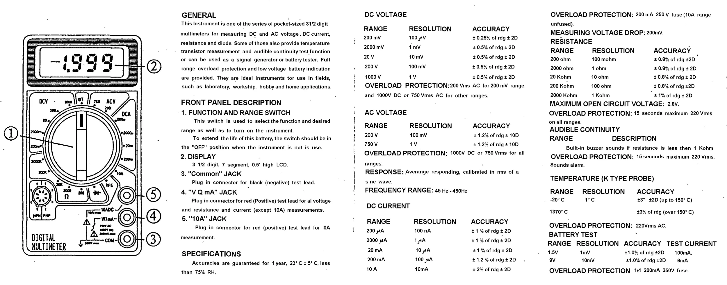
FRONT PANEL DESCRIPTION
1. FUNCTION AND RANGE SWITCH
This switch is used to select the function and desired
range as well as to turn on the instrument.
To extend the life of this battery, the ~witch should be in
the "OFF" position when the instrument is not is use.
2. DISPLAY
3 1/2 digit, 7 segment, 0 .5' high LCD.
3. "Common" JACK
Plug in connector for black (negalive) test lead.
4. "VQmA"JACK
Plug in connector for red (Positive) test lead for al voltage
and resistance and current (except 10A) measurements.
5. "1 OA" JACK
Plug in connector for red (positive) test lead for IOA
measurement.
SPECIFICATIONS
Accuracies are guaranteed for 1 year, 23° C ± 5° C, less
than 75% RH.
DC VOLTAGE
RANGE
RESOLUTION
ACCURACY
200mV
100J"'V
±0.25%ofrdg±20
2000 mV
1mV
±0.5%ofrdg±20
20V
10mV
±0.5%ofrdg±20
200V
100mV
±0.5%ofrdg±20
1OOO V
1V
±0.5% of rdg ±2D
OVERLOAD PROTECTION:200 Vms AC for 200 mv range
and 1OOOV DC or 750 Vrms AC for other ranges.
AC VOLTAGE
RANGE
200V
RESOLUTION
100mV
ACCURACY
±1.2%ofrdg±100
750 V
1V
±1.2% of rdg ±1OD
OVERLOAD PROTECTION: 1ooov DC or 750Vrms for all
ranges.
RESPONSE: ,Averange responding, calibrated in rms of a
sine wave.
FREQUENCY RANGE: 45 Hz-450Hz
DC CURRENT
RANGE
RESOLUTION
ACCURACY
200J"'A
100 nA
±1%ofrdg±20
2000J"'A
1J"'A
±1%ofrdg±20
20mA
10J"'A
±1%ofrdg±20
200mA
100J"'A
±1.2%ofrdg±20
10A
10mA
±2%ofrdg±20
OVERLOAD PROTECTION: 200 mA 250 v fuse (10A range
unfused).
MEASURING VOLTAGE DROP: 2oomv.
RESISTANCE
RANGE
RESOLUTION
ACCURACY
200 ohm
100 mohm
± 0.8% of rdg ±20
2000 ohm
1 ohm
±0.8%ofrdg±20
20 Kohm
10ohm
± 0.8% of rdg ±~20
200 Kohm
100 ohm
± 0.8% of rdg ±20
2000 Kohm
1 Kohm
±1%ofrdg±20
MAXIMUM OPEN CIRCUIT VOLTAGE: 2.sv .
OVERLOAD PROTECTION: 15 seconds maximum 22ovrms
on all rang~s.
AUDIBLE CONTINUITY
RANGE
DESCRIPTION
Built-in buzzer sounds if resistance is less then 1 Kohm
OVERLOAD PROTECTION: 15 seconds maximum 220 Vrms.
Sounds alarm.
TEMPERATURE (K TYPE PROBE)
RANGE RESOLUTION ACCURACY
-20°C
1°c
±3° ±2D (up to 150° C)
1370°C
±3% of rdg (over 150° C)
OVERLOAD PROTECTION: 22ovrmsAC.
BATTERY TEST
RANGE RESOLUTION ACCURACY TEST CURRENT
1.5V
9V
1mV
10mV
±1.0% of rdg ±20
±1.0% of rdg ±20
100mA,
6mA
OVERLOAD PROTECTION 1/4 2oomA 250V fuse.
OPERATIONG INSTRUCTIONS
WARNING
1. To avoid electrical shock hazard and/or damage of the
instrument. do not measure voltages that might exceed SOOV
above earth ground.
2. Before the use of instrument, inspect test leads, connectors
and probes for cracks, breaks, or crazes in the 1nsu1ation.
DO VOLTAGE MEASUREMENT
1. Connect red test lead to .. V 0 mA" jack. Black lead to
..COM" jack.
2 Set RANGE.swich to desired DCV position. II the voltage
to be measured is not known beforehand, set switch to the
highest range and reduce it untill satisfactory reading is
obtained.
3. Connect test leads to device or circuit being measured.
4. Tum on power of the device or circuit being measured,
voltage value will appear on Digital Display along with the
voilage polarity.
AC VOLTAGE MEASUREMENT
t. Red lead to ..V 0 mA" . Blackleakto ..COM"
2. RANGE switch to desired ACV position.
3. Connect test leads to device or circuit being tested.
4. Read voltage value on Digital Display.
DC CURRENT MEASUREMENT
1. Red lead to ..V o mA" . Black lead to ..COM" . (For
measurements between 200mA and 1OA connect red
1• • leaoto ..10A• jack.)
2. RANGE switch to desired DCA position.
3. Open the circuit to be measured, and connect test leads
IN SERIES with the load in which current is to be measured.
4. Read current value on Digital Display.
RESISTANCE MEASUREMENT
t.Redleadto "V0 mA" . Blackleadto "COM" .
2. RANGE switch to desired 0 Position.
3. II the resistance being measured Is connected to a circuit,
lurn off power and discharge all capacitors before
measurement.
4. Connect test leads to circuit being measured.
5. Read resistance value on Digital Display.
DIODE MEASUREMENT
t. Red lead to ·v OmA. . Black lead lo "COM" .
2. RANGE switch to ~ position.
3. Connect the red test lead to the anode of the diode to be
measured and black test lead to cathode.
4. The forward voltage drop in mV will be displayed. II the
i cflOCle is reversed, figure •1 • will be shown.
TRANSISTOR hFE MEASUREMENT
1. RANGE switch to Iha hFE position.
2. Detennine whether the transistor IS NPN or PNP type and
locate the Emitter, Base and Collecter leads. Insert the leads
into the proper holes of th8 hFE Socket on the front panel.
3. The meter will display the approximate hFE value at the
condition of base current 10 u A and VCE 2.SV.
TEMPERATURE MEASUREMENT
1. RANGE switch to TEMP position and the current room
temperature appears on the display with the charactor C.
2. Connect the k type thermoelectric couple to •v OmA"
and "COM " jackS.
3. Contact the object under measurement with the thermoeletriC
couple carefully.
4. Read the tempereture C on the display.
BAlTERY TEST
1.Redleadto "V0 mA" . Blackleadto "COM" .
2. RANGE switch to BATT position.
3. Connect test leads to the termlnalS of lhe battery under
measurement and read the display value.
AUDIBLE CONTINUITY TEST
1. Red lead to ..VO mA" . Black lead to "COM" .
2. flANGE switch to •t>) position.
3. CoMect test leads to two points ol circuit to be tested. If
the resistance is lower then I k ohm, buzzer will sound.
TEST SIGNAL USE
1. RANGE switch to .J'1.r position.
2.A test signal (SOHz or 1000Hz depending on the model of
multimeter) appears between •v o mA" and "COM " jacks.
The output voltage is apporx. SVpp with a certain DC
component, so additional Insulating capacitor should be used.
BATTERY AND FUSE REPLACEMENT
Fuse rarely need replacement and blow almost always
as a result of operator error.
II "BAT " appears on display, it indicates that lhe baltery
Should be replaced.
To replace battery & Fuse (200rnA/250V) remove the 2
screws in the bottom d the case. Sinpty remove the old, and
replace with a new one. Be carefUI to observe polarity..
CAUTION
Before attempting to open the case d the Instrument, be
· sur e to disconnect test leads from any energized circuits to
avoid shock hazard.
ACCESSORIES
• Operator' s instruction manual
·
Set of test leads
• Giflbox
• K type thermoelectric couple (Optional)
• 9 volt battery, NEDA t694 6F22 TYPE (OptioilaQ
OPERATOR'S
. I NSTRUCTION MANUAL
MINI DIGITAL MULTIMETER
~ WARNING ---
..
READ AND UNDERSTAND THIS MANUAL
BEFORE USING THE INSTRUMENT
Failure to understand and comply with the
WARNINGS and operating Instructions can
result in serious or fatal Injuries and /or PIXIP
erty damage.