/


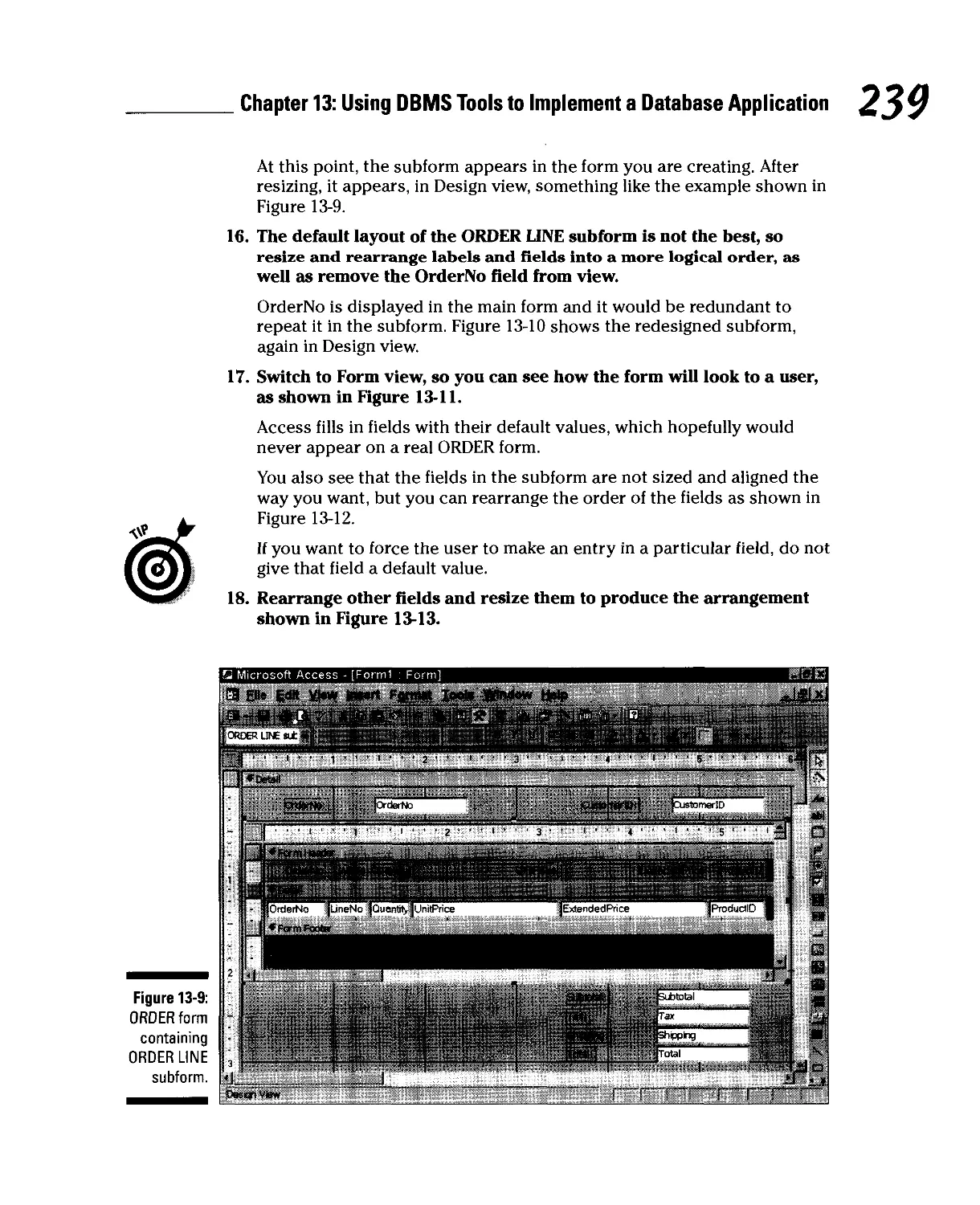


Author: Taylor A.G.
Tags: informatics information technology computer science databases for dummies series database development wiley publishing
Year: 2000


Text
Your fun and easy guide to
"abase design and implenentat.on
i 9 9 9
g^. Visit us at
*V/*
dummies.com
'99
?o*
o
A Reference
^ for the, m m .,
Rest of Us!
Get tips
for putting your
database on
the Web
Allen G. Taylor
Authorof SQL For Dummies4
V
database development
For dummies*
'&**
>***
Concerting a Semantic Object Model
into a Relational Model
The semantic object model defines several different types of semantic object.
Each type translates into an equivalent relation or multiple relations:
C" Simple object: Translates into a single relation.
C" Composite object: Translates into one relation for the base object and an
additional relation for each repeating group in the base object.
C" One-to-one compound object pair: Translates into two relations.
C" One-to-many compound object pair: Translates into two relations.
V Many-to-many compound object pair: Translates into two relations plus
an intersection relation.
V One-to-one hybrid object pair: Translates into two relations plus an
additional relation for each repeating group in either of the base objects.
v* One-to-many hybrid object pair: Translates into two relations plus an
additional relation for each repeating group in either of the base objects.
f Many-to-many hybrid object pair: Translates into two relations plus an
intersection relation plus an additional relation for each repeating group
in either of the base objects.
u* Association object: Translates into two relations corresponding to the
two base objects plus one relation for the association object.
«-<* Parent/subtype objects: Translate into a relation for the parent object plus
a relation for each of the subtype objects.
w Archetype/version objects: Translate into one relation for the archetype
object plus one relation for the version object.
For Dummies9: Bestsellina Book Series for Beginners
BBSTSELUNG
BOOK SERIES
beiJelopment
F§f Dummies
oA
The Phases of System Development
1. Definition Phase: Precisely define the problem to be solved, its magnitude,
and who will work on it.
2. Requirements Phase: Develop a detailed description of exactly what the
development effort will produce. Gather all relevant information and put it
into a requirements document (Statement of Requirements). Get client
signoff.
3. Evaluation Phase: Determine exactly how you will meet the requirements.
What tools will you use? How will you deploy your development team?
Determine if the job is doable within time and budget constraints.
4. Design Phase: Create a database model and then design a database and
database application that satisfy the terms of the requirements document.
5. Implementation Phase: Build the database and the database application.
Include copious documentation within the code and in external documents.
6. Final Documentation and Testing Phase: Give the database and application
a tough workout. Hit the system with every conceivable input condition and
a few inconceivable ones. Try to overload it. See where it breaks. When it
breaks, send it back to the implementers or even back to the designers.
Document everything.
7. Maintenance Phase: Fix lingering bugs as they arise. Provide updates and
enhancements called for by the client.
Ill
ill
££ o
HI
o> w
■5
III
III
III
III
1st
II|
= art
oS
i!
Copyright ©2001 Wiley Publishing, Inc.
All rights reserved.
Item 0752-4.
For more information about Wiley Publishing,
call 1-800-762-297*.
1?5
For Dummies®: Bestseiiina Book Series for Beginners
BESTSELLER
BOOK SERIES
References for the
Rest of Us!&
Are you intimidated and confused by computers? Do you find
that traditional manuals are overloaded with technical details
you'll never use? Do your friends and family always call you to
fix simple problems on their PCs? Then the For Dummies®
computer book series from Wiley Publishing, Inc. is for you.
For Dummies books are written for those frustrated computer users who know they
aren't really dumb but find that PC hardware, software, and indeed the unique vocabulary of
computing make them feel helpless. For Dummies books use a lighthearted approach,
a down-to-earth style, and even cartoons and humorous icons to dispel computer novices'
fears and build their confidence. Lighthearted but not lightweight, these books are a perfect
survival guide for anyone forced to use a computer.
"I like my copy so much I told
friends; now they bought copies.
—Irene C, Orwell, Ohio
"Thanks, I needed this book Now I
can sleep at night."
—Robin F, British Columbia, Canada
"Quick, concise, nontechnical,
and humorous."
—Jay A., Elburn, Illinois
Already, millions of satisfied readers agree. They have
made For Dummies books the #1 introductory level
computer book series and have written asking for more.
So, if you're looking for the most fun and easy way to
learn about computers, look to For Dummies books to
give you a helping hand.
Wiley Publishing, Inc.
5/09
Database
Development
FOR
Database
Development
FOR
by Allen G.Taylor
WILEY
Wiley Publishing, Inc.
Database Development For Dummies®
Published by
Wiley Publishing, Inc.
Ill River Street
Hoboken, NJ 07030
www.wiley.con
Copyright © 2001 Wiley Publishing, Inc., Indianapolis, Indiana
Published simultaneously in Canada
No part of this publication may be reproduced, stored in a retrieval system or transmitted in any form or by any means,
electronic, mechanical, photocopying, recording, scanning or otherwise, except as permitted under Sections 107 or 108
of the 1976 United States Copyright Act, without either the prior written permission of the Publisher, or authorization
through payment of the appropriate per-copy fee to the Copyright Clearance Center, 222 Rosewood Drive, Danvers, MA
01923, (978) 750-8400, fax (978) 646-8700. Requests to the Publisher for permission should be addressed to the Legal
Department, Wiley Publishing, Inc., 10475 Crosspoint Blvd., Indianapolis, IN 46256, (317) 572-3447, fax (317) 572-4447,
e-mail1, perncoordinator® wiley .con.
Trademarks: Wiley, the Wiley Publishing logo, For Dummies, the Dummies Man logo, A Reference for the Rest of Us!, The
Dummies Way, Dummies Daily, The Fun and Easy Way, Dummies.com, and related trade dress are trademarks or
registered trademarks of John Wiley & Sons, Inc. and/or its affiliates in the United States and other countries and may not be
used without written permission. All other trademarks are the property of their respective owners. Wiley Publishing, Inc.,
is not associated with any product or vendor mentioned in this book.
LIMIT OF IJABILITY/DISCLAIMER OF WARRANTY: WHILE THE PUBLISHER AND AUTHOR HAVE USED THEIR BEST
EFFORTS IN PREPARING THIS BOOK, THEY MAKE NO REPRESENTATIONS OR WARRANTIES WITH RESPECT TO THE
ACCURACY OR COMPLETENESS OF THE CONTENTS OF THIS BOOK AND SPECIFICALLY DISCLAIM ANY IMPLIED
WARRANTIES OF MERCHANTABILITY OR FITNESS FOR A PARTICULAR PURPOSE. NO WARRANTY MAY BE CREATED
OR EXTENDED BY SALES REPRESENTATIVES OR WRITTEN SALES MATERIALS. THE ADVICE AND STRATEGIES
CONTAINED HEREIN MAY NOT BE SUITABLE FOR YOUR SITUATION. YOU SHOULD CONSULT WITH A PROFESSIONAL
WHERE APPROPRIATE. NEITHER THE PUBLISHER NOR AUTHOR SHALL BE LIABLE FOR ANY LOSS OF PROFIT OR
ANY OTHER COMMERCIAL DAMAGES, INCLUDING BUT NOT LIMITED TO SPECIAL, INCIDENTAL, CONSEQUENTIAL,
OR OTHER DAMAGES.
For general information on our other products and services or to obtain technical support, please contact our Customer
Care Department within the U.S. at 800-762-2974, outside the U.S. at 317-572-3993, or fax 317-572-4002.
Wiley also publishes its books in a variety of electronic formats. Some content that appears in print may not be available
in electronic books.
Library of Congress Catatoging-in-Publication Data:
Library of Congress Control Number: 00-103400
ISBN: 0-7645-0752-4
Manufactured in the United States of America
109876543
10/TQ/RS/QV/1N
About the Author
Allen G. Taylor is a 28-year veteran of the computer industry and the author
of 17 computer-related books, including SQL For Dummies. In addition to
writing, he is a database consultant and seminar leader in database design and
application development. Allen lives with his family on a small farm outside
of Oregon City, Oregon. You can contact Allen at agt@transport. com.
dedication
This book is dedicated to my wife, Joyce C. Taylor, who continues to
encourage me, even though she believes 1 spend too much time staring into a
computer monitor.
Acknowledgments
1 have received help from many quarters in this book. 1 am especially
indebted to Keith Taylor, Heath Schweitzer, Joshua McKinney, Sue Preston,
and Ernest Argetsinger.
Thanks to my editor, John Pont, and all the folks at Wiley Publishing who
helped make this book possible, including Debra Williams Cauley, Kristy
Nash, Nancee Reeves, Angie Hunckler, and Constance Carlisle.
Thanks once again to my agent, Matt Wagner of Waterside Productions, who
continues to help me advance my writing career.
Thanks to Patrick J. McGovern, who built a structure that gave me my first
trip to China as well as the opportunity to write this book.
Thanks to Joyce, Jenny, Valerie, Melody, Neil, Rob, and Sam for sacrificing
some of their time with me so that 1 could write.
Publisher's Acknowledgments
We're proud of this book; please send us your comments through our online registration form
located at www.dummies .com/register/.
Some of the people who helped bring this book to market include the following:
Acquisitions, Editorial, and Production
Media Development Project Coordinator: Nancee Reeves
Project Editor: John W Pont ^^ and Graphic8. Amy Adrian
Acquisitions Editor: Debra Williams Cauley Karl Brandt, John Greenough,
Proof Editor: Teresa Artman LeAndra Johnson, Jill Piscitelli,
Heather Pope, Brian Torwelle
Technical Editor: Ernest Argetsinger _ . , „
Proofreaders: John Bitter,
Editorial Manager: Constance Carlisle Nancy Price, Marianne Santy,
Editorial Assistant: Sarah Shupert, York Production Services, Inc.
Candace Nicholson, Amanda Foxworth Indexer: York Production Services, Inc.
Publishing and Editorial for Technology Dummies
Richard Swadley, Vice President and Executive Group Publisher
Andy Cummings, Vice President and Publisher
Mary C. Corder, Editorial Director
Publishing for Consumer Dummies
Diane Graves Steele, Vice President and Publisher
Joyce Pepple, Acquisitions Director
Composition Services
Gerry Fahey, Vice President of Production Services
Debbie Stailey, Director of Composition Services
♦
The publisher would like to give special thanks to Patrick J. McGovern,
without whom this book would not have been possible.
♦
c
Contents at a Glance
•••••••••••••••••••••••••••••••••••••••••••••••••
introduction 7
Part I: Basic Concepts 7
Chapter 1: Database Processing 9
Chapter 2: Database Development 21
Part 11: Data Modeling: What Should
the Database Represent? 39
Chapter 3: The Users' Model 41
Chapter 4: The Entity-Relationship Model 49
Chapter 5: The Semantic Object Model 67
Chapter 6: Determining What You Are Going to Do 89
Part III: Database Design 103
Chapter 7: The Relational Model 105
Chapter 8: Using an Entity-Relationship Model to Design a Database 129
Chapter 9: Using a Semantic Object Model to Design a Database 141
Part IV: Implementing a Database 159
Chapter 10: Using DBMS Tools to Implement a Database 161
Chapter 11: Addressing Bigger Problems with SQL Server 2000 199
Chapter 12: Using SQL to Implement a Database 217
Part V: Implementing a Database Application 229
Chapter 13: Using DBMS Tools to Implement a Database Application 231
Chapter 14: SQL and Database Applications 251
Part VI: Using Internet Technology
v)ith Database 257
Chapter 15: Database on Networks 259
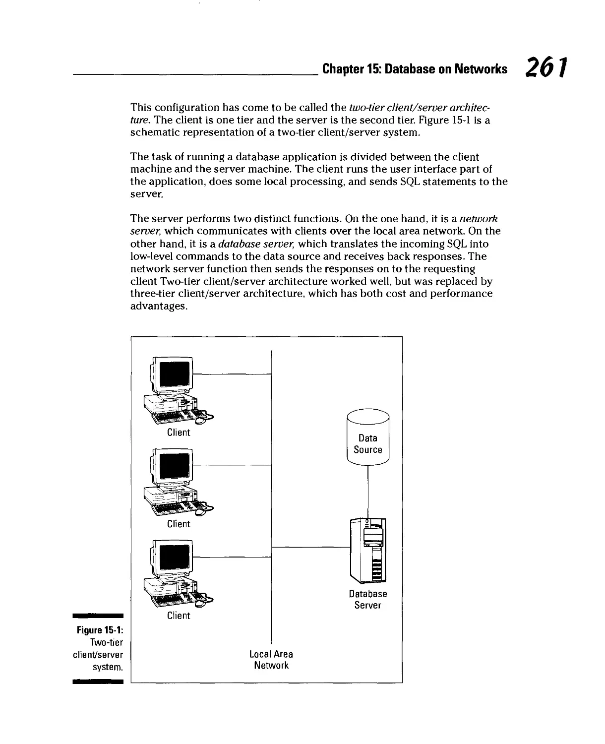
Chapter 16: Database Security and Reliability 271
Part VII: The Part of Tens 281
Chapter 17: Ten Rules to Remember When Creating a Database 283
Chapter 18: Ten Rules to Remember When Creating a Database Application 289
Glossary 293
Index 305
Cartoons at a Glance
By Rich Tennant
IN^J&ve
^TS3S^*g»S- «« M™**;
page
103
The 5th Wave BtBlfliTeimaiit
TbeJ&38£
page 39
OUtA.
*' K> 1W WAVT ME TO CALL THE COMRW fW WVE THEM
SEW ANOTHER REVIEW 03V CF TUE1R BtWWBE SfTWWE
5VOTA,CRCOY0U WCW WlWT-rCVfiE GOIMj TD WRITE?"
page 7
/>«0e 229
^^MJmsrssjF
|fi£JtMfave
lyMchfeiniiM
AH0WER 5U* "J^ oW WS MIND-
"Vbur databsise is beycnd repaid but before I -tell xpu
question- How manij indaecadfiAiirrt.-n---1 -
P«9e 257
^a^ta^™
page
159
Fax: 978-546-7747
E-mail: ri chtennant@the5thwave. com
WortdWide Web: www.the5thwave.com
Table of Contents
# # # c* =$> # * $■ # & ^ % ■& ^ si? # #■ %■■ ■& & $ ######%#### ^ # * ^ # m m m m ###### #
Introduction /
About This Book 1
Who Should Read This Book? 2
Foolish Assumptions 2
How This Book Is Organized 2
Part 1: Basic Concepts 3
Part 11: Data Modeling: What Should the Database Represent? 3
Part 111: Database Design 3
Part IV: Implementing a Database 3
Part V: Implementing a Database Application 4
Part VI: Using Internet Technology with Database 4
Part Vll: The Part of Tens 4
Conventions Used in This Book 5
Icons Used in This Book 5
Where to Go From Here 5
Part I: Basic Concepts 7
Chapter 1: Database Processing 9
The Different Classes of Databases 9
Enterprise databases 10
Personal databases 10
Workgroup databases 11
So Much Data, So Little Time 11
Databases and privacy: We know who you are,
and we know where you live 12
Amazon.com and the online merchants 13
Data deluge: It came from outer space 14
The fierce urgency of now 15
What Is Database Processing? 16
File processing: The old way 16
Database processing: The new way 18
Types of database systems 19
Chapter 2: Database Development 21
What Is a Database? 21
Developing a Database 22
The difference between a database and a database application ...22
The phases of system development 23
Educating the client 34
Database Development For Dummies
Resisting the Urge to Build a Database Right Now 35
The need becomes apparent 35
The schedule is tight 35
Standing your ground and preventing disaster 36
Some Development Tools May Be Too User Friendly 37
Part II: Data Modeling: What Should
the Database Represent) 39
Chapter 3: The Users' Model 41
Who Are the Interested Parties, and What Are They Thinking? 41
The manager who hired you 42
The people who are scheduled to use your application 42
The data processing standards people 43
The big boss 44
The big boss's relatives 44
What Should the System Be? 45
Politics: Whose opinions really count? 45
Reconciling differences 46
Arriving at a consensus users' model 46
Chapter 4: The Entity-Relationship Model 49
Exploring the Structure of the E-R Model 49
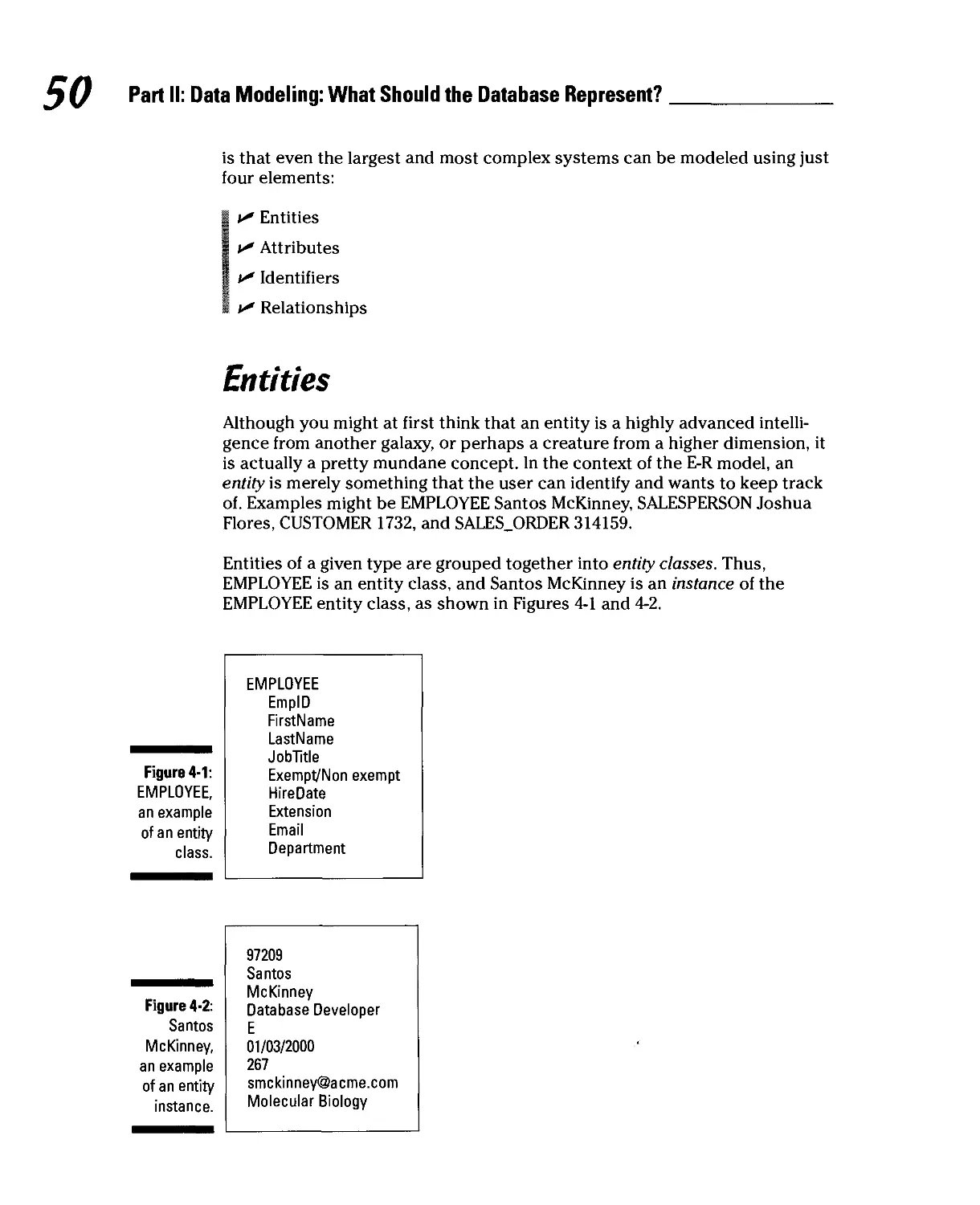
Entities 50
Attributes 51
Identifiers 51
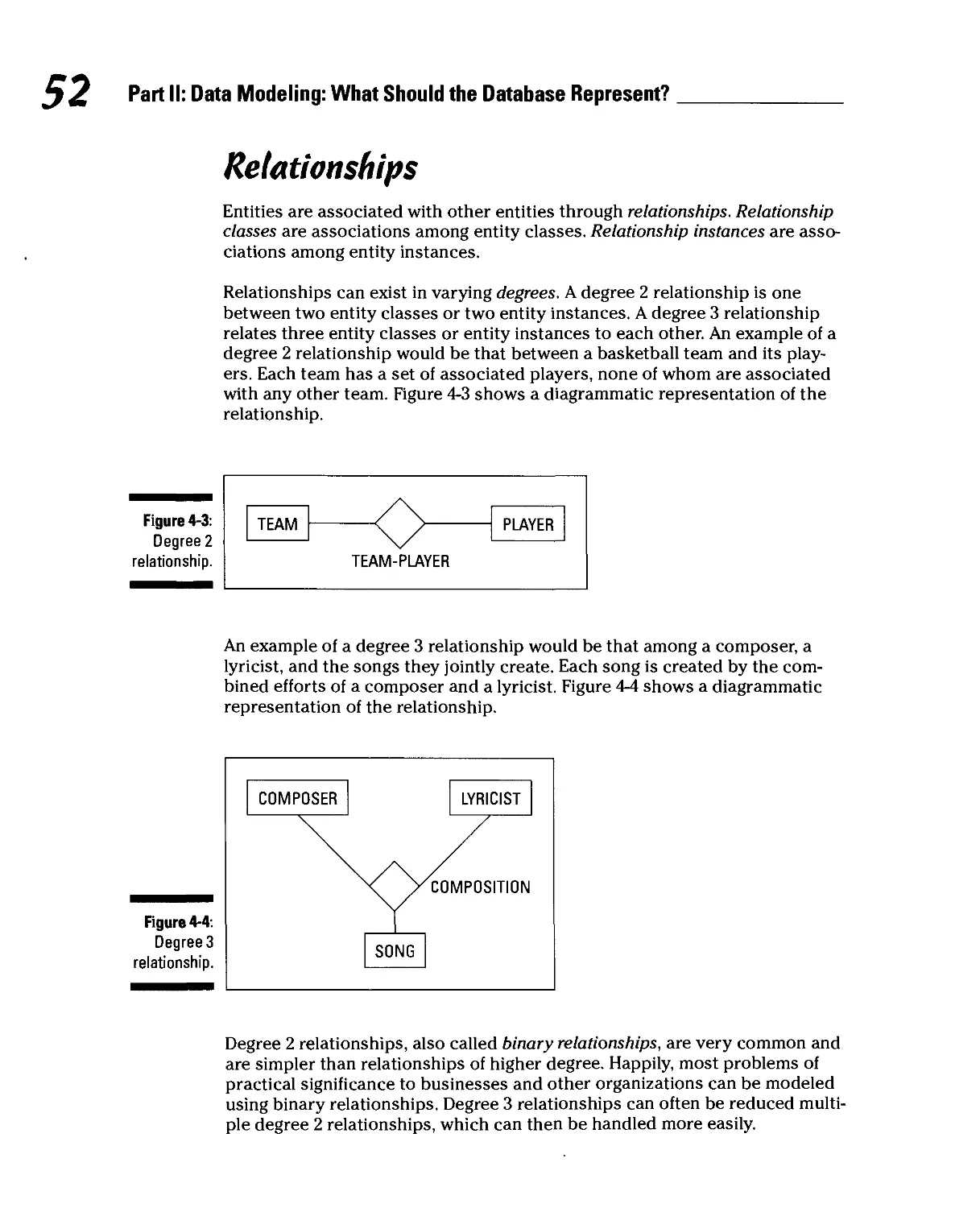
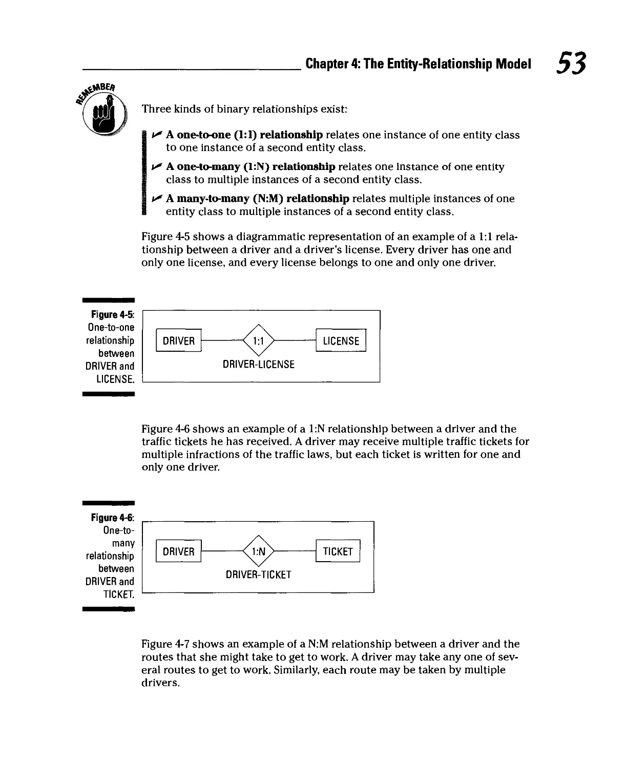
Relationships 52
Creating Entity-Relationship Diagrams 54
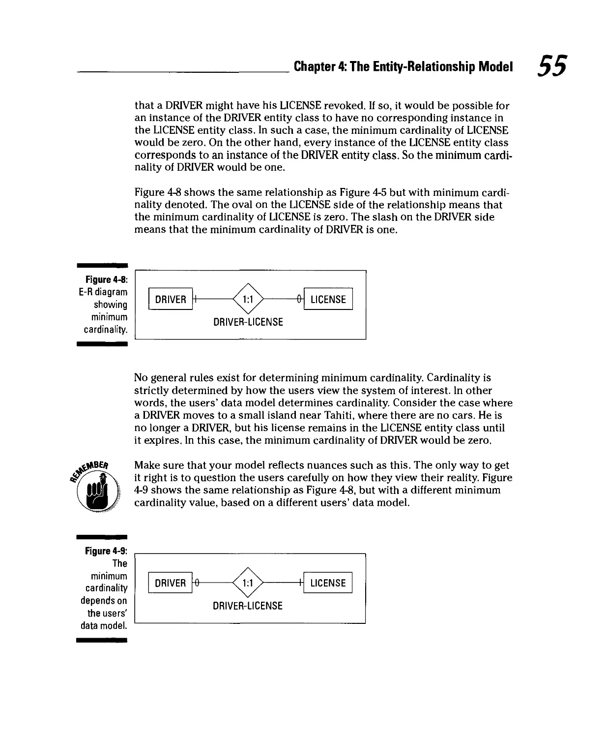
Maximum cardinality.... 54
Minimum cardinality 54
Refining the E-R Model 56
Strong entities and weak entities 56
ID-dependent entities 58
Supertype and subtype entities 59
Capturing business rules 61
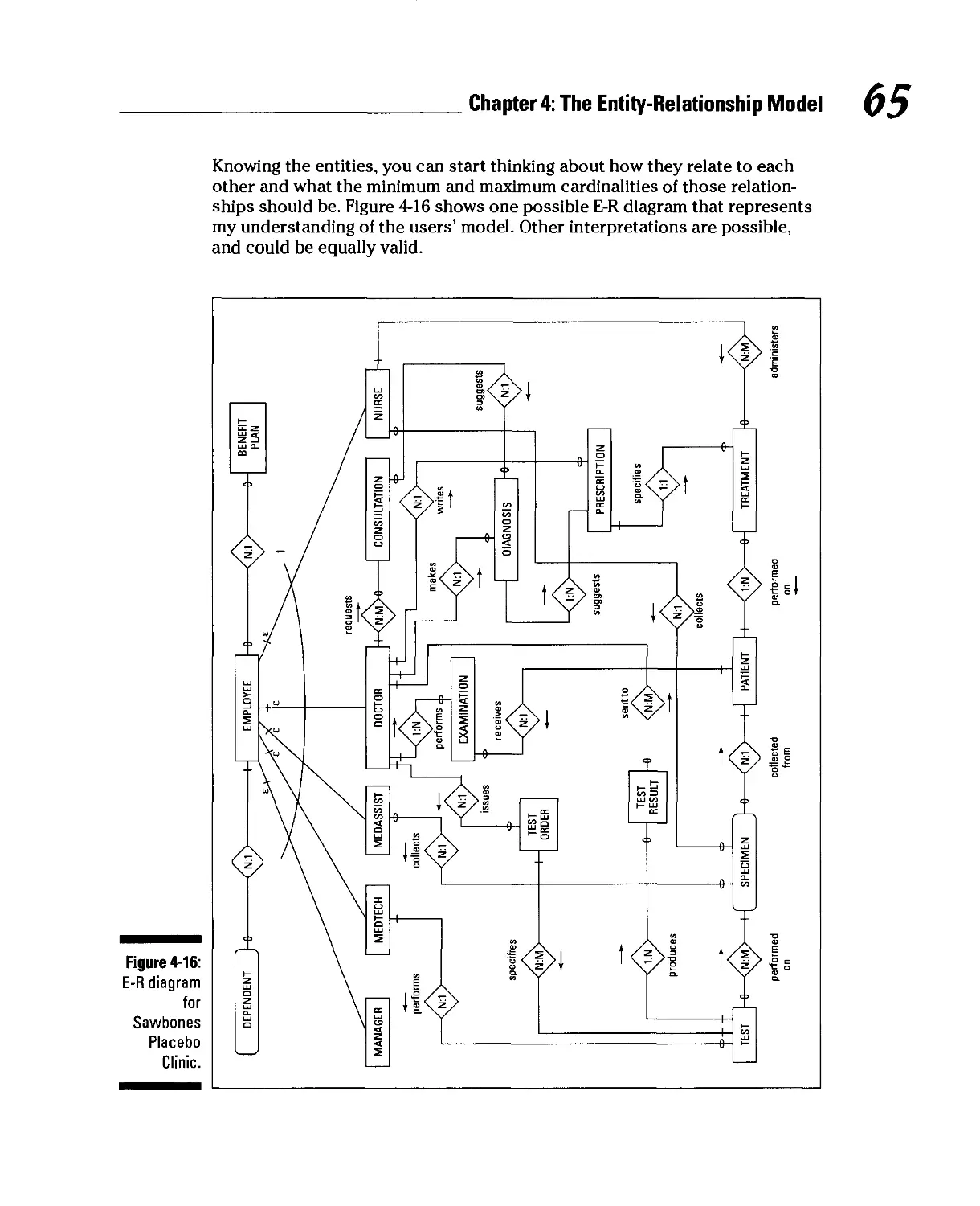
It's Time to Look at Some E-R Examples 61
A fairly simple example 61
A more complex example 63
Chapter 5: The Semantic Object Model 67
Examining the SOM Structure 67
Semantic objects 67
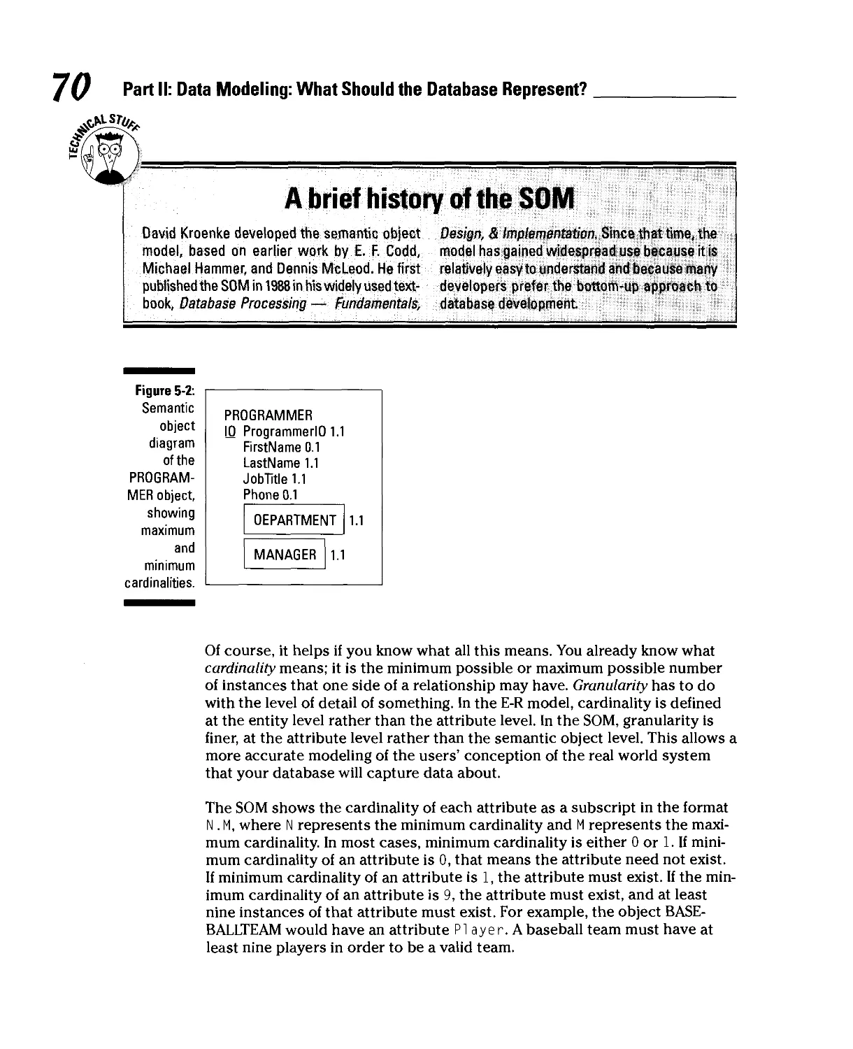
Attributes 68
Object identifiers 71
Relationships 71
Attribute domains 72
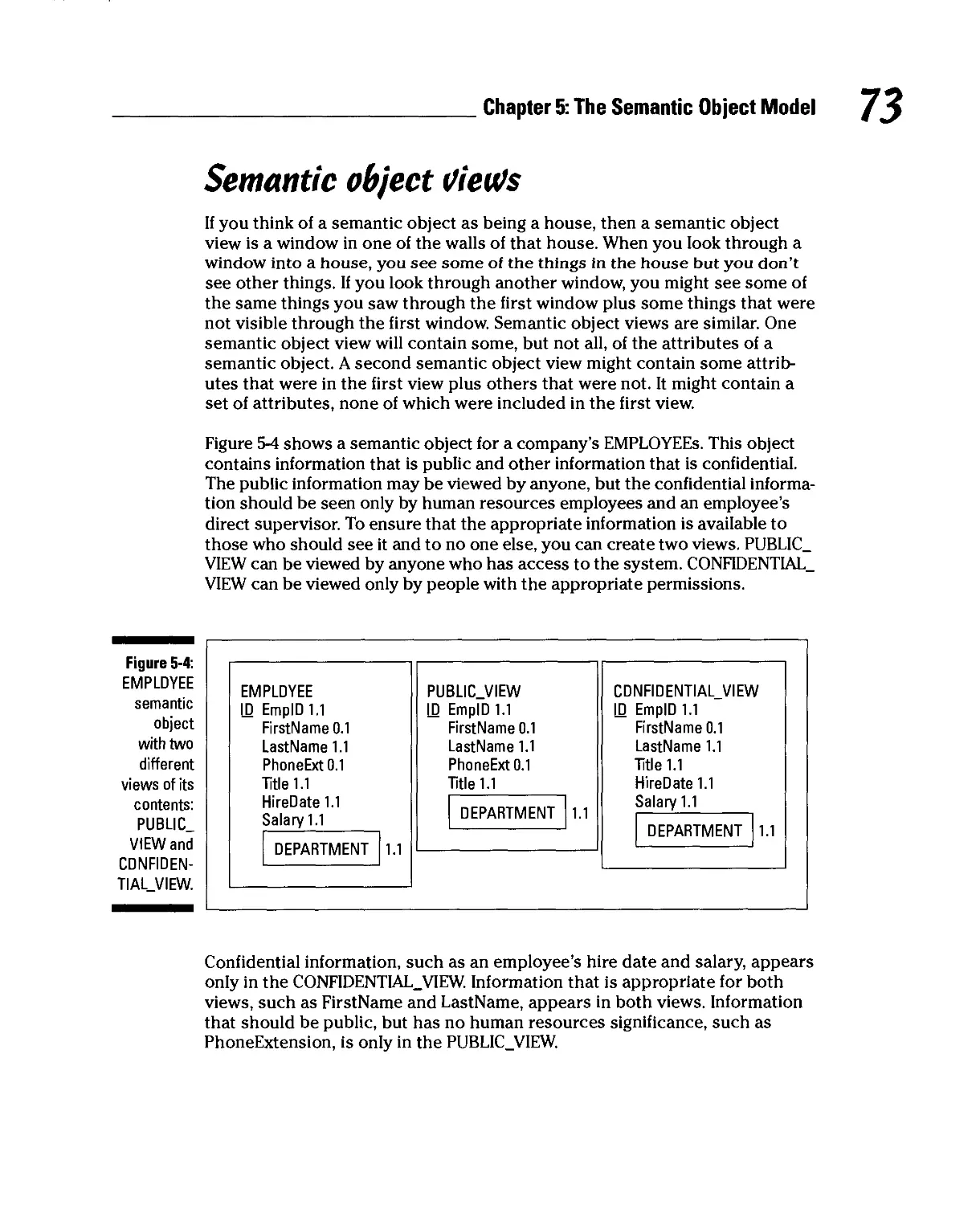
Semantic object views 73
Table of Contents XVii
Different Types of Objects Model Different Situations 74
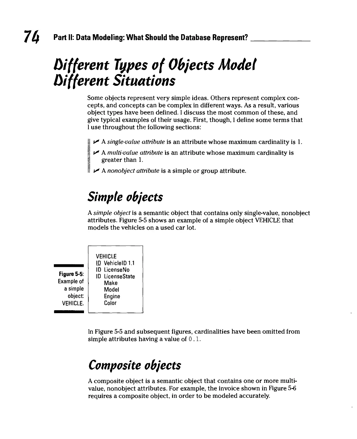
Simple objects 74
Composite objects 74
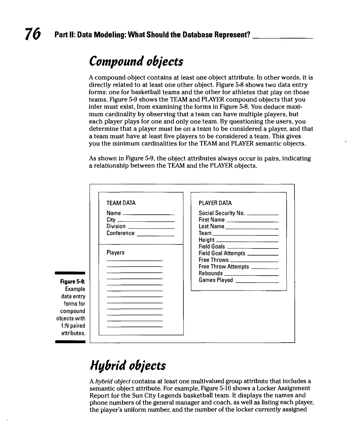
Compound objects 76
Hybrid objects 76
Association objects 78
Parent/subtype objects 80
Archetype/version objects 81
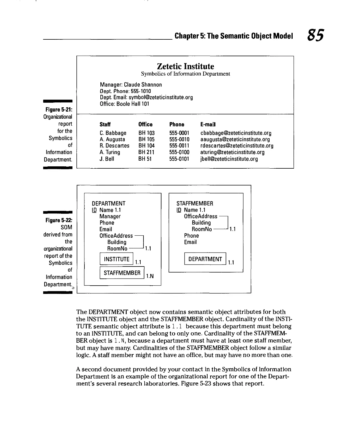
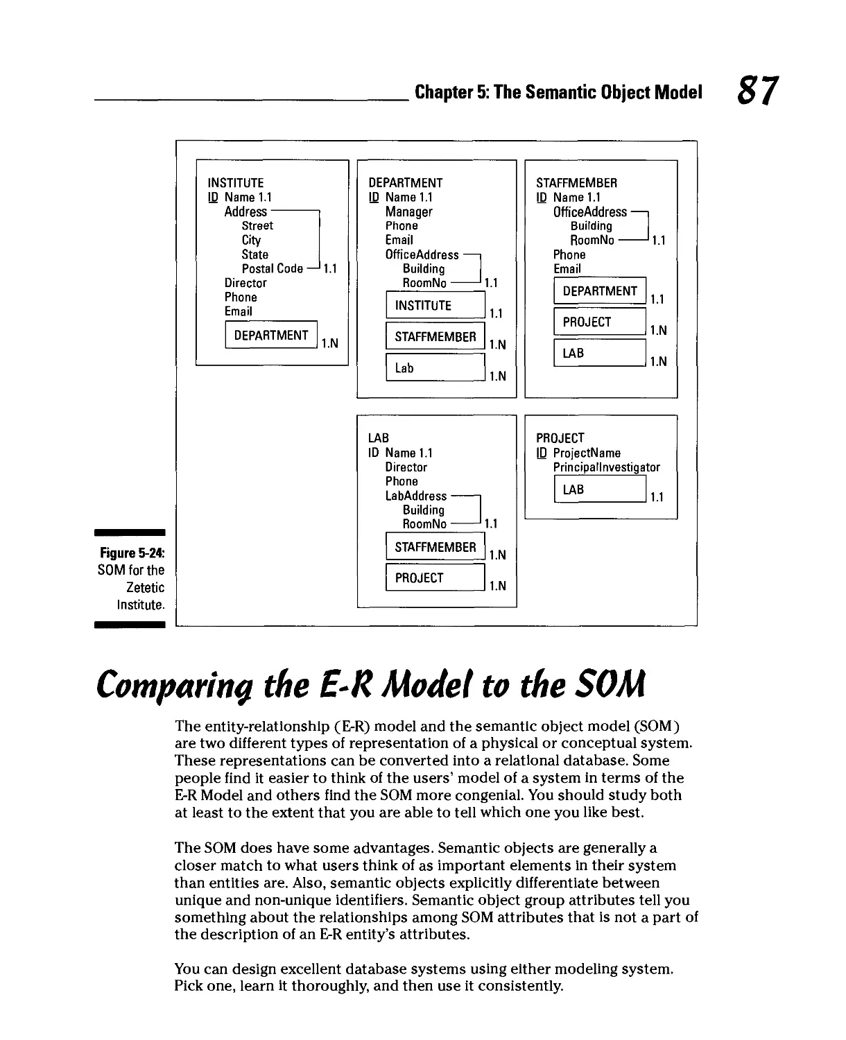
Building a Semantic Object Model, an Example 82
Comparing the E-R Model to the SOM 87
Chapter 6: Determining What You Are Going to Do 89
Upgrading an Existing System 89
Identify the stakeholders 90
Examine existing documents 90
Interview stakeholders 90
Building a New System from Scratch 93
Identify the stakeholders, and find out what they want 94
Insist on a formal requirements document 94
Create a solutions document 95
Obtain client signoff on the solutions document 96
What Will Matter Five Years from Now? 96
Lessons learned from the Y2K bug 97
How will the organization grow or evolve? 98
Determining the Project's Scope 100
What the client wants 100
What the client wants to pay 101
When the client wants it 101
Part III: Database Design 103
Chapter 7: The Relational Model 105
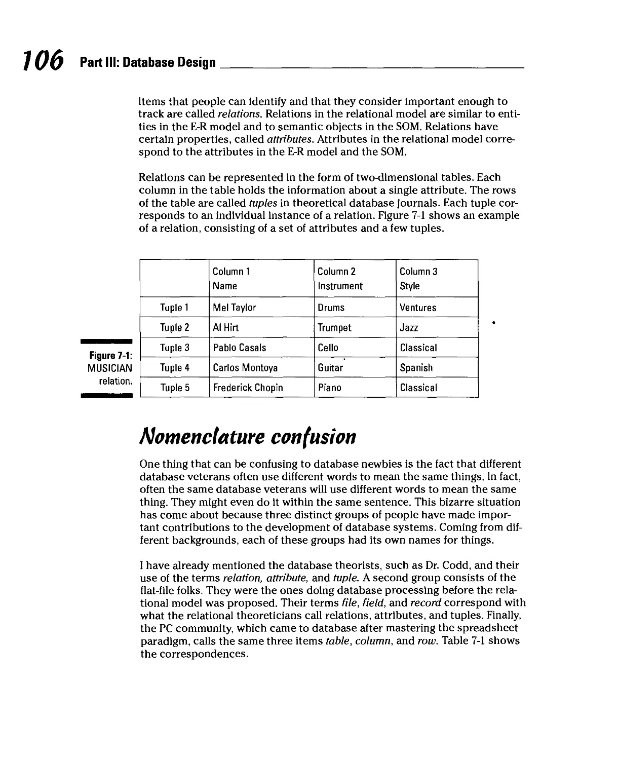
Relations, Attributes, and Tuples 105
Nomenclature confusion 106
Formal definition of a relation 107
Functional dependencies 108
Keys 108
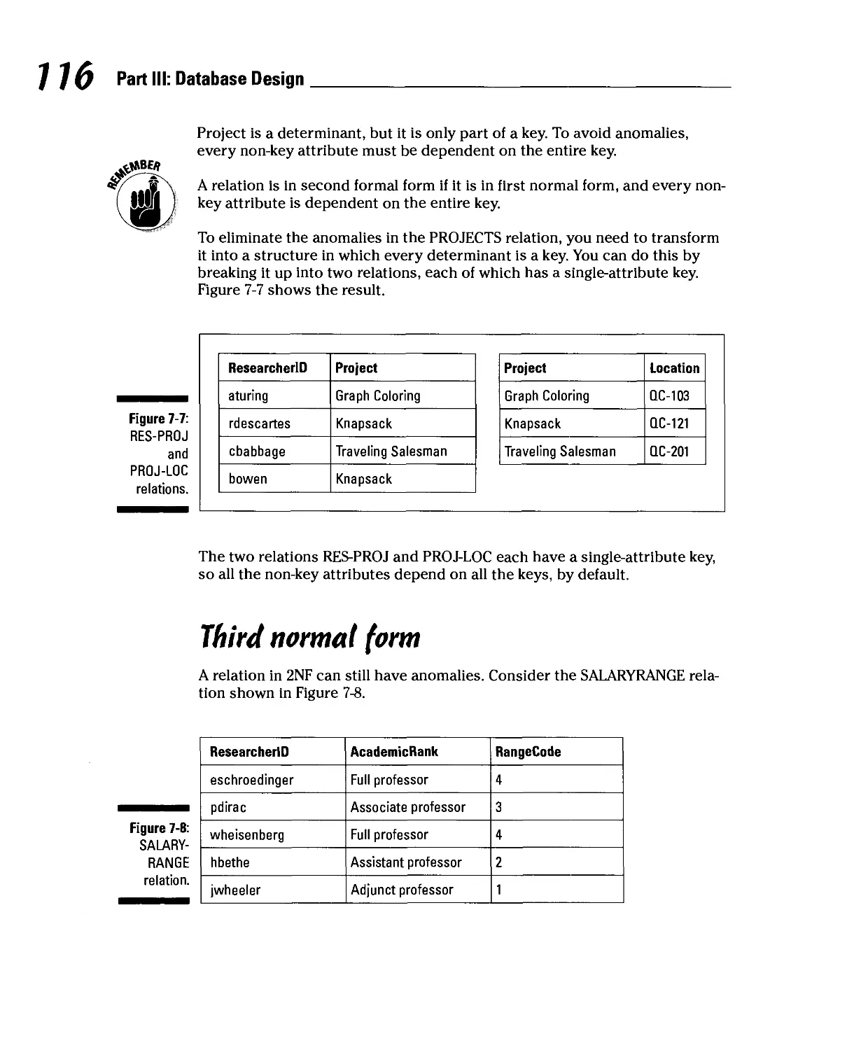
Problems with Your Relations 110
Fixing Problems through Normalization 113
First normal form 114
1 Second normal form 115
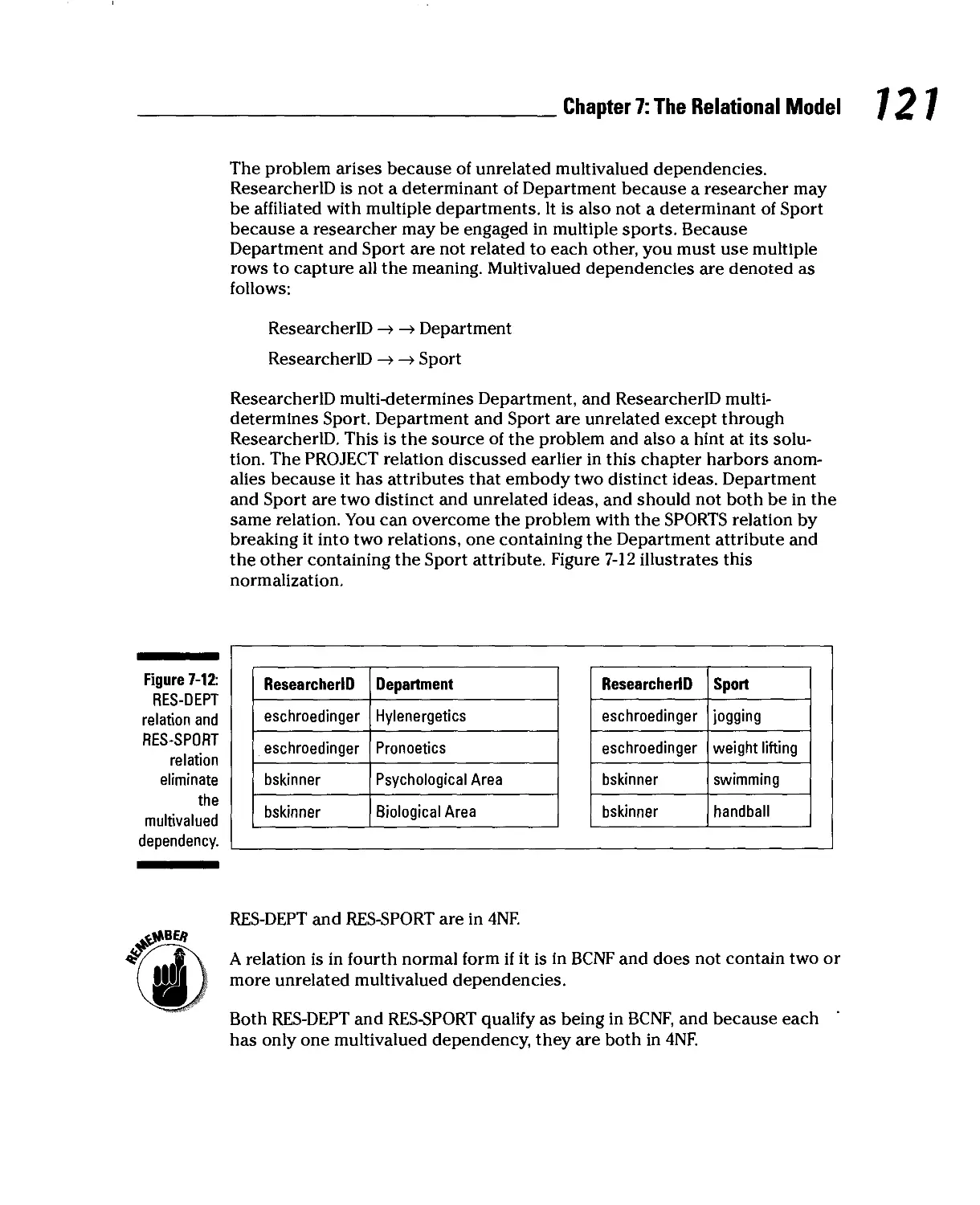
Third normal form 116
Boyce-Codd normal form 117
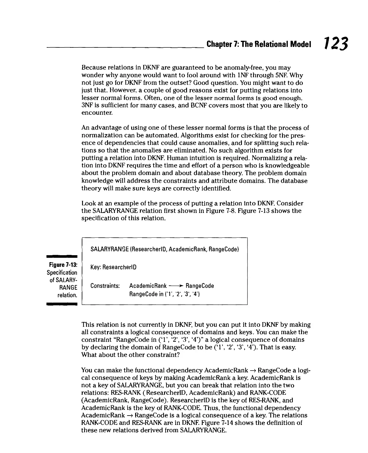
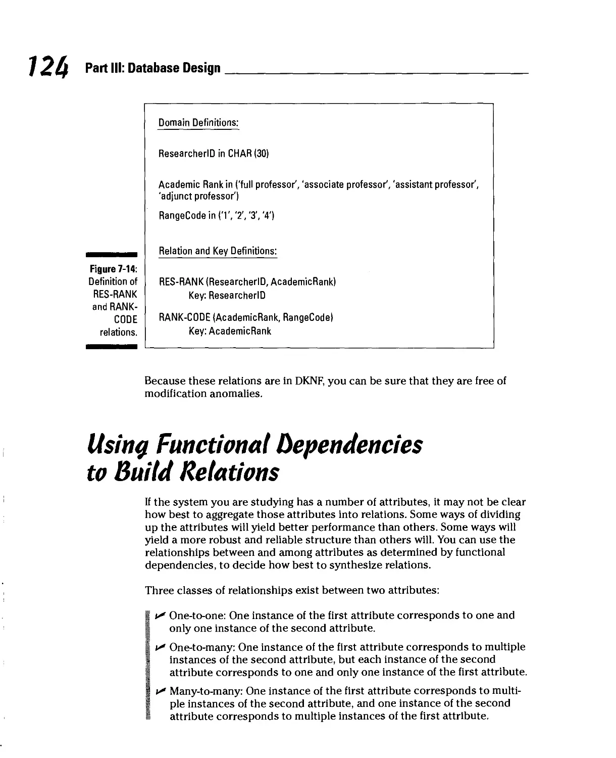
Fourth normal form 119
Fifth normal form 122
Domain/key normal form 122
Using Functional Dependencies to Build Relations 124
One-to-one attribute relationships 125
One-to-many attribute relationships 125
Many-to-many attribute relationships 126
Can a Database be too Normalized? 126
Trading Off Data Integrity Against Performance 127
Chapter 8: Using an Entity-Relationship Model to
Design a Database 129
Capturing the User's Model with an E-R Model 129
Converting an E-R Model into a Relational Design 130
Relations, attributes, keys, and relationships 130
Normalizing 131
One-to-one relationships 132
One-to-many relationships 134
Many-to-many relationships 136
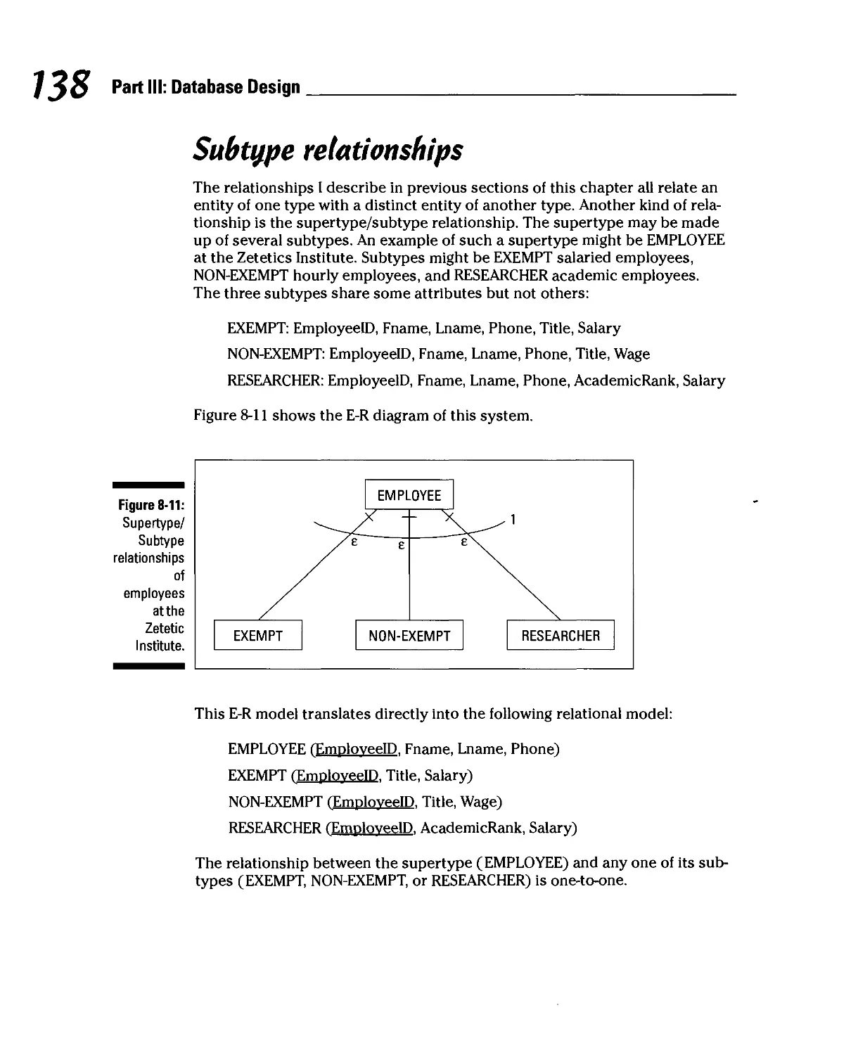
Subtype relationships 138
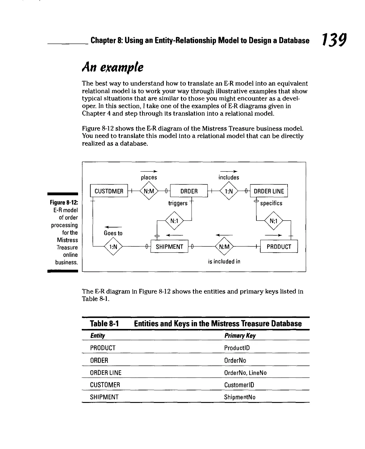
An example 139
Chapter 9: Using a Semantic Object Model
to Design a Database 141
Converting an SOM into a Relational Design 141
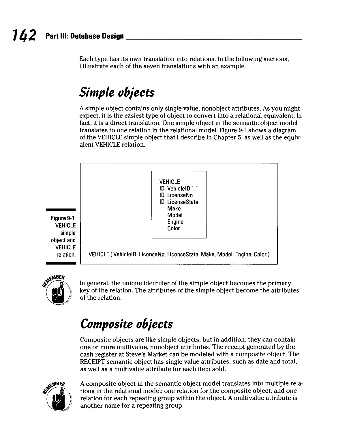
Simple objects 142
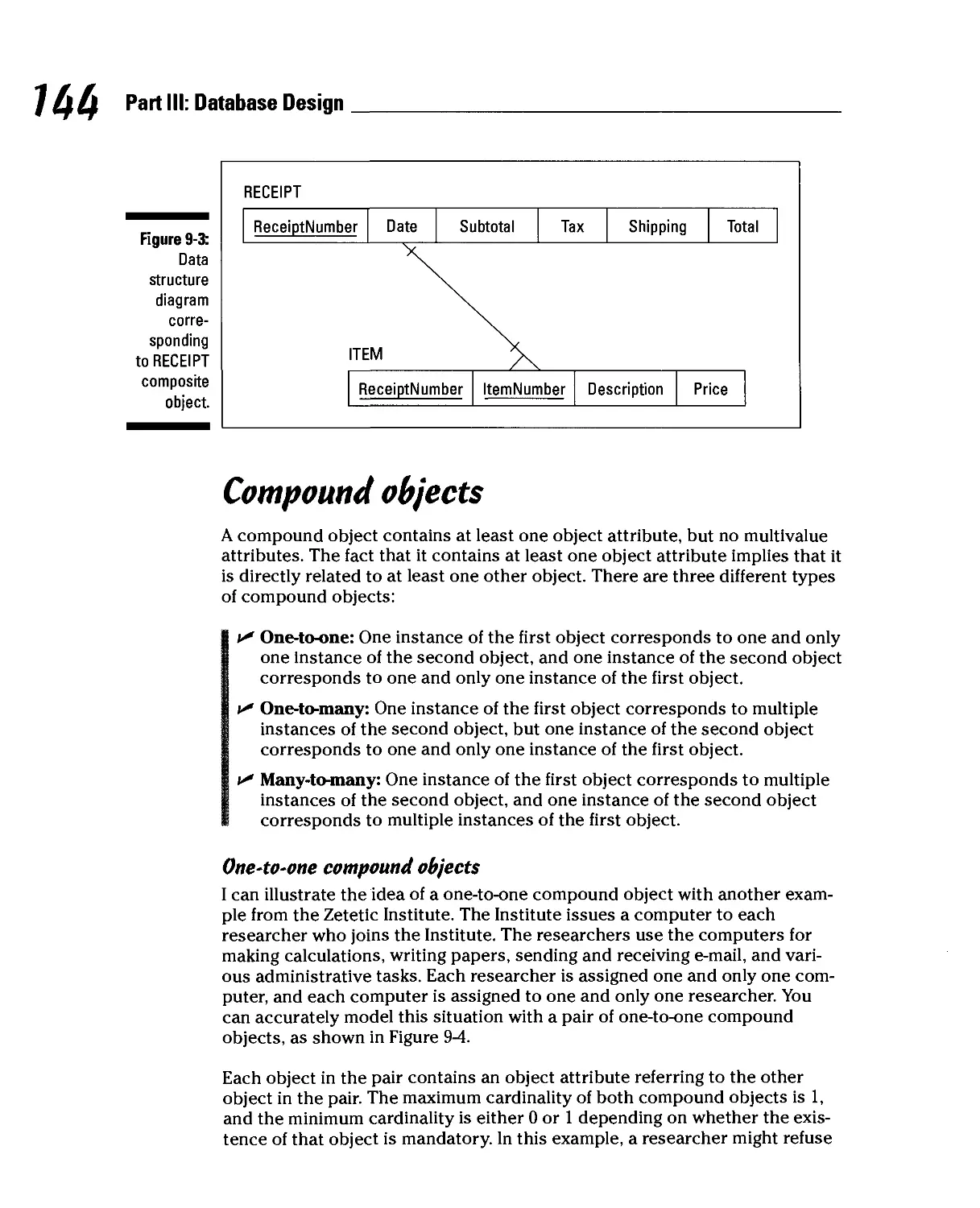
Composite objects 142
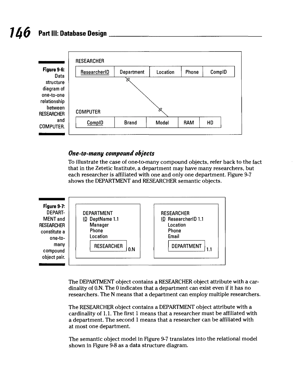
Compound objects 144
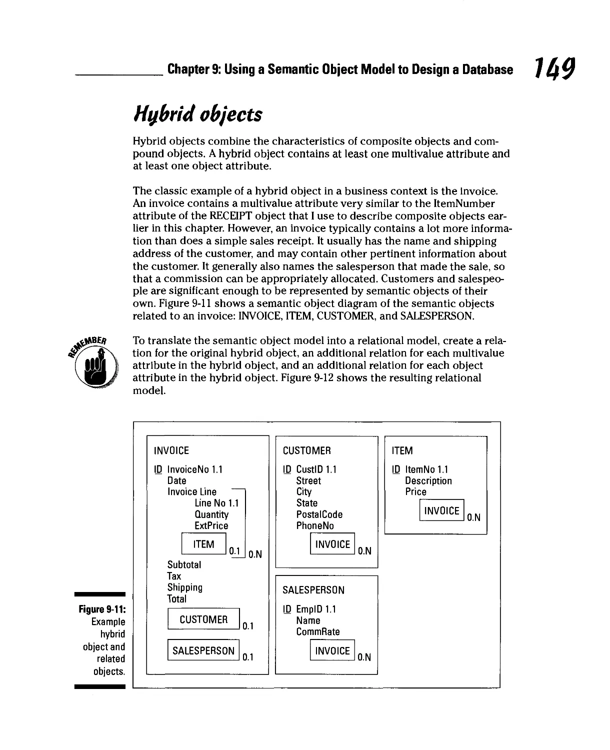
Hybrid objects 149
Association objects 150
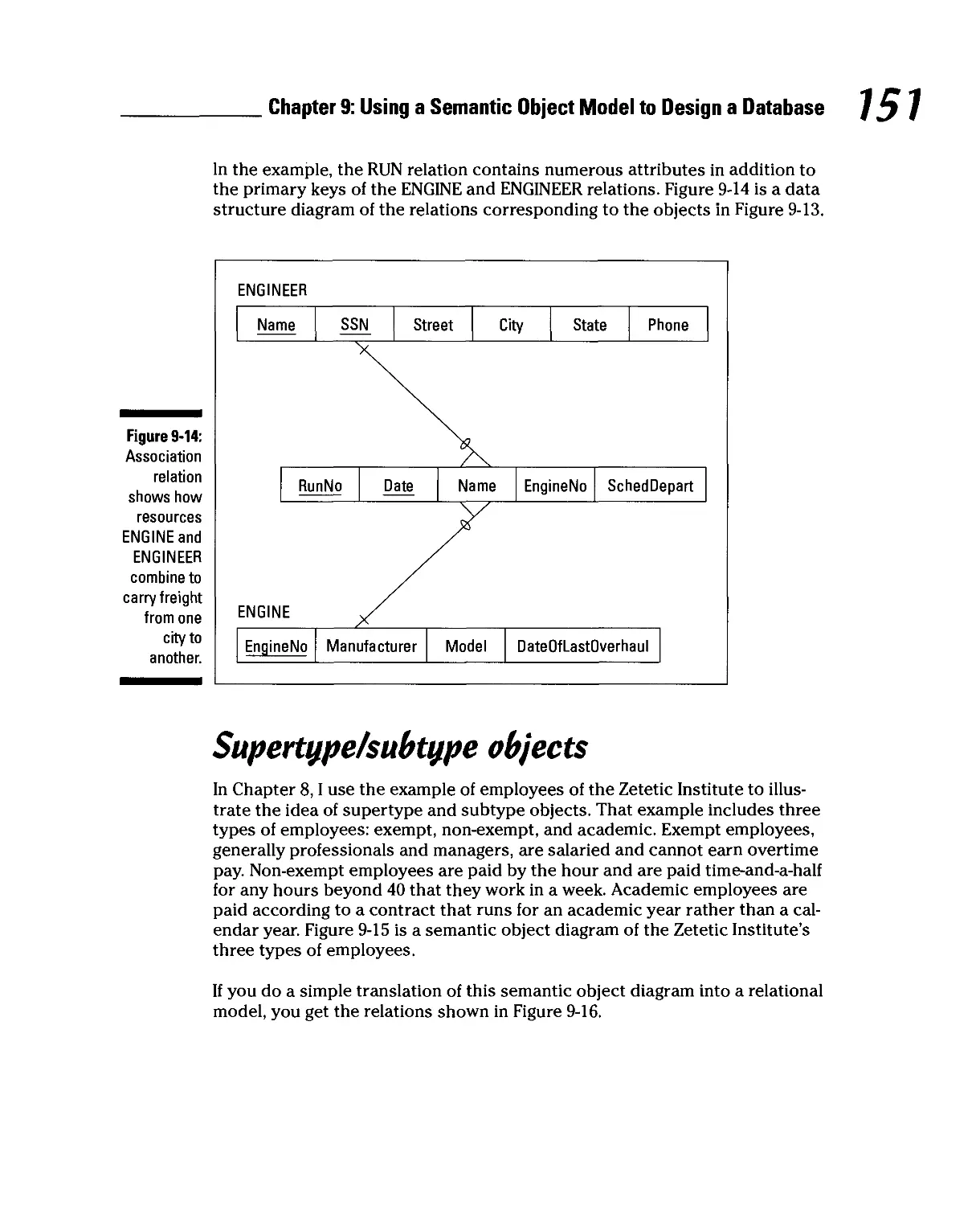
Supertype/subtype objects 151
Archetype/version objects 153
An Example 155
Part W: Implementing a Database 159
Chapter 10: Using DBMS Tools to Implement a Database 161
Translating a Relational Model into a Database 162
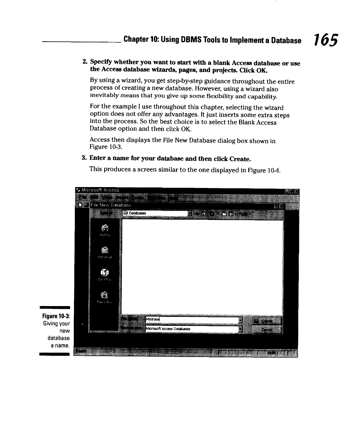
Access 2000 163
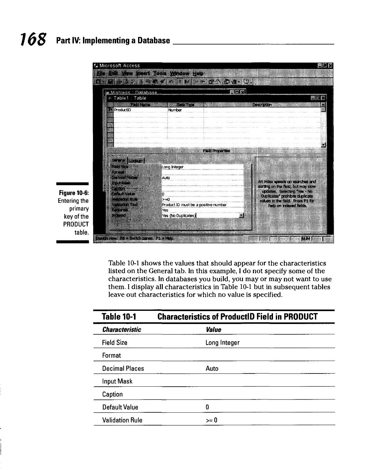
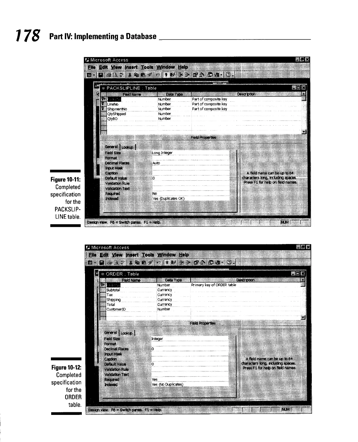
Building tables 164
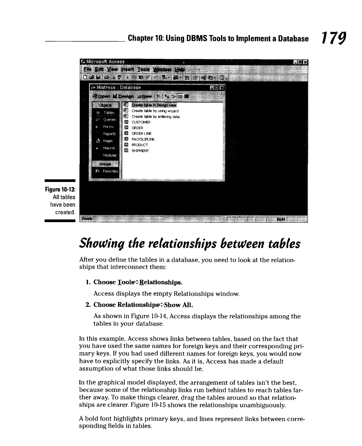
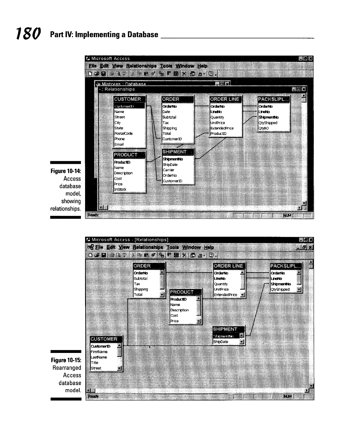
Showing the relationships between tables 179
Adding data to tables 181
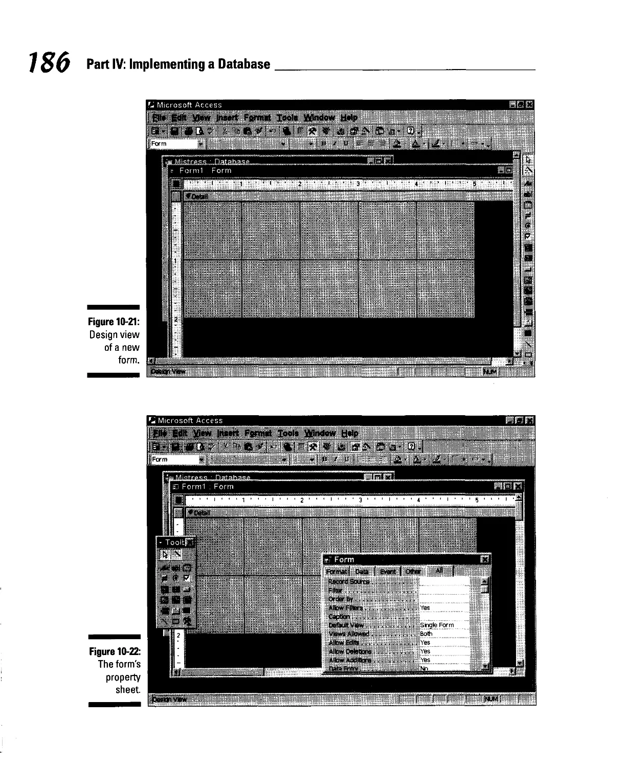
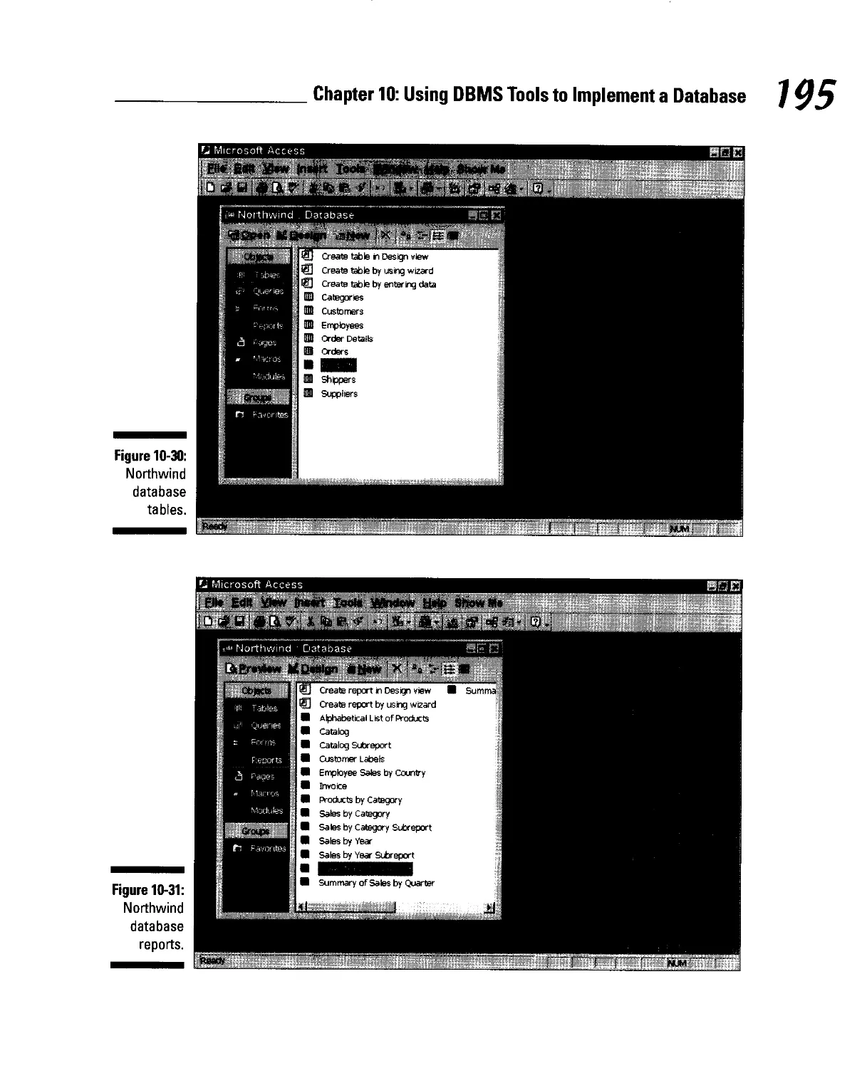
Creating forms 183
Creating queries 189
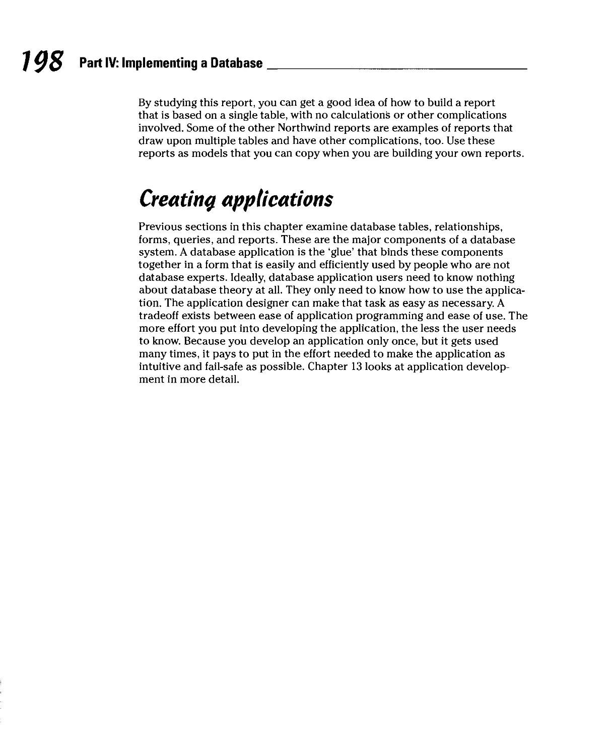
Creating reports 194
Creating applications 198
Table of
Chapter 11: Addressing Bigger Problems with SQL Server 2000... 199
Getting to Know SQL Server 2000 199
Translating Your Relational Model into a SQL Server Database 200
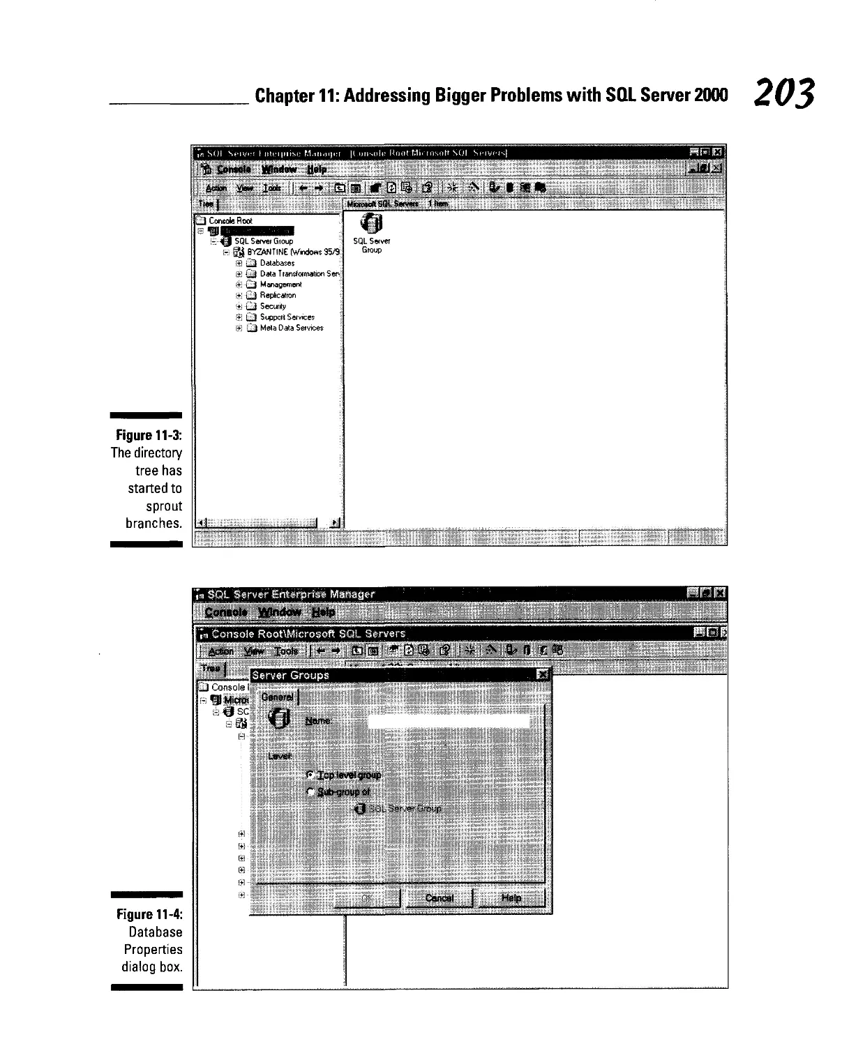
Starting SQL Server 201
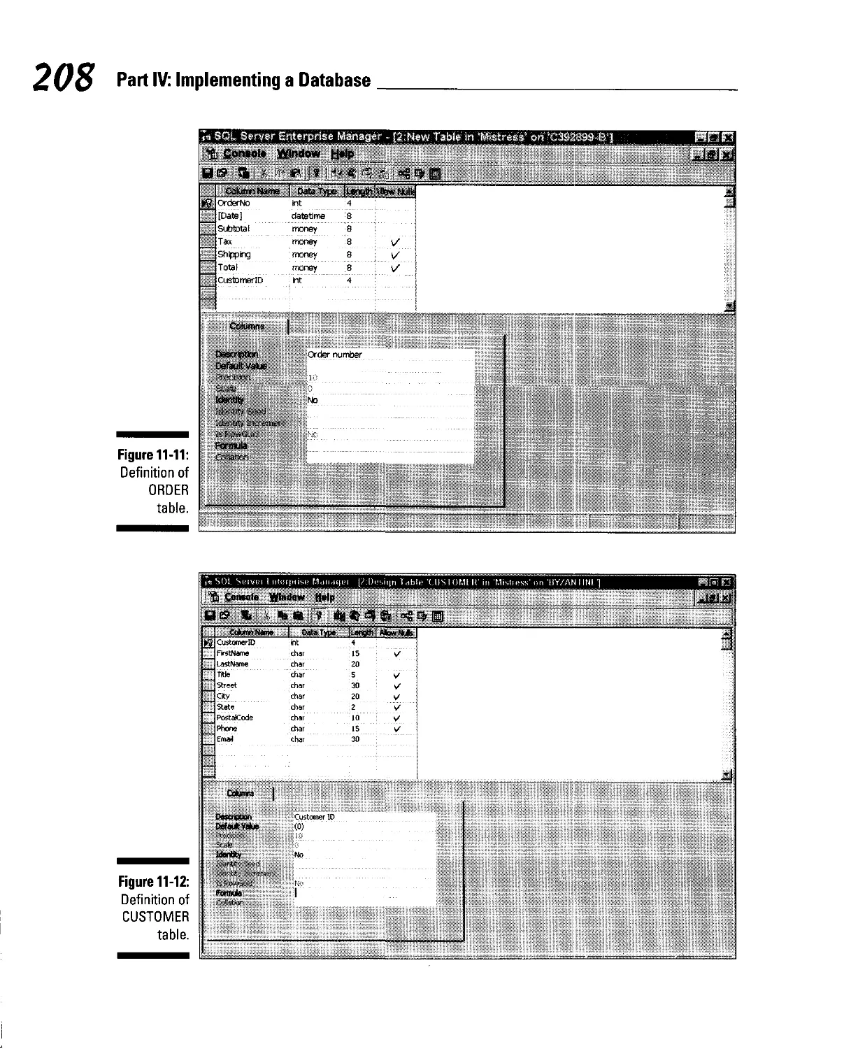
Building tables 202
Establishing the relationships among tables 209
Is that all there is to it? 212
Adding data to tables 213
Creating queries 214
Creating forms, reports, and applications 216
Chapter 12: Using SQL to Implement a Database 217
The Evolution of SQL 217
ANSI Standard SQL 218
The standards conflict 218
Interactive SQL 219
Embedded SQL 220
SQL Variants 220
Creating a Database with SQL 221
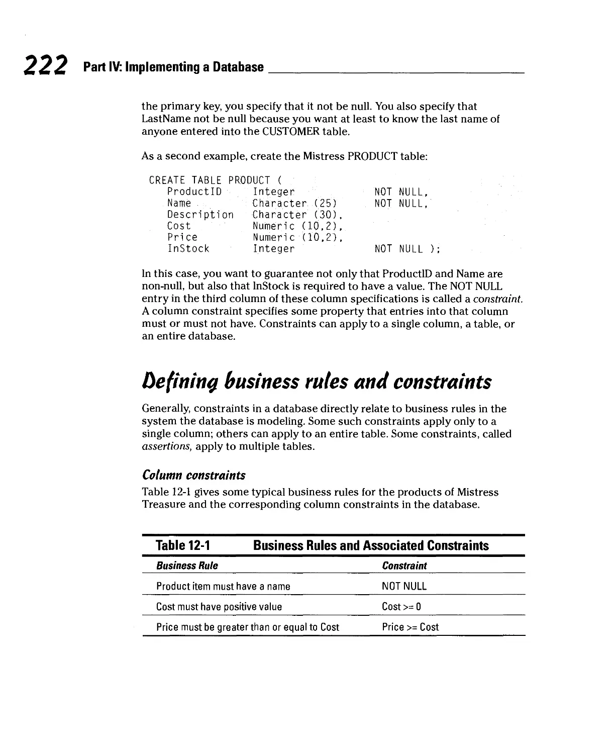
Creating the table structure 221
Denning business rules and constraints 222
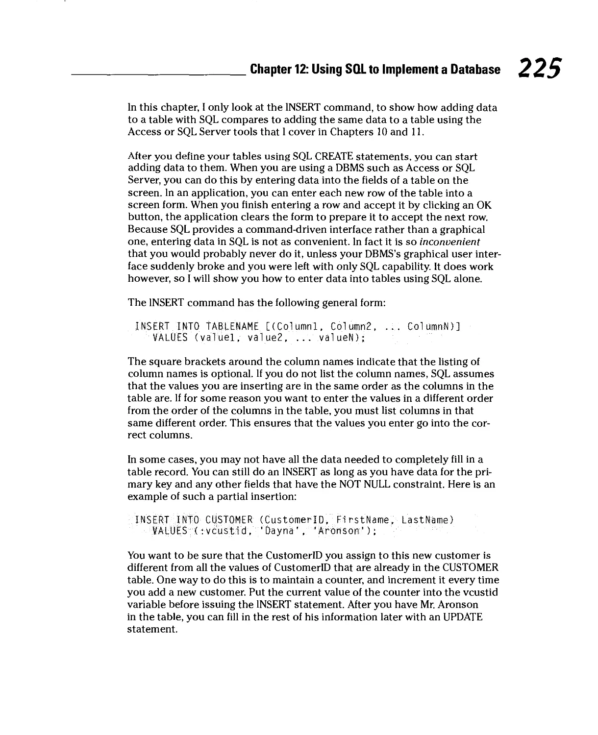
Adding data to tables 224
Building security and reliability into your databases 226
Part V: Implementing a Database Application 229
Chapter 13: Using DBMS Tools to Implement
a Database Application 231
Building a Forms-based Application with Access 232
Doing justice to the stages of system development 232
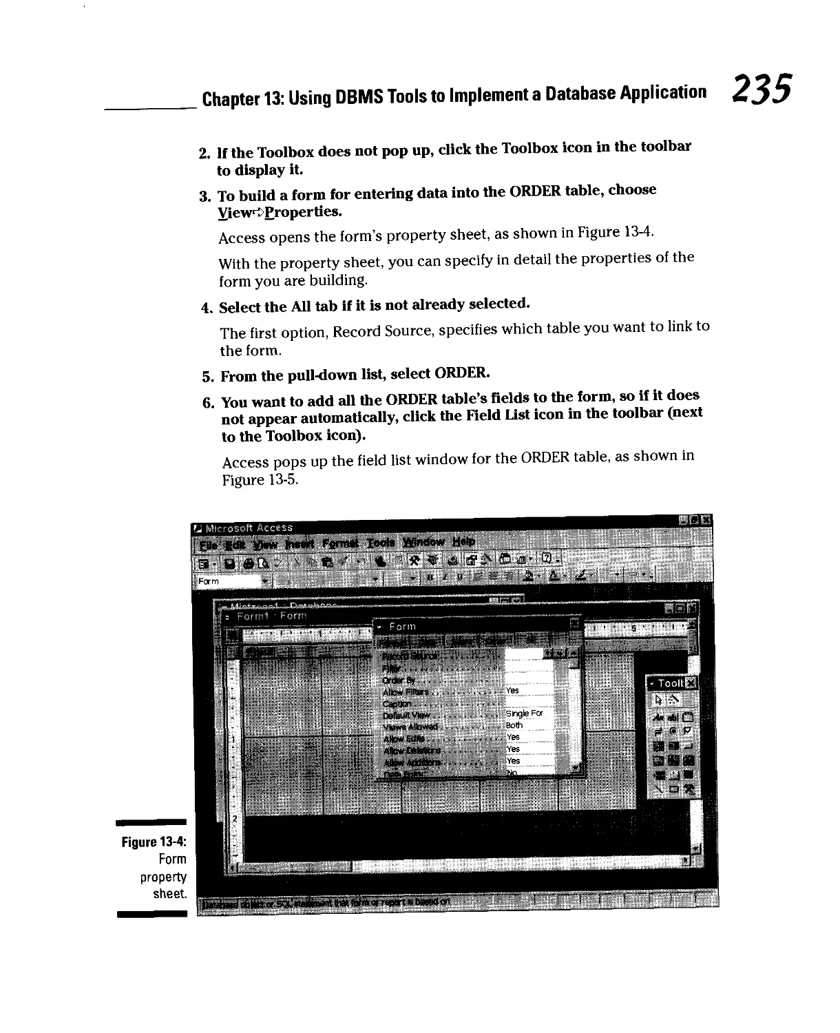
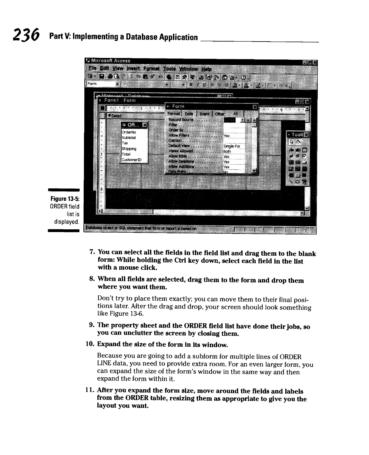
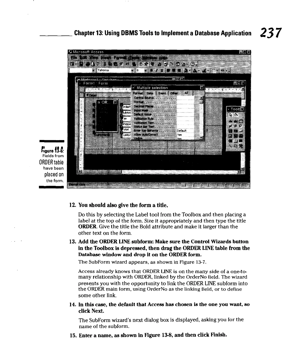
Building the application's forms 232
Tying things together with a switchboard form 242
Using VBA to Create a More Sophisticated Application 248
Chapter 14: SQL and Database Applications 251
Programs and Procedural Languages 251
SQL and Set-at-a-Time Operations 252
Combining the Procedural and the Nonprocedural 253
Embedding SQL in a procedural program 254
Using module language 255
Using SQL without a Host Language 256
Database Development For Dummies
Part VI: Usina Internet Technology v)ith Database 257
Chapter 15: Database on Networks 259
The Architecture and Functions of Client/Server Systems 259
Two-tier client/server architecture 260
Three-tier client/server architecture 262
Comparing ODBC (Open Database Connectivity)
and native drivers 263
Front-end code 264
Back-end code 264
The Internet Changes Everything 264
Two-tier Web architecture 265
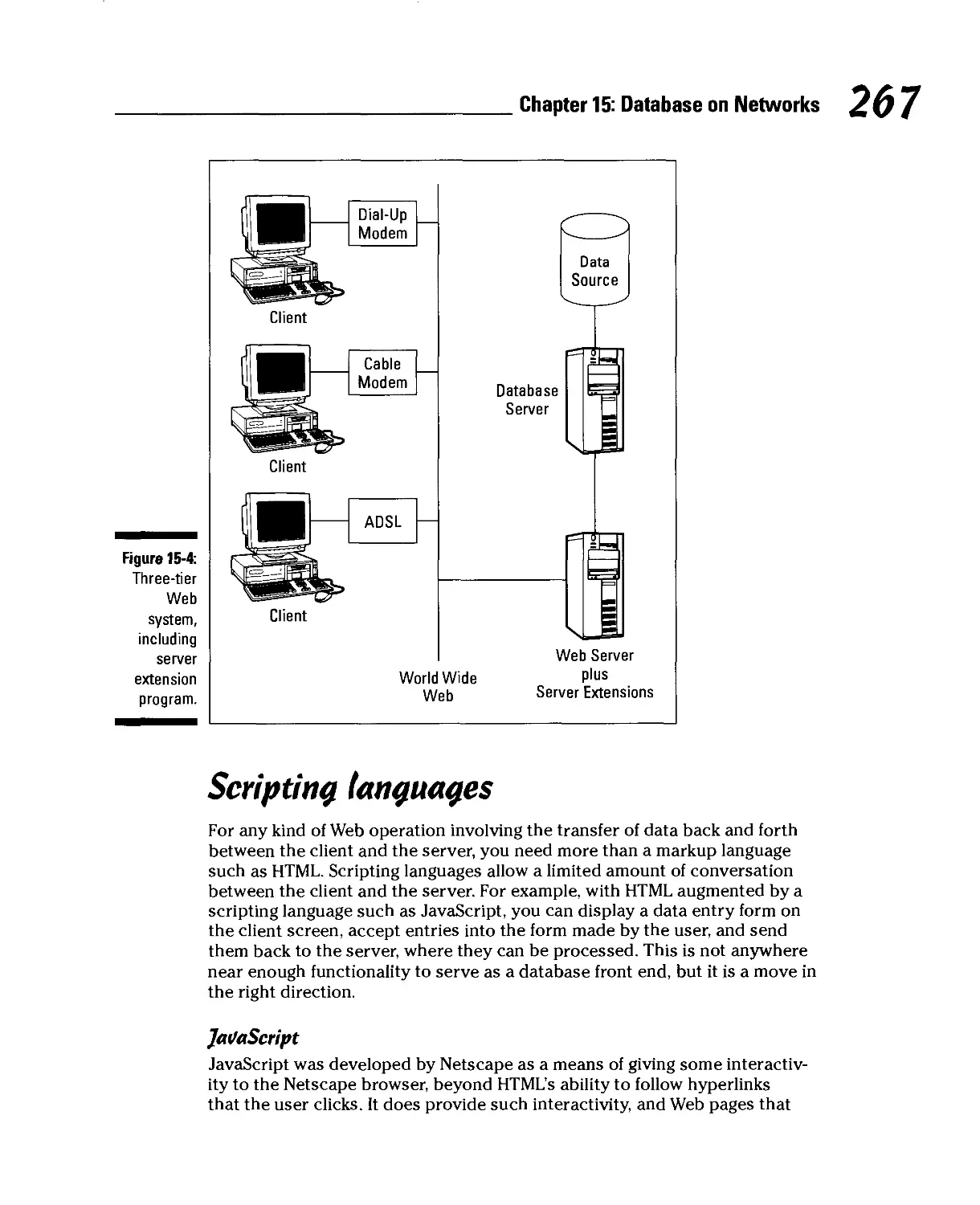
Three-tier Web architecture 265
The language of the Web 266
Scripting languages 267
Java 269
Serving Up Information Over the Organizational Intranet 269
Chapter 16: Database Security and Reliability 271
Maintaining Database Security 272
Users and privileges 272
Classes of users and the privileges they have 273
Controlling Concurrent Access 275
Transactions 276
Serializability 276
Locking 277
Database Crash and Recovery 278
How system crashes can hurt you 278
Recovering from a crash 279
Part VII: The Part of Tens 281
Chapter 17: Ten Rules to Remember When
Creating a Database 283
Databases, Even Huge Ones Such as NASA's Bill of Materials for the
Space Shuttle, Can Be Designed, Built, and Maintained 284
Build Your Database Model to Accurately Reflect the
Users'Data Model 284
Be Sure to Budget Enough Time to Do Justice to Every One of the
Phases of Development 284
Build a Conceptual Model of Your Proposed Database 285
Make Your Model as Detailed as It Needs to Be, but Not More So 285
Build Flexibility into Your Systems So They Will Adapt Easily When
Requirements Change 285
Table of Contents
Accurately Assess the Project's Scope at the Beginning 286
Make Sure All the Relations in Your Model Deal
With Only One Idea 286
Sometimes, for Performance Reasons, You Will Want
to Denormalize Relations So They Deal With More than One Idea....286
Reduce Any Many-to-Many Relationships in a Model to
Multiple One-to-Many Relationships 287
Chapter 18: Ten Rules to Remember When Creating
a Database Application 289
Talk to Your System's Future Users a Lot 289
Document Every Phase of the Development Process 290
Test Your Application Frequently 290
Be a Consensus Builder 290
Pick the Right Tools for the Job 290
Database Applications Communicate with Databases Using SQL 291
Use Standard SQL Wherever Possible 291
Optimize the Server for Fast Data Transfer 291
Configure the Client for Lowest Cost 291
Pump Some Life into Web-based Applications 292
Glossary 293
Index 305
XXII Database Development For Dummies
Introduction
ecause you are reading this, 1 assume that you have recently become
interested in database. Perhaps you would like to impress your friends
by casually tossing out some big words that they have never heard before —
words such as semantic object model, denormalization, or maybe even tuple.
Perhaps your boss at work has just informed you that your department will be
computerizing its records and that you have been assigned to build the
database. Whatever your motivation, this book will get you started down the path
to becoming a true database guru. When you reach that exalted level,
impressing your friends with big words will pale in significance compared to what you
will be able to do with your organization's most important information.
Ever since computers became powerful enough to support them, databases
have been at the core of both commercial and scientific data processing. The
domain of database processing includes any problem or task that must deal
with large amounts of data. Most database systems in existence today, and
practically all new systems being implemented, make use of relational
database technology, the subject of this book.
About This Book
This book takes you step by step through the conceptualization, design,
development, and maintenance of relational database systems. It gives you
a solid grounding in database theory and then shows how to reduce that
theory to practice using two of the more popular database management
systems in use today: Microsoft Access and Microsoft SQL Server. Major topics
covered include
v* Understanding database architecture and how it has evolved
v* Recognizing how database technology affects everyday life
*-" Using a structured approach to database development
v* Creating an appropriate data model
v* Creating a reliable relational design
v* Implementing a relational design
v* Keeping a database secure
v* Putting your database on the Internet
B
Database Development For Dummies
My objective with this book is to give you the information you need to build
a robust database system that will do what you want it to do. When designed
correctly, a database system will give you the performance, flexibility, and
reliability to meet your needs, both now and in the future.
Who Should Read This Book)
Anyone tasked with the development of a software system that incorporates
a database element, or anyone managing the people who do such
development, should read this book. Any person in any organization that uses
database technology (that should be just about anybody who works anywhere)
can benefit from understanding the concepts I explain in this book.
Databases have penetrated every nook and cranny of our highly connected,
information-intensive society. The more you understand about how they
function and the differences between well-designed and poorly designed
databases, the better you will be able to decide the best way to use your
organization's database resources.
foolish Assumptions
In order to write this book, I had to make some assumptions about who would
be reading it and what their level of expertise would be. Based on feedback I
have received from readers of SQL For Dummies, I know that accurately
targeting readership is incredibly difficult. I expect that some readers will be gaining
their first exposure to databases, while others will be professional database
developers. I have tried to make the book understandable to the first group,
while at the same time making it a useful guide to the second group.
Hou? This Book Is Organized
This book contains seven major parts. Each part consists of several chapters.
It makes sense to read the book from beginning to end because later material
builds on an understanding of what has gone before. You may decide to skip
either the Access chapter or the SQL Server chapter if they do not apply to
you. However, the implementation details that I describe in those chapters will
be similar to what you will encounter in other development environments, and
thus will probably be valuable to you anyway.
Introduction
Part I — Basic Concepts
Part I establishes the context for the rest of the book. It describes the position
of data and databases in the world today and then describes how to
systematically design and develop a database system incorporating a database and one
or more applications that operate on that database. This part also describes
challenges that often arise in the course of a database development project,
and how you can best address them.
Part II — Data Modeling: What Should
the Database Represent}
In any database development project, you must address a few key questions —
for example: What exactly should the database represent, and to what level of
detail? Answers to these questions come from finding out who will use the
proposed system and how they will use it. Finding out the needs and expectations
of the users, and then transforming those needs and expectations into a
formal, structured data model forms the core of Part II. Getting this part
right is absolutely critical to the successful completion of a development
project.
Part III — Database Design
After you have a model of the proposed system that is satisfactory to
everyone concerned, you need to convert that model into a database design. In
order for your design to be reliable as well as functional, you need to decide
how best to transform complex relationships among data items into simpler
relationships that are not subject to the data corruption problems that often
accompany complexity. Part III highlights the complexities you are likely to
encounter, and in each case describes how best to transform them into a
simpler form that eliminates the problems.
Part IV— Implementing a Database
Part IV starts with a database design, developed using the techniques that I
explain in Part III, and shows step by step how to convert that design into a
database using some of the more popular database development tools available
today. First, I cover the process using Microsoft Access 2000. Then, I show you
how to implement the same design using the SQL Server 2000 DBMS. Finally, I
explain how to implement the design using straight SQL code, without the help
of any fancy development tools. I clearly delineate the strengths and
weaknesses of each approach as I describe each method.
Database Development For Dummies
Part V— Implementing a
Database Application
The application is the part of a database system that the users see and
interact with. It is the application that answers whatever questions the users pose
to the database.
The implementation of a database application can differ greatly from one
development environment to another. On the one hand, Access gives developers an
integrated forms wizard and report writer and the ability to create a complete
application without writing a single line of procedural code. On the other, a
developer can write a database application using only procedural code with
embedded SQL statements, without the aid of a DBMS such as Access. SQL
Server falls somewhere in the middle. You can use external forms generator
and report writer packages along with procedural code to operate on an SQL
Server database. You can also employ a hybrid approach in which you use
some or all of these facilities. The ability to use all these tools gives you the
ultimate in flexibility, but also requires the highest level of expertise.
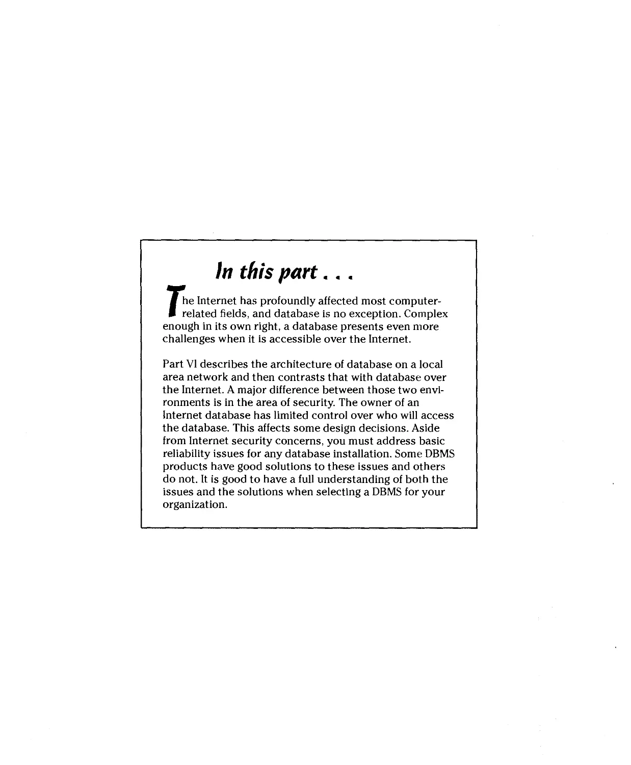
Part VI — Using Internet Technology
With Database
Databases are most useful when resident on networks available to multiple
people. That usefulness is multiplied when the number of users increases, as
it does when the database is accessible over the Internet or a large
organizational intranet. In Part VI, I discuss network architectures, the kinds of threats
to data integrity that network operation causes, and the particular threats
that are peculiar to the Internet. In general, good countermeasures to these
threats exist, but developers and database administrators must be aware of
the threats so they can apply the countermeasures effectively.
Part VII — The Part of Tens
Part VII distills the messages of the preceding six parts, providing concise
summaries of the main things to keep in mind when designing and building
systems based on relational database technology. If you keep these principles
in mind, you can't go too far wrong.
Introduction
Contentions Used in This Book
In this book, I use several typographical conventions. 1 use monofont type for
code that appears within a regular paragraph of text — for example, to tell you
about anaccess denied error message. I use command arrows (O) to present
menu commands in the most concise manner possible. For example, if 1 didn't
use command arrows, I would have to give you instructions like this: "In the
menu bar, choose File. Then, in the resulting menu, choose Open." With the
command arrow, all that verbiage boils down to this: "Choose FileOOpen."
Icons Used in This Book
Throughout the pages of this book, 1 use these icons to highlight particularly
helpful information.
Tips save you time and keep you out of trouble.
You really should pay attention whenever you see this icon. A major danger
is described, along with the best way to avoid it.
This material is not absolutely necessary for a good understanding of the
concepts being presented, but is often interesting to know.
Generally, the text marked with this icon is material that you will need later.
Make a mental note of it.
Where to Go From Here
Enough preliminaries! Dig into the real meat of this book — what databases are
and how to build them. Understanding those two things is rapidly becoming a
requisite for just about anyone involved in commerce, science, or anything else
that involves the storage and processing of data. Start with Chapter 1. It gives
you the perspective you need to understand where database technology came
from and where it stands today.
%) Database Development For Dummies
Parti
Basic Concepts
The 5th Wave
BvRichTennan
i< co you vwrr me to call thegqmbwy/np mve them
SEW MOTHER REVIEW QOPY OF THEIR WWMSE SDRYflRE
SVSIHM.ORPDYOI KNOW WHAT YOTRE GOING TD WRITE?"
In this part...
/n Part 1,1 give you the background information you
need in order to build high-quality databases and
database applications. I describe the different classes of
databases and what makes them different. I also describe
the critical role that databases play in our data-saturated
world, including the so-called "new economy." 1 offer a
brief history of data processing and the advent of
database systems, leading up to coverage of what databases
and database applications are, followed by a structured
approach to building them. I also describe some of the
major pitfalls of database development, and explain how
to avoid them.
Chapter 1
Database Processing
In This Chapter
D* Sorting out the different classes of databases
► Discovering what databases can do for you
► Understanding database processing
m database processing is one of the more common operations performed
W<f on computers today. In fact, only word-processing and spreadsheet
packages outrank database management systems among the most popular
business tools. Everyone, from the largest corporate entities to private
individuals, wants to keep track of something. Applications such as order entry,
accounts receivable, accounts payable, and general ledger all incorporate
databases. Companies keep track of their customers, product inventories,
employees, and capital assets in databases. Businesses, governments, and
organizations around the world would grind to a halt without databases.
The different Classes of Databases
Large international corporations and national governments have substantially
different data management needs from those of a private individual or even a
small to medium-sized company. Large database users have demanding
capacity and performance requirements and are willing to pay what it takes to meet
those requirements. That kind of power would be serious overkill for an
individual, local non-profit organization, or small business, and would be too
expensive anyway. As a result, different database development tools are
available for addressing different market segments. Some of these tools, called
database management systems (DBMSs), are capable of supporting huge, high-
performance databases, but require very powerful (and expensive) mainframe
computers to do the job. Other tools run on personal computers, and are
limited in the size and performance of databases they are able to support.
Part I: Basic Concepts
Enterprise databases
The first databases, back in the 1960s, although primitive by today's standards,
were applied to large, enterprisewide problems, such as airline reservation
systems, and maintaining bills of materials for NASA spacecraft. In those days,
computers were big, expensive to buy, and expensive to run. Only large
corporations or government agencies could afford to own the computers that could
support a database. As a result, the first databases were enterprise class
databases. The database management systems that were used to create databases
were powerful, robust, and resource-hungry.
As computer power has steadily increased and become less expensive,
enterprise class databases have become even more powerful and are capable
of supporting much larger collections of data. The data on such systems is also
accessible to thousands of simultaneous users. Today, large organizations get
orders of magnitude larger and faster databases for much lower cost than was
true in the early days of database, but costs of such systems are still out of
reach for individual users. This is not a big problem, because few individuals
need a database system that supports thousands of simultaneous users.
Personal databases
In 1975, the first, primitive personal computer kits arrived on the scene, and in
1976 you could buy one already assembled. (Pretty slick, eh?) These machines
were not powerful enough to support even a very cut-down database
management system, but performance improved steadily. With the advent of the IBM
PC coupled with hard disk storage, database technology started to proliferate
on personal computers in 1981.
Personal database products are much simpler than their enterprise class
ancestors. For one thing, they have to support only one simultaneous user,
rather than thousands. For another, typical single-user applications use much
smaller databases than those needed to run an airline reservation system or
something similarly huge. Furthermore, because there were soon millions of
personal computers compared to a much smaller installed base of mainframe
computers, the economies of scale kick in and it is possible to sell personal
databases at a much lower price than mainframe databases and still make a
profit. Development costs are spread over many more units.
Today, personal computers have become so powerful that the DBMS
products available on them have much more capacity and much better
performance than did the mainframe DBMS products of yesteryear.
Chapter 1: Database Processing
The Y2K catastrophe
Remember the big Y2K scare? People were seri- were taken out. Who knows? Maybe even Pez®
ously concerned that on the stroke of midnight dispensers would cease functioning.
on December 31,1999, the world as we knew it „.„. , . „ ..mm*
..,„,.m ■.„„„ f„ „„ „„a ia/„h m„..t,„ „„♦ „„m„ *,. Billions of dollars were spent worldwide to exor-
would come to an end. Well, maybe not come to iL. „„„ . ...!_ ... llit. .
an end, but terrible things would surely happen. cis,e;he tY2fK,dem°n: m™M a" *at m0"eV
Airliners would fall out of the sky. ElevaSors 9°? Most of ,t went to mod,fy.ng database files
would drop downtheir shaftsand crash intothe andthe aPPl'"t.ons that accessed them. Some
buildingbasementfloor.Carengineswouldturn ™s fPfJ °" new equ'pm!;nt' because *e
off while you were cruising at 60 mph on the thre+at of Y2K d,saster made' ?as'e[ f°r wo?"
freeway. Libraries would send fine money to fhrs t0 c0™nce mva"a9ement ^t0 b« safe-
patrons with overdue books, because the books ** needed new Y2K-compl,ant computers or
were returned a hundred years before they z IS|)e
Workgroup databases
After millions of personal computers had been sold and installed in companies
large and small, people came to a fundamental realization. Millions of people,
each with their own personal computer, now had far greater ability to do their
work faster and with less effort than had been the case before. Productivity had
taken a quantum leap forward. However, each one of those personal computers
was an isolated island of compute power and data storage. Productivity would
be boosted even more if somehow the data and compute power residing on
those personal computers could be shared.
Networking connected the personal computers together, and a new class of
database — the workgroup database — was invented to take advantage of
the new connectivity. Workgroup databases, accessed by perhaps up to 50 or
100 simultaneous users, filled the gap between the enterprise database and
the personal database. Today, in small to medium-sized organizations,
workgroup databases are the most common of the three database classes.
So Much Data, So Little Time
Ever since electronic computers first came into use in the late 1940s, they
have generated data of all types much faster that had ever been possible
using adding machines along with paper and pencil. Since then, the power of
computers has been increasing at an exponential rate. Moore's Law, named
after Intel co-founder Gordon Moore, has held true for decades, stating that
the power of computers doubles about every 18 months, as shown in
Figure 1-1.
Part I: Basic Concepts
Figure 1-1:
Growth of
computer
power as a
function
of time.
1GB
100MB
10MB
1MB
100KB
10KB
1KB ^
1KB
256MB ^
64MB /
16MB / Z „ . „
y^ yw Pentium II
4MBy
1MB^/^*"
256KB S^tf*
S^j± 80386
64KB /%/^Wm
s£Swm
™Y~7* 68000
4KB/~/^ 8086
• /*£* 8085
£/*8080
4044
70 74 78 82 86 90
S% Pentium Pro
JkP Pentium
80486
68040
▲ Memory [ORAM]
• Microprocessor/Logic
1 '
94 98
The amount of data that computers are able to process doubles at a
comparable rate. As a result, we are being drowned in a veritable sea of data. Much
of it is potentially valuable, but the situation has reached the point where
data is being gathered so fast that much of it may never be put to use. Raw
data has very little value. It gains value when it is organized in such a way
that it conveys meaningful information to people who can use that
information. Databases are our most powerful tool for organizing data into
potentially valuable information.
Databases and privacy: We know who
you are, and We know Where you iiVe
One of the unanticipated consequences of the tremendous growth in the
amount of data that is generated every day is the erosion of personal privacy.
A generation ago, as long as you were not a famous or notorious person,
nobody knew much of anything about you. Your private life was just that,
private. If you wanted to drop out of sight, move somewhere else and start a new
life, it was not very difficult to do. Aside from a small number of people in your
local community who had lived and worked with you, you were a complete
unknown to the world at large. Those days are gone and will never return.
Now it is practically impossible to buy anything, sell anything, or travel
anywhere by air, rail, or sea, without the fact being recorded in a database
somewhere. Ever since the days of J. Edgar Hoover, the FBI has prided itself in its
ability to know the whereabouts of and important facts about individuals it
Chapter 1: Database Processing
considers important. Nowadays, you don't have to be the FBI or the CIA to
have that kind of knowledge about anyone you care to know about.
Merchants, airlines, and travel agents have data on your living and buying habits.
With the recent rash of mergers of all kinds of organizations into larger
entities, this data is becoming centralized. Residing in databases that can be
"mined" for useful information, companies can find out not only who you are
and where you live, but also what you like to eat, what you like to read, who
your favorite musicians and entertainers are. They know what your favorite
sports teams are, and what sports you like to participate in yourself. They
know where you shop and how often. They know when you are about to run
out of something you buy regularly. They know when your kids are born,
when they are about to enter kindergarten, when they will graduate from high
school, and when they are engaged to be married.
All this data is stored in databases. The databases are growing larger, not
only because more data is added to them on a daily basis, but because new
kinds of data are being captured and stored, based on the activities and
transactions that you participate in, in the course of your daily living. The
amount of data being stored in databases every day, based on people's
actions and transactions, is already huge, but will get even larger in the
coming months and years.
Bottom Line: Although databases are constantly getting larger, even data
stored in huge databases can be quickly and easily processed to give users
exactly the information they want.
Amazon.com and the online merchants
The rise of e-commerce on the World Wide Web has accelerated the
accumulation of data about people. Records are kept of people who visit Web sites, and
even more elaborate records are kept about people who actually buy things
at Web sites. Many Web sites require users to register before allowing access
to their best content. By registering, the user reveals personal information
that the site then uses to construct a user profile. The profile enables the site
to display personalized content to visitors. For commercial sites, this means
users are more likely to become buyers, because they are being presented
with advertisements and other content that are tailored to their interests.
Amazon.com, the largest retailer on the Web, has perfected the technique of using
. databases to characterize its customers. By analyzing the kinds of products you
have bought or expressed interest in, in the past, Amazon.com can present you
with displays of similar products that you are likely to find interesting. This sales
strategy requires not only massive, well structured databases, but also
sophisticated data mining software that finds associations and relationships in
customers' past behavior that allow predictions of what they are likely to do and
want in the future.
Basic Concepts
Other online merchants are following Amazon's lead and using databases and
data mining technology to offer visitors a customized experience. This is
good in that people are not presented with content they are not interested in,
or advertisements for products that do not interest them. It is potentially bad
because merchants will know a lot about people, and that knowledge could
be abused.
Bottom Line: Like it or not, unless you are a hermit living in a cave, people
you don't know and have no reason to trust know many intimate details
about your life. If you use checks or credit cards, your life is an open book. If
you buy things from merchants such as Amazon.com on the Web, that book
is an international bestseller.
Data deluge: It came from outer space
The United States has been launching rockets into earth orbit since 1958,
and ever since, satellites have been radioing high-capacity streams of data
back to Earth. Russia, Japan, China, and the European Space Agency do the
same thing and are also receiving vast quantities of data from their space
probes. All this data is being stored in the hope that someday it will be
analyzed and human knowledge will be advanced as a result. The most promising
data is analyzed fairly soon after it is received, but the large majority of data
returned from space is not examined for years, if ever. The speed with which
we collect data far exceeds the speed with which we can analyze it and draw
useful conclusions.
In 1994, the Clementine spacecraft orbited the moon for several months,
taking data on its entire surface. That data is stored on 88 CD-ROMs, each
holding about 640MB, for a total of 56GB of data about the lunar surface. The
data is in raw form, cataloged by orbit number. Only a small portion of the
data has been examined in detail, particularly data about the areas around
the North and South Poles. The spectral signature of water that appears in
the data from the polar regions has caused excitement among scientists and
advocates of space exploration. However, because the entire dataset is not
organized into a database, it is difficult to search for specific features and
make generalizations about them.
Another spacecraft, Galileo, has been studying the Jupiter system for several
years. It also has sent back huge amounts of data. By studying a small fraction
of that data, space scientists have inferred the existence of a global ocean
under the ice covering the surface of Jupiter's moon Europa, and the probable
existence of a similar ocean under the surface of Callisto. However, the large
Chapter 1: Database Processing
majority of Galileo's data remains unstudied, because in its unorganized state,
it is very difficult to extract useful information from it, unless you already
know what you are looking for. Organizing the data into a database would be
of tremendous benefit, but NASA has no funding for such a massive effort.
Mars Global Observer, currently orbiting Mars, has returned huge quantities of
data to Earth. Some of this, such as dramatic high-resolution photographs of the
Martian landscape, has been analyzed and reported upon. Most, however, has
merely been archived, against the day when resources will allow it to be
studied. In its current raw form, it is practically impossible to discern patterns in the
data that might lead to greater understanding.
Bottom Line: It is difficult to wring information from large datasets that are not
organized into databases. As a result, much of this data sits in archives, unused.
If the storage medium (magnetic tapes or disks, photographic film) is not
maintained properly, the data could degrade to the point of being unusable. In that
case, all the effort that went into collecting it is lost.
The fierce urgency ofnout
The data explosion is out of hand and getting worse every day. The only hope
for making sense out of the floods of data that we are receiving is to organize
it in a way that allows fast, efficient retrieval of just the information we want,
regardless of how large the dataset is. The longer you wait to perform that
organization, the harder it will be to do. If you are in business, your
competitors are using databases to get a handle on their data. If you don't do the
same, and soon, they will gain a huge competitive advantage. Whether you
are just starting out, and as yet have not collected any data, or you are in an
established organization that has been collecting data for years, there will
never be a better time than right now to decide the best way to organize your
data so that you can quickly receive answers to the questions you will want
to ask both now and in the years to come. After you decide what kinds of
information you are likely to want to extract from the data, you can design a
database that will make it easy to do so.
Bottom Line: It is a good thing you are reading this book. Unless you have the
cash to hire a highly paid database guru, you need to understand how to
design a database, so you can do it yourself. Even if you do have the cash to
hire a highly paid database guru, you still will be better off if you understand
what that expert does for you. If you would like to become a highly paid
database guru, this book will start you on your way, and serve as a valuable
reference after you arrive.
Part I: Basic Concepts
What Is database Processing)
By this time you are probably asking, "What makes database processing so
wonderful?" You can understand the value of organized data compared to
unorganized data, but there are many ways to organize data. What makes the
database structure so superior to just plain old storing things in a consistent,
logical order? That is a valid question. To answer it, 1 describe how computer
scientists organized data before databases came into use, so you can see the
advantages and disadvantages of that method. Then, I explain how the
structure of an information system based on database technology differs, along
with the advantages and disadvantages of the database method. On balance,
the advantages of using database technology far outweigh the disadvantages.
file processing: The old Way
As shown in Figure 1-2, computers consist of three principal subsystems: the
processor, the memory, and the input/output subsystem, which includes
such components as the keyboard and the monitor's screen. The processor
performs all the computations and operations. The memory stores things
when they are not being processed. The input/output subsystem conveys
information back and forth between the computer and the user. You control
computations and other operations with program code, which is stored in
memory. The data that you operate on is also stored in memory.
Figure 1-2:
The
principal
subsystems
of a
computer.
Memory
Processor
Input/Output
Screen
Keyboard
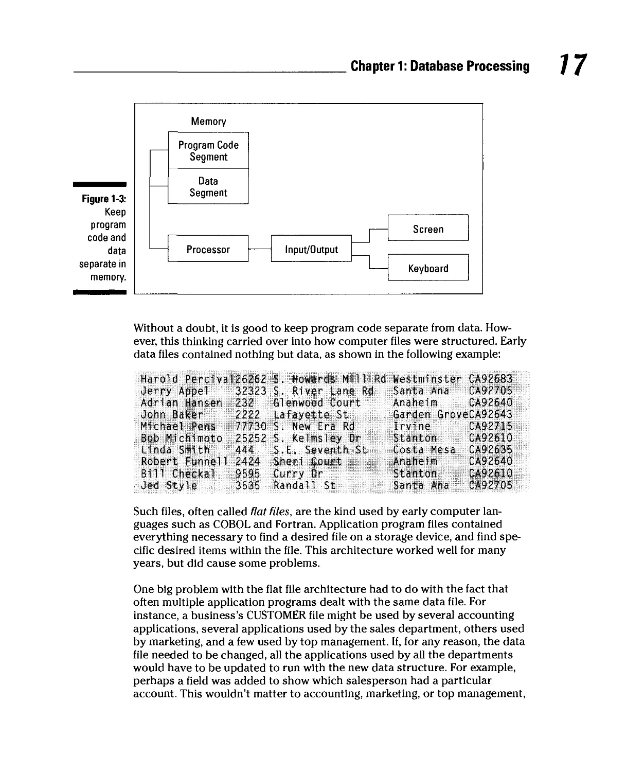
To early computer scientists, it made a lot of sense to rigidly separate the
memory used to store program code from the memory used to store data, as
shown in Figure 1-3. For most applications, data changes frequently while an
application is processing it. On the other hand, it is very dangerous to allow
program code to change while that very same program code is executing.
More often than not, such self-modifying code causes what have come to be
called computer crashes.
Chapter 1: Database Processing
Figure 1-3:
Keep
program
code and
data
separate in
memory.
Memory
Program Code
Segment
Data
Segment
Processor
Input/Output
Screen
Keyboard
Without a doubt, it is good to keep program code separate from data.
However, this thinking carried over into how computer files were structured. Early
data files contained nothing but data, as shown in the following example:
Harold Percival26262
Jerry Appel
Adrian Hansen
John Baker
Michael Pens
Bob Michimoto
Linda Smith
Robert Funnel 1
Bill Checkal
Jed Style
OlOl J
232
2222
77730
25252
444
2424
9595
3535
S. Howards Mill Rd
S. River Lane Rd
Glenwood Court
Lafayette St
S. New Era Rd
S. Kelmsley Or
S.E. Seventh St
Sheri Court
Curry Dr
Randall St
Westminster
Santa Ana
Anaheim
Garden Grov
Irvine
Stanton
Costa Mesa
Anaheim
Stanton
Santa Ana
CA92683
CA92705
CA92640
eCA92643
CA92715
CA92610
CA92635
CA92640
CA92610
CA92705
Such files, often called flat files, are the kind used by early computer
languages such as COBOL and Fortran. Application program files contained
everything necessary to find a desired file on a storage device, and find
specific desired items within the file. This architecture worked well for many
years, but did cause some problems.
One big problem with the flat file architecture had to do with the fact that
often multiple application programs dealt with the same data file. For
instance, a business's CUSTOMER file might be used by several accounting
applications, several applications used by the sales department, others used
by marketing, and a few used by top management. If, for any reason, the data
file needed to be changed, all the applications used by all the departments
would have to be updated to run with the new data structure. For example,
perhaps a field was added to show which salesperson had a particular
account. This wouldn't matter to accounting, marketing, or top management,
Part I: Basic Concepts
but all their applications would have to be updated anyway. Not only was this
a lot of extra work, but it also made those applications subject to errors. The
old adage, "If it ain't broke, don't fix it" applies in spades here. However, with
the flat file structure, those unrelated applications did become "broke" and
needed to be fixed.
Another problem with the flat file structure is not so obvious, but just as
important. In today's rapidly changing computing environment, it is not wise
to tie your applications to any specific hardware implementation. You can be
sure that your hardware will become obsolete sooner or later, probably
sooner. After a while, obsolete hardware is not supported any longer. Once
you can't get replacement parts or operating system upgrades anymore, it is
time to discard your old hardware. You don't want to discard your
application programs along with it.
So, computer programs should be independent of the hardware they run on.
That is not possible with flat file systems, because the information about the
physical location of the data is included in the application programs. This fact
caused major pain in the 1960s when IBM moved its customer base from the old
transistor-based 709X architecture to the new integrated circuit-based System
360 architecture. IBM's customers were not happy about having to rewrite all
their application code, but they had little choice.
Lesson Learned: Somehow, structure things so that application programs can
access data without having to know its physical location.
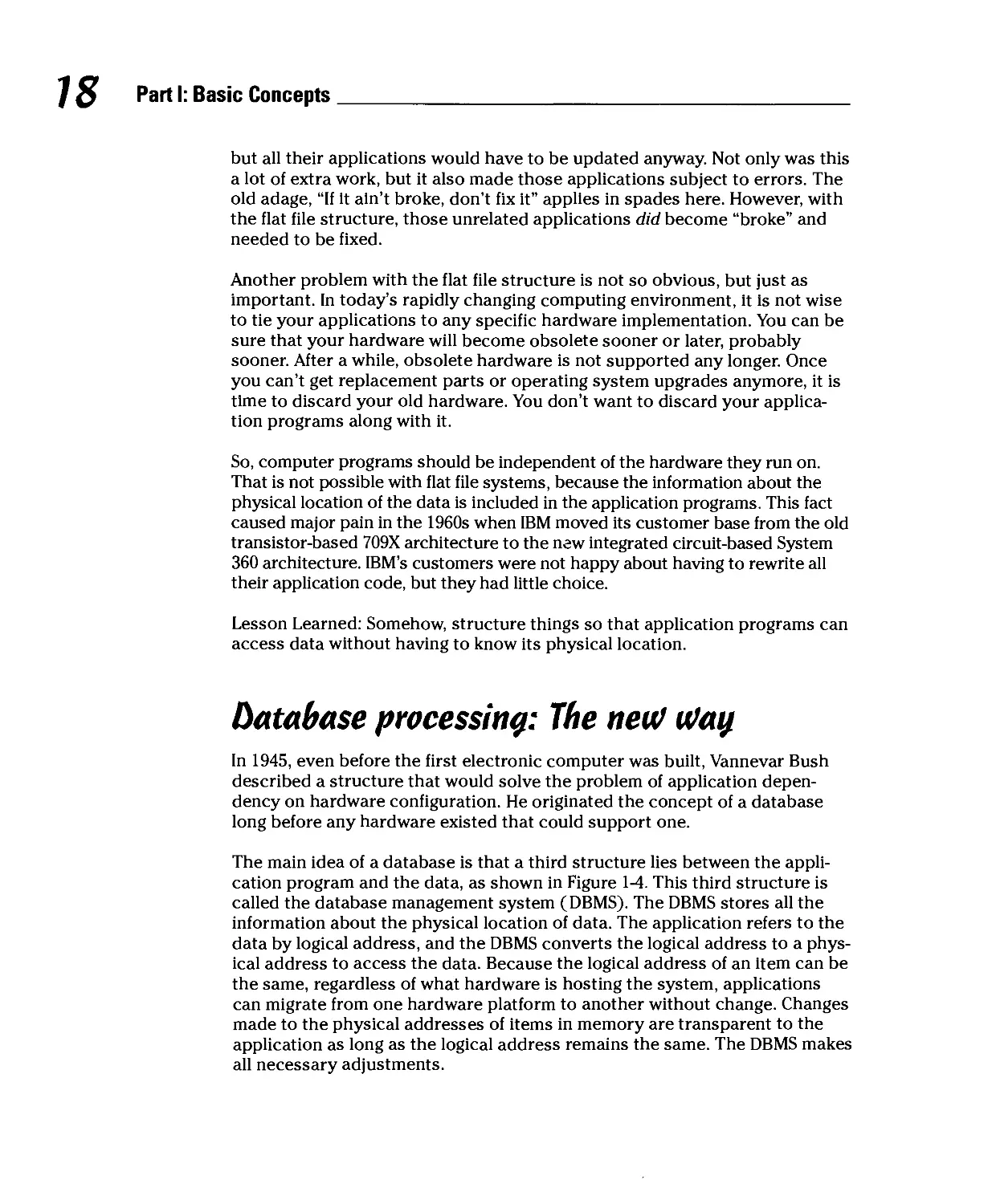
Database processing: The neu? ufay
In 1945, even before the first electronic computer was built, Vannevar Bush
described a structure that would solve the problem of application
dependency on hardware configuration. He originated the concept of a database
long before any hardware existed that could support one.
The main idea of a database is that a third structure lies between the
application program and the data, as shown in Figure 1-4. This third structure is
called the database management system (DBMS). The DBMS stores all the
information about the physical location of data. The application refers to the
data by logical address, and the DBMS converts the logical address to a
physical address to access the data. Because the logical address of an item can be
the same, regardless of what hardware is hosting the system, applications
can migrate from one hardware platform to another without change. Changes
made to the physical addresses of items in memory are transparent to the
application as long as the logical address remains the same. The DBMS makes
all necessary adjustments.
Chapter 1: Database Processing
Seems strange, doesn't it, that the idea of a database was known, but early
computer pioneers went ahead and based their software on flat data files
anyway? They had good reason, however, for this seemingly shortsighted
choice. A DBMS requires a great deal of computer power, raw speed, in order
to return results in a tolerable amount of time. The early computers did not
have enough power to run a DBMS. As a result people designed around flat
file systems. Without the overhead of a DBMS, these systems ran much faster,
and meaningful work could be done on slow vacuum tube-based and later
transistor-based hardware.
As computer performance improved, use of database architecture became
more and more feasible. Finally, in the early 1960s, the first commercial
database systems started to appear. Initially, they were used only on the largest
computers, applied to the largest projects, such as keeping track of all the
parts and documents associated with the Saturn V launch vehicle and Apollo
moon landing spacecraft. At the time, the Saturn V/Apollo combination was
the most complex machine that humanity had ever built. As computer power
continued to increase, database technology trickled down to ever-smaller
machines, until it became available on personal computers around 1980.
Today, robust database management systems are available on computers of
all sizes and are used routinely by individuals and organizations to manage
the data that is important to them.
Types of database systems
There are a number of ways that a DBMS could organize data, and there are
advantages and disadvantages to each of those ways. A number of different
structures have been tried, some with more success than others. IBM's DBMS
for NASA's Saturn V/Apollo project, later dubbed IMS, had a hierarchical
Part I: Basic Concepts
structure. Competing products of the same era had a network structure. The
evolutionary descendants of these pioneering products are still in use today.
The vendors that support them have maintained compatibility over the years
so that their customers can continue to benefit from the massive investments
they have made in applications that use those DBMS structures.
Hierarchical databases have a simple, hierarchical structure (no surprise
there, I guess) that allows very fast data access. However, as Robert A.
Heinlein once pointed out, "There Ain't No Such Thing As A Free Lunch
(TANSTAAFL)." You pay for that fast access with structural rigidity. Once a
hierarchical database has been implemented, it is very difficult to modify. In
the real world that I live in, requirements change over time. Business models
change, markets change, companies grow, companies shrink, companies
enter new markets or exit old ones. They introduce new product lines and
abandon others that are no longer popular. This situation caused early
databases to be a major bottleneck and impaired many organizations' ability to
react to change in a timely manner.
Network databases were not a significant improvement, although they had
different problems. In contrast to the simple relationships characteristic of the
hierarchical structure, network databases allowed any item in the database to
be directly related to any other item. This allowed more flexibility than the
hierarchical structure, but sacrificed some speed to do it. In addition, the
added complexity made network databases more difficult to maintain.
In 1970, E.F. Codd, then at IBM, published a landmark paper that outlined the
basic structure of a new type of database system: the relational database.
Relational databases are much more flexible than either hierarchical or
network, but at the same time have a simple structure. Nevertheless, TANSTAAFL
is still in force. The advantages of the relational model are offset by the fact
that it carries significantly more overhead than either of the other database
models. This means that it runs significantly slower. However, as computer
performance has improved over time, the use of relational databases has
become progressively more feasible.
Over time, the relational model has displaced the earlier hierarchical and
network models in practically all new installations and is the dominant type of
database in use today. In some application areas, an even newer model, the
object-oriented model has gained adherents. A hybrid, the object-relational
model, retains the advantages of relational DBMSs while gaining the benefits
of the newer object model. However, the usage of object and object-relational
DBMS products is still relatively small. In this book, I concentrate on
relational database technology, with one chapter devoted to object-oriented and
object-relational technology.
Chapter 2
Database Development
In This Chapter
► Defining database
► Exploring the database development process
► Understanding the difference between a database and a database application
► Fighting the urge to cut corners
/n Chapter 1,1 explain several important points about data and databases.
Just in case you weren't paying attention, or you skipped Chapter 1
entirely, here are three key points that you need to consider:
I i<" We all have lots of data.
? v" That data is much more valuable if it is organized.
| v0 A relational database is probably the best way to organize most types of
? data.
So, what exactly is a database, specifically a relational database, and how
does one go about building one? Those are two separate questions. The first
can be answered rather simply. The answer to the second question could
take a book. Fortunately, you have that book in your hands.
What Is a Database)
A database is a self-describing collection of integrated records. By self-
describing, I mean that it contains a description of its own structure as part
of the data that it stores. When 1 say that the records in a database are
integrated, I mean that relationships exist among the records that bind them all
together into a cohesive, logical system.
I: Basic Concepts
A relational database is a database that conforms to the relational model
specified by E. F. Codd. 1 describe this model in detail in Chapter 7. For now,
suffice it to say that relational databases are principally composed of two-
dimensional tables with rows and columns. Of course, there's more to it than
that, and Chapter 7 goes into it more deeply.
Developing a Database
Now that you know what a database is, how do you build one? This reminds
me of the old riddle, "How do you eat an elephant?" Elephants are so huge
and intimidating, it is bizarre to even think about eating one. However, there
is a way. The answer to the riddle is, "One bite at a time." Databases can also
be huge and intimidating, but there is a way to build one. The answer is, "One
step at a time."
You can break the task of constructing a database into distinct phases, and
then subdivide the phases into smaller, manageable tasks. Tackle the tasks
one at a time until, by completing the last one, you have built a structure of
great value to the organization that hired you.
The difference between a database
and a database application
Sometimes when non-specialists talk about using a database to solve a
particular business problem, they fail to make a distinction between two very different
parts of the solution: the database and the database application. Databases do
not solve business problems. A database is a collection of records that has
some well-defined characteristics. It is a structured repository of data. It is not
a kind of computer program.
To get a computer to perform some set of desired operations, you must give
it a sequence of instructions. Such sequence is usually in the form of a
program. A database application is a program that is designed to operate on
the data stored in a database. It is the database application that creates the
screens the user looks at, the forms into which updates are made, and the
reports that are printed out. So what the typical user is interfacing with is not
the database itself, but rather the database application that lies between the
user and the database, as shown in Figure 2-1.
Chapter 2: Database Development
It is possible for a user to operate directly on a database from the keyboard,
using a data access language such as SQL. This is, however, uncommon. The
usual mode of interaction with a database is through a database application
program. This program may be written in a standard third-generation
programming language such as Basic or C, in a more object-oriented language,
such as Visual Basic or C++, or with a Rapid Application Development (RAD)
tool such as Borland's InfoBuilder or C++ Builder.
The phases of system development
Building any software program with real utility — that is.pne considerably
more complex than the trivial examples often found in programming texts —
is a challenging and often frustrating task. It is hard to build a program that
does what you want it to do, avoids doing what you don't want it to do, and
does so reliably and consistently. This is even more true for a database
application than it is for just about any other kind of application.
To maximize the chances of creating a database and accompanying
application that adhere to your specifications and give you the functionality and
performance that you need, both reliably and consistently, you must divide the
task up into manageable chunks, and then perform each one in sequence.
The exact steps you go through may vary depending on the nature and scope
of any particular development effort. Generally, however, your project should
include the following major phases:
1. Definition
2. Requirements
3. Evaluation
4. Design
Concepts
5. Implementation
6. Final documentation and testing
7. Maintenance
Each of these phases is critically important to a successful database project.
Don't short-change any of these phases because of time pressure. Otherwise,
you could end up with a buggy, unreliable product. Even worse, you could
have an excellent and highly reliable solution to a problem that nobody has.
In the following sections, 1 look at each phase a little more closely and explain
why it is important.
definition phase
The definition phase is arguably the most important of all, although it is often
not given the attention that it deserves. As the name implies, this is the
phase in which you define the problem that your database application must
solve.
Define the problem as concisely as possible, eliminating all ambiguity about
what exactly is the desired result.
Following the problem definition, the next step is to determine project scope.
How big is the project, and how much time and resource must be put into it
in order to guarantee success?
Usually, any development effort has time and budget constraints. The final
product must be delivered by a certain time, and the entire project must cost
no more than some fixed budget. You may find that, considering the scope of
the project, it will not be possible to complete it within the available time and
budget, considering the resources at hand. This feasibility analysis may
cause you to decide to turn down the project, rather than get involved in
something that is doomed from the start. On the other hand, it may cause
your client to grant you additional time and budget. Either way, you are
better off than you would have been if you had just started working under
the original time and budget constraints, then at some point hit a brick wall
that you could not climb over or walk around.
After the problem definition, scoping, and feasibility analysis, you need to
choose the development team that will tackle the project. Choose people
whose combined talents and expertise satisfy all the requirements.
Finally, document everything you have done so far.
Chapter 2: Database Development
#
*J*B£*
The definition phase involves the following tasks:
1. Define the problem.
2. Determine project scope.
3. Perform feasibility analysis.
4. Form the project team.
5. Document problem definition, scope, feasibility analysis, and team
membership.
Requirements phase
During the definition phase, you receive a clear, but not necessarily detailed,
picture of the desired outcome of the project. During the requirements phase,
you find out, in detail, exactly what your final product will be expected to do.
Getting the detailed picture you need could be a simple task, or it could be
complex, difficult, and time-consuming. Which way it will be depends largely
on the sophistication of your client.
Sophisticated clients have had database applications produced for them in
the past, and they know what you will need to do your job. Such clients will
give you very concise, complete specifications of exactly what they want the
system to look like and be able to do. They can show you similar applications
that they already have, which you can use as models. This is the type of
client you will love to work with. There is no ambiguity or confusion about
what you are to do. What is desired is clearly understood by all parties, and
when you deliver it, the client is happy and you get paid. This type of client
is, unfortunately, a database developer's fantasy. Any organization that knows
this much about database development probably has its own in-house
database developers and has no need to hire you. Occasionally, you might
encounter this type of client, when its in-house staff is overbooked. Cherish
such occasions.
A naive client is another situation altogether. Such clients do not really know
what they want, except in vague terms. They have a general idea of what
functions they want the application to perform, but have not thought out the
details of what it should do or how it should interface with the user.
With this type of client, you need to spend time interviewing everyone who
will touch the system. Who will actually be using it? Who is their supervisor
and what will his involvement with the system be? Who is authorizing this
development and signing your checks? What is her interest and involvement
in this development effort? You need to talk to all these people.
Basic Concepts
You will find that as you talk to the different categories of people involved,
you will hear different priorities, different expectations, different ideas of
what features should be present, and different ideas about how the screens
should look and how printed reports should be formatted. Somehow, you
have to come up with a solution that is satisfactory to all the stakeholders.
You may have to go back and talk to them repeatedly, and get them to
communicate with each other, before you can get agreement on what is truly
required, as opposed to what would be nice to have.
When you finally get the client stakeholders to agree among themselves on
what is required, you can transform that into a model of the system you are
to build. This model is called the users' data model, because it captures what
the users of the system conceive the system to be. The users' data model
incorporates all the types of items of interest and how they relate to each
other. It also includes information on what specific items are included in each
item type, as well as business rules that place restrictions on what can be
done with those items. Chapter 3 gives specific pointers for developing the
users' data model.
In order to get an accurate picture of all that the users want, you need to
record what they tell you when you interview them. You can do this by taking
very detailed notes, or by tape-recording your conversations with them and
transcribing the tapes later. Transcriptions are better than notes, because
they tend to be more complete. After you transcribe a conversation and read
the transcript, you will frequently notice things that you failed to ask about,
but that are potentially important. You can go back to those users on a
follow-up call and fill in holes in your information or clarify any points that
were not clearly expressed.
Part of the Statement of Requirements that is the main product of this phase
is an explicit statement of the update, display, and control mechanisms that
the application will include. Exactly what data items may need to be updated
from time to time and how will that be done? How will the display work? Will
there be multiple screens? How will navigation between screens be done?
How will operations be controlled? By mouse? If so, what mouse operations
will produce what results? By keyboard? If so, what key depressions will
produce what results? If the user does not have a clear idea of the pros and cons
of the various options, you can make suggestions.
What will the screens look like? How will information be arranged on each
one? Is there a preferred color scheme? Should the screen contain dynamic
elements? You should mock up prototype screens at this point for the client
to look at. Sometimes they have an image in their mind that is not really
feasible on the kinds of screens that they have. If they have 800x600 screens, build
your prototype to those specifications. Let the client see what its idea will
look like if you implement it in the way the client has asked for it.
Chapter 2: Database Development
The Statement of Requirements is essentially a contract. It describes exactly
what is required to satisfactorily complete the project. It is based on what
you have learned in your conversations with the client. Through those
conversations, you have inferred the users' data model, and have gained
agreement on the desired update, display, and control mechanisms, as well as the
look and feel of the application's screens.
After you generate the Statement of Requirements, have the responsible
party at the client organization sign and date it. You sign and date it too,
indicating that you are both in agreement about what you will deliver.
To summarize, the requirements phase includes the following tasks:
1. Interview representatives of all classes of client stakeholder.
2. Get all stakeholders to agree on what they want.
3. Create the users' data model of the proposed system.
4. Create the Statement of Requirements, describing in detail what
functions will be provided, and what screens and reports will look like.
5. Get the responsible party at the client to sign and date the Statement
of Requirements.
Evaluation phase
After you know what you are supposed to do, you need to figure out how you
are going to do it. Of course, you should already have a pretty good idea of
how to do it, or you should not have signed the Statement of Requirements.
Now is the time to fill in the details. How will you structure the system? The
users' data model should be your guide here. What DBMS should you use to
implement your design? Different DBMS products have different capabilities
and limitations. Some will be appropriate for this particular job and others
won't. At this time, you need to choose the one that fits the job best. A number
of factors will figure into this decision besides the DBMS' capabilities and
limitations. For example, your proficiency level and the amount of time available to
come up to speed on a DBMS may be a factor. You may decide for strategic and
career reasons to choose a platform that you are not experienced in, but would
like to gain that experience. The client may specify the tool it wants you to use.
This happens often when companies already have some database applications
that were developed in one environment. They naturally want to keep new
applications consistent with what they already have, so that they do not have
to train for and support two different development environments in the
maintenance phase.
In the definition phase, you determined who would be on the team that
developed this project. Now is the time to create detailed job descriptions for these
people so that everyone knows exactly what they will be called upon to do.
Part I: Basic Concepts
You can prevent a lot of conflict and frustration In the future If It is clear to all
at an early stage, just who Is responsible for what.
After you know the architecture you will use, the tools you will use to build it,
and the people who will do the work, step back and reassess the feasibility of
the whole project. You now know a lot more about the project than you did
when you first assessed feasibility in the definition phase. It is entirely
possible that knowing what you know now, it would be best not to proceed with
the project. Considering the resources you have, and the deadlines and
budgets you agreed to in the Statement of Requirements, you may find that a
high probability exists that you will not be able to deliver what you promised.
If you proceed anyway, the client will be angry, and you will have wasted a lot
of effort and money. It Is better to take the pain now, before you get in too
deep. I am reminded of the old FRAM oil filter TV ads. They showed an auto
mechanic replacing a car's oil filter with a new FRAM oil filter. He said, "You
can either pay me now or pay me later." At that, the screen showed the
mechanic replacing a blown engine. It is a lot cheaper to apply a little
preventive maintenance early than to just keep driving until a much more expensive
repair is required. By the same token, it is smart to pull the plug on a project
that Is likely to fail, rather than keep working In the hopes that through some
miracle you will be able to pull It off.
When you reassess the feasibility of a project, and it looks bad, you don't
always have to pull the plug. Perhaps you can change the requirements, still
delivering the main functionality that the client wants. The client may be
agreeable to deferring some features until later, and discarding others
outright. These kinds of changes may turn what looked like a nightmare project
Into something quite doable. Be sure to explore all avenues with your client,
and choose the one that is best for all concerned.
<&
&'
JABE*
The final task in the evaluation phase, and an important component of every
phase, Is to document everything. What system architecture did you choose
and why did you choose it? Include team member job descriptions in the
documentation. Document the steps you went through in your feasibility analysis
and the conclusion you came to. Document any changes to the Statement of
Requirements based on the deferral or elimination of features. Put all these
things Into a single document that contains all the important information on
the evaluation phase.
During the evaluation phase, you complete the following tasks:
1. Select the best DBMS or development tool for the task at hand.
2. Create job descriptions for team members.
3. Reassess the feasibility of the project, based on what you know now.
4. Reduce the scope of the project if time and budget targets cannot
be met.
5. Document all choices and decisions made in this phase.
Chapter 2: Database Development
design phase
You now have a refined and detailed representation of the users' data model.
You know, from the Statement of Requirements, exactly what functionality
you have agreed to deliver. You have examined those requirements and your
capabilities with a critical eye, and have concluded that this is a job you can
do, and do well. Now the task is to translate the users' data model into a
relational database design that will run with the DBMS and on the hardware
platform that you have chosen. After you design that database, you must design
an application that runs on it and produces the agreed upon functionality
Database design
There are a number of ways of representing the users' data model. In this
book, I cover two of the more popular methods: the entity-relationship (E-R)
model and the semantic object model (SOM). The first step in designing a
database is to represent the users' data model in one of these paradigms.
Both have been used over a number of years in every imaginable context.
They have been refined and extended to cover just about any case that you
might encounter. In Chapter 4,1 discuss the entity-relationship (E-R) model,
and in Chapter 5,1 cover the semantic object model (SOM).
After you have your system modeled in terms of either the E-R model or the
SOM, you need to transform that model into a relational model. The relational
model consists of data items (called attributes), tables (called relations),
relationships among tables, and constraints. Chapter 7 takes a general look at
this conversion. Chapter 8 specifically addresses converting an E-R model to
a relational database, and Chapter 9 discusses converting a SOM.
As is true in other phases, you need to document the conversion from the
users' data model to the E-R model or the SOM. Record the reasoning behind
any decisions that are not trivially obvious. Be aware that what may seem
trivially obvious to you now might be a complete mystery to someone else
who picks up this project six months from now, after you had moved on to
something else. It might even seem mysterious to you six months from now,
if you had been away from it for that long.
Database application design
Designing the database is only half the job. A database stores the data that
interests you, but does not make it particularly accessible to the people who
need to use it. For that you need a database application. The application
mediates the interaction between the database and its users.
How will users access the various functions that they need to perform on the
database. Will you supply them with a menu of choices? Will it be a pop-up,
pull-down, or radio button menu? How will it look? Will it be centered on the
screen? What font will you use? What labels should you apply to the menu
choices? These are just a few examples of questions you must ask and answer.
Of course, much of this has already been done in the requirements phase when
you built your prototypes. However, now things are much more concrete and
Concepts
constrained than they were back in the requirements phase. You must design
the actual user interface, based on the development tools available to you as
well as on the client's expectations.
In addition to menus, you must design data entry and display screen forms,
printed reports, and a method for making ad hoc queries of the database. The
query capability needs to be there because it is impossible to anticipate all
the possible questions that a user might want to ask of the database. Cover
the ones you can anticipate with menu items. Provide an ad hoc query facility
to cover the rest.
Now is the time to figure out exactly how you are going to implement the
update, display, and control mechanisms that you defined during the
requirements phase. It is also the time when you design the logical flow of control
of your application. What functions are present and how are they related to
each other? What are all the possible sequences of events that a user might
possibly pass through in the course of using this application? What might go
wrong, and what safeguards should you build into the application to ensure
that small user errors do not cause big problems in the database? These are
the kinds of questions that must be asked and answered at this point in the
development project.
Document the application design thoroughly — not only what the final design
is, but also why you decided to do it this way as opposed to other ways that
you considered.
The final task in this phase is to go to the responsible party at the client,
explain your design in detail, backed up by your documentation, and get a sig-
noff, signifying client agreement with what you have presented. Signoff here is
essential to prevent "feature creep." Feature creep is when the client comes to
you in mid-project and says something like, "What you have here is very nice,
but it would be a lot more valuable to our sales force if you could just add this
one little feature that we forgot to tell you about at the beginning. It shouldn't
be very difficult to add this one small thing." This sounds pretty harmless, and
you might be inclined to go along and provide the extra feature for no extra
charge. However, this could also be the first step down a path that will cause
you much pain. The old adage "Give 'em an inch and they'll take a mile" comes
to mind. Be aware of the dangers of feature creep, and protect yourself by
obtaining client signoff at the end of the design phase.
Here are the key tasks in the design phase:
1. Translate the users' data model into a standard database model, such
as the E-R model or the SOM.
2. Transform the standard database model into a relational model.
3. Document the reasoning behind your translation from the users' data
model to the standard database model.
Chapter 2: Database Development
4. Design the user interface of the database application.
5. Design the logical flow of control of the application.
6. Determine what might go wrong, and incorporate safeguards to
prevent those potential problems.
7. Document the application design thoroughly.
8. Get the client to sign off your final design document, to head off any
possibility of feature creep.
Implementation phase
At last! The preliminaries are over! You have done all the planning that you
can do, and you can finally apply fingers to keyboard and actually start
building something. Believe it or not, sometimes developers, fueled either by over-
confidence, naivete, or schedule pressure, start here rather than going
through the phases I describe in previous sections of this chapter. That is a
dangerous thing to do.
,j»,\NG.' Unless the project is extremely small and easy to understand (which would
seem to be impossible for any project involving a database), starting the
implementation without proper attention to planning often results in a
product that does not meet the client's needs, even if it works the way you
want it to.
The first implementation task is to build the database structure, using the
tools provided by the DBMS you have chosen. Taking the relational model
you build in the design phase, you can create tables that correspond to the
relations, with columns that correspond to the table attributes. You can link
the tables to each other using the relationships identified during the design
phase. You can also add constraints to the tables, the relationships, and to
the database as a whole, based on the business rules that you identified in
the users' model and subsequently translated into constraints during the
design phase.
Implementing the database application follows the implementation of the
database itself, or you could do the two tasks in parallel. The database application
depends heavily on the structure of the database, but you know what that
structure is, because you established it during the design phase. Thus to save time,
one member of the team could be working on implementation of the database
while another could be working on the application. Often, tremendous amounts
of money can be saved or earned by putting a critical database application
online sooner rather than later. In such cases, tasks that can be performed in
parallel, should be performed in parallel. It may make sense to assign a larger
team to a project if the earlier completion that results from parallel
development would bring a significant economic advantage.
Concepts
Documentation of the implementation phase should be fairly easy. The DBMS
you are using will provide printouts of the database structure that you build.
You shouldn't need anything beyond that for the database. Regarding the
database application, any program code that you write should be copiously
commented so that the logic behind each functional block is clear. Where
they might be helpful, comments on individual lines of code are also in order.
Always ask yourself, "What if I win the lottery next week and decide to quit
and live a life of luxury in Tahiti? Would a new developer be able to
understand what I have done and why I did it the way I did?" If you cannot answer
those questions with a resounding "Yes," you have not commented your code
well enough yet.
During the implementation phase, you complete the following tasks:
1. Build the database structure.
2. Build the database application.
3. Document what you have built, including detailed commenting of
program code.
Testing and final documentation phase
After your database is complete and the application does everything that the
Statement of Requirements says it is supposed to do, it is time to subject the
entire system to rigorous testing. Someone unconnected to the development
team, who is completely independent and impartial, should do this testing.
The job of this tester is to confirm that the application does indeed do all the
things it is supposed to do, that the user documentation is clear and
complete, and that the system recovers gracefully when the user does something
wrong. Another important chore is to find any latent bugs that may be lurking
in the code. To find such bugs, it helps if the tester is an unconventional
thinker, perhaps someone who "marches to the beat of a different drum." If
everyone on the development team approaches the application in
approximately the same way, it often takes someone with a very different perspective
to uncover flaws that only show up under certain unusual conditions.
Really big projects may go through several stages of testing, each one finding
subtler problems than the last one found. These stages are often called alpha,
beta, and gamma testing. A product that is in gamma test should be almost of
release quality, with only the most insignificant and obscure problems and
deficiencies remaining. After the problems uncovered in the gamma test stage
are corrected, the product goes "golden" and is ready for release, and if
applicable, commercial production.
Chapter 2: Database Development
While testing is going on, documentation is being finalized in parallel by the
development team. It should include all necessary user documentation, as
well as all the documentation generated throughout the entire development
process. User documentation may be in the form of online help files or
printed manuals. In most cases, you should supply both. Online help is best
for quickly giving short answers to common questions. Printed manuals are
better for providing in-depth information that also covers a broader range
of topics.
J?
*JHBE*
When testing and documentation is complete, the moment has finally arrived
when you turn the system over to the client and you stand back, beaming,
while she fires it up and runs it through its paces for the first time. If you have
done your job right, everything works flawlessly, the client is pleased, and
signifies her pleasure by signing the acceptance form that you provide. Add your
copy of this to the rest of the documentation that you keep on the project.
This is usually the time when the final payment for your work is released to
you. You can now take your team out for a well-deserved celebration.
The testing and final documentation phase includes the following tasks:
1. Turn the system over to an independent testing entity to test
functionality and ease of use.
The tester should confirm that the application does everything it is
supposed to do.
The tester should confirm that the application does not do anything it is
not supposed to do.
For large projects, several stages of progressively more rigorous testing
may be required.
2. Produce final documentation.
3. Turn the system over to the client and receive signed acceptance and
final payment for your work.
4. Celebrate success with your team!
Maintenance phase
Just because you delivered your product and got paid for it, that does not
mean that you are through with it. Even if you put a lot of thought into
planning, design, implementation, and particularly testing, the product may still
have bugs that do not come to the surface until after the client has accepted
it and used it for a while. You may be obligated to correct any such problems
or deficiencies, free of charge. Your responsibility for this class of task could
continue indefinitely. You are never completely off the hook. This fact
provides strong motivation for doing very thorough testing before your deliver
to the client.
Part I: Basic Concepts
Even If the client never experiences problems, you still have a responsibility
for the product. No matter how conscientious a client is in specifying to you
everything that the application should do, sooner or later the client will
want enhancements or updates to accommodate its changing business
environment.
Because you and your team are the most knowledgeable people in the world
on the application, it is natural for the client to come to you for any
enhancements or updates. This is fine, because the client will pay you for this
additional work, and maintenance work can provide a nice, steady, base revenue
stream during times when new development jobs are not coming in. However,
it is important to include the fact that this work will make demands on you
when you are making staffing decisions and planning workloads.
The maintenance phase never really ends. It just slowly becomes less and
less significant as the product ages. The classic case of this is the famous
Y2K crisis. Applications written in the 1950s referred to data structures that
would work just fine for over 40 years. No one ever dreamed that they would
still be in use when the year 2000 rolled around, but they were. Hundreds of
millions of dollars were spent in maintenance of those applications and the
data files that they used, in order to make them Y2K-compliant.
During the maintenance phase, you perform the following tasks:
1. Correct latent bugs that client finds after acceptance.
2. Provide enhancements and updates as required by the client, for an
additional charge.
Educating the client
A big part of success in database development is controlling client
expectations. Typically, clients — the users of database technology — do not have an
appreciation of what is doable and what is not doable with current technology.
Even in the doable category, your client may not realize what is relatively easy
to provide and what is extremely difficult.
Throughout the definition, requirements, and evaluation phases, you will be
listening to client stakeholders, but also informing them on the costs, in terms
of time and staffing, of the things they are asking for. This mutual sharing of
information will help to ensure that the product that you ultimately deliver
gives the client the best solution to its needs at the lowest cost. It also
protects you from being trapped into promising to deliver functionality that
neither the budget nor the schedule will support. It is in everyone's best interest
that both client and developer know as much about the job as possible.
tjjUBE*
Chapter 2: Database Development
Resisting the Urge to Bui fit
a DataBase Right Alou/
It's awfully hard to predict the future. If I could do it, I would be living a life
of luxury right now in Tahiti, rather than writing this book. It's no easier for
managers of organizations large and small. As a result, they often don't
realize that they will need a database application to handle their work until
the need becomes painfully critical. All too often, they go into panic mode,
so they call you in and task you with developing the database application
they need.
The need becomes apparent
Things have been working just fine. The processes and procedures the
organization has in place are handling the demands of daily operations and
management feels good about the way things are working. However, change is
inevitable. Perhaps the market for a firm's products suddenly explodes and
much more volume must be produced and tracked than ever before. Maybe
a new market opens up and must be addressed with a whole family of new
products. Possibly the competitive landscape changes overnight as foreign
competitors invade your traditional markets in force. Any number of things
could happen, and in today's world, they can happen very quickly and change
everything. Changes like these may suddenly make obsolete the processes and
procedures that have served the firm so well in the past. The only way to stay
abreast of things is to get a much better handle on relevant data. The firm needs
a database and its associated applications, maybe several databases, and at last
management knows it.
By the time the need for a database application becomes apparent to the
decision-makers that can authorize the development of one, it is already late.
The market is getting away. The competitors are gobbling market share.
Something must be done, and it must be done right away.
The schedule is tight
Because the need for a database solution to a business problem is already
acute by the time a developer is called in to discuss the project, you face
significant pressure to deliver a finished product as soon as possible. The client
wants to have it up and running the day after tomorrow. You know that doing
the job right will take four months of intense effort by your full development
team. Somehow, you have to bridge this gap. The only other option is to walk
away from the job, and let somebody else crash and burn.
Part I: Basic Concepts
One way to bridge the gap is to make sure both you and your client have a
clear understanding of the project scope. How big a job is the client asking
for and how much effort will it require? This may cause the client to either
relax the schedule somewhat or relinquish features that are not needed
initially, but will take a lot of time and effort to develop.
Another way to bridge the gap is to get the client to agree to pay for
additional team members, so that more of the work can be done in parallel, thus
allowing faster completion. This only works to an extent, because much of
the work is based on what has been done in previous phases. If the fraction
of the total work that can be done in parallel is small, the speedup of the
overall schedule will also be small.
Another thing that could help is to acquire and use more powerful
development tools than the ones you are now using. The time gained will be offset
somewhat as your team climbs the learning curve of a new unfamiliar tool.
After the tool has been mastered however, it can be used on subsequent
projects, causing productivity gains in the future.
ajflNG/ Do not try to accelerate the schedule by skimping on any of the phases of
4^\3^\ development of database systems. Each phase is critical to the ultimate suc-
( >tf^x I cess of a development project, and should be executed in its entirety. Small
x^P'jP projects do not need as careful adherence to each step of each phase as do
larger projects. The amount of time and effort devoted to each phase should
be commensurate with the size and complexity of the task at hand.
Standing your ground and
preventing disaster
In the final analysis, you are the expert. You are the one who knows how to
develop a solid, reliable, powerful database application. You know what is
needed to do the job right and deliver a product that will satisfy the client
and that you can be proud of. Don't let the client talk you into committing
to deliver sooner than you believe is possible.
Perhaps you can speed things up somewhat by working your team harder.
That route has its own dangers. If people burn out from excessive overtime,
at best they become less efficient. At worst, they quit, and leave you with a
much-diminished team, facing the same imminent deadline.
To avoid the problems caused by unrealistic schedules, be firm with the
client about your schedule estimates. If you know what it will take to do the
job and have developed your schedule accordingly, stick to it. Both you and
the client will be better off in the long run.
Chapter 2: Database Development
Some development Tools May
Be Too User Friendly
Approximately 20 years ago, when the first relational database management
systems were appearing on personal computers, creating databases was a
fairly complex operation. Command-driven environments required you to
enter a command to specify each column in a table. Command parameters
specified keys and links between tables. Today, you can create databases,
complete with tables, relationships and constraints, very easily. The vendors
of database management systems and rapid application development ( RAD)
tools have done a good job of making database creation as painless as
possible. This may not be an unalloyed blessing.
The ergonomically designed graphical user interfaces that characterize
today's RAD tools make it easy for people to create database tables. This is
particularly true for people who are more comfortable with pictures than
with words. Because it is so easy to create database tables, there is a
tremendous temptation to do so right away, rather than slog through tedious, time-
consuming operations, such as the definition, requirements, evaluation, and
design phases of database development. Inexperienced developers are most
likely to fall prey to this temptation. They are also the ones who will suffer
the most from skipping the early phases of development, because they lack
the experience that might give them an intuitive understanding of what is
required for success.
Not only do contemporary database development tools make it easy to
create tables, they make connecting them together a snap. Generally, clicking
a mouse button on the graphic object representing one table, and dragging to
the object representing a second table is all that is needed to establish a
relationship in the database.
To casual observers, it would seem that creating a database is not any more
complicated than building a spreadsheet, and maybe less complex than
creating a formatted word-processor document. What they may not see is all the
conceptual work and client communication that must take place before the
easy part with the RAD tool is begun.
^fs^\ Don't fall for the Siren Song: "Don't Waste Time Planning. Create the Database
( /^^ J Now It's Soooo Easy"
The DBMS or RAD tool calls out to you, imploring you to place your hands on
the keyboard and start creating database tables. Resist the temptation until
you are truly ready. Make sure that the definition, requirements, evaluation,
and design phases have received their just due. Just as a house must be built
on a strong foundation to resist being destroyed by stormy weather, a
database must be built on the strong foundation of a good design, based on a
clear understanding of what the client needs and what you can provide.
^q Part I: Basic Concepts
Part II
Data Modeling:
What Should
the Database
Represent?
The 5th Wave By Rich Tennant
'No.-ttoe solution to our eastern being
&wn is 26T &r ue> to woriconouir Knees!'
In this part...
J\ database and its associated applications constitute
v \ a model of some physical or conceptual reality. For
that model to be accurate, it must be in close agreement
with what the users conceive that reality to be. In Part 11,
1 discuss the users' model, the people who have input
into the users' model, and how to reconcile differing user
inputs into a consensus that everyone can accept. After
you have a users' model, you need to translate it into a
formal structure. Part 11 provides details about two of
the more popular formal modeling systems: the entity-
relationship model and the semantic object model. Part 11
also offers some practical advice on how to conceptualize
and scope the problem at hand based on what the client
tells you and what you can infer based on your experience.
Chapter 3
The Users' Model
In This Chapter
■<- Identifying your clients and figuring out what they want
, Gaining agreement about what your clients really want
-- Building the users' data model
JM ny successful database system must satisfy the needs of the people
v \ who are going to use it. This group includes the people who will actually
be entering data or retrieving results. It also includes others, though. People
in various levels of management may rely on reports generated by the system.
People in other functional areas, such as sales or production, may use the
products of the system, such as mailing lists or bar code labels. The
information technology people who set overall data processing standards for an
organization may also have a say in how the system is constructed and what
its outputs will be. You must consider the needs of all these groups when
designing your system. They all contribute to a consensus called the users'
data model.
Who Are the Interested Parties, and
What Are They Thinking}
When you are first called in to do a database development job, one of your
first tasks is to determine who all the interested parties are, and what their
involvement in the system will be after you have completed it. You also want
to know who will be involved in decisions about the system while it is under
development.
Human relations is an important part of your job here. When views in the
client organization conflict with each other, as they often do, whom do you
believe? You cannot simply take the word of the person with the most
impressive title.
Part II: Data Modeling: What Should the Database Represent?
Often, the unofficial lines of authority in an organization (which are the ones
that really count) differ significantly from what the official organization chart
might show.
The manager Who hired you
Generally, if you are dealing with a medium-sized to large organization, the
person who contacts you about doing a development project is a middle
manager of some sort. This person typically has the authority to find and
recommend a developer for a needed application, but may not have the budget
authority to approve the total development cost.
The person who hired you is probably your closest ally in the organization.
She wants you to succeed because she will look bad if you don't. Be sure that
you have a good understanding of what she wants and how important her
stated desires are to her. It could be that she has merely been tasked with
obtaining a developer and does not have strong opinions about what is to be
developed. On the other hand, she may be directly responsible for what the
application will deliver, and have a very specific idea of what is needed. In
addition to hearing what she tells you, you must also be able to read between
the lines and determine how much importance she ascribes to what she is
saying.
The people who are scheduled
to use your application
After the manager who hires you, the next group of people you will probably
meet are the ones who will actually use the system you will build. These are
the people who will enter the data that will populate your database tables.
They are the ones who will run queries to answer questions that they and
others in the organization may have. They are the ones who will print reports
that will be read by co-workers and various levels of management. They are
the ones that will come into closest contact with what you have built.
Generally, these people are already accustomed to dealing with the data that
will be in your system, or data much like it. They are either using a manual
system, based on paper records, or a computer-based system that your system
will replace. In either case, they have become comfortable with a certain look
and feel for forms and reports.
Chapter 3: The Users' Model
To ease the transition from their old system to the new one you are building,
you will probably want to make your forms and reports look as much like the
old ones as possible. Your system may present them with new information,
but if it is presented in a familiar way, the users will accept it more readily
and start making effective use of it sooner.
The people who will actually be using your system probably have very
definite ideas about what they like and what they don't like about the system
they are currently using. It is important that your system eliminate the things
they don't like, and retain the things they do like. The acceptance of these
people is critical to your overall success. Even if your system does
everything that the Statement of Requirements specifies, it will be an utter failure if
this group of people does not embrace it. Aside from providing them with
what they want, you should be careful to build up rapport with these people
during the development effort. Make sure they are in agreement with what
you are doing, every step along the way.
The data processing standards people
Larger organizations, with existing software applications, may have
standardized on a particular hardware platform and operating system. This choice may
well constrain which DBMS you use, because not all database management
systems are available on all platforms. The standards organization may even have a
preferred DBMS. This is almost certain to be true if the organization already
supports other databases.
Supporting database applications on an ongoing basis requires a significant
infrastructure. That infrastructure includes DBMS software, periodic DBMS
software upgrades, training of users, and training of support personnel. If the
organization already supports applications based on one DBMS, it makes sense to
leverage that investment by mandating that all future database applications use
the same DBMS. If the application you have been brought in to create would
best be built upon a foundation of another DBMS, you will have to justify the
increased support burden. Often, this can only be done if the already supported
DBMS just cannot do the job that is needed.
Aside from your choice of DBMS, the standards people might also have
something to say about your coding practices. They might have standards requiring
structured programming and modular development, as well as very specific
documentation guidelines. You will have to make sure that you are in
compliance with all these standards.
Part II: Data Modeling: What Should the Database Represent?
Smaller organizations probably will not have any data processing standards
people enforcing data processing standards guidelines. In those cases, you must
act as if you were the data processing standards people. Try to understand what
would be best for the client organization in the long term. Make your selections
of DBMS, coding style, and documentation with those long-term considerations
in mind, as well as what might be most expedient for the current project. Be
sure to make the clients aware of why you make the choices you do. They may
want to participate in the decision, and at any rate will appreciate the fact that
you have their interests at heart.
The biq boss
Unless you are dealing with a very small organization indeed, the manager
who hired you for this project is not the highest-ranking person who has an
interest in what you will be producing. It is quite likely that the manager with
whom you have direct dealings must carry your proposals to a higher level
for approval, and must also get approval for your payment. You may
negotiate a schedule in which you get paid at the completion of specific milestones
along the way, or you may receive a lump sum at the completion of the entire
project. Either way, someone higher than your direct contact probably must
accept your work and approve payment.
It is important that you find out who the big boss is, and get a sense of what
that person wants your application to accomplish for the organization. Once
again, this person may or may not carry the most prestigious title in the
organization. Generally, the troops on the front line, the people who will be using
your system, will be able to tell you where the real power resides. If possible,
find out what is most important to this person. After you find out, make sure
you provide it in your final product.
The biq boss's relatives
1 shouldn't have to say this. It should never be an issue, but alas, sometimes
it is, so I will alert you to it. Sometimes a person with a very minor position in
the organization will have an inordinate amount of influence on whether a
system is accepted or rejected. 1 call this person "the big boss's girlfriend,"
but actually it could be a person of either gender.
Particularly in smaller organizations (mainly because larger organizations
have rules against it), relatives or close friends of managers will be given
jobs. If they don't have other skills, they might have a position as an
administrative assistant or data entry operator. Such people, who may be less
qualified than others who were selected on an impartial basis, may be the ones
Chapter 3: The Users' Model
entering data into your database application or running queries on it. If this is
the case, be sure you spend time with them and make sure that your
application runs in a way that is satisfactory to them. This may actually be good in
that it will force you to make sure that the user interface of your application
is as easy to understand and use as possible.
What Should the System Be7
After you have talked to all the interested parties in the client organization, you
are likely to be confused. Some people will want one feature and not care about
a second. Others will insist upon the second and not even mention the first.
Some will want it to look and operate one way, and others will want an entirely
different look and feel. Some people will consider one particular report to be
the most important thing about the application, and other people will not care
about reports at all, but only be interested in the ad hoc query capability. It
would be a rare situation indeed if everyone in the client organization wanted
the same things and assigned the same levels of importance to them.
In order to create a users' data model, you are going to have to transform all
these diverse messages into a compromise that everyone can agree upon. It is
not enough just to satisfy the big boss. The rank-and-file users can torpedo the
entire project just by refusing to use it. By the same token, it is not enough to
satisfy the rank-and-file users. If the big boss doesn't like the results that the
system provides, you may never get final acceptance and payment. To be
successful in the database development game, you have to be a good negotiator
and somewhat of a politician to boot.
Politics: Whose opinions realty count)
If different people or groups in a client organization express differing views on
what an application should do or how it should interact with the user, it is not
always easy to tell whom to believe. It should not be your job to arbitrate
disagreements within the client organization, but sometimes you must in order for
the work to move forward. There are various categories of stakeholders, and
those categories will vary from one organization to the next. In one case, the
big boss will have a lot to say about your system's look and feel, and in another
case, that person may care only about the reports the system produces. One
class of users might want one thing, and another class that uses it in a different
way, may want another.
Part II: Data Modeling: What Should the Database Represent?
You are going to have to spend time in the client organization, both with
individuals and groups, to get a sense of who cares most passionately about how
the system will work and what it will produce, and whose opinions carry the
most weight. There is no one right answer to these questions. Each
organization will be different. The judgments you make regarding whose opinions
carry the most weight will probably affect the way you design your system.
This in turn will affect how long it takes to develop, and how much the
development effort will cost.
Reconciling differences
Somehow, the conflicting input you receive from all the stakeholders you
interview about your project must be combined into a uniform vision of what
the proposed system should be and do. You may need to ask the disagreeing
groups or people to sit down together and arrive at a compromise that is at
least satisfactory to all, if not everything that they had wished for. To arrive
at a system that can be built within the time and budget constraints that have
been set out for the project, some people may have to give up on features
that they would like to have, but that are not absolutely necessary. As an
interested but impartial outsider, you may be able to serve as a facilitator in
the discussion about what absolutely must be included and what could be
left out without seriously inconveniencing anyone.
Arriving at a consensus users' model
After you help all the stakeholders to agree on what they want the new
database system to do for them, you need to transform this consensus into a
model that represents their thinking. The model should include all the items
that are of interest. It should describe how these items relate to each other. It
should describe in detail the attributes of each of the items of interest. This
users' model will be the basis for either an entity-relationship model or a
semantic object model that you will then convert into a relational database
model.
If it seems as if I am talking about lots of models all of a sudden, I am.
Subsequent chapters clarify the role that these various models play in the
development process. In this chapter, I describe the importance of finding
out how the system's stakeholders view it. Their views are the basis for the
users' model. However, you cannot build a database directly from the users'
model. It is neither definite enough nor detailed enough. You can, however,
derive either an entity-relationship model or a semantic object model from it.
In Chapter 4,1 show how to derive the E-R model, and in Chapter 5, the SOM.
Chapter 8 shows how to convert an E-R model into a relational model, and
from there into a database. Chapter 9 does the same thing for a SOM.
Chapter 3: The Users' Model
The key point here is that your database model is not based on the
organization's business. Rather, it is based on the users' perception of that business.
Many database development projects have failed because the developers
based the system on their perception of the organization and how it worked.
Any database/database application combination that you build will be used
by people. It must be consistent with the way those people view reality
rather than with reality itself.
After you identify all the items that the users deem important, their attributes,
and the relationships among them, you are ready to move on to the next step:
transforming that users' model into either an entity-relationship model or a
semantic object model. Either of those can be directly translated into a
relational model, from which you can build a database.
So, what is the users' model, anyway? It is a conceptual structure on which
all stakeholders agree. The structure includes all items that are deemed to be
important parts of the system. It also includes the attributes of those items,
and the relationships among the items. As a developer, you must generate a
complete list of items, identify the significant attributes of each item, and
recognize and document any relationships among items.
Q, q Part II: Data Modeling: What Should the Database Represent?
Chapter 4
The Entity-Relationship Model
••••••
«#####
••••••••••••••••••••
In This Chapter
► Understanding the structure of an E-R model
► Sorting out entities, attributes, identifiers, and relationships
► Taking a look at E-R diagrams
► Refining the E-R model
► Examining some E-R examples
•*•*••»••••»#••
• • • * •
«••••••
• * • # •
*£«&*
J\ fter you have a users' data model that all stakeholders can support, you
¥ \ need to put that model into a formal structure that you can map directly
into a relational model and then implement as a database. This chapter
describes the most popular such formal structure, the entity-relationship
model.
In 1976, six years after E. F. Codd's seminal paper on relational database
theory appeared, Peter Chen published a paper in the ACM Transactions on
Database Systems that described the entity-relationship (E-R) model. The E-R
model was significant because it could be directly translated into a relational
model that met Codd's criteria for a true relational design. At that time,
relational database was still a theoretical discipline. The first commercial
relational database management system had not yet reached the market. The
practical applicability of the E-R model gave added incentive to software
companies to take the financial risk inherent in developing the first relational
DBMS products.
Exploring the Structure of the E-R Model
The E-R model can be used to represent a wide variety of systems that people
want to track in some detailed manner. The system could be physical, such as
the space shuttle or the human genome, or it could be conceptual, such as the
financial records of a large corporation. One of the strengths of the E-R model
Part II: Data Modeling: What Should the Database Represent?
is that even the largest and most complex systems can be modeled using just
four elements:
V Entities
V Attributes
V Identifiers
i V Relationships
Entitles
Although you might at first think that an entity is a highly advanced
intelligence from another galaxy, or perhaps a creature from a higher dimension, it
is actually a pretty mundane concept. In the context of the E-R model, an
entity is merely something that the user can identify and wants to keep track
of. Examples might be EMPLOYEE Santos McKinney, SALESPERSON Joshua
Flores, CUSTOMER 1732, and SALES_ORDER 314159.
Entities of a given type are grouped together into entity classes. Thus,
EMPLOYEE is an entity class, and Santos McKinney is an instance of the
EMPLOYEE entity class, as shown in Figures 4-1 and 4-2.
EMPLOYEE
EmpID
FirstName
LastName
JobTitle
Exempt/Non exempt
HireDate
Extension
Email
Department
97209
Santos
McKinney
Database Developer
E
01/03/2000
267
smckinney@acme.com
Molecular Biology
Figure 4-1:
EMPLOYEE,
an example
of an entity
class.
Figure 4-2:
Santos
McKinney,
an example
of an entity
instance.
Chapter 4: The Entity-Relationship Model
Attributes
There are some things about an entity instance that an organization wants to
track and others that it probably does not. For instance, the company that
employs Santos McKinney will doubtless want to record his first and last
names, and perhaps his hire date, but not his shoe size.
The attributes of an entity are the characteristics of that entity that are of
interest to the user. Thus, FirstName, LastName, and HireDate would likely
be attributes of the EMPLOYEE entity class, but ShoeSize would not. In
most organizations, management does not care about the shoe size of its
employees.
Identifiers
In a database, it is pretty important that you be able to distinguish one
entity instance from another. For example, it is bad form to send a bill to a
CUSTOMER for an item that the customer did not order. It is even worse to
fail to bill a CUSTOMER who did order, and then took delivery on your
company's top-of-the-line luxury yacht.
So, you must have some way to identify the individual instances of an entity
class. Logically enough, the E-R model does this with attributes or
combinations of attributes called identifiers:
V A unique identifier will identify one and only one instance of an entity
class.
V A non-unique identifier will identify a set of instances that share some
common characteristic or group of characteristics.
V An identifier that is composed of two or more attributes is called a
composite identifier.
Often, a single attribute will serve as a unique identifier for an entity class.
At other times, however, no single attribute will narrow things down to that
extent. In such cases, other attributes, making up a composite identifier, can
be added until the combination of attributes is enough to uniquely identify
every instance in the class. For example, a Social Security Number is a unique
identifier of a resident of the United States. A person's last name is probably a
non-unique identifier of a resident of the United States, particularly if that last
name happens to be Smith, Rodriguez, Lee, or Nguyen. A composite identifier,
such as the combination of a person's first name, last name, street, city, and
state is probably enough to uniquely identify a person, unless perhaps a
father and son have the same name and live at the same address.
Part II: Data Modeling: What Should the Database Represent?
Relationships
Entities are associated with other entities through relationships. Relationship
classes are associations among entity classes. Relationship instances are
associations among entity instances.
Relationships can exist in varying degrees. A degree 2 relationship is one
between two entity classes or two entity instances. A degree 3 relationship
relates three entity classes or entity instances to each other. An example of a
degree 2 relationship would be that between a basketball team and its
players. Each team has a set of associated players, none of whom are associated
with any other team. Figure 4-3 shows a diagrammatic representation of the
relationship.
Figure 4-3:
Degree 2
relationship.
TEAM
/\
TEAM-PLAYER
PLAYER
An example of a degree 3 relationship would be that among a composer, a
lyricist, and the songs they jointly create. Each song is created by the
combined efforts of a composer and a lyricist. Figure 4-4 shows a diagrammatic
representation of the relationship.
Figure 4-4.
Degree 3
relationship.
COMPOSER
SONG
CO
LYRICIST
MPOSITION
Degree 2 relationships, also called binary relationships, are very common and
are simpler than relationships of higher degree. Happily, most problems of
practical significance to businesses and other organizations can be modeled
using binary relationships. Degree 3 relationships can often be reduced
multiple degree 2 relationships, which can then be handled more easily.
Chapter 4: The Entity-Relationship Model
4St!*BE*
Three kinds of binary relationships exist:
V A one-to-one (1:1) relationship relates one instance of one entity class
to one instance of a second entity class.
V A one-to-many (1:N) relationship relates one instance of one entity
class to multiple instances of a second entity class.
V A many-to-many (N:M) relationship relates multiple instances of one
entity class to multiple instances of a second entity class.
Figure 4-5 shows a diagrammatic representation of an example of a 1:1
relationship between a driver and a driver's license. Every driver has one and
only one license, and every license belongs to one and only one driver.
Figure 4-5:
One-to-one
relationship
between
DRIVER and
LICENSE.
DRIVER
1:1
DRIVER-LICENSE
LICENSE
Figure 4-6 shows an example of a 1:N relationship between a driver and the
traffic tickets he has received. A driver may receive multiple traffic tickets for
multiple infractions of the traffic laws, but each ticket is written for one and
only one driver.
Figure 4-6.
One-to-
many
relationship
between
DRIVER and
TICKET.
Figure 4-7 shows an example of a N:M relationship between a driver and the
routes that she might take to get to work. A driver may take any one of
several routes to get to work. Similarly, each route may be taken by multiple
drivers.
Part II: Data Modeling: What Should the Database Represent?
Figure 4-7:
Many-to-
many
relationship
between
DRIVER and
ROUTE.
Creating Entity-Retationship Diagrams
Figures 4-5, 4-6, and 4-7 are examples of entity-relationship diagrams. Entities
are represented as named rectangular boxes, and relationships as lines
connecting the boxes. The relationship lines contain symbols that represent the
maximum and minimum cardinality of the relationship. Cardinality? What's
that? Read on to find out.
Maximum cardinality
The diamond at the center of the relationship lines in Figures 4-5,4-6, and 4-7
shows the maximum cardinality — that is, the maximum number of instances
of an entity on each side of a relationship. For example, the 1.1 in the
diamond in Figure 4-5 means that a single instance of the entity on the left is
related to a single instance of the entity on the right. Similarly, the 1:N in the
diamond in Figure 4-6 means that a single instance of the entity on the left is
related to multiple instances of the entity on the right. The N:M in the
diamond in Figure 4-7 means that multiple instances of the entity on the left are
related to multiple instances of the entity on the right, and the maximum
number of instances on the left is not necessarily equal to the maximum
number of instances on the right.
Minimum cardinality
Just as maximum cardinality is the maximum number of instances of an
entity on each side of a relationship, minimum cardinality is the minimum
number of instances of an entity on each side of a relationship. In some
cases, the minimum number of instances of an entity might be zero. For
example, in the DRIVER-LICENSE example shown in Figure 4-5, it is possible
Chapter 4: The Entity-Relationship Model
that a DRIVER might have his LICENSE revoked. If so, it would be possible for
an instance of the DRIVER entity class to have no corresponding instance in
the LICENSE entity class. In such a case, the minimum cardinality of LICENSE
would be zero. On the other hand, every instance of the LICENSE entity class
corresponds to an instance of the DRIVER entity class. So the minimum
cardinality of DRIVER would be one.
Figure 4-8 shows the same relationship as Figure 4-5 but with minimum
cardinality denoted. The oval on the LICENSE side of the relationship means that
the minimum cardinality of LICENSE is zero. The slash on the DRIVER side
means that the minimum cardinality of DRIVER is one.
Figure 4-8:
E-R diagram
showing
minimum
cardinality.
DRIVER
1:1
DRIVER-LICENSE
LICENSE
No general rules exist for determining minimum cardinality. Cardinality is
strictly determined by how the users view the system of interest. In other
words, the users' data model determines cardinality. Consider the case where
a DRIVER moves to a small island near Tahiti, where there are no cars. He is
no longer a DRIVER, but his license remains in the LICENSE entity class until
it expires. In this case, the minimum cardinality of DRIVER would be zero.
.tjABE*
Make sure that your model reflects nuances such as this. The only way to get
it right is to question the users carefully on how they view their reality. Figure
4-9 shows the same relationship as Figure 4-8, but with a different minimum
cardinality value, based on a different users' data model.
Figure 4-9:
The
minimum
cardinality
depends on
the users'
data model.
DRIVER
1:1
DRIVER-LICENSE
LICENSE
Part II: Data Modeling: What Should the Database Represent?
In most cases, the minimum cardinality of an entity will be either zero or one.
It is zero if the existence of at least one instance of the entity is not required,
and it is one if the existence of at least one instance is required. In some
cases, however, the minimum cardinality for an entity may be more than one.
For example, a baseball team must have at least nine players to engage in a
game of baseball. Any group of athletes that consists of less than nine
players, is thus not a baseball team. You could argue that the minimum
cardinality of a baseball team is nine. You could also argue otherwise. It all depends
on the users' data model.
The difference between a minimum cardinality of one and a minimum
cardinality of zero is the difference between "must exist" and "need not exist."
This is a pretty big difference. On the other hand, the difference between a
minimum cardinality of one and a minimum cardinality of nine is merely a
matter of degree. In both cases, something exists. In most systems that you
model, you only need to distinguish between those things that must exist and
those that need not. The exact value of the minimum number that exists is
usually not of major concern as long as that minimum number is not zero.
Refining the £-/? Model
Many real world systems can be modeled using entities, attributes,
identifiers, and relationships, incorporating the notions of maximum and minimum
cardinality. However, for many other systems, those elements alone cannot
be combined in such a way as to adequately match the users' model of the
system. For those cases, the E-R model must be extended in any of several
ways to provide a better match. A major extension is the recognition that not
all entities are alike. There can be different kinds of entities.
Strong entities and Weak entities
In previous sections of this chapter, 1 talk about entities as if they were
roughly equivalent to each other, at least conceptually. For example, a retail
database might have a CUSTOMER entity class, a SALESPERSON entity class,
and a PRODUCT entity class. These three classes might all be related to each
other through a SALES_ORDER entity class. Figure 4-10 shows one possible
E-R diagram for such a system.
Chapter 4: The Entity-Relationship Model
Figure 4-10:
E-R diagram
for retail
database.
CUSTOMER -6—<1:N>—6- SALES_ORDER -9—<N:1>—6- SALESPERSON
.N:M,
PRODUCT
Business rules may vary from one company to another, but one reasonable
set might comprise the following rules:
W A CUSTOMER can exist who has not yet bought anything.
v* A SALESPERSON can exist who has not yet sold anything.
W A PRODUCT can exist which has not yet been sold.
^ A SALES_ORDER can exist without a CUSTOMER, SALESPERSON, or
PRODUCT.
The first three rules seem reasonable, based on how the user views the
business. You might consider anyone on your mailing list to be a customer,
whether or not they have bought anything yet. You would certainly consider a
newly hired salesperson to be a salesperson, even if she had not sold anything
yet. Products sitting on your shelves, but as yet unsold, are still products.
However, the fourth rule might require some explaining. Perhaps someone
walks into the business, buys a special service for cash, and then walks out.
There is no opportunity to enter this person into the CUSTOMER table, the
special service is not listed in the PRODUCT table, and the technician who
performed the service is not listed in the SALESPERSON table. Nevertheless,
a SALES_ORDER is generated to record the sale. So, in this four-entity E-R
model, none of the four entities depend on any of the others for its existence.
They all can exist independently of the other entities.
Now consider the DRIVER-LICENSE relationship that 1 mention in previous
sections of this chapter. A driver can exist without a driver's license, but a
driver's license cannot exist without a driver. A driver's license is existence-
dependent on a driver. An entity that is existence-dependent on another
entity is called a weak entity. Any entity that is not a weak entity is called a
strong entity. Thus, LICENSE is a weak entity, and DRIVER is a strong entity.
yQ Part II: Data Modeling: What Should the Database Represent?
You denote weak entities by rectangles with rounded corners. The diamond
showing the maximum cardinality of a relationship between a weak entity
and its associated strong entity also has rounded corners. Figure 4-11 shows
the DRIVER-LICENSE relationship, with LICENSE displayed as a weak entity.
Figure 4-11:
DRIVER-
LICENSE
relationship,
showing
LICENSE
as a weak
entity.
DRIVER
1:1
DRIVER-LICENSE
LICENSE
lb-dependent entities
A special class of weak entity depends on a strong entity not only for its
existence, but also for its very identity. Consider the case of a seat on an airline
flight. A seat cannot exist unless it is installed in an airliner. Thus, the
identifier 10-B by itself does not specify a seat. However, seat 10-B on today's flight
1372 from San Jose to San Diego does specify a seat adequately. In this case,
seat 10-B is a weak entity that depends on the strong entity flight 1372 for its
existence. It also depends on flight 1372 for its identity, because the identifier
for the flight is part of the identifier for the seat. SEAT is ID-dependent on
FLIGHT. Figure 4-12 shows the SEAT-FLIGHT relationship.
Figure 4-12:
FLIGHT-
SEAT
relationship,
in which
SEAT is ID-
dependent
on FLIGHT.
Chapter 4: The Entity-Relationship Model
Supertype and subtype entities
An entity class might include instances that share some characteristics with
all other instances, but have other characteristics that they do not share with
all other instances. Consider a college community. It will have students,
faculty members, and staff. Students are working toward a degree. Faculty
members teach classes and do research. Staff employees, such as the president
and the janitors, provide other services besides teaching and research.
All members of the community have some common characteristics, such as
name, home address, telephone number, and e-mail address. Other
characteristics are unique to each group. Students would have a grade point average,
but faculty and staff would not. Faculty would have an academic rank, but
students and staff would not. Staff would have a job category, but students
and faculty would not.
In this example, STUDENT, FACULTY, and STAFF are all subtypes of the super-
type COMMUNITY.
An important feature of supertype/subtype relationships is the notion of
inheritance. The subtypes in such a relationship inherit all the attributes of the
supertype entity. The inherited attributes combine with the attributes that are
exclusively held by the subtype to provide a total description of the subtype
entity. Thus, all members of the COMMUNITY have the attributes Name,
HomeAddress, TelephoneNumber, and EmailAddress. Only members of the
STUDENT subtype would also have the GradePointAverage attribute. Only
members of the FACULTY subtype would have the AcademicRank attribute,
and only members of the STAFF subtype would have the JobCategory
attribute. Figure 4-13 is an E-R diagram of a supertype-subtype relationship.
Figure 4-13:
COMMUNITY
entity with
STUDENT,
FACULTY,
and STAFF
subtype
entities.
STUDENT
COMMUNITY contains: J
Name
Home Address
Telephone Number
Email Address
£^>^~—
COMM
e
FAC
UNITY
JLTY
__^><£
STAFF
STUDENT contains: FACULTY contains: STAFF contains:
GradePointAverage AcademicRank JobCategory
Advisor Department Job Title
Class Phone Extension Phone Extension
Part II: Data Modeling: What Should the Database Represent?
In Figure 4-13, the e next to the relationship lines shows that STUDENT,
FACULTY, and STAFF are subtypes of COMMUNITY. The curved line indicates
that every member of COMMUNITY must be a member of one of the three
subtypes, and cannot be a member of more than one subtype.
A supertype member does not necessarily have to belong to a subtype, nor must
subtypes be mutually exclusive. Consider American League baseball players.
They all share certain characteristics, including name, height, weight, position
played, as well as such offensive statistics as at-bats, hits, runs, stolen bases, and
runs batted in. Every player could at least potentially be called upon to go to the
plate and try to get a hit, although weak-hitting pitchers and pinch runners may
never be called upon to do so.
Weak-hitting pitchers are rarely called upon to hit because in the American
League a manager may use a designated hitter to hit for any player in the
lineup. This is usually the pitcher. Pitchers in general are notoriously weak
hitters because they must spend so much time concentrating on pitching,
they are not able to practice hitting as much as the other players.
Players who are not pitchers, but play other defensive positions, such as first
base, shortstop, or center field, are called position players. Position players
have defensive statistics, including putouts, assists, and errors. Pitchers share
those characteristics but have additional ones such as innings pitched,
strikeouts, walks, wins, losses, and saves.
All players have offensive statistics, but designated hitters, pinch hitters, and
pinch runners that never play the field would not have defensive statistics.
Position players do have defensive statistics. Pitchers have defensive statistics
and also have pitching statistics. Pitchers and position players are subtypes of
the supertype baseball player.
Figure 4-14 shows an E-R diagram for baseball players. PLAYER is the super-
type that includes the PITCHER and POSITION-PLAYER subtypes. Designated
hitters do not fall into either of these categories, but are still members of the
PLAYER supertype. Also, it is possible that a player who is normally a
position player might be called upon to pitch in an extra-innings game after all the
regular pitchers have been used. In this case, the subtypes are not mutually
exclusive.
Figure 4-14:
E-R diagram
of
nonexclusive
subtypes.
/ e
PITCHER
PLAYER
\ ^-^m
£\
POSITION-PLAYER
Chapter 4: The Entity-Relationship Model
The m next to the curved line means that a member of PLAYER may belong
to from zero to many subtypes. A designated hitter would belong to zero.
A position player who also occasionally pitched would belong to multiple
subtypes.
Capturing business rules
In previous sections of this chapter, 1 make occasional references to business
rules. Business rules are formal statements about how an organization does
business. For example, one university may have a rule that a person may not
simultaneously be a student and a member of the faculty. Another university
may allow faculty to take classes for credit, thus making them students.
B£# Business rules vary from one organization to the next, even though the orga-
fX nizations seem otherwise to be virtually identical. Even two branch offices of
Mfl 1 the same company may differ in their employee relations policies, for exam-
^J pie. You must interview the actual users at the location where your program
will be used and ask them detailed questions about the way they conduct
their business. From their responses, you can infer the appropriate business
rules.
To ensure that your database application accurately reflects the way your
clients conduct their business, you must capture all the important business
rules. You should interview people representing every group that has a stake
in the application, and ask every question you can think of, to maximize the
accuracy of your user's model.
It'$ Time to Look at Some £-/? Examples
One of the better ways to understand a fairly complex concept is to carefully
examine one or two examples, so that you can relate theory to actual
practice. In this section, 1 show you two examples of usage of the E-R model —
one fairly simple, and the second more complex. After you understand these
examples, you should be able to construct E-R models of your own.
A fairly simple example
Consider a small dot-com business named Mistress Treasure that sells
women's intimate apparel from its Web site. The business displays its
products and takes credit card orders on the site. There is no "brick and mortar"
store. Fulfillment is outsourced to a fulfillment house, which receives and
warehouses products from vendors, and then, upon receiving orders from
Mistress Treasure, ships orders to customers.
&
Part II: Data Modeling: What Should the Database Represent?
The Web site front end consists of HTML pages that include text descriptions
and graphic images of products, as well as a virtual shopping cart and forms
for capturing customer and payment information. The Web site back end
contains a database that stores customer, payment, inventory, and shipment
status information. Figure 4-15 shows an E-R diagram of the Mistress Treasure
system. It is a very small system for a very small "boutique" business.
Figure 4-15:
E-R diagram
of small
Web-based
business.
VENDOR
SUPPLIER
ISP
FULFILLMENT
HOUSE
N:M> PRODUCT KN:M
ORDER
PRODUCES
INCLUDES
1:N
STOCKS
INVENTORY
ITEM
CUSTOMER
Note that VENDOR is a supertype of the SUPPLIER, ISP, and FULFILLMENT,
HOUSE subtypes. Shared attributes of all vendors belong to the VENDOR
entity, while attributes that are unique to each subtype belong to either the
SUPPLIER, ISP, or FULF1LLMENT_H0USE entities.
A many-to-many relationship exists between SUPPLIER and PRODUCT, as well
as between PRODUCT and ORDER. Chapter 7 explores the problems that
such relationships can cause, as well as techniques for overcoming those
problems. For now, you just want to create an E-R model that matches the
users' data model as closely as possible.
Other relationships in the model are one-to-many. The model has no one-to-one
relationships. Often, a one-to-one relationship between two entities means they
are actually two aspects of the same entity. In such cases, you should combine
the attributes of both into a single entity. In other cases, however, keeping the
two entities separate makes sense. For example, if some attributes are public
information and others are confidential, assign the public attributes to one
entity and the confidential attributes to the second entity.
Chapter 4: The Entity-Relationship Model
A more complex example
Most real-life applications are more complex than the Mistress Treasure
example that 1 describe in the preceding section. Consider the Sawbones
Placebo Clinic, which treats hypochondriacs with a variety of therapies. By
interviewing the clinic manager, Pat Answer, you find that she wants to keep
records on all employees, and also track the treatment of patients by clinic
staff. She tells you what her mental model of the clinic is, and what
information she wants to capture for later review and analysis. You listen carefully to
her description, either writing it down or recording it for later transcription.
Sawbones employs doctors, nurses, medical technologists, and medical
assistants. The company extends certain benefits to employees and to their
dependents. Doctors, nurses, and medical technologists all must be licensed
by a recognized licensing authority. Medical assistants may be certified, but
need not be, to be employed in a hospital or clinic.
Typically, a patient will see a doctor, who will examine the patient and then
order one or more tests. A medical assistant or nurse will take samples of the
patient's blood, urine, and so on, and take the samples to the laboratory. In
the lab, a medical technologist will perform the tests that the doctor ordered
on these samples, usually called specimens. The medical technologist then
sends the test results to the primary care physician who ordered the tests, as
well as perhaps one or more consulting physicians. Based on the test results,
the doctor, in consultation with the consulting physicians, makes a diagnosis
of the patient's condition and prescribes a course of treatment. One or more
nurses then administer the prescribed treatment to the patient.
To build a database that meets the client's needs, using the tool of the Entity-
Relationship diagram, the first step is to identify those important items that
should be considered entities. By carefully listening to Ms. Answer and asking
for clarification frequently, you come up with the following list of candidate
entities:
Employee
Manager
Doctor (physician)
Nurse
Medical technologist
Medical assistant
Benefits
Dependents
Patients
Doctor's license
Part II: Data Modeling: What Should the Database Represent?
Nurse's license
Medical technologist's license
Medical assistant's certificate
Examination
Test order
Test
Test result
Consultation
Diagnosis
Prescription
Treatment
This list is a first cut at an entity list. You build the list by extracting the major
nouns that Pat Answer used in her description of the business. Some of these
nouns definitely represent entities and others do not. After listing them all, go
over the list carefully and eliminate those items that are perhaps attributes of
entities, as well as those that are not relevant to the client's goals for your
database solution.
Pat has told you that she wants to keep track of employees, and mentioned
several different types of employees. She also made a point of mentioning
benefits and the fact that employee dependents receive some of those
benefits. From this information, you conclude that EMPLOYEE, MANAGER,
DOCTOR, NURSE, MEDTECH, and MEDASS1ST are entities, while MANAGER,
DOCTOR, NURSE, MEDTECH, and MEDASS1ST are subtypes of the supertype
EMPLOYEE. You also assume that DEPENDENT is an entity that you will be
concerned about. You find upon asking, that the company provides only one
benefit plan that applies to all employees equally. You conclude that BENE-
F1TPLAN should also be an entity.
Because doctors, nurses, and medical technologists must possess current
licenses in order to legally practice their professions, it is important to keep
track of license status for these professionals. However, because each
professional can have one and only one license for its job category, you assume
that these licenses are attributes of their respective professional's entity. The
same would be true for medical assistant certification.
PATIENT clearly deserves to be an entity, as does EXAMINATION. These are
things that questions might arise about later. The examination is the first step
in a chain of events, each represented by an entity. The TESTORDER is an
entity, as are TEST and TESTRESULT. You may want to record the physicians
that took part in the CONSULTATION that arrived at a DIAGNOSIS and issued
a PRESCRIPTION. Finally, the results of the TREATMENT should be recorded.
Chapter 4: The Entity-Relationship Model \)J
Knowing the entities, you can start thinking about how they relate to each
other and what the minimum and maximum cardinalities of those
relationships should be. Figure 4-16 shows one possible E-R diagram that represents
my understanding of the users' model. Other interpretations are possible,
and could be equally valid.
Figure 4-16:
E-R diagram
for
Sawbones
Placebo
Clinic.
Part II: Data Modeling: What Should the Database Represent?
This diagram reflects certain things you know about the system. You can
state these things in a series of sentences:
V An EMPLOYEE can have from zero to many DEPENDENTS, but a
DEPENDENT must be associated with one and only one EMPLOYEE.
V An EMPLOYEE could be a MANAGER, MEDTECH, MEDASSIST, DOCTOR,
or NURSE.
V A DOCTOR can perform many EXAMINATIONS, but each EXAMINATION
is performed on one and only one PATIENT.
V A DOCTOR can issue many TESTORDERs, and each TESTORDER can
specify multiple TESTs.
V A MEDASSIST or a NURSE can collect multiple SPECIMENS from a
PATIENT, but each SPECIMEN is from one and only one PATIENT.
i* A MEDTECH can perform multiple TESTs on a SPECIMEN, and each TEST
might be performed on many SPECIMENS.
i* A TEST can produce multiple TESTRESULTs, but each TESTRESULT is
associated with one and only one TEST.
V A TESTRESULT is sent to one or more DOCTORS.
V A DOCTOR may request a CONSULTATION with one or more other
DOCTORS.
V A CONSULTATION may suggest a DIAGNOSIS.
V A DOCTOR may make a DIAGNOSIS of a PATIENT, based on one or more
TESTRESULTs and possibly one or more CONSULTATIONS.
V A DIAGNOSIS could suggest multiple possible PRESCRIPTIONS.
V A DOCTOR writes many PRESCRIPTIONS for the TREATMENT of
PATIENTs.
V Each PRESCRIPTION specifies one and only one TREATMENT for each
PATIENT.
V One or more NURSEs administer a TREATMENT to a PATIENT.
Chapter 5
The Semantic Object Model
In This Chapter
► Examining the structure of the SOM
► Reviewing the various object types
► Building a sample SOM
► Comparing the E-R model and the SOM
rhe semantic object model (SOM) is an alternative to the E-R model, and
in many situations may be preferable to it. (I describe the E-R model in
Chapter 4.) The SOM is particularly well suited to projects that use the
bottom-up design methodology. It also has the advantage of being easier to
translate into a relational database design.
Examining the SOM Structure
The semantic object model is similar to the entity-relationship model at the
highest level of structure, but differs when you take a more detailed look:
K* Where the E-R model has entities, the SOM has semantic objects.
v* Where the E-R model has attributes, the SOM has attributes, although
they are defined slightly differently from E-R model attributes.
v* Where the E-R model has identifiers, the SOM has object identifiers.
K* Where the E-R model has relationships, the SOM also has relationships.
K* Both models also have the concepts of domains and view. The
discussion of domains and views, in this chapter, also applies to the E-R model.
Semantic objects
A semantic object is a representation of some identifiable thing that the user
cares about. Formally, a semantic object is a collection of attributes that
sufficiently describes a distinct identity. This is similar to the definition of an entity.
0Q Part ll: Data Modeling: What Should the Database Represent?
Top-down versus bottom-up
You can take two approaches to a complex
problem: top-down or bottom-up. These
approaches are, in many ways, the opposite of
each other. The top-down approach, which is
often taken by people who use E-R models, has
a global perspective. Designers look not just at
the immediate task at hand, but also at how that
task fits in with other elements of the system
that already exist or that may be needed in the
future. Design decisions are made based on
"the long view." The rationale forthis approach
is that if possible future needs are considered
now, there will be less need for rework of the
current task when additional elements of the
total system are eventually added.
The bottom-up approach uses the opposite
logic. The developers narrow their focus to the
task immediately at hand and implement the
quickest, best solution for that specific task,
without worrying about what may or may not be
added later. The rationale is that if significant
time is spent speculating on what future needs
might affect the current design decision, an
entire market window might be lost. The delay
in completing the project and starting its use
may severely reduce its value. If future
expansion requires rework of the current design, so
be it. It will have paid for itself by then, thanks to
its early availability.
So, which approach is better? That depends on
each project's requirements. Sometimes, when
immediate availability is not critical, and future
expansion is inevitable, the top-down approach
is better. Other times, getting the application
operational as soon as possible, regardless of
other considerations, dictates the bottom-up
approach.
There are additional similarities. For example, semantic objects are grouped
together into classes. A Web site development company might have a
semantic object class PROGRAMMER, and an instance of that class might be Glenn
Cooper. The fact that semantic objects represent distinct identities means
that each instance of a semantic object class is unique and identifiable.
Semantic objects can represent physical identities, such as a PROGRAMMER,
or things that do not physically exist, such as an INVOICE. An INVOICE is a
representation or model of a business transaction. So something does not
need to be physical in order to be considered a semantic object. It does need
to be identifiable by the users as separate and distinct.
Attributes
Semantic objects have attributes in the same way that entities have
attributes, but differences exist between the attributes in the semantic object
model and the attributes in the entity-relationship model.
Chapter 5: The Semantic Object Model
AtfBE*
The semantic object model has three types of attributes:
v* Simple attributes correspond to the ordinary attributes in the E-R model.
(See Chapter 4 for more information about the E-R model.)
v* Group attributes correspond to composite attributes in the E-R model.
^ Semantic object attributes have no parallel in the E-R model. They are a
distinguishing feature of the SOM. To understand semantic object
attributes, study Figure 5-1, a semantic object diagram.
Figure 5-1:
Semantic
object
diagram
of the
PROGRAMMER object.
PROGRAMMER
[D ProgrammerlD
RrstName
LastName
JobTitle
Phone
DEPARTMENT
MANAGER
The diagram in Figure 5-1 shows the attributes of the PROGRAMMER object.
Two of those attributes — DEPARTMENT and MANAGER — are semantic
object attributes. They indicate that the PROGRAMMER object is linked to
the DEPARTMENT and MANAGER objects.
The semantic object diagram in Figure 5-1 is incomplete in a couple of ways.
Most obvious is the fact that it refers to the DEPARTMENT and MANAGER
objects, but does not show them. A subtler deficiency is the fact that the
diagram does not show maximum and minimum cardinalities of the attributes.
In the entity-relationship model, cardinalities are applied to the relationships
between entities. The SOM features a finer granularity of cardinality, in that
maximum and minimum cardinalities are assigned to each attribute, as
shown in Figure 5-2.
Here is an opportunity for you to impress your friends at cocktail parties or
down at the Midway Pub and Restaurant. Casually work into your
conversation something like this: "I believe the finer granularity of cardinality of the
semantic object model makes it more useful that the entity-relationship model
in many applications." This statement will probably leave your listeners in
slack-jawed awe of your sophistication and technical knowledge. Offers of
employment and requests for dates cannot be far behind.
/ 0 Part II: Data Modeling: What Should the Database Represent?
*£«&>
A brief history of the SOM
David Kroenke developed the semantic object
model, based on earlier work by E. F. Codd,
Michael Hammer, and Dennis McLeod. He first
published the SOM in 1988 in his widely used
textbook, Database Processing — Fundamentals,
Design, & Implementation. Since that time, the
model has gained widespread use because it is
relatively easy to understand and because many
developers prefer the bottom-up approach to
database development.
Figure 5-2.
Semantic
object
diagram
of the
PROGRAMMER object,
showing
maximum
and
minimum
cardinalities.
PROGRAMMER
[0 ProgrammerlO 1.1
FirstName 0.1
LastName 1.1
JobTitle 1.1
Phoned
OEPARTMENT
MANAGER
1.1
1.1
Of course, it helps if you know what all this means. You already know what
cardinality means; it is the minimum possible or maximum possible number
of instances that one side of a relationship may have. Granularity has to do
with the level of detail of something. In the E-R model, cardinality is defined
at the entity level rather than the attribute level. In the SOM, granularity is
finer, at the attribute level rather than the semantic object level. This allows a
more accurate modeling of the users' conception of the real world system
that your database will capture data about.
The SOM shows the cardinality of each attribute as a subscript in the format
N . M, where N represents the minimum cardinality and M represents the
maximum cardinality. In most cases, minimum cardinality is either 0 or 1. If
minimum cardinality of an attribute is 0, that means the attribute need not exist.
If minimum cardinality of an attribute is 1, the attribute must exist. If the
minimum cardinality of an attribute is 9, the attribute must exist, and at least
nine instances of that attribute must exist. For example, the object BASE-
BALLTEAM would have an attribute PI ayer. A baseball team must have at
least nine players in order to be a valid team.
Chapter 5: The Semantic Object Model
The maximum cardinality of an attribute is the largest number of instances
allowed for that attribute. For example, a baseball league might impose a
limit on the number of players that a team may have, such as 27. In such a
case, the Player attribute of the BASEBALLTEAM semantic object would
have a minimum cardinality of 9 and a maximum cardinality of 27, denoted
PI ayer9 27. For most systems of interest, the exact value of the maximum
cardinality of an attribute is not known. In such cases, the variable N is used
to represent a value greater than 1.
Object identifiers
In the E-R model (see Chapter 4), you need a way to identify individual
instances of an entity class. To do this, you use identifiers, consisting of one
attribute, or composite identifiers, consisting of multiple attributes. Similarly,
in the SOM, you need to be able to identify individual instances of a semantic
object class. Object identifiers perform this job.
If an object identifier consists of a single attribute, it is called a simple-value
identifier. If an object identifier consists of more than one attribute, it is
called a group identifier. In semantic object diagrams, the letters ID to the left
of the attribute name denote object identifiers. If the object identifier is
unique, the letters ID are underlined.
Generally, if an attribute is an identifier, it must have a value, meaning that the
minimum cardinality may not be 0. Similarly, an identifier should not have
more than one value, so the cardinality of an identifier is almost always 1.1.
Other simple-value attributes that are not identifiers usually are not required,
and thus may have a minimum cardinality of 0. They may also have a
maximum cardinality of more than one, so their overall cardinality in some cases is
O.N. However, in most cases, non-identifier simple-value attributes need not
exist, but have a cardinality of one if they do exist. So, to reduce clutter in
semantic object diagrams in the remainder of this book, I do not show
cardinality for simple-value identifier attributes if cardinality is 1.1, and I do not
show cardinality for simple-value non-identifier attributes if cardinality is 0.1.
Relationships
Relationships in the semantic object model are denoted differently from the
way relationships are denoted in the entity-relationship model. Consider
Figure 5-3, which shows two related semantic objects: CUSTOMER and
ORDER.
Part II: Data Modeling: What Should the Database Represent?
Figure 5-3:
CUSTOMER
and ORDER
objects.
CUSTOMER
ID CustomerlD 1.1
FirstName 0.1
LastName 1.1
Street 0.1
City 0.1
State 0.1
PostalCode 0.1
Phone 0.1
ORDER
1.N
OROER
ID OrderNum1.1
Subtotal 1.1
Tax 0.1
Shipping 0.1
Total 1.1
CUSTOMER
ORDER LINE
1.1
1.N
Note that the CUSTOMER object has a semantic object attribute named
ORDER, and the ORDER object has a semantic object attribute named
CUSTOMER. This is an example of paired attributes. It is a way of showing the
rather obvious fact that if CUSTOMER is related to ORDER, then ORDER must
be related to CUSTOMER.
The respective cardinalities of the semantic object attributes show that a
one-to-many relationship exists between the CUSTOMER and ORDER
semantic objects. One CUSTOMER may make many ORDERs, but each ORDER is
made by one and only one CUSTOMER. The ORDER object is also paired with
the ORDER LINE object (not shown).
Attribute domains
The domain of an attribute is the set of all possible values that the attribute
may assume. This set may be described in several ways. One way is an
enumerated list, which merely lists each value that the attribute may take. If, for
instance, the attribute in question were North American countries, the
domain would be (Canada, Uni ted States, Mexi co).
Another way to describe a domain is to give a combination of a physical
description and a semantic description. The physical description might be a n
alphanumeric string no more than 30 characters in length.The
semantic description conveys meaning, and might be the street address
of a customer. However you specify a domain of an object attribute, it
should contain all possible instances of the attribute.
Chapter 5: The Semantic Object Model
Semantic object Vieuts
If you think of a semantic object as being a house, then a semantic object
view is a window in one of the walls of that house. When you look through a
window into a house, you see some of the things in the house but you don't
see other things. If you look through another window, you might see some of
the same things you saw through the first window plus some things that were
not visible through the first window. Semantic object views are similar. One
semantic object view will contain some, but not all, of the attributes of a
semantic object. A second semantic object view might contain some
attributes that were in the first view plus others that were not. It might contain a
set of attributes, none of which were included in the first view.
Figure 5-4 shows a semantic object for a company's EMPLOYEES. This object
contains information that is public and other information that is confidential.
The public information may be viewed by anyone, but the confidential
information should be seen only by human resources employees and an employee's
direct supervisor. To ensure that the appropriate information is available to
those who should see it and to no one else, you can create two views. PUBLIC_
VIEW can be viewed by anyone who has access to the system. CONFIDENTIAL.
VIEW can be viewed only by people with the appropriate permissions.
Figure 5-4.
EMPLDYEE
semantic
object
with two
different
views of its
contents:
PUBLIC.
VIEW and
CDNFIDEN-
TIAL.VIEW.
EMPLDYEE
ID EmpID 1.1
FirstName 0.1
LastName 1.1
PhoneExtO.1
Title 1.1
HireDate 1.1
Salary 1.1
DEPARTMENT
1.1
PUBLIC.VIEW
ID EmpID 1.1
FirstName 0.1
LastName 1.1
PhoneExtO.1
Title 1.1
DEPARTMENT
1.1
CONFIDENTIAL VIEW
ID EmpID 1.1
FirstName 0.1
LastName 1.1
Title 1.1
HireDate 1.1
Salary 1.1
DEPARTMENT
1.1
Confidential information, such as an employee's hire date and salary, appears
only in the CONFIDENTIAL_VIEW Information that is appropriate for both
views, such as FirstName and LastName, appears in both views. Information
that should be public, but has no human resources significance, such as
PhoneExtension, is only in the PUBLIC_VIEW
Part II: Data Modeling: What Should the Database Represent?
Different Types of Objects Model
Different Situations
Some objects represent very simple ideas. Others represent complex
concepts, and concepts can be complex in different ways. As a result, various
object types have been defined. 1 discuss the most common of these, and
give typical examples of their usage. First, though, 1 define some terms that
1 use throughout the following sections:
C" A single-value attribute is an attribute whose maximum cardinality is 1.
C" A multi-value attribute is an attribute whose maximum cardinality is
greater than 1.
C" A nonobject attribute is a simple or group attribute.
Simple objects
A simple object is a semantic object that contains only single-value, nonobject
attributes. Figure 5-5 shows an example of a simple object VEHICLE that
models the vehicles on a used car lot.
Figure 5-5:
Example of
a simple
object:
VEHICLE.
VEHICLE
ID VehiclelD 1.1
ID LicenseNo
ID LicenseState
Make
Model
Engine
Color
In Figure 5-5 and subsequent figures, cardinalities have been omitted from
simple attributes having a value of 0 .1.
Composite objects
A composite object is a semantic object that contains one or more multi-
value, nonobject attributes. For example, the invoice shown in Figure 5-6
requires a composite object, in order to be modeled accurately.
Chapter 5: The Semantic Object Model
Figure 5-6:
Modeling
this invoice
requires a
composite
object.
Name_
Phone_
Date_
INVOICE NO:.
Salesperson.
Item
1
2
3
4
ProductID
Description
Price
Quantity
Extended Price
Subtotal.
Tax
Shipping.
Total
Figure 5-7 shows an object diagram for the INVOICE object. The attribute Item
is a group attribute having a maximum cardinality of N. The attributes that
make up Item (ProductID, Description, Price, and so on) can occur multiple
times in an instance of the INVOICE semantic object. The minimum
cardinality of the Item attribute is 1, meaning that an INVOICE cannot exist unless it
has at least one Item. Some businesses may allow an invoice to be started
before any item is specified for purchase; in such cases, the minimum
cardinality would be 0. You must interview the users to find out which
specification for minimum cardinality is appropriate for a given case.
Figure 5-7:
Object
diagram for
the INVOICE
composite
object.
INVDICE
IJJ InvoiceNo
Name
Phone
Date 1.1
Salesperson
Item
ProductID 1.1
Description
Price 1.1
Quantity 1.1
Extended Price 1.1 —
Subtotal 1.1
Tax
Shipping
Total 1.1
1.N
Part II: Data Modeling: What Should the Database Represent?
Compound objects
A compound object contains at least one object attribute. In other words, it is
directly related to at least one other object. Figure 5-8 shows two data entry
forms: one for basketball teams and the other for athletes that play on those
teams. Figure 5-9 shows the TEAM and PLAYER compound objects that you
infer must exist, from examining the forms in Figure 5-8. You deduce
maximum cardinality by observing that a team can have multiple players, but
each player plays for one and only one team. By questioning the users, you
determine that a player must be on a team to be considered a player, and that
a team must have at least five players to be considered a team. This gives
you the minimum cardinalities for the TEAM and PLAYER semantic objects.
As shown in Figure 5-9, the object attributes always occur in pairs, indicating
a relationship between the TEAM and the PLAYER objects.
PLAYER DATA
Social Security No. _
First Name
Last Name
Team
Height
Field Goals
Field Goal Attempts _
Free Throws
Free Throw Attempts
Rebounds
Games Played
Hybrid objects
A hybrid object contains at least one multivalued group attribute that includes a
semantic object attribute. For example, Figure 5-10 shows a Locker Assignment
Report for the Sun City Legends basketball team. It displays the names and
phone numbers of the general manager and coach, as well as listing each player,
the player's uniform number, and the number of the locker currently assigned
Figure 5-8:
Example
data entry
forms for
compound
objects with
1:N paired
attributes.
TEAM DATA
Name
City
Division
Conference
Players
Chapter 5: The Semantic Object Model
to that player. A player need not have a locker assigned, and a locker need not
be assigned to any player. A player may be assigned no more than one locker.
Figure 5-11 shows the semantic objects that you can deduce from the report.
LockerAssignment is a multivalued group attribute that includes the PLAYER
semantic object attribute.
TEAM
IJJ Name 1.1
City
Division
Conference
PLAYER
5.N
ID
PLAYER
IJJ SSN 1.1
FirstName
LastName 1.1
Height
FieldGoals
FGA
FreeThrows
FA
Rebounds
Games Played
TEAM 1.1
Sun City Legends
General Manager: R. Cousy (555) 555-5555
Coach: W. Chamberlain (555) 555-5100
Locker Assignment Report
Player
D.Schayes
W. Reed
E.Johnson
M. Jordan
M. Lemon
R. Parrish
L Bird
E. Baylor
G. Petrie
B. Walton
B. Russell
Uniform No.
34
54
33
23
15
00
15
12
44
22
51
Locker
101
102
103
104
105
106
107
108
109
110
111
Part II: Data Modeling: What Should the Database Represent?
Figure 5-11:
Semantic
objects
deduced
from the
sample
report in
Figure 5-10.
TEAM
[D Name 1.1
GeneralManager
GMPhone
Coach
CoachPhone
LockerAssignment ~~
PLAYER
0.1
LockerNo. 0.1
O.N
PLAYER
ID Name 1.1
ID
UniformNo1.1
TEAM
1.1
An alternative representation would put the LockerNo attribute into the
PLAYER semantic object rather than the TEAM semantic object. This would
eliminate the need for a LockerAssignment attribute. In general, there is
usually more than one valid way to model a system.
Association objects
An association object relates two or more objects and stores data about the
relationship. Figures 5-12, 5-13, and 5-14 show a report and two data entry forms
that refer to freight train scheduling on the Great Eastern & Nutley Railroad.
Figure 5-12:
Source
document
used to infer
relevant
semantic
objects: a
railroad's
schedule for
the morning
of atypical
day of
operation.
Great Eastern & Nutley Railroad
09-16-2000 Morning Schedule
Run: DIBU1
Scheduled Departure Time: 6:20
Engineer: C.Jones
Engine: BALDWIN382
Run:DIBU2
Scheduled Departure Time: 8:45
Engineer: J. Dockerty
Engine: GE3544
Run:DIBU3
Scheduled Departure Time: 11:09
Engineer: K. Herbert
Engine: GE6624
Chapter 5: The Semantic Object Model
Figure 5-13:
Form for
data kept
about
engineers,
on 3-x-5
cards.
Great Eastern & Nutley Railroad
Engineer Data Form
Name:
Social Security Number:
Street:
City:
State:
Phone:
Freight service on the Great Eastern & Nutley Railroad runs East to West and
West to East. Runs are identified by their points of origination and
destination. Run OIBU3 refers to the third train from Oak Island to Buffalo on the
current day. Engineers are identified by their employee ID number, and engines
are identified by engine number. GE6624, for example, refers to Great Eastern
& Nutley engine 6624, which was manufactured by General Electric.
Figure 5-15 shows three semantic objects that you can infer based on the
report and forms. The RUN object associates the ENGINEER object with the
ENGINE object.
Figure 5-14:
Form for
data kept
about
locomotives,
on 3-x-5
cards.
Great Eastern & Nutley Railroad
Engine Data Form
Engine Number:
Manufacturer:
Model:
Date of Last Overhaul:
Part II: Data Modeling: What Should the Database Represent?
Parent/subtype objects
In many cases, a category of items contains some attributes that are shared
by some but not all of the instances of the category. For example, on a
baseball team, all players share such defensive statistics as put outs, errors, and
assists. Pitchers have additional defensive statistics that do not apply to
other players, such as wins, losses, walks, balks, wild pitches, saves, and
earned run average.
You could include pitchers along with other players in a single semantic object
named PLAYER. In that case, semantic object instances for non-pitchers would
have null values for those attributes that pertain only to pitchers, as shown
in Figure 5-16.
Figure 5-15:
The
association
object
named RUN
forms an
association
between a
railroad
ENGINEER
and the
ENGINE that
person
drives.
RUN
IJJ RunID —|
RunNo
Date —1
1.1
SchedDepart
ENGINEER
ENGINE
1.1
1.1
ENGINEER
ID Name 1.1
ID SSN1.1
Street
City
State
Phone
RUN
0.1
ENGINE
IJJ EngineNo1.1
Manufacturer
Model
DateOfLastOverhaul
RUN
O.N
Figure 5-17 shows the same information modeled differently. In this case, a
parent object PLAYER contains the attributes that apply to all players and a
PITCHER semantic object attribute that forms a link to the subtype object
PITCHER. PITCHER holds only the attributes that apply exclusively to
pitchers and a semantic object attribute PLAYER that links back to the PLAYER
parent object.
Subtype objects have the property of inheritance. A subtype object inherits
all the attributes of its parent (or supertype) object. It is possible for a
semantic object to have multiple subtypes, or even nested subtype objects.
Happily, these more complicated models are beyond the scope of this book.
There is quite enough complication here for your eyes to glaze over and your
attention to drift off, as it is.
Chapter 5: The Semantic Object Model
^^^^^—
Figure 5-16:
Representing
PLAYER
data by
including all
players in
a single
semantic
object.
PLAYER
ID SocSecNo1.1
FirstName
LastName 1.1
Position
PutOuts
Errors
Assists
Wins
Losses
Walks
Balks
WildPitches
Saves
EarnedRunAvg
-,
> Player Data
y Pitcher Data
Figure 5-17:
Separating
out pitchers
into the
PITCHER
object as a
subtype of
the parent
object
PLAYER.
PLAYER
ID SocSecNo1.1
FirstName
LastName 1.1
Position
PutOuts
Errors
Assists
PITCHER
O.ST
PITCHER
PLAYER
Wins
Losses
Walks
Balks
WildPitche
Saves
EarnedRun
p
s
<Wg
Archetype/Version objects
An archetype object is one that encompasses multiple versions, releases, or
editions. The archetype object contains those attributes that are common to
all versions. The version object contains those attributes that distinguish one
version from another. Figure 5-18 shows the archetype and version semantic
objects that model a software product that goes through multiple revisions
after its initial release.
Part II: Data Modeling: What Should the Database Represent?
VERSION
VersionNo 1.1
PROGRAM
1 1
1.1
PROGRAM
ID ProgramID -
Name
Publisher —
J 1.1
Prima ryAuthor
Category
VERSION
1 N
Building a Semantic Object
Model, an Example
The best way to figure out how a modeling system works is to see it in action.
In this section, 1 describe a users' data model, and then show you how to
translate it into a semantic object model.
You can use several methods to obtain a users' conceptual model of a system
that you have been asked to move to a database system. One valuable
method is to talk to the users and record what they say. This probably should
be a supplemental method rather than the primary method of finding out
about the system, however.
In all probability, your clients already have a system of some sort, either
computerized or manual. They no doubt have printed reports and data entry
forms. These printed documents can reveal much about the underlying
structure of the users' model. From the reports and forms, you can infer much
about the semantic objects that you will need to accurately represent the
users' model as a semantic object model.
The Zetetic Institute is a fictitious interdisciplinary research institute located
in Champaign, Illinois. It was founded by the unrecognized genius and
visionary who first invented and demonstrated sound motion pictures, Joseph T.
Tykociner. The Institute is divided into 12 departments, each one dedicated
to a major area of human knowledge. One of the basic ideas of the Institute is
to place top scholars from each of the 12 areas in close proximity to each
other. This facilitates the discovery of new knowledge through the
interaction of world-class researchers who would not normally interact with peers
from other disciplines. Membership in the Institute includes both permanent
and visiting staff. Permanent staff provide continuity, and visiting staff
periodically infuse fresh ideas and perspectives into the conceptual mix.
Figure 5-18:
Example of
archetype/
version
semantic
object.
Chapter 5: The Semantic Object Model
/
jjjUBEtf
One way to model the Zetetic Institute is to examine reports and forms that
are generated there, and infer what the important objects at the Institute
must be. After you develop a semantic object model based on these
documents, you can talk to users to refine the inferences you have made. Start
your analysis by looking at the Institute's top-level organizational report, as
shown in Figure 5-19.
This report shows information that applies to the entire Zetetic Institute, such
as its name, street address, director, phone, and e-mail address. It also shows
a repeating group that lists the departments that make up the Institute. From
this report, you can infer that in addition to an INSTITUTE semantic object,
the model should also include a DEPARTMENT semantic object.
In general, when you see a repeating group such as this in a report, it usually
(but not always) means that another semantic object exists in the system,
and that it bears a many-to-one relationship to the first object.
The report lists the names of the 12 departments that make up the Institute,
along with their managers and each department's main telephone number.
These will all translate to attributes of the DEPARTMENT semantic object.
Figure 5-20 shows the INSTITUTE and DEPARTMENT objects that you infer
from your inspection of the organizational report.
Figure 5-19:
Organizational
report for
the Zetetic
Institute.
Department
The Arts
Zetetic Institute
401 E. Green Street
Champaign, IL 61822
Paul Doering, Director
(217) 555-8642
www.zeteticinstitute.org
Manager
W. A. Mozart
Symbolics of Information C. Shannon
Hylenergetics
Biological Area
Psychological Area
Sociological Area
Exeligmology
Pronoetics
Regulative Area
Disseminative Area
Zetetics
Integrative Area
A. Einstein
G. Mendel
S. Freud
M. L King, Jr.
C. Darwin
R. A. Heinlein
A. Smith
A. Carnegie
W. Rose
L daVinci
Phone
555-1357
555-1010
555-8888
555-0880
555-0000
555-4386
555-1234
555-2120
555-3003
555-5555
555-9182
555-1504
Part II: Data Modeling: What Should the Database Represent?
Within the INSTITUTE semantic object, the Institute address has a
cardinality of 1.1, indicating that the Institute must have an address, but can have
no more than one. Street has a minimum cardinality of zero because the
Institute is so well known in Champaign that the letter carrier can find it
easily, even without street information. City and State have a minimum
cardinality of zero, because PostalCode is sufficient by itself to direct mail to
Champaign. By the same token, PostalCode has a minimum cardinality of
zero, because it duplicates City and State information. The DEPARTMENT
semantic object attribute has a cardinality of 1. N, which makes sense,
because the INSTITUTE does indeed have multiple departments.
Now that you see that the Institute has departments, if your client has not
already volunteered the information, you can ask to see the documents that
specifically pertain to departments. Figure 5-21 shows a report similar to the
Institute's organizational report, but for the Symbolics of Information
Department instead.
This report shows information that is specific to this department. Some of
this information you have already seen in the Institute's organizational
report, but some is new. You already knew the name of the department, the
name of the manager, and the department phone number. New information
includes the department e-mail address, physical address, and information
about the department's staff. The staff information is in the form of a
repeating group, suggesting that you should add another semantic object to your
model: the STAFFMEMBER object. This report specifically does not reveal
whether a staff member is a member of the permanent staff or a visiting
scholar. This is intentional on the part of the Institute to emphasize that all
members are on an equal footing. There are no 'second-class' citizens. Figure
5-22 shows a revised semantic object diagram reflecting the addition of the
STAFFMEMBER object.
DEPARTMENT
ID Name 1.1
Manager
Phone
INSTITUTE
Figure 5-20:
SOM
derived
from the
organizational
report of the
Institute.
INSTITUTE
ID Name 1.1
Street
City
State
Postal Code —
1.1
Director
Phone
Email
DEPARTMENT
1 N
Chapter 5: The Semantic Object Model
Figure 5-21:
Organizational
report
for the
Symbolics
of
Information
Department.
Zetetic Institute
Symbolics of Information Department
Manager: Claude Shannon
Dept. Phone: 555-1010
Dept. Email: symbol@zeteticinstitute.org
Office: Boole Hall 101
Staff
C. Babbage
A. Augusta
R. Descartes
A. Turing
J. Bell
Office
BH103
BH105
BH104
BH211
BH51
Phone
555-0001
555-0010
555-0011
555-0100
555-0101
E-mail
cbabbage@zeteticinstitute.org
aaugusta@zeteticinstitute.org
rdescartes@zeteticinstitute.org
aturing@zeteticinstitute.org
jbell@zeteticinstitute.org
Figure 5-22:
S0M
derived from
the
organizational
report of the
Symbolics
of
Information
Department.
DEPARTMENT
ID Name 1.1
Manager
Phone
Email
OfficeAddress
Building
RoomNo —
INSTITUTE
1.1
STAFFMEMBER
1.1
1.N
STAFFMEMBER
ID Name 1.1
OfficeAddress
Building
RoomNo —
Phone
Email
DEPARTMENT
1.1
1.1
The DEPARTMENT object now contains semantic object attributes for both
the INSTITUTE object and the STAFFMEMBER object. Cardinality of the
INSTITUTE semantic object attribute is 1.1 because this department must belong
to an INSTITUTE, and can belong to only one. Cardinality of the
STAFFMEMBER object is 1. N, because a department must have at least one staff member,
but may have many. Cardinalities of the STAFFMEMBER object follow a similar
logic. A staff member might not have an office, but may have no more than one.
A second document provided by your contact in the Symbolics of Information
Department is an example of the organizational report for one of the
Department's several research laboratories. Figure 5-23 shows that report.
Part II: Data Modeling: What Should the Database Represent?
Zetetic Institute
Symbolics of Information Department
Quantum Computation Lab
Lab Director: John Bell
Lab Phone: 555-7777
Location: Boole Hall 51
Principal Investigator Project
A.Turing Graph Coloring
R. Descartes Knapsack
C. Babbage Traveling Salesman
In this report, you can see additional information about some of the staff
members that you encountered earlier. You also see what these people are
working on. Another thing you may notice is that people are working on
projects in the lab. In fact, the list of projects is a repeating group. This indicates
that in addition to a LAB semantic object, there may be a PROJECT semantic
object, too.
Whether or not to consider projects as semantic objects depends on the
nature of the projects and the way the users view them. If they are relatively
long-term endeavors that will need to be reported on repeatedly, they
probably should be considered semantic objects. If they are transient, quick-turn
jobs that are referred to once and then filed away, they probably do not
deserve to be considered semantic objects. However, if that were the case,
they probably would not show up on an organizational report such as the
one shown in Figure 5-23. For that reason, in this example, consider PROJECT
to be a semantic object. Figure 5-24 shows a semantic object diagram, based
on the new information you obtained from the Quantum Computation Lab.
You could continue "drilling down" forever, creating an ever more detailed
semantic object model of the Zetetic Institute's structure. However, you must
exercise judgment about when to stop that process. If the model is detailed
enough to produce a database design that gives the client what they want,
then it is detailed enough. At this point, you have taken the process as far as
you need to go.
Figure 5-23:
Organizational
report
for the
Quantum
Computation
Lab.
Chapter 5: The Semantic Object Model
Figure 5-24:
SOM for the
Zetetic
Institute.
INSTITUTE
ID Name 1.1
Address
Street
City
State
Postal Code ■
Director
Phone
Email
DEPARTMENT
1.1
I.N
DEPARTMENT
ID Name 1.1
Manager
Phone
Email
OfficeAddress —i
Building
INSTITUTE
STAFFMEMBER
Lab
1.1
1.1
I.N
IN
LAB
ID Name 1.1
Director
Phone
LabAddress -
Building
RoomNo -
STAFFMEMBER
PROJECT
1.1
I.N
I.N
STAFFMEMBER
ID Name 1.1
OfficeAddress —
Building
'hone
Email
DEPARTMENT
PROJECT
LAB
1.1
1.1
I.N
I.N
PROJECT
[D ProjectName
Principallnvestigator
LAB
1.1
Comparing the E-R Model to the SOM
The entity-relationship (E-R) model and the semantic object model (SOM)
are two different types of representation of a physical or conceptual system.
These representations can be converted into a relational database. Some
people find it easier to think of the users' model of a system in terms of the
E-R Model and others find the SOM more congenial. You should study both
at least to the extent that you are able to tell which one you like best.
The SOM does have some advantages. Semantic objects are generally a
closer match to what users think of as important elements in their system
than entities are. Also, semantic objects explicitly differentiate between
unique and non-unique identifiers. Semantic object group attributes tell you
something about the relationships among SOM attributes that is not a part of
the description of an E-R entity's attributes.
You can design excellent database systems using either modeling system.
Pick one, learn it thoroughly, and then use it consistently.
QQ Part II: Data Modeling: What Should the Database Represent?
Chapter 6
Determining What You
Are Going to Do
In This Chapter
I*- Improving an existing system
► Starting from scratch with a new system
► Anticipating future needs
► Determining the project's scope
Throughout the previous chapters in this book, 1 emphasize that database
developers should not try to build a model that accurately represents an
existing reality. That would be impossible anyway, because a real system
potentially has an infinite level of detail. Instead, you try to build a model of
the users' model of the system. This model includes only those aspects of the
real system that are important to the user — a much more manageable task.
Development projects come in two major varieties: those that replace an
existing paper-based or computerized system, and those that implement a
new function that the client organization does not have. The two varieties of
tasks call for two different approaches to design and development. In this
chapter, 1 consider both types.
Upgrading an Existing System
Assume that a system already exists, but your client deems it to be
inadequate for some reason, and calls you in to build its replacement. To replicate
the users' model in a database, you need to find out what is important to the
users. That involves several tasks.
Part II: Data Modeling: What Should the Database Represent?
Identify the stakeholders
Different categories of people will have a stake in the system you build. Not
all those stakeholders will be immediately evident, but you can easily identify
some of them. For example, the regular users of the system definitely have an
interest in what you produce. They are already accustomed to doing things in
a specific way, and probably would not be comfortable with radical changes
to the way they do their job. Another interested party is the users' immediate
supervisor, who probably also has definite ideas about how the system
should work and what it should look like.
Other interested parties may not be so easy to identify. You might have to ask
some probing questions to find them. For example, you might ask for a list of
all people or job functions that will look at reports generated by the system.
You might ask, "Aside from the regular users, who might use the system on
an infrequent basis?" Check to see if the organization has any ergonomic or
usability standards for software. You need to know what is important to all
possible interested parties before you make a serious attempt to define the
requirements of the system you are to build.
Examine existing documents
You can discover the structure of the system that your client wants you to
build by examining documents that your client already uses. (The Zetetic
Institute example in Chapter 5 uses this method.) In all likelihood, if
something appears in documents that are being actively used, the client considers
it to be important.
interview stakeholders
You can verify the importance of documents in use by questioning the people
who use them. Some of the information in the documents may be carried
along for historical reasons and no longer serve any useful purpose. If none
of the stakeholders care about this "fossil" information any more, leaving it
out will simplify your job and will make your final product easier to
understand and use.
Some things in the existing documents will be important to some
stakeholders but not others. It is important that you hear from all interested parties, so
that you do not eliminate something that turns out to be important to
someone who you failed to interview.
«S»NG/
Chapter 6: Determining What You Are Going to Do
In some cases, the people you talk to will agree that certain information is
very important, even critical, and other information is less important but still
needed. This kind of feedback can guide how you will present information on
screen and in printed reports. You want the most important information to be
very easy to find and very easy to identify. Those functions that will be used
most often should be the easiest to access and perform.
Which parts of the old system should you retain)
Clearly, the existing system is not ideal. If it were, you would not have been
called in to replace it. On the other hand, because people are accustomed to
using it, and because it was originally designed to fill the need, it probably
has aspects that you should retain.
What you should keep will vary from one project to another. You will
probably want to keep some of the old system, throw some of it away, and add new
functions that the old system lacked. The decisions you make here will affect
the complexity of your model.
Replacing a paper-based system
If you are replacing a paper-based system, you may want to retain the printed
reports, the data entry forms, and the procedures used to process entered
data into printed reports. If people are satisfied with the existing reports and
data entry forms, duplicate them as closely as possible with your computer-
based database system. The procedures that are currently used to process
data can be reduced to algorithms that you can implement in your database
application. Taking this approach shortens the learning curve for users of
your new system, and makes them more comfortable with it from the start.
Even if you can think of a more efficient or logical way of presenting the
information, it is often better to stick with what the users are accustomed to
seeing. You will have to use your judgment in each case, as to whether it is
better to make improvements or leave the user interface as similar to the old
system as possible.
You can reverse engineer existing reports and forms to arrive at a semantic
object model of the system you are going to rebuild. (See the Zetetic Institute
example in Chapter 5.) If you are going to add new functionality to an existing
system, you will need to prototype new reports and screen forms, get user
concurrence, reverse engineer them, and then combine the result with the
model you obtained from reverse engineering the existing forms and reports,
to arrive at a complete model of the proposed new system.
^BE*
Part II: Data Modeling: What Should the Database Represent?
Replacing an old computer-based system
If you are replacing a record-keeping system that is already computerized, all
the considerations that 1 mention for a paper-based system still apply. People
are already familiar with reports in a certain format. They are accustomed to
entering data into screen forms that are laid out in a certain way. Unless you
find general agreement that the forms and reports should look or work
differently, you will probably want to retain the format of the existing forms and
reports. If additional functions are desired, construct prototype forms and
reports for those new functions, and then reverse engineer a semantic object
model from the complete set of both old and new reports and forms.
«A\NG/
Which parts of the old system should you discard)
If the existing system has been in use for any period of time, the needs of the
organization it serves have probably changed. Features and capabilities that
once were needed are no longer relevant. Other capabilities may still be
needed, but it is now clear that they were not implemented in the best possible
manner. In those cases, you may want to discard what exists and replace it.
If you are replacing a paper-based system, this means redesigning the
existing forms and reports to more accurately meet current requirements. If you
are replacing a computer-based system, it means discarding the designs of
the obsolete program modules, and replacing them with new designs that
meet the new requirements.
If you are considering the removal of any part of an existing system, make
sure you identify all the stakeholders in the system. Make sure they are all
aware of your plan to remove an existing function and that they all concur
with that removal. You don't want clients coming to you after you finish the
project and complaining that you have eliminated a function that is critical to
them. Adding it back will be much more difficult than keeping it in the first
place.
What new features should you add)
At the start of a project to upgrade an existing system, stakeholders typically
come up with wish lists of all kinds of things they would like the new system
to do, that it does not do now. In many cases, the features that they have
been dreaming about are either beyond the capability of current technology
or at the very least budget busters that the organization cannot afford. You
need to discover the true priorities. Which new features are truly critical,
which are important, and which are "nice to have?" You may get different
answers to these questions, depending on whom you ask. Human relations
skills and business savvy are just as important here as are the technical skills
involved in designing a good database model.
Chapter 6: Determining What You Are Going to Do
After you get all the input from all the stakeholders, you will have to perform
"feature triage." In hospitals after a major disaster such as an earthquake or
volcanic eruption, when the doctors are confronted with an overwhelming
number of injured people, they divide the patients up into three groups:
those that are not badly hurt, those that are badly hurt and in need of
immediate attention, and those that are so badly hurt that they will die, even if
they receive immediate attention. The best use of the doctors' time is to
concentrate immediately on the second group. The third group is going to die
anyway, so the best you can do is ease their pain. The first group can afford
to wait. It is the second group where the doctors' efforts can make a lifesav-
ing difference. After those are taken care of, the doctors can go back to the
first group of people who are not badly hurt and attend to their needs.
Similarly, when modeling a database design, divide the proposed new
features into three categories:
? J-" Features that are feasible to include, considering time and budget con-
I straints, but are not of critical importance.
| J-" Features that are both feasible to include and critically important.
I v0 Features that are either technically or financially infeasible.
Concentrate on the second group of features — those that are both
technically and financially feasible and also critically important. After you include
those features, if you have any time and budget left, go back and implement
as many of the noncritical features from the first group as you can. You can
exclude the third group completely.
Building a AJeu/ System from Scratch
Building a new system entirely from scratch has both positive and negative
aspects, when compared to upgrading an existing system. The positive side
is due to the fact that you can design the system based on what it best today,
without having to worry about maintaining compatibility with some existing
legacy system. Such compatibility considerations could force you to use a
DBMS or application development language that would not be your first
choice. Another advantage you gain when you implement a brand new
function for the client organization is that users will not have to "unlearn" any
established habits before they can start becoming effective with the new
system.
Part II: Data Modeling: What Should the Database Represent?
Identify the stakeholders, and
find out tfhat they Want
When you are building a new system, implementing a function that the
organization has not previously had, it is just as important to identify and talk to
all the potential stakeholders as it was in the case of replacing an existing
system. Who will input data into the system? Who will make online queries?
Who will ask someone else to make online queries for them? Who will read
the reports?
Besides the obvious users, multiple levels of management may be involved,
as well as outside auditors and accountants. You need to find out who all
these people are and what they all need. After you identify the stakeholders,
talk to them about their needs and expectations for the system you have
been called upon to develop.
Notwithstanding the foregoing, it shouldn't be your job as a database
developer to also be a stakeholder detective. You usually can't afford to spend a
lot of non-billable time tracking down and interviewing possible
stakeholders. This is where the formal requirements document comes in.
Insist on a format requirements document
Sometimes, in fact often, a communications breakdown occurs between the
client and the developer when it comes to exactly what the system under
development will do and when it will be delivered. Such breakdowns usually
work to the disadvantage of the developer, because payment for services is
normally contingent on client acceptance of the finished system.
Feature creep is that insidious process by which the client continues to ask
for additional functionality that you did not originally understand to be part
of the system. You could be on the hook forever, providing free development
services, if it is not clearly understood right from the beginning, exactly what
is to be delivered. The formal requirements document is your best defense
against feature creep.
A formal requirements document is generated by the client, hopefully after
extensive dialog with the developer, that spells out specifically what the
proposed system will do. It may also specify a required delivery date.
Often, a client's first attempt at a requirements document will be so vague
that leaves too much room for varying interpretations. You may have to meet
with the client and clarify in detail what is actually required. The revised
requirements document that results from this process should give a very
clear description of exactly what the client wants and expects.
j^beh
Chapter 6: Determining What You Are Going to Do
Create a solutions document
The requirements document is the clients' statement of what they want. The
solutions document is the developers' statement of what they will deliver, how
it will be implemented, and when they will deliver it.
In an ideal world, the requirements document and the solutions document
would agree completely on the deliverables. The developer would commit to
providing the client with exactly what the requirements document called for
in terms of functionality, delivery time, and cost. However, in the world where
1 live, things are rarely ideal:
J-" It may not be possible to provide all the functionality specified in the
requirements document.
J-" It may be possible to provide the required functionality, but not within
the time constraints specified.
u* It may be possible to meet both functionality and time requirements, but
not for the specified cost.
The solutions document is the developers' statement of what they can do. If
all functionality, time, and cost requirements cannot simultaneously be met,
the solutions document should describe what can be done. It may be
appropriate to include several alternative solutions. Sometimes the client is willing
to sacrifice some functionality in order to obtain delivery by the stated
deadline. Sometimes delivering on time is more important than cost, and at other
times the opposite is true. If your solutions document offers choices, the
clients can select the one option that best meets their goals for the project.
If you respond to a requirements document with a solutions document that
does not promise to simultaneously meet all the clients' functionality, time,
and cost criteria, you may not get the job. That may be disheartening, but it
is better than the alternative. If you commit to doing more than you are really
capable of, you could lose far more than the opportunity to do a job. You
could lose staff members who burn out trying to do something they don't
have the time or expertise to do. You could lose money by having to put
more resources onto the project than you can afford to commit. Worst of all,
you could lose your hard-earned reputation by failing to deliver what you
have promised. You might even be sued for nonperformance on a contract.
Give the solutions document your best estimate, and if the clients don't agree
to it, or show some flexibility in their requirements, thank them for their time
and move on.
Part II: Data Modeling: What Should the Database Represent?
Obtain client siynoff on
the solutions document
The solutions document is effectively a contract. In it, you state what you will
do, when you will do it, and what your fee will be. If your clients agree to
what you are proposing, they signify that acceptance by signing the
document in the space you have provided at the end. Getting a formal signoff is
important. After you have that signature, there can be no dispute at a later
date as to what you committed to deliver. After you deliver everything that
you promised in the solutions document, you have upheld your part of the
deal. Feature creep should never become an issue.
If during the course of development your clients should ask you to do
something additional, refer them to the signed solutions document. If what they
are asking for is not mentioned in the document, you are not obligated to
provide it. You may offer to provide the new feature, but for an additional cost,
and with a new delivery deadline. Don't commit to any additional work if it
will jeopardize your chance to complete the original job in the time originally
allotted.
What Witt Matter Five \lears from Nout7
Remember back in 1999, when everyone was worried that our computer-
addicted society would come to a screeching halt when the clock struck
12 midnight on December 31? Most of those fears were exaggerated, but
some concerns were well founded.
j-" Many of the data files that dealt with dates used the last two digits of a
four-digit year to represent the year.
J-" Many of the programs that dealt with those data files assumed that the
missing first two digits were 19.
J-" When computers incremented the date from 12-31-99 to 01-01-00, many
programs would assume that the current year was 1900 rather than
2000. This could have caused confusion at the very least, and might
have caused many other problems that were hard to anticipate.
j-" A massive, multimillion dollar effort went into making existing computer
hardware and software Y2K compliant. This effort was largely successful,
as evidenced by the fact that there was very little disruption on New
Years Day 2000 or during the succeeding months.
Chapter 6: Determining What You Are Going to Do
Lessons teamed from the \I2K buy
Although the multimillion-dollar effort to squash the Y2K bug was successful,
it still cost organizations hundreds of millions of dollars worldwide. Could
that expense have been avoided? Yes. Much of it could have been avoided
with the application of a little foresight.
The idea of representing years with only two digits and assuming the other
two were 19 occurred to people early in the history of electronic computers
when memory was very expensive. Each decimal digit takes one byte of
memory, so if a database contained one date per record, developers could
save two bytes for every record by using a two-digit year rather than a four-
digit year. In the 1950s, that amounted to a significant savings. By the 1980s
the cost of memory had decreased substantially, and to an even greater
extent by the 1990s. However, the habit of using two-digit year codes had
become so ingrained in programmers' minds that they kept on using them
even as the year 2000 bore down on them relentlessly like a gigantic tidal
wave.
It was not until the latter half of the 1990s before anybody took any serious
action to address what became known as the Y2K problem. If the problem
had been recognized and addressed sooner, Y2K compliance could have been
merged into existing software as it underwent normal upgrades and
maintenance. That would have been a lot cheaper than the panicked effort that
many organizations had to exert to beat the December 31 deadline.
What can we learn from this? We can learn that it is wise to think ahead. Of
course, you must meet the requirements of the present, but it is wise to think
of what the future might bring also. What kind of business will your clients
have five years from now? What will their business be like one year from
now? Some industries are changing so rapidly that the only sure answer to
that question is that things will be very different from what they are now.
Perhaps you or your client can anticipate some changes with a degree of
confidence. It would be wise to build your system in such a way that those
changes will not cause disruption or require a major reworking of the system.
There will probably be other changes that you cannot anticipate. With that in
mind, can you design things in such a way that flexibility is built in? That way,
whatever the future holds, your system will be adaptable to the new reality.
This kind of adaptability has real value to your client, and is a strong selling
point if you are able to bring it out at the beginning.
Part II: Data Modeling: What Should the Database Represent?
Hovi) Mill the organization qrou? or ei/oti/e>
One change that you can anticipate for a client organization is that it might
be successful. Certainly your client will be working to make that happen.
Success usually implies growth. If the business grows bigger, what impact
will that have on its database system? It will probably impact the database
in several ways.
Greater Volume of business
Success can be measured several ways. One might be to have one of your
products favorably reviewed by Consumer Reports magazine. Another might
be for your mother, after all these years, to finally say she is proud of you. In
the fast moving world of dot com businesses, the most widely recognized
measure of success is that you are doing three times as much business this
year as you did last year. Even if you are not in a hot e-business, your sales
volume might still increase significantly. One can always hope.
If your sales do increase, that probably means you have more customers,
who are buying more products. You have more different products, and are
keeping more of them in stock in your warehouse. You have more vendors
supplying you with the raw materials for your wider range of products. You
probably have to think more about taxes, and all the record keeping that goes
along with them. All these things mean that you must have greater capacity
in your database. You need more storage and faster processing speed to give
you performance comparable to what you enjoyed when your database was
smaller. The database engine you use to implement your database must be
robust enough to take advantage of the increased capacity of your upgraded
hardware.
Bottom Line: Buy increased capacity before you need it. Anticipate success.
Build your system on top of a platform that will grow with the business.
More people
If you are successful and doing a larger volume of business, you will
doubtless need more people to handle the increased load. More people means
more people trying to access the database at the same time. How many
simultaneous users can your system handle? This is something that you
should consider at the beginning, when you are choosing a DBMS. Some have
a lot more capacity in this area than others.
Bottom Line: Choose to build your database system on the foundation of a
DBMS that will be able to support as many simultaneous users as you are
likely to have if your business is wildly successful in the next few years.
Chapter 6: Determining What You Are Going to Do
Greater need for structure
As a business grows, the informal management style that worked so well at
the beginning becomes less effective. The CEO no longer knows everyone by
name. The all-company meetings become less frequent, and eventually cease
altogether. The organization becomes harder for one person to understand
and harder to control. It is time to add some structure to the way things are
run. More structure means that additional functions must be added to the
company database system.
Bottom Line: Structure your database and the application that uses it in such
a way that new tables can be added to the database and new functional
modules can be added easily and seamlessly to the application. Keep in mind that
the system you create now might have to be expanded in the future.
Higher teVet of security
As an organization grows and more people have access to the database
system, it becomes clear that access to some of the data in the database
should be restricted. In the early days of a small business, everyone is an
owner or a highly trusted employee and has access to everything in the
database. As the business grows, confidential information must be more tightly
controlled.
Bottom Line: Different database management platforms offer different levels
of security for data. Choose a DBMS that has security facilities that will meet
your future needs as well as those you have now.
More concern for data integrity
Whether your business is large or small, you want the data stored in your
database to be accurate and complete. Nobody wants to lose data or have it
corrupted. However, larger systems are more susceptible to data corruption
and loss than are small ones. Large systems, with large numbers of users are
more likely to encounter conflicts in which two users try to access the same
data at the same time. Such conflicts can cause incorrect values to be written
into database records.
Bottom Line: With an eye toward possible future expansion, build your
database application on top of a platform that offers robust data integrity features.
7 00 Part ll: Data Modeling: What Should the Database Represent?
Determining the Project's Scope
One of the more critical determinants of whether a database development
project will be successful for both the developer and the client is that the
scope of the project be accurately determined at the very beginning:
J-" How big a project is it?
*-" What will it require in terms of expertise?
*-" What will it require in terms of time?
*-" What will it require in terms of development tools?
J*" What will it require in terms of workspace?
i* What will all these things cost?
If you underscope a project, at best you will lose money. At worst, you will
not be able to deliver as promised. If you overscope a project, your costs will
be too high and the client will hire a different developer to do the job.
Bottom Line: Put a lot of thought, time, and effort into scoping any
development project that you pursue. The investment you make in scoping will be
well worth whatever it costs.
A number of factors enter into the scope of a development project. The first
of those factors is what the client wants the new system to do.
What the client Wants
The dialog between developer and client that occurs between the writing of
the requirements document and the final signing of the solutions document
should put what the client wants and is willing to accept, into concrete form.
After you know what the client wants the system to do, you can determine
the best way to implement it. You will be able to come up with answers to
such questions as
v0 What DBMS would be best for this system?
v0 What development tools (both hardware and software) will 1 need?
*-" What expertise will I need?
J-" Do I already have the needed expertise, or will I need to either learn it or
hire it?
Chapter 6: Determining What You Are Going to Do
What the client Wants to pay
After you have scoped and costed out the project, based on what the client
wants, as specified in the signed solutions document, you should have a good
idea of what it will cost you to do the project. Does your projected cost, along
with some profit, match the price that the client is willing to pay for the job?
If your scoping exercise shows that you will lose money, it is best to cut your
losses and decline to take the job rather than go ahead with it and suffer a
much larger loss. A compromise might be to go back to the client and
negotiate either a larger payment or a less ambitious project.
When the client Wants it
Often, delivery time is much more critical for a client than cost. A system
may be worth a great deal to the client if it can be put into use before some
particular critical date, such as the start of the fall semester at a college or
the beginning of the fiscal year for a business. When you are scoping a job,
scope the time it will take to complete it as well as what it will cost. Before
you take a job with a hard and fast deadline, make sure you can meet the
required delivery date. You may be able to get the client to pay for additional
developers or other resources to help assure that you deliver on time.
/ 02 Part II: Data Modeling: What Should the Database Represent?
Part III
Database Design
"I SmM> DESIGNING tXTABASe SOFTWARE SV5TEM3 AFTER SEQNQ HOW S/SV IT
WS TO PESSQN OFFICE FURNITURE,"
In this part...
FJ&rt 111 is the heart of the book. It describes the rela-
V tional model, covers the importance of normalization,
and then tells you how to design a database based on the
transformation of an entity-relationship model or a
semantic object model into a relational model. You can apply the
material in this part to any problem that requires a
database management system.
Chapter 7
The Relational Model
••••••••••••••••••••••••••••••••••••••••••••••••a
In This Chapter
► Understanding relational models
► Converting your E-R model or SOM into a relational model
► Normalizing your relationships
► Building relationships by using functional dependencies
► Making tradeoffs between data integrity and system performance
•••••••••#♦•#••••••••••«•#••#•#••••••••••••#•••••
Jm s I explain in Chapters 4 and 5, you can capture what the users want for
r * a proposed database system in the form of either an entity-relationship
(E-R) model or a semantic object model (SOM). These two modeling systems
correspond well with how the users think of their system. They do not,
however, translate directly into a database design.
After you create either an E-R model or a SOM of your target system, you
must convert the model to a relational model consisting of tables and
relationships. A relational model translates directly to a database design. After
you have a relational model, you will probably need to refine it in order to
ensure data integrity, system reliability, and acceptable performance. In this
chapter, I explain how to convert a model (either E-R or SOM) to a relational
model, and then optimize that model to meet your clients' needs.
Relations, Attributes, and Tuples
Relational database theory traces back to a paper published in 1970 by
E. F. Codd, then of IBM. In that paper, Dr. Codd gave names to the major
constituents of a relational model. Definite parallels exist between the elements
that make up a relational model and the corresponding elements of the E-R
and semantic object models.
Part III: Database Design
Items that people can identify and that they consider important enough to
track are called relations. Relations in the relational model are similar to
entities in the E-R model and to semantic objects in the SOM. Relations have
certain properties, called attributes. Attributes in the relational model
correspond to the attributes in the E-R model and the SOM.
Relations can be represented in the form of two-dimensional tables. Each
column in the table holds the information about a single attribute. The rows
of the table are called tuples in theoretical database journals. Each tuple
corresponds to an individual instance of a relation. Figure 7-1 shows an example
of a relation, consisting of a set of attributes and a few tuples.
Figure 7-1:
MUSICIAN
relation.
Tuple 1
Tuple 2
Tuple 3
Tuple 4
Tuple 5
Column 1
Name
Mel Taylor
AlHirt
Pablo Casals
Carlos Montoya
Frederick Chopin
Column 2
Instrument
Drums
Trumpet
Cello
Guitar
Piano
Column 3
Style
Ventures
Jazz
Classical
Spanish
Classical
Nomenclature confusion
One thing that can be confusing to database newbies is the fact that different
database veterans often use different words to mean the same things. In fact,
often the same database veterans will use different words to mean the same
thing. They might even do it within the same sentence. This bizarre situation
has come about because three distinct groups of people have made
important contributions to the development of database systems. Coming from
different backgrounds, each of these groups had its own names for things.
I have already mentioned the database theorists, such as Dr. Codd, and their
use of the terms relation, attribute, and tuple. A second group consists of the
flat-file folks. They were the ones doing database processing before the
relational model was proposed. Their terms file, field, and record correspond with
what the relational theoreticians call relations, attributes, and tuples. Finally,
the PC community, which came to database after mastering the spreadsheet
paradigm, calls the same three items table, column, and row. Table 7-1 shows
the correspondences.
Chapter 7: The Relational Model
Table 7-1
Theoreticians say
Flat-file folk say
PC community says
Three Ways of Saying the Same Thing
Relation Attribute Tuple
File Field Record
Table Column Row
It Is not uncommon for database veterans to mix these terms in the course of
explaining or describing something. Don't let that throw you. Use this handy
table to keep things straight in your mind.
s!&™*
Format definition of a relation
Actually, a relation is not exactly the same thing as a file or a table, although
those terms are often used interchangeably. Because relations were defined by
theoreticians, they have a very precise definition. The words file and table, on
the other hand, are in general use and are often much more loosely defined.
When I use those terms in this book, I use them in the more restricted sense,
as being alternate terms for relation.
So, what's a relation? Formally, a relation is a two-dimensional table that has
the following characteristics:
v* Each cell in the table must contain a single value, if it contains any value
at all. Repeating groups and arrays are not allowed as values.
*** All the entries in any column must be of the same kind. For example, if a
column contains an employee name in one row, it must contain
employee names in all rows that contain values.
v* Each column has a unique name.
v* The order of the columns doesn't matter.
*** The order of the rows doesn't matter.
v* No two rows may be identical.
If and only if a table meets all these criteria, it is a relation. You might have
tables that fail to meet one or more of these criteria. For example, a table
might have two identical rows. It is still a table in the loose sense, but it is not
a relation.
/ 08 Part lll: Database Design
Functional dependencies
Functional dependencies are relationships between or among attributes.
Consider the example of two attributes of the CUSTOMER relation: Zipcode
and State. If you know the customer's zip code, you can obtain the state by a
simple lookup, because each zip code resides in one and only one state. In
relational terms, you say that State is functionally dependent on Zipcode or
that Zipcode determines State. Zipcode is called a determinant. The reverse is
not true. State does not determine Zipcode, because states can contain
multiple zip codes.
The following example shows how you denote functional dependencies:
Zipcode -»State
A group of attributes may act as a determinant. Consider the relation
INVOICE (Inv#, CustID, W/R, ProdlD, Quantity, Price, Extprice). Assuming
products have both a wholesale and a retail price, the W/R attribute tells
whether this is a wholesale or a retail transaction. ProdlD identifies the
product. Extprice is extended price, derived by multiplying Quantity by Price.
ProdlD tells us which product we are considering. W/R tells us whether we
are charging the wholesale price or the retail price. Thus, the combination of
W/R and ProdlD determines Price. Similarly, the combination of Quantity and
Price determines Extprice:
(W/R, ProdlD) -> Price
(Quantity, Price) -»Extprice
Neither W/R nor ProdlD by itself determines Price; they are both needed to
determine Price. Both Quantity and Price are needed to determine Extprice.
Keys
Keys are groups of one or more attributes that uniquely identify a tuple in a
relation. One of the characteristics of a relation is that no two rows (tuples)
are identical. You can guarantee that no two rows are identical if at least one
field (attribute) is guaranteed to have a unique value in each row, or if some
combination of fields is guaranteed to be unique for each row.
Figure 7-2 shows an example of the PROJECT relation. It lists researchers
affiliated with the Zetetic Institute's Quantum Computation Lab, the project they
are working on, and the room in which they are conducting their research.
Chapter 7: The Relational Model
Figure 7-2:
PROJECT
relation.
ResearcherlD
aturing
rdescartes
cbabbage
bowen
Project
Graph Coloring
Knapsack
Traveling Salesman
Knapsack
Location
QC-103
QC-121
QC-201
QC-121
In this table, each researcher is assigned to only one project. Is this a rule?
Must a researcher be assigned to only one project or is it possible for a
researcher to be assigned to more than one project? If a researcher can be
assigned to only one project, then ResearcherlD is a key. It guarantees that
every row in the PROJECT table is unique. What if no such rule exists? What
if a researcher may work on several projects at the same time? Figure 7-3
shows this situation.
Figure 7-3:
PROJECTS
relation.
ResearcherlD
aturing
aturing
rdescartes
cbabbage
cbabbage
bowen
Project
Graph Coloring
Traveling Salesman
Knapsack
Traveling Salesman
Knapsack
Knapsack
Location
QC-103
QC-201
QC-121
QC-201
QC-121
QC-121
In this scenario, Dr. Turing works on both the Graph Coloring and the
Traveling Salesman projects, while Professor Babbage works on both the
Traveling Salesman and the Knapsack projects. Clearly, ResearcherlD cannot
be used as a key. However, the combination of ResearcherlD and Project is
unique and is thus a key.
You are probably wondering how you can reliably tell what is a key and what
is not at key. Looking at the relation in Figure 7-2, it looks like ResearcherlD is
a key because every entry in that column is unique. However this could be
due to the fact that you are looking at a limited sample, and any minute now
someone could add a new row that duplicates the value of ResearcherlD in
one of the existing rows. How can you be sure that won't happen? Ask the
users.
/ / 0 Part III: Database Design
The relations you build are models of the mental images that the users have
of the system they are dealing with. You want your relational model to
correspond as closely as possible to the model the users have in their minds. If
they tell you that in their organization researchers never work on more than
one project at a time, you can use ResearcherlD as a key. On the other hand,
if it is even remotely possible that a researcher might be assigned to two
projects simultaneously, you will have to revert to a composite key made up of
both ResearcherlD and Project.
A question that might arise in your mind is, "Is it possible for a relation to
exist that has no key?" By the definition of a relation the answer is "no."
Every relation must have a key. One of the characteristics of a relation is that
no two rows may be exactly the same. That means you can always
distinguish any two rows from each other, although you may have to include all the
relation's attributes in the key to do it.
Problems tilth \/our Relations
Most people have trouble with their relations at one time or another. Quite
often, the relation in question is the mother-in-law. She never really believed
that you were worthy of marrying her pride-and-joy. Now she knows for sure
that you are no good because you spend way too much time with your
computer and not nearly enough with your spouse. Personally, I have a very good
relationship with my mother-in-law. Of course, the fact that she lives about
3,000 miles away from me may have something to do with that. She wouldn't
see me very much even if 1 didn't spend too much time with my computer.
Like humans, databases are also subject to problem relations. The fact that a
table meets the minimum requirements to be called a relation does not mean
that it is structured appropriately for the entity it is modeling. If the structure
of a relation is inappropriate, problems can arise when you make changes to
the data. A database wouldn't be much use if you couldn't add to or delete
from the data in it, so these problems, called modification anomalies, are
pretty important.
Take another look at Figure 7-2. Suppose Dr. Babbage was taken off the
Traveling Salesman project and his row was deleted from the PROJECT table.
This causes a problem because not only do you lose the fact that Babbage is
working on the Traveling Salesman project, you also lose the fact that this
project is located in room QC-201. This problem is called a deletion anomaly.
In general, a deletion anomaly occurs when, in the process of deleting
information you no longer want, you also delete information that you want to
retain. The fact that Babbage is no longer working on the Traveling Salesman
project should not cause you to lose the fact that the project is being
investigated in lab QC-201.
Chapter 7: The Relational Model
Suppose the director of the Quantum Computation Lab decides to begin an
investigation of the Clique problem, and puts the quantum computational
equipment for that project into lab QC-203. However, he has not yet assigned
a researcher to that project. He cannot add a new row to the relation in
Figure 7-2 until a researcher has been assigned. This problem is called an
insertion anomaly. You should be able to record the fact that the new Clique
project is located in lab QC-203 whether or not a researcher has been
assigned to the project.
Clearly, the relation in Figure 7-2 has value, and can be used for some things.
However, the fact that it is subject to deletion and insertion anomalies
seriously compromises its value. You can eliminate the anomalies by breaking
the PROJECT (ResearcherlD, Project, Location) relation into two relations:
RES-PROJ (ResearcherlD, Project) and PROJ-LOC (Project, Location). Figure
7-4 shows these two relations.
Figure 7-4:
RES-PROJ
and
PROJ-LOC
relations.
ResearcherlD
aturing
rdescartes
cbabbage
bowen
Project
Graph Coloring
Knapsack
Traveling Salesman
Knapsack
Project
Graph Coloring
Knapsack
Traveling Salesman
Location
QC-103
QC-121
QC-201
Now, if Babbage is removed from the RES-PROJ relation, the fact that the
Traveling Salesman project is located in lab QC-201 is preserved in the PROJ-
LOC relation. Also, you can add the fact that the new Clique project is located
in lab QC-203 to the PROJ-LOC relation, even though a researcher has not yet
been assigned to that project.
\*.
The problem with the PROJECT relation in Figure 7-2 is brought about by the
fact that the relation deals with two distinct ideas. First, it records which
researchers are assigned to which projects. Second, it tells you where on
campus each project is located. Although these two ideas are related, they
are clearly distinct. You eliminated the modification anomalies in PROJECT
by splitting it into two relations: one that dealt only with the researcher
assignment idea, and another that dealt only with the project location idea.
Generally, if a relation deals with more than one idea, it is probably subject to
modification anomalies. You may want to seriously consider breaking it up
into two or more relations, each of which deals with only one idea.
Part III: Database Design
Remember TANSTAAFL? (There ain't no such thing as a free lunch.) Breaking
one relation into two has some associated costs. First, you have the obvious
cost of having to deal with more relations. Another cost is the fact that you
have introduced some redundancy into the model. In the PROJECT relation,
the Project attribute appears only once. However, after you break the relation
into two, the Project attribute appears in both the RES-PROJ and the PROJ-
LOC relation. A third cost is that you may have created a referential integrity
constraint.
I talk about referential integrity in a moment, but for now, look at the current
example and see what the possible effects of breaking PROJECT in two might
be. I indicated earlier that the director of the Quantum Computing Lab
wanted to be able to assign a project to a location even if a researcher had
not yet been assigned to the project. Suppose the Zetetic Institute also has
a business rule that a researcher may not be assigned to a project unless
the project has a location. Perhaps the Institute does not want to pay a
researcher's salary unless the researcher is doing productive work, and
productive work cannot be done in the absence of a properly equipped lab. You
must incorporate this rule into the database model in the form of a
constraint, which you might state like this:
A row may not be added to the RES-PROJ relation unless the value of its
Project attribute matches the value of the Project attribute in one of the
rows of the PROJ-LOC relation.
This is a referential integrity constraint, which restricts what can be done to
one relation, based on what is contained in a second relation. Referential
integrity constraints may be needed when two relations share one or more
columns. Whenever you break a relation incorporating two ideas into two
relations, they are going to share at least one column, and so referential
integrity may become an issue. On the other hand, it may not become an
issue.
For example, suppose the business rules of the Zetetic Institute say that a
researcher can be assigned to a project whether or not a location for the
project has been assigned, and that a project can be given a location whether or
not a researcher has yet been assigned. In this case, you can add and delete
rows from either the RES-PROJ or the PROJ-LOC relations without worrying
about referential integrity.
Chapter 7: The Relational Model
The way the users view their system is critical to the creation of a correct
model. You must ask them about their business rules so that you can apply
all the needed constraints to your model. Without those constraints, your
system will not match the system it is modeling.
Fixing Problems through Normalization
When Dr. Codd described the relational model, he recognized that
modification anomalies could cause problems. He identified certain problems with the
structure of the relations that caused those problems. To eliminate the
problems, he described additional restrictions on relations beyond those that I
describe in the formal definition of a relation, earlier in this chapter. Each of
these additional restrictions was designed to prevent a specific type of
modification anomaly. Codd called these restricted structures normal forms.
In Codd's definition of a relational database, any table that qualifies as a
relation is said to be in first normal form (INF). Relations in INF are immune to
some kinds of modification anomalies but susceptible to others. By adding a
restriction, you eliminate some of those anomalies and put the relation in
second normal form (2NF). Successively adding restrictions puts a relation in
third normal form (3NF), Boyce-Codd normal form (BCNF), fourth normal
form (4NF), and fifth normal form (5NF).
By the time you get to 5NF, a relation is pretty well protected from anomalies,
but it cannot be proven that a relation in 5NF is guaranteed to be free of
modification anomalies. Domain/key normal form (DKNF), which was described
by Rob Fagin in 1981, does give such a guarantee.
The normal forms have a nested structure. First normal form is the least
restrictive, so all the relations that are in 2NF are, by definition, also in INF.
All relations in 3NF are also in 2NF, and so on. Figure 7-5 shows a schematic
representation of the relationships among the normal forms.
Part III: Database Design
Figure 7-5:
The normal
forms
hierarchy.
Relations in DKNF are guaranteed to be free of anomalies and thus are
automatically in 5NF, 4NF, BCNF, 3NF, 2NF, and INF. The reverse is also true. A
relation that is free of all possible anomalies must be in DKNF.
First normal farm
The definition of first normal form is the same as the definition of a relation.
If a table qualifies as a relation, it is in INF. The criteria are
v* Each cell in the table must contain a single value, if it contains any value
at all. Repeating groups and arrays are not allowed as values.
v* All the entries in any column must be of the same kind. For example, if a
column contains an employee name in one row, it must contain
employee names in all rows that contain values.
*** Each column has a unique name.
v* The order of the columns doesn't matter.
v* The order of the rows doesn't matter.
v* No two rows may be identical.
Chapter 7: The Relational Model
These "restrictions" are pretty loose. If, for example, each column did not
have a unique name, you could not distinguish between two columns that
had the same name. If two rows could be identical, you could not distinguish
between those two rows. In either case, the ambiguity would be a source of
problems. The result is that practically any table that a reasonable person
might construct is probably in INF. The PROJECT relation in Figure 7-2 is in
INF. It satisfies all the criteria in the preceding bulleted list.
Second normal form
To understand 2NF, take a look at the PROJECTS relation in Figure 7-6.
Figure 7-6.
PROJECTS
relation.
ResearcherlD
aturing
aturing
rdescartes
cbabbage
cbabbage
bowen
Project
Graph Coloring
Traveling Salesman
Knapsack
Traveling Salesman
Knapsack
Knapsack
Location
QC-103
QC-201
QC-121
QC-201
QC-121
QC-121
This relation differs from the PROJECT relation in Figure 7-2 in that a
researcher may be involved with more than one project. The PROJECTS
relation is in INF, but is nonetheless subject to modification anomalies. Say Dr.
Turing decides to remove himself from the Graph Coloring project so that he
can concentrate his full energies on the Traveling Salesman project. If the
appropriate row is removed from the PROJECTS relation, you lose the fact
that the Graph Coloring project is located in room QC-103. This is a deletion
anomaly. Furthermore, if you decide to start a new project to investigate the
Clique problem, you cannot do so until a researcher is assigned to that
project. This is an insertion anomaly.
Why is there a problem here? The problem has to do with keys and
dependencies. In the PROJECTS relation, because a researcher can be assigned to
more than one project, ResearcherlD might be repeated and thus cannot be a
key. The combination of ResearcherlD and Project can be a key, however. The
fact that PROJECTS has a composite key does not necessarily cause a
problem, but in this case the Location attribute depends only on Project:
Project -»Location
Part III: Database Design
I0*BE*
Project is a determinant, but it is only part of a key. To avoid anomalies,
every non-key attribute must be dependent on the entire key.
A relation is in second formal form if it is in first normal form, and every non-
key attribute is dependent on the entire key.
To eliminate the anomalies in the PROJECTS relation, you need to transform
it into a structure in which every determinant is a key. You can do this by
breaking it up into two relations, each of which has a single-attribute key.
Figure 7-7 shows the result.
Figure 7-7:
RES-PROJ
and
PROJ-LOC
relations.
ResearcherlD
aturing
rdescartes
cbabbage
bowen
Project
Graph Coloring
Knapsack
Traveling Salesman
Knapsack
Project
Graph Coloring
Knapsack
Traveling Salesman
Location
QC-103
QC-121
QC-201
The two relations RES-PROJ and PROJ-LOC each have a single-attribute key,
so all the non-key attributes depend on all the keys, by default.
Third normal form
A relation in 2NF can still have anomalies. Consider the SALARYRANGE
relation shown in Figure 7-8.
Figure 7-8:
SALARY-
RANGE
relation.
ResearcherlD
eschroedinger
pdirac
wheisenberg
hbethe
jwheeler
AcademicRank
Full professor
Associate professor
Full professor
Assistant professor
Adjunct professor
RangeCode
4
3
4
2
1
Chapter 7: The Relational Model
The attributes are ResearcherlD, AcademicRank, and RangeCode.
ResearcherlD is unique and is a single-attribute key, so the relation is in 2NF.
However, anomalies are possible. What if Professor Dirac is lured away by
MIT and his row is removed from the SALARYRANGE relation? Not only do
you lose the fact that he was an associate professor; you also lose the fact
that associate professors are paid according to salary range 3. This is a
deletion anomaly. What if you want to add the rank of a visiting scientist at salary
range 4? You cannot do so until you actually hire a visiting scientist. This is
an insertion anomaly.
What causes this problem? Again, the problem has to do with keys and
dependencies. AcademicRank depends on ResearcherlD. RangeCode depends
on AcademicRank, and through AcademicRank it depends on ResearcherlD.
This is a transitive dependency:
ResearcherlD —> AcademicRank —> RangeCode
4?
*^BE*
You can eliminate the anomalies by breaking SALARYRANGE into two
relations, RES_RANK(ResearcherlD, AcademicRank) and
RANK_RANGE(AcademicRank, RangeCode). This eliminates the transitive
dependency and serves as an example of third normal form.
A relation is in third normal form if it is in second normal form and has no
transitive dependencies.
Boyce-Codd normal form
A relation in 3NF can still harbor anomalies, due to considerations of keys
and dependencies. Consider the case in which a Zetetic Institute associate
may be affiliated with multiple departments within the Institute. The cross-
disciplinary nature of the Institute's founding philosophy encourages such
relationships. However, within each department, a researcher will be
assigned to a team whose leader is affiliated with only that department. In
every case, team leaders work exclusively in their major area of study, and
may lead only one team in that area, but team members may cross
disciplinary lines. Figure 7-9 illustrates this scenario.
Part III: Database Design
Figure 7-9:
AFFILIATION
relation.
ResearcherlD
eschroedinger
eschroedinger
bskinner
bskinner
aturing
aturing
aturing
santhony
jsalk
Department
Hylenergetics
Pronoetics
Psychological Area
Biological Area
Symbolics of Information
Disseminative Area
Zetetics
Sociological Area
Biological Area
TeamLeader
1. Newton
A. Clarke
C.Jung
L. Pasteur
G. Boole
B. Franklin
A. von Vogt
F. Douglass
E. Jenner
Because a researcher can be affiliated with more than one department,
ResearcherlD does not determine Department, and thus cannot by itself be a
key. For the same reason, Department does not determine ResearcherlD, and
so it cannot by itself be a key either. However, because a researcher can be
assigned to only one team within a department, the combination of
ResearcherlD and Department does determine TeamLeader, so
(ResearcherlD, Department) is a composite key.
Similarly, because a team leader can be affiliated with only one department,
the combination of ResearcherlD and TeamLeader determines department.
Either (ResearcherlD, Department) or (ResearcherlD, TeamLeader) could
serve as primary key for this relation. Both are considered to be candidate
keys until you select one to be the primary key. You have the functional
dependencies:
(ResearcherlD, Department) —> TeamLeader
(ResearcherlD, TeamLeader) —> Department
One additional functional dependency exists, because a team leader must be
associated with one and only one department:
TeamLeader -> Department
This can lead to problems. Suppose Susan Anthony leaves the Institute.
When you remove her tuple from the relation, you lose the fact that Douglas
is a team leader in the Sociological Area. This is a deletion anomaly. What if
the Institute has just hired Richard Feynman to be a team leader in the
Nanotechnology Area? You cannot show that fact until a researcher signs on
in that area. This is an insertion anomaly.
Chapter 7: The Relational Model
jjt^BE*
The problem Is due to the fact that the relation contains a determinant that Is
not a candidate key. To eliminate this problem, you can put this relation into
Boyce-Codd normal form.
A relation is in Boyce-Codd normal form if every determinant is a
candidate key.
To achieve that condition, you can break the relation into two in which all
determinants are candidate keys. Figure 7-10 shows how this is done.
Figure 7-10:
RES-DEPT
relation and
RES-
LEADER
relation.
ResearcherlD
eschroedinger
eschroedinger
bskinner
bskinner
aturing
aturing
aturing
santhony
jsalk
Department
Hylenergetics
Pronoetics
Psychological Area
Biological Area
Symbolics of Information
Disseminative Area
Zetetics
Sociological Area
Biological Area
ResearcherlD
eschroedinger
eschroedinger
bskinner
bskinner
aturing
aturing
aturing
santhony
jsalk
TeamLeader
1. Newton
A. Clarke
C.Jung
L Pasteur
G. Boole
B. Franklin
A. von Vogt
F. Douglass
E. Jenner
In the RES-DEPT relation, (ResearcherlD, Department) is the primary key, and
includes every attribute in the relation. Thus, there are no non-key
determinants. Similarly in the RES-LEADER relation, (ResearcherlD, TeamLeader) is
the primary key, and includes every attribute in the relation. There are no
non-key determinants here, either. These two relations are in Boyce-Codd
normal form.
Fourth normal form
Boyce-Codd normal form does a fine job of protecting you from modification
anomalies caused by problems with functional dependencies and keys.
However, other types of anomalies are possible. Suppose the management
of the Zetetic Institute encourages physical fitness among its staff members
by sponsoring a number of intramural sports leagues. Researchers can
Part III: Database Design
represent their departments In a competitive context. A variety of different
sports are supported so that all researchers can participate in activities that
they enjoy. Suppose that Schroedinger participates in jogging and weightlift-
ing, while Skinner prefers swimming and handball. Figure 7-11 shows how this
information might be represented in a relation that shows the researchers,
their departments, and the sports they play.
Figure 7-11:
SPORTS
relation.
ResearcherlD
eschroedinger
eschroedinger
eschroedinger
eschroedinger
bskinner
bskinner
bskinner
bskinner
Department
Hylenergetics
Pronoetics
Hylenergetics
Pronoetics
Psychological Area
Biological Area
Psychological Area
Biological Area
Sport
jogging
jogging
weight lifting
weight lifting
swimming
swimming
handball
handball
Something must be wrong here because this table has a tremendous amount
of redundancy. It takes four rows to show the two activities Schroedinger
does and the two departments he represents. If he were to decide to engage
in a third activity, you would need to add two more rows, one for each of his
two departments. You can only hope that he would not then decide to
affiliate himself with another department. If he did, you would need nine rows to
show all the relationships.
The SPORTS relation is clearly in INF. No single attribute uniquely identifies a
row, nor does any pair of attributes. All three attributes (ResearcherlD,
Department, Sport) must be used to define the key. There are no non-key
attributes, so by default SPORTS is also in 2NF. There are no transitive
dependencies for the same reason, so SPORTS is in 3NF. (ResearcherlD,
Department, Sport) is the only potential determinant in the relation, and is a
key, so every determinant is a candidate key (in fact, a primary key). Thus,
SPORTS is in BCNF. However, even though SPORTS is in BCNF, as I've already
noted, something is wrong. A design incorporating this much redundancy
can't be the best. If Schroedinger were to add or drop a department or an
activity, multiple rows would have to be updated. This is an open invitation
to error.
Chapter 7: The Relational Model
The problem arises because of unrelated multivalued dependencies.
ResearcherlD is not a determinant of Department because a researcher may
be affiliated with multiple departments. It is also not a determinant of Sport
because a researcher may be engaged in multiple sports. Because
Department and Sport are not related to each other, you must use multiple
rows to capture all the meaning. Multivalued dependencies are denoted as
follows:
ResearcherlD —> —> Department
ResearcherlD -> -> Sport
ResearcherlD multi-determines Department, and ResearcherlD multi-
determines Sport. Department and Sport are unrelated except through
ResearcherlD. This is the source of the problem and also a hint at its
solution. The PROJECT relation discussed earlier in this chapter harbors
anomalies because it has attributes that embody two distinct ideas. Department
and Sport are two distinct and unrelated ideas, and should not both be in the
same relation. You can overcome the problem with the SPORTS relation by
breaking it into two relations, one containing the Department attribute and
the other containing the Sport attribute. Figure 7-12 illustrates this
normalization.
Figure 7-12:
RES-DEPT
relation and
RES-SPORT
relation
eliminate
the
multivalued
dependency.
ResearcherlD
eschroedinger
eschroedinger
bskinner
bskinner
Department
Hylenergetics
Pronoetics
Psychological Area
Biological Area
ResearcherlD
eschroedinger
eschroedinger
bskinner
bskinner
Sport
jogging
weight lifting
swimming
handball
RES-DEPT and RES-SPORT are in 4NF.
A relation is in fourth normal form if it is in BCNF and does not contain two or
more unrelated multivalued dependencies.
Both RES-DEPT and RES-SPORT qualify as being in BCNF, and because each '
has only one multivalued dependency, they are both in 4NF.
Design
Fifth normal form
The problems that lead to the definition of 4NF are not nearly as clear-cut as
are those that lead to INF, 2NF, 3NF, and BCNF. You can have considerable
redundancy in relations that are not in 4NF, but you can also have
redundancy in tables that are in 4NF, as shown in Figure 7-12. How much
redundancy is too much? It is not an easy call.
You put a relation containing multiple unrelated multivalued dependencies
into 4NF by breaking the relation into multiple relations that separate the
unrelated attributes. What about a relation that contains multiple related
multivalued dependencies? Sometimes, you can reduce redundancy by breaking
such relations into multiple relations, each of which contains only one
multivalued dependency. Doing this creates relations that are in 5NF.
Fifth normal form is even harder to comprehend than 4NF, and doing so is
probably not worth the effort. Even if you could put a relation into 5NF, you
do not guarantee that it will be free of all anomalies. You only guarantee that
it will be free of all anomalies that have been identified so far. To be sure a
relation is anomaly-free, you must put it into domain/key normal form
(DKNF). In his 1981 paper in the A CM Transactions on Database Systems, Rob
Fagin defined DKNF and proved that it eliminates all modification anomalies.
Domain/key normal form
Although the definitions of the normal forms become progressively more
complex as you proceed from INF to 5NF, the definition of DKNF is
refreshingly simple.
A relation is in domain/key normal form if every constraint on the relation is
a logical consequence of the definition of keys and domains.
The only things you need to understand are constraints, keys, and domains:
K" A constraint is a rule that governs the static values of attributes. The
constraint must be precise enough for you to tell whether it is true or
not. Static values are those that do not vary with time.
K" As you have already seen, a key is a unique identifier of a tuple.
is0 A domain is a description of an attribute's values.
If enforcing key and domain restrictions causes all constraints to be met,
then the relation is in DKNF. This also ensures that the relation has no
modification anomalies.
Chapter 7: The Relational Model
Because relations in DKNF are guaranteed to be anomaly-free, you may
wonder why anyone would want to fool around with INF through 5NF. Why
not just go for DKNF from the outset? Good question. You might want to do
just that. However, a couple of good reasons exist for putting relations into
lesser normal forms. Often, one of the lesser normal forms is good enough.
3NF is sufficient for many cases, and BCNF covers most that you are likely to
encounter.
An advantage of using one of these lesser normal forms is that the process of
normalization can be automated. Algorithms exist for checking for the
presence of dependencies that could cause anomalies, and for splitting such
relations so that the anomalies are eliminated. No such algorithm exists for
putting a relation into DKNF. Human intuition is required. Normalizing a
relation into DKNF requires the time and effort of a person who is knowledgeable
about the problem domain and about database theory The problem domain
knowledge will address the constraints and attribute domains. The database
theory will make sure keys are correctly identified.
Look at an example of the process of putting a relation into DKNF. Consider
the SALARYRANGE relation first shown in Figure 7-8. Figure 7-13 shows the
specification of this relation.
Figure 7-13:
Specification
of SALARY-
RANGE
relation.
SALARYRANGE (ResearcherlD, AcademicRank, RangeCode)
Key: ResearcherlD
Constraints: AcademicRank
RangeCode
RangeCode in ('V, '2', '3', '4')
This relation is not currently in DKNF, but you can put it into DKNF by making
all constraints a logical consequence of domains and keys. You can make the
constraint "RangeCode in (T, '2', '3', '4')" a logical consequence of domains
by declaring the domain of RangeCode to be (T, '2', '3', '4'). That is easy.
What about the other constraint?
You can make the functional dependency AcademicRank -> RangeCode a
logical consequence of keys by making AcademicRank a key AcademicRank is
not a key of SALARYRANGE, but you can break that relation into the two
relations: RES-RANK (ResearcherlD, AcademicRank) and RANK-CODE
(AcademicRank, RangeCode). ResearcherlD is the key of RES-RANK, and
AcademicRank is the key of RANK-CODE. Thus, the functional dependency
AcademicRank —> RangeCode is a logical consequence of a key The relations
RANK-CODE and RES-RANK are in DKNF. Figure 7-14 shows the definition of
these new relations derived from SALARYRANGE.
Part III: Database Design
Figure 7-14:
Definition of
RES-RANK
and RANK-
CODE
relations.
Domain Definitions:
ResearcherlDinCHAR(30)
Academic Rank in ('full professor', 'associate professor', 'assistant professor',
'adjunct professor')
RangeCodein('1','2','3','4')
Relation and Key Definitions:
RES-RANK (ResearcherlD, AcademicRank)
Key: ResearcherlD
RANK-CODE (AcademicRank, RangeCode)
Key: AcademicRank
Because these relations are in DKNF, you can be sure that they are free of
modification anomalies.
Using Functional Dependencies
to Build Relations
If the system you are studying has a number of attributes, it may not be clear
how best to aggregate those attributes into relations. Some ways of dividing
up the attributes will yield better performance than others. Some ways will
yield a more robust and reliable structure than others will. You can use the
relationships between and among attributes as determined by functional
dependencies, to decide how best to synthesize relations.
Three classes of relationships exist between two attributes:
I C" One-to-one: One instance of the first attribute corresponds to one and
I only one instance of the second attribute.
1
| K" One-to-many: One instance of the first attribute corresponds to multiple
* instances of the second attribute, but each instance of the second
I attribute corresponds to one and only one instance of the first attribute.
I c" Many-to-many: One instance of the first attribute corresponds to multi-
S pie instances of the second attribute, and one instance of the second
t attribute corresponds to multiple instances of the first attribute.
Chapter 7: The Relational Model
One-to-one attribute relationships
A relation can contain two attributes that bear a one-to-one relationship with
each other. For example, consider the STAFF relation maintained by the
Zetetic Institute's Human Relations Department: STAFF (ResearcherlD, SSN,
Fname, Lname, Street, City, State, Zipcode). The ResearcherlD attribute bears
a one-to-one relationship with the SSN attribute, because each researcher has
a unique ResearcherlD and a unique Social Security Number. The following
dependencies hold:
$
x^beh
ResearcherlD —> SSN
SSN —> ResearcherlD
If one attribute determines a second attribute, and the second attribute
determines the first attribute, the two attributes have a one-to-one
relationship with each other.
ResearcherlD and SSN are both candidate keys of the relation STAFF. All
the other attributes of STAFF must be functionally determined by either
ResearcherlD or SSN in order for STAFF to be in DKNF. By the same reasoning,
you cannot add a new attribute to STAFF unless that new attribute is
functionally determined by either ResearcherlD or SSN.
One-to-many attribute relationships
A relation may also contain two attributes that bear a one-to-many
relationship with each other. The SALARYRANGE relation illustrated in Figure 7-8 is
an example of such a relation. Every researcher, identified by ResearcherlD,
has one and only one value of AcademicRank. If Dr. Schroedinger holds the
rank of full professor, he cannot also be an associate professor. However,
each academic rank may correspond to many researchers. Multiple
researchers may hold the rank of full professor, and several others may be
assistant professors. In this case, the following dependencies hold:
ResearcherlD -> AcademicRank
AcademicRank -> ResearcherlD
ResearcherlD determines AcademicRank, but AcademicRank does not
determine ResearcherlD. Because ResearcherlD determines AcademicRank,
ResearcherlD must be a key Any additional attributes that you might want to
add to the SALARYRANGE relation must also be determined by ResearcherlD
in order for SALARYRANGE to be in DKNF.
Design
Many-to-many attribute relationships
A relation may contain two attributes that bear a many-to-many relationship
to each other. In a many-to-many relationship between two attributes, the
first attribute does not determine the second attribute, and the second
attribute does not determine the first attribute.
The RES-DEPT relation in Figure 7-12 contains a many-to-many relationship. A
researcher, identified by ResearcherlD, may belong to multiple departments,
identified by Department. Similarly, a Department may employ multiple
researchers. This relation has the following nondependencies:
ResearcherlD -f> Department
Department -f> ResearcherlD
Because ResearcherlD does not determine Department, and Department does
not determine ResearcherlD, neither one by itself can be a key. Together,
ResearcherlD and Department form a composite key. Any new attribute that
you might want to add to the relation must be dependent on the entire key in
order to be in DKNF. Such a new attribute cannot be dependent on either
ResearcherlD or Department alone.
a Database be too Normalized)
In previous sections of this chapter, I go to great lengths to demonstrate the
evils of unnormalized relations and, in contrast, the virtues of normalized
relations. I portray DKNF as the ultimate in both virtue and normalization.
Now I put forward the heretical notion that, in some cases, you may not want
to fully normalize the relations in your database.
Although normalization can protect you from modification anomalies, it
comes at a price. TANSTAAFL remains in effect. The price you may have to
pay for a guarantee of anomaly-free relations might be higher than you want
to pay
What does normalization cost? Think about what you do when you normalize
a relation. You split it into two or more relations that contain the same
information. More tables require more space. You must duplicate one or more of
the columns of the original table to provide links among the newly created
tables. Having more tables involves additional overhead. However, the
biggest cost is likely to be reduced performance.
Chapter 7: The Relational Model
When you created the original unnormalized relation, the attributes it
contained were grouped together for a reason. They were related to each other
and probably would be used together to generate reports and to respond to
queries. If, by normalizing the relation, you separate attributes that should
appear together in either reports or query responses, you lengthen the time
required to generate those reports or run those queries. What was split apart
will have to be joined together again, at least temporarily, to produce the
desired reports and query results. For large relations and complex retrievals,
the performance degradation can be significant.
For some projects, you face the real possibility that putting all the relations
in a database into DKNF will drive system performance to an unacceptably
low level. How can you maintain high data integrity and still have acceptable
performance?
Trading Off Data Integrity
Against Performance
In any database development project, two important objectives are in direct
conflict with each other:
1 K" You want your database to be free of modification anomalies.
1 V You want operation to be speedy and results to be produced quickly.
To be sure that modification anomalies do not corrupt your data, you should
put all relations in the database into DKNF. However, separating related data
items into different relations will slow operations on those data items, and
the performance degradation could be significant.
In an ideal world, you would want your database to be structured in such a
way that no modification anomalies would be possible. Also in that ideal world,
responses to queries and requests for reports would be instantaneous. Of
course, you don't live in an ideal world, so the question becomes, "How close
can you come to the ideal situation? Can you get data integrity and
performance that are both good enough to meet your needs?" In most cases, yes, you
can. Using good judgment and common sense, you can arrive at a compromise
that will deliver satisfactory integrity and performance at the same time.
Consider the following CUSTOMER relation:
CUSTOMER(CustID, Fname, Lname, Street, City, State, Zipcode)
Key: CustID
Functional Dependencies: CustID -> all non-key attributes
Zipcode —> State
Design
The CUSTOMER relation Is not In DKNF because State Is dependent upon a
non-key attribute. If you know the zip code of an address, you know what
state that address is in. You could break the CUSTOMER relation into two
relations: CUST(CustlD, Fname, Lname, Street, City, Zipcode) and CODE-
STATE(Zipcode, State). Both relations would be in DKNF, and the possibility
of modification anomalies having to do with states and postal codes would
have been eliminated. However, this is not a sensible thing to do.
Most reasons for accessing the CUSTOMER relations involve retrieving the
full address of the customer, including State. It is silly to break the State
information off from the rest of the address if you are going to have to recombine
the two relations almost every time you want to look at or use a customer
record.
If you don't normalize the CUSTOMER relation, what trouble can you get into?
What anomalies are possible? What if you want to delete a customer who
happens to be the only customer in the relation that has the zip code 92683?
If you delete that row from the table, you lose not only the information on
that customer, but also the fact that the zip code 92683 is in the state of
California. This is a deletion anomaly. Yes it is a deletion anomaly, but who
cares? I don't. For the purposes of my business, if 1 don't have any customers
in zip code 92683,1 don't care what state that zip code is in.
Insertion anomalies are also not a concern in this case. You cannot record the
fact that the zip code 97209 is located in the state of Oregon until you have a
customer in that zip code. Big deal! If you don't have a customer there, you
don't care about that anyway.
In this example, choosing not to normalize the CUSTOMER relation has
consequences, but they are consequences that I don't care about. The message
here is to use common sense when normalizing relations. Try to achieve an
appropriate balance between data integrity and performance, keeping in
mind which classes of anomalies can hurt you and which cannot.
Chapter 8
Using an Entity-Relationship
Model to Design a Database
In This Chapter
i»- Converting the E-R model into a relational design
► Normalizing the E-R model to produce the final database design
>*• Understanding different types of relationships
Jt/iy goal in this book is to show you how to design and build robust, reli-
/f I able databases and database applications that will do the job you
want done. A database will be only as good as the model you create to
capture what the users have in their minds about the system. The E-R model is
probably the most popular model used by database designers as a basis for a
relational database design.
After you translate the E-R model into a relational model, you probably need
to normalize the relational model to ensure that your database will not
experience modification anomalies. In this chapter, I describe how to convert an
E-R model into a relational model, and how to normalize that model to
produce a final database design. 1 describe different types of relationships, and
then I present a detailed example, to show step-by-step how to design a
highly functional, efficient, and reliable database.
Capturing the User's Model
With an £-/? Model
The first step in any database development effort is to recognize that the
process has discrete steps. As 1 describe in Chapter 2, a robust design
requires that you go through the stages of system development. Before you
can even think about capturing the users' data model, you must get a very
Part III: Database Design
clear picture of exactly what is required. You do this by spending the
necessary time and effort in the definition phase, the requirements phase, and the
evaluation phase. (See Chapter 2 for details about these phases.) It is
critically important that you give these phases their just due.
After you receive client signoff on the evaluation phase, you may enter the
design phase. The first part of the design phase is to convert the users' data
model that you gathered through research and interviews into an E-R model.
Make the E-R model match the users' data model as closely as possible. After
you have started building the E-R model, you will probably have to go back to
the client more than once with additional questions, in order to clear up any
ambiguities or fill in any missing facts.
Converting an E-R Model
r Relational Design
After you have an E-R model of the system you are building, most of the hard
work is done. Now all you have to do is convert the E-R model into an
equivalent relational model. Although this is not exactly a no-brainer conversion, it
is close. Many of the features of the E-R model transfer directly to a relational
model.
Relations, attributes, keys,
and relationships
In Chapter 4,1 explain that an E-R model has four main elements: entities,
attributes, identifiers, and relationships. These four elements correspond to
the relations, attributes, keys, and relationships of the relational model.
In many cases, an entity from the E-R model translates directly into a relation
in the relational model. The attributes of that entity translate into the
attributes of the corresponding relation. Identifiers in the E-R model translate into
keys in the relational model. Relationships between entities translate into
relationships between relations. Figure 8-1 represents this correspondence.
After you convert your E-R model into a relational model, inspect it for
susceptibility to modification anomalies. See if any of your relations deal with
more than one theme. If they do, you can eliminate potential problems by
normalizing the relations to DKNF.
into a
tfWEH
Chapter 8: Using an Entity-Relationship Model to Design a Database
Figure 8-1:
Correspondence
between the
E-R model
and the
relational
model.
E-R Model
Entities
Attributes
Identifiers
Relationships
^
Relational Model
Relations
Attributes
Keys
Relationships
Normalizing
Consider the AFFILIATE relation, in which the Zetetic Institute keeps contact
information about other research institutions around the world. Figure 8-2
shows the AFFILIATE entity in the E-R model and the corresponding AFFILIATE
relation in the relational model.
Figure 8-2:
AFFILIATE
entity and
corresponding
AFFILIATE
relation.
AFFILIATE entity contains
AffilNum
InstitutionName
Street
City
State
PostalCode
Country
ContactName
ContactPhone
AFFILIATE (AffilNum. InstitutionName, Street. City, State, PostalCode, Country,
ContactName, ContactPhone)
A close look at the relation's attributes should tell you whether it deals with
more than one idea:
AFFILIATEf AffilNum. InstitutionName, Street, City, State, PostalCode,
Country, ContactName, ContactPhone)
Design
In this case, it does deal with more than one idea, and is thus not in DKNF. It
could be subject to modification anomalies. The affiliate institution is one
idea; the relationship between postal codes and addresses is a second idea;
the institution's contact information is a third idea.
You can normalize the AFFILIATE relation by breaking it into three relations
that carry the same information, each dealing with only one theme or idea.
The three new relations are
AFFILIATEf AffilNum. InstitutionName, Street, PostalCode, Country,
ContactName)
POSTAL/ PostalCode. Country. City, State)
CONTACTf ContactName. ContactPhone)
Each of these new relations deals with only one idea. AffilNum is the primary
key of the AFFILIATE relation; PostalCode, Country, and ContactName are
foreign keys. PostalCode and Country form a composite primary key for the
POSTAL relation, while ContactName is the primary key of the CONTACT
relation.
Now that you have normalized the AFFILIATE relation to DKNF, you can ask
whether this is what you really want. If your most frequent use of the
AFFILIATE relation is to extract the name and address of the contact person at an
affiliate institution, you may choose not to normalize. You make this decision
based on how badly performance degrades during such a use, when you
switch from the unnormalized single-relation form to the normalized three-
relation form. Perhaps the best approach is to build the database in the
normalized form, and then monitor performance.
If performance becomes unacceptable, you may purposely denormalize the
design. If you denormalize consciously, you recognize the potential risks of
modification anomalies, and you can include code in your database
applications that will prevent them from happening. Alternatively, you can decide
that anomalies that might be introduced will not cause problems. For
example, if a deletion anomaly causes you to lose the fact that a particular postal
code is located in a specific state, you may not care.
One-to-one relationships
The simplest form of binary relationship is the one-to-one (1:1) relationship,
in which an entity of one type is related to one and only one entity of another
type. An example of this type of relationship would be that between a Zetetic
Institute researcher and his or her assigned computer. Every researcher at
Chapter 8: Using an Entity-Relationship Model to Design a Database
the Zetetic Institute is issued a laptop computer for use at the Institute and
while traveling to seminars and symposia. Each computer is assigned to only
one researcher. Figure 8-3 illustrates the relationship as an E-R diagram.
Figure 8-3:
One-to-one
relationship
example.
RESEARCHER
1:1
COMPUTER
The ovals denoting minimum cardinality next to both the RESEARCHER entity
and the COMPUTER entity show that a researcher need not accept a
computer if he or she doesn't want one, and not every computer in the Institute's
inventory need be assigned to a researcher at any given time.
You can translate this E-R model into a relational model. The relationship
between the two relations is established by taking the primary key of one
relation and placing it into the second relation as a foreign key. Figure 8-4
shows one way of doing this.
Figure 8-4:
Relational
model
representation of
one-to-one
relationship.
RESEARCHER) ResearcherlD. Department, Location, Phone, CompID ;
COMPUTER) CompID. Brand, Model, RAM, HD )
In Figure 8-4, the primary key of COMPUTER has been added to the
RESEARCHER relation as a foreign key. Another way of forming the
relationship would be to place the primary key of RESEARCHER into the COMPUTER
relation as a foreign key. Figure 8-5 illustrates this structure.
Figure 8-5:
Relational
model
representation of
one-to-one
relationship.
RESEARCHER) ResearcherlD. Department Location, Phone)
COMPUTER! CompID. Brand, Model, RAM, HD, ResearcherlD ]
Design
The two structures shown in Figure 8-4 and Figure 8-5 both represent the
relationship accurately. However, one may be preferred over the other based on
performance considerations. Look at the following queries:
I& How much RAM does Schroedinger's computer have?
& List all researchers who have Sony computers.
The first query starts from the RESEARCHER relation, links to the appropriate
row in the COMPUTER relation, and then returns the value of the RAM
attribute. The second query starts from the COMPUTER relation, links to the
appropriate rows in the RESEARCHER relation, and then returns the names of
all the researchers who have been assigned Sony computers.
If queries of the first type are run more often than those of the second type,
you may get better performance with the structure shown in Figure 8-4,
because your link to the COMPUTER relation is via its primary key. The
structure in Figure 8-5 would also work, but might be slower because access to the
COMPUTER relation is via a foreign key.
The same logic applies, but in the reverse direction, if queries of the second
type are more common. In this case, the query starts with the COMPUTER
relation, and then links to appropriate rows in the RESEARCHER relation. By
reasoning similar to that given previously, you may get better performance
with the structure shown in Figure 8-5, because the link to the RESEARCHER
relation is via its primary key. I say may because, depending on the specific
implementation you are working with, and the sizes of your tables, the
difference in performance due to how you link tables may or may not be significant.
One-to-many relationships
One-to-many relationships (1:N) are more complex than 1:1 relationships
because one instance of the first entity type is related to multiple instances of
the second entity type. This type of relationship occurs frequently in many
different contexts. For example, in the Zetetic Institute, a DEPARTMENT may
have many instances of RESEARCHER, but each RESEARCHER is affiliated
with one and only one DEPARTMENT. Regarding the Institute's non-academic
staff, each STAFFMEMBER reports to one and only one MANAGER, but a
MANAGER may supervise multiple instances of STAFFMEMBER. Figures 8-6 and 8-7
show the E-R diagrams for these two relationships.
Chapter 8: Using an Entity-Relationship Model to Design a Database
Figure 8-6:
Mandatory-
to-
mandatory
1:N
relationship.
DEPARTMENT
V.N.
RESEARCHER
Figure 8-7:
Optional-to-
mandatory
one-to-
many
relationship.
MANAGER
1:N
STAFFMEMBER
In Figure 8-6, a DEPARTMENT must have at least one RESEARCHER and a
RESEARCHER must be affiliated with a DEPARTMENT, so the minimum
cardinality is one on both ends of the relationship. In Figure 8-7, a STAFFMEMBER
must report to a MANAGER, but a MANAGER need not have a STAFFMEMBER
reporting to her in order to hold the rank of MANAGER. Thus, the minimum
cardinality of the relationship is zero on the STAFFMEMBER side and one on
the MANAGER side.
Sometimes, one-to-many relationships are called parent<hild relationships. In
this context, a parent can have many children, but a child can have one and
only one parent. The analogy to biology breaks down a little here, but people
use this terminology anyway, so don't be surprised if you see it.
To show the one-to-many nature of a parent-child relationship, you need a
richer form of representation than the simple structure shown in Figures 8-4
and 8-5. Data structure diagrams provide this added richness, enabling you to
distinguish between the one side and the many side of a relationship. Figure
8-8 is a data structure diagram that corresponds to the E-R diagram shown in
Figure 8-6.
Each relation is shown enclosed in a rectangular box, and the line connecting
the two relations has a splayed crow's foot at the many end, but no crow's
foot at the one end. The primary key of the DEPARTMENT relation (DeptID)
has been placed into the RESEARCHER relation as a foreign key. The DeptID
attribute provides the link between the two relations.
Part III: Database Design
Figure 8-8:
Relational
model of
relationship
between
DEPARTMENT and
RESEARCHER
entities
shown in
Figure 8-6.
DEPARTMENT
DeptIO
RESEARCHER
ResearcherlD
DeptName
Name
Manager
Phone
Phone
Location
Location
DeptID
Many-to-many relationships
Many-to-many relationships (M:N) are the third and most complex type of
binary relationship. One tuple in the first relation corresponds to multiple
tuples in the second relation, and one tuple in the second relation
corresponds to multiple tuples in the first relation. Figure 8-9 shows an example of
this type of relationship. A RESEARCHER can work on more than one
PROJECT at the same time, and each PROJECT can be staffed by more than one
RESEARCHER.
Figure 8-9:
Many-to-
many
relationship
between
RESEARCHER
and
PROJECT.
RESEARCHER
,n:m;
PROJECT
Minimum cardinality is zero at both ends of the relationship because you
have found, by interviewing users, that a PROJECT can be started before a
RESEARCHER has been assigned to it, and that a RESEARCHER may be on
staff, but not currently assigned to any PROJECT.
Now you have a problem. You cannot easily draw a data structure diagram
for a many-to-many relationship. You cannot place the primary key of
PROJECT into the RESEARCHER relation as a foreign key, because a researcher
Chapter 8: Using an Entity-Relationship Model to Design a Database
may be involved in more than one PROJECT, each with its own primary key
Similarly, you cannot place the primary key of RESEARCHER into the
PROJECT relation as a foreign key, because a PROJECT may employ more than
one RESEARCHER.
More than one way exists to deal with M:N relationships, but the simplest
and safest is to decompose a single M:N relationship into two 1:N
relationships. You know very well how to translate 1:N relationships into the
relational model.
The procedure for decomposing a M:N relationship into two 1:N relationships
is straightforward. Create a third relation, called an intersection relation,
whose attributes are the primary key of the M side and the primary key of
the N side. Place this new relation between the original two, with 1:N links
running from the original relations to the new one, as shown in Figure 8-10.
Now, you have more tables, which in one sense adds to the complexity of the
database. However, the relationships between tables are much simplified.
Overall, this makes the database much less subject to modification
anomalies. It also makes the database much easier to understand.
Figure 8-10:
Relational
representation of
decomposed
M:N
relationship.
RESEARCHER
ResearcherlD
Name
PROJECT
ProjectID
Phone
Location
RES-PROJ \.
ResearcherlD
ProjectID
ProjectName
Principallnvestigator
Part III: Database Design
Subtype relationships
The relationships I describe in previous sections of this chapter all relate an
entity of one type with a distinct entity of another type. Another kind of
relationship is the supertype/subtype relationship. The supertype may be made
up of several subtypes. An example of such a supertype might be EMPLOYEE
at the Zetetics Institute. Subtypes might be EXEMPT salaried employees,
NON-EXEMPT hourly employees, and RESEARCHER academic employees.
The three subtypes share some attributes but not others:
EXEMPT: Employee©, Fname, Lname, Phone, Title, Salary
NON-EXEMPT: EmployeelD, Fname, Lname, Phone, Title, Wage
RESEARCHER: EmployeelD, Fname, Lname, Phone, AcademicRank, Salary
Figure 8-11 shows the E-R diagram of this system.
Figure 8-11:
Supertype/
Subtype
relationships
of
employees
at the
Zetetic
Institute.
EXEMPT
/ £
EMPLOYEE
e
NON-EXEMPT
^\
RESEARCHER
This E-R model translates directly into the following relational model:
EMPLOYEE rEmploveelD. Fname, Lname, Phone)
EXEMPT rEmploveelD. Title, Salary)
NON-EXEMPT rEmploveelD. Title, Wage)
RESEARCHER rEmploveelD. AcademicRank, Salary)
The relationship between the supertype (EMPLOYEE) and any one of its
subtypes (EXEMPT, NON-EXEMPT, or RESEARCHER) is one-to-one.
Chapter 8: Using an Entity-Relationship Model to Design a Database
An example
The best way to understand how to translate an E-R model into an equivalent
relational model is to work your way through illustrative examples that show
typical situations that are similar to those you might encounter as a
developer. In this section, I take one of the examples of E-R diagrams given in
Chapter 4 and step through its translation into a relational model.
Figure 8-12 shows the E-R diagram of the Mistress Treasure business model.
You need to translate this model into a relational model that can be directly
realized as a database.
Figure 8-12:
E-R model
of order
processing
for the
Mistress
Treasure
online
business.
CUSTDMER
Goes to
1:N.
DRDER
SHIPMENT
includes
1:rO—fr
DRDER LINE
.N:M,
is included in
PRDDUCT
The E-R diagram in Figure 8-12 shows the entities and primary keys listed in
Table 8-1.
Table 8-1
Entity
PRODUCT
ORDER
ORDER LINE
CUSTOMER
Entities and Keys in
the Mistress Treasure Database
Primary Key
ProductID
OrderNo
OrderNo, LineNo
CustomerlD
SHIPMENT
ShipmentNo
Part III: Database Design
Looking at the maximum cardinality diamonds, you can conclude
11^ One CUSTOMER can place more than one ORDER (1:N).
W One ORDER can include more than one ORDER LINE (1:N).
& One ORDER LINE specifies one PRODUCT, but a product may appear on
more than one ORDER LINE (1:N).
& More than one PRODUCT can be included in one SHIPMENT, and one
PRODUCT can be included in more than one SHIPMENT (N:M).
* More than one SHIPMENT can go to one CUSTOMER (N:l).
This model has one N:M relationship, and the rest are 1:N relationships.
To convert the E-R model to an anomaly-free relational model, you need to
make sure that all the relations are in DKNF and that the N:M relationship has
been decomposed into two 1 :N relationships with an intersection relation in
the middle. Because you know how to normalize relations to DKNF, assume
that the relations in Figure 8-12 all deal with a single theme and are already in
DKNF. After the relations are in DKNF, the next step is to make sure that the
relationships between relations form proper relational links.
You can establish the 1:N relationship "ORDER LINE specifies PRODUCT" by
placing the primary key of PRODUCT (ProductID) into the ORDER LINE
relation as a foreign key. You can handle the other 1 :N relationships in a similar
fashion:
I* The primary key of ORDER (OrderNo) is already in ORDER LINE, so you
don't need to add anything.
W Place the primary key of CUSTOMER (CustomerlD) into ORDER as a
foreign key.
* Place the primary key of CUSTOMER (CustomerlD) into SHIPMENT as a
foreign key.
Create the intersection relation PRODUCT-SHIPMENT (ProductID, ShipmentNo)
between the PRODUCT and SHIPMENT relations. The primary key of PRODUCT
(ProductID) is in PRODUCT-SHIPMENT as a foreign key. The primary key of
SHIPMENT (ShipmentNo) is also in PRODUCT-SHIPMENT as a foreign key. One tuple
in the PRODUCT relation may correspond to multiple tuples in the PRODUCT-
SHIPMENT relation, but each tuple in the PRODUCT-SHIPMENT relation
corresponds to one and only one tuple in the PRODUCT relation. Similarly, one tuple
in the SHIPMENT relation may correspond to multiple tuples in the PRODUCT-
SHIPMENT relation, but each tuple in the PRODUCT-SHIPMENT relation
corresponds to one and only one tuple in the SHIPMENT relation.
At this point, you have a fully normalized relational design that matches the
users' data model, and can be implemented with a relational database
management system.
Chapter 9
Using a Semantic Object Model
to Design a Database
/n TA/5 Chapter
l» Transforming your SOM into a relational design
|». Handling different object types
# # ¥ m ® # # ^ # # :l« ^ # # '^ m ^ W m * #£ # # * # # # # $> * IS St # # °t # <p *£ >& # ^ #• # IS *£J # Is *!■ «&
f
■ f you have chosen to convert your client's users' model into a semantic
*£ object model (SOM), you are well on your way to having a database design.
As I show you in this chapter, the conversion from a semantic object model to
a corresponding relational model, in most cases, is quite straightforward.
In Chapter 5,1 describe seven different types of semantic objects. Each
of those object types has a direct translation into one or more relations.
Furthermore, because each semantic object, by definition, represents a
single idea, any relational model derived from a SOM will most likely already
be in DKNF. You do not need to expend any further normalization effort.
Converting an SOM into
a Relational design
Chapter 5 describes the seven different types of semantic objects:
V Simple objects
V Composite objects
| c" Compound objects
c" Hybrid objects
£ V Association objects
V Supertype/subtype objects (parent/child objects)
c" Archetype/version objects
Part III: Database Design
Each type has its own translation into relations. In the following sections,
1 illustrate each of the seven translations with an example.
Simple objects
A simple object contains only single-value, nonobject attributes. As you might
expect, it is the easiest type of object to convert into a relational equivalent. In
fact, it is a direct translation. One simple object in the semantic object model
translates to one relation in the relational model. Figure 9-1 shows a diagram
of the VEHICLE simple object that I describe in Chapter 5, as well as the
equivalent VEHICLE relation.
Figure 9-1:
VEHICLE
simple
object and
VEHICLE
relation.
VEHICLE! VehiclelD, Licen
VEHICLE
ID VehiclelD 1.1
ID LicenseNo
ID LicenseState
Make
Model
Engine
Color
seNo, LicenseState, M
ake, Model, Engine
Color)
&*M»
In general, the unique identifier of the simple object becomes the primary
key of the relation. The attributes of the simple object become the attributes
of the relation.
Composite objects
Composite objects are like simple objects, but in addition, they can contain
one or more multivalue, nonobject attributes. The receipt generated by the
cash register at Steve's Market can be modeled with a composite object. The
RECEIPT semantic object has single value attributes, such as date and total,
as well as a multivalue attribute for each item sold.
^jABEfl A composite object in the semantic object model translates into multiple rela-
^^\ tions in the relational model: one relation for the composite object, and one
|jJH ) relation for each repeating group within the object. A multivalue attribute is
another name for a repeating group.
Chapter 9: Using a Semantic Object Model to Design a Database
From the definition of a relation, you know that a relation may not contain
any repeating groups. Thus, you must create a new relation for each such
repeating group. Figure 9-2 diagrams the RECEIPT semantic object and shows
the two relations that it translates into: RECEIPT and ITEM.
Figure 9-2:
RECEIPT
composite
object,
RECEIPT
relation, and
ITEM
relation.
RECEIPT (Recei
RECEIPT
ID ReceiptNumber 1.1
Date
Item —.
ItemNumber 1.1
Description
Price 1.1
1.N
Subtotal 1.1
Tax
Shipping
Total 1.1
ptNumber, Date, Subtotal, Tax, Shipping, Total)
ITEM ( ReceiptNumber, ItemNumber, Description, Price )
The unique identifier of the composite object (underlined in Figure 9-2)
becomes the primary key of the RECEIPT relation. The unique identifier of
the RECEIPT relation (ReceiptNumber), combined with the unique identifier
of the repeating group (ItemNumber), form a composite primary key for the
ITEM relation (underlined in Figure 9-2). The attributes of ITEM are the
attributes of the semantic object's repeating group plus the primary key of the
RECEIPT semantic object, and the attributes of the RECEIPT relation are the
attributes of the RECEIPT semantic object, excluding the attributes in the
repeating group.
Because minimum and maximum cardinality are specified for a composite
object, you must also translate that information to the relational representation.
The minimum cardinality of the repeating group may be 0 or 1. You indicate a
minimum cardinality of 0 with an oval on the data structure diagram
representing the corresponding relation. For a minimum cardinality of 1, you show a slash
mark on the data structure diagram. Figure 9-3 shows a data structure diagram
of the relational representation of the RECEIPT composite object.
The data structure diagram shows the link between the RECEIPT and the
ITEM relations, and also shows the maximum and minimum cardinality.
Primary keys are underlined. Maximum cardinality of 1 or N is shown by the
absence or presence of a crow's foot on the line linking the two relations.
Minimum cardinality of 0 or 1 is shown by an oval or a slash, respectively, on
the connecting line.
Part III: Database Design
Figure 9-3:
Data
structure
diagram
corresponding
to RECEIPT
composite
object.
RECEIPT
ReceiptNumber
Date
Subtotal
Tax
Shipping
Total
ITEM p^
ReceiptNumber
ItemNumber
Description
Price
Compound objects
A compound object contains at least one object attribute, but no multivalue
attributes. The fact that it contains at least one object attribute implies that it
is directly related to at least one other object. There are three different types
of compound objects:
V One-to-one: One instance of the first object corresponds to one and only
one instance of the second object, and one instance of the second object
corresponds to one and only one instance of the first object.
v* One-to-many: One instance of the first object corresponds to multiple
instances of the second object, but one instance of the second object
corresponds to one and only one instance of the first object.
v* Many-to-many: One instance of the first object corresponds to multiple
instances of the second object, and one instance of the second object
corresponds to multiple instances of the first object.
One-to-one compound objects
I can illustrate the idea of a one-to-one compound object with another
example from the Zetetic Institute. The Institute issues a computer to each
researcher who joins the Institute. The researchers use the computers for
making calculations, writing papers, sending and receiving e-mail, and
various administrative tasks. Each researcher is assigned one and only one
computer, and each computer is assigned to one and only one researcher. You
can accurately model this situation with a pair of one-to-one compound
objects, as shown in Figure 9-4.
Each object in the pair contains an object attribute referring to the other
object in the pair. The maximum cardinality of both compound objects is 1,
and the minimum cardinality is either 0 or 1 depending on whether the
existence of that object is mandatory. In this example, a researcher might refuse
Chapter 9: Using a Semantic Object Model to Design a Database
to accept a computer, preferring to do all calculations, writing, and
administration the old-fashioned way. In the interests of academic freedom, the
Institute allows this choice, although it does not encourage it. So the
minimum cardinality of the COMPUTER object attribute is 0. By the same token,
a computer may be sitting in inventory, unassigned, so the minimum
cardinality of the RESEARCHER object attribute is also 0.
Figure 9-4:
One-to-one
compound
objects.
RESEARCHER
ID ResearcherlD 1.1
Department
Location
Phone
COMPUTER
01
COMPUTER
ID CompID 1.1
Brand
Model
RAM
HD
RESEARCHER
m
The compound object in Figure 9-4 translates into the two relations shown in
Figure 9-5. The two relations are linked by the fact that the RESEARCHER
relation contains the primary key of the COMPUTER relation (CompID) as a
foreign key.
Figure 9-5:
Relational
model
representation of
one-to-one
compound
objects.
RESEARCHER (ResearcherlD, Department, Location, Phone, CompID )
COMPUTER ( CompID, Brand, Model, RAM, HD )
Each relation deals with one and only one idea and is in DKNF. No additional
normalization is needed, or even possible. Figure 9-6 shows the data
structure diagram for the COMPUTER-RESEARCHER relationship. The primary key
of COMPUTER has been placed into the RESEARCHER relation. Because this
is a one-to-one relationship, it would have been equally valid to place the
primary key of the RESEARCHER relation into the COMPUTER relation.
Part III: Database Design
^^
Figure 9-6:
Data
structure
diagram of
one-to-one
relationship
between
RESEARCHER
and
COMPUTER
RESEARCHER
ResearcherlD
COMPUTER
CompID
Department
Location
Phone
CompID
\
Brand
Model
RAM
HD
One-to-many compound objects
To illustrate the case of one-to-many compound objects, refer back to the fact
that in the Zetetic Institute, a department may have many researchers, but
each researcher is affiliated with one and only one department. Figure 9-7
shows the DEPARTMENT and RESEARCHER semantic objects.
Figure 9-7:
DEPARTMENT and
RESEARCHER
constitute a
one-to-
many
compound
object pair.
DEPARTMENT
ID DeptName1.1
Manager
Phone
Location
RESEARCHER
O.N
RESEARCHER
[D ResearcherlD 1.1
Location
Phone
Email
DEPARTMENT
1 1
The DEPARTMENT object contains a RESEARCHER object attribute with a
cardinality of O.N. The 0 indicates that a department can exist even if it has no
researchers. The N means that a department can employ multiple researchers.
The RESEARCHER object contains a DEPARTMENT object attribute with a
cardinality of 1.1. The first 1 means that a researcher must be affiliated with
a department. The second 1 means that a researcher can be affiliated with
at most one department.
The semantic object model in Figure 9-7 translates into the relational model
shown in Figure 9-8 as a data structure diagram.
Chapter 9: Using a Semantic Object Model to Design a Database
Figure 9-8:
Relational
model of
relationship
between
DEPARTMENT and
RESEARCHER
semantic
objects.
DEPARTMENT
DeptName
RESEARCHER
DeptName
Manager
Phone
Location
X
\^
^X
Nv
X
ResearcherlD
Location
Phone
Email
The diagram in Figure 9-8 shows the one-to-many nature of the relationship
with the crow's foot on the RESEARCHER end of the line linking the two
relations. Minimum cardinality is shown by the oval at the RESEARCHER end and
the slash at the DEPARTMENT end.
Many-to-many compound objects
Generally, the real world is more complex and harder to model than we
would prefer. Many-to-many relationships are common to a wide variety of
contexts. You model these relationships with many-to-many compound
objects, which you must then translate into their equivalents in the relational
model. As you would expect, because many-to-many compound objects are
more complex than one-to-one or one-to-many compound objects, they
translate into more complex structures in the relational model.
Consider the organizational structure of the Zetetic Institute. A researcher
may be assigned to several projects at the same time. Similarly, a project may
be staffed by several researchers at any given point in time. This is an
example of a many-to-many relationship. You can model this many-to-many
relationship as shown in Figure 9-9.
Figure 9-9:
Many-to-
many
compound
objects
RESEARCHER
and
PROJECT.
RESEARCHER
ID ResearcherlD 1.1
Name
Phone
Location
PROJECT
ON
PROJECT
ID ProjectID 1.1
ProjectName
Principallnvestigator
RESEARCHER
1 N
Part III: Database Design
PROJECT is an object attribute in the RESEARCHER relation with a cardinality
of O.N, and RESEARCHER is an object attribute in the PROJECT relation with
a cardinality of l.N. The many-to-many nature of the relationship is shown
by the cardinalities of the object relationships. Both object attributes have
a maximum cardinality of N. The minimum cardinality of 0 for the PROJECT
object attribute in the RESEARCHER relation shows that a researcher may not
be assigned to any project. The minimum cardinality of 1 for the RESEARCHER
object attribute of the PROJECT relation shows that a project cannot exist
unless it has at least one researcher assigned to it.
Because you cannot represent a many-to-many relationship between two
semantic objects by two normalized relations, you decompose the many-to-
many relationship into an equivalent structure that has two one-to-many
relationships feeding into an intersection relation that lies between the two
relations that correspond to the two original semantic objects. Figure 9-10
illustrates this structure.
Between the PROJECT and RESEARCHER relations, you have the new
intersection relation RES-PROJ. RES-PROJ is on the many side of a one-to-many
relationship with PROJECT and is also on the many side of a one-to-many
relationship with RESEARCHER. You have traded the conceptual complexity
and susceptibility to anomalies of a many-to-many relationship for the
relative simplicity and reliability of two one-to-many relationships. All the trade
costs you is the addition of one relation to your schema. That is a small price
to pay for a reliable design.
Figure 9-10:
Relational
representation of
decomposed
M:N
relationship.
RESEARCHER
ResearcherlD
Name
PROJECT
ProjectID
Phone
Location
RES-PROJ^Sk
ResearcherlD
ProjectID
ProjectName
Principallnvestigator
Chapter 9: Using a Semantic Object Model to Design a Database
Hybrid objects
Hybrid objects combine the characteristics of composite objects and
compound objects. A hybrid object contains at least one multivalue attribute and
at least one object attribute.
The classic example of a hybrid object in a business context is the invoice.
An invoice contains a multivalue attribute very similar to the ItemNumber
attribute of the RECEIPT object that I use to describe composite objects
earlier in this chapter. However, an invoice typically contains a lot more
information than does a simple sales receipt. It usually has the name and shipping
address of the customer, and may contain other pertinent information about
the customer. It generally also names the salesperson that made the sale, so
that a commission can be appropriately allocated. Customers and
salespeople are significant enough to be represented by semantic objects of their
own. Figure 9-11 shows a semantic object diagram of the semantic objects
related to an invoice: INVOICE, ITEM, CUSTOMER, and SALESPERSON.
J0MJE*
To translate the semantic object model into a relational model, create a
relation for the original hybrid object, an additional relation for each multivalue
attribute in the hybrid object, and an additional relation for each object
attribute in the hybrid object. Figure 9-12 shows the resulting relational
model.
Figure 9-11:
Example
hybrid
object and
related
objects.
INVOICE
ID InvoiceNo 1.1
Date
Invoice Line
Line No 1.1
Quantity
ExtPrice
ITEM
0.1
O.N
Subtotal
Tax
Shipping
Total
CUSTOMER
SALESPERSON
0.1
0.1
CUSTOMER
ID CustID 1.1
Street
City
State
PostalCode
PhoneNo
INVOICE
ON
ITEM
ID ltemNol.1
Description
Price
INVOICE
ON
SALESPERSON
ID EmpID 1.1
Name
CommRate
INVOICE
ON
Part III: Database Design
Figure 9-12:
Relational
model of
hybrid
object
INVOICE.
INVOICE (InvoiceNo, Date, Subtotal, Tax, Shipping, Total, CustID, EmpID )
INVLINE (InvoiceNo, LineNo, ItemNo, Quantity, ExtPrice )
ITEM (ItemNo, Description, Price )
CUSTOMER ( CustID, Street, City, State, PostalCode, PhoneNo )
SALESPERSON ( EmpIO, Name, CommRate )
All the relations are linked by columns that serve as the primary key in one
relation and as a foreign key in the second relation. ItemNo links the ITEM
relation to the INVLINE relation. InvoiceNo links the INVLINE relation to the
INVOICE relation. CustID links the CUSTOMER relation to the INVOICE
relation, and EmpID links the SALESPERSON relation to the INVOICE relation.
Association objects
Association objects are a special case of compound objects that often shows
up in scheduling situations. Chapter 5 describes the example of tracking
freight service on the Great Eastern &Nutley Railroad. A train pulled by an
engine, driven by an engineer, makes a run from a starting point to a
destination, on a given day. Figure 9-13 shows the semantic object diagram that
captures this slice of life in the real world.
Figure 9-13:
RUN is an
association
object that
links the
ENGINE
object to the
ENGINEER
object
RUN
ID RunID
RunNo
Date
SchedDepa
1.1
rt
ENGINEER
ENGINE
1.1
1.1
ENGINEER
ID Name 1.1
ID SSN 1.1
Street
City
State
Phone
RUN
01
ENGINE
ID EngineNo 1.1
Manufacturer
Model
DateOfLastOverhaul
RUN
O.N
jfitBER The relations formed from association objects differ from the intersection
t£y~^\ relations formed from other compound objects that have a many-to-many
jj|}| J! relationship with each other Association relations carry additional
information beyond merely containing the primary keys of the relations they are
associating.
Chapter 9: Using a Semantic Object Model to Design a Database
In the example, the RUN relation contains numerous attributes in addition to
the primary keys of the ENGINE and ENGINEER relations. Figure 9-14 is a data
structure diagram of the relations corresponding to the objects in Figure 9-13.
Figure 9-14:
Association
relation
shows how
resources
ENGINE and
ENGINEER
combine to
carry freight
from one
city to
another.
ENGINEER
Name
SSN
Street
City
State
Phone
RunNo
Date
Name
EngineNo
SchedDepart
ENGINE
EngineNo
Manufacturer
Model
DateOfLastOverhaul
Supertype/subtype objects
In Chapter 8,1 use the example of employees of the Zetetic Institute to
illustrate the idea of supertype and subtype objects. That example includes three
types of employees: exempt, non-exempt, and academic. Exempt employees,
generally professionals and managers, are salaried and cannot earn overtime
pay. Non-exempt employees are paid by the hour and are paid time-and-a-half
for any hours beyond 40 that they work in a week. Academic employees are
paid according to a contract that runs for an academic year rather than a
calendar year. Figure 9-15 is a semantic object diagram of the Zetetic Institute's
three types of employees.
If you do a simple translation of this semantic object diagram into a relational
model, you get the relations shown in Figure 9-16.
/ f}2 Part lll: Database Design
Figure 9-15:
Supertype/
subtype
objects
representing
employees
at the
Zetetic
Institute.
EMPLOYEE
ID EmployeelD 1.1
Fname
Lname
Phone
EXEMPT
NON-EXEMPT
RESEARCHER
0,ST
0,ST
0,ST
1.1.1
EXEMPT
ID EmployeelD 1.1
Title
Salary
EMPLOYEE
P
NON-EXEMPT
ID EmployeelD 1.1
Title
Wage
EMPLOYEE
P
RESEARCHER
ID EmployeelD 1.1
AcademicRank
Salary
EMPLOYEE
Figure 9-16:
Naive
relational
model of
Zetetic
Institute's
employee
types.
EMPLOYEE ( EmployeelD, Fname, Lname, Phone)
EXEMPT ( EmployeelD, Title, Salary)
NON-EXEMPT ( EmployeelD, Title, Wage)
RESEARCHER ( EmployeelD, AcademicRank, Salary)
The relationship between the supertype (EMPLOYEE) and any one of its
subtypes (EXEMPT, NON-EXEMPT, or RESEARCHER) is one-to-one. This model is
valid, but it has a problem nonetheless.
Chapter 9: Using a Semantic Object Model to Design a Database
Say you know the name of a Zetetic Institute employee, and you want to know
her compensation, but you don't know whether she is exempt, non-exempt,
or a researcher. To find the information you want, you have to scan the
EXEMPT, NON-EXEMPT, and RESEARCHER relations sequentially until you
find her record in one of them. If the subtype relations have many records,
this could be a slow process.
One solution to this problem would be to add an EmployeeType field to the
EMPLOYEE relation, in which an EmployeeType of 'E' would denote an
exempt employee, a type of 'N' would denote a non-exempt employee, and a
type of 'R' would denote a researcher. The resulting model, shown in Figure
9-17, would permit quick retrieval of data located in the subtype relations. No
time would be wasted searching tables that do not contain the target record.
Figure 9-17:
Improved
relational
model of
Zetetic
Institute's
employee
types.
EMPLOYEE ( EmployeelD, Fname, Lname, Phone, EmployeeType)
EXEMPT ( EmployeelD, Title, Salary)
NON-EXEMPT ( EmployeelD, Title, Wage )
RESEARCHER ( EmployeelD, AcademicRank, Salary)
*J*BE*
The relationship between a supertype and any of its subtypes is always one-
to-one, so maximum cardinality of a supertype/subtype relationship is 1.
Minimum cardinality must be 1 on the supertype side, and may be either 0
or 1 on the subtype side, depending on whether existence of the subtype
is mandatory.
Archetype/Version objects
In Chapter 5,1 illustrate the idea of archetype/version objects with software.
Operating systems or application programs are released, then as
improvements are made newer versions are released. For example, Windows NT is
the archetype of an operating system. Windows NT 3.51, Windows NT 4.0 and
Windows 2000 are examples of versions of the Windows NT operating system.
Figure 9-18 shows the semantic object diagram for a versioned software
product.
Part III: Database Design
Figure 9-18:
Archetype/
version
objects
representing a
software
product.
PROGRAM
ID
ProgramID
Name
Publisher
PrimaryAuthor
Category
1.1
VERSION
1.N
VERSION
ID VersionID -
VersionNo 1.1
PROGRAM
1^J1.1
As you can see from Figure 9-18, archetype/version objects constitute a
specific type of compound object. The PROGRAM object contains an object
attribute for the VERSION object and vice versa. Figure 9-19 shows the data
structure diagram corresponding to the objects in Figure 9-18. Name and
Publisher together form a composite key for the PROGRAM relation. To link
the PROGRAM relation to the VERSION relation, Name and Publisher must be
added to the VERSION relation, where together they constitute a foreign key.
Figure 9-19:
Data
structure
diagram for
PROGRAM
and
VERSION
objects.
PROGRAM
Name
Publisher
PrimaryAuthor
Category
VERSION ^v
Name
Publisher
VersionNo
There is only one software product, but there could be multiple versions,
so the maximum cardinality from the PROGRAM relation to the VERSION
relation is one-to-many For the relationship to exist at all, the software
must exist, and furthermore, at least one version of the software must exist,
so minimum cardinality is one on both ends of the relationship.
Chapter 9: Using a Semantic Object Model to Design a Database
An Example
In this section, you look at the same Mistress Treasure business that I analyze
in Chapter 8, but this time in the context of the semantic object model rather
than the entity-relationship model. There are similarities and differences in
the way you translate the two models into equivalent relational models, but
you should end up with a relational model that is equally valid, regardless of
which approach you take.
Figure 9-20 shows the semantic object diagram of the Mistress Treasure
business model. You need to translate this model into a relational model that can
be directly realized as a database.
The semantic object diagram in Figure 9-20 shows the semantic objects and
primary keys that I list in Table 9-1.
Figure 9-20:
SOMof
order
processing
for the
Mistress
Treasure
online
business.
CUSTOMER
ID CustomerlDI.I
Name
Street
City
State
PostalCode
Phone
Email
ORDER
SHIPMENT
O.N
O.N
PACKSLIPLINE
ID OrderNol.1
ID LineNo 1.1
ID ShipmentNol.1
QtyShipped
QtyBO
ORDER
SHIPMENT
1.1
OR
ID
)ER
OrderNol.1
Date
DrderLine
D LineNo
luantity
JnitPrice
ExtendedPrice
PRODUCT
PACKSLIPLINE
Subtotal
Tax
Shipping
Total
CUSTOMER
SHIPMENT
1 1
1.1
1.1
O.N
PRODUCT
[D ProductlD1.1
Name 1.1
Description
Cost
Price
InStock
ORDER
SHIPMENT
O.N
ON
SHIPMENT
ID ShipmentNo1.1
ShipDate
Carrier
ORDER
CUSTOMER
PRODUCT
PACKSLIPLINE
11
1.1
IN
IN
Part III: Database Design
Table 9-1
Semantic Object
PRODUCT
ORDER
PACKSUPUNE
CUSTOMER
SHIPMENT
Semantic Objects and Keys
in the Mistress Treasure Database
Primary Key
ProductID
OrderNo
OrderNo, LineNo, ShipmentNo
CustomerlD
ShipmentNo
Looking at the maximum and minimum cardinality subscripts, you can come
to the same conclusions that I describe in Chapter 8:
v* One customer can place multiple orders (1:N).
i^ One order can include multiple order lines (l.N).
v* One order line specifies one product (1:1).
v* Multiple products can be included in one shipment, and one product can
be included in multiple shipments (N:M).
k t<" Multiple shipments can go to one customer (N:l).
This model has one N:M relationship, and the rest are 1:N relationships.
All the semantic objects in the Mistress Treasure model are compound
objects. To convert the semantic object model to an anomaly-free relational
model, you need to make the translations described earlier in this chapter
for compound objects.
The repeating group in the ORDER semantic object requires you to create
a new ORDERLINE relation. You can establish the 1:N relationship between
PRODUCT and ORDERLINE by placing the primary key of PRODUCT
(ProductID) into the ORDERLINE relation as a foreign key. You can handle
the rest of the relationships in a similar fashion:
I W The primary key of ORDER (OrderNo) is already in ORDERLINE, so you
j don't need to add anything.
V Place the primary key of CUSTOMER (CustomerlD) into ORDER as a
foreign key.
V Place the primary key of CUSTOMER (CustomerlD) into SHIPMENT as
a foreign key.
V Place the primary key of ORDER (OrderNo) into SHIPMENT as a
foreign key.
Chapter 9: Using a Semantic Object Model to Design a Database
Create the intersection relation PACKSLIPLINE between the ORDERLINE and
SHIPMENT relations. The primary key of ORDERLINE (OrderNo, LineNo) is in
PACKSLIPLINE as a foreign key. The primary key of SHIPMENT (ShipmentNo)
is also in PACKSLIPLINE as a foreign key. One tuple in the ORDERLINE relation
may correspond to multiple tuples in the PACKSLIPLINE relation, but each
tuple in the PACKSLIPLINE relation corresponds to one and only one tuple in
the ORDERLINE relation. Similarly, one tuple in the SHIPMENT relation may
correspond to multiple tuples in the PACKSLIPLINE relation, but each tuple in
the PACKSLIPLINE relation corresponds to one and only one tuple in the
SHIPMENT relation. Figure 9-21 is a data structure diagram of the resulting
relational model.
This model is now ready for implementation using a database management
system or SQL.
—
Figure 9-21:
Mistress
Treasure
order
processing
model
derived from
theSOM.
PRODUCT
ProductID
ORDERLINE
OrderNo
OROER -
LineNo
/ -1
'ACKSLIPLINE
OrderNo
ProductID
\
LineNo
X
OrderNo
CustomerlO
SHIPMEN
r
ShipmentNo
y
ShipmentNo
QtyShipped
OrderNo CustomerlD
QtyBO
CUSTOMER
CustomerlD
/
/
/ f)Q Part III: Database Design
Part IV
Implementing
a Database
*TWS SECURITY PROGRAM WILL RESPOND ID WB THINGS *•
AM INCORRECT AXE55 GQPE, )N IW4PRROPRKTE FILE REQUEST*
OR SOMETIMES A CRAZV HUNCH "WAT NWBE WU 'RE JUST
ANDIHER SUME-EALL WITH MISAPPROPRIATION OF SECUREP
tm ON HIS MIND."
In this part...
MJsx\. IV takes the general principles of relational data-
V base design that 1 explain in Part 111 and applies them
to three specific development environments. In the first
case, 1 show you how to use a database design to create a
Microsoft Access database. Access is probably the most
popular DBMS running on personal computers. It is
appropriate for small- to moderate-sized database systems.
Next, 1 show you how to take a database design and
convert it into a Microsoft SQL Server database. SQL Server is
the most popular DBMS for building large database
systems based on the Windows operating system. Finally, 1
describe how to build a database using pure command-
driven SQL.
Chapter 10
Using DBMS Tools to
Implement a Database
In This Chapter
► Transforming your relational model into a database design
ts»- Developing a database system using Access 2000
► Creating tables
► Establishing relationships between tables
► Adding data to the tables
► Creating forms, queries, and reports
► Building applications
••••••••••••••••••••••••••••••••••••a************
Jm ny database development project has two parts: developing the data-
W \ base itself, and developing the application that uses the database to
accomplish some purpose. You can create a database in two ways: directly,
by using SQL statements invoked from within a host program; or, by using
development tools supplied by your DBMS vendor. In this chapter, 1 describe
the process of developing a database using the tools included with one of the
more popular database management systems. (1 explain how to build a
database with SQL in Chapter 12.)
Microsoft Access is an entry-level database management system, designed
for relatively inexperienced developers who need to build small- to medium-
sized database applications for use by individuals or small organizations. For
larger jobs, Microsoft has a more powerful DBMS product named SQL Server.
Knowledgeable developers and administrators use SQL Server to build and
maintain large, complex applications. 1 discuss SQL Server in Chapter 11.
Before you can implement a database and expect it to meet your needs
consistently and reliably, you must pass through the earlier development phases
that 1 describe in Chapter 2: definition, requirements, evaluation, and design.
You should thoroughly and meticulously complete all these phases before
you decide which DBMS would be the best to use in implementing your
system. As you gain experience, you will probably be able to make a good
Part IV: Implementing a Database
guess at which will be best, but even then, you should reserve judgment until
you complete all the phases up to and including the design phase. In the
process of gathering the information that enables you to create a design that
meets all the requirements, you may find that your initial choice of DBMS is
not the best. You may even find that it will not meet your needs at all.
Don't choose your tools until you know what the task will require. It is
discouraging and a waste of time to try to excavate for a skyscraper's
foundation using a hand trowel. On the other hand, it is frustrating and a waste of
money to use a backhoe to plant a half-dozen tulips.
Translating a Relational
Model into a Database
Figure 10-1 shows the Mistress Treasure relational database model. (For
details on developing this model, see Chapter 9.)
This simplified model has six relations. I can use this model to illustrate what
you must do to create a practical database, but it probably does not capture
enough detail to serve as a model for a real system.
Figure 10-1:
Relational
model of
order
processing
for Mistress
Treasure
database.
PRODUCT
ProductID
ORDER LINE
OrderNo
-
ORDER -
LineNo
/
F
'ACKSLIPLINE
OrderNo
ProductID
5
\
LineNo
X
OrderNo
CustomerlD
SHIPMEN
r
ShipmentNo
OrderNo
/
ShipmentNo
QtyShipped
QtyBO
CustomerlD
c
CUSTOMER
CustomerlD
/
3 C
>
Chapter 10: Using DBMS Tools to Implement a Database
j#
A\NG/
Database models in the real world are always more complex than those you
find in books. Models in books are designed to illustrate principles without
obscuring those principles with unnecessary detail. On real projects,
however, that detail is important, because it makes the model match the users'
model. More detail means more relations and more relationships.
All the relationships in the model in Figure 10-1 are one-to-many, and in every
case, you link the two relations in each relationship by putting the primary
key of the relation on the 'one' side into the relation on the 'many' side as a
foreign key.
The final relational design, based on the relationships shown in Figure 10-1
and the attributes shown in Figure 9-20, is as follows:
PRODUCT (ProductID, Name, Description, Cost, Price, InStock)
ORDER LINE (OrderNo, LineNo, Quantity, UnitPrice, ExtendedPrice,
ProductID)
SHIPMENT (ShipmentNo, ShipDate, Carrier, CustomerlD)
PACKSLIPLINE (OrderNo, LineNo, ShipmentNo, QtyShipped, QtyBO)
ORDER (OrderNo, Date, Subtotal, Tax, Shipping, Total, CustomerlD)
CUSTOMER (CustomerlD, FirstName, LastName, Title, Street, City, State,
PostalCode, Phone, Email)
This system, with only six relations, straightforward relationships, and
simple business rules, is a good match for the capabilities of Microsoft
Access 2000. In the following sections, I describe how you can implement
it using Access' development tools.
Access 2000
9»
Microsoft Access today serves as the main introduction to database for many
people. It is part of the Professional Edition of the Microsoft Office suite of
basic applications, and is designed to integrate seamlessly with such other
Office applications as Word, Excel, Outlook, and Front Page. Ease of use has
been a primary consideration in the development of all the Office
applications, but particularly so in the case of Access, because database
management systems are inherently complex. Access is an appropriate tool for
developing small- to medium-sized databases and database applications.
Do not consider this chapter to be a quick and easy way for you to find out
everything there is to know about building databases with Access 2000. The
purpose of this book is to explain the general principles of database
development. I only use Access 2000 to illustrate those principles. As a result, I only
scratch the surface here. For a treatment that focuses on Access 2000, read
Access 2000 Programming For Dummies.
Part IV: Implementing a Database
Building tables
Relations in the relational model translate directly into tables in a relational
database. Each database management system has its own tools for building
tables. To show how to use the table-building tools in Microsoft Access 2000,
this section steps through the construction of the tables in the Mistress
Treasure database. After you have a normalized database design for
whatever project you are building, you can go through the same steps. The
sequence of steps will be the same. Only the details that are specific to the
system you are modeling will be different.
After you have an agreed upon and approved design for a table structure,
which you do for the Mistress Treasure database (see the preceding section),
you can proceed with database implementation:
1. Launch the Microsoft Access application.
Access loads and then displays a screen similar to that shown in
Figure 10-2.
Tm Microsoft Access
Ell* Edit yitw limit Iool« Jtfndow U*lp
oaf in a:w •
Microsoft Access
Craafe a now database taring ■
£1
i* Blank teens database
' Accent databaw wizards, pages, and projects
6
* Qpenanexnttigflla
-3
:..llif'nl ^tW(*P
Cancel
Figure 10-2:
Microsoft
Access 2000
opening
screen.
Chapter 10: Using DBMS Tools to Implement a Database
2. Specify whether you want to start with a blank Access database or use
the Access database wizards, pages, and projects. Click OK.
By using a wizard, you get step-by-step guidance throughout the entire
process of creating a new database. However, using a wizard also
inevitably means that you give up some flexibility and capability.
For the example I use throughout this chapter, selecting the wizard
option does not offer any advantages. It just inserts some extra steps
into the process. So the best choice is to select the Blank Access
Database option and then click OK.
Access then displays the File New Database dialog box shown in
Figure 10-3.
3. Enter a name for your database and then click Create.
This produces a screen similar to the one displayed in Figure 10-4.
Part IV: Implementing a Database
Ell* Edit Yisw insert loots Window Ualp
4. In the pane on the right side of the dialog box, select Create Table In
Design View by double-clicking that option.
Access displays the Table 1 dialog box shown in Figure 10-5. Table 1 is the
default name given to the first table you create. You can change this
name to something more meaningful later.
The data entry form has three columns: Field Name, Data Type, and
Description. On the left edge of the form, an arrowhead indicates that
the top row is selected.
5. Enter the name of your first attribute in the Field Name column, and
its type in the Data Type column.
In this example, 1 put ProductlD in the FieldName column and Number
in the Data Type column. The Description field is optional. If you have
something descriptive and helpful to enter here, it is a good idea to do
so. If the purpose of a field is obvious from its name, you may not want
to bother putting anything into the Description field.
You need to let Access know which attribute is the table's primary key.
In this example ProductlD is the primary key.
Chapter 10: Using DBMS Tools to Implement a Database
6. With the pointer still in the ProductID row, click the key icon in the
icon bar.
This puts a key symbol in the slender column at the left edge, showing
that Access now considers ProductID to be the primary key of the table
you are building.
Some default values will appear in the General tab at the lower left of the
dialog box. Generally, you have to change at least some of these values,
regardless of what database you are building.
7. Make changes in this area to reflect what is shown in Figure 10-6.
The default Field Size of Long Integer is all right, as is the Decimal Places
of Auto. Zero is an acceptable Default Value for this field. Because
ProductID is the primary key of this table, the value of Required should
be Yes and the value of Indexed should be Yes (No Duplicates). A table's
primary key must have a non-null unique value.
1OO Part M Implementing a Database
uwuLmMJjjjj
Ell* EdR yiiw heart Toolt Window rjelp
Figure 10-6:
Entering the
primary
key of the
PRODUCT
table.
M'Hij'my'j'.H"
.r-ilicl!
iir
ii
Field Properties
Ganral uxtap |
Field Size
Format
Oaclmal plans
Input Ms*
Caption
OeftuttVatuo
Vendition Ruto
VaJWsttonTsxt
Required
MtatM
>.'■. lnlfy»
-•jij
"
•=0
•-I i rt it* 'D rnliSt *tq ^ [^tff'tw n< "^er
-n.
•tf. "J-i T: i I.Hlu-ll
Jj
An nctex speeds lp sfercrKS and
sortng on tie field, but may slow
updates. Selecting *res - No
Duplicate;" pronfelte diplcata
•aluBs n tre field Press Fl fix
help on indexed fields.
t|iBp MewT Fo • Switch panBs.'F'i < Help.
Table 10-1 shows the values that should appear for the characteristics
listed on the General tab. In this example, I do not specify some of the
characteristics. In databases you build, you may or may not want to use
them. I display all characteristics in Table 10-1 but in subsequent tables
leave out characteristics for which no value is specified.
Table 10-1
Characteristic
Field Size
Characteristics of ProductID Field in PRODUCT
Value
Long Integer
Format
Decimal Places
Auto
Input Mask
Caption
Default Value
0
Validation Rule >=0
Chapter 10: Using DBMS Tools to Implement a Database
Characteristic
Validation Text
Required
Indexed
Value
Product ID must be a positive number
Yes
Yes (No Duplicates)
Access checks the validation rule for a field whenever a user enters
something into that field. If the entry violates the validation rule, Access
rejects the entry and displays the Validation Text. This gives the user
the opportunity to recognize the mistake and make a valid entry.
8. After finishing the ProductID row, proceed to enter the rest of the
attributes of the PRODUCT relation to successive rows in the Table 1
table.
When you are building your own database tables, you have to determine
the appropriate values for the characteristics of each field. Tables 10-2
through 10-6 show the values I have chosen for the characteristics of the
remaining fields in the PRODUCT table.
Table 10-2
Characteristic
Field Size
Required
Allow Zero Length
Indexed
Unicode Compression
Characteristics of Name Field in PRODUCT
Value
30
Yes
No
Yes
Yes
Because Name is a Text field, I specify the maximum Field Size as 30.
Names longer than 30 characters will be truncated. 1 have decided that
the Name field must contain a value, so Required has a value of Yes. I
index the Name field because I will frequently want to retrieve records by
a product's name. I specify Unicode Compression as Yes to save storage
space. With compression, every character in the Text field takes up one
byte of storage. Without compression, every character takes up two
bytes. If you are storing lots of text, this could make a big difference in
the size of your database. Because storage isn't free yet, smaller is better.
Although 1 use Name as an attribute name in the Mistress Treasure
database design, it is not a good idea to do so. DBMSs often reserve words
such as "Name," "Date," and "Order," and those words may have
restricted meanings. It would be better to use something less common,
such as ProdName.
MUGi
Part IV: Implementing a Database
Table 10-3
Characteristic
Field Size
Required
Allow Zero Length
Indexed
Unicode Compress
Characteristics of Description Field in PRODUCT
ion
Value
50
No
No
No
Yes
For the Description field shown in Table 10-3,1 set Field Size at 50,
because a description of the product might conceivably be that long.
A description is not Required, however.
Table 10-4
Characteristic
Format
Decimal Places
Default Value
Validation Rule
Validation Text
Required
Indexed
Characteristics of Cost Field in PRODUCT
Value
Currency
Auto
0
>=0
Cost must be positive number
Yes
No
The Cost field has the Currency data type. Required is Yes because I
want the user to enter a cost for every product Mistress Treasure
carries, even if the cost is zero.
Table 10-5
Characteristic
Format
Decimal Places
Default Value
Characteristics of Price Field in PRODUCT
Value
Currency
Auto
99999
Validation Rule
>=0
Chapter 10: Using DBMS Tools to Implement a Database
Characteristic
Validation Text
Required
Indexed
Value
Product ID must be positive number
Yes
No
The Price field also has the Currency data type. Default Value is not zero,
because I do not want to inadvertently give away a product for free.
Required is Yes because 1 want the user to enter a suggested price for
every product Mistress Treasure carries.
Table 10-6
Characteristic
Field Size
Format
Decimal Places
Default Value
Validation Rule
Validation Text
Required
Indexed
Characteristics of InStock Field in PRODUCT
Value
Integer
Standard
0
0
>=0
Product ID must be positive number
Yes
No
The Integer data type takes up less space than the Long Integer data
type, so it is good practice to use Integer if you know that the largest
value that will be stored in a field is less than the maximum for the
Integer type. Unless you think you might stock more than 32,767 of an
item, you can save space by using the Integer type. If you might stock
more than that, the Long Integer type is good for over two billion copies
of an item. Standard Format means commas are used to separate groups
of three decimal places and periods are used to separate the integer part
from the fractional part of a number (for example, 99,999.99).
9. After you enter the proper data into all the fields of Table 1, save the
table specification you have just entered by choosing FileOSave.
Access displays the dialog box shown in Figure 10-7, asking you for the
name you want to give this table.
Part IV: Implementing a Database
10. Enter a name (in my example, it's PRODUCT) and then click OK.
You can turn the other relations into database tables in the same manner,
with perhaps a few small differences. For the ORDER LINE table, one
important difference is that the table has a composite key, made up of OrderNo and
LineNo.
Specifying a composite key is a little tricky:
1. Enter the information for OrderNo and LineNo on the first two lines of
the entry form for the ORDER LINE table.
2. Select both lines by putting the cursor in the narrow column at the
left edge of the form.
The cursor changes shape to a little right-pointing arrow.
3. With the Ctrl key depressed, click one row and then the second.
Access highlights the selected rows, as shown in Figure 10-8.
Chapter 10: Using DBMS Tools to Implement a Database
fj Microsoft Access
File Edit ¥tew Insert Ioote Bfrdow tyfe
Figure 10-8:
First two
rows of the
ORDER LINE
table are
selected.
F»ld OropertBS
General 10*143 ]
Field Sm
Format
Decimal Places
Input Mast
Caption
Default Value
Validation Rule
Valoaton Tent
Requred
Indexed
. vr : ■-,.!
... r
1
-I"iL''i. " -.s"
ip-
..' ii
- - . "■" *l\6 i'. '_*"
fc flab name can be up to M
J characters tang, hcbdng spaces.
I R-eesFi far help on (toldnames.
Des<»i>le» F6 = Switch pares. Fi^Heb
NUM
4. Click the key icon in the icon bar.
Access puts key icons into the narrow left-hand column of both selected
rows, indicating that they are both parts of a composite key
You may now fill in the rest of the rows of the ORDER LINE specification,
giving each field the appropriate characteristics. Tables 10-7 through 10-12
show the values of the characteristics of the fields in the ORDER LINE table.
Table 10-7
Characteristic
Field Size
Decimal Places
Default Value
Validation Rule
Validation Text
Required
Characteristics of OrderNo Field in ORDER LINE
Value
Long Integer
Auto
0
>=0
OrderNo must be a positive number
Yes
Indexed
Yes (Duplicates OK)
Part IV: Implementing a Database
Because OrderNo is part of a composite key, it is Required and Indexed.
Duplicates are OK because OrderNo by itself is not the primary key
Table 10-8
Characteristic
Field Size
Decimal Places
Default Value
Validation Rule
Validation Text
Required
Indexed
Characteristics of LineNo Field in ORDER LINE
Value
Long Integer
Auto
0
>=0
LineNo must be a positive number
Yes
Yes (Duplicates OK)
Like OrderNo, LineNo is part of a composite key It is Required and Indexed,
and Duplicates are OK.
Table 10-9
Characteristic
Field Size
Decimal Places
Default Value
Validation Rule
Validation Text
Required
Indexed
Characteristics of Quantity Field in ORDER LINE
Value
Integer
0
0
>=0
Quantity must be a positive number
Yes
No
Because Mistress Treasure does not anticipate that anyone will order as
many as 32,767 of anything, I set Field Size to Integer rather than the default
Long Integer. Quantity should always be a whole number so I set Decimal
Places to zero. On any order line, the quantity being ordered is Required.
There is no point in indexing on the Quantity field, because there are likely to
Chapter 10: Using DBMS Tools to Implement a Database
be many duplicates. Also, it is unlikely that anyone would want to make a
retrieval based on the quantity of items ordered. It is much more likely that
people would retrieve information based on OrderNo.
Table 10-10
Characteristic
Format
Decimal Places
Default Value
Validation Rule
Validation Text
Required
Indexed
Characteristics of UnitPrice Field in ORDER LINE
Value
Currency
Auto
99999
>=o
UnitPrice must be a positive number
Yes
No
UnitPrice is in the currency format, and a value is required, even if it is zero.
I set Default Value to a high number, to prevent accidentally giving a product
away for free.
Table 10-11
Characteristic
Format
Decimal Places
Default Value
Validation Rule
Validation Text
Required
Indexed
Characteristics of ExtendedPrice Field in ORDER LINE
Value
Currency
Auto
99999
>=0
ExtendedPrice must be a positive number
Yes
No
ExtendedPrice is the product of UnitPrice and Quantity. Because both
UnitPrice and Quantity are required to have values, ExtendedPrice also must
have a value.
Part IV: Implementing a Database
Table 10-12
Characteristic
Field Size
Decimal Places
Default Value
Validation Rule
Validation Text
Required
Indexed
Characteristics of ProductID Field in ORDER LINE
Value
Long Integer
Auto
0
>=0
Product ID must be a positive number
Yes
Yes (Duplicates OK)
Every line in an order must be for a product, so ProductID is required.
ProductID is a foreign key referring back to the PRODUCT table, so it has the
same characteristics as it has in the PRODUCT table, except for the fact that
it need not be unique in the ORDER LINE table. Figure 10-9 shows the
completed specification for the ORDER LINE table.
Figure 10-9:
Completed
specification
for the
ORDER LINE
table.
1a Microsoft Access
File Edit yi«w Insert Tools Window H*lp
I" ■ U . -. . r •' ■■> • \t ■ ■■ ■£
I£
General | Lookup |
Currency
Currency
Number
FtatdPrcperttes
Le»j|.!icf
[JDesqnvle* F6 = Switch pann Fl=Help
^
Flak) See
Format
Decimal Places
Input Mask
Caption
Default Value
validation Rule
Vaidauon Taut
Pegu red
Indexed
1 <■ x.\'•<•}."
i.t>
i
)
It. 'duct ID must be a positive number
Yt-
r. ■• ■.: .i> ■■ j|
J
Art Wfex speeds up sjarches and
sorting on the fleW, but may slow
update. Selecting »ve$ - No
Duplicate" prghMs duplicate
values nine field. Press Fl for
heipon indexed fields.
Chapter 10: Using DBMS Tools to Implement a Database
If you want to follow along with the example that 1 use throughout this
chapter, create the remaining tables in much the same way as you created the
PRODUCT and ORDER LINE tables, specifying reasonable values for the
characteristics of each field. Figure 10-10 shows the specification for the
SHIPMENT table.
Figure 10-11 shows the specification for the PACKSLIPLINE table. The
composite key of this table consists of three attributes.
Specifying the ORDER table is pretty straightforward. CustomerlD is a foreign
key that refers to the primary key of the CUSTOMER table. Figure 10-12 shows
the completed specification.
The CUSTOMER table has a primary key of CustomerlD, which is both
Required and Indexed (No Duplicates).The management of Mistress Treasure
also wants LastName and Email to be required fields so the company can
maintain contact will all its customers.
After you define all six tables in the database, Access lists them in the
Database dialog box, which has been on the screen all the time, although
hidden behind the table specification forms. It shows all the objects currently
defined in the system, as shown in Figure 10-13.
Microsoft Access
FHa Edit W*y Insert Tooli Window Ua|p
n ■ a - .. ■*••'■ ■ w
Figure 10-10:
Completed
specification
for the
SHIPMENT
table.
rtM i*lQH*VS
'■cti 4a«
.Lirr-U»
:'TV* Mask
■ Vinr
[«j*3UI> V3U-
vd eatnr a-.,*
VrilltMVV "lilt
?gqutui
(tin? «Wto TA s 'ifr'.l'Ci-VH
'•rvc, .r t* tta!, t>.' r * ij»
41S10JH '.* B^iru '**■ r«o
hull :> irkwoJ 'ukfc>
Part IV: Implementing a Database
\U Microsoft ,
Ell* Edit VJ«w Insert Tools Window Help
Figure 10-11:
Completed
specification
for the
PACKSLIP-
LINE table.
■3-
Ei
mi PACKSLIPLINE : Table
Field Name
l
OataTypa |
Cenerat 1 Lookup |
Number
Number
Number
Number
rotf £ oT CuFlifjusite ^ey
Part of composite key
Part of composite key
Ftgtri PropetilBS
Descrpt|on _
d
zi
Field See
Formal;
Decimal Places
Input Mask
Caption
Osfeult value
Validation Rule
VaKdattonTBit
Required
Mdemd
Long Integer
Auto
0
No
Yes (Duplicates OK)
Oesiqn view, F6 = Switch panes, Fl = Help.
i A field name can be up to 64
I characters tang, including spaces,
, Press Fl for help on Held names.
Hi'JM-IMifMI+l
Figure 10-12:
Completed
specification
for the
ORDER
table.
Fll* Edit YJtw Insert Iools Window Help
[ ^..litir.i
3RDER : Table
Field Name
General Lookup |
Data Type |
Laser-ptHy.
Currency
Currency
Currency
Currency
Number
1
^1
Field Properties
Field See
Format
Decimal Places
Input Mask
Caption
Default value
Validation Rule
Valdatlon Te«*
Pequred
Indexed
1.1.:.-
i
i
,--
. .| ! Jl>
A feU name can be up to 64
characters long, including spaces.
Press Fl for help on field names.
jSsOi view F6 ' Switch panes f; = Het>.
NUM|
Chapter 10: Using DBMS Tools to Implement a Database
Figure 10-13:
All tables
have been
created.
Q Microsoft Access
Fid Edit ¥l»w Insert Tools Ufimtow ti**l>
Showing the relationships between tables
After you define the tables in a database, you need to look at the
relationships that interconnect them:
1. Choose Tools11 Relationships.
Access displays the empty Relationships window.
2. Choose RelationshipsOShow All.
As shown in Figure 10-14, Access displays the relationships among the
tables in your database.
In this example, Access shows links between tables, based on the fact that
you have used the same names for foreign keys and their corresponding
primary keys. If you had used different names for foreign keys, you would now
have to explicitly specify the links. As it is, Access has made a default
assumption of what those links should be.
In the graphical model displayed, the arrangement of tables isn't the best,
because some of the relationship links run behind tables to reach tables
farther away. To make things clearer, drag the tables around so that
relationships are clearer. Figure 10-15 shows the relationships unambiguously.
A bold font highlights primary keys, and lines represent links between
corresponding fields in tables.
/ oi) Part IV: Implementing a Database
\L, Microsoft Acces
EH* Edit yiew Relationships Ioola Wjndow Help
Figure 10-14:
Access
database
model,
showing
relationships.
iFTrWWWhl'.RHH
jama
LlLI
5^Tlild":IirT3l
Irrtlri
' i '. :
r ti i" ■'■ "■
P jJ I1-.
s
s
GnlwNi
IffwNrj
5rifimt5rtNu
r: ■
/
/
^
beadi
Figure 10-15:
Rearranged
Access
database
model.
u Microsoft Access - [Relationships]
jag P« Edit »ew Belatiomnlp* Ioolt «flndow Help
Customer!) £\
FirstName
LastName
Title
Street _jj
OrderNo
Subtotal
Tax
Shippng
Total jJ
aMaiiaii
ProductD
Name
Description
Cost
Price
SEfflSfaBBia
OrderNo
LineND
Quantity
UnitPnce
ExtendedPrice j|J
-Jg)X
OrderNo
LiibNd
ShpmerriNo
QtyShipped -I
[ReaSy
"psfr
^
Chapter 10: Using DBMS Tools to Implement a Database
Adding data to tables
After you create a database's tables, you can fill them with data. Usually, you
do this with the help of a custom data entry form embedded in an
application. However, you can also enter data without a form. Access gives you the
ability to add data directly to tables.
For example, to enter the Mistress Treasure products into the PRODUCT
table, double-click PRODUCT in the dialog box shown in Figure 10-13. This
brings up a generic data entry form similar to that shown in Figure 10-16.
This form has a column for each field in the PRODUCT table. Each column
gets a default length, and the form already shows the default values that you
entered for some of the fields. You will always have to change the default
ProductID value to the actual ID for the product you are entering. You have
to change the default cost of zero to the product's actual cost, and you need
to change the default price of $99,999.00 to the suggested selling price. You
also have to change the zero in the InStock field to reflect the actual number
of this item that you have in stock.
As you finish entering each line, the cursor jumps down to the next line so
you can make a series of entries without stopping. Figure 10-17 shows the
Product data entry form after a few entries have been made.
Part IV: Implementing a Database
UMimmmmi
Figure 10-17:
PRODUCT
data entry
form after
several
entries have
been made.
Eile Edit yiew Insert Format Records Tools Window Help
ft 'II' iff fffflMtfr1 !WW
J ProductipJ Name
*-' IiT/'l'J,/'-
moral
Description
lmj " . 1 i_;h- ■ | ■ . ii ■ . ! i" ■ • .
1 ■_:■— l•—■_:- "'■ 1 ■:- ■ i *- . *i ■,! -*-1i' '*-
3 Tiger Legs (L) Tiger-striped party hose (Large)
0
Cost
$3 95
$0.00
Price
v- ■"•■■
$10 95
$99,999 00
fptimay kev
As you enter each row, the row below it pops into existence, with the default
values already present. When you finish entering data into this table, click the
lower of the two X buttons in the upper-right corner of the Access window. A
dialog box appears asking, Do you want to save changes to the layout
of table ' PRODUCT? If you have made any layout changes, click Yes to save
them. The data that you have entered is already saved in a temporary file. To
store you entries permanently, close the database by choosing FileOClose
from the Access menu bar.
You can enter data in the rest of the tables in the same way if you want. Enter
customers in the CUSTOMER table. As they make orders, make appropriate
entries in the ORDER and ORDER LINE tables. Then, as products ship, fill in
the appropriate data in the PACKSLIPLINE and SHIPMENT tables.
Entering data this way works, but it is no way to run a business. It is much
more complicated, slow, and error-prone than it needs to be. You can make
the data entry process much more intuitive, which in itself would reduce
errors. In addition, error-checking logic that prevents invalid entries would
make things even better. With forms and applications, you can gain these
important advantages.
Chapter 10: Using DBMS Tools to Implement a Database
Creating forms
Access gives you two ways to create a form:
I ^ In Design view, as I demonstrate with the tables in the preceding section
| of this chapter
i V With the Form wizard
Using the Form wizard is quicker and easier, but less flexible. You have less
control over what the final form looks like. However, a wizard-generated form
works just fine, and if the data-entry operators get accustomed to it, they can
enter data into it just as fast as they could with a more ergonomically
designed form.
Using the Form Wizard
To understand the steps involved in using the Form wizard, and to see
what the resulting form might look like, you can create the CUSTOMER form
with the Form wizard. (For details on building the database that I use for
the examples throughout this chapter, see the previous sections.) In the
Mistress:Database dialog box (see Figure 10-13, earlier in this chapter), click
Forms in the list on the left edge. The contents of the pane on the right
change to what is shown in Figure 10-18.
Double-click the Create Form By Using Wizard option. Access opens the Form
wizard shown in Figure 10-19.
Part IV: Implementing a Database
Because the CUSTOMER table is already selected in the Tables/Queries
dropdown list, you don't need to select it. To create the entry form for the
CUSTOMER table, you want to select all the available fields because you will want
to enter data into all of them. To select all the available fields in a single
operation, click the >> button in the middle of the Form wizard dialog box and
then click Next. This action transfers all the fields from the Available Fields
pane into the Selected Fields pane in a single operation.
Now the Form wizard asks you what kind of layout you want, giving you the
options of Columnar, Tabular, Datasheet, and Justified. None of these choices
are ideal, but Columnar is probably the best of the group, so select Columnar
and then click Next.
Next, the Form wizard gives you a choice of several styles. A style defines a
background pattern. The default style, Standard, is a solid gray background.
It is not very aesthetic, but may well be the easiest on the eyes. Select
Standard, or some other style that you fancy, and click Next. This brings
up the Form wizard's final screen.
The last Form wizard screen asks what you want to name the form, assuming
a default answer of CUSTOMER. This is a pretty safe guess for a form that
takes fields from only one table. For forms that take data from multiple tables,
Chapter 10: Using DBMS Tools to Implement a Database / $5
you will probably have to think up an appropriate name. Finally, you are asked
whether you want to open the form or modify its design. Assuming you are
satisfied with what you have designed, select Open The Form and then click
Finish.
The form you have just created pops onto the screen, with the default value
of zero already in the CustomerlD field. Figure 10-20 shows the new
CUSTOMER form, ready to accept data. It's not very pretty, but it will do the job.
Creating a form in design rteu)
Compared to using the Form wizard, creating a form in Design view takes
more work and a higher level of skill. However, you may want to acquire that
higher level of skill and take the extra time in development to build a better
looking and more usable form. Assuming the Mistress database is open, from
the screen shown back in Figure 10-18, double-click the Create Form In Design
View option. Access displays the screen shown in Figure 10-21.
A blank form appears, waiting for you to fill it with content. On the left edge,
a Toolbox also appears, giving you some of the tools you need to put content
into the form. To build a form for entering data into the CUSTOMER table,
choose ViewOProperties. Access opens the form's property sheet, as shown
in Figure 10-22.
Figure 10-20:
CUSTOMER
data entry
form.
i UUSIUMER
»
Re
CustomsrlD
Name
Street
Oty
State
PostolCorJe
PtionB
Email
on) Hi • II
■■HI
1
I!fl3 El i
■I.1I..I0M
InJm'
/ q\) Part IV: Implementing a Database
j EH* Edit U*w insert Farmat Ieola Window fcWp
jW-"'b mSk"- '" !-«B *•'!' »;r" * * *S !*> O-Ja- 3-1
Figure 10-21:
Design view
of a new
form. IT
UMIiULMUIIJ
EH* Edit y|m Insert Farmat Ioels Window H»lp
""-. urn a c ■■ -■■ e ■*'"■■' ♦'■""tf^^tf^cj-s.'
F«m • ; • » II / u £■&■.£
Chapter 10: Using DBMS Tools to Implement a Database
With the property sheet, you can specify in detail the properties of the form
you are building. The first option, Record Source, specifies which table you
want to link to the form. From the pull-down list, select CUSTOMER.
You want to add all the CUSTOMER table's fields to the form, so click the
Field List icon in the toolbar. This pops up the field list window for the
CUSTOMER table, as shown in Figure 10-23.
You can select all the fields in the field list and drag them to the blank form.
Hold the Ctrl key down while selecting each field in the list with a mouse
click. When all fields are selected, drag them to the form and drop them
where you want them. Don't try to place them exactly; you can move them to
their final positions later. After the drag and drop, your screen should look
something like Figure 10-24.
Now that the property sheet and the CUSTOMER field list have done their
jobs, you can unclutter the screen by removing them. Click the X control in
the upper-right corner of each. Expand the size of the form in its window by
dragging the form's lower-right corner down and to the right. This will give
you a little more room for making an easy to read placement of the form's
fields. For an even larger form, you can expand the size of the form's window
in the same way and then expand the form within it.
After you expand the form size, you can move around the fields and labels,
resizing them as appropriate to give you the layout you want. You should also
give the form a title. Select the Label tool from the Toolbox and then place
a label at the top of the form. Size it appropriately and then type the title
Customers. Give the title the Bold attribute and make it larger than the other
text on the form. Figure 10-25 shows what the result might look like after you
switch from Design view to Form view.
After you finish the form, exit it by clicking the X control in the upper-right
corner of the form window. A dialog box appears, asking if you want to save
changes to the design of the form 'Forml'. Click Yes. Access asks you to give
the new form a name. Type CUSTOMER in the Save As dialog box and then
click OK. The CUSTOMER form is ready to start accepting data. As you enter
each record into the form, it is stored in the CUSTOMER table.
You can create forms for entering data into the other tables in the database.
You can also create additional forms for other purposes. You may also use
forms to view or modify the data in a database table, one record at a time.
/ OQ Part IV: Implementing a Database
Tm Microsoft Access
Ell* Edit Mew Insert Format Xoolt WJndow Help
S • H S a , *S <-' « » is # <»■ .a cS":N S a• 0.
-j n. » » ii / u .£ ■ i
0E3Es
Figure 10-23:
The
CUSTOMER
field list is
displayed.
Database obiect or SQL statement that form or report ts based on
MWULWAWMIM
Ell* Edit View Insert Farmat Tools WJndow delp
- '■•: - -t - I / BjKIl 2' ^- i£-
Figure 10-24:
Fields
from the
CUSTOMER
table have
been placed
on the form.
rnsral
' Multiple selection
Format | Data | Event | Other
Control Source
Format
Decimal Plans . .
Input Mas*
DefaultVakjB. ...
Validation Rule
Validation Tent. .
Status Bar Text
filer Key Behavior.
Allow AutoCorrect.
Vbble....
Design Vhw
Chapter 10: Using DBMS Tools to Implement a Database
Figure 10-25:
CUSTOMER
form has
been laid
out and
given a title.
^^^_
K Mlcrmm Access - [CUSTOMER]
5 Ella Edit ¥ltw Jr»«rt Ftf$»gJ$«c«gt IotfJJ Window Help
tt.- a #4? * RaP. '•"-~*.''*rB,Tv€"" « '►• « iff:© a. g.
• Mr '.a-s-^i' - ■! ',111 ill j ^•lf- - «=•
►
Re
Fa
Customers
CuslomerlD |
Name |
Street |
Cfly |
Stale |
PostalCoda |
Phone |
Email |
ror* Hl'll ■ > iMl.-lof 1
mVlew ""
unci
-islx
NUM.
Creating queries
After you build your database and fill its tables with data, you can start using
it to answer questions you have about the data it contains. These questions
are called queries. Access provides a query by example (QBE) facility as the
means for you to ask questions of the database. QBE is a graphical approach
that does not require the user to understand any computer language.
You can pose a query that extracts information from one or more tables
and puts the result in a new, temporary table. This result table can be read
directly, or you can use it to provide the base information for a report.
Reports put information retrieved by queries in a more readable and easily
understandable form.
To illustrate how to use the QBE facility, this section shows you how to
create a query to answer the question, "What is the total value of all orders
written by customers in the state of Oregon?" This question requires
information from the CUSTOMER table and the ORDER table. The CUSTOMER table
contains the information about the state of residence of all customers. The
ORDER table holds the values of all the individual orders. You can use
Access's Query Design view to build the query to answer this question.
Part IV: Implementing a Database
In the Mistress:Database dialog box (see Figure 10-13, earlier in this chapter),
click Queries. You can choose to proceed either by creating a query in Design
view or by using a wizard. Double-click the Create Query In Design View
option. Access displays the Query Design grid and the Show Table dialog box,
as shown in Figure 10-26.
In the Show Table dialog box, select CUSTOMER and then click Add. This
adds the CUSTOMER table to the table/query pane of the Query Design Grid.
Do the same thing to add the ORDER table to the query. Close the Show Table
dialog box. Resize the Query Design grid and the tables in the table/query
pane so that all the fields in both tables are displayed. The screen should
look like the example in Figure 10-27.
In the Query Design grid, select CUSTOMER.CustomerlD from the drop-down
list in the first field position, CUSTOMER.State from the drop-down list in the
second field position, and ORDER.Subtotal from the list in the third. Because
you want to retrieve only those records for customers in Oregon, type ='OR'
into the cell at the intersection of the Criteria: row and the State column. This
produces the screen shown in Figure 10-28.
FJ Microsoft Access
EH* Edit yiew Insert Query Toole yyindow Help
Figure 10-26:
The Query
Design grid
and the
Show Table
dialog box.
c»U<
i K* Queryl : Select Query
of
■*-'
3.
Show Table
Field' I
Tabie. '
s.i:;
ahGw:
Criteria'
Tables [Queryl Both
mmmm
i .'.i
we
DUNE
■f.U. .T
■■.I'M NT
■. ti '■ jard Items
add
Close
M
J
Chapter 10: Using DBMS Tools to Implement a Database / y /
uimiumMimi
Eila Edit yiiw Insert Quary Ivoli Vflndow fcjttp
> *:>■:■ j.
Figure 10-27:
Query
starting
point.
Pila Edit Sflew InMrt Quary loola Window yelp
r • a , ■>. ■ r • «> ff - ! s i -'i
> B«- 0.
Figure 10-28:
Completed
query.
Part IV: Implementing a Database
This query will return a table with three columns. The only rows in the
table will be those in which the customer has an Oregon address. The first
column will show the Customer IDs of all the Oregon customers. The
second column will have 'OR' in every row. The third column will contain
the total value of each order in the ORDER table.
This table is not a relation in the formal sense. If a customer has made
multiple orders, the Customer ID field will be duplicated. The State field is
definitely duplicated, because it contains 'OR' in every row. The Subtotal field
could also contain duplicates. It is quite possible that the same customer
might make two or more orders that have the same subtotal. This causes
duplicate rows, so the table is not in first normal form. Nevertheless, it is
still valuable in getting you where you want to go.
The query you have just created does not answer the question, "What is the
total value of all orders written by customers in the state of Oregon?" but it
does take you partway in that direction. To get what you want, you have to
add up all the numbers in the third column of the result table. In addition to
that, you don't really need to display the Customer IDs or the state
information. You know the state will always be 'OR'.
SQL View
SQL is a database language that has been standardized by an international
standards organization and adopted by relational database vendors around
the world. All queries that you construct with QBE are translated into SQL
before being submitted to the Access database engine for processing. Take
a look at the SQL generated by the query shown in Figure 10-28. Choose
ViewOSQL View. This command shows the SQL produced by the query:
SELECT CUSTOMER.CustomerlD, CUSTOMER.State, ORDER.Subtotal
FROM CUSTOMER INNER JOIN [ORDER] ON CUSTOMER.CustomerlD -
ORDER.CustomerlD
WHERE (((CUSTOMER.State)=,0R"));
It is not the intent of this book to teach you SQL. For that read, SQL For
Dummies. However, by analyzing an SQL statement such as this example, you
can get some sense of how SQL works.
The SELECT clause specifies which fields to take from the source tables for
inclusion in the result table. In this example, you are taking the CustomerlD
and State fields from the CUSTOMER table and the Subtotal field from the
ORDER table. The FROM clause identifies where these columns come from:
the CUSTOMER table joined to the ORDER table. (The nature of joins is
beyond the scope of this book, but is fully explained in SQL For Dummies.}
In this case, the only rows included in the result table are those in which
CustomerlD from the CUSTOMER table matches CustomerlD from the ORDER
table. The WHERE clause restricts the number of rows retrieved. Only those
rows corresponding to customers in the state of Oregon go into the result
table.
Chapter 10: Using DBMS Tools to Implement a Database
The preceding example is a valid SQL statement, but it does not produce the
result you want. You don't need to display the CustomerlD and State
information, although the query has to know about them. Furthermore, you want to
sum the Subtotal column. Returning to Design View, you can get rid of the
unneeded columns by unchecking CustomerlD and State in the Show: row of
the Query Design grid. This change is immediately and automatically
reflected in the SQL view, which becomes
SELECT ORDER.Subtotal
FROM CUSTOMER INNER JOIN [ORDER] ON CUSTOMER.CustomerlD -
ORDER.CustomerlD
WHERE {((CUSTOMER.State^'OR"));
Now, only the column of subtotals will be displayed. At this point, all you
have to do is add up that column. SQL provides just the tool you need to do
that: the SUM function. By applying the SUM function to the Subtotal field,
you arrive at a query that answers the original question:
SELECT SUM(0RDER.Subtotal)
FROM CUSTOMER INNER JOIN EORDfR] ON CUSTOMER.-CustwnerlD .-
ORDER.CustomerlD
WHERE (((CUSTOMER.State)-''OR'));
In SQL view, modify the SQL generated by Access to include the SUM function
as shown in this example. This statement will give the desired result. The
change you have made is reflected immediately and automatically in Design
view. If you switch back to Design view now, you will see how the QBE
version of the query has changed.
Design VievD
Just by adding the SUM function to the SQL, you have substantially modified
the way the Query Design grid looks. Figure 10-29 shows how it has changed.
The first column now has an expression in the Field: row (Exprl: Sum( ORDER,
Subtotal )), and is the only column that has a check mark in the Show: field.
The State column from the CUSTOMER table does not have a check mark in
the Show: field, and has 'OR' in the Criteria field. Here's what all that means:
Display the sum of all the subtotals of orders in the ORDER table where the
customers who made those orders live in the state of Oregon.
The best of both Worlds
In some cases, it is easier to express a query using QBE; in other cases, it is
easier to use SQL. You do not have to choose one or the other. You can use
them both, as the preceding example shows. For the parts that are easier to
formulate with QBE, use QBE. Then switch to SQL view for the parts that are
easier to express in SQL. You can go back and forth as many times as you like
in the process of perfecting your query.
Part IV: Implementing a Database
£11* Edit yiaw Insert Query Iooli Window Help
E - H .**•>■- rS-!%=- - rS" :> (0 & - 13.
Creating reports
Whereas forms provide a mechanism for entering raw data into a database,
reports are designed to extract and display meaningful information from a
database. You can either view a report on the computer screen or print it out
on paper. Reports can be simple or elaborate, displaying information drawn
from one table or many. Information can be grouped in a variety of ways, and
can include computations such as subtotals and totals.
One of the better ways to find out how to create reports is to use Design view
to examine an existing report that is similar to what you want to produce.
Microsoft Access helps you with this strategy by providing several sample
databases, each with a full complement of tables, queries, forms, and reports.
One of these sample databases is the Northwind database, which concerns
the business of a fictitious international trading company.
Figure 10-30 shows the Northwind:Database dialog box, with Tables selected.
Eight tables have been defined, including one named Products.
A number of reports have been created to extract desired information from
the Northwind database. By clicking the Reports option from the list on the
left side of the dialog box, you can see the names of these reports, as shown
in Figure 10-31.
Chapter 10: Using DBMS Tools to Implement a Database / yy
Ell* Edit Umv mwrt look
1Mb ttwwM*
Noithwind Databas
Figure 10-30:
Northwind
database
tables.
qflOpMi NEa*4*n jdIjvw ' x '■:- :: ■
ObjKIS |
■it, -. -.hip,-
' *"nt "*
cy^fe
* ■.HGQfc
Modules
Qtm» 1
n f-a^ontas
'1
'I
>j
a
31
31
31
CD
■
31
31
iP^tP '"iL*1 n Z-> ) • 'Hw
Create table by using wizard
Create table by entering data
Categories
Customers
Employees
Drder Details
Crders
■■
dippers
Suppliers
Ell* Edit ytow tnstrt Iool» Uflndew bMp Show Ma
Figure 10-31:
Northwind
database
reports.
Part IV: Implementing a Database
The Northwind example has quite a few reports, some simple and some quite
complex. One of the simpler reports is the Alphabetical List of Products
report. Figure 10-32 shows what this report looks like when displayed on the
screen.
The report has four columns, all taken from the Products table. The products
are sorted alphabetically, with a horizontal line separating the products
whose names start with the letter 'a' from those starting with the letter 'b'
and so on. A report header identifies the report, and a page footer gives the
page number. To see how this report was built, switch to Design view. Figure
10-33 shows the Design view specification that created the report shown in
Figure 10-32.
^^^_^
Figure 10-32:
Alphabetical
List of
Products
report.
UIAIUJ.U.I.fi!JJUBMI.I.kl,!millUl.lJ^.!.IIU^
■ Ell* Edit ¥lew Iools Bflndow Help ShowM*
U.-m PQ(Dffl '■"■■'■■ ~ Close F■ C a■
■
■
1
1
1
I
I
■
H
fp»98 ■■mi
pfiadv
Report]
IIIIIIIIIIIIIIIJIIllllllllllll
ls?lHHH£HHni
Alphabetical List of Products
(X-Jm-2000
A
Product Name:
Aniseed Syrup
B
Product Name;
Boston Crab Meal
C
Product Name:
Camembert Pierrot
»l>ll «l
Category Name:
Condiments
Category Name:
Seafood
Category Name:
Dairy Products
Quantity Per Unit:
12-550 mi bottles
Quantity Per Unit:
24-4 02 tins
Quantity Per Unit:
15 ■ 300 g rounds
I
Sum"
J
Ji
..^
Chapter 10: Using DBMS Tools to Implement a Database
Figure 10-33:
Design view
of the
Alphabetical
List of
Products
report.
■ ER* EdR yi«w insert Farm* Tdoto SfrMtow fcwp Straw M*
^IfiJiJ
♦SafiaftWwiflr
Alphabetical List of Products
=Format(DateO, "dd-mmm-i/y
1
*Pa9eHB«ter
SslqnVlBW
^"ft"
The Access Report generator is a band-oriented report writer. The Alphabetical
List of Products report shows seven bands:
v0 The Report Header band contains information that appears at the top of
the report. In this case, it includes the title of the report and the date it
was printed.
V The Page Header band contains items that appear at the top of every
page. For this report, the Page Header band is empty.
V The ProductName Header contains the identifier of each group of
products (A for those starting with the letter A, B for those starting with the
letter B, and so on) and the column heading of each column.
V The Detail band contains the actual list of products.
V The Product Name Footer contains a horizontal line to separate the
products starting with one letter from the products starting with the
next letter.
v0 The Page Footer holds whatever will be at the bottom of every page. In
this case, it holds the page number.
v* The Report Footer is empty in this example. Normally, it holds items
1 designed to appear at the end of the report.
Part IV: Implementing a Database
By studying this report, you can get a good idea of how to build a report
that is based on a single table, with no calculations or other complications
involved. Some of the other Northwind reports are examples of reports that
draw upon multiple tables and have other complications, too. Use these
reports as models that you can copy when you are building your own reports.
Creating applications
Previous sections in this chapter examine database tables, relationships,
forms, queries, and reports. These are the major components of a database
system. A database application is the 'glue' that binds these components
together in a form that is easily and efficiently used by people who are not
database experts. Ideally, database application users need to know nothing
about database theory at all. They only need to know how to use the
application. The application designer can make that task as easy as necessary. A
tradeoff exists between ease of application programming and ease of use. The
more effort you put into developing the application, the less the user needs
to know. Because you develop an application only once, but it gets used
many times, it pays to put in the effort needed to make the application as
intuitive and fail-safe as possible. Chapter 13 looks at application
development in more detail.
Chapter 11
Addressing Bigger Problems
with SQL Server 2000
In This Chapter
I* Translating a relational model into a SQL Server database
|i- Creating tables and establishing relationships
I* Adding data to your tables
|»- Creating queries
► Building forms, reports, and applications
J\ s I explain in Chapter 10, you can build a database in either of two ways:
V » using development tools supplied by your DBMS vendor; or directly, by
using SQL statements invoked from within a host program. In Chapter 10,1
demonstrate how to develop a database using the tools included with
Microsoft Access, one of the more popular database management systems. In
this chapter, I describe the process for building a database with the
development tools in Microsoft SQL Server 2000. Chapter 12 examines the process of
implementing a database via SQL statements.
Getting to Know SQL Serter 2000
Microsoft SQL Server 2000 is not just a larger, more robust product than
Access; it is aimed at a different audience, and thus has different features. It
is important to have a clear idea of what SQL Server is and what it is good for.
Whereas Access is designed to support a relatively small number of users,
running primarily noncritical applications, SQL Server is designed to support
anywhere from dozens to thousands of users, running applications that may
be vital to an organization's continued existence.
Part IV: Implementing a Database
The developers of Access assumed that the people creating and maintaining
Access databases would not be database professionals, and would have little
or no knowledge of database theory or reliable design. The developers of SQL
Server, on the other hand, assumed that those who would be called upon to
develop and maintain SQL Server databases would be highly trained
professionals, whose primary job would be working with SQL Server. This difference
in audience dictated a major difference in features offered and user interface.
SQL Server has a much less intuitive user interface than Access does.
Furthermore, where Access is an integrated package that you can use to
build databases, forms, reports, and applications, SQL Server provides basic
database functions, but assumes that you will use other tools to generate
forms, reports, and applications.
Because Access and SQL Server are both Microsoft products, they have
several things in common. For example, you can create a database design in
Access, but specify that the data file be in SQL Server format. Consequently,
you can design and build the database using the user-friendly Access tools
and then run it in the more robust SQL Server environment.
If you do use Access to design a database that will later be operated upon by
SQL Server, it may not be as full-featured as a database built from the ground
up with SQL Server. You may have to make some fairly extensive
modifications using the SQL Server tools, before you can use it in an enterprise-class
application.
Translating \lour Relational Model
into a SQL Server Database
To provide a direct comparison of database implementation in SQL Server
with database implementation in Access, this chapter uses the Mistress
Treasure model again. Figure 11-1, the same as Figure 10-1, shows the model
that I use for the examples in the following sections of this chapter.
This model has six relations and fairly simple one-to-many relationships. The
challenge now is to implement the model using SQL Server. I assume that SQL
Server has already been successfully installed on your Windows 98, Windows
NT, or Windows 2000 machine.
Chapter 11: Addressing Bigger Problems with SQL Server 2000
Figure 11-1:
Relational
model of the
Mistress
Treasure
database.
PROOUCT
ProductID
ORDER LINE
OrderNo
-
ORDER -
LineNo
/
ProductID
'ACKSLIPLINE =\
OrderNo
LineNo
/
OrderNo
CustomerlD
SHIPMENT
ShipmentNo
/
ShipmentNo
QtyShipped
OrderNo CustomerlD
QtyBO
CUSTOMER
CustomerlD
/
C3 C
>
Starting SQL Server
Even the simple act of starting SQL Server running is not as easy as it is for
Access:
1. Click StartOMicrosoft SQL Server.
A submenu pops up with a number of options. The option you want is
Enterprise Manager.
2. Click Enterprise Manager to display the Enterprise Manager screen
shown in Figure 11-2.
The screen you see may look a little different from Figure 11-2, depending on
what SQL Server Groups have already been created, but the general
appearance should be similar to that shown here.
As with Access, the first step in transforming a relational design into an
implementation is to create tables. Creating tables with SQL Server is similar
in general to creating them with Access, but with differences in detail.
202 Part IV: Implementing a Database
Figure 11-2:
Enterprise
Manager.
Console Window Help
nns
GE3E5H
j ft*" »» I«* 1, «• ■* ' BIBB !*'llll.|lf|j^:-Mi>t^Hl
1*19
Tt«|
i Microsoft SQL Sews* 1 Item
SQL Server
Group
Building tables
To create database tables with SQL Server, go through the following steps:
1. In the left-hand pane of the Enterprise Manager, click the + sign to the
left of the Microsoft SQL Servers icon.
The SQL Server Group icon drops down.
2. Click the + sign to the left of the SQL Server Group icon.
The icon for your server drops down. (My server is named Byzantine.)
3. Click the + sign to the left of your server icon.
A whole list of things drops down, as shown in Figure 11-3.
4. Double-click the Databases icon.
Several database icons drop down. These include databases that
Microsoft delivers along with SQL Server, plus any that people in your
organization may have created. You don't want to deal with any of the
databases that already exist; you want to create a new one.
5. Click the New icon, shaped like a starburst, in the toolbar.
SQL Server displays the Database Properties dialog box shown in
Figure 11-4.
Chapter 11: Addressing Bigger Problems with SQL Server 2000 203
Figure 11-3:
The directory
tree has
started to
sprout
branches.
| £en*)te Klnifow |t»lp
¥*?. &*. .1°* ;l.*!_?J_S:Si jf.Ei.iS! i
Tosej
UUJJ
■?s\&*mm
'. Microsoft SQL Satveis 1 Ham
Qj Console Root
) SQL Server Gioup
| BVZANT1NE (Windows 95/9
,+' —3 Databases
+ £j DataTransfotmatoiSer-'
+ uJ Management
+ l_J RepScarion
+ i_J Security
* L3 Support Services
+ JJ Meta Data Services
jj
SQL Server
Group
Figure 11-4:
Database
Properties
dialog box.
'la SQL S«r««r Enterprise Mar»aa*«*
Camol* Window Help
i Console RoaftMicrosoft SQL Servers
Action tfaw Iools ! «- -* (t) 33 * 3 I
Tree J
Stnir Groups
-'r * a- ri r.
1M
_J .3"! = .
•Ji Micros General |
-«fsc
@
Uevaf:
game:
<» lop tew* group
r Sub-giotipot
-Q SOL S»v» Group
'>! J Cancel
Help
Part IV: Implementing a Database
6. Enter the name you want to give to your new database. (I named mine
Mistress.)
SQL Server adds an icon representing your new database to the display
of databases in the right pane of the Enterprise Manager window. The
database has been created, but as yet it contains no tables.
7. Right-click the icon for your database, and choose New.
SQL Server displays a submenu, as shown in Figure 11-5.
This submenu offers a whole list of new things that you can create.
8. Choose Table from the submenu.
SQL Server displays the window shown in Figure 11-6, which is waiting
for you to enter the specifications for the first table in your new
database.
If you try to follow along with the Mistress Treasure database example
that I use throughout this chapter, you will find that you cannot define
the PRODUCT table in exactly the same way as you define it in the
Access database (see Chapter 10). For one thing, SQL Server has
somewhat different data types from those in Access. For another, the
properties you can assign to a column differ.
9. Fill in the values for the PRODUCT table so the table definition form
looks like Figure 11-7.
se Manage
Figure 11-5:
Menus for
actions that
affect a
database.
Console Window Help
o Console RooftMicrosoft SQL Servers\SQL Server Group\C392899-B (Windows NT/2000)\D .. HHI
Action y»w lools *■■» S[H X |SP 3 Es !
Tree I Databases 7 Items
-- * & 0 33 Q
_l . . 1- ■
TJJ •-■..-. ■■ .1 ... .-
-•»--■-.. ■-■<-■- ■■
.'.f. > <■'.•■: . ■-
_j Database?
. ij i,, ■. ■
. l.i mi=iip = .
. sj ill:
• ij ■ i-
. U " ■••■! > i I
• il :iip«
■ ..J - ■ ' ■■■ • ■■
■_!■■■ ■:
• .1 ■ sUIlS' ■
._)■-..-.
. _l ... ■...■ ■■ ■
. _J ■'.■■■■! !■■■ ■
-.* '
..■I, •
i J J ij
■ c-.i.- -tv ■ ...i:j
Database Usee...
Databas* Rale...
Database Diagram..
Iable...
View...
Stored Procedure...
■■ix'ur.tiM; aiorta Ptorrd>ji«
Rule...
Default...
User Defined Data Type...
User Defined Function...
Publication...
Pull Subscription
i I I
New Database...
AllTasha
New JQ0ndow from Here
Qelete
Refresh
Properties
Help
Chapter 11: Addressing Bigger Problems with SQL Server 2000 203
Figure 11-6:
Table
definition
form.
Qotmott )B0ndow tMp
1:Consoie Root\Mlcrosoft SQL ServersiS
roup\C392899-B (Windows NTV20QOK... HH
Tre« I
g
is *,-.* »a v J#4t3is <4%&
crtumnMw | anaimt j-en^WiiwNu^
1
Columns
IJ
Miates;
Figure 11-7:
Definition
of the
PRODUCT
table.
t £omah Hfhitaw Blip
jjajjsi
otitwiw I DetaTyae lianrjtHAejuHJs
ProducHD
Name
Description
Cost
Price
InStock
mt
char
char
money
money
mt
4
3D
50
S
8
4
3
^J
rokjnnt 1
DMorvtaon
MfautVakie
Identity
,
Formula
4 •
N-irfrei iy If i s**i»
N-
-J
206
Part IV: Implementing a Database
As you can see in Figure 11-7, ProductID is the key and is of the integer
type (not long integer as is the case with Access). Access and SQL
Server define their data types differently, and the i n t type in SQL Server
is the closest equivalent to the long integer type in Access.
I unchecked the Allow Nulls column for all fields except the Description
field. All other fields must have some value, even if it is zero.
10. To save the newly defined table, click the diskette icon in the upper-
left corner of the screen.
A dialog box pops up asking for a name to give the new table.
11. Enter the name PRODUCT and then click OK.
This creates the PRODUCT table in the Mistress database.
12. Return to the Enterprise Manager by clicking the lower of the two X
controls in the upper-right corner of the screen.
You can define the rest of the tables in the same way. To define another table,
either click the New icon as you did last time, or choose ActionONew Table.
SQL Server responds by displaying a blank table definition screen, which you
can populate as you did the PRODUCT definition screen.
Figures 11-8 through 11-12 show the definition screens for the other tables in
the Mistress Treasure database.
Figure 11-8:
Definition of
ORDER LINE
table.
SQL Server Enterprise Manager
Consolt Window Help
i 1:Console RoottMicrosoft SQL Sereers\SQt StrverGreuplC392883.fi (Windows NTI2000W... HH1
Action View Iools , «= ■* ' 6C- E ?< iff E EJ :§
'"ree J
:-s a* u m cs
o
Column mum | Data Type |lsnglh| Allow Nulls I
Quantity mt
UnitPrice money
ExtendedPrice money
Columns
i
zl
Descrpton
Default Vale
Identity
Chapter 11: Addressing Bigger Problems with SQL Server 2000 20 T
Figure 11-9:
Definition of
SHIPMENT
table.
!f] Canute Window U*lp
a&'% > e *"'*»*'«j 7-'«s'*ib
9
i_
Column Name j Da&Type |.eng«TJHIaw Null;
ShipmentNo int 4
ShtpDate datettme 8 !
Carrier char 30 '>
OrderNo int 4
CustomerlD tnt 4
Columna 1
_■:**.!■? *k£
-" H. * . •
vf-
. 1.1? J ■
Ucfcfefafeblrf.M
-Ifflx
-
zJ
CoiifrmmmB | paBfwie \jmgtjuiattNum
jQbrderNo ' ' -I
g [LmeNo] .--.-. H
9 ShpmentNo int 4
QtyShipped int 4
QtyBO int 4
Ltl
Columns
Figure 11-10:
Definition
of PACK-
SLIPUNE
table.
in SQL Server Enterprise Manager - [2:New Table in 'Mistress" on *€3928§3-B"1
,l£j Camel* Window H»lp
B © a - f » Jj« « .r °«S i* B
1
208
Part IV: Implementing a Database
Figure 11-11:
Definition of
ORDER
table.
m SQL Server Enterprise Ummam - f2;N#w Table in 'Mistress* on *C392t9S-B'J
fi Console yyjndow U«lp
MJiU
Cokam Nmi»_j ^^ T3* Jt-gnQth Ho<* Nuite|
[Date]
Subtotal
Tax
Shipping
Total
CustDmerlD
Formula
datetime
money
money
money
money
nt
Columns I
V
1
2l
Descrptlon *n,t '.--o-i-r
Default value
Identity
Figure 11-12:
Definition of
CUSTOMER
table.
wiimiiiiiiiiiii
|jg CustomerlD
FirstName
LastName
Title
% Console JtfliKtow Help
Data Type |iw^|AfewNote[
OSStTptKffl
IwfaJtVak*
Idsnbty
char
char
char
char
char
char
char
char
char
20
5
30
20
2
10
15
Chapter 11: Addressing Bigger Problems with SQL Server 2000
Establishing the relationships
among tables
After you define the tables, you must specify the relationships among them.
In the Mistress Treasure example, just because the CUSTOMER table and the
ORDER table both include an attribute named CustomerlD, SQL Server does
not assume that they refer to the same thing.
With ORDER selected in the right pane of the Enterprise Manager, choose
ActionCDesign Table. SQL Server opens the definition screen for the ORDER
table. At this point, you could modify the table definition if you wanted to.
However, you only want to establish its relationships to the tables to which it
is linked by virtue of sharing a key field. In this case, it is linked to the
CUSTOMER table by the CustomerlD field. Click the Manage Relationships icon to
display the Properties dialog box shown in Figure 11-13.
Click the New button. SQL Server assumes you want the relationship with the
CUSTOMER table, and fills in the dialog box's fields, as shown in Figure 11-14.
Figure 11-13:
Properties
dialog
box for
managing
relationships.
I Ub £on»l> Hladow Help
'be9 % stew » ft^qs «gj?ig
TablB "OROfcir in 'Bisdess* on 'BY7AHTINM
.JiUI
Tat*a Rutouorotip. | indnuXqn | Chert. Gonmartt |
Table name
"3
1
zi
r
r
r
r
r
1
zi
"2 H*>
210 Part IV: Implementing a Database
Figure 11-14:
ORDER_
CUSTOMER
relationship.
HHBWHBf,fV!
"ti Console Window Help
m - PiBesIgn TaMe "ORIJfcft* to 'Mistress" #« WMwrfNf
-sq-i
JSJ2<1
Tat*,, Reiebwsrrp. j lmfc-et/n*y« | Chec* Constant! |
'able name: GRKH
Selected rdobonshp' L. ., ,.,,., ..,-.;„.
Retaclenshi] name
ftmarytey table
| ='■.«-■
3f
Ffrorgnltv table
~3T
P Chech ewsanp, data on creation
P ErforM«htiorBhp[prr«|ikation
P SnforiB natoonsht) for inserts and UPOATEi
r CmcaooUiaete Related Fields
r &scsda Delete Related Records
"3
Berate
1i
Jj
~3
zJ
heb
The selected relationship, FK_ORDER_CUSTOMER, indicates that ORDER is
on the many (°° side of the relationship. FK refers to the fact that ORDER is
linked to this relationship by a foreign key. CUSTOMER is the primary key
table, and ORDER is the foreign key table.
To establish the relationship, in the Primary Key Table column, under
CUSTOMER, click in the first row and then pull down the field menu. Select
CustomerlD. Next, move to the Foreign Key Table column, pull down the field
menu, and select CustomerlD. In this way, you specify that CustomerlD in the
primary key table CUSTOMER is the same as CustomerlD in the foreign key
table ORDER. Figure 11-15 shows the dialog box after these selections have
been made.
The three checked boxes, Check Existing Data On Creation, Enforce Relationship
For Replication, and Enforce Relationship For INSERTs and UPDATEs, mean
that you want this relationship to be enforced under all circumstances. The
two unchecked boxes require a little more explanation.
Cascade Update Related Fields means in this case that if the CustomerlD for a
customer is changed in the CUSTOMER table, it will also be changed in all the
entries for that customer in the ORDER table. Cascade Delete Related Records
means that if the record for a particular customer is deleted from the
CUSTOMER table, all records for that customer in the ORDER table also will
be deleted.
Chapter 11: Addressing Bigger Problems with SQL Server 2000 211
Figure 11-15:
CustomerlD
field links
the ORDER
table to the
CUSTOMER
table.
X tonola gfindvw Itilp
us a *fea j '-*'.■- ™?q-n
7»hle "Ot«)Hi' in "Mimes' >ih W/fttJTtMH
■JOA
hcv -vtf ttw 1 -ijraii. v#41 tw»' rfRmi;
efecbad i atotxmsNp- 1 • i .*[.i h-
•" 1
Jahmnshtiname! |fk_ORDER_CUSTOMER
SnwyteywMe ftraonteytoWe
CUSTOMER jj (ORDER
CustomerlD CustomerlD
*? dwc&axii^ date <» creation
v Enforce wtoUDtwNp lor naptcatkin
P Cascade ypdatafteiatad Raids
I" QsscfldeDefc^ Rented lUscords
1 °r 1
Estate |
Zl
Li
M*
J?iJ<J
"1
d
Click Close to establish the relationship.
In a one-to-many relationship, the table on the one side is called the parent,
and the table on the many side is called the child. A parent can have multiple
children, but (in this usage anyway) a child can have one and only one parent.
When a parent is updated or deleted, the effects of that update or deletion may
or may not cascade to its children, depending on whether the Cascade Update
Related Fields checkbox or the Cascade Delete Related Records checkbox
holds a checkmark.
Establish the other relationships between tables to match the relationships
as specified in the relational model shown in Figure 11-1. After you enter all
the relationships, you can show them graphically, using the Create Database
Diagram wizard. Right-click the Diagrams icon in the tree in the left pane of the
Enterprise Manager. When the wizard appears, follow its directions, and it will
automatically create a diagram of your database, as shown in Figure 11-16.
The diagram shows the relationships among the tables, with a key symbol on
the one side of each relationship and an infinity sign on the many side of each
relationship.
212 Part 'V: Implementing a Database
Figure 11-16:
Diagram of
the Mistress
database.
|lt«m—llM.ll.liU!I.L(il»iiH«ffl.l!ll
f] £onsule Jflflnduw Help
b s a \ * * * -: *k a a
'Mistress1 mi 'UY/ANIINH 'I
* SS! ■«? Qr ;
-IJUI
1]
OfiDGR
TaUl
CurtowIP
Qauiie'IO
SHIPMENT
UJ
OROCftUNE
I $')'o»fc.>fa
blMM>iia
J- -8Q
J
/s t/wrt«// t/fere is to it)
After you have defined tables and established the relationships among them,
are you finished with building the database structure, and ready to start
filling the tables with data? Probably not. SQL Server is much more robust than
Access and can handle much larger, more complicated systems. That power
comes at the price of added complexity however.
The Design Table screens, such as those shown in Figures 11-7 through 11-12,
have several icons in the icon bar in addition to the Set Primary Key icon:
Triggers, Show Permissions, Show Dependencies, and Generate SQL Script.
(You used the Manage Relationships icon in the preceding section of this
chapter.)
The icon bar also has a Manage Indexes/Keys icon and a Manage Constraints
icon. By clicking the Manage Constraints icon, you can apply constraints to
a table field in much the same way that validation rules work in Access. The
permissions function enables you to specify what level of access a particular
class of user may have to a table. You can prevent a given class of users from
accessing a table or selectively allow them to view the contents of a table, add
rows to a table, change existing rows in a table, or delete rows from a table.
Chapter 11: Addressing Bigger Problems with SQL Server 2000
^jjABE^ The details of these options are beyond the scope of this book, which is not
a tutorial on how to use SQL Server 2000.1 use SQL Server and Access merely
to illustrate two different tools that you might use in converting a relational
design into a functional database. I also hope to give you some sense of the
differences in complexity between two products that have the same general
purpose.
Adding data to tables
After you create your tables and establish the relationships among them,
you can add data. You perform this task in much the same way as you do in
Access. In the Enterprise Manager, with Tables selected in the tree pane on
the left, right-click the table you want to fill with data, and choose £)pen
TableOReturn AH Rows, as shown in Figure 11-17.
SQL Server returns a tabular view of the table you specified. If the table does
not yet contain any data, it will be waiting for you to enter some. Figure 11-18
shows the table after a couple rows have been entered.
Figure 11-17:
Choosing to
add data
to the
CUSTOMER
table.
$ CwmoI* Window Hatp
fr*on ttmlooit *i«*(t!EB'JteXlS,I3L§ -r>
Tm j Tabte 26lt»M
_J „i:.rf- ■■■ _£
*£] M- ■ , i LL * *
'- ^]| SQL Setver Group
f- gg BYZANTINE {Winouw -
-" LJ Databases
f+! $ master
H Q Mistress
st§ Diagram
JJJ Stored »Vi *
is*Rc4e:
"Rules
3D«f«|-
£L User Drtr, J
ffa User Del"-*.'
+* tjf model
m Q pubs
ft & temp*
+ LJ DataTrarofonnaivr
*. Q Management
+, CJ Repfcation
+, £2 Security „
• | SuppcrtSwvicet
* .J Mpi>OalaServn» jj
«i 1 .r
Ha '
2!3 ^properties
HCRDEB
UNDERLINE 1
3p*cksupline
13 PRODUCT .
3 HIPMENT
1 iv$coturnns —
23 Jvscotwnents
23 ii-sdepends
3 I'sfSesroups
-*] ysfiles
3viawi
2J .i-sforsjgnfceys •
23*,sfuftesitcatafc
3 ./sMftextno'i'V
'"1 jysndenes
23 'vsndexkeys
23 .^members
23 :v*sobf*c&
23 swpemtrssiorw
23 -^properties
23 "i>sprotects
231*1"'"* :es
11-v«
TOVNW
ltowT«|te...
. JHh^hP** .„ ff lily
^^^^^^^^^^^^^1
5UOiCC3
IT*.
Item
HBangiiBi
1 C»M»Data
5/13/00 8 2017 PM
^7jvm^»m pm
RRHMI5ah
JNlfet lf.de* TaHc » "^ j'pj?
M?«fe»
Qatat*
Rwnnia
Popartta*
" ■ •
H»lp
dbo
dbo
dbo
dbo
dbo
dbo
dbo
dbo
dbo
dbo
„ —
Sy
*em
;iem
item
tern
dem
lem
tern
stem
System
System
System
System
System
System
System
System
System
4/18/001 '51 58 AM
4/18/001 51 58 AM
4/18/00151 58 AM
4/18/00151 58 AM
4/18/00151 58 AM
4/18/00151 58 AM
4/18/00151 58 AM
4/18/00151 58 AM
4/18/00151 58 AM
4/18/001.51:58 AM
4/18/001:51:58 AM
4/18/O01:51:58 AM
4/18/001:51:58 AM
4/1 8/O0 1:51:58 AM
4/18/001:51:58 AM
4/18«) 1:51:58 AM
4/18/O01.51:58 AM
4/18/001:51:58 AM
4/18/001-51 58 AM
.JdJ-J
I
Part IV: Implementing a Database
Figure 11-18:
Two rows
have been
added to the
CUSTOMER
table.
WIMItlllli'llilll—
j% Console Window Help
& !Hii"i"ai,i*'rifc9;:
TK ®S|%
fCustomerlP JFtatName jlaflffame jlftle iSfreat
Jolene
Anita
McKmney
Ferguson
123 S£ 42nd St Stumptown
987 Sue 5ky Terr. Irvine
503-555-6666
949-555-7777
joleneh^poccedu
betty@voriAhchad.com
Creating queries
After you have your database populated with data, you can start getting
some value out of it by asking some questions. These questions are called
queries. Whereas Access enables you to pose queries either by using the
graphical QBE approach or the command-driven SQL approach, SQL Server
expects its users to be fluent in SQL, and so does not provide QBE.
To formulate a query, choose ToolsOSQL Server Query Analyzer from the
Enterprise Manager menu bar. SQL Server displays the Query Analyzer
screen, as shown in Figure 11-19.
The cursor is blinking in the blank window on the right, waiting for you to
enter an SQL statement. You can type in a valid SQL statement or a series
of such statements. Then from the menu bar, choose QueryOExecute. SQL
Server executes the statements you have entered and displays the result.
Figure 11-20 shows the result for a simple query that requests the display
of all the records in the CUSTOMER table.
Chapter 11: Addressing Bigger Problems with SQL Server 2000 215
&%, SOL Qtifefy Af*atv2a<-
Figure 11-19:
SQL Server's
Query
Analyzer
screen.
I I, M:" -111." |
gfcHSCl BlOWMT
fife p ■« rt
2<i
jlV.*VV.,| -
J L =-'--M
+ |J master
!+■ (J Mistress
+ (J model
•+ [J msdb
>+- EJ Northwmd
!+ {J pubs
!+ (J tempdb
I."...) Common Objects
i+ ^_J Configuration Functior
i* _J Cursor Functions
it LJ Date and Ttme Functn
i+ UJ Mathematical Functor
[* uJ Aggregate Functions
<•+■ i ) Metadata Functions
& 1-3 Security Functions
+ LJ String Functions
+ Li System Functions
+ LJ System Statistical fun
+ .....j Text and Image Funct
* „.,.J Rowset Functions
+ _J System Data Types
<l 1 »l
igm*i>tWi«K**>>l
Figure 11-20:
Result of
simple SQL
query.
fiueiy laute
. WBWTINe.Mistressua - Untitled!*]
|a»fi*0«l v s
2bjeet Browser JK
tJ BYZANTINEM *
|J BYZANTINE
f {J master
+ U Mistress
+ (J mode!
+ tj msdb
* U Natthwind
+ U pub®
+ (J tempdb
1 1 Common Objects
>* | Configuration Functior
'* _3 Cursor Function:
i* , 1 Date and Time Functn
!+ 1 Mathematical Functior
<t ™J Aggregate Functions
f+ —J Metadata Functions
!+ ,_j Security Functions
+ _j String Functions
;+ _J System Functions
'+ _j System Statistical Fun
'+ _j Text and Image Funet
'* «J Bowset Functions
>+ | System Data Types
«l . 1 »l
mm^m,\
S3 •»
V k m
|u "»*«« BiQi^^fiS'
KObtacalteTtmctalal
FKOK CUSTOHER
1^
iCustowerlD FlrstName
Title str*et
Jolene
Ames
HcKmney
Ferguson
12 3 SE 42
987 Blue
nd St.
Sky Terr.
lL
fj Grids HJJ M»»a8«|
JJ
Query batch completed. pYZANTINE ip.bj [saP2) Mistress : 0:00:00 prows [U2, CoTl
216
Part IV: Implementing a Database
This example demonstrates how you get data out of a SQL Server database.
You can enter and execute the query manually as in this example, or you can
write a program in some host language such as C, C++, Java, or Visual Basic
that contains SQL embedded in it. In most cases, you would not expect users
to retrieve data manually. Rather, they would use an application that you or
someone else would write. The application would give them data entry forms,
choices of reports that they could print out, or the ability to display the results
of queries that you know in advance will be needed on a frequent basis.
This book is not meant to show you how to formulate and use SQL queries.
For that, refer to SQL For Dummies by Allen G. Taylor.
Creating forms, reports, and applications
SQL Server 2000 does not provide tools for creating forms, reports, or
applications. The assumption is that these things are not database functions, but
rather are application functions. Tools such as report writers are available to
help you perform some of this application work, but much of it must be done
by writing application program code and interfacing it to your SQL Server
database. These activities are way beyond the scope of this book, so I will
leave the matter there.
Chapter 12
Using SQL to Implement
a Database
In This Chaff ter
► Sorting out ANSI-standard SQL and its variants
► Building a database with SQL statements
► Creating the table structure
► Specifying business rules and constraints
|» Adding data to the table
► Providing security and reliability
1
■ n Chapters 10 and 11,1 show you how to create a database and fill it with
«C data, using two popular database management systems. After you become
proficient in their use, these DBMS tools can save you lots of time. However,
you don't absolutely need to have such tools to create databases. You can
create a database from a design without any fancy tools, using nothing more
than the SQL language. This raises a question. Just what is the SQL language
anyway?
The Evolution of SQL
Shortly after E. F. Codd described relational database structure in his seminal
paper on that subject, database researchers and professionals recognized
that a language was needed to create and operate on relational databases.
Various companies involved in the development of relational database
management systems developed several such languages. Codd's own employer,
IBM, developed a prototype relational database system named System R and
a language to work with it named SEQUEL. SEQUEL was an acronym for
Structured English QUEry Language. The label was appropriate because
SEQUEL statements were much like English language sentences, but were
more structured than most English sentences are. You could build queries
with SEQUEL that looked like a kind of structured English.
218
Part IV: Implementing a Database
IBM eventually released a relational database product on the market, based on
System R. The language IBM delivered with that product was enough different
from SEQUEL that IBM wanted to give it a name that was different, yet related
to the older name. IBM opted to drop the vowels out of SEQUEL and call it SQL,
pronounced 'ess-que-ell' Many people today persist in pronouncing SQL as
'sequel' even though this pronunciation is not correct. Even book authors will
state that SQL is an acronym for Structured Query Language, which it is not.
SQL is not a structured language in the commonly accepted meaning of that
term. The original association with structured English has nothing to do with
true structured programming languages such as Pascal or C++.
ANSI Standard SQL
Over time, IBM's SQL became a de facto standard in the industry, gradually
displacing other database query languages. The de facto standard became a
standard dejure when the American National Standards Institute (ANSI)
issued the SQL-86 specification in 1986. The idea was to specify a common
core of SQL syntax that everyone would follow, to facilitate portability of
code from one DBMS to another. The 1986 specification was revised and
expanded in 1989 and again in 1992. SQL-92 is also an international ISO
standard. Most recently, SQL: 1999, the most comprehensive version to date, has
been released. DBMS manufacturers are working to bring their products into
compliance with it, but have a long way to go before they can claim complete
compatibility.
The standards conflict
Producers of database management system software face a difficult dilemma:
Should they make their DBMS completely compliant with the international
standard or not? There are strong arguments for both conclusions.
Adhering to the standard makes a lot of sense. This way, database
programmers all over the world will know how to build applications using your DBMS.
If your SQL is nonstandard, they will have to go through a costly and time-
consuming learning process to become familiar with your product's
idiosyncrasies. They may decide not to bother, and use a different DBMS instead. So
database management system vendors face significant pressure to adhere to
the standard.
On the other hand, if your DBMS product has exactly the same capabilities as
the products of all the other DBMS vendors, why should anyone choose
yours? It would be nice if your product had distinctive capabilities that no
other product had. Then, in order to make use of these capabilities, a
Chapter 12: Using SQL to Implement a Database
database application developer would have to buy your DBMS over all the
others. It is in a vendor's interest to offer capabilities that competitors do not
offer. These extra capabilities differentiate your product from others in the
marketplace.
Now take the point of view of database developers. Should they restrict
themselves to using only standard SQL or should they make use of one or more of
the nifty nonstandard features offered by one of the DBMS vendors? There
are arguments both ways.
By writing your applications entirely in standard SQL, you insure yourself
against the obsolescence of any single DBMS product or the demise of the
vendor that produces it. Your application will run in a variety of
environments with little or no alteration as you move it from one platform to another.
This is good.
However, if you make a conscious decision not to use a powerful
nonstandard tool that is offered by the DBMS system that you are using anyway, you
will without a doubt spend more time and effort in building your application
than you otherwise would. Because deadline pressure is common and time to
market critical to profitability in many cases, it may be difficult to avoid using
every tool at your disposal, in order to deliver on time. Having to make tough
decisions such as this gives application developers and their managers
premature gray hair. You must evaluate each case on its individual merits, and
make a decision as to whether or not to use a nonstandard feature.
Interactive SQL
You can use SQL to create or manipulate data in a database in either of two
ways: directly from a terminal, or embedded in a program written in some
host language, such as C++ or Visual Basic. With interactive SQL, you enter a
SQL statement from your keyboard, and it gets executed right away.
Alternatively, you can enter a series of SQL statements and execute them as a batch.
In either case, you hold a conversation with SQL, and it responds to your
instructions immediately.
This mode of operation is appropriate if you are performing an operation that
you will do only once, or at most a few times. You might use interactive SQL
when you are creating a database. You might use it if you are doing system
administration tasks such as modifying permissions for a particular user or
class of users. You might also use it if you are making an unusual query that
you probably will not need to repeat any time soon.
Because there is a human in the loop, operating with interactive SQL is not
particularly fast. It is most appropriate for tasks that you will do only once.
220 Part IV: Implementing a Database
Embedded SQL
As the name implies, embedded SQL consists of SQL statements that you
embed in a program written in some general-purpose programming language
such as C++ or Visual Basic. SQL by itself is not a full-featured language,
concentrating as it does on database manipulations. SQL does not include a
complete set of flow of control structures and mathematical operators. The host
language supplies such features.
Embedded SQL is most appropriate when the task at hand is something that
you must do on a regular basis — for example, querying a transaction
database on a monthly basis to determine a company's current profitability. The
query is the same every time; only the data is different.
Using embedded SQL is faster than interactive SQL and assures consistent
results. After you verify that the code is correct, you can use it repeatedly
without fear of errors creeping in due to a keyboarding mistake.
Programs containing embedded SQL pass through a preprocessor that
translates the SQL into equivalent code in the host language. The resulting code is
then fed to the host language compiler, which reduces it to machine code.
The machine code is executed by the computer, returning the results
specified by the original SQL statements.
SQL Variants
The SQL standard does not specify everything normally needed to create a
robust, commercial-grade database application. Some things have been left
unspecified. To cover these items, DBMS vendors have developed their own
implementations, which are not necessarily compatible with the
implementations of other vendors. In addition, vendors are motivated to add unique
features to their products that they think will give them an advantage over their
competitors. These factors cause the syntax of one DBMS product's SQL to
differ to a greater or lesser extent from the syntax of another product's SQL.
Because Access and SQL Server are both Microsoft products, it is reasonable
to assume that although the SQL of each may not be identical to the other,
they are probably more similar than either would be with, for example, the
syntax of Oracle's SQL or that of IBM's DB/2.
1 doubt that you are interested in the gory details of exactly which keywords
or syntactical variants apply to which DBMS product. Whichever product you
are looking at will have documentation about its capabilities and how to use
them. If you are interested in whether a particular feature of a DBMS
complies with the SQL standard, you can consult the SQL specification or SQL For
Dummies.
Chapter 12: Using SQL to Implement a Database 22 1
Creating a database With SQL
In Chapters 10 and 11,1 show you how to create a very basic database using
Access and SQL Server development tools. You can also create databases
without any such tools using pure SQL.
SQL is logically divided into three components: the Data Definition
Language (DDL), the Data Manipulation Language (DML), and the Data
Control Language (DCL). Use the commands that make up the Data Definition
Language to create a database structure. After you create the structure, use
the Data Manipulation Language to add data to tables and manipulate it. The
Data Control Language gives you the capability to protect the security of
your database.
Creating the table structure
SQL's Data Definition Language comes close to the ultimate in simplicity. It
contains only three commands: CREATE, ALTER, and DROP. These commands
apply to tables, views, and a few other things that 1 do not cover here.
Furthermore, you don't have to be a rocket scientist to figure out what these
commands do:
i W Use CREATE to create a new table.
v0 Use ALTER to change the structure of an existing table.
v* And finally, use DROP to eliminate a table from a database.
To find out how to use SQL's DDL, you can create the CUSTOMER table for
the Mistress database, using ANSI Standard SQL. (For details on designing
this sample database, see Chapter 9.)
CREATE TABLE CUSTOMER (
CustomerlD
Fi rstName
LastName
Title
Street
City
State
PostalCode
Phone
Email
Integer
Character
Character
Character
Character
Character
Character
Character
Character
Character
(15),
(20)
(5),
(25),
(20),
(2),
(10),
(15),
(30) );
This DDL statement creates the same CUSTOMER table that 1 show you how
to build using Access and SQL Server in Chapters 10 and 11, respectively. The
only difference is the way you specify the attributes. Because CustomerlD is
NOT NULL,
NOT NULL,
222
Part IV: Implementing a Database
the primary key, you specify that it not be null. You also specify that
LastName not be null because you want at least to know the last name of
anyone entered into the CUSTOMER table.
As a second example, create the Mistress PRODUCT table:
CREATE TABLE PRODUCT (
ProductID Integer NOT NULL,
Name Character (25) NOT NULL,
Description Character (30),
Cost Numeric (10,2),
Price Numeric (10,2),
InStock Integer NOT NULL );
In this case, you want to guarantee not only that ProductID and Name are
non-null, but also that InStock is required to have a value. The NOT NULL
entry in the third column of these column specifications is called a constraint.
A column constraint specifies some property that entries into that column
must or must not have. Constraints can apply to a single column, a table, or
an entire database.
Defining business rules and constraints
Generally, constraints in a database directly relate to business rules in the
system the database is modeling. Some such constraints apply only to a
single column; others can apply to an entire table. Some constraints, called
assertions, apply to multiple tables.
Column constraints
Table 12-1 gives some typical business rules for the products of Mistress
Treasure and the corresponding column constraints in the database.
Table 12-1 Business Rules and Associated Constraints
Business Rule
Product item must have a name
Cost must have positive value
Constraint
NOT NULL
Cost >= 0
Price must be greater than or equal to Cost Price >= Cost
Chapter 12: Using SQL to Implement a Database
To incorporate these constraints into the definition of the PRODUCT table,
you must add a couple of lines:
CREATE TABLE PRODUCT (
Product ID Integer NOT NULL,
Name Character (25) NOT NULL,
Description Character (30),
Cost Numeric (10,2)
CHECK (Cost >- 0),
Price Numeric (10,2)
CHECK (Price >- Cost),
InStock Integer NOT NULL );
The CHECK clauses enforce constraints on the Cost and Price fields,
respectively.
Table constraints
A table constraint applies to an entire table. In the preceding section, you
could use a table constraint in the definition of the CUSTOMER table rather
than the NOT NULL constraint you apply to the CustomerlD field. Here is an
example of this usage:
CREATE TABLE CUSTOMER (
KEY,
CustomerlD
FirstName
LastName
Title
Street
City
State
PostalCode
Phone
Email
Integer
Character
Character
Character
Character
Character
Character
Character
Character
Character
(15),
(20)
(5),
(25),
(20),
(2),
(10),
(15),
(30) );
PRIMARY
NOT NULL
The only difference between this definition and the previous one is that the
PRIMARY KEY constraint has replaced the NOT NULL constraint on the
CustomerlD field. The PRIMARY KEY constraint is actually a stronger
constraint, because it implies the NOT NULL constraint, but also establishes that
this field is the primary key of the table.
Part IV: Implementing a Database
Assertions
Assertions apply to multiple tables. Consider the following example:
CREATE TABLE ORDER (
OrderNo Integer PRIMARY KEY,
OrderDate Date,
Subtotal Numeric (10,2),
Tax Numeric (10,2),
Shipping Numeric (10,2),
Total Numeric (10,2),
CustomerlD Integer );
CREATE TABLE SHIPMENTS
ShipmentNo Integer PRIMARY KEY,
ShipDate Date,
CustomerlD Integer,
OrderNo Integer );
CREATE ASSERTION
CHECK (NOT EXISTS SELECT * FROM ORDER, SHIPMENT
WHERE ORDER.OrderNo - SHIPMENT.OrderNo
AND SHIPMENT.ShipDate < ORDER.OrderDate);
This assertion guarantees that when an entry is made into the SHIPMENT
table corresponding to a particular order, the date of the shipment of the
goods cannot come before the date the order for the goods was placed. This
kind of constraint prevents one class of data entry errors.
Adding data to tables
Whereas SQL's Data Definition Language deals with the structure of a
database, its Data Manipulation Language (DML) deals with the data that resides
in that structure. Where the DDL has only three commands (CREATE, ALTER,
and DROP), SQL's DML is much more complex, with four commands (INSERT,
UPDATE, DELETE, and SELECT):
. W Use the INSERT command to put new data into a database table.
v0 Use the UPDATE command to change the contents of rows already in a
database table.
j** Use the DELETE command to remove selected rows from a database
table.
, t* And finally, use the SELECT command to retrieve selected rows from a
< database table or a combination of database tables.
Chapter 12: Using SQL to Implement a Database
In this chapter, I only look at the INSERT command, to show how adding data
to a table with SQL compares to adding the same data to a table using the
Access or SQL Server tools that 1 cover in Chapters 10 and 11.
After you define your tables using SQL CREATE statements, you can start
adding data to them. When you are using a DBMS such as Access or SQL
Server, you can do this by entering data into the fields of a table on the
screen. In an application, you can enter each new row of the table into a
screen form. When you finish entering a row and accept it by clicking an OK
button, the application clears the form to prepare it to accept the next row.
Because SQL provides a command-driven interface rather than a graphical
one, entering data in SQL is not as convenient. In fact it is so inconvenient
that you would probably never do it, unless your DBMS's graphical user
interface suddenly broke and you were left with only SQL capability. It does work
however, so I will show you how to enter data into tables using SQL alone.
The INSERT command has the following general form:
INSERT INTO TABLENAME [(Columnl, Column2, ... ColumnN)]
VALUES (valuel, value2, ... valueN);
The square brackets around the column names indicate that the listing of
column names is optional. If you do not list the column names, SQL assumes
that the values you are inserting are in the same order as the columns in the
table are. If for some reason you want to enter the values in a different order
from the order of the columns in the table, you must list columns in that
same different order. This ensures that the values you enter go into the
correct columns.
In some cases, you may not have all the data needed to completely fill in a
table record. You can still do an INSERT as long as you have data for the
primary key and any other fields that have the NOT NULL constraint. Here is an
example of such a partial insertion:
INSERT INTO CUSTOMER (CustomerlD, FirstName, LastName)
VALUES (tvcustid, 'Dayna', 'Aronson');
You want to be sure that the CustomerlD you assign to this new customer is
different from all the values of CustomerlD that are already in the CUSTOMER
table. One way to do this is to maintain a counter, and increment it every time
you add a new customer. Put the current value of the counter into the vcustid
variable before issuing the INSERT statement. After you have Mr. Aronson
in the table, you can fill in the rest of his information later with an UPDATE
statement.
Part IV: Implementing a Database
Building security and reliability
into your databases
Most data that is important enough for people to put into databases is
important enough to protect from loss or corruption. Threats to a database come
in various forms:
\^ The hardware your system is running on might fail.
\^ The software you are using to access your database might be buggy.
\^ Two users accessing the same data at the same time might interfere with
each other.
v0 A user might accidentally make a mistake that alters or destroys data.
W A user might maliciously alter or destroy data.
To protect your database against these threats, SQL provides a set of
commands that collectively are referred to as the Data Control Language (DCL).
Different defenses apply to different threats.
To protect against the malicious user, SQL incorporates a system of user
access levels. The person in charge of maintaining the database, called the
database administrator (DBA), can assign different privilege levels to
different people. Highly trusted people, with the appropriate need, can be given
the right to view, insert, update, and delete rows from tables that they are
authorized to work on. People who do not require that level of access might
be granted the right to view a table, but not insert new rows into it.
The DML has the SELECT, INSERT, UPDATE, and DELETE commands, which
allow a person to view a table, add rows to a table, change the contents of
rows in a table, or delete rows from a table. The DBA can selectively GRANT
the privilege of using one or more of these commands to an individual or a
group of individuals. Furthermore, the owner of a table (generally the person
who created it) automatically has these privileges, and also has the power to
GRANT them to others.
As an example of the granting of privileges, say the sales manager at Mistress
Treasure is the owner of the CUSTOMER table. She can grant access to that
table to the assistant sales manager as follows:
GRANT SELECT INSERT UPDATE DELETE
ON CUSTOMER
TO AssistantSalesManager;
Chapter 12: Using SQL to Implement a Database
Now the assistant sales manager can take care of business while the sales
manager is in Hawaii on vacation. This is fine, but perhaps not enough. The
sales clerks that report to the assistant sales manager have a legitimate need
to see the customer list, but perhaps not to alter it in any way. The sales
manager can meet this need by giving the assistant sales manager the right to
delegate access privileges. This can be accomplished by modifying the
GRANT statement as follows:
GRANT SELECT INSERT UPDATE DELETE
ON CUSTOMER
TO AssistantSalesManager
WITH GRANT OPTION;
This revised statement gives the assistant sales manager the right to grant
the SELECT, INSERT, UPDATE, and DELETE privileges on the CUSTOMER table
to anyone she wants. Here is a typical use of this right:
GRANT SELECT
ON CUSTOMER
TO Valerie, Melody;
If you grant privileges to people, you must also have a way of revoking them.
For example, an employee may resign and go to work for a competitor. It
would be a good idea to revoke any access privileges that employee might
have. Do this with the DCL REVOKE command, as follows:
REVOKE SELECT
ON CUSTOMER
FROM Valerie;
Establishing user access levels can provide significant protection against
malicious attacks by users who have no business accessing the database.
Such access levels, however, do not protect the database from mistakes
made by authorized users. You must rely on validity checks and constraints
to help with that class of problem.
Hardware failures and software bugs happen, and user access levels provide
no protection against these types of problems. SQL uses a transaction
structure as a defense against such threats. Whenever an SQL statement that
could make a change to a database is executed, it is encapsulated in a
transaction. Either the transaction will complete successfully or it will fail. If it
completes successfully, no problem. If the transaction fails, everything that
was done to the database up to the point of failure is rolled back. After a
rollback, the database is returned to the condition it was in before the
transaction started. At this point, the user or DBA can address the problem, and
after fixing it, rerun the transaction.
228 Part ,V: Implementing a Database
Even though modern DBMS products encapsulate your SQL statements in
transactions, it is a good practice to back up your databases frequently, just
to be on the safe side. What is a reasonable backup interval depends on how
many changes are made to it per unit time. If the database is receiving
thousands of updates per hour, it should be backed up more often than a
database that receives only a few dozen updates per week.
PartV
Implementing a
Database
Application
The 5th Wave
^it-mw
J QJ CZ3
nt
' HE S4IP THE CULY H0W METAL HE MS INTO WS MAINFRAMES,"
in this part...
J\ database is only half the solution to an organiza-
r »tion's data management problems. The other half is
the application (or applications) that makes the data in
the database accessible to the users in a meaningful form.
Using the tools in Microsoft Access, I show you how to
build the forms and reports that the users see and
interact with. Then I show how to bind those elements together
with a menu system to create an easy-to-understand, easy-
to-navigate application.
SQL is the language that the database understands, but by
itself, SQL is not powerful or flexible enough to create a
total application. It must either be combined with features
of a development environment such as Access or with a
programming language such as Visual Basic, C, or C++.
Part V describes how two basically incompatible things
(SQL and any procedural programming language) can be
made to work together seamlessly.
Chapter 13
Using DBMS Tools to Implement
a Database Application
In This Chapter
► Creating a forms-based application with Access
I* Developing a more sophisticated application with Visual Basic for Applications (VBA)
I\ fter you have a database (see the Chapters in Part IV of this book), you
¥ \ need an application to retrieve and otherwise manipulate the data in it.
This chapter describes tools that database management systems provide to
establish a communication link between a database and its users. Most
people need an easier way to enter data into a database than typing UPDATE
statements. They also need an easier way of retrieving information from a
database than typing SELECT statements.
Access 2000 provides easy to use tools that enable you to create applications
without being a programmer. You can build an entire, but admittedly modest,
application, just using the facilities provided by Access. If you can program a
little, you can build more powerful applications using Access's programming
language, called Visual Basic for Applications (VBA). VBA is also the
language in Microsoft's Visual Basic development environment.
SQL Server, on the other hand, as well as other enterprise-class database
management systems, does not provide as many user-friendly tools. The
vendors of such major league DBMS products assume that their products' users
are experienced programmers who will write programs to provide the needed
user interface. SQL Server does not have forms generator or report generator
facilities. It assumes you will either use external tools to build these things or
code them from scratch yourself. 1 talk about that scenario in Chapter 14.
Part V: Implementing a Database Application
Building a Forms-based Application
With Access
In Chapter 10,1 give a step-by-step procedure for building a form using the
tools Access provides. You can use such forms for entering data, displaying
the results of queries, and changing the contents of database records. Those
three uses of forms, along with the printing of reports, constitute the main
things that a user sees and interacts with. If you make those forms and
reports easily accessible by, for example, menu selections, you have a
database application. For many jobs, that is all you need.
With Access, you can build a special kind of form that acts as a wrapper
around other forms, providing a context in which they live. This special kind
of form is called a switchboard form. You can use a switchboard form to bind
together the various components you create for an application, converting a
collection of components into a real application. In the following sections, I
show you how to create this type of application, using the Mistress Treasure
database as an example. For more information about the design and
development of the Mistress Treasure database, see Parts III and IV in this book.
Doing justice to the stages
of system development
In any development project, you must perform all the phases of the system
development process, as I describe in Chapter 2. By the time you actually
start using Access in the implementation phase, you have already spent
significant time and effort in the definition, requirements, evaluation, and design
phases. Every detail of the user interface should already be decided. You
should make sketches of all the screen forms, and the users should buy off on
them before you build them. The same goes for the switchboard form.
Carefully document what it contains and how it will work before you start to
build it.
Building the application's forms
In Chapter 10,1 show you how to build the CUSTOMER form for entering data
into the CUSTOMER table. In this section, you fill out the Mistress database
by creating forms for PRODUCT and ORDER.
_ Chapter 13: Using DBMS Tools to Implement a Database Application
The ORDER form will contain a subform with which you can enter data into
the ORDER LINE table. Using a subform is convenient when you want to
display on the same form, the data from two tables that bear a one-to-many
relationship with each other. Because a one-to-many correspondence exists
between a SHIPMENT and the lines on the packing slip that goes with that
shipment, the SHIPMENT form will contain a subform for PACKSLIPLINE. 1 do
not go into building the SHIPMENT form here, because the procedure is the
same as that for building the ORDER form.
You can build the PRODUCT form in exactly the same way that you build the
CUSTOMER form (see Chapter 10). Figure 13-1 shows the completed
PRODUCT form.
The ORDER form, interfacing as it does with two tables, deserves a closer
look. To create the ORDER form, complete the following steps:
1. In the dialog box shown in Figure 13-2, double-click Create Form In
Design View.
Access displays the screen shown in Figure 13-3.
A blank form appears. Somewhere on the screen, a Toolbox may also
appear, giving you some of the tools you need to put content into the
23H Part V: Implementing a Database Application
\U Microsoft Access
EH* Edit yi*w Insert Tools Window Help
Figure 13-2:
Forms
creation
dialog box.
Figure 13-3:
Design
view of a
new form.
Q Microsoft Access
EM* Edit Yl*w Insert Farms* lool* Jtfndow Help
r;B / «:;;.• .; ,;. j^. j A, .;,£ .
Chapter 13: Using DBMS Tools to Implement a Database Application
2. If the Toolbox does not pop up, click the Toolbox icon in the toolbar
to display it.
3. To build a form for entering data into the ORDER table, choose
ViewOProperties.
Access opens the form's property sheet, as shown in Figure 134.
With the property sheet, you can specify in detail the properties of the
form you are building.
4. Select the All tab if it is not already selected.
The first option, Record Source, specifies which table you want to link to
the form.
5. From the pull-down list, select ORDER.
6. You want to add all the ORDER table's fields to the form, so if it does
not appear automatically, click the Field List icon in the toolbar (next
to the Toolbox icon).
Access pops up the field list window for the ORDER table, as shown in
Figure 13-5.
Part V: Implementing a Database Application
Figure 13-5:
ORDER field
list is
displayed.
Microsoft Acces
Eile Edit yisw Insert Format loots Window H»lp
7. You can select all the fields in the field list and drag them to the blank
form: While holding the Ctrl key down, select each field in the list
with a mouse click.
8. When all fields are selected, drag them to the form and drop them
where you want them.
Don't try to place them exactly; you can move them to their final
positions later. After the drag and drop, your screen should look something
like Figure 13-6.
9. The property sheet and the ORDER field list have done their jobs, so
you can unclutter the screen by closing them.
10. Expand the size of the form in its window.
Because you are going to add a subform for multiple lines of ORDER
LINE data, you need to provide extra room. For an even larger form, you
can expand the size of the form's window in the same way and then
expand the form within it.
11. After you expand the form size, move around the fields and labels
from the ORDER table, resizing them as appropriate to give you the
layout you want.
Chapter 13: Using DBMS Tools to Implement a Database Application
EH* Edit Iflw* UiMrt Farm* jj»»* OMmi Wtfp
12. You should also give the form a title.
Do this by selecting the Label tool from the Toolbox and then placing a
label at the top of the form. Size it appropriately and then type the title
ORDER. Give the title the Bold attribute and make it larger than the
other text on the form.
13. Add the ORDER LINE subform: Make sure the Control Wizards button
in the Toolbox is depressed, then drag the ORDER LINE table from the
Database window and drop it on the ORDER form.
The SubForm wizard appears, as shown in Figure 13-7.
Access already knows that ORDER LINE is on the many side of a one-to-
many relationship with ORDER, linked by the OrderNo field. The wizard
presents you with the opportunity to link the ORDER LINE subform into
the ORDER main form, using OrderNo as the linking field, or to define
some other link.
14. In this case, the default that Access has chosen is the one you want, so
click Next.
The SubForm wizard's next dialog box is displayed, asking you for the
name of the subform.
15. Enter a name, as shown in Figure 13-8, and then click Finish.
2jO Part V: Implementing a Database Application
12 Microsoft Access
Ffto Edit Vfanw lw«»rf Pftnwtafct Tf%nt* \Mrtrimur Main
Figure 13-7:
The
SubForm
wizard.
Choose from a list
WtwByouikatodef^^ttfeldjl»,y(^mahfbfmto«)i6Subfixm
you-sslf, or choose from t» list bolciw?
Define my own,
[ M«t> j Bnteh I
H"
2 Microsoft Access
Figure 13-8:
Naming the
subform.
Chapter 13: Using DBMS Tools to Implement a Database Application
At this point, the subform appears in the form you are creating. After
resizing, it appears, in Design view, something like the example shown in
Figure 13-9.
16. The default layout of the ORDER LINE subform is not the best, so
resize and rearrange labels and fields into a more logical order, as
well as remove the OrderNo field from view.
OrderNo is displayed in the main form and it would be redundant to
repeat it in the subform. Figure 13-10 shows the redesigned subform,
again in Design view.
17. Switch to Form view, so you can see how the form will look to a user,
as shown in Figure 13-11.
Access fills in fields with their default values, which hopefully would
never appear on a real ORDER form.
You also see that the fields in the subform are not sized and aligned the
way you want, but you can rearrange the order of the fields as shown in
Figure 13-12.
If you want to force the user to make an entry in a particular field, do not
give that field a default value.
18. Rearrange other fields and resize them to produce the arrangement
shown in Figure 13-13.
13 Efle EdK yj«w hurt Fgnmrt looi> window Ueip -Iflx
21) (/ Part V: Implementing a Database Application
Figure 13-10:
ORDER
form with a
redesigned
ORDER LINE
subform.
75 ED* Edit View insart Forms* Tools Window Ualp
9 • H e» ■* . e ■' ■ * C # «■ ,a If -> S J • !3 -
rip"
l_l
i
■ i ■ ''■■:■ ■ ' ■ 3 ■ ' 4 ■ , . . 5 .
(nfe/NO:
D
U
J
■ 1
I,.,-,.
1 , .
Li*;to
■ ■ 1
i
. , .*..._,.. ... 5
* Fctti Header
# Detail
|Lhia\ ji-irj4iu~*.l[' | j imii-i e {'-
^ ftrtw Foptef
I
i
ii)o?f*
Taa
Shppng
:T«BI |
Vltl", ;l! -1PI Vl'Tni .
I
-■■ ■
h
|U, .
|r.-.
«J i
DesqnVte* j [ | j
■ ■
=l
e ]
1
*
l?l xl
*.
Is
■ \
abl
a
-1
r-
(i
a
B
_i
E3
•B
-J
■
\
r*
a
< «
Figure 13-11:
ORDER
form in
Form view.
O Eila Edit ¥iaw Insert Ffirmst Bscords Tools Window Ualp
, .■>>•■■ • '■■-■ ••■ • * ' i A' &■ ij- 1' =■.
►
Rp
Fo
OrderNo | Customer-ID | i
|Lln«N<! Quant [ UnitPrlce i ExtandadPrlce ProductldBJB
Record Hi • 11 . > [>i|>-| of 1
Sustmal. | J"'. i.i'-L'-'
Tar | 11~ '-■-'
Shipping [ |ru
Total. | |i-lj
Cord »|-ll • lMl-.|0f 1 <l 1
rrnVtsw
-w*i
2l
Chapter 13: Using DBMS Tools to Implement a Database Application 21} 1
3RDER Forml
S Efl» Ed» tfrar htmrt Fgfnte Met** X«*i Wndow d«ip
Figure 13-12:
ProductID
field has
been moved
to the left. I RKutf nt-ir
Ifta^ ley tain nuxxicT'jabfe
Microsoft Access - fORDER ■ Forml
' 3 EH* Edit Sfltw Insert Format Records Iools Window Help
■ ! fc-ji
■r i.rnniaffiffi 1Z1
Figure 13-13:
Subform
fields have
been
rearranged
and resized.
Jx
-Ifflx
Part V: Implementing a Database Application
19. Now that the form is finished, exit it by clicking the X control in the
upper-right corner of the form window.
If you have not already saved the form, a dialog box appears, asking if
you want to save changes to the design of the form Forml.
20. Click Yes.
Access asks you to give the new form a name.
21. Type ORDER in the Save As dialog box and then click OK.
The ORDER form is ready to start accepting data. As you enter each
record into the form, Access stores appropriate parts of it in the ORDER
table and in the ORDER LINE table.
22. Build the SHIPMENT form, which also contains a subform, the same
way that the ORDER form was built.
You can build all the application's forms the same way, either with or
without subforms.
Aside from forms, the other main element of an application is reports. I take a
brief look at how to build reports in Chapter 10.
After you create all the forms and reports you need, you can embed them in a
wrapper that makes them easy to access. That wrapper is a switchboard form.
Tyinq things together With
a switchboard form
Access can make a switchboard form for you, if you build your system using
the Database wizard. Alternatively, you can build your own switchboard form
in one of two ways:
f You can navigate between forms using hyperlinks,
f You can write a custom program using VBA.
The following example uses the hyperlink method, which does not involve
any programming.
From the Database window shown in Figure 13-2, double-click Create Form In
Design View. Access puts a blank form on the screen in Design view. Populate
it with labels as shown in Figure 13-14.
Create the Customer Operations menu first. This menu provides hyperlinks
to all the different operations you want to perform on the CUSTOMER list.
You can insert the hyperlinks one at a time. To start, select the Add a new
CUSTOMER label and then right-click it. Access displays the pop-up menu
shown in Figure 13-15.
Chapter 13: Using DBMS Tools to Implement a Database Application
Microsoft Access
EN* Edit ¥l*w |ns*rt Ffirmat Tool* WJndow H*lp
9 - B at Co. i B " % # « *3 eff ■■ E! a - H'J.
VI*W
2. &. J.
«• "♦ id G)' <S d F*»r1tat» Qo« Ifl " -AIMJ" ='?fe<.Ad- MSBWv'e^or.3lM:~e3-l ".*
^j Microsoft Ac
EH* Edit ¥ltw Immrt Fgrmat Iooli WJndow U*lp
3- B »Br JM<? > * " * «■ «5) ffi> O a- ■3.1
> " O Gj (2 <Q Favorites- fio» Ti ■ .wir ■■ •■t- n .-. ■■
Figure 13-15:
Pop-up
menu.
Am
abl
|a
r-
(S
I p
-I I
Part V: Implementing a Database Application
Choose Properties from the menu, to display the Properties dialog box
shown in Figure 13-16.
Click the small button to the right of the Hyperlink Address field in the
Properties dialog box. Access displays the Edit Hyperlink dialog box, as
shown in Figure 13-17.
You want to link to the CUSTOMER form, so select it as shown in Figure 13-17
and then click OK. In a similar fashion, make the appropriate hyperlinks for
the rest of the options on the Customer Operations menu. Then, perform a
similar process for the main menu shown in Figure 13-18.
Select the Operate on CUSTOMER records option, as shown in Figure 13-18,
and then go through the process of editing its hyperlink, as shown in
Figure 13-19.
Now that you have created the main menu, return to the Customer Operations
menu and add the Return to Main Menu hyperlink (see Figure 13-20).
In Form view, the main menu just created looks like Figure 13-21.
The Customer Operations menu looks like Figure 13-22.
The first option on the Customer Operations menu links to the CUSTOMER
form shown in Figure 13-23.
H Microsoft Acc*ss
EH* £» tftw InMrt Format I«oIb Window Help
.xx" »:a-w »h,- . | a /luiiiisV'Jk'IftV'dE
«■ ■* 0 Q. (3 <A FnrerttM» So' W - .■Jif».,v. ah ••.--:■• ..■■,.
Figure 13-16:
Properties
dialog box
for the Add
a new
CUSTOMER
label.
J-.V.I...O--. n?
IE
■ Customer Menu : Form
•Detail
::A&JU<S*
Update an ^tistir Caption
Delete
Display d
«J_-
Path cr URL lo tarqet document
Label: Label3
Format | asta | Event | Other | All |
Hyppi \rk Address ...
riypsrirfc 5tiiAdckess.
VfeMe
I
Display When
Let
Top..
Width
Back Style.
Back Color.
jd
-d
d
_]£b]
1*1
ID
!ff
a
»
Chapter 13: Using DBMS Tools to Implement a Database Application 21*5
EJ Microsoft Access
EHa Edit yiaw Intart Ffimwt laelt M0ndow U«lp
a- a &a
Figure 13-17:
The Edit
Hyperlink
dialog box.
DesxriviRw
EUGZSXEQZia
pi
Ella Edit lflaw tnaart Ffiirmt loon tfflndow Halp
.1.1 » . ... • ■/ I fia a- i-i-
*■ ■» © [d fl <fi FavorHaa' fio- T • *:■.■. *■. i.:.'. ....... i : •!« . ;.-■ i-.,. ■ i
Part V: Implementing a Database Application
Q Microsoft Access
Elle Edit yiew Insert Fermat loois Window tjelp
Figure 13-19:
Adding a
hyperlink
to the
Customer
Operations
menu.
Edit Hyperlink
Eil» Edit View Insert FBrmat loois Window Help
a- a c.
S-iafx
Figure 13-20:
The Edit
Hyperlink
dialog box
for Return to
Main Menu.
DUb L# ■ V'lew
Chapter 13: Using DBMS Tools to Implement a Database Application 21} /
i*Uimmi.gfflEES
EH* Edit yi«w Inwrt Format B»eord» Iools Window H*lp
* . -It/'! , Jfc ■ A ^ ' '
*" "♦ O ill' 0 O F»V0l1tM » Q*» W : V'-^.TVJhifciiic-i.-'iitiic-f^jjrah.M'.ceiilni
Figure 13-21:
Main
menu in
Form view.
EUe Edit »*w Insert Farm* B«cords Iools Window ri«lp
a, -a sa y '■ p i?i ■ * ■• >. '.< - ,h >■" sea- 0.
Figure 13-22:
Customer
Operations
menu in
Form view.
Part V: Implementing a Database Application
Q Microsoft Access
File Edit Ylew Insert Fgrmat Records Iools Window Help
K-Uair H'i' ' * ». it "'■ t *» »•* ? "? -■
• u r u m- u m 2 ■ 6.- lL-
... _ 3 .-' " Q Favorites • So - T
You now have a basic Access database application. You could still do much
more to give it additional functionality or to make it more intuitive, but you
have the essentials in place. Users unfamiliar with Access could use this
application to maintain the data that is important to the Mistress Treasure
company, after a short training session.
Using VBA to Create a Mote
Sophisticated Application
As you might expect, you can also navigate among menus, forms, and reports
by writing program code that performs these functions directly. With a
programming language such as VBA or Visual Basic, you have finely detailed
control over everything and thus can build an application that looks and acts
exactly the way you want it to. This is great! However, remember TANSTAAFL.
(There Ain't No Such Thing As A Free Lunch.) The price you pay for that
extra power is that you must know how to program.
To become a truly adept VBA programmer takes months of training and years
of experience. If you already have that training and experience, wonderful. 1
don't have to tell you what to do here, to build an application to wrap around
Chapter 13: Using DBMS Tools to Implement a Database Application
your forms and reports. If you do not already have that training and
experience, walking you through the code here would not do you any good. You
might consider starting with a good book, such as Visual Basic For Dummies.
A good plan might be to start off building simple applications glued together
with switchboard menus, gradually introducing snippets of VBA code as you
come to understand how to use them. Eventually, you will become a full-
fledged VBA programmer, and your Access applications will elicit gasps of
awe from astounded users. Well, maybe not exactly gasps of awe. Most users
will probably have no appreciation whatsoever of the creativity and
cleverness that you have put into your applications. No matter. You and a small
circle of cognoscenti will know and appreciate what you have accomplished.
250 Part V- Implementing a Database Application
Chapter 14
SQL and Database Applications
In This Chapter
i» Understanding how SQL differs from procedural languages
|» Combining SQL and procedural programming
► Using SQL without a host language
/M s 1 demonstrate in Chapter 12, SQL is a great tool for building relational
r » databases. You might even say that it is the only tool for building
relational databases, because the logical structures you specify with user-
friendly rapid application development environments, complete with
graphical user interfaces and wizards, ultimately get translated into SQL,
which is then fed into the DBMS to create the physical database structure on
disk. However, database applications are something else.
Database applications are programs that automate the interactions between
users and databases. Database applications are written to perform certain
very specific operations on a database, to achieve predetermined results.
You cannot write a database application program entirely in SQL, because
SQL is not a complete programming language. In this chapter, 1 explain what a
complete programming language is, as well as why SQL is not one. Then, 1
describe how you can use SQL in the building of a database application even
though it is not a complete programming language.
Programs and Procedural Languages
A computer is a machine that follows instructions. Give it an instruction, and
it performs an operation. Give it a second instruction, and it performs a
second operation. Keep feeding it instructions, and it continues to perform
operations. At the hardware level, the instructions that a computer
understands are very simple — for example:
1. Go to location 1000 in memory and retrieve what you find there,
putting it in register A.
2. Go to location 1002 in memory and retrieve what you find there,
putting it in register B.
Part V: Implementing a Database Application
3. Add the contents of register A to the contents of register B, putting the
result back into register A.
4. Write the contents of register A to output port 220.
Computers can execute instructions in a sequence, such as the sequence
listed here. This sequence is a simple computer program, which performs a
useful function. It adds two numbers together and then sends the result to a
display device.
A sequence of instructions that performs some useful operation is called a
procedure. A typical computer program contains numerous procedures, each
one performing an operation that, when strung together, accomplishes a
more complex purpose.
Computer languages that operate in this manner are called procedural
languages. Visual Basic is a procedural language. C and C++ are procedural
languages. In fact, most of the computer languages that you are probably
familiar with are procedural languages.
Procedural languages contain instructions that perform operations. In a
procedural language program, these instructions are written one after another,
then executed sequentially. The flow of execution may be linear, with each
instruction following the previous one from beginning to end. Or, it may
branch down one of two or more paths, or the flow may loop back and
execute a sequence of instructions multiple times.
In any of these cases, the intent of the program is accomplished by executing
its instructions in an order that is partially determined by the programmer
and partially determined by conditions at runtime. Not all computer
languages are procedural, however, and SQL is an example of one that is not.
SQL and Set-at-a-Time Operations
Unlike Visual Basic or C, SQL, as defined by the international SQL-92
specification, is not a complete programming language. It does not have the flow of
control structures that enable branching or looping back to repeat a
sequence of instructions. It lacks some other features of a complete
programming language, too, such as complex mathematical operations.
SQL was created for the purpose of interacting directly with a database. It was
not originally intended to serve as a general-purpose programming language.
Over the years, it has acquired additional features, but the SQL-92 version is
still far from being a complete programming language. DBMS vendors, in
anticipation of the rollout of the much-enhanced SQL: 1999 specification, have
incorporated many of the missing features into their implementations of SQL.
Even so, in many cases, the power of a procedural language is still needed.
Chapter 14: SQL and Database Applications
One difference between SQL and procedural languages is that you do not
execute a sequence of SQL statements to perform some single function. Each
SQL statement performs a complete operation all by itself. For example, if
you wanted a list of all the customers who had bought Tiger Legs panty hose,
size small, between February 1 and February 14, you could produce such a
list with a single SQL SELECT statement.
When you operate on a database with a procedural language, because of the
nature of procedural languages, you must deal with the data one record at a
time. To find all the people who bought a particular item during a particular
span of time, you have to step through several tables, record by record. If the
database is properly indexed, you don't have to touch all the records, but
you still have to process all the records that you do touch, one record at a
time. If you were a procedural language programmer, you would have to tell
the computer not only what you wanted, but also exactly how to get what
you wanted and how to return it to you.
SQL processes queries such as the previous example, a set of records at a
time rather than a single record at a time. With SQL, you just tell the computer
what you want and let the DBMS figure out the most efficient way to do it.
Because the DBMS knows, at any given point in time, how fast the system's
storage devices are, and the relative speeds of all the other components of the
system, it has a much better chance of choosing the best execution plan than
does the application programmer, who may have never even seen the system
on which the application runs. Even if the programmer has seen it, she
probably does not know much about its various performance parameters.
Knowing those parameters is the job of the database administrator (DBA).
Based on that knowledge, the DBA tunes the DBMS to give the best
performance on the SQL statements that occur most frequently. This generally
involves a tradeoff. When you improve the performance of some operations,
it is usually at the expense of other operations, which will perform worse.
Such tuning is useful if the operations you improve occur frequently and the
ones that get worse are used less often or not at all.
Combining the Procedural
and the Nonprocedural
Here's the problem: Procedural languages such as Visual Basic or C++ are
great tools for writing the skeleton of a database application. With them, you
can create screens and controls, do complex math, make on-the-fly decisions,
loop through a section of code multiple times, and do all the other things
that are not directly related to communicating with the database. However,
Part V: Implementing a Database Application
procedural languages are not very good for operating on the database. SQL is
ideal for operating on the database, but cannot do those other things that
procedural languages can do.
Wouldn't it be great if you could somehow combine SQL with a procedural
language in a way that would take advantage of the strengths of both? The
SQL could deal with the database, and the procedural language could deal
with everything else. Happily, you can make such a combination. In fact, all
relational database applications above a modest level of complexity are
composed of just such a combination. You can combine SQL with a
procedural language in two different ways: with embedded SQL and using module
language.
Embedding SQL in a procedural program
What could be simpler? Write a procedural program in some powerful
language such as C, and when you need to deal with your database, drop an SQL
statement into the code, and then write some more C until you are done. It
almost works that way, but there is one little problem with that idea. It comes
from the fact that computers do not understand programs written in the C
language (or Visual Basic, or Fortran, or COBOL, for that matter).
Computers understand only one language: machine language. In order for a C
program to be executed, it must first be translated into machine language.
That translation is performed by a program called a C compiler. C compilers
are designed to recognize C commands in a source file and translate them
into machine language commands in an object file. C compilers do not
recognize SQL statements, and will produce an error if they encounter one.
To overcome this problem, programs containing embedded SQL must be
passed through a preprocessor before they go to the compiler. The
preprocessor finds all the SQL statements in the program and puts them in an
external routine, replacing each embedded SQL statement with a CALL to the
routine. The compiler recognizes the CALL command as legal and is happy.
The SQL in the external routine performs the database operations as it
should. By this simple device, you can enjoy the benefits of both procedural
programming and SQL data manipulation in the same program.
Consider the following fragment of C code, which controls a user's logon to
the Mistress database:
if (argc — 1) {
EXEC SQL CONNECT TO mistress;
CHECKERR ("CONNECT TO MISTRESS");
}
else if (argc -- 3) (
strcpy (userid, argv[lj);
strcpy (passwd, argv[2]);
Chapter 14: SQL and Database Applications
255
EXEC SQL CONNECT TO mistress USER -.userid USING
:passwd;
CHECKERR ("CONNECT TO MISTRESS");
}
el se {
printf ("\nUSAGE: login [userid passwd]\n\n");
return 1;
} /* endif */
printf( "Connect to Mistress\n" );
printf( "**********************************\n\n")•
It is all C code except for two embedded SQL statements. The first of the two
SQL statements is
EXEC SQL CONNECT TO mistress;
And here is the second SQL statement:
EXEC SQL CONNECT TO mistress USER :userid USING :passwd;
The EXEC SQL prefix to the SQL CONNECT statements is a flag to the
preprocessor, telling it that the current line is an SQL statement rather than a
C command. The preprocessor operates on only these lines, because the C
compiler knows how to handle all the others.
Embedded SQL, such as that illustrated here, is the most common means of
combining the strengths of procedural programming with those of SQL.
Module language is a second method for accomplishing the same thing.
Usinq module lanquaqe
Conceptually, using module language is very similar to using embedded SQL.
The difference is that no SQL is embedded in the procedural code. Instead,
you place all the SQL in a separate module. Each SQL statement is a
procedure unto itself and is individually callable from the main procedural
program. The procedural program contains only procedural code, with calls to
specific SQL procedures in the SQL module, as needed.
Although module language is less popular than embedded SQL, it has some
advantages:
| V You don't need to have a super-programmer who operates at the guru
| level in both a procedural language and in SQL. Such dual expertise is
1 rare. Your procedural language guru can concentrate on the main proce-
i dural program, and your SQL guru can concentrate on the SQL module.
Part V: Implementing a Database Application
V Standard code debuggers will work on the procedural language program,
because it has no SQL present to confuse them. This can make a big
difference in development time, not to mention program maintenance after
release.
The downside is that you must jump back and forth between the procedural
language program and the SQL module to follow the flow of execution of the
program. TANSTAAFL.
lisinq SQL without a Host Lanquaqe
It's fine that you can combine SQL with a procedural host language to write
database applications, but wouldn't it be even better if you could extend SQL
to do the things that the procedural language does as well as the traditional
data handling functions of SQL? Yes, it would. Going through a preprocessor
stage and then a compilation stage is complex and time-consuming. Having to
keep two different kinds of expertise in-house to maintain a single application
seems inefficient. Debugging or modifying a hybrid application will be more
difficult than it would be if only a single language were used.
These issues give vendors of database management systems valid reasons to
want to extend their versions of SQL to include some of the more commonly
needed features of procedural languages, such as branching and looping
instructions. However, they also have strong reasons to keep their
implementations compatible with the international SQL standard, SQL-92. In light of
this conflict, what are the vendors doing? Many have made extensions they
felt were needed, not waiting for the SQL standard to specify them. Seven or
eight years is a long time to wait.
Even though it may seem otherwise, the international SQL standard is not a
static document. It has been under revision since 1992. The newest version of
the standard, SQL: 1999, is in the process of being rolled out in segments. The
first two parts of it, called the Framework and the Foundation, were released
in 1999, providing for added functionality. These two parts do not address
the issues of branching and looping. Branching and looping are addressed in
Part 4, named Persistent Stored Modules. Because the release of SQL: 1999 is
so recent, (some parts still have not been released), it will be a while before
DBMS vendors make their syntax for flow control structures such as
branching and looping compliant with the specification. They will have to continue
to support their existing customers who bought their products using the
proprietary versions of those flow control structures.
At any rate, as time goes on, the need to switch out of SQL and into a general-
purpose procedural language will lessen. You will be able to do more and
more without having to leave SQL.
Part VI
Using Internet
Technology
with Database
The 5th Wave BvRichTennant
"Youv database is beyond, vepair.but, bete I -tell ipu
our backup ttecomnBiidstbn.'let me ask you a
question. How tnatuj indac catde do you £liink will fit
on -tVie walls c£ ipoc compute* tcom?"
In this part...
7he Internet has profoundly affected most computer-
related fields, and database is no exception. Complex
enough in its own right, a database presents even more
challenges when it is accessible over the Internet.
Part VI describes the architecture of database on a local
area network and then contrasts that with database over
the Internet. A major difference between those two
environments is in the area of security. The owner of an
Internet database has limited control over who will access
the database. This affects some design decisions. Aside
from Internet security concerns, you must address basic
reliability issues for any database installation. Some DBMS
products have good solutions to these issues and others
do not. It is good to have a full understanding of both the
issues and the solutions when selecting a DBMS for your
organization.
Chapter 15
Database on Networks
In This Chapter
!*• Accessing data over a client/server network
Ik Working with databases via the Internet
In Handling database processing on your company's intranet
yi^ost computers today are connected to other computers by some kind
# V 9 of network. As you might imagine, accessing data over a network
involves complexities not present on a single-computer system. If you want
to make your database accessible to computers other than the one that hosts
it, you need to know something about how computers are connected to each
other. Before the rise of the Internet, the most common way of connecting
computers together was with so-called client/server architecture.
The Architecture and functions
of Ctient/Seri/er Systems
In a client/server system, computers take on two different roles: client and server.
The server is the computer that is physically connected to the database. It is
typically optimized for hosting large databases. A server generally has
t" Large, fast hard disks that hold the databases
t" High-speed links between the hard disks and the processor
t" A fast processing system, often consisting of multiple central processing
units (CPUs)
t" A very large, fast main memory
t" High-speed cache memory
Part VI: Using Internet Technology with Database
Servers are optimized for transferring large quantities of data into and out of
disk storage, as fast as possible.
The client in a client/server system has a much different role from that of the
server, and thus is configured quite differently. For one thing, you can
connect multiple clients to a single server. The client computer serves as the
user interface for the people who are running applications. Because
providing a user interface places a relatively light demand on processing power,
client computers generally include
t" Relatively small, inexpensive hard disks
t" Moderately powered, inexpensive processors
i* Modest amounts of standard-speed, inexpensive memory
From a cost/benefit standpoint, minimizing the cost of clients makes sense
because you have so many of them. On the other hand, putting extra money
into the server to beef it up pays dividends, because you often have only one
server. Even in a large system with multiple clustered servers, each server
may support hundreds of clients.
By putting the database in one central place, the server, many people can
have shared access to data that is important to them. Multiple shared access
can lead to contention problems if two people try to access the same data at
the same time. However, effective solutions to the problem exist and have
been implemented by all DBMS vendors.
Another advantage of centralized data is that everyone is "working off the
same page." If each client had its own personal copy of the organization's data,
changes to one that were not reflected in all the rest would lead to
inconsistencies that would ultimately render the database worthless. Which of the many
disconnected versions was correct? Who knows? Probably none of them.
Aside from the high degree of data integrity that client/server architecture
delivers, it also delivers a major cost savings over isolated, unconnected
computers. Because the server does all the heavy lifting, the client machines
are little more than data entry and display stations that do a little bit of local
processing. That means they can be cheap. Considering the number of clients
connected to each server, the cheaper you make the clients, the lower your
overall costs will be.
Two-tier client/server architecture
The system that 1 describe in the preceding section is the original form of
client/server architecture. A server is connected to some data source, usually
one or more hard disks, by a high-speed bus. It also is connected to a local
area network, and through the network to multiple client computers.
Chapter 15: Database on Networks
This configuration has come to be called the two-tier client/server
architecture. The client is one tier and the server is the second tier. Figure 15-1 is a
schematic representation of a two-tier client/server system.
The task of running a database application is divided between the client
machine and the server machine. The client runs the user interface part of
the application, does some local processing, and sends SQL statements to the
server.
The server performs two distinct functions. On the one hand, it is a network
server, which communicates with clients over the local area network. On the
other hand, it is a database server, which translates the incoming SQL into
low-level commands to the data source and receives back responses. The
network server function then sends the responses on to the requesting
client Two-tier client/server architecture worked well, but was replaced by
three-tier client/server architecture, which has both cost and performance
advantages.
Figure 15-1:
Two-tier
client/server
system.
Client
Client
Client
Data
Source
HI
\m
Database
Server
Local Area
Network
262
Part VI: Using Internet Technology with Database
Three-tier client/server architecture
In a three-tier client/server system, network server and database server
functions are separated. The network server concentrates on directing the traffic
between the database server and the clients, and thus can take some of the
processing load of both. Reducing the client's processing load allows the use
of less powerful, less expensive client machines. Reducing the database
server's processing load enables the database server to concentrate on
processing requests and moving data into and out of the data source as fast as
possible, improving overall performance. The network server, because its
main function is to mediate the communication between the data source and
the clients, is often called middleware. Figure 15-2 is a schematic
representation of a three-tier client/server system.
Figure 15-2:
Three-tier
client/server
system.
Client
Client
Client
Data
Source
Database
Server
IS
u
Local Area
Network
Network
Server
(Middleware)
Chapter 15: Database on Networks
Comparing ODBC (Open Database
Connectivity) and native drivers
It's amazing that client/server architecture works as well as it does. When
you move beyond the fairly trivial case of a single server supporting multiple
clients, all of whom are running code written specifically for that server,
compatibility concerns assume mammoth proportions. What about the fairly
common case in which clients are accessing multiple servers, each with a
different application programming interface (API), sometimes even from the
same application?
Theoretically, this should not be a problem. SQL is standardized, right? Well,
yes and no. It is standardized, but DBMS vendors adhere to the standard to a
greater or lesser degree. Furthermore, when you get down to the API level,
the standard is not well defined.
API? What's that? Actually, the term application programming interface is
pretty descriptive. A database management system, in order to communicate
with mere mortals and thus be of use to them, must interface with an
application program. Each DBMS has a standard way of providing such
communication, its API. A problem arises because every DBMS vendor has its own idea
of what the API should be like.
You can address this issue in two ways. One way is to accept the fact that
different data sources are going to have different interfaces. This requires that
the application have a different driver for each such source. These drivers,
which are custom tailored to their data sources, are called native drivers. A
native driver is optimized for the one data source it works with and thus
provides the best performance available for that data source. The downside is
that a native driver will not work at all with any other data source. If you have
seven different data sources, you need seven different native drivers to talk
to them.
The second way to address this issue is with ODBC (Open Database
Connectivity). The ODBC code sits between the application and the data
source. It presents the same interface to the application, regardless of which
data source is being accessed.
On the data source side, the ODBC code presents a driver that is custom
tailored for each data source it talks to. The advantage of ODBC is that the
application program does not have to know the nature of the data source it is
dealing with. The ODBC interface always looks the same, regardless of what
data source is on the back end. This makes application programs that use
ODBC much more portable than those that use native drivers. The same
application can be used with multiple different data sources.
Using Internet Technology with Database
Front-end code
The client in a client/server system is often called the front end, and the
server is called the back end. This makes sense from the point of view of the
user. The user is sitting right in front of the client machine, and the server is
generally out of sight, perhaps in a back room or even in another building.
The code running on the client machine is the front-end code. The database
application, written in some procedural host language is the front-end code.
This code controls the flow of execution on the client machine, and provides
a context for the SQL statements that are either embedded in it or contained
in a separate module. The SQL doesn't execute on the client machine.
Instead, it is passed over the network to the server, where it is executed.
Back-end code
The back end code, running on the server, consists of the SQL that comes
over the network from the client. In addition, pieces of code called stored
procedures also run on the server. Stored procedures are commonly used
routines that might be called upon multiple times during the execution of an
application. Storing them on the server saves network bandwidth, because
they will not be repeatedly sent from the client every time they are invoked.
In addition to incoming SQL and stored procedures, the back end also runs
code that accepts data from the data source, formats it, and then sends it
over the network to the requesting client.
Internet Changes Everything
Believe it or not, Al Gore did not invent the Internet. The Internet that is so
much a part of our lives today was originally developed by the United States
Department of Defense.
During most of the last half of the 20th Century, both the United States and
the Soviet Union lived in fear that the other would launch a pre-emptive
nuclear strike. The centralized command-and-control system that the United
States had during the 1950s and 1960s was susceptible to being knocked out
by a single well-placed thermonuclear bomb. Realizing this, military brass
put into place a decentralized command-and-control structure that could
survive even if major segments of it were destroyed. Critical defense
communications would be automatically rerouted over parts of the network that were
still functional. Originally, this network, called DARPANET (Defense Advanced
Chapter 15: Database on Networks
Research Projects Agency NETwork), connected military installations,
defense contractors, and universities that were doing defense-related
research.
As time went on, professors and students found the network so valuable for
communicating with colleagues at other universities that they started to use
it to talk about non-defense topics. Gradually, the civilian uses of the network
overtook the military uses. The military migrated to other systems, using
satellites and other communication channels. The DARPANET reflected the
transformation to a substantially civilian communication system by changing
its name to ARPANET. Finally with communication going to other countries
on an ever-increasing basis, the name changed again to the Internet. In the
latter half of the 1990s the graphically oriented World Wide Web took off,
squeezing out the text-based services, such as gopher and veronica, which
had preceded it on the Internet.
Two-tier Web architecture
It is interesting to draw parallels between the evolution of client/server
architecture and Web architecture. Both started with a two-tier structure, and then
migrated to a more capable three-tier structure. In the two-tier client/server
case, a client computer running an application is connected by a local area
network to a server computer hosting a database. In the two-tier Web case, a
client computer running a browser is connected by the World Wide Web to a
server computer hosting a Web site. Figure 15-3 diagrams how a two-tier Web
system is connected.
The two-tier architecture is fine for informational or educational Web sites,
but not useful for e-commerce or anything else that requires database access.
Database access over the Web requires three-tier Web architecture.
Three-tier Web architecture
The three-tier client/server system separates the server into a network
server (middleware) and a database server. To achieve a similar effect, the
three-tier Web system adds a database server to the already existing Web
server. The Web server also incorporates a server extension program that
translates Web-speak (signals and protocols) to a language that the database
server can understand. Figure 15-4 shows how a three-tier Web system is
configured.
266
Part VI: Using Internet Technology with Database
Figure 15-3:
Two-tier
Web
system.
The language of the Web
The language of the Web is HTML (HyperText Markup Language). Web
servers communicate with Web clients using HTML. Database servers,
however, do not understand HTML at all. Consequently, you need a server
extension program to translate HTML to something the database server
understands, and vice versa.
It should be no surprise that database servers do not understand HTML.
HTML is not a programming language at all; it is a markup language. The
purpose of HTML is to format text and graphics on a client's screen. HTML doesn't
do anything at the server end of the connection. The server sends HTML to
the client's Web browser for display. After it reaches the browser, the HTML
determines the layout, colors, fonts, and so on of the display. That's all it does.
Chapter 15: Database on Networks 2v7
Figure 15-4:
Three-tier
Web
system,
including
server
extension
program.
Dial-Up
Modem
Client
Cable
Modem
Client
ADSL
Client
Data
Source
Database
Server
IB
i
P=To
Ja.
Worldwide
Web
Web Server
plus
Server Extensions
Scripting languages
For any kind of Web operation involving the transfer of data back and forth
between the client and the server, you need more than a markup language
such as HTML. Scripting languages allow a limited amount of conversation
between the client and the server. For example, with HTML augmented by a
scripting language such as JavaScript, you can display a data entry form on
the client screen, accept entries into the form made by the user, and send
them back to the server, where they can be processed. This is not anywhere
near enough functionality to serve as a database front end, but it is a move in
the right direction.
JavaScript
JavaScript was developed by Netscape as a means of giving some
interactivity to the Netscape browser, beyond HTML's ability to follow hyperlinks
that the user clicks. It does provide such interactivity, and Web pages that
Part VI: Using Internet Technology with Database
incorporate JavaScript can be much more engaging than those that only use
static HTML (or even dynamic HTML, for that matter). JavaScript was never
designed to facilitate heavy data transfer between a server and its clients.
Although the name JavaScript is suspiciously similar to the name of Sun's
Java language, the two are not closely related. In fact, Netscape originally
called its scripting language LiveScript. Later, for marketing reasons,
Netscape made a deal with Sun and changed the name to JavaScript.
Although Java and JavaScript exhibit some syntactical similarities, neither is
derived from the other, and they are not compatible. JavaScript code is
designed to be embedded in HTML documents to enhance client-side
interactivity. Java is a full-fledged programming language that stands on its own.
VBScript
Although Microsoft supports JavaScript with its Internet Explorer browser, it
does so begrudgingly JavaScript suffers from the defect (from Microsoft's
point of view) of not being a Microsoft invention. The fact that JavaScript was
invented by Microsoft's rival Netscape makes matters even worse. To remedy
this unseemly situation, Microsoft developed VBScript. VBScript, like
JavaScript, is an interpreter that processes source code embedded in HTML
documents. It has comparable functionality to JavaScript when run from
within Internet Explorer.
One difference between VBScript and JavaScript has to do with compatibility.
Whereas JavaScript is not a subset of Java, and has different syntax,
commands, and rules, VBScript is a subset of VBA, which in turn is a subset of
Visual Basic. If you are already a Visual Basic programmer, learning VBScript
will be easy for you.
XML
XML (eXtended Markup Language), like HTML, is a scripting language derived
from SGML. SGML (Standard Generalized Markup Language) is a standard for
specifying markup languages rather than being a language itself. XML, like
HTML, is characterized by content surrounded by tags. Unlike HTML, it is not
involved with laying out content on a Web page, but rather with identifying
by use of tags, the nature of the content being surrounded. XML provides a
way to structure data as text. Because XML separates the data from the
formatting of that data (which is done by HTML), it provides a way of
exchanging data over networks that not only works well with the HTTP protocol, but
also makes it easy for a receiving machine to extract the data, without having
to strip off confusing formatting tags. HTTP (Hypertext Transfer Protocol) is
the protocol that defines the way information is formatted for transfer across
the World Wide Web.
Data of interest can be stored in the form of XML files, but its best use is as a
standard means of transporting data between machines, either over the
Internet, an intranet, or a local area network. Because XML is not compatible
with SQL-based relational databases, any content in XML format will have to
Chapter 15: Database on Networks
be translated into a form a relational database can accept before true
communication can take place using XML. Vertical market software packages
exist and are under development that do just that. XML should become an
important piece of the worldwide data/communications infrastructure in the
years to come.
Ja</a
Unlike scripting languages such as JavaScript and VBScript, Java is a real
programming language. It was developed by Sun specifically for use on the Web.
Java is based on C++, the high-powered, professional, workhorse language
used by systems programmers, compiler writers, and other exalted beings
who operate on a higher plane than most mortals. The developers of Java
dropped some of the more arcane features of C++ to make Java development
something that ordinary humans could do. They did succeed in broadening
their audience. Java programming is not as easy as scripting, but not as hard
as C++ programming.
Java is designed to be used in an unusual way. Initially, the Java code resides
on the server, but typically is not executed there. When a client makes a
connection to the server, the server downloads a Java applet, which is a small
program designed to run on a client machine. The applet gives the client the
ability to interact with a database on the server.
One of the prime advantages of using Java as opposed to say, Visual Basic,
is that Java is platform-neutral. It will run under Microsoft operating systems,
but will run equally well under UNIX. If you are developing an application
and think it might run in a Sun Solaris environment, or under Linux, as well
as under Windows 2000, it makes sense to use Java as your development
language.
Serving Up Information Over the
Organizational Intranet
Multinational corporations and other large organizations have been using
computers for a long time. Initially, they employed large mainframe
computers that lived in raised-floor "glass houses," attended by acolytes, er .. . 1
mean computer operators. To have a program run, you had it keypunched
into a card deck that you turned in at the vestibule of the glass house. An
operator would then put your deck into the computer's card reader. Several
hours later, your output would appear in your designated bin in the
vestibule.
Part VI: Using Internet Technology with Database
A big improvement in efficiency came about when tens or hundreds of dumb
terminals (the ultimate thin client) were attached to the mainframe. This
saved a lot of walking back and forth between your office and the glass
house, although it was probably a blow to the cardiovascular fitness of the
world's programmers. The mainframe/dumb terminal paradigm was
eventually replaced by client/server architecture, another big improvement in
performance, and at a lower overall cost.
The explosion of the World Wide Web in the mid-1990s exposed the world to
the advantages of communicating with clients running browsers. The de facto
standard browsers from Netscape and Microsoft would run on a wide variety
of platforms, running a wide variety of operating systems. Unlike the front-
ends of typical client/server applications, browsers were cheap. Today, they
are even cheaper; you can download one for free. Not only that, converting
from a client/server system to a browser-based intranet involves minimal
hardware expense. The same computers and networking infrastructure can
be used. These advantages were not lost on the people running
organizational networks. If browser-based communication works well on the Internet,
it ought to work even better on a network completely contained within a
single organization. Better yet, all the experimenting and development had
already been done. Thus, the intranet was born.
An intranet works just like the Internet, with servers serving up content, and
clients accessing that content. It is a much safer environment than the
Internet because the organization has physical control over all the machines
on the net and can decide who has access to them. Security is much less of a
concern, making the infrastructure for an intranet simpler than what is
required for the Internet. As a result, databases storing sensitive corporate
information can be safely placed on an intranet, without the fear that hackers
will be able to access it.
Using an intranet for an organization's database operations offers the
following advantages:
IV This approach uses established technology pioneered on the Internet.
No expensive development needed.
u0 Users are already familiar with the user interface, a standard browser.
W Browsers are the ultimate bargain, not just free, but also well supported.
v* Because the intranet is isolated from the outside world, security worries
are minimized.
Chapter 16
Database Security and Reliability
• ••••••••••••••••••••••••••••••••••••••••••••••I**
In This Chapter
► Improving database security
► Providing concurrency control
► Recovering from database crashes
•••••••••••••••••••••••••••••••••••••••••••••••••
1
m f you have read this far, you know that databases are fairly complex things
4 to create and maintain. You cannot go into a database development
project lightly, and have any hope of succeeding. That being the case, people
generally don't build a database unless the data they intend to put into it is
important to them. If your data is important to you, you want to protect it
from threats and preserve it from degradation. Thus, database security and
reliability are major concerns of database developers.
So, what could threaten your database's safety? A number of things, including:
v* Malicious people seeing your data, and based on that knowledge,
hurting you or others
V Malicious people accessing your data and trashing it, thus depriving you
of its use
V Malicious people accessing your data and changing it in subtle ways,
causing you to make bad decisions
v* Innocent people accessing your data and trashing it by mistake
v* Two people corrupting your data by trying to access the same record at
the same time
V Hardware failures while your database file is open
v* Software failures while your database file is open
Lots of things could go wrong. If your data is important to you, you need to
address all the concerns in the preceding list, and be alert to possible threats
that you have not thought of yet. When it comes to maintaining databases, it
helps to be a little paranoid.
Part VI: Using Internet Technology with Database
Maintaining Database Security
For the purpose of maintaining database security, establish a set of
categories of users, and assign different access privileges to different categories.
That way, people will have access to the information and privileges they need
to do their jobs, but will not have access to areas and functions that do not
or should not concern them.
Users and privileges
As more and more databases are being made accessible over the Internet,
the issue of security rises to primary importance. Malicious people, some of
them very smart, are using the Internet. Even within an organization, malice
might exist. A disaffected employee may have a private agenda that is not in
agreement with the best interests of your organization. Earlier in this chapter,
1 list several bad things that malicious people can do to your database. You
need protections against those bad things. You also need protections against
the innocent mistakes of people who bear you no malice. What can you do?
Potentially, users can do five things to a relational database table. Each one
is facilitated by a SQL keyword:
They can see selected records in a table. The SQL SELECT statement
does this.
They can add a new record to a table. The SQL INSERT statement does
this.
| V They can change the contents of a record in a table. The SQL UPDATE
i statement does this.
I V They can delete a record from a table. The SQL DELETE statement does
i this.
| i^ They can link one table to another table. The SQL REFERENCES clause
5 does this.
Your database will contain some information that you do not want
unauthorized and potentially malicious people to see. Don't put that information on
the Internet. It's possible that password protection and encryption will
protect your information adequately, but I wouldn't count on it. Some awfully
clever, persistent, and malicious people are out there. Because anyone
anywhere in the world can access your Web site, and spend 24/7 trying to crack
your security, I wouldn't bet against the forces of evil in cases like this.
s i^
Chapter 16: Database Security and Reliability
On the other hand, your database may include some information that you
don't mind even evil people seeing, such as your company's product catalog.
As far as you are concerned, anybody can see your product catalog, but you
don't want just anybody to be able to change it. With SQL, you can define
different classes of users, and grant appropriate privileges to each class,
withholding privileges that are not appropriate.
Classes of users and the
privileges they have
In any database system, somebody must have broad, sweeping powers to do
anything that can possibly be done to the database. If such an individual did
not exist, situations would arise in which something needed to be done but
no one would have the power to do it. Considering the power she wields, this
person should probably be called "The Database Empress" or at the very least
"The Database Queen." Computer scientists are not known for their
imagination, however, so this exalted person goes by the mundane moniker of
Database Administrator, abbreviated DBA. Who this person is depends on the
size of the organization and the number of databases that must be maintained.
The database administrator
If you work in a small organization and are the only person that knows beans
about computers, you are the DBA by default. You install the database
management system, create database tables, write applications, and stack the
empty soda cans. Because you installed the DBMS, you can grant yourself all
the privileges that are available to be granted. You are the sovereign of an
admittedly small empire, master of all you survey.
ajfftNG/ Having the immense powers of a DBA can be dangerous. Because a DBA can
4?/~3K do anything, while in the course of working on an application or other pro-
( /^^ ) ject, you might inadvertently do something that irrevocably messes up your
\*JJ database. To protect yourself from that unhappy situation, create a second
account for yourself that has limited powers. Use the limited account
whenever you are doing database development. Log on as DBA only when you are
doing administration tasks that require the power of the DBA. When you
finish doing the administration, log off as DBA and log on again using your
limited privilege logon.
Larger organizations will have multiple programmers creating databases and
database applications. In this context, the DBA has expanded responsibilities.
She must see that resources are shared equitably, that authorized people
have the access they need, and that databases are protected. This can be a
complex and demanding job, and people with the proper skills and
experience are much in demand.
Part VI: Using Internet Technology with Database
If you are responsible for an organizational database installation, make sure
that you have at least one backup DBA. What would happen if your one and
only DBA became unavailable for some reason, such as sudden illness or
being hired away by a competitor? Without the DBA password, you would
not be able to perform critical maintenance tasks and your database system
would eventually become unusable. Play it safe. Make sure the DBA
passwords, system maintenance information, and secret handshakes are shared
with one or more highly trusted and well trained individuals.
Database object outners
One of the privileges the DBA can grant to someone else is the right to create
database objects such as tables or views. Anyone who creates a table or view
can specify who the owner of that object will be.
If you are creating a database for yourself, you will probably want to name
yourself as owner of the objects it contains. If you are creating a database for
a client, you may want to name the client as owner.
Database object owners have all rights with respect to the objects they own.
They can fill tables with data, change the data, delete it, or merely look at
it. They can even destroy the tables or views they own, if they want to.
Furthermore, database object owners can grant access privileges to their
objects to other people. The powers of a database object owner are second
only to the powers of the DBA, when it comes to that owner's database
objects.
Privilege grantees
Database object owners can pass on access rights to their objects, using the
SQL GRANT statement. Consider the following SQL statement:
GRANT SELECT ON VENDOR TO RurchaslngManager;
This statement allows the purchasing manager to view the VENDOR table,
but not to change anything about it. To allow the purchasing manager to add
new vendors to the list, the owner could issue the following statement:
GRANT INSERT ON VENDOR TO PurchasingManager;
Going one step further, the following statement not only allows the
purchasing manager the privilege to view the vendor table, it also allows him to pass
on that privilege to others:
GRANT SELECT,OR VENDOR TO PurchasingManager
WITH GRANT OPTION;
Chapter 16: Database Security and Reliability
1 do not go into further detail on using SQL to grant and revoke user privileges
here. (Yes, any privilege that can be granted can also be revoked.) 1 cover this
subject in SQL For Dummies. Suffice it to say that anyone who has a privilege
and also has the grant option for that privilege, can pass the privilege on to
someone else. Privilege owners can also revoke any privileges that they have
granted.
The public
Any user who has not been specifically granted access privileges to a
database object is considered a member of the public. In all likelihood, your
database has tables or views that should be made available to anyone who wants
to access them. Rather than naming everyone in the world with a very long
GRANT statement, you can cover them all with a simple grant to the public,
as in the following example:
GRANT SELECT ON PRODUCTLIST TO Public;
After this GRANT statement, anyone who has access to the database can
view the contents of the product list table.
Controlling Concurrent Access
Early multi-user database systems ran into problems when two users tried to
access the same data at the same time. Consider the following scenario:
Salespeople Roxie and Vera take telephone orders all day for the Mistress
Treasure intimate apparel company. One Tuesday afternoon, Roxie receives
a call from a customer who wants to buy three pair of Tiger Legs panty hose,
size small. Roxie checks inventory on her computer terminal and sees that
five pair are in stock. She informs the customer they are in stock and asks for
the sale. The customer says, "I'll take them. Just a minute while 1 get out my
credit card."
Meanwhile, Vera takes a call from a second customer. This customer asks if
Vera has Tiger Legs panty hose, size small in stock. Vera queries the database
and then replies that five pair are in stock. The customer has her credit card
number ready and says she will take all five, so Vera executes the sale.
Inventory for this item is decremented from five to zero.
Now Roxie's customer returns to the phone with her credit card number, but
when Roxie tries to complete the transaction, she now finds that none are in
stock. Roxie misses the sale, and Mistress Treasure has an unhappy customer,
who will probably diss the company to her friends. Heaven forbid that the
Part VI: Using Internet Technology with Database
unhappy customer happens to be the lingerie critic for the local newspaper.
There should be a way to prevent this kind of problem from happening. Such a
way exists; it is called the transaction.
Transactions
A transaction is any one execution of a user program in a DBMS. Any
transaction involves the use of one or more database objects, such as tables,
columns within a table, or records within a table. After a transaction starts,
the objects it uses are locked in such a way that any attempt by another
transaction to access those objects will be blocked until the first transaction
completes. How would the conflict between Roxie and Vera have been
handled if transaction processing had been in effect?
1. Upon receiving the first call, Roxie locks access to the Tiger Legs, size
small, record in the PRODUCT table.
2. Vera checks inventory and finds the table locked. She starts exchanging
small talk with her customer while waiting for the lock to be lifted.
3. Roxie's customer gives Roxie her credit card number, triggering the sale
of three pair of panty hose and the decrementing of the number in stock
from five to two. The transaction completes.
4. Vera notices that the lock on the Tiger Legs record has been lifted and
that two pair are in stock. She informs her customer, who purchases the
two remaining pair.
In this scenario, Roxie's customer is happy, and Vera's customer is also
reasonably happy, although she would have been willing to buy more if more
had been available. Neither customer was given false hopes that were
subsequently dashed. Transaction processing has brought about a happy result for
everyone.
Seriatizabitity
The preceding example, in which transaction processing completely stops a
second user while the first user has control of a database object, prevents
concurrency problems, but can have a severe effect on overall system
performance. Forcing transactions into a serial schedule in which one transaction
cannot proceed until another completes is not absolutely required in order to
guarantee database integrity. It is sufficient for transactions to be serializable,
rather that strictly serial.
Chapter 16: Database Security and Reliability
Serializable transactions are a set of transactions whose effect on the
database state is identical to what the database state would be if the transactions
had been executed in some serial order. In other words, transactions can be
interleaved as long as the net effect on the database is the same as it would
have been if they had been run serially.
Serializable transactions are just as safe as serial transactions and may in
some instances provide better performance. Where performance is an
overriding concern, it is also possible to set transaction processing such that seri-
alizability is not guaranteed. In these cases, anomalies in the data become
possible. The DBA may choose to accept the possibility of anomalies in
exchange for better performance. This requires an intimate knowledge of the
data and how it will be used, as well as of what constitutes minimally
acceptable performance. The DBA must exercise carefully considered judgment in
order to provide the needed performance without invalidating results
because of corrupted data.
Locking
In the discussion of transactions, 1 mention that a transaction would attempt
to lock all the resources (database objects) that it needs to perform its
designated function. Different kinds of locks exist — specifically, shared locks and
exclusive locks.
If two users want to look at the same database record at the same time, no
conflict exists. A shared lock allows both users access simultaneously.
However, that same lock will prevent a third user from coming in and
changing that record.
To change a record, a transaction needs to obtain an exclusive lock. If a
record is already locked with a shared lock, an exclusive lock cannot be
applied. Exclusive locks prevent the unfortunate conflict that Roxie and Vera
experience in the example 1 describe in the previous section.
A potential problem exists with exclusive locks, however. Consider this
example:
User 1 initiates a transaction that requires two resources: Table A and Table
B. At the same time, User 2 initiates a transaction that requires the same two
resources: Table B and Table A. User 1 gets to Table A first and puts an
exclusive lock on it. User 2 gets to Table B first and puts an exclusive lock on it.
User 1 now tries to lock Table B, but cannot. User 2 tries to lock Table A, but
cannot. Both transactions keep trying to acquire the resource they lack, but
can never succeed. This situation is called deadlock. Not realizing that they
Part VI: Using Internet Technology with Database
will never be able to acquire the missing resource, both transactions will
keep trying forever, bringing the processor to its knees and slowing all other
active transactions to a crawl.
Different DBMS systems have different solutions to the deadlock problem. As
a database developer, you don't have to worry too much about this. It is the
DBA's concern, and anyway, good workarounds exist. If you are working on an
old legacy system, however, you might run into this problem. In such a case,
the computer operator has to manually terminate one of the offending
transactions, allowing the other to complete.
Database Crash and Recovery
Computer systems crash. On a Windows system, this event is often announced
by the appearance of the infamous "Blue Screen of Death." At other times, the
system just freezes, without any helpful announcement. If a system crash
occurs while database transactions are active, the database will be corrupted.
Any DBMS used for serious applications must be able to recover from any
possible damage that might be done to a database, even if the crash occurs
at the worst possible time. For a database in constant use, sooner or later, a
crash will occur at the worst possible time.
Hou) system crashes can hurt you
Computers have two kinds of storage, called volatile and nonvolatile. Volatile
storage, also called main memory, comprises semiconductor memory chips.
They are called volatile because when power is removed from the chips, the
information they contain leaks away. Loss of power means loss of memory.
A computer's nonvolatile storage is principally in the form of hard disks.
Hard disks store data in tiny magnetic domains that do not forget their
contents when power is lost.
The volatility of main memory causes significant challenges to the recovery
from system crashes. However, because memory chips are many orders of
magnitude faster than nonvolatile hard disks, computer manufacturers
continue to use volatile storage for their systems' main memory. Software
remedies have been developed for recovery from crashes.
When a transaction has completed successfully, it is said to have committed.
When a transaction has been abandoned short of completion, it is said to
have aborted. Transactions that are still in progress are said to be active.
These three conditions lead to three different problems when a crash occurs:
Chapter 16: Database Security and Reliability
J*" A transaction that has committed, but has not yet been written to the
stable storage of a hard disk when the crash occurs is a problem. No
record of the database changes up to and including the transaction's
successful completion exists.
J-" A transaction that has aborted, but for which record of the abort has not
been written to stable storage when the crash occurs is a problem. No
record of the database changes made since the transaction began exist,
so the system does not know what to roll back.
j-<* A transaction that is active may have made some changes to database
tables but not others at the time of the crash. No record of how far the
transaction got before the crash happened exists.
These are serious concerns. Small databases running on personal computers
may not have to worry too much about crashes. Going to your last backup
and redoing a few transactions may not be a very big problem for you.
However, if you are running a large enterprise database system around the
clock, 365 days a year, recovery from system crashes is a critical concern.
Recovering from a crash
The key to recovering from a crash is to have a relatively recent known good
copy of your database and a record of all the transactions that had been
applied to it up to the time of the crash. This requires an ironclad and rigidly
adhered to backup policy. Ask yourself, "How often should 1 backup my
database?" and then answer with another question, "How bad off would 1 be if my
hard disk crashed one minute before my next scheduled backup?" If you are
uncomfortable with the answer to that question, you need to consider
backing up more frequently.
Even if you back up your system frequently, that still leaves the problem of
how you will know all the changes that have been applied to the database
since the last backup. The solution to that problem is logging.
Logging
When 1 talk about logging in the context of database systems, 1 am not
referring to the chopping down of large trees. Logging in database parlance is very
eco-friendly. It refers to recording on stable storage (other than the hard disk
that holds your database) every action that you perform on your database
before you perform it. That way, if a system crash happens immediately after
you have changed a database record, the fact that you made that change is
recorded in the log, even though the change itself has been lost.
280 Part V': Using Internet Technology with Database
Logging enables you to go back to the last time when you knew the state of
the database and reapply all the changes that took place between then and
the time of the crash. You can then continue on, saving to stable storage
the transactions that have committed, undoing the transactions that have
aborted, and completing the transactions that were still active at the time of
the crash.
Checkpointing
A checkpoint is a snapshot of the database state that is saved to stable
storage. By taking checkpoints periodically, you decrease considerably the
amount of work that must be done to recover from a system crash. Your log
only has to go back to the last checkpoint before starting to redo the lost
transactions, rather than back to the time just before the start of the oldest
transaction at the time of the crash.
Mirroring
You mirror a database by maintaining two separate copies of it on two
different stable storage devices. Every time you make a change to one, you change
the other at the same time. Thus, if one of your hard disks crashes, you not
only do not lose any data, you do not lose any time either, because
processing can continue using the mirror disk.
Crash recovery facilities such as logging and checkpointing are effective
but expensive. Mirroring is even more expensive. For mission-critical
database environments such as those hosted by IBM's DB/2, Oracle's Oracle, or
Microsoft's SQL Server, the reliability enhancement obtained with these
techniques is often deemed worth the cost. You will not find such facilities on
inexpensive personal computer database management systems such as
Microsoft Access, however. This could be an important factor in your
decision of what DBMS to choose for your organization.
Part VII
The Part of Tens
The 5th Wave
BvRichTennant
"1 TttLVA I'M STILL GETTING INTERFERENCE-
WREITG0ES4GAIN.''
In this pan.
IMyith the help of this book, you know how to design
WW and build databases of distinction. I hereby exhort
you to go forth and practice your craft. Design databases
and then build them. However, before you do, read and
take to heart the rules given in Part VII. They will remind
you of the fundamentals and keep you from making major
mistakes in the databases and applications you design.
Even seasoned pros would do well to refresh their minds
periodically with these basic principles.
Chapter 17
Ten Rules to Remember When
Creating a Database
In This Chapter
► Divide and conquer
► See the system as its users see it
► Don't cut corners
► Build an accurate model
► Don't make the model more detailed than necessary
► Design for adaptability
► Carefully estimate the project's scope
► Normalize the relations in your model
► For performance reasons, consider denormalizing a relation
► Simplify the many-to-many relationships in your model
/n this book, 1 give hundreds of pages of detailed information on how to
build efficient, reliable databases. It is a lot to remember. To make matters
easier for you, 1 have distilled down the essence of this material to ten rules.
If you follow these ten rules when building your databases, you can't go too
far wrong.
Part VII: The Part of Tens
Databases, Even Huge Ones Such
as MSA's Bill of Materials for the
Space Shuttle, Can Be Designed,
Built, ami Maintained
Large database projects may be intimidating due to their complexity and
sheer size. However, by breaking the task up into phases and then dividing
those phases into manageable tasks, you can get the job done.
Build your Database Model
to Accurately Reflect the
Users' Data Model
It is impossible to build a database that accurately models a real, physical
system, such as the Space Shuttle. That is all right, however, because you
don't want to model real physical systems anyway. What you want to model
is the way the users of a system think about it. This users' data model is an
abstraction of the real system, that the user knows how to deal with.
Be Sure to Budget Enough Time
to Do Justice to Ei/ery One of the
Phases of Development
You will always face pressure from the client to deliver your product
according to the schedule that was agreed to at the outset. Make sure that the
schedule you agree to at that time allows for a full development including
adequate time for all seven phases — definition, requirements, evaluation,
design, implementation, testing and final documentation, and maintenance.
Chapter 17: Ten Rules to Remember When Creating a Database
285
Build a Conceptual Model of
\lour Proposed database
After you receive all the necessary input from users and other stakeholders,
and come to a consensus that everyone agrees to, build a model of the system
that agrees with that consensus. Use one of the popular, proven modeling
systems such as the entity-relationship model or the semantic object model.
Make \lour Model as detailed as
It Needs to Be, but Not More So
Make sure your model is rich enough to incorporate all the nuances that
came out in the course of your discussions with the users. However, don't fall
into the trap of trying to make your model more accurate than it needs to be.
Design it so that it meets the users' requirements, then stop. The fact that
you could build it to more closely reflect the physical system you are
modeling is not important. You only want to go down to the level of detail that the
user cares about.
Build Flexibility into \lour Systems
So They Witt Adapt Easily When
Requirements Change
If you build a database system to meet an organization's present day needs, it
will probably not meet the users' needs five years from now. It might not be
satisfactory even one year from now. Knowing that, build it so that it will be
expandable. Make it easy to eliminate parts that are no longer needed, and to
add new parts that meet requirements that were not anticipated during the
initial development.
286 Part VII: The Part of Tens
Accurately Assess the Project's
Scope at the Beginning
It is absolutely critical to understand the scope of a project from the
beginning. Mow big? How complex? How long will It take? The decision as to
whether to move ahead with a project will depend on what it will cost in
terms of time, materials, and money. If you estimate too conservatively, the
client may decide not to proceed. If you estimate too aggressively, you will
not be able to complete the project on time and on budget. That outcome
could be even worse than the alternative. Spend all the time and effort
necessary to come up with the best possible estimate of what the task will require.
Make Sure Aft the Relations in your
Model Deal With Ontu One Idea
Any relation that deals with more than one idea is probably subject to
modification anomalies. Because modification anomalies can cause inconsistencies
in your database, it makes good sense to avoid them by normalizing your
relations to the point where they deal with only one idea.
Sometimes, for Performance Reasons,
\lou Witt Want to deformalize Relations
So They beat With More than One Idea
You may not care about some modification anomalies. They do not affect
you, based on how you are using your database. In such cases, you may be
able to improve performance by combining fully normalized relations into a
denormalized form. For example, in a CUSTOMER relation, the combination
of the City and State attributes is redundant with the PostalCode attribute.
You may want to keep them all in the same relation anyway, because they are
usually used together in addressing an envelope.
Chapter 17: Ten Rules to Remember When Creating a Database
287
Reduce Any Many*to*Many
Relationships in a Model to Multiple
One*to*Many Relationships
Many-to-many relationships in an entity-relationship model or semantic
object model are difficult to convert into a relational model. By adding an
intersection relation between the two relations that are connected by a many-
to-many relationship, you transform one many-to-many relationship into two
one-to-many relationships. The addition of one more relation to the model is
a small price to pay for the reduction in relationship complexity.
288
Part VII: The Part of Tens
Chapter 18
Ten Rules to Remember When
Creating a Database Application
In This Chapter
p- Listen to the users
► Document everything
p- Test early and often
S>- Build consensus
► Pick the right tools for the job
io- Use SQL as the bridge between application and database
► Use standard SQL, if possible
► Optimize the server for fast data transfer
► Configure the client for lowest cost
► Pump some life into a Web-based database application
Jm fter your database is designed and implemented, you need a way for
v » users to communicate with it. That is where the database application
comes in. It is important that the database application be tailored to the
people who will be using it. It is also important that the application function
properly and efficiently. The following ten rules remind you of the important
things to keep in mind when creating a database application.
Talk to l/our System's Future Users a Lot
The database application displays the part of a system that users see and
interact with. Make sure they can easily understand what they see. You must
have a clear picture in your mind of who the users of your application are
and how they think. Tailor the user interface of your system to these people
and to the way they are accustomed to operating. The success or failure of
your project depends not only on how good your system is, but also on how
well this select group of people can use it.
290 Part VII: The Part of Tens
Document Every Phase of
the Development Process
Carefully document every phase of the development process, from your
initial discussions with your client, all the way to final delivery and beyond.
This will help to keep you focused on the primary objective and keep you
from diverging off onto tangents. It will also help keep the client honest and
reduce feature creep and scope creep.
Test \lour Application Frequently
Start testing early in the implementation phase. No matter how good you are
as a developer, your application programs are going to contain bugs. The
bigger the project, the more likely it will have hidden problems. The more
testing you do, the sooner you will find and eliminate those problems. The
farther along in a development process you are before you find a bug, the
more expensive it will be to fix.
Be a Consensus Builder
Any large database development project has multiple classes of users, each
with its own perspective on what is required. You must act as a bridge
between those divergent perspectives and bring them together. At the end of
the project, you want everybody to be happy with the result, not just one
class of user.
Pick the Right Tools (or the Job
One size does not fit all, and you need to use a DBMS that is appropriate
for the size of the system you are building. Some DBMS products, such as
Microsoft Access, are designed for relatively small applications accessed by
no more than a few dozen users. They assume that the people writing
applications are not necessarily database professionals. The development tools
are friendly, but the product is not designed to support large, complex
systems. Other DBMS products, such as Oracle, DB/2, or SQL Server, do assume
that developers are professionals. Development tools are not as friendly
because the assumption is that they don't need to be. The products
themselves are considerably more robust than are the Access-class products.
Chapter 18: Ten Rules to Remember When Creating a Database Application
database Applications Communicate
With Databases Using SQL
You may write database applications in any programming language, such
as C++ or Visual Basic, or you may write them using a rapid application
development environment such as Borland Delphi or C++ Builder.
Regardless of which tool you choose, any communication that takes place between
the application and the database is done by means of SQL. The SQL may be
embedded in the application code, or it may be in a separate module called
by the application code.
Use Standard SQL Wherever Possible
DBMS vendors all try to offer SQL that complies with the international SQL
standard. They also try to offer nonstandard features that will differentiate
their product from the competition. If you stick to standard SQL, your
applications will be more portable across different operating environments.
Optimize the Server (or
Fast Data Transfer
In a client/server system, the server's primary job is to retrieve requested
data and send it to the requester as quickly as possible. Design every aspect
of the server architecture and operating software to provide the fastest
possible data transfer.
Configure the Client for Lou/est Cost
The client in a client/server system doesn't have to do much beyond support
the user interface. This does not require much processing power or memory.
Because you probably have many more clients than servers on a system, you
want to minimize client cost. Savings at the client end can be applied to making
the server faster.
292 Part VII: The Part of Tens
Pump Some Life into
Web-based Applications
When building a Web-based database application, give the screen some
dynamic elements. Web site visitors are generally not engaged by the static
screens produced by plain vanilla HTML. This is just as true of a database
site as it is of any other. Add some activity to your site by using a scripting
language to provide some interactivity.
Glossary
ActiveX control: A reusable software component that can be added to an
application, reducing development time In the process. ActiveX is a Microsoft
technology, and ActiveX components can only be used by developers who
work on Windows development systems.
aggregate function: A function that produces a single result based on the
contents of an entire set of table rows. Also called a set function.
alias: A short substitute or "nickname" for a table name.
applet: A small application stored on a Web server that is downloaded to and
executed on a Web client that connects to the server.
Application Programming Interface (API): A standard means of
communicating between an application and a database or other system resource.
assertion: A constraint that is specified by a CREATE ASSERTION statement
(rather than by a clause of a CREATE TABLE statement). Assertions
commonly apply to more than one table.
attribute: A characteristic of an entity, semantic object, or relation.
back end: That part of a DBMS that interacts directly with the database.
business rule: A restriction on an organization's activities that must be
reflected in any model of that organization.
catalog: A named collection of schemas.
checkpoint: A point of synchronization between a database and its
associated transaction log.
client: That part of a DBMS that displays information on a screen and
responds to user input (the front end).
client/server system: A multiuser system in which a central processor (the
server) is connected to multiple intelligent user workstations (the clients).
cluster: A named collection of catalogs.
Database Development For Dummies
collating sequence: The ordering of characters in a character set. All
collating sequences for character sets that have the Latin characters (a, b, c,...)
define the obvious ordering (a,b,c,...). But they differ in the ordering of
special characters (+, -, <, ?, and so on) and in the relative ordering of the digits
and the letters.
column: A component of a table that holds a single attribute of the table.
commit: The successful completion of a database transaction.
composite key: A key made up of two or more table columns.
conceptual view: The schema of a database.
concurrent access: Two or more users operating on the same rows in a
database table at the same time.
constraint: A restriction you specify on the data in a database.
constraint, deferred: A constraint that is not applied until you change its
status to immediate or until you COMMIT the encapsulating transaction.
cursor: An SQL feature that specifies a set of rows, an ordering of those rows,
and a current row within that ordering.
Data Control Language (DCL): That part of SQL that protects the database
from harm.
Data Definition Language (DDL): That part of SQL used to define, modify,
and eradicate database structures.
data integrity: Data that is logically consistent is said to have data integrity.
Data Manipulation Language ( DML): That part of SQL that operates on
database data.
data redundancy: Having the same data stored in more than one place in a
database.
data source: A source of data used by a database application. It may be a
DBMS or a data file.
data sublanguage: A subset of a complete computer language that deals
specifically with data handling. SQL is a data sublanguage.
database: A self-describing collection of integrated records.
Glossary
database, enterprise: Same as organizational database.
database, organizational: A database containing information used by an
entire organization.
database, personal: A database designed for use by a single person on a
single computer.
database, workgroup: A database designed to be used by a department or
workgroup within an organization.
Database Administrator (DBA): The person ultimately responsible for the
functionality, integrity, and safety of a database.
database application: Programs that work with a database to maintain and
deliver desired information.
database engine: That part of a DBMS that directly interacts with the
database (part of the back end).
database publishing: The act of making the contents of a database available
on the Internet or an intranet.
database server: The server component of a client/server system.
DBMS: A database management system.
deadlock: Two transactions requiring the same resources each lock one
resource while trying to lock the one already locked by the other transaction,
freezing execution of both transactions.
deletion anomaly: An inconsistency in a database that occurs when a row
is deleted from one of its tables.
denormalize: To purposely lower the normal form of a system of tables in
order to improve performance. This is done with recognition of the fact that
it could introduce anomalies into the data.
descriptor: An area in memory used to pass information between an
application's procedural code and its dynamic SQL code.
diagnostics area: A data structure managed by the DBMS that contains
detailed information about the last SQL statement executed and any errors
that occurred during its execution.
Database Development For Dummies
distributed data processing: A system in which data is distributed across
multiple servers.
domain: The set of all values that a database item can assume.
domain integrity: A property of a database table column where all data items
in that column fall within the domain of the column.
driver: That part of a database management system that interfaces directly
with a database.
driver manager: A component of an ODBC-compliant database interface. On
Windows machines, it is a dynamic link library (DLL) that coordinates the
linking of data sources with appropriate drivers.
entity: Something important to the user, that needs to be included in a
database.
entity, ID-dependent: A weak entity whose identifier includes the identifier of
the corresponding strong entity.
entity, strong: Any entity that is not a weak entity.
entity, weak: An entity that depends for its existence in a database on the
existence of another (strong) entity.
entity class: A set of entities of the same type.
entity class, subtype: A set of entities that shares some attributes with one
or more other sets of entities, but also has some attributes that it does not
share.
entity class, supertype: A set of entities that includes two or more subtype
entities.
entity integrity: A property of a database table that is entirely consistent
with the real-world object that it models.
entity-relationship model: A formal, structured way of representing a users'
model, developed by Peter Chen in 1976, that can be directly converted into
a relational model.
feature creep: The tendency of the scope of a development project to
gradually increase while development is in process. Often due to users
"remembering" things that they absolutely need, but neglected to specify at the
beginning of the project.
Glossary
file server: The server component of a resource sharing system. It does not
contain any database management software.
firewall: A piece of software or a combination of hardware and software that
isolates an intranet from the Internet, allowing only trusted traffic to travel
between them.
flat file: A collection of data records having minimal structure.
foreign key: A column or combination of columns in a database table that
references the primary key of another table in the database.
front end: That part of a DBMS that interacts directly with the user.
functional dependency: A relationship between or among attributes of a
relation.
hierarchical database model: A tree-structured model of data.
host variable: A variable that is passed between an application written in
a procedural host language and embedded SQL.
HTML ( HyperText Markup Language): A standard formatting language for
Web documents.
HTTP (HyperText Transfer Protocol): The protocol that defines the way
information is formatted for transfer across the World Wide Web.
identifier: One or more attributes that, when taken together, identify an
entity instance.
identifier, object: One or more object attributes that, when taken together,
identify a semantic object instance.
implementation: A particular relational DBMS running on a specific
hardware platform.
index: A table of pointers used to locate rows in a data table rapidly.
information schema: The system tables, which hold the database's
metadata.
insertion anomaly: An inconsistency introduced into a database when
a new row is inserted into one of its tables.
Internet: The worldwide network of computers.
Database Development For Dummies
intranet: A network that uses World Wide Web hardware and software, but
access is restricted to users within a single organization.
IPX/SPX: A local area network protocol.
Java: A platform-independent compiled language designed specifically for
Web application development.
JavaScript: A scripting language used to add client-side functionality to
HTML documents. Although JavaScript bears some syntactical similarity to
Java, the two languages are not compatible with each other.
JDBC (Java DataBase Connectivity): A standard interface between a Java
applet or application and a database. The JDBC standard is modeled after the
ODBC standard.
join: A relational operator that combines data from multiple tables into a
single result table.
key: A group of one or more attributes that identify a unique row in a
relation.
lock, exclusive: The allocation of a system resource to a transaction in a
concurrent processing system, such that no other transaction may either read
or write to that resource.
lock, shared: The allocation of a system resource to a transaction in a
concurrent processing system, such that other transactions may read the
resource, but they may not write to it.
logging: Writing to a file a record of all changes made to a database system.
The log should reside on nonvolatile media other than the media storing the
database.
logical connectives: Used to connect or change the truth value of predicates
to produce more complex predicates.
maximum cardinality: The maximum number of values that an attribute may
have.
metadata: Data about the structure of the data in a database.
middleware: Software in a client/server system that translates traffic coming
from the front-end client into a form understandable to the back-end data
source, and vice versa.
Glossary 2yy
minimum cardinality: The minimum number of values that an attribute may
have.
modification anomaly: A problem introduced into a database when a
modification (insertion, deletion, or update) is made to one of the tables in the
database.
module language: A form of SQL in which SQL statements are placed in
modules, which are called by an application program written in a host language.
nested query: A statement that contains one or more subqueries.
NetBEUI: A local area network protocol.
Netscape plug-in: A software component that is downloaded from a Web
server to a Web client, where it is integrated with the client's browser,
providing additional functions.
network database model: A way of organizing a database so that redundancy
of data items is minimized by allowing any data item (node) to be directly
connected to any other.
normal forms: A set of rules that specify how a relation may be structured.
normalization: A technique that reduces or eliminates the possibility that
a database is subject to modification anomalies.
ODBC (Object DataBase Connectivity): A standard interface between a
database and an application that is trying to access the data in that database.
ODBC is defined by an international (ISO) and a national (ANSI) standard.
one-to-many relationship: A relationship between two relations where one
row of the first table may correspond to multiple rows of the second table,
but one row of the second table corresponds to one and only one row of the
first table.
one-to-one relationship: A relationship between two relations where one row
of the first table corresponds to one and only one row of the second table,
and one row of the second table corresponds to one and only one row of the
first table.
Oracle: A relational database management system marketed by Oracle
Corporation.
parameter: A variable within an application written in SQL module language.
Database Development For Dummies
precision: The maximum number of digits allowed in a numeric data item.
predicate: A statement that may be either true or false.
primary key: A column or combination of columns in a database table that
uniquely identifies each row in the table.
procedural language: A computer language that solves a problem by
executing a procedure in the form of a sequence of steps.
query: A question you ask about the data in a database.
query by example (QBE): A type of query interface in which a user can
express a query by providing examples of the values of some of the attributes
of the desired records.
rapid application development (RAD) tool: A proprietary graphically
oriented alternative to SQL. A number of such tools are on the market.
record: A representation of some physical or conceptual object.
referential integrity: A state in which all the tables in a database are
consistent with each other.
relation: A two-dimensional array of rows and columns, containing single-
valued entries and no duplicate rows.
relationship, many-to-many: A relationship between two relations where one
row of the first table may correspond to many rows of the second table, and
one row of the second table may correspond to many rows of the first table.
relationship, one-to-many: A relationship between two relations where one
row of the first table may correspond to multiple rows of the second table,
but one row of the second table corresponds to one and only one row of the
first table.
relationship, one-to-one: A relationship between two relations where one
row of the first table corresponds to one and only one row of the second
table, and one row of the second table corresponds to one and only one row
of the first table.
reserved words: Words that have a special significance in SQL and cannot
be used as variable names or in any other way that differs from their
intended use.
Glossary
requirements document: A document generated at the beginning of a
database development project that clearly states exactly what the proposed
system will be required to do.
rollback: The process of undoing the effects of faulty or partially processed
transactions.
row value expression: A list of value expressions enclosed in parentheses
and separated by commas.
scale: The number of digits in the fractional part of a numeric data item.
schema: The structure of an entire database. The database's metadata.
schema owner: The person who was designated as the owner when the
schema was created.
scoping: Determining the size of a project in terms of time and resources.
semantic object: A named collection of attributes that sufficiently describes
a distinct entity.
semantic object model: A formal, structured way of representing a users'
model, developed by David Kroenke and published in 1988, that can be
directly converted into a relational model.
SEQUEL: A data sublanguage created by IBM that was a precursor of SQL.
serializable: A transaction execution schedule whose results are identical to
the results of an execution schedule in which all transactions are executed
serially.
set function: A function that produces a single result based on the contents
of an entire set of table rows. Also called an aggregate function.
SGML (Standard Generalized Markup Language): A standard for how to
specify a document markup language or tag set. SGML is not in itself a
document language, but a description of how to specify one. HTML is an example
of a SGML-based language. XML is another example.
solutions document: A document that responds to the requirements
document of a proposed database development project. It tells exactly how the
requirements will be met and what the project will cost in terms of time,
resources, and money.
Database Development For Dummies
SQL: An industry standard data sublanguage, specifically designed to create,
manipulate, and control relational databases. SQL: 1999 is the latest version of
the standard.
SQL, dynamic: A means of building compiled applications in which all data
items are not identifiable at compile time.
SQL, embedded: An application structure in which SQL statements are
embedded within programs written in a host language.
SQL, interactive: A real-time conversation with a database, using SQL
statements.
SQL/DS: A relational database management system marketed by IBM
Corporation.
subquery: A query within a query.
table: A relation.
TANSTAAFL: Acronym for "There Ain't No Such Thing As A Free Lunch." In
the context of databases, it means that whenever you find a new way of doing
something that has an advantage, a hidden disadvantage is probably mixed in
there somewhere.
TCP/IP ( Transmission Control Protocol/Internet Protocol): The network
protocol used by the Internet and by intranets.
teleprocessing system: A powerful central processor connected to multiple
dumb terminals.
transaction: A sequence of SQL statements whose effect is not accessible to
other transactions until all the statements are executed.
transitive dependency: One attribute of a relation depends on a second
attribute, which in turn depends on a third attribute.
translation table: Tool for converting character strings from one character
set to another.
trigger: A small piece of code that tells a DBMS what additional actions to
perform after certain SQL statements have been executed.
tuple: A group of attributes in a relation that all pertain to the same entity
Same as row and record.
Glossary
update anomaly: A problem Introduced Into a database when a table row Is
updated.
users' model: The users' concept of the physical or conceptual system that
they want to model with a database system.
validation rule: A rule that applies a constraint to the values that an
attribute of a relation may take on.
value expression: An expression that combines two or more values.
value expression, conditional: A value expression that assigns different
values to arguments, based on whether a condition is true.
value expression, datetime: A value expression that deals with DATE, TIME,
TIMESTAMP, or INTERVAL data.
value expression, numeric: A value expression that combines numeric
values using the addition, subtraction, multiplication, or division operators.
value expression, string: A value expression that combines character strings
with the concatenation operator.
value function: A function that performs an operation on a single character
string, number, or datetime.
VBScript: A Microsoft scripting language that is a subset of Visual Basic for
Applications, with functionality comparable to that of JavaScript.
view: A database component that behaves exactly like a table but has no
independent existence of its own.
virtual table: A view.
weak entity: See entity, weak.
wizard: A tool provided by software development software packages that
automates one of a variety of procedures.
World Wide Web: An aspect of the Internet that has a graphical user
interface. The Web is accessed by applications called Web browsers, and
information is provided to the Web by installations called Web servers.
XML: An acronym for extensible Markup Language. In contrast to HTML, with
XML you can create your own tags, which convey meaning about the objects
they contain rather than merely specifying formatting.
3 Oty Database Development For Dummies
Index
••••••••••••••••••••••••••••••••••••••••••••••a*
• Numbers •
INF. See first normal form (INF)
2NF. See second normal form (2NF)
3NF See third normal form (3NF)
4NF. See fourth normal form (4NF)
5NF See fifth normal form (5NF)
•A •
aborted transaction, 278
Access (Microsoft)
applications, creating, 198
Database dialog box, 177
Design view, 185, 187, 233, 239
Edit Hyperlink dialog box, 244
File New Database dialog box, 165
Form view, 187, 239
Form wizard, 183-185
forms, creating, 183, 185, 187
forms-based application, building,
232-233, 23-237, 239, 242
Northwind: Database dialog box, 194,
196-198
opening screen, 164
overview of, 161, 163, 231, 290
Properties dialog box, 244
queries, creating, 189-190, 192-193
reports, creating, 194, 196-198
Save As dialog box, 171
Show Table dialog box, 190
SQL Server compared to, 200
SubForm wizard, 237, 239, 242
switchboard form, building, 242, 244
Table 1 dialog box, 166-171
tables, adding data to, 181-182
tables, building, 164-167, 169-177
tables, showing relationships
between, 179
access, controlling concurrent
overview of, 275
serializable transaction, 276-277
transaction, 276
Action@raDesign Table (SQL Server), 209
Action@raNew Table (SQL Server), 206
ad hoc query facility, 30
adding features when upgrading, 92-93
AFFILIATE relation example,
normalization, 131-132
AFFILIATION relation example, Boyce-
Codd normal form, 117-119
airline seat example of ID-dependent
entity, 58
ally in organization, 42
Amazon.com, 13-14
American National Standards Institute
(ANSI), 218
API (application programming
interface), 263
Apollo spacecraft, 19
applet, 269
application. See also database
application
database type, 22-23
definition of, 4
design phase for, 29-30
immediacy of need for, 35
problem of dependency on
hardware, 18
schedule for development of, 35-36
standards and, 218-219
standing ground on development of, 36
supporting, 43
Database Development For Dummies
application programming interface
(API), 263
archetype objects
converting to relations, 153-154
description of, 81
assertion, 224
association objects
converting to relations, 150-151
description of, 78
example of, 78
assumptions of author, 2
attribute domains (SOM), 72
attributes
E-R model, 50-51
group of as determinant, 108
key type, 108-110
relational model and, 106
SOM, 68-71
audience for book, 2
automating normalization, 123
•«•
back-end code, 264
backing up data, 228, 279
baseball example
parent/subtype object, 78, 80
supertype and subtype entities, 60-61
basketball example
compound object, 75
hybrid object, 76
BCNF. See Boyce-Codd normal form
(BCNF)
binary relationship, 52-53. See also one-
to-one relationship; one-to-many
relationship; many-to-many
relationship
bottom-up design methodology, 68
Boyce-Codd normal form (BCNF), 117,
118-119
branching, SQL and, 256
browser, 270
building database. See developing
database
Bush, Vannevar, 18
business example
complex E-R model, 63-66
E-R model, 50
paired attributes, 72
semantic object view, 73
simple E-R model, 61-62
strong and weak entities, 56-57
business rules
assertions, 224
capturing, 61
column constraints, 222
constraints and, 222
retail database example, 57
table constraints, 223
business volume, planning for growth
in, 98
•O
C compiler, 254
C language, 254
C++, 269
candidate key, 118
capacity, anticipating, 98
car lot example of simple object, 74
cardinality
composite object, 143
definition of, 70
maximum, 54
minimum, 54-56
SOM and, 69, 71
checkpointing, 280
Chen, Peter, 49
Clementine spacecraft, 14
client
client/server architecture, 260
configuring, 291
front-end code, 264
client (person)
as database object owner, 274
educating, 34
feature creep and, 30, 94
requirements phase and, 25-26
schedule and, 36
solutions document and, 96
wants and scope of project, 100
client/server architecture
back-end code, 264
client, configuring, 291
front-end code, 264
overview of, 259-260
server, optimizing, 291
three-tier configuration, 262
two-tier configuration, 260-261
Web architecture compared to, 265
Codd, E.F., 20, 49, 105,217
code, commenting, 32
college community example of supertype
and subtype entities, 59-60
column constraint
business rules and, 222
description of, 222
commenting code, 32
committed transaction, 278
composite identifier, 51
composite key, specifying, 172-173
composite objects
converting to relations, 142-143
description of, 74
compound objects
converting to relations, 144-148
description of, 75
example of, 75
compression, 169
computer. See also crash and recovery
issues
database terminology and, 106
description of, 251
early use of, 269
growth of power of, 11
power of and DBMS, 19
subsystems of, 16
computer-based system, replacing, 92
conceptual model, building, 285
configuring client, 291
consensus, building, 290
constraint
business rules and, 222
column type, 222
DKNFand, 122
referential integrity type, 112
table type, 223
controlling concurrent access
overview of, 275
serializable transaction, 276-277
transaction, 276
cost and scope of project, 101
counter, maintaining, 225
crash and recovery issues
overview of, 278
recovery, 279-280
volatile storage, 278-279
Create Database Diagram wizard (SQL
Server), 211
Customer form ( Mistress Treasure
example), 248
Customer Operations menu (Mistress
Treasure example), 244
CUSTOMER relation (Mistress Treasure
example)
adding data to, 213
CUSTOMER relation example
data integrity and performance issues,
127-128
functional dependency, 108
CUSTOMER switchboard (Mistress
Treasure example), 242
J I/O Database Development For Dummies
o
DARPANET ( Defense Advanced Research
Projects Agency NETwork), 264
data
adding to tables with SQL, 224-225
backing up, 228, 279
e-commerce and, 13-14
growth of, 12-13
importance of organizing, 15
satellites and, 14
Data Control Language (DCL) of SQL
commands, 226-227
description of, 221
Data Definition Language (DDL) of SQL
commands, 221-222
description of, 221
data integrity
client/server architecture, 260
organizational growth and, 99
performance and, 127-128
Data Manipulation Language (DML)
of SQL
commands, 224-225
description of, 221
data mining technology, 13
data structure diagram, 135
database
classes of, 9
database application compared to,
22-23
description of, 21
enterprise class of, 10
personal class of, 10
workgroup class of, 11
Y2K scare and, 11
database administrator (DBA), 226, 273
database application
client, configuring, 291
consensus, building, 290
creating, 289
creating in Access, 198
database compared to, 22-23
description of, 251
documentation and, 290
forms-based, building with Access,
232-233, 235-237, 239, 242
server, optimizing, 291
SQL and, 251,291
SQL Server and, 216
switchboard form, building with
Access, 242, 244
testing, 290
tools for, 290
users, tailoring for, 289
VBA and, 248-249
Web-based, building, 292
Database dialog box (Access), 177
database management system ( DBMS)
choosing, 27, 44, 161
constraints on choice of, 43
description of, 9, 18
execution plan and, 253
hierarchical type, 20
network type, 20
object-oriented type, 20
relational type, 20
types of, 19
database object owner, 274-275
database processing
file processing compared to, 16-18
overview of, 9, 18-19
Database Properties dialog box (SQL
Server), 202
database server, 261
DB/2, 290
DBA. See database administrator (DBA)
DBMS. See database management
system (DBMS)
de facto standard, 218
de jure standard, 218
deadline and scope of project, 101
deadlock, 277
definition phase of development, 24-25
degrees of relationship, 52-53
deletion anomaly, 110, 115, 117
denormalizing relations, 132, 286
Department of Defense, 264
design methodology, 68
design phase of development
database application design, 29-30
database design, 29
overview of, 29, 129
Design Table screens (SQL Server),
212-213
Design view (Access), 185, 187, 194,
196-198, 233, 239
developing database. See also users'
data model; upgrading existing
system
conceptual model, building, 285
definition phase, 24-25
design phase, 29-30, 129
educating client, 34
evaluation phase, 27-28
flexibility, building in, 285
from scratch, 93
identifying stakeholders, 94
implementation phase, 31-32, 232
maintenance phase, 33-34
many-to-many relationships,
reducing, 287
model, detailing, 285
modification anomaly, 286
need becomes apparent, 35
overview of, 22
perception versus reality of
organization, 47
phases of, 23-24
planning for growth, 98-99
relations, denormalizing, 286
requirements document, 94
requirements phase, 25-27
schedule for, 35-36, 284
scope of project, 24, 36, 100-101, 286
solutions document, 95-96
standing ground, 36
task, breaking down, 284
testing and final documentation phase,
32-33, 290
thinking ahead, 97
tools for, 37
transitioning from old system to
new, 43
user, seeing as, 284
development tools
choosing, 162, 290
RAD, 37
difference between minimum cardinality
values, 56
discarding parts of old system when
upgrading, 92
DKNF (domain/key normal form), 113,
122-124
document
requirements type, 94
solutions type, 95-96
documentation
database application and, 290
design phase, 30
evaluation phase, 28
examining existing when upgrading
system, 90
implementation phase, 32
testing phase, 32-33
domain, definition of, 122
domain/key normal form (DKNF), 113,
122-124
domains of attributes (SOM), 72
driver and license example
E-R model, 53
minimum cardinality, 54-55
strong and weak entities, 57
310
Database Development For Dummies
• £•
e-commerce, 13-14
E-R model. See entity-relationship (E-R)
model
Edit Hyperlink dialog box (Access), 244
educating client, 34
embedded SQL, 220, 254-255
EMPLOYEE relation example, subtype
relationship, 138
enterprise class of database, 10
Enterprise Manager (SQL Server), 201
entities
ID-dependent, 58
overview of, 50
relation and, 130
strong and weak, 56-58
supertype and subtype, 59-61
entity class, 50
entity list, creating, 64
entity-relationship ( E-R) model
attributes, 51
business rules and, 61
Chen and, 49
complex example of, 63-66
converting into relational database,
129-130, 139-140
design phase of development and, 129
elements of, 49
entities, 50
ID-dependent entities, 58
identifiers, 51
many-to-many relationship, 136-137
normalizing, 131-132
one-to-many relationship, 134-135
one-to-one relationship, 132-134
refining, 56
relationships, 52-53
simple example of, 61-62
SOM compared to, 67-87
stating in sentences, 66
strong and weak entities, 56-58
subtype relationship, 138
supertype and subtype entities, 59-61
top-down approach and, 68
entity-relationship diagram
maximum cardinality, 54
minimum cardinality, 54-56
Mistress Treasure business model, 139
one-to-many relationship, 134-135
one-to-one relationship, 132-134
overview of, 54
subtype relationship, 138
evaluation phase of development, 27-28
exclusive lock, 277-278
existing system. See upgrading existing
system
feasibility analysis
definition phase, 24
evaluation phase, 28
upgrading existing system, 93
feature creep, 30, 94
feature triage, 93
field list window (Access), 187, 235
fifth normal form (5NF), 122
File New Database dialog box
(Access), 165
file processing, 16-18
file, relation compared to, 107
first normal form (INF), 113-114
flat file structure
description of, 17
problem with, 18
terminology for, 106
flexibility, building in, 285
Form view (Access), 187, 239
Form wizard (Access), 183-185
forms
creating in Access, 183-185, 187
SQL Server and, 216
uses of, 232
viewing in Access, 187
forms-based application, building with
Access, 232-233, 235-237, 239, 242
fourth normal form (4NF), 119-121
front-end code, 264
functional dependency
classes of, 124
description of, 108
many-to-many attribute
relationship, 126
one-to-many attribute relationship, 125
one-to-one attribute relationship, 125
Galileo spacecraft, 14
gamma test stage, 32
GRANT statement (SQL), 274-275
granting privileges (SQL), 226-227
granularity, 70
group attribute, 69
group identifier, 71
hard disk, 278
hardware level and instruction, 251
hierarchical database, 20
HTML (HyperText Markup Language),
266, 268
HTTP (HyperText Transfer
Protocol), 268
human relations
arriving at consensus, 46
big boss, 44
consensus, building, 290
importance of, 41
influential person, 44
manager of project, 42
perception versus reality of
organization, 47
politics and, 45
reconciling differences, 46
hybrid objects
converting to relations, 149, 150
description of, 76-77
hyperlink method for switchboard form.
See switchboard form
ID-dependent entity, 58
identifiers, 51
identifying stakeholders, 90, 94
immediacy of need for application, 35
implementation phase of development,
31-32, 232
inheritance, 59, 80
input/output subsystem, 16
INSERT command (SQL), 225
insertion anomaly, 111, 115, 117
instance, 50
instructions for computer, 251
Integer data type (Access), 171
integration, definition of, 21
interactive SQL, 219
interactivity, providing, 292
Internet
HTML, 266
intranet compared to, 270
overview of, 264-265
scripting languages, 267-269
three-tier Web architecture, 265
two-tier Web architecture, 265
intersection relation, 137
interviewing stakeholders
features to add, 92-93
overview of, 90
parts of old system to discard, 92
replacing computer-based system, 92
replacing paper-based system, 91
intranet, 270
invoice example
composite object, 74
hybrid object, 149, 150
312
Database Development For Dummies
•7-
Java, 268-269
JavaScript, 267-268
./C«
key
candidate type, 118
DKNF and, 122
overview of, 108-110
Kroenke, David, 70
• £•
language
HTML, 266
Java, 269
JavaScript, 267
scripting, 267
VBScript, 268
XML, 268-269
locking transaction, 277-278
logging, 279
logical address, 18
looping, SQL and, 256
Main menu ( Mistress Treasure
example), 244
maintaining database security
controlling concurrent access, 275-278
overview of, 272
users and privileges, 272-275
maintenance phase of development,
33-34
many-to-many attribute relationship, 126
many-to-many compound object, 144,
147-148
many-to-many relationship
description of, 53
E-R model, 136-137
example of, 53, 62
reducing, 287
Mars Global Observer, 15
maximum cardinality
composite object, 143
E-R model, 54
SOM, 71
memory, 16
file processing and, 16
history of, 97
Microsoft Access. See Access
( Microsoft)
Microsoft SQL Server. See SQL Server
( Microsoft)
Microsoft VBScript, 268
middleware, 262
minimum cardinality
composite object, 143
E-R model, 54-56
SOM, 70
mirroring, 280
Mistress Treasure example. See also
ORDER relation ( Mistress Treasure
example)
business rules and constraints, 222
controlling concurrent access, 275-278
converting E-R model to relational
model, 139-140
converting SOM to relational model,
155-157
Customer form, 248
Customer Operations menu, 244
CUSTOMER switchboard, 242
CUSTOMER table in SQL, 221
E-R model, 61-62
entities and keys, 139
forms, creating, 183-185, 187
forms, viewing, 187
granting privileges (SQL), 226
Main menu, 244
ORDER form, creating, 232-233,
235-237, 239, 242
PRODUCT form, creating, 232-233
Index
313
PRODUCT table in SQL, 222
queries, creating, 190, 192-193
queries, creating in SQL Server, 214, 216
relational database model, 162-163, 200
Return to Main Menu hyperlink, 244
revoking privileges (SQL), 227
SHIPMENT relation, 177
SQL Server and, 200
tables, adding data to, 181-182
tables, adding data to in SQL
Server, 213
tables, building, 165-167, 169-177
tables, building in SQL Server, 202,
204, 206
tables, designing in SQL Server, 212-213
tables, establishing relationships
among in SQL Server, 209-211
tables, showing relationships
between, 179
user's logon, 254
model. See also relational model; users'
data model
detailing, 285
real world compared to book
example, 163
model building, 89
modification anomaly, 110-113, 286
module language, 255
Moore's Law, 11
multi-value attribute, 74, 142
MUSICIAN relation example, 106
N
native driver, 263
Netscape JavaScript, 267-268
network
back-end code, 264
client/server architecture, 259-260
front-end code, 264
ODBC and native drivers, 263
three-tier client/server
architecture, 262
two-tier client/server architecture,
260-261
network database, 20
network server, 261
non-unique identifier, 51
nonobject attribute, 74
nonvolatile storage, 278
normal forms
Boyce-Codd normal form, 117-119
domain/key normal form, 122-124
fifth normal form, 122
first normal form, 114
fourth normal form, 119-121
overview of, 113-114
second normal form, 115-116
third normal form, 116
normalization
automating process of, 123
converting E-R model to relational
model, 131-132
data integrity and performance issues,
127-128
degree and cost of, 126-127
Northwind database example, 194,
196-198
0
object identifiers (SOM), 71
object-oriented database, 20
objective of book, 2
ODBC (Open Database
Connectivity), 263
one-to-many attribute relationship, 125
one-to-many compound object, 144-147
one-to-many relationship
as parent-child relationship, 211
description of, 53
E-R model, 134-135
example of, 53, 62
reducing many-to-many to, 287
Database Development For Dummies
one-to-one attribute relationship, 125
one-to-one compound object, 144-145
one-to-one relationship
description of, 53
E-R model, 132, 134
example of, 62
online help, 33
online merchants, 13, 14
Open Table@raReturn All Rows
(SQLServer), 213
optimizing server, 291
Oracle, 290
ORDER LINE relation (Mistress Treasure
example)
completed specifications for, 176
defining in SQL Server, 206
ExtendedPrice field characteristics, 175
LineNo field characteristics, 174
OrderNo field characteristics, 173
ProductlD field characteristics, 175
Quantity field characteristics, 174
UnitPrice field characteristics, 175
ORDER relation (Mistress Treasure
example)
completed specifications for, 177
form, creating, 232-233, 235-237,
239, 242
organization of data, importance of, 15
organizational growth
business volume, 98
data integrity, 99
overview of, 98
security issues, 99
staff additions, 98
structure increases with, 99
organizational report example, 83-86
PACKSLIPLINE relation (Mistress
Treasure example)
completed specifications for, 177
paired attributes, 72
paper-based system, replacing, 91
parent objects, 78, 80
parent-child relationship, 135, 211
performance and data integrity, 127-128
personal class of database, 10
personal privacy, 12-13
physical description of domain, 72
planning ahead
organizational growth, 98-99
overview of, 97
primary keys
Mistress Treasure example, 155, 166
value of, 167
privilege grantee, 274-275
privileges
database administrator, 273-274
database object owner, 274
GRANT statement (SQL), 274-275
granting (SQL), 226, 227
maintaining security and, 272-275
revoking (SQL), 227, 275
problems with relations
normalization and, 113-124
overview of, 110-113
procedural language
description of, 252
SQL, combining with, 253-55
SQL, using without, 256
procedure, definition of, 252
processor, 16
PRODUCT relation ( Mistress Treasure
example)
adding data to table, 181-182
Cost field characteristics, 170
defining in SQL Server, 204, 206
Description field characteristics, 169
form, creating, 232-233
InStock field characteristics, 171
Name field characteristics, 169
Price field characteristics, 170
ProductlD field characteristics, 168
programming language, features of, 252
PROJECT relation example
key, 108-110
modification anomaly, 110-113
PROJECTS relation example, second
normal form, 115-116
Properties dialog box (Access), 244
Properties dialog box (SQL Server),
209-211
property sheet for form (Access), 185,
187, 235
public user, 275
•0«
QBE (query by example) facility
overview of, 189-190, 192
SQL and,192-193
SUM function and, 193
query
creating in Access, 189-90, 192-193
creating in SQL Server, 214, 216
design of database based on, 134
Query Analyzer screen (SQL Server), 214
Query Design grid (Access), 190, 193
RAD tools. See rapid application
development (RAD) tools
railroad example of association object,
' 78, 150-151
rapid application development ( RAD)
tools, 37
RECEIPT composite object and relation,
142-143
recovering from system crash
checkpointing, 280
expense of, 280
logging, 279
mirroring, 280
overview of, 279
redundancy in model, 112
referential integrity constraint, 112
relation
Boyce-Codd normal form and, 117-119
breaking one into two, 112
characteristics of, 107
description of, 107
domain/key normal form and, 122-124
entity and, 130
fifth normal form and, 122
first normal form and, 114
fourth normal form and, 119-121
key and, 108-110
many-to-many attribute
relationship, 126
modification anomalies and, 110-113
normal forms and, 113-114
one-to-many attribute relationship, 125
one-to-one attribute relationship, 125
relational model and, 106
second normal form and, 115-116
third normal form and, 116
transitive dependency, 117
relation, denormalizing, 286
relational database
description of, 22
history of, 20
SQL and, 251
relational model. See also relation
adding data to tables, 181-182
archetype/version objects, converting
to,153-154
association objects, converting to,
150-151
composite objects, converting to,
142-143
compound objects, converting to,
144-148
converting E-R model to, 129-130,
139-140
converting SOM to, 141, 155-157
Database Development For Dummies
relational model (continued)
data integrity and performance
considerations, 127-128
database design and, 105
functional dependency, 108, 124
hybrid objects, converting to, 149-150
many-to-many relationship, 137
Mistress Treasure example,
162-163, 200
normalization and, 126-127
normalizing, 131-132
one-to-many relationship, 135
one-to-one relationship, 133-134
overview of, 29
showing relationships between
tables, 179
simple objects, converting to, 142
supertype/subtype objects, converting
to, 151-153
terminology, 106
theory overview, 105
translating relations into tables,
164-167, 169-177
user and,110
relationship class, 52
relationship instance, 52
relationships. See also one-to-one
relationship; one-to-many
relationship; many-to-many
relationship
E-R model, 52-53
functional dependency, 108, 124
many-to-many attribute type, 126
one-to-many attribute type, 125
one-to-one attribute type, 125
SOM, 71
supertype/subtype, 59
reliability
crash and recovery issues, 278-280
SQL and,226-227
Remember icon, 5
repeating group in SOM, 83, 142
reports
creating in Access, 194, 196-198
SQL Server and, 216
requirements document, 94
requirements phase of development,
25-27
retaining parts of old system when
upgrading, 91-92
Return to Main Menu hyperlink
(Mistress Treasure example), 244
revoking privileges (SQL), 227, 275
rules
assertions, 224
capturing, 61
column constraints, 222
constraints and, 222
example of, 57
table constraints, 223
•5«
SALARYRANGE relation example
domain/key normal form, 123-124
one-to-many attribute relationship, 125
third normal form, 116
satellites, data from, 14
Saturn V launch vehicle, 19
Save As dialog box (Access), 171
Sawbones Placebo Clinic example of E-R
model, 63-66
schedule for application development,
35-36
scope of project
client requirements, 100
cost, 101
deadline, 101
determining, 24, 36, 286
overview of, 100
scripting languages
Java, 269
JavaScript, 267
overview of, 267
VBScript, 268
Web-based database application
and,292
XML, 268-269
second normal form (2NF), 115-116
security issues
controlling concurrent access, 275-278
intranet compared to Internet, 270
organizational growth and, 99
overview of, 271-272
personal privacy, 12-13
SQL and,226-227
users and privileges, 272-275
self-describing, definition of, 21
semantic description of domain, 72
semantic object attribute, 69
semantic object diagram, 69-71
semantic object model (SOM)
advantages of, 87
archetype/version objects, 81
archetype/version objects, converting,
153-154
association objects, 78
association objects, converting,
150-151
attribute domains, 72
attributes, 68-71
building from users' data model, 82-86
composite objects, 74
composite objects, converting, 142-143
compound objects, 75
compound objects, converting, 144-148
converting to relational model, 141
designing database with, 141
E-R model compared to, 67, 69, 87
history of, 70
hybrid objects, 76
hybrid objects, converting, 149-150
Mistress Treasure example, 155-157
object identifiers, 71
overview of, 67
parent/subtype objects, 78, 80
relationships, 71
semantic object views, 73
semantic objects, 67
simple objects, 74
simple objects, converting, 142
supertype/subtype objects, converting,
151-153
semantic objects
defining, 86
Mistress Treasure example, 155
overview of, 67
views of, 73
SEQUEL (Structured English QUEry
Language), 217
serializable transaction, 276-277
server
back-end code, 264
client/server architecture, 259
optimizing, 291
SGML (Standard Generalized Markup
Language), 268
shared lock, 277-278
SHIPMENT relation (Mistress Treasure
example)
completed specifications for, 177
Show Table dialog box (Access), 190
simple attribute, 69
simple objects
converting to relations, 142
description of, 74
simple-value identifier, 71
single-value attribute, 74
software example, archetype/version
objects, 153-154
solutions document
description of, 95
obtaining client signoff on, 96
SOM. See semantic object model (SOM)
speed
embedded SQL, 220
Database Development For Dummies
SPORTS relation example
fourth normal form, 119-121
many-to-many attribute
relationship, 126
SQL
Access and, 192-193
assertions, 224
business rules and constraints,
defining, 222
column constraints, 222
components of, 221
database application and, 251, 291
embedded type, 220, 254-255
GRANT statement, 274-275
history of, 217
host language, using without, 256
interactive type, 219
keywords for user privileges, 272
module language and, 255
procedural language compared to,
252-253
procedural language, combining with,
253-255
relational database and, 251
security and reliability, building in,
226-227, 272-275
standards and, 218-256
table constraints, 223
table structure, creating, 221-222
tables, adding data to, 224-225
variants of, 220
SQL Server (Microsoft)
Access compared to, 200
complexity of, 212-213
Create Database Diagram wizard, 211
Database Properties dialog box, 202
Design Table screens, 212-213
Enterprise Manager screen, 201
forms, reports, and applications,
creating, 216
Mistress Treasure example, 200
overview of, 161, 199, 231, 290
Properties dialog box, 209-211
queries, creating, 214, 216
Query Analyzer screen, 214
starting, 201
Table definition form, 204
tables, adding data to, 213
tables, establishing relationships
among, 209-211
SQL view (Access), 192-193
SQL: 1999, 256
STAFF relation example, one-to-one
attribute relationship, 125
staff, planning for growth in, 98
stakeholders
identifying, 90, 94
interviewing, 90-93
standards people in organization, 43-44
standards, SQL and, 218-219, 256, 291
Statement of Requirements, 27
storage
compression and, 169
volatile and nonvolatile types of,
278-279
stored procedure, 264
strong entity, 57
structure, planning for increased need
for, 99
SubForm wizard (Access), 237, 239, 242
subform, using, 233
subtype entity, 59
subtype objects
converting to relations, 151-153
example of, 78, 80
subtype relationship, 138
SUM function (Access), 193
Sun's Java language, 268-269
supertype entity, 59
supertype objects, converting to
relations, 151-153
supporting database applications, 43
switchboard form, 232, 242, 244
system crash. See crash and recovery
issues
table
adding data to in Access, 181-182
adding data to in SQL, 224-225
adding data to in SQL Server, 213
building in Access, 164-177
creating in SQL, 221-222
designing in SQL Server, 212-213
establishing relationships among in
SQLServer, 209-211
first normal form and, 114
relation compared to, 107
showing relationships between in
Access, 179
table constraint, 223
Table definition form (SQL Server), 204
Tablel dialog box (Access), 166-171
TANSTAAFL (There ain't no such thing
as a free lunch), 20, 112
team members working in parallel, 36
Technical Stuff icon, 5
terminology, 106
testing phase of development, 32-33, 290
thinking ahead, 97
third normal form (3NF), 116
three-tier client/server architecture, 262
three-tier Web architecture, 265
timeline and scope of project, 101
Tip icon, 5
tools. See development tools
Tools@raSQL Server Query Analyzer
(SQLServer), 214
top-down design methodology, 68
transaction
committed and aborted types, 278
description of, 276
locking and,277-278
serializability and, 276-277
transaction structure (SQL), 227
transitive dependency, 117
tuple, 106
two-tier client/server architecture,
260-261
two-tier Web architecture, 265
unique identifier, 51, 143
upgrading existing system
examining documents, 90
identifying stakeholders, 90
interviewing stakeholders, 90-93
overview of, 89
user. See also client
acceptance by, 43
big boss as, 44
constraints and, 113
database application, tailoring for, 289
determining, 41
identifying, 90, 94
influential person as, 44
interviewing, 90-93
manager as, 42
meeting, 42
overview of, 41
planning for growth in number of, 98
privileges and, 272-275
relational model and, 110
transitioning from old system to
new, 43
user access levels (SQL), 226-227
user manual, 33
user profile, 13
users' data model. See also upgrading
existing system
arriving at consensus, 46
building SOM from, 82-86
creating, 45
description of, 47, 284
design phase of development and, 129
minimum cardinality and, 56
politics and, 45
reconciling differences, 46
requirements phase and, 26
Database Development For Dummies _
VBA. See Visual Basic for Applications
(VBA)
VBScript, 268
VEHICLE simple object and relation, 142
vendors
API and,263
extensions to SQL, 256
SQL variants and, 220
version objects
converting to relations, 153-154
description of, 81
views of semantic objects, 73
Visual Basic for Applications (VBA), 231,
248-249
volatile storage, 278-279
• W
Warning icon, 5
weak entity, 57
Web
HTML, 266
scripting languages, 267-269
Web architecture
three-tier, 265
two-tier, 265
Web-based database application,
building, 292
wizard, using, 165
workgroup class of database, 11
working in parallel, 36
XML (extended Markup Language),
268-269
Y2K scare
concerns of, 96
lessons learned from, 97
money spent on, 11
• Z«
Zetetic Institute example
many-to-many compound object,
147-148
one-to-many compound object, 146-147
one-to-one compound object, 144-145
SOM, 82-86
supertype/subtype objects, 151-153
Notes
■wnw^ii p$ "i,lss" "jsj^sj^s'"-■■ *" w
u.;..;;..j ;.,.;
Notes
The two most popular
data modeling methods
— explained in plain English
Find out what it takes
to develop a well-designed database
Whether you want to keep records for a small business or run a large
e-commerce Web site, developing the right database system can be a
challenge. That's where this friendly guide comes in. From data modeling
methods and development tools to Internet accessibility and security, it
explains step-by-step how to build a custom system from the ground up.
Allen G. Taylor has more than 28 years of experience in the computer
industry. He is a database consultant and seminar leader in database
design and application development.
discover
• •:
Model data accurately
Design a reliable,
functional database
Deliver robust relational
databases on time and
on budget
Build a user-friendly
database application
Put your database on
the Web
THE
Explanations in plain English
-Get in, get out" information
icons and other navigational aids
Tear-out cheat sheet
Top ten lists
A dash of humor and fun
Get smart!
@ www.dummies.com
v* Find listings of all our books
v* Choose from many different
subject categories
v* Sign up foreTips at
etips.dummies. com
$29.99 US
$38.99 CN
£19.99 UK
Databases
ISBN rj-7t=i45-D752-i4
52 99 9
9 78076^507526
For Dummies®
A Branded Imprint of
OWILEY