/


Tags: weapons military affairs machine gun patent
Year: 1884
Text
2 Sheets—Sheet 1.
(No Model.)
C. B. SCOTT.
MACHINE GUN.
No. 299,686. Patented June 3, 1884.
N PETERS Photo LillioRr.iphei' Wnahmgton D C
(No MotLl.)
No. 299,686.
2 Sheets—Sheet 2.
C. B. SCOTT.
MACHINE GUN.
Patented June 3, 1884.
14 PETEftS Photo Lithographer Washington D C
United States Patent Office»
CHARLES B. SCOTT, OF LAS VEGAS, TERRITORY OF NEW MEXICO.
MACHINE-GUN.
SPECIFICATION forming part of Letters Patent No. 299,686, dated June 3, 1884.
Application filed January 8,1884. (Ko model.)
To all whom it may concern:
Be it known that I, Charles B. Scott, a
citizen of the United States, residing at Las
Vegas, in the county of San Miguel and Terri-
5 tory of New Mexico, have invented certain
new and useful Improvements in Magazine or
Machine Guns; and I do declare the following
to be a full, clear, and exact description of the
invention, such as will enable others skilled in
io the art to which it appertains to make and use
the same, reference being had to the accompa-
nying drawings, and to the letters and figures
of reference marked thereon, which form a
part of this specification.
15 My invention has for its object to provide a
magazine or machine gun of a novel and sim-
plified construction, whereby the same may be
fired at any angle without changing the posi-
tion of the base upon whichitrests, andwhere-
20 in the cartridges are horizontally conveyed to
and exploded at the exact moment of passing
the breech of the gun-barrel, and also by which
the cartridges may be fed consecutively into
position in unlimited numbers without cessa-
25 tion of firing, means being also provided for
regulating the temperature of the gun-barrel
during the operation of firing; and my im-
provements consist, essentially, of the details
of construction and general arrangement of
30 parts, all as will be hereinafter fully described,
and specifically designated in the claims.
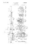
In the accompanying drawings, Figure 1
represents a perspective' view of my complete
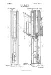
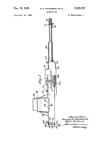
invention; Fig. 2, a side elevation of the same;
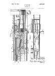
35 Fig. 3, a top plan view, and Fig. 4 a detail
sectional view thereof.
Similar letters of reference occurring on the
several figures indicate corresponding parts.
In carrying out my invention, the base or
40 bed frame A is preferably of a tripod shape,
being composed of a flat circular table sup-
ported by three spreading legs, as shown, the
upper part of the circular table being recessed
out to receive the circular base В of the hinged
45 upright B', and the said base В being held
upon the said table by an overlapping circular-
flange, A', as fully shown in Fig. 1.
In the upper end of the upright B' is piv-
oted the lower part of the frame C, which car-
50 ries the gun-barrel, the sliding magazine
breech-block, and the mechanism for operat-
ing said breech-block and for discharging the
cartridges, said frame being composed of two
elongated and solid sides, C' C'2, united by an
elongated slotted bottom, C3, and an upper 55
central block or cover, C‘, the gun-barrel D
being formed solid with the center of the side
O', as shown. Within the slotted bottom of
the frame C is arranged a series of rollers, a,
upon which the elongated magazine breech- 60
block E is adapted to freely slide in a horizon-
tal position, and at right angles to the breech
of the gun, the said elongated breech-block E
being provided with a horizontal range of
charge-chambers, &, which are arranged at such 65
distances apart that at each movement of the
breech-block a cartridge is brought into firing
position in the rear of the gun-barrel D.
Upon each side of the upper and lower sur-
faces of the breech-block E is arranged a nar- 70
row ratchet, c, the angles of the ratchet upon
one side projecting in a reverse direction to
the angles of the ratchet upon the opposite
side, the object of such an arrangement being
that either end of the said breech-block may 75
be readily inserted in position in the frame C
with the same effect.
Upon the upper surface of the slotted bot-
tom C3, and immediately in the rear of the
gun-barrel D, is arranged a flat spring, d, the 80
free end of which engages with the ratchet
nearest the rear of the gun-barrel, upon the
lower surface of the breech-block, the object
of the same being to prevent the said breech-
block from moving in a contrary direction to 85
that intended, as also to hold the breech-block
in place as each cartridge is brought forward
in position for firing.
Near one end of the gun-frame C are pro-
vided two uprights, e e', which are pivoted 90
near the bottom of said frame—one on each
side—and connected together at the top by a
cross-arm, e'2, as shown.
Upon the center of the cross-arm e1 are jour-
naled the outer ends of two arms, F F', the in- 95
ner end of the arm F' being adapted to work
through a slot in the central block or cover,
C\ and engage with the ratchet upon the up-
per surface of the breech-block E, opposite
the rear of the gun-barrel, a spring, f, se- 100
cured to the upper part of the central block
or cover, C‘, serving to keep the end of said
2
299,686
5
ю
15
20
25
30
35
40
45
50
55
60
65
arm F' down in contact with the ratchet. The
inner end of the arm F is of a wedge or cam
shape, which works beneath a small arm or
lug, <7, on a vertical rod, h, which is support-
ed in slots in a cross-frame, G, and in the cen-
tral block or cover, C‘, through which it works,
a spring, i, upon the cross-frame G serving
to depress the rod h down in the slot through
the central block or cover, G‘, and the lower
end of the said rod h being sharp or pointed
for engagement with the ratchet upon the up-
per surface of the breech-block E nearest the
rear of the gun-barrel.
Upon the back part of the side C2, and rig-
idly secured thereto, is provided a downward-
ly-projecting frame, H, having a cross-arm,
H', projecting over the same, as shown, and
within which is journaled the driving-wheel I,
having a suitable crank-handle, Г, for oper-
ating the same, said wheel being provided
with two inwardly-projecting angular flanges,
I2, as shown. To the right of the wheel I is
arranged the trigger J, which is pivoted at its
center within a projection upon the side of
the frame H, the bottom of said trigger being
bent outwardly at right angles to its length to
provide a short arm, 7c, upon which is jour-
naled a friction-roller, k'. The upper end of
the trigger J projects into an opening in the
said frame H, and abuts against the firing-pin
I, which maybe of any suitable construction, a
spring, 7c2, in the lower part of the frame H en-
gaging with the lower portion of the trigger J
to throwit outwardly at each operation of firing.
To the left of the wheel I is provided an elon-
gated and vertical spring-arm, K, which is
secured at its lower end to the bottom of the
frame H, while its upper end is provided with
a wedge-shaped bolt, иг, which projects through
a slot in the said frame H, witj^pne side abut-
ting against the lower end of the upright e',
below the point where said upright is pivoted
to the frame.
The gun-barrel D is surrounded by an in-
closing jacket, D', of copper, brass, or other
suitable material, the space between the two
parts being adapted to be filled with water,
and is provided with an exhaust-cock, n, be-
neath the muzzle of the gun, and a valve, o,
at the breech of the same, the object being to
keep the barrel cool during the operation of
firing.
To the base of the vertical upright B' is pro-
vided a rigid cross-arm, L, upon each end of
which are pivoted the one ends of the arms I/
L', the opposite ends of said arms being piv-
oted to the lower ends of the two rods L2 L2,
the upper ends of which in turn are pivoted
to a circular projection, M, beneath the muz-
zle of the gun. A cross-bar, K, is pivoted be-
tween the two rods L2 L2, near their lower
ends, and said cross-bar is provided with a
circular screw-opening for the reception of the
outer end of the screw-rod P, the inner end of
which has its bearings in a bracket upon the
side of the vertical upright B', and is provided
with a suitable wheel, R, for turning said
screw-rod in reverse directions for either ele-
vating or depressing the muzzle of the gun.
To the lower end of the upright B' is secured 70
a cross-frame, S, which is provided with a le-
ver, T, by means of which the gun, with its
mechanism, is turned in any suitable direc-
tion, as may be required.
The construction of<ny invention being as 75
above described, it will be observed that in
the operation of the same the sliding breech-
block E, having its chambers filled with car-
tridges, is first adjusted in the frame C upon
the rollers a, with the end of the arm F' en- 80
gaging with the ratchet c upon the outer up-
per surface of said breech-block. The wheel
I is then turned by the crank Г, causing one of
the angular flanges I2 to press the wedge-
shaped bolt m on the upper end of the spring- 85
arm К into the recess in the frame, and to
force back the lower end of the upright e',
causing its upper end and the cross-arm e2 to
move forward, thereby operating the arm F',
which pushes the breech-block inwardly, un- 90
til a cartridge is brought into position at the
rear of the breech of the gun and in true
line therewith. Simultaneous with the move-
ment of the arm F' the arm F also moves for-
ward, its wedge-shaped end moving outwardly 95
from beneath the lug g. and allowing the verti-
cal rod 7г to descend and engage with the ratchet
upon the inner upper surface of the breech-
block to hold the same in place, aided by the
spring d upon the upper surface of the slotted 100
bottom C3, until the cartridge is exploded. At
the moment of the cartridge arriving in posi-
tion at the breech of the gun the opposite
angular flange I2 on the wheel I operates the
trigger J to explode said cartridge, which is 105
no sooner accomplished than the trigger J" and
spring-arm K, having cleared the said angular
flanges I2 on the wheel I, resume their former
positions, the arm e2 being thrown back by
the spring s upon the frame H, and the arms no
F F' raising the vertical rod Itfand dropping
into the next depression of the ratchet in re-
spective order. The above operation is re-
peated at pleasure, causing a continuous and
regular discharge of the cartridges as they are 115
brought forward to the breech of the gun in
consecutive order. Before the breech-block
E has passed entirely through the frame C, a
duplicate breech-block filled with cartridges
can be inserted in the said frame directly in 120
the rear of the first breech-block, and this op-
eration being repeated an unremitting dis-
charge of the gun may be kept up.
Having thus described my invention, what I
claim as new and useful is— 125
1. In a machine-gun, the combination,with
the single barrel D, having a surrounding
jacket, D', provided with inlet and outlet con-
nections, said jacket bearing against the frame
0, and serving to support the barrel, of the 130
frame 0, the breech-block E, sliding hori-
zontally therein, and mechanism for operating
said breech-block and for discharging the car-
tridges as they are fed into position at the
299,686
3
breech of the gun, all substantially as shown
and described.
2. In a machine-gun, the combination,with
the barrel D, of the slotted frame C, having
5 its bottom provided with a continuous series
of anti-friction rollers, a, the breech-block re-
versely ratcheted on opposite sides of top and
bottom, and supported on such rollers, to-
gether with suitable pawl mechanism, where-
io by the breech-block is moved endwise and the
chambers brought into alignment with the
barrel of the gun in proper sequence for firing,
all substantially as shown and described.
3. In a machine-gun, the combination, with
15 the frame C, having the horizontal sliding-
breech-block E and slotted cover C4, the jip-
rights e e', pivoted to the frame, and provided
with cross-arm e2, of the arms F F', journaled
at their outer ends on the arm e2, the inner
20 end of the arm F' passed into the slot of the
cover to engage the ratchet of the block, and
the spring/, holding the arm in contact with
the ratchet,and the arm F,having its inner end
engaging the lug on the rod Л, said arm pass-
ing through an opening in the cross-arm G, 25
and the spring i, for depressing said rod, as
shown and described.
4. In a machine-gun, the combination,with
the cross-arm L upon the hinged upright B',
and the frame C, mounted on said upright, and 30
carrying the gun D, of the arms I/ I/, piv-
oted to the cross-arm, and the rods L2 L2, piv-
oted to the end of the gun and to the arms L'
I/, and provided with cross-bar K, having the
screw-rod P, as and for the purpose set forth. 35
5. The combination of the upright B', car-
rying the frames C and H and gun D, and
provided with the circular base B, cross-frame
S, and bar or lever T, with the tripod-shaped
base A and flange A', substantially as and for 40
the purpose specified.
In testimony whereof I affix my signature in
presence of two witnesses.
CHABLES B. SCOTT.
Witnesses:
John AV. Belles,
J. H. Oneehuls.