/
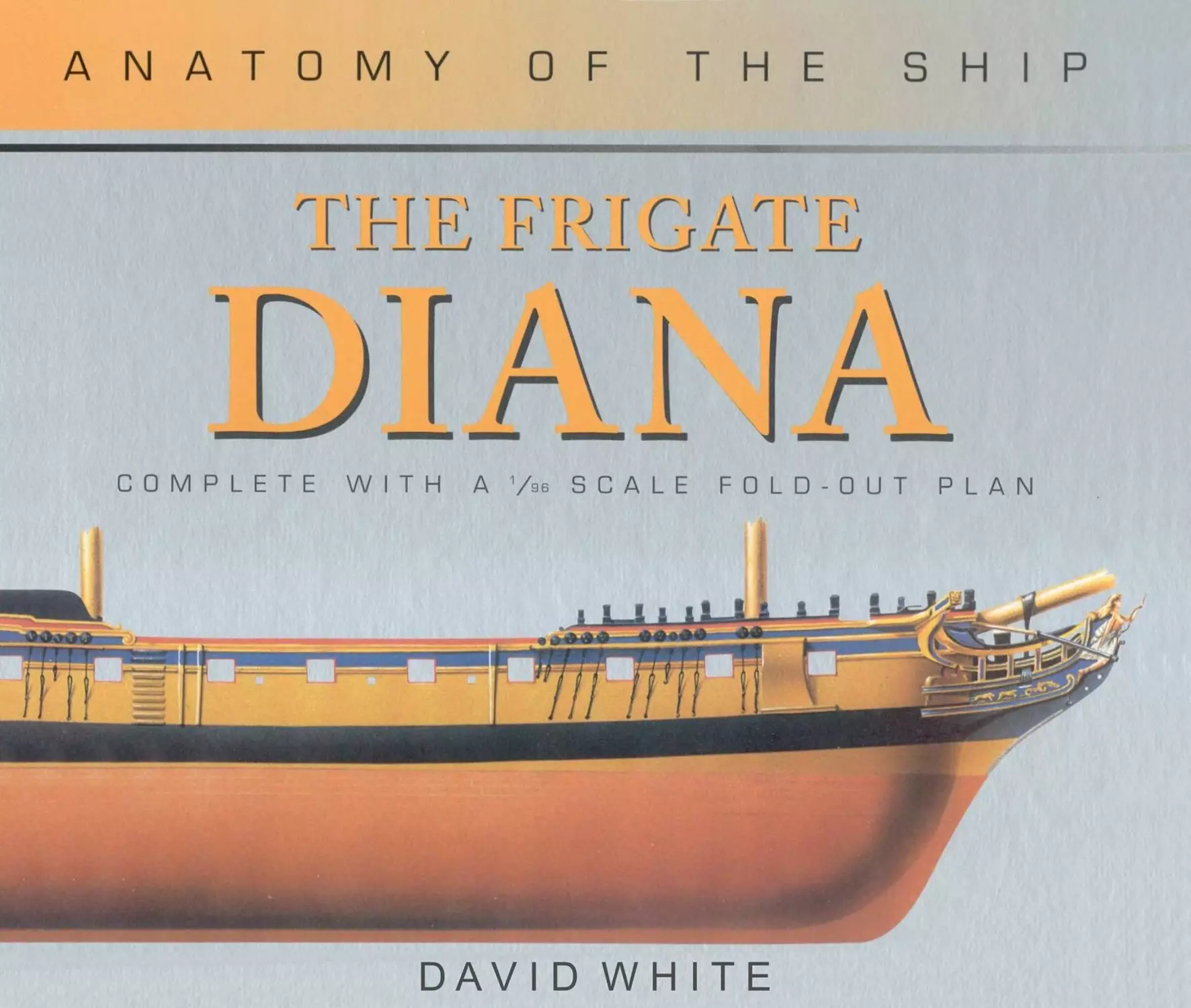





Text
                    ase»-.

м

г


DAVID WHITE


HE FRIGATE

ANATOMY

H E

CONWAY MARITIME PRESS
Frontispiece

1. The starboard quarter of NMM model number 1794-2 showing the decoration
of the stern and quarter galleries to advantage. Notice also the fine run aft to the
round tuck stern.

© David White 2004

All rights reserved. No part of this book may be reproduced or transmitted in any form without prior
written permission from the publisher.

First published in 1987 by Conway Maritime Press

This edition published in 2004 by Conway Maritime Press

An imprint of Chrysalis Books Group plc

The Chrysalis Building

Bramley Road

London W10 6SP

www.conwaymaritime.com

An imprint of ChrysalidBooks Group plc

987654321

A CIP catalogue record for this book is available from the British Library

ISBN 0 85177 967 0

Printed and bound in Singapore
CONTENTS

INTRODUCTION........................6

Design..............................6

Construction .......................7

Rigging ............................9

Armament ...........................9

Service history....................10

Sources ...........................14

THE PHOTOGRAPHS....................15

THE DRAWINGS.......................25

A.	Lines and arrangements..........26

B.	Hull structure..................31

C.	Internal hull...................44

D.	External hull...................66

E.	Anchors and cables .............75

F.	Spars and rigging...............78

G.	Armament ......................106

H.	Helm ..........................112

I.	Boats .........................117
INTRODUCTION

Wartime inevitably provides a great boost for warship design and construc-
tion; not only does it provide greater incentive but equally importantly it also
provides the necessary finance. It is therefore not surprising to find that on 6
November 1778, just five months after the entry of France into the War of
American Independence, the Board of Admiralty had arrived at the stage
where it was able to establish one of the most significant milestones in the
history of the British sailing frigate. On that day the Board ordered two new
ships to be built, one at Deptford Dockyard and one at Woolwich Dockyard.
These ships were the first two frigates t6 be ordered with a main armament of
18-pounder guns, 12-pounders having been the largest guns carried until then.

When Flora was launched at Deptford eighteen months later she was the
first 36-gun ship to have been built for the Navy for twenty-two years. A month
later Minerva was launched at Woolwich and made history by becoming the
first British 38-gun ship to be built. She was followed by a sister ship Arethusa
in 1781 and by two further sisters Phaeton and Thetis, with slightly modified
hulls, in 1782.

In the eighteenth century there were two Surveyors of the Navy at any one
time and it was common practice for each one to produce a design to the same
specification when new ships were contemplated. The new 38-gun ships were
no exception. The Minerva, designed by Edward Hunt, was followed into the
water nine months later by Latona, to the design of Sir John Williams. The
latter was presumably the less successful of the two designs as it was not
repeated.

Although the Minervas showed themselves to be good ships they suffered
from one serious fault: they were too small for their armament. The problem
was not one of weight, as they had been given a new lighter 8-foot 18-pounder
gun, instead of the standard 9-foot one. It was one of space: the guns were too
close together. The design was modified by reducing the number of guns on
the upper deck by two, with a consequent increase in the space between the
remainder of some 8 or 9 inches. In January 1783, just as the War of American
Independence ended, a new draught to build this 36-gun version was sent to
Messrs Hilhouse of Bristol, who had built Arethusa two years before. Although
this ship, Melampus, was completed two years later no further frigates were to
be ordered until the advent of the Revolutionary War in 1793.

This new war started on 1 February and on the 14th of the same month the
Admiralty ordered the Navy Board to prepare draughts for a proposed new
class of six 38-gun ships, to be built in merchant yards. Although frigate
building had been at a standstill for almost a decade the Navy Board had
obviously been keeping up to date with its design work, for the new draught
was delivered to the Admiralty only eight days later. Their Lordships
approved it on 2 March and on the same day the Navy Board produced a
further, slightly modified draught endorsed ‘for building’. Copies of this were
sent to the builders for Artois and Apollo on 22 March, Diamond and Diana on
28 March and Seahorse and Janus on 1 April. Contracts must have been

negotiated whilst the copies of the draught were being made as it is on record
that work on Diana commenced in March.

The new ships, with a lower deck length of 146 feet, were 5 feet longer than
the Minervas, giving them an increase in space between the guns of just under 5
inches. Once the ships got into service, however, it soon became apparent that
this increase was quite inadequate and so the Admiralty experimented with a
series of one-off ships in the hope of arriving at a suitable design. These were
Naiad (147ft), Hydra (148ft 2in), Boadicea (148ft 6in) together with Amazon,
Hussar and Active (150ft); Amazon and Hussar were sister ships and Active was
an enlarged Artois. None of these designs was perpetuated and in the end the
Leda, based on the lines of the French ship Hebe captured in 1782, was chosen
as the model for the standard 38-gun frigate. The Leda class ultimately became
the largest class of sailing frigates ever built for the Royal Navy. No less than
forty-seven were built between 1800 and 1830, in four different versions.

Concurrently with these experimental ships a further three Artois class ships
were built. The first two were Clyde and Tamer, both built in Chatham
Dockyard, and differing from their more conventional sisters in that they were
largely built of fir and had square tuck sterns. The last ship of the class,
Ethalion, was virtually identical to the first six. Brief details of the class are
given in Table 1.

TABLE 1: ARTOIS CLASS

Name	Launched	Builder	Disposal
Artois	3 Jan 1794	Wells, Rotherhithe	Wrecked	31 July 1797
Diana	3 Mar 1794	Randall, Rotherhithe	Sold	7 Mar 1815
Diamond	17 Mar 1794	Barnard, Deptford	Broken up	June 1812
Apollo	18 Mar 1794	Perry, Blackwall	Wrecked	7 Jan 1799
Jason	3 Apr 1794	Dudman, Deptford	Wrecked	13 Aug 1798
Seahorse	11 June 1794	Stalkartt, Rotherhithe	Broken up	July 1819
Clyde	26 Mar 1796	Chatham dockyard	Sold	Aug 1814
Tamer	26 Mar 1796	Chatham dockyard	Broken up	Jan 1810
Ethalion	14 Mar 1797	Graham, Harwich	Wrecked	19 Dec 1799

DESIGN

The two Surveyors of the Navy in 1793 were Sir William Rule and Sir John
Henslow, the latter being responsible for the design of Diana and her sisters.

There was nothing revolutionary about the lines of the ships. They used a
conventional three-sweep midship section with variable length floor sweep
radii based on a diagonal. Undoubtedly the modified Minerva lines that were
used for Phaeton and Thetis were taken as a basis for the new class, as below the
lower height of breadth the midships sections are almost identical. By lowering
the lower height of breadth approximately 6 inches amidships and 18 inches at
the extremities, Sir John made very little difference to the waterline amidships
FEET BELOW LWL FOR VC В

Fig 1	Hydrostatic curves

LWL	Load waterline

LCB	Longitudinal centre of buoyancy

VCB	Vertical centre of buoyancy

MCT1"	Moment to change trim one inch

TP1"	Tons per inch immersion

TABLE 2: BASIC DIMENSIONS

	As designed		As built
	ft	in	ft	in
Length on lower deck	146	0	146	3
Length of keel for tonnage	121	7't	121	81
Breadth extreme	39	0	39	3*
Depth in hold	13	9	13	9
Burthen in tons	9837°/94		99943/94

but produced a fuller waterline fore and aft, probably in order to reduce
pitching. Shortening the lower breadth sweeps produced a slightly finer hull
throughout and altering the floor sweeps gave a moderately sharper entry and a
finer run aft. Combined with the increase in length these alterations should
have resulted in a better performance. The hollow floors which were one of the
features which distinguished the second pair of Minervas from the first pair
were retained in a less exaggerated form.

As already mentioned the lower height of breadth admiships was lowered
about 6 inches. At the same time the upper height of breadth was raised and the
upper breadth sweeps were lengthened. This reduced tumblehome and in-
creased the width of the decks. The basic design dimensions are given in Table
2, which also gives the dimensions as built for comparison. Secondary design
dimensions can be found in Table 3.
TABLE 3: SECONDARY DIMENSIONS

Lengths	ft in

From fore side of the taffarel at the height of the fife rail to fore side of the figure	173 9

From fore side of the stem to fore side of the knee of the head	13 4

From after side of the wing transom to after side of the stern timber at the angle
of the lower counter on the middle line	5 7

From after side of the wing transom to after side of the stern timber at the angle
of the second counter on the middle line	7 6>

Moulded breadths

Amidships	38 6

At the height of breadth at the aftermost part of the counter	25 0

At the toptimber line amidships	35 2

At the toptimber line aft	20 0

Heights above the upper side of the keel

Cutting down line amidships	1 7j

Lower deck - upper side of the plank on the middle line at the after side of the

stem	17 0

- at the fore side of the rabbet	of the stern post	18	5

Upper side of the wing transom at the	stern	post	22	1

Angle of the lower counter on the middle line	26 1

Lower height of breadth amidships	16	8i

Upper height of breadth amidships	19	1j

Toptimber line - at the stem	29 8

-	amidships	27	11

-	at the stern timber	32	8

Height between decks on the middle line

From upper	side of orlop beams to lower side of lower deck plank	5	1

From upper	side of after platform to lower side of lower deck plank	6	0

From upper	side of fore platform to lower side of lower deck plank	5	3

From plank of the	lower deck to upper side of upper deck beams	6	4

From plank of the	upper deck to upper side of quarterdeck beams - forward	6	6

-aft	7	0

From plank of the	upper deck to upper side of forecastle beams	6	6

From plank of the	upper deck to gunwale	6	9

From plank of the	upper deck to lower port sills	2	1

CONSTRUCTION

Diana was built by Randall and Brent of Rotherhithe. This company had three
yards on the Thames, totalling between them seven building ships, two double
docks and one single dock. They were situated one on either side of the
Greenland Dock and one at Cuckold’s Point on the site of what is now Nelson
Dock. It is not known at which of these yards Diana was built.

The company was one of the biggest merchant builders in the country and
had constructed many ships for the Royal Navy. The first ship known to have
been built by them was the 28-gun frigate Tartary launched at Cuckold’s Point
in April 1756. She was also the first frigate to be built in a merchant yard,
having been launched some six weeks before her sister ship Lowesloffe, even
although the latter had been ordered three weeks before her. These two ships
had the added distinction of being the first ones to have been designed as
frigates, as opposed to being designed as 24-gun ships and later re-armed as
28s.

Randall and Brent’s contract, in line with the practice of the day, was to
supply the completed hull only, at a rate of £14 per ton. The tonnage figure
used to arrive at the total value was calculated from the design dimensions; the
contract was quite emphatic about this. Most ships exceeded their designed
dimensions, and consequently their designed tonnage. Increase in beam due to
the frames falling outwards during building was the commonest error and as
the tonnage figures were proportional to the square of the beam it was the most
significant one also. Diana's designed tonnage was 983 7%4 giving a value of
£13,772. She exceeded her designed dimensions by 3 inches in length and ЗУ2
inches in breadth, increasing her tonnage to 999 43/94. Using this figure to
calculate her value it would have increased payment by £80. However, had the
frames been allowed to fall out another 2l/z inches increasing the beam by a
total of 6 inches - a figure that was by no means uncommon - then the tonnage
would have risen to 1011 H/94 and the value on this basis to £14,155.

Minor adjustments were made to the basic amount. Additions were made for
items supplied or jobs done which were not specified in the original contract.
Deductions were made for items ‘found by His Majesty’, amongst which were
such things as mixt metal or copper underwater fittings. The final amount
received by the contractors was £13,788.

The contract laid down the scantlings of every major timber in the ship. The
types of timber, elm for the keel, oak for the frames and so on, were often
specified for specific items and the following paragraph covered the rest:

That all the Timber and Plank shall be of the Growth of England, except the
Plank of the Bottom under the light Draught of Water, which may be East
Country Plank, provided it be good white Crown Plank, otherwise to be English
Plank. All the Knees, Standards, Riders, Crutches, and Breast Hooks to have so
full a faying of Spine against the respective Beams, Sides, Decks, Ceilings &c that
the Bolts for fastening of each may not be naked when the Sap rots away, as has
too frequently appeared, to the evident weakening of Ships formerly built in
Merchants Yards, and has proved the principal Means of their too soon Decay;
and also the whole Frame to be well grown, square edged, free from Sap, Shakes,
and Defects; and that all the Plank of the Bottom, Sides, and Decks, shall be dry
and well seasoned before it is wrought; and that all the Prussia Deals for the
Decks, &c be good, yellow Wood, free from Sap, Shakes or Defects, and that no
Sap shall be wrought in the Edges of them.

In addition to specifying the timber scantlings the contract also dealt with
ironwork of all types; use of iron knees, size and numbers of bolts, eyebolts,
swivels, ringbolts etc. In general it stated that ‘All the Iron Work shall be
wrought out of the best sort of Orgrounds Iron, not burnt, or hurt in working;
all the Bolts to be clenched or belayed, as shall be directed; those to the Iron
Knees and Standards to be drove through them into the Transoms, Beams, or
Timbers, and all clenched on Rings let into the Wood.’

Construction followed the normal pattern for the period and the outboard
appearance was typical of ships in the first part of the last decade of the
eighteenth century, a period regarded by many as being the zenith of the
development of the sailing warship. The garish top-heavy sterns of the late
seventeenth and early eighteenth centuries had long since disappeared, while
the open rails of the quarterdeck, although berthed up, still retained their
elegant serpentine curves at the forward end, a feature they were soon to lose.
In fact only the first six ships of the class had this feature; the last three were
built with ugly square-cut bulwarks on the quarterdeck.

With the exception of a few of the very earliest ships all frigates had a shapely
round bow, culminating in a lightly built head with a full-length figure, as
opposed to the ugly beakhead bulkhead of the larger ships. Diana and her first
five sisters were amongst the last ships, other than First Rates, to have a
full-length figure, as the Admiralty issued an order in 1796 abolishing the
fitting of new ones in Second Rates and below. The last three ships of the class
were filled with the scroll head that the Admiralty decreed should replace the
figure. Such was the outcry against this austerity, however, that the Admiralty
partly relented a few years later and allowed ships to have a bust instead - but
the full-length figure for frigates had unfortunately gone forever.
Diana and all her sisters retained the open timberheaded forecastle of their
predecessors which was to be replaced a few years later by the more utilitarian,
but less aesthetically pleasing, built-up square bulwarks of the nineteenth
century. They also had a feature in common with all of Sir John Henslow’s
ships, which no other frigates had, in that they had four head timbers instead of
the more usual three.

The ship’s bottom was payed with ‘Tar boiled to a strong resistance, or as
shall be directed’ and the sides were painted from the wales upwards with
‘three good Coats of Paint, the last Coat to be of a yellow cast.’ The great cabin,
steerage, all the cabins, rails, stanchions, ladders, gratings, gangways, bulk-
heads, capstans, upper deck beams and knees were also given three coats of
paint ‘and all Work in Wake of them, and without Board for finishing and
compleating the Hull of the said Ship, shall be done in a workmanlike Manner,
equal in all Respects to those of His Majesty’s Ships of the like Quality in the
King’s Yards.’

Eleven months after building was started, on 3 March 1794, Diana was
launched and towed the short distance downstream to the Royal Dockyard at
Deptford where she was to be fitted out. She was docked the next day, her
bottom was coppered, and she returned to the water on 13 March. Her
progress from then onwards can be summarised by extracts from the Master’s
log, with comments in brackets.

April 14 Lt England commissioned the ship [he was the first lieute-
nant; the captain, Johnathon Faulknor, had yet to join]

22 Riggers began by contract

May 3 Riggers finished [13 days inclusive. They worked a seven-
day week]

15 Blacked the yards. Received anchors

25	Received	cables

29	Received	sails. Painters onboard

June 7 Ran down the river al midnight to Gravesend

10	Received	Gunner’s stores and carronadcs

11	Received	guns

12	Unmoored and ran for the Nore

The cost of the ship’s masts and yards was £2675 and that of her rigging and
stores a further £5528. An approximate breakdown of the latter figure can be
obtained by taking average proportionate figures obtained from similar ships
of the same period. These are:

% £

Rigging	26	1437

Sails	14	774

Anchors	8	442

Cables	14	774

Boatswain’s stores	13	719

Carpenter’s stores	13	1382

This brings the cost of building and filling the ship for sea to £21,991 plus the
cost of supplying the underwater copper fittings. To this must be added at least
another £1000 for guns and the Gunner’s stores, bringing the total cost to over
£23,000.
RIGGING

Like all other frigates Diana was ship rigged. That is to say that she had three
masts, all of which were square rigged. In 1794, when she was built, frigates’
masts were composed of three parts: a lower mast, a topmast and a topgallant
mast. Each of these components carried a yard at right angles to it and with the
exception of the mizen mast each yard carried a sail. The yard on the mizen
(lower) mast was known as the crossjack. Those on the main and fore (lower)
masts were the main and fore yards respectively, their sails being the main sail,
or main course, and the fore sail, or fore course. The yards on the topmasts
were named after their sails, not after the masts, being the mizen, main and
fore topsail yards. Those on the topgallant masts were known simply as the
mizen, main and fore topgallant yards and carried mizen, main and fore
topgallant sails.

All ships were supplied with topgallant masts of two or sometimes three
lengths. The longest of these, the long pole head topgallant mast, was only
rigged in fair weather and was long enough to carry an additional sail above the
topgallant. Commonly called the royal, this sail was actually the topgallant
royal and should not be confused with the true royal which was carried on a
separate royal mast. Frigates in 1794 were not fitted with royal masts.

Topgallant royals were set flying: that is to say that the only running rigging
that they had was a halliard. There were no braces or sheets, the clues of the
sails being seized to the topgallant yardarms. True royals, on their own masts,
were fully rigged in the same way that the topgallants were.

Diana, when first rigged, carried one other square sail. This was the
spritsail, which was carried on a yard slung under the bowsprit. Added to the
courses, topsails, topgallants and topgallant royals this brought the total
number of square sails to twelve. The courses had two reef bands and the
mizen topsail three but the main and fore topsails would have had the four
bands laid down by the Admiralty Order of 4 November 1788.

The main and fore courses, topsails and topgallants could be extended by
means of studding sails on either side. Studding sails were never fitted on the
mizen. The mizen however carried a large fore and aft sail, known as a driver,
spread between a gaff and a boom and in the words of the authorising
Admiralty Order ‘in the form of a brig’s mainsail’. A mizen staysail, mizen
topmast staysail and a mizen topgallant staysail were carried between the
mizen and main masts, although in practice the last named was seldom used.
Between the main and foremasts the staysails carried were the main staysail,
main topmast staysail, middle staysail and main topgallant staysail, whilst
ahead of the foremast were the fore staysail, fore topmast staysail and jib.
Storm main and fore staysails were also provided so that a full suit of sails,
when first commissioned, consisted of twelve square sails, twelve studding
sails and thirteen fore and aft sails; a total of thirty-seven, not including spares.

This total was not to last for long, however. On 18 August 1794 a Navy
Board warrant authorised the introduction of a flying jib and its associated
Hying jibboom. Further additions to the sail plan followed, together with
alterations to the rigging - some official, some not. In September the logs
mention a spanker. As the names spanker and driver were both used indiscri-
minately when referring to the driver it is difficult to establish when the
loose-footed spanker was actually acquired. The Master’s log suggests that it
had been in existence from the very beginning. In June 1795 it records the use
of a spritsail topsail yard as a replacement for a damaged main topgallant yard,
but there is no mention of actually using a spritsail topsail at this period. In
January 1796 Diana's fore mast was moved 4 inches aft, possibly as a counter to
the flying jib. Strangely, two of her sisters, Jason and Diamond, had their fore
masts moved forward 6!4 inches the following year, the year that the Admiral-
ty authorised the issue of main trysails and gaffs.

The first mention of royal masts being fitted that has been found is dated
13 February 1808. They must have existed before that, however, because in
August 1806 Diana was setting not only royals but skyscrapers, which upsets
the commonly held view that they were introdudced by the Americans in the
War of 1812. (Skyscrapers were set flying above royals, on the royal mast, just
as the topgallant royals had been set flying above topgallants when the ship first
commissioned.) At the same time she also set a spritsail topsail, obsolete by
then, together with two sails which officially did not exist: a gaff topsail and a
cross jack, both of which are associated with the clipper sail era rather than with
the Napoleonic Wars. There is also mention of an inner jib in 1806 but this may
well have been a change of name for the fore topmast staysail, rather than being
an additional sail.

Main lower studding sails had officially been abolished by an Admiralty
Order in 1801. By 1807 royal studding sails and an upper main staysail were
being carried, bringing Diana's unofficial outfit to at least forty-nine, plus
spares.

The mast and spar dimensions of the ship, as first fitted, are listed in Tables
4 and 5. Table 6 lists the probable belaying points at the same time.

ARMAMENT

The standard main armament of a 38-gun frigate consisted of twenty-eight
18-pounder carriage guns on one deck, the upper deck. Diana was no
exception to this and she carried these guns throughout her career. They were
mounted on standard carriages and the only way that they differed from the
usual 18-pounder gun of the period was that, in common with the guns carried
by all the 38-gun ships of the period, they were only 8 feet long. The reason
why the 38-gun ships carried 8-foot guns when the standard 18-pounder was 9
feet long is straightforward. It was a matter of weight. The early 38s were
virtually no bigger than contemporary 36s; in fact the 36-gun M elamp us was
actually a sister ship of the first 38s, the Minervas. Melampus was able to carry
twenty-six 9-foot guns satisfactorily; Minerva was only able to carry two extra
guns because the weight of twenty-eight short guns was virtually the same as
the weight of twenty-six long ones.

The original design for Diana and her sisters called for eight 9-pounder
carriage guns on the quarterdeck, with a further two on the forecastle. The
quarterdeck guns were to be 7 feet long; the forecastle ones, being chase guns,
6 inches longer to give them extra range. These were standard guns, on
standard carriages and all the ships of the class carried them when first built.

The carronade armament was more complex. Although these close-range
weapons had been established in the Navy as early as 1779 both the ‘proposed’
and the ‘for building’ draughts for the Artois class made no provision for them.
The Navy Board copy of the contract for the class, which is on a standard
printed form, has the sizes of the carronade ports overwritten on it and yet still
specifies details of the stocks for the swivel guns that the carronades super-
seded.

An Admiralty Order of 25 November 1782 specified 24-pounder carronades
for 38-gun ships in lieu of 18-pounders, but there is no evidence to show that
this was ever put into effect. The fact that hostilities ended two months later
probably accounts for this. When the Revolutionary War broke out in 1793
Minerva was ordered to fit 18-pounders and this was the weight of metal fitted
to the ships of the Artois class when first built. They carried four carronades on
the quarterdeck and two on the forecastle.
TABLE 4: MAST DIMENSIONS

					Long	Proper	Stump
Mast	Overall		Head		pole	pole	pole	Diam
					head	head	head
	ft	in	ft	in	ft in	ft in	ft in	in
Mam	92	6	12	10				27$
Main topmast	55	6	6	2				161
Main topgallant	27	9			16	8	10 91	2 81	91
Fore	82	3	11	5				24|
Fore topmast	49	4	5	51				161
Fore topgallant	24	8			14 10	9 7	2 5	81
Mizen	79	31	8	91				181
Mizen topmast	41	71	4	01				111
Mizen topgallant	20	91			12	61	8 1	2 0	7
Bowsprit	55	6						271
Jibboom	39	71						111

TABLE 5: SPAR DIMENSIONS

Spar	Length		Diam
	ft	in	in
Main yard	82	3	191
Main topsail yard	58	9	121
Mam topgallant yard	35	3	7
Mam royal yard	29	5	61  161
Fore yard	72	0
Fore topsail yard	51	5	101
Fore topgallant yard	30	10	61
Fore royal yard	25	9	51
Crossjack	51	5	101
Mizen topsail yard	39	2	81  41
Mizen topgallant yard	23	6
Mizen royal yard	19	7	41
Spritsail yard	51	5	101
Driver boom	58	9	101
Driver gaff	36	9	101
Mam lower studding sail boom	45	8	91
Mam topmast studding sail boom	29	4}	81
Main topgallant studding sail boom	17	71	6
Fore lower studding sail boom	45	8	91
Fore topmast studding sail boom	36	0	71
Fore topgallant studding sail	25	9	51
Main lower studding sail yard	26	1	51
Main topmast studding sail yard	16	91	41
Main topgallant studding sail yard	10	81	3
Fore lower studding sail yard	45	8	91
Fore topmast studding sail yard	20	7	41
Fore topgallant studding sail yard	14	9	3
Ensign staff	35	10	6
Jack staff	15	5

The Admiralty promulgated a compulsory establishment of carronades on
19 November 1794, which laid down that 38-gun ships were to carry six
32-pounders on the quarterdeck with a further two on the forecastle. For the
first time ships were to lose carriage guns to make room for them. Diana
received 32-pounders on 23 February 1795 in place of her 18-pounders, but as
she was only given six, not eight, she did not lose any of her 9-pounders. A
further two 32-pounders were acquired later on and although circumstantial
evidence suggests that no 9-pounders were given up in exchange it is not
possible to confirm this. Although it has not been possible to establish the exact
date when this addition was made, the most likely time would have been
during the 1796 refit.

On 12 December 1799 the Admiralty ordered that all frigates, on refitting,
were to have the carriage guns on their quarterdecks and forecastles replaced
by carronades, with the exception of two, which were to be retained as chase
guns. As a result of this Diana's quarterdeck armament became twelve
32-poundcr carronades and her forecastle armament became two 32-pounder
carronades and two 9-pounder carriage guns. The most likely date for this to
have taken place would have been during the 1801 refit.

This was probably the last change in the ship’s armament, although a
manuscript Navy List dated 1816 states that her forecastle carronades were
24-pounders. This is probably a clerical error. It was also out of date because
Diana had been sold to the Dutch in 1815. However as she went into Ordinary
in 1812 to await a ‘very large repair’ it is just possible that lighter weapons had
been fitted prior to this, in order to reduce the strain on what by then was a very
tired structure. It is very unlikely though, as the difference in weight between a
24- and 32-pounder carronade was only 23/4 hundredweight.

SERVICE HISTORY

First Commission (Captain Johnathon Faulknor - 19 April 1794 to 28 March 1799)

13 June 1794: 61/’ weeks at the Nore working-up, and completing her crew.

27	July: sailed for the Downs. Joined there by sister ship Artois.

31	July: proceeded down Channel to join Sir John Warren’s frigate squadron on the
Irish station to help patrol south western approaches to the Channel, from southern
Ireland to the French coast.

8	August: Plymouth harbour with Diamond and on 13th joined Artois at Falmouth.
15 August: joined Sir John Warren off Lizard, with rest of squadron.

23	August: fired first shot in anger - with her sisters and Santa Margarita drove French
36-gun ship Volontaire ashore on Penmarck rocks and her two consorts ashore
further along the coast.

27	August: with the squadron recaptured two merchant vessels making for France.
September: with consorts from Sir Edward Pellew's squadron recaptured Swedish brig
Haesingland and French cutter La Quartidi.

November-December: damaged by bad weather whilst on patrol.

23	January 1795: lost fore topmast and backstays and put into Scilly Isles for repairs.
End January: Plymouth Harbour ‘making good defects’ caused by bad weather on
patrol in previous months.

February-June: almost continually at sea on Irish station.

25	June: Cork harbour for a month’s repair work.

August: highlight of career. With sister ship Seahorse and frigate Unicom captured
Dutch East Indiaman Cromhout, another merchant ship Hustelderk, and their escort
Komeet. £46,900 prize money from Cromhout alone.

7 December: after seven weeks’ repairs at Spithead, sailed with convoy for Cork.
Late 1795 - May 1796: patrols in Irish waters. Was one of squadron which captured
French cutter L'Abeille in May.

June: refit at Portsmouth

August: accompanied by Seahorse and Cerberus captured French privateer brig L'In-
demnite , west of Finisterre.

Early November: shared in capture of French privateer Le Franklin - last event of note
in 1796.

January - mid-May 1797: apart from spells in Cork, patrolled Western Approaches.
22-29 May: to Dungeness with convoy, captured 2 French fishing boats on way back.
June-July: at anchor in Spithead.

August: week at Weymouth as part of escort for the King.

September: with Cerberus captured privateer cutter Le Neptun, recaptured the mer-
chant prize Albion; and Kangeroo captured privateers Craff Bemstoff and San
Norberto, and on her own took the French privateer L’Hibustion
TABLE 6: BELAYING POINTS

No Mem

Location (the letter* weed are those in drawing* F5 10-12 with additions)

A - Taffarei

В - Mizen topsail sheet bitts
Q - Mizen mast

D - Fore brace bitts

E - Quarterdeck breast rail

F - Main mast

G - After sk«d beam

H - Mam tear bitts

I - Mam topsail sheet bitts
j - Forward skid beams
к - Forecastle breast rad

L - Bef*ry

M - Fore jeer bitts

N - Fore mast

О - Fore topsail sheet txtts
P - Breasthook pm rad
0 - Upper deck m the wars!
R - See remarks column
S - Mizen channel
T - Mam channel
U - Fore channel
V - Mizen pm rad
W - Mam pm rail
X - Fore shrouds

Y - Gangway
Z - Forecastle

35	Braces

36	Oue fanes

37	Reef tackles

38	Bunt Unes

39	Bowlines

40	Sheets

Loen Side Type Remarks

ABC

V	В	W	Wrth 38 - bunt imes

В	В	—

V	В	W	With 36 - clue hnes

W	В	W	Startward bow<me belays on

larboard side and vice versa

В	В	—

L - Larboard s de only
В - Both sdes

S - Starboard side only

Mam topsail

41	Litts

42	Halliards

43	Braces

44	СЮе hnes

45	Reef tackles

46	Bunt tines

47	Bowimes

48	Sheets

E	В	—

R	8	8	Ouanerdeck

В	В	-

E	В	-

E	В	—

E	В	-

MB —
I	8	—

Type

В - Kevei block

C - Cleat

H - Knighthead

I - Iron pm
к - Kevai cleat

No	Item

Crosstac*

1	Truss pendant

2	Nave ime

3	Braces

Loen

Lifts

C
В
w

V

A - Range cleat

S - Shroud cleat

T - T imberhead

W - Wooden pm

x - As convenient

Side Type Remarks

L	C

В	-

В	W	Startward brace belays on artward

s»de and vice ve^sa

В	W

Fore topsail

49	Litts

50	Haihards

51	Braces

52	Cue mes

53	Reef tackles

54	Bunt i mes

55	Bowlines

56	Sheets

X	В	S

Z	В	В

J	В	I

X	8	S

М	В

X	В	S

0	8-

О	В

Mizen topgallant sail

57	Lifts

58	Haihards

59	Braces

60 Clue hnes

61	Bowlines

62	Sheets

R В — Shroud m mizen top

В	L	-

ABC

R	В	S Mtzen shrouds

0	8	—

В	В	—

Mam course

5	Truss pendants	F

6	Nave i ne	F

7	Jeers	H

8	Outer tne ng I nes	W

9	Inner toeing hnes	W

Ю	Braces	R

11	Lifts	R

12	Leech lines	E

13	Bunt lines	К

14	Clue garnets	I

15	Sheets	R

16	Tacks	Q

17	Bowimes	Z

18	Siabbnes	I

Fore course

19	Truss pendants	N

20	Nave ime	N

21	jeers	M

2?	Outer toeing imes	X

23	Inner tnang hnes	X

2<	Braces	0

25	Lifts	R

26	Leech unes	К

27	Bunt hnes	К

Clue garnets	О

29	Sheets	О

30	Tacks	R

31	Bowimes	О

32	Sablinas	О

Mizen topsail

33	Utts	V

34	Haiiivd	R

В	C

-	C

В	—

В	W

В	W

8	R	Ouanerdeck

В	8	Abreast mast

В	-

8	—

8	—

8	R	Quarterdeck

8	R

В	В

8	—

В	C

-	C

8	—

В	C

В	C

В	—

В	8 Abreast mast

8	-

8	—

8	-

8	R

®	C Cathead

8	—

8	-

8	W

s	8	Quarterdeck

Mam topgallant sail

63	Litts	R

64	Haiiards	D

65	Braces	V

66	Clue lines	E

67	Bowlines	M

68	Sheets	E

Fore topgallant sail

69	Lifts	R

70	Haihards	M

71	Braces	L

72	Clue hnes	X

73	Bowhnes	О

74	Sheets	M

Spntsaii

75	Braces	К

76	bfts	P

77	Bunt hnes	P

78	Clue imes	P

79	Sheets	О

Driver

80	Throat halbard	R

81	Peak halliard	R

82	Vangs	A

83	Boom sheet	R

84	Guys	A

85	Topping lifts	C

86	Peak txa4s	R

87	Middle brails	A

88	Throat braHs	C

89	Foot brads	C

90	Sheet	R

В	— Shroud m main top

L	—-

В	W

В	—

В	—

В	-

В	— Shroud m fore top

В	-

В	С

В	S

В	—

В	-

В	-

8	W

В	W

В	W

В	С

S	С	Quarterdeck bulwark

L	С	Ouanerdeck bulwark

В	С

—	С	Quarterdeck m»ddie hne

В	C	Taff are! Me rail

В	C

В	C	Ouanerdeck bulwark

8	S	Mizen shrouds

В	C

В	C

—	C	Dover boom
No	Item

Mizen staysail

91	Halliard

92	Downhauler

93	Sheets

94	Brails

Loen Side Type Remarks

В	S	—

D	S	—

V	В	W

D	В	—

Main staysail

95	Halliard

96	Downhauler

97	Sheets

Fore staysail

98	Halliard

99	Downhauler

100	Sheets

Mizen topmast staysail

101	Halliard

102	Downhauler

103 Sheets

104	Tacks

Main topmast staysail

105	Halliard

106 Downhauler

107	Sheets

108 Tacks

109	Brails

Fore topmast staysail

110	Stay

111	Halliard

112	Downhauler

113	Sheets

114	Outhauler

Middle staysail

115	Stay

116	Halliard

117	Downhauler

118 Sheets

119	Tacks

120	Tricing line

Jib

121	Stay

122	Halliard

123	Downhauler

124	Sheets

125	Inhauler

126	Outhauler

Mizen topgallant staysail

127	Halliard

128	Downhauler

129	Sheets

130	Tacks

Main topgallant staysail

131 Halliard

W	S	W

M	S	—

W	В	W

X s s
P s w
z в T

В	L

D	L	—

V	В	W

W	В	W

W	L	W

ML	—

G	В	I

X	В	S

MB	—

M
X
p
z
p

D
W
M

G
R
R

M
X
p
z
p
p

в
R
V
R

S

S

S

S
S

L
В

S

S

S
w

w

w

X

X

S
w

w
w

s	—

в	w

В	X

W L W

Note: The numbers used are those in drawings F5/1O-12.

Fore top

Fore top

Main top rail

Main top

October: captured French privateer Le Filibustier.

December: captured La Manche in company with Shannon.

2 February - early April 1798: refit at Portsmouth.

21 April: arrived off Ushant.

21 May: ventured into harbour at Brest with Triton and counted no less than 14 ships of
the line and 12 frigates trapped by the British blockade.

No	Item	Loen	Side	Туре
132	Downhauler	R	. —
133	Sheets	G	в	I
134	Tacks	R	в	X
Main studding sail
135	Topping lift	W	в	W
136	Fore guy		в	с
137	After guy	s	в	X
138	Martingale		в	X
139	Outer halliard	w	в	W
140	Inner halliard	w	в	W
141	Fore tack	Q	в	с
142	After tack	S	в	X
143	Fore sheet	W	в	W
144	After sheet	W	в	W
Fore studding sail
145	Topping lift	X	в
146	Fore guy	z	в
147	After guy		в	X
148	Martingale	и	в	X
149	Outer halliard	X	в	1
150	Inner halliard	X	в	—
151	Fore tack	z	в	н
152	After tack	Q	в	с
153	Fore sheet	X	в
154	After sheet	X	в
Main topmast studding sail
155	Topping lift	w	в	W
156	Brace	s	в	X
157	Halliard	w	в	W
158	Tack	s	в	X
159	Fore sheet	w	в	W
160	After sheet	w	в	W
161	Downhauler	J	в	1

Remarks

Fore top rail

Fore top

Fore topmast studding sail

162 Topping lift

163 Brace

164 Halliard

165 Tack

166	Fore sheet

167	After sheet

168 Downhauler

Main topgallant studding sail

169 Halliard

170 Tack

171	Fore sheet

172	After sheet

Fore topgallant studding sail

173 Halliard

174 Tack

175	Fore sheet

176	After sheet

X
Y
X
Y
X
X
Z

В
в
в
в
в
в
в

R
S
R
R

В
В

В
В

—	Main top rail

X

—	Main topsail yard

—	Shroud in main top

R

R
R

В
В

В
В

—	Fore top rail

X

—	Fore topsail yard

—	Shroud in fore top

11 July - end September: at sea on Irish Station.

1-17 October: at Cork. A week later, back at sea she took her only prize for the year.
Dunkfelt.

7 November: Milford Haven for repairs.

21 November: arrived back at Cork for 6 weeks.

4 January — 8 February 1799: first patrol of the year on Irish station.
6 March: reached Scilly Isles with convoy from Cork.	.

28 March: moored off Southsea Castle where Captain Fraser relieved Captain Faulk-

nor.

Second Commission (Captain Alexander Fraser - 29 March 1799 to 11 June 1800;
Lieutenant Nott -12 June 1800 to 12 July 1800; Captain John Poo Beresford -13
July 1800 to 21 October 1801)

30 March: Portsmouth Dockyard for IVi month refit, followed by working-up in
Spithead.

6 September: sailed as part of an escort for a convoy bound for the West Indies where
she was to spent two years on local convoys and patrolling amongst the islands,
mainly intercepting and examining small craft engaged in fishing or inter-island

trade.

11 November: Left Carlisle Bay with those ships which were not staying at Barbadoes.
Worked her way to the Leeward Islands dropping off ships on the way.

26 November: Left St Kitts and was almost continually at sea for the rest of the year.

January - May 1800: constant patrolling of the West Indies - mostly uneventful.

12 May: recaptured an American schooner; 16 May recaptured an American sloop and
on 17 May captured the privateer La Medie which had taken the former vessels.

12 June: Lieutenant Nott acting captain, relieving Captain Fraser who, like many of the
crew, had yellow fever and had been invalidated home.

25 June: recaptured American brig William of Baltimore and four days later the

privateer L"Industrie.

13 July: John P

Beresford replaced Lt Nott. Patrols continued in same pattern into

early 1801.

28 February 1801: t

•It

к French privateer Le Triumphant.

5 March: took unarmed schooner.

8 March: with Amphitrite sent boats inshore to cut out two launches and a ship from
under the guns of St Jago and on 11 March captured Spanish brig Actaeon.

28 March: anchored off Danish island St Thomas’s and fired on the Grand Battery,
which struck its colours. Rear Admiral Duckworth’s squadron sent in flag of truce.
St Thomas’s, St Johns and several smaller islands surrendered 29 March.

May onwards: resumed patrolling.

1 August: sailed for Britain with convoy of 190 ships

25 September: anchored in Spithead having delivered convoy to the Downs.

2 October: Portsmouth for refit and re-coppering, new main and mizen mast.

Third Commission (Captain Thomas James Mating - 22 October 1801 to 28 October

1807)

12 October: declaration of end of hostilities with France.

15 December: sailed for Mediterranean.

27 January 1802: sailed from Malta with Northumberland and Bonne Citoyenne

9 February - 19 April: al anchor in Corfu Roads.

29 April: peace proclaimed in London.

21 April: two months at Malta.

5 July: sailed for Naples, then back to Malta before sailing eastwards.

2 September: reached Smyrna Bay. Spent two months cruising amongst Greek islands,
returning to Smyrna at end of October.

10 November: Constantinople and then up the Bosphorus.

28 November- 7 January 1803: Beukdryh (Buyiikdere)

16 January: Lord Elgin’s baggage and horses embarked at Constantinople. He
embarked on 17th and Diana sailed for home.

18 May: hostilities recommenced with France.

3 June: arrived at Spilhead lowing the French brig L’Euphrosyne, captured two days
previously on her way up the Channel.

4 July: Two-week cruise in the Channel; intercepted two ships on passage from
America to Germany.

4 August: escorted homecoming convoy of 22 ships from Lisbon.

26 September: reached the Downs, having captured Spanish ship and French brig Le
Jean Marie. Escorted another convoy up the Channel to the Downs.
4 December: sailed from St Helens with convoy to Lisbon and the Mediterranean.

21 January 1804: Reached Gibraltar and spent a month in vicinity intercepting coastal
shipping.

24 February: left Gibraltar with homeward bound convoy, losing one ship, which had
sprung a leak, on the way.

8 April - 9 June: repairs and re-coppering at Portsmouth.

21 June: sailed for Cork to collect convoy for the West Indies.

24 July: left Madeira with enlarged convoy and 3 more escorts: Beaulieu, Bacchante and
Kingfisher.

6 September: arrived Port Royal, Jamaica.

13 September: first cruise of many in West Indies, eastwards along coast of St
Domingo, south to Dutch islands off South America. During this time captured
Spanish schooner and brig and with Echo accepted the surrender of the island of
Aruba.

20 November: returned to Port Royal with captured si

p and four other prizes.

6 December: sailed with Suffisante. The Spanish Diligentia surrendered on the 21st

after being chased by Diana and La Pique.

January - March 1805: Island of Aruba as base. T

к numerous prizes and recaptured

3 American vessels.

April: fitting out at Port Royal.

28 April - 3 September: cruised westwards.

30 September - 21 October: after a month in harbour at Port Royal, sailed to north
coast of Jamaica. Sent two prizes home to Falmouth.

2 November: to sea, heading for Britain with 24-ship convoy assisted by 18-gun brig

si


p Port Mahon. Anchored in Port Antonio and joined by a further 17 ships and

two more escorts Bacchante and Wolf.

23 February - 16 April 1806: refit at Portsmouth.

12 May: sailed from St Helen’s with convoy for Gibraltar, collecting more ships,

including Richmond, from Falmouth on the way, making a total of 60. On 24 May

Richmond left with 9 ships for Oporto and on 29 May Lisbon

rtion of convoy

departed.

8 June: squall carried away mizzen topmast and main topgallant yard two days into
return passage to Spithead.

1 August: sailed from Cork to cruise in Atlantic with Dryad and Princess Charlotte.

26 September: severe storm in Atlantic snapped bowsprit which brought down fore
mast, main and mizen topmasts. 9 killed and 25 injured in clearing wreckage.
Turned back under jury rig, whilst repairs were made.

10 October: repairs at Portsmouth for ZVi months.

5 January 1807: convoy to Cork followed by several months in Channel approaches.

18 February; captured Charlotte.

15 March: quarter watch allowed ashore at Bear Island, but 15 deserted.

April: captured Guernsey smugglers Dart and Eliza.

30 April - 12 May: spell as Admiral Lord Gardner’s flagship,; passage to Portsmouth.

27 May: sailed with two supernumeries for Jamaica. Uneventful, except for grounding
off Porto Rico.

7 July: sailed for Vera Cruz and by 27th had six prizes in company and one in tow.

2 August: anchored off Vera Cruz; sent boat ashore with flag of truce. Embarked 1273
boxes and 14 bags of dollars.

24 August -19 October: passage home in company with John and Thames, uneventful.

Fourth Commission (Captain Charles Grant - 29 October 1807 to 11 April 1811)

30 October - 31 December: repairs and re-coppering at Portsmouth

January - April 1808: cruised independently off Biscay coast. 4 February t

к

sch

ner off Cordovan Light. 6 February reconnoitred Basque Roads and captured

two chasse-marees. End February captured galliot Naphousan.

March: successful month, took or destroyed 18 vessels.

27 April: Plymouth for repairs and stores.

18 May: departed for vicinity of Finnistere. Uneventful patrolling until December, the
only break being in July when she accompanied a convoy to Oporto.

17-31 January 1809: docked at Plymouth and then in Plymouth Sound.
12 March: sailed for South America with Rear Admiral the Honourable Michael de
Courcy who was to relieve Sir Sidney Smith as Flag Officer, Brazil.

15 March: recaptured brig Hayti.

1 May: reached Rio de Janeiro. Sir Sidney embarked. Loaded bullion for three weeks.

21 June: Left Rio, accompanied by Cheerly and Nancy. Recaptured Spanish Santa
Francisco de Paulo.

9 August: Anchored at Spithead. Admiral’s flag struck, and on 11th the specie was
discharged.

27 August: Sailed with Nereus and Brilliant to patrol coast between Boulogne and
Dieppe.

5 October: Captain Grant temporarily superseded by Captain Cramer, probably due to
illness. Channel patrol.

22 October: arrived at Flushing with 40 women for the army.

23 November: moored at Barcelen (Borsselen) upstream from Flushing for three
weeks.

16 February 1810: sailed for Bay of the Seine. Continuous blockade for 12 months, for
first 7 months broken only by monthly visits to Spithead.

12 November: Diana and Niobe intercepted two French frigates L'Ama zone and
L'Elize and drove them into La Hogue Roads. After bombardment by Diana, Niobe,
Donegal and Revenge, L'Elize was hard aground and L'Amazone a complete wreck.
Diana and Niobe remained in the vicinity for five weeks.

23-24 December: Diana's boats went in at night and set fire to L'Elize.

19	February - 6 April 1811: Plymouth for re-coppering and repairs.

Fifth commission (Captain William Ferris - 12 April 1811 to 2 May 1812)

20	May: arrived Biscay coast on last commission in Royal Navy. Two months as part of
force blockading Rochefort.

21	July: put to sea. Five weeks beating back and forth in vicinity of Cordovan Light
blockading upstream port of Bordeaux.

24	August: incident at mouth of Gironde, whilst in company with Semiramis, which
resulted in retaking the former British brig Teazer and destroying the French brig Le
Pluvier. Boats took many prizes. Remained on patrol off Cordovan Light.

15 September: Plymouth, repairs.

11 November: sailed for French blockade. Apart from brief return to Portsmouth
remained on patrol off Ushant until end of March 1812.

2 May 1912 - 3 March 1813: end of career with Royal Navy. In Ordinary at Plymouth.

19 March: On slip al Blackburn for ‘very large repair’.

30 May 1814: Britain and France signed peace treaty.

29 November: Left dock after coppering and fitted for sea.

7 March 1815: sold to Dutch Government for £36,796.

19 May: sailed from Portsmouth for the last lime. Joined Dutch Navy in the
Mediterranean.

27 August 1816: one of six frigates of Dutch squadron that combined with British fleet
to take part in bombardment of Algiers.

Late 1816: returned to Netherlands.

1819 and 1826: back in Mediterranean.

10 November 1834: sailed to Dutch East Indies with Governor General Elect of East
Indies.

December 1835: New Guinea.

April 1836: Key Islands.

5 August: Batavia to Texel, making record time for passage.

16 January 1839: destroyed by accidental fire in drydock at Willemsoord.

SOURCES

At the National Maritime Museum

ADM/A series - Navy Board, In letters and orders

ADM/B series - Admiralty, In letters
ADM/L series - Lieutenants’ logs

LOG/N/D/12 - Log, author unknown

DOU/100 - Log, Midshipman Douglas

ADM/168 series - Ships’ contracts (ADM/168/149 - Artois class)

AND 35 - Notebook 1793; illustrations and explanations related to ship,
building

SPB series - Miscellaneous documents concerning shipbuilding
Admiralty Collection draughts

At the Public Record Office

ADM/8 series - List books

ADM/36 series - Ships’ musters

ADM/51 series - Captains’ logs

ADM/52 series - Masters’ logs

ADM/95 series - Controller’s Office miscellanea (Navy Board warrants)

ADM/106 series - Navy Board In letters (Standing orders to Dockyards
and Surveyor’s Office minutes)

ADM/112 series - Contract ledgers

ADM/180 series - Progress books
о т

All the photographs are reproduced by courtesy of the National Maritime
Museum, which has three models of Diana. Two of them, numbers 1794—2
and 1794-2a, are virtually identical and were undoubtedly built by the same
hand. The third one, number 1794-3, differs in detail and shows signs of a
different modelmaker. All these models are preliminary ones; they do not
represent the ship as built.

2. Model number 1794-2. The starboard
side of the ship on her launching cradle. One
of the principal differences between this
model and 1794-2a is that this one has no
riders.
3. The stem of 1794-2 demonstrating the
run of the hull planking. The decoration on
the stern of this model is identical to that of
1794-2a but differs from the ship as built.
4.	This overhead view of 1794-2a gives a
good impression of the lines of the hull and
the layout of the decks. The model lacks the
chesstrees that can be seen on 1794-2.
5.	1794-2a from the larboard quarter. This
model is the only one to have rudder chains,
gangway stanchions and entering ropes.


6.	A broadside view of 1794-3. This model
has far more detail than the other two.
Amongst the more obvious items are gun
port lids, oar ports, various eyebolts below
the channels, fenders, bill board, leaded
gripe and scuppers. The decoration on the
quarter galleries and the two dogs on the
trailboard are very similar to those on the
ship as built.

Apart from two items this model is the
nearest one to the actual ship as built. The
first difference is in the curve of the gripe,
which is much sharper than it is on the other
models. The latter agree with the draughts.
Secondly, it has crutches for temporary skid
beams instead of having permanent ones, a
feature long obsolete by the time that Diana
was built, the most likely explanation for this
is that the original design for the class
followed close behind that of the Minervas of
the early 1780s and that when the war ended
n 1782 it was not pursued further. This
model probably dates from then.

When the French Revolutionary War
commenced in 1793 the design was
resurrected and two further, more austere,
models were made. One of them. 1794-2a,
was made for the Surveyor. Sir John
Henslow. It remained in the possession of
the Henslow family until 1957, when Mrs E
Henslow presented it to the museum.

7,8. Two pictures of a model of Minerva,
the ship from which Diana and her sisters
were developed. This model, quite rightly,
has crutches for portable skid beams. One of
the more noticeable, although minor,
differences between the two classes is the
position of the quarterdeck breastwork. In
Minerva it is ahead of the mainmast; in Diana
it is abaft it.


9, 10. The model in these two
photographs is of a 32-gun frigate of 1780.
However apart from the hawse pieces having
boxing on them the construction is virtually
the same as Diana’s. Note that there are no
filling frames; they have been omitted for the
sake of clarity.

11,12. The model depicted
here is usually described as a
36-gun frigate c1805 but the
hull has characteristics of
detail which place it between
1796 and 1800. The rigging,
which is believed to be original,
is almost identical to that of
Diana.

THE

DRAWINGS

SOURCES

The drawings in this section are the tip of an iceberg built up as a result of more
than thirty-five years’ research. They are, of course, all reconstructions, most
of them of drawings which never existed when the ship was built. Those that
appear in the following pages are part of what is believed to be the largest and
most accurate collection of plans of the classic frigate to ever exist.

The study has been largely based on the Admiralty Collection in the
Draught Room of the National Maritime Museum at Greenwich. There are
around eight thousand draughts in this collection, of which roughly one-
quarter relate to frigates. Thirty-eight of these are of the Artois class ships and
according to the catalogue ten of them represent Diana. However, this is not
so. Draught number 1883, the sheer draught, is the original Navy Board copy
for building the class and has several projected modifications overdrawn on it -
one of them for a 36-gun version. The inside and outside planking expansions,
draughts numbers 1884 and 1884A, remain mysteries. They are dated ‘Dept-
ford Yard 14 May 08’ and as far as can be ascertained no ship of the class was
ever in the state depicted. Circumstantial evidence in other fields points to
them being academic exercises only.

Many other channels have been explored and re-explored to obtain accurate
and authentic information. Some of the major ones are listed at the end of the
Introduction under the heading ‘Sources’. To list them all would require a
further volume.

The scales are based on the standard lA inch = 1 foot (1/48th) utilized in
Admiralty draughts of the period, with details in multiples thereof -1/96 being
Vs inch = 1 foot, 1/192 being Vie inch = 1 foot, and so on.
A1 LINES

A1/1 Sheer draught (1/192 scale,
except body plan 1 /96)

A1/1
А1/2

2.

3.

4.

5.

6.

Perspective (no scale)

Toptimberline
Sheer line

Heights of breadth
Waterlines

Rabbet

Joint line
в
A

A1/3

В
Draughting the midship section
(no scale)

Radius of the toptimber sweep

Radius of the upper breadth sweep
Radius of the lower breadth sweep
Radius of the reconciling sweep
Radius of the floor sweep

Middle line

Rabbet line

Toptimber sweep

Centres of the toptimber sweeps
Maximum breadth

Lower breadth sweep

Centre of the lower breadth sweep
Reconciling sweep

Centre of the reconciling sweep

Floor sweep

Centre of the floor sweep and the
rising line of centres of the floor sweep
Rise of floor
A
А2 GENERAL ARRANGEMENT

A2/1 Perspective (no scale)

1.	Quarterdeck

2.	Gangway

3.	Forecastle

4.	Stern post

5.	Keel

6.	Wale

7.	Upper deck
A 2/2

1.

2.

3.

4.

5.

6.

7.

8.

9.

10.

12.

13.

14.

15.

16.

Profile (1/192 scale)

Quarterdeck

Great cabin
Upper deck
Companion

Wheel

Coach (larboard), bedplace
(starboard)

Capstan

Mam jeer bitts

Barricade

Mam topsail sheet bitts

Mam hatchway

Fore hatchway

Riding bitts

Belfry

Galley stove
Fore jeer bitts
Fore topsail sheet bitts

18.	Wardroom

19.	Bread room

20.	Lower deck

21.	After magazine

22.	After platform

23.	Fish room

24.	Spirit room

25.	After hold

26.	Shot lockers

27.	Pump shaft

28.	Well

29.	Orlop

30.	Mam hold

31.	Cable tier

32.	Fore hold

33.	Forward magazine

34.	Fore platform

35.	Filling room

36.	Light room

A2/2
B1 KEEL

В1/1 Post, keel and stem (1/192 scale)

1.	Deadwood knee

2.	Stemson knee

3.	Crutch

4.	Keelson

5.	Keel scarph

6.	Frame bend floor

7.	Frame bend first futtock

8.	Filling frame floor

9.	Filling frame first futtock

10.	Rising wood

11.	Fore mast step hooks

12.	Breasthook

13.	Rabbet

14.	Deck hook

15.	Stemson

16.	Apron

17.	Stem

18.	Forward deadwood

19.	Boxing

20.	Keel

21.	False keel

22.	Wing transom

23.	Filling transom

24.	Deck transom

25.	Stern post

26.	Inner post

27.	After deadwood

28.	Plan view of keel showing scarphs

B1/2 Explodedviewof part of keel
assembly showing scarphs (no
scale)

1.	Keelson

2.	Rising wood

3.	Keel

4.	False keel

KyAyC,

E,G Verticals at the middle line in the
planes of joint lines й AC.E and G

В1/3 Boxing (no scale)

1.	Tabled scarph

2.	Forefoot

3.	Heel of stem

4.	Keel

5.	False keel

2

A
B1/4
В1/5

В1/4 Fastening the stem post to
the keel (1/16 scale)

1.	Stern post

2.	Bolts

3.	Copper dovetail plate

4.	Tenon

5.	Keel

6.	False keel

7.	Inner post

В1/5 Horseshoe plate (1/16 scale)

1.	Stem

2.	Rabbet

3.	Horseshoe plate

4.	Boxing

5.	Keel

6.	False keel

7.	Forefoot

8.	Gripe

B2 BOW

B2/1 Stem and knee ofthe head (1/96
scale)

1.	Stem

2.	Hole for the mainstay collar

3.	Gammoning knee or standard

4.	Gammoning slot

5.	Ekeing

6.	Lacing

7.	Block

8.	Chocks

9.	Bobstay piece

10.	Bobstay holes

11.	Main piece

12.	Face piece

13.	Gripe

14.	False keel

15.	Forefoot

16.	Boxing

17.	Deadwood

18.	Keelson

19.	Stemson

20.	Apron
В 2/4

В 2/3

В2/3

2.

5.

8.

10

20

18.

10

13

12

13

12.

13.

18.

19.

20.

21.

В 2/2

2.

9.

10.

Plan of the hawse pieces (1/48
scale)

Cathead

Angle piece abaft the hawse pieces

Hawse pieces

Bollard timber

Stem

Apron

Location of hawse holes

Short timber under the hawse pieces
Long timber under the hawse pieces
Foremost double cant frame

Hawse pieces, starboard side
(1/96 scale)

Plansheer

Angle piece abaft the hawse pieces
Short hawse pieces over the hawse
holes

Bollard timber

Stem

Hawse holes

Hawse pieces

Short hawse pieces under the hawse
holes

Short timber under the hawse pieces
Long timber under the hawse pieces
Cutting down line

Forefoot

False keel

Deadwood

Keelson

Lower futtock

Double futtock

Third futtock

Fourth futtock

Toptimber

Cathead

В2/4

10

13

15.

16.

В2/2

Hawse pieces from forward (1/96
scale)

Bollard timber

Hawse pieces

Plansheer

Angle piece abaft the hawse pieces

Cathead

Short hawse pieces over the hawse
holes

Hawse holes

Short hawse pieces under the hawse
holes

Foremost cant frame

Long timber under the hawse pieces

Short timber under the hawse pieces
Keel

False keel

Stem

Bowsprit

Chock over the bowsprit
ВЗ/1

B3	STERN AND STERN FRAME

B3/1 Stem from aft (1/96 scale)

1.	Quarter piece

2.	Quarter gallery false light

3.	Plansheer

4.	Rough tree rail

5.	Taffarel fife rail

6.	Middle counter timber

7.	Quarterdeck chase port

8.	Midship counter timber

9.	Taffarel

10.	Cove

11.	Necking

12.	Upper counter rail

13.	Lower counter rail

14.	Lower finishing

15.	Upper counter

16.	Lower counter

17.	Wing transom

18.	Munnion

19.	Helm port

20.	Rudder

21.	Lower deck port

22.	Upper deck chase port lid

23.	Great cabin sash light

24.	Wale

25.	Drop
ВЗ/2 Stern, starboard side (1/96 scale)

1.	Taffarel fife rail

2.	Rough tree rail

3.	Plansheer

4.	Fretwork to the upper finishing

5.	Quarterdeck carronade port

6.	Upper finishing

7.	Quarter gallery sash light

8.	Upper stool rail

9.	Console bracket (canting livre)

10.	Quarterdeck gun port

11.	Quarterdeck berthing

12.	Taffarel

13.	Quarter piece

14.	Upper counter rail

15.	Upper counter

16.	Lower counter rail

17.	Quarter gallery false lights

18.	Rim rail

19.	Rudder

20.	Stern post

21.	Tuck rail

22.	Drop

23.	Lower finishing

24.	Lower stool rail

25.	Quarter gallery berthing

26.	Wale

27.	Upper deck gun ports

B3/2
В 3/3 Plan of the stern (1/96 scale)

1.	Quarter piece

2.	Fretwork to the upper finishing

3.	Upper finishing

4.	Upper stool rail

5.	False lights

6.	Sash light

7.	Munnion

8.	Rim rail

9.	Quarterdeck carronade port

10.	Upper deck gun port

11.	Rough tree rail

12.	Quarterdeck gun port

13.	Taffarel

14.	Taffarel fife rail

15.	Quarterdeck chase port

16.	Quarterdeck transom

17.	Flat of quarterdeck

18.	Companion

B3/3
ВЗ/4

ВЗ/4 Framing of the stem (left-from
aft; right-from forward, omitting
the quarter gallery; 1/96 scale)

1.	Munnion

2.	Upper stool

3.	Upper finishing

4.	Fretwork to the upper finishing

5.	Outer planking of hull

6.	Side counter tim ber

7.	Middle counter timber

8.	Midship counter timber

9.	Taffarel fife rail

10.	Transom on the quarterdeck

11.	Quarterdeck transom

12.	Seat transom

13.	Upper deck transom

14.	Rim

15.	Stanchion for the berthing

16.	Lower stool

17.	Lower finishing

18.	Wing transom

19.	Short counter timber

20.	Lower sill of upper deck chase port

21.	Filling piece

22.	Upper sill of lower deck port

23.	Short counter timber
ВЗ/5

ВЗ/5


2.

3.

4.

5.

6.

7.

8.

9.

10.

11.

12.

13.

14.

15.

16.

17.

18.

19.

20.

21.

22.

23.

Framing of the stern (middle line
section, 1/96 scale)

Taffarel

Taffarel fife rail

Rough tree rail

Timbers on the side counter timber

Plansheer

Quarterdeck carronade port

Quarterdeck gun port

Cove

Necking

Lipper counter rail

Lipper counter (second counter)

Seat transom

Lower counter rail

Lower counter

Gallery doorway

Scarphed extension to forward
fashion piece

Forward fashion piece

Stem post

Wing transom

Filling transom

After fashion piece

Upper deck gun port

Wing transom knee
ВЗ/6

I •
2.
3.
4.
5.
6.
7.
8.
9.
10.
11.
12.
13.
14.
15.
16.
17.

Framing of the stern, (plan, 1/96
scale)

Midship counter timber

Middle counter timber

Transom on the quarterdeck

Short counter timber

Seat transom

Side counter timber

Upper deck transom

Wing transom

Wing transom knee

Lower deck clamp

Quarterdeck transom

Short counter timber

Helm port

Chock to upper deck transom

After fashion piece

Forward fashion piece

Deadwood

B3/6

4	5	6	7	5	9	IO
ВЗ/7 Stern frame from aft (1/96 scale)

1.	Forward fashion piece

2.	Wing transom

3.	Stem post

4.	Filling transom

5.	After fash ion piece

6.	Deck transom

7.	Filling transoms

8.	Chocks under the transoms

9.	Inner post

10.	Deadwood

11.	Keel

B3/8 Stem frame from starboard (1/96
scale)

1.	Forward fashion piece

2.	After fashion piece

3.	Deadwood

4.	Wing transom

5.	Filling transoms

6.	Deck transom

7.	Filling transoms

8.	Chocks under the transoms

9.	Rabbet

10.	Stern post

11.	Inner post

12.	False keel

B3/9 Section of the upper counter rail
(1/4 scale)

B3/10 Section of the lower counter rail
(1/4 scale)

B3/11 Section of the tuck rail (1/4 scale)

B3/9	B3/10

B3/11
В4/1

В4 FRAMES

В4/1 Profile and half breadth (1/192
scale)
The main drawings show the ship
with three quarterdeck
carronade ports as fitted 1796,
but with hawse pieces as
originally designed (for hawse
pieces as built see B2/2,3,4). The
partial view shows the ship as
originally built with two
quarterdeck carronade ports.

1.	Carronade port

2.	9-pounder gun port

3.	18-pounder gun port

4.	Oar port

5.	Inserted timberheads

6.	Side counter timber

7.	Quarter gallery door

8.	Wing transom

9.	Deck transom

10.	Filling transom

11.	Stern post

12.	After fashion piece

13.	Forward fashion piece

14.	After deadwood

15.	Hawse holes

16.	Hawse pieces as originally designed
17. Bollard timbers (knightheads)

18.	Stem

19.	Forward deadwood

20.	Keel

21.	False keel

22.	Cathead

23.	Floor

24.	Lower futtock

25.	Second futtock

26.	Third futtock

27.	Fourth futtock

28.	Toptimber

29.	After cant frames

30.	Forward cant frames

31.	Counter timbers

11	24 23	25
2А
В4/2

Я.

А.

В.

С.

D.

Е.

Г
2.
3.

4.

5.

6.

7.

8.

9.

10.

11.

12.

13.

14.

15.

16.

Midship and A frame bends in
perspective (no scale)

Plane of $$ frame bend joint line
Plane of A frame bend joint line
Line of the floor heads

Line of the lower futtock heads

Line of the second futtock heads

Line of the third futtock heads
Toptimberline

J8J frame bend

A frame bend

Filling frame

Toptimber

Fourth futtock

Third futtock

Second futtock

Lower (first) futtock

Floor

Chock

Cross chock

Gun port upper sill

Gun port lower sill

Rising wood

Keel

False keel


i
i

16

15

9
B4/4

В4/3 Location plan of the frame bends
in B4/4 to B4/7 (1/192 scale)

B4/4 Components of the midship bend
from forward (left - abaft the joint
line; right—forward of the joint
line; 1/96 scale)

1.	Toptimber

2.	Chock

3.	Third futtock

4.	Lower futtock

5.	Fourth futtock

6.	Second futtock

7.	Floor

8.	Keelson

9.	Floor chock

10.	Rising wood

11.	Keel

12.	False keel

13.	Crosscheck
11

12	10	13


В4/5 Components of bend N from
forward (left—abaft the joint Une;
right—forward of the joint line;

1/96 scale)

1.	Extension to toptimber forming
timberhead

2.	Toptimber

3.	Chock

4.	Third futtock

5.	First futtock

6.	Fourth futtock

7.	Second futtock

8.	Floor

9.	Keelson

10.	Floor chock

11.	Rising wood

12.	Keel

13.	False keel

14.	Cross chock
в Hull structure

B4/6

B4/6 Components ofcant frame bend
W from forward (left—abaft the
joint line; right—forward of the
joint line; 1/96 scale)

1.	Toptimber

2.	Chock

3.	Third futtock

4.	First futtock

5.	Cross chock

6.	Keel

7.	Keelson

8.	Deadwood

9.	False keel

10.	Timberhead

11.	Fourth futtock

12.	Second futtock
г
В4/8

В4/7 Components of bend 21 from
forward (left - abaft the joint line;
right—forward of the joint line;
1/96 scale)

1.	Fourth futtock

2.	Chock

3.	Second futtock

4.	Floor

5.	Keelson

6.	Deadwood

7.	Keel

8.	False keel

9.	Toptimber

10.	Third futtock

B4/8 Components of cant frame bend
29 from forward (left—abaft the
joint line; right—forward of the
joint line; 1/96 scale)

1.	Fourth futtock

2.	Chock

3.	Second futtock

4.	Keelson

5.	After deadwood

6.	Keel

7.	False keel

8.	Toptimber

9.	Third futtock

10.	Lower futtock

Lower futtock

12. Cross chock
c Internal hull

01 ARRANGEMENTS
c'z'

1» Quarterdeck

2.	Gangway

3.	Forecastle
After platform

5» Lower deck

6. Orlop
Upper deck

8- Fore platform
С1/1
С1/2
1.
2.
3.

5.
6.

8*
9.

10.

12*
13.

14.
15.

16.

1&
19.

20.

Hull «t side (1/192 scale)
Rough tree rail
Quarterdeck waterway
32-pounder carronade port
18-poundergun port
9-pounder gun port
Quarterdeck berthing
Quarterdeck plansheer
Quarterdeck clamp
Iron hanging tree
Top rider
Iron cast knee
Quarterdeck spirketting
Wooden dagger knee
Oar port
Wooden hanging knee
Iron dagger knee
Quarterdeck breast beam
Gunwale

Skid beam
String

23

28.

29.

30.

31.

32.

34*

Зв'
37.

39^
40.

Forecastle breast beam

Forecastle plansheer

Forecastle spirketting

Forecastle clamp

Iron hook over bowsprit

Forecastle waterway

Stem

Hawse hook

Hawse hole

Upper deck hook

Breast hook

Lower deck hook

Transom on the quarterdeck

Iron knee to the transom on the
quarterdeck
Quarterdeck transom

Iron knee to the quarterdeck transom

Quarter gallery doorway

Seat transom

Iron knee to the seat transom

Upper deck waterway

41.	Upper deck transom

42.	Iron knee to the upper deck transom

43.	Wing transom

44.	Wooden knee to the wing transom

45.	Diagonal transom knee

46.	Lower deck waterway

47.	Sleeper (pointer)

48.	Crutch

49.	Cabin scuttle

50.	Combined iron standard and hanging
knee

51.	Upper deck clamp

52.	Lower deck spirketting

53.	Wooden standard

54.	Orlop beam

55.	Main mast step

56.	Upper deck spirketting

57.	Lower deck clamp

58.	Air space

59.	Fore mast step hooks

60.	Fore mast step.

C1/2
C Internal hull

29	30 31	32	33	31	30	34	30	33	32

C2/2
С2 QUARTERDECK AND
FORECASTLE

C2/1 Plan of structure (1/192 scale)

1.	Waterway

2.	32-pounder carronade port

3.	Two oak strakes next to the waterway

4.	9-pounder gun port

5.	Companion

6.	Mizen mast

7.	Wheel

8.	Gratings

9.	Capstan

10.	Ladderway

11.	Top-tackle scuttle

12.	Bitts

13.	Pump scuttle

14.	Mainmast

15.	Fixed part of gangway

16.	Quarterdeck breast beam

17.	Skid beams

18.	Gangway

19.	Belfry stanchions

20.	Forecastle breast beam

21.	Steam grating

22.	Funnel

23.	Fore mast

24.	Cathead

25.	Chase port

26.	Iron transom knee

27.	Counter timber

28.	Deck transom

29.	Side counter timber

30.	Half beam

31.	Carling

32.	Hanging knee

33.	Lodging knee

34.	Quarterdeck beam

35.	Forecastle beam

36.	Deck hook

37.	Cattail

C2/2 Arrangement of fittings (1/192
scale)

1.	Companion

2.	Mizen mast

3.	Wheel

4.	Gratings

5.	Upper capstan

6.	Ladderway

7.	Mam top-tackle scuttle

8.	Brace bitts

9.	Breast rail

10.	Pump scuttle

11.	Main mast

12.	Ladder

13.	Skid beams

14.	Belfry

15.	Steam grating

16.	Funnel

17.	Grating

18.	Fore top-tackle scuttle

19.	Fore jeer bitts

20.	Fore mast

21.	Fore topsail sheet bitts

22.	Cathead

C2/3 Belfry (right-after elevation;
left-starboard elevation; 1/32
scale)

1.	Canopy

2.	Iron bell strap or crank

3.	Bell beam

4.	Bell

5.	Stanchion

C2/3
СЗ/1

20 9 3

зос

31

30 —

32

33

34

г

53

50

46 49

42 43

40

39

35 36 37


СЗ UPPER DECK

СЗ/1 Plan of structure (1/192 scale)

1.	Waterway

2.	Spirketting

3.	18-pounder gun port

4.	Binding strakes

5.	Mizen mast

6.	Top rider

7.	Companion

8.	Ladderway

9.	Scupper

10.	Capstan

11.	After hatchway

12.	Main jeer bitts

13.	Pump

14.	Main mast chocks

15.	Mainmast

16.	Main topsail sheet bitts

17.	Main hatchway

18.	Ladderway

19.	Grating

20.	Fore hold

21.	Riding bitts

22.	Standard

23.	Fore mast chocks

24.	Fore mast

25.	Fore topsail sheet bitts

26.	Bowsprit partners

27.	Bollard timber

28.	Apron

29.	Stem

30.	Counter timbers

31.	Helm port

32.	Deck transom

33.	Iron transom knee

34.	Side counter timber

35.	Half beam carling

36.	Half beam

37.	Iron hanging knee

38.	Lodging knee

39.	Iron lodging knee in way of rider

40.	Mizen partners carling

41.	Coaming carling

42.	Ledge

43.	Beam

44.	Carling

45.	Capstan step

46.	Midship tier carlings

47.	Main mast partner

48.	Iron lodging knees

49.	Beam arm

50.	Side tier carlings

51.	Middle tier carlings

52.	Carling under the fire hearth

53.	Carling under the standard

54.	Fore jeer bitts, lower arm

55.	Fore mast partners

56.	Ekeing

57.	Deck hook

58.	Hawse pieces
21 9 6 23 3	22	24	25

55 56 57

СЗ/2 Arrangement of fittings (1/192
scale)

1	. Great cabin lights

2.	Rudder head

3.	Rudder casing

4.	Sliding door to quarter gallery

5.	Great cabin

6.	Bulkhead

7.	Coach

8.	Rider

9.	Mizen mast

10.	Bed place

11.	Oar port

12.	Grating

13.	Ladderway to lower deck

14.	Lower capstan

15.	Ladder to quarterdeck

16.	Chain pump brake

17.	Main jeer bitts

18.	Chain pump cistern

19.	Elm tree pump

20.	Main mast

21.	Main topsail sheet bitts

22.	Main hatchway

23.	Fore hatchway

24.	Riding bitts

25.	Galley stove

26.	Fore mast

27.	Bowsprit step .

28.	Manger boards

29.	Manger

30.	Hawse hook

31.	Hawsehole

32.	Bowsprit

C3/2
C3/3 Galley Brodie stove -starboard
side (1/24 scale)

1.	Adjustable baffle plate

2.	Swivelling funnel

3.	Chain drive from smoke jack to spits

4.	Lower spit

5.	Oven door

6.	Drip tray

7.	Condenser delivery pipe

8.	Condenser cooling water inlet

9.	Condenser cooling water jacket

10.	Condenser cooling water overflow

11.	Boiler feed
СЗ/4 Galley Brodie stove - fore side
(1/24 scale)

1.	Swivelling funnel

2.	Hinged flap

3.	Swinging suspension arms

4.	Ringbolt

5.	Range grate

6.	Drip pan

7.	Stone tiles

8.	Upper deck

9.	Upper chain wheel of spit drive

10.	Spits

C3/5

13 14	15

18

19

20

21
С 3/5 Galley Brodie stove—section
(1/24 scale)

1.	Chimney

2.	Impeller

3.	Smoke jack

4.	Gear box

5.	Upper chain wheel

6.	Swinging suspension arm

7.	Flue

8.	Oven

9.	Drop bar

10.	Front bars

11.	Range grate

12.	Drip tray

13.	Condenser delivery pipe

14.	Condenser cooling water inlet

15.	Condenser cooling water jacket

18.	Condenser cooling water overflow

17.	Boiler feed

18.	Boiler

19.	Cock

20.	Furnace

21.	Bottom plate
C4 LOWER DECK

C4/1 Plan of structure (1/192 scale)

1	. Stern post

2.	Inner post

3.	Scuttle to the bread room

4.	Mizen step

5.	Standard

6.	Four strakes of oak planking worked top
and butt

7.	Ladderway

8.	Hatch to the fish room

9.	After hatch

10.	Bitt pin

11.	Main mast partners

12.	Main mast

13.	Main hatch

14.	Fir flat of deck

15.	Oak binding strake

16.	Fore hatch

17.	Waterway

18.	Fore partners

19.	Fore mast

20.	Stemson

21.	Apron

22.	Stem

23.	Deck transom

24.	After fashion piece

25.	Forward fashion piece

26.	Carling under the mizen step

27.	Hanging knee

28.	Lodging knee

29.	Beam

30.	Carling

31.	Ledge

32.	Beam arm

33.	Deck hook

34.	Hawse pieces
18 19	20

С4/2 Arrangement of fittings (1/192
scale)

1.	Tiller

2.	Rudder

3.	Stern post

4.	Stemson knee

5.	Bread bins

6.	Scuttle to the bread room

7.	Mizen step

8.	Mizen mast

9.	Iron standard in cabins

10.	Wardroom

11.	Ladder down to the after platform

12.	Ladder up

13.	Wardroom bulkhead

14.	Hatchway to the fish room

15.	Captain’s pantry

16.	After hatchway

17.	Pumps

18.	Mainmast

19.	Main partners

20.	Main hatchway

21.	Ladder up to the waist

22.	Top rider

23.	Wooden standard

24.	Ladder up to the waist

25.	Fore hatchway

26.	Ladder down to the fore platform

27.	Bitt pin

28.	Carling under the fire place

29.	Hanging knee

30.	Fore mast

31.	Fore partner

32.	Bowsprit step

33.	Breasthook

34.	Stem

35.	Upper deck hook

36.	Stemson

37.	Apron

38.	Line of the inner planking

39.	Stemson

40.	Stem

41.	Apron

Cabins

A.	Purser

B.	Third Lieutenant

C.	Master

D.	Lieutenant of Marines

E.	Captain’s Clerk

F.	Boatswain

G.	Surgeon

H.	First Lieutenant

I.	Second Lieutenant

J.	Captain of Marines

K.	Gunner

L.	Carpenter
C5/2
С5 ORLOP AND PLATFORMS

C5/1 Plan of structure (1 /192 scale)

1.	After platform

2.	Well

3.	Orlop

4.	Cable tier

5.	Cable tier stanchion

6.	Fore platform

7.	Scuttle to light room

8.	Scuttle to fore peak

9.	Fish room hatchway

10.	Spirit room hatchway

11.	Mainmast

12.	Main hatchway

13.	Moveable planking

14.	Riding bitt pins

15.	Scuttle to fore magazine

16.	Fore mast

C5/2 Arrangement of fittings (1/192
scale)

1.	Bread room

2.	Pillars to mizen mast step

3.	After magazine

4.	Light room

5.	Fish room hatchway

6.	Steward’s room

7.	Slop room

8.	Marine clothing room

9.	Spirit room hatchway

10.	Well

11.	Main mast

12.	Main hatchway

13.	Lattice bulkhead

14.	Boatswain’s store room

15.	Sail room

16.	Passage to gunner’s store and light

rooms

17.	Ladderto magazine light room

18.	Foremast

19.	Light room

20.	Gunner’s store

21.	Passage to after magazine

22.	Captain’s store room

23.	After platform (cockpit)

24.	Lieutenant’s store room

25.	Orlop

26.	Cable tier

27.	Cable tier stanchions

28.	Fore platform

29.	Pitch room

30.	Passage to fore magazine

31.	Ladder to fore magazine

32.	Carpenter’s store room

33.	Scuttle to fore peak

C6 HOLD

C6/1 Arrangement of fittings (1/192
scale)

1.	Bread room

2.	After magazine

3.	Fish room

4.	Spirit room

5.	After hold

6.	Shot locker

7.	Chain pump

8.	Main mast

9.	Elm tree pump

10.	Well

11.	Main hold

12.	Fore hold

13.	Forward magazine

14.	Filling room

15.	Light room

16.	Foremast

17.	Fore peak

18.	Keelson

C6/1
С6/2 Stowage of iron ballast (1 /96
scale)

1.	Ground tier half pigs

2.	Shot locker

3.	Well

4.	Main mast

5.	Ground tier whole pigs

6.	Line of floor heads

7.	Keelson

8.	Third tier

9.	Second tier

10.	Ballast cant

C6/2

1	2	3	4	2	5

7

6

9

10
С6/3

2.

3.

5*
6

&
9.
XX
YY

Stowage of beer and water casks
(starboard side-ground tier;
larboard side-third tier; 1/96
scale)

Spirit room bulkhead

After hold

After edge of orlop

Keelson

Main hold

Orlop pillar

Forward edge of orlop

Fore hold

Forward magazine bulkhead

Section through main hold (see C6/5)

Section through fore hold (see C6/6)

C6/3

x
V
C6/4

C6/5

C6/6
С 6/4 Stowage of beer and water casks
(larboard side—second tier;
starboard side - fourth tier; 1 /96
scale)

1.	Spirit room bulkhead

2.	After edge of orlop

3.	Forward edge of orlop

4.	Fore hold

5.	Forward magazine bulkhead

6.	After hold

7.	Keelson

8.	Main hold

9.	Orlop pillar

XX	Section through main hold (see C6/5)

YY Section through fore hold (see C6/6)

C6/5 Section through main hold
looking forward (1/96 scale)

1.	Orlop pillar

2.	Orlop beam

3.	Shingle ballast

4.	Frame bend 3

5.	Cast iron pig ballast

6.	Limber passage

7.	Keelson

8.	Beer and water casks

9.	Main hatchway

C6/6 Section through fore hold looking
forward (1/96 scale)

1.	Fore hatchway

2.	Lower deck planking

3.	Fourth tier of casks

4.	Third tier of casks

5.	Frame bend E

6.	Second tier of casks

7.	Shingle ballast

8.	Ground tier of casks

9.	Lower deck pillar

10.	Orlop beam

11.	Orlop pillar

12.	Limber passage

13.	Keelson

C6/7 Well and shot lockers (1/48 scale
isometric)

1.	Lower deck beams

2.	Main mast

3.	Loovered battens

4.	Door - starboard side only

5.	Comer stanchion

6.	Orlop beam

7.	Shot locker lid

8.	Shot locker

9.	Bulkhead

10.	Keelson

11.	Middle stanchion

12.	Mast step

13.	Syphered [bevel-edged] planking

14.	Partition

15.	Harris cut corner stanchion

16.	Footwaling

17.	Limber strokes

18.	Limber passage

19.	Limber board"

10
2

3
С6/8

C6/8 Magazine and filling room, middle
line section (1/96 scale)

1.	Fore platform

2.	Magazine bulkhead

3.	Magazine

4.	Wing panels

5.	Wing stanchions

6.	Battened bulkhead

7.	Cartridge rack

8.	Filling room

9.	Hinged shutter

10.	Hinged sash

11.	Lantern

12.	Light room

13.	Fore mast

14.	Palleting flat

15.	Access scuttle to the limber

16.	False keel

17.	Keel

18.	Deadwood

19.	Keelson

20.	Mast hook

21.	Mast step

C6/10
С6/9

2.

3.

4.

5.

в.

8.

9.

10.

11.

12.

13.

14.

15.

16.

17.

18.

19.

20.

Magazine and filling room, plan
(1/96 scale)

Magazine bulkhead

Wing panel

Wing stanchion

Wing

Battened bulkhead

Water-tight bulkhead
Racks for cartridges
Filling room
Shutter
Light sash
Step hook
Ladder up
Mast step carling
Light room
Lantern
Spla board
Magazine

Access scuttle to limber

Palleting

Watercourse flat

C6/10Section through the fore end of
the magazine looking forward
(1/96 scale)

1.	Wing stanchion

2.	Fore platform

3.	Ledge

4.	Carling

5.	Beam

6.	Shutters to sash lights

7.	Battened bulkhead

8.	Wing panel

9.	Water-tight wing bulkhead

10.	Perforated board

11.	Watercourse chock

12.	Magazine flat

13.	Palleting

14.	Limber passage

15.	Magazine flat beam

16.	Palleting carling

17.	Palleting beam

18.	Watercourse

19.	Watercourse flat

20.	Sill
С7/1 Location plan of sections in C7/2
to C7/6 (1/192 scale)

aa	Frame bend 29

bb	Frame bend 21

cc	Midship frame bend

dd	Midship frame bend

ее	Frame bend N

ff	Frame bend W

C7/2 Amidships (1/96 scale)

1.	Gunwale

2.	Gangboards

3.	Skid beam

4.	Skid beam iron knee

5.	Skid beam clamp

6.	Sheer strakes

7.	String

8.	Plank of the side

9.	Fourth futtock

10.	Upper deck spirketting

11.	Upper deck waterway

12.	Thickstuff on the wales

13.	Filling piece

14.	Upper deck clamps

15.	Wales

16.	Quickwork

17.	Lower deck spirketting

18.	Thickstuff under the wale and the

diminishing strakes

19.	Lower deck waterway

20.	Filling piece

21.	Lower deck clamps

22.	Filling chock

23.	Airspace

24.	Strake on the end of the orlop beam

25.	Plank of the bottom

26.	Orlop clamp

27.	Second futtock

28.	Thickstuff on the first futtock head

29.	Th ickstuff on the floor head

30.	Footwaling

31.	Limber strakes

32.	Limber board

33.	Garboard strake

34.	Upper deck plank

35.	Upper deck carling

36.	Upper deck ledge

37,	Upper deck binding strakes

38.	Upper deck hatch coaming carling

39.	Lower deck plank

40.	Lower deck carling

41.	Lower deck ledge

42.	Lower deck binding strakes

43.	Lower deck coaming carling

44.	Orlop plank

45.	Orlop carling

46.

49.

50.

52

54.

55.

56.

57.

58.

59.

60.

61.

62.

58

59

12

60

15

50

61

18

53

47

62

22

54

63

25

55

27

28

20

21

23	44 45 46

24

10	34 35 36

13

14

16

19

26

39 40 41

37 38


42

43

52

30 31 32

Orlop ledge

Orlop coaming carling
Upper deck beam
Upper deck pillar
Lower deck beam
Lower deck pillar
Dunnage batten
Orlop beam
Orlop pillar
Keelson
Keel
False keel
Gun port upper sill
Gun port lower sill
Upper deck hahging knee
Lower deck hanging knee
Pillar
Orlop standard
Floor
60	59

С7/3 Starboard side of frame bend N
looking forward (1/96 scale)

1.	Forecastle deck planking

2.	Forecastle beam

3.	Iron pillar in way of fire place

4.	Standard to the after bitts

5.	Upper deck planking

6.	Carling under the after bitt standard

7.	Upper deck beam

8.	Carling under the fire place

9.	Upper deck pillar

10.	Lower deck planking

11.	Lower deck carlings

12.	Lower deck beam

13.	Lower deck pillar

14.	Fore platform plank rabbeted and

caulked in way of the magazine

15.	Fore platform beam

16.	Keelson

17.	Upper deck binding strakes

18.	Upper deck ledge

19.	Upper deck carling

20.	Forecastle clamp

21.	Upper deck spirketting

22.	Upper deck waterway

23.	Lower deck ledge

24.	Lower deck binding strakes

25.	Upper deck hanging knee

26.	Upper deck clamp

27.	Lower deck spirketting

28.	Lower deck waterway

29.	Fore platform ledge

30.	Fore platform carling

31.	Lower deck hanging knee

32.	Lower deck clamp

33.	Fore platform standard

34.	Limber board

35.	Limber strakes

36.	Footwaling

37.	Thickstuff on the floor heads

38.	Thickstuff on the first futtock heads

39.	Forecastle waterway

40.	Forecastle spirketting

41.	Timberhead

42.	Plansheer

43.	Sheer strakes

44.	Upper port sill

45.	Forecastle hanging knee

46.	Lower port sill

47.	Toptimber

48.	Thickstuff on the wales

49.	Chock

50.	Wales

51.	Thickstuff under the wales

52.	Diminishing strakes

53.	Third futtock

54.	Plank of the bottom

55.	First futtock

56.	Cross chock

57.	Garboard strake

58.	Rising wood

59.	Keel

60.	False keel
С7/4 Starboard side of frame bend W
looking forward (1/96 scale)

1.	Forecastle deck planking

2.	Forecastle deck beam

3.	Upper deck planking

4.	Upper deck ledge

5.	Upper deck beam

6.	Upper deck pillar

7.	Lower deck planking

8.	Lower deck ledge

9.	Lower deck beam

10.	Lower deck pillar

11.	Fore platform planking

12.	Fore platform beam

13.	Keelson

14.	Deadwood

15.	Keel

16.	Forecastle clamp

17.	Forecastle hanging knee

18.	Upper deck spirketting

19.	Upper deck waterway

20.	Forecastle spirketting

21.	Forecastle waterway

22.	Upper deck carlings

23.	Upper deck hanging knee

24.	Upper deck clamp

25.	Lower deck spirketting

26.	Lower deck carlings

27.	Lower deck waterway

28.	Lower deck iron hanging knee

29.	Fore platform carlings

30.	Thickstuff on the first futtock head

31.	Timberhead

32.	Plansheer

33.	Carronade port sill

34.	Sheer strakes

35.	Upper sill of upper deck port

36.	Toptimber

37.	Fourth futtock

38.	Lower sill of upper deck port

39.	Thickstuff on the wales

40.	Wales

41.	Thickstuff under the wales

42.	Diminishing strakes

43.	Chock

44.	Second futtock

45.	Plank of the bottom

46.	Footwaling

47,	Limber strakes

48.	Garboard strake

49.	False keel
С7/5 Starboard side of frame bend 21
looking aft (1/96 scale)

1.	Rough tree rail

2.	Berthing up

3.	Plansheer

4.	Quarterdeck carronade port sill

5.	Sheer strakes

6.	Upper deck port sill

7.	Toptimber

8.	Thickstuff on the wales

9.	Wales

10.	Thickstuff under the wales

11.	Diminishing strakes

12.	Third futtock

13.	Plank of the bottom

14.	First futtock

15.	Garboard strake

16.	False keel

17.	Quarterdeck spirketting

18.	Quarterdeck waterway

19.	Quarterdeck beam

20.	Quarterdeck planking

21.	Quarterdeck clamp

22.	Quarterdeck hanging knee

23.	Upper deck spirketting

24.	Upper deck waterway

25.	Upper deck carling

26.

27.

28.

29.

30.

31.

32.

33.

34.

3&

37.

38.

39.

40.

41.

42.

43.

44.

4бё

47.

48.

49.

50.

51.

52.

Upper deck beam

Upper deck ledge

Upper deck binding strakes

Upper deck planking

Upper deck clamp

Upper deck hanging knee

Upper deck pillar

Lower deck spirketting

Lower deck waterway

Lower deck carling

Lower deck ledge

Lower deck beam

Lower deck binding strakes

Lower deck clamp

Lower deck iron hanging knee

Thickstuff on the first futtock head

After platform planking

After platform carling

After platform ledge

After platform pillar

After platform beam

Th ickstuff on the floor heads

Limber strakes

Keelson

Cross chock

Deadwood

Keel
С7/6	Starboard side of frame bend 29	21.

looking aft (1/96 scale)	22.

1.	Rough tree rail	23.

2.	Berthing up	24.

3.	Plansheer	25.

4.	Sheer strakes	26.

5.	Toptimber	27.

6.	Upper deck gun port sills	28.

7.	Thickstuff on the wales	29.

8.	Wales	30.

9.	Thickstuff under the wales	31.

10.	Diminishing strakes	32.

11.	Third futtock	33.

12.	Lower deck clamp	34.

13.	First futtock	35.

14.	Garboard strake	36.

15.	False keel	37.

16.	Quarterdeck spirketting	38.

17.	Quarterdeck waterway	39.

18.	Quarterdeck planking	40.

19.	Quarterdeck beam	41.

20.	Quarterdeck clamps	42.

Upper deck spirketting
Upper deck waterway
Upper deck planking
Upper deck half beam
Upper deck binding strakes
Upper deck beam
Upper deck carling
Upper deck clamp
Upper deck hanging knee
Lower deck spirketting
Lower deck waterway
Lower deck beam
Lower deck carlings
Lower deck binding strakes
Upper deck pillar
Lower deck planking
Lower deck ledge
Lower deck hanging knee
Ceiling
Crutch

Keelson
Deadwood
Keel
С8/1

1

I
10

It

12

13

C8 PUMPS

C8/1
1.
2.
3.

s'
6.

8*
9.

10.

12*
13.
14.
15.

Chain pump (1/32 scale)

Sprocket wheel

Spindle

Rhoding [bearing]

Leather washer

Square case

Single link

Double link

Saucer link

Cylindrical chamber

Cast iron roller

Cistern

Pump dale

Keelson

Water inlet

Floor

C8/2 Elm tree pump (1 /24 scale)

1.	Forked stanchion

2.	Head hoop

3.	Brake

4.	Forelock

5.	Outlet (at right angles to brake)

6.	Upper deck

7.	Plan of head

8.	Socket for forked stanchion

9.	Head hoop

10.	Section showing lower (fixed) valve

11.	Fixed common box with valve

12.	Operating rod

13.	Moving common box with valve
С8/3 Plan of upper deck (1/64 scale)

1.	Chain pump brake

2.	Main jeer bitts

3.	Larboard chain pump cistem

4.	Larboard elm tree pump

5.	Main topsail sheet bitts

6.	Stanchion

7.	After hatchway

8.	Starboard chain pump cistern

9.	Main mast

10.	Starboard elm tree pump

11.	Main hatchway

C8/4

C8/4

2.

10

Section looking forward showing
larboard chain pump and
starboard elm tree pump (1/64
scale)

Larboard chain pump cistem hood
Larboard chain pump cistern
Upper deck

Lower deck

Orlop

Mast partners

Starboard elm tree pump

Lower (fixed) valve
Well

Limber strakes
D External hull

D1/1

D EXTERNAL HULL

D1 GENERAL

D1/1
1.
2.
3.

5*
6.
7.
8.

9.
10.

12.
13.

14.
15.

16.
17.

18.
19.

20.
21.

22.
23.

24.
25.

26.

Profile (1 /192 scale)

Taffarel

Taffarel fife rail
Rough tree rail
Mizen channel
Quarterdeck plansheer
Backstay stool
Quarterdeck drift rail
Main channel
Main drift

Sheer rail
Gunwale
Fore drift
Forecastle plansheer
Fore channel
Forecastle drift rail
Cat block

Cathead
Waist rail
Oar ports
Wale

Steps

Fenders

Chesstree
Anchor lining
Bolster

Head
D1/2 Planking expansion (1/192 scale)

1.	Rough tree rail

2.	Quarterdeck plansheer

3.	Quarterdeck berthing

4.	Wale

5.	Gunwale

6.	Sheer strakes

7.	Plank of the side

8.	Thickstuff on the wale

9.	Forecastle plansheer

10.	Cathead

11.	Hawse holes

12.	Cheeks

13.	Wale

14.	Diminishing strakes

15.	Plank of the bottom

16.	Garboard strake

D1/2

13

14

15

16
D External hull

D1/3 Quarter detail (1/96 scale)

1.	Eyebolt for standing end of main

brace

2.	Fixed double block for main brace

and main preventer brace

3.	I ron knee or tee plate with eyebolt

4.	Leaded hole for gun port lid tackle
span

5.	Mizen channel

6.	Iron knee or tee plate

7.	Fixed block for main sheet

8.	Hammock netting crane

9.	Hammock netting ridge rope

10.	Eyebolt

11.	Backstay stool

12.	Swivel for shifting backstay

13.	Studding sail boom crutch

14.	Main channel

15.	Socket for studding sail boom
gooseneck

16.	Ringbolt for gun port lid tackle span

17.	Gun port with lid

18.	Swivel for launch

19.	Eyebolt for standing end of main
sheet

20.	Ventilation scuttle for lower deck
cabin

21.	Oar port

22.	Gun port without lid

23.	4in scupper

24.	Upper link

25.	Middle link

26.	Toe link

27.	5in pump scupper

28.	Preventer link

29.	Load waterline
D1/5

D1/4 Waist details (1/96 scale)

1.	Main drift

2.	Gangway stanchion

3.	Eye for entering rope

4.	Fixed block for spritsail sheet

5.	Fixed block for fore sheet

6.	32ft pinnace on the skid beams

7.	Hammock netting crane

8.	Gripes

9.	Hammock netting ridge rope

10.	Anchor bed

11.	Fore drift

12.	Eyebolt for entering rope

13.	Steps

14.	Fenders

15.	Gun port without lid

16.	Eyebolt for the standing end of the

fore sheet

17.	Oar port

18.	Wale

19.	Chesstree

20.	Load waterline

21,	4in scupper

D1/5 Bow details (1/96 scale)

1.	Anchor bed

2.	Eyebolt

3.	Fixed block for main tack

4.	Swivel for shifting backstay

5,	Spare bower anchor (starboard);
sheet anchor (larboard)

6.	Iron knee or tee plate with eyebolt

7.	9-pounder gun port

8.	Deadeye

9.	Fore channel

10.	Eyebolt for fore lower studding sail
boom gooseneck

11.	Leaded hole for gun port lid tackle
span

12.	Carronade port

13.	Best bower anchor (starboard); small
bower anchor (larboard)

14.	Cathead knee

15.	Cathead

16.	False rail

17.	Seat of ease

18.	Gammoning

19.	Boomkin

20.	Iron horse

21.	Gun port without lid

22.	Eyebolt

23.	Load waterline

24.	Upper link

25.	Wale

26.	4in scupper

27.	Middle link

28.	Toe link

29.	Preventer link

30.	Anchor lining

31.	Anchor lining bolster

32.	Gun port with lid

33.	Ringbolt for gun port lid tackle span

34.	5in manger scupper

35.	Hawse bolster or navel hood

36.	Wash cant

37.	Lead sheathing to the gripe

38.	Trailboard

39.	Triangular ringbolt for the boomkin

lashing

40.	Holes for the bobstays
D2 HEAD

D2/1 Starboard side from outboard
(1/48 scale)

1.	Forecastle plansheer

2.	Cathead

3.	Bollard timber

4.	Horse

5.	Seat of ease

6.	False rail

7.	Bowsprit

8.	Block

9.	Hair bracket

10.	Lacing piece

11.	Main rail

12.	Lower rail

13.	Bobstay piece

14.	Forward head timber

15.	Middle head timber

16.	Gammoning bolster

17.	Gammoning slot

18.	After head timber

19.	Stem timber

20.	Trailboard

21.	Cathead supporter

22.	Ekeing

23.	Hawse holes

24.	Bolster

25.	Upper cheek

26.	Filling piece

27.	Lower cheek

28.	Wash cant

28
17
16

02/2

5.

.	anead (1/48 scale)

1.	Bollard timber

2.	Seat of ease

3.	Forecastle plansheer

4.	Cathead

Cathead supporter

Main rail

10.

11.

12.

13.

14.

15.

16.

Hawseholes
Bolster
Upper cheek
Filling piece
Lower cheek
Wash cant
Lacing piece
Head timber
Lower rail
Bobstay piece
5

5.

6.

8.

9.

10.

11.

12.

13.

Stem

After cross piece
Seat of ease
Ledge

False rail

Middle cross piece

Carling

Forward cross piece
Main rail

1

10

Head timbers
Gammoning slot
Gammoning knee (standard)
Hole for mainstay collar
D2/4 Plan with gratings (1/48 scale)

1.	Cathead

2.	Main rail

3.	False rail

4.	Ledges

5.	After cross piece

8.	Seat of ease

7.	Ledges

8.	Middle cross piece

9.	Forward cross piece

10.	Lacing

11.	Chock

12.	Bobstay piece

13.	Carlings

14.	Gammoning knee

15.	Stem

16.	Apron

D2
2
D2/5

5
D2/5 Plan omitting gratings (1/48
scale)

1.	Cathead knee

2.	Thumb cleat for cathead stopper

3.	Eyebolt for fish davit fore guy

4.	Iron noop

5.	Fixed sneaves for cat fan

6.	Catnead

7.	Supporter

8.	Outer pianking

9.	Main rail

10.	Fke»ng

11.	Stem timber

12.	After head timber

13.	Lower rail

14.	M ddle neaa tirroer

15.	I orward neaa timber

16.	Leong

17.	Chock

18.	Bobstay p ece

19.	Gammoning k^ee (standard)

20.	Stem

21.	Apron

22.	Uppe' cneck

23.	Cat ta i

24.	Forecastle deck beam

25.	Fiat of the forecastle

26.	Toptimber

27.	Eyebolt for standing end of cat fall

- 6

20

19
D2/6

D2/8


D2/7

D2/6

1.

2.

3.

5^
6.

7.

8.

9.

10.

11.

12.

13.

Rails, diagrammatic (no scale)

Cross piece

Carling

Ledge

Inner lining

Plansheer (upper lining)

False rail

Main rail

Face piece

Lower rail

Head timber

Upper cheek

Filling piece

Lower cheek

D2/7 Moulding details (left-part of the
larboard main rail; right-part of
the starboard lower rail and
ekeing; no scale)

D2/8 Figurehead (1 /32 scale)
E1 ARRANGEMENT

Е1/1 Profile (messenger rigged to
heave in on starboard cable;
1/192 scale)

1.	Quarterdeck

2.	Upper deck

3.	Lower capstan

4.	Upper capstan

5.	Main hatchway

6.	Overhead roller

7.	Returning messenger

8.	Riding bitts

9.	Forecastle

10.	Vertical roller

11.	Starboard inner hawse hole

12.	Bowsprit

13.	Mizen mast

14.	Lower deck

15.	Heaving side of messenger

16.	Mainmast

17.	Compressor

18.	Cable tier

19.	Orlop

20.	Fore mast

21.	Starboard cable

E1/2 Upper deck plan (ship riding to
larboard anchor; messenger
rigged to heave in on starboard
cable; 1/192 scale)

1.	Mizen mast

2.	Capstan

3.	After hatchway

4.	Main mast

5.	Main hatchway

6.	Deck stopper

7.	Fore hatchway

8.	Larboard cable bitted

9.	Bitt stopper

10.	Foremast

11.	Manger

12.	Hawseholes

13.	Messenger

14.	Roller

15.	Compressor

16.	Starboard cable nipped to messenger
ready to heave in

17.	Riding bitts
E Anchors and cables

E2/2

14

16

18

10

ANCHORS

Construction of bower anchors
(1/48 scale)

Hoops
Nut
Ring
Stock
Treenail
Bolt

13

12

13

16

18

Stock sectioned
Square
Small

Shank
Throat
Bill
Snape
Palm or fluke

Blade
Arm
Crown

CAPSTAN

13

E3/1

3

E2/2

Size comparison (1/48 scale)

40cwt bower anchor
1Ocwt stream anchor

5

E2/3

5cwt kedge (1/24 scale)

Ring and forelock
Iron stock

10

Arrangement and vertical section
(1/24 scale)

Hole for bar
Drum head
Upper chock

Surge

Lower chock
Iron ribs
Collar

Muntin screw thread bolt

Muntin

Trundle head
Drop pawl
Pawl head

15

16

21

23

26.

26.

28.

Ladderway coaming
Upper deck beam
Cap
Iron hoop
Circular iron plate
Whelp
Barrel

Partner iron half hoop
Partner
Quarterdeck beam
Iron spindle
Pawl rim

Upper deck planking
Step

Iron cup or stop
Square iron plate

10

26

27

28	16

17

ЕЗ/1
Fl SPARS

F1/1 Sparplan (1/384 scale)

1.	Mizen royal yard

2.	Long pole head to mizen topgallant
mast

3.	Mizen topgallant yard

4.	Mizen topgallant mast

5.	Mizen topsail yard

6.	Mizen topmast

7.	Gaff

8.	Crossjack

9.	Mizen mast

10.	Ensign staff

11.	Driver boom

12.	Main royal yard

13.	Long pole head to main topgallant

mast

14.	Main topgallant yard

15.	Main topgallant mast

16.	Main topsail yard

17.	Maintopmast

18.	Main yard

19.	Mainmast

20.	Fore royal yard

21.	Long pole head to fore topgallant

mast

22.	Fore topgallant yard

23.	Fore topgallant mast

24.	Fore topsail yard

25.	Fore topmast

26.	Fore yard

27.	Foremast

28.	Bowsprit

29.	Jibboom

30.	Jack staff

31.	Spritsail yard
F1/2

26

30
F1/2 Main mast (1/96 scale)

A.	Athwartships-construction

B.	Athwartships - arrangement from aft

C.	Fore and aft - construction

D.	Fore and aft-arrangement from
starboard

E.	Line of partners at upper deck

1.	Heel tenon

2.	Heel hoop

3.	Heel

4.	Fish hoop

5.	Side trees

6.	Spindle

7.	Woolding

8.	Iron hoop

9.	Cheek

10.	Hounds

11.	Cheek hoop

12.	Head hoops

13.	Head

14.	Front fish

15.	After side fish

16.	Forward side fish

17.	Bib
F1/3

F1 /3 Lower masts—size comparison
(1/192 scale)

1.	Made main mast

2.	Made fore mast

3.	Single tree mizen mast

4.	Line of partners at upper deck

F1/4 Topmasts (1/96 scale)

1.	Lower sheave hole for the top rope

2.	Fid hole

3.	Upper sheave hole for the top rope

4.	Main topmast - larboard side

5.	Hoop

6.	Block - eight-square section

7.	Heeling - square section

8.	Eight-square section

9.	Main topmast - after side

10.	Circular section

11.	Hounds - eight-square section

12.	Stop

13.	Head-square section

14.	Cheek block

15.	Cap tenon

16.	Fore topmast

17.	Mizen topmast
F1 /5 Topgallant masts (1/96 scale)

1.	Main topgallant mast - after side

2.	Stump pole head

3.	Common pole head

4.	Long pole head

5.	Heel - square section

6.	Sheave hole for the top rope

7.	Sheave hole for the topsail tye

8.	Sheave hole for the staysail halliard

9.	Truck

10.	Sheave hole for the flag or royal

halliard

11.	Main topgal lant mast - larboard side

12.	Hounds-eight-square section

13.	Stop

14.	Fore topgal lant mast

15.	Mizen topgallant mast

F1/6

B.

C.

1.

2.

3.

5*
6.

8.

9.

Main top (1/96 scale)

Section from starboard

From ahead

Plan

Battens

Rail

Stanchion

Gunwale

Timber

Bolster

Cross tree

Main topmast

Cap

10.	Eyebolts

11.	Chock

12.	Rim

13.	Deals

14.	Trestle tree

15.	Fid

16.	Bib

17.	Main mast

18.	Filling

19.	Fid plate

20.	Swivel socket plate

21.	Slot for futtock plate
F1/7 Main topmast cross trees (1/96
scale)

A.	Section from starboard

B.	From ahead

C.	Plan

1.	Main topgallant mast

2.	Tenon

3.	Cap

4.	Cheek blocks

5.	Bolster

6.	Fid

7.	Cross tree

8.	Trestle tree

9. Hounds

10.

Main topmast

Sheave for fore topgallant brace

18

10

11

F1/8 Bowsprit and jibboom (1/96 scale)

1.	Bowsprit - starboard side

2.	Jibboom heel

3.	Bee’s seat

4.	Bee block

5.	Heel tenon

6.	Hoops

7.	Bed

8.	Position of the gammoning cleats

9.	Fairlead saddle

10.	Bowsprit-plan

11.	Jibboom saddle

12.	Spritsail sling saddle

13.	Woolding

14.	Larboard bee

15.	Square

16.	Cap tenon

17.	Heel-eight-square section

18.	Jibboom plan

19.	Hole for heel lashing

20.	Sheave hole for the top rope

21.	Cap

22.	Sheave for the outhauler

23.	Stop

F1/9 Bowsprit cap (1/48 scale)

1.	Hole for the heel lashing

2.	Sheave hole forthetop rope

3.	Eight-square section

4.	Jibboom

5.	Jack staff

6.	Leathered hole for the jibboom

7.	Starboard bee

8.	Sheave for the fore topmast stay

9.	Section on AA looking forward

10.	Bowsprit

11.	Jibboom saddle

12.	Spritsail sling saddle

13.	Woolding

14.	Starboard bee

15.	Bee block

16.	Sheave for the fore topmast preventer

stay-larboard side

17.	Sheave for the fore topmast stay-

starboard side

18.	Square

19.	Cap

20.	Forelock

21.	Bolt	c
3

4

1

F1/10 Main yards and studding sail
booms (1/96 scale)

1.	Royal yard - plan

2.	Topgallant yard-plan

3.	Topsail yard - plan

4.	Lower yard - plan

5.	Topgallant studding sail boom - plan

6.	Top studding sail boom-plan

7.	Lower studding sail boom - elevation

8.	Hoop

9.	Stop cleat

10.	Sling cleat

11.	Sprig eyebolt

12.	Outer boom iron

13.	Inner (hinged) boom iron

14.	Eight-square section

15.	Battens

16.	Gooseneck

F1/11 Driver boom, gaff and spritsail
yard (1/96 scale)

1.	Gaff-plan

2.	Driver boom - plan

3.	Spritsail yard from below

4.	Jaws

5.	Eyebolt

6.	Hoop

7.	Sheave hole

8.	Sprig eyebolt

9.	Stop cleat

10.	Sling cleat

84 16
—
F2 STANDING RIGGING

F2/1 Stays and backstays (1/384
scale)

1.	M izen royal backstay

2.	Mizen topgallant backstay

3.	Mizen burton pendant

4.	Mizen topmast standing backstays

5.	M izen royal stay (flag staff stay)

6.	Mizen topgallant stay

7.	Main royal backstay

8.	Main topgallant backstay

9.	Mizen topmast stay

10.	Main topmast standing backstays

11.	Mizen stay

12.	Main topmast shifting backstay

13.	Main royal stay

14.	Main topgallant stay

15.	Main burton pendant

16.	Main topmast stay

17.	Main topmast preventer stay

18.	Main tackle pendant

19.	Main stay tackle pendant

20.	Main stay tackle

21.	Fore stay tackle

22.	Main topmast breast backstay

23.	Fore royal backstay

24.	Fore topgallant backstay

25.	Main stay

26.	Main preventer stay

27.	Fore topmast standing backstays

28.	Fore topmast shifting backstays

29.	Fore royal stay

30.	Fore topgallant stay

31.	Fore burton pendant

32.	Fore topmast stay

33.	Fore tackle pendant

34.	Fore topmast preventer stay

35.	Fore stay

36.	Fore topmast breast backstay

37.	Fore preventer stay

38.	Inner bobstay

39.	Outer bobstay

40.	Martingale

F2J2
1.

2.

3.

5^
6.

8^

9.

10.

12*
13.

14.

15.

Shrouds (1/384 scale)

Mizen topgallant shrouds

Mizen topmast shrouds
Mizen futtock shrouds
Mizen shrouds

Main topgallant shrouds

Main topmast shrouds

Main futtock shrouds

Main shrouds

Fore topgallant shrouds
Fore topmast shrouds
Fore futtock shrouds
Fore shrouds
Jibboom guy tackle
Bowsprit shroud
Jibboom guy pendant

F2/3 Perspective (no scale)

1.	M izen topgallant backstay

2.	Mizen topmast backstays

3.	Mizen topgallant stay

4.	Mizen topmast stay

5.	Mizen stay

6.	Main topgallant backstay

7.	Main topmast backstays

8.	Main topgallant stay

9.	Main topmast stay

10.	Main topmast preventer stay

11.	Main stay

12.	Main preventer stay

13.	Fore topgallant backstay

14.	Fore topmast backstays

15.	Fore topgallant stay

16.	Fore topmast stay

17.	Fore topmast preventer stay

18.	Forestay

19.	Fore preventer stay

20.	Jibboom guy

21.	Bowsprit shroud

22.	Martingale stay

23.	Bobstays

24.	Fore topmast breast backstay

25.	Fore channel

26.	Main topmast breast backstay

27.	Main channel

28.	Backstay stool

29.	Mizen topmast breast backstay

30.	Mizen channel

F2/3
30
F3 SAILS

F3/1 Sail plan-square sails (1/384
scale)

1.	Mizen royal

2.	Mizen topgallant

3.	Mizen topsail

4.	Main royal

5.	Main topgallant

6.	Maintopsail

7.	Main course

8.	Fore royal

9.	Fore topgallant

10.	Fore topsail

11.	Fore course

12.	Spritsail
F3/2 Sail plan—fore and aft sails (1/384
scale)

1.	Driver

2.	Mizen topgallant stay

3.	Mizen topmast stay

4.	Mizen staysail stay

5.	Mizen topgallant staysail

6.	M izen topmast staysai I

7.	Mizen staysail

8.	Main topgallant staysail stay

9.	Middle staysail stay

10.	Main topmast preventer stay

11.	Main staysail stay

12.	Main topgallant staysail

13.	Middle staysail

14.	Main topmast staysail

15.	Mainstaysail

16.	Jib stay

17.	Fore topmast preventer stay
F3/3 Courses—fore side (1/192 scale)

1.	Earing

2.	Main course

3.	Reef bands

4.	Head bolt rope

5.	Outline of fore course

6.	Clue rope

7.	Tabling

8.	Bunt line cloth

9.	Bunt line cringle

10.	Middle band

11.	Foot bolt rope

12.	Lining

13.	Upper reef cringle

14.	Lower reef cringle

15.	Upper bowline cringle

16.	Middle bowline cringle

17.	Lower bowline cringle

18.	Leech bolt rope
F3/4 Main and fore topsails - fore side
(1/192 scale)

1.	Earing

2.	Maintopsail

3.	Reef bands

4.	Head bolt rope

5-	Outline of fore topsail

6.	Clue rope

7.	Tabling

8.	Bunt line cloth

9.	Mast cloths (after side)

10.	Top lining (after side)

11.	Bunt line cringle

12.	Middle band

13.	Foot bolt rope

14.	Lining

15.	Upper reef cringle

16.	Middle reef cringle

17.	Lower reef cringle

18.	Reef tackle cringle

19.	Upper bowline cringle

20.	Middle bowline cringles

21.	Lower bowline cringle

22.	Leech bolt rope

F3/4

F3/5

F3/5 Mizentopsail-foreside(1/192
scale)

1.	Earing

2.	Reef bands

3.	Head bolt rope

4.	Clue rope

5.	Tabling

6.	Bunt line cloth

7.	Mast cloths

8.	Top lining

9.	Bunt line cringle

10.	Middle band

11.	Foot bolt rope

12.	Lining

13.	Upper reef cringle

14.	Middle reef cringle

15.	Lower reef cringle

16.	Reef tackle cringle

17.	Upper bowline cringle

18.	Middle bowline cringle

19.	Lower bowline cringle

20.	Leech bolt rope
F3/8

F3/6 Topgallant sails (1/192 scale)

1.	Main topgallant sail

2.	Fore topgallant sail

3.	Mizen topgallant sail

4.	Earing

5.	Clew rope

6.	Upper bowline cringle

7.	Middle bowline cringle

8.	Lower bowline cringle

9.	Lining

10.	Tabling

11.	Patches

F3/7 Royal sails (1/192 scale)

1.	Main royal sail

2.	Fore royal sail

3.	Mizen royal sail

4.	Earing

5.	Leech bolt rope

6.	Clue rope

7.	Head bolt rope

8.	Foot bolt rope

9.	Tabling
F3/9

re
F3/8 Spritsail (1/192 scale)

1.	Earing

2.	Head bolt rope

3.	Reef bands

4.	Tabling

5.	Leech bolt rope

6.	Reef cringle

7.	Water hole

8.	Bunt line cringle

9.	Foot bolt rope

10.	Clue rope

F3/9 Driver (1/192 scale)

1.	Peak earing thimble

2.	Peak piece

3.	Tabling

4.	Brail thimbles

5.	Leech bolt rope

6.	Lining

7.	Reef thimble

8.	Clue thimble

9.	Head bolt rope

10.	Nock thimble

11.	Nock piece

12.	Luff bolt rope

13.	Reef bands

14.	Tack piece

15.	Tack thimble

16.	Foot bolt rope

F3/10 Mizen staysails (1/192 scale)

1.	Mizen staysail

2.	M izen topmast staysail

3.	Peak thimble

4.	Peak piece

5.	Brail cringle

6.	Clue piece

7.	Clue rope

8.	Mizen topgallant staysail

9.	Nock thimble

10.	Lining

11.	Tack thimble

F3/11

F3/11 Main staysails (1/192 scale)

1.	Mainstaysail

2.	Middle staysail

3.	Main topgallant staysail

4.	Peak thimble

5.	Peak piece

6.	Clue piece

7.	Clue rope

8.	Lining

9.	Tack thimble

10.	Nock thimble
1

F3/12 Main topmast staysail (1/192
scale)

1.	Peak thimble

2.	Peak piece

3.	Brail cringle

4.	Clue piece

5.	Clue rope

6.	Nock thimble

7.	Lining

8.	Tack thimble

F3/13 Fore staysails (1/192 scale)

1.	Fore staysail

2.	Fore topmast staysail

3.	Peak thimble

4.	Peak piece

5.	Tack thimble

6.	Clue piece

7.	Clue rope

F3/14 Jib (1/192 scale)

1.	Peak thimble

2.	Peak piece

3.	Clue piece

4.	Clue rope

5.	Lining

6.	Tack thimble
F4 RUNNING RIGGING—SPARS

F4/1

1.

2.

3.

4.

5.

6.

7.

8.

9.

10.

11.

12.

13.

14.

15.

16.

Halliards (1/384 scale)
Mizen topgallant tye
Mizen topsail tye
Gaff peak halliard
Boom topping lift
Mizen topmast backstay
Traveller on backstay
Mizen topmast halliard
Mizen topgallant halliard
Mizen topgallant yard
Mizen topsail yard
Crossjack sling
Crossjack

Gaff throat halliard
Main topgallant tye
Main topgallant halliard
Main topsail tye

17.	Main topmast backstay

18.	Traveller on backstay

19.	Main topsail halliard

20.	Main topgallant yard

21.	Main topsail yard

22.	Main jeers

23.	Main yard

24.	Fore topgallant tye

25.	Fore topsail tye

26.	Fore topgallant halliard

27.	Fore topmast backstay

28.	Traveller on backstay

29.	Fore topsail halliard

30.	Fore topgallant yard

31.	Fore topsail yard

32.	Fore jeers

33.	Fore yard

34.	Spritsail yard

35.	Spritsail yard halliard

F Spars and rigging

F4/2
F4/2 Braces (starboard only shown,
except crossjack which is
larboard; no scale)

1.	Mizen topgallant brace

2.	Mizen topsail brace

3.	Larboard crossjack brace

4.	Main topgallant brace

5.	Main topsail brace

6.	Main brace

7.	Fore topgallant brace

8.	Fore topsail brace

9.	Fore brace

10.	Spritsail brace

11.	Driver gaff

12.	M izen topmast stay

13.	Mizen stay

14.	Aftermost starboard main shroud

15.	Main topmast stay

16.	Mainstay

17.	Forestay
F4/5

5.

6.

8.

9.

5.

6.

6

Main yard lifts from forward
(larboard side — yards hoisted;
starboard side — yards lowered;
1/192 scale)

Common pole head
Topgallant yard
Topgallant lift
Topgallant mast
Topmast cap
Topsail yard

3.

Topsail lift
Topmast
Lower mast cap
Lower yard
Main lift
Thimble seized between the two
foremast topgallant shrouds
Sister block seized between the two
foremost topmast shrouds
Span

Spritsail yard from aft (1/192
scale)

Sling

Standing lift strap

Bowsprit cap

Standing lift

Lift

Jibboom guy pendant thimble

Horse

Stirrup

Flemish horse

Driver (no scale)

Gaff

Vang pendants

Vang purchases

Boom

Guy pendants
Guy purchases
Boom sheet
Lower yard—sling and truss (no
scale)

Lower mast cap

Nave line

Top

Lower yard

Truss pendant

Bolster

Sling

Laniard

Strap

Sling cleats
6

F4/7 Topsail yard—parral (1 /24 scale)

1.	Rib

2.	Truck

3.	Topmast

4.	Upper parral rope

5.	Une of lower parral rope

6.	Upper parral rope with parral

unrigged

7.	Lower parral rope

8.	Cleat

9.	Spunyarn seizing

10.	Topsail yard

11.	Batten

F5	RUNNING RIGGING-SAILS

F5/1 Main course (fore side on the left;
after side on the right; 1/192
scale)

1.	Yard tackle pendant

2.	Brace pendant

3.	Bowline bridles

4.	Bowline

5.	Yardarm cleat

6.	Futtock shroud

7.	Main top

8.	Leech line

9.	Bunt lines

10.	Quarter block

11.	Main shroud

12.	Inner tricing line

13.	Yard tackle triced up

14.	Outer tricing line

15.	Horse

16.	Stirrup

17.	Yard tackle pendant triced up

18.	Topsail sheet block

19.	Slabline

20.	Clew garnet

21.	Sheet block

22.	Tack
21 22

F5/2 Main topsail (fore side on the left;
after side on the right; 1/192
scale)

1.	Topsail yard

2.	Brace pendant

3.	Bowline bridles

4.	Bowline

5.	Lower yard

6.	Bunt line

7.	Topsail tye block

8.	Topmast cross tree

9.	Sister block seized between the two

foremost shrouds

10.	Reef tackle pendant

11.	Stirrup

12.	Topgallant sheet

13.	Yardarm sheave

14.	Reef tackle

15.	Topmast shroud

16.	Horse

17.	Clewline

18.	Futtock shroud

19.	Topsail sheet

20.	Flemish horse

F5/3 Main topgallant sail (fore side on
the left; after side on the right;
1/192 scale)

1.	Topgallant yard

2.	Bowline bridle

3.	Toggled bowline

4.	Horse

5.	Clue line

6.	Topsail yard

7.	Sheet
F5/4

F5/4 Spritsail (fore side on the left;
after side on the right; 1/192
scale)

1.	Spritsail yard

2.	Bunt line

3.	Bowsprit

4.	Clue line

5.	Sheet

F5/5 Driver (1/192 scale)

1.	Ensign halliard

2.	Peak brail

3.	Middle brail

4.	Throat brail

5.	Foot brail

6.	Sheet

7.	Gaff

8.	Mizen mast

9.	Parral

10.	Saddle

11.	Horse

12.	Comb cleat

13.	Boom

14.	Sheet cleat

15.	Mast hoops

F5/6 Mizen staysails (1/192 scale)

1.	Mizen topgallant staysail

2.	Mizen topgallant stay

3.	Mizen topgallant staysail halliard

4.	Mizen topgallant staysail downhauler

5.	Mizen topgallant staysail sheet

(double)

6.	Mizen topgallant staysail tack

(double)

7.	Main topmast shroud

8.	Mizen topmast staysail

9.	M izen topmast stay

10.	Mizen topmast staysail halliard

11.	Mizen topmast staysail downhauler

12.	Mizen topmast staysail sheet (double)

13.	Mizen topmast staysail tack (double)

14.	Main shroud

15.	Mizen staysail

16.	Mizen staysail stay

17.	Mizen staysail halliard

18.	Mizen staysail downhauler

19.	Mizen staysail sheet

20.	Mizen staysail tack

21.	Mizen staysail brail

22.	Mizen shroud

23.	Mizen mast

24.	Main mast
ю

F5/7 Main staysails (1/192 scale)

1.	Mainmast

2.	Main topgallant staysail

3.	Main topgallant staysail stay

4.	Main topgallant staysail halliard

5.	Main topgallant staysail downhauler

6.	Main topgallant staysail sheet

(double)

7.	Main topgallant staysail tack (double)

8.	Fore topmast shroud

9.	Middle staysail

10.	Middle staysail stay (starboard)

11.	Middle staysail halliard (starboard)

12.	Middle staysail downhauler

13.	Middle staysail sheet (double)

14.	Middle staysail tack (double)

15.	Main topmast staysail

16.	Main topmast preventer stay

17.	Main topmast staysail halliard

(larboard)

18.	Main topmast staysail downhauler

19.	Main topmast staysail sheet (double)

20.	Main topmast staysail tack (double)

21.	Main topmast staysail brail

22.	Fore mast

23.	Fore shroud

24.	Main staysail

25.	Main staysail stay

26.	Main staysail halliard

27.	Main staysail downhauler

28.	Main staysail sheet (double)

29.	Main staysail tack

30.	Main bowline block

31.	Middle staysail stay tricing line


28

F5/8 Fore staysails (1/192 scale)

1.	Fore mast

2.	Jib

3.	Jibstay (larboard)

4.	Jib halliard (larboard)

5.	Jib downhauler

8.	Jib tack

7.	Jib traveller

8.	Jib inhauler (starboard)

9.	Jib downhauler (larboard)

10.	Jibouthauler

11.	Jib sheet (double)

12.	Fore topmast staysail

13.	Fore topmast staysail stay (starboard)

14.	Fore topmast staysail halliard

(starboard)

15.	Fore topmast staysail downhauler

16.	Fore topmast staysail outhauler

17.	Fore topmast staysail sheet (double)

18.	Fore staysail

19.	Fore preventer say

20.	Fore staysail halliard

21.	Fore staysail downhauler

22.	Fore staysail tack

23.	Fore staysail sheet

24.	Bowsprit

25.	Jibboom
F5/9
1.
2.
3.
4.
5.
6.
7.
8.
9.

10.
11.
12.
13.
14.
15.
16.

Bowlines (1/384 scale)

Mizen topgallant sail

Mizen topgallant bowline

Mizen topsail

Mizen topsail bowline

Maintopgallant sail

Main topgallant bowline

Main topsail

Main topsail bowline

Main course

Main bowline

Fore topgallant sail

Fore topgallant bowline

Fore topsail

Fore topsail bowline

Fore course

Fore bowline

F5/9

9

F5/10 Belaying plan (1/192 scale)

F5/11 Belaying profile (1/192 scale)

F5/12 Belaying locations (1 /96 scale)

A.	Taffarel

B.	Mizen topsail sheet bitts

C.	Mizen mast

D.	Fore brace bitts

E.	Quarterdeck breast rail

F.	Main mast

G.	After skid beams

H.	Main jeer bitts

I.	Main topsail sheet bitts

J.	Forward skid beams

K.	Forecastle breast beam

L.	Belfry

M.	Fore jeer bitts

N.	Fore mast

O.	Fore topsail sheet bitts

P.	Breasthook pin rail

Crossjack

1.	Truss pendant

2.	Nave line

3.	Braces (starboard brace belays on
larboard side and vice versa)

4.	Lifts

Main course

5.	Truss pendants

6.	Nave line

7.	Jeers

8.	Outer tricing lines

9.	Inner tricing lines

10.	Braces

11.	Lifts

12.	Leech lines

13.	Bunt lines

14.	Clue garnets

15.	Sheets

16.	Tacks

17.	Bowlines

18.	Slablines

Fore course

19.	Truss pendants

20.	Nave line

21.	Jeers

22.	Outer tricing lines

23.	Inner tricing lines

24.	Braces

25.	Lifts

26.	Leech lines

27.	Bunt lines

28.	Clue garnets

29.	Sheets

30.	Tacks

31.	Bowlines

32.	Slablines

Mizen topsail

33.	Lifts

34.	Halliard

35.	Braces

36.	Clue lines

37.	Reef tackles

38.	Bunt lines

39.	Bowlines (starboard bowline belays

on larboard side and vice versa)

40.	Sheets

Main topsail

41.	Lifts

42.	Halliards

43.	Braces

44.	Clue lines

45.	Reef tackles

46.	Bunt lines

47.	Bowlines

48.	Sheets

Fore topsail

49.	Lifts

50.	Halliards

51.	Braces

52.	Clue lines

53.	Reef tackles

54,	Bunt lines

55.	Bowlines

56.	Sheets

Mizen topgallant sail

57.	Lifts

58.	Halliards

59.	Braces

60.	Clue lines

61.	Bowlines

62.	Sheets

Main topgallant sail

63.	Lifts

64.	Halliards (main top)

65.	Braces

66.	Clue lines

67.	Bowlines

68.	Sheets

F5/10	39	140	135 159 143 131	97

39	140	135 159 143 116	97
Fore topgallant sail

69.	Lifts (fore top)

70.	Halliards

71.	Braces

72.	Clue lines

73.	Bowlines

74.	Sheets

Spntsail

75.	Braces

76.	Lifts

77.	Bunt lines

78.	Clue lines

79.	Sheets

Driver

80.	Throat halliard

81.	Peak halliard

82.	Vangs

83.	Boom sheet

84.	Guys

85.	Topping lifts

86.	Peak brails

87.	Middle brails

88.	Throat brails

89.	Toot brails

90.	Sheet

Mizen staysail

91.	Halliard

92.	Downhauler

93.	Sheets

94.	Brails

Main staysail

95.	Halliard

96.	Downhauler

97.	Sheets

Fore staysail

98.	Halliard

99.	Downhauler

100.	Sheets

Mizen topmast staysail

101.	Halliard

102.	Downhauler

103.	Sheets

104.	Tacks
К L	М	NOP

Main topmast staysail

105.	Halliard

106.	Downhauler

107.	Sheets

108.	Tacks

109.	Brails

Fore topmast staysail

110.	Stay

111.	Halliard

112.	Downhauler

113.	Sheets

114.	Outhauler

Middle staysail

115.	Stay

116.	Halliard

117.	Downhauler

118.	Sheets

119.	Tacks (fore top)

120.	Tricing line (fore top)

Jib

121.	Stay

122.	Halliard

123.	Downhauler

124.	Sheets

125.	Inhauler

126.	Outhauler

Mizen topgallant staysail

127.	Halliard

128.	Downhauler (mam top)

129.	Sheets

130.	Tacks (main top)

Main topgallant staysail

131.	Halliard

132.	Downhauler (fore top)

133.	Sheets

134.	Tacks (fore top)

Mam studding sail

135.	Topping lift

136.	Fore guy

137.	After guy

138.	Martingale

139.	Outer halliard

140.	Inner halliard

141.	Fore tack

142.	Aftertack

143.	Fore sheet

144.	After sheet

Fore studding sail

145.	Topping lift

146.	Fore guy

147.	After guy

148.	Martingale

149.	Outer halliard

150.	Inner halliard

151.	Fore tack

152.	Aftertack

153.	Fore sheet

154.	After sheet

Mam topmast studding sail

155.	Topping lift

156.	Brace

157.	Halliard

158.	Tack

159.	Fore sheet

160.	After sheet

161.	Downhauler

Fore topmast studding sail

162.	Topping lift

163.	Brace

164.	Halliard

165.	Tack

166.	Fore sheet

167.	After sheet

168.	Downhauler

Mam topgallant studding sail

169.	Halliard (maintop)

170.	Tack

171.	Fore sheet (main topsail yard)

172.	After sheet (main top)

Fore topgallant studding sail

173.	Halliard (fore top)

174.	Tack

175.	Fore sheet (fore topsail yard)

176.	After sheet (fore top)
F Spars and rigging

18
F6

F6/1

1.

2.

3.

4.

5.

6.

7.

8.

9.

10.

11.

12.

13.

F6/2

2.

3.

4.

5.

6.

7.

8.

9.

10.

12*

13.

14.

15.

16.

17.

18.

19.

20.

STUDDING SAILS

Main mast booms run out, from
aft (1/384 scale)

Topgallant yard

Topsail yard
Lower yard
Topgallant studding sail boom
Topmast studding sail boom
Boom running-out tackle

Topping lift pendant

Brace

Lower boom

Topping lift

Fore guy

After guy

Martingale

Main mast studding sails rigged,
from aft (1/384 scale)

Topgallant sail

Topgallant studding sail

Topgallant studding sail halliard
Topgallant studding sail tack
Topgallant studding sail sheet
Topsail

Topmast studding sail

Topmast studding sail halliard
Topmast studding sail tack
Topmast studding sail forward sheet
Topmast studding sail after sheet
Topmast studding sail downhauler
Course

Lower studding sail

Lower studding sail outer halliard
Lower studding sail inner halliard
Lower studding sail forward tack
Lower studding sail aftertack
Lower studding sail forward sheet
Lower studding sail after sheet

F6/3 Main mast studding sails (1 /192
scale)

1.	Lower studding sail

2.	Topmast studding sail

3.	Topgallant studding sail

4.	Reef bands

5.	Earing cringles

6.	Reef earing cringles

7.	Downhauler cringle

8.	Clew cringles

9.	Tabling

10.	Bolt rope

11.	Piece

G1/4

G1/5
G1 18-POUNDER 8-FOOT CARRIAGE
GUN

G1/1 Perspective (no scale)

G1/2 Side elevations (1/24 scale)

G1/3 Plan (1/24 scale)

G1/4 Rear elevation (1/24 scale)

G1/5 Carriage (1/24 scale)

1.	Cascable

2.	First reinforce

3.	Second reinforce

4.	Chace

5.	Button

6.	Breech

7.	Pan

8.	Vent

9.	Chamber

10.	Capsquare eyebolt

11.	Capsquare

12.	Trunnion

13.	Capsquare joint bolt

14.	Bore

15.	Muzzle

18. Quoin

17.	Bracket

18.	Train tackle loop

19.	Linchpin

20.	Hind truck

21.	Gun tackle loop

22.	Bed bolt

23.	Forelocked bracket bolts

24.	Quadrant

25.	Breeching ringbolt

26.	Fore truck

27.	Transom bolt

28.	Capsquare key

29.	Stool bed

30.	Bolster

31.	Hind axletree

32.	Iron axletree hoop

33.	Fore axletree

34.	Iron dowel pin

35.	Transom

36.	Fore loop

37.	Axletree stay

38.	Traversing plate

10	13

□
10

6
G1/6

G1 /6 Tackles — upper deck gun number
13 (7th from forward on the
larboard side) in the run-out
position (1/48 scale)

1.	Main hatchway coaming

2.	Relieving (train) tackle ringbolt

3.	Line of the relieving tackle

4.	Port tackle

5.	Grommet seized to the cascable

6.	Breeching-shown on the righthand

side only

7.	Port tackle eyebolt

8.	Breeching ringbolt

9.	Eyebolt for port tackle when training

the gun

10.	Line of the port tackle when training
the gun - shown on the lefthand side
only

11.	Line of the port tackle when running
the gun out - shown on the lefthand
side only

G1/7

 в

2.

3.

4.

5.

6.

7.

8.

9.

10.

11.

12.

13.

14.

15.

16.

17.

Gun port number 13 from inboard
(1/48 scale)

Port tackle eyebolt for training

Port tackle eyebolt for running out

Skid beam iron knee

Skid beam

Number 13 gun port

Top rider

Gunwale

Gangway

String

Skid beam clamps

Quickwork

Spirketting

Waterway

Breeching ringbolt

Upperdeck beam

Scupper

Oar port

14

15

14	16

17

15
G2 9-POUNDER 7-FOOT AND 7-
FOOT 6-INCH CARRIAGE GUNS

G2/1 Size comparisons (1/24 scale)

1.	18-pounder 8-foot- upper deck

2.	9-pounder 7-foot 6-inch - forecastle
chase

3.	9-pounder 7-foot-quarterdeck

G3 32-POUNDER CARRONADE (all
1/24 scale)

G3/1 Side elevation

1.	Elevating screw box

2.	Cascable ring (breeching loop)

3.	Joint bolt

4.	Step sight

5.	Elevating screw

6.	Eyebolt for port tackle

7.	Socket for iron crow

8.	Truck

9.	Bolt

10.	Eyebolt for training tackle

11.	Skead or slide

12.	Breeching ringbolt

13.	Carriage

14.	Joint chocks

15.	Gudgeon

16.	Fighting bolt

G3/2 Front elevation

1.	Step sight

2.	Cascable loop

3.	Joint bolt

4.	Breeching ringbolt

5.	Fighting bolt

6.	Joint chock

7.	Carriage

8.	Skead or slide

8	9 10

11 12 13 14

15

9

16

G3/2
G3/3

G3/4

G3/3 Plan

1.	Truck

2.	Eyebolt for training tackle

3.	Slot for gudgeon

4.	Socket for iron crow

5.	Eyebolt for port tackle

6.	Elevating screw box

7.	Breeching ringbolt

8.	Socket for iron crow

9.	Bolt

10.	Skead or slide

11.	Carriage

12.	Cascablering

13.	Base patch

14.	Step sight

G3/5 Skead from below and rear
elevation of carriage and
skead

1.	Slot for gudgeon

2.	Gudgeon

3.	Iron plate bracket for fighting bolt

4.	Truck

5.	Eyebolt for training tackle

6.	Socket for iron crow

7.	Carriage

8.	Skead or slide

9.	Iron plate bracket

G3/4 Longitudinal section of carriage
and skead on centre line with
transverse section through
gudgeon

1.	Elevating screw plate

2.	Gudgeon

3.	Carriage

4.	Skead or slide

5.	Slot for gudgeon ring

6.	Forelock slot

7.	Iron plate bracket for fighting bolt

8.	Fighting bolt

9.	Gudgeon ring

G3/5
G3/6

G4/1

G3/6 Size comparisons

1.	32-pounder as fitted in 1795

2.	18-pounder as fitted temporarily in

1794

G4 GUN EQUIPMENT

G4/1 Gun lock (¥2 scale)

1.	Cock screw

2.	Jaw

3.	Leather

4.	Flint

5.	Hammer

6.	Plate pins

7.	Cock

8.	Lanyard

9.	Pin and nut

10.	Fixing holes

G4/2 Gun tools (1/24 scale)

1.	Rope sponge with rammer head

2.	Sponge

3.	Rammer

4.	Wad hook

4
Н1/2
Н1/1

HI WHEEL AND TILLER

H1/1

1.

2.

3.

4.

5.

6.

7.

8.

9.

10.

11.

12.

Schematic (no scale)

Rudder head
Tiller
Tensioning tackle
Gooseneck
Sweep
Roller
Wheel
Upper pintle
Rudder
Horizontal sheave
Tiller rope
Vertical sheave

H1 /2 Arrangement - elevation (lower
hance in original designed
position, not as built; 1/96 scale)

1.	Counter timber

2.	Quarterdeck

3.	Mizen mast

4.	Wheel

5.	Rudder

6.	Stem post

7.	Upper deck

8.	Tiller

9.	Gooseneck

10.	Sweep

11.	Tiller rope

H1 /3 Arrangement - plan (1 /96 scale)

1.	Rudder head

2.	Tiller

3.	Gooseneck

4.	Sweep

5.	Mizen mast

6.	Vertical sheave

7.	Horizontal sheave

8.	Tiller rope

I 2
1

Н2 WHEEL

Н2/1 Arrangement (1 /24 scale)

1.	Spoke

2.	Felloe

3.	Stanchion

4.	Knave

5.	Drum

6.	Handle

H2/2 Construction (1/24 scale)

1.	Handle

2.	Felloe

3.	Spoke

4.	Knave

5.	Spindle

6.	Drum
Н2/2

в
НЗ/1

8	9	10

НЗ TILLER AND SWEEP

H4 RUDDER

H3/1 Arrangement (1/32 scale)

1.	Rudderhead

2.	Tiller securing bolt

3.	Eye hoop for tiller securing bolt

4.	Tightening nut

5.	Tiller

6.	Tensioning tackle

7.	Eye hoop

8.	Shifting gooseneck

9.	Upper deck beam

10.	Sweep

11.	Roller

12.	Horn hoop

13.	Tiller rope

H3/2 Shifting gooseneck (1 /8 scale)

1.	Screw cut eyebolt

2.	Shifting gooseneck

3.	Brass plate on shifting gooseneck

4.	Upper deck beam

5.	Forelocked bolts

8. Fixed slide

7.	Tiller

8.	Iron plate on sweep

9.	Sweep

10.	Lignum vitae roller

H4/1 Arrangement (1/48 scale)

1.	Head hoops

2.	Upper pintle strap

3.	Upper hance

4.	Hook for rudder pendant chain

5.	Lower hance

6.	Ring plate

7.	Pintle strap

8.	Back piece

9.	Sole

10.	Inner post

11.	Hole for spare tiller

12.	Hole for tiller

13.	Sternpost

14.	Score

15.	Brace strap

16.	Pintle

17.	Bearding

18.	Keel

19.	False keel

H4/2 Construction (1/48 scale)

1.	Two-part main piece (oak)

2.	Back piece (fir)

3.	Fir piece

4.	Sole (fir)

5.	Section through head

6.	Section between hances

7.	Section through rudder

8.	Bearding piece (elm)
Н4/1
Н4/2
H Helm

Н4/3
Н4/3 Upper irons (1/24 scale)

1.	Head hoops

2.	Upper pintle strap

3.	Upper pintle

4.	Upper brace

H4/4 Lower hance irons and ring plate
(1/24 scale)

1.	Back piece

2.	Ring plate

3.	Main piece

4.	Pintle strap

5.	Pintle

6.	Brace

7.	Stern post

8.	Outer hull planking

H4/4

О
I Boats

II 32-FOOT PINNACE

11/1 Unes (1/48 scale)

11/2 Arrangement(1/48scale)

1.	Coxswain's seat

2.	Backboard

3.	Sternsheets

4.	Washboard

5.	Knee

6.	Tholepin

7.	Thwart

8.	Main mast

9.	Fore mast

10.	Decking

11.	Rudder

12.	Ringbolt

13.	Sternsheet bench

14.	Grating

15.	Keelson

18. Main mast step

17.	Footwaling

18.	Fore mast step

19.	Bench

20.	Main mast

21.	Foremast

11/1

1

2

19

20

21
12 26-FOOT LAUNCH

12/1 Lines (1/48 scale)

I2/2 Arrangement (1 /48 scale)

1.	Davit

2.	Davit supports

3.	Knee

4.	Rowlocks

5.	Thwart

6.	Windlass

7.	Wash strake

8.	Mast

9.	Rudder (unshipped if the davit is
shipped)

10.	Transom knee

11.	Davit step

12.	Sternsheet bench

13.	Sternsheet footwaling

14.	Keelson

15.	Mast step

16.	Mast clamp

17.	Hole for windlass bar

18.	Footwaling

19.	Breasthook

I2/3 Section (1/12 scale)

1.	Wash strake

2.	Upper strake

3.	Landing strake

4.	Rising

5.	Futtock

6.	Plank of bottom

7.	Floor

8.	Garboard strake

9.	Keel

10.	Gunwale

11.	Knee

12.	Footwaling

13.	Thwart

14.	Keelson

13 24-FOOT CUTTER

13/1 Lines (1/48 scale)

I3/2 Arrangement (1/48 scale)

1.	Ringbolt

2.	Sternsheets

3.	Starboard rowlock

4.	Knee

5.	Rising

6.	Wash strake

7.	Rudder

8.	Grating

9.	Thwart

10.	Main mast step

11.	Main mast

12.	Fore mast step

13.	Foremast

14.	Footwaling

15.	Main mast clamp

16.	Keelson

17.	Fore mast clamp

18.	Mast thwart

19.	Breasthook

I4	18-FOOT CUTTER (JOLLY BOAT)

14/1 Lines (1/48 scale)

I4/2 Arrangement (1 /48 scale)

1.	Rudder

2.	Ringbolt

3.	Sternsheets

4.	Grating

5.	Starboard rowlocks

6.	Thwarts

7.	Mast step

8.	Mast clamp

9.	Mast

10.	Knees

11.	Rising

12.	Wash strake

13.	Breasthook

14.	Keelson

15.	Footwaling

28	14 15
N A Т □ M Y

The frigate was the eighteenth-century equivalent of the cruiser,
used for a wide variety of roles from fleet reconnaissance to
patrolling the sea lanes. Launched in 1794, Diana was a typical
British frigate of the period, whose long and active career spanned
virtually all the French Revolutionary and Napoleonic Wars. In
1815 she was sold to the Dutch Navy, which she continued to
serve until destroyed by an accidental fire in 1839.
Н Е

Н

THIS

VOLUME

FEATURES

•	A full description of the ship and her position in the
development of the British frigate.

•	A pictorial selection covering the most reliable models of the
ship.

•	A guide to the ship s colour scheme and decorative work on the
book jacket.

•	More than 300 perspective and 3-view drawings, with in-depth
descriptive keys, of every detail of the ship — general
arrangements, hull construction, fittings, masts and yards,
rigging and sails, and armament.

A complete anatomy of the ship in words, photographs and
drawings.


ANATOMY OF THE SHIP

Lines and general arrangement
(scale 1/96)

w


DAVID WHITE


Ц 1
ft
»
*

1

I

I


I
I
I

i

I

I

Body plan

Sheer and profile

I
<

I

Half-breadth plan

I

I

I

7

I

1

I

г
I

I
I

!

11

।

!1
I

i

»


/I

/

•>*

I

I

I

I

4

-1

i

— - T

1

I

I

/
I

I
! I

I

/
/
/
/
I
I

I
I
I

i
l
i
i

4

n-

T


t


I

1


□ /
/
I

I
I

I

/

I
I
I

I
11

/

I
I
I
I

4


31

29


I


I

i
।

I

I

I

I

I
i
T
I

I


I

- - T-

— Г ~ ~

*

I
»

।

--r •"

I

I

I
*
I

I
I

I
I

I
I
i

I

I
I

I

«


I


27

25

23


I

I


1

I

I


t

I


I
I

I

I

I

l

I

»
I

+

I
I
I

t
I


I

I

I
I

I

♦


♦
I


i

I
t


i
।

I

T
I
I

I

▲

I

♦

I
•

I
fl

I

»

I

I

I

I

I

I

I

I
I


I


I
I

I

I

I


I

I

♦

I

।

1

21

19

17

15

13

11

9

7

5

3

1

I

I

*

I

I

I

I

I


I

I

I


J.
I

I
i

a
I
1


1

I
»

I
I

1

u

I

I

L

♦

8

A

C

E

G

L

i


I

I

I


1

I

*•

♦

I

N

P

R

I
I
I

•

I
I
I

I

I

W

Y


I

I
«

I


I
t

I

I
I

i

i

I

I
I

i

i

i
।

I

i


।

I

I

i

<

I

I
»

I

I

I

I

I

I

I
I


I

I

I

|
l
I
I

I

I

I


I

I

I

I


I


I

I

i


i

i

I


I

I

I
t

»

1


I


I

I


I

I

1

1