/


Tags: military affairs engineering design handbook
Year: 1963
Similar


Text
3
STATEMENT #2 UNCLASSIFIED
This document is subject to special export
controls and each transmittal to foreign
governments or foreign nationals may be made
only with prior approval of: Army Materiel
Command, Attn: AMCRD-TV, Washington, D.C.
20315
1963
ENSBiEEK'NG DESIGN HANDBOOK SERIES
Tbc Engineering Design Handbook Serie» is intended to provide a compilation oi principle* and fundamental data to
supplement experience in assisting engineer* in the evolution of new designs which will meet tactical and technical
needs while also embodying satisfactory produtibility and maintainability.
Listed I elow are the HandbookswlJefa have been publishedor submitted forpublicatioh. Handbook» with publication
dates prior to 1 August 1962 were published as 20-reriee Ordnance Corps pamphlets. AHC Circular 310-38. 19 July
1963, redesignated those publications :.s 706-serie* ЛМС pamphletc (i.e.. ORDP 20-138 was redesignated ЛМСР 706-
138); All new, reprinted, or revised .handbooks are being publtrhed ns 786-series AMC pamphlets.
General and Miscellaneous Subjects
Ballistic Missile Series
Number Title
106 Elements of Armament Engineering, Part One,
Sources of Energy
107 Elements of Armament Engineering. Part Two,
Ballistics
108 Elements of Armament Engineering, Part Three,
Weapon Systems and Components
IIP Experimental Statistics, Section 1, Btsic Con-
cepts and Analysis of Measurement Data
111 Experimental Statistics, Section 2, Analysis of
Enumerative and Classificatory Data
112 Experimental Statistics, Section 3, Planning and
Analysis of Comparative Experiments
113 Experimental Statistics, Section 4, Special
Topics
114 Experimental Statistics, Section 5, Tables
134 Maintenance Engineering Guide for Ordnance
Design
135 Inventions, Patents, and Related Matters
136 Servomechanisms, Section 1, Theory
137 Servomechanisms, Section 2, Measurement
and Signal Converters
138 Servomechanisms, Section 3, Amplification
139 Servomechanisms, Section 4, Power Elements
and System Design
17G(C) Armor and Its Application to Vehicles (U)
270 Propellant Actuated Devices
290(C) Warheads—General (U)
331 Compensating Elements (Fire Control Series)
355 The Automotive Assembly (Automotive Series)
Ammunition and Explosives Series
175 Solid Propellants, Part One
176(C) Solid Propellants, Part Two (U)
177 Properties of Explosives of Military Interest,
Section 1
178(C) Properties of Explosives of Military Interest,
Section 2 (U) *
210 Fuzes, General and Mechanical
211(C) Fuzes, Proximity, Electrical, Part One (U)
212(5) Fuzes, Proximity, Electrical, Part Two (U)
2] 3(S) Fuzes, Proximity, Electrical, Part Three (U)
214 (S) Fuzes, Proximity, Electrical, Part Four (U)
215(C) Fuzes, Proximity, Electrical, Part Five (U)
244 Section 1, Artillery Ammunition—General,
with Table of Contents, Glossary and
Index for Series
245(C) Section 2, Design for Terminal Effects (U)
246 Section 3, Design for Control of Flight Char-
acteristics
247(C) Section 4, Design for Projection (U)
248 Section 5, Inspection Aspects of Artillery
Ammunition Design
249(C) Section 6, Manufacture of Metallic Components
of Artillery Ammunition (U)
Number
281(S-RD)
282
284(C)
286
Title
Weapon System Effectiveness (U)
Propulsion and Propellants
Trajectories (U)
Structures
Ballistics Series
140 Trajectories, Differential Effects, and Data
for Projectiles
160(S) Elements of Terminal Ballistics, Part One,
Introduction, Kill Mechanisms, and
Vulnerability (U)
161(5) Elements of Terminal Ballistics, part Two,
Collection and Analysis of Data Concern-
ing Targets (U)
162(5-RD) Elements of Terminal Ballistics, Part Three,
Application to Missile and Space Targets(U)
Carriages and Mounts Series
341 Cradles
342 Recoil Systems
343 Top Carriages
344 Bottom Carriages
345 Equilibrators
346 Elevating Mechanisms
347 Traversing Mechanisms
Materials Handbooks
301 Aluminum and Aluminum Alloys
302 Copper and Copper Alloys
303 Magnesium and Magnesium Alloys
305 Titanium and Titanium Alloys
366 Adhesives
3C7 Gasket Materials (Nonmetallic)
308 Glass
309 Plastics
310 Rubber and Rubber-Like Materials
311 Corrosion and Corrosion Protection of Metals
Surface-to-Air Missile Series
291 Part One, System Integration
292 Part Two, Weapon Control
293 Part Three, Computers
294(5) Part Four, Missile Armament (U)
295(5) Part Five, Countermeasures (U)
296 Part Six, Structures and Power Sources
297(5) Part Seven, Sample Problem (U)
HEADQUARTERS
UNITED STATES ARMY MATERIEL COMMAND
WASHINGTON 25, D.C.
30 September 1963
AMCP 706-286, Structures, forming part of the Ballistic Missile
Series of the Army Materiel Command Engineering Design Handbook
Series, is published for the information and guidance of all concerned.
(AMCRD)
FOR THE COMMANDER:
SELWYN D. SMITH, JR
Major General, USA
Chief of Staff
OFFICIAL:
R. O. DAVID SON <_____
Colonel, GS
Chief, Administrative Office
DISTRIBUTION: Special
FRtrACE
'’'This handbook has been prepared as one of a series on the design of
ballistic missiles. It presents selected data on the properties of materials
of construction including the effects of elevated temperatures and other
operational conditions on ballistic missile structures. Particular attention
has been given to the stress analysiscf thin shells. In addition the special
design considerations applicable to ballistic missile structures are discussed.
The handbook was prepared for the Office of Ordnance Rese^: c.n,
Ordnance Corps, U. S. Army. The text and illustrations were prepared by
Vitro Laboratories under contract with Duke University, with the technical
assistance of Army Ballistic Missile Agency and the Special Projects
Branch of Navy Bureau of Ordnance.
STRUCTURES
CONTENTS
Ckcptfr Page
1 Introduction________________.... . . ................ 1
1'1. Purpose and Scope............................... 1
1-2. Ballistic Missile Structural Considerations________ 2
1-3. Elevated Temperature Effects______________________ 3
2 Properties of Materials...—..........—............ .. 7
2-1. Mechanical Behavior............................ 7
2-2. Creep Behstibr ................................ 11
2-3. Heat Transfer________________________________ 13
2-4. Selected Data on Properties of Materials of Construc-
tion--------------.------------------------------ 16
2-5. References and Bibliography..................... 38
3 Stress Analysis..................... -..................41
3-1. General Considerations......................... 41
3-2. Stresses and Deformations in Thin Shells Under Uni-
form Internal Pressure........................... 41
3-3. Disccntinuitj Stresses in Thin Sheds .. 42
3-4. Buckling of Thin Circular Cylindrical Sheilc 44
3-5. Buckling of Thin Spherical Shells.... .... 46
3-6. Thermal Stresses .............................. 46
3-7. Thermal Buckling.................... .... 48
3-8. Creep Effects ............................... 51
3-9. References and Bibliography ......................55
4 Design Considerations................................. 57
4-1. General Comments ................................ 57
4-2. Aerodynamic Influence on External Configuration ... 57
4-3. Aerodynamic Heating ............................. 58
4-4. Design for Applied Loads......................... 62
4-5. Structural Failure ............................ 66
4-6. Time and Temperature Dependence of Design Criteria 69
4-7. Miscellaneous Factors Affecting Structural Design.. 70
4-8. References and Bibliography...................... 73
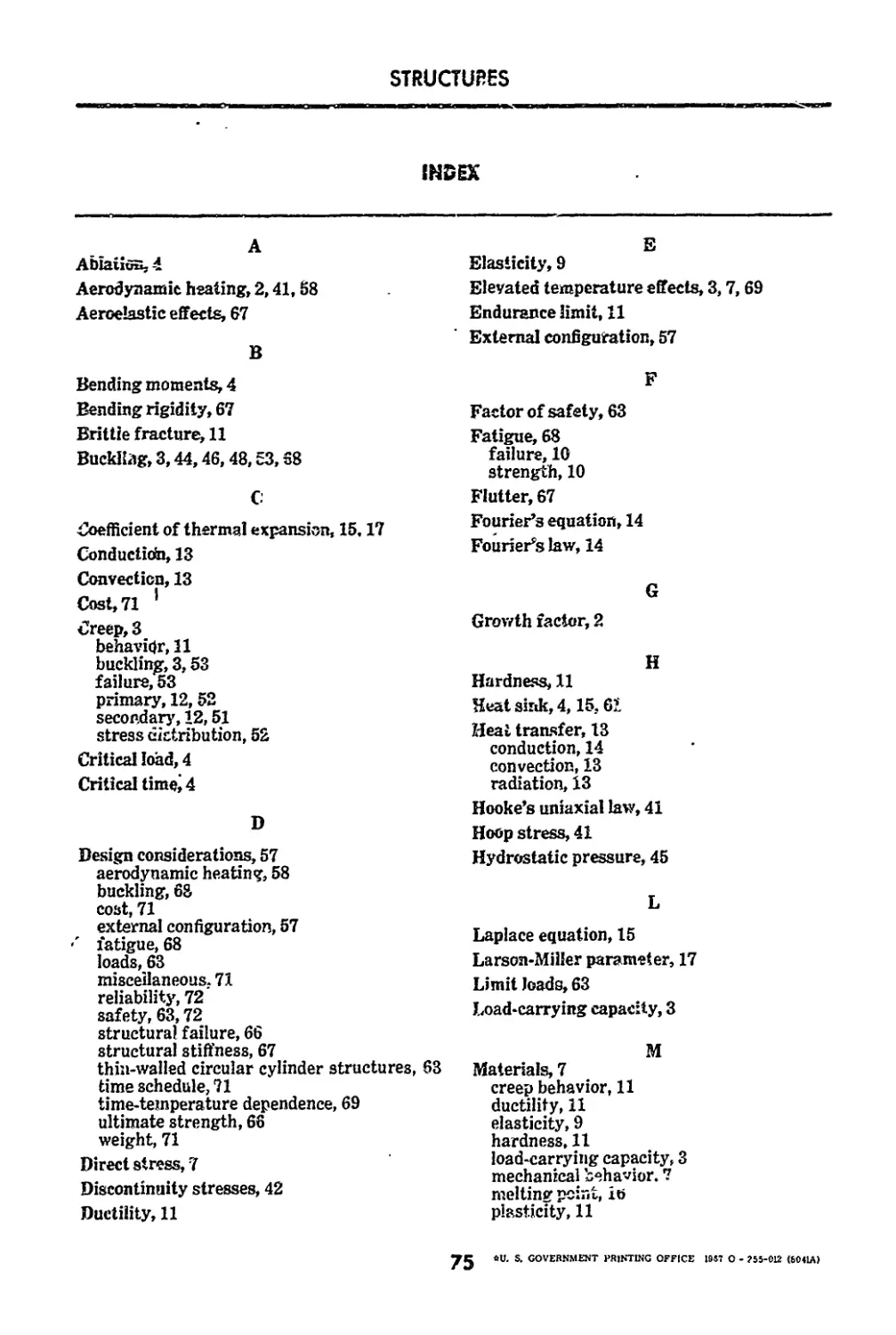
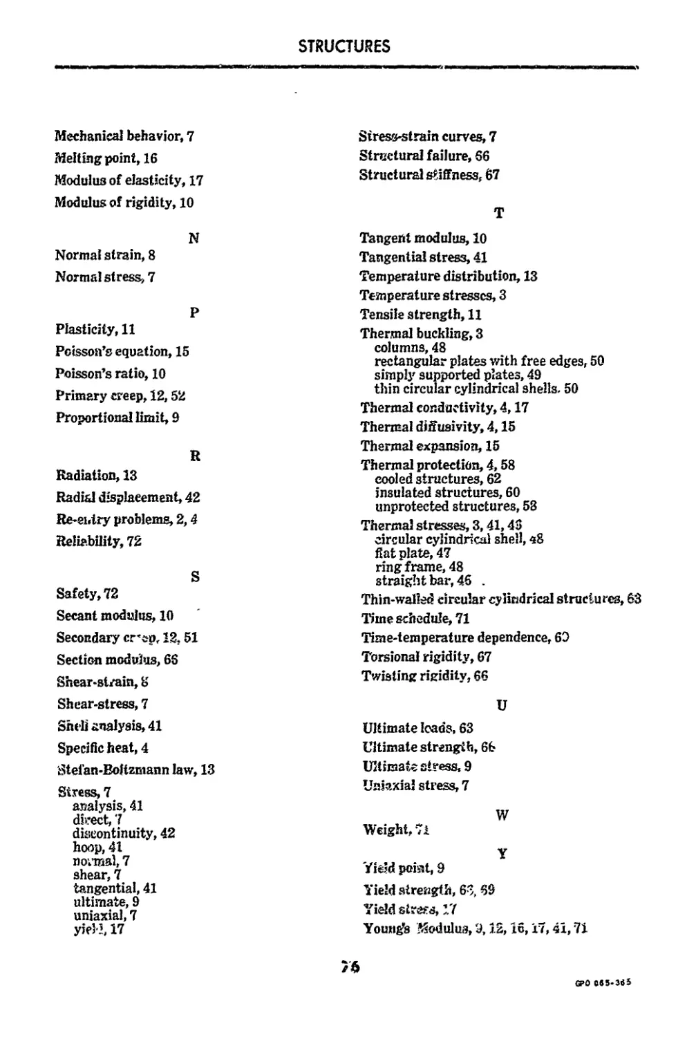
Index ..................................... .............................. 75
iii
STRUCTURES
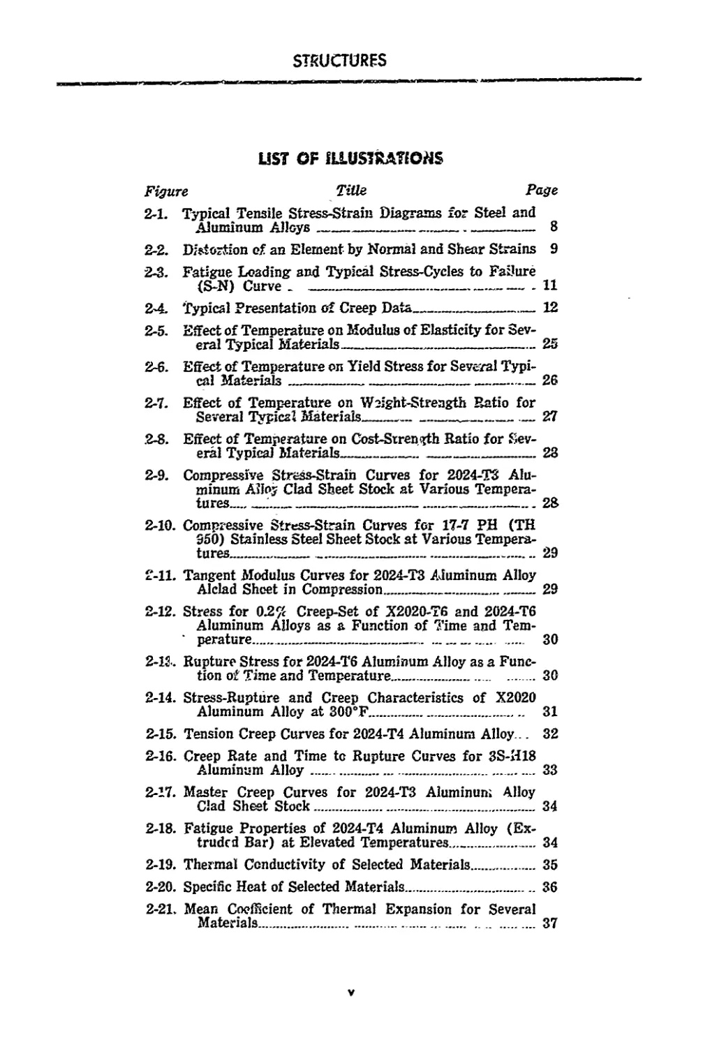
LIST OF fLLUSTRATfOriS
Figure Title Page
2-1. Typical Tensile Stress-Strain Diagrams for Steel and
Aluminum Alloys 8
2-2. Distortion of an Element by Normal and Shear Strains 9
2-3. Fatigue Loading and Typical Stress-Cycles to Failure
(S-N) Curve _ ----------------------------------11
2*4. Typical Presentation of Creep Data_______________12
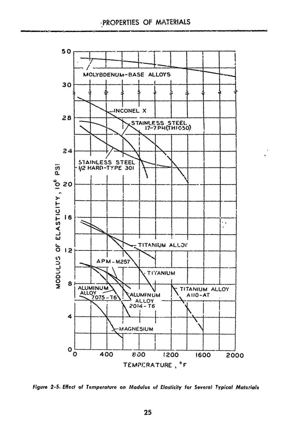
2-5. Effect of Temperature on Modulus of Elasticity for Sev-
eral Typical Materials--------------------------25
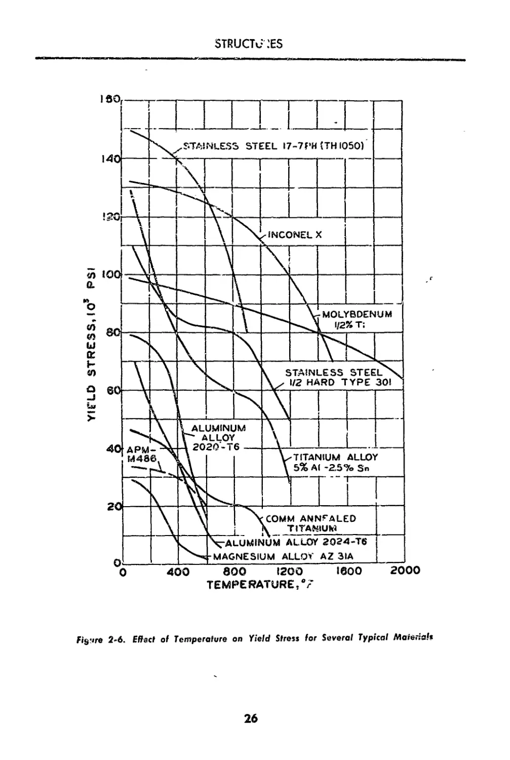
2-6. Effect of Temperature on Yield Stress for Several Typi-
cal Materials 26
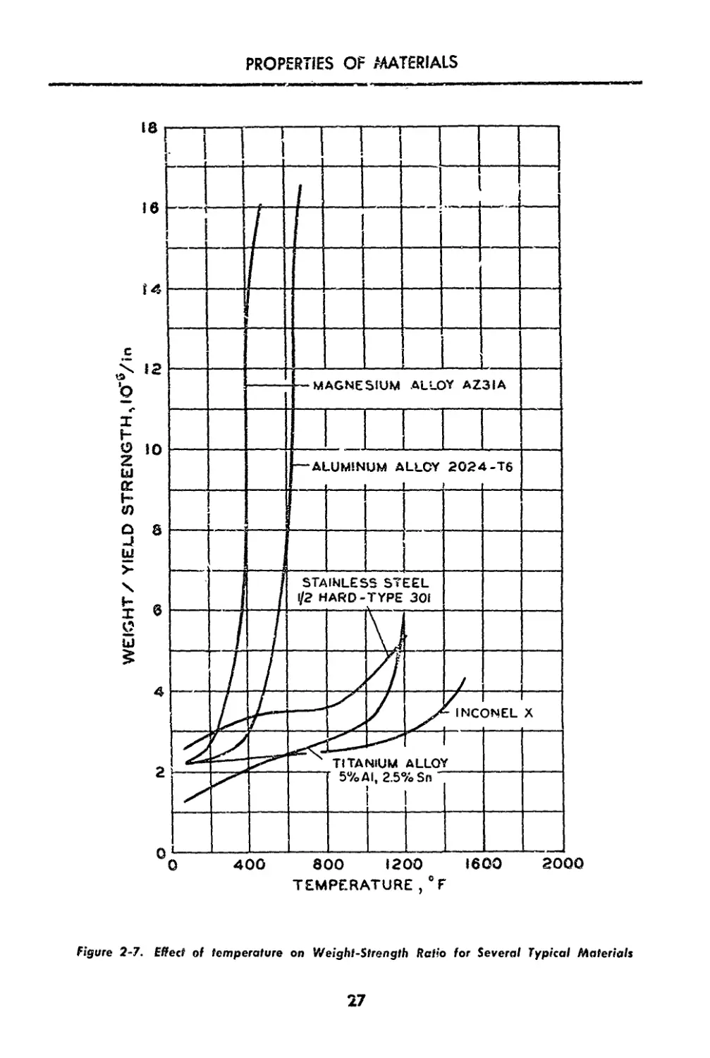
2-7. Effect of Temperature on Weight-Strength Ratio for
Several Typical Materials 27
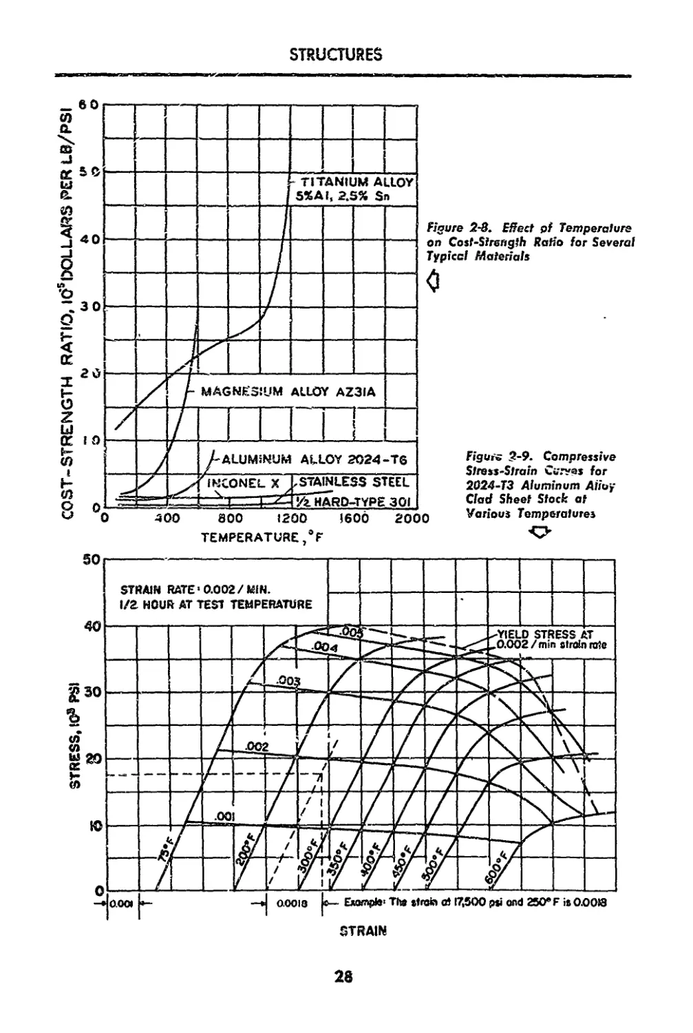
2-8. Effect of Temperature on Cost-Srrength Ratio for Sev-
eral Typical Materials—_________________________28
2-9. Compressive Stress-Strain Curves for 2024-T3 Alu-
minum Alloy Clad Sheet Stock at Various Tempera-
tures____________J______________________________28
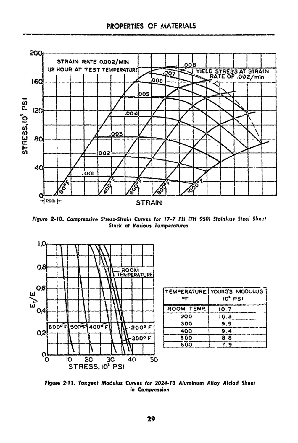
2-10. Compressive Stress-Strain Curves for 17-7 PH (TH
350) Stainless Steel Sheet Stock at Various Tempera-
tures._______________________________________________ 29
2-11. Tangent Modulus Curves for 2024-T3 Aluminum Alloy
Alclad Sheet in Compression................... 29
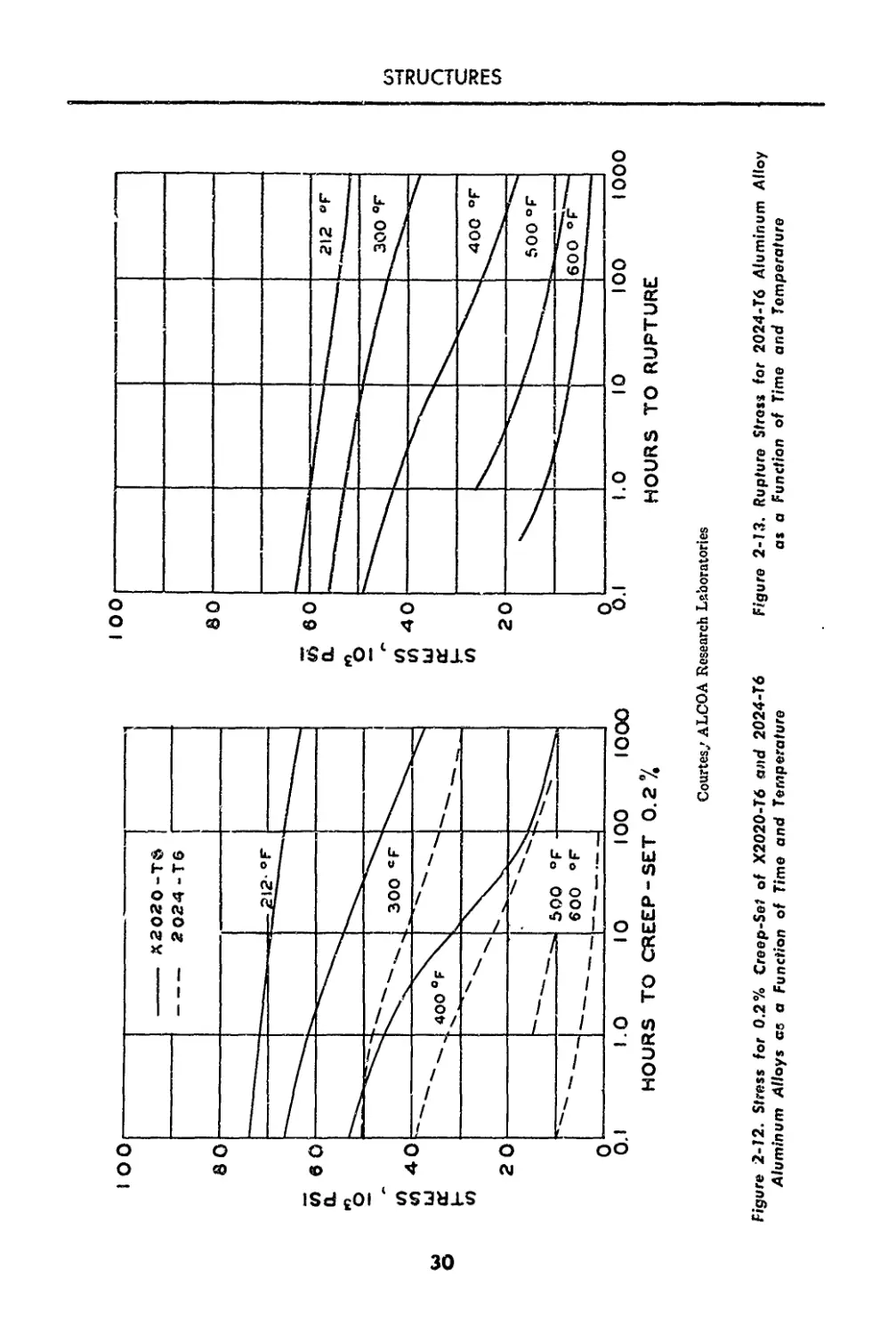
2-12. Stress for 02% Creep-Set of X2020-T6 and 2024-T6
Aluminum Alloys as & Function of Time and Tem-
' perature................................. 30
2-1J . Rupture Stress for 2024-T6 Aluminum Alloy as a Func-
tion of Time and Temperature................... 30
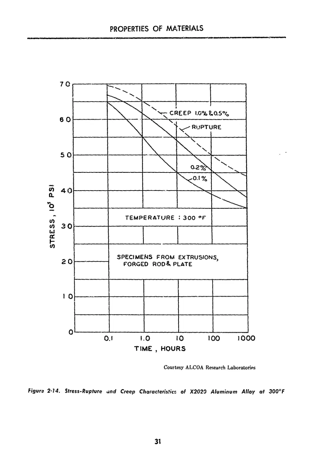
2-14. Stress-Rupture and Creep Characteristics of X2020
Aluminum Alloy at 300eF.............................. 31
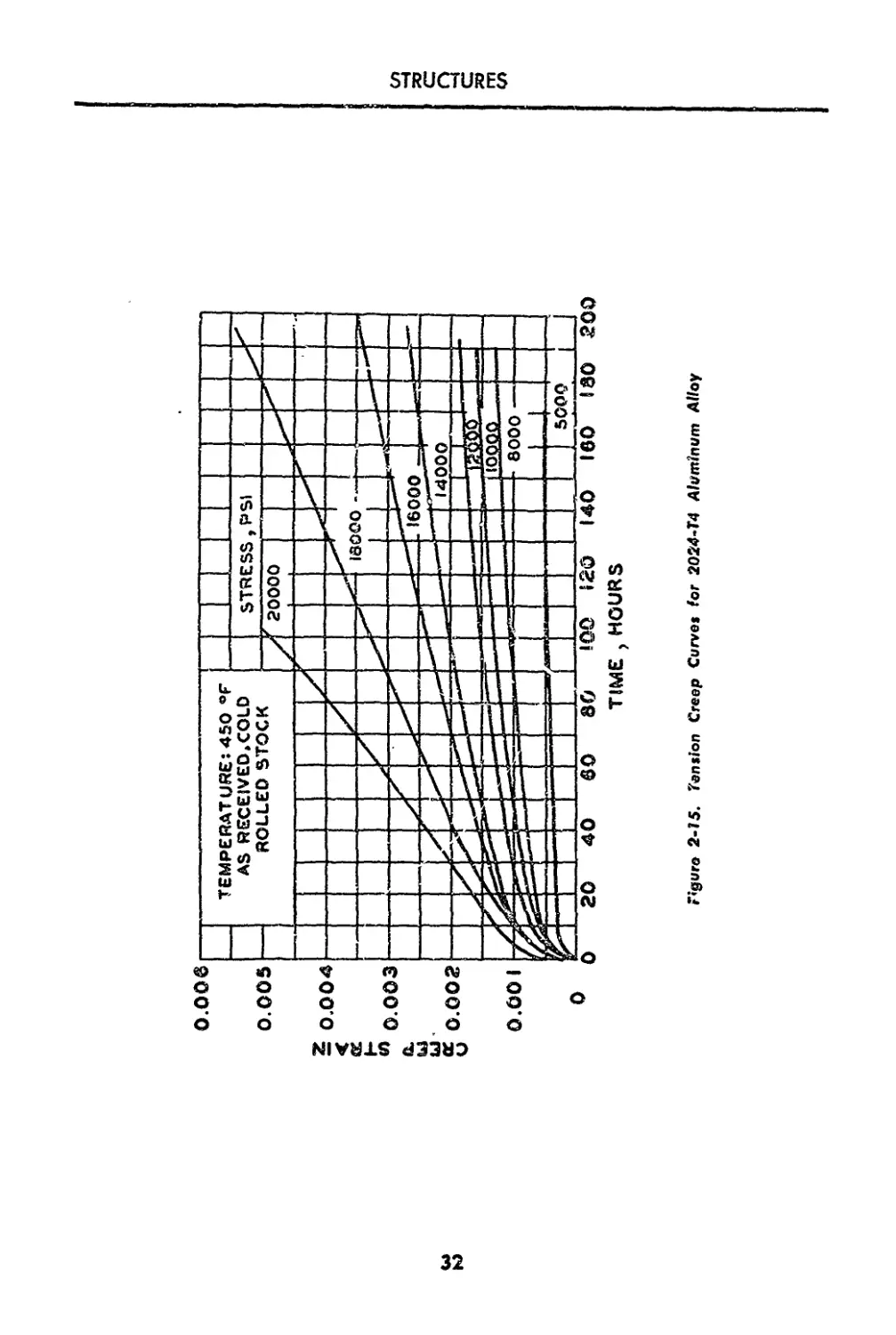
2-15. Tension Creep Curves for 2024-T4 Aluminum Alloy... 32
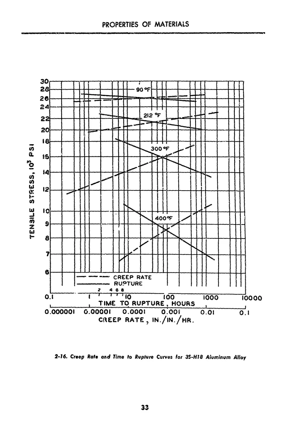
2-16. Creep Rate and Time tc Rupture Curves for 3S-H18
Aluminum Alloy........................................ 33
2-17. Master Creep Curves for 2024-T3 Aluminum Alloy
Clad Sheet Stock...................................... 34
2-18. Fatigue Properties of 2024-T4 Aluminum Alloy (Ex-
truded Bar) at Elevated Temperatures.................. 34
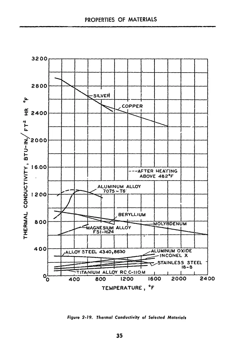
2-19. Thermal Conductivity of Selected Materials...... 35
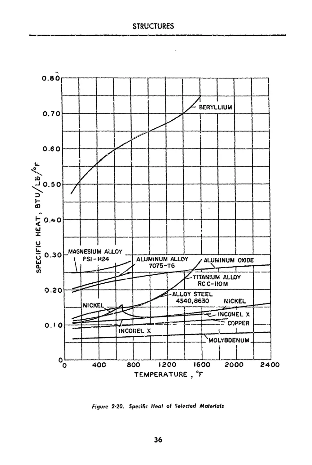
2-20. Specific Heat of Selected Materials............. 36
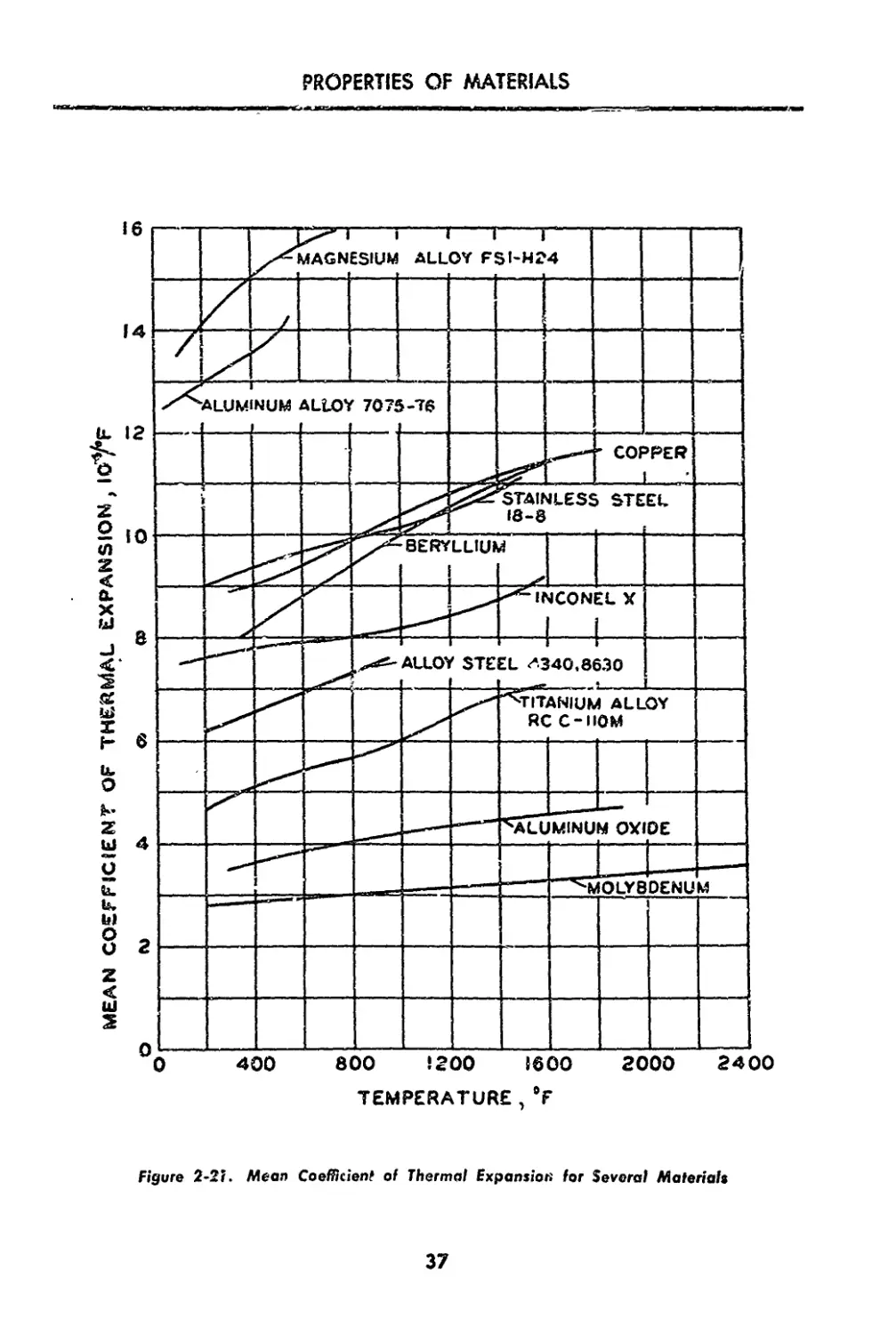
2-21. Mean Coefficient of Thermal Expansion for Several
Materials........................................... 37
STRUCTURES
tnuMteac»
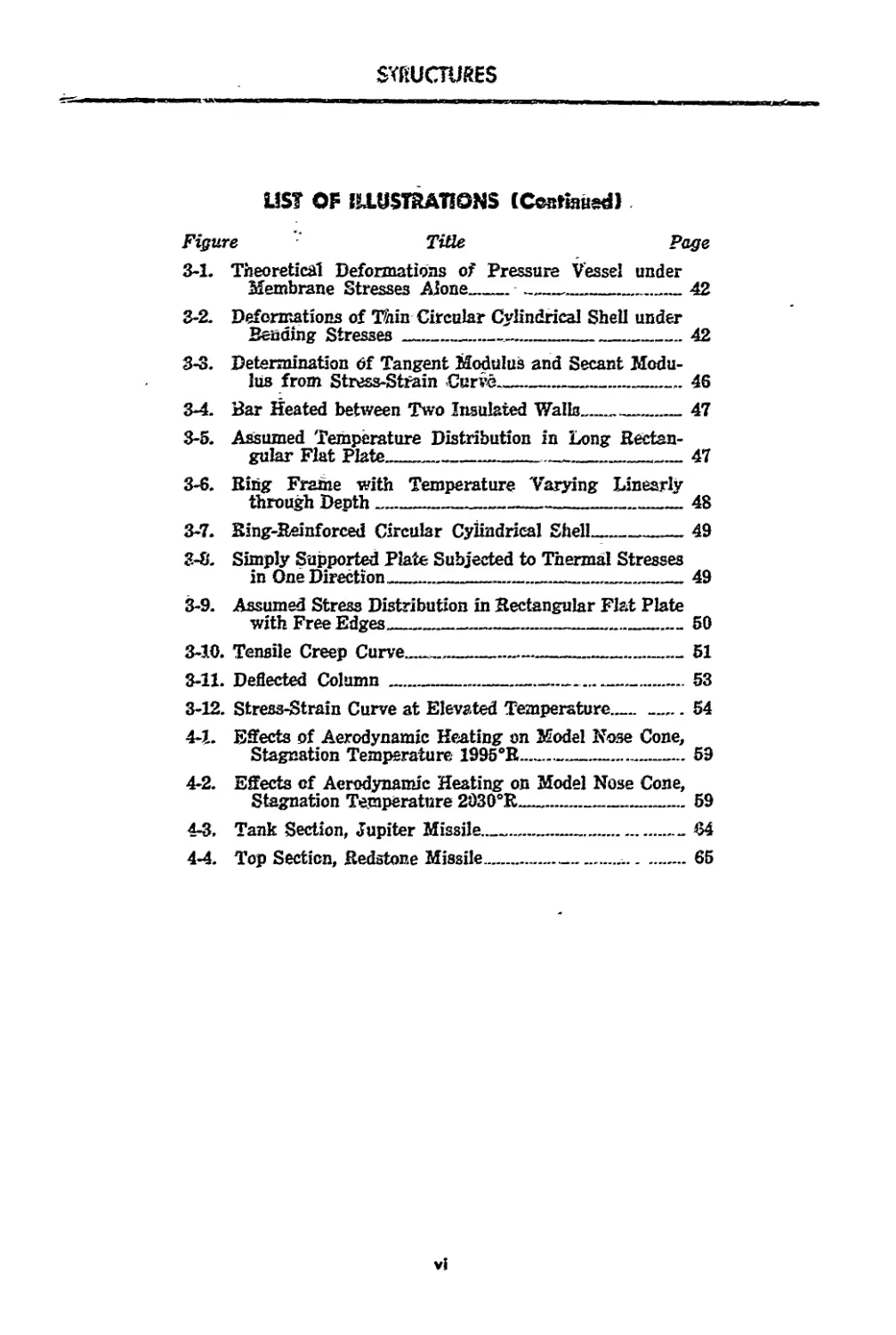
LIST OF ILLUSTRATIONS (Continued)
Figure Title Page
3-1. Theoretical Deformations of Pressure Vessel under
Membrane Stresses Alone_____..........________42
3-2. Deformations of Thin Circular Cylindrical Shell under
Bending Stresses_________________________________42
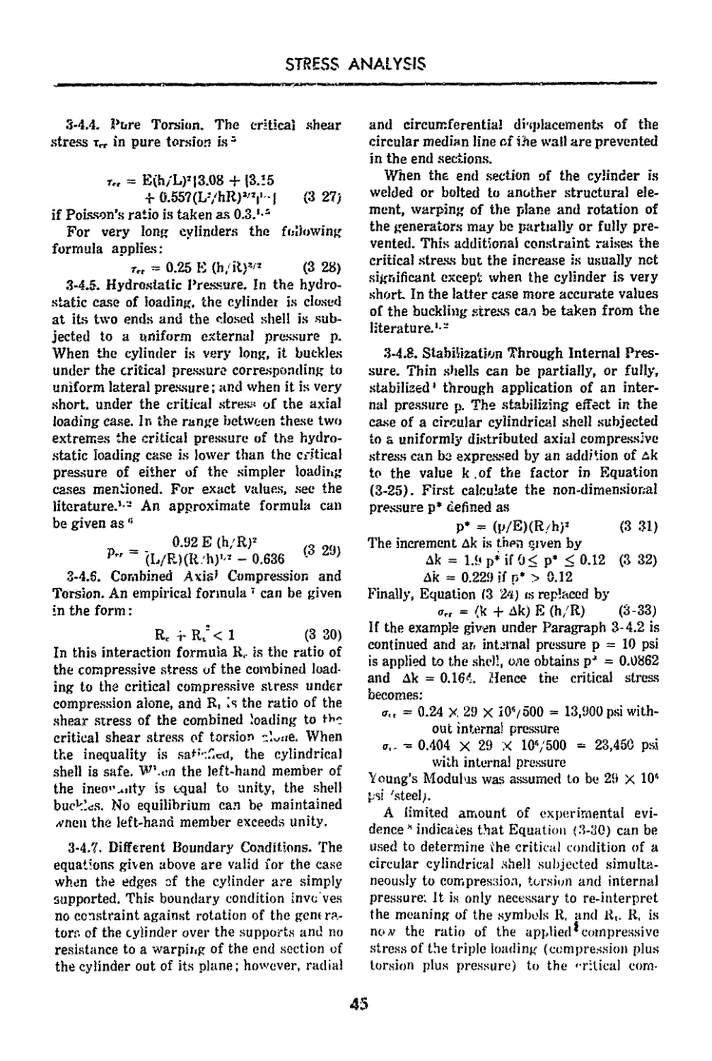
3-3. Determination Of Tangent Modulus and Secant Modu-
lus from Stress-Strain Curve.____________________46
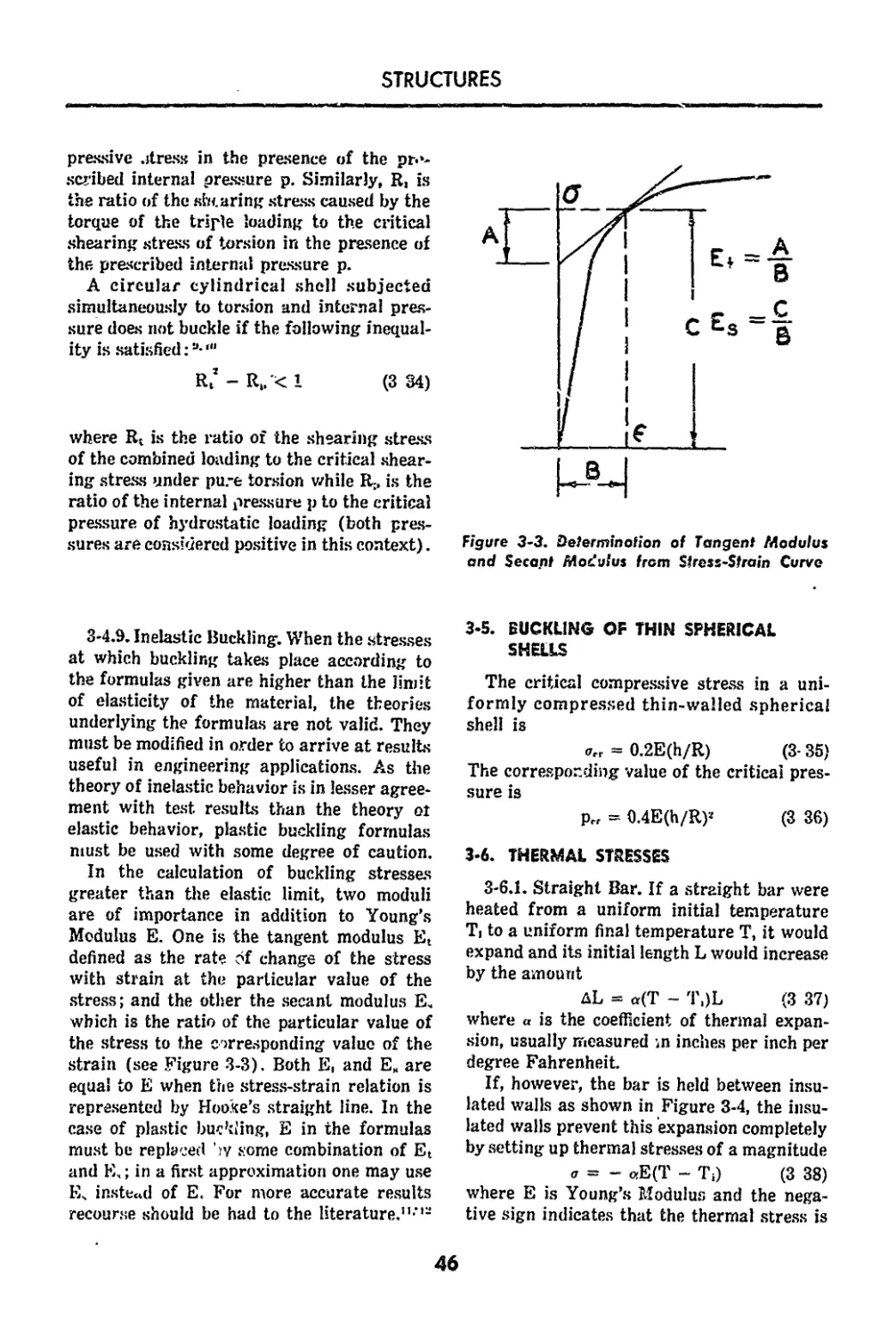
3-4. Bar Heated between Two Insulated Walls_____47
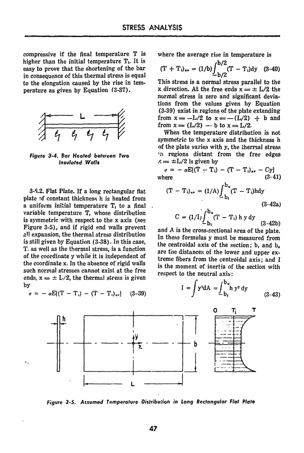
3-5. Assumed Temperature Distribution in Long Rectan-
gular Flat Plate________________________________ 47
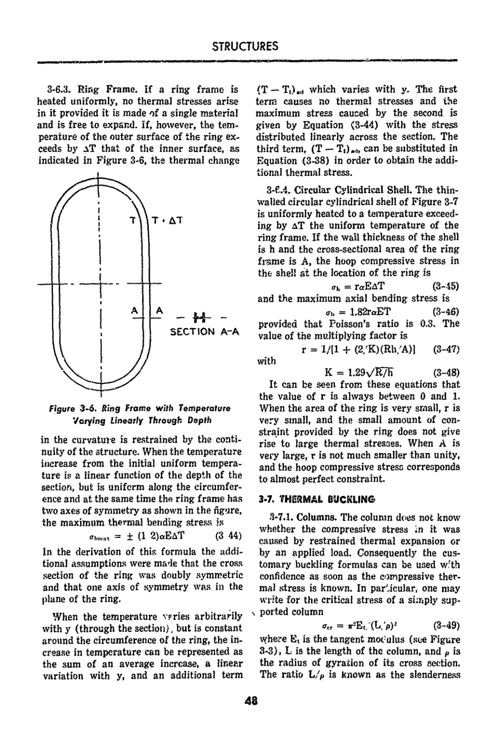
3-6. Bing Frame with Temperature Varying Linearly
through Depth 48
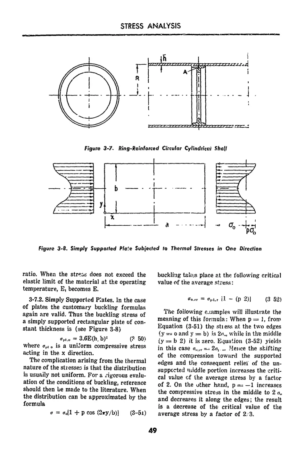
3-7. Sing-Reinforced Circular Cylindrical Shell_49
3-8. Simply Supported Plate Subjected to Thermal Stresses
in One Direction________._____________________49
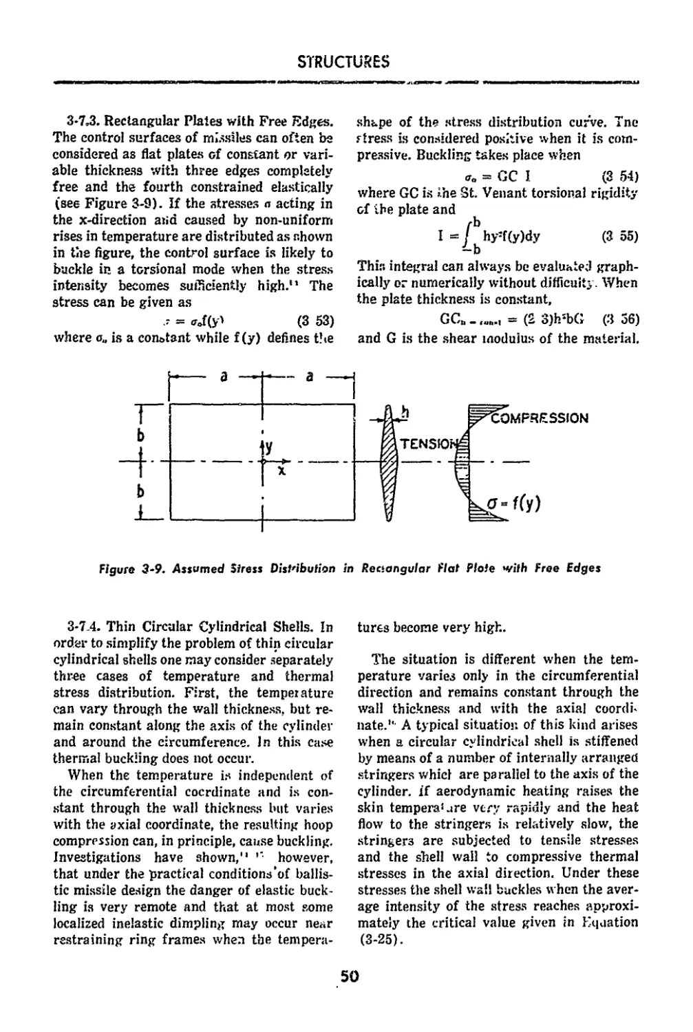
3-9. Assumed Stress Distribution in Rectangular Flat Plate
with Free Edges____________________________50
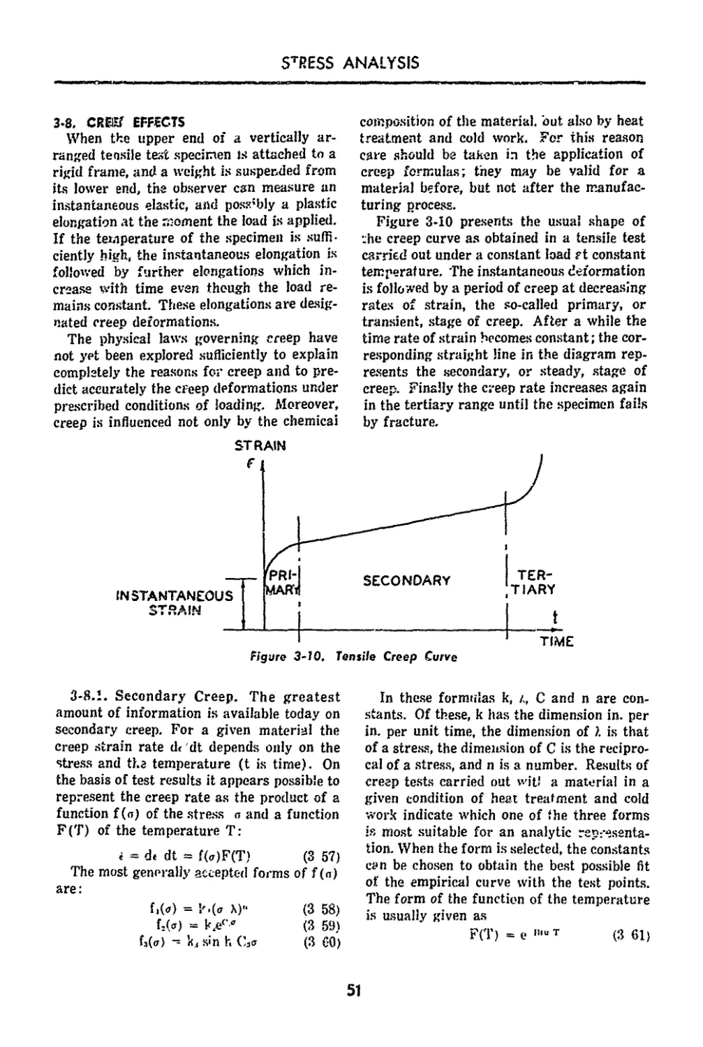
3-10. Tensile Creep Curve.51
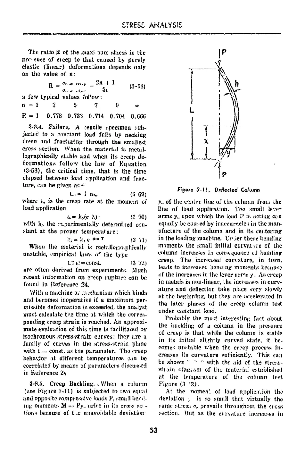
3-11. Deflected Column_______________________________53
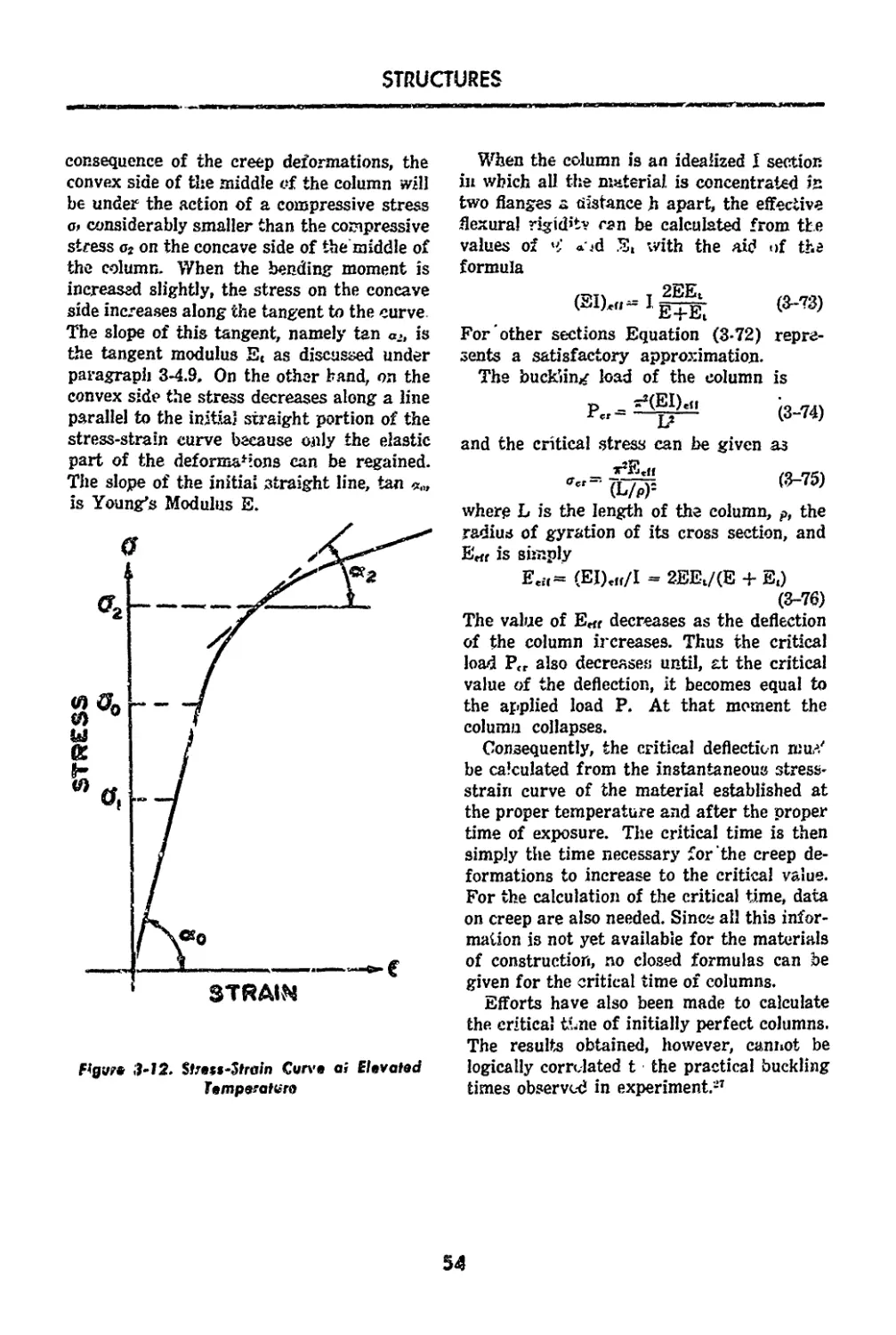
3-12. Stress-Strain Curve at Elevated Temperature_ __ 54
4-1. Effects of Aerodynamic Heating on Model Nose Cone,
Stagnation Temperature 1995°R________59
4-2. Effects of Aerodynamic Heating on Model Nose Cone,
Stagnation Temperature 2930°R_____________ 59
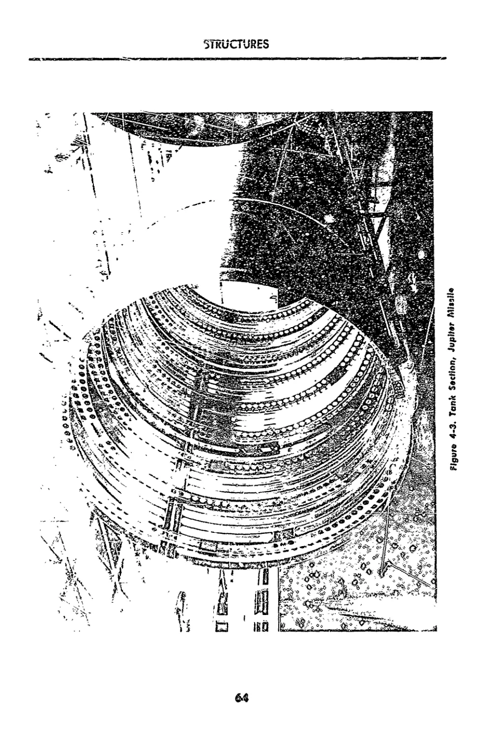
4-3. Tank Section, Jupiter Missile____________________ 64
4-4. Top Section, Redstone Missile............. 65
vi
STRUCTURES
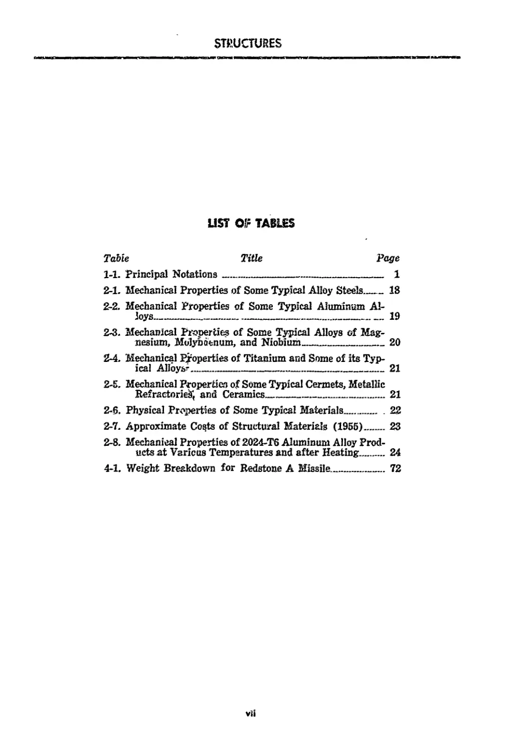
LIST ОГг TABLES
Table Title Page
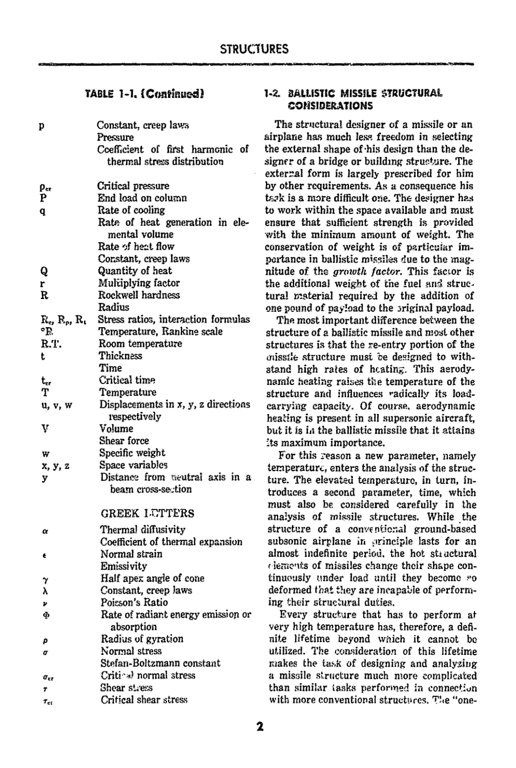
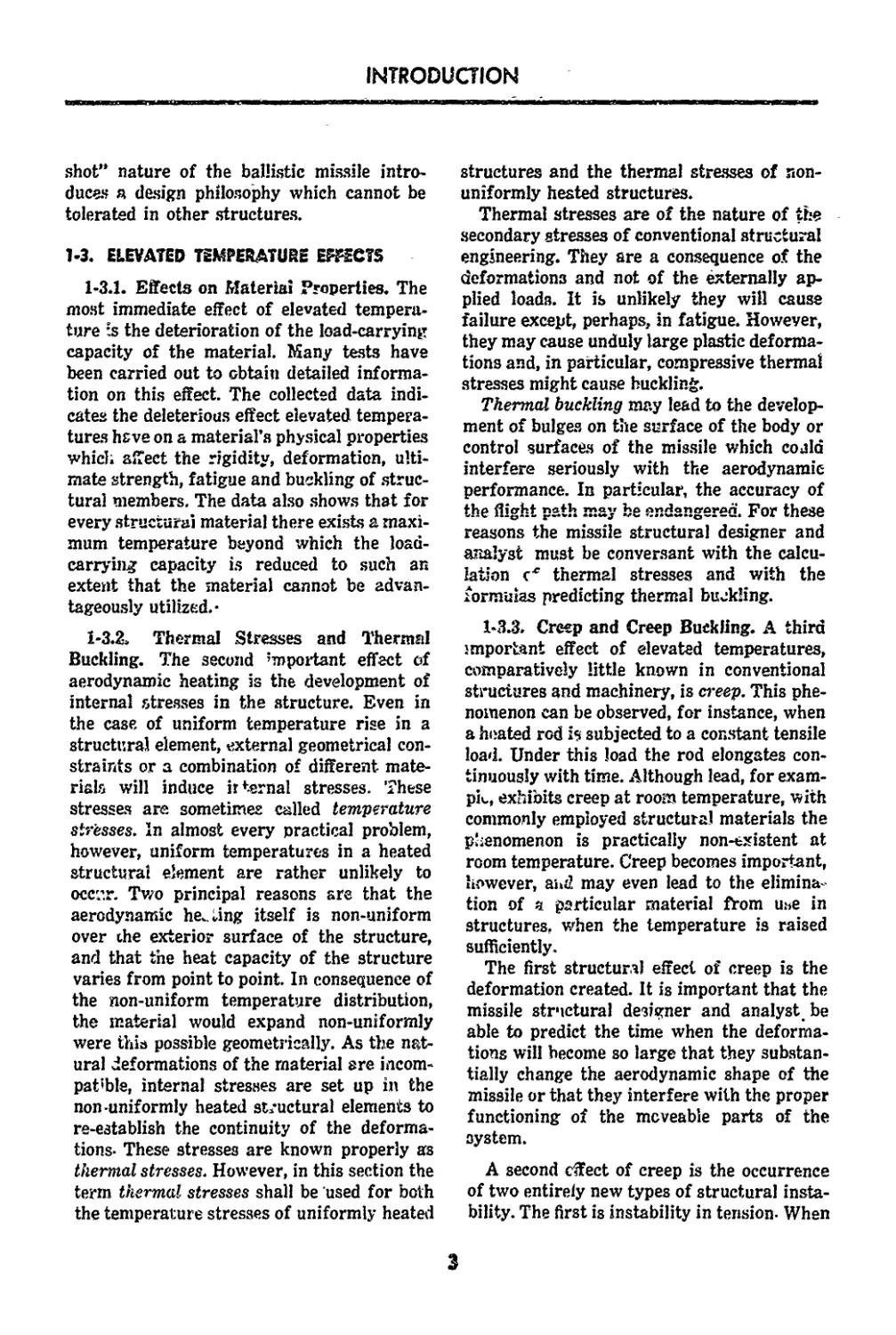
1-1. Principal Notations 1
2-1. Mechanical Properties of Some Typical Alloy Steels_18
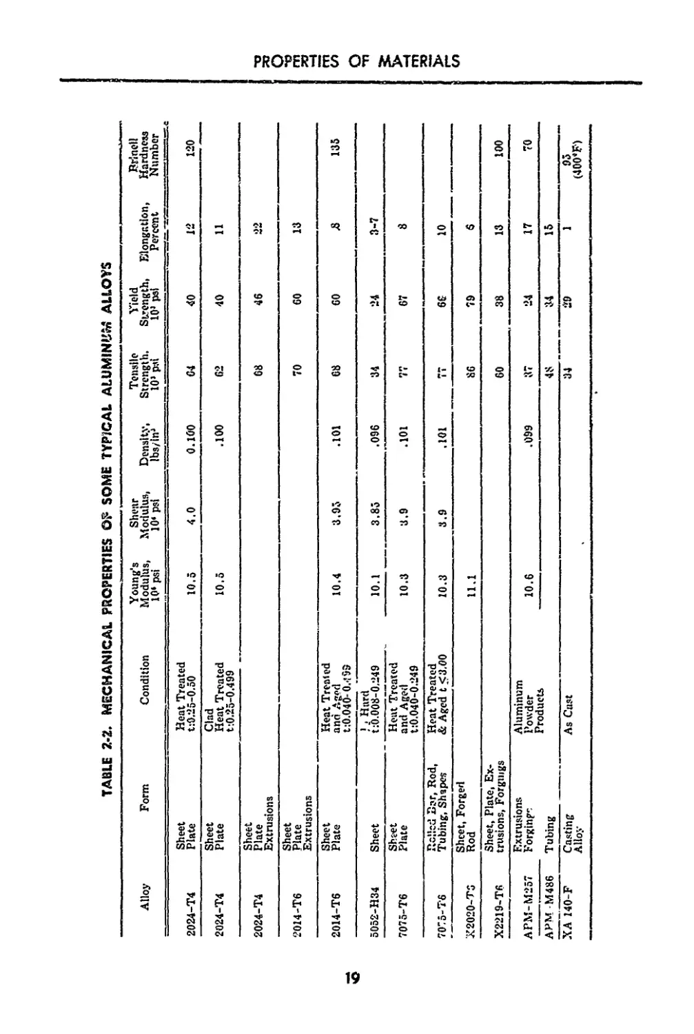
2-2. Mechanical Properties of Some Typical Aluminum Al-
loys______________________________________________19
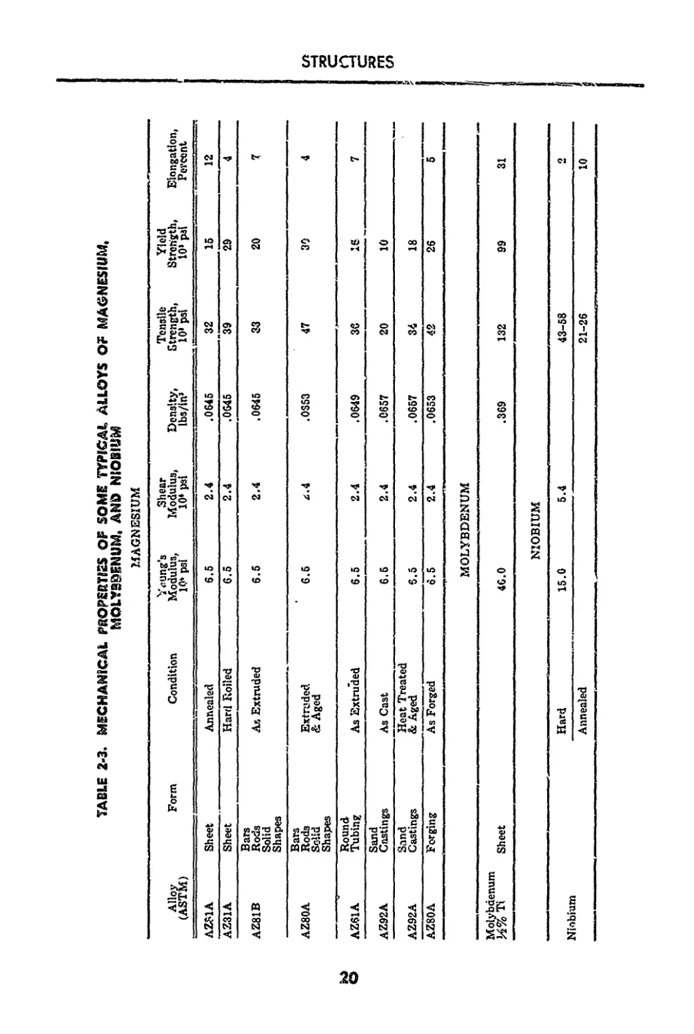
2-3. Mechanical Properties of Some Typical Alloys of Mag-
nesium, Molybdenum, and Niobium 20
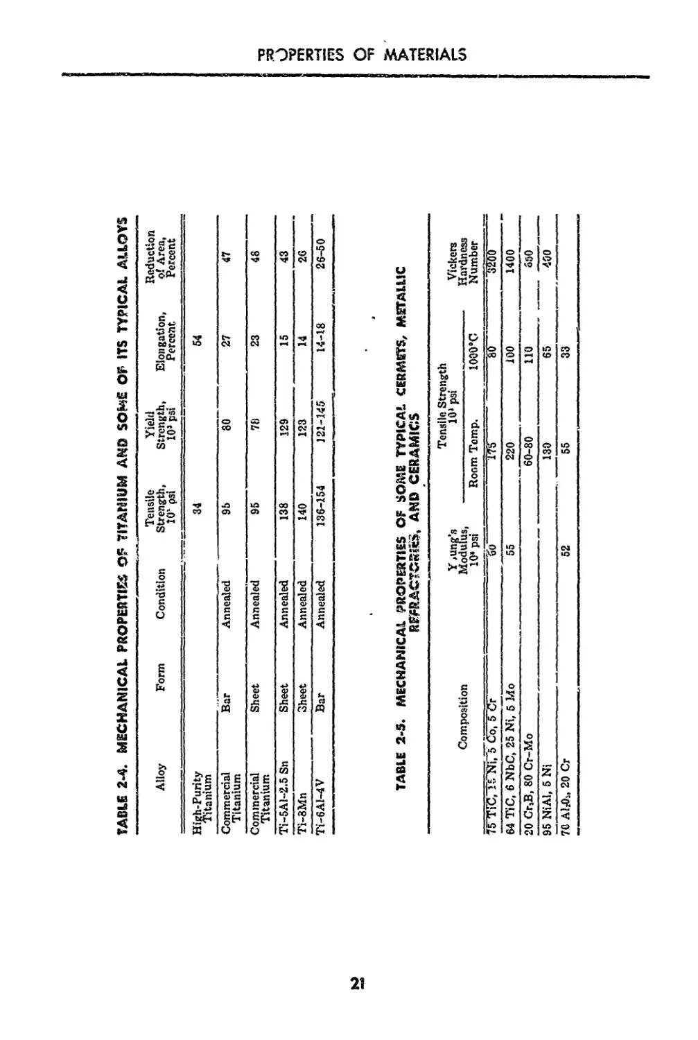
2-4. Mechanical Properties of Titanium and Some of its Typ-
ical Alloys?21
2-5. Mechanical Properties of Some Typical Cermets, Metallic
Refractories?, and Ceramics______________________21
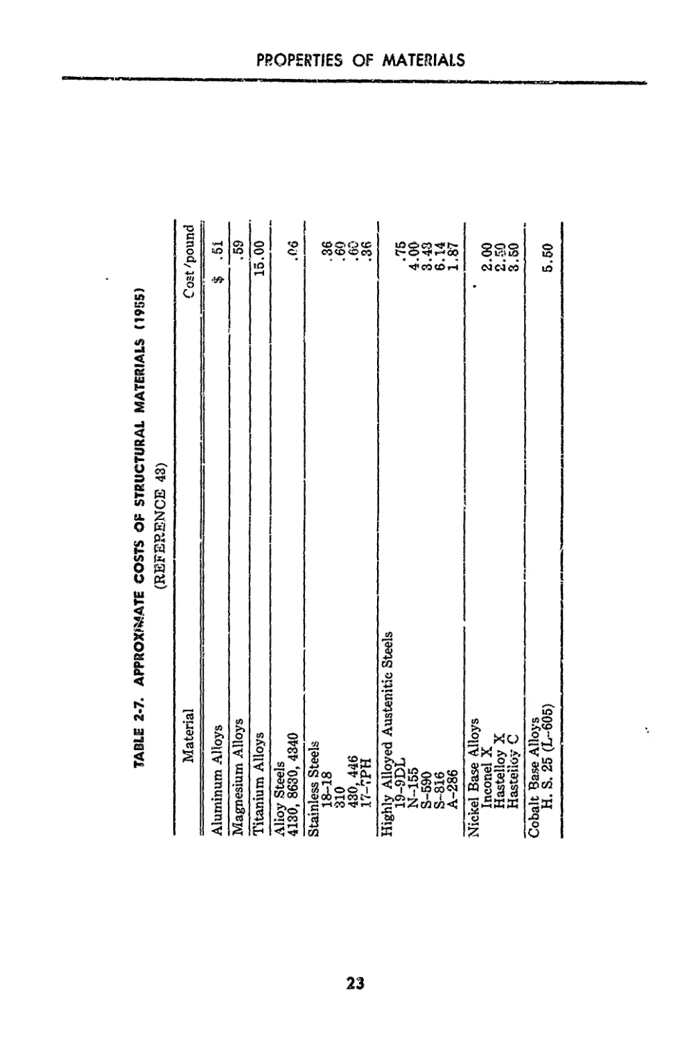
2-6. Physical Properties of Some Typical Materials......22
2-7. Approximate Costs of Structural Materials (1955)___23
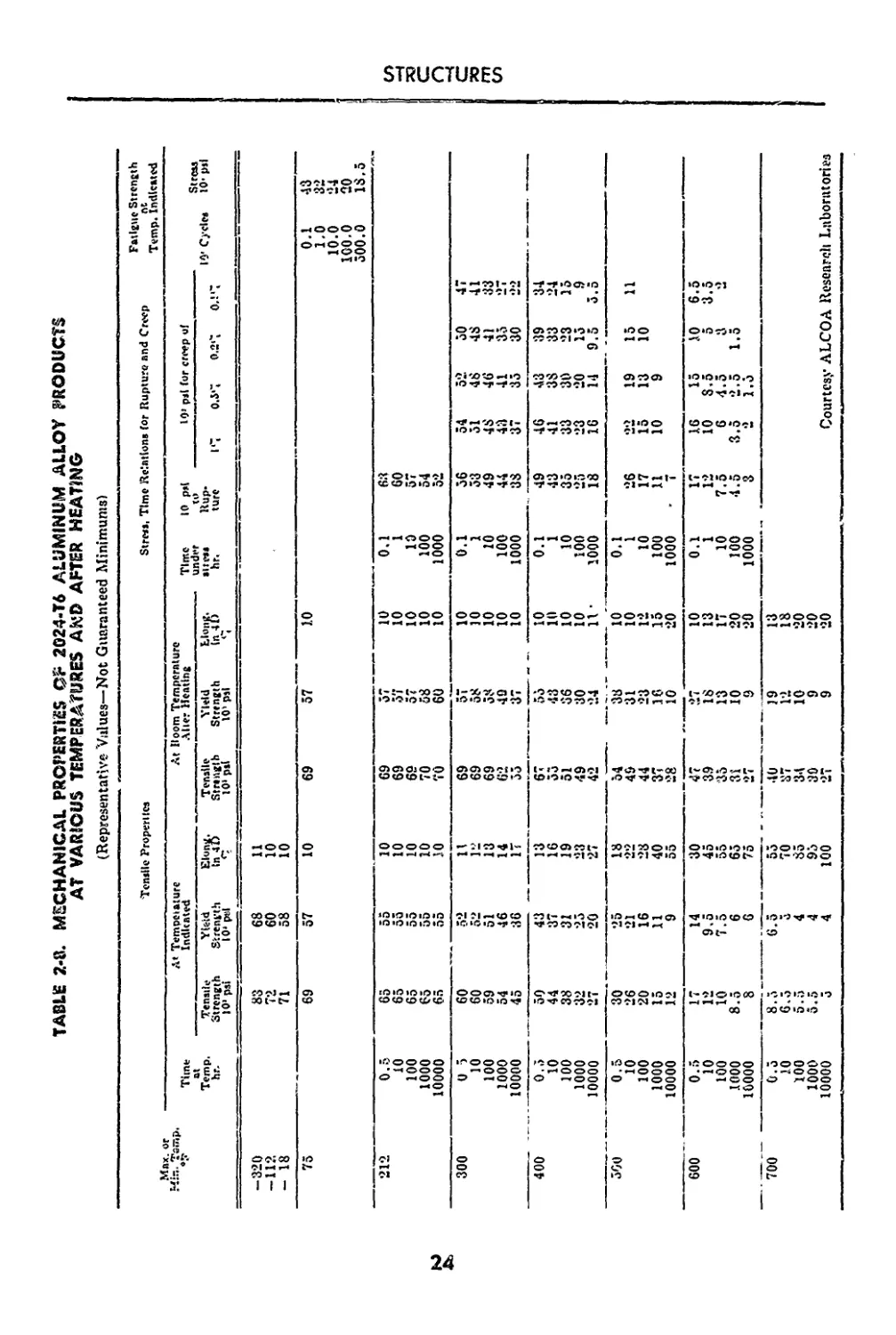
2-8. Mechanical Properties of 2024-T6 Aluminum Alloy Prod-
ucts at Various Temperatures and after Heating...24
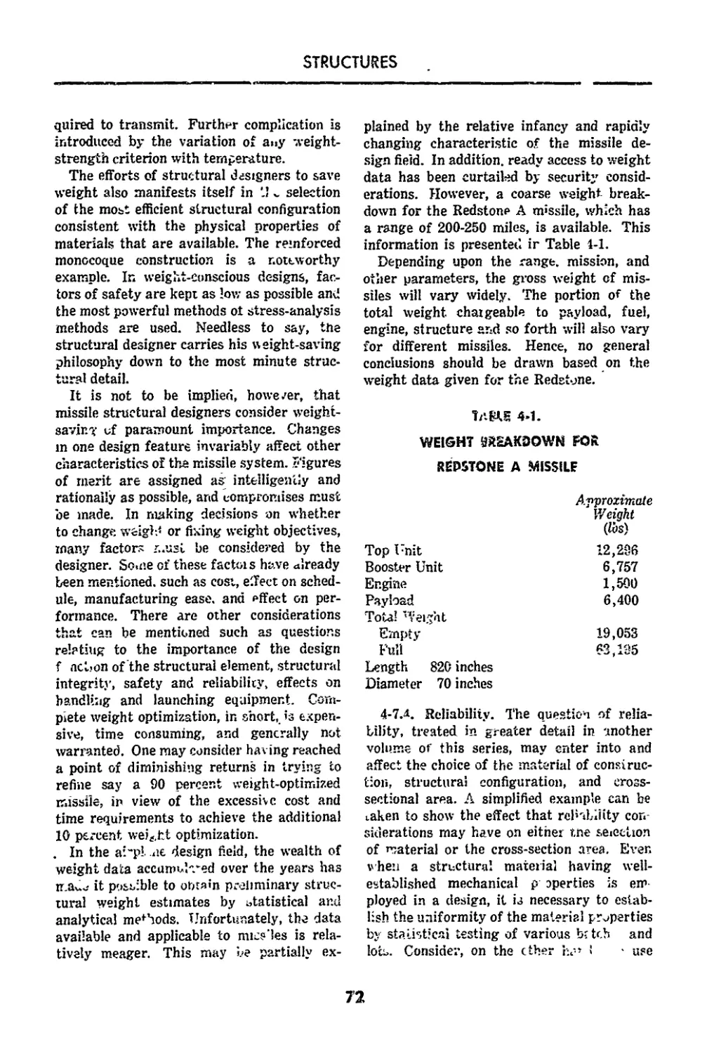
4-1. Weight Breakdown for Redstone A Missile____________ 72
vii
/in
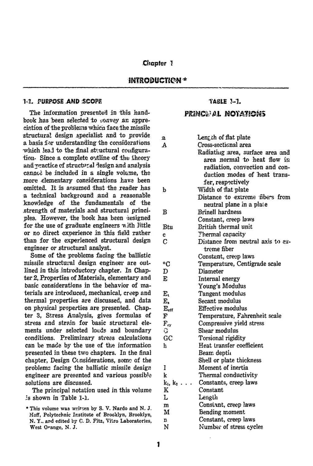
INTRODUCTION*
Chapter I
ЪЬ PURPOSE AND SCOPE
The information presented in this hand-
book has been selected to convey an appre-
ciation of the problems -which face the missile
structural design specialist and to provide
a basis for understanding the considerations
-which lead to the final st’.-uctural configura-
tion- Since a complete outline of the theory
and practice of structural designand analysis
cannot be included in a single volume, the
more elementary considerations have been
omitted. It is assumed that the reader has
a technical background .and a reasonable
knowledge of the fundamentals of the
strength of materials and structural princi-
ples. However, the book has been designed
for the use of graduate engineers -with little
or no direct experience in this field rather
than for the experienced structural design
engineer or structural analyst.
Some of the problems facing the ballistic
missile structural design engineer are out-
lined in this introductory chapter. In Chap-
ter 2, Properties of Materials, elementary and
basic considerations in the behavior of ma-
terials are introduced, mechanical, creep and
thermal properties are discussed, and data
on physical properties are presented. Chap-
ter 3, Stress Analysis, gives formulas of
stress and strain for basic structural ele-
ments under selected loads and boundary
conditions. Preliminary stress calculations
can be made by the use of the information
presented in these two chapters. In the final
chapter, Design Considerations, some of the
problems facing the ballistic missile design
engineer are presented and various possible
solutions are discussed.
The principal notation used in this volume
is shown in Table 1-1.
* This volume was writ-sen by S. V. Nardo and N. J.
Hoff, Polytechnic Institute of Brooklyn, Brooklyn,
N. Y.. and edited by C. D. Fitz, Vitro Laboratories,
West Orange, N. J.
ТА81Ж W.
a Length of fiat plate
A Cross-sectional area
Radiating -area, surface area and
area normal to heat flow in
radiation, convection and con-
duction modes of heat trans-
fer, respectively
b Width of flat plate
Distance to extreme fibers from
neutral plane in a plate
В Brinell hardness
Constant, creep laws
Btu British thermal unit
c Thermal capacity
C Distance from neutral axis to ex-
treme fiber
Constant, creep laws
°C Temperature, Centigrade scale
D Diameter
E Internal energy
Young’s Modulus
Et Tangent modulus
E, Secant modulus
Еек Effective modulus
F Temperature, Fahrenheit scale
Fcy Compressive yield stress
G Shear modulus
GC Torsional rigidity
h Heat transfer coefficient
Beam: depth
Shell or plate thickness
I Moment of inertia
к Thermal conductivity
ki, k2 . . . Constants, creep laws
К Constant
L Length
m Constant, creep laws
M Bending moment
n Constant, creep laws
N Number of stress cycles
1
STRUCTURES
TABLE 1-1. (Coaffmued)
P«
P
q
Q
r
R
Re, RP, Rt
°R
R.T.
t
te,
T
U, V, w
V
X, y, z
У
a
У
X
p
Ф
p
cr
ffcr
T
Tc[
Constant, creep laws
Pressure
Coefficient of first harmonic of
thermal stress distribution
Critical pressure
End load on column
Rate of cooling
Rate of heat generation in ele-
mental volume
Rate of heat flow
Constant, creep laws
Quantity of heat
Multiplying factor
Rockwell hardness
Radius
Stress ratios, interaction formulas
Temperature, Rankine scale
Room temperature
Thickness
Time
Critical time
Temperature
Displacements in x, y, z directions
respectively
Volume
Shear force
Specific weight
Space variables
Distance from vseutrai axis in a
beam cross-se<;tion
GREEK LETTERS
Thermal diffusivity
Coefficient of thermal expansion
Normal strain
Emissivity
Half apex angle of cone
Constant, creep Jaws
Poisson’s Ratio
Rate of radiant energy emission or
absorption
Radius of gyration
Normal stress
Stefan-Boltzmann constant
Critic? normal stress
Shear stress
Critical shear stress
1-2. BALLISTIC MISSILE STRUCTURAL
CONSIDERATIONS
The structural designer of a missile or an
airplane has much less freedom in selecting
the external shape of-his design than the de-
signer of a bridge or building structure. The
external form is largely prescribed for him
by other requirements. As a consequence his
t&?k is a more difficult one. The designer has
to work within the space available and must
ensure that sufficient strength is provided
v/ith the minimum amount of weight. The
conservation of weight is of particular im-
portance in ballistic missiles due to the mag-
nitude of the growth factor. This factor is
the additional weight of the fuel and struc-
tural material required by the addition of
one pound of payload to the original payload.
The most important difference between the
structure of a ballistic missile and most other
structures is that the re-entry portion of the
missile structure must be designed to with-
stand high rates of heating. This aerody-
namic heating raises the temperature of the
structure and influences ••adically its load-
carrying capacity. Of course, aerodynamic
heating is present in all supersonic aircraft,
but it is in the ballistic missile that it attains
its maximum importance.
For this reason a new parameter, namely
temperature, enters the analysis of the struc-
ture. The elevated temperature, in turn, in-
troduces a second parameter, time, which
must also be considered carefully in the
analysis of missile structures. While the
structure of a conventional ground-based
subsonic airplane in ;irinciple lasts for an
almost indefinite period, the hot structural
< iements of missiles change their shape con-
tinuously under load until they become «о
deformed that they are incapable of perform-
ing their structural duties.
Every structure that has to perform at
very high temperature has, therefore, a defi-
nite lifetime beyond which it cannot be
utilized. The consideration of this lifetime
makes the task of designing and analyzing
a missile structure much more complicated
than similar tasks performed in connection
with more conventional structures. T!<e “one-
2
INTRODUCTION
.shot” nature of the ballistic missile intro-
duces a design philosophy which cannot be
tolerated in other structures.
1-3. ELEVATED TEMPERATURE EFFECTS
1-3.1. Effects on Material Properties. The
most immediate effect of elevated tempera-
ture :s the deterioration of the load-carrying
capacity of the material. Many tests have
been carried out to obtain detailed informa-
tion on this effect. The collected data indi-
cates the deleterious effect elevated tempera-
tures have on a material’s physical properties
which affect the rigidity, deformation, ulti-
mate strength, fatigue and buckling of struc-
tural members. The data also shows that for
every structural material there exists a maxi-
mum temperature beyond which the load-
carrying capacity is reduced to such an
extent that the material cannot be advan-
tageously utilized.-
1-3.2. Thermal Stresses and Thermal
Buckling. The second ’mportant effect of
aerodynamic heating is the development of
internal stresses in the structure. Even in
the case of uniform temperature rise in a
structural element, external geometrical con-
straints or a combination of different mate-
rials will induce irtgrnal stresses. These
stresses are sometimes called temperature
stresses. In almost every practical problem,
however, uniform temperatures in a heated
structural element are rather unlikely to
occr.r. Tvzo principal reasons are that the
aerodynamic heating itself is non-uniform
over the exterior surface of the structure,
and that the heat capacity of the structure
varies from point to point. In consequence of
the non-uniform temperature distribution,
the material would expand non-uniformly
were this possible geometrically. As the nat-
ural deformations of the material ere incom-
patible, internal stresses are set up in the
non-uniformly heated structural elements to
re-establish the continuity of the deforma-
tions- These stresses are known properly as
thermal stresses. However, in this section the
term thermal stresses shall be used for both
the temperature stresses of uniformly heated
structures and the thermal stresses of non-
uniformly heated structures.
Thermal stresses are of the nature of the
secondary stresses of conventional structural
engineering. They are a consequence of the
deformations and not of the externally ap-
plied loads. It is unlikely they will cause
failure except, perhaps, in fatigue. However,
they may cause unduly large plastic deforma-
tions and, in particular, compressive thermal
stresses might cause buckling.
Thermal buckling may lead to the develop-
ment of bulges on the surface of the body or
control surfaces of the missile which could
interfere seriously with the aerodynamic
performance. In particular, the accuracy of
the flight path may be endangered. For these
reasons the missile structural designer and
analyst must be conversant with the calcu-
lation c* thermal stresses and with the
lormuias predicting thermal buckling.
1-3.3. Creep and Creep Buckling. A third
important effect of elevated temperatures,
comparatively little known in conventional
structures and machinery, is creep. This phe-
nomenon can be observed, for instance, when
a heated rod is subjected to a constant tensile
load. Under this load the rod elongates con-
tinuously with time. Although lead, for exam-
ple, exhibits creep at room temperature, with
commonly employed structural materials the
phenomenon is practically non-existent at
room temperature. Creep becomes important,
however, and may even lead to the elimina-
tion of a particular material from use in
structures, when the temperature is raised
sufficiently.
The first structural effect of creep is the
deformation created. It is important that the
missile structural designer and analyst be
able to predict the time when the deforma-
tions will become so large that they substan-
tially change the aerodynamic shape of the
missile or that they interfere with the proper
functioning of the moveable parts of the
system.
A second effect of creep is the occurrence
of two entirely new types of structural insta-
bility. The first is instability in tension- When
3
STRUCTURES
a straight bar is attached to a rigid structure
at its upper end and is loaded bj' a weight at
its lower end, the bar elongates continuously
with time. As creep deformations of metals
take place substantially without any change
in the total volume of the material, «, one
percent increase in the length of the bar
must be accompanied by a one percent de-
crease in its cross-sectionai area. However,
a constant load applied to а гмаПег cross-
sectional area causes an increased stress in
the bar which in turn increases the rate at
which creep deformations hike place. The
creep strain rate is generally a non-linear
function of the stress, increasing much more
rapidly than the stress. The consequence is
a very rapid acceleration of the creep process
which can end only in a reduction of the
cross-sectional area to the value at which the
material will rupture instantaneously under
the applied load. The time at which this rup-
ture takes place is known as the critical time.
This characteristic exists for all structural
materials at elevated temperatures and must
be known to the structural designer.
A second instability of importance is
known as creep buckling. This type of buck-
ling differs in many respects from elastic and
inelastic buckling as these phenomena are
known to the structural engineer. The main
difference is that in creep buckling one can-
not utilize the concept of a critical load.
Buckling takes place under any compressive
load however small if one waits long enough
after the application of the load. On the other
hand, just as in the case of tension, a new
concept must be introduced, namely that of a
critical time. An explanation of this phenom-
enon can be given without difficulty.
Every practical column, as distinguished
from the idealized ones underlying some
theoretical calculations, is imperfect. This
means that the column’s axis is never com-
pletely straight and the load is never applied
to it completely centrally.. Consequently the
column is subjected to bending moments. A
bending moment car. be calculated as the ap-
plied load multiplied by its lever arm, or the
distance of the centroid of the cross-section
from the line of load application, Under the
action of these bending moments the column
deforms in creep bending. The increasing
curvatures in turn lead to increasing lever
arms which again result in increasing imnd-
ing moments. This is a vicious circle which
can end only in the development ot very large
curvatures and complete collapse of the
column. When the behavior of the material is
such that the creep rates increase more rap-
idly than the-bendisfesnsingnts^-the _time
necessary for creep buckling to occur isai-
ways finite (not infinitely long). Consequent-
ly we can properly talk of a critic?’
Depending upon the material, the lo<u., -<nd
the temperature, this critical time may be a
few years, a few months, a few days, a few
minutes or even a few seconds. It is therefore
most important that the engineer be con-
versant with the facts of creep buckling
when designing missile structures.
1-3.4. Melting and Ablation. Other phe-
nomena which must be treated, if a complete
picture of the problems of ballistic missile
structures is to be given, are even farther re-
moved from conventional structural analysis.
The heating rates experienced by ballistic
missiles on re-entry are so large that the
surface of the material may melt, sublime or
even burn. The designer of the missile must
therefore take the necessary precautions in
this regard. Some of these precautions are of
an entirely aerodynamic nature; if the con-
tours of the missile are properly shaped, the
heating that the missile will experience can
be minimized. A second precautionary meas-
ure is more in the realm of the structural
designer; it consists of provisioro- for ther-
mal protection through shielding the struc-
tural material with insulation, through cool-
ing the structure by means of the evaporation
of a coolant, or. through other means.
In some designs the external metal cover-
ing of the missile is used as a heat sink. When
this is the case, information is required aoout
the thermal conductivity, the thermal diffu-
sivity.. and the specific heat of the material.
The former quantities determine how rapidly
heat will be transmitted from the surface of
the missile tc its interior, while the last item
4
INTRODUCTION
^ibiiimiit—mwwn iv i wg——I mihi'iu in। и i n—мтд
indicates how much heat can be stored in the
material.
Re-entry has also been accomplished suc-
cessfully through letting the surface of the
missile melt and the molten meta] be carried
away by the windstream. If sufficient mate-
rial is available in the structure, the integrity
of the missile may not be impaired by this
melting. However, the rates of melting and
ablation must be calculated, and the designer
must also have information about the sta-
bility of the process; in particular, whether
ridges or pits will be formed or whether the
material will be consumed uniformly over the
entire surface. Similarly it has been sug-
gested that a missile might be allowed to
Ьигя during re-entry just as in the case of a
meteor. Again, a great deal of information
is needed on this problem before the designer
can employ burning as a means of maintain-
ing the integrity of the interior of the
structure.
5
PROPERTIES OF MATERIALS
Chapter 2
2-}. MECHANICAL BEHAviO?
In the analysis and design of any structure,
(he physical properties of available materials
are of primary importance. With relatively
few exceptions, structural engineers in the
past were concerned only with those proper-
ties which might be classed as purely me-
chanical. Certain elastic constants, yield and
breaking strengths, and fatigue characteris-
tics might be cited as examples. The rela-
tively recent developments in jet and rocket
propulsive systems, high-performance air-
craft, and missiles have greatly increased the
complexity of structural analysis and design
problems. Designers of today’s high-speed
aircraft and missiles are interested not only
in the material properties already mentioned,
but also in the thermal, creep and plastic
characteristics. Indeed, it is certain that this
interest will extend to those physical charac-
teristics which were heretofore in the domain
of solid-state physics.
A major reason for this extension of in-
terest in materia? properties is that ballistic
missiles are subject to high rates of heating.
This heating occurs upon re-entry into the
atmosphere and (under certain trajectory
conditions) during the ascending phase of
the flight. Unless the heat is dissipated the
temperature will rise. The load carrying ca-
pacity of the structure is affected by the
temperatures attained, and also by the length
of time at an elevated temperature.
As a genera! rule, it may be said that ele-
vated temperatures have a deleterious effect
on the mechanical properties of materials.
For example, the modulus of elasticity, yield
stress, and the ultimate stress usually de-
crease with increasing temperature. It will
also be seen that the rupture stress in
fatigue, or the number of cycles to failure
generally decreases with an increase in
temperature.
Data on the properties of some of the more
pertinent engineering materials used in mis-
sile design are collected and presented in
tabular and graphical form at the end of this
chapter.
2-1.1. Stress-Strain Curves. Probably the
mechanical data most familiar to engineers
are stress-strain curves. This information is
obtained experimentally by testing a pre-
scribed standard specimen of the material in
tension or compression and simultaneously
recording the load and elongation, in thc-
simplest o' these tests, a cylindrical speci-
men is loaded in tension ir. a testing machine,
the observed load is divided by the original
cross-sectional area to obtain the average
stiess, and the elongation is measured over
a unit length to obtain the strain. When the
data are presented graphically in the form of
stress as a function of strain, the result is a
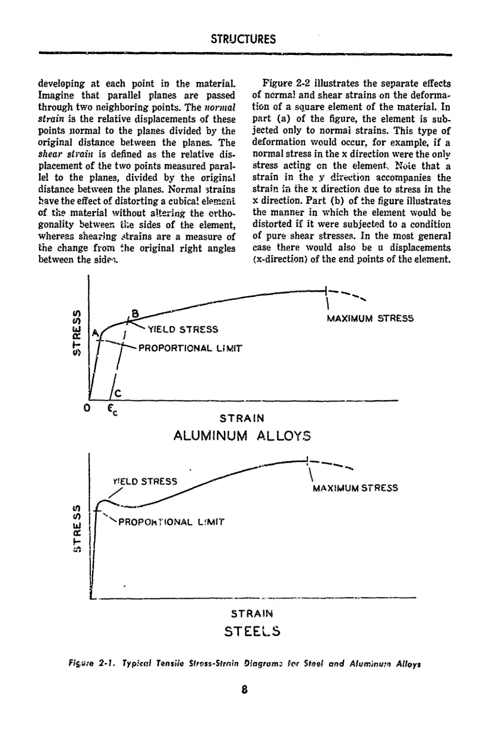
stress-strain curve. Typical curves are shown
in Figure 2-1 for steel «nd aluminum alloys-
Before the information derivable from
these curves is discussed, a brief review of
the concepts of stress and strain will be pre-
sented. Stress is the intensity of the force per
unit area acting on a plane. This property is
a vector quantity; the normal component of
the vector is the normal or aired stress, and
the component in the plane, the slt<.ar stress.
In a cylindrical test specimen, the quantity
obtained by dividing the total force by the
cross-sectional area is the normal stress act-
ing on a plane perpendicular io the axis of
the cylinder With a material that can be
considered homogeneous and isotropic, and
with a centrally applied load, this definition
is reasonably consistent and accurate. Inas-
much as this normal stress is the only stress
acting in this simplified case, the stress con-
dition is said to be uni-axial.
The stress picture is accompanied by a
strain picture with normal and shear strains
7
STRUCTURES
developing at each point in the material.
Imagine that parallel planes are passed
through two neighboring points. The normal
strain is the relative displacements of these
points normal to the planes divided by the
original distance between the planes. The
shear strain is defined as the relative dis-
placement of the two points measured paral-
lel to the planes, divided by the original
distance between the planes. Normal strains
have the effect of distorting a cubical element
of the material without altering the ortho-
gonality between the sides of the element,
whereas shearing strains are a measure of
the change from the original right angles
between the side -..
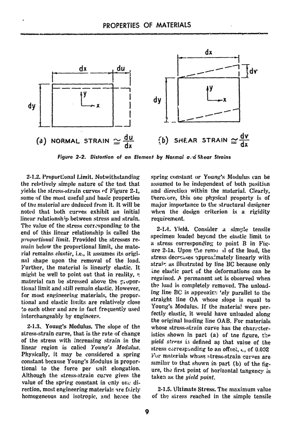
Figure 2-2 illustrates the separate effects
of normal and shear strains on the deforma-
tion of a square element of the material. In
part (a) of the figure, the element is sub-
jected only to normal strains. This type of
deformation would occur, for example, if a
normal stress in the x direction were the only
stress acting cn the element. Note that a
strain in the у direction accompanies the
strain in the x direction due to stress in the
x direction. Part (b) of the figure illustrates
the manner in which the element would be
distorted if it were subjected to a condition
of pure shear stresses. In the most general
case there would also be u displacements
(x-direction) of the end points of the element.
ALUMINUM ALLOYS
STEELS
Figure 2-1. Typical Tensile St.Tss-Strnin Oiagromj for Steel and Aluminum Alloys
8
PROPERTIES OF MATERIALS
NORMAL STRAIN ~
QX
ri v
b) SHEAR STRAIN ~ —
z ~ ax
Figure 2-2. Distortion of an Element by Normal a, a Shear Strains
2-1.2. Proportional Limit. Notwithstanding
the relatively simple nature of the test that
yields the stress-strain curves 'T Figure 2-1,
some of the most useful and basic properties
of the material arc deduced from it. It will be
noted that both curves exhibit an initial
linear relationship between stress and strain.
The value of the stress corresponding to the
end of this linear relationship is called the
proportional limit. Provided the stresses re-
main below the proportional limit, the mate-
rial remains elastic, i.e., it assumes its origi-
nal shape upon the removal of the load.
Further, the material is linearly elastic. It
might be well to point out that in reality, ч
material can be stressed above the propor-
tional limit and still remain elastic. However,
for most engineering materials, the propor-
tional and elastic limits are relatively close
to each other and are in fact frequently used
interchangeably by engineers.
2-1.3., Young’s Modulus. The slope of the
stress-strain curve, that is the rate of change
of the stress with increasing strain in the
linear region is calicd Youny’s Modulus.
Physically, it may be considered a spring
constant because Young’s Modulus is propor-
tional to the force per unit, elongation.
Although the stress-strain curve gives the
value of the spring constant in only one di-
rection, most engineering materials are fairly
homogeneous and isotropic, and hence the
spring constant or Young’s Modulus can be
assumed to be independent of both position
and direction within the material. Clearly,
there.ore, this one physical property is of
major importance to the structural designer
when the design criterion is a rigidity
requirement.
2-1.4. Yield. Consider a simple tensile
specimen loaded beyond the elastic limit to
a stress corresponding to point В in Fig-
ure 2-la. Upon the remo d of the load, the
stress decreases approximately linearly with
strain as illustrated by line BC because only
tne elastic part of the deformations can be
regained. A permanent set is observed when
the load is completely removed. The unload-
ing line BC is approxim. tely parallel to the
straight line OA whose slope is equal to
Young’s Modulus. If the material were per-
fectly elastic, it would have unloaded along
the original loading line OAB. For materials
whose stress-strain curve has the character-
istics shown in part (a) of tne figure, th»
yield stress is defined a? that value of the
stress corresponding to an offset, of О.ОЭ2
Fur materials whose stress-strain curves are
similar to that shown in part (b) of the fig-
ure, the first point of horizontal tangenc.v is
taken as the yield point.
2-1.5. Ultimate Stress. The maximum value
of the stress reached in the simple tensile
9
STRUCTURES
test is called the ultimate stows. Since all
stresses are based on the original cross-
sectional area of the specimen, the ultimate
stress corresponds to the maximum ioad, and
it may be considered as indicative of the
strength of the material. Relatively few
members in airplane and missile structures,
however, are critical in tension. The ultimate
stress of a material in compression is not
quite as clear-cut because of the column
action. Even when the column action is pre-
vented by lateral constraints or by the pro-
portions of the test specimen only some
materials such as wood and stone will exhibit
a definite value of the ultimate stress. For
most metals, an arbitrary criterion must be
used to define this quantity. When the design
criterion is associated with failure or rupture
of the structural member, then the ultimate
stress assumes major importance as a ma-
terial property.
2-1.6. Tangent and Secant Modulus, Modu-
lus of Rigidity. In some structural analyses
(column buckling, for example), a so-called
tangent modulus is used. This quantity is
simply the slope of the stress-strain curve at
any point. Below the proportional limit, the
tangent modulus is everywhere equal to the
Young’s Modulus. Some investigators use the
concept of a secant modulus, which is the
ratio of stress to strain at any point. Young’s
Modulus and the secant modulus are also
equal below the proportional limit. Torsion
stress-strain diagrams can also be plotted
from torsion tests on round tubes or round
solid sections. The initial slope of this curve,
analogous to Young’s Modulus, yields the
modulus of elasticity in shear, referred to
as the Modulus of frigidity.
2-1.7. Poisson’s Ratio. For homogeneous,
isotropic materials, the Modulus of Rigidity
is related to Young’s Modulus in the follow-
ing manner:
G — E/2(l + v) (2-1)
where
E is Young's Modulus
G is Modulus of Rigidity
v is Poisson’s Ratio
Poisson’s Ratio is the absolute value of the
ratio of the lateral strain to the axial strain
in a uniaxially stressed material, /s men-
tioned earlier, a cylindrical tensile test speci-
men subjected to an axial load produces an
axial strain. This axial strain is always ac-
companied by a lateral strain smaller in
magnitude, and opposite in sign [Figure
2-2(a)]. For most engineering materials
Poisson’s Ratio has a value of approximately
0.3.
2-1.8. Fatigue. The physical properties of
materials discussed so far have been based
on static tests in which the load is slowly ap-
plied without repetition. It is well known that
some structural elements are subject to vi-
brations which cause the stresses to fluctuate.
Under these conditions, failure can occur at
a stress level which may be considerably
lower than the ultimate stress previously dis-
cussed. This type of failure is known as
fatigue failure.
The fatigue strength of a structural ele-
ment is probably the least amenable to analy-
sis and hence the most difficult of the various
design strengths to evaluate. Unfortunately,
its determination is not confined .‘o a knowl-
edge of the nature and magnitude of the
fluctuating stresses and some simply physical
properties. It is known that the 'atigue
strength of a specimen is affected by size,
local discontinuities, and heat treatment, to
mention a few of the parameters. Investiga-
tors in this field have nevertheless made sig-
nificant strides by their analytical studies
and extensive experimental programs.
The data used by design engineers in de-
termining fatigue strength are based on tests
cf standard specimens (smooth or notched)
subject to controlled fluctuating stresses, in
which the number of cycles to failure is re-
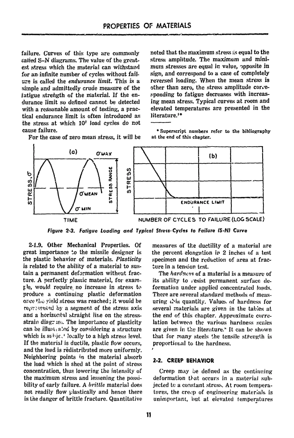
corded. Part (a) of Figure 2-3 shows a peri-
odic variation of stress to which a fatigue
specimen may be subjected and defines the
important stress parameters affecting fatigue
life. In part (b) of the figure, a characteristic
curve is presented which gives results of
fatigue tests on a specimen. The curve is
drawn for a mean stress value of zero, and
relates the stress to the number of cycles to
10
PROPERTIES OF MATERIALS
failure. Curves of this type are commonly
tailed S-N diagrams. The value of the great-
est stress which the material can withstand
for an- infinite number of cycles without fail-
ure is called the endurance limit. This is a
simple and admittedly crude measure of the
fatigue strength of the material. If the en-
durance limit so defined cannot be detected
with a reasonable amount of testing, a prac-
tical endurance limit is often introduced as
the stress at which 10’ load cycles do not
cause failure.
For the ease of zero mean stress, it will be
noted that the maximum stress Ls equal to the
stress amplitude. The maximum and mini-
mum stresses are equal in value, opposite in
sign, and correspond to a case of completely
reversed loading. When the mean stress is
other than zero, the stress amplitude corre-
sponding to fatigue decreases with increas-
ing mean stress. Typical curves at room and
elevated temperatures are presented in the
literature.”
* Superscript numbers refer to the bibliography
at the end of this chapter.
2-1.9. Other Mechanical Properties. Of
great importance to the missile designer is
the plastic behavior of materials. Plasticity
is related to the ability of a material to sus-
tain a permanent deformation without frac-
ture. A perfectlj' plastic material, for exam-
ple, would require, no increase in stress to
produce a continuing plastic deformation
once the yield stress was reached; it would be
repr J rented by a segment of the stress axis
and a horizontal straight line on the stress-
strain diagrim. The importance of plasticity
can be illusli aied by considering a structure
which is svbje? locally to a high stress level.
If the material is ductile, plastic flow occurs,
and the load is redistributed more uniformly.
Neighboring points in the material absorb
the load which is shed at the point of stress
concentration, thus lowering the intensity of
the maximum stress and lessening the possi-
bility of early failure. A brittle material does
not readily flow plastically and hence there
is the danger of brittle fracture. Quantitative
measures of the ductility of a material are
the percent elongation in 2 inches of a test
specimen and the reduction of area at frac-
ture in a tension test.
The hardness of a material is a measure of
its ability to resist permanent surface de-
formation under applied concentrated loads.
There are several standard methods of meas-
uring ibis quantity. Values of hardness for
several materials are given in the tables at
the end of this chapter. Approximate corre-
lation between the various hardness scales
are given in the literature.’* It can be shown
that for many steels the tensile strength is
proportional to the hardness.
2-2. CREEP BEHAVIOR
Creep may be defined as the continuing
deformation that occurs in a material sub-
jected to a constant stress. At room tempera-
tures, the cre.jp of engineering materials is
unimportant, but at eievated temperatures
11
STRUCTURES
creep effects may yield important desigh
criteria.
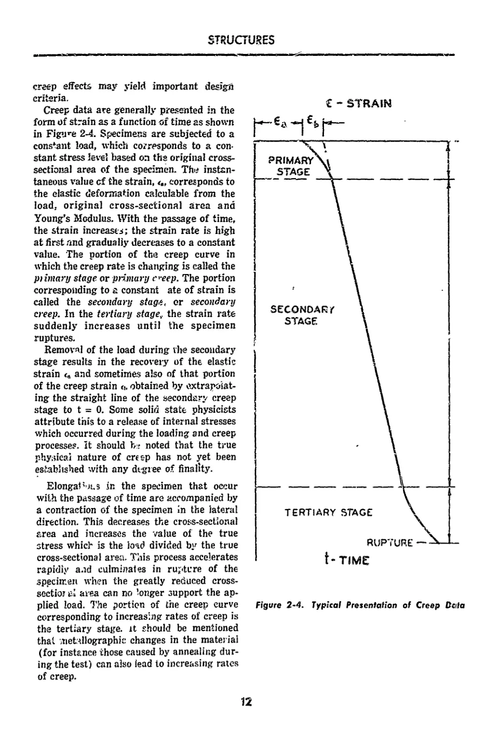
Creep data are generally presented in the
form of strain as a function of time as shown
in Figure 2-4. Specimens are subjected to a
constant load, which corresponds to a con-
stant stress level based on the original cross-
sectional area of the specimen. The instan-
taneous value cf the strain, corresponds to
the elastic deformation calculable from the
load, original cross-sectional area and
Young’s Modulus. With the passage of time,
the strain increases; the strain rate is high
at first and gradually decreases to a constant
value. The portion of the creep curve in
which the creep rate is changing is called the
primary stage or primary e'-eep. The portion
corresponding to a constant ate of strain is
called the secondary stagt, or secondary
creep. In the tertiary stage, the strain rate
suddenly increases until the specimen
ruptures.
Removal of the load during the secondary
stage results in the recovery of the elastic
strain ta and sometimes also of that portion
of the creep strain a, obtained by extrapolat-
ing the straight line of the secondary creep
stage to t = 0. Some solid state physicists
attribute this to a release of internal stresses
which occurred during the loading and creep
processes, it should noted that the true
physical nature of creep has not yet been
established with any degree of finality.
ElongaP-M.5 in the specimen that occur
with the passage of time are accompanied by
a contraction of the specimen in the lateral
direction. This decreases the cross-sectional
area and increases the value of the true
stress which is the load divided by the true
cross-sectional area. This process accelerates
rapidiy and culminates in rupture of the
specimen when the greatly reduced cross-
sectioi £1 area can no longer support the ap-
plied load. The portion of the creep curve
corresponding to increasing rates of creep is
the tertiary stage, it should be mentioned
that metallographk: changes in the material
(for instance those caused by annealing dur-
ing the test) can also lead io increasing rates
of creep.
€ - STRAIN
Figure 2-4. Typical Presentation of Creep Data
12
PROPERTIES OF MATERIALS
2-3. HEAT TRANSl-TR
It is customary to distinguish three basic
modes by which heat is transferred from one
point to another: (1) radiation, (2) convec-
tion, and (3) conduction. While the actual
mechanism underlying the transfer of heat
energy is not completely understood, the
phenomenon is observed io be consistent vith
certain physical laws postulated by various
investigators. The particular law whic.1 is
applicable can be established by recourse to
experimental methods.
Whatever the of heat transfer, the
missile designer is basically interested in
temperature distribution either as a function
>f space or of space and time. The tempera-
ture distribution is required to determine
heat transfer rates, to make possible the com-
putation of thermal stresses, to determine
the change in material physical properties,
or to cope with a problem in melting, abls.
tion or burhing.
2-3.1. Radiatiea. The transfer of heat
energy by radiation is probably best exem-
plified by considering the transfer of heat
from the sun to the earth. Thermal energy
from a hot body, the sun, is converted into
electromagnetic energy which is transmitted
through space to a cold body, the earth,
where it is reconverted into thermal energy.
The radiant energy reaching the cold body
can be absorbed, reflected or transmitted
through the body. Since most engineering
materials are opaque, the transmissivity of
these materials is zero, hence the r< activity
and absorptivity only need be consideied.
The concept fa black body is the limiting
case of a body with 100'/ absorptivity and
zero reflectivity. For a given absolute tem-
perature, no body emits or absorbs more heat
than a black body. The rate at which the
radiant energy is emitted or absorbed by a
black body is given by the Stefan-Boltzmann
law: фн = aAT‘ (2 2)
Фь = rate of radia.'L energy emission or ab-
sorption by a bi'aek body, Btu hr
a = Stefan-Boltzmann constant
0.174 X 10-’ Btu/(hr)(fts)(F') ,
A = radiating area, ft-
T = absolute temperature, F
A so-called gray body will reflect some of
the radiant energy received, hence the emis-
sive power of a gray body will depend upon
the proport’ons of radiant energy that are
absorbed and reflected. It should be noted
that the radiating poxver of a body, in addi-
tion to being proportional to the fourth
power of the temperature, is also dependent
upon the physical properties of the body and
varies with the wave length. It is usual to
neglect th/ dependence of the radiant power
on the wave length. The corresponding equa-
tion for Ф for a gray body is written
-= effAT‘ (2 3)
whe^e < is the emissivity of the gray body.
The^emissivity foi, some engineering mate-
rials is given in the literature.’"'
Two final relations should be considered.
The first is that radiant interchange between
surfaces is governed by the above principles
if there is a. non-absorbing medium between
the surfaces. Second, the radiant interchange
also depends upon the inverse square of the
distance between the surfaces and the rela-
tive orientation of one surface with respect
to another. If it is assumed that the radiation
from a heated surface has the same flux in
all directions, the orientation or “view” be-
comes purely geometrical in nature. These
factors are also given in the literature.1-’
2-3.2. Convection. The transmission of heat
by convection differs materially from the
transmission of heat by radiation. In the case
of convective heat transfer, heat is conveyed
from one point to another by the movement
of a fluid stream; i.e., the transport process
is associated with the actual moveme.it of a
fluid stream. Convective heat transfer may
be natural or forced depending upon whether
the fluid motion occurs by virtue of the nat-
ural tendency of the heated, lighter element
of the fluid to rise, or whether a pump>
blower or other means are used to produce
the fluid motion. It shall simply be mentioned
here that natural convective cooling of a sur-
face area A a* the boundary of a solid is
proportional to (T„ -TJ" ' where T„ and T,
are the surface and ambient fluid tempera-
13
STRUCTURES
tores respectively. In practice, a linearized
approximation can usually be taken and the
analytical expression for the convective cool-
ing of a surface can be written as
q = hA(T„-Tj (2 4).
where
q = rate of cooling, Btu/hr
h = heat transfer coefficient,
Btu/(hr)(ft»)(F)
Strictly speaking, the convective cooling of a
surface is a combination of heat transfer
b' th by coiivectk n and conduction within the
fluid!. The reader will note that the above
equation is similar to Fourier’s basic heat
conduction Equation (2-5). The reason for
its appearance here lies in a concept which
essentially converts the convective cooling
problem to a conduction problem. This con-
cept considers that there is a film adjacent to
the surface through which there is a linear
temperature drop from Tw to Te. The effec-
tive film thickness is difficult to measure and
is incorporated in the heat transfer coefficient
h which also is a function of the physical
and dynamical properties of the media
involved.
2-3.3. Conduction. Of greatest interest to
the missile structural designer is the trans-
mission of heat by conduction. This process
is generally interpreted as a simple molecu-
lar interchange of kinetic energy from one
molecule to an adjacent molecule by virtue of
elastic impacts. The heat flow is observed to
pass from the molecules at high temperature
to those at a relatively lower temperature.
it has been customary in the analysis of
the temperature distribution in a structure to
consider convective and radiant heat transfer
as the means by which the external air flow
heats the structure, and to disregard these
modes of heat transfer when the flow of heat
in the interior of the structure is sought.
Two reasons can be mentioned in defense of
this simplified approach; first, the equations
of conduction have been solved rigorously for
many more cases than those governing the
other two modes of heat transfer; and sec-
ond, the results obtained from an analysis
based on conduction alone always correspond
to higher thermal stresses than those based
on a consideration of all three modes, in a
solid structure the oniy mode of heat transfer
is conduction; in hollow structure, however,
convtxiion and radiation can significantly
modify the temperature distribution calcu-
lated on the basis of conduction alone.
It might be mentioned that a relatively
complete analysis of simultaneous effects of
conduction; convection, and radiation is pos-
sible through the use of computers.
The basic law of heat conduction has *te
origin in the fundamental work of the French
mathematician Jean Fourier. Fourier’s Law
states that the instantaneous rate of heat
flow in a one-dimen.'ienai body is given by
the product of the area perpendicular to the
flow, the rate of change of temperature in
the direction of flc’**, . nd the thermal
conductivity.
.d9 = q = _ кд ?'Г_ (2 5)
dt Ox
In tba above expression
Q = quantity of heat, Btu
t =time, hr
q =rate of heat flow, Btu/hr
к —ther&sl co.rduclivily, the amount of heat
per unit time flowing through a unit
area under a unit temperature gradient,
Btu-in./ft’hr F
A =area normal to heat flow, ft2
T -- temperature, F
x = space coordinate in 'low direction, ft
The units used are British Gravitational
units, and the minus sign is arbitrarily
chosen to make Q a positive- quantity. In the
form siiown, the temperature T is. assumed
to be a function of space and time (transient
conduction), although it may be a function of
space alone (steady conduction). Taking the
case of steady conduction in one dimension
and one for which A is not a function of x,
Fourier’s Equation is
q= -k-f-(T,-T,)
(2 6)
where
L = total path length (x2 - x,)
T7 = temperature at x2
Tf = temperature at Xi
14
PROPERTIES OF MATERIALS
n tarmac**'
Consider, fur example, a rod of uniform
crass-sectional area A and length L. For a
constant value of the heat flow q, the tem-
perature difference (Ts —Tj is inversely
proportional to the thermal conductivity k.
Thus з material of high thermal conductivity
will allow a given heat flow at a lower tem-
perature difference than a material of lower
thermal conductivity. The missile designer
interested in conducting the heat input on the
surface of a structure to the interior with a
minimum temperature rise at the surface,
will choose a materia’ having high thermal
conductivity (assuming all other material
properties are the same).
In the transient state of heat conduction,
the quantity of heat entering and leaving a
volume element at any instant is not equal.
The increase in internal energy, dE is
dE == c w V -dS dt (2 7)
dt
where
c = thermal capacity of the material, the
amount of heat energy the materia!
can absorb per unit weight for a unit
temperature rise Btu/lb./°F
w = specific weight of the material, lbs/ft3
V = volume, ft3
A missile designer interested in using the
structural material as a heat sink, would
choose a material of high thermal capacity,
again assuming that other material proper-
ties were equal. The equation of continuity
for the heat flow through a volume element
in three dimensions can be written
d dT. . d ,, <?T d d'T
ax ax^ + ’ay ay+ az? tz*
+ e w + q = 0 (2 8)
Uv
where the effect of the heat input q, Btu/ft:‘-
hr, has been added. In the most general case,
k, c, w and q are functions of x, y, z and T;
q may also be time dependent. As written,
Equation (2-8) is valid for an inhomogene-
ous, but isotropic solid. Moreover, the equa-
tion is non-linear if k, c, or w depend on T.
Many cases of practical interest are covered
by taking q as a function of T only, and
assuming k, c, and w constant Under these
conditions, the most general heat conduction
equation reduces to
_orr 97 £jT q
Лх1 oy‘ ' Й’ с 6l к
(2-S)
where
a — k- = thermal diffusivity ft*/hr
For systems that do not contain heat sources
or sinks, q = 0, and Equation (2-9) becomes
the Fourier liquation. If sources and sinks are
present but the temperature is steady, = 0,
and Equation (2-9) reduces to Poisson’s
Equation. Finally, for steady conduction in
systems free of sources and sinks, the well-
known Laplace Equation is obtained. This
linear partial-differential equation appears
frequently in many branches of science.
Solutions are discussed in the literature.
The thermal diffusivity is a derived mate-
rial property important to the missile de-
signer as a measure of the ability of a
material to absorb or diffuse heat. As defined
by Equation (2-9) thermal diffusivity is
essentially the ratio of tfip thermal conduc-
tivity to the specific heat. The time required
to bring a material to a specified temperature
level varies inversely with the thermal dif-
fusivity and directly with the square of the
conducting path length.
2-3.4, Thermal Expansion. When an engi-
neering material is heated, it expands in all
directions in a manner that is dependent
upon the material and the temperature rise.
For the single dimension case the ratio of the
unit elongation per unit temperature rise is
called the coefficient of thermal expansion.
a = (2 10)
where
a ~ coefficient of thermal expansion 1 F
< elongation per unit length
Engineers find it more convenient to define a
mean coefficient of thermal expansion as
follows: q’
/т/т
- T - To (2 11)
15
STRUCTURES
where TM is a reference temperature. The
unit elongation can he easily calculated after
an is computed and plotted as a function of
temperature from
t = a.„(T - T„) (2 12)
If the unit elongation is required for a tem-
perature rise other than from the reference
temperature, say Ti to T-, then
t ^ml( 1 • 1 uj — 1 о)
(2 13)
Consider the case of a slender rod of origi-
nal length L.,, heated to a temperature Ti
from a reference temperature value T«. The
increase in the length of the rod due to the
effects of thermal expansion is required.
Taking T, — T„ = T = 100°F as the tem-
perature rise, L„ = 1 ft, and assuming L„,
for the material паз a value of 10“’', the unit
elongation from (2-12) is
e » «...(Ti - To) - 10-«101) = io-1
The elongation of the rod is
ДЬ = eLo « 10~3ft (2-14)
It might be well to point out the implicit
assumption that the rod is not subject to any
external constraints. If the rod is constrained
to remain at its original length, then the
temperature rise would produce normal
stresses in the rod corresponding to the
stress required to produce an equal and op-
posite unit elongation. The value of this
(thermal) stress is obtained by multiplying
the unit elongation by Young’s Modulus:
<r = Ее (2-15)
Hence if Young's Modulus for the rod used
in the above example is 10T psi, the stress
can easily be calculated:
<z = 107(10-’) = 10,000 psi
Partial restraints at the ends of the rod pro-
duce thermal stresses which are between the
Values of zero thermal stress for unre-
strained ends and the thermal stress calcu-
lated above for fully restrained ends.
Expansion of the rod in the lateral direc-
tions may be calculated in a similar manner.
The coefficient of thermal expansion is usu-
ally assumed to be independent of direction.
Since most engineering materials can be con-
sidered isotropic, the assumption is fairly
good. The quantity a is also called the co-
efficient of linear expansion. Coefficients of
thermal expansion for some engineering ma-
terials are given in the tables and graphs at
the end of this chapter.
2-4. SELECTED DATA GN PROPERTIES OF
MATERIALS OF CONSTRUCTION
Collected in the pages that follow are
selected data on material properties pertinent
to missile design. Data are included on ma-
terials that appear to have promise for appli-
cation in designs of the future. These data
have been gleaned from a number of refer-
ences which are listed in the bibliography.
One of the principal reasons for collecting
the information has been to give the reader a
quantitative feeling for the order of magni-
tude of the physical properties involved. In
some instances, the variations in these physi-
cal properties for different alloys of the same
material are presented, but this is not con-
sidered of paramount interest. In addition to
the objective mentioned, the curves are set
up to afford an easy comparison between one
material and another. The frequency with
which time and temperature appear as pa-
rameters may be noted.
Another objective in the presentation of
the data is to point up the form of presenta-
tion which finds favor with the missile de-
signer and stress analyst. In many instances
date, of a particular kind are shown only for
one alloy of one material. This is particularly
true in the graphical presentation of creep
data, and stress-strain and tangent modulus
curves as functions of temperature.
Tables 2-1 through 2-5 cover several alloys
each of steel, aluminum, titanium, magne-
sium, and a few ceramics. In this compilation
the room temperature mechanical properties
are given for each alloy and for a selected
form and condition. Young’s Modulus, yield
and ultimate strengths are presented on the
basis of tensile test data. The yield stress is
based upon a 0.2% permanent offset condi-
tion. The elongation is the percent change in
length measured over 2 inches of a test
specimen.
Table 2-6 summarizes the physical prop-
erties of various materials: density, melting
16
PROPERTIES OF MATERIALS
point, specific heat, thermal conductivity and
coefficient of thermal expansion. In this com-
pilation, only one or two alloys of steel,
magnesium, aluminum and titanium are
listed, but the properties of materials such
as copper, tungsten, molybdenum, oxides,
carbides and borides are presented because
of the attract iveness of one or more of their
properties at elevated temperatures. Mean
values of the thermal properties are given
together with the temperature range within
which they are applicable. For a number of
materials, the thermal properties are plotted
as a function of temperature and a reference
to the corresponding figure is given.
In Figures 2-5 and 2-6 the modulus of
elasticity anil the yield stress are plotted as
functions of the temperature for a selected
number of typical materials. As already men-
tioned, the principal purpose is not only to
show the variation of these properties for a
material, but also to indicate the relative
magnitudes and the behavior between differ-
ent materials, it is significant to point out
that these properties are affected by the rate
of heating, soaking time at test temperature,
and the strain rate. Most of the mechanical
properties shown are for moderate heating
and strain rates, and are soaked for one-half
hour or more at the test temperature. Short
time test results, which arc not quite as plen-
tiful, indicate an increase in the modulus of
elasticity and yield stress with an increase
in the heating rate and strain rate and with
a decrease in the soaking time.
The weight-strength and cost-strength
ratios of one alloy each of aluminum, mag-
nesium, titanium, steel and nickel are pre-
sented in Figures 2-7 and 2-8. Note how effec-
tively the curves give an approximate idea
of the maximum useful temperatures of the
various alloys based upon these criteria. Cost
data are listed in Table 2-7 and strength data
are based on the tensile yield strength given
in Figure 2-6. The reader is cautioned against
arriving at any broad generalization based
upon criteria of this type.
Stress-strain curves at various tempera-
tures are shown for an aluminum alloy and
a steel alloy in Figures 2-9 and 2-10 respec-
tively. A word of caution is made in connec-
tion with the interpretation of ths curves
shown in these figures. The stress-strain
curves shown vze obtained at a constant tem-
perature given by the intersection of the
curve with the temperature axis. The stress-
strain curves are spread in their correct
position on the temperature axis (abscissa)
in order that curves at intermediate tem-
peratures may be interpolated. For any given
stress-strain curve, the strain at any stress
level may »je obtained by interpolation be-
tween constant strain lines or by using the
strain scale (shown only in Figure 2-9) and
measuring from the point of zero stress. An
illustrative example :<? given in Figure 2-9
for further clarifies?. <n.
Tangent ata at various stresses
are shown for ax cminum alloy in Figure
2-11. The valuer «re shown as ratios of
Tangent Modulus, to ig’s Modulus, E,
at various temper. A tabulation of
mechanical properties at room and elevated
temperatures for an aluminum alloy is given
in Table 2-8. Creep and fatigue data are
included.
The creep data given in Figures 2-12
through 2-17 are in the forms preferred by
structural designers and analysts. In Figure
2-15, the reader should note that the elastic
strain is subtracted from the total strain to
obtain the curves. The log-log plot of mini-
mum creep rate as a function of stress in
Figure 2-16 is particularly useful in the
formula4on of creep laws for engineering
materials. Finally, in the master creep curves
of Figure 2-17, the parameters are total
strain, and a so-called Larson-Miller param-
eter which includes both the time and tem-
perature effect. The comments made in con-
nection with Figures 2-9 and 2-10 also hold
for this figure except that temperature is
replaced by the Larson-Miller parameter.
Inasmuch as fatigue considerations are
relatively unimportant in missile type struc-
tures, only one set of curves is given for an
alloy of aluminum in Figure 2-18.
The final set of figures, 2-19 through 2-21,
show the thermal properties of a wide va-
riety of materials as functions of tempera-
ture. To enable a comparison between the
various materials, each figure shows the
variation of a particular thermal property.
17
4
00
TABLE 2-1. MECHAKiCAL PROPERTIES L'F SOME TYPICAL ALLOY STEELS
Alloy Form Condition Young's Modulus, 10‘ psi Shear Modulus, 10‘ psi Density, Ibs/in’ Tensile Strength, 10’ psi Yield Strength, 10’ psi Elongation, - Percent Hardness
Rc* Bhn 3
4130 8630 Tube Sheet Plate t <0.188 29.0 11.0 0.233 95 75
Tube Heat Treated 125 103 23
8630 Sheet- to Obtain 29.0 11.0 .283 150 132 18.5
4340 Bar Tensile Strength Indicated 200 176 13.5
Annealed 29.0 12.5 .283 75 30
18-8 Type 301 Sheet Strip Cold Rolled И Hard 26.0 11.0 .286 150 110 IS 32
Cold Rolled & HeatTreated « Hard 27.0 11-5 .286 150 120 9 41
18-8 Type 304 Sheet Annealed 29.0 .286 85 30 60 170
Cold Rolled 185 160 8 4W
Stainless 422M Heat Treated 150-175 120-140 38
Stainless 17-7H TH 1050 27.6 180 150 6
Inconel X Rods Heat Treated & Hot Rolled 30.5 11.5 .300 162 92 24
Hot Roiled & Aged 30,5 11.5 .300 184 132 24 340
i Rockwell C scale.
4 Bnnell hardness number.
TABLE 2-2. MECHANICAL PROPERTIES OF SOME TYPICAL ALUMINUM ALLOYS
Alloy Form Condition Young's Modulus, 10* psi Shear Modulus, 10* psi Density, Ibs/in* Tensile Strength. 10’ psi Yield Strength, 10’ psi Elongation, Percent Brinell Hardness Number
2024-T4 Sheet Plate Heat Treated t:0.25-0.50 10.5 4.0 0.100 04 40 12 120
2024-T4 Sheet Plate Clad Heat Treated t *.0.25-0.499 10.5 .100 62 40 11
2024-T4 Sheet Plate Extrusions 68 46 22
2014-T6 Sheet Plate Extrusions 70 60 13
2014-T6 Sheet Plate Heat Treated and Aged t:0.040-0.*193 10.4 3.95 .101 68 60 .8 135
5052-H34 Sheet ! _• Hard t:0.008-0.249 10.1 3.85 .096 34 24 3-7
7075-T6 Sheet Plate Heat Treated and Aged t:0.040-0.249 10.3 3.9 .101 77 67 8
7075-7'6 Rolled Ear, Rod, Tubing, Shapes Heat Treated & Aged t <3.00 10.3 3.9 .101 77 66 10
X2020-TS Sheet, Forged Rod 11.1 86 79 5
X2219-T6 Sheet, Plate, Ex- trusions, Forgings 60 38 13 100
APM-M257 Extrusions Forging*: Aluminum Powder Products 10.6 .099 37 24 17 70
АРМ -M486 Tubing 48 34 15
XA 140-F Casting Alloy As Cast 34 29 1 95 (4004F)
TABLE 2-3. MECHANICAL PROPERTIES OP SOME TYPICAL ALLOYS OF MAGNESIUM,
M0LYS9ENUM, ANS> NIOBIUM
MAGNESIUM
Alloy (ASTM) Form Condition Young's Modulus, 10* psi Shear Modulus, 10‘ psi Density, lbs/in’ Tensile Strength, 10’ psi Yield Strength, 10» psi Elongation, Percent
AZ$1A Sheet Annealed 6.5 2.4 .0645 32 15 12
AZ31A Sheet Hard Roiled 6.5 2.4 .0645 39 29 4
AZ81B Bars Rods Solid Shapes As Extruded 6.5 2.4 .0645 33 20 7
AZ80A Bars Rods Solid Shapes Extruded & Aged 6.5 4.4 .0553 47 30 4
AZ61A Round Tubing As Extruded 6.5 2.4 .0649 36 le 7
AZ92A Sand Castings As Cast 6.5 2.4 .0657 20 10
AZ92A Sand Castings Heat Treated & Aged 5.5 2.4 .0657 34 18
AZ80A Forging As Forged 6.5 2.4 .0653 42 26 5
MOLYBDENUM
Molybdenum Ti Sheet 46.0 .369 132 99 31
Niobium NIOBIUM Hard 15.0 5.4 43-58 2 Annealed 21-26 10
TABLE 2-4. MECHANICAL PROPERTIES OF TITANIUM ANU SOME OF ITS TYPICAL ALLOYS
Alloy Form Condition Tensile Strength, 10' psi Yield Strength, 10’ psi Elongation, Percent Reduction of Area, Percent
High-Purity Titanium 34 54
Commercial Titanium Bar Annealed 9b 80 27 47
Commercial Titanium Sheet Annealed 95 78 23 48
Ti-5Al-2.5 Sn Sheet Annealed 138 129 15 43
Ti-8Mn Sheet Annealed 140 123 14 26
TJ-6A1-4V Bar Annealed 136-154 121-145 14-18 26-50
TABLE 2-5. MECHANICAL PROPERTIES OF SOME TYPICAL CERMETS, METALLIC
RFiPRACTCwscs, and CERAMICS
Composition Y >ung's Modulus, 10* psi Tensile Strength 101 psi Vickers — Hardness Number
Room Temp. 1000’C
75 TIC, 15 Ni, 5 Co, 5 Cr 60 176 SO
64 TiC, 6 NbC, 25 Ni, 5 Mo 55 220 100 1400
20 CrsB, 80 Cr-Mo 60-80 110 650
95 NiAl, 5 Ni ISO 65 400
70 A1A, 20 Cr 52 55 33
PROPERTIES OF MATERIALS
TABLE: 2*6. PHYSICAL PROPERTIES OF SOME TYPICAL MATERIALS
Material Density Melting Point, Specific Heat Thermal Conductivity Mean I Coefficient of Thermal Expansion !
lb/in? oy Temp. Range, °F Btu/lb per °F Temp. Ran(?e. ’F Btu-in. Temp. — Ranpe, lO-'/’F
ft’ hr °F
2024-73 Clad Aluminum Alloy 0.100 935-1180
7075-T6 Aluminum Alloy .100 890-1180 (a> (b) (c)
FS1-H24 Magnesium Alloy .064 1160 ( a) (b) (c)
6A1-4V Titanium Alloy .160 2800 90-932 932-1652 5.2 5.8
C-110M Titanium Alloy .171 2730-2910 (a) (b) (a)
Inconel X Nickel Base .298 2540 (a) (b) (c)
N> N> 4340, 8630 Alloy Steel (200.000 psi T. S.) .283 2500 (a) (b) (a)
Molybdenum .369 4710 (a) (b) (a)
Tungsten .697 6120 70-212 70-1832 0.034 .0365 70 1060 32-932 1112-1832 Й.5 2.88
Aluminum Oxide Alite 212 .131 3720 ( a ) (b) (a)
Beryllium Oxide .113 4500 257-1870 .071 2012 70-122 70-1800 6.0
Zirconium Boride .180-.191 5400 60 1800 .115 .25 110 191 75-1000 75-2200 2.7 3.2
Silicon Carbide .183 3990 70-1832 32-2550 .186 .285 2000 2200 66 109-113 70-2000 70-2550 2.5 2.44
Molybdenum Disilicide .220 3400 300 1000 1400 385 240 220 70-2732 5.1
Titanium Carbide + 10 to 40% Ni or Ni Alloy .198-.234 5800 70 206-247 70-1200 4.5-6.2
Cop 'er .324 1980 (a) 212-387 212-1535 (b) 3040 2490 (c>
Beryllium .066 2355 (a) (b) (ci
Niobium .311 4370 32-212 .064 32-212 4.0
( a)see Figure 2-20. ( b)see Figure- 2-19. (c)see Figure 2-21.
STRUCTURES
TABLE 2-7. APPROXIMATE COSTS OF STRUCTURAL MATERIALS (1955) (REFERENCE 43)
Material Cost /pound
Aluminum Alloys $ .51
Magnesium Alloys .59
Titanium Alloys 15.00
Alioy Steels 4130, 8630, 4340 .06
Stainless Steels
18-18 .36
310 .60
430, 446 .60
17-7PH .36
Highly Alloyed Austenitic Steels
19-9DL .75
N-155 4.00
S-590 3.43
S-816 6.14
A-286 1.87
Nickel Base Alloys •
Inconel X 2.00
Hastelloy X win SB
Hasteiloy C 3.50
Cobalt Base Alloys
H. S. 25 (L-605) 5.50
PROPERTIES OF MATERIALS
W
TABLE 2«8. MECHANICAL PROPERTIES OF 2024-T6 ALUMINUM ALLOY PRODUCTS
AT VARIOUS TEMPERATURES AND AFTER HEATING
(Representative Values—Not Guaranteed Minimums)
Tensile Properties Strosii Time Relations (or Rupture and Creep Fatigue Strength nt Temp. Indicated
М:г.. Temp. Time At Tempciature Indicated At Boom Temperature Alier Heating Time 10 psi 10» psi (or creep of
Temp, hr. Tensile Strength 10* psi Yfctd Strength 10* pal Elung, tn 41) Tensile Strength 10‘ psi Yield Strength 101 psi blong< InjD sites* hr. Rup- ture 0.S4 о.з*'; 0.!'7 10’ C/cIm 10* psi
-320 -11?, - 18 83 72 71 68 60 58 11 10 10
75 69 57 10 69 57 10 0.1 1.0 10.0 100.0 500.0 43 32 24 20 ! 18.5 j
212 0.5 10 100 1000 10000 65 65 65 65 65 О>С’О’СЛСЛ Ut&IQlOlQf 10 10 10 10 10 69 69 69 70 70 57 57 57 58 60 10 10 10 10 10 0.1 1 19 100 1000 63 60 57 54 52
300 0 5 10 100 1000 10000 60 60 59 54 45 51 46 36 11 12 13 14 17 69 69 69 62 55 57 58 58 49 37 10 10 10 10 10 0.1 1 10 100 1000 56 53 49 44 38 54 51 48 43 37 52 48 46 41 35 50 48 41 35 30 47 41 33 22
400 0.5 10 100 1000 10000 50 44 38 32 27 43 37 31 25 20 13 16 19 23 27 67 55 51 49 42 55 43 36 30 24 10 10 10 10 11 • 0.1 1 10 100 1000 49 43 35 25 18 46 41 33 23 16 43 38 30 20 14 39 33 23 15 9.5 34 24 15 _ ? 5.5
560 0.5 10 100 1000 10000 30 26 20 15 12 25 21 16 11 9 18 2’? 28 40 55 1 1 i ! 38 31 23 16 10 10 10 12 15 20 0.1 1 10 100 1000 26 17 11 7 22 15 10 19 13 9 15 10 11
600 0.5 10 100 1000 10000 17 12 10 8.5 8 14 9.5 7.5 6 6 30 45 55 65 75 47 3.9 35 31 27 18 13 10 9 10 13 17 20 20 0.1 1 10 100 1000 16 10 6 3.5 > 15 8.5 4.5 2.5 1.5 JO 5 3 1.5 6.5 3.5 .»
700 0.5 10 100 1000 10000 1 00 <9 >0*0 1 1 j »Q TP -4* 55 70 85 95 100 40 87 34 30 27 19 12 10 9 9 13 18 20 20 20 Courtesy ALCOA Rescnrcli Laboratories •
STRUCTURES
PROPERTIES OF MATERIALS
MODULUS OF ELASTICITY, IO6 PS?
TEMPERATURE,°F
Figure 2-5. Effect of Temperature on Modulus of Elasticity for Severn) Typical Materials
25
STRUCTURES
YIELD STRESS, IO’ PSI
TEMPERATURE/7
Figure 2-6. Effect of Temperature on Yield Streit for Several Typical Material*
26
PROPERTIES OF MATERIALS
WEIGHT/ YIELD STRENGTH JO"6/tn
Figure 2-7. Effect of temperature on Weight-Strength Ratio for Several Typical Materials
27
STRUCTURES
28
PROPERTIES OF MATERIALS
STRESS, 10 PSI
Figure 2-10. Compressive Stress-Strain Curves for 17-7 PH (TH 950) Stainloss Steel Sheet
Stock at Various Temperatures
Figure 2-11. Tangent Modulus Curves for 2024-T3 Aluminum Alloy Alclad Sheet
in Compression
29
STRESS , IO3 PSI
HOURS TO RUPTURE
STRUCTURES
Courtesy ALCOA Research Laboratories
Figure 2-12. Stress for 0.2% Creep-Set of X2020-T6 and 2024-T6
Aluminum Alloys as a Function of Time and Temperature
Figure 2-13. Rupture Stress for 2024-T6 Aluminum Alloy
as a Function of Time and Temperature
PROPERTIES OF MATERIALS
STRESS , IO5 PSI
Courtesy ALCOA Research Laboratories
Figure 2-14. Stress-Rupture mnd Creep Characteristics of X2020 Aluminum Alloy al 300°F
31
CREEP STRAIN
0.008
F’guro 2-15. Tontion Creep Curve» for 2024-T4 Aluminum Alloy
PROPERTIES OF MATERIALS
TENSILE STRESS, 10’ PSI
2-16. Creep Rafe and Time to Rapfare Curves for 3S-HIS Aluminum Alloy
33
STRUCTURES
PERCENT OF ROOM TEMPERATURE
COMPRESSIVE YIELD STRESS
figure 2-17. Matter Creep Curvet for 2024-73 Aluminum Alloy Clad Sheet Stock
Courtesy Alcoa Research Laboratories
Figure 2-18. Fatigue Properties of 2024-74 Aluminum Alloy (Extruded Bar) at
Elevated Temperatures
34
PROPERTIES OF MATERIALS
THERMAL CONDUCTIVITY, BTU-IN
TEMPERATURE, °F
Figure 2-19. Thermal Conductivity of Selected Materials
35
STRUCTURES
SPECIFIC HEAT, BTu/lB/°F
Figure 2-20. Specific Heat of Selected Materials
36
PROPERTIES OF MATERIALS
MCfa
MEAN COEFFICIENT OF THERMAL EXPANSION , lO^F
Figure 2-21. Mean Coefficient of Thermal Expansion for Several Materials
37
STRUCTURES
?-5. REFERENCES AND BIBLIOGRAPHY
1. Strength of Metal Aircraft Elements,
March 1955 ed., Air Materiel Command-
5 Bulletin, Government Printing Office,
Washington, D. C.
2. Engineering Materials Handbook, 1st
ed., edited by C. L. Mantell. McGraw-
Hill Book Co., doc., New York, N. Y.,
1958.
3. Metals Handbook, 1948 ed., American
Society for Metals, Cleveland 3, Ohio.
4. Besserer, C. W., Guided Missiles Hand-
book, D. Van Nostrand Co., Inc., Prince-
ton, N. Y., 1958.
5. Stainless Steel Handbook, Allegheny
Ludlum Steel Corporation, Pittsburgh
22, Pennsylvania.
6. American Institute of Physics Hand-
book, McGraw-Hill Book Co., Inc., New
York, N. Y., 1957.
7. Handbook of Chemistry and Physics,
£9th Edition, Chemical Rubber Publish-
ing Company, Cleveland, Ohio, 1947.
§. Handbook of Experimental Stress Anal-
ysis, ed. by M. Hetenyi, John Wiley and
Sons, Inc., New York, N. Y., 1950.
9. Alcoa Structural Handbook, Aluminum
Company of America, Pittsburgh, Pa.,
1950.
10. Research and Development Technical
Handbook, Vol. I, Aviation Age, Cono-
ver-Nast Publication, New York, N. Y.,
1.957-53.
11. Zwikker, C., Physical Properties of Solid
Materials, Pergamon Press, New York,
N. Y., 1954.
12. Frankel, J. P., Principles of the Prop-
erties of Materials, McGraw-Hill Book
Co.. Inc., New York, N. Y., 1957.
13. Carlson, R. L. and Manning, G. K.,
“Investigation of Compressive - Creep
Properties of Aluminum Columns at
Elevated Temperatures, Part 2, Stabil-
ity Problems,” Wright Air Development
Center, WADC TR52-251, May 1954.
14. Dorn, J. E. and Tietz, T. C., "Creep and
Stress-Rupture Investiga^ons on Some
Aluminum Alloy Sheet Metals,” Pro-
ceedings of the American Society for
Testing Materials, Vol. 49, P 815, 1949.
15. McAdams, W. H., Heat Transmission,
3rd ed., John Wiley and Sons, Inc., New
York, N. Y., 1954.
16. Jakob, Max, Heat Transfer, Volume 1,
John Wiley and Sons, Inc., New York
N. Y., 1949.
17. Pohle, P. V., “Heat Transmission in the
Structure,” Chapter 3 of AGARDO-
GRAPH entitled High Temperature
Effects in Aircraft Structures.
18. Schneider, P. J., Conduction Heat
Transfer, Addison - Wesley Publishing
Co., Inc., Cambridge, Mass., 1955. ,
19. Cars’aw, H. S., and Jaeger, J. C., Con-
duction of Heat in Solids, 1st ed., Ox-
ford, Clarendon Press, 1947.
20. Evans, Jerry E., Jr., “Thermal Conduc-
tivity of 14 Metals and Alloys up to
HOOCF.” National Advisory Committee
for Aeronautics, NACA RM E50L07,
March 2, 1951.
21. Wisler, P., “Materials—-Heat Sink and
Expand n Problems,” General Electric
Company, Missiles and Ordnance Sys-
tems Dept. July 26,1956.
22. Gatewood, В. E., Thermal Stresses, Mc-
Graw-Hill Book Co., Inc., New York
N. Y., 1957.
23. Manson, S. S., “Behavior' of Metals
Under Conditions of Thermal Stress,”
National Advisory Committee for Aero-
nautics, NACA TR 1170, 1954.
24. Favor, Ronald J., et al., “Materials—
Property—Design Criteria for Metals,
Part 5. The Conventional Short-Time,
Elevated Temperature Properties of
Selected Stainless Steels and Super
Alloys,” Wright Air Development Center
WADC TR 55-150, October 1957, ASTIA
Document No. AD 142069.
25. Favor, Ronald J., et al., “Materials—
Property—Design Criteria for Metals,
Part 7. The Conventional Short-Time,
Elevated Temperature Properties of
Selected Low and Medium-Alloy Steels,”
Wright Air Development Center, WADC
TR 55-150, October 1957, ASTIA Dgcu-
m-mt No. AD 14264.
26. Fortney, Robert E., and Avery. Charles
H., “Effects of Temperatnre-Time-Stress
33
PROPERTIES OF MATERIALS
Histories on the Mechanics! Properties
of Aircraft Structural Metallic Mate-
rials, Part I. Temperature-Time Studies
for 2024-T3 and 7075-T6 Alclad Sheet,”
Wright Air Development Center, TR 56-
585, September J 957, ASTIA Document
No AD 142007.
27. Schwartzberg, R. R., et al., “The Prop-
erties of Titanium Alloys at Elevated
Temperatures,” Battelle Memorial Insti-
tute. Titanium Metallurgical Laboratory
Report No. 82, September 10, 1957.
28. P.oe, William P. and Kattus, J, Robert,
“Tensile Properties of Aircraft Struc-
tural Metals at Various Rates of Load-
ing After Rapid Heating,” Wright Air
Development Center, WADC TR 55-199,
September 1957, ASTIA Document No
AD 142003.
29. Shinn, D. A., “Selected Properties of
Structural Materials at Elevated Tem-
peratures,” Advisory Group for Aero-
nautical Research and Development, Re-
port 104, April 1957.
30. Sandven, O. A., “Cermets as Potential
Materials for High-Temperature Serv-
ice,” Advisory Group for Aeronautical
Research and Development, Report 99,
April 1957.
31. Schwarzkopf, Pau! and Kieffer, Richard,
Pefractory Hard Metals, The MacMillan
Company, New York, N. Y., 1953.
32. Killmar, H. M., and Wroten, W. L.,
“Special Ceramic Materials of Construc-
tion for Rocketry,” Ceramic Industry,
Vol. 58, No. 5, pp. 93-6, May 1956.
33. Ault, Neil N., "Characteristics of Re-
fractory Oxide Coatings Produced by
Flame - Spraying,” American Ceramic
Society, J., Vol. 40, No. 3, pp. 69-74,
March 1957.
34. Westerholm, R. J., et al.. S« i:on I—
“Some Aspects of the Development and
Performance of Pure Oxide Coatings,”
Section II—“Application of ROKIDE:
A Coating to Ramjet Engine Combustion
Components,” papers presented at ARS-
ASME Aviation Division Conference
Los Angeles, California, March 1956.
35 Sullv A H for
U Kt» Al Ot) VV. Vfllgk. I, vl
Metals Used at High Temperatures,”
Product Engineering, Vol. 25, No. 1, pp.
135-6, January 1954.
36. Criner, С. B., and Spuhler, E., “Sum-
mary of Information—Alloy X2020,”
Aluminum Company of America, Report
No. 13-57-AKS7, September 30, 1957.
37. Lemon, R. C., and Sicha, V/. E., "New
Aluminum Casting Alloy XA140 for
Elevated Temperature Applications,”
paper presented at 60th Annual Meeting
of the American Foundrymen’s Society,
May 7, 1956.
38. Lyle, John P., Jr., “Aluminum Powder
Metallurgy Products,” Materials and
Methods, Vol. 43, No. 4, pp. 106-111,
April 1956.
39. Dix, E. H., Jr., “Aluminum Alloys for
Elevated Temperature Applications.”
paper presented at the ASME Aviation
Conference, Paper No. 56-AV-8, March
14-16, 1956..
40. “Symposium on Effect of Cyclic Heating
and Stressing on Metals at Elevated
Temperatures,” American Society for
Testing Materials 57th Annual Meeting,
Chicago, Illinois, ASTM Special Techni-
cal Publication No. 165, June 1954.
41. Gough, H. J., “Crystalline Structure in
Relation to Failure of Metals—Espe-
cially by Fatigue,” Edgar Marburg Lec-
ture, Proceedings of the American
Society for Testing Materials, Vol. 33,
Part 2, 1933.
42. Howard, H. B., “Merit Indices for Struc-
tural Materials,” Advisory Group for
Aeronautical Research and Develop-
ment, Report No. 105, April 1957.
43. Dukes, W. H. and Schmitt, A. (ed.),
“Structural Design for Aerodynamic
Heating.” Part J—Design Information;
Part II—Analytical Studies; (confi-
dential) Part III—Structural Design
(SECRET), Wright Air Development
Center, WADC TR 55-305, October 1955.
39
40
Chapter 3
STRESS ANALYSIS
3-1. GENERAL CONSIDERATIONS
In the fifty-odd years since the first suc-
cessful flight of a heavier-than-air machine,
the analysis of the stresses in aircraft struc-
tures has been developed to a highly perfected
art. Good textbooks on airplane stress analy-
sis are readily available. The purpose of this
chapter is to present those principles and
formulas which are peculiar to missile struc-
tural analysis and are not to be found, as a
rule, in books on airplane structures.
In this category belong shell analysis, the
study of thermal stresses, and the investiga-
tion of the effects of creep. Shell analysis is
peculiar to ballistic missile design because
most of the structural elements of these
missiles are thin shells, often unreinforcecl.
The customary methods of reinforced thin
shell analysis, amply discussed in textbooks
on aircraft structures, are not applicable to
these missiles. Thermal stresses and creep
arise as a consequence of aerodynamic heat-
ing ; for this reason they are ot great impor-
tance to very-high-speed missiles but of little
account in conventional airplanes.
3-2. STRESSES AND DEFORMATIONS IN THIN
SHELLS UNDER UNIFORM INTERNAL
PRESSURE
3-2.1. Circular Cylindrical Shell. The tan-
gential or koop stress, c,.. and the stress ir.
the longitudinal or axial direction, within
circular cylindrical shells under a uniform
interna! pressure are
where p is the excess of the internal pressure
in the closed cylindrical shell over the exter-
nal pressure, R is the mean radius of the
cylindrical shell, and h is the wall thickness.
The stresses <?, and <k are tensile if the in-
ternal pressure is larger than the external
pressure, and compressive when the opposite
is true.
3-2.2. Conical Shell. In a conical shell under
a uniform internal pressure the tangential
stress, n„ and the axial stress acting in the
direction of the generator, n„ are
a, = pR/h cos 7 (3 3)
~ pR/2h cos 7 (3 4)
where R is the local mean radius of the shell
measured in a plane perpendicular to the
axis of the cone, у is the angle subtended by
any generator with the axis of the cone (the
half apex angle of the cone), and the remain-
ing symbols rre defined as before.
3-2.3. Spherical Shell. The normal stress
acting in any direction in the plane tangen-
tial to the sphere at the considered point
known as the membrane stress, я„„ may be
expressed as
_ pR
"’ ~ 2’n
(3 5)
3-2.4. Thin Shell. All of the stresses given
heretofore are membrane stresses. These are
stresses distributed uniformly through the
thickness of the wa<!. Unde?' their action the
shell changes its size slightly. When the ma-
terial is perfectly elastic and when it follows
Hooke’s uniaxial law
t = a, E (3 6)
wh₽re t is the strain (elongation per unit
length) and E Young’s Modulus of elasticity,
the mean radius of tiie cylinder increases by
the amount
AR.o =(1 - ojpt (3 7)
where v is Poisson’s ratio whose value is 0.3
for steel and aluminum alloys. Eor the cone
the corresponding quantity is
AR.... = (1 - о 1 t.'upR (3 8)
\ 2 / Eh cos 7
and tor the sphere
AR.... = (1 - -) ^Eh °)
41
STRUCTURES
3-3. DISCONTINUITY STRESSES IN
THIN SHELLS
When a cylindrical pressure vessel is pro-
vided with two hemispherical pressure vessel
heads, and the vessel is filled with a gas at
high pressure, the change in the length of the
radius of the cylinder is more than twice the
change in the length of the radius of the
sphere in accordance with Equations (3-7)
and (3-9) if the wall thicknesses are equal.
Such deformations are obviously impossible
when cylinder and hemisphere are welded
together (see Figure 3-1). For this reason
bending stresses develop in the walls of the
vessel in addition to the membrane stresses
discussed in Section 3-2. When the material
is perfectly elastic, these bending stresses
vary linearly across the wail and attain their
maximum values on the juter and inner sur-
faces of the wall. Th j “bending stresses add
up to a bending moment of M„ per unit length
of the circumference at the edge of the cylin-
der of Figure 3-2 and the shearing stresses
accompanying them to a shear force V„ per
unit length of the circumference.
Figure 3-1. Theoretical Deformations of Pressure
Vessel under Membrane Stresses Alone
Figure 3-2. Deformations of Thin Circular
Cylindrical Shell under Bending Stresses
Under the action of the edge moment and
the edge shear force the region of the shell
close to the edge deforms. The deformations
of the edges of cylinder and hemisphere are
of such magnitude that the discontinuity in
the deformations as caused by the membrane
stresses alone is eliminated and cylinder and
hemisphere fit together. The bending stresses
caused by and V., are known as disconti-
nuity stresses.
When M„ and V„ are applied to the edge of
the cylindrical shell shown in Figure 3-2, the
radial displacement caused by them is given
by the following equation
(h)(M-+ VKt)<3
The positive directions of M, V and w are as
shown in the figure. The slope of the de-
formed shape of the shell is
(dw/dx)„ » 2ч/р(А -vt) (2MOK 4- V„R)
nil
(3-11)
Equation (3-11) yields a negative slope when
M„ and V„ are positive; correspondingly the
radial displacement w decreases with in-
creasing x in Figure 3-2, that is the slope
shown in the figure is negative.
The value of the constant К in Equations
(3-10) and (3-11) is
M e-K*'11
(3 13)
к = V3(i - s~) \/(К/Ь) (3-i?i
The bending moment M„ is not necessarily
the largest bending moment in the wall of
the shell; variation !n the value of the bend-
ing moment is given by the equation
/ Kx , . Kx\
(cos -R +sin RJ
V<,R - Kx!
К 8,0 R'_
The location of the maximum bending mo-
ment can be computed from the formula
cot R- - 1 + у R (3 14)
The connection between the maximum bend-
ing stress and the bending moment is
~ 6M/h’ (3-15)
The'attenuation of the bending stresses is
characterized by the factor e~Kx/lt; this is
unity at x = 0 and e — 0.368 when
x„, = R/K (3 16)
42
STRESS ANALYSIS
When the attenuation length xlt is small as
compared to the undisturbed, uniform por-
tion of the length of the cylinder, the equa-
tions given here are valid; if the attenuation
length is larger the equations must be re-
placed by more complex equations discussed
in the literature.
Experience has shown that satisfactory
accuracy is obtained for' engineering pur-
poses if the actual shell configurations are
imagined to be replaced by equivalent circu-
lar cylindrical shells in the calculation of the
disturbance stresses. In the case of the spher-
ical shell, the equivalent cylindrical shell has
the same radius as the spherical shell that it
replaces. In the ease of the arbitrary rota-
tionally symmetric shell which joins the cyl-
inder with a continuous tangent, the radius
of the equivalent shell is
= R(r/R)s (3-17)
where R is the radius of the cylinder and r
is the radius of the meridian of the rotation-
ally symmetric shell at the junction with the
cylinder. Equations (3-10) to (3-16) retain
their validity for the general rotationally
symmetric shell joining the cylinder with a
continuous tangent if R is replaced in them
by R«, and if x is measured along a meridian.
This is true, however, only if the change in
the values of the principal curvatures of the
rotationally symmetric shell is insignificant
over the attenuation length xat denned in
Equation (3-16).
V. hen the head of the pressure vessel has
a tangent which changes discontinuously
from the tangent of the cylinder, the equiva-
lent cylinder concept is still valid, but the
forces and displacements must be resolved in
the proper directions.
For illustrative purposes the numerical values
characterizing the pressure vessel of Figure 3-1
may be taken as
Radius of median surface of cylinder
Rc>i = 25 ?n
Radius of median surface of hemisphere
R»l>hiTe — ^3 1П
Length of cylinder
L = 100 in
Wall thickness of cylinder and hemisphere
h = 0.125 in
Modulus of elasticity
E = 29 X 10* psi
Poisson’s ratio
V = 0.3
Internal pressure
p - 100 psi
From Equations (3-1), (3-2) and (3-5) one
obtains
Hoop stress in cylinder
a, = 20,000 psi
Axial stress in cylinder
<7X = 10,000 psi
Membrane stress in hemisphere
= 10,000 psi
’.'he changes in the length of the radius of
cylinder and hemisphere are computed from
Equations (3-7) and (3-9)
aR-yi = 1.466 X 10“; in
AR.pb«. = 0.603 X IO"2 in
The misfit between cylinder and hemisphere
is therefore
aRCJ.i - aR,ph„. = 0.863 X 10"? in
This misfit must be eliminated with the aid
of the bending stresses.
First, the hemisphere is replaced by the
equivalent cylinder, and a coordinate x' is
introduced in it which is measured to the left
from the juncture between cylinder and
hemisphere. An edge moment M,. and an edge
shear force V., are applied to the cylinder as
shown in Figure 3-2 and equal and opposite
quantities are applied to the cylinder replac-
ing the hemisphere. The conditions must now
be enforced that under the action of M„ and
V„ the relative displacement of the two shell
wails is 0.863X 10~-’ in., and that the slope of
the generators remains continuous. The lat-
ter condition is fulfilled if M„ = 0 because
the wall thicknesses are the same in cylinder
and hemisphere. As the real and the equiva-
lent cylinder are equal in size, under the
action of the same shear force V„ each one
shows the same numerical value of change
in the length of the radius. Hence Equation
(3-10) becomes
...............................>
3(1 — p-) \ К/
(3 18)
43
STRUCTURES
From Equation (3-12) К = 18.2 and substi-
tution of the numerical values in Equation
(3-18) yields
V. = - 1.99 X 10» X 8.63 X 10
= — 17.2 lb per in
With = 0 the condition of a maximum
moment becomes
Kx R = r . 4 (3-19)
Substitution in Equation (3-13) leads to
Mm« = 0.322VoR;K = 0.442V.
-- — 7.6 in lb per in
The corresponding stress is from Equation
(3-15)
ffbmax = 2920 psi
From Equation (3-19) the iocation of the
maximum bending stress is
x = (x,4)(R/K) = 1.08 in.
which is very close to the juncture. The at-
tenuation length is from Equation (3-16)
x.« = R, К = 1.37 in.
Hence interference from the top of the hemi-
sphere and from the other end o:' the cyiin der
is negligible and the results obtained are
accurate enough for engineering purpose, i.
Superposition of and of yields the
maximum normal stress which acts in the
cylinder in the axial direction at a distance
of 1.08 in. from the juncture on the outer
surface of the wall:
= 10,000 + 2920 = 12,920 psi
Finally a general formula can be derhed
from Equations (3-13), (3-18) and (3-19)
which is valid when the cylinder and the
equivalent cylinder have the same radius and
the same wall thickness:
M,.,» =- - 0.0465-тД—^h-
yl — p’ К
(3-1’0)
When v - 0.3, this becomes
Mm„ = - 0.0487Eh2-^^-~^^-f
(3-21)
3-4. BUCKLING OF THIN CIRCULAR
CYLINDRICAL SHELLS
3-4.1. Uniform Lateral Pressure. If a uni-
form external pressure p is acting over the
circular cylindrical surface of a shell, but not
over the end sections, the cylinder hackles
when.the pressure reaches the following
critical value:
li f h*
p„ = 0.92E yj—-; (3-22)
Here E is Young’s Modulus, h the wall thick-
ness, R the radius of the median surface of
the cylinder, and L the length' of the cylinder
between supports; Poisson’s ratio v is taken
as 0.3. This.- equation is valid only if
0.763 x'ETRE > 1 (3-23)
The meaning of this restriction should be
understood from a numerical example. When
R = 25 in. and h = % in., the inequality
reduces to 0.4321 > 1. If L = 10 in., the left-
hand member is 4.32; with this value one can
expect a reasonable approximation. The ac-
curacy increases wi,h increasing L.
For very long cylinders the critical pres-
sure is
p„ = {E (4(1 - .-)H(h, R)’ (3-24)
Equation (3-24) is to Ы used in preference
to Equation (3-22) when it predicts a higher
buckling pressure than Equation (3-22).
For very short cylinders which do not sat-
isfy inequality (3-23), the literature should
be consulted.’--’’
3-4.2. Uniform Axial Pressure. The buck-
ling stress under the application of a uniform
axial pressure can be calculated fiom the
formula 4
= kE('n, R) (3-25)
where
k = 9(h/R)oe + 0.16(R. L)”(h, R)°3 (3-26)
and h, R, and L are as defined in the previous
paragraph. For example, k = 0.24 when
R/h 500 and R L == 1. For short and com-
paratively thick-walled cylinders Equation
(3-25) yields values of k exceeding 0.3; it is
recommended that in such cases k should be
taken as 0.3.
3-4.3. Pure Bending. It is customary to cal-
culate the maximum bending stress in a
cylindrical shell from the engineering theory
of bending. If the maximum compressive
stress so found is less than 1.33 times the
critical axial stress obtained from Equation
(3-24), the cylinder is not expected to buckle.
414
STRESS ANALYSIS
3-4.4. Pure Torsion. The critical shear
stress тгг in pure torsion is 5
r,, = E(h;L)7|3.08 + [3.15
-r 0.557(L-7hR),/Ii' -| (3 27)
if Poisson’s ratio is taken as 0.3?-s
For very long cylinders the following
formula applies:
= 0.25 E (h,'R)»'« (3 28)
3-4.5. Hydrostatic Pressure. In the hydro-
static case of loading, the cylinder is closed
at its two ends and the closed shell is sub-
jected to a uniform external pressure p.
When the cylinder is very long, it buckles
under the critical pressure corresponding to
uniform lateral pressure; and when it is very
short, under the critical stress of the axial
loading case. In the range between these two
extremes the critical pressure of the hydro-
static loading case is lower than the critical
pressure of either of the simpler loading
cases mentioned. For exact values, see the
literature.’-- An approximate formula can
be given as“
0.92 E (h/Rp gg
Prr (L/R)(R 'h)''J - 0.636 • ;
3-4.6. Combined Axial Compression and
Torsion. An empirical formula7 can be given
in the form:
Rc 4- R? < 1 (3 30)
In this interaction formula R.. is the ratio of
the compressive stress of the combined load-
ing to the critical compressive stress under
compression alone, and R, is the ratio of the
shear stress of the combined loading to the
critical shear stress of torsion :'«ziie. When
the inequality is sat’-.Scd, the cylindrical
shell is safe. When the left-hand member of
the ineo”_uity is equal to unity, the shell
buckles. No equilibrium can be maintained
л^пеп the left-hand member exceeds unity.
3-4.7. Different Boundary Conditions. The
equations given above are valid for the case
when the edges of the cylinder are simply
supported. This boundary condition invc'ves
no constraint against rotation of the gent ra-
ters of the cylinder over the supports and no
resistance to a warping of the end section of
the cylinder out of its plane; however, radial
and circumferential displacements of the
circular median line cf the wall are prevented
in the end sections.
When the end section of the cylinder is
welded or bolted to another structural ele-
ment, warping of the plane and rotation of
the generators may be partially or fully pre-
vented. This additional constraint raises the
critical stress but the increase is usually net
significant except when the cylinder is very
short In the latter case more accurate values
of the buckling stress can be taken from the
literature? -
3-4.8. Stabilization Through Interna! Pres-
sure. Thin shells can be partially, or fully,
stabilised* through application of an inter-
nal pressure p. The stabilizing effect in the
case of a circular cylindrical shell subjected
to a uniformly distributed axial compressive
stress can ba expressed by an addition of дк
to the value к .of the factor in Equation
(3-25). First calculate the non-dimensional
pressure p* defined as
P* = (p/E)(R./hp (3 31)
The increment Дк is then given by
Дк = 1.9 p* if 0< p* < 0.12 (3 32)
Дк = 0.229 if p* >0.12
Finally, Equation (3 24) is replaced by
o„ = (к + Дк) E (h/R) (3-33)
If the example given under Paragraph 3-4.2 is
continued and an internal pressure p = 10 psi
is applied to the she)’, one obtains p-* = 0.0862
and Дк = 0.164. Hence the critical stress
becomes:
<7,, = 0.24 X 29 X lO’/aOO = 13,900 psi with-
out internal pressure
<7,- - 0.404 X 29 X 106/500 - 23,450 psi
with interna! pressure
Young’s Modulus was assumed to be 29 X 106
psi 'steel;.
A limited amount of experimental evi-
dence” indicates that Equation (3-30) can be
used to determine the critical condition of a
circular cylindrical shell subjected simulta-
neously to compression, torsion and internal
pressure: It is only necessary to re-interpret
the meaning of the symbols R, and R,. R. is
nov the ratio of the applied*compressive
stress of the triple loading (compression plus
torsion plus pressure) to the <-r:tical com-
45
STRUCTURES
pressive .stress in the presence of the pre-
scribed internal pressure p. Similarly, R, is
the ratio of the shearing stress caused by the
torque of the triple loading to the critical
shearing stress of torsion in the presence of
the prescribed internal pressure p.
A circular cylindrical shell subjected
simultaneously to torsion and internal pres-
sure does not buckle if the following inequal-
ity is satisfied:a-
Rj-RpXl (3 34)
where Rt is the ratio of the shearing stress
of the combined loading to the critical shear-
ing stress under pu.-e torsion while R:, is the
ratio of the internal pressure p to the critical
pressure of hydrostatic loading (both pres-
sures are considered positive in this context).
Figure 3-3. Determination of Tangent Modulus
and Secant Modulus from Stress-Strain Curve
3-4.9. Inelastic Buckling. When the stresses
at which buckling takes place according to
the formulas given are higher than the limit
of elasticity of the material, the theories
underlying the formulas are not valid. They
must be modified in order to arrive at results
useful in engineering applications. As the
theory of inelastic behavior is in lesser agree-
ment with test results than the theory oi
elastic behavior, plastic buckling formulas
must be used with some degree of caution.
In the calculation of buckling stresses
greater than the elastic limit, two moduli
are of importance in addition to Young’s
Modulus E. One is the tangent modulus Et
defined as the rate of change of the stress
with strain at the particular value of the
stress; and the other the secant modulus E.
which is the ratio of the particular value of
the stress to the corresponding value of the
strain (see Figure 3-3). Both E, and Es are
equal to E when the stress-strain relation is
represented by Hooke’s straight line. In the
case of plastic buckling, E in the formulas
must be replaced iv some combination of Et
and E,; in a first approximation one may use
Es instead of E. For more accurate results
recourse should be had to the literature.”'*-’
3-5. BUCKLING OF THIN SPHERICAL
SHELLS
The critical compressive stress in a uni-
formly compressed thin-walled spherical
shell is
o„ = 0.2E(h/R) (3- 35)
The corresponding value of the critical pres-
sure is
p„ = 0,4E(h/R)! (3 36)
3-6. THERMAL STRESSES
3-6.1. Straight Bar. If a straight bar were
heated from a uniform initial temperature
Ti to a uniform final temperature T, it would
expand and its initial length L would increase
by the amount
AL = a(T - T,)L (3 37)
where a is the coefficient of thermal expan-
sion, usually measured m inches per inch per
degree Fahrenheit.
If, however, the bar is held between insu-
lated walls as shown in Figure 3-4, the insu-
lated walls prevent this expansion completely
by setting up thermal stresses of a magnitude
О = - «Е(Т - Ti) (3 38)
where E is Young’s Modulus and the nega-
tive sign indicates that the thermal stress is
46
STRESS ANALYSIS
compressive if the final temperature T is
higher than the initial temperature Ti. It is
easy to prove that the shortening of the bar
in consequence of this thermal stress is equal
to the elongation caused by the rise in tem-
perature as given by Equation (3-37).
Figure 3-4. bar Heated between Two
Insulated Well»
3-S.2. Flat Plate. If a long rectangular flat
plate of constant thickness h is heated from
a uniform initial temperature T( to a final
variable temperature T, whose distribution
is symmetric with respect to the x axis (see
Figure 3-5), and if rigid end walls prevent
all expansion, the thermal stress distribution
is still given by Equation (3-38). In this case,
T. as well as the thermal stress, is a function
of the coordinate у while it is independent of
the coordinate x. In the absence of rigid walls
such normal stresses cannot exist at the free
ends, x = ± L/2, the thermal stress is given
by
a = - aE((T - T.) - (T - T,).,] (3-39)
where the average rise in temperature is
fb/2
(T 4- T,).T = (1/b)J (T - Ti)dy (3-40)
—b/2
This stress is a norma! stress parallel to the
x direction. At the free ends x = ± L/2 the
normal stress is zero and significant devia-
tions from the values given by Equation
(3-39) exist in regions of the plate extending
from x = —L/2 to x =— (L/2) 4- b and
from x = (L/2) — b to x = L/2.
When the temperature distribution is not
symmetric to the x axis and the thickness n
of the plate varies with y, the thermal stress
regions distant from the free edges
.t = ±L/2 is given by
<r = - aE|(T - TO - (T - Ti)„ - Cy]
where (3-41)
rbu
(T - Ti)„ = (1/A) / (T - Ti)hdy
-bl
(3-42a)
rbu
C = (l/I|/ (T-Ti)hydy
— bi (3-42b)
and A is the cross-sectional area of the plate.
In these formulas у must be measured from
the centroidal axis of the section; b, and bu
are the distances of the lower and upper ex-
treme fibers from the centroidal axis; and I
is the moment of inertia of the section with
respect to the neutral axis:
/zbu
y’dA = I h y2 dy
- bi (3-43)
Figure 3-5. Assumed Temperature Distribution in Long Rectangular Flat Plate
47
STRUCTURES
3-6.3. Ring Frame. If a ring frame is
heated uniformly, no thermal stresses arise
in it provided it is made of a single material
and is free to expand, if, however, the tem-
perature of the outer surface of the ring ex-
ceeds by дТ that of the inner surface, as
indicated in Figure 3-6, the thermal change
Figure 3-6. Ring Frame with Temperature
Varying Linearly Through Depth
in the curvature is restrained by the conti-
nuity of the structure. When the temperature
increase from the initial uniform tempera-
ture is a linear function of the depth of the
section, but is uniform along the circumfer-
ence and at the same time the ring frame has
two axes of symmetry as shown in the figure,
the maximum thermal bending stress is
(Липах = ± (1 2)аЕдТ (3 44)
in the derivation of this formula the addi-
tional assumptions were made that the cross
section of the ring was doubly symmetric
and that one axis of symmetry was in the
plane of the ring.
When the temperature vpries arbitrarily
with у (through the section;, but is constant
around the circumference of the ring, the in-
crease in temperature can be represented as
the sum of an average increase, a linear
variation with y, and an additional term
<T —Т|)Я1| which varies with y. The first
term causes no thermal stresses and the
maximum stress caused by the second is
given by Equation (3-44) with the stress
distributed linearly across the section. The
third term, (T — Ti)«.i, can be substituted in
Equation (3-38) in order to obtain the addi-
tional thermal stress.
3-C.4. Circular Cylindrical Shell. The thin-
walied circular cylindrical shell of Figure 3-7
is uniformly heated to a temperature exceed-
ing by дТ the uniform temperature of the
ring frame. If the wail thickness of the shell
is h and the cross-sectional area of the ring
frame is A, the hoop compressive stress in
the shell at the location of the ring is
сть = ГаЕдТ (3—15)
and the maximum axial bending stress is
<7„ = 1.82raET (3-46)
provided that Poisson’s ratio is 0.3. The
value of the multiplying factor is
r = 1/[1 4- (2/K)(Rh,'A)l (3-47)
with ____
К = 1.29v/R7K (3-48)
It can be seen from these equations that
the value of r is always between 0 and 1.
When the area of the ring is very small, r is
very small, and the small amount of con-
straint provided by the ring does not give
rise to large thermal stresses. When A is
very large, r is not much smaller than unity,
and the hoop compressive stress corresponds
to almost perfect constraint.
3-7. THERMAL BUCKLING
3-7.1. Columns. The column does not know
whether the compressive stress in it was
caused by restrained thermal expansion or
by an applied load. Consequently the cus-
tomary buckling formulas can be used with
confidence as soon as the compressive ther-
mal stress is known. In particular, one may
write for the critical stress of a simply sup-
\ ported column
<xcr = v-Et.XL/p)-* (3-49)
where Et is the tangent modulus (see Figure
3-3), L is the length of the column, and p is
the radius of gyration of its cross section.
The ratio L/p is known as the slenderness
48
STRESS ANALYSIS
Figure 3-8. Simply Supported Plate Subjected to Thermal Stresses in One Direction
ratio. When the stress does not exceed the
elastic limit of the material at the operating
temperature, E, becomes E.
3-7.2. Simply Supported Plates. In the case
of plates the customary buckling formulas
again are valid. Thus the buckling stress of
a simply supported rectangular plate of con-
stant thickness is (see Figure 3-8)
<7„,.o = 3.6E(h, b)1 (? 50)
where a,.( o is a uniform compressive stress
acting in the x direction.
The complication arising from the thermal
nature of the stresses is that the distribution
is usually not uniform. For a rigorous evalu-
ation of the conditions of buckling, reference
should then be made to the literature. When
the distribution can be approximated by the
formula
a = <70[l 4- p cos (2ry/b)J (3-51)
buckling takes place at the following critical
value of the average stress:
C-O.er = <7,.l.r il - (p 2)1 (3 52)
The following examples will illustrate the
meaning of this formula: When p = 1, from
Equation (3-51) the stiess at the two edges
(у -- о and у — b) is 2«„, while in the middle
(y — b 2) it is zero. Equation (3-52) yields
in this case <т„ ,.r — 2<r, ... Hence the shifting
of the compression toward the supported
edges and the consequent relief of the un-
supported middle portion increases the criti-
cal value cf the average stress by a factor
of 2. On the other hand, p — 1 increases
the compressive stress in the middle to 2 <i„
and decreases it along the edges; the result
is a decrease of the critical value of the
average stress by a factor of 2/3.
49
STRUCTURES
3-7,3. Rectangular Plates with Free Edges.
The control surfaces of missiles can often be
considered as flat plates of constant or vari-
able thickness with three edges completely
free and the fourth constrained elastically
(see Figure 3-9). If the stresses a acting in
the x-direction and caused by non-uniform
rises in temperature are distributed as shown
in the figure, the control surface is likely to
buckle in a torsional mode when the stress
intensity becomes sufficiently high.” The
stress can be given as
- = <zof(y> (3 53)
where o„ is a constant while f (y) defines t’ie
shape of the stress distribution curve. Tne
stress is considered positive when it is com-
pressive. Buckling takes place when
vo = GC I (3 54)
where GO is the St. Venant torsional rigidity
of the plate and
I = j hy-f(y)dy
This integral can always be evaluated graph-
ically or numerically without difficulty. When
the plate thickness is constant,
GCb — ,un.t = (— o)h*bG (3 об)
and G is the shear modulus of the material.
(3 55)
Figure 3-9. Assumed Stress Dist'ibufion
in Rectangular Flat Plate with Free Edges
3-7.4. Thin Circular Cylindrical Shells. In
order to simplify the problem of thin circular
cylindrical shells one may consider separately
three cases of temperature and thermal
stress distribution. First, the temperature
can vary through the wall thickness, but re-
main constant along the axis of the cylinder
and around the circumference. In this case
thermal buckling does not occur.
When the temperature is independent of
the circumferential cocrdinate and is con-
stant through the wall thickness but varies
with the axial coordinate, the resulting hoop
compression can, in principle, cause buckling.
Investigations have shown,” •' however,
that under the practical conditions’of ballis-
tic missile design the danger of elastic buck-
ling is very remote and that at most some
localized inelastic dimpling may occur near
restraining ring frames when the tempera-
tures become very high.
The situation is different when the tem-
perature varies only in the circumferential
direction and remains constant through the
wall thickness and with the axial coordi-
nate." A typical situation of this kind arises
when a circular cylindrical shell is stiffened
by means of a number of internally arranged
stringers whicl are parallel to the axis of the
cylinder, if aerodynamic heating raises the
skin tempera1 are very rapidly and the heat
flow to the stringers is relatively slow, the
stringers are subjected to tensile stresses
and the shell wail to compressive thermal
stresses in the axial direction. Under these
stresses the shell wall buckles when the aver-
age intensity of the stress reaches approxi-
mately the critical value given in Equation
(3-25).
50
STRESS ANALYSIS
3-8. CREEf EFFECTS
When the upper end of a vertically ar-
ranged tensile test specimen is attached to a
rigid frame, and a weight is suspended from
its lower end, the observer can measure an
instantaneous elastic, and poss;bly a plastic
elongation at the moment the load is applied.
If the temperature of the specimen is suffi-
ciently high, the instantaneous elongation is
followed by further elongations which in-
crease with time even though the load re-
mains constant. These elongations are desig-
nated creep deformations.
The physical laws governing creep have
not yet been explored sufficiently to explain
completely the reasons for creep and to pre-
dict accurately the creep deformations under
prescribed conditions of loading. Moreover,
creep is influenced not only by the chemicai
composition of the material, out also by heat
treatment and cold work. For this reason
care should be taken in the application of
creep formulas; they may be valid for a
material before, but not after the manufac-
turing process.
Figure 3-10 presents the usual shape of
•.he creep curve as obtained in a tensile test
carried out under a constant load at constant
temperature. The instantaneous deformation
is followed by a period of creep at decreasing
rates of strain, the so-called primary, or
transient, stage of creep. After a while the
time rate of strain becomes constant; the cor-
responding straight line in the diagram rep-
resents the secondary, or steady, stage of
creep. Finally the creep rate increases again
in the tertiary range until the specimen fails
by fracture.
3-8.1. Secondary Creep. The greatest
amount of information is available today on
secondary creep. For a given material the
creep strain rate dt 'dt depends only on the
stress and the temperature (t is time). On
the basis of test results it appears possible to
represent the creep rate as the product of a
function f(o) of the stress о and a function
F(T) of the temperature T:
i = dt dt = f(<z)F(T) (3 57)
The most generally accepted forms of f (n)
are:
f.(ff) = ’/.(<7 X)" (3 58)
f.(a) - кл!Св (3 59)
f3(a) - k., sin h Сза (3 60)
In these formulas к, a, C and n are con-
stants. Of these, к has the dimension in. per
in. per unit time, the dimension of 1 is that
of a stress, the dimension of C is the recipro-
cal of a stress, and n is a number. Results of
creep tests carried out wit,1 a material in a
given condition of heat treatment and cold
work indicate which one of the three forms
is most suitable for an analytic representa-
tion. When the form is selected, the constants
can be chosen to obtain the best possible fit
of the empirical curve with the test points.
The form of the function of the temperature
is usually given as
F(T) = e T (3 61)
51
STRUCTURES
where the constant Btu Ь.ал aie dimension
of a temperature.
Although theje formulas represent the re-
sults of constant-stress tests, they have been
generally used under variable stress condi-
tions also. They are more likely to give re-
liable results during loading than during un-
loading. The values of n in ballistic missile
applications usually range between S and 15.
3-8.2. Primary Creep. During the primary
stage of creep the creep rate changes with
time. Results of tests carried out at constant
stress and constant temperature can usually
be represented as
i (3-62)
However, this equation is unsuitable under
conditions of variable stress. It can be
brought into a form in which time does not
appear explicitly; this is necessary because
the presence of t in a formula representing
creep strain leads to logical inconsistencies
uador variable stress conditions. Discussion
of this can be found in the literature.17 This
assumption on which the transformation is
.based is that the creep rate at constant tem-
perature is only a function of the instantane-
ous values of stress and strain but not of the
history of loading. This assumption implies
the ex istence of a mechnical equation of state.
The recommended formulation is
. - к gw,,
p ei-’ ’
vhere the constants have the same values as
in Equation (3-62).
As the value of p is usually between 2 and
3, the strain rate decreases with increasing
strain, that is with increasing time. For this
reason materials whose creep behavior can
be expressed by Equation (3-63) are often
referred to as strain-hardening materials.
Again, this creep law is more reliable in
applications in which the load increases than
in which it decreases.
3-8.3. Stress Distribution Accompanying
Creep. The presence of creep change/ the
stress distribution in a structure from the
one calculated from the linear theory of elas-
ticity. The only exception to this statement
is the stress distribution accompanying linear
creep; ibis is characterized bv in
Equations (3-53) and (3-62). L» car еггер
is occasionally observed with high polymers
but not with metals.
Since the material, in general, is subject
to elastic deformations even though creep
deformations are also present, the «cress
distribution caused by a prescribed loading
depends on the interaction between elasticity
and creep, and it changes with time. At the
moment when the loads are applied, the
linear elastic distribution prevails. With in-
creasing time this changes over into one that
is governed by the creep faw alone.
This final distribution is the seme whether
the creep phenomenon is represented by
Equation (3-58) for secondary creep or
Equation (3-62) for primary creep as long
as the value of. n ir- the same. Its analysis
can be carried out with the aid of analogues
and minimal principles derived in the lit-
erature.”* --
As an example, the results of the analysis
of the stress distribution in a solid rectang-
ular beam subjected to a constant bending
moment may be presented. If h is the depth
of the beam and у the distance measured
from the neutral axis of the cross section, the
distribution of the normal stresses (bending
stresses) is characterized by the equation
o/a,„M = (2y/h)’"' (3-64)
where <7„,« is the stress in the extreme fiber
and n is the exponent in the creep law. The
maximum stress in turn is given by the
formula
where M is the applied moment and I the
moment of inertia of the cross section.
In- the case of linear creep or linear elas-
ticity
o!a.... 2y h (3-66)
Mh. 21 (3-67)
The stress distribution is linear only when
creep deformations are absent, or when they
are governed by a linear law as is the case
with some high polymers. With metals the
final stress distribution is non-linear since
the creep law is non-linear.
52
STRESS ANALYSIS
The ratio R of the maxi num stress in the
prc-ance of creep to that caused by purely
elastic (linear) deformations depends only
on the value of n:
R = O,‘M r"'v = 2пЛ 1 (3-63)
V,.,,, .-b,r ОП
a few typical values follow:
n = 1 3 5 7 9 «
R = 1 0.778 0.733 0.714 0.704 0.666
3-8.4. Failure, A tensile specimen sub-
jected to a constant load fails by necking
down and fracturing through the smallest
cross section. When the material is metal-
lographieaily stable and when its creep de-
formations follow the law of Equation
(3-58), the critical time, that is the time
elapsed between load application and frac-
ture, can be given as
t,r- 1 n«„ (3 69}
where i„ is the creep rate at the moment of
load application
i.,= ks(v X)" (3 70)
with k.-, the oxnerimenlaliy determined con-
stant at the proper temperature:
k1=k,e1"aT (3 71;
When the material is metallographic-ally
unstable, empirical laws of the type
t,'7 *:,*=const, <3 72}
are often derived from experiments- Much
recent information on creep rupture can be
found in Reference 24,
With a machine or .r.echanisnr which binds
and becomes inoperative if a maximum per-
missible deformation is exceeded, the analyst
must calculate the time at which the corres-
ponding creep strain is reached. An approxi-
mate evaluation of this time is facilitated by
isochronous stress-strain curves; they are a
family of curves in the stress-strain plane
with t — const, as the parameter. The creep
behavior at different temperatures can be
correlated by means of parameters discussed
in Reference 2ч
3-8,5. Creep Buckling. When a column
(see Figure 3-11) is subjected to two equal
and opposite compressive loads P, small bend-
ing moments M -- Py„ arise in its cross se> -
tions because of the unavoidable deviation-
Figure 3-1 J. Deflected Column
y„ of the center line of the column from the
line of load application. The small kvev
arms y„ upon which the load ? is acting can
equally be caused by inaccuracies in the man-
ufacture of the column and in its centering
in the loading machine. Under these bending
moments the small initial curvature of the
column increases in consequence of bending
creep. The increased curvature, in turn,
leads to increased bending moments because
of the increases in the lever arms y, As creep
in metals is non-linear, the increases in curv-
ature and deflection take place very slowly
at the beginning, but they are accelerated in
the later phases of the creep column test
under constant load.
Probably the most interesting fact about
the buckling of a column in the presence
of creep is that while the column is stable
in its initial slightly curved state, it be-
comes unstable when the creep process in-
creases its curvature sufficiently. This can
be shown Jl with the aid of the stress-
strain diagiam of the materia! established
at the temperature of the column test
Figure (3 ’2)..
At the -nomen!, of load application the
deviation ; is so small that virtually the
same stress n„ prevails throughout the cross
section. But as the curvature increases in
53
STRUCTURES
consequence of the creep deformations, the
convex side of the middle of the column will
be under the action of a compressive stress
a> considerably smaller than the compressive
stress аг on the concave side of the middle of
the column. When the bending moment is
increased slightly, the stress on the concave
side increases along the tangent to the curve.
The slope of this tangent, namely tan a>, is
the tangent modulus Et as discussed under
paragraph 3-4.9, On the other hand, on the
convex side the stress decreases along a line
parallel to the initial straight portion of the
stress-strain curve because only the elastic
part of the deformations can be regained.
The slope of the initial straight line, tan
is Young’s Modulus E.
Figure 3-12. Slrett-Sfrain Curve ai Elevated
Temperature
When the column is an idealized I section
in which all the material is concentrated in
two flanges a distance h apart, the effective
flexural rigid’tv ran be calculated from the
values of ȣ a jd E, 'with the aid of the
formula
(SIK„»I^|- (3-73)
For other sections Equation (3-72) repre-
sents a satisfactory approximation.
The buckiing load of the column is
Per- (3-74)
and the critical stress can be given аз
(E^
where L is the length of the column, p, the
radius of gyration of its cross section, and
Енг is simply
Еег< = (El) иг/1 = 2EEt/(E 4- E,)
(3-76)
The value of Erif decreases as the deflection
of the column ircreases. Thus the critical
load Ptr also decreases until, at the critical
value of the deflection, it becomes equal to
the applied load P. At that moment the
column collapses.
Consequently, the critical deflection mu?/
be calculated from the instantaneous stress-
strain curve of the material established at
the proper temperature and after the proper
time of exposure. The critical time is then
simply the time necessary for the creep de-
formations to increase to the critical value.
For the calculation of the critical time, data
on creep are also needed. Since all this infor-
mation is not yet available for the materials
of construction, no closed formulas can be
given for the critical time of columns.
Efforts have also been made to calculate
the critical time of initially perfect columns.
The results obtained, however, cannot be
logically correlated t the practical buckling
times observed in experiment.-*7
54
STRESS ANALYSIS
3>9. REFERSHCBS AN3 BIBLIOGRAPHY
1. Timoshenko, S.. Theory of Elastic Sta-
bility, McGraw-Hill Book Co., New York,
N. Y., 1936.
2. Batdorf, S. B., “A Simplified Method of
Elastic-Stability Analysis for Thin Cy-
lindrical Shells,” National Advisory
Committee for Aeronautics, NACA Re-
port No. 874, 1947.
3. Fliigge, Wilhelm, Statik und Dynamik
der Scholen, Julius Springer, Berlin,
1934.
4. Fung, Y. C. and Schler, E. E., “Buck-
ling of Thin-Walled Circular Cylinders
under Axial Compression and Internal
Pressure,” Journal of the Aeronautical
Sciences, Vol. 24, No. 5, pp. 351-56, May
1957.
5. Donnell, L. H., “Stability of Thin-Walled
Tubes under Torsion,” National Advisory
Committee for Aeronautics, NACA Re-
port No. 479, 1933.
6. Bijlaard, P. P., “Buckling Stress of Thin
Cylindrical Clamped Shells Subject to
Hydrostatic pressure,” Journal of the
Aeronautic' Sciences, Vol. 21, No. 12, p.
852, December 1954.
7- Batdorf, S. B., et al, “Critical Combina-
tions of Torsion and Direct Axial Stress
for Thin-Walled Cylinders,” National
Advisory Committee for Aeronautics,
NACA TN 1345, June 1947.
8. Harris, Leonard A., et al, “The Effect
of Internal Pressure on the Buckling
Stress of Thin-Walled Circular Cyli id?rs
Under Combined Axial Compression and
Torsion,” Journal of the Aeronautic.'!
Sciences, Vol. 25, No. 2, pp. 142-3, Feb-
ruary 1958.
9. Crate, H., et al, “The Effect of Internal
Pressure on the Buckling Stress of Thin-
Walled Circular Cylinders under Tor-
sion,” National Advisory Committee for
Aeronautics, NACA APR 14E27, May
1944.
10. Gerard, George and Becker, Herbert,
“Handbook of Structural Stability, Part
III, Buckling of Curved Plates and
Sheil V’ National Advisory Committee
for /• -onautics, ЧАСА TN 3783, Au-
gust 1957.
11. Bijlaard, P. P., “Theory and Tests on
the Plastic Stability of Plates and
Shells,” Journal of the Aeronautical
Sciences, Vol. 16, No. 9, pp. 529-41, Sep-
tember 1949.
12. Gerird, George, "Plastic Stability The-
ory of Thin Shells,” Journal of the Aero-
nautical Sciences, Vol. 24, No. 4, pp. 269-
74, April 1957.
13. Hoff, N. J., “Approximate Analysis of
the Reduction in Torsional Rigidity and
of the ‘lorsional Buckling of Solid Wings
under Thermal Stresses,” Journal of the
Ae 'onautical Sciences, Vol. 23, No. 6, p.
June 1956.
14. h-.n, N. J., “Buckling of Thin Cylindri-
cal Shell Under Hoop Stresses Varying
i.u Ax,al DirectioJournal of Applied
Mechanics, Vol. 24, No. 3. pp. 405-12.
September 1957.
15. Hoff, N. J., “Thermal Buckling of Super-
sonic Wing Panels,” Journal of the Aero-
nautical Sciences, Vol. 23, No. 11, pp.
1019-28, November 1956.
16- Abir, David, “Thermal Buckling of Cir-
cular Cylindrical She'd Under Circum-
ferential Temperature Gradierts,” Ph.D.
Dissertation, Polytechnic Institute of
Brooklyn, Brooklyn, N. Y., June 1958.
17. Hoff, N. J., “High Temperature Struc-
tures,” Stanford University, Stanford,
California, SUDAER No. 79, June 1958;
prese ited at the 3rd Symposium on High-
Speed Aerodynamics and Structures, San
Diego, California, March 25-27, 1958.
18. Hoff, V. J., “Approximate Analysis of
Struct ires in the Presence of Moderately
Large Creep Deformations,” Quarterly
of Apilied M .thematicз, Vol. 12, No. 1,
p. 49 April 1914.
19. Warg, Alexander J. and Prager,
Wil'iam, “Thermal and Creep Effects in
Work-Hardening Elastic-Plastic Solid,”
Journal of the Aeronautical Sciences,
Vol. 21, No. 5, pp. 343-4, 360, May 1954.
20. Hoff, N, J., “Stress Distribution in the
55
STRUCTURES
Presence of Steady Creep,” Proceedings
of the Conference on High-Speed Aero-
nautics, Polytechnic Institute of Brook-
n, Brooklyn, N. Y., 1955-
21. I .off, jT. J„ “Effets thermiques dans le
calcul tie la resistence de« structures
d’avions et d’engins,” Advisory Group
for Aerc nautical Research and Develop-
ment, AGARD Report No. 52, Paris, Jan-
uary 1956.
22. Sanders, J. Lyell, Jr., et al, "A Varia-
tional Theorem for Creep with Applica-
tions to Plates and Columns," National
Advisory' Committee for Aeronautics,
NACA TN 4003, May 1957.
23. Hoff, N. J., "The Necking and the Rup-
ture of Rods Subjected to Constant Ten-
sile Loads,” Journal of Applied Mechan-
ics, Vol. 20, No. 1, pp, 105-8, March 1953.
24. Hesmerl, George J., "Time-Temperature
Parameters and an Application to Rup-
ture and Creep of Aluminum Alloys,”
National Advisory Committee for Aero-
nautics, NACA TN 3195, June 1954.
25. Fraeijs de Veubeue, B., “Creep Buck-
ling,” Chapter 13 of High Tcmperat. :<•
Effects tn Aircraft Structures, edited by
N. J. Hoff, published for AGARD by Per-
gamon Press, London, England, 1958.
26. Chapman, J. C., et as, “A Theoretical
and Experimental Investigation of Creep
Buckling,” Polytechnic Institute of
Brooklyn, Brooklyn, N. Y., PIBAL Re-
port No. 406, October 1957.
27. Hoff, N. J., “A Survey of the Theories of
Creep Buckln.g,” Stanford University,
Stanford, California, SUDAER No. 80,
1958.
56
DESIGN CONSIDERATIONS
Chapter 4
4-1. GENERAL COMMENTS
The design of a complete weapon system
is a rather formidable task requiring *he
services of scientists and engineers in a va-
riety of fields and a high degree of coordina-
tion of effort.1 While attention in this chap-
ter is focused on structural design considera-
tions, it will be seen that these c msiderations
are intimately connected with the guidance,
control, propulsion and other aspects of the
entire missile design.
The structural design problem can be vis-
ualized in a manner similar to closed loop
systems for the guidance of aircraft and mis-
siles. One starts, for example, with a study
and establishment of the environmental con-
ditions, gees cn to a consideration of the mis-
sion of the missile and then to a ~et-up of the
design criteria. At this stage, the choice of
a propulsive system may be made. The struc-
tural analysis and design is undertaken, fol-
lowed by laboratory tests of components or
assemblies. The final stage involves the flight
tests of the vehicle with instrumentation to
check the environment assumed at the outsac
Thus one arrives at the start of the 'wp
and refinements are made by going through
the loop as many times as necessary.
It may be well to distinguish between
structural analysis and structural design. In
structural analysis, the structure, loads and
boundary conditions are given, and the
analyst is required to find the stresses and
deformations. In a design problem, however,
a set of loads are to be transmitted o.er given
distances, subject, for example, to a weight
and stiffness specification. The designer mus.
tentatively choose a material, structural cor.-
figuration, and hardware cross-section which
he feels will meet the specifications. The
structure, under the given loads, is now
checked against the requirements, and one
is back to analysis once more
The accent in this chapter is on the design
and analysis portion of the closed loop out-
lined above. Some of the «most important
aspects of the environment, mission, or de-
sign criteria of the missile are considered,
one at a time, and their effects on the design
are noted. While the treatment is qualitative
in nature, the discussion will point up the
manner in which the selection of materials,
structural configuration, and cross-sectional
areas are affected by the environment, mis-
sion and design criteria.
The radically different environments and
missions of the many varieties of missiles
precludes the possibility of establishing one
set of design criteria. A particularly good
example is the importance of the thermal
environment, especially m the case of long
range ballistic micsiles. For these missiles,
high speeds are obtained high altitudes
and a whole array of pre^.em.-, arise when
the missile enters the lower, denser atmo-
sphere at the end of its trajectory. These
are usually called re-entry problems and in-
volve all aspects of the structural design.
Design criteria must be intelligently set up
for each missile design from a careful study
of all the information available on the en-
vironment. mission, requii<-ments of rigidity,
deformation, weight and balance, and others.
4-2. AERODYNAMIC INFLUENCE ON
EXTERNAL CONFIGURATION
One of the major problems confronting
designers of high speed aircraft and missiles
is the roie that aerodynamics plays in fixing
the external configuration of the missile.
From the structural designer’s standpoint,
aerodynamic considerations impose restric-
tions on the overall size and shape of the
structure, and therefore on the capacity to
transmit applied loads. If the restrictions
are very severe, it may be necessary to seek
better materials or more efficient structural
configurations. A typical example is the wing
57
STRUCTURES
of a high speed aircraft or the control vanes
of a missile. The wave drag is proportional
to the square of the wing thickness, hence the
acrodynamicist would like to have as thin a
wing as possible. The ability of the struc-
ture with> i the wing to carry certain loads,
however, increases approximately as the
square of the wing thickness. In general,
such cases of conflicting interests are settled
by a compromise; this is almost always true
in design problems. Should the aerodynamic
requirement be very severe and have high
priority, decreasing the wing thickness may
lead to a prohibitively high weight for the
wing design. Jn this event, the structural
designer may have w study ‘.he possibility of
a more efficient structural configuration,
stronger alloys of conventional materials, or
even the use of a new material.
The example cited has been over implified
in order to illustrate the manner in which the
interests of one group affect those of anctner.
One could go further with the above exa lie
and show the effect that an extremely ::hin
wing may have on other aspects of the design.
The thin wing may introduce problems in
connection with the housing of certain com-
ponents. Generally speaking, changes in one
design feature will affect many other aspects
of the design; the importance of making in-
tel’igent compromises cannot be overempha-
sized in the success of an aircraft or mis-
sile design.
4*3. AERODYNAMIC HEATING
Probably the most serious problems aris-
ing from the aerodynamics of flight that
affect the missile structural designer are
those associated with aerodynamic heating.
Depending on the speed, character of the
boundary layer, and other factors, the heat
input over ertieal portions of the surface of
a missile can attain values of the order of
10" Btu/ft-’/hr. Tht qualitative and quanti-
tative aspects of this phenomenon are cov-
ered in another volume of this series.
The effects of aerodynamic heating on nose
cone models are shown in Figures 4-1 and
4-2. These tests were run in the hypersonic
tunnel at the Polytechnic Institute of Brook-
lyn. The model shown in Figure 4-1 was
made of cast aluminum alloy and had a wall
thickness ef 0.5 inch. After 50 secends of
heating at a tunnel stagnetion pressrre of
100 psia an., a stagnation temperature of
1995 "R, a moderate amount of melting occur-
red at the stagnation region. Of interest is
the symmetric manner in which the molten
metal recrystallized after being carried
downstream to the relatively cooler surface
of the model. The model shown in Figure
4-2 was tested for 62 seconds. The model and
test conditions were identical to those des-
cribed above except that the stagnation tem-
perature was 2030°R. The melted portion of
the nose cone was observed to have disinte-
grated into relatively Jarge particles.
Structural design for aerodynamic heating
is undobutedly one of the major problem
areas for the missile designer and analyst.2
Under the influence of high heating rates,
and the resulting high temperatures, mate-
rials which had performed satisfactorily in
the past may be wholly inadequate. In the
most critical regions (nose cone, control sur-
faces), several solutions may be considered
by the designer to copp with the adverse
effects of elevated temperatures on material
properties and structural behavior of missile
components. Even in regions subject to mod-
erate conditions of thermal environment, the
structural design problems are formidable.
Structural design configurations for aerody-
namic heating may be conveniently classified
as (1) unprotected, (2) in&ulated, (3)
cooled, or a combination of these.
4-3.1. Unprotected Structures, Unprotected
structures may be defined as structures that
do not employ any fluid coolant or special
insulators to deal with the thermal input
from the boundary layer air. They present
unusually difficult design problems inasmuch
as the designer is concerned directly w.?th
material properties and structural behavior
at elevated temperatures, aeroelastic, and
propellant task problems. In addition, the
designer must seriously consider transfer of
heat to the interior of the missile because
there may be temperature limitations on the
proper functioning of electronic and other
58
DESIGN CONSIDERATIONS
-’igure 4-1. Effects of Aerodynamic Heating on Model Nose Cone, Stagnation
Temperature 1995°R
Figure 4-2. Effects of Aerodynamic Heating on Modal Nose Cone, Stagnation
Temperature 2030°R
59
STRUCTURES
equipment. The unprotected design should
of course be compared with insulated and
cooled designs in order tn arrive at an opti-
mum of csjifigqration.
Unprotected structures have been classi-
fied 2 into three categories depending on the
manner in which the effects of aerodynamic
heating are handled: (a) heaf-sustaining,
(b) beat sink, and (cj thermal stress reduc-
ing types. On the heat sustaining type of
structure the most complex problems arise
from the effects of thermal expansion which
cause structural growth, structural distor-
tion, and thermal stresses. Structural growth,
for example, <%‘ves rise to detail design prob-
lems in the attachment of internal equipment
to the missile body and of surface control
which compensates for growth of the struc-
ture. Structural distortions are unavoidable
in the unprotected type of structure. Even
if equilibrim temperatures are attained, tem-
peratures are not uniform over the surface
of the structure due to variations m heat
transfer coefficients and local concentrations
of material which serve as heat sinks. As
mentioned in the early part of this chapter,
variations in temperature from an average
temperature give rise to thermal stresses and
attention must be given to the possibility of
stress concentrations or thermal buckling.
In the heat sink approach, extra material
is added io the external surface of the mis-
sile. This addition of material has the effect
of reducing temperatures, increasing mate-
rial strength and reducing structural growth
and distortions. The thermal stresses, how-
ever, may not be changed significantly. This
solution to the aerodynamic heating problem
is most efficient when adiabatic wall tempera-
tures and flight times are such that additional
material can be added to a light alloy struc-
ture. This is because specific heats of the
light alloys are considerably higher than the
specific heats of alloys of steel and titanium.
For very short exposure times, the mechani-
cal properties of this configuration are far
superior to those shown in Chapter 2 for
which exposure times may be one-half hour
or more.
T‘he stress reducing type of structure an
attempt to evolve a structural configuration
that minii.:-zts the thermal stresses caused
by uneven distribution of material and vari-
ations in the heat transfer coefficient. For
wing-like structures, trussed and corrugated
webs and ribs have been investigated. Con-
sideration has also been giveb to sandwich
construction of the surface to surface and
individual surface types, and the use of shal-
low, closely spaced stringers. In each of the
configurations mentioned th? basic idea is to
avoid concentrations of material which give
rise to temperature differences, and hence
thermal stresses, in a structural component.
The ?1озе1у spaced shallow stringer config-
them down into a number of smaller heat
sinks. The shallow depth keeps the average
stringer temperature close to the skin tem-
perature, thus reducing the thermal stresses.
Introducing a flexible connection or support
between components avoids a build up of in-
ternal stresses due to constraints.
4-3.2. Insulated Structures. The insulated
structure introduces the concept of one struc-
ture to absorb the primary loads and a second
structure to cope with the thermal input.
Consider, for example, a cor’ -ntional struc-
tural configuration of a material which may
have only fair high temperature character-
istics. A ccating of insulating material may
be applied to the surface of the structure to
keep the temperature of the load carrying
structure at reasonably low levels. This com-
posite type of structure, however, requires
either a reinforced plastic or refractory for
the insulatmg material in order to compare
favorably with the double wall solution.
Moreover, the insulating material has strin-
gent mechanical and thermal requirements.
It should be erosion and heat resistant, and
it must possess good adhesive character-
istics. Although some ceramics and refrac-
tories appear to have some of these uesirable
properties, it seems that the necessary re-
quirements are too severe to be met by a
single material. Many refractory materials
are brittle and have low thermal shock re-
sistance. Although ceramics in the oxide
family have a lower thermal conductivity
than those in the silicide, boride or carbide
groups, a 0.10 inch coating of aluminum
oxide would have little insulating value in
60
DESIGN CONSIDERATIONS
regions of moderate to high thermal inputs.
Developmental work in this direction is
nevertheless worthwhile becauci of the sim-
plicity and low cost possibilities
A more promising and feasible insulated
structure is a double wall construction. The
outer shell is fabricated from a heat resistant
material and is relatively thin and light
The panels of the outer shell essentially carry
only the local normal loads, and tharefore
need be designed to withstand thesf. loads in
only at the elevated temperature. The inner
wall or shell is the primary load carrying
structure and may be conventional in design
and material. The reason for this is that the
inner structure will not be subject to high
thermal inputs and the temperature rise is
kept low enough that material properties are
not significantly affected. Interj/osed between
the walk fc a suitable light and effective insu-
lator. For relatively close spacing between
the walls, air alone might cer.x effectively as
the insulating medium. If the outer panels
are designed in such a manner that each in-
dividual panel can expand or contract freely,
it offers the advantage of complete absence
of thermal stresses. The cuter panels can be
allowed to float by attaching them to the pri-
mary structure with thin strips or clips
which allow expansion of the panel in its own
plane. In addition to the advantage of com-
plete absence of thermal stresses, other fea-
tures of this design Include its feasibility
from the standpoint of developmental time,
heat protection for internal equipment, and
freedom from panel flutter.
Some of the most interesting insulated
structure solutions co the aerodynamic heat-
ing problem have been proposed for missiles
of long range re-entering the atmosphere at
high speeds. One of these solutions is the
non-melting heat sink. In this application,
the primary or load-carrying structure is
covered with an engineering material in
sufficient quantity that it can absorb the
thermal input without melting. Insulation is
interposed between the outer heat-absorbing
material and the inner load-carrying struc-
ture in order to keep the load-carrying struc-
ture relatively cool. It is tc be noted that this
heat sink is quite different from the heat sink
unprotected type structure. In this latter
case, the mass of the unprotected primary
structure was simply increased in order to
enlarge its heat absorption capacity. The
heat sink approach has received a great deal
of attention because of its simplicity. Copper
appears to be a suitable cover material for
heat sink purposes primarily because of its
excellent thermal diffusivity. The poor high
temperature mechanical characteristics of
copper have not affected its use for this pur-
pose.
Should the thermal input conditions be ex-
ceptionally severe, the designer may still
utilize the heat sink approach, except that
the heat sink material is allowed to melt
The molten material is then ablated or car-
ried away by the windstream. This approach
has been used successfully in several re-entry
bodies. One of the major problems in the
application of this solution is the instability
of the ablation process. Any irregularity
or pit in the surface may increase the heat
transfer locally, melting material at a greater
rate and precipitating a very rapid and
wholesale ablation of the material in the en-
tire area.
Sublimation cooling is another interesting
and promising approach to the aerodynamic
heating problem for very high thermal inputs
in which the thermal shield material itself is
sublimated at the surface, The sublimation
cooling solution is here classified as an insu-
lated structure inasmuch as there is a pri-
mary structure which is being protected by
the outer cover of material which is sublimat-
ing In common with the nonmelting and
melting heat sink discussed in the preceding
paragraphs, the sublimation cooling tech-
nique is basically one in which a thertnal
shield protects a primary load-carrying
structure. Materials which show promise as
outer covers, are poor thermal conductors,
and it appears that there is no necessity to
interpose insulation between the primary
structure and the outer cover.
The principal beneficial effects of sublima-
tion cooling are in the reduction of the heat
transfer coefficient due to introduction of
61
STRUCTURES
fluid material into the boundary layer, and
in the large heat required lor sublimation.
It is also reported that uneven heating or
local hot spots are absent Moreover there is
a built-in stability in the system; local high
heating increases the sublimation rate at that
location, thus affecting a reduction in heat
transfer. A possible defect in this approach
exists in connection with the use of low heat
of sublimation materials which may blow so
much material that the characteristics of the
boundary layer could be altered. This could
lead to large scale turbulence phenomena
with attendant higher heating rates. It has
also been reported that burning accompany-
ing sublimation doss not seem ti be a serious
matter.
Another method for protecting the struc-
ture consist? of the application of surface
coatings which maximize the radiation of
heat Materials such as cerium having high
radiant emissivity characteristics may be
utilized for this purpose.
4-3 J. Cooled Structures. Under certain con-
ditions of the missile mission and expected
thermal environment, a cooled structure may
be necessary or desirable. It appears desir-
able to consider direct cooling of the primary
structure for small’missiles where space is
not available for insulation or for very short
flight times.
Cooling of the primary structure may be
accomplished by an internal cooling system
or by porous cooling. In the internal cooling
system, a fluid is circulated through the
structure to effect a transfer of heat from
the structural material to the fluid. The
coolant may be circulated in channels which
are an integral part of the structure or other-
wise in separate ducts which are in intimate
contact with the structure. For long range
missiles or where there is a re-entry problem,
it appears that the high heat capacity of the
low atomic number metals is an attractive
property. These metals would be used in the
molten state. Some of the undesirdable char-
acteristics mentioned have been their poor
thermal conductivities and difficulties of fab-
rication and handling.
In a porous cooling solution, the structural
material must be porous in order to allow
the passage of the fluid through its thickness.
The structural material may be manufac-
tured by powder metallurgy techniques or
constructed by compressing layers of screens
to the desired thickness. The fluid may be
either a gas or a liquid, bat probably a liquid
coolant would be preferable in order to take
advantage of the large heat absorption asso-
ciated with the phase change and the de-
creased container requirements. There are a
number of interesting features associated
with this method of cooling a structure. It
appears that blowing through the boundary
layer reduces the magnitude of the heat
transfer coefficiert which is. of course, de-
sirable. There is also a built-in stability in
the system inasmuch as a local hot spot will
evaporate more fluid at that point Under
these conditions, more heat is absorbed at the
location in question and the net effect is a
tendency to make the thermal inputs more
uniform over the surface of the missile.
Structures employing a combination of cool-
ing and insulation techniques are also fea-
sible,
4-4. DESIGN РОЙ APPLIED LOADS
Design for the transmission of the applied
loads requires a careful study of critical load-
ing conditions, material properties and struc-
tural configurations. In order to enable the
structural designer to predict required hard-
ware cross-sectional areas, there must also be
available a rational set of structural design
criteria. Where there exists a long history
of experience with a particular type of struc-
ture and its environment, adequate design
criteria have been established. Unfortun-
ately, this is not the case in the missile field.
The experience accumulated thus far is rela-
tively limited, and a great deal of complica-
tion has been introduced by the dependence
of the design criteria on both temperature
and time.
While details of the considerations in-
volved in obtaining design loads, factors of
safety, and allowable stresses and deforma-
tions will not be discussed, the more care-
fully these items are selected, the more effi-
62
DESIGN CONSIDERATIONS
cient will the design De from the structural
standpoint.
4*4.1. Types of Leads. Stress analysts fre-
quently speak of primary 5 nd secondary
loads. Primary loads are the major loads
that must be resisted and transmitted by trie
structure. Consider, for example, that under
a particular flight condition, certain loads
are acting on the missile structure. If we cut
of? tne tail portion and examine the equi-
librium of this portion as a free rigid body,
then three forces and three moments will be
required at the section of the cut in order to
maintain equilibrium. These may be consid-
ered as the primary loads being transmitted
at the section.
Secondary loads are self-equilibrating.
They are a consequence of structural defor-
mations rather than externally applied loads.
Thermal stresses are an example of second-
ary stresses. Although secondary stresses
can be disregarded in some branches of en-
gineering, they cannot be overlooked in mis-
sile structural design.
The principal loads on the missile struc-
ture areaerodynamic, inertial, and thermal.
There are also important loads which are im-
posed on the structure that do not fall pre-
cisely in the above categories, but which are
nevertheless important in determining the
structural design. These include loads in-
duced by the propulsive system, those induced
by internal pressurization, fuel slosh, vibra-
tory loads, and loads encountered in trans-
portation, handling and launching.
4-4.2 Limit and Ultimate Loads; Factor
of Safety. The loads that are actually antici-
pated during the lifetime of a missile are
called limit loads. These loads may be cal-
culated by specialists in various fields and
the information made available to the struc-
tural analyst and designer. It is possible that
data in the form of tables and curves can be
made available to the designer for prelimi-
nary design purposes. Limit loads are multi-
plied by a factor of safety to obtain ultimate
loads. In the design of aircraft, factors of
safety are specified;3 these can be applied to
missiles until such time as separate design
criteria are established for missiles or if the
procuring agency doss not specify safety fac-
toiT in a specific missile development. Fac-
tors cf safety are applied to limit loads to
take into account uncertainties in con^ectior.
with the establishment uf the limit load».,
properties of materials, and r.;sthods of
stress analysis.
4-4.3. Thin-walled Circular Cylinder Struc-
tural Design. Assume that the designer has
tentatively chosen a thin-walled circular cyl-
inder as a structural configuration; this
choice based upon his experience and infor-
mation available on the expected environment
and mission of the vehicle. It may be con-
venient to consider that aside from the nose
cone and control vanes, the circular cylinder
comprises the entire body of the missile. One
can now confine himsiff to the applied loads,
and inquire into the efficiency of the struc-
tural configuration, and into the effect that
the magnitude of the loads and design cri-
teria have on material selection and required
cross-sectional areas.
Figure 4-3 is a photograph of the tanx sec-
tion of the Jupiter missile illustrative of
the thin-walled circular cylinder as a struc-
tural configuration. Note the extremely large
ratio of radius to wall thickness and the cir-
cumferential reinforcement rings. The photo-
graph in Figure 4-4 shows the top section of
the Redstone being inspected prior to move-
ment to the assembly area where internal
equipment is installed. In the background is
the nose cone in which the warhead is in-
stalled.
Treating the circular cylinder as a beam,
the cylinder is required to transmit three
force and three moment components at any
cross-section. For simplicity, the two force
components in the plane of the cross-section
can be obtained into a single shear force, and
the two moment components in the plane of
the cross-section into a single bending mo-
ment The remaining force component is an
axial force, the remaining moment compon-
ent is called the torque.
63
STRUCTURES
Figure 4-3. TenJt Section, Jupiter Missile
64
DESIGN CONSIDERATIONS
flguro 4-4. Top S®ci/on, йесШопо fAltaUe
65
STRUCTURES
Taking the shear force in the plane of the
cross-section passing through the center of
the circle, this forca is transmitted by means
of shear stresses which are symmetrically
disposed about the line of action of the re-
sultant force. The variation is sinusoidal;
varying from zero at the point of intersection
of the line of action of the force and the cyl-
inder, to a maximum value at 90 degrees, and
back io zero at ISO degrees. The maximum
shear stress is twice the average value ob-
tained by dividing the force by the cross-see-
tiox^l area. The axial force gives rise to a
uniform normal stress distribution whose
value is given by the axial force divided by
the crGss-seciionaJ area.
Turning now to the moments which are to
be transmitted, it can be shown that the thin-
walled circular cylinder ia about, one and one-
half as efficient as a solid rectangular section.
Comparing these cross-sections on the basis
of equal areas and equal maximum normal
stresses, the criterion is simply the section
modulus, which is the ratio of the moment of
inertia to the distance from the neutral axis
to the extreme fibers. The relative efficiencies
of the I-beam, circular cylinder and solid rec-
tangular section are 1, 3,2, and Уъ respec-
tively. The thin-walled circular cylinder has
a moment of inertia which is constant- about
any diameter. Thus this shape can absprb a
bending momeiit acting in any direction with
equal facility.
The remaining moment component, the
torque, is most efficiently transmitted by the
thin-walled circular section. In a circular
section the twisting rigidity (torque per unit
angle of twist) is proportional to its polar
moment of inertia. A tubular cross-section
has a higher polar moment than a solid cir-
cular section of the same area. The torque
is resisted by a uniform distribution of shear
stresses, and the moments by a distribution
of normal stresses given by the well-known
MC/T formula.
It is to be noted that considerations of
buckling, concentrated loads, edge effects and
others have been disregarded.
Normal pressures acting over the surface
of the cylindrical shell are conveniently re-
sisted by hoop or membrane stresses. Curved
two-dimensional elements are naturally effi-
cient in this respect. A fiat two-dimensional
element, or plate, can resist normal pressures
only by means of ita bending resistance. Tills
generally gives rise to fairly high stresses.
On the pther hand, curved two-dimensional
elements are able to supply tension force com-
ponents opposite to the direction of the pres-
sure vector and therefore ar л used wherever
possible to withstand high normal pressures.
4-5. STRUCTURAL FAILURE
In analyzing the integrity of a design, tht.
stress analyst considers yield and ultimate
ctrength, stiffness, fatigue strength, and
buckling Assume that the designer has ten-
tatively chosen a structural configuration and
the material or materials of construction.
Also assume that tentative cross-sectional
areas have been established. The primary
object then is to study the manner in which
the design criteria affect the cross-sectional
area. At a very &> Aj stage in the design a
tentative structure must be laid out, or it
would not be possible to calculate preliminary
aerodynamic loads, thermal inputs, thermal
stresses, inertia loads and other quantities.
4-5.1. Yield and Ultimate Strength. The
criteria established in analyzing the yield
and ultimate strength of a structure are es-
sentially the following. At limit load, the
structure should not suffer more than a cer-
tain, maximum permanent deformation. A
0.2% permanent set is usually specified. The
integrity of the structure should be main-
tained, i.e., no collapse or failure up to the
ultimate load. This means that the stress
analyst, in checking the yield strength of the
structure, must perform stress calculations
for the limit loads under a variety of environ-
mental conditions and ascertain that the
stresses nowhere exceed the yield stress of
the material of construction. In order to sim-
plify the calculations, the analyst generally
investigates the most critical conditions and
the most critical portions of the structure.
If the maximum stresses are below the yield
stress of the material, then the structure has
66
DESIGN CONSIDERATIONS
sufficient yield strength. To check the ulti-
mate strength, the analyst multiplies the
limit loads by a factor of safety and goes
through the stress calculation. The maximum
stresses must everywhere be less than the
ultimate stress of the material.
Should the yield stress of the material be
exceeded under limit loads, or the ultimate
stress exceeded under ultimate loads, then
the structure is obviously too weak and the
design must be strengthened. One of tbs
most straight-forward measures that can be
taken by the designer is to increase the cross-
sectional area sufficiently that the maximum
stresses are reduced below the yield or ulti-
mate strength criterion, depending upon
which one is critical. In the case of the thin-
walled circular cylinder, the designer may
increase the wall thickness. This solution, of
course, adds weight to the structure which
may well be intolerable. The designer may
then consider another alloy of the same
material with higher yield and ultimate
strengths. This may give a satisfactory solu-
tion, provided that no trouble is anticipated
due to increased cost, manufacturing difficul-
ties, the possibility that the material is too
brittle, and other considerations. The de-
signer may also investigate the desirability
of altering the structural.configuration or the
use of another material.
4-5.2. STRUCTURAL STIFFNESS
A measure of the stiffness of a structure
is the product of Young’s Modulus of Hie
material and the geometry of the cross-sec-
tion, namely the moment of inertia. This pro-
duct, El, is called the bending rigidity. Tor-
sional rigiaity, GC, is also the product of a
material elastic constant and the cross-sec-
tion. G is the Modulus of Rigidity and C is
a property only of the cross-section. For
solid or tubular cross-sections, C is the polar
moment of inertia of the section. The stiff-
ness of a structural element is also affected
by. the magnitude and type of load to which
it is subjected. Compressive loads tend to
decrease the effective stiffness of a structural
element, whereas tensile loads have the oppo-
site effect.
Strictly speaking, the stiffness criterion is
not directly related to the strength of a struc-
ture. A stiffness criterion on a structure or
structural component may be established be-
cause too much flexibility of the structure
may interfere with the proper operation of
the control system, c-r may seriously affect
the stability and control characteristics of
the missile. Consider the design of control
Ikikage systems and their supports. It is
obvious that if the supports were attached to
a very flexible structure, the supports would
fall out of line under the applied loads and
could '.-ender the control system inoperable.
The same would be true if the control shaft
itself were to deflect transversely between
supports. To insure the proper operation of
such control systems, the design is governed
by a stiffness criterion.
A number of other examples may be cited.
It is important to consider the relative defor-
mation between the sensing instrument, say
in a stabilization system, and the control sur-
face. If too much twisting or bending of the
structure occurs between the location of the
sensing equipment and the control surface,
the desired stabilization may not be achieved.
It is also possible to adversely affect the sta-
bility derivatives of a missile if there is ex-
cessive deformation in bending, or control
effectiveness may be impaired if a control
surface does not have suffir lent torsional stiff-
ness. The important point that must be borne
in mind is that rigidity requirements are im-
portant coKsideratmns in the design of a mis-
sile and some of its components.
There are instances in which a rigidity
requirement is imposed in order to safeguard
the integrity of a structure. Under some
flight conditions, the aerodynamic fcrees may
vary in resonance with the natural frequency
of the structure which in turn is a function
of the structures stiffness and mass distribu-
tion. This resonance can lead to catastrophic
failure. Interaction; between aerodynamic,
elastic, and inertia forces are called aero-
elastic effects. The speed at which these
forces resonate is called the flutter speed and
the phenomenon is called flutter. The com-
ponents of a missile that are most, apt to
67
STRUCTURES
flutter are the control surfaces. Individual
panels of a structure may also flutter under
the proper conditions.
The above considerations are very impor-
tant and the aeroelastician must calculate
the flutter speed to insure that it is well above
the speeds expected to be encountered. The
analytical computations cannot be performed
until the design has progressed sufficiently to
enable the analyst to determine the elastic
resistance and mass distribution of the struc-
ture. Aerodynamic and structural damping
are usually included in the analytical formu-
lation of the problem. Once the missile has
been constructed, an experimental check can
be made of the structural stiffness by
statically loading the member or missile and
observing the deflections and slopes, or by
forced vibration techniques by which the
stiffness can be deduced from the amplitude
and frequency response of the structure.
It may also be worthwhile to mention that
liquid sloshing and liquid impact against
bulkheads at thrust cut-off may .affect rigid-
ity requirements of certain structural com-
ponents.
4-5.3. Fatigue. The design of a structure
for vibratory loads is a source of major con-
cern for all missile structural designers. A
vibratory load on i* structural element im-
mediately gives rise to the possibility of fail-
ure by fatigue. For flight vehicles that are
designed to last (in principle) an indifiniteiy
long time, the possibility of fatigue failure
is important and always investigated. For
ballistic missiles, however, the relatively
short life duration usually preclude» the pos-
sibility of fatigue failure. Fatigue failure
should be investigated in a missile design,
but it is generally not important as a design
consideration.
An example under which a ballistic missile
may be subject to fatigue failure can be
cited. A ballistic missile is erected on its
launching pad in such a manner that the
stand load is introduced at the tips of the
fins. The missile may remain in this position
for a relatively long time. At a particular
speed, lateral winds passing over the fins
may cause the fins to resonate, introducing
additional oscillating loads on the fin sup-
port points and thereby creating the possi-
bility of fatigue failure.
The problems associated with vibratory
loads are more in the nature of their effect
on the performance of the missile rather than
with the strength or integrity of the struc-
tural component. A vibrating panel could
conceivably affect the aerodynamic behavior
of the missile. At times the problem is asso-
ciated with the proper functioning of elec-
tronic equipment or with acoustical trans-
mission. There are also other problems
created by the vibratory loads, some of which
may be of greater concern to some designers
than those mentioned above. Having noted
that fatigue is not the important considera-
tion, but rather one of interaction with other
phases of the missile design, the question
raised is in connection with the steps that
the structural designer can take to alleviate
the undesirable conditions.
One obvious method of approach is to elim-
inate the vibratory forces at their source.
Ibis cannot always be accomplished. How-
ever, if the source of the virbatory loads can
be traced to the engine, or if vibrations occur
in transit and storage, a shock mounting
technique may be effective. In other cases,
the designer must seek to increase the itiff-
ness of the structure or portion of the struc-
+?re which is involved. Inasmuch as the
structural stiffness is proportional to he
product of Young's Modulus (or the moduiue
of rigidity) and the geometry of the cross-
section, the designer can either choose a new
material with a higher Young’s Modulus, or
he can change the cross-section. Changing
the cross-section to increase the stiffness can
be achieved by altering the configuration
without increasing the area, or by increasing
the area.
4-5.4. Buckling. She. r stresses and normal
compressive stresses ac*mg on thin-walled
elements give rise to tht possibility of buck-
ling. Fortunately, buckling of a curved two-
dimensional thin-wall element requires a
stress which is much higher than the buck-
ling stress of a fiat eleme.it. The buckling
stress of a square flat plate simply supported
68
ЭЕ-SIGN CONSIDERATIONS
on all four sides and unhormly jompressed in
one direction can easily be calculated for
elastic buckling. If the plate were to be
rolled into a cylinder, the critical stress due
to uniform axial compression would be
about 200 times higher based on an original
square plate of 12 inch sides and a thickness
of 0.032 inch.
Failure by buckling is at times the de-
cisive criterion in the selection of a material
of construction and in the determination of
cross-section areas. As an example of how
buckling considerations can affect the choice
of a material, consider a fiat plate subject to
edge compression in one direction. The buck-
ling stress of the plate varies with the square
of the thickness. A comparison of the buck-
ling stress is desired between two plates; one
of aluminum and one of steel. The plates are
to have the same length and width, and the
same weight. Since aluminum is about %
lighter than steei, the thickness of the alu-
minum plate can be three times thicker for
the same weight. Inasmuch as the buckling
stress varies with the square of the thick-
ness, the aluminum plate .will have a buckling
stress that is approximately nine times that
ol the comparable steel piate. This is one
of the strong reasons that aluminum alloys
are selected over steels in the design of most
aircraft and missiles that do not operate at
temperature in excess of say 400 CF.
If buckling of a structural component re-
sults in the collapse or. failure of the entire
structure, it is clear that the buckling stress
of the structural component would be the
maximum allowable stress. In such an event,
the structural designer must increase the
cross-sectional area of the component until
the value of the stress falls below the maxi-
mum allowable. It might be proper to point
out, however, that buckling of a structural
component does not necessarily correspond to
failure of the entire structure. Consider, for
example, a structure composed of a single
bar in compression. The buckling load and
maximum load or such l one-dimensional ele-
ment are identical fo- a'i practical purposes.
Buckling wculd correspond to failure of both
the element and the structure. This is not
the case, however, if the bar in ]uesf m is
but one bar of a redundant framework, be-
cause the other bars in the framework ean
absorb additional loads. A flat or curved t%o-
dimensional element in edgewr-e compres-
sion in one direction will buckle at a rela-
tively low load, especially if the thickness is
small. This does not correspond to the maxi-
mum load or failure if the unloaded sides are
supported. The material near the supports
is constrained against transverse deflection
and can absorb loads beyond those corre-
sponding to the buckling load.
4-5. TIKE AND TEMPERATURE DEPENDENCE
OF DESIGN CRITERIA
Most of the mechanical design criteria
previously discussed are applicable not only
to missiles but also to other types of flight
vehicles and to many types of ground based
structures. What problems in this area then
are peculiar to the design of missiles? The
answer is that if one again goes back to
considerations of aerodynamic heating and
finds that the thermal inputs are significant,
then design criteria established in connection
with the strength and stiffness requirements
must be re-examined. Reference 4 contains
a more detailed discussion of the strength,
stiffness and fatigue requirements for both
cold and elevated temperature structures and
proposes revised design criteria for struc-
tures at elevated temperatures.
Briefly, the complicating factor is the de-
pendence of the design criteria, and even the
stress analysis itself, on temperature and
time parameters. Investigation of the yield
strength of a heated structure may serve as
an illustration. At room temperature, the
yield strength of a structure, in the simplest
case, is a matter of keeping the stresses
below the yield stress of the material used
in the construction of the structure. Room
temperature mechanical data of this sort is
abundant and easily available. At elevated
temperatures, however, the mechanical prop-
erties of the material may undergo significant
changes. Inasmuch as these data are also
available, it would seem logical to use the
69
STRUCTURES
yield stress at an appropriate design tempera-
ture as a yield strength criterion. While
this procedure rnay appear logical and ex-
pedient, the time parameter cannot be
ignored.
A ba’li?t:e missile may be subject to sig-
nificant thermal inputs and temperatures for
relatively short time periods, i.e., of the
order of several minutes. The temperature-
time history is generally transient during
this period. Even if a design temperature
could be established for this period, the
elevated temperature mechanical data at the
same temperature may not be strictly appli-
cable because these data are usually obtained
after the specimens have been soaked at .the
test temperature for */<> hour or more. It
is well known that the elevated temperature
properties of a material are affected by the
time element as well as by other time de-
pendent factors such as ths strain rate.
Mechanical data for very short times are
relatively scarce. Hence, a missile designer
may have no recourse but to use the data
that is available with the risk of being
over-conservative.
A final consideration is the possibility of
the occurence of creep of the structural ma-
terial. The yield strength criterion in this
case could be taken as the stress required to
produce a 0.2% creep-set at a given tem-
perature. The value of this stress is also a
function of the time; the longer the time
required to produce the C.2% creep-set, the
higher the allowable stress value (see Figure
2-12). For the short-time requirements at
load and temperature for ballistic missiles,
however, it appears that creep is not a major
design problem. Nevertheless, there are
some designers who feel that creep may
become a major design problem. For exam-
ple, a missile compartment must maintain
atmospheric pressure at high altitudes be-
cause some of the components within the
compartment would not function at lower
pressures. The skin of this compartment is
heated to a high temperature during the
ascending phase of the night due to aero-
dynamic heating and cools slowly while
coasting outside the denser atmosphere. Be-
cause the differential pressure will cause
high hoop stresses in the hot skin of the
compartment, significant creeping can occur
in a period of time corresponding to a few
minutes.
Similar remarks can be made in connec-
tion'with temperature-time-load effects on
other structural strength requirements. The
immediate objective of the ^preceding dis-
cussion was to show the significant effects
that the thermal environment had in the
ultimate structural-design criteria that were
established.
It is important to point out-that the deter-
mination of the loads on a niissile, and lb:
establishment of the associated design cri-
teria are not confined to design conditions
which occur after the miss?L leaves the
launching platform. "The designer riuet £lso
obtaip information on ihs lofds.which may be
imposed on the missile from the time of
fabrication to the time of launching and
•establish appropriate design criteria. Pre-
flight loads air important and not to be
overlooked. They may be critical in the
design of a structural detail or even in a
major .portion of the structure. Pre-flight
loads may have to be investigated during
production, handling, transportation, or while
poised in the launcher. A particularly inter-
esting example is that of a missile of thin-
walled design which requires positive in-
ternal pressure to stabilize the skin against
buckling, even while it is in production!
4-7. MISCELLANEOUS FACTORS AFFECTING
STRUCTURAL DESIGN
A number o£ miscellaneous considerations
affect in or.e way or another the final missile
structural design. The considciarieas should
not be assumed secondary or unimportant
solely on the basis of space allocation in this
discussion. Maintenance considerations, for
example, are not separately discussed, yet a
poor design would result if the designer
neglected to make provision for replacement,
r<»p4.z, adjustment, access, etc., of various
components of the missile. Indeed, some de-
signers can point to one or more of tne items
70
DESIGN CONSIDERATIONS
to be mentioned as the consideration that
pervaded an entire design. Most of the fol-
lowing factors entering and influencing "the
missile structural design are not peculiar to
the missile field, but rather to the general
field of design of flight structures. This is
the principal reason that little more than a
listing of the various considerations is
presented.
4-7.1. Time Schedule. As a first item,
the effect of atime schedule is taken as a pos-
sible factor influencing a missile structural
design. This factor is purposely taken at the
outset because one normally might not con-
ceive of the possibility of a development,
production or delivery schedule profoundly
affecting the final product. It is nevertheless
true that if a strict deadline faces a missile
designer, the finai design may be quite differ-
ent from the design envisaged had.more time
been available. One w!.;ht imagine that a
missile designer is intrigued by the attrac-
tive properties possessed by a particular
material and seriously contemplates its use
in the design. One or two important physical
properties of this material may be unknown
or uncertain, and the designer feels that an
investigation of these properties is warranted
before authorizing its use in the design. In
the face of a tight time schedule and the
uncertain length of time required to estab-
lish the acceptability of the new material,
he may be forced to stand by a material with
which he has already had experience, but
which might have effectively been replaced
by the new material.
4-7.2. Cost Considerations. In .'12 struc-
tural design of the primary or s-vondary
structure, the designer frequently has several
possible solutions to the problem on hand.
The choice of the best solution involves a
careful evaluation of the advantages and dis-
advantages of each possible solution from
the standponit of peiformance, ease of manu-
facture, weight, reliability and many other
factors. Whe.i a design is exceptionally cost
conscious, it is reflected in assigning a large
figure of merit to cost considerations in evalu-
ating several possible structural solutions.
While material A may be superior in a par-
ticular application material В may never-
theless be called ?ut for the material of
construction because of lower cost. A struc-
tural component can be made lighter and
stronger by choosing solution A over solution
B. A'rain, solution В may be incorporated
into ti. i design if manufacturing costs of the
other are excessive. Numerous other exam-
ples c n be cited ir which one notes that both
major and minor slru?tnral designs are in-
volved. This subject is discussed in greater
detaiLin another volume of this series.
4-7.3. Weight Considerations. Up to this
point, only brief mention has been made of
the importance of weight control in the de-
sign of a missile. The important advan-
tages that are realize! in a weight-conscious
design are apparent when performance
characteristics are studied. Each pound of
weight saved is reflected either in an increase
in the flight performance of the missile or,
for the same weight, ar, increase in the pay-
load is made possible. The misviie structural
designer is always weight-conscious not-
withstanding the fact that the structural
weight may be only of the order of 5 percent
of the missile take-off gross weight.
Weight-consciousness is reflected in the
structural design in a number of ways. In the
selection of the material of construction, it
means that the weight-strength character-
istics must be given serious consideration.
Unfortunately, no simple criterion exists for
the weight-strength characteristic of a ma-
terial. If Young’s Modulus is chosen а„ a
strength criterion, it is noted that most com-
mon metals of construction have approxi-
mately the same ratio of density fo Young’s
Modulus. Molybdenum and L i ..ten, how-
ever, are notable exceptions. The ratio of
density to the yield stress of a material is
generally taken as the best indication of its
weight-strength ratio. One of the principal
reasons that a single simple weight-strength
criterion is not decisive, lies in the fact that
the true weight-strength property of a
structural element is dependent on its con-
figuration and the type of load that it is re-
71
STRUCTURES
quired to transmit. Further complication is
introduced by the variation of any weight-
strength criterion with temperature.
The efforts of structural designers to save
weight also manifests itself in 'J _ selection
of the most efficient structural configuration
consistent with the physical properties of
materials that are available. The reinforced
monccoque construction is a noteworthy
example. In weight-conscious designs, fac-
tors of safety are kept as low as possible and
the most powerful methods oi stress-analysis
methods are used. Needless to say, the
structural designer carries his weight-saving
philosophy down to the most minute struc-
tural detail.
It is not to be implied, howe/er, that
missile structural designers consider weight-
savin? of paramount importance. Changes
in one design feature invariably affect other
characteristics of the missile system. Figures
of merit are assigned as intelligently and
rationally as possible, and compromises must
be made. In making decisions on whether
to change, weigh.1 or fixing weight objectives,
many factors must be considered by the
designer. Some of these factois have already
been mentioned, such as cost, effect on sched-
ule, manufacturing ease, and effect on per-
formance. There are other considerations
that can be mentioned such as questions
relating to the importance of the design
f act.-on of the structural element, structural
integrity, safety and reliability, effects on
handling and launching equipment. Com-
plete weight optimization, in snort, is expen-
sive, time consuming, and generally nut
warranted. One may consider having reached
a point of diminishing returns in trying io
refine say a 90 percent weight-optimized
missile, in view of the excessive cost and
time requirements to achieve the additional
10 percent weight optimization.
. In the ai-p! ae design field, the wealth of
weight data accumubzed over the years has
rr.a^o it possible to obtain preliminary struc-
tural weight estimates by statistical and
analytical methods. Unfortunately, the data
available and applicable to mics’les is rela-
tively meager. This may be partially ex-
plained by the relative infancy and rapidly
changing characteristic of the missile de-
sign field. In addition, ready access to weight
data has been curtailed by security' consid-
erations. However, a coarse weight break-
down for the Redstone A missile, which has
a range of 200-250 miles, is available. This
information is presented ir Table 4-1.
Depending upon the range, mission, and
other parameters, the gross weight of mis-
siles will vary widely. The portion of the
total weight chargeable to pay load, fuel,
engine, structure and so forth will also vary
for different missiles. Hence, no general
conclusions should be drawn based on the
weight data given for the Redstone.
V.&S 4-1.
WEIGHT FOR
REPSTONE A MISSILE
Top Unit
Booster Unit
Engine
Payload
Total ’Veight
Empty
Full
Length 820 inches
Diameter 70 inches
Approximate
Weight
(lbs)
12,296
6,757
1,500
6,400
19,053
63,195
4-7A Reliability. The question of relia-
bility, treated in greater detail in another
volume of this series, may enter into and
affect the choice of the material of construc-
tion, structural configuration, and cross-
sectional area. A simplified example can he
taken to show the effect that reliability con
siderations may have on either tne selection
of material or the cross-section area. Even
when a structural material having well-
established mechanical p aperties is em
ployed in a design, it is necessary to estab-
lish the uniformity of the material properties
by statistical testing of various bftch and
loti». Consider, on the ether hr» l - use
72
DESIGN CONSIDERATIONS
of a material of inconsistent physical prop-
erties. The scatter of tests about the sample
mean or median of a strength characteristic
would dictate a lower design allowable, and
hence a larger cross-sectional area for a
given applied stress. In a preliminary design
evaluation this may well lead to the struc-
tural designer to choose a material of more
consistent physical properties.
4-7.5. Safety. The philosophy of design
for safety is somewhat different in ballistic
missiles than it is in the design of manned
flight vehicles. In ballistic missile design the
physical safety of flight personnel need not
be considered. Thus the structural designer
can keep safety factors at a minimum, espe-
cially for well-established design conditions
and for secondary structures, when he can
choose a structural material without the
necessity of considering the potential loss of
life. The possibility of structural failure
near the launching platform, however, does
involve physical safety of personnel, and
cannot be overlooked.
4-8. REFERENCES AND BIBLIOGRAPHY
1. Ramo, S., “ICBM: Giant Step into Space,”
Astronautics, Vol. 2, No. 1, pp. 34-41,
August 1957.
2. Dukes, W. H., ar.d Schmitt, A. (ed.),
“Structural Design for Aerodynamic
Heating.” Part I—Design Information
(Confidential). Part II — Analytical
Studies (Confidential). Fart III—Struc-
tural Design (Secret), Wright Air De-
velopment Center, WADC TR 55-305,
October 1955.
3. Strength of Aircraft Metal Elements,
March 1955 ei., Air Materiel Command-
5 Bulletin, Government Printing Office,
Washington, D. C.
4. Goldin, Robert, “Thermal Creep Design
Criteria,” paper presented to Institute
of Aeronautical Science National Sum-
mer Meet’.ng, Los Angeles, California,
Reprint No. 730, July 1957.
5. Batdorf, Samuel B., “Structural Prob-
lems in Hypersonic Flight,” Jet Propul-
sion, 7ol. 27, No. 11, pp. 1157-1161,
November 1957.
6. Bonney, E. A., et al, Aerodynamics, Pro-
pulsion, Structures, Vol. 2, Principles of
Guided Missile Design Series, D. Van
Nostrand Co., Inc., Princeton, N. J., 1956.
7. Cox, Donald D, “Selecting Structural
Materials for Supersonic Flight,” Aero-
nautical Engineering Review, Vol. 17,
No. 1, pp. 28-31, January 1958.
8. Hoff, N. J., “The Structural Effects of
Aerodynamic Heating,” Proceedings of
the Third General Assembly of the Ad-
visory Group for Aeronautical Research
and Development, NATO, London, Eng-
land, p. 47, 1953.
9. Horf, N. J., “Structural Problems of
Future Aircraft,” Proceedings of the
Third Anglo-American Aeronautical
Conference, The Royal Aeronautical
Society, London, England, p. 77, 1951.
10. Hoff, N. J., “The Thermal Barrier—
Structures,” Transactions of the Ameri-
can Society of Mechanical Engineers,
Vol. 77, No. 5, p. 759, July 1955.
73
STRUCTURES
INDEX
A
AbiauuS- i
Aerodynamic heating, 2,41,88
Aeroelastic effects, 67
В
Bending moments, 4
Bending rigidity, 67
Brittle fracture, 11
Buckling, 3,44,46,48,53,68
C
Coefficient of thermal expansion, 15.17
Conduction, 13
Convection, 13
Cost, 71 1
Creep, 3
behavior, 11
buckling, 3,53
failure, 53
primary, 12,52
secondary, 12,51
stress distribution, 52
Critical load, 4
Critical time^ 4
D
Design considerations, 57
aerodynamic heating, 58
buckling, 68
cost, 71
external configuration, 57
<' fatigue, 68
loads, 63
miscellaneous. 71
reliability, 72
safety, 63,72
structural failure, 66
structural stiffness, 67
thin-walled circular cylinder structures,
time schedule, 71
time-temperature dependence, 69
ultimate strength, 66
weight, 71
Direct stress, 7
Discontinuity stresses, 42
Ductility, 11
E
Elasticity, 9
Elevated temperature effects, 3,7,69
Endurance limit, 11
External configuration, 57
F
Factor of safety, 63
Fatigue, 68
failure, 10
strength, 10
Flutter, 67
Fourier’s equation, 14
Fourier’s law, 14
G
Growth factor, 2
H
Hardness, 11
Heat sink, 4,15,6?.
Heat transfer, 13
conduction, 14
convection, 13
radiation, 13
Hooke’s uniaxial law, 41
Hoop stress, 41
Hydrostatic pressure, 45
L
Laplace equation, 15
Larson-Miller parameter, 17
Limit loads, 63
Load-carrying capacity, 3
M
Materials, 7
creep behavior, 11
ductility, 11
elasticity, 9
hardness, 11
load-carrying capacity, 3
mechanical behavior. 7
melting pcint, it>
plasticity, 11
OU. S. GOVERNMENT PRINTING OFFICE 1967 О - 755-012 (6041A)
STRUCTURES
Mechanical behavior, 7
Melting point, 16
Modulus of elasticity, 17
Modulus of rigidity, 10
N
Normal strain, 8
Normal stress, 7
P
Plasticity, 11
Poisson’s equation, 15
Poisson’s ratio, 10
Primary creep, 12,52
Proportional limit, 9
R
Radiation, 13
Radial displacement, 42
Re-entry problems, 2,4
Reliability, 72
S
Safety, 72
Secant modulus, 10
Secondary cr*ep, 12.51
Section modulus, 66
Shear-strain, 8
Shear-stress, 7
Shell analysis, 41
Specific heat, 4
Stefan-Boltzmann law, 13
Stress, 7
analysis, 41
direct, 7
discontinuity, 42
hoop, 41
normal, 7
shear, 7
tangential, 41
ultimate, 9
uniaxial, 7
yiell, 17
Stress-strain curves, 7
Structural failure, 66
Structural stiffness, 67
T
Tangent modulus, 10
Tangential stress, 41
Temperature distribution, 13
Temperature stresses, 3
Tensile strength, 11
Thermal buckling, 3
columns, 48
rectangular plates with free edges, 50
simply supported plates, 49
thin circular cylindrical shells. 50
Thermal conductivity, 4,17
Thermal diffusivity, 4,15
Thermal expansion, 15
Thermal protection, 4,58
cooled structures, 62
insulated structures, 60
unprotected structures, 58
Thermal stresses, 3,41,45
circular cylindrical shell, 48
fiat plate, 47
ring frame, 48
straight bar, 46 .
Thin-walled circular cylindrical structures, 63
lime schedule, 71
Time-temperature dependence, 6Э
Torsional rigidity, 67
Twisting rigidity, 66
U
Ultimate loads, 63
Ultimate strength, 66
Ultimate stress, 9
Uniaxial stress, 7
W
Weight, 71
Y
Yit’d point, 9
Yield strength, 63, 59
Yield stress, 1.7
Youngs Modulus, 9,12, lu, 17,41,71
/6
GPO 085-385