/


Tags: military affairs engineering design handbook
Year: 1963
Similar


Text
AMC PAMPHLET
АМСР 706-150
ENGINEERING DESIGN HANDBOOK
BALLISTICS SERIES
INTERIOR BALLISTICS OF GUNS
'[ Atonal technical i Best Available Copy
information service I r7
I U.S. DEPARTMENT OF COMMERCE
l! SPRINGFIELD, VA. 22161 ;
HEADQUARTERS, U.S. ARMY MATERIEL COMMAND
FEBRUARY 196$
HEADQUARTERS
UNITED STATES ARMY MATERIEL COMMAND
WASHINGTON, D.C. 20315
26 February 1965
AMCP 706-150, Interior Ballistics of Guns, forming part of
the Ballistics Series of the Army Materiel Command Engineering
Design Handbook Series, is published for the information and guid-
ance of all concerned.
(AMCRD)
FOR THE COMMANDER:
SELWYN D. SMITH, JR.
Major General, USA
Chief of Staff
OFFICIAL:
WICK I
Administrative Office
STANLEY
Co lone
Chief,
DISTRIBUTION: Special
PREFACE
The Engineering Design Handbook Series of the Army Materiel Command is a
coordinated series of handbooks containing basic information and fundamental
data useful in the design and development of Army materiel and systems. The
handbooks arc authoritative reference books of practical information and quanti-
tative facts helpful in the design and development of Army materiel so that it
will moot the tactical and the technical needs of the Armed Forces. Several of
these handbooks give the theory and experimental data pertaining to interior,
exterior and terminal ballistics. The present handbook deals with the interior
ballistics of guns.
This handbook, Interior Ballistics о/ Guns, presents fundamental data, fol-
lowed by development of the theory and practice of interior ballistics, with appli-
cation to rifled, smooth-bore and recoilless guns. Included in the presentation arc
studies pertaining to heat transfer, temperature distribution and erosion, together
with standard and experimental methods of measurements. Finally, ignition, flash
and other special topics arc explored.
This handbook has been prepared as an aid to scientists and engineers en-
gaged in military research and development programs, and as a guide and ready
reference for military and civilian personnel who have responsibility for the
planning and interpretation of experiments and tests relating to the performance
of military materiel during design, development and production.
The final text is the result of the joint writing efforts of R. N. Jones, H. P.
Hitchcock and D. R. Villegas, of the staff of John I. Thompson and Company,
for the Engineering Handbook Office of Duke University, prime contractor to
the Army Research Office-Durham. Many valuable suggestions were made by the
Interior Ballistics Laboratory and Development and Proof Services at Aberdeen
Proving Ground, Picatinny Arsenal, Frankford Arsenal and Springfield Annory.
During the preparation of this handbook Government establishments were
visited for much of the material used and for helpful discussions with many techni-
cal personnel.
Elements of the U. S. Army Materiel Command having need for handbooks may
submit requisitions or official requests directly to Publications and Reproduction
Agency, Lettcrkcnny Army Depot, Chambersburg, Pennsylvania 17201. Con-
tractors should submit such requisitions or requests to their contracting officers.
Comments and suggestions on this handbook arc welcome and should be
addressed to Army Research Officc-Durham, Box CM, Duke Station, Durham,
North Carolina 27706.
1-й
TABLE OF CONTENTS—(continued)
Chapteh 3
ПЕЛТ TRANSFER, TEMPERATURE DISTRIBUTION
AND EROSION OF GUN TUBES
Paragraph Page
LIST OF SYMBOLS .......................................... 3-1
3-1 Heat Transfer............................................ 3-2
3-1.1 General Discussion....................................... 3-2
3-1.2 Heat Transfer Coefficient................................ 3-2
3-1.3 Calculation of the Rate of Heat Input.................... 3-3
3-1.4 Nondimensional Heat Transfer Coefficient................. 3-5
3-2 Temperature Distribution................................. 3-6
3-2.1 The Equations of Temperature Distribution in Reduced
Variables............................................. 3-6
3-2.2 Heat Input............................................... 3-7
3-2.3 The “Thermal Analyzer”....................................... 3-7
3-2.4 Comparison With Experiment............................... 3-8
3-3 Erosion.................................................. 3-8
3-3.1 General Discussion....................................... 3-8
3-3.2 Estimation of the Erosion of Gun Tulres.................. 3-9
3-3.3 Life of Gun Tubes........................................3-14
3-3.4 Erosion in Vents.........................................3-14
REFERENCES.............................................. 3-21
Chapteh 4
EXPERIMENTAL METHODS
LIST OF SYMBOLS ...........................................4-1
4-1 Introduction................................................... 4-2
4-2 Pressure Measurements.................................... 4-2
4-2.1 General Principles....................................... 4-2
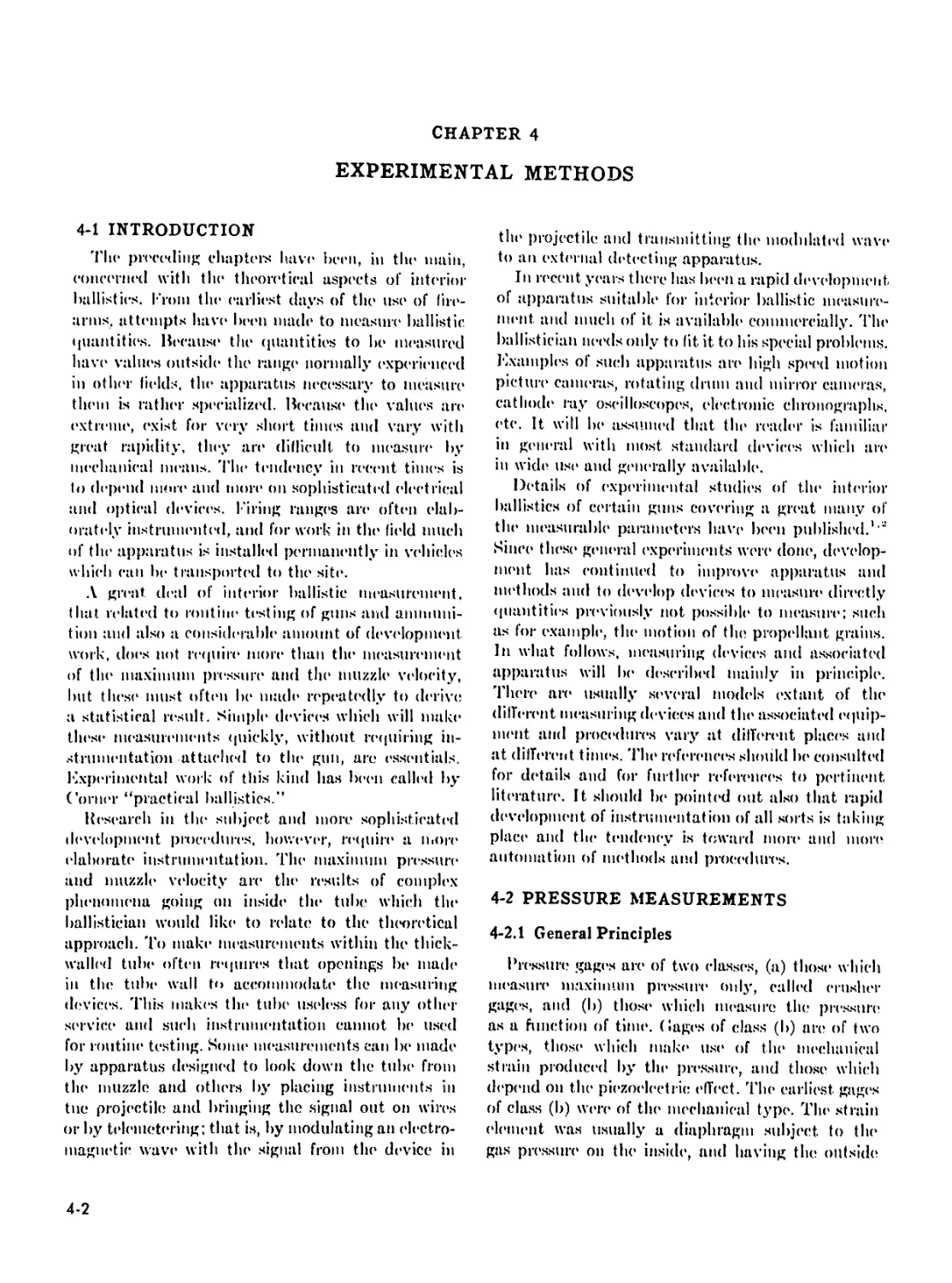
4-2.2 The Quartz Piezoelectric Gage................................ 4-3
4-2.3 Strain Type Pressure Gages............................... 4-5
4-2.4 (’rusher Gage................................................ 4-8
4-3 Measurement of Muzzle Velocity........................... 4-9
4-3.1 General Principles....................................... 4-9
4-3.2 Chronographs.............................................4-10
4-3.3 Detecting Devices............................................4-12
4-3.4 The Calculation of the Muzzle Vehx’ity...................4-12
4-4 Travel-Time Measurements.................................4-14
4-4.1 Barrel C ontacts.........................................4-14
4-4.2 Microwave Interferometer.................................4-14
4-4.3 Measurement of Projectile Travel Near the Start of Motion . . 4-17
4-5 In-Bore Velocity and Acceleration Measurement............4-17
4-5.1 Differentiation of the Travel-Time Data .................4-17
1-5.2 The Measurement of Velocity..............................4-18
15.3 The Measurement, of Acceleration.........................4-19
4-6 The Measurement of Bast* Pressure*.......................4-20
v
TABLE OF CONTENTS—(continued)
Paragraph Page.
4-7 The Measurement of Bore Friction..........................4-21
4-8 The Measurement of Barrel Erosion.........................4-22
4-8.1 General.................................................4-22
4-8.2 The Star Gage...........................................4-22
4-8.3 The Pullover Gage.......................................4-22
4-8.4 The Automatic Recording Bore Gage.......................4-23
4-9 Barrel Temperature Measurements...............................4-23
4-9.1 Thermocouples...........................................4-23
4-9.2 Resistance Type Temperature Measuring Gages.............4-25
4-10 Motion of the Propellant During Burning.................4-26
4-11 Rotating Mirror Camera..................................4-28
REFERENCES...............................................4-32
Chapter 5
SPECIAL TOPICS
LIST OF SYMBOLS ......................................... 5-1
5-1 The Hydrodynamic Problems of Interior Ballistics.............. 5-2
5-1.1 Pressure Distribution and Kinetic Energy of the
Propellant Gases................................................. 5-2
5-1.2 The Emptying of the Gun................................. 5-4
5-2 Ignition of Propellants................................. 5-7
5-2.1 General Discussion...................................... 5-7
5-2.2 Laboratory Investigations of Ignition................... 5-7
5-2.3 Theories of Ignition ................................... 5-8
5-2.4 Ignition in Guns........................................5-10
5-2.5 Ignition Systems for Guns...............................5-12
5-3 Flash and Smoke.........................................5-12
5-3.1 Flash..........................................._..........5-12
5-3.2 Flash Suppression...........................................5-16
REFERENCES..............................................">-18
LIST OF ILLUSTRATIONS
Fig. No. Title Page
1-1 Recoil Gun System ................................................. 1-3
1-2 Recoilless Gun System.............................................. 1-4
1-3 Pressure-Travel and Velocity-Travel Curves......................... 1-5
1-4 Pressure-Travel Relationship....................................... 1-6
1-5 Effects of Grain Configuration on Prcssuie-Travcl Curves.......... 1-7
1-6 Effects of Independently Varying Grain Size ....................... 1-7
1-7 Typical Shapes of Propellant Grains................................ 1-8
1-8 Sizes of Some Typical Grains....................................... 1-8
1-9 Web Thickness and Route of Burning Progress through
a Progressively Burning Grain........................................... 1-9
1-10 Relative Areas of Burning As a Function of Percent of
Individual Grain Consumed for Several Typical Grain Shapes . . 1-9
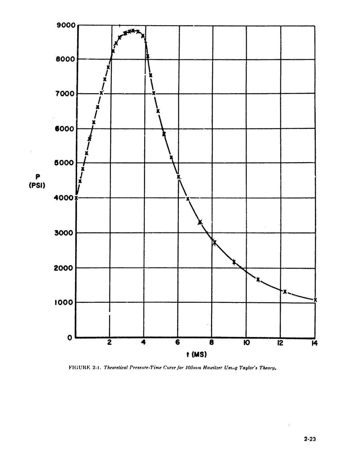
2-1 Theoretical Pressure-Time Curve for 105mm Howitzer
Using Taylor’s Theory...........................................2-23
2-2 Result of the Analysis of a Firing Record for a 105mm
Howitzer Round (Measured Values of Pressure and
Displacement. Velocity and Acceleration Determined
by Numerical Differentiation of Displacement.)................ 2-30
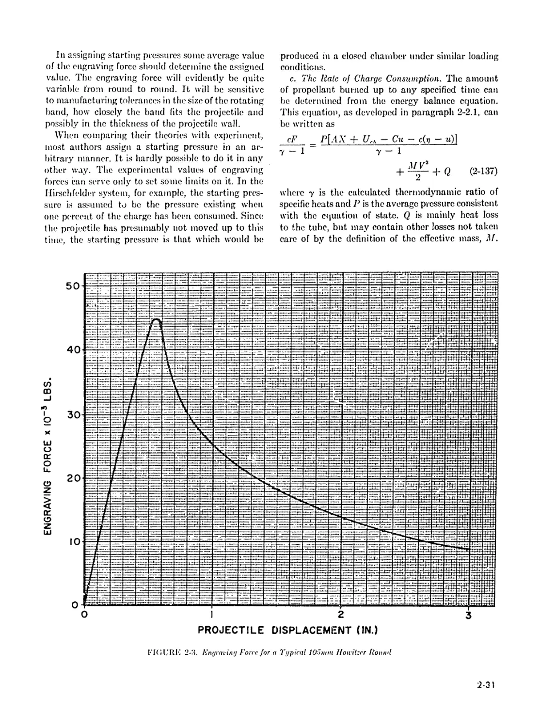
2 -3 Engraving Force for a Typical 105mm Howitzer Round ................2-31
2-4 Charge Burned versus Time for 37mm Gun.............................2-33
2-5 Linear Burning Rate versus Pressure for 105mm Howitzer,
Ml Propellant...................................................2-34
3-1 Observed Radial Wear per Round at the Commencement of
Rifling versus Calculated Heat Input per cm’ per Round .... 3-10
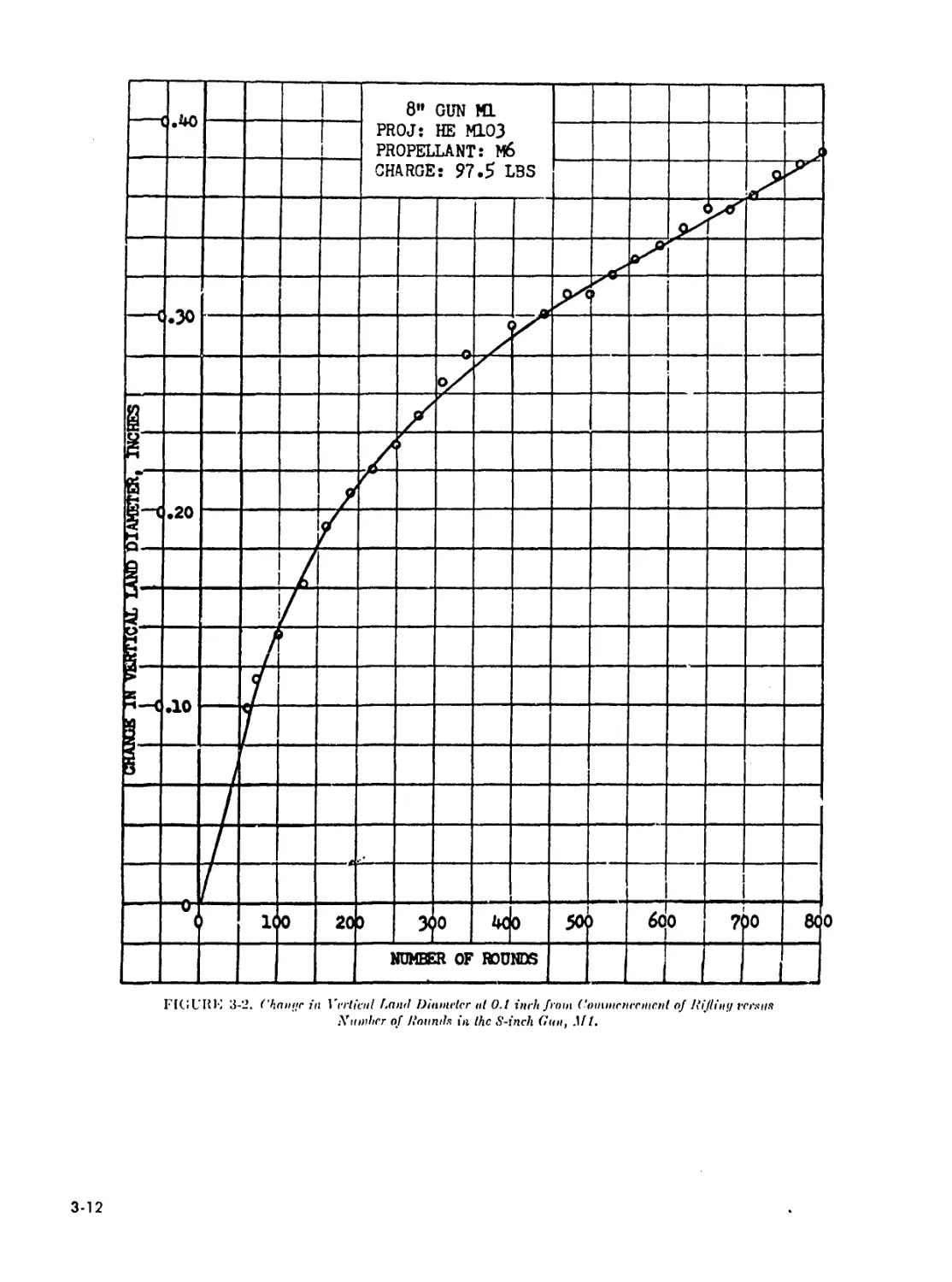
3-2 Change in Vertical Land Diameter at 0.1 Inch from
Commencement of Rifling versus Number of Rounds in the
8-Inch Gun, Ml..................................................3-12
3-3 Bore Enlargement at Origin versus Equivalent Service Rounds.
16-inch/45 Caliber Guns Marks 6 and 8...........................3-13
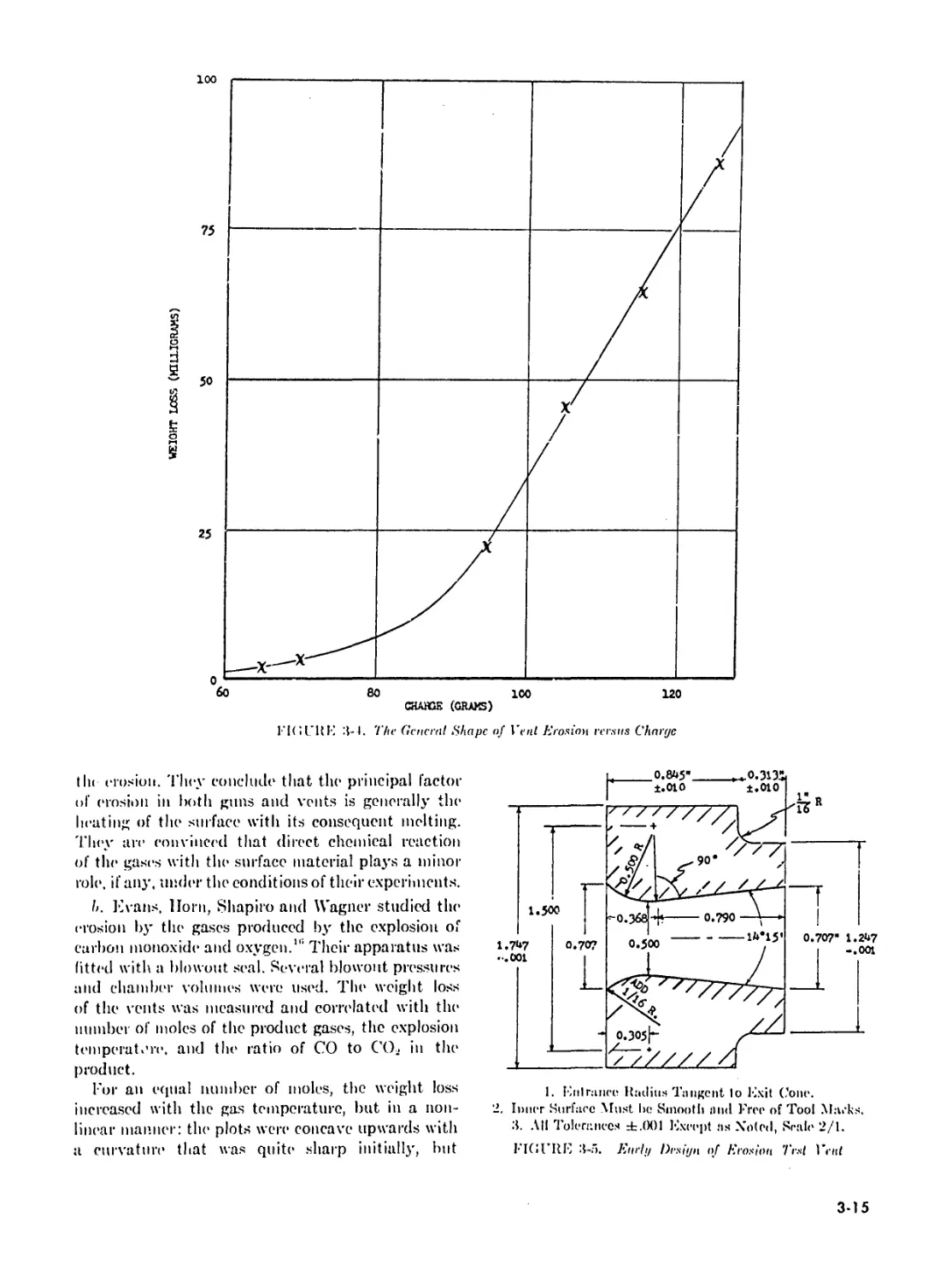
3-4 The General Shape of Vent Erosion versus Charge....................3-15
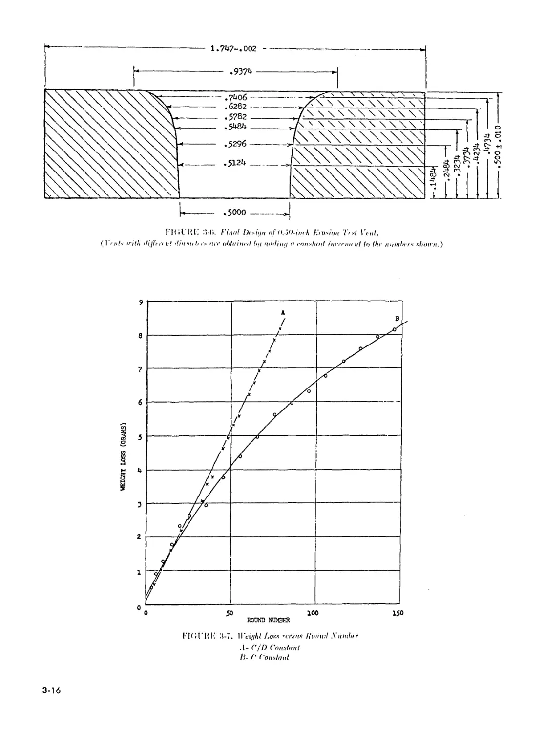
3-5 Early Design of Erosion Test Vent..................................3-15
3-6 Final Design of 0.50-Inch Erosion Test Vent. (Vents With
Different Diameters Are Obtained by Adding a Constant
Increment to the Numbers Shown.)................................3-16
3-7 Weight Loss versus Round Number................................3-16
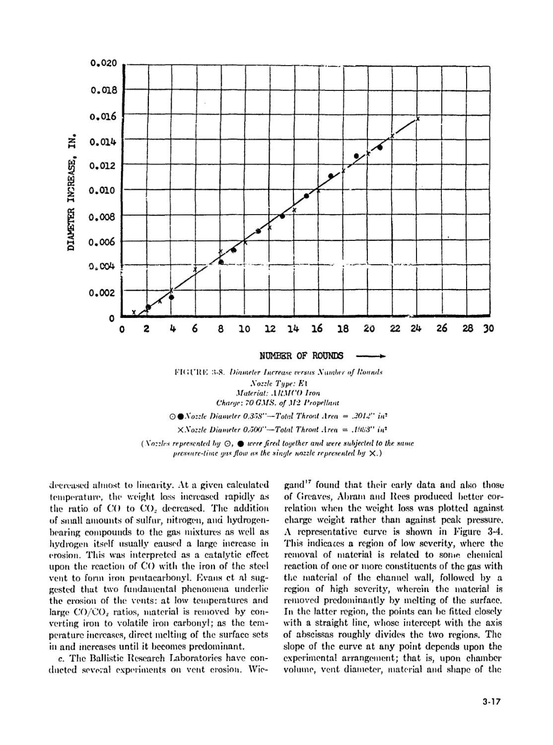
3-8 Diameter Increase versus Number of Rounds......................3-17
3-9 Weight Loss versus Number of Rounds............................3-18
3-10 Weight Loss and Diameter Increase* versus Number of Rounds . . 3-19
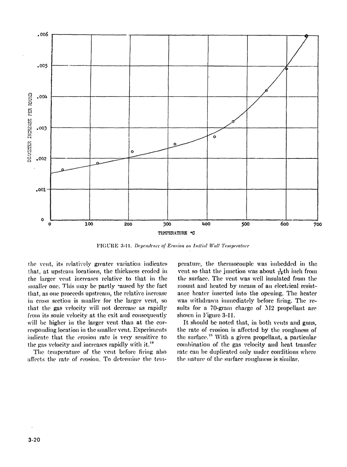
3-11 Dependence of Erosion on Initial Wall Temperatun*..............3-20
4-1 Quartz Piezoelectric Pressure Gage............................. 4-3
4-2 Diagram of Recording System for Piezoelectric Pressure Gage ... 4-4
4-3 Typical Pressure-Time Records from Quartz Piezoelectric Gage
(155mm Gun)..................................................... 4-4
4-4 Dead Weight Apparatus for Calibration of Pressure Gages .... 4-5
4-5 The C-AN Strain Type Pressure Gage Using a Wire-Wrapped
Ferrule......................................................... 4-6
vii
LIST OF ILLUSTRATIONS—(continued)
l'iy. A <>. Title Page
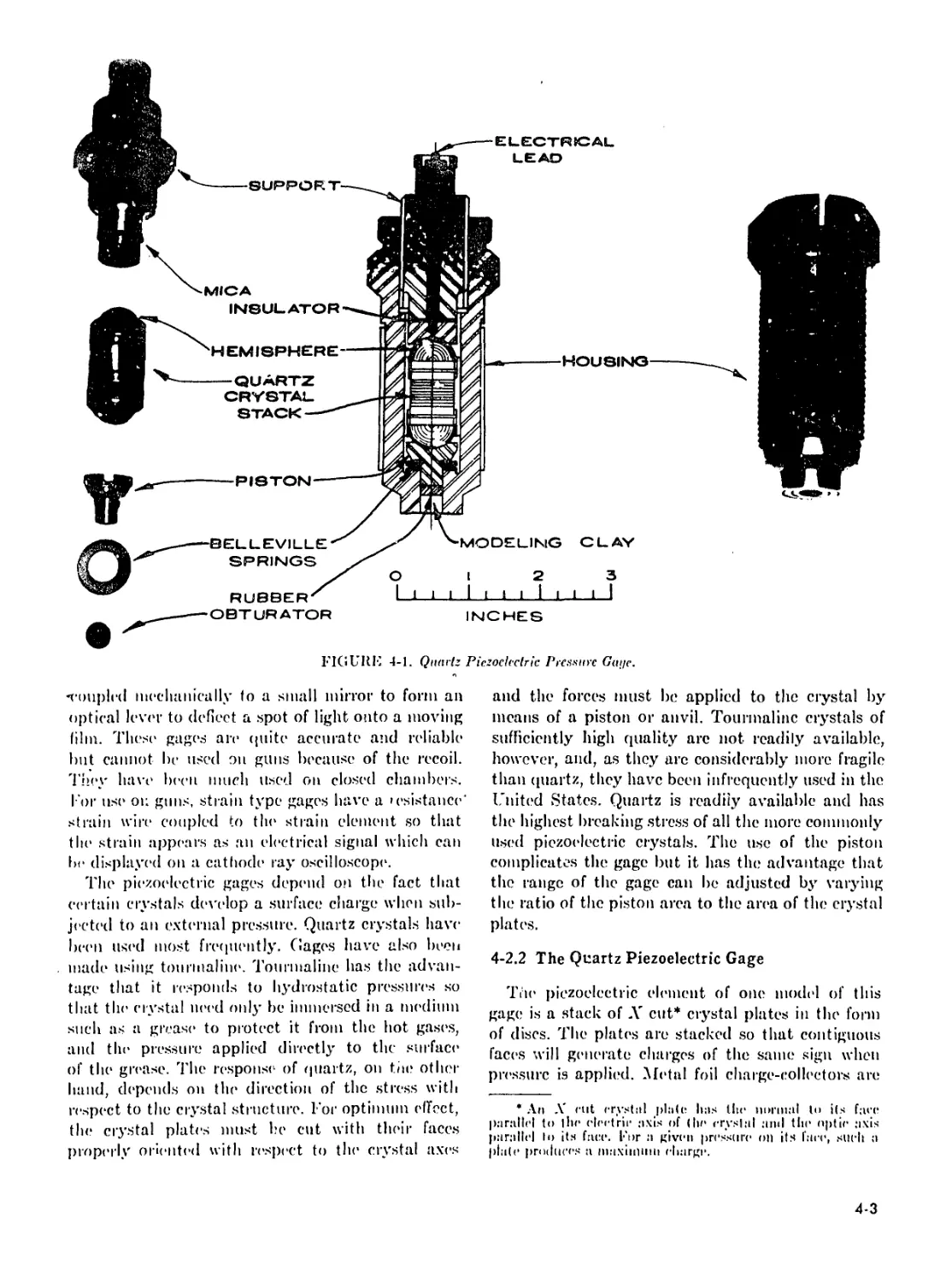
4-6 An Improved Strain Type Pressure Gage Using Cemented
Foil Strain Patches to Permit the Use of a Smaller Ferrule
to Reduce Dimensions of the Gage................................ 1-7
4-7 Internal Strain Type Pressure Gage Mounted in Cartridge
Case to Measure Breech Pressure ................................ 1-7
4-8 The Hat Gage Mounted in Cartridge Case to Measure
Breech Pressure................................................ 4-8
4-9 Typical Input Circuit of Strain Type Pressure Gages.................. 4-8
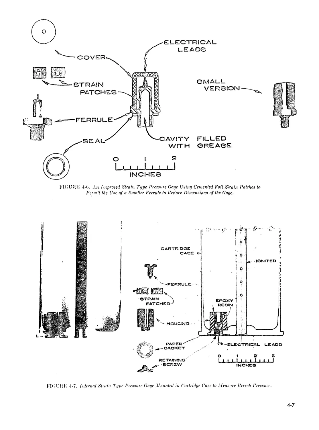
4-10 Гпчщепсу Response Curves for Different Types of Pressure
Gages When Subjected to a Stepwise Pressure Signal in a
High Pressure Shock Tube....................................... 4-9
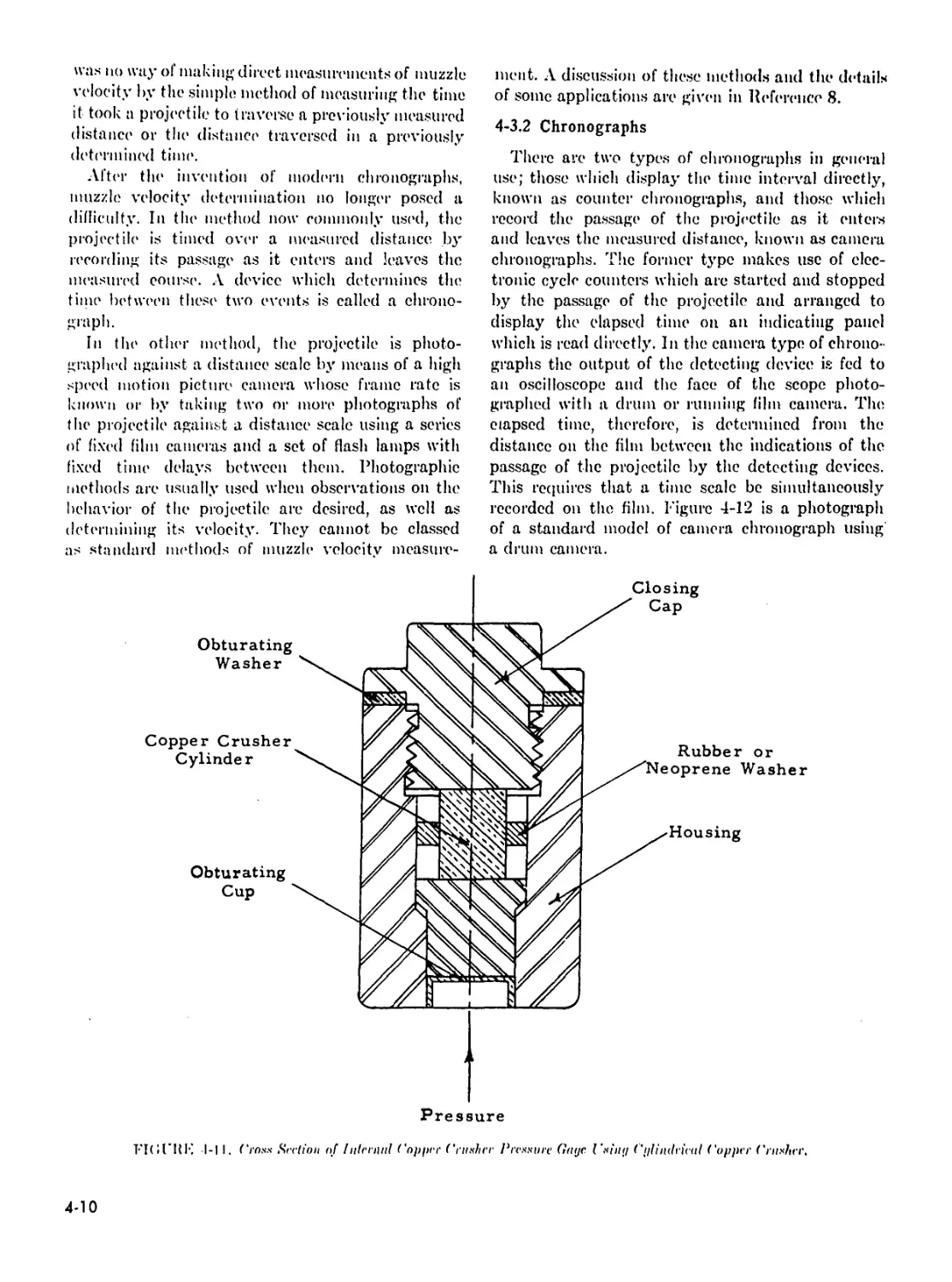
4-1 I Cross Section of Internal Copper Crusher Pressure Gage
Using Cylindrical Copper Crusher................................4-10
4-12 Photograph of a Drum Camera Chronograph Mounted in
Range Recording Room ...........................................4-11
4-13 Drum Camera Chronograph Record of Signal from Velocity Coils . 4-12
4-14 Lumilike Screens in Use in an Indoor Range .........................4-13
4-15 Typical Microwave Interferometer Record of Projectile
Travel versus Time (Caliber .50) .............................4-15
4-16 Block Diagram of the Microwave Interferometer for
Measuring Projectile Travel versus Tiny*........................4-15
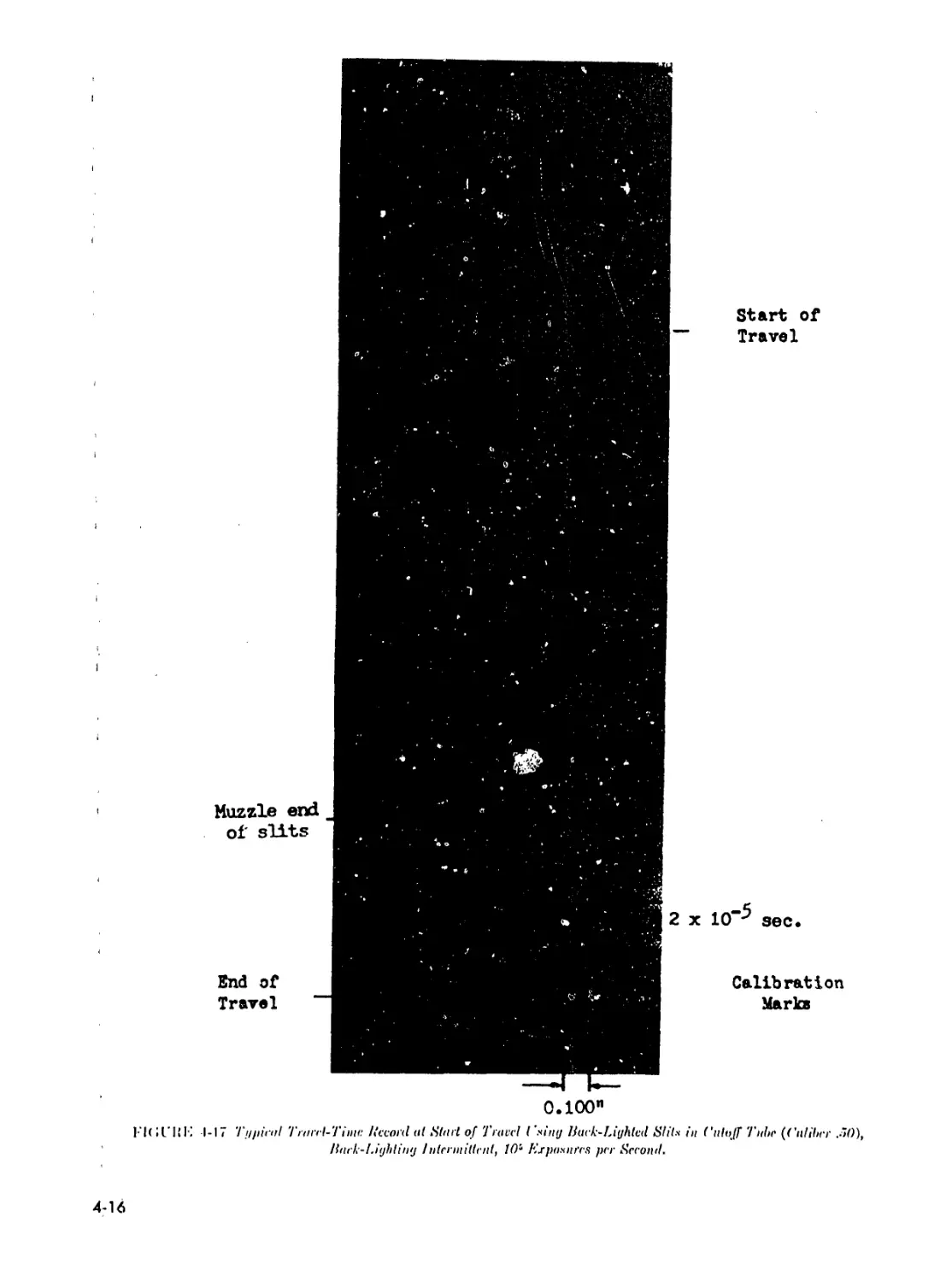
4-17 Typical Travel-Time Record at Start of Travel Using
Back-Lighted Slits in Cutoff Tube (Caliber .50), Back-
Lighting Intermittent, 10’ Exposures per Second.................4-16
4-18 I’oil Contactor Assembly for Measuring Travel During
the Engraving Process, 105mm Howitzer...........................4-17
4-19 Consolidated Plot of the Data and Results for the First
Four Inches of Travel in the 105mm Howitzer.....................4-18
4-20 Diagram of Quartz Piezoelectric Acceleration Gage
Assembled in the Projectile.....................................4-19
4-21 Diagram of the Variable Capacitance Acceleration Gage...............4-19
4-22 Diagram of Quartz Piezoelectric Base Pressure Gage
Mounted in the Projectile.......................................4-20
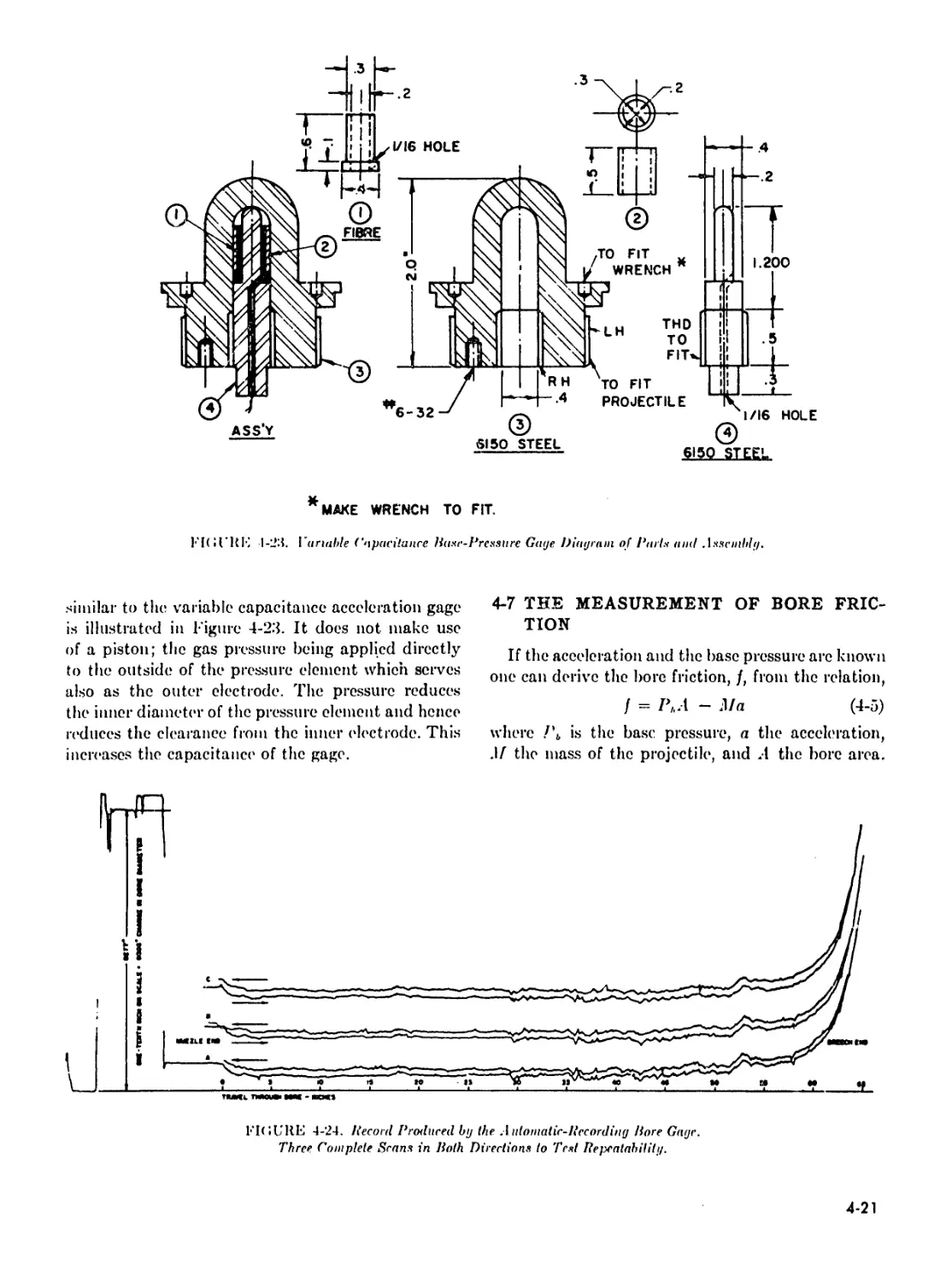
4-23 Variable Capacitance Base Pressure Gage Diagram of
Parts and Assembly.............................................4-21
4-24 Record Produced by the Automatic-Recording Boro Gage.
Three Complete Scans in Both Directions to Test Repeatability. . 4-21
4-25 Diagram of One Model of the Automatic-Recording Bore Gage . . 4-22
4-26 Diagram of Bore Surface Thermocouple and Housing, BRL
Model...........................................................4-22
4-27 Block Diagram of Apparatus for Observing Motion During
Firing of a Radioactive Source Iml>edded Initially in a.
Propellant Grain................................................4-23
4-28 Photograph of Apparatus for the Study of Propellant Motion
During Firing Using Radioactive Tracer Technique. 37mm Gun
With Four Scintillation Counters on Each Side of the Barrel . . 4-24
4-29 Calibration Curves Showing Radioactive Source Position versus
Time............................................................4-25
4-30 Typical Record of Source Position and Pressure versus Time . . . 4-26
vlii
LIST OF ILLUSTRATIONS—(continued)
Fig. No. Title Page
4-31 Consolidated Plot of Observations Showing Correlation of
Radioactive Source and Projectile Positions versus Time .... 4-27
4-32 Consolidated Plot of Radioactive Source and Projectile Motion
Compared With Gas Motion Аз Predicted by the Lagrange
Approximation ....................................................... 4-27
4-33 Distance Traveled by Radioactive Source As a Function of
Initial Position Compared With the Displacement of the Gas
Given by the Lagrange Approximation...................................4-28
4-34 Velocity Attained by Radioactive Source As a Function of Initial
Position Compared With the Velocity of the Gas Given by the
Lagrange Approximation................................................4-29
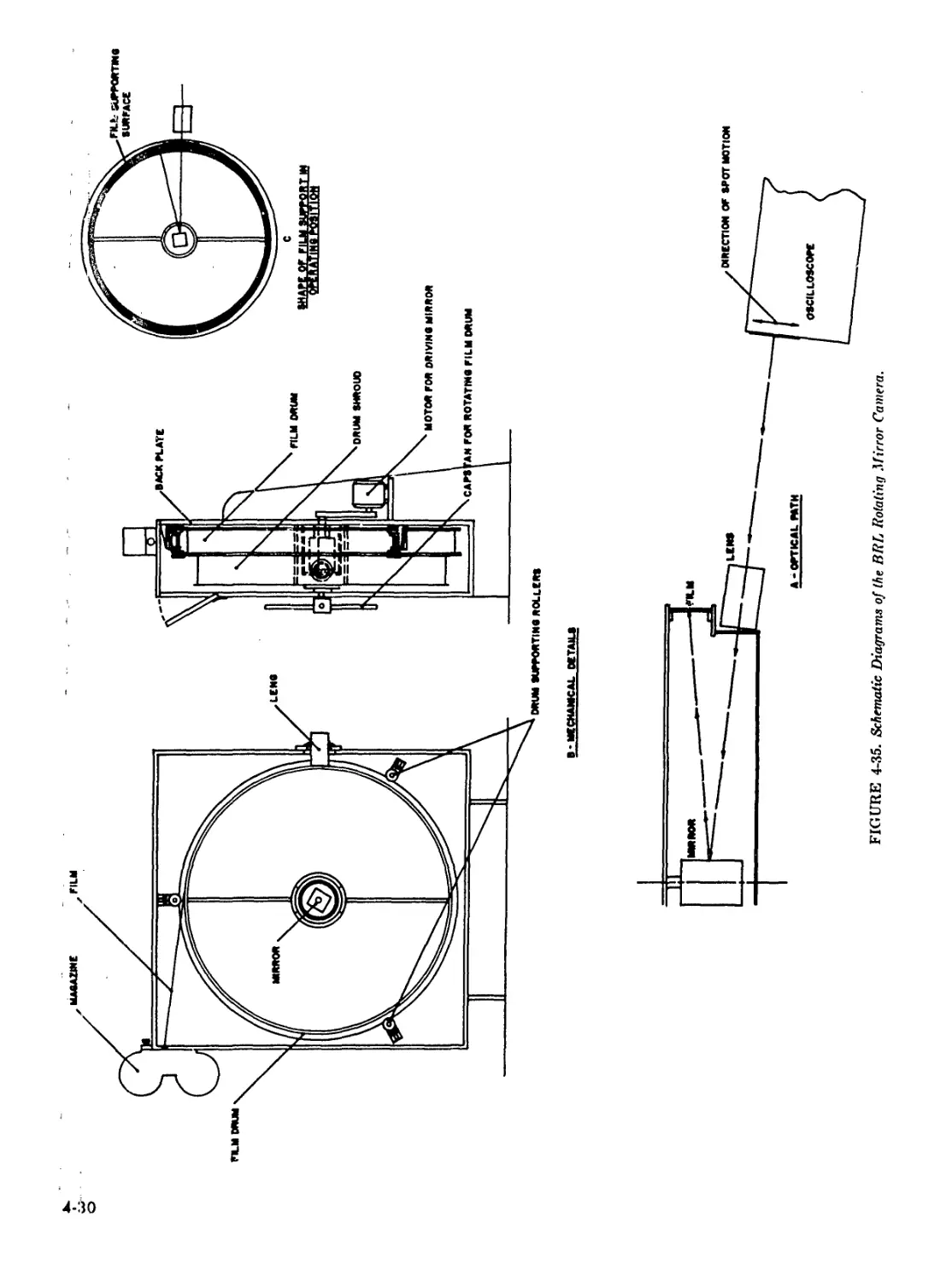
4-35 Schematic Diagrams of the BRL Rotating Mirror Camera.............4-30
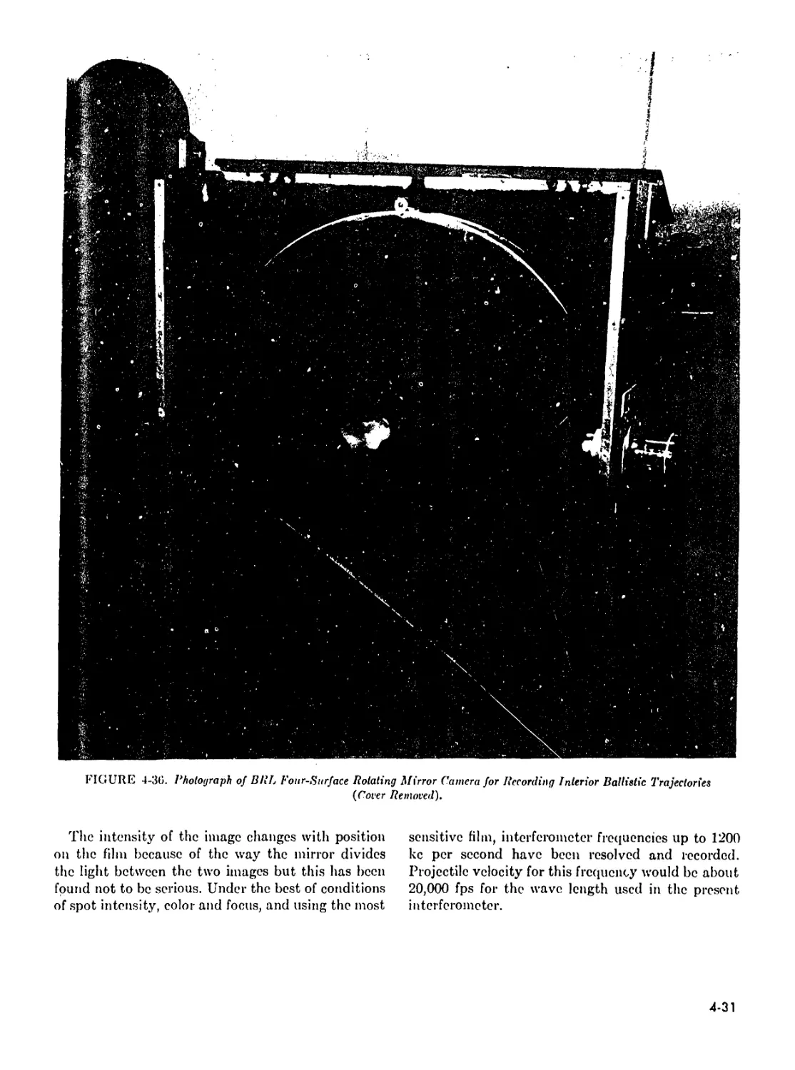
4-36 Photograph of BRL Four-Surface Rotating Mirror Camera for
Recording Interior Ballistic Trajectories (Cover Removed) . . . 4-31
5-1 Graph of c( As a Function of € and n........................... 5-5
5-2 Contour Map of Lincs of Constant C|............................ 5-6
5-3 Reduced Surface Temperature, U, versus Logarithm of Reduced
Time, т...............................................................5-11
5-4 Muzzle Flash from 57mm Gun .......................................5-13
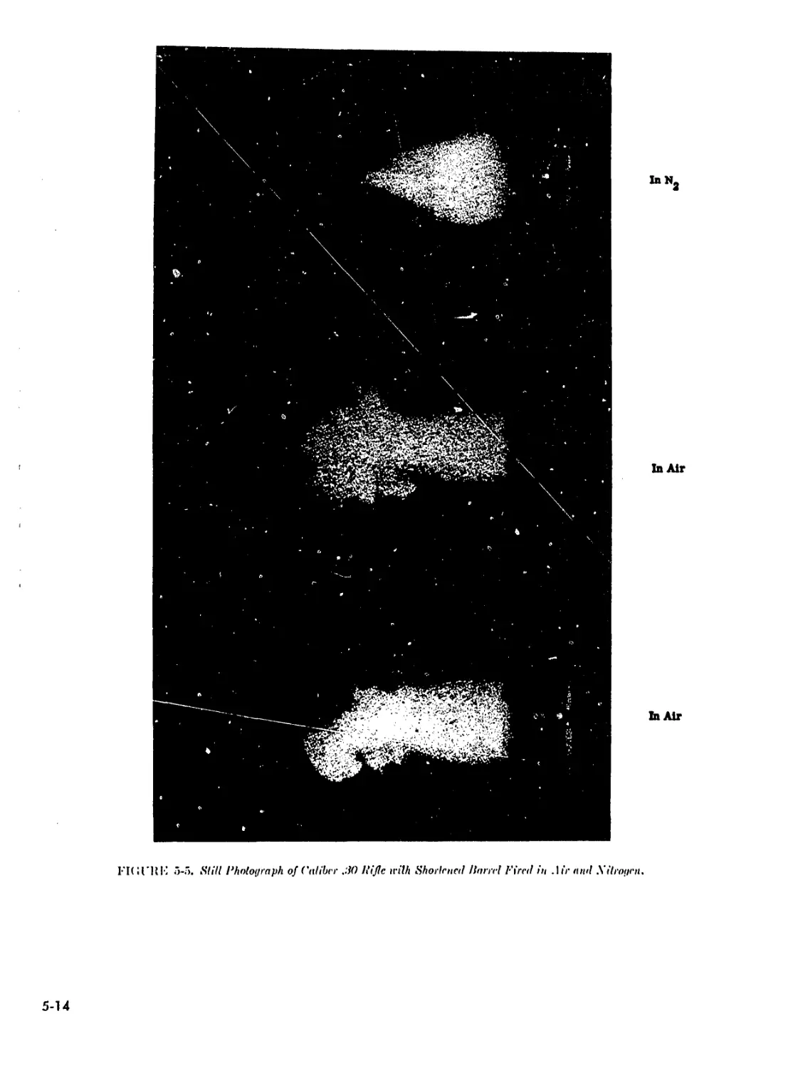
5-5 Still Photograph of Caliber .30 Rifle With Shortened Barrel
Fired in Air and Nitrogen.............................................5-14
5-6 Primary Flash and Muzzle Glow from 37mm Gun.......................5-15
lx
LIST OF CHARTS
Chari Xo. Title Pag
2-1 Pressure Ratio .................................................2-1
2-2al ' 2-
2-21)> Interior Ballistics Trajectories.....................................2-
2-2c 2-
2-3 Time, Pressure and Travel Functions...................................2-
2-1 Chart for Interior Ballistic Calculations by the Scheme of
Strittmater...............................................................2-
2-5 Velocity at Um/U0 = 5 and Pm = (Ю kpsi As a Function of
С/ 1Г (Small Arms)........................................................2-
2-6 Relative Velocity Normalized to Unity at an Expansion Ratio of
5 As a Function of Expansion Ratio (Small Arms)..............
2-7 Velocity Relative to the Velocity at a Peak Pressure of 60 kpsi
As a Function of Peak Pressure (Small Arms)..................
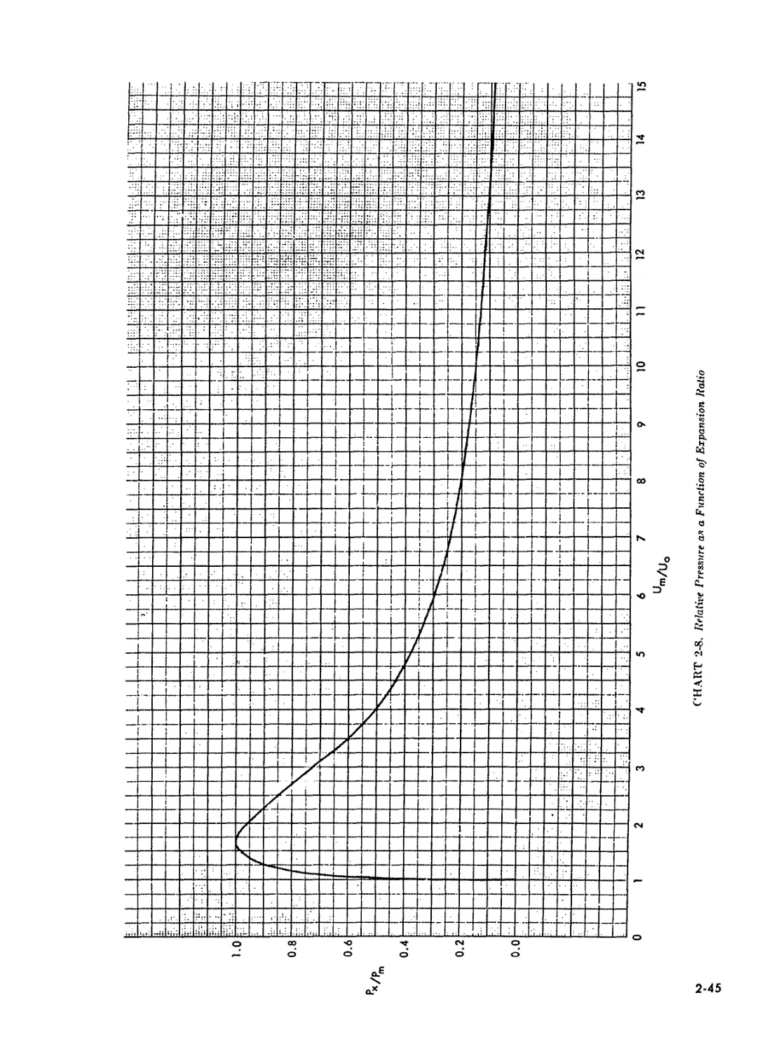
2-S Relative Pressure As a Function of Expansion Ratio................
2-9 Ratio, of Nozzle Pressure to Reservoir Pressure...................
LIST OF TABLES
Table A o.
P
Till's
1-1 Calculated Thermochemical Values for Standard Propellants
(Including Residual Volatiles)..............................................I
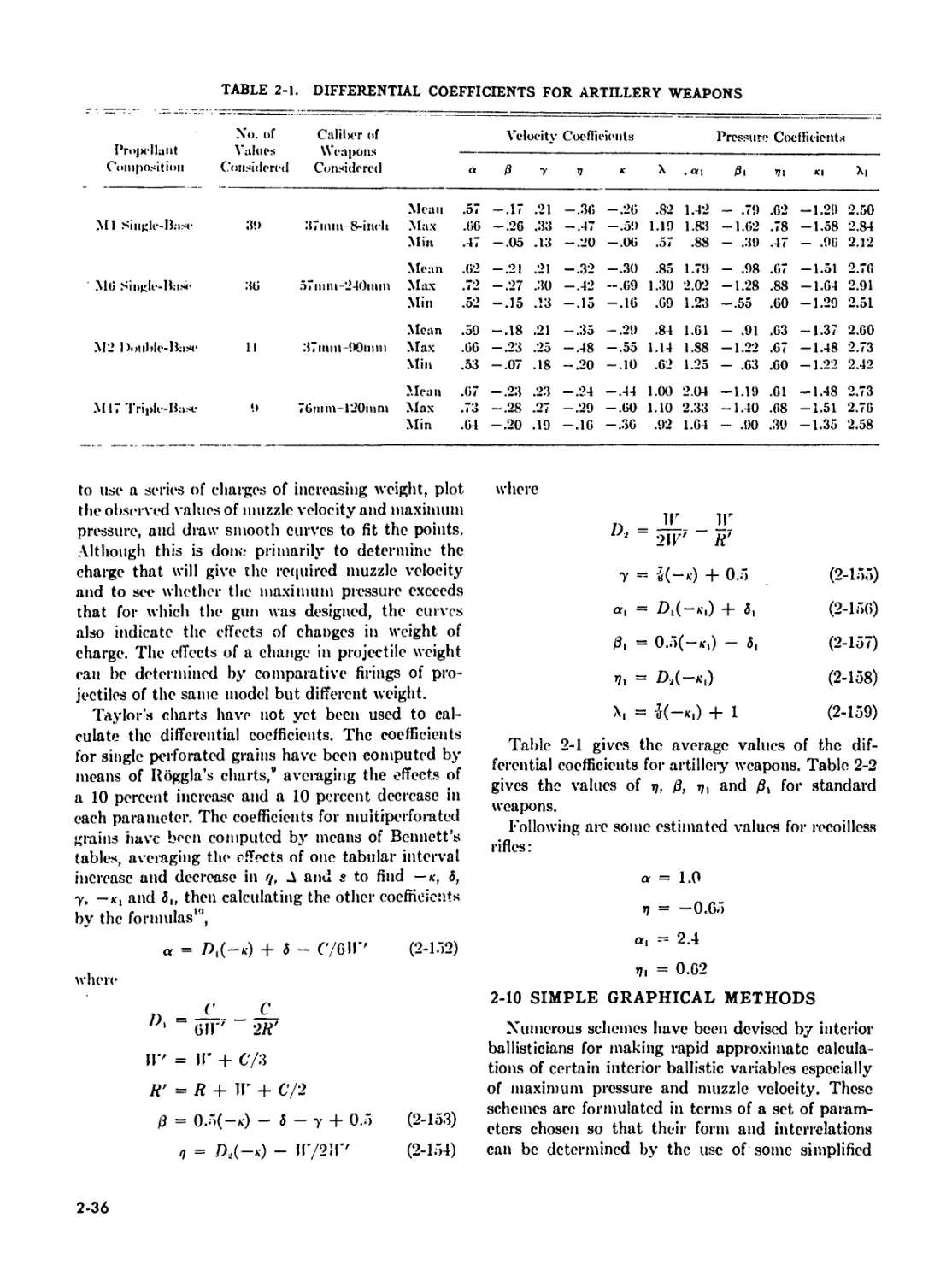
2-1 Differential Coefficients for Artillery Weapons......................L
2-2 Values of r), 0, rj, and 3i for Standard Weapons.....................1
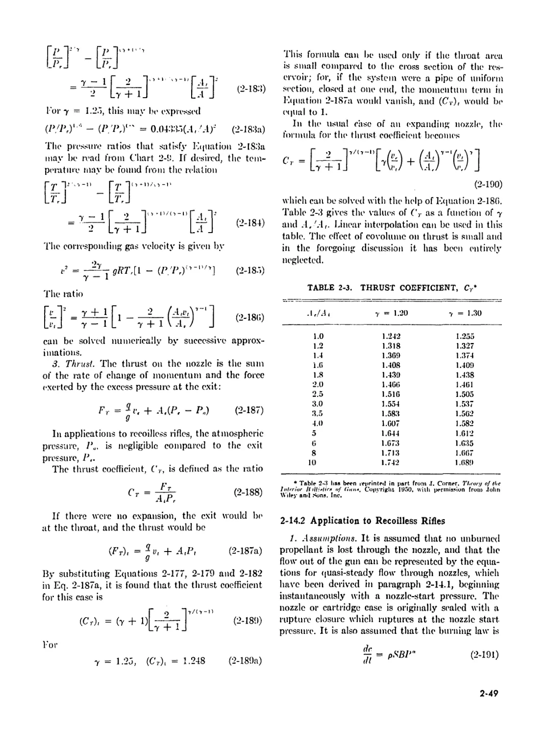
2-3 Thrust Coefficient, Cr..................................................1
3-1 Heat Transfer Function, /(r), for Chins During Burning ...........
3-2 Heat Transfer Function, /(r), for Chins After All Burnt for
r<, = 24 and 28...................................................
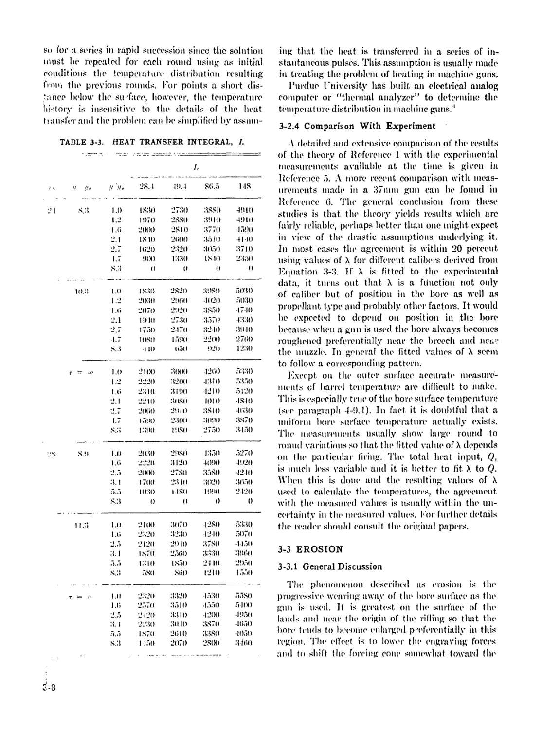
3-3 Heat Transfer Integral, /...............................................
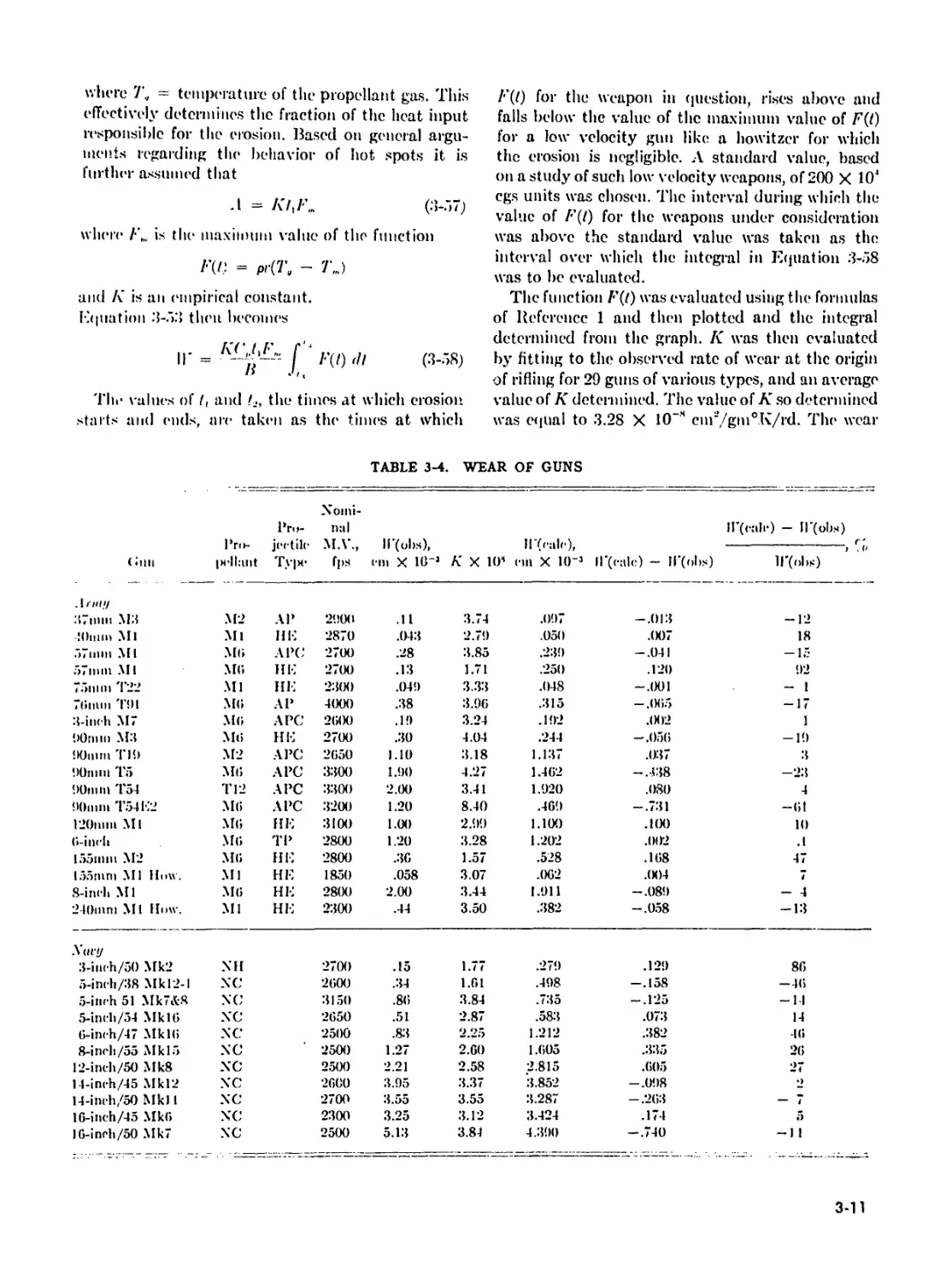
3-1 Wear of Chins...........................................................
5-1 |
5-2 Tables for the Pidduck-Kent Solution....................................
5-5 Approximate Range* of Values of the Variables and Parameters
Used in Hicks’ Thermal Theory of Ignition.................................
5-6 Interior Ballistic Data for 8-inch Howitzer Firing HE
Projectile M106...........................................................
x
CHAPTER 1
LIST OF SYMBOLS
H (• Burning rate ce>eflicient Mass of propelling charge1 n Number of moles of gas per unit weight of propellant gas
(', Specific heat of propellant gas at constant P Pressure
volume R Molar gas constant
(\ Average specific heat of propellant gas at A Area of burning surface of propelling charge
constant volume a„ Initial surface area of propelling charge
c Mass of propellant burned 7’ Temperature of propellant gas
1) Outer diameter of propellant grain П Adiabatic flame temperature of propellant
d Diameter of the perforations of propellant I Time
grain r. Volume of the propellant gas
!: Specific energy or potential el’ solid propellant и Travel of projectile
F Force of propellant Г Velocity
1 Fraction of web Ir.srm-d through w Web thickness
I Internal energy of propellant gas a Burning rate pressure* exponent
к Energy expended by propellant gas in doing work and heating tube Y Factor analogous to the ratio of specific heats at constant pressure and volume*
M Mass of projectile 4 Specific covohime of propellant gas
N Number of grains in the charge* P Specific mass of the* propellant
bl
CHAPTER 1
DISCUSSION OF THE PROBLEM
1-1 INTRODUCTION
The imparting of high velocities to projectiles
requires tremendous force. The source of the energy
which supplies these forces must be readily manu-
factured, easy to transport, and capable' of being
safely applied. At various time's, proposals have*
been made1 for utilization of energy provided by
means other than explosives, such as compressed
air, electromagnetic force, and centrifugal force.
Thus far, however, no results have been attained
from any of the'se; sources which approach those*
realized from chemical explosives.
Interior ballistics of guns (that branch e»f ballistics
dealing with motion imparteel to a projectile by a
gun) comprises a study of a chemical energy source,
a working substance, anel the' accessory apparatus
fe>r controlling the release' of energy and for directing
the* activity e>f the* working substance. Of allied
interest is the* mechanical functioning of guns and
accessories. General information on the* type's of guns
anel their construction and functions is given in
Reference 1. Reference's applicable* to each chapter
of this Handbook are given at the* end of the* chapter.
Since1 unnecessary weight is an unjustified logistical
ext ravagance, weapons are* designed to operate1 under
greater extremes of temperature and pressure than
are* usually encountered in the* use* of nonmilitary
engines. Be'cause* the* time* cycle* involved is e|iiite*
small, there is not sullicient. time* for the consumma-
tion e>f slow processes such as he*at transfer. Con-
sequently, it is necessary that the chemical energy
source* also furnish the* gaseous products which in
themselves constitute the working substance-. This
energy source* may be* a se>lid propellant, as in most
guns, or a liepiid fuel ami oxidizer source*, such as
is sometimes list'd in rocket propulsion.
Propellants are* studied from several aspects.
Thermodynamic properties indicate the* re*le*ase* of
as much energy per unit weight as may be* con-
sistent with other demands. Studies e>f the mech-
anism of decomposition inelicate* the* effects e>f uncon-
trollable* parameters such as ambient temperature.
Dynamics of the* gases are; necessarily a subject of
investigation because the kinetic energy of the*
propelling gases is an important part of the total
energy of the: process. The study of motion of a
projectile inside; the gun tube is not a matter of
simply applying Newton’s laws to the motion of
the; projectile regarded as a point mass, but a
complicated study of the* rate; at which the high
temperature; gas is evolved from the propellant; the*
motion of the gas so produced; and the effect of
this gas on the motion of the projectile itself. The
passage of the projectile; stresses the* tube mechan-
ically and subjects the interior of the barrel to siding
friction. The passage of high temperature gases, in
addition to the high, pressures generated, heats the
barrel to the extent that chemical interaction with
the metal itself occurs.
Interior ballistics is defined as the branch of
applied mechanics which deals with the motion and
behavior characteristics of projectiles while under
the influence of the gases produced by the propellant.
As an applied science it is still much of an art
and largely empirical. The phenomena with which
it deals are explicable in terms of well established
physical and chemical principles. Unfortunately, the
phenomena are complex and related in subtle and
obscure ways so that considerable experience and
judgment are necessary in the application of the
principles if trustworthy theoretical results are to
be derived. There occur in the formulation of the
theory quantities which arc difficult to determine
by independent measurement because their proper
values for particular cases depend in obscure ways
on tb.e particular circumstances of the case con-
sidered. They have the nature of empirical correction
factors whose values can frequently be estimated
only from the results of numerous examples in-
volving comparison of the theory used with the
records of actual firings. The beginner is, therefore,
forewarm'd to be on his guard. All theoretical results
should be as firmly backed up by comparison with
actual firings as is possible. In this sense the theory
serves as a means of interpolation between, or
extrapolation from, existing designs.
The subject of interior ballistics of guns has been
investigated through more than 200 years, starting
with the invention of tin* ballistic pendulum in 17-1.3.
1-2
Л very extensive literature lias been built up, anil
many excellent, texts are available, l or general
background, the texts prepared by ('огне»2 and
Hunt' are n*commended. Mori* specific treatments
have been made by Bennett ' and Taylor and Vagi’.
A consolidated NDR.C report, written by Curtiss
and W rench", covers the work done during World
War 11. A general treatment of the problem with
applications to guns is given in I’elcrence 7.
1-2 GUN?
1-2.1 Deiin'tion
The term yun in this handbook, unless otherwise
indicated, may be taken in its general sense, that is,
a projectile-throwing device consisting essentially
of a projectile-guiding tube, with an incorporate or
connected reaction chamber in which the chemical
energy' of a propellant is rapidly converted into heat
and the hot gases produced expand to expel the
projectile at a high Velocity.
1-2.2 Classification
l or convenience of discussion gnus are classified
according to their salient features, functions, inodes
of operation, etc.1 'I’he* boundaries of these classifica-
tions are not always clearly defined, and the classi-
fications and nomenclature art* often traditional.
'I'he classifications are useful, however, and are in
common use. 'i’he principal one is based roughly
on size and portability' and classifies guns as small
arms and artillery. Small arms art* in general less
than tlOniin in caliber and are usually portable by
foot soldiers. Artillery consists of the larger weapons
usually mounted on carriages and moved by other
than human power. Small arms are more variable
in design and function. They include* such weapons
as rifles, machine* guns, pistols, etc. Artillery weapons
include guns (specific), howitzers and mortars, duns
(specific) include those firing usually at lower eleva-
tion and higher velocity, and howitzers include those
which operate in general in a lower velocity range.
The latter can be fired al high angles and use
zoned charges, that is, charges which are loaded
in separate increments and can be varied within
limits by t he gunner. Mortars operate at high angles
like howitzers but operate at still lower velocities
and are generally loaded from the muzzle. They' are
simple in design and can be broken down and trans-
ported by' foot soldiers.
1-2.3 Action Inside the Gun
A gun is essentially a heat engine. Its action
resembles the power stroke of an automobile engine
with the expansion of hot gases driving the pro-
jectile instead of a piston (figure* l-l). When the
charge is ignited, gases are evolved from the surface
of each grain of propellant, and the pressure in
the chamber increases rapidly. Resistance* to initial
motion of the projectile is great anel relatively high
chamber pressures are attained before much motion
of the projectile takes place. In the solution of the
interior ballistics problem, fictitious starting pres-
sures art1 assumed, which work well in practice.
The chamber volume is increased by the* inovr-
ment of the projectile, which has the elTcct of
decreasing thr pressure; however, the rale of burning
of the charge increases. ’I’he net elTect is a rapid
increase in the propellant pressure1 until the point
of maximum pirssun* is re*ache*d. 'I his occurs at a
relatively short distance* fremi the* ei'igin e>f rifling.
Be*yond that point, pre*ssure drops and, at the*
muzzle*, n*ache*s a value* cemsiderably less than
maximum pressure, probably e»f the* order eif I0r('
to 30% there-eif, elependmg upon the weapon ele*sign
and the* propellant. This muzzle* pre*ssure* cemtinue*s
to act em the* projectile* for a short elistance* beyond
the* muzzle. Thus, the1 projectile* continues te> ae*-
cclerate* beyond the* muzzle*.
A special form of this met heal of propulsion is
repre'sented by the1 re*e*e>ille*ss system (l*'igiire* 1-2).
Here* r<*cenl force's are* countered by the* discharge*
of gases threiugh a nozzle* at the* hr<*e*ch. The* nite*
e>f elischarge of gases can be* contre>lle*d by emit rolling
propellant burning, thus perm it t ing a balance1 of
the1 momentum of the* gun-propi*ilant gas-preije*rtile*
ГК;I’1!К l-l. Iiiioil ({ин Si/th iti,
b3
RECOILLESS RIFLE
FIGURE 1 -2. Jlecoilless Gun System.
system. The interior ballistic problem here is not
only one of combustion but of balancing the orifice
diameter against thrust required to maintain a mean
recoil velocity of the weapon at zero. The propellant
weight in this case exceeds that for a comparable
recoil gun by a factor of 2 to 3. The pressure-travel
curve is designed for minimum muzzle velocity
consistent with satisfactory exterior ballistic per-
formance, thus permitting the use of a thin gun
tube which is necessary to maintain the charac-
teristic light weight of this weapon. The subject
of tecoilless weapons and other leaking guns is
covered more fully in Chapter 2 of this handbook.
1-3 PROJECTILES
Projectiles, like guns, exist in a great variety of
designs, depending upon the intended use. Since
most of the design characteristics do not affect the
interior ballistics, we shall consider only a few. The
most important of these factors is the mass of
the projectile. This must always be taken into
account in the formulation of interior ballistics
theory, as it has a major effect on acceleration and
velocity of the projectile, as well as on the propellant
pressure at all points.
Another very important characteristic is the de-
sign of the rotating band on those projectiles which
are to be spin stabilized. The band is slightly
larger than the tube diameter and must be swaged
to the tube diameter and engraved by the rifling.
Tin1 result of this process is a high initial resistance
to motion of the projectile, which means that the
gases must build up a relatively large starting pres-
sure before the projectile has moved appreciably.
This has an important effect on the interior ballistics,
particularly on the maximum pressure reached and
the time at which it occurs. This variable is largely
eliminated in recoilless weapons in which tin1 rotating-
band of the projectile is preengraved to fit the rifling.
It is also eliminated in smooth bort' weapons which
fire fin-stabilized projectiles. Here an important
factor is the amount of clearance between the
projectile and the tube, as this determines the
leakage of gas around the projectile. The principal
weapon having this problem is the mortar. Here,
with muzzle loading, the clearance must be sufficient
to permit the escape of air so that the projectile
will slide down the bore and strike the firing pin
with the impact energy required to initiate the
primer.
Only one other characteristic of the projectile need
be mentioned and that is the axial moment of inertia
for spin-stabilized project'1^. And here the effect
on interior ballistics is quite small, as the energy
of rotation normally represents only a fractional
percent of the energy of translation of the projectile.
1-4 DISTRIBUTION OF ENERGY
As an indication of the relative magnitude of the
factors involved in utilizing the energy developed
by the burning of the propellant in a medium caliber
recoil gun, the following possible distribution is given:
Eiieryy Absorbed of Total
Translation of projectile 32.0
Frictional work on projectile
(Due to engraving of rotating
bands and wall friction) 2.0
Translation of propellant gases 3.0
Heat loss to gnn and projectile 20.0
Sensible and latent heat losses in
propellant gases 42.0
Rotation of projectile and translation
of recoiling parts (each about 0.1'<’
nod residuals in approximations total) 1.0
Propellant potential, E ItX).(X)
Distribution of the available energy of the
propellant charge is discussed in Chapter 2, as
basic to the solution of the interior ballistics probk m.
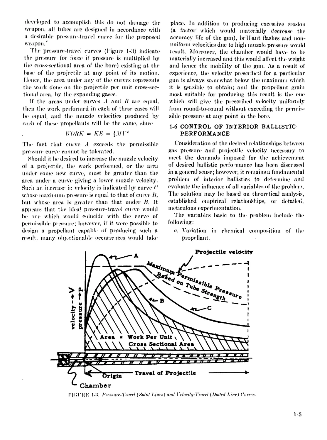
1-5 PRESSURE-TRAVEL CURVES
In order that the projectile may acquire the*
designated muzzle velocity, and that the' pressures
1-4
developed to accomplish this do not damage the
weapon, all tubes are designed in accordance with
a desirable pressure-travel curve for the proposed
weapon?
The pressure-travel curves (l-'igure 1-3) indicate
tin1 pressure (or force if pressure is multiplied by
tin1 cross-sectional area of the bort1) existing at the
base of the projectile at any point of its motion,
lienee, the area under any of the curves represents
tin- work done on the projectile per unit cross-sec-
tional area, by the expanding gases.
If the areas under curves .1 and li are equal,
then the work performed in each of these cases will
be equal, and the muzzle velocities produced by
each of these propellants will he the same, since
WORK = KE = j.i/r-
The fact that curve .1 exceeds the permissible
pressure curve cannot be tolerated.
Should it be desired to increase the muzzle velocity
of a projectile, the work performed, or the area
under some new curve, must be greater than the
area under a curve giving a lower muzzle velocity.
Such an increase in velocity is indicated by curve* <’
whose* maximum pressure* is eepial to that of curve* li,
but whose area is greater than that under li. It
appears that the* ide*a! pre*ssure*-trave*l curve would
be* one which would coincide with the* curve* of
permissible* pressure; however, if it were* possible te>
d(*sign a propellant capable- e>f producing such a
re*sult, many e>bji etionable occurrence's woulel take*
place*. In addition te> producing excessive erosion
(a factor which would materially decrease* the*
accuracy life of the gun), brilliant flashes and non-
uniform velocities due to high muzzle pressure* would
result. Me>re*ove*r, the chamber would have* to Im-
materially incre*ased and this would allect the* weight
and hence* the mobility of the.* gum As a re*sult of
experience, the? velocity prescribed for a particedar
gun is always somewhat below the maximum which
it is risible to obtain; and the propellant grain
me>st suitable for producing this result is the* one*
which will give the* prescribed velocity uniformly
from round-to-round without exceeding the* permis-
sible pre*ssure at any point in the bon*.
1-6 CONTROL OF INTERIOR BALLISTIC
PERFORMANCE
Consideration of the* dcsiri'el relationships between
gas pressure and projectile; velocity nc*ce*ssary to
meet the demands imposed fen* the* achievement
of desired ballistic performance* has be;en discussed
in a general sense; however, it remains a fundamental
problem of interior ballistics to determine anel
evaluate* the influence* of all variable’s e>f the* problem.
The* solution may be based em theoretical analysis,
established empirical relationships, or de*taile*d,
meticulous experimentation.
The variable's basic te> the* problem inclueh* flu*
following:
«. Variation in chemical cennpositiem of the*
propellant.
El( H UE 1-3. PirxnHir-Tiwrii (Soh’il l.bo-x) anil VrloiiLi-Tiaril (Dottcil Line) Chiitx,
1-5
1
Travel, u
Kltll'KE 1-1. Pit'xsnre-7'rate! Ii<la!io>isltip.
Strong Ignition
(High initial surface
area)
Pressure, P
Weak Ignition
^Lfow initial surface area
Rapid change in surface area (degressive)
small web thickness (many holes or
grains)
small
Larger web thickness (fewer
area.
holes
-—More rapid chamber expansion
4 (lighter projectile, less resis-
xtance, etc.)
Less rapid chamber expansion
h. Variations in rate of reaction.
c. Variations in ignition characteristics.
(I. Variation in grain geometry (surface factors).
c. Variation in charge weight (density of loading).
./’. Environmental factors.
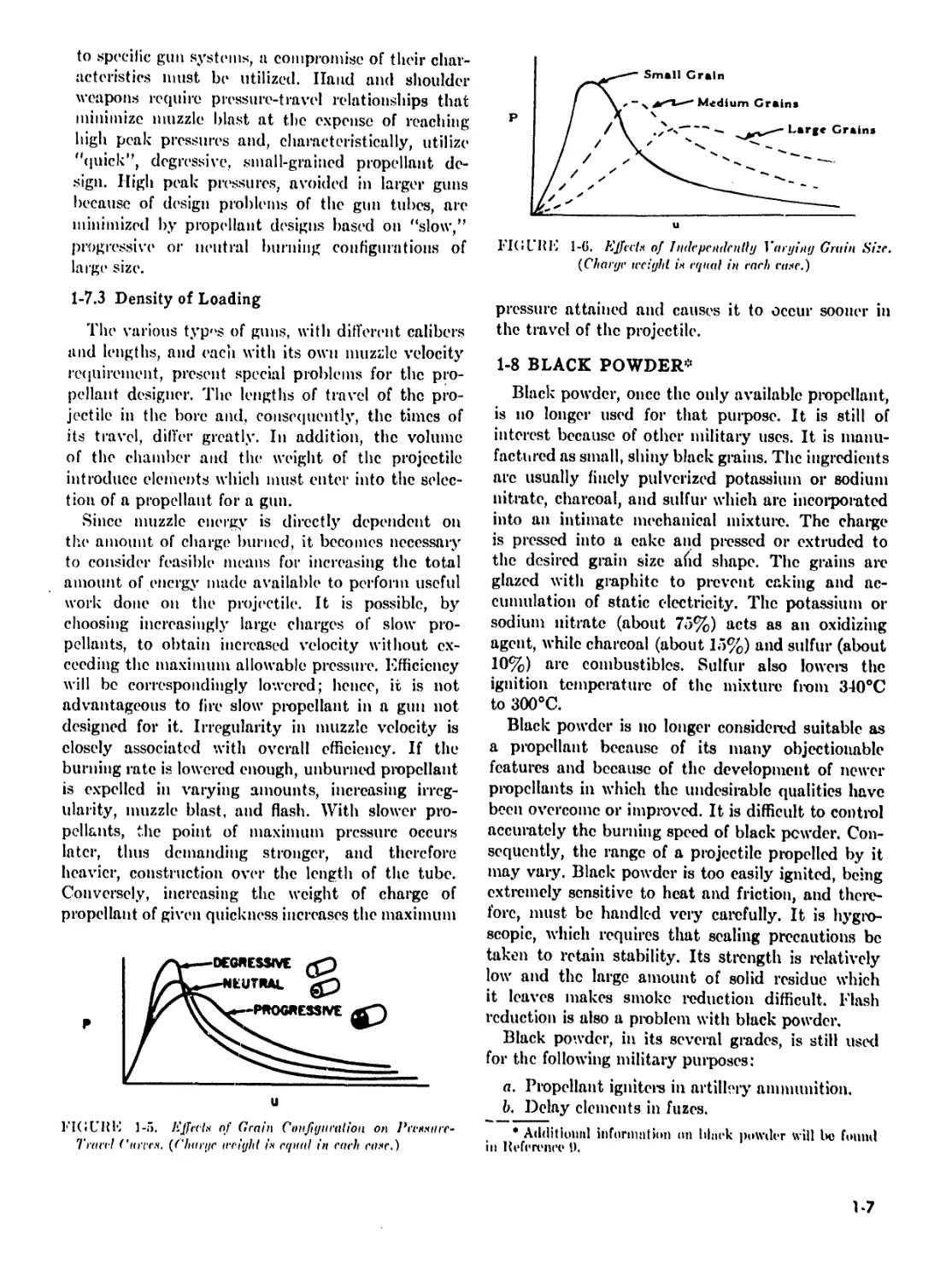
1-7 EFFECTS OF PROPELLANT GRAIN
CHARACTERISTICS
Assuming proper ignition of all propellant grains,
the characteristic shaping of pressure-travel or pres-
sure-time relationships for the gun system is depend-
ent on such variables as grain composition (quick-
ness), grain size, grain configuration, and density'
of loading. Although in a final design all factors
may be involved, it is of basic importance to note
first the independent effects of such variables.
Propellant compositions (single-base, double-base,
nitroguanidine, etc.) and definitions of configura-
tions (degressive, neutral and progressive burning
propellants) arc discussed in subsequent paragraphs
of this chapter. Performance of gun systems is
usually demonstrated using pressure (/^-travel (a)
coordinates, although pressure-time relationships are
often used in experimental investigations.
in each cast* discussed in this paragraph, initial
burning rates are directly related to area exposed
for the total number of grains per charge; hence,
it is difficult to consider the influence of single
factors without making allowance for the* total area
initially exposed to kindling temperatures. For any
pressure-travel curve, the shape of the curve is
affected by the variables shown in Figure 1 -4. For
a given pressure-travel curve (Figure 1-4) the slope
of the curve1 in tin1 region (I) to (2) is dictated
by ignition characteristics and total area initially
exposed to burning. The region (3) to (4) will be
governed primarily by the grain configuration. The
methods of manufacturing propellants and determin-
ing and maintaining the desired configuration of
the propellant grains are covered in References 7
and !).
1-7.1 Grain Configuration
Exposed burning area as a function of “percent
grain consumed’’ (Figure J-10) offers a key to the
effects of configuration on pressure-travel relation-
ships. As indicated in Figure l-.i, changing con-
figuration to a more progressive burning design
(employing grains of the same initial surface area,
composition, and total charge weight) results in
lowered peak pressures (with peak pressure occurring
later in the cycle) and in higher muzzle pressure
when compared with degressive grains. For identical
charge weight, areas under tl(e curve are approx-
imately equal. In order to meet requirements for
equal initial surface areas for the total charge,
the degressive grains must be the smallest of the
designs considered.
1-7.2 Grain Size
For a fixed weight of charge of similar composition
and configuration, shaping of pressure-travel rela-
tionships may be accomplished by varying the initial
area exposed to burning by varying grain size.
Similar effects illustrated in Figure l-.*> result as
grain size is increased (Figure l-(i).
Similarly, comparative results of independently
varying composition (quickness) or web thickness
(a combination of size1 and configuration parameters)
can lx* demonstrated. In adapting such relationships
L6
to specific gun systems, a compromise of their char-
acteristics must be utilized. Hand and shoulder
weapons require pressure-travel relationships that
minimize muzzle blast at the expense of reaching
high peak pressures and, characteristically, utilize
"quick”, degressive, .small-grained propellant de-
sign. High peak pressures, avoided in larger guns
because of design problems of the gun tubes, arc
minimized by propellant designs based on "slow,”
progressive or neutral burning configurations of
large size.
1-7.3 Density of Loading
The various typ<>s of guns, with different calibers
and lengths, and eacii with its own muzzle velocity
requirement, present special problems for the pro-
pellant designer. The lengths of travel of the pro-
jectile in the bore and, consequently, the times of
its travel, differ greatly. In addition, the volume
of the chamber and the weight of the projectile
introduce elements which must enter into the selec-
tion of a propellant for a gun.
Since muzzle energy is directly dependent on
the amount of charge burned, it becomes necessary
to consider feasible means for increasing the total
amount of energy made available to perform useful
work done on the projectile. It is possible, by
choosing increasingly large charges of slow pro-
pellants, to obtain increased velocity without ex-
ceeding the maximum allowable pressure. Efficiency
will be correspondingly lowered; hence, it is not
advantageous to fire slow propellant in a gun not
designed for it. Irregularity in muzzle velocity is
closely associated with overall efficiency. If the
burning rate is lowered enough, unburned propellant
is expelled in varying amounts, increasing irreg-
ularity, muzzle blast, and flash. With slower pro-
pellants, the point of maximum pressure occurs
later, thus demanding stronger, and therefore
heavier, construction over the length of the tube.
Conversely, increasing the weight of charge of
propellant of given quickness increases the maximum
1-'I( I UK E 1-5. Effect* of Grain Conjiyuraliou on Pre**tirc-
Trarel ('lore*. (Chari/c irright in in each cn*e.)
FIGUKE 1-6. Effect* of Jiirlepciirlcntly Varying Grain Size.
(Charge weight in crinal in each cane.)
pressure attained and causes it to occur sooner in
the travel of the projectile.
1-8 BLACK POWDER*
Black powder, once the only available propellant,
is no longer used for that purpose. It is still of
interest because of other military uses. It is manu-
factured as small, shiny black grains. The ingredients
arc usually finely pulverized potassium or sodium
nitrate, charcoal, and sulfur which arc incorporated
into an intimate mechanical mixture. The charge
is pressed into a cake and pressed or extruded to
the desired grain size afid shape. The grains are
glazed with graphite to prevent caking and ac-
cumulation of static electricity. The potassium or
sodium nitrate (about 75%) acts as an oxidizing
agent, while charcoal (about 15%) and sulfur (about
10%) arc combustibles. Sulfur also lowera the
ignition temperature of the mixture from 340°C
to 300°C.
Black powder is no longer considered suitable as
a propellant because of its many objectionable
features and because of the development of newer
propellants in which the undesirable qualities have
been overcome or improved. It is difficult to control
accurately the burning speed of black powder. Con-
sequently, the range of a projectile propelled by it
may vary. Black powder is too easily ignited, being
extremely sensitive to heat and friction, and there-
fore, must be handled very carefully. It is hygro-
scopic, which requires that scaling precautions be
taken to retain stability. Its strength is relatively
low and the large amount of solid residue which
it leaves makes smoke reduction difficult. Flash
reduction is also a problem with black powder.
Black powder, in its several grades, is still used
for the following military purposes:
«. Propellant igniters in artillery ammunition.
b. Delay elements in fuzes.
* Additionnl information on block powder will be found
in Heference V.
1-7
о
SHEET
PELLET
SINGLE PERFORATED
STRIP
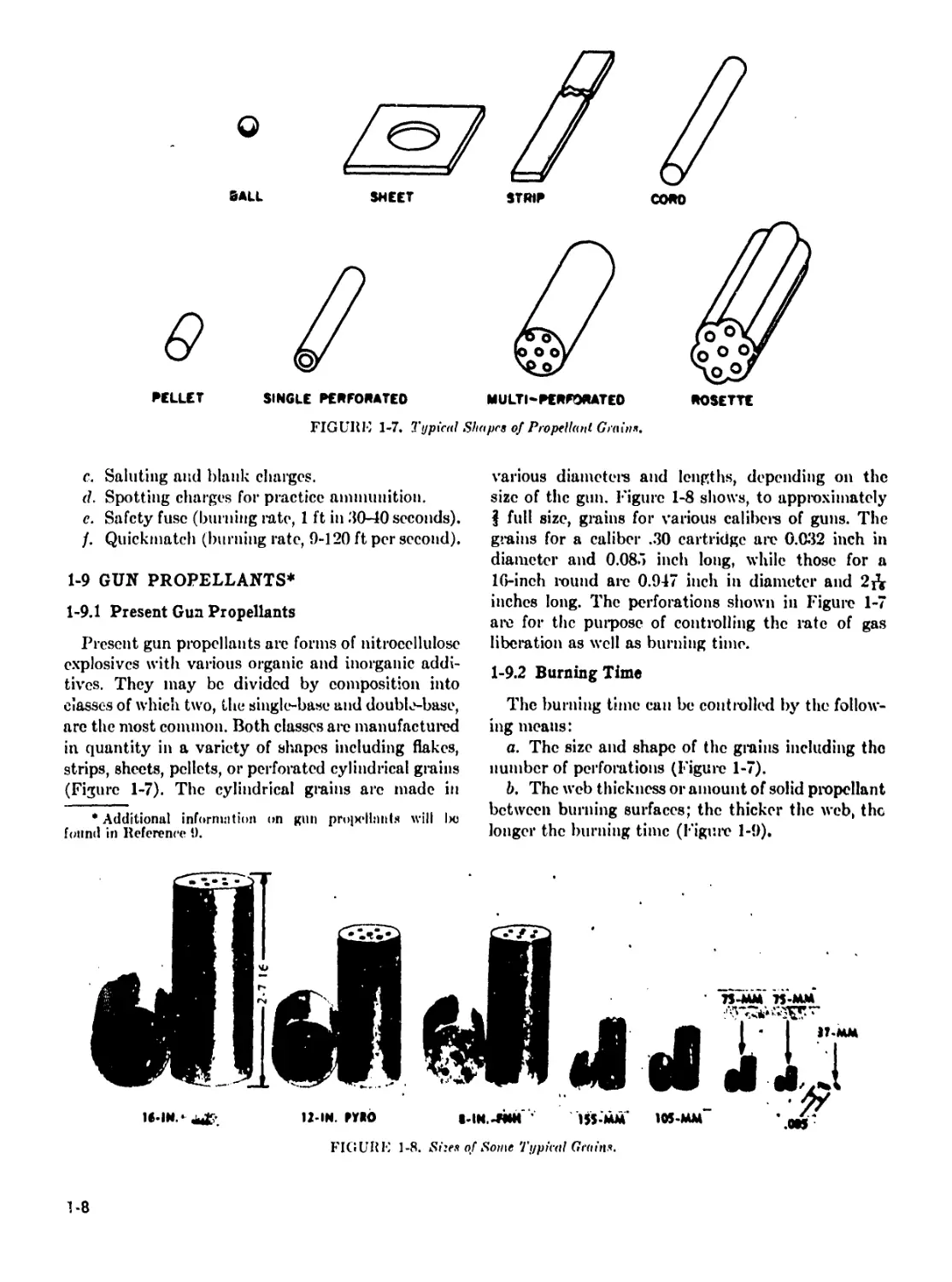
FIGURE 1-7. Typical Shapes of Propellant Grain*.
c. Saluting and blank charges.
(1. Spotting charges for practice ammunition.
e. Safety fuse (burning rate, 1 ft in 30-40 seconds).
/. Quickmatch (burning rate, 9-120 ft per second).
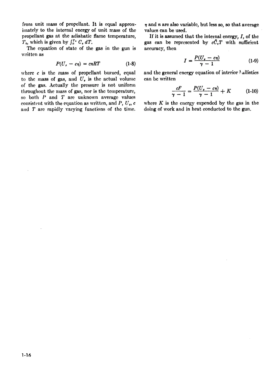
1-9 GUN PROPELLANTS*
1-9.1 Present Gun Propellants
Present gun propellants arc forms of nitrocellulose
explosives with various organic and inorganic addi-
tives. They may be divided by composition into
classes of which two, the single-base and double-base,
arc the most common. Both classes are manufactured
in quantity in a variety of shapes including flakes,
strips, sheets, pellets, or perforated cylindrical grains
(Figure 1-7). The cylindrical grains arc made in
* Additional information on gun pro]x*ll:inIs will Ixj
found in Reference 9.
various diameters and lengths, depending on the
size of the gun. Figure 1-8 shows, to approximately
J full size, grains for various calibers of guns. The
grains for a caliber .30 cartridge arc 0.032 inch in
diameter and 0.085 inch long, while those for a
16-inch round are 0.947 inch in diameter and 2Д
inches long. The perforations shown in Figure 1-7
are for the purpose of controlling the rate of gas
liberation as well as burning time.
1-9.2 Burning Time
The burning time can be controlled by the follow-
ing means:
a. The size and shape of the grains including the
number of perforations (Figure 1-7).
b. The web thickness or amount of solid propellant
between burning surfaces; the thicker the web, the
longer the burning time (Figure 1-9),
FIGURE 1-8. Sizes of Some Typical Grains.
1-8
A —UNBURNED GRAIN
1 —BURNING GUIN
I’K! UHE 1-9. )l>6 'J'hickncss ami Houle of Burning Progress through a Progressively Burning Grain.
c. The quickness or rate of burning of the pro-
pellant.
d. The percentages of volatile materials, inert
materials, and moisture present. A 1% change in
volatiles in a low volatile content propellant may
cause as much as a 10% change in burning rate.
1-9.3 Burning Action
I’nconfined smokeless propellant burns with little
ash or smoke. When confined, its rate of burning
increases with temperature and pressure. In order
not to exceed the permissible chamber pressure of
the weapon, the time of burning of the propellant
is controlled. At constant pressure the time of burn-
ing is proportional to the amount of exposed pro-
pellant surface. Therefore, a propellant charge is
made up of accurately sized grains of specified shape.
Since the grains burn only on exposed surfaces,
the rate of gas evolution for a given propellant will
depend upon the area of the burning surface. For a
given weight of propellant the initial burning surface
will depend upon the form and dimensions of the
grains. As burning continues, the rate of combustion
and of pressure variation will depend upon how the
area of surface changes, that is, upon the rate of
area increase or decrease. Figure 1-10 shows, for
typical grain configurations, the relation between
percent of grain consumed and area of burning
surface.
The rapidity with which a propellant will burn
depends upon the chemical composition, pressure,
and area exposed to burning. The quickness of a
propellant is a relative term only, expressing its
rate of burning compared with others. A quick
propellant will burn more rapidly and produce a
higher pressure in a given gun than a slow one.
Propellants of fixed weight, chemical composition,
and grain geometry may be made quicker by de-
creasing size, thus increasing burning area.
1-9.4 Degressive Burning
The total surface of a propellant grain changes
with burning, and on cord and strip forms the
surface area of the grain decreases. The burning
action of these grains is classified as degressive.
1-9.5 Neutral Burning
As a single-perforated grain burns, the outer
surface decreases and the inner surface increases.
The result of the two actions is that the net burning
surface remains approximately the same. The burn-
ing of this type of grain is known as neutral.
FIGURE 1-10. Relative. Лгсая of Burning .Is <i Function of
Percent of Iniliriilual Grain Consumed, for Several Typical
Grain Shapes.
1*9
1-9.6 Progressive Burning
When the inultipcrforated grain burns, the total
surface area increases since the perforated grain
burns from the inside and outside at the same time.
This type of burning is called progressive (Figure
1-9). When a inultipcrforated grain is not completely
consumed, as may be the case when a reduced
charge is used, portions of the grain remain in the
form of slivers and may be ejected as such from the
weapon. The rosette grain (Figure 1-7) was designed
to reduce the formation of slivers.
1-9.7 Single-Base Propellants
Single-base propellants are essentially gelatinized
nitrocellulose to which various organic substances
an> added either to produce improved qualities or
for special purposes. Single-base propellants are
amber, brown, or black in color, depending on the
additives present.
Single-base propellant is rather insensitive. In fact,
it is difficult to ignite, requiring a powerful primer
and additionally, in large ammunition, a black
powder igniter. It ignites at 315°C. In the open,
single-base propellant burns very much like celluloid.
Seemingly, this explosive is very safe but the fact
should not be overlooked that, although it is used
as a low explosive, it is an organic nitrate and may
detonate if burned in large quantities. It may also
detonate sympathetically from the detonation of
other explosives, although in actual practice this
rarely occurs. Single-base propellant is more power-
ful than black powder, giving off 1000 calories and
900 cubic centimeters of gas per gram, compared
with 700 calorics and 300 cubic centimeters per gram
of black powder. It has a burning speed of 0.1 to
18 centimeters per second at pressures up to (>0,000
pounds per square inch.
Single-base propellant is unstable and decomposes
in hot moist storage. It is hygroscopic, although not
as hygroscopic as black powder. Xitrocellulo.se in
the presence of moisture hydrolizes to free acid,
which takes the form of oxides of nitrogen. These
oxides accelerate the decomposition, building up
heat to an ignition temperature, and spontaneous
combustion may result. Addition of a chemical
stabilizer brings the stability to acceptable limits.
To summarize, the characteristics of single-base
propellants are:
«. Controlled burning. The burning time of single-
base propellants can he controlled to a point when1
the maximum propelling cITect is obtained.
l>. Sensitivity. Ignition is dillicnlt, and the pro-
pellant is reasonably safe.
c. Stability. The propellant is unstable, but this
can be controlled to within acceptable limits by the
addition of stabilizers.
d. Residue. There is some residue and smoke.
e. Manufacture. This is complicated but safe.
Raw materials arc plentiful.
/. Erosive action. Single-base propellant erodes the
bore, but not quite as much as black powder. Its
isochoric adiabatic flame temperature is 2400°K
to 3000°K.
g. Flash. This is caused by hot gases which ignite
when they come into contact with oxygen at the
muzzle. It can be controlled by adding cooling
materials to the propellant.
Single-base propellant can be produced in a form
lacking most of the objectionable features.
The propellant grains for small arms arc usually
glazed with graphite to facilitate machine loading
and to prevent the accumulation of static electricity,
and thus present a black, polished apper nee. Since
the grains are small, they ignite more readily and
burn more freely than cannon propellant. When
moisture »:> present or abnormal temperatures pre-
vail, they arc subject to more rapid deterioration
than the larger grains.
1-9.8 Double-Base Propellants
This form of propellant is essentially a combina-
tion of nitroglycerin and nitrocellulose with certain
additives to give special properties. The nitro-
glycerin increases the potential and reduces hygro-
scopicity, the latter improving the stability. The
color of the grains is gray-green to black, and the
forms are the same as for single-base propellant.
Double-base propellant is more sensitive than
single-base propellant, igniting at 1.50°C to 160°C.
It detonates more readily than single-base propellant
and can be made to yield a higher potential and
liberate more heat, but produce a smaller volume
of gas. The burning rate, generally faster than that
of single-base propellant, can be controlled similarly.
The characteristics of double-base propellants are,
in summary:
a. Controlled burning. Burning can be controlled,
as with single-base propellants.
b. Sensitivity. This is greater than for single-base
propellant, slightly increasing hazard.
r. Stability. Double-base propellants can be made
stable by the add’dion of stabilizing ingredients.
d. Residue. Since there is not so much inert
material, there is little solid residue. Smoke can
be controlled.
c. Manufacture. Not as safe as single-base pro-
1-10
pellant due to presence of nitroglycerin. Raw
materials arc readily available.
/. Erosirc action. High temperature and heat of
explosion from the higher potential double-base
propellants cause more erosion than results from
use of single-base propellants.
g. Elash. As in the case with single-base pro-
pellants, flash can be controlled to a certain extent
by the use of additives. The presence of nitro-
glycerin accentuates the tendency to flash by in-
creasing the flame temperature.
Double-base propellants have limited use in
artillery weapons and in small arms in the U. S.
They are widely used in mortal’s, where erosion is
not an important factor. However, they arc used
as the standard propellants in most other countries.
The U. S. Army and Navy both evaluated single-base
and double-base propellants in guns prior to World
War I and decided in favor of the forme!’ due to
their lesser erosive effect.
J-9.9 Nitroguanidine (Triple-Base) Propellants
A propellant containing nitroguanidine in addition
to nitroglycerin and nitrocellulose as principal in-
gredients is commonly referred to as a triple-base
propellant. This type of propellant was developed
in Great Britain during World War II as a result
of research directed toward obtaining a propellant
with desirable properties such as cool burning, low
erosion, and flashlessness, without decrease in
stability or potential. The British have designated
their nitvoguanidine propellant as Cordite N. The
nitroguanidine propellant, designated M-15, de-
veloped by the United States, represents an interim
solution for selected rounds of ammunition where
the flash or obscuration problem is critical and
where its special properties are particularly needed.
The M-15 propellant has a ballistic potential
comparable to single-base propellants currently in
use but with a lower erosive effect and loss tendency
to flash.
1-9.10 Solvent Emulsion Propellant (Ball Powder)
A radically different manufacturing process uses
a volatile solvent to form propellant in small grains
of spherical shape, designated Ball Powder.* The
sizes of the grains arc appropriate for use in small
arms. The propellant is produced by dissolving wet
nitrocellulose in a solvent (ethyl acetate) with
additives. When a protective colloid is added and
the solution is agitated, small globules are formed.
* Trademark of Olin Mathieson Chenncal Corporation.
Befereiwc !> contains additional information.
When the volatile solvent is removed by evaporation
the globules solidify, and when coated, dried, and
graphited, become balls or spheres, A wide variety
of double-base and single-base compositions may be
produced by this technique. Because of the economy
and speed with which this powder can be manu-
factured, this propellant has promise in future
applications not limited to small arms.
1-9.11 Characteristics of Standard Propellants
The compositions of some of the standard and
experimental (M and T designations, respectively)
propellants, and some of the thermodynamic and
calorific values of them are given in Table 1-1.
The practice, as illustrated therein, of specifying
certain additives, coatings and residues as percent-
ages of the total of the principal constituents,
resulting in over 100% total contents, is standard
in the explosives field.
1-9.12 The Rate of Burning
Since the burning of a propellant occurs only on
the exposed surfaces, the smallest dimensions be-
tween the exposed surfaces become the critical dimen-
sions, as it determines in general when the propellant
will be completely consumed. This critical dimension
is called the web. As was explained in discussion
of the progressive, multipcrforated grain, burning
through of the web is followed, in this case, by
burning of the slivers. A corrected form of multi-
perforated grain is the rosette, illustrated in Figure
1-7. With the exception of multipcrforated grains,
all forms of propellant grains arc completely con-
sumed when the web is burned through.
In the multipcrforated grains, having seven sym-
metrically located perforations, Figure 1-9, the web
may be calculated from the formula
w = 0.25(7) - M) (1-1)
where
w = web thickness
D = outside diameter of the grain
(I = diameter of the perforations.
Experimental measurements show that the rate
of burning of a propellant is primarily dependent
on the pressure under which the reaction proceeds
and this dependence may be expressed approxi-
mately by the pressure to some power.
The mass rate at which gas is produced may then
be expressed as
de
% = pMl>" (1-2)
1-11
where
< is the mass of propellant burned
/ the time
/' the pressure
/> thi* burning rate cocllicie-nt
a tin* binning rate pressure exponent
p the specific mass of the propellant
.S the area of the burning surface
The dependence of the burning surface area on
the remaining web as the charge is consumed can
be calculated from the gemm-try of the grain by
assuming that this geometry does not change during
burning, i.e., that the linear burning rate is the
same at all points on the burning surface. Inn-
propellant in thin sheets, the area of the edges is
negligible ami the surface is constant during burning,
lor single perforated cylindeis, if .S’„ is the initial
surface and f the fraction of the web burned through
.8 = 5„ - 2*Nfw(J), + e/„) (1-3)
where .V is the number of grains in the charge.
The second term on the right arises from the
combined effect of the change in the area of the
end surfaces and the* reduction in length of the
grain. Otherwise, the decrease in the outer diameter
is coinpensatisl by the increase in the inner diameter.
If tin* second term can be m-gh-cted, the burning
surface is constant. I'or single perforated grains of
the usual piojxwtiems, the neglect of this second
term gives a surface area, at burnout of the charge,
which is approximately ten percent tex? high. That is,
the charge is actually somewhat degressive, l-'or
seven perforated grains, the charge is progressive
until the web is burned through; after which it is
degressive.
A relation such as Equation 1-3, which takes
account of the elTect on the rate of gas evolution
of the changing burning surface area, is called the
form function of the granulation. This function is
simple for shex-ts, cords and long single perforated
grains or tubes, l-’or seven perforated grains, it is
complex, especially after splintering, l-'or the simple
shapes it is expresses! as a polynomial in the.* remain-
ing web, but for se-ven perforated grains it is e>fte*n
given in tabular form. l-'ormulas for the surfaces
fe>r complex shapes are* given in Reference 10. l-'or
other formulations e>f the* form function se-e* Rcfer-
ences 2, 3 anil 0.
In practice- the: eiifTerence- in the interior ballistics
fen- single- ami multiple- perforated grains is not as
great as theory indicates. In calculating the.- surfaces
from tin? geometry, the? assumption is maek? that
the- ignition is simultaneous over all surfaces. This
is never the- case- in practice-, l or the- seven perforated
charges the- de-gre-ssive burning of the slivers remain-
ing after the* web is burne-d through tends te> reduce-
the- progre-ssive- character of the early burning. Alse>
the burning rate- is influenced m>t only by the
pre-ssnre- but also by the* fle>w e>f the? gas e>ve-r the*
grain ami within the: pe-rforations. The? shape- e>f the:
grains is not exactly maintained during burning.
Except, then-ion-, fen- highly de-gressive- grains such
as eends, the- assumption e>f a constant burning
surface: is adeepiate-.
With this assumptiem, the burning surface* e»f the*
charge- may be- calculated by the formula
X — ~'
pw
(1-4)
(’ is the- mass e>f charge?
In practice, the- rate at which gas is e-volve-d
depe-nds eni the- detailed conditions under which
the- charge- is burned. A stanelarel methoel for ele*-
te-rmining burning rates is te> burn the* charge- in
a closesi chamber at constant volume* ami nn-asure
simultaneously the- pressure and its time- ele-rivative.
Then, if the- relation betwe-en c ami P is known,
a value- for the- burning rate? cocflieient, H, can be
elerive-el by the use- e>f Eifuations 1-2 ami 1-1. The:
loeflicient, H, se> determined, is afse> calle-el the*
cleised chamber burning rate- coe-llicie-nt, ami it is
used mainly for comparative* purpe>se-s ami fen-
standardizing propellant lots. The- details eif the:
methed are- given in Re-fe-re-nces 3 ami 7.
The- cle>sed chamber burning rate- coefficient rarely
yields gioel agre-e-me-nt with observation if used in
interior ballistic calculatienis fen- guns. 'The- condi-
tions in the* gun are? very dilTercnt, ami the- burning
rate coefficient must be de-termimd by adjustment
to th? results of actual firings. By observing the?
results of numerous firings when fitted te> a given
formulation of the: theory, the: user can estimate
a burning rate- cocflicie-nt for a particular case which
then can be adjusted to the? actual case? in (jucstion.
The- burning rate? pressure index, a, varie-s for
elilTerent propellants, but the? latest experiments
indicate- that it lies between 0.8 and 0.9. A figure-
as le>w as has been used by some? authors, ami
freepiently it is assumed te> be cepial te> unity. In the-
latte-r case-, the solution of the? e-epiations of the:
theory can be: given analytically, otherwise? this is
not possible- and numerical methods must be use*d.
With the- development e>f high spe?cel computing
1-12
TABLE 1-1 CALCULATED THERMOCHEMICAL
VALUES FOR STANDARD PROPELLANTS
(INCLUDING RESIDUAL VOLATILES)
(Located in the back of this
handbook)
1-13/1-14
nacliines, this is not the disadvantage it once was.
The value of a may be determined from closet!
chamber measurements. The methods are described
n Reference 3.
1-9.13 Energy of Propellants
The propellant gas is a complex mixture of several
Cases and for the mixture to have the same properties
of independence of energy from density) all changes
n equilibrium which occur must be cquivoluminar
md independent of the density. This in effect
estricts the theory to “cool” propellants,* that is,
о those for which the temperature is not high
nough to produce significant dissociation of the
nain constituents of the gas mixture. To the approx-
mation of the assumed equation of state, each
>ropellant formulation has a definite explosion tem-
•erature. Thus, the decomposition of a unit mass
•f propellant always liberates the same amount of
nergy which then heats the product gases to the
ame temperature independent of the density. For
nost propellants, the most important equilibrium
i the water gas equilibrium and since this cquilib-
ium is equimolar, the assumed equation of state
i sufficiently accurate for use in the interior ballistic
hcory of guns. The use of a more accurate equation
f state would greatly complicate the theory and
roiild not be justified in view of other simplifying
ssnmptions and approximations which are always
art of any formulation of the theory. In treating
he thermochemistry of propellants, however, a more
ccurate equation of state must be used. Extended
reatments of the thermochemistry of propellants
re given in References 1 and 5.
It is standard practice in the formulation of
iterior ballistic theory to assume an equation of
tate of the simple covolumc type. This is an equa-
ion of state of the Van der Waals type with the
a” term omitted but not the “b” term and is
nown as the Aliel equation of state. I’or a gas
beying such an equation of state, the internal
nergy depends only on the temperature and not
n the density. The Abel equation is expressed as
P(V - 4) = nRT (1-5)
n interior ballistics it is usually written in terms
f a unit weight of gas, so that lz and have dimen-
ions volume per unit weight and n is the number
f moles per unit weight. Many authors also define
I as the gas constant per unit weight so that n
* “Cool" pro]M*IlnntM may l>e defined roughly ns those
>r which the uiirooled explosion temperature is not greater
ban Ж1" K.
does not appear explicitly in the equation. R so
defined is not constant unless n is also.
If Ta is the adiabatic flame temperature, the
energy released by the decomposition of unit weight
of propellant, called the “force6 of the propellant,
although it has the dimensions of energy per unit
weight, i.e., length, is defined by
F = nRTa (1-C.)
The force can be determined experimentally by
burning a charge of propellant in a closed chamber
(i.e., at constant volume) and measuring the maxi-
mum pressure produced and using Equation 1-5,
along with suitable cooling corrections. To do this
requires a knowledge of rj which can be determined
simultaneously by firing a series of charges of dif-
ferent masses and measuring the corresponding max-
imum pressures.
Table 1-1 includes values of the force for a
number of standaid and experimental gun pro-
pellants. Force and other thermodynamic parameters
of propellants can be calculated theoretically if the
neccssaiy thermochemical data arc available. Re-
sults of extended calculations of this sort are given
in Reference 11. The subject is also covered briefly
in Reference 9.
During the operation of the gun, the gas is pro-
duced at temperature, 7'u, and falls to a lower
temperature, 7', due to the loss of heat to the tube
and the performance of work during the expansion.
The change in internal energy per unit mass of gas
can be expressed as C’,(7’u — 7') where C, is an
average value of the specific heat of the gas at
constant volume averaged over the temperature
range, (7’u — 7’). This energy is used in heating
the gun and in imparting kinetic energy to the
projectile, the gas, and moving parts of the weapon.
The quantity C,T0 is called the specific energy or
potential of the propellant.
It is assumed in interior ballistics that the average
specific heat at constant volume, C, bears the same
relation to p, the gas constant, as the specific heat
at constant volume for a perfect gas does, so that
it may be stated nR = C,(y — 1). However, у is
not now the actual ratio of specific heats, but is
analogous to it, its value being adjusted for best
fit to the theory used. In effect, C’, is replaced by
nR/у — 1. Then, from Equation 1-G, if E
denotes the potential, C,T0
E represents effectively the total energy available
Preceding page blank i
from unit mass of propellant. It is equal approx-
imately to the internal energy of unit mass of the
propellant gas at the adiabatic flame temperature,
TQ, which is given by C, dT.
The equation of state of the gas in the gun is
written as
P(Ut - cv) = cnRT (1-8)
where c is the mass of propellant burned, equal
to the mass of gas, and U, is the actual volume
of the gas. Actually the pressure is not uniform
throughout the mass of gas, nor is the temperature,
so both P and T arc unknown average values
consistent with the equation as written, and P, U„ c
and T arc rapidly varying functions of the time.
r) and n are also variable, but less so, so that average
values can be used.
If it is assumed that the internal energy, I, of the
gas can be represented by cC,T with sufficient
accuracy, then
I = Р(ил-сг)) (ig)
У — 1
and the general energy equation of interior ballistics
can be written
= + K (1.10)
у — 1 у — 1
where К is the energy expended by the gas in the
doing of work and in heat conducted to the gun.
1-16
REFERENCES
1. AMCP 706-250, Engineering Design Handbook,
Guns—General.
2. J. Corner, Theory о/ the Interior Ballistics of
Guns, John Wiley & Sons, X. Y.. 1950.
3. !’. R. W. Ilui.t, Internal Ballistics, Philosophical
Library, Inc., X. V., 1951.
4. A. A. Bennett, Tables for Interior Ballistics,
War Dept. Document Xo. 2039, 1921. Revision
and expansion directed by H. P. Hitchcock,
BRL Report Xo. 993, 1956 and BRL Technical
to Xo. 1298, 1960.
5. W. C. Taylor and F. Vagi, .1 Method far Com-
puting Interior Ballistic Trajectories in Guns for
Charges of Arbitrarily Varying Burning Surface,
BRL Report Xo. 1125, 1961.
6. C. F. Curtiss and J. W. Wrench, Jr., Interior
Ballistics, .1 Consolidation and Revision of Pre-
vious Reports, Interior Ballistics I to VII, Na-
tional Defense Research Committee Report X’o.
A-397, DDC Document No. ATI 24855.
7. AMCP 706-247, Engineering Design Hand-
book, Design for Projection.
8. AMCP 700-252, Engineering Design Handbook,
Gun Tubes.
9. AMCP 706-175, Engineering Design Handbook,
Solid Propellants, Part One.
10. Jerome M. Frankie and Jones R. Hudson, Pro-
pellant Surface Area Calculations for Interior
Ballistic Systems, BRL Memorandum Report
No. 1187, 1959.
11. Paul G. Baer and Kenneth R. Bryson, Tables
of Computed Thermodynamic Properties of Mil-
itary Gun Propellants, BRL Memorandum Re-
port Xo. 1338, 1961.
1-17
CHAPTER 2
LIST OF SYMBOLS
A Area of the cross section of the bore, in2 Q
Л Area of the cross section of a nozzle, in2 Q
-1. Leakage area, in2 Q
a Acceleration, in/sec2 Q,
a Throat area of nozzle, in2 li
0» Sonic velocity in gas, in/sec R
R Burning rate coefficient, in/sec-/’*' r
В Momentum index, dimensionless r
C Weight of the propellant, lb
CQ Weight of propellant for ideal rifle, lb r
Cr Thrust coefficient, dimensionless D
c Weight of propellant burnt, lb 5
C, Specific heat at constant volume, in-lh/12 s
slugs-°K T
d Caliber of the gun, diameter of the projectile body, in T
1-: Specific energy of the propellant, in-lb/lb T'
Eo Standard, specific energy of the propellant, in-lb/lb
e Ballistic efficiency, dimensionless To
F Specific force of the solid propellant, in-lb/lb t
F. Engraving force, lb I
Ft Thrust force, lb I
f Similarity factor, dimensionless и
f Momentum factor, dimensionless и
/ Heat loss ratio, dimensionless
(J Gravitational acceleration, in/sec2 uc
I Internal energy of the gas, in-lb Ua
F Axial moment of inertia of the projectile, и
lb-in-sec2 и.
К Work done by the gas, in-lb и,.
I; Axial radius of gyration of the projectile, in V
k Leakage factor, dimensionless v,
C Reduced chamber length, dimensionless vr
Effective mass of the projectile, 12 slugs
J/| Modified effective mass of the projectile, 12 slugs V, V
III Log, 10 (approximately 2.302G) F
III Momentum of gun, Ib-scc V
X Angular velocity of the projectile, rad/scc 1Г
V Proportion of the propellant that is in a IK,
recoilless rifle in gaseous form, dimensionless w
и Lead of rifling, dimensionless
F Space average pressure, Ib/in2 w
P Z’/тг, dimensionless X
P Reduced pressure, dimensionless X
Ileat loss, in-lb
Quickness (Bennett), dimensionless
Rate of flow, lb/in2-sec
Empirical quickness factor, (in3/lb)5
Weight of gun and recoiling parts, lb
Gas constant, in-lb/lb-°K
Linear rate of regression, in/sec
Ratio of actual to tabular velocity, dimen-
sionless
Ballistic parameter, dimensionless
Empirical velocity factor, (Ib/in3)1
Surface area of the grains, in2
Space ratio (expansion), dimensionless
Energy of the fraction of the charge burned,
in-lb
Temperature, °K
Ratio of the gas temperature at any time
after burnt to the mean value during burning,
dimensionless
Adiabatic flame temperature, °K
Time, sec
Reduced time, dimensionless
Dimensionless time
Free volume, in3
Volume from nozzle throat to base of pro-
jectile in recoilless rifles, in3
Chamber volume, in3
Volume of the propellant gas, in'4
Specific volume of the solid propellant, in3/lb
Specific volume of the gas, in3/lb
Specific volume of water: 27.G8 in3/lb
Velocity of the projectile, in/scc
Leakage velocity coefficient, in/sec
Velocity of the recoiling parts of the gun and
carriage, in/sec
Sonic velocity in air, in/scc
Dimensionless projectile velocity
Average projectile velocity after burnt, in/scc
Velocity of gas, in/scc
Weight of the projectile, lb
Effective projectile weight (Strittmater), lb
Effective projectile weight, lb (Mayer and
Hart; and Bennett)
Web thickness, in
Travel of the projectile, in
Axial coordinate of the projectile, in
2-1
Д' Dimensionless travel
•r Volume expansion ratio: dimen-
sionless
'/ Ratio of muzzle pressure to peak pressure:
P„, P,„ dimensionless
: Piezometric efficiency, dimensionless
ix Burning rate exponent (assumed = 0.8)
ix Differential coefficient: (С<?Г„,) (Г,„<?('), di-
mensionless
a„ Escape speed of gas, in sec
a, DilTerential coefficient: (CdPlt) (P^dC), di-
mensionless
3 Burning rate coefficient (linear law), in‘/lb-sec
3 DilTerential coefficient: (J:r>,dV,„) '(E„,c)(’<,,.),
dimensionless
3i DilTerential coefficient: (fС’,.*),
dimensionless
у Ratio of specific heats of the gas (assumed
elTective value: 1.30)
у DilTerential coefficient: (A'„,d!’„),'(Г„ЭЛ’И),
dimensionless
Ratio of specific heats of the gas, adjusted to
take account of loss of heat to the gun,
dimensionless
Л 1 lensity of loading, specific gravity of loading,
dimensionless
<5 DilTerential coefficient: (Adi',,,) (Г,„ЭД), di-
mensionless
о I’idduck-Kent constant, dimensionless
a, DilTerential cocflieient: (AdP„)/(PltdA), di-
, mcnsionless
i Interior ballistic parameter, in-lb
Interior ballistic parameter: /aw/flCX’', di-
mensionless
i; Specific covolume of the gas, in'/lb
7) Differential coefficient: (1ГЭГи)./(ГисНГ),
dimensionless
Differential coefficient: (JTc)/\)/(/>„c)H’), di-
> mcnsionless
factor accounting for rotational energy and
frictional resistance (assumed value: 0.05)
i, fraction of total energy available to pro-
jectile: Katsanis factor, dimensionless
л DilTerential coefficient (irM’,,,) '(Г,„д1с), di-
mensionless
Kt DilTerential cocflieient: (wdPp)/(Ppdw')l di-
mensionless
X Differential coefficient: (Ed!’,„)/(JrmdE), di-
mensionless
X, Differential cocflieient: (EdPJ/^PpdE), di-
mensionless
g(w) Pressure function, dimensionless
,u Ratio of throat area to bore area: .!</.!,
dimensionless
v(w) Travel function, dimensionless
$ Dependent variable: w/(<lK/dT), dimen-
sionless
ir Pressure factor, lb, in2
P Specific weight of propellant, lb/in*
a Ballistic parameter: FpSB/A(y — 1), di-
mensionless
r(w) Time function, dimensionless
т Time unit, sec
Ф Independent variable: log (7’/E), dimen-
sionless
Ф Proportion of the propellant burned, dimen-
sionless
ф Ballistic parameter, function X, dimensionless
w Dependent variable (A'/7’)i, dimensionless
Subscripts
0 Initial value: when t = 0
1 Characteristic of fast propellant in dual
granulation charge
2 Characteristic of slow propellant in dual
granulation charge
a Of atmosphere
b At end of burning: "burnt” value
c Chamber value: at breech
c At nozzle exit
i Either 1 or 2
m Muzzle value: when base of projectile is at
muzzle
н Xozzle opening
p At peak or theoretical maximum
r In reservoir
r Space maximum at any instant
x At base of projectile
I Tabulated value (Bennett)
t At nozzie throat
CHAPTER 2
THEORY AND PRACTICE OF INTERIOR BALLISTICS
2-1 INTRODUCTION
There arc numerous systems of interior ballistics.
Different ballisticians have formulated the theory
in various ways. Their systems, if they arc not
purely empirical, do not differ essentially since they
are treatments of the same thermodynamical and
mechanical phenomenon. They differ in the sim-
plifying assumptions made, that is, mainly in degree
of complexity and sophistication of treatment and
in the details of the mathematical procedures. For
many practical problems, very simple formulations
are adequate and these arc much used. However,
with the widespread and increasing availability of
high speed automatic computers the more com-
plicated formulations can be used without too much
expenditure of time and effort.
There arc five general equations which arc used
in the formulations of interior ballistic theory. They
are: (1) the equation of state of the propellant
gases; (2) the equation of energy; (3) the equation
of motion; (4) the burning rate equation; and (5)
the equation of the form function. The first two
of these are related, as the first is involved in the
formulation of the second; therefore, only four equa-
tions arc basic to any particular formulation of the
theory.
The form of the equation of state of the propellant
gases generally used in interior ballistics has been
discussed in Chapter 1 and is given in Equation 1-8.
The equation has been shown, by experience, to be
sufficiently accurate for the purpose.
The equation of energy has also been discussed
in Chapter 1 and its form is given in Equation 1-10.
The equation of energy is a statement of how the
energy released by the combustion of the propellant
is distributed during the operation of the gun.
The equation of motion is the formulation of
Newton’s second law as applicable to the interior
ballistic problem. It relates the forces due to the
gas pressure to the acceleration of the projectile.
The burning rate equation takes account of the
rate at which new gas is being generated in the gun
by the combustion of the charge. This rate is assumed
to be a function only of the pressure, under which
the combustion takes place, and the area of the
reacting surface. The form of the equation used
here is given in Equation 1-2.
If the reacting surface is not constant, it is
necessary to introduce the form function to account
for the effect of the changing burning surface on
the rate of generation of gas in the gun. Except
for vciy degressive granulations, the assumption of
constant burning surface is generally sufficiently
accurate and this assumption is made in the explicit
treatments which follow.
2-2 STATEMENT OF THE EQUATIONS
2-2.1 The Energy Equation
There is presented here first the formulation due
to Taylor'. The fundamental units used in the
Taylor system are the inch, pound (weight) and
second. This makes mass a derived unit with dimen-
sions weight over gravitational acceleration. With
the length unit the inch, the unit of mass is equal
to 12 slugs.
The energy equation may be stated simply as
T = К + I (2-1)
where
T is the energy released by the amount of charge
which has been burned
К the work done by the gas, plus energy lost by
heating the barrel
I the internal energy of the gas
By Equation 1-10
cF
Т = (2-2)
where F is now defined as the energy per unit
weight of propellant (specific force) and by Equa-
tion 1-9
= P(U, - crj)
У - 1
(2-3)
where L’„ is the volume occupied by the gas. K, the
work done by the propellant gas, consists of several
parts.
a. The principal part is the translational kinetic
2-3
energy of the projectile, equal to 1П’2/2д where
IF is the weight of the projectile, F its velocity
and g the gravitational acceleration.
b. Treating the gases and unbunicd propellant
as a fluid consisting of the gases and burning solid
grains thoroughly mixed, and supposing the tube
to be cylindrical (that is, neglecting chambragc),
an approximation of Lagrange in which the density
of the fluid is assumed independent of position may
be used for ordinary velocities. Then the velocity
of this fluid increases linearly from 0 at the breech
to Г at the base of the projectile; the average
velocity is F/2, and the mean square velocity is
F'/З. Hence, the kinetic energy of the unburned
propellant and the gas is C’F'/Off, where C is the
weight of the propellant charge.
c. The projectile, propellant, and recoiling parts
of the gun and carriage may be considered a system
whose initial momentum is zero and remains so
providing there is no recoil mechanism or shoulder
of the user to prevent free recoil. Under this assump-
tion, if R is the weight of the recoiling parts and
— F, their velocity, the momentum equation is
(IFF + (’F/2 — Z?F,) = 0 (2-4)
whence
_ оце/эг (2_5)
Therefore, in free recoil, the kinetic energy of the
recoiling parts is
(1Г + C/2)2F2
2gR
(2-5a)
l or standard weapons, the ratio (IF + C/2)/R is
of the order of 0.02. The energy of recoil is, there-
fore, a very small fraction of K. The recoil velocity
is much less than that given by Equation 2-5; as
the energy is absorbed in cannon by the recoil
mechanism. In nonautomatic small arms fire the
energy is transferred to the body of the man firing
the weapon. The energy of recoil can be neglected
without serious effect.
d. The rotational kinetic energy of the projectile is
where
is the axial moment of inertia and
N is the angular velocity.
The axial moment of inertia may be expressed as
^ = ^7 (2-Ga)
where
к is the axial radius of gyration
The angular velocity is
N = 2tV/nd (2-7)
where
n is the lead or twist of rifling in cailibcrs, that is,
the number of calibers in which the land makes
one complete turn and
d is the caliber
By substitution, it is found that
Z,№
IFF2
,nd ) 2g
(2-8)
2
For most guns, n is between 18 and 32 calibers,
say 25. For a solid cylinder, (к/d')2 is 0.125; but
for high explosive projectiles, it is about 0.14. There-
fore, the factor (2irk/nd)2 is approximately 0.01.
e. The work done against the frictional resistance
to the motion of the projectile, including the en-
graving of the rotating band, is equal to a small
proportion of the translational kinetic energy, say
fl, IFF2
2g
If et is taken to be constant, this is equivalent to
assuming that the resistance is proportional to the
pressure. The value of 6, is usually of the order
of 0.04.
/. The heat transferred from the hot gas to the
gun is denoted by Q. Adding the contributions a. to /.
IFF2 CF2 (IF + C/2)2F2
2g + + 2gR
УГ »,И'Г
+ UJ^r+ 2g +Q (2‘9)
Equation 2-9 is complicated but can be simplified
in the following manner. Drop the third term on the
right as negligible, and let
0 = (2-irk/nd)2 + (2-10)
In the calculations, 0 will be taken equal to 0.05.
Also, let an "effective” mass be defined as
,V _ П + W + e/3 e.in
2-4
Then, if Q is neglected or accounted for in some
other manner, К takes the simple form
MV2
2
(2-12)
It is customary to take account of the heht loss
Q by adjusting the value of у upward so that the
estimated total available energy of the gas is reduced.
The effect of the heat loss is to reduce the kinetic
«‘nergy produced by the gas and has an effect similar
to an increase in the effective mass. Assuming that
the (‘fleet can be taken account of by simply in-
creasing the effective mass by a constant factor,
Q = I (2-13)
Then, omitting the covolume term for simplicity
1 1/V2
—L-r (cF - PU,) = (1 + /),
у — 1 J
and if у is the adjusted value of у
so that
LJZJ. = 1 + / (2-14)
у - 1
In practice / is about 0.15 but may be considerably
larger than this especially ia small arms. To take
account of heat loss then, one simply substitutes
the value of у for у wherever the latter occurs.
Taylor assumed an adjusted value of у equal to
1.30. In what follows it will he assumed that у
has been adjusted so that, in the subsequent text,
у represents the adjusted value, unless the heat
loss, Q, occurs explicitly in the equation. For more
detailed discussion of the heat loss problem, see
Keferences 2 and 6, also Corner1, page 141.
The interna! energy of the propellant gas is then
expressed as
, = Ш, -zo) = JS-
у - 1 у — I
where
/* is an average pressure consistent with the
equation of state and
Г„ the volume occupied by the gas
'rhe complete expression for the free volume is
U = АЛ' + I',,. — Си + cu — ci] (2-10)
where
A is the area of the cross section of the bore
A’ the travel of the projectile
Uek the chamber volume
и the specific volume of the solid propellant and
the specific covolumc of the gas.
Initially A' = 0, the free volume is then
Ua = Uck - Cu+ c„(u - 4) (2-17)
where cu is the weight of the small amount of charge
burned before start of projectile motion. Substituting
U from Eq. 2-16 in Eq. 2-15 the equation for the
internal energy of the gas is
I = —Ц [АЛ' + Uch - Cu + c(u - ,)] (2-18)
The specific volume of the propellant (w) is about
17.5 in‘/lb. The specific covolumc (?j) (the volume
apparently occupied by the molecules in a unit
weight of gas) is approximately 27.7 in’/lb. The
specific covolume of the gas is thus about 1.5 times
the specific volume of the solid propellant. It is
assumed here that they arc equal, r] = и for the
sake of simplicity. This assumption is often made
in interior ballistics, but its validity becomes ques-
tionable for high ratios of charge to chamber volume.
With this assumption, Equation 2-17 becomes
U„ = Ufh - Cu (2-17a)
and from Eqs. 2-16 and 2-18
U = Uo + A A' (2-16a)
I = (A A' + V,h - Cu) (2-18a)
Substituting from Equations 2-2, 2-12 and 2-18a
in Equation 2-1 the energy equation becomes
Fc MV2 P
7^ = 2* + 7ТГТ (Л* + urk - Cu) (2-19)
2-2.2 The Equation of Motion
The equation of motion expresses the relation
Ix-tween the acceleration of the projectile and the
pressure on its base, P„ Since the unburned pro-
pellant and the gas are being accelerated along with
the projectile and there is also friction at tiie bore
surface, there is a pressure gradient in the gas.
The result is that the average pressure, P, occurring
in Equation 2-19 is not the same as the base pressure,
P„. Furthermore, it is customary to measure tin;
pressure in a gun at a location at or near the breech.
'Го solve the equations theoretically and to express
2-5
the result in terms of the measured pressure, Pc,
some assumption must be made concerning the
relations between the different pressures. An assump-
tion commonly used is that
C C
P p • P =1-|- ----------------• 1 -I______----- • 1
' ' + 2(1 + 0)1Г + 3(1 + 0)11' • 1
(2-20)
This relation is an approximation based on a
special solution of the Lagrange problem which is
discussed more fully in Chapter 5. Its use is re-
stricted to artillery weapons firing at moderate
velocities. When applied to treatments of high
velocity weapons or to small arms, it yields poor
results. I’sing Equations 2-11 and 2-20
p _ + g)ir _ (1 + g)jr .
' (1 + в)1Г + C/3 Mg
If the friction of the bore surface is neglected, the
equation of motion of the projectile is
w _ (i +
g ,11
Substituting Eq. 2-21 in Eq. 2-22, gives
*
AP = M — (2-23)
which expresses the equation of motion in terms
of the average pressure and the effective mass, .1/,
given by Equation 2-11.
Since
Г = (2-24)
the equation of motion may be written
dV
AP = MV-^ (2-25)
dX
2-2.3 The Burning Rate Equation
The burning has been described in Chapter 1.
The area of the burning surface, which is here
assumed constant, may he calculated by the formula
or
.S’ = — (2-26)
pw
where
.S' is the surface area of the propellant grains
ic the web thickness and
p the specific weight of the propellant, that is,
the weight per unit volume.
The rate of regression of the surface is assumed to
be uniform over the entire surface. Propellant gas
is evolved at a rate
de
% = pSBP" (2-27)
where
В is the burning rate coefficient and
a is the burning rate pressure exponent, which is
here assumed to be 0.8.
В should be determined for each type of propellant
under actual conditions of use; that is, by adjusting
its value for best fit of the theory to actual firing
records. В is frequently determined from closed
chamber measurements but these values usually
yield poor results when used in gun calculations
because the conditions in the gun arc very different
from those in the closed chamber. The closed
chamber values are, however, of great value in
determining relative burning rates of different types
and lots of propellant.
2-2.4 Elimination of Variables
The preceding equations involve about a dozen
variables. By straightforward manipulation, they
can be reduced to three equations involving only
four variables: К, P, X and T. T will be treated
as the independent variable. Differentiating Equa-
tion 2-12, gives
dK = MV dV (2-28)
By substitution in Eq. 2-25.
dK = AP dX (2-29)
Since .-IdA' = dC by differentiation of Eq. 2-16a
dK = PdU (2-30)
Finally, since dX = Г dl by definition
dK = APV dt (2-31)
The right members of these four equations arc all
equal. Furthermore, by differentiating Eq. 2-1,
dT = dK + di (2-32)
Now, by Eqs. 2-2 and 2-31,
dK = APVdt
dT F dc/(y - 1)
which, by Eq. 2-27, may be expressed
dK = (y - 1)APF
dT FpSBPn '
2-6
Defining a constant
= pPSIi
-4(y - 1)
(2-35)
and substituting Eq. 2-12, Equation 2-34 becomes
(IK
(IT
12KP'-
(2-3G)
Combining Eqs. 2-32 and 2-3G
Substituting Eq. 2-30 in the differential of Eq. 2-15
gives
= dK , UdP
у — 1 у — 1
(2-38)
Combining the last three equations yields
l2KP'-a . UdP
(2-39)
Eliminating I from Eqs. 2-1 and 2-15
_ (T - A)(y - 1)
U P
(2-40)
Substituting this in Eq. 2-39 and rearranging
produces
dp__________p Г _ i - 1^pl~°~
dT (y - 1)(7’ - K) L7 7 V M <r .
(2-41)
Eliminating C from Eqs. 2-lGa and 2-40 gives
Uo + ЛХ = (T ~ -1) (2-42)
Uo + AX = (2.42)
In order to obtain solutions which arc compatible
with observed results, initial conditions must be
imposed that represent gun conditions as closely as
feasible. The resistance to the motion of the pro-
jectile during the engraving of the rotating band
is much greater than it is at any later stage. Closer
agreement between computed and observed results
is frequently obtained at small cost in added com-
plexity by imposing an added resistance correspond-
ing to engraving resistance, which prevents the
projectile from moving until the pressure reaches
a certain value*, Pn, called the starting pressure.
This has already been taken into account in that
a resistance proportional to pressure varies some-
what like a combination of engraving resistance and
later bore friction, being large in the early stage and
small later.
The initial conditions arc then
V = 0, A' = 0, P = P,„ X = 0,
U P
т = тп = -^Ц-, и = Un (2-43)
у — 1
where
Uo is the initial free volume as given by Equation
2-17a namely,
Uo = Uch — C'u and T„ (the adiabatic flame
temperature) is derived from Equation 2-43.
In order to facilitate the solution of this system
by machine methods, three new variables, ф, ы and f
arc defined by the following relations:
Equations 2-36 and 2-41 form a system of two
first order differential equations in К and P with
T as independent variable, and Eq. 2-42 relates A'
to those variables.
T = «10* (2-44)
« = Vkjt (2-45)
ы _dK f dT (2-46)
2-3 SOLUTION OF THE EQUATIONS
2-3.1 Reduction to Normal Form
Let the system of equations that was just derived
be rewritten:
dK f2KP'~a 9
5т (2'3G)
dP p г , f2K P'~”~
dT (y - 1)(T - K) L7 1 7 V M <7 _
(2-41)
where t is a constant to be defined later (Eq. 2-G1)
and ф is the new independent variable.
In accordance with these definitions,
dw m /1
(1ф “ 2 4 “ “
(2-47)
where m = log, 10 (approximately 2.3026).
Eliminating dK/dT from Eqs. 2-36 and 2-46, and
differentiating logarithmically, produces
df _ dP , 1 dK
--- = (1 -«)— + -— (2-48)
2-7
I sing Eqs. 2-11 and 2-45, this may be expressed
df = f]T Jl 1
5 T (2 + Г-ы:
1 -
(2-49)
J-’innlly', using Eqs. 2-36, 2-46 and 2-44, this becomes
in^ <1ф
(2-50)
From Eqs. 2-46, 2-36 and 2-45, there results
Let 7’ —> 7'0 and £ —> when w —> 0; then P —> Po
and
(2-52)
Фо = log (2-60)
t\7 —
Identifying this with l£q. 2-58, produces, from
Eq. 2-55
= П1Л, = Un [pSFB П7Т/(,-2п)
e 7-1 7-1L a \t7oJ ( J
or, from Eq. 2-35
f _ £-<2-2u)/(.4-2..) 1/l/W-2«)^_ ^(2a-l)/(?,-2a>ff2/(3-2«)
(2-62)
Also from Eqs. 2-56 and 2-58 it follows that
log = — J log 2(7 - 1) - Фо (2-63)
Thus the system of Equations 2-36, 2-41 and 2-42
has been changed into the normal form
Substituting T„ from Eq. 2-43, this becomes
t
hlL ~ 1
\ 2
(2-53)
Since, by definition,
log?,, = -| log 2(7 - 1) - -9~-ф„ (2-63)
= rPSri
• 1(7 - 1)
this may be written
_____i_____pSBF [j7 r_L’
— 1) *4 ii-
(2-54)
Let
Here, the independent variable is
ф = log (T/e) (2-44a)
where « is defined by Eq. 2-61, and the dependent
variables are
« = Vk/t
(2-45)
t - 4L
s
'pSiiF fi7T,/(3_;i”
_ A X'G.
(2-55)
(2-46)
anil substitute in Eq. 2-54,
1 riry—
л/2(у - 1)
(2-56)
Xcxt define
P P,
p = 40 that p„ = ~ (2-57)
and let
Ф,, = log p,, = log (2-58)
From Eqs. 2-44 and 2-43,
rr P
T„ = e10a- = (2-59)
7 ~ 1
This gives
The numc.ical solution of the normal form and
its use in computing trajectory data will be dis-
cussed next. After that, some simple methods of
estimating trajectory data will be given, and the
effects of variations in the parameters will be
explained.
2-3.2 Numerical Integration of the Normal Form
The system of equations in normal form represents
a one-parameter family of trajectories. The param-
eter is the initial value ф0 of the independent variable
ф. This system has been integrated numerically by
computer for values of фо ranging from —2.5 to +1.8.
It was observed that the set of curves for ф0 less
than —2.5 tends asymptotically to the solution for
the case of zero starting pressure, which may be
called the "limiting trajectory". From the solutions
working charts have been constructed.
2-8
2-3.3 Interior Ballistic Trajectories During Burning
The principal problem of interior ballistic theory
is to determine the pressure history and the travel
of the projectile in the gun To obtain this informa-
tion, the pressure, P, and the velocity, V, as func-
tions of the time, I, or travel, A-, arc needed, and
also X as a function of t. This may be obtained
from the trajectories, which arc conveniently divided
into two phases: (1) during burning and (2) after
burning. The first phase will now be considered.
From Equation 2-12, the work done by the gas
is expressed as
Combining this with the definitions in Eqs. 2-44
and 2-45, yields
Г/ы = V2e/.IZ10*/2
From Eqs. 2-3G, 2-4G and 2-12,
For a = 0.8 and у = 1.30, this becomes
1.6968(1 -wVs10’wr Un
л - -----------T (2-68a)
Equations 2-64 and 2-68 give V and X as functions
of ф. These quantities can be obtained by routine
calculation. However, the computation of pressure
and time can be facilitated by the use of a reduced
pressure and a reduced time.
2-3.4 Reduced Variables
The reduced pressure, p, is defined by the formula
(2-69)
Then Eq. 2-66 becomes
p _
p
or, using the definitions of a and e, Equations 2-35
and 2-61
Equating the right members and simplifying gives
](T*/2 (2-66)
If the values of P arc calculated for a fixed ф = ф„
trajectory, the point at which the peak pressure, P„
occurs can be located. By taking values from all
the trajectories, P, can be obtained as a function
of the normal variables ы and £.
In Equation 2-40 the free volume was expressed as
r = ~ - 1)
P
Substituting the values of T, К and P from Equa-
tions 2-44, 2-45 and 2-66 makes
v - <^>
As can he seen from Equation 2-lGa,
V _ U ~ U"
A
Hence,
(2-68)
For a — 0.8 and у --- 1.30, Equations 2-69 and
2-71 become
p = (f 10*za)1 (2-69a)
and
P = 1.076 ~ (2-71»)
Uup
By Equation 2-2 the released energy is
T =
у — 1
and by Equation 2-27 the rate of burning is
de
Substituting the derivative of T from Equation 2-2
and using the definition of a from Equation 2-35
leads to
dT = АаРа dt (2-72)
By differentiation of Equation 2-44
dT = nulO* dф (2-73)
where in = log, 10
Equating the right members gives
wielO* ..
dl = (!ф (2‘74)
AL a
2-9
The reduced time is defined by the formula
Then, with the help of Eq. 2-66 the integral of
Eq. 2-74 may he expressed
I'or a = 0.8,
I = f lO^t* </ф (2-75a)
, I*'»1 7 \
/ = —q-;; J (2-/6а)
• la .1/
2-3.5 Pressure Ratio Chart
The ratio of initial pressure, /*,„ to peak pressure,
/\, as a function of
P>
Pn
II
where II is defined by Equation 2-55 is shown in
('hart 2-1. This chart permits a determination of
the theoretical maximum pressure, to be expected
for any choice of starting pressure for any given
gun, propellant and projectile system.
2-3.6 Interior Ballistic Trajectory Charts
On Charts 2-2a, -2b and -2c several sets of curves
give data from the interior ballistic trajectories.
The abscissa is ы and the ordinate is log $.
<£.-traj<*ctorics are solid curves, starting with the
labeled values of ф and showing the coordinates
along each trajectory. (Chart 2-2a)
i ф-curves are dashed curves joining the points of
Constant ф on all trajectories. The value of ф on
bach of these curve's is the labeled value. (Chart 2-2a)
/\-curve crosses all trajectories at the points
where the pressure is a maximum. (Chart 2-2a)
Г-curves join points of constant reduced time on
bach trajectoiy, and are so lalwlcd. (Chart 2-2b)
' /7-curvcs join pouits of constant reduced pressure
on each trajectory. They arc labeled with the values
bf log p. (Chart 2-2c)
, The charts reproduced here arc for illustration
purposes only. I'or use in calculations they should
be reproduced on a much larger scale.
The use of the trajectory charts is as follows.
Estimate a starting pressure, which depends on the
gun and projectile. Bennett’ assumed a value of
2500 psi for his tables, but it may be anywhere
from 1000 to 5000 psi. Compute 'r,>, .1/, S, a and
t from Equations 2-17a, 2-11, 2-26, 2-35 and 2-62,
respectively. Setting у = 1.30 and a = 0.8 the
latter two equations become
pSBF (2-35a)
u 0.3A
and
e = [0.027U’M 'a"’]',r (2-62a)
Then compute
* - '"K 0.3, (2-60a)
This identifies the <«„ trajectory (the set of values
of w, t and ф along the solid line from ф = ф„ on
Chart 2-2a) which is applicable until the end of
burning. If “burnt” values arc denoted by the
subscript Ъ, ф becomes
* “ losiS (-’’77)
The intersection of the ф-curve for ф = фь (dotted
line on (’hart 2-2a) and the ф.-trajcctory indicates
the point on the trajectoiy at which the charge
was all burned, that is the point («,„ $>,, фь).
The intersections of the p-curvcs and the I-curvcs
with the ^„-trajectoiy give the values of the reduced
pressure and reduced time. (To do this using the
three Charts 2-2a, 2-2b and 2-2c requires that the
Ф„ trajectory I>e transposed from (’hart 2-2a to
Chart 2-2b for I, and to Chart 2-2c for /1) (The three
charts have lx*en combined into one so that this
transposition is not necessary. The combined chart
however, is complicatixl and hard to read unless
made very large. A coinbimxl chart was produced
on a large scale at Ballistic R/'search liilxn-atories
and copies can lx? obtained. A reduced copy is
published in Reference 1.) Then the pressure and
time can lx? computed by Equations 2-71a and 2-76a.
In particular, the “burnt” values, pb and Ib, can be
found. Also, the peak pressure, can be calculated
from p„, which is the value of p at the intersection
of the /\-curve (Chart 2-2a) and the ^.-trajectory.
/*, is the th<*oretical peak pressure which is not
necessarily the same as the actual maximum pres-
sure. It will Ik* the same only if the charge does not
burn out before P, is reached, that is, the time to
reach th? theoretical peak pressure must be less
than the time to burnt. If this is not the case,
the actual maximum pressure is the pressure at
burnt, Pb.
After фь has been calculated from Eq. 2-77, wb
has been obtained from Chart 2-2a, and Pb has been
computed, the free volume, Ub, the travel, X» and
the velocity, I”,,, at “burnt” can be calculated by
2-10
СИЛ ПТ 2-1. /'tenure littlio
2-11
CHART 2-2a. INTERIOR BALLISTICS
TRAJECTORIES
(Located in the back of this handbook)
Preceding page blank
2-13/2-K
CHART 2-2b. INTERIOR BALLISTICS
TRAJECTORIES
(Located in the back of this handbook)
Preceding page blank
2-15/2-16
CHART 2-2c. INTERIOR BALLISTICS
TRAJECTORIES
(Located in the back of this handbook)
Pi-Ceding page blank
2-17/2-18
the formulas
2-3.7 Conditions After Burnt
After all the propellant is burned, c = ('. With
this substitution, Equation 2-2 shows that the
released energy is
T = — — — = constant (2-81)
7 — 1
As before, the work done by the gas is, Equation 2-12
and the internal energy is, Equation 2-15
r- "L.
7—1
Hence, the energy equation may be expressed
’ FC = PU + .1/Г (2-82)
«J
Taking differentials produces,
0 = P dU + U dP + (7 - 1).VF dU (2-83)
By Equations 2-28 and 2-30
)IVdV = PdU (2-84)
., * dP dU q->
so that JT = -У (2-8-))
Integrating with Pb and Ub as initial values, yields
PUy = PbU? (2-8G)
(2-87a)
(2-87b)
(2-88)
(2-89)
Since the right member is a constant, the expansion
is adiabatic; actually, the value of 7 is adjusted to
account for the loss of heat.
From Equations 2-40 and 2-45, the energy equa-
tion may also be expressed
PU = (y- 1)(1 - ы=)7’
At burnt,
PbUb = (7 - 1)(1 - bfiTb
But after burnt, T = Tb, so that
1 - и = PU
1 - «i! P,,ub
Then, by Eq. 2-8G
1 - = Гн."I”7
1 - «i Lnb_
Hence
(2-80)
U = Lt П _ ы2]‘/<>- (1 - ^)'"'-7) 1 J (2-90)
Substituting Eqs. 2-90 and 2-81 in Eq. 2-87a, gives
P = [1 -ы;],/,1-7,^[1 -ыгр/(’-” (2-91)
By Eqs. 2-82 and 2-86,
Г'’-(7-1).1/ (/,’C " (2-92)
Using Eqs. 2-81, 2-87b and 2-90, produces
,, / 2FC
“ A (7 - 1)3/ ш (2-93)
The travel is, from Equation 2-lGu
V = U ~ U"
A
From Equation 2-23
л = л?',г
With lb and J',, as initial values, the integral of
this is
' = (2’94)
Substituting Eqs. 2-91 and 2-03 in Eq. 2-94, gives
[1 -
2-3.8 Time, Pressure and Travel Functions
To facilitate the determination of time, pressure
and travel after burnt, Chart 2-3 has curves of the
following functions of w:
r(«) = Г (1 - a,2)-'3''3 du J» (2-9G)
n(u) = (1 - ы2),3/3 (2-97)
p(«) = (1 - Ы2)-,О/3 (2-98)
Using these functions with 7 = 1.30, Equations 2-95,
2-91 and 2-90 may be expressed
1 = ll’ + .!₽(»,) ^0.3FC ~
U = e-101»
Then A’ can be calculated by Eq. 2-lGa and F by
Eq. 2-93, with 7 = 1.30.
Preceding ПЯ(ГО hlonL
2-19
ш
СИЛИТ 2-3. Time, Pressure and Travel Functions
!?-20
These equations apply from the position at burnt,
denoted by the subscript, I), to the muzzle, denoted
by the subscript, in. If A',„ is known, l’,„ can be
found,
= C„ + AA',„ (2-102)
and then
p(w„.) = yr- е(ы,,) (2-103)
o'ь
then w., can be determined from the chart.
Finally, t,„, P„ and F„ can be calculated as
explained above. In practice J’„ is divided by 1?
to obtain the muzzle velocity in feet per second.
2-3.9 Examples
a. Determine the maximum pressure; the time,
pressure and travel at burnt; and the time, pressure
and velocity at the muzzle for the 105mm Howitzer
M4, firing the High Explosive Projectile Ml, pro-
pelled by 10 ounces of multiperforated propellant
Ml lot*.
* A “hit” of propellant, is the product of one set of
manufacturing operations such that its characteristics an;
essentiallj- uniform, or a combination of such products ob-
tained by blending so that the grains are thoroughly mixed
and statistical uniformity among charges mav be expected,
even though slight variations exist among individual grains.
The nianufactu ?r furnishes the characteristics of each lot.
Characteristic Symbol Value Unit Remarks
Area of bore .4 13.4 in1 Given
Chamber volume 1Л» 153.8 in’ Given
Travel (to muzzle) A'„, 80.4 in Given
Weight of projectile IF 33.0 lb ('liven
Starting pressure P„ 4000 psi Given
Weight of propellant C 0.025 lb Given
in/see
Burning rate coefficient li 0.0011 (psi)0-’ Given
Force of profiellant I’ 3.73 X 10» in-lb/lb Given
Specific weight t p 0.0571 lb/in’ Given
Web thickness w 0.0140 in Given
Friction factor e 0.05 Given
Adjusted ratio of sjiecific heats 5 1.30 Given
Burning surface s 1504 in’ Eq. 2-26
Initial free volume f'o 142.9 in’ Eq. 2-17a
Effective mass .1/ 0.0903 12 slugs Eq. 2-11
Constant <r 9.115 X 101 Eq. 2-35
Constant t 5.384 X 10» Eq. 2-02n
^„-trajectory фо -0.451 Eq. 2-G0a
Ф-curvc Фь 0.100 Eq. 2-77
Abscissa of intersection Wb 0.323 Chart 2-2u
Ordinate of intersection log 0.056 Chart 2-2u
Reduced time curve h 1.87 Chart 2-2b
Reduced pressure curve log j>b 0.070 Chart 2-2c
Reduced peak pressure curve log 0.600 Charts 2-2a, -2c
Maximum pressure Pp 8870 psi Eq. 2-7la
Pressure at burnt Ръ 8065 psi Eq. 2-7la
Time at burnt u , 3.91 X 10"’ sec Eq. 2-76a
Free volume at burnt 240.9 in’ Eq. 2-78
Travel at burnt -V» 7.31 in Eq. 2-70
Free volume at muzzle U„ 1220 in’ Eq. 2-102
Travel function »(w») 1.435 Chart 2-3
Travel function r(u„i) 7.27 Eq. 2-103
Abscissa 0.670 Chart 2-3
Time function r(w,„) 1.970 Chart 2-3
Time function r(wi) 0.380 Chart 2-3
Pressure function д(<Ут) 0.075 Chart 2-3
Time at muzzle tm 14.02 X 10-’ sec Eq. 2-99
Pressure at muzzle P„ 1040 psi Eq. 2-100
Velocity at muzzle r„ 8789 in/sec Eq. 2-93
Velocity at muzzle 732 ft/sec Eq. 2-93
+ The manufacturer customarily gives the specific gravity of (he propellant. To obtain the specific weight in pounds per cubic Inch, this most bo divided
by the specific volume of water, which is 27.68 in1, lb.
2-21
If desired, the foregoing process can be repeated
for selected values of ф less than фь, and selected
values of « between wb and w„,. Interpolated values
of time, pressure, travel and velocity corresponding
to the selected points can then be determined from
which pressure-time, pressure-travel and velocity-
travel curves can be drawn. Figure 2-1 is the pres-
sure-time curve for the preceding example.
b. Determine the weight of the same lot of pro-
pellant that will give a maximum pressure of 10,000
psi in the same gun, firing the same projectile as
in the first example (par. 2-3.9n), and compute the
resulting muzzle velocity.
For this example, some of the formulas need
revision. First, equate the right members of Equa-
tions 2-58 and 2-60, and obtain
• - [;<' (2’104)
Also, Equation 2-62a may be expressed
a = Lo.O27C',tl/J
Finally. combining Equations 2-26 and 2-35 yields
O.l5w.l
' ’•-нГ’
(2-106)
Since /'0 = 4,000 psi, Pn 'P„ = 0.400. Entering
Chart 2-1 with this ratio, find p0 = 0.2935.
Now, a trial and error method should be used.
Using an estimated value of C, compute Uu and
J/ as in the first example then calculate e, a and
(‘ by the formulas above. If the two values of C
are not the -ame, use the calculated C as the second
estimate, and repeat the calculations. If necessary,
repeat again. When both values agree, this gives
the desired maximum pressure; the muzzle velocity’
can then be found as in tin* first example.
Since 0.625 pound of propellant gave a maximum
pressure of 8,870 psi, C must he greater in the present
problem. Paragraph 2-9 will explain how this in-
crease can be estimated; however, for the present,
a charge of 0.800 pound will be assumed.
The following tables give the results of the
computations.
Thus, a charge of 0.709 pound will give a maximum
pressure of 10,000 psi and a muzzle velocity of 780 fps.
c. Determine the weight and web thickness of a
charge of Ml propellant that will give a maximum
pressure of 15,000 psi and a muzzle velocity of
1000 fps in the same gun, firing the same projectile
as in the preceding examples.
t"(e.<t) 0.800 0.704 0.709
Co 139.8 141.5 141.5
.V 0.0904" 0.09036 0.09039
e 6.351 X 10я 6.428 X 10я 6.424 X 10"
<r 1.027 X HP 1.034 X 10- 1.033 X 10'
c (calc.) 0.704 0.709 0.709
Фи —0.532
Ф'. 0.137
0.319
l<>R 0.69
9980
l'b 238.0
I'm 1220
г(ыь) 1.43
7.33
Шт 0.670
1 ml U 780
2-22
(PSI)
8000
7000
•ООО
•ООО
4000
5000
2000
1000
О
—r 7 *
X / X / If X w
/ X / X
1 X /
r X If 1 i.
► X
•x^
2 4 € 1 C i h о i: г к
t (MS)
FIGURE 2-1. Theoretical Pressure-Time Curve for 105mm Hountzer Using Taylor's Theory.
2-23
Solving Equation 2-10(5 for iv give's
The results of these* computations arc given below.
= FR('
0.15 Ла
(2-10Ga)
Entering Chart 2-1 with the ratio Г,,'!*,, = 0.2607,
find p„ = 0.170.
Assume a series of value's of C; calculate e, а
and w by Eejuations 2-104, 2-105 and 2-106a; and
compute the muzzle velocity as in the first example.
The value* of C that will produce a muzzle velocity
of 1000 fps and the corresponding web thickness
can then be' found by interpolation. The results of
such a calculation are* tabulated below.
(’barge, lb Web Ibiekness, in Muzzle Velocity, Гри
l.IXX) .0137 927
1.100 .0152 969
1.2(H) .0107 1004
I.I88* .0165* 1000
• In I (*r|M>late« 1.
<1. When the- IDC Projectile Ml was propelled by
1 pound of propellant Ml with a web thickness of
0.0140 inch in the 105mm Howitzer M4, a maximum
pressure of 14,200 pounds per square inch and a
muzzle velocity of 920 feet per second were observed.
Adjust the values of the factor в and the burning
rate coefficient, li, so'» that the calculated results
will agree with the; observed one's.
With the known values of P,, and /\, Chart 2-1
can be used to find p„. With this value of p„, e can
be computed by Eepiation 2-104. Then ыь and log j)b
can be found with the help of Chart 2-2c, and ы„
with the help of Chart 2-3. With the known value
of l'_, the adjusted value of Л/ can be computed
by the formula
" - '2407)
Solving Equation 2-11 for в, gives
0 = -Г° ^-/3 - 1 (2-llb)
Using the adjusted values of e and M, a can be
calculated by E<|uation 2-105. Finally, solving Feta-
tion 2-106 for li, yields
В = (2-10Gb)
Thus the factor 9, which accounts for rotational
energy and frictional resistance, is 0.062 instead of
Symbol
Value
Itemarks
Л 13.4 (liven
U'b 153.8 (liven
x„ 80.1 (liven
1И 33.0 (liven
4IXX) (liven
1.00 (liven
г 3.73 X 10" (liven
p 0.0571 (liven
w 0.01 10 (liven
p, 14,2(H) (liven
11,010 (liven
0.2817
Vo 0.183 Chart 2-1
Ф: -0.738 Eq. 2-58
136.3 ]'7<[. 2-17:i
t 9.93 X 10" Eq. 2-101
Фь 0.0975 Kq. 2-77
0.320 Chart 2-2»
Iok (/, 0.102 Chart 2-2:i
1"B /'» 0.7-17 Chart 2-2c
1<>К Л. 0.737 Churls 2-2:i, -2e
/’₽ 14,360 Eq. 2-7la
/4 14,010 Eq. 2-7la
239 Eq. 2-78
(•„. 1214 Eq. 2-102
1.42 Chart 2-3
e(w,„) 7.21 Eq. 2-103
0.670 Chart 2-3
At 0.0916 E<i. 2-107
0 0.062 Eq. 2-1 lb
<r 1.402 X IP* Eq. 2-105
H 0.00(06 Eq. 2-106b
the assumed vtluo 0.050; the burning rate; coefficient,
B, is 0.00106, which is practically the same as the;
closed chamber value, 0.00110.
2-3.10 Dual Granulation Charges
In some guns, especially howitzers and mortars,
two or more charges arc used so as to obtain various
muzzle velocities and thus vary the angle of fall.
The lowest velocity is obtained with a base charge;
and the higher velocities, by adding increments.
The same velocity can be obtained with different
types of propellant or different web thicknesses by
adjusting the weight of charge. A charge with a
faster burning rate or a smaller web thickness will
produce a higher pressure along the first part of
the travel, and therefore a higher maximum pres-
sure, and a lower pressure along the latter part
of the travel, including the muzzle. It has been
found that the round-to-round dispersion in muzzle
velocity for a given charge is large when the max-
2-24
imum pressure is very low. There Гоге, it is desirable
to use a fast propellant for the low velocities. How-
ever, the use of such a fast propellant at the high
velocities is likely to make the maximum pressure
exceed the pressure that the gun can stand without
damage.
This difficulty could he solved by using fast
propellant throughout for the low charges and slow
propellant throughout for the high charges. However,
it is more feasible to use fast propellant for the base
charge and low increments, and slow propellant for
the additional increments. For howitzers, it is cus-
tomary to use small, single-perforated grains for the
low charges and add increment charges of large,
multiperforated grains for the high charges. More
than two granulations could be used, but this is
not customary.
The fundamental theory is the same for dual
granulation as for single granulation, but some of
the equations have to be modified to make them
applicable to dual granulation. It is here assumed
that both kinds of propellant arc ignited at the
same time, but the faster propellant is burnt sooner
than the slower propellant.
The subscript 1 will be used to refer to the char-
acteristics of the fast propellant, or to the trajectory
during the simultaneous burning of both propellants.
The subscript 2 will be used to refer to the charac-
teristics of the slow propellant, or to the trajectory
during the burning of the slow propellant alone.
The subscript i will denote either 1 or 2.
The characteristics of the gun and projectile are
the same as before: the area of the cross section
of the bore, .1; the chamber volume, L7; the travel,
X (A”„ at the muzzle); weight of the projectile,
IF; and starting pressure, Po. The characteristics
of the propellants are: the burning rate coefficient,
lit; the force, F,; the specific weight, p,; and the
web thickness, w<.
Obviously, the total charge is
С = C, + C2 (2-108)
The surface area of the grains may be calculated
by the formula
S; = 2Ci/p,wi (2-109)
The initial free volume is
Г, = - (—+ —) (2-1Ю)
\Pi p2/
As before,
= 1.0.5 IK + C/3
386
While both propellants are burning, the constants
and
e( = (0.027Сиг.1/\гГ)'/Г (2-112a)
The trajectory starts at
At the burnt position of the fast propellant,
= log (24I4o)
On Chart 2-2a, at the intersection of the ^-trajec-
tory and the фц-curve, the coordinates ulb and
log $16 arc found.
While only the slow propellant is burning,
(FpSB\ .
" “0ЛЛ- (2'Illb)
The second phase starts at the coordinates and
log and
log £21, = log (f1(.<r2/<r,) (2-115)
On Chart 2-2a, the «^-trajectory and the «/>2„-curve
that cross this point arc found. Then, since the
weight of burnt propellant and the pressure are the
same at the beginning of the second phase as at
the end of the first phase,
e2 = e|(10*‘710*’") (2-112b)
At the burnt position of the slow propellant,
Фгь = log--------------- (2-114b)
On Charts 2-2a, -2c at the intersection of the
«/.„„.-trajectory and the tf2(,-curve, ы2(, and log arc
found. At all burnt, then, the pressure is
p 1.076«2
'IGai
and the free volume is
_ (1 - ^t)(F,C, -I- F2C2)
c26 — p (/-li/;
* 2«,
If the reduced peak pressure curve crosses the
used part of cither the ф,.-trajectory or the «/>„2-
trajectory, the intersection indicates the value of
p,p. Then, the maximum pressure can be calculated
by the formula
p” = (24iGb)
If the p„-curve docs not cross either trajectory, B2b
is the actual peak pressure.
At the muzzle, the free volume is
Um = AA\ + Co (2-102)
2-25
Alter finding from Chart 2-3, compute
J = 77=-»'(«,,.) (2-П8)
and find from the chart. Then the velocity at
the muzzle is
r" = (2’119)
The modifications of the formulas for time, pres-
sure, velocity, and travel at arbitrary values of ы
are obvious; they will not be given here.
2-3.11 Example for Dual Granulation Charges
Determine the maximum pressure and muzzle
velocity for the 105mm Howitzer M4, firing the
HE Projectile Ml, propelled by 2 ounces of single-
perforated propellant M8 lot__________and 8 ounces
of inultipcrforated propellant Ml lot
Charnel eristic Symbol Value Unit Remarks
Area of lion- .1 13.1 in’ Given
Chninlicr volume Г,л 1574.8 in3 (iiven
Travel (to muzzle) -V„ 80.4 in (liven
Weight of projectile IF 33.0 lb Given
Starting pressure Po 4000 psi (liven
(’barge: M8 (\ 0.125 lb Given
Ml 0.500 lb Given
Tt:!::! (' 0.025 ll> Eq. 2-108
Burning rate coefficient Hi 0.01X25 :n/scc (psi)»» Given
R. 0.0011 Given
Force Fi 4.60 X 10» i.Mb/lb Given
F. 3.71 X 10’ in-lb/lb Given
S|«-< ifie weight Pl 0.0571 lb/in’ (liven
Pl 0.0571 lb/in’ Given
Web thickness tC| 0.0040 in Given
U’j 0.0140 in Given
Burning Surface Si 1095 in’ Eq. 2-109
S> 1251 in’ Eq. 2-109
Initial free volume Co 142.9 in’ Eq. 2-110
Effective mass M 0.09031 12 slugs Eq. 2-1 la
Constant Pi 2 518 X 10’ Eq. 2-1 Ila
Constant «1 2.209 X 10T Eq. 2-112a
0„i-trajeelorv фи I -1.081 Eq. 2-113
фи-curve 016 -0.930 Eq. 2-il4a
Abscissa 0.023 (.’hart 2-2a
Ordinate log fll, 0.782 Chart 2-2n
Constant <r* 7.291 X 101 Eq. 2-111b
Ordinate log 0.244 Eq. 2-115
0„-trajcctorv Ф..1 -0.225 Chart 2-2a
0jM-curve Ф:., -0.190 Chart 2-2a
Constant <J 4.184 X 10“ Eq. 2-112b
026-(‘Urve Ф:>, 0.293 Eq. 2-114b
Abscissa 0.366 Chart 2-2a
Reduced Pressure log ?7 Г6 0.616 Chart 2-2<:
Reduced [teak pressure log 0.567 Charts 2-2a, -2c
Maximum pressure FP 8540 psi Eq. 2-116b
Pressure at burnt F;6 7630 psi Eq. 2-116a
Free volume at burn I (’=6 277 in’ Eq. 2-117
Free volume at muzzle Г.. 122(1 in’ Eq. 2-102
Travel function »(а>;б) 1.00 Chart 2-3
Travel function »(wm) 7.05 Eq. 2-118
Abscissa Wsi 0.665 Chart 2-3
Velocity at muzzle 8924 in/sec Eq. 2-119
Velocity at muzzle r„ 744 ft/sec Eq. 2-119
2-26
2-4 THE HIRSCHFELDER SYSTEM
Tn th;- Hirschfelder System it is assumed that
the burning rate is linearly proportional to the pres-
sure, that is, a = 1. With this assumption the
equations are solvable analytically. Hirschfelder does
not assume rj = и nor that the burning surface is
constant. If the burning surface is not constant a
fourth equation, the form function equation, is
introduced into the system of equations to bo solved
simultaneously. The form of this equation depends
on the shape of the grains and in effect takes account
of the change in the burning surface as the web
burns away. The system also assumes a starting
pressure taken as the pressure produced when one
percent of the charge has been consumed. This
can be obtained from closed chamber data since
until the projectile moves the burning is at constant
volume. The Hirschfelder System is covered com-
pletely and in detail in Reference 6 of Chapter 1
(Report Xo. 1) and is presented together with charts
and working tables for use in gun design problems.
There is also included a discussion of the thermo-
dynamic properties of propellants.
2-5 “SIMPLE” INTERIOR BALLISTIC
SYSTEMS
2-5.1 General
By neglecting all, or most, secondary effects which
are difficult to evaluate, such as heat and friction
losses and starting pressures, and by making all
or most of the usual simplifying assumptions, a very
simple analytical treatment can be given. Examples
of this are the British RD-38 System (Cf. Corner1)
and the Mayer and Hart System5. These systems
result in simple analytic formulas for the variables
and, if the adjustable parameters are adequately
evaluated by numerous comparisons with firing
records, can yield results valid to a few percent
for standard guns, especially for the larger calibers.
They arc also useful in that the interrelations be-
tween the more important parameters are more
obvious than in the more involved systems, so that
they allow a more direct feeling for the interrelations
to develop.
2-5.2 The Mayer and Hart System
The Mayer and Hart System employs the follow-
ing simplifying assumptions:
(1) the starting pressure and engraving pressure
are zero, that is, the projectile starts to move as
soon as the propellant begins to burn;
(2) the covohime of the gas is equal to the original
charge volume, that is, i) = к;
(3) the burning rate is linearly proportional to the
pressure, that is, a = 1;
(4) the burning surface is constant throughout the
burning;
(5) all terms in the kinetic energy expression are
negligible except those for the kinetic energy of the*
gas and the projectile; and
((>) energy losses due to friction and heating are
also negligible.
Assumptions (5) and (t>) do not affect the form
of the theory, since the neglected energies arc taken
account of in practice by adjusting the values of
the weight of the projectile and the specific heat
ratio, y, to some effective values. Consistent with
the practice of other interior ballistics methods, the
kinetic energy of the propellant gas is accounted
for by adding one-third of the phargc weight to the
projectile weight, producing an adjusted projectile
weight, 1Г', equal to projectile weight plus C/3.
The symbol If' will be used in the remainder of
this discussion for the adjusted weight. The value
of у may be adjusted according to the judgment
or experience of the user. In the preceding method,
according to Taylor, an adjusted value of у of 1.30
is assumed. This value may not be valid in the
Mayer and Hart method, because of assumption
in the latter method of linear proportionality of the
burning rate to the pressure.
In the following, the original notation of Mayer
and Hart has been changed to conform to that
exhibited in the List of Symbols at the beginning
of Chapter 2. Mayer and Hart also introduced
numerical factors in their formulas to adjust for
the units used. These have been omitted, leaving
it to the user to express the quantities in a consistent
set of units.
The three fundamental equations arc then
de = 2CBP
di w
(2-120)
W
PU = cF - (v - 1) 1- (2-121)
“У
and
IT dV
g dl
(2-122)
Mayer and Hart define two ballistic parameters
having the dimensions of pressure
(2BCFV(W' \
\ Aw / \gUuJ
(2-123)
2-27
and
(2-124)
where is the initial free volume, equal to the
chamber volume minus the volume of the charge.
Pr is the pressure which would lie developed in
the chamber if there were no motion of the projectile.
If it is assumed that the pressures occurring in
Equations 2-120 and 2-121 are the same, tliat is,
that the pressure drop in the gas can be neglected
The energy of the projectile up to burnout is
given by
И2 = 21>»un Fi _ f<LYl1“n/2
2(7 (V - I)2 L \Uj
(2-132)
The conditions at burnt can be obtained by setting
с C = 1 in Eq. 2-126 to derive U at burnt, and
substituting (' at burnt in Eqs. 2-128 and 2-132
to derive P and Г at burnt. The travel at burnt
is derived from f ’ = ('0 + A.V.
The corresponding values at burnout are
anti also
= I’„ _1 - 5(7 - »(£) 1> -2/0^1) * I )/(-y-1 > (2-132a)
1\ = p. 1 - )(V - 1) 7Г * (2-132b)
v„ = P,l ' U.,g Y7-’ M'Pj (2-132c)
(2-132d)
which state the relations between the fraction of
the charge binned and the expansion ratio. Since*
Г = + .I.V, Equation 2-126 yields also the
relation between the fraction of charge burned
and the travel.
By Eqs. 2-12.”» and 2-127
After burnout the gas expands adiabatically so
that, when the projectile is at the muzzle, the
pressure is given by (7 The pressure when
the projectile is at the muzzle is therefore given
from Equations 2-132a and 2-132b by
2P/£_
7 - 1
(2-: 28)
(2-133)
The muzzle* energy is given by
The pressure is, theoretically, a maximum when
IT
• > r М»
2(7
P T‘l
I )! J )
(2-134)
2-6 THE EFFICIENCY OF A GUN-AMMUNI-
TION SYSTEM
c_ _ Ijl
C yPe
(2-130)
anil has the theoretical value
(2-131)
This value will be reached only if P„/Pc 5 y,
that is, if the theoretical maximum pressure Is
reached before the charge is all burned. Otherwise
occurs when c/C is equal to unity and the
maximum pressure is then the pressure at burnt.
There arc two "efficiencies” commonly used to
estimate the effectiveness of a given gun-propellant
system in imparting energy to a projectile. These
arc thermodynamic or ballistic efficiency and the
piczomctric efficiency.
The former is defined as the ratio of the transla-
tional energy of the projectile at the muzzle to the
total energy of the charge as defined by Equation
2-2, that is
Thermodynamic Efficiency =
(y - 1)1ГП
2CPg
(2-135)
2-28
I'he piezoinctric efliciency is defin<*d as the ratio
of the mean base pressure, which acting during the
travel to the muzzle, would produce the muzzle
velocity, to the maximum pressure. It is related
to th** flatness of the* pressure-travel relation. A high
piezoinctric efliciency means a higher muzzle pres-
sure and the projectile position at burnt further
toward the muzzle. This will result in increased
muzzle blast and greater round to round variation
in muzzle velocity.
A high ballistic efliciency results when the charge
is completely burned as early as possible in the
projectile travel. Thus a high thermodynamic or
ballistic efliciency corresponds to a low piezometric
efliciency.
2-7 COMPARISON WITH EXPERIMENT
2-7.1 General Considerations
Whatever system of interior ballistics one make's
use of, when faces! with a practical problem in tin*
analysis e»f interior ballistic measurements or in the*
design of a gun, one must assign values to certain
of the parameters occurring in the theory which
cannot be determint'd by independent means. The*
most important of the*se* parameters is the* burning
rate' coefficient which will occur in anj’ formulation
of the theory. Others aro the' hi'at loss ratio which
deterni’mes tin* adjustcal value' of y, the starting
pressure, and the' burning rate' pressure' exponent.
Proper value's of these' parameters must hci de*-
» l|.., .I!., .t, Г.1 *1... *1. * . I
t С " • i i i iii’i I I >5 a.ijii.-iliii lie. i<> 111 Illi- IIII-VI v 111 11 TO 111:>
of actual gun firings. 'Го match the* theory to
observation l>y simultaneous adjustment of al! such
uncertain parameters would be* very tedious, and,
in view of the simplifying assumptions made' in the*
formulation of the* theory, unwarranted. One must
make a judgment as to the1 most uncertain param-
eters and those- to which the solution is most
sensitive' and assign approximate' value's to the least
important ones and adjust the* others for best fit.1’
By a process of trial and error one arrives at the*
best set of values to fit tin* theory to the* e'xpcrimciital
data. It is often possible' to estimate approximate
or limiting values of certain parameters theoretically
or by independent measurements. l or example, the*
thermodynamic value* of у can be calculated and
the effective value will be* greater than this. The
heat loss could be calculated approximately by the
method of Uhapter 3. Relative1 values of the burning
rate1 constant can be* determined for different pro-
pellants from closed chamber measurement.
If one1 has to deal with guns of unconventional
design such as the so called light gas guns or other
guns operating outside the usual range of pressure
and velocity a greater dependence on theory be-
comes necessary. A major difficulty in treating high
performance guns such as modern tank guns is the
proper treatment of the pressure gradient in the gas.
This problem is discussed in some detail in Chapter 5.
2-7.2 Experimental Evaluation of the Parameters
a. (Icneral Pruccdurcx. The interior ballistic quan-
tities that can be measured with modern instru-
mentation aro described in Chapter 4. To try to
furnish data on all of these would not be warranted
except possibly for firings carried out in connection
with research in the subject. Usually the data
supplied will Im* much loss extensive and complete.
This will influence the complexity of the theory
used to analyze the data and the procedures followed.
If all that Is available are crusher gage values of
the peak pressure and the muzzle velocity a very
simple theory such as that of Mayer and Hart may
lx* adequate.
For a more detailed r nalysis of the interior ballistic
trajectories, the firing records will furnish breech
pressure and projectile travel as functions of the
time. The records will lx1 provided with a common
time' scale and fiducial marks to adjust the time
scales to a common zero time (sec Chapter 4).
These records are read by means of an optical
comparator capable of measuring both horizontal
and vertical displacements on the record. Usually
tin- travel-time data are derived from an inter-
ferometer record which furnishes values of the time
for equal intervals of distance. By interpolation,
these data arc* converted to intervals of distance
for equally spaced intervals of time so that one
finally has the breech pressure and projectile travel
presented on a common time scale. The travel data
is then differentiated twice to provide values of the
velocity and acceleration of the projectile also as
functions of the time. This will require considerable
smoothing and other mathematical manipulation.
For details and references to the mathematical
literature underlying the process see Reference 7.
'Го reduce the data in this manner and to make
comparisons with the theoretical formulas in detail
for many records, is a very time consuming process.
To analyze the records from a single firing may take
two or more man weeks if carried out with desk
calculators. Where the necessary automatic record-
measuring and computing equipment is available,
the procedures can he automated and coded for
high speed computers so that the data from a gun
2-29
I IGL'KE 2-2. Hesutl of the Analysis of a Firing liecord for a 105mm. Howitzer Hound (Measured Values of Pressure and Dis-
placement. Velocity and Acceleration Determined by Numerical Differentiation of Displacement)
firing can be processed in a matter of hours.7 A plot
of the result of such a record analysis, for a typical
ease, is shown in Figure 2-2.
b. The Conditions in the Early Stages of Burning;
the Starting Pressure. From such a record, the pres-
sure at the actual start of motion can be read
directly. From the record shown, it is about 750 psi.
It should be emphasized, however, that the time
of start of motion is difficult to determine accurately
because it is difficult to determine from the record
just where the displacement actually begins. This
would be true even if the graph were precisely
determined. Error of reading and reduction will
increase the uncertainty.
The “starting pressure” used in the formulation
of interior ballistic theories is a quantity quite
different from the actual pressure at the start of
motion. Immediately after the projectile starts to
move, the rotating band engages the rifling and a
large resisting force is developed. After engraving,
the resisting force drops rapidly to a much lower
Value. One might expect this to show as an ir-
regularity in the graph of the acceleration in Figure
2-2. It docs not do so because the resolution of the
apparatus and the data reduction procedures arc
not sufficient to show it. Thia is usually the case
unless special methods arc used to study the motion
during engraving. A description of one such method
is given in paragraph 4-4.3.
If the acceleration is adequately determined, the
effective pressure, P., on the base of the projectile,
that is the difference between the actual base pres-
sure and the pressure necessary to balance the forces
of engraving and friction, can be determined from
the relation
= % (2-130)
If a measurement of the base pressure, P„ is
available or if it can be calculated by the use of a
formula such as Equation 2-20, an estimate of the
engraving and frictional force can be calculated from
the difference Р,Л — P,A. A graph of this force
for a typical 105mm Howitzer round is shown in
Figure 2-3. The observed maximum force of about
45000 pounds, divided by the nomimal bore area of
13.4 square inches gives a starting pressure of 3350
pounds per square inch. This compares reasonably
well with the value indicated on Figure 2-1 of
4000 psi.
2-30
In assigning starting pressures some average value
of the engraving force should determine the assigned
value. The engraving force will evidently be quite
variable from round to round. It will be sensitive
to manufacturing tolerances in the size of the rotating
band, how closely the band fits the projectile and
possibly in the thickness of the projectile wall.
When comparing their theories with experiment,
most authors assign a starting pressure in an ar-
bitrary manner. It is hardly possible to do it in any
other way. The experimental values of engraving
forces can serve only to set some limits on it. In the
Ilirschfelder system, for example, the starting pres-
sure is assumed to be the pressure existing when
one percent of the charge has been consumed. Since
the projectile has presumably not moved up to this
time, the starting pressure is that which would be
produced in a closed chamber under similar loading
conditions.
c. The Hale of Charge Consumption. The amount
of propellant burned up to any specified time can
be determined from the energy balance equation.
This equation, as developed in paragraph 2-2.1, can
be written as
cF = PpLY + Urh - Си - c(y - a)]
7 - I 7—1
+ + Q (2-137)
where 7 is the calculated thermodynamic ratio of
specific heats and P is the average pressure consistent
with the equation of state. Q is mainly heat loss
to the tube, but may contain other losses not taken
care of by the definition of the effective mass, ЛЛ
FIGURE 2-3. Engraving Force, for a Typical lOoniiii llon itzer Round
2-31
P can be converted to breech pressure by the use
of the Pidduck-Kent solution for the pressure ratios
determined from paragraph 5-1.1 or by the use of
Equation 2-20 for the case of low velocity weapons.
The value of the effective mass, M, may also be
determined more accurately by the use of the
Pidduck-Kent solution for the kinetic energy of the
unburued propellant and the gas.
Assuming that P is correctly related to the breech
pressure and that M is determined with sufficient
accuracy, c can be determined from Equation 2-137
provided some knowledge of the value of Q is
available.
Q is often neglected entirely because of the dif-
ficulty of incorporating it in the analysis. This may
lead to error, as the heat loss can be a considerable
fraction of the available energy, especially in smaller
weapons or when hot propellants arc used. The use
of a nominal value of from 5 to 20 percent of J/F‘72
should improve the analysis; the lower value to be
used for standard cannon, and the upper range for
high velocity gtms and small arms.
Allowing for Q in this manner and substituting
measured values of P, X and V in Equation 2-137
c can be calculated for specified values of t and a
graph of c against I plotted. This graph should
approach a limit whey с = C since the charge docs
not burn out discontinuously, as the charge is not
ignited simultaneously over its entire surface and
the burning rate is not the same everywhere. The
burning surface, and therefore dc/dt go to zero at
burnout. This may not be obvious on the graph
depending on the shape of the grains and the
effectiveness of the ignition as well as the time
resolution of the data.
Because of errors in the values of P and in the
assigned value of Q, c will not, in general, equal C
when dc'dt becomes equal to zero. Since it should
do so a further adjustment must be made in P or Q
or both to bring it about. As Q is a correction term
its value docs not affect the adjustment as strongly
as docs that of P and since the formulas for the
pressure ratios arc admittedly uncertain the adjust-
ment should be brought about mainly by changes
in the values of P.
After burnout, the right-hand side of Equation
2-137 should remain constant, equal to CF/y — 1.
As Г and A' increase, P declines, as the gas continues
to do work arid lose heat to the barrel. The graph
for c should, therefore, remain at the value C. This
can be brought about by continuing to make the
necessary adjustments in P.
In the interval before burnt, P can be adjusted
using the same ratio of P to P„ (the adjusted value
of P) as was necessary to make c equal to C at
burnt. This is in accord with the usual formulas
which state that the pressure ratios are constant
during burning. This, however, is hardly possible
at the start of motion where the ratio ought to be
equal to unity. A procedure which has been used
in practice is to adjust the ratio linearly with time
from its experimental value at burnt to unity at
the start of motion. A graph of c versus t constructed
in this way, for a 37mm gun firing, is shown in
Figure 2-4.
Once the graph of c versus I has been constructed
in this way an experimental value of the time to
burnt can be read off immediately and experimental
values of the travel and velocity at burnt will be
known from the associated values of X and V.
The graph can also be differentiated and the rate
of charge consumption determined as a function of
time. The surface area, S, of the burning grains
can be calculated from the geometry of the grains'*
and the linear burning rate, r, at any specified time
determined from the relation
1 de
pS dl
(2-138)
Since the pressure, P, at the same instant is also
known, a graph of the linear rate of burning veraus
P can be constructed. In general this graph will not
be a straight line when plotted on a log-log scale
indicating that the burning rate dependence on the
pressure cannot be represented by a simple power
relation. This is to be expected because the burning
in the gun takes place at different pressures in
different parts of the tube and the average burning
rate will depend on the pressure distribution and
also on how the unburned propellant is distributed.
The rate at any time during the burning depends
also on factois other than the pressure, such as
the velocity of the gas. The graph, however, can be
used to estimate an effective value of the pressure
exponent. A graph of linear burning rate versus
pressure contracted in this way for the 105mm
Howitzer is shown in Figure 2-5. The closed chamber
burning rate for the same propellant is also shown.
Above about 1700 psi the pressure exponent for
the gun burning rate is lower than that for the
closed chamber and below 1700 psi the exponent
for the gun is considerably larger than for the closed
chamber. It is also considerably greater than unity.
There is no theoretical reason why this should not
be possible.
2-32
Weight of Charge Burned (lb)
Time (milliseconds)
theory such as that of Mayer and Hart and that
their specification docs not involve a knowledge of
unknown quantities such as starting pressures or
burning rates. Charts or nomograms arc then con-
structed showing the relation between the chosen
parameters. The charts or nomograms are adjusted
to their final form by fitting to numerous firing
records. In solving a practical problem the given
data will permit the evaluation of certain of the
parameters and from the charts or nomograms the
proper values of the others can be read off. The
parameters an* known functions of the desired var-
iables such as maximum pressure and muzzle velocity
so that the latter can be determined once the proper
values of the parameters arc known.
Such a scheme is that published by Strittmater11
which is presented in a single working chart (Chart
2-4). The theory used is that of Mayer and Hart
supplemented by a further assumption that bore
friction is proportional to chamber pressure. This
assumption is used to improve the agreement be-
tween the chart and experiment by adjusting the
effective projectile weight.
The resulting effective weight is defined as
TABLE 2-2. VALUES OF 4, 3, 4l, AND 0, FOR STANDARD WEAPONS
Weapon, (Inn | Projectile j Pr<>|x-llant Wt Zone Vel. fps Crusher Press, psi Coellicient
Velocity Pressure
| Model : Tyi>e |wt, ll> Lot । Tyi>e Web, in 4 0 Vl 0i
; M I2A1 | HE 12.80 G0105-S MP, MG .0365 55.72 oz 2700 37100 -.31 -.21 .65 -1.17
7<>niiii M1 ’ М62Л1 1 •APC-T 15.40 1763G-R MP, MG .0419 (>1.17 oz 2600 42300 -.35 —.22 .G9 -1.18
| M352 , HE 15.00 60105-S MP, MG .0365 55.01 oz 2400 28400 -.38 -.19 .69 - .82
76nim M32 ; M339 1 AP-T 14.50 63848 MP, M17 .0565 85.40 oz 3200 44800 -.30 -.21 .66 -1.18
‘•Omni M1 M7I i ,IE 23.40 17665 MP, MG .0496 115.13 oz 2700 36600 -.30 — .22 .68 -1.01
•Minim M3G, M71E1 1 HE-T 23.40 63439 MP, Ml .0340 85.38 oz 2400 358(X) -.39 -.21 .67 - .90
Mil T91 1 HE-T 18.00 38740-S MP, Ml .0267 72.46 oz 24(X) 265IX) -.38 -.21 .66 - .78
М31 SAI AP-T 24.10 38714-S MP, M17 .0784 141.58 oz 3000 44000 — .24 -.23 .65 -1.22
I'.Mluim Ml M73 HE 50.00 38470-S MP, MG .0674 23.38 lb 3100 3721X) -.30 -.21 .66 - .97
M356 HE 50.40 38723-R SP, M15 .0344 12.24 lb *2500 385<X) -.39 -.21 .57 - .82
120mm M58 M358 ЛГ-Т 50.85 33879-S MP, Ml7 .1140 29.43 lb 35(X) 44800 -.23 -.25 .62 -1.21
20.68 lb
1 .”>5uiin М2 Midi HE 05.00 30348-S MP, MG .0559 Reduced 2100 173(H) -.35 -.21 .64 - .69
30.86
Full 28(X) 38ЫХ) I —.24 .67 - .90
16697-S MP. MG .0839 80.89 lb Reduced 2(500 29300 -.31 -.25 .66 - .80
M10 Charge 1Г2.27 lb
Normal 2850 37600 — .42 -.26 .88 - .86
S in M I Ml 03 HE 240 850 l-S MP, M6 .0691 53.00 lb Reduced 2100 18700 -.34 -.22 .64 - .66
M9 Charge 74.50 lb
Normal 2600 33500 -.34 —.25 .66 - .78
280min T131 M124 HE COO 39370 MP, MG .0688 52.83 lb 1 1380 8800 -.39 .60
60580 .100 90.15 lb 2 1780 15400 -.39 .60
118.70 lb 3 2100 22000 -.39 .64
15G.92 lb 4 2500 33400 -.38 ,G5
2-37
2-8 SIMILARITY AND SCALING
When the solution of the equations for a theory
of interior ballistics is attained, the solutions for
particular eases arc found to be characterized by
certain ballistic parameters which arc combinations
of the quantities specifying the details of the gun
and charge. What these parameters are and their
form will depend on the way the theory is formulated.
If the characteristics of two gun-ammunition sys-
tems lead to the same numerical values for the
ballistic parameters, the theoretical solutions for
both will have the same form and the actual solu-
tions can be transformed one into the other by
simple changes of scale.
If now one starts from a standard gun-ammunition
system which has been well studied experimentally
so that the gun-ammunition parameters occurring
in the theory are properly adjusted to match the
theory to experiment and numerical values of the
ballistic parameters are known, the similarity can
be used to predict the trajectories for sealed models
of the standard gun system.
It follows also that in tabulating solutions the
extent of the tables can be much reduced by tabulat-
ing solutions for only certain values of the ballistic
parameters. Solutions for other values can then be
obtained by interpolation. The tables can be con-
verted also into graphs or nomographs from which
PRESSURE, PSI
FIGURE 2-5. I.inrar Hurning Hale versus Pressure for lOonim Howitzer, Mt Propellant
2-34
TABLE 2-2. (Continued)
I Coefficient
Weapon, 1 1’rojeciilc Pro|>eliiint Crusher Velocity Pressure
i y.»l
Model Tyi>e Wt, II 1 Lot I Type Web, in* 1 1 Zone fps psi »n
i ! ; 1 j 8.55 oz 1 650 6600 — .48 -.18 .62 - .67
1 i 9.98 oz o 710 8200 -.48 -.17 .62 - .67
! 12.51 oz 3 780 9(XX) — .48 -.18 .62 - .69
l()5liu>i М2Л1 Ml HE 33.00 61080 SP, .0143 16.31 oz 4 875 11 (XX) -.44 — .14 .57 - .58
61180 MP, Ml .0262 22.08 oz 5 1020 143(X) -.43 -.15 .64 - .GO
30.85 oz 6 12:<5 19800 -.42 -.16 .66 - .G9
i ! 45.24 oz 7 1550 31 (XX) -.40 -.18 .69 - .85
1 654GO-S MP, Ml .0331 4.161b 3 880 55(H) -.33 -.11 .51) - .46
5.32 U> 4 1020 7(KX) -.33 -.15 .55 - .19
! I M4A1 Charge 7.05 lb 5 1220 10209 — .34 -.17 .60 - .58
1 1 9.82 lb 6 1520 17500 -.37 -.20 .64 - .69
! 13.191b 7 1850 31 (XX) -.38 -.23 .67 - .81
I->5ii>u> M IA1 Ml()7 HE 1)5.00 3712-S SP, Ml .0165
! 1.95 lb 1 680 48(H) — .46 -.12 .62 - .48
2.14 lb 2 770 62(X) -.16 -.13 .62 - .50
, i М3 Charge 3.09 lb 3 880 84(H) — .46 -.11 .62 - .51
1 1 3.98 lb * 1020 12(XX) — .46 -.18 .62 — .5/
i I 5.50 lb 1220 18'KX) -.15 -.20 .61 - .73
1 i 8295-S SP, Ml I .9161 5.33 lb 1 820 76(X) -.13 -.12 .58 - .47
1 j 6.28 lb 2 *.MX) 9600 — .44 -.13 .60 - .49
i ! 7.52 lb 3 1000 124(X) — .44 -.15 .62 — .55
1 Ml Charge 9.5-1 lb 4 1150 17100 — .44 -.15 .GO — .65
1 13.161b 5 1380 27(XX) -.45 -.16 .56 - .81
S in М2 j MI(XJ 1 HE 200.00
! । 10567-S MP, Ml .0111 16.62 1b 5 1380 121XJ0 -.23 -.13 .60 - .70
21.84 lb 6 1640 19800 -.26 -.16 .66 - .85
1 1 1 М2 Charge 28.05 lb t i _ 7 1950 32000 -.29 -.18 .68 - .99
[ I 1 43.64 lb 1 1500 10400 -.30 -.16 .60 - .63
2 lOumi M1 । Mill | HE 360.00 №310 MP, M6 .0719 54.01 lb 2 1740 15100 -.31 -.18 .64 - .65
[ 66.59 lb 3 2020 22900 -.34 -.21 .(Mi - .79
1 1 | 79.75 lb 4 2300 3 4(XX) -.35 —.22 .70 - .89
И', = 1Г + 5 X 10’г/л „/Ki (2-160)
The parameters are presented on Chart 2-4. They
are in reduced form and are the following:
e thermodynamic efficiency
z piezometric efficiency
,r volume expansion ratio
r energy ratio
у pressure ratio
They arc defined by the following equations
_ ft l)(ir t C/3)g
2gl< C
" 2g/\U„
;r u„
FC
r P„U„
(2-162)
(2-163)
(2-164)
(2-165)
Equation 2-162 is in accord with the definition in
paragraph 2-6, when Vm is defined as the product
of the bore area multiplied by the projectile travel
2-38
different solutions can be obtained with little
auxiliary computation.
As an example, the effect of increasing all linear
dimensions of a gun-ammunition system will be
investigated using Bennett’s theory and tables/ The
ballistic parameters and the* scaling factors of
Bennett’s theory arc the quantities 7, A, r, and (
as defined below, and to take account of changes
in propellant type a standard specific energy, 7iu,
is used equal to 15 X 10” in-lb
projectile weight is taken as
1Г = 1Г 4- C/3
and weight ratio is defined as
II' + C/2
e ~ H
lb. The effective
(2-139)
(2-140)
where It is the weight of gun and recoiling parts.
The quickness, 7, is then defined as
(/;/?:„)?/ч/:2(||'Э,/-
4 71 " w.-l(l+e)
(2-141)
where //,. which depends on the type, temperature
and moisture content of the propellant, is determined
empirically.
A, the density of loading, is defined by
A = Г.С/Г,* (2-142)
where U„ is the specific volume of water. A, so
defined, is actually a specific gravity of loading and
is dimensionless. It is numerically equal to density
of loading in grams per cubic centimeter. The pro-
jectile travel, X, is given in terms of the expansion,
s, as defined by
s = 1 + (A/Ca).Y (2-143)
Three of Bennett’s tables tabulate values of pressure,
P,, velocity, I',, and time, as functions of 7, A
and s. The actual values of P, Г and t are related
to the tabulated values by the following relations
P = (E/EJP, (2-144)
so that if the propellant is not changed the actual
pressure is the tabulated one.
Г = (2-145)
where r = r^E'E^iU^./W'^ and r, is again a
factor to be determined empirically.
t = (t/r)l, (2-140)
where
Now consider the effects of changing all linear
dimensions of the gun-ammunition system by a
factor, /. The composition of the propellant will
not be changed so that E is not changed but the
web and other dimensions of the propellant will
change by a factor, /. .1 will change by I7a, It, 1Г
and (,’ will all change by /'.
It follows from Equations 2-141 and 2-142 that
7 and A remain unchanged so that the tabulated
values of pressure, velocity and time remain un-
changed for the same value of the expansion, s.
The actual value of the pressure is the tabulated
value and since r is also unchanged the velocity is
the same for the same expansion. The displacement,
Д', will be changed according to Eq. 2-143, the second
term on the right being divided by /. Since ( is
changed by a factor, /, the time scale will be mul-
tiplied by / so that it will take / times as long to
reach the same expansion.
2-9 EFFECTS OF CHANGES IN THE PARAM-
ETERS
To Iw considered chiefly are the effects on muzzle
velocity, Г,, and maximum pressure, P,,, due to
changes in Urll, Xm, II’, w and E. A change in
C and/or L’rk may be expressed as a change in A.
Equations 2-26 and 2-27 show that the effects of
a change in 13 is equal to the same proportional
change in ic, but in the opposite sense; that is, a
10 percent increase in В produces the same effect
as a 10 percent decrease in w.
The effects are usually expressed as differential
coefficients, which are defined by the formulas
(See: List of Symbols)
+ к — + ,\ (2-148)
w Г,
. АдГ„
5 ~ KdA
(2-149)
dC dU,,, , dll' dw
F + 31 FT + IT + * F
dE
E
+ x
(2-150)
. AdZ\
3| P,dA
(2-151)
These differential coefficients may be determined
cither experimentally or theoretically by changing
one of the parameters at a time. In testing a new
lot of propellant or a new projectile, it is customary
2-35
TABLE 2-1. DIFFERENTIAL COEFFICIENTS FOR ARTILLERY WEAPONS
Projsdlant Composition Xu. of Values Considered Calilx'r of Weapons Considered Velocity Coefficients Pressure Coefficients
a 0 у 4 К X . «1 П1 KI Xi
Mean .57 -.17 .21 -.36 -.26 .82 1.42 - .79 .62 -1.29 2.50
Ml Single-Base 39 37iiun-8-in<'h Max .66 -.26 .33 -.47 -.59 1.19 1.83 -1.62 .78 -1.58 2.84
Min .47 -.05 .13 -.20 -.06 .57 .88 - .39 .47 - .96 2.12
Mean .62 -.21 .21 —.32 -.30 .85 1.79 - .98 .67 -1.51 2.76
Мб Single-Base 36 57nim-240inm Max 7*> -.27 .30 -.42 -.69 1.30 2.02 -1.28 .88 -1.64 2.91
Min .52 -.15 .13 -.15 -.16 .69 1.23 — .55 .60 -1.29 2.51
Mean .59 -.18 .21 -.35 - .29 .84 1.61 - .91 .63 -1.37 2.60
М2 Double-Base 11 37inni-90mm Max .66 -.23 .25 -.48 —.55 1.14 1.88 -1.22 .67 -1.48 2.73
Min .53 -.07 .18 -.20 -.10 .62 1.25 - .63 .60 -1.22 2.42
Mean .67 -.23 .23 -.24 -.44 1.00 2.04 -1.19 .61 -1.48 2.73
M 1“ Triple-Base 9 76nini-l20mni Max .73 -.28 .27 -.29 -.60 1.10 2.33 -1.40 .68 -1.51 2.76
Min .64 -.20 .19 -.16 -.36 .92 1.64 - .90 .39 -1.35 2.58
where
to use a scries of charges of increasing weight, plot
the observed values of muzzle velocity and maximum
pressure, and draw smooth curves to fit the points.
Although this is done primarily to determine the
charge that will give the required muzzle velocity
and to see whether the maximum pressure exceeds
that for which the gun was designed, the curves
also indicate the effects of changes in weight of
charge. The effects of a change in projectile weight
can be determined by comparative firings of pro-
jectiles of the same model but different weight.
Taylor’s charts have not yet been used to cal-
culate the differential coefficients. The coefficients
for single perforated grains have been computed by
means of Koggla’s charts/ averaging the effects of
a 10 percent increase and a 10 percent decrease in
each parameter. The coefficients for muitiperforated
grains have been computed by means of Bennett’s
tables, averaging the effects of one tabular interval
increase and decrease in q, A and s to find —к, 5,
у, —к1 and 3,, then calculating the other coefficients
by the formulas10,
a = + 3 - C/Gir (2-152)
where
D
' 611" 2R
jp = |Г + C/3
Д' = /? + ir + C/2
0 = 0.5(-к) - 3 - у + 0.5 (2-153)
q = D2(-k) - 1Г/21Г' (2-154)
D,
IF _ IT
2IF7 Я'
V ~ tf(-x) + 0.5 (2-155)
“i = Dl(-xl) + 3, (2-156)
0. = 0.5( —*•,) - 3, (2-157)
)?> = DA-Kt) (2-158)
Xi = i(—<C|) + 1 (2-159)
Table 2-1 gives the average values of the dif-
ferential coefficients for artillery weapons. Table 2-2
gives the values of tj, /3, tj, and 0t for standard
weapons.
Following arc some estimated values for recoilless
rifles:
a = 1.0
q = —0.65
a, = 2.4
ih = 0.62
2-10 SIMPLE GRAPHICAL METHODS
Numerous schemes have been devised by interior
ballisticians for making rapid approximate calcula-
tions of certain interior ballistic variables especially
of maximum pressure and muzzle velocity. These
schemes are formulated in terms of a set of param-
eters chosen so that their form and interrelations
can be determined by the use of some simplified
2-36
Ballistic Effi ci «псу,
.7
Ballistic Parameter, r
CHART 2-1. Chart for Interior Ballistic Calculation» by the Scheme of Stritimater
2-39
to the muzzle and P„ is delined as the space mean
pressure at the time of maximum pressure. The
latter may also lx* called the space mean peak
pressure.
With Equation 2-160 substituted in Eqs. 2-161
and 2-162 using the numerical values 1.30 and 386
lor у and y, the ballistic and piezometric efficiencies
may be expressed
t _ w x ln- +
(2-16 la)
(!!' + (’ 3)Г; + 5 X 10 W„ (9.162a)
i i —1 pl M
Solving the former for U* gives
. 2574FCe — 5 X 10’dA’,,, ,o ,
1 - -----------II- + C/3---------
If the maximum breech pressure, P,„, is given,
the space mean peak pressure, Pt„ is calculated by
the* formula
p = lL+c/3
" 1Г + (72
(2-167)
The initial free volume is defined by Equation
2-17a as
U„ = Ueh - Си
The free volume at the muzzle is defined by Equa-
tion 2-102 as
Г„ = C„ + ЛЛ7
Theoretically, if any two of the reduced param-
eters are known, the other three can be evaluated
by incans of the chart.
The use of the chart will be illustrated by an
example. The data were taken from the firing record
for a caliber .30 gun, firing a 150.5-grain bullet,
propelled by 50 grains of a certain lot of propellant.
'I’he characteristics of the gun and charge arc:
Characteristic
Symbol
Value
Unit Remarks
weight 0.00714 lb Gi ven
S[»e<’ifie force 4.023 X 10е in-lb/lb Given
Sixrifir volume К 17.5 in’/ll > Given
ChamlM*r volume r.,. 0.258 in’ Given
Area of bore .1 0.0735 in- Given
Bore diameter </ 0.30 in Given
Travel to muzzle .v.„ 21.79 in Given
Projectile weight If 0.0215 lb Given
- - - - . — , — ♦ —. ----- - ——
To calculate at least two of tiie parameters one
also needs to know either the muzzle velocity or
the space mean peak pressure. One or both of these
will normally be specified in any gun design problem.
In the present example the maximum breech pressure
will 1)0 HSottiiicd to be f^ive»* mid e***.i°i '"cas-
tired value 35,890 lb, in', so that the space mean
peak pressure can be calculated by’ Equation 2-167.
Now suppose the following are calculated:
Characteristic Sy in’-, >1 Value Unit Remarks
Initial free volume C„ 0.133 in’ Eq. 2-17a
Muzzle free volume r,„ 1.735 in’ Eq. 2-102
Space mean peak
pressure P- 34,180 Ib/in’ Eq. 2-167
Voltime expansion
ratio X 13.05 Eq. 2-163
Ballistic parameter r 0.32 Eq. 2-16 1
Then from Chart 2-4 e, z and у can be read as:
Ballistic efficiency, c = 0.352
Piezometric efficiency, z — 0.566
Pressure ratio, у = 0.316
from which muzzle pressure is calculated as 10,800
lb in', and the muzzle velocity as 2,572 feet per
second. The observed value of the muzzle velocity
was 2,565 feet per second for the firing used.
If the theory represented by the chart were exact,
the lines representing the five different parameters
for any gun-ammunition system would all intersect
at a point. When experimental values for the quan-
tities defining the parameters are substituted in the
corresponding equations the lines so determined do
not cross at a single point but form a polygon. If
the experimental values arc not subject to serious
error, the dimensions of this polygon arc a measure
of the discrepancies involved in using the chart.
The triangles shown on the chart arc the result
of using experimental values (inserted into Equations
2-161, 2-163 and 2-164), to determine e, x and r
for the weapons indicated. For the example, the
predicted value of e, using the values for ,r and r
in the preceding table, is 0.352 which the triangle
indicates is too high by about 0.006; the amount
corresponding to the height of the triangle.
A set of nomograms constructed by similar
methods, for the rapid determination of muzzle
velocities for artillery weapons has been constructed
by Kravitz. These are published in usable form with
instructions for their use in Reference 12.
2-40
z-11 EMPIRICAL METHODS
Lor many practical problems of gim design, theory
is used as a guide to the selection of a set of dimen-
sionless parameters in terms of which the scheme
to be used is formulated and to define the chosen
parameters in terms of the interior ballistic variables
themselves. If then sufficient firing data are avail-
able from a group of weapons, not too dissimilar
from each other, fitted graphs or charts can be
prepared connecting pertinent variables with tin*
chosen ballistic parameters which will vary for dif-
ferent members of the reference group. The most
commonly list'd parameters are propellant weight
per unit projectile weight, expansion ratio and den-
sity of loading, From such a set of graphs the
parameters and ballistic variables of a now but
similar weapon system can be determined by simple
interpolation. Such a set of graphs, prepared at
Frankford Arsenal for use in small arms design,
art* presented on Charts 2-5, 2-6, 2-7 and 2-8. These
normalized graphs were obtained by reducing exper-
imental data from firing eleven different small arms
weapon systems. Least squares curves were drawn
to give the best fit to the data. Tiny are used to
relate maximum pressure', propellant weight, pro-
jectile weight, expansion ratio, muzzle velocity and
chamber pressure at a given projectile travel.
Example: (liven the Cartridge, Caliber .30. Ball
М2 data as follows:
Projectile weight
Propellant weight
Bore area
Case volume'
Bullet travel
Maximum pressure
- 150 grains
- 49.9 grains
- 0.0732 in"
- 0.25 in:l
- 21.9 in
- 51.2 kpsi
1'ind the muzzle velocity.
Calculation:
0.0732 X 21.9 + 0.25 _ (,
U=-------------65л =
г - X I-- X
’ 5 » t>u
= 2610 X 1.106 X 0.981 = 2832 ft/scc
where: 2610 is read from Chart 2-5, 1.106 is read
from Chart 2-6 and 0.981 is read from Chart 2-7.
For comparison, the muzzle velocity was actually
recorded as 2832 ft/sec.
It should be noted that these graphs work well
lor a nearly optimum selection of propellant and
primer. In order to select the best propellant for
a given system, use is made of the relation:
, HT„
mb a —-—
where IF and .1 have the usual meanings and
is the projectile velocity at all burnt. This generally
occurs in small arms systems at an expansion ratio
of about 3.5. For purposes of estimation, the velocity
at burnout may be replaced by muzzle velocity,
and a new system compared to an existing well
performing one.
2-12 THE ATTAINMENT OF HIGHER VE-
LOCITIES
2-12.1 General
In many tactical situations great advantage is
derived from the use of guns with higher muzzle
velocities. The use of such guns means; shorter time
of flight to the target and a flatter trajectory thus
improving the probability of hitting the target,
especially a moving one. Against an armored target
such as a tank, high velocity is necessary to penetrate
the armor with a projectile depending on striking
energy’ for penetration. The using services therefore
demand higher velocity guns.
2-12.2 The Optimum Gun
a. If the geometry of the gun, the mass and
geometry of the projectile, the propellant to be used
and the maximum pressure arc specified, the density
of loading is varied there is a density of loading
for which the muzzle velocity is a maximum. To
avoid exceeding the maximum pressure one must
vary the web, increasing the web as the density of
loading is increased. Increasing the web will cause
the travel of the projectile at burnout to shift toward
the muzzle and perhaps increase the variation of
the mnzzlc velocity. The thermodynamic efficiency
will also decrease because the muzzle pressure and
temperature will be higher, as the gas formed late
in the cycle docs less work on the projectile. As
stated previously, the piezoinctric efficiency will
increase.
b. If the total volume of the gun, the density
of loading and the maximum pressure are fixed, and
the expansion ratio is varied by changing the chamber
volume, the muzzle velocity will attain a maximum
value for a certain chamber volume, that is, for a
certain charge.
r. When these two conditions are simultaneously
2-41
Velocity in 100 fps
ю
к
GJ
'h/ л
Mil 2777 7777 ; in 727 72 x| I u Z 2-2 2 ’ 11 XX 4X2. uu. ! U '. :::: u':. • x 1 • t • .’ I u . n Zl MT L •
—— * <• 1. т • —r- 9- — -. . •r —- ....L... » ..« TT-* * 1 .r X —— ** ♦• -9-9 • 9 .... 99-99 • •—9 — 9- 9. — —. . — . —_. ... _
” — *’ - - - — -XT — M .... j ’IX ;~T. — 4- XT.' -.•X T lx * —' u.z ;:u ';;;J ' .9 24 U T .... '.У. ’. * 9 * 9 1"** ,. - —
:: -U ' T- •-t-r . TT,< X27T. 1112' :217| z:x • • r ♦ X;; Ui: ;X1 XX 7X1 t -»* r- XU U.T ’ u. U 4 .* : U.. u.; •-►-т-t I t.u. ux uu zuu XX мм. и и • •-r- Ill. U-.
7.. —* ’-ГТ-. IT 12 M-L 7777 1 —21 .' 12: ’.хи izz 7 .1.2 ; 4X -H. x: т *r ♦ -9-9 9 U-U 4 U .* ;zx » 9 99 I •44' iui xu ruz XI uif Xlz 1411
> • »-»- 77 —.»» ♦ t-f • • • ♦ « t r- * ••. ► ». • -».-« » ♦- 9 9-9 • • . • * .... • • 9-9 *-> -9-9 • - » 9. ♦ « < » 9.9-9 9- 9 9 • .. H—. . 9 9 9 . . .
-—i T7-. 1 ’-*’ TZU ZUrl •«*-ч ZX-* •»r ► •* ’♦ ~~ T’_ «in uzz X’1 *x XU: uu •’ •-* *9-9 I •X; -XI IX" Х-t- -т—» .:::
777'- .7777 •^7 pS L? 5—» • 2211 7221 r:rr rtir 22 21J. £™ d;i ux HH X — . i*x hUV — »1 TU4 ; uv . и XX M 9 - TUT TUT xzz ♦ ••r и и UM ::r. : ;x
1X1 7772. ... ♦ •f •" — » --г — ♦ T ♦ • 1»». • • «ч. ♦- * ♦-» * X тЯ Xu • i-«- - --.. ’ Т-» • *"^ f ♦ • - .
7777 77-b xm. r . » t .... x:: _xx: 1T11 T7U xit Ulr U” 2V 1 + • T’ XU 4’1? X'*:. 1.2. I’T*. ZU . । и t •». 1'1
zzu IZZZ. 777* TXT 2227 ixzx t— • .-t.- ZZIT ZTIZ 2211 ‘2U ’‘H X IX i;X uiu »zu ..Г-. -t •. :u’ и T~ •-. U-U X- z:;i TUT .11 77 Z12Z • 1:
txt; 777 ;777 f77*T- 4.;u ZU’ ~U [" 271’ ‘H U-X. XX ’ ’ XI .IX f • < • X*; x ♦-.-r-r UJ'. :ui '•u; (-MU Z-U :;r UU и и :;X X?' 11 X .•tr— tz:i : :x n li::
J T~* * * Ur— ,1:4 Hhi 777~ — -г-f 1711 x:z • • r-1 IM :u: TUT zuz uu и;:. -»-. fl • -г-»- f*t-* rX' u u :r:i • । ITU XL XX xx 9- 2- 22 1 XZ2. IT 1-2 uu zr;: MX 21?
«• — UZT '7J77 MM TUI 77 *~ 1122 122: --Г-Т— m: _'ZZT XZT. XU XX ¥~ 1* ux 7x7, U-Ll H’ uu U2Z. XX 2X2 .'212 2 112. 1121 XTI. Xll ZX ’-TU- ZU XT 7 1'2 '.IT. ITT
7-7.2 H 1717 • - -. 77—* 11 X ;— «-r. . Zlx 2XX »H 1 2 X? tsx uu ri* 1Ё1 xu' :u: 1Ш1 7H ‘ +-^-< 1 ’—Z U u их им • -*-»- It I. их >-.—4 UM .-f-t » -9 9.9. ,4- 9. U-X UU
7772' —*-U Z1ZT -.T- t- » ITU •t •• ’’-H .... .124 X-. .... X .7 X -X xx ’-*7* UT • ’X — 99 U — uiz - . 9-9 *, U' t-[t- “’7 X-’ -.X •*” • zzzz —
r—- —. —• - Т» • - . < —' R • . 4 r. -- -Г-» »-• -9— <» 9 * 9^ - XU 9-9 9- -9 -9- -9 9-*9- 9 ► 9 999 Г-—. 9 — । ..
.2X1 7777 77272 ~T7 7777 T*TT ~U it "+• * - - -~Xi uq xr 2X1 XX tt XI Ilk ziq XU XT- U’U i.m :x: 1 ZU -: ’ z uz IX -;;x xzz UM X * • -4—* -туг Ur» TTU -9-9 .- X'J 72 2 J i; и
7777 7772 XT Г Hl TUT TTU 77 ~* TUI f 1ХХ 4 111 n X XX uu X *211 2212 2UZ ii rrzz 11U U It HIT В XX X;1 T *•* •• Hl 7’7“ XU Mi
7777 7 TZU *177 TT*-1 11ZU -. * 99 121 w un ♦ 9 9»' -.♦.4 —;U rjtj XT* * 9 9-9- -9-* 9 9 tr-j-1- ’ tU MZ’ uiz TZU 1112 -ftf их TXT' IT. 111-. X' X' --tZzZ. Л77 211 12 12
.--1- — — » » . . — • —.» « V » T- « *9-1 < xli 9*-9 ~ -^-r^ -*-9-~ * *-*T- -- • * •9 *-9 t-r-r-» ”Г * * * . . • -.9-^9 * t- • -9 -r- • 9 ’t -»— —..
7777 7772 -t-77-. MX ’.zu: Г7 Z1Z 7 xur UTZ 1X2 xx XX TtU" zxu it : .* XU xx * -9-t* ZZu- id" xu и и •ГЧ -9-9 uu X хи U11 t »xi TXT ju; Ul’ Z1X Mr: •_T7’
77 ZI 1777 777Z MX *~*~*~* 27X7 и ; 71^ ХЩ Uzz uzz ZTZr 7МГ hiii -.-г — xu 14-X ir,L x~u uh XX XU XU :1U1 и и XU rv- uu 211 X I 2 77U xi: X-T
7777 7772 TTU' ".X 7X27 UTZ —• i-t:! 7777 7772 zBz ZTTZ XX- X’rT -t-. -4-» '1 XU xx Uu n 1-2 XU- 727. •** * r i .-T-Z JUU Z1_ZJ -1 ’-U -f • ZUl" TZU MU Flip lL±L t - r« ttz; 1: T -Z’rU 11
— .'Ml 22" -Г-» r— •Si Z2Z2 XX —f.. IXU •UU' 1 XT XU 1 < f • -• - -4— XT xu XX XX -J X fcLiz r-»-f r H 1 xx Xzz XX 4X2 . fr. X - 19 .-.4-. TUT tuz 1211 xu 4X7 zz:
Mil - 77Г — 1! ! 11 xu — Ill Slffi i! 1X1 —22 •SIR Ut— xx • - •*X 7 XT, Xh Й11 XU' iWWiHTi И1 W lili » 7777 ^rr= z—и Will 111 Ill mi «I !|il !lii -Uzt .1? —
277 —. «Mi 27X7 1H11 1 i 1! hi 1 ! Illi Bl!!)!; ШШ! 1221 ТГ2 -,-Xl XX- 1ШЖ —f Г— !В !ioi x xk ЙИ 1 (7 ! li r4 XX И» TUT St ~7 МШ Till 1: H, :: luiil i < - X 21 - —
_1_!XL Jill <TZ~ - - - - It:' r—— 2 1! ; T1X XU m 111 ll! , 4-U xu 1X ” l‘rfil 11XJ BL 'TX '-U-z 2T T. -H-
1 2 3 4 5 6 7 8 9 lO 11 12 13 )4 15
U /U
m о
CHART 2-6. Relative Velocity Xormalized to Unity at an Expansion Ratio of 5 as a Function of Expansion Ratio (Small Arms)
2-44
V /V
m
60
PmM
CHAR Г 2-i. I rloctln Itclatirc to the 1 clociln al a Peak Pressure of 60 kpsi as n Function of Peak Pressure (Small .Iniw)
C HART 2-8. Relative Pressure as a Function of Expansion Ratio
2-45
satisfied, for a gun of specified total volume and
maximum pressure, the gun should give the maxi-
mum muzzle velocity which can be imparted to the
projectile with the propellant used. That is, the gun
is operating at its maximum efficiency.
I’o satisfy these conditions may require a gun
having unsatisfactory muzzle velocity regularity or
other characteristics that would prohibit its use
in practice, l ew standard gun systems arc optimum
in the theoretical sense but employ compromises
among the many factors involved.
2-12.3 The Conventional Procedure to Attain
Higher Velocities
In order to increase muzzle velocity the available
energy must lx* increased. This involves using a
larger charge of hotter propellant with a lower value
of у. 1 fie larger charge at optimum density of loading
requires a larger chamber. If the expansion ratio
is to be near optimum a larger tube volume is
required for the gun. In general, the* length of the
gun must be limited for practical reasons, so that
the increased volume must often be attained hy
increasing tin* tube diameter. The muzzle velocity
for a given projectile travel can lx* increased further
by increasing the permitted operating pressure of the
gun by using a stronger tube. Then a smaller web
can be used for the optimum density of loading.
This will permit the travel at burnt to be smaller
and increase the efliciency. To attain higher veloc-
ities, therefore, by conventional means, one must
use a larger gun operating at higher pressure.
The optimum solution for a specified operating
pressure may be such that the caliber of the gun
required to give* the muzzle velocity wanted is larger
than the diameter of the projectile. This means that
the projectile must be provided with some type* of
sleeve, called a sabot, to fit properly in the bore.
The salwt forms an integral part of the projectile
while* in the bore but is designed to be discarded
immediately after exit. From an interior ballistic
point of view the sabot permits the use of a larger
bore which, for a given pressure, increases the force*
on the* projectile* and hence? the acceleration, so that
a higher velocity is reached for the same travel.
The extra mass of the sabot is useless and must
be kept to a minimum. Design of the sabot is, there-
fore, a very important feature.
The increase in the? operating pressure of the gun
is limited hy the yield strength of the steel available
and also by weight considerations which limit the
wall thicknesses which can be used. The strength
of the barrel cannot be increased indefinitely by
increasing the wall thickness. There is a limiting
ratio of inside to outside diameter of the tube
beyond which no increase in the tube strength
results. Tubes can be made stronger however, by
special fabrication methods.u The operating pressure
will also be limited by the design of the projectile
and sabot which may not be able to withstand the
resulting base pressures and set back forces dm? to
the larger accelerations. The development of modern
high strength steels have made it possible to design
gun tubes to withstand higher pressures and the
operating pressures of high velocity guns are being
constantly increased with a consequent increase in
muzzle velocity.
The use of hot propellants is limited hy the rapid
increase in erosion of the tube that accompanies
increase in the temperature of the propellant gas.
Since high pressure and velocity also increase the
erosion high velocity guns usually have relatively
short lives. Special methods for reducing erosion
have been de eloped, however, so that the erosion
problem is not as serious as it once was.
2-12.4 Unconventional High Velocity Guns
Several unconventional schemes have been pro-
posed to attain higher muzzle velocities from guns.
None of these, however, shows much promise of
resulting in a practical field weapon and only one
has been much developed as a laboratory device.
Two such schemes that have been seriously con-
sidered are incorporated in the so called traveling
charge gun and the light gas gun. They are both
designed to circumvent the limitation imposed on
the attainment of high velocity by the pressure
gradient which must exist in the gas during expan-
sion and to reduce the amount of kinetic energy in
the gas. The more rapidly this expansion must take
place? the greater will be the drop in pressure between
the breech and the projectile base. This limits the
acceleration that can be produced and hence the
velocity attained in a given travel.
a. The Traveling Charge Gun. The traveling
charge gun attempts to surmount this difficulty by
having the charge attached to and move with the
projectile and burn at the rear surface at such a
rate as to form gas just fast enough to maintain
a constant pressure in the gas column. The gas then
is at rest up to exit of the projectile and a larger
fraction of the available energy is transferred to
the projectile. Although this ideal situation cannot
be realized in practice, some increase in gun efliciency
could possibly he attained by partial application
of the principle. The main difficulties encountered
2-46
iii attempts to apply the principle are designing
propellants with sufficiently high burning rates and
arranging the charge so that the burning rate is
sufficiently controllable over the burning period,
blven if the difficulties could l>o overcome, poor
muzzle velocity uniformity probably would result.
Laboratory studies of tin* travelling charge principle
are described in Reference l-l and work on the
development of rapidly burning charges in Ref-
erences 13 and Hi.
I>. 77/c Liyht Gas Gun. The light gas gun is so
designed that the expanding gas which does work
on the projectile has a low molecular weight and
a high value of 7. This assures that for a given
projectile velocity the fraction of the energy appear-
ing as kinetic energy of the gas is reduced. The
pressure gradients in the gas will also be reduced
because these ele'penel on the velocity at which
rarefaction waves can propagate in the gas; that is,
on the velocity of sound in the gas. If the projectile'
had zero mass, the gas would expand freely. There
is a limit to the free rate of expansion determined
by what is called the eseapt' speed of the' gas given
by the relation
= -2<l"- (2-1(18)
7 - 1
where o„ is the escape speed and a„ is the velocity
of sound, f or a perfect gas a„ is given by
= (vf/AT)’'-' (2-НИ1)
Since a large escape speed means a reduced pressure
gradient for a given expansion raft', the working
gas of a gun should have a low molecular weight
and a high value of y. ’I’he working gas most often
used in light gas gnus is helium for which M — -I
and у j.
Light gas guns have undergone much development
as laboratory devices for launching small projectiles
of various shapes to be used in experiments on high
velocity impact and for launching models for the
study of the aerodynamics of projectiles at very
high velocities. These developments are continuing
an<l a number of schemes have been proposed and
studied. ’Hie most successful have been the combus-
tion heated light gasgnn" and the piston compressor
type in which the light gas is heated adiabatically
by compression with a propellant driven piston1".
2-12.5 Extension of Interior Ballistic Theory to
High Velocity Weapons
The1 forninlations of the theory of interior ballistics
so far presented are limited in their usefulness if
applied to very high velocity guns mainly because
they lack an adequate incorporation into the theory
of the hydrodynamics of the propellant gas. The
use of unrealistic expressions for the pressure ratios
is one of the chief factors which limit their usefulness
when extended to guns with muzzle velocities above
about 3000 feet per second (Cf. par. .5-1.1). The
development of light gas guns particularly has
demanded an extension of interior ballistic theory
to permit its application to high velocity weapons19.
A general discussion of the pressure ratios and their
dependence on projectile velocity and chamber
geometry is given in Reference 10 of Chapter .5.
2-13 THE HIGH-LOW PRESSURE GUN
Under some circumstances it may be desirable
to fire a projectile from a standard gun at much
lower than the standard velocity. This means that
the gun must operate at a much reduced pressure.
The pressure may be so low that it becomes difficult
to ignite the charge effectively and the charge may
not burn with sufficient uniformity from round to
round. To circumvent this difficulty and maintain
a high pressure in the chamber and a lower pressure
in the bore, a plate pierced by one or more nozzles
or holes can be interposed between the chamber
and the* bore, that, is, at tin* mouth of the cartridge
case. The area of the nozzles is adjusted to maintain
adequate pressure in the chamber to assure stable
ignition and burning and also to provide sufficient
mass flow of gas through the nozzles to adjust the
pressure in tin- bore to the required limits. Such
a gun is called a high-low pressure gun. A theory
of the high-low pressure guns is given in Reference 3.
'I’he theory of the' burning in the high pressure'
chamber ofsuch a gun is given by Vinti and Kravitz.2"
An application of the high-low pressure principle
appears in the design of mortar cartridges where
part of tin' charge' is ignited and burned inside* a
perforated chamber. The principle* could also have
application in special low pressure cartridge' actuated
thrusters and e'je'ctors such as are* used to eject
apparatus from aircraft and rockets’’1
2-14 RECOILLESS RIFLES13
2-14.1 Theory of Efflux of Gas Through
Nozzles’1' -7
I. IIn order to eliminate* the* ne*exl
lor he*avy recoil me'chanisms, some* guns arc built,
with a nozzle in the* breech, se> that part of the*
propellant gas can flow backward and counter-
balance* the. momentum e»f the* projex'tile> ami the*
?-47
part of the propellant that moves forward. Such
guns are called recoilless guns or recoilless rifles.
The theory of efllux of gas through nozzles will
first be discussed in simple form and then applied
to the interior ballistics of recoilless rifles. This
presentation is essentially that developed by Corner'*.
It is assumed that the gas originates in a large
reservoir; that the cross-sectional area of the nozzle
decreases to a minimum, called the throat; and then
the area increase's to the exit, where the gas flows
into the atmosphere. It is also assumed that the
condition of the gas is a function of the coordinate A",
measured along the axis of the nozzle, and is uniform
across each norma! cross section; that loss of heat
to the walls, turbulence, and surface resistance can
be neglected; and that the fluid does not separate
from the walls. The assumption that the reservoir
is large means that the conditions in the reservoir
Ho not change appreciably in the time required for
Im clement of the gas to pass through the nozzle;
the flow is then said to be quasi-steady; that is,
4 is assumed that the equations for steady flow
apply at each instant of time and may be applied
to the non-steady flow in the recoilless rifle. It is
also assumed that the nozzle is so designed and that
the flow conditions are such that the gas undergoes
ti. continuous expansion through the nozzle so that
the velocity of the gas increases steadily7 and the
pressure falls steadily between the reservoir and the
exit of the nozzle» This will occur if the reservoir
pressure is always considerably higher than the
pressure at the exit and if the flow entering the
irozzle is subsonic and becomes sonic at the throat
oif the nozzle. Except at the beginning and possibly
the end of the firing cycle of a recoilless gun the
pressures and temperatures of the gas are such as
to satisfy these conditions.
: 2. Theory. As stated the following equations are
strictly true only for a steady state, but they an*
approximately true for slowly varying flow. The
expansion is adiabatic. The effects of the covolume
ot the gas are neglected, they amount to only a
fclw percent theoretically, and can be compensated
for by using empirical coefficients. The discussion,
therefore, is for perfect gases and for adiabatic flow.
The fundamental units are as before the inch, pound
(weight), second.
The rate of gas flow, q (weight per second), at
any section of area, .1, is a constant and is given by
q = Ape == /Lp.i’f (2-170)
where p is the weight of the gas per unit volume
and v its velocity. Since the expansion is adiabatic,
Pp-y = PlP7y = l\P;y (2-171)
The subscripts r and I refer to conditions in the
reservoir and at the throat, respectively. The equa-
tion of state of a perfect gas is
P/p = 7?7’ (2-172)
where li is in inch-pounds per pound weight per
degree. The equation of energy may be expressed as
yli(T, - T) у — 1 V ~ '1<J (2-173)
Since d.l\ dx /, 0 (2-174)
by logarithmic dill ere ntiation of Equation 2-170
/1 dp\ \p d.r/ V dA :) = ° • t (2-175)
From Equations 2-11 shown that '1, 2-172 and 2-175 it can be
T 2 (2-176)
T V + 1
P, 2 7/( 7-1) (2-177)
Pr " _Y + 1 _
p. 2 (2-178)
Pr Lv + iJ
and from Equations 2-173 and 2-176
- —
l< 7 + 1
Let
о 1(7*I>/|2(T-I)I
(2-179)
(2-180)
(2-181)
(2-182)
1.25
Then the rate of flow may be expressed
q = ^prA,(97?Tr),/2
or
q = /PrAi(RTr)',/ig'/i
For most propellants, у is approximately
according to Equation 2-180, ф is close to O.GG.
Actually, the covoluine correction and other varia-
tions from standard conditions bring the empirical
value of a few percent below the theoretical value.
For у = 1.25, Equations 2-178 and 2-179 show
that the specific weight and velocity at the throat are
p, = O.G2p„ i-( = 1.05(^7?Tr),/2
The pressure at any expansion ratio, .1, '.1, may
be found from the relation
248
2 Lv + U L-l J
Гогу = 1.25, this may be expressed
(P,'Pr)1 - (/,7\)‘-' = 0.04335(4,/.!)-
(2-183)
(2-183a)
The pressure ratios that satisfy Equation 2-l83a
may be read from Chart 2-9. If desired,
perature may be found from the relation
the tern-
_7'r_
z
T
.1,
-1 _
(2-184)
The corresponding gas velocity is given by
r2 = —j-- ('’W’,4
(2-185)
The ratio
у + 1 Г _ 2 Л4,е,у-‘
у — 1 L у + 1 \ 4, /
(2-18G)
can be solved numerically by successive approx-
imations.
3. Thrust. The thrust on the nozzle is the sum
of the rate of change of momentum and the force
exerted by the excess pressure at the exit:
Fr = + A.(P, - P„) (2-187)
g
In applications to recoilless rifles, the atmospheric
pressure, Pa, is negligible compared to the exit
pressure, P,.
The thrust coefficient, is defined as the ratio
CT = (2-188)
A,rr
If there were no expansion, the exit would be
at the throat, and the thrust would be
(FT), = *v, + A,P, (2-187a)
By substituting Equations 2-177, 2-179 and 2-182
in Eq. 2-187a, it is found that the thrust coefficient
for this case is
For
у = 1.25, (Ст), = 1.248 (2-189a)
This formula can be used only if the throat area
is small compared to the cross section of the res-
ervoir; for, if the system were a pipe of uniform
section, closed at one end, the momentum term in
Equation 2-187a would vanish, and (Cr), would be
equal to 1.
In the usual ease of an expanding nozzle, the
formula for the thrust coefficient becomes
(2-190)
which can be solved with the help of Equation 2-180.
Table 2-3 gives the values of Cr as a function of у
and 4,Linear interpolation can be used in this
table. The effect of covohune on thrust is small and
in the foregoing discussion it has been entirely
neglected.
TABLE 2-3. THRUST COEFFICIENT, Cr*
v = 1.20 у = 1.30
1.0 1.242 1.255
1.2 1.318 1.327
1.4 1.369 1.374
1.6 1.408 1.409
1.8 1.439 1.438
2.0 1.466 1.461
2.5 1.516 1.505
3.0 1.554 1.537
3.5 1.583 1.562
4.0 1.607 1.582
5 1.644 1.612
6 1.673 1.635
8 1.713 1.667
10 1.742 1.689
* Table 2-3 has been reprinted in part from I. Corner. Theory of (he
Interior Ji of (inn*. Copyright 1950, with permission from John
Wiley and Sons, Inc.
2-14.2 Application to Recoilless Rifles
1. Assumptions. It is assumed that no unburned
propellant is lost through the nozzle, and that the
flow out of the gun can be represented by the equa-
tions for quasi-steady flow through nozzles, which
have been derived in paragraph 2-14.1, beginning
instantaneously with a nozzle-start pressure. The
nozzle or cartridge case is originally scaled with a
rupture closure which ruptures at the nozzle start,
pressure. It is also assumed that the burning law is
= pSBP" (2-191)
2-49
.50
Pressure Ratio
00
.45
.40
.35
.30
1.
a. |O.
.25
.20
.15
.10
.05
0 2.0 4.0 6.0 8.0 10.0
Expansion Ratio A t
A
CHAHT '2-9. Itutio of Xo-le Prcssiire to Pesrrvoir Pressure
2-50
'but the surface of the grains is not necessarily
constant.
2. Eymilionx of Motion. The equation of state for
unit weight of the nncooled products of explosion
is expressed as
/'Ge, - v) = RT„ (2-192)
1'he specific force is
F = RT., (2-193)
The relations connecting the space mean pressure,
/*, the breech pressure, and the projectile pres-
sure, discussed in paragraph 2-2.2, are affected
by the flow through the nozzle, because this changes
the* velocity distribution. At any instant, there is
a maximum pressure at some place in the gun; this
is identified with the “reservoir pressure”, F,. The
propellant weight, (', must here be replaced by
l;('X, when' .V is the proportion of the charge that
has burned but remains in the gun, and k is an
empirical factor (taken as a constant, although it
actually varies during the motion of the projectile).
When there is no backward How, k = 1; but with
backward flow, /.• is appreciably less than 1. The
pressure relations now become (Cf. Equation 2-20)
(1 + »
(1 + 0)11’ + kCN/ii '
(1 + *)1Г
(1 + 0)11’ + A-C.V/2 '
(2-194)
(2-193)
On the basis of Equation 2-195, the modified effec-
tive mass of the projectile is (Cf. Equation 2-11)
The specific volume of the gas, u„ is assumed
to bo uniform along the gun. Then the volume
occupied by the gas in the gun is
СЛХ = C’rA + АЛ' — Си + си
(2-197)
From Equation 2-194, the equation of state at
the reservoir temperature, Tr, may be written
Л(и7-,)=/?т{1+и(ГТ^] (2-198)
.Multiplying hy CN and substituting Eq. 2-197
makes this
P,(U.л + АЛ' - Си + ch ~ CNii)
” C'VR7’’LI + Str+^jlr.
(2-199)
During burning, this equation may be approximated
by
/'.(Г,. + .-I.V - C„) - CNin-. [1 +
(2-199a)
After burning, this approximation is inadequate, and
Equation 2-199 must be used.
The equations of motion of the projectile arc now
AP, = .1/, Г =~ (2-200)
with .1/, defined by Equation 2-190.
3. Nozzle Flow and Епсгуц. In order to solve1 these*
cepiations, .1/,, which involves CN (weight of gas
remaining in the gun), must be evaluated. If Сф
denotes the* weight of propellant burned, the rate*
of flow through the nozzle is
Substituting Eq. 2-182 in Eq. 2-201
C = C - фд''1РгА,(иТгу'/2 (2-202)
Se) the* reservoir te*mperature, T,, must be* de-
termined. To do this, divide the temperature? dif-
ferential inte> three parts:
dT, = dT, + dT, + dTs (2-203)
First, in providing the* kinetic energy, AP.dX, the*
gas lose*s temperature by the* amount
dT, = ~^~dX (2-204)
t A c,
where* r, is the specific heat at constant volume,
that is, energy per unit mass per de*gre*e*. But
so
</7’, = -(У Tw17'" <IX (2'20G)
Second, if E is the specific internal energy, the gas
acepiircs energy at the* rate
CNc
CE(T„) ,1ф = CE(Tr) <1ф + dT, (2-207)
If c, is constant from 7’, to 7’»,
dT, = Ln~~^ (1Ф (2-208)
4Л
2-51
Third, since the gas that escapes through the nozzle
at the rate, 7, expands adiabatically
= (2.эд
»' p
neglecting the covohnne. Also
p X
Hence
<1ТЛ = (7 - V)dN ~-фТг (2-211)
A
Adding Equations 2-206, 2-208 and 2-211, mul-
tiplying by N, and substituting in Eq. 2-203 gives
XdT, = -(7 - 1) ~fdX + (7’„ - 7\) аф
+ (7 - 1)7’, (dtf - (1ф) (2-212)
Since
r/(xV7\) = У dT, + T, dN (2-213)
Equations 2-202 and 2-212 yield
d(NTr) .. ..AP,dX
;ir - -(T- V l:irijr
+ T„ ft - (9HT)''‘ (2-214)
where 7 denotes the ratio of specific heats adjusted
to take account of the loss of heat to the gun, as
explained in paragraph 2-2.1./.
In terms of <p and P,, Equation 2-191 may be
expressed
= (2-191a)
dt C
The differential Equations 2-200, 2-202, 2-214 and
2-191a can be solved numerically with the help of
Equations 2-196 and 2-199 or 2-199a. Before P, is
high enough to open the nozzle, At = 0. Before it
is high enough to start the projectile, A' = 0. Before
the propellant is all burned, ф is less than 1, and
Equation 2-199a may be used; after it is all burned,
ф = 1 and Equation 2-199 must be used.
4. Recoil MoHienluiH. While the projectile is mov-
ing in the bore, there is a force, APr, tending to
Move the rifle backward. While the gas is flowing
through the nozzle, there is a thrust, Fr, tending
to move the rifle forward. Their difference is the
rate of change of momentum:
= AP, - Fr (2-215)
at
if AP, > FT the momentum, in, is positive to the
rear. Using the definition of the thrust coefficient,
Cr (Eq. 2-188), and letting
Д = A,/A (2-216)
Equation 2-215 may be written
= (1 - цСт)АР, (2-217)
Note that A denotes the cross-sectional area of the
bore, not the nozzle.
If the nozzle flow starts at the same time as the
projectile begins to move, it is theoretically possible
to find a throat area that makes the resultant force
vanish at all times, including the post-ejection
period. The rifle would then be truly recoilless. How-
ever, this condition is difficult to achieve. Further-
more, if the nozzle start time, l„, is different from
the projectile start time, /„ it is theoretically im-
possible. Therefore, there is no alternative but to
make the total integrated momentum zero. Since
the force acts for only a short time, the rifle will
recoil only a short distance and return to its original
position.
Before the projectile is ejected, at time, l„, the
pressure, /\, is evaluated in solving the interior
ballistic equations. Thereafter, according to Ilugo-
niot’s theory of efflux of gases from a reservoir
Sj/lj-l)
P, =
CN„RT„
(2-218)
I - l„
where
2 ( 1 /7+1\174|)/(7-,Т/:
7 — 1 \Л + A J _ygRT„ \ 2 /
(2-219)
By integrating Equation 2-217 it is found that
the momentum at projectile ejection is
= Л f ’ P, dl - рС'тЛ f P, dt (2-220)
Similarly, by substituting Equation 2-218 in Eq.
2-217, the additional momentum after projectile
ejection is found
CN RT /-v — 1\
Am = (1 - дС’,.)А II—J. L (2-221)
Approximately, if 7 is about 1.25
Am = \M-~^CnS— X'’ (2.221a)
1 + д \ g /
2-52
The total momentum, then, is
in = in,,, + A in (2-222)
It is theoretically possible to detenu inc a ratio, д,
of throat area to bore area that will make in = 0.
5. Ballistic Efficiency. The ballistic efficiency of a
conventional weapon is defined as the ratio of the
linear kinetic energy of the projectile at the muzzle
to the energy of the solid propellant
И’Г2
' - wF: <M23)
The specific energy of the propellant E, defined as
F/y — 1, is discussed in paragraph 1-8.13. The
modification of the projectile weight, considered in
paragraph 2-2.1, is neglected here.
In a recoilless rifle, part of the energy is used
in preventing recoil. Katsanis has proposed a new
definition of its ballistic efficiency22
e = C„/(! (2-224)
where is the propellant weight for an ideal
recoilless rifle. If C, is the weight of propellant gas
that leaves the nozzle, the total energy for the ideal
recoilless rifle is
7Z IK 71
2g + 2g
(2-225)
where r, is an effective exit velocity. If к is the
fraction of the total energy available to the projectile,
IK K2
kC„E = (2-226)
2g
Then the weight of the propellant gas that balances
the recoil in the ideal rifle is
C. = (1 - k)(\, = Cn - ~~~ (2-227)
The actual recoilless rifle may have a small mo-
mentum, which is designated f\VV„/g. The factor,
/, is positive if the rifle moves backward; negative
if it moves forward. Then the momentum equation is
C.v, + /IKK„ = IKK,,,
The exit velocity is then
Vt = (1
Squaring and multiplying by C,/2g with
of liquation 2-227 produces
C.v2 = (1 - /)7<ik2k2
2f? 2gCnE — IKK2
(2-229)
the help
(2-230)
(2-231)
Substituting this in Equation 2-225 and rearranging
yields
с = Fi -u о -
’ 2gE L Co - WV2„/2gE
Solving as a quadratic equation in C„ gives, as the
positive solution
IKK2 г ,---------------------n
Co = Ll + V(1 - lY2gE/v:] (2-232)
Therefore, according to the definition, Eq. 2-224,
the ballistic efficiency of a recoilless rifle is
* = 5^11 + /)2-WK2] (2-233)
The ballistic cfficiences of the 57mm M18, 75mm
M20, 105mm M27, and 106mm M40 Rifles, firing
High Explosive, High Explosive Antitank and White
Phosphorus Projectiles, vary from 0.44 to 0.54.
2-14.3 Graphical Methods for Recoilless Rifles
To avoid the large amount of computation neces-
sary if a general theory such as that given above is
used in the design of conventional recoilless guns,
Katsanis has developed a simplified semiempirical
treatment and presented it in the form of graphs
and nomograms that can be used to determine the
interior ballistic trajectories for recoilless rifles -of
standard characteristics. The method is explained
and the graphs and nomograms are presented in
usable form in Reference 23.
2-15 SMOOTH BORE MORTARS AND WORN
GUNS
Smooth bore mortal's arc loaded by dropping the
fin-stabilized projectile into the muzzle. Therefore,
there has to be an appreciable clearance between
the bore and the projectile body with the result that
some of the propellant gas escapes past the projectile.
Thus, the space between the bore and the projectile
is like a nozzle, and the theory of efflux through
nozzles can be applied to smooth bore mortars.
Since the flow is forward, the leakage factor k is
equal to unity, (Cf. par. 2-14.2).
In rifled guns, there is no appreciable leakage
when they arc new; but after they arc badly worn,
there is considerable leakage between the rotating
band and the bottom of the grooves. Therefore,
the same theory can be applied to a worn rifled gun
as to a smooth bore mortar.
For simplicity, the linear law of burning will be
used.
2-53
Let
<lz
'"л’3'
_ 'LL
(2-234)
(2-235)
where
ф is the function of у defined in Equation 2-180
.11 is the leakage* area
/* = -
Corner1 shows that a leaking gun behaves almost
like an orthodox gun with the effective charge
<’' = ("(! — Ф) (2-23G)
Also, the muzzle velocity, F„, and maximum pres-
sure. P„. vary approximately according to the
relat ions
F„, a 1 - еФ (2-237)
P„ a 1 - 2Ф (2-238)
The cocflieient, e, depends on the details of the gun
and charge*, hut is usually about 0.7.
Equation 2-237 may also be expressed
~ - = -»Ф (2-23!))
or
With some further approximations, Corner finds that
the variation in muzzle velocity is
(2-240)
where .1 is the cross-sectional area of the bore,
and the coefficient, Г,, is about 24,000 in/see
(2,000 ft'sec). If d is the caliber of the mortar,
Ad the diametral clearance* between mortar and
projectile
AI'„=-2FI^ (2-241)
It is thus seen that the clearance should be small,
not only to increase the efliciency of the mortar,
but also to decrease* the dispersion in muzzle velocity,
and hence in range. Besides, a small clearance makes
the projectile fly nearly straight after ejection, so
that the air resistance is minimized.
2-16 THE USE OF HIGH SPEED COMPUT-
ING MACHINES
Large high speed automatic computing machines
are becoming increasingly available. Their use will
greatly facilitate the solution of the equations of
interior ballistics and the reduction of experimental
data so that more sophisticated treatments of the
theory and more elaborate instrumentation for ex-
periment and testing can be used without too great
an expenditure of time and labor. Once a formula-
tion of the theory has been properly prepared for
machine computation, the effect of changes in the
parameters can be determined very rapidly. The
parameters to which the solution is most sensitive
can be readily selected and the adjustment for best
fit to firing records made with relatively little ex-
penditure of time and labor. These machines will
not, however, entirely supercede the use of the
simple analytical formulas or the use of charts or
tables of solutions as exemplified earlier. For many
problems, especially of preliminary design, the
simple methods arc sufficiently accurate and arc
rapid and easy to use and do not involve a large
computing group.
For treatment of interior ballistic theory devised
especially for solution by high speed digital com-
puters the reader is referred to References 24 and 2.5.
2-54
REFERENCES
1. W. ('. Taylor and F. Vagi, .1 Method for Cmn-
pulimj Interior ballistic Traflrtorii x in Guns for
Charges of Arbitrarily Varying burning Surface,
BRL Report Xo. IL’.'», 1961.
2. J. 1’. Vinti. The Ei/nations of Interior ballistics.
BRL Report No. 307. 1942.
3. J. (‘orner. Theory of the Interior ballistics of
Guns. John Wiley it Sons, X'. V., 1950.
I. A. A. Bennett. Tables for Interior ballistics.
War Dept. Document Xo. 2039, 1921. Revision
and expansion directed by II. I’. 1 litclicock.
BRL Report Xo. 993. 1956 and BRL Technical
Note No. 1298. 1960.
5. J. E. Mayer and B. L Hart, “Simplified Equa-
tions of Interior Ballistics”, J. Franklin Inst.
240, 401 (1945).
6. J. P. Vinti and J. Cpersiick, Interior ballistics
for Powder of Constant burning Surface. BRL
Report Xo. 625, 1917.
7. P. (1. Baer and -L M. Frankie, Ri.l'iclimi of
Interior ballistic Data from Artillery Weapons
by High Speed Digiltil Computer, BRL Mcni-
oranduin Report Xo. 1148, 1958.
8. J. M. Ei-ankle and J. R. Hudson, Propellant
Surface Area Calculations for Interior ballistic
Systems, BRL Memorandum Report Xo. 1187,
1959.
9. II. P. Hitchcock, Formulas [or Differential Varia-
tions by Means of Roggla's Charts, BRL File
R-ll-31, 1941.
10. II. P. Hitchcock. Differential Cucflici.nts for
Interior ballistics, BRL Report Xo. 169, 1940.
11. R. C. Strittinater, .1 Single Chart System of
Interior ballistics, BRL Report Xo. 1126, 1961.
12. S. Kravitz, Nomographs for Interior ballistics.
Picatinny Arsenal Technical Report Xo. 3035,
1963.
13. AMCP 706-252, Engineering Design Handbook,
Gun Tubes.
14. D. C. Vest, .1 n Experimental Trarcling Charge
Gun, BRL Report Xo. 773, 1951.
15. Fast Fuming Propellant. Olin Mathieson Chem-
ical Corp., East Alton, III., Contract DA-23-073-
ORD-369, Phases I, II, and IV, Final Report,
1955.
16. D. C. Vest et al, .1 Qnalilalire Discussion of
the burning Mechanism of Porous Propellants,
BRL Report Xo. 902, 1954.
17. M. I-'. Ford. Performance of a .jOnim Combustion-
Heated Light Gas (tun Launcher, Arnold En-
gineering Development (’(niter Technical Xote
Xo. (>0-176, I960.
18. A. ('. Charters, В. P. Denardo and V. J.
Rossow, Derclopnunt of a Pistmi-Comjircssor
Type Light (las (inn for Launching of Free Flight
Models at High Velocity, National Advisory
Committee for Aeronautics Technical Note Xo.
4143, 1957.
19. P. С. '>а<т, “The Application of Interior Ballistic
Thomy in Predicting the Performance of Light,
(las Hypervelocity Ijiimchers”, Fourth Sym-
posiiin on 11 yperrclocit:; Impact, Vo.1. II, Air
Pr('Y...'g (hound Center Technical Report Xo.
G0-39 (II), I960.
20. J. P. Vinti and S. Kravitz, Theory of the Tran-
sient Stale of a Rocket Motor or of the Reservoir
of a High-Low Pressure Cun, BRL Report No.
772, 1951.
21. AMCP 706-270, Engineering Design Handbook,
Propellant Actuated Devices.
22. D. J. Katsanis, .1 New Concept of the ballistic
Efficiency of Recoilless Rifles, Frankford Arsenal,
Pitman-Dunn |gd>. Report Xo. 1312, 1956.
23. D. J. Katsanis, Graphical Presentation of ballis-
tics for Recoilless Rifles, Frankford Arsenal Re-
port Xo. 1410, 1957.
24. P. (I. Baer and J. M. Frankle, The Simulation
of Interior ballistic Performance of Guns by
Digital Coniputer Program, BRL Report No.
1183, 19G2.
25. S. Kravitz, .1 Digital Computer Program for
Interior ballistics, Picatinny Arsenal Technical
Mcinorandim Xo. 1127, 1963.
26. AMCP 706- .82, Engineering Design Handbook,
Propulsion and Propellants.
27. M. J. Zucrow, Principles of det Propulsion and
Gas Turbines. John Wiley & Sons, X’. Y., 1948.
2-55
CHAPTER 3
LIST OF SYMBOLS
.1 Cross-sectional area ' hore
H Burning rate coeffic^
Ji Quantity of heat necessary to raise a unit
volume of the metal to the melting point
and melt it
(' Weight of propellant
C,. Specific heat of propellant gas at constant
temperature
(', Specific heat of steel
(', Specific heat of gas at constant volume
c Weight of burnt propellant
<1 Diameter of the here: the caliber
A' Specific energy of the propellant
A’ Burning parameter
h'FC Equivalent full charge factor
F Specific force of the propellant
F(l) Function of time
A Taxi mum value of F(l)
f(r) Heat transfer function
g Gravitational acceleration
II Dimensionless heat transfer cocflieient
11 Instantaneous rate of heat input to the hot
spots per unit area
1Г Time rate* of heat flow
h Heat transfer coefficient
I Heat transfer integral, defined by Equa-
tion 3-52
j Weight ratio: ll"/C
К Empirical constant
/. Thermal conductivity of steel
A Heating parameter
A Heat of fusion of the steel tube
ii Number of moles of gas formed by burning
one gram of propellant
P Pressure
P Maximum chamber pressure
Q Heat input
11 Molar gas constant
.S’ Expansion ratio
T Temperature of the gas
T„ Temperature of the gas
7’,, Adiabatic flame temperature
7’, Initial temperature of the tube
T„ Average temperature of the gas when the
projectile is at the muzzle
7’,,, Melting temperature of the tube
I Time
t' Time after ejection: t —
I- Free volume
Uct, Chamber volume
Г Velocity of projectile
Г Muzzle velocity
Г, Speed of surface regression
i* Velocity of the gas
r' Velocity factor
IF Wear per round
IF' Effective weight of projectile
a* Web thickness
A’ Travel of projectile
.r Coordinate along the axis of the bore
,r “I ravel of projectile plus reduced chamber
length
у Reduced coordinate along the axis of the
hore: F .1
Z Empirical constant
z Coordinate normal to surface
a Time factor
3 Distance factor
у Ratio of specific heats
A Density of loading: C'/L'rll
5 Density of solid propellant
f Dimensionless distance from the inner sur-
face of the barrel
i] Specific covolume of the gas
в Temperature rise
в„ Temperature of the gas
9. Temperature of the metal surface
X Friction factor
p Density of the gas
pt Density of the steel tube
т Dimensionless time
Ф Factor: BCgF/wA
Subscripts
0 Initial value: at time of projectile start
I Pertaining to ammunition for which EFC= 1
1 Beginning of erosion interval
2 End of erosion interval
b At time when propellant is all burnt
g Property of the gas
tn At time when the projectile is at the muzzle
p At time of peak pressure
3-1
CHAPTER 3
HEAT TRANSFER, TEMPERATURE DISTRIBUTION
AND EROSION OF GUN TUBES
3-1 HEAT TRANSFER
3-1.1 General Discussion
The transformation of the propellant from the
solid to the gaseous state produces a large amount
of heat and the difference in temperature between
the gas and the surface of the gun bore is always
very large. This, combined with the fact that the
boundary layer is very thin, leads to a large tem-
perature gradient to the surface. This results in a
high rate of heat transfer to the surface* and appre-
ciable heating of tlu* barrel, in spite of the short
time during which the hot gas is in contact with
the wall. The heating effect is most marked in
rapid-fire weapons, such as machine guns, where tlu*
temperature attaint'd limits the number of rounds
that may lx* fired continuously. In the larger caliber
slower-fired weapons the heating of the bore surface
is a major cause of the erosion of the 1югс which
limits the useful life of the barrel.
'1'he flow of tlu* gas in a gun is highly turbulent
and the heat transfer is by forced convection. In
trending the problem theoretically, it has been the
universal practice to assume that the equations of
heat transfer for steady, fully developed flows in
pipes or over flat plates can be taken over into the
theory for guns, despite the existence of a highly
unsteady state, and tlu* lack of a fully developed
flow. Dm* to these conditions the heat transfer varies
rapidly with time and the boundary layer has not
reached its final form, since the theory must lx*
applied at positions too close to the entrance of
the bore. The boundary layer is always very thin
and has not reached its final form for steady flow
anywhere in tlu* barrel.
The theory starts by assuming the well known
heat transfer equation
1Г = h(0, - в.) (3-1)
where
[[' is the time rate of heat flow
0, the temperature of the fluid in the flow beyond
tlu* boundary layer
в, the temperature of the surface and
h the heat transfer coefficient
3-1.2 Heat Transfer Coefficient
X’ordheim, Soodak and Nordheim made an exten-
sive study of thermal effects of propellant gases.1
They assumed that Equation 3-1 is valid, in the
sense that it is valid at each instant of time. Although
this assumption is doubtful, the results appear to
be reasonable. The following discussion is based on
their work.
There exists an extensive literature on the spec-
ification of Л. A very simple formula for Л which
is adequate for the heat transfer problem in guns
was adopted by tlu* investigator, namely:
Л = O..-)Xr„pe (3-2)
where f‘„ is the specific heat of the gas at constant
pressure, and p and /• its density and velocity,
respectively. The dimensionless factor, A, is called
the friction factor. It is related to the frictional force
on the surface due to the flow of the gas and hence
on the momentum transfer to the surface. Equation
3-2 expresses the analogy between the momentum
transfer and the heat transfer and is called the
Reynolds analogy. X depends on the surface condi-
tion, particularly on the roughness. It is not possible
to specify the roughness, or its effect upon X, in
any simple way so that X must be determined by
comparison with experiment.
The only experimental data on guns available at
the time were* data derived from calorimetric meas-
urements made, just beyond the forcing cone on a
caliber .50 machine gun, by Maehler.2 Based on
these measurements a value of X for this weapon,
equal approximately to 5 X IO-3, was derived. Two
assumptions were made concerning the distribution
of the unburnt propellant,* (a) that it was uniformly
distributed in the gas, and (b) that it renw:acd in
the chamber, so that the value of X depends on
the assumption used. Assumption (a) is the better
assumption and is assumed in all the systems pre-
sented in this handbook.
'Го evaluate X for other calibers a formula based
3-2
on heat transfer in pipes was modified and stated
in the form
7
(3-4)
X = (Z + 4 log,,, (1)" ’
(3-3)
where
where <1 is the caliber and Z is an empirical constant.
When (? is expressed in centimeters, Z has the value
13.2. This formula asserts that X depends only on </.
Diter experiment has shown that this is not so,
as X is also a function of position along the tube.
It will also depend on the condition of the bore
surface. The validity of Equation 3-3 is doubtful,
but it will be used hen*.
3-1.3 Calculation of the Rate of Heat Input
a. Heat Transfer ('oejfirirut. Consider the example
of paragraph 2-3.9u, pertaining to the 105mm
Howitzer tiring a High Explosive Projectile Ml
propelkal by propellant Ml. To calculate the rate
of heat input, //', the* heat transfer coefficieiit, Л.
must be determined by Equation 3-2.
By Equation 3-3, with
Z = 13.2
</ = 10.5 cm
the friction factor is
X - I 300
'1’he effective chamber
length is
'I’lie total travel is
Distance from the breech
to the muzzle
The muzzle velocity is
I -Il = H.5 in
A'„ = 80.4 in
= 91.!) in
J’„ = 8789 in/sec
Therefore, assuming the gas velocity to vary linearly
from the breech to the projectile when the projectile
is at the muzzle, the estimated gas velocity at the*
front end of the* chamber is
'• = лк; S78!) = 1100 in 'sec
91.9
Using a value* of C„ equal to 199 cal, lb-°K and
substituting these values in Equation 3-2 gives
Л — 0.187 cal in’-sec-°I< at the front
end of the chamber
h = 1.-493 cal. ii1’-sec-°K at the muzzle
b. Temperature liejorc Ejection. The temperature
of the propellant gas needs also to be known. With
substitution of Equation 2-14 in Equation 9 of
Reference 3 and the .issmnption that the specific
covolume of the gas is equal to the specific volume
of the solid propellant, the equation of state may
be written
E
7;
7’0
и
is the specific force of the propellant
the absolute temperature of the gas
the adiabatic flame temperature
the free volume
the pressure* and
the weight of burnt propellant
It was shown in Chapter 1 that
T" = (:’’5)
where is an appropriate average value of tin*
specific heat at constant vohmie. Hence,
7* = ..
“ (v - OCc-
Iii the example chosen,
/' = P„. ~ 1040 psi
C = l’„, = 1220 in3
V - I = 0.21»
— 5SI(> in-lb/lb-0 К
c = C = 0.025 lb
(3-0)
By substitution in Equation 3-0 when tin* projectile
is at the muzzle, the absolute temperature is
1 ,j — /„. = L’».’,0°K
If the inner surface of the gun is taken as 300°l< then
— в. = 7’„ — 300 = I030°K and by Eq. 3-1
the heat input rate
IP = 0.187 (1030) = 194 cal/ in'-sec at
the front end of the chamber and
//' = 1.493 (103(1) = 1547 eal/in’-'-scc
at the muzzle
c. Density, Velocity ami Temperature .1 Jter Ejec-
tion. After the projectile is ejected, the hot gas
remaining in the bore continues to transmit heat
to the barrel. 'I’he density, velocity and temperature
can be determined during this phase by the following.
Let
•r = -V + I’,ч/. 1 (3-7)
'I’he density, p, pressure, /’, and temperature, T„
should be nearly independent of .r; but the velocity,
v, may be assumed to be a linear function of >*:
v = r'.r (3-8)
3-3
Substituting this in Equation 3-14 gives
where the factor, r', is a function of the time, I, only.
Since the motion of the gas is assumed to be
one-dimensional, the equations of continuity, ino-
tion, anil energy may be expressed
dp &Г П hi + ' a.,- = 0 (3-9)
dr dr (3-Ю)
(’ p ~y + p Y = ° (3-11)
Under the above assumptions, these become equations
dp , , n + „ =0 (3-12)
(Ir* .,
(U + - = ° (3-1.3)
f.p= 0 (3-11)
Let the subscript hi denote values at and let ejection,
/' = t - t,n (3-15)
Then integration of Equation *>-13 leds to
Assuming
.. I/jC» _ 'fP'Po1''
"di 1 - qp
nil = C..(y - 1)
(3-22)
(3-23)
and with the help of Equations 3-1G and 3-20,
(3-24)
JL d'Li = ~ D'’»>_________
T, dt 1 + r„,l' — -qp,,,
The integral of this is
1 il >1/ i — ijp„, _l + r„,/ — VP„.- 7-1 (3-25a)
or
7; = t„ J 1 ₽ ₽ 1 1 >-> (3-25b)
which is the adiabatic relation for an imperfect gas
that obeys the equation of state (Eq. 3-21). Here,
the ratio of specific heats, y, should be adjusted
to take account of the loss of heat; as in paragraph
2-2.1. Let us assume у = 1.30.
By Equations 3-20, 3-21 and 3-25, the pressure is
I [oner, by Equation 3-8, the velocity is
P = Pm 1 1 ₽-l ₽ 1 1 5 Q. 1 1 7 (3-26a)
or
P = P,„ 1 — VP, _ 1 + r,„t — VP- (3-26b)
This example can be continued by calculating the
rate of heat input at the muzzle 0.1 second after the
projectile is ejected.
It is evident that
/„, = I r', = I „ (3-18,)
where is the muzzle velocity of the projectile.
Integration of Equation 3-12 gives
p Pm = r', /', (3-i!)/
Hence, by substituting Equation 3-1(5, the density
is found
The equation of state is
P(l'P - v) = nliT, (3-21)
where
i.-, the specific covokinie of the gas
н the number of moles of gas formed by burning
one gram of propellant and
Il the molar gas constant
Symbol
Unit Remarks
i’ 0.1 see Assumed
J* = J*,,. 91.!) iii (liven
r„ 8789 in/sec (liven
Pm 5.12 X IO'1 Ib/in3 Given
T„ 133(5 °K Given
p„. 1040 Ib/in3 Given
19!) e;il/lb-°K Given
X 1 /300 Given
4 27.7 in’/lb Pur. 2-2.1
1.30 Given
l'„. 95.0 see-1 Eq. 3-18
1 + v'J' 10.50
V 832 in/sei: Eq. 3-17
p 4.85 X IO'1 Ib/in3 Eq. 3-20
II 0.0131 r:ii/in»-scc-°K Eq. 3-2
T„ 057 °K Eq. 3-25.»
e, - o. 357 °K
fl' 4.78 cnl/in’-sec Eq. 3-1
p 48.1 Ib/in* Eti- 3-201»
3-4
3-1.4 Nondimensional Heat Transfer Coefficient
In order to apply the calculation of heat input
to all calibers, it is convenient to define a non-
dimensional heat transfer coefficient.
A simple interior ballistic theory similar to that
of Mayer and Hart (paragraph 2-5.2) is used. The
notion in the following has been changed where
necessary from that used in Reference 1 to conform
to the notation used in Chapter 2.
The burning rate coefficient, /?, is defined by the
weight burning rate law
de = BOB
til ~ ir
The position of the projectile is defined by the
coordinate1
// = CM (3-27)
Its initial position is then y„ = The relation
between the position of the projectile and its velocity
is given, up to the time the charge burns out, by
,7
(3-28)
whei-еф has the dimensions of velocity and is given by
ф ~ wA
(3-2!))
Equation 3-28 holds up to // = y,,, the position of
the projectile at the time of charge burnout, when
it becomes
where Л’ is given by
!h.
/• = V_T__L of
2 &
(3-30)
(3-31)
and j is equal to 1Г', С. E is called the burning
parameter. It is dimensionless and specifies the
gun-ammunition system. Systems with the same E
have similar ballistics. 1’roin Equation 3-28 E is
given by
(3-32)
before the charge burns out. After burnout it is
given by
The pressures before and after burnout arc given
respectively, by
and
p =
1 - A, 5 \y„) \y /
The maximum pressure comes at
?/„= / 2y у’7'7'
lh \y + 1/
unless i/„ „„„ is not greater than yb, when it comes
at yb. The value of the maximum pressure is given by
JA 2 1 /у + Л17*1’717-”
I — A/6 у \ 2y /
for E (y + l)/2y
JA/* ,. >,. <i +1)/(т-i>
1 - A/6 k
for E < (y + l)/2y
The gas temperatures are given by
T = 7’,,^—^ before burnout (3-36)
7’ = 7’„( —) ( —) after burnout (3-36a)
\//„/ \y /
In using the system, the values of ф and, hence,
E are determined from Equations 3-35 and 3-35a
from the observed maximum pressure. The ballistics
can then be cross checked by comparing the muzzle
velocity calculated from Equation 3-32a with the
observed value. The calculation of ф from Equation
3-29 leads to poor results because the value of В is
not well known.
It is to be noted that in Equations 3-32 to 3-36
the dimensions of the gun do not appear. Also
since J’///,, = <Utll(y/yv), an examination of Equa-
tions 3-32 and 3-32a shows that if a reduced time
defined by
2ф ,
т = —7~~_.T t ~ G>-3<)
,'/o(y - 1)
is introduced, the velocity-time curves for all guns
are the same on the reduced scale. The result is that
for a given gun class defined by E, a change in the
size of the gun means simply a change in the time
scale. All ballistic curves arc the same except for
multiplicative factors when expressed as functions
3-5
ol tlu* retllic<‘<l time. This result is true, of course,
only to the approximation of the simple theory.
It follows from the above discussion that, to this
approximation, the heat transfer coefficient, h, is
a universal function of the reduced time variable,
r, except for the mnltiplicative factor. X, so that
// = ,\A„
where A„ applies to all cases if expressed in the
r scale.
3-2 TEMPERATURE DISTRIBUTION
3-2.1 The Equations of Temperature Distribution
in Reduced Variables
To calculate the temperature distribution in the
gun out' must solve tin* lourier equation of heat
conduction subject to the proper boundary condi-
tion. The curvature of the bort* surface is neglected
and the equation is restricted to one dimension.
This approximation is also used by Corner (Refer-
ence 1 of Chapter 1) and is probably sufficient in
view of the other approximations in the theory.
Variations in the thermal properties of the barrel
materia) are also neglected and constant average
values are assumed.
The l ourier equation in one dimension is
00 _ z' fL0
dl ~ C.p, W
where /., C, and p, are the thermal conductivity,
the specific heat and tin; density, respectively, of
the material in which the heat is being conducted;
in the case of the gnu, the steel of th<> barrel wall.
'I'lie boundary condition at the wall expressing the
conservation of heat flux is
j* — /J; where d" — C.p.a, -k Equations 3-39, 3-10
and 3-41 become1, respectively,
11(0,
Or ~ 2 df (3-3‘>a)
- ».>+- <> (3-4 0a)
0((), n - о (3-4i a)
where
(3-42)
is tin* reduced heat transfer coefficient.
If it is assume*d that tin* unburnt propellant is
uniformly distributed in the gas the? mass flow of
the* gas is given by
(3-43)
where1 .r is the? axial coordinate of position along
the barrel defined by
,r I (3-44)
where I', is the- volume' between the position, .r,
and the breech. ,r. is the position at which pr is
determined, a: is the position of the projectile1 and
flx.'dl its velocity. p„ is the1 density of tlu1 propellant.
The coefficient // can bo expressed as a function
of the reduced distance1 down tlu* bort! .г, '.п, (where
,r„ = f'..,, '.!), anil the reduced time, r, in tin1 form
II = (,r, .r„)/./(r). (3-I.-1)
L, which is called the heating parameter, is given by
1,(0, - 0.) + I.- 7- = 0 (3-40)
<)z
whore z is a coordinate1 normal to tin* surface! in
the direct ion of heat flow. The initial condition is
L
(3-1G)
0(0, 2) = 0
so that 0 represents temperature above the initial
temperature of the barrel.
Substituting the reduced variables т — at and
where A is here defined as C, L is a function
only’ of specific quantities related to the gun system.
The; time dependence is given by /(r) which is
expressed as
t3-471
3-6
before burnout, anil
(:;-i“a)
/(r) is tabulated in 'tables 3-1 and 3-2.
'Phe theory so Гаг developed holds up to the time
of exit of the projectile. After exit the hot gases
continue to flow from the tube and so continue to
transfer heat by turbulent forced convection. For
location near the muzzle most of the heat is so
transferred. If the gases in the barrel undergo a
uniform adiabatic expansion, from Equations 3-16,
3-17 anil 3-2Ga,
// = //
1 ~ _____________________________
_l — i)(’ .l.r„, + b(r — r„,)_
(3-48)
(3-4!))
where the subscript >u indicates values when the
projectile is at the muzzle and l> = F,„ '«.r,,,. The
problem is now completely specified.
Equations 3-39a, 3-4()a and 3-41a cannot be solved
analytically. They have been solved numerically for
a limited range of the parameters and tables of the
solutions are published in Reference 1. The theory
has been coded for machine computation at the
Ballistic Research Laboratories.
3-2.2 Heat Input
After the temperature distribution for any spec-
ified time has been computed, the heat input, Q,
up to the specified time can be found by means
TABLE 3-1. HEAT TRANSFER FUNCTION, /(r),
FOR GUNS DURING BURNING
r 1000/(r) r l(XX) /(r) T l(XX) f(-
0 0.068 12 1.51 21 3.!X)
I 0.11X1 13 1.78 25 3.88
•J 0,132 I 1 2.06 26 3.88
3 0.177 15 2.31 27 3.88
1 0.230 16 2.62 28 3.81
5 0.310 17 2.89 29 3.78
6 0.101 IS 3.15 30 3.72
7 0.521 I!) 3.35 31 3.61
s 0.661 20 3.51 32 3.51
<1 0.810 21 3.68 33 3.43
10 0.9IIU 22 3.7(1 31 3.31
11 1.21 23 3.86 35 3.20
TABLE 3-2. HEAT TRANSFER FUNCTION, f(r\
FOR GUNS AFTER ALL BURNT FOR rb = 24 AND 28
r rj = 21 T ть = 28
1000 /(r) r I000/(r) l(XX)/(r) T l(X)!)/(r)
25 3.80 53 .675 2:1 3.80 62 .552
26 3.60 5/ .550 30 3.60 66 .116
27 3.40 61 .456 31 3.39 70 .367
28 3.20 65 .386 32 3.18 71 .308
2!) 3.1X1 6!) .322 33 2.99 7S .262
30 2.81 73 .285 34 2.80 82 .226
31 2.63 77 .218 35 2.62 86 .197
32 2.46 81 .219 36 2.46 102 .122
33 2.30 85 .194 37 2.30 118 .0835
34 2.14 8(1 .175 38 2.16 131 .0605
35 2.01 105 .117 39 2.1X1 150 .0158
36 1.88 121 .0814 40 1.88 166 .0358
37 1.76 137 .1X132 41 1.76 182 .0289
38 1.65 153 .0491 42 1.64 198 .0237
3!) 1.54 169 .0396 46 1.31 214 .0199
40 1.45 185 .0325 50 1.01 230 .0168
41 1.36 42 1.28 43 1.21 44 1.14 45 1.07 46 1.01 47 0.961 48 0.(110 49 0.860 Projectile leaves muzzle 201 217 233 219 .0270 .0230 .0197 .0171 54 0.850 58 0.6(19 Project ile leaves muzzle 216 .0115
of the integral
Q = j t) (I; (3-50)
In terms of the nondimemsional distance, f
Q = (2W,p,/'a)''-7(T, //.//;„), (3-51)
when1
7(r, I//!/,,} = [ т) (3-52)
•4)
Two values of Q are of special interest: at the
time when the projectile leaves the muzzle, and
at an infinite time. Therefore, the heat transfer
integral, 7, is tabulated in Table 3-3 as a function
of //.///„ and the heating parameter, L, for two values
of the burning time, r(,, at muzzle time corresponding
to two values of //,„.///<„ and also at т - .
3-2.3 The “Thermal Analyzer”
The solution of the Fourier equation is quite
complicated, even for a single round, and even more
3-7
so for a scries in rapid succession since the solution
must he repeated for each round using as initial
conditions the temperature distribution resulting
from tin* previous rounds, l or points a short dis-
tance below the surface, however, the temperature
history is insensitive to the details of the heat
transfer and the problem can be simplified by assum-
TABLE 3-3. HEAT TRANSFER INTEGRAL, I.
L
ч !!» fl !!>• 2S.I •19.1 S0.5 LIS
s,:j 1.0 IS30 2730 3SS0 1910
1.2 1970 2SS0 3910 -1910
l.li 2IMKI 2S10 3770 1590
2.1 IS 10 2000 3510 I LIO
.) “ 1020 2320 3050 3710
1.7 900 1330 IS 10 2350
S.3 (1 0 0 0
10.3 1.0 1S30 2S20 39S9 5030
1.2 2030 2900 1020 5030
l.li 2070 2920 3S50 1710
2.1 191(1 2730 3570 -1330
2.7 1750 2170 3210 3910
1.7 I0S0 1590 2200 2700
b.o 1 10 050 920 1230
1.0 2100 3000 1200 5330
1.2 2220 3200 -1310 5350
l.li 2310 3190 1210 5120
2.1 2210 30S0 1010 IS 10
• ) - 2000 2910 3SI0 -1030
1.7 1590 2300 3090 3S70
b..» 1390 I9S0 2750 3150
S 4 1.1) 2030 2 OSO •1350 5270
1.0 _'22ll 3120 1090 4920
2000 27SO 35S0 12(0
3.1 1700 2310 3020 3050
5.5 1030 1 ISO 1990 2120
S.3 0 0 0 0
1 1.3 1.0 2100 3070 12S0 5330
l.li 2320 3230 1210 5070
«?.•> 2120 29 0) 37SO •1150
3.1 IS70 2500 3330 3900
5.5 1310 IS50 21 10 2950
s.3 5S0 SOO 1210 1550
1.0 2320 3320 1530 55S0
1.0 2570 3510 1550 5100
2.5 2120 3310 1200 1950
3. 1 2230 3010 3S7O 1050
5,5 LS70 2010 33S0 •1050
s.3 1 150 2070 2SOO 3100
ing that the heat is transferred in a series of in-
stantaneous pulses. This assumption is usually made
in treating the problem of heating in machine guns.
Purdue University has built an electrical analog
computer or "thermal analyzer" to determine the
temperature distribution in machine guns.1
3-2.4 Comparison With Experiment
A detailed and extensive comparison of the results
of the theory of Reference 1 with the experimental
measurements available at the time is given in
Reference 5. A more recent comparison with meas-
urements made in a 37mm gun can be found in
Reference 6. The general conclusion from these
studies is that the theory yields results which are
fairly reliable, perhaps better than one might expect,
in view of th(> drastic assumptions underlying it.
In most cases the agreement is within 20 percent
using values of X for different calibers derived from
Equation 3-3. If X is fitted to the experimental
data, it turns out that X is a function not only
of caliber but of position in the bore as well as
propellant type and probably other factors. It would
be expected to depend on position in the bore
because when a gun is used the bore always becomes
roughened preferentially near the breech and near
the muzzle. In genera! the fitted values of X seem
to follow a corresponding pattern.
Except on the outer surface accurate measure-
ments of barrel temperature are difficult to make.
This is especially true of the bon1 surface temperature
(see paragraph -1-9.1). In fact it is doubtful that a
uniform bore surface temperature actually exists.
The measurements usually show large round to
round variations so that the fitted value of X depends
on the particular firing. The total heat input, Q,
is much less variable and it is better to fit X to Q.
When this is done and the resulting values of X
used to calculate the* temperatures, the agreement
with the measured values is usually within the un-
certainty in tin* measured values. For further details
the reader should consult the original papers.
3-3 EROSION
3-3.1 General Discussion
The phenomenon described as erosion is the
progressive wearing away of the bore surface as the
gun is used. It is greatest on the surface of the*
lands and near the origin of the* rifling so that the*
bore tends to become' enlarged preferentially in this
region. The effect is to lower the engraving forces
and to shift the» forcing coni' somewhat toward tin*
3
itiuzzle. This is equivalent to increasing the effective
chamber volume and to lowering the engraving
resistance and the starting pressure. The result on
the interior ballistics is to lower the maximum
pressure and the muzzle velocity, an effect called
pressure and velocity drop. These effects were
studied by Xobel7.
The details of the erosion process are not under-
stood. The process is extremely complex and in-
volves mechanical, chemical and thermal effects
which are interrelated in unknown ways and no
doubt interrelated differently depending on the par-
ticular circumstances. It is a fact of observation,
however, that erosion is very sensitive to the heating
of the barrel. Low energy weapons using cool pro-
pellants erode very slowly. As the muzzle velocity
is increased the erosion per round increases rapidly
so that a high velocity tank gun erodes at a rate
many times that of a howitzer of similar caliber.
The erosion is particularly severe if hot propellants
are used. As the flame temperature is increased,
for constant ballistics, the erosion rate increases
much more rapidly than the rate of increase of the
flame temperature, so much so that the thermal
effects become dominant. That the erosion is inti-
mately related to the heating is indicated by Figure
3-1 which is a plot of the observed erosion per
round versus the heat input Q calculated by the
method of Reference 1.
There are other forms of damage to the tube
due to firing, some of them due to thermal effects.
When a gun is fired, the firing cycle is very short,
of the order of milliseconds. During this interval,
the tube is subjected to very large thermal and
mechanical stresses. The most characteristic result
of this is heat checking. The bore surface develops
a characteristic pattern of cracks which lead to a
developing roughness which increases the heat trans-
fer. These cracks erode locally so that the surface
eventually becomes quite rough and gas tends to
leak past the rotating band which causes large local
erosion. For more details on erosion and other types
of damage of gun tubes and methods of dealing with
them, reference should be made to another handbook
in this series, Reference 8.
3-3.2 Estimation of the Erosion of Gun Tubes
A general theory of erosion of guns has not been
formulated. The erosion rate decreases as the gun
is used due to changes in the interior ballistics
resulting from the erosion. It does not seem possible
to formulate a complete theory from first principles
in any general way. Jones and Breitbart” developed
a semi-empirical thermal t’;'erv anplicab!., to the
erosion near the commencement of rii'.mg m. a row
gun for slow rates of fire. In discussing erosion by
propellant gases, it is usually assumed that the
surface is first brought to the melting point and
then removed in the molten form by the frictional
forces of the gas flowing over the surface. A math-
ematical treatment of this problem has been given
by Landau.10 Jones and Breitbart could not fit this
picture to the observed data for guns and were led
to assume that, due to the roughness, the surface
reaches the melting point only locally so that erosion
occurs at "hot spots”. The heat involved in the
erosion is only a small fraction of the total input.
The hot spots occur for short times and shift about
on the surface. The instantaneous rate at which
material is being removed can be averaged over
the surface and will define an instantaneous average
rate of surface regression, Ur. The surface will move
back on the average in one round an amount
1Г = ’ Гг dl (3-53)
where /| and !> specify the beginning and end of
the erosion interval, respectively. If
II is the instantaneous rate of heat input to the
hot spots per unit area and
В is the quantity of heat necessary to raise a
unit volume of the metal to the meltin '' point
and melt it,
Г, = H/B (3-54)
Evidently,
В = p.[C.(T„, - T) + 7,] (3-55)
where
p, is the density of the tube material
C, the specific heat of the tube material
T„ the melting temperature of the tube material
the initial temperature of the tube material and
L the heat of fusion of the tube material
Taking
p, = 7.8 gm/cm1
C. = 0.13 cal/gm-°K
T,„ - 7’, = 14004’
L = 00 cal 'gm
one finds that В = 1.9 X 10'3 cal/cm’*. Using Equa-
tions 3-1 and 3-’2 it is assumed that an erosion
function, .1, can be defined by the equation
II = .IC„pr(7’„ - 7’„,) (3-56)
3-9
RADIAL WEAR PER ROUND
1 1
i 1
q Amy (tana в Маэу (tana Calibers • Range from 37 MM through 16 in.
—60
50
la A
4v
» /
30
/•
□
10 3 ( • z
- n
c nr ГТ*-1 I
—q ) 1 0 -L- 2 ) У 4< _1 ) 4 I 6 ) _JO_
Q TOTAL HEAT INPUT PER CM2 PER ROUND, CAIS.
FIGURE 3-1. Observed Radial Wear per Round al the Commencement of Rifling versus Calculated Heat Input per cm’ per Round.
3-10
where T., = temperature of the propellant gas. This
effectively determines the fraction of the heat input
responsible for the erosion. Based on general argu-
ments regarding the behavior of hot spots it is
further assumed that
-1 =
where is the maximum value of the function
/'(/.! = pr(7'B — 7',,,)
and К is an empirical constant.
Equation then becomes
IГ = f /’(/) (3-58)
Tin- values of I, and the times at which erosion
starts and ends, arc taken as the times at which
/’’(/) for the weapon in question, rises above and
falls below the value of the maximum value of F(f)
for a low velocity gun like a howitzer for which
the erosion is negligible. A standard value, based
on a study of such low velocity weapons, of 200 X 10‘
cgs units was chosen. The interval during which the
value of /•’(/) for the weapons under consideration
was above the standard value was taken as the
interval over which the integral in Equation 3-58
was to be evaluated.
The function F(l) was evaluated using the formulas
of Reference 1 and then plotted and the integral
determined from the graph. К was then evaluated
by fitting to the observed rate of wear at the origin
of rifling for 29 guns of various types, and an average
value of К determined. The value of A' so determined
was equal to 3.28 X 10~4 cm2/gm°K/rd. The wear
TABLE 3-4. WEAR OF GUNS
( illli Pro- IH'llant Pro- jectile Ty|>e Xomi- nal M.V., fps IF(ul)s), em X 10~J К X 10* H'(eale), rm X К)’3 H’(eal<:) - JF(<>l>s) 1Г(са1г) — 1Г(оЬя) 1 Г(<>1 >s)
• I ' »*//
37mni М3 М2 Al’ 2900 .11 3.74 .097 -.013 -12
lOniin M1 Ml HE 2870 .043 2.79 .050 .(X)7 18
57inin Ml Mli A PC 2700 .28 3.85 .239 -.041 -15
57n>in Ml mi; HE 2700 .13 1.71 .250 .120 92
75ihih 1’22 Ml HE 2300 .049 3.33 .048 — .1X41 - 1
7(>nun Till mi; AP 4000 .38 3.96 .315 -.065 -17
3-ineh M7 Mi; A PC 2600 .19 3.24 .102 .(X12 1
OOniin М3 Mti HE 2700 .30 4.04 .244 -.056 -19
IKJinin Tl!> М2 A PC 2650 1.10 3.18 1.137 .037 3
OOnim T5 Mi; A PC 3300 1.90 4.27 1.462 -.438 -23
90mm 1'54 T12 A PC 3300 2.00 3.41 1.920 .080 4
9(hnm T54E2 Mi; A PC 3200 1.20 8.40 .469 -.731 -61
12()inin Ml Mi; HE 3100 1.00 2.99 1.100 . 100 10
6-iiieli Mi; TP 2800 1.20 3.28 1.202 .002 .1
I'loiimi М2 mi; HE 2800 .36 1.57 .528 .168 47
I55rnm Ml Him; Ml HE 1850 .058 3.07 .062 .1X14 7
8-incli Ml mi; HE 2800 2.00 3.44 1.911 -.080 - 4
24(>inni M1 Him’. Ml HE 2300 .44 3.50 .382 -.058 -13
Xary 3-ineh/50 Mk2 XH 2700 .15 1.77 .279 .129 86
5-ineli/38 Mkl2-1 xc 2600 .34 1.61 .498 —.158 -46
5-ineh 51 Mk7&8 xc 3150 .81! 3.84 .735 -.125 -11
5-inch/54 Mkl6 xc 2650 .51 2.87 .583 .073 14
6-inch/47 Mklli xc 2500 .83 2.25 1.212 .382 46
8-incli/55 Mkl5 xc 2500 1.27 2.60 1.605 .335 26
12-ineh/50 Mk8 xc 2500 2.21 2.58 2.815 .605 27
14-ineh/45 Mkl2 xc 2600 3.95 3.37 3.852 -.098 »)
14-ineh/5O Mkl 1 xc 2700 3.55 3.55 3.287 -.263 — 7
16-inch/45 Mk6 xc 2300 3.25 3.12 3.424 .174 5
IG-inch/50 Mk7 xc 2500 5.13 3.84 4.390 -.740 -Il
3-11
.40 8» GUN ML PROJ: HE ML03 PROPELLANT: Мб CHARGE: 97.5 LBS
1
.30 СИ? •
"“k A <
BJ
SIAtehR. LA I •20
1- / X
Д / /
^4
MIK IN V! 1 A 1 .10
i
—0" ( к Ю 20 3 з4о 4C 0 50 6c 0 7 )0 8(
NUMBER OF ROUNDS
FIGURE 3-2. Chance in Vertieul Lan<l Diameter nt O.t inch from Commencement of 1‘iflimj versus
Number of Jiounils in the S-inch Gun, Mt.
3-12
per round as calculated using this average' value is
presented in Table 3-4 along with other pertinent
data and compared with the measured values. It is
shown that the theory correlates the data with the
interior ballistics fairly well over a wide range of
different guns and ammunition. The measured values
themselves are subject to considerable uncertainty,
because they vary for different tubes of the same
model and with the amount of use the particular
tube has undergone (Cf. Figures 3-2 and 3-3). The
agreement is also, at least in part, a reflection of
the fact that the guns studied are approximately
scale models of each other. The erosion rate depends
on minor differences in the guns such as the design
of the forcing cone and the rifling which are not
taken account of in the theory. Some of the scatter
may, therefore, be due to such factors.
The theory applies only to erosion at the origin
of rifling since the specification of .1 by Equation
3-57 is not possible at other locations.
The evaluation of 1Г from Equation 3-58 is time
consuming. By making a number of quite drastic
approximations, Breitbart11 recast the procedure in
analytical form and derived a simple algebraic ex-
pression for IF which yields results in almost as
good agreement with observed values as Equation
3-58, namely:
... [>;, - IGOOfH
II = —- —:|-------------------- (.,-.><))
* ’ L. * tn
FI< i 1П{F 3-3. Hore Knlargemcnl al Origin гегякз Eqaivalenl Sereivc Hounds. te-itwh/.'t.i Caliber Guns Marks 6 and S.
{Data from U. S. Naval П’саропя Laboratory, Dahlgren, Virginia)
3-13
where 5 is dimensionless and is equal to 27.G8 C/l'cl,.
Numerically it corresponds to the density of loading
in gm co. A’.„ is the travel to the muzzle (in),
£ the expansion ratio and the maximum pres-
sure (psi).
Breitbart evaluated the empirical constant, K, by
fitting the formula to the measured wear per round
at the commencement of riding in the S-inch gun Ml.
If 1Г represents the increase in the diameter per
round in inches and the units of the other quantities
are as indicated above, К has the value 4.2!) X IO-"’.
Tht' formula as written applies to standard guns.
Breitbart showed that it can be applied to howitzers
by introducing an empirical correction factor equal
to f'A'„, 4.87711 so that Eq. 3-59 becomes for
howitzers
A"('A'X'„ Г/< - IGOOfr”! .
11 = SV L /------------------J
whire Г is the charge', d tht- caliber and K' =
К 4.S7 = 8.81 X 10"*.
3-3.3 Life of Gun Tubes
a. Estimation о/ Cun Life. Paragraph 3-3.2 gives
formulas for the rate of wear of gun tubes, derived
by Jones and Breitbart. Eventually, a tube wears
so much that it cannot be used, cither because the
muzzle velocity is so low that it cannot be properly
allowed for in firing, or because the spin of the
projectile is too low to stabilize it properly. The
instability of the projectile can usually be traced
to shearing of the engraved part of the rotating
band while it is still in the tube. Examination of
the bands of recovered projectiles will usually in-
dicate the expected remaining accuracy life.
After studying data pertaining to cannon from
37mm to 203mm (8-inch) caliber, Jones and Breit-
bart found that the useful life can be correlated
rather well with the wear at the commencement
of rifling.1' The coninienccnient of rifling is defined
as the point at which the full height of the land is
first encountered, in contrast to the origin of rifling,
which is the point at which the land starts to rise.
At the end of the useful life of these guns, the wear
at the commencement of rifling was between 3.5
and 5 percent of the original diameter between the
lands. Therefore, a wear of 5 percent of the original
bore diameter may be taken as the tolerable limit
and having calculated the rate of wear, the life of
the gun can be estimated.
b. Equivalent Full Charge Factors. In order to
estimate the useful life of guns that fire different
kinds of projectiles with different charges, it is
necessary to determine a factor that represents the
relative erosiveness of the ammunition. Such a factor
is called the equivalent full charge (EFC) factor.
After studying all available data, Kiel found an
empirical formula that satisfies the experimental
results quite well.1'1 This formula is
EFC = (/> />,)" ‘(f б’,)7Г. ГЖ7Л) (3-60)
where
EFC is the equivalent full charge factor
I1 the maximum chamber pressure
C the weight of propellant
Г the muzzle velocity
E the specific energy of the propellant
and the subscript 1 denotes the value pertaining
to the ammunition for which the EFC is chosen
to be unity. Of course, the data for both types
of ammunition must be expressed in the same units;
if two types of propellant are used in a mixed charge,
their average specific energies may be substituted
for E.
Kiel has tabulated the estimated life and EFC
for most of the present artillery ammunition.14
3-3.4 Erosion in Vents
Many experiments, going back over many years
have been conducted to study the erosion of mate-
rials by propellant gases. These experiments have
been conducted to study the basic processes involved
as well as to develop materials more resistant to
gas erosion. The technique most often used is to
burn the propellant in a combustion chamber and
allow the gases to flow out through a nozzle or vent
and to study the effect upon the nozzle surface.
There is an extensive literature-on the subject some
of which will be reviewed here.
a. Greaves, Abram and Bees used three chambers
of different volumes and tested several different
propellants with different adiabatic flame temper-
atures.15 They measured only peak pressures, using
copper crusher gages. They rated their materials
on a relative scale of “crodability”: the slope of
the linear part of the graph of weight loss versus
peak pressure.
They established a strong dependence of weight
loss on the “calorific value” of the propellant. In
their experiments, for a given maximum pressure,
the weight loss per unit charge is independent of
the chamber volume. Their data confirm the ex-
pected result that the weight loss tends to go up
as the melting point of the vent material goes down.
In the case of steels, the milder the steel, the less
3-14
100
tlu erosion. They conclude that the principal factor
of erosion in both guns and vents is generally the
heating of the surface with its consequent melting.
They are convinced that direct chemical reaction
of the gases with the surface material plays a minor
role, if any, under the conditions of their experiments.
l>. Evans, Horn, Shapiro and Wagner studied the
erosion by the gases produced !\y the explosion of
carbon monoxide and oxygen.1" Their apparatus was
fitted with a blowout seal. Several blowout pressures
and chamber volumes were used. The weight loss
of the vents was measured and correlated with the
number of moles of the product gases, the explosion
temperature, and the ratio of CO to C’O2 in the
product.
I'or an equal number of moles, the weight loss
increased with the gas temperature, but in a non-
linear manner: the plots were concave upwards with
a curvature that was quite sharp initially, but
1. ICtilrance Itailins Tangent Io Exit (.'one.
2. Inner Surface Must be Smooth and Free of Tool Macks.
3. All Tolerances ±.(M)1 Except as Noted, Scale4 2/1.
FIGURE 3-5. Eurli/ Di’siyn of Erosion 7'rsl Teat
3-15
1.71*7-. 002 --------------------------
• 9371*
Л231*-------
- .U73U -
500 + .010
Hi-Z Final iJisii/n of D. iO-iiiih Erosion l ist W ot.
(1 fills ii'itn ilijtfi'i lit iliiiou !> rs ore obtainiil hi/ dihliiifi fl eonstilnt Inri'rini nt to the luiinhei's stioirn.)
!•’[(’>l’H1'1 3-7. Il'iu/Al Loss ’-ei'siis li'iiniiil .Vnnihir
.1- C/D Const"nt
li- C Constant
3-16
0.020
£
О
0.018
0.016
0.014
0.012
0.010
0.008
О.ООб
0й004
0.002
.. X
I
c
C
-
)
28 30
О 2 4 6 8 10 12 14 16 18 20 22 24 26
NUMBER OF ROUNDS ---------------
EKiГНК :>-S. Diameter Increase versus Xumlnr of Hounds
Xozzle Type: El
Material: Alt.Mt'O Iron
Chanje: 70 GMS. of М2 1’ropellant
O®.Vozzle Diameter O.3-7S”—Total Throat Area = .2012” in-
X. Xozzle Diameter O.oOO”—Total Throat Area — .t!ll>3” in'1
(Xozzlrs represented by Q, • were fired together and were subjected to the same
pressure-time yas flow as the sinyte nozzle represented by X.)
decreased almost to linearity. At a given calculated
temperature, the weight loss increased rapidly as
the ratio of CO to CO, decreased. The addition
of small amounts of sulfur, nitrogen, and hydrogen-
bearing compounds to the gas mixtures as well as
hydrogen itself usually caused a large increase in
erosion. This was interpreted as a catalytic effect
upon the reaction of CO with the iron of the steel
vent to form iron pentacarbonyl. Evans ct al sug-
gested that two fundamental phenomena underlie
the erosion of the vents: at low temperatures and
large CO/COj ratios, material is removed by con-
verting iron to volatile iron carbonyl; as the tem-
perature increases, direct melting of the surface sets
in and increases until it becomes predominant.
c. The Ballistic Research Laboratories have con-
ducted several experiments on vent erosion. Wie-
gand17 found that their early data and also those
of Greaves, Abram and Rees produced better cor-
relation when the weight loss was plotted against
charge weight rather than against peak pressure.
A representative curve is shown in Figure 3-4.
This indicates a region of low severity, where the
removal of material is related to some chemical
reaction of one or more constituents of the gas with
the material of the channel wall, followed by a
region of high severity, wherein the material is
removed predominantly by melting of the surface.
In the latter region, the points can be fitted closely
with a straight line, whose intercept with the axis
of abscissas roughly divides the two regions. The
slope of the curve at any point depends upon the
experimental arrangement; that is, upon chamber
volume, vent diameter, material and shape of the
3-17
vent, type and granulation of the propellant, method
of ignition, and any other factor that affects the
rate of heat transfer.
The apparatus consists of the breech and chamber
of a 37nini gun with the; barrel cut off just before
the forcing cone, and an adapter to hold the vent
m place. In the early experiments1’’ vents like that
of f igure 3-5, with various throat diameters and
an expanding cone beyond the throat, wen* used.
It was found that the erosion varied along the vent
so as to change its shape. The result was that the
erosion per round was not constant but depended
<m tie' round number. That is, the plot of the
integrated erosion, as measured by total weight loss,
against round number was not a straight line and
no valid erosion rate per round could be determined.
To circumvent this difficulty the shape of the vent
was changed to conform to Figure 3-6 and also
steps were taken to adjust the charge to maintain
constant maximum chamber pressure. It was found
that this could be done over a considerable change
in vent diameter by simply keeping the ratio of
charge to vent diameter constant. This would ensure
that the characteristics of the gas flow were nearly
constant from round to round. The type of data
obtained is illustrated ir. Figure 3-7. The results
l it il’KE 3-9. Height Еояя еегяпя Xamberof Hounds
Xozzle Tgpe: El
Material—.1 KMCO Iron
Charge: 70 GMS. of М2 Propellant
O9^ozzlc Diiuueter 0.358"- -Total Throat .l/ru = .2012" in2
XXozztn Diameter 0.500"—Total Throat Area = .11)83” in1
(X ozzles represented bg O, 9 were fired together and Were subjected to the same
pressnre-tinie gas flow us the single nozzle represented bg X.)
3-18
NUMBER OF ROUNDS
FIGURE 3-10. Weight Loss ami Diameter Increase versus Xiimhcr of Unuails.
Xozzle Type—El
Material-—-Gun Steel (4140)
Charge—SS GMS. of М2 Propellant
Maximum Chamber Pressure—22,600 psi.
О A Xozzle Xo. J41-3. Diam. = 0.4171'' Throat .lira = 0.1367 iiC
• Д Xozzle Xo. J211-3. Diam. =* O.2S66" Throat .lrc« = 0.06.(3 in1
also show that when these procedures are used, the
weight loss per round is proportional to the diameter
increase per round so that either may be used as a
measure of erosion.
Figure 3-8 shows the increase in throat diameter
versus round number for three different veins of
the later type. The two small ones were fired
simultaneously, using a manifold attached to the
chamber. Their combined throat area was approx-
imately the same as that of the larger one, which
was fired alone* from the same chamber with the
same charge so as to produce the same flow condi-
tions. With all vents tested, the rate of diametral
increase was independent of the diameter.
Figure 3-9 shows the weight loss versus round
number for the same series of firings. The fact that
the weight losses of the two small vents are nearly
the same proves the reproducibility of the data.
With vents of different sizes, the ratio of the weight
losses is larger than the ratio of diameters Figure
3-10. Since the weight loss is a measure of the
integrated erosion over tin* entire inner surface of
3-19
FIGL'KE 3-11. Dependence of Erosion on Initial П'п/Z Temperature
the vent, its relatively greater variation indicates
that, at upsteam locations, the thickness eroded in
the larger vent increases relative to that in the
smaller one. 'Phis may be partly ?aused by the fact
that, as one proceeds upstream, the relative increase
in cross section is smaller for the larger vent, so
that the gas velocity will not decrease as rapidly
from its sonic velocity at the exit and consequently
will be higher in the larger vent than at the cor-
responding location in the smaller vent. Experiments
indicate that the erosion rate is very sensitive to
the gas velocity and increases rapidly with it.18
The temperature of the vent before firing also
affects the rate of erosion. To determine the tem-
perature, the thermocouple was imbedded in the
vent so that the junction was about rgth inch from
the surface. The vent was well insulated from the
mount and heated by means of an electrical resist-
ance heater inserted into the opening. The heater
was withdrawn immediately before firing. The re-
sults for a 70-gram charge of М2 propellant arc
shown in Figure 3-11.
It should be noted that, in both vents and guns,
the rate of erosion is affected by the roughness of
the surface.1” With a given propellant, a particular
combination of the gas velocity and heat transfer
rate can be duplicated only under conditions where
the nature of the surface roughness is similar.
3-20
REFERENCES
I. L. W. Nordheim, II, Soodak and G. Nordheim,
Thermal Ejhels of Prupellanl Gases in Erosion
I'ndx am/ in Guns, National Defense Research
Connhittee Report A-2G2, 1944.
2. R. C. Maehler, The Temperature of the Horn
Surface of Guns, National Defense Research
Committee Report Л-201, 1943.
3. J. O. Hirschfelder, R. B. Kershner and С. 1’.
Curtiss, Interior Ballistics I, National Defense
Research Committee' Report Л-142, 1943.
4. E. A. Trabant and W. E. Thompson, Description
ami Schematic Diagrams of the Purdue 'Thermal
Analyzer, Lafayette, Indiana, Purdue Univer-
sity Engineering Experiment Station Report
S-l-10-53, 1933.
5. M. Boyd, .J. A. Dooling, V. Grilling and It.
Moller, Healing and Erosion Studies in (tuns.
Catholic University 1’inal Report, Task 3, Con-
tract NOrd 10,260, 1956.
6. E. Bannister, R. N. Jones and D. R. Bagwell,
Heat 'Transfer, Parrel Temperature and 'Thermal
Strains in thins, BRL Report No. 1192, 1963.
7. II. A. Noble, Jr., Interior Ballistic Effects of
Gun Erosion, Aberdeen Proving Ground Mis-
cellaneous Report No. 156, 1948.
S. AMCP 70G-252, Engineering Design Handbook,
Gun Tubes.
9. R. N. Jones and S. Breitbart, .1 Thermal Theory
for Erosion of Gunsby Powder Gases, BRL Report
No. 747, 1951.
10. 11. G. Landau, Quart. Appl. Math. 1, 81 (1950).
11. S. Breitbart,.! Simplified Method for Calculating
Erosion in Guns, BRL Memorandum Report
No. 549, 1951.
12. R. N. Jones and S. Breitbart, On lhe Estimation
of Gun Life, BRL Memorandum Report No.
497, 1949.
13. R. IL Riel, .la Empirical Method for Predicting
Equiralenl full Charge Parlors for Artillery
Ammunition, Aberdeen Proving Ground D&PS
Report No. 271, 1961.
14. R. H. Riel, EEC Tartars and Percent Remaining
Life for Gun, Howitzer, and Hccoillcss IHJIe Tubes,
Aberdeen Proving Ground D&PS Report TW-
417/1, Revised I960.
15. R. II. Greaves, II. II. Abram and S. II. Rees,
“The Erosion of Gun&”, J. Iron & Steel Inst.
117, 113 (1929).
1G. R. C. Evans, !’. II. Horn, Z. M. Shapiro and
R. L. Wagner, “The Chemical Erosion of Steel
by Hot Gases Under Pressure”, J. Phys, and
Coll. Chem. 51, No. G (1947).
17. J. H. Wiegand, Erosion of Vent Plugs, BRL
Report No. 520, 1945.
18. R. N. Jones and E. R. Weiner, Experiments
on lhe Erosion of Steel by Propellant Gases I’sing
the Uc/d Technique, BRL Report No. 1012, 1957.
19. E. R. Weiner, The Derclopment of Surface liough-
ness in Gun and Vent Bores, BRL Report No.
904, 1954.
3-21
CHAPTER 4
LIST OF SYMBOLS
.1 .1,. a Area of the bore Area of the piezoelectric gage piston Acceleration of projectile or piston / Gage pressure Time of passage of projectile over measured distance, 1)
(' Ballistic coefficient A' Distance from the muzzle! to the midpoint of
1) Distance between sky screens sky screens
/ Bore friction z Reduced distance: X/C
.1/ Mass of projectile s Phase difference
in Mass of piston I Difference in distance traveled by two beams
Breech pressure X Wave length of radiation
Bast* pressure
4-1
CHAPTER 4
EXPERIMENTAL METHODS
4-1 INTRODUCTION
The1 preceding chapters have been, in the main,
concerned with the theoretical aspects of interior
ballistics. Krom the earliest days of the use of fire-
arms, attempts have been made to measure ballistic
quantities. Because the quantities to be measured
have value's outside the range' normally experienced
in other fields, the' apparatus necessary to measure
them is rather specialize'd. Because the* value's art*
extreme, exist for very short time's anel vary with
great rapidity, they are' diflicult te> measure1 by
mechanical me*ans. ’I’he' tenelency in recent times is
to elepenel more1 anel nmre em sophisticate*d electrical
ami optical device's. I’iring ranges are1 often elab-
orately instrumentcel, anel for work in the* field much
of tin- apparatus is installe'el permanently in vehicles
which can be* transpt,rte*d te> the site.
A great ileal of interior ballistic measurement,
that related te> routine' testing of guns and ammuni-
tion anel also a considerable* amount of development
work, does not require more' than the* measurement
of the* maximum pressure anil the muzzle velocity,
but these' must often be made repeatedly te> derive
a statistical result. Simple device's which will make
these* measurements quickly, without requiring in-
strumentation attached to the* gun, are essentials.
Experimental work e»f this kind has been called by
Corner “practical ballistics."
Kesearch in the subject anel more sophisticate'll
elevelopment procedures. however, rt'tpiirt* a ihorc
elaborate* instrumentation. The* maximum pressure
and muzzle velocity an* the* results of complex
phenomena going on inside* the* tube* which the*
ballistician wenikl like* to relate* to the theoretical
approach. To make* measurements within the thick-
walled tube* e»fte*n retpnres that openings be* made*
in the* tube- wall to accommodate' the measuring
elevices. This makes tin1 tube useless for any other
service and such instrumentation cannot be1 used
for routine1 testing. Some* measurements can be made
by apparatus designed to look down the tube* from
the* muzzle? and others by placing instruments in
tne projectile? and bringing the signal out on wires
or by telemetering; that is, by modulating an electro-
magnetic wave1 with the signal from the de*vicc in
tin* projectile and transmitting the* modulated wave1
te> an external detecting apparatus.
In recent years there has been a rapid development
ol apparatus suitable for interior ballistic measure-
nu'iit and much of it is available1 commercially. The1
ballistician needs only to lit it to his special problems.
Example's of such apparatus are* high spei'd motion
picture* cameras, rotating drum and mirror cameras,
cathode* ray oscilloscopes, electronic chronographs,
etc. It will be assumed that the reader is familiar
in general with most standard device's which are*
in wide* use* and generally available*.
Details of experimental studie'.s of the interior
ballistics of certain guns covering a great many of
the* measurable* parameters have* been published.*
Since these general experhnents were done, develop-
ment has continued to improve* apparatus and
methods anel te> develop devices te> measure1 dirt'ctly
quantities previously not possible* te> measure*; such
as for example', the* motion of the? propellant grains.
In what fedlows, measuring device's anel associated
apparatus will be* elt'scribt*el mainly in principle*.
There* are* usually several models extant of the*
diilerent measuring elevices anel the* associated equip-
ment anel proceelurcs vary at dilTerent places and
at dille*re*nt time's. The* reference's should be* consulted
for details and Гог further references to pertinent
literature. It shoulel be1 pointed emt also that rapid
development of instrumentation of all sea ts is taking
place1 anti the tenelency is toward more anel more*
automation of methods anti procedures.
4-2 PRESSURE MEASUREMENTS
4-2.1 General Principles
Pressure? gages are of twei classes, (a) tlmse which
measure1 maximum pressure only, called crusher
gages, and (b) those1 which measure the pressure*
as a function of time. Gages e>f class (b) are* e>f two
types, those* which make use of the mechanical
strain produceel by the pressure, and those which
(h'pend on the piezoelcctric effect. The* earliest gage's
of class (b) were* of the* mechanical type. The strain
element was usually a diaphragm subject to the*
gas pressure* on the inside, anil having the outside?
4-2
INCHES
FIGURE 4-1. Quartz Piezoelectric Pressure Gui/c.
OBTURATOR
-coupled mechanically to a small mirror to form an
optical lever to deflect a spot of light onto a moving
him. These gages art' quite accurate and reliable
but cannot be used on guns because of the recoil.
They have been much Used on closed chambers.
For use ou guns, strain type gages have a lesistance
strain wire coupled to tlu* strain element so that
the strain appears as an electrical signal which can
be displayed on a cathode ray oscilloscope.
The piezoelectric gages depend on the fact that
certain crystals develop a surface charge when sub-
jected to an external pressure. Quartz crystals have
been used most frequently. Gages have also been
made using tourmaline. Tourmaline has the advan-
tage that it responds to hydrostatic pressures so
that the crystal need only be immersed in a medium
such as a grease to protect it from the hot gases,
and the pressure applied directly to the surface
of the grease. The response of quartz, on tiie other
hand, depends on the direction of the stress with
respect to the crystal structure. For optimum effect,
the crystal plates must be cut with their faces
properly oriented with respect to the crystal axes
and the forces must be applied to the crystal by
means of a piston or anvil. Tourmaline crystals of
sufficiently high quality arc not readily available,
however, and, as they arc considerably more fragile
than quartz, they have been infrequently used in the
United States. Quartz is readily available and has
the highest breaking stress of all the more commonly
used piezoelectric crystals. The use of the piston
complicates the gage but it has the advantage that
the range of the gage can be adjusted by varying
the ratio of the piston area to the area of the crystal
plates.
4-2.2 The Quartz Piezoelectric Gage
Tiie piezoelectric element of one model of this
gage is a stack of A' cut* crystal plates in the form
of discs. The plates are stacked so that contiguous
faces will generate charges of the same sign when
pressure is applied. Metal foil charge-collectors are
* An A' rut crystal Inis the nornial to its face
parallel to ihr electric axis of (hr crystal anil the optic axis
parallel Io its face. For a given pressure on its face, such a
plate produces a niaxinuiih charge.
4-3
Cathode
Ray
Rotating
Drum4
PE. Gag® Ballast Capacitor
Gage Leads
^High Gain DC
Amplifier
Photographic
Paper or Film
EKil'BE 1-2. Diayram of Rrconlinij System for Pte’oeleetrie Pressure Gaye.
placed between the plates and so connected that
the* total charge of each sign appears at the electrodes
at opposite ends of the stack. The end surfaces arc
in contact with electrodes of hemispherical shape.
This shape, which fits into corresponding sockets
on the element through which the pressure is applied,
tends to assure that the pressure will be uniformly
distributed over the surface of the crystals to
minimize the possibility of cracking. To further
assure that the pressure will be uniformly dis-
tributed the surfaces of the crystal plates and metal
parts in contact with them must be optically ground
and lapped. The details of the construction and
mounting of the gage element are shown in figure
•l-l for a model much used at Ballistic Research
Laboratories.
The recording circuit and apparatus are illustrated
in figure 4-2. The charge developed by the gage
is shared with a ballast capacitor in parallel with
the gage and the voltage developed across the gage
and capacitor fed through a high gain direct current
amplifier to a cathode ray oscilloscope. The cathode
spot is tlirni photographed by a running film or
rotating drum camera. A timescale is simultaneously
placed on the record by photographing an inter-
mittent light source. This can also be done by block-
ing the cathode spot intermittently to make breaks
in the record. A typical record is shown in figure 4-3.
To determine the pressure from the record requires
that the gage mid recording apparatus be calibrated.
The gage is calibrated separately in the laboratory
because it is not practicable to calibrate the gage
when mounted in the gun. This is done using a
dead weight hydraulic pressure apparatus, figure
4-4. The gage is mounted in a hydraulic chamber
provided with a piston which is attached through
a mechanical linkage to a scale platform carrying
a scries of weights. Oil is then pumped into the
hydraulic chamber until the weights are lifted and
the pressure in the chamber determined from the
piston area and the weight lifted. The hydraulic
chamber is provided with a quick release valve which
releases the pressure very rapidly. To make a
calibration, the charge developed by the gage under
pressure is first removed by shorting the gage and
then the pressure is suddenly released. An equal
charge of opposite sign is generated by the gage.
This charge is immediately sent through a ballistic
galvanometer and its magnitude determined from
the deflection of the galvanometer. The recording
apparatus is calibrated by applying a known charge
across the ballast capacitor and observing the deflec-
tion of the cathode ray spot.
Quartz piezo gages are rugged and tend to hold
their calibration well. By varying the number of
plates in the stack the sensitivity can be adjusted.
The crystals will not withstand stresses much above
15000 psi but the working stress on the crystals can
be varied by adjusting the piston area. The piston
size has a practical lower limit, below which it will
deform and bind. This imposes an upper limit on
the pressures that can be measured. Practical gages
can be made to measure-pressures between 15,000
and “0,000 psi. The gage has a high impedance
and problems of grounding and shielding have to be
dealt with, especially in field use where the leads
from the gage to the recording equipment may be
Time —*
—I I-one millisecond
<3000 IGNITION POOR IGNITION
EK l ГIIE 1-3. Typical Pressure-Time Iteeords from Quart:
Pieioclcelrie Gaye (tnnmm Gun').
4-4
long, even with mobile equipment. Piezoelectric
gages are not suitable for measuring low pressures
of long duration such as exist in rocket motors
because the gage discharges too rapidly, mainly
through the input impedance of the amplifier. Also,
for use at low pressures, the gage would have to be
large to generate sufficient charge for ease of meas-
urement.
4-2.3 Strain Type Pressure Gages
The sensitive clement in these gages is a short
tube or ferrule closed at one end and so mounted as
FIGURE 4-1. Dead Weight Apparatus for Calibration of 1‘геяяиге Gages.
4-5
to be subjected to the gas pressure either on the
inside or outside surface. In the earlier models the
pressure is exerted on the inner surface, the ferrule
being filled with a hydraulic medium such as grease
or oil. A strain wire is wound on the outside of the
ferrule and cemented to the surface or applied in
the form of a commercial strain patch cemented
to the surface in the usual way. The strain wire or
patch forms one arm of a Wheatstone bridge circuit.
When the pressure is applied, the bridge is un-
balanced; the degree of unbalance being a measure
of the pressure. The cmf developed across the bridge
by the unbalance is fed to a suitable amplifier and
then to a cathode ray oscilloscope. The deflection
of the cathode spot is then photographed with a
running film or drum camera.
One model in which the pressure is applied to the
outside of the ferrule has been referred to as a
"hat” gage because of the shape of the ferrule.
In this model the strain wire or patch is on the
inner surface. The operation of the gage is the same
as for the other models. Some typical models are
shown in Figures 4-5, 4-G, 4-7, and 4-8, which arc
self-explanatory.
A typical recording circuit is shown in Figure 4-9.
The circuit is calibrated by a suitable variable
resistor in the gage arm of the bridge which estab-
lishes the relation between bridge output and resist-
ance change in the gage. The gage itself is calibrated
in the laboratory on the dead weight calibrator to
establish the relation between the resistance change
in the gage and the applied pressure.
Strain type gages can be used to measure lower
pressures of long duration. The pressure range of the
ELECTRICAL. LEADS
FIGURE !-5. The C'-.l.V Slrain Type Pressure Gage Using a Wire-Wrapped Ferrule.
4-6
FIGURE 4-6. -in Improved Slrain Type Pressure Gaye Using Cemented Foil Strain Patches lo
Permit the Use of a Smaller Ferrule to Reduce Dimensions of the Gage.
QAGKCT
RETAINING
CARTRIDGE
CAGE e. '
v^-EL-ECTRtGAL. LEAQO
0 13 3
I J .l L.t.).,и1м.,1.1
INCHE©
FIGURE 4-7. Internal Strain Type Pressure Gage Mounted in Cartridge Case to Measure Hreceh Pressure.
4-7
STRAIN
PATCH-
HAT GAGE ..
PAPER
GASKET
RETAINING
SCREW
o i a s
L-l.. 1...1 1 I . t_4 , I I I.J.l
INCHES
!•']< Jl'HI'S 1-8. The Hut Guijc Mounted in Cartridge Cane to Measure lirceeh Pressure.
gage can be adjusted by design of the ferrule. They
can also be made? smaller than piezoelectric gages
of the same pressure range and can be used in
locations where space is restricted.
All pressure gages possess natural frequencies of
oscillation. They will, therefore, overshoot and os-
cillate when subjected to rapid pressure changes.
These oscillations will damp out more or less rapidly
depending on the design of the gage and its mount.
If too much damping is designed into the gage,
however, it will be sluggish in response and will not
accurately follow rapid pressure changes. Coin-
WHEATSTONE BRIDGE
FICL'HI-: 1-9. 7 'apical Input Circuit of Strain Type
Pressure Gayes.
promises must therefore be introduced. A high
natural frequency is desirable for rapid response.
The gage should be small and rigid. The hat gage
shows up well in this respect. Figure 4-10 shows
the response of the different types of gages when
subjected to an almost instantaneous rise in pressure
due to the impact on the gages of a shock wave
generated in a high pressure shock tube.
For further information on pressure-time recording
gages and their use the reader is referred to Ref-
erences 3, 4, 5 and Г». Reference 4 gives a brief
review of pressure gage development at Ballistic
Research Laboratories and is the source of the
figures used in paragraphs 4-2.2 and 4-2.3.
4-2.4 Crusher Gage7
For routine proof firing and most developmental
firing, the pressure-time relation is not needed, but
the maximum pressure is desired. For this purpose,
crusher gages are used. A crusher gage consists of
a steel cap, a copper gas-check cap, and a steel
housing that contains a steel piston and a copper
or lead cylinder. For recording very low pressures,
the lead cylinder is required. An illustration of the
crusher gage is given by Figure 4-11.
The copper gages arc made in three sizes; their
uses and the mean dimensions of their cylinders
4-8
EK 1UК Е l-IO. i'l'cr/itent'!/ Response Curves for Different Types of Pressure Gages when Subjected to a
Stepwise Pressure Signal in a High Pressure Shock Tube.
are tabulated below. The medium and major caliber
gages use the same copper cylinders but have dif-
ferent size housings.
Size (Juns Diameter Length
Minor caliber Small arms .2'26 .400
Medium calilH'r Small and
medium cannon .2525 .500
Major caliber Major cannon .2525 .500
Гог work on small arms, one minor caliber gage
is inserted in the wall of a gun that is set aside for
this purpose. For medium calibers, two medium
caliber gages arc placed in the chamber. Two major
caliber gages are placed in depressions on the inner
side of the breechblock for recording pressures in
separate loading, major caliber, weapons.
The propellant gas pressure is exerted against the
gas-check cap and transmitted to the piston, which
compresses the cylinder against the cap. The length
of the cylinder is measured in ten thousandths of
an inch with micrometer calipers, both before and
after firing. A table, which relates the compression
to the static pressure that produces it, is based
on values obtained by subjecting representative
samples of cylinders from a lot to various pressures
in a hydraulic press for 15 seconds. The pressures
taken from the table are recorded and corrected,
since they arc less than the dynamic pressures cor-
responding to the same compression. Comparisons
with piezoelectric gage pressures show that copper
crusher gage pressures, when determined from copper
crushers calibrated statically, should be multiplied
by 1.20 to obtain the true chamber pressure, which
is used in interior ballistic calculations. For the lead
crusher gages, used for low pressures, the static pres-
sure obtained is less than half the dynamic pressure.
Recent developments in dynamic calibration tech-
niques have made it possible to reduce the difference
between the maximum pressure as determined by
a crusher gage and by a piezoelectric or strain type
gage. The crusher elements arc calibrated under
pressures applied at rates approximating those occur-
ring in guns. Those techniques have been developed
to the point where, for the larger caliber guns,
crusher gages can be made to yield maximum pres-
sures equivalent to those given by the pressure time
measuring gages.
4-3 MEASUREMENT OF MUZZLE VELOC-
ITY
4-3.1 General Principles
Before the invention of chronographs capable of
recording very short intervals of time and of cameras
capable of photographing projectiles in flight, there
4-9
was no way of making direct measurements of muzzle
velocity by the simple method of measuring the time
it took a projectile to traverse a previously measured
distance or the distance traversed in a previously
determined time.
After the invention of modern chronographs,
muzzle velocity determination no longer posed a
difliculty. In the method now commonly list'd, the
projectile is timed over a measured distance by
recording its passage as it enters and leaves the
measured course. A device which determines the
time between these two events is called a chrono-
graph.
In the other method, the projectile is photo-
graphed against a distance scale by means of a high
speed motion picture camera whose frame rate is
known or by taking two or more photographs of
the projectile against a distance scale using a series
of fixed film cameras and a set of flash lamps with
fixed time delays between them. Photographic
methods are usually used when observations on the
behavior of the projectile are desired, as well as
determining its velocity. They cannot be classed
as standard methods of muzzle velocity measure-
ment. A discussion of these methods and the details
of some applications are given in Reference 8.
4-3.2 Chronographs
There are two types of chronographs in general
use; those which display the time interval directly,
known as counter chronographs, and those which
record the passage of the projectile as it enters
and leaves the measured distance, known as camera
chronographs. The former type makes use of elec-
tronic cycle counters which are started and stopped
by the passage of the projectile and arranged to
display the elapsed time on an indicating panel
which is read directly. In the camera type of chrono-
graphs the output of the detecting device is fed to
an oscilloscope and the face of the scope photo-
graphed with a drum or running film camera. The
elapsed time, therefore, is determined from the
distance on the film between the indications of the
passage of the projectile by the detecting devices.
This requires that a time scale be simultaneously
recorded on the film. Figure 4-12 is a photograph
of a standard model of camera chronograph using
a drum camera.
Pressure
FIGl'KE -1-11. Cross Section of Internal Copper Crusher Pressure Gaye I'siny Ciiliiulrieal Copper Crusher.
4-10
FIGURE 1-12. I' h i>t идеи />h uf и Dinin ('пиита ('h rrimit/fn i>h Mniinliil in Пицц!' lucoi'iliini /<’<н»ш.
4-11
The camera chronograph provides a permanent
photographic record, which can be checked at any
time: but about 20 minutes is re<|uireel to develop,
fix, and dry the film before' it can be read. With
the* counter chronograph, about one minute is re-
quired to compute' the- velocity and repent it: but
the* reading is e-raseel after the* time1 interval is noted.
A permanent re'corel can be* provided by photograph-
ing the display panel or the process can be simplified
by having the elapsed time* printed out automatically.
Senne* of the earlier models e>f counter chronographs
we're1 rather critical in operation and difficulty arose
because' they could be' activated by noise on the
lines. In newer models, the1 operating conditions are
less critical and these1 difficulties have been largely
eliminated. The* present tendency is to increasing
use' of the counter chronograph because1 of its speed
and portability. I'or field use it has the great ad-
vantage1 that it does not rei|Uire* photographic
processing facilities.
4-3.3 Detecting Devices
Commonly used device's to dete'ct the passage1
of the1 projectile* are1 of two types. One1 depends on
the1 ineluctive effect as the* projectile, which has
Iwen previously magnetized, passes through a coil
of wire1, and the- either by the* variation in the*
intensity of the* light falling on a photoelectric cell
causcel by the* passage* of the* projectile. The coil
is the* simpler device.1’ It reepiires little care and
can be1 use*d in the* open without special protection
e>r attention. Two coils can be* easily mounteel at
opposite* ends of a frame anel the* assembly elevated
on a fewer at an angle* so that the gun can be fired
at its normal operating elevation. This is more*
eliflicult te> dt) with the* more* elaborate and fragile*
photoelectric devices. The coils, however, cannot be*
use*d with nonmagnctizabli* projectiles, such as small
arms bullets anti the* other devices must be used.
Xoninagiietizable, developmental projectiles used in
interior ballistic research have* been provideel with
small imbeddeel permanent magnets to permit the*
use* of coil detectors.
The design of the coil detector is important.” As
the* projectile* appreeaches the* coil tin* increasing
magnetic flux through the coil induces an emf in it
which increases anel reaches a maximum value? when
the projectile? is in such a positiem that the rate
of change? of flux is a maximum. The emf then begins
te> decline* as the* rate* of change* of flux declines anel
becomes cepm! to zero, at which time? the? emf is
zero. 'I'he* (lux then tends to decrease* as the1 pro-
jectile starts te> leave the1 ceeil and the emf reverses
b’lCI’KE 1-13. Dnun ('aincrii ('hrtoioijrii/ih Riror<)
of Sif/oiil from Vt-locHi/ ('oils.
sign anel follows a course1 similar te> the* approach
but reversed in direction. The coil should be* so
designed that the? signal reversal is sharp so that
the* record crosses the* axis steeply. The* film distance*
between the crossing points is then accurately de-
tcrmineel and serves to determine the? time* accurately,
figure 4-13 shows a drum camera chronograph re-
cord from coil detectors.
There arc two type's of photoelectric detectors,
lumilinc screens and sky screens. Lumilinc screens
use a light source* incorporate*d in the apparatus
and sky screens use* the* light from the* sky. In the*
latten* the photocell is screened so that it is il-
luminated by the* light from a narrow region of the*
sky transverse* to the* trajectory. When the* pro-
jectile* crejsses this region of the* sky, the* illumination
of the cell is reeluced sufficiently to induce a voltage*
change in the* cell circuit which deflects a cathode
ray oscilloscope* and the* deflection is photographed
on a moving film camera or the signal can start
or stop a counter chronograph. Sky screens have
been developed for field use and arc fully described
together with the associated counter chronograph
in Reference* 10.
The light source* in the lumilinc screen is a long
filament electric lamp mounted in a metal frame?
behind a narrow slit transverse* to the* trajectory.
A photocell is mounted behind another slit on the*
opposite* side* of the* frame. A projectile* passing
through the frame* reduces the illumination on the*
cell in a manner similar to that of the sky screen.
Lumilinc screens are used mainly in indoor ranges
for measuring the* velocity of small caliber pro-
jectiles such as bullets from small arms. Screens
in use* are shown in figure 4-14.
4-3.4 The Calculation of the Muzzle Velocity
Once* the time* of passage, t, of the* projectile over
the* measured distance, 1), is known, the* ratio, 7,
gives the* average* velocity over the* distance, D.
This average* velocity will occur at the midpoint
of D provided the* acceleration e>f the* projectile* is
constant. The* latte*r cemditiem will Imlel if the* air
4-12
resistance to the motion of the projectile docs not
change appreciably over the distance D. This is
closely the case so that the velocity furnished by
the instrumentation can be assumed to occur at
the midpoint of D.
On account of the air resistance, the velocity
decreases between the muzzle and the midpoint of
the detecting devices. The small correction required
to give the velocity at the muzzle is proportional
to the ratio
Z = X/C (4-1)
FIGURE -1-14. Lttiniline Screens in Use, in an Iniloor Kanye.
4-13
where
Л' is the distance from the muzzle to the midpoint
and
( is the ballistic coefficient
C is a function of the weight, caliber and shape
of the projectile, the density of the atmosphere,
and the range wind. The correction factor, which
depends on the velocity and the drag function, has
been tabulated by the Instrument Laboratory of
the Development and Proof Services at Aberdeen
Proving ('.round."’ "
For a short distance in front of the muzzle, the
projectile is surrounded by propellant gas. Since the
muzzle blast increases the projectile velocity, another
correction must be subtracted from the apparent
muzzle velocity to obtain the true one. From the
measurements of the spin of several projectiles by
a radiosonde, extrapolated to the muzzle, Hitchcock
found that the increase in velocity due to the muzzle
blast is about 1.2 percent of the apparent muzzle
velocity for gnus having a normal expansion ratio.1"’
4-4 TRAVEL-TIME MEASUREMENTS
4-4.1 Barrel Contacts
The position of the* projectile in the barrel as a
function of time can be determined by inserting
insulated probes through holes bored in the barrel
wall which make contact with the projectile as it
passes. Lach probe is part of an electrical circuit
which is completed through the projectile and the
barrel. The projectile acts as a switch which closes
the circuits momentarily. The current in the circuits
can be detected and displayed on a cathode raj'
oscilloscope and the face of the oscilloscope photo-
graphed on a moving film or drum camera in the
usual way anil related to a time scale on the film.
The zero of time is usually indicated on the film
bj' detecting the initiation of the primer or by a
contact at the muzzle.
Barrel contacts have to be designed and used with
care if the signal is to occur when the projectile
has the same position with respect to the contact
at each location. This can be assured in part by
machining a notch in the forward part of the pro-
jectile. The shape of the notch is such that a vertical
surface is presented to the contact. If care is taken
to insert the contacts only in the rifling grooves
of the gun, thej' will then establish contact with
the rotating band only.1 l or smooth bore weapons
and when firing jacketed bullets, the notch in the
projectile becomes necessary." If the electrical poten-
tial of the contacts is too high the current may start
before mechanical contact is made. This is especially
likely if the gas ahead of the projectile becomes
ionized. This can happen if hot gas leaks past the
projectile or if the air in the tube is compressed by
the motion of the projectile itself.
Barrel contacts are extensively used in interior
ballistic research, the exact form varying with the
user, often as check points against other methods
of measuring projectile displacement.1'1
When it is desired to derive from the measure-
ments an accurate travel-time relation, a rather
large number of contacts must be used. This involves
considerable damage to the barrel thus making it
useless for other purposes. Considerable time and
expense is involved in doing the necessary machine
work.
4-4.2 Microwave Interferometer
The microwave interferometer is the microwave
analog of the well known Michelson moving mirror
interferometer which is used to measure small dis-
tances using light of optical wave lengths. In both
instruments a beam of radiation is divided into two
beams. One beam is sent to a reflector at a fixed
distance and the other beam to a reflector which
can be moved. The reflectors return the radiation
to the point of separation where the beams are
superimposed and combine to form a beam of radia-
tion whoso intensity depends on the amplitudes of
the reflected beams and their phase difference. The
phase difference depends on the difference in the
distance traveled by the two beams from the point
of separation and back again according to the
relation
6 = ~ (-1-2)
Л
where 5 is the phase difference, ( the difference in
distance and X the wave length of the radiation.
Now, if the movable reflector is displaced parallel
to the direction of the reflected beam, t will be
changed and 5 will be different. This will change
the intensity of the combined beam. If ( is changed
continuously 5 changes continuously and by one
cycle (2tf radians) every time I changes by one wave
length. The intensity of the combined beam changes
cyclically, going through one cycle every time 6 docs.
Since t changes by one wave length when the
movable reflector moves one-half wave length, one
cycle of intensity change indicates a displacement
of the reflector of one-half the wave length of the
radiation.
4-14
6
о
FIGURE 4-15. Typical Microwave Interferometer Record of Projectile Travel versus Time (Caliber .50)
For the wave length range used in the microwave
interferometer, the radiation is propagated in a
wave guide. The source of the radiation is a Klystron
oscillator. The radiation is divided at a “magic tee”.
One part is led by wave guide and directed down
the barrel of the gun to the projectile which con-
stitutes the moving reflector. The other part is led
to the fixed reflector and in this arm of the circuit
there is provided an attenuator and a phase shifter
so that the intensity of the output signal can be
adjusted to a convenient value initially and the
phase difference adjusted to zero.
The combined output is detected by a crystal
detector and fed to a cathode ray oscilloscope
through suitable amplifiers. The face of the oscillo-
scope is then photographed on moving film along
with a time scale. A typical record is shown in
Figure 4-15 and a block diagram of the apparatus
in Figure 4-16. For further details of the construction
and use of the interferometer the reader is referred
to References 14 and 15.
The microwave interferometer has obvious ad-
vantages over the barrel contacts. It requires no
modification of the tube and yields a continuous
record of the travel of the projectile so that a more
accurate travel-time curve can be derived. The
relative accuracy for the two methods is discussed
in Reference 13 where it is shown that even with
nnee«-«rr нома
ттмся люм гшни смсшт
ТМММГГПсЯ UMT
1ММСАТ0Я UMT
FIGVKE -1-16. lilock Diagram. of the .V icroirarc Interferometer for Measuring Projectile Travel versus Time.
4-15
I
Start of
Travel
Muzzle end
of slits
2 x 10“^ sec
End of
Travel
Calibration
Marks
0.100”
l‘l( III! E 1-17 Tupind Triircl-Tinie ttccord al Shut of Travel ('.sing Sack-Lighted Slits in Cnlojf Tube (Caliber JO),
liark-Lighliii'j /ntcrniittcnt, 10l Exposures per Second.
4-16
FIGURE 4-18. Foil Contaclor Assembly for Measuring Travel During the Engraving Process, 105mm Howitzer.
great care in the design and placement of the
contacts they exhibited some erratic behavior al-
though there was no systematic error in the results
derived from their use. There were no systematic
errora in the results for cither system, however.
4-4.3 Measurement of Projectile Travel Near the
Start of Motion
Neither the barrel contacts nor the interferometer
gives a sufficiently detailed and accurate account
of the motion of the projectile at the start of motion
and during engraving to permit entirely satisfactory
conclusions to be drawn about engraving forces and
starting pressures.
If extra tubes arc available, for research purposes
it is often permissible to cut the tube off so that the
nose of the projectile is visible and then take a
high speed motion picture of the projectile as it
moves. Another method2 is to machine two slits on
opposite sides of the tube so located that the nose
of the projectile projects slightly beyond the breech
end of the slits. The slits arc then backlighted and
an image of the illuminated slits formed on the
film of a moving film camera so that the film runs
perpendicular to the image. As the projectile moves
the slits are progressively covered and the boundary
between the illuminated and unilluminatcd part of
the film is the locus of the travel-time curve, Figure
4-17. The tube must be cut off just beyond the end
of the slits since the slits relieve the pressure when
the projectile base passes and the projectile may
stop in the tube.
If damage to the tube is not permissible other
methods must be used. One of these which has been
used for measurements on a 105mm Howitzer is
described in Reference 16. In this method, a rod
is inserted down the barrel and fixed at the muzzle.
At the other end, the rod holds a set of foil contactors
inside the hollowed out projectile. An internal con-
tact is provided in the projectile, arranged so that
the projectile movement causes the internal contact
to touch the foil contactors in succession. The
arrangement is shown in Figure 4-18. The rod and
contactor assembly are insulated from the barrel
electrically and an electrical circuit is completed
through the projectile and the barrel when contact
is made with the foils. After a travel of about four
inches the base of the projectile comes in contact
with the end of the rod and forces it out of the
barrel. In the 105mm Howitzer the rod comes out
smoothly. It may not do this if used in higher
velocity weapons where the accelerations are larger
and the force on the rod greater.
The results of the measurements were differ-
entiated twice to yield the acceleration, and from
a simultaneous measure of the pressure the resistance
to the motion is determined from the relation
PA - / = Ma (4-3)
where / is the resistance to the motion. A typical
result is shown in the consolidated plot, Figure 4-19.
4-5 IN-BORE VELOCITY AND ACCELERA-
TION MEASUREMENT
4-5.1 Differentiation of the Travel-Time Data
The velocity and acceleration in the bore can be
determined by differentiating the travel-time data
provided by the interferometer or barrel contacts.
To do this requires a complicated data reduction
process and if the differentiations are to yield ac-
curate results, not only must the records be read
with great accuracy but the records must be very
precise to begin with. In no case is the original
data obtained from the records sufficiently accurate
to be used directly. It must be first smoothed and
the smoothed data differentiated. The result of the
4-17
ttOr-
l 'l( И ‘HE 1-1!». Consolidated Plot of the Data and Penults for the Pird Pour inches of Travel in the Юйтт Howitzer.
first differentiation must also be smoothed before
the second differentiation, and the final result will
usually require some final smoothing. The amount
of work required to reduce the data and make the
calculations for a single round is considerable*'17 and
the results may be subject to unknown errors. It is
desirable to measure the velocity and acceleration
directly.
4-5.2 The Measurement of Velocity
A standard method of measuring the velocity of
projectiles makes use of the Doppler effect; that is,
the change in frequency which occurs when a radar
beam is reflected from the projectile. There arc a
number of ways, differing in detail, which the-
oretically can be used to measure the Doppler shift.
Due method is to use two stabilized Klystrons
differing in frequency by a few megacycles. The
fadiation from one is led down the barrel of the
gun and reflected from the projectile. The second
klystron is provided with a control system which
locks its frequency to the signal from the first after
reflection, which serves as a reference signal. When
the projectile is not moving, the control voltage*
required to lock the second Klystron to the radiation
of the first is constant. Another method of providing
the reference signal, using only one Klystron, is to
lead part of the signal from the Klystron out and
shift its frequency, thus taking the place of the
signal from the second Klystron. If now the pro-
jectile starts to move, the reference signal will be
increased in frequency and the control voltage will
increase or decrease depending upon whether the
difference in frequency between the two Klystrons
is increased or decreased. The change in the control
voltage iii proportional to the frequency change and
hence to the change in velocity. The control voltage
is recorded as a measure of the velocity. It has
been found that the controlled Klystron has a
locking range of about 200 kc which corresponds
to projectile velocities of about 5000 feet per second.
These methods for measuring the velocity directly
simplify the determination of displacement and ac-
celeration. Not only will the tedious smoothing and
differentiating processes be reduced but the accuracy
of the final results should be improved. The direct
measurement of the velocity by the Doppler effect
is simple in principle and from an accurate measure-
ment, the displacement can be determined by integra-
tion, which is a more accurate process than dif-
ferentiation, and the acceleration determined by a
single differentiation which will eliminate the errors
due to the second differentiation.
4-18
A Gage Ixxly
C Copper rotating band with obturation skirts
1) Ball contactor
E Lucite bushing
G Signal conductor
H Lock nut
J Cup retainer
К Wire-collector cup
L Bore wire terminal screw
О Quartz crystal
P Retaining screw
Q Brass contact button
R Weight
S Set screw
FIGURE 4-20. Diagram of Quartz Piezoelectric Acceleration Gage Assembled in the Projectile.
4-5.3 The Measurement of Acceleration
To measure the acceleration directly requires in-
strumentation in the projectile. The earliest accelera-
tion gages for mounting in projectiles depended upon
the pressure developed on a quartz crystal plate
by the inertial reaction to th<* acceleration of a
weight bearing against the crystal plate. One model
is shown in Figure 4-20.,M
To record the signal from the gage one must
transmit the signal out of the barrel. This is done
by leading a wire down the barrel and connecting
it to one terminal of the gage, the circuit being
FIGURE 4-21. Diagram of the Variable Capacitance
Acceleration Gage.]
completed by grounding the other terminal to the
projectile wall which makes contact with the barrel
through the rotating band. As the projectile moves
the wire is gathered up in a cup-shaped receptacle
at the forward end of the projectile.
Considerable difficulty is usually encountered with
this system of measurement. It requires direct cur-
rent operation and it is difficult to eliminate the
noise generated by the sliding contact at the rotating
band. In the process of gathering up the wire, it
may shatter at the higher velocities which will
generate noise as will leakage of ionized gases past
the projectile.
In an attempt to circumvent these difficulties,
apparatus has been developed'” using an acceleration
gage depending on the change in capacitance when
subjected to acceleration. The design of one model
of the gage is shown in Figure 4-21. When the pro-
jectile is accelerated, the body of the gage is slightly'
flattened which decreases the separation between
the metal plated surfaces and hence increases the
capacitance. In use the gage is part of an oscillator
circuit. If the capacitance of the gage is changed
the frequency of the oscillator is shifted; the fre-
quency shift being a measure of the acceleration.
This scheme permits the use of alternating current
4-19
АН ел screw
Л (fugv 1ии1у
В C'opjMT к:1як«Ч
(' CopiMT rotating band with obturation skirts
I) Ball contactor
Lucite bushing
F Lucite insulators
(1 Signal conductor
II Lock nut
К Wire-collertor cup
L Bore wire terminal screw
M Neoprene disk
N Piston
() Quartz crystal
I* Retaining screw
Q Brass contact button
R Weight
’1 Top contactor
J (.’up retainer
l'|(i(’RR 1-22. Diagram of Quart' Piezoelectric На-че-Prex.aire Gage Moiinteil in the Projectile.
operation so that much of the unwanted noise can
be blocked out of the recording circuits by proper
filtering. It introduces other difficulties, however,
in that the instrumentation in the projectile is much
more complicated, and as it must function while
under large acceleration, the design requirements
are very stringent. One is also never quite certain
that the frequency of the oscillator will be stable
under the conditions of firing. Models have been
used successfully in the 105mm Howitzer where the
conditions are not too drastic. There seems to be
no difficulty in designing apparatus rugged enough
to withstand high velocity gun accelerations. The
question of stability will remain.
Trouble also arises with the uncertainty of the
calibration of the capacitance gage. It is obviously
not possible to subject the gage to a known accelera-
tion of the required magnitude. Recourse has, there-
fore, been made to subjecting the gage to a mechan-
ical force applied externally with a press. Under
acceleration, however, the force system acting on
the gage is not the same as that used in the calibra-
tion. The gage has a complex shape and any distor-
tion due to acceleration cannot be predicted ac-
curately by theory so that it could be allowed for.
The piezoelectric crystal gages, discussed in para-
graph 4-2.2, could be calibrated much more con-
fidently as the (‘(feet of the acceleration in the
crystal itself was considered negligible, the charge
developed therefore being entirely due to the inertial
pressure of the weight.
4-6 THE MEASUREMENT OF BASE PRES-
SURE
The methods described to measure acceleration
can be used to measure base pressure.1’* All that is
needed is to modify the gages and their installation
in the projectile to withstand and be subjected to
the pressure of the gases and to make the effects
of the acceleration negligible with respect to those;
due to the gas pressure. The design of a piezoelectric
base pressure gage is shown in Figure 4-22. It is
similar to the acceleration gage except that the
crystal is now compressed by a piston subject to
the gas pressure through an opening in the base
of the projectile. Because the piston also has inertia,
the pressure on the gage, P„, is not equal to the base
pressure, P,„ but is given by
where in is the? mass of the piston and .1,, its area.
A variable capacitance base pressun? gage de-
signed for alternating current operation in a manner
4-20
*MAKE WRENCH ТО ПТ.
EIGl'RE 1-23. Variable Capaeitanre Huxr-Pressure Gage Diagram of Paris ami Assembly.
similar to the variable capacitance acceleration gage
is illustrated in 1’ignre 4-23. It does not make use
of a piston; the gas pressure being applied directly
to the outside of the pressure element which serves
also as the outer electrode. The pressure reduces
the inner diameter of the pressure clement and hence
reduces the clearance from the inner electrode. This
increases the capacitance of the gage.
4-7 THE MEASUREMENT OF BORE FRIC-
TION
If the acceleration and the base pressure arc known
one can derive the bore friction, /, from the relation,
/ = I\A - Ma (4-5)
where !\ is the base pressure, a the acceleration,
M the mass of the projectile, and Л the bore area.
EIGURE 4-24. Record Produced by the A iitomalic-llecordiiig Ноге Gage.
Three Complete Seans in Both Directions to Test Rejyatability.
4-21
KlGl’HE 1-25. Diagram of One Model of the A aloinatic-Hccording Hore Gage
An examination of Equations 4-4 and 4-5 shows
that if the mass of the piston, nt, is so chosen that
nt .1,, = .1/. .1, then / = РаЛ so that under these
circumstances the output of the gage is proportional
to the bore friction. By use of this property, a base
pressure gage can be designed to yield a simultaneous
measure of the bore friction.
4-8 THE MEASUREMENT OF BARREL ERO-
SION
4-8.1 General
The standard devices list'd to measure changes
in bore diameter are the star gage and the pullover
gage. They are both mechanical micrometers de-
signed especially to measure both the diameter of
the tube at a certain location and the distance to
the point of measurement. The measuring head is
attached to a long stall. The staff serves to manip-
ulate the head to make the diameter measurement
and is also provided with a scale to measure the
distance to the point of measurement. Both gages
are made in a number of sizes for use with the
vari ms calibers. The details of their construction
and use are given in Reference 20.
4-8.2 The Star Gage
There are several type's of star gages but the
principal oik's arc the lever and small bore gages
used for large and small calibers. They do not differ
in principle, the difference being only in the mech-
anism used to manipulate the measuring head. In
both types, the head is provided with contactors
which are forced out radially to make contact with
the surface of the bore by advancing a cone shaped
piece upon which the inner ends of the contactors
ride. When the cone is retracted the contactors
disengage1 from the surface. The position of the cone
when contact is made with the bore surface is an
indication of the diameter, and is read on a scale
at the operating end of the staff.
4-8.3 The Pullover Gage
This gage functions in a manner similar to a
telescoping inside micrometer. The head which is
constructed so that it will telescope and retain its
minimum size is initially set larger than the bore
diameter and inserted with its staff into the barrel
to the distance at which the measurement is to
be made. This requires that it be set at an angle,
with respect to the staff. It is then "pulled over”
which forces it to telescope until its length is equal
to the inner diameter of the tube. A vernier scale
is provided on the head so that the diameter can
be read off when the gage is withdrawn.
I'Kil.’HE -1-2(1. Diagram of Hare Surface Tlicrniocoiiide
and Hoaxing, IHIL Model.
4-22
1J в} is| »e^ 22| 27| 37-g
। । t । । ii ।
78 (INCHES)
i
(ARRANGEMENT OF SCINTILLATION COUNTERS ALONG THE GUN BARREL)
ZZZZZZZZZZZZZZZZZZZZZZZZZZZZZZZZ2
zzzzzzzzzzzzzzzzzzzzzzzzzzzzzzzzz?
CRYSTAL ELEMENTS OF THE SCINTILLATION
COUNTERS. (ALL CRYSTALS ARE
FOUR CHANNEL RECORDING C. R .O.
COLLIMATED WITH LEAD BRICKS)
---«► TO BREECH PRESSURE GAGE
___* TO CONTACTS FOR DETERMINING
POSITION OF PROJECTILE
___t> TO-MUZZLE VELOCITY COILS
1'K i I’HE 4-27. Hloek Diagram of .1 pparatus for Observing Mol ion Diiriiiij Firing of
a Radioactive Source Imbedded Initially in a Propellant Grain.
4-8.4 The Automatic Recording Bore Gage
Bore gages have been constructed which depend
on the strain produced at the surface of a cantilever
beam. The beam is mounted in a frame which fits
into the barrel and carries one or more contactors
which bear on the bore surface. When the frame
is forced into the bore, the beam is bent from its
initial position by the force on the contactors. The
strain produced in the beam is recorded by a system
of two strain gages cemented to opposite surfaces
of the beam and forming two arms of a Wheatstone
bridge so arranged as to maximize the bridge output.
When calibrated by applying known deflections to
the beam the imbalance of the bridge is a measure
of the bore diameter.
A gage of this type was developed21 to record
automatically a continuous measurement of the bore
diameter (or radius, depending on the model) when
it was pulled through the barrel by a motor driven
mechanism. The gage is provided with supports
which engage the rifling so that the contact stays
on the same land throughout the travel. The output
of the gage is fed to an automatic recorder which
traces on a moving paper a record of the bore
diameter as a function of distance. A calibration is
placed on the record by pulling the gage through
a calibration tube provided with stepwise diameter
changes or by a micrometer calibrator which, can
be varied continuously by a micrometer screw.
These gages have been found to be consistent
in operation and to give reproducible results. The
records can be read to ,000"> inch and the precision
is about of this order. By reducing the radius of
curvature of the tip of the contactor they can be
made to record the major roughnesses of the surface
and yield knowledge of the condition of the surface.
The type of record produced is shown in Figure 4-24
and a diagram of one model of the gage in Figure 4-2">.
4-9 BARREL TEMPERATURE MEASURE-
MENTS
4-9.1 Thermocouples
A variety of thermocouples have been used for
barrel temperature measurement. On the outside
surface where the temperature variations arc low,
no special difficulty is encountered; all that is nec-
essary is a good bond to the surface which can be
obtained by soldering or welding.
To make measurements within the wall, holes must
4-23
be bored to the desired depth and an insulated
thermocouple wire inserted to make good thermal
and electrical contact with the bottom of the hole.
This usually requires welding although mechanical
pressure can be made to work. Such contact may be
unreliable, however, in a gun during firing. Electric
welding of the contact requires care. If too much
metal is melted, the exact location of the contact
is uncertain. Just enough and no more should be
incited. This usually requires an automatically con-
trolled switching mechanism and the time to just
make the weld is determined by trial in a separate
test sample.
The hole and wire should be small and the thermal
diffusivity of the wire and weld should be as close
to that of the barrel material as possible. This is
to minimize the disturbance to the heat distribution
brought about by the presence of the hole and
riCUHE -1-28. Photograph of Apparatus for the Shaly of Propellant Motion During Firing Using
Hailioaelirr Tracer Tcchnignc, STnun Gun icith Four Scintillation Counters on Each Side of the Barrel.
4-24
TIME (MILLISECONDS)
l•’Г<^l’ltI•2 ('u/ihi ation ('ттг. Slion'ini/ PailiunctiiT
Soilin' Position vri'sus Time.
thermocouple wire. The thermojunction formed by
a single wire inserted in this manner in a steel
barrel is that between iron and the material of the
wire. Nickel is a good material for the wire since
its thermal properties are similar to those of iron.
Two wire thermocouples can be used for in-wall
temperatures but these require a larger hole and
would be expected, in general, to disturb the tem-
perature distribution more than the single wire.
I’or very rapidly varying temperatures they would
also be expected to follow the temperature change's
less accurately then the welded single wire.
Thermocouples have' been developed especially for
bore surface temperature' measurements. The) orig-
inal model was developed in Germany"’. Various
otlie'r models have1 been developed in different lab-
oratories but they elo not differ in principle' from
I he original. 1’ignre l-2(i is a diagram of one model.'"1
The thermocouple consists essentially of an in-
sulated nickel wire inserted through a hole in the
gun steel mounting plug. The wire and plug are
then faced off and ground and polished. A thin
layer of known thickness (2-5д) of nickel is then
deposited on the polished surface. The deposited
nickel bridges the thin layer of insulation on the
wire and a thermojunction is formed between the
nickel and the steel. The emf generated is that for
nickel and iron. In the original model the nickel
wire was insulat'd by heating in air to form a layer
of nickel oxide. lAtcr models use aluminum oxide
(AljOa) as an insulating material Ix'cause it stands
up better at higher temperatures. These thermo-
couples require care in fabrication. They are fragile
and last only a few rounds in high performance guns.
In use the thermocouple is so mounted that the
surface of the nickel plate forms part of the bore
surface. It has been found not to be necessary to
match the surface of the nickel layer exactly to
the surface. It is an advantage to withdraw the
thermocouple surface somewhat to protect it and
this can be done up to a millimeter or so without
apparently reducing the indicated temperature. The
temperatures indicated by these thermocouples show
large round to round variations'1. This may be
partly due to the deposition of variable layers of
contamination from the propellant which is ob-
served to occur. Much of the variation is, however,
real. The temperature of the propellant gases is not
uniform. Gas produced early in the cycle has ex-
panded more than gas produced later and is cooler.
The reading of the thermocouple will record this
fact by random round-to-round variations in ix'-
sponse. It has been shown experimentally''1 that if
rounds are fired with charges of mixed hot and cool
propellants the responses of the thermocouples an)
much more variable. In a gun, the firing cycle is so
brief that there is not time for parts of the gas
at different temperatures to mix and come to a
uniform average temperature.
4-9.2 Resistance Type Temperature Measuring
Gages
These gages measure surface temperature changes
by noting the change in electrical resistance of a
fine wire in contact with the surface. One model,
which is available commercially, resembles in ap-
pearance an ordinary cemented-on strain gage. They
are very convenient for measuring external Imrrel
temperatures. They are mounttxl in a manner
similar to a strain gage and form an arm of a Wheat-
stone bridge circuit. When the gage is heatixl the
4-25
('inf appearing across the bridge is an indication
of the temperature rise if multiplied by the proper
calibration factor.
4-10 MOTION OF THE PROPELLANT DUR-
ING BURNING
In any theory of interior ballistics some assump-
tion must be made about the distribution of the
iinburnt propellant. It is usual to assume either one
of two limiting situations, namely; that the pro-
pellant remains in the chamber during burning and
burns at the chamber pressure; or is uniformly dis-
tributed in the gas column behind the projectile and
burns, on the average, at the average pressure in
the gas. The actual situation is neither of these
extremes but until recently there was no way of
measuring even approximately the actual motion
of the grains of propellant. This difficulty has been
overcome, at least to a large extent, by the avail-
ability of radioactive tracer techniques.21
The method is to incorporate in one of the grains
of the charge a gamma radioactive source of suffi-
cient strength that a measurable amount of the
gamma radiation from the source will penetrate the
barrel wall and activate gamma ray detectors placed
along the outside of the barrel. The detectors are
shielded with lead shielding except for a narrow
opening on the side toward the barrel. When the
source passes in front of the opening the detector
is activated and the fact recorded as a displacement
of the spot on the screen of a cathode ray oscillo-
scope. The motion of the spot is recorded with a
moving film camera and related to a time scale so
that one derives from the observations a displace-
ment-time curve; for the activated grain. By repeated
brings, with the activated grain initially at different
distances from the breech end of the chamber, a
composite picture of the motion of the charge can
be derived.
The sources used were either Ta|K‘ or Co"", 50-100
millicuries in strength. They were sheathed in stain-
HGIIHE 1-30. 7'Цpiettl Hrronl of Source Ponition not! Рггмпге гегкин Time.
4-26
BREECH PRESSURE
(KILOPOUNOS/ INCHES 2)
CORRELATION OF PROPELLANT (O)
AND PROJECTILE (A) MOTION
FIGURE 1-31. Consolidated Plot of Observations Showing Correlation of Radioactive Source and Projectile Positions versus Time.
FIGURE 4-3'2. Consolidated Plot of Radioactive Source and Projectile Motion
Compared with Gas Motion as Predicted by the Lagrange Approximation.
4-27
less steel and imbedded in a small hole drilled in
the center of the* grain. The activated grain was
about 30 percent heavier than the normal grain
because of the higher density of the source.
The motion of the grain was followed by eight
collimated scintillation counters placed along the
barrel. The individual scintillation pulses from the
scintillation counters have a time duration of ap-
proximately 0.1 microsecond. The possible counting
rate is, therefore, several million per second. The
counting rate must be high to obtain the necessary
statistical accuracy because the time interval over
which the measurements are made is of the order
of a few milliseconds. The individual pulses arc
amplified and fed to pulse height discriminator
circuits. The uniform output pulses of these circuits
aro then fed to integrator circuits with time con-
stants small compared to the time intervals to be
measured and large compared to the individual
pulse widths. A block diagram of the apparatus is
shown in Figure 4-2“ and a photograph of the
apparatus and the gun in Figure 4-28.
The apparatus was checked by firing a metal
pellet containing the source through the barrel with
an air gun. Screen contacts were placed at the breech
and muzzle to detect the passage of the pellet. Data
from the screens and the counters arc shown in
Figure 4-29 which shows that the counters record
faithfully the position of the source.
Figure 4-30 is a typical record. The upper and
lower parts were recorded on different oscilloscopes
on a common time scale. The numbers 1-6 indicate
the times of the maxima of the detector pulses,
starting at the breech. The letter a indicates firing
pin contact, b the time when the projectile had
moved one-half an inch, c the time when the pro-
jectile had moved 9| inches and d the time when
the projectile was at the muzzle. The trace D in-
dicates the pressure.
Figure 4-31 is a consolidated plot of the data
for four different initial positions of the activated
grain. The early motion of the source could not
be followed because of the excessive thickness of
the walls of the chamber.
Figures 4-32, 4-33 and 4-34 derived from Figure
4-31 exhibit the relation between the motion of the
activated grain as compared with the motion of the
gas as predicted by the Lagrange approximation.
The grains will always lag behind the gas because
of the higher density of the grain. The activated
grain will lag even more because of its still higher
density and this effect will be enhanced as the grain
burns away leaving the source itself. A groat deal
A - Project lie
©- Propellant
FIGURE 4-33. Distance Traveled by Radioactive Source as a
Function of Initial Position Compared with the Displacement
of the Gas Given by the Lagrange Approximation.
of the lag probably occurs early when the velocity
of the gas is low and the gas density also low. The
Lagrange approximation docs not hold in the early
stages when the charge is still burning. The results
show in general that the propellant grains follow
the gas motion as predicted by the I^agrangc ap-
proximation more closely the farther forward they
arc initially and tend to approach it more closely
in the later stages of the burning.
4-11 ROTATING MIRROR CAMERA
When using the microwave interferometer to meas-
ure projectile displacement, a long continuous record
is usually desired, and for higher projectile velocities
the film speed must be large to resolve the oscilla-
tions sufficiently. This can be done with the com-
mercially available running film cameras up to about
2000 fps at which velocity the oscillation frequency
is 100 kc per second.
For use at higher velocities a specially designed
4-28
rotating mirror camera was built."’5 Rotating mirror
cameras sweep the image over a stationary film by
means of a rotating mirror. They are available
commercially but the design is not advantageous
for use with the interferometer. In most models
the image is on the film for only a fraction of the
time of one revolution of the mirror and the length
of the film is too short for a long record.
In the Ballistic Research Laboratories model use
is made of a four-sided mirror which, as it rotates,
divides the incident beam of light from the lens
of the camera so as to form two images, at least one
of which is always on the film. The record, therefore,
is continuous.
Figure 4-35 shows the design of the basic optical
system. The two images are always 180° apart, and
as the film is carried around the focal surface more
than 180°, one image always comes on the film
before the other leaves it. When photographing the
spot of a cathode ray oscilloscope the spot can be
stepped across the screen and a record several times
the length of the film can be recorded. Since the
axis of rotation of the mirror is not at the reflecting
surfaces, the focal curve is not a circle. Also the
image of an cxtcnc’/'d object is not everywhere in
exact focus on the film so that as the spot changes
position on the screen the sharpness of focus Of the
spot image on the film will change. These effects
are not large in the present model where the distance
from the lens to the film is about 40 inches. The
instrument works at approximately one to one
magnification so that the image of the spot is the
same size as the spot itself and any fuzziness is
reproduced in the image. The instrument uses an
ordinary ballopticon projection lens. The mirror is
made of stainless steel and is driven by a one-half
horse power motor. The faces of the mirror arc 3 by
4 inches. The film is held on the focal curve by being
wrapped on a plexiglass surface, emulsion side to-
ward the mirror, the plexiglass surface being formed
to the focal curve. The film is loaded in daylight
from a built-in film supply and loading arrangement.
A photograph of the camera with the cover removed
is shown in Figure 4-3(1. This is a prototype model
in which no attempt was made to optimize the
design either mechanically or optically.
FKiL'HL 4-31. VeliMily Attained Inj Hadionctire Source as a Function of initial Position Coniparcd irith the Velocity id
the Gas Giren Inj the i.arjrtintje . 1 pproxiinalion.
4-29
B-MtOWCM. октлнл
FIGURE 4-35. Schematic Diagrams of the BRL Rotating Mirror Camera.
FIGURE 4-36. Photograph of BRL Four-Surface Rotating Mirror Camera for Recording Interior Ballistic Trajectories
{Cover Removed).
The intensity of the image changes with position
on the film because of the way the mirror divides
the light between the two images but this has been
found not to be serious. Under the best of conditions
of spot intensity, color and focus, and using the most
sensitive film, interferometer frequencies up to 1200
kc per second have been resolved and recorded.
Projectile velocity for this frequency would be about
20,000 fps for the wave length used in the present
interferometer.
4-31
REFERENCES
L (a) С. Г. Curtiss et al, Secund Report mi Firings
in Svlnch Gun at David IP. Taylor Model
Basin, National Defense Research Coni-
mittee Report No. A-323, 1945.
(b) Report of National Bureau of Standards to
Bureau of Ordnance, Nary Department on
Firings in 90mm Bun al David IP. Taylor
Model Basin, NAVORD Report No. 430,
1947.
2- Results of Firings in the Caliber .50 Velocity or
Pressure Test Barrel al New York University,
NYU Research Division, College of Engineering,
Final Report No. 78.05, 1950.
3- I1'. W. Whitlock, Piezoelectric Pressure-Time ac-
cording Equipment: Its Construction and Use as
a Ballistic Measuring 'Tool, Independence, Mo.,
Lake City Arsenal Industrial Engineering Divi-
sion Report 59-1, 1959.
4- IL I’. Cay, The Evolution of Cages for Measuring
Pressure in (Inns and Buckets al the Ballistic
Research Laboratories, BRL Memorandum Re-
port No. 1402, 1962.
5. A. J. Hodges, Equipment for Dynamic Pressure
Measurements al the New Mexico Experimental
Range, New Mexico School of Mines, Research
and Development Division, Task D, Contract
NOrd-9817, Interim Report, 1950.
6. V. II. McNeilly and J. W. Hanna, Strain-
Resistance Pressure Cage, Model C-AN, BRL
Memorandum Report No. 422, 1947.
7. OPM 80-10, Weapon Pressure Instrumentation,
Volume IV, Aberdeen Proving Ground, 1963.
8. E. L. Bonhage and H. G. McGuire, Microflash
Photographic Instrumcnlation of the Interior Bal-
listic Laboratory, BRL Memorandum Report
No. 1216, 1959.
9. R. H. Kent, Description and Instruction for the
Use of the Solenoid Chronograph, Ordnance Tech-
nical Note 8, 1927.
10. TM 9-1860-7, Field Sky Screen and Counter
Chronograph, Dept, of Army, 1956.
11. Tables of Drag Coefficient, Aberdeen Proving
Ground Instrumentation Lab. Report No. 4,
1955.
12. II. P. Hitchcock, Effect of Muizle Blast on
Maximum Yaw, BRL Memorandum Report No.
649, 1953.
13. I. Slawsky, A. E. Scigel, L. T. IIo and .1. T.
Vanderslice, .1 Comparison Study Between a
Microwave Interferometer and an Electrical Con-
tact System for Following the Motion of a High
Speed Projectile, University of Maryland, In-
stitute of Molecular Physics, 1958.
14. D. C. Vest et al, Ballistic Studies With a Micro-
wave Interferometer: Part I, BRL Report No. 968,
1955.
15. D. C. Vest et al, Ballistic Studies With a Micro-
wave Interferometer: Part II, BRL Report No.
1006, 1957.
16. ,1. A. Petersam, IL G. McGuire and T. E.
Turner, Measurement of Projectile Motion During
Engraving Process, BRL Memorandum Report
No. 1070, 1957.
17. P. G. Baer and J. M. 1'Tankle, Reduction of
Interior Ballistic Data from Artillery JPcnpem?
by High Speed Digital Computer, BRL Memo-
randum Report No. 1148, 1958.
18. N. M. Smith, Jr. and J. A. Crocker, Measure-
ment of Various Ballistic Quantities on a Pro-
jectile Moving in the Bore of a Gun, National
Defense Research Committee! Report A-259,
1944.
19. W. M. Kendrick and L. A. Peters, Interior
Ballistic Telemetering, BRL Memorandum Re-
port No. 1183, 1958.
20. OPM 80-41, Measurement of Internal Diameters
of Cannon, Aberdeen Proving Ground, 1957.
21. B. L. DeMare, The Mouse Automatic Boregage,
BRL Report No. 1054, 1958.
22. P. Hackemann, A Mcihod for Measuring Rapidly
Changing Surface Temperatures and Its Applica-
tion to Gun Barrels, Armament Research Estab-
lishment Translation 1/46 by С. K. Thornhill.
23. E. Bannister, R. N. Jones and D. R. Bagwell,
Heat Transfer, Barrel Temperature and Thermal
Strains in Guns, BRL Report No. 1192, 1963.
24. K. A. Yamakawa, R. IL Comer and R. J.
Epstein, Propellant Motion in a 37mm Gun Using
Gamma Ray Tracer Techniques, BRL Report No.
940, 1955.
25. B. L. DcMarc, II. G. McGuire and E. L.
Bonhage, .1 High Speed Rotating Mirror Camera,
BRL Report No. 1069, 1959.
4-32
CHAPTER 5
LIST OF SYMBOLS
«„ Parameter characteristic of the Pillduck-Kent
solution
(’ Mass of charge
<, A function of « and n
c' Heat capacity of the propellant per unit
volume
E Activation energy for the reaction
e Base of natural logarithm
/ Frequency factor
Л Heat transfer coefficient
К Thermal conductivity of the propellant
Kt Kinetic energy of the gas and unburnt
propellant
K„ Kinetic energy of the projectile
M Effective mass of the projectile
n Polytropic index: 1/(7 — 1)
/’ Average pressure
Pc Breech pressure
P, Base pressure
Q Heat evolution per unit volume
q Heat of reaction per unit volume
li Universal gas constant
T Temperature at any point in the propellant
T„ Gas temperature
t Time
I,, Heating time
(’ Reduced temperature variable
I' Velocity of the projectile
.r Distance from gas-solid interface
« Initial slope of (2?t + 3)/5 versus n
d Ratio (final slope/initial slope) of (2n + 3)/5
versus n
7 Effective ratio of specific heats
5 Pidduck-Kent constant
t Ratio: C/M
n Dummy variable;
$ Reduced distance variable
т Reduced time variable
Subscripts
g Gas phase
г Ignition
ia Adiabatic ignition
ini Minimum ignition
0 Shut-off or end of heating
Oc Critical heating
Superscripts
(0) Initial value
(1) A subsequent value
5-1
CHAPTER 5
SPECIAL TOPICS
5-1 THE HYDRODYNAMIC PROBLEMS OF
INTERIOR BALLISTICS
5-1.1 Pressure Distribution and Kinetic Energy of
the Propellant Gases
In most formulations of the theory of interior
ballistics, it is customary to account for the effects
of the motion of the gas and the unburnt propellant
by means of certain simple formulas. These purport
to define (a) the relations between the different
pressures occurring in the basic equations of the
theory; namely, the breech pressure, Pe, the pressure
on the base of the projectile, P„ and the average
space pressure, P, consistent with the equation of
state of the gas, and (b) the amount of kinetic energy
to lx* attributed to the gas and unburnt propellant,
(Cf. paragraphs 2-2.2 and 2-2.3). If e denotes the
ratio of the mass of the charge, C, to that of the
projectile, .1/, where .1/ may be an effective mass
as in Chapter 2, these relations can be stated as:
P. = P.(l + 5) (5-1)
P = P.(\ + (5-2)
A; = A'„ (.5-3)
where K„ is the kinetic energy of the gas and unburnt
propellant and K„ the kinetic energy of the projectile.
These relations are very approximate and relate
rather remotely to the actual situation in a gun.
They can be justified under certain conditions by
appeal to solutions of what is called the I^grange
Ballistic Problem.
This problem was first formulated by Lagrange
in 1793 and is based on the following simple model.
The propellant is all burnt instantaneously so that
one deals only with the gas. For the black powder
used as a propellant in Lagrange’s day this is not
too bad an assumption. The gas is then initially
at uniform pressure, density, and temperature, and
at rest. It is assumed also that the bore and chamber
are of uniform cross section so that they are parts
of a uniform tube closed at one end. At the origin
of time the projectile is released. The problem then
is to find the distribution of pressure, density and
velocity of the gas Ijetween the breech and the pro-
jectile at all subsequent times during the travel of
the projectile to the muzzle.
The problem was first solved completely using
analytical methods by Love and Pidduck.1 The
treatment assumes that the flow is one-dimensional
and adiabatic, that is there is no heat loss to the
wall, and that gas friction at the wall is negligible.
A general discussion of the Love and Pidduck
solution as applied to guns is given in Corner.2 The
rigorous solution is characterized by rarefaction
waves traveling back and forth between the breech
and projectile base and the ratios Pr/P, and Ka/Kp
oscillate and approach certain limiting values cor-
responding to a certain special solution of the equa-
tion of motion of the gas. This special solution was
worked out by Pidduck3 and by Kent4 and is called
the Pidduck-Kent special solution of the lAgrange
problem. It has not been proved that the rigorous
solution approaches the special solution in the limit
of large travel, but it is usually assumed that it does.
The Pidduck-Kent solution does not satisfy the
initial conditions of the Lagrange problem but cor-
responds to an initially nonuniform distribution of
pressure and density.
The Pidduck-Kent solutions for the pressure and
kinetic energy ratios can be expanded in powers of
e and arc given in Corner.2 When all the terms in
the expansions beyond those in the first power of e
are dropped, Equations 5-1, 5-2 and 5-3 result. These
equations are, therefore, only valid, even as approx-
imations, for small values of e; that is, for relatively
low velocity guns.
The complete Pidduck-Kent solutions for the
pressure and kinetic energy ratios can lx» stated in
the form
P, = P,(l “ a«)’h” (5-4)
P = P‘(} + i) м
\ 0/
A', = K„ - (5-6)
5-2
•'.here &, the Pidduck-Kent constant, is given by
1 = _____________11 __ П 2(n + 1)~|
& 2u + 3 « _
where a„ is a parameter characteristic of the Pidduck-
Kent solution, n = 1 (у — 1) and у can be an
effective value of у adjusted as in paragraph 2-2.1
of Chapter 2.
Vinti and Kravitz’ prepared tables and graphs
TABLE 5-1.
TABLE FOR THE PIDDUCK-KENT SOLUTION
In the following table a is given as u function of « for the
following values; c = 0(.05) 1 (.1)4 (.2) 10. It is found from
the following formula:
a = 2,'<[v/r+ 2/t j In (I 4- e 4- ex/l 4- 2/t)} -2]
The first forward differences of the function are given in the
third column marked A,. Linear interpolation is permissible.
a A! a A. t a Ai
ЛЮ .6667 -G6 1.0 .5621 -81 4.0 .4038 -67
.05 .6601 — 64 1.1 .5540 -78 4.2 .3971 —65
.10 .653* -62 1.2 .5462 — 75 4.4 .3906 -62
.15 .6475 — -61 1.3 .5387 -73 4.6 .3844 -59
.20 .6414 —5!» 1.4 .5314 -70 4.8 .3785- — 57
.25 .6355 + — 57 1.5 .5244 -67 5.0 .3728 -56
.30 .6298 — 56 1.6 .5177 -65 5.2 .3672 -53
.35 .6242 — 55 1.7 .5112 -63 5.4 .3619 — 51
.40 .6187 — 53 1.8 .5049 -61 5.6 .3568 -49
.45 .6134 — 52 1.9 .4988 — 59 5.8 .3519 -48
.51) .6082 -51 2.0 .4929 — 57 6.0 .3471 -46
.55 .6031 -50 2.1 .4872 —56 6.2 .3425 + -44
.00 .5981 -48 2.2 .4816 -53 6.4 .3381 -43
.65 .5933 -48 2.3 .4763 6.6 .3338 — 42
.70 .о88э 4~ -46 2.4 .4710 -50 6.8 .3296 -41
.7*5 .583!) -46 2.5 .4660 -50 7.0 .3255 + -39
.80 .5793 -44 2.6 .4610 -48 7.2 .3216 -38
.85 .574!) -44 2.7 .4562 -46 7.4 .3178 -37
.IX) .5705 + -42 2.8 .4516 -46 7.6 .3141 -36
.95 .5663 -42 2.9 .4470 -44 7.8 .3105 + —35
3.0 .4426 -43 8.0 .3070 -34
3.1 .438!$ — 42 8.2 .3036 -33
3.2 .4341 -41 8.4 .3003 -32
3.3 .4300 -40 8.6 .2971 -31
3.4 .4260 -3!) 8.8 .2940 -31
3.5 .4221 -39 9.0 .2909 -30
3.6 .4182 -37 9.2 .2879 -29
3.7 .4145 + -36 9.4 .2850 + -28
3.8 .4109 -36 9.6 .2822 -27
3.9 .4073 -35 9.8 .2795 - -27
10.0 .2768
for calculating numerical values of 1/5 for different
values of t and n and these are reproduced in
Tables 5-1, 5-2, 5-3 and 5-4 and Figures 5-1 and 5-2.
In these tables 1/5 is expressed in terms of new
variables a, /3 and c( in the form
. 1 + r.Jiii
+ ail ,-------------
i + c,n J
(5-7:i)
and the tables and graphs are for a, and c, in
terms of t anti n. These tables and graphs permit
theoretical values of the ratios to be calculated over
the range of practical values of C and 7.
Equations 5-4, 5-5 and 5-6 assert that the pressure
TABLE 5-2.
TABLE FOR THE PIDDUCK-KENT SOLUTION
In the following table 0 is given ns :i function of « for the
following values: t = 0(.l)2.6(.2)5(.25)10.
0 = I /a\\/k — 2/t]
where к is the solution of
« *= 21т* fl, r“ls' iln
The first forward differences of the function are given in the
column marked A,. Linear interpolation is permissible.
< 0 Ai « 0 Ai « 0 Ai
0.0 1.0000 67 2.5 1.1686 G3 5.00 1.3160 136
0.1 1.0667 69 2.6 1.1749 125 5.25 1.3296 135
0.2 1.0136 69 5.50 1.3431 134
0.3 1.0205 — 69 2.8 1.1871 124 5.75 1.3565 + 132
0.4 1.0274 70
0.5 1.0344 69 3.0 1.1!)98 122 6.00 1.3G97 131
0.6 1.0413 70 3.2 1.2120 121 6.25 1.3828 129
0.7 1.0483 70 3.4 1.2241 119 6.50 1.3957 128
0.8 1.0553 69 3.6 1.2360 118 6.75 1.4085- 126
0.9 1.0622 69 3.8 1.2478 117
1.0 1.0691 69 4.0 1.2595- 115 7.00 1.4211 126
1.1 1.0760 69 4.2 1.2710 114 7.25 1.4337 124
1.2 1.0829 68 4.4 1.2824 113 7.50 1.4461 123
1.3 1.0897 68 4.6 1.2937 112 7.75 1.4581 121
1.4 1.0965 + 68 4.8 1.3049 ill
1.5 1.1033 67 8.00 1.4705 + 121
1.6 1.1100 67 8.25 1.4826 120
1.7 1.1167 66 8.50 1.4946 118
1.8 1.1233 66 8.75 1.5061 118
1.9 1.129!) 65
2.0 1.1364 66 0.00 1.5182 116
2.1 1.1430 64 9.25 1.5298 116
2.2 1.1494 65 9.50 1.5414 115
2.3 1.1559 64 9.75 1.5529 113
2.4 1.1623 63 10.00 1.5642
5-3
TABLE 5-3.
TABLE FOR THE PIDDUCK-KENT SOLUTION
In the following table ci is given ns a function of « and
n for all combinations of the following values: e = 0(.2)1 (1)10;
n => J 2, 1(1)5.
n
( u 1 2 3 4 5
0.0 1.000 l.(XX) l.0(X) 1.000 1.000 1.000
»> 1.010 1.016 1.016 1.016 1.016 1.016
.4 1.1)29 1.020 1.02!» 1.02!» 1.020 1.030
1.038 1 (13!) 1.039 1.030 1.030 1.030
.8 1.015 1.016 1.046 1.047 1.0-17 1.047
1 1.(151 1.051 1.052 1.052 1.053 1.053
• > 1.059 1.061 1 .(X>3 1.064 1 .(X>5 1 .(X >5
3 1.053 1.057 l.(X> 1 1 .(X>3 1 .(Mil 1.IX15
1 1.012 1.017 1.053 1.055 1.057 1.058
5 1.029 1.036 1.042 1.04G 1.0-18 1.04!)
6 1.015 1.023 1.031 1.035 1.037 1.030
7 1.000 1.010 1.010 1.024 1.027 1.02!)
s .986 .997 l.(X)8 1.013 1.016 1.018
(1 .973 .985 .!>!>7 1.(X)2 1 .(XXi 1.008
10 .96(1 .973 .986 .992 .006 .008
and kinetic energy ratios are constant for fixed values
of 7 and « and arc independent of the velocity of
the projectile. As was mentioned earlier, the general
solution predicts that the ratios arc initially oscilla-
tory but the oscillations tend to die out. Love and
Pidduck appled their formulas to the case of a gun
for which e = 0.24 having a muzzle velocity of
about 2500 feet per second. These results are repro-
duced in Corner"’ and show that, for this case, the
theory predicts that the pressure and energy ratios,
apart from the oscillations, arc nearly constant
up to exit of the projectile.
Recent interest in the development of high veloc-
ity guns, especially the so-called light gas guns, has
stimulated a revived interest in the hydrodynamic
problems of interior ballistics. The recent practice
is to solve the problems numerically by the method
of characteristics rather than analytically as was
done by Love and Pidduck. With modern com-
puters, it is probably less work to solve the in-
dividual problem numerically from the Ijcginning
than to use the analytical formulas which are com-
plicated. Recent treatments of the problem by the
method of characteristics for different assumed forms
of the equation of state of the gas arc given in
References 6, 7 and 8. An experimental investigation
of the problem is described in Reference 9.
A treatment of the problem taking account of
chambrage and chamber geometry is given in
Reference 10 in connection with a study of light
gas gun performance.
5-1.2 The Emptying of the Gun
The emptying of the gun after the projectile
leaves is a problem of some interest in interior
ballistics. The gas flowing from the tube continues
to impart recoil momentum to the barrel which can
be estimated by integrating the breech pressure over
the time of emptying. This contribution to the recoil
momentum can be appreciable especially for the
higher velocity guns.
Theoretical treatments of the flow of the gas from
the gun have been given by several authors. In
general, they assume that the initial conditions for
the problem are those given by the solution of the
Lagrange problem when the projectile is at the
muzzle. Such a treatment is given by Corner,2 who
also gives references to other work on the subject
as well as a general discussion of the problem.
The gas flowing from the muzzle can be made to
reduce the recoil forces by attaching a system of
bailies just beyond the muzzle. These bailies are
designed so as to deflect the muzzle gases sideways
and to the rear. The gases, therefore, tend to force
the barrel forward and so reduce the recoil forces.
TABLE 5-4.
TABLE FOR THE PIDDUCK-KENT SOLUTION
Vallies । t>f e as a function of rt and n.
n
r( У 1 2 3 4 5
1.000 0.00 0.(X) 0.00 0.00 0.1X1 0.1X)
1.010 0.11 0.11 0.11 0.11 0.11 0.11
1 .020 0.25 0.25 0.25 0.25 0.25 0.25
1.030 0.43 0.42 0.42 0.41 0.4G 0.40
1.040 0.65 0.65 0.64 0.64 0.6.' 0.60
1.050 0.97 0.97 0.94 0.92 0.91 0.90
1.060 1.69 1.50 1.44 1.40 1.35
1.063 «- — 1.98 1.75 1.63 1.60
1.065 . — 2.00 1.92
1 .(X>5 • —- — , — 2.73 .298
1.1X13 — . 2.45 2.95 3.18 3.35
1.060 2.50 3.12 3.43 3.62 3.75
1.0.50 3.29 3.73 4.28 4.55 4.75 4.87
1.040 4.15 4.60 5.20 5.52 5.73 5.89
1.030 4.92 5.44 (>.(X> 6.45 0.70 6.85
1.020 5.65 6.23 6ЛЮ 7.37 7.65 7.85
1.010 6.34 6.98 7.80 8.30 8.60 8.83
1.000 7.00 7.75 8.70 9.22 9.58 9.80
,9!M) 7.72 8.57 9.65 . - —— —' .
.980 8.45 9.40 . — - —
.970 9.20 —-— . ——— —— —
5-4
с
1.070
1.060
1.050
1.040
1.030
1.020
1.010
1.000
.990
.980
.970
.960
0 123456789 10
€
5
4
3
2
1
2
2
FIGURE 5-1. Graph of ct as a Function of t ami п (Data from Table 6-3)
Сл
6.
е
FIGURE 5-2. Contour Map of Line* of Constant c, (Data from Table o-.f)
A device of this type is called a muzzle brake. For
a general discussion of the design feature's and use
o| muzzb brake's, the1 reader is again referred te>
C’eirner."
The* emptying of the1 gun is alse) of importance; in
tank applications anel automatic we*apons. If the1
breech is opened before1 the' breech pressure has
Ix'conie' negligible, gases will flow from the' brooch.
This can be* serious especially when the gun is
operated in an enclosed turret, whei'e1 the* gases can
accumulate. The' gases can feerm a combustible' mix-
ture' with air anel are* alse) initiating as well as toxic
te> pensonne'l sine'e' the'V contain ammonia fumes anel
carbon monoxide*.
Even) when the' breech pressure' has fallen to
atmosphenie' pressure, some1 propellant gas will re-
main in the* barrel. This gas can emerge from the*
open breech. Te> permit eai'Iy opening and to present
gas How from the* breech. a device* known as a bore*
evacuate»' has been invented. It consists essentially
of a chamber located near the- muzzle, surrounding
the* tube* anel opening into it. se) that when the' pro-
jectile1 passes the* openings. gas flows into the* chamber
anel tills it to a pressure near that in the1 tube. When
the* projectile* leaves the1 muzzle' and the pressure*
in the* tube1 falls below that in the* evacuatorchamber,
the1 gas in the* chamber Hows back into the* tube.
The1 openings are- se) designee! that the1 reverse flow
has a component towarel the* muzzle. The* effect is
to drive the1 gases in the* tube* towarel the* muzzle*
anel so prevent their ('mergence from the breech.
5-2 IGNITION OF PROPELLANTS
5-2.1 General Discussion
When a solid propellant is burned, the preponder-
ance' of experimental evidence' supports the' conclu-
sion that tin* burning proceeds in two stages.11 The
first stage* takes place in a thin layer of the soliel
at the* surface, and is characterized by a chemical
reaction in the solid material. The reaction converts
the soliel propellant into gaseous products which
stream away from the' surface* in a perpendicular
direction. These1 products continue* to react in the
gas phase* which constitutes the* second stage of the*
process. If the* ambient pressure is sufficiently high,
the gas phase reactions continue; until the final
products are* produced and, under these circum-
stances, the temperature' of the product gases be-
comes hi,qi. enough somewhere1 along the* stream that
the gases become1 luminous and a flame* appears.
The base of the flame* is (piitc sharply defined and
its position with respect to the surface is dependent
on the ambient pressure; the base of the flame mov-
ing closer to the* surface* as the ambient pressure
increases. At pressures of about 1000 psi, the separa-
tion of the flame from the surface becomes too small
to be easily observable.
At pressure* around an atmosphere or less, it is
possible for the propellant to burn without the
occurrence of the* flame. This would indicate that
the* gas phase' reaction does not go to completion,
leaving combustible' products. This condition can be
brought about by gentle ignition so that the igniter
itself does not start the* flame reaction which then
would be* self-sustaining. For pressures below al>out
100 atmospheres, the* presence of the flame does not
appreciably alter the1 rate* of regression of the surface.
The1 solid phase1 reaction can, therefore, proceed with-
out the reception of heat from any outside* source.
It will be accelerate'd, however, by heating from the*
environment, and this accounts for the* effect of
pressure* on the burning rate, which forces the hot
flame1 zone* closer to the* surface and hence* increases
the? rate of heat transfer back te> the* surface*.
When a propellant burns without the* presence* of
flame* it is saiel to fizz burn. The* surface* appeal's
te) boil and bubble anel a fizzing sound is audible.
The* nature of the products produced when a pro-
pellant fizz burns is not completely known. The
absorption spectrum of the* dark zone* exhibits the*
absorption bands of nitrous oxide*. The* products of
the thermal decomposition of nitrocellulose* have*
been studied by Wolfram.12 The* products of the fizz
burning of propellants probably contain similar frac-
tions but in greater variety anel in different pro-
portions.
5-2.2 Laboratory Investigations of Ignition
Ignition is brought about by the* application of
heat to the* surface* of the propellant. A great deal
of research on a laboratory scale* has bex'n done* in
attempts te> study the process in detail. In most
cases, the procedure has been to apply heat suddenly
to a selected sample* of propellant anel then to
observe by photographic and photo-electric means
the behavior of the surface anel the* initiation of the*
flame as a function of the time. Apart from qualita-
tive* description, the experiments yield quantitative*
measurements of the times necessary to initiate* tin*
soliel phase* and gas phase* reactions. The former is
assumed to begin when evidence of surface? dis-
integration appears anel the latter when the gases
become sufficiently luminous for the* luminosity to
lx; detected by the measuring apparatus. These*
limits arc* obviously somewhat arbitrary as is the*
5-7
sharp division of the total combustion reaction into
two phases sharply separated in time and space.
The flame zone will appear where and when the
total reaction has proceeded to the point at
which the temperature of the products is high enough
to stimulate the (‘mission of observable radiation.
In studies of ignition, it is usually assumed that
when observable radiation appears effective ignition
has taken place. In some experiments, thermo-
couples have been imbedded in the propellant
sample close to the surface and measurements made
of the way the temperature in the surface layer
changes during ignition and early burning of the
propellant.
'Го apply the heat several methods have been used.
They dilfer in detail but can be classified as (a)
contact, with a hot solid such as a heated wire,"
(bl contact with or immersion in a quiescent hot
gas," (c) immersion in a stream of hot gas" and
(d) irradiation of the surface by a source of heat
radiation."’ Methods (b) and (c) have been most
commonly used. In these cases, it is found that the
observed time delays depend not only on the tem-
perature and velocity of the igniting gas but also
upon its chemical constitution, particularly on the
amount of oxygen it contains. The presence of
oxygen shortens the time to ignition as evidenced
by the appearance of luminosity. Gun propellants
are usually oxygen deficient and oxygen in the
igniter gases should promote the combustion reac-
tions. One would expect differences in ignition time
also when different inert gases arc used because the
heat transfer coefficients for both conductive and
convective transfer are functions of the chemical
constitution.
Much of the recent work on ignition, both the-
oretical and experimental, has been done on com-
posite propellants designed for use in rockets. In
rocket propellants, the fuel and oxidizer are usually
separate substances mixed more or less intimately.
In gun propellants, the constituents cannot be
classified separately as fuel and oxygen supplying
elements. Each constituent carries its own oxygen
which forms part of the molecular structure. The
present discussion is concerned primarily with gun
propellants. Reports of further work on composite
propellants arc to be found in the publication cited
in Reference 16.
In most of the laboratory investigations, cor-
relations have been made between the observed
ignition delay times and the heat transfer, for dif-
ferent propellant samples, igniter gas composition
and temperature, heating times and other pertinent
parameters. Although these correlations often lead
to quantitative relations between ignition times and
such quantities as heat input rates or total heat
input, it cannot bi* said, as yet, that any complete
and generally agreed upon un 'erstanding of the
ignition process has been arrived at. The quantita-
tive results are specific to the experimental method
and procedures adopted and to the nature of the
propellant sample investigated.
In general, it is observed that if heat is applied
to the surface of a propellant at a fixed rate and
under steady conditions of pressure and other con-
trollable experimental parameters, the propellant
will eventually ignite* and the sample will he con-
sumed. If the pressure is low enough and the ignition
is not too vigorous or if the heat is supplied by a
fast moving hot gas, the sample may fizz burn only.
If the pressure is an atmosphere or more and the
ignition is not too brief or gentle, the flame will
appear and what is considered to be effective ignition
and normal combustion is observed. In many experi-
ments, it is possible to observe the onset of the fizz
reaction and the flame reaction as separate and non-
simultaneous events."
If the time interval over which the heat is supplied
is shortened sufficiently, the ignition may or may not
go to completion. There seems to be a threshold
condition, determined by the manner of heating the
surface, below which the propellant will not ignite
or above which it always ignites. In the threshold
region, the ignition is unstable and effective ignition
may or may not take place. If it does take place,
it docs so after a variable time delay.
5-2.3 Theories of Ignition
Attempts have been made to formulate general
theories of ignition based on thermal and chemical
considerations. Although the result of these theories
can bo brought into rough correlation with certain
aspects of the ignition process as revealed by observa-
tion, they are by no means complete or adcouate for
quantitative prediction of the ignition characteristics
of a given propellant or as guides for the develop-
ment of ignition systems for guns. In formulating
a theory of ignition, one must of necessity assume
a much simplified model of the process.
The purely thermal theory due to Hicks17 will
serve to illustrate one approach. It is assumed that
the ignition and burning of the propellant is de-
pendent bn the flow of heat in it and is a function
only of its temperature. The propellant is assumed
to occupy the half space defined by the coordinate ,r
for .v > 0. It is heated uniformly over its surface
5-8
at .г = 0 by gas at temperature, 7’„, and heat is
generated within it by a chemical reaction at a rate
dependent on the temperature.
The partial differential equation describing the
heat How in such a model is
<•' v = K v* + Q- 1 > °- (5-s>
<>l o.r
where
7’ is the temperature at any point in the propellant
/ the time
.r the space coordinate as defined above
c' the* heat capacity of the propellant per unit
volume
К the thermal conductivity of the propellant and
Q the heat (‘volution per unit volume
The (‘volution of heat due to the reaction is
assumed to be of tlu* form
9 = (/fc '; "7 (5-9)
7 is the heat of reaction per unit volume
/ the frequency factor
E the activation energy for the reaction and
R the gas constant
At the surface, the boundary condition is
-К V- = /i(7’„ - 7’): .r = 0, t > 0. (5-10)
d.r
where h is the heat transfer cocflieient.
At an infinite distance, it is assumed that the heat
(low vanishes so that the second boundary condi-
tion is
= 0;
t > 0
(5-11)
Initially, the temperature of the propellant is
assumed to be a constant and independent of ,r
so that
7=7......; .r^O, / = 0. (5-12)
It is assumed also that at I = 0 the hot igniter
gas at temperature, 7’„, is suddenly brought in
contact with the propellant surface and continues
to transfer heat to the surface at a constant rate
until t = t„ (the heating time) when the heat transfer
effectively ceases. This is taken account of in the
mathematical solution by assuming that T„ has a
constant value T'J" until t ~ ltl when it suddenly
drops to a much lower constant value 7’*” or
= o</sz.. (5.,:1)
'Д = 7’!";
The mathematical problem is now defined. Tlu;
solution yields values of the temperature as a func-
tion of .r and t. The assumption is then made that
if the temperature reaches a certain value, 7’,, called
the ignition temperature, the propellant will ignite.
It is further assumed that when the surface reaches
the ignition temperature effective ignition occurs.
Because of the exponential form assumed for the
dependence of Q on T (Equation 5-9), the tempera-
ture in a sample of propellant obeying Equation
5-8 will always eventually reach the ignition tem-
perature at some value of .r. The time taken for
this to happen when no heat is supplied to the
surface is called by Hicks the adiabatic ignition
time. This time will, obviously, be dependent on
the initial temperature of the propellant. When heat
is supplied from the outside, the propellant will,
according to the theory, ignite sooner.
The equations are such that the solution can only
be given numerically. Hicks solved the problem in
the dimensionless variables U, т and £, defined by
H<ll .
cE
(5-14)
(5-15)
(5-16)
lie also expressed h in the reduced form
The approximate range of the different parameters
occurring in the theory is given in Table 5-5.
The nature of the solution at the surface (f = 0)
is shown in figure 5-3 for the indicated values of
17*"’ and I/'”. The graph shows that under
the influence of external heating the temperature
of the surface rises monotonically. If the external
heating is continued long enough, the surface reaches
the ignition temperature (I/, = 0.046) at a time
r,„,, the minimum ignition time. If the heating is
stopped at a heating time r,, which is less than riw
the surface temperature will then decline at first
but will reach a minimum and then increase again
and continue to rise until the ignition temperature
is reached at an ignition time т,- greater than t,„.
5-9
TABLE 5-5. APPROXIMATE RANGE OF VALUES OF THE VARIABLES AND PARAMETERS USED IN
HICKS’ THERMAL THEORY OF IGNITION.*
Dinienstoital Dimensionless
Depth to which reliction penetrates Az - 10-‘ - It)3 cm At - 10’ - IO’0
Time intervals At - 10’ sec At - 10’ - 10’°
1 leatiiig time to - К)"6 - It)’ sec T0 - It)' - 10”
Temperature T - 200° - (it.XTK U - 0.010 - 0.050
(ins temperature (hot) 7’,/°’ - 15(H)0 - 3tXX)°K (/„<»' - 0.18, 0.20
(ias tem|MTatnre (cooled Jf - 300° - (>00°K L'„‘" - 0.021
Initial propellant temperature 7'.u> _ -Joo0 - 400°K /"” - 0.010 - 0.034
Ignition temperature Ti - 075° - 1250°К t \ - 0.015, 0.059
Heat transfer coefficient Л - К)'6 - 3 X 10"’cal/ein’-sec-0K 7/ _ ю-to _ u X 10 °
Heat capacity. unit volume c' — 0.5 — 0.8 cal/ctn’-’C
Thermal conductivity К — IO-5 — 10"* cid/cni-sce-’C
Heat of reaction'unit Vohliuc* <7 — 10'- — 10’ cal/cm’
JTei|iiency factor f - 10” - 10” sec"'
Activation energy A’ - 3.0 - 5.0 X 10⁴ eal/mole
(Jas e..listmil JI - l.!>8!) enl/inole-’K
* The values in tin* seconil ruliimn are. for the most part, those encountered in practice. The values tn the third column arc those used in the numerical
work for die |>rcs<*ht report.
1 (7. Chapter 2 for ч1цп«Гн апсе of
♦ In our treat tncni. 9 and / do not enter separately and only the product. <if appears, which has the гапце IO1'4 — 10** cal, cin’-sec.
Th:* graph also shows the adiabatic ignition time r,„
and the effect of the surface1 heating in decreasing
the ignition time from the adiabatic value is evident.
As t„ is increased, r„ and t, become equal to one
another and also to r,,„.
If t„ is decreased below т... т( increases very
rapidly. If (A1’ S ( (0, т), т > r„ (that is, at т = r„
the igniter gas temperature falls to or Ix'low the
surface temperature) then for a sulliciently short
heating time r„, r,, delined as the* time for the
surface to reach they ignition temperature, becomes
greater than the adiabatic ignition time. Under these
conditions the maximum temperature is not at they
surface and the ignition temperature is reached first
somewhere inside the solid propellant. The heating
time for which r, = r,„ is called by Hicks the
critical heating time and designated as r„r. It is
shown in Figure 5-3 to be close to r,,„.
If I'!," (’(0, т), т > r„. the maximum tem-
perature remains at the surface and there is no
critical heating time. r. is then less than r,„. This
situation would be most likely to occur in practice
because hot gases evolved from the propellant would
tend to be hotter than the surface; itself and tend
to maintain the heating after the igniter ceased to
operate.
It is dillicult to check a theory, such as that of
Hicks, by detailed quantitative correlation with the
results of experiments. One would not expect any
(dose agreement, quantitatively, both because numer-
ical values of the pertinent parameters arc not known
for certain and also because the model assumed by
the theory is too simple. The theory, however, docs
in a rough way, account for the critical nature of
the ignition process leading to the existence of var-
iable time delays when the ignition is not sufficiently
vigorous and extended in time.
Hicks later extended his theoretical work to in-
clude chemical ('fleets associated with the production
of nitrous oxide.,x
5-2.4 Ignition in Guns
In guns the charge is a bed of propellant grains
contained in a tightly sealed chamber. Initially the
spaces between the grains are filled with air at
atmospheric pressure. As soon as any gas is generated
either by the igniter itself or by combustion of the
propellant, the pressure will rise. Ignition in guns,
therefore, is always accompanied by an increasing
pressure.
In its usual form the igniter produces hot gas
which possibly contains hot solid particles. The
igniter gas flows more or loss freely through tin*
propellant bed and heats the surface of the grains
by conductive and convective heat transfer. The
igniter gases do not reach all parts of the charge
at the same time and may never reach some parts
at all. They also cool as they flow through the charge.
The grains near the igniter will ignite first. These
will produce hot gas which will combine with the
igniter gas and aid in the ignition of more remote
parts of the charge. The ignition, therefore, will
5-10
LL'ff
FIGURE 5-3. Reduced Surface Temperature, I', Verxux Logarithm of Reduced Time, r
spri-ae! through the charge even after the original
igniter has ceased to function. The rise- in pressure
which accompanies this process tends to promote
combustion and to make the ignition spread more
effectively.
To start the combustion process effectively, the
igniter gases must initiate the solid phase1 reaction
and remain ell'ective until the combustion process
has been established. 'I'his requires that the igniter
should lx* so designed as to initiate combustion
simultaneously over as much of the surface of the
entire charge as possible. If the initial region of
ignition is too localized, it is possible* tor the* more
remote parts of the charge1 to be1 heateel but not
e-ITe-ctive-ly ignited so that the1 solid phase1 reaction
proce-eels alone1 generating gase-s neit completely re1-
acte-el. These- gases can accumulate1 ami be1 sub-
sequently ignite-d expleisively, leaeling tei sporadic
surge's eif high pressure1. Occasionally, the1 pressure’s
so generatexl exe-exd the1 pressure for which the tube
is designed, anel it may be1 pe-rmane-ntly eliste-nele-el
or e*ve>u nipture-el completely. 'I'his sent of behavior
is metre- preibable- whe-n the1 ammunition is used at
very kiw temperature* be-eause1 the* igniter gases are-
ceietled more* rapidly in the- ceikl preipellnnt heal and
become1 less effective1 in igniting the1 grains further
away freiin the1 igniter.
I’eieir ignition in guns alsei results in less uni-
formity in muzzle1 veletcity, pressure waves in the1
chamber which generate* variations in burning rate
and cemseepmntly reiugh pressure1 time? curves. I’eieir
ignition alsei results in variation in the- length of
the* fn ing cycle1 of the- gun. In rapid fire1 automatic
weapons, this can cause* difficulties be’eause* the* firing
rate1 eif the1 gun should lx* uniform and pre>pe*rly
related to the1 natural vibration rate1 of the1 mount.1”
In the1 dcvehipment of any particular gun anel am-
munition system, therefeire, the1 development of the*
ignition system is a matter of the greatest impor-
tance. Although general design principles have? Ix'cn
formulated, the? application of these1 principles is
often ceimplicated by the* either aspects of the com-
plete round under ceinsielcration, so that a certain
ameiunt of empiricism and experimentation is
required.
5-2.5 Ignition Systems for Guns
The substance1 most commonly used tei generate*
the* igniter gas in guns is black powder/" although
either materials have been and are lx?ing developed
in an attempt to produce? more elle-ctive ignition
systems. The black powder is ignited by gases from
a small charge? of high explosive, which is initiated
electrically or by percussion. The- black powder
charge, calk'd the primer charge, is enckised in a
ine-tal tube called a primer tube? or in one? or more1
cloth bags. The metal tube is uscxl in cased am-
munition and the cloth bags in se-parate-ly kiadeel
une?ase*d ammunition. In cased ammunition the1 gas
emerges from the- primer tube1 through a system of
holes or vents distributee! along the length of the1
tube in various ways, 'I'he* holes are1 chised by a
paper liner in the1 tube*. ’I'he1 paper liner ruptures
when sufficient pressure? develops inside* the1 tube,
tei permit the1 edhi.x of the* primer gases.
factors affecting the1 design of artilk-ry primers
are- eliscussed in I’e-tereaice* 21. Although a ge-ncral
guiek1 for designing a primer e:an be* ele-eluccel from
eiX|ieirieneie* anel laboratory studies of ignition of
prope-llants, the1 eletails of an elective* design for any
particular case are* eiften specific to the case1 in epies-
tion. A eksign feature- which eliminates a certain
difficulty in one* case* may not elo so in another.
The de-tails eif the- behavior of a primcr-pretpellant
.system) are* usually not known. The* only criterion
is whether satisfactory uniformity in pressure* anel
muzzle- ve-locity is eibtained. Laboratory inve-stiga-
tions of the- functioning eif stnndnrel artille-ry primers
as we'll ns experinieiitnl nieidels desigimel to in-
vestigate- the1 e-fTe-ct eif certain specific eksign fea-
tures have1 Ix-e'U conducted. The- results eif these?
experiments can be- found in Kefere-nces 22 and 23.
Further in fori nation on the- ele-ve-hipme-nt and e-valua-
tiem of gun primers and igniters for se-parate- kiaeliiig
ammunition may be- found in Be-fe-re-nce-s 24, 25, 2(i,
27 and 28.
5-3 FLASH AND SMOKE
5-3.1 Flash
The- gases issuing from the- muzzle- eif a gun are?
usually hot enough tei lx- luminous. The.- himineisity
is frequently very intense1 and can be? obvious even
in broael daylight, anel although it e-xists only mo-
mentarily as an intense flash of light, it is very
effective in re-ve-aling the location of the; we-apon.
It also may impair the? vision of the- gunner.
A study of the- phenomenon re-ve-als that there*
are three- re-giems of himineisity/"’"" (a) a rather
small hemispherical region eif low himineisity at the-
muzzle; sometimes called the? muzzle- glow, (bj a
region of high intensity, just be-yeind the- muzzle? and
separated from the? muzzle? glow by a dark region,
usually called the1 primary flash, and (c) a rather
ill-defined region eif high intensity, be-yonel but us-
ually not \ve-ll scparateel from the primary flash,
5-12
(h) Motion I'ii tiin of M I-lax),, 1800 I'riiincx/Seconil.
Kifil'Kl'’ 5-4. Мк::1е I'laxh front oiinni Gan.
5-13
!•'!(!I'llE 5-5. Slill 1‘holoyraph of Caliber .:Ю Hijlc tvilh Shortened Itnrrel Fired in Air and Xilroyen.
5-14
called the secondary flash? The three luminous zones
arc most easily observed in small weapons. In
medium and large artillery weapons the secondary
flash can be very large and extend many feet beyond
the muzzle and persist for relatively long times of
the order of 0.1 second or more so that the primary
flash is not obvious, Figure .">-4. If a small weapon
such as a caliber .30 rifle is fired into an atmosphere
of an inert gas such as nitrogen the secondary flash
is suppressed and the appearance of the primary
flash is clearly evident, Figure .*>-*>. The muzzle glow
and primary flash, for a 37mm gun is shown in
Figure 5-(>.
While the phenomenon of muzzle flash is not
understood in detail, the general view is that the
gases as they leave the muzzle are hot enough to
lx? self-luminous. Immediately after exit, they expand
rapidly and cool so that tlic luminosity disappears
forming the dark zone. At this point they are over
expanded and subsequently are recomprcsscd ad-
iabatically through a shock. This recompression
raises the temperature again almost to the muzzle
temperature and the gases are again luminous and
form the primary flash. In the meantime the gases
have entrained air and a combustible mixture has
been formed of the unburned hydrogen and carbon
monoxide in the muzzle gases; and if the rccompres-
sion has raised the temperature above the ignition
temperature of this mixture, it will ignite and burn
as a diffusion flame forming the secondary flash.
Some investigators "have also postulated that excited
chemical species play a part in the ignition of the
secondary flash. The primary flash is small and
persists for a very short time (a few milliseconds)
and is not visible at great distances. The secondary
flash because of its extent and longer duration has
a high visibility especially for the larger weapons.
A phenomenon similar to muzzle flash occurs in the
gases issuing from the nozzles of recoilless guns.
An examination of the spectra of muzzle flashes
reveals that most of the luminosity is due to the
presence of metallic impurities in the propellant
gases. The gases produced by pure propellant con-
stituents arc mainly H,O, Ha, CO and CO, along
with Na and NO. These gases are poor emitters of
visible radiation. Except for a weak background of
continuous radiation, the spectrum of the muzzle
gases in the visible region reveals strong radiation
from sodium, potassium and calcium and the oxides
of calcium and copper. The radiation from sodium
* The nomenclature in not standardized. The three re-
gions are also called primary, intermediate and secondary
flash. Other nomenclature also exists in the literature.
is the uirce of the yellow tint of the flash. Sodium,
potassium and calcium will be present as they are
always present in the materials used in propellant
manufacture. Copper comes predominantly from the
rotating hands.
FIGURE 5-0. Primary Flash and Muitlc Gloir
From 37mm Gun.
5-15
5-3.2 Flash Suppression
The tendency of a weapon to flash depends in a
complicated way on the design of the weapon and
its interior ballistics as well as on the chemistry of
the propellant. One would expect that anything
which reduced the temperature and probably the
pressure of the gases issuing from the muzzle would
tend to reduce the tendency to flash. This is il-
lustrated by the following example.
After the troops had complained of bright flashes
accompanied by loud noise and strong blast in the
8-inch Howitzer, the High Explosive Projectile M10G
was fired with experimental charges. Single per-
forated Ml propellant with a web thickness of
0.0161 inch was used for Zones 1 to producing
muzzle velocities from 820 to 1380 feet per second.
Multiperforatcd Ml propellant with a web thickness
of 0.0414 inch was used for Zones 5 to 7, producing
muzzle velocities from 1380 to 1950 feet per second.
With the single perforated grains, there was little
flash and blast; but with the inultipcrforated grains,
there was considerably more flash and blast, espec-
ially in Zone 5. Although a combination of black
powder and potassium sulfate reduced the flash in
Zones 5 and 0, it produced an intolerable amount
of smoke.
In order to explain these phenomena, interior
ballistic calculations were made for Zones 5 and 6
of the 8-ineh Howitzer. The results are summarized
in Table 5-6. The distance to burnout is greatest
and the pressure at burnout lowest for the multi-
perforated propellant in Zone 5. The muzzle pressure
with the multiperforatcd propellant is 50 percent
higher than with the single perforated propellant in
TABLE 5-6. INTERIOR BALLISTIC DATA FOR
8-INCH HOWITZER FIRING HE PROJECTILE M106
Web, in .0161’ .0414 f .0414t
Charge weight, lb 13.0 16.6 21.8
Velocity, fps 1380 1380 1640
Length of Travel, in 173.83 173.83 173.83
Approximate Distance to Burnout, in 10 120 90
Copper Pressure, psi 27,000 12,900 19,800
Approximate Pressure at Point of Burnout, psi 21,000 6,400 11,600
Muzzle Pressure, psi 2700 4100 5500
Temperature of Gases at Muzzle, °F 13-40 1580 1505
* Single perforated,
t Mnhiperfora(e<l.
the same zone. The temperature of the gas at the
muzzle is highest with the multiperforated grains in
Zone 5. This combination of high pressure and tem-
perature at the muzzle was probably the cause of
the flash and blast.
Pressure-time traces of the standard charges
showed that the base-ignited Zone 7 charge did not
ignite properly, and that the point of burnout was
closer to the muzzle than the calculations indicate.
To improve the ignition, a long, thin, segmented
igniter bag was inclosed in a tube located longi-
tudinally through the center of the charge and an
igniter pad assembled to the base of the charge.
Also, dual granulation was adopted in order to
increase the maximum pressure in the intermediate
zones and thus reduce the distance to burnout. This
eliminated most of the flash.
Although it has iieen proposed and investigated
experimentally, it docs not seem possible to eliminate
flash by eliminating the impurities responsible for
the luminosity. J.t has been discovered, largely by
trial and error, that the secondary flash can be
greatly reduced and often practically eliminated by
two methods, namely; by adding certain chemical
substances to the propellant, or by attaching a
mechanical device to the muzzle. It is not known
exactly in any particular case why either of these
methods work.
a. Chemical Flash Suppressors. Numerous chem-
ical compounds when added to the propellant will
tend to reduce the tendency to flash. The most
studied have been salts of the alkali metals. Re-
search done in Japan during World War II showed
that, for the alkali halides, the effectiveness in terms
of the relative amount of material necessary to
suppress the flash increased with both the atomic
number of the alkali and the halide so that cesium
iodide was the most effective compound. The tests
were made in small weapons, a 60mm mortar, a
25mm rifle and a 7.7mm rifle. The results might not
hold in larger or different weapons.
Most commonly used in practice arc the salts of
potassium. The Japanese workers found that some
of the most effective compounds were:
Potassium iodide (KI)
Potassium bromide (KBr)
Potassium oxalate (KjCjO^-H^O)
Potassium acid oxalate (KHC2O, • l/2HaO)
Potassium sulfate (KjSOJ.
The number of potassium atoms in the molecule
had no appreciable effect on the effectiveness of the
compound. In Apierican practice the most com-
5-16
moldy used compound is potassium sulfate. (’hem-
ical suppressors do not suppress the primary (lash;
the primary flash, being- due to the adiabatic re-
compression of the gases, is not influenced by rela-
tively small change's in their chemical constitution.
I>. Mechanical Flash Sitpprixstiex. 'i'he* earliest
mechanical (lash suppressor was in the form of a
com'- or funnel-shaped device attached to the
muzzle. There seems to be some doubt as to whether
this device was originally intended to hide the flash
from the enemy or to shield the eyes of the' gunner
so that his vision was not impaired. In any case it
appeared to reduce the flash. 'I'his is probably be-
cause it reduced the* amount of over-expansion of
the gas by causing it to expand more slowly and
smoothly and so eliminated or reduced the tendency
for a shock to form in the (lowing gases with a
consequent sudden increase in luminosity.
In investigating this form of suppressor slits were
cut in the corn.' to permit observation of the luminos-
ity inside. It was found that these slits not only
permitted observation but also had a favorable effect
on the* flash. I’urther study revealed that the conical
shape could be eliminated entirely and a more effec-
tive suppressor designed by using a system of rods
or bars arranged around the muzzle and parallel to
the tube in such a way that they formed effectively
a cylinder with wide longitudinal slots cut in it.
It is not known in detail why this device is
effective but it is believed that the gas expands
through the slots which breaks up the continuity
of the flow and so prevents shock formation. Me-
chanical suppressors, therefore, suppress the primary
flash as well as the secondary flash.
Mechanical flash suppressors are not used on
larger caliber weapons. Eor the larger weapons de-
pendence is on chemical methods. Potassium salt
added to the propellant greatly increases the amount
of smoke produced. An excessive amount will reduct!
the efliciency of the weapon and change its interior
ballistics. The use of a chemical suppressor will also
result in changes in the interior ballistics of the
weapon and may require change's in the chemical
composition of the propellant. An extensive treat-
ment of the problem of gun flash and its suppression
is given in the classified Keferencc 31.
5-17
REFERENCES
1 Л. E. П. Love and 1'. В. Pidduck, "The Lagrange
Ballistic Problem", Phil. Trans. Roy. Soc. 222,
167 (1921).
2. J. Corner, The Theory of the Interior Ballistics
of (Inns, John Wiley & Sons, X. V. 19.10.
3. F. B. Pidduck, J. Appl. Phys. 8, 141 (1937).
4. R. H. Kent, "Some Special Solutions for the
Motion of the Powder Gas", Physics 7, Xo. 9,
319 (1936); 8, 144 (1937); 9, 734 (1938).
.1 . J. P. Vinti and Sidney Kravitz, Table for the
Pidduck-Kent Special Solutions for the Motion
of the Powder Gas in a Gun, BRL Report Xo.
693, 1949.
6. P. de Haller, "Une Solution Graphiquc du
Problem de Lagrange* en Ballistique Intcricure”,
Bull. Tech, de la Suisse Romande 1, 1 (1948).
7. W. Ileybey, Л Solution of Lagrange’s Problem
of Interior Ballistics by Means of Its Charac-
teristic Lincs, Xaval Ordnance Laboratory Re-
port Xo. M-10819, 19.10.
8. M. barber and J. Lorcll, Jet Propulsion Lal>-
oratory, California Institute of Technology, Pro-
gress Report Xo. 17-3, 1950.
9. A. E. Seigel, An Experimental Solution of the
Lagrange Ballistic Problem, Xaval Ordnance
Lalxnatory Report Xo. 2693, 1952.
10. W. B. Stephenson, Theoretical Light Gas Gun
Performance, Arnold Engineering Development
Center Technical Report Xo. 61-1, 1961.
11. B. L. Crawford, Jr., C. Hugget and J. J. Mc-
Brady, “The Mechanism of the Burning of
Double Base Propellants", J. Phys. Chem. 54,
854 (1950). See also other authors in the same
volume, pp. 885, 929.
12. M. L. Wolfram et al, "The Controlled De-
composition of Cellulose Xitrate”, Part I, .J. Am.
Chem. Soc. 77, 6573 (1955); Part II, 78, 2719
(1956).
13. D. Altman and A. F. Grant, Jr., "Thermal
Theory of Solid Propellant Ignition by Hot
Wires”, Fourth Symposium on Combustion,
Williams and Wilkins Co., Baltimore, 1953.
14. H. G. Brickford and G. P. Wachtcll, Investiga-
tion of Propellant Ignition, The Franklin In-
stitute, Philadelphia, Pa., Final Report Xo.
F-2411, 1955.
15. S. W. Churchill, R. W. Kruggel and J. C. Brier,
"Ignition of Solid Propellants by Forced Con-
vection", J. Am. Inst. Chem. Engrs. 2, 568
(1956).
16. R. B. Beyer and Norman Fishman, "Solid Pro-
pellant Ignition Studies With High Flux Radiant
Energy as a Thermal Source”, Solid Propellant
Pocket Research, Vol. I, Academic Press, N. Y.,
1960.
17. B. L. Hicks, J. W. Kelso and J. Davis, Math-
ematical Theory of the Ignition Process Con-
sidered as a Thermal Reaction, BRL Report
Xo. 756, 1951. Also in J. Chem. Phys. 22,
414 (1953).
18. B. L. Hicks, Л Unified Theory of the Ignition
and Burning of Propellants, BRL Memorandum
Report Xo. 666, 1953.
19. AMCP 706-252, Engineering Design Handbook,
Gun Tubes.
20. AMCP 706-175, Engineering Design Handbook,
Solid Propellants, Part One.
21. IL J. Sherwood, Some Factors Affecting the De-
sign of Artillery Primers, Picatinny Arsenal
Research and Development Lecture Xo. 14,
1954.
22. D. C. Vest et al, On the Performance of Primers
for Artillery Weapons (Г), BRL Report No.
852, 1953. (Confidential)
23. E. E. Ekstedt et al, Pressure Studies of Artillery
Primers Fired Statically (U), BRL Report No.
938, 1955. (Confidential)
24. H. Hassman, Ignition Studies of Igniter Design
for Davy Crockett (XM 28) System, Picatinny
Arsenal Technical Note No. 35, 1959.
25. E. T. Smith,, An Adiabatic Self-Healing Ap-
paratus for Determining the Kinetic Parameter of
the Rocket Propellant Decomposition Process,
Picatinny Arsenal Technical Note No. 36, 1961.
26. E. Daniels and I. Nadcl, Combustible Igniter
Types for Charge, Propelling, M-51 and XM-115
for Cannon, Howitzer, 155mm, T-255 and T-258,
Picatinny Arsenal Technical Report No. 3052,
1963.
27. T. Zimmerman, Combustible Primers for Use in
Combustible Cartridge Cases, Picatinny Arsenal
Technical Report Nro. 2522, 1958.
28. H. Hassman, Initial Evaluation of Low Energy
Detonating Cord to Ignite Metal Oxidant Type
5-18
Puicders in Artillery Primers, Picatinny Arsenal
Technical Report Xo. 2460, 1957.
29. R. Ladcnburg, Report on Muzzle Flash, BRL
Report Xo. 426, 1943.
30. IL Ladcnbiirg, Studies of the Muzzle Flash and
Ils Suppression, BRL Report Xo. 618, 1947.
31. I’. P. Carfagno, Handbook on Gun Flash (U),
The Franklin Institute, Philadelphia, Pa. Pre-
pared for Ammunition Branch, Office Chief of
Ordnance, U. S. Army, 1961. (Confidential)
• U. S. GOVERNMENT PRINTING OFFICE: 1в?0 О - 4J0-MJ-PO-MMA
5-19
м
СИЛИТ 2*2с. Znlrrior flulh'Hiri Trnjfetorift
I МШ'ЮЛПП и/ r-vv^/iou их,
TABLE l-l CALCULATED THERMOCHEMICAL VALUES FOR STANDARD PROPELLANTS «INCLUDING RESIDUAL VOLATILES)
V.
Artillery
llxToillev
Mortar
ЯтяП Arm*
Гг»«ре?1пп| Ml М2 M5 МП MI4 MI5 MI7 T.*0 MIO TI8 TJ5 M20 M7 M8 M9 IM II Ml 2 MI8
JAN-P- JAN-P- JAN-P- JAN-P- JAN-P- PA-PD- PA Pl>- PA-PD- PA-PD- PA-PD- PA-PD- JAN-P- JAN-P- MiL-P- JAN-P- JAN-P
«pi 'ilxMlii'fi 309 323 323 309 :ww 20 20 123 320 329 329 659 381 20306 733 628 26A
Nil|.«- Ич1<~ 85.0 77.45 81.05 87Л 90.0 20.0 22.0 20.0 98.0 72.11 73.25 67.25 54.6 52.15 57.75 100.0 07.7 80.0 13.15 10O
*5 Ni’rMtim 13.15 1.3.25 13.25 13.15 13.15 13.15 13.15 13.15 13.15 13.15 13.15 13.15 13.15 13.25 13.15 1X15 13.15
Ni’r«4*l ’• • •••’«» . . • 10.60 15.00 19.0 21.5 13Л 10.75 20.00 25.00 35.5 43.00 40 BO
П:1Г»>.п« 1.40 1.40 0.75 0.75 0.75
r. t <>. |X<- lie 0.75 0.75 0.70 0.70 0.70 1.25 140 • • •
P«4h p r> |ib»rntf 7.80
Х|И«ЧГ1г1Пм|»ж- .. . 54.7 54.7 60.0 ...
Ihritlr* t-Ji-m- ] > ij'h’h.'iHtr !>w thi 10.0 6.0 10.0 3.0 8.0 2.0 5.0 ... 3.00 ... 8Л| •л"
r< K. iiiri lie 1.0 ... ... 1.0* 0.75
I h l *'» |l El?B 1 ~ nlr-l’-ir* 1.0* o.trfl 0.60 1.0* 1.0» 6.0 1.5 2.0 1.11 6.60 5.00 6.00 0.90 0.60 0.75 0.7* 0.75 0.80 14
(.r:»| 11.30 0.30 0. It O.IOt 0.30 0.30 0-30
Cerium l»i4« к • . • 1.20 ...
Crj. 0.3 0.3
Ell-11 n*rvh< J f Mi «ulna!) 0.75 2.30 2.30 0.90 1.00 0.30 0.30 0.30 1.50 1.20 1.20 1.20 0.80 0.40 0.50 0.00 l ГЭ 0 50
В я!» г 1 Hr-i lo-iH « .••I*»* *r U.N) 0.70 0.70 0.50 0.25. 0.00 0.00 o.uo 1.0* 0.50 0.30 0.30 0-30 0.00 0.00 0.00 1.00 1.4» 0.00
« |i »r»» tl tnp, *K 2417 33111 3245 2570 2710 3017 2388 3000 2938 .3071 3081 3734 3695 3799 Ж7 29U6 2577 319
Г«< •, fl |ln |l, x IO’1 305 360 355 317 327 336 364 314 339 346 353 356 368 382 382 325 'Й6
I >*«• *t.li>t-*l <:«»|w»n, % 8.1» 65.3 1) 47.2 0 47.4 6.8 62.4 5 58.9 9.5 51.0 3.9 38.7 11.0 53.1 4 54.5 3.4 59.1 14 2.2 0 33.4 0 37.2 0 324 1.9 И .2 6 53.66 •3
11* "i «4 «al/pm 700 imo 1IM7 758 800 79d w 712 П30 010 062 DM 1255 1244 1295 МЛ 'tl.1 77J
1«Л» *>'l”»nr. 11.04X13 0.03900 о.аюзз 0.04432 O.O433S 0.04645 0.04:138 0.04704 0.04068 0.04219 0.04133 0.04157 0.01543 0.03711 0.03618 0.04137 0.0WJ7 0АМ5*
Из?» • 'И *|* • t*.« >н*я!я 1.2593 1.2238 1.2253 1.2513 1.2490 1.2557 1.2402 1.2501 1.2342 1.2421 1.2373 1.2383 1.2100 1.2148 14102 1Л4О0 t W1
1м4;;ом Япгм blip, *К l>n<ily, lb« in’ 1910 2712 2647 2050 2168 2006 2433 1807 2431 2365 2482 3488 3065 3042 3139 22» 2431
0.0507 0.0507 0.0596 0.0571 0.0582 0.0000 0.0003 0.0602 1.0588 0.0585 0.0585
Cetetamr. in1, lb 30.57 27.01 27.52 29.92 29.54 31.17 29.50 30.41 27.76 29.13 28.06 28.77 ... 26.63 25.97 2847 27.91 8X24
•Added
fGkaed
touting Added
ЭЗЫЗ^ХЭ 4^N#3AOO.J,V
1.П/Ы4
rw/tie *. » . ‘ . Д , A * A"'
TABLE OF CONTENTS
Paragraph Page
PREFACE......................................... i
LIST ОГ ILLUSTRATION'S.........................vii
LIST OF CHARTS.................................. x
LIST OF TABLES.................................. x
Chapter 1
DISCUSSION’ OF THE PROBLEM
LIST OF SYMBOLS ............................................. 1-1
1-1 Introduction.................................................. 1-2
1-2 Guns.......................................................... 1-3
1-2.1 Definition.................................................. 1-3
1-2.2 Classification ............................................. 1-3
1-2.3 Action Inside the Gun....................................... 1-3
1-3 Projectiles................................................... 1-4
1-4 Distribution of Energy........................................ 1-4
1-5 Pressure-Travel Curves........................................ 1-4
1-0 Control of Interior Ballistic Performance..................... 1-5
1-7 Effects of Propellant Grain Characteristics .................. 1-0
1-7.1 Grain Configuration ........................................ 1-0
1-7.2 Grain Size.................................................. 1-G
1-7.3 Density of Loading.......................................... 1-7
1-8 Black Powder.................................................. 1-7
1-9 Gun Propellants............................................... 1-8
1-9.1 Present Gun Propellants .................................... 1-8
1-9.2 Burning Time................................................ 1-8
1-9.3 Burning Action ............................................. 1-9
1-9.4 Degressive Burning.......................................... 1-9
1-9.5 Neutral Burning............................................. 1-9
1-9.0 Progressive Burning.........................................1-10
1-9.7 Single-Base Propellants.....................................1-10
1-9.8 Double-Base Propellants.....................................1-10
1-9.9 Nitroguanidine (Triple-Base) Propellants.....................1-11
1-9.10 Solvent Emulsion Propellant (Ball Powder)...................1-11
1-9.11 Characteristics of Standard Propellants.....................1-11
1-9.12 The Rate of Burning.........................................l-ll
1-9.13 Energy of Propellants.......................................1-15
REFERENCES...................................................1-17
Preceding page blank
TABLE OF CONTENTS—(continued)
CllAl’TEH 2
THEORY AND PRACTICE ()E INTERIOR BALLISTICS
/'нгш/геер// Page
LIST OE SYMBOLS ............................................ 2-1
2-1 Introelnetiein..........................................................
2-2 Slntcnicnt-of tiie Equations.......................................
2-2.1 The Energy Equation...................................................
2-2.2 The Equation of Motion ...............................................
2-2.:; i'he Burning Rate Equation.................................... 2-6
2-2.1 Elimination of Variables ..................................... 2-6
2-3 Solution of the Equations........................................ 2-7
2-3.1 Reduction to Normal I’orm..................................... 2-7
2-3.2 Numerical Integration of th<* Normal I’orm.................... 2-8
2-3.3 Interior Ballistic Trajectories During Bunting............... 2-!>
2-3.1 Reduced Variables............................................ 2-!)
2-3.5 Pressure Ratio Chart..........................................2-10
2-3.6 Interior Ballislie Trajectory Charts..........................2-10
2-3.7 Conditions After Btirnl......................................2-1!)
2-3.8 Time, Pressure and Travel functions..........................2-1!)
2-:;.!» Examples......................................................2-2!
2-3.10 Dual Granulation Charges......................................2-24
2-3.11 Example for Dual Granulation Charges..........................2-26
2-1 The 11 irschfclder System........................................2-27
2-5 ‘•Simple’’ Interior Ballistic Systems............................2-27
2-5.1 General.......................................................2-27
2-5.2 The Mayer and Hart System.....................................2-27
2-6 The Ellicicncy of a Guii-Animunitioii System.....................2-28
2-7 Comparison With Experiment......................................2-2!)
2-7.1 (icncral Considerations......................................2-2!)
2-7.2 Ex]X'iinu'iital Evaluation of the Parameters......................2-2!)
2-8 Similarity and Scaling ..........................................2-34
2-!) Effects of Changes in the Parameters.............................2-35
2-10 Simple Graphical Methods .............................2-36
2-11 Empirical Mcthfxls...............................................2-41
2-12 The Attainment of Higher Velocities.............................2-41
2-12.1 General.......................................................2-41
2-12.2 The Optimum Gun...............................................2-41
2-12.3 The Conventional Procedure' to Attain Higher Velocities . . . 2-46
2-12.1 [’nconventioiial High Velocity Guns...........................2-46
2-12.5 Extension of Interior Ballistic Theory to High Velocity
Weapons..................................................................2-47
2-13 The High-Low Pressure'Gun .......................................2-47
2-14 Recoilless Rifles................................................2-47
2-14.1 Theory of Ellhtx of Gas thremgh Netzzlcs......................2-47
2-14.2 Application te> Recoilless Rifle's...........................2-4!)
2-14.:’> Graphical Mcthexls for Rccetillcss Rilles.....................2-53
2-15 Snwoth Boro Mortars and Worn Guns.............................2-53
2-16 The1 Vse> e>f High Spe-e'el Cemiputing Machines..................2-51
REI’ERENCES.....................................................2-55
iv
n-l/Cl’»
CHART 2-2a- hltritr ЫИ/iif Trnjtdoria
TABLE 1.1 CALCULATED THERMOCHEMICAL VALUES FOE STANDARD PROPELLANTS (INCLUDING RESIDUAL VOLATILES)
l'*r ГгоргНап! Artillery lUcoiUe* Mortar &мИ Алт
Mi М2 M5 MO M14 MIS M17 TJO M10 TI8 T25 M20 M7 M8 MO IMIl M12 M18
JAN-P- JAN-P- JAN-P- JAN-P- JAN-P- PA-PD- PA-PD- PA-PD- PA-PD- PA-PD- PA-PD- JAN-P- JAN-P- MIL-P- JAN-P- JAN-P FA-PIK»
.uf>( rilirHlii'fl 30» 323 323 300 30» 25 20 123 320 329 321) 650 381 20306 733 528 26A
XihiM'* Hnh'** 85.0 77.45 81.05 87.0 90.0 20.0 22.0 20.0 96.0 72.0 73.25 ' 67.25 54.6 52.15 57.75 100.0 97.7 80.0
r. Ni*r:»lw»n 13.15 13.25 13.25 13.15 13.15 13.15 13.15 13.15 13.15 13.15 1X15 13.15 13.15 13.25 13.15 1X15 13.15 13.18
Si»ri4’l’. ит’н» . - . 10.50 15.00 19.0 31.5 13.0 10.75 20.00 25.00 35.5 43 00 40.00 10D
TV,.r»’ ni i.bi:»U* • . - 1.40 1.40 0.75 0.75 0.75 . . .
l*iU.i-'i’iUi niM.th* 0.75 0.75 . . . 0.70 0.70 0.70 . . . 1.25 1.50
1'i-h' «sr.im j* r hti'fiitr . . . . . . 730 ...
. . . 54.7 54.7 60.0 . . . . . . .. . • • «
1 tinier* ti lrft’r 10.0 . .. 10.0 8.0 . . . .. . ... 8D(
!»1'чЦ’|'Ь1Ь:Лл|г 1 In ih\ IplOhnlnlr 5.0 3.0 2.0 5.0 s.oo ... »D~
Г* rHhlr 1.0 . .. ... ID’ 0.75
Til- • . » . . . . . . 0.78
in Havre Lili; t м n*rr»’il- 1.0’ O.t2> 0.00 1.0» 1.0’ 6.0 1.5 2.0 1.(1 6.50 5.00 6.00 0.00 0.60 0.75 0.7’ 0.80 ID
h’r о.:ю 0.30 Olt O.iOf 0.30 0Л0 030 . - -
Lb* к . . . . . 1.20
Cn-.l-f-- . . . . . . . . 0.3 0.3 . . . ...
Etl i! ii<n‘h"l t hi 0.15 2.30 2.30 0.90 1.00 0.30 0.30 0.30 1.50 1.20 1.20 1.20 0.80 0.40 0.50 0.60 1 Г.Э 0Л0
litli r < U--i tu-.-t' О.Г-0 0.70 0.70 0.50 0.25. 0.00 0.00 0.00 0.50 030 0.30 030 0.00 0.00 0.00 IDO 1.(10 0.0Q.
« «»|н*** »r 1.0’ .. * ... ... ...
1» -ru O.u<i<' I* mp. *K 2117 33111 3245 2570 2710 2504 3017 2388 3000 2038 3071 3081 3734 3005 3709 2827 2996 2577
l i-r -. Ц 11» II. X HI-« 305 360 355 317 327 336 .164 314 339 346 353 356 368 382 382 325 336 319
I fl*-li.lovd <n»h*<n, %• 8.0 0 II 6.8 5 0.5 3.0 11.6 4 3.4 13 2.2 0 0 0 1.9 6 63
05 1 47.2 47.4 62.4 №.» 51.0 38.7 53.1 54.5 M.l . . . 33.4 37.2 32.8 50.2 53.66 06.6
Ill’ll i»l t*^ph»ion. ral/gm 700 1080 1047 758 800 790 !№2 712 936 010 062 066 1255 1244 1295 366 !«3 772
iJ-i* v.4»>>nr, tiu !> < gni 0.04533 0.01000 0.030.35 0.04432 0.04338 0.04645 0.04338 0.04794 0.04068 0.04219 0.04133 0.04157 0.03543 O.O37II 0.03616 0.04137 0.04037 0Л4457
hrM* 1.2503 1.2238 1.2258 1.2513 1.2400 1.2557 1.2402 1.2501 12342 1.2421 1.2373 13383 1.2100 13148 1.2102 1.2400 1.2326 1.2523
Пчпм* 1* n*|S WK 1010 2712 2047 2050 2108 2006 2433 1807 2431 2365 2482 3488 3085 3042 3139 2280 2431 2058
1>пч(у, U»« in’ 0.0507 0.0507 0.0590 0.0571 0.0582 0.0000 0.0003 ... 0.0603 1.0688 OD585 ... ...
Cmdumr. in*. Ih 30.57 27.01 27.52 29.02 ЛЛ4 31.17 20.60 30.41 37.76 29.13 28D6 2X77 ... 26.63 25.97 28Л7 27.91 MM
’Added
fGhwd
tCoatini Added
143/1-14
CHART 2-2K 7«lrn<w IMlintici Trajrrtnrir*
«i-vzri
ENGINEERING DESIGN HANDBOOK SERIES
Listed below arc the Handbooks which have been published or submitted for publication. Handbooks with publica-
tion dates prior to 1 August 1962 were published as 20-series Ordnance Corps pamphlets. AMC Circular 310-38, 19
July 1963, redesignated those publications as 706-series AMC pamphlets (i.e., ORDP 20-138 was redesignated AMCP
706-138). All new, reprinted, or revised Handbooks are being published as 706-series AMC pamphlets.
General and Miscellaneous Subjects Ballistic Missile Series
Number Title Number Title
106 Elements of Armament Engineering, Part One, 281(S-RD) Weapon System Effectiveness (U)
Sources of Energy 282 Propulsion and Propellants
107 Elements of Armament Engineering, Part Two, 284(C) Trajectories (U)
Ballistics 286 Structures
108 Elements of Armament Engineering, Part Three,
Weapon Systems and Components Ballistics Series
110 Experimental Statistics, Section 1, Basic Con- 140 Trajectories, Differential Effects, and
cepts and Analysis of Measurement Data Data for Projectiles
111 Experimental Statistics, Section 2, Analysis of 150 Interior Ballistics of Guns
Enumerative and Classificatory Data 160(S) Elements of Terminal Ballistics, Part
112 Experimental Statistics, Section 3, Planning One, Introduction, Kill Mechanisms,
and Analysis of Comparative Experiments and Vulnerability (U)
113 Experimental Statistics, Section 4, Special 161(S) Elements of Terminal Ballistics, Part
Topics Two, Collection and Analysis of Data
114 Experimental Statistics, Section 5, Tables Concerning Targets (U)
I 21 Packaging and Pack Engineering 162(S-RD) Elements of Terminal Ballistics, Part
134 Maintenance Engineering Guide for Ordnance Three, Application to Missile and
Design Space Targets (U)
1 35 Inventions, Patents, and Related Matter s
(Revised) Carriag es and Mounts Series
136 Servomechanisms, Section 1, Theory 340 Carriages and Mounts--General
, 37 Servomechanisms, Section 2, Measurement 341 Cradles
and Signal Converters 342 Recoil Systems
138 Servomechanisms, Section 3, Amplification 343 Top Carriages
139 Servomechanisms. Section 4, Power Elements 344 Bottom Carriages
and System Design 345 Equilibrators
170(C) Armor and Its Application to Vehicles (U) 346 Elevating Mechanisms
250 Guns--General (Guns Series) 347 Traversing Mechanisms
252 Gun Tubes (Guns Series)
270 Propellant Actuated Devices Materials Handbooks
290(C) Warheads--General (U) 301 Aluminum and Aluminum Alloys
331 Compensating Elements (Fire Control Series) 302 Copper and Copper Alloys
355 The Automotive Assembly (Automotive Series) 303 Magnesium and Magnesium Alloys
305 Titanium and Titanium Alloys
Ammunition and Explosives Series 308 Glass
175 Solid Propellants, Part One 309 Plastics
176(C) Solid Propellants, Part Two (U) 310 Rubber and Rubber-Like Materials
177 Properties of Explosives of Military Interest,
Section I Military Pyrotechnics Series
178(C) Properties of Explosives of Military Interest, 186 Part Two, Safety, Procedures and
Section 2 (U) Glossary
210 Fuzes, General and Mechanical 187 Part Three, Properties of Materials
211(C) Fuzes, Proximity, Electrical, Part One (U) Used in Pyrotechnic Compositions
212(S) Fuzes, Proximity, Electrical, Part Two (U)
Z13(S) Fuzes, Proximity, Electrical, Part Three (U) Surface- to-Air Missile Series
214(S) Fuzes, Proximity, Electrical, Part Four (U) 291 Part One, System Integration
215(C) Fuzes, Proximity, Electrical, Part Five (U) 292 Part Two, Weapon Control
244 Section 1, Artillery Ammunition--General, 293 Part Three, Computers
with Table of Contents, Glossary and 294(S) Part Four, Missile Armament (U)
Index for Series 295(S) Part Five, Countermeasures (U)
245(C) Section 2, Design for Terminal Effects (U) 296 Part Six, Structures and Power Sources
246 Section 3, Design for Control of Flight 297(S) Part Seven, Sample Problem (U)
Characteristics
247 Section 4, Design for Projection
248 Section 5, Inspection Aspects of Artillery
Ammunition Design
249 Section 6, Manufacture of Metallic Components
of Artillery Ammunition