/


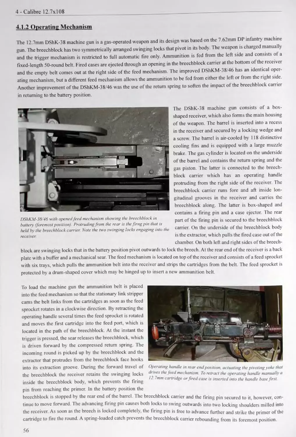
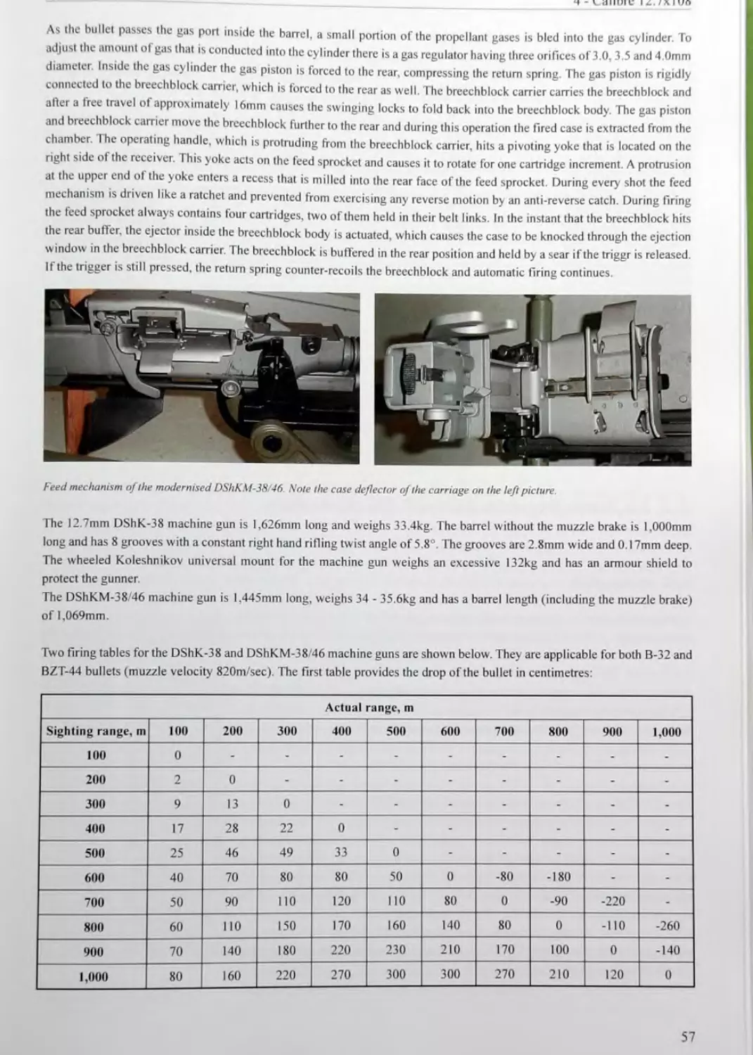
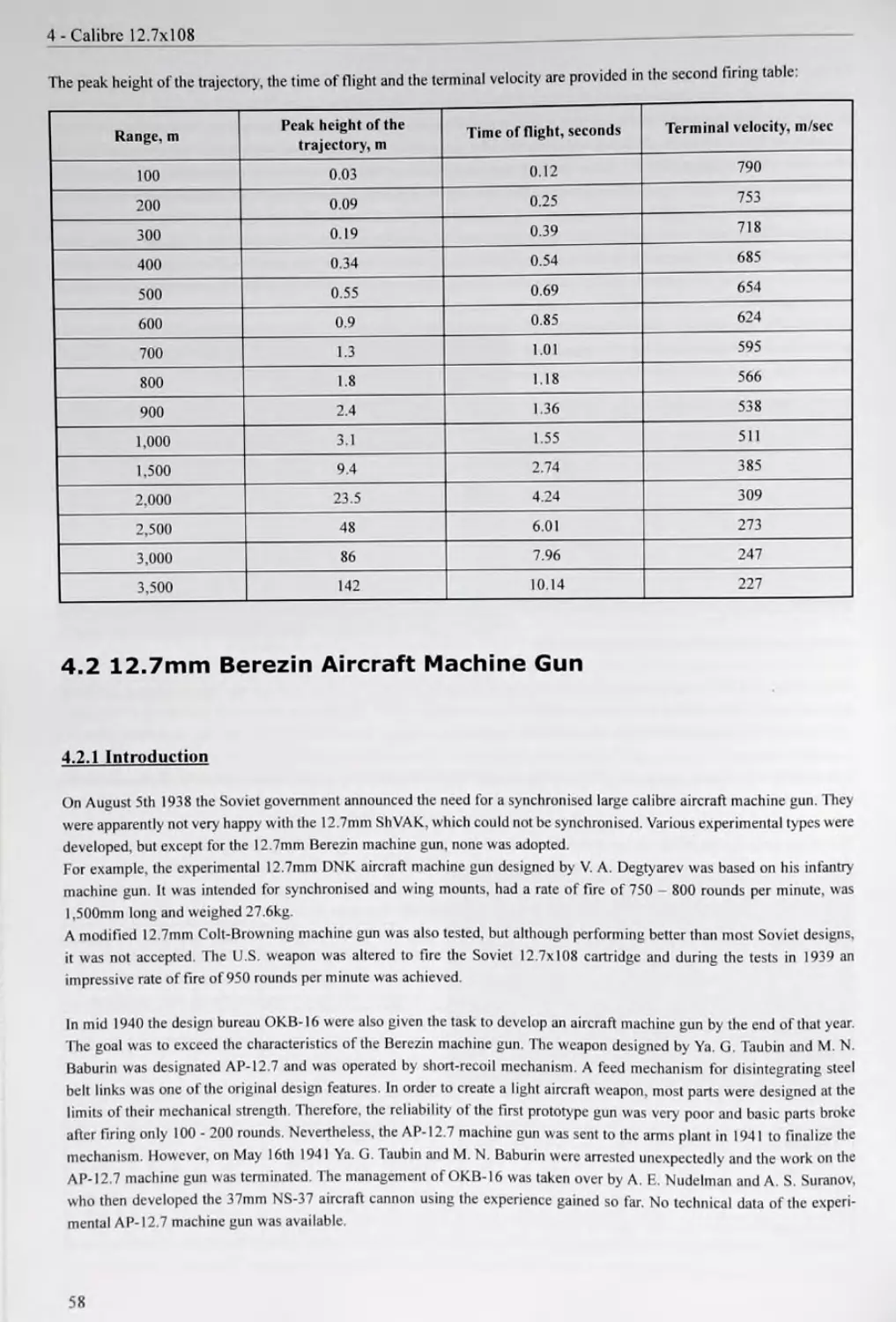
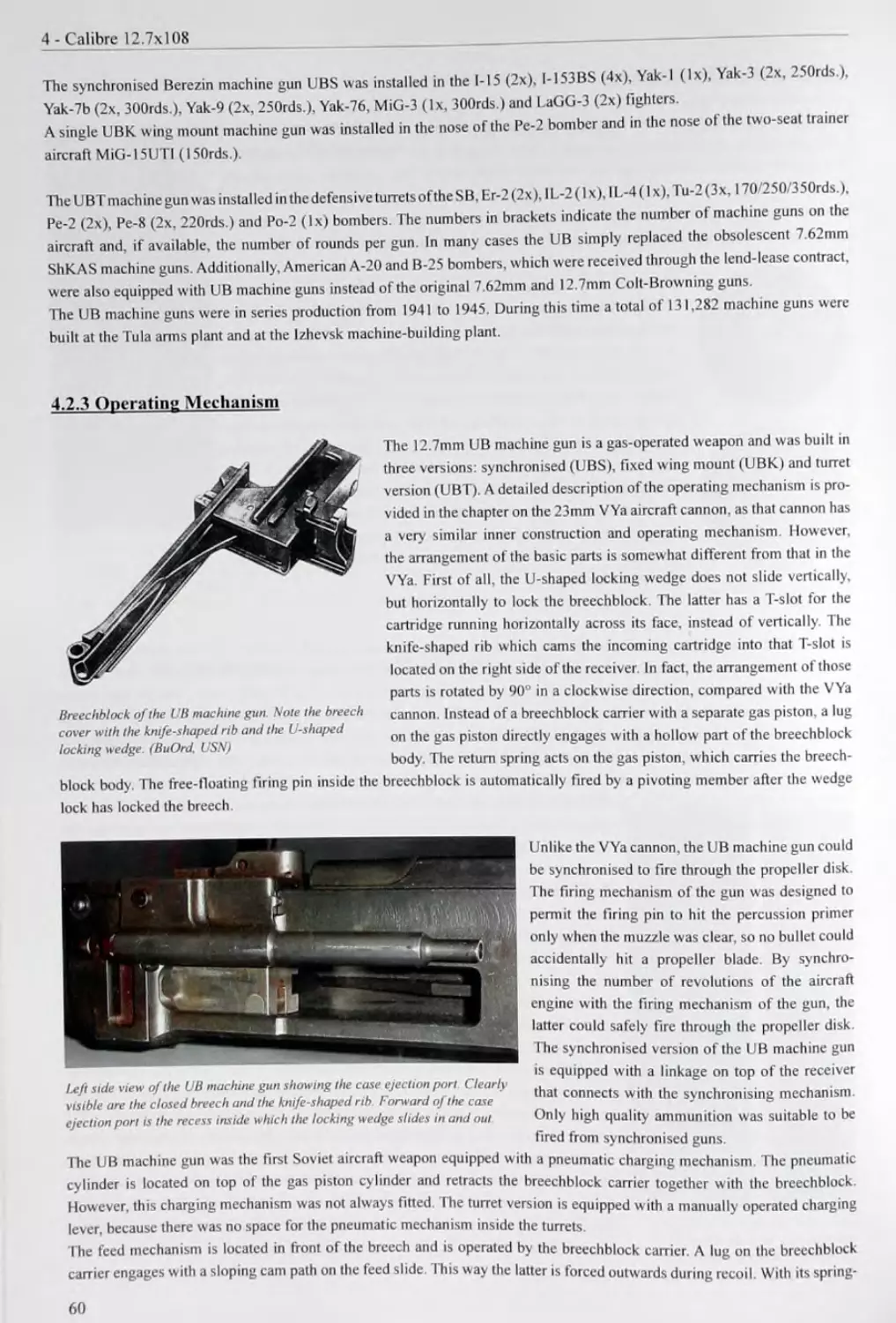


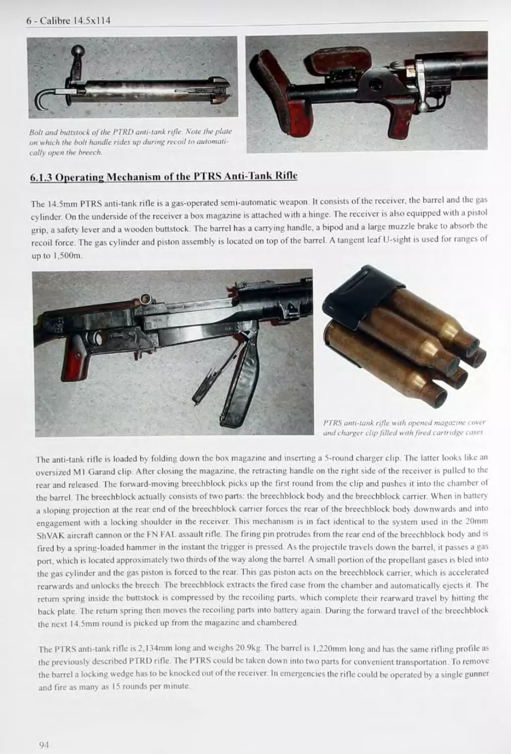
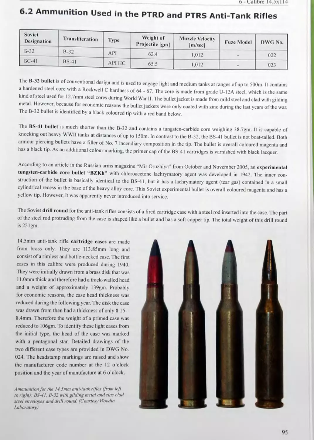
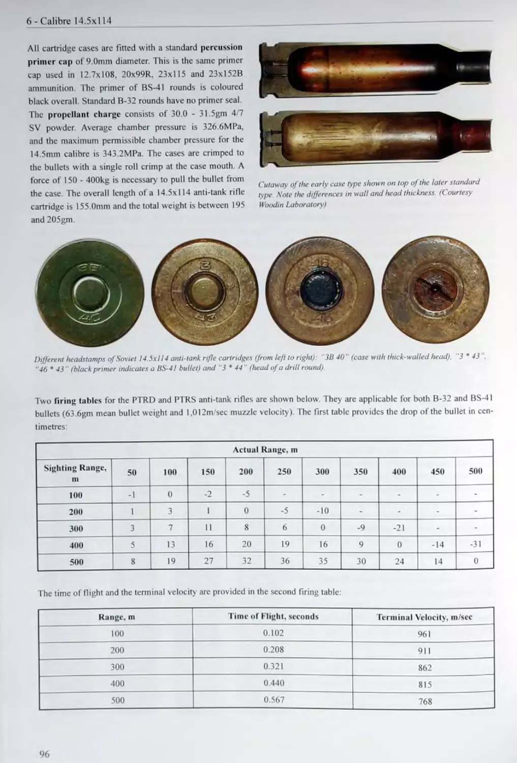
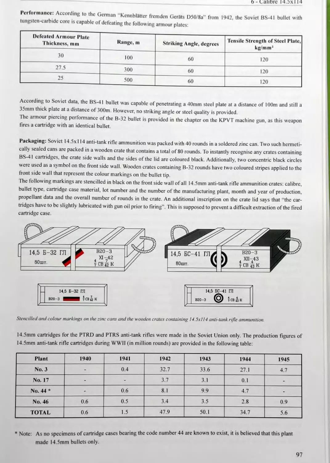

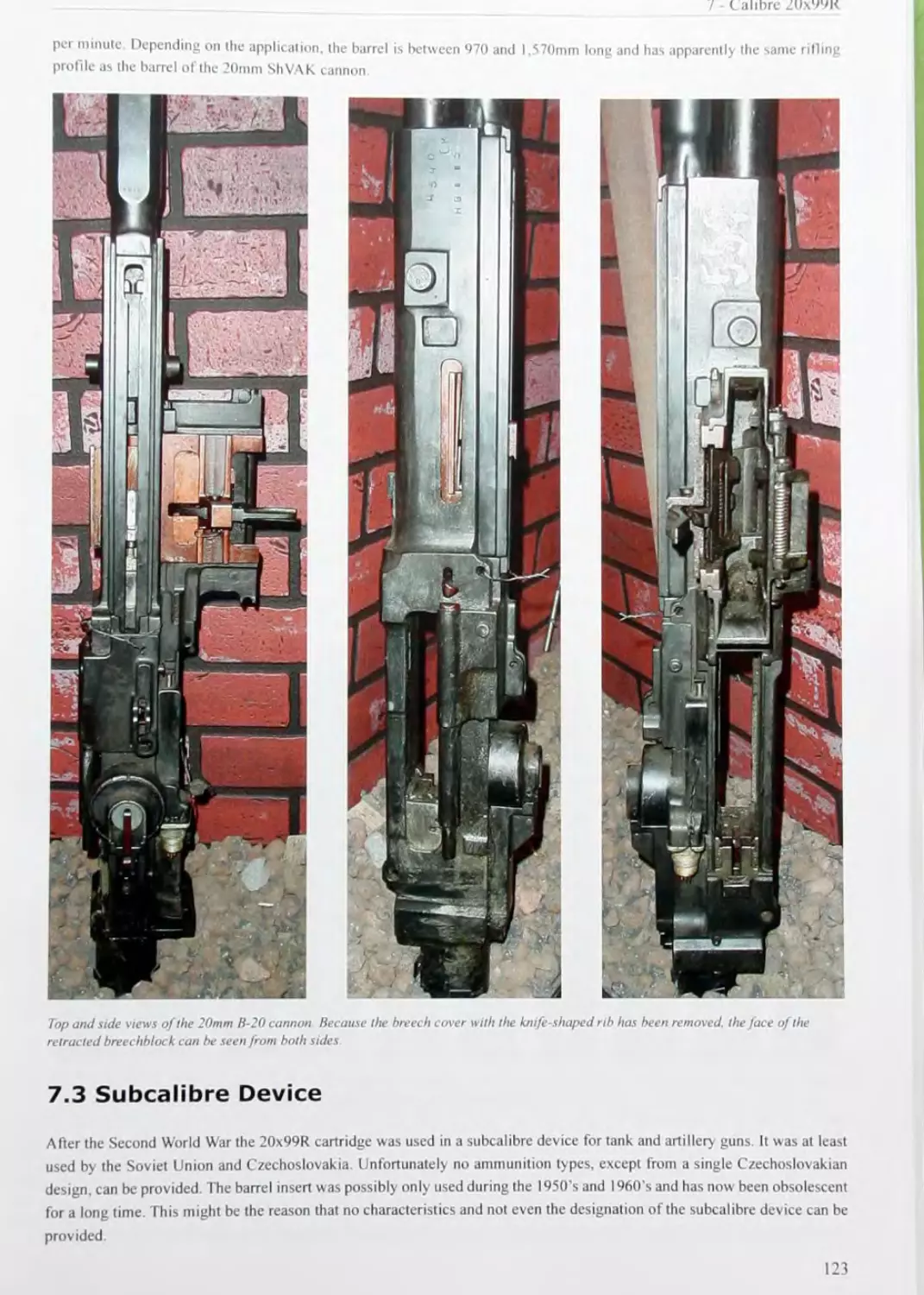
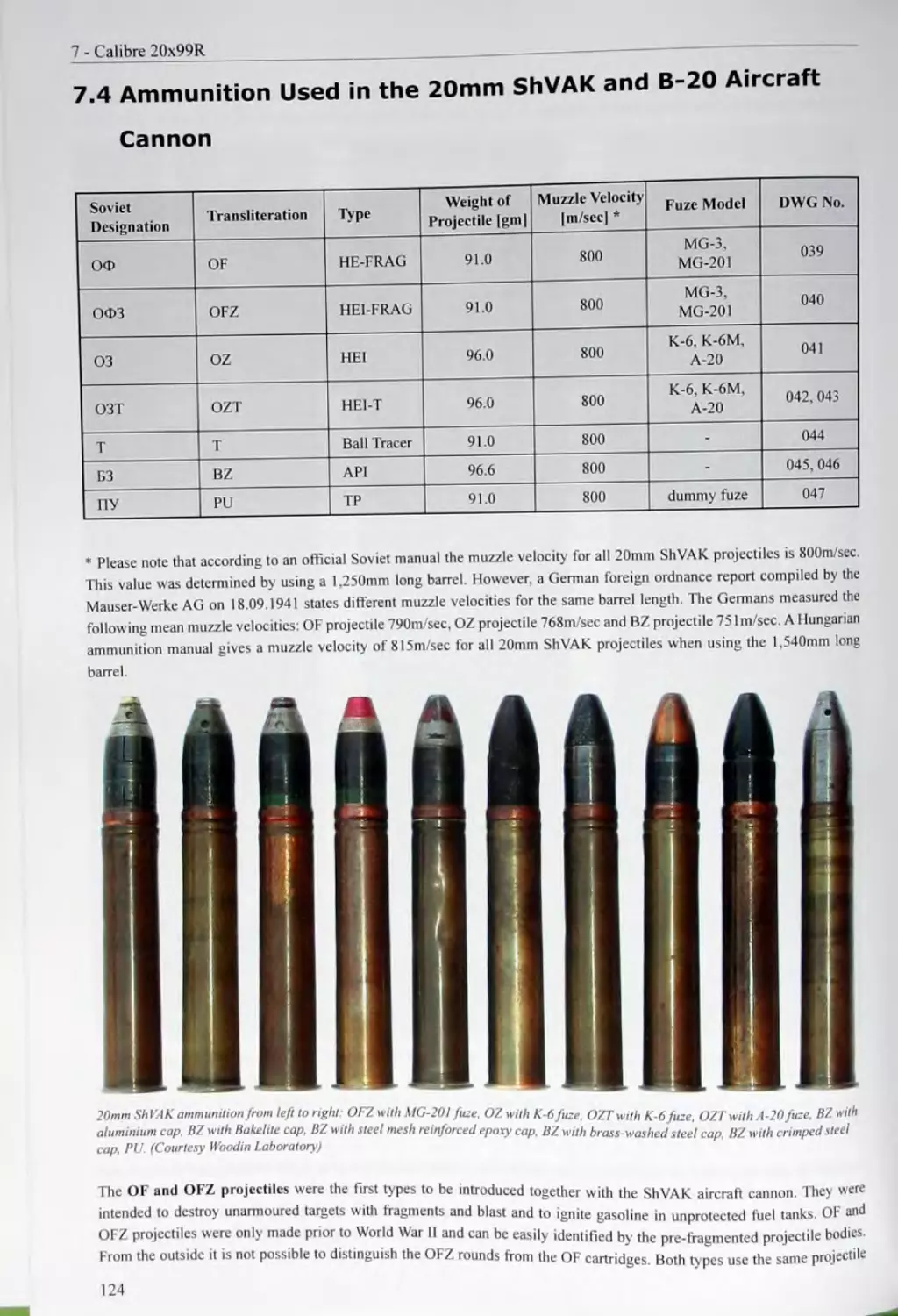
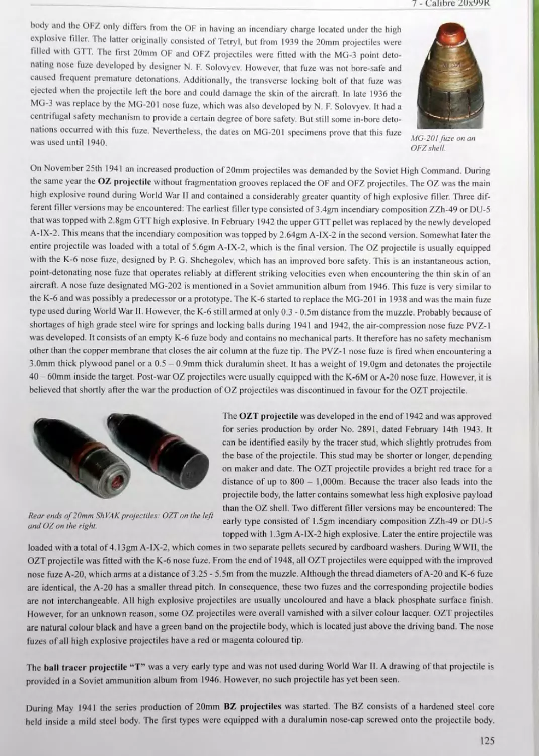
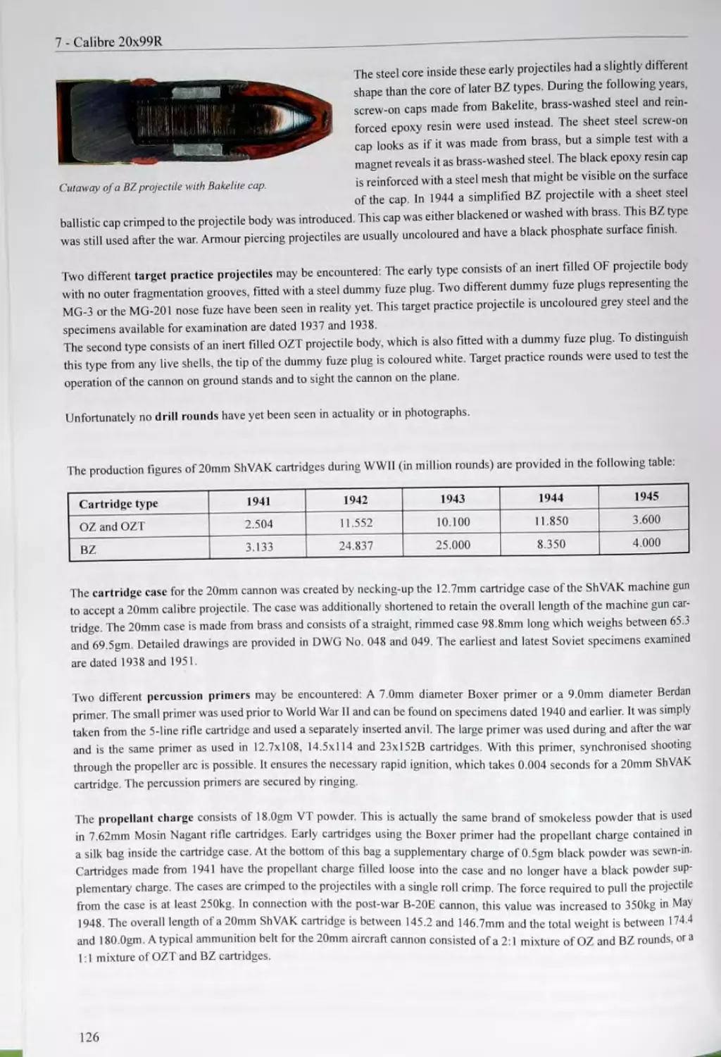
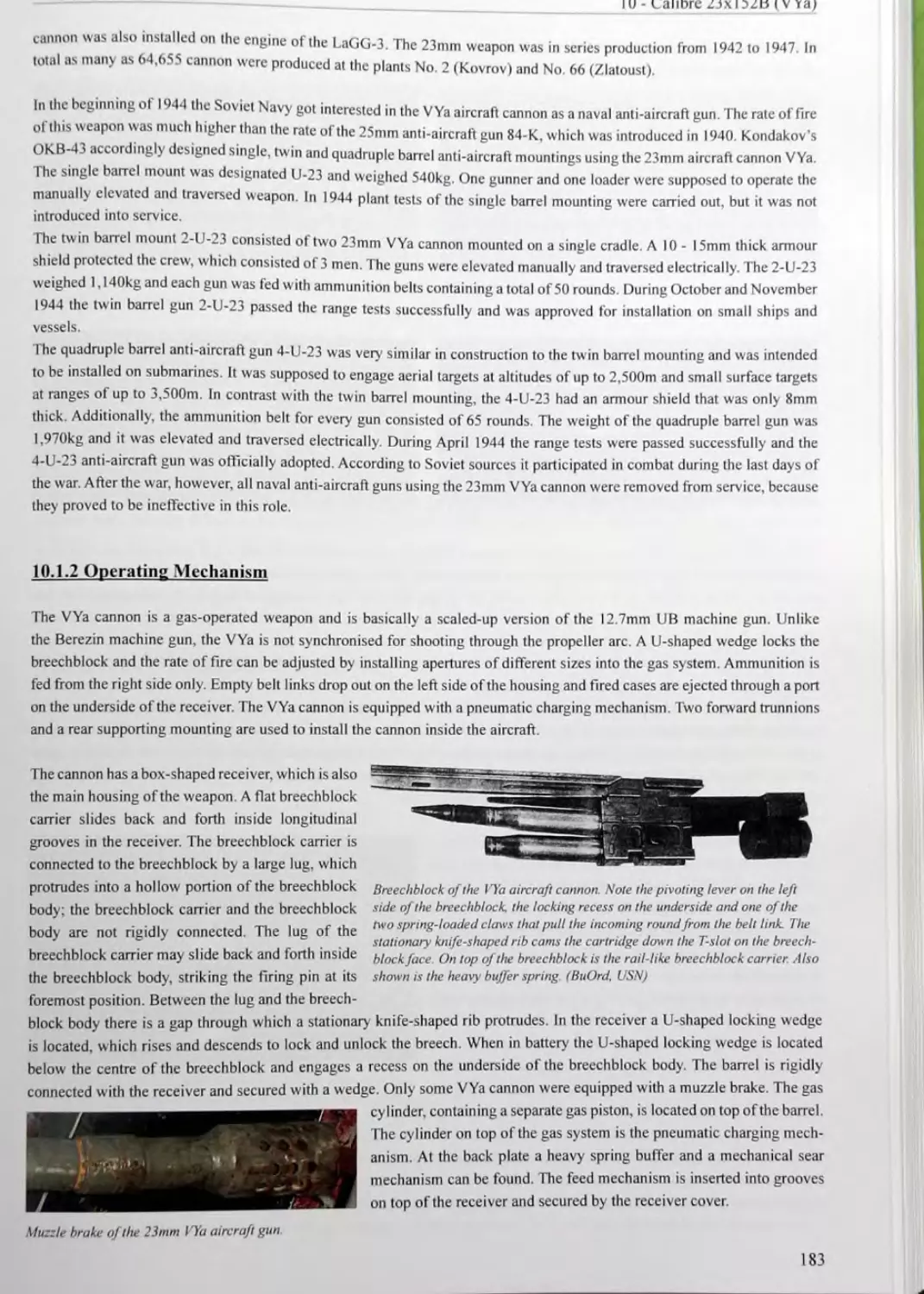
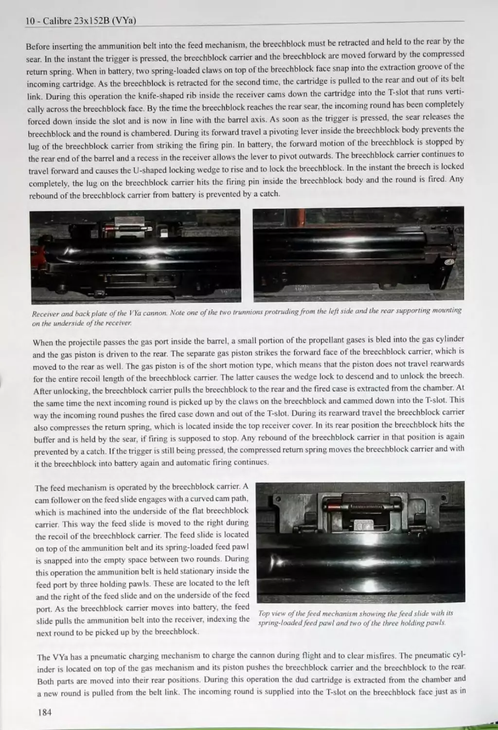
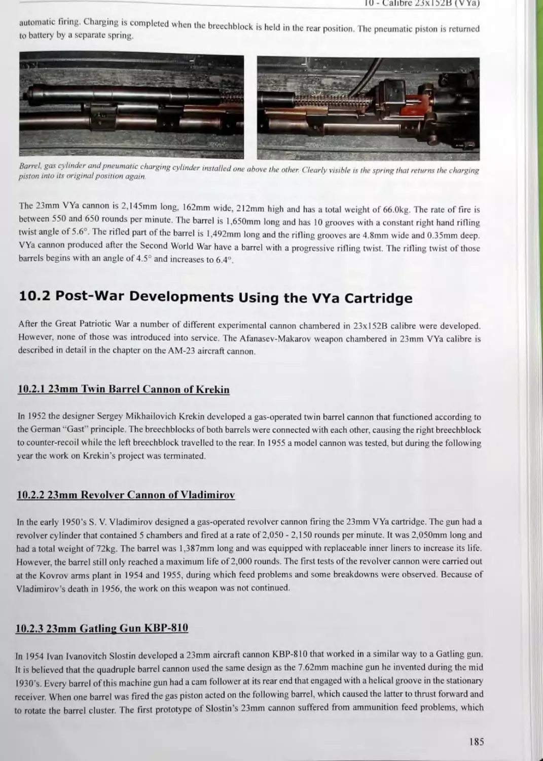
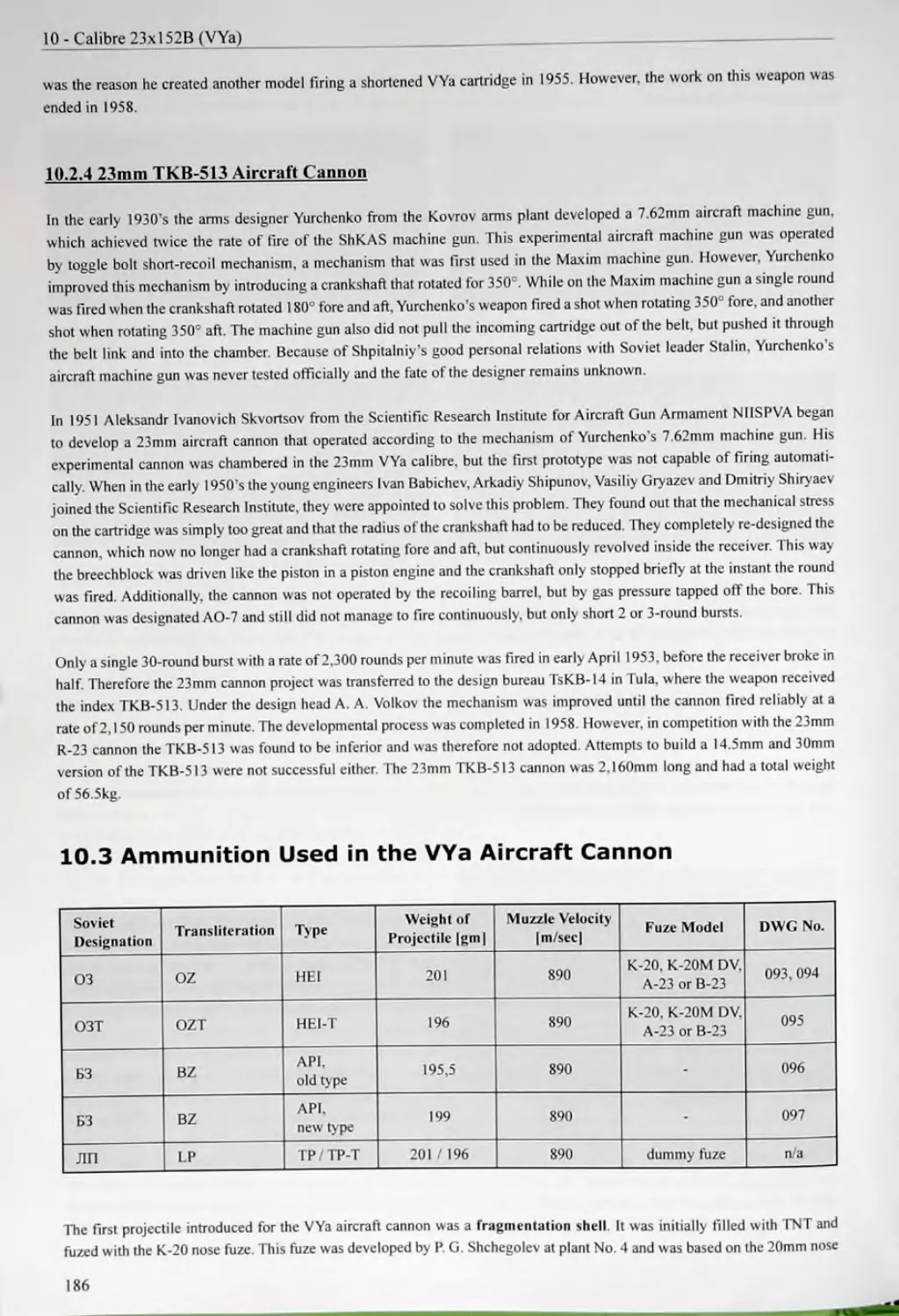


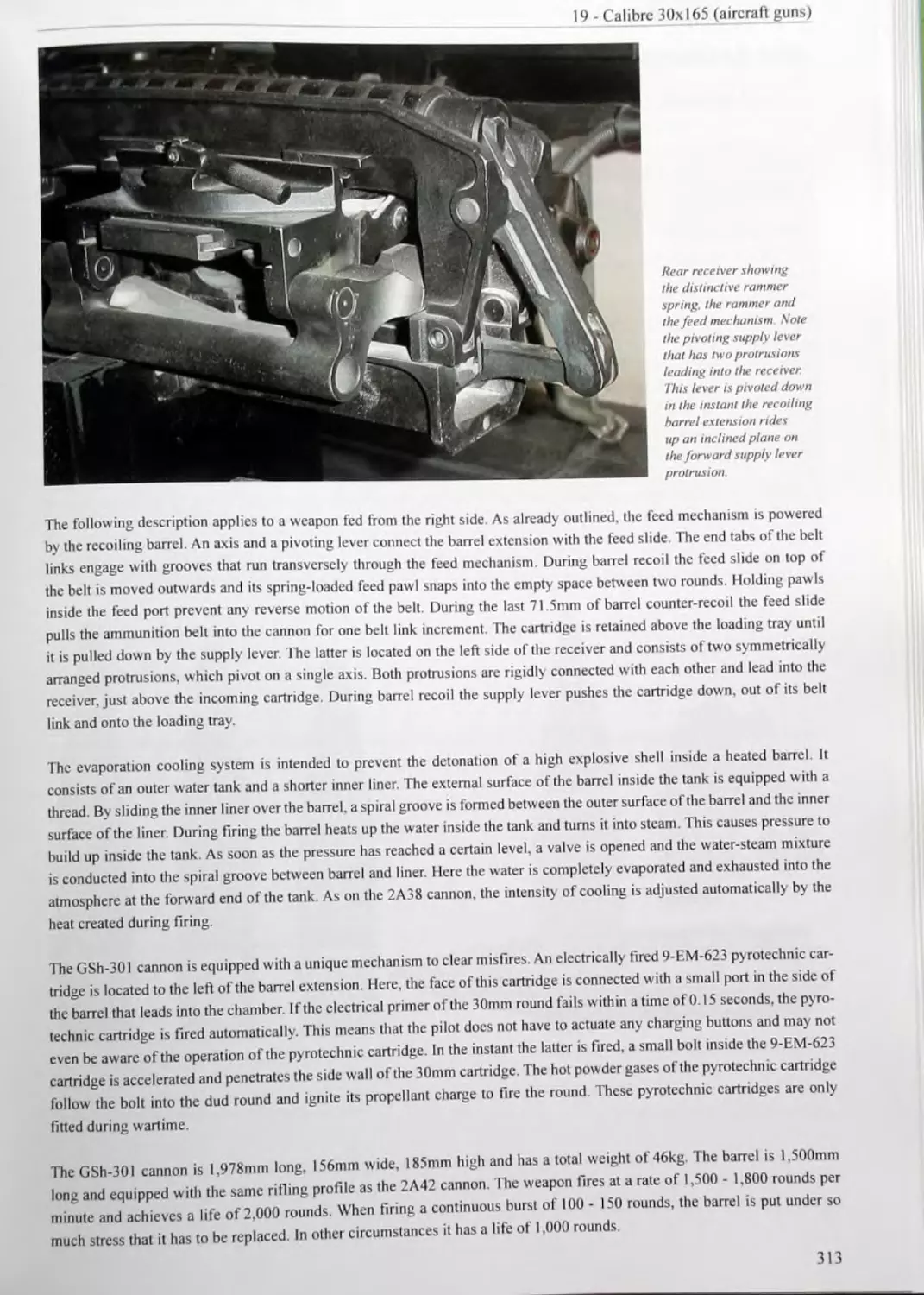
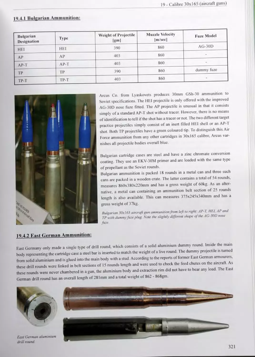

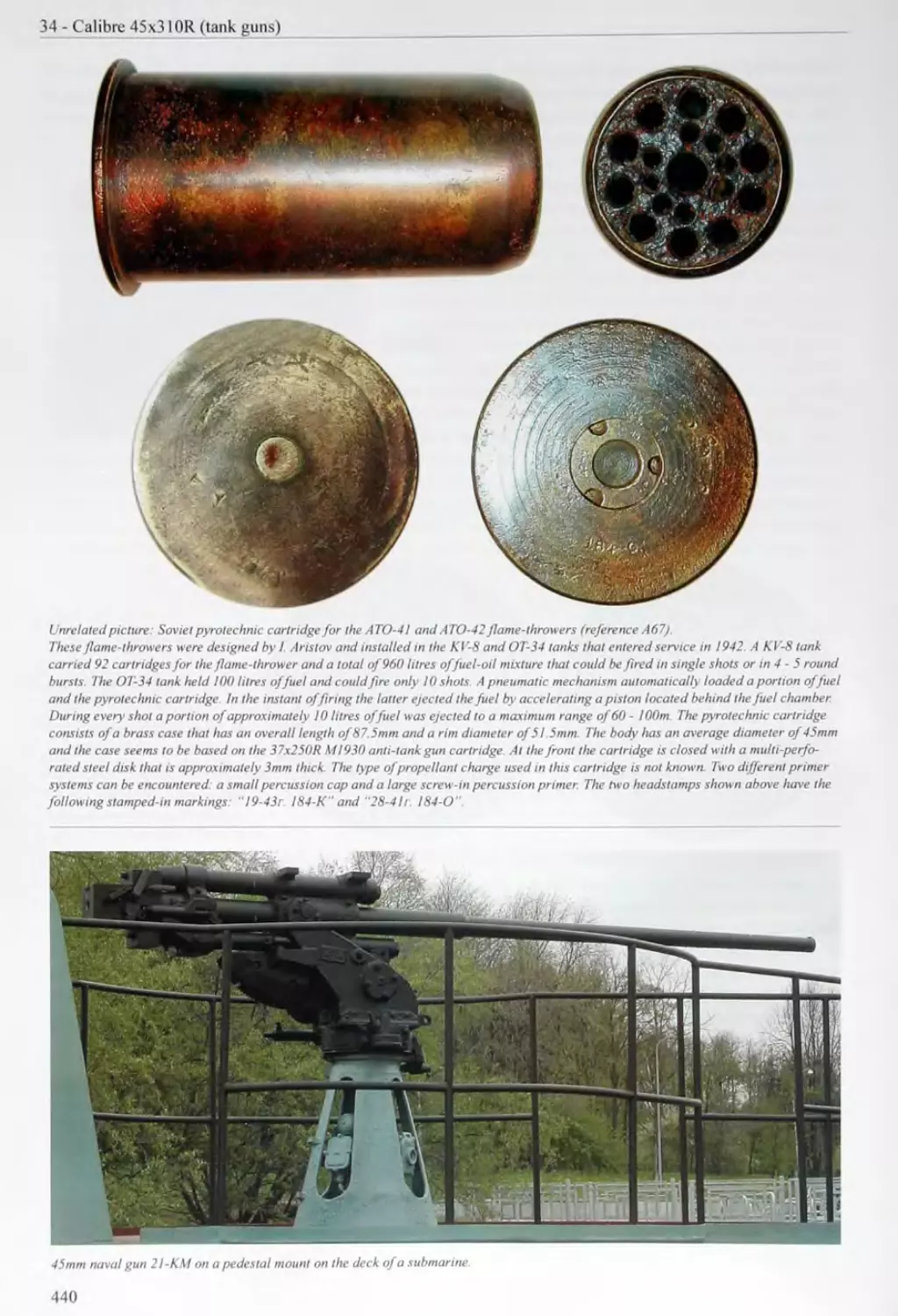
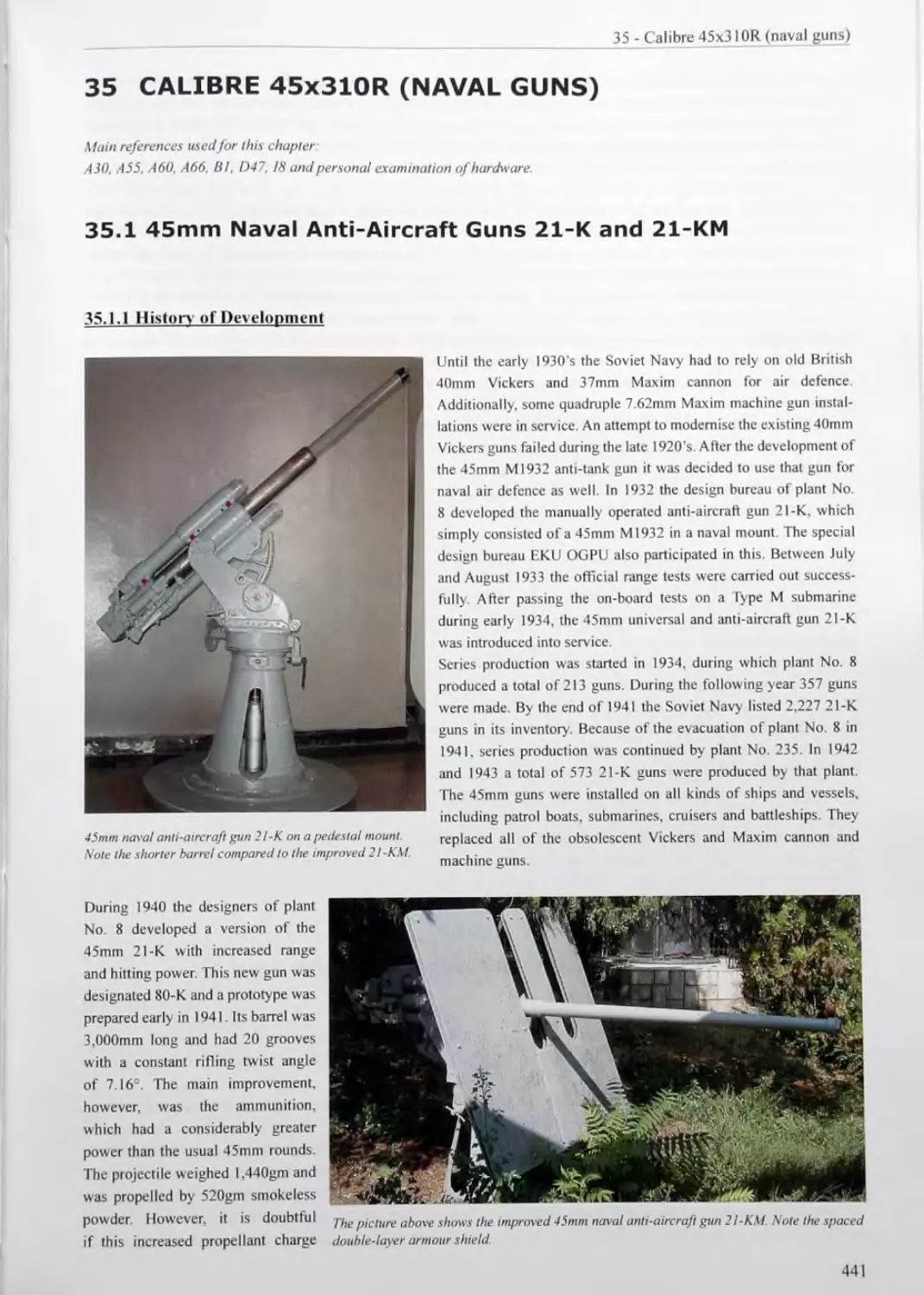
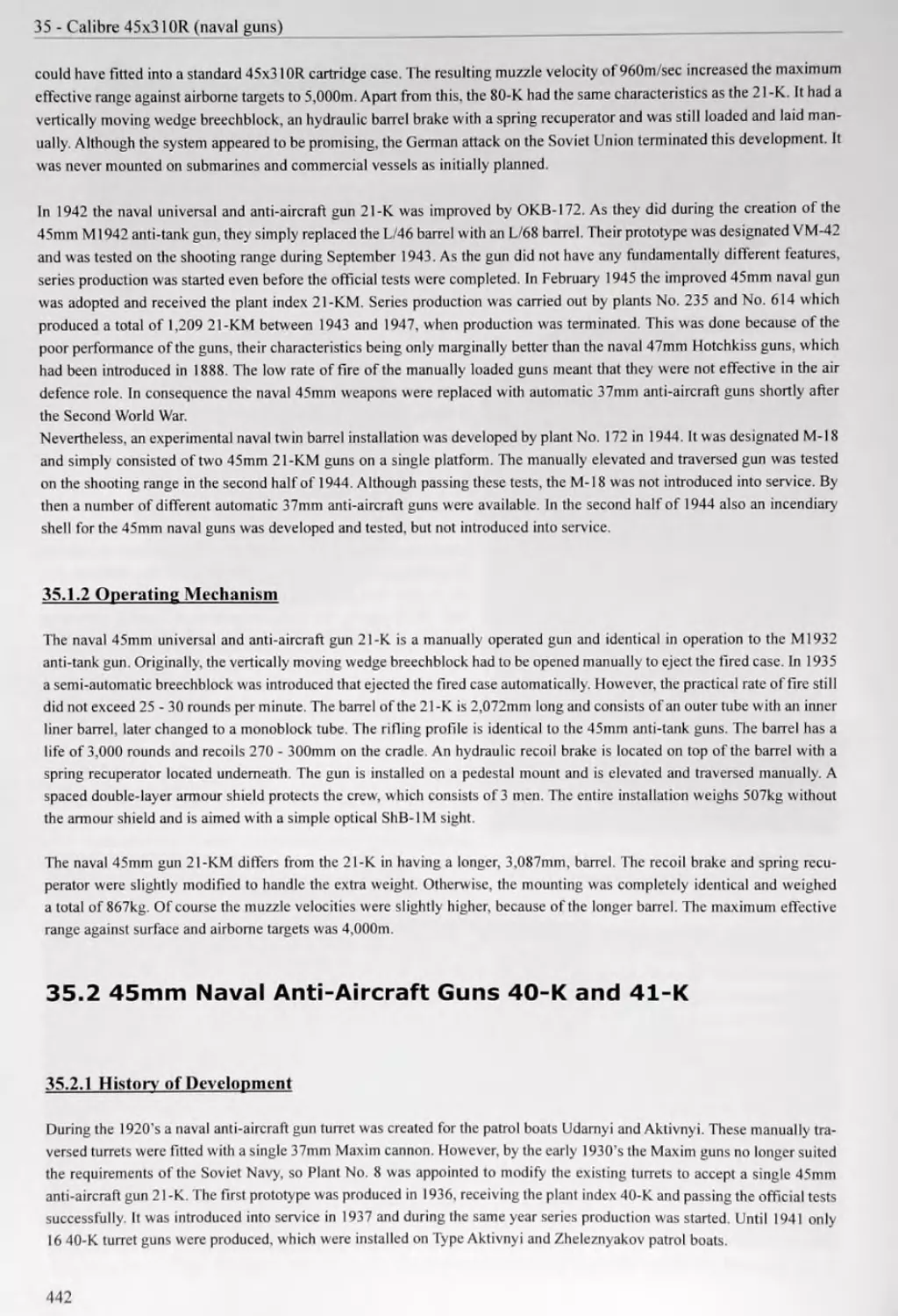
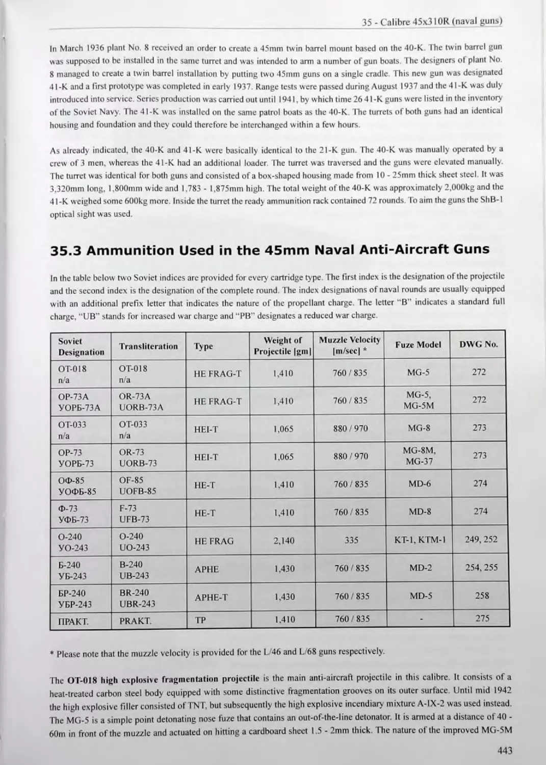


Text
Christian Roll
SOVIET CANNON
A COMPREHENSIVE STUDY OF SOVIET GUNS AND
AMMUNITION IN CALIBRES 12.7MM TO 57MM
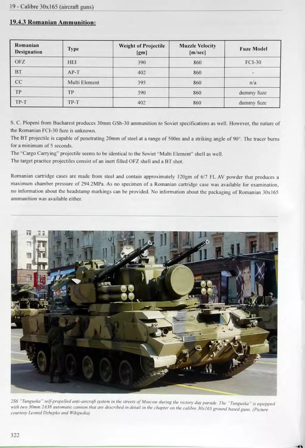
CONTENTS
I FOREWORD.........
II ACKNOWLEDGEMENTS...............................10
III INTRODUCTION.........................................
DISCLAIMER
THE CYRILLIC ALPHABET
SOVIET AMMUNITION DESIGNATIONSAND NOMENCLATURE
1.4 Abbreviated Ammunition Designations of the Warsaw Pact States.
2 SOVIET AMMUNITION MARKINGS.........................................31
2.1 Stamped-In Markings....................................................31
2.2 Colour Markings.................................... • -.......... 35
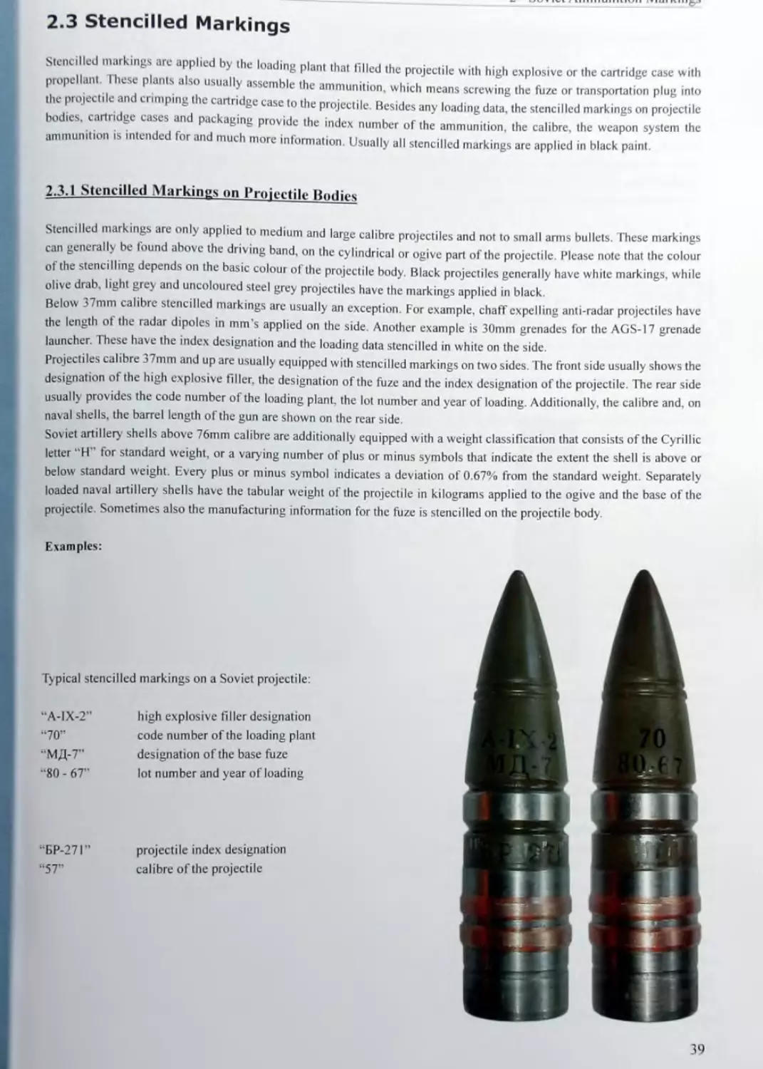
2.3 Stencilled Markings....................................................39
3 AMMUNITION CHEMISTRY..............................................................43
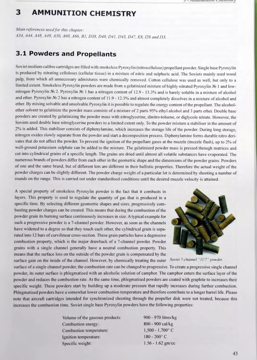
3.1 Powders and Propellants.....................................................43
3.2 High Explosives.............................................................46
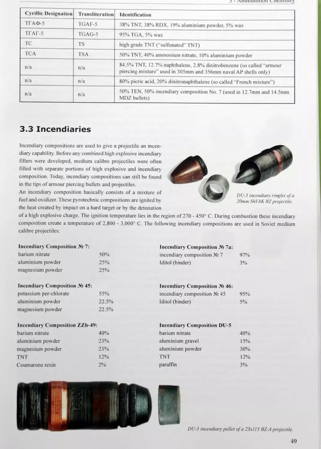
3.3 Incendiaries........................................................ -.....49
CALIBRE 12.7x10⁸
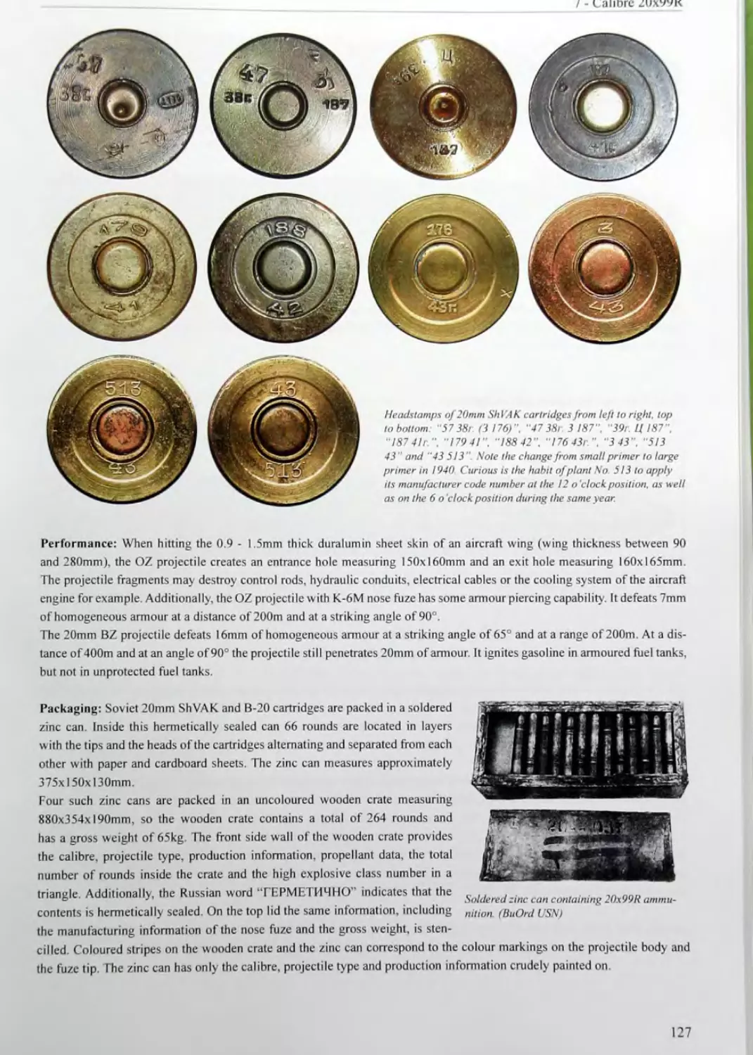
5 6 7 CALIBRE 12.7xlO8R 87 5.1 12.7mm ShVAK Aircraft Machine Gun 87 5.2 Ammunition used in the 12.7mm ShVAK Aircraft Machine Gun 88 CALIBRE 14.5x114 91 6.1 14.5mm PTRD and PTRS Anti-Tank Rifles 91 6.2 Ammunition Used in the PTRD and PTRS Anti-Tank Rifles 95 6.3 14.5mm KPV Machine Gun 98 6.4 14.5mm Subcalibre Devices 102 6.5 Miscellaneous 14.5mm Weapons 104 6.6 Ammunition Used in the KPV Machine Gun 104 CALIBRE 20x99R 117 7.1 20mm ShVAK Aircraft Cannon 117 7.2 20mm B-20 Aircraft Cannon 121 7.3 Subcalibre Device 123 7.4 Ammunition Used in the 20mm ShVAK and B-20 Aircraft Cannon 124
8 CALIBRE 23x115 (NS-23) 131 8.1 23mm NS-23 Aircraft Cannon 131 8.2 23mm NR-23 Aircraft Cannon 136 8.3 Ammunition Used in the NS-23 and NR-23 Aircraft Cannon 142 CALIBRE 23x115 (AM-23) 153 9.1 23mm AM-23 Aircraft Cannon 153 9.2 23mm GSh-23 Twin Barrel Aircraft Cannon 155 9.3 23mm GSh-6-23 Gatling Aircraft Cannon 162 9.4 Ammunition Used in the AM-23. GSh-23 and GSh-6-23 Aircraft Cannon 166
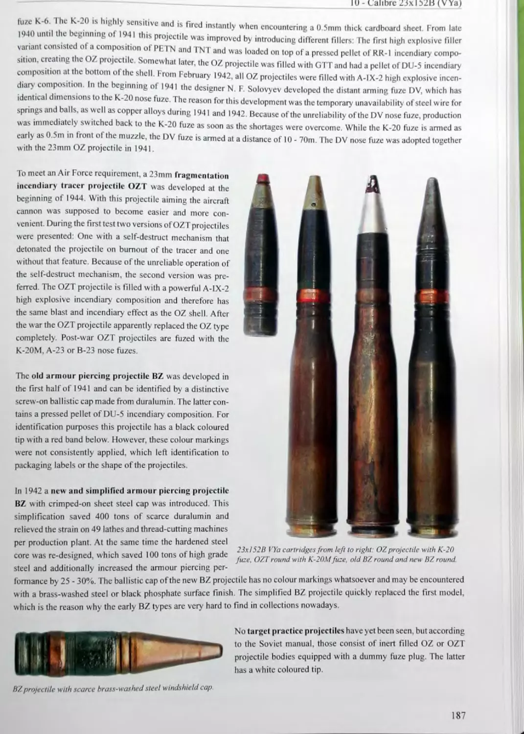
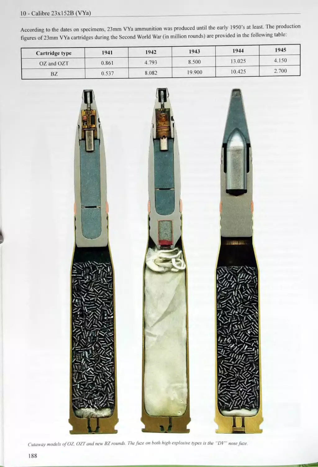
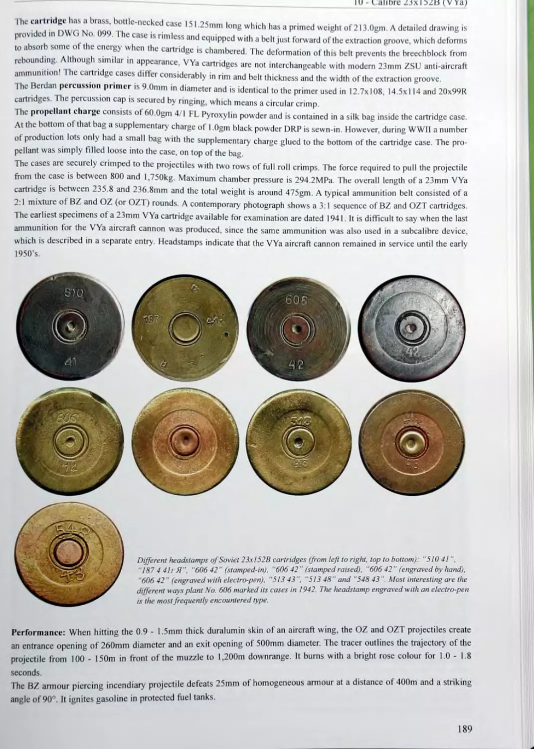
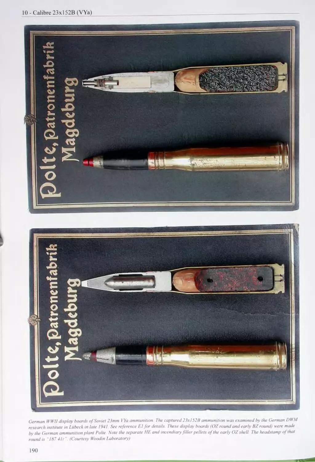
10 CALIBRE 23x152В (VYa) 181 10.1 23mm VYa Aircraft Cannon 181 10.2 Post-War Developments Using the VYa Cartridge 185 10.3 Ammunition Used in the VYa Aircraft Cannon 186 10.4 23mm Subcalibre Devices 191 10.5 Ammunition Used in the 23mm Subcalibre Devices 193
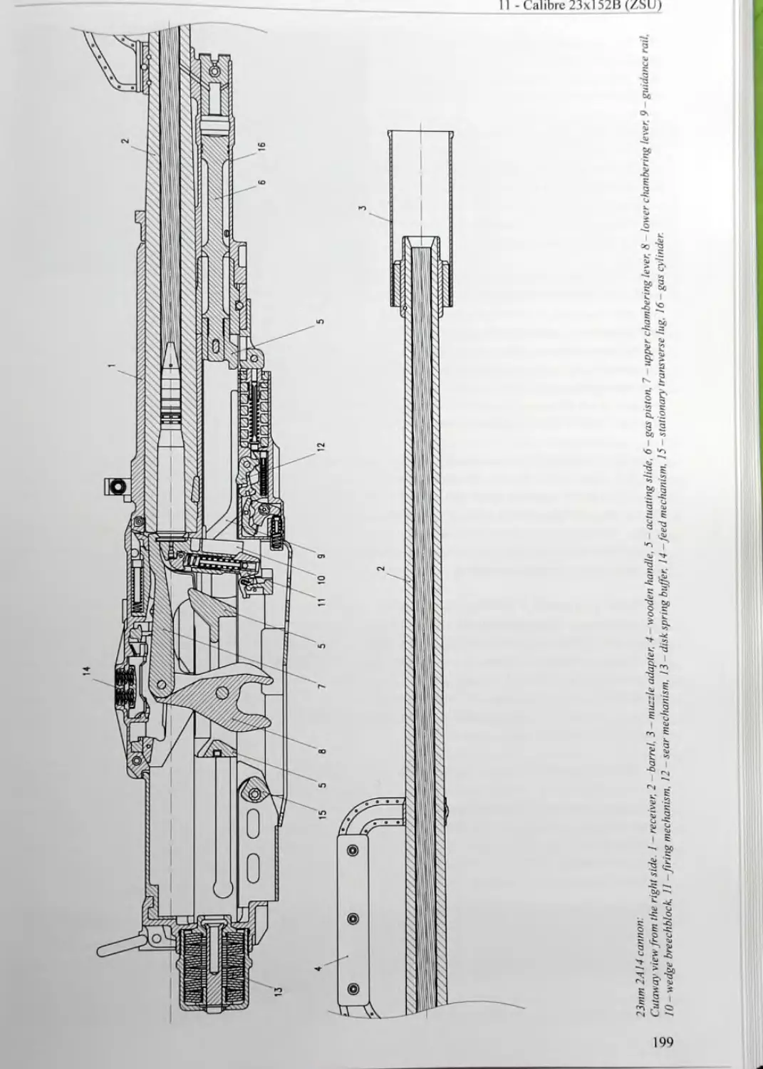
И CALIBRE 23xl52B (ZSU) 195 11.1 23mm ZU-23 Anti-Aircraft Gun 195 11.2 23mm ZSU-23-4 Self-Propelled Anti-Aircraft Gun 196 11.3 Ammunition Used in the 2A14 (ZU-23) and 2A7 (ZSU-23^1) Anti-Aircraft Guns 201
12 CALIBRE 23x260................................................................ 211
12.1 23mm R-23 Aircraft Cannon.............................................211
12.2 Ammunition Used in the R-23 Aircraft Cannon...........................218
13 CALIBRE 25x218SR..............................................................221
13.1 25mmAnti-AirctaftGunM1940..............................................221
13.3 Naval 25mm Anti-Aircraft Gun 84-KM..............................................................222
13.4 Ammunition Used in the 25mm Anti-Aircraft Guns 72-K, 94-KM and 84-KM............................222
14 CALIBRE 25x218........................................................................... 227
14.1 25mm Naval Anti-Aircraft Gun 2M-3..............................................227
14.2 25mm Naval Anti-Aircraft Gun 2M-3M.............................................231
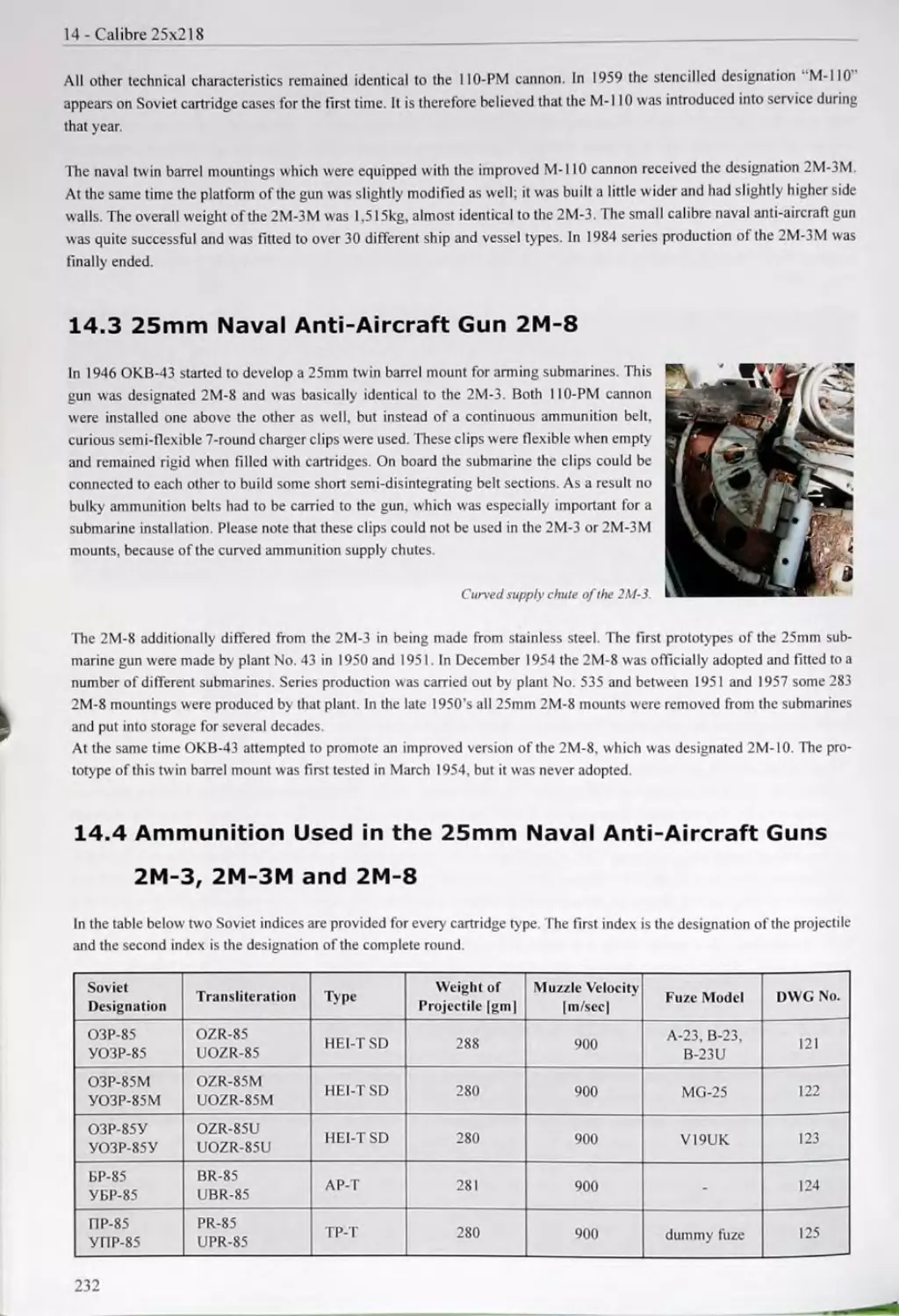
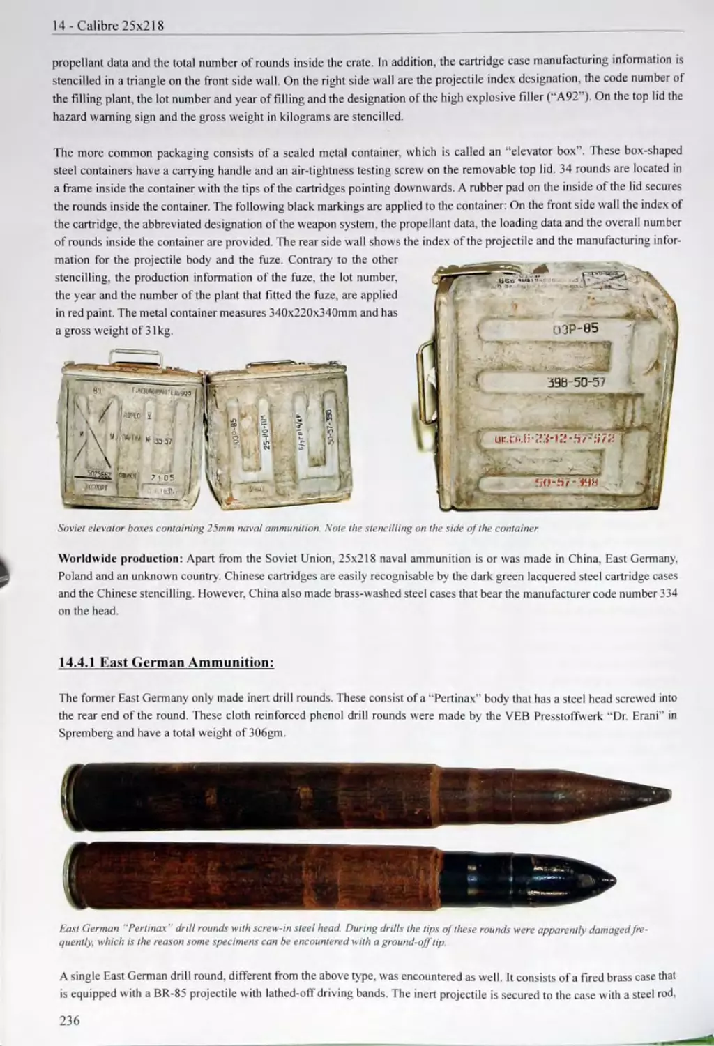
14.4 Ammunition Used in the 25mm Naval Anti-Aircraft Guns 2M-3.2M-3M and 2M-8.......................232
15 CALIBRE 30x28B.........................................239
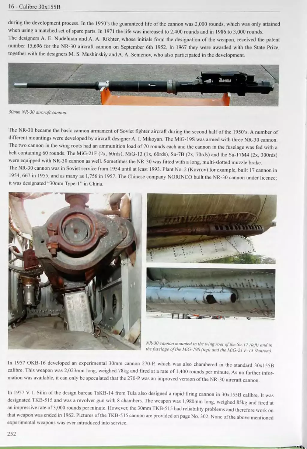
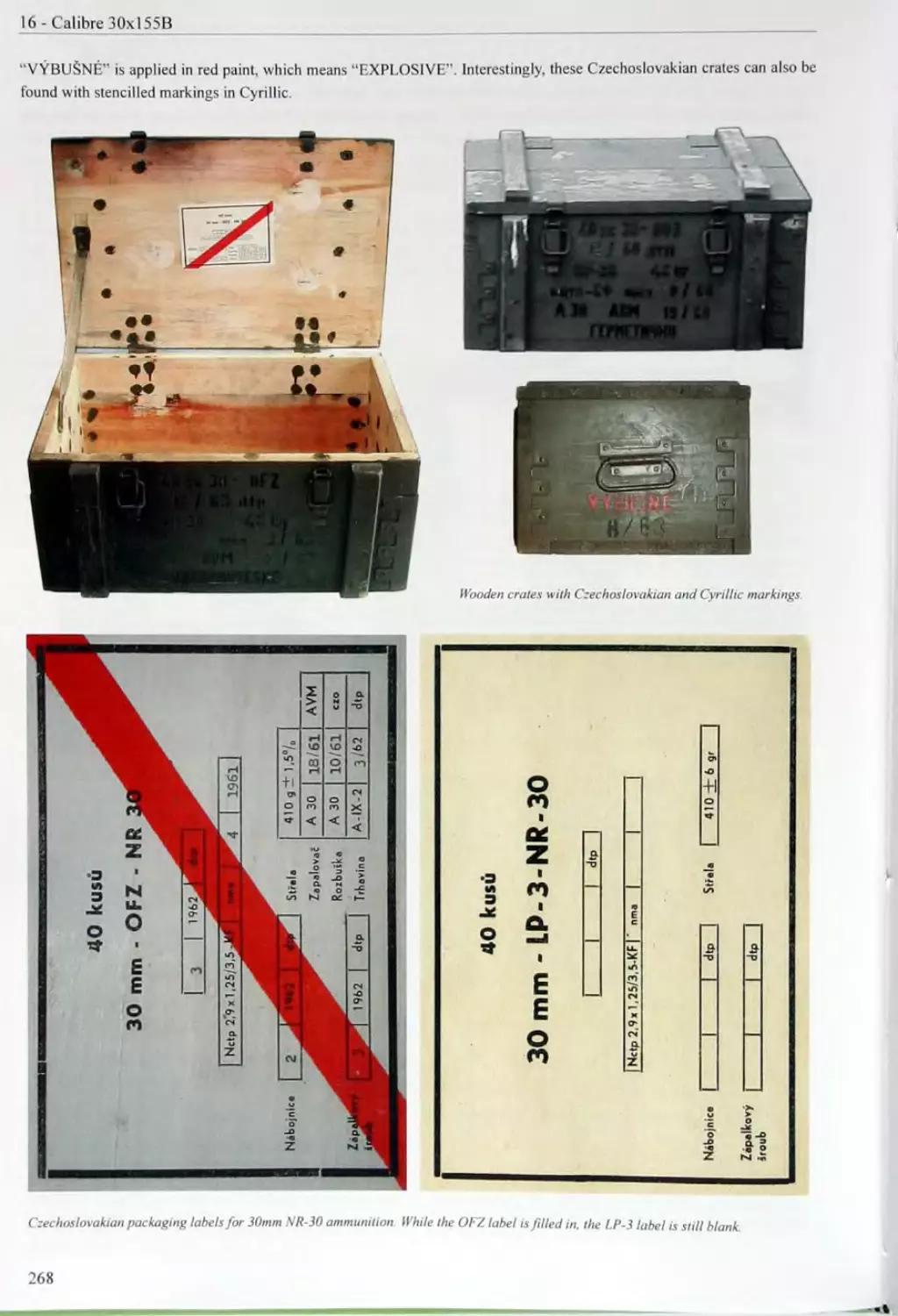
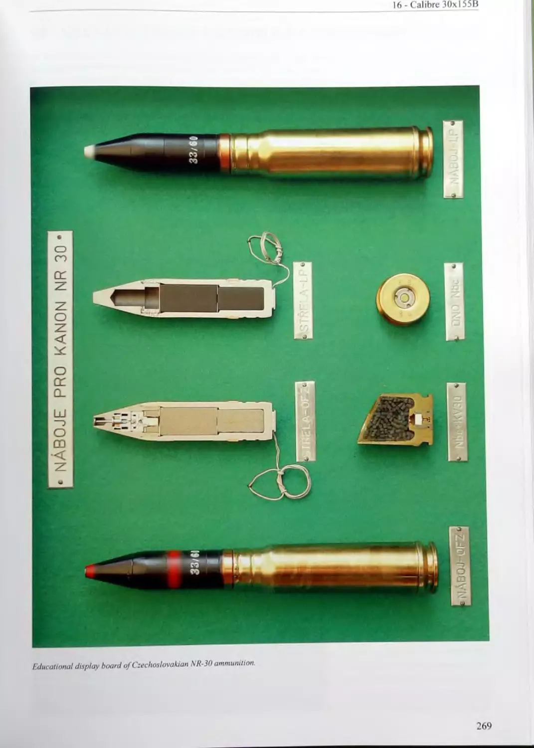
16 CALIBRE 30xl55B.......................................251
16.1 30mm NR-30 Aircraft Cannon......................................................................... 251
16.2 Ammunition Used in the NR-30 Aircraft Cannon
256
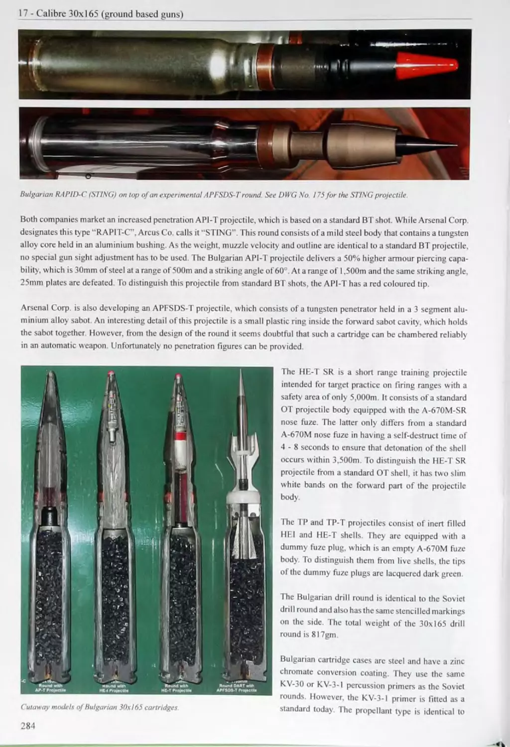
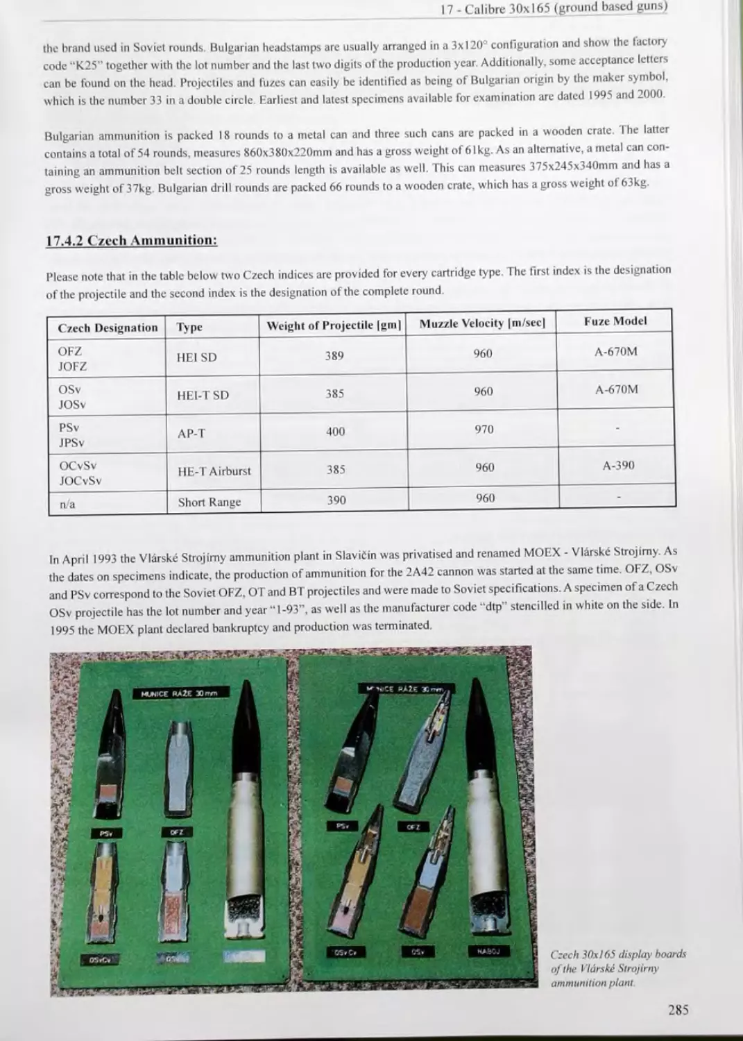
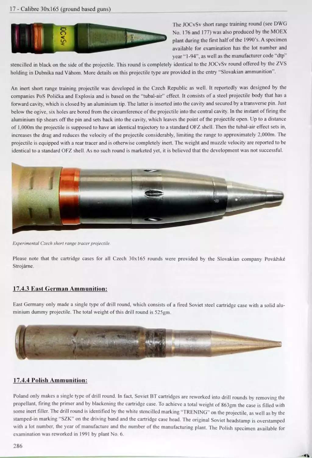
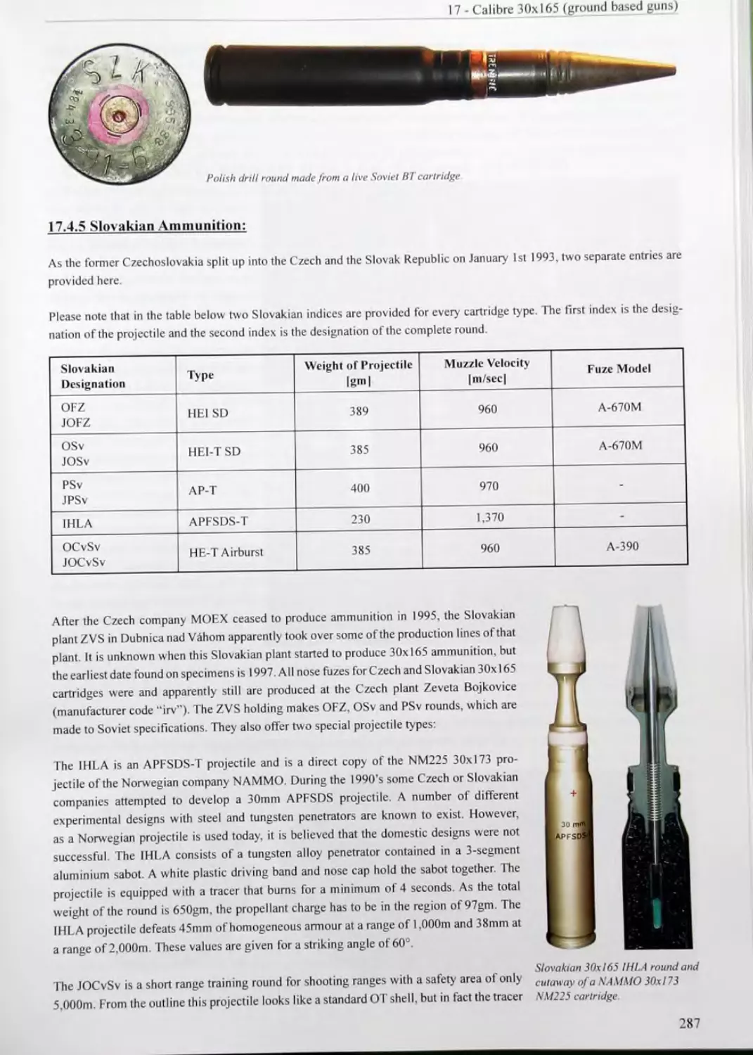
17 CALIBRE 30x165 (GROUND BASED GUNS).....................271
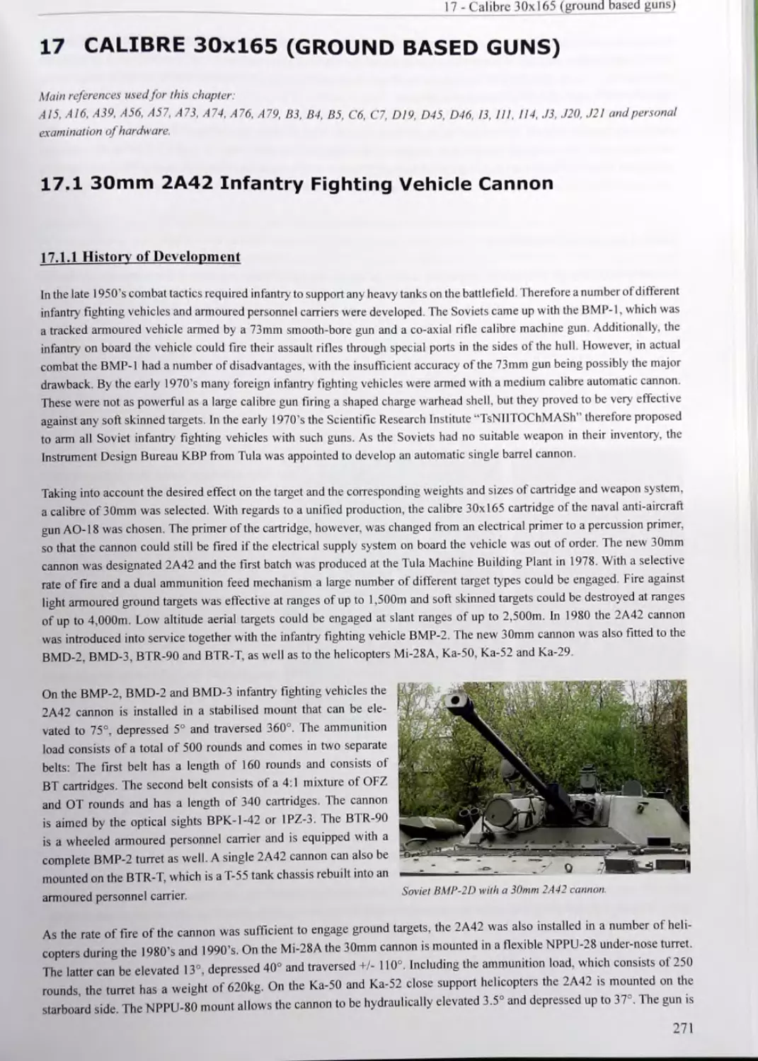
17.1 30mm 2A42 Infantry Fighting Vehicle Cannon.
17.2 30mm 2A72 Infantry Fighting Vehicle Cannon.
271
17,4 Ammunition Used in the 2A42,2A72 and 2 A38 Cannon.............................278
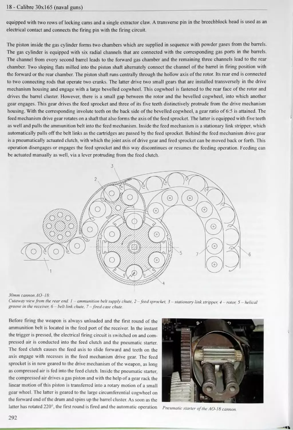
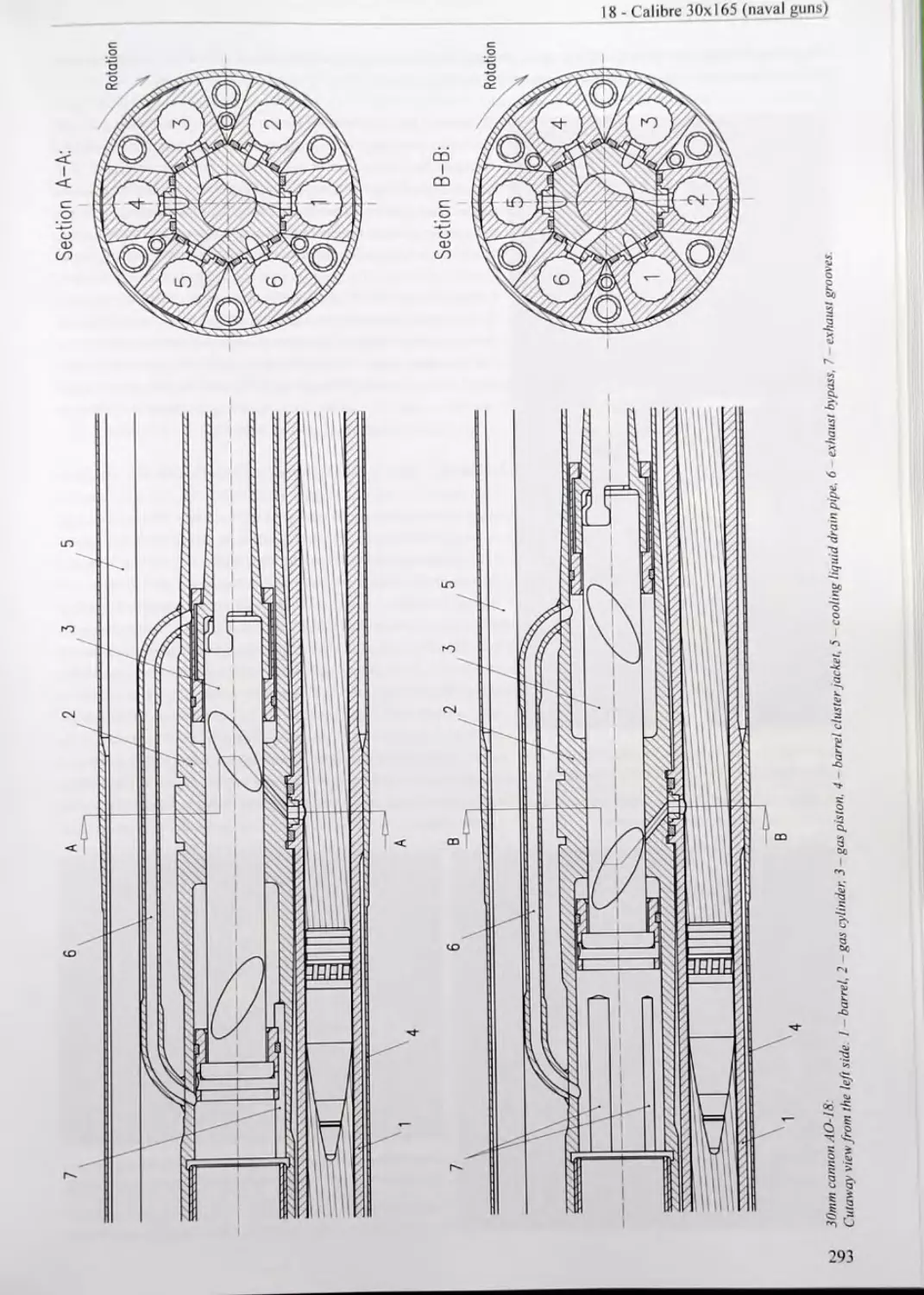
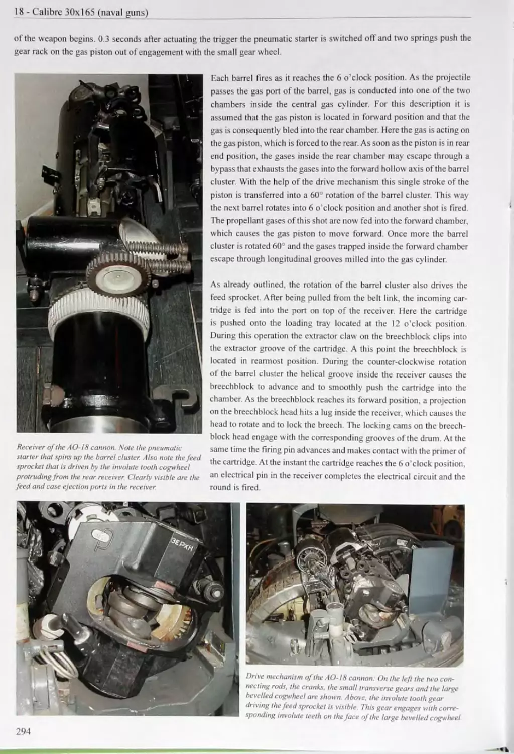
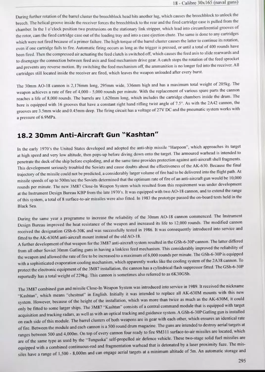
18 CALIBRE 30x165 (NAVAL GUNS)....................................................................289
18.1 30mm Anti-Aircraft Guns AK-630 and AK-630M............................................289
18.2 30mm Anti-Aircraft Gun “Kashtan”. .................................................. 295
18.3 30mm Anti-Aircraft Gun AK-306 ...................................................... 296
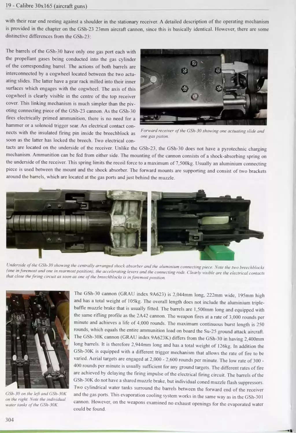
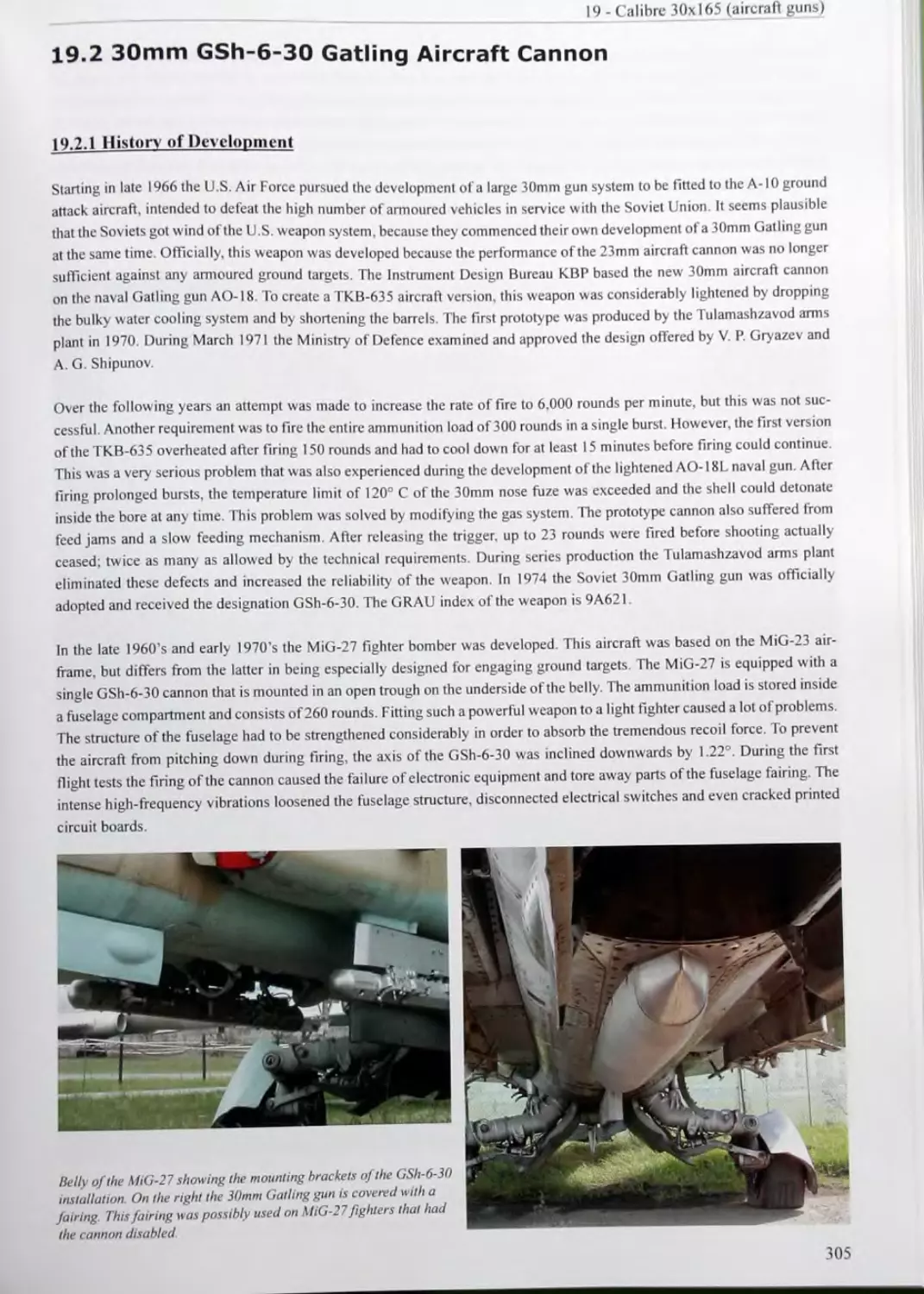
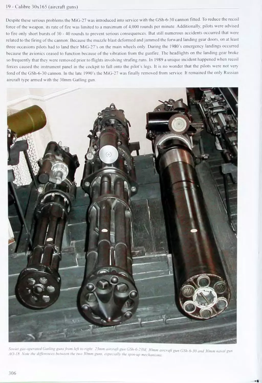
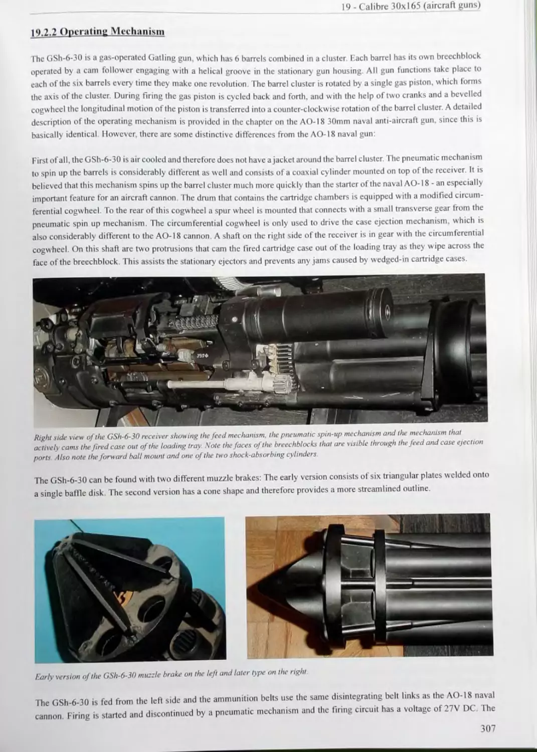
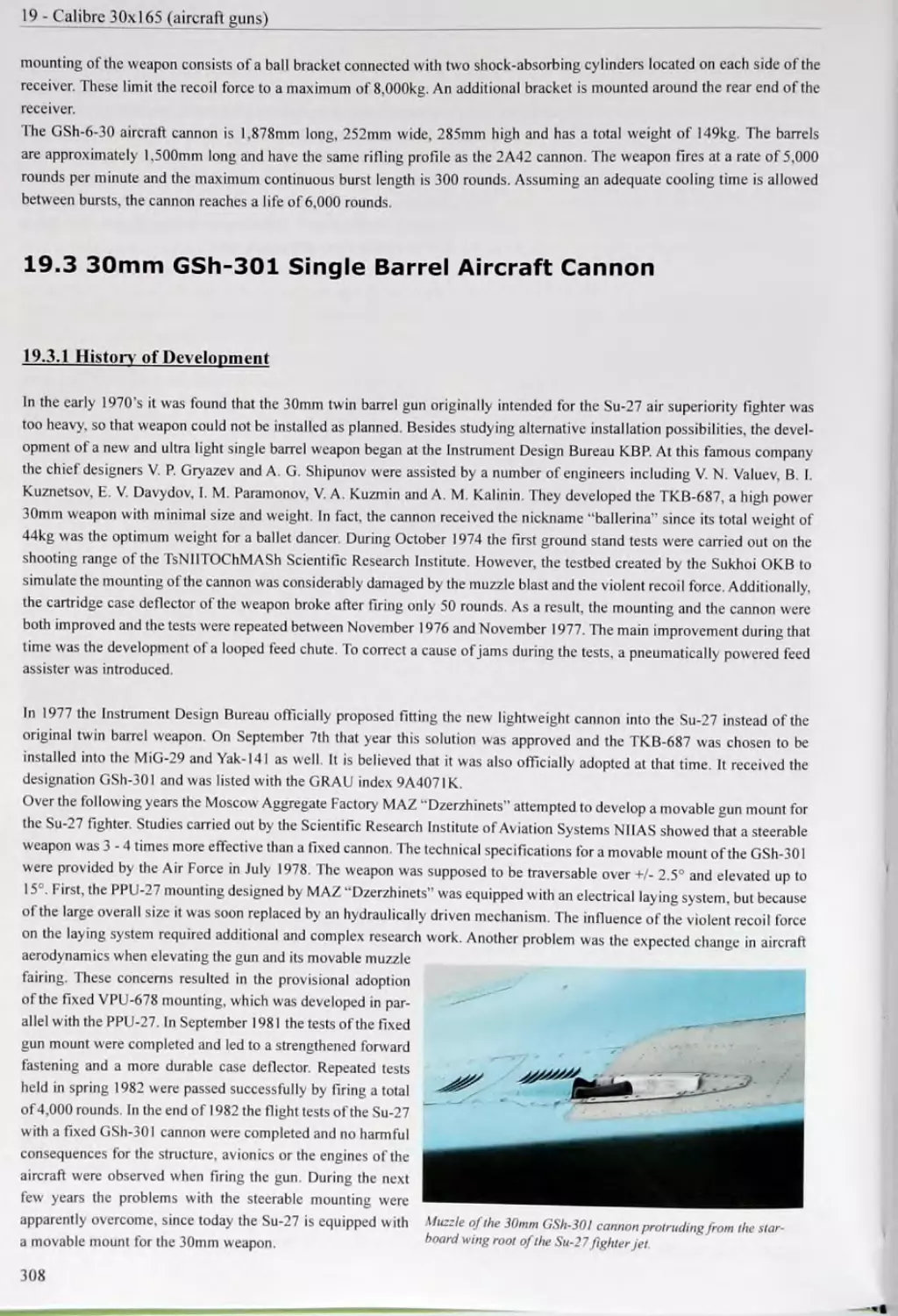
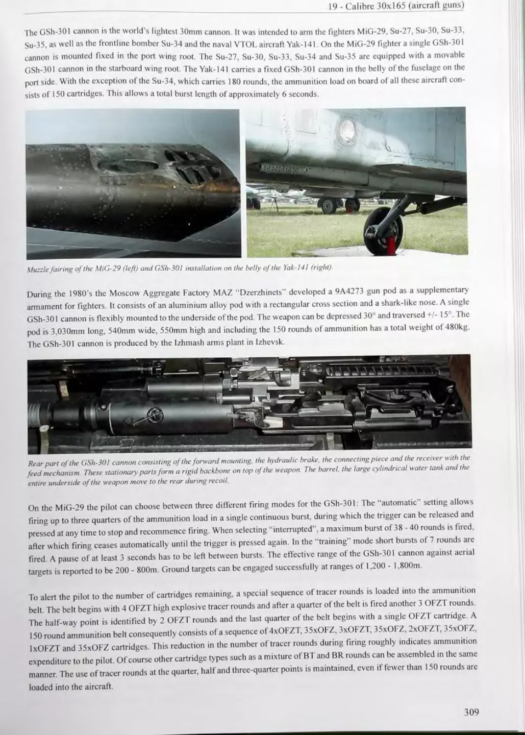
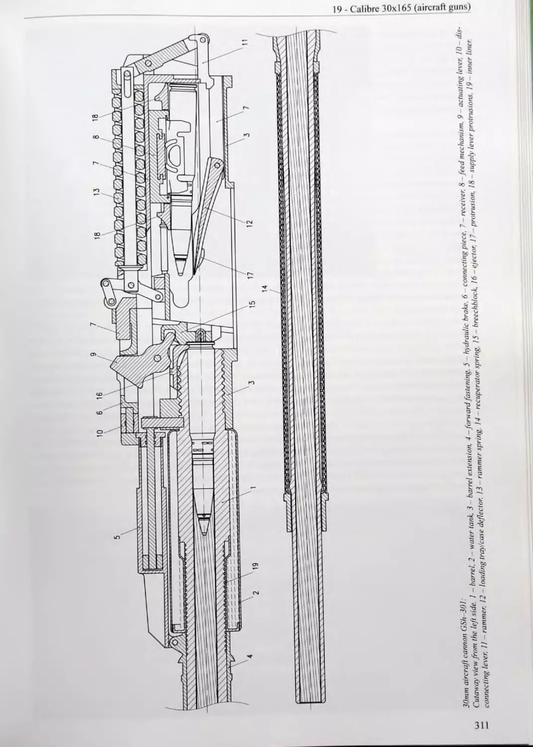
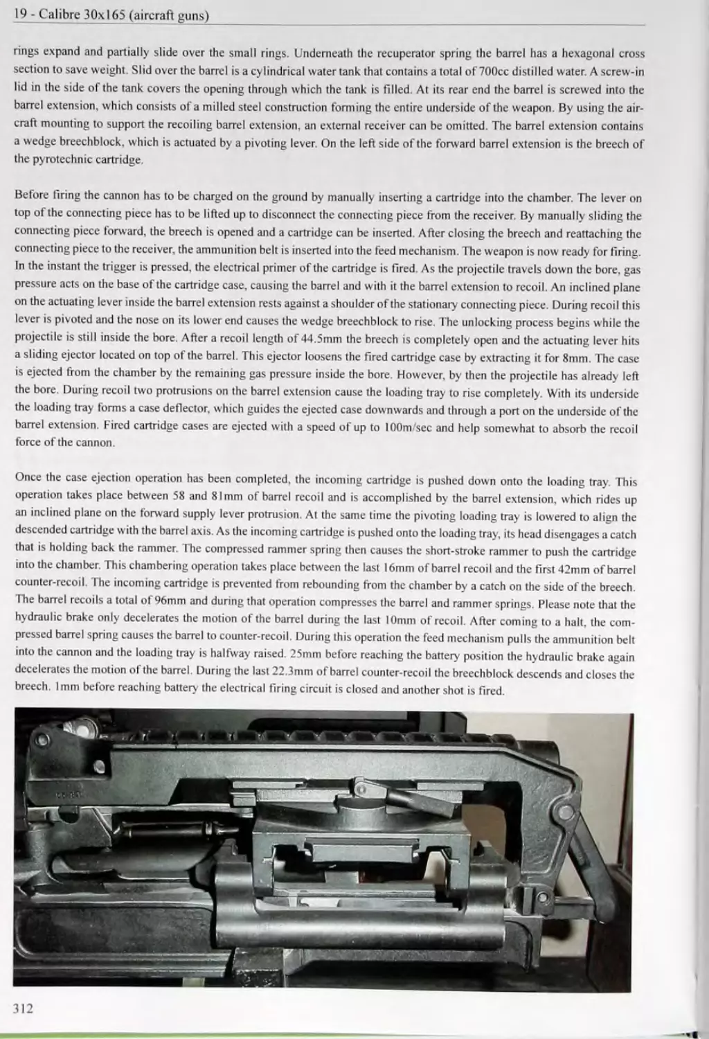
19 CALIBRE 30x165 (AIRCRAFT GUNS)..........................303
19.4 Ammunition Used in the GSh-30, GSh-6-30 and GSh-301 Aircraft Cannon 314
20 CALIBRE 30x210В 323 20.1 30mm Naval Anti-Aircraft Gun AK-230 323 20.2 Ammunition Used in the 30mm Naval Anti-Aircraft Gun AK-230 328
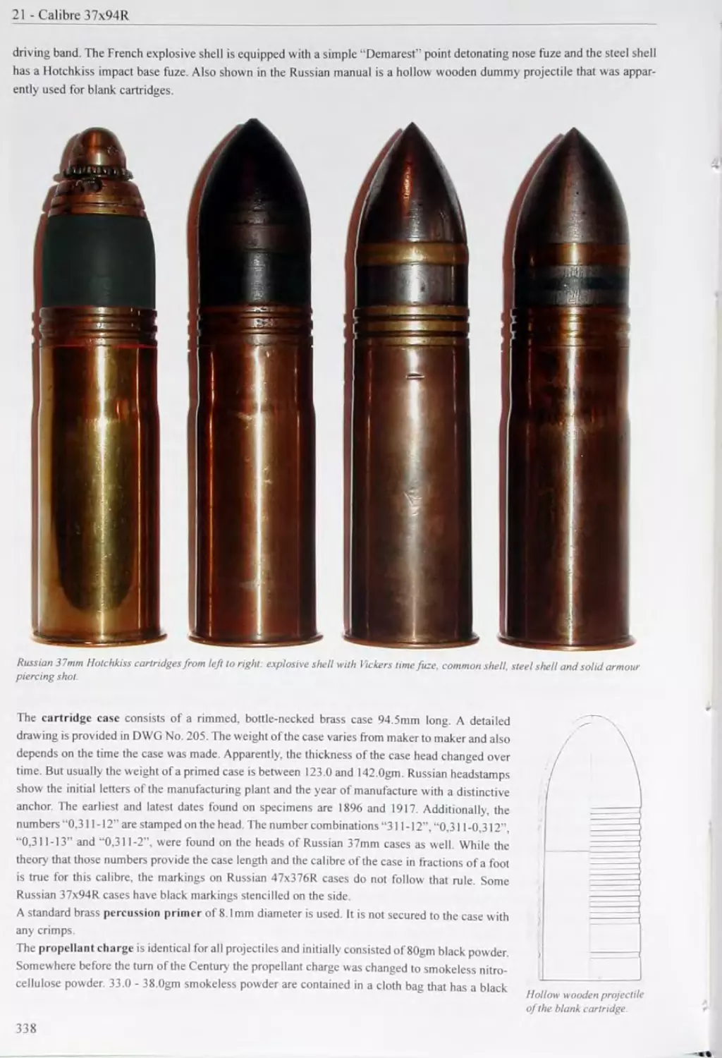
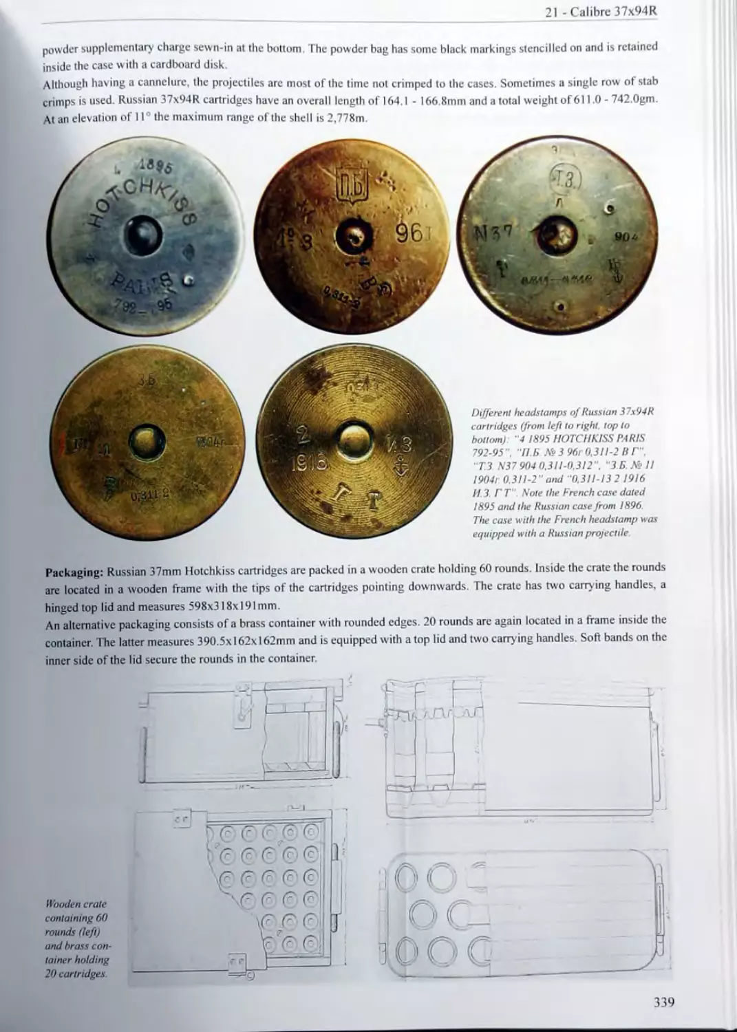
21 CALIBRE 37x94R 335 21.1 37mm Hotchkiss Guns 335 21.2 Miscellaneous 37mm Trench Guns 336 21.3 Ammunition Used in the 37mm Hotchkiss and Trench Guns 337
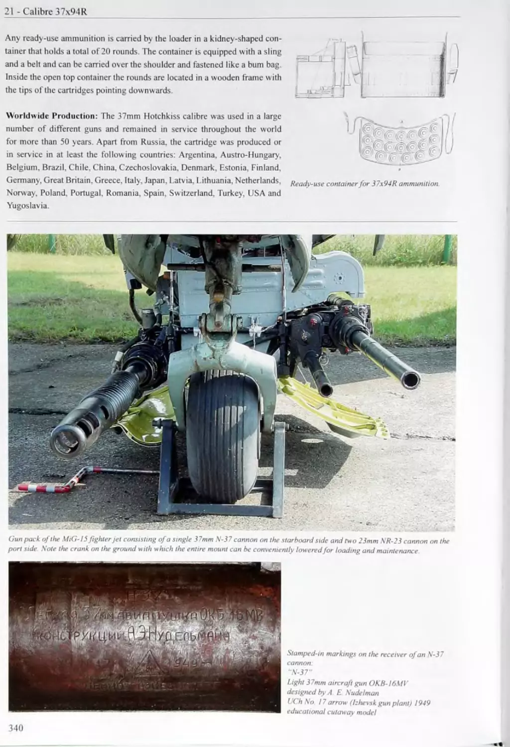
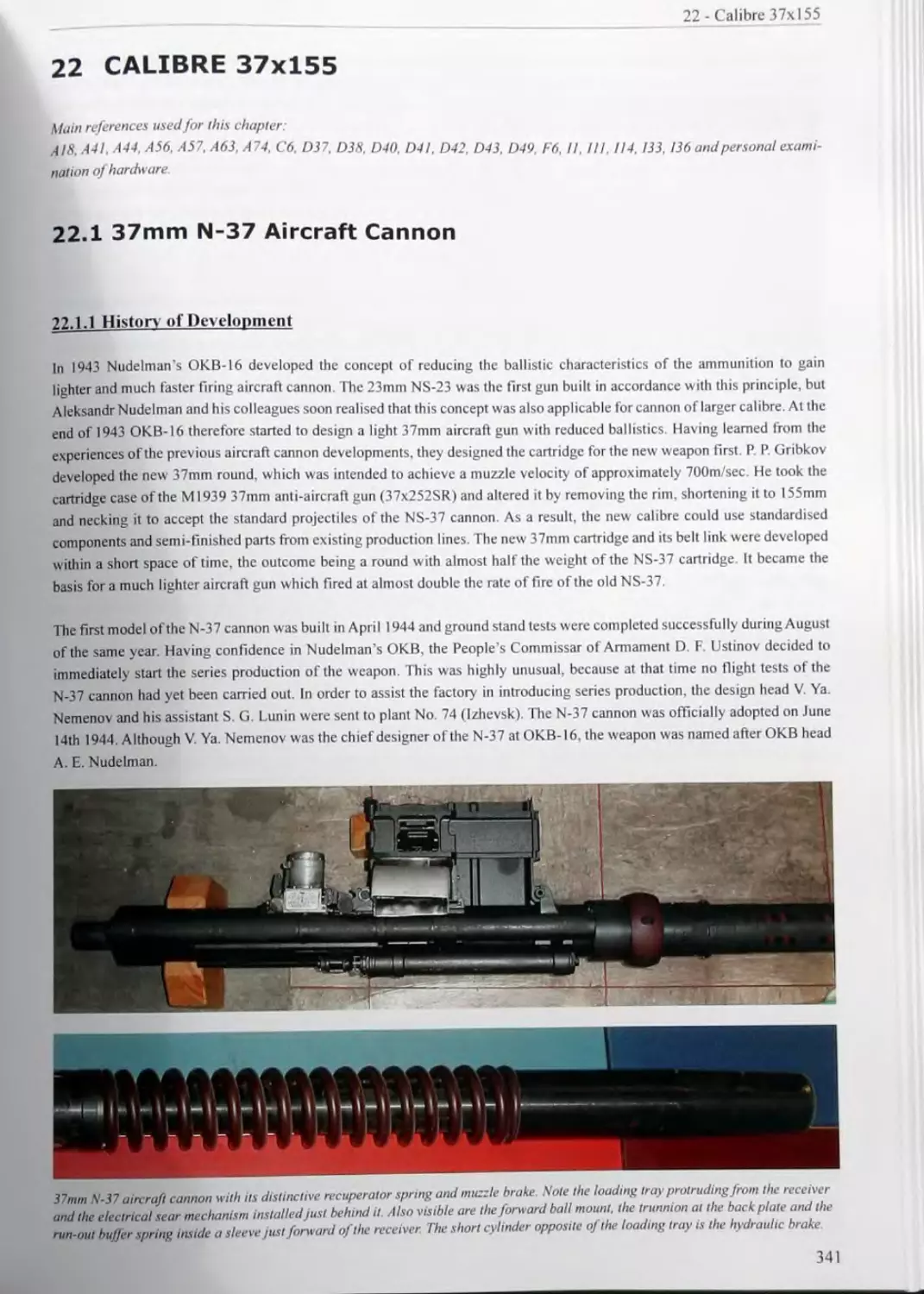
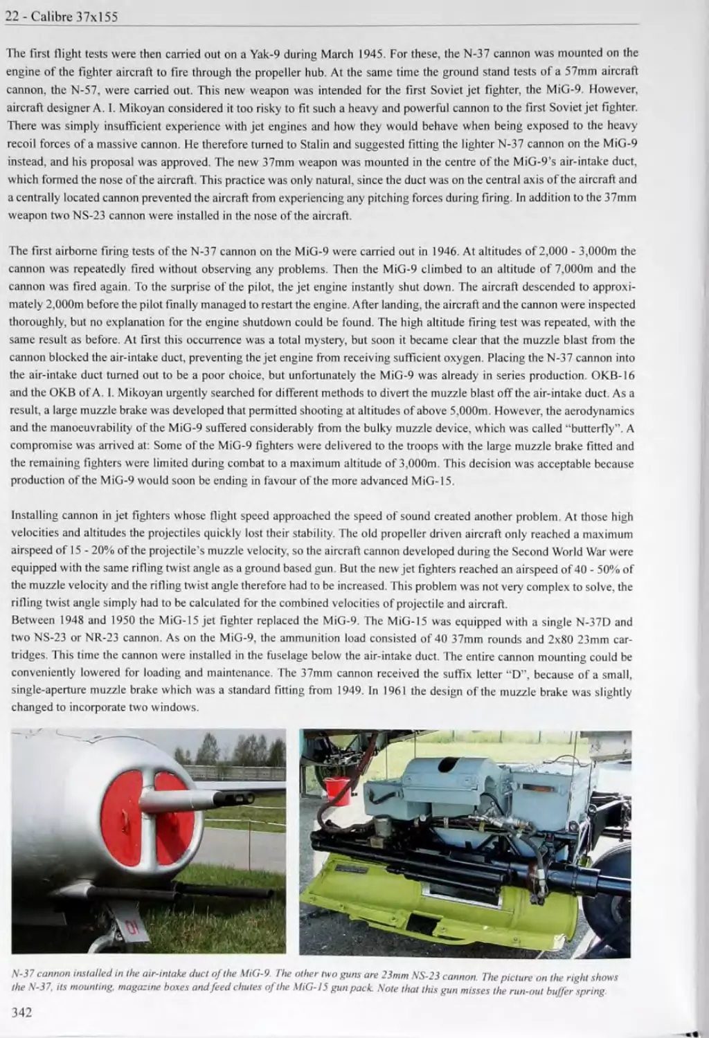
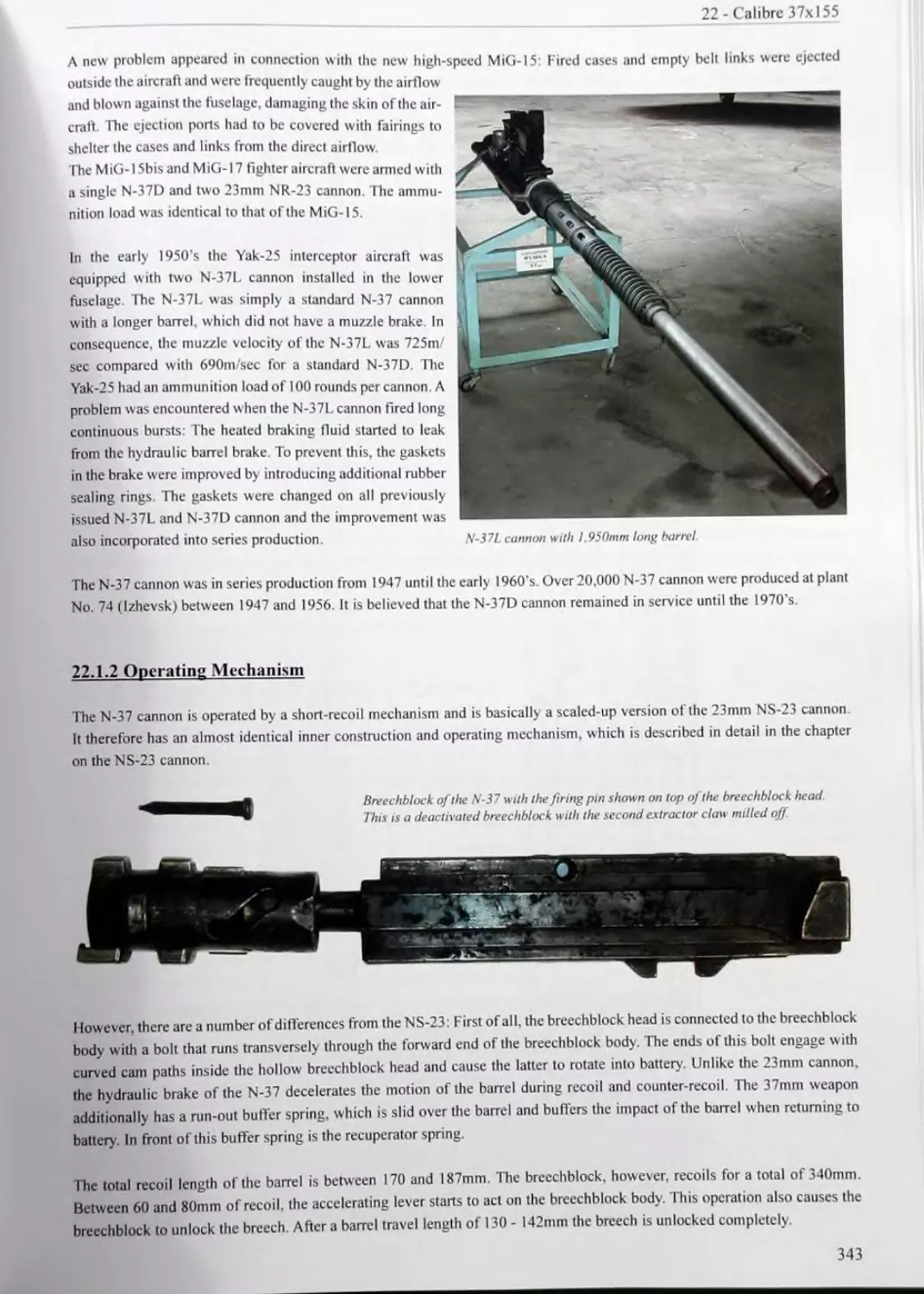
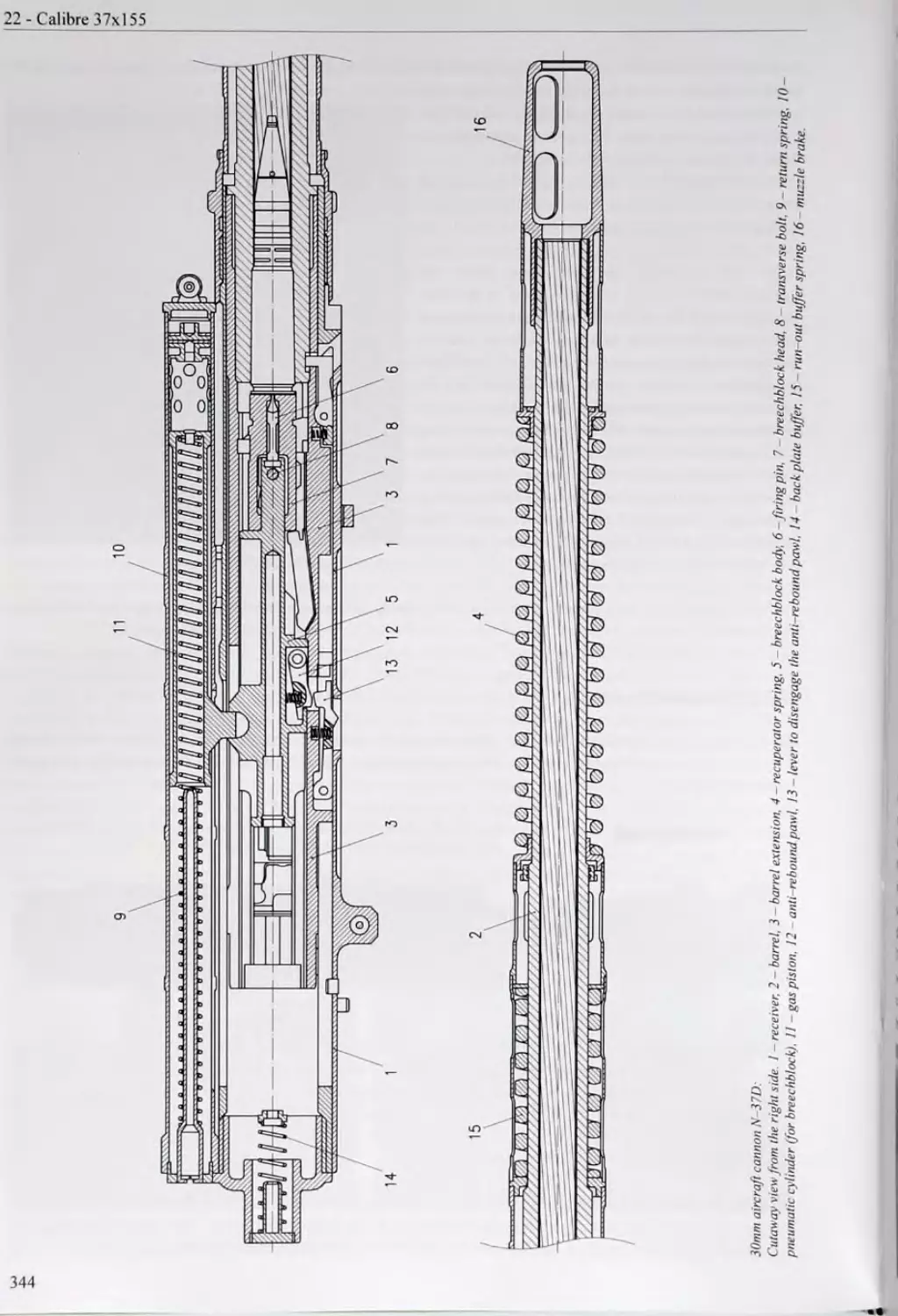
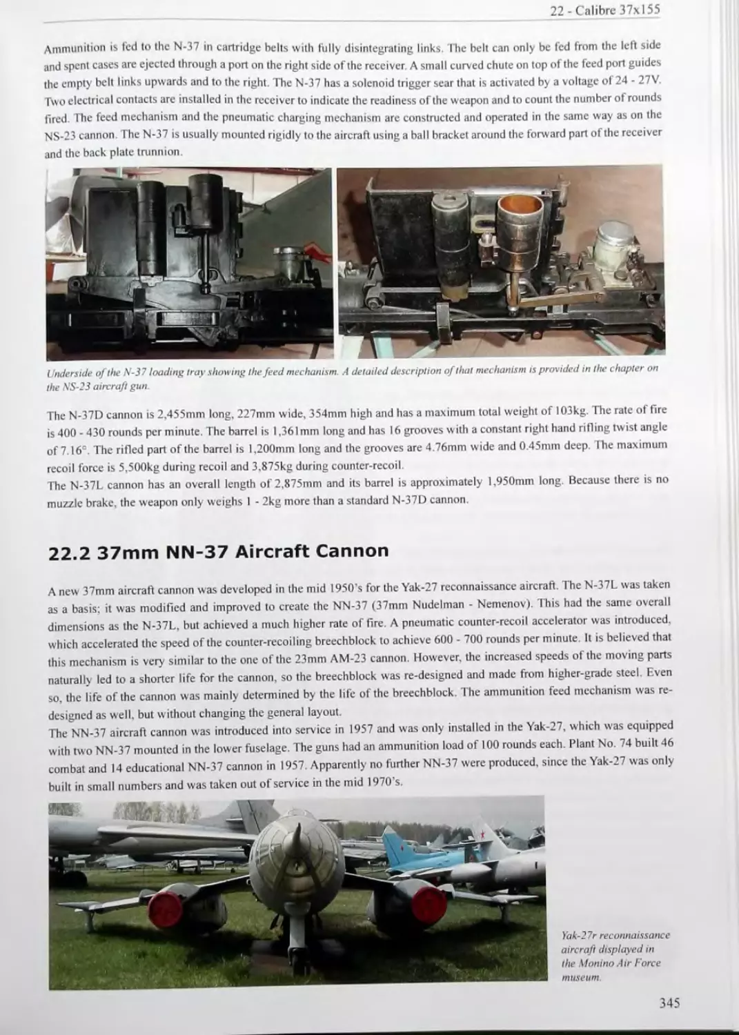
22 CALIBRE 37x155 341 22.1 37mm N-37 Aircraft Cannon 341 22.2 37mm NN-37 Aircraft Cannon 345 22.3 Ammunition Used in the N-37 and NN-37 Aircraft Cannon , 346
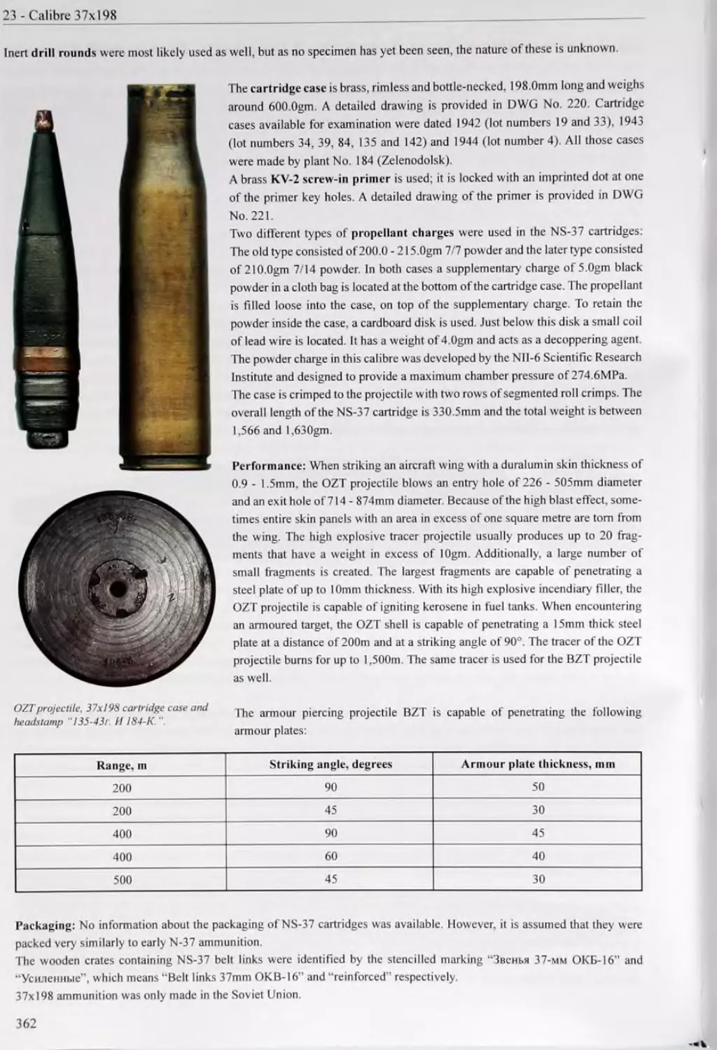
23 CALIBRE 37x198 355 23.1 37mm Sh-37 Aircraft Cannon 355 23.2 37mm NS-37 Aircraft Cannon 355 23.3 Ammunition Used in the Sh-37 and NS-37 Aircraft Cannon 361
24 THE FIRST SOVIET ANTI-AIRCRAFT GUNS 363 24.1 M1928 37mm Automatic Anti-Aircraft Gun 363 24.2 25mm Anti-Aircraft Gun of the Kovrov Arms Plant 363 24.3 AKT-37 37mm Anti-Aircraft Gun 364 24.4 ASKON-37 37mm Anti-Aircraft Gun 365 24.5 ASKON-45 45mm Anti-Aircraft Gun 365 24.6 AP-20 20mm Anti-Aircraft Gun 365 24.7MI930 20mm Anti-Aircraft Gun 365 24.8 M1930 37mm Anti-Aircraft Gun 367
25 THE FIRST SOVIET ANTI-TANK GUNS AND RIFLES 369 25.1 37mm Anti-Tank Gun MI930 369 25.2 Recoilless 37mm Anti-Tank Gun “K” 371 25.3 20mm Anti-Tank Gun INZ-10 372 25.4 Korovin’s 20mm Anti-Tank Gun 372 25.5 25mm Anti-Tank Gun MTs 373 25.6 37mm Anti-Tank Gun of OKB-15 373 25.7 Blyum 14.5mm Anti-Tank Rifle 373 25.8 RES 20mm Anti-Tank Gun 373 25.9 LPP-25 25mm Anti-Tank Gun 374
26 THE FIRST SOVIET TANK GUNS 375 26.1 37mm Hotchkiss Tank Gun 375 26.2 37mm Tank Gun PS-2 375 26.3 37mm Tank Gun B-3 375 26.4 45mm Tank Gun 6-K 376 26.5 37mm Tank Gun ZIS-19 376 26.6 Miscellaneous Tank Guns 376
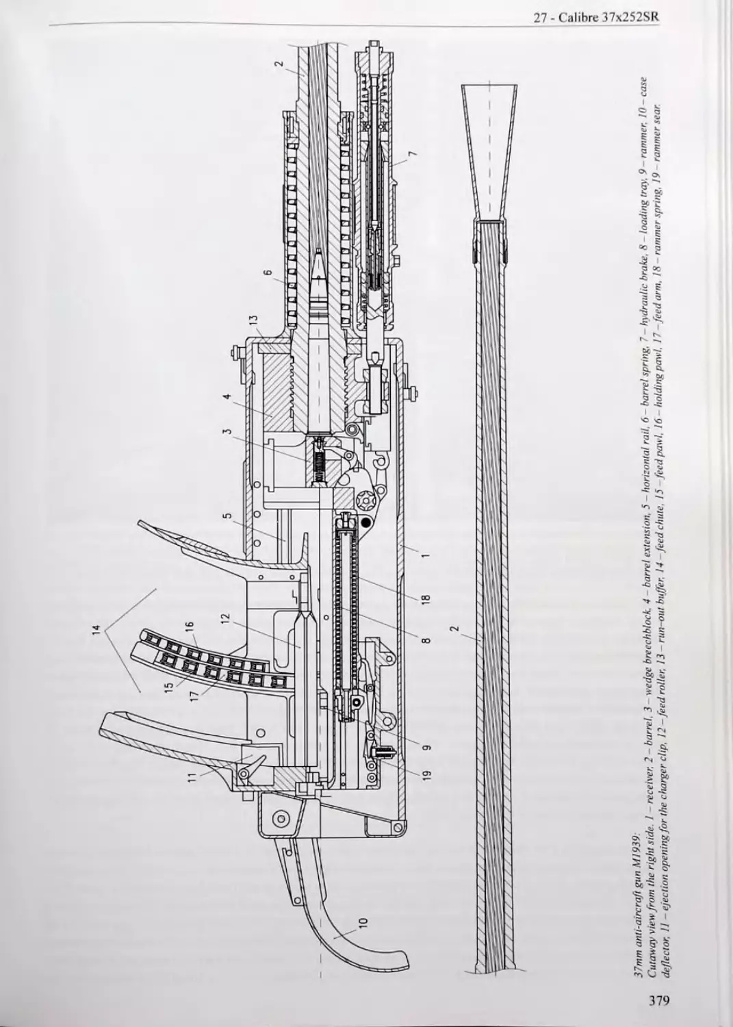
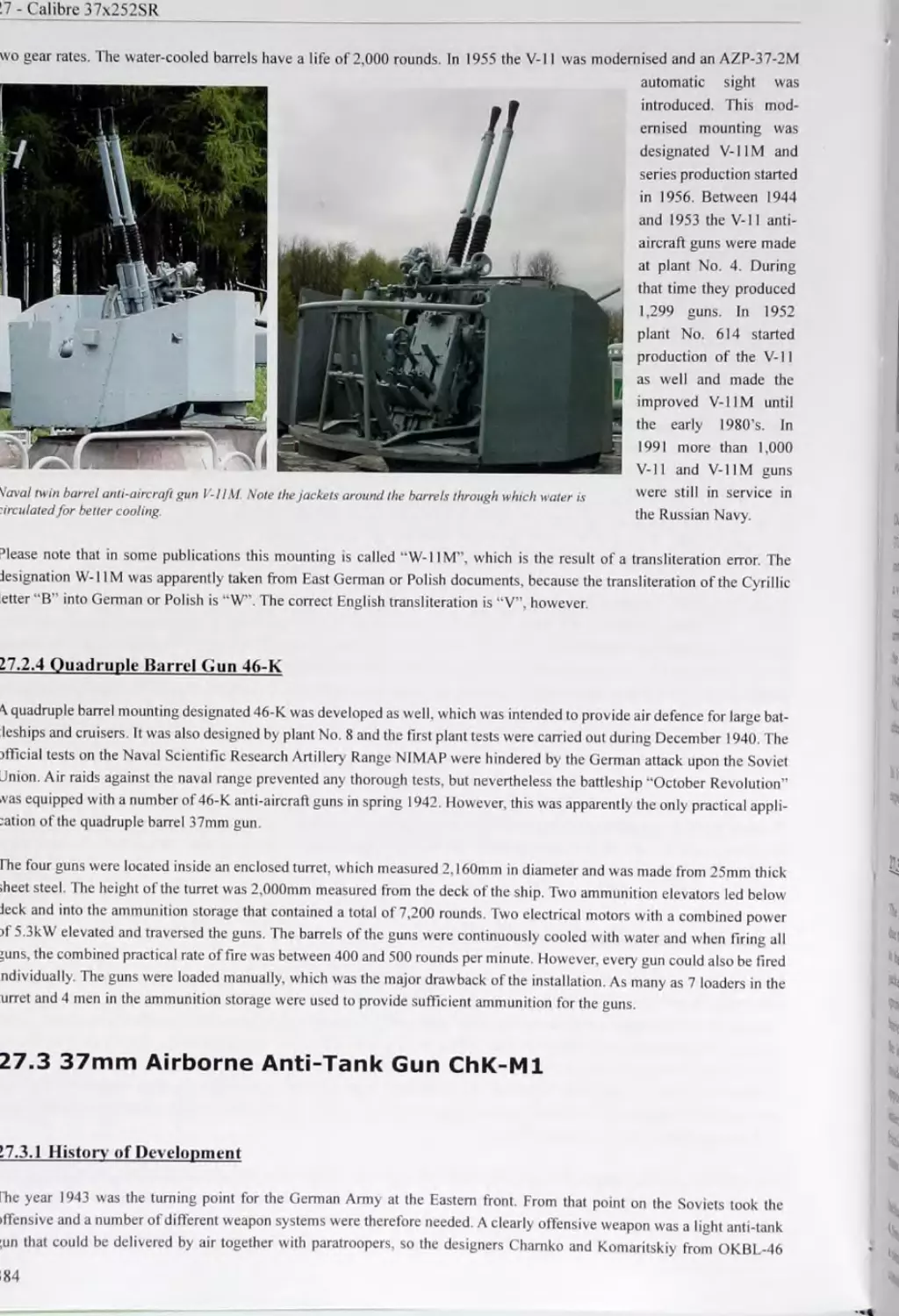
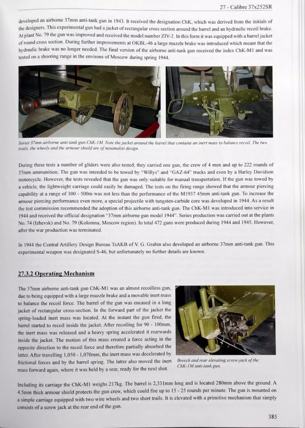
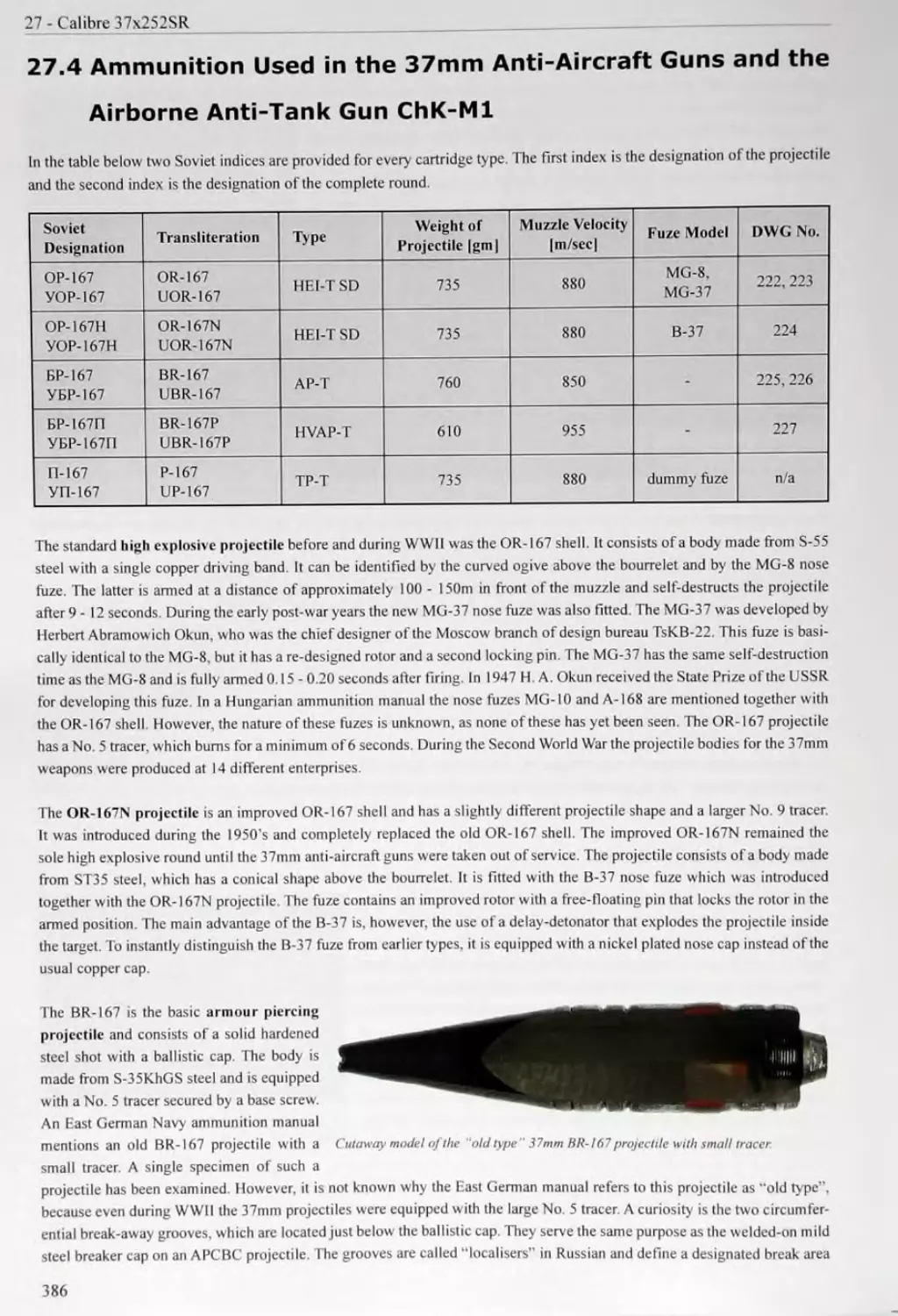
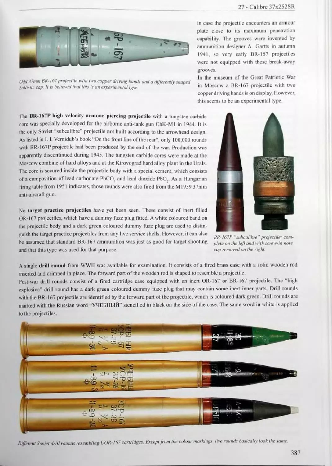
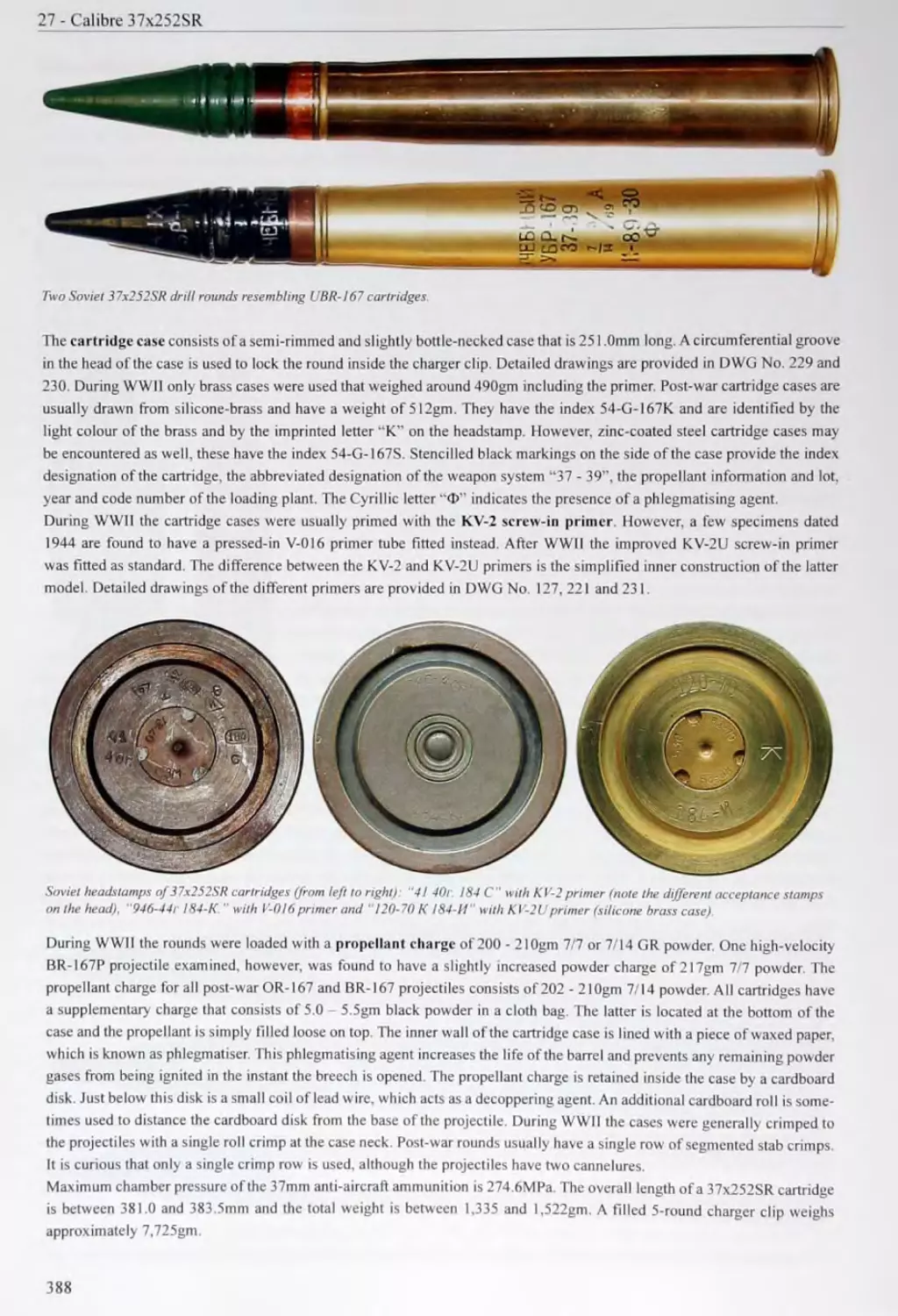
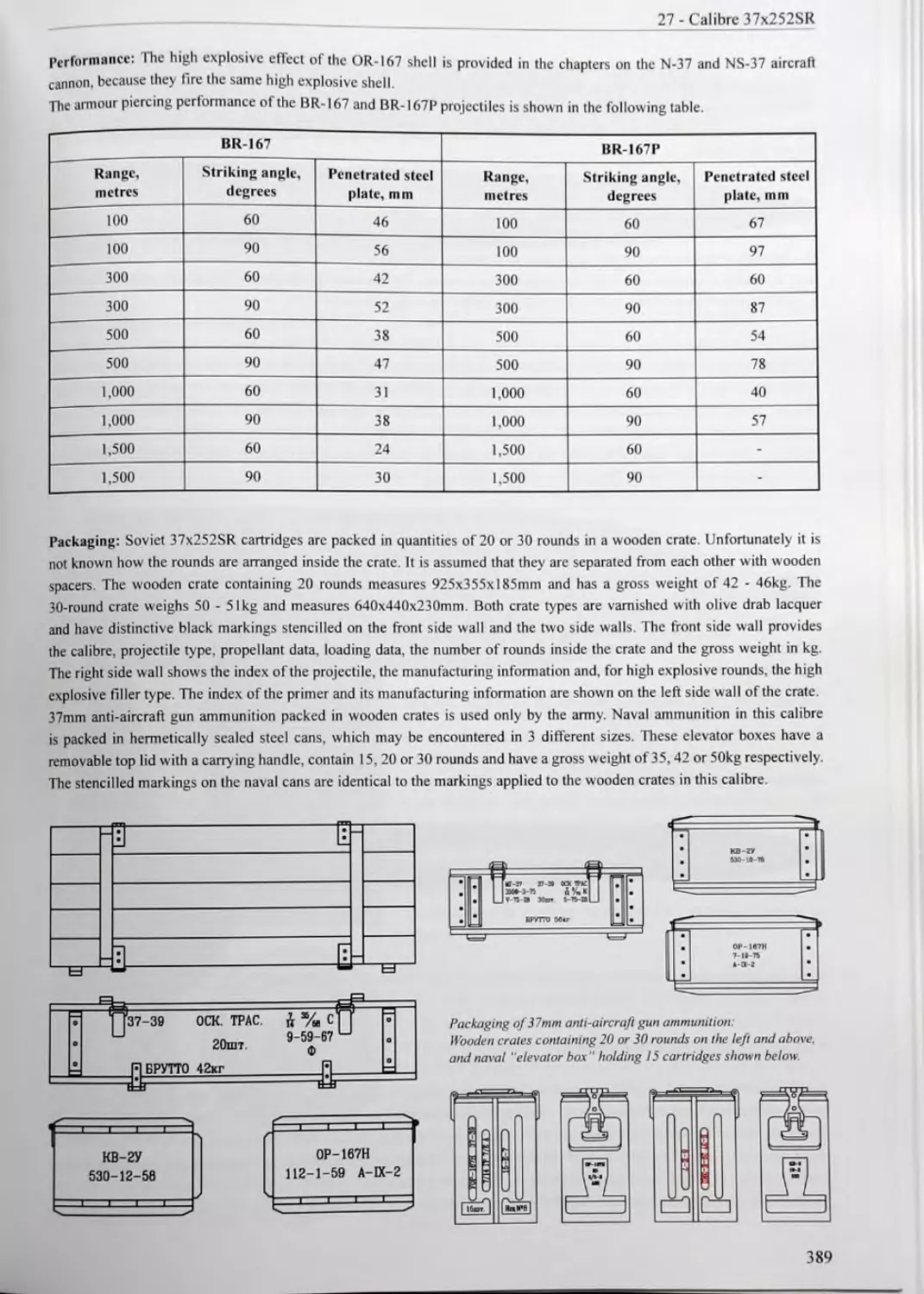
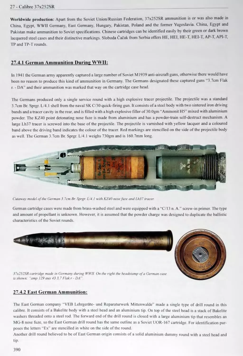
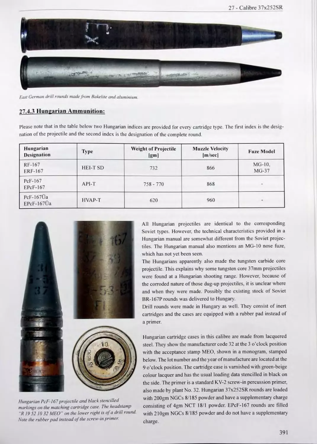
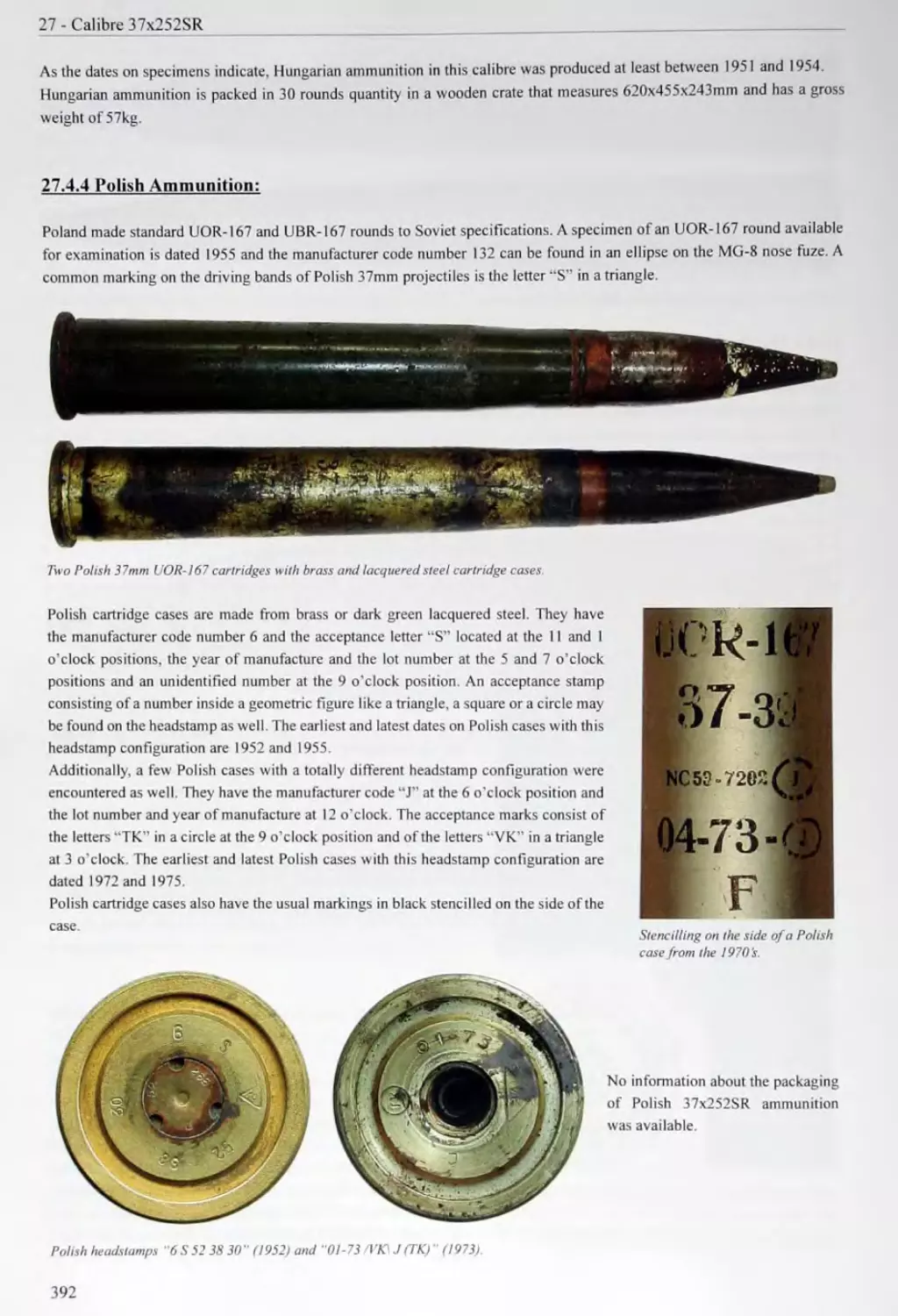
27 CALIBRE 37x252SR 377 27.1 37mm Anti-Aircraft Gun Ml939 377 27.2 Naval 37mm Anti-Aircraft Guns 383 27.3 37mm Aitbome Anti-Tank Gun ChK-M 1 384 27.4 Ammunition Used in the 37mm Anti-Aircraft Guns and the Airborne Anti-Tank Gun ChK-M 1 386
28 EXPERIMENTAL 37MM ANTI-AIRCRAFT GUNS 393 28.1 37mm Anti-Aircraft Gun MIK-4 393 28.2 37mm Anti-Aircraft Gun ZIV-4 393 28.3 37mm Anti-Aircraft Gun A-15 393 28.4 37mm Anti-Aircraft Gun 500-P 394 28.5 Ammunition Used in the Experimental 37mm Anti-Aircraft Guns 395
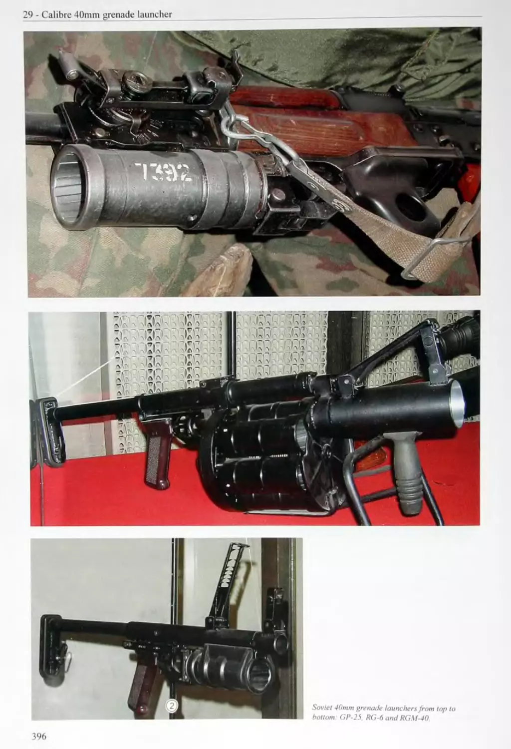
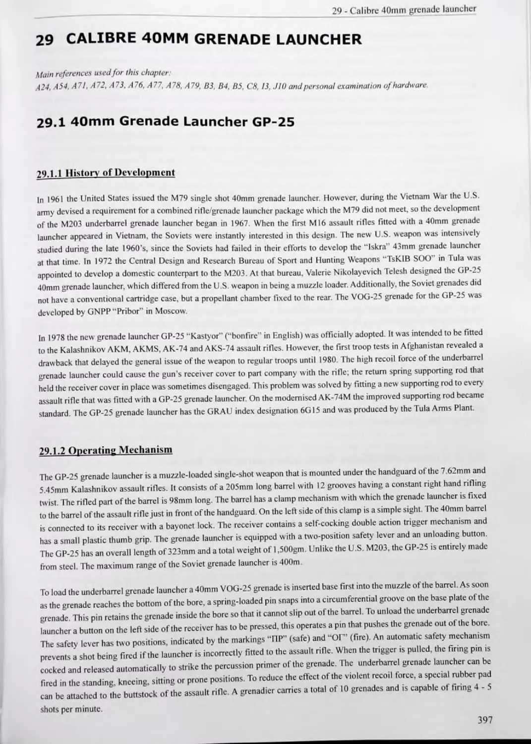
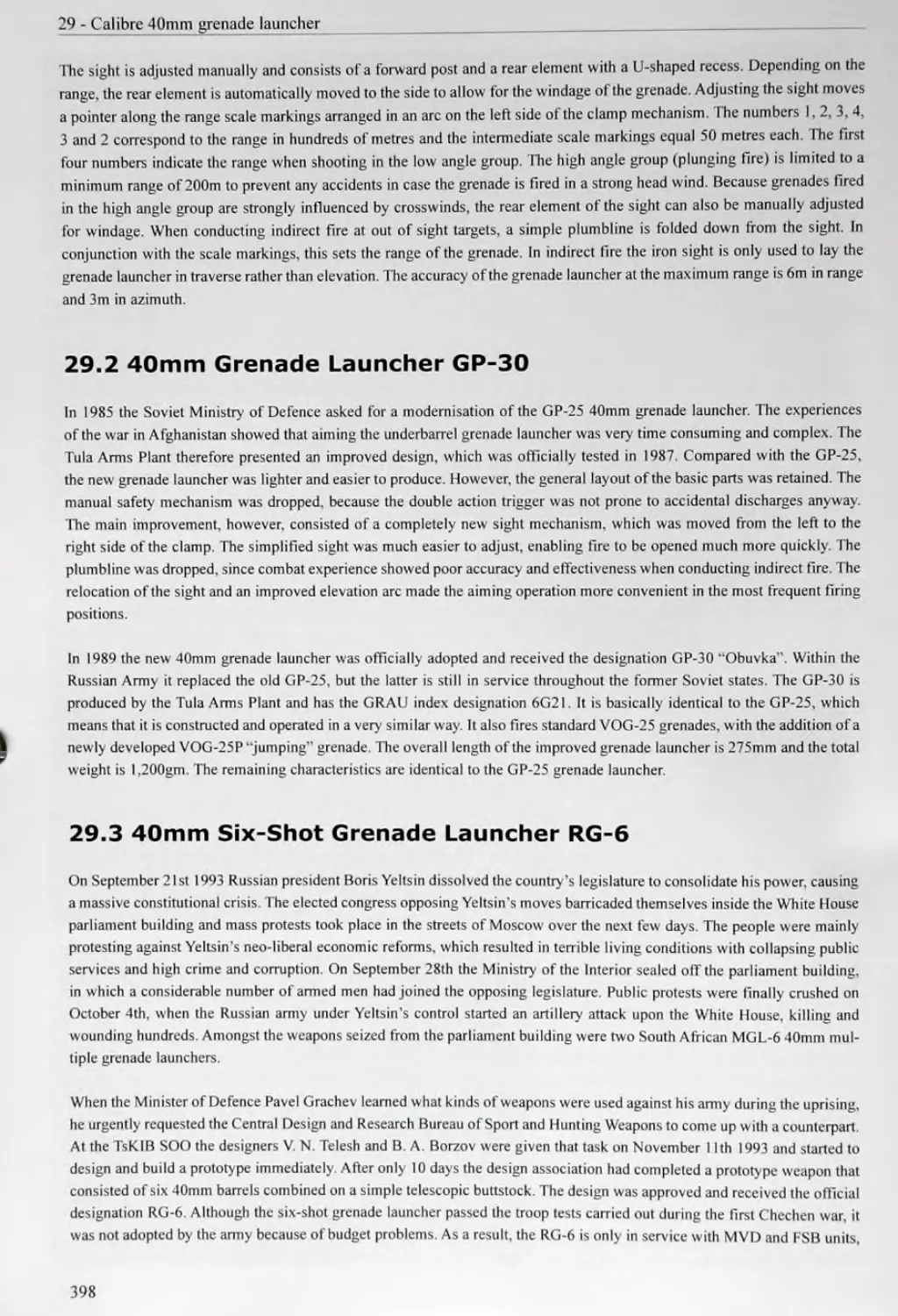
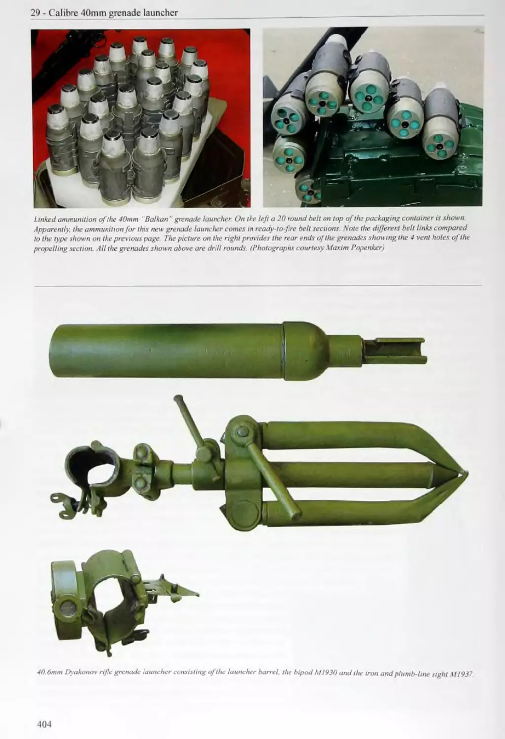
29 CALIBRE 40MM GRENADE LAUNCHER 397 29.1 40mm Grenade Launcher GP-25 397 29.2 40mm Grenade Launcher GP-30 398 29.3 40mm Six-Shot Grenade Launcher RG-6 398 29.4 40mm Grenade Launcher RGM-40 399 29.5 Spade Grenade Launcher “Variant 399 29.6 Ammunition Used in the 40mm Grenade Launchers 399 29.7 Automatic Grenade Launchers TKB-0134 “Kozlik" and 6G27 “Balkan” 403
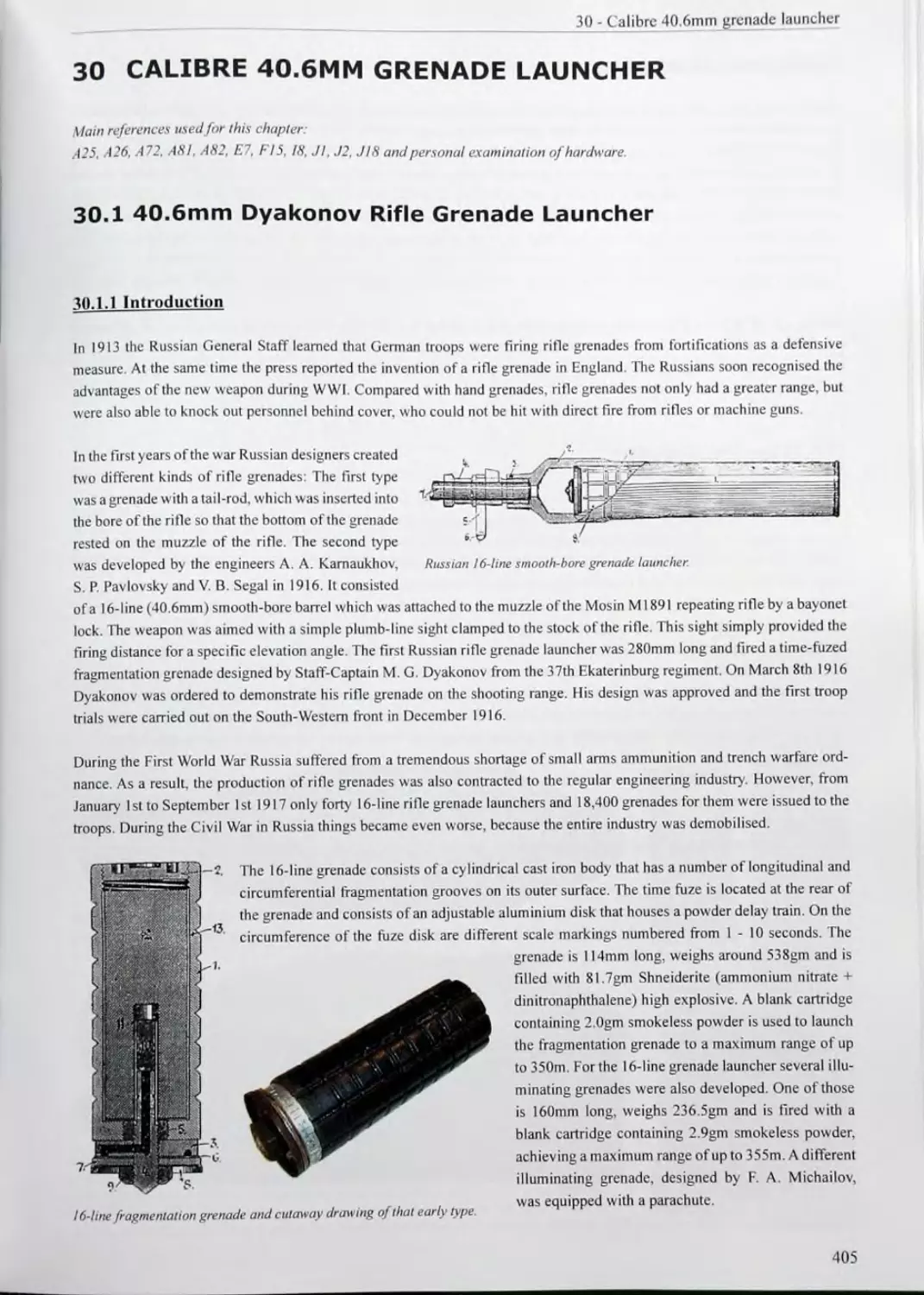
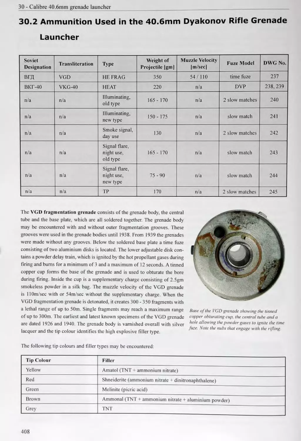
30 CALIBRE 40.6MM GRENADE LAUNCHER 405 30.1 40.6mm Dyakonov Rifle Grenade Launcher 405 30.2 Ammunition Used in the 40.6mm Dyakonov Rifle Grenade Launcher 408 30.3 Taubin's Automatic 40.6mm Grenade Launcher 411
31 MISCELLANEOUS GRENADE LAUNCHERS 413 31.1 30mm Grenade Launcher BS-1 413 31.2 43mm Grenade Launcher “Iskra” 414 31.3 43mm Grenade Launcher GM-94 414
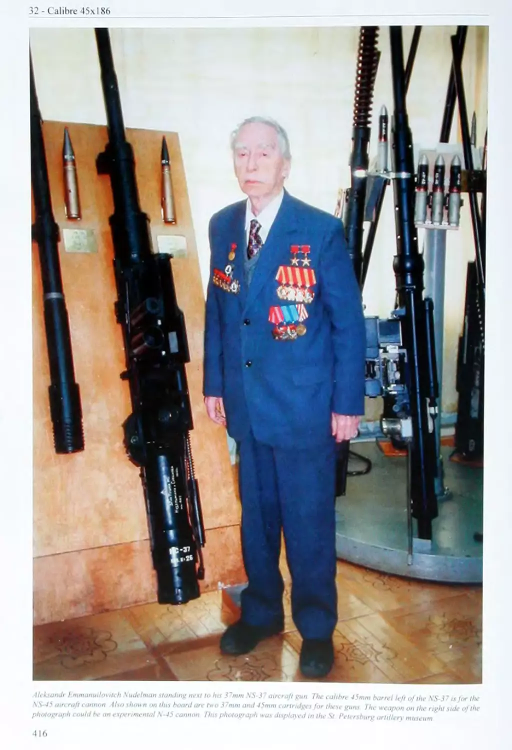
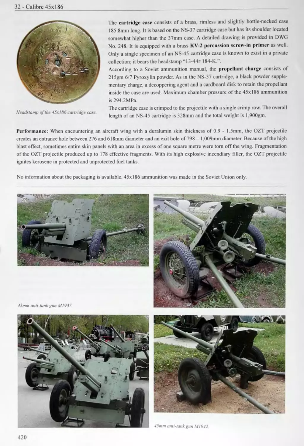
32 CALIBRE 45x186.......................................417
418
419
33 CALIBRE 45x310R (ANTI-TANK GUNS)...........................421
Gun M1932 ..............
33.245mmAnti-TankGunMI937...................................................422
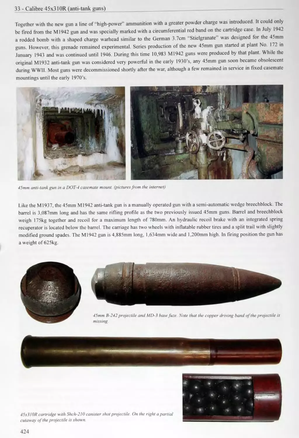
33.345mmAnti-TankGunM1942 .................................................. 423
425
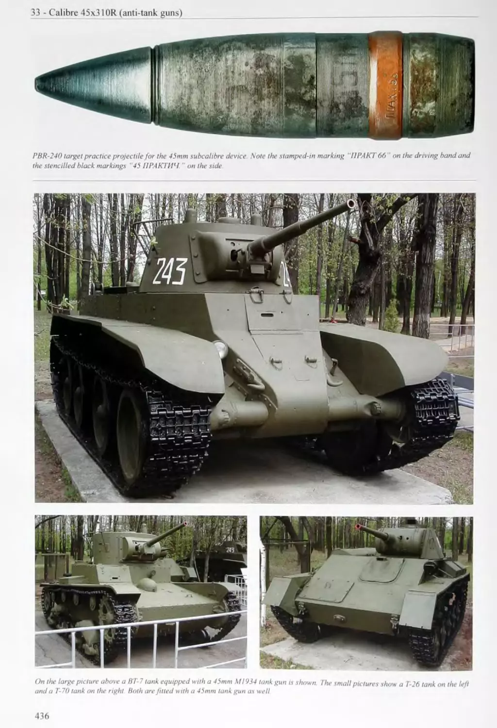
33.5 45mm Subcalibre Device........................................................................435
36 CALIBRE 45x386SR...................................................447
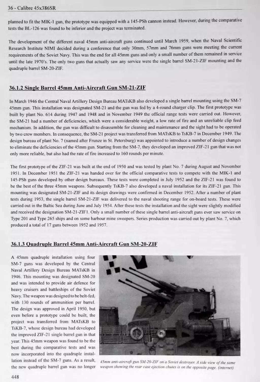
36.1 Naval 45mm Anti-Aircraft GunsSM-21-ZIF and SM-20-ZIF................................................447
450
37 CALIBRE 47x131 R 453 37.1 47mm Hotchkiss Revolver Gun 453 37.2 Ammunition Used in the 47mm Hotchkiss Revolver Gun 453
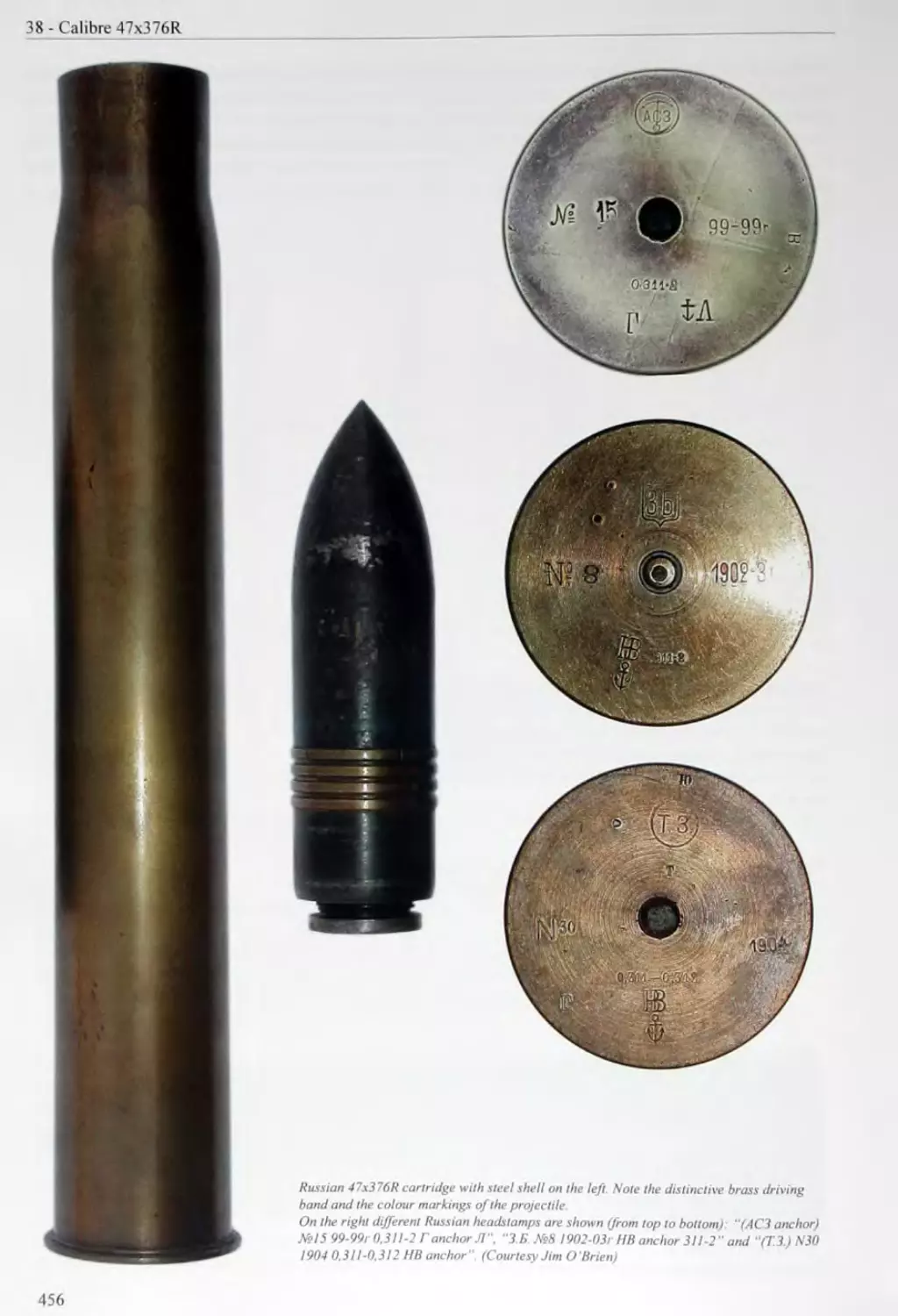
38 CALIBRE 47x376R 457 38.1 47mm Single Barrel Hotchkiss Gun 457 38.2 Ammunition Used in the Single Barrel 47mm Hotchkiss Gun 457
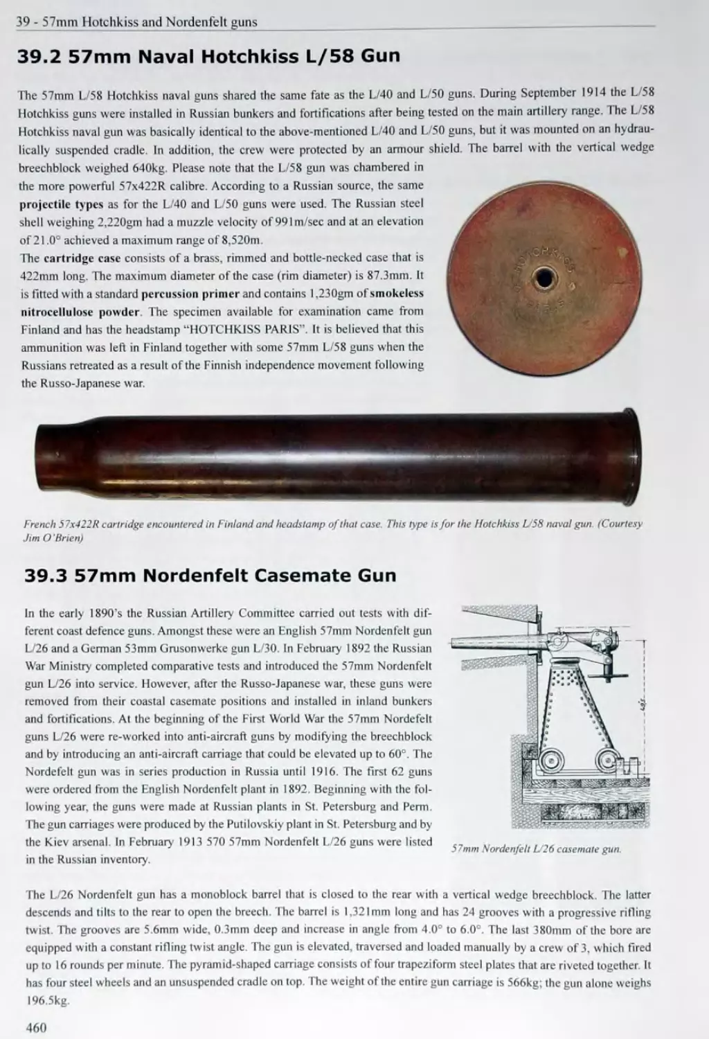
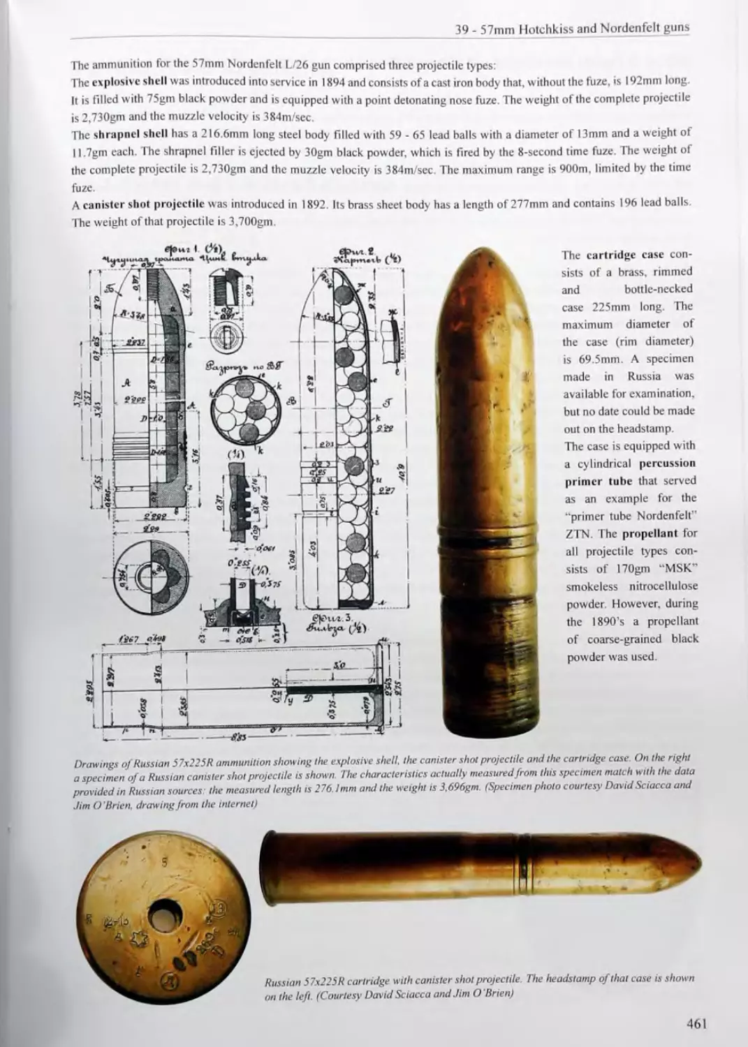
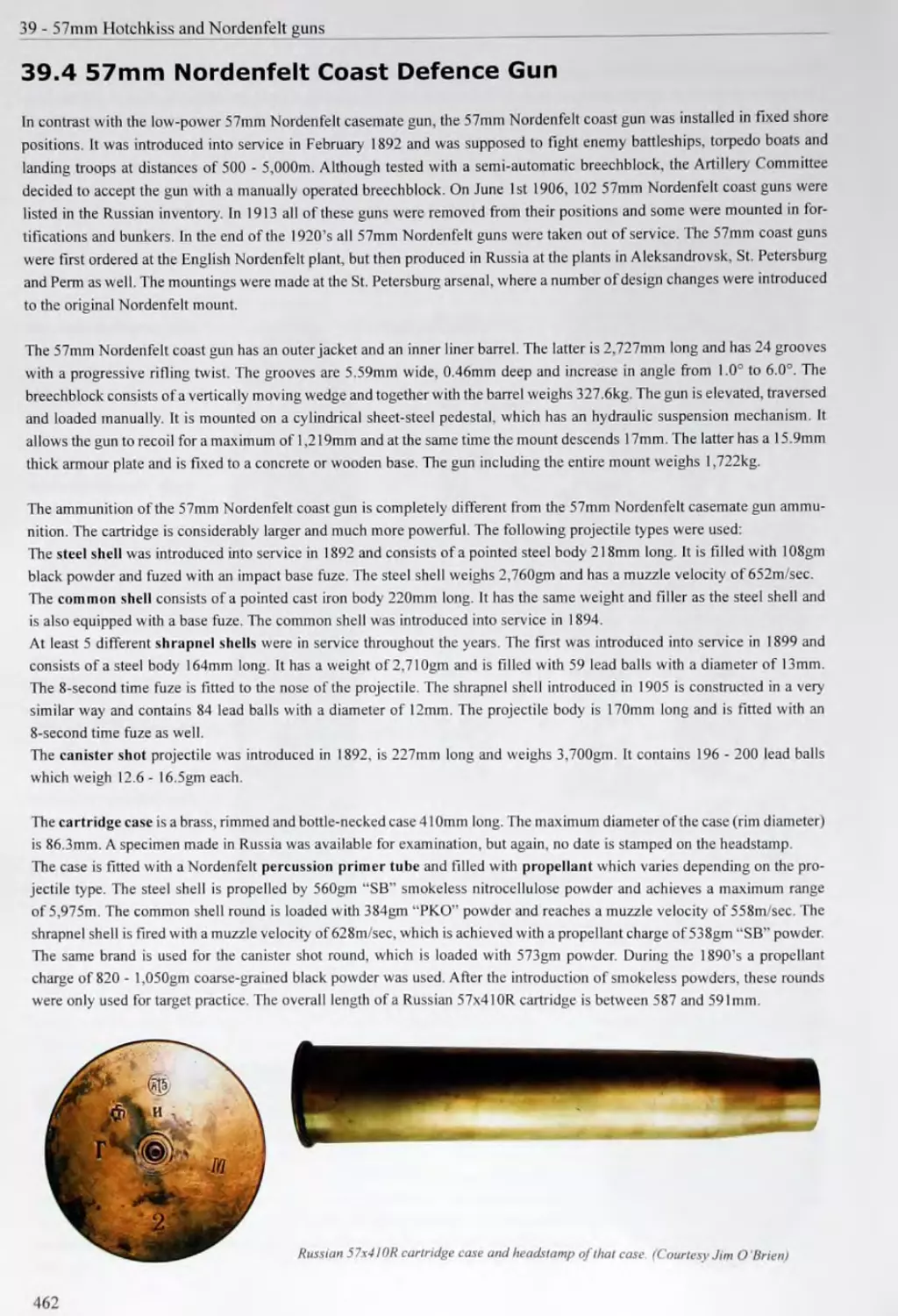
39 57MM HOTCHKISS AND NORDENFELT GUNS 459 39.1 57mm Naval Hotchkiss L/40 and L/50 Guns 459 39.2 57mm Naval Hotchkiss L/58 Gun 460 39.3 57mm Nordenfelt Casemate Gun 460
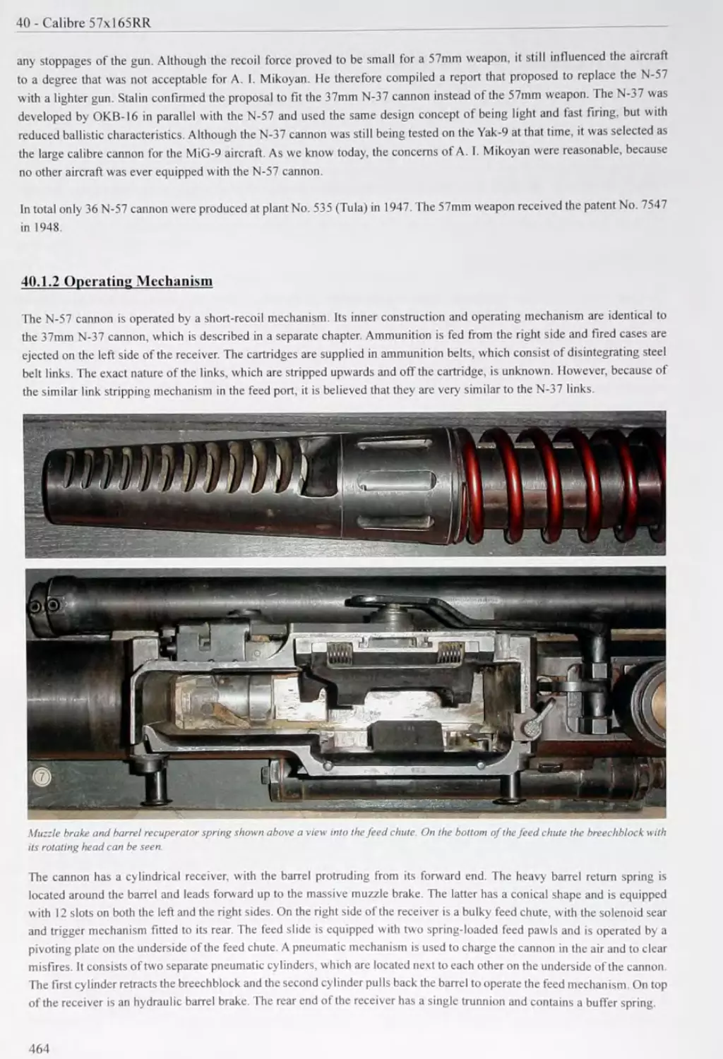
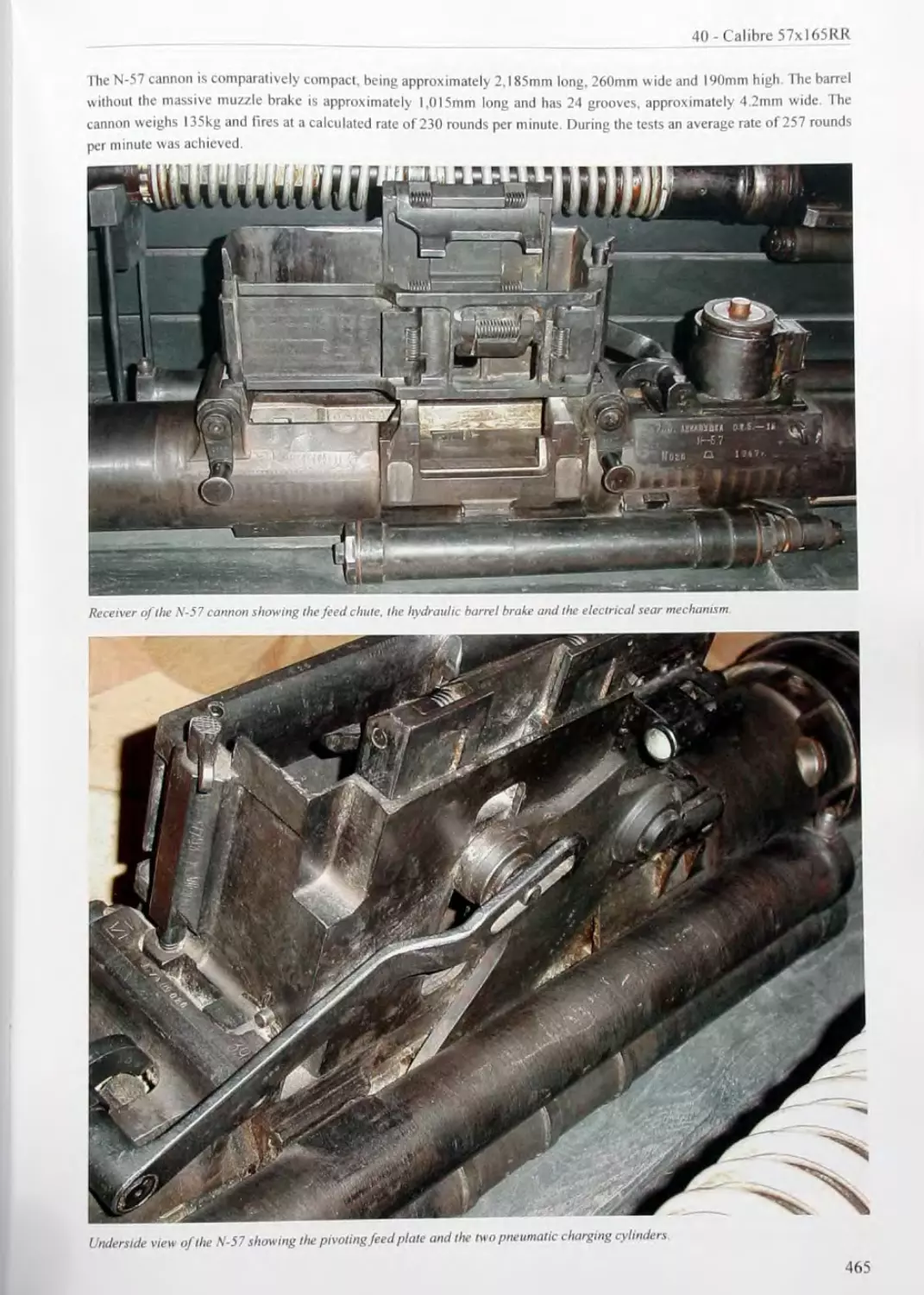
40 CALIBRE 57xl65RR.................................................463
463
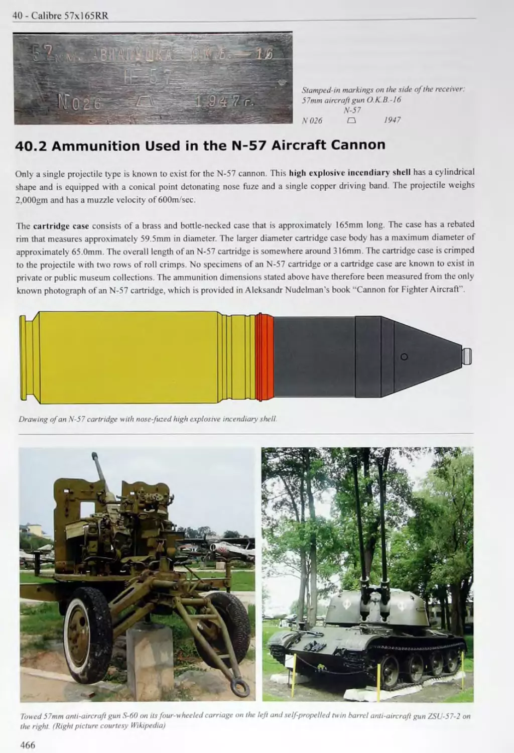
40.2 Ammunition Used in the N-57 Aircraft Cannon................................
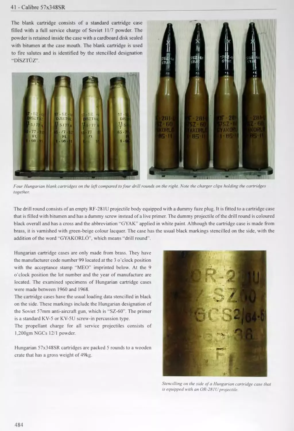
41 CALIBRE 57x348SR..............................................................................467
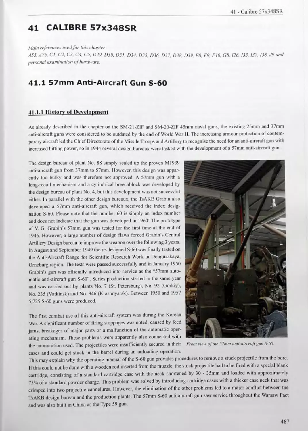
41.1 57mm Anti-Aircraft Gun S-60............................................................467
41.2 Self-Propelled Twin Barrel 57mm Anti-Aircraft Gun ZSU-57-2........................... 472
41.3 Naval 57mm Anti-Aircraft Guns..........................................................472
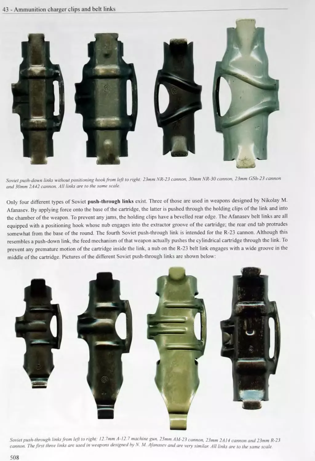
43 AMMUNITION CHARGER CLIPS AND BELT LINKS......................................503
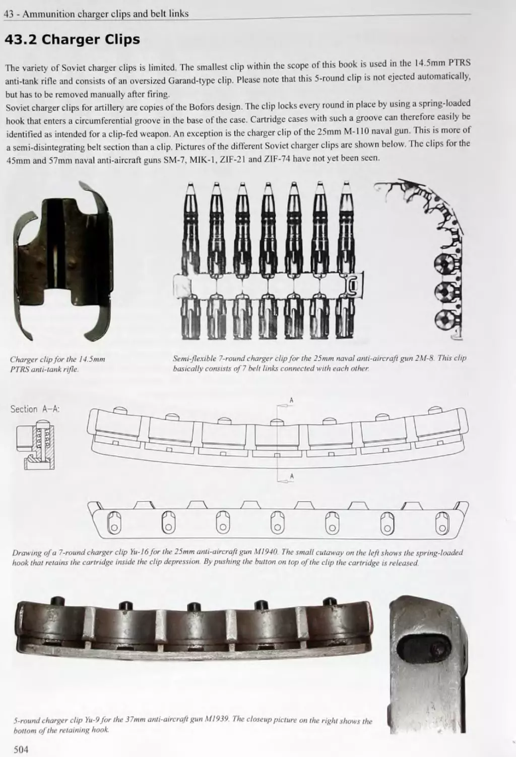
43.2 Charger Clips.......................................................504
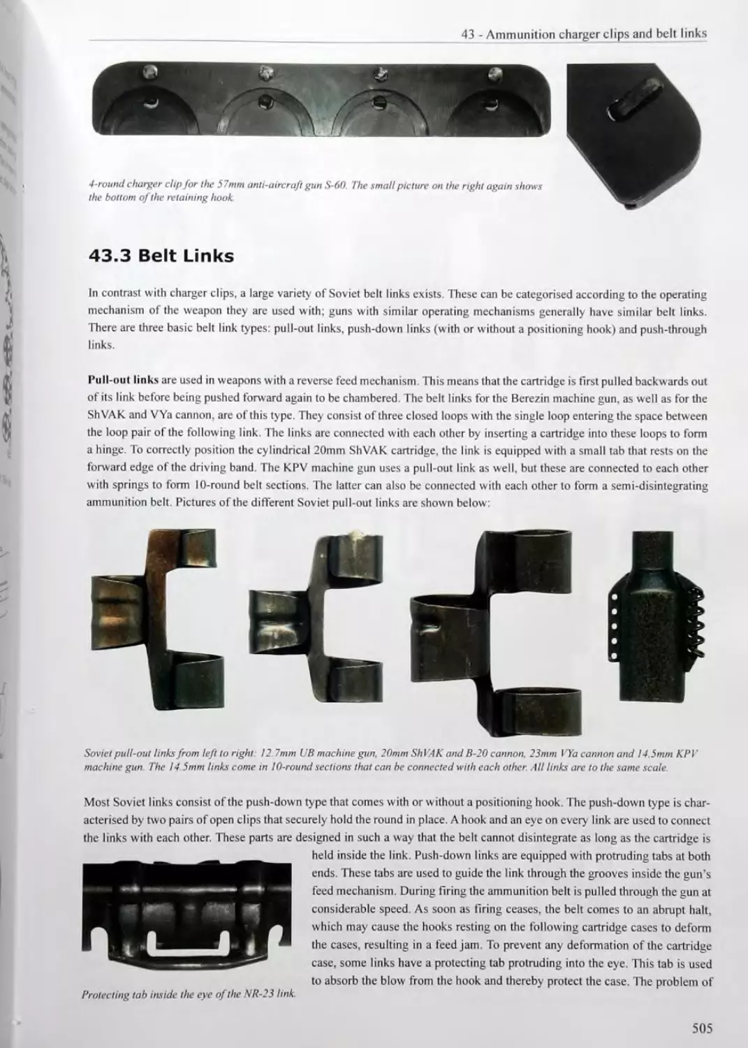
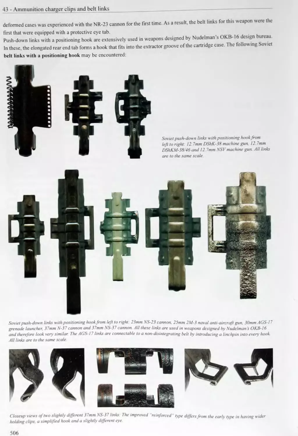
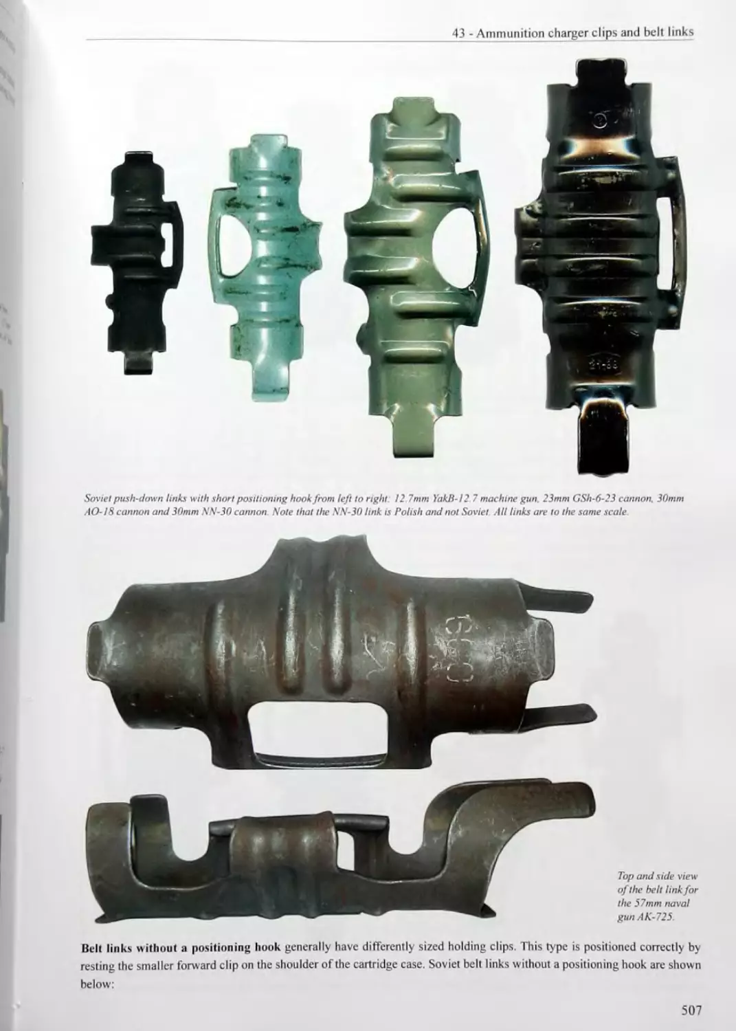
43.3 Belt Links..........................................................505
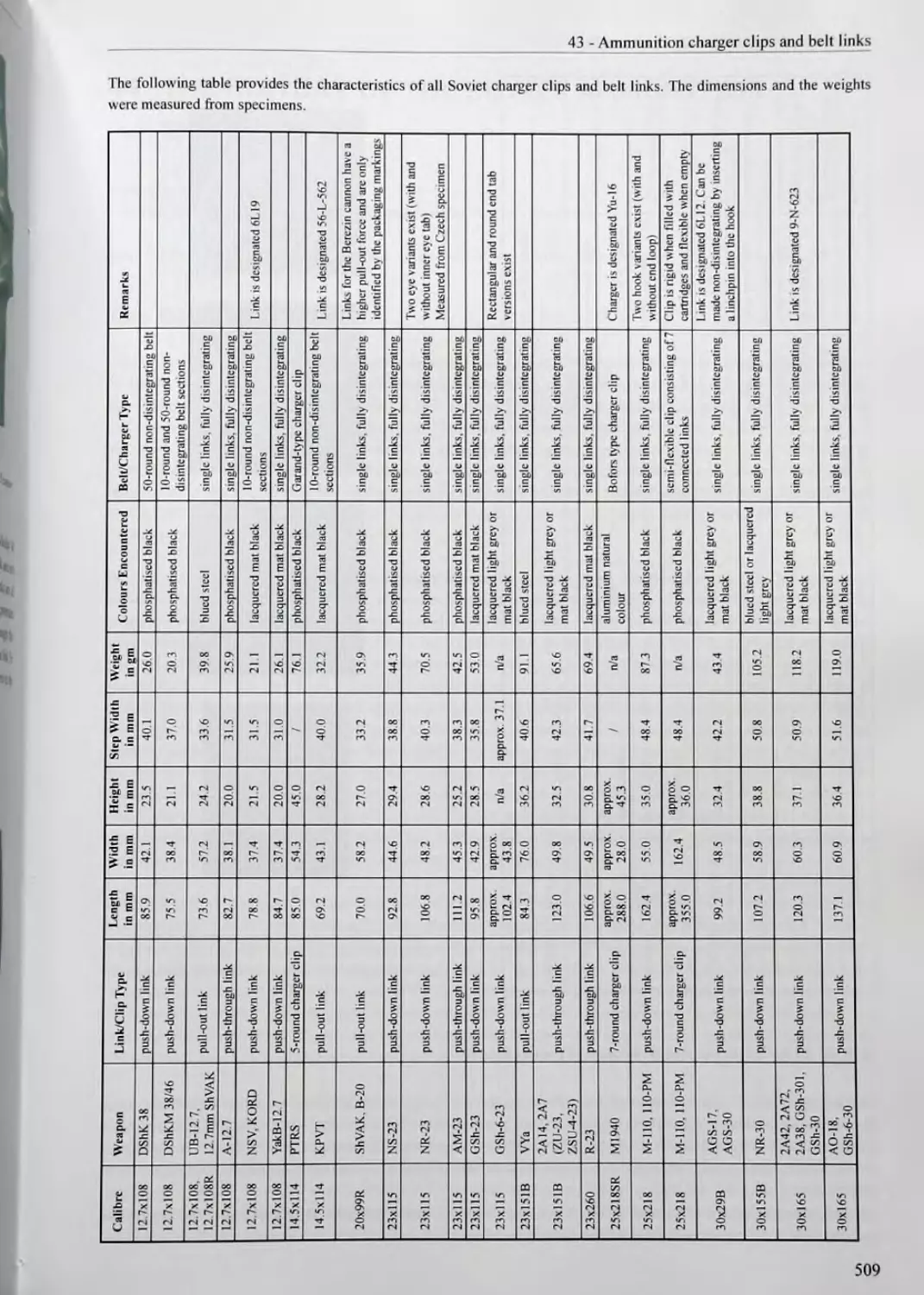
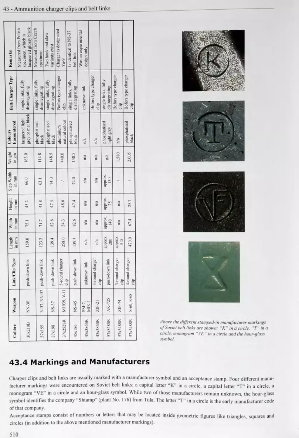
43.4 Markings and Manufacturers..........................................510
44 THE HISTORY OF THE SOVIET AMMUNITION INDUSTRY.....511
The Soviet Era
The Second World War................................................................516
The Cold War........................................................................517
The Breakdown of the Soviet Union...................................................518
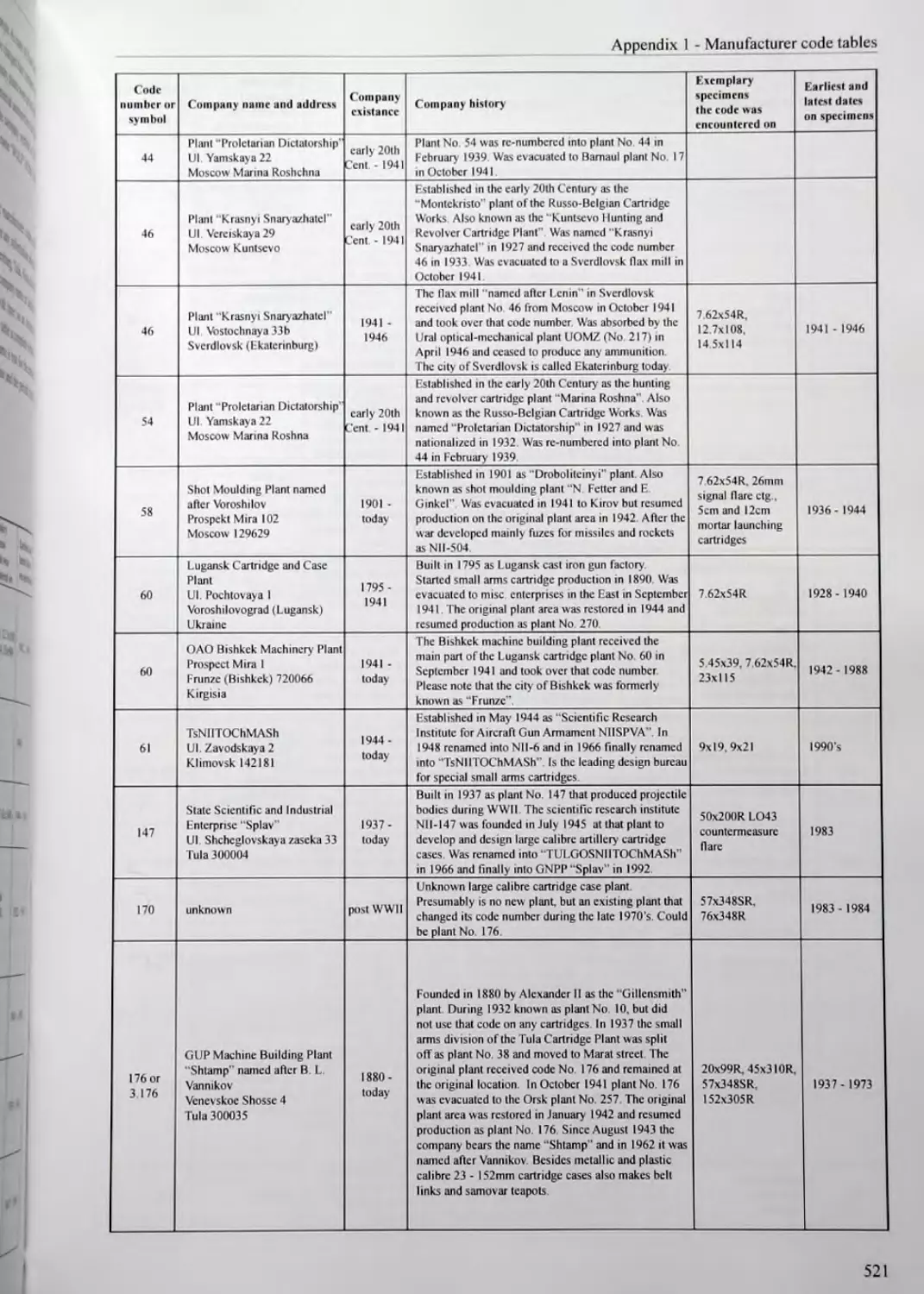
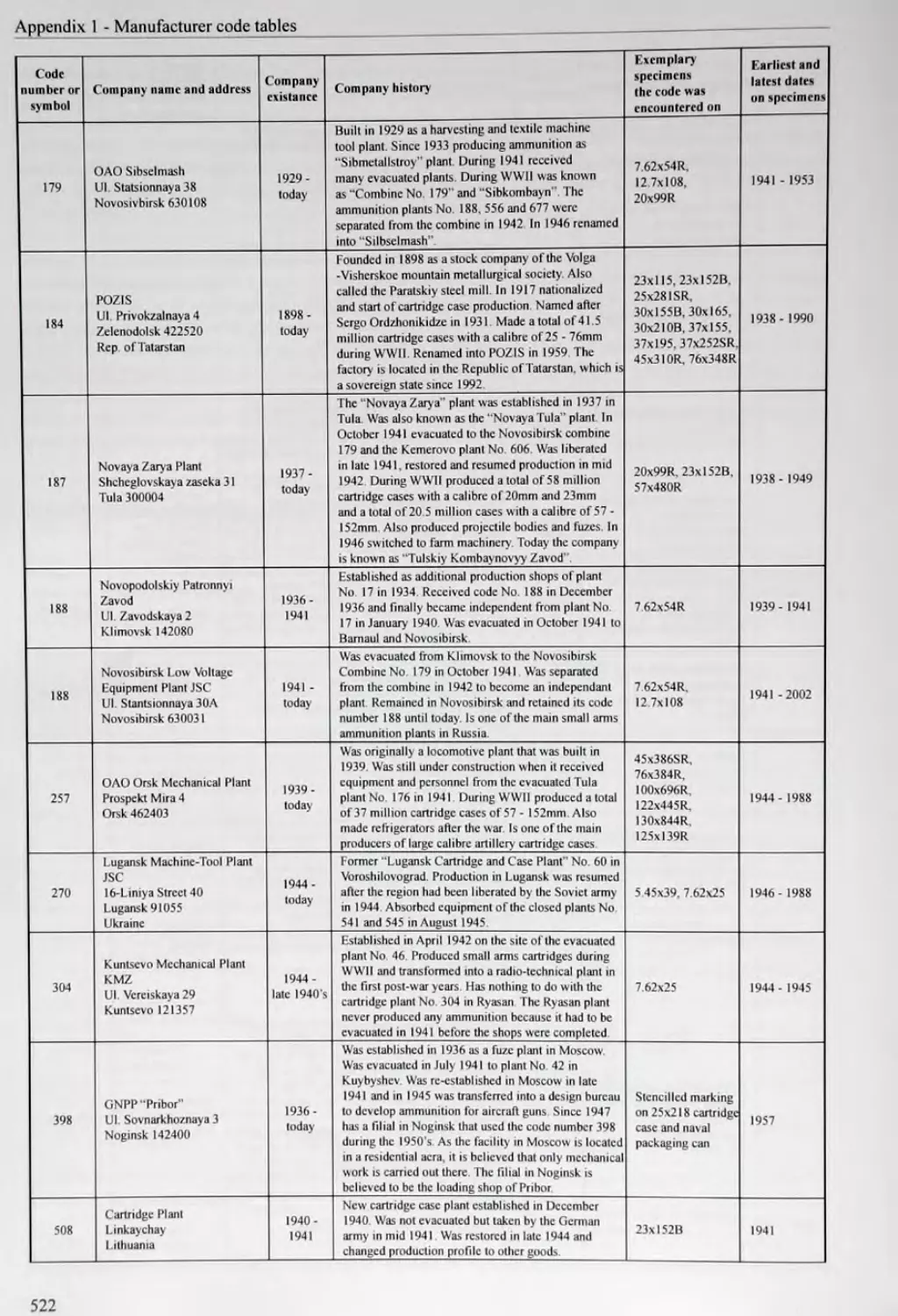
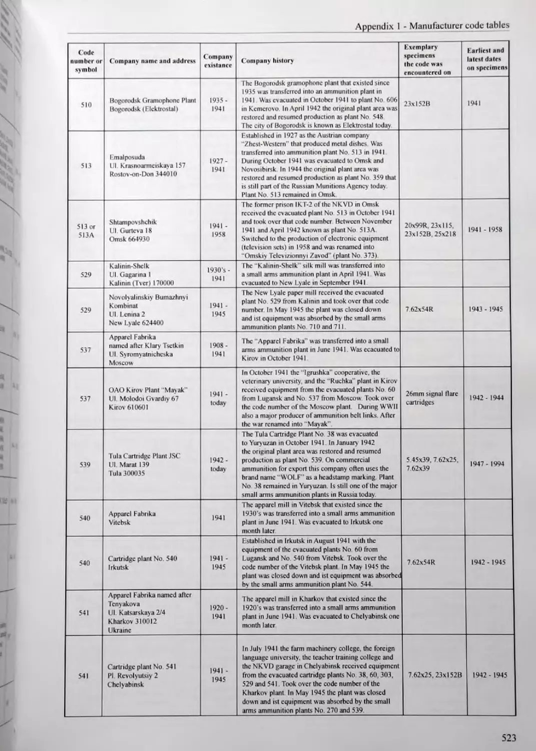
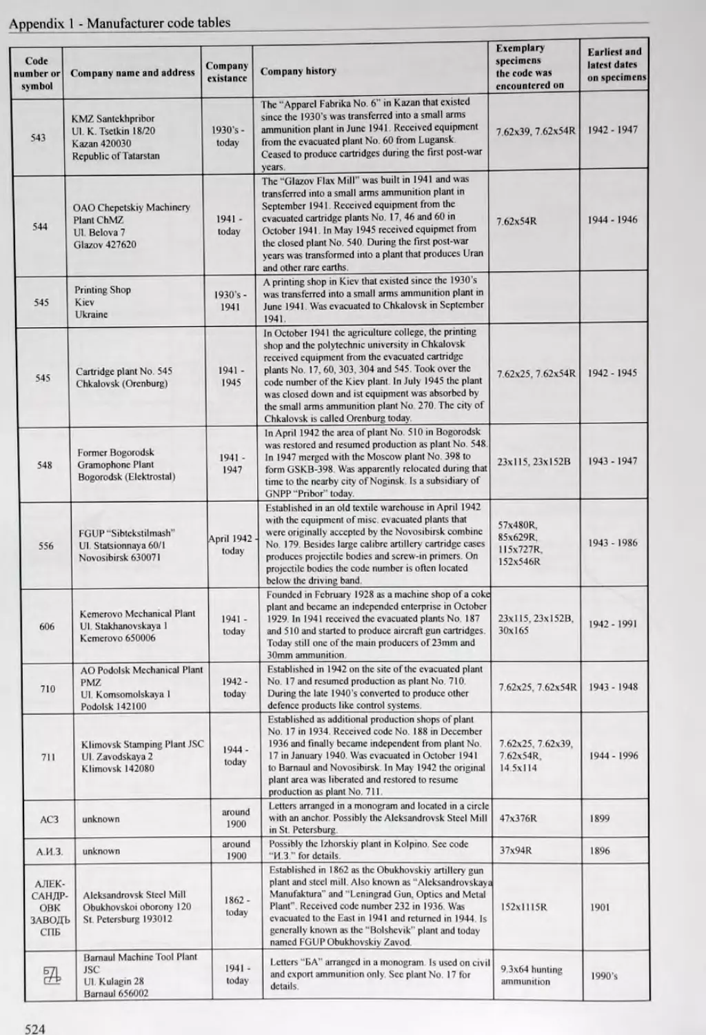
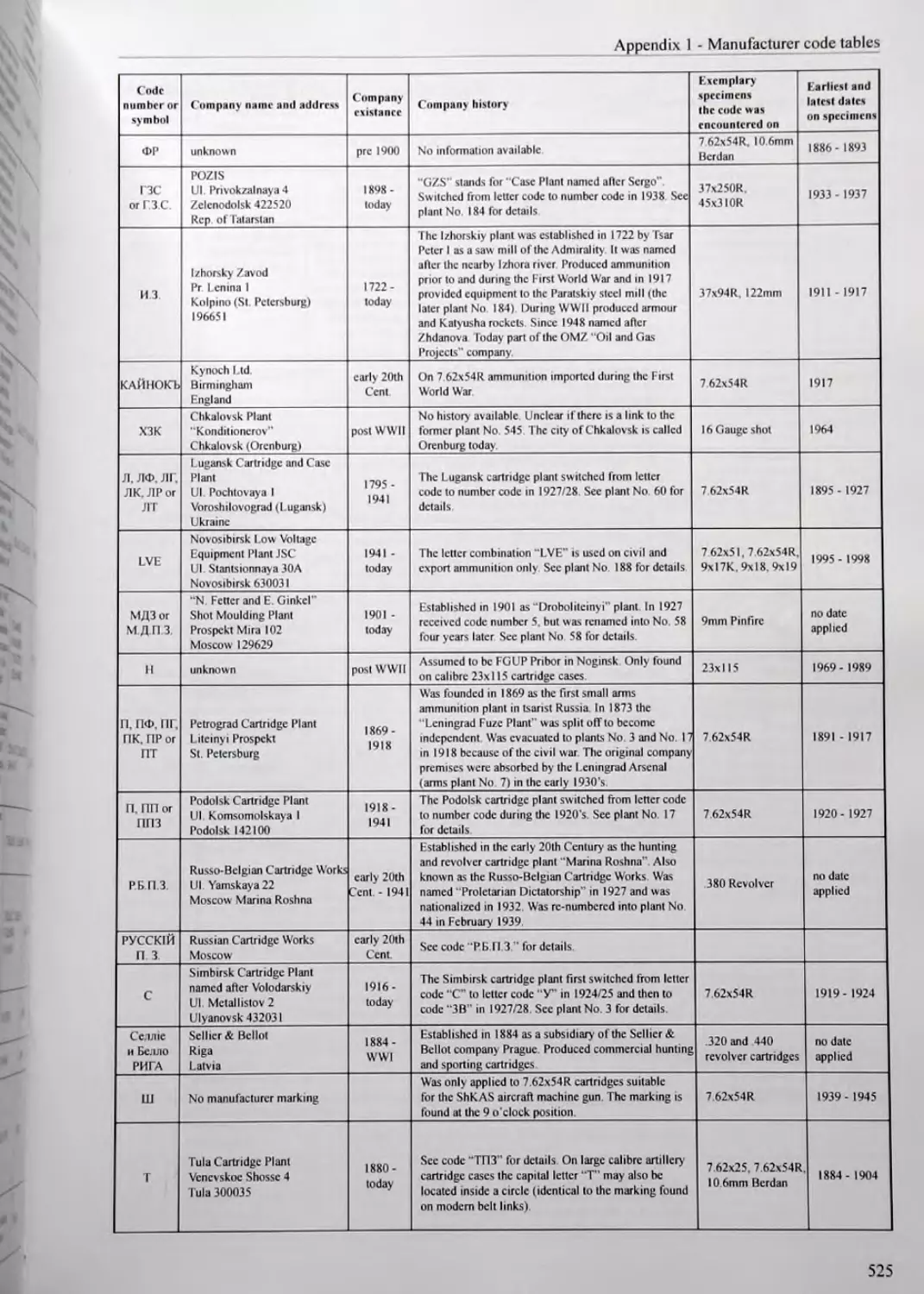
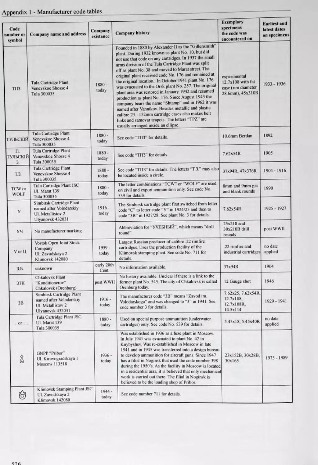
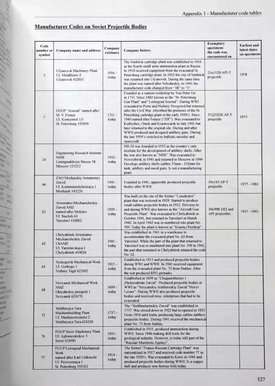
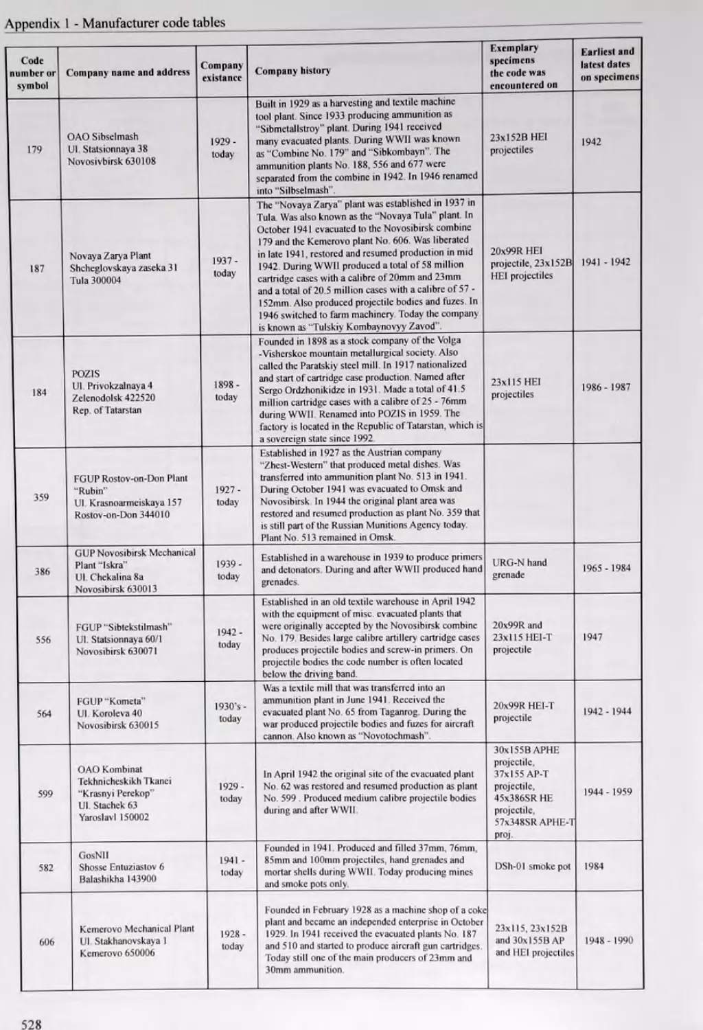
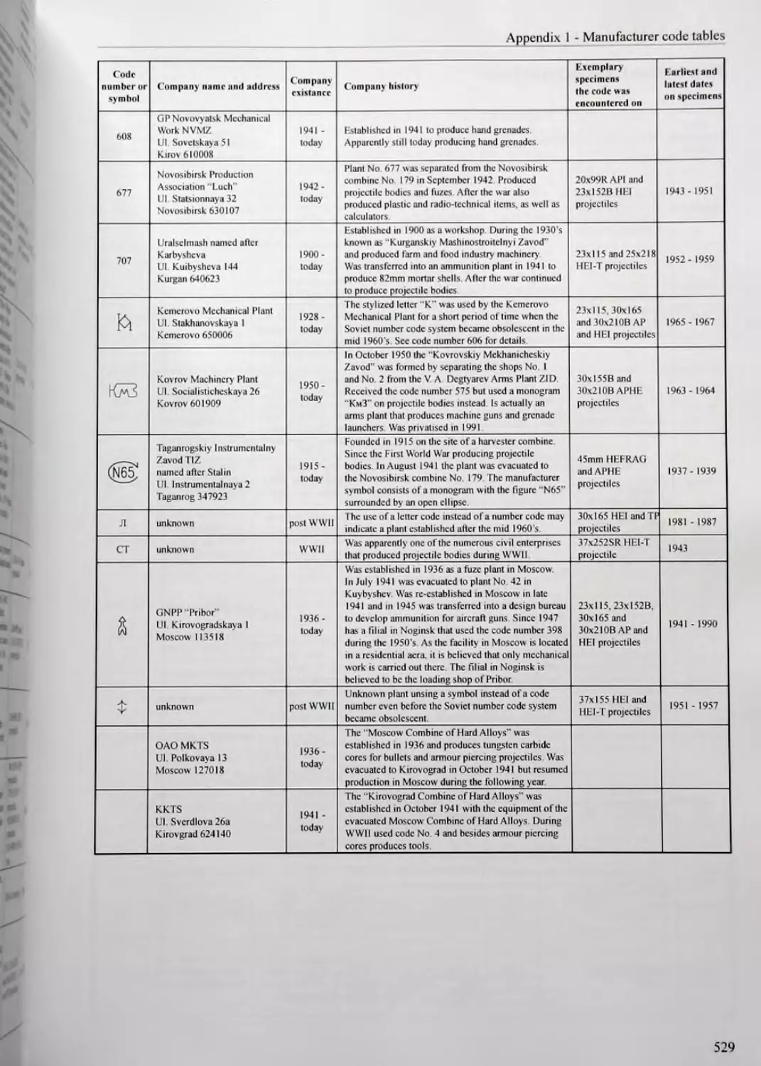
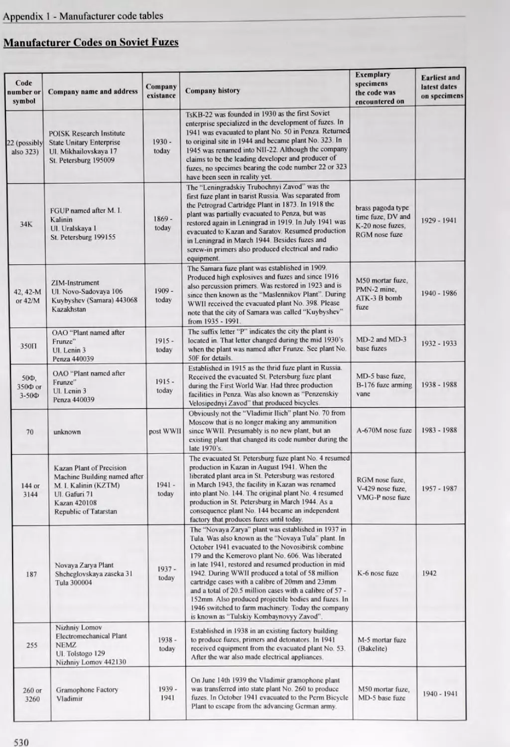
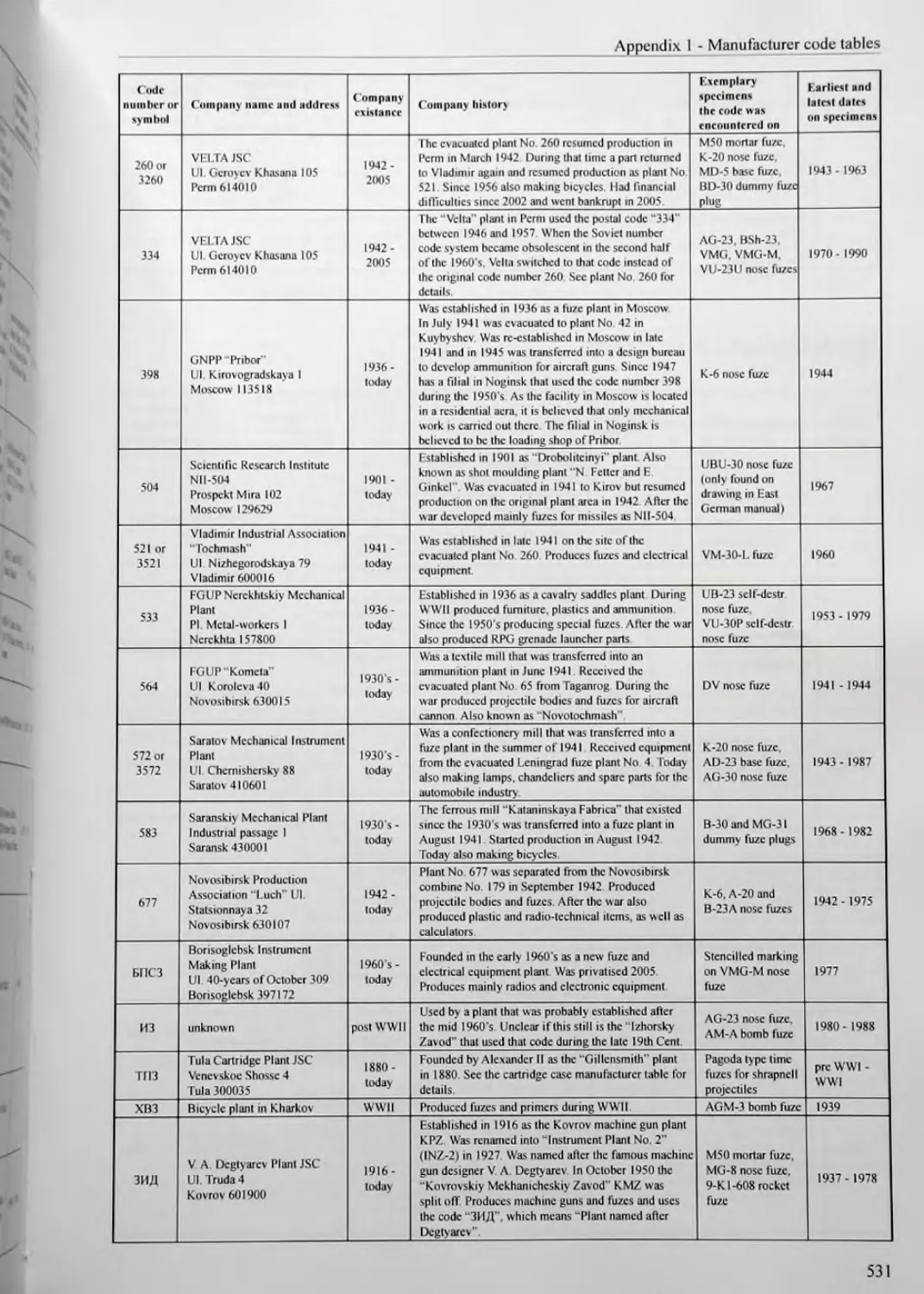
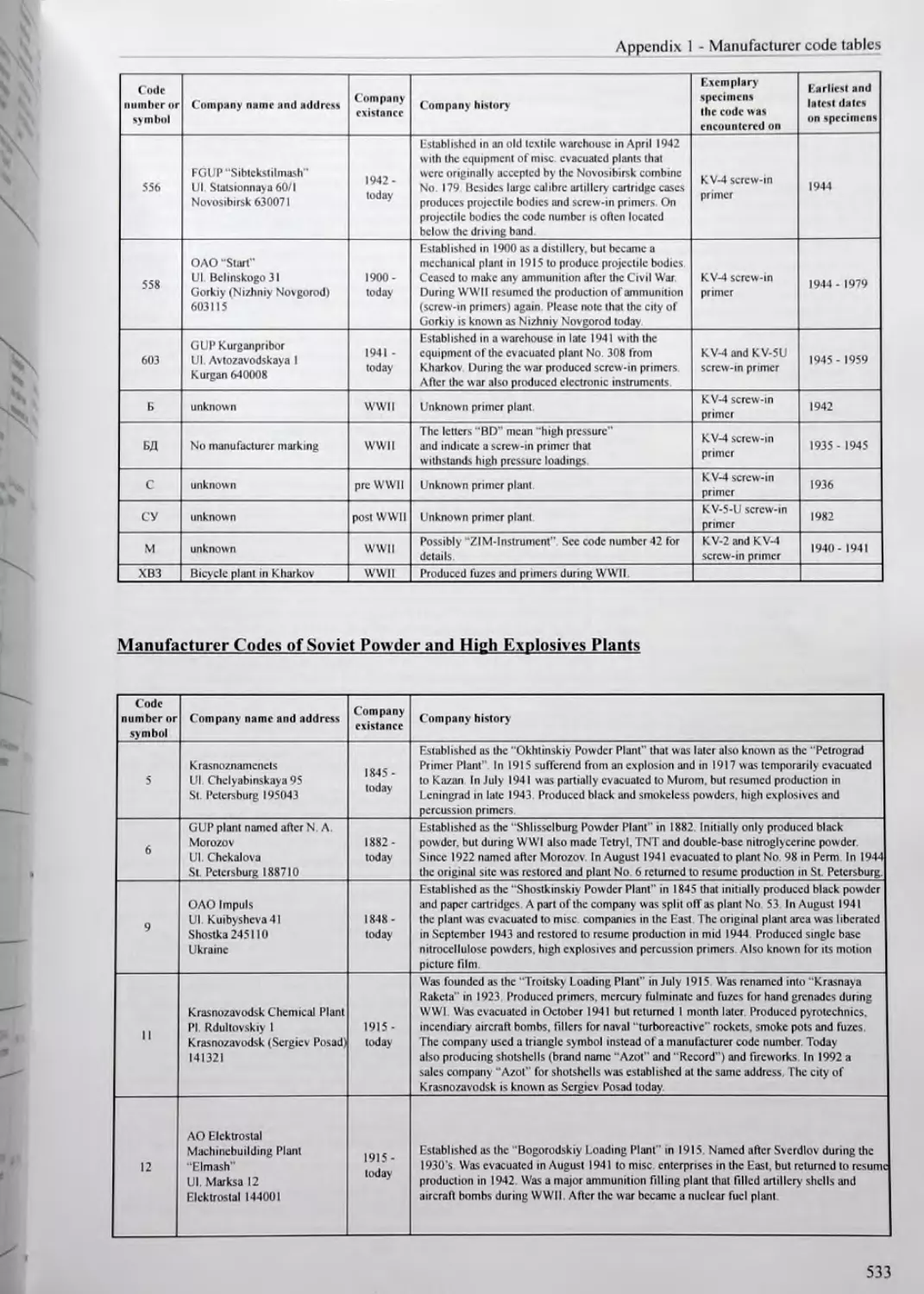
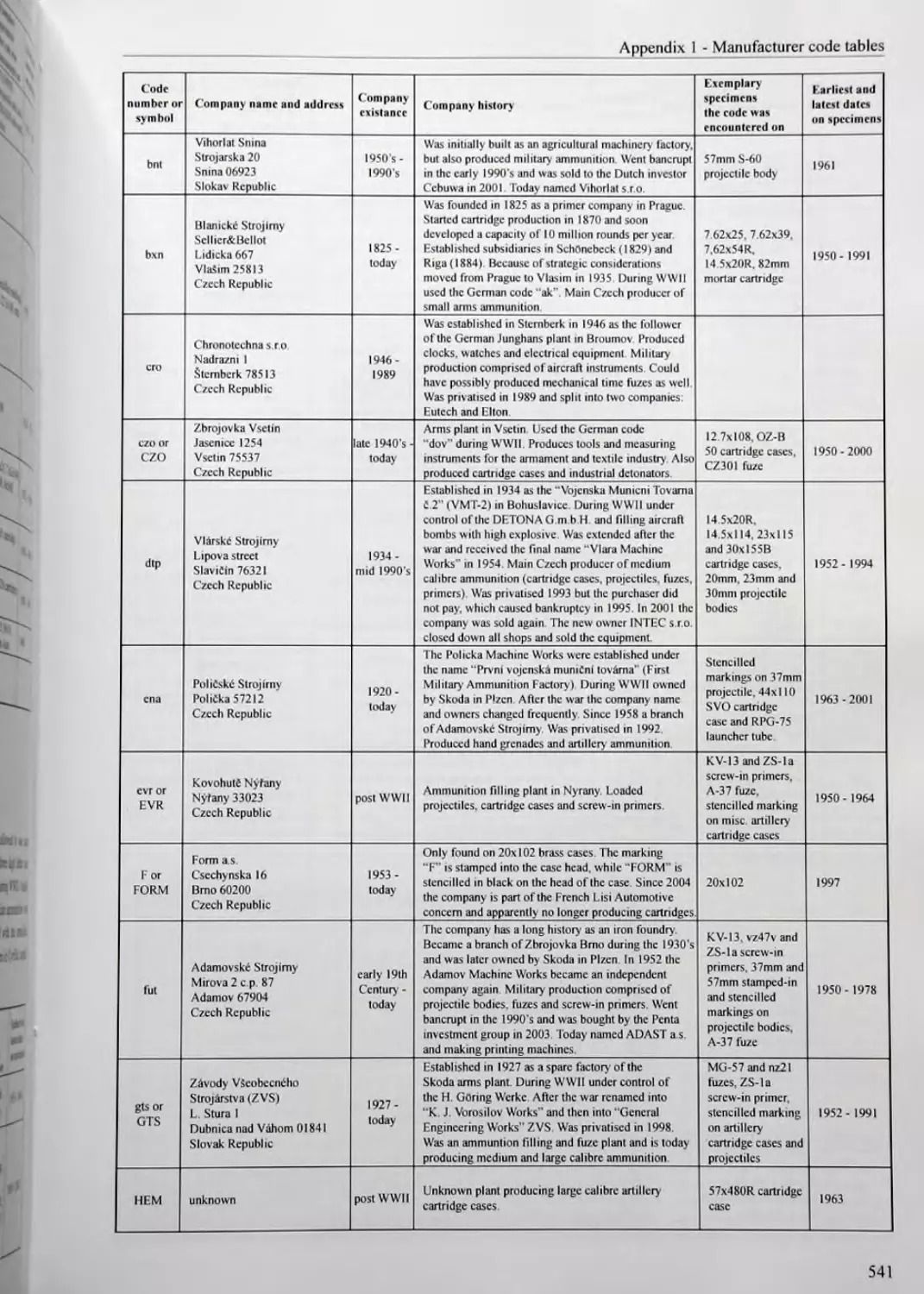
APPENDIX 1 - MANUFACTURER CODE TABLES...............................519
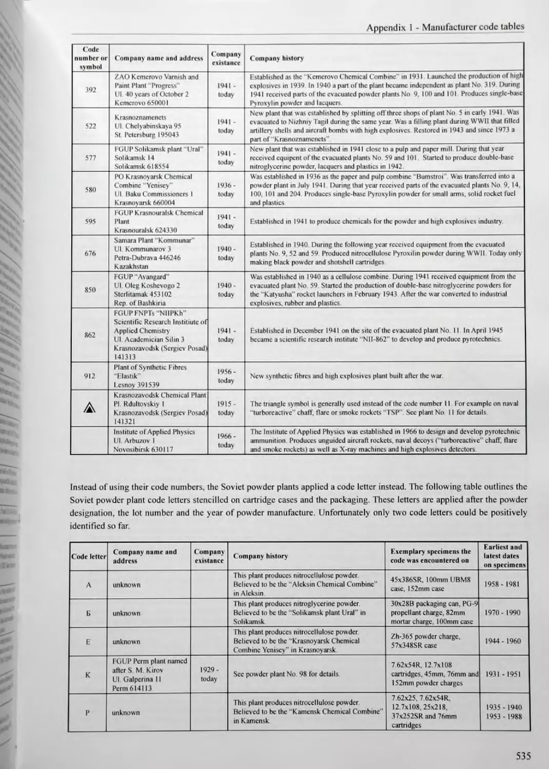
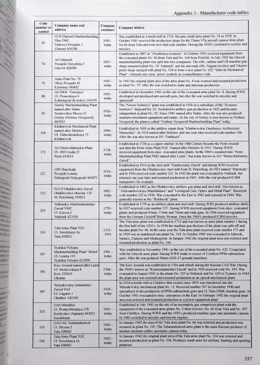
Soviet Manufacturer Codes..........................................519
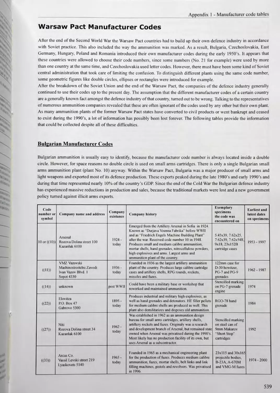
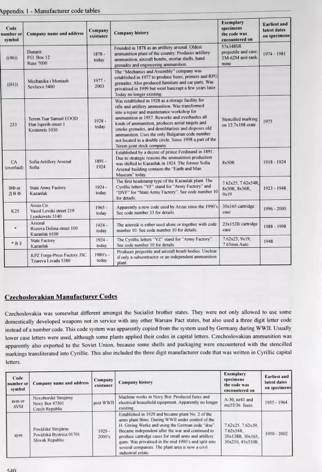
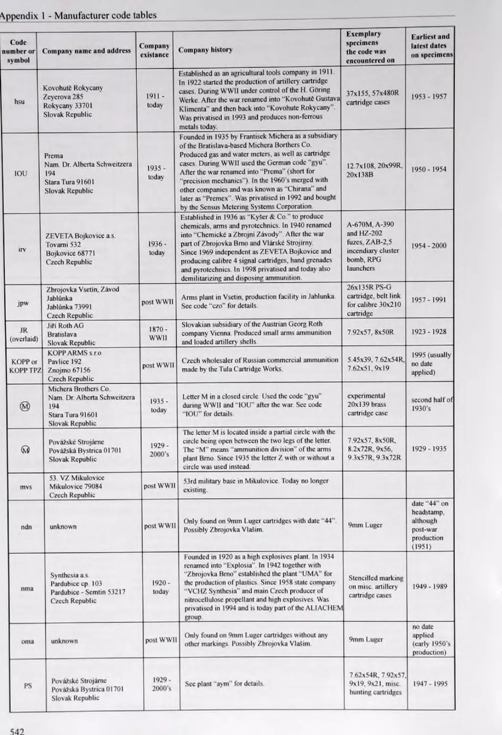
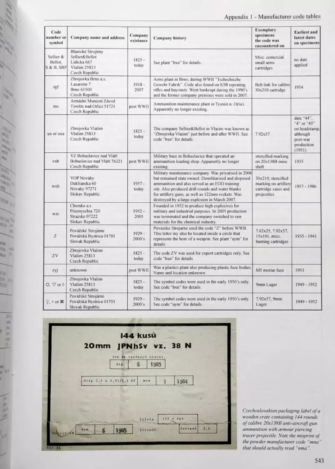
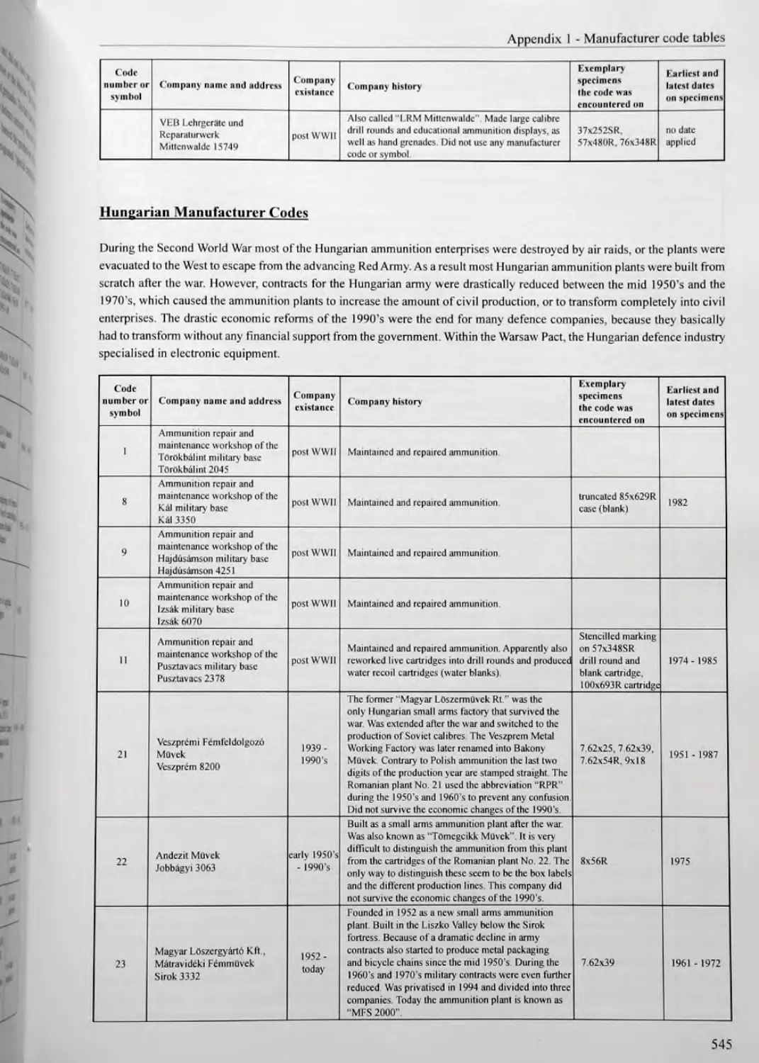
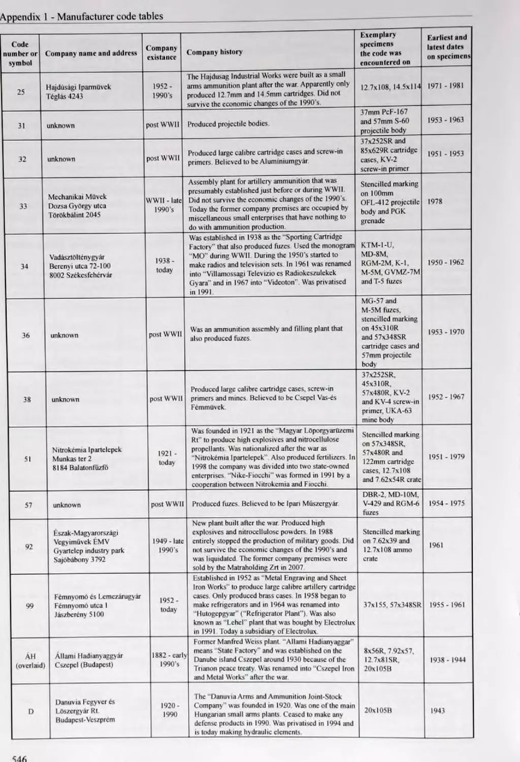
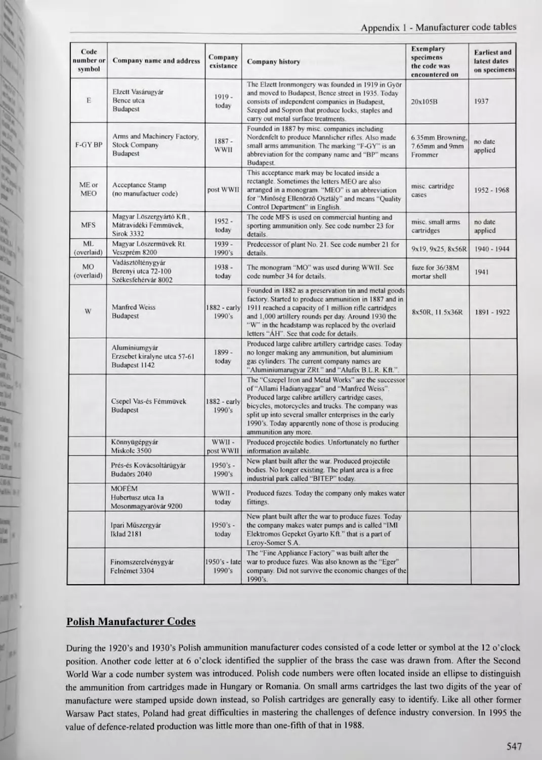
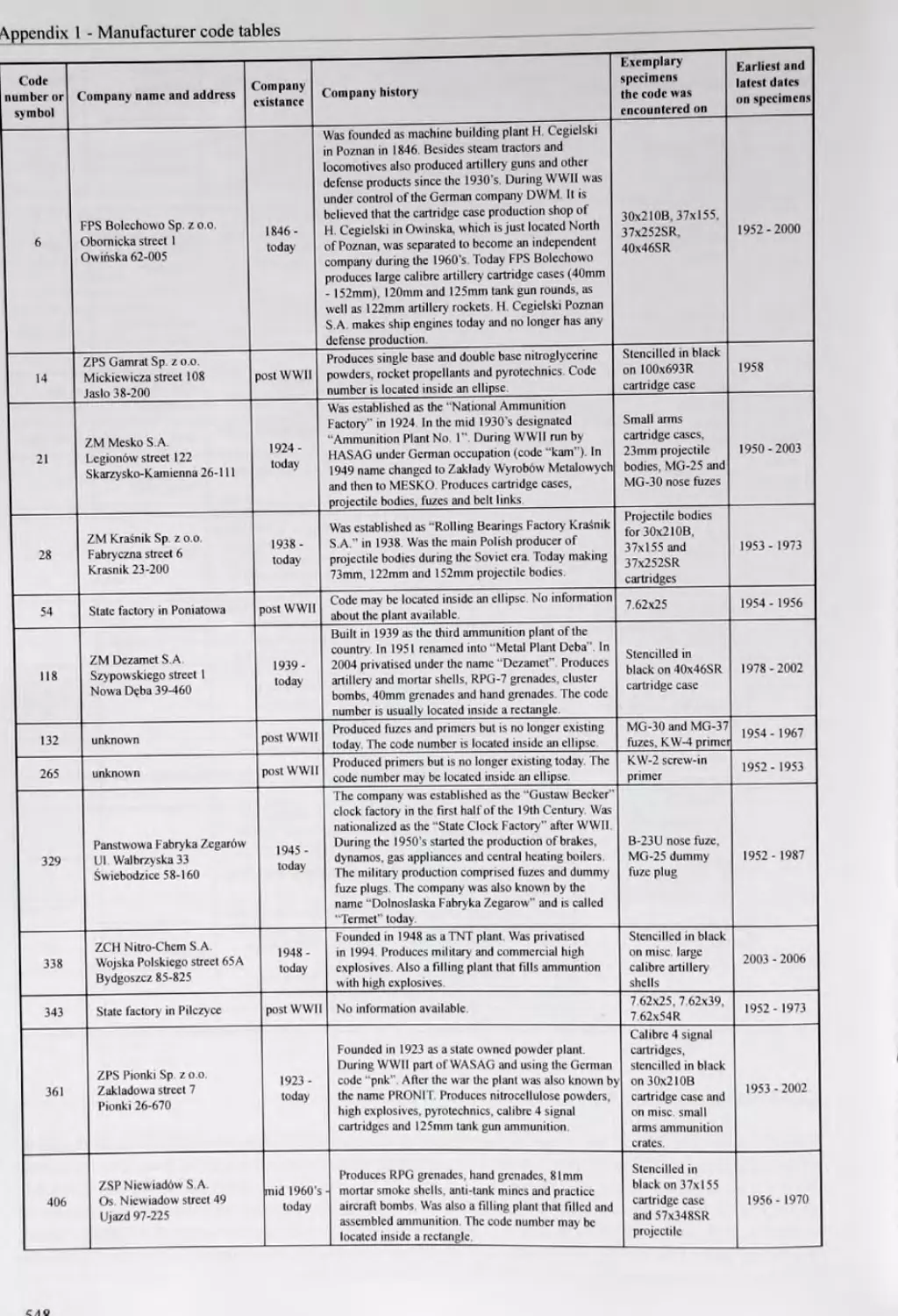
Warsaw Pact Manufacturer Codes.....................................539
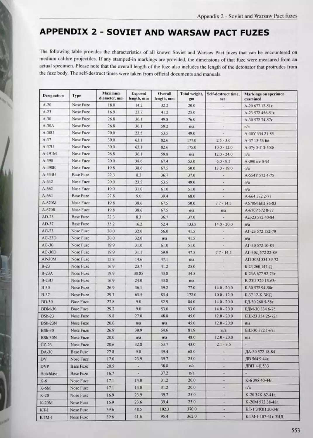
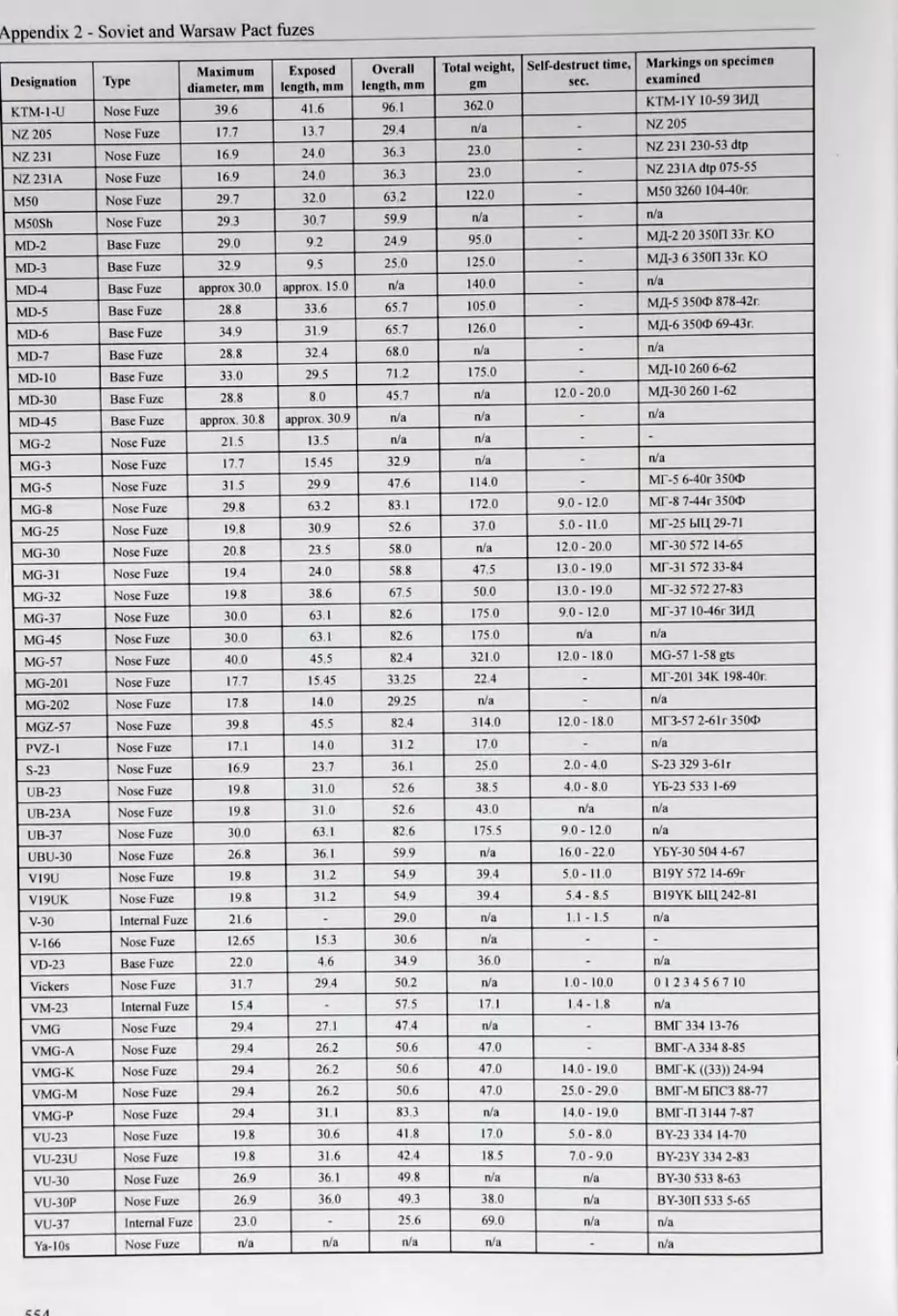
APPENDIX 2 - SOVIET AND WARSAW PACT FUZES............................553
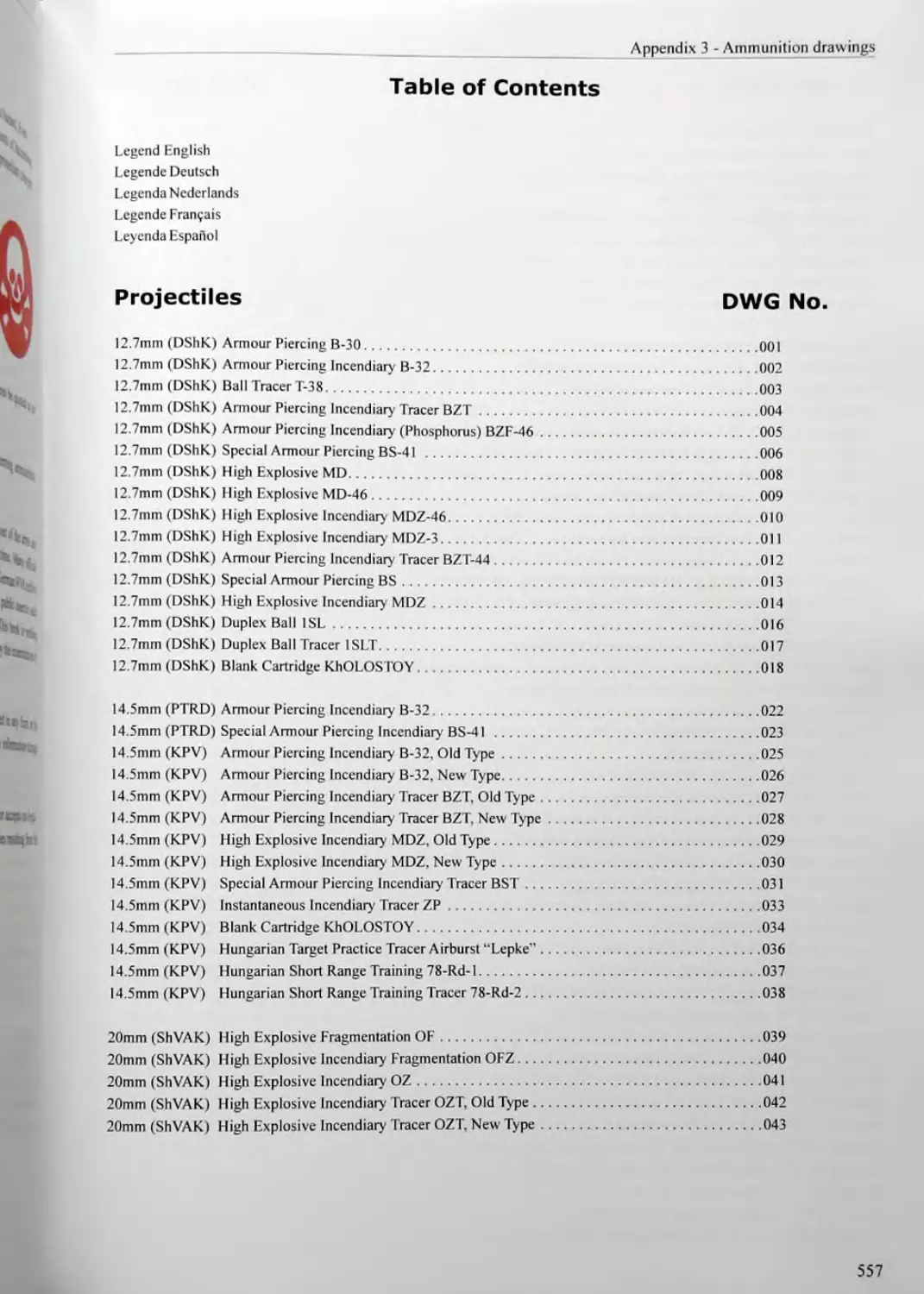
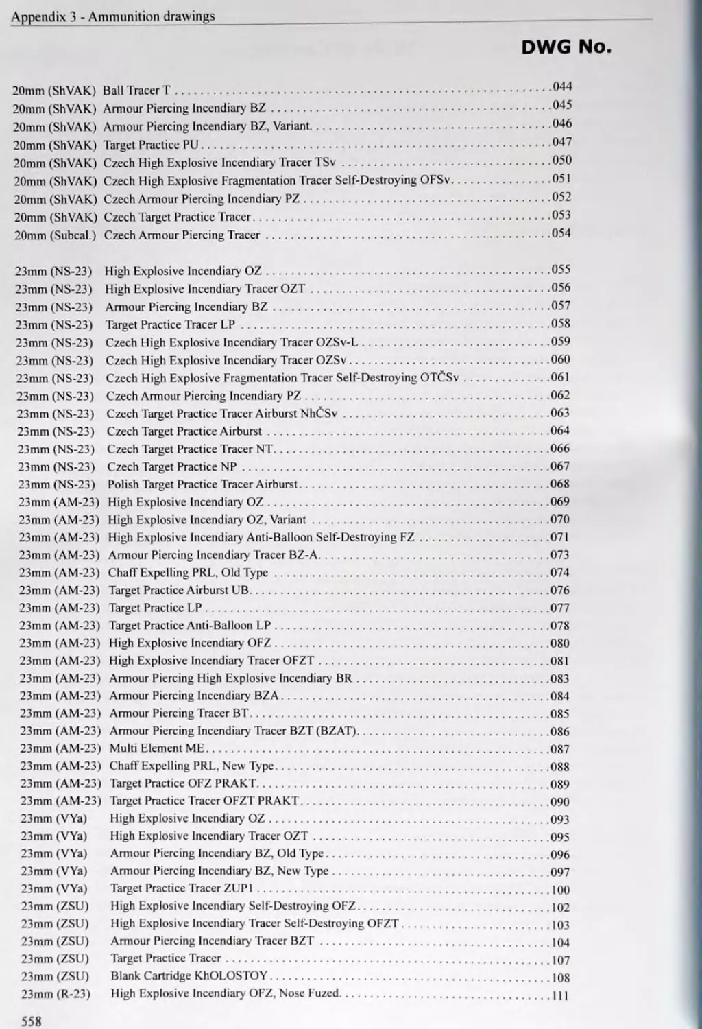
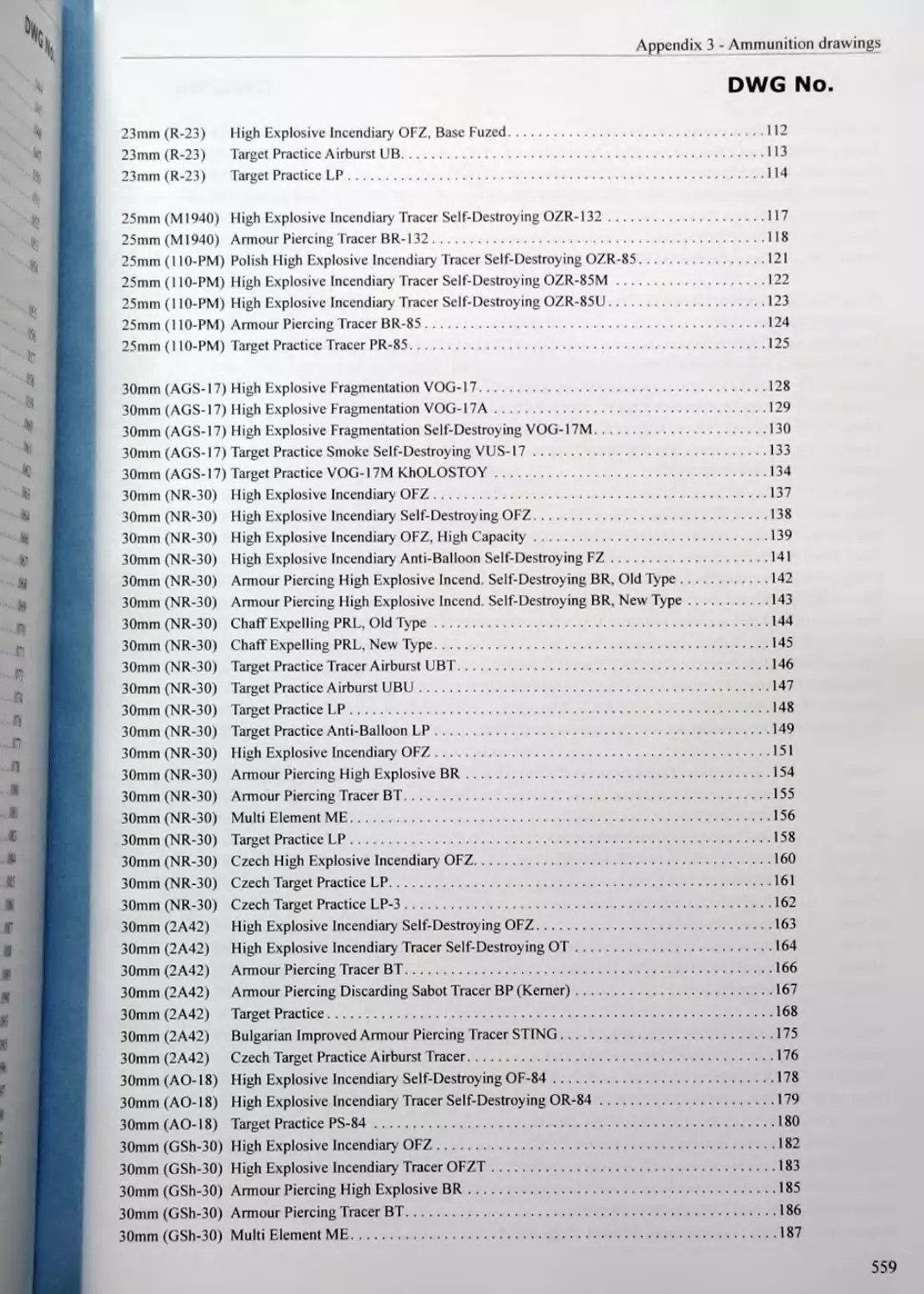
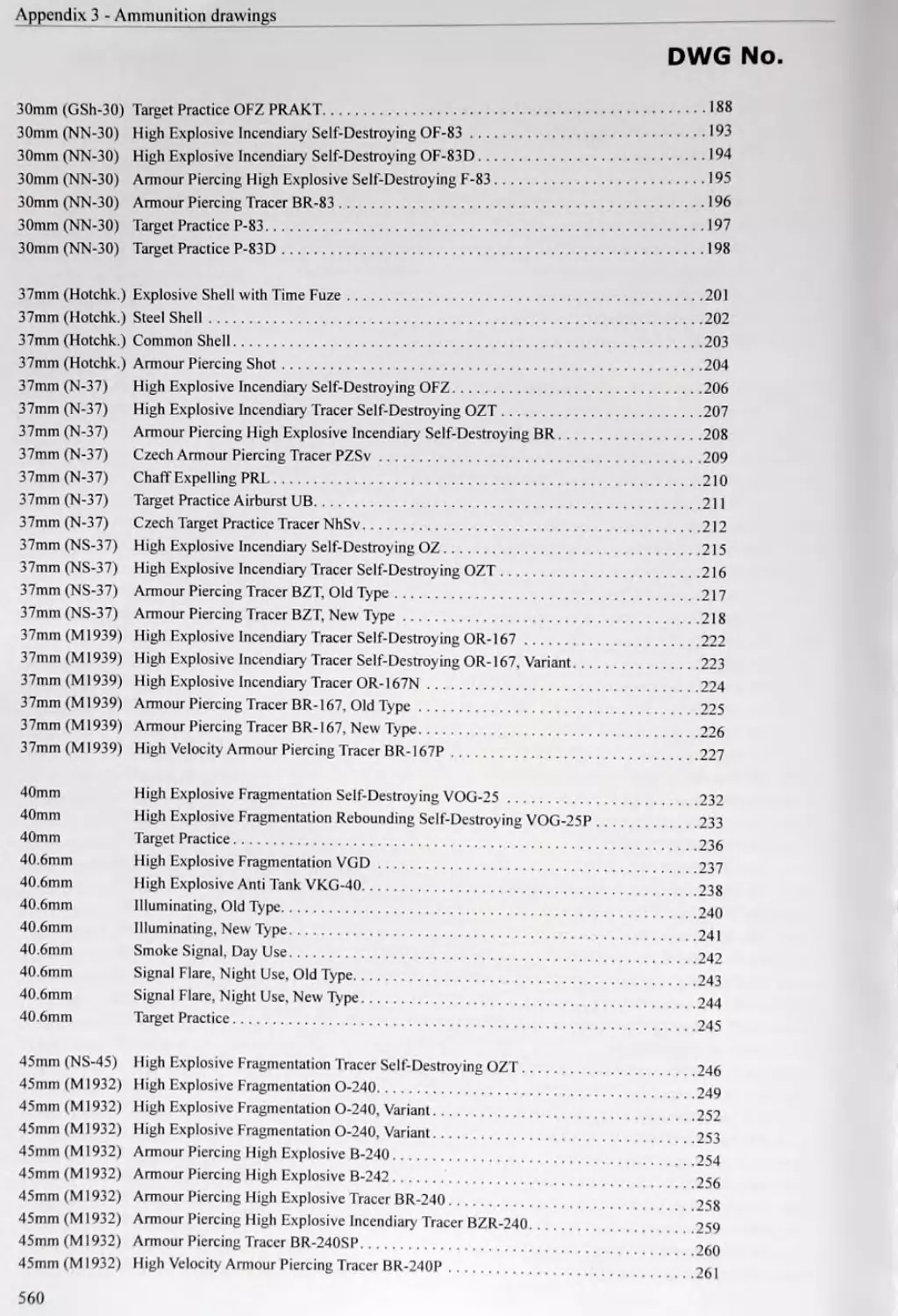
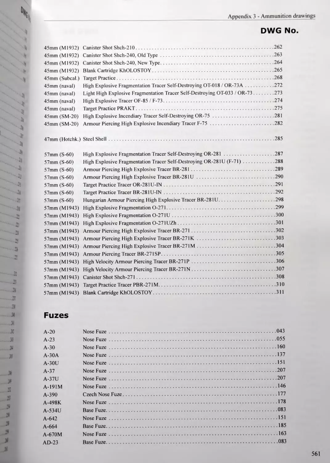
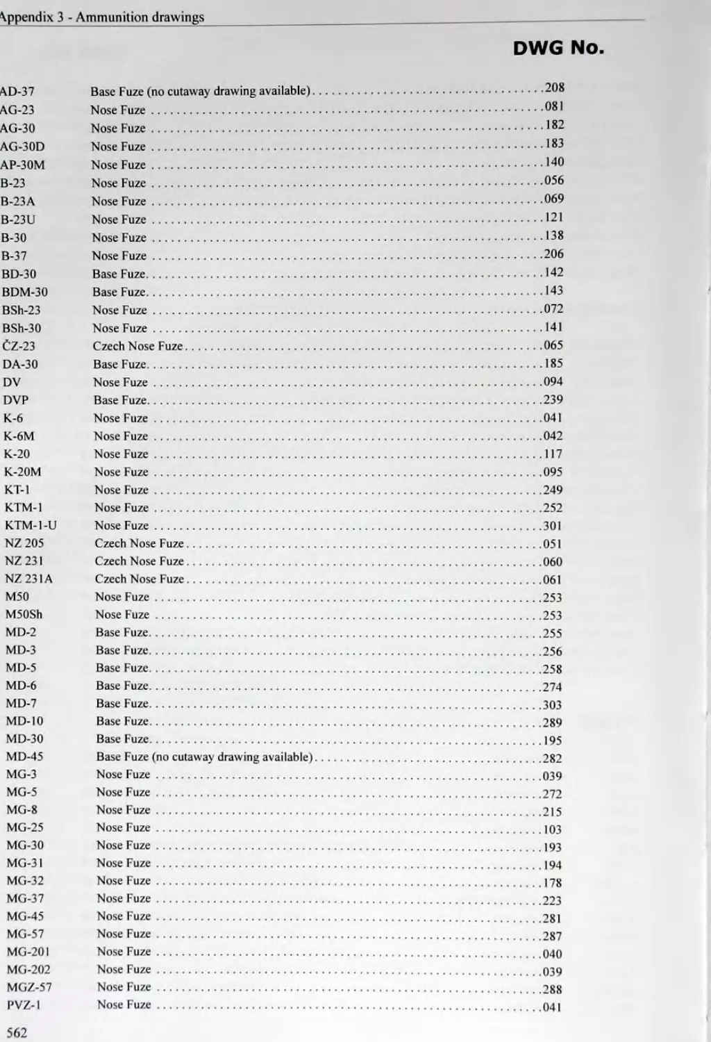
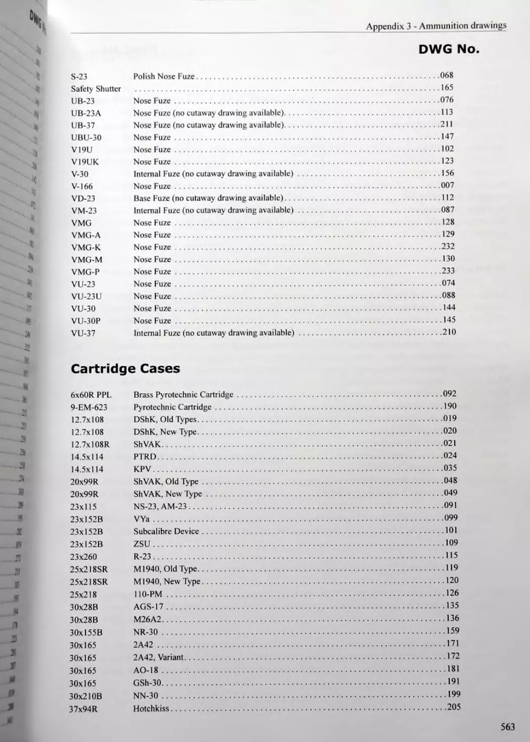
APPENDIX 3 - AMMUNITION DRAWINGS (ON CD-ROM)........555
BIBLIOGRAPHY..............................................565
INDEX.....................................................579
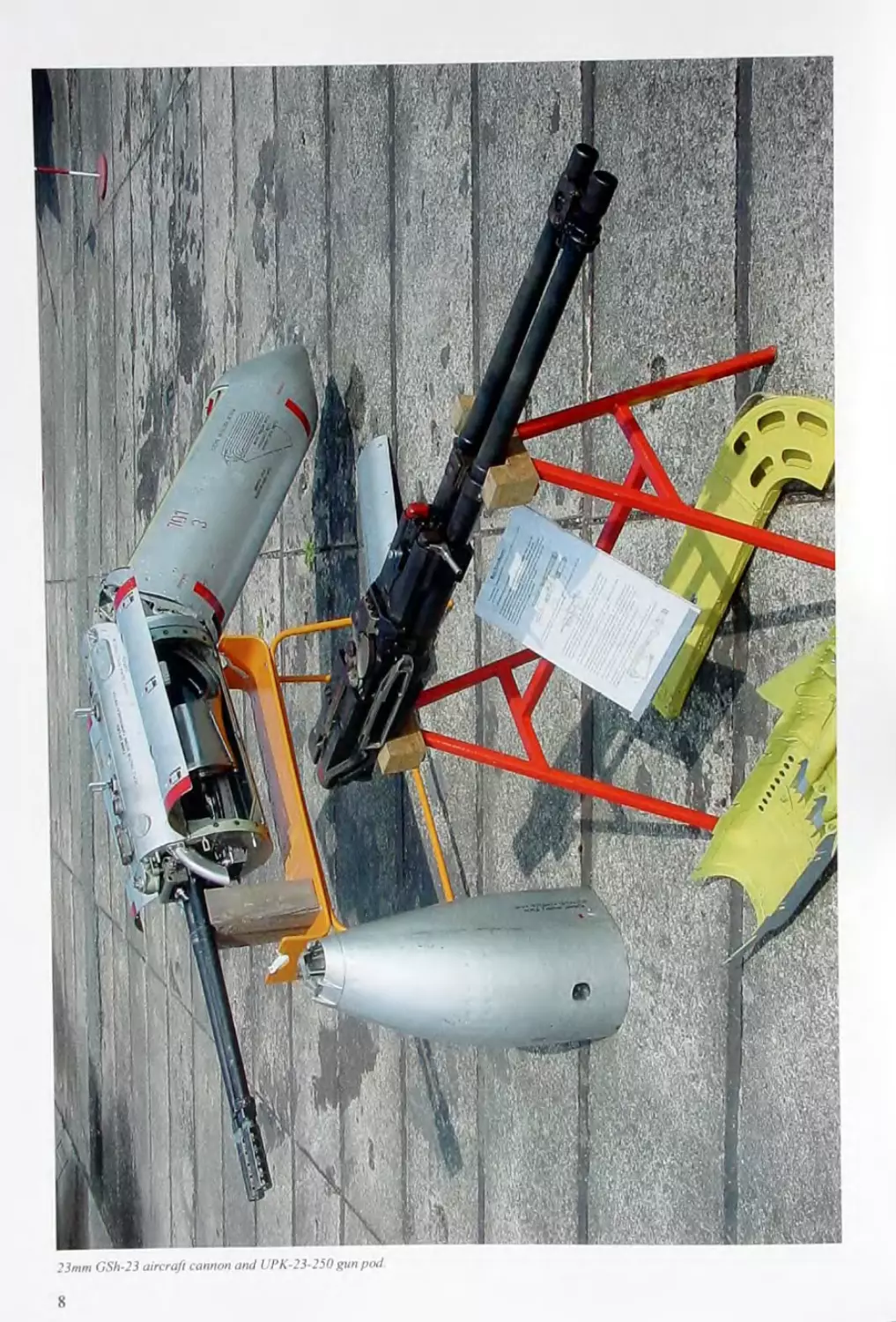
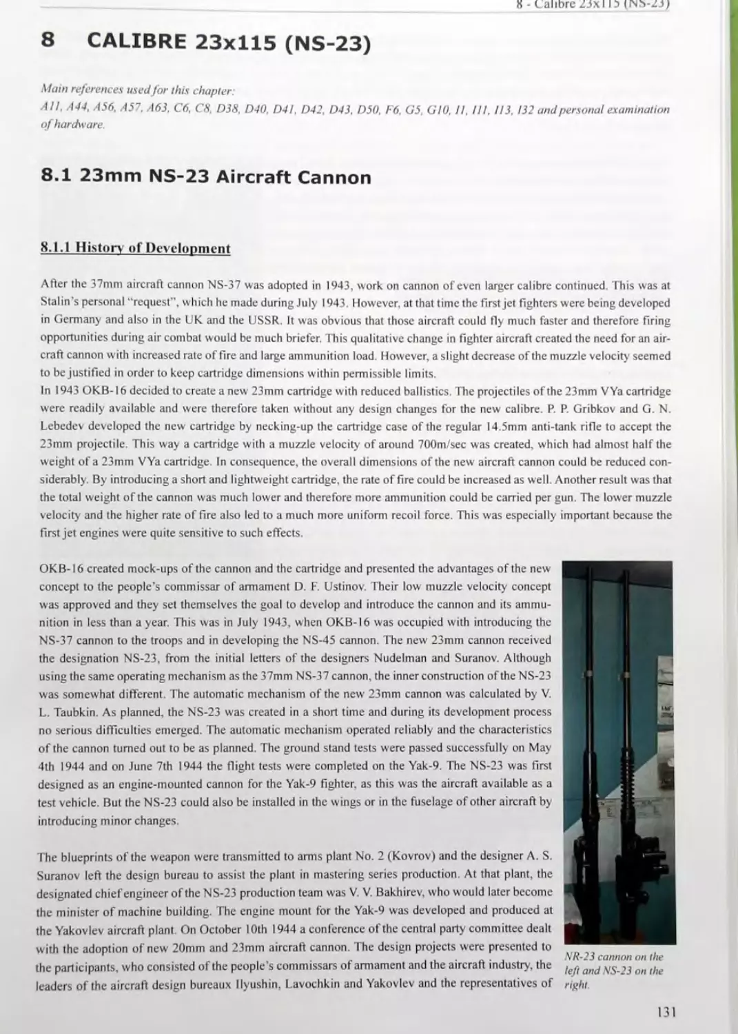
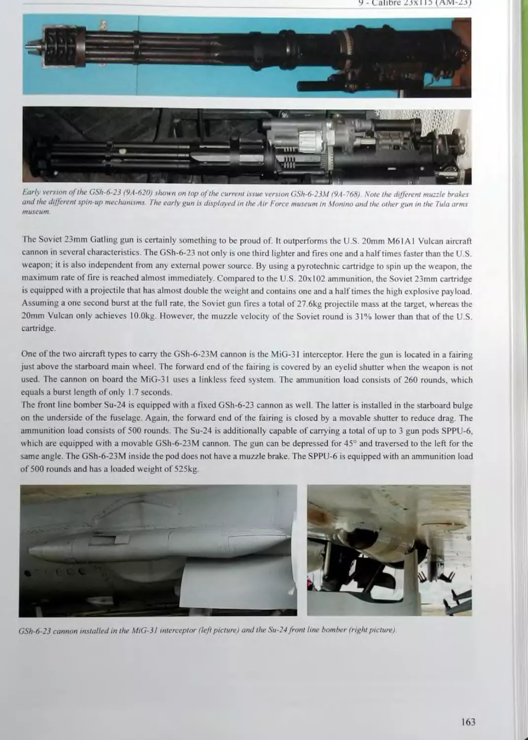
23mm GSh’23 aircraft cannon and UPK-23-250gun pod
8
I FOREWORD
This impressive book is the result of more than ten years of research by Christian Koll. It brings together for the first time all
available information on medium-calibre Soviet arms and ammunition - 12.7mm to 57mm inclusive including those of the
Warsaw Pact countries, during the period 1922 to 1991, with some modem developments also.
Every aspect is covered: the designation system and markings, links and clips, powders, explosive compositions, ballistics,
and the factory codes for cartridge case, projectile and component manufacturers (for example. 83 different Soviet cartridge
case plants!). Nearly all of these codes are identified. Also included is a history of the Soviet ammunition industry, with
information about the various factories and their period of operation, as well as information on the weapons used, including
their operating mechanism and cutaway drawings. More than 1,100 color photos of ammunition and weapons illustrate this
book.
One third of the book is devoted to almost 300 scale drawings in color of cartridge cases, projectiles and components, both
whole and cutaway views and showing all markings.
Christian Koll. an electro-technical engineer, was bom in Linz, Austria in 1976. He became interested in cartridges at an early
age, and eventually decided to specialize in the field of Soviet medium-calibre ammunition. Besides researching the major
collections and available literature, he established a web page and from this was able to gather and correlate a large amount
of additional information from all over the world.
All of this dedication and effort, which included several trips to Russia, has resulted in a massive and detailed work, con-
taining much hitherto-unavailable information, which will be an invaluable resource for researchers and historians for years
to come.
William H. Woodin, President
Woodin Laboratory
Tucson, Arizona. USA
September. 2008
9
II ACKNOWLEDGEMENTS
This book would not have been possible without the help and support of numerous people from all over the world.
First of all I would like to thank Rolf Pfennig from Germany, who collected and compiled a tremendous amount of infor-
mation on Soviet ammunition, even before I became interested in this topic. He also took care of the content proof reading.
I also owe special thanks to William H. Woodin from Tucson AZ, who twice hosted me and provided access to his incredible
collection and document archive. Bill also did me the honour of writing a forew ord for this book.
As English is not my native language, I am grateful that Anthony G. Williams from the United Kingdom proof read and
edited my text. As an experienced writer of numerous arms and ammunition books, he also provided advice about publishing
and printing.
My friend and colleague Josef M6tz, who wrote several books about Austrian small arms and ammunition, supported me in
overcoming the difficulties of authorship and also shared his experiences with printers and publishers.
From the numerous people and institutions who contributed to this work by providing information, photographs and assistance,
I would especially like to express my sincere thanks to:
Dmytro Adyeyev (“Treshkin") UA, Jost-Burkhard Anderhub D, Ernest Ashworth GB, Koen Bakker NL, Georg Becker A.
Alexander B. Bernardo USA, Armin Bickel D. Michael Blendinger D, Akos Boda B, Karl Bbhm A, Yuri Bushin RUS,
Alexander Diehl D, Joop Dijkman NL, Bernd Ddhring D, Wehrmachtsmuseum Eben D, ECRA - European Cartridge Research
Association, Harry Galloway GB, Dimitri Goulas CH, Hans HSfeli CH, Pavel Hamemik CZ, Emil Hamza H, Dirk J. Harms
NL, Andras Hatala H, Robert Hawkinson Jr. USA, Jiri Hrala CZ, 1ЛА - International Ammunition Association, Naiden lliev
BG, Ludek Jedlicka CZ. Petr Jezek CZ, Reino Karha FIN, Peter Keller D, Mika Kestila FIN, Imre Kiss H. WTS Koblenz D.
Erhard Koch USA, Gyula Kovacs B, Navy Museum Kronstadt RUS, Tank Museum Kubinka RUS, Przemyslaw Kupidura
PL, Jean-Francois Legendre F, “Megatron" A, Blaz Mihelic NL, Gerd Mischingcr D, Dimitar Mitev BG, Werner Mdnig
A, Museum of the Air Force Monino RUS. Museum of the Great Patriotic War Moscow RUS, Central Museum of the Red
Army Moscow' RUS, Panzermuseum Munster D, Detlev Nagot D. James P. O’Brien t USA, Christoph Opsommer D, Istvan
Pacser H, Keith Painter GB, Patronensammlervereinigung e.V. D, Patrice Pctermann D, Peter Petrusic D, Sigrid Pfennig D,
Roman Placek CZ. Klaus P6hl D, Michael Pontisso USA. Robert Pontisso USA, Joseph Pontisso USA, Maxim Popenker
RUS, “Poroch" UA, John Roks NL, Militarmuseum Rosenau A, Wehrtechnikmuseum Rdthenbach D, Milan Sabata CZ,
John R. Crittenden Schmitt USA. Rainer Schneck D, David Sciacca USA, Rick Seid USA, Robert Scyfrid E, Ralf Sommer
D, Artillery Museum St. Petersburg RUS, Dietmar Staude D, Liviu Stoica USA, Vince Strak H, Militararchiv Strausberg D,
Werner SOnkel D, Wolfgang Thamm D. Attila Toth H, Javier Torijano B, Arms Museum Tula RUS, Oleg V. Valetskiy UA,
Navy Museum Varna BG, Vesa Vasara FIN. Petr Voboril CZ, Stefan Wagner D, Harald Wehner D, Charles J. Wells USA,
Gene Whitehead USA, Giinter Wiesinger A, Mick J. Wilkinson UK. Jiirgen Wttlk D, Beth Woodin USA. Zdenek Zapp CZ.
Ren6 Zscheckel D.
Thanks are also due to all those who are not included in the above list because they did not want to be mentioned, or because
I forgot to mention them. If the latter is the case, please accept my apologies.
10
Ill INTRODUCTION
Before 1 start outlining the idea and concept of this book, I would like to introduce myself. 1 was born in 1976 in Linz,
Austria and work as an electro-technical engineer in a private company. Ever since I was a teenager I have been curious about
ammunition and, as time went by, this developed into a serious interest. I learned that 1 was not the only one interested in
this topic when I joined the German branch of ECRA (European Cartridge Research Association) and the IAA (International
Ammunition Association). I he members of these associations research the history and technical aspects of ammunition
and share their knowledge in publications and databases. This work is carried out by private individuals, in their spare time
and at their cost, and has resulted in numerous publications especially valuable for official purposes such as forensic and
explosive ordnance disposal services. In fact, most governmental and military agencies simply do not have the knowledge
and resources to do this work. It is therefore an irony that many officials and politicians do not see the cartridge researchers
and collectors as the partners they actually are, but as a criminal threat. Especially in Europe, collectors and researchers are
threatened with increasingly restrictive and sometimes ridiculous legislation. Strict gun laws, a reduction in individual rights
and increasing surveillance measures are a clear expression of a general mistrust of the citizenry. As we Europeans apparently
tend not to learn from our past, or the history of other dictatorships, the European Union might end up in becoming a new
"Soviet Union - a centralised, bureaucratic and unjust monster state. This book is therefore also intended to demonstrate
what can be accomplished by enthusiasts free to research in this field - if we are allowed to.
The idea tor this book was bom 10 years ago, when I realised that there was almost no information available about Soviet
medium calibre ammunition. Even a well known publisher, specialising in books about weapon systems, was rather confused
with this topic. While there were some good books on Soviet small amis and ammunition, and at least some information
available about artillery rounds, this can not be said about medium calibre cartridges and their guns. What are “medium
calibre” guns anyway? This type of weapon combines the high rate of tire of a machine gun with the ability to fire a fuzed
high explosive projectile. Technically this means any automatic weapon with a calibre between 12.7mm and 57mm and
includes anti-tank, anti-aircraft and aircraft guns. The need to maximise the effectiveness of such small artillery shells has
resulted in a large variety of projectile types. The Soviets, in particular, were very imaginative in designing special purpose
rounds for their medium calibre weapons.
Due to their rough exterior, Soviet arms are often regarded as crude and simple, and are accordingly underrated. During
my research work I came across so many curious and clever designs that I had to admit that this prejudice couldn’t be more
wrong. Since no comprehensive historical or technical information about Soviet medium calibre weapons was available in the
West, I decided to include a detailed description of these guns in this work. Understanding how a particular weapon works can
also explain why a certain cartridge is designed in the way it is; so it not possible to separate guns and ammunition anyway.
I also hope that the circle of readers interested in this book will be much wider than would have been the case for a purely
ammunition book. I decided to publish this book in English, to make it available and understandable worldw ide.
How was the information contained in this book collected? In 1999 I published my “Russianammo” internet webpage to get
into contact with as many people as possible and to collect their knowledge about Soviet arms and ammunition. The basic
idea was to freely provide the information I had gathered so far and at the same time ask the readers for contributions in
return. As a result I received information, pictures and declassified military manuals from all over the world that otherwise
would not have been accessible. I also discovered that most of the information was already published in Russian books or on
the internet, but because of the language barrier was not available to readers in the West. I therefore learned a little Russian
and travelled to Russia to visit arms museums and to acquire relevant literature. 1 believe that for me as an Austrian, living
in a non-aligned country next to the former “Iron Curtain”, it was probably easier to get access to that kind of information. I
also think that ten years after the end of the Warsaw Pact turned out to be the correct time to start such a work. Perestroika and
Glasnost only slowly replaced the Soviet altitude of strict secrecy concerning everything to do with arms and ammunition.
I have to point out that this book is highly specialised and not a general or “popular” book on arms and ammunition. As I
look a scientific approach, a basic competence in ordnance is assumed in the reader. This work only deals with arms and
ammunition introduced or in service during the Soviet era: 1922 - 1991. Black powder filled shells of the Russian Empire
arc outside the scope of this book, as are the latest arms developments of the Russian Federation. The Cyrillic alphabet is the
key to understanding the markings and designations used. I therefore strongly recommend the reader to learn this alphabet,
so that he will not be left confused.
11
Please note that throughout the book the metric system is used for any numerical data. Every calibre is designated in the
European system that consists of the projectile diameter multiplied by the length of the cartridge case in millimetres. An
additional suffix letter indicates the case type (no letter = rimless case. R = rimmed case, SR = semi-rimmed case. RR ~
rebated rim case. В = belted case). An example: “30xl55B” means a 30mm cartridge with a belted cartridge case that has a
length of 155mm.
1 tried my best to give this book as clear and consistent a structure as possible. For every calibre a separate chapter has been
written. Please excuse the fact that, due to time constraints, a simplified referencing system has been used. At the beginning
of every chapter the main references used for that chapter are outlined. The summary list of all references forms the bibli-
ography at the end of the book. Every chapter contains the history and a detailed description of the operating mechanism
of each individual medium calibre weapon. The operating mechanisms are briefly described in a way which is intended to
be easy to understand. Besides explaining the Soviet ammunition in every chapter, the cartridge types produced in the other
Warsaw Pact states are also mentioned. Although only an adjunct to arms and ammunition, the ammunition packaging and
the belt links deserve a mention in such a work as well. Finally, to do away with the confusion concerning these topics, I have
included comprehensive studies of Soviet manufacturer codes and the Soviet ammunition designation and marking system
Although only listed as an appendix, the drawings consist of almost 300 pages and form a unique resource. Each drawing has
an individual drawing number (DWG No.) that can also be found in the tables throughout the book. To keep this book within
an easily manageable size I decided to put all these drawings on a CD-Rom that is enclosed to the book. The information
cut-off date for this book is September 2008.
In retrospect 1 can say that I very much enjoyed researching and writing, during which I had numerous “aha!” experiences and
made the acquaintance of many kind and enthusiastic people from around the world. I sincerely hope that the reader can share
the excitement I felt when able to answer questions which have puzzled arms and ammunition researchers for decades.
Christian Koll
Linz, August 10th 2008
12
IV DISCLAIMER
1. Please note that any kind of ammunition is extremely dangerous and a serious hazard. Even
inert ammunition, ordnance or its components may be dangerous, because of remnants of hazardous
chemicals like high explosives or other fillers. Any information about powders and propellant charges
is not intended as reloading data.
THIS IS A VERY SERIOUS WARNING:
DO NOT ATTEMPT TO HANDLE ANY KIND OF
MILITARY AMMUNITION. EITHER LIVE, DUD
OR SUSPECTED TO BE INERT!
Although the information in this book has been thoroughly researched, it should not be quoted as an
authority for action.
2. Always follow the laws and regulations of the country you live in concerning ammunition,
ordnance, high explosives, pyrotechnics and arms.
3. This publication does not provide any classified military information. Most of the arms and
ammunition described in this book have been retired from service for a long time. Many official
manuals have therefore been declassified and are available in archives such as the German N VA archive
in Strausberg. Information like that provided in this book is also available from public sources such
as the publishers “Military Parade" and “Jane’s", as well as from the internet. This book is nothing
more than a summary of the information that is already available, supplemented by the examination of
specimens.
4. All rights reserved. No part of this book may be reproduced or transmitted in any form or by
any means, electronic or mechanical including photocopying, recording or by any information storage
and retrieval system, w ithout permission from the author in writing.
5. Use the information contained in this book at your own risk. The author accepts no legal
responsibility for personal injury, death or property damage to users or third parties resulting from the
use of this book.
13
V THE CYRILLIC ALPHABET
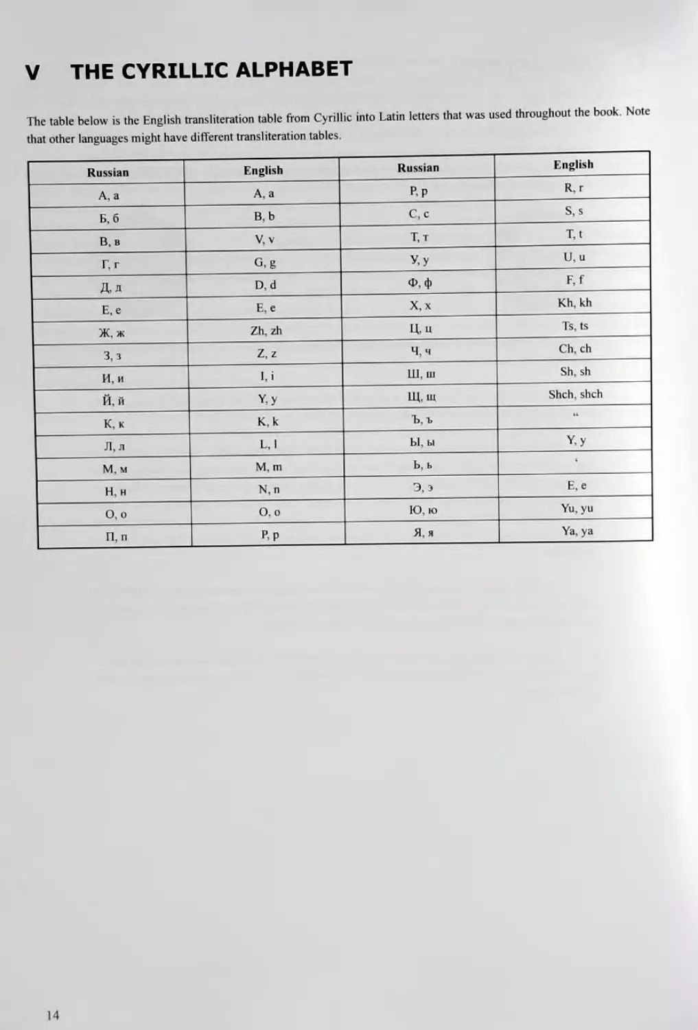
The table below is the English transliteration table from Cyrillic into Latin letters that was used throughout the book. Note
that other languages might have different transliteration tables.
Russian English Russian English
A, a А, а p.p R, r
Б, 6 В.Ь C,c S,s
B.b V, v T.t T,t
Г, г G.g У у U, u
Дд D, d ф, Ф F, f
E,e Е, е X, x Kh, kh
Ж, ж Zh,zh Ц, u Ts, ts
3,з Z,z Ч,ч Ch, ch
И, и и Ш, ш Sh, sh
Й. й Y,y Щ, ш Shch,shch
К, к К, k Ъ.ъ 11
Л, л L, 1 Ы, ы У.У
М,м М. m Ь, ь i
Н, н N, n Э, э E, e
О.о O,o Ю, ю Yu, yu
П, п Pp Я, я Ya, ya
14
1 SOVIET AMMUNITION DESIGNATIONS AND
NOMENCLATURE
Main references used for this chapter:
,r. A42. A44. A48. A49. A50. A65. Bl, Cl. C2, Ci, DI. D38, D40. D4I. D42, D43, D47. E7. E8. G4. 128. 133. .19. .III. JI2.
J13, J14, JI 5 and personal examination of hardware.
Soviet ammunition nomenclature and designation systems can be very confusing if they are not separated into the groups
they apply to. There is no uniform Soviet ammunition designation system, but several systems depending on the calibre of
the cartridge and the arm of the service the ammunition is used in. Any attempt to combine all the different designations into
a single list will leave the reader contused. Therefore the following chapter is structured to provide only the projectile and
cartridge designations that apply to the corresponding calibre group.
1.1 Designation System for Small Arms Ammunition
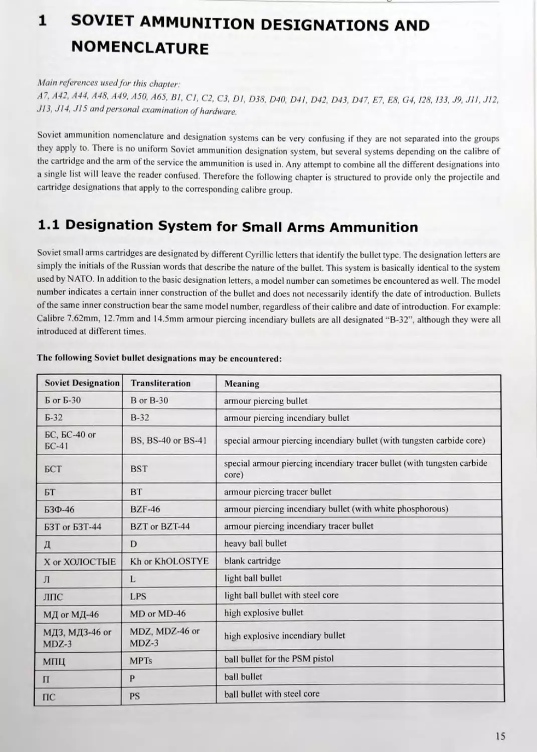
Soviet small arms cartridges are designated by different Cyrillic letters that identify the bullet type. The designation letters are
simply the initials of the Russian words that describe the nature of the bullet. This system is basically identical to the system
used by NATO. In addition to the basic designation letters, a model number can sometimes be encountered as well. The model
number indicates a certain inner construction of the bullet and does not necessarily identify the date of introduction. Bullets
of the same inner construction bear the same model number, regardless of their calibre and date of introduction. For example:
Calibre 7.62mm, 12.7mm and 14.5mm armour piercing incendiary bullets are all designated “B-32”, although they were all
introduced at different times.
The following Soviet bullet designations may be encountered:
Soviet Designation Transliteration Meaning
Б or Б-30 В or B-30 armour piercing bullet
Б-32 B-32 armour piercing incendiary bullet
БС. БС-40 or БС-41 BS, BS-40 or BS-41 special armour piercing incendiary bullet (with tungsten carbide core)
БСТ BST special armour piercing incendiary' tracer bullet (with tungsten carbide core)
БТ ВТ armour piercing tracer bullet
БЗФ-46 BZF-46 armour piercing incendiary bullet (with white phosphorous)
БЗТ or БЗТ-44 BZT or BZT-44 armour piercing incendiary tracer bullet
Д D heavy ball bullet
X or ХОЛОСТЫЕ Kh or KhOLOSTYE blank cartridge
Л L light ball bullet
ЛПС LPS light ball bullet with steel core
МД or МД-46 MD or MD-46 high explosive bullet
МДЗ. МДЗ-46 or MDZ-3 MDZ, MDZ-46 or MDZ-3 high explosive incendiary bullet
МПЦ MPTs ball bullet for the PSM pistol
П P ball bullet
ПС PS ball bullet with steel core
15
1 - Soviet Ammunition Designations and Nomenclature
Soviet Designation Transliteration Meaning
ПЗ PZ instantaneous incendiary bullet
P R ball bullet for the Nagant revolver
1СЛ ISL duplex ball bullet
1СЛТ ISLT duplex ball tracer bullet
T, T-30, T-38, T-45 orT-46 T, T-30, T-38, T-45 or T-46 tracer bullet
УС US subsonic ammunition for silenced weapons
УЧ UCh drill round
3 Z incendiary bullet
ЗБ-46 ZB-46 armour piercing incendiary tracer bullet
ЗП ZP instantaneous incendiary tracer bullet
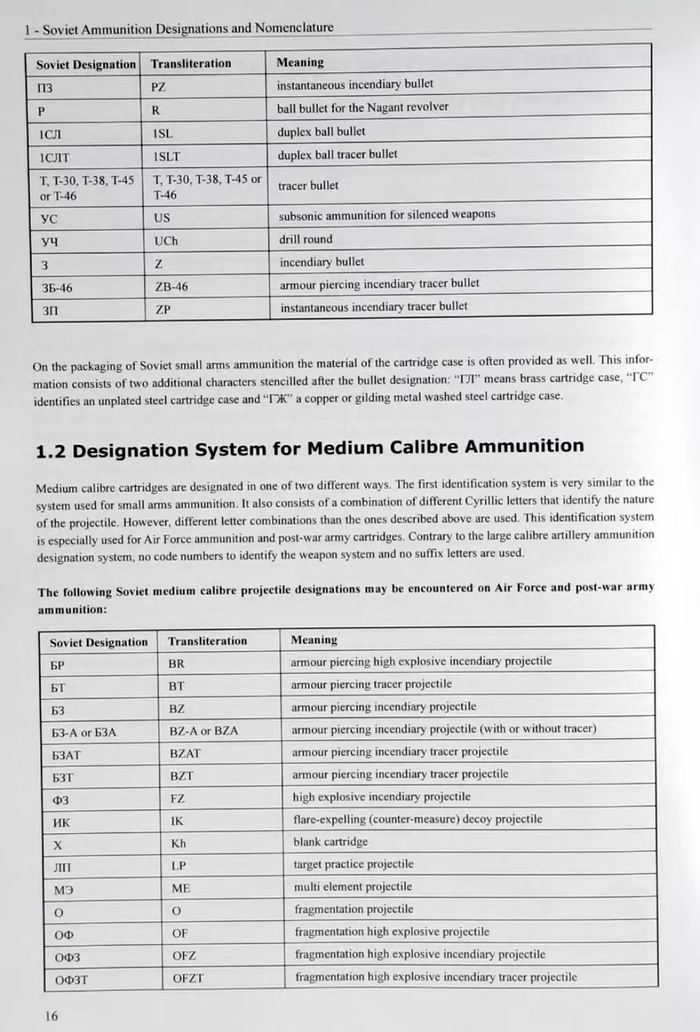
On the packaging of Soviet small arms ammunition the material of the cartridge case is often provided as well. This infor-
mation consists of two additional characters stencilled after the bullet designation: “ГЛ” means brass cartridge case, “ГС”
identifies an unplated steel cartridge case and “ГЖ" a copper or gilding metal washed steel cartridge case.
1.2 Designation System for Medium Calibre Ammunition
Medium calibre cartridges are designated in one of two different ways. The first identification system is very similar to the
system used for small arms ammunition. It also consists of a combination of different Cyrillic letters that identify the nature
of the projectile. However, different letter combinations than the ones described above are used. This identification system
is especially used for Air Force ammunition and post-war army cartridges. Contrary to the large calibre artillery ammunition
designation system, no code numbers to identify the weapon system and no suffix letters are used.
The following Soviet medium calibre projectile designations may be encountered on Air Force and post-war army
ammunition:
Soviet Designation Transliteration Meaning
БР BR armour piercing high explosive incendiary projectile
БТ ВТ armour piercing tracer projectile
БЗ BZ armour piercing incendiary projectile
БЗ-А or БЗА BZ-A or BZA armour piercing incendiary projectile (with or without tracer)
БЗАТ BZAT armour piercing incendiary' tracer projectile
БЗТ BZT armour piercing incendiary' tracer projectile
ФЗ FZ high explosive incendiary projectile
ИК IK flare-expelling (counter-measure) decoy projectile
X Kh blank cartridge
ЛП LP target practice projectile
МЭ ME multi element projectile
о О fragmentation projectile
ОФ OF fragmentation high explosive projectile
ОФЗ OFZ fragmentation high explosive incendiary projectile
ОФЗТ OFZT fragmentation high explosive incendiary tracer projectile
16
Soviet Designation Transliteration Meaning
ОТ ОТ fragmentation tracer projectile
03 OZ fragmentation incendiary projectile
O3T OZT fragmentation incendiary tracer projectile
ПРЛСТ PRACT target practice projectile
ПРЛ PRL chaff-expelling (counter-measure) decoy projectile
ПУ PU target practice projectile
ПУТ PUT target practice tracer projectile
УБ or УБУ UB or UBU target practice airburst projectile
УБТ U ВТ target practice tracer airburst projectile
УЧ UCh drill round
The second identification system for Soviet medium calibre cartridges is identical to the large calibre artillery ammunition
system, which is outlined below. Any post-war Soviet army ammunition with a calibre greater than 36mm was designated
according to this system. Previous to and during the Second World War even rounds with a smaller calibre were designated
this way. The Soviet Navy used the large calibre artillery designation system for all its ammunition, regardless of calibre and
vintage.
1.3 Designation System for Large Calibre Artillery Ammunition
When it comes to the Soviet ammunition designation system, usually the system for large calibre artillery rounds is meant.
This system was introduced around the year 1930 and was maintained until the 1970’s. It consists of a prefix, an index
number that identifies the weapon system the ammunition can be fired from, and a suffix. Ever}' component of a cartridge
(projectile, cartridge case, powder charge and complete round) has its own designation. Only the projectile designation
and the designation of the complete (fixed) round are stencilled on the projectile, the cartridge case and the packaging. On
separately loaded ammunition the designation of the propellant charge is applied to the powder bag or the separately loaded
cartridge case. The index designation of the cartridge case is never stencilled on the case and is used only in technical docu-
ments and on the packaging of empty cases.
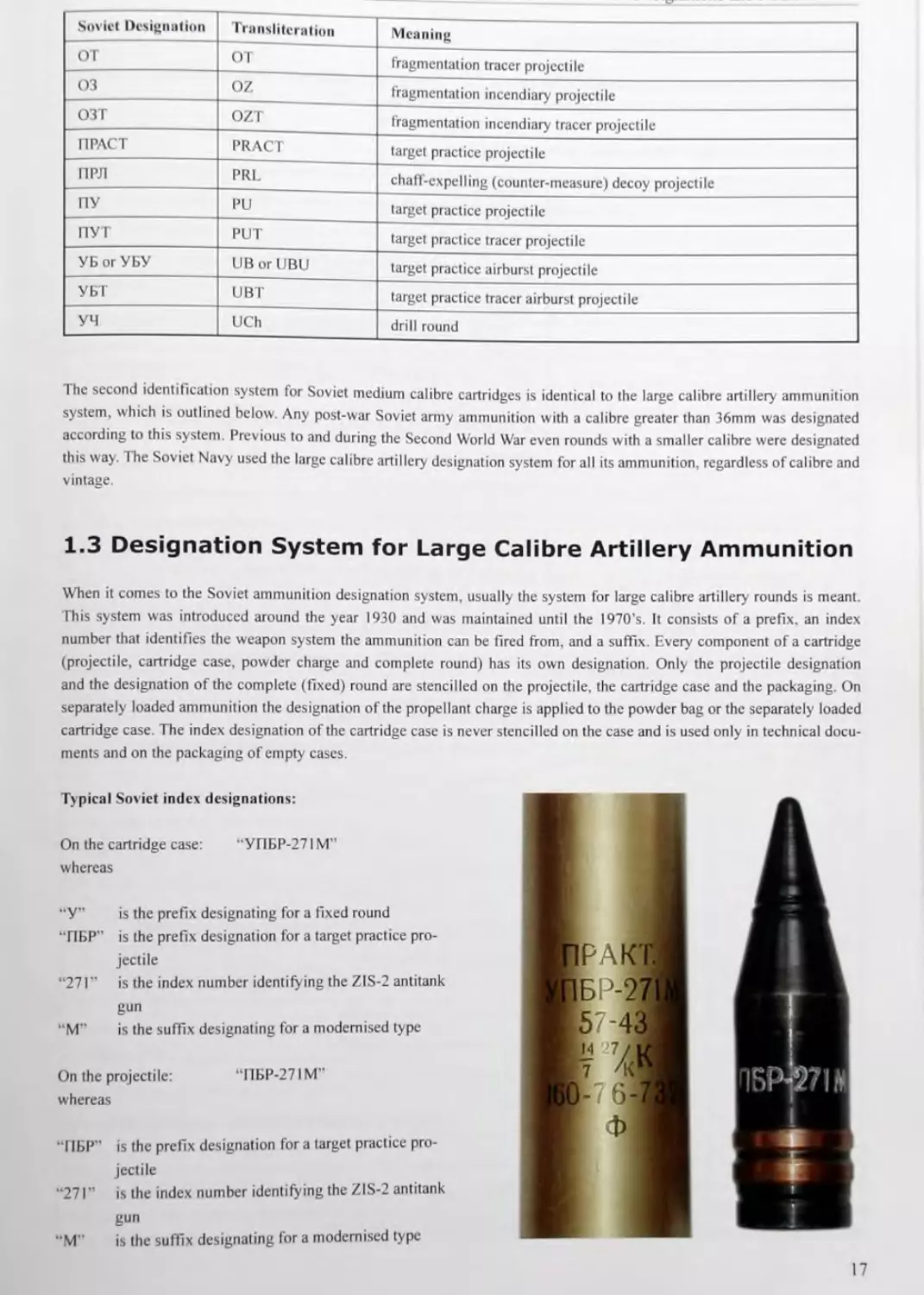
Typical Soviet index designations:
On the cartridge case: “УПБР-271М"
whereas
“У” is the prefix designating for a fixed round
“ПБР" is the prefix designation for a target practice pro-
jectile
“271" is the index number identifying the ZIS-2 antitank
gun
“M" is the suffix designating for a modernised type
On the projectile: “ПБР-271M”
whereas
“ПБР” is the prefix designation for a target practice pro-
jectile
“271" is the index number identifying the ZIS-2 antitank
gun
“M" is the suffix designating for a modernised type
17
I - Soviet Ammunition Designations and Nomenclature
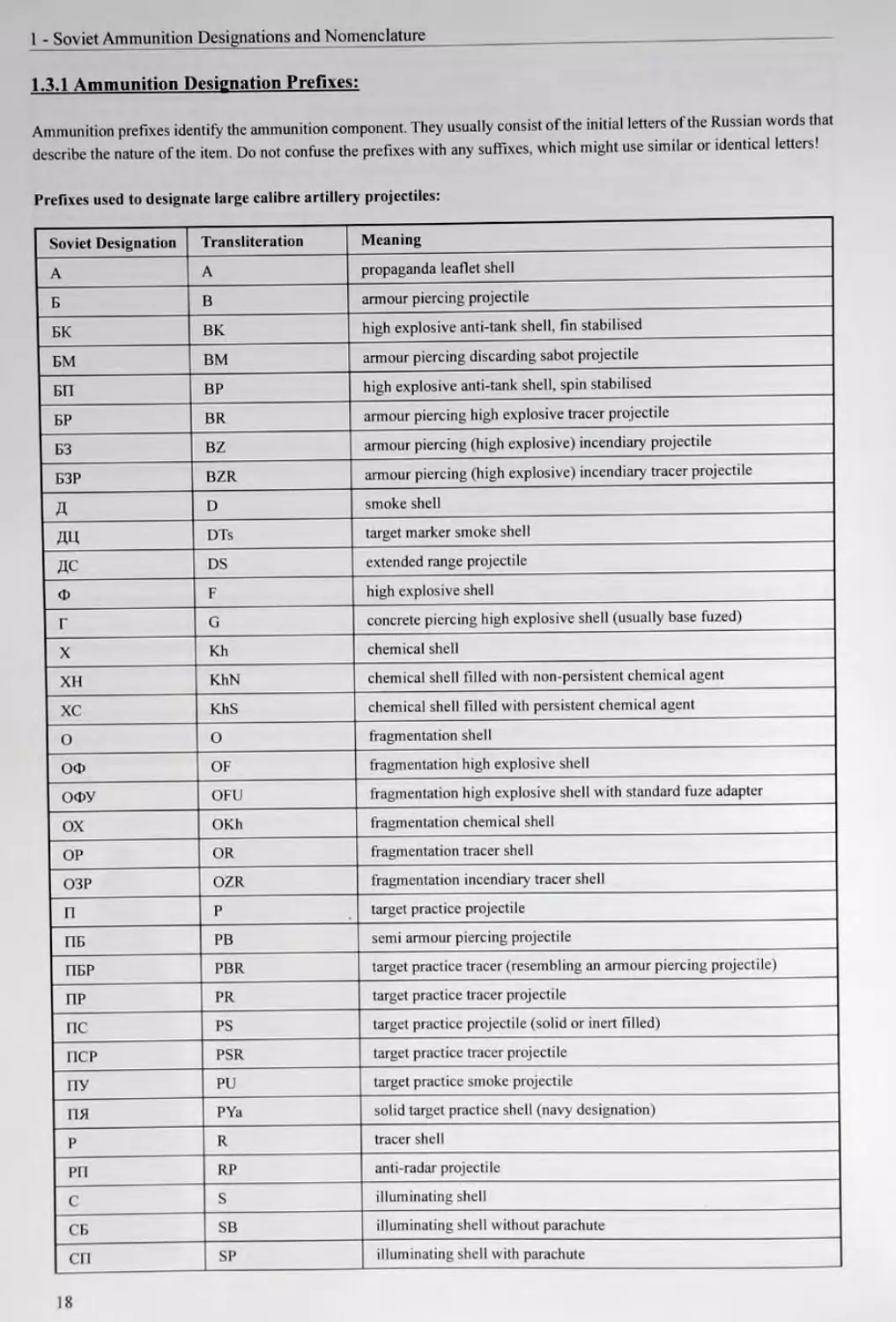
1.3.1 Ammunition Designation Prefixes:
Ammunition prefixes identify the ammunition component. They usually consist of the initial letters of the Russian words that
describe the nature of the item. Do not confuse the prefixes with any suffixes, which might use similar or identical letters!
Prefixes used to designate large calibre artillery projectiles:
Soviet Designation Transliteration Meaning
A А propaganda leaflet shell
Б В armour piercing projectile
БК ВК high explosive anti-tank shell, fin stabilised
БМ ВМ armour piercing discarding sabot projectile
БП ВР high explosive anti-tank shell, spin stabilised
БР BR armour piercing high explosive tracer projectile
БЗ BZ armour piercing (high explosive) incendiary projectile
БЗР BZR armour piercing (high explosive) incendiary tracer projectile
Д D smoke shell
ДЦ DTs target marker smoke shell
ДС DS extended range projectile
Ф F high explosive shell
г G concrete piercing high explosive shell (usually base fuzed)
X Kh chemical shell
XH KhN chemical shell filled with non-persistent chemical agent
xc KhS chemical shell filled with persistent chemical agent
о О fragmentation shell
ОФ OF fragmentation high explosive shell
ОФУ OFU fragmentation high explosive shell with standard fuze adapter
ox OKh fragmentation chemical shell
OP OR fragmentation tracer shell
O3P OZR fragmentation incendiary' tracer shell
П P target practice projectile
ПБ PB semi armour piercing projectile
ПБР PBR target practice tracer (resembling an armour piercing projectile)
ПР PR target practice tracer projectile
ПС PS target practice projectile (solid or inert filled)
ПСР PSR target practice tracer projectile
ПУ PU target practice smoke projectile
пя PYa solid target practice shell (navy designation)
р R tracer shell
РП RP anti-radar projectile
с S illuminating shell
СБ SB illuminating shell without parachute
СП SP illuminating shell with parachute
18
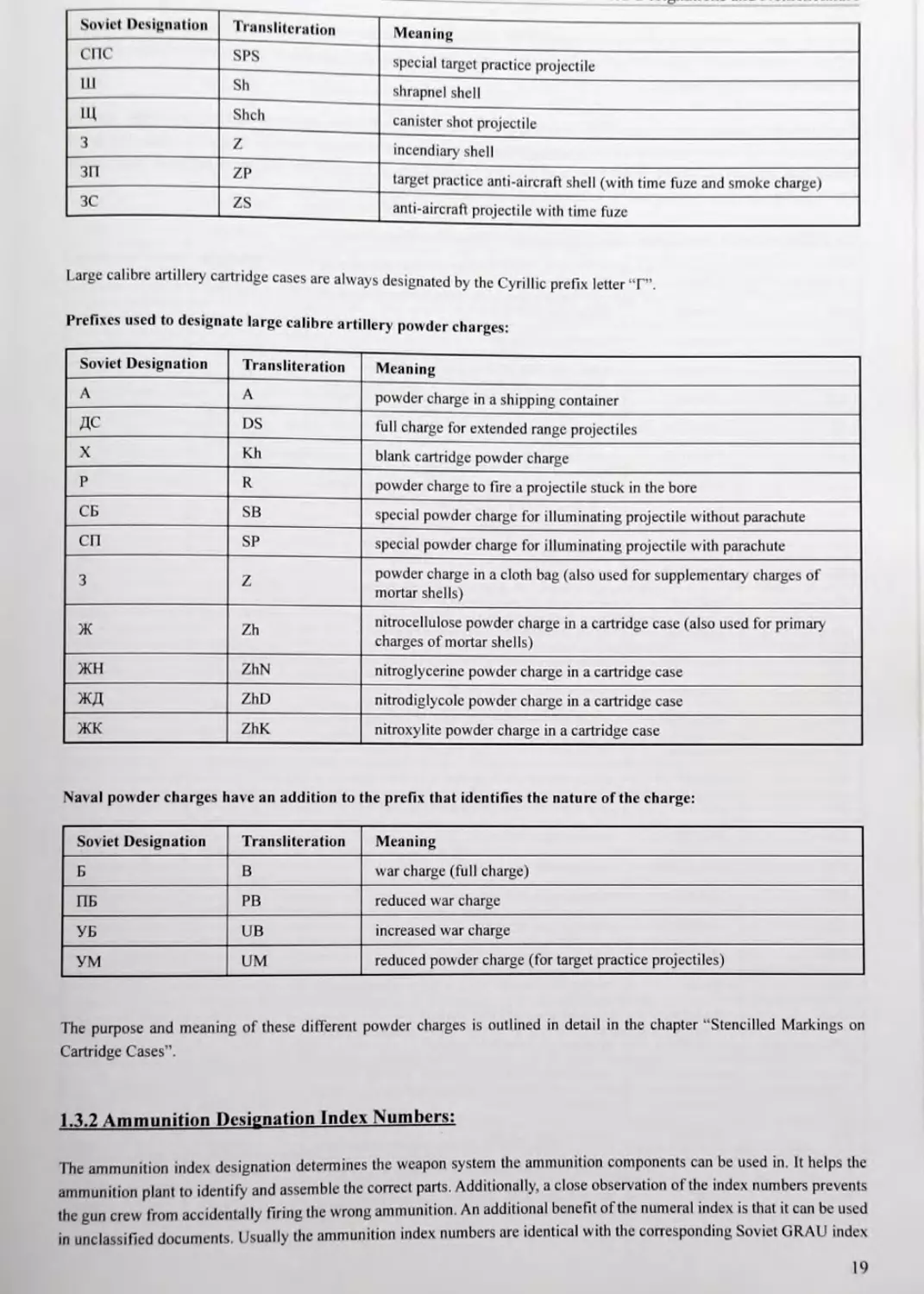
Soviet Designation Transliteration Meaning
СПС SPS special target practice projectile
U1 Sh shrapnel shell
1Ц Shch canister shot projectile
3 Z incendiary shell
ЗП ZP target practice anti-aircraft shell (with time fuze and smoke charge)
3C zs anti-aircraft projectile with time fuze
Large calibre artillery cartridge cases are always designated by the Cyrillic prefix letter “Г”.
Prefixes used to designate large calibre artillery powder charges:
Soviet Designation Transliteration Meaning
A А powder charge in a shipping container
ДС DS full charge for extended range projectiles
X Kh blank cartridge powder charge
p R powder charge to fire a projectile stuck in the bore
СБ SB special powder charge for illuminating projectile without parachute
СП SP special powder charge for illuminating projectile with parachute
3 Z powder charge in a cloth bag (also used for supplementary charges of mortar shells)
Ж Zh nitrocellulose powder charge in a cartridge case (also used for primary charges of mortar shells)
ЖН ZhN nitroglycerine powder charge in a cartridge case
жд ZhD nitrodiglycole pow der charge in a cartridge case
жк ZhK nitroxylite powder charge in a cartridge case
Naval powder charges have an addition to the prefix that identifies the nature of the charge:
Soviet Designation Transliteration Meaning
Б В war charge (full charge)
ПБ PB reduced war charge
УБ UB increased war charge
УМ UM reduced powder charge (for target practice projectiles)
The purpose and meaning of these different powder charges is outlined in detail in the chapter “Stencilled Markings on
Cartridge Cases”.
1,3.2 Ammunition Designation Index Numbers:
The ammunition index designation determines the weapon system the ammunition components can be used in. It helps the
ammunition plant to identify and assemble the correct parts. Additionally, a close observation of the index numbers prevents
the gun crew from accidentally firing the wrong ammunition. An additional benefit of the numeral index is that it can be used
in unclassified documents. Usually the ammunition index numbers are identical with the corresponding Soviet GRAU index
19
1 - Soviet Ammunition Designations and Nomenclature
numbers. This is, however, only true until the late 1970's. From the 1960’s the index designations were gradually replaced by
individual model numbers for every calibre. Today, the index number of a modem Russian artillery round no longer identifies
the weapon system it is used in.
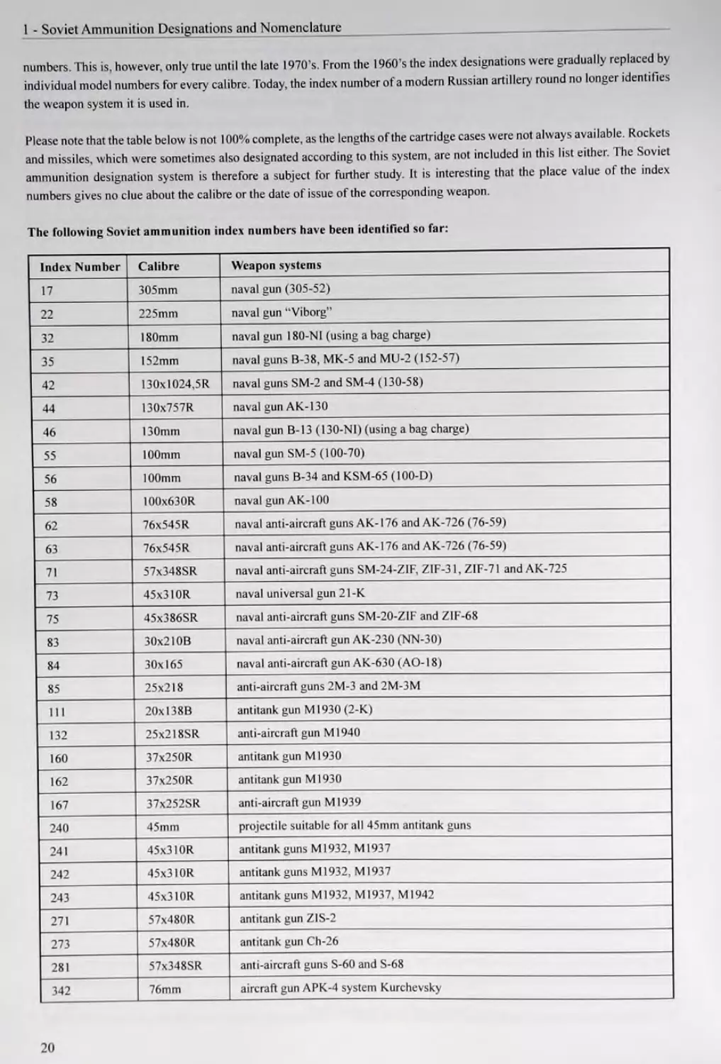
Please note that the table below is not 100% complete, as the lengths of the cartridge cases were not always available. Rockets
and missiles, which were sometimes also designated according to this system, are not included in this list either. The Soviet
ammunition designation system is therefore a subject for further study. It is interesting that the place value of the index
numbers gives no clue about the calibre or the date of issue of the corresponding weapon.
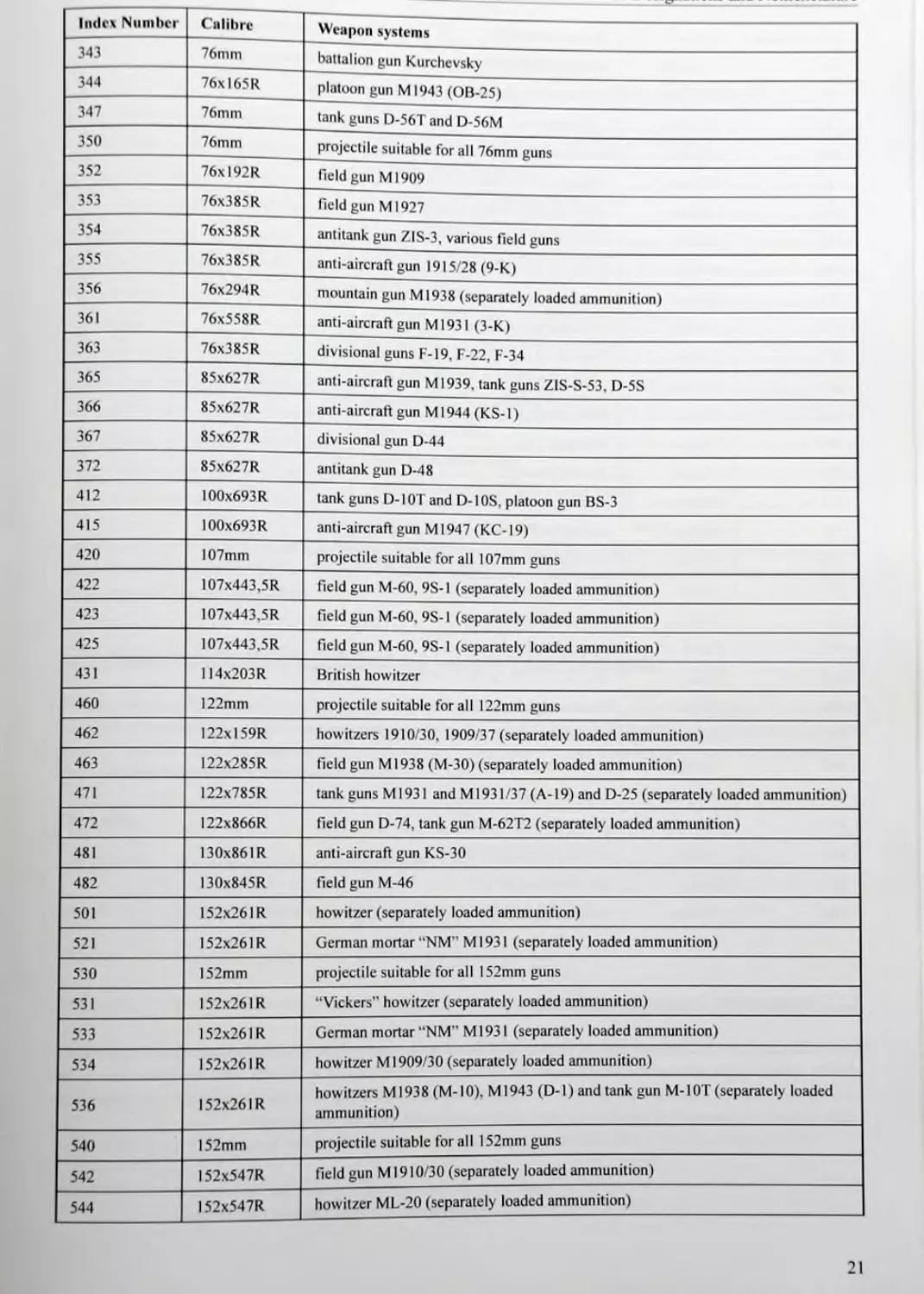
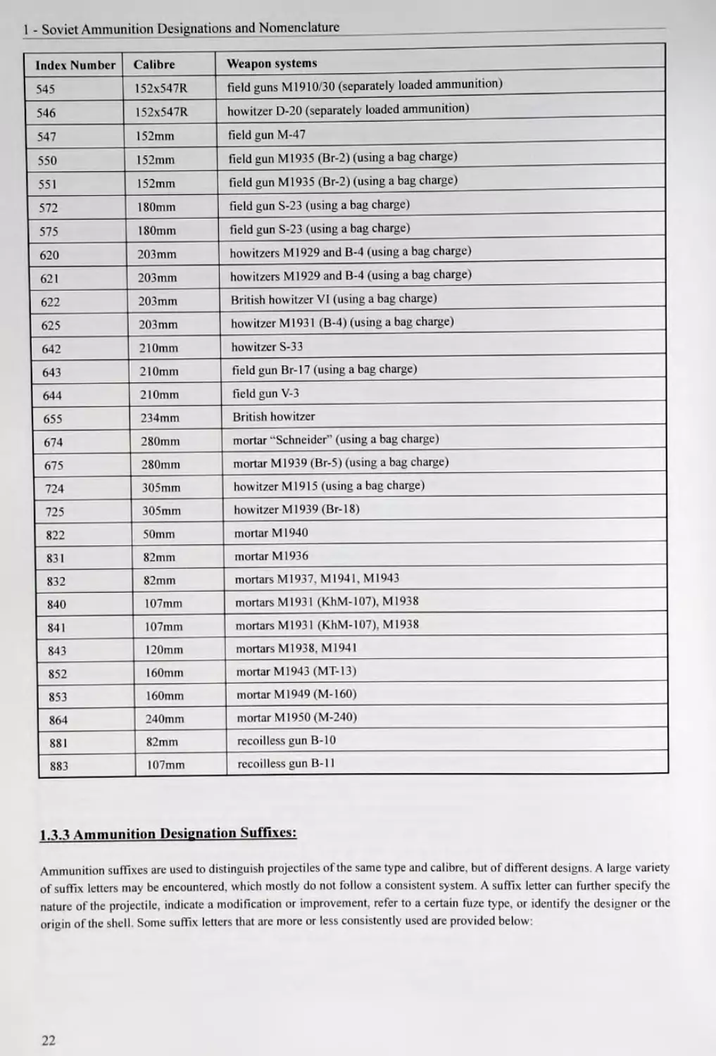
The following Soviet ammunition index numbers have been identified so far:
Index Number Calibre Weapon systems
17 305mm naval gun (305-52)
22 225mm naval gun "Viborg”
32 180mm naval gun 180-NI (using a bag charge)
35 152mm naval guns B-38, MK-5 and MU-2 (152-57)
42 130x1024,5R naval guns SM-2 and SM-4 (130-58)
44 130x757R naval gun AK-130
46 130mm naval gun В-13 (130-NI) (using a bag charge)
55 100mm naval gun SM-5 (100-70)
56 100mm naval guns B-34 and KSM-65 (100-D)
58 !00x630R naval gun AK-100
62 76x545R naval anti-aircraft guns AK-176 and AK-726 (76-59)
63 76x545R naval anti-aircraft guns AK-176 and AK-726 (76-59)
71 57x348SR naval anti-aircraft guns SM-24-ZIF, Z1F-31, ZIF-71 and AK-725
73 45x3l0R naval universal gun 21-K
75 45x386SR naval anti-aircraft guns SM-20-ZIF and Z1F-68
83 30x210B naval anti-aircraft gun ЛК-23О (NN-30)
84 30x165 naval anti-aircraft gun AK-630 (AO-18)
85 25x218 anti-aircraft guns 2M-3 and 2M-3M
111 20x138В antitank gun M1930 (2-K)
132 25x2I8SR anti-aircraft gun M1940
160 37x250R antitank gun Ml930
162 37x25OR antitank gun Ml930
167 37x252SR anti-aircraft gun Ml939
240 45mm projectile suitable for all 45mm antitank guns
241 45x310R antitank guns M1932, M1937
242 45x3l0R antitank guns M1932, M1937
243 45x310R antitank guns M1932, M1937, Ml942
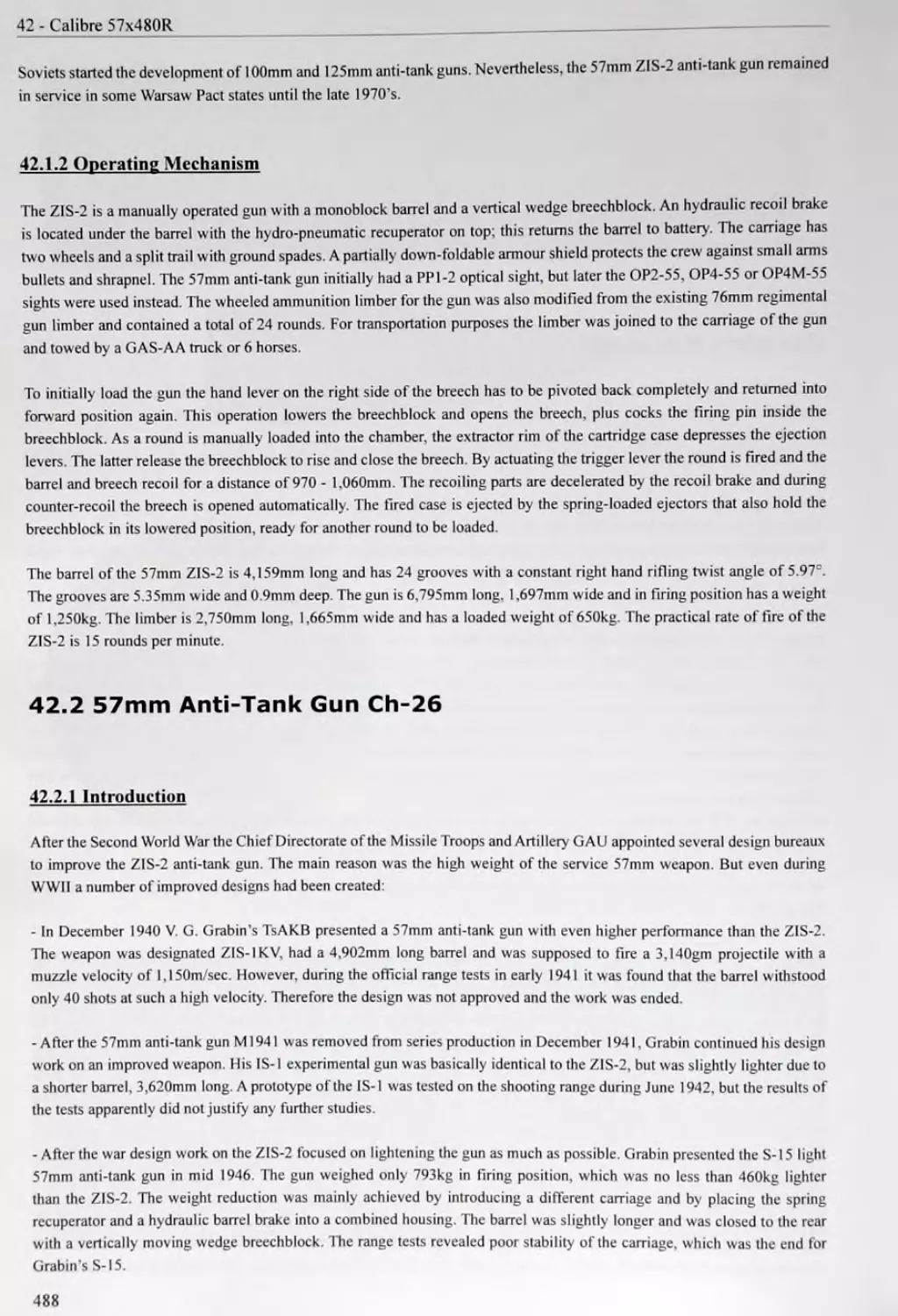
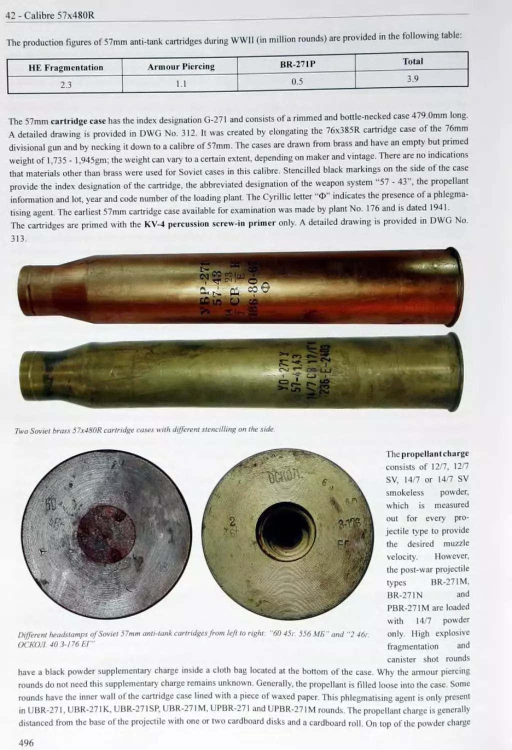
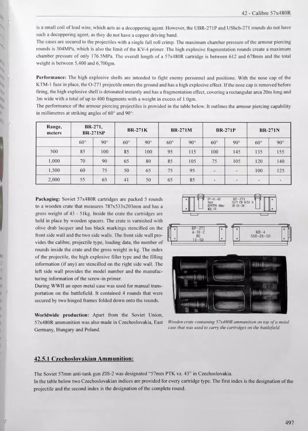
271 57x480R antitank gun ZIS-2
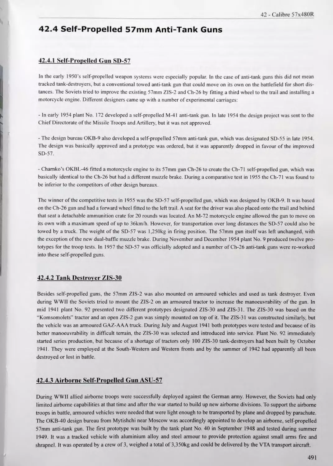
273 57x480R antitank gun Ch-26
281 57x348SR anti-aircraft guns S-60 and S-68
342 76mm aircraft gun APK-4 system Kurchevsky
20
Index Number
C alibre Weapon systems
343 76mm battalion gun Kurchevsky
344 76x165R platoon gun M1943 (OB-25)
347 76mm tank guns D-56T and D-56M
350 76mm projectile suitable for all 76mm guns
352 76x192R field gun Ml909
353 76x385R field gun Ml927
354 76x385R antitank gun ZIS-3, various field guns
355 76x385R anti-aircraft gun 1915/28 (9-K)
356 76x294R mountain gun Ml938 (separately loaded ammunition)
361 76x558R anti-aircraft gun Ml931 (3-K)
363 76x385R divisional guns F-19, F-22, F-34
365 85x627R anti-aircraft gun Ml939. tank guns ZIS-S-53, D-5S
366 85x627R anti-aircraft gun M1944(KS-1)
367 85x627R divisional gun D-44
372 85x627R antitank gun D-48
412 100x693R tank guns D-I0T and D-10S. platoon gun BS-3
415 100x693R anti-aircraft gun Ml947 (КС-19)
420 107mm projectile suitable for all 107mm guns
422 107x443,5R field gun M-60, 9S-1 (separately loaded ammunition)
423 107x443,5R field gun M-60, 9S-1 (separately loaded ammunition)
425 107x443,5R field gun M-60, 9S-I (separately loaded ammunition)
431 114x203R British howitzer
460 122mm projectile suitable for all 122mm guns
462 122xl59R howitzers 1910/30, 1909/37 (separately loaded ammunition)
463 122x285R field gun Ml938 (M-30) (separately loaded ammunition)
471 122x785R tank guns M1931 and M1931/37 (A-19) and D-25 (separately loaded ammunition)
472 !22x866R field gun D-74, tank gun M-62T2 (separately loaded ammunition)
481 130x861R anti-aircraft gun KS-30
482 130x845R field gun M-46
501 152x261R howitzer (separately loaded ammunition)
521 152x261R German mortar “NM” Ml931 (separately loaded ammunition)
530 152mm projectile suitable for all 152mm guns
531 152x261R “Vickers” howitzer (separately loaded ammunition)
533 152x261R German mortar “NM" Ml931 (separately loaded ammunition)
534 152x261R howitzer Ml909/30 (separately loaded ammunition)
536 152x261R howitzers M1938 (M-10), M1943 (D-1) and tank gun M-10T (separately loaded ammunition)
540 152mm projectile suitable for all 152mm guns
542 152x547R field gun M1910/30 (separately loaded ammunition)
544 152x547R howitzer ML-20 (separately loaded ammunition)
21
1 - Soviet Ammunition Designations and Nomenclature
Index Number Calibre Weapon systems
545 152x547R field guns M1910/30 (separately loaded ammunition)
546 152x547R howitzer D-20 (separately loaded ammunition)
547 152mm field gun M-47
550 152mm field gun M1935 (Br-2) (using a bag charge)
551 152mm field gun M1935 (Br-2) (using a bag charge)
572 180mm field gun S-23 (using a bag charge)
575 180mm field gun S-23 (using a bag charge)
620 203mm howitzers M1929 and B-4 (using a bag charge)
621 203mm howitzers Ml929 and B-4 (using a bag charge)
622 203mm British howitzer VI (using a bag charge)
625 203mm howitzer M1931 (B-4) (using a bag charge)
642 210mm howitzer S-33
643 210mm field gun Br-17 (using a bag charge)
644 210mm field gun V-3
655 234mm British howitzer
674 280mm mortar “Schneider” (using a bag charge)
675 280mm mortar M1939 (Br-5) (using a bag charge)
724 305mm howitzer M1915 (using a bag charge)
725 305mm howitzer M1939 (Br-18)
822 50mm mortar Ml940
831 82mm mortar M1936
832 82mm mortars M1937. M1941. M1943
840 107mm mortars MI931 (KhM-107), M1938
841 107mm mortars M1931 (KhM-107), M1938
843 120mm mortars Ml938, Ml941
852 160mm mortar M1943 (MT-13)
853 160mm mortar M1949 (M-160)
864 240mm mortar M1950 (M-240)
881 82mm recoilless gun B-10
883 107mm recoilless gun B-l 1
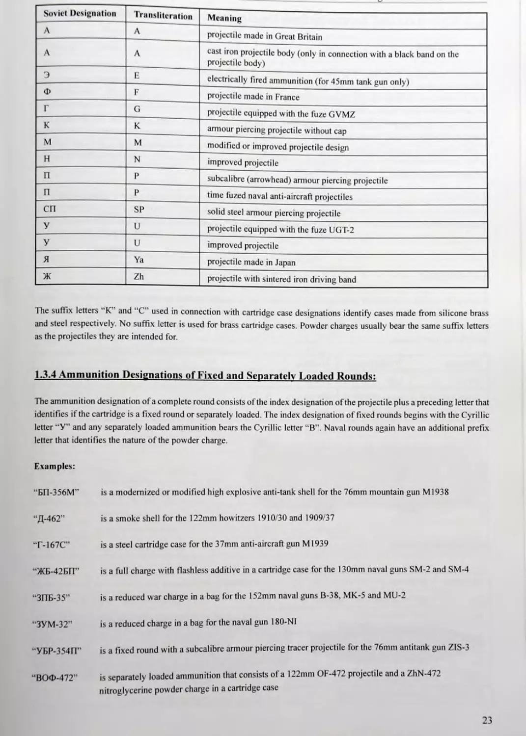
1.3.3 Ammunition Designation Suffixes:
Ammunition suffixes are used to distinguish projectiles of the same type and calibre, but of different designs. A large variety
of suffix letters may be encountered, which mostly do not follow a consistent system. A suffix letter can further specify the
nature of the projectile, indicate a modification or improvement, refer to a certain fuze type, or identify the designer or the
origin of the shell. Some suffix letters that are more or less consistently used are provided below:
22
Soviet Designation Transliteration Meaning
A А projectile made in Great Britain
A А cast iron projectile body (only in connection with a black band on the projectile body)
Э В electrically fired ammunition (for 45mm tank gun only)
Ф F projectile made in France
Г G projectile equipped with the fuze GVMZ
К К armour piercing projectile without cap
M М modified or improved projectile design
H N improved projectile
П Р subcalibre (arrowhead) armour piercing projectile
П Р time fuzed naval anti-aircraft projectiles
СП SP solid steel armour piercing projectile
У и projectile equipped with the fuze UGT-2
У и improved projectile
Я Ya projectile made in Japan
Ж Zh projectile with sintered iron driving band
The suffix letters “K” and “C” used in connection with cartridge case designations identify cases made from silicone brass
and steel respectively. No suffix letter is used for brass cartridge cases. Powder charges usually bear the same suffix letters
as the projectiles they are intended for.
13.4 Ammunition Designations of Fixed and Separately Loaded Rounds:
The ammunition designation of a complete round consists of the index designation of the projectile plus a preceding letter that
identifies if the cartridge is a fixed round or separately loaded. The index designation of fixed rounds begins with the Cyrillic
letter “У” and any separately loaded ammunition bears the Cyrillic letter “B”. Naval rounds again have an additional prefix
letter that identifies the nature of the powder charge.
Examples:
“БП-356М” is a modernized or modified high explosive anti-tank shell for the 76mm mountain gun Ml938
“Д-462” is a smoke shell for the 122mm howitzers 1910/30 and 1909/37
“Г-167С” is a steel cartridge case for the 37mm anti-aircraft gun Ml939
“ЖБ-42БП" is a full charge with flashless additive in a cartridge case for the 130mm naval guns SM-2 and SM-4
“ЗПБ-35” is a reduced war charge in a bag for the 152mm naval guns B-38, MK-5 and MU-2
“ЗУМ-32” is a reduced charge in a bag for the naval gun 180-N1
“УБР-354П” is a fixed round with a subcalibre armour piercing tracer projectile for the 76mm antitank gun ZIS-3
“ВОФ-472” is separately loaded ammunition that consists of a 122mm OF-472 projectile and a ZhN-472 nitroglycerine powder charge in a cartridge case
23
1 - Soviet Ammunition Designations and Nomenclature
1.4 Abbreviated Ammunition Designations of the Warsaw Pact
States
Ammunition produced in the states of the Warsaw Pact is generally designated and marked according to the Soviet ammunition
designation system. However, the markings are usually applied in the alphabet of the country that produced the ammunition.
With the exception of Bulgaria, this means Latin letters. Therefore the Soviet ammunition and powder designations were
transliterated into Latin letters according to the transliteration table for that language. Every language has a slightly different
transliteration table for the Cyrillic alphabet, which may result in different Latin designations for one and the same item.
While the Cyrillic letter “B” is transliterated into “W” in Germany and Poland, the Hungarian and Romanian transliteration
of that letter is “V”. Instead of simply transliterating Soviet designations, Hungary and Czechoslovakia also used their own
abbreviations to designate the nature of a projectile or round. These designations consist of the initial letters of the I lungarian
or Czech words that describe the nature of the item.
In the following paragraphs frequently encountered markings and abbreviations that are applied to ammunition produced in the
Warsaw Pact states are outlined, but no separate glossary for ammunition related terms is provided. Today very sophisticated
translation engines are available on the internet that may help to translate almost everything, even specialised terminology. A
list of useful online translation engines can be found in the bibliography (references J25, J26, J27, J28, J29, J30 and J31).
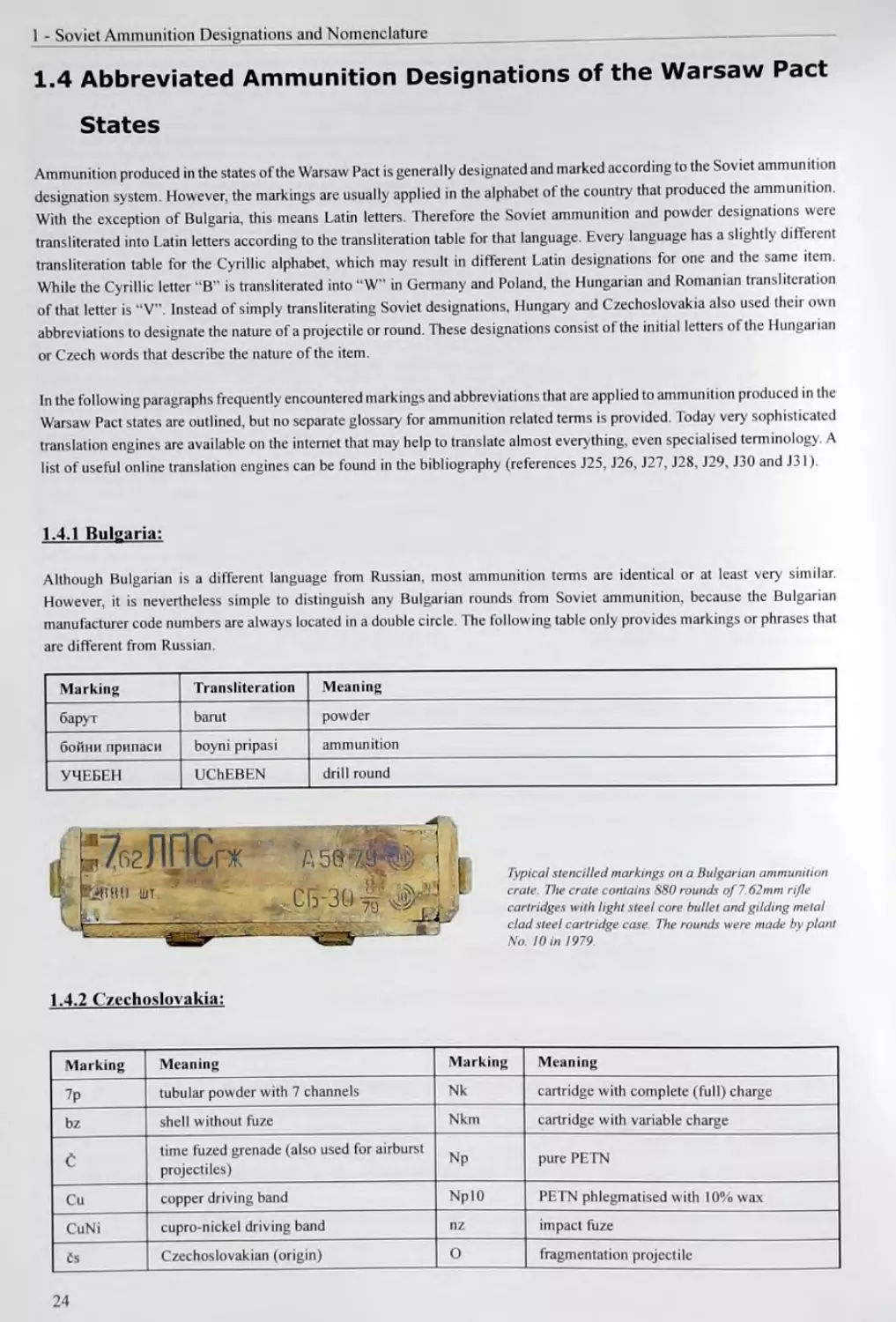
1.4.1 Bulgaria:
Although Bulgarian is a different language from Russian, most ammunition terms are identical or at least very similar.
However, it is nevertheless simple to distinguish any Bulgarian rounds from Soviet ammunition, because the Bulgarian
manufacturer code numbers are always located in a double circle. The following table only provides markings or phrases that
are different from Russian.
Marking Transliteration Meaning
барут barut powder
бойни припаси boyni pripasi ammunition
УЧЕБЕН UChEBEN drill round
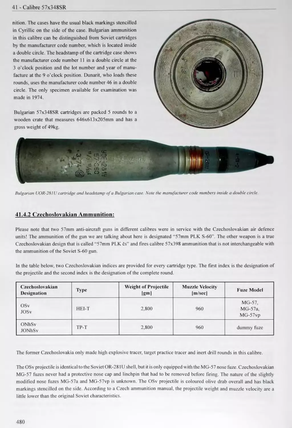
Typical stencilled markings on a Bulgarian ammunition
crate. The crate contains S80 rounds of 7 62mm rifle
cartridges with light steel core bullet and gilding metal
clad steel cartridge case. The rounds were made by plant
No. 10 in 1979
1.4.2 Czechoslovakia:
Marking Meaning Marking Meaning
7p tubular powder with 7 channels Nk cartridge with complete (full) charge
bz shell without fuze Nkm cartridge with variable charge
C time fuzed grenade (also used for airbursl projectiles) Np pure PETN
Cu copper driving band NpIO PETN phlegmatised with 10% wax
CuNi cupro-nickel driving band nz impact fuze
Cs Czechoslovakian (origin) О fragmentation projectile
24
Marking Meaning Marking Meaning
Cv blank cartridge (or airburst shell) OF fragmentation high explosive projectile
Cv-okraj blank cartridge with folded case mouth OTK technical acceptance bureau
D smoke shell P armour piercing projectile
Dg dinitrodiethyleneglycol powder Pb decoppering lead wire
dp powder in flake form PLK anti-aircraft gun
dz base fuze PTK or TK anti-tank or tank gun
E separately loaded shot PPI full calibre armour piercing projectile
elp electrical detonator Pp subcalibre armour piercing projectile
F high explosive projectile pp powder in ribbon form
F powder stabilised with centralite Pi pistol
Fe steel cartridge case Pr shaped charge (HEAT) projectile
FeS sintered iron driving band PZ armour piercing incendiary projectile
FL phlegmatiser Rd short range bullet
G grenade revid. overhauled
H howitzer S Soviet (origin)
H pure RDX §k drill round
H10 RDX phlegmatised with 10% wax SnPb decoppering tin-lead wire
J fixed round st projectile, missile
К artillery gun Sv tracer
К or KV powder with muzzle flash reducing additive T TNT
Kr carbine Tbpl gilding metal
ks or kusu pieces tp tubular powder
M mortar shell, mine tr box
mn reduced charge Tz heavy pointed ball bullet
Ms brass cartridge case TzSv heavy tracer
mz mortar fuze vn full charge
n powder charge VybuSne explosive (on warning labels)
Nc nitrocellulose powder vz. model
Ne cartridge case z fuze
Ng nitroglycerine powder Z incendiary
Nh target practice projectile zS screw-in primer
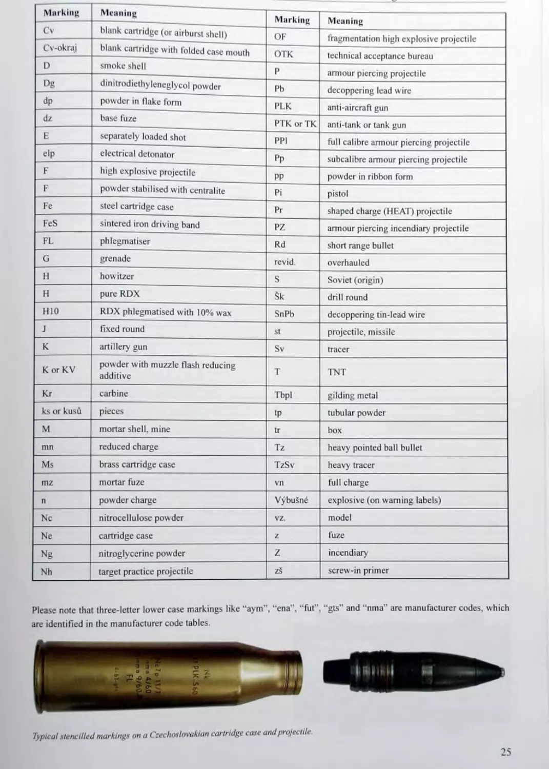
Please note that three-letter lower case markings like “aym”, “cna”, “fut”, “gts” and “nma' are manufacturer codes, which
are identified in the manufacturer code tables.
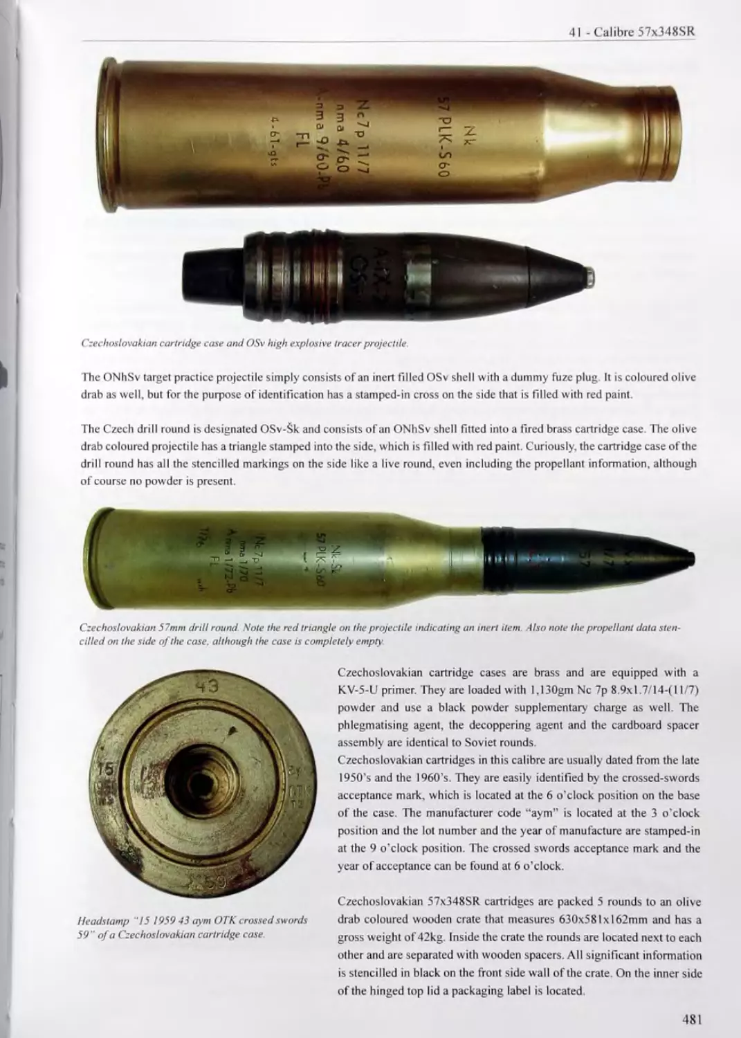
Typical stencilled markings on a Czechoslovakian cartridge case and projectile.
25
1 - Soviet Ammunition Designations and Nomenclature
1.4,3 East Germany:
Marking Meaning
Brd incendiary
Ex or Ex-P drill round
Explosiv explosive
Fcrtigung production information
FLG illuminating rocket (with parachute)
GerSteb.-P. proof cartridge
Gr. projectile
HL shaped charge (HEAT) projectile
Ld. hermetically sealed packaging
L'spur tracer
MK blank cartridge
o.L. without chargers
Patr. cartridge
Pist. pistol
Platzpatr. blank cartridge
PTr blank cartridge to launch rifle grenades
Pz armour piercing
Spl fragmentation
Spr high explosive
St. or StUck pieces
Stk. steel core
ГКО technical acceptance department
Treibldg. or ; Treib.- Ldg. powder charge
Ob. target practice
WBK recoil cartridge (with water packet simulating a projectile)
ZUnder fuze
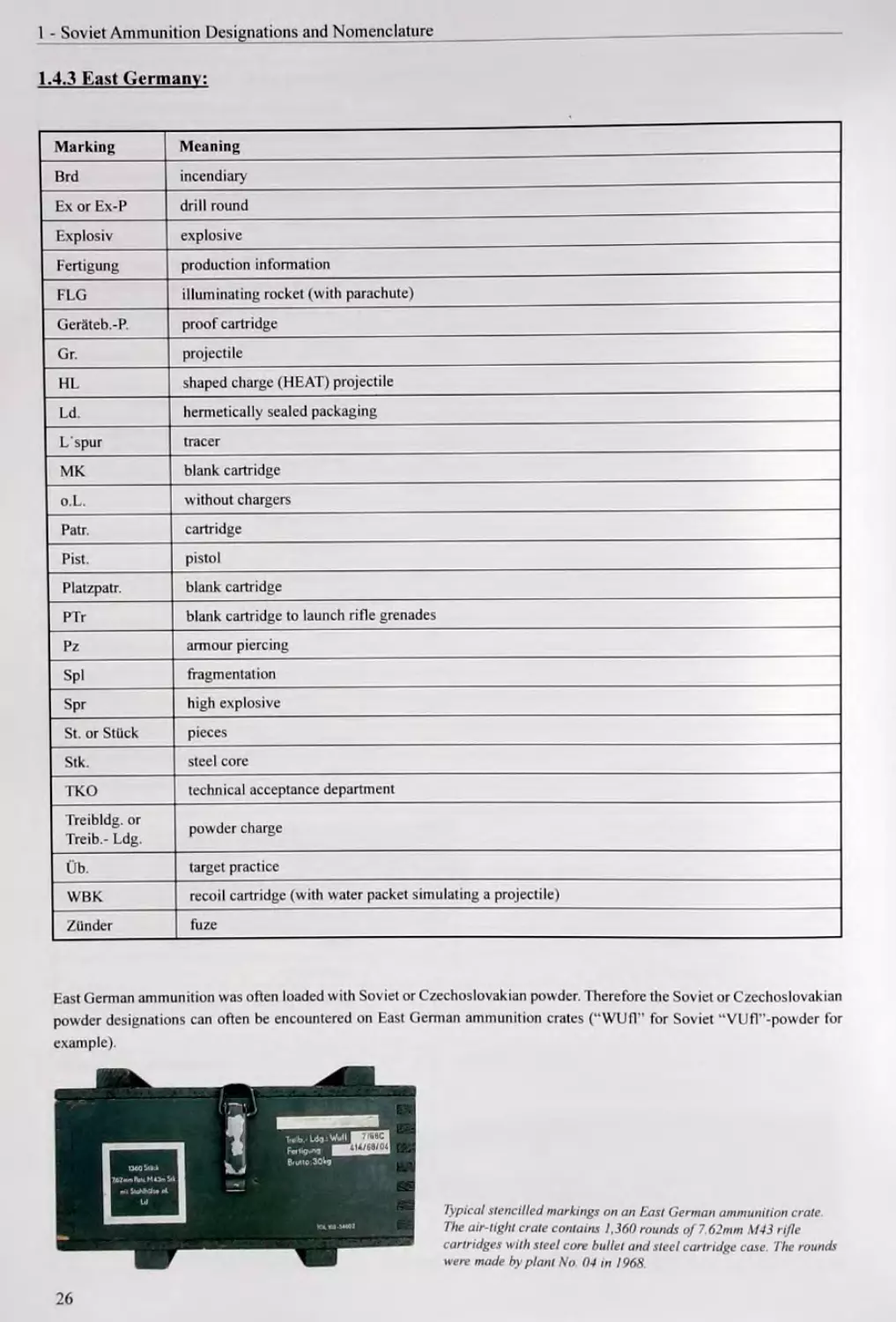
East German ammunition was often loaded with Soviet or Czechoslovakian powder. Therefore the Soviet or Czechoslovakian
powder designations can often be encountered on East German ammunition crates (“WUfl” for Soviet “VUfT’-powder for
example).
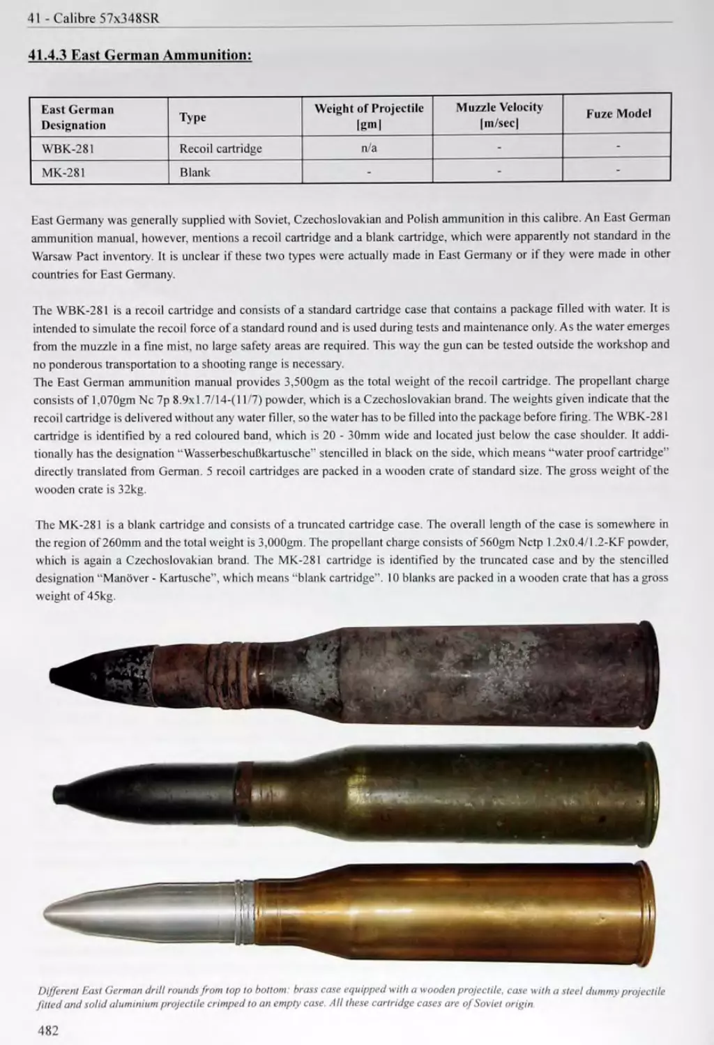
Typical stencilled markings on an East German ammunition crate.
The air-tight crate contains 1,360 rounds of 7 62mm M43 rifle
cartridges with steel core bullet and steel cartridge case The rounds
were made by plant No 04 in 1968
26
1.4.4 Hungary:
Marking Meaning
BZ armour piercing incendiary bullet
DB, Db, db. or drb. pieces
disztOz blank cartridge
DPSz heavy ball bullet with steel core
E fixed round
F or F£nyj. tracer
F or Fl. phlcgmatiser
GL brass cartridge case
gr. or GR projectile
GZS gilding metal clad steel cartridge case
GYAK orGYAKORLd drill round
gyar plant, factory
gyujtd fuze, incendiary
Kes canister shot projectile
KUM military representative acceptance mark
LEGM CSOM hermetically sealed packaging
lopor powder
Idveddk projectile
M or minta model
ME in square or MEO acceptance department of the manufacturing plant
NC nitrocellulose powder
NCT supplementary charge nitrocellulose powder
NG nitroglycerine powder
NGCs tubular nitroglycerine powder
nyomjelzd tracer
Pc or Pct. armour piercing projectile
PL.H. without chargers
PSZ ball bullet with steel core
R or Rep. fragmentation projectile
Ro high explosive projectile
RRo fragmentation high explosive projectile
Rd short range bullet
SKASz ammunition for ShKAS aircraft machine gun
T solid armour piercing projectile (suffix)
tipus type
tdltdny cartridge
Oa subcalibre armour piercing projectile
VAK, VAKLOSZER or vaklOlttSny blank cartridge
27
1 - Soviet Ammunition Designations and Nomenclature
Marking Meaning
Veszely danger
Z incendiary
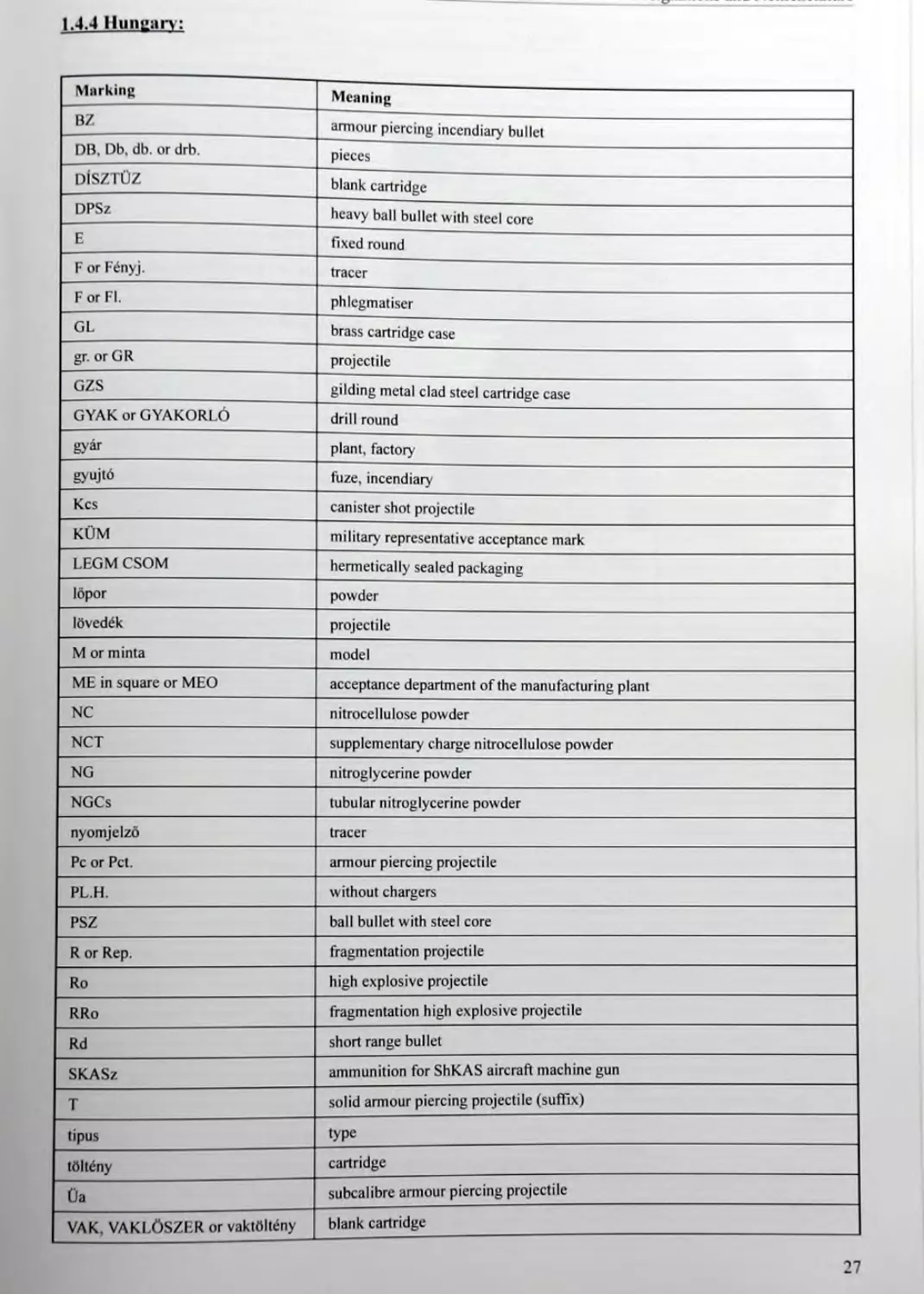
Typical stencilled markings on the lid of a
Hungarian ammunition can The can contains
66() rounds of 7.62mm M43 rifle cartridges with
armour piercing incendiary bullet and gilding
metal clad steel cartridge case The rounds were
made by plant No. 23 in November / 984
1.4.5 Poland:
Marking Meaning
amunieja ammunition
balist dummy fuze plug
£wiczebny target practice
CZEP. BALIST. ballistic cap
GL brass cartridge case
GS lacquered steel cartridge case
G1 gilding metal clad steel cartridge case
HERMETYCZNE hermetically sealed packaging
luska cartridge case
LM brass cartridge case (alternative to GL)
LSt lacquered steel cartridge case (alternative to GS)
LB or LPL gilding metal clad steel cartridge case (alternative to GZ)
MW H.E. (high explosive)
nb. or nabdj cartridge
Niebezpiecznie danger
P pistol cartridge
pocisk projectile
pod kali brow}' subcalibre
proch powder
r or rok year (letter “r” stamped after a date for example)
SKRZ. crate
Slepy blank cartridge
smugow tracer
splonka primer, detonator
SZK. SKOL or szkolne dummy, drill round
szt. or SZT pieces
28
Marking Meaning
taSma ammunition belt
treningowe, treningowy target practice, drill round
UCZ drill round
wz. or wz6r model
ZAPALN1K fuze
ZAST dummy fuze plug
z-d plant, factory
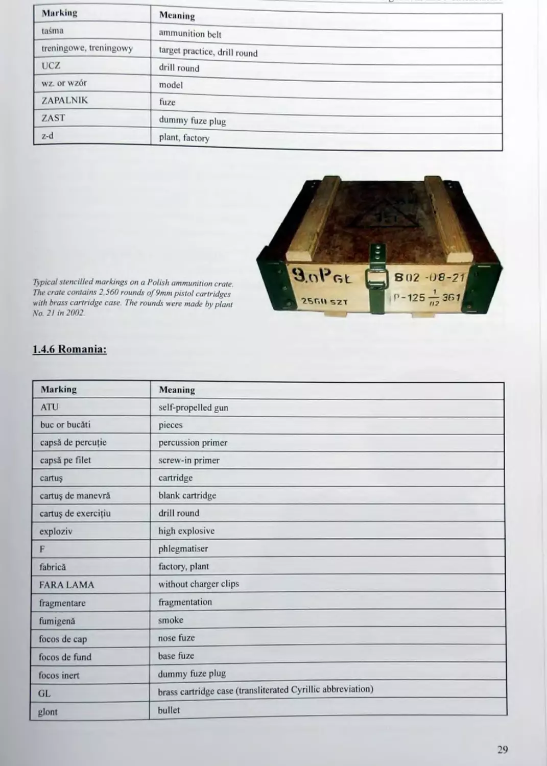
Typical stencilled markings on a Polish ammunition crate.
The crate contains 2.560 rounds of 9mm pistol cartridges
with brass cartridge case. The rounds were made by plant
bio. 21 in 2002.
1.4.6 Romania:
Marking Meaning
ATU self-propelled gun
buc or bucSti pieces
capsS de percupe percussion primer
capsS pe filet screw-in primer
cartu§ cartridge
cartu§ de manevrS blank cartridge
cartu§ de exercifiu drill round
exploziv high explosive
F phlegmatiser
fabric^ factory, plant
FARA LAMA without charger clips
fragmen tare fragmentation
fumigenS smoke
focos de cap nose fuze
focos de fund base fuze
focos inert dummy fuze plug
GL brass cartridge case (transliterated Cyrillic abbreviation)
glont bullet
29
1 - Soviet Ammunition Designations and Nomenclature
Marking Meaning
grenada grenade
GS steel cartridge case (transliterated Cyrillic abbreviation)
incarcitura de pulbcre propellant powder
incendiar incendiary
instruepe target practice
LESTAT inert display dummy (“Lestat" is not a Romanian word, however)
lovitura fixS fixed round
lovitura separata separately loaded projectile
LPS light ball bullet with steel core (transliterated Cyrillic abbreviation)
miez de o(el steel core
md or model model
munitiune ammunition
proiectil projectile
PE LAME in charger clips
perforant armour piercing
PERICOL danger
R Romanian (suffix letter)
S (+ number) lot number
sigilata ermetic hermetically sealed
TANC tank
TR tubular powder
trasor tracer
tub de cartu§ cartridge case
uzini factory, plant
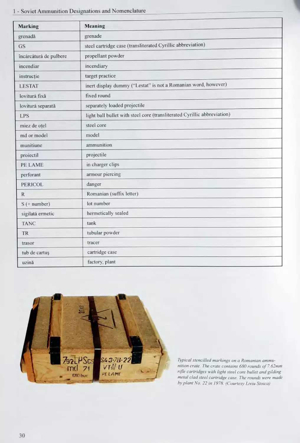
Typical stencilled markings on a Romanian ammu-
nition crate The crate contains 680 rounds of 7.62mm
rifle cartridges with light steel core bullet and gilding
metal clad steel cartridge case The rounds were made
by plant No. 22 in 1978. (Courtesy Liviu Stoica)
30
2 SOVIET AMMUNITION MARKINGS
Main references used for this chapter:
Л7. .442. A44. A48, A49, A50. A65. Д/. DI. D38. D40. D41. D42. D43. E7. E8. G4.128. 133 and persona! examinaUon of
hardware.
Markings arc intended to positively identify the ammunition. There are stamped-in markings, colour markings and stencilled
markings, v ic i arc applied to projectiles, fuzes, cartridge cases, screw-in primers and the packaging. Soviet markings
slightly changed with time. It is therefore not possible to provide a consistent system that is uniform for all Soviet ammu-
nition. For example, between 1952 and 1956 the year of manufacture was applied in the form of a capital Cyrillic letter:
Г - 195-. Д 1953. E 1954, И - 1955 and К - 1956. However, the Soviet marking system generally includes the symbol or
code number of the manufacturing plant, the lot number and the last two digits of the year of manufacture. The states of the
Warsaw Pact used the Soviet marking system as well, but had the markings applied in their own alphabet. To limit the con-
fusion. the follow ing chapter is clearly structured and equipped with numerous examples. Additional examples can be found
in the drawings on CD-Rom that is enclosed to this book.
2.1 Stamped-In Markings
Stamped-in markings are symbols, letters, numbers and a combination of those, that are stamped into the ammunition.
Stamped-in markings are intended to provide the manufacturing data of the ammunition components and are applied by the
manufacturing plant. They generally consist of the code number or symbol of the manufacturing plant, the lot number, and the
year of manufacture, each separated with a dash. Armour piercing projectiles and cartridge cases are additionally equipped
with a number indicating the metal alloy they are made of. The manufacturing information is always supplemented by an in-
plant acceptance stamp. The latter consists of the initial letter of the surname, or of the initial letters of the first name and the
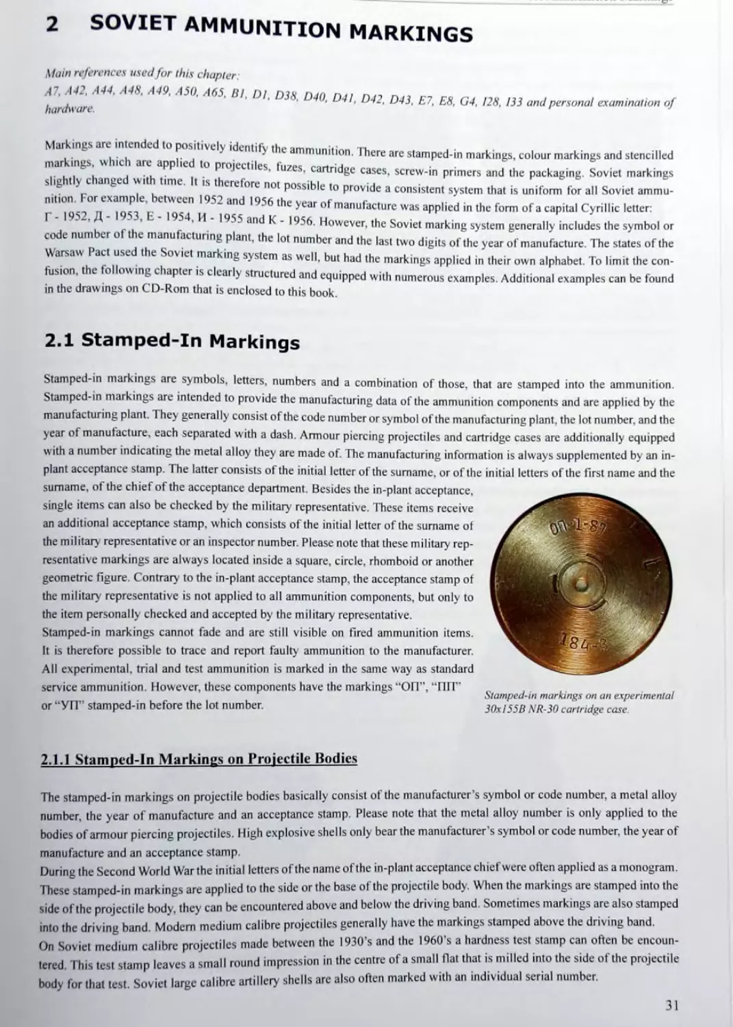
surname, of the chief of the acceptance department. Besides the in-plant acceptance,
single items can also be checked by the military representative. These items receive
an additional acceptance stamp, which consists of the initial letter of the surname of
the military representative or an inspector number. Please note that these military rep-
resentative markings are always located inside a square, circle, rhomboid or another
geometric figure. Contrary to the in-plant acceptance stamp, the acceptance stamp of
the military representative is not applied to all ammunition components, but only to
the item personally checked and accepted by the military representative.
Stamped-in markings cannot fade and are still visible on fired ammunition items.
It is therefore possible to trace and report faulty' ammunition to the manufacturer.
All experimental, trial and test ammunition is marked in the same way as standard
service ammunition. However, these components have the markings “ОП”, “ПП"
or “УП” stamped-in before the lot number.
Stamped-in markings on an experimental
30xl55B NR-30 cartridge case
2.1.1 Stamped-in Markings on Projectile Bodies
The stamped-in markings on projectile bodies basically consist of the manufacturer’s symbol or code number, a metal alloy
number, the year of manufacture and an acceptance stamp. Please note that the metal alloy number is only applied to the
bodies of armour piercing projectiles. High explosive shells only bear the manufacturer’s symbol or code number, the year of
manufacture and an acceptance stamp.
During the Second World War the initial letters of the name of the in-plant acceptance chief were often applied as a monogram.
These stamped-in markings are applied to the side or the base of the projectile body. When the markings are stamped into the
side of the projectile body, they can be encountered above and below the driving band. Sometimes markings are also stamped
into the driving band. Modem medium calibre projectiles generally have the markings stamped above the driving band.
On Soviet medium calibre projectiles made between the 1930’s and the 1960’s a hardness test stamp can often be encoun-
tered This test stamp leaves a small round impression in the centre of a small flat that is milled into the side of the projectile
body for that test. Soviet large calibre artillery shells are also often marked with an individual serial number.
31
2 - Soviet Ammunition Markings
Inert projectiles for target practice, instructional or drill purposes have the marking “ИН , “ИНЕР1 , ПРАК I. , OX or
“УЧ" stamped into the projectile body and/or the driving band.
Examples:
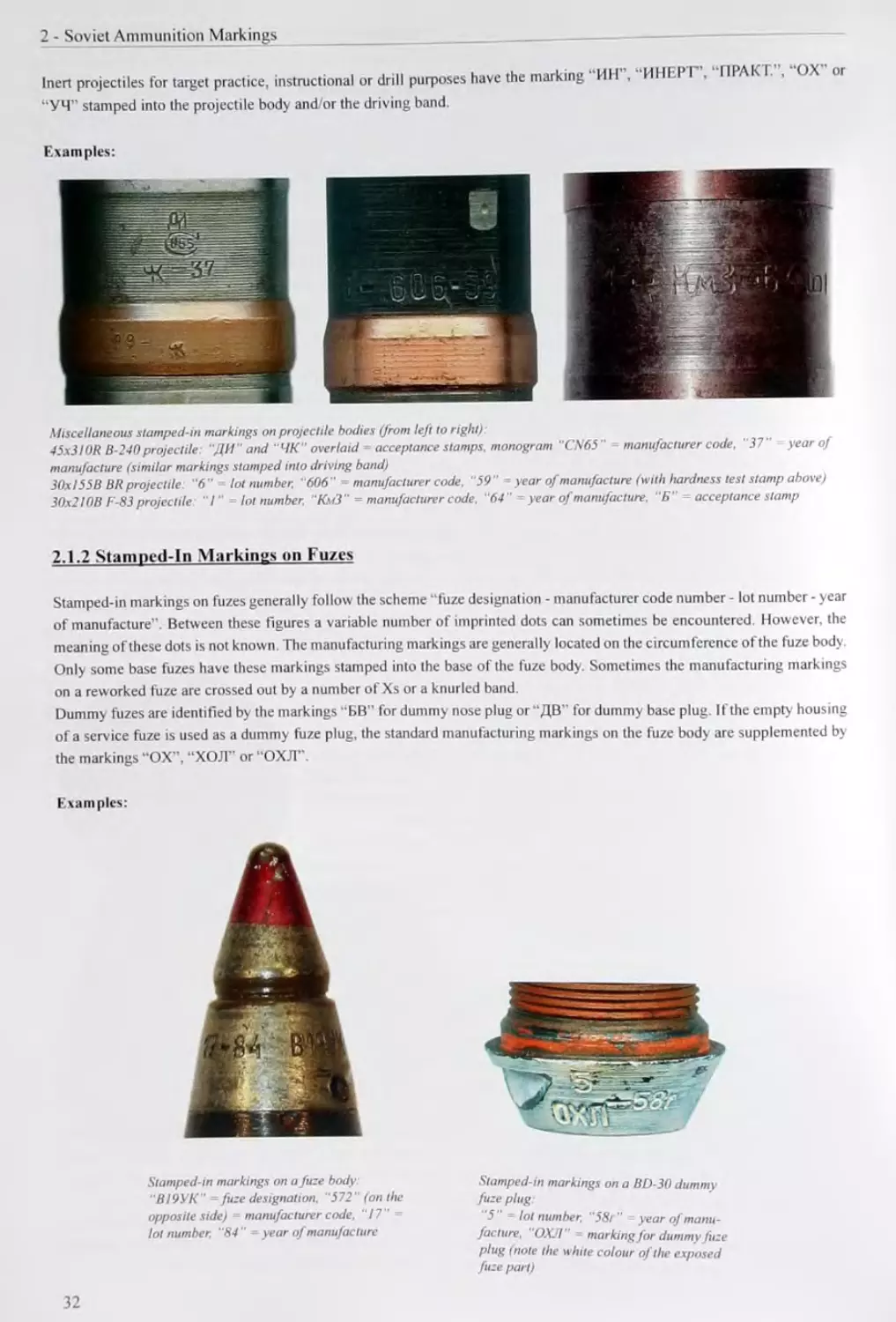
Miscellaneous stamped-in markings on projectile bodies (from left to right):
45x31 OR B-240 projectile: "ДИ" and “ЧК" overlaid acceptance stamps, monogram "CN65“ manufacturer code. “37" year of
manufacture (similar markings stamped into driving band)
30x155B BR projectile “б" lot number. “606" manufacturer code. “59“ year of manufacture (with hardness test stamp above)
30x21 OB F-83 projectile “Г loinumber. "Км/3” = manufacturer code, “64” ~ year of manufacture. “Б” acceptance stamp
2.1.2 Stamped-ln Markings on Fuzes
Stamped-in markings on fuzes generally follow the scheme “fuze designation - manufacturer code number - lot number - year
of manufacture”. Between these figures a variable number of imprinted dots can sometimes be encountered. However, the
meaning of these dots is not known. The manufacturing markings are generally located on the circumference of the fuze bod)
Only some base fuzes have these markings stamped into the base of the fuze body. Sometimes the manufacturing markings
on a reworked fuze are crossed out by a number of Xs or a knurled band.
Dummy fuzes are identified by the markings “БВ” for dummy nose plug or “ДВ” for dummy base plug. If the empty housing
of a service fuze is used as a dummy fuze plug, the standard manufacturing markings on the fuze body are supplemented by
the markings “OX”, “ХОЛ” or “ОХЛ”.
Examples:
Stamped-in markings on a fuze body
“В19УК” fuze designation. “572" (on the
opposite side) = manufacturer code. ”17”
lol number. “84” - year of manufacture
Stamped-in markings on a BD-30 dummy
fuze plug
“5 “ = lol number. "58r " year of manu-
facture. ОХЛ marking for dummy fuze
plug (note the white colour of the exposed
fuze part)
32
2.1.3 Stainiwd-ln Markings on Cartridge Case*
The markings on the heads of Soviet cartridge cases u. □
Лит mlihre rjirtrirto/» m ar^ cons,derably depending on calibre and vintage. Small arms and
medium calibre cartridge cases up to and including я еяКк™ . .
i numhi»r «nd th., vnnr лг с ca"°re °f-3mm are only equipped with the manufacturer symbol or
code number and the year of manufacture Normniiv г ...
। i »wn dinitc «г г * > he manufacturer code number is located at the 12 o’clock position and
the last two digits of the year of manufacture at th., а i • ..
... onvQQD нс □ 4 ° C 0Ck Pos,t,on- However, this system is not 100% consistent, since
some calibre 20x99R, 23x115 and 23x152R rartriH™__________ .
. . f “ ^ge cases have the manufacturer code number located at the 6 o'clock
position and the year of manufacture at the P o’clnrL nndhnn T. . .
л “ oc* Pos,t,on- The headstamp markings on small arms and medium calibre
cartridge cases are often raised and not stamped-in.
Medium calibre cartridge cases with a calibre of 25 - 45mm have their heads marked in one of two different ways; The first
headstamp sty e asica у follows the scheme of large calibre artillery cases, which have the manufacturer code number
and the in p ant acceptance stamp located at the 3 о clock position and the lot number and year of manufacture at the 9
о clock position. 1 is headstamp style was sometimes also used for pre-war 12.7mm and 23mm cartridge cases. However,
no acceptance stamp was applied to these small calibre cases.
The second headstamp sty le has the lot number and year of manufacture located at the 12 o’clock position and the manufac-
turer s code number and the in-plant acceptance stamp al the 6 o'clock position. The lot number and the year of manufacture
are separated by a dash, as are the manufacturer code number and the in-plant acceptance stamp. It is interesting that both
headstamp styles were applied to calibre 25 - 45mm cases between WWII and the 1960’s. Since the 1970’s only the second
headstamp style is used. Reworked or repaired ammunition has the original headstamp markings crossed out with a number
of Xs and is equipped with new markings.
The heads of large calibre artillery cases (calibre 45mm and up) provide even more information: At the 3 o'clock position, the
code number or symbol of the manufacturing plant and (just below') the in-plant acceptance stamp are located. The lot number
and the year of manufacture are stamped-in at the 9 o’clock position. The year of manufacture is located just below the lot
number and may be supplemented by the Cyrillic lower case letter “n”, which is short for “god" and means “year" in English.
At the 12 о clock position the number of the metal alloy is located. The 6 o’clock position is reserved for the acceptance
stamp of the military' representative, which is again located inside a geometric figure.
Besides the manufacturing information, other markings can be encountered on the heads of cartridge cases:
Marking Meaning
УЧ marking on drill rounds
УЧЕБ. marking on drill rounds
УЧЕБНЫЙ marking on drill rounds
OX marking on drill rounds reworked from live rounds
ОХОЛ marking on drill rounds reworked from live rounds
К cartridge case made from silicone brass
T cartridge cases with thicker case neck (on 57x348SR cases only)
ВС abbreviation for “barrel insert’’ (on brass post-war 23x152B cases only)
Cyrillic letters Г, Д, Е, И or К (instead of a year of manufacture) code letter for the year of manufacture during the Korean war (Г - 1952, Д - 1953, E - 1954, И - 1955 and К - 1956)
Cyrillic letters А, Б, H or M (in addition to the year of manufacture) unknown, could be a metal alloy or a lot letter (on 23x152B ZSU steel cartridge cases)
Ш cartridge intended for the 7.62mm ShKAS aircraft machine gun (on 7.62x54R cases only)
+ reloaded cartridge case (a plus symbol is imprinted for every time the case was reloaded)
33
2 - Soviet Ammunition Markings
Marking Meaning
pentagonal star cartridge suitable for synchronised aircraft machine guns (on 12.7x10⁸ cartridges)
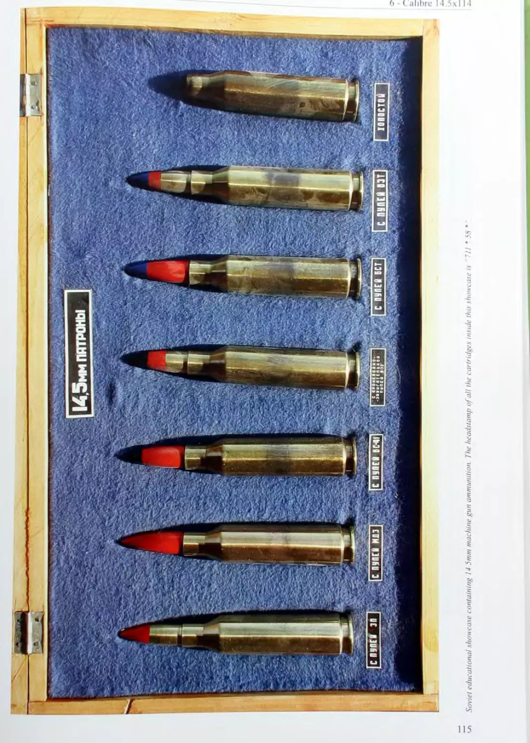
pentagonal star light cartridge case drawn from a disk with reduced thickness (on 14.5x114 cartridges)
Roman numbers month of manufacture (during WWII on small arms cartridges)
anchor naval acceptance stamp
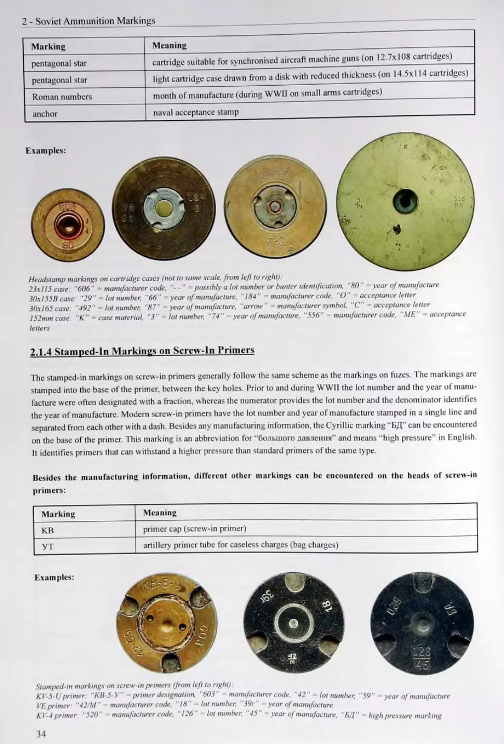
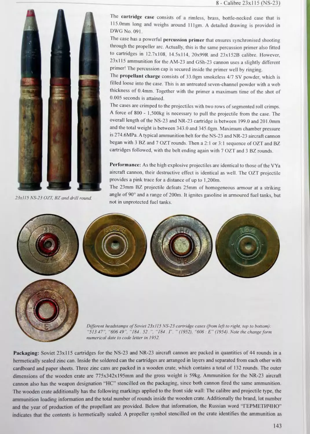
Headstamp markings on cartridge cases (not to same scale, from left to right):
23x115 case: "606" = manufacturer code. = possibly a lot number or bunler identification, "80" = year of manufacture
30x1558 case "29" lot number, "66" - year of manufacture, "184" manufacturer code, "O" acceptance letter
30x165 case: "492" lot number, "87" - year of manufacture, "arrow " manufacturer symbol, "C" acceptance letter
152mm case: "K" case material, "3" lot number, "74" year of manufacture, "556" manufacturer code. "ME" acceptance
letters
2.1.4 Stamped-!n Markings on Screw-In Primers
The stamped-in markings on screw-in primers generally follow the same scheme as the markings on fuzes. The markings are
stamped into the base of the primer, between the key holes. Prior to and during WWII the lot number and the year of manu-
facture were often designated with a fraction, whereas the numerator provides the lot number and the denominator identifies
the year of manufacture. Modem screw-in primers have the lot number and year of manufacture stamped in a single line and
separated from each other with a dash. Besides any manufacturing information, the Cyrillic marking “БД” can be encountered
on the base of the primer. This marking is an abbreviation for “большого давления" and means “high pressure" in English
It identifies primers that can withstand a higher pressure than standard primers of the same type.
Besides the manufacturing information, different other markings can be encountered on the heads of screw-in
primers:
Marking Meaning
KB primer cap (screw-in primer)
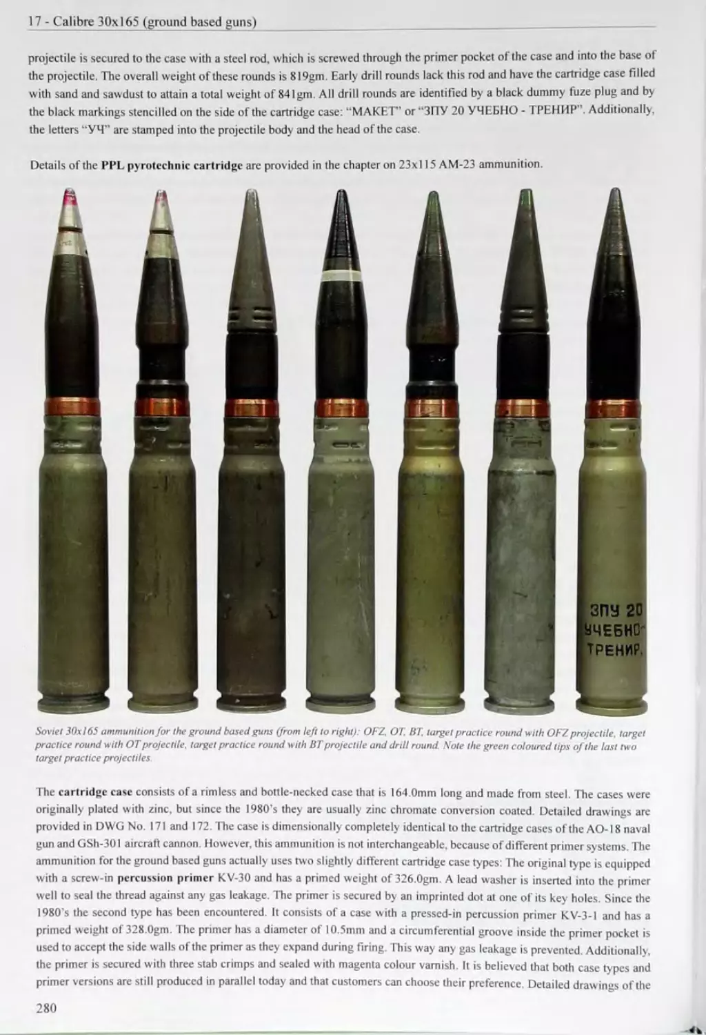
УТ artillery' primer tube for caseless charges (bag charges)
Examples:
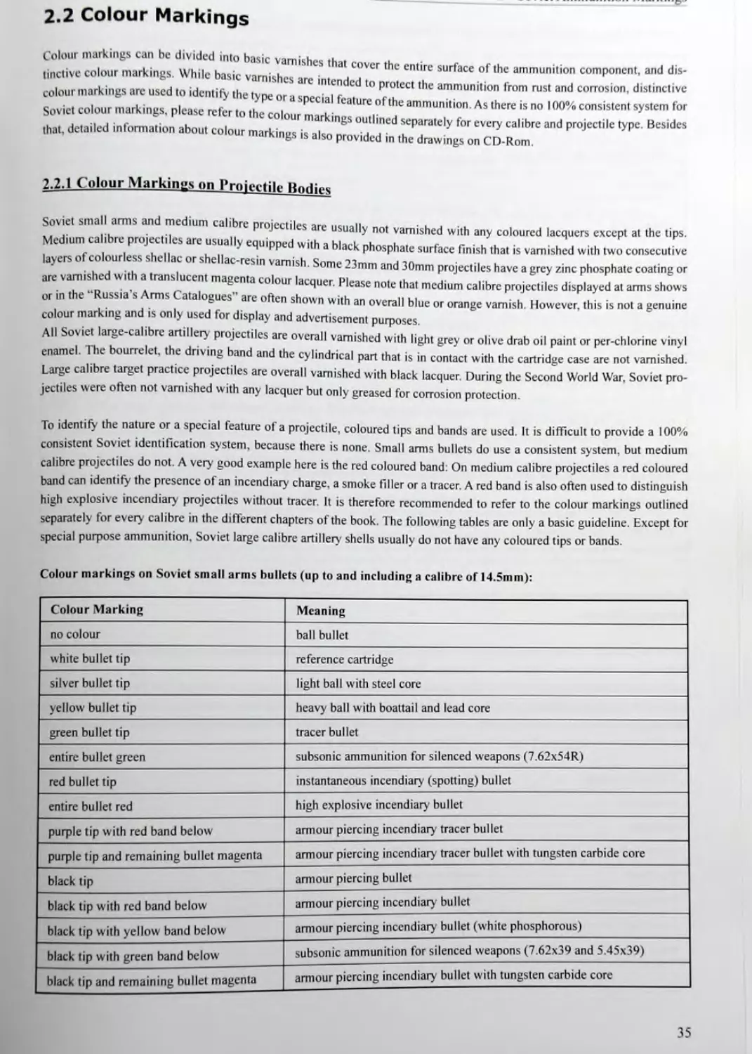
Stamped-in markings on screw-in primers (from left to right):
КГ-5-U primer "КВ-5-У" primer designation, "603" manufacturer code. "42" lot number. "59" year of manufacture
VE primer "42/M" manufacturer code. "18" lot number. "39Г year of manufacture
Kl'-4 primer "520" manufacturer code. "126" lot number. "45" year of manufacture. "БД" -- high pressure marking
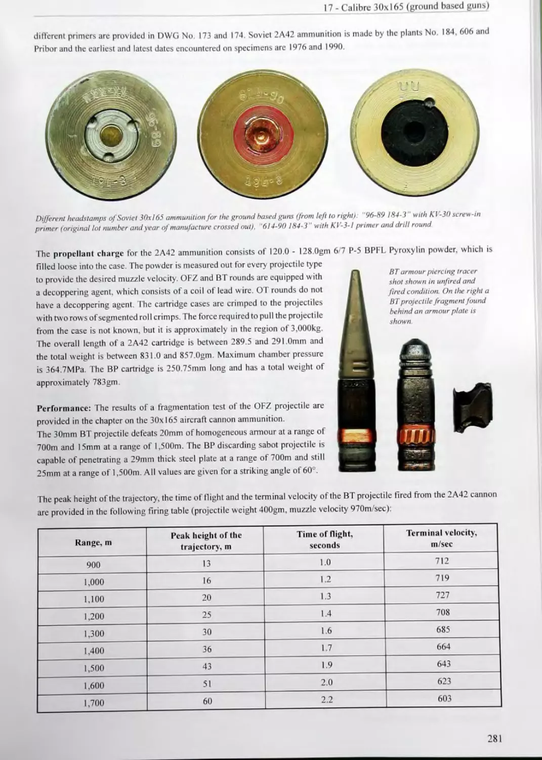
34
2.2 Colour Markings
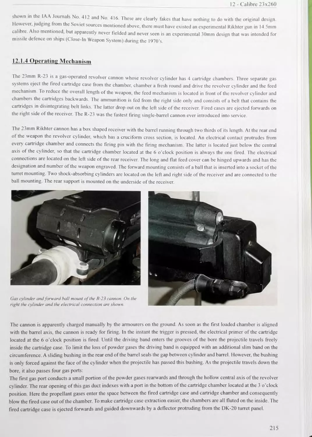
Colour markings can be divided into basic varnishes th,. .l
tinctive colour markings. While basic varnishes are intended t u ° S °' ammuni,i°n C°"1P°"C"'. and dis'
colour markings arc used to identify the type or a special feat 7 h ammUn,"°n 'rOm rUS‘and Corrosion' diS'inC‘ive
Soviet colour markings, please refer to the colour markines out! T ammun,,l«n As ,here is no '00% consistent system for
. * HotaiUd information ok * i n^S outl,nc<l separately for every calibre and projectile type. Besides
hat, detailed information about co our markincs к яко л • . .
•ndrKings is also provided in the drawings on CD-Rom.
2.2.1 Colour Markings on Projectile Bodies
Soviet small arms and medium calibre projectiles are uci.aiu, . . .. ... . .
... ... I l are usually not varnished with any coloured lacquers except at the tips.
Medium calibre projectiles are usuallveqiiioDed with» hhrL nhoenk.. r _ . , . . ... ..
r . . , • м pp wnn a mack phosphate surface finish that is varnished with two consecutive
Javers of colourless shellac or shellac-resin vamish Some эо ... . ...
sn ^ome ~3mm and 30mm projectiles have a grey zinc phosphate coating or
are varnished with a translucent magenta colour lacouer Р1ряср not., thn» n,. г i u • ... .. . . .
ь ui idcqucr. i lease note that medium calibre projectiles displayed al arms shows
or in the “Russia’s Arms Catalogues” are often shown u.-i»h ^n о.,oroii ui ... .. .
5 icn snow n w itn an overall blue or orange varnish. However, this is not a genuine
colour marking and is only used for display and advertisement purposes.
All Soviet large calibre artillery projectiles are overall varnished with light grey or olive drab oil paint or per-chlorine vinyl
enamel. I he bourrelet, the driving band and the cylindrical part that is in contact w ith the cartridge case are not varnished.
Large calibre target practice projectiles are overall varnished with black lacquer. During the Second World War. Soviet pro-
jectiles were often not varnished with any lacquer but only greased for corrosion protection.
To identify the nature or a special feature of a projectile, coloured tips and bands are used. It is difficult to provide a 100%
consistent Soviet identification system, because there is none. Small arms bullets do use a consistent system, but medium
calibre projectiles do not. A very good example here is the red coloured band: On medium calibre projectiles a red coloured
band can identify the presence of an incendiary' charge, a smoke filler or a tracer. A red band is also often used to distinguish
high explosive incendiary' projectiles without tracer. It is therefore recommended to refer to the colour markings outlined
separately for every calibre in the different chapters of the book. The following tables are only a basic guideline. Except for
special purpose ammunition, Soviet large calibre artillery' shells usually do not have any coloured tips or bands.
Colour markings on Soviet small arms bullets (up to and including a calibre of 14.5mm):
Colour Marking Meaning
no colour ball bullet
white bullet tip reference cartridge
silver bullet tip light ball with steel core
yellow- bullet tip heavy ball with boattail and lead core
green bullet tip tracer bullet
entire bullet green subsonic ammunition for silenced weapons (7.62x54R)
red bullet tip instantaneous incendiary (spotting) bullet
entire bullet red high explosive incendiary bullet
purple tip with red band below armour piercing incendiary tracer bullet
purple tip and remaining bullet magenta armour piercing incendiary tracer bullet with tungsten carbide core
black tip armour piercing bullet
black tip with red band below armour piercing incendiary bullet
black tip with yellow band below armour piercing incendiary bullet (white phosphorous)
black tip with green band below- subsonic ammunition for silenced weapons (7.62x39 and 5.45x39)
black tip and remaining bullet magenta armour piercing incendiary bullet with tungsten carbide core
2 - Soviet Ammunition Markings
Colour markings on Soviet medium calibre projectiles (calibre 20mm - 57mm):
Colour Marking Meaning
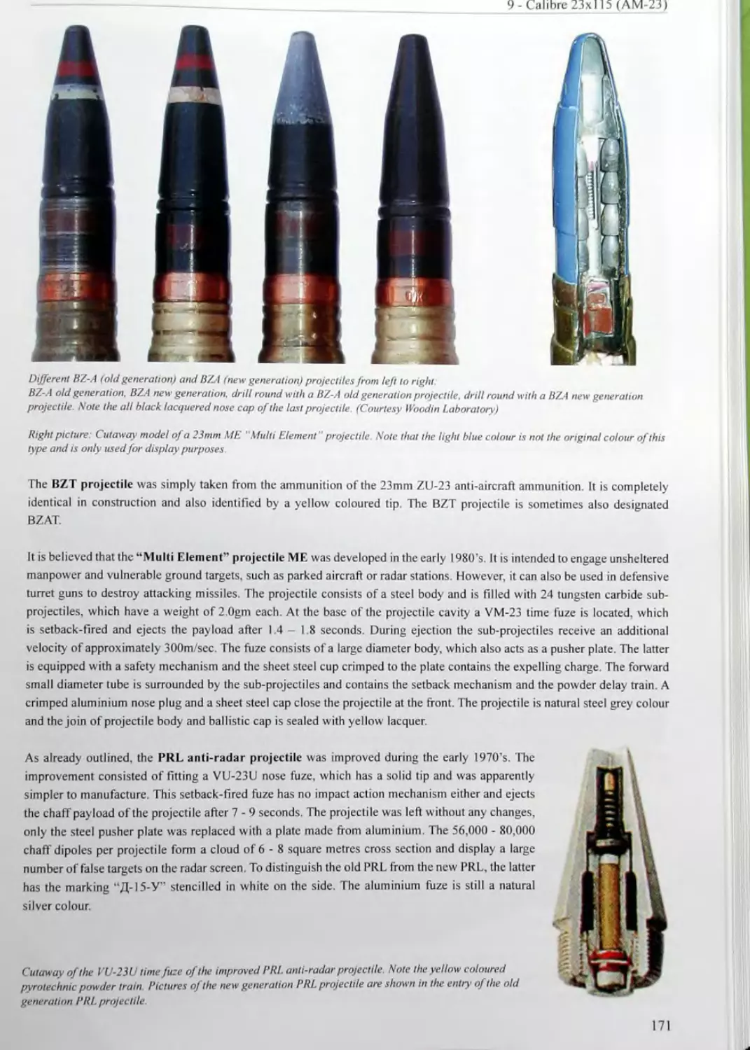
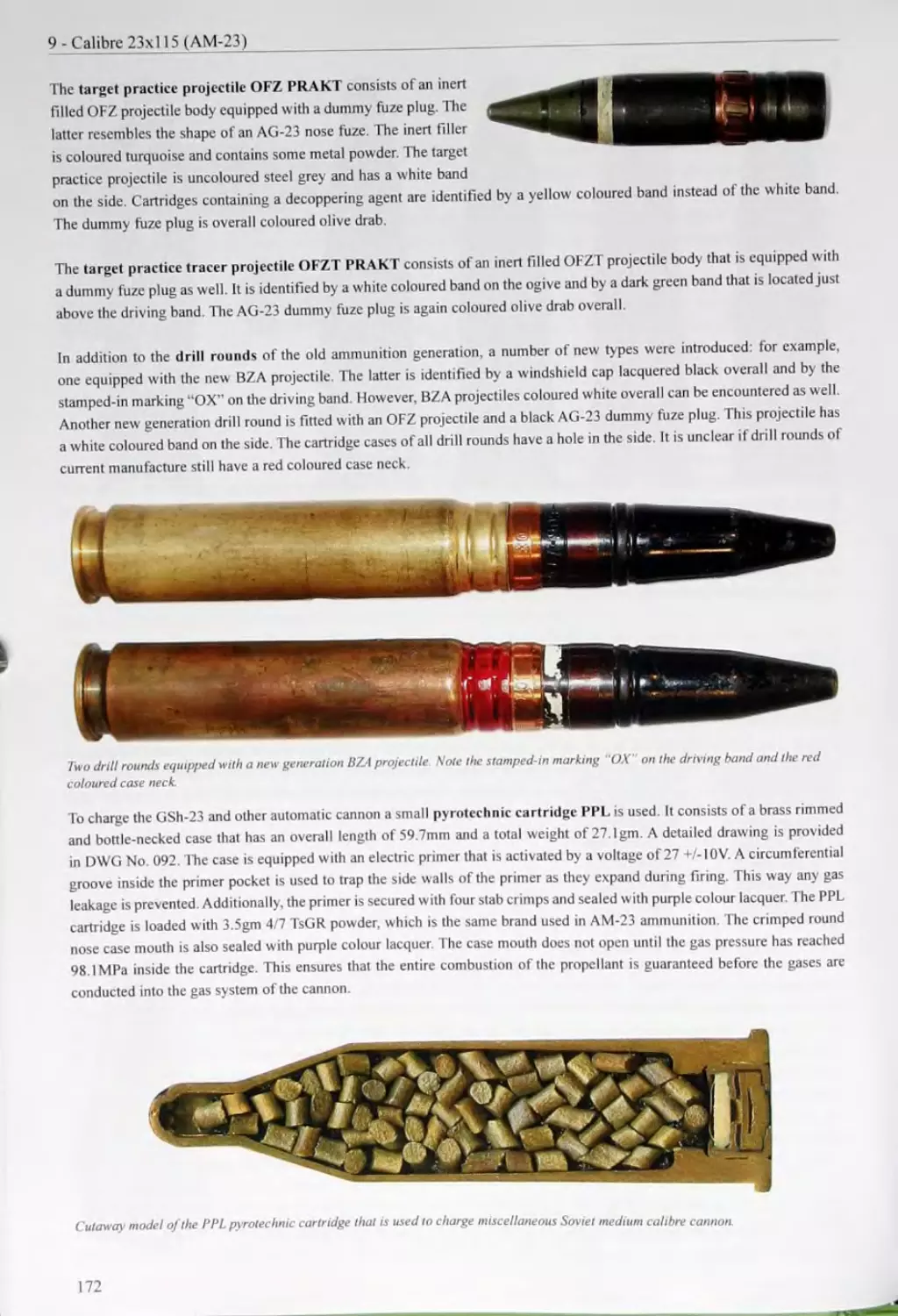
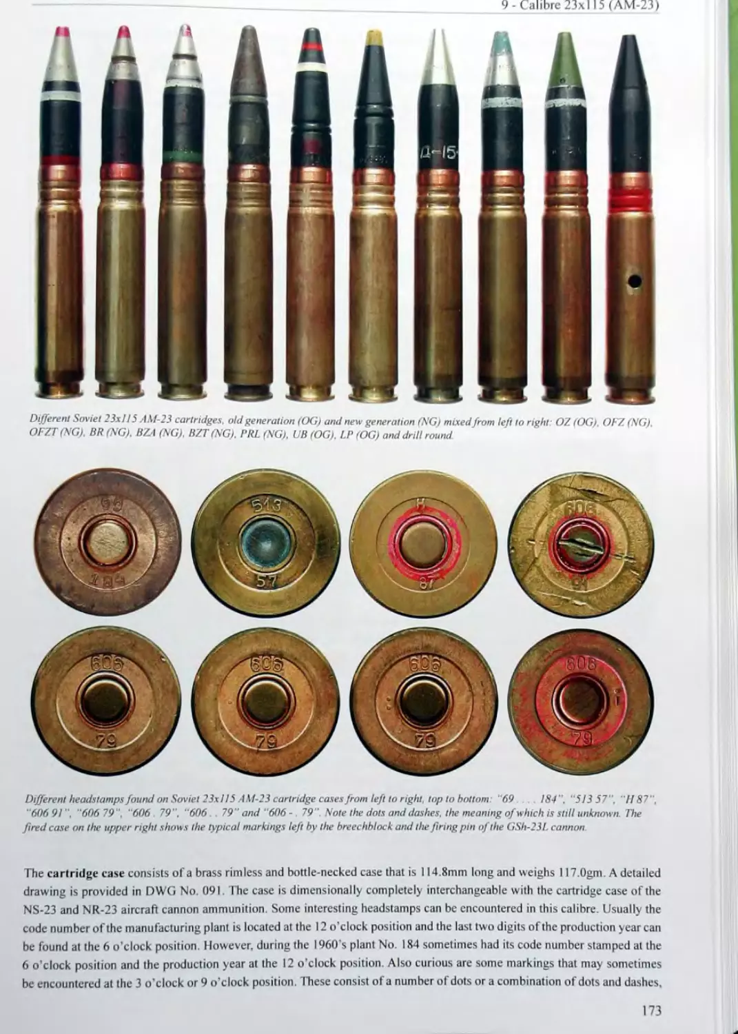
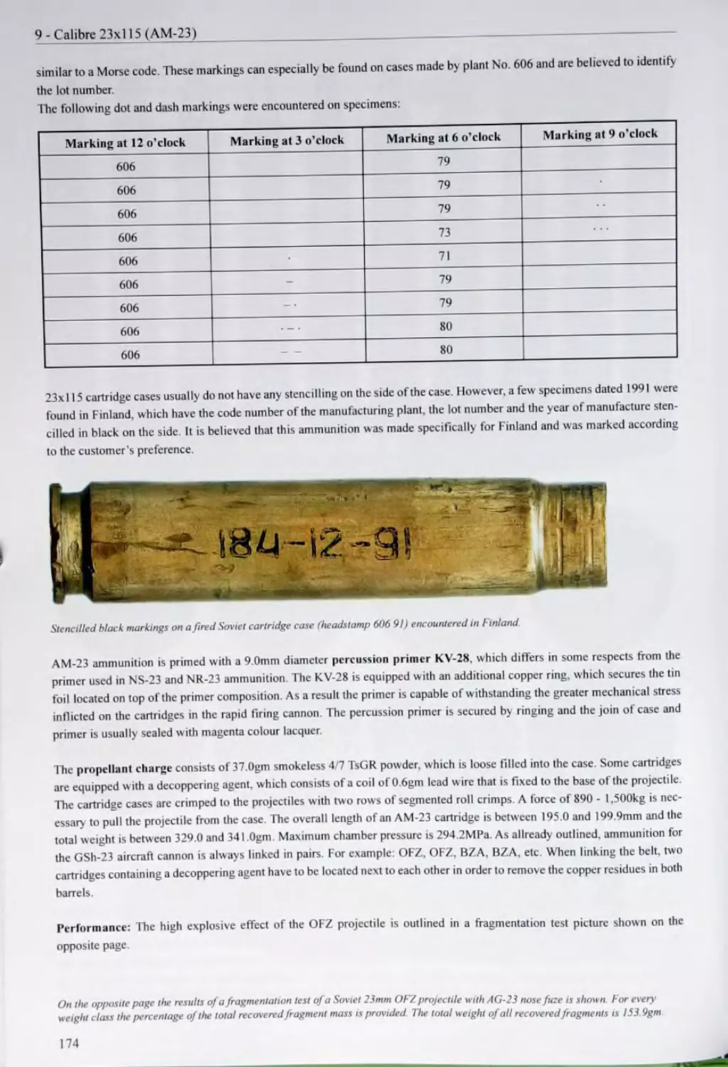
white band target practice projectile Note: On calibre 23x115 projectiles the white band identifies life service ammunition for the AM-23 aircraft cannon
entire projectile body light grey no colour marking, but basic varnish on large calibre artillery shells calibre 57mm and up
yellow tip armour piercing incendiary tracer projectile (in 23x115 and 23x152B calibre)
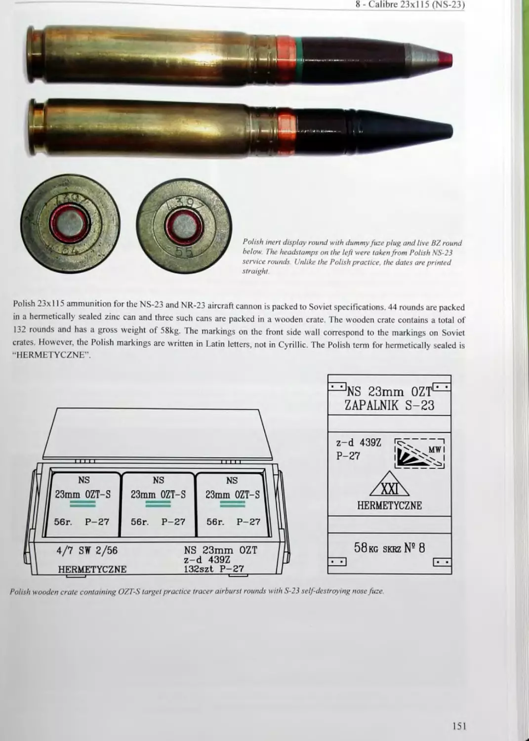
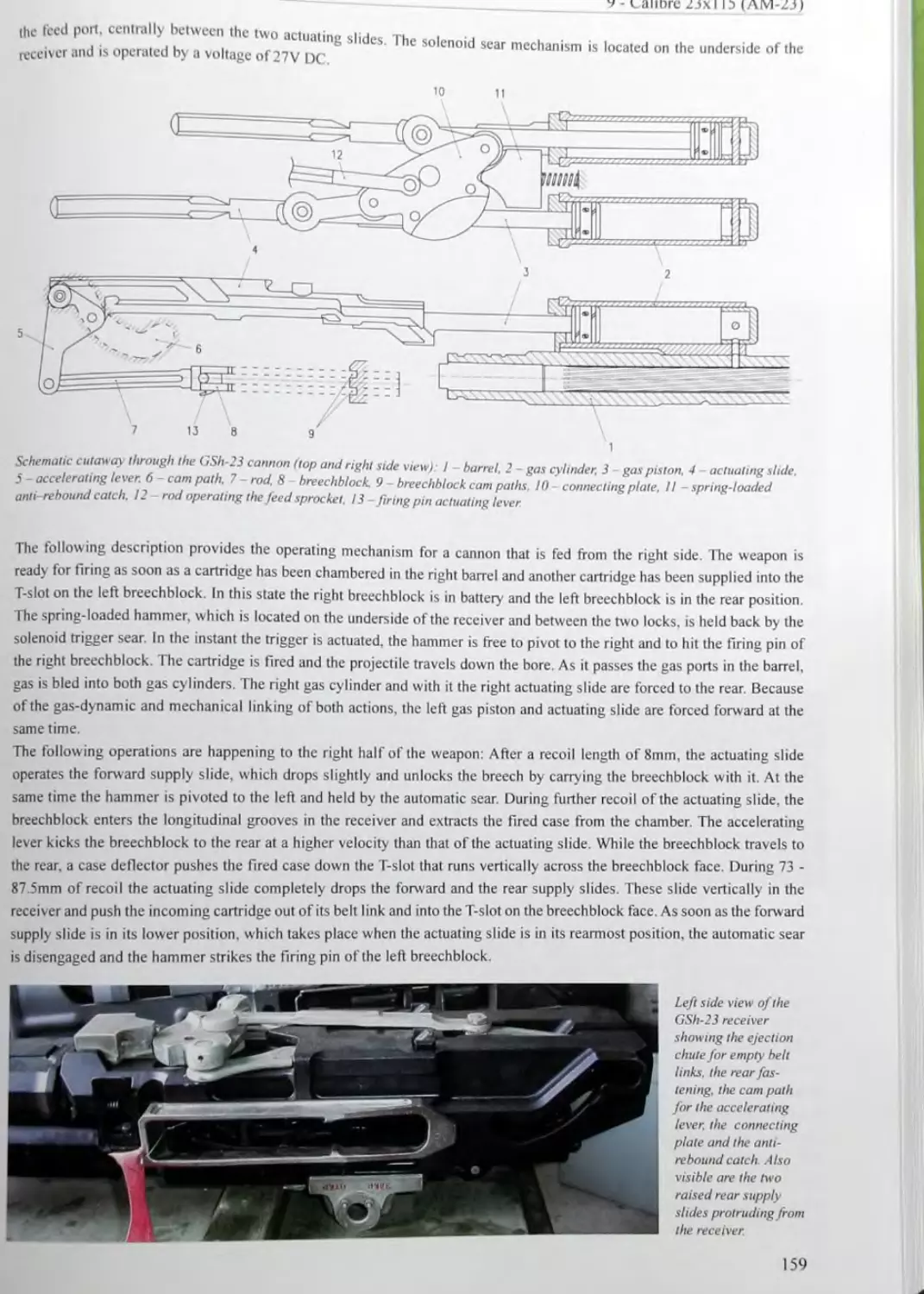
yellow band cartridge containing a decoppering agent Note: On 23mm and 30mm “multi element” projectiles the yellow band is only a seal and has no meaning
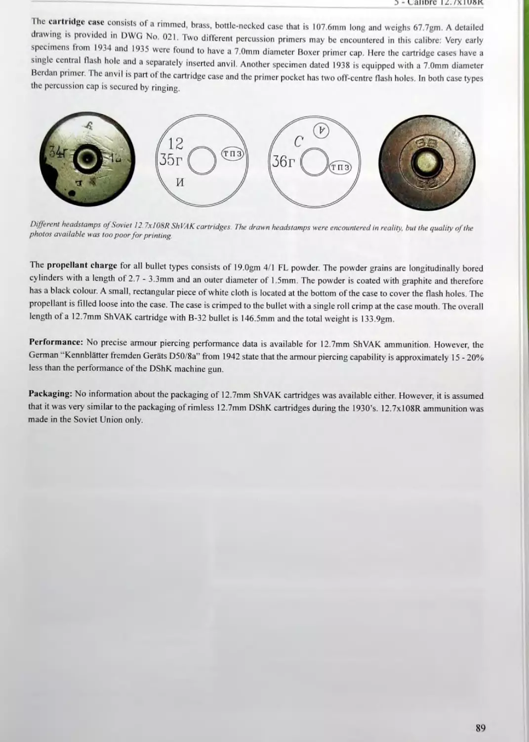
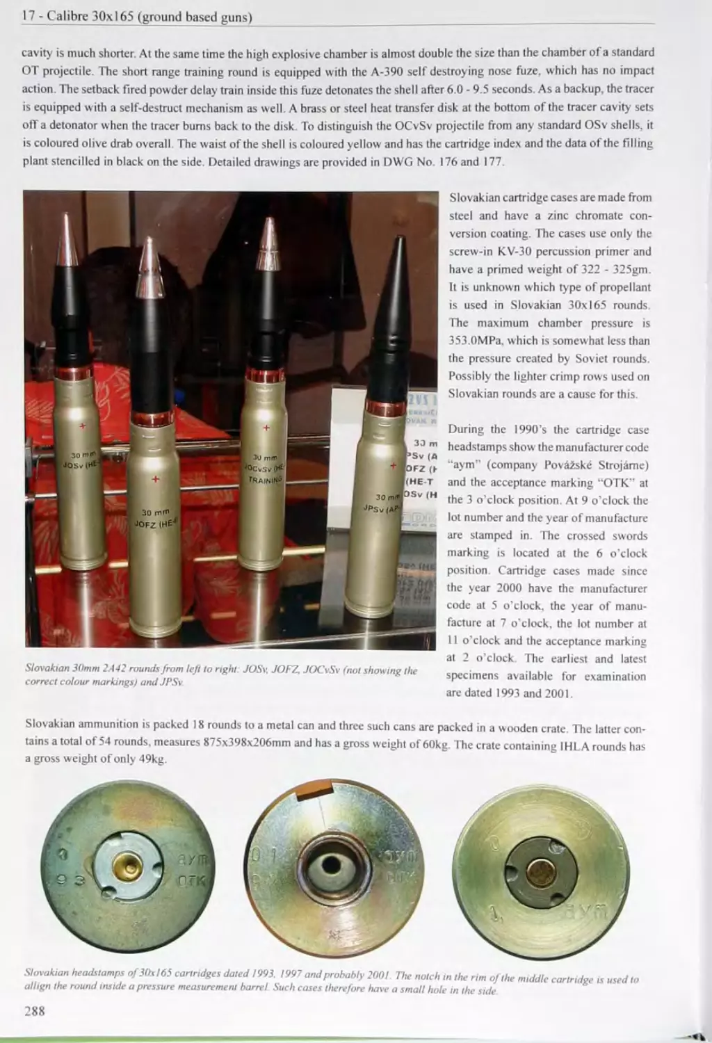
red band different meanings; please refer to the calibre chapters and drawings for details
entire projectile body magenta high explosive incendiary projectile (in 23x 115, 23x 152B and 30x 155B calibre only)
green tip target practice or target practice tracer projectile
green band projectile with tracer
entire projectile body green naval round (in calibre 30x165 for the naval AO-18 cannon, to distinguish from army and air force types in the same calibre)
entire projectile body olive drab no colour marking, but basic varnish on large calibre artillery shells calibre 57mm and up
black tip armour piercing tracer projectile (in 23x115 calibre)
black tip with red band below armour piercing incendiary projectile
black band projectile body made from cast iron (on 45x31 OR 0-240 shells only)
entire projectile body black target practice or drill round (note: the black colour has to be a varnish, not a black phosphate surface finish)
For colour markings on bullets and projectiles made in the Warsaw Pact states, please refer to the different chapters and
drawings in the book.
Soviet large calibre artillery shells are sometimes equipped with colour markings as well. Especially prior to the Second World
War coloured bands were used to a great extent. There are two different colour marking systems for large calibre artillery
shells: the old system prior to 1938 and the new system after 1938. The old system also consists of two different marking
types, which distinguishes shells produced and loaded during peacetime and projectiles made during war. No detailed colour
markings for large calibre artillery shells are outlined here, because these are too numerous and are outside the purpose of this
book. The basic colour markings of large calibre artillery shells (new system) are:
Colour Marking Meaning
white band illuminating shell
red band incendiary’ shell
entire projectile body red propaganda shell
blue band concrete piercing shell
black band (on ogive) smoke shell
black band (above driving band) projectile body made from cast iron
entire projectile body black target practice or drill round
36
2.2.2 C olour Markings on Fuzes
Sd v icc tn/с. v generally not varnished hut may have coloured tips to identify the nature of the projectile they are fitted to.
Espccia у ncse uzes or medium calibre projectiles are equipped with a coloured tip. With a few exceptions, fuzes for small
arms bullets and large calibre artillery shells do not have any colour markings.
Until the mid I 70 s inert dummy nose tuzc plugs are in natural colour and have a white coloured lip. Instead of the latter,
large calibre arti cry dummy fuze plugs may have a white coloured band on the side. Dummy base fuze plugs have the
exposed circumference coloured white. Since the mid 1970’s inert dummy fuze plugs are overall painted black, ochre or
olive drab.
The following table identifies (he most common colour markings on Soviet fuzes for medium calibre cartridges:
Colour Marking Meaning
white tip dummy fuze plug on target practice projectiles (up to the mid 1970’s)
white band dummy fuze plug
magenta tip high explosive projectile
red tip high explosive projectile
green tip target practice (calibre 30x21 OB) or target practice tracer projectile (calibre 23x152B ZSU and 30x165 2A42) Note: the calibre 30x155B UBT projectile is a high explosive filled airburst tracer projectile whose A-19IM nose fuze has a green tip as well.
light blue tip high explosive airburst projectile (with self-destroying fuze)
dark blue band grenade without self-destruct mechanism (only on VMG-A nose fuze of 30mm VOG-I7A grenades)
ochre band is only a seal and has no meaning (on modem graze-sensitive nose fuzes like the AG-23)
entire fuze olive drab dummy fuze plug on target practice projectiles (since the mid 1970’s)
entire fuze ochre dummy fuze plug on target practice projectiles (a variation of the olive drab paint)
entire fuze black dummy fuze plug on inert drill rounds
2.2.3 Colour Markings on Cartridge Cases
Brass cartridge cases are generally not varnished. Medium calibre steel cartridge cases are either varnished with lacquer, zinc
coated or zinc chromate conversion coated. Lacquered steel cases are varnished with a special cartridge case lacquer that acts
as a lubricant to assist the extraction of the fired case from the chamber. The colour of this lacquer can be between grey and
olive drab. Soviet steel cartridge cases for large calibre artillery' rounds are either zinc coated or zinc chromate conversion
coated.
37
2 - Sov iet Ammunition Markings
Besides the basic varnish of steel cases, colour markings are only encountered to a limited extent. The following table iden-
tifies the colour markings on Soviet cartridge cases:
Colour Marking Meaning
red band on the side ammunition intended for the 45mm Ml942 anti-tank gun only (only on calibre 45x31 OR cases)
red case neck drill round (only on medium calibre cartridges)
red band on the neck auxiliary cartridge to fire a stuck projectile (only on large calibre naval cartridges; is used together with a red segment on the head)
red segment on the head auxiliary cartridge to fire a stuck projectile (only on large calibre naval cartridges; is used together with a red band on the neck)
blue segment on the head cartridge containing a flash-less propellant charge (only on large calibre naval cartridges)
2.2.4 Colour Markings on Screw-In Primers
Screw-in primers are generally not varnished with any lacquers. During the Second World War a single colour marking was
used for Soviet primers, which consisted of a white coloured segment on the base of the primer. This marking indicates a
reloaded primer and for every time the primer was reloaded, a white segment was applied between the primer key holes.
2.2.5 Colour Markings on the Packaging
Until the late 1950's wooden crates and zinc-coated steel cans were in natural colour. Since then, the Soviet packaging is
usually varnished with olive drab lacquer. Besides this basic protection varnish, different colour markings are used to identify
the contents of the packaging. Coloured stripes on steel cans and wooden crates correspond to the colour markings on bullet
tips and medium calibre projectiles. Apart from these stripes, the following colour markings can be encountered on
Soviet ammunition crates and cans:
Colour Marking Meaning
two vertical red stripes on the front side wall indicates packaging containing high power ammunition for the 45mm M1942 anti-tank gun
two concentric red circles indicates packaging containing MDZ high explosive incendiary rounds
red propeller indicates packaging containing cartridges suitable for synchronized aircraft guns
two concentric purple circles indicates packaging containing cartridges with special armour piercing tracer bullet (with tungsten carbide core)
single vertical black stripe on the front side wall indicates packaging containing improved ammunition with deeper cannelures and thick- walled case neck (on packaging of 57mm S-60 anti-aircraft gun ammunition only)
black propeller indicates packaging containing cartridges suitable for synchronized aircraft guns
two concentric black circles indicates packaging containing cartridges with special armour piercing bullet (with tungsten carbide core)
black side walls and black sides of top lid indicates packaging containing cartridges with special armour piercing bullet (with tungsten carbide core)
black can-opener symbol indicates that a can-opener is located inside the wooden crate
Prior to the Second World War the colour markings on Soviet large calibre artillery shells were also applied to the sides of the
packaging. However, these early markings are outside the purpose of this book.
38
2.3 Stencilled Markings
Stencilled markings are applied by the loading plant that tilled the projectile with high explosive or the cartridge case with
propellant these plants also usually assemble the ammunition, which means screwing the fuze or transportation plug into
the projectile and crimping the cartridge case to the projectile. Besides any loading data, the stencilled markings on projectile
bodies, cartridge cases and packaging provide the index number of the ammunition, the calibre, the weapon system the
ammunition is intended for and much more information. Usually all stencilled markings are applied in black paint.
23.1 Stencilled Markings on Projectile Bodies
Stencilled markings are only applied to medium and large calibre projectiles and not to small arms bullets. These markings
can generally be found above the driving band, on the cylindrical or ogive part of the projectile. Please note that the colour
of the stencilling depends on the basic colour of the projectile body. Black projectiles generally have white markings, while
olive drab, light grey and uncoloured steel grey projectiles have the markings applied in black.
Below 37mm calibre stencilled markings are usually an exception. For example, chaff expelling anti-radar projectiles have
the length of the radar dipoles in mm’s applied on the side. Another example is 30mm grenades for the AGS-17 grenade
launcher. These have the index designation and the loading data stencilled in white on the side.
Projectiles calibre 37mm and up are usually equipped with stencilled markings on two sides. The front side usually shows the
designation of the high explosive filler, the designation of the fuze and the index designation of the projectile. The rear side
usually provides the code number of the loading plant, the lot number and year of loading. Additionally, the calibre and, on
naval shells, the barrel length of the gun are shown on the rear side.
Soviet artillery shells above 76mm calibre are additionally equipped with a weight classification that consists of the Cyrillic
letter “H” for standard weight, or a varying number of plus or minus symbols that indicate the extent the shell is above or
below standard weight. Every plus or minus symbol indicates a deviation of 0.67% from the standard weight. Separately
loaded naval artillery shells have the tabular weight of the projectile in kilograms applied to the ogive and the base of the
projectile. Sometimes also the manufacturing information for the fuze is stencilled on the projectile body.
Examples:
Typical stencilled markings on a Soviet projectile:
“A-IX-2” high explosive filler designation
“70” code number of the loading plant
“МД-7” designation of the base fuze
*80 - 67” lot number and year of loading
“БР-27Г
“57”
projectile index designation
calibre of the projectile
39
2 - Soviet Ammunition Markings
23.2 Stencilled Markings on Cartridge Cases
Stencilled markings on cartridge cases are applied in black and can be found on the side written in numerous rows. The
markings provide the index designation of the round, the calibre and weapon system the cartridge is intended for. the pro-
pellant data, as well as the lot number, the year and the code number of the plant that loaded and/or assembled the round. A
single Cyrillic letter “Ф” in the last row indicates the presence of a phlegmatising agent inside the cartridge case. On some
medium calibre cartridge cases with target practice projectiles the marking “ПРАКТ.” is applied below the index designation
of the round. In addition to the weapon system the phrase “СУ и ТАНК” indicates that the ammunition can be fired from self-
propelled guns, as well as from tank guns. Separately loaded artillery ammunition also has the nature of the powder charge
written out in full on the side of the case.
The following markings can be encountered:
Cyrillic Marking Transliteration Meaning
ПОЛНЫЙ POLNYY full charge
ПЕРЕМЕННЫЙ PEREMENNYY variable charge
УМЕНЬШЕННЫЙ UMEN’ShENNYY reduced charge
ХОЛОСТОЙ KhOLOSTOY blank cartridge
Typical stencilled markings on Soviet cartridge cases:
“H-37” designation of the gun “УБМ 8“ index designation of the fixed round
"БЗГ’ index designation of the projectile “100” calibre in mm
“23 - 52” lot number and year of cartridge assembly “СУ и ТАНК” intended for self-propelled guns and tanks
“3-Д” abbreviation for “zavod” (= “plant”) “12/7” powder designation (first powder type)
“184” code number of the manufacturing plant “12/И” lot number and year (И 1955) of powder
“4/1 ФЛ” powder designation manufacture
“3/52” lot number and year of powder manu- “C” code letter of the powder plant
facture “16/1 TP“ powder designation (second powder type)
“K” code letter of the powder plant (not visible “3/81” lot number and year of powder manu-
on the above picture) facture
“A” code letter of the powder plant
“52” lot number of cartridge assembly
“83” year of cartridge assembly
“22” code number of the assembly plant
“ф” powder with phlegmatising agent
40
1 he stencilling on Soviet naval cartridge cases usually provides more information than that on standard army cases. An addi-
tional row below the index designation identifies the nature of the powder charge, no matter if the round is fixed or separately
loaded. At the same time the index designation is amended by one or two characters that correspond to the abbreviated
powder charge identification designation:
Powder Charge Designation Corresponding amendment letter in the cartridge index designation Meaning
БОЕВ, or БОЕВОЙ Б war charge (full charge)
УСИЛ. УБ increased war charge
ПОНИЖ. ПБ reduced war charge
УМЕНЫ11. УМ reduced powder charge (for target practice projectiles)
OCBET. - powder charge for illuminating shell
СПЕЦИАЛЬНЫЙ - special powder charge
The powder charge designation on naval rounds is especially important to calculate the life of the barrel the ammunition is
fired from. The “war charge” is the most frequently used powder charge and provides the tabular muzzle velocity and range
for standard shells. The “increased war charge" is used to fire at extended ranges and provides the maximum possible muzzle
velocity'. However, at the same time the bore is strained to a great extent and the life of the barrel is reduced considerably. The
“reduced war charge” consists of approximately one third less powder and is especially used when firing in the high angle
group (plunging fire). When shooting target practice ammunition, the “reduced powder charge” is used. It only consists of
half a full charge and consequently the life of the barrel is increased accordingly. There are also some special powder charges
for illuminating shells, to heat up the barrel at temperatures of below' 0° C, to remove oil or grease from the bore, or to fire
salutes.
2.3.3 Stencilled Markings on the Packaging
Stencilled markings on steel cans and wooden crates are applied in black as well. The packaging provides a summary of the
most important markings on the ammunition components. The degree of detail depends on the calibre of the cartridges. The
larger the calibre of the round, the more detailed is the stencilling on the packaging. Please refer to the packaging markings
outlined separately for every calibre in the different chapters of the book.
On soldered or lock-seamed steel cans, which are packed in a wooden crate, often only the calibre, the projectile type, a
lot number and the year of manufacture can be found. Wooden crates provide more detailed information. This first of all
includes the index designation of the round, the calibre and the weapon system the ammunition is intended for. Additionally,
the fuze designation and manufacturing information, the propellant data, the number of rounds inside the crate and the gross
w eight in kg are provided. These markings are usually applied to the front side wall of the wooden crate. Sometimes a part
of this information is stencilled on the top lid instead. In front of the fuze model number the Cyrillic abbreviation “OK CH”
is often applied, which means that the round is fully equipped and ready for firing. The Cyrillic marking “ГЕРМЕТИЧНО”
or “ГЕРМОУКУПОРКА” on the front side wall indicates that the contents is hermetically sealed. On the right side wall
the index number of the projectile, the high explosive filler type and the lot number, plus the year and code number of the
plant that filled the projectile are shown. On the left side wall the designation and manufacturing information of the primer
are applied. The packaging of drill rounds is identified by the black stencilled marking “ОХОЛ”, “ОХОЛОЩЕННЫЕ” or
“УЧЕБНЫЕ”.
As well as manufacturing information, other markings can be found on wooden crates:
A hazard warning sign, consisting of an equilateral triangle with a side length of 15cm, is often stencilled to the front side
wall and/or the lop lid of a wooden crate. Inside this triangle a number designating the classification of the explosive hazard
is located. A square with an explosion symbol and the phrase “ОПАСНО BB” (“DANGER HE.” in English) generally
indicates that the contents is hazardous. The rear side wall of a wooden crate is often used to apply the shipping information
in case the ammunition is intended for export. This information consists of the railway stations of sender and addressee, the
41
2 - Sov ict Ammunition Markings
contract number, the delivery number, as well as the gross and net weights. Additionally, an individual crate number is applied
("ЯЩ№”).
Numerous examples of stencilled markings on Soviet ammunition packaging can also be found in t e in
chapters of the book.
“H-37mm”
“3-Д 184"
“УЧЕБНЫЕ”
“П-1-И”
“47кг”
“ЯЩ№ 114”
Typical stencilled markings on Soviet ammunition crates.
designation and calibre of the gun
manufacturing plant 184
drill rounds
lot number and year of manufacture (И = 1955)
gross weight of the crate in kg
individual crate number
Stencilled markings on the cans:
Stencilled markings on the crate.
ОХОЛОЩЕННЫЕ”
ГШ-6-30А”
ОФЗ"
I -76”
drill rounds
designation of the gun
designation of the projectile
lot number and year of manu
facture
“БВ” dummy fuze plug
“A-662” fuze designation
“ОФЗ” designation of the projectile
“Г L1J-6-30A" designation of the gun
“ОХОЛОЩ" drill rounds
“184- I - 76” code number of the manufacturing
plant, lot number and year of
manufacture
54шт total number of rounds inside the crate
БРУ I l О 56кг" gross weight of the crate
The purple stamp on the inside of the lid resembles the
stamped-in manufacture markings of the projectile (man-
ufacturer symbol, year, in-plant acceptance letter and
acceptance letter of the military representative inside a
rhomboid).
42
3 AMMUNITION CHEMISTRY
Main references used for this chapter:
A34, A44. A48, A49, A50, A60. A66. Bl. D38, D40. D4I. D43. D47. E8. /28 and 133.
3.1 Powders and Propellants
Soviet medium calibre cartridges are filled with smokeless Pyroxylin (nitrocellulose) propellant powder. Single base Pyroxylin
is produced by nitrating celluloses (cellular tissue) in a mixture of nitric and sulphuric acid. The Soviets mainly used wood
pulp, from which all unnecessary admixtures were chemically removed. Cotton cellulose was used as well, but only to a
limited extent. Smokeless Pyroxylin powders are made from a gelatinized mixture of highly nitrated Pyroxylin № I and low-
nitrogen Pyroxylin № 2. Pyroxylin № 1 has a nitrogen content of 12.9 - 13.3% and is barely soluble in a mixture of alcohol
and ether. Pyroxylin № 2 has a nitrogen content of 11.9 - 12.3% and almost completely dissolves in a mixture of alcohol and
ether. By mixing solvable and unsolvable Pyroxylin it is possible to regulate the energy content of the propellant. The alcohol-
ether solvent to gelatinize the powder mass consists of a mixture of 2 parts 95% ethyl alcohol and 3 parts ether. Double base
powders are created by gelatinizing the powder mass with nitroglycerine, dinitro-toluene, or diglycole nitrate. However, the
Soviets used double base nitroglycerine powders to a limited extent only. To the powder mixture a stabiliser in the amount of
2% is added. This stabiliser consists of diphenylamine, which increases the storage life of the powder. During long storage,
nitrogen oxides slowly separate from the powder and start a decomposition process. Diphenylamine forms durable nitro deri-
vates that do not affect the powder. To prevent the ignition of the propellant gases at the muzzle (muzzle flash), up to 2% of
well-ground potassium sulphate can be added to the mixture. The gelatinized powder mass is pressed through matrices and
cut into cylindrical grains of a specific length. The grains are dried until almost all volatile substances have evaporated. The
numerous brands of powders differ from each other in the geometric shape and the dimensions of the powder grains. Powders
of one and the same brand, but of different lots are different in their ballistic properties. Therefore the actual weight of the
powder charges can be slightly different. The powder charge weight of a particular lot is determined by shooting a number of
rounds on the range. This is carried out under standardised conditions until the desired muzzle velocity is attained.
A special property of smokeless Pyroxylin powder is the fact that it combusts in
layers. This property is used to regulate the quantity of gas that is produced in a
specific time. By selecting different geometric shapes and sizes, progressively com-
busting powder charges can be created. This means that during the combustion of the
powder grain its burning surface continuously increases in size. A typical example for
such a progressive powder is a 7-channel powder. However, as soon as the channels
have widened to a degree so that they touch each other, the cylindrical grain is sepa-
rated into 12 bars of curvilinear cross-section. These grain particles have a degressive
combustion property, which is the major drawback of a 7-channel powder. Powder
grains with a single channel generally have a neutral combustion property. This
means that the surface loss on the outside of the powder grain is compensated by the
surface gain on the inside of the channel. However, by chemically treating the outer
Soviet 7-channel " 11/7" powder.
surface of a single channel powder, the combustion rate can be changed to progressive. To create a progressive single channel
powder, its outer surface is phlegmatised with an alcoholic solution of camphor. The camphor enters the surface layer of the
powder and reduces the combustion rate. At the same time, phlegmatised powders are coated with graphite to increases their
specific weight. These powders start by building up a moderate pressure that rapidly increases during further combustion.
Phlegmatised powders have a somewhat lower combustion temperature and therefore contribute to a longer barrel life. Please
note that aircraft cartridges intended for synchronized shooting through the propeller disk were not treated, because this
increases the combustion time. Soviet single base Pyroxylin powders have the following properties.
Volume of the gaseous products:
Combustion energy:
Combustion temperature:
Ignition temperature:
Specific weight:
900 - 970 litres/kg
800 - 900 cal/kg
1,500- 1,700° C
180-200° C
1.56 - 1.62 gm/cc
43
3 - AmmunitiqnChemistry _____________ _____ — —
Soviet tubular powders are designated with a fraction that indicates the size of the powder grain. Tubular pc dcr t r
Soviet medium calibre cartridges consist of cylindrical grains that may have one or multiple channels. The numerator
powder designation indicates the web size in l/10ths of a millimetre. The denominator identifies the number of channels that
arc bored longitudinally through the cylindrical grain. Tubular powders for large calibre artillery shells often have the suflix
“TR” to identify the shape of the powder. Other suffixes provide any special admixtures or treatments.
Soviet Паке powder is designated with the prefix “PL" and two numbers separated with a dash. The first number indicates
the thickness of the flake in l/IOOs of a millimetre and the second number provides the width of the flake in 1/lOths of a
Soviet ribbon powder can be identified by the prefix “L" and a single number. This number indicates the thickness of the
ribbon in 1/100s of a millimetre.
Porous Pyroxylin powder has a low density and a 4 - 8 times greater combustion rate than conventional nitrocellulose
powders. This type is used in weapons with a short barrel, like pistols, mortars and grenade launchers. The porous structure
of the powder is attained by mixing a specific percentage of potassium nitrate into the nitrocellulose powder. 1 he number
following the designation “П” indicates the parts of potassium nitrate per 100 parts of nitrocellulose. Please note that after
drying and cutting the powder mixture, the potassium nitrate is removed again by soaking the powder grains in hot water.
The following table identifies a variety of Soviet powder designations and suffixes:
Cyrillic Designation or Suffix Transliteration Identification
БП BP powder with a muzzle flash reducing additive
БУГ BUG Pyroxylin powder with a muzzle flash reducing additive
ДогДГ Dor DG Dinitrodiethyleneglycol powder
ДРП DRP black powder (supplementary' charge)
ФЛ FL phlegmatised powder
ГР GR powder coated with graphite
X Kh blank cartridge powder
КЗДП-1 KZDP-1 black powder (supplementary charge)
Л (plus number) L (plus number) powder in ribbon form
H N double base nitroglycerine powder
HA N/A Pyroxylin powder with a low nitrogen content
НБ NB double base nitroglycerine powder
НБК NBK double base nitroglycerine powder in ring form
НБЛ NBL double base nitroglycerine powder in ribbon form
НДТ (plus number) NDT (plus number) cold double base nitroglycerine powder (the number indicates the combustion energy, which is regulated by partially replacing the nitroglycerine with dibutyl phthalate)
HTC-10 NTS-10 cold double base nitroglycerine powder (59% nitrocellulose, 30% nitroglycerine, 10% centralite and 1% vaseline)
ОД OD sPecial delivery (imported lend-lease powder for example)
П-200 P-200 porous Pyroxylin powder (the number indicates the percentage of potassium nitrate, which is added and then removed again from the powder mixture)
ПЕР PER reworked powder
ПГ (plus weight in kg) PG (plus weight in kg packet with muzzle flash reducing agent (potassium sulphate) inside the cartridge case
ПЛ (plus two numbers PL (plus two numbers powder in flake form
44
J - П111111 Uli IIIVII V I IVIII 1.Э11 J
Cyrillic Designation or Suffix Transliteration Identification
СФ SF low-quality powder (produced in a short time or with a lack of raw materials)
CM SM powder consisting of a mixture of several lots
CT ST stabilised powder made by treating old powder with a stabiliser
CB SV powder made from fresh Pyroxylin
TP TR tubular powder (used as a suffix after the fraction)
Ц Ts Pyroxylin powder stabilised with centralite
УФ UF powder produced with a shortened production process
УГ UG Pyroxylin powder with a muzzle flash reducing additive (50% Pyroxylin powder. 48% potassium sulfate. 2% additive)
УГФ UGF Pyroxylin powder with a muzzle flash reducing additive
B/A V/A Pyroxylin powder with a high nitrogen content
B/B V/V powder produced during the war
ВБП VBP unknown (possibly a powder with an improved muzzle flash reducing additive)
ВЛ VL rifle powder for light bullets
ВТ VT rifle powder for heavy bullets
ВТЖ VTZh rille blank cartridge powder
ВУФЛ VUFL slightly phlegmatised rifle powder
WM WM foreign Cordite powder (imported lend-lease powder in blank cartridges)
Examples:
“4 1 FL" is a phlegmatised single base powder that has a single channel and a web size of 0.4mm.
“4/7 TsGR"
is a coated single base powder stabilised with centralite that has seven channels and a web size of 0.4mm.
Note that this specific powder type is not coated with graphite, but possibly with a different substance.
“NBPL 14-10" is a double base nitroglycerine powder that consists of square powder flakes that are 0.14mm thick and
1.0mm wide.
“NBL-33" is a double base nitroglycerine powder in ribbon form with a thickness of 0.33mm.
is a cold nitroglycerine powder with a combustion energy of 3,020kJ/kg.
“NDT-2"
Soviet "4'7 TsGR " powder on the left
and ”6/7 P-5 BPFL " powder on the
right Note the dark grey graphite
coaling of the 6'7 powder
45
3 - Ammunition Chemistry
3.2 High Explosives
Military high explosives can be separated into two groups: primary high explosives and secondary high explosives. I rimary
high explosives are used in primers and detonators and are intended to ignite propellant charges and to initiate the detonation
of a secondary high explosive. They are very sensitive and instantly detonate when exposed to any mechanical or thermal
stress. This especially includes the impact of a firing pin or the flash from a percussion cap. Secondary high explosives are
used as main fillers of high explosive shells. To withstand the high loads that act on the filler in the instant the shell is fired,
secondary high explosives are relatively insensitive.
3.2.1 Primary High Explosives in Primers
Soviet primers may be encountered as push-in primer caps, screw-in primers and primer tubes. Despite the variety of sizes
and shapes, these are all constructed in a very similar way.
The 9.0mm synchronous percussion primer cap for Soviet 12.7mm, 20mm and 23mm cartridges consists of a brass cup,
which is varnished on the inside with clear lacquer. The latter serves for a secure connection between the cup and the primer
composition and also prevents any corrosion of the metal cup. Into the latter 0.10-0.12gm of a corrosive primer composition
are pressed with a pressure of 108 - I l8MPa. The primer composition consists of a mixture of 25% mercury fulminate, 37.5%
potassium chlorate and 37.5% antimony trisulfide. Mercury fulminate is a very sensitive high explosive and produces a flash
when struck by the firing pin. Antimony trisulphide increases the sensitivity of the mercury fulminate against impact and
temperature. Potassium chlorate releases oxygen during the combustion of the other two
components. A tin foil on top of the primer composition seals the primer cap and prevents
any mechanical damage to the primer composition.
Small percussion primer caps are not only used in cartridge cases. They can also be encoun-
9 Omni percussion primer caps tered in fuzes to ignite a self-destruct powder train for example.
The percussion screw-in primer KV-2 consists of a brass body that is screwed into the head of the cartridge case. Inside the
body the percussion primer cap is located and held in place by a screw-in bushing. On top of this bushing the anvil and a
copper sealing cone are located. The KV-2 screw-in primer contains 0.018 - O.O25gm of the above mentioned primer com-
position and a supplementary charge of 0.4gm black powder. At the top the primer is closed with a gauze and brass foil disk
and hermetically sealed with paste and varnish.
ZTN percussion primer tube
rhe ZTN percussion primer tube consists of a tubular brass body that is pressed into
the head of the cartridge case. Inside the tube a primer cap and a second brass cap
that forms an anvil are located. The join of tube and brass cap is hermetically sealed
with a lead washer, which prevents any leakage of propellant gases. Additionally, the
primer cap is secured with a circular crimp and sealed with varnish. The ZTN primer
tube contains 0.065 - O.O85gm of the above mentioned primer composition and a sup-
plementary charge of 1.25gm black powder. The primer tube is closed at the top with
a pasteboard disk and sealed with paste and shellac varnish.
KV-5- U percussion screw-in primer
Electrical EKV-30 screw-in primer
46
3.2.1 Primary High Explosives in Detonators
As already outlined, detonators are used to initiate a high explosive projectile
filler. I he MG-201 detonator used in many Soviet medium calibre cartridges
consists of an outer cup made from German silver (an alloy of primarily
copper, nickel and zinc). The cup is equipped with a flange, with which the
detonator is fixed to the fuze body. The German silver cup is usually filled
with 0.14gm PETN. but during WWII it was filled with Tetryl instead. On top
MG-201 detonator.
of the secondary charge an inner aluminium cup is located. This cup is filled with a thin layer of 0.06gm “Nakolny” primer
composition and 0.21 gm lead azide primary high explosive. The “Nakolny” primer composition consists of a mixture of
50% lead trinitroresorcinate, 20% barium nitrate, 25% antimony trisulphide and 5% tetrazen. It is fired by the impact of the
firing pin and sets off the lead azide. The detonator is assembled by pressing the inner cup into the outer cup with a pressure
of59MPa.
Fuzes that use a gas-dynamic delay mechanism to explode the projectile inside the target have detonators that are not fired
by a firing pin, but by a flash. Therefore the inner aluminium cups of these detonators have a central hole, which is closed
with a silk disk. The primary charge consists of lead trinitroresorcinate desensitized with bitumen and lead azide mixed with
dextrin. The secondary explosive is again PETN. The application of desensitized primary high explosives makes it possible
to increase the durability of the detonator. This is especially important to withstand the mechanical and thermal stress at the
instant the projectile enters the target.
3.2.2 Secondary High Explosives
TNT, RDX and PETN are the three types of secondary high explosives that can be encountered most frequently. Other high
explosives like HMX and Tetryl are used to a limited extent only. Please note that during the Second World War a number of
substitute high explosives like ammonium nitrate, picric acid, dinitrobenzene and dinitronaphthalene were used to overcome
shortages of TNT. Whereas pure TNT is insensitive enough to be filled directly into the shells, RDX and PETN have to be
desensitized with wax to withstand the high setback force that occurs during firing. To attain the desired high explosive or
fragmentation effect, TNT. RDX and PETN are often mixed with different substances. By adding aluminium powder, the
power of the high explosive is increased and the projectile receives an incendiary capability. The high explosive incendiary
composition most frequently encountered in Soviet medium calibre projectiles is A-IX-2. This combined high explosive
incendiary composition was developed by naval engineer Eugene Grigorevich Ledin in 1940. It was developed to increase the
power of armour piercing high explosive projectiles and in fact, A-IX-2 is more than twice as powerful as TNT. In February
1942 the Soviet state committee for defence decided to adopt the new high explosive incendiary composition, and by the end
of that year all medium calibre projectiles were filled with it.
The designation “A-IX-2” is often stencilled onto projectiles
above 30mm calibre. However, naval ammunition is marked
with a different version of that designation: the dashes are
omitted and instead of a Roman number “IX” an Arabic
number “9” is used. The naval designation “A92” can also
be found stamped into the driving band and stencilled onto
the packaging. A-IX-2 has the following properties:
Volume of the gaseous products:
Explosion energy.
Detonation velocity:
Explosion temperature:
Ignition temperature:
Specific weight.
Pressed pellet of A-IX-2 high explosive.
750 litres/kg
1,550- 1,720 cal/kg
7,800 - 8.510 m/sec
4,900° C
215 -230° C
1.65 - 1.80 gm/cc
Soviet medium calibre projectiles are usually filled with a preformed pressed pellet of A-IX-2. To securely accommodate the
filler pellet inside the projectile, the filler is secured with wax and cardboard washers. Modem high explosive projectiles have
the filler pressed directly into the shell and no longer need any cardboard washers.
47
3 - Ammunition Chemistry
The following table identifies the different high explosive fillers used in Soviet shells. The Cyrillic designation is often sten
cilled onto the projectile.
Cyrillic Designation Transliteration Identification
A A 90% ammonium nitrate, 10% TNT
A-40 A-40 40% ammonium nitrate, 60% TNT (sometimes desensitised with 3 % wax or 4% naphthalene)
A-50 A-50 50% ammonium nitrate, 50% TNT
A-80 A-80 80% ammonium nitrate, 20% TNT
A92 A92 naval designation for A-IX-2
AMA AMA 40% ammonium nitrate, 50% TNT, 10% aluminium powder
AT-40 AT-40 A-40 topped with pure TNT
AT-80 AT-80 A-80 topped with pure TNT
АТФ-40 ATF-40 pressed mixture of 40% ammonium nitrate and 60% TNT
A-1X-I A-1X-1 95% RDX, 5% wax
A-IX-2 A-IX-2 80% A-IX-1, 20% aluminium powder
А-1Х-2Г A-1X-2G improved A-IX-2 (possibly with a different content or type of desensitiser to improve stability in aircraft cartridges)
ДЬТ DBT dinitrobenzene and TNT
ГТГ GTT 75% RDX, 12.5% TNT, 12.5% Tetryl
K-l K-l 70% TNT, 30% dinitrobenzene
K-2 K-2 80% TNT, 20% dinitrobenzene
K-3 K-3 70% picric acid, 30% dinitrobenzene
M M Melinite (picric acid, trinitrophenole)
MC MS 19% TNT, 57.6% RDX, 17% aluminium powder, 6.4% wax
ОКФОЛ OKFOL HMX desensitised with 5% wax
ОКТОЛ OKTOL HMX desensitised with TNT
ОЛ OL HMX desensitised with 5% wax
Пентолит-50 Pentolit-50 50% PETN, 50% TNT
P-4 R-4 white phosphorous
Ш Sh Schneiderite (88% ammonium nitrate, 12% dinitronaphthalene)
ШТ ShT Schneiderite topped with pure TNT
T T TNT
T-80 T-80 80% TNT, 20% RDX
TA TA 80% TNT, 20% aluminium powder
ТД-42 TD-42 42% TNT, 58% dinitronaphthalene
ТД-50 TD-50 50% TNT, 50% dinitronaphthalene
ТДУ TDU pressed mixture of TN Г and aluminium powder
TEH TEN PETN desensitized with 3 - 5% paraffin wax
ТГ-20 TG-20 20% TNT, 80% RDX
! ТГ-50 TG-50 50% TNT, 50% RDX
ТГА TGA 60% TNT, 24% RDX, 16% aluminium powder
48
J - t \ IJ1111II111•1 Ul I k_ IICIIIIMI/
Cyrillic Designation Transliteration Identification
ТГЛФ-5 TGAF-5 38% TNT, 38% RDX, 19% aluminium powder, 5% wax
ТГАГ-5 TGAG-5 95% TGA, 5% wax
TC TS high grade TNT (“sulfonated” TNT)
TCA TSA 50% TNT, 40% ammonium nitrate, 10% aluminium powder
n/a n/a 84.5% TNT, 12.7% naphthalene, 2.8% dinitrobenzene (so called “armour piercing mixture” used in 305mm and 356mm naval AP shells only)
n/a n/a 80% picric acid, 20% dinitronaphthalene (so called ‘French mixture”)
n/a n/a 50% TEN, 50% incendiary composition No. 7 (used in 12.7mm and 14.5mm MDZ bullets)
3.3 Incendiaries
Incendiary compositions are used to give a projectile an incen-
diary capability. Before any combined high explosive incendiary
fillers were developed, medium calibre projectiles were often
filled with separate portions of high explosive and incendiary
composition. Today, incendiary compositions can still be found
in the tips of armour piercing bullets and projectiles.
An incendiary composition basically consists of a mixture of
fuel and oxidizer. These pyrotechnic compositions are ignited by
the heat created by impact on a hard target or by the detonation
of a high explosive charge. The ignition temperature lies in the region of 270 - 450° C. During combustion these incendiary
composition create a temperature of 2,800 - 3,000° C. The following incendiary compositions are used in Soviet medium
calibre projectiles:
Incendiary Composition № 7: Incendiary Composition № 7a:
barium nitrate 50% incendiary' composition № 7 97%
aluminium powder 25% Iditol (binder) 3%
magnesium powder 25%
Incendiary Composition № 45: Incendiary Composition № 46:
potassium per-chlorate 55% incendiary composition № 45 95%
aluminium powder 22.5% Iditol (binder) 5%
magnesium powder 22.5%
Incendiary Composition ZZh-49: Incendiary Composition DU-5
barium nitrate 40% barium nitrate 40%
aluminium powder 23% aluminium gravel 15%
magnesium powder 23% aluminium powder 30%
TN Г 12% TNT 12%
Coumarone resin 2% paraffin 3%
49
3 - Ammunition Chemistry
3.4 Pyrotechnics
Different pyrotechnic compositions can be encountered in Soviet ammunition. These include supplementary charges in
primers, powder delay trains in self-destruct fuzes, illuminating and smoke compositions, tracer compositions and igniting
compositions.
To build up an initial pressure inside a cartridge and to ensure the ignition of a propellant charge, a primer is equipped w ith a
supplementary charge. The latter can be located in a separate silk or cloth bag at the bottom of the cartridge case, or included
inside a screw-in primer or a primer tube. Up to the 1960's black powder was the most frequently used pyrotechnic compo-
sition for supplementary charges. However, the great disadvantage of black powder is that its major component potassium
nitrate is hygroscopic. This means that with time black powder absorbs moisture, which makes it unusable. Therefore modem
Soviet screw-in primers are equipped with a different and more stable supplementary charge. However, the composition of
this white coloured substance is unknown.
Self-destruct elements of the A-670M nose fuze
(left) and the HD-30 base fuze (right)
Smoke and fuel pellet oj a 30mm I'US-17
smoke grenade.
The self-destruction of Soviet projectiles is often accomplished by means of
a setback-fired powder train inside the fuze. It is important for such a pyro-
technic delay composition that it should only produce a limited amount of gas
during combustion. Otherwise a high pressure could build up inside the fuze
body and prematurely fire the detonator. A powder delay train generally con-
sists of three sections: an ignition charge, a delay charge and a self destroying
charge. The latter is used to set off a small primer cap at the end of the delay
train to explode the detonator. The Soviet delay composition consists of barium
chromate, potassium perchlorate, nitrocellulose, red lead (Pb,O4) and zir-
conium. This composition has a distinctive yellow' colour and when exposed to
the atmosphere combusts at a rate of approximately 4.5mm per second.
Illuminating and smoke compositions in Soviet medium calibre ammunition
are mainly used for signalling and training purposes. A flare star consists of a
similar pyrotechnic composition as a tracer. Smoke consists of very small solid
particles that float in the air. As a consequence, coloured smoke can be created
by dispersing dye in the air w ith the help of a fuel and oxidizer mixture.
To reduce barrel wear and to prevent the ignition of any remaining propellant
gases in the instant the breech is opened, a phlegmatiser is used. The latter
simply consists of a sheet of paper that is soaked in a mixture of paraffin and
ceresin wax. The paper lines the inner side w all of the cartridge case and sur-
rounds the propellant charge. Only cartridges with a calibre of 37mm and above
are equipped with such a phlegmatiser.
Tracers outline the trajectory of the projectiles and enable the fire of an automatic weapon to be corrected. The tracer
composition is designed to provide the desired combustion time, brightness and colour. In essence it consists of powdered
aluminium or magnesium metal, an oxidizer and a binder. When ignited, such a composition bums with a bright and coloured
flame at temperatures of up to 3,700° C. The colour of the flame is determined by ingredients such as strontium nitrate or
barium nitrate. These chemicals are also oxidizers, which release the oxygen necessary for the combustion. A binder is used
to give the compressed tracer composition the necessary mechanical strength and plasticity. During production, the binder
is added to the mixture in the form ot a 50/о spirit solution. I he alcohol is then evaporated by drying the tracer. To create a
tracer the pyrotechnic composition is pressed in several layers into a metal cup, using a pressure of 785 - 980MPa. On top of
the tracer composition an igniting composition is located. The latter is used to reliably ignite the tracer composition, which
cannot be ignited by the hot propellant gases alone. To increase the probability of a failure-free ignition during firing, the
exposed surface of the ignition composition has an indented profile. To conceal the firing position a dim tracer is used, which
consists of an igniting composition that does not produce any light. The following tracer compositions are used in Soviet
bullets and projectiles. They bum bright red at a rate of approximately 5.0 - 5.5mm per second
50
J - / \ 111111 и 11 II I Ul I VIIUIIIIMiy
61.5%
23%
6%
9.5%
Tracer composition used in (he 12.7mm BZT-44 bullet:
strontium nitrate
magnesium powder
aluminium and magnesium powder
50% Iditol varnish (binder)
Tracer composition used in 20mm and 23mm OZT projectiles:
strontium nitrate 45%
magnesium powder 45%
50% resin varnish (binder) 10%
Tracer composition used in 37mm OZT and BZT projectiles:
strontium nitrate 45%
magnesium powder 47%
50% Iditol varnish (binder) 8%
Ignition composition for the tracers listed above:
barium nitrate 22%
barium peroxide 48%
magnesium powder 21%
50% Iditol varnish (binder) 9%
Tracers oj the 25x218 OZR-85M projectile (top) and the 30x165 ОТ projectile
(hot torn)
51
4-Calibre 12.7x10⁸
12. 7mm DShK machine gun on the Koleshnikov universal infantry carriage
12. 7mm DShK on a naval pedestal mount.
52
ч - vannre । z. /хiио
4 CALIBRE 12.7x10⁸
Main references used for this chapter:
A!. A2. A7, A34. Л44, A53. A56, A57, A59, A63, A64, A71. A73, Л76. /177, A78, C8. DI. D2. D3. D35, D36. D38. D40. D4I,
D42. D43, El, E3. E4, E5, E6. E7, Fl. Gl, G4, G5. GIO. HI. H2. H3, //, 13. Ill, 113, 114.115. JI 6 and persona! examination
of hardware.
4.1 12.7mm Degtyarev Machine Gun
4.1.1 History of Development
The Soviet Union was one of the last countries to develop a large calibre machine gun and to design a cartridge for it. As
early as October 1917 the German war ministry ordered the development of a large calibre machine gun for the engagement
of tanks and aircraft. However, the 13mm T.u.F. machine gun never saw any service, because the war ended at the same time
that development was completed. But many countries followed the example and subsequently created their own designs.
Russia, however, was paralyzed by a civil war, which prevented the domestic arms industry from conducting any research
and design work. Therefore the Soviet infantry' was defenceless against low flying aircraft during the 1920’s. Eight years
after the German initiative, the Revolutionary Military Council of the USSR ordered the development of a domestic infantry
machine gun with a calibre between 12 and 20mm. It was supposed to be used against low flying aircraft and the first designs
were demanded on May 1st 1927.
Initially, tests with a prototype machine gun developed at the Tula arms factory were carried out. This weapon was chambered
in calibre .50 inch Vickers and was a scaled-up copy of the German Dreyse machine gun. However, the tests revealed a low
reliability and a low rate of fire. As progress was too slow, the Kovrov arms plant was appointed to develop a large calibre
machine gun as well. Al that plant Vasiliy Alexeevich Degtyarev had developed the 7.62mm DP machine gun, which was
adopted in 1927. This light and simple infantry machine gun was a milestone in Soviet arms development and was the best
of its class during the late 1920's and the early 1930’s.
Military manoeuvres carried out in 1929 confirmed the need for large calibre anti-aircraft machine guns and V. A. Degtyarev
was urged to finish a prototype weapon as soon as possible. At the same time the Soviet Cartridge and Fuze Trust was ordered
to develop a powerful domestic cartridge, because the .50 Vickers cartridge did not satisfy the requirements of the Soviet
Army. The development of Degtyarev’s 12.7mm machine gun was completed in 1930. It was simply a scaled-up version of
the 7.62mm DP machine gun and had a 30-round drum magazine that was developed by A. Kladov. In early 1931 comparative
firing tests were carried out between the 12.7mm Degtyarev and the scaled-up Dreyse machine gun. Degtyarev’s machine
gun was clearly superior to the Dreyse in being simpler to manufacture and in permitting the future development of a belt
feed mechanism. It was therefore adopted as the DK (Degtyarev, large calibre) machine gun and the first pieces were made
in 1933. The DK was mounted on the Koleshnikov universal mount, which consisted of a wheeled carriage which was used
for transportation and for firing at ground targets. Additionally, the trails of the carriage served as a tripod when the weapon
was used in the anti-aircraft role. Because of the drum magazine, the rate of fire was limited to 360 rounds per minute, so the
DK could not deliver its full potential as an anti-aircraft gun. This was the main reason why only a few pieces were produced
by 1934. During the following year series production was discontinued.
Experimental 12.7mm cartridge made by the Tula cartridge plant in 1935 The case length of this
specimen is 107.9mm and the maximum diameter of the case is 28.6mm. Note the “ОП" marking on
(he head indicating an experimental design. No further information available. (Woodin Laboratory)
53
4-Calibre 12.7x10⁸
In 1937 designer Georgiy Shpagin developed a belt feed mechanism for the DK to replace the drum magazine. Without intro-
ducing major changes to the rest of the machine gun, the ample ammunition supply provided by the new feed mechanism
enabled the rate of fire to reach 550 - 600 rounds per minute. The ammunition was ted in a non-disintegrating metal belt
that held a total of 50 rounds. The first firing tests were passed successfully in April 1938 and on February 26th 1939 the
improved weapon was adopted. It was designated Degtyarev-Shpagin large calibre machine gun DShK mod. 1938 and was
still mounted on the Koleshnikov universal mount. In 1938, 1941 and 1943 special anti-aircraft sights were developed and in
1943 the turret version DShKT was mounted on the Soviet heavy tank IS-2 for the first time.
Unknown naval twin barrel mount on a small vessel. This could
be the 2M-1 mount
The Soviet Navy started to use the DShK in 1940 and placed it on
simple manually laid pedestal mounts. On June 22nd 1941 only
830 single barrel DShK mountings were counted in the inventory
of the Navy. During the war a number of twin barrel mountings
were developed as well: The DShKM-2 was intended for Type
30 destroyers and simply consisted of two 12.7mm machine guns
arranged next to each other on a single cradle, in the beginning
of 1943 TsKB-19 designed the DShKM-2B mounting that con-
sisted of a closed turret with an armour thickness of 10mm. The
twin barrel mountings MSTU and 2-UK were frequently used
on torpedo and patrol boats during the war. The MTU-2 was
employed likewise, but it consisted of a single DShK machine
gun only. In 1945 OKB-43 designed a twin barrel mounting
2M-I that could still be found on small vessels a long time after
the war.
Production figures of the DShK were low until the Soviet Union became involved in the Second World War. Only 2.000
large calibre machine guns were produced during the pre-war years and the first weapons were issued in 1940. During the
war the value of a large calibre machine gun in combat was recognised and consequently production figures went up. In the
beginning of 1942 the Red Army had 720 DShK machine guns in its inventory, in mid 1942 they counted 1,947 and during the
following year this number increased to 5,218. In the beginning of 1944 the army had as many as 8.442 DShK machine guns
in operation. During the war the Soviet Navy received 5,164 DShK machine guns that were supplemented by 92 lend-lease
12.7mm quadruple barrel Vickers and 1,611 12.7mm twin barrel Colt-Browning machine gun mounts.
After the war the DShK machine gun was improved by K.
1. Sokolov and Aleksandr Norov. These two arms designers
introduced a new feed mechanism taken from the 7.62mm
RP-46 machine gun It allowed ammunition to be fed from
either the left or from the right side, enabling the guns to
be conveniently installed in twin barrel anti-aircraft mounts.
Just as on the DShK, the new feed mechanism is driven by
the pivoting yoke on the right side of the receiver However,
the feed mechanism transfers the rotary motion of the yoke
into a lateral motion of the feed slide, which pulls the ammu-
nition belt into the receiver. Stamped sheet steel parts were
used for the new feed mechanism, which resulted in sim-
plified and cheaper production. A new semi-disintegrating
ammunition belt was developed that disintegrated into
pieces of 10-round lengths. Further improvements, such as
a breechblock anti-rebound catch, enhanced the reliability
of the gun and reduced the failure rate from 0.8% to below
Original DShK-38 with opened feed mechanism cover showing the
fied sprocket and the stationary link stripper (BuOrd. USN)
0.36%. However, the improved machine gun still had no quick-change barrel. The modernized machine gun was adopted in
1946 and received the designation DShKM 1938/46. Series production started in February 1945 at the Saratov arms factory
and 250 machine guns were produced in that month. The tank turret version of this machine gun was designated DShKMT
and was mounted (among others) on the T-54. T-55 and T-62 tanks. It was operated manually and apparently had a mechanical
sear mechanism, just like the standard DShKM.
54
12.7mm machine gun DShK-38:
Cutaway view from the left side. I - receiver, 2 - barrel. 3 - gas cylinder. 4 - return spring. 5 gas piston. 6 breechblock carrier. 6a - ejection window. 7 operating handle. 8 breechblock, 9 -firing pm.
10 - ejector, 11 extractor, 12 - buffer, 13 sear, 14 feed sprocket, 15 link stripper. 16 anti-rebound catch. 17 gas regulator. 18 pivoting yoke, 19 rear sight. 20 - forward sight. 21 muzzle brake
4-Calibre 12.7x10⁸
4.1.2 Operating Mechanism
The 12.7mm DShK-38 machine gun is a gas-operated weapon and its design was based on the 7.62mm DP infantry machine
gun. The breechblock has two symmetrically arranged swinging locks that pivot in its body. The weapon is charged manually
and the trigger mechanism is restricted to full automatic fire only. Ammunition is fed from the left side and consists ot a
fixed-length 50-round belt. Fired cases are ejected through an opening in the breechblock carrier at the bottom of the receiver
and the empty belt comes out at the right side of the feed mechanism. The improved DShKM-38/46 has an identical oper-
ating mechanism, but a different feed mechanism allows the ammunition to be fed from either the left or from the right side.
Another improvement of the DShKM-38/46 was the use of the return spring to soften the impact of the breechblock carrier
in returning to the battery position.
DShKM-38/46 with opened feed mechanism showing the breechblock in
battery (foremost position) Protruding from the rear is the fir ng pin that is
held by the breechblock carrier. Note the two swinging locks engaging into the
receiver.
The DShK-38 machine gun consists of a box-
shaped receiver, which also forms the main housing
of the weapon. The barrel is inserted into a recess
in the receiver and secured by a locking wedge and
a screw. The barrel is air-cooled by 118 distinctive
cooling fins and is equipped with a large muzzle
brake. The gas cylinder is located on the underside
of the barrel and contains the return spring and the
gas piston. The latter is connected to the breech-
block carrier which has an operating handle
protruding from the right side of the receiver. The
breechblock carrier runs fore and aft inside lon-
gitudinal grooves in the receiver and carries the
breechblock along. The latter is box-shaped and
contains a firing pin and a case ejector. The rear
part of the firing pin is secured to the breechblock
carrier. On the underside of the breechblock body
is the extractor, which pulls the fired case out of the
chamber. On both left and right sides of the breech-
block are swinging locks that in the battery position pivot outwards to lock the breech. At the rear end of the receiver is a back
plate with a buffer and a mechanical sear. The feed mechanism is located on top of the receiver and consists of a feed sprocket
with six trays, which pulls the ammunition belt into the receiver and strips the cartridges from the belt. The feed sprocket is
protected by a drum-shaped cover which may be hinged up to insert a new ammunition belt.
To load the machine gun the ammunition belt is placed
into the feed mechanism so that the stationary link stripper
cams the bell links from the cartridges as soon as the feed
sprocket rotates in a clockwise direction. By retracting the
operating handle several times the feed sprocket is rotated
and moves the first cartridge into the feed port, which is
located in the path of the breechblock. At the instant the
trigger is pressed, the sear releases the breechblock, which
is driven forward by the compressed return spring. The
incoming round is picked up by the breechblock and the
extractor that protrudes from the breechblock face hooks
into its extraction groove. During the forward travel of
the breechblock the receiver retains the swinging locks
inside the breechblock body, which prevents the firing
pin from reaching the primer. In the battery position the
Operating handle in rear end position, actuating the pivoting yoke that
drives the feed mechanism. To retract the operating handle manually a
12. 7mm cartridge or fired case is inserted into the handle base first
breechblock is slopped by the rear end of the barrel. The breechblock carrier and the firing pin secured to it, however, con-
tinue to move forward. The advancing firing pin causes both locks to swing outwards into two locking shoulders milled into
the receiver. As soon as the breech is locked completely, the firing pin is free to advance further and strike the primer of the
cartridge to fire the round. A spring-loaded catch prevents the breechblock carrier rebounding from its foremost position.
56
dllUI и U./AI ’/о
As the bullet passes the gas port inside the barrel, a small portion of the propellant gases is bled into the gas cylinder. To
adjust the amount of gas that is conducted into the cylinder there is a gas regulator having three orifices of 3.0, 3.5 and 4.0mm
diameter. Inside the gas cylinder the gas piston is forced to the rear, compressing the return spring. The gas piston is rigidly
connected to the breechblock carrier, which is forced to the rear as well. The breechblock carrier carries the breechblock and
after a free travel of approximately 16mm causes the swinging locks to fold back into the breechblock body. The gas piston
and breechblock carrier move the breechblock further to the rear and during this operation the fired case is extracted from the
chamber. The operating handle, which is protruding from the breechblock carrier, hits a pivoting yoke that is located on the
right side of the receiver. This yoke acts on the feed sprocket and causes it to rotate for one cartridge increment. A protrusion
at the upper end of the yoke enters a recess that is milled into the rear face of the feed sprocket. During every shot the feed
mechanism is driven like a ratchet and prevented from exercising any reverse motion by an anti-reverse catch. During firing
the feed sprocket always contains four cartridges, two of them held in their belt links. In the instant that the breechblock hits
the rear buffer, the ejector inside the breechblock body is actuated, which causes the case to be knocked through the ejection
window in the breechblock carrier. I he breechblock is buffered in the rear position and held by a sear if the triggr is released.
If the trigger is still pressed, the return spring counter-recoils the breechblock and automatic firing continues.
Feed mechanism of the modernised DShKM-38/46. Note the case deflector of the carriage on the left picture
The J2.7mm DShK-38 machine gun is 1,626mm long and weighs 33.4kg. The barrel without the muzzle brake is 1,000mm
long and has 8 grooves with a constant right hand rifling twist angle of 5.8". The grooves arc 2.8mm wide and 0.17mm deep.
The wheeled Koleshnikov universal mount for the machine gun weighs an excessive 132kg and has an armour shield to
protect the gunner.
The DShKM-38/46 machine gun is 1.445mm long, weighs 34 - 35.6kg and has a barrel length (including the muzzle brake)
of 1,069mm.
Two firing tables for the DShK-38 and DShKM-38/46 machine guns are shown below. They are applicable for both B-32 and
BZT-44 bullets (muzzle velocity 820m'sec). The first table provides the drop of the bullet in centimetres:
Actual range, m
Sighting range, m 100 200 300 400 500 600 700 800 900 1,000
100 0 - - - - - - - - -
200 2 0 - - - - - - - -
300 9 13 0 - - - - - - -
400 17 28 22 0 - - - - - -
500 25 46 49 33 0 - - - - -
600 40 70 80 80 50 0 -80 -180 - -
700 50 90 110 120 110 80 0 -90 -220 -
800 60 110 150 170 160 140 80 0 -110 -260
900 70 140 180 220 230 210 170 100 0 -140
1,000 80 160 220 270 300 300 270 210 120 0
57
4-Calibre 12.7x10⁸
The peak height of the trajectory, the time of flight and the terminal velocity are provided in the second firing table.
Range, m Peak height of the trajectory, m Time of flight, seconds Terminal velocity, m/sec
100 0.03 0.12 790
200 0.09 0.25 753
300 0.19 0.39 718
400 0.34 0.54 685
500 0.55 0.69 654
600 0.9 0.85 624
700 1.3 1.01 595
800 1.8 1.18 566
900 2.4 1.36 538
1,000 3.1 1.55 511
1,500 9.4 2.74 385
2.000 23.5 4.24 309
2,500 48 6.01 273
3,000 86 7.96 247
3,500 142 10.14 227
4.2 12.7mm Berezin Aircraft Machine Gun
4.2.1 Introduction
On August 5th 1938 the Soviet government announced the need for a synchronised large calibre aircraft machine gun. They
were apparently not very happy with the 12.7mm ShVAK. which could not be synchronised. Various experimental types were
developed, but except for the 12.7mm Berezin machine gun, none was adopted.
For example, the experimental 12.7mm DNK aircraft machine gun designed by V. A. Degtyarev was based on his infantry
machine gun. It was intended for synchronised and wing mounts, had a rate of fire of 750 800 rounds per minute, was
1,500mm long and weighed 27.6kg.
A modified 12.7mm Colt-Browning machine gun was also tested, but although performing better than most Soviet designs,
it was not accepted. The U.S. weapon was altered to fire the Soviet 12.7x10⁸ cartridge and during the tests in 1939 an
impressive rate of fire of 950 rounds per minute was achieved.
In mid 1940 the design bureau OKB-16 were also given the task to develop an aircraft machine gun by the end of that year.
The goal was to exceed the characteristics of the Berezin machine gun. The weapon designed by Ya. G. Taubin and M. N.
Baburin was designated AP-12.7 and was operated by short-recoil mechanism. A feed mechanism for disintegrating steel
belt links was one of the original design features. In order to create a light aircraft weapon, most parts were designed at the
limits of their mechanical strength. Therefore, the reliability of the first prototype gun was very poor and basic parts broke
after firing only 100 - 200 rounds. Nevertheless, the AP-12.7 machine gun was sent to the arms plant in 1941 to finalize the
mechanism. However, on May 16th 1941 Ya. G. Taubin and M. N. Baburin were arrested unexpectedly and the work on the
AP-12.7 machine gun was terminated. The management of OKB-16 was taken over by A. E. Nudelman and A. S. Suranov,
who then developed the 37mm NS-37 aircraft cannon using the experience gained so far. No technical data of the experi-
mental AP-12.7 machine gun was available.
58
4 - Calibre 12.7x1 OX
4.2.2 History of Development
Mikhail Evgenevich Berezin was a shift foreman at the Tula arms plant when he was appointed
an engineer at the design bureau of the plant in 1935. As early as 1937 he started the development
oi a synchronised aircraft machine gun that fired the standard 12.7mm cartridge of the infantry
machine gun. A synchronised machine gun could fire through the propeller arc of the aircraft. By
transmitting the rotation ot the propeller to the trigger mechanism of the weapon, the exact time of
every shot could be determined, preventing any accidental damage to the propeller blades.
Headstamps "3B 39" and
“3B * 40"
However, only ammunition with constant and predictable internal
ballistics was suitable lor shooting through the propeller arc. By intro-
ducing a large and powerful percussion primer and a new powder brand
in 1939, the firing time of the 12.7mm cartridge was reduced to below
0.003 seconds. The percussion primer had a diameter of 9.0mm and
reliably ignited the entire powder charge inside the cartridge case. The
powder brand 4/7 used in all new 12.7mm cartridges is neither phleg-
matised, nor treated with graphite. These treatments would increase
the time of the shot, which is not desirable. To distinguish 12.7mm
cartridges suitable for synchronised shooting from ordinary 12.7mm
ammunition, the head of the cartridge case was marked with one or
two pentagonal stars. Additionally, a red coloured propeller symbol
was applied to the packaging of 12.7mm cartridges suitable for syn-
chronised shooting.
UBT (left) and UBK (right)
machine guns. Note the
pneumatic charging cyl-
inder of the UBK.
Berezin’s first prototype was finished in October 1938 and two months later extensive ground test were carried out, using
two additional guns. These first prototypes turned out to be very reliable and fired a total of 4,000 rounds before some
minor breakages occurred. These were basically caused by missing heat treatment. The durability of the w eapon was further
improved, so it withstood a minimum of 10,000 rounds. Additionally, the installation possibilities on different aircraft were
discussed with the aircraft designers. On April 13th 1939 the Defence Committee decided to start the series production of
the new machine gun which was designated 12.7mm BS (Berezin synchronised). The troop tests were carried out by the
116th Air Force regiment during January and February' 1941 and the BS proved to be a reliable gun. However. Berezin's
Left and right side view of the UB
machine gun Note the open case
ejection port through which the
breechblock can he seen
first machine gun only had a manually operated charging mechanism, which was very
inconvenient to operate during air battles. Additionally, the reasons for some jams that
occasionally happened w'ere unknown.
To further improve his weapon and to make it suitable for fixed wing mounts, synchro-
nised mounts and bomber turrets, he designed the UB universal Berezin machine gun.
Subsequently, three different versions were developed, which were named according
to their designated mounting. The Berezin universal machine guns differed from the
BS in having an improved feed mechanism, an improved connection of the gas piston
and breechblock carrier, an improved firing mechanism and a modified fastening of
the rear breechblock buffer. But the main improvement was the installation of a pneu-
matic charging mechanism to the wing and synchronised versions. This was actually
the first time such a mechanism was incorporated into a Soviet aircraft gun. However,
all these changes also increased the mass of the UB by approximately I kg. The new gun
proved much more reliable under a wide range of combat conditions, especially w hen
in the low temperatures at high altitudes. Additionally, the manufacturing process of the
gun was simplified and production costs thereby reduced. This also explains the crude
surface finish of these guns. During January and February' 1941 the Berezin universal
machine gun successfully underwent troop tests. On April 22nd 1941 the UB machine
gun was finally adopted. A typical ammunition belt for the UB machine gun consisted
of a 1:1:1 mixture of B-32, BZF-46 and MDZ-3 rounds.
59
4-Calibre 12.7x10⁸
The synchronised Berezin machine gun UBS was installed in the 1-15 (2x), I-I53BS (4x), Yak-1 (lx), Yak-3 (*.x, ~50rds).
Yak-7b (2x, 300rds.), Yak-9 (2x, 250rds.), Yak-76, MiG-3 (lx, 300rds.) and LaGG-3 (2x) fighters.
A single UBK wing mount machine gun was installed in the nose of the Pe-2 bomber and in the nose of the two-seat trainer
aircraft MiG-15UTI (150rds.).
The U ВТ machine gun was installed in the defensive turrets of the SB, Er-2(2x), IL-2 (lx), IL-4(lx),Tu-2(3x, 170/250/3 50rds.),
Pe-2 (2x), Pe-8 (2x. 220rds.) and Po-2 (lx) bombers. The numbers in brackets indicate the number of machine guns on the
aircraft and, if available, the number of rounds per gun. In many cases the UB simply replaced the obsolescent 7.62mm
ShKAS machine guns. Additionally, American A-20 and B-25 bombers, which were received through the lend-lease contract,
were also equipped with UB machine guns instead of the original 7.62mm and 12.7mm Colt-Browning guns.
The UB machine guns were in series production from 1941 to 1945. During this time a total of 131,282 machine guns were
built at the Tula arms plant and at the Izhevsk machine-building plant.
4.2.3 Operating Mechanism
Breechblock of the UB machine gun. Note the breech
cover with the knife-shaped rib and the U-shaped
locking wedge. (BuOrd. USN)
The 12.7mm UB machine gun is a gas-operated weapon and was built in
three versions: synchronised (UBS), fixed w ing mount (UBK) and turret
version (UBT). A detailed description of the operating mechanism is pro-
vided in the chapter on the 23mm VYa aircraft cannon, as that cannon has
a very similar inner construction and operating mechanism. However,
the arrangement of the basic parts is somewhat different from that in the
VYa. First of all, the U-shaped locking wedge does not slide vertically,
but horizontally to lock the breechblock. The latter has a T-slot for the
cartridge running horizontally across its face, instead of vertically. The
knife-shaped rib which cams the incoming cartridge into that T-slot is
located on the right side of the receiver In fact, the arrangement of those
parts is rotated by 90° in a clockwise direction, compared with the VYa
cannon. Instead of a breechblock carrier with a separate gas piston, a lug
on the gas piston directly engages with a hollow part of the breechblock
body. The return spring acts on the gas piston, which carries the breech-
block body. The free-floating firing pin inside the breechblock is automatically fired by a pivoting member after the wedge
lock has locked the breech.
Left side view of the UB machine gun showing the case ejection port Clearly
visible are the closed breech and the knife-shaped rib Forward of the case
ejection port is the recess inside which the locking wedge slides in and out
Unlike the VYa cannon, the UB machine gun could
be synchronised to fire through the propeller disk.
The firing mechanism of the gun was designed to
permit the firing pin to hit the percussion primer
only when the muzzle was clear, so no bullet could
accidentally hit a propeller blade. By synchro-
nising the number of revolutions of the aircraft
engine with the firing mechanism of the gun, the
latter could safely fire through the propeller disk.
Hie synchronised version of the UB machine gun
is equipped with a linkage on top of the receiver
that connects with the synchronising mechanism.
Only high quality ammunition was suitable to be
fired from synchronised guns.
The UB machine gun was the first Soviet aircraft weapon equipped with a pneumatic charging mechanism. The pneumatic
cylinder is located on lop of the gas piston cylinder and retracts the breechblock carrier together with the breechblock.
However, this charging mechanism was not always fitted. The turret version is equipped with a manually operated charging
lever, because there was no space for the pneumatic mechanism inside the turrets.
The feed mechanism is located in front of the breech and is operated by the breechblock carrier. A lug on the breechblock
carrier engages with a sloping cam path on the feed slide. This way the latter is forced outwards during recoil. With its spring-
60
4 - L allbrc 12. /XI UK
loaded Iced pawl (he feed slide pulls the ammunition belt into the receiver during counter-recoil. Ammunition is fed from
the right side only and fired cases are ejected through an opening on the left side of the receiver. Empty belt links fall down
at the right side of the gun housing after the cartridge has been pulled out of the link. The 12.7mm Berezin machine gun has
a mechanical rear scar and fires in lull automatic mode only. Two forward trunnions and a rear support secure the machine
gun in fixed mountings.
Closeup views of the feed mechanism and the pneumatic charging mech-
anism. Note the sloping cam path of the feed slide on the left picture
The synchronised machine gun UBS weighs 21.45kg and has a rate of fire of 700 800 rounds per minute. The wing mounted
version UBK weighs 21.4kg. The overall length of these two versions is 1,346mm. Л German ordnance report, however,
notes an overall length of 1,365mm and a total weight of 25.5kg for the UBS machine gun. The turret machine gun UBT
weighs 21 43kg. Wing and turret version fire at a rate of 800 - 1,050 rounds per minute. The UBT is slightly longer than the
other two versions and has an overall length of 1,397mm. Л manually operated charging lever is fitted to the UBT version. As
the handgrip of the charging lever protrudes from the receiver, the height of this version is considerably greater. Apart from
this, the width and height of all three UB versions are identical and measure 150mm and 160mm respectively. The barrel
is 1,010mm long and has 8 grooves w ith a constant right hand rifling twist angle of 6.0е. The grooves are 2.8mm wide and
0.17mm deep.
Turret machine gun UBT with a manual charging lever and rear spade grips. Note the trigger protruding from the right side of the back
plate
4.3 12.7mm Afanasev Aircraft Machine Gun
4.3.1 History of Development
In 1949 Nikolay M. Afanasev started to develop a machine gun for the defensive turrets of the Tu-4 bomber. This gun was
supposed to have a considerably higher rate of fire than the UB aircraft machine gun. After the Second World War various
attempts were made to increase the rate of fire of the Berezin machine gun. Reducing the cycle time by increasing the speed
of the moving parts was the most obvious thing to do. I lowever. this resulted in a considerable reduction of life and reliability.
Another attempt was to reduce the motion length of the moving parts while retaining their speed within permissible limits.
61
4 - Calibre 12.7x10⁸
When using a conventional design, the motion length of an actuating slide always has to be as long as the overall length ol
the cartridge to chamber and extract the latter. N. M. Afanasev took a different approach by introducing an acceleration lever,
which transferred the energy of a short motion actuating slide into a long motion of a chambering and case extraction arm
This way the motion length of the actuating slide could remain shorter than the overall length of the cartridge, thus increasing
the rate of fire. Later, the same operating mechanism was used in the 23mm ЛМ-23 and 2A14 cannon as well.
Afanasev's prototype 12.7mm machine gun was designated TKB-481 and reached an impressive rate ot tire of 1,400 rounds
per minute. However, pre-production tests showed that the barrel wore out too quickly at such a high rate. Io overcome this
problem experiments with a hard metal insert inside the barrel were carried out, but these were not successful. Therefore I
G. Divakov developed a special electrical trigger system, which artificially reduced the rate of fire to 800 - 1.100 rounds per
minute. This meant that the new machine gun had practically no tactical advantages over the UB. Nevertheless, on September
8th 1953 Afanasev’s 12.7mm aircraft machine gun was adopted and received the designation A-12.7. lhe GRAU index des-
ignation of the weapon is 9-A-016P.
During 1959 - 1964 the research and design institute TsNIITOChMASh in Klimovsk developed a highly sensitive bullet
with instantaneous incendiary effect for the A-12.7 machine gun. This bullet was designated ZMDBCh and was intended to
shoot down reconnaissance balloons, which the U.S. launched from West German territory
during the Cold War. The bullet was considerably more sensitive than conventional high
explosive bullets and detonated instantly when encountering the thin skin of a balloon It
created a hole of 160 - 195mm diameter in the balloon skin, which caused the balloon to
drop rapidly. The incendiary effect ignited the balloon, if it was filled with hydrogen gas
In the beginning of the 1970’s the ZMDBCh bullet was additionally equipped with a self-
destruction mechanism. To reliably and safely fire this new bullet type, the A-12.7 machine
gun was modified by the designers O. D. Leoshkevich. В. P. Kurdin and A. S. Neugod.
While they were at it. the gas mechanism was improved as well. This modified Afanasev
machine gun was designated Л-12.7Л and was adopted in 1966.
The A-12.7 machine gun never armed the Tu-4 bomber as initially intended. By then, machine guns were considered obso-
lescent for this purpose and 23mm cannon were employed instead. Therefore the A-12.7 was only used in training aircraft
and helicopters. The UTI trainer versions of the MiG-15, MiG-17 and MiG-19 aircraft carried a single A-12.7 machine gun
together with 150 rounds of ammunition. The belt consisted of a 3:1 sequence of B-32 and BZT rounds.
On lhe left the A-12.7 machine gun is installed in a MiG-15 UTI trainer The right picture shows the machine gun in an unknown pod on
the belly of a MiG-2 IU trainer aircraft.
The main application of Afanasev’s 12.7mm machine gun. however, was the armament of helicopters. The Mi-4 A helicopter
was equipped with a single gun with 200 rounds in the gondola below the fuselage A single A-12.7 was also installed in
the nose of the Mi-6 A transport helicopter The improved NUV-IMK mounting allowed the gun to be traversed >/- 30° and
62
4 - Calibre 12.7x10⁸
depressed 55°. The standard ammunition
ammunition box.
load oi 200 rounds could be extended by another 70 rounds with an additional
The Mi-8TV had an A-12.7
machine gun in its nose as well
and on the Mi-24A it was installed
in the turret NUV-I, which used
a PKV sight. The 700 round
ammunition bell for the Mi-8TV
helicopter consisted of a 7:3
mixture of B-32 and BZT rounds.
The A-12.7 was usually installed in
the aircraft with a shock absorbing
mounting. Series production of the
A-12.7 machine gun was carried
out at plants No. 74 and 535 in
Izhevsk and Tula.
4.3.2 Operating Mechanism
Nose of the Mi-24A helicopter and a closeup
view into the NUV-1 turret
The A-12.7 machine gun is a gas-operated weapon with a vertically moving wedge breechblock. On the actuating slide two
pivoting, jointed chambering levers are mounted. Those chambering levers actually work like the arms of a praying mantis.
I he upper, longer lever is used to ram the cartridge from the belt link into the chamber. An extraction claw on its forward end
is used to extract the fired cartridge case. The lower lever protrudes into the weapon housing and has a U-shaped recess on
its lower end. As the actuating slide moves back and forth, a traverse lug in the weapon housing is cammed into this recess
to guide the chambering levers. Any rebound of the levers is prevented by a catch mechanism. A detailed description of the
operating mechanism is provided in the chapter on the 23mm 2AI4 anti-aircraft gun, as this weapon is basically constructed
and operated identically.
Left side view of the A-12.7 machine gun showing the feed port and the upper chambering lever. The picture on the right shows the
underside of the gun Clearly visible is the breechblock that moves up and down to close or open the breech. Forward of the breechblock
is the case ejection window of the actuating slide Inside this window one of (he cam paths that guide the breechblock up and down is
visible. Behind the breechblock (he U-shaped recess of the lower chambering lever can be seen. As the actuating slide moves to the rear
it engages with a transverse lug that is shown on the right edge of the picture. Note the two cylindrical housings containing the pneu-
matic charging mechanism (left side of receiver) and the actuating slide return spring (right side of receiver)
The A-12.7 aircraft machine gun has an electrical sear mechanism that is operated by a voltage of 26V. At the back plate a
spring buffer is located. Ammunition may be fed from either the left or from the right side. A pneumatically operated charging
mechanism on the left side of the receiver is used to charge the machine gun and to clear misfires. The cylindrical housing on
the other side of the receiver contains the return spring of the actuating slide. Note that the positions of these cylinders can
be switched according to the installation requirements. The forward mount consists of two trunnions and the rear supporting
mount is fixed on the underside of the receiver or the back plate.
The 12.7mm Afanasev machine gun is 1,423mm long, 153mm wide, 154.5mm high and has a total weight of 25.5kg. The
barrel is 1,005mm long and has the same rifling profile as the DShK machine gun. With a maximum continuous burst length
of 200 rounds the barrel reaches a life of 4,000 rounds.
63
4-Calibre 12.7x10⁸
4.4 12.7mm YakB Helicopter Machine Gun
4.4.1 History of Development
As already outlined in the section on the Л-12.7 machine gun, the rate of fire of a single-barrel weapon could not be increased
over the level of the UB machine gun. Additionally, there were some installation problems with the Л-12 .7 machine gun on
the Mi-24 helicopter. The Council of Ministers of the USSR therefore decided to start the development of a new rapid-firing
12.7mm machine gun for the Mi-24 helicopter. Order No. 1044-381 was released on December 26th 1968 and appointed the
Design Bureau for Sport and Hunting Weapons TsKIB SOO to develop the new gun. Petr G. Yakushev and Boris A. Borzov
were the design heads and completed a TKB-063 prototype machine gun in the end of 1969. It was a quadruple barrel Gatling
machine gun that was gas-operated and therefore independent of any external power source. The plant tests were successfully
carried out during the same year, but the finalising process took as much as eight years. Besides technical improvements to
the mechanism, the machine gun had to be made smaller and lighter than originally planned. Especially the spring starter, the
feed mechanism, the gas system and the belt links had to be re-designed I he prototype of the YakB-12.7 machine gun was
equipped with an individual gas piston for every barrel However, during the finalising process these pistons were exchanged
for a single gas piston. Additionally, a device was introduced to control the rate of fire and that ensured a smooth chambering
of the cartridges. However, the desired rate of fire of 5,000 - 6.000 rounds per minute was not quite achieved. In 1977 the
weapon was finally introduced into service as YakB-12.7 machine gun rhe index designation of Yakushev's and Borzov’s
machine gun used in internal documents of the Main Rocket and Artillery Administration GRAU was 9-A-624
Usually the YakB-12.7 machine gun fired ammunition belts that consisted of a sequence of 4 B-32 and 4 BZ I-44 rounds.
But during the 1980's the TsNUTOChMASh institute in Klimovsk developed two different 12.7mm duplex cartridges for the
Soviet Air Force. The designers of these unique cartridges were Vikotor Sabelnikov, Petr Sazonov, Vladimir Bobrov, Valeriy
Chervyakov, Sergey Rozanov, Vladislav Dvoryaninov and Ulyanov. The first type is designated ISL and consists of two ball
bullets with a mild steel core and an incendiary composition in the tip. The second duplex round has the index 1SLT and
consists of a ball bullet with a ball tracer bullet to the rear. These duplex cartridges are easily identified by three indented dots
in the cartridge case wall, which hold the lower bullet. Additionally, the ISLT tracer round has a dark green coloured bullet
tip fhey are designed to function reliably in the YakB-12.7 machine gun at temperatures from -60° C to +60° C The duplex
bullets do not have any armour piercing effect and are intended against vulnerable air and ground targets only Nevertheless,
they increase the effectiveness of the YakB-12.7 machine gun by a factor of 1.5.
/ 2 7mm ISLT cartridge for the YakB machine gun
During the Afghan war, Soviet Mi-24 helicopters ploughed up earthen shelters and positions at ranges of 800 - 1,000m with
the YakB-12.7 machine gun. During August 1982, a bus that was going in front of a convoy in the environs of Kandahar
was literally cut in half by a single burst of a YakB-12.7. However, the Afghan war also revealed a number of deficiencies of
the Soviet 12.7mm Gatling gun. It suffered from dust and mud. plus tended to overheating and jams of the feed mechanism.
64
4 - Calibre 12.7x1 OX
Under combat conditions, firing 500 rounds without a jam was considered a success. Additionally, the range of the 12.7mm
machine gun was simply too short to stay away from Afghani anti-aircraft weapons.
A single YakB-12.7 machine gun is installed in the mobile USPU-24 turret of lhe Mi-24B, Mi-24D, Mi-24V and Mi-25 heli-
copters. It is guided b\ the KI S-53AV lire control station and the KS-53 sight. The turret can be depressed -40° and elevated
+20 lhe horizontal traverse angles are +/-60°. The USPU-24 turret originally contained 1,470 rounds of ammunition for
the machine gun. but this amount was later reduced to a third, because of the afore-mentioned feed jamming problems. The
YakB-12.7 is also installed together with two GShG-7.62 machine guns in the universal machine gun pod GUV 9-A-669.
Loaded with a total ot 4,350 rounds oi ammunition, this gun pod weighs 452kg and is attached to an external weapon station
of the helicopter During the Afghan war the Soviet pilots were not very happy with the GUV gun pod, because it was exces-
sively heavy and its huge ammunition load could not be expended anywhere on the battlefield. However, they did fly with
the fully-loaded pod. possibly because they feared punishment. The GUV gun pod can be carried by the Mi-24 and Mi-28
helicopters lor example. The YakB-12.7 machine gun is produced by the Tulamashzavod arms plant in Tula.
USPU-24 turret of the Mi-24 (left) and universal machine gun pod GUI’ 9-A-669 on the right On this pod the YakB-12.7 is accompanied
by two 7.62mm GShG- 7.62 Gatling machine guns
4.4.2 Operating Mechanism
Disassembled YakB-12.7 machine gun as shown on a poster in the German WTS Koblenz: (I) stationary receiver and solenoid trigger.
(2) barret cluster and rotor. (3) gas piston with torsion spring. (4) feed chute, feed sprocket, drive mechanism and pyrotechnic charging
mechanism. (5) four breechblocks and buffer spring
In common with all Gatling guns, the four barrels of the 12.7mm YakB-12.7 machine gun are combined in a cluster, which
rotates on a central axis. Every barrel has its own breechblock that rotates together with the barrel. Every breechblock has a
cam follower that engages with a helical groove in the stationary gun housing. As the barrel cluster rotates, the helical groove
in the weapon's housing causes the four breechblocks to slide fore and aft, thereby effecting the chambering, firing and case
extraction operations. Each of the four barrels goes through one firing cycle per revolution. This way a high rate of fire is
65
4-Calibre 12.7x10⁸
achieved, which simply results from the number of revolutions per minute of the barrel cluster multiplied by the number of
barrels The YakB-12.7 is air cooled only and ammunition is fed from the left side.
Unlike Western Gatling guns, which are usually electrically driven, the YakB-12.7 machine gun is powered by gas-operation
The strokes of a single gas piston, which forms the central axis of the barrel cluster, are transferred into a counter-clockw ise
rotation of the cluster. The operating mechanism is basically identical to the mechanism of the naval anti-aircraft gun AO-18.
which is described in detail in that chapter However, the YakB-12.7 differs in some respects from the 30mm Gatling gun
The barrel cluster is spun-up by a spring starter at the beginning of every burst. This spring is located on the central axis of
the barrel cluster and is wound-up at the end of every' burst. While the last two rounds are fired, a clutch engages and the
torsion spring is wound-up. This in turn also stops the rotation of the barrel cluster. A special mechanism is used to prevent
the deformation of the cartridges at the instant firing ceases. The YakB-12.7 machine gun has a solenoid trigger mechanism
and up to three pyrotechnic charging cartridges can be inserted into the back plate. It is believed that standard PPI cartridges
arc used. The weapon is fastened to the cradle with three pairs of short rails that are located on the left and the right side of
the receiver. A buffer spring on the underside of the receiver connects the latter with the cradle and reduces the recoil force
to a maximum of 1,400kg.
Details of (he YakB-12.7 machine gun showing
the feed mechanism (feed chute, feed sprocket
and drive mechanism/, the fir ng mechanism
(firing cable, solenoid sear and pyrotechnic
charging mechanism) and the buffer spring
on the underside of the gun On the lower left
picture the cover of (he pyrotechnic charging
mechanism is partially sled outwards to insert
the py rotechnic cartridges
The 12.7mm YakB-12.7 machine gun is 1,345mm long, 145mm wide and 190mm high. It weighs 45kg and fires at a rate of
4,000 - 4,500 rounds per minute. The life of the bands is 8,000 rounds when limiting them to a maximum continuous burst
length of 400 rounds.
The improved YakBYu-12.7 machine gun apparently appeared after the Afghan war. This weapon has a slightly higher rate
of fire of up to 5.000 rounds per minute and has an increased barrel life of 12,000 rounds. Additionally, the maximum con-
tinuous burst length was increased to 750 rounds It is therefore assumed that the mam improvement comprised of heavier
barrels. This would also explain the greater total weight of 60kg. The overall dimensions of the YakBYu-12.7 machine gun
arc identical to those of its predecessor.
66
4 - V annrc 12. /XI UK
4.5 12.7mm NSV Machine Gun
4.5.1 History of Development
Although the DShK 38/46 was an effective and very reliable infantry machine gun, it was not very accurate. Additional draw-
backs were its heavy weight, plus the lack of a quick-change barrel and optical sights. By the 1960’s, tactical and operational
requirements made the DShK obsolescent. Therefore the designers G. I Nikitin, Yu. M. Sokolov and V. I. Volkov from the
design bureau IsKB 14 in Tula were assigned to develop a new' large calibre machine gun in 1969. In little more than a year
the\ designed and built a first prototype. I he following tests showed that the new weapon was much lighter and more reliable
than the DShK. Additional!). it was more rationally designed, which made it cheaper and easier to produce. The rate of fire
was between 700 and 800 rounds per minute, which was somewhat higher than the rate of the DShK. In 1972 the 12.7mm
Nikitin-Sokolov-Volkov machine gun was introduced into the Soviet army as NSV-12.7 (index 6PI I), where it received the
nickname “Utes" (“rock").
Ammunition for the NSV machine gun is supplied in boxes that contain a semi-disintegrating 50-round belt. The belt consists
of five 10-round increments that separate when the last cartridge of each increment has been extracted. Although a new type
of belt link was designed for the NSV, the old belts of the DShKM-38/46 can be used as well.
L. V. Stepanov and K. A. Baryshev developed an infantry tripod for the NSV that was much lighter (18kg) than the bulky
Koleshnikov universal mount. This 6T7 tripod is not suitable for anti-aircraft fire, but it can be separated into two compact
packages that may be carried easily on the backs of tw o team members. The tripod was adopted in 1976 and came in different
versions, which had features to facilitate mounting the NSV in gun ports or bunkers. When the machine gun was used in such
applications, it was found that it did not produce large amounts of gas which might pollute these small spaces. On the standard
6T7 tripod the machine gun is equipped with a skeleton buttstock, a pistol grip and is designated NSVS-12.7 or NSVP-I2.7.
NSl'S-12.7 machine gun on a 677 infantry tripod. Note the safety
lever and charging handle on the right side of the weapon.
To fire at aerial targets a special tripod model 6U6 is used. This mount has a 3.5x optical sight and a seat for the gunner, who
elevates and traverses the gun manually. The complete 6U6 mount weighs 92.5kg and is carried by a crew of 5.
The NSV-12.7 is also used in pintle and coaxial turret mountings on a large number of armoured vehicles and tanks. In this
modification it is designated NSVT and uses a solenoid trigger mechanism that is actuated by a voltage of 24V. An optical
K10-T sight is used to engage aerial targets during day and night. The ammunition load of the turret version consists of 150
linked rounds in a box.
The Soviet Navy uses the NSV in a twin barrel anti-aircraft mounting called “Utes-M2”. This closed turret was adopted in
1976 and was developed by the designers Kandaurov, Sokolov, Ustinkin and Lavrichenko. It is elevated and traversed man-
ually, aimed with an optical periscope sight and fired electrically. The left-hand gun is fed from the left side and the right-hand
gun from the right side. Fired cartridge cases may be collected outside of the turret.
The NSV machine gun was produced at the Soviet plant No. 525 “Metallist" in Kuybyshev. Apparently it is still in production
in the Ukraine. Licences were sold to companies in Bulgaria, Poland and the former \ugoslavia.
67
4-Calibre 12.7x10⁸
4.5.2 Operating Mechanism
The NSV-12.7 machine gun is a gas-operated weapon with a trigger restricted to full automatic fire only. The breech is locked
by the breechblock, which in battery position is forced to the left and into a locking recess in the receiver. Ammunition is fed
from either the right or from lhe left side and the feed direction is built-in at the factory to the customer’s preference. Usually,
lhe NSV machine gun is fed from the right side. Although fitted with backup iron sights for ranges of up to 2,000m, the
standard sight is a 3-6x optical sight model SPP. Additionally, a number of different night sights are available. The barrel of
the machine gun is of the quick-change type and has a cartying handle and a conical muzzle flash suppressor. A safety lever
and a retracting handle are located on the right side of the receiver.
The NSV-12.7 machine gun consists of a box-shaped receiver that is made from pressed steel components held together by
welds and rivets. The barrel is attached to the receiver with the help of a locking wedge. The gas cylinder and piston are
located below the barrel. The breechblock carrier and gas piston are connected to each other by a hinge. This hinge and the
guiding and supporting rollers on the breechblock carrier ensure a smooth and reliable operation of the automatic mechanism.
The breechblock runs back and forth inside the receiver and is carried along by the breechblock carrier. At the rear end of the
receiver a buffer spring and a sear mechanism are located. After firing, the latter always retains the breechblock in lhe rear
position, which excludes the possibility of a cartridge cooking-off in an overheated chamber. The sear mechanism is located
in a separate housing above and behind the receiver group and is actuated by the trigger with the help of a vertically moving
shaft.
In the instant the trigger is actuated, the scar releases the breechblock, which is driven forward by the compressed return
spring to chamber the round. Before that, the incoming cartridge has been stripped from the belt link and forced down by the
stationary link stripper. Here, the round waits in the feed port until it gets picked up by the forward-traveiling breechblock.
Two spring-loaded, vertically arranged extraction claws on the breechblock face snap into the extraction groove of the car-
tridge case. As soon as the breechblock is in battery, it is forced to the left and into a locking recess in the receiver. While the
breech is being locked, the breechblock carrier is still continuing its forward travel. As a safety mechanism, any misalignment
of the breechblock prevents the firing pin from reaching the percussion primer. In lhe instant lhe breech is completely locked,
lhe firing pin strikes the percussion primer of lhe cartridge and fires the round.
As the bullet passes the gas port in the bore, which is located about halfway along the barrel, a small portion of the propellant
gases is bled into the gas cylinder. A two-position gas regulator limits the amount of gas that can enter the cylinder to act on
lhe face of the gas piston. The latter is connected to the breechblock carrier, which is accelerated rearwards and moves the
breechblock out of its engagement with the locking recess. During the rearward travel of the breechblock, the return spring
located inside a space bored into the breechblock carrier is compressed. At the same time the extractor claws pull the fired
case out of the chamber. Before the breechblock carrier reaches its rear position, an ejector arm is activated, which wipes the
fired cartridge case off the breechblock face. The fired case is moved to the right, because there is a T-slot running horizontally
across the breechblock face. The case is then guided into an ejection chute and retained there, until it is completely ejected by
the forward moving breechblock carrier. In the rear position lhe breechblock carrier is buffered on a heavy spring.
The feed mechanism is operated by the breechblock carrier that causes a vertical shaft to rotate and to operate the feed lever.
During recoil this feed lever pivots inwards and causes the feed slide to pull the ammunition belt into the receiver. Here, the
cartridge is automatically stripped from the belt link by a stationary link stripper. While the forward travelling breechblock
chambers the round, lhe feed slide is moved outwards for one belt link increment. Here, the spring-loaded feed pawls snap
downwards and into the empty space between two rounds. During this operation lhe ammunition belt is held stationary by a
spring-loaded holding pawl inside lhe feed port. The NSV-12.7 machine gun is charged by means of a retracting handle and
a cable, which are located on the right side of the receiver and which remain stationary during firing.
The semi-disintegrating 50-round ammunition belts usually consist of a 3:1 mixture of B-32 and BZT-44 rounds.
The NSV-12.7 machine gun is 1,560mm long and weighs 25.0kg. The barrel is 1,100mm long, weighs 9.2kg and has 8
grooves with a constant right hand rifling twist angle. The air cooled barrel withstands a maximum continuous burst length
of up to 150 rounds. The rate of fire is 700 - 800 rounds per minute.
Hie NSVT-12.7 turret machine gun is 1,610mm long and weighs 26.8kg. As already outlined, it only differs in being equipped
with a solenoid (rigger mechanism instead of a mechanical sear.
68
12.7mm machine gun NSV:
Cutaway view from the left side. 7 - receiver. 2 - barrel. 3 - gas piston. 4 breechblock carrier. 5 - breechblock. 6 - buffer spring. 7 - sear mechanism. 8 - return spring. 9 -feed mechanism.
<5
cannrc iz./xiue
4-Calibre 12.7x10⁸
4.6 12.7mm KORD Machine Gun
4.6.1 History of Development
The official reason for developing a new large calibre machine gun was that the NSV-12.7 was no longer accurate enough.
However, the NSV had a built-in dispersion that artificially made it less accurate than it naturally was. With this built-in dis-
persion enemy infantry and vehicles could be engaged effectively at ranges of up to 800 - 1,000m. A Soviet source states a
mean deviation of 1.45m at a range of 1,000m. Beyond these ranges the effectiveness is limited, especially when being used
against aircraft and armoured vehicles. In fact, the actual reason for developing a new large calibre machine gun was the
dependency on Kazakhstan, which since 1991 was no longer a part of the Russian Federation. When the Soviet Union broke
apart, the sole arms plant that produced the NSV machine gun was located in Kazakhstan. This plant was apparently also
very unreliable with the delivery of machine guns and spare parts. It is therefore not surprising that the Russian government
decided to establish a new production line in Russia. After the end of the Soviet Union, defence budgets were cut drasti-
cally and many arms factories were close to bankruptcy. To financially support one of the largest domestic arms factories by
starting a new development might have been a consideration as well.
In either case, the V. A. Degtyarev plant in Kovrov was appointed to develop a new and improved large calibre infantry
machine gun in the early 1990's. The arms designers A. A. Namitulin. N. M. Obidin, Yu. M. Bogdanov and V. I. Zhirokhin
developed a weapon with an improved gas-operated automatic mechanism. A new quick-change barrel with a much more
uniform heat distribution was designed as well. This feature contributes to a much longer barrel life compared with the NSV
machine gun. Additionally, sustained fire can be maintained without any barrel cooling time and since the automatic mech-
anism of the new machine gun does not create any vibrations, the accuracy is increased. The breech is closed by a wedge lock
and as soon as the latter is locked completely, the firing pin is released automatically. A trigger with a mechanical sear fires
the weapon in full automatic mode only. However, with sufficient training, single shots may be fired by pulling the trigger
for a fraction of a second.
Because of a multi-baffle muzzle brake the recoil force of the new machine gun is considerably lower than the force created
by its predecessors. It is therefore possible to fire the weapon from the shoulder by attaching a bipod and a skeleton buttstock.
Additional benefits of the new machine gun are a higher reliability under difficult conditions and easier maintenance opera-
tions. The gas cylinder is located below the barrel. Ammunition is fed in bells from either the left or from the right side. The
ammunition belt links of the NSV machine gun are used. Fired cartridge cases are ejected forwards through a chute on the
right side of the receiver. On the left side of the receiver there is a mount for an optical or an electro-optical sight. Standard
iron sights for ranges of up to 2,000m are used as a backup.
In 1997 the new machine gun underwent its first tests
and series production was prepared. It received the
official designation "KORD” (large calibre weapon
of Degtyarev design). On March 27th 2001 the V.
A. Degtyarev plant started large scale production,
since the new' machine gun had been accepted by the
Russian army. The GRAU index designation for the
KORD machine gun is 6P50.
It is interesting to note that the export version of the
12 7 mm KORD machine gun with bipod and a skeleton buttstock.
(Courtesy Maxim Popenker)
KORD is also available in calibre 12.7x99 (.50 BMG). The basic characteristics are the same as for the original calibre,
although the barrel and feed system had to be changed to accept the NATO cartridge.
Die 12.7mm KORD machine gun is 1,577mm long and weighs 25.0kg. The rate of fire is between 650 and 750 rounds per
minute. The mean deviation (R^) at a range of 100m is slated to be less than 300mm. This is reported to be 1.5 times more
accurate than the NSV machine gun. The basic overall dimensions of the KORD are identical to the NSV, which allows the
use of the same installations and mounts. The V. A. Degtyarev plant claims a gun life of 10,000 rounds. The turret version of
the KORD machine gun is designated 6P49 and has an electrically actuated solenoid sear. It weighs 27kg, just like the coaxial
version, which is designated 6P51. The latter is 1,625mm long and ammunition is fed from the left side.
70
ч - vaiiuru u./xivo
4.7 Miscellaneous 12.7mm Weapons
4.7.1 Mauser Anti-Tank Rifle
Copying the German 13mm Mauser Tankgewehr was a stop-gap solution while the 14.5mm anti-tank rifles PTRD and PTRS
were developed. It was one ot the last attempts to create the urgently needed anti-tank weapons for the infantry. Designer
V. N. Solokhov was appointed to copy the German rifle, but to chamber it in the standard 12.7x10⁸ calibre. In July 1941
production began at the Moscow Higher Technical School Bauman and the design bureau NIPSVO. Apparently the 12.7mm
BS-41 bullet with tungsten carbide core was developed for this anti-tank rifle, but the armour piercing performance was still
unsatisfactory and the availability1 ot 14.5mm anti-tank rifles stopped production in 1942. It is therefore questionable if the
Soviet Mauser anti-tank rifles ever saw- any service.
4.7.2 Anti-Material and Sniper Rifles
Besides machine guns, 12.7x10⁸ ammunition may also be fired from a variety of long range sniper and anti-material rifles.
The Russian V-94, OSV-96, SVN-98 and KSVK rifles are chambered in this calibre.
The “Vzlomscik” V-94 rifle was presented in 1994 by the KBP
Instrument Design Bureau in Tula. It is a gas-operated semi-
automatic weapon with a detachable 5-round magazine. The
special feature of this weapon is a hinge between the barrel
and the receiver, which allows the rifle to be folded, reducing
the overall length from 1,700mm to 1,100mm, which equals
the barrel length. The total weight of the V-94 is 11.7kg. The
OSV-96 sniper rifle is an improved version of the V-94 and
has an identical operating mechanism. It is 1,746mm long
(1.154mm when folded) and weighs 12.9kg.
The SVN-98 is a bolt-action rifle in “Bullpup” design and was
developed by the Izhmash arms factory. It has a detachable
5-round magazine, w'hich is located behind the pistol grip. It is
1,350mm long and weighs 11.0kg including a bipod.
Receiver of the Russian 12.7mm OSV-96 sniper rifle
The latest development is the ASVK (army large calibre sniper rifle), w hich is similar to the SVN-98 rifle and was initially
known as the KSVK (Kovrov large calibre sniper rifle). It is a development of the ZID Degtyarev plant in Kovrov and is
also a bolt-action rifle in “Bullpup” design. It is 1.400mm long and weighs 12.0kg without any ammunition in the 5-round
magazine. All these long range sniper or “anti-material’’ rifles have a large muzzle brake, a foldable bipod and a padded
buttstock.
For these rifles designer V. N. Dvoryaninov from the TsNIlTOChMASh institute has developed a special“Snaiperskiy” sniper
bullet. The obvious reason is the fact that standard machine gun cartridges simply do not have the precision that is needed for
such tasks. For example, groups of standard machine gun ammunition fired from a sniper rifle at 300m range usually measure
160mm in diameter. The “Snaiperskiy” consists of a gilding metal clad steel envelope that contains a hardened steel core in
the lip. The remaining interior of the bullet is filled with lead. The sniper bullet has an overall length of 65.5mm and is iden-
tified by a black tip. It weighs 58.6 - 59.5gm and has a muzzle velocity of 770 - 785m/sec. According to the manufacturer, the
Ulyanovsk Machinery' Plant, groups fired al a range of 300m measure not more than 90mm in diameter. At a range of 800m
and a striking angle of 90° the bullet is capable of penetrating a 10mm thick steel plate. The Tula arms plant designates this
sniper cartridge SPB-12.7.
Similar rifles chambered in 12.7x10⁸ calibre are offered by Czech (model OP 96), Hungarian (Gepard M I, М2 and M4) and
Ukrainian companies.
71
4-Calibre 12.7x10⁸
4.7.3 Subcalibre Devices
Calibre 12.7x10⁸ ammunition is also used in a subcalibre device. The Czechoslovakian 82mm BzK vz. 59 and vz. 59A
recoilless anti-tank guns may use a barrel insert in 12.7mm calibre for economical target practice. This “Zbrojovka Hoick
ZH-59 subcalibre device is a gas-opcratcd semi-automatic weapon with the forward part of the barrel having a large number
of small holes in the side. The propellant gases may therefore escape from the bore even before the bullet leaves the muzzle
This way the original muzzle velocity of the high-power cartridge is reduced to 770m/sec. Hereby the trajectory ot the
Czechoslovakian 12.7mm PZSv44 cartridge is matched to the fin-stabilised 82mm “JPrSv” shell for a range of up to 1,200m
The latter is a HEAT shell with tracer that weighs 4.75kg and has a muzzle velocity of 745m/sec. The only ammunition used
with the ZH-59 subcalibre device is a standard Czech PZSv44 machine gun round. The barrel of the rifle is 895mm long and
has 8 grooves with a right hand rifling twist. As the 82mm recoilless anti-tank rounds are fired electrically, the ZH-59 has a
solenoid trigger mechanism as well.
4.7.4 Nail Driving Device
The Czechoslovakian army also used a nail driving tool desig-
nated OZ-B 50 “Beranidlo”. It is unknown if this tool is still in
use today in the Czech or Slovakian army. The “Beranidlo” is
used to repair railroad tracks and drives the railroad nails into
the sleeper. To power the device a 59mm long tool cartridge
is used The latter consists of a shortened 12.7x10⁸ cartridge
case that is bottle-necked and has a star-crimped case mouth.
Standard Czechoslovakian steel cartridge cases varnished with
dark brown lacquer are used. The propellant charge consists of
approximately 6 5gm “Nctp 1.2x0.5/1.2-K.F" powder. These
tool cartridges are packed in a 10 round cardboard box, which
measures 75x70x65mm. For protection against moisture the
entire box is coated with paraffin wax.
4.8 Ammunition Used in the 12.7mm Machine Guns Prior to
and During WWII
Soviet Designation Transliteration Type Weight of Projectile |gm| Muzzle Velocity |m/scc| Fuze Model DWG No.
Б-30 B-30 AP 51.1 -51.9 810-860 - 001
Б-32 B-32 API 48.2 - 49.5 810-825 - 002
T-38 T-38 Tracer 43.0-44.0 845 - 865 - 003
БЗТ BZT API-T 45.6 - 46.0 840 - 855 - 004
БЗФ-46 BZF-46 API Ph 45.4 -48.0 845 - 860 - 005
БС-41 BS-41 API HC 51.8-53.8 850 - 006
ПЗ PZ Ranging incendiary 46.0-48.0 865 - 880 internal fuze n/a
МД MD HE 43.5 - 45.0 855 - 870 V-166 008
МД-46 MD-46 HE 42.1 -43.4 845 - 860 air-compr. 009
МДЗ-46 MDZ-46 HE1 42.1 -43.4 845 - 860 air-compr. 010
МДЗ-3 MDZ-3 HEI 33.8 - 39.5 875 - 890 air-compr. Oil
72
ч - vanorc iz./xiue
I he bullets are described in detail in the drawings on CD-Rom enclosed to the book. The drawing numbers (DWG No.) in
the table correspond to the file names of the bullet and projectile drawings on the disk.
Generali}, the В 30 and B-32 bullets are conventional in design and consist of a gilding metal clad steel envelope with a lead
jacket and a hardened steel core. Instead of lead, the tip of the B-32 bullet is filled with incendiary composition. Note that
the model numbers 30 and 32 do not indicate that these 12.7mm bullet types were developed in 1930 and 1932 respectively!
These were named after identically constructed bullet types for the 7.62mm Mosin Nagant bolt action rifle, which were intro-
duced in those years. The 12.7mm B-30 bullet was only used prior to WWII. A specimen shown in the German “Kennbiatter
fremden Gerdts is dated 1935. It was soon replaced by the B-32 bullet, which was superior in having an incendiary effect.
The B-30 bullet has a black coloured tip, whereas the B-32 bullet is identified by a black tip with a red band below.
Examples of the 1-38 tracer bullet have not yet been found. However, it is described in detail in a Soviet ammunition album
that dates from the first post-war years. I his bullet has a lead core and a tracer in a brass or steel cup. The T-38 tracer bullet
was only used prior to WWII as well. It is identified by a green coloured tip.
Cutaway of the 12.7 mm BZT bullet.
The BZT bullet is of conventional design and has a small diameter
tracer located behind the steel core. The tracer is accommodated inside
a steel bushing, which provides the desired weight and shape of the
bullet. The tracer is closed to the rear with a steel washer that slightly
protrudes from the base of the bullet. The earliest known specimen
with this bullet type is dated 1939. The BZT bullet only ignites fuel
in armoured fuel tanks. If an unprotected fuel tank is hit, the bullet
usually passes through the tank without igniting the filler. The tracer bums bright red or white for a distance of up to 1,000m.
The bullet is identified by a purple tip with a red band below.
Full view and cutaway of the 12.7mm BZF-46 bullet.
Note the separate brass tip and the yellow band below
the black tip.
The BZF-46 bullet is constructed similarly to the BZT bullet. However,
instead of the tracer it has a cup behind the steel core that is filled with
white phosphorus. The forw ard end of the steel bullet envelope is cut
open and into this opening a separate brass tip is inserted. This soft
tip and the lead filler in the nose are intended to rupture the bullet
envelope (and consequently to expose the incendiary' agent) not only
when hitting an armour plate, but also when hitting soft targets like
a 0.5mm duralumin sheet or a 3mm plywood panel. As a result the
phosphorus bullet can ignite fuel in both protected and unprotected
fuel tanks. The BZF-46 bullet was introduced together with the UB
machine gun in 1941. However, production ceased at the end of the
war. The bullet is identified by a black tip with a yellow band below.
The BS-41 tungsten-carbidc core bullet was an attempt to increase the armour piercing capability of some experimental
12.7mm anti-tank rifles. These weapons were a stop-gap solution in 1941 before the 14.5mm anti-tank rifles PTRD and PTRS
were available. The 12.7mm BS-41 bullet was introduced into service on July 12th 1941. It is identical in inner construction
to the 14.5mm BS-41 bullet and has the same colour markings. It is believed that these 12.7mm bullets were not produced or
used to any great extent. They were not intended to be fired by any machine guns.
No example of the PZ incendiary bullet has yet been located, but according to the German “Kennbiatter fremden Gerats”,
the inner construction is very similar to the 7.62mm PZ incendiary- bullet. It is assumed that this bullet type was used only
prior to WWII. The 12.7mm PZ bullet is identified by a red coloured tip. Bullets with missing colour marking might be iden-
tified by a clear rattling of the firing pin inside the bullet.
Hie MD high explosive bullet with V-166 nose fuze has so far only been seen on a single photograph and in a Soviet manual.
This bullet was developed and adopted in 1940. As no specimens are known to exist in private or museum collections, it is
assumed that it was very soon replaced by the MD-46 and MDZ-46 bullets.
73
4-Calibre 12.7x10⁸
MDZ-46 bullet on the left and MDZ-3
bullet on the right
The MD-46 and MDZ-46 bullets were high explosive bullet designs from early WWII
and a number of specimens from that time exist. Inside the gilding metal clad steel
envelope a steel body filled with high explosive is located. The MDZ-46 bullet differs
from the MD-46 in having an additional incendiary filler below the high explosive
payload. The projectiles are closed with a screw-on nose cap made from brass, which
acts as an air compression fuze. Below the fuze a KV-11 or RG-14 detonator cap is
pressed into the steel body. The high explosive bullets have no colour markings, since
they can be easily distinguished from other rounds by their appearance.
The MDZ-3 high explosive incendiary bullet is a simplified design that was intro-
duced during WWII. It was developed by a man called Zabcgin and it is believed that
it replaced the MDZ-46 bullet in 1944. It differs from the latter in having a slightly
higher filler capacity and no separate nose screw. Two different filler versions exist:
The first version consists of two separate portions of high explosive and incen-
diary composition fhe second version consists of four alternating portions of high
explosive and incendiary filler. The air compression tube together with the detonator
is inserted into the steel body and then the bullet jacket is simply crimped over at the
tip. A brass membrane closes the opening in the bullet tip. Again, this high explosive
incendiary bullet has no colour markings and is identified by its appearance only. According to the markings on specimens
examined, this type was produced until 1949 at least.
An experimental discarding sabot projectile from the early 1930’s has been examined in detail. It consists of a standard
7.62mm Mosin Nagant “D” bullet that is held in a 12.7mm sabot. The latter consists of a gilding metal-clad steel envelope
and has an aluminium core, into which the 7.62mm bullet is inserted. The bullet weighs 11 9gm and the sabot has a weight of
5.7gm. This experimental type was apparently not fired from any machine guns. The corresponding cartridge case that came
with this bullet has the headstamp “33".
Very early Soviet 12.7x10⁸ cartridge with experimental discarding sabot bullet (Courtesy Hoodin Laboratory)
A drill round was used during WWII as well It consists of a fired cartridge case with a steel rod inserted into the case The
part of the steel rod protruding from the case is shaped like a bullet and has a soft copper tip. The total weight of this drill
round is I63gm. Another drill round dated 1944 is equipped with a wooden rod inserted into the fired case. Again, the wooden
rod is shaped like a bullet at its forward end. Please note that drill rounds from WWII use standard brass cartridge cases that
do not have any flutes on the side.
The earliest date encountered on a 12.7x10⁸ cartridge case is
1933. The headstamp on the left belongs to the experimental
discarding sabot round shown above
On the right: Headstamp "3 * 44" of a ll’H’ll era drill round
that has a steel rod with copper tip inserted into the case This
drill round is shown in the picture on fhe apposite page
Generally, all Soviet 12.7mm projectiles are equipped with two cannelures. The cartridge case is secured to the bullet by
crimping the case neck into these grooves. However, very early bullets (pre 1936) only have a single cannelure, are press-fit
into the case neck and secured with a single crimp row.
74
ч - vaiiore । t. /к i uo
lhe production figures ol 12.7mm machine gun cartridges during WWII (in million rounds) are provided in the following
table:
Plant 1940 1941 1942 1943 1944 1945
No. 3 8.2 31.1 48.5 66.4 53.4 27.3
No. 17 - - 6.4 26.2 16.7 7.4
No. 44 * - 0.1 0.6 - - -
No. 46 14.6 46.5 11.9 10.9 0.9 -
No. 179 - 1.8 - - - -
No. 188 - 26.8 31.5 33.4 28.8 Ill
TOTAL 22.8 106.5 98.9 136.9 99.8 45.8
♦ Note: As no specimens of cartridge cases bearing the code number 44 are known to exist, it is believed that this plant
made 12.7mm bullets only.
Soviet 12 7x10⁸ cartridges from the WWH era (from left to right) B-30, B-32, BZT, BZF-46. MDZ-46, MDZ-3 and drill round Note lhe
single crimp row of the B30 cartridge
75
4-Calibre 12.7x10⁸
4.9 Ammunition Used in the 12.7mm Machine Guns Post WWII
Soviet Designation Transliteration Type Weight of Projectile |gm| Muzzle Velocity |m/sec| Fuze Model DWG No.
Б-32 B-32 API 48.2 818 - 002
БЗТ-44 BZT-44 API-T 44.0 818 - 012
БС BS API HC 55.8 818 - 013
МДЗ MDZ HEI 43.0 828 air-compr. 014
ЗМДБЧ ZMDBCh HEI Anti- Balloon n/a n/a Ya-10s n/a
1СЛ 1SL Duplex 31.0/31.0 735 / 680 - 016
1СЛТ ISLT Duplex-T 31.0/27.0 730 / 700 - 017
ХОЛОСТОЙ Kholostoy Blank - - - 018
After the war the B-32 bullet was left unchanged. It is a proven design and is still used in modem machine guns today.
The BZT-44 bullet is the result of improving the BZT bullet at the end of the war. The steel bushing and the small tracer
container were replaced by a large and thin-walled tracer container, which held a considerably greater amount of tracer com-
position for belter visibility during day time. The tracer bums bright red for a distance of up to 1.000m. The colour markings
on the bullet tip are identical to those of the BZT bullet. To distinguish cartridges with the BZT-44 bullet from those fitted
with the early model, the ammunition crates were marked with the bullet designation.
The modernized BZT-44M is basically identical to the BZT-44 bullet and only differs from the latter in having a dark tracer up
to a distance of 50 - 120m in front of the muzzle. The BZT-44M was adopted by the Russian army between 2002 and 2003.
12.7mm BS bullet on the left and MDZ
bullet on the right
The BS special armour piercing bullet was introduced in 1972. It was developed
to increase the effectiveness of the large calibre machine guns when firing at heavily
armoured targets. It contains a tungsten carbide core housed in an aluminium jacket.
Two different fillers are located in the tip and inside a cup behind the core. The nose
filler has a weight of 0.85gm and consists of a conventional incendiary composition No.
7. The steel cup behind the core contains O.75gm of a high explosive incendiary compo-
sition. The latter consists of equal parts of PETN and incendiary composition No. 7. To
prevent the detonation of the high explosive filler during firing the PETN is desensitized
with wax and separated from the bottom of the cup with an insulating cardboard disk. A
copper disk closes the steel cup and prevents the heavy alloy core from setting back onto
the rear filler. The BS projectile penetrates up to 20mm of armour at a distance of 750m
and at a striking angle of 70°. It is coloured magenta overall and has a black tip.
The MDZ bullet replaced the MDZ-3 bullet some time after the war. The earliest known
specimen is dated 1971. The post-war MDZ bullet has a pointed shape, but is capable of
holding the same amount of high explosive filler as its predecessor. An air compression
fuze is used, which has no safety mechanism other than the copper tip covering the
hardened steel air-compression tube. The bullet is coloured red overall.
The instantaneous incendiary bullet ZMDBCh is intended to shoot down reconnaissance balloons. According to a
description in a Soviet manual it consists of a body that is filled with high explosive incendiary and closed at the top with a
highly sensitive nose fuze Ya-10s. This fuze is supposed to be basically identical in design to the anti-balloon fuzes in 23mm
and 30mm calibre, but it lacks the self-destruct mechanism. As outlined in the entry of the A-12.7 aircraft machine gun. the
ZMDBCh bullet was equipped with a self-destruct mechanism in the early 1970's. It is believed that this was accomplished
with a tracer. Although no specimen has yet been seen, the ZMDBCh bullet apparently can be identified easily by a flat point.
The nose fuze might have a red coloured tip.
76
ч -1 анпге I Z. /х hik
lhe ISLand IS LT duplex bullets are described in detail in lhe entry of the YakB-12.7 machinegun
I or training purposes blank cartridges are used, the case mouth is heavily crimped and closed with a cardboard wad. which
is sealed with green lacquer. Most commonly encountered are 12.7mm blank rounds dating from the 1970's.
For comparative ballistic tests a reference cartridge is used It is
equipped with a standard B-32 bullet and is identified by a white col-
oured bullet lip. The colour markings of all bullet types are shown and
described in the corresponding drawings. In addition to any coloured
tips, the case mouth and primer annulus of post-war cartridges are
usually sealed with red lacquer.
Post-war inert drill rounds differ from those used during the Second World War. They consist of empty cartridge cases that
have tour long flutes along the case body. A very early specimen dated 1952 has an empty bullet jacket crimped to the car-
tridge case and weighs a total ot 77gm. Another specimen dated 1970 has a complete standard B-32 bullet crimped to the case
and therefore weighs a total of 117gm. The primer of these drill rounds is fired.
Sectioned drill round and display-board of the Novosibirsk Low Voltage Equipment Plant (manufacturer code number 188) below.
(Courtesy Woodin Laboratory)
77
4 - Calibre 12.7x10⁸
Modern Soviet 12.7x10⁸ cartridges (from left to right) B-32. BZT-44. BS, MDZ. blank and drill round
The cartridge case consists of a rimless, brass bottle-necked case that is 107.6mm long and weighs between 63.7 and
72.0gm. Detailed drawings are provided in DWG No. 019 and 020. Besides the code number of the manufacturing plant and
the year of manufacture, one or two pentagonal stars may be located on the head of the case. These stars were introduced in
1940 to identify high quality ammunition suitable for synchronised shooting with the UB aircraft machine gun. Il is assumed
that after the war this marking was retained as a qualitative classification mark for cartridge cases. Otherwise it cannot be
explained that small arms ammunition in different calibres (not intended for any aircraft machine guns) has these pentagonal
stars on the head as well. It is further assumed that on ammunition presently produced, these stars have more of a decorative
value than any qualitative meaning The headstamp markings on Soviet 12.7x10⁸ cases are not stamped-in. but raised.
As already outlined, Sov.et 12.7x10⁸ ammunition usually has brass cartridge cases. However, a single specimen with brown
lacquered steel case is known to exist. It has a B-30 armour piercing bullet fitted and the headstamp of the case is "3B » 41”
As specimens with steel case are very rare, it is assumed that these were only used to a very limited extent
/2 7x10⁸ cartridge with lacquered steel case (Courtesy Woodin Laboratory)
78
4 - сапоге 12./х! UK
Prior to 1940 (he percussion primer consisted of 7n
available for examination is dated 1933 has a «in ь я i ' <Iame,cr Pr’mer caP- The earliest 12.7x10⁸ cartridge case
An examined case dated 1935 has two flash holes and isfiti ’t’' T' 7 0'°"”" В°ХвГ РГ'тСГ W',h “ separa,ely inserted anvil'
1938 and 1939 were also fitted with a 7.0mm diamete R. t W''a °mmBerdanpri,nerExami,’edsPecimens from 1937,
Berdan percussion cap occurred, which is still used t и 1'1 РГ'тСГ Cap' Dur'nU 1939 lhe final change to a 9.0mm diameter
V. S. Benkovskiy and Л. I. Lyubimov in 1938 |t was' 7 "S Р°*еГ,и1 primer was devcl°Pe<l ЬУ 'he designers of NII-6.
essentia, for synchronised shooting wiXV’ РГ0РС"ат
to give it a progressive combustion rate Additionally the noud Г “ P°WdCr W3S phlcgma,ised
With the introduction of the synchronised aircraft machi hr W3’C°ated W'*h ёГар'11,е '° increasc ,he loadin8 densi,y
SV powder. This progressive pyroxylin powder wasno nhh" r 7 ‘^d '° 17•Og'I,
. • . phlegmatised nor treated with graphite and therefore guaranteed the
minimum combustion time essential for synchronised т • . Б
n э .h .„ ,. fr 17 QV r . -7 ' ° shoot,ng. Today, approximately I6.5gm of 4/7 TsGR powder is used.
The change from 4 7 SV to 4/7 TsGR powder was made during the 1970’s
The cartridge cases are heavily crimped to the bullets with two rows of segmented roll crimps. A force of 250 - 450kg is
necessary to pul the bullet from the case. An exception is very early (pre 1936) rounds, which onlv have a single crimp row.
Maximum chamber pressure ts 3O4MPa. The overall length of a 12.7x10⁸ DShK cartridge is between 144.3 and 14L0mm
and the totaI weight is between 118.0 and l37.0gm. An exception is the blank cartridge of course, wh.ch is 111 .1mm long
and weighs 80.1 gm.
Different headstamps of Soviet 12.7x10⁸ cartridges cases (from left to right, top to bottom): "4 35 3C" (partially illegible). "3 XU
(December) * 44 . "3 * Д (1953) * . "17*41 , "46 * 43 . "188 *42". "188 * 52 * and "188 * 73 *" Xote the small Berdan primer
of the very early (1935) case and the sealed primer annulus of (he modern (1973) case
Tool cartridge used to remove a torn-off and stuck case neck from the chamber
79
4-Calibre 12.7x10⁸
Performance: According to a Soviet ammunition manual, the B-32 bullet is capable of penetrating 16mm of homogeneous
steel at a distance of 200m and a striking angle of 65°. The same manual lists 10mm of steel penetrated at a striking angle ot
60° and a distance of 300m for the BZT bullet. This armour piercing incendiary tracer bullet additionally provides a bright
white or red colour trace for a distance of up to 1,000m. The post-war BZT-44 bullet has a minimum tracer burning time of 3
seconds, which also equals a range of at least 1,000m.
The high explosive incendiary bullet MDZ-3 ignites gasoline in unprotected fuel tanks only. When fired into a duralumin
aircraft wing, the MDZ-3 bullet creates an entrance opening with a diameter of approximately 20mm and an exit opening of
up to 110mm diameter. The modem MDZ bullet defeats a 2.0mm duralumin sheet at a range of up to 1,500m.
Old packaging of Soviet 12.7 mm machine gun cartridges. Note
lhe propeller symbol on the left crate, which contains BZT rounds
made by plant No. 46 in December 1939
Packaging: Before and during WW1I 12.7x10⁸ DShK cartridges were packed in quantities of 72 or 85 rounds in a soldered
zinc can. which has the calibre, bullet type, production information and the number of rounds in the can crudely painted
on. A propeller symbol indicates ammunition suitable for synchronised aircraft machine guns. Inside the can the rounds
are arranged with the tips and the heads of the cartridges alternating. The rounds are separated from each other with paper
and cardboard sheets. Iwo of these airtight zinc cans arc packed in an uncoloured wooden crate, which contains a total of
144 or 170 cartridges and has a gross weight of 24 or 29kg respectively. The wooden crate containing 170 rounds measures
487x342x158mm and has the calibre, bullet type, production information, propellant data and the total number of rounds
inside the crate stencilled in black on front side wall. On the crate the Russian term “ГЕРМУКУПОРКА" indicates that the
contents is hermetically sealed. Coloured stripes on the wooden crate and the zinc can correspond to the colour markings on
the bullet tip.
Modern Soviet packaging holding lhe rounds
in lock-seamed steel cans Note lhe stencilling on the cans and lhe front side wall
80
ц - l аипге iz./xiUB
Since the 1970 s 80 rounds arc packed in an airtight, lock-seamed steel can with two of
these cans per wooden crate. Inside the olive drab coloured can the cartridges are arranged
in layers with the tips and heads ol the cartridges alternating. Paper sheets separate the car-
tridges from each other. A modern wooden crate contains a total of 160 rounds and has a
gross weight of 27 - 28kg. The steel can and the wooden crate have the calibre, bullet type
and cartridge case material, production information, propellant data and the total number
of rounds in the can or crate stencilled on the top lid and the front side wall respectively.
Lock-seamed steel can containing
80 drill rounds.
Again, any coloured stripes on the wooden crate and the steel can correspond to the colour markings on the bullet tip.
Blank cartridges are packed in 95 rounds quantity per steel can with a total of 190 rounds per wooden crate. The steel can has
a size of 360x155x105mm and the modem wooden crate measures 490x353x152mm.
Wooden crate of2,000 hell links for the A-12.7 machine gun
The wooden crate containing UB aircraft machine gun belt
links measures 1,255x280x333mm. It contains a total of 1.200
links and has a gross weight of 60kg.
Belt links for the A-12.7 aircraft machine gun are packed in
quantities of 2,000 in a wooden crate that weighs 70kg.
Worldwide production: Apart from the Soviet Union/Russian Federation, 12.7x10⁸ DShK ammunition is or was made
in Belgium. Bulgaria, China. Czechoslovakia, East Germany, Egypt. France, Iran, Iraq, Pakistan. Poland. Romania and
Yugoslavia.
4.9.1 Bulgarian Ammunition:
12.7mm cartridges with B-32 and BZT-44 bullets are marketed by “Arsenal Corp.” from Kazanlak. Bullet types and their
colour codes are to Soviet specifications. The cartridge cases are brass and have a standard Berdan percussion primer.
Unfortunately no specimen made in Bulgaria was available, so the configuration of the headstamp cannot be provided. It is
believed that Bulgaria entirely imports the ammunition from the Russian Federation today.
An early Bulgarian drill round is shown in the picture below. It consists of a fired Soviet cartridge case and has a white plastic
dummy bullet. The drill round has a total weight of 72gm. The Bulgarian word for drill round “УЧЕБЕН” is stencilled in
black on the side of the case.
Bulgarian drill round using a Soviet case with the headstamp “188 * 41
Czechoslovakian 12.7x10⁸ ammunition inside a Bulgarian crate.
The Czech BZT-44 rounds from 1951 were re-packed by the
Bulgarian plant No. 233 in 1975. Note the stencilling on the side
of the crate, with the marking "PEM" being an abbreviation for
"remont", which means “overhaul " in English
81
4-Calibre 12.7x10⁸
4.9.2 Czechoslovakian Ammunition:
Czechoslovakian Designation Type Weight of Projectile |gm| Muzzle Velocity |m/sec|
PZ-32 API 49.5 815
PZSv-44 API-T 45.5 845
Nh-50 TP 49.5 815
NhSv-50 TP-T 45.5 845
Czechoslovakian PZ-32, PZSv-44 and drill round
(full view and cutaway model).
Czechoslovakian cartridges slightly differ in some respects from Soviet
rounds. Although basically identical in inner construction, their bullets
are a little heavier than the Soviet design. The Czechoslovakian bullets
also consist of a gilding metal clad steel envelope containing a lead jacket
and a hardened steel core. Both, PZ-32 and PZSv-44 bullets have an
incendiary filler in the tip. The PZSv-44 differs from the Soviet design in
having lhe tracer container closed to the rear with a metal foil, which is
sealed with lacquer. The colour markings of Czechoslovakian bullets are
basically identical to the Soviet markings. However, the light purple tip
of the PZSv-44 bullet is clearly lighter in colour than the Soviet purple
tip.
There are some curious Czechoslovakian cartridges, whose PZ-32 bullets
have three symmetrically imprinted dots on the circumference. These
dots are located on the ogive, approximately 17mm down the bullet tip
The dots seem to be factory made, since the surface around every* dot
is perfectly smooth. Any later attempt to make these dots would have
created an uneven surface and formed a bulge around the dot. Because the
cartridges examined were originally loaded, these dots cannot be pulling
marks. The intention of this curious design remains a mystery.
Two different target practice bullets were introduced as well, which had identical
properties to the corresponding service bullets. The Nh-50 and NhSv-50 bullets only
differ from the PZ-32 and PZSv-44 bullets in having an inert filler in the tip. These
target practice bullets are identified by an additional grey band below the usual colour
marking. As only very few of these Nh-50 and NhSv-50 bullets have been seen as yet,
it is assumed that they were only used to a limited extent These bullets do not make
any sense anyway, because standard service bullets are just as good for target practice
shooting.
PZ-32 bullet with imprinted dots and
NhSv-50 bullet below
Experimental Czech APFSDS projectile
The Czech Republic apparently attempted to develop a fin-stabilised
APFSDS bullet with a tungsten penetrator and a two-segment alu-
minium sabot. However, as no such round is marketed, it is believed
that this development was not crowned by success.
Besides live cartridges, Czechoslovakian inert drill rounds exist as
well. They are equipped with an entirely white coloured bullet and the
standard steel cartridge case has 4 holes in the side. Czechoslovakian
drill rounds have a total weight of 114gm.
82
4 - cannre iz./xiub
Czechoslovakian cartridge cases are always made from steel and are varnished with a dark brown lacquer. Two different
primers can be found: Up to 1952 a small brass Berdan primer model “V14’’ with a diameter of 7.7mm was used. During 1952
the change to a large Berdan primer “K” occurred. The latter is 9.0mm in diameter and is interchangeable with the original
Soviet primer cap. The primer annulus is sealed with black lacquer.
The propellant charge consists of 16.0 - 16.75gm “Nctp 2.4x1/З-K-F’’ powder. Early Czechoslovakian cartridges only had a
single segmented roll crimp to secure the bullet to the case. Since 1952 - 53 the steel cases have a Soviet-style double row
crimp. The case mouth is usually sealed with black lacquer.
The maximum chamber pressure of the Czechoslovakian cartridges is 3O4MPa. The earliest encountered case dates from
1951 and the latest available specimen is dated 1956. Early cases have the lot number stamped-in at the 9 o'clock position
and the last two digits of the year of manufacture at 3 o’clock. These cases were made by Zbrojovka Vsetin. Later cases have
an alphabetic manufacturer code stamped in al the 12 o’clock position and the last two digits of the manufacturing year at 6
o’clock. In this configuration the date figures are stamped upside down
At a range of 500m and at a striking angle of 90° the Czechoslovakian PZ-32 bullet is capable of penetrating a 20mm thick
steel plate. At the same distance and striking angle the PZSv-44 bullet defeats 15mm.
Czechoslovakian headstamps from left to right: "51 7", “12 51 ”. “39 52 ”. “CZO 54 " and "IOU 54 ". Note (he primer size change
between 1951 and 1952.
Apparently, Czechoslovakian 12.7mm cartridges were exported to the Caribbean island state of Grenada. Several thousand
rounds were found there by U.S. troops during their intervention in 1983. Socialist Prime Minister Maurice Bishop was over-
thrown by his former comrade Bernard Coard in October 1983. which caused the U.S. to send troops to defend their interests.
The Czech PZ-32 and PZSv-44 cartridges found in Grenada were dated 1951 - 1954.
Czechoslovakian 12.7x10⁸ cartridges were packed in quantities of 100 rounds in a soldered zinc-coated steel can, which has
the calibre, bullet ty pe and production information stencilled on the top lid. Three such hermetically sealed cans are packed
in an olive drab coloured wooden crate that has a hinged lid and contains a total of 300 rounds. On the front side wall the
calibre and bullet type, the production information, the metal of the bullet jackets and the cartridge cases, the total number of
rounds in the crate, the gross weight of the crate and the propellant data is stencilled in black. Early wooden crates measured
565x284x262mm, whereas later crates measure 590x280x289mm. The gross weight of a wooden crate containing PZ-32
cartridges is 46kg and a crate filled with PZSv-44 rounds weighs 45kg.
83
4-Calibre 12.7x10⁸
The Czech company VTUVM from SlaviCfn recently offered
12.7x10⁸ cartridges with Norwegian NAMMO calibre .50
BMG multi-purpose bullets NMI40 “MP" and armour
piercing bullets NMI73 “AP-S”. The MP bullet weighs
43.0gm, has a muzzle velocity of 955m/sec and is identified
by a green coloured bullet tip. The AP-S bullet has a silver col-
oured tip, weighs 47.0gm and has a muzzle velocity of 955m/
sec as well. These bullets are loaded into Serbian cartridge
cases that bear the headstamp “ППУ 2002" and have a single
roll crimp at the case mouth. The propellant charge consists of
SDNf-55 powder and develops a maximum chamber pressure
of 350MPa A target practice cartridge “PRACT” is offered as
well, whose bullet weighs 47.0gm and has a muzzle velocity
of 820m/sec. It is made from solid brass and has the same
trajectory as the Soviet B-32 bullet.
Czechoslovakian packaging label providing the manufacturing
information and the quantity of powder loaded into the cases
4.9.3 East German Ammunition:
The former East Germany produced a
number of different drill rounds that
were used by the infantry troops of
the “Volksarmee”. The earliest type
is made from “Pertinax”, which is a
cloth-reinforced kind of phenol. The
steel extraction rim is screwed into the
Pertinax body and the drill round has a
total weight of 60gm.
Another early type consists of a solid
aluminium dummy round. According
to the reports of former East German
armourers, these aluminium drill rounds
were linked in belt sections of 15 rounds
length and were used to check the feed
chutes on the aircraft. As these rounds
Different East German drill rounds as desenhed in the text were never chambered in a gun. the alu-
minium body and extraction rim did not
have to bear a great load. However, the total weight of only 94gm is less than the weight of a live cartridge.
East German aluminium drill rounds with a steel head may be encountered as well. These have a total weight of I26gm.
Ammunition that was imported into East Germany received an additional packaging label written in German While the left label pro-
vides the Soviet manufacturing information oj propellant and cartridge (B-32 bullet), the label on the right «4,7/ blank (BZTbullet).
84
4 - vannrc iz./xiue
Another drill round believed to be of East German origin consists of a fired Soviet brass cartridge case with a solid aluminium
dummy bullet. This type has a weight of 81 gm.
lhe latest and most common type is constructed similar to the “Pertinax” round, but consists of a black plastic body. It has
a head o! uncoloured steel, which is attached to the body with the help of a steel rod. The latter almost extends through the
entire length of the round, which has a total weight of 127gm. The Pertinax and black plastic drill rounds were made by the
VEB Presstoffwerk “Dr. Erani” in Spremberg.
An apparently experimental type with a red plastic body instead of the usual black body was encountered as well.
4.9.4 Hungarian Ammunition:
Hungary also produced ammunition in this calibre. Standard B-32 and BZT-44 cartridges were made to Soviet specifications.
Unfortunately, only two different drill rounds with Hungarian headstamps were available for examination. They consist of
a brass cartridge case with four flutes on the side and are equipped with a live B-32 bullet. The cartridge case has a raised
headstamp with the manufacturer code 25 at the 12 o’clock position. The last two digits of the production year are located at
the 6 o'clock position and are stamped straight. It is interesting that one of these two drill round types does not have a primer
pocket, but a solid head. The total weight of the Hungarian drill rounds is 117gm.
12.7 BZT-44 CL
11-25
61 IX
Hungarian drill round and headstamp markings "25 80". Hole
the solid head in the right headslamp picture. On the right a
Hungarian wooden crate and steel can are shown.
11-25
61 IX
Hungarian 12.7mm machine gun cartridges are packed in quantities of 85 rounds in an olive drab coloured lock-seamed steel
can. Two such hermetically sealed cans are packed in an uncoloured wooden crate that contains a total of 170 rounds and has
descriptive stencilled markings on the front wall.
4.9.5 Polish Ammunition:
Polish B-32 bullet and drill round (below)
Mesko from Skarzysko-Kamienna produced B-32, BZT-44 and drill rounds in
this calibre. The service bullets were made and marked to Soviet specifications.
The drill round consists of a brass case with four long flutes on the side of the
case. The case is completely filled with white plastic, which also forms a dummy
85
4-Calibre 12.7x10⁸
bullet. The primer pocket of the case is filled with white plastic as well. The total weight ol this drill round is 93gm. To make
Polish drill rounds also Soviet cartridge cases were used.
Polish cartridge cases in this calibre are made from brass. The markings on the headstamp consist of the factory code number
21 at the 12 o'clock position. The last two digits of the production year are located at the 6 о clock position and are stamped
upside down. Very early cases may also have a lot number located at the 9 o’clock position. Earliest and latest dates available
on specimens are 1954 and 1976. Current Mesko product catalogues do not list this calibre any more.
Heads lamp "21 55“ ofa Polish 12.7x10⁸
cartridge.
On the right a Polish soldered-up can of 8-32
rounds and a wooden crate containing drill
rounds are shown.
Polish 12.7x10⁸ cartridges with service bullets were packed in two different ways: The old packaging consists of a metal can
that contains 80 rounds and is closed by soldering up the lid of the can. The modem packaging is a lock-seamed steel can that
contains 85 rounds. Inside both can types the cartridges are separated from each other with paper sheets. Two metal cans are
packed in a wooden crate. Drill rounds are directly packed in 180 rounds quantity in a wooden crate. Inside the crate the drill
rounds are again separated from each other with paper sheets.
4.9.6 Romanian Ammunition:
U. M. Cugir produces 12.7mm cartridges with B-32. BZT-44 and MDZ bullets to Soviet specifications. They make blank
cartridges as well, which have a red or rose coloured paper disk to close the case mouth. The colour markings on the service
bullets are the same as on Soviet specimens.
Romanian cartridge cases are made from steel and varnished with brown lacquer. The cases have a raised headstamp with the
manufacturer code numbers 15 or 21 at the 12 o'clock position. The last two digits of the production year are located at the 6
o'clock position and are stamped straight. During the 1980’s the 12 o'clock position on the headstamp was left blank. These
cases without any manufacturer marking were made by U. M. Cugir as well. The only markings on the headstamp are the last
two digits of the production year, which are located at the 6 o'clock position and are stamped straight.
Romanian B-32 carlridge and different Romantan headstamp styles. The first three headstamp pictures wen kindly provided by l.iviu
Stoica, who picked up those cases during the revolutionary events in Bucharest in late 1989
86
5 - сапоге iz./хювк
5 CALIBRE 12.7X10⁸R
Main references used for this chapter:
Л5-/. J 56, A57, A 59, E7, II, /8, 115 and persona! examination of hardware.
5.1 12.7mm ShVAK Aircraft Machine Gun
5.1.1 History of Development
In the early 1930 s Boris G. Shpitalniy and his assistant Irinarkh A. Komaritskiy developed the 7.62mm ShKAS aircraft
machine gun. This was the first Soviet automatic weapon to see service, which had been especially designed for aircraft use.
B. G. Shpitalniy made use of the gas-operation mechanism and introduced a number of original ideas, for example, a multi-
stranded return spring. On October IIth 1932 the ShKAS machine gun was formally adopted and several years later was
successfully employed during the Spanish Civil War. Of course, the new and promising design was also used as the basis for
a large calibre machine gun. The increasing armour of foreign military' aircraft and vehicles created the need for a more pow-
erful aircraft gun. On February 9th 1931 the specifications for a 12.7mm aircraft machine gun using the operating mechanism
ot the ShKAS were issued. These specifications included the ability to synchronise the machine gun so it could fire through
the propeller arc of the aircraft.
Designer Semen V. Vladimirov created a prototype in May 1932 and another three machine guns were completed in December
1934. Although basing the 12.7mm weapon on the 7.62mm ShKAS, designer Vladimirov and his colleagues at the Machine
Gun Design Bureau in Tula did not simply scale-up the rifle-calibre gun by enlarging the original parts. The layout of the
moving parts was changed to optimize the mechanism and to reduce weight. For example, the gas piston, which was located
on top of the barrel on the 7.62mm ShKAS, was relocated under the barrel. The feed mechanism and the automatic sear were
also thoroughly re-designed. During 1933 and 1934 the large calibre machine gun underwent official tests and was finally
adopted as 12.7mm ShVAK in 1934. As with its smaller brother, the name of the weapon was derived from the names of the
designers: Shpitalniy-Vladimirov aircraft machine gun, large calibre.
In 1935 series production of the 12.7mm ShVAK began at the 1NZ-2 plant in Kovrov and a total of 6 ground-based and 86
aircraft machine guns were made during that year. The planned target of 40 ground-based and 410 aircraft machine guns
could not be fulfilled in 1935. The ShVAK aircraft machine gun was built in wing and turret versions. The turret version, for
example, could be installed in defensive turrets like the Shpitalniy ring mount, which was later improved by Ivan Leshchinsky.
However, before any great number of 12.7mm ShVAK guns could be produced, it was removed from series production in mid
1936. One of the reasons was the absence of any high explosive effect of the 12.7mm bullets. Although the bullets had suf-
ficient armour piercing capability and incendiary effect, the calibre was too small to develop much high explosive potential.
In addition, the ShVAK fired a unique cartridge that was not interchangeable with the rimless 12.7mm cartridge of the DShK
infantry machine gun. The feed mechanism of the ShVAK required a rimmed cartridge case. So there were two 12.7mm
cartridges w ith equal performance in service, which were not interchangeable. This combined with the complex design were
possibly the main reasons that the ShVAK was soon replaced by the 12.7mm Berezin aircraft machinegun. The latter fired the
standard rimless cartridge of the infantry machine gun. Besides the Yatsenko 1-28 fighter prototypes, which were equipped
with two 12.7mm ShVAK machine guns, no other aircraft are mentioned in the sources available. However, as a photograph
of the ShVAK shows the weapon with rear spade grips, it must have been used as a turret machine gun as well.
5.1.2 Operating Mechanism
The 12.7mm ShVAK machine gun is a scaled-up and improved version of the 7.62mm ShKAS machine gun. It is a gas-
operated weapon with a unique feed mechanism that continuously pulls the cartridges out of their belt links. The ammunition
is fed from the right side and is contained in a disintegrating-link belt. It is believed that the belt links are identical to those
used in the 12.7mm Berezin machine guns. The turret version of the 12.7mm ShVAK is equipped with three rear spade grips.
87
5-Calibre !2.7xlO8R
Additionally, two threaded posts on top of the barrel are used to install the sights. The machine gun is fastened to its mounting
with a forward bracket fastening at the receiver and a rear eye on the underside of the receiver.
The construction and operating mechanism of the 12.7mm ShVAK machine gun is identical to the 20mm ShVAK cannon and
is described in detail in that chapter.
The overall length of the 12.7mm ShVAK machine gun is 1,726mm. Width and height of the weapon are apparently identical
to the 20mm ShVAK cannon. The 12.7mm barrel is 1,246mm long and has 8 grooves with a constant right hand rifling twist.
The total weight of the machine gun must have been slightly lower than the weight of the 20mm ShVAK cannon. The rate of
fire is not known either, but it is estimated to be somewhere around 1,000 rounds per minute.
5.2 Ammunition used in the 12.7mm ShVAK Aircraft Machine
Gun
Soviet Designation Transliteration Type Weight of Projectile |gm| Muzzle Velocity [m/sec] Fuze Model DWG No.
Б-30 B-30 AP 51.1 -51.9 810 - 001
Б-32 B-32 API 48.2 -49.5 805 - 820 - 002
БЗТ BZT API-T 45.6 - 46.0 820 - 835 - 004
ПЗ PZ Ranging incendiary 46.0 - 48.0 805 - 820 - n/a
The bullets for the 12.7mm ShVAK machine gun are completely identical to those of the 12.7mm DShK machine gun.
Therefore the drawing numbers provided in the above table actually refer to the bullets of the DShK machine gun. 12.7mm
ShVAK ammunition was only made during the 1930’s, which is the reason that the bullets only have a single cannelure. The
earliest specimen available for examination is dated 1934 and has an unidentified bullet with a cupro-nickel envelope. The
latest specimen available for examination is from 1938 and is equipped with a B-32 bullet.
Earliest and latest known specimens of 12 7x!08R ShVAK cartridges Note the black/red coloured tip of the B-32 bullet. (Courtesy
Woodin Laboratory)
88
э - сапоге i z. /х шок
lhe cartridge case consists of a rimmed, brass, bottle-necked case that is 107.6mm long and weighs 67.7gm. Л detailed
drawing is provided in DWG No. 021. Two different percussion primers may be encountered in this calibre: Very early
specimens from 1934 and 1935 were found to have a 7.0mm diameter Boxer primer cap. Here the cartridge cases have a
single central Hash hole and a separately inserted anvil. Another specimen dated 1938 is equipped with a 7.0mm diameter
Berdan primer. The anvil is part of the cartridge case and the primer pocket has two off-centre flash holes. In both case types
the percussion cap is secured by ringing.
Different headslamps of Soviet / 2.7x10⁸R ShVAK cartridges. The drawn headstamps were encountered in reality, but the quality of the
photos available was too poor for printing
The propellant charge for all bullet types consists of !9.0gm 4/1 FL powder. The powder grains are longitudinally bored
cylinders with a length of 2.7 - 3.3mm and an outer diameter of 1.5mm. The powder is coated with graphite and therefore
has a black colour. A small, rectangular piece of w hite cloth is located at the bottom of the case to cover the flash holes. The
propellant is filled loose into the case. The case is crimped to the bullet with a single roll crimp at the case mouth. The overall
length of a 12.7mm ShVAK cartridge with B-32 bullet is 146.5mm and the total weight is 133.9gm.
Performance: No precise armour piercing performance data is available for 12.7mm ShVAK ammunition. However, the
German "Kennblatter fremden Gerdts D50/8a” from 1942 state that the armour piercing capability is approximately 15 - 20%
less than the performance of the DShK machine gun.
Packaging: No information about the packaging of 12.7mm ShVAK cartridges was available either. However, it is assumed
that it was very similar to the packaging of rimless 12.7mm DShK cartridges during the 1930’s. 12.7xl08R ammunition was
made in the Soviet Union only.
89
6 - Calibre 14.5x114
PTRD anli-lank rifle Note the tubular buttstock, the offset sights and the cheek pad. as well as the foldable bipod and the muzzle brake
Pl RS anti-tank rifle with closeup views of the breech
and the muzzle brake
90
о - c annre 14.эх114
6 CALIBRE 14.5x114
6.1 14.5mm PTRD and PTRS Anti-Tank Rifles
Main references used for this chapter:
/13, A 7, A34, A59, A60, DI, E7, HO, //3 and persona! examination of hardware.
6.1.1 History of Development
With the appearance of the first tanks during World War I, the eternal struggle of guns vs. armour reached a new phase. The
Germans were the first to develop a 13mm Mauser “Tankgewehr” as a countermeasure against British tanks during 1917 -
18. The concept of the anti-tank rifle was plausible at that time, since tank armour was still weak and could be penetrated by
large calibre rifle ammunition. When compared with conventional anti-tank artillery, such rifles were quick, easy and cheap
to manufacture and could be carried along and operated by the infantry anywhere on the battlefield. While other countries
were developing their own tanks and anti-tank rifles after the First World War. Russia was paralyzed by a revolution and the
following civil war. Additionally, the Soviet military' leadership was confident that small and medium calibre artillery were
easily capable of knocking out tanks. Therefore no research and development work on anti-tank rifles or special anti-tank
guns was conducted during the 1920’s. However, in the early 30’s the increasing armour thickness of contemporary tanks
convinced the Soviets to begin the construction of special anti-tank weapons. These developments led to various experi-
mental designs during the 1930’s and 1940’s: A copy of the 13mm Mauser rifle in 12.7x10⁸ calibre developed by NIPSVO.
Vladimirov's 12.7mm anti-tank rifle, a 12.7mm anti-tank rifle developed by TsKB-2, a 14.5mm anti-tank rifle designed by
the NIPSVO engineers. Vladimirov’s 14.5mm anti-tank rifle, a 20mm anti-tank gun INZ-IO, Korovin’s 20mm anti-tank gun,
a 25mm anti-tank gun MTs and a recoilless 37mm anti-tank gun designed by Kurchevskiy.
The 20mm, 25mm and 37mm anti-tank guns were developed during 1931 - 38 and are described in detail in the chapter on the
first Soviet anti-tank guns. They were not rifles and did not comply with the tactical and technical requirements of a highly
portable anti-tank rifle system for the infantry. In consequence, none of them was adopted. In fact, the desired technical
specifications were not determined clearly until late 1938. This led to the development of a large number of useless weapons
which emphasised the urgency of the need for an infantry anti-tank system. In November 1938 the Artillery Committee of the
RKKA finally defined the desired armour piercing performance of penetrating a 20mm steel plate at a distance of 500m and at
a striking angle of 60°. To fulfil this task, a 14.5mm cartridge was developed in 1938, which had a steel-core bullet weighing
64gm and a muzzle velocity of l,OI2m/sec. During 1939 - 40 the design of the cartridge was finalized by the cartridge plant,
which improved the shape of the armour piercing core and determined the final thickness of the cartridge case head. On July
16th 1941 the 14.5mm cartridge with B-32 armour piercing incendiary bullet was officially adopted. During the same year
the Moscow combine of hard alloys suggested the use of bullet cores made from tungsten carbide. As a consequence, the
designers Andreev, Kasatkin, Pankov, Legostov, Nikolaev, Koshkin, Tanygin. Kuznetsov and Sovetov developed the 14.5mm
BS-41 bullet, which was adopted on August 15th 1941.
The urgent need for suitable anti-tank rifles forced the designers to develop weapons for the new 14.5mm cartridge even
before the latter was perfected. Arms designer Boris Shpitalniy developed a single-shot rifle that was loaded manually and
ejected the fired case automatically. The pivoting breechblock was automatically unlocked by the short-recoil motion of the
barrel. During this operation the fired case was extracted and ejected by a movable deflector. The firing mechanism con-
sisted of a spring-loaded hammer and a trigger that had no safety device. Shpitalniy’s rifle had a muzzle brake, a bipod and a
tangent-leaf sight for ranges of up to 1,500m.
Semen Vladimirov’s experimental anti-tank rifle was operated by long barrel recoil and had a breechblock with rotating head.
It weighed a total of 18.05kg and could be taken down into two loads to be conveniently carried by the crew.
However, both weapons were inferior to the design of Nikolay Rukavishnikov. Like the two other designers, he developed
his anti-tank rifle in 1939. It was a semi-automatic weapon operated by a conventional gas mechanism. The breechblock was
moved into battery by lhe return spring and had a rotating head to lock lhe breech. The cartridges were fed from a single-row
magazine that contained a total of 5 rounds. After firing the cartridge, the gas piston unlocked the breech and the fired case
91
6 - Calibre 14.5x114
was extracted and ejected automatically. Rukavishnikov’s rifle had a safety lever on the right side of the trigger guard, a pistol
grip and a padded buttstock. The rifle rested on a bipod and the tangent-leaf sight could be adjusted to fire at ranges of up
to 1,000m. The barrel was equipped with a carrying handle and a large muzzle brake to absorb the recoil forces. As desired,
the rifle was man-portable, convenient to handle and could fire approximately 15 rounds per minute. Comparative test on
the shooting range were carried out on August 13th and 31st 1939. During these tests, Rukavishnikov s anti-tank rifle was
found superior over the designs of Spitalniy and Vladimirov. In late 1939 series production of Rukavishnikov s anti-tank rifle
was prepared with the plan to make as much as 15,000 rifles during the following year. However, a number of deficiencies
were discovered during the final development process. The rifle did not operate reliably when being employed in dusty areas
or at high elevation angles and was rather complicated in design. The early cartridge cases having thicker heads and side
walls were prone to extraction problems as well. Although these flaws were supposed to be eliminated as soon as possible,
Rukavishnikov's anti-tank rifle was never to be series produced.
On August 26th 1940 the Soviet People's Commissar of armament Grigory Kulik ordered a stop to the development and
production of any anti-tank rifles and furthermore that any issued rifles had to be withdrawn from service. Rukavishnikov's
anti-tank rifle had already been delayed and series production was no longer in sight. How' could this have happen at a time
when war with Germany was inevitable?
Soviet intelligence reported that the Germans were re-arming their troops on a large scale with new' tanks which had much
thicker armour of far better quality. The Soviet military leadership must have believed that the Germans were duplicating
their recent developments in heavy tanks, the A-20 and T-34. They even considered their 45mm and 76mm anti-tank guns as
obsolescent. The Soviets greatly overestimated the thickness of German armour and considered that small-calibre anti-tank
rifles were useless. As the Soviets had no time and resources to spare, they stopped the development and production of
anti-tank rifles immediately. The work force released by this was used for the production of sub-machine guns and other
badly needed ordnance.
Less than a year later the German army started its invasion of the Soviet Union on June 22nd 1941. To the big surprise of the
Soviet military leadership, they were using mainly outdated Pz. 1, Pz. II and captured French Renault tanks, which had an
armour thickness of only 13mm. The Soviets realised that they had made an unpardonable mistake and that the Red Army
had no anti-tank means whatsoever; not even against light tanks.
While the German troops were advancing quickly during July 1941, the renowned arms designers Vasiliy A. Degtyarev and
Sergey G. Simonov were appointed to develop an anti-tank rifle in the shortest possible time. Before that, Rukavishnikov’s
anti-tank rifle was evaluated again, but considered to be too complicated in design for rapid series production under wartime
conditions. Stalin personally insisted that other arms designers should hand in their developments as well, in order to have
a simple and reliable design available as soon as possible. In late July 1941 V. A. Degtyarev presented two different maga-
zine-fed bolt-action rifles in 14.5mm calibre. The first version unlocked the bolt during recoil and extracted and ejected the
fired case automatically. The second version only unlocked the bolt during recoil. However, a number of deficiencies were
revealed during the first test on the shooting range in August 1941: The rifles did not operate reliable when they were dusty
or excessively lubricated. The bipod was not stable enough and shooting without any forward support was not possible. And
finally, the buttstock had to be moved away from the shoulder to load the rifle. To simplify the mechanism it was also sug-
gested that one of the rifles should be converted to single-shot operation. Soon after the first tests V. A. Degtyarev presented
an improved single-shot prototype. On August 29th 1941 firing tests were carried out with the modified rifle and the design
was approved. It was officially adopted as ” 14.5mm PTRD model 1941” (PTRD - anti-tank rifle design Degtyarev). Series
production began immediately al the Kovrov arms plant. Because most parts of the rifle could be machined on lathes, as many
as 30 - 40 rifles were produced per hour.
Sergey G. Simonov developed a gas-operated semi-automatic rifle for the 14.5mm anti-tank cartridge. After working day and
night, his first prototype was presented only 22 days after he had received the development assignment. It was based on an
experimental 7.62mm self-loading rifle he had developed in 1938. Simonov simply scaled-up his 7.62mm rifle, modified the
trigger system and introduced a magazine that was loaded with a 5-round charger clip. This clip magazine had less weight
than a conventional magazine, which was especially important for a highly portable weapon. At first, the Soviet leadership
was sceptical about the self-loading design and had doubts that such a complex system could be developed and manufactured
quick enough. The experience with the complex Rukavishnikov anti-tank rifle was still fresh. However, firing test showed
that Simonov’s anti-tank rifle was much simpler in design, more reliable and could be taken down into two loads easily. While
Rukavishnikov’s anti-tank rifle jammed twice during the tests, Simonov’s prototype fired in excess of 1,000 rounds without
any problems, ft was also simpler and cheaper to manufacture, having fewer parts than Rukavishnikov’s rifle, ft was therefore
92
о - calibre 14.эх 114
preferred and officially adopted as “14.5mm PTRS model 1941" (PTRS - anti-tank rifle design Simonov). The Tula arms
plant was assigned to organise series production within 14 days. During this time all tools and gauges had to be developed and
produced. This was accomplished in time and the first parts for the PTRS anti-tank rifle were produced in 1941. However, by
(hen the German army had already reached the proximity of Tula and like so many enterprises, the plant had to be evacuated.
The machinery, tools and gauges for the production of the anti-tank rifle were shipped to Saratov, where production was
recommenced in a factory building. Subsequently, the 14.5mm PTRD and PTRS anti-tank rifles were produced at a large
number of factories throughout the Soviet Union. During 1941 a total of 17,688 PTRD rifles were made and no less than
184,800 during 1942. The corresponding numbers for the PTRS anti-tank rifle are 77 in 1941 and 63,308 in 1942. By 1943
the demands of the Red Army were completely satisfied and the arms factories could build-up stocks.
The first Soviet 14.5mm anti-tank rifles were used by the 16th Army in the defence of Moscow during autumn 1941. This
makes the 14.5mm anti-tank rifles the weapons with the shortest time period between drawing board and battlefield. However,
cartridge case extraction problems and stoppages under dusty conditions led to an improvement programme in June 1942. A
number of parts had to be replaced in existing guns and at the factories the acceptance standards were tightened. The troops
were additionally instructed to slightly lubricate the cartridge cases with gun oil for a smoother extraction of the fired cases.
The PTRD and PTRS anti-tank rifles were often deployed in platoon and company strength. They were successfully used
throughout the war and apart from “Molotov Cocktails” were the backbone of the infantry when it came to countering German
tank attacks. However, the small 14.5mm bullet did not have much behind-armour effect. When no crew member, fuel tank
or ammunition was hit, the tank was not harmed at all. It was therefore not unusual to find damaged German tanks with as
many as a dozen bullet holes in their armour. With the appearance of improved German tanks in mid 1943, the anti-tank rifles
became less effective, but they could still be used successfully in the anti-material role against armoured personnel carriers
and machine gun positions. Captured 14.5mm rifles were used by the German army as well. The PTRD was designated PzB
783(r) and the PTRS the PzB 784(r) by the Germans.
Series production of the PTRS and PTRD anti-tank rifles ended in January 1945. However, these rifles were reportedly still
in service after WWII. Fitted with telescopic sights, they were used as long-range sniper rifles against U.N. troops during the
Korean War for example. Some of the PTRD and PTRS rifles have apparently survived in Albania and Finland, where they
were still in stock as recently as in the 1980’s. In the Soviet Union, the anti-tank rifle ammunition from WWII was used up
after the war in the KPVT machine guns.
6.1.2 Operating Mechanism of the PTRD Anti-Tank Rifle
The 14.5mm PTRD anti-tank rifle is a manually loaded single-shot rifle with a semi-automatic breechblock. The latter
does not differ from a conventional bolt of a bolt-action rifle and has two locking lugs. The rifle is of minimalist design
and consists of the barrel, the cylindrical receiver and a tubular buttstock with pistol grip, cheek and butt pads. The barrel
is not stationary, but may recoil together with the receiver and the bolt against the force of the return spring located inside
the buttstock. Therefore the sights are offset to the left and the gunner is protected from the recoiling parts by the cheek pad.
Recoil is still severe, although it is partially absorbed by the large muzzle brake and the return spring. The barrel has a car-
rying handle and a bipod.
Before firing, the bolt is pulled back to the rear position. The safety mechanism consists of a hook that protrudes from the rear
end of the bolt. By pulling and turning the hook for 90°, the safety is switched on or off. To load the rifle a round is inserted
into the chamber and the gunner closes the bolt manually. In the instant the trigger is pressed, the spring-loaded firing pin
is released and the round is fired. Barrel, receiver and bolt recoil together and compress the return spring inside the tubular
buttstock. During recoil the bolt handle rides up the inclined plane of a plate that is welded to the right side of the buttstock.
This causes the breechblock to rotate for 90° and to unlock the breech. At this moment the recoiling parts have reached the
limit of their rearward travel and the bolt is held by the sear in that position. The return spring moves barrel and receiver back
into battery and this way the fired case is extracted and ejected from the chamber. The rifle is now ready for a follow-up shot.
The semi-automatic mechanism of the PTRD could be described as manually-loaded long-recoil system.
The PTRD anti-tank rifle is 2,000mm long and weighs 17.3kg. The barrel is 1,227mm long and has 8 grooves with a
right-hand rifling twist angle of 6.2°. The grooves are 3.4mm wide and 0.215mm deep. A skilled team of gunner and loader
may fire 8-10 rounds per minute.
93
6-Calibre 14.5x114
Bolt and buttstock of the PTRD anti-tank rifle. Note the plate
on which the boll handle rides up during recoil to automati-
cally open the breech
6.1.3 Operating Mechanism of the PTRS Anti- l ank Rifle
The 14.5mm PTRS anti-tank rifle is a gas-operated semi-automatic weapon. It consists of the receiver, the barrel and the gas
cylinder. On the underside of the receiver a box magazine is attached with a hinge. The receiver is also equipped with a pistol
grip, a safety lever and a wooden buttstock. 1Ъе barrel has a carry ing handle, a bipod and a large muzzle brake to absorb the
recoil force. The gas cylinder and piston assembly is located on top of the barrel. A tangent leaf U-sight is used lor ranges of
up to 1,500m.
The anti-tank rifle is loaded by folding down the box magazine and inserting a 5-round charger clip l he latter looks like an
oversized M1 Garand clip. After closing the magazine, the retracting handle on the right side of the receiver is pulled to the
rear and released. The forward-moving breechblock picks up the first round from the clip and pushes it into the chamber of
the barrel. The breechblock actually consists of two parts: the breechblock body and the breechblock carrier When in battery
a sloping projection at the rear end of the breechblock carrier forces lhe rear of the breechblock body downwards and into
engagement with a locking shoulder in the receiver I his mechanism is in fact identical to lhe system used in the 20mm
ShVAK aircraft cannon or the FN FAL assault rifle. The firing pin protrudes from the rear end of the breechblock body and is
Tired by a spring-loaded hammer in the instant the trigger is pressed. As the projectile travels down the barrel, it passes a gas
port, which is located approximately two thirds of the way along lhe barrel A small portion of the propellant gases is bled into
the gas cylinder and the gas piston is forced to the rear. This gas piston acts on the breechblock carrier, which is accelerated
rearwards and unlocks the breech The breechblock extracts the fired case from the chamber and automatically ejects it l he
return spring inside lhe buttstock is compressed by the recoiling parts, which complete their rearward travel by hitting the
back plate. The return spring then moves lhe recoiling parts into battery again. During the forward travel of the breechblock
the next 14.5mm round is picked up from the magazine and chambered.
The PTRS anti-tank rifle is 2.134mm long and weighs 20.9kg. The barrel is 1,220mm long and has the same rifling profile as
the previously described P l RD rifle The PTRS could be taken down into two parts for convenient transportation. To remove
the barrel a locking wedge has to be knocked out of the receiver In emergencies the rifle could be operated by a single gunner
and fire as many as 15 rounds per minute
94
О - Calibre 14.Эх 114
6.2 Ammunition Used in the PTRD and PTRS Anti-Tank Rifles
Soviet Designation Transliteration Type Weight of Projectile |gm| Muzzle Velocity |m/sec| Fuze Model DWG No.
Б-32 B-32 API 62.4 1,012 - 022
БС-41 BS-41 API HC 65.5 1,012 - 023
The B-32 bullet is of conventional design and is used to engage light and medium tanks at ranges of up to 500m. It contains
a hardened steel core with a Rockwell C hardness of 64 - 67. The core is made from grade U-12A steel, which is the same
kind of steel used for 12.7mm steel cores during World War II. The bullet jacket is made from mild steel and clad with gilding
metal. However, because for economic reasons the bullet jackets were only coated with zinc during the last years of the war.
The B-32 bullet is identified by a black coloured tip with a red band below.
The BS-41 bullet is much shorter than the B-32 and contains a tungstcn-carbide core weighing 38.7gm. It is capable of
knocking out heavy WWII tanks at distances of up to 150m. In contrast to the B-32, the BS-41 bullet is not boat-tailed. Both
armour piercing bullets have a filler of No. 7 incendiary composition in the tip. The bullet is overall coloured magenta and
has a black tip. As an additional colour marking, the primer cap of the BS-41 cartridges is varnished with black lacquer.
According to an article in the Russian arms magazine “Mir Oruzhiya” from October and November 2005, an experimental
tungstcn-carbide core bullet uBZKh” with chloroacetone lachrymatory agent was developed in 1942. The inner con-
struction of the bullet is basically identical to the BS-41. but it has a lachrymatory agent (tear gas) contained in a small
cylindrical recess in the base of the heavy alloy core. This Soviet experimental bullet is overall coloured magenta and has a
yellow tip. However, it was apparently never introduced into service.
The Soviet drill round for the anti-tank rifles consists of a fired cartridge case with a steel rod inserted into the case. The part
of the steel rod protruding from the case is shaped like a bullet and has a soft copper tip. The total weight of this drill round
is 221 gm.
14.5mm anti-tank rifle cartridge cases are made
from brass only. They are 113.85mm long and
consist of a rimless and bottle-necked case. The first
cases in this calibre were produced during 1940.
They were initially drawn from a brass disk that was
11.0mm thick and therefore had a thick-walled head
and a weight of approximately I39gm. Probably
for economic reasons, the case head thickness was
reduced during the following year. The disk the case
was drawn from then had a thickness of only 8.15
8.4mm. Therefore the weight of a primed case was
reduced to IO6gm. To identify these light cases from
the initial type, the head of the case was marked
with a pentagonal star. Detailed drawings of the
two different case types are provided in DWG No.
024. The headstamp markings are raised and show
the manufacturer code number at the 12 o'clock
position and the year of manufacture at 6 o'clock.
Ammunition for the / 4.5mm anti-tank rifles (from left
tn right) BS-41. B-32 with gilding metal and zinc dad
steel envelopes and drill round (Courtesy Woodin
Laboratory)
95
6-Calibre 14.5x114
All cartridge cases are fitted with a standard percussion
primer cap of 9.0mm diameter. This is the same primer
cap used in 12.7x10⁸, 20x99R, 23x115 and 23xl52B
ammunition. The primer of BS-41 rounds is coloured
black overall. Standard B-32 rounds have no primer seal.
The propellant charge consists of 30.0 - 31.5gm 4/7
SV powder. Average chamber pressure is 326.6MPa,
and the maximum permissible chamber pressure for the
14.5mm calibre is 343.2MPa. The cases arc crimped to
the bullets with a single roll crimp at the case mouth. A
force of 150 - 400kg is necessary to pull the bullet from
the case. The overall length of a 14.5x114 anti-tank rifle
cartridge is 155.0mm and the total weight is between 195
and 205gm.
Cutaway of the early case type shown on top of the later standard
type. Note the differences in wall and head thickness. (Courtesy
Woodin Laboratory)
Different headslamps of Soviet 14.5x114 anti-tank rifle cartridges (from left to right) "3B 40" (case with thick-walled head). "3 * 43
"46 • 43 " (black primer indicates a BS-41 bullet) and "3 * 44 (head of a drill round).
Two firing tables for the PTRD and PTRS anti-tank rifles are shown below. They are applicable for both B-32 and BS-41
bullets (63.6gm mean bullet weight and l,012m/sec muzzle velocity). The first table provides the drop of the bullet in cen-
timetres.
Actual Range, m
Sighting Range, in 50 100 150 200 250 300 350 400 450 500
100 -1 0 -2 -5 - r - - - -
200 1 3 1 0 -5 -10 - - - -
300 3 7 II 8 6 0 -9 -21 - -
400 5 13 16 20 19 16 9 0 -14 -31
500 8 19 27 32 36 35 30 24 14 0
The time of flight and the terminal velocity arc provided in the second firing table:
Range, m Time of Flight, seconds Terminal Velocity, m/scc
100 0.102 961
200 0.208 911
300 0.321 862
400 0.440 SI 5
500 0.567 768
96
О - Lallbrc 14.ЭХ I 14
Performance: According to the German "Kennblatter fremden Geritts D50/8a” from 1942. the Soviet BS-41 bullet with
tungstcn-carbide core is capable of defeating the following armour plates:
Defeated Armour Plate Thickness, mm Range, in Striking Angle, degrees Tensile Strength of Steel Plate, kg/mm2
30 100 60 120
27.5 300 60 120
25 500 60 120
According to Soviet data, the BS-41 bullet was capable of penetrating a 40mm steel plate at a distance of 100m and still a
35mm thick plate at a distance of 300m. However, no striking angle or steel quality is provided.
The armour piercing performance of the B-32 bullet is provided in the chapter on the KPVT machine gun, as this weapon
fires a cartridge with an identical bullet.
Packaging: Soviet 14.5x114 anti-tank rifle ammunition was packed with 40 rounds in a soldered zinc can. Two such hermeti-
cally sealed cans are packed in a wooden crate that contains a total of 80 rounds. To instantly recognise any crates containing
BS-41 cartridges, the crate side walls and the sides of the lid are coloured black. Additionally, two concentric black circles
were used as a symbol on the front side wall. Wooden crates containing B-32 rounds have two coloured stripes applied to the
front side wall that represent the colour markings on the bullet tip.
The following markings are stencilled in black on the front side wall of all 14.5mm anti-tank rifle ammunition crates: calibre,
bullet type, cartridge case material, lot number and the number of the manufacturing plant, month and year of production,
propellant data and the overall number of rounds in the crate. An additional inscription on the crate lid says that “the car-
tridges have to be slightly lubricated with gun oil prior to firing". This is supposed to prevent a difficult extraction of the fired
cartridge case.
14.5 Б-32 ГЛ
B20-3 ?CB^K
Stencilled and colour markings on lhe zinc cans and the wooden crates containing 14.5x114 anti-tank rifle ammunition.
14.5mm cartridges for the PTRD and PTRS anti-tank rifles were made in the Soviet Union only. The production figures of
14.5mm anti-tank rifle cartridges during WWII (in million rounds) are provided in the following table:
Plant 1940 1941 1942 1943 1944 1945
No. 3 - 0.4 32.7 33.6 27.1 4.7
No. 17 - - 3.7 3.1 0.1 -
No. 44 * 0.6 8.1 9.9 4.7 -
No. 46 0.6 0.5 3.4 3.5 2.8 0.9
TOTAL 0.6 1.5 47.9 50.1 34.7 5.6
• Note: As no specimens ofcartridge cases bearing the code number 44 are known to exist, it is believed that this plant
made 14.5mm bullets only.
97
6 - Calibre 14.5x114
6.3 14.5mm KPV Machine Gun
Main references used for this chapter:
A4. Л5, A6. A54. A59. A73, A75, A76. A77, A78. C8. D4. D5. D6. D7. D8. D35. D36. D38. D5I. F2. Gl. G2. G3, G5, GIO.
HI, H2. H3. 13, 115, J20 and personal examination of hardware
63.1 History of Development
During the summer of 1942 a group of Soviet soldiers wrote a letter to the famous arms designer Vasiliy A. Degtyarev. They
suggested the development of an infantry' machine gun chambered in the hard hitting 14.5mm cartridge of the anti-tank rifles
The soldiers were thinking of countering massive tank attacks with such an anti-tank machine gun. At the Kovrov arms plant
V. A. Degtyarev had a colleague named Semen V. Vladimirov. He was an engineer and a designer as well and in 1944 he
started to develop such an anti-tank machine gun. He was assisted by the designers A. Finogenov. P. Protasov. V. Ryzhkov,
V. Kalinin and A. Bulanova. Vladimirov chose the short-recoil mechanism, which was a rather new concept for Soviet arms
designers. Before late 1942, most automatic weapons in the Soviet inventory were gas-operated. His preference for a short-
recoil mechanism led to numerous discussions about the reliability of such a weapon. A gas-operated version was therefore
built for comparison. Both weapons were tested under harsh conditions and, to everybody’s surprise, Vladimirov’s short-
recoil mechanism proved to be more reliable. This was achieved thanks to a well protected breechblock, which was not prone
to be affected by powder residues, dirt or moisture.
The new machine gun was designated KPV, which simply means “large calibre machine gun Vladimirov”. Because of its
cylindrical design, it was very simple and cheap to manufacture. Most parts were made of stamped steel and field stripping
did not require any special tools. Vladimirov’s 14.5mm machine gun was introduced into service in 1949. Mounted on an
infantry carriage designed by Sergey Kharykin it was designated PKP. This carriage was equipped with two wheels and a
split trail. However, the PKP weighed 114kg. which was simply too heavy for an infantry machine gun. Therefore K. A.
Baryshev was appointed in 1952 to develop a lighter carriage. He designed a wheeled tripod, which weighed only one third
of Kharykin’s carriage. The accuracy of automatic fire was considerably increased by introducing a forward trail into the
carriage. His mount was adopted in 1955, but production of the original KPV machine gun ceased during the same year.
Preference was given to the tank version of the KPV machine gun, which had an electrical sear mechanism and was desig-
nated KPVT. This machine gun is still in use today on a variety of armoured vehicles and tanks. It is also still in production
and marketed by the arms plant “ZID” in Kovrov.
The high performance of the 14.5mm machine gun made it suitable for air defence mountings as well. At the outbreak of the
Second World War, the Soviet Union lacked sufficient anti-aircraft guns. They were powerless against the German airborne
forces that advanced so quickly during 1941. In that year the senior department head of the air defence troops reported to the
Soviet Chief Artillery Directorate that his troops needed as many as 3,000 large calibre anti-aircraft machine guns. This need
was not even close to being satisfied with the 12.7mm DShK machine guns and suitable anti-aircraft mounts available during
World War II. Now, after the war, the Soviet Union saw herself again defenceless against low and fast flying aircraft. The
technology of the jet engined aircraft that was developed in Germany and the UK during the war quickly spread around the
world. The only countermeasure against such fast-flying aircraft were rapid firing and hard hitting anti-aircraft machine guns,
preferably in multiple barrel mountings. Therefore the designers E. Vodopyanov, E. Rachinskiy. S. Vladimirov, G. Markov
and I. Leshchinskiy created the first post-war anti-aircraft guns ZPU-1, ZPU-2 and ZPU-4 in 1949.
These guns were all laid manually and for transportation were towed by a vehicle. The ZPU-1 was equipped with a single
KPV machine gun and consisted of a wheeled carriage with a total weight of 437kg. The ZPU-2 weighed 1,000kg and was
installed on a platform that had to be placed directly on the ground before fire could be opened. To transfer the ZPU-2 into
firing position its wheels had to be removed. It was equipped with two KPV machine guns arranged next to each other and
had a practical rate of fire of 300 rounds per minute. The ZPU-4 was a quadruple barrel mounting on a carriage with four
non-detachable wheels. Whilst the ZPU-1 and ZPU-2 were aimed manually with a simple anti-aircraft sight, the ZPU-4 had
a computer that calculated the impact point relative to target speed and flight path.
In the early 1950’s the ZU-2 was developed to replace the bulky ZPU-2. This new carriage was based on the ZPU-1 and was
slightly modified to accept two KPV machine guns. Like the ZPU-1, the new twin barrel mount could be disassembled into
several packages for manual transportation. In 1953 a further reduction in weight was carried out by developing the single
barrel mount ZGU-I. Designer R. Ya. Purtsen finished a prototype in 1954 that weighed only 220kg and could be taken
98
6 - Calibre 14.5x114
down into packages weighing not more than 40kg. This mount was intended for and especially appreciated by the mountain
troops. It made transport considerably easier in such difficult terrain. By the time his design was completed, the manually
seared KI V machine gun was removed from series production. Instead, only the production of the electrically seared KPVT
was continued. Series production of the ZGU-1 was delayed until 1968, because Soviet leader Nikita Khrushchev saw the
future of air defence in terms of missile systems only. With the experience gained during the Vietnam War. this assessment
was proven wrong. 1 he lightweight ZGU-1 anti-aircraft machine guns did very well in the hilly jungle terrain of Vietnam and
those ZGU-1 s were initially almost exclusively exported to that country. None of the early 14.5mm anti-aircraft machine
guns are in service today. Most of them were replaced by the ZU-23 during the 1960’s.
14.5 mm anti-aircraft guns (from left to right) ZPU-! (foreground). ZPU-2 and 2 M-7 naval mount
The 14.5mm KPV machine gun was also used by the Soviet Navy. In the early 1950's the design bureau OKB-43 from St.
Petersburg developed a number of naval twin barrel mounts that consisted of two KPV machine guns arranged next to each
other on a single cradle. All these naval guns were produced by plant No. 535 and were mounted on small vessels such as
patrol and torpedo boats. The 2M-5 twin barrel turret mount had a total weight of 550kg and was introduced into service in
1952. The 2M-6 was a turret mount as well and had a total weight of 1,560kg. The slightly modified version 2M-6T had a
total weight as high as 1,900kg. In 1951 the twin barrel pedestal mount 2M-7 was also introduced, this had a total weight of
600kg. Contrary to the other designs, the two KPV machine guns were installed one above the other on the 2M-7. After the
war the Kovrov arms plant “ZID” developed the MTPU pedestal mount, which uses a single KPVT machine gun, weighs
350kg and is still in use today.
On the left two pictures of the ZPU-4 quadruple barrel anti-aircraft gun are shown. The pictures on the right show an unidentified naval
mount This is either the 2M-5 or the 2M-6 installation.
99
6 - Calibre 14.5x114
6.3.2 Operating Mechanism
The KPV machine gun is operated by the short-recoil mechanism and fires in full automatic mode only. During firing a
muzzle adapter gives the barrel an additional rearward momentum and thereby assists the recoil operation. The breechblock
runs back and forth inside the cylindrical receiver and locks the breech by rotating its head. Ammunition can be fed from
either the left or right side and the feed direction can be changed in the field. Fired cases are ejected through a chute on the
underside of the receiver. To fire blank cartridges a special muzzle adapter and an insert for the feed mechanism have to be
installed. For ranges of up to 2,000m the infantry machine gun is equipped with a tangent leaf U-sight. However, the tank
version KPVT uses either the PP-61 or the KM-l optical sight. The machine gun mountings consist of a bracket at the forward
part of the receiver and a fixed rear mounting point on the underside of the receiver. In multiple barrel anti-aircraft mountings
the KPV machine guns are usually fitted in individual spring-suspended mounts to attain a certain amount of dispersion.
The 14.5mm KPV machine gun consists of a cylindrical receiver made from pressed sheet steel components held together by
rivets. The quick-change barrel has a jacket with a carrying handle and a conical muzzle flash suppressor and is attached to
the receiver with a bayonet lock. The cylindrical breechblock runs back and forth inside the receiver. It consists of the breech-
block body, the breechblock head and the firing pin. On lop of the breechblock body two spring-loaded extractors are located
symmetrically, which pull the incoming cartridge out of the belt link. Between these two extractors a pivoting supply lever is
mounted, which pushes the incoming cartridge into a T-slot that runs vertically across the breechblock face. Two lugs on top
of the breechblock body engage with a breech rail which guides the feed slide. The breechblock head and the firing pin are
connected to the breechblock body with two shafts that run transversely through the entire breechblock assembly and engage
with longitudinal cam paths on the left and right side of the receiver. These shafts are used to rotate the breechblock head in
battery- and to accelerate the breechblock body during unlocking. At the rear of the receiver the return and buffer springs and
the sear mechanism are located. The KPVT tank machine gun is equipped with a solenoid trigger mechanism that is actuated
by a voltage of 27V. After firing, the KPV machine gun always retains the breechblock in rear position, which excludes the
possibility of any cartridge ignition in an overheated chamber.
To load the machine gun an ammunition belt is inserted into the feed mechanism until the holding pawl snaps into the space
between the first two rounds. By operating the retracting handle twice, the first cartridge is moved into the receiver, pulled
from the belt link and guided down into the T-slot that runs vertically across the breechblock face. The machine gun is now
cocked and ready for firing. In the instant the trigger is pressed, the sear releases the breechblock, which is driven forward
by the compressed return spring. A spring-loaded pin retains the cartridge inside the T-slot on the breechblock face The
breechblock head has two half-sleeves protruding from its face that are equipped with seven rows of locking lugs on their
inner surfaces. These half-sleeves slide over the barrel extension, which has the corresponding locking grooves on its outer
surface. When in battery the forward motion of the breechblock head is stopped by the rear end of the barrel. The breechblock
body and the firing pin. however, continue to move forward. The curved cam paths in the breechblock body cause the forward
shaft, and with it the breechblock head, to rotate in counter-clockwise direction. This operation locks the breech. The firing
pin, rigidly connected to the breechblock body by the rear shaft, advances together with the breechblock body and when in
battery strikes the percussion primer of the cartridge.
As the round is fired gas pressure acting on the bottom of the cartridge case forces the barrel to the rear. As the bullet passes
the muzzle, the propellant gases are briefly trapped in a chamber inside the muzzle flash suppressor. Here the propellant
gases act on lhe muzzle adapter, through which the barrel receives an additional rearward push. Barrel and breechblock
recoil together against the force of lhe barrel spring and the breechblock return spring After a free recoil length of 5mm lhe
unlocking process begins. The curved cam paths in the stationary receiver cause the forward shaft and with it the breechblock
head to rotate in a clockwise direction to unlock the breech. Because the forward shaft also engages with curved cam paths in
the breechblock body, the latter receives an additional rearward momentum. This operation accelerates the breechblock body
and separates lhe breechblock from the barrel. The breech is completely unlocked after a recoil length of 18mm, which is also
lhe maximum recoil length of the barrel. Any further barrel recoil is prevented by a collar around the barrel that in rearmost
position rests against the receiver. After recoil the barrel is returned to battery by the compressed barrel spring. At the same
time the breechblock continues to travel to the rear. During this operation the fired case is extracted from the chamber, lhe
feed mechanism is operated and the return spring is compressed In the rearmost position the breechblock is buffered by a
spring and held by lhe sear if firing is supposed to stop. Otherwise, automatic firing continues as long as the trigger is pressed
and ammunition is supplied.
100
! 4.5 mm machine gun KPV
Cutaway view from the right side. 1 receiver. 2 barrel, 3 breechblock body. 4 breechblock head, 5-firing pin. 6 extractor, 7 supply lever. 8 - shafts. 9 return spring. 10 bujferspnng.il cam
path. 12 - muzzle adapter. 13 barrel spring. 14 breech rail, 15 feed slide. 16 ramp. 17 - case ejection chute.
6 - Calibre 14.5x114
The feed mechanism consists of the breech rail and the feed slide, which are operated by the recoiling breechblock. The
breech rail is equipped with a sloping groove into which a lug on the feed slide engages. This way the longitudinal motion of
the breech rail is transmitted into a lateral motion of the feed slide. On the back side the breech rail is equipped with another
sloping groove. By simply reversing the breech rail and turning the feed slide the feed direction can be changed from one side
to another. During breechblock recoil the feed slide on top of the feed port is moved outwards for one belt link increment. A
spring-loaded pawl on its forward end is snapped down and into the space between two rounds. During counter-recoil the feed
slide pulls the ammunition belt into the receiver. When in battery the two extractors located on the left and right side ot the
breechblock body snap into the extraction groove of the incoming cartridge. During the following recoil the incoming round
is pulled from the belt link and pushed down into the T-slot on the breechblock face. This is accomplished by the pivoting
supply lever, which is guided by a ramp inside the receiver. The incoming cartridge pushes the fired case down and off the
T-slot, where it falls into the ejection chute on the underside of the receiver. The Tired case is finally ejected forwards by the
counter-recoiling breechblock. If the extractors fail to grab the rim of the incoming cartridge, a mechanism turns off the feed
mechanism to prevent the ammunition belt being pulled further into the receiver.
The KPV machine gun is 2,000mm long and weighs 47.5kg. The rate of fire is between 550 and 650 rounds per minute
The barrel is 1,350mm long and has 8 grooves with a constant right hand rifling twist angle of 6.2°. The machine gun is air-
cooled and withstands a maximum continuous burst of 150 rounds. Maximum mean chamber pressure is 323.6MPa. The tank
version KPVT is 1,980mm long and weighs 52.2kg.
The ammunition belt is of the semi-disintegrating type and consists of 10-round lengths that separate from each other when
the last round of each increment is removed from the link. An ammunition box for the infantry machine gun KPV contains
a belt with 40 rounds. Unfortunately no precise linkage data was available. Because of the similar application, the cartridge
sequence may be identical to the NSV-12.7 machine gun, which is 3 B-32 to I BZT. According to an East German ammu-
nition manual, cartridge belts for KPVT machine guns used in anti-aircraft role contain 50% MDZ rounds.
6.4 14.5mm Subcalibre Devices
The 14.5mm subcalibre devices 2Khl5. 2Kh3O and 2Kh35 are intended for economical target practice shooting with the gun
of a main battle tank. They can be inserted into the bore of the 125mm tank guns 2A46 and 2A46M of the T-72, T-80 and T-90
tank series. The operations to fire a 14.5mm round are basically the same as when shooting with the 125mm tank gun. All
subcalibre devices are fired electrically, using a solenoid trigger mechanism operated by the tank’s on-board computer. The
only ammunition type used in these guns is the cartridge with BZT bullet. Only cartridges with lacquered steel cases may be
used. The trajectory of the 14.5mm bullet is identical to the trajectories of the fin-stabilised 125mm HE and HEAT shells.
6.4.1 Subcalibre Device 2КЫ5
The 2Khl5 subcalibre device is a gas-operated semi-automatic revolver gun. It consists of the barrel, the receiver with the
revolver drum, the electrical trigger and the bearings that centre the weapon inside the lank gun barrel.
The 14.5mm barrel has a right-hand rifling twist with 8 grooves. A gas port which leads into a gas cylinder above the barrel
is located at approximately two thirds of its length. The gas cylinder is adjustable with apertures of 3 different sizes. Near
the muzzle the subcalibre barrel is fixed to the forward bearing. The latter is adjustable via screws to centre the device. The
receiver is the main housing of the weapon and is used to secure the subcalibre device inside the chamber of the tank gun.
Therefore the forward part of the receiver has the shape of a 125mm cartridge case, which acts as a rear support for the
weapon. The revolver drum has 6 chambers and a central hole for the rotation axis. Every chamber is equipped with a gasket
sleeve that seals the gap between cylinder and barrel. The electrical trigger consists of a solenoid mechanism and is located
on the underside of the receiver.
The six 14.5mm cartridges are loaded manually into the revolver drum. Aller holding down the drum fairing, the first three
cartridges may be inserted into the chambers. After pulling the retracting handle to rotate the drum, the remaining three
cartridges can be loaded. The wedge breechblock of the tank gun securely holds the subcalibre device in place. The latter
can only be fired when the lank gun breechblock is locked properly. By actuating the trigger of the main tank gun, a single
14.5mm round is fired. During firing the revolver drum is held stationary by two locking lugs. As soon as gas pressure acts
on the gasket sleeve, the latter seals the small gap between revolver drum and barrel. As the bullet passes the gas port in the
102
6 - Calibre 14.5x114
barrel, a small portion ol the propellant gases is bled into the gas cylinder. Here the gas piston is accelerated rearward to com-
press the return spring. After completing its rearward travel, the gas piston is moved back into battery by the return spring.
At the same lime a ratchet rotates the revolver drum to the next cartridge. The rotating revolver drum in turn compresses
the firing pin spring, which readies the weapon for another shot. With the help of an extractor hook, fired cases are removed
manually after all 6 rounds have been fired. The barrel has to be cleaned and lubricated after firing 100 - 250 rounds.
Unfortunately no technical data about this subcalibre device are available.
6.4.2 Subcalibre Device 2Kh30
The 2Kh3O subcalibre device is very similar to the previously described 2Khl5. It only differs from the latter in being a semi-
automatic gas-operated gun with a longitudinally moving breechblock. It consists of the barrel, the receiver, the electrical
trigger, the rotating cartridge clip, the breechblock and the buffer.
The barrel has a right-hand rifling twist with 8 grooves. The gas port is located 797mm forward of the beginning of the rifling
grooves. Just as on the 2Kh 15, the receiver and a forward bore bearing secure the subcalibre device inside the tank gun barrel.
The cartridge clip has the shape of a sprocket and holds a total of six rounds. The notches of this sprocket clip resemble the
cross-section of the breechblock. The latter moves back and forth inside the receiverand its head is rotated to lock the breech
A catch prevents any rebound of the breechblock as it returns to batter)'. In the rear position the breechblock is buffered by a
heavy spring. The solenoid trigger operates in single-shot mode only.
Before firing, the breechblock is held to the rear by the sear. The first round in the locked cartridge clip is in line with the
barrel axis. As soon as the solenoid trigger releases the breechblock, the latter is moved forward by the compressed return
spring. The breechblock moves through the notch of the cartridge clip, picks up the waiting cartridge and chambers it. Once
in battery the breechblock head is rotated by cams on the outer breechblock body to lock the breech. The anti-rebound catch
engages and the firing pin strikes the percussion primer of the cartridge. A small portion of the propellant gases is bled
through the gas port and into the gas cylinder. The gas piston is located above the barrel and acts on the breechblock carrier,
which unlocks the breech. The breechblock carrier and the remaining gas pressure inside the barrel accelerate the breechblock
rearward. The fired case is extracted and inserted into the empty notch of the rotary cartridge clip again. The breechblock is
buffered at the rear position and retained there by the sear. The breechblock carrier has its own return spring, which moves
the carrier and the gas piston into battery again. During this forward motion the cartridge clip is rotated for one cartridge
increment. The rotating clip picks the fired case from the extractor claws on the breechblock face and lines up a new round.
After the cartridge clip has been locked by two catches, the subcalibre device is ready for another shot.
To load and unload the rotary cartridge clip, the breechblock has to be in the rear position. Otherwise the clip won't rotate and
access to all its notches would not be possible. The 14.5mm rounds are inserted into the notches manually. Fired cases are
removed likewise. The entire barrel has to be cleaned and lubricated after firing 300 rounds. The breechblock can be removed
without removing the entire barrel from the tank gun.
The 2Kh30 subcalibre device is 1,770mm long. 104mm wide and 175mm high. It weighs a maximum of 35kg and has a life
of at least 4,000 rounds. The electrical trigger is actuated by a voltage of 22 - 29V. The 14.5mm BZT cartridge is fired with
a muzzle velocity of 980m/sec.
6.4.3 Subcalibre Device 2Kh35
This is the latest model developed and marketed by the V. A. Degtyarev arms plant from Kovrov. It is a conventional semi-
automatic, gas-operated weapon with the gas cylinder located on the right side of the barrel. The receiver of the training
device has a U-shaped cross-section and the solenoid trigger is located on its rear upper end. The breechblock has two locking
lugs and runs back and forth inside the receiver. In batter}' the breechblock head rotates to lock the chamber. Gas pressure
tapped off a port in the barrel moves the gas piston and breechblock rearward, where the latter is automatically held by the
sear. A total of 6 cartridges are fed from a linear cartridge clip magazine that vertically protrudes from the top of the weapon
housing. On the underside of the receiver a cloth bag is located to collect the fired cases.
103
6 - Calibre 14.5x114
The 2Kh35 subcalibre device is 1.660mm long, 175mm wide. 350mm high and has a total weight of 29kg. The rate of fire
may not exceed 10 rounds per minute to achieve a total life of 6,000 rounds. Muzzle velocity and operating voltage are iden-
tical to the 2Kh30 system.
6.4.4 Czech Sucalibre Device vz. 85
The Czech company Zeveta a.s. from Bojkovice developed the “Tabor” subcalibre device vz. 85. It is intended for the 125mm
tank gun 2A46 as well, and is also chambered in 14.5x114 calibre. Like the Soviet barrel inserts, it is a semi-automatic and
electrically fired weapon, but it uses a 6-round box magazine. It additionally simulates the loading action of the tank gun,
which takes about 10-12 seconds. Contrary to the Soviet design it extracts the fired case and chambers a new cartridge
electrically. The Czech subcalibre device vz. 85 is 1,810mm long, 301mm wide. 174mm high and weighs 29kg. The barrel
is 1,350mm long, has 8 grooves and fires 3-4 rounds per minute. The operating voltage is between 22 and 29V and the
maximum range with standard PZSv-BZT ammunition is 1,500m. The muzzle velocity is 980mzsec. This Czech subcalibre
device was also exported to a number of different countries.
6.4.5 Hungarian Sucalibre Device VLOH
Reportedly, Hungary' developed a barrel insert in 14.5x114 calibre for practice shooting w ith the 122mm gun ShH251.
However, no technical details of this device are known.
6.5 Miscellaneous 14.5mm Weapons
6.5.1 Long Range Sniper and Anti-Material Rifles
Hungary has developed a sniper rifle in this calibre, w hich is designated “Gepard М3”. It appears that this rifle was formerly
known by the name “Elephant”. The М3 is based on the 12.7mm М2 and is also a semi-automatic rifle with a long-recoil
mechanism. It additionally has a hydro-pneumatic buffer and a large muzzle brake, which absorbs in excess of 50% of the
recoil force. Approximately in the centre of the rifle a bipod is attached to the receiver and above that a earn ing handle is
located. The М3 is 1.880mm long and weighs 21 0kg. The detachable magazine is located next to the pistol grip and contains
either 5 or 10 cartridges. The barrel is 1,480mm long and has 8 grooves with a right-hand rifling twist. The М3 rifle has been
in production since 1995.
6.5.2 Experimental Czechoslovakian Machine Gun
In April 1951 the Czechoslovakian army ordered the development of a large calibre machine gun chambered in 14.5x114
at the “Konstrukta” company, fhe development was initially scheduled to be completed in 1954. This machine gun was
designated ZK-514 and the first tests were carried out in December 1953. The weapon could be universally fed with ammu-
nition belts and magazines. However, its development was never finished and therefore no series production took place.
Unfortunately no technical data is available. The only item that is likely related to this experimental weapon is a curious
push-through belt link encountered in the Czech Republic.
6.6 Ammunition Used in the KPV Machine Gun
During 1957 the general design of all 14.5mm bullets was re-engineered by introducing a new bullet jacket with a smaller
engraving portion. This was apparently carried out to reduce barrel wear. Additionally, the steel jackets were no longer plated
w ith gilding metal, but with brass. However, the inner construction of the bullets remained without any changes. During the
late 1950’s the cartridge case material was changed from brass to lacquered steel as well.
104
6 - Calibre 14.5x114
Soviet Designation Transliteration Type Weight of Projectile |gm| Muzzle Velocity |m/scc| Fuze Model DWG No.
Б-32 B-32 API 64.0 990 - 025, 026
БЗТ БЗТ-М BZT BZT-M API-T 59.6 1,000 - 027, 028
МДЗ МДЗ-М MDZ MDZ-M HEI 59.7 1,000 air-compr. 029, 030
БС-41 BS-41 API HC 65.5 1,000 - 023
БСТ BST API-T HC 69.0 1,000 - 031
БС BS API HC n/a n/a - n/a
ЗП ZP lncend.-T 60.0 1,000 - 033
ХОЛОСТОЙ Kholostoy Blank - - - 034
B-32 and BZT bullets are of conventional design and
are identical in construction to their smaller brothers
in 12.7x10⁸ calibre. The same is true for the colour
markings of these bullet types. The modernized BZT-M
is basically identical to the BZT bullet and only differs
from the latter in having a dark trace up to a distance of
50 - 120m in front of the muzzle. It was adopted by the
Russian army between 2002 and 2003.
Reference ball cartridges are equipped with a standard
B-32 bullet, which has a white coloured tip.
Soviet 14.5mm bullets B-32. BZT, reference ball. MDZ and ZP.
The 14.5mm MDZ bullet is identical in construction to the 12.7mm MDZ bullet as well. It is intended to engage aerial targets
and may only be fired from the KPVT machine gun if a special adapter is fitted to the muzzle. Otherw ise there is a risk of a
premature detonation of the bullet inside the muzzle flash suppressor. The MDZ bullet is overall coloured red.
The modernized MDZ-M is basically identical to the MDZ bullet and has an increased incendiary effect. It was adopted by
the Russian army between 2002 and 2003.
The BS-41 tungsten carbide core bullet is identical to the special armour piercing bullet used in the PTRD and PTRS
anti-tank rifles. Besides using up the anti-tank rifle ammunition after the war, the BS-41 cartridge was in production until mid
1955. During that time it was replaced by the BST bullet that had an even better armour piercing performance.
The BST bullet was developed for the KPV machine gun only and was introduced into service in mid 1955. It consists of
a gilding metal clad steel envelope and contains a tungsten carbide core housed in an aluminium jacket. A small tracer cup
housed in lead is located in the base. The tracer burns bright red for 1,700m. The BST bullet is coloured magenta overall and
has a purple coloured tip. The packaging of BST rounds is identified by two concentric purple circles on the front side wall.
A Soviet showcase from the late 1950’s shows the BS-41 and BST cartridges together with the other 14.5mm cartridge types.
A Soviet KPVT machine gun manual from 1957 also describes these two types. However, it is believed that production of the
BST bullet was discontinued when the new ammunition generation was introduced in 1957.
The 14.5mm BS bullet was developed by Petr Sazonov, Vladimir Bobrov, Viktor Shitov and Donat Veronsky from
TsNIITOChMASh in 1989. According to an article in a Russian arms magazine, this modem development has little in
common with the tungsten carbide core bullet BS-41 from WWII. However, no information about the inner construction
of this bullet and no technical data arc available. The new BS bullet for the KPV machine gun is reported to have twice the
penetration capability of the 14.5mm B-32 bullet.
105
6-Calibre 14.5x114
The ZP incendiary tracer bullet is more or less a scaled-up version of the 7.62mm PZ incendiary bullet, supplemented with
a tracer. It contains an incendiary filler in the tip and a simple impact action fuze in the middle of the bullet It is curious that
East German manuals and documents refer to this bullet type as “PZ” or “PZT”. This seems to be a typo, since photographs
of the packaging in the same documents clearly bear lhe Cyrillic marking “ЗП”. The incendiary tracer bullet is identified by
a red coloured tip.
Blank cartridges identical in construction to the 12.7mm blanks are used for training purposes. Blank cartridge cases may
be brass or lacquered steel.
Modern Soviet 14 5x114 cartridges for the KPI' machine gun (from left to right) B-32 (pre 1957). B-32 (post 1957), BZT (pre 1957).
BZT (post 1957). ZP (pre 1957), MDZ (post 1957) and blank cartridge (Courtesy H'oodtn Laboratory)
Besides service cartridges, inert drill rounds are used as well. Early models from lhe 1960’s consist of a copper or brass-
washed steel case that has four long Hutes on the case body Later models from the 1970’s still have brass-washed steel cases,
but are equipped with four short flutes. Drill rounds from the 1980’s are lacquered steel and have four short flutes as well. To
all these drill round cartridge cases an empty bullet envelope is crimped. They have a total weight of 112 - I I6gm.
The first cartridge cases for the KPV machine gun were made of brass and did not differ from those for the anti-tank rifles
They consisted of a rimless, bottle-necked case that is 113.7mm long and weighs 107.4gm. Probably for economic reasons,
Soviet cases were made from lacquered steel by the late 1950 s. Those had lhe same overall length but a lower weight of
only 96.4gm. The colour of the lacquer is somewhere between green and beige. Л detailed drawing is provided in DWG No.
035.
.1 tool cartridge to remove a torn-off and stuck case neck from the chamber ts used in 14 5x114 calibre as well
106
6-Calibre 14.5x114
Soviet ! 4.5mm drill rounds differing from each oilier in the surface coaling and the length of l he flutes The cutaway models show the
inner construction of the drill rounds with the empty bullet envelopes
Brass and steel cartridge cases are equipped with a percussion primer that consists of a brass cup with a diameter of 9.0mm.
This is the same percussion primer used in 12.7x10⁸, 20x99R and 23x152B ammunition.
The propellant charge of all 14.5mm service cartridges consists of 28.8gm smokeless 5/7 N/A Pyroxylin powder. The
powder grains are not covered w ith graphite and therefore have a yellow - brown colour. Blank cartridges are loaded with
17.9gm VTZh powder.
The case is crimped to the bullet with a single roll crimp at the case mouth. Cartridges fitted with post 1957 bullets have the
case mouth and primer annulus sealed with red lacquer. The overall length of a 14.5x114 KPV cartridge is around 155.5mm.
The total weight is between 193.9 and 200.2gm for the brass case rounds and between 184.8 and I89.2gm for the lacquered
steel case rounds. An exception is the blank cartridge of course, which is 118.0mm long and weighs 114.5gm.
Different Soviet headslamps (from left to right) "3 * E *" (1954),
"3 • 65 • ". "3 • 88 * " (blank cartridge). "17 • E • ” (1954), "17
9 86*" and "711 * 59 * ". Note the green primer sea! of the blank
cartridge
107
6 - Calibre 14.5x114
Performance: The B-32 bullet is capable of penetrating a 20mm thick homogeneous armour plate at a range of 300m and
a striking angle of 70°. The BZT bullet penetrates the same steel plate at a range of 100m and a striking angle of 70 It
additionally provides a bright red trace for a distance of up to 2.000m. The improved BZT-M has a tracer range of 2,100m.
The MDZ projectile is reliably detonated when striking a 2.0mm thick duralumin plate at ranges of up to 1.500m. It creates
an entrance hole that measures approximately 200 - 300mm in diameter. The incendiary effect of the B-32, BZT and MDZ
bullets is capable of igniting B-70 gasoline. All 14.5mm cartridges have a mean deviation of 200mm al a range of
300m.
Packaging: Soviet 14.5x114 ammunition for the KPVT machine gun is packed in two different ways: During the 1950’s 42
cartridges were packed in a soldered, zinc-coated steel can. Two of these hermetically sealed cans were packed in an uncol-
oured wooden crate that contained a total of 84 rounds and had a gross weight of 23kg. Wooden crates with blank cartridges
contained a total of 118 rounds. During the 1950's inert drill rounds were packed directly into a wooden crate. This resulted
in a total of 112 rounds per crate.
Since the 1960's Soviet 14.5mm ammunition has been packed in 40-round lock-seamed steel cans. Inside the olive-drab can
the cartridges are arranged in layers with their tips and heads alternating. Paper sheets separate the cartridges from each other
Two of these hermetically sealed cans are packed in an uncoloured wooden crate that contains a total of 80 rounds and has a
gross weight of 22kg. Every wooden crate is equipped with a can-opener, which is located on the inside of the hinged top lid
Modem drill rounds are packed like standard service cartridges.
Old and new packaging of 14 5 mm machine gun cartridges. The ammunition in the modern crate shown on the right was actually made
in Romania (plant No. 21. 1975) and has an East German label on the front side wall However, the crate is identical to the modern
packaging of Soviet rounds and has similar Cyrillic markings stencilled on the front side wall On the inside of the lid a can-opener is
located.
Steel can containing 40 drill rounds in 14 5x114 calibre
108
6-Calibre 14.5x114
О an new we i i cn crates ave the calibre, the bullet type and cartridge case material, the production information, the pro-
pellant ala an l e tota number ol rounds inside the crate stencilled in black on the front side wall. The same information is
stencil e on t e top id of the steel cans. Any coloured stripes on the can or the crate correspond to the colour markings on
the bullet tip. Woe den crates containing MDZ rounds are identified by two concentric red circles, which are applied to the
front side wall.
Worldwide production. Apart from the Soviet Union/Russian Federation, 14.5x114 ammunition is or was made in
Be gium, u gana, ma. C zechoslovakia, East Germany, Egypt, France, Hungary, Iraq. North Korea. Pakistan, Poland and
Romania.
1 he I rench maker Manurhin seems to have made brass cartridge cases for Egypt and Iraq during the 1970’s. These cases are
equipped w ith ty pical Arabic markings on the heads. French cases may also have a different headstamp configuration, which
shows the calibre “14,5” at the 12 o’clock position and the year of manufacture at 6 o’clock.
A reference ball cartridge with Egyptian headstamp is the only cartridge known to be loaded in Belgium. These have black
markings stencilled on the side of the case.
During the 1960’s the United States conducted experiments with direct
copies of the Soviet B-32 and BS-41 bullets. These bullets were made by
Frankford Arsenal and are identified by a silver coloured tip and a knurled
cannelure. Examples of these bullets are show n on the left.
6.6.1 Bulgarian Ammunition:
14.5mm cartridges with B-32 and BZT bullets are marketed by “Arsenal Corp.” from Kazanlak. Bullet types and their colour
codes are to Soviet specifications, lhe cartridge cases are lacquered steel and have a standard Berdan percussion primer.
Unfortunately no specimen was available, so the configuration of the headstamp cannot be provided, it is believed that today
Bulgaria imports the ammunition from the Russian Federation for onward sale.
6.6.2 Czechoslovakian Ammunition:
Czechoslovakian Designation Type Weight of Projectile lfiml Muzzle Velocity |m/sec|
PZ-B32 API 64.0 990
PZSv-BZT API-T 59.6 1,000
Nh TP 64.0 990
NhSv TP-T 59.6 1,000
The range of Czechoslovakian 14.5mm service ammunition consists ofcartridges equipped with PZ-B32 and PZSv-BZT
bullets. Those are identical to the Soviet pre 1957 B-32 and BZT bullets and have the same colour markings. However, the
light purple tip of the PZSv-BZT bullet is somewhat lighter in colour than the purple tip of the Soviet BZT bullet.
Just as in the 12.7x10⁸ calibre, two different target practice bullets may be encountered. The 14.5mm Nh and NhSv bullets
only differ from the PZ-B32 and PZSv-BZT bullets in having an inert filler inside the tip. They are identified by an additional
grey band below the usual colour marking. As none of these target practice bullets have been seen, it is assumed that they
were only used to a limited extent.
109
6-Calibre 14.5x114
The Czechoslovakian drill round consists of a thick-walled
steel body with two large holes in the side. The bullet is part
of the steel body and is coloured white overall. The head
of the drill round holds a large diameter rubber pad. The
total weight of these rounds is 268gm. Reportedly these drill
rounds were made for export to Iraq.
All Czechoslovakian cartridges use a brass cartridge case
that weighs 107.4gm. The headstamp markings consist of
the manufacturer code, which is stamped at the 12 o'clock
position. The last two digits of the production year are
located at the 6 o'clock position and are usually stamped
upside-down. Some Czechoslovakian cases have a three
digit lot number stamped in at the 3 or 9 o’clock position.
Czechoslovakian 14.5mm cartridge cases were made by the
maker “dtp" only. The earliest and latest specimens available
for examination date from 1956 and 1958.
The cartridge case is fitted with a standard 9.0mm diameter
Berdan primer cap. The latter is secured by a slight circular
crimp. The propellant charge consists of 29.0 - 31 .Ogm “Nc
5/7 SV" powder. The cartridge case is secured to the bullet
with a single roll crimp at the case mouth.
Czechoslovakian P7.-B32, PZSv-BZT and drill round
Typical Czechoslovakian headstamps
of calibre 14.5x114 cartridges from
left to right "dtp 56 ”, "dtp 025 57"
and "dtp 002 58 ”.
Czechoslovakian 14.5x114 cartridges are packed in quantities of 70 rounds in a zinc-coated steel can that measures
210x154x210mm. The cartridges are arranged inside the can with their heads and tips alternating. The hermetically-sealed
soldered can has the calibre, the bullet type, the cartridge case material, the total number of rounds inside the can. the
propellant information and the loading data stencilled in black on the top lid. Additionally, two coloured stripes on the lid
correspond to the colour markings on the bullet tip. Three of those steel cans are packed in a wooden crate that has a hinged
top lid and contains a total of 210 cartridges. The front side wall has the same data stencilled on as the steel cans. Additionally,
the word “VZDUCHOTESNE" is applied, which means “hermetically sealed”. Czechoslovakian wooden crates are coloured
olive drab, measure 590x295x289mm and have a gross weight of 53kg.
Czechoslovakian packaging consisting of a soldercd-up sice! can and an olive drab coloured wooden crate with hinged lid The above
picture shows lhe stencilling on the rear side wall of the crate Note that the crate and the can are not shown to the same scale
110
6 - Calibre 14.5x114
6.63 East German Ammunition-
The former East Germany produced a number of different
drill rounds, which are basically identical to the types used in
12 7x10⁸ calibre. The earliest type is made from “Pertinax”.
has a steel extraction rim screwed into its body and weighs
I78gm. The latest and most commonly encountered type con-
sists of a black plastic body, which has a steel head as well
I he head is attached to the body with the help of a steel rod,
which extends almost the entire length of the round. This type
has a total weight of 194gm. The Pertinax and black plastic drill
rounds were made by the VEB Presstoffwerk “Dr. Erani” in
Sprembcrg. A solid aluminium drill round with steel head may
be encountered as well. It has a total weight of 216gm. Another
drill round believed to be of East German origin consists of a
fired Soviet brass cartridge case with a solid aluminium dummy
bullet. This type weighs I62gm.
14,5 mm
Polrennarkc:
PatroDlcran|«da(ci
84 Sluck
nzer-Brand
mil L'spur
БЗТ гл
IZ. Nr. 12a
ironen
East German packaging labels (BZ1 on the left and MDZ on the right) as applied to imported ammunition. Both labels are blank.
6.6.4 Hungarian Ammunition:
Hungary' produced standard B-32, BZT and possibly also MDZ bullets to Soviet specifications. The drill rounds made in
Hungary are plated overall with tin. They are equipped with a live B-32 bullet, have four holes in the case wall and weigh
195gm. However, a single specimen of a drill round with an unplated brass case and a wooden dummy bullet exists as well.
Hungary only used brass cartridge cases for its 14.5mm ammunition. The headstamps bear the manufacturer code number at
the 12 o’clock position and the last two digits of the production year at the 6 o’clock position. Hungarian 14.5mm ammunition
was made by plant No. 25 only, making it easily distinguishable from Polish or Romanian cartridges. The earliest and latest
specimens available forexamination are dated 1970 and 1981.
Apart from standard service ammunition, Hungary- also produced three different short-range training rounds:
Hungarian Designation Type Weight of Projectile lgm| Muzzle Velocity |m/sec| DWG No.
Lepke TP-T airburst 57.5 1,000 036
78-Rd-l TP 30.0-31.7 1,095 037
78-Rd-2 TP-T 31.0-32.7 1,075 038
6 - Calibre 14.5x114
The "Lepke” ("butterfly” in English) target practice tracer airburst bullet is very similar in inner construction to a standard
BZT bullet. However, the steel core is equipped with a rear cavity that is filled with incendiary composition and a detonator
The latter is fired on burnout of the tracer, whose container has a hole to connect with the face of the detonator. The bullet has
a light blue coloured tip and self-destructs at a range of 1,500 - 1,800m. This way the maximum range of the bullet is reduced
considerably. The "Lepke” was Tired in machine guns and barrel insert subcalibre devices and is no longer used today. It was
replaced by the "Bodzab£l” short-range training rounds that are described below.
Hungarian 14.5x114 ammunition (from left to right) cutaway model of the "Lepke ‘ target practice tracer airburst round. 78-Rd-l and
78-Rd-2 rounds and cutaway models of those, tin-plated drill round and drill round with wooden substitute bullet
Between 1982 and 1986 Hungary developed two new short-range training
rounds intended for shooting ranges with limited safety areas. These rounds are
designated “Bodzabel” ammunition and lhe reduced range is simply attained
by the light bullet weight. For a range of up to 750m they are ballistically
matched to the B-32 and BZT bullets. The maximum range of these bullets is
below 5,000m.
Cutaway of an alternative Hungarian 78-Rd-l
bullet without lip filler.
The 78-Rd-l and 78-Rd-2 bullets consist of a gilding metal clad steel envelope and an aluminium core, which is housed in
a lead jacket. The tip of the bullet is filled with an inert substance that contains aluminium powder as an ingredient. The
78-Rd-2 bullet differs from lhe 78-Rd-l in having a tracer container in the rear. The 78-Rd-l cartridge is identified by a light
blue coloured bullet tip and a white band below. The tracer
bullet of the 78-Rd-2 cartridge has a red coloured tip with a
white band below.
The short range training rounds weigh between 160 and
I75gm and their overall length is 156mm. Their handling,
storage and packaging does not differ from the other 14.5mm
service rounds. Both types have brass cartridge cases, made
by plant No. 25 only. The “Bodzabel” target practice rounds
are mainly used in the turret machine gun KPVT, but they
may also be used in subcalibre devices intended for the 85mm
D-44 divisional gun and the 100mm tank gun.
Hungarian headslamps with lhe manufacturer code "25 " al lhe
12 о clock position and the Iasi iwo digits of the dale (71 and 81)
at 6 о clock. The silver coloured case belongs to a drill round
112
6 - Calibre 14.5x114
6.6.5 Polish Ammunition:
14.5mm B-32, BZI. blank cartridges and drill rounds were produced by Mesko
1,0111 S*4’,r/>Sb»-Kamienna i<> Soviet
colour marking on the Polish BZT bullet differs in some respects from the Soviet
design. The bullet tip is dark blue and has a red band below.
I he blank cartridge consists of a lacquered steel case with a green paper wad closing
the ease mouth. However, the Polish book “Polska amunieja strelecka 19I9 - 2004” also shows a blank cartridge with a steel
cartridge case and a star-crimped case mouth.
The drill round consists of a lacquered steel case, which has six lens-shaped flutes in the middle of the case body. It is com-
plete!) tilled with white plastic and this filler also forms a dummy bullet. The primer pocket is filled with white plastic as
well. The Polish drill round has a total weight of !40gm.
Polish cartridge cases arc made only from steel and are varnished with dark green lacquer. The case heads have the manu-
facturer code No. 21 located at the 12 о clock position. To distinguish them from Romanian rounds, the last two digits of the
production year are stamped upside down at the 6 o'clock position. The earliest and latest specimens available for exami-
nation are dated I97j and 1990. In the book mentioned above, Polish cartridge cases produced as early as 1957 are noted.
Current Mesko product catalogues do not list this calibre any more.
Polish N 5mm machine gun cartridges (from left to right) BZT,
blank and drill round
On the right two Polish headstamps "21 75" and21 78" are
shown. The specimen with the white plastic filled primer pocket is
a drill round.
Polish I4.5x 1114 cartridges with service bullets are packed in quantities of 80 in a wooden crate. 116 blank cartridges are
packed per wooden crate and drill rounds are packed 122 rounds in a wooden crate. Inside the crates the cartridges are sepa-
rated from each other with paper sheets. It is not known whether or not Polish I4.5x114 ammunition was hermetically sealed
inside the crate. Unfortunately, the dimensions and the markings of the crates are not known either.
113
6 - Calibre 14.5x114
6.6.6 Romanian Ammunition:
Romanian 14.5x114 rounds (from left to right). B-32 (brass case). B-32 (steel case). BZT (steel case). MDZ (brass case), blank (brass
case), blank (steel case) The headstamp of the brass-cased B-32 is shown in the drawing below. (Courtesy Woodin Laboratory)
During the Soviet era the Romanian company U. M. Cugir made B-32. BZT. MDZ and blank cartridges to Soviet speci-
fications. The first Romanian blank cartridges differ from the Soviet design in consisting of a brass cartridge case with a
star-crimped case mouth. Later, Romanian blanks had the case mouth closed with a red paper disk
Romanian cartridge cases during the 1950’s, 1960’s and early 1970’s were made from brass. The headstamps during that time
were stamped raised and had the manufacturer code “21” or “22 RPR” located at the 12 o’clock position. The last two digits
of the production year are located at the 6 o'clock position and are stamped straight.
Since the mid 1970’s the cartridge cases have been made from steel and varnished with dark brown lacquer. During the 1980's
the 12 o’clock position on the headstamp was left blank. These cases without any manufacturer marking were made by U. M
Cugir as well. The only markings on the headstamp are the last two digits of the production year, which are located at the 6
o’clock position and are stamped straight.
Different Romanian headstamps from left Io right "22
RPR 57 ". "21 74" '21 78" and "82 " Note the way how
the number "2" is written This way Romanian cases are
identified easily
On the right a Romanian ammunition crate is shown
Although the stencilling looks Soviet in the first place, this
crate definitively contained Romanian cartridges Interesting
is the lack of any manufacturer codes Romanian ammunition
in this calibre was frequently exported to East Germany
114
Soviet educational showcase containing !4 5mm machine gun ammunition. The headstamp o f all the cartridges inside this showcase is "7 JI • 55
6 -1 alibre 14 11-1
7 - Calibre 20x99R
20mm ShVAK cannon with three different 12 7mm Berezin machine guns in the background
Closeup view of the curious feed mechanism of the 20mm Shi A К cannon
116
7 - Calibre 20x99R
7 CALIBRE 20x99R
Main references used for this chapter:
A8. Л34, A44. A56, A57, A63, C6, C8. D49 D50 E2 F3 Fd F4 fa fi и m пл > / • r
. иju, lj. м pi a a j Jjq an(j personai examination of
hardware.
7.1 20mm ShVAK Aircraft Cannon
7.1.1 History of Development
Although the l~.7mm ShVAK machine gun was an effective weapon in terms of armour piercing capability, its small calibre
was insufficient when it came to high explosive effect. During tests on the firing range it was found that the mechanical parts
of the ShVAK machine gun had a wide safety margin. In the 1930’s the Soviets did not yet have the technology of sophisti-
cated heat treatment. Therefore the stressed parts of automatic weapons were generally designed with a wide safety margin
against failure by breakage. This allowed the engineers A. Gnatenko, P. Ivanov. G. 1. Makanev, A. Popov and A. Golyshev
from the Kovrov arms plant INZ-2 to build a 20mm cannon by simply changing the barrel of the 12.7mm machine gun. Of
course, some minor adjustments at the feed mechanism had to be made as well, as the 20mm cartridge had a larger diameter
at the forward end. I he ShVAK cannon was the first aircraft weapon designed to the dual-calibre principle, whereby two dif-
ferent guns could be created simply by fitting barrels of different calibres. This trend was extensively followed during World
War II, for example during the development of the NS-37/45 aircraft cannon.
The flight tests of the 20mm ShVAK cannon were carried out successfully on an 1-16 fighter and a first batch of the new
aircraft cannon was produced in 1936. Three years later, the cannon was successfully employed at the Khalkhin-Gol battle
during the war with the Japanese. The OF, OFZ and T projectile were the only types that were used during that time. In its
early days the 20mm ShVAK aircraft cannon was a promising weapon, but soon the poor high explosive effect of its small
projectiles was revealed. The design of the cannon also had a number of deficiencies that led to difficulties during production
and operation. In particular, the feed and case ejection mechanisms were so complicated that the assembly of a reliably oper-
ating cannon took a lot of time during series production. The ShVAK cannon also had a tendency to cartridge case extraction
failures, w hich led to stoppages that could not be remedied during flight. The initial extraction of the fired case began while
there was still a certain amount of gas pressure inside the bore. Sometimes this led to a breakage of the extraction rim or to a
break-off of the cartridge case head, leaving the forward part of the case stuck inside the chamber. Those kinds of jams could
only be removed on the ground and armourers were required to take the entire cannon apart. To prevent any case extraction
problems, the cartridges had to be slightly lubricated before firing. When trying to disassemble the cannon for cleaning and
maintenance, access to the main parts was extremely difficult due to the complex construction. These were possibly the main
reasons why the 20mm ShVAK cannon was replaced by the B-20 cannon. This replacement programme was started in 1944.
The 20mm Berezin cannon was more reliable, had the same rate of fire and almost half the weight of the ShVAK.
Series production of the 20mm ShVAK aircraft cannon was increased in 1941. From 1942 - 1946 a total of 100,920 cannon
were released in three different versions. According to the markings found on specimens, the 20mm ShVAK was, at least,
made by the Izhevsk machine building plant, which used an arrow in a pentagram as its symbol. Series production of the
20mm aircraft cannon was finally ended in 1946, after a quantity had been made that was not to be reached again by any
other aircraft cannon.
The ShVAK cannon was mounted in a large number of aircraft. The synchronised and wing version was installed in the 1-16
(2x, 150rds.), I-153P (2x), La-5F (2x, 200rds.), La-5U (2x, 170rds.) and Pe-3 (2x) fighter aircraft and in the wing roots of
the Tu-2 (2x, !50rds.) bomber. In 1943 a number of British “Hurricane’ fighters, that were received during the lend-lease
programme in 1941, were equipped with two 20mm ShVAK cannon instead of the calibre .303 Browning machine guns.
The engine version of the ShVAK was installed in the Yak-1 (lx. l20rds), Yak-7b(lx. 130rds.)and the LaGG-3 (lx) fighters.
The Pe-8 (2x. 200rds.) and Er-2 (lx) bombers were equipped with the turret version of the 20mm ShVAK cannon. The
numbers in brackets indicate the number of cannon on the aircraft and, if available, the ammunition load per cannon.
117
7 - Calibre 20x99R
During 1941 and 1942 a slightly modified ShVAK engine cannon was installed on the T-60 and [-38 tanks. I his cannon
received the designation TNSh-20 and was used extensively during the Istra battle for Moscow in December 1941.
The designers from the Kovrov arms plant also proposed to use the 20mm ShVAK as an anti-aircraft gun for the infantry.
To test a possible anti-aircraft application, the ShVAK cannon was fitted to two different anti-aircraft carriages in 1935. The
first type was designed by Koleshnikov and was originally made for the German 20mm anti-aircraft gun M1930. The second
type was the original carriage delivered by Rheinmetall together with their 20mm anti-aircraft gun. However, neither car-
riage passed the tests held in March 1936. During World War II the aircraft cannon saw limited use as an anti-aircraft gun in
a naval application. A small number of 20mm ShVAK cannon were installed on improvised carriages on torpedo and patrol
boats of the Black Sea fleet.
7.1.2 Operating Mechanism
The 20mm ShVAK cannon is a gas-operated weapon that was created simply by fitting a 20mm barrel to the 12.7mm ShVAK
machine gun. As with the latter, the ammunition is fed in disintegrating belts from the right side only. Hie cannon has no
safety device and its trigger is limited to automatic fire only. With an adjustable chute, fired cartridge cases can be set to eject
either forwards or to the rear. The 20mm cannon can additionally be equipped with a pneumatic recocking mechanism to clear
misfires. This mechanism was particularly installed on later models. The cannon is fitted to its mounting with a bracket at the
forward part of the receiver. The wing cannon additionally has a single trunnion protruding from the back plate.
The ShVAK cannon consists of the stationary receiver, the barrel with the gas cylinder and the feed mechanism. The barrel is
rigidly connected to the receiver with a locking wedge. Its muzzle is threaded externally to accept a cylindrical muzzle blast
adapter. The latter reduces the blast effect and conducts the expanding propellant gases to a distance where they no longer
harm the skin of the aircraft. However, the cannon was usually used without the muzzle adapter and the thread at the muzzle
was protected with a nut. The gas cylinder below the barrel has a regulator with apertures of 3.5mm. 4.0mm, 4.5mm and
6.0mm diameter, with which the rate of fire can be adjusted. The breechblock runs back and forth inside the receiver and is
carried along by the gas driven breechblock carrier. The breech of the cannon is locked by the rear surface of the breechblock,
which rises against a locking shoulder in the receiver. The ShVAK has a forward sear, which consists of an automatic sear
and a trigger sear that act directly on the hammer. The trigger sear is connected to a cable that runs through the receiverand
is actuated mechanically or with a solenoid mechanism. On the back plate there are two heavy spring buffers for the breech-
block and the breechblock carrier. The rear trunnion of the wing version contains the connections for the trigger and the
manual charging mechanism. The cylindrical feed mechanism surrounds the receiver and consists of the sprocket-like feed
cage and the inner and outer feed drums.
Disassembled 20mm Shi A К cannon showing the Jeed cage, the outer feed drum the er,-,.. ,
. . ... . i j L J me return spring, the receiver, the breechblock and
the breechblock carrier, thejeed slide, the case ejection arm. the buffer springs and //ip ti , » „ -
, i ki I .1 к tki b . и K a me Sas piston The picture on the right provides a
closeup view of the breechblock, the breechblock carrier and the feed s ide (picture from the internet)
118
20mm aircraft cannon ShVAK: Cutaway view from the right side I receiver, 2 - barrel, 3 - gas cylinder, 4 - gas regulator. 5 breechblock, 6 breechblock carrier, 7 - automatic sear. 8 trigger sear pin,
— 9 buffers. 10 feed cage. ! 1 - inner feed drum. 12 outer feed drum. 13 top feed cover. 14 supply arm. 15 -charging lever (flipped up). 16 helical grooves. 17- hammer. 18 gas piston. 19 return
3 spring, 20 - feed slide. 21 spring loaded lever.
- Calibre ZUxVvK
7 - Calibre 20x99R
To load the cannon the ammunition belt is inserted into the feed mechanism, which
means engaging the belt into the notches of the eleven-tooth feed cage. A small hinged
cover on top of the feed drum is opened to check the loading operation and to switch
off the supply arm. To fill the feed cage with cartridges the flip-up charging lever,
located on top of the receiver and just behind the feed drum, has to be actuated several
times. This causes the feed cage to rotate in a counter-clockwise direction between the
stationary inner and outer feed drums. The rims of the cartridge cases enter two helical
grooves that run in parallel on lhe outer and inner surfaces of the feed drums. As the
feed cage rotates, these grooves continuously cam the rounds to the rear and out ot
their belt links. Rearward camming starts at the 11 o’clock position and is completed
at the 12 o'clock position, after the round has made a full revolution together with the
feed cage. During feeding the belt links rest against the forward face of the stationary
feed drums until they finally fall off on the left side of the weapon. After closing the
top feed cover, the breechblock is retracted and released which cocks the hammer and
chambers the first cartridge. During this operation the spring-loaded supply arm pushes
the incoming cartridge through the feed port, which is located in the centre of the feed
cage and in lhe path of the breechblock. The weapon is now ready for firing.
Feed cage being rotated by the feed
slide that is carried along by the
breechblock carrier. (BuOrd, USN)
Note the flipped-up charging lever and the three
spade grips of this turret cannon On lhe right the
feed cage and the helical groove of the inner feed
drum can be seen This damaged gun apparently
came from an aircraft wreck.
In the instant the trigger sear is actuated, the spring-loaded hammer is
released to fire the cartridge. As the projectile travels down the bore, it
passes a gas port, which is located 635mm forward of the rear end of the
barrel. A small portion of the propellant gases is bled into the gas cylinder
to act on the gas piston, which is forced to the rear. This gas piston is con-
nected with the breechblock carrier, which is accelerated rearward as well
and unlocks the breech after travelling for 16mm. The gas piston and the
breechblock carrier move the breechblock further to the rear and the fired
case is extracted from the chamber. During recoil the breechblock carrier
compresses the return spring and operates the feed cage that rotates for
one cartridge increment. This is accomplished by a feed slide, which is
mounted on the underside of the breechblock carrier. Lugs on this feed
slide rotate the feed cage as the breechblock carrier moves to the rear. At
the same time the hammer is cocked and retained in this position by the
automatic sear. 30mm before reaching the rear buffer an ejector arm is
activated by the breechblock carrier and sweeps across the breechblock
face to wipe off the fired cartridge case. The case is guided into an ejection
chute and is retained there by a catch until it is completely ejected by the
forward moving breechblock carrier. The fired cartridge cases are usually
ejected forwards and the ejection chute is located on the lower right side
of the w eapon housing.
In their rear positions, lhe breechblock carrier and breechblock are buffered by heavy springs. The total recoil length of the
breechblock carrier is 184mm. The compressed return spring, which has four strands, pushes the breechblock carrier, and
with it the breechblock, forward again. During this operation the next cartridge in the feed port is picked up by a spring-loaded
lever on top of lhe breechblock body. The round is guided by its rim into the T-slot that runs vertically across the breechblock
face. Here the cartridge is securely held in position by two spring-loaded pins inside the T-slot grooves. When in battery, the
forward motion of the breechblock is stopped by the rear of the barrel. The breechblock carrier, however, continues to move
forward and a sloping projection at its rear end forces the rear of the breechblock upward and into engagement with a locking
shoulder in the receiver. As soon as lhe breech is fully locked, the automatic sear is disengaged by a ramp on the breechblock
carrier. If the trigger is still pressed, the hammer passes the trigger sear and strikes the firing pin. If shooting is supposed to
stop, the hammer is retained by the trigger sear.
120
I - calibre zuxvvk
I hrcc versions ol the 20mm ShVAK aircraft cannon were built:
I he synchronised wing cannon SP-20, the engine cannon MP-20 and the turret cannon with pistol grip and a rear spade
grips.
I he SP-20 wing cannon has an overall length of 1,767mm, weighs 39.5 - 40.0kg and is equipped with a 1,250mm long barrel.
Synchronised shooting is achieved with the trigger sear, which only releases the hammer when the muzzle is clear.
The MP-20 engine cannon is 2,155mm long and weighs 44.5kg. The barrel is 1,540mm long and is equipped with an unrifled
forward extension tube to reach all the way through the aircraft engine. With this tube fitted the barrel has a total length of
1,700mm. Whilst the other versions have a rigid mounting, the engine cannon is equipped with a shock-absorber.
1 he 20mm ShVAK turret cannon can easily be identified by the pistol grip and the single rear spade grip. Overall length and
barrel length are identical to the wing cannon. The turret cannon has a total weight of 42.0kg.
Regardless of the version, the 20mm ShVAK cannon is 154mm wide and 155mm high. Il has a rate of fire of 700 - 800 rounds
per minute, although the synchronised cannon naturally has a slightly lower rate of fire. The barrel is equipped with 8 grooves
with a constant right hand rifling twist angle of 5.0°. The rifling grooves are 5.25mm wide and 0.35mm deep. Maximum
chamber pressure is 300MPa.
ShVAK firing table: The peak height of the trajectory and the time of flight are provided in the following firing table (pro-
jectile weight 96gm, muzzle velocity 800m/sec):
Range, m Peak height of trajectory, m Time of flight, seconds
100 0.00 0.1
200 0.01 0.2
300 0.23 0.4
400 0.62 0.6
500 0.87 0.8
600 1.5 1.1
700 2.4 1.4
800 3.5 1.7
900 4.9 2.0
1,000 7.0 2.3
1,500 24.9 4.3
2,000 62.0 6.7
2.500 131.6 9.7
7.2 20mm B-20 Aircraft Cannon
7.2.1 History of Development
As with the 20mm ShVAK cannon, the B-20 was created simply by replacing the 12.7mm barrel of the UB machine gun with
a 20mm barrel. Of course some minor changes had to be made as well. Various sources stale that the 20mm Berezin aircraft
cannon was developed in 1944. In fact, a declassified list of orders of the Soviet High Command mentions the B-20 cannon as
early as 1941, with tests of this aircraft cannon arranged by order No. 106 dated July 11 th 1941. This leads to the conclusion
that the development of the B-20 cannon started even before the 12.7mm UB machine gun was officially adopted in April
1941. More than three years after the first tests, the B-20 aircraft cannon was finally adopted together with the NS-23 cannon
(order No. 6681, dated October 10th 1944). It will remain a mystery why it took three years to adopt that cannon, when the
121
7 - Calibre 20x99R
Soviets claim the B-20 was created by simply fitting a 20mm barrel. Possibly personal and/or political reasons delayed the
introduction of the B-20. As outlined in Aleksander Nudelmans book “Cannon for fighter aircraft , Boris G. Shpitalniy was
not afraid to use arbitrary allegations and political repression to prevent the weapons of other designers from reaching official
status. In any case, the B-20 was clearly superior to the ShVAK in offering the same rate of fire and muzzle velocity at a
much lower weight. Additionally. Berezin’s cannon was far more reliable and simpler to produce and to operate. Because of
its small size, it was far more universally applicable as well.
In 1946 the series production of an electrically seared B-20 cannon was begun. This version was designated B-20E and was
intended to arm the remote-controlled turrets of the Tu-4 bomber. 10 cannon were installed in this new' long range bomber in a
total of five defensive turrets. The B-20E differed from a standard B-20 cannon in having a solenoid trigger sear mechanism.
Additionally, the barrel was 1.100mm long. To increase the reliability of those remote-controlled turrets, the acceptance
conditions for 20mm ammunition were tightened. The projectiles had to be fastened to the cases with a stronger crimp and
the belt links also had to hold the cartridges more tightly. During ammunition acceptance, the rate of fire and the pressure of
the propellant gases in the gas port were measured on a B-20E cannon. Only cartridges with these increased standards were
allowed for use in this cannon. To distinguish those from early ShVAK ammunition, the packaging had the marking “Б-20"
applied in black paint. If old ShVAK ammunition was fired from the B-20E cannon, frequent jams and stoppages were the
result. In the autumn of 1947 I. V Stalin decided to replace all 20mm turret cannon with the new' 23mm NS-23. The B-20E
therefore saw only limited service on the Tu-4.
From 1944 the B-20 replaced the ShVAK cannon on the IL-2. Yak-1, Yak-2P. Yak-7b. LaGG-3, and La-5 fighter aircraft. An
experimental La-7 aircraft was equipped with three synchronised B-20 cannon by order No. 7231 dated December 29th 1944.
In this application, each B-20 had an ammunition load of 200 rounds. On the IL-10 attack aircraft the 20mm turret cannon
was designated BT-20. On the Tu-2 bomber, both ShVAK cannon in the wing roots were replaced by the B-20’s as well.
Series production of Berezin’s 20mm cannon started in 1944 and was continued until 1949. During this time a total of 15,352
B-20 cannon were built in three basic versions: synchronised mount, non-synchronised wing cannon and turret cannon.
7.2.2 Operating Mechanism
The operating mechanism of the B-20 aircraft cannon is identical to that of the UB-12.7 machine gun. Only minor adjust-
ments had to be made to handle the larger cartridge. For example, the breechblock had to be altered to accept the 20x99R
cartridge, which has a larger diameter head than the 12.7x10⁸ machine gun round. In contrast with the UB machine gun, the
B-20 cannon has a solenoid sear mechanism. A detailed description of the operating mechanism is provided in the chapter on
the 23mm VYa aircraft cannon, which is a scaled-up version of the Berezin machine gun with the same mechanism.
The B-20 cannon tires the same ammunition as the ShVAK cannon and the belt links are completely interchanceable as
well. However, the B-20E cannon needs belt links that hold the cartridges more tightly, because the turret mounting of the
Tu-4 bomber has a complex supply system. Therefore the force that was necessary' to pull a cartridge from the belt link was
increased from 4 - 12kg to 8 - 12kg.
The B-20 cannon could be charged manually or by a pneumatic mechanism, the latter being usually used on remote-con-
trolled turret mountings.
The overall length of the B-20 cannon is between 1.480 and 2.070mm depending on barrel length. As only the barrel is
different, the width of 150mm and the height of 160mm remain the same as those of the UB-12 7 machine gun. The total
weight of the B-20 is only 25kg, which makes it the lightest automatic 20mm cannon in the world The rate of fire of the
synchronised version is 600 rounds per minute and the non-synchronised turret and wing versions fire at a rate of 800 rounds
122
I - Calibre ZUxvvk
per minute Depending on (he application, the barrel is between 970 and 1.570mm long and has apparently the same rilling
profile as (he barrel of the 20mm ShVAK cannon
Top and side views of the 20mm B-20 cannon Because the breech cover with the knife-shaped rib has been removed, the face of the
retracted breechblock can be seen from both sides
7.3 Subcalibre Device
After the Second World War the 20x99R cartridge was used in a subcalibre device for tank and artillery guns. It was at least
used by the Soviet Union and Czechoslovakia. Unfortunately no ammunition types, except from a single Czechoslovakian
design, can be provided. The barrel insert was possibly only used during the 1950's and 1960’s and has now been obsolescent
for a long time. This might be the reason that no characteristics and not even the designation of the subcalibre device can be
provided.
123
7 - Calibre 20x99R
7.4 Ammunition Used in the 20mm ShVAK and B-20 Aircraft
Cannon
Soviet Designation Transliteration Type Weight of Projectile |gm| Muzzle Velocity |m/scc| * Fuze Model DWG No.
ОФ OF HE-FRAG 91.0 800 MG-3, MG-201 039
ОФЗ OFZ HEI-FRAG 91.0 800 MG-3, MG-201 040
03 OZ HEI 96.0 800 K-6, K-6M, A-20 041
O3T OZT HEI-T 96.0 800 K-6, K-6M, A-20 042,043
T T Ball Tracer 91.0 800 - 044
БЗ BZ API 96.6 800 - 045, 046
ПУ PU TP 91.0 800 dummy fuze 047
* Please note that according to an official Soviet manual the muzzle velocity for all 20mm ShVAK projectiles is 800m/sec.
This value was determined by using a 1,250mm long barrel. However, a German foreign ordnance report compiled by the
Mauser-Werke AG on 18.09.1941 states different muzzle velocities for the same barrel length. The Germans measured the
following mean muzzle velocities: OF projectile 790m/sec, OZ projectile 768m/sec and BZ projectile 751m/sec. A Hungarian
ammunition manual gives a muzzle velocity of 8l5m/sec for all 20mm ShVAK projectiles when using the 1,540mm long
barrel.
20n,m ShVAK ammunition from left to right OFZ with MG-201 fuze. OZ with K-6 fuze. OZT with K-6 fuze. OZT with A-20 fuze. BZ with
aluminium cap. BZ wth Bakehte cap. BZ wtth steel mesh reinforced epoxy cap. BZ with brass-washed steel cap. BZ with crimped steel
cap, PU. (Courtesy Wooatn Laboratory) K K
The OF and OFZ projectiles were lhe first types to be introduced together with the ShVAK aircraft cannon. They were
intended to destroy unarmoured targets with fragments and blast and to ignite gasoline in unprotected fuel tanks. OF and
OFZ projectiles were only made prior to World War II and can be easily identified by the pre-fragmented projectile bodies.
From the outside it is not possible to distinguish the OFZ rounds from the OF cartridges. Both types use the same projectile
124
body and the OFZ only differs from the OF in having an incendiary charge located under the high
explosive filler. The latter originally consisted of Tetryl, but from 1939 the 20mm projectiles were
Idled with GT I. The first 20mm OF and OFZ projectiles were fitted with the MG-3 point deto-
nating nose fuze developed by designer N. F. Solovyev. However, that fuze was not bore-safe and
caused frequent premature detonations. Additionally, the transverse locking bolt of that fuze was
ejected when the projectile left the bore and could damage the skin of the aircraft. In late 1936 the
MG-3 was replace by the MG-201 nose fuze, which was also developed by N. F. Solovyev. It had a
centrifugal safety mechanism to provide a certain degree of bore safety. But still some in-borc deto-
nations occurred with this fuze. Nevertheless, the dates on MG-201 specimens prove that this fuze
was used until 1940.
MG-201 fuze on an
OFZ shell
On November 25th 1941 an increased production of 20mm projectiles was demanded by the Soviet High Command. During
the same year the OZ projectile without fragmentation grooves replaced the OF and OFZ projectiles. The OZ was the main
high explosive round during World War II and contained a considerably greater quantity of high explosive filler. Three dif-
ferent filler versions may be encountered: The earliest filler type consisted of 3.4gm incendiary composition ZZh-49 or DU-5
that was topped with 2.8gm GTThigh explosive. In February 1942 the upper GTT pellet was replaced by the newly developed
A-IX-2. This means that the incendiary' composition was topped by 2.64gm A-IX-2 in the second version. Somewhat later the
entire projectile was loaded with a total of 5.6gm A-IX-2, which is the final version. The OZ projectile is usually equipped
with the K-6 nose fuze, designed by P. G. Shchegolev, which has an improved bore safety. This is an instantaneous action,
point-detonating nose fuze that operates reliably at different striking velocities even when encountering the thin skin of an
aircraft. A nose fuze designated MG-202 is mentioned in a Soviet ammunition album from 1946. This fuze is very' similar to
the K-6 and was possibly a predecessor or a prototype. The K-6 started to replace the MG-201 in 1938 and was the main fuze
type used during World War 11. However, the K-6 still armed at only 0.3 - 0.5m distance from the muzzle. Probably because of
shortages of high grade steel wire for springs and locking balls during 1941 and 1942, the air-compression nose fuze PVZ-1
was developed. It consists of an empty K-6 fuze body and contains no mechanical parts. It therefore has no safety mechanism
other than the copper membrane that closes the air column at the fuze tip. The PVZ-1 nose fuze is fired when encountering a
3.0mm thick plywood panel or a 0.5 0.9mm thick duralumin sheet. It has a weight of l9.0gm and detonates the projectile
40 60mm inside the target. Post-war OZ projectiles were usually equipped with the K-6M or A-20 nose fuze. However, it is
believed that shortly after the war the production of OZ projectiles was discontinued in favour for the OZT projectile.
The OZT projectile was developed in the end of 1942 and was approved
for series production by order No. 2891, dated February 14th 1943. It
can be identified easily by the tracer stud, which slightly protrudes from
the base of the projectile. This stud may be shorter or longer, depending
on maker and date. The OZT projectile provides a bright red trace for a
distance of up to 800 - 1,000m. Because the tracer also leads into the
projectile body, the latter contains somewhat less high explosive payload
than the OZ shell. Two different filler versions may be encountered: The
Rear ends of 20mm ShVAKprojectiles: OZTon the left . . 4 _ ,. ... ni i c
. , early type consisted of I.}gm incendiary composition ZZh-49 or DU-5
andOZon the right j jr ° j r
topped with 1.3gm A-IX-2 high explosive. Later the entire projectile was
loaded with a total of 4.13gm A-IX-2, which comes in two separate pellets secured by cardboard washers. During WWII, the
OZT projectile was fitted with the K-6 nose fuze. From the end of 1948, all OZT projectiles were equipped with the improved
nose fuze A-20, which arms at a distance of 3.25 - 5.5m from the muzzle. Although the thread diameters of A-20 and K-6 fuze
are identical, the A-20 has a smaller thread pitch. In consequence, these two fuzes and the corresponding projectile bodies
are not interchangeable. All high explosive projectiles are usually uncoloured and have a black phosphate surface finish.
However, for an unknown reason, some OZ projectiles were overall varnished with a silver colour lacquer. OZT projectiles
are natural colour black and have a green band on the projectile body, which is located just above the driving band. The nose
fuzes of all high explosive projectiles have a red or magenta coloured tip.
The hall tracer projectile “T” was a very early type and was not used during World War II. A drawing of that projectile is
provided in a Soviet ammunition album from 1946. However, no such projectile has yet been seen.
During May 1941 the series production of 20mm BZ projectiles was started. The BZ consists of a hardened steel core
held inside a mild steel body. The first types were equipped with a duralumin nose-cap screwed onto the projectile body.
125
7- Calibre 20x99R
Cutaway of a B7. projectile with Bakelite cap.
The steel core inside these early projectiles had a slightly different
shape than the core of later BZ types. During the following years,
screw-on caps made from Bakelite, brass-washed steel and rein-
forced epoxy resin were used instead. The sheet steel screw-on
cap looks as if it was made from brass, but a simple test with a
magnet reveals it as brass-washed steel. The black epoxy resin cap
is reinforced with a steel mesh that might be visible on the surface
of the cap. In 1944 a simplified BZ projectile with a sheet steel
ballistic cap crimped to the projectile body was introduced. This cap was either blackened or washed with brass. This BZ type
was still used after the war. Armour piercing projectiles are usually uncoloured and have a black phosphate surface finish.
Two different target practice projectiles may be encountered: The early type consists of an inert tilled OF projectile body
with no outer fragmentation grooves, fitted with a steel dummy fuze plug. Two different dummy fuze plugs representing the
MG-3 or the MG-201 nose fuze have been seen in reality yet. This target practice projectile is uncoloured grey steel and the
specimens available forexamination are dated 1937 and 1938.
The second type consists of an inert filled OZT projectile body, which is also fitted with a dummy fuze plug. To distinguish
this type from any live shells, the tip of the dummy fuze plug is coloured white. Target practice rounds were used to test the
operation of the cannon on ground stands and to sight the cannon on the plane.
Unfortunately no drill rounds have yet been seen in actuality or in photographs.
The production figures of 20mm ShVAK cartridges during WWII (in million rounds) are provided in the following table:
Cartridge type 1941 1942 1943 1944 1945
OZ and OZT 2.504 11.552 10.100 11.850 3.600
BZ 3.133 24.837 25.000 8.350 4.000
The cartridge case for the 20mm cannon was created by necking-up the 12.7mm cartridge case of the ShVAK machine gun
to accept a 20mm calibre projectile. The case was additionally shortened to retain the overall length of the machine gun car-
tridge. The 20mm case is made from brass and consists of a straight, rimmed case 98.8mm long which weighs between 65.3
and 69.5gm. Detailed drawings are provided in DWG No. 048 and 049. The earliest and latest Soviet specimens examined
are dated 1938 and 1951.
Two different percussion primers may be encountered: A 7.0mm diameter Boxer primer or a 9.0mm diameter Berdan
primer. The small primer was used prior to World War 11 and can be found on specimens dated 1940 and earlier. It was simply
taken from the 5-line rifle cartridge and used a separately inserted anvil. The large primer was used during and after the war
and is the same primer as used in 12.7x10⁸. 14.5x114 and 23xl52B cartridges. With this primer, synchronised shooting
through the propeller arc is possible. It ensures the necessary rapid ignition, which takes 0.004 seconds for a 20mm ShVAK
cartridge. The percussion primers are secured by ringing.
The propellant charge consists of 18.0gm VT powder. This is actually the same brand of smokeless powder that is used
in 7.62mm Mosin Naganl rifle cartridges. Early cartridges using the Boxer primer had the propellant charge contained in
a silk bag inside the cartridge case. At the bottom of this bag a supplementary charge of 0.5gm black powder was sewn-in.
Cartridges made from 1941 have the propellant charge filled loose into the case and no longer have a black powder sup-
plementary charge. The cases are crimped to the projectiles with a single roll crimp. The force required to pull the projectile
from the case is at least 250kg. In connection with the post-war B-20E cannon, this value was increased to 350kg in May
1948. The overall length of a 20mm ShVAK cartridge is between 145.2 and 146.7mm and the total weight is between 174.4
and 180.0gm. A typical ammunition belt for the 20mm aircraft cannon consisted of a 2:1 mixture of OZ and BZ rounds, ora
1:1 mixture of OZT and BZ cartridges.
126
I - taimrc zuxwk
Headslamps of 20mm Shi A К cartridges from left to right, top
to bottom "5738г (3 176)", "47 38г 3 187", "39г. Ц 187".
"187 41г". "179 41". "188 42". "176 43г ", "3 43". "513
43 " and "43 513 ". Note lhe change from small primer to large
primer in 1940 Curious is the habit of plant No 513 to apply
its manufacturer code number al lhe 12 о ’clock position, as well
as on lhe 6 о ‘dock position during the same year.
Performance: When hitting the 0.9 - 1.5mm thick duralumin sheet skin of an aircraft wing (wing thickness between 90
and 280mm), the OZ projectile creates an entrance hole measuring 150x160mm and an exit hole measuring 160x165mm.
The projectile fragments may destroy control rods, hydraulic conduits, electrical cables or the cooling system of the aircraft
engine for example. Additionally, the OZ projectile with K-6M nose fuze has some armour piercing capability. It defeats 7mm
of homogeneous armour al a distance of 200m and at a striking angle of 90°.
The 20mm BZ projectile defeats 16mm of homogeneous armour at a striking angle of 65° and at a range of 200m. At a dis-
tance of400m and at an angle of 90° the projectile still penetrates 20mm of armour. Il ignites gasoline in armoured fuel tanks,
but not in unprotected fuel tanks.
Packaging: Soviet 20mm ShVAK and B-20 cartridges are packed in a soldered
zinc can. Inside this hermetically sealed can 66 rounds are located in layers
with the tips and the heads of the cartridges alternating and separated from each
other with paper and cardboard sheets. The zinc can measures approximately
375x150x130mm.
Four such zinc cans are packed in an uncoloured wooden crate measuring
880x354x190mm, so the wooden crate contains a total of 264 rounds and
has a gross weight of 65kg. The front side wall of the wooden crate provides
the calibre, projectile type, production information, propellant data, the total
number of rounds inside lhe crate and the high explosive class number in a
triangle. Additionally, the Russian word “ГЕРМЕТИЧНО" indicates that the
contents is hermetically scaled. On the top lid lhe same information, including
Soldered zinc can containing 2O.x99R ammu-
nition. (BuOrd USN)
the manufacturing information of the nose fuze and the gross weight, is sten-
cilled. Coloured stripes on the wooden crate and the zinc can correspond to the colour markings on the projectile body and
the fuze tip. The zinc can has only the calibre, projectile type and production information crudely painted on.
127
7 - Calibre 20x99R
Until May 1949 the airtight cans were marked with the des-
ignation “ШВАК”. The cartridges from those cans were
suitable for shooting with the ShVAK and B-20 cannon,
but not for the B-20E cannon. Since May 1949 the marking
“Б-20” was applied instead of the marking “ШВАК”. Those
cartridges were now suitable for all ShVAK and B-20
cannon, including the B-20E cannon.
The wooden crate containing ShVAK and B-20 belt links
measures 1,255x280x333mm. It contains a total of 1,200
links and has a gross weight of 60kg.
Drawing of a wooden crate and a zinc can showing the markings
applied to the ammunition packaging during (he early 1950 s.
Worldwide production: 20mm ShVAK ammunition was manufactured in the Soviet Union and in Czechoslovakia.
Interestingly, a Finnish gunsmith is offering the RK20 APH anti-material rifle in this calibre. What kind of ammunition he
uses for shooting his rifle is not known.
7.4.1 Czechoslovakian Ammunition:
Czechoslovakian Designation Type Weight of Projectile |gm| Muzzle Velocity |m/sec| Fuze Model DWG No.
TSv HEI-T 96.5 800 K-6 050
OFSv HE-TSD 96 800 NZ2O5 051
PZ API 94 800 - 052
NT TP-T 93.5 800 dummy fuze 053
n/a AP-T 120 n/a - 054
The Czechoslovakian TSv projectile is a direct copy of the Soviet OZT shell. However, it is equipped with the K-6 nose fuze
only. The TSv projectile is varnished with black lacquer and has a red coloured fuze tip.
The PZ projectile is also identical to the latest model of the Soviet BZ projectile. It has a sheet steel cap crimped to the pro-
jectile body. However, the Czechoslovakian version has no cardboard roll inside the ballistic cap to hold the incendiary ringlet
in place. The PZ projectile is coloured black. The TSv and PZ projectiles are clearly intended for the ShVAK aircraft cannon,
as indicated on two factory drawings from Zbrojovka Brno A. S. dated May 3rd and 5th 1947.
During the early 1950’s the Czechs apparently also developed their own line of 20mm ammunition. According to the manual,
the weapon for these cartridges is designated BTN, which apparently indicates a turret version of the B-20 aircraft cannon.
The Czech introduced an OFSv shell, with a tracer self-destruct mechanism, that was Fitted with an original NZ205 nose
fuze. The latter is very similar to the Czech 23mm nose fuze NZ23I or NZ23IA. It is believed that the OFSv shell is filled
with desensitized PETN instead of the usual A-IX-2 filler. Unfortunately no information about the colour markings of this
projectile was available. However, it is presumed that it is coloured black and has a yellow over a green band on the side. The
fuze most likely has a red coloured tip.
An inert filled OFSv shell with an empty NZ205 fuze body is used as target practice tracer projectile. It is designated NT and
is uncoloured grey steel. All specimens of Czechoslovakian projectiles examined date from the early 1950’s.
128
7 - Calibre 20x99К
Czechoslovakian .V7 large! practice round with a PZ armour piercing incendiary round below While the NT projectile is uncoloured
steel grey, the OFSv projectile is presumably coloured black with a yellow and a green band on the side From the outside any live OFSv
shells with Jaded colour markings cannot be distinguished from an inert NT projectiles This poses the risk of accidentially taking an
OFSv shell for an inert NT projectile
The AP-T projectile weighing !20gm is clearly intended only for the subcalibre device. It is uncoloured grey steel and is
identical to the Czechoslovakian AP-T projectile used in 20x138B subcalibre ammunition. The ShVAK subcalibre cartridge
examined has an overall length of 156.1mm, uses a brass cartridge case from the Czech maker “1О1Г, and is dated 1957.
Czechoslovakian 20x99R round for an unknown subcalibre (barrel insert) device. Note that this round is considerably longer than
standard ShVAK ammunition and can therefore not be fired from the automatic aircraft guns.
Czechoslovakian cartridge cases are brass and equipped with a standard 9.0mm Berdan primer. Unfortunately no information
about the propellant charge or the packaging of this ammunition was available.
Headslamp of a Czechoslovakian 20x99R cartridge dated 1954
129
7 - Calibre 20x99R
German И IV1I d,splay boards of Soviet 20mm ShlAK ammunition A captured ShVAK a.rcrafi cannon and ds ammunition was exammed
by lhe Mauser arms plant ,n September 194! At the same tune the on,типа,on was also exammed by Rheinmetall-Borsig AG Herl,,,-
Tegel See reference E2 for details The headstamp of both rounds is '187 4lr" (Courtesy H'oodin Laboratory)
130
X - Calibre Z3xi15 ()
8 CALIBRE 23x115 (NS-23)
Main references usedfor this chapter:
All. A44, A 56, A57, A63. C6, C8. D38. D40. D4i, D42, D43. D50, F6. G5, GIO. П. III. 113. 132 and personal examination
of hardware.
8.1 23mm NS-23 Aircraft Cannon
8.1.1 History of Development
After the 37mm aircraft cannon NS-37 was adopted in 1943, work on cannon of even larger calibre continued. This was at
Stalin's personal “request", which he made during July 1943. However, at that time the first jet fighters were being developed
in Germany and also in the UK and the USSR. It was obvious that those aircraft could fly much faster and therefore firing
opportunities during air combat would be much briefer. This qualitative change in fighter aircraft created the need for an air-
craft cannon with increased rate of fire and large ammunition load. However, a slight decrease of the muzzle velocity- seemed
to be justified in order to keep cartridge dimensions within permissible limits.
In 1943 OKB-16 decided to create a new 23mm cartridge with reduced ballistics. The projectiles of the 23mm VYa cartridge
were readily available and were therefore taken without any design changes for the new calibre. P. P. Gribkov and G. N.
Lebedev developed the new cartridge by necking-up the cartridge case of the regular 14.5mm anti-tank rifle to accept the
23mm projectile. This way a cartridge with a muzzle velocity- of around 700m/sec was created, which had almost half the
weight of a 23mm VYa cartridge. In consequence, the overall dimensions of the new aircraft cannon could be reduced con-
siderably. By introducing a short and lightweight cartridge, the rate of fire could be increased as well. Another result was that
the total weight of the cannon was much lower and therefore more ammunition could be carried per gun. The lower muzzle
velocity and the higher rate of fire also led to a much more uniform recoil force. This was especially important because the
first jet engines were quite sensitive to such effects.
OKB-16 created mock-ups of the cannon and the cartridge and presented the advantages of the new
concept to the people's commissar of armament D. F. Ustinov. Their low muzzle velocity concept
was approved and they set themselves the goal to develop and introduce the cannon and its ammu-
nition in less than a year. This was in July 1943. when OKB-16 was occupied with introducing the
NS-37 cannon to the troops and in developing the NS-45 cannon. The new 23mm cannon received
the designation NS-23, from the initial letters of the designers Nudelman and Suranov. Although
using the same operating mechanism as the 37mm NS-37 cannon, the inner construction of the NS-23
was somewhat different. The automatic mechanism of the new 23mm cannon was calculated by V.
L. Taubkin. As planned, the NS-23 was created in a short time and during its development process
no serious difficulties emerged. The automatic mechanism operated reliably and the characteristics
of the cannon turned out to be as planned. The ground stand tests were passed successfully on May
4th 1944 and on June 7th 1944 the flight tests were completed on the Yak-9. The NS-23 was first
designed as an engine-mounted cannon for the Yak-9 fighter, as this was the aircraft available as a
test vehicle. But the NS-23 could also be installed in the wings or in the fuselage of other aircraft by
introducing minor changes.
The blueprints of the weapon were transmitted to arms plant No. 2 (Kovrov) and the designer A. S.
Suranov left the design bureau to assist the plant in mastering series production. At that plant, the
designated chief engineer of the NS-23 production team was V. V. Bakhirev, who would later become
the minister of machine building. The engine mount for the Yak-9 was developed and produced at
the Yakovlev aircraft plant On October I Oth 1944 a conference of the central party committee dealt
with the adoption of new- 20mm and 23mm aircraft cannon. The design projects were presented to
the participants, who consisted of the people’s commissars of armament and the aircraft industry, the
leaders of the aircraft design bureaux Ilyushin. Lavochkin and Yakovlev and the representatives of
NR-23 cannon on the
left and NS-23 on the
right.
131
8-Calibre 23x115 (NS-23)
the aircraft gun design bureaux. Besides the B-20 and NS-23 cannon, the Sh-20 aircraft cannon was also presented at that
conference. The latter was designed by B. G. Shpitalniy and had also passed the oflicial tests. However, the Sh-20 cannon was
not selected and the work on that experimental weapon was ended. After prolonged consideration, the NS-23 and the Berezin
B-20 cannon were officially adopted. On November 22nd 1944 the NS-23 aircraft cannon received the patent No. 5859. The
designers A. E. Nudelman, A. S. Suranov. P. P. Gribkov. G. N. Lebedev. A. A. Rikhter and M. P. Bundin were awarded with
the Slate Prize in 1946.
The NS-23 aircraft cannon was produced in two versions: the NS-23KM wing
cannon and the synchronised NS-23S cannon. S. A. Lavochkin’s new fighter
La-9 was equipped with four NS-23 that had to fire through the propeller disk,
so a synchronised version of the cannon was ordered in 1944. This was a very
difficult and complex task, since nobody in the USSR had built a synchro-
nised large calibre cannon before. Shooting through the propeller disk was
only possible with ammunition providing very stable interior ballistics. The
NS-23 cartridge was suitable, since it had a relatively small propellant charge
with a high loading density. The same primer cap and powder brand as used in
12.7x10⁸ ammunition were selected. Test firings on the metal La-9 propeller
also showed that no catastrophic destruction of the blade occurred when it was
accidentally hit by a 23mm projectile. A. A. Rikhter was assigned to build the
synchronising mechanism, which had to be fitted within the dimensional limits
of a standard NS-23 cannon A. A. Rikhter introduced a firing pin spring and
a sear into the breechblock. When the breechblock had locked the breech, the
firing pin remained cocked and was only released by a trigger-pin when the
muzzle was clear. This way every shot was fired at a predetermined time and
could be synchronised with the number of revolutions of the aircraft engine.
The introduction of additional parts in the breechblock body naturally lowered
its mechanical strength and decreased the life of the cannon. The synchronised
cannon had a life of 3,000 rounds, whereas a standard NS-23KM had a life of
4,000 rounds. I. V. Markov, the chief engineer of the Air Force, proposed to
replace the NS-23S cannon after only 2,500 rounds to ensure trouble-free and
reliable operation. The work on the synchronised NS-23S cannon for the La-9
aircraft was finished in early 1946. Only a small number of NS-23S cannon
Top and underside view of the NS-23 aircraft
cannon.
were produced, since only the La-7 and La-9 (4x, 75rds.) and the La-11 (3x) were fined with it in 1946. These were the last
propeller-driven fighters of the Soviet Air Force.
The NS-23KM cannon was first installed in the wings of the IL-10 attack aircraft in 1944. This aircraft was equipped with
4 NS-23KM cannon and had a total ammunition load of 600 rounds. In 1946 the NS-23KM cannon was installed in the first
Soviet jet fighters, the MiG-9 (lx N-37, 2x NS-23KM) and the Yak-15 (2x NS-23KM). In 1947 the MiG-15 was equipped
with one N-37 and two NS-23KM cannon. In the early 1950’s the modernised versions of IL-10 and MiG-15 were equipped
with the NR-23 cannon instead of the NS-23.
132
8-Calibre 23x115 (NS-23)
The NS-23 cannon was in scries production from 1944 to 1953. Plant No. 2 (Kovrov) produced 22,479 NS-23 cannon from
1944 - 1950 and plant No. 535 (Tula) produced 6,000 NS-23 cannon between 1951 and 1953.
8.1.2 Operating Mechanism
The NS-23 cannon is operated by short-recoil mechanism. However, it is not just a scaled-down version of the 37mm NS-37
cannon. The layout of the basic parts was changed considerably and the construction was generally simplified. For example,
the barrel recuperator spring is located around the barrel and no longer behind the barrel extension. Additionally, the breech-
block return spring was placed inside a long cylindrical casing on top of the receiver. These two design changes reduced the
overall length ot the receiver considerably. Two electrical contacts arc installed inside the cannon: The first is located on the
supply lever and the second can be found on the breechblock. These contacts signal the readiness of the weapon during firing
and supply signals to the cartridge counter and to the electrical unit
of the pneumatic charging mechanism. The NS-23 was one of the
first aircraft cannon where the positions of the moving parts and
the readiness of the weapon were detected via electrical contacts.
Ammunition is fed from the left side and fired cases are ejected on
the right side of the receiver.
Breechblock of lhe NS-23 (BuOrd, USN)
The NS-23 aircraft cannon has a cylindrical receiver, which is also lhe main housing of the weapon It holds the barrel
extension and the barrel, which are rigidly connected with each other and move as a single unit. Inside the receiver and the
barrel extension the bolt-shaped breechblock runs fore and aft. It consists of the rear breechblock body, which holds the firing
pin, and the breechblock head which has a long shaft with a single rotation cam, which is inserted into the breechblock body.
The breechblock head is equipped with two rows of locking cams and has a T-slot located on its face. The firing pin runs
through the breechblock head. The feed mechanism and the solenoid sear protrude from the left side of the receiver. At the
back plate a compact spring buffer is located. The recoil accelerating lever is pivoting from the underside of the receiver. The
long cylinder on top of the receiver contains the breechblock return spring and a gas piston, which retracts the breechblock
during pneumatic charging. The hydraulic barrel brake consists of a short cylinder, which is located next to the return spring
cylinder, offset to the right side.
Educational cutaway model of the NS-23 cannon showing lhe breechblock in battery (foremost)
position. Clearly visible is the way how the breechblock head is connected with lhe breechblock
body On lhe right picture the accelerating lever protruding from the receiver into the barrel
extension can be seen The small cylinder on this picture is the hydraulic barrel brake that is con-
nected to lhe barrel extension
Before firing the breechblock is
held in the rear position by the
solenoid sear. In the instant the
trigger is pressed, the trigger
sear releases the breechblock,
which is moved forward by the
compressed return spring. The
incoming cartridge, which has
been moved into the T-slot on the
breechblock face, is chambered.
Once in battery', the forward
motion of the breechblock head
is stopped by the rear end of the
barrel, lhe breechblock body,
however, continues to travel
forward for another 20mm. The
breechblock head is forced to
rotate and to lock the breech
by the rotation cam on its shaft,
which follows a curved path
inside the breechblock body.
7mm before reaching the battery
position a spring-loaded anti-re-
bound paw l in the breechblock
133
8-Calibre 23x115 (NS-23)________________________________
body snaps into a recess in the barrel extension. As soon as the breechblock body is in its foremost position, the firing pin
protrudes from the face of the breechblock head and fires the percussion cap of the cartridge.
As the projectile travels down the bore, the barrel together with the barrel extension and the breechblock are forced to the rear
A small lever opposite the anti-rebound pawl rides up an inclined plane of the receiver and this way unlocks the pawl. During
further recoil the breechblock body receives additional speed by the recoil accelerating lever, which transfers the excess
energy of the recoiling barrel to the breechblock. This operation also causes the breechblock head to rotate and to unlock the
breech. The barrel extension and the breechblock separate after a combined motion of 55mm The total recoil length of the
barrel is between 80 and 87mm. The hydraulic brake does not decelerate the barrel during its rearward travel. After recoil
has been completed, the barrel spring pushes the barrel and w ith it the barrel extension forward and into battery again. 38mm
before reaching that position, the hydraulic brake decelerates the motion of the counter-recoiling barrel. This way the impact
force of the barrel is reduced. The total recoil length of the breechblock is 226.5mm. after w hich it is buffered on the back
plate and retained by the automatic sear. If the trigger is still pressed, the automatic sear is released as soon as the incoming
round has fully entered the T-slot on the breechblock face. If firing is supposed to slop, the breechblock with the incoming
round is held in the rear position.
The feed mechanism is identical in construction and operation to that of the 37mm NS-37 cannon and is described in detail
in that chapter. The charging mechanism is identical as well and also consists of two pneumatic cylinders. The first cylinder
retracts the breechblock and the second operates the feed slide. During charging the barrel remains stationary. Both pneu-
matic cylinders are simultaneously operated by a pressure of at least З.ОМРа and use 10 litres of air in a single charging
operation.
Top and underside view of the loading tray, showing the feed mechmam On the left picture the feed slide and its two feed pawls as well
as the stationary link stripper, can be seen. The right picture shows the underside of the loading tray with the triangular plate that is
pivoted outwards by the recoiling barrel extension The compressed feed spring then acts on the feed slide to pull the ammunition belt
into the cannon I he second cylinder on the unders.de of the loading tray actuates the pivoting plate during pneumatic charging Note
that this educational cutaway mode! has some of its parts cut open
134
I—/
ст»
23mm aircraft cannon NS-23KM:
Cutaway view from the right side I receiver, 2 barrel extension, 3 barrel. 4 recuperator spring. 5 - breechblock body. 6 -firing pin. 7 breechblock head. 8 cam path. 9 - buffer spring. 10- acceler-
ating lever (partially dashed). 11 - return spring. 12 pneumatic cylinder (for breechblock), 13 gas piston, 14 anti rebound pawl. 15 - pneumatic cylinder (for feed mechanism)
8 - Calibre 23x115 (NS-23)
Disassembled breechblock of the synchronised NS-23S cannon. (BuOrd.
USN)
The NS-23KM cannon is 1,985mm long, 256mm wide.
164mm high and has a total weight of 37.5 - 38.2kg.
The rate of fire is 600 rounds per minute. The barrel is
1,450mm long and equipped with 10 grooves that have
a constant right hand rifling twist angle of 5.6°. The
rifling grooves are 4.8mm wide and 0.35mm deep. The
NS-23KM is attached to the aircraft mounting with a rigid
forward and rear trunnion mount. The forward fastening
absorbs most of the recoil energy and the rear mount
allows the adjustment of the cannon in both elevation
and traverse.
The synchronised NS-23S cannon is basically identical to the NS-23KM, with the exception of the breechblock. Instead
of a single oblong firing pin, a separate spring-loaded firing pin and an additional sear mechanism are installed inside the
breechblock. The breechblock sear only allows the firing pin to strike the primer of the cartridge if the muzzle is clear. The
synchronised weapon could be converted into a standard NS-23KM cannon by simply exchanging the breechblock. Due to
the synchronising mechanism the rate of fire of the NS-23S was somewhat lower.
8.2 23mm NR-23 Aircraft Cannon
8.2.1 History of Development
The development of new bombers and the need to improve their defensive armament required a more versatile cannon than
the NS-23. The weapons developed by OKB-16 so far only had a single-sided feed mechanism. But when arranging the
cannon symmetrically in an aircraft, left and right feed mechanisms were required. In autumn 1947 Stalin ordered that a
calibre of at least 23mm had to be used for the guns mounted in any defensive bomber turrets. At that time these turrets were
armed with the B-20 cannon which fired projectiles that were ineffective against contemporary’ aircraft. Stalin insisted that
the new Tu-14 bomber was armed with defensive turrets equipped with a 23mm cannon. Al the same time the Air Force asked
OKB-16 to modernise the NS-23 cannon in order to increase its rate of fire to 800 - 900 rounds per minute.
After the war. the Soviet aircraft gun designers attentively studied the German aircraft cannon. In particular, the 13mm
MGI3I and the 30mm MKI08 were studied in detail and the feed mechanism of the MK108 was considered a useful design.
In fact, lhe German MK108 could be fed from either the left or right side and the feed direction could be changed easily in
the field.
Mechanisms to increase the rale of fire and allow ammunition feeding from both sides could not be incorporated into the
NS-23 without essentially changing the layout of the weapon. It was therefore easier to design a new cannon from scratch.
The first sketches of the future NR-23 were drawn in December 1946. in 1947 actual design work began and lhe development
of the NR-23 cannon soon became the priority of the entire defence ministry. The NS-23 and its ammunition were the basis
for the new cannon. To increase the rate of fire the cycle time reserves of the NS-23 were cut and lhe speeds of the moving
parts were generally increased. Additionally, a counter-recoil acceleration lever and a universal feed mechanism were intro-
duced. The electrical fire control mechanism was re-designed and the pneumatic charging mechanism improved.
Within a short lime the first model cannon was prepared and demonstrated to A. N. Tupolev, who was the designer of the
new Tu-14 bomber. He approved the new weapon and required an accelerated development, because he planned to equip his
long range bomber Tu-4 with the new 23mm cannon as well. The people’s commissar of armament D. F. Ustinov ordered that
development be speeded up and made this the most important task of his ministry. In 1948 the NR-23 cannon was installed
in S. A. Lavochkin s new jet tighter La-15 tor the first time. Although the cannon was insufficiently tested at that time, it was
adopted together with the La-15. The designers A. E. Nudelman and A. A. Rikhter received the patent number 7,770 for the
NR-23 aircraft cannon on September 13th 1947.
136
8 - Calibre 23x115 (NS-23)
Л number of difficulties had to be overcome before the cannon was perfected in 1951. During the first tests an insufficient
gun life was observed. I his was actually expected, since the mass of the moving parts was identical to the corresponding
parts of the NS _3 cannon, but their speed was increased considerably. The first firing tests revealed that the rotation cams on
the breechblock head shaft were worn after 700 - 1.000 rounds. Great force was applied to those cams to cause the breech-
block head to rotate into battery. The barrel extension also placed a considerable load on the recoil acceleration lever, which
therefore wore out quickly. The technicians of the production plant and the metallurgical scientists that D. F. Ustinov sent for
support were able to solve this problem. New methods of isothermal heat treatment using lithium salts were developed. To
reduce the friction of the rotation cams inside the cam paths, these parts were plated with cadmium. The acceleration lever
was treated likewise. A. A. Rikhter also introduced some minor design changes: The breechblock was equipped with a second
row of rotation cams, which in addition were increased in size. With those improvements a life of 3,000 rounds was achieved
for the first series-production lot. But the people's commissar of armament D. F. Ustinov requested to further increase the life
of the NR-23 cannon to a value of 6.000 rounds within a year. The production plant, assisted by the metallurgical institute,
successfully managed this complex task in time.
23nim NR-23 aircraft cannon and closeup view of the receiver. Note that the recuperator spring around the barrel is located inside a
sleeve, just forward of the receiver.
Another problem with the NR-23 cannon was a high and inconsistent recoil force. During the first flight tests on the MiG-17
fighter, it was also found that the dispersion of the projectiles was too large. It was very important to eliminate those defi-
ciencies. because otherwise the accuracy of the defensive bomber turrets would have been lower than required. During the
tests it was discovered that the recoil force changed during firing. The recoil force basically depended on the velocity of the
recoiling barrel, which increased as the ammunition was used up. because the feed mechanism then had to pull a considerably
shorter cartridge belt. As a matter of fact, the energy consumption for the feed operation decreased with every shot. In con-
sequence. the barrel hit the back plate with increasing velocity, creating a greater recoil force. As the NR-23 was already in
series production, only minor changes could be introduced to reduce the recoil force. A hydraulic buffer was incorporated,
which buffered the barrel in its rear position and limited the recoil force to 26kN.
B. G. Shpitalniy developed and promoted a 23mm aircraft cannon for defensive bomber turrets as well. His Sh-3-23 cannon
was developed in 1949 and was a 23mm version of a series of identically constructed aircraft guns. The other versions were
chambered in 12.7mm, 14.5mm, 20mm, 25mm and 30mm calibre and were developed between 1948 and 1953. The Sh-3-23
was a gas-operated cannon with a longitudinally moving breechblock. The breech was closed with a toggle-bolt, which works
in a similar way to an elbow, being hinged halfway during recoil and remaining rigid in battery. A very similar mechanism
was used in the Maxim machine gun. The Sh-3-23 fired slightly different ammunition from the NS-23 and NR-23 cannon.
For design reasons the cartridge case was shortened by 10mm, which resulted in a 4% drop in muzzle velocity, although the
barrel length of the NS-23 and NR-23 cannon was retained. The overall length of the Sh-3-23 cannon was 1,460mm and the
total weight was 42 - 48kg. The final model of this cannon had a rale of fire of 1.800 - 2,000 rounds per minute. However, the
Sh-3-23 had a front sear which left a new cartridge in the chamber after every shot. After a burst of 100 - 150 rounds it was
observed that the cartridge could “cook-off" inside the heated chamber. It was therefore clear that a cannon with forward sear
was not suitable for a defensive bomber turret with an ammunition load of 300 - 500 rounds. As a result, none of the Sh-3
cannon ever saw any service.
137
8 - Calibre 23x115 (NS-23)
В. G. Shpitalniy s experimental Sh-3-23 aircraft cannon
However. B. G. Shpitalniy revealed a number of deficiencies of the NR-23 cannon. When firing from a bomber turret, the
airflow around the aircraft created a perpendicular momentum that acted on the barrel of the cannon Since the NR-23 had
a recoiling barrel, this could disturb the automatic operation or even lead to feed jams. During the ground stand tests this
problem was simulated by tying a rope to the barrel and by applying a sideways force equal to the load of the airflow during
flight. The rate of fire of the NR-23 was somewhat reduced when applying a significant force, so additional design measures
had to be taken to reduce this effect.
Even after a large number of NR-23 cannon had been delivered, some modifications had to be made. An occasional feed
failure made it necessary to send out fifteen teams of mechanics to do some milling work at the receiver and to introduce
a new supply lever. This had to be done because on some guns the incoming round sometimes failed to enter the T-slot on
the breechblock face. As a result the round was chambered but not fired and could not be extracted from the chamber The
solution to this problem was developed by A. S. Suranow. The feed port was simply locked when a cartridge remained inside
the chamber. This way no additional cartridge could be forced into the stuck cartridge and accidentally hit its percussion
primer.
In 1951 a batch of NR-23 cannon showed some cracks in the receiver housing near the recoil accelerating lever. 5.000
housings had to be replaced because of poor heat treatment at the production plant. These were only some of the problems
that appeared during early scries production, but they also helped OKB-16 and the production plants to gain more experience
For the first time during series production, the operating cycle was recorded for every cannon. In addition, the recoil force
was measured fore every individual weapon. Many new technological developments to increase the life and durability of the
stressed parts were made 1Ъе use of special alloy steel, heat treatment, mechanical surface treatment and surface coating
were directly connected with the development of the NR-23 aircraft cannon. Additionally, the fibre direction of the steel
was taken into account for the first time as well. In 1951 the designers and some leading technicians of the production plant
were honoured with the State Prize for creating the NR-23 cannon: Л. E. Nudelman, A. A. Rikhter. V. V. Naumenko, M. S.
Mushinskiy, 1. V. Nefelov, D. F. Isakov, M. L. Kisin, V. F. Mochalov. G. S. Zavyalov and V. A. Prokofiev.
Defensive turrets of the Tu-4 bomber equipped with two 23mm NR-23 cannon each.
138
8-Calibre 23x115 (NS-23)
The Tu-4 bomber was armed with five remote-controlled turrets each equipped with
two NR-23 cannon. During the summer of 1949. the first flight tests of the Tu-4 with
the NR-23 cannon were successfully carried out.
The IL-28 was the first Soviet jet bomber and was armed with two fixed NR-23
cannon in the underside of the aircraft's nose and another two NR-23 cannon
mounted inside a defensive tail turret IL-K6. The forward cannon had an ammu-
nition load of 200 rounds and the turret was equipped with 225 rounds per cannon,
lhe IL-K6 was developed by E. V. Fedorov and aimed via an electro-hydraulic
laying system. The guns could be elevated for 60°, depressed for 40° and traversed
for +/- 70°. The gun sight automatically calculated the lead of the target and the
trajectories of the projectiles depending on the target distance.
The Yak-23, La-15, MiG-15bis, MiG-17, MiG-19 and IL-IOM were also armed
with NR-23 cannon.
Defensive IL-K6 turret (guns removed)
Two NR-23 cannon mounted in a MiG-17F. The picture on the right shows the gun bay in the fuselage with the mount and the feed chutes.
The NR-23 was in series production from 1948 to 1956. Factory No.2 (Kovrov) and No. 535 (Tula) produced 70,383 NR-23
cannon from 1948 - 1955. In 1957 the last cannon were assembled from spare parts. In total over 80.000 NR-23 cannon were
produced in the Soviet Union. China bought a licence to produce the NR-23 cannon, which they designate type 23-1.
8.2.2 Operating Mechanism
The NR-23 cannon is operated by a short-recoil mechanism and can be regarded as an improved successor of the NS-23
cannon. It consists of a cylindrical receiver, a barrel, barrel extension and breechblock. The run out buffer and recuperator
springs are located around the barrel and are covered with a sheet steel sleeve. A pneumatic charging cylinder is located on the
right side of the receiver, consisting of a long cylindrical casing containing two separate gas pistons. These are connected to
the breechblock and the barrel extension and move the latter to the rear. The breechblock return spring is also located inside
the pneumatic charging cylinder. On the left side of the receiver is an hydraulic buffer, consisting of a small cylinder used to
buffer the barrel in the rear position. The solenoid sear mechanism is attached behind the feed mechanism, which is located
on top of the receiver. Two electrical contacts are installed at the barrel and the breechblock, which serve the same purpose as
in the NS-23 cannon. Ammunition can be fed from either the left or right side. Fired cases are ejected on the underside of the
receiver and empty belt links drop out of the feed mechanism at the opposite side from which the ammunition is fed.
Before firing, the breechblock with the incoming cartridge in its T-slot is always held back in the rear position by the sear.
In the instant that the solenoid sear is supplied with current, it releases the breechblock, which is driven forward by the com-
pressed return spring. The breechblock consists of two parts, the breechblock head and the breechblock body. These parts are
connected with each other as in the corresponding parts of the NS-23 cannon. However, the firing pin is located inside the
breechblock head and is fired by a pivoting lever. Once the cartridge has been chambered completely, the forward motion of
the breechblock head is stopped by the rear end of the barrel. The breechblock body, however, continues to travel forward for
another 20mm and the breechblock head is forced to rotate and to lock the breech by the rotation cam paths. 5 - 6mm before
reaching the battery position, a spring-loaded pawl in the barrel extension snaps into a recess of the breechblock body to
prevent the breechblock from rebounding. As soon as the breechblock body is in the foremost position, it hits the lever inside
lhe breechblock head, which in term strikes lhe firing pin and the percussion cap of the cartridge. The lever can only strike
the firing pin if the breechblock head is fully rotated and locked.
139
8-Calibre23x115 (NS-23)
As the projectile travels down the bore, the barrel together with the barrel extension and the breechblock are accelerated
rearwards. During recoil the anti-rebound pawl is disengaged and the breechblock body receives additional momentum from
the recoil accelerating lever. The latter is installed on die left side of the receiver, just forward of the hydraulic barrel buffer. It
causes the breechblock body to separate from the barrel extension after a combined motion of 52mm. The curved cam paths
inside the breechblock body rotate the breechblock head to unlock the breech. The fired cartridge case is extracted from the
chamber and the breechblock strikes the back plate after a total recoil length of 234mm. During recoil the breechblock is
decelerated only by the return spring, which is compressed. The automatic sear retains the breechblock in the rear position
until the feed mechanism has fully installed the incoming round into the extraction claws on the breechblock face.
The recoiling barrel is decelerated by the barrel spring and in reaching the rear position it is cushioned by the hydraulic buffer.
The total recoil length of barrel and barrel extension is 85mm. The compressed barrel and buffer springs cause the barrel to
counter-recoil and to move into battery again. Close to the end of barrel counter-recoil the automatic sear is disengaged by
the barrel extension and the breechblock is released. The counter-recoil of the breechblock is powered by the compressed
return spring and partially by the barrel spring. During the last few millimetres of barrel counter-recoil the breechblock with
the incoming round is accelerated by the counter-recoil accelerator. The latter is located just forward of the recoil acceleration
lever and transfers the excess energy of the counter-recoiling barrel to the breechblock. The first shot of every burst is tired
without of the aid of the counter-recoil accelerator, because the barrel remains stationary in battery. Therefore the cycle time
of the first shot is slightly longer than the cycle time of the consecutive shots. In battery the barrel is buffered by the run out
buffer spring.
The feed mechanism is driven by the motion of the barrel. The levers that transfer the longitudinal motion of the barrel
extension into a pivoting motion of the feed lever are located forward of the feed mechanism housing. The barrel extension
acts on a pivoting yoke, which protrudes into the receiver on the left side. The yoke is connected with a round cam plate,
which has a curved cam path on its outer surface. A lug on the forward end of the feed lever, which protrudes halfway from
the feed mechanism housing, enters into this cam path. During barrel recoil the feed lever pivots inwards and pulls the
ammunition belt into the cannon for one belt link increment. The end tabs of the belt links engage with grooves that run
transversely through the feed mechanism. During the second half of barrel counter-recoil the feed lever pivots outwards and
the spring-loaded feed pawl on its rear end is snapped into the empty space between two rounds. During this operation the
ammunition belt is held stationary by the holding pawl inside the feed port. At the same time the incoming cartridge, which
is located in the centre of the feed mechanism, is pushed downwards out of its belt link by the supply lever and guided down
into the T-slot, which runs across the breechblock face. The fired cartridge case, which is still located inside the T-slot. is
pushed away by the incoming round and ejected through a port on the underside of the receiver. By replacing the round cam
plate and reversing the feed pawls and supply lever, the feed direction can be changed from left to right.
Feed mechanism of the NR-23 cannon consisting of a pivoting yoke, a round cam plate and the feed lever The picture on the right shows
the inner side of the feed mechanism cover Clearly visible are the inner feed pawl and the outer holding pawls
The NR-23 cannon is equipped with a pneumatic charging mechanism operated by an air pressure of at least 3MPa. The
pistons inside the charging cylinder move the breechblock and the barrel extension to the rear. During charging the barrel
extension is moved rearwards against the force of the barrel spring. The rearward travelling barrel extension operates the feed
lever as in automatic firing. Even before reaching its rear position, the barrel extension is stopped and retained by a catch.
During charging the barrel travels rearwards for only 70.5 - 71 5mm, which means that the hydraulic buffer is not actuated.
The breechblock is moved back against the force of the return spring until it reaches its rear position. Here, the catch retaining
the barrel extension is disengaged automatically and the barrel is forced into batten- again by the compressed barrel spring.
140
23mm aircraft cannon NR-23:
Cutaway view from the underside. 1 receiver, 2 - barrel, 3 - barrel extension, 4 recuperator spring, 5 - run out buffer spring, 6 pneumatic charging cylinder. 7 - gas piston. S - return spring, 9 hydraulic
buffer. 10 breechblock head. 11 - breechblock body 12 firing pin. 13 - pivoting lever. 14 -cam paths. 15 - anti -rebound pawl. 16 recoil accelerating lever. 17 counter recoil accelerating lever. 18-
back plate
8-Calibre 23x115 (NS-23)
The supply lever is operated by the forward travelling barrel extension and supplies a new round into the extraction claws of
the breechblock. Charging is completed when the barrel has been returned to battery.
The NR-23 cannon is 2,018mm long, 164.5mm wide, 136mm high and has a maximum total weight of 39kg. The rate of tire
is between 800 and 950 rounds per minute. The barrel has the same length and is equipped with an identical rifling profile as
the barrel of the NS-23 cannon. The NR-23 cannon is rigidly fastened to the aircraft mounting using two trunnions protruding
from the left and right side of the receiver. The rear supporting fastening consists of a number of T-shaped protrusions on the
top and on the underside of the receiver. The single rear trunnion can be used as well.
8.3 Ammunition Used in the NS-23 and NR-23 Aircraft Cannon
Cartridges for the NS-23 and NR-23 differ considerably from the later, much improved cartridges for the AM-23 and GSh-23
aircraft cannon. The NS and NR types can be identified by the more streamlined shape of their projectiles and by a much
smaller nose fuze. Although cartridge case dimensions are identical, NS-23 and NR-23 cartridges may not be fired in the
AM-23 and GSh-23 aircraft cannon. However, AM-23 ammunition can be fired safely from the NS-23 and NR-23.
Soviet Designation Transliteration Type Weight of Projectile |gm| Muzzle Velocity |m/sec| Fuze Model DWG No.
03 OZ HE! 201 690 K-20, K-20M, A-23 or B-23 055
O3T OZT HEI-T 196 690 K-20, K-20M, A-23 or B-23 056
БЗ BZ API 199 690 - 057
ЛП LP TP TP-T 201 / 196 690 dummy fuze 058
As already outlined, the projectiles for lhe 23mm NS-23 and NR-23 cartridges were simply taken from the 23mm VYa car-
tridge. Those are described in detail in that chapter.
During the 1940's the first OZ and OZT projectiles were fitted with the K-20 or K-20M nose fuze. However, in the early
1950’s those fuzes were replaced by the A-23 and B-23 point detonating nose fuzes. The A-23 is very similar to the 20mm
A-20 nose fuze and is fully armed at a distance of 3.5 - 5.25m from the muzzle. The B-23 fuze has a delay mechanism to
detonate the projectile inside the target. This way the effectiveness of the projectile could be increased considerably. It seems
that the OZ projectile was only used during the 1940’s, since it is no longer mentioned in a Soviet manual dated 1953. The
OZT projectile, however, can be encountered frequently and was apparently the main high explosive shell in that calibre.
The BZ armour piercing incendiary projectile contains a hardened
steel core with an incendiary filler inside the crimped windshield
cap. It does not differ from the BZ projectile of the VYa aircraft
cannon.
The LP target practice projectile consists of an inert filled OZ or
OZT projectile body fitted with a dummy fuze plug. To distinguish
this training cartridge from any high explosive rounds, the dummy
fuze plug has a white coloured tip.
The drill round simply consists of a completely inert target practice
round that has a drill hole in the side of the case. This drill round has
a total weight of 292gm.
23x45 projectiles for the NS-23 and NR-23 aircraft cannon (from left to
right): OZ with K-20 fuze. OZT with A-23 fuze and BZ.
142
8 - Calibre 23x115 (NS-23)
23x115 NS-23 OZT. BZ and drill round
I he cartridge ease consists of a rimless, brass, bottle-necked case that is
115.0mm long and weighs around lllgm. Л detailed drawing is provided in
DWG No. 091.
The case has a powerful percussion primer that ensures synchronised shooting
through the propeller arc. Actually, this is the same percussion primer also fitted
to cartridges in 12.7x10⁸. 14.5x114, 20x99R and 23xl52B calibre. However.
23x115 ammunition for the AM-23 and GSh-23 cannon uses a slightly different
primer! The percussion cap is secured inside the primer well by ringing.
The propellant charge consists of 33.0gm smokeless 4/7 SV powder, which is
tilled loose into the case. This is an untreated seven-channel powder with a web
thickness of 0.4mm. Together with the primer a maximum time of the shot of
0.005 seconds is attained.
fhe cases are crimped to the projectiles with two rows of segmented roll crimps.
A force of 800 - 1,500kg is necessary to pull the projectile from the case. The
overall length of the NS-23 and NR-23 cartridge is between 199.0 and 201.0mm
and the total weight is between 343.0 and 345.Ogm. Maximum chamber pressure
is 274.6MPa. A typical ammunition belt for the NS-23 and NR-23 aircraft cannon
began with 3 BZ and 7 OZT rounds. Then a 2:1 or 3:1 sequence of OZT and BZ
cartridges followed, with the belt ending again with 7 OZT and 3 BZ rounds.
Performance: As the high explosive projectiles are identical to those of the VYa
aircraft cannon, their destructive effect is identical as well. The OZT projectile
provides a pink trace for a distance of up to 1.200m.
The 23mm BZ projectile defeats 25mm of homogeneous armour at a striking
angle of 90° and a range of 200m. It ignites gasoline in armoured fuel tanks, but
not in unprotected fuel tanks.
Different headstamps of Soviet 23x115 NS-23 cartridge cases (from left to right, top to bottom):
"513 47", "606 49", "184 52 . ", "184 Г " (1952). "606 E" (1954). Note the change form
numerical date to code letter in 1952.
Packaging: Soviet 23x115 cartridges for the NS-23 and NR-23 aircraft cannon are packed in quantities of 44 rounds in a
hermetically sealed zinc can. Inside the soldered can the cartridges are arranged in layers and separated from each other with
cardboard and paper sheets. Three zinc cans are packed in a wooden crate, which contains a total of 132 rounds. The outer
dimensions of the wooden crate are 775x342x195mm and the gross weight is 59kg. Ammunition for the NR-23 aircraft
cannon also has the weapon designation “HC” stencilled on the packaging, since both cannon fired the same ammunition.
The wooden crate additionally has the following markings applied to the front side wall: The calibre and projectile type, the
ammunition loading information and the total number of rounds inside the wooden crate. Additionally the brand, lot number
and the year of production of the propellant are provided. Below that information, the Russian word “ГЕРМЕТИЧНО”
indicates that the contents is hermetically sealed. A propeller symbol stencilled on the crate identifies the ammunition as
143
8 - Calibre 23x115 (NS-23)
being suitable for synchronised shooting through the propeller disk. Coloured stripes on the wooden crate and the zinc can
correspond to the colour markings on the projectile body and the fuze tip.
The wooden crate containing NS-23 belt links measures 1,255x280x333mm. It contains a total of 1,250 links and has a gross
weight of 71 kg.
The belt links for the NR-23 cannon are packed in quantities of 350 or 750 pieces in a wooden crate. The gross weights of
these crates are 30 - 34kg and 71kg respectively. The dimensions of the 750-piece crate are identical to those of the NS-23
belt link crate.
ЗВЕНЬЯ 23-ыы ЯЩ №
____________J ] ПАРТИЯ
з-д № 513 1 № 5lr
1250шт БРУТТО 71кг
Wooden crates containing NS-23 and NR-23 belt links.
Worldwide production: NS-23 and NR-23 ammunition is or was made in Czechoslovakia, East Germany, Hungary, Poland
and the Soviet Union. Although China built the NR-23 cannon under licence, there is no information to indicate that they
made ammunition specifically for that gun. The only Chinese ammunition in 23x115 calibre is intended for the type 23-2
(AM-23) aircraft cannon, which, however, can also be fired from the NR-23.
8.3.1 Czechoslovakian Ammunition:
Czechoslovakian Designation Type Weight of Projectile lgm| Muzzle Velocity |m/sec| Fuze Model DWG No.
OZSv-L HEI-T 196 690 A-23 059
OZSv HEI-T 197 690 NZ23I orNZ23IA 060
OTCSv HE-T SD 197 690 NZ231 orNZ231A 061
PZ API 199 690 - 062
NhCSv TP-T airburst 197 690 dummy fuze 063
n/a TP airburst 188.5 690 CZ23 064, 065
NT TP-T 197 690 dummy fuze 066
NP TP 199 690 - 067
The Czechoslovakian OZSv-L projectile is a direct copy of the Soviet OZT projectile and can be identified easily by its cone-
shaped base and the A-23 nose fuze.
144
8-Calibre 23x115 (NS-23)
At first glance the OZSv projectile looks alike the previously described projectile, but it differs in the shape of its base and the
nose fuze NZ231 or NZ-31 A. It is unclear why the Czechs modified the shape of the base and developed two domestic fuze
types. A change in performance was not the case, as both types have identical filler mass, shell weight and muzzle velocity.
1 he OIC Sv projectile is basically identical to the OZSv projectile, but it is equipped with a self-destruct mechanism. A small
detonator explodes the shell on bumout of the tracer. To distinguish it from conventional high explosive shells, it has an addi-
tional yellow coloured band on the side.
The Czechoslovakian PZ projectile is identical to the Soviet BZ projectile. It can be identified as having the steel grey body
surface overall varnished with black lacquer. On the side of the projectile there are white stencilled markings. During the
early 1950 s, Soviet BZ projectiles were apparently imported by Czechoslovakia and loaded into Czechoslovakian cases.
Despite the phosphate surface finish of the Soviet projectiles, the latter were additionally lacquered with black varnish and
received the typical white stencilling. As a result these imported projectiles look like PZ projectiles made in Czechoslovakia.
However, they can easily be identified by the stamped-in Soviet markings on the base of the projectile.
Czechoslovakian OZSv-L (left) and two OZSv projec-
tiles Note the different bases of these two similar types
Also note the copper and sintered iron driving hands
From left to right. Soviet made PZ projectile with Czech colour
markings. NP target practice projectile and Czechoslovakian
made PZ projectile. Note the surface finish differences (below
the driving band) of the Soviet and lhe Czech type. The light
blue band on the case identifies a reference cartridge.
The NhCSv airburst projectile is used for target practice shooting and is almost identical to the OTCSv projectile. Its high
explosive filler is detonated on bumout of the tracer. The NhCSv projectile does not have a nose fuze, but is fitted with a
dummy fuze plug, which has a blue coloured tip.
In the early 1960's lhe NhCSv projectile was apparently replaced by a target practice airburst projectile without tracer.
According to a packaging label it is designated “Ndhradni tfiStivy se samodestrukei”, which means “target practice high
explosive with self-destruction’'. It consists of a projectile body completely different from the usual design and a large self-
destruction nose fuze. This OZ 23 fuze is setback fired, has no point detonating mechanism and detonates the projectile after
2.1 - 3.5 seconds. The projectile is overall coloured yellow and has a dark green coloured band at the join of fuze and pro-
jectile body. Projectile and fuze have no stamped-in markings whatsoever, but the stencilled black colour markings identify
the lol number and manufacturing year.
145
8 - Calibre 23x115 (NS-23)
Czechoslovakian target practice airburst projectile and
packaging label of that type.
Two different ty pes of target practice rounds with
inert projectiles are used. The first is designated NT
and consists of an inert filled OZSv projectile body
fitted with a dummy fuze plug.
The second type NP resembles a PZ projectile and
consists of a solid mild steel shot with a ballistic
cap crimped to its forward end. The windshield cap
does not contain a filler. Both inert target practice
projectiles are identified by a white coloured tip.
An inert target practice projectile is also fitted to the reference cartridge, which is designated “SVEDECNY". To distinguish
reference ammunition from standard target practice rounds, the cartridge case has a blue coloured band on the side.
Czechoslovakian drill rounds consist of an NT target practice projectile that is crimped and additionally soldered to a fired
brass cartridge case. The inert projectile of the drill round has a white or red coloured tip and a white band on the dummy
fuze plug. Additionally, the capital letter is stencilled in white on the side of the cartridge case. This drill round has a total
weight of 3O5gm. Another Czechoslovakian drill round consists of an unprimed brass cartridge case that has a wooden rod
inserted. The rod reaches down to the bottom of the case and its exposed length is shaped like a projectile.
146
8-Calibre 23x115 (NS-23)
Czechoslovakian tool cartridge or chamber gauge
It is interesting that Czechoslovakian 23mm projectiles are generally lacquered with black varnish, whereas the Soviet pro-
jectiles have a phosphate surface finish. Beneath the varnish. Czechoslovakian projectiles do not have any additional surface
finish and are natural colour steel grey. On the side of the projectiles are white stencilled markings. It is also interesting that
OZSv, OfCSv and BZ projectiles were made with either copper or sintered iron driving bands.
Czechoslovakian 23x115 car-
tridge cases are made from
brass and have a primed weight
of 113.5 - II 5.0gm. The head-
stamp of the case provides the
maker code “dtp” at the 12
o'clock position and the year
of manufacture at 6 o’clock.
Sometimes a lot-number is Czechoslovakian headstamps “dtp 52", "dtp 55" and "dtp 01 63".
located at the 9 o’clock position.
Czechoslovakian hcadstamps are not raised, but stamped-in.
The Czechoslovakian percussion primer is designated V14 and consists of a brass cap with a diameter of 9.0mm. The primer
annulus is sealed with red lacquer.
The propellant charge of Czechoslovakian cartridges consists of 33.0gm “Nc 7p 4x0.6/3” powder. The projectiles are secured
to the cases with two rows of segmented roll crimps. Czechoslovakian NS-23 and NR-23 ammunition was made during the
1950’sand 1960’s.
Czechoslovakian 23x 115 ammunition was usually packed in quantities of 144 rounds in a wooden crate. Inside the crate the car-
tridges are contained in 3 hermetically sealed zinc cans. The wooden crate is coloured olive drab, measures 600x280x300mm
and has a gross weight of 60kg. On the front side wall and on the inner side of the lid a colourful packaging label is located.
Additionally, the front side wall has the total number of rounds inside the crate, the calibre, the projectile type and the
designation of the weapon system, as well as the gross weight of the wooden crate stencilled on in black paint. The word
“VZDUCHOTESNE” is located on the front side wall as well, which indicates that the contents is hermetically sealed.
Czechoslovakian target practice ammunition was sometimes packed directly into the wooden crate, without any airtight
cans. These crates then contained a total of 152 rounds. Czechoslovakian ammunition belts for the NS-23 and NR-23 aircraft
cannon usually consisted of a 2:1 mixture of OZSv and PZ rounds.
Czechoslovakian wooden crate for 23x115 NS-23 ammunition The
packaging label on the inside of the hinged lid was also applied to the
front side wall Note that the outer label was removed from this crate
147
ОС
Calibre 23x115 (NS-23)
Miscellaneous Czechoslovakian packaging labels (from left to right, top to bottom) label for OZSv rounds, label of crate containing a linked belt of OZSv and PZ rounds (linkage 2:1), blank label in
English (apparently for export), label for OTCSv rounds, label for PZ rounds and label for reference cartridges with NP projectile (reproduction of an overstuck label) The Czech terms "PASOVANO and
PREBALENO" mean "linked" and "repacked" respectively.
On the opposite page Educational display board as used by the Czechoslovakian Air Force.
-Calibre 23x115 (NS-23)
8 - Calibre 23x115 (NS-23)
8.3.2 East German Ammunition:
The former East Germany only made a single type of drill round, which consists of a solid aluminium dummy round.
According to the reports of former East German armourers, these aluminium drill rounds were linked in belt sections of 15
rounds length and were used to check the feed chutes on the aircraft. As these rounds were never chambered in a gun, the
aluminium body and extraction rim did not have to bear a great load. However, the total weight ol these drill rounds is only
225gm, which is considerably less than the weight of a live cartridge.
8.3.3 Hungarian Ammunition:
A magazine article about the director of the Hungarian company “Fdmnyomo £s Lemezarugyar” in Jaszbereny shows a
picture of the different brass cartridge cases made by this plant. The picture clearly shows a 23x115 cartridge case, which
indicates that this calibre was also made in Hungary. Although the headstamp is not shown, the case supposedly bears the
manufacturer code number 99 at the 12 o’clock position and the last two digits of the year of manufacture at the 6 o’clock
position. Unfortunately no information was available about the projectile types produced in Hungary.
8.3.4 Polish Ammunition:
Polish Designation Type Weight of Projectile |gm| Muzzle Velocity |m/sec| Fuze Model DWG No.
OZT HEI-T 196 690 A-23 or B-23 n/a
BZ API 200 690 - n/a
OZT-S TP-T SD 196 690 S-23 068
The Polish company Mesko from Skarzysko-Kamienna made standard OZT and BZ rounds to Soviet specifications. However,
a special target practice tracer airburst round was also produced in Poland. The OZT-S projectile consists of a standard OZT
projectile body and is fitted with a S-23 self-destruct nose ftize. The latter is a Polish development and has no point detonating
mechanism. The setback-fired self-destruct fuze detonates the projectile 2 - 4 seconds after firing. The Polish airburst pro-
jectile is identified by a light blue coloured fuze lip and has an additional light blue band above the driving band.
Inert Polish display rounds dated 1990 and 1991 are known to exist, which are equipped with an inert BZ projectile or an
empty OZT projectile body with a steel dummy fuze plug. Those were handed out at arms shows and as trophies during
sporting activities. The shape of the dummy fuze plug on these rounds does not resemble a service fuze! The possession of
any military fuzes by private individuals is not allowed in Poland. This is probably the reason why this dummy fuze plug is
shaped differently. Polish OZT rounds have a turquoise, instead of a dark green coloured band above the driving band
Polish cartridge cases are brass and are identical to Soviet cases. The headstamps provide the manufacturer code “439Z",
which is located at the 12 o’clock position. The last two digits of the production year are stamped straight at the 6 o’clock
position. The earliest and latest specimens available for examination are dated 1954 and 1991
The percussion primer is 9.0mm in diameter and the primer annulus is scaled with red lacquer
The propellant charge consists of 33.0gm 4/7 SW powder, which is simply the Polish designation of the Soviet 4/7 SV
powder.
150
8-Calibre 23x115 (NS-23)
Polish inert display round with dummy fuze plug and live BZ round
below. The headstamps on the left were taken from Polish NS-23
service rounds Unlike the Polish practice, the dates are printed
straight
Polish 23x115 ammunition for the NS-23 and NR-23 aircraft cannon is packed to Soviet specifications. 44 rounds are packed
in a hermetically sealed zinc can and three such cans are packed in a wooden crate. The wooden crate contains a total of
132 rounds and has a gross weight of 58kg. The markings on the front side wall correspond to the markings on Soviet
crates. However, the Polish markings are written in Latin letters, not in Cyrillic. The Polish term for hermetically sealed is
“HERMETYCZNE”.
^NS 23mm OZT^
ZAPALNIK S-23
HERMETYCZNE
58 kg skrz № 8
Polish wooden crate containing OZT-S target practice tracer airburst rounds with S-23 self-destroying nose fuze.
151
9-Calibre23x115 (AM-23)
Experimental aircraft gun of Ts KB-14 in 23x152В Г>о calibre This w eapon is displayed in the Tula arms museum and in the upper
picture is show n between the 30mm GSh-301 and the 23mm R-23 aircraft cannon The topmost gun on the rack is an A-12.7 machine gun
and on the left a NSV-12.7 infantry machine gun mounted on a tripod is shown.
The two smaller pictures show a tube that conducts gas into (he gas buffer at the back plate This buffer was used in the AM-23 as well
Underside of the 23mm AM-23 aircraft cannon Note the electrical sear mechanism and the breechblock just behind it. Further behind is
the actuating slide, from which the U-shaped recess of the lower chambering lever protrudes. Just behind that the transverse lug for that
lever is located
Top view of the AM-23 Note the tube that leads back from the gas port to (he gas buffer Clearly visible are the two shock-absorbing
trunnions.
Left side view of the AM-23 Again note the gas tube and the trunnion The cylinder below the feed port contains the return spring of the
actuating slide The cylinder on the other side of the receiver is the pneumatic charging cylinder
152
9 - Calibre 23x115 (AM-23)
9 CALIBRE 23x115 (AM-23)
Main references used for this chapter:
A36. A37.A51. A52. A56. A57. A63, A74, A76. A77. A78, A84. C6, D9. D38. D40. DAI. D42. D43. D49, D50. F6. G5. GIO.
HI. 113. 14. 15, Hl. 114. 116. 132, J20, J21 and personal examination of hardware
9.1 23mm AM-23 Aircraft Cannon
9.1.1 History of Development
In 1953 the first strategic jet bomber, the Iu-16, was introduced into the Soviet Air Force. A new 23mm cannon was needed
for the defensive turrets of this bomber, which was supposed to be more compact and faster firing than the NR-23. At that
time the Soviet design bureaux were trying to increase the rates of fire of their gas and short-recoil operated single barrel
weapons. OKB-15, OKB-16 and TsKB-14 each presented their latest designs for the armament of the Tu-16 bomber:
Design head B. G. Shpitalniy from OKB-15 proposed his Sh-3-23 developed in 1949. This weapon is described in detail in
the chapter on the NR-23 cannon and was not adopted because of cartridge “cook-otT problems.
In 1952 A. A. Rikhter from OKB-16 developed the 220-P 23mm cannon, which was an improved version of the NR-23. It was
1,521mm long, had a total weight of 42kg and fired at a rate of 1,050 rounds per minute. During the tests a rate of up to 1,200
rounds per minute was achieved. The cartridge fired by the 220-P was the standard 23x115 ammunition. In 1952 it failed the
official tests due to frequent breakdowns. Rikhter had to admit that the possibilities of his 23mm short-recoil operated weapon
were exhausted and that no further increase in the rate of fire could be attained.
In the beginning of the 1950’s the designers Nikolay M. Afanasev and Nikolay E Makarov from the TsKB-14 design bureau
scaled-up the A-12.7 12.7mm machine gun to create a 23mm aircraft cannon. Two versions were built, one firing the pow-
erful ammunition of the VYa aircraft cannon (23xl52B) and one chambered in NS-23 calibre (23x115). The prototype
weapon in VYa calibre weighed 66kg and fired at a rate of 1,100 rounds per minute. The barrel was 1,272mm long and the
23mm projectile achieved a muzzle velocity of 880m/sec. However, this version was found to be too bulky for mounting in a
bomber turret. The prototype TKB-495 chambered in 23x 115 calibre was more reasonable in size and weight. It was therefore
selected to compete with the Sh-3-23 and 220-P cannon designed by the other design bureaux. The TKB-495 achieved a rate
of 1,350 rounds per minute during the tests and was found to be superior to the other designs. In May 1954 it was officially
adopted and in honour of its designers it received the name AM-23. The GRAU index of the new defensive turret cannon was
9-A-036. The first flight tests on the Tu-16 were carried out in 1953 and 1954 and had to be repeated because of inadequate
optical and radar sights. After improving the latter the flight tests were passed successfully in May 1955.
The Tu-16 bomber was armed with a total of
seven AM-23 cannon. A single cannon was
fixed in the nose of the aircraft and the others
were mounted in pairs inside the defensive
turrets. The mount in the nose of the aircraft
was designated PU-88 and was equipped with
100 rounds. The DT-V7 turret on top of the
fuselage had a total weight of 541kg including
the cannon and the ammunition load, which
DT-N7-S turret and DK- 7 tail turret of the Tu-16 bomber.
consisted of 250 rounds per gun. It could be
elevated 90°, depressed 3° and traversed a full
360°. The DT-N7-S turret is located on the lower fuselage and could be depressed 90°, elevated 2° and traversed +/- 95°. The
ammunition load amounted to 350 rounds per gun and the total weight of the turret was 623kg. The DK-7 tail turret could be
elevated 60°. depressed 40° and traversed +/- 70е. It had a total weight of 1.152kg and the ammunition load consisted of 500
rounds per cannon. Fired cartridge cases and belt links were collected, except for the tail turret which ejected these. All turrets
were laid by electrical motors with a power of I. I kW. The aiming station consisted of the fire computer PVV-53V, the PRS-1
153
9-Calibre 23x115 (AM-23)
“Argon” radar and the PS-53 optical sight. With these, aerial targets at ranges of 200 - 2,000m could be engaged effectively.
The fixed nose cannon was aimed with the optical cockpit sight PKI.
The Tu-95 bomber was in most versions equipped with a total of six AM-23 cannon located in three defensive turrets. The
DT-V12 turret on top of the fuselage was retractable and could be elevated 90°, depressed 4° and traversed a full 360 .
Including the 600 rounds of ammunition per gun the turret had a total weight ot 835kg. The hydraulic system of the aircraft
retracted the turret 240mm, which took 3 seconds. The DT-N12-S turret on the underside of the fuselage was equipped with
the same ammunition load per cannon and had a total weight of 826kg. It could be depressed 90 elevated 2 and traversed
360°. The DK-12 tail turret could be elevated 60°. depressed 40° and traversed +/- 68°. It had a total weight of 1.180kg and
was also equipped with 600 rounds per gun. Again, only the tail turret ejected fired cartridge cases and belt links outside the
aircraft. As on the Tu-16, all turrets were laid with l.lkW electric motors. The sighting system consisted of the fire control
system AVS-153, the PRS-I “Argon” radar and the PS-I53K, PS-153VK and PS-153BP optical sights. From the early 1960’s
the Tu-95K-22 and Tu-95 RTs were equipped with an improved radar designated “Krypton”. Later, the tail turret was com-
pletely replaced by an electronic countermeasures installation, which resulted in the Tu-95MS. Apart from the Fu-16 and
Tu-95, the AM-23 cannon was also installed on the An-8, An-12B, B-8, B-10, IL-54, IL-76, M4, 3M and M-6 bombers and
transporters. The DB-65U tail turret of the An-12 transporter was equipped with two AM-23 cannon for example.
The AM-23 cannon was also used in a single naval application. During the 1960’s two DT-V12 turrets of the Tu-95 bomber
were each mounted on various patrol and torpedo boats, such as the Type 125 boats and the Type 125 A hovercraft. The naval
turret was designed by OKB-43 and was equipped with an ammunition load of 1,000 rounds. It was designated AN-23 and
was officially adopted in 1964. The electrically laid guns were directed by a Xenon-125 radar and had a maximum range of
2,000m. However, it is believed that the AN-23 naval turrets were only used to a limited extent.
The AM-23 cannon was in series production for over 25 years. In 1953 production started at plant No. 535 (Tula) and until
1957 as many as 11,164 cannon were produced. China apparently bought a licence to produce a copy of the AM-23 cannon,
which they designate type 23-2.
9.1.2 Operating Mechanism
The AM-23 aircraft cannon is a gas-operated weapon with a vertically moving wedge breechblock. Two jointed chambering
levers are pivoted from the actuating slide. The upper, longer lever is used to ram the cartridge from the belt link into the
chamber. An extraction claw on its forward end is used to extract the fired cartridge case. The lower lever protrudes into the
weapon housing and has a U-shaped recess on its lower end. As the actuating slide moves back and forth, a lug in the weapon
housing is cammed into this recess to guide the chambering levers. A detailed description of the operating mechanism is pro-
vided in the chapter on the 23mm ZSU anti-aircraft gun. as this weapon is basically constructed and operated identically.
There is, however, one distinctive difference from the 23mm anti-aircraft
cannon 2A7: On the back plate the AM-23 has a gas buffer instead of a disk
spring buffer. The air-cooled barrel is equipped with two gas ports, which have
diameters of 6.5 and 4.0mm. The larger gas port is used to bleed a small portion
of the propellant gases into the gas cylinder, which operates the actuating slide.
The second gas port is connected with a tube, which is located on the left side
of the receiver. This tube conducts gas into the buffer to soften the impact of the
actuating slide when it reaches the back plate. Immediately afterwards the com-
pressed gas inside the buffer is used to impart a considerable forward velocity to
the actuating slide, which is used to rebound the latter from the back plate and to
counter-recoil it with the compressed return spring. The advantages of that gas
buffer are a light weight, a long life and a high energy recovery factor.
rhe AM-23 aircraft cannon has an electrical trigger mechanism, which is located
on the underside of the receiver. Ammunition may be fed from either the left
or from the right side. Fired cartridge cases are ejected through a port on the
underside of the receiver and empty belt links drop out of the feed mechanism at
the opposite side from which the bell was fed. A pneumatic charging mechanism
Gas buffer of the AM-23. Note the tube leading
forward to the gas port.
154
9 - Calibre 23x115 (AM-23)
is used to charge the cannon and to clear misfires. The pneumatic cylinder of the
left or on the right stde of the receiver and its position apparently depends on the
installation requtrements. The cylinder on the other side of the receiver contains
the return spring of the actuating slide. The mounting of the cannon is achieved
by two shock-absorbing trunnions on the left and right side of the receiver and a
rear supporting mounting on the underside of the receiver. The absorber springs
limit the recoil force to a maximum of 2,000kg.
charging mechanism may be located on the
4 view into the feed port shows the upper chambering lever. Clearly visible is the feed mechanism that is described in detail in the
chapter on the 23 mm ZSl' anti-aircraft gun. The picture on the right shows the pneumatic charging cylinder on the right side of the
receiver.
The AM-23 cannon is 1,467mm long, 166mm wide, 175mm high and has a weight of 43kg. The barrel is 1,000mm long and
it is believed that it has the same rifling profile as the GSh-23 cannon. The weapon fires at a rate of 1,250 rounds per minute,
which is somewhat lower than the maximum rate achieved during the official tests. The cannon achieves a life of at least
6,000 rounds.
To protect the glazed nose of the bombers, the AM-23 cannon fitted in this part of the aircraft was usually equipped with a
longer barrel and a muzzle brake. Two diflerent muzzle brakes can be encountered, which are designated LI and L3. The
brake was screwed onto the muzzle and basically consisted of two rows of approximately ten perpendicular tubes each. The
designations of the cannon with muzzle brake fitted were AM-23L1 and AM-23L3 respectively. These differed from the
original AM-23 in being 1,767mm long and weighing 44kg. The barrel including the muzzle brake was 1,450mm long.
9.2 23mm GSh-23 Twin Barrel Aircraft Cannon
9.2.1 History of Development
Because the rate of fire of a conventional single barrel aircraft gun could not be increased over a certain value, the Soviets
began to develop a number of different twin barrel, revolver and Gatling guns during the 1950’s. One approach was to revive
the idea of German designer Carl Gast, who developed a rapid firing twin barrel aircraft machine gun during the First World
War. The basic concept of Gast's weapon was combining two guns and linking the actions of both breechblocks. This way the
recoil of one gun furnished the energy to load and fire the other gun. thus obtaining a series of uninterrupted shots at a very'
high rale of fire. The main advantage of such a combined mechanism was not only the high rate of fire, but the possibility of
creating a twin barrel gun with the size and weight of a single barrel weapon.
In 1955 the young arms designers Vasiliy Petrovich Gryazev and Arkadiy Georgievich Shipunov created a 23mm twin barrel
cannon at the Scientific Research Institute for Aircraft Gun Armament “NIISPVA” in Klimovsk. This gas-operated weapon
was designated AO-9 and like the German Gast machine gun had two linked actions. A first prototype of the cannon was
equipped with a laterally moving feed slide, but as this mechanism did not work properly, a cogwheel-like feed sprocket
was introduced instead. In 1957 the AO-9 project was transferred to OKB-575 to complete the development. In late 1958
the ЛО-9 cannon passed the ground stand tests successfully and during June 1959 the flight tests were carried out. After
passing these, series production started immediately at the Kovrov arms plant. However, the plant found out that the cannon
155
9-Calibre23x115 (AM-2 >)
had a number of design flaws and only achieved a low life. They therefore perfected the mechanism and increased the life to
4.000 rounds. Because of Khrushchev's general disapproval of gun armament, the 23mm twin barrel aircraft cannon was not
adopted until 1965. In honour of its designers the new weapon received the designation GSh-23. Besides the Kovrov arms
plant, the GSh-23 at one time was also produced at the Izhmash arms plants in Izhevsk. China apparently bought a licence to
produce a copy of the GSh-23 cannon, which is designated type 23-3.
Closeup view of the GSh-23 L receiver. Note the dropped right and the raised left supply slides on top of the receiver.
The GSh-23 L is one of the most widely
used Soviet aircraft cannon and can be
encountered on a large number of dif-
ferent aircraft The later versions of the
MiG-21 were equipped with a single
cannon, which is mounted rigidly to
the belly of the aircraft between the
frames No. I) and 16. The axis of
the weapon is inclined downwards by
1.5°. The ammunition load consists
of 200 rounds and is located in a box
magazine arranged around the central
air-intake duct. Below the magazine is
a compartment for the empty belt links.
Fired cases are ejected outside the air-
Right picture. GSh-23 mounted to the belly of a MiG-2!
fighter jet. Note the removed fairing with the two distinctive
case ejection chutes on the left picture
craft through distinctive chutes that protrude from the streamlined fairing of the weapon.
Several versions of the MiG-23 had a GSh-23L cannon installed on the underside of the fuselage as well. The installation was
very similar to the mount described just above. The ammunition load inside the rectangular box magazine consisted of 200
or 250 rounds, depending on the version.
GSh-23L mounted to the belly of a MiG-23. Note the slightly different
fairing and the box magazine on the left.
The Yak-281 carried 350 rounds for its single GSh-23L cannon, which was located on the right side of the forward fuselage.
The Mi-24VP and the Mi-35M attack helicopters have a single cannon mounted in the NPPU-24 chin turret that is supplied
with 470 rounds of ammunition.
Furthermore, the GSh-23L was installed in defensive turrets on a number of different transporters and bombers, i.e. the
IL-76M, TU-22M. TU-95MS and Tu-142. On the mantime patrol aircraft Be-12 the DB-29 tail turret was equipped with a
156
9 - < alibre23x115 (AM-23)
single GSh-23 cannon and 300 rounds of ammunition. The turret could be elevated «0.5», depressed 4.2» and traversed a full
360' 1 he loaded turret had a total weight of 372kg
The tail turret UKU-9K-502-I of the Tu-22M-2 bomber was armed with two GSh-23L cannon and 600 rounds per gun. The
turret could be elevated 40 , depressed 30 and traversed +/- 45е. It had a total weight of 776kg and was laid by an electrical
motor. The aiming station consisted of the radar sight “Krypton” and lhe television sight TP-I-KM The tail turret of the
TU-22M-3 bomber was only equipped with a single GSh-23L cannon.
The Tu-95MS had two GSh-23 cannon in its UKU-9K-502-1I tail turret. The latter could be elevated 50°, depressed 40° and
traversed +/- 57 It is believed that lhe ammunition load was more or less identical to lhe very similar turret of the Tu-22M-2
bomber.
lhe GSh-23 L cannon was also installed in a number of different gun pods. One of the most frequently encountered pods is the
SPPU-22, which has the 23mm cannon mounted flexibly. The gun can be depressed up to 30° and is supplied with 260 rounds
of ammunition. The SPPU-22 pod is 3,800mm long, has a diameter of 400mm and a total weight of 320kg. It is intended to
be mounted on the Su-15, Su-17 and MiG-27 aircraft.
SPPU-22 gun pod with a flexibly mounted GSh-23 cannon The lower left picture shows the gun depressed (there is a second pod on the
other wing).
The UPK-23-250 is often used as well, but its single GSh-23L cannon is fixed in place. As the index designation of the pod
indicates, the ammunition load consists of 250 rounds. The UPK-23-250 can be fitted to the MiG-23 aircraft and the Mi-24
helicopter for example. The pod is approximately 3.000mm long, has a diameter of 395mm and a loaded weight of 218kg.
UPK- 23-250 gun pod containing a fixed GSh-23L cannon and 250 rounds of ammunition The ammunition
bell is located in lhe rear section of the pod that can be lowered for loading and unloading procedures To
service the gun the side panels can be opened, giving access to the feed chutes.
157
9 -Calibre 23x115 (А.М-23)
The GP-9 pod contains a single fixed 23mm cannon and was mounted on
the belly of aircraft that were not originally equipped with a cannon. It can
be encountered on early MiG-21*s or the YaK-38M for example. Including
the 250 rounds of ammunition the pod has a loaded weight of 210kg.
The SPPU 9A-4454 external gun pod was apparently used to a limited
extent only, it has the GSh-23L cannon mounted flexibly and carries up
to 1.400 rounds. The gun can be elevated for 15°. depressed for 30c and
traversed for */- 30°. The aircraft platform this massive pod was used on is
not known.
GP-9 gun pod on a MiG-2 ISPS
9.2.2 Operating Mechanism
The GSh-23L cannon is a gas-operated twin barrel gun with the actions of both breeches linked. The recoil of one actuating
slide causes the other to counter-recoil and vice versa. The breeches are locked by individual breechblocks, which rise and
have their back ends resting against shoulders in the stationary receiver. The GSh-23L is equipped with an electrical sear
mechanism and ammunition may be fed from either the left or from the right side. The cartridge belt must always consist of
an even number of cartridges, so that no live round remains in the barrel after firing the entire ammunition load. Additionally,
different cartridge types have to be belted in pairs throughout the entire length of the belt, with the beginning and the end of
the bell consisting of non-high explosive types. Atypical ammunition belt sequence consists of 2 OFZ and 2 BZA rounds, or
4 OFZ and 4 BZA rounds. Fired cartridge cases are ejected forwards from the underside of the receiver. Empty belt links drop
out of the feed mechanism at the opposite side from which the belt was fed. A pyrotechnic mechanism is used to charge the
cannon and to clear misfires. The mounting of the cannon is via a shock-absorbing cylinder on the underside of the receiver.
The absorber spring limits the recoil force to a maximum of 3,000kg. Usually an aluminium connecting piece is used between
the mount and the shock absorber. The forw ard mounting has a supporting role and consists of a bracket around the barrels,
just forward of the receiver.
The GSh-23L has a box-shaped receiver that forms the main housing of the weapon. The barrels are arranged next to each
other and are rigidly connected to the receiver. This means that the barrels can not be removed or exchanged. At a distance
of 279.2mm from the rear end of every barrel two gas ports with a diameter of 5.0mm are located. These ports connect with
channels in the receiver that conduct the propellant gases into the gas cylinders, which are located on top of the barrels. While
the first channel of the right barrel conducts the propellant gases in front of the right gas piston, the second channel conducts
the propellant gases behind the left gas piston The channels originating from the left barrel do the same thing, but end in front
of the left gas piston and behind the right piston. This way the gas pressure inside one barrel actuates both pistons.
Each gas piston is connected to an actuating slide, which is the main
element of the automatic mechanism. The actuating slide operates the
forward and the rear supply slides by means of a number of angled pro-
jections. On its rear end the actuating slide is connected with a pivoting
accelerating lever, whose roller engages into a curved cam path in the
stationary receiver. With this lever the short travel length of the actuating
slide is transferred into a long travel length of the breechblock. A rod
connects the lower end of the accelerating lever with the breechblock.
The latter consists of a box-shaped piece that slides fore and aft in lon-
gitudinal grooves milled into the receiver. At the front end these grooves
are discontinued to allow the breechblock to rise and to lock the breech.
The actuating slides of both barrels are connected to each other with a
pivoting connection plate that is clearly visible on top of the receiver. If
either breechblock is in battery, a spring-loaded nose engages one of the
two notches in the rim of the connection plate to act as an anti-rebound
catch. A rod leads from the connection plate to the rear end of the top
receiver cover. This rod operates the feed sprocket, which is located in
Schematic view of the gas ports, the gas pistons and
the channels in the receiver.
158
v - l anore zjx 11 э (am-zj)
the feed port, centrally between the two actuating tu
• iml is onerated hv n vnh m S s°leno,d sear mechanism is located on the underside of the
receiver ana is operated by a voltage of 27V DC'
Schematic cutaway through the GSh-23 cannon (top and right side view): 1 barrel, 2 gas cylinder, 3 gas piston, 4 actuating slide.
5 - accelerating lever. 6 - cam path. 7 rod. 8 - breechblock. 9 - breechblock cam paths. If) - connecting plate. II - spring-loaded
anti rebound catch. / 2 rod operating the feed sprocket. / 3 firing pm actuating lever
The following description provides the operating mechanism for a cannon that is fed from the right side. The weapon is
ready for firing as soon as a cartridge has been chambered in the right barrel and another cartridge has been supplied into the
T-slot on the left breechblock. In this state the right breechblock is in battery and the left breechblock is in the rear position.
The spring-loaded hammer, which is located on the underside of the receiver and between the two locks, is held back by the
solenoid trigger sear. In the instant the trigger is actuated, the hammer is free to pivot to the right and to hit the firing pin of
the right breechblock. The cartridge is fired and the projectile travels down the bore. As it passes the gas ports in the barrel,
gas is bled into both gas cylinders. The right gas cylinder and with it the right actuating slide are forced to the rear. Because
of the gas-dynamic and mechanical linking of both actions, the left gas piston and actuating slide are forced forward at the
same time.
The following operations are happening to the right half of the weapon: After a recoil length of 8mm, the actuating slide
operates the forward supply slide, which drops slightly and unlocks the breech by carrying the breechblock with it. At the
same time the hammer is pivoted to the left and held by the automatic sear. During further recoil of the actuating slide, the
breechblock enters the longitudinal grooves in the receiver and extracts the fired case from the chamber. The accelerating
lever kicks the breechblock to the rear at a higher velocity than that of the actuating slide. While the breechblock travels to
the rear, a case deflector pushes the fired case down the T-slot that runs vertically across the breechblock face. During 73 -
87.5mm of recoil the actuating slide completely drops the forward and the rear supply slides. These slide vertically in the
receiver and push the incoming cartridge out of its belt link and into the T-slot on the breechblock face. As soon as the forward
supply slide is in its lower position, which takes place when the actuating slide is in its rearmost position, the automatic sear
is disengaged and the hammer strikes the firing pin of the left breechblock.
Left side view of the
GSh-23 receiver
showing the ejection
chute for empty belt
links, the rear fas-
tening, the cam path
for the accelerating
lever, the connecting
plate and the anti-
rebound catch Also
visible are the two
raised rear supply
slides protruding from
the receiver
159
-Calibre 23x115 (AM-23)
23mm aircraft cannon GSh-23 L:
Cutaway view from the right side. 1 receiver. 2 barrel, 3 gas cylinder. 4 gas piston. 5 actuating slide. 6 - accelerating lever. 7 - cam path. 8 rod. 9 breechblock. 10 feed sprocket. 1 1- sear
mechanism. 12 shock absorber. 13 - muzzle brake. 14 forward supply slide. 15 rear supply slide, 16 - grooves for the bell link end tabs. 17 - box for pyrotechnic cartridges. 18 firing cable.
v - сапоге zjxi id t aivi-zj)
While the right actuating slide recoils, the following operations are happening to the left half of the weapon: The incoming
cartridge, which has been pushed down into the T-slot on the breechblock face, is chambered. During this operation the fired
cartridge case, which is still held in the lower half of the T-slot, is finally ejected forward. Pivoted by the curved cam path
in the receiver, the accelerating lever again increases the speed of the breechblock relative to the actuating slide. During
20 - 71.5mm ot counter-recoil the actuating slide completely raises the rear supply slide. The breechblock has completely
chambered the cartridge 24.8mm before the actuating slide is in battery. In this position the actuating slide begins to raise
the forward supply slide. The latter carries along the breechblock, which may also rise because it no longer engages into the
longitudinal grooves in the receiver. With its rear surface the breechblock rests against a shoulder in the receiver and this way
locks the breech. 8mm before the actuating slide is in battery, the breech is completely locked. As soon as the actuating slide
is in foremost position, the automatic sear is disengaged and the hammer strikes the firing pin of the breechblock. The overall
length of one actuating slide stroke (recoil or counter-recoil) is 110mm.
The feed mechanism is powered by the motion of the actuating
slides, which causes the connecting plate on top of the receiver
to pivot. A rod mounted on the connecting plate leads into the
receiver and engages a zigzag groove on the circumference of
a barrel. This barrel transfers the longitudinal motion of the
rod into a rotation of the feed sprocket. The latter pulls the
ammunition belt into the receiver for one belt link increment
every time the actuating slides make one stroke. To prevent
a reverse motion of the ammunition belt, the feed sprocket is
equipped with a catch mechanism. The breechblock located
next to the side from which the belt is fed, is supplied with a
cartridge first. However, this breechblock is always supplied
with cartridges with an even number in the belt. This means
that the first, third, fifth, etc. round is passed on by the feed
sprocket to the other breechblock. The end tabs of the belt links engage into grooves that laterally lead through the receiver.
For each breechblock a forward and a rearward supply slide is used to push the incoming cartridge down and out of its bell
link.
Connecting plate of the GSh-23 cannon and rod that actuates the feed sprocket Note the barrel inside the receiver that has a zigzag
groove on its circumference. To the left and right of the rod the two rear feed slides protrude from the receiver
The charging mechanism contains three pyrotechnic cartridges PPL, which are sufficient to charge the cannon in the air, to
clear one misfire and to check if the entire ammunition load has been fired. The box with the pyrotechnic cartridges is located
between the barrels, just in front of the receiver. A heavy cable connects the solenoid trigger mechanism with the box and the
electrical connector for the gun. When the charging lever in the cockpit is pressed, the first pyrotechnic cartridge is fired and
the propellant gases are conducted into a separate gas cylinder. This cylinder is located between the two main gas cylinders
and forms an autonomous gas system. The charging piston inside this cylinder is moved to the rear and carries along the one
actuating slide that is in battery Please note that the actuating slide is only carried to the rear for 39mm However, it continues
to travel into rear end position by the kinetic energy that has been transferred from the charging piston to the actuating slide.
As the latter moves to the rear, the actions of both guns are functioning as they do during automatic firing. While the dud car-
tridge is extracted from the chamber, a mechanism prevents the firing pin from striking the percussion primer of this round.
The number of pyrotechnic charging operations is limited to 200, after which the life of the cannon is deemed to have ended.
161
9-Calibre 23x115 (AM-23)
Pyrotechnic charging mechanism with the firing cable removed and showing the three chambers for the PPL cartridges. Note the two
exhaust tubes of the gas cylinders. On the right picture the firing cable is in place and closes the breech of the pyrotechnic cartridges. On
this educational cutaway model one of the gas cylinders and gas channels is cut open
On the ground the cannon has to be charged and unloaded manually with a special lever. This is a tricky operation, during
which the hammer always has to be secured with a safety clip.
The GSh-23 cannon is 1,387mm long, 165mm wide, 168mm high and has a total weight
of 50kg. The barrels are each 1,000mm long and have 10 grooves with a constant right
hand rifling twist angle of 7.16°. The grooves are 4.8mm wide and 0.35mm deep. The
cannon fires at a rate of 3,000 - 3.400 rounds per minute. The maximum permissible
continuous burst length is 100 rounds, after which the gun has to cool down for 15
minutes.
The GSh-23L cannon differs from the GSh-23 in having a multi-baffle muzzle brake. Including the latter, the cannon is
1,537mm long and weighs 51kg.
9.3 23mm GSh-6-23 Gatling Aircraft Cannon
93.1 History of Development
In the 1950’s the Soviets realised that the rate of fire of a conventional single barrel aircraft gun could not be increased
over that of the AM-23 cannon. Therefore the development of various twin barrel, revolver and Gatling guns was begun at
that time. However, the first attempt to create a Soviet medium calibre Gatling gun failed in 1958. Additionally, unguided
weapons like cannon were regarded as obsolete during the Khrushchev era. The design work on all medium calibre guns for
aircraft, infantry support, naval and anti-aircraft purposes was therefore terminated in 1958-59. Instead, the design bureaux
formerly dealing with these matters had to switch to other activities, such as rocket engineering.
When during the Vietnam War the Soviets learned that the U.S. used a 20mm Gatling gun as an aircraft weapon, they had to
admit that they did not have a comparable system in their inventory'. In 1964 designer A. G. Shipunov was sent to Vietnam
to examine captured U.S. weapons. When he returned, he convinced the former People's Commissar of Armament D. F.
Ustinov, who was by then the secretary of the Central Committee, to resume the development of medium calibre cannon. The
Soviet Ministry of Defence agreed and activated the corresponding design and production facilities in 1965.
On the basis of the naval gun AO-18, which was developed from 1963, two aircraft cannon in 30mm and 23mm calibre were
created. The 23mm version had the plant designation AO-19 (index TKB-613) and like the AO-18 was designed by V. P.
Gryazev and A. G. Shipunov. In the end of 1965 the ground stand tests of this weapon were passed successfully. However,
the intended rate of fire of 10,000 rounds per minute was not quite attained. Apparently, the final development process of the
AO-19 took until 1972, because during this year series production was begun at the Tula Machine Building Plant. In 1974
the new 23mm aircraft gun was finally adopted and received the official designation GSh-6-23. Today, the modernised GSh-
6-23 M is produced at the Tula Machine Building Plant and the Izhmash Arms Plant.
162
9 - calibre zjxi id (aivi-zjj
Early version of the GSh-6-23 (9A-620) shown on top of the current issue version GSh-6-23M (9/1-768). Note lhe different muzzle brakes
and the different spin-up mechanisms The early gun is displayed tn the Air Force museum in Monino and lhe other gun in the Tula arms
museum.
The Soviet 23mm Gatling gun is certainly something to be proud of. It outperforms the U.S. 20mm M6I Al Vulcan aircraft
cannon in several characteristics. The GSh-6-23 not only is one third lighter and fires one and a half times faster than the U.S
weapon; it is also independent from any external power source. By using a pyrotechnic cartridge to spin up the weapon, the
maximum rate ot fire is reached almost immediately. Compared to the U.S. 20x102 ammunition, the Soviet 23mm cartridge
is equipped with a projectile that has almost double the weight and contains one and a half times the high explosive pay load.
Assuming a one second burst at the full rate, the Soviet gun fires a total of 27.6kg projectile mass at the target, whereas the
20mm Vulcan only achieves 10.0kg. However, the muzzle velocity of the Soviet round is 31% lower than that of the U.S.
cartridge.
One of lhe two aircraft types to carry the GSh-6-23M cannon is the MiG-31 interceptor. Here the gun is located in a fairing
just above the starboard main wheel. The forward end of the fairing is covered by an eyelid shutter when the weapon is not
used. The cannon on board the MiG-31 uses a linkless feed system. The ammunition load consists of 260 rounds, which
equals a burst length of only 1.7 seconds.
The front line bomber Su-24 is equipped with a fixed GSh-6-23 cannon as well. The latter is installed in the starboard bulge
on the underside of the fuselage. Again, the forward end of the fairing is closed by a movable shutter to reduce drag. The
ammunition load consists of 500 rounds. The Su-24 is additionally capable of carrying a total of up to 3 gun pods SPPU-6,
which are equipped with a movable GSh-6-23M cannon. The gun can be depressed for 45° and traversed to the left for the
same angle. The GSh-6-23M inside the pod does not have a muzzle brake. The SPPU-6 is equipped with an ammunition load
of 500 rounds and has a loaded weight of 525kg.
GSh-6-23 cannon installed in lhe MiG-31 interceptor (left picture) and lhe Su-24 front line bomber (right picture)
163
9-Calibre 23x115 (AM-23)
9.3.2 Operating Mechanism
The GSh-6-23 is a gas-operated Gatling gun with 6 barrels combined in a cluster. Each barrel has its own breechblock
operated by a cam follower engaging with a helical groove in the stationary gun housing. Ever)' stage of the operating cycle
takes place with each barrel as they make one revolution. The barrel cluster is rotated by a single gas piston, which forms
the axis of the cluster. During firing the gas piston is cycled back and forth and with the help of two cranks and a bevelled
cogwheel the longitudinal motion of the piston is transferred into a counter-clockwise rotation of the barrel cluster. A detailed
description of the operating mechanism is provided in the chapter on the 30mm aircraft gun GSh-6-30, since this weapon
uses a similar operating mechanism.
Two basic versions of the GSh-6-23 aircraft cannon exist, which differ in the way the barrel cluster is spun up: The early
version has the index designation 9A-620 and it is understood that the barrel cluster was spun up by compressed air supplied
from an external source. A similar mechanism using a spur wheel on the circumference of the drum can be found on the 30mm
GSh-6-30 aircraft cannon. The 9A-620 is identified by the box-shaped electrical firing mechanism located on top of the feed
port. In addition, this version has a muzzle brake, which consists of three bevelled baffle disks in front of the muzzle.
GSh-6-23 (9A-620) cannon with a box-shaped spin-up mechanism that is believed to be powered by an external source Note the small
transverse cogwheel that engages with the spur wheel and spins up the barrel cluster. Clearly visible is the ball bracket mount and one of
the two shock-absorbing cylinders.
However, it is believed that the 9A-620 was very soon replaced by the GSh-6-23M, which has the index designation 9A-768
This improved version is equipped with a pyrotechnic spin-up mechanism that spins up the barrel cluster much more quickly.
The mechanism consists of a silver coloured drum that is located on top of the receiver, just forward of the feed port. The
drum contains ten PPL cartridges, w hich consequently allow firing ten bursts from the gun. Considering the ammunition load
of the weapon, this number seems to be adequate. After every burst the drum is rotated for one cartridge increment to index
the next pyrotechnic cartridge with the spin-up mechanism. The 9Л-768 also differs from the 9Л-620 in having an active case
ejection mechanism that is described in the chapter on the GSh-6-30 aircraft cannon. To drive this mechanism a circumfer-
ential cogwheel forward of the spur wheel was introduced. The 9A-768 can be encountered without any muzzle brake or with
a brake that diverts the propellant gases to the circumference to assist the rotation of the barrel cluster.
The 9A-768 is produced in two versions, which differ from each other in the feed mechanism used. The first version is fed with
ammunition belts that use the same disintegrating belt links as the 9A-620. Apparently, the belt links were responsible for a
number of jams, which is not surprising at such a high rate of fire. A second version using a linkless feed system was therefore
164
9 - Calibre 23x115 (AM-23)
Closeup view of the modernised GSh-6-23 M (9A-768) cannon showing the improved spin-up mechanism using ten PPL cartridges inside
the silver coloured drum Note the additional cogwheel in front of the spur wheel that is used to drive an active case ejection mechanism
developed, and it is believed that this version is the standard issue weapon today. All versions of the GSh-6-23 aircraft cannon
have an electrical trigger mechanism, which is operated by a voltage of 27V. However, this electrical system only supplies
current to the pyrotechnic cartridge and to operate the clutch of the feed mechanism. The cartridges are fired mechanically
by a conventional firing pin. Ammunition is fed from the left side only and fired cartridge cases are ejected on the right side
of the receiver. The mounting of the weapon consists of a ball bracket that is connected with two shock-absorbing cylinders
located on the left and the right side of the receiver. These limit the recoil force to a maximum of 4.500kg.
The original GSh-6-23 cannon including the muzzle brake is approximately 1,520mm long. Without the muzzle brake the
weapon has an overall length of 1,392mm and a total weight of 73kg.
The belt-fed version of the GSh-6-23M is 1,400mm long, 180mm wide, 243mm high and has a total weight of 76kg. The
barrels are each 1,000mm long and are again believed to have the same rifling profile as the GSh-23 cannon. The cannon fires
at a rate of at least 9,000 rounds per minute.
With the 9EYu768 feed unit included, the linkless version of the GSh-6-23M is 1,440mm long, 654mm wide. 573mm high
and has a total weight of 148kg. The rate of fire for the linkless version is at least 8,500 rounds per minute.
Muzzle brake of the early GSh-6-23 on the left and of the modernised
GSh-6-23M on the right
165
9-Calibre 23x115 (AM-23)
9.4 Ammunition Used in the AM-23, GSh-23 and GSh-6-23
Aircraft Cannon
For the AM-23 aircraft cannon a new series of improved ammunition was developed. This new ammunition differs from
the cartridges intended for the NS-23 and NR-23 cannon and is responsible for a higher muzzle velocity' and rate of fire.
Although NS-23 and AM-23 ammunition is dimensionally the same, it is not permitted to fire NS-23 and NR-23 ammunition
in the AM-23 or GSh-23. However. AM-23 ammunition can be fired safely in the NS-23 and NR-23. To instantly distinguish
AM-23 cartridges from the NS-23 ammunition, the AM-23 projectiles have a 4mm wide white coloured band on the side.
Over the years the ammunition for the AM-23, GSh-23 and GSh-6-23 aircraft cannon was improved. New projectile ty pes
were introduced and old types were removed from service. It is possible to identify two different ammunition generations
used before and after the mid 1970’s.
9.4.1 Old Ammunition Generation (1954 - ca. 1975):
Soviet Designation Transliteration Type Weight of Projectile |gm| Muzzle Velocity |m/sec| Fuze Model DWG No.
03 OZ HEI 175 710 B-23A, B-23M 069. 070
ФЗ FZ HEI SD Anti- Balloon 175 710 BSh-23 071,072
БЗ-А BZ-A AP1-T 175 710 - 073
ПРЛ PRL Anti-Radar 181 700 VU-23 074
ИК or ПИКС IK or PIKS IR flare 174 710 n/a n/a
Д D smoke 181 700 n/a n/a
УБ UB TP-airburst 175 710 UB-23 076
ЛП LP TP 175 710 dummy fuze 077. 078
The OZ projectile was introduced together with the AM-23 cannon in 1954. It consists of a cylindrical projectile body
with only a very slight ogive and is considerably lighter than the OZ shell of the NS-23 ammunition. An improved B-23A
point detonating fuze is fitted, which is fully armed at a distance of 2.5 - 50m in front of the muzzle. The gas-dynamic delay
mechanism of the fuze detonates the shell 0.2 - 0.4m inside the target. An East German ammunition manual also mentions a
B-23M nose fuze, which differs from the B-23A in having a slightly shorter delay time. However, no B-23M fuze has been
seen as yet. The earliest and latest dates on Soviet OZ projectiles available for examination are 1958 and 1975. The OZ pro-
jectile has a white coloured band on the ogive and a red coloured band located just above the driving band. The nose fuze has
a magenta coloured tip. An additional yellow band on the projectile body is applied to cartridges equipped with a piece of lead
wire. This decoppering agent is fixed to a mushroom-shaped stud at the base of the projectile. However, only OZ projectiles
with this decoppcring agent have a stud machined at the base. Standard OZ projectiles have a flat base.
The FZ projectile consists of a standard OZ projectile body equipped with a highly sensitive BSh-23 nose fuze. It is believed
that this projectile was developed during the late 1950’s and early 1960’s. It was intended to shoot down reconnaissance bal-
loons. which the U.S. launched from West German territory during the Cold War. The BSh-23 is considerably more sensitive
than any conventional fuzes and detonates the projectile instantly when encountering the thin skin of a balloon. An East
German ammunition manual designates the anti-balloon fuze as “A-436”. which might have been the early index designation
of the BSh-23. The specimen available for examination is dated 1972, which proves the existence of the FZ type a long time
after the U.S. had ceased to use reconnaissance balloons. The FZ projectile has identical colour markings as the OZ shell. The
BSh-23 nose fuze has its blunt tip coloured red.
166
9 - Calibre 23x115 (AM-23)
FZ anti-ballnon projectile and highly sensitive BSh-23 nose fuze
The BZ-A projectile was the first armour piercing type that
was introduced together with the AM-23 aircraft cannon. It
differs from the BZ projectile of the NS-23 ammunition in
consisting of a solid hardened steel shot. The crimped-on
sheet steel windshield cap contains a compressed pellet of
incendiary composition. The BZ-A projectile has a small
cavity in the rear, which is filled with tracer composition
to indicate the trajectory of the projectile. However, only
very early BZ-A projectiles had the cavity filled with tracer
composition. Later, the tracer was apparently no longer
desirable and the rear cavity was filled with an inert sub-
stance. During the 1960’s the BZ-Л projectile was replaced
by the BZA, which is described separately. The BZ-A pro-
jectile is identified by a red over a white coloured band on
the windshield cap.
Between 1955 and the early 1960’s the design association NPO “Pribor”
developed the 23mm PRL anti-radar projectile. This chaff-expelling
counter-measure decoy projectile is intended to disguise the defending air-
craft amongst a large number of false targets displayed on the radar screen
of an attacking aircraft. It was officially adopted on February 9th 1962 and
received the index designation “PRL-AM-23" (GRAU index “9-A-418").
The projectile consists of a steel body containing a stack of 3 chaff bundles.
The chaff consists of very thin glass needles, which are 15mm long and
coated with zinc. The projectile wall is very thin at the base and is crimped
over a steel base plate. The VU-23 time fuze is fitted to the nose of the pro-
jectile. It is setback-fired and has no impact action mechanism. 5 - 8 seconds
after firing the expelling charge is exploded and the steel pusher plate forces
the chaff pay load and the base plate out through the rear. The black pro-
jectile has the marking “Д-15” (dipoles, 15mm long) stencilled in white
on the side. The aluminium fuze is natural colour silver. During the early
1970’s the PRL projectile was improved by fitting a different nose fuze.
Miscellaneous PRL anti-radar projectiles from left to right old generation with VU-23 fuze, new generation with VU-23U fuze and new
generation with I 'U-23U fuze and decoppering lead wire fixed to the base Note the different case crimps of the old and new generation
rounds
The IK flare projectile was apparently developed in parallel with
the PRL and is the second type of counter-measure projectile in this
calibre. Shortly after firing it emits infrared radiation that is supposed
to jam optical proximity fuzes or the IR sensor of an attacking missile.
There are two different types of IK projectiles: The early type consists
of a steel body with both a forw ard and a rear chamber. Both chambers
are filled with a pyrotechnic flare composition. While the rear filler
is ignited by the hot propellant gases like a tracer, the forward flare is
ignited by the setback-fired nose fuze. The new type no longer has a
rear chamber, but a larger forward chamber. It is filled with a flare star
Drawings of IK flare projectiles early type with rear as well and closed at the top with a setback-fired time fuze of unknown
cavity and new type with a single chamber. designation. 0.8 - 1.2 seconds after firing the pow der delay train inside
the fuze ignites the filler, which causes the nose fuze to part company
with the projectile body. The Hare filler combusts for a minimum of 3.8 seconds and continuously emits IR radiation of 1.8
- 6.0pm wavelength. Although no such projectiles have been seen yet, a Soviet manual claims that the single chamber IK
projectile has a yellow coloured fuze tip and the double chamber projectile a green coloured fuze lip.
167
9-Calibre 23x115 (AM-23)
The I) smoke projectile was only used together with PRL anti-radar rounds. It is supposed to indicate to the aircraft crew the
location of the chaff cloud and at which point of the trajectory the chaff was ejected. However, it is not known how many of
these smoke cartridges were introduced into a belt with PRL rounds. It is possible that the smoke projectile only served for
training purposes and was not used for combat missions. Anyway the projectile is basically identical to the single chamber
IK flare shell and instead of a flare star is filled with smoke composition. In the instant the powder delay train inside the time
fuze has burnt out, the fuze is blown out of the projectile body and the pyrotechnic filler creates a distinctive smoke cloud in
the sky. The ballistic properties and the self-destruction time are identical to the PRL projectile. The fuze tip of the D smoke
projectile is reported to be coloured green. However, no such projectile has been seen as yet.
The UB target practice airburst projectile is used to train pilots to engage aerial targets. It consists of a standard OZ
projectile body filled with high explosive incendiary and fitted with the UB-23 self-destruct nose fuze. The latter is setback
fired and has no impact action mechanism. The powder delay train inside the fuze destroys the shell after 4 - 8 seconds. The
specimen available for examination is dated 1968. The fuze thread on this specimen is locked with four imprinted dots at the
join of fuze and projectile body. OZ projectiles have the fuze thread locked with only two imprinted dots. The UB projectile
is identified by a white coloured band on the ogive of the projectile body and by a light blue coloured fuze tip.
The LP is a standard target practice projectile and consists of an inert filled OZ projectile
body equipped with a dummy fuze plug which usually resembles the standard B-23A nose
fuze, although a plug in the shape of the BSh-23 anti-balloon fuze may also be encountered.
The LP projectile is used for ground stand tests and to zero the 23mm cannon on the aircraft.
It has a white coloured band on the ogive. The dummy fuze plug is natural colour silver and
has a white coloured tip. However, in 1975 the colour marking system changed and since
then the dummy fuze plug is coloured olive drab overall.
It is believed that target practice projectiles with tracer were also used during the 1950’s and
60's. For that purpose a live BZ-A projectile was taken and the forward half of its wind-
shield cap was varnished with white lacquer. Because of the black phosphate surface finish,
the colour of the lacquer appears light grey. This target practice projectile is not inert, but
has an incendiary pellet inside the windshield cap and a tracer in the base.
LP target practice projectiles with differently coloured dummy fuze plugs
A variety of inert drill rounds may be encountered in this calibre. They consist of an empty cartridge case equipped with an
inert projectile and a fired primer. The empty OZ projectile body has a steel dummy fuze plug fitted, which is coloured black
overall. Sometimes also a dummy fuze plug resembling the shape of the BSh-23 anti-balloon fuze is fitted. The projectiles
on inert drill rounds have the usual black phosphate surface finish and do not have any coloured bands. To distinguish drill
rounds from live cartridges, the cartridge cases of drill rounds have a bright red coloured neck. Additionally, a hole is drilled
into the side of the cartridge case. These drill rounds have a total weight of 273 - 277gm.
23x115 AM-23 drill rounds with inert OZ projectile body and dummy fuze plug The lower round is equipped with a dummy fuze plug
resembling the BSh-23 anti-balloon fuze
168
9 - Calibre 23x115 (AM-23)
Some BZ-A target practice tracer rounds were apparently reworked into drill rounds as well. Despite the fact that they are
marked w ith a large white tip. these are not inert. The BZ-Л projectiles still contain the incendiary pellet inside lhe windshield
cap and a tracer in the base. The cartridge case of these rounds has a drill hole in the side as well, but no red coloured case
neck. The total weight of this drill round type is 286gm.
9,4.2 New Ammunition Generation (1975 - Present):
The projectile types of lhe new ammunition generation were mainly introduced during lhe mid 1970’s. As by then the NS-23
and NR-23 had been obsolescent tor a long time, no white coloured band was applied to these types any more.
Soviet Designation Transliteration Type Weight of Projectile |gm| Muzzle Velocity |m/sec| Fuze Model DWG No.
ОФЗ OFZ HEI 184 700 AG-23, AG-23D 080
ОФЗТ OFZT HEI-T 176 710 B-23A, AG-23, AG-23D 081
ФЗ FZ HEI SDAnti Balloon 188 700 BSh-23N n/a
БР BR APHE 182 720 AD-23 (A-554U) 083
БЗА BZA API 176 710 - 084
БТ ВТ AP-T 186 700 085
БЗТ (БЗАТ) BZT (BZAT) API-T 190 690 - 086
МЭ ME Multi Element 184 700 VM-23 087
ПРП PRL Anti-Radar 184 700 VU-23U 088
ОФЗ ПРАКТ OFZ PRAKT TP 184 700 dummy fuze 089
ОФЗТ ПРАК Г OFZT PRAKT TP-T 176 710 dummy fiize 090
The new generation high explosive incendiary projectile is designated OFZ and was
introduced in the second half of the 1970’s. Its projectile body is identical to lhe body
of lhe OFZ shell of the ZU-23 anti-aircraft ammunition. However, the projectile bodies
made by the plants Pribor and Pozis differ from each other. To simplify the production
process, the high explosive incendiary filler no longer consists of compressed blocks,
but is directly pressed into the projectile body. The OFZ shell is usually equipped with
the AG-23 nose fuze, which is a graze sensitive point detonating fuze with two safety
barriers. It is armed at 1.5 - 100m distance from the muzzle and has a delay mechanism
to detonate the projectile inside the target. An improved version of this nose fuze is des-
ignated AG-23D. It is basically identical to the AG-23 and only differs from the latter in
having an additional safety barrier, consisting of an out-of-line rotation ball containing a
detonator. The AG-23D is armed at a distance of 20 - 200m from lhe muzzle and has the
same delay time of 0.15 milliseconds as the AG-23 nose fuze. The OFZ projectile body
has a black phosphate surface finish and is varnished overall with translucent magenta
colour lacquer. However, this is only true for projectile bodies produced by Pribor. Any
OFZ projectiles made by Pozis have an uncoloured steel grey surface finish. These pro-
jectiles also have a welded-on driving band, which can be recognized easily by remnants
of copper just above and below the edges of the band. All OFZ projectiles have a magenta
coloured fuze tip.
OFZ projectiles made by Pribor
(left) and Pozis (right).
169
9-Calibre 23x115 (AM-23)
OFZ cartridges containing a decoppering agent are identified by a yellow coloured band on the projectile body. The small coil
of lead wire is no longer fixed to a rear stud, but simply taped to the base of the shell.
23x115 OFZT projectile and the bottom and AG-23 fuze
of a detonated shell
The OFZT projectile is intended to indicate the trajectory of the pro-
jectile and is mainly used for target practice purposes. Il consists of
a projectile body with two separate chambers. The forward cavity is
filled with high explosive incendiary and the rear cavity contains the
tracer. The latter is directly pressed into the projectile body and bums
for a minimum of 5 seconds. A specimen dated 1980 was found to be
fitted with a B-23A nose fuze, while an AG-23 nose fuze was encoun-
tered on a projectile dated 1985. The improved nose fuze AG-23D can
be fitted to this type as well. The OFZT projectile is identified by a
dark green coloured band that is located on the projectile body just
above the driving band. Additionally, a white coloured band is applied
to the ogive.
The modem FZ anti-balloon projectile consists of an OFZ projectile body equipped with an improved BSh-23N nose fuze.
The latter is identical in inner construction to the BSh-23 nose fuze, but it has a fuze body with a different outline. The basic
difference is the way the membrane at the tip of the fuze is fixed to the projectile body. While the BSh-23 has the mem-
brane fixed with a crimped steel band on the outer circumference of the body, the BSh-23N has a two-part fuze body with
a conventionally fixed membrane. The anti-balloon fuze is armed at a distance of 25 - 250m from the muzzle and the self-
destruct mechanism detonates the projectile after 12-20 seconds. Because of the high sensitivity of the fuze, the anti-balloon
projectile may not be used during rain. The FZ projectile is a natural black colour and the fuze has a red coloured tip. The
existence of an anti-balloon cartridge in today’s inventory is curious. However, the Soviets claim that this projectile type is
also very effective against radar and antenna installations, as well as similar vulnerable ground targets.
The 23mm BR projectile was developed by the design associ-
ation NPO “Pribor” in the early 1970’s. It consists of a hardened
steel body with a cavity in the rear. The blunt nose of the pro-
jectile is covered with a crimped-on windshield cap. The rear
cavity is filled with high explosive incendiary and closed with
the AD-23 base detonating fuze. The latter is a simple inertia action impact
fuze that is armed at a distance of 2 - 100m from the muzzle. The fuze delays
the detonation of the projectile for 0.20 milliseconds, which is sufficient to
burst the shell inside the target. The sensitivity of the fuze is low. which
results in a considerably number of duds when the projectile hits the soft
ground instead of a hard target. The fuze is only reliably fired if the projectile
encounters a 5mm thick duralumin sheet at a velocity of at least 350m/sec.
The early designation of this base fuze was A-554U. The BR projectile is a
natural steel grey colour and does not have any colour markings. The earliest
and latest specimens available forexamination were dated 1975 and 1984.
BR projectile and its base detonating fuze Note
the different designations А-554У and АД-23.
As already outlined, the BZ-A projectile was replaced by the BZA during the 1960’s, fhe BZA no longer has a tracer cavity
in the rear, but is completely solid instead. The earliest and latest dates on specimens available for examination are 1968 and
1984. The BZA projectile is identified by a red over a white coloured band on the windshield cap as well. It is therefore dif-
ficult to instantly distinguish the old BZ-A from the new BZA. However, the latter can be identified by the slightly longer
windshield cap. The picture on the opposite page illustrates the differences between the old BZ-A and new BZA projectiles.
The ВТ projectile is basically identical to the BZT projectile of the 23mm ZU-23 anti-aircraft ammunition. The only dif-
ference is that the ВТ does not have an incendiary' pellet inside the crimped-on windshield cap; the cap is completely empty.
•Russia’s Arms Catalog Vol. VII" claims a tracer burning time of only 2 seconds. However, it is believed that this is a typo,
since the cutaway photographs clearly show tracer cavities of identical size for the ВТ and BZT projectiles. To distinguish this
type from the BZT projectile, the ВТ has a black coloured tip. This is curious, since the windshield cap has a black phosphate
surface finish as well. However, the black lacquer is usually clearly visible at the tip.
170
9-Calibre 23x115 (AM-23)
Different BZ-A (old generation) and BZA (new generation) projectiles from left to right
BZ-A old generation. BZ4 new generation, drill round with a BZ-A old generation projectile, drill round with a BZA new generation
projectile Note the all black lacquered nose cap of the last projectile (Courtesy Woodin Laboratory)
Right picture Cutaway model of a 23mm ME "Multi Element" projectile. Note that the light blue colour is not the original colour of this
type and is only used for display purposes
The BZT projectile was simply taken from the ammunition of the 23mm ZU-23 anti-aircraft ammunition. It is completely
identical in construction and also identified by a yellow coloured tip. The BZT projectile is sometimes also designated
BZAT.
It is believed that the “Multi Element” projectile ME was developed in the early 1980’s. It is intended to engage unsheltered
manpower and vulnerable ground targets, such as parked aircraft or radar stations. However, it can also be used in defensive
turret guns to destroy attacking missiles. The projectile consists of a steel body and is filled with 24 tungsten carbide sub-
projectiles, which have a weight of 2.0gm each. At the base of the projectile cavity a VM-23 time fuze is located, which
is setback-fired and ejects the payload after 1.4 1.8 seconds. During ejection the sub-projectiles receive an additional
velocity of approximately 300m/sec. The fuze consists of a large diameter body, which also acts as a pusher plate. The latter
is equipped with a safety mechanism and the sheet steel cup crimped to the plate contains the expelling charge. The forward
small diameter tube is surrounded by the sub-projectiles and contains the setback mechanism and the powder delay train. A
crimped aluminium nose plug and a sheet steel cap close the projectile at the front. The projectile is natural steel grey colour
and the join of projectile body and ballistic cap is sealed with yellow lacquer.
As already outlined, the PRL anti-radar projectile was improved during the early 1970’s. The
improvement consisted of fitting a VU-23U nose fuze, which has a solid tip and was apparently
simpler to manufacture. This setback-fired fuze has no impact action mechanism either and ejects
the chaff pay load of the projectile after 7 - 9 seconds. The projectile was left without any changes,
only the steel pusher plate was replaced with a plate made from aluminium. The 56,000 - 80,000
chaff dipoles per projectile form a cloud of 6 - 8 square metres cross section and display a large
number of false targets on the radar screen. To distinguish the old PRL from the new PRL, the latter
has the marking “Д-15-У” stencilled in white on the side. The aluminium ftize is still a natural
silver colour.
Cutaway of the VU-23U time fuze of the improved PRL anti-radar projectile. Note the yellow coloured
pyrotechnic powder train Pictures of (he new generation PRL projectile are shown in the entry of (he old
generation PRL projectile
171
9-Calibre 23x115 (AM-23)
The target practice projectile OFZ PRAKT consists of an inert
filled OFZ projectile body equipped with a dummy fuze plug. The
latter resembles the shape of an AG-23 nose fuze. The inert filler
is coloured turquoise and contains some metal powder. The target
practice projectile is uncoloured steel grey and has a white band
on the side. Cartridges containing a decoppering agent are identified by a yellow' coloured band instead of the white band.
The dummy fuze plug is overall coloured olive drab.
The target practice tracer projectile OFZT PRAKT consists of an inert filled OFZT projectile body that is equipped with
a dummy fuze plug as well. It is identified by a white coloured band on the ogive and by a dark green band that is located just
above the driving band. The AG-23 dummy fuze plug is again coloured olive drab overall
In addition to the drill rounds of the old ammunition generation, a number of new types were introduced: for example,
one equipped with the new BZA projectile. The latter is identified by a windshield cap lacquered black overall and by the
stamped-in marking “OX" on the driving band. However, BZA projectiles coloured white overall can be encountered as well.
Another new generation drill round is fitted with an OFZ projectile and a black AG-23 dummy fuze plug. This projectile has
a white coloured band on the side. The cartridge cases of all drill rounds have a hole in the side. It is unclear it drill rounds of
current manufacture still have a red coloured case neck.
Two drill rounds equipped with a new generation UZA projectile Note the stamped-in marking "OX on the driving band and the red
coloured case neck.
To charge the GSh-23 and other automatic cannon a small pyrotechnic cartridge PPL is used. It consists of a brass rimmed
and bottle-necked case that has an overall length of 59.7mm and a total weight of 27.1 gm. A detailed drawing is provided
in DWG No. 092. lhe case is equipped with an electric primer that is activated by a voltage of 27 +/-I0V. A circumferential
groove inside the primer pocket is used to trap the side walls of the primer as they expand during firing. This way any gas
leakage is prevented. Additionally, the primer is secured w ith four stab crimps and sealed with purple colour lacquer. The PPL
cartridge is loaded with 3.5gm 4/7 TsGR powder, which is the same brand used in AM-23 ammunition. The crimped round
nose case mouth is also sealed with purple colour lacquer. The case mouth does not open until the gas pressure has reached
98.1 MPa inside the cartridge. This ensures that the entire combustion of the propellant is guaranteed before the gases are
conducted into the gas system of the cannon.
Cutaway mode! of the PPL pyrotechnic cartridge that is used to charge miscellaneous Soviet medium calibre cannon
172
9-Calibre 23x115 (AM-23)
Different Soviet 23x115 AM-23 cartridges, old generation (OG) and new generation (NG) mixed from left to right: OZ (OG). OFZ (NG).
OFZT (NG). BR (NG). BZA (NG). BZT (NG). PRL (NG), UB (OG). LP (OG) and drill round
Different headstamps found on Soviet 23x115 AM-23 cartridge cases from left to right, lop to bottom: "69 184". "51357", "H87",
"606 91". "606 79". "606 . 79". "606 79” and "606 - 79”. Note the dots and dashes, the meaning of which is still unknown. The
fired case on the upper right shows the typical markings left by the breechblock and the firing pin of the GSh-23L cannon
The cartridge case consists of a brass rimless and bottle-necked case that is 114.8mm long and weighs 117.0gm. A detailed
drawing is provided in DWG No. 091. The case is dimensionally completely interchangeable with the cartridge case of the
NS-23 and NR-23 aircraft cannon ammunition. Some interesting headstamps can be encountered in this calibre. Usually the
code number of the manufacturing plant is located at the 12 o’clock position and the last two digits of the production year can
be found at the 6 o’clock position. However, during the 1960's plant No. 184 sometimes had its code number stamped at the
6 o’clock position and the production year at the 12 o’clock position. Also curious are some markings that may sometimes
be encountered at the 3 o’clock or 9 o’clock position. These consist of a number of dots or a combination of dots and dashes.
173
9 - Calibre 23x115 (AM-23)
similar to a Morse code. These markings can especially be found on cases made by plant No. 606 and are believed to identify
the lot number.
The following dot and dash markings were encountered on specimens:
Marking at 12 o’clock Marking at 3 o’clock Marking at 6 o’clock Marking at 9 o’clock
606 79
606 79
606 79
606 73
606 • 71
606 - 79
606 - • 79
606 — 80
606 — 80
23x 115 cartridge cases usually do not have any stencilling on the side of the case. However, a few specimens dated 1991 were
found in Finland, which have the code number of the manufacturing plant, the lot number and the year of manufacture sten-
cilled in black on the side. It is believed that this ammunition was made specifically for Finland and was marked according
to the customer’s preference.
Stencilled black markings on a fired Soviet cartridge case (headstamp 606 91) encountered in Finland.
AM-23 ammunition is primed with a 9.0mm diameter percussion primer KV-28. which differs in some respects from the
primer used in NS-23 and NR-23 ammunition. The KV-28 is equipped with an additional copper ring, which secures the tin
foil located on top of the primer composition. As a result the primer is capable of withstanding the greater mechanical stress
inflicted on the cartridges in the rapid firing cannon. The percussion primer is secured by ringing and the join of case and
primer is usually sealed with magenta colour lacquer.
The propellant charge consists of 37.0gm smokeless 4/7 TsGR powder, which is loose filled into the case. Some cartridges
are equipped with a decoppering agent, which consists of a coil of 0.6gm lead wire that is fixed to the base of the projectile.
The cartridge cases are crimped to the projectiles with two rows of segmented roll crimps. A force of 890 - 1,500kg is nec-
essary to pull the projectile from the case. The overall length of an AM-23 cartridge is between 195.0 and 199.9mm and the
total weight is between 329.0 and 341 .Ogm. Maximum chamber pressure is 294.2MPa. As allready outlined, ammunition for
the GSh-23 aircraft cannon is always linked in pairs. For example: OFZ, OFZ. BZA. BZA, etc. When linking the belt, two
cartridges containing a decoppering agent have to be located next to each other in order to remove the copper residues in both
barrels.
Performance: The high explosive effect of the OFZ projectile is outlined in a fragmentation test picture shown on the
opposite page.
On the opposite page the results of a fragmentation test of a Soviet 23mm OFZ projectile with AG-23 nose fuze is shown For every
weight class the percentage of the total recovered fragment mass is provided The total weight of all recovered fragments is I53.9gm
174
9-Calibre 23x115 (AM-23)
fuze parts
21.83%
driving band
2.83%
above 2. Ogm
3.38%
1.0- I 99gm
4.55%
0.5 - 0 99gm
19 49%
0.25 - 0.49gm
23.00%
0 1-024gm
13.52%
0 02-0 09gni
7.73%
below 0.02gm
2.76%
dust
0 91%
175
9 - Calibre 23x115 (AM-23)
Cutaway models of Soviet 23x115 AM-23 cartridges (from bottom to top) OZ with B-23A nose fuze. OFZ with AG-23 nose fuze. HR with
AD-23 base fuze. BZ-A with tracer. BZA without tracer. BZT, PRL anti-radar and LP target practice.
176
9-Calibre 23x115 (AM-23)
Packaging: AM-23 ammunition was packed in two different ways: The early
packaging was identical to the packaging of NS-23 ammunition and is out-
lined in detail in that chapter. Since the 1970's Soviet 23x115 ammunition has
been packed in 44 rounds batches in a lock-seamed steel can that measures
325x230x125mm. Inside the hermetically sealed can, eleven cartridges each
are arranged in four horizontal rows with lhe heads and tips of the rounds alter-
nating. The cartridges inside the can are separated from each other with paper
and cardboard sheets. Every steel can contains two cartridges equipped with
a decoppering agent. On the lid of the olive drab coloured can the following
markings are stencilled in black: the weapon designation, the projectile type,
the lot number and the year of manufacture.
Three steel cans are packed in a wooden crate with a hinged top lid which
contains a total ot 132 rounds. The olive drab coloured wooden crate measures
870x400x200mm and has a gross weight of 60 - 61kg. Every crate contains a
simple can-opener to open the steel cans. The wooden crate has the following
markings stencilled on the front side wall: the projectile type, the weapon
designation (one or several), the production information of the fuze, the pro-
duction information of the round, the production information of the propellant,
the total number ot rounds inside the wooden crate and the gross weight. To
the rear side wall the following markings are applied: the railway stations of
sender and addressee, the contract number, the delivery number, the gross and
net weights and the crate number. The hazard class number is located on the
hinged top lid.
Lock-seamed steel cans containing drill rounds with PRL projectile (top picture) and FZprojectile. The early wooden crates shown
above contain drill rounds with OFZ projectile (left picture) and BZA projectile Note the can-opener, which is located in a pocket
between lhe two right cans.
Modern wooden crate containing ObZ rounds. Note lhe opened
can and one of the two rounds with dccoppenng lead wire
(yellow band on projectile) per steel can. The stencilling on the
front side wall of this crate provides lhe shipping information
and lhe gross and net weights. The manufacturing information
is hereby applied to the rear side wall.
177
9 - Calibre 23x1 ЩАМ-23)
The pyrotechnic cartridge PPL is packed in two different
ways as well: The old packaging consists of a soldered zinc
can that holds 10 rounds. 16 of these airtight cans are packed
in a wooden crate containing a total of 160 rounds and with
a gross weight of 11kg. Since the 1970’s the PPL cartridges
have been packed in quantities of 10 rounds in a cardboard
box. The box is located in an airtight steel can with a sol-
dered top lid, which is tom off in order to open the can. A
cloth band is wrapped around the cardboard box. which is
used to pull the box out of the can. The cardboard box and
the can have the designation of the cartridge and the pro-
duction information stencilled on in black.
30 steel cans are packed in a wooden crate that measures
500x340x160mm and has a gross weight of 18kg. The front
side wall of the crate provides the designation “ППЛ”. the
production information, the total numbers of rounds inside
the crate and the production information of the propellant.
The same information including gross and net weights, as
well as the hazard class number may be stencilled on the
top lid.
Modern cardhoard box and steel can shown above a drawing of an
old wooden crate containing ! 60 PPL rounds packed in zinc cans
। Их У I
ЭКСПОРТ
СТ БРЕСТ-ЦЕНТРАЛЬНЫЙ
БЕЛОРУССКОЙ ЖА
СТ ФРАНКФУРТ п» ОДЕРЕ РДР
ГШ 23мм
МЕСТО №43
БРУТТО 65кг 1000шт
МЕСТЕ №
Belt links for the GSh-23 aircraft cannon were packed in
wooden crates containing either 750 or 1,000 links. The gross
weights of these crates were 70 and 85kg respectively. On the
front side wall of these crates the railway stations of sender
and addressee, the designation ‘ТШ 23мм”, the crate number,
the gross weight and the total number of links inside the crate
are stencilled.
Worldwide production: 23x115 ammunition for the AM-23 and GSh-23 cannon is or was made in Bulgaria, China, Egypt,
India. Pakistan, Poland. Romania, Yugoslavia and the Soviet Union/Russian Federation.
China is the only country producing lacquered steel cartridge cases in this calibre. The dark
green coloured cases have ty pical Chinese characters stencilled on the side and are equipped
with standard OZ or BZA projectiles.
The types produced in Egypt are unknown, but it is believed that at least standard OZ and
BZA loadings exist. An Egyptian headstamp is shown on the right.
The Indian ordnance factory' Khamaria from Jabalpur produces OZ and BZA rounds to
Soviet specifications. The same types are produced by Pakistan Ordnance Factories, with
the addition of a conventional target practice round.
The Serbian company Sloboda CaCak offers HE. HEI, API, AP1-T, and TP rounds.
Serbian calibre 23x115 headslamp. HEI and API round The latter two are direct copies of the Soviet OZ and BZA types and only differ in
the colour markings used. (Courtesy Woodin Laboratory)
178
ч - Calibre 23X11э (ЛМ-23)
9.4.3 Bulgarian Ammunition:
Bulgarian Designation Transliteration Type Weight of Projectile l«m | Muzzle Velocity |m/sec| Fuze Model
03 OZ HEI 175 710 B-23A
БЗА BZA API 176 710 -
The Bulgarian companies “Arsenal Corp.” from Kazanlak and “Arcus Co.” from Lyaskovets produce
23x115mm ammunition with standard OZ and BZA projectiles to Soviet specifications. Projectiles and
fuzes can easily be identified as being of Bulgarian origin by the maker symbol, which is the number
33 in a double circle.
All Bulgarian specimens available tor examination were equipped with Soviet cartridge cases made by
plant No. 606. It is therefore unclear if Bulgarian companies ever produced cases in 23x115 calibre, or
if those were entirely supplied by the Soviet Union.
The propellant charge is to Soviet specifications as well. The muzzle velocity of only 690m/sec pro-
vided in an Arsenal Corp, product poster is apparently a misprint.
No information about the packaging of Bulgarian ammunition is available.
Bulgarian OZ round with the projectile having a coil of decoppering lead wire attached to its base. The upper picture clearly shows the
Bulgarian manufacturer code 33 in a double circle
9.4.4 Polish Ammunition:
Polish Designation Type Weight of Projectile lgm| Muzzle Velocity |m/sec| Fuze Model
OFZT HEI-T 173 710 B-23A
BZA API 174 720 -
n/a TP 175 710 dummy fuze
The Polish company Mesko from Skarzysko-Kamienna makes OFZT, BZA and target practice rounds. These differ from the
rounds for the NS-23 and NR-23 aircraft cannon made by the same company.
The Polish OFZT projectile is not identical to the Soviet OFZT shell. It is believed that an OZT projectile body for the NS-23
aircraft cannon ammunition was re-designed to accept the larger B-23A nose fuze. The Polish high explosive tracer projectile
is 97.95mm long and filled with 11 4gm A-IX-2 high explosive. Its tracer bums for a minimum of 3.6 seconds. For identifi-
cation purposes the projectile has a turquoise coloured band on the side. The nose fuze has the usual magenta coloured tip.
The Polish BZA projectile is identical to the Soviet BZA. It consists of a solid hardened steel shot and has a long sheet steel
cap crimped to its forward end. The Polish BZA projectile is capable of penetrating a 10mm thick steel plate at a range of
200m and a striking angle of 60°. The colour markings on the cap consist of an orange band with a white band below.
The Polish target practice projectile consists of an inert filled OFZT shell that is equipped with a steel dummy fuze plug. The
projectile and fuze have a black phosphate surface finish. The colour markings of this projectile consist of a white band on
the ogive and a turquoise band just above the driving band.
179
9-Calibre23x115 (AM-23)
Polish cartridge cases are brass and are identical to the cases
used for NS-23 and NR-23 ammunition. The headstamps
bear the manufacturer's mark “439Z” at the 12 o'clock
position and the last two digits of the production year at the
6 o’clock position, stamped straight. The earliest and latest
dates on Polish specimens are 1975 and 1991.
The average maximum chamber pressure for all projectile
types is 295MPa.
Polish 23x 115 AM-23 ammunition is packed to Soviet spec-
ifications.
Polish BZA round on top of a target practice round equipped with a
projectile that resembles an OFZT shell The headstamps show the
date printed straight, which is rather unusual for Polish cartridges.
9.4.5 Romanian Ammunition:
Romanian Designation Type Weight of Projectile lum| Muzzle Velocity |m/scc| Fuze Model
OFZ HEI 174 720 B-23A
BZA API 176 720 -
CC Multi Element 184 700 n/a
n/a TP-T 175 720 dummy fuze
Romanian ammunition in this calibre is made by S. C. Plopeni. The OFZ projectile differs considerably from the Soviet
design. It appears that the Romanians also altered an OZT projectile body from the NS-23 aircraft cannon ammunition to
accept the B-23A nose fuze. However, contrary to the Polish OFZT shell, the Romanian design does not have a tracer; the
rear tracer cavity is simply left empty. According to a Romanian sales brochure the OFZ projectile is 102.5 - 105.8mm long
and filled with A-IX-2 high explosive. To distinguish the round from old NS-23 or NR-23 ammunition, the projectile body is
equipped with a white coloured band, rhe nose fuze has a magenta coloured tip.
The Romanian BZA projectile is identical to the Soviet BZA. The colour markings are to Soviet specifications as well.
The “Cargo Carrying” projectile also seems to be identical to the Soviet “Multi Element" shell.
rhe Romanian target practice projectile consists of an inert filled OFZ projectile body equipped with a dummy fuze plug. In
contrast with the Romanian OFZ shell, the target practice projectile actually does have a tracer, which bums for a minimum of
4 seconds. On the ammunition picture of die sales brochure the target practice round is shown without any colour markings.
The black projectile body is equipped with a natural silver colour dummy fuze plug.
Romanian cartridge cases are made from brass and have a weight of 118.0gm. As no specimen of a Romanian case has yet
been examined, no information about the hcadstamp markings can be provided.
The powder charge consists of 37.0gm 4/7 Tgr powder, which is apparently the same type used in Soviet rounds. Maximum
chamber pressure is 294.2MPa.
No information about the packaging of Romanian ammunition in this calibre is available.
180
_________________iv - сапоге zjxi t v та;
10 CALIBRE 23x152В (VYa)
Main references used for this chapter:
Л40. A43. A44. A56. A57. A63. A84. C6. D13, DI 4. D49. El. E3. E4. E5. E6, E7. F4. II. Hl. 113 and personal examination
of hardware
10.1 23mm VYa Aircraft Cannon
ЮЛ.1 History of Development
In 1936 a military revolt under General Franco brought Spain to a civil war that lasted until spring 1939. This conflict was
aggravated by foreign powers supporting the rival parties. The German Reich and Italy supported General Franco’s right
wing rebels and the Soviet Union was on the side of the Spanish left wing government. Both Germany and the Soviet Union
used this war to test their latest military developments in actual combat. The experiences of the air war in Spain showed the
Soviets that their 7.62mm ShKAS aircraft machine gun was not powerful enough to deal with the latest German aircraft. The
successor of the 7.62mm ShKAS was the 20mm ShVAK aircraft cannon, which underwent the ground stand tests in 1936.
However, those tests revealed the low effectiveness of the small-capacity 20mm projectiles as well. The Soviet Air Force
therefore ordered the development of a new, hard-hitting 23mm cartridge in the beginning of 1938. This cartridge was sup-
posed to have a high muzzle velocity of 900m/sec and a projectile weight of 200gm. With these characteristics armoured
ground targets could also be successfully engaged. At the same time the task of developing an aircraft cannon for the new'
23mm cartridge was given to the design bureaux OKB-14, OKB-16 and TsKB-14.
The designers Salishchev and Galkin of OKB-14 developed a gas-operated 23mm cannon TKB-198, but as there is no further
mention of it, this gun apparently did not get on the short-list.
OKB-16 headed by Ya. G. Taubin started to develop a cannon w ith long-recoil mechanism and a cartridge clip magazine.
This cannon was designated MP-3 and had a rate of fire of 300 rounds per minute. However, the Air Force demanded not
less than 600 rounds per minute, which could only be achieved by a significantly shorter length of barrel recoil. Therefore
an accelerating lever was introduced, which transferred the energy of the recoiling barrel to the breechblock. While retaining
the recoil length of the breechblock, the barrel was only allowed to recoil for a short distance. This way a weapon with short-
recoil mechanism was created. The modified cannon was designated MP-6, which was an abbreviation for “engine cannon,
600 rounds per minute". The speeds of the recoiling parts naturally increased with the higher fire rate and consequently led to
a considerable reduction in life and reliability. Additionally, the recoil and counter-recoil force was increased and the breech-
block sometimes rebounded from the battery position. Accordingly, some design changes had to be made that unfortunately
increased the overall dimensions of the cannon. Those no longer matched with the outline drawings agreed with the aircraft
designers, which caused some arguments.
The rebound problem was solved without introducing any changes to the cannon at all: A belt of somewhat larger diameter
than the case was applied just forward of the extraction groove of the cartridge case. This belt struck the rear end of the
barrel when the breechblock reached the battery position. The belt was designed to be deformed and this way absorbed
some of the energy when the round was chambered. This short delay during final chambering prevented the breechblock
from rebounding. The cartridge clip magazine, however, was very' complicated and caused a lot of problems. It consisted of
a number ofclips holding 9 cartridges each and was located above the breech opening of the receiver. Nine such clips were
arranged next to each other with the cartridges pointing forwards and forming a total magazine block of 81 rounds. A special
feed mechanism supplied the cartridges from the clip into the cannon and indexed the next clip with the breech opening as
soon as the previous clip was empty.
In the beginning of 1940 the MP-6 cannon was installed in the VK-105 engine of the LaGG-3 fighter aircraft and somewhat
later under the wings of the new IL-2 attack aircraft. Those aircraft were the designated carriers of the new 23mm cannon,
fhe first tests showed that the MP-6 was suitable as an engine cannon. However, because of the bulky clip magazine, it was
clearly not useable as a wing cannon. On the IL-2 the empty cartridge clips protruding from the cannon were bent by the air
181
10-Calibre 23x152В (VYa)
flow and jammed the weapon. A. E. Nudelman therefore developed a belt feed mechanism in the summer ol 1940, which was
later copied and used in the NS-37, NS-23 and N-37 cannon. Nevertheless, the clip-fed MP-6 cannon - or PTB-23 cannon,
as it was called in honour of OKB-head Ya. G. Taubin and chief designer M. N. Baburin - was approved for production as
an engine cannon in November 1940. Series production was started at two plants (Tula and Kovrov) and was mastered with
difficulty, because of an insufficiently developed operating mechanism.
In spring 1941 competitive tests of two IL-2 aircraft armed with the MP-6 and the VYa cannon were held. Although passing
the tests, the MP-6 was dropped in favour of the VYa. The clip-fed engine cannon was removed from series production in
May 1941. Several hundred MP-6 cannon produced until that date were used as anti-aircraft guns in carriages designed by
N. F. Tokarev in the battle for Tula in late 1941. Additionally, a number of Taubin’s MP-6 cannon were experimentally fitted
to the light T-40 tank. In this application they were designated PT-23TB. The clip-fed MP-6 cannon weighed 70kg including
the magazine. Its ballistic characteristics were identical to those of the VYa cannon, because both weapons fired identical
ammunition.
Receiver of the 23mm VYa aircraft cannon. Note the gas cylinder on top of the barrel that lacks the pneumatic charging mechanism,
instead, this weapon is charged manually, using a hand grip and a cable located on (he right side of the back plate
At the design bureau TsKB-14 in Tula the designers A. A. Volkov and S. A. Yartsev developed the TKB-201 cannon. This
weapon later received the designation VYa, which represents the initials of the inventors. The VYa was a gas-operated
weapon that fired the same 23mm ammunition as the MP-6 cannon. In contrast with its competitor, the VYa was originally
designed to be fed with ammunition contained in disintegrating belts. Basically, the VYa cannon was a scaled-up version of
the 12.7mm Berezin aircraft machine gun. It had a rate of tire of 550 - 650 rounds per minute and because of the powerful
ammunition, a violent recoil as well. As a consequence a heavy spring buffer was added to the back plate. Even with this, the
cycle of the cannon was anything but smooth, decreasing the life of the moving parts and causing jams. Despite a pneumatic
charging mechanism, these jams could often only be removed by the armourers on the ground.
The workshop drawings of the VYa cannon were completed in early May 1940. Later that year the first flight tests were
carried out using German Bf 110 fighter aircraft. N. I. Volkov from the design bureau of A. I. Mikoyan removed the 20mm
Oerlikon cannon from the fuselage of the German aircraft and installed the VYa or MP-6 cannon instead. The German planes
were used because the new ground attack aircraft IL-2 was not yet available. During those tests the performance of the new
23mm projectiles on ground targets was examined for the first time. However, it was found that the ammunition was still
insufficiently developed, as it was not uniform in its characteristics and had a tendency to misfire. Those misfires damaged
the VYa cannon and delayed the weapon's development. Although the VYa did perform comparatively well, preference was
first given to the MP-6 cannon. The reason for this decision could have been the initial thoughts of using the high power
weapon as an engine cannon only.
Problems with the MP-6 cannon at the production plants resulted in repeated comparative tests of the MP-6 with the VYa
cannon during April and May 1941. Those were carried out on the IL-2 ground attack aircraft and both cannon were installed
in the wings this time. The MP-6 cannon now also had a belt feed mechanism instead of the bulky clip magazine. The com-
parative tests on the Monino airfield showed that both cannon performed equally well. Earlier complaints about the excessive
recoil force of the MP-6 cannon served as an excuse to adopt the VYa cannon this time. In fact, the problems with the high
recoil force during the creation of the MP-6 and VYa cannon led to the development of recoil force measurement stands in
spring 1941. Here the recoil force of automatic weapons could be actually measured for the first lime in the Soviet Union. As
an additional set-back for OKB-16. their head Ya. G. Taubin was arrested in May 1941 for arbitrary reasons.
A 23mm VYa cannon was installed in both wings of the IL-2 ground attack aircraft. The weapon was rigidly mounted to the
airframe at two points. Equipping the IL-2 with powerful 23mm guns became the top priority in early WWII. Each cannon
had an ammunition load of 150 rounds, stored in the wings of the aircraft. Besides the Ilyushin IL-2 Stormovik, the VYa
182
Iи - сапоге zjxidzd i v va;
cannon was also installed on the engine of the LaGG-3. The 23mm weapon was in series production from 1942 to 1947. In
total as many as 64,655 cannon were produced at the plants No. 2 (Kovrov) and No. 66 (Zlatoust).
In the beginning ot 1944 the Soviet Navy got interested in the VYa aircraft cannon as a naval anti-aircraft gun. The rate of fire
of this weapon was much higher than the rate of the 25mm anti-aircraft gun 84-K, which was introduced in 1940. Kondakov’s
OKB-43 accordingly designed single, twin and quadruple barrel anti-aircraft mountings using the 23mm aircraft cannon VYa.
The single barrel mount was designated U-23 and weighed 540kg. One gunner and one loader were supposed to operate the
manually elevated and traversed weapon. In 1944 plant tests of the single barrel mounting were carried out, but it was not
introduced into service.
The twin barrel mount 2-U-23 consisted of two 23mm VYa cannon mounted on a single cradle. A 10 - 15mm thick armour
shield protected the crew, which consisted of 3 men. 1 he guns were elevated manually and traversed electrically. The 2-U-23
weighed 1.140kg and each gun was fed with ammunition belts containing a total of 50 rounds. During October and November
1944 the twin barrel gun 2-U-23 passed the range tests successfully and was approved for installation on small ships and
vessels.
The quadruple barrel anti-aircraft gun 4-U-23 was very similar in construction to the twin barrel mounting and was intended
to be installed on submarines. It was supposed to engage aerial targets at altitudes of up to 2,500m and small surface targets
at ranges of up to 3,500m. In contrast with the twin barrel mounting, the 4-U-23 had an armour shield that was only 8mm
thick. Additionally, the ammunition belt for every gun consisted of 65 rounds. The weight of the quadruple barrel gun was
1,970kg and it was elevated and traversed electrically. During April 1944 the range tests were passed successfully and the
4-U-23 anti-aircraft gun was officially adopted. According to Soviet sources it participated in combat during the last days of
the war. After the war, however, all naval anti-aircraft guns using the 23mm VYa cannon were removed from service, because
they proved to be ineffective in this role.
10.1.2 Operating Mechanism
The VYa cannon is a gas-operated weapon and is basically a scaled-up version of the 12.7mm UB machine gun. Unlike
the Berezin machine gun, the VYa is not synchronised for shooting through the propeller arc. A U-shaped wedge locks the
breechblock and the rate of fire can be adjusted by installing apertures of different sizes into the gas system. Ammunition is
fed from the right side only. Empty belt links drop out on the left side of the housing and fired cases are ejected through a port
on the underside of the receiver. The VYa cannon is equipped with a pneumatic charging mechanism. Two forward trunnions
and a rear supporting mounting are used to install the cannon inside the aircraft.
The cannon has a box-shaped receiver, which is also
the main housing of the weapon. A flat breechblock
carrier slides back and forth inside longitudinal
grooves in the receiver. The breechblock carrier is
connected to the breechblock by a large lug. which
protrudes into a hollow portion of the breechblock
body; the breechblock carrier and the breechblock
body are not rigidly connected. The lug of the
breechblock carrier may slide back and forth inside
the breechblock body, striking the firing pin at its
foremost position. Between the lug and the breech-
block body there is a gap through which a stationary
is located, which rises and descends to
Breechblock of the I Ta aircraft cannon. Note the pivoting lever on the left
side of the breechblock, the locking recess on the underside and one of the
two spring-loaded claws that pull the incoming round from the belt link. The
stationary knife-shaped rib cams the cartridge down the T-slot on the breech-
block face. On top of lhe breechblock is the rail-like breechblock carrier. Also
shown is the heavy bujfer spring (BuOrd, USN)
knife-shaped rib protrudes. In the receiver a U-shaped locking wedge
in battery the U-shaped locking wedge is located
the underside of the breechblock body. The barrel is rigidly
lock and unlock the breech. When
below the centre of the breechblock and engages a recess on
connected with the receiver and secured with a wedge. Only some VYa cannon were equipped with a muzzle brake. The gas
Muzzle brake of the 23mm ITa aircraft gun
cylinder, containing a separate gas piston, is located on top of the barrel.
The cylinder on top of the gas system is the pneumatic charging mech-
anism. At the back plate a heavy spring buffer and a mechanical sear
mechanism can be found. The feed mechanism is inserted into grooves
on lop of lhe receiver and secured by the receiver cover.
183
10-Calibre 23x152B (VYa)
Before inserting the ammunition belt into the feed mechanism, the breechblock must be retracted and held to the rear by the
sear. In the instant the trigger is pressed, the breechblock carrier and the breechblock are moved forward by the compressed
return spring. When in battery, two spring-loaded claws on top of the breechblock face snap into the extraction groove of the
incoming cartridge. As the breechblock is retracted for the second time, the cartridge is pulled to the rear and out of its belt
link. During this operation the knife-shaped rib inside the receiver cams down the cartridge into the T-slol that runs verti-
cally across the breechblock face. By the time the breechblock reaches the rear sear, the incoming round has been completely
forced down inside the slot and is now in line with the barrel axis. As soon as the trigger is pressed, the sear releases the
breechblock and the round is chambered. During its forward travel a pivoting lever inside the breechblock body prevents the
lug of the breechblock carrier from striking the firing pin. In battery, the forward motion of the breechblock is slopped by
the rear end of the barrel and a recess in the receiver allows the lever to pivot outwards. The breechblock carrier continues to
travel forward and causes the U-shaped locking wedge to rise and to lock the breechblock. In the instant the breech is locked
completely, the lug on the breechblock carrier hits the firing pin inside the breechblock body and the round is fired. Any
rebound of the breechblock carrier from battery is prevented by a catch.
Receiver and back plale of the I'Ya cannon. Note one of the two trunnions protruding from the left side and the rear supporting mounting
on the underside of the receiver.
When the projectile passes the gas port inside the barrel, a small portion of the propellant gases is bled into the gas cylinder
and the gas piston is driven to the rear. The separate gas piston strikes the forward face of the breechblock carrier, which is
moved to the rear as well. The gas piston is of the short motion type, which means that the piston does not travel rearwards
for the entire recoil length of the breechblock carrier. The latter causes the wedge lock to descend and to unlock the breech.
After unlocking, the breechblock carrier pulls the breechblock to the rear and the fired case is extracted from the chamber. At
the same time the next incoming round is picked up by the claws on the breechblock and cammed down into the T-slot. This
way the incoming round pushes the fired case down and out of the T-slot. During its rearward travel the breechblock carrier
also compresses the return spring, which is located inside the top receiver cover. In its rear position the breechblock hits the
buffer and is held by the sear, if firing is supposed to stop. Any rebound of the breechblock carrier in that position is again
prevented by a catch. If the trigger is still being pressed, the compressed return spring moves the breechblock carrier and with
it the breechblock into battery again and automatic firing continues.
The feed mechanism is operated by the breechblock carrier. A
cam follower on the feed slide engages with a curved cam path,
which is machined into the underside of the fiat breechblock
carrier. This way the feed slide is moved to the right during
the recoil of the breechblock carrier. The feed slide is located
on top of the ammunition belt and its spring-loaded feed pawl
is snapped into the empty space between two rounds. During
this operation the ammunition belt is held stationary inside the
feed port by three holding pawls. These are located to the left
and the right of the feed slide and on the underside of the feed
port. As the breechblock carrier moves into battery, the feed
slide pulls the ammunition belt into the receiver, indexing the
next round to be picked up by the breechblock.
Top view oj the feed mechanism showing the feed slide with its
spring-loaded feed pawl and two of the three holding pawls
The VYa has a pneumatic charging mechanism to charge the cannon during flight and to clear misfires. The pneumatic cyl-
inder is located on top of the gas mechanism and its piston pushes the breechblock carrier and the breechblock to the rear
Both parts are moved into their rear positions. During this operation the dud cartridge is extracted from the chamber and
a new round is pulled from the belt link. The incoming round is supplied into the T-slot on the breechblock face just as in
184
Iи - calibre 23X1 52B (VYa)
automatic tiring. C hanging is completed when the breechblock is held in the rear position. The pneumatic piston is returned
to battery by a separate spring.
Barrel, gas cylinder and pneumatic charging cylinder installed one above the other Clearly visible is the spring that returns the charging
piston into its original position again
I he 23mm VYa cannon is 2.145mm long, 162mm wide, 212mm high and has a total weight of 66.0kg. The rate of fire is
between 550 and 650 rounds per minute. The barrel is 1,650mm long and has 10 grooves with a constant right hand rifling
twist angle of 5.6°. The rifled part of the barrel is 1,492mm long and the rifling grooves are 4.8mm wide and 0.35mm deep.
VYa cannon produced after the Second World War have a barrel with a progressive rifling twist. The rifling twist of those
barrels begins with an angle of 4.5° and increases to 6.4°.
10.2 Post-War Developments Using the VYa Cartridge
After the Great Patriotic War a number of different experimental cannon chambered in 23x152B calibre were developed.
However, none of those was introduced into service. The Afanasev-Makarov weapon chambered in 23mm VYa calibre is
described in detail in the chapter on the AM-23 aircraft cannon.
10.2.1 23mm Twin Barrel Cannon of Krekin
In 1952 the designer Sergey Mikhailovich Krekin developed a gas-operated twin barrel cannon that functioned according to
the German “Gast” principle. The breechblocks of both barrels were connected with each other, causing the right breechblock
to counter-recoil while the left breechblock travelled to the rear. In 1955 a model cannon was tested, but during the following
year the work on Krekin's project was terminated.
10.2.2 23mm Revolver Cannon of Vladimirov
In the early 1950’s S. V. Vladimirov designed a gas-operated revolver cannon firing the 23mm VYa cartridge. The gun had a
revolver cylinder that contained 5 chambers and fired at a rate of 2,050 - 2,150 rounds per minute. It was 2,050mm long and
had a total weight of 72kg. The barrel was 1,387mm long and was equipped with replaceable inner liners to increase its life.
However, the barrel still only reached a maximum life of 2,000 rounds. The first tests of the revolver cannon were carried out
at the Kovrov arms plant in 1954 and 1955. during which feed problems and some breakdowns were observed. Because of
Vladimirov’s death in 1956, the work on this weapon was not continued.
10.2.3 23mm Gatling Gun KBP-810
In 1954 Ivan Ivanovitch Slostin developed a 23mm aircraft cannon KBP-810 that worked in a similar way to a Gatling gun.
It is believed that the quadruple barrel cannon used the same design as the 7.62mm machine gun he invented during the mid
1930’s. Every barrel of this machine gun had a cam follower al its rear end that engaged with a helical groove in the stationary
receiver. When one barrel was fired the gas piston acted on the following barrel, which caused the latter to thrust forward and
to rotate the barrel cluster. The first prototype of Slostin’s 23mm cannon suffered from ammunition feed problems, which
185
10-Calibre 23x152В (VYa)
was the reason he created another model firing a shortened VYa cartridge in 1955. However, the work on this weapon was
ended in 1958.
10.2.4 23mm TKB-513 Aircraft Cannon
In the early 1930's the arms designer Yurchenko from the Kovrov arms plant developed a 7.62mm aircraft machine gun.
which achieved twice the rate of fire of the ShKAS machine gun. This experimental aircraft machine gun was operated
by toggle bolt short-recoil mechanism, a mechanism that was first used in the Maxim machine gun. However, Yurchenko
improved this mechanism by introducing a crankshaft that rotated for 350°. While on the Maxim machine gun a single round
was fired when the crankshaft rotated 180° fore and aft. Yurchenko’s weapon fired a shot when rotating 350° fore, and another
shot when rotating 350° aft. The machine gun also did not pull the incoming cartridge out of the belt, but pushed it through
the belt link and into the chamber. Because of Shpitalniy’s good personal relations with Soviet leader Stalin. Yurchenko's
aircraft machine gun was never tested officially and the fate of the designer remains unknown.
In 1951 Aleksandr Ivanovich Skvortsov from the Scientific Research Institute for Aircraft Gun Armament NIISPVA began
to develop a 23mm aircraft cannon that operated according to the mechanism of Yurchenko’s 7.62mm machine gun. His
experimental cannon was chambered in the 23mm VYa calibre, but the first prototype was not capable of firing automati-
cally. When in the early 1950’s the young engineers Ivan Babichev, Arkadiy Shipunov, Vasiliy Gryazev and Dmitriy Shiryaev
joined the Scientific Research Institute, they were appointed to solve this problem. They found out that the mechanical stress
on the cartridge was simply too great and that the radius of the crankshaft had to be reduced. They completely re-designed the
cannon, which now no longer had a crankshaft rotating fore and aft, but continuously revolved inside the receiver. This way
the breechblock was driven like the piston in a piston engine and the crankshaft only stopped briefly at the instant the round
was fired. Additionally, the cannon was not operated by the recoiling barrel, but by gas pressure tapped off the bore. This
cannon was designated AO-7 and still did not manage to fire continuously, but only short 2 or 3-round bursts.
Only a single 30-round burst with a rate of 2,300 rounds per minute was fired in early April 1953. before the receiver broke in
half. Therefore the 23mm cannon project was transferred to the design bureau TsKB-14 in Tula, where the weapon received
the index TKB-513. Under the design head A. A. Volkov the mechanism was improved until the cannon fired reliably at a
rate of2,!50 rounds per minute. The developmental process was completed in 1958. However, in competition with the 23mm
R-23 cannon the TKB-513 was found to be inferior and was therefore not adopted. Attempts to build a 14.5mm and 30mm
version of the TKB-513 were not successful either. The 23mm TKB-513 cannon was 2.160mm long and had a total weight
of 56.5kg.
10.3 Ammunition Used in the VYa Aircraft Cannon
Soviet Designation Transliteration Type Weight of Projectile |gm| Muzzle Velocity [m/sec| Fuze Model DWG No.
03 OZ HEI 201 890 K-20, K-20M DV. A-23 or B-23 093,094
O3T OZT HEI-T 196 890 K-20, K-20M DV, A-23 or B-23 095
БЗ BZ API, old type 195,5 890 - 096
БЗ BZ API, new type 199 890 - 097
ЛП LP TP/TP-T 201 / 196 890 dummy fuze n/a
The first projectile introduced for the VYa aircraft cannon was a fragmentation shell It was initially filled with TNT and
fuzed with the K-20 nose fuze. This fuze was developed by P G. Shchegolev at plant No. 4 and was based on the 20mm nose
186
IU - Calibre 23x152b (VYa)
fuze К 6. The К -0 is highly sensitive and is fired instantly when encountering a 0.5mm thick cardboard sheet. From late
1940 until the beginning ot 1 941 this projectile was improved by introducing different fillers: The first high explosive filler
valiant consisted of a composition of PI. IN and TNI and was loaded on top of a pressed pellet of RR-I incendiary compo-
sition. creating the OZ projectile. Somewhat later, the OZ projectile was filled with GTTand had a pellet of DU-5 incendiary
composition at the bottom of the shell. From February 1942, all OZ projectiles were filled with A-IX-2 high explosive incen-
diary composition. In the beginning of 1941 the designer N. F. Solovyev developed the distant arming fuze DV, which has
identical dimensions to the K-20 nose fuze. The reason for this development was the temporary unavailability of steel wire for
springs and balls, as well as copper alloys during 1941 and 1942. Because of the unreliability of the DV nose fuze, production
was immediately switched back to the K-20 fuze as soon as the shortages were overcome. While the K-20 fuze is armed as
early as 0.5m in front of the muzzle, the DV fuze is armed at a distance of 10 - 70m. The DV nose fuze was adopted together
with the 23mm OZ projectile in 1941.
To meet an Air Force requirement, a 23mm fragmentation
incendiary tracer projectile OZT was developed at the
beginning of 1944. With this projectile aiming the aircraft
cannon was supposed to become easier and more con-
venient. During the first test two versions of OZT projectiles
were presented: One with a self-destruct mechanism that
detonated the projectile on burnout of the tracer and one
without that feature. Because of the unreliable operation of
the self-destruct mechanism, the second version was pre-
ferred. The OZT projectile is filled with a powerful A-IX-2
high explosive incendiary composition and therefore has
the same blast and incendiary effect as the OZ shell. After
the war the OZT projectile apparently replaced the OZ type
completely. Post-war OZT projectiles are fuzed with the
K-20M. A-23 or B-23 nose fuzes.
The old armour piercing projectile BZ was developed in
the first half of 1941 and can be identified by a distinctive
screw-on ballistic cap made from duralumin. The latter con-
tains a pressed pellet of DU-5 incendiary composition. For
identification purposes this projectile has a black coloured
tip with a red band below. However, these colour markings
were not consistently applied, which left identification to
packaging labels or the shape of the projectiles.
In 1942 a new and simplified armour piercing projectile
BZ with crimped-on sheet steel cap was introduced. This
simplification saved 400 tons of scarce duralumin and
relieved the strain on 49 lathes and thread-cutting machines
per production plant. At the same time the hardened steel
core was re-designed, which saved 100 tons of high grade
steel and additionally increased the armour piercing per-
23x152В VYa cartridges from left to right: OZ projectile with K-20
fuze. OZT round with K-20M fuze, old BZ round and new BZ round
formance by 25 - 30%. The ballistic cap of the new BZ projectile has no colour markings whatsoever and may be encountered
with a brass-washed steel or black phosphate surface finish. The simplified BZ projectile quickly replaced the first model.
which is the reason why the early BZ types are very hard to find in collections nowadays.
BZ projectile with scarce brass-washed steel windshield cap
No target practice projectiles have yet been seen, but according
to the Soviet manual, those consist of inert filled OZ or OZT
projectile bodies equipped with a dummy fuze plug. The latter
has a white coloured tip.
187
10 - Calibre 23x152В (VYa)
According to the dates on specimens, 23mm VYa ammunition was produced until the early 1950’s at least. The production
figures of 23mm VYa cartridges during the Second World War (in million rounds) arc provided in the following table:
Cartridge type 1941 1942 1943 1944 1945
OZ and OZT 0.861 4.793 8.500 13.025 4.150
BZ 0.537 8.082 19.900 10.425 2.700
Cutaway models of OZ, OZTand new BZ rounds The fuze on both high explosive types is the DI'" nose fuze
188
। и - v anore zjxizjzb (v Ya;
lhe cartridge has a brass, bottle-necked case 151.25mm long which has a primed weight of 213.0gm. Л detailed drawing is
provided in DWG No. 0)9. I he case is rimless and equipped with a belt just forward of lhe extraction groove, which deforms
to absorb some of the energy when the cartridge is chambered. The deformation of this belt prevents the breechblock from
rebounding. Although similar in appearance. VYa cartridges arc not interchangeable with modern 23mm ZSU anti-aircraft
ammunition' 1 he cartridge cases differ considerably in rim and belt thickness and the width of lhe extraction groove.
The Berdan percussion primer is 9.0mm in diameter and is identical to the primer used in 12.7x10⁸. 14.5x114 and 20x99R
cartridges. The percussion cap is secured by ringing, which means a circular crimp.
The propellant charge consists of 60.0gm 4/1 FL Pyroxylin powder and is contained in a silk bag inside the cartridge case.
At the bottom of that bag a supplementary charge of l.Ogm black powder DRP is sewn-in. However, during WWII a number
ol production lots only had a small bag with the supplementary charge glued to the bottom of the cartridge case. The pro-
pellant was simply filled loose into the case, on top of the bag.
The cases are securely crimped to the projectiles with two rows of full roll crimps. The force required to pull the projectile
from the case is between 800 and 1.750kg. Maximum chamber pressure is 294.2MPa. The overall length of a 23mm VYa
cartridge is between 235.8 and 236.8mm and the total weight is around 475gm. A typical ammunition belt consisted of a
2:1 mixture of BZ and OZ (or OZ1) rounds. A contemporary photograph shows a 3:1 sequence of BZ and OZT cartridges.
The earliest specimens of a 23mm VYa cartridge available for examination are dated 1941. It is difficult to say when the last
ammunition tor the VYa aircraft cannon was produced, since the same ammunition was also used in a subcalibre device,
which is described in a separate entry. Headstamps indicate that the VYa aircraft cannon remained in service until the early
1950's.
Different headstamps of Soviet 23x152B cartridges (from left to right, top to bottom): "510 41
"187 4 411 Я". "606 42" (stamped-in), "606 42" (stamped raised), "606 42" (engraved by hand).
"606 42" (engraved with electro-pen). "513 43". "513 48" and "548 43 Most interesting are the
different ways plant No 606 marked its cases in 1942 The headstamp engraved with an electro-pen
is lhe most frequently encountered type.
Performance: When hitting the 0.9 - 1.5mm thick duralumin skin of an aircraft wing, the OZ and OZT projectiles create
an entrance opening of 260mm diameter and an exit opening of 500mm diameter. The tracer outlines the trajectory of the
projectile from 100 - 150m in front of the muzzle to 1.200m downrange. It bums with a bright rose colour for 1.0 - 1.8
seconds.
The BZ armour piercing incendiary projectile defeats 25mm of homogeneous armour at a distance of 400m and a striking
angle of 90°. It ignites gasoline in protected fuel tanks.
189
10-Calibre 23x152B (VYa)
German ll'IVII display boards of Soviet 23mm Ha ammunition The captured 23x152В ammunition was examined bv the German DWM
research institute in Lubeck in late 1941 See reference E! for details These display boards (07. round and early BZ round) were made
by the German ammunition plant Polte Sole the separate HF. and incendiary filler pellets of the early 07. shell The headstamp of that
round is ' 187 4 h " (Courtesy Hood tn Laboratory)
190
IU-Calibre 23x152В (VYa)
Packaging: Soviet 23mm VYa cartridges were packed in a soldered zinc can
Inside this hermetically sealed can 30 rounds arc located and separated from each
other with paper and cardboard sheets. The zinc can measures approximately
260x320x130mm. Three such zinc cans are packed in an uncoloured wooden
crate that measures 880x354x190mm. As a consequence, the wooden crate con-
tains a total of 90 rounds and has a gross weight of 60kg. The front side wall of
the wooden crate provides the calibre, projectile type, loading information, pro-
pellant data, the total number of rounds inside the crate and the high explosive
class number in a triangle. No weapon designation "ВЯ" is stencilled on the pack-
aging, since during early WWII no other weapon in 23mm calibre was in service.
On the crate the Russian word “ГЕРМЕТИЧНО" indicates that the contents is
hermetically sealed. On the top lid is stencilled the same information including
the manufacturing data of the nose fuze and the gross weight. Coloured stripes
on the wooden crate and the zinc can correspond to the colour markings on the
projectile body and the fuze tip. The zinc can only has the calibre, projectile type
and production information crudely stencilled on.
Solderedcine can containing 23mm VYa
ammunition. (BuOrd, USN)
The wooden crate containing VYa belt links measures 1,255x280x333mm. It contains a total of 560 links and has a gross
weight of 66kg.
Picture of a wooden crate containing 23mm VYa ammunition. These early BZ rounds were made by plant No. 508 (in Linkaychay,
Lithuania) in 1941 The markings applied after the war are shown in the drawing on the right.
23mm VYa ammunition was made in the Soviet Union only.
10.4 23mm Subcalibre Devices
10.4.1 23mm Subcaiibre Device VYa (52KhO24)
The 23mm subcalibre device “VYa” was the first training device intended for economical target practice shooting with the
guns of the T-34-85 and T-54 main battle tanks. It came in two versions: The first version was intended for the 85mm gun
ZIS-S-53 of the T-34-85 tank and the second type was used in the T-54 tank, which had a lOOmm gun D-10T. The later
version of the subcalibre device was also designated 52Kh024. The barrels inserts are very simple in construction and consist
of the barrel of a standard VYa aircraft cannon attached to a receiver that is shaped to fit into the chamber of the 85mm or
100mm tank gun. The receiver contains two mechanisms that prevented any longitudinal or rotary motion of the subcalibre
device inside the bore. A case extraction mechanism is located inside the receiver, which is operated by the extraction lever
of the main tank gun. It automatically ejects the fired case when the breechblock is opened. The barrel insert has no breech-
block of its own, but is locked by the breechblock of the tank gun. To fire the 23mm cartridge, a special firing pin has to be
191
10-Calibre23x152В (VYa)
installed into the breechblock. Near the muzzle of the 23mm barrel, a bearing is fitted to centre the barrel inside the bore.
The subcalibre device for the 85mm tank gun only has a supporting bearing, while the device for the 100mm tank gun was
equipped with a bearing that could be locked inside the bore. Both versions have a muzzle adapter that protects the tank gun
barrel from the muzzle blast of the subcalibre device.
The barrel inserts were apparently developed to use up the obsolescent aircraft cannon and their ammunition after the war.
The VYa subcalibre device was a single-shot gun and the 23mm cartridge was loaded manually. A wooden loading rod was
used to ram the round into the chamber. This way the ejection lever was depressed and the breechblock was released and
closed automatically. Target practice shooting could be carried out for distances of up to 1,500m. No dimensional data of the
devices was available.
Standard 23mm VYa aircraft cannon ammunition with OZ, OZT or BZ projectiles was used in those early subcalibre devices.
However, firing high explosive projectiles with K-20 or K-20M nose fuze was not permitted, since these were considered
not 100% bore safe. The muzzle velocity of all cartridge types was 890m/sec, which indicates a barrel length identical to the
VYa aircraft cannon.
The peak height of the trajectory and the time of flight of the VYa aircraft cannon ammunition fired from the subcalibre
device are provided in the following firing table (projectile weight I96gm, muzzle velocity 890m/sec):
Range, m Peak height of the trajectory, m Time of flight, seconds
100 0.01 0.1
200 0.1 0.2
300 0.2 0.4
400 0.3 0.5
500 0.5 0.6
600 0.8 0.8
700 1.1 0.9
800 1.5 l.l
900 2.0 1.3
1,000 2.6 1.4
1,500 7.7 2.5
Very similar subcalibre devices were used in 23x115 calibre as well. Those were designated “NS" and “NR" and appar-
ently only differed in the barrels, which were obviously taken from the NS-23 and NR-23 aircraft cannon. The East German
manual DV-23/6 states that those subcalibre devices were used for another arm of the service, which means not for tank guns.
It is therefore possible that the NS and NR subcalibre devices were used in artillery. Standard service ammunition with high
explosive projectiles fitted with A-23 or B-23 nose fuze was used for target practice shooting.
10.4.2 23mm Subcalibre Device Model 73
rhe 23mm subcalibre device model 73 was also used in the 100mm gun D-10T of the T-54 lank. It differs from the previ-
ously described models in having an adjustable bearing at the receiver end. Two brass rings near the muzzle only centre the
forward part of the barrel. Four screws at the rear receiver face are used to secure the barrel insert within the chamber of the
100mm tank gun. A simpler and more compact ejection mechanism ejects the fired case when the breechblock of the tank
gun is opened. It consists of two levers arranged at opposite sides that are operated by the ejection lever of the tank gun. As
on the earlier model, the firing pin of the tank gun breechblock has to be changed for a special subcalibre device firing pin.
Additionally, a balancing bar has to be installed on the cartridge case deflector of the tank gun. This way the tank gun is
balanced with the subcalibre device in place. The operation of the improved subcalibre device model 73 is identical to the
192
IU-Calibre 23x152В (VYa)
operation ol the previously described models. It is believed that none of the 23mm barrel insert systems is still in service
today.
10.5 Ammunition Used in the 23mm Subcalibre Devices
Up to the mid-1960’s standard 23mm VYa aircraft cannon ammunition with OZ, OZT or BZ projectiles was used. At that lime
the old aircraft cannon ammunition was apparently used-up and special target practice ammunition was developed.
Soviet Designation Transliteration Type Weight of Projectile |gm| Muzzle Velocity |m/sec) Fuze Model DWG No.
ЗУП1 ZUPI TP-T 190 890 - 100
I he ZUPI target practice projectile consists of a mild steel body with a rear tracer cavity and a sheet steel cap crimped to
the blunt nose. From the outside it looks like a conventional 23mm BZT projectile of the ZU-23 anti-aircraft gun. The only
obvious difference between BZT and ZUPI projectile is the absence of any incendiary composition in the latter. The target
practice projectile therefore has no colour markings.
ZUPI target practice round for the 23 mm barrel insert
The cartridge cases for this training ammunition are made from brass and for identification purposes bear the Cyrillic letters
“BC” on the headstamp. This marking is an abbreviation for the Russian term “barrel insert”. They are identical in con-
struction to WWII cartridge cases of the VYa aircraft cannon and weigh 205gm. A detailed drawing is provided in DWG No.
101. The earliest known headstamp bearing the marking “BC” is dated 1965 and the latest is dated 1986.
The percussion primer is 9.0mm in diameter and is secured by ringing. The propellant charge consists of 60gm 4/1 FL
powder in a silk bag. A black powder supplementary charge is sewn-in at the bottom of the silk bag.
The target practice tracer projectile is secured to the case w ith two rows of segmented roll crimps and the force required to
pull the projectile from the case is between 800 and 1,750kg. The overall length of the 23mm subcalibre cartridge is 236.0mm
and the total weight is around 456gm. These cartridges are packed in quantities of 21 rounds in a hermetically sealed steel can.
Three of these lock-seamed cans are packed in a wooden crate, whose precise dimensions and gross weight are not know n.
Heads lamps of 23xi52B subcalibre ammunition from left to right "184 61 M . 606 - BC-77 and "606 BC 82 Note that the case
dated 1961 does not hear the "BC" marking, but is clearly intended for the barrel insert system, because by 1961 no I Ya aircraft guns
were in service any more
23mm subcalibre device ammunition was produced in the Soviet Union and East Germany only.
193
10-Calibre 23x152B (VYa)
10.5.1 East German Ammunition
The East Germany company “VEB Lehrgerate- und Reparaturwerk Mittenwalde” made a single type of drill round. It con-
sists of a standard brass cartridge case with a solid aluminium dummy projectile. The latter is secured to the case with a steel
rod. which is screwed through an enlarged primer pocket of the case and into the base of the projectile. For identification
purposes the case of the drill round has the white marking “Ex” stencilled on the side. This is an abbreviation for the German
word “Exerzier”. which means “drill”.
East German drill round with solid aluminium dummy projectile for the barrel insert systems
23mm anti-aircraft gun ZU-23 displayed at the St. Petersburg artillery museum. (Courtesy Wikipedia)
194
______________11 - сапоге z.5x i dzh )
11 CALIBRE 23x152В (ZSU)
Main references used for this chapter:
М2. .455, .4 73, Я 6. A77. A78. B3. B4. B5. C6. Dll). Dll. DI2. DM. D36. D37. D38. D39. F5. G5. G6. GIO and persona!
examination of hardware.
11.1 23mm ZU-23 Anti-Aircraft Gun
11.1.1 History of Development
In 1954 the Chief Directorate ot the Missile Troops and Artillery GAU appointed TsKB-14 from Tula (today Instrument
Design Bureau KBP) to develop a new anti-aircraft weapon to replace the 14.5mm ZPU and 37mm Ml939 anti-aircraft
guns. By then the 14.5mm weapon simply had insufficient power against any armoured ground attack aircraft. Additionally,
the bullets were too small to contain enough high explosive to down a contemporary aircraft. The manually laid 37mm anti-
aircraft gun M1939 was too bulky for convenient transportation and had a rate of fire that was too slow for the new fast flying
jet aircraft.
In the beginning of the 1950's designer Nikolay M. Afanasev from TsKB-14 scaled-up his 12.7mm aircraft machine gun
A-12.7 to create an aircraft cannon that Tired the 23mm VYa ammunition. However, his prototype weapon was found to be
too bulky for an aircraft installation and instead a version using the 23x115 cartridge (the later AM-23) was developed. When
the government requested a new anti-aircraft gun system in 1954, it is believed that Afanasev presented his prototype aircraft
cannon in 23mm VYa calibre for this purpose. The new anti-aircraft gun was designated 2A14 and fired a steel cartridge case
almost identical in dimensions to the 23mm VYa cartridge case. The main difference, however, was a thicker extractor rim
that was apparently necessary because of the violent case extraction operation of the 2A14 cannon. The design was approved
and plant No. 535 (Tula) started to produce the new 23mm weapon. However, because of the complex operating mechanism
the development of the cannon took several years.
The new 23mm anti-aircraft gun was supposed to be mounted in single, twin and quadruple barrel installations and a
number of different designers presented their prototype carriages. Amongst those was a twin barrel mount developed by E.
V Vodopyanov, which was designated ZU-40. It had a carriage with four wheels and the front wheels had to be removed to
convert the gun into its firing position. The ZU-575 was also a carriage with four wheels and was developed by the designers
Zhdanov, Rachinskiy and Purtsen. It was intended to protect convoys on the move and could even fire when being towed by
a vehicle. A self-propelled carriage was developed on the basis of the ZU-575 in the beginning of 1958. It was designed by
A. A. Moreyn and N. E. Chudakov and was powered by an M-72 motorcycle engine. The elevation and traverse mechanisms
were taken from the 25mm 2M-3 naval anti-aircraft gun and the levelling jacks were driven hydraulically as well. However,
none of these carriages received the approval of the Chief Directorate of the Missile Troops and Artillery GAU and work was
therefore stopped in 1958.
During February 1955 the designers E. K. Rachinskiy and R. Ya. Purtsen from TsKB-14 presented a single barrel ZU-1
mounting that was based on the carriage of the 14.5mm ZGU-1 anti-aircraft gun. A twin barrel ZU-14 was presented by these
designers as well. It consisted of a carriage with two wheels, a triangular platform and three screw-type levelling jacks. Two
2A14 cannon were installed in a single cradle, inside which they could recoil for a distance of 14 - 18mm. A complete ZU-14
anti-aircraft gun with full ammunition boxes weighed 950kg and could be transferred from travelling condition into a firing
position in 15 - 20 seconds. The automatic anti-aircraft sight ZAP-23 could be used to engage aerial targets with flight speeds
of up to 300m/sec at a maximum slant range of 2,000m.
Plant tests of the single barrel gun ZU-1 and the twin barrel gun ZU-14 were carried out between April and September 1956.
The ZU-1 was not successful because its weight of 440kg was too high in relation to its firepower. The twin barrel mounting,
however, was approved and found to be most effective. During spring 1959 the ZU-14 passes the troop tests successfully. It
was consequently adopted and received the designation ZU-23 “Konkurent” in 1960. The GRAU index of the ZU-23 was
2A13.
195
11 -Calibre 23x152В (ZSU)
Tow ed ZU-23 twin barrel anti-aircraft gun "Konkurenl". Mote the two 2A14 cannon
mounted side by side
This anti-aircraft gun was released in very large quantities and participated in many wars and conflicts throughout the world.
It was especially effective in the ground-to-ground role and for better mobility was also installed on trucks and armoured per-
sonnel carriers. A modernized mounting ZU-23M is offered by the Instrument Design Bureau KBP today. It has an improved
optical-electronic sight and electrical drives for vertical and horizontal laying. Two SAM missiles "Igla” or “Stinger" may be
installed on the improved carriage as well.
11.2 23mm ZSU-23-4 Self-Propelled Anti-Aircraft Gun
11.2.1 History of Development
When the U.S. introduced their M42 self-propelled anti-aircraft system (2x 40mm L/60 Bofors guns) in the early 1950's, the
Soviets had to come up with an equivalent. Self-propelled anti-aircraft systems were especially popular at that time. On April
17th 1957 the Soviet Council of Ministers therefore ordered the development of a radar guided, self-propelled anti-aircraft
system. Two different versions covering different tasks were presented: The first was the “Shilka", which was equipped with
a 23mm quadruple barrel mounting and was intended to protect motorised rifle regiments against aerial threats at altitudes of
up to 1.500m. The second version was the 37mm anti-aircraft system “Yenisey” that was supposed to protect tank regiments
and is described in a separate chapter.
Those two systems were developed simultaneously during the late 1950’s. They both had the designation “ZSU”. which is
the Russian abbreviation for “self-propelled anti-aircraft system”. The 23mm 2A14 cannon was taken as the basis for the
armament of the ZSU-23-4 “Shilka”, although it was modified for this application, receiving a water-cooled barrel, an elec-
trical sear mechanism and a pneumatic charging mechanism The modified gun received the designation 2A7 and four of
those guns were combined in the "Amur” 2A10 quadruple mounting. Another designation of this quadruple gun was AZP-23
and the first prototypes were produced at plant No. 535 (Tula) in 1963. However, the factory had to introduce a large number
of changes during the follow ing years, before the combined guns operated reliably. Most of the problems were connected
with the case ejection chutes that were frequently clogged with fired cases, which in term jammed the weapons. The barrel
cooling system and the elevation and traverse mechanisms had to be improved as well.
The official range tests of the ZSU “Shilka” were carried out on the tank range in Kubinka and on the anti-aircraft range in
Donguzskaya. During these tests a total of 14.194 rounds were fired and only 7 jams were observed. The gun laying system
was found to be satisfying and the hit probability of a single ZSU-23-4 was several times higher than that of the obsolescent
14.5mm ZPU-4 or an entire 37mm M1939 battery. The ZSU-23-4 went into series production in 1964 and the first “Shilkas”
were delivered to the troops in 1965. The annual production output was approximately 300 systems during the late 1960’s.
The “Shilka” consisted of a tracked chassis GSh-575 with a six-cylinder diesel engine with 280 horse powers. A generator
driven by a gas turbine supplied the vehicle with electricity. The turret is equipped with the AZP-23 gun and a RPK-2 “Tobol”
196
11 - сапоге zjxozh (/ли;
radar system. I he quadruple gun AZP-23 is fed from two ammunition compartments each containing 1,000 rounds. The
upper guns are supplied with 480 rounds each and the lower guns each have 520 rounds available.
However, the Soviet Council of Ministers was not satisfied
with the 23mm gun and in 1967 demanded fundamental
improvements to the 2A7. The strength of the moving parts
was increased to make the gun more reliable and to reduce
maintenance time. The barrel jacket which circulated the
cooling liquid was improved as well and the life of the barrel
thereby increased from 3,500 to 4,500 rounds. The pneumatic
mechanism for charging the 2A7 guns was found to be very
unreliable and this system was replaced with a mechanism
using a pyrotechnic cartridge. The improved 23mm gun was
designated 2A7M and was introduced together with the ZSU-
23-4M in 1973. A friend-or-foe identification system was
introduced in 1978 (ZSU-23-4MZ) and a year later a special
ground-to-ground version was developed for employment
in Afghanistan. To increase the ammunition load to 3,000
rounds, the radar system had to be removed. In addition, night
vision equipment was fitted to aim the guns at ground targets
during night.
Self-propelled anti-aircraft gun ZSU-23-4 “Shilka " equipped with
four 2 A 7 cannon
The ZSU-23-4 not only replaced the 14.5mm and 37mm anti-aircraft guns as initially intended, but also the self-propelled
ZSU-57-2 anti-aircraft system. It was improved several times and in recent conflicts has mainly been used in ground-to-
ground role. When in 1975 the United States introduced the A-10 “Thunderbolt", they claimed that their new ground attack
aircraft was invulnerable to the 23mm projectiles of the ZSU “Shilka". This led to the development of the self-propelled gun
and missile system “Tunguska" during the 1970’s and 1980's. This improved anti-aircraft system had two 30mm guns and
replaced all remaining ZSU-23-4’s of the Russian Army during the 1990's.
11.2.2 Operating Mechanism
The 23mm 2AI4 automatic anti-aircraft gun is a gas-operated weapon with a vertically moving wedge breechblock. Its
operating mechanism is identical to the mechanisms of the A-12.7 aircraft machine gun and the AM-23 aircraft cannon. The
basic concept of these weapons is a gas-driven actuating slide, which has a shorter travel length than the overall length of
the cartridge. By reducing the motion length of this actuating slide, the rate of fire can be increased proportionally. On the
2A14 cannon for example, the motion length of the upper chambering lever is 1.4 times longer than the motion length of the
actuating slide. Ammunition may be fed from either the right or left side and fired cases are ejected through an opening in the
bottom of the receiver. To fire blank cartridges, an insert for the feed mechanism has to be installed.
The raised breechblock and the upper chambering lever can be seen clearly if the
top feed mechanism cover of the 2A14 cannon (this is actually a 2 A 7i is removed.
Note the feed slide and its supply pawl on the right side of the receiver
The cannon has a box-shaped receiver which
forms the main housing of the weapon. The
barrel is of the quick-change type and is
attached to the receiver with a locking wedge.
The chamber inside the barrel has a number
of longitudinal grooves that help to extract
the fired case smoothly. A cylindrical muzzle
adapter is used to suppress any muzzle flash
and a wooden handle on the barrel is used to
hold a heated barrel during removal Inside
the receiver an actuating slide is running back
and forth during firing. This actuating slide
is connected with the gas piston and has two
jointed, pivoting levers attached. The upper
197
Il -Calibre 23x152B (ZSU)
chambering lever is used to ram (he cartridge into the chamber. An extractor claw on its forward end is used to extract the
tired cartridge case. The lower chambering lever protrudes into the weapon housing and has a U-shaped recess on its lower
end. The return spring acts on the actuating slide and is located on the left side of the receiver (on guns that are fed from the
right side). Two sloping guidance rails on the actuating slide force the wedge breechblock up and down as the actuating slide
moves fore and aft. The firing mechanism is located inside
the breechblock and is cocked and Tired automatically as the
breechblock rises. The sear mechanism is located below lhe
cartridge chamber in the receiver of the weapon. It retains the
actuating slide to the rear with a mechanical catch mechanism.
At the back of the receiver a disk spring buffer is located for
the actuating slide. The feed mechanism is located on the
right side of the receiver (on guns that are fed from the right
side) and is driven by lhe actuating slide. The mounting of the
cannon consists of two shock-absorbing trunnions on the left
and right side of the receiver and a rear supporting fastening
on the underside of the receiver.
Backplate of the 2A / 4 cannon showing the disk spring buffer
housing and the rear carrying handle.
To load lhe 2AI4 cannon a filled ammunition box has to be placed onto the box holder. During this operation the first car-
tridge protruding from the box is inserted into the feed port. By operating the retracting handle, the actuating slide is pulled
to the rear and held by the sear. During this operation the feed mechanism pulls the first round into the receiver and lowers
the forward part of the cartridge to point in lhe direction of lhe cartridge chamber. However, the round is still held inside the
belt link and the forward end of the upper chambering lever rests against the cartridge case head. The weapon is now loaded
and ready for firing.
By depressing the firing pedals of the ZU-23 gun, the mechanical sear is disengaged and the compressed return spring forces
the actuating slide forward. The upper chambering lever starts to push the cartridge through the belt link and into the chamber.
As the actuating slide moves forw ard, a stationary lug in lhe receiver is cammed into the U-shaped recess of the lower cham-
bering lever. This lug is mounted transversely inside lhe receiver and causes the two pivoting chambering levers to accelerate
their motion. This way the travel length of the heavy actuating slide may be kept short and a high rate of fire can be attained.
As a consequence, the incoming cartridge is fully chambered before the actuating slide has reached its battery' position. The
upper chambering lever continues to move forward and its extraction claw snaps over lhe rim of the chambered cartridge
case. The wedge breechblock has cam paths on the left and right side that engage with the guidance rails of the actuating
slide. As lhe latter is moving forward, lhe guidance rails cause the wedge breechblock to rise. During this operation the firing
mechanism inside the breechblock is cocked automatically 1.5 - 2.0mm before the breechblock has reached its upper position
the compressed hammer spring is released. When the vertically operating hammer hits a rotary arm, the blow is transferred
to the firing pin, which is arranged horizontally. This operation is timed so that the firing pin hits the percussion primer of the
cartridge in the instant the breech is closed completely.
As the projectile passes the gas port in the barrel, a small portion of the propellant gases is bled into the gas cylinder so that
lhe gas piston together with the actuating slide is forced to the rear. The actuating slide travels for a distance of 7 - 10mm
before lhe unlocking operation of the breechblock begins. This provides sufficient time for the projectile to leave the bore.
The guidance rails on the actuating slide then cause lhe wedge breechblock to descend and to unlock lhe breech. As soon
as the breech is unlocked completely, the upper chambering lever starts to pull the fired cartridge case out of the chamber.
Longitudinal flutes inside the chamber prevent the cartridge case neck from being stuck inside the chamber. At the beginning
of the cartridge case extraction operation, the upper chambering lever and lhe actuating slide have the same velocity. When
the U-shaped recess of the lower chambering lever hits the lug inside the receiver, lhe molion of lhe two chambering levers
is again accelerated. The upper chambering lever now extracts the fired case al a very high velocity In rear end position the
actuating slide has compressed the return spring completely and is buffered by a heavy disk spring. At the same time the
velocity of the upper chambering lever decreases as well and the fired case slips off the extraction claw. A deflector on the
underside of the upper chambering lever guides the fired case downwards and through lhe ejeclion port of the receiver. In
rear end position the upper chambering lever snaps behind the head of the cartridge waiting in the feed port. If the trigger is
still pressed, the actuating slide rebounds from the buffer spring and is moved forward again by the force of the compressed
return spring. If firing is stopped, the actuating slide is held to lhe rear, which excludes the possibility of any cartridge igniting
in an overheated chamber.
198
"cut^'a^view^rom the right side. 1 - receiver. 2 barrel. 3 muzzle adapter. 4 wooden handle. 5 actuating slide. 6-gas piston. 7 upper chambering lever. 8 lower chambering lever. 9 guidance rail.
10 - wedge breechblock, 11 -firing mechanism. 12 sear mechanism. 13 - disk spring buffer. 14 -feed mechanism. 15 stationary transverse lug. 16 - gas cylinder.
II - Calibre 23x152В (ZSU)
11 - Calibre 23x152В (ZSU)
The feed mechanism pulls the ammunition belt into
the cannon and consists of the transportation rail, the
feed slide and the spring-loaded supply pawl. The
transportation rail is connected with the actuating slide
and has a number of sloping cam paths on its outer
surface. Lugs on the feed slide run inside these cam
paths and cause the feed slide to rise or descend as the
transportation rail travels back and forth together with
the actuating slide. The spring-loaded supply pawl
is mounted on top of the feed slide and transfers the
vertical movement of the feed slide into a horizontal
movement of the ammunition belt.
When the actuating slide is travelling forward, the
sloping cam paths on the transportation rail cause the
feed slide to descend. In its lower position the supply
pawl automatically snaps outwards and into the space
Note the feed slide, its supply pawl and one of the two rollers that run on
sloping surfaces to pivot the supply pawl inwards. On the underside of the
receiver the electrical sear (2A 7 cannon) is located.
between two cartridges. As the actuating slide is moved to the rear by the gas piston, the feed slide is raised again. During
this operation two rollers on the supply pawl run on sloping surfaces and cause the pawl to pivot inwards and to pull the
ammunition belt into the receiver. A holding pawl inside the receiver prevents the ammunition belt from slipping out of the
feed port. Inside the receiver the end tabs of the belt links run inside grooves that prevent any longitudinal motion of the link.
This way the latter remains stationary when the upper chambering lever pushes the cartridge out of the link.
When the last round of the ammunition belt has been supplied into the centre of the receiver, the actuating slide is automati-
cally held to the rear by the sear. This prevents the last round from being chambered and fired. The sear is activated by a
rising lug in the feed port that detects if another cartridge is located inside the feed port. If no following round is depressing
this lug. the sear is actuated and firing is discontinued automatically. By placing another filled ammunition box onto the box
holder, a fresh ammunition belt is inserted into the feed port. Firing may now be continued by simply depressing the firing
pedals. Because the last round of the previous ammunition belt has been saved, there is no need to pull the retracting handle
and firing can be continued immediately.
The 23mm 2AI4 cannon is 2,555mm long and weighs 75kg. The rate of fire is between 800 and 1,000 rounds per minute.
The barrel without the muzzle adapter is 1,880mm long and has 10 grooves with a progressive rifling twist. The length of the
rifled part is 1,730mm and can be divided into three sections: The first 140mm have a constant rifling twist with an angle of
3.6°. During the following 850mm, the rifling twist angle gradually increases to 6.0е. The remaining 740mm again consist
of a constant rifling twist with an angle of 6.0°. fhe maximum continuous burst length is 50 rounds, which is a complete
belt inside a ZU-23 ammunition box. A heated or worn barrel may be changed in only 15-20 seconds. Maximum chamber
pressure is 3 !4MPa. The 2AI4M cannon is an improved and more reliable version of the original 2A14. The guaranteed life
of the 2 AI4M is 8,000 rounds.
The 23mm 2Л7 cannon is basically identical to the 2A14 cannon. It only differs from the 2A14 in having a water cooled
barrel, an electrical sear mechanism and a pneumatic charging mechanism. To attain better cooling, the barrel is equipped
with external grooves and surrounded by a jacket through which water is circulated. The 2A7 is therefore easily distinguished
by the water pipe and supplies on top of the barrel. The muzzle flash suppressor has a conical shape and the overall length of
the cannon is 2.610mm. Because of the water cooling the total weight of the 2A7 is 85kg and the maximum continuous burst
length is 150 rounds. The 2A7M is an improved version with a higher reliability and greater life. It was introduced in 1973
and has an improved water cooling system and a pyrotechnic instead of a pneumatic charging mechanism.
200
II - Calibre 23xl52B (ZSU)
11.3 Ammunition Used in the 2A14 (ZU-23) and 2A7
(ZSU-23-4) Anti-Aircraft Guns
Soviet Designation Transliteration Type Weight of Projectile |gm| Muzzle Velocity |m/sec| Fuze Model DWG No.
ОФЗ OFZ HEI SD 184 980 VI9U, V19UK 102
ОФЗТ OFZT HEI-T SD 188.5 980 MG-25, V19U. V19UK 103
БЗТ BZT API-T 190 970 - 104
n/a n/a TP-T 190 970 - 107
ХОЛОСТОЙ Kholostoy Blank - - - 108
The OFZ high explosive incendiary projectile without tracer was introduced some time after the OFZT, as it is only
encountered with the V19U or VI9UK nose fuze. The projectile body is identical to the body of the 23x115 AM-23 OFZ
projectile. The earliest specimen of an OFZ shell available for examination is dated 1969. Depending on the manufacturer it
is natural steel grey colour or overall varnished with a translucent magenta colour lacquer. Specimens made by plant No. 184
usually have a welded-on driving band.
The OFZT high explosive incendiary tracer projectile is of conventional design and consists of a boat-tailed steel shell. It
is fitted with the MG-25 fuze, which is a point detonating nose fuze with self-destruct and delay mechanism. The MG-25 is
armed at a distance of 3 - 80m in front of the muzzle. Until the late 1960’s the OFZT projectile was the sole high explosive
shell in that calibre. During this time the improved nose fuze V19U was introduced. This new fuze is graze sensitive, which
is a feature the MG-25 does not have. When in the mid 1970’s the self-destruct time of the V19U was changed, the modified
fuze received the designation V19UK. Whilst the V19U detonates the projectile between 5 and 11 second after firing, the
VI9UK has a self-destruct time of only 5 - 8 seconds. Additionally, the VI9UK has a simplified delay mechanism that
ensures the detonation of the projectile inside the target. All high explosive shells have a phosphate surface finish and the
fuzes have a magenta coloured tip.
The BZT armour piercing incendiary tracer projectile is a
solid steel shot with a tracer cavity in the rear. The blunt nose
of the projectile is covered with a crimped sheet steel cap that
contains a DU-5 incendiary pellet. The projectile is identified
by a yellow coloured tip and may have an additional yellow
band on the projectile body. This yellow band identifies cartridges containing a piece of decoppering lead wire. Interestingly,
only cartridges with BZT projectile are equipped with a decoppering agent. In a steel packaging can containing a total of 21
BZT rounds, only two cartridges have a decoppering agent and are therefore specially marked. The earliest and latest dates
on specimens available for examination are 1964 and 1984.
The target practice projectile consists of a solid mild steel shot with a ballistic cap. From the outside it looks like a standard
BZT projectile, but it does not contain any incendiary filler and is distinguished by a dark green coloured lip. The target
practice projectile also has a tracer that bums for a minimum of 5 seconds. Unfortunately the designation of this projectile
type remains unknown.
Blank cartridges are used for training purposes only. They consist of a standard steel cartridge case and contain a total of
32.5gm VTZh powder. The blank cartridge is heavily crimped at the case mouth, closed with a cardboard wad and sealed
with green lacquer.
To train lhe gun crew and to practice different loading operations, inert drill rounds are used. They consist of an empty OFZ
or OFZT projectile body with a dummy fuze plug. The projectile is secured to the case with a steel rod, which is screwed
201
11 - Calibre 23x152В (ZSU)
through the primer pocket of the case and into the base of the projectile. The drill round is identified by four longitudinal
flutes on the cartridge case wall and has a total weight of 422 - 433gm.
Early drill rounds, however, do not have any flutes but a red coloured case neck. The inert projectile is not secured by a steel
rod, but only by the crimp rows on the case neck. Early drill rounds have the case filled w ith a mixture of sand and sawdust
and have a total weight of 445gm.
Cutaway models of Soviet drill
rounds using an empty OFZ
or OFZTprojectile body with
a dummy fuze plug. The drill
round shown below uses a BZT
projectile and has a red coloured
case neck.
23mm ZSU ammunition from left to right OFZT with MG-25 fuze, OFZ with \’19U fuze. BZT. target practice tracer, blank cartridge and
two drill rounds. (Courtesy Woodin Laboratory)
202
II - Calibre 23x152В (ZSU)
I he cartridge case consists of a belted and rimless steel case lacquered with varnish somewhere between green and brown
in colour. 1 he case is bottlenecked, 151.1 mm long and weighs around 179.5gm. A detailed drawing is provided in DWG No.
109. 23mm ZSI I anti-aircraft ammunition is not operationally interchangeable with 23mm VYa aircraft cannon ammunition.
To make that very clear the following picture is provided:
On the left the head of a 23mm ZSU lacquered
steel case is shown, fhe case shown on the right is
made of brass and is intended for the 23mm VYa
aircraft cannon and a number of subcalibre devices.
Both cases are shown in unfired condition. It can be
easily seen that the distances between the forward
edge of the belt (the part that headspaces the round)
and the head of the case are different. This distance
is 11.9mm on the ZSU case and only IO.85mm on
the VYa. This means that those two guns have two different headspace sizes, which requires the two different kinds of car-
tridge cases. Additionally, the ZSU case has a thicker rim and a deeper extraction groove. Minor differences also appear
because the first case is made from steel and the second from brass.
Soviet headstamps show the manufacturer code number at the 12 o’clock position and the last two digits of the production
year at the 6 o'clock position. Sometimes a single Cyrillic letter is located at the 3 o’clock or 9 o’clock position, whose
purpose is not known. So far the letters Л. Б. H and M have been encountered, which could identify the steel alloy lot. The
earliest and latest specimens available for examination are dated 1962 and 1984. The cartridge case of the ZSU anti-aircraft
gun is equipped with a pressed-in KV-3 percussion primer. This primer is considerably larger in diameter (IO.35mm) than
the primer of the VYa cartridge. A detailed drawing is provided in DWG No. 110. The primer contains a supplementary
charge to uniformly ignite the propellant. A circumferential groove inside the primer pocket is used to accept the side walls
of the primer as they expand during firing. This w ay any gas leakage is prevented. Additionally, the primer is usually secured
w ith three stab crimps and sealed with magenta colour varnish.
The propellant charge consists of 76.3gm 5/7 TsFL powder, which is filled loose into the case. The decoppering agent con-
sists of a small coil of lead wire placed on top of the powder charge.
The cases are heavily crimped to the projectiles with two rows of segmented roll crimps. A force of 1.540 - 2,214kg is
required to pull the projectile from the case. The overall length of a 23x152B ZSU cartridge is around 235.6mm and the total
weight is between 439.8 and 445.8gm. An exception is the blank cartridge of course, w hich is 151.5mm long and weighs
231.0gm.
Different headstamps of Soviet 23x152B ZSU cartridges (from left to right): "184 ОХОЛ 66" (drill round), "184 A 70", "184 M 78" and
"arrow 81"
Performance: The minimum armour piercing performance of the BZT projectile is 15mm of steel plate al a distance of 100
- 150m and at a striking angle of 60°. At 500m distance and 90° striking angle the BZT projectile penetrates 25mm. A ty pical
ammunition bell sequence for the 23mm anti-aircraft guns usually consists of a 3:1 mixture of OFZT and BZT rounds.
The following firing tables outline the trajectories of the OFZT and BZT projectiles. Please note that for these firing tables a
muzzle velocity of 930m/sec is used. This is the muzzle velocity that can be achieved from a barrel with average barrel wear,
in the middle of its life.
203
11 - Calibre 23x152В (ZSU)
The first table provides the drop of the projectiles in centimetres (projectile weight 188.5gm, muzzle velocity 930m/scc):
Actual range
Sighting range, m 100 200 300 400 500 600 700 800 900 1,000 1,500 2,000
100 0 -0.1 -0.4 - - - - - - - - -
200 0.1 0 -0.2 -0.6 - - * - - - - -
300 0.1 0.1 0 -0.3 -0.8 - - - - - -
400 0.2 0.3 0.2 0 -0.4 -1.0 * - - - - -
500 0.3 0.5 0.5 0.3 0 -0.5 -1.3 - - - - -
600 0.4 0.6 0.7 0.7 0.4 0 -0.6 -1.5 - - - -
700 0.5 0.8 1.0 1.0 0.9 0.5 0 -0.8 -1.8 - - -
800 0.6 1.0 1.3 1.4 1.4 1.1 0.7 0 -0.9 -2.1 - -
900 0.7 1.2 1.6 1.8 1.9 1.7 1.4 0.8 0 -1.1 - -
1,000 0.8 1.4 1.9 2.3 2.5 2.4 2.2 1.7 1.0 0 - -
1,500 1.5 2.9 4.1 5.2 6.1 6.8 7.2 7.5 7.4 7.3 0 -
2,000 2.6 5.0 7.4 9.5 12 13 15 16 17 18 16 0
The peak height of the trajectory, the time of flight and the terminal velocity are provided in the second firing table:
Range, m Peak height of the trajectory, m Time of flight, seconds Terminal velocity, m/sec
100 0.02 0.11 888
200 0.1 0.22 847
300 0.2 0.34 806
400 0.3 0.46 766
500 0.5 0.59 727
600 0.7 0.73 689
700 1.0 0.88 652
800 1.4 1.04 616
900 1.9 1.21 581
1,000 2.5 1.39 548
1,500 7.5 2.47 413
2,000 18.0 3.86 328
Packaging: 21 or 28 cartridges are packed in an airtight
steel can, which is closed by lock-seaming. Inside the can.
the cartridges are arranged in horizontal rows with the
heads and tips of the rounds alternating. The cartridges
inside the can are separated from each other by cardboard
sheets. Three steel cans are packed in a wooden crate that
contains a total of 63 or 84 rounds and has a gross weight
of 44 or 55kg respectively. One of the steel cans has a cloth
band wrapped around it. in order to assist with pulling it
out of the crate. To open the cans, a can-opener is located
204
II - Calibre 23x152В (ZSU)
in every second wooden crate. Wooden crates containing a can-opener have an additional marking on the lid in the shape of
the can-opener.
On the lid of the olive drab coloured cans the following markings are stencilled in black paint: calibre, projectile type, lot
number and year of production. The wooden crate has the following markings stencilled on the front side wall: calibre and
projectile type, gross weight and the total number of rounds inside the wooden crate. Additionally, the brand, lot number and
year ot production of the propellant are provided. Below that information, data concerning the company which loaded the
ammunition is shown.
Please note that blank cartridges are shipped differently: They are packed 30 rounds to a steel can. Three of these steel cans
are packed in a wooden crate that contains a total of 90 rounds and weighs 37kg.
Inert drill rounds are directly packed into the wooden crates. The drill rounds are arranged in horizontal rows inside the crate
and are separated from each other with cardboard sheets.
Worldwide production: Apart from the Russian Federation, 23x152B ZSU ammunition is or was made in Bulgaria,
China, East Germany, Egypt, Finland, India, Iran, Israel, the Netherlands, Poland, South Africa, Switzerland and the former
Yugoslavia.
Chinese OFZT and BZT cartridges are easily recognised by the white stencilled designations “HEI-T” or “API-T” on the side
of the projectile.
Egyptian cartridges are identified by the Arabic headstamp markings on the dark grey lac-
quered steel cartridge cases. Egyptian projectiles are to Soviet specifications.
A yellow coloured TP-T projectile and a green-brown coloured lacquered steel case with
screw-in primer made in Finland were found in a collection. The Finns also make blank car-
tridges from fired Soviet cartridge cases. Other than this, the Finnish Navy seems to use Soviet
ammunition.
The Indian Ordnance Factory' Khamaria from Jabalpur produces standard Soviet types. No
Iranian ammunition has yet been seen.
From Israel only a single drill round with Hebrew headstamp markings was available for Egyptian headstamp.
examination.
The Netherlands only offer their “Break-up” projectile in that calibre. Those are apparently loaded into Bulgarian cartridge
cases.
DENEL/PMP from South Africa produces HEI, APCI-T, TP and inert drill rounds for the ZU-23 and ZSU-23 guns in service
with their army. Their lacquered steel cartridge cases have a distinctive black colour.
Switzerland has developed a FAPDS-T projectile with a moulded plastic sabot. Those are loaded into Finnish cartridge cases,
which have the typical screw-in percussion primer.
The Serbian company Sloboda CaCak offers HE, HEI, HE-T, HEI-T, API, API-T, TP and TP-T rounds.
11.3.1 Bulgarian Ammunition:
23mm ZSU ammunition with standard OFZ, OFZT, BZT and target practice projectiles is marketed by “Arsenal Corp.” from
Kazanlak and “Arcus Co.” from Lyaskovets. They also offer blank cartridges and inert drill rounds.
The two high explosive projectiles do not differ from the Soviet types and may be fitted with the MG-25 or the V19UK nose
fuze. Contrary to Soviet practice, Bulgarian companies also equip some high explosive incendiary rounds with a decoppering
agent.
BZT rounds and blank cartridges are identical to the corresponding Soviet types as well. However, the tip colour of the BZT
projectile may be silver instead of yellow. In addition to the Soviet types the Bulgarian companies also make an armour
piercing tracer ВТ projectile without incendiary effect. This projectile has the shape of the BZT projectile and consists of a
hardened steel shot with a flat point. It has no filler inside the ballistic cap and is identified by a black coloured tip. Although
the phosphate surface finish of the ballistic cap is black as well, the black tip colour is usually clearly visible. It is believed
that the ВТ projectile is also used for target practice purposes.
205
II - Calibre 23x1 52В (/SI )
Conventional target practice projectiles consist of an inert
filled OFZT projectile body and have a MG-25 dummy fuze
plug. Interesting to note is the fact that the dummy fuze plug
is an empty fuze body, which is filled with a knurl of lead wire
and closed with an empty self-destruction casing. For identifi-
cation purposes, the dummy fuze has a green coloured tip and
the projectile body is marked with a white band.
Bulgarian dummy fuze plug containing a knurl of lead wire.
Swiss 23mm FAPDS-Tprojectile with nose cap removed
Arsenal Corp, additionally offers a round with FAPDS-T pro-
jectile, which is obviously the one developed and made in
Switzerland. This frangible projectile weighs 150gm and has
a muzzle velocity of l,140m/sec. It is capable of penetrating a
21mm steel plate at a distance of 1,000m and at an angle of 60°
NATO.
The sole drill round used in Bulgaria consists of an inert BZT projectile body that is crimped to a standard cartridge case.
No use is made of a steel rod to secure the projectile to the cartridge case. The Bulgarian drill round does not have a fluted
cartridge case, but is identified by an overall silver colour coating. The total weight is 438gm.
Bulgarian 23x152В ammunition from left to right OFZT with MG-25 fuze. BZT with decoppering lead wire, target practice. ВТ. blank
cartridge and drill round. (Courtesy Woodin laboratory)
206
II - Calibre 23x152В (ZSU)
Cutaway models of Bulgarian 23x152В cartridges from left to right OFZ with MG-25 fuze. OFZT with MG-25 fuze. BZT. target practice,
blank cartridge and FAPDS-Tround
Bulgarian cartridge cases are made of steel and are lacquered with light grey vamish. Sometimes a green - brown colour
lacquer is used instead. The Bulgarian cases use the same percussion primer and propellant as the Soviet rounds. Bulgarian
headstamps are usually arranged in a 3x120° configuration and show the factory No. 10 together with the year of production
and a symbol like a triangle or an asterisk. Sometimes, however, only an asterisk is stamped-in at the 12 o’clock position
and the last two digits of the production year are located at the 6 o’clock position. Bulgarian projectiles and fuzes can easily
be identified by the maker symbol, which is the number 33 in a double circle. Earliest and latest specimens available for
examination are dated 1974 and 1998.
Different Bulgarian headstamps from left to right "10 triangle 74 ". "10 triangle 85 ”, " * 89 " and "10 97"
Bulgarian ammunition is packed 21 rounds to a metal
can and three such cans are packed in a wooden crate.
The latter contains a total of 63 rounds, weighs 44kg
and is marked to Soviet specifications. Bulgarian blank
cartridges are also packed like Soviet blanks.
Bulgarian wooden crate containing 63 OFZT rounds
207
11 - Calibre 23x152В (ZSU)
11.3.2 East German Ammunition:
The former East Germany only made two types of drill rounds. The first type consists of a black plastic body and a steel head,
which is secured to the body with a steel rod. The latter almost extends the entire length of the plastic body. These plastic drill
rounds were made by the VEB Presstoffwerk “Dr. Erani” in Spremberg and have a total weight of 422gm.
The second drill round type consists of a solid aluminium dummy round equipped with a steel head. This type weighs
478gm.
East German drill rounds made from solid aluminium and black plastic The two cutaway models show the inner construction of the
latter type
63 SfUck
23 mm Spliller-Spreng-Brand-Granalpalronen
m. L'spur
ОФЗ T for 3Y-23
Spl-^Spr-Brd
I ______
63 Stuck
23 mm Panzer-Brand-Granatpatronen m. L'spur
БЗТ for ЗУ-23
East German packaging labels as applied to imported 23mm ZSU ammunition crates llhile the left label is for OFZT rounds, the label
on the right is for BZT cartridges Both labels are blank.
208
II - Calibre 23x152В (ZSU)
11.3.3 Polish Ammunition:
I he Polish company Mesko from Skarzysko-Kamicnna offers standard OFZT, BZT. target practice and blank cartridges.
Those arc made to Soviet specifications, but the OFZT projectile is fitted with the MG-25 nose fuze only.
Mesko has also developed an APDS-T projectile that consists of an opaque white plastic sabot containing a heavy alloy pen-
etrator. I he tip ot the penetrator is exposed. This projectile weighs 130gm, has a muzzle velocity of l,!70m/sec and defeats
two separated steel plates 10 and 20mm thick at a distance of 60m and at a striking angle of 45°.
Another APDS-1 projectile offered by Mesko looks very similar to the Swiss type and has a black plastic body with a short
plastic nose cap.
Polish 23mm APDS-Tprojectiles with black and opaque white plastic bodies
As a Polish manual indicates, the Dutch “Break-up" projectile is used in Poland as
well. It consists of a white plastic body that is filled with compressed iron filings.
The projectile disintegrates in the instant it leaves the bore. The “Break-up" pro-
jectile is designated PF-23 in Poland.
Polish drill rounds are fitted with an inert target practice projectile. The MG-25
dummy fuze plug is easily identified by the stamped-in markings “SZK”, “SZKOL”
or “balist”. The projectile is secured to the case with a steel rod, which is screwed
through the primer pocket of the case and into the base of the projectile. The drill
round is identified by four shallow flutes on the cartridge case wall and by a white
band on the projectile body. It has a total weight of 444gm.
Polish cartridge cases are also made of steel and are lacquered with a dark green
varnish. The headstamp has the manufacturer code “439Z” or “21" located at the 12
o'clock position. The last two digits of the production year are stamped upside down
at the 6 o'clock position. The earliest and latest specimens available forexamination
are dated 1972 and 2002.
Dutch 23mm "вгеак-ир" projectile.
Polish 23x152B ZSU ammunition is packed 28 rounds to a metal can and three such cans are packed in a wooden crate. The
latter contains a total of 84 rounds and has a gross weight of 55kg.
209
11 - Calibre 23x152В (ZSU)
Four different Polish dummy and drill rounds from left to right dummy resembling an OF/ Г round, drill round и ith a BZT project de and
h» о drill rounds with an OFZT projectile Note the shallow flutes on the cases of the drill rounds On the right some Polish headstamps
are shown (from top to bottom) "439Z 76". "21 X84" and "21 OF! "
Soviet Tu~22 bomber displayed at the Air Force museum in Monmo This aircraft is equipped with a single R-23 cannon
210
12-Calibre 23x260
12 CALIBRE 23x260
Main references used for this chapter:
Л41, A51. A52. A56. A57, 863. 874, A76. A80, 884. D42. III. /14. 117, 118. 125. J7. J8 and personal examination of
hardware.
12.1 23mm R-23 Aircraft Cannon
12.1.1 Introduction
The 23mm Rikhter aircraft cannon and its unique telescoped ammunition remained a military secret for a long time. Developed
in the second halt of the 1950's, it was known only in the Soviet Union until the Tu-22 bomber was exported to Iraq and Libya
during the 1970’s. Those countries in the Middle East were the first outside the Soviet Union to learn about the defensive
revolver cannon and its curious ammunition. In 1973 Iraq ordered 12 Tu-22B bombers and received an additional delivery of
4 Tu-22K’s in 1981. During 1973 - 74 the Iraqi pilots were trained in the Soviet Union and the Tu-22K crews were reportedly
Soviet. The bombers were based at the Al-Walid Air Force base and saw action during the war with Iran between 1980 and
1988. At least 5 Iraqi Tu-22B bombers were shot down by Iranian F-14 fighters during this war. In the early 1990’s only a few
Iraqi Tu-22’s were still operational and all of these were destroyed on the ground during operation Desert Storm in 2003.
Libya received ten Tu-22B’s and two Tu-22U bomber trainers between 1977 and 1983. They were based at the Obka Ben
Nafi air base near Tripoli and are probably no longer operational today. The 23mm Rikhter cannon and its ammunition was
brought to the attention of French EOD personnel when a Libyan Tu-22B was shot down by a French MIM-23B Hawk SAM
battery in Chad in 1987.
Chad had a military assistance agreement with France, formed in 1960 after “French Central Africa” became independent. In
the 1980's a civil war in Chad led to open hostilities between Libyan forces supporting the Chadian opposition and the French
assisting the Chadian government. A Libyan air raid in February 1986 triggered a new French deployment, which was called
operation “Epervier”. On September 7th 1987 two Libyan Tu-22B bombers were underway to strike the Chadian airfield at
N’Djamena. This was a retaliatory response to a devastating attack of the Chadian army against the Libyan Ma'atan Bishrah
base the day before. A battery of MIM-23B Hawk SAM’s of the 402nd French Air-Defence Regiment fired two missiles at the
leading Tu-22B, which was hit by one missile and exploded. The other Tu-22B aborted the mission and escaped to the North.
A French search party' was deployed to find the wreckage of the downed Tupolev bomber. They found the cockpit section
with all three dead East German crew members still inside. French NEDEX Air Force explosive ordnance disposal engineers
discovered the R-23 turret cannon and its curious ammunition.
It is interesting that the crew of the downed Libyan bomber was East German, as the German Democratic Republic had
no Tu-22's in its inventory. Nevertheless, there is a clue to the telescoped Rikhter ammunition in an East German military
training manual. The handbook “Aircraft Cannon and Machine Guns. Basics” 2nd revised edition written by OSL DI Bauke
shows a cutaway drawing of the forward part of a 23mm Rikhter cartridge on page 46. The description on this page explains
it as “a cartridge for a multi-barrel cannon, which is loaded in a rearward direction”. In connection with the East German crew
of the Libyan Tu-22B it is interesting to note that this handbook is dated 1984 and was issued at the Officer's college “Franz
Mehring” of the East German Air Force.
The Israeli army had discovered the 23mm Rikhter ammunition even before the French, without knowing what kind of
weapon it was used with. During the Israeli occupation of South Lebanon from June 1982 to June 1985, the Israeli army
captured a crate of R-23 ammunition. This crate was delivered by mistake within a shipment of Soviet 23mm ZSU cartridges.
This anti-aircraft ammunition was originally shipped to Syria and ended up in Lebanon, where it was found by the Israeli
army.
After these incidents in the 1980’s information about the Rikhter cannon and its ammunition spread quickly within official
and EOD circles. It is curious that this cannon remained secret for such a long time. Its employment on a single platform and
211
12 - Calibre 23x260
its experimental use in outer space may be reasons for this. In 1993 A. E. Nudelman's book “Cannon for Fighter Aircraft
was published. This described the development of the cannon and its ammunition in detail and even showed a small cutaway
drawing of the weapon.
12.1.2 History of Development
In the late 1940’s and the early 1950's the 23mm NR-23 cannon was developed for defensive bomber turrets. During the first
tests of that cannon and its employment on the Tu-4 bomber, a problem caused by the air flow affecting the weapons barrel
was observed. The force of the air flow acting on the recoiling barrel reduced the rate of fire. Additionally, great force was
necessary to elevate and traverse the guns in the defensive turrets, although the Tu-4 was still a propeller driven aircraft. It
was obvious that those problems would get worse on future jet bombers that reached the speed of sound. Therefore a turret
cannon had to be developed in the 1950's, whose short barrel provided a minimum area for the air flow' to act on.
A competition between ОКБ-16 and the design bureau in Tula was held, which led to the adoption of the R-23 and the AM-23
cannon. Aron Abramovich Rikhter from OKB-16 had the idea to create a highly compact weapon by using the revolver prin-
ciple and by installing the feed mechanism in front of the revolver cylinder. This way the overall length of the cannon was
just as long as the length of the barrel plus the length of the cylinder. The feed mechanism was close to the cannon's centre of
gravity, which was especially favourable when traversing and elevating the weapon. However, a feed mechanism that cham-
bered the rounds base-first from the front of the weapon required a cartridge completely different from the usual design. A
telescoped cartridge that completely contained the projectile inside the cartridge case was therefore developed by GSKB-398
(today GNPP“Pribor”). Because of its unique feed direction the R-23 received the nickname “Reverse Kicker” at OKB-16.
The revolver cannon principle was entirely new for OKB-16 and had to be developed from scratch. Various problems con-
nected with this operating principle had to be solved. For example, every cartridge chamber had to be aligned precisely
with the barrel axis to prevent any damage to the driving band. A miss-alignment of only 0.13mm could shear off parts of
the driving band, which could in turn get into the mechanism and cause a jam. The high rate of fire also demanded precise
primer firing, which could only be solved satisfactorily with an electrical primer. The R-23 was accordingly the first Soviet
aircraft cannon to use electrically primed ammunition. During firing and chambering, the revolver cylinder had to remain
stationary for a fraction of a second; the constantly interrupted movement of the cylinder and ammunition belt caused severe
vibrations.
Another problem was obturation between the barrel and cartridge chamber, together with the free travel of the projectile
before the driving band entered the rifling grooves. At the joint of barrel and cylinder there is a small gap, through which
high pressure propellant gases could escape. The obturation of this gap is achieved by means of a sliding bushing in the rear
end of the barrel. The propellant gases force this bushing backwards, pressing it against the face of the cylinder and sealing
the gap.
Before the driving band can enter the rifling grooves of the barrel, the projectile first has to leave the cartridge case. Before
reaching the beginning of the grooves it has travelled inside the case for approximately 80mm and has gained a considerable
velocity. A full rifling twist angle would apply too great a torque load on the driving band, which would result in damage or
even shear-off. A progressive rifling twist was therefore introduced, which began w ith a very shallow angle and reached its
final angle after a barrel length of 621 mm.
Even so, the high rate of fire of 2,500 rounds per minute w ore out the barrel quickly. As an additional draw back, the revolver
cylinder reached a very high temperature when firing long bursts. At a cylinder temperature of 300 - 450° C the cook-off of
a chambered cartridge could happen at any time. The maximum operational burst length of the R-23 cannon was thereofre
limited to 250 rounds.
Despite these problems the engineers at OKB-16 persevered with the design and the first 261-P prototype cannon was pro-
duced in 1957. Two years later it underwent ground stand tests and during 1962 - 1963 the first flight tests on the Tu-22 were
carried out. On August 7th 1964 the cannon was adopted by the order No. 0223 of the People’s Commissar of the Air Force
and received the official designation R-23. It is unknown how many R-23 aircraft cannon were built, but as Nudelman indi-
cates in his book, it must have been in excess of 500. Series production of the R-23 was carried out by plant No. 535 (Tula).
A. A. Rikhter was the most talented arms designer of OKB-16 and he was in total awarded three State Prizes and the Medal
of Lenin. He also developed the first Soviet pacemaker, the EKS-2.
212
12 - Calibre 23x260
Receiver of the 23mm aircraft cannon R-23. The small picture below shows the DK-20 turret of the Tu-22 bomber
The 23mm Rikhter cannon is installed in the DK-20 tail turret of
the “А”, “В”, “K” and “R” versions of lhe Tu-22 bomber only. This
defensive turret was designed by OKB-43 “Vympcl” under the man-
agement of I. I. Toropov. With the help of a shock-absorbing mounting
the recoil force during Tiring was limited to 3,500kg. The hydraulically
elevated and traversed DK-20 turret uses the radar sight “Krypton” and
the television sights TP-1 or TP-1A. The elevation and traverse angles
are +/- 30° and laying is carried out at a variable speed of 0.25 - 45
degrees/second. Fired cartridge cases are ejected outside the aircraft.
The case ejection chute is located on the turret next to the barrel. The
DK-20 turret weighs 593kg including the R-23 cannon and 500 rounds
of ammunition. The series production of this turret was carried out by
plant No. 43 “Kommunar” in Moscow.
During the early service years of the Tu-22 bomber, the R-23 cannon was re-engineered by A. A. Rikhter. He not only
improved the gas system and lhe ammunition feed mechanism, but also found methods to increase the life of the barrel. Those
improvements were indicated by a suffix letter “M” to the designation of the cannon. In lhe first quarter of 1973 the official
tests of the R-23M cannon together with a “canister shot” projectile began. The latter was intended to destroy “air-to-air” or
“surface-to-air” missiles threatening the Tu-22 bomber. However, it is unclear if the R-23M cannon ever saw any service.
The early Tu-22’s generally had a very bad reputation and air crews called the aircraft impossible to fly. Design flaws made it
difficult to operate and sometimes the crews even refused to board lhe aircraft. The Tu-22 had the highest accident rate in the
Soviet Air Force. 70 bombers (22% of the total production!) were lost in accidents by the mid 1970's, when most of the design
flaws were finally removed. The unhappiness with lhe early Tu-22’s did not help the reputation of the R-23 cannon either.
A. E. Nudelman states in his book “Cannon for Fighter Aircraft” that the R-23 was a technologically simple and reliable
cannon. However, other sources note that the production of lhe R-23 was very complex and that the cannon was unreliable.
The ammunition for lhe R-23 was not interchangeable with any other weapon and rather complicated in design. Il is therefore
no wonder that the R-23 cannon and its unique ammunition shared the fate of the unpopular Tu-22.
To overcome the disadvantage of the non-interchangeable R-23 ammunition, A. A. Rikhter designed a revolver cannon using
standard 23x115 ammunition in 1968. The cannon received the experimental index 225-P, had a cylinder with 5 cartridge
chambers and achieved a rate of fire of 4.200 rounds per minute. The automatic mechanism of the cannon was operated by
gas pressure and worked in a similar way to lhe mechanism of the R-23 cannon. For example, the fired cartridge case was
blown out of the chamber by the propellant gases. The 225-P was a compact and light weapon, but the percussion primer
of the cartridge and the lack of a charging mechanism were major drawbacks. It was tested at the end of the 1960’s but not
adopted. The experimental 225-P cannon was 1,455mm long, weighed only 36.0kg and fired standard 23x115 ammunition
that provided a muzzle velocity of 705m/sec.
12.1.3 Star Wars
As already mentioned, the 23mm Rikhter cannon remained a military secret for a long time. As late as 1996 the Russians still
denied lhe existence of such a weapon, even if shown them their own published documents about the Rikhter cannon. This
213
12-Calibre 23x260
can be partially explained by lhe fact that the R-23 cannon was used in outer space, arming Soviet space stations. In so doing,
the Soviets violated international agreements that banned the employment of any weapons in outer space. Nevertheless, when
the first generation of space stations was planned, the Soviets considered the use of self-defence weapons. Soviet space sta-
tions were launched unmanned and were occupied by crews later. They were intended for manned visual and photographic
reconnaissance, inspection of enemy satellites from orbit, attacking enemy spacecraft and obtaining an early warning of a
nuclear attack. Two Soviet designers competed for the first manned surveillance space station.
Dimitri Ilyich Kozlov from OKB-1, branch No. 3 in Samara developed the Soyuz VI spacecraft in 1965. It was designated
7K-V! and had the project name “Zvezda”. A number of failures with the Soyuz module led to a complete redesign in 1967. A
Rikhter revolver cannon was installed above the descent module, intended for shooting in outer space to defend the spacecraft
from enemy satellite inspector and interceptor satellites. However, the entire Zvezda spacecraft had to be manoeuvred to aim
and lay the cannon. A special gun sight and a pneumatically suspended mounting were installed in the descent module. This
way the cosmonaut could aim the cannon and keep it pointed at the target with a minimum expenditure of fuel. During firing
the spacecraft was prevented from spinning by using the manual controls. In the middle of 1967 a mock-up of the Zvezda
spacecraft and the gun mount for testing the Rikhter cannon were built. The documentation of the 7K-V1 spacecraft and the
Soyuz-M launch vehicle were transferred to the Progress factory and the first flight was scheduled in 1969. However, the
Zvezda project was cancelled in 1968 and none of Kozlov’s reconnaissance spacecrafts reached orbit.
More successful was Kozlov’s arch-rival, chief designer Vladimir Nikolaevich Chelomei from OKB-52. In 1964 his first
generation of space stations consisted of military “Almaz" and civilian “Salyut” stations. To obscure the military nature of
the Almaz stations, those were also called Salyut in public announcements. It is interesting that Nikita Khrushchev’s son
Sergey participated in the development of die military Almaz space stations as one of Chelomei’s designers. The first civilian
space station Salyut 1 and the first military space station Salyut 2 were failures. On June 25th 1974 the successful launch of
a Proton rocket carrying Salyut 3 was announced from Baikonur. The pseudonym “Salyut-3” obscured the military space
station Almaz OPS-2. The latter was equipped with a Rikhter revolver cannon, which was installed in the forward section. A
Sokol-1 circular observing periscope was used for the observation of space and earth and for tracking space targets. During
test firing on the ground, considerable vibrations of the entire OPS-2 station were observed. Therefore orbital tests during
manned operations were regarded as too risky.
During the Soyuz 14 mission in July 1974, two cosmonauts boarded the OPS-2 station and stayed for 15 days before returning
to earth. The Soyuz 15 mission during August 1974 was also supposed to bring two cosmonauts to the OPS-2 space station.
However, a failure of the automatic rendezvous system forced the control team to abort the mission. Because of necessary
modifications to the docking system no further expeditions to OPS-2 were scheduled. But shortly before “Salyut-3” was
brought down from orbit on January 24th 1975, ground controllers commanded the Rikhter cannon to shoot. They fired in
the direction opposite to the station’s velocity vector, in order to shorten the orbital life of the cannon’s projectiles. In total
three test firings were carried out during the unmanned flight of OPS-2. The target reportedly was a test satellite at ranges of
500 - 3,000m, which was destroyed during the tests.
It is possible that the subsequent Almaz stations were also equipped with a revolver cannon for self-defence, but no details
are available. The missions of the early Salyut stations showed that manned reconnaissance was not worth the expense and
that unmanned satellites would do the job better and cheaper. Therefore the Almaz programme was terminated in 1978 and
subsequent Soviet space stations were used for scientific research work only, which had no need for any armament.
The calibre of the Rikhter revolver cannon on board the Almaz space station and the nature of its projectiles are both unclear.
A. B. Shirokorad mentions in his book The History of Aircraft Armament" that test firings in outer space were carried out
with conventional revolver cannon having calibres of 23mm and 14.5mm. A. E. Nudelman also states in his book “Cannon
for Fighter Aircraft" that A. A. Rikhter attempted to design revolver cannon in smaller calibres. He mentions a calibre of
15mm as an example and that the corresponding cannon would have reached a rate of fire of 5,000 rounds per minute. A
number of photographs are available on the internet that show a Rikhter spacecraft cannon and its ammunition. However, the
lack of any scale prevents the size of the weapon and its ammunition from being determined. However, the proportions of the
cartridges shown in those pictures clearly do not correspond with those of conventional 23x260 ammunition.
Around the year 2000 a number of Soviet telescoped cartridges in different calibres showed up in the U.S. These consist of
designs in 5.45mm, 7.62mm, 12.7mm. 14.5mm and two versions (short and long) in 30mm calibre and were described and
214
12-Calibre 23x260
shown in the IAA Journals No. 412 and No. 416. These are clearly fakes that have nothing to do with the original design.
However, judging from the Soviet sources mentioned above, there must have existed an experimental Rikhter gun in 14.5mm
calibre. Also mentioned, but apparently never fielded and never seen is an experimental 30mm design that was intended for
missile defence on ships (Close-In Weapon System) during the 1970’s.
12.1.4 Operating Mechanism
lhe 23mm R-23 is a gas-operated revolver cannon whose revolver cylinder has 4 cartridge chambers Three separate gas
systems eject the fired cartridge case from the chamber, chamber a fresh round and drive the revolver cylinder and the feed
mechanism Го reduce the overall length ot the weapon, the feed mechanism is located in front of lhe revolver cylinder and
chambers the cartridges backwards. The ammunition is fed from the right side only and consists of a bell that contains the
cartridges in disintegrating belt links. I he latter drop out on the left side of the receiver. Fired cases are ejected forwards on
the right side ot the receiver. The R-23 was the fastest firing single-barrel cannon ever introduced into service
The 23mm Rikhter cannon has a box shaped receiver with the barrel running through two thirds of its length. At the rear end
of the weapon (he revolver cylinder, which has a cruciform cross section, is located. An electrical contact protrudes from
every cartridge chamber and connects the firing pin with the firing mechanism, l he latter is located just below the central
axis of the cylinder, so that the cartridge chamber located at the 6 o’clock position is always the one fired. The electrical
connections are located on the left side of the rear receiver. The long and flat feed cover can be hinged upwards and has the
designation and number of the weapon engraved. The forward mounting consists of a ball that is inserted into a socket of the
turret mounting. Two shock-absorbing cylinders are located on the left and right side of the receiver and are connected to the
ball mounting. The rear support is mounted on the underside of the receiver.
Gas cylinder and forward ball mount of the R-23 cannon On lhe
right the cylinder and the electrical connection are shown
The cannon is apparently charged manually by the armourers on the ground. As soon as the first loaded chamber is aligned
with the barrel axis, the cannon is ready for firing. In the instant the trigger is pressed, the electrical primer of the cartridge
located at the 6 o’clock position is fired. Until the driving band enters (he grooves of the bore the projectile travels freely
inside the cartridge case. To limit the loss of powder gases the driving band is equipped with an additional slim band on the
circumference. A sliding bushing in the rear end of the barrel seals the gap between cylinder and barrel. However, (he bushing
is only forced against the face of lhe cylinder when the projectile has passed this bushing. As the projectile travels down the
bore, it also passes four gas ports:
The first gas port conducts a small portion of the powder gases rearwards and through the hollow central axis of the revolver
cylinder, rhe rear opening of this gas duct indexes with a port in the bottom of the cartridge chamber located at the 3 o’clock
position. Here the propellant gases enter the space between the tired cartridge case and cartridge chamber and consequently
blow the fired case out of the chamber. To make cartridge case extraction easier, the chambers are all fluted on the inside. The
fired cartridge case is ejected forwards and guided downwards by a deflector protruding from the DK-20 turret panel.
215
23mm aircraft cannon R-23:
Cutaway view from the right side Please note that this is only a schematic view with many details missing. I receiver. 2 barrel. 3 revolver cylinder. 4 firing mechanism, 5 - forward fastening. 6 - gasket
bushing. 7 - chambering gas piston, 8 - cartridge. 9 - belt link, 10 - gas piston rotating the cylinder. II feed lever, 12 pyrotechnic cartridges
12-Calibre 23x260
1 he second gas port is located about 20mm forward of the first port and conducts the propellant gases to the rear of a short-
stroke gas piston. I his piston is in line with the axis of the incoming cartridge and the cartridge chamber located at the 12
o'clock position. The piston imparls a sharp blow to the forward end of the cartridge, which is pushed through its belt link
and into the cartridge chamber. A catch prevents the cartridge from rebounding from the chamber. During firing, case ejection
and chambering, the revolver cylinder remains stationary and is indexed in position. These operations all happen simultane-
ously.
The ammunition feed and cylinder rotation
operations take place after the previous
operations have been completed. As the pro-
jectile passes the third and fourth gas ports,
the propellant gases are bled into another
gas piston. The last two gas ports are located
at the same distance from the muzzle, which
is another 20mm forward of the second gas
port. The gas cylinder is arranged perpen-
dicular to the barrel axis and is located just
behind and above the forward mounting of
the cannon. The piston inside this cylinder
is cycled laterally back and forth every time
a round is fired. The feed lever pivots inside
the receiver cover and is connected with the
gas piston. As the gas piston moves to the
Left side view of the receiver showing the face of the cylinder
left, the feed lever is pivoted outwards. A spring-loaded feed pawl on its forward end snaps into the empty space between two
rounds. This happens together with the case ejection and chambering operations. As soon as the projectile has left the bore,
the compressed gas trapped inside the cylinder moves the gas piston to the right and causes the feed lever to pivot inwards.
The latter pulls the ammunition belt into the receiver and indexes the incoming cartridge with the chamber. At the same lime
the revolver cylinder is rotated in a counter-clockwise direction for 90°. This operation is carried out by the gear rack on the
feed lever, which engages with a ratchet cogwheel that drives the cylinder.
The R-23 cannon has an automatic charging mechanism that fires the cannon in case of a misfire. Two electrically fired
pyrotechnic cartridges DZ-R are located below the revolver cylinder. Here, every cartridge chamber in the cylinder has two
small ports that when in the 6 o’clock position connect the case w all of the R-23 cartridge with the faces of the pyrotechnic
cartridges. When one of the pyrotechnic cartridges is fired, a small bolt inside the DZ-R cartridge is accelerated to pen-
etrate the side wall of the R-23 cartridge. The hot propellant gases of the pyrotechnic cartridge follow the boll into the dud
R-23 cartridge and ignite the propellant charge to fire the round. This unique and curious mechanism was obviously used
in the R-23 cannon for the first time. It is intended for emergency
use only and the presence of two pyrotechnic cartridges allows only
two charging operations. The same kind of mechanism with a single
pyrotechnic cartridge wras later incorporated into the 30mm GSh-301
aircraft cannon.
The R-23 cannon is 1,468mm long, 170mm wide. 165mm high and
has a total weight of 58.5kg. The barrel is approximately 1.140mm
long and has 12 grooves with a progressive rifling twist. The grooves
are 4.0mm wide and 0.35mm deep. The maximum rate of fire is
between 2,400 and 2,600 rounds per minute. However, during series
production the rate was reduced to 1,800 - 2.000 rounds per minute to
increase the reliability of the cannon. The electrical firing circuit has a
voltage of 26V DC. The life of the cannon is 3,000 rounds.
Ammunition hell filling machine for 23mm R-23 ammunition.
217
12-Calibre 23x260
12.2 Ammunition Used in the R-23 Aircraft Cannon
Soviet Designation Transliteration Type Weight of Projectile |gm| Muzzle Velocity |m/sec| Fuze Model DWG No.
ОФЗ OFZ HEI, nose fuzed 175 850 B-23A Ill
ОФЗ OFZ HEI, base fuzed 174 850 VD-23 112
УБ UB TP-airburst 175 850 UB-23A 113
ЛП LP TP 175 850 dummy fuze 114
The projectile body of the OFZ projectile is basically identical to the body of the 23x115 AM-23 OZ projectile. The only
difference is the single cannelure and the copper driving band. The latter has an additional slim band on the circumference
and therefore a different profile with a slightly larger diameter. A piece of decoppering lead wire is fixed to the base of the
projectile with string and red tape. A standard B-23A nose fuze is fitted. Cartridges with the OFZ projectile have a red col-
oured band on the coned end of the case. The GRAU index designation of the R-23 cartridge with nose fuzed OFZ projectile
is 9-A-364.
Partial cutaway of a telescoped 23x260 cartridge with OFZ projecttie.
The R-23 cannon fires a second type of OFZ projectile, which can be regarded as semi-armour piercing. It consists of a
hardened steel body that has a large rear cavity filled with high explosive incendiary. The projectile has a blunt nose, which is
covered with a swaged sheet steel cap. The projectile has a VD-23 base fuze, whose inner construction is unknown. However,
it can be assumed that this fuze is very similar in inner construction to the 23mm AD-23 base fuze. In addition to the standard
copper driving band, a forward copper bourrelet band is fitted to the projectile. It is assumed that the projectile is uncoloured
steel grey. The index of the OFZ cartridge with base fuzed projectile is 9-A-506.
The target practice airburst projectile UB consists of a standard OFZ projectile body filled with high explosive incendiary.
Instead of the B-23A nose fuze a self-destruct UB-23A fuze is fitted, which has no point detonating mechanism. This fuze
is most likely very similar to the UB-23 self-destruct nose fuze, which is used with calibre 23x115 AM-23 ammunition. The
suffix letter “A” might indicate a minor design change or a different self-destruction time. For identification purposes the
nose fuze has a light blue coloured tip. It can also be assumed that the 9-A-511 cartridge with UB projectile has a light blue
coloured band on the coned end.
The LP target practice projectile consists of an inert filled OFZ shell and has a dummy fuze plug with a white coloured tip. No
such round has been seen, so it can only be assumed that the coned end of the case is marked a white coloured band.
Drill rounds are equipped with an inert LP projectile with a black coloured dummy fuze plug The cases have a small hole
drilled into the side and their groove is filled with bright red paint.
For the R-23M cannon a cartridge with a canister shot projectile was created, which contained 32 preformed sub-projectiles.
The purpose of these cartridges was to destroy threatening “air-to-air” or "surface-to-air” missiles at distances of 1,500
- 2.000m. A burst of 1.5 seconds (40 - 60 rounds) created a spray of up to 1,920 sub-projectiles, which resulted in a hit prob-
ability of 95%. Unfortunately no technical details of this cartridge are known and it is unclear if it ever saw any service.
218
12 - Calibre 23x260
In the late I960 s Nudelman s design bureau Tochmash (the former OKB-16) also developed a smoothbore version of the
R-23 aircraft cannon. This experimental weapon was designated R-23U and had an overall length of 2,440mm. The barrel
was 2,100mm long and had no rifling for the purpose of firing special fin-stabilised discarding sabot projectiles. These were
contained in an anodized aluminium cartridge case that was 260mm long. The dart-shaped projectile body was made from
solid steel and the propellant charge was located around the penetrator, inside the telescoped case. Unfortunately, no further
details were available.
23mm R-23 OFZ cartridge on top of a drill round. (Courtesy Woodin Laboratory)
The 23mm Rikhter cartridge case consists of a straight, zinc-coated steel case that is 260.0mm long. It has a maximum
diameter of 28.0mm and weighs 255.0gm. A detailed drawing is provided in DWG No. 115. According to Soviet sources, the
weight of the case was later increased to 267.Ogm. The wall thickness of the case varies and measures 2.0mm at the forward
part and reduces to 1.0mm at the propellant chamber. The rear end of the cartridge case holds a small electrical screw-in
primer, which is designated EKV-23A. A detailed drawing is provided in DWG No. 116. This primer is fired by a voltage of
26V DC. Curiously, this primer is also used with the 73mm ammunition of the 2A28 tank gun. On the coned end of the 23mm
cartridge case a coloured band is located, which identifies the projectile type.
The propellant charge consists of 67.0gm 4/7 FL VBP smokeless powder, which is poured loose into the case. The graphite-
covered powder grains have a diameter of 2.3mm and a length of 2.9 - 3.3mm. It is assumed that the powder is slightly
compressed inside the case, because on a loaded round no rattling of the propellant can be observed.
The case is crimped to the projectile with a single row' of segmented roll crimps. Here, the cartridge case has a wide groove
into w hich a nub on the belt link engages and this way prevents any longitudinal movement of the round inside the link. This
groove also marks the point where the case wall reduces in thickness.
As the R-23 cartridge is a telescoped round, the overall length of the case is identical to the overall length of the round, which
is 260.0mm. The total weight of the cartridge is between 509.0 and 521 .Ogm.
No information about the packaging of 23mm Rikhter ammunition is available. However, it is believed that it is packed in a
similar way to 23x115 AM-23 ammunition.
23x260 ammunition was produced in the Soviet Union only. It was made until 1991 at least, when the Soviet Air Force still
operated some Tu-22K bombers. Current Russian Federation ammunition catalogues do not list this calibre any more.
219
13-Calibre 25x218SR
25mnt anti-aircraft gun Ml 940
Twin barrel 25mm anti-aircraft gun 94-KM
220
13 - сапоге z?xz । о.эгч
13 CALIBRE 25x218SR
Main references used for this chapter:
A13. A55, A 60, A 61. A 62, III, .19 and personal examination of hardware.
13.1 25mm Anti-Aircraft Gun M1940
13.1.1 History of Development
In 1939 the 37mm Ml939 anti-aircraft gun was introduced into Soviet service. This weapon was the first medium calibre
anti-aircraft gun developed by Soviet designers. However, because of its four-wheeled carriage it was rather bulky and not
very mobile. Therefore the Kalinin plant No. 8 started the development of a gun in 25mm calibre, which was supposed to
be lighter and easier to move on the battlefield. At plant No.8 the new gun was designed by L. A. Yavlyalas. The prototype
weapon was designated ZIK-25 and the first plant tests were carried out during October 1939. The design was based on
the previously adopted 37mm anti-aircraft gun Ml939 and the 25mm gun can be regarded as its smaller brother. The long-
recoil operation, however, was also the major drawback of the weapon and prevented the gun from being light and compact.
Additionally, long-recoil guns generally have a rather slow rate of fire.
Nevertheless, the prototype was approved and tested on the Anti-Aircraft Range for Scientific Research Work in Donguzskaya
during April and May 1940. The 25mm gun received the plant designation 72-K and was installed on a four-wheeled carriage.
During the range tests it was found that the projectiles were badly designed and inaccurate. As a result the immediate devel-
opment of improved projectiles was requested. Additionally, the test commission noted that the 25mm anti-aircraft gun had
no essential advantages over the 37mm gun M1939. The carriage was just as large and therefore the intended higher mobility
could not be attained. It is curious that the gun 72-K was nevertheless adopted in 1940. It received the official designation
“25mm automatic anti-aircraft gun model 1940".
The first M1940 anti-aircraft guns were produced by plant No. 172 in Perm during 1941. The Kalinin plant No. 8 was unable
to produce even four pre-series guns, because they had to be evacuated from the advancing German army. As suitable gun
carriages were not available either, the first 25mm anti-aircraft guns could not be mounted as originally planned. Instead, they
were installed on trucks, which made them apparently as manoeuvrable as initially intended. Production also commenced
in 1942 plant No. 4 (named after Voroshilov in Krasnoyarsk) and in 1943 plant No. 88 (Kaliningrad). By then they were
mounted on the designated four-wheeled carriages, which from 1943 were also equipped with an armoured shield. Between
1941 and 1945 approximately 4.600 Ml940 anti-aircraft guns were produced. In 1945 series production was terminated,
apparently because of the bulky design and the low firepower compared with the 37mm gun Ml 939. It is assumed that the
M1940 was taken out of service shortly after the end of the Second World War. The guns and the remaining ammunition were
apparently sold to Yugoslavia, who kept it in service until approximately the mid 1970's.
13.1.2 Operating Mechanism
The Ml 940 25mm anti-aircraft gun has a long-recoil mechanism. It is a scaled-down version of the Ml 939 37mm anti-air-
craft gun described in detail later, being identical in its construction and operating mechanism. However, the 25mm weapon
differs in some respects: unlike the 37mm gun, ammunition for the M1940 is fed in 7-round charger clips. Unfortunately, the
overall dimensions of the gun are not known, but the total weight is approximately 445kg. The gun could fire single shots as
well as full automatic fire with a rate of fire of 240 rounds per minute. The barrel without the conical muzzle flash suppressor
is 1,915mm long, weighs 43kg and has 12 grooves that are 4.4mm wide and 0.29mm deep. The right hand rifling twist is
constant and has an angle of 7.16°. The barrel recoils for a length of 118 - 136mm and has a life of 1,200 - 1,300 rounds.
On its carriage, the Ml940 is 5,300mm long, 1,700mm wide and 1,800mm high. Although the four-wheeled carriage is con-
siderably lighter than the carriage of the 37mm M1939 anti-aircraft gun, the 25mm M1940 still weighs 1,210kg including
221
13 - Calibre 25x218SR
the armoured shield. It can be towed at a maximum speed of 60km/h. The gun is operated by a crew of 6 and can be changed
from marching into firing position in only 45 seconds. The weapon is elevated and traversed manually. Contrary to the 37mm
anti-aircraft gun, the M1940 only has a single seat for the gunner, located to the rear of the cradle. This is the main recognition
point on photographs. Targets with a speed of up to 200m/sec may be engaged at a maximum slant range of 2.400m.
13.2 Twin Barrel 25mm Anti-Aircraft Gun 94-KM
A twin barrel mounting using two 72-K anti-aircraft guns was designed by lhe design bureau of plant No. 88 in the end of
1943. It was designated 94-K and simply consisted of two 25mm guns mounted on the carriage of an Ml 939 37mm anti-
aircraft gun. The guns were manually elevated and traversed and operated by a crew of 9. In 1944 official range tests were
carried out. during which a number of design flaws were revealed. These were consequently corrected and the improved gun
received the plant index 94-KM. being introduced into service as the “25mm anti-aircraft gun model 1944”. The weapon has
a total weight of 2,150kg. Between 1944 and 1945 only 237 guns were produced by plant No. 88. Some of the weapons were
not mounted on the four-wheeled carriage, but on a ZIS-11 truck. Production ceased in 1945 and a proposal by plant No. 88
to build a Z-5 quadruple barrel mounting was not approved.
13.3 Naval 25mm Anti-Aircraft Gun 84-KM
As with the Ml939 37mm anti-aircraft gun, the 25mm version was also built in a naval mounting. In March 1940 the Kalinin
plant No. 8 was given the task of developing a naval mounting based on the 72-K 25mm anti-aircraft gun. Their prototype
was designated 84-K and was elevated and traversed manually. It was mounted on an open platform with a diameter of
1,720mm and had a total weight of 835kg. The barrel was air-cooled and the 3 men operating the gun were protected by a
6mm thick armoured shield. The official range tests were passed successfully in July 1941 and the design was approved. The
naval 25mm gun 84-K was officially adopted on August 3rd 1941. However, at the same time plant No. 8 had to be evacuated
as the German army advanced and therefore could not start series production. It took until December 1943 before plant No. 88
was appointed to produce the 84-K naval 25mm gun. The design bureau of that plant reviewed the design and found a number
of things that could be improved. In early 1944 the first 84-KM modernised guns were produced and in May the on-board
tests were passed successfully. The naval 25mm weapon was introduced into service and mounted on a number of different
small vessels. Only about 330 84-KM naval guns were built by plant No. 88 before production was terminated in 1945.
The design bureau of plant No. 88 also designed a twin barrel mount basing on the 84-KM in 1944. Il was designated Z-l and
was intended to be mounted on submarines. In late 1944 range tests were carried out successfully and on-board tests were
scheduled. However, lhe end of the war also put an end io this development.
13.4 Ammunition Used in the 25mm Anti-Aircraft Guns 72-K,
94-KM and 84-KM
Please note that in the table below two Soviet indices are provided for every cartridge type. The first index is the designation
of the projectile and the second index is the designation of the complete round.
Soviet Designation Transliteration Type Weight of Projectile (gm| Muzzle Velocity' |m/sec| Fuze Model DWG No.
O3P-132 У03Р-132 OZR-132 UOZR-132 HE1-TSD 288 910 K-20 117
БР-132 УБР-132 BR-132 UBR-132 AP-T 295 900 - 118
222
I j - v.ani'iv
Between 1939 and 1940 the Scientific Research Institute N11-24 from Moscow developed a high explosive tracer projectile
for the 25mm anti-aircraft gun M1940. It consisted of a steel body with two separate compartments. This early projectile had
no self-destruct mechanism. During the first range tests in April and May 1940, very poor accuracy due to the low quality of
the ammunition was observed. In addition, the tracer frequently parted company with the projectile in the early stage of flight.
Accordingly, a considerable improvement in the ammunition was demanded. This led to the development of the OZR-132
and BR-132 projectiles in 1941 and 1942.
The OZR-132 projectile consists of a steel body fitted with three copper driving bands. It is
filled with separate elements of high explosive and incendiary composition and is fuzed with
the K-20 point detonating nose fuze. The OZR-132 projectile has a self-destruct mechanism
activated by the tracer. A brass cup with a cone is located at the bottom of the tracer cavity. It
separates the tracer from the high explosive filler, but transfers the heat of the tracer to a sen-
sitive primer composition inside the brass cone. When this primer is ignited, a black powder
pellet is exploded and the incendiary composition and high explosive filler are detonated.
This heat-transfer self-destruction mechanism was extensively used in German 2cm Flak
shells and the Soviets w ere possibly inspired by the German design. The tracer bums bright
red for 5 seconds. There seems to be a variant of this projectile that has the tracer secured
with a base screw: it protrudes somewhat from the base of the projectile.
The BR-132 projectile consists of a solid steel shot with a ballistic cap. The crimped-on
windshield cap does not contain a filler. The projectile has a tracer in the base, located in
a brass cup and secured with a steel washer. Again, there is a variant of this projectile with
a base screw securing the tracer. Additionally, some BR-132 projectiles are equipped with
two circumferential break-away grooves on the upper projectile body. The BR-132 pro-
jectile was introduced into service on August 14th 1941.
Both service projectiles have three copper driving bands and no colour markings what-
soever. This means that they are steel grey and were only greased for protection against
corrosion.
Soviet OZR-132 shell with K-20
fuze and fired BR-132 projectile
without windshield cap.
Yugoslavian HEI-T round with Soviet BR- / 32 projectile (without break-away grooves) and cartridge case below Except from the colour
markings the Yugoslavian round is identical to a Soviet UOZR-132 cartridge. (C ourtesy H'oodin Laboratory)
A single drill round is known to exist in this calibre. It consists of solid aluminium dummy round and has a small rubber pad
instead of the primer. It is interesting that this drill round does not have a circumferential groove in the head, which excludes
the use of the loading clip. The total weight of this drill round is 538gm.
Soviet solid aluminium drill round Note the missing groove in the head and the rubber pad instead of a
primer.
223
13-Calibre 25x218SR
The production rates of 25mm Ml 940 cartridges during WWII (in % compared to 1941) are provided in lhe following table.
Unfortunately no precise figures were available.
1941 1942 1943 1944 1945
100 440 470 745 200
The cartridge case consists of a brass semi-rimmed and slightly bottle-necked case that is 218.0mm long and weighs between
263.0 and 27l.7gm including the primer. Detailed drawings are provided in DWG No. 119 and 120. A circumferential groove
in the head of the case is used to lock the round inside lhe charger clip. On the side of the case different markings are stencilled
in black. These include the index designation of the cartridge and the weapon system, lhe propellant data and the lot, year
and code number of the loading plant.
Early cartridge cases were primed with the KV-2 screw-in primer, but from 1943 lhe pressed-in primer tube V-016 was
fitted. A detailed drawing is provided in DWG No. 127. lhe earliest known specimen of a Soviet 25x218SR cartridge is dated
1941 and the latest is from 1955.
The propellant charge consists of lOO.Ogm 6/7 powder. A cloth bag with a black powder supplementary charge is located at
the bottom of the case and the propellant is filled loose on top of it. The propellant charge is retained inside the case with a
cardboard disk. A cardboard roll and a second disk are used to distance the propellant charge from the base of the projectile.
Between disk and powder charge is a small coil of lead wire, which acts as a decoppering agent.
The cases are crimped to the projectiles with a single roll crimp at the case mouth. The lowest driving band of the projectile
is located inside the cartridge case. Maximum chamber pressure is 284.4MPa. l he overall length of a 25x218SR cartridge is
between 290.9 and 291.6mm and the total weight is between 671 and 687gm.
Different Soviet headstamps of25x218SR cartridge cases (from left to right) ”20-41 r 184-C. " (with Kl'-2 srew-in primer). "5-44 /.
184-C” (with pressed-in primer tube Г-016) and " 10-И 184-0” (1955).
Performance: The armour piercing performance of the BR-132 projectile is show n in lhe following table:
Range, in Striking angle, degrees Penetrated steel plate, mm
100 60 35
100 90 42
250 60 32
250 90 38
500 60 28
500 90 34
750 60 24
750 90 30
1,000 60 21
1,000 90 26
224
I J - V-dllUI t LJ.M. I
Packaging: Soviet 25x218SR cartridges are packed in quantities of 70 rounds in a wooden crate. The rounds are arranged
in 10 layers of 7 cartridges each, with their heads and tips alternating. Inside the crate the cartridges are separated from each
other by wooden spacers. I he wooden crate measures 375x270x370mm and has a gross weight of 56kg. The crate is uncol-
oured and has distinctive black markings stencilled on the front side wall and the two side walls.
Worldwide production: The Soviet Union was the sole producer
of 25x218SR ammunition during the Second World War. After the
war the former Yugoslavia also made cartridges in that calibre.
They produced HEI-T SD and ЛР-Т projectiles, which were direct
copies of the Soviet designs. Additionally, they made drill rounds
consisting of a black plastic body with a brass head and tip.
Wooden crate containing 70 rounds of 25x218SR ammunition.
25mm twin barrel anti-aircraft gun 94 -KM
225
14 - Calibre 25x218
Naval 25mm anti-aircraft gun 2M-3M
Naval 25mm anti-aircraft gun 2M-8
226
14 CALIBRE 25x218
Main references used for this chapter
A42, A 5 5. A 75, A 76, DI 5, DI 6. DI 7. D34, D36, D37, D38, III and personal examination of hardware
14.1 25mm Naval Anti-Aircraft Gun 2M-3
14.1.1 History of Development
Scries production of the 25mm naval anti-aircraft gun 84-KM was discontinued in 1945. apparently because of its low
performance. This weapon was based on the Ml 940 anti-aircraft gun of the army and employed the long-recoil operating
mechanism. Inconsequence, it was rather bulky and only achieved a low rate of tire. In February 1945 the Scientific Research
and Experimental Naval Artillery Institute in St. Petersburg published a number of tactical and technical requirements for a
25mm naval twin barrel mount. This new gun was intended to equip light patrol and torpedo boats. The 25mm 84-KM was
apparently unable to meet these requirements, so a new automatic weapon had to be designed.
Aleksandr E. Nudelman from OKB-16 was once again chosen to develop the new gun. The basic design of the short-recoil
operated weapon was completed in 1945. It was designated 110-P and a first prototype was presented during the following
year. It fired 25mm ammunition with almost identical ballistic properties as the old anti-aircraft gun 84-KM. However, for
design reasons the rim of the cartridge case was removed, thus creating a rimless case. A rimmed case was needed for a long-
recoil operated gun, but in a short-recoil operated weapon a rim was rather a nuisance than useful. Additionally, the shoulder
of the bottle-necked case and the extraction groove were modified. But basically, the design of the long and slim cartridge
case was retained.
Nudelman’s 110-P cannon was repeatedly tested and improved between 1946 and 1950. In total five different models were
presented, because the automatic mechanism of the cannon was found to be unreliable. For example, the barrel extension
of the third model broke during the range tests in November 1948. The official tests of the fourth model were carried out in
late 1949 and early 1950, but still the reliability of the cannon left something to be desired. The fifth model passed the range
tests held between August and December 1950 and was finally adopted. To distinguish the improved model from the original
design, the cannon received the index designation 110-PM.
It is surprising that the 110-PM cannon required such a long and complicated development process as it is basically a
scaled-up version of the 23mm NS-23 cannon, which is rather simple in design and was perfected within 15 months. The
basic design difference is the use of a cogwheel and a gear rack instead of an accelerating lever. The designers of OKB-16
were very experienced at that time, which makes one wonder why it took them so long to develop a reliable cannon. Possibly
the long and slim cartridge was one of the reasons. The end result of the troublesome process was a weapon that fired only
30 - 60 rounds per minute faster than the 25mm 84-KM from 1940. However, the 110-PM cannon was a considerable 344kg
lighter than the old 25mm anti-aircraft gun.
The naval twin barrel mount 2M-3, equipped with two 110-PM cannon, was designed by chief designer S. A. Kharykin of
OKB-43. The tactical and technical requirements of the naval 25mm twin barrel gun were specified by the representative of
the People’s Commissar of the Soviet Navy in spring 1947. The engineering design of OKB-43 was presented in August 1947
and three prototypes were produced by plant No. 43 (in Moscow) during the following two years. However, the first guns
did not pass the range and onboard tests held in December 1949. It was therefore decided to develop an improved version to
comply with modified tactical and technical requirements. In early 1950 OKB-43 had completed the improved design and
plant No. 535 produced four prototypes by the end of the year. The hydraulic laying system was designed by TsNII-173 and
was produced by plant No. 46. After passing the plant and range tests, the improved prototype was tested on board a Type
183 patrol and torpedo boat during January - March and October - November 1952. On March 5th 1953 the twin barrel naval
anti-aircraft gun 2M-3 and the automatic cannon 110-PM were officially adopted by the Soviet Navy. Series production was
carried out by plant No. 535 in Tula. Between 1949 and 1957 as many as 1,641 2M-3 naval twin barrel mountings were
produced.
227
14-Calibre 25x218
A competitor to the 2M-3 anti-aircraft gun was the BL-130 designed by A. L. Konstantinov of OKB-172. This naval twin
barrel mount was developed during 1949 - 1950 and was also equipped with two 25mm cannon 110-P. However, the weapons
were located side by side and were charged with a pneumatic mechanism. The crew of the BL-130 was protected by 3 - 4mm
thick armour plates and the pedestal twin barrel mount had a total weight of 1,400kg. Although Konstantinov’s naval gun
somewhat exceeded the technical characteristics of the 2M-3, it was not adopted. At the end of 1950 it was decided to discon-
tinue the work on the BL-130, since the development of the 2M-3 was more advanced at that time.
In the late 1940’s OKB-172 also developed a quadruple barrel mount that was intended to arm heavy cruisers and destroyers.
This anti-aircraft gun was designated BL-120 and came in two versions: The first had the electro-hydraulic laying system
powered by direct current motors, and the second used alternating current motors. The four 110-P cannon were air-cooled
and fed with cartridge clips containing 4 rounds each. The BL-120 had 6 - 10mm thick armour plates and weighed a total of
4,000kg. Plant No. 535 produced two prototypes which were installed and tested on the destroyer “Neustrashimyy” in 1954.
During the previous year the design work was taken over by OKB-43 and the BL-120 was renamed 4M-120. However, the
25mm quadruple barrel mount was not adopted.
14.1.2 Operating Mechanism
The 25mm 110-PM is a short-recoil operated automatic cannon with a longitudinally moving breechblock that locks the
breech by rotating its head. The basic design feature is a forced and controlled recoil of the breechblock, which is achieved
with a cogwheel and a gear rack during barrel counter-recoil. Ammunition can be fed from both sides, although the 2M-3
mount permits feeding from the right side only. Empty belt links drop out al the left side of the feed mechanism and fired
cases are ejected through a port on the underside of the receiver. The 110-PM is air-cooled, but during the replacement of the
ammunition boxes the barrels could additionally be cooled by circulating water through the bore. For that purpose a similar
system to that of the 57mm anti-aircraft gun S-60 was used. The cannon were charged by using the hydraulic circuit of the
vertical laying system of the 2M-3 mount. As a backup, the guns could be charged manually with a ratchet lever as well.
The 110-PM naval cannon has a long receiver that forms the main housing
of the weapon. It holds the barrel and the barrel extension which are free
to move fore and aft inside the receiver. The barrel extension has a gear
rack milled into its left outer surface, and on the underside there is a
lug that connects with the hydraulic brake. Longitudinal rails inside the
receiver guide the breechblock as it moves fore and aft. It consists of die
rear breechblock body with the firing pin and the forward breechblock
head. The latter has a long shaft, which is inserted into the breechblock
body. Tbe breechblock head has three pairs of locking cams and is rotated
into battery by a transverse bolt, which engages with two curved cam
paths in the shaft of the breechblock head. The cogwheel housing is
located in a longitudinal groove in the receiver, within which it may slide
fore and aft. The cogwheel connects the barrel extension with another
gear rack, which is acting on the breechblock body. The feed mechanism
is located on top of the receiver and has a hinged top cover. On the back
plate is a safety lever (“ПРЕДОХРАНЬ” - “safe” and “ОГОНЬ” - “fire”),
which acts on the mechanical sear to prevent an accidental discharge.
The long cylinder on the right side of the receiver contains the breech-
block return spring and a cable to retract the breechblock with the manual
charging lever. A lug protruding from the underside of the cylinder is
used to connect with lhe hydraulic charging mechanism of the 2M-3
mount. The hydraulic barrel brake consists of a short cylinder located on
the underside of the receiver.
Before firing the breechblock is held to the rear by the mechanical sear,
rhe cogwheel housing is also located in its rear position. In the instant
the trigger is pressed, the breechblock is released and moved forward by
the compressed return spring. It picks up the incoming cartridge that is
Receiver and backplate of the 110-PM cannon. Mole
lhe safety lefer and lhe manual charging lever.
228
И - Lannre z?xzi о
waiting in the teed port and chambers it. At the same time the cogwheel housing is moved forward as well and the cogwheel
rotates between gear rack and barrel extension. As soon as the breechblock head is in battery, its forward travel is stopped by
the rear end of the barrel. I he breechblock body, however, continues to travel forward for another 20mm. The transverse bolt
connecting breechblock body and breechblock head causes the latter to rotate 45° to lock the breech. 4mm before reaching
the battery position a spring-loaded anti-rebound pawl in the breechblock body is snapped into a recess in the receiver. In the
instant the breechblock body is in its foremost position, the tip of the firing pin protrudes from the face of the breechblock
and fires the percussion cap of the cartridge.
Forward part of the 110-PM receiver showing the ball mount, the gear rack, the cogwheel housing and the hydraulic barrel brake
As the projectile travels down the bore, the barrel together with the barrel extension, the breechblock and the cogwheel
housing are accelerated rearwards. During this operation the anti-rebound pawl is disengaged and the barrel and return
springs are compressed. At the same time the hydraulic brake decelerates the motion of the moving parts. After a recoil length
of 190mm a catch in the cogwheel housing engages with a recess in the receiver and this way prevents any forward motion
of the housing. Please note that during recoil the cogwheel does not rotate and therefore rigidly connects the barrel extension
with the gear rack and the breechblock body. Barrel and breechblock continue their combined rearward travel until the recoil
energy is completely consumed after a motion length of 203.5 - 205.3mm. After this the counter-recoil of the barrel and the
forced recoil of the breechblock take place. The second half of breechblock recoil is entirely powered by the compressed
barrel spring.
After the end of barrel recoil, the barrel spring pushes the barrel and with it the barrel extension forward and into battery.
Because the catch mechanism holds the cogwheel housing stationary inside the receiver, the cogwheel begins to rotate and to
transfer the forward motion of the barrel into a corresponding rearward motion of the breechblock. This causes the breech to
be unlocked and the breechblock to separate from the barrel extension. The total recoil length of the breechblock is twice the
minimum recoil length of the barrel: 2 x 190mm 380mm. The breechblock head extracts the fired case from the chamber
and ejects it automatically. 65 - 80mm before reaching battery position, the hydraulic brake decelerates the motion of the
counter-recoiling barrel. As barrel and breechblock are connected to each other by the cogwheel, the rearward motion of the
breechblock is decelerated at the same time, so no back plate buffer is needed for the breechblock. At the point the barrel is
in battery, the breechblock has reached its rearmost position as well. 8 - 10mm before that, the catch retaining the cogwheel
housing is disengaged. At its rear position the breechblock is either held by the sear, or, if the trigger is still pressed, it is
moved forward again by the fully compressed return spring.
The feed mechanism is powered by the motion of the breechblock body, which in term is driven by the barrel spring. It
consists of a feed barrel, a feed lever and a feed slide. The feed barrel is located in the rear part of the receiver with its axis
parallel to the barrel axis. The purpose of the feed barrel is to transfer the longitudinal motion of the breechblock into a piv-
oting motion of the feed lever. It therefore has a curved cam path on its outer surface, which is engaged by a roller on top of
the breechblock body. As the breechblock passes under the feed barrel, the roller and the cam path cause the feed barrel to
rotate. To change the feed direction, the feed barrel has a second cam path at the opposite side. The feed lever installed in the
feed mechanism cover is connected with the feed barrel and the feed slide. The latter has a spring-loaded pawl on its forward
end that engages with the ammunition belt. During the last 160mm of breechblock recoil, the feed lever is pivoted inwards
229
230
8
- Calibre 25x218
25mm cannon 110-PM:
Cutaway view from above 1 receiver. 2 barrel, 3 barrel extension, 4 breechblock body, 5 - breechblock head, 6 cogwheel housing, 7 - cogwheel, 8 - gear rack, 9 - safety lever, 10 return spring, 11
charging lever. 12 - barrel spring, 13 - ball mount
14 - с аиоге zzjxzia
and the Iced slide pulls the ammunition belt into the cannon for one belt link increment. The incoming round is stripped from
the belt link and pushed down into the path of the breechblock.
During the first hall of breechblock counter-recoil the feed lever is pivoted outwards. The feed slide is moved outwards as
well and its spring-loaded paw I is snapped into the empty space between two rounds. During this operation the ammunition
belt is held stationary by the holding pawls inside the feed port. When the last round of the ammunition belt has been fed into
die feed port, the breechblock is automatically held to the rear by the sear. This prevents the last round from being chambered
and fired. I he scar is activated by a rising lug in the feed port that detects if another cartridge is located inside the feed port.
If no following round is holding down this lug, the sear is actuated and firing is discontinued automatically. Because the last
round ol every ammunition belt is saved, there is no need to charge the cannon after reloading and firing can be resumed
more quickly.
Empty’ belt links drop out of the feed mechanism on the left side
The 25mm 110-PM cannon is 2,845mm long, 240mm wide. 205mm high and w eighs 101kg. The rate of fire is between 270
and 300 rounds per minute. The air-cooled barrel without the muzzle flash suppressor is 2,000mm long and has 12 grooves
with a constant right hand rifling twist angle of 7.16°. The rifling grooves are 4.0mm wide and 0.29mm deep. The receiver
of the 110-PM cannon has a forw ard ball mount that is inserted into a socket of the cradle. The rear supporting mount can be
found on the underside of the receiver. The cannon is fastened rigidly to the cradle.
Die naval anti-aircraft gun mount 2M-3 consists of an open platform, which is approximately 1800mm long, 1974mm wide
and has 4mm thick side walls that are 900mm high. The entire mount weighs 1.500kg and is operated by a single gunner and
an assistant loader. Two automatic 25mm cannon 110-PM are installed one above the other in separate cradles. The latter are
connected with a parallelogram mechanism that elevates both guns simultaneously. In a horizontal position the barrels are
located 440mm and 815mm above the base of the platform. The twin barrel gun is elevated and traversed with a hydraulic
laying system driven by two MI-32FS electric motors with a power of 0.95kW. As a backup, the guns could be elevated and
traversed manually as well. Maximum elevation and depression angles are 85е and 10° respectively. The traverse angle is a
full 360°. The ammunition load per gun consists of 65 rounds in a disintegrating belt, which is stored in a magazine box. The
2M-3 is equipped with a simple mechanical anti-aircraft sight, which allows the engagement of aerial and naval targets at
ranges of up to 2.800m. However, aerial targets can only be engaged if they have a speed of no more than 150m/sec.
14.2 25mm Naval Anti-Aircraft Gun 2M-3M
Apparently, the Soviet Navy was not very happy with the performance of the 2M-3 25mm anti-aircraft gun. The rale of fire
of a single 110-PM cannon was only marginally higher than that of the 84-KM, which it w as supposed to replace. Engineer
К. I. Sokolov from OKB-43 therefore improved the 110-PM cannon in the late 1950’s by introducing a pneumatic buffer. The
latter increased the counler-rccoil speed of the breechblock and thereby considerably increased the rate of fire. To operate the
buffer a small quantity of propellant gas was tapped from the bore and led to lhe rear. An identical mechanism was also used
in the 23mm AM-23 aircraft cannon. As a result, the improved 25mm naval cannon achieved an impressive rate of 470 - 480
rounds per minute. The improved weapon also received a run out buffer for the barrel that can be found inside a cylindrical
sleeve between the receiver and lhe barrel spring. To distinguish the new cannon from the original design, it received the des-
ignation M-l 10. The design changes resulted in a shorter overall length of 2.810mm and a slightly greater weight of 11 Okg.
231
14 - Calibre 25x218
All other technical characteristics remained identical to the 110-PM cannon. In 1959 the stencilled designation M-IIO
appears on Soviet cartridge cases for the first time. It is therefore believed that the M-IIO was introduced into service during
that year.
The naval twin barrel mountings which were equipped with the improved M-IIO cannon received the designation 2M-3M
At the same time the platform of the gun was slightly modified as well; it was built a little wider and had slightly higher side
walls. The overall weight of the 2M-3M was 1,515kg, almost identical to the 2M-3. The small calibre naval anti-aircraft gun
was quite successful and was fitted to over 30 different ship and vessel types. In 1984 series production of the 2M-3M was
finally ended.
14.3 25mm Naval Anti-Aircraft Gun 2M-8
In 1946 OKB-43 started to develop a 25mm twin barrel mount for arming submarines. This
gun was designated 2M-8 and was basically identical to the 2M-3. Both 110-PM cannon
were installed one above the other as well, but instead of a continuous ammunition belt,
curious semi-flexible 7-round charger clips were used. These clips were flexible when empty
and remained rigid when filled with cartridges. On board the submarine the clips could be
connected to each other to build some short semi-disintegrating belt sections. As a result no
bulky ammunition belts had to be carried to the gun, which was especially important for a
submarine installation. Please note that these clips could not be used in the 2M-3 or 2M-3M
mounts, because of the curved ammunition supply chutes.
Curved supply chute of the 2M-3.
The 2M-8 additionally differed from the 2M-3 in being made from stainless steel. The first prototypes of the 25mm sub-
marine gun were made by plant No. 43 in 1950 and 1951. In December 1954 the 2M-8 was officially adopted and fitted to a
number of different submarines. Series production was carried out by plant No. 535 and between 1951 and 1957 some 283
2M-8 mountings were produced by that plant. In the late 1950’s all 25mm 2M-8 mounts were removed from the submarines
and put into storage for several decades.
At the same time OKB-43 attempted to promote an improved version of the 2M-8, which was designated 2M-10. The pro-
totype of this twin barrel mount was first tested in March 1954, but it was never adopted.
14.4 Ammunition Used in the 25mm Naval Anti-Aircraft Guns
2M-3, 2M-3M and 2M-8
In the table below two Soviet indices are provided for every cartridge type. The first index is the designation of the projectile
and the second index is the designation of the complete round.
Soviet Designation Transliteration Type Weight of Projectile |gm| Muzzle Velocity lm/sec| Fuze Model DWG No.
O3P-85 УОЗР-85 OZR-85 UOZR-85 HEI-T SD 288 900 A-23, B-23, B-23U 121
O3P-85M УОЗР-85М OZR-85M UOZR-85M HEI-T SD 280 900 MG-25 122
ОЗР-85У УОЗР-85У OZR-85U UOZR-85U HEI-T SD 280 900 V19UK 123
BP-85 УБР-85 BR-85 UBR-85 AP-T 281 900 - 124
ПР-85 УПР-85 PR-85 UPR-85 TP-T 280 900 dummy fuze 125
232
I Ч - VdllDie ZJAZ, I О
The OZR-85 projectile was the first high explosive type to be introduced for the 110-PM naval anti-aircraft gun. It is
intended lor use against aerial targets, as well as small and unarmoured shore and naval targets. The OZR-85 projectile is
basically identical to the OZR-132 shell used in the Ml940 25mm anti-aircraft gun. The only apparent difference is a shallow
waist between the two lower driving bands and the use of an improved nose fuze. The A-23 point detonating fuze was initially
fitted, but very soon replaced by the B-23, which has a delay mechanism to detonate the projectile inside the target. However,
the nose fuze most frequently encountered on the OZR-85 shell is the B-23U. Compared with the B-23. it has an additional
safety element. The B-23U is fully armed at a distance of 2.5 - 70m in front of the muzzle. The OZR-85 projectile is filled
with A-IX-2 high explosive and has a separate incendiary ringlet located at the bottom of the shell cavity. The ringlet consists
ofZZh-49 incendiary composition, which is ignited by a nitrocellulose powder pellet on burnout of the tracer. This way the
self-destruction of the projectile is attained 3 - 6 seconds after firing.
The OZR-85M projectile replaced the OZR-85 shell in the late 1950’s. It consists of an improved projectile body capable
of holding 68% more high explosive filler than the old model. The improved shell can be easily identified by the two wide
driving bands used instead of the usual three. The projectile body also has an additional cannelure located between the driving
bands. I he MG-25 point detonating nose fuze is used, which has a self-destruct mechanism to detonate the shell 5-11
seconds after firing. As a result the complex heat-transfer mechanism, which consisted of an steel cup inserted at the bottom
of the tracer cavity', is no longer needed. The tracer of the OZR-85M projectile bums for a minimum of 3 seconds.
The OZR-85U projectile is identical to the OZR-85M shell, but instead of the MG-25 nose fuze, the V19U or VI9UK is
fitted. Unlike the MG-25. these two point detonating fuzes are graze sensitive and they only differ from each other in the
duration of the self-destruction time. Whilst the VI9U detonates the projectile 5-11 seconds after firing, the VI9UK has a
self-destruction time of only 5 - 8 seconds.
25mm UOZR-85U round.
The BR-85 armour piercing tracer projectile is used to engage lightly armoured shore and naval targets. It consists of a solid
hardened steel shot and is basically identical to the BR-132 projectile used in the 25mm anti-aircraft gun Ml940. However,
the BR-85 is somewhat lighter and has a distinctive shallow waist between the two lower driving bands. Additionally, the
tracer cavity is not closed by any disks or washers. Regardless of vintage the BR-85 projectile is always equipped with three
driving bands. The tracer bums for a minimum of 4 seconds.
The PR-85 target practice projectile consists of an inert filled OZR-85 or OZR-85M projectile body equipped with a
dummy fuze plug. For the purpose of identification, the latter is coloured olive drab overall. Additionally, the projectile has
a white band on the side.
All 25mm naval projectiles have a black phosphate surface finish and are covered with two layers of translucent shellac
varnish. The tips of all service fuzes, except from the A-23, are coloured magenta. For additional corrosion protection, the
projectiles are coated with a thin layer of gun grease.
Three different types of drill rounds are used: The early models consist of a fired brass case into which a wooden or Bakelite
rod is inserted. The latter is shaped like a 25mm projectile and is secured to the case with a single crimp row just above the
case shoulder. In addition, a steel rod is screwed through the primer pocket of the case and into the bottom of the wooden or
Bakelite dummy projectile. The wooden drill round type has a total weight of 649gm.
The recent drill round type consists of an empty OZR-85 or OZR-85M projectile body equipped with a dummy fuze plug.
The inert projectile is secured to the brass case by a steel rod, which is screwed through the primer pocket of the case and into
the base of the projectile. The drill round is identified by the black stencilled markings “25-110ПМ УЧЕБНО - ТРЕНИР.”
on the side of the case. In addition, the head of the case is marked with the stamped-in letters “УЧ”.
233
14 - Calibre 25x218 ____
Early 25x218 drill rounds equipped with a wooden flop} or a Bakelite dummy projectile
Soviet 25x218 naval car-
tridges from left to right.
LOZR-85 • projectile with
B-23Uficek UOZR-85M
•projectile with MG-25
jicei. L OZR-85M
• lacquered steel сазе/.
UBR-85 and recent drill
round f Courtesy Goodin
Laboratory}
234
The cartridge case consists of a rimless and bottle-necked case 218.0mm long with a weight of 259.0gm including the
primer. Л detailed drawing is provided in DWG No. 126. Early cases were made from brass and have the index designation
‘G-85 So\iet steel cases with lhe index G-85S are varnished with a lacquer somewhere between green and brown in
colour. However, most cases arc made from silicone brass, which can be identified by a distinctive light colour. The earliest
know n Soviet specimen is dated 1955 and the latest is from 1984. On the side of the case different markings are stencilled in
black. These include the index designation of the cartridge, the calibre, the weapon system, the propellant data and the lot,
year and code number of the loading plant. Cartridges with target practice projectiles have the abbreviation “ПРАКТ.” applied
below the index designation of the round.
The cartridge case is lilted with a pressed-in V-016 percussion primer tube, which is basically a truncated ZTN primer
tube. A detailed drawing is provided in DWG No. 127. The primer is secured with a circular crimp and sealed with magenta
coloured lacquer.
Different headstamps of Soviet 25x218 naval ammunition (from left to right): "32-K 513-0” (drill round dated 1956), "3-76 184-11" and
"14-84 184-3" (note that the original lot number and year of manufacture were crossed out)
The propellant charge is identical for all projectile types and consists of 95.0gm 6/7 GR smokeless Pyroxylin powder. A
cloth bag containing 2.5gm black pow der is glued with shellac to the primer tube at the bottom of the case. On top of this sup-
plementary charge the propellant is filled loose into the case. The powder charge is retained inside the case with a cardboard
disk and distanced from the bottom of the projectile w ith a cardboard roll and a second disk. These cardboard disks have a
central opening, which allows the hot propellant gases to pass through to ignite the tracer.
Between the lower disk and the powder charge is a small coil of lead wire. This decop-
pering agent has a weight of 2.0gm.
The cases are crimped to the projectiles with two crimp rows at the case neck. The lower
crimp row is wide and shallow' and engages with the distinctive waist on the projectile
body. The upper crimp row consists of a conventional segmented or full roll crimp.
Cartridges equipped with OZR-85M and OZR-85U projectiles have an additional roll
crimp at the case mouth. The lowest driving band of all projectiles is always located
inside the cartridge case neck. The join of case mouth and projectile is sometimes sealed
with magenta lacquer. Maximum chamber pressure of the 25mm naval ammunition is
289.3MPa. The overall length of a 25x218 cartridge is between 290.6 and 291.3mm and
the total weight is between 641.5 and 649.5gm.
Cardboard disks and spacer roll.
Wooden crate containing three soldered steel cans
YaM-85
Packaging: Soviet 25mm naval cartridges are packed in two different
ways: The early packaging consists of a soldered steel can YaM-85.
Inside this hermetically sealed zinc-coated can the rounds are located
in 3 rows of 6 cartridges each. The rounds are arranged with their
heads and tips alternating and are separated from each other by paper
and cardboard sheets. The can is opened by tearing off a soldered
band and its top lid has the basic particulars of the cartridges sten-
cilled in black. Three such steel cans are packed in a Ya-85 wooden
crate that has its edges reinforced with steel comers. The crate has a
hinged top lid, contains a total of 54 rounds and has a gross weight
of approximately 52kg. The front side wall of lhe wooden crate pro-
vides the calibre, lhe index designation of the weapon system, the
235
14 - Calibre 25x218
propellant data and the total number of rounds inside the crate. In addition, the cartridge case manufacturing information is
stencilled in a triangle on the front side wall. On the right side wall are the projectile index designation, the code number of
the filling plant, the lot number and year of filling and the designation of the high explosive filler (“A92 ’)• On the top lid the
hazard warning sign and the gross weight in kilograms are stencilled.
The more common packaging consists of a sealed metal container, which is called an “elevator box”. These box-shaped
steel containers have a carrying handle and an air-tightness testing screw on the removable top lid. 34 rounds are located in
a frame inside the container with the tips of the cartridges pointing downwards. A rubber pad on the inside of the lid secures
the rounds inside the container. The following black markings are applied to the container: On the front side wall the index of
the cartridge, the abbreviated designation of the weapon system, the propellant data, the loading data and the overall number
of rounds inside the container are provided. The rear side wall shows the index of the projectile and the manufacturing infor-
mation for the projectile body and the fuze. Contrary to the other
stencilling, the production information of the fuze, the lot number,
the year and the number of the plant that fitted the fuze, are applied
in red paint. The metal container measures 340x220x340mm and has
a gross weight of 31 kg.
Soviet elevator boxes containing 25mm naval ammunition Note the stencilling on the side of the container
Worldwide production: Apart from the Soviet Union, 25x218 naval ammunition is or was made in China, East Germany,
Poland and an unknown country. Chinese cartridges are easily recognisable by the dark green lacquered steel cartridge cases
and the Chinese stencilling. However. China also made brass-washed steel cases that bear the manufacturer code number 334
on the head.
14.4.1 East German Ammunition:
The former East Germany only made inert drill rounds. These consist of a “Pcrtinax” body that has a steel head screwed into
the rear end of the round. These cloth reinforced phenol drill rounds were made by the VEB Presstoffwerk “Dr. Erani” in
Spremberg and have a total weight of 306gm.
East German Pertinax " drill rounds with screw-in steel head. During drills the tips of these rounds were apparently damaged fre-
quently. which is the reason some specimens can be encountered with a ground-off tip
A single East German drill round, different from the above type, was encountered as well. It consists of a fired brass case that
is equipped with a BR-85 projectile with lathed-off driving bands. The inert projectile is secured to the case with a steel rod.
236
14 - vaiiurc z-jaz. । о
which is screwed through the primer pocket of the case and into the base of the projectile. On the side of the case the marking
“EX GRANAT-PATRONE is stencilled in black. The total weight of this drill round is 636gm.
East German drill round using a Soviet brass case dated 1958. Note the German stencilling on the side
of the case.
14.4.2 Polish Ammunition:
Polish Designation Type Weight of Projectile l£ml Muzzle Velocity |m/sec| Fuze Model
UOZR-85 OZR-85 HEI-T SD 288 900 B-23U
UBR-85 BR-85 AP-T 281 900 -
Poland made standard UOZR-85 and UBR-85 rounds to Soviet specifications. Only the old high explosive shell with three
driving bands was made in Poland. The only nose fuze encountered is the B-23U.
The armour piercing tracer BR-85 projectile is identical to the Soviet design. Contrary to the Soviet projectile, the Polish
BR-85 may have a red coloured band just below the crimped-on sheet steel cap.
It is possible that Poland also made target practice projectiles. However, no specimen has yet been seen in reality' or in pic-
tures.
The Polish Navy apparently used Soviet or East German drill rounds.
Polish cartridge cases in this calibre are made only from steel
and varnished with golden colour lacquer. The markings on
the headstamp consist of the manufacturer code number
“6” and the technical acceptance stamp “S” at the 9 о clock
position. The lot number and the year of manufacture are
stamped at the 3 o’clock position. Additionally, an acceptance
stamp with a two-digit number in a triangle can be found
at 6 o’clock. On the side of the case different markings are
Polish UOZR-85 and UBR-85 cartridges and headslamps of those
stencilled in black. These markings are applied in the same
pattern as on Soviet rounds, except that, the markings on
Polish cases are of course in Latin letters. The earliest and
latest dates on Polish 25mm naval cartridges available for examination are 1961 and 1963.
237
14-Calibre 25x218
The primer and the powder charge of Polish cartridges are identical to Soviet rounds as well.
No information about the packaging of Polish cartridges was available. However, it is assumed that standard 34-round
“elevator boxes” were used as well.
14.4.3 Unidentified Ammunition:
A single cartridge in this calibre could not be identified. Its imprinted and stencilled markings do not indicate production in
the Soviet Union or in any of the above mentioned countries.
The round consists of a standard brass cartridge case and has an
OZR-85 projectile fitted. The latter is equipped with a Soviet
A-23 nose fuze made by plant No. 50 in 1952. On the projectile
body only the code number “013” is stamped-in. The headstamp
of the case shows the code number “012”, but again, no year of
manufacture. On the side of lhe case the black markings “023”
and “25mm” are stencilled in two lines. The letters “mm” are in
Latin characters and not in Cyrillic. The Cyrillic lower case letter
“m” would read “m”.
The join of the projectile body and fuze, as well as the case
mouth, are sealed with magenta lacquer. The fuze has a magenta
coloured tip.
Unidentified 25x2 ! 8 naval round (Courtesy Hbodin Laboratory)
Because it uses the old type of high explosive tracer projectile, we can assume that this cartridge was made during the 1950’s.
As outlined earlier, the naval anti-aircraft gun 2M-3 was introduced into the Soviet Navy in 1953. The date on lhe fuze is
1952. which would mean a production even before the date of adoption. However, the date on the fuze does not necessarily
mean that the entire cartridge was produced at that lime. These Soviet fuzes may have been fitted to the projectiles at a later
date as well.
But which country could have made this cartridge? Generally, the markings on this mysterious round do not resemble the
ammunition marking scheme of the Soviet Union or the Warsaw Pact states. The cartridge is generally very well made, which
makes production in a developing country unlikely. Maybe this cartridge was made by the Soviet Union for countries like
North Korea or Cuba? Perhaps a completely different marking system was used to disguise the origin of the ammunition?
238
15 CALIBRE 30x28В
Main references used for this chapter:
AI4. /156. Я57. A I. A72. A73.A74. A76. B3. B4. B5. C4. C6. C7. DIB. D38. 13. III. 114. 131 and personal examination of
hardware.
15.1 30mm Automatic Grenade Launcher AGS-17
15.1.1 History of Development
In 1967 the Soviet design bureau lochmash'’ - the former OKB-16 - began to work on a 30mm infantry automatic grenade
launcher. The need for such a weapon was apparently triggered by the experience of the Vietnam War, where U.S. troops
successfully employed their 40mm grenade launchers against the North Vietnamese Army. More than 30 years before, the
Soviets had invented the first automatic grenade launcher in history. As outlined in the chapter on the 40.6mm Dyakonov rifle
grenade launcher, the lounder of OKB-16, Ya. G. Taubin, developed such a weapon during the 1930’s. However, the value ot
Taubin’s automatic grenade launcher was not appreciated at that time He was even arrested, sentenced to death and executed
for arbitrary political reasons. It is an irony of history that the designers of his design bureau developed such a w eapon more
than 30 years after he proposed an automatic grenade launcher for the first time.
The plant tests of the experimental 30mm grenade launcher 216-P developed by KB “Tochmash” were passed at the beginning
of 1969. During July and August 1969 range tests took place and later that year a small number of grenade launchers was
built at the arms plant. In 1971 the grenade launcher was introduced into Soviet Army service under the designation AGS-17.
The troops called it “Plamya", which means “flame”. The AGS-17 30mm weapon system consists of the automatic grenade
launcher AG-17, the tripod SAG-17 and the optical sight PAG-17. In 1971 large scale series production started at the “Molot”
Engineering Arms Plant from Vyatskie Polyany, which still makes the grenade launcher today.
AGS-17 grenade launcher system consisting of the 30mm weapon
AG-17, the tripod SAG-17 and the optical sight PAG-17
In December 1968 the Council of Ministers of the USSR
ordered the development of an Air Force version ol the
AG-17 grenade launcher to arm the Mi-24 helicopter. The
standard AG-17 was modified by introducing an electrical
trigger, a cartridge counter and a different barrel. The latter
is 300mm long and has a thick-walled aluminium jacket
to provide better cooling. In addition, the rate of fire was
increased to 470 - 520 rounds per minute and the rifling
twist angle of the barrel was changed to 8.9°. The modified
grenade launcher was designated AG-I7A and received the
GRAU index 9A800; it is sometimes also known as AP-30.
239
15- Calibre 30x28В
A large 300-round magazine supplied the grenade launcher with ammunition. In contrast with the infantry version, the belt
links were not semi-disintegrating, but fully disintegrating. However, the weapon still had to be charged manually with a
retractable handle. The AG-17A is 895mm long and weighs 21 - 22kg. Width and height are identical to the infantry version.
During the Afghan war the AG-17A was frequently installed in door mounts on the Mi-8T transportation helicopter. Today it
is installed in the GUV-8700 gun pod, which is intended for the Mi-24 gunship.
The Naval version AG-I7M differs from the infantry grenade launcher AGS-17 only in having a different barrel that pro-
vides better cooling. It is installed on pedestal mounts on ships and also in the turret of the airborne BMD-3 infantry fighting
vehicle.
15.1.2 Operating Mechanism
The 30mm grenade launcher AG-17 is a blowback operated weapon, which means that only the inertia of the breechblock
locks the breech. The mass of the breechblock is designed to hold the breech closed for as long as the grenade is still inside the
bore. Unlike most other blowback weapons, the AG-17 grenade launcher fires from a closed bolt. Ammunition is fed from a
29-round drum magazine, which is located on the right side of the receiver. Fired cartridge cases are ejected on the underside
of the receiver. The trigger is located between two horizontal grips at the back plate of the weapon. The grenade launcher
may fire single rounds or automatic bursts. On the left side of the receiver a fire selector lever is located (“ОД” - single shots,
“ABT’ - frill automatic fire).
The grenade launcher AG-17 has a box-shaped receiver, which forms the main housing of the weapon. The barrel is relatively
short and is connected to the receiver by a locking pin. It is equipped with a jacket with a number of circumferential grooves
on its outer surface in order to improve cooling. The breechblock consists of a massive box-shaped bolt, w hich runs longitu-
dinally back and forth inside the receiver. A vertically moving supply plate forms the face of the breechblock and picks the
incoming cartridge from the belt link. Inside the breechblock body there is an hydraulic buffer to decelerate the recoil and
counter-recoil movements. There is a strong return spring to each side of the hydraulic buffer. The firing mechanism is located
on the left side of the receiver, outside the main weapon housing. It consists of a cylinder containing the firing pin spring
and the safety mechanism. The feed mechanism is located on top of the receiver and its cover can be flipped up to insert the
ammunition belt into the feed mechanism. A retractable handle at the back plate is connected to a cable, which acts on the
breechblock with the help of a pulley.
After the ammunition belt is inserted into the feed mechanism, the retracting handle has to be pulled once to load the grenade
launcher. During this operation the breechblock is moved to the rear and the feed mechanism pulls the first round into the
receiver. The hydraulic buffer does not work when the breechblock is moved slowly. On releasing the retracting handle both
return springs push the breechblock forward and into battery position. The incoming round is picked up by the breechblock
and chambered. As soon as the breechblock is in battery, the grenade launcher is ready for firing.
When the trigger is pressed, the compressed firing pin spring is released and hits a pivoting lever inside the breechblock
body. This lever transfers the rearward motion of the spring into a forward motion of the firing pin. The round is fired and gas
pressure inside the bore causes the breechblock to recoil. Because of its considerable inertia, the breechblock does not recoil
until the grenade has left the bore. The return springs and the hydraulic buffer decelerate the breechblock as it travels to the
rear. During this operation the fired cartridge case is extracted from the chamber and wiped off the breechblock face by an
ejection lever. After the breechblock has hit the back plate, it is forced forward again by the compressed return springs. In the
initial phase of counter-recoil the supply plate on the forward end of the breechblock is raised by two pivoting levers. These
two levers are located on each side of the breechblock and each has a lug that runs inside a curved cam path in the receiver.
The supply plate picks the incoming round from the belt link. During further forward travel of the breechblock the pivoting
levers cause the supply plate to descend in order to bring the cartridge into alignment with the barrel axis. At the same time
the firing pin spring is compressed and cocked. The forward travel of the breechblock is again decelerated by the hydraulic
buffer. If the trigger is set to full automatic mode, the firing pin spring is released automatically in the instant the breechblock
has reached the battery position.
The feed mechanism is operated by the recoiling breechblock. It consists of a pivoting feed lever, whose roller on the rear
end engages a curved cam path on the upper side of the breechblock. During recoil the feed lever pivots inwards and pulls
240
15 - Calibre 3Ux2«l5
the ammunition belt into the receiver. During breechblock counter-recoil
the feed lever pivots outwards and a spring-loaded pawl on its forward
end snaps into the empty space between two rounds. At the same time
the ammunition belt is held stationary by the holding pawls inside the
feed mechanism housing. The ammunition belt consists of three semi-
disintegrating 10-round increments, which separate from each other as
soon as the last cartridge of every increment has been removed from the
link. The ammunition belt contains a total of 29 rounds, which leaves the
first link of the bell empty.
The AG-17 automatic infantry grenade launcher is 840mm long, 159mm
wide. 166mm high and weighs 18kg without the tripod and any ammu-
nition. The tripod weighs 12kg and a filled ammunition box has a weight
of 14.5kg. The barrel is 290mm long and has 16 rifling grooves with
a depth of 0.45mm. The right hand rifling twist is constant and has an
angle of 7.5е. The maximum horizontal range is 1,730m. The maximum
vertical range is 905m and is attained at an elevation angle of 70°. The
rate of fire is between 350 and 400 rounds per minute. At a range of
400m the mean deviation (R50) is 4.3m in range and 0.2m in azimuth.
15.2 30mm Automatic Grenade
Launcher AGS-30
The AGS-30 automatic grenade launcher (index 6S9) was developed by
the KBP Instrument Design Bureau to replace the AGS-17. The devel-
opment started in the early 1990’s and the main improvement consisted
of a considerable reduction in weight. The improved AGS-30 grenade
launcher is basically identical to the AGS-17, but has a slightly mod-
ified operating mechanism, which is called “advanced primer ignition
blowback”. This means that the cartridge is fired when the counter-
recoiling breechblock has reached its maximum speed, just before it
has returned to battery. The primer is fired even before the cartridge
is completely chambered, although the cartridge case is located far
enough inside the chamber to be properly supported. With this mod-
ified blowback mechanism the recoiling cartridge case has to arrest the
forward momentum of the breechblock first, before it can begin to push
the latter rearwards. The benefit of advanced primer ignition is a much
lighter breechblock body and therefore a higher rate of fire. Because
of the advanced primer ignition blowback operation, the weapon has to
fire from an open bolt. This can be problematic and lead to accidental
discharges if an improperly trained gunner attempts to close the breech
as he used to do on the AGS-17.
The AGS-30 is 1,100mm long and weighs only 16kg including the
tripod. The rate of fire is around 400 rounds per minute. Feed direction
and case ejection are identical to the AGS-17. The barrel no longer has
any cooling grooves and the grips for laying the grenade launcher are
located on the tripod. To charge the weapon a rectangular lever on the
right side of the receiver has to be pivoted to the rear several times. The
first AGS-30 grenade launchers were issued during 1999 and are used
either on an infantry tripod or in remote-controlled turrets on vehicles.
In the turret application the automatic grenade launcher is equipped with
241
15-Calibre30x28В
an electrical trigger mechanism. At present the AGS-30 is made at the ZID arms plant in Kovrov. For the AGS-30 grenade
launcher the improved fragmentation round VOG-30 was developed.
15.3 Other Grenade Launchers
15.3.1 Semi-Automatic Grenade Launcher “Arbalet”
According to the Russian magazine “Oruzhie”, issue No. 4 1999, a shoulder fired grenade launcher was also developed in
30x28B calibre. It was designed by Valerie Nikolayevich Telesh of TsKIB SOO during the 1990's. This design bureau is
located in Tula and is a subsidiary of the KBP Instrument Design Bureau. The grenade launcher is designated TKB-0249
“Arbalet” and is intended for snipers to use against enemy personnel. This statement made by the design bureau is inter-
esting, as the Soviet 30mm grenades are an “area target” weapon, rather than a “point target” weapon. A private venture by
the management of TsKIB SOO, the 30mm grenade launcher “Arbalet” was successfully demonstrated at a Russian arms
exhibition in 1998. It is unclear whether any sales were made. The crude exterior and the simple construction seem to be too
unsophisticated, even by Russian standards. At best, this weapon could be sold cheaply to third world countries, which could
possibly use it in guerrilla warfare.
The semi-automatic grenade launcher has a cylindrical receiver with the barrel protruding from its forward end. Inside the
receiver is a breechblock, probably with a rotating head. The rear end of the receiver apparently contains a heavy spring
buffer. With the help of two rails a tubular frame is mounted to the underside of the receiver. The forward end of the frame
holds a bipod, which may be folded back during transportation. In the centre of the frame a drum magazine and a pistol grip
are located. A padded buttplate is attached to the rear end of the frame to form a simple buttstock. The rear end of the receiver,
however, extends behind the bunplate by several centimetres. A safety catch is located above the brown plastic pistol grip.
The drum magazine comes in two different sizes and contains either 5 or 10 rounds. Standard ammunition for the AGS-17 and
AGS-30 automatic grenade launchers is used. Fired cases are ejected to the right side of the receiver. Apart from simple iron
sights, an optical sight may be fitted to the grenade launcher. The maximum sighting range is 1,000m. The 30mm grenade
launcher “Arbalet” is 900mm long and weighs I Okg.
15.3.2 Ukrainian Automatic Grenade Launcher “Valar”
The Ukraine recently developed an automatic grenade launcher chambered in 30x28B calibre as well. The weapon is gas-
operated and based on the Kalashnikov series of assault rifles. It has a box shaped receiver and is equipped with a skeleton
shoulder stock, a pistol grip and a foldable bipod. On top of the receiver and the handguard is an adjustable iron sight. The
drum magazine underneath the receiver may contain 5 or 15 rounds. The “Valar” grenade launcher is 1,050mm long and has
an unloaded weight of 9kg.
15.3.3 Slovakian Automatic Grenade Launcher RAG-30
In October 2000 the Slovakian company Technopol International presented a shoulder fired automatic grenade launcher in
30x28B calibre. This weapon was developed by VUSTAM a.s. from Povaisk^ Bystrica in 1998. It is easily recognized by
the detachable 5-shot magazine, which is located on top of the receiver. It has a telescoping shoulder stock, a pistol grip, a
foldable bipod and a telescopic sight which is offset to the left. Collapsed, the RAG-30 is 755mm long, weighs 13.2kg fully
loaded and has a rate of fire of 350 rounds per minute. The effective firing range is reported to be 400m.
15.3.4 Shoulder-Fired 30mm Grenade Launcher M26A2
A shoulder-fired grenade launcher for the 30x28B cartridge was also produced by an unknown Central American country.
This weapon was discovered by Western arms specialists in El Salvador in early 1990. It was used by the Farbundo Marti
242
15 - Calibre 30x28B
Liberation Front FMLN. which was a left-wing group fighting against right-wing opponents and the government during the
civil war in El Salvador between 1979 and 1992. The М26Л2 grenade launcher was described in an operation manual of
the FMNL, together with a number of other weapons of Soviet origin. However, according to the description of the weapon
published in the magazine “Soldier of Fortune”, issue October 1991. the M26A2 is too crudely fabricated and too unreliable
in operation for any Eastern European source. As Cuba had very close connections with the Soviet Union, it is believed
that those shoulder-fired grenade launchers were built there. This is, however, only an assumption, as all examined grenade
launchers had their stamped-in manufacturer markings obliterated. The serial numbers, however, indicate a production figure
in excess of 8,000.
The M26A2 is a single-shot weapon that looks very similar to the U.S. M203 under barrel grenade launcher. Attached to the
pistol grip is a removable buttstock, l he receiver of the weapon consists of two aluminium alloy castings with a steel breech
face press-fit into the receiver body. A safety-lever is located on the right side of the receiver. The barrel is 289mm long, has
16 grooves and is equipped with a wooden hand guard. A free-travelling obturation bushing is located inside the chamber,
because the low pressure developed by the special cartridges is not sufficient to expand the heavy side walls of the steel
cartridge case. In the instant of firing the propellant gases thrust this sleeve rearward and against the breech face to seal the
chamber. By manually operating the barrel locking lever on the left side of the receiver, the barrel is unlocked and the trigger
is cocked again. The barrel can now be slid forward to eject the fired case. The M26A2 is approximately 790mm long and
weighs 2.99kg. The sights of the M26A2 are adjusted for 150m and consist of a forward round post and a folding rear sight.
Although looking identical, lhe ammunition for
the M26A2 is not interchangeable with any ammu-
nition for the AGS-17 automatic grenade launcher.
A standard round for the Soviet AGS-17 would
develop a very high pressure and a recoil force
too severe for any shoulder-fired weapon, so only
special high-low pressure cartridges with reduced l'OG-26 cartridge for the shou Ider-Ji red M26A2 grenade launcher
ballistic properties may be fired. According to the
report of the “Soldier of Fortune” magazine, the designation of the high-low pressure round is VOG-26. A single specimen
was available for examination. It consists of a standard 30mm grenade body with a VMG-M nose fuze. The fuze has a wide
green coloured band on its body, which makes it distinguishable from standard AGS-17 ammunition.
The only difference to a standard Soviet VOG-17M round is the cartridge case. The latter is made from steel and was re-
designed to accept a screw-in high pressure chamber with 12 port holes on lhe circumference. Inside this chamber a brass
cup is located, which contains the propellant charge. The percussion primer seems to be identical to the primer of a standard
AGS-17 round. In the instant the primer is fired the powder charge is ignited and builds up a high pressure inside the small
chamber. This pressure ruptures the brass cup and the powder gases flow through the 12 port holes and into the interior of
the cartridge case. This large chamber causes the pressure to drop considerably, which is necessary to accelerate the grenade
inside lhe bore smoothly. The muzzle velocity of this high-low pressure cartridge is not known, but it is assumed that it is
somewhere in the region of 90m/sec. A detailed drawing of this special cartridge case is provided in DWG No. 136.
High-low pressure cartridge case of the l'OG-26 round (assembled on the left,
disassembled on the right). (Courtesy Woodin Laboratory)
The high-low pressure cartridge case examined
has no manufacturer markings whatsoever. The
high explosive fragmentation grenade that came
with this case has Soviet manufacturer markings
clearly stamped into its base. They consist of an
arrow, the last two digits of the year of manufacture
and some acceptance marks. The VMG-M nose
fuze has Soviet manufacturer markings as well. It
is therefore almost certain that lhe entire VOG-26
round was designed and produced in the Soviet
Union. The high-low pressure propulsion system
was apparently developed in the Soviet Union as well, because this technology was far too sophisticated for any Central
American country at that lime. The same is true for the pre-fragmented high explosive grenade and lhe VMG-M nose fuze.
which is very complex in design.
243
15 - Calibre 30x28В
15.4 Ammunition Used in the 30mm Grenade Launchers
Soviet Designation Transliteration Type Weight of Projectile |gm| Muzzle Velocity |m/sec| Fuze Model DWG No.
ВОГ-17 VOG-17 HE-FRAG 275 185 VMG 128
ВОГ-17А VOG-17A HE-FRAG 275 185 VMG-A 129
ВОГ-17М VOG-I7M HE-FRAG SD 275 185 VMG-M 130
ВОГ-30 VOG-30 HE-FRAG SD 275 185 VMG-M n/a
ГПД-30 GPD-30 HE-FRAG n/a n/a n/a n/a
ВУС-17 VUS-17 TP-Smoke SD 275 185 VMG-M 133
ХОЛОСТ KhOLOST TP 275 185 dummy fuze 134
The VOG-17 (GRAU index 7P9) was the first service grenade for the AGS-17 grenade launcher. It consists of a thin-walled
steel body containing a coil of pre-fragmented steel wire. Two compressed blocks of A-1X-1 high explosive are inserted into
the grenade and secured with wax and cardboard washers. The VOG-17 grenade is identified by the VMG nose fuze, which
is a rather simple point-detonating fuze. A setback-fired percussion cap ignites a pyrotechnic delay train that causes the fuze
to arm at a distance of 10 - 30m in front of the muzzle. The VMG does not have a self-destruct mechanism, which was likely
the reason for replacing this fuze rather soon with two improved nose fuzes. All 30mm grenades for the AGS-17 grenade
launcher are uncoloured and have a black phosphate surface finish. Distinctive markings are stencilled in while on the side of
the grenade. These markings consist of the model number of the grenade, the high explosive filler A-IX-1. the number of the
loading plant, the lot number and the last two digits of the year of loading. The only specimen of a VOG-17 round available
for examination is dated 1973. This is also the earliest date encountered for this calibre.
The VOG-17M (GRAU index 7P9M) grenade completely replaced the above-mentioned VOG-17 grenade in the mid 1970’s.
It is basically identical to that type and only differs in having an improved nose fuze fined. The VMG-M nose fuze has a
pyrotechnic delay arming mechanism and a pyrotechnic self-destruct mechanism. It is quite complex in design, containing
a setback primer, three detonators and two delay mechanisms. The self-destruction powder train bums for 25 - 29 seconds,
which is the longest time delay incorporated in any Soviet medium calibre fuze. During combustion of this powder train,
approximately !90cc of gas is produced, which has to be vented in order to prevent the build-up of pressure inside the fuze.
The gas has to escape uniformly and symmetrically in order to avoid disturbing the trajectory' of the projectile. Therefore
the nose cover of the fuze is spring-loaded and rises as soon as a certain amount of gas pressure has built up inside the fuze
body. The pyrotechnic delays are ignited by a setback primer and the VMG-M nose fuze is hilly armed 10 - 60m in front of
the muzzle. Two versions of the VMG-M fuze may be encoun-
tered. The early version is rather scarce and can be identified
by the stamped-in manufacturer markings and the two wrench
flats on the upper fuze body. Its inner construction is basically
identical to the later, more common type. The only difference is
the construction of the impact collar, which is the part that holds
the central firing pin. It is solid in the early model, whereas most
of its interior was removed in the later type. The later fuze model
has the manufacturer markings stencilled in black on the top lid.
The earliest and latest dates on VOG-I7M rounds available for
examination are 1974 and 1981.
Self-destruct element of the I ’MG-M fuze
The VOG-17A grenade is basically identical to the previously described VOG-17M, but it is fitted with the VMG-A nose
fuze instead. Unlike the VMG-M. the VMG-A fuze does not have a self-destruct mechanism. It may therefore only be used
against ground targets. To readily distinguish the VOG-I7A rounds, the VMG-A fuze has a dark blue coloured band on its
244
15 - Calibre 30x2815
body. It seems that the VOG-17A grenade was introduced somewhat later than the VOG-17M, as the only available specimen
is dated 1985. The fuze thread of all 30mm grenades is sealed with white silicone.
The VOG-30 (GRAU index 7P36) is an improved high
explosive fragmentation grenade and was introduced together
with the AGS-30 grenade launcher. It no longer contains a coil
of pre-fragmented steel wire, but consists of a single piece pro-
jectile body with weakening grooves on its inner surface. It can
easily be identified by the slightly corrugated outer surface of
the grenade body. The high explosive filler mass was increased
to 40gm. which contributes to a better blast and fragmentation
effect. According to the developer GNPP “Pribor", the kill
probability of the VOG-30 grenade is 1.3 - 1.5 times higher
than (he performance of the VOG-I7M grenade. However, the
Stencilled manufacturer markings on the top lids of a I'MG-sl
(left) and VMG-M nose fuze.
lethal radius of 6 - 7m is identical for both grenade types. The nose fuze fitted to the VOG-30 is still the VMG-M. In adver-
tisement brochures this nose fuze is frequently shown with a red tip. which is a colour marking not used for standard service
ammunition in this calibre.
Improved 30mm GPD-30 grenade of the KBP Instrument Design
Bureau, as displayed at the "Eurosatory" arms show in Paris 2006.
A recent advertisement brochure of the KBP Instrument
Design Bureau shows a ‘‘High Effective HE-Frag”
grenade GPD-30. It is intended to increase the range and
accuracy of the 30mm grenade launchers and to provide
an enhanced fragmentation effect. The GPD-30 con-
sists of a conventional steel body, whose high explosive
chamber is pre-fragmented on the inside. Below the
driving band the grenade is boat-tailed and has a hollow
base, which contains the propellant charge. An improved cartridge case was developed for this grenade, fhe grenade is
equipped with a nose fuze with a one-part body with a streamlined shape. These low-drag features give the grenade a
maximum range of 2.100m. which is 370m more than any other 30mm grenade. Unfortunately, no further technical details
are known about this latest development from Tula.
For target practice and target designation a smoke grenade VUS-17 (GRAU index 7P9U) was developed together with the
VOG-I7M round. It consists of a thick-walled steel body and is filled with 24.0gm of a pyrotechnic smoke composition. The
latter consists of three compressed blocks, which are each located inside paper sleeves. The upper two blocks are identical
and consist of what appears to be an aniline dye smoke composition. At the bottom of the grenade there is a black powder fuel
tablet weighing 5.8gm which does not contain any dye. During combustion the filler produces red coloured smoke, which is
vented through two holes in the side of the projectile body. The VUS-17 grenade is equipped with a standard VMG-M nose
fuze. For identification purposes the grenade has a red coloured band on the side. The specimen examined bears the latest
date found in this calibre, which is 1995.
30mm VUS-17 target practice smoke grenade
The standard target practice grenade, however, is an empty shell with the side wall thickness designed to attain the desired
projectile weight. Il is fitted with a dummy fuze plug, which is made from aluminium. The grenade body has the usual black
phosphate surface finish and the marking “ХОЛОСТ’ stencilled in white on the side. Target practice grenades intended for
ground stand tests have the Cyrillic letters “лфт” stamped into the body. Additionally, the marking “ВОГ-17М ЛАФ” is
stencilled in white on the side.
245
15 - Calibre 30x28В
Soviet drill rounds consist of inert target practice rounds with the primer and the powder charge removed. They have a total
weight of347gm.
30mm AGS-I7 grenades from left lo right VOG-17 with VMGfuze, VOG-17A with VMG-Afuze. VOG-I7M with VMG-Mfuze, target
practice grenade, drill round and educational cutaway model showing lhe coil of pre-fragmented steel wire Note lhe stencilling on the
side of the grenades The stamped-in and stencilled markings “ЛФТ" and "ЛАФ " on the target practice grenade are an abbreviation for
"lafetniy". which means "lest stand” in English
Different headstamps of Soviet 30x28B cartridge cases (from left to right): "arrow-73-triangle". "8i-E”. "arrow-P 83 " and "arrow I'
94 Note the missing manufacturer code on lhe second specimen from lhe left The third headstamp from the left is a misprint and was
used for a drill round only.
The cartridge case consists of a belted, rimless and straight steel case that is between 28.2 and 28.4mm long. A detailed
drawing is provided in DWG No. 135. Early cases from the 1970's arc lacquered with green varnish. Beginning with the
1980’s the cases were usually zinc chromate conversion coated. The latter surface treatment gives the cases a distinctive
golden colour. These cases are additionally varnished with clear lacquer. A primed case weighs 73.3gm. A new cartridge case
was introduced together with the VOG-30 grenade. The outer dimensions of the case were retained, but the interior at lhe
base was removed to form a cylindrical powder chamber. In comparison, the conventional cartridge case has a base shaped
like a half-sphere.
The percussion primer is designated KVM-3 and is very similar in construction to a standard shot shell primer. It is pressed
into the head of the case and sealed with red lacquer, rhe primer pocket side wall has a number of shallow grooves to secure
the primer to the case during firing.
The propellant charge consists of approximately 4.5gm NBPL 14-10 powder. This is a double base nitroglycerine powder
in Паке form. The square powder flake is 0.14mm thick and 1.0mm wide. The sizes of the powder Hakes have to be con-
trolled very accurately to attain a constant muzzle velocity of 185 ± 2.5m/sec. The inner ballistics of the AGS-17 grenade
246
15-Calibre 30x28В
launcher are very sensitive to such variations, because the chamber size is small and the barrel length is short The cases are
crimped to the grenades with a single roll crimp at the case mouth. The maximum chamber pressure of the 30x28B cartridge
is I l7.7MPa. The overall length of this ammunition is 131 6mm and it has a total weight of 352.8gm.
The following firing tables outline the trajectory of the 30mm grenade. The first table provides the drop of the grenade in
centimetres:
Actual Range
Sighting range, m 50 100 150 200 250 300 350 400 450 500
50 0 -0.7 -2.3 - - - - - - -
100 0.4 0 -1.2 -3.3 - - - - - -
150 0.8 0.8 0 -1.6 -4.1 - - - - -
200 1.2 1.6 1.2 0 -2.1 -5.1 - - - -
250 1.6 2.4 2.5 1.7 0 -2.6 -6.1 - - -
300 2.0 3.3 3.7 3.4 2.1 0 -3.1 -7.2 - -
350 2.5 4.2 5.1 5.2 4.3 2.7 0 -3.6 -8.3 -
400 3.0 5.1 6.5 7.0 6.6 5.4 3.2 0 -4.2 -9.5
450 3.4 6.0 7.9 8.9 9.0 8.2 6.5 3.7 0 -4.8
500 3.9 7.0 9.3 II 11 11 9.8 7.6 4.3 0
The peak height of the trajectory, the time of flight and the terminal velocity are provided in the second firing table. Please
note that this is the firing table for the low-angle register only.
Range, m Sighting angle, degrees Peak height of trajectory, m Time of flight, seconds Terminal velocity, m/sec
100 0.57 0.4 0.5 177
200 1.48 1.6 I.l 169
300 2.47 3.8 1.7 161
400 3.48 7.1 2.3 154
500 4.57 11 3.0 148
600 5.73 17 3.7 141
700 6.98 25 4.5 135
800 8.35 34 5.3 129
900 9.85 45 6.1 124
1,000 11.48 60 7.0 119
1,100 13.27 79 8.0 114
1,200 15.27 100 9.1 110
1,300 17.53 126 10 107
1,400 20.08 160 11 104
1,500 23.13 203 13 101
1,600 27.18 266 15 100
1,700 33.40 368 17 100
247
15-Calibre 30x28В
Packaging: Soviet 30x28B cartridges are packed in quantities
of 48 or 60 rounds in a hermetically sealed steel can. The latter
is coloured olive drab and closed by lock-seaming. Inside the
can the cartridges are arranged in rows with the heads and
tips of the rounds alternating. Ever}' grenade is protected with
a cardboard sleeve and additionally separated from the other
rounds with paper and cardboard sheets. The steel can has
some distinctive markings stencilled in black on the top lid.
These consist of the model number of the grenade, the number
of the loading plant, the lot number and the year of loading,
the model number and manufacturing information of the fuze,
the type and manufacturing information of the propellant and
the total number of rounds inside the can.
Two steel cans containing 48 rounds each are packed in a
wooden crate that contains a total of 96 rounds and has a gross
weight of 50kg. The second crate type contains two steel cans
as well, holds a total of 120 rounds and has a gross weight of 59kg. The wooden crates are coloured olive drab overall and
have distinctive black markings stencilled on the front side wall. These consist of the same markings that are applied to the
steel can. with the addition of the gross weight. On the left side of the wooden crate the high explosive filler designation
“A-IX-1" is shown. Every wooden crate contains a can-opener and an instruction of how to use the can-opener.
Worldwide production: Apart from the Soviet Union/Russian Federation. 30x28B ammunition is or was also made in
Bulgaria, China. Czechoslovakia. East Germany, Hungary. India and Yugoslavia. Il is rumoured that the grenades are also
made in Finland, but no specimen has yet been seen: only a single photograph of what is believed to be a Finnish round was
available. However, it is not known if this yellow coloured grenade with green band was really made in Finland, or if the
colour markings are the work of an ammunition artist.
Norinco from China produces standard high explosive fragmentation rounds and a HEAT grenade in this calibre. India makes
a copy of the Soviet VOG-I7M grenade and target practice rounds. The Serbian company Sloboda Cadak offers HE, HEI.
HEAT. TP and TP-Smoke grenades. Their high explosives types do not contain a pre-fragmented wire coil, but have circum-
ferential fragmentation grooves on the outer surface of the grenade body.
15.4.1 Bulgarian Ammunition:
Arcus from Lyaskovets produces a copy of the Soviet VOG-I7M high explosive grenade. However, they do not use the
Soviet designation, but call it “10-30". This standard round has a self-destruct mechanism in its VMG-M-L nose fuze, which
detonates the grenade after 28 - 36 seconds. This fuze is a slightly modified version of the Soviet VMG-M nose fuze and is
equipped with a longer self-destruction delay lime. As an option, the 10-30 round may also be equipped with the VMG-M-H
nose fuze, which has no self-destruct mechanism. Arcus also produces Ю-30ТР target practice rounds of conventional design,
which have an aluminium dummy fuze plug.
248
lhe Bulgarian company Arsenal also makes 30mm grenade launcher ammunition. Their standard high explosive grenade
is designated “RHV-HEF” and the target practice round is designated “RHV-TP”. The two Bulgarian nose fuzes made by
Arsenal for these grenades are designated “FSQSD1” and ‘FSQSD3”.
Bulgarian cartridge cases are made to Soviet specifications and they are loaded with lhe same NBPI. 14-10 powder as all
Soviet rounds. The headslamps of Bulgarian cases show the last two digits of the year of production at lhe 12 o’clock position
and a lot number following the Cyrillic letter "P” al the 6 o’clock position. It is interesting that no manufacturer’s symbol is
applied.
Different Bulgarian headstamps
from left to right "97 PIO”. "I
05" and "P7".
Bulgarian 30mm cartridges for the AGS-17 grenade launcher arc packed 36 rounds to a sealed metal can and three such cans
are packed in a wooden crate. The wooden crate contains a total of 108 rounds, measures 875x398x220mm and has a gross
weight of 54kg.
The 10-30 high explosive shell is also used for the body of a Bulgarian hand grenade. The AR-ROG defensive hand grenade
is equipped with an UZRGM delay fuze that has a mousetrap release-lever mechanism. It is also offered by Arcus and has a
total weight of 270gm.
15.4.2 Czechoslovakian Ammunition:
The former Czechoslovakia only made a single type of drill round. Projectile and cartridge case consist of a single body,
which is machined from steel bar. An aluminium dummy fuze plug is fitted to the dummy round. To soften the impact of the
firing pin, a small rubber pad is inserted into the head of the drill round. The drill round is lacquered black overall and has lhe
markings “30-VOG-I7-SK*’ stencilled in white on the side. The dummy fuze plug is uncoloured, but has a white band on the
lower part of its body. The total weight of a Czechoslovakian drill round is 384gm.
Czechoslovakian drill round on lhe left, Slovakian
fired target practice projectile and cartridge case in
lhe centre and headstamp of that case on lhe right
The primer has the raised markings "S В P * * • "
249
15-Calibre 30x28В
After the separation of the Czech and the Slovak Republics in 1993, 30x28B target practice ammunition was produced in
Slovakia. These rounds were intended for the automatic grenade launcher RAG-30. The Slovakian target practice grenade
consists of an inert projectile that is equipped with a steel dummy fuze plug. It has a weight of 266gm and on the side of the
projectile body the marking “VOG-17 PRACTIC” is stencilled in white. The blackened cartridge cases for these rounds are
made to Soviet specifications and are equipped with a standard shotshell primer from Scllicr & Bcllot. The latter bears the
raised markings “S В P * * The Slovakian cartridge case has a weight of 68gm.
According to the book “ZabudnuUi MuniCka na Povaii” from Karol Smatana the headstamp of the cartridge case show s the
year of manufacture “99” at the 12 o’clock position and the lot number at 6 o'clock. However, the specimen available for
examination did not have any markings whatsoever.
15.4.3 East German Ammunition:
The former East Germany made two types of drill rounds. The first type consists of a fired Soviet cartridge case with a solid
Pertinax body, w hich roughly resembles the outline of the grenade. The Pertinax body is attached to the cartridge case with a
simple wood screw, which is screwed through the primer pocket of the case and into the Pertinax body.
East German drill round made from steel.
The second type consists of a dummy round that is
entirely machined from a steel bar. To reduce the
weight of the drill round to a total of 509gm, a hole
is drilled through almost the entire length of the
round. The heads of East German drill rounds do
not have a pad for the firing pin. The round has a
black phosphate surface finish and is marked w ith
the designation “ВОГ-17М", which is stencilled
in white on the side. Above the model number
the marking “EX" is stencilled in white colour as
well. This is an abbreviation for the German word
“Exerzier”, w hich means “drill”.
15.4.4 Hungarian Ammunition:
Drill rounds machined from solid steel were also found in Hungary'. In contrast with the East German design they do not
have a central weight reduction hole or any surface treatment. The specimens encountered in Hungary were badly worn
and therefore no markings could be found. Hungarian drill rounds are natural colour steel grey and have a total weight of
697gm.
250
16-Calibre 30x155В
16 CALIBRE 30x155В
Main references usedfor this chapter:
A51, A52, Л56. A57, A63. A74. A76, C6, D37, D38. D40, D4I. D42, D43. D49, F6, G7, III, 114 and persona! examination
of hardware.
16.1 30mm NR-30 Aircraft Cannon
16.1.1 History of Development
In the beginning of the 1950’s automatic cannon were still the basic armament of Soviet fighter jets, although the development
of guided missiles had already begun. At this time the Soviet Air Force was thinking about how future aircraft cannon could
be improved by minimizing their overall size and weight and by increasing their firepower. Experimental studies were carried
out by the design bureaux, the scientific research institutes and the Air Force to determine the optimum calibre for an aircraft
cannon. The search for the best compromise between destructive effect and the size of the weapon resulted in the selection
of a calibre of 30mm. The basic characteristics of a future aircraft cannon were defined, which also took into account instal-
lation in supersonic jet fighters. This especially concerned the rifling twist of the barrel, which had to be designed with the
high speed of the aircraft in mind. The new cartridge was designed by Л. E. Nudelman's OKB-16. The final development of
the ammunition and the preparation for series production were carried out by the design bureau of A. A. Bobrovskiy.
In the early 1950’s a design competition for a compact 30mm aircraft cannon was held, intended to fire the new hard-hitting
ammunition. Three design bureaux participated: OKB-15. OKB-16 and KBP.
In the late 1940’s B. G. Shpitalniy designed the Sh-3-30 cannon, which was a 30mm version of a series of identically con-
structed aircraft cannon. The Sh-3-30 was gas-operated and the breech was closed with a toggle-bolt, which was hinged
halfway during recoil and remained rigid when in battery. Unlike normal Soviet practice. Spitalniy’s 30mm aircraft cannon
fired from a closed bolt. The cannon was 2,235mm long, had a total weight of 79.5kg and fired at a rate of 1.120 rounds per
minute.
The V-30 cannon (experimental index TKB-494) was designed by A. A. Volkov's design bureau KBP from Tula and had an
identical operating mechanism to the A-12.7 aircraft machine gun. It was gas-operated and had a vertically moving wedge
breechblock. By introducing an actuating slide, which had a shorter travel length than the overall length of the cartridge, a
high rate of fire was attained.
In 1953 the same design bureau designed the experimental TKB-500, which was 2,270mm long, weighed 75kg and fired
at a rate of 950 rounds per minute. It was chambered in the same calibre, but only achieved a muzzle velocity of 773m/sec.
Unfortunately no further information was available about this weapon.
At OKB-16 the designers Л. E. Nudelman and A. A. Rikhter developed a short-recoil operated weapon, which had the experi-
mental index 235-P. This was basically an improved and scaled-up version of the 23mm NR-23 cannon. All the moving parts
were arranged along the barrel axis, which resulted in minimal vibration during firing. The designer M. S. Mushinskiy took
care of a slender exterior of the 235-P cannon.
The official tests to determine the best of the three 30mm aircraft cannon were held simultaneously on the shooting range. The
chief designers of all three design bureaux were present during the tests and could examine the results for themselves. This
way the disputes which occurred during the selection of previous aircraft cannon were prevented. Apparently, the Sh-3-30
cannon of OKB-15 was ruled out first, because a forward sear (closed breechblock) was not suitable for an aircraft cannon.
The reasons for selecting the 235-P cannon of OKB-16 are not known, however, it was found to be the best of the three air-
craft cannon and was recommended for adoption. Series production was prepared in 1954 and during the following year the
new 30mm cannon was introduced into service under the designation NR-30.
Series production was carried out without major problems, because the designers from OKB-16 had learned from the diffi-
culties that occurred during the creation of the 23mm NR-23 cannon. The only problems were connected with the durability
of the gas ports of the pneumatic barrel brake. These gas ports determined the life of the barrel, which was a major concern
251
16 - Calibre 30x155В
during the development process. In the 1950’s the guaranteed life of the cannon was 2.000 rounds, which was only attained
when using a matched set of spare parts. In 1971 the life w as increased to 2,400 rounds and in 1986 to 3,000 rounds.
The designers A. E. Nudelman and A. A. Rikhter, whose initials form the designation of the weapon, received the patent
number 15,696 for the NR-30 aircraft cannon on September 6th 1952. In 1967 they were awarded with the State Prize,
together with the designers M. S. Mushinskiy and A. A. Semenov, who also participated in the development.
30mm NR-30 aircraft cannon.
The NR-30 became lhe basic cannon armament of Soviet fighter aircraft during the second half of the 1950’s. A number of
different mountings were developed by aircraft designer Л. I. Mikoyan. The MiG-19S was armed with three NR-30 cannon.
The two cannon in the wing roots had an ammunition load of 70 rounds each and the cannon in the fuselage was fed with a
belt containing 60 rounds. The MiG-2 IF (2x, 60rds), MiG-13 (lx, 60rds). Su-7B (2x, 70rds) and the Su-I7M4 (2x. 300rds)
were equipped with NR-30 cannon as well. Sometimes the NR-30 was fitted with a long, multi-slotted muzzle brake.
The NR-30 cannon was in Soviet service from 1954 until at least 1993 Plant No. 2 (Kovrov) for example, built 17 cannon in
1954, 667 in 1955. and as many as 1.756 in 1957. The Chinese company NORINCO built (he NR-30 cannon under licence;
it was designated “30mm Type-1" in China.
NR-30 cannon mounted in lhe wing root of the Su-17 (left) and in
the fuselage of the MiG-!9S (topi and the MiG-2! F-13 (bottom)
In 1957 OKB-16 developed an experimental 30mm cannon 270-P, which was also chambered in the standard 30xl55B
calibre. This weapon was 2,023mm long, weighed 78kg and fired at a rale of 1.400 rounds per minute. As no further infor-
mation was available, it can only be speculated that the 270-P w as an improved version of the NR-30 aircraft cannon.
In 1957 V. I. Silin of the design bureau TsKB-14 from Tula also designed a rapid firing cannon in 30xl55B calibre. It was
designated TKB-515 and was a revolver gun with 8 chambers. The weapon was 1,980mm long, weighed 85kg and fired at
an impressive rate of 3,000 rounds per minute. However, the 30mm TKB-515 had reliability problems and therefore work on
that weapon was ended in 1962. Pictures of the TKB-515 cannon are provided on page No. 302. None of the above mentioned
experimental weapons was ever introduced into service.
252
16 - Calibre 30x155В
16.1.2 Operating Mechanism
The NR-30 cannon is operated by a short-recoil mechanism and is basically a scaled-up and improved version of the 23mm
NR-23 cannon. The inner construction and the operating mechanism are ver}' similar and a detailed description is provided in
the chapter on the NR-23. However, the NR-30 does not have a barrel recuperator spring, no run out buffer and no hydraulic
barrel buffer. The layout of the moving parts was designed to achieve the best performance w ith the minimum size and
weight.
Recoil accelerator and feed mechanism drive yoke protruding into the
receiver.
The 30mm NR-30 cannon has a recoil and counter-recoil
accelerator and a rear disk spring buffer for the breech-
block. The recoil accelerator is located on the left side of
the feed mechanism housing and consists of a pivoting
lever that protrudes into the receiver. Right next to the
accelerating lever, on the same axis, is the drive yoke
for the feed mechanism. The recoil accelerating lever
transmits the excess energy of the recoiling barrel to the
breechblock body. The counter-recoil acceleration lever
is installed on the underside of the receiver and works
in the same way during counter-recoil. Two electrical
contacts are installed at the barrel and the breechblock,
which serve the same purpose as in the NR-23 cannon.
During recoil the barrel extension and breechblock separate after a joint motion of 60mm. The recoil accelerator acts on a
spring-loaded accelerating slide in the receiver that in term acts on the breechblock body. The maximum recoil length of the
barrel is 100mm. Л pneumatic barrel brake is used instead of a spring recuperator. This mechanism decelerates the barrel
during recoil and also moves it into battery again. Two gas ports in the barrel conduct a small portion of the propellant gases
into the brake chamber, which consists of a closed jacket around the barrel. These gas ports continue to conduct propellant
gases into the brake, until the barrel has recoiled for 64mm. At this point the gas ports slide into a gasket bushing, which traps
the propellant gases inside the brake chamber. During further barrel recoil, the gas is compressed inside the chamber and in
this way the barrel is decelerated and then returned to battery. The trapped gas escapes from the brake chamber as soon as the
gas ports slide out of the gasket bushing. By this time, of course, the projectile has already left the bore. In other respects, the
cycle of operation is identical to the NR-23 cannon.
The feed mechanism is driven by the motion of the barrel. A nose on the
drive yoke axis engages into an eye of a cam plate that is located inside the
feed mechanism cover. This cam plate is equipped with two curved cam
paths that guide the smaller inner and the larger outer feed slides. During
recoil the large feed slide pulls the ammunition belt into the cannon for a half
belt link increment. At the same time the supply lever is raised. During the
first half of barrel counter-recoil the small feed slide pulls the ammunition
belt into the cannon for the remaining half belt link increment. During the
second half of barrel counter-recoil the supply lever pushes the cartridge
downwards, out of the belt link and into the T-slot. The Tired cartridge case
is moved away by the incoming round and ejected through a port on the
underside of the receiver. The automatic solenoid sear retains the breech-
block to the rear until the cartridge is fully held within the T-slot that runs
across the breechblock face. The automatic sear releases the breechblock
7.7 - 8.0mm before the barrel returns to battery.
NR-30 with opened feed mechanism cover. Note the electrical connection behind
the feed mechanism and the long cylinder on the right side of the receiver This
cylinder contains the return spring and the pneumatic charging mechanism
253
254
16 - Calibre 30x155B
30mm aircraft cannon NR-30
Cutaway view from the underside / receiver. 2 - barrel. 3 barrel extension. 4 - pneumatic charging cylinder. 3 gas piston 6 - return spring 7 - breechblock head 9 _ h^rkhl 1 h a. о r-
bu^'‘l9lesear"^campa"'' ” m“~reb°und paw'' '3 - 4p of accelerating lever. 14 spring-loaded accelerating slide. 15 - pneumatic barrel brake. 16 gasket bushing. 17 - backplate. IS-dfskspri^
16 - Calibre juxiddo
Feed mechanism of the NR-30 cannon. Note the cam plate on the inside of the feed mechanism cover that with its curved cam paths
guides the small inner and the large outer feed slides. Л lug on the right side of the outer feed slide causes lhe supply lever to pivot and
to push the incoming cartridge out of its belt link. Note the two transverse rails on which the end tabs of the bell links rest as they move
through the feed mechanism Relow these rails the breechblock body can be seen in battery position
The NR-30 cannon is equipped with a pneumatic charging mechanism which requires an air pressure of at least 3.7MPa. It
consists of a long cylindrical casing that is located on the right side of the receiver. Inside lhe cylinder two separate gas pistons
are located, which move lhe barrel and breechblock into their rear positions. Because there is no barrel spring, the charging
mechanism only has to overcome the force of the breechblock return spring. The barrel is returned into battery by lhe same
pneumatic mechanism. During charging the feed mechanism is operated in the same way as during automatic firing.
The NR-30 aircraft cannon is 2,153mm long, 181 mm wide, 186mm high and has a total weight of only 66.5kg. These data
do not include the muzzle brake, which was only used to a limited extent. The rate of fire is between 850 and 1,000 rounds
per minute. The barrel is 1,600mm long and has 16 grooves with a constant right hand rifling twist angle of 7.5°. The rifling
grooves are 3.5mm wide and 0.45mm deep. With a shock absorbing forward mounting lhe recoil force does not exceed 45kN.
With a rigid mounting the recoil force is 60kN. The cannon is usually installed with a rigid forward mounting and a sup-
porting rear mount. The rear mount could either be fitted to the back plate trunnion or on lhe underside of the receiver.
Alternative muzzle brake of the NR-30 cannon.
255
16 - Calibre 30x155В
16.2 Ammunition Used in the NR-30 Aircraft Cannon
16.2.1 Old Ammunition Generation (1954 - ca. 1973):
The old ammunition generation can be easily identified by the distinctive shape of the projectiles. The high explosive shells
have a cylindrical body and are equipped with a large, cone-shaped nose fuze. In addition, a mushroom-shaped stud is
located at the base of these shells. Between 1954 and 1957 the projectiles had a driving band with a different outline than
later driving bands. These early driving bands were larger in diameter thanks to an additional slim band in the middle of the
circumference.
Soviet Designation Transliteration Type Weight of Projectile |gm| Muzzle Velocity |m/sec| Fuze Model DWG No.
ОФЗ OFZ HEI (SD) 410 780 A-30, A-30A. B-30 137. 138
ОФЗ OFZ HEI, high capacity 400 780 AP-30M 139, 140
ФЗ FZ HEI SD, Anti- Balloon 410 780 BSh-30 141
БР BR APHEI SD, old type 408 780 BD-30 142
БР BR APHEI SD, new type 402 780 BDM-30 143
ПРЛ PRL Anti-Radar, old type 405 780 VU-30 144
ПРЛ PRL Anti-Radar, new type 405 780 VU-30P 145
УБТ UBT TP-T airburst 415 780 A-19IM 146
УБУ UBU TP airburst 410 780 UB-30, UBU-30 147
лп LP TP 410 780 dummy fuze 148, 149
The OFZ projectile consists of a cylindrical projectile body that only has a very slight ogive. The diameter reduction from
the forward end of the projectile body to the lip is almost entirely incorporated in the fuze body, which is rather large and
has a distinctive conical shape. The projectile is filled with compressed blocks of A-IX-2 high explosive incendiary; which
are secured inside the cavity with beeswax and cardboard washers. The first point-detonating nose fuze fitted on the OFZ
shell was the A-30. This fuze is armed at 5 - 50m distance from the muzzle and has a delay mechanism to detonate the pro-
jectile 0.3 0.6m inside the target. The second fuze type is the B-30 nose fuze, which looks identical from the outside, but
has a completely different inner construction. It is equipped with a setback fired self-destruct mechanism that detonates the
shell after 14-20 seconds. The arming distance is identical to
the A-30 fuze and the delay mechanism detonates the projectile
0.1 - 0.3m inside the target. The third and last fuze type for the
OFZ shell is the Л-30А nose fuze, which is identical in inner
construction to the B-30 fuze, but lacks the self-destruct powder
train. The A-30A has not yet been seen and is only known from
drawings in an official manual; it is therefore believed that this
fuze type was used only to a limited extent. The OFZ projectile
has a black phosphate surface finish and a red coloured band
on the side. Regardless of type, the nose fuze has a magenta
coloured tip.
Early 30mm OFZ projectiles Note the differently sized studs at
the base to which a coil of decoppering lead wire is fixed. Also
note the additional slim band on the driving band.
256
16-Calibre 30x15513
Cutaway model of the high capacity OFZ shell with AP-30M nose fuze
(Courtesy Woodin Laboratory)
The high capacity OFZ. projectile has a com-
pletely different projectile body with a long and
distinctive ogive. The screw-in base resembles (hat
of the Naval OF-83 shell in 30x21 OB calibre. The
projectile is Tilled with 50% more high explosive
incendiary than the conventional OFZ shell. It is
equipped with the AP-30M nose fuze, which is
very small compared with the usual nose fuzes in this calibre. The high capacity OFZ projectile is possibly an intermediate
design between (he old and the new projectile generation. As only a single specimen was available for examination, it is
assumed that it was only used to a very limited extent. l he projectile has a black phosphate surface finish and the fuze has a
magenta coloured tip.
The FZ anti-balloon projectile consists of a standard OFZ projectile body fitted with a highly sen-
sitive BSh-30 nose fuze. The latter is basically identical in inner construction to the 23mm BSh-23
nose fuze. Because of the large diameter fuze body, the central self-destruction element is located
in a screw-in adapter. Again, the projectile has a black phosphate surface finish and a red coloured
band on the side. The nose fuze has a red coloured tip as well.
Two different types of BR armour piercing high explosive projectiles may be encountered. The
early type consists of a hardened steel body with a cavity in the rear and a long ballistic cap. The
projectile is Tilled with high explosive incendiary and fitted with the BD-30 base detonating fuze.
The latter is armed at 30 70m distance from the muzzle and has a delay mechanism to detonate
the projectile 0.15 0.35m inside the target. Additionally, a setback-fired powder train self-destruct
mechanism detonates the shell after 14-20 seconds. Specimens available for examination all date
from the late 1950’s. The projectile is uncoloured and has a black phosphate surface finish
BSh-30 anti-balloon
fuze of the FZ shell.
The second type of BR projectile has a hardened steel body with a completely different shape. It contains considerably more
high explosive incendiary filler and is closed to the rear with a BDM-30 base detonating fuze. This fuze has an identical inner
construction to the BD-30 base fuze, with the inner parts being completely interchangeable; the only difference is the larger
diameter thread of the BDM-30 fuze body. The ballistic cap of the new BR projectile is much shorter and its outline resembles
the distinctive conical shape of an OFZ projectile nose fuze. These improved BR projectiles usually date from the mid 1960’s
and early 1970’s. It is believed that they completely replaced the early BR projectile type (with long ballistic cap) in the early
1960’s. The new BR projectile is uncoloured and has a black phosphate surface finish as well.
Old BR projectile with long cap on top of a cutaway model of the new type with short cap On the right the difference between the BD-30
(left) and lhe BDM-30 (right) base fuzes is shown The interior of these two fuzes is completely identical.
A series of PRL anti-radar projectiles in different calibres was developed by NPO “Pribor”. The design process began in
1955 and in December I960 chaff-expelling PRL projectiles in 23mm, 30mm and 37mm calibre were introduced into Soviet
service. The first 30mm PRL projectile for the NR-30 aircraft cannon consists of a thick-walled steel body containing a
slack of 4 chaff bundles. The chaff consists of very thin glass needles, which are 15mm long and coaled with zinc. The chaff
bundles are held in steel supports and are separated from each other by steel disks. The projectile wall is very thin at the
base and at this point is crimped over a steel base plate. The VU-30 time fuze is setback-fired and has no point detonating
mechanism. When lhe powder delay train inside the fuze has burned out, the expelling charge is exploded and the aluminium
257
16-Calibre 30x155В
pusher plate forces the chaff pay load and the base plate out through the rear. Unfortunately no technical data concerning this
time fuze were available. The projectile has a black phosphate surface finish and the marking “Д-15” is stencilled in white on
the side. An examined specimen of this projectile is dated 1963.
As a specimen from 1965 indicates, the PRL
anti-radar projectile was very soon improved by
introducing a thin-walled projectile body. In con-
sequence, it contains a considerably larger chaff
payload. Contrary to the previously described
projectile, the improved PRL has the base plate
press-fitted into the rear of the projectile; the pro-
jectile body is no longer crimped over that base
plate. An improved VU-30P time fuze is fitted,
which is identical in inner construction to the
VU-30, but has an additional plastic gasket at the
outer thread. The pusher plate that forces the chaff
Fired 30mm PRL projectile with VU-30 time fuze. Shown below is the
improved type with VU-30P fuze
pay load out through the rear is made from steel. 25 seconds after ejection, the chaff dipoles form a cloud of 18 square metres
cross section which disguise the aircraft amongst a large number of false targets displayed on the radar screen. Usually two
bursts of 10 - 12 rounds are fired with a pause of approximately 10 seconds. It is unclear whether a smoke projectile to
indicate the location of the chaff cloud existed in 30xl55B calibre as well. The improved PRL anti-radar projectile is iden-
tified by the white stencilled marking “Д-15-П” on the side of the projectile body.
The UBT target practice airburst tracer projectile is a very early type and was used for shooting at aerial targets. Because
no such projectile has yet been seen, it is believed that it was not used to any great extent. It consists of a projectile body with
two separate chambers. The forward cavity' is filled with high explosive incendiary' and the rear cavity contains the tracer. The
latter is directly pressed into the projectile body and bums for a minimum of 4.5 seconds. The A-I9IM self-destruct fuze is
very similar in inner construction to the VU-30 time fuze. It has no point detonating mechanism and detonates the projectile
after 12-24 seconds. The projectile is identified by a green coloured fuze tip.
The UBU target practice airburst projectile apparently replaced the UBT soon afterwards. This type uses a standard OFZ
projectile body, which has no tracer. Two different self-destruct fuzes may be encountered, which are both setback-fired and
have no point detonating mechanism. The UB-30 faze has a self-destruction time of 14 - 20 seconds and the UBU-30 fuze
detonates the shell after 16-22 seconds. Both fuzes are identified by a light blue coloured tip. Again, no such projectile has
been seen and the only information comes from East German and Hungarian Air Force ammunition manuals. The Hungarian
manual designates this projectile ty pe UBM-30.
LP target practice projectile with dummy fuze plug.
The LP is a standard target practice projectile and
consists of an inert filled OFZ projectile body, which
is fitted with a dummy fuze plug. The latter usually
resembles the standard A-30 or B-30 nose fuze,
although a plug in the shape of the BSh-30 anti-balloon
fuze may also be encountered. The LP projectile is
used for ground stand tests and to zero the cannon on
the aircraft. It is identified by a white coloured tip.
Drill rounds in 30xl55B calibre are fitted with the body of an OFZ projectile. This is usually fitted with a solid dummy fuze
plug, but sometimes with an actual fuze body that may contain some or even all of the mechanical inner parts. These parts
are inert of course and do not have a detonator or any pyrotechnic components. Sometimes OFZ projectiles are fitted with a
solid dummy fuze plug resembling the shape of the BSh-30 anti-balloon fuze. The projectiles of inert drill rounds are usually
varnished overall with black lacquer. The cartridge cases are additionally marked with the word “УЧЕБНЫЙ” stencilled
in black on the side, or they have a bright red coloured case neck. The empty cartridge cases have a small hole drilled into
the side. The total weight of these drill rounds is between 704 and 764gm. except that the cases of drill rounds fitted with a
dummy anti-balloon projectile are filled with gravel and have a total weight of 781 gm.
258
16 - Calibre 30x155В
Genuine inert BR drill round with propper colour markings
There are also drill rounds equipped with a BR (old type) projectile. Please take special care when handling any drill rounds
with BR projectile! There arc two serious dangers connected with these drill rounds:
1 .) Some armourers and EOD personnel from the former Communist Block states are ignorant of the
fact that the BR is actually a high explosive shell and simply refer to this type as “armour piercing"
or “armour piercing incendiary”. It is known that Soviet troops reworked live BR cartridges into drill
rounds by drilling a hole into the case and by removing only the propellant and firing the primer.
They sometimes even painted the case neck red, although the type of red is somewhat different to the
original red colour found on genuine drill rounds. If such reworked rounds are mixed up w ith genuine
drill rounds, nobody would suspect a live BR projectile, which poses a serious risk!
2 .) Genuine 30x155B drill rounds with BR projectile often lack any identification markings. From the outside they can
sometimes not be distinguished from any live BR rounds’ The task of proper identification becomes even more difficult if
somebody removed any original colour markings or repainted the projectile in order to make the round “look good".
Truly inert drill rounds with BR shell can only be identified by pulling the projectile from the case. While a live base fuze is
natural silver colour (zinc coating), a dummy fuze plug has a black phosphate surface finish. The exposed circumference of
the dummy fuze may also be varnished with white lacquer. Additionally, a dummy fuze plug has either no markings what-
soever, or is equipped with the additional stamped-in marking “OX". “ХОЛ" or “ОХЛ". However, if the base fuze is heavily
corroded by the corrosive primer composition of a fired primer, a positive identification can still be difficult. If in any doubt,
always regard such a BR projectile as live!
Dummy fuze plugs of inert drill rounds are either black
with no stamped-in markings whatsoever, or they are
coloured white on the circumference and have an addi-
tional stamp "OX", "ХОЛ" or "ОХИ".
Cutaway models of different inert drill rounds with BR projectile. Besides
empty shells and dummy fuze plugs, projectiles filled with a mixture of plaster
and sulfur exist The dummy fuze plugs may contain some inert fuze parts or
a lead sea! and paper.
On the right the difference between a live BO-30 fuze (left) and an inert
dummy fuze plug (right) is shown
259
16 - Calibre 30x155В
Old 30x155В .\'R-30 ammunition generation (from left to right): OFZ round with A-30 nose fuze, old BR round with long cap. new BR
round with short cap. PRL anti-radar round. LP target practice round, drill round with OFT shell and drill round with FZ anti-balloon
projectile
16.2.2 New Ammunition Generation (1974 - ca. 1993):
I"he new generation of NR-30 ammunition can be identified by the streamlined shape of the high explosive projectiles. The
latter also have much smaller nose fuzes.
Soviet Designation Transliteration Type Weight of Projectile (gm| Muzzle Velocity |m/sec| Fuze Model DWG No.
ОФЗ OFZ HEI 400 780 A-30U 151
ОФЗТ OFZT HEI-T 402 780 A-30U n/a
ФЗ 1 / HEI SD Anti- Balloon 400 780 BSh-30N n/a
БР BR APHEI 401 780 DA-30 154
БТ ВТ AP-T 403 785 - 155
МЭ ME Multi-Element 404 780 V-30 156
ПРЛ PRL Anti-Radar 405 780 n/a n/a
ЯП LP TP/TP-T 400 780 dummy fuze 158
260
16-Calibre 30x155В
The OFZ projectile body is more or less identical to the OFZ body in 30x165 calibre. Only the base of the NR-30 shell body
differs in having a slightly boat-tailed shape. The new generation of OFZ projectiles has a piece of decoppering lead wire
taped to their bases and therefore no longer need a rear stud. In contrast with the old ammunition generation, the modem
A-30U nose fuze is graze sensitive. This fuze is armed at a distance of 1.5 100m in front of the muzzle and has a delay
time of 0.15 milliseconds. The entire projectile is varnished with a translucent magenta lacquer. The nose fuze has a magenta
coloured tip as well.
The OFZT projectile is basically identical to the previously described OFZ shell, but it has a tracer in the base. According to
the pictures provided in the “Russia’s Amis Catalog Vol. VII’’, the inner construction is somewhat different to the OFZT shell
in 30x165 calibre. It seems that the tracer composition is directly pressed into the rear cavity of the shell and secured with a
washer and a base screw. The tracer bums for 1.5-4 seconds. The OFZT shell is also fitted with the A-30U nose fuze. For
identification purposes the OFZT projectile has a white coloured band on the ogive.
The FZ projectile consists of the same projectile body as the OFZ shell and only differs from the latter in having the highly
sensitive point detonating nose fuze BSh-30N fitted. This fuze is almost cylindrical in shape and has a flat point. The inner
construction is identical to the 23mm BSh-23 nose fuze. It is armed at a distance of 30 250m in front of the muzzle and has
a setback fired self-destruct mechanism that detonates the shell after 12 - 20 seconds. The delay time of the detonator train is
0.05 milliseconds. The existence of an anti-balloon projectile is curious, as no reconnaissance balloons have been used for a
long time. According to Soviet documents this projectile ty pe can also be used successfully against antenna and radar instal-
lations. The entire projectile is varnished with a translucent magenta lacquer and the fuze has a red coloured tip.
The old BR armour piercing high explosive projectile was carried forward from the previous ammunition generation
without any changes. However, “Russia’s Arms Catalog Vol. VII’’ shows some cutaway pictures of this projectile fitted with
the DA-30 base fuze, which has no self-destruct mechanism. On the same page, however, a self-destruction time of 14 20
seconds is provided for the BR projectile, which indicates the use of the original BD-30 base fuze. If in fact the modem
DA-30 base fuze is used, considerably more high explosive filler fits into the projectile, because of the shorter length of this
fuze. The DA-30 fuze is armed at a distance of 2 - 100m in front of the muzzle and has a delay time of 0.2 milliseconds. The
BR projectile defeats 20mm of homogenous armour at a distance of 700m and at a striking angle of 60°. The projectile is
uncoloured and has a black phosphate surface finish.
The ВТ projectile is a type not used in the previous
ammunition generation. It consists of a hardened
steel body with a copper driving band and a tracer
cavity in the rear. Actually, the projectile body is
identical to the body of the ВТ projectile in 30x165
calibre. However, to stay within the overall length
limits of the 30x155B cartridge, the ballistic cap is somewhat shorter. The ВТ projectile is capable of penetrating 20mm of
homogenous armour at a distance of 600m and at a striking angle of 60°. The projectile is natural steel grey colour and has a
red band on the windshield cap.
The “Multi Element” projectile ME is intended to engage unsheltered manpower and vulnerable ground targets, such as
parked aircraft or radar stations. It consists of a steel body filled with 28 tungsten carbide sub-projectiles, which weigh 3.5gm
each. At the bottom of the projectile cavity a V-30 time fuze is located, which is setback-fired and ejects the pay load after I I
- 1.5 seconds. The precise inner construction of this fuze is unknown, but the delay is achieved with a simple powder delay
train. The upper fuze body acts as a pusher plate and the expelling charge is located at the bottom of a sheet steel cup. The
latter is crimped Io the pusher plate and also contains the delay mechanism. When leaving the projectile, the sub-projectiles
are dispersed at an angle of 8°. A crimped aluminium nose plug and a sheet steel cap close the projectile at the front. The
projectile is natural steel grey colour and the join of the projectile body and the ballistic cap is sealed with yellow lacquer.
The new generation PRL anti-radar projectile has a body with a streamlined shape and small aluminium nose fuze. It con-
tains a stack of 5 chaff bundles, which are separated from each other by steel disks. In total, the chaff payload consists of a
minimum of 480,000 zinc coated glass needles. Like the old generation PRL projectile, the chaff is ejected through the base.
The designation of the time fuze is not known, but the cutaway picture shown in “Russia’s Arms Catalog Vol. VII” indicates a
very similar design to the 23mm VU-23U time fuze. According to the information provided in the catalogue, the nose fuze is
261
16 - Calibre 30x155В
setback-fired, has no point detonating mechanism and ejects the payload after 6 8 seconds. It is believed that the projectile
has the length of the chaff stencilled in white on the side.
The target practice projectiles consist of an inert filled OFZ or OFZT projectile body equipped with a dummy fuze plug.
For the purpose of identification, the projectile has a white coloured band on the side and the dummy fuze plug is coloured
olive drab overall.
The modem drill round consists of an empty OFZ projectile body equipped with a black coloured dummy fuze plug. The
empty cartridge case has a drill hole in the side and is simply crimped to the projectile. Л fired screw-in primer is fitted into
the head of the case.
New generation 30x155В ammunition from left to right cutaway model of the OFZ round. OFZ. BR. ВТ and drill round. Note that the
modern target practice projectile looks almost identical to the shell of the drill round and only differs in having a while band on the side
and an olive drab coloured dummy fuze plug (Courtesy H'oodm Laboratory)
262
16-Calibre 30x155В
lhe cartridge eases tor both ammunition generations are identical and consist of a brass case 155.0mm long which weighs
around 3I4gin. lhe case is bottle-necked and has a belt just forward of the extractor groove. A detailed drawing is provided
in DWG No. 159. The earliest and latest dates on specimens available for examination are 1956 and 1989.
lhe first cases up to the year 1956 were primed with a brass KV-2 percussion screw-in primer The standard primer,
however, is a KV-30 percussion type, which is sealed with a lead washer and secured by an imprinted dot at one of the
screw-in primer key holes. Л detailed drawing is provided in DWG No. 173. A single experimental cartridge case dated 1987
was found with a pressed-in KV-3-1 percussion primer. However, this primer variation was apparently not adopted, because
cases dated 1986 and 1988 are equipped with standard KV-30 screw-in primers.
Different headstamps of Soviet NR-30 cartridges (from left to right) “142 К 184 О ” (with KV-2 primer), ”29 66 184 O" (with KV-30
primer), “287-88 184-3” and “ОП-1-87 184-3" (experimental case with KV-3-1 primer).
Up to 1962 the propellant charge consisted of 95.0gm 5/7 V/A Pyroxylin powder. From 1963 the rounds were loaded with a
propellant charge of lOO.Ogm 6/7 FL VBP powder. In both cases the powder is filled loose into the case. All first generation
high explosive incendiary' projectiles are equipped with a small coil of decoppering lead wire, which is attached to the base
stud of the projectile w ith string. The second generation projectiles have a decoppering agent as well, which is simply taped
to the base of the shell.
The cases are crimped to the projectiles with two rows of segmented roll crimps. A force of 2,040 3,060kg is necessary
to pull the projectile from the case. The overall length of the NR-30 cartridge is between 264.1 and 267.8mm and the total
weight is between 824 and 856gm. Maximum chamber pressure is 300MPa.
Packaging: Soviet 30x155B cartridges for the NR-30 aircraft cannon are
packed in quantities of 18 rounds in a lock-seamed steel can that measures
325x230x125mm. Inside the hermetically sealed can the cartridges are arranged
in layers with the heads and tips of the rounds alternating, lhe cartridges are sepa-
rated from each other with paper and cardboard sheets. The steel can has some
distinctive markings stencilled in black and red on the top lid, which consist of
the calibre and weapon system, the index of the grenade, the lot number and the
year of manufacture.
Three of these steel cans are packed in a wooden crate, which consequently con-
tains a total of 54 rounds. The wooden crate measures 870x400x200mm and has
a gross weight of 63 - 64kg. The front side wall of the wooden crate provides the
Steel can containing 18 drill rounds with FZ.
anti-balloon projectile.
calibre, projectile type, production information, propellant data and the total number of rounds inside the crate. In addition,
the Russian word “ГЕРМЕТИЧНО" indicates that the contents is hermetically sealed.
Early crate containing 48 BR drill rounds Note that these particular drill rounds - although originally packed - do not have a red col-
oured case neck. Once out of the crate these can no longer be distinguished amongst live BR rounds that had lhe propellant removed
263
16-Calibre 30x155В
Wooden crates containing 69 OFZ drill rounds. The picture below shows how the rounds are arranged inside the crate.
Inert drill rounds are packed into wooden crates of two dif-
ferent sizes: The early type consists of an uncoloured wooden
crate that measures 665x365x210mm, contains a total of 48
rounds and has a gross weight of 51 kg. The more recent type is
usually coloured olive drab, measures 870x400x200mm. con-
tains a total of 69 rounds and has a gross weight of 62 - 63kg.
Both crate types have the drill rounds directly packed into the
crate and separated from each other with paper sheets.
Belt links for the NR-30 cannon are packed in quantities of
500 in a wooden crate that weighs 70kg.
ЭКСПОРТ
1И x VI
СТ БРЕСТ-ЦЕНТРАЛЬНЫЙ
БЕЛОРУССКОЙ ЖА
СТ. ФРАНКФУРТ «ОДЕРЕ ГДР
HP 30мм
МЕСТО М43
БРУТТО 70кг 500шт
МЕСТЕ №
On the left a wooden crate containing NR-30 belt links is shown
Performance: The results of a fragmentation test of an old BR projectile are shown on the opposite page.
Worldwide production: Apart from the Soviet Union. 30x155B ammunition is or was
made in Bulgaria, China, Czechoslovakia, Egypt and Pakistan. China is the only country
that produces lacquered or brass-washed steel cases; all other countries use only brass
cases. The types produced in Egypt are apparently only TP and TP-T. Pakistan produces
standard OFZ, BR (old type) and LP rounds of the old Soviet ammunition generation.
Headstamp of a case made in Pakistan.
16.2.3 Bulgarian Ammunition:
According to a sales brochure, “Arsenal Corp.” from Kazanlak only made a single cartridge type in this calibre, which is
API-T. The inner construction of this armour piercing projectile is unknown. It weighs 406gm and has a muzzle velocity of
800m/sec.
Another advertisement brochure shows a picture of a target practice round, whose projectile has a dummy fuze plug. The
outline of this projectile resembles a Soviet OFZ shell of the old ammunition generation. The target practice projectile in the
picture is coloured black overall and has a white and a red band on the side.
Bulgarian cartridge cases are of brass and are fitted with a pressed-in KV-3-1 percussion primer. Unfortunately no farther
information is available. At present Arsenal does not list this calibre in its production catalogue any more.
264
16-Calibre 30x155В
3 46%
5.0- 9 99gm
8.56%
fuze parts
2282%
driving band
/ 91%
above lO.Ogm
18.68%
2.0-4 99gm
1666%
1.0 - l.99gm
7.95%
0.5-0.99gm
6.60%
0.25 - 0.49gm
5.10%
0.1 - 0.24gm
3.23%
0 05 - 0.09gm
2 11%
below 0.05gm
2.46%
dust
0.47%
Results of a fragmentation test of a Soviet 30mm BR projectile with BD-30 base fuze For every weight class the percentage of the total
recovered fragment mass is provided The total weight of all recovered fragments is 341. Ogm
265
16 - Calibre 30x155В
16.2.4 Czechoslovakian Ammunition:
Czechoslovakia made only three different projectile types. The first two are copies of the Soviet OFZ and LP projectiles of
the old ammunition generation.
Czechoslovakian Designation T>pe Weight of Projectile |gni| Muzzle Velocity |m/sec| Fuze Model DWG No.
OFZ HEI 410 780 A-30 160
LP TP 410 780 dummy fuze 161
LP-3 TP 410 780 - 162
Czechoslovakian NR-30 cartridges from left to right OFZ, LP-3, LP, reference and drill round. While the other rounds were made during
the 1960's. lhe LP target practice projectile was made in 1991 The reference cartridge consists of a standard LP round and is identified
by a blue band
266
16 - Calibre 30x155В
The Czechoslovakian OFZ projectile is a direct copy of the Soviet OFZ (old generation) and is fitted with the A-30 nose fuze
only. In contrast with the Soviet original, the Czechoslovakian nose fuze has no spanner hole and is lacquered with black
varnish. At the factory the fuze is screwed onto the projectile body with the help of a rubber bushing, which explains the
missing spanner hole. The fuze thread is locked with varnish, which makes it very hard to unscrew. Unlike Soviet projectiles
in this calibre, all Czechoslovakian types are lacquered overall with black varnish. The lot number and the year of manu-
facture are stencilled in white on the side. The OFZ projectile is identified by a red band and a red fuze tip.
The LP target practice projectile consists of an inert filled OFZ projectile body, which is fitted with a dummy fuze plug. The
latter has a white tip. Reference cartridges for comparative ballistic tests are also fitted with an LP target practice projectile.
To distinguish these special cartridges from standard LP rounds, the projectile body of the reference cartridge has a blue
coloured band on the side.
Cutaway of a Czechoslovakian LP-3 projectile
The LP-3 target practice projectile consists of an empty steel
body with a crimped-on ballistic cap This is an original
Czechoslovakian design, which was apparently cheaper to
manufacture than the Soviet standard target practice pro-
jectile. The LP-3 projectile is coloured black overall with a
white tip.
Drill rounds consist of an unfired brass cartridge case fitted with an LP projectile. The cartridge case has 4 holes in the side
and the dummy projectile is coloured white overall. The projectile is secured to the case with a steel rod, which is screwed
through the primer pocket of the case and into the base of the projectile. Inside the projectile an empty screw-in primer body
serves as nut to lock the steel rod. The total weight of a Czechoslovakian drill round is 781,0gm.
This cutaway model shows the interior of a Czechoslovakian drill round. Note the inert fuze parts inside the dummy fuze plug.
Czechoslovakian NR-30 ammunition uses only brass cartridge cases, which have a primed
weight of 33O.Ogm. The headstamp of the case has the manufacturer code “dtp” located at
the 3 o’clock position with the technical acceptance stamp “OTK” below. At the 9 o’clock
position the lot number and the year of manufacture are located. Czechoslovakian NR-30
ammunition was made during die 1960’s. However, a single LP target practice projectile
was examined with the marking “515/91” stencilled on its body. This marking indicates a
projectile loaded in 1991. although it is crimped to a cartridge case dated 1962.
The primer consists of a standard KV-30 screw-in primer, which is not secured by an
imprinted dot at one of the key holes.
Czechoslovakian cartridges contain a propellant charge of approximately 95.0gm “Nctp 2.9x1.25/3.5-K.F” powder.
Like the Soviet rounds, the Czechoslovakian cases are crimped to the projectiles with two rows of segmented roll crimps. The
case mouth is usually sealed with red lacquer.
Czechoslovakian NR-30 cartridges are packed in quantities of 20 in a welded zinc can. Two of these hermetically sealed
cans are packed in a wooden crate, which is varnished with olive drab lacquer and contains a total of 40 rounds. On the inner
side of the hinged lid is a packaging label. The wooden crate measures 550x365x270mm and has a gross weight of 48kg.
Information is stencilled in black on the crate. The front side wall provides the number of rounds inside the crate, the calibre
and projectile type, the production information, the weapon designation, the gross weight and the propellant information.
Crates containing OFZ cartridges additionally have information on the nose fuze applied. The marking “VZDUCHOTESNE”
is located on the front side wall as well, indicating that the contents is hermetically sealed. On the two side walls the marking
267
16 - Calibre 30x155В
“VYBU&NE" is applied in red paint, which means “EXPLOSIVE". Interestingly, these Czechoslovakian crates can also be
found with stencilled markings in Cyrillic.
Wooden crates with Czechoslovakian and Cyrillic markings
Czechoslovakian packaging labels for 30mm NR-30 ammunition While the OFZ label is filled in. the l.P-3 label is still blank.
268
16 - Calibre 30x155B
NABOJE PRO KANON MR 30
Educational display board of Czechoslovakian NR-30 ammunition.
269
16-Calibre 30x155В
16.2.5 East (terman .Ammunition:
East Germans only made a single drill round type, which consists of a solid aluminium dummy round. According to the
reports of former East German armourers, these aluminium drill rounds were linked in belt sections of 15 rounds length and
were used to check the feed chutes on the aircraft As these rounds were never chambered in a gun. the aluminium body and
extraction rim did not have to bear a great load
East German drill round made from solid aluminium
Receivers nJ the 30mm guns (from lop to
bottom/ 2A42, 2.138 and 2.1 72.
30mm ground based guns as displayed tn the
Tula arms museum (from left Io right/. 2 142.
2A 38 and 2 A 72. The small gun on the very
right is a 23mm I \l-23 aircraft cannon
270
17 - Calibre 30x165 (ground based guns)
17 CALIBRE 30x165 (GROUND BASED GUNS)
Main references used for this chapter:
AIS, A16, A39. A56, A57, A73, A74. A76. A79, B3. B4. B5. C6. C7, D19, D45, D46. 13, HI. 114, J3, J20. J2I and personal
examination of hardware.
17.1 30mm 2A42 Infantry Fighting Vehicle Cannon
17.1.1 History of Development
In the late 1950 s combat tactics required infantry to support any heavy tanks on the battlefield. Therefore a number of different
infantry fighting vehicles and armoured personnel carriers were developed. The Soviets came up with the BMP-1, which was
a tracked armoured vehicle armed by a 73mm smooth-bore gun and a co-axial rifle calibre machine gun. Additionally, the
infantry' on board the vehicle could fire their assault rifles through special ports in the sides of the hull However, in actual
combat the BMP-1 had a number of disadvantages, with the insufficient accuracy of the 73mm gun being possibly the major
drawback. By the early 1970’s many foreign infantry' fighting vehicles were armed with a medium calibre automatic cannon.
These were not as powerful as a large calibre gun firing a shaped charge warhead shell, but they proved to be very effective
against any soft skinned targets. In the early 1970’s the Scientific Research Institute “TsNIITOChMASh’’ therefore proposed
to arm all Soviet infantry fighting vehicles with such guns. As the Soviets had no suitable weapon in their inventory, the
Instrument Design Bureau KBP from Tula was appointed to develop an automatic single barrel cannon.
Taking into account the desired effect on the target and the corresponding weights and sizes of cartridge and weapon system,
a calibre of 30mm was selected. With regards to a unified production, the calibre 30x165 cartridge of the naval anti-aircraft
gun AO-18 was chosen. The primer of the cartridge, however, was changed from an electrical primer to a percussion primer,
so that the cannon could still be fired if the electrical supply system on board the vehicle was out of order. The new 30mm
cannon was designated 2A42 and the first batch was produced at the Tula Machine Building Plant in 1978. With a selective
rate of fire and a dual ammunition feed mechanism a large number of different target types could be engaged. Fire against
light armoured ground targets was effective at ranges of up to 1,500m and soft skinned targets could be destroyed at ranges
of up to 4,000m. Low altitude aerial targets could be engaged at slant ranges of up to 2,500m. In 1980 the 2A42 cannon
was introduced into service together with the infantry fighting vehicle BMP-2. The new 30mm cannon was also fitted to the
BMD-2, BMD-3, BTR-90 and BTR-T, as well as to the helicopters Mi-28A, Ka-50, Ka-52 and Ka-29.
On the BMP-2, BMD-2 and BMD-3 infantry fighting vehicles the
2A42 cannon is installed in a stabilised mount that can be ele-
vated to 75°, depressed 5° and traversed 360°. The ammunition
load consists of a total of 500 rounds and comes in two separate
belts: The first belt has a length of 160 rounds and consists of
ВТ cartridges. The second belt consists of a 4:1 mixture of OFZ
and ОТ rounds and has a length of 340 cartridges. The cannon
is aimed by the optical sights BPK-1-42 or IPZ-3. The BTR-90
is a wheeled armoured personnel carrier and is equipped with a
complete BMP-2 turret as well. A single 2A42 cannon can also be
mounted on the BTR-T, which is a T-55 tank chassis rebuilt into an
armoured personnel carrier.
Soviet BMP-2D with a 30mm 2A42 cannon.
As the rate of fire of the cannon was sufficient to engage ground targets, the 2A42 was also installed in a number of heli-
copters during the 1980’s and 1990’s. On the Mi-28A the 30mm cannon is mounted in a flexible NPPU-28 under-nose turret.
The latter can be elevated 13°, depressed 40° and traversed +/- 110°. Including the ammunition load, which consists of 250
rounds, the turret has a weight of 620kg. On the Ka-50 and Ka-52 close support helicopters the 2A42 is mounted on the
starboard side. The NPPU-80 mount allows the cannon to be hydraulically elevated 3.5° and depressed up to 37°. The gun is
271
17 - Calibre 30x165 (ground based guns)
aimed in azimuth by traversing the helicopter and the mounting traverse angles of 9° to the right and 2.5° to the left are only
used to stabilise the weapon. The ammunition load on board the Kamov helicopters consists of two belts: One with 240 ВТ
rounds and the second with 230 OFZ cartridges. The Ka-29 is actually a transport helicopter, but in a combat variant it can
be equipped with a fixed 2A42 cannon on the port side
Another application of the 2A42 cannon is the naval “Klinok” turret that was developed by the Tochmash design bureau. The
weapon is installed on a pedestal mount and can be depressed 20°, elevated 70° and traversed +/-150°. The directly controlled
version has a seat for the gunner located at the left side of the mount and an ammunition box containing 150 rounds mounted
to the right side. The remote controlled version has a second ammunition box instead of the gunner’s seat
17.1.2 Operating Mechanism
The 2A42 is a gas-operated automatic cannon with a selective rate of fire and a dual ammunition feed mechanism. For the fol-
lowing description it is assumed that the cannon is standing horizontally on its receiver, which means that the feed mechanism
is pointing upwards. The cannon basically consists of the receiver, the barrel, the breechblock carrier, the breechblock and
the return spring. The weapon is built up on an oblong steel support that has a U-shaped cross section and forms the receiver
of the weapon. Inside this receiver a number of rails allow barrel and breechblock to slide fore and aft. The feed mechanism
operates inside a sheet steel frame that is rigidly fastened to the rear third of the receiver. This frame protrudes from the
receiver and has two symmetrically arranged feed chutes leading vertically into the mechanism. The back plate housing is
located behind the frame and contains the feed lever and the solenoid sear. In front of the sear, which protrudes vertically
from the sloping back plate, the safety lever and the belt selection lever are located Just behind the sear is the manual firing
Feed mechanism and back plale of lhe 2A 42
cannon Note the safety, bell selection and
manual charging levers
lever.
The barrel is a monoblock tube and has a
double-baffle muzzle brake fitted. A barrel
extension is slid over the rear end of the
barrel and is rigidly fastened with two trans-
verse bolts. Part of the barrel extension is
the case ejection port, which is located on
top of the barrel. To protect the mechanism
from dust and moisture, the ejection port is
closed with a hinged lid. The gas cylinder is
located under the barrel, is also connected to
the barrel extension and at the forward end
has a small channel leading into the bore.
Around the gas cylinder there is a special
spring, which is used to buffer the barrel and
breechblock carrier and to return the barrel to
battery. The spring consists of an alternating
stack of small and large diameter rings. By
applying force onto this spring the stack is
compressed, because the large rings expand
and partially slide over the small rings.
The breechblock carrier is in line with the
gas cylinder and moves back and forth inside the receiver. The gas piston is located at its forward end and the breechblock
body is rigidly fastened to the rear end of the carrier. The breechblock head has two symmetrically arranged locking cams
that each contain a spring-loaded extractor. A nose protruding from the top of the breechblock head is used to eject the
fired cartridge case during counter-recoil. To the rear the breechblock head is equipped with a shaft that is inserted into the
breechblock body. A transverse bolt runs vertically through this shaft and its end rollers engage into curved cam paths on the
breechblock body. The multi-strand return spring is slid over a supporting rod and has its forward end inserted into the hollow
rear portion of the breechblock carrier.
272
17 - Calibre 30x165 (ground based guns)
Before tiring, the breechblock carrier is held to the rear by the sear. When the trigger is pressed the breechblock carrier is
released and forced forward by the compressed return spring. During its forward travel the breechblock head picks up the
incoming cartridge and pushes it into the chamber. Here a mechanism prevents the breechblock head from rotating during
counter-recoil. Once in battery, two spring-loaded extractors on the breechblock head snap over the rim of the cartridge.
While the breechblock carrier continues to move forward, the breechblock head is stopped by the rear end of the barrel. The
curved cam paths in the advancing breechblock body cause the breechblock head to rotate 60° in clockwise direction, which
locks the breech. In the instant the breechblock carrier has reached battery, the firing pin strikes the percussion cap of the
cartridge. A mechanism inside the breechblock prevents the firing pin from reaching the primer if the breech is not completely
locked. An anti-rebound catch engages and holds the breechblock carrier in battery.
As the projectile travels down the bore, the barrel and breechblock carrier start to move to the rear. After a joint recoil length
of 7 - 8mm the projectile passes the gas port inside the barrel and gas is bled into the gas cylinder. Pressure acting on the gas
piston separates the breechblock carrier from the barrel. The pressure is also acting on the forward end of the gas cylinder,
which consequently decelerates the barrel. The curved cam paths in the breechblock body cause the breechblock head to
rotate and unlock the breech. During the rearward travel of the breechblock carrier the fired cartridge case is extracted from
the chamber and the return spring is compressed. An ejection lever, pivoting on the breechblock carrier, pushes the fired
case upwards and into an ejection chute. Here it is retained by a catch until it is completely ejected by the nose on top of the
counter-recoiling breechblock head.
The recoiling barrel is stopped by the buffer spring after a travel length of 30 - 35mm. This spring pushes the barrel forward
again and prevents any rebound from the battery position. Close to the end of breechblock recoil two lugs on the gas piston
hit the rear projections of a bush that is surrounded by the buffer spring. This bush compresses the spring and consequently
buffers the breechblock carrier at the rear. The breechblock carrier recoils for a total length of 405mm. after which it is
retained by the sear or returned to battery'. The solenoid trigger mechanism is activated by a voltage of 27V DC and is used
to fire single shots, as well as full automatic bursts at low and high rates of fire. To achieve 200 - 300 rounds per minute the
breechblock carrier is held back by the sear for approximately 0.15 seconds during every cycle. The high rale of fire is not less
than 550 rounds per minute and occurs when the sear does not delay the motion of the breechblock carrier. In emergencies the
cannon can also be fired mechanically, during which an actual rate of fire of 600 - 800 rounds per minute is achieved.
The feed mechanism is powered by the motion of the breechblock carrier and consists of the drive yoke, the belt selection
mechanism and the feed slide. The latter has a pair of spring-loaded feed pawls on each side of its forward end, which are
moved up and down on the inner sides of the feed chutes. The belt selection lever determines which pair of feed pawls pro-
trudes into its corresponding feed chute. At any time only one pair of feed pawls is in engagement with an ammunition belt.
Both ammunition belts are inserted into the feed chutes with the belt links pointing outwards. The end tabs of the links fit
into vertical grooves that lead through the entire length of the chutes. Two pairs of holding pawls in every- feed chute prevent
any reverse motion of the belts. As the breechblock carrier moves to the rear, a projection on the carrier hits the drive yoke,
which is pivoted backwards. The motion of the drive yoke is transmitted to the feed slide, which in turn causes one pair of
feed pawls to descend and to pull the ammunition belt into the mechanism for one belt link increment. Inside the feed chute
the incoming cartridge is stripped from its belt link and guided into the path of the breechblock. Empty' belt links simply fall
out of the feed chutes on the underside of the feed mechanism. During breechblock counter-recoil, the drive yoke is pivoted
forwards and the feed slide causes the feed pawls to rise for one belt link increment. The pawls rest against the incoming
cartridges and snap into the empty space between two rounds. During every feeding operation an electrical contact supplies
signals to the cartridge counter.
The pyrotechnic charging mechanism is located on the underside of the receiver, just below the feed mechanism. It consists of
a block that contains 3 PPL pyrotechnic cartridges and is closed with an electrical switch. The latter selectively fires the pyro-
technic cartridges for a total of three charging operations. From the faces of the cartridges a channel leads into an extension
of the gas cylinder. This extension is part of the barrel extension and with a belt on the breechblock carrier forms a second gas
cylinder and piston. Gas from the pyrotechnic cartridge acts on this belt and forces the breechblock carrier to the rear.
The manual charging lever is located at the rear end of the receiver, on the right side of the back plate. By repeatedly pivoting
this lever backwards 90°, a gear rack and a ratchet mechanism retract the breechblock carrier until it is held to the rear by the
sear. A charging operation including the extraction of a dud cartridge from the chamber requires a force of 60kg.
273
I7 - Calibre 30x165 (ground based guns)
The 2A42 cannon is 3,027mm long and has a total weight of 115kg. The barrel is approximately 2,400mm long, has a weight
of 38.5kg and is equipped with 16 grooves. The latter are 3.5mm wide, 0.45mm deep and have a constant right hand rifling
twist angle of 7.5°. The maximum continuous burst length at the high rate of fire is 100 rounds. However, the second half of
this burst has to be fired with short pauses in between to achieve a life of 6,000 rounds. Thanks to lhe muzzle brake and the
buffer spring the maximum recoil force is between 4,000 and 5,000kg. The weapon is rigidly attached by the receiver to its
mount. On the BMP-2 the cannon is installed tilted with the feed mechanism pointing to the right.
17.2 30mm 2A72 Infantry Fighting Vehicle Cannon
17.2.1 History of Development
During lhe Afghan war the BMP-2 proved to be very effective; however, a number of drawbacks were revealed during actual
combat. When the 2A42 cannon was fired, especially in the high rate of fire mode, an excessive amount of powder fumes
filled the compartment of the vehicle. This was very unpleasant for the crew, who consequently stuck to the low rate of fire
most of the time. This was found to be effective for any kind of targets on the battlefield anyway. Only entrenched targets
could not be engaged successfully with the 30mm cannon. To eliminate these deficiencies the Instrument Design Bureau KBP
was appointed to develop a new and more powerful armament for the BMP-2. However, the latter was not upgraded, and
instead a completely new infantry fighting vehicle was designed. By the late 1980's the improved BMP-3 was finished, with
an all-welded aluminium armour construction. Its armament comprised a rifled 100mm gun, a new co-axial 30mm automatic
cannon and a co-axial 7.62mm machine gun. With the automatically loaded 100mm gun 2A70, entrenched targets, as well as
infantry taking cover in buildings, could be successfully engaged.
The new 30mm cannon is designated 2A72 and was developed by the Instrument Design Bureau in the early 1980’s. As the
Soviet maintenance manual is dated 1984, it is believed that the 2A72 was accepted in that year. During the following year
series production began at the Tula machine building plant. The 2A72 cannon fires the same ammunition as the 2A42 and
has a selective rate of fire and a dual ammunition feed mechanism as well. By using the long-recoil operating mechanism
and a moderate rate of fire, the powder gases have enough lime to escape from the bore before the breech is opened, thereby
minimising the gas pollution inside lhe turret. On the BMP-3 the co-axial weapons are fully stabilised and can be elevated to
60°, depressed 5° and traversed 360°. As on the BMP-2, the ammunition load consists of a total of 500 rounds and comes in
two separate belts of 200 ВТ cartridges and 300 OFZ and OT rounds. The cannon is aimed by the optical sights IК13-2 or
PPB-2, the fire computer 1V5439 and the laser range finder 1D16-2. The 2A72 cannon is also fitted to the airborne infantry'
fighting vehicle BMD-4, the armoured personnel carrier BTR-80A. the reconnaissance vehicle BRM-3K and the prototype
of the anti-aircraft system “Pantsir”.
The BMD-4 is the successor to the BMD-3 and was introduced into Russian service in 2005. Il is equipped with a BMP-3
turret. The BTR-80A is an improved version of the standard ВTR-80 and is marketed by lhe Arzamas Machinery Plant from
the Nizhni Novgorod region. Its turret is equipped with a single 2A72 cannon and a co-axial 7.62mm machine gun. These
weapons can be elevated 70°, depressed 5° and traversed 360°. The ammunition load for the 30mm cannon consists of two
separate belts with a length of 150 rounds each. To update armoured personnel carriers and infantry fighting vehicles, the
Instrument Design Bureau has developed the “Kliver” turret. It can be installed on all existing BTR-80 and BMP-1 vehicles
and utilises a welded steel construction. The “Kliver” is armed with a single 2A72 cannon, a co-axial 7.62mm machine gun
and four 9M133 “Komet” guided anti-tank missiles. The ammunition load for the 30mm cannon is stowed inside the turret
and consists of 350 rounds, file cannon is stabilised and can be elevated 30°, depressed 10° and traversed 360°.
During the 1990’sthe BRM-3K “Rys” reconnaissance vehicle basing on the BMP-3 was developed by the Rubtsovsk Machine
Building Plant. Its turret is armed with a 2A72 cannon and a co-axial 7.62mm machine gun. which can be elevated 64° and
traversed 360°. The 30mm cannon is aimed by the sights BPK-2-42 or PPB-2 and lhe fire computer IV520. The ammunition
load on board the BRM-3K consists of a total of four hundred 30mm rounds.
The development of the anti-aircraft vehicle “Pantsir” began at the Instrument Design Bureau KBP in 1990. The first pro-
totype was armed with two 2A72 cannon, but because of the low rate of fire no cruise missiles could be engaged. Accordingly
the “Pantsir-SI” was developed, which is equipped with two rapid firing 2A38M cannon instead.
274
17 - Calibre 30x165 (ground based guns)
17.2.2 Operating Mechanism
1 he 2A72 cannon is a long-recoil operated automatic cannon with a selective rate of fire and a dual ammunition feed
mechanism. It is 3,006mm long, has a total weight of 82kg and a maximum recoil force of 6,000kg. The cannon basically
consists ot the barrel, the barrel spring, the breechblock, the return spring and the receiver. The barrel is approximately
2,400mm long, has a weight of 36kg and is equipped with a rifling profile identical to the 2A42 cannon. The barrel does not
have a muzzle brake, which allows the use of discarding sabot projectiles. The rear end of the barrel is threaded and rigidly
attached to a barrel extension that slides back and forth inside the receiver. During firing the barrel recoils for a maximum of
335mm. A barrel spring is located inside a cylindrical bushing that is slid over the barrel and screwed onto the forward end of
the receiver. Inside the receiver the cylindrical breechblock runs back and forth in longitudinal grooves. It consists of a rear
breechblock body and a forward breechblock head. When in battery' the latter rotates to lock the breech. Two massive locking
cams are located on the breechblock head, which also each contain a spring-loaded extractor. The breechblock is returned to
battery by the return spring installed in the receiver, behind the breechblock.
Top and side view of the 2A72 receiver Note the belt selection lever, the electrical connection
and the stranded return spring The lower right picture shows the back plate
The receiver forms the main housing
of the cannon and has two symmet-
rically arranged feed mechanisms
on the left and right side. The feed
mechanism is driven by the recoiling
barrel extension and in every' feed
port a spring-loaded feed pawl and
a pair of holding pawls are located
Ammunition is fed in two belts from
the top with the belt links pointing
outwards. The end tabs of the links
engage with vertical grooves that are
located on the outer sides of the feed
ports. A sloping projection strips the
cartridge from the link as it is moved
down and into the receiver by the
feed pawl. Fired cases are ejected
forwards through a port in the
receiver on top of the barrel. Empty
belt links fall out of the feed ports on
the underside of the receiver. On top
of the receiver there is a large lever that can be pivoted to the left or to the right to determine which belt is fed. The rear top
receiver cover has a cylindrical solenoid trigger mechanism fitted on the left side. Two mounting points are located on each
side of the receiver.
The long-recoil mechanism is characterised by the fact that the barrel and breech-
block recoil together as a single unit until they hit the back plate. In this position
the breechblock is unlocked and held back, while the barrel is pushed forward
by the compressed barrel spring. This operation extracts the fired cartridge case.
Close to the end of barrel counter-recoil the breechblock is released and forced
forward by the compressed return spring. During this operation the incoming
round is chambered and fired automatically as soon as the breech is locked. The
solenoid trigger mechanism of the 2A72 cannon is activated by a voltage of 27 V
DC and is used to fire single shots, as well as full automatic bursts at low and high
rates of fire. While 200 rounds per minute are achieved by delaying the motion of
the breechblock with the sear, the high rate of fire is not less than 330 rounds per
minute. Like the 2A42, the cannon can also be fired mechanically, during which
an actual rate of fire of 350 - 390 rounds per minute is achieved. The 2A72 cannon
is charged with the help of an electric motor and as a backup can also be charged
manually.
275
17 - Calibre 30x165 (ground based guns)
17.3 30mm 2A38 Anti-Aircraft Cannon
17.3.1 History of Development
Even before the ZSU-23-4 “Shilka" was introduced into service, there were doubts about the effectiveness of this self-pro-
pelled anti-aircraft system. The military representatives were concerned about the limited slant range and the low power of
the high explosive shells. In consequence, a number of designs were studied in the second half of 1962 that had the “Shilka"
equipped with different 30mm and 57mm cannon. Amongst these were the naval guns NN-30 and AO-18, as well as two
new 30mm and 57mm twin barrel cannon AO-17 and AO-16. The Instrument Design Bureau KBP developed the latter two
especially for the improved ZSU. In March 1963 the technical characteristics of the different armament upgrades were dis-
cussed and the council decided to select a calibre of 30mm. The AO-17 was selected, because it could be most conveniently
installed inside the existing vehicle. At the same time, however, series production of the ZSU-23-4 armed with the original
quadruple barrel gun AZP-23 began.
It remains unclear why the Soviets actually introduced the “Shilka" and produced it in significant numbers, considering they
were already planning to equip it with a different gun. By 1970 they apparently realised that an upgrade of the ZSU-23-4
was no longer realistic. They consequently decided to start a completely new development programme for an improved self-
propelled anti-aircraft system. Al that time new combat tactics constituted a serious threat to motorized rifle and tank units.
Very low flying jet aircraft and hovering helicopters firing guided missiles only needed to stay in an air defence zone for a
very short time. This required an air defence system with a very short reaction time and the capability to engage very low
targets at ranges of 0 - 10km. The idea of the Instrument Design Bureau KBP was to use a combination of air defence guns
and missiles on a single vehicle, to create overlapping kill zones controlled by a single guidance system.
At target speeds of up to 300m/sec the Soviets determined the optimum rate of fire for a self propelled anti-aircraft gun with
5,000 rounds per minute. At this rate a maximum kill probability of 40 - 60% is attained. The new self-propelled anti-aircraft
system, which was by then designated “Tunguska", was accordingly equipped with two AO-17 cannon that fired at a rate
of 2,500 rounds per minute each. Vasiliy P. Gry azev and Arkadiy G. Shipunov were the designers of the cannon, which was
a somewhat modified version of the GSh-30 aircraft gun. It is believed that this w eapon was officially adopted during the
1970's. It received the GRAU index designation 2A38 and in 1978 series production was started at plant No. 535. The new'
self-propelled air defence system 2S6 “Tunguska" was tested on the anti-aircraft range in Donguzskaya between September
1980 and December 1981. It was officially adopted in September 1982 and during 1990 was upgraded to the improved 2S6M
“Tunguska-M". The latter is based on a GSh-352 tracked chassis which is powered by a 780hp diesel engine. The turret is
equipped with a total of 8 surface-to-air missiles 9M3II and two 2A38M cannon, which are guided by a tracking radar, an
optical sight IA29M and the fire computer 1A26M. The cannon can be hydraulically elevated 87°, depressed 10° and tra-
versed 360°. The ammunition load on board the vehicle consists of 1.904 rounds, which are belted in a 4:1 mixture of OFZ
and ОТ rounds. With the guns, aerial and ground targets can be engaged at slant ranges of up to 4.000m.
Apart from the Tunguska, the 2A38 cannon is also
fitted to the air defence systems “BRAMS”, “Sosna"
and “Pantsir-SI". The BRAMS has emerged from the
STROP, which was a light air defence system developed
in Czechoslovakia during the 1980’s. When that country
broke apart in 1993, the design process was continued
in the Slovak Republic. They designated that vehicle
BRAMS, which consists of a wheeled 8x8 chassis
equipped with a centrally arranged turret. The single
2A38 cannon mounted in the turret can be elevated 85°,
depressed 5 and traversed 360°. The ammunition load
consists of two boxes each containing 260 rounds.
The trailer-mounted air defence system Sosna was
developed by the design bureau Tochmash during the
1990’s. It has a single 2Л38 cannon mounted in the
Model of the Pantsir-Sl air defence system.
276
17 - Calibre 30x165 (ground based guns)
centre ot the platform and can be elevated 85°, depressed 5° and traversed 360D as well. To the left of the gun is an enclosed
operator cabin and an electro-optical control system. As an option, the towed Sosna can also be equipped with different
surface-to-air missiles. The ready ammunition load for the gun consists of 300 rounds.
The Pantsir-SI is a combined missile and gun air defence system as well and is supposed to replace the 2S6 Tunguska in the
future. It consists of a KAMAZ-6560 8x8 truck that is powered by a 400hp engine and has twelve ready to fire 57E6 surface-
to-air missiles and two 2A38 cannon mounted on the loading area. The ammunition load for the cannon consists of 700
rounds. Aerial targets with a minimal radar cross section and a speed of up to LOOOm/sec can be engaged within a maximum
range of 20km. In 2007 the Pantsir-SI was exported to Syria and in a modified version to the United Arab Emirates.
17.3.2 Operating Mechanism
The 2A38 cannon is a gas-operated twin barrel gun with the actions of both breeches linked. Its construction and operating
mechanism is basically identical to the 30mm GSh-30 aircraft cannon, which is described in detail in a separate entry. There
are. however, a number of distinctive differences to the GSh-30.
First of all, the 2A38 fires ammunition equipped with a percussion primer, not an electrical primer. The 2A38 therefore has
a solenoid sear, a hammer and firing pins similar to the GSh-23 aircraft cannon. One of the two barrels is equipped with a
velocity measurement sensor that provides the actual muzzle velocity to the fire computer. In this way the barrel wear, car-
tridge production tolerances and the actual powder temperature can be taken into account. The muzzle of the second barrel
has a tube fitted to protect the sensor from any additional blast. Electrical contacts detect the positions of the breechblocks
and transfer these signals to the cartridge counter and the electrical unit of the charging mechanism. The latter consists of
three PPL pyrotechnic cartridges that are inserted into a block on top of the receiver. As a backup, the cannon can also be
charged manually.
The barrels of the 2A38 cannon are cooled by a self-contained and automatically adjusting cooling system that uses water or
an anti-freeze cooling liquid. Around each barrel there is an individual cylindrical water jacket. These are the high pressure
chambers and surround the barrels almost for their entire length. Because the external surface of the barrel is equipped with
longitudinal grooves, closed channels are formed between the surface of the barrel and the inner wall of the high pressure
chamber. Around the latter is a shorter, but large diameter low pressure chamber. This large cylindrical tank is located forward
of the receiver and also contains the gas cylinders. Water pipes on top of the barrels lead from the forward end of the high
pressure chambers to a valve and then into the low pressure chamber. Another valve connects the low pressure chamber with
the channels that are formed by the grooved external surfaces of the barrels.
Before firing the high pressure chambers are filled with a maximum of 14 litres of water each. During firing the barrels heat
that water and turn it into steam, which causes pressure to build up inside the high pressure chamber. As soon as a pressure
of 0.8 - 1.25MPa is reached, a valve is opened and the steam is conducted into the low pressure chamber. Because the steam
can expand inside that chamber, it cools down and turns into water again. This occurs until a pressure of 0.2MPa has built
up inside the low pressure chamber. Then the second valve is opened and the water is conducted into the channels along the
external surfaces of the barrels. Here the water is turned into steam for the second time and exhausted into the atmosphere
close to the muzzles of the barrels. The advantages of this evaporation cooling system are the low consumption of cooling
30mm cannon 2A38: Cutaway view from the left side. 1 - barrel. 2 high pressure chamber. 3 - low pressure chamber. 4 water pipe.
5 valve. 6 - valve. 7 opening to fill the high pressure chamber with water.
277
17 - Calibre 30x165 (ground based guns)
liquid and the fact that it does not require any external pumps to circulate the liquid. In
addition, the intensity of the cooling is adjusted automatically by the heat created during
firing.
Section A-A:
Apart from this, the 2Л38 is completely identical to the GSh-30 aircraft cannon. Ammunition
can be fed from either the left or right side and fired cartridge cases are ejected on the
underside of the cannon. The mounting of the cannon incorporates a shock-absorbing cyl-
inder on the underside of the receiver, which limits the recoil force to 6,200kg. The 2A38M
is an improved version of the 2A38 cannon and only differs from the latter in having a 30%
longer life of 8,000 rounds. The 2A38M is 3.478mm long, 222mm wide, 195mm high
and has a maximum total weight of 223kg. This weight includes the cooling water, which
consists of a total of 28 litres. The barrels are approximately 2.400mm long and have the same rifling profile as the 2A42
and 2Л72 cannon. The cartridge chambers are fluted, which means they have a number of longitudinal grooves on the inner
surface of the chamber to facilitate extraction of the fired cartridge cases. Firing at a rate of 1,950 - 2.500 rounds per minute.
the maximum continuous burst length is 100 rounds, after which the weapon must cool down. I he 2A38 cannon only tires
high explosive and target practice ammunition, but no armour piercing rounds’
17.4 Ammunition Used in the 2A42, 2A72 and 2A38 Cannon
Soviet Designation Transliteration Type Weight of Projectile |gm| Muzzle Velocity |m/sec| Fuze Model DWG No.
ОФЗ OFZ HEI SD 390 960 A-670M 163
ОТ ОТ HEI-T SD 388 960 A-670M 164, 165
БТ ВТ AP-T 400 970 - 166
БП BP APDS-T 304 1,120 - 167
n/a n/a TP 390 960 dummy fuze 168
The OFZ is the main projectile type in this calibre and is intended to engage soft-skinned air and ground targets. It consists of
a thin-walled steel body that holds a considerable amount of high explosive incendiary filler. The projectile is equipped with
an A-670M point detonating nose fuze, which is graze sensitive and fully armed at a distance of 20 - 100m from the muzzle.
A delay time of 0.15 milliseconds serves to detonate the projectile inside the target. The self-destruct mechanism of the fuze
consists of a setback-fired powder train that, according to the manufacturer, bursts the shell after 9-14 seconds. The manual
of the 2A42 cannon, however, states a self-destruction time of 7.5 - 14.5 seconds, which equals a range of 3.900 - 5.300m.
The fuze thread is sealed with white silicone and locked with two imprinted dots at the join of the projectile and fuze body.
All OFZ projectiles have a small coil of lead wire taped to their bases. The high explosive incendiary projectile is coloured
natural steel grey and may be additionally varnished with clear lacquer. The fuze has a magenta coloured tip.
The ОТ is a high explosive incendiary tracer projectile that can be identified easily by the distinctive
waist that is located just forward of the copper driving band. The tracer of the ОТ projectile bums
bright red for a minimum of 9 - 10 seconds, which equals a range of 4,300m. A cardboard roll and a
disk insulate the tracer composition from the steel shell, which helps to attain a uniform combustion
of the tracer. The shell is equipped with the A-670M nose fuze as well. However, a single specimen
was encountered having an A-670R (Cyrillic “A-670P”) nose fuze, which was made by plant No. 572
in 1977. The nature of this fuze is unknown, but the inner cavity of the fuze body indicates a con-
struction identical to the A-670M. It is possible that the A-670R is equipped with a different arming
distance, delay- or self-destruction time. Apparently, this type was an experimental design or used to
a very limited extent only. The nose fuzes on ОТ shells are not locked with any imprinted dots. The
ОТ projectile is also a natural steel grey colour and is varnished with clear lacquer.
Possibly experimental
A-670R паче fuze
278
17 - Calibre 30x165 (ground based guns)
The В Г armour piercing (racer projectile is used against light armoured ground targets and consists of a solid hardened
steel shot. I he blunt nose ot the projectile is covered with a sheet steel cap, which does not contain a filler. The ballistic cap
is securely fastened to the projectile body with three crimp rows. The projectile is equipped with a rear cavity, which contains
a tracer. I here are two different versions of this rear cavity: the early variant is coned below the cylindrical tracer chamber,
but the current cavity consists ot two cylindrical chambers of different diameters. According to the dates on specimens, the
change from coned to cylindrical nozzle was carried out during the early 1980's. The tracer burns bright red for a minimum
of 3.0 - 3.5 seconds, which equals a range ot 2,300m. Л cardboard roll and a disk are again used to insulate the tracer com-
position from the steel body. In this case the decoppering lead wire is not attached to the projectile, but filled loose into the
case, on top ot the propellant charge. I he ВТ projectile has a black phosphate surface finish and the ballistic cap is a natural
steel grey colour.
In the ammunition display of the Russian tank museum in Kubinka an experimental armour piercing incendiary tracer type
is shown. It consists ot a considerably shorter solid steel body that is equipped with a rear tracer. Contrary to the standard
ВТ projectile, this experimental type has a pellet of incendiary composition located inside the ballistic cap. Unfortunately no
technical data can be provided.
The BP armour piercing discarding-sahot tracer projectile
was developed by GNPP”Pribor", presumably during the early
|990’s. It is also referred to as the ‘Kerner” projectile and its
index designation is 3UBR8. The BP projectile consists of an
aluminium sabot that is equipped with a slim copper driving
band. The tungsten alloy core held inside this sabot has a blunt
nose, which is covered by a crimped sheet aluminium cap.
The core has a tracer in its base that bums for 1.5 seconds.
To transmit the spin of the sabot to the core, the latter has two
noses protruding from its base. These engage into a milled
slot in the bottom of the sabot. The projectile is closed with a
screw-on nose cap in sand brown plastic. An aluminium bour-
relet ring with four designated break areas is moulded into this
cap. This ring supports the core during firing and separates
the nose cap into four petals as soon as the projectile leaves
the bore. The BP projectile is a natural silver colour and sand
brown. The BP round differs in some respects from any other
rounds in this calibre: The cartridge case for the BP projectile
has a flash tube inserted into the primer pocket, which leads
into the centre of the powder charge. The propellant is also
different, however, the designation of the powder is not
BP discarding sabot tracer project de and cutaway model of that
type. On the right an experimental APDS-T projectile is shown.
known. As the BP projectile only has a single cannelure, it is secured
to the case with a single crimp row.
In the Kubinka tank museum two experimental 30mm APDS-T projectiles are on display. The first type consists of a 3-petal
aluminium sabot that has the tip of the tungsten core exposed. On the outside this type is either anodized golden or lacquered
beige. The second type is apparently similar, but consists of an aluminium sabot with an olive drab coloured nose cap. No
technical data of these two types can be provided.
Target practice round on lop of a drill round Mole the white hand
and the olive drab coloured dummy fuze plug. The dummy fuze
plug of drill rounds is coloured black.
The target practice projectile consists of an inert filled OFZ
shell equipped with a dummy fuze plug. For the purpose of
identification, this projectile has a white coloured band on the
side and the dummy fuze plug is coloured olive drab overall.
Target practice tracer rounds with inert OT and ВТ projec-
tiles may also be encountered. These are identified by a green
coloured tip and were apparently only used to a very limited
extent.
To train the gun crew and to practice different loading opera-
tions, inert drill rounds are used. These consist of an empty
OFZ projectile body equipped with a dummy fuze plug. The
279
17 - Calibre 30x165 (ground based guns)
projectile is secured to the case with a steel rod, which is screwed through the primer pocket of the case and into the base of
the projectile. The overall weight of these rounds is 8l9gm. Early drill rounds lack this rod and have the cartridge case filled
with sand and sawdust to attain a total weight of 841 gm. All drill rounds are identified by a black dummy fuze plug and by
the black markings stencilled on the side of the cartridge case: “МАКЕГ' or "ЗПУ 20 УЧЕБНО - ТРЕНИР”. Additionally,
the letters “УЧ” are stamped into the projectile body and the head of the case.
Details of the PPL pyrotechnic cartridge are provided in the chapter on 23x115 AM-23 ammunition.
Soviet 30x165 ammunition for lhe ground based guns (from left to right): OFZ. ОТ, ВТ, target practice round with OFZ projectile, target
practice round with OT projectile, target practice round with ВТ projectile and drill round Note lhe green coloured tips of the last two
target practice projectiles
The cartridge case consists of a rimless and bottle-necked case that is 164.0mm long and made from steel. The cases were
originally plated with zinc, but since the 1980's they are usually zinc chromate conversion coated. Detailed drawings are
provided in DWG No 171 and 172. The case is dimensionally completely identical to the cartridge cases of the AO-18 naval
gun and GSh-301 aircraft cannon. However, this ammunition is not interchangeable, because of different primer systems. The
ammunition for the ground based guns actually uses two slightly different cartridge case types: The original type is equipped
with a screw-in percussion primer KV-30 and has a primed weight of 326.0gm. A lead washer is inserted into the primer
well to seal the thread against any gas leakage. The primer is secured by an imprinted dot at one of its key holes. Since the
1980’s the second type has been encountered. It consists of a case with a pressed-in percussion primer KV-3-1 and has a
primed weight of 328.0gm. The primer has a diameter of 10.5mm and a circumferential groove inside the primer pocket is
used to accept the side walls of the primer as they expand during firing. This way any gas leakage is prevented. Additionally,
the primer is secured with three stab crimps and sealed with magenta colour varnish. It is believed that both case types and
primer versions are still produced in parallel today and that customers can choose their preference. Detailed drawings of the
280
17 - Calibre 30x165 (ground based guns)
different primers are provided in DWG No. 173 and 174. Soviet 2A42 ammunition is made by the plants No. 184. 606 and
Pribor and the earliest and latest dales encountered on specimens are 1976 and 1990.
Different headstamps of Soviet 30x165 ammunition for the ground based guns (from left to right) 96-89 184-3“ with KI-30 screw-in
primer (original lot number and year of manufacture crossed out). "614-90 184-3 ” with КI -3- / primer and drill round
The propellant charge for the 2Л42 ammunition consists of 120.0 - !28.0gm 6/7 P-5 BPFL Pyroxylin powder, which is
filled loose into the case. The powder is measured out for every projectile type
to provide the desired muzzle velocity. OFZ and ВТ rounds are equipped with
a decoppering agent, which consists of a coil of lead w ire. ОТ rounds do not
have a decoppering agent. The cartridge cases are crimped to the projectiles
with two rows of segmented roll crimps. The force required to pull the projectile
from the case is not known, but it is approximately in the region of 3,000kg.
The overall length of a 2A42 cartridge is between 289.5 and 291.0mm and
the total weight is between 831.0 and 857.0gm. Maximum chamber pressure
is 364.7MPa. The BP cartridge is 250.75mm long and has a total weight of
approximately 783gm.
Performance: The results of a fragmentation test of the OFZ projectile are
provided in the chapter on the 30x 165 aircraft cannon ammunition.
The 30mm ВТ projectile defeats 20mm of homogeneous armour at a range of
700m and 15mm at a range of 1,500m. The BP discarding sabot projectile is
capable of penetrating a 29mm thick steel plate at a range of 700m and still
25mm at a range of 1,500m. All values are given for a striking angle of 60°.
ВТ armour piercing tracer
shot shown in unfired and
fired condition. On the right a
ВТ projectile fragment found
behind an armour plate is
shown
The peak height of the trajectory, the time of flight and the terminal velocity of the ВТ projectile fired from the 2A42 cannon
are provided in the following firing table (projectile weight 400gm, muzzle velocity 970m/sec):
Range, m Peak height of the trajectory, m Time of flight, seconds Terminal velocity, m/sec
900 13 1.0 712
1,000 16 1.2 719
1,100 20 1.3 727
1,200 25 1.4 708
1,300 30 1.6 685
1,400 36 1.7 664
1,500 43 1.9 643
1,600 51 2.0 623
1,700 60 2.2 603
281
17 - Calibre 30x165 (ground based guns)
Packaging: 30x165 2A42 ammunition is packed with 18 rounds in a lock-seamed steel can that measures 325x230x125mm.
Inside the hermetically sealed can the cartridges are arranged in three horizontal rows of 6 cartridges each with the heads and
tips of the rounds alternating. The cartridges are separated from each other with paper and cardboard sheets. On the lid of the
olive drab coloured can the following markings arc stencilled in black: the weapon designation, the projectile type, the lot
number and the year of manufacture.
Steel cans and wooden crate containing 30x165 2A42 ammunition, While the
upper can contains ВТ rounds, the lower can holds 18 OT cartridges.
Three steel cans arc packed in a wooden crate that has a hinged top lid and contains a total of 54 rounds. The olive drab
coloured wooden crate measures 870x400x200mm and has a gross weight of 62kg. Every second crate contains a simple
can-opener to open the steel cans. The wooden crate has the following markings stencilled on the rear side wall: the projectile
type, the weapon designation, the production information of the fuze, the production information of the round, the production
information of the propellant, the total number of rounds inside the wooden crate and the gross weight. On the front side wall
the following markings are applied: the railway stations of sender and addressee, the contract number, the delivery number,
the gross and net weights and the crate number. On the hinged top lid the hazard class number is located inside a triangle.
Drill rounds are packed 42 rounds to a wooden crate. They are directly packed into the crate, without the use of any steel cans.
The wooden crate has two compartments lined with bituminous paper. The drill rounds are individually wrapped in paper
and additionally separated from each other with paper and cardboard sheets. The wooden crate containing drill rounds has a
gross weight of approximately 50kg.
Worldwide production: 30x165 ammunition for the ground based guns is or was made in Bulgaria, the Czech Republic, East
Germany. India. Poland. Slovakia, Switzerland, Yugoslavia and the Soviet Union/Russian Federation.
The Indian ordnance factory' Khamaria from Jabalpur produces standard OFZ, OT and ВТ rounds to Soviet specifications.
OerlikonContraves PyrotccAG from Zurich in Switzerland has developed A PFSDS-T, FAPIDS-T. A BM/KETF andTPFDS-T
projectiles in this calibre. Please note that "ABM/KETF” is just another designation for the Oerlikon AHEAD type. All Swiss
rounds in this calibre use Slovakian cartridge cases.
The Serbian company Sloboda OaCak offers HE. HEI, HE-T, HE1-T, AP. AP-T, TP and TP-T rounds.
Swiss FAPIDS-T round in 30x165 calibre
282
17 - Calibre 30x165 (ground based guns)
17.4.1 Bulgarian Ammunition:
Bulgarian Designation Type Weight of Projectile lgm| Muzzle Velocity |m/sec| Fuze Model
HEI HEI SD 389 960 A-670M
HE-T HE1-TSD 385 960 A-670M
AP-T AP-T 400 970 -
RAPIT-C, STING API-T 400 970 -
APFSDS-T APFSDS-T 250 1,250 -
HE-T SR HEI-TSD 385 960 A-670M-SR
1 P TP 389 960 dummy fuze
TP-T TP-T 385 960 dummy fuze
The Bulgarian companies “Arsenal Corp.” from Kazanlak and “Arcus Co.” from Lyaskovets produce 30mm 2A42 ammu-
nition with standard OFZ, OT and ВТ projectiles to Soviet specifications. However, these companies have started to use the
NATO abbreviation system to designate their rounds. Apart from the standard types, a number of original developments are
offered.
Different Bulgarian headstamps from left to right "1-98 (Г) В К К-25 , "K25 J I 99 and K25 28 00
283
17 - Calibre 30x h> и । - »und based guns i
Bulgarian RAPID-C (STING) on top of an experimental APFSDS-T round. See DBG No. 175 for the STING projectile.
Both companies market an increased penetration API-T projectile, which is based on a standard ВТ shot. While Arsenal Corp,
designates this type “RAPIT-C”. Arcus Co. calls it “STING”. This round consists of a mild steel body that contains a tungsten
alloy core held in an aluminium bushing. As the weight, muzzle velocity and outline are identical to a standard ВТ projectile,
no special gun sight adjustment has to be used. The Bulgarian API-T projectile delivers a 50% higher armour piercing capa-
bility, which is 30mm of steel at a range of 500m and a striking angle of 60°. At a range of 1,500m and the same striking angle.
25mm plates are defeated. To distinguish this projectile from standard ВТ shots, the API-T has a red coloured tip.
Arsenal Corp, is also developing an APFSDS-T projectile, which consists of a tungsten penetrator held in a 3 segment alu-
minium alloy sabot. An interesting detail of this projectile is a small plastic ring inside the forw ard sabot cavity, which holds
the sabot together. However, from the design of the round it seems doubtful that such a cartridge can be chambered reliably
in an automatic weapon. Unfortunately no penetration figures can be provided.
Cutaway models of Bulgarian 30x165 cartridges
The HE-T SR is a short range training projectile
intended for target practice on firing ranges with a
safety area of only 5,000m. it consists of a standard
ОТ projectile body equipped with the A-670M-SR
nose fuze. The latter only differs from a standard
A-670M nose fuze in having a self-destruct time of
4 - 8 seconds to ensure that detonation of the shell
occurs within 3,500m. To distinguish the HE-T SR
projectile from a standard ОТ shell, it has two slim
white bands on the forward part of the projectile
body.
The TP and TP-T projectiles consist of inert filled
HEI and HE-T shells. They are equipped with a
dummy fuze plug, which is an empty A-670M fuze
body. To distinguish them from live shells, the tips
of the dummy fuze plugs are lacquered dark green.
The Bulgarian drill round is identical to the Soviet
drill round and also has the same stencilled markings
on the side. The total weight of the 30x165 drill
round is 817gm
Bulgarian cartridge cases are steel and have a zinc
chromate conversion coating. They use the same
KV-30 or KV-3-1 percussion primers as the Soviet
rounds. However, the KV-3-1 primer is fined as a
standard today. The propellant type is identical to
284
17 - Calibre 30x165 (ground based guns)
the brand used in Soviet rounds. Bulgarian headstamps arc usually arranged in a 3x120° configuration and show the factory
code “K25” together with the lot number and the last two digits of the production year. Additionally, some acceptance letters
can be found on the head. Projectiles and fuzes can easily be identified as being of Bulgarian origin by the maker symbol,
which is the number 33 in a double circle. Earliest and latest specimens available forexamination are dated 1995 and 2000.
Bulgarian ammunition is packed 18 rounds to a metal can and three such cans are packed in a wooden crate. The latter
contains a total of 54 rounds, measures 860x380x220mm and has a gross weight of 61kg. As an alternative, a metal can con-
taining an ammunition belt section of 25 rounds length is available as well. This can measures 375x245x340mm and has a
gross weight of 37kg. Bulgarian drill rounds are packed 66 rounds to a wooden crate, which has a gross weight of 63kg.
17.4.2 C zech Ammunition:
Please note that in the table below two Czech indices are provided for every cartridge type. The first index is the designation
of the projectile and the second index is the designation of the complete round.
Czech Designation Type Weight of Projectile |gm| Muzzle Velocity |m/sec| Fuze Model
OFZ JOFZ HEI SD 389 960 A-670M
OSv JOSv HEI-TSD 385 960 A-670M
PSv JPSv AP-T 400 970 -
OCvSv JOCvSv HE-T Airburst 385 960 A-390
n/a Short Range 390 960 -
In April 1993 the Vlarske Strojimy ammunition plant in SlaviCin was privatised and renamed MOEX - VIArsk£ Strojimy. As
the dates on specimens indicate, the production of ammunition for the 2Л42 cannon was started at the same time. OFZ, OSv
and PSv correspond to the Soviet OFZ, OT and ВТ projectiles and were made to Soviet specifications. A specimen of a Czech
OSv projectile has the lot number and year “1-93”, as well as the manufacturer code “dtp” stencilled in white on the side. In
1995 the MOEX plant declared bankruptcy and production was terminated.
Czech 30x165 display hoards
of the I 'ldrske Strojimy
ammunition plant
285
17 - Calibre 30x165 (ground based guns)
The JOCvSv short range training round (see DWG
No. 176 and 177) was also produced by the MOEX
plant during the first half of the 1990’s. A specimen
available for examination has the lot number and
year “ I -94", as well as the manufacturer code “dtp"
stencilled in black on the side of the projectile. This round is completely identical to the JOCvSv round offered by the ZVS
holding in Dubnika nad Vehorn. More details on this projectile type are provided in the entry ‘‘Slovakian ammunition'
An inert short range training projectile was developed in the Czech Republic as well. It reportedly was designed by the
companies PoS PoliCka and Explosia and is based on the “tubal-air" effect. It consists of a steel projectile body that has a
forward cavity, which is closed by an aluminium tip. The latter is inserted into the cavity and secured by a transverse pin. Just
below the ogive, six holes are bored from lhe circumference of the projectile into the central cavity. In lhe inslant of firing the
aluminium tip shears off the pin and sets back into the cavity, which leaves the point of the projectile open. Up to a distance
of 1.000m the projectile is supposed to have an identical trajectory to a standard OFZ shell. Then the tubal-air effect sets in.
increases the drag and reduces the velocity of lhe projectile considerably, limiting the range to approximately 2.000m. The
projectile is equipped with a rear tracer and is otherwise completely inert. The weight and muzzle velocity are reported to be
identical to a standard OFZ shell. As no such round is marketed yet. it is believed that the development was not successful.
Experimental Czech short range tracer projectile
Please note that the cartridge cases for all Czech 30x165 rounds were provided by the Slovakian company PovA2sk£
Stroj^me.
17.4.3 East German Ammunition:
East Germany only made a single type of drill round, which consists of a fired Soviet steel cartridge case with a solid alu-
minium dummy projectile. The total weight of this drill round is 525gm.
17.4.4 Polish Ammunition:
Poland only makes a single type of drill round. In fact, Soviet ВТ cartridges are reworked into drill rounds by removing the
propellant, firing the primer and by blackening the cartridge case. To achieve a total weight of 863gm the case is filled with
some inert filler. The drill round is identified by the white stencilled marking “TRENING" on the projectile, as well as by the
stamped-in marking “SZK” on the driving band and the cartridge case head. The original Soviet hcadstamp is overstamped
with a lot number, the year of manufacture and the number of the manufacturing plant. The Polish specimen available for
examination was reworked in 1991 by plant No. 6.
286
17 - Calibre 30x165 (ground based guns)
Polish drill round made from a live Soviet ВТ cartridge
17.4.5 Slovakian Ammunition:
As the former Czechoslovakia split up into the Czech and the Slovak Republic on January 1st 1993, two separate entries are
provided here.
Please note that in the table below two Slovakian indices are provided for ever)' cartridge type. The first index is the desig-
nation of the projectile and the second index is the designation of the complete round.
Slovakian Designation Type Weight of Projectile lgm| Muzzle Velocity |m/sec| Fuze Model
OFZ JOFZ HEI SD 389 960 A-670M
OSv JOSv HE1-TSD 385 960 A-670M
PSv J PSv AP-T 400 970 -
IHLA APFSDS-T 230 1,370 -
OCvSv JOCvSv HE-T Airburst 385 960 A-390
After the Czech company MOEX ceased to produce ammunition in 1995, the Slovakian
plant Z VS in Dubnica nad Vehorn apparently took over some of the production lines of that
plant. It is unknown when this Slovakian plant started to produce 30x165 ammunition, but
the earliest date found on specimens is 1997. All nose fuzes for Czech and Slovakian 30x165
cartridges were and apparently still are produced at the Czech plant Zeveta Bojkovice
(manufacturer code “irv”)- The ZVS holding makes OFZ. OSv and PSv rounds, which are
made to Soviet specifications. They also offer two special projectile ty pes:
The 1HLA is an APFSDS-T projectile and is a direct copy of the NM225 30x173 pro-
jectile of the Norwegian company NAMMO. During the 1990’s some Czech or Slovakian
companies attempted to develop a 30mm APFSDS projectile. A number of different
experimental designs with steel and tungsten penetrators are known to exist. However,
as a Norwegian projectile is used today, it is believed that the domestic designs were not
successful. The IHLA consists of a tungsten alloy penetrator contained in a 3-segment
aluminium sabot. A white plastic driving band and nose cap hold the sabot together. The
projectile is equipped with a tracer that bums for a minimum of 4 seconds. As the total
weight of the round is 650gm, the propellant charge has to be in the region of 97gm. The
IHLA projectile defeats 45mm of homogeneous armour at a range of 1,000m and 38mm at
a range of 2,000m. Fhese values are given for a striking angle of 60°.
The JOCvSv is a short range training round for shooting ranges with a safety area of only
5,000m. From the outline this projectile looks like a standard ОТ shell, but in fact the tracer
Slovakian 30x165 Hi LA round and
cutaway of a NAMMO 30x173
NM225 cartridge
287
17 - ( alibrc ЗОх 165 (ground based guns)
cavity is much shorter. At the same time the high explosive chamber is almost double the size than the chamber of a standard
OT projectile. The short range training round is equipped with the A-390 self destroying nose fuze, which has no impact
action. The setback Tired powder delay train inside this fuze detonates the shell after 6.0 - 9.5 seconds. As a backup, the tracer
is equipped with a self-destruct mechanism as well. A brass or steel heat transfer disk at the bottom of the tracer cavity sets
off a detonator when the tracer bums back to the disk. To distinguish the OCvSv projectile from any standard OSv shells, it
is coloured olive drab overall. The waist of the shell is coloured yellow and has the cartridge index and the data ot the filling
plant stencilled in black on the side. Detailed drawings are provided in DWG No. 176 and 177.
Slovakian 30mm 2A42 rounds from left to right JOSv. JOFZ. JOCvSv (not showing the
correct colour markings) and JPSv
Slovakian cartridge cases are made from
steel and have a zinc chromate con-
version coating. The cases use only the
screw-in KV-30 percussion primer and
have a primed weight of 322 - 325gm.
It is unknown which type of propellant
is used in Slovakian 30x165 rounds.
The maximum chamber pressure is
353.0MPa, which is somewhat less than
the pressure created by Soviet rounds.
Possibly the lighter crimp rows used on
Slovakian rounds are a cause for this.
During the 1990’s the cartridge case
headstamps show- the manufacturer code
“aym” (company Povdiske Strojame)
and the acceptance marking "OTK" at
the 3 o'clock position. At 9 o'clock the
lol number and the year of manufacture
are stamped in. The crossed swords
marking is located at the 6 o’clock
position. Cartridge cases made since
the year 2000 have the manufacturer
code at 5 o’clock, the year of manu-
facture at 7 o’clock, the lot number at
11 o’clock and the acceptance marking
at 2 o’clock. The earliest and latest
specimens available for examination
are dated 1993 and 2001.
Slovakian ammunition is packed 18 rounds to a metal can and three such cans are packed in a wooden crate. The latter con-
tains a total of 54 rounds, measures 875x398x206mm and has a gross weight of 60kg. The crate containing I HL A rounds has
a gross weight of only 49kg.
Slovakian headslamps of30x165 cartridges dated 1993. 1997 and probably 2001 The notch in the rim of the middle cartridge is used to
alhgn the round inside a pressure measurement barrel Such cases therefore have a small hole in the side
288
IX - Calibre ЗОх 165 (naval guns)
18 CALIBRE 30x165 (NAVAL GUNS)
Main references used for this chapter:
A55, A75. A 76, A 77. A 78. A79, B3. B4. B5, D20, D21. H3, Hl. J20. J2I and personal examination of hardware.
18.1 30mm Anti-Aircraft Guns AK-630 and AK-630M
18.1.1 History of Development
In 1962 the 30mm naval anti-aircraft gun AK-230 was introduced into the Soviet Navy. However, during that period a new
threat to warships appeared: anti-ship missiles. These could only be destroyed by delivering a high volume of fire into the
flight path of the missile, but the rale of fire of the AK-230 was apparently not sufficient for that purpose. In July 1963 it
was therefore decided to develop a new weapon system that was especially designed for destroying an approaching missile.
Additionally, the new gun was supposed to engage aircraft, small vessels, floating mines and soft-skinned shore targets.
The Central Design and Research Bureau for Sport and Hunting Weapons was appointed to develop this Close-In Weapon
System. At that institute the design head was M. S. Knebelman, who was able to present the first two models in late 1964.
The Instrument Design Bureau KBP in Tula provided the automatic weapon for that mount. Following the example of the
United States, who had recently introduced a 20mm Gatling aircraft gun, the designers V. P. Gryazev and A. G. Shipunov
built a similar weapon firing at a rate of up to 5,000 rounds per minute. Their experimental cannon was designated TKB-025
and was chambered in a new 30x165 calibre. Unlike the U.S. Gatling gun. the Soviet weapon was not externally driven, but
gas-operated.
The A-213 prototype mounts produced by the Tula machine building plant were tested on the firing range between 1964
and 1966. The high rate of fire made it necessary to continuously cool the barrels during shooting. Different methods were
tested, including a special cooling cartridge that was repeatedly introduced into the ammunition belt. This special cartridge
was loaded with cooling liquid and was fired like a standard round. However, these internal cooling mechanisms were not
successful and the final version of the TKB-025 cannon was equipped with a cylindrical jacket that allowed cooling liquid
to circulate around the barrel cluster.
The official on-board tests of the A-213 mounts were carried out between May and October 1971 and had to be repeated
during the following year, because of a defective radar system. During these tests the firing regime against aerial targets was
also determined. Fire was opened in short bursts at the maximum slant range and switched to long bursts when the target
entered the zone with the highest kill probability. In 1972 the weapon system was slightly modified according to the test
results and again tested in summer 1973. On January 6th 1976 the 30mm Close-In Weapon System was finally introduced
into service and received the official designation AK-630. The series production of the cannon and the mounting was carried
out by plant No. 535 and from 1969 to 1972 a total of 67 naval anti-aircraft guns were produced by that plant. The TKB-025
cannon received the official designation AO-18.
In the early 1970’s a new generation of destroyers and
missile cruisers was supposed to be equipped with the
AK-630 anti-aircraft gun. However, the installation
possibilities on these ships required a more compact
ammunition storage facility than the cabinet-like mag-
azine of the AK-630, so a curved 2.000 round magazine
was introduced. The modified weapon system was
tested with an improved radar in the Baltic Sea in late
1979. On August 26th 1980 it was officially adopted
and received the designation ЛК-630М. Series pro-
duction of the improved Close-In Weapon System was
started at plant No. 535 in 1972. The AK-630M is one
of the most widely encountered Soviet naval anti-air*
30mm AO-18 Gatling gun inside the AK-630 turret
289
18 - Calibre 30x165 (naval guns)
craft systems and was fitted to over 40 different ship types. It often replaced the ЛК-230, because it could be easily installed
instead of that mounting.
AK-630M naval anti-aircraft system consisting of the 30 mm gun turret (foreground), the curved 2.000 round magazine (at the hack) and
the fire control system on the left.
The naval anti-aircraft gun AK-630M consists of a turret, which is closed at the top with a plastic dome that has a diameter
of approximately 1,350mm. The conical base of the turret contains the mechanisms for elevation and traverse. The entire
installation is 1,070mm high and has a maximum total weight of 1,850kg, which does not include the ammunition or the radar
system. The AO-18 cannon inside the turret is elevated and traversed with an electro-hydraulic laying system. Maximum
elevation and depression angles are 88° and 12° respectively. The maximum traverse angle is +/- 180°. The ammunition load
consists of a magazine with 2,000 rounds and an additional reserve magazine containing 1,000 rounds, which are both located
below- deck. The 2,000 rounds inside the magazine weigh 1,918kg. The ammunition belt is supplied to the gun with the help
of a pneumatic feed drive. The maximum continuous burst length is 400 rounds, after which the firing circuit is automatically
switched off for 30 seconds. After 3 long bursts the weapon has to be cooled for a minimum of 15 minutes. The cooling liquid
for the barrel cluster consists of water or antifreeze cooling liquid No. 65. The consumption of cooling liquid when firing 2,000
rounds is 180 litres. Inside the turret, fired cartridge cases and empty belt links are guided below- deck and there simply fall
on the floor. To prevent the build up of a dangerous amount of inflammable gases, the latter are continuously ignited by three
Magazine loading plan and pneumatic ammunition feed drive
spark plugs located inside the
turret and on the magazine.
Up to two naval anti-aircraft
guns AK-630M are simul-
taneously directed by the
autonomous radar system
MR-123 “Vympel”, which
allows the engagement of
aerial and naval targets at
slant ranges of up to 4,000m.
The ЛК-630М comes in two
versions, which are supplied
by a 220V 400Hz or a 380V
50Hz voltage system.
290
18 - Calibre ЗОх 165 (naval guns)
During the 1980’s various attempts to increase the effectiveness of the 30mm Close-In Weapon System were undertaken. In
1982 the development ot a proximity fuze for the 30mm shells began. During the following year the first tests were carried
out. but because of the high costs the Council of Ministers finally terminated the project in June 1989.
In June 1983 the Central Design and Research Bureau for Sport and Hunting Weapons designed an experimental turret
equipped with two AO-18 Gatling guns. This installation was designated ЛК-630М1-2 ‘'Roy" and the two cannon were
located one above the other. By using the same pivot bearing the new turret could be easily installed into existing AK-630
deck mounts. In 1984 the first prototype was tested and the on-board tests of the final version were completed successfully
in the summer of 1989. However, because of the appearance of combined missile and gun systems like the “Kashtan". the
AK-630M1-2 was never adopted. Today, this naval Close-In Weapon System is ottered for export only. The AK-630M1-2
is supplied with a total of 4.000 rounds and is guided by an improved radar system and a laser rangefinder. The guns can be
elevated 90°. depressed 25° and traversed +/- 180°.
18.1.2 Operating Mechanism
The AO-18 is a water cooled, gas-operated Gatling gun, which has 6 barrels combined in a cluster. Every barrel has its own
breechblock operated by a cam follower engaging a helical groove in the stationary gun housing. All gun functions take place
with each of the six barrels once as they make one revolution. The barrel cluster is rotated by a single gas piston, whose cyl-
inder forms the axis of the cluster. During firing the gas piston is cycled back and forth, and with the help of two cranks and
a bevelled cogwheel the longitudinal motion of the piston is transferred into a counter-clockwise rotation of the barrel cluster.
Ammunition is fed from the left side only and fired cartridge cases are ejected through a port on top of the receiver. Like the
cases, empty belt links are guided into a curved chute. The forward fastening of the weapon consists of a bracket around the
barrel cluster that is equipped with two rails and a lifting hook. On each side of the receiver is a pair of short rails. These slide
back and forth inside longitudinal grooves in the cradle and allow the cannon to recoil for a maximum of 13mm. A buffer
spring connects the receiver with the cradle and limits the recoil force to a maximum of 7,000kg.
The AO-18 naval cannon consists of the barrel cluster, the receiver, the
gas piston and the feed mechanism. A total of 6 barrels are arranged
around a central gas cylinder. A gas port is located approximately
halfway along every barrel and is connected with a corresponding
opening in lhe gas cylinder. The barrel cluster is encased in a cylindrical
jacket that is used to circulate cooling liquid through the cluster. The
latter is closed to the rear with a drum that contains 6 cartridge chambers
and is equipped with grooves for the locking cams of the breechblocks.
On the outside the drum can easily be recognized by the large circum-
ferential cogwheel, which is located on its forward end. Around the
drum is a stationary collector sleeve that conducts the cooling liquid
through channels in the drum and into the barrel cluster. Pipes are
located between the barrels, which drain the heated cooling liquid to
the rear and out of the weapon again. On the underside of the collector
sleeve there are two connections for the supply and draining of coolant.
The pneumatic starter is mounted on top of the collector sleeve, this is
used to spin up the barrel cluster.
Business end of the AO-18 cannon. Note the face of lhe
gas piston al the bottom of the hollow axis
The drum is inserted into the cylindrical receiver, which forms the stationary housing of the weapon. A feed port and a
case ejection port are both located next to each other on lop of the receiver. To the rear the receiver is closed with the drive
mechanism and the feed mechanism is attached on the left side. A helical groove on the inner surface of the receiver guides
the breechblocks, which run back and forth inside the housing. The breechblocks are supported by the rotor that connects
lhe drive mechanism with the barrel cluster. The six longitudinal loading trays, which hold the cartridges during chambering
and extraction, give the rotor a cross section like a sprocket. The breechblocks each consist of a breechblock head and a
breechblock body. The latter is equipped with a cam roller that engages with the helical groove in lhe receiver. Three rollers
and a rail on the breechblock body slide inside longitudinal grooves along the loading tray. The cylindrical forward end of the
breechblock body contains the spring-loaded firing pin and forms the axis of rotation for the breechblock head. The latter is
291
18 - Calibre 30x165 (naval guns)
equipped with two rows of locking cams and a single extractor claw'. A transverse pin in the breechblock head is used as an
electrical contact and connects the firing pin with the firing circuit.
The piston inside the gas cylinder forms two chambers which are supplied in sequence with powder gases from the barrels.
The gas cylinder is equipped with six radial channels that are connected with the corresponding gas ports in the barrels.
The channel from every second barrel leads to the forward gas chamber and the remaining three channels lead to the rear
chamber. Two sloping fiats milled into die piston shaft alternately connect the channel of the barrel in firing position with
the forward or the rear chamber. The piston shaft runs centrally through the hollow- axis of the rotor. Its rear end is connected
to two connecting rods that operate two cranks. The latter drive two small gears that are installed transversely in the drive
mechanism housing and engage with a large bevelled cogwheel. This cogwheel is fastened to the rear face of the rotor and
drives the barrel cluster. However, there is a small gap between the rotor and the bevelled cogwheel, into which another
gear engages. This gear drives the feed sprocket and three of its five teeth distinctively protrude from the drive mechanism
housing. With the corresponding involute teeth on the back side of the bevelled cogwheel, a gear ratio of 6:5 is attained. The
feed mechanism drive gear rotates on a shaft that also forms the axis of the feed sprocket. The latter is equipped with five teeth
as w ell and pulls the ammunition belt into the feed mechanism. Inside the feed mechanism is a stationary link stripper, which
automatically pulls off the belt links as the cartridges are passed by the feed sprocket. Behind the feed mechanism drive gear
is a pneumatically actuated clutch, with w hich the joint axis of drive gear and feed sprocket can be moved back or forth. This
operation disengages or engages the feed sprocket and this way discontinues or resumes the feeding operation. Feeding can
be actuated manually as well, via a lever protruding from the feed clutch.
30mm cannon AO-18:
Cutaway view from the rear end. / ammunition bell supply chute. 2 feed sprocket. 3 - stationary link stripper. 4 rotor. 5 - helical
groove in the receiver, 6 belt link chute. 7 fired case chute
Before firing the weapon is always unloaded and the first round of the
ammunition belt is located in the feed port of the receiver. In the instant
the trigger is pressed, the electrical firing circuit is switched on and com-
pressed air is conducted into the feed clutch and the pneumatic starter.
The feed clutch causes the feed axis to slide forward and teeth on the
axis engage with recesses in the feed mechanism drive gear, rhe feed
sprocket is in now geared to the drive mechanism of the weapon, as long
as compressed air is fed into the feed clutch. Inside the pneumatic starter,
the compressed air drives a gas piston and with the help of a gear rack the
linear motion of this piston is transferred into a rotary- motion of a small
gear wheel. The latter is geared to the large circumferential cogwheel on
the forward end of the drum and spins up the barrel cluster. As soon as the
latter has rotated 220°, the first round is fired and the automatic operation
Pneumatic starter of the AO-18 cannon
292
Section A-A:
i
Section B-B:
S CuTXay Wew/rom'/Ae left side I - barrel. 2 gas cylinder. 3 - gas piston. 4 - barrel cluster jacket, 5 - cooling liquid dram pipe. 6 exhaust bypass. 1 exhaust grooves.
18 - Calibre 30x165 (naval guns)
of the weapon begins. 0.3 seconds after actuating the trigger the pneumatic starter is switched off and two springs push the
gear rack on the gas piston out of engagement w ith the small gear wheel.
Receiver of the AO-18 cannon. Note the pneumatic
starter that spins up the barrel cluster. Also note the feed
sprocket that is driven by the involute tooth cogwheel
protruding from the rear receiver Clearly visible are the
feed and case ejection ports in the receiver
Each barrel fires as it reaches the 6 o'clock position. As the projectile
passes the gas port of the barrel, gas is conducted into one of the two
chambers inside the central gas cylinder. For this description it is
assumed that the gas piston is located in forward position and that the
gas is consequently bled into the rear chamber. Here the gas is acting on
the gas piston, which is forced to the rear. As soon as the piston is in rear
end position, the gases inside the rear chamber may escape through a
bypass that exhausts the gases into the forward hollow axis of the barrel
cluster. With the help of the drive mechanism this single stroke of the
piston is transferred into a 60° rotation of the barrel cluster. This way
the next barrel rotates into 6 o'clock position and another shot is fired
The propellant gases of this shot are now fed into the forward chamber,
which causes the gas piston to move forward. Once more the barrel
cluster is rotated 60° and the gases trapped inside the forward chamber
escape through longitudinal grooves milled into the gas cylinder.
As already outlined, the rotation of the barrel cluster also drives the
feed sprocket. After being pulled from the belt link, the incoming car-
tridge is fed into the port on top of the receiver. Here the cartridge
is pushed onto the loading tray located at the 12 o’clock position.
During this operation the extractor claw on the breechblock clips into
the extractor groove of the cartridge. A this point the breechblock is
located in rearmost position. During the counter-clockwise rotation
of the barrel cluster the helical groove inside the receiver causes the
breechblock to advance and to smoothly push the cartridge into the
chamber. As the breechblock reaches its forward position, a projection
on the breechblock head hits a lug inside the receiver, which causes the
head to rotate and to lock the breech. The locking cams on the breech-
block head engage with the corresponding grooves of the drum. At the
same time the firing pin advances and makes contact w ith the primer of
the cartridge. Al the instant the cartridge reaches the 6 o’clock position,
an electrical pin in the receiver completes the electrical circuit and the
round is fired.
Drive mechanism of the AO-18 cannon: On the left the two con-
necting rods, the cranks, the small transverse gears and the large
bevelled cogwheel are shown Above, the involute tooth gear
driving fhe feed sprocket is visible. This gear engages with corre-
sponding involute teeth on the face of the large bevelled cogwheel
294
18 - Calibre 30x165 (naval guns)
During further rotation ol the barrel cluster the breechblock head hits another lug. which causes the breechblock to unlock the
breech. The helical groove inside the receiver forces the breechblock to the rear and the Tired cartridge case is pulled from the
chamber. In the I o’clock position two protrusions on the stationary link stripper, which lead into circumferential grooves of
the rotor, cam the fired cartridge case out of the loading tray and into a case ejection chute. The same is done to any cartridges
which were not tired because of a primer failure. The high torque of the barrel cluster causes the latter to continue its rotation,
even if one cartridge fails to fire. Automatic firing occurs as long as the trigger is pressed, or until a total of 400 rounds have
been Tired. I hen the compressed air actuating the feed clutch is switched off, which causes the feed axis to slide rearwards and
to disengage the connection between feed axis and feed mechanism drive gear. Л catch stops the rotation of the feed sprocket
and prevents any reverse motion. By switching the feed mechanism off, the ammunition is no longer fed into the receiver. All
cartridges still located inside the receiver are fired, which leaves the weapon unloaded after every burst.
The 30mm AO-18 cannon is 2,176mm long, 295mm wide. 336mm high and has a maximum total weight of 205kg. The
weapon achieves a rate of fire of 4,000 - 5.000 rounds per minute. With the replacement of various spare parts the cannon
reaches a life of 8,000 rounds. The barrels are 1,620mm long, which includes the cartridge chambers inside the drum. The
bore is equipped with 16 grooves that have a constant right hand rifling twist angle of 7.5°. As with the 2A42 cannon, the
grooves are 3.5mm wide and 0.45mm deep. The firing circuit has a voltage of 27V DC and the pneumatic system works with
a pressure of 6.9MPa.
18.2 30mm Anti-Aircraft Gun "Kashtan"
In the early 1970’s the United States developed and adopted lhe anti-ship missile “Harpoon", which approaches its target
at high speed and very low altitude, then pops-up before diving down onto the target. The armoured warhead is intended to
penetrate the deck of the ship before exploding, and at lhe same time provides protection against anti-aircraft shell fragments.
This development seriously troubled the Soviets and cause doubts about lhe effectiveness of the AK-630. Because the final
trajectory of the missile could not be predicted, a considerably larger volume of fire had to be delivered into lhe flight path. At
missile speeds of up to 500m/sec the Soviets determined that the optimum rate of fire of an anti-aircraft gun would be 10,000
rounds per minute. The new 3M87 Close-In Weapon System which resulted from this requirement was under development
at the Instrument Design Bureau KBP from the late 1970's. It was equipped w ith two AO-18 cannon, and to extend the range
of this system, a total of 8 surface-to-air missiles were also fitted. In 1983 the prototype passed the on-board tests held in the
Black Sea.
During the same year a programme to increase the reliability of the 30mm AO-18 cannon commenced. The Instrument
Design Bureau improved the heat resistance of the weapon and increased its life to 12.000 rounds. The modified cannon
received the designation GSh-6-30K and was successfully tested in 1986. Il was consequently introduced into service and
fitted to the ЛК-630М anti-aircraft mount instead of the old AO-18.
A further development of that weapon for the 3M87 anti-aircraft system resulted in the GSh-6-30P cannon. The latter differed
from all other Soviet 30mm Gatling guns in having a linkless feed mechanism. This considerably improved the reliability of
the weapon and allowed the rale of fire to be increased to a maximum of 6,000 rounds per minute. The GSh-6-30P is equipped
with a sophisticated evaporation cooling mechanism, which apparently works like the cooling system of the 2Л38 cannon. To
protect the electronic equipment of the 3M87 installation, lhe cannon has a cylindrical flash suppressor fitted. The GSh-6-30P
reportedly has a total weight of 229kg. This cannon is sometimes also referred to as 6K30GSh.
The 3M87 combined gun and missile Close-In Weapon System was introduced into service in 1989. It received the nickname
“Kashtan". which means “chestnut" in English. Initially it was intended to replace all AK-630M mounts with this new
system. However, because of the height of the installation, which was more than twice as much as lhe AK-630M, it could
only be fitted to some larger ships. The 3M87 “Kashtan" consists of a central command module that is equipped with target
acquisition and tracking radars, as well as with an optical tracking and guidance system. A GSh-6-30P Galling gun is installed
on each side of this module. The barrel clusters of both weapons are in gear with each other, which ensures an identical rate
of fire. Between the module and each cannon is a 500 round drum magazine. The guns are intended to destroy aerial targets at
ranges between 500 and 4,000m. On top of every cannon four ready to fire 9M311 surface-to-air missiles are located, which
are of the same type as used by the “Tunguska" self-propelled air defence vehicle. These two-stage solid fuel missiles are
equipped with a combined continuous-rod and fragmentation warhead that is detonated by a laser proximity fuze. The mis-
siles have a range of 1,500 - 8,000m and can engage aerial targets at a minimum altitude of 5m. An automatic storage and
295
18 - Calibre 30x165 (naval guns)
loading system below deck supplies the 3M87 “Kashtan” with a total of 32 missiles. A maximum of 6 targets can be engaged
simultaneously. The entire anti-aircraft system has a weight of 13.500kg.
A competitor to the 3M87 “Kashtan” was developed by the Nudelman Design Bureau of Precision Engineering lochmash
during the 1990’s. The “Palma” naval air defence system also consists of a central command module equipped with an optical
tracking and guidance system and a laser range finder. Target acquisition is accomplished by the central radar installation
of the ship. On each side of the module is an AO-18KD Gatling gun, which also uses a linkless feed system. Like the U.S.
“Phalanx” Close-In Weapon System, the weapon is designed to fire discarding sabot projectiles. However, it is unclear if the
30mm “Kerner” projectile of the 2A42 ammunition is used. As an option, the “Palma” can also be equipped with various
types of surface-to-air missiles. Including the ammunition load, whose amount is still unknown, the “Palma” has a weight of
6,900kg.
18.3 30mm Anti-Aircraft Gun AK-306
The AK-630 anti-aircraft system was too heavy to be mounted on small ships, so the Soviet Council of Ministers ordered
the development of a lightweight version in March 1971. M. S. Knebelman from the Central Design and Research Bureau
for Sport and Hunting Weapons again designed this mount and a first prototype was finished in July 1973. The lightweight
anti-aircraft system had the designation A-219 and was based on the AK-630. The official tests on the shooting range were
carried out between June 1974 and February 1978. During these tests an insufficient strength and life of the barrels, as well as
other deficiencies were noted. A serious problem was to fulfil the requirement of firing the entire ammunition load in a single
burst. To lighten the installation the water cooling system was dropped and the ammunition load was reduced to 500 rounds.
Although the rate of fire was artificially reduced as well, the barrels heated up to an extent that exceeded the temperature
limit of the 30mm nose fuze. In consequence, premature detonations inside the bore occurred that destroyed the prototype
weapon. After the on-board tests were held in October 1979, the test commission noted that the A-219 was not very sophis-
ticated. because it did not have a radar guidance system, a range tinder or a stabilisation mechanism. These were all dropped
to lighten the installation. Nevertheless, the weapon was adopted in June 1980 and received the official designation AK-306.
Series production began at the Tula machine building plant in 1978 and from then until 1986 a total of 125 lightweight anti-
aircraft systems were produced. The AK-306 was installed on a large number of small vessels such as harbour mine sweepers,
transporters and hovercraft.
From the outside the AK-306 looks almost identical to the AK-630 and can only be identified by the absence of the jacket
around the barrel cluster. The AK-306 is a low magnetic weapon and consists of parts made from aluminium alloys, plastic
and low magnetism steel. The distinctive feature of the weapon is the AO-18L cannon, which is a lightweight version of the
standard issue AO-18. In contrast with the AO-18, the AO-I8L is driven externally by an electrical motor. This alternating
current motor has a power of 3.5k W and drives the barrel cluster to achieve a rate of fire of 600 - 1.000 rounds per minute. As
a result, the AO-I8L cannon does not have any gas ports in the barrels, a gas piston, an internal drive or a pneumatic spin-up
mechanism. The weapon is 2.166mm long, 270mm wide, 305mm high and has a maximum total weight of 155kg. The elec-
trical drive mechanism including the gear and a solenoid clutch weighs another 35kg. With the replacement of various spare
parts the cannon achieves a life of 18,000 rounds. As already outlined, the ammunition load comprises 500 rounds and has
a weight of 480kg. The disintegrating cartridge belt consists of a 10:1 mixture of OF-84 and OR-84 rounds. These can be
fired in shorts bursts of 4 - 6 rounds with pauses of 2 - 5 seconds in between, or in long bursts of 60 - 90 rounds with pauses
of 25 - 30 seconds. The maximum continuous burst length is 250 rounds. The cannon can be elevated 85°, depressed 12°
and traversed +/- 180°. The AK-306 is only aimed with the optical sight column OPU-I “Lazur”. The overall dimensions
of the AK-306 are identical to the AK-630. As intended, the total weight was reduced considerably to 1,100kg. The slightly
modified versions AK-306-01, -02 and -03 have a reduced rate of fire of only 300 - 500 rounds per minute.
18.4 Ammunition Used in the Naval Anti-Aircraft Guns
In the table below two Soviet indices are provided for every cartridge type. The first index is the designation of the projectile
and the second index is the designation of the complete round. Sometimes the index is supplemented by the prefix “A3”
(example: АЗ-УОФ-84).
296
18 - Calibre 30x165 (naval guns)
Soviet Designation Transliteration Type Weight of Projectile |gm| Muzzle Velocity |m/sec| Fuze Model DWG No.
ОФ-84 УОФ-84 OF-84 UOF-84 HEISD 390 890 MG-32 (A-498K) 178
OP-84 УОР-84 OR-84 UOR-84 HE1-TSD 388 890 MG-32 (A-498K) 179
ПС-84 УПС-84 PS-84 UPS-84 TP 390 890 dummy fuze 180
The OF-84 and OR-84 projectiles are completely identical to the OFZ and ОТ shells of the 2Л42 ammunition. They only
differ in having a MG-32 nose fuze fitted, which is a somewhat modified version of the A-670M fuze. From the outside these
two fuzes look identical and can only be distinguished from each other by the stamped-in markings. The MG-32 (formerly
also known as A-498K) is a point detonating nose fuze, which is graze sensitive and fully armed at a distance of 30 - 200m
from the muzzle. The self-destruct mechanism of the fuze detonates the shell after 13-19 seconds. All OF-84 projectiles
have a small coil of lead wire taped to their bases. To distinguish the 30mm naval rounds from any other 30x165 cartridges,
the projectile bodies are overall coloured green. This vamish also serves as a corrosion protection. The fuze has a magenta
coloured tip.
30x165 naval ammunition from left to right UOF-84. UOR-84. UPS-84 and
drill round (Courtesy Woodin Laboratory)
The PS-84 projectile consists of an inert filled
OF-84 shell that is equipped with a dummy fuze
plug. To aid identification, this projectile has a
white coloured band on the side and the dummy
fuze plug is coloured ochre overall.
Two slightly different types of inert drill rounds
exist: The first type consist of an empty OF-84
projectile body equipped with a dummy fuze
plug. The green coloured projectile body may
or may not have a white band on the side. The
projectile is secured to the case with a steel rod,
which is screwed through the primer pocket of
the case and into the base of the projectile. The
primer pocket is additionally filled with epoxy
resin. This type has a total weight of 819gm and
the head of the case is marked by the stamped-in
letters “УЧ”.
The second type is basically identical, but it
does not have a steel rod to fasten the projectile.
Instead, the inert shell is secured with the usual
crimp rows on the case neck. The case of this
drill round variant is filled with sand and sawdust
and has an inert primer fitted. It has a total weight
of 831gm.
The drill rounds are identified by an all-black
dummy fuze plug, although some have the plug
varnished with ochre lacquer instead. All drill
rounds have black stencilled markings on the
side of the cartridge case, which include the terms
‘‘МАКЕТ’ or “МАКЕТ 30 AO-18” or “AO-18
УЧЕБНО - ТРЕНИР.” and the lot number, year
of manufacture and the code number of the man-
ufacturing plant.
297
18 - Calibre 30x165 (naval guns)
To check the electrical circuit of the firing mech-
anism a test cartridge is used. It consists of a
thick walled steel body in the shape of a cartridge
case and has a coned end at the case mouth. Inside
the test cartridge an electrical resistance is located.
chambered by slowly rotating the barrel cluster by hand. The
lightens up 6 times while the test button is being pushed. The
To check the firing circuit six test cartridges are
firing circuit is intact if a signal lamp on the switchboard
lest cartridge is identified by its shape and by the marking
“МАКЕТ” on the side.
Different headslamps of Soviet 30x165 naval cartridges (from left to right): "268-83 184-3”. ”269-83 184-3” and ”167-84 arrow-C”.
Note the two consecutive lot numbers 268 and 269
The cartridge case is completely identical to the cartridge cases of the 2A42 cannon and GSh-301 aircraft cannon. Again
note that this ammunition is not interchangeable, because of different primer systems. The cartridge cases of the AO-18
ammunition have black stencilled markings on the side, which consist of the index designation of the round, the calibre and
designation of the weapon system, the propellant information and the lot number, year and code number of the loading plant.
Cartridges with target practice projectiles have the abbreviation “ПРАКТ.” applied below the index designation of the round.
A detailed drawing is provided in DWG No. 181.
The ammunition for the naval guns is fitted with an EKV-30 or EKV-30M electrical screw-in
primer. A detailed drawing is provided in DWG No. 192. The difference between these two
types is currently unknown. A lead washer is inserted into the primer well to seal the thread.
The primer is secured by an imprinted dot at one of the primer key holes. Soviet naval ammu-
nition is made by the plants No. 184 and Pribor and the earliest and latest dates encountered on
specimens so far are 1979 and 1988.
The propellant charge for the naval ammunition consists of 120.0 - 122.0gm 6 7 FL Pyroxylin
powder, which is filled loose into the case. The powder is measured out for every projectile type
to provide the desired muzzle velocity. OF-84 and PS-84 rounds are equipped with a decop-
pering agent, which consists of a coil of lead wire taped to the projectile base, or of a lead ribbon
glued into the cartridge case. OR-84 rounds do not have a decoppering agent. The cartridge
cases are crimped to the projectiles with two rows of segmented roll crimps. Maximum chamber
pressure is 313.8MPa. The overall length of an AO-18 cartridge is between 289.5 and 291.0mm
and the total weight is between 828.0 and 838.Ogm.
Decoppering agent glued
into the case neck.
Performance: The results of a fragmentation lest of the OF-84 projectile are provided in lhe chapter on 30x165 aircraft
cannon ammunition.
Packaging: 30x165 AO-18 ammunition is packed in a sealed metal container, which is called an “elevator box”. These box-
shaped steel containers have a carrying handle and an air-tightness testing screw on the removable top lid. There are two
different elevator boxes, which contain either 22 or 26 rounds. The rounds are located in a frame inside lhe container with lhe
tips of the cartridges pointing downwards. A rubber pad on the inside of the lid secures the rounds inside lhe container. The fol-
lowing black markings are applied to the container: On the front side wall the index of lhe cartridge, the abbreviated designation
of the weapon system, the propellant data, the loading data, the total number of rounds inside the container and the container
298
18 - Calibre 30x165 (naval guns)
Elevator box containing 22 rounds for the 30mm naval guns.
number are provided. The
rear side wall shows the
index of the projectile
and the manufacturing
information concerning
the projectile body and
fuze. Contrary to the other
stencilling, the production
information of the fuze,
the lot number, the year
and the number of the
plant that fitted the fuze,
are applied in red paint. On
the left side wall the gross
weight of the container and
the hazard class number in a triangle arc stencilled. The right side wall is reserved for any shipping information While the
elevator box containing 22 rounds weighs 27kg, the metal container holding 26 cartridges has a gross weight of 31kg. Both
elevator boxes have a size of 340x345x220mm.
Drill rounds can be packed
into elevator boxes in the same
way as service cartridges, or
in a wooden crate. Inside the
wooden crate 60 drill rounds
are arranged in three horizontal
rows with the heads and tips
of the cartridges alternating.
The rounds are separated from
each other with paper and card-
board sheets. The drill rounds
arc packed directly into the
crate, without any intermediate
packaging. The blue col-
oured wooden crate measures
Different elevator box containing 26 rounds
875x378x206mm and has a gross weight of 62kg. To the front side wall the following markings are applied in black: the
railway stations of sender and addressee, the contract number, the delivery number, the gross and net weights and the crate
number.
Wooden crate containing 30x165 naval drill
rounds.
Worldwide production: 30x165 ammunition for the naval guns is or was made in Bulgaria, Romania, Yugoslavia and the
Soviet Union/Russian Federation.
The Serbian company Sloboda CaOak offers HE, HEI, HE-T, HEI-T, AP. AP-T, TP and TP-T rounds.
299
18 - Calibre 30x165 (naval guns)
18.4.1 Bulgarian Ammunition:
Bulgarian Designation Type Weight of Projectile |gni| Muzzle Velocity |m/sec| Fuze Model
HEI HEI SD 389 890 A-670M
HE-T HEI-T SD 385 890 A-670M
Arcus Co. from Lyaskovets produces 30mm naval ammunition with
standard OF-84 and OR-84 projectiles to Soviet specifications. This
also means that the shells are overall lacquered green. However,
Bulgarian naval projectiles are fitted with an A-670M nose fuze that
has a self-destruction time of 7.5 - 14.5 seconds.
Arcus apparently also produces target practice and target practice
tracer rounds. These are equipped with a dummy fuze plug that has a
green coloured tip.
Bulgarian cartridge cases are steel and have a zinc chromate con-
version coating. They use an EKV-30M primer and are loaded with
the same type of propellant as the Soviet rounds.
Bulgarian ammunition is packed 18 rounds to a metal can and three
such cans are packed in a wooden crate. The latter contains a total
of 54 rounds, measures 860x380x220mm and has a gross weight of
60kg. As an alternative, a metal can containing an ammunition belt
section of 25 rounds length is available as well. This can measures
375x245x340mm and has a gross weight of 37kg.
Bulgarian 30x165 HEI and HEI-T rounds for the naval AO-18 cannon. The
round in the middle is a target practice tracer round
18.4.2 Romanian Ammunition:
Romanian Designation Type Weight of Projectile |gm| Muzzle Velocity |m/sec| Fuze Model
OF-84 UOF-84 HEI SD 390 890 MG-32
OR-84 UOR-84 HEI-T SD 387 890 MG-32
CC Multi Element 395 890 n/a
Multieffect API-T n/a n/a n/a
IP TP 390 890 dummy fuze
TP-T TP-T 387 890 dummy fuze
300
18 - Calibre 30x165 (naval guns)
S. C. Plopcni also produces 30mm naval ammunition to Soviet specifications. The projectiles are coloured green overall and
are fitted with an MG-32 nose fuze with a self-destruction time of 11 - 19 seconds. The tracer of the Romanian OR-84 bums
for a minimum of 12 seconds.
The “Cargo Carrying" projectile seems to be identical to the Soviet “Multi Element" shell.
The nature of the “Mullieffect" API-T projectile remains unknown.
The target practice projectiles consist of inert filled OF-84 and OR-84 shells fitted with a dummy fuze plug.
Romanian 30x165 UOF-84 and UOR-84 naval rounds (cutaway models and complete cartridges) are shown in the foreground In the
background Romanian 30x2 / OB naval cartridges for lhe AK-230 and 2x30 Md 80 anti-aircraft guns are shown (from left to right)
UOF-83. UB/.R-83R. LJOF-83R. UBR-83 and UF-83 (Army Export Romania)
Romanian cartridge cases are made from steel and contain 120 - 121gm of 6/7 FLM powder that produces a maximum
chamber pressure of313.8MPa. As no specimen of a Romanian cartridge case was available forexamination, no information
about the headstamp markings can be provided. However, the cartridge cases have black markings stencilled in Latin letters
on the side.
No information about the packaging of Romanian 30x165 ammunition was available.
301
19 - Calibre 30x165 (aircraft guns)
Unrelated pictures
Experimental Soviet 30mm revolver aircraft cannon TKB-515
designed in 1957 by К / Silin of TsKB-14 This weapon is cham-
bered in 30x155B calibre The work on this gun was ended in 1962.
This weapon is displayed in the 7iila arms museum
Soviet double-barrel aircraft guns from top to bottom 30mm GSh-ЗОК, 30mm GSh-30 and 23mm GSh-23L Note the water tanks around
the barrels of the GSh-30 К cannon.
On the left a GSh-30 aircraft gun mounted in the belly of a Su-25 ground attack aircraft is shown. Note that the combined muzzle brake
is missing, showing the forward mounting point of the installation The picture on the right shows the GSh-ЗОК mounted to the starboard
side of a Mt-24P gunship helicopter. Note the coned muzzle fash suppressors
302
19 - Calibre 30x165 (aircraft guns)
19 CALIBRE 30x165 (AIRCRAFT GUNS)
Main references used for this chapter
A38, A56, A57, A74, A76, A77, A78. A79, B3. B4, B5. C6. D44, H3. 114, JI7, J20, J2I and personal examination of
hardware.
19.1 30mm GSh-30 Twin Barrel Aircraft Cannon
19.1.1 History of Development
The experimental AO-10 30mm cannon was developed at the Instrument Design Bureau KBP in parallel with the 23mm
GSh-23. Like the latter, the AO-10 was a gas-operated twin barrel gun with two linked actions. V. P. Gryazev and A. G.
Shipunov scaled up and simplified the 23mm weapon to create the AO-10. The latter was chambered in 30xl55B (NR-30)
calibre and fired at a rate of up to 3,500 rounds per minute. The AO-10 was 2,100mm long, 214mm wide, 198mm high and
had a total weight of 87.5kg. Using 1.600mm long barrels, the 30mm shells were fired at a muzzle velocity of 780m/sec. Like
the GSh-23. the AO-10 was completed at OKB-575 from 1957. Two years later the first ground stand tests were carried out
on the shooting range at the Nll-61 Scientific Research Institute. However, Soviet leader Nikita Khrushchev considered gun
armament for aircraft as primitive and ineffective, which resulted in the development being terminated.
During the 1960's a modified version of the AO-10 was developed for use as an anti-aircraft gun. This weapon was des-
ignated AO-17 and was chambered in the new 30x165 cartridge. In the early 1980’s this twin barrel gun was fitted to the
self-propelled anti-aircraft system “Tunguska" and received the official designation 2Л38.
In 1971 the technical characteristics of the gun armament for the new Su-27 air superiority fighter were compiled. The
required calibre and rate of fire were almost exactly geared to the performance of the AO-17 cannon. To meet the require-
ments and installation possibilities, the Instrument Design Bureau KBP created a modified version designated АО-17Л. This
weapon had truncated barrels and an increased rate of fire of 3.000 rounds per minute. It was developed and introduced into
service during the first half of the 1970’s. The new- weapon received the official designation GSh-30, representing the initials
of its designers. Series production was carried out at the Kovrov arms plant. However, installation studies indicated that this
cannon was too heavy and bulky for the Su-27. In consequence, the GSh-301 30mm single barrel cannon was fitted to that
fighter instead.
During the same period the Su-25 ground attack aircraft was under development. The first flight tests with a single GSh-30
cannon fitted were carried out in February 1975. The final version of the Su-25 was introduced in 1981 and had the GSh-30
installed in the belly of the fuselage, offset to the port side, fhe ammunition load consists of 250 rounds, which is sufficient
for five bursts of one second duration each. The improved Su-25TM, which is also know n as Su-39, is also equipped with a
single GSh-30 cannon. However, the gun was transferred to the starboard side and is located in an open NNPU-8M mount on
the underside of the belly. The ammunition load on board the Su-25TM consists of 200 rounds.
The "P" version of the Mi-24 gunship helicopter was introduced in 1981 as well. It was intended to provide close air support
in Afghanistan together with the Su-25 and was therefore equipped with a powerful 30mm cannon. To increase the effec-
tiveness against ground targets, the GSh-30 was modified for the Mi-24P. It received a selective rate of fire, an evaporation
cooling system and considerably longer barrels. With the latter the muzzle velocity and the armour piercing performance
could be increased to make up the airspeed loss compared with the jet aircraft. The modified cannon was officially adopted in
1980 and received the designation GSh-30K. On the Mi-24P helicopter the cannon is rigidly mounted to the starboard side of
the fuselage and partially covered by a fairing. The ammunition load on board the helicopter consists of 750 rounds.
19.1.2 Operating Mechanism
The GSh-30 cannon is a gas-operated twin barrel gun with the actions of both breeches linked. The recoil of one actuating
slide causes the other to counter-recoil and vice versa. The breeches arc locked by individual rising breechblocks, which lock
303
19 - Calibre 30x165 (aircraft guns)
with their rear end resting against a shoulder in the stationary receiver. A detailed description of the operating mechanism
is provided in the chapter on the GSh-23 23mm aircraft cannon, since this is basically identical. However, there are some
distinctive differences from the GSh-23:
The barrels of the GSh-30 have only one gas port each with
the propellant gases being conducted into the gas cylinder
of the corresponding barrel. The actions of both barrels are
interconnected by a cogwheel located between the two actu-
ating slides. The latter have a gear rack milled into their inner
surfaces which engages with the cogwheel. The axis of this
cogwheel is clearly visible in the centre of the top receiver
cover. This linking mechanism is much simpler than the piv-
oting connecting piece of the GSh-23 cannon. As the GSh-30
fires electrically primed ammunition, there is no need for a
hammer or a solenoid trigger sear. An electrical contact con-
nects with the insulated firing pin inside the breechblock as
soon as the latter has locked the breech. Two electrical con-
Forward receiver of the GSh-30 showing one actuating slide and
one gas piston.
tacts are located on the underside of the receiver. Unlike the GSh-23, the GSh-30 does not have a pyrotechnic charging
mechanism. Ammunition can be fed from either side. The mounting of the cannon consists of a shock-absorbing spring on
the underside of the receiver. This spring limits the recoil force to a maximum of 7,500kg. Usually an aluminium connecting
piece is used between the mount and the shock absorber. The forward mounts are supporting and consist of two brackets
around the barrels, which are located at the gas ports and just behind the muzzle.
Underside of the GSh-30 showing lhe centrally arranged shock absorber and the aluminium connecting piece. Note the two breechblocks
(one in foremost and one in rearmost position I. the accelerating levers and the connecting rods. Clearly visible are the electrical contacts
that close the firing circuit as soon as one of the breechblocks is in foremost position
GSh-30 on the left and GSh-30 К
on the right Note the individual
water tanks of lhe GSh-ЗОК.
The GSh-30 cannon (GRAU index 9A623) is 2,044mm long, 222mm wide. 195mm high
and has a total weight of 105kg. The overall length does not include the aluminium triple-
baffle muzzle brake that is usually fitted. The barrels arc 1.500mm long and equipped with
the same rifling profile as the 2A42 cannon. The weapon fires at a rate of 3,000 rounds per
minute and achieves a life ot 4.000 rounds. The maximum continuous burst length is 250
rounds, which equals the entire ammunition load on board the Su-25 ground attack aircraft.
The GSh-ЗОК cannon (GRAU index 9A623K) differs from the GSh-30 in having 2.400mm
long barrels. It is therefore 2.944mm long and has a total weight of 126kg. In addition the
GSh-ЗОК is equipped with a different trigger mechanism that allows the rate of fire to be
varied. Aerial targets are engaged at 2,000 - 2,600 rounds per minute. The low rate of 300 -
400 rounds per minute is usually sufficient for any ground targets. The different rates of fire
are achieved by delaying the firing impulse of the electrical firing circuit. The barrels of the
GSh-ЗОК do not have a shared muzzle brake, but individual coned muzzle flash suppressors.
Two cylindrical water tanks surround the barrels between lhe forward end of the receiver
and the gas ports. This evaporation cooling system works in the same way as in the GSh-301
cannon. However, on the weapons examined no exhaust openings for the evaporated water
could be found.
304
19 - Calibre 30x165 (aircraft guns)
19-2 30mm GSh-6-30 Gatling Aircraft Cannon
19.2.1 History of Development
Starting in late 1966 the U.S. Air Force pursued the development of a large 30mm gun system to be fitted to the A-10 ground
attack aircraft, intended to defeat the high number of armoured vehicles in service with the Soviet Union. It seems plausible
that the Soviets got wind ot the U.S. weapon system, because they commenced their own development of a 30mm Gatling gun
at the same time. Officially, this weapon was developed because the performance of the 23mm aircraft cannon was no longer
sufficient against any armoured ground targets. The instrument Design Bureau KBP based the new 30mm aircraft cannon
on the naval Gatling gun AO-18. To create a TKB-635 aircraft version, this weapon was considerably lightened by dropping
the bulky water cooling system and by shortening the barrels. The first prototype was produced by the Tulamashzavod arms
plant in 1970. During March 1971 the Ministry of Defence examined and approved the design offered by V. P. Gryazev and
A. G. Shipunov.
Over the following years an attempt was made to increase the rate of fire to 6.000 rounds per minute, but this was not suc-
cessful. Another requirement was to fire the entire ammunition load of 300 rounds in a single burst. However, the first version
of the TKB-635 overheated after firing 150 rounds and had to cool down for at least 15 minutes before firing could continue.
This was a very serious problem that was also experienced during the development of the lightened AO-18L naval gun. After
firing prolonged bursts, the temperature limit of 120° C of the 30mm nose fuze was exceeded and the shell could detonate
inside the bore at any time. This problem was solved by modifying the gas system. The prototype cannon also suffered from
feed jams and a slow feeding mechanism. After releasing the trigger, up to 23 rounds were fired before shooting actually
ceased; twice as many as allowed by the technical requirements. During series production the Tulamashzavod arms plant
eliminated these defects and increased the reliability of the weapon. In 1974 the Soviet 30mm Gatling gun was officially
adopted and received the designation GSh-6-30. The GRAU index of the weapon is 9A62I
In the late 1960's and early 1970’s the MiG-27 fighter bomber was developed. This aircraft was based on the MiG-23 air-
frame. but differs from the latter in being especially designed for engaging ground targets. The MiG-27 is equipped with a
single GSh-6-30 cannon that is mounted in an open trough on the underside of the belly. The ammunition load is stored inside
a fuselage compartment and consists of260 rounds. Fitting such a powerful weapon to a light fighter caused a lol of problems.
The structure of the fuselage had to be strengthened considerably in order to absorb the tremendous recoil force. To prevent
the aircraft from pitching down during firing, the axis of the GSh-6-30 was inclined downwards by 1.22°. During the first
flight tests the firing of the cannon caused the failure of electronic equipment and tore away parts of the fuselage fairing. The
intense high-frequency vibrations loosened the fuselage structure, disconnected electrical switches and even cracked printed
circuit boards.
lie Uy of the MiG-27 showing the mounting brackets of the GSh-6-30
installation. On the right the 30mm Gatling gun is covered with a
fairing. This fairing was possibly used on MiG-27 fighters that had
the cannon disabled
305
19 - Calibre 30x165 (aircraft guns)
Despite these serious problems the MiG-27 was introduced into service with the GSh-6-30 cannon fitted. To reduce the recoil
force of the weapon, its rate of fire was limited to a maximum of 4.000 rounds per minute Additionally, pilots were advised
to fire only short bursts of 30 - 40 rounds to prevent serious consequences. But still numerous accidents occurred that were
related to the firing of the cannon Because the muzzle blast deformed and jammed the forward landing gear doors, on at least
three occasions pilots had to land their MiG-27’s on the main wheels only During the 1980’s emergency landings occurred
because the avionics ceased to function because of the vibration from the gunfire The headlights on the landing gear broke
so frequently that they were removed prior to flights involving strafing runs In 1989 a unique incident happened when recoil
forces caused the instrument panel in the cockpit to fall onto the pilot’s legs. It is no wonder that the pilots were not very
fond of the GSh-6-30 cannon In the late 1990’s the MiG-27 was finally removed from service It remained the only Russian
aircraft ty pe armed with the 30mm Gatling gun.
Sov,rt gas-operated Galling guns from left to right 23mm aircraft gun GSh-6-23 M. 30mm aircraft gun GSh-6-30 and 30mm natal gun
AO-18 Note the differences between the two 30mm guns, especially the spin-up mechanisms
306
19 - Calibre 30x165 (aircraft guns)
19.2.2 Operating Mechanism
The GSh-6-30 is a gas-operated Gatling gun, which has 6 barrels combined in a cluster. Each barrel has its own breechblock
operated by a cam follower engaging with a helical groove in the stationary gun housing. All gun functions take place to
each of the six barrels every time they make one revolution. The barrel cluster is rotated by a single gas piston, which forms
the axis ot the cluster. During firing the gas piston is cycled back and forth, and with the help of two cranks and a bevelled
cogwheel the longitudinal motion of the piston is transferred into a counter-clockwise rotation of the barrel cluster. A detailed
description of the operating mechanism is provided in the chapter on the AO-18 30mm naval anti-aircraft gun. since this is
basically identical. However, there are some distinctive differences from the AO-18 naval gun:
First of all, the GSh-6-30 is air cooled and therefore does not have a jacket around the barrel cluster. The pneumatic mechanism
to spin up the barrels is considerably different as well and consists of a coaxial cylinder mounted on top of the receiver. It is
believed that this mechanism spins up the barrel cluster much more quickly than the starter of the naval AO-18 - an especially
important feature tor an aircraft cannon. The drum that contains the cartridge chambers is equipped with a modified circum-
ferential cogwheel. To the rear of this cogwheel a spur wheel is mounted that connects w ith a small transverse gear from the
pneumatic spin up mechanism. The circumferential cogwheel is only used to drive the case ejection mechanism, which is
also considerably different to the AO-18 cannon. A shaft on the right side of the receiver is in gear with the circumferential
cogwheel. On this shaft are two protrusions that cam the fired cartridge case out of the loading tray as they wipe across the
face of the breechblock. This assists the stationary ejectors and prevents any jams caused by wedged-in cartridge cases.
Right side view of the GSh-6-30 receiver showing the feed mechanism, lhe pneumatic spin-up mechanism and the mechanism that
actively cams lhe fired case out of the loading tray Note the faces of the breechblocks that are visible through lhe feed and case ejection
ports Also note the forward ball mount and one of the two shock-absorbing cylinders
The GSh-6-30 can be found with two different muzzle brakes: The early version consists of six triangular plates welded onto
a single baffle disk. The second version has a cone shape and therefore provides a more streamlined outline.
Early version of the GSh-6-30 muzzle brake on the left and later type on the right
The GSh-6-30 is fed from the left side and lhe ammunition belts use lhe same disintegrating belt links as the AO-18 naval
cannon. Firing is started and discontinued by a pneumatic mechanism and the firing circuit has a voltage of 27V DC. The
307
19 - Calibre 30x165 (aircraft guns)
mounting of the weapon consists of a ball bracket connected with two shock-absorbing cylinders located on each side of the
receiver. These limit the recoil force to a maximum of 8.000kg. An additional bracket is mounted around the rear end of the
receiver.
The GSh-6-30 aircraft cannon is 1,878mm long, 252mm wide, 285mm high and has a total weight of 149kg. The barrels
are approximately 1.500mm long and have the same rifling profile as the 2A42 cannon. The weapon fires at a rate of 5,000
rounds per minute and the maximum continuous burst length is 300 rounds. Assuming an adequate cooling time is allowed
between bursts, the cannon reaches a life of 6,000 rounds.
19.3 30mm GSh-301 Single Barrel Aircraft Cannon
19.3.1 History of Development
In the early 1970’s it was found that the 30mm twin barrel gun originally intended for the Su-27 air superiority fighter was
too heavy, so that weapon could not be installed as planned. Besides studying alternative installation possibilities, the devel-
opment of a new and ultra light single barrel weapon began at the Instrument Design Bureau KBP. At this famous company
the chief designers V. P. Gryazev and A. G. Shipunov were assisted by a number of engineers including V. N. Valuev, В. I.
Kuznetsov, E. V. Davydov, I. M. Paramonov. V. A. Kuzmin and Л. M. Kalinin. They developed the TKB-687, a high power
30mm weapon with minimal size and weight. In fact, the cannon received the nickname “ballerina” since its total weight of
44kg was the optimum weight for a ballet dancer. During October 1974 the first ground stand tests were carried out on the
shooting range of the TsNIITOChMASh Scientific Research Institute. However, the testbed created by the Sukhoi OKB to
simulate the mounting of the cannon was considerably damaged by the muzzle blast and the violent recoil force. Additionally,
the cartridge case deflector of the weapon broke after firing only 50 rounds. As a result, the mounting and the cannon were
both improved and the tests were repeated between November 1976 and November 1977. The main improvement during that
time was the development of a looped feed chute. To correct a cause of jams during the tests, a pneumatically powered feed
assister was introduced.
In 1977 the Instrument Design Bureau officially proposed fining the new lightweight cannon into the Su-27 instead of the
original twin barrel weapon. On September 7th that year this solution was approved and the TKB-687 was chosen to be
installed into the MiG-29 and Yak-141 as well. It is believed that it was also officially adopted at that time. It received the
designation GSh-301 and was listed with the GRAU index 9A407IK.
Over the following years the Moscow Aggregate Factory MAZ “Dzerzhinets” attempted to develop a movable gun mount for
the Su-27 fighter. Studies carried out by the Scientific Research Institute of Aviation Systems NIIAS showed that a steerable
weapon was 3 - 4 times more effective than a fixed cannon. The technical specifications for a movable mount of the GSh-301
were provided by the Air Force in July 1978. The weapon was supposed to be traversable over +/- 2.5° and elevated up to
15°. First, the PPU-27 mounting designed by MAZ “Dzerzhinets” was equipped with an electrical laying system, but because
of the large overall size it was soon replaced by an hydraulically driven mechanism. The influence of the violent recoil force
on the laying system required additional and complex research work. Another problem was the expected change in aircraft
aerodynamics when elevating the gun and its movable muzzle
fairing. These concerns resulted in the provisional adoption
of the fixed VPU-678 mounting, which was developed in par-
allel with the PPU-27. In September 1981 the tests of the fixed
gun mount were completed and led to a strengthened forward
fastening and a more durable case deflector. Repeated tests
held in spring 1982 were passed successfully by firing a total
of4,000 rounds. In the end of 1982 the flight tests of the Su-27
with a fixed GSh-301 cannon were completed and no harmful
consequences for the structure, avionics or the engines of the
aircraft were observed when firing the gun. During the next
few years the problems with the steerable mounting were
apparently overcome, since today the Su-27 is equipped with
a movable mount for the 30mm weapon.
Muzzle of the 30mm GSh-301 cannon protruding from the star-
hoard wing root of the Su-27 fighter jet
308
19 - Calibre 30x165 (aircraft guns)
The GSh-301 cannon is the world’s lightest 30mm cannon It was intended to arm the fighters MiG-29, Su-27, Su-30, Su-33.
Su-35, as well as the frontline bomber Su-34 and the naval VTOL aircraft Yak-141. On the MiG-29 fighter a single GSh-301
cannon is mounted fixed in the port wing root. The Su-27, Su-30, Su-33, Su-34 and Su-35 are equipped with a movable
GSh-301 cannon in the starboard wing root. The Yak-141 carries a fixed GSh-301 cannon in the belly of the fuselage on the
port side. With the exception ol the Su-34, which carries 180 rounds, the ammunition load on board of all these aircraft con-
sists of 150 cartridges. This allows a total burst length of approximately 6 seconds.
Muzzle fairing of the MiG-29 (left) and GSh-301 installation on the belly of the Yak-1-11 (right)
During the 1980's the Moscow Aggregate Factor)' MAZ “Dzerzhinets” developed a 9A4273 gun pod as a supplementary'
armament for fighters. It consists of an aluminium alloy pod with a rectangular cross section and a shark-like nose. A single
GSh-301 cannon is flexibly mounted to the underside of the pod. The weapon can be depressed 30° and traversed +/-15°. The
pod is 3,030mm long, 540mm wide, 550mm high and including the 150 rounds of ammunition has a total weight of 480kg.
The GSh-301 cannon is produced by the Izhmash arms plant in Izhevsk.
Rear part of the GSh-301 cannon consisting of the forward mounting, the hydraulic brake, the connecting piece and the receiver with the
feed mechanism. These stationary parts form a rigid backbone on top of the weapon. The barrel, the large cylindrical waler tank and the
entire underside of the weapon move to the rear during recoil.
On the MiG-29 the pilot can choose between three different firing modes for the GSh-301: The “automatic” setting allows
firing up to three quarters of the ammunition load in a single continuous burst, during which the trigger can be released and
pressed at any time to stop and recommence firing. When selecting “interrupted”, a maximum burst of 38 - 40 rounds is fired,
after which firing ceases automatically until the trigger is pressed again. In the “training” mode short bursts of 7 rounds are
fired. A pause of at least 3 seconds has to be left between bursts. The effective range of the GSh-301 cannon against aerial
targets is reported to be 200 - 800m. Ground targets can be engaged successfully at ranges of 1,200 - 1,800m.
To alert the pilot to the number of cartridges remaining, a special sequence of tracer rounds is loaded into the ammunition
belt. The belt begins with 4 OFZT high explosive tracer rounds and after a quarter of the belt is fired another 3 OFZT rounds.
The half-way point is identified by 2 OFZT rounds and the last quarter of the belt begins with a single OFZT cartridge. A
150 round ammunition belt consequently consists of a sequence of 4xOFZ 1, 35xOFZ, 3xOFZT, 35xOFZ, 2xOf Z 1,35xOFZ,
IxOFZT and 35xOFZ cartridges. This reduction in the number of tracer rounds during firing roughly indicates ammunition
expenditure to the pilot. Of course other cartridge types such as a mixture of ВТ and BR rounds can be assembled in the same
manner. The use of tracer rounds at the quarter, half and three-quarter points is maintained, even if fewer than 150 rounds are
loaded into the aircraft.
309
19 - Calibre 30x165 (aircraft guns)
193.2 Operating Mechanism
The GSh-301 is a short-recoil operated automatic weapon, which has a vertically moving wedge breechblock. Unusual fea-
tures are a water cooled barrel, a pivoting loading tray/case deflector and a unique pyrotechnic mechanism to clear misfires.
The ammunition can be fed from either side, depending on the installation possibilities of the aircraft. Fired cartridge cases
are ejected to the underside of the barrel extension and empty belt links drop out of the feed mechanism on the opposite side
from which the round was fed. Firing is started and discontinued with a firing circuit with a voltage of 27V DC. An electrical
contact inside the weapon serves to supply signals to the cartridge counter The main mounting of the weapon consists of a
ball bracket located just forward of the water tank. This mounting is rigidly connected w ith lhe airframe and has to absorb a
recoil force of up to 7,500kg. A rail on each side of the barrel extension is used to support the cannon inside the aircraft. The
latter also supports the forward part of the barrel as it recoils.
The GSh-301 cannon consists of stationary and moving parts, whereas the latter include the barrel, the water tank and the
barrel extension. The forward mounting, the hydraulic brake, the connecting piece and the receiver with the feed mechanism
remain stationary during firing. These parts are connected with each other and form a rigid backbone on top of the weapon.
The forward fastening slides over the barrel and is connected with the hydraulic brake via a hinge. The connecting piece is
the most important part of the weapon and connects the housing of the hydraulic brake with the receiver. The breechblock
actuating lever protrudes through an opening on top of the connecting piece. On the left side of the connecting piece is the
electrical connection for the firing circuit. A lever on top of the connecting piece is used to disconnect the latter from the
receiver. Fhe receiver is a milled steel construction
that holds the feed mechanism, the rammer and
the pivoting loading tray/case deflector. On top
of the receiver a distinctive spring can be found,
which powers the rammer to chamber the incoming
cartridge. The feed mechanism is inserted into lon-
gitudinal grooves in the receiver. It can be pulled
out of the receiver and inserted the other way round
to conveniently change the feed direction from left
to right.
Top receiver of the GSh-301 showing the connecting piece and the breechblock actuating lever. Note that the lever that disconnects the
connecting piece is halfway lifted The raised loading tray and the forward supply lever protrusion can be seen as well. Also note the
electrical connection and the breech of the pyrotechnic cartridge
Forward end of the barrel showing the nut that secures lhe barrel
recuperator spring
The barrel consists of a monoblock tube whose cartridge
chamber is equipped with longitudinal flutes to enable the fired
cartridge case to be extracted more easily. Around the barrel is
a special recuperator spring consisting of an alternating stack
of 76 large and 76 small diameter rings. By applying force
onto this spring the stack is compressed, because the large
310
30mm aircraft cannon GSh-301: o , . . • n , j-
Cutaway view from the left side. 1 - barrel, 2 - water tank, 3 barrel extension, 4 - forward fastening, 5 hydraulic brake. 6 connecting piece, 7 - receiver. 8 -feed mechanism. 9 actuating lever. 10 dis-
connectinglever. 11 - rammer. 12 loading tray/case dejleclor. 13 rammer spring. 14 recuperator spring. 15 breechblock, 16 -ejector. 17 - protrusion. 18 - supply lever protrusions. 19 - inner liner
19 - Calibre 30x165 (aircraft guns)
19 - Calibre 30x165 (aircraft guns)
rings expand and partially slide over the small rings. Underneath the recuperator spring the barrel has a hexagonal cross
section to save weight. Slid over the barrel is a cylindrical water lank that contains a total of700cc distilled water. A screw-in
lid in the side of the tank covers the opening through which the tank is filled. At its rear end the barrel is screwed into the
barrel extension, which consists of a milled steel construction forming the entire underside of the weapon. By using the air-
craft mounting to support the recoiling barrel extension, an external receiver can be omitted. The barrel extension contains
a wedge breechblock, which is actuated by a pivoting lever. On the left side of the forward barrel extension is the breech of
the pyrotechnic cartridge.
Before firing the cannon has to be charged on the ground by manually inserting a cartridge into the chamber. The lever on
top of the connecting piece has to be lifted up to disconnect the connecting piece from the receiver. By manually sliding the
connecting piece forward, the breech is opened and a cartridge can be inserted. After closing the breech and reattaching the
connecting piece to the receiver, the ammunition bell is inserted into the feed mechanism. The weapon is now ready for firing.
In the instant the trigger is pressed, the electrical primer of the cartridge is fired. As the projectile travels down the bore, gas
pressure acts on the base of the cartridge case, causing the barrel and with it the barrel extension to recoil. An inclined plane
on the actuating lever inside the barrel extension rests against a shoulder of the stationary connecting piece. During recoil this
lever is pivoted and the nose on its lower end causes the wedge breechblock to rise. The unlocking process begins while the
projectile is still inside the bore. After a recoil length of 44.5mm the breech is completely open and the actuating lever hits
a sliding ejector located on top of the barrel. This ejector loosens the fired cartridge case by extracting it for 8mm. The case
is ejected from the chamber by the remaining gas pressure inside the bore. However, by then the projectile has already left
the bore. During recoil two protrusions on the barrel extension cause the loading tray to rise completely. With its underside
the loading tray forms a case deflector, which guides the ejected case dow nwards and through a port on the underside of the
barrel extension. Fired cartridge cases are ejected with a speed of up to lOOm/sec and help somewhat to absorb the recoil
force of the cannon.
Once the case ejection operation has been completed, the incoming cartridge is pushed down onto the loading tray. This
operation takes place between 58 and 81mm of barrel recoil and is accomplished by the barrel extension, which rides up
an inclined plane on the forward supply lever protrusion. At the same time the pivoting loading tray is lowered to align the
descended cartridge with the barrel axis. As the incoming cartridge is pushed onto the loading tray, its head disengages a catch
that is holding back the rammer. The compressed rammer spring then causes the short-stroke rammer to push the cartridge
into the chamber. This chambering operation takes place between the last 16mm of barrel recoil and the first 42mm of barrel
counter-recoil. The incoming cartridge is prevented from rebounding from the chamber by a catch on the side of the breech.
The barrel recoils a total of 96mm and during that operation compresses the barrel and rammer springs. Please note that the
hydraulic brake only decelerates the motion of the barrel during the last IOmm of recoil. After coming to a halt, the com-
pressed barrel spring causes the barrel to counter-recoil. During this operation the feed mechanism pulls the ammunition belt
into the cannon and the loading tray is halfway raised. 25mm before reaching the battery position the hydraulic brake again
decelerates the motion of the barrel. During the last 22.3mm of barrel counter-recoil the breechblock descends and closes the
breech. 1mm before reaching battery the electrical firing circuit is closed and another shot is fired.
312
19 - Calibre 30x165 (aircraft guns)
Rear receiver showing
the distinctive rammer
spring, lhe rammer and
the feed mechanism. Note
the pivoting supply lever
that has two protrusions
leading info the receiver.
This lever is pivoted down
in lhe instant lhe recoiling
barrel extension rides
up an inclined plane on
the forward supply lever
protrusion.
The following description applies to a weapon fed from the right side. As already outlined, the feed mechanism is powered
by the recoiling barrel. An axis and a pivoting lever connect the barrel extension with the feed slide. The end tabs of the belt
links engage with grooves that run transversely through the feed mechanism. During barrel recoil the feed slide on top of
the belt is moved outwards and its spring-loaded feed pawl snaps into the empty space between two rounds. Holding pawls
inside the feed port prevent any reverse motion of the belt. During the last 71.5mm of barrel counter-recoil the feed slide
pulls the ammunition belt into the cannon for one bell link increment. The cartridge is retained above the loading tray until
it is pulled down by the supply lever. The latter is located on the left side of the receiver and consists of two symmetrically
arranged protrusions, which pivot on a single axis. Both protrusions are rigidly connected with each other and lead into the
receiver, just above the incoming cartridge. During barrel recoil the supply lever pushes lhe cartridge down, out of its bell
link and onio the loading tray.
The evaporation cooling system is intended to prevent the detonation of a high explosive shell inside a heated barrel. It
consists of an outer water tank and a shorter inner liner. The external surface of the barrel inside lhe tank is equipped with a
thread. By sliding the inner liner over the barrel, a spiral groove is formed between the outer surface of the barrel and lhe inner
surface of the liner. During firing the barrel heats up the water inside the tank and turns it into steam. This causes pressure to
build up inside the tank. As soon as the pressure has reached a certain level, a valve is opened and lhe water-steam mixture
is conducted into lhe spiral groove between barrel and liner. Here the water is completely evaporated and exhausted into the
atmosphere at the forward end of the tank. As on the 2A38 cannon, the intensity of cooling is adjusted automatically by the
heat created during firing.
The GSh-301 cannon is equipped with a unique mechanism to clear misfires. An electrically fired 9-EM-623 pyrotechnic car-
tridge is located to the left of the barrel extension. Here, the face of this cartridge is connected with a small port in the side of
lhe barrel that leads into the chamber. If the electrical primer of the 30mm round fails within a time of 0.15 seconds, the pyro-
technic cartridge is fired automatically. This means that the pilot does not have to actuate any charging buttons and may not
even be aware of the operation of the pyrotechnic cartridge. In the instant the latter is fired, a small bolt inside the 9-EM-623
cartridge is accelerated and penetrates the side wall of the 30mm cartridge. The hot powder gases of the pyrotechnic cartridge
follow the bolt into the dud round and ignite its propellant charge to fire the round. These pyrotechnic cartridges are only
fitted during wartime.
The GSh-301 cannon is 1,978mm long, 156mm wide, 185mm high and has a total weight of 46kg. The barrel is 1.500mm
long and equipped with the same rifling profile as the 2A42 cannon. The weapon fires at a rate of 1,500 - 1.800 rounds per
minute and achieves a life of 2,000 rounds. When firing a continuous burst of 100 - 150 rounds, the barrel is put under so
much stress that it has to be replaced. In other circumstances it has a life of 1.000 rounds.
313
19 - Calibre 30x165 (aircraft guns)
19.4 Ammunition Used in the GSh-30, GSh-6-30 and GSh-301
Aircraft Cannon
Soviet Designation Transliteration Type Weight of Projectile |gm| Muzzle Velocity |m/sec| * Fuze Model DWG No.
ОФЗ OFZ HEI 390 860 AG-30 (A-662), AG-30D 182
ОФЗТ OFZT HEI-T 387 860 AG-30 (A-662), AG-30D 183
ФЗ FZ HEI SDAnti Balloon 388 860 BSh-30N n/a
БР BR APHE 390 860 DA-30 (A-664) 185
БТ ВТ AP-T 400 860 - 186
МЭ ME Multi-Element 395 860 V-30 187
ОФЗ ПРАКТ OFZ PRAKT TP 390 860 dummy fuze 188
ОФЗТ ПРАКТ OFZT PRAKT TP-T 387 860 dummy fuze n/a
♦ Please note that “Russia’s Arms Catalog Vol. VII" provides a muzzle velocity of 890m/sec for the 30x165 aircraft cannon
ammunition. However, it is believed that this value was determined by using a 2,000mm long test barrel, which is 500mm
longer than the barrels of the GSh-30, GSh-6-30 and GSh-301 cannon. Because of 2.400mm long barrels, the GSh-30K air-
craft cannon achieves a muzzle velocity of 940m/sec.
The OFZ projectile is completely identical to the OFZ shell of the 2A42 ammunition. It only differs in having an AG-30 or
AG-30D nose fuze fitted. The standard fuze is the AG-30 (originally known as the Л-662), which is a point detonating fuze
that is graze sensitive and fully armed at a distance of 1.5 - 100m from the muzzle. A delay time of 0.15 milliseconds serves
to detonate the projectile inside the target. The improved AG-30D is completely different from the AG-30 and it additionally
has a self-destruct mechanism. Although using a shorter fuze body, the inner construction of the AG-30D is actually identical
to the A-670M nose fuze. It is armed at a distance of 20 - 200m from the muzzle and has a presumed self-destruction time of
7.5 - 14.5 seconds. All OFZ rounds are equipped with a decoppering agent. The high explosive incendiary projectile is natural
steel grey colour and may be additionally varnished with clear lacquer. The fuze has a magenta coloured tip.
The OFZT projectile is intended to indicate to the
pilot how many rounds are left from the ammu-
nition load. This tracer shell has nothing in common
with the OT projectile of the 2A42 ammunition, but
is a completely independent design. It consists of
a modified OFZ projectile body equipped with a
threaded rear cavity holding an aluminium screw-in tracer. The tracer bums bright red for 1.5 - 4.0 seconds. To distinguish
the OFZT projectile from any OFZ shells it is marked with a red coloured band on the side. The OFZT also has either the
AG-30 or AG-30D nose fuze fitted.
The FZ projectile uses the same projectile body as the OFZ shell. The only difference is the presence of the highly sensitive
BSh-30N point detonating nose fuze, which is described in detail in the chapter on the 30x155B NR-30 ammunition.
314
19 - Calibre 30x165 (aircraft guns)
The BR projectile is intended to engage lightly armoured aerial and
ground targets. It consists of a hardened steel body with a small high
explosive filled cavity in the rear. The projectile is closed with the DA-30
base fuze, formerly also known as the Л-664. There are two different
versions of this fuze, which only differ slightly in inner construction; the
basic layout and the mechanism are identical. The fuze is fully armed
at a distance of 2 - 100m from the muzzle. To reliably fire the fuze at
least 6mm of duralumin sheet have to be struck with a velocity of 350m/
sec. A delay time of 0.20 milliseconds serves to detonate the projectile
inside the target. The high explosive payload is sealed against the entry
of any powder gases with a lead washer and red lead on the fuze thread.
The blunt nose of the projectile is covered with a sheet steel cap. BR
rounds are often mistaken as armour piercing tracer rounds. Even some
armourers and EOD personnel from the former Communist Block states
refer to this type as “armour piercing" or “armour piercing incendiary"
The picture on the left shows the differences between the miscellaneous
30mm armour piercing projectiles.
From left to right: long cap ВТ shot (30x165 ground based guns). BR projectile
(30x165 aircraft guns) and medium cap ВТ shot (30x165 aircraft guns)
The ВТ projectile consists of a hardened steel body with a copper driving band and a tracer cavity in the rear. The tracer
bums for a minimum of 2 seconds. The projectile body is identical to the ВТ shot of the 2A42 ammunition. However, to dis-
tinguish these two types, which are not interchangeable, the ballistic cap is somewhat shorter and marked with a red coloured
band. The ВТ projectile in 30x155B NR-30 ammunition looks identical, except that its ballistic cap is even shorter. The dif-
ferent ВТ projectiles in 30x165 2Л42, 30x165 GSh-30 and 30x155B NR-30 calibre are shown in the following picture.
based guns), medium cap В Т projectile (30x165 GSh
aircraft guns) and short cap ВТ shot (30x155В NR-30 air-
craft gun). ЛИ three types use the same projectile body.
Soviet 30mm "ME" projectile with cut-off nose
showing the tungsten carbide subprojectiles.
(Courtesy Woodin Laboratory)
The “Multi Element" projectile ME is basically identical to the ME projectile in 30xl55B NR-30 calibre and is described
in detail in that chapter. It only differs from the latter in having a slightly longer windshield cap. The ME projectile has a
small coil of lead wire taped to its base. The projectile is natural steel grey colour and the join of the projectile body and the
ballistic cap is sealed with yellow lacquer.
315
19- ( alibre 30x165 (aircraft guns)
30mm "Multi Element" round and view into lhe empty projectile body. Note the hexagonal cross-
section of the cavity that is used to transfer the spin of the projectile to lhe subprojectiles.
(Courtesy Woodin Laboratory)
l he target practice projectiles consist of an inert filled OFZ
or OFZT projectile body fitted with a dummy fuze plug. For the
purpose of identification, the projectile has a white band on the
side and the dummy fuze plug is coloured olive drab overall.
Please note that there are two different types of dummy faze
plugs. One has a smooth outer surface and the other has a step
machined into the body.
The drill round consists of an empty OFZ projectile body
equipped with a black or steel grey dummy fuze plug. The empty
cartridge case has a drill hole in the side and is simply crimped to
the projectile. In the head of the case is a fired screw-in primer.
The drill round has a total weight of 718 - 722gm.
Target practice projectiles with different dummy fuze plugs
Note the press-fit (top) and the welded-on (bottom) driving
bands These are actually inert drill rounds (Courtesy
Woodin Laboratory)
Soviet 30x165 aircraft gun cartridges from left to right OFZ round. BR round. ВТ round and OFZ PRAKT round. Cutaway models of
these types are shown on the opposite page Again note lhe differences between the press-fit and the welded-on driving bands
316
19 - Calibre 30x165 (aircraft guns)
317
19j^Calibre 30xl652aircraft guns)
All 30x165 projectiles are fitted with a single copper driving band. While the driving band was originally pressed into a
knurled groove on early specimens, the copper band has been welded onto the steel body since the early 1980's. Welded-on
driving bands can be recognized easily by remnants of copper just above and below the edges of the band. During the early
1990's the design association GNPP “Pribor” from Moscow developed plastic driving bands for its line of 30mm aircraft
gun ammunition. They offer their OFZ. ВТ and ME projectiles fitted with a double plastic driving band, which guarantees
a barrel life three times longer. However, because of defence budget problems the plastic driving bands were not introduced
into Russian service.
A detailed drawing of the 9-EM-623 pyrotechnic cartridge is provided in drawing No. 190.
Fired 30x165 cartridge case with markings from the fluted chamber of one of the 30mm aircraft guns.
The cartridge case is completely identical to the cartridge cases of the 2A42 cannon and AO-18 naval gun. Again note
that this ammunition is not interchangeable, because of different primer systems and a shorter overall length of the GSh-30
cartridges. A detailed drawing of the cartridge case is provided in DWG No. 191. The ammunition for the aircraft cannon
is equipped with an EKV-30 or EKV-30M electrical screw-in primer, the latter being shown in DWG No. 192. However,
the difference between these two types is currently unknown. A lead washer is again inserted into the primer well to seal the
thread. The primer is secured by an imprinted dot at one of the key holes. Soviet aircraft cannon ammunition is made by the
plants No. 184, 606 and Pribor and the earliest and latest dates encountered on specimens so far are 1976 and 1989.
The propellant charge for the GSh-30 ammunition consists of 117.0 - 118.Ogm 6/7 FL Pyroxylin powder, which is filled
loose into the case. The powder is measured out for every projectile type to provide the desired muzzle velocity. All OFZ.
ME and OFZ PRAKT rounds are equipped with a decoppering agent. The latter either consists of a coil of lead wire taped
to the projectile base, or of a lead ribbon glued into the cartridge case. The case is crimped to the projectile with two rows
of segmented roll crimps. Maximum chamber pressure is 313.8MPa and the ballistic time of the shot is 0.006 seconds. The
overall length of a GSh-30 cartridge is between 282.7 and 283.2mm and the total weight is between 828.0 and 840.0gm.
Different Soviet headslamps of 30x165
aircraft gun cartridges (from left Io right)
XO 184-И 220-76" (drill round). "492-87
arrow-C". The original lot number and
year of manufacture of the drill round were
crossed out Please note that the head-
stamps of aircraft gun cartridge do not
differ from those of the naval cartridges
Performance: The results of a fragmentation test of the OFZ projectile are provided in the picture on the opposite page.
The BR projectile defeats 15mm of homogenous armour at a range of 1,300m and a striking angle of 60е. At the same range
and striking angle the ВТ projectile is capable of penetrating a 20mm thick steel plate.
318
19 - Calibre 30x165 (aircraft guns)
2 0- 4 99gm
II 43%
fuze parts
12 65%
above 5 Ogm
3.94%
0.25 - 0 49gm
10.76%
0 1 - 0.24gm
9.72%
0.02 - 0 09gm
5.17%
dust
0.67%
below 0.02gm
2.17%
I a, AG 30 nose fuze For every weight class the percentage of the total
Results of a fragmentation test of a 30mm OI’'ZProJectl^l recovered fragments is 327.2gm The single piece above 5 Ogm is the base of
recovered fragment mass ts provided The total weight oj all J s
the projectile
319
19 - Calibre 30x165 (aircraft guns)
Packaging: 30x 165 aircraft cannon cartridges are packed in exactly the same way as 2A42 cartridges. 18 rounds are packed in
a lock-seamed steel can and three of these cans are packed in a wooden crate. The latter also contains a total of 54 rounds and
has a gross weight of 62kg. Instead of the weapon designation “2A42”, the designations “ГШ-ЗОГ*. “ГШ-30”, “ГШ-30К”
or “ПП-6-30" are stencilled on the packaging. Sometimes all these designations are applied.
Drill rounds for the 30mm aircraft cannon are packed in the same way as standard service rounds. The wooden crate con-
taining 54 drill rounds has a gross weight of 56kg.
Steel cans containing 18 rounds of calibre 30x165 aircraft gun
cartridges While the can on the left contains OFZ rounds, the
picture on the right shows the interior of another can con-
taining inert drill rounds
Wooden crates containing 30x165 drill rounds
The two crates on the left contain drill rounds
that are equipped with an OFZ projectile and a
dummy fuze plug. The single crate on the right
(with different top lid) contained drill rounds
with HR projectile How these were marked
to distinguish them from live BR rounds is not
known.
Worldwide production: 30x165 ammunition for the aircraft guns is or was made in Bulgaria, East Germany, India, Romania,
Yugoslavia and the Soviet Union/Russian Federation.
The Khamaria Indian ordnance factory at Jabalpur produces standard OFZ and target practice rounds to Soviet specifica-
tions.
The Serbian company Sloboda CaCak offers HE, HEI, АР, AP-T, and TP rounds.
320
19 - Calibre 30x165 (aircraft guns)
19.4.1 Bulgarian Ammunition:
Bulgarian Designation Type Weight of Projectile lgm| Muzzle Velocity |m/sec| Fuze Model
HEI HEI 390 860 AG-30D
AP AP 403 860 -
AP-T AP-T 403 860 -
TP TP 390 860 dummy fuze
TP-T TP-T 403 860 -
Arcus Co. from Lyaskovets produces 30mm GSh-30 ammunition to
Soviet specifications. The HEI projectile is only offered with the improved
AG-30D nose fuze fitted, fhe AP projectile is unusual in that it consists
simply of a standard ЛР-Т shot without tracer. However, there is no means
of identification to tell if the shot has a tracer or not. The two different target
practice projectiles simply consist of an inert filled HEI shell or an ЛР-Т
shot. Both TP projectiles have a green coloured tip. To distinguish this Air
Force ammunition from any other cartridges in 30x165 calibre. Arcus var-
nishes all projectile bodies overall blue.
Bulgarian cartridge cases are steel and have a zinc chromate conversion
coating. They use an EKV-30M primer and are loaded with the same type
of propellant as the Soviet rounds.
Bulgarian ammunition is packed 18 rounds in a metal can and three such
cans are packed in a wooden crate. The latter contains a total of 54 rounds,
measures 860x380x220mm and has a gross weight of 60kg. As an alter-
native. a metal can containing an ammunition belt section of 25 rounds
length is also available. This can measures 375x245x340mm and has a
gross weight of 37kg.
Bulgarian 30x165 aircraft gun ammunition from left to right: AP-T, HEI, AP and
TP with dummy fuze plug Note the slightly different shape of the AG-30D nose
fuze.
19.4.2 East German Ammunition:
East Germany only made a single type of drill round, which consists of a solid aluminium dummy round. Inside the main
body representing the cartridge case a steel bar is inserted to match the weight of a live round. The dummy projectile is turned
from solid aluminium and is glued into the main body with a stud. According to the reports of former East German armourers,
these drill rounds were linked in belt sections of 15 rounds length and were used to check the feed chutes on the aircraft. As
these rounds were never chambered in a gun. the aluminium body and extraction rim did not have to bear any load. The East
German drill round has an overall length of 281mm and a total weight of 862 - 868gm.
East German aluminium
drill round.
321
19 - Calibre 30x165 (aircraft guns)
19.4.3 Romanian Ammunition:
Romanian Designation Type Weight of Projectile lKml Muzzle Velocity |m/scc| Fuze Model
OFZ HEI 390 860 FCI-30
ВТ AP-T 402 860 -
CC Multi Element 395 860 n/a
TP TP 390 860 dummy fuze
IP-1 TP-T 402 860 dummy fuze
S. C. Plopeni from Bucharest produces 30mm GSh-30 ammunition to Soviet specifications as well. However, the nature of
the Romanian FCI-30 fuze is unknown.
The ВТ projectile is capable of penetrating 20mm of steel at a range of 500m and a striking angle of 90°. The tracer bums
for a minimum of 5 seconds.
The “Cargo Carrying’’ projectile seems to be identical to the Soviet “Multi Element’’ shell as well.
The target practice projectiles consist of an inert filled OFZ shell and a ВТ shot.
Romanian cartridge cases are made from steel and contain approximately 120gm of 6/7 FL AV powder that produces a
maximum chamber pressure of 294.2MPa. As no specimen of a Romanian cartridge case was available for examination,
no information about the headstamp markings can be provided. No information about the packaging of Romanian 30x165
ammunition was available either.
2S6 Tunguska " self-propelled anti-aircraft system in lhe streets of Moscow during the victory day parade The "Tunguska " is equipped
with two 30mm 2A38 automatic cannon that are described in detail in lhe chapter on the calibre 30x165 ground based guns (Picture
courtesy Leonid Dzhepko and Wikipedia)
322
20-Calibre 30x21 OB
20 CALIBRE 30x210B
Main references used for this chapter
A42, ASS. A7S. A76, C6, D22, D23. D24, D25, D26, D34, D36, D37, D38. Hl, H3, 16, HI and persona! examination of
hardware.
20.1 30mm Naval Anti-Aircraft Gun AK-230
20.1.1 History' of Development
In February 1956 the Soviet Navy expressed the need for a 30mm twin barrel anti-aircraft gun for cruisers and destroyers.
This new air defence system was needed because the effectiveness of the 25mm gun 2M-3 left much to be desired. The
25mm naval weapon was a clear weather system only, that was directed and laid manually. It could therefore only engage
low flying aircraft with a maximum speed of 150m/sec. An automatically laid gun directed by radar would be considerably
more effective than such an unsophisticated system. The tactical and technical requirements for the new 30mm anti-aircraft
gun were defined by the representative of the People's Commissar of the Navy and the experienced design bureaux OKB-43
and OKB-16 were appointed to develop the mount and the automatic cannon.
Chief designer S. A. Kharykin from OKB-43 presented the engineering design of his 30mm twin barrel mount in August
1956. It was designated KL-302 and consisted of an enclosed automatic turret with a domed cover. In OKB-16 the chief
designers A. E. Nudelman and V. Ya. Nemenov developed a 30mm revolver gun that was not gas-operated like all conven-
tional revolver guns, but recoil operated. This weapon was designated 291 -P and the first prototype was presented in October
1957. However, some technical characteristics turned out to be different from the ones agreed with OKB-43. The overall
dimensions, the total weight and the recoil force of the 30mm cannon did not match the characteristics which the turret of
OKB-43 was designed for. OKB-16 therefore had to redesign the cannon, but the modified weapon presented in March 1958
still did not fit as originally intended. It was therefore necessary to modify the turret as well, which somewhat delayed the
completion of the first prototypes.
The official range tests of the new 30mm naval anti-aircraft gun were held between February and August 1959. These were
passed successfully and the KL-302 was mounted on a Type 205 missile-launcher for the onboard tests. The latter were
carried out in the Baltic Sea between September I960 and October 1961. Following successful test results, the KL-302 twin
barrel mount with the 291-P cannon was recommended for adoption.
When the 30mm anti-aircraft system was finally introduced into service by the Soviet Minister of Defence on September 18th
1962, it received the official designation AK-230. The 291-P cannon was renamed as well; it received the designation NN-30,
which represents the initials of the designers Nudelman and Nemenov and the calibre of the weapon. Series production of
the AK-230 and the NN-30 cannon was carried out by plant No. 535 from 1959. The twin barrel mount was produced in
two different versions: The AK-230A was intended for ships with a 220V direct current supply system and the AK-230B
was powered by 380V alternating current motors. The 30mm guns were directed by MR-104 “Rys”, an autonomous radar
system designed by Л. P. Maliyevskiy. The laying system was produced by plant No. 710 in Moscow. Between 1959 and
1970 approximately 1,020 AK-230 were produced. Throughout the Warsaw- Pact this anti-aircraft gun was very popular and
it was mounted on a large number of cruisers and destroyers. An order from December 12th 1983 finally put an end to the
production of the AK-230, which was discontinued in the following year. In China the AK-230 is designated “Type 69” and
produced under licence.
The AK-230 naval anti-aircraft gun consists of a turret which is enclosed by a riveted steel dome with a diameter of 1,350mm.
The conical base contains the mechanisms for elevation and traverse. The entire installation is 1.340mm high and has a
weight of 1,800 - 1,974kg, depending on the version. l\vo NN-30 automatic 30mm cannon are installed next to each other
on a single cradle with the barrel axes 240mm apart. The combined rate of fire is 2,000 rounds per minute. The twin barrel
mount is elevated and traversed with an electrical laying system. Maximum elevation and depression angles are 87° and 12°
respectively. The maximum traverse angle is +/- 180°, but this value was later reduced to +/- 155°. The ammunition load per
323
20-Calibre 30x210В
gun consists of 500 rounds in a disintegrating belt, which is stored in a magazine below deck. The ammunition belt is sup-
plied to the gun with the help of an electrical feed drive. Fired cartridge cases are guided below deck, into a space between
the magazine and the hull of the mount. To prevent the build-up of inflammable gases during prolonged firing, nitrogen gas is
conducted into the turret. The MR-104 “Rys” radar system allows the engagement of aerial and naval targets at slant ranges
of up to 4,000m.
30mm naval anti-aicraft gun AK-230. Note the cooling water draining hoses
below the barrels
In November 1960 OKB-43 was given a number of tactical and technical requirements for a low magnetic version of the
AK-230 for mounting on minesweepers. OKB-43 developed the new system, designated AK-230M, which was tested on
a Type 266 minesweeper in May 1963. On November 6th that year the AK-230M was officially adopted. It was powered
by 380V alternating current motors and had an identical performance to the standard version of the 30mm gun. The Types
257A, 266. 1252 and 1265 minesweepers were among those equipped with the AK-230M. Between 1962 and 1964 some 67
ЛК-23ОМ anti-aircraft guns were produced by plant No. 535.
Romania has developed a towed anti-aircraft gun “2x30 Md 80” (reportedly also called “A436”) equipped with two NN-30
cannon. This manually directed and laid gun is operated by a crew of 5 and may engage aerial targets with a speed of up
to 350m/sec at an altitude of up to 3,500m. The NN-30 have an adjustable rate of fire of 2x100, 2x250 or 2x500 rounds
per minute. The ammunition is fed in belts, which are held in 30-round boxes on each side of the carriage. The guns can
be elevated 85°, depressed 5° and traversed 360°. The towed carriage has four wheels and is equipped with two seats for
the gunners and an armour shield. In firing position the “2x30 Md 80” is 6,400mm long, 2,100mm wide. 1,800mm high
and weighs 3,460kg. An improved version of this anti-aircraft gun is equipped with radar and the ACT-30 automatic laying
system, which is fitted on the left side of the mount.
The former Yugoslavia developed two land service guns chambered in 30x210B calibre, which are completely different to
the NN-30. The Zastava M86 and M89 cannon are basically identical and are used on armoured air defence and infantry
fighting vehicles like the BOV-30. They are both conventional gas-operated weapons with a breechblock return spring and an
integral gas buffer. The trigger sear and the charging mechanism are operated by an hydraulic circuit. The M86 is 3,000mm
long and has a total weight of 200kg. Its barrel is 2,100mm long and has 12 grooves with a progressive right hand rifling
twist. It achieves a rate of fire of 650 - 750 rounds per minute and is equipped with a single-side feed mechanism. The M89
is identical to the M86, except that it is equipped with a dual feed mechanism, thanks to which the total weight increases to
215kg. Both cannon fire standard 30x210B naval ammunition at a muzzle velocity of 1,050 - l.lOOm/sec and use the same
belt links as the AK-230.
20.1.2 Operating Mechanism
The 30mm NN-30 is an automatic revolver cannon that has a revolver cylinder with 4 cartridge chambers. Unlike most
revolver guns, which are gas-operated, the NN-30 is recoil operated. The ammunition feed direction can be from the left or
right and is built in at the factory. The gun mount has a pneumatic system which powers a rammer, used to chamber the car-
324
20-Calibre 30x210В
fridges, and also charges the cannon and clears misfires. Empty belt links drop out of the feed mechanism at the opposite side
from which the round was fed. Fired cartridge cases arc ejected to the rear. The NN-30 not only has a water-cooled barrel,
but also an internal evaporation cooling mechanism. The latter sprays a small quantity of coolant into the bore each time the
revolver cylinder is rotated The cannon is rigidly mounted to the cradle with a bracket at the forward part of the housing. The
rear supporting mounting is located on the underside of the housing.
Top view of lhe 30mm NN-30 cannon The upper left picture
shows lhe two large cylinders containing lhe recuperator
springs and pneumatic charging pistons. Between these two
cylinders lhe small measuring cylinder of the evaporation
cooling mechanism is located. The upper right picture
shows the two symmetrically arranged cam paths of the gun
housing, lhe cylinder drive ring and its cam roller The rear
gun housing with the cam plate for the two feed levers is
shown in the picture on the left
The NN-30 cannon has an outer housing that holds all parts of the weapon. Inside the stationary housing the barrel, the
revolver cylinder and the receiver recoil together as a single unit. The quick-change barrel is rigidly connected to the receiver
with a bayonet lock. A rifled stub, which is part of the receiver, leads into the rear end of the barrel. Sea water is circulated
between the outer surface of lhe barrel and the inner surface of a jacket, which is fitted over the barrel. A gas tube on top of
the barrel leads from a muzzle adapter to the face of the revolver cylinder. The latter is located to the rear of the barrel and
revolves on a central axis inside the receiver. Every cartridge chamber inside the cylinder is equipped with a sliding gasket
bushing to seal the small gap between cylinder and barrel. Between all chambers small channels are bored longitudinally into
the cylinder. These four channels alternately conduct cooling liquid from a measuring chamber to lhe nozzles on the cylinder
face. A drive ring with a cam roller on the forward circumference of the cylinder is used to rotate the latter during counter-
recoil. The receiver forms a fixed breech and holds all of the moving parts together. It slides back and forth inside the housing
using longitudinal grooves engaging w ith rails on lhe left and right side of the housing. The receiver is also connected w ith the
housing via two recuperator springs and an hydraulic brake. Each recuperator spring is located inside a cylindrical housing
on top of the forward part of the housing. Between these two cylinders there is a small cylinder that during recoil measures
out the amount of cooling liquid that is sprayed into the bore. On the underside of the housing the hydraulic brake is located.
The feed mechanism forms the rear end of the weapon housing. A connection for the pneumatically driven rammer is located
on the very rear underside of the housing.
On the right the gas lube above, and the water drain pipe
below the barrel are shown. The other picture shows the
rear face of the revolver cylinder Note the case ejection
port at the 9 о clock position of the cylinder
325
20 - Calibre 30x210В
The following description is of the operating mechanism for a cannon that is fed from the left side and whose revolver cyl-
inder consequently rotates in a clockwise direction. The cannon is ready for firing if cartridges have been supplied to the
chambers located at the 12 o’clock, 3 o'clock and 6 o’clock positions. The cartridge inside the 6 o’clock chamber is supported
to the rear by the receiver, which forms a fixed breech. The axis of that chamber is in line with the barrel axis. In the instant the
trigger is pressed, the electrical firing pin inside the breech fires the cartridge. During firing and recoil the revolver cylinder
does not rotate, being locked by a catch inside the receiver. As the projectile travels down the bore, gas pressure is acting on
the bottom of the cartridge case and forces the receiver and with it the cylinder and the barrel to the rear. As the projectile exits
the muzzle, the propellant gases are briefly trapped inside the muzzle adapter. A small portion of these gases is conducted to
the rear and into the receiver. The gas tube ends forward of the revolver cylinder, just in front of the cartridge chamber located
at the 9 o’clock position. Here, the cartridge case fired during the previous cycle is blown out of its chamber and ejected to
the rear with a velocity of up to 25m/sec.
While the moving parts travel to the rear, the recuperator springs are compressed and the measuring cylinder of the evapo-
ration cooling system is filled with 55cc of coolant. At the same time the receiver carries the rammer to the rear. The latter
consists of a projection protruding from the loading tray and in the rear position is automatically retained by a spring-loaded
catch. The recoil of receiver, cylinder and barrel is completed after a maximum travel length of 90mm.
The counter-recoil of the receiver is powered by the compressed recuperator springs and partly assisted by the compressed air
inside the rammer. During this operation the revolver cylinder is rotated by the drive ring. The latter is equipped with a cam
roller, which engages with a curved cam path in the stationary gun housing. During recoil, this cam path causes the drive ring
to rotate in a counter clockwise direction. However, a ratchet mechanism prevents this rotation from being transferred to the
cylinder. During counter-recoil the ratchet catch engages with the cylinder and rotates the latter in a clockwise direction. The
drive ring does not rotate the cylinder for a full 90°, but only starts the rotation, which is completed by the inertial momentum
of the cylinder. Two curved cam paths are symmetrically located in the weapon housing. The right cam path serves to rotate
the cylinder in a weapon fed from the left side and the left cam path does the same for right hand feed weapons. While the cyl-
inder is rotated, the fired cartridge case is automatically extracted for 3 - 5mm by a wedge protruding from the receiver. This
way the case is loosened inside the chamber so it can be blown out easily during the next shot. If after the cylinder rotation
the 6 o’clock cartridge chamber is not in line with the barrel axis, the electrical firing circuit is automatically disconnected.
During counter-recoil the forward part of the revolver cylinder and the rear end of the barrel are cooled by the evaporation
cooling system. While the cylinder is rotated, one of the four nozzles on its face passes the breech end of the barrel. The
piston inside the measuring cylinder forces cooling liquid through the channel in the receiver and into the hollow axis of the
revolver cylinder. A port on the underside of this axis indexes with one of the four channels inside the revolver cylinder. These
channels run between two cartridge chambers and conduct the coolant to a nozzle located on the cylinder face. During the
last 35mm of counter-recoil the nozzle sprays the coolant into the bore. At the same time the hydraulic brake decelerates the
receiver until it returns to battery. The brake does not act on the receiver throughout the entire recoil length and the first two
thirds of counter-recoil. During recoil the receiver is sufficiently decelerated by the recuperator springs.
14mm before returning to battery the rotation of the cylinder is completed and stopped by the catch mechanism inside the
receiver. During its further forward travel the receiver disengages the catch that holds back the rammer. In its rear position
the rammer rests against the head of the incoming cartridge supplied by the feed mechanism. The compressed air of the
pneumatic system acts on the rammer, which is forced forward to chamber the cartridge. The rammer only travels forward for
60mm. after which it is buffered by a heavy spring. During this short distance the incoming cartridge is accelerated to a speed
of 13.5m/sec. Because of its momentum, the cartridge continues to travel forward into the chamber located at the 12 o'clock
position. The belt on the cartridge case is slightly deformed and this softens the impact of the cartridge inside the chamber. A
spring-loaded catch protruding from the receiver additionally prevents the cartridge from rebounding from the chamber. The
air pressure to operate the rammer is 6.4MPa.
The feed mechanism is operated by the recoiling receiver and consists of a cam plate, two feed levers and two feed slides.
The cam plate on top of the receiver has two symmetrical curved cam paths, with which the rollers at the forward ends of
the feed levers engage. The feed levers pivot inside the feed mechanism and act on a small and a large feed slide. During
recoil both feed levers are symmetrically pivoted outwards. This causes the small feed slide to move inwards and to pull the
ammunition belt into the housing for 2/5th of a belt link increment. At the same time the large feed slide is moved outw ards
and two spring-loaded feed pawls snap down and into the empty space between two rounds. During counter-recoil the feed
levers are pivoted inwards and the large feed slide pulls the ammunition belt into the housing for the remaining 3/5th belt
326
20-Calibre 30x210В
link increment. At the same time the small feed slide is moved outwards and its spring-loaded feed pawl is snapped down and
behind the next round to be fed. Inside the feed mechanism the incoming cartridge is automatically cammed down and out of
its belt link. It rests on the loading tray where it waits to be chambered by the rammer.
Left underside of the NN-30 cannon housing showing the feed port with the two feed slides, the rear fastening and the hydraulic brake
Note the case ejection chute just below the feed port and the pneumatic connection of the rammer that protrudes from the underside of
the backplate The pneumatic connection for the case ejection mechanism (during pneumatic charging) is shown on the very left of the
picture.
The pneumatic system of the gun mount is also used to remotely charge the gun and to clear misfires. Inside both recuperator
spring cylinders there is a gas piston which compresses these springs and moves the receiver to the rear. Here the receiver is
released and the recuperator springs force the receiver forward and into battery again. During charging, the feed mechanism
and the cylinder rotation drive are operated in the same way as during automatic firing. At the same time as the recuperator
springs are compressed, the pneumatic system conducts compressed air into the case ejection channel. Here the fired cartridge
case located inside the 9 o’clock chamber is ejected. The rammer is operated by the pneumatic system as during automatic
firing.
The 30mm NN-30 cannon is 2,677mm long, 232mm wide. 280mm high and has a maximum total weight of 155kg. The gun
achieves a minimum rate of fire of 1,000 rounds per minute. The water-cooled barrel is 1,805mm long and has 12 grooves
with a constant right hand rifling twist angle of 6.4°. The rifling grooves arc 4.5mm wide and 0.6mm deep. The maximum
continuous burst length is 100 rounds, after which the barrel has to be cooled for 15 - 20 minutes. In emergencies the entire
ammunition load may be fired with cooling pauses of 15 - 20 seconds after every 100 rounds. The coolant for the inner evapo-
ration cooling system consists of equal parts of distilled water and corrosion protection liquid “3xK”.
20.2 Ammunition Used in the 30mm Naval Anti-Aircraft Gun
AK-230
In the table below two Soviet indices are provided for every cartridge type. The first index is the designation of the projectile
and the second index is the designation of the complete round. Sometimes the index is supplemented by the prefix “A3”
(example: АЗ-УОФ-83).
328
20-Calibre 30x210В
Soviet Designation Transliteration Type Weight of Projectile |gm| Muzzle Velocity |m/sec| Fuze Model DWG No.
ОФ-83 УОФ-83 OF-83 UOF-83 HEI SD, old type 358 1,050 MG-30 193
ОФ-83Д УОФ-83Д OF-83D UOF-83D HEI SD, new type 358 1,050 MG-31 194
Ф-83 УФ-83 F-83 UF-83 APHEI SD 358 1,050 MD-30 195
БР-83 УБР-83 BR-83 UBR-83 AP-T 328.5 1,050 - 196
П-83 УП-83 P-83 UP-83 TP, old type 358 1,050 dummy fuze 197
П-83Д УП-83Д P-83D UP-83D TP, new type 358 1,050 dummy fuze 198
Soviet 30x210B naval cartridges /гот left to right UOF-83 with MG-30 nose fuze. UOF-83 D with MG-31 nose fuze. UF-83, UBR-83.
UP-83D and drill round (Courtesy Woodin Laboratory)
329
20--Calibre 30x21 OB
The OF-83 was the first high explosive projectile and was introduced together with the AK-230 gun. The design of the pro-
jectile body is unusual in that it has a separate screw-in base. This base screw has a left hand thread and is used to close the
shell after filling it from the rear. The MG-30 point detonating fuze is fitted to the nose of the projectile and only its detonator
leads into the high explosive chamber. The fuze is equipped with a delay mechanism that detonates the shell inside the target.
A setback-fired self-destruct mechanism is used to burst the shell after 12-20 seconds, which equals a range of about 5,000m.
All naval 30mm projectiles are equipped with two copper driving bands. The lower driving band is larger in diameter thanks
to an additional slim band in the middle of the circumference. The 30mm projectiles have a black phosphate surface finish
and are covered with two layers of translucent shellac varnish. The fuze of the OF-83 shell has a magenta colour tip.
The improved OF-83D high explosive projectile replaced the OF-83 during the mid 1970’s. It consists of a conventionally
drawn steel body that no longer has a screw-in base. However, this simplified production method reduced the high explosive
filler pay load by 23%. The main improvement over the OF-83 shell, however, consists of the MG-31 point detonating nose
fuze. The latter differs from the MG-30 in being graze sensitive and in having an additional safety barrier. It is armed at a
distance of 30 - 200m from the muzzle and has a delay mechanism that detonates the projectile inside the target. The pyro-
technic self-destruct mechanism is setback-fired and bursts the shell after 13-19 seconds. The fuze is reliably fired when
encountering a 2mm thick duralumin plate at a velocity of 350m/sec. For identification purposes the tip of the fuze is coloured
magenta. The projectile body of the OF-83D shell does not have a black phosphate finish, but is natural steel grey in colour.
The F-83 armour piercing high explosive projectile was introduced at the same time as the
OF-83 shell. It consists of a hardened steel body, whose blunt nose is covered with a crimped sheet
steel cap. The MD-30 base detonating fuze (shown on the right) is also equipped with a delay
mechanism that detonates the shell inside the target. A setback-fired powder train is used as a self-
destruct mechanism, with the same combustion time as the mechanism inside the MG-30 nose
fuze. From the outside the MD-30 base fuze looks identical to the closure screw of the OF-83 shell.
However, the fuze does not have a phosphate surface finish, but is zinc coated and therefore has
a silver appearance. The production of UF-83 shells was apparently discontinued during the late
1960’s or early 1970’s, so this type is no longer used today.
Cutaway' model of a 30mm BR-83 projectile
Although the index designation BR-83 indicates an
armour piercing type, this projectile is actually a ball
tracer projectile. It consists of a mild steel body equipped
with an empty forward cavity and a rear tracer boring. The
tracer bums for a minimum of 8 seconds. Early BR-83
projectiles have the tracer cavity closed with a celluloid
disk. The forward cavity is closed with an aluminium
nose screw, which is natural silver colour. U BR-83 and
UOF-83D rounds are the only two types that are still in production today. In an ammunition belt for the AK-230 naval anti-
aircraft gun, every fifteenth round is an UBR-83 tracer cartridge.
The P-83 target practice projectile consists of an inert filled OF-83 projectile body and is equipped
with an MG-30 dummy fuze plug. For the purpose of identification, the latter has a green coloured
tip. A picture of such an MG-30 dummy fuze plug is shown on the right.
The P-83D is the successor to the P-83 target practice projectile. It consists of an inert filled OF-83
or OF-83D projectile body and is equipped with an MG-31 dummy fuze plug with a green coloured
tip. Rounds equipped with this target practice projectile may have the index designation “УОФ-83Д
ПРАКТ." or “АЗ-УПСБ-83 ПРАКТ".
The drill round consists of an empty OF-83 projectile body equipped with a dummy fuze plug. The inert projectile is secured
to the brass case with a steel rod, which is screwed through the primer pocket of the case and into the base of the projectile. The
drill round is identified by the black stencilled markings “НН-30 УЧЕБНО - ТРЕН HP." on the side of the case. Additionally,
the head of the case is marked with the stamped-in letters “УЧ". The total weight of the drill round is l,059gm.
330
20 - Calibre 30x21 OB
The cartridge ease consists of a belted, rimless and bottle-necked case that is 209.0mm long and has a primed weight of
5l0.0gm. A detailed drawing is provided in DWG No. 199. The first cases were made from brass, but since the mid 1960’s
the cartridge cases are usually drawn from silicone brass. The earliest known Soviet specimen is dated 1961 and the latest
is from 1988. On the side of the case various markings are stencilled in black. These include the index designation of the
cartridge and the weapon system, the propellant data and the lot. year and code number of the loading plant. Cartridges with
target practice projectiles have the abbreviation “ПРАКТ.” applied below the index designation of the round.
The cartridge case is equipped with an EKV-2 electrical screw-in primer, which is fired by a current of 0.24 - 0.25Л al a
voltage of 26V DC. A detailed drawing is provided in DWG No. 200. A lead washer is inserted into the primer well to seal
the thread against any gas leakage. The primer is secured with an imprinted dot at one of the key holes.
The propellant charge ZhB-83BP is identical for all projectile types and consists of 190.0gm 6/7 BPGR smokeless Pyroxylin
powder, which is filled loose into the case. A small coil of decoppering lead w ire is fixed to the base of every projectile with
string and a piece of adhesive tape.
The cartridge cases are crimped to the projectiles with two rows of segmented roll crimps at the case neck. Maximum
chamber pressure of the 30mm naval ammunition is 3O4.OMPa. The overall length of a 30x210B cartridge is between 303.9
and 304.8mm and the total weight is between 1,036 and 1.066gm.
Different headstamps of Soviet 30x2l0B cartridges (from left to right): "13 64 К 184 О". " 116-84 К 184-3" and drill round.
The following firing table provides the peak height of the trajectory, the time of flight and the terminal velocity. This firing
table can be used for all projectile types, since they all have identical characteristics.
Range, m * Peak height of the trajectory, m Time of flight, seconds Terminal velocity, m/sec
183 0 0.2 973
549 0 0.6 820
1,097 2 1.3 602
1.463 4 2.1 474
2,012 15 3.4 347
2,561 40 5.2 282
2,926 60 6.6 257
3,475 110 8.9 224
4,024 195 11.6 197
4,572 315 14.8 176
4,938 420 17.1 166
5,487 630 21.2 157
6,036 935 25.8 156
6,584 1,465 32.6 161
6,692 2,920 46.9 180
331
20 - Calibre 30x210В
* Please note that the range in the original firing table is provided in “cables”, but was calculated to metres (1 “cable equals
183m). The odd ranges in the table are therefore always multiples of a “cable”.
Packaging: Soviet 30mm naval cartridges are packed in two
different ways: The early packaging consists of a soldered steel
can containing 12 cartridges. Inside this hermetically sealed
zinc-coated can the rounds are separated from each other with
paper and cardboard sheets. It is presumed that three such
steel cans are packed in a wooden crate that contains a total
of 36 rounds and that has a gross weight of approximately
54kg. For short term storage the cartridges may also be packed
directly into a wooden crate. Hereby a total of 26 rounds are
contained in three compartments, with the outer two compart-
ments each holding 8 rounds. Inside the crate the cartridges
have to be arranged with the heads and lips alternating and
must be separated from each other with paper and cardboard
sheets. Unfortunately not even the official manual provides
more details on the wooden crates. However, it is believed
that the latter are very similar to lhe crates containing 25x218
110PM cartridges.
Wooden crate containing 26 rounds for lhe 30mm NN-30 cannon
Sealed elevator box containing 18 calibre 30x21 OB cartridges The stencilling on this box identifies the contents as drill rounds.
The more common packaging consists of a sealed metal container, which is called an “elevator box”. These box-shaped
steel containers have a carrying handle and an air-tightness testing screw on lhe removable top lid. 18 rounds are located in
a frame inside the container with the tips of the cartridges pointing downwards. A rubber pad on the inside of the lid secures
the rounds inside the container. The following black markings are applied to the container: On the front side wall the index of
lhe cartridge, the abbreviated designation of the weapon system, the propellant data, the loading data and the overall number
of rounds inside the container are provided. The rear side wall shows the index number of the projectile and the manufac-
turing information of projectile body and fuze. Contrary to the other stencilling, the production information of the fuze, the
lot number, lhe year and the number of the plant that fitted the faze, are applied in red paint. The metal container measures
337x355x215mm and has a gross weight of 29kg.
Worldwide production: Apart from the Soviet Union. 30x210B naval ammunition is or was made in China. India, Poland,
Romania and Yugoslavia. The Chinese company NORINCO produces UOF-83 and UBR-83 rounds to Soviet specifications.
It is unknown if Chinese cartridge cases in this calibre are made from brass or brass-washed steel.
Indian UOF-83, UBR-83 and UP-83 rounds are produced to Soviet specifications by the Khamaria ordnance factory at
Jabalpur.
The Serbian company Sloboda Cadak offers HEI. TP and AP-T rounds. The latter is equipped with a projectile consisting of
a mild steel body with tracer, a hardened steel core and a sheet steel windshield cap.
332
20 - Calibre 30x210В
20.2.1 Polish Ammunition:
Polish Designation Type Weight of Projectile |gm| Muzzle Velocity |m/sec| Fuze Model
OF-83 UOF-83 HEI SD 358 1,050 MG-30
F-83 UF-83 APIIEI SD 358 1,050 MD-30
BR-83 UBR-83 AP-T 328.5 1,050 -
P-83 UP-83 TP 358 1,050 dummy fuze
Poland made standard UOF-83, UF-83, UBR-83 and UP-83 rounds to Soviet specifications. Polish fuzes can be identified
easily by the Latin markings and the manufacturer code number 21 or 132, which is located in an ellipse. A Polish dummy
fuze plug consisting of an empty MG-30 fuze body was found with an additional manually stamped-in marking “ZAST*.
Polish projectiles generally bear the same colour markings as the corresponding Soviet shells.
Two different drill rounds may be encountered in Poland: The first type consists of an inert Polish OF-83 or UBR-83 pro-
jectile secured to the brass case with a steel rod. This drill round has a total weight of 1.030gm.
The second Polish drill round type was made by modifying a standard Soviet drill round. The central steel rod that secures
the projectile to the case was removed and the hole in the base of the case was enlarged to approximately 25mm. The hole is
closed with epoxy resin or a rubber pad. Except for the driving bands, this drill round type is plated overall with chromium.
Polish cartridge cases in this calibre are made from silicone brass only. The markings on the
headslamp consist of the manufacturer code number “6" and the technical acceptance stamp
“S” at the 3 o’clock position. The lot number and the year of manufacture are stamped in at
the 9 o’clock position. Additionally, an acceptance stamp with a two-digit number in a tri-
angle can be found at 6 o’clock. The letter "K”, which identifies the cartridge case material,
is located at the 12 o'clock position. On the side of the case various markings are stencilled
in black colour. These are in the same pattern as on Soviet rounds, except that they are in
Latin letters. The earliest and latest dates on Polish 30mm naval cartridges available for
examination are 1967 and 1971.
Polish cartridges in this calibre were also packed in 18-round “elevator boxes”.
Polish drill rounds with OF-83 projectile (chromium plated) and
BR-83 shot (blackened). On the right the stencilled markings on
the front and rear side walls of a Polish elevator box containing
UBR-83 cartridges are shown. Note the red manufacturing
markings of the aluminium screw-in nose
333
20 - Calibre 30x210В
20.2.2 Romanian Ammunition:
Romania produces two different ammunition families in this calibre: The first is intended for the AK-230 naval anti-aircraft
gun and is made to Soviet specifications. The second consists of two cartridge types developed in Romania for the towed
“2x30 Md 80" anti-aircraft gun. To distinguish them from the naval rounds, the index designations are equipped with a suffix
letter “R”. However, it seems that both ammunition families are completely interchangeable and can be fired from both
weapon systems.
Ammunition used in the Naval Anti-Aircraft Gun AK-230:
Romanian Designation Type Weight of Projectile l8ml Muzzle Velocity |m/scc| Fuze Model
OF-83 UOF-83 HEI SD 356 1,050 MG-30
F-83 UF-83 HEI SD 360 1,050 MD-30
BR-83 UBR-83 AP-T 357 1.050 -
The ammunition listed in the table above is produced by S. C. Plopeni and is made to Soviet specifications. Apart from the
Latin stencilling on the cartridge case, these rounds do not differ from Soviet specimens.
Ammunition used in the Towed Anti-Aircraft Gun 2x30 Md 80:
Romanian Designation Type Weight of Projectile lgm| Muzzle Velocity |m/sec| Fuze Model
OF-83R UOF-83R HEI-T SD 360 1,050 MG-30
BZR-83R UBZR-83R API-T 360 1,050 -
The OR-83R projectile is basically identical to the Soviet OR-83 shell, but it is equipped with a tracer that bums for a
minimum of 9 seconds. The Romanian high explosive tracer projectile is 135mm long and filled with A-IX-2 high explosive
incendiary. Because of the large tracer the high explosive payload is apparently considerably smaller than in a standard OF-83
shell. The MG-30 nose fuze is to Soviet specifications. For identification purposes the projectile may have a red coloured
band located just above the upper driving band.
From the outside the Romanian BZR-83R looks very similar to the Yugoslavian AP-T projectile in this calibre. It consists of
a steel body with two copper driving bands and is equipped with a sheet steel windshield cap. However, it is not known if the
Romanian projectile is solid or if it contains a hardened steel core like the Yugoslavian type. In either case a DU-5 incendiary
pellet is located inside the crimped windshield cap. The BZR-83R is also equipped with a tracer which bums for a minimum
of 4 seconds. The projectile has an overall length of 119mm and is capable of penetrating a 20mm thick steel plate at 90°
striking angle and a range of 1,000m. The BZR-83R is coloured black overall and has a red band located just above the upper
driving band.
Romanian cartridge cases for both ammunition families are identical and are made from brass. As no specimen was available
for examination, no information about the headstamp markings can be provided. On the side of the case are the usual black
stencilled markings in Latin letters. The primer and the powder charge of Romanian cartridges are to Soviet specifications
as well.
No information about the packaging of Romanian 30x210B ammunition was available.
A picture showing Romanian 30x210B cartridges is provided in the chapter on calibre 30x165 naval ammunition.
334
21 - Calibre 37x94R
21 CALIBRE 37x94R
Main references used for this chapter:
A17, A55, A58, A60,120, .122, ,123, ,124 and personal examination of hardware.
21.1 37mm Hotchkiss Guns
21.1.1 History of Development
In (he 1870’s the development of fast and highly mobile torpedo boats posed
a serious threat to large battleships. Because of their small size and high
mobility, these torpedo boats could not be engaged with heavy naval guns,
so new methods of fighting those small vessels were necessary. A solution
to this problem was a small and easily traversed gun with a high rate of fire.
Beginning in the second half of the 1870’s, the Russian Navy acquired a
number of foreign quick firing guns that were specially designed for that
purpose. Amongst those were 72 quadruple barrel 25.4mm Palmcrantz-
Nordenfelt guns and 61 single barrel 44.5mm Engstrom guns.
In 1874 the American Benjamin Berkeley Hotchkiss patented a revolver
gun in France. This was mechanically different from the Gatling gun, a
design that was invented first in the U.S. in 1861. The Hotchkiss gun has 5
barrels combined in a cluster that are rotated by a manually operated crank.
A single breechblock chambers the rounds and extracts the fired cases. The
ammunition is inserted into a chute on top of the receiver and the gun is laid
25 4nun Palmcrantz-Nordenfelt naval gun
manually with primitive iron sights. Usually the revolver gun is installed on a simple pedestal mount.
In September 1879 (he Russians tested a number of 37mm Hotchkiss revolver guns, which had previously been adopted
by the French Navy. They also tested a number of 37mm Nordenfelt guns, which had also been designed for torpedo boat
defence. However, compared with the Nordenfelt gun, the 37mm Hotchkiss revolver gun proved itself the better weapon.
As a result, (he Russian Navy ordered several 5-barrel 37mm revolver guns from Hotchkiss in the early 1880's. In 1884 the
Russian Naval Department listed 126 37mm Hotchkiss revolver guns in its inventory. Two years later (hey decided to buy a
licence for 200,000 Francs to build the 37mm and 47mm Hotchkiss revolver guns in Russia. Production was carried out in
Tula and lasted until 1896. The 37mm Hotchkiss revolver gun is 1,485mm long and has a weight of 209kg. The barrels are
740mm long and have 12 grooves with a constant right hand rifling twist angle of 6.0°. The grooves are 8.2mm wide and
0.4mm deep.
Apart from the revolver gun, a single-barrel 37mm Hotchkiss gun was purchased in 1883 as well. It was tested on the cruiser
“Africa" during the following year and, after approval, was also licence produced in Russia. Series production was carried
out by the Obukhovskiy plant in St. Petersburg. In the beginning of 1901 the Russian Naval Department listed 276 single
barrel 37mm Hotchkiss guns in its inventory, The gun is manually loaded and has a vertical wedge breechblock. The barrel
is 842mm long and has the same rifling profile as the 5-barrel revolver gun. The gun is installed on a rigid pedestal mount or
on a hydraulically suspended cradle developed by Alekseyev.
During the Russo-Japanese war 1904 - 1905 the Russians learned the hard way that the age of black powder filled shells
had ended. In fighting for dominance in Korea and Manchuria, the Russians were crushingly defeated by the Japanese Navy.
While the Russian shells were filled with black powder or gun cotton, the Japanese used a true high explosive filler: picric
acid. Besides the problem of providing ample ammunition for the troops, the Russians had designed their naval shells for
maximum armour penetration. In consequence, their shells only contained a small amount of explosive filler. The Japanese
put the main emphasis on high explosive effect, which proved to be the right strategy. After that war the Russians began
to remove the 37mm and 47mm Hotchkiss guns from their ships. However, during the Russian Civil War the single barrel
335
21 - Calibre 37x94R
Mode! of a 37mm Hotchkiss revolver gun on a pedestal mount and right side view of the actual weapon.
Hotchkiss guns were still used on small vessels of the river flotilla. Л few 37mm Hotchkiss guns were still in service on small
transportation vessels as late as 1941
21.2 Miscellaneous 37mm Trench Guns
Naval spotting guns using the 37mm Hotchkiss cartridge were also in service in the Russian Navy. During the First World
War, those obsolete 37mm spotting guns were re-worked into infantry and trench guns. In 1915 M. F. Rosenberg, a member of
the Artillery Committee, proposed the development of a small calibre artillery' piece for the infantry. He convinced the Chief
of Artillery Sergey Mikhaylovich and presented his design during the same year. His prototype was tested and approved for
introduction into service under the name “37mm gun model 1915”. However, this was generally referred to as the “Rosenberg”
gun by the army. When the first guns reached the troops in 1916, it became clear that there was an insufficient quantity of
the old Naval spotting guns in stock, so the Obukhovskiy plant in St Petersburg received an order to produce 400 barrels
for the 37mm trench gun. By the beginning of 1917 only 137 Rosenberg guns had been issued to the troops. Further planned
deliveries could not be fulfilled, because during March 1917 the defence industry' began to disintegrate due to the political
disturbances of the February revolution.
The 37mm Rosenberg trench gun had a 824 - 870mm long barrel that was closed to the rear with a simple screw-in breech-
block. The barrel was mounted by two trunnions on a rigid wooden cradle. Two types of carriages were used, which basically
differed in having the 6 - 8mm thick armour shield in front of, or behind, the two wheels. The carriages and wheels were
both made from wood. On the carriage designed by Rosenberg the gun had an overall length of 780mm and a total weight
of 180kg. The carriage designed by Durlach had the armour shield in front of the wheels. On this carriage the gun was
700mm long and weighed 178kg. The gun was operated by a crew of 3 - 4 and was transported manually on the battlefield. A
Rosenberg gun was accompanied by three model 1884 ammunition limbers, which carried a total of 720 rounds.
After the First World War the Russians acquired a small number of Japanese 37mm “Pyuto” and German 37mm “Grusonwerke"
infantry guns. These were tested between 1922 and 1924 and some of those were still listed in the inventory as late as 1936.
Both guns fired the same 37x94R Hotchkiss ammunition, which was as obsolescent as the trench guns by the mid 1930’s.
336
21 - Calibre 37x94R
21.3 Ammunition Used in the 37mm Hotchkiss and Trench
Guns
Tjpc Weight of Projectile Igm | Muzzle Velocity |m/sec| Fuze Model DWG No.
HE 455 442 Time fuze 201
Steel Shell 505 442 Hotchkiss type base fuze 202
Common Shell 520 442 Hotchkiss type base fuze 203
AP 500 442 - 204
Russian made 37mm Hotchkiss projectiles can be easily identified by the typical brass driving band. The latter is 12.25
- 12.45mm wide and has two pronounced circumferential grooves. On early projectiles a forward brass bourrelet band is
located. However, it seems that the forward band was omitted from approximately 1915. The steel shell and the solid shot are
shown in a Russian manual dated 1888. indicating that these types were introduced at that time.
Vickers type time fuze of the
Russian explosive shell.
The explosive projectile is actually not filled with any high explosive, but with approximately
20gm black powder. Because of that filler, the explosive effect of the 37mm projectiles was
very poor. In addition, it frequently happened that the projectile body was not tom apart.
Instead, the fuze was knocked out of the projectile and the explosive effect was consequently
non-existent. The explosive projectile consists of a steel body with a brass driving band and
is fitted with a brass time fuze. This time fuze is very similar in construction to the Vickers
No. 121 fuze and has no point detonation mechanism. The scale on the adjustable time setting
ring is numbered from 0-10, which apparently represents seconds. The examined specimen
is uncoloured steel grey.
The steel shell is of typical Hotchkiss design and consists of a pointed projectile body made
from steel. The rear cavity of the projectile is filled with black powder and closed with a steel
base screw. Л simple setback-armed base fuze is used, which is of typical Hotchkiss design
and is fixed to the base screw. Usually this shell is found with a forward brass bourrelet
band. The Russian manual designates this shell as designed by a man named Baranovsky. No
colour markings were found on the specimen examined.
A Russian source states that during 1914 - 1917 the steel shell was used for air defence and
instead of the base fuze a tracer was fitted. The tracer combusted for 8 seconds and detonated
the shell on burnout. However, no such projectile has yet been seen.
The common shell consists of a pointed cast iron projectile filled with
black powder. Instead of a base screw, the brass fuze is directly screwed
into the base of the shell. The inner construction and mechanism of this
fuze are identical to the above-mentioned base fuze of the steel shell.
The common shell may be encountered with or without the forward brass
bourrelet band. The specimen examined is coloured black overall.
The solid armour piercing shot is made from steel and comes with the
forward brass bourrelet band as well. According to a Russian source it
could penetrate a 25mm thick steel plate put up at the muzzle at 90° angle.
A blue coloured band is located on the projectile body and it appears that
the entire projectile was additionally varnished with clear lacquer.
French ammunition was initially fired from the Russian 37mm Hotchkiss
guns. French projectiles can be identified by the single 30mm wide copper
Base fuze of the common shell and its inner parts.
337
21 - Calibre 37x94R
driving band. The French explosive shell is equipped with a simple “Demarest" point detonating nose fuze and the steel shell
has a Hotchkiss impact base fuze. Also shown in the Russian manual is a hollow wooden dummy projectile that was appar-
ently used for blank cartridges.
Russian 37mm Hotchkiss cartridges from left to right: explosive shell with Kickers time fuze, common shell, steel shell and solid armour
piercing shot.
The cartridge case consists of a rimmed, bottle-necked brass case 94.5mm long. A detailed
drawing is provided in DWG No. 205. The weight of the case varies from maker to maker and also
depends on the time the case was made. Apparently, the thickness of the case head changed over
time. But usually the weight of a primed case is between 123.0 and 142.0gm. Russian headstamps
show the initial letters of the manufacturing plant and the year of manufacture with a distinctive
anchor The earliest and latest dates found on specimens are 1896 and 1917. Additionally, the
numbers “0.311-12” are stamped on the head The number combinations “311-12”, “0,311 -0,312",
“0,311-13” and “0,311-2". were found on the heads of Russian 37mm cases as well. While the
theory that those numbers provide the case length and the calibre of the case in fractions of a foot
is true for this calibre, the markings on Russian 47x376R cases do not follow that rule. Some
Russian 37x94R cases have black markings stencilled on the side.
A standard brass percussion primer of 8 I mm diameter is used. It is not secured to the case with
any crimps.
The propellant charge is identical for all projectiles and initially consisted of 80gm black powder.
Somewhere before the turn of the Century the propellant charge was changed to smokeless nitro-
cellulose powder. 33.0 - 38.Ogm smokeless powder are contained in a cloth bag that has a black
Hollow wooden projectile
of the blank cartridge.
338
21 - Calibre 37x94R
powder supplementary charge sewn-in at the bottom. The powder bag has some black markings stencilled on and is retained
inside the case with a cardboard disk.
Although having a cannelure, the projectiles arc most of the time not crimped to the cases. Sometimes a single row of stab
crimps is used. Russian 37x94R cartridges have an overall length of 164.1 - 166.8mm and a total weight of 611.0 - 742.Ogm.
At an elevation of 1Г the maximum range of the shell is 2,778m.
Different headstamps of Russian 37x94R
cartridges (from left to right, lop Io
bottom): "4 1895 HOTCHKISS PARIS
792-95", "11.5 №3 96r0,311-2 R Г".
"T.3 N37 904 0,311-0,312". "ЗБ № II
1904i 0,311-2" and "0.311-13 2 1916
113. Г T ". Note the French case dated
1895 and the Russian case from 1896.
The case with the French headslamp was
equipped with a Russian projectile
Packaging: Russian 37mm Hotchkiss cartridges are packed in a wooden crate holding 60 rounds. Inside the crate the rounds
are located in a wooden frame with the tips of the cartridges pointing downwards. The crate has two carrying handles, a
hinged top lid and measures 598x318x191 mm.
An alternative packaging consists of a brass container with rounded edges. 20 rounds are again located in a frame inside the
container. The latter measures 390.5x162x162mm and is equipped with a top lid and two carrying handles. Soft bands on the
inner side of the lid secure the rounds in the container.
Wooden crate
containing 60
rounds (left)
and brass con-
tainer holding
20 cartridges
339
21 - Calibre 37x94R
Any ready-use ammunition is carried by the loader in a kidney-shaped con-
tainer that holds a total of 20 rounds. The container is equipped with a sling
and a belt and can be carried over the shoulder and fastened like a bum bag.
Inside the open top container the rounds are located in a wooden frame with
the tips of the cartridges pointing dow nwards.
Worldwide Production: The 37mm Hotchkiss calibre was used in a large
number of different guns and remained in service throughout the world
for more than 50 years. Apart from Russia, the cartridge was produced or
in service in at least the following countries: Argentina, Austro-Hungary,
Belgium. Brazil, Chile. China, Czechoslovakia, Denmark, Estonia. Finland.
Germany, Great Britain. Greece. Italy. Japan, Latvia. Lithuania, Netherlands.
Norway, Poland, Portugal, Romania, Spain, Switzerland. Turkey, USA and
Yugoslavia.
Ready-use container for 37x94R ammunition
Gun pack of the MiG-15 fighter jet consisting of a single 37mm N-37 cannon on the starboard side and two 23mm NR-23 cannon on the
port side Note the crank on the ground with which the entire mount can be conveniently lowered for loading and maintenance
Stamped-in markings on the receiver of an N-37
cannon
“N-37"
Light 37mm aircraft gun OKB-16MV
designed by A E Nudelman
UCh No 17 arrow (Izhevsk gun plant) 1949
educational cutaway mode!
340
22-Calibre 37x155
22 CALIBRE 37x155
Main references used for this chapter:
A18. A4I. A44. A56. A57, A63, A74. C6. D37. D38, D40, D4I, D42, D43, D49, F6. II. III. 114, 133, 136 and personal exami-
nation of hardware
22.1 37mm N-37 Aircraft Cannon
22.1.1 History of Development
In 1943 Nudelman’s OKB-16 developed the concept of reducing the ballistic characteristics of the ammunition to gain
lighter and much faster firing aircraft cannon. The 23mm NS-23 was the first gun built in accordance with this principle, but
Aleksandr Nudelman and his colleagues soon realised that this concept was also applicable for cannon of larger calibre. At the
end of 1943 OKB-16 therefore started to design a light 37mm aircraft gun with reduced ballistics. Having learned from the
experiences of the previous aircraft cannon developments, they designed the cartridge for the new weapon first. P P. Gribkov
developed the new 37mm round, which was intended to achieve a muzzle velocity of approximately 700m/sec. He took the
cartridge case of the Ml 939 37mm anti-aircraft gun (37x252SR) and altered it by removing the rim. shortening it to 155mm
and necking it to accept lhe standard projectiles of the NS-37 cannon. As a result, the new calibre could use standardised
components and semi-finished parts from existing production lines. The new 37mm cartridge and its belt link were developed
w ithin a short space of time, the outcome being a round with almost half the weight of the NS-37 cartridge. It became the
basis for a much lighter aircraft gun which fired at almost double the rate of fire of the old NS-37.
The first model of the N-37 cannon was built in April 1944 and ground stand tests were completed successfully during August
of the same year. Having confidence in Nudelman’s OKB. the People’s Commissar of Armament D. F. Ustinov decided to
immediately start the series production of the weapon. This was highly unusual, because at that time no flight tests of the
N-37 cannon had yet been carried out. In order to assist the factory in introducing series production, the design head V. Ya.
Nemenov and his assistant S. G. Lunin were sent to plant No. 74 (Izhevsk). The N-37 cannon was officially adopted on June
14th 1944. Although V. Ya. Nemenov was the chief designer of the N-37 at OKB-16. the weapon was named after OKB head
A. E. Nudelman.
37mm N-37 aircraft cannon with its distinctive recuperator spring and muzzle brake. Note the loading tray protruding from the receiver
and (he electrical sear mechanism installed just behind it Also visible are the forward ball mount, lhe trunnion al the back plate and lhe
run-out buffer spring inside a sleeve just forward of the receiver The short cylinder opposite of the loading tray is the hydraulic brake
341
22 - Calibre 37x155
The first flight tests were then carried out on a Yak-9 during March 1945. For these, the N-37 cannon was mounted on the
engine of the fighter aircraft to fire through the propeller hub. At the same time the ground stand tests of a 57mm aircraft
cannon, the N-57, were carried out. This new weapon was intended for the first Soviet jet fighter, the MiG-9. However,
aircraft designer Л. I. Mikoyan considered it too risky to fit such a heavy and powerful cannon to the first Soviet jet fighter.
There was simply insufficient experience with jet engines and how they would behave when being exposed to the heavy
recoil forces of a massive cannon. He therefore turned to Stalin and suggested fitting the lighter N-37 cannon on the MiG-9
instead, and his proposal was approved. The new 37mm weapon was mounted in the centre of the MiG-9’s air-intake duct,
which formed the nose of the aircraft. This practice was only natural, since the duct was on the central axis of the aircraft and
a centrally located cannon prevented the aircraft from experiencing any pitching forces during firing. In addition to the 37mm
weapon two NS-23 cannon were installed in the nose of the aircraft.
The first airborne firing tests of the N-37 cannon on the MiG-9 were carried out in 1946. At altitudes of 2,000 - 3,000m the
cannon was repeatedly fired without observing any problems. Then the MiG-9 climbed to an altitude of 7,000m and the
cannon was fired again. To the surprise of the pilot, the jet engine instantly shut down. The aircraft descended to approxi-
mately 2,000m before the pilot finally managed to restart the engine. After landing, the aircraft and the cannon were inspected
thoroughly, but no explanation for the engine shutdown could be found. The high altitude firing test was repeated, with the
same result as before. At first this occurrence was a total mystery, but soon it became clear that the muzzle blast from the
cannon blocked the air-intake duct, preventing the jet engine from receiving sufficient oxygen. Placing the N-37 cannon into
the air-intake duct turned out to be a poor choice, but unfortunately the MiG-9 was already in series production. OKB-16
and the OKB of A. I Mikoyan urgently searched for different methods to divert the muzzle blast off the air-intake duct. As a
result, a large muzzle brake was developed that permitted shooting at altitudes of above 5,000m. However, the aerodynamics
and the manoeuvrability of the MiG-9 suffered considerably from the bulky muzzle device, which was called “butterfly”. A
compromise was arrived at: Some of the MiG-9 fighters were delivered to the troops with the large muzzle brake fitted and
the remaining fighters were limited during combat to a maximum altitude of 3,000m. This decision was acceptable because
production of the MiG-9 would soon be ending in favour of the more advanced MiG-15.
Installing cannon in jet fighters whose flight speed approached the speed of sound created another problem. At those high
velocities and altitudes the projectiles quickly lost their stability. The old propeller driven aircraft only reached a maximum
airspeed of 15 - 20% of the projectile's muzzle velocity, so the aircraft cannon developed during the Second World War were
equipped with the same rifling twist angle as a ground based gun. But the new jet fighters reached an airspeed of 40 - 50% of
the muzzle velocity and the rifling twist angle therefore had to be increased. This problem was not very complex to solve, the
rifling twist angle simply had to be calculated for the combined velocities of projectile and aircraft.
Between 1948 and 1950 the MiG-15 jet fighter replaced the MiG-9. The MiG-15 was equipped with a single N-37D and
two NS-23 or NR-23 cannon. As on the MiG-9, the ammunition load consisted of 40 37mm rounds and 2x80 23mm car-
tridges. This time the cannon were installed in the fuselage below the air-intake duct. The entire cannon mounting could be
conveniently lowered for loading and maintenance. The 37mm cannon received the suffix letter “D”, because of a small,
single-aperture muzzle brake which was a standard fitting from 1949. In 1961 the design of the muzzle brake was slightly
changed to incorporate two windows.
N-37 cannon installed in the air-intake duct of the MiG-9. The other two guns are 23mm NS-23 cannon. The picture on the right shows
the N-37. its mounting, magazine boxes and feed chutes of the MiG-15 gun pack. Note that this gun misses the run-out buffer spring
342
22 - Calibre 37x155
A new problem appeared in connection with the new high-speed MiG-15: Fired cases and empty belt links were ejected
outside the aircraft and were frequently caught by the airflow
and blown against the fuselage, damaging the skin of the air-
craft. The ejection ports had to be covered with fairings to
shelter the cases and links from the direct airflow.
The MiG-15bis and MiG-17 Tighter aircraft were armed with
a single N-37D and two 23mm NR-23 cannon. The ammu-
nition load was identical to that of the MiG-15.
In the early 1950’s the Yak-25 interceptor aircraft was
equipped with two N-37L cannon installed in the lower
fuselage. The N-37L was simply a standard N-37 cannon
with a longer barrel, which did not have a muzzle brake. In
consequence, the muzzle velocity of the N-37L was 725m/
sec compared with 690m/sec for a standard N-37D. The
Yak-25 had an ammunition load of 100 rounds per cannon. Л
problem was encountered when the N-37L cannon Tired long
continuous bursts: The heated braking fluid started to leak
from the hydraulic barrel brake. To prevent this, the gaskets
in the brake were improved by introducing additional rubber
sealing rings. The gaskets were changed on all previously
issued N-37L and N-37D cannon and the improvement was
also incorporated into series production.
N-37L cannon with 1.950mm long barrel.
The N-37 cannon was in series production from 1947 until the early 1960’s. Over 20,000 N-37 cannon were produced at plant
No. 74 (Izhevsk) between 1947 and 1956. ft is believed that the N-37D cannon remained in service until the 1970’s.
22.1.2 Operating Mechanism
The N-37 cannon is operated by a short-recoil mechanism and is basically a scaled-up version of the 23mm NS-23 cannon.
It therefore has an almost identical inner construction and operating mechanism, which is described in detail in the chapter
on the NS-23 cannon.
Breechblock of the N-37 with the firing pin shown on top of the breechblock head
This is a deactivated breechblock with the second extractor claw milled off
However, there are a number of differences from the NS-23: First of all, the breechblock head is connected to the breechblock
body with a bolt that runs transversely through the forward end of the breechblock body. The ends of this bolt engage with
curved cam paths inside the hollow breechblock head and cause the latter to rotate into battery. Unlike the 23mm cannon,
the hydraulic brake of the N-37 decelerates the motion of the barrel during recoil and counter-recoil. The 37mm weapon
additionally has a run-out buffer spring, which is slid over the barrel and buffers the impact of the barrel when returning to
battery. In front of this buffer spring is the recuperator spring.
The total recoil length of the barrel is between 170 and 187mm. The breechblock, however, recoils for a total of 340mm.
Between 60 and 80mm of recoil, the accelerating lever starts to act on the breechblock body. This operation also causes the
breechblock to unlock the breech. After a barrel travel length of 130 - 142mm the breech is unlocked completely.
343
344
tj
- Calibre 37x155
flflflflflflflflQflQQQ Q fl Q^~
Ь Ь (3/ Ь Ь ГУ b ГУ Ь b b b b b b/TF'
Z2
30mm aircraft cannon N-37D
Cutaway view from the right side I - receiver. 2 barrel. 3 - barrel extension. 4 - recuperator spring. 5 - breechblock body. 6 -firing pin. 7 breechblock head. 8 - transverse bolt 9 return spring 10
pneumatic cylinder (for breechblock). II - gas piston. 12 anti-rebound pawl. 13 - lever to disengage lhe anti-re bound pawl. 14 back plate buffer. 15 - run-out buffer spring. 16 muzzle brake.
22-Calibre 37x155
Ammunition is fed to the N-37 in cartridge belts with fully disintegrating links. The belt can only be fed from the left side
and spent cases are ejected through a port on the right side of the receiver. A small curved chute on top of the feed port guides
the empty belt links upwards and to the right. The N-37 has a solenoid trigger sear that is activated by a voltage of 24 - 27V.
Two electrical contacts are installed in the receiver to indicate the readiness of the weapon and to count the number of rounds
tired. The feed mechanism and the pneumatic charging mechanism are constructed and operated in the same way as on the
NS-23 cannon. The N-37 is usually mounted rigidly to the aircraft using a ball bracket around the forward part of the receiver
and the back plate trunnion.
Underside of the N-37 loading tray showing the feed mechanism. .*1 detailed description of that mechanism is provided in the chapter on
the NS-23 aircraft gun.
The N-37D cannon is 2,455mm long, 227mm wide, 354mm high and has a maximum total weight of 103kg. The rate of fire
is 400 - 430 rounds per minute. The barrel is 1,361 mm long and has 16 grooves with a constant right hand rifling twist angle
of 7.16е. The rifled part of the barrel is 1,200mm long and the grooves are 4.76mm wide and 0.45mm deep. The maximum
recoil force is 5,500kg during recoil and 3,875kg during counter-recoil
The N-37L cannon has an overall length of 2,875mm and its barrel is approximately 1,950mm long. Because there is no
muzzle brake, the weapon only weighs 1 - 2kg more than a standard N-37D cannon.
22.2 37mm NN-37 Aircraft Cannon
A new 37mm aircraft cannon was developed in the mid 1950’s for the Yak-27 reconnaissance aircraft. The N-37L was taken
as a basis; it was modified and improved to create the NN-37 (37mm Nudelman - Nemenov). This had the same overall
dimensions as the N-37L, but achieved a much higher rate of fire. A pneumatic counter-recoil accelerator was introduced,
which accelerated the speed of the counter-recoiling breechblock to achieve 600 - 700 rounds per minute. It is believed that
this mechanism is very similar to the one of the 23mm AM-23 cannon. However, the increased speeds of the moving parts
naturally led to a shorter life for the cannon, so the breechblock was re-designed and made from higher-grade steel. Even
so, the life of the cannon was mainly determined by the life of the breechblock. The ammunition feed mechanism was re-
designed as well, but without changing the general layout.
The NN-37 aircraft cannon was introduced into service in 1957 and was only installed in the Yak-27, which was equipped
with two NN-37 mounted in the lower fuselage. The guns had an ammunition load of 100 rounds each. Plant No. 74 built 46
combat and 14 educational NN-37 cannon in 1957. Apparently no further NN-37 were produced, since the Yak-27 was only
built in small numbers and was taken out of service in the mid 1970's.
Yak-2 7r reconnaissance
aircraft displayed in
the Monino Air Force
museum
345
22-Calibre 37x155
22.3 Ammunition Used in the N-37 and NN-37 Aircraft Cannon
Soviet Designation Transliteration Type Weight of Projectile |gm| Muzzle Velocity |m/scc| * Fuze Model DWG No.
ОФЗ OFZ HEI SD 726 690 B-37 206
O3T OZT HEI-TSD 735 690 MG-37, A-37, A-37u 207
БР BR APHE1 SD 734,5 690 AD-37 208
БЗТ BZ API 760 675 - 209
ПРЛ PRL anti-radar 727 690 VU-37 210
УБ UB TP / TP-T airburst 726 / 735 690 UB-37 211
ЛП LP TP / TP-T 726 / 735 690 dummy fuze 212
• Please note that the muzzle velocity of the ammunition fired from the N-37L and NN-37 cannon is 725m/sec.
Although listed first, the OFZ projectile was introduced somewhat later than the OZT; the OFZ is not mentioned in a Soviet
manual from 1953. As one specimen examined is dated 1955, it can be assumed that it was introduced during the previous
two years. The OFZ projectile has no tracer and can therefore carry a larger high explosive payload. From the outside it is
distinguishable by a slightly shorter conical part forward of the bourrelet and by a mushroom-shaped stud at the base. To this
rear stud a coil of decoppering lead wire is fixed with cord. The OFZ is only fuzed with the B-37 nose fuze, which contains
an improved rotor and an additional pin that locks the rotor in the armed position. The main advantage of the B-37 fuze is the
use of a delay-detonator to explode the projectile inside the target. The self-destruct lime is identical to the A-37u fuze. The
OFZ projectile is identified by a red coloured band on the side. The B-37 fuze has a silver colour nose cap.
The main service projectile in this calibre is the OZT shell, which
was taken from the NS-37 ammunition without any changes.
Forward of the bourrelet the original OZT projectile has a curved
ogive. It is fitted with the MG-37 nose fuze, which is armed at a
distance of 40 - 100m in front of the muzzle and has a self-destruct
time of 8 - 13 seconds.
In 1949 the curved ogive type was replaced by a new high explosive
tracer projectile, which has a conical ogive. In addition, the tracer
cavity received three transverse radial holes that lead from the
cavity to the circumference of the projectile body. These pressure
balance holes allow the propellant gases to enter the tracer cavity in
order to prevent any damage to the tracer or the tracer closure screw
at the instant of firing. The tracer closure screw holds a washer with
Different bases of 37nun projectiles: OFZprojectile on the
left and OZTprojectile on the right
ribbons of decoppering lead foil. Post-1949 high explosive tracer projectiles are either fitted with the Л-37 or the A-37u nose
fuze. The A-37 was introduced first and is basically identical in inner construction to the MG-37 fuze. However, it is armed
at a distance of 20 60m in front of the muzzle and has a self-destruct time of only 2.2 3 seconds. As a result of increased
aircraft speeds the self-destruct time needed to be delayed The A-37u fuze was accordingly created; this is identical to the
A-37 but has a self-destruct lime of 9 12 seconds. From the second half of 1951 all OZT projectiles were equipped with the
A-37u nose fuze only. The OZT projectile is natural black colour and has no colour markings. A-37 and A-37u fuzes have a
copper nose cap.
The BZT projectile is identical to the armour piercing tracer
projectile of the NS-37 cannon. However, please note that the
tracer closure screw holds a washer with ribbons of a decop-
pering lead foil. From 1949 the tracer screw has two longitudinal
346
22-Calibre 37x155
recesses milled into its body. 1 hese grooves are located on the outer surface of (he screw and are arranged at opposite sides.
They serve the same purpose as the pressure balance holes on the OZT projectile.
The BR armour piercing high explosive projectile was possibly developed in the early 1960’s. However, as no specimen
has yet been seen, it is assumed that this type was not much used. Hie BR projectile consists of a hardened steel body with a
copper driving band and has a large cavity in the rear. Its blunt nose is covered with a crimped sheet steel cap. The projectile
is filled with 36.1 gm A-IX-2 high explosive and it is fuzed with the AD-37 base fuze. However, the inner construction of this
fuze is unknown. The AD-37 base fuze is armed at a distance of 3 - 70m in front of the muzzle and detonates the projectile
150 - 350mm behind the armour. A self-destruct mechanism in the fuze detonates the projectile after 14 - 20 seconds. It is
assumed that the BR projectile has a steel grey surface finish.
The 37mm PRL anti-radar projectile was introduced into service in December 1960. It consists of a standard OFZ projectile
body containing a chaff pay load. At the bottom of the shell cavity is an internal VU-37 fuze that is setback-fired and ejects
the payload after a fixed time. However, the inner construction of this fuze is unknown. The forward end of the projectile is
covered with a screw-in aluminium tip that is sheared-off when the internal fuze builds up pressure inside the shell. The chaff
pay load is ejected forwards and forms a 25m2 cloud of reflecting radar dipoles. The PRL projectile is natural black colour and
has the marking “Д-15” stencilled in white on the side. Unfortunately no specimen has yet been seen.
The most common types of 37mm N-37 ammunition (from left to right)
OZT. OFZ and BZT Note the differently shaped ogives of the OZT and OFZ
The UB target practice airburst projectile con-
sists of a standard OFZ or OZT projectile body filled
with a high explosive incendiary composition. The
only difference from the OFZ or OZT projectile is
the UB-37 nose fuze, which has no impact action
and self-destructs the projectile after 9-12 seconds.
Unfortunately the inner construction of this fuze is
unknown. For identification purposes the nose fuze
has a light blue coloured tip. Again, no specimen has
ever been seen in reality or in photographs.
For ground stand tests and to zero the N-37 cannon on
the aircraft, an inert filled OFZ or OZT projectile is
used. These target practice projectiles are equipped
with a dummy fuze plug that has a white tip.
Drill rounds are fitted with an inert OZT or BZT
projectile. The OZT type is fitted with an olive drab
coloured dummy nose fuze that contains some inert
inner parts. The empty' projectile body has a white
band on the side. Please note that because of the
yellow corrosion protection grease the drill rounds are
conserved in. the white band appears to be yellow' too.
The total weight of this drill round type is l,075gm.
Drill rounds with a BZT projectile are usually iden-
tified by an all black varnished projectile. The total
weight of this drill round type is I,l25gm. However,
a very early specimen from 1944 was encountered
that consists of a steel grey BZT projectile having no
break-away grooves but a white (appearing yellow)
band on the side. This drill round has a total weight
of 1,131 gm. The empty cartridge cases of all drill
rounds have a small hole drilled into the side and are
fitted with a fired primer. Drill rounds are usually
marked with the Russian word “УЧЕБНЫЙ” sten-
cilled in black on the side of the case.
347
22-Calibre 37x155
Soviet drill rounds for the N-37 cannon (from left to right): drill round with all black varnished BZT projectile (note lhe stencilling on the
case), closeup view of a very early BZT shot without break-away grooves and four different drill rounds with OZT projectile and dummy
fuze plug. Note lhe curved ogive of the first OZT projectile Instead of having an olive drab coloured dummy fuze plug, the OZT projectile
on the very right is overall varnished with black lacquer
The cartridge case consists of a brass, rimless and bottle-necked case that is 154.5mm long. Detailed drawings are provided
in DWG No. 213 and 214. Stencilled in black on the side of the case are the designation of the cannon and the projectile type,
lot and year of manufacture of the projectile, lot, year and code number of the loading plant and the propellant information.
The Cyrillic marking “з-д” is just an abbreviation for “zavod”. w hich means “factory” in English.
Up to 1949 the cases were primed with a screw-in percussion primer KV-2. These early cases have a primed weight of 372gm.
From 1950 the pressed-in ZTN percussion primer tube is used; this is secured by ringing. These cases have a primed weight
of approximately 414gm. Detailed drawings of the different primers are provided in DWG No. 221 and 267. The earliest and
latest dates on Soviet N-37 ammunition available for examination are 1944 and 1956.
Different headstamps of Soviet 37x155 cartridges from left to right 32-47r. 184-0" (note lhe KI -2 screw-in primer), "33-52t. 184-0"
and "40-K184-0" (1956)
348
________________________ 22 - Calibre 37x155
The propellant charge consists ot 122.0 l28.0gm 4/7 FL or 7/1 FL powder. Cartridges with the KV-2 primer needed an
additional supplementary charge to properly ignite the propellant. This supplementary charge consists of 2.Ogm DRP black
powder in a cloth bag located at the bottom of the case. In addition, the propellant charge is separated from the base of the
projectile by two cardboard disks and a spacer roll. Cartridges with the ZTN primer do not need a supplementary charge or
a cardboard spacer assembly. All cartridges have a decoppering agent that consists of 4.Ogm tin-lead foil. This decoppering
agent is either Fixed to the rear stud of the projectile, or to a washer that is held by the tracer closure screw. The case is crimped
to the projectile with two rows ot segmented roll crimps. The force required to pull the projectile from the case is between
1,400 and 4.000kg. Maximum chamber pressure is 274.6MPa. The overall length of an N-37 cartridge is 284.0 - 287.6mm
and the total weight is between 1,271 and l,298gm.
A typical ammunition belt for the N-37 began with 3 BZT and 7 OFZ (or OZT) rounds. Then a 3:1 sequence of OFZ (or OZT)
and BZT cartridges followed, with the belt ending with 6 OFZ (or OZT) and 3 BZT rounds.
Performance: It is interesting that the armour piercing projectile is designated BZT by the Soviets, although it has no par-
ticular incendiary composition, apart from the large tracer No. 5 in the base. This provides a visible trace for a distance of up
to 1.500m. The BZT projectile defeats 40mm of homogenous armour at a range of 400m and a striking angle of 60°. At 800m
range and at a striking angle of 90° 30mm are penetrated.
The high explosive effect of the OZT projectile is identical to the OZT of the NS-37 ammunition. Because of its kinetic
energy and the high blast effect, the OZT projectile also has some armour piercing capability. At a range of 200m and at a
striking angle of 90° it defeats a 15mm thick steel plate. The OZT projectile is equipped with the same No. 5 tracer as the
BZT projectile. The results of a fragmentation test are shown in a separate picture.
Packaging: Early N-37 cartridges were packed in quantities of 20 rounds in a wooden crate that measured 725x375x225mm.
Inside the crate the rounds were separated from each other with w ooden spacers. Because the cartridges inside these old crates
are not hermetically sealed, the projectiles had to be protected against corrosion by individually dipping them into molten gun
grease. After that, a paper sheet was wrapped around every round. The gun grease had to be removed completely before the
ammunition could be linked into belts and loaded into the aircraft magazine. These old ammunition crates are coloured olive
drab, have a hinged lid and a gross weight of 38kg. The front side wall of the wooden crate provides the calibre, the projectile
type, the production information, the propellant data, the total number of rounds inside the crate and the high explosive class
number in a triangle. On the top lid the same information including the manufacturing information of the nose fuze and the
gross weight is stencilled in black. Early N-37 ammunition crates containing cartridges with a ZTN primer tube instead of the
old KV-2 screw-in primer have the additional marking “3TH” on the front side wall.
37мм 0ФЗ
П-30-Е
ГЕРМЕТИЧНО
64кг ЯЩ №5
Early N-37 crate containing 20 rounds on (he left and drawing of crate holding 30 rounds in three sealed steel cans on (he right
In the 1960’s the packaging of N-37 ammunition was changed to a lock-seamed steel can measuring 325x230x125mm and
containing 10 rounds. Because the steel can was air tight, the cartridges no longer had to be greased for protection against
corrosion or cleaned before use. Three steel cans are packed in a wooden crate that measures 870x400x200mm, contains a
total of 30 rounds and has a gross weight of 64 - 66kg. The new crates have the same stencilling applied as the old packaging.
However, to indicate that the contents is hermetically sealed, the Russian word ‘ГЕРМЕТИЧНО” is also applied.
Inert drill rounds are packed in quantities of 32 rounds in an uncoloured wooden crate that has a nailed-up lid, measures
780x345x 180mm and has a gross weight of 47 - 48kg. To indicate the contents the front side wall and the top lid are marked
with the word “УЧЕБНЫЕ” underlined with a white stripe. Additionally, two diagonal stripes are applied in black on the
front side wall and the top lid.
The wooden crate containing N-37 belt links measures 1,255x280x333mm. Il contains a total of 400 links and has a gross
weight of 63kg.
349
22-Calibre 37x155
Results of a fragmentation test of a 37mm OZT projectile with A-37 nose fuze For every weight class lhe percentage of the total
recovered fragment mass is provided The total weight of all recovered fragments ts 660.3gm Please note that the fragments are dis-
played smaller than they actually are
350
22-Calibre 37x155
The crate on the left holds a total of 32 drill rounds with OZT
projectile. Note the waxed yellow paper that is used to protect the
rounds from corrosion. On the right a drawing of the crate con-
taining N-37 bell links is shown
Worldwide production: Apart from the Soviet Union. N-37 ammunition was also made in Czechoslovakia, East Germany,
Hungary and Poland.
22.3.1 Czechoslovakian Ammunition:
Please note that in the table below two Czechoslovakian indices are provided for ever)' cartridge type. The first index is the
designation of the projectile and the second index is the designation of the complete round.
Czechoslovakian Designation Type Weight of Projectile |gm| Muzzle Velocity |m/sec| Fuze Model
OZSv JOZSv HEI-T SD 735 690 A-37
PZSv JPZSv API-T 760 680 -
NhSv JNhSv TP-T 735 690 dummy fuze
The former Czechoslovakia produced direct copies of the standard projectile types OZT and BZT, which were made to Soviet
specifications. The high explosive incendiary tracer projectile OZSv has a black phosphate surface finish and is varnished
with a translucent green lacquer overall. The armour piercing incendiary tracer projectile PZSv is varnished with translucent
maroon lacquer.
The NhSv target practice projectile consists of an inert filled OZSv projectile body and is fitted with a dummy fuze plug. It
is either lacquered grey or olive drab overall and has a red cross stencilled on the side. A single specimen was encountered
that has a white band on the side and shows the index designation “OZNhSv”. Another specimen has the designation “N6hr.
JOFSv” stencilled on the side of the cartridge case. Both are standard target practice tracer rounds.
A single specimen of a Soviet cartridge with Czechoslovakian colour markings was available for examination as well. This
Soviet-made target practice projectile has an inert filler and is fitted with a dummy fuze plug. It is lacquered black overall and
has the Czechoslovakian marking “8/63 ena” stencilled in white on the side. The dummy fuze plug has a white coloured tip
with a light green band below. It is assumed that this particular round was used by the Czechs for ballistic tests only.
The Czechoslovakian drill round consists of a standard cartridge case with an uncoloured target practice projectile. A steel rod
leads through the primer pocket of the case and into the base of the projectile to help secure the shell. The empty projectile is
marked with a stamped-in triangle filled with red paint. The total weight of these drill rounds is l,145gm.
Czechoslovakian cartridge cases are either made from brass, phosphatized steel or lacquered steel. They have various black
markings stencilled in Latin letters on the side, with the first line providing the Czechoslovakian designation of the gun.
which is “37 LK”. The headslamp has the maker code “aym” or “hsu” located at the 12 o’clock position and the year of
351
22 - Calibre 37x155
manufacture at 6 o'clock. The lot number can be found at the 3 o'clock position and the year of acceptance with the typical
crossed swords is stamped-in at 9 o'clock.
The cases are loaded with I28.5gm “Nc 7p 5x0.87/3.2-F" powder and are fitted with a standard ZTN percussion primer tube.
The decoppering agent consists of 3.0gm tin-lead foil, which is fixed to the projectile with a washer. The propellant data is
printed on a small piece of paper, which is located on top of the propellant charge. Czechoslovakian 37x155 ammunition
available for examination was dated 1952 - 1957. No information about the Czechoslovakian packaging could be found.
Czechoslovakian ammunition for the N-3 7 aircraft cannon from left to right “JOZNhSv target practice round resembling a JO7Sv car-
tridge. JPZSv round. Soviet target practice tracer round with unusual Czechoslovakian colour markings. JNhSv round and drill round
Note the different cartridge case materials
Czechoslovakian 37x155 headstamps from left to right aym 52 26 1952 ". "9 I 56 аут OTK 56 " and "hsu 57 3 57"
352
22 - Calibre 37x155
Educational display board of Czechoslovakian N-37 ammunition
22.3.2 East German Ammunition:
East Germany only made a single type of drill round, which consists of a solid aluminium dummy round. According to the
reports of former East German armourers, these aluminium drill rounds were linked in belt sections of 15 rounds length and
were used to check the feed chutes on the aircraft. As these rounds were never chambered in a gun. lhe aluminium body and
extraction rim did not have to bear a great load. How'ever. the total weight ol this drill round is only 888gm. which is consid-
erably less than the weight of a live cartridge.
353
22-Calibre 37x155
East German solid aluminium drill round
22.3.3 Hungarian Ammunition:
A few specimens of Hungarian brass cartridge cases were available for examination.
They all have the manufacturer code “99“ located at 3 o’clock with the Hungarian
acceptance stamp "MEO" imprinted below. At the 9 o’clock position are the lot number
and the year of manufacture. At 12 o’clock an alloy lot number is located. All Hungarian
cartridge cases available forexamination were made in 1955 (lot No. I. 7 and 12).
It is assumed that standard OZT and BZT projectiles were produced in Hungary.
However, no complete rounds have yet been seen.
Hungarian headstamp of a drill round.
22.3.4 Polish Ammunition:
Polish Designation Type Weight of Projectile lam 1 Muzzle Velocity |m/sec| Fuze Model
OZT HEI-T SD 735 690 A-37
BZT API 760 680 -
Poland only made OZT and BZT rounds to Soviet specifications. Earliest and latest known specimens date from 1955 and
I960. The BZT projectiles are lacquered olive drab overall and have black markings stencilled on the ballistic cap. No Polish
OZT projectile has yet been examined.
As indicated in an official ammunition catalogue, East Germany used Polish N-37 cartridges for its Air Force as well. An East
German ammunition manual states that for target practice shooting, BZT rounds were used.
Polish cartridge cases are made from brass and have the manufacturer code number
“6" stamped-in at the 12 o'clock position. The acceptance letter “S” can be found
at 9 o’clock, the lot number at 3 o’clock and the last two digits of the year of
manufacture at 6 o’clock. Various numbers and letters in geometric figures such
as triangles, squares or circles may be encountered on the headstamp as well. The
cartridge cases also have the usual markings stencilled in black on the side. These
markings are in Latin letters of course, not in Cyrillic. Descriptive markings in
Latin letters are also stencilled on the wooden crates, which contain a total of 30
rounds and have a gross weight of approximately 64kg.
Polish headslamp with Polish BZT cartridge below Note the black stencilling on the round that unfortunately has somewhat faded.
354
23 -Calibre 37x198
23 CALIBRE 37x198
Main references used for this chapter:
A41. A43. A56. A 57, A60, A63, E4, E5. E6 // /// //? n ,
' nt. /13 and personal examination of hardware
23.1 37mm Sh-37 Aircraft Cannon
In 1940 the Soviets had realised that war with Germany was inevitable. To maintain air supremacy and to fight massive tank
attacks, a new and powerful aircraft armament was needed. At that time only 12.7mm machine guns and 20mm ShVAK
cannon were in service at the Soviet Air Force. However, those were nowhere near powerful enough to deal with tanks. For
that purpose the VYa 23mm aircraft cannon was developed in the late 1930’s and early 1940’s. But the Soviet Air Force went
even further and demanded a weapon that could destroy an enemy aircraft with a single hit. Additionally, a large calibre shell
could knock out tanks and concentrations of vehicles and equipment more easily. Those requirements were exactly geared to
suppress a German "Blitzkrieg" attack, which consisted of massive air raids and a large deployment of armoured vehicles.
Therefore the Air Force selected a calibre of 37mm for that purpose and designated the attack aircraft IL-2 as the platform
of the new cannon.
In the late 1930’s Boris G. Shpitalniy, who was the head of the OKB-15 experimental design bureau, began to develop a
37mm aircraft cannon, designated Sh-37. In 1940 the development was accelerated, but a number of difficulties delayed
series production. The Sh-37 was a gas-operated weapon and was fed from a magazine containing a total of 20 rounds. A
shock-absorbing mounting allowed the entire weapon to move fore and aft during firing. As the magazine recoiled together
with the cannon, frequent stoppages and jams resulted. As an additional drawback the Sh-37 had a forward sear, which
could cause a cartridge to “cook-ofi” inside a heated chamber. Despite these disadvantages the Sh-37 cannon was officially
approved and put into series production in 1941. The Izhevsk Machine Building Plant mastered series production only with
difficulty, since Shpitalniy's cannon was very complex in construction. In 1941 only 40 cannon and in 1942 just 196 Sh-37
were produced by that plant.
The Sh-37 was mounted in engine and wing mounts, for which separate versions were built. However, as a major drawback,
those two versions were not interchangeable. In the beginning of 1942 the engine version of the Sh-37 was tested on the
LaGG-3 aircraft. In this application the cannon including the 20-round magazine and the engine mounting weighed 208.4kg.
During the tests an average rate of fire of 184 rounds per minute was measured. For the tests two Sh-37 cannon were also
mounted under the wings of the IL-2 attack aircraft. In this application the cannon were each equipped with a 40-round
magazine and fired at a rate of 169 rounds per minute. Including the magazine and the wing mount, the Sh-37 weighed an
excessive 302.5kg. During the tests it was found that the bulky weapons affected the aerodynamics and flight characteristics
of the IL-2 aircraft considerably. Even worse was the fact that during firing the aircraft experienced a negative pitching force,
which prevented any aimed continuous fire.
23. 2 37mm NS-37 Aircraft Cannon
23.2.1 History of Development
The arms designers A. E. Nudelman and A. S. Suranov from the OKB-16 experimental design bureau began to discuss the
development of a 37mm aircraft cannon as early as April 1941. Earlier, OKB-16, under the management of Ya. G. Taubin,
had lost a competition against Shpitalniy’s OKB-15 in introducing a 23mm aircraft cannon (MP-6 versus VYa). Nudelman
and Suranov recognised the numerous drawbacks of the Sh-37 and, although that cannon was about to be introduced into
series production, they decided to come up with their own design. The two design heads developed the automatic mechanism
of their new 37mm cannon and led the entire design team. V. Ya. Nemenov designed the feed mechanism, M. P. Bundin
conducted basic tests and G. A. Zhimykh designed the hydraulic brake, the back plate and did the calculations for the auto-
matic mechanism of the cannon. Having learned from the failure of the magazine-fed MP-6 cannon, the new 37mm gun was
355
23 - Calibre 37x198
designed with an ammunition belt feed mechanism. This meant that the cannon could be installed in engines and wings with
no modifications being necessary. The first prototype of the short-recoil operated 11-P 37mm cannon was completed on July
27th 1941. Only three months later the weapon was installed on the VK-105 engine of the LaGG-3 aircraft and tested on the
Ural shooting range for the first time.
37 mm NS-37 aircraft cannon. (St. Petersburg artillery museum)
The first version of the I l-P cannon fired a belted cartridge case, in which the belt was slightly deformed during chambering
thereby absorbing some of the impact energy. This simple method was used previously on the 23mm MP-6 cannon to prevent
any rebound of the breechblock as it reached the battery position. However, during the ground and flight tests in April 1942
the Air Force requested that the I l-P cannon should fire the standard cartridge of the Sh-37 cannon, which was already in
series production. The Sh-37 cartridge was basically identical to the cartridge used in the experimental I l-P cannon and
only differed in having no belt. After switching to the unbelted cartridge, the breechblock of the 11 -P cannon rebounded and
frequent misfires resulted. In consequence, improvements to the weapon and repeated tests were requested. The designers of
OKB-16 overcame the rebound problem by slightly shortening the cartridge chamber and by introducing two anti-rebound
pawls in the breechblock body.
The improved 1 l-Pcannon chambered for the standard Sh-37 cartridge passed
the second tests successfully during July and August 1942. These tests clearly
showed that the 1 l-P was far superior to the Sh-37. It was smaller, lighter,
faster firing, more reliable and consisted of little more than half the number
of parts as the Sh-37. Additionally, the design of the w eapon did not limit the
ammunition load, as it was the case on the Sh-37. However, no recommen-
dation to introduce the I l-P cannon into series production was made. This
can be explained by the fact that the Air Force had previously accepted the
Sh-37, which now turned out to be inferior to the 11 -P cannon. The members
of the test commission were apparently unwilling to lose face in front of
Stalin, so they played for time. The Air Force delayed the approval of the I l-P
cannon and requested numerous repeated tests. This was too much for Л. E.
Nudelman, who directly turned to the Soviet leader 1. V. Stalin and explained
the matter. His complaint was successful, because the people’s commissar
of armament then ordered the Izhevsk Machine Building Plant to prepare 40
I l-P cannon by November 7th 1942. At that time, during the most intense
moments of WWII, this factory had to produce two different aircraft cannon
in the same calibre. Only by working in three shifts per day and for 7 days a
week could the requested 40 weapons be finished in time.
On December 30th 1942 the State Committee for Defence decided by its
order No. 2674 to remove the Sh-37 from series production and to accept the
I l-P aircraft cannon instead. The weapon received the official designation
NS-37, with the first two letters representing the initials of the designers
Nudelman and Suranov. The NS-37 cannon received the patent number 5664
and its designers were awarded the State Prize. Large scale series production
started in 1943 and A. S. Suranov assisted lhe Izhevsk Machine Building
Plant in mastering this. At that plant lhe hydraulic barrel brake of the NS-37
was improved by a talented engineer: A. A. Rikhter. He was asked to work in
OKB-16, where he subsequently became one of the leading designers.
Damaged NS-37 from a Soviet aircraft wreck
356
23-Calibre 37x198
I he series production of A. S. Yakolev s fighter aircraft Yak-9T (T for “tyazhelovooruzhenniy” heavily armed) was ordered
on December 25th 1942. It was armed with a single NS-37 engine cannon provided with an ammunition load of 30 rounds.
The weapon was rigidly mounted to the aircraft's engine in order to absorb the violent recoil force. However, the engines
were not designed to withstand such a high load and frequent cracks in the cylinder heads and the mounting lugs were
observed. The 37mm cannon had its maximum recoil force of 7,500kg in the instant the breechblock hit the back plate.
To solve this problem an additional support was installed at the back plate. However, because of this additional mount the
pilot s seat had to be moved back 400mm. I he first Yak-9 Г fighters armed with the NS-37 participated in the battle of Kursk
between July and August 1943. The appearance of the Yak-9T had devastating consequences for the German Air Force. The
regiment of F. I. Shinkarenko claimed 49 German aircraft downed in only 4 days during 1943 and at the same time only lost
4 Yak-91 fighters. As a result, German pilots tried not to get involved in combat when encountering a “flying Ferdinand”, as
they called the Yak-9T.
Three years after the initial request of the Air Force, two NS-37 cannon were finally installed under the wings of the IL-2
attack aircraft. In this application the aircraft carried a total ammunition load of 100 rounds. The guns received a muzzle brake
to reduce the heavy recoil, which made accurate firing at small targets very difficult. On April 8th 1943 series production of
the IL-2 attack aircraft armed with two NS-37 cannon was approved. From July to December 1943 troop tests were carried
out. but in November that year it was decided to replace the 37mm guns with two 23mm VYa cannon. Apparently, the 37mm
weapons were just too powerful for the IL-2.
The NS-37 cannon did not remain in service for long after WWII. since the aircraft that carried it were soon replaced by new
jet fighters. A total of 8,090 NS-37 cannon were produced by plant No. 74 (Izhevsk) by the end of 1945, when production
was terminated.
Заместителю главного инженера /5 воздушной армии по вооружению
инженер-полковнику тов. ТРОН ЗА
Копия: Начальнику и Главному конструктору ОКБ-16
тов. ПУДЕЛЬ МАНУ
Действующая Армия
Брянский фронт
ОТЗЫВ
О БОЕВОЙ РАБОТЕ 37-мм АВИАПУШКИ ОКБ-16 НУДЕЛЬМАНА-СУРЛНОВА
,.НС-37“. УСТАНОВЛЕННОЙ НА САМОЛЕТЕ ЯК-9Т
В составе // смешанного Авиационного .Корпуса, действующего в настоящее время на Брянском
фронте, имеются 3 авиационных полка, вооруженных (по две эскадрильи) 37-ям авиапушками
НУДЕЛЬМАНА-СУРАНОВА .НС-37'.
За время боевой работы этих полков с ЗВ июля по /5 августа If) 13 года самолетами ЯК-'П <’
пушками .НС-37' произведено 727 боевых самолетовылетов, произведено из пушек .НС-37' 385В вы-
стрелов п уничтожено
самолетов противника — //л
автомашин — 30
железнодорожных эшелонов - 3
паровозов — /
вагонов с боеприпасами - 6
зенитных точек — 2
На основании указанной выше боевой работы необходимо сделать вывод, что 37-мм авиа пушка
ОКБ-/6 НУДЕЛЬМАНА-СУРАНОВА .НС-37' является отличным образцом авиавооружения. Высокий
темп стрельбы, большая начальная скорость снарядов, безотказная работа автоматики, си иные дей-
ствия снарядов по самым разнообразным целям, сравнительно небольшой вес, простота устройства пуш-
ки и ее установки на самолете ЯК-чТ и простота в эксплоатиции - обеспечивают данной пушке самые
хорошие отзывы летного и технического состава и указанный выше эффект ее боевого применения.
Одновременно с этим прошу передать конструкторам пушки .НС-37' и коллективу завода
А& 77 НКВ, освоившему серийное производство пушки, БЛАГОДАРНОСТЬ за создание, массовое из-
готовление и доведение до боевой работы такого мощного образца авиавооружения, каковой является
37-мм авиапушка ОКБ-16 НУДЕЛЬМАНА-СУРАНОВА .Н&37\ о которой летный и технический
состав дают с фронта самые хорошие отзывы.
23 августа 1943 года.
Заместитель главного инженера по вооружению И смешанного
авиационного корпуса инженер-майор ЧЕКИСЛОВ
Report of the troops dated August 23rd 1943. regarding the NS-37 aircraft gun. A translation of this report is provided on the next page.
357
23-Calibre 37x198
The deputy chief engineer for armament of the 15 airforces.
Engineer-Colonel comrade TRONZA
Copy: To the head and chief designer of OKB -16,
comrade NUDEL MA /V
The army
of the Bryansk front
OPINION
ON THE COMBAT EMPLOYMENT OF THE 37mm AIRCRAFT CANNON NUDELMAN-SURANOV
“NS-37”, INSTALLED IN THE AIRCRAFT Yak-9T
Within the 11 combined air corps operating at the Bryansk front at the moment, 3 air regiments (two squadrons) are armed with the
37mm aircraft cannon Nudelman-Suranov "NS-37".
The aircraft Yak-9T of these regiments armed with the "NS-37" cannon conducted 727 sorties, fired 3.850 rounds and destroyed the fol-
lowing enemy equipment during combat operations from July 30th to August 15 th 1943
enemy aircraft 16
motor vehicles 30
trains 3
locomotives /
railroad cars with ammunition 6
anti-aircraft positions 2
On the basis of the combat operations outlined above, it is possible to conclude that the 37mm aircraft cannon of OKB-16, the
Nudelman-Suranov "NS-37", is the ultimate aircraft armament.
The high rate offire, high muzzle velocity, failure-free operation, large effect of the projectiles on different targets, comparatively low
weight, simplicity of the cannon and its installation on the aircraft Yak-9T and the simplicity in exploitation ensure, that this cannon is
(he best choice for pilots and technical personnel and the combat employment as indicated above
Simultaneously with this note I would like to express my APPRECIATION for the creation, mass production and combat employment of
this powerful aircraft armament to the designers of the cannon "NS -37" and to the association of fhe plant No. 74 NKV, who mastered
(he series production of the cannon The pilots and technical personnel on the front have the best opinion of the 37 mm aircraft cannon of
OKB-16, NUDELMAN-SURANOV "NS-37"
August 23rd 1943
The deputy engineer for armament of the I! combined
air corps, engineer major CHEK1SLOV
23.2.2 Operating Mechanism
The 37mm NS-37 aircraft cannon is a short-recoil operated weapon that has a bolt shaped breechblock with a rotary head to
lock the breech. Ammunition is fed from the left side only and is contained in disintegrating belt links. Fired cases are ejected
through a port on the right side of the receiver. Empty belt links are stripped upwards and guided into a chute on top of the
feed mechanism. The NS-37 is rigidly mounted to the aircraft with a bracket at the forward part of the receiver. An additional
mounting could be fixed to the back plate. The weapon is capable of firing its entire ammunition load in a single burst.
The NS-37 has a cylindrical receiver, which is also
the main housing of the weapon. Grooves on the
inside of the receiver are used to guide the barrel
extension as it moves fore and aft. Barrel and barrel
extension are rigidly connected to each other and
move as a single unit. Within the receiver and barrel
extension the bolt-shaped breechblock runs fore
and aft. It consists of the breechblock head, which
has six locking cams, and the rear breechblock
body that holds the firing pin. The breechblock
body has a long shaft with a rotation cam, which
engages with a curved cam path inside the hollow
Barrel extension and breechblock of the NS-37 cannon. Note the two anti-
rebound pawls of the breechblock. (BuOrd, USN)
breechblock head. A feed mechanism with a bulky feed tray protrudes from the left side of the receiver. The solenoid sear
is located on the left side of the receiver as well, just behind the feed tray. The barrel recuperator spring is located inside the
receiver, behind the barrel extension and around the breechblock return spring. The back plate, which closes the receiver to
the rear, is equipped with an additional buffer spring for the breechblock. An accelerating lever is pivoted from the underside
of the receiver. The hydraulic barrel brake and one of the two pneumatic charging cylinders are located on top of the receiver.
The hydraulic brake is adjustable and limits the average recoil force to 2,230kg.
358
9
Gaww view from the right side. 1 - receiver. 2 - barrel. 3 - barrel extension, 4 - recuperator spring. 5 - return spring. 6 back plate. 7 buffer spring, 8 accelerating lever. 9 hydraulic brake. 10 pneu-
matic cylinder (for the breechblock). // breechblock head. 12 breechblock body. 13 cam path. 14 anti -reboundpawls, 15 -firing pin.
23 - Calibre 37x198
23-Calibre37x198
Before firing, the breechblock is held to the rear by the solenoid sear. There are actually two sears located in the same
housing: The automatic sear retains the breechblock while the incoming round is fed into the extraction claws on the breech-
block face, and the other sear is the trigger sear. In the instant the trigger is pressed, the trigger sear releases the breechblock,
which is driven forward by the compressed return spring. Once in battery, the forward motion of the breechblock head is
stopped by the rear end of the barrel. The breechblock body, however, continues to move forward and its rotation cam causes
the breechblock head to rotate and lock the breech. 10mm before reaching batter}', the advancing breechblock body causes
two spring-loaded anti-rebound pawls to snap into corresponding recesses in the barrel extension. Only if the breechblock
head is fully rotated and only if the anti-rebound pawls are engaged, is the firing pin able to strike the percussion primer of
the cartridge.
As the projectile travels down the bore, the barrel together with the barrel extension and the breechblock are accelerated
rearwards. During recoil the breechblock body receives additional speed by lhe recoil accelerator, which transfers the excess
energy of the recoiling barrel to the breechblock body. This operation causes the breechblock head to rotate and unlock the
breech. Barrel extension and breechblock separate after a joint motion of 100mm. The barrel and with it the barrel extension
recoil for a total of 215mm and compress the barrel spring in the rear part of the receiver. Additionally, the barrel is decel-
erated by the hydraulic brake during its entire recoil length. At the end of barrel recoil, the barrel spring pushes the barrel and
barrel extension forward and into battery again. During the last 65mm of barrel counter-recoil the hydraulic brake softens the
impact of the barrel without reducing the rate of fire of the cannon.
After travelling rearward for a total of 375mm. the breechblock hits the rear buffer and is retained there by the automatic sear.
The feed mechanism then feeds the incoming round into the extractor claws of the breechblock, which are formed by a T-slol
running across the breechblock face. As soon as the feeding operation is completed, the automatic sear is disengaged and the
breechblock is driven forward again by the compressed return spring. If firing is supposed to stop, the breechblock with the
incoming round is held to the rear by the trigger sear, thereby preventing the ignition of a cartridge inside a hot chamber.
The feed mechanism is driven by the recoiling barrel. A lug on the barrel extension causes a triangular plate on the underside
of the receiver to pivot outwards. The feed spring on the underside of the feed tray is compressed by this plate and moves
the feed slide outwards for one belt link increment. Three spring-loaded paw ls on the feed slide rest against the incoming
cartridges and are each snapped upwards and into the space between two rounds. During this operation the ammunition belt
is held stationary by the holding paw l inside the feed port. The feed spring remains cocked until the barrel is in battery. After
being released by the barrel extension, the feed spring moves the feed slide inwards, pulling the ammunition belt into the feed
port. The belt link is stripped off the cartridge before the latter enters the receiver. The stationary link stripper consists of two
inclined planes that are forced between belt link and cartridge as the latter passes under the link stripper in the middle of the
feed tray. Inside the receiver the incoming cartridge is guided into the T-slot, which runs across the breechblock face. The
fired cartridge case, which is still located in this Т-slot, is pushed away by the incoming round. In the instant the feed slide
has reached its inward end position, the automatic sear releases the breechblock. A spring-loaded pin on the breechblock face
retains the round in position while it is being chambered.
A pneumatic mechanism with a solenoid valve charges the NS-37 cannon. Two pneumatic cylinders are simultaneously
operated by a pressure of at least 3.4MPa. The first cylinder retracts the breechblock and moves it to the rear, where it is held
by the sear. This operation also compresses the return spring. The second cylinder is located on the underside of the feed tray
and compresses the feed spring. After being released, the latter then operates the feed slide as in automatic firing.
The 37mm NS-37 aircraft cannon is 3,400mm long. 415mm wide and 215mm high. The weight of the engine version is
171kg and the wing version weighs 160kg. The weapon is capable of tiring at a rate of fire of 240 - 260 rounds per minute.
The barrel is 2,300mm long and has 16 grooves with a constant right hand rifling twist angle of 6.0°.
NS-3 7 cartridge with BZTprojectile.
360
23-Calibre 37x198
23. 3 Ammunition Used in the Sh-37 and NS-37 Aircraft Cannon
Soviet Designation Transliteration Type Weight of Projectile |gm| Muzzle Velocity |m/scc| Fuze Model DWG No.
03 OZ HEI SD 720 880 MG-7, MG-8 215
O3T OZT HEI-TSD 735 880 MG-8 216
БЗТ BZT API-T, old type 720 880 - 217
БЗТ BZT API-T, new type 760 880 - 218
ЛП LP TP / TP-T 720/735 880 dummy fuze n/a
In 1939 tests with the air defence gun MI939 revealed that a high explosive shell without tracer was not suitable for anti-
aircraft fire. However, such a projectile was recommended for (he new 37mm aircraft cannon. The OZ projectile was initially
filled with 43gm TNT and equipped w ith the MG-7 nose fuze. Then two other high explosive filler versions were developed
by the NII-6 Scientific Research Institute: A TNT filler located above a DU-5 incendiary pellet and a high explosive mixture
consisting of 40% RDX and 60% TNT. In the second half of 1941 the OZ projectile was improved by filling it with A-IX-2
and by fitting the MG-8 nose fuze. This new fuze was designed by H. A. Okun and was equipped with both a distant-arming
and self-destruct mechanisms. The OZ projectile has a natural black phosphate surface finish.
37mm OZ projectile and stamped-in markings on the base of that shell
The OZT projectile was apparently introduced somewhat later than the OZ. It is identical to the OR-167 projectile of the
37mm anti-aircraft gun MI939, which is described in detail in that chapter. The OZT projectile for the NS-37 cartridge is
only fitted with the MG-8 nose fuze. The latter is highly sensitive and fully armed at a distance of 80 - 130m in front of the
muzzle. It self-destructs the projectile by means of a pyrotechnic powder train after 9-12 seconds.
According to a Soviet ordnance identification drawing, a BZT projectile without ballistic cap and with a deep tracer cavity-
was fired by the NS-37 cannon. However, it is assumed that this is a very early type, which was soon replaced by the capped
BZT projectile. The old BZT has the index designation 4-BZT-I23 and is somewhat lighter than the capped BZT shot. No
specimen of such an old BZT projectile has yet been seen.
The new BZT projectile was taken from the 37mm Ml939 anti-aircraft gun without any changes. It was introduced in the
second half of 1941 and apparently replaced the uncapped BZT. This projectile has the usual large No. 5 tracer in its base.
According to Aleksandr E. Nudelman, experiments with an armour piercing shot with a tungsten carbide core were carried
out in 37x198 calibre as well. This was most likely the BR-167P projectile that was developed for the airborne anti-tank gun
ChK-M I in 1944. Nudelman states that a penetration of 110mm of armour was achieved during the tests. However, this pro-
jectile type was apparently never introduced into service for use in the NS-37 aircraft cannon.
A target practice round was used to test the operation of the cannon on ground stands and to zero the cannon on the aircraft,
ft is equipped with an inert filled OZ or OZT projectile body with a dummy fuze plug. The target practice projectile is uncol-
oured steel grey and the dummy fuze plug has a white coloured tip.
361
23-Calibre 37x198
Inert drill rounds were most likely used as well, but as no specimen has yet been seen, the nature ot these is unknown.
OZT projectile. 37x198 cartridge case and
headstamp “ !35-43г. И 184-K. ".
The cartridge case is brass, rimless and bottle-necked, 198.0mm long and weighs
around 600.0gm. A detailed drawing is provided in DWG No. 220. Cartridge
cases available for examination were dated 1942 (lot numbers 19 and 33). 1943
(lot numbers 34, 39, 84. 135 and 142) and 1944 (lot number 4). All those cases
were made by plant No. 184 (Zelenodolsk).
A brass KV-2 screw-in primer is used; it is locked with an imprinted dot at one
of the primer key holes. A detailed drawing of the primer is provided in DWG
No. 221.
Two different types of propellant charges were used in the NS-37 cartridges:
The old type consisted of200.0 - 215.0gm 7/7 powder and the later type consisted
of 210.0gm 7/14 powder. In both cases a supplementary charge of 5.0gm black
powder in a cloth bag is located at the bottom of the cartridge case. The propellant
is filled loose into the case, on top of the supplementary charge. To retain the
powder inside the case, a cardboard disk is used. Just below this disk a small coil
of lead wire is located. It has a weight of 4.0gm and acts as a decoppering agent.
The powder charge in this calibre was developed by the Nil-6 Scientific Research
Institute and designed to provide a maximum chamber pressure of 274.6MPa.
The case is crimped to the projectile with two rows of segmented roll crimps. The
overall length of the NS-37 cartridge is 330.5mm and the total weight is between
1.566 and l.630gm.
Performance: When striking an aircraft wing with a duralumin skin thickness of
0.9 - 1.5mm. the OZT projectile blows an entry hole of 226 - 505mm diameter
and an exit hole of 714 - 874mm diameter. Because of the high blast effect, some-
times entire skin panels with an area in excess of one square metre are tom from
the wing. The high explosive tracer projectile usually produces up to 20 frag-
ments that have a weight in excess of lOgm. Additionally, a large number of
small fragments is created. The largest fragments are capable of penetrating a
steel plate of up to 10mm thickness. With its high explosive incendiary filler, the
OZT projectile is capable of igniting kerosene in fuel tanks. When encountering
an armoured target, the OZT shell is capable of penetrating a 15mm thick steel
plate at a distance of 200m and at a striking angle of 90°. The tracer of the OZT
projectile burns for up to 1,500m. The same tracer is used for the BZT projectile
as well.
The armour piercing projectile BZT is capable of penetrating the following
armour plates:
Range, m Striking angle, degrees Armour plate thickness, mm
200 90 50
200 45 30
400 90 45
400 60 40
500 45 30
Packaging: No information about the packaging of NS-37 cartridges was available. However, it is assumed that they were
packed very similarly to early N-37 ammunition.
The wooden crates containing NS-37 belt links were identified by the stencilled marking “Звенья 37-мм ОКБ-16” and
“Усиленные”, which means "Belt links 37mm OKB-16” and "reinforced” respectively.
37x198 ammunition was only made in the Soviet Union.
362
24 - The first Soviet anti-aircraft guns
24 THE FIRST SOVIET ANTI-AIRCRAFT GUNS
Main references used for this chapter:
A34. A55, //. 119, 120, J22 andJ23.
The October revolution of 1917 and the civil war which followed prevented any arms developments in the new Soviet Union.
Because of the civil war, the victorious powers of the First World War took economic sanctions against the country in 1919.
These circumstances caused a backlog in science and technology that could not be caught-up without help from abroad. At the
same time the treaty of Versailles prohibited Germany from owning or developing military aircraft, tanks or heavy artillery.
In 1922 the treaty of Rapallo terminated the hostilities between Germany and the Soviet Union, allowing diplomatic and
commercial relationships to be resumed. But apparently also military cooperation was begun In allowing German specialists
to develop and test their latest military equipment in the Soviet Union, the latter could gain some state-of-the-art defence
technology. Germany benefited in having the opportunity to build-up a new military potential out of the reach of the allied
powers. The Germans even had their own artillery design bureau, designated KB-2. in the Soviet Union. The Soviets were
inspired by this military cooperation to come up with a large number of experimental designs during the 1920’s and 1930’s.
24.1 M1928 37mm Automatic Anti-Aircraft Gun
The first attempt to create a contemporary air-defence weapon was to modernise the existing naval 40mm (2 Pdr) Vickers
anti-aircraft guns in 1926. An improvement in the ballistics and an increase in reliability were carried out by the design
bureau of the Bolshevik arms plant No. 232 (St. Petersburg). They simply fitted a 37mm calibre barrel to these guns in order
to increase the muzzle velocity to 686m/sec. It is believed that they just necked-down the 40xl58R Vickers cartridge case to
accept a 37mm projectile. The first prototype of this anti-aircraft gun was tested in September 1928, but it was not successful
because of low quality ammunition. Nevertheless, the gun received the official designation “37mm automatic anti-aircraft
gun Ml928”.
In the end of 1928 the artillery administration of the R.KKA ordered that work on all anti-aircraft weapons was to be concen-
trated in plant No. 8, which was named after Kalinin. This also affected the improved Vickers gun. which was then designated
I l-K by the Kalinin plant. In 1929 this plant received an order for 50 11-K anti-aircraft guns for the Soviet Navy. But as
the Kalinin plant had no experience with automatic weapons, they were not able to produce more than 5 guns by 1932. One
year later the project was terminated and apparently none of the improved Vickers guns ever saw any service. At the same
time, however, the Bolshevik plant No. 232 continued its work on the 37mm Ml928 anti-aircraft gun and developed the B-5
w heeled carriage. This carriage was tested in October 1930, but was returned to the plant because of a number of design
flaws.
Like the original 40mm Vickers gun, the Ml928 37mm automatic anti-aircraft gun had a toggle-bolt short-recoil mechanism.
On the experimental B-5 carriage the gun weighed 800kg and its barrel recoiled 56 - 70mm. The gun was fed with an ammu-
nition belt containing 25 rounds and fired at a rate of 240 rounds per minute This is more than double the rate of the Vickers
2 Pdr The barrel was 1,665mm long and had 12 grooves with a rifling twist angle of 6.0°. The chamber was 148mm long,
which is roughly the length of the cartridge case. These cases were made at the ammunition plants in Tula and Izhorskiy
and were fitted with three different projectile types. The first was a high explosive projectile that weighed 806gm and had a
muzzle velocity of 690m/sec. It was 137mm long and was equipped with a Melnitsky powder delay fuze. The nature of the
other two projectiles is not known, but they weighed 760 and 860gm and had a muzzle velocity of 720 and 685m/sec respec-
tively. Maximum chamber pressure was 252.5MPa.
24.2 25mm Anti-Aircraft Gun of the Kovrov Arms Plant
In the middle of the 1920's the INZ-2 arms plant al Kovrov attempted to modernise the old 37mm Maxim anti-aircraft guns.
But this failed, as did the development of a 40mm anti-aircraft gun with a barrel length of 2,300mm and a charger clip feed
mechanism. Between 1929 and 1930 the Kovrov arms plant designed and built an experimental 25mm anti-aircraft gun.
This weapon was gas-operated and had a 2,000mm long barrel. It fired a high explosive shell that weighed 290gm and had a
363
4 - The first Soviet anti-aircraft guns ______________________
nuzzle velocity of 1,000m/sec. The armour piercing projectile weighed 245gm and achieved a remarkable 1,120m/sec. Both
jrojectiles were propelled by 140gm G2 3/26 powder and were tired at a maximum chamber pressure of 319MPa. Despite the
ligh performance, the gun was only tested on the factory stand and work was apparently discontinued after those tests.
24.3 AKT-37 37mm Anti-Aircraft Gun
In 1932 the designers Kondakov and Tolochkov from the Artillery Radio-Technical Academy (later renamed OKB-43) started
the development of a universal 37mm gun that could be mounted in aircraft or installed in ground based anti-aircraft car-
riages. The gun was designated AKT-37, representing the initials of the designers. It was a short-recoil operated weapon and
because of its possible application as an aircraft cannon, it was designed to have a recoil force as low as possible. To help
achieve this, the 5-round clip magazine recoiled together with the barrel after every shot. However, this feed mechanism was
also the major drawback of the gun. In the beginning of 1935 a prototype was built in the workshops of the academy and a
year later the first official tests were carried out on the shooting range. After passing these tests, the gun was installed in an
R-6 aircraft and conducted flight tests on the Noginsk shooting range during August 1936. A number of stoppages during
these flight tests showed that the AKT-37 was not suitable for installation in aircraft.
However, the work on the ground based anti-aircraft gun continued and two different carriages were developed for it. The first
was designated LAKT-37 and consisted of a two-wheeled carriage from which the gun had to be removed in order to transfer
it into firing position. The second carriage, lhe TAKT-37, was intended for mounting the gun on a ZIS-12 truck or on the
ZU-7 4-wheeled chassis. Both carriages w ere thoroughly tested during October - December 1938, but neither was approved
because the AKT-37 was not operating reliably. This was lhe end for the gun and only 20 pieces were made by the plants No.
4 and No. 7 between 1936 and 1938.
The AKT-37 was approximately 3.050mm long and weighed 375kg. The gun had a rear sear, an hydraulic barrel brake and
a spring recuperator. An accelerating lever transferred the excess energy of the recoiling barrel to lhe breechblock and also
determined the motion of lhe breechblock during recoil and counter-recoil. The barrel was 1,900mm long and had 16 grooves
with a progressive rifling twist. During the firing tests a rate of fire of 150 - 200 rounds per minute and a maximum recoil
force of 700kg were observed. On the first design drawings the gun was supposed to use the barrel and the ammunition
of the German 37mm anti-aircraft gun M1930. In 1936, however, the cartridge case was truncated to a length of 240mm.
Two different projectiles were used, which weighed 630 and 645gm. They were propelled by 200gm 9/1 NGV powder or
190gm 85/185 NGV powder and had muzzle velocities of 940 and 850m/sec respectively. Maximum chamber pressure was
279.5MPa.
Unidentified experimental 37mm anti-aircraft gun. This weapon is displayed at the museum of the Great Patriotic liar in Moscow
364
24 - The first Soviet anti-aircraft guns
24.4 ASKON-37 37mm Anti-Aircraft Gun
While the AK Г-37 was being ofiicially tested in May and June 1936, designer Kondakov was already working on an improved
and taster-firing version of the gun. The barrel was elongated to 2,335mm and received some outer longitudinal Hutes for
better cooling. The unreliable teed mechanism was changed completely and the new mechanism no longer moved with the
recoiling barrel. To increase the rate of fire to 250 rounds per minute, the recoil length of the barrel was shortened to 117mm.
This improved weapon was designated ASKON-37 and two prototypes were built for the Air Force and the Chief Directorate
of the Missile Troops and Artillery GAU in 1938. During tests in late 1938, the ASKON-37 was mounted on a 4-wheeled
ZU-7 chassis. However, the gun was found to be too complex so the design was not approved. The ASKON-37 was 3,318mm
long and its barrel had 16 grooves with a constant rifling twist angle of 6.0°. The 37mm fragmentation projectile weighed
645gm and achieved a muzzle velocity of l,060m/sec. The propellant charge consisted of 378gm of smokeless powder and
developed a maximum chamber pressure of 284.4MPa. The length of the cartridge case was somewhere in the region of 260
- 265mm.
24.5 ASKON-45 45mm Anti-Aircraft Gun
During 1935 and 1936 Kondakov also developed a 45mm automatic anti-aircraft gun, which was designated ASKON-45.
However, it had nothing to do with the previously described gun in 37mm calibre. The ASKON-45 was gas-operated and had
a magazine containing 5 rounds. The barrel was 2,370mm long and had 16 grooves with a constant rifling twist angle of 6.0°.
The rate of fire was between 100 and 120 rounds per minute. The 45mm projectile weighed l,425gm and with a propellant
charge of 405gm 7/7 powder achieved a muzzle velocity of 800m/sec. Maximum chamber pressure was 263.8MPa. The car-
tridge case was approximately 320 - 325mm long. In the beginning of 1937 a prototype of the gun was built by the workshop
of the design bureau. Official test were carried out using the pedestal mount of a 76mm gun. but the work on the ASKON-45
was terminated in May 1938.
24.6 AP-20 20mm Anti-Aircraft Gun
As already described in the chapter on the 20mm ShVAK aircraft cannon, the 1936 trials of that gun as an infantry anti-
aircraft weapon were unsuccessful. One of the reasons was the low power of the 20mm ammunition, which was not sufficient
to inflict significant damage to an aircraft. The designers I. N. Grishel, V. A. Degtyarev, R. N. Kozyrev, G. A. Gulin, A. A.
Volkov and S. A. Yartsev from TsKBSV-75 accordingly attempted to redesign the 20mm ShVAK to fire the 20x 138B ammu-
nition of the German Ml 930 anti-aircraft gun. This experimental gun was designated AP-20 and was supposed to combine
the high fire rate of the ShVAK cannon and the firepower of the German 20mm cartridge. In 1936 the Kovrov arms plant
built three experimental guns and designed a carriage for them. However, no official tests were ever carried out, because the
German 20mm cartridge was also considered to have insufficient hitting power.
24.7 M1930 20mm Anti-Aircraft Gun
As already mentioned above, the cooperation between the Soviet Union and Germany during the 1920’s and 1930's was
beneficial for both parties. To circumvent the Versailles treaty the Germans installed a fictitious company “BUTAST GmbH”
(Bureau for Technical Works and Studies, Ltd.) to sell defence technology to the Soviet Union. On August 28th 1930 the
Soviet Union signed a contract with this company for the delivery of six different weapon systems worth a total of 1.125
million U.S. $. Amongst those were a 152mm howitzer, a 152mm mortar, a 76.2mm anti-aircraft gun, a 37mm anti-aircraft
gun, a 37mm anti-tank gun and a 20mm anti-aircraft gun. The latter was the predecessor of the German 2cm Flak 30 anti-
aircraft gun, which was introduced into the German army in 1934.
Four years before entering German service, two 20mm anti-aircraft guns, one spare cradle and the entire technical documen-
tation were delivered to the Soviet Union. The gun was supposed to be mounted on a tripod or on a horse-drawn carriage with
wooden wheels. After testing, the German gun was approved by the Soviets and designated “20mm automatic anti-aircraft
gun Ml930”. Series production started at plant No. 8 in 1932, where the gun received the plant designation 2-K. As already
outlined, the production of all small and medium calibre anti-aircraft guns for the army and the navy had been concentrated
365
,4 - The first Soviet anti-aircraft guns
t plant No. 8 since the late 1920’s. Although the 20mm anti-aircraft guns were made according to the German blueprints, the
ilant had great difficulties in attaining the desired quality. From the 74 guns produced during 1932 and 1933. only 13 were
iccepted by the army. Nevertheless, attempts to build a twin barrel mounting were carried out by design bureau No. 1 in 1931.
\t the same time a self-propelled version using a three-axle Ford truck was designed. Another planned application was the
ight tank T-27, in which the weapon was supposed to be installed instead of the machine gun. However, none of those ideas
vere realised, as the Soviets were apparently not ven' happy with the German 20mm gun. In November 1936 only 21 guns
эп wheeled carriages and 18 guns mounted on ZIS-6 trucks were listed in the inventory of the Soviet army.
The German Ml930 20mm automatic anti-aircraft gun is a short-recoil operated weapon with a pivoting lock. Before firing,
the breechblock and barrel are both held back in their rear positions and join up during counter-recoil. 18mm before returning
to battery the round is chambered and a pivoting lever below the breechblock locks the breech. Ammunition is fed from a
detachable 20-round magazine. The Ml930 weighs 286kg on its wheeled carriage, the gun itself weighing 172.2kg. The
barrel is 1,300mm long and has 8 grooves with a constant right hand rifling twist angle of 5.0°. The grooves are 5.35mm wide
and 0.35mm deep. The theoretical rate of fire is 280 rounds per minute and the practical rate is 130 - 135 rounds per minute.
Maximum chamber pressure is 274.6MPa.
The following ammunition types in 20xl38B calibre were produced in the Soviet Union:
Soviet Designation Transliteration Type Weight of Projectile |gm| Muzzle Velocity |m/sec| Fuze Model DWG No.
O-l 11 O-lll HE 128 845 MG-3 n/a
P-lll R-l 11 Tracer 130 845 - n/a
Б-111 B-lll APHE 137 815 MD-I n/a
The 0-111 high explosive projectile contains 8gm of high explosive and is fitted with an MG-3 point detonating nose
fuze.
The R-l 11 projectile is apparently a pointed, solid steel shot with a tracer in the rear.
The B-lll is a semi armour piercing projectile and contains lOgm of high explosive. It is fuzed with the MD-I base fuze,
which is most likely a very simple base detonating fuze. These Soviet 20mm projectiles were all 80mm long.
Early German 20mm projectiles from left to right
"Selma ", "Paulina massiv" and "Hanna ".
None of the above projectile types has yet been seen. Only the nature of the
MG-3 nose fuze is known, which is described in detail in the chapter on the
20mm ShVAK aircraft cannon. It is believed that BUTAST also delivered
ammunition together with its anti-aircraft guns, so the Soviet projectiles
may have been very similar to the German types. However, the early
German 20mm projectiles were considerably different in construction to
those used during WWII. The О-Ill could have been very similar to the
Solothurn type “Selma”, the R-l 11 very similar to the “Paulina massiv”
and the B-lll very similar to the “I lanna”.
The cartridge case consists of a brass bottle-necked case that is rimless
and has a distinctive belt forward of the extraction groove. The case is
138.0mm long and weighs l40gm. Unfortunately, no such case with a
Soviet headstamp has yet been seen. The propellant charge consists of
41 gm smokeless 4/1 powder. The overall length of the 20xl38B cartridge
is 202.8 - 204.2mm and the total weight is between 302 and 3 !2gm.
366
5 - The first Soviet anti-tank guns and rifles
German 3.7cm PA К 36 on the left and experimental Soviet anti-tank gun LPP-25 on the right, (right picture from the internet)
Recoilless 37mm anti-tank gun “K". The designation letter stands for the designer of the weapon Lonid Kurchevskiy. (pictures from the
internet)
ИЛЛЕРИЙСКОЕ УПРАВЛЕНИЕ КРАСНОЙ АРМкМ
Для служебного пользования
972
Экз. №
Ни и ноем случае
но допускать в руин Прага
20-льи
противотанковое ружье РЕС
обр. 1942 г.
(Системы Рашкова, Ермолаева. Слухоциого)
Краткое рукоподстии службы
Военное Нэдатольстао
Народного Комнссярната Оборони
10 4 2
Original Soviet manual of the 20mm RES anti-tank gun On the right a
drawing of the gun and the 20mm cartridge are shown (pictures from the
internet)
368
25 - The first Soviet anti-tank guns and rifles
25 THE FIRST SOVIET ANTI-TANK GUNS AND RIFLES
Main references used for this chapter:
A9, A10. A 2 2, A 23, A46, A 55, J22, J23 and personal examination of hardware.
During the First World War, British forces employed armoured vehicles on the battlefield for the first time. At the same time,
Russia was paralysed by a revolution and a civil war, which prevented the domestic arms industry from conducting any
research and design work. In November 1920 the Russian civil war ended with the victory of the Soviet Red Army. During
the following years the artillery administration conducted a stocktaking and review of all the artillery that survived the war.
It was found that light artillery guns with a calibre of 37 - 65mm were suitable for knocking out any contemporary tank at
close ranges. The Soviets therefore saw no need to develop any special anti-tank guns in the 1920's. Instead, a number of light
infantry guns were developed, which were supposed to fight tanks and infantry positions. These guns were rather primitive
in design and consisted of a barrel with a vertical wedge breechblock, an hydraulic recoil brake with spring recuperator, and
an unsuspended steel carriage with wooden wheels. During March 29th - 31st 1928 comparative tests of the 45mm Sokolov
infantry gun, the 45mm Lender infantry gun MM (low power), the 45mm Lender infantry gun BM (high power), the 60mm
Lender infantry' gun and the 65mm Durlach infantry' gun were carried out. All these guns fired fragmentation shells, armour
piercing projectiles and canister shot rounds. The tests confirmed that these infantry guns met the tactical and technical
requirements of the early 1920’s. However, the tests also revealed that the guns could not destroy any tanks with armour in
excess of 15mm thick. It was therefore clearly foreseeable that they would become obsolescent within a few years.
25.1 37mm Anti-Tank Gun M1930
As outlined in the chapter on the first Soviet anti-aircraft guns, the cooperation between Germany and the Soviet Union
during the 1920’s gave a boost to Soviet science and technology. These close relations led to the adoption of the German
3.7cm anti-tank gun in 1931. According to a contract from August 28th 1930, the “BUTAST GmbH” delivered twelve 37mm
prototy pe anti-tank guns to the Soviet Union and granted a licence to build these guns there. These were predecessors of
the anti-tank gun that was later introduced into German service as 3.7cm PAK 35/36. When the Soviets tested these guns, a
controversy about the armour piercing capability came up. The Soviets found out that the armour piercing performance was
not equal to the value claimed by the Germans. A month passed before the reason for this discrepancy was found: While
the Germans called it a successful defeat of the armour if at least 50% of the projectiles actually pierced the target, the cor-
responding Soviet value was 75%. Nevertheless, the German gun was adopted as “37mm anti-tank gun Ml930" by an order
of the Revolutionary Military Council on February 13th 1931.
During the same year series production of these anti-tank guns started at plant No. 8 (named after Kalinin in Podlipki near
Moscow). The factory' index designation of this gun was 1-K, which indicates the first gun model of the Kalinin plant. In 1931
they made 255 guns and in 1932 254 guns were produced. In 1933 the production of the 37mm Ml 930 ceased, because the
45mm anti-tank gun M1932 with improved armour piercing capability was available by then. However. 105 of the previously
issued 37mm guns were returned to the factory for overhaul. In 1932 troop tests in Byelorussia revealed that on unpaved
roads the gun carriage could only be towed manually. Being towed on poor roads by trucks or horses could damage the car-
riage. Even on paved roads, the towing velocity was limited to 20km/h. Nevertheless, the Ml930 37mm anti-tank gun was
introduced into service and in 1936 the Red Army listed 506 of them in its inventory. In June 1941 the Soviet 8th mechanised
corps was still equipped with some of these guns. This gun served as the basis for a number of tank guns, which are described
in a separate chapter.
The Ml930 37mm anti-tank gun is a manually operated gun with a horizontal wedge breechblock that has a '/«-automated
action. This means that the gun was loaded, fired and unlocked manually, but the breechblock closed automatically. Its
barrel is 1,665mm long and consists of an outer tube with an inner liner barrel. It has 16 grooves 4.76mm wide and 0.45mm
deep. Barrel and breechblock together weigh 67kg. An hydraulic recoil brake is used to limit the recoil length to 570mm.
The carriage has two wooden wheels with steel tires that are not spring-suspended. A split trail with ground spades supports
the carriage and a 4.5mm thick armour plate is used to protect the crew. The weight of the complete anti-tank gun in firing
position is 313kg. The sight consists of a simple optical sight and serves for firing at distances of up to 2,500m. The crew
could fire up to 10 - 15 rounds per minute.
369
25 - I he first So\ id anti-tank guns and rifles
The following projectile and cartridge types were produced in the Soviet Union:
Soviet Designation Transliteration Type Weight of Projectile |gm| Muzzle Velocity |m/sec| Fuze Model DWG No.
0-160 УО-162 0-160 UO-162 111 645 825 MG-2 n/a
Б-160 УБ-162 B-160 UB-162 APHE 660 820 MD-2 n/a
Щ-160 УЩ-160 Shch-160 UShch-160 Canister Shot 928/950 n/a - n/a
The 0-160 projectile consists of a steel body equipped with a single copper driving band and filled with 22.0gm of an
unknown high explosive. It possessed a very poor fragmentation effect, producing only between 34 and 65 fragments with
a weight in excess of 2gm. The effective range of these fragments was 30m. The 0-160 projectile has the MG-2 nose fuze
fitted, which is a point detonating fuze made from brass. The two-part fuze body has a maximum diameter of 21.5mm, but
unfortunately its inner construction remains unknown. The 0-160 projectile has an overall length of approximately 112.8mm
and comes with a black phosphate surface finish. The specimens available for examination have imprinted markings on their
bases and were made in 1934 and 1935.
Soviet 37 mm 0-160 shell with MG-2 nose fuze on the left
and В-160 projectile with MD-2 base fuze on the right.
The В-16ft armour piercing projectile is very similar to the German
3.7cm Pzgr. and only differs in having a slightly longer ogive. It is
also fitted with a single copper driving band and is filled with 9.Ogm
high explosive. The MD-2 base fuze is a copy of the German “Bd.
Z. 5103” fuze and comes in 3 different versions. The Soviet armour
piercing projectile is capable of defeating a 30mm armour plate at
a distance of 300m and a striking angle of 90°. At a distance of
800m the projectile could not defeat a 25mm thick armour plate al
90° striking angle. The B-160 projectile is approximately 112.3mm
long and has a light colour varnish with black stencilled markings
on the side. The projectile shown in the picture on the left was made
in 1934 and its MD-2 base fuze is dated 1932.
Two different canister shot projectiles were used to defend the gun
position in the case of an infantry attack. These were true Soviet
developments and had no German example. The first canister shot
projectile contains 30 lead balls and weighs 928gm. The second type
contains 50 lead balls and weighs 950gm. The projectile consists of
a cardboard body with a steel base plate fixed to the back, fhe latter
is equipped with a single copper driving band. The maroon colour
cardboard body contains the shot balls and is closed at the top with a
wad. The overall length of the 37mm canister shot projectile shown
in the picture below is approximately 190mm.
37 mm Shch-160 canister shot projectile with steel base and cardboard body Which of the two passible types this projectile is. could not
be determined
370
25 - The first Soviet anti-tank guns and rifles
The cartridge case consists of a brass, rimmed and slightly bottle-necked case 250mm long. It is fully interchangeable with
German PAK 35/36 ammunition and primed with a KV-2 screw-in primer. The propellant charge for 0-160 and B-160
projectiles consists of 200gm smokeless powder, which reportedly is the same powder used in 47mm Naval gun ammu-
nition. The cases are crimped to the projectiles with a single roll crimp al the case mouth. Only a single specimen of a Soviet
37x250R cartridge case was available for examination. It was made by the plant *T3C” and is dated 1934. No further infor-
mation about the ammunition was available.
25.2 Recoilless 37mm Anti-Tank Gun "K"
A large number of experimental anti-tank guns and rifles was created in accordance with a special resolution of the Soviet
government on March 13th 1936. The growing number of armoured vehicles in the world made them realise that these tanks
would play an important role in future conflicts. Until that time the German 37mm anti-tank gun M1930 and its larger brother
in 45mm calibre were lhe only guns especially designed for that purpose. It was clear, however, that those weapons could
not always knock-out lhe tanks in time and lhat the infantry alone was defenceless against a lank attack. A highly portable
anti-tank gun or rifle was therefore considered to be the only way for the infantry to deal with massive tank attacks. Different
designers came up with a large number of developments:
Designer Leonid Kurchevskiy developed the first recoilless guns in the Soviet Union. As early as 1931 he presented two ver-
sions of a recoilless 37mm anti-tank gun: The low-power version had a total weight of 28kg and fired a projectile weighing
500gm with a muzzle velocity of 475m/sec. The high-power version fired a projectile with a weight of 600gm at a muzzle
velocity of 525m/sec. The barrel had a jet nozzle that allowed most of the powder gases to exhaust to the rear and this way
balanced the recoil force. Kurchevskiy’s experimental anti-tank guns were tested during 1932 - 33 and the high power
version was introduced into service in 1934. It received the official designation 37mm Anti-Tank Gun “K”, but was very soon
withdrawn from service. The gun was found to be very dangerous to handle and unreliable in operation. Its armour piercing
performance was considered poor as well. Nevertheless, experiments continued with the 37mm weapon as an aircraft gun (as
such designated APK-11 or APK-37), fitted to an I-Z fighter. Additionally, a number of other recoilless weapons in different
calibres were designed by Kurchevskiy. His 37mm anti-tank gun was one of lhe first recoilless guns in the world that was
actually introduced into service.
The 37mm “K” anti-tank gun is minimalist in design and basically consists of a muzzle-loaded barrel with a fixed rear jet
nozzle. On top of the barrel is a tube magazine which contains up to 3 rounds of ammunition. By operating the feed rod
on the left side of the gun, a cartridge is pushed out of the magazine and onto the muzzle brake, which has an open top and
also serves as loading tray. When the feed rod is retracted again, a pusher plate on its forward end pushes the round into the
bore. At the back of the barrel the cartridge chamber slightly reduces in diameter to wedge and lock the round fast. A safety
mechanism locks the feed rod to prevent a second cartridge from being accidentally loaded into the bore. On the underside of
the barrel a single trunnion is located, to which a fragile tripod is attached with a hinge. The trigger lever is also located there;
it cocks the hammer with the help of an actuating shaft leading back to the receiver. The primer consists of an oblong strip
that is inserted into the receiver and contains 12 percussion caps in a line. Pressing the trigger causes this primer strip to move
for one primer increment, indexing a new percussion cap with the flash hole on the left side of the barrel. In the instant the
primer is fired, a small piece of lead shot inside the primer strip is accelerated down the flash hole to penetrate the side wall
of lhe combustible cartridge case. The hot gases of lhe primer following the lead shot into the round ignite the supplementary
371
25 - The first Soviet anti-tank guns and rifles
charge of the cartridge. A screw-jack type of supporting leg at the rear end of the barrel is used to elevate and depress the gun.
Horizontal laying is by means of a wheel and a traverse rail.
The recoilless 37mm anti-tank gun has an overall length of 2,006mm and a total weight of 32.0kg. The barrel is 1,250mm
long and is partially equipped with circumferential cooling fins. The bore has 12 grooves 0.25mm deep with a constant right
hand rifling twist angle of 5.97°. The jet nozzle is 420mm long and its inner coned surface has an angle of 10°. The gun is
equipped with a simple optical sight that is adjustable for 200, 300 and 500m. The latter figure also indicates the maximum
effective range of the gun.
Only a single ammunition type was introduced with the recoilless anti-tank gun. It consists of an armour piercing projectile
with a combustible cartridge case. The hardened steel shot has a rear cavity filled with 9gm of high explosive. The projectile
is closed with a base screw containing an MD-4 base detonating fuze. Attached to the rear face of the base screw' is a driving
band cup, which is smaller in size than the calibre of the gun to allow the cartridge to be muzzle-loaded. The driving band cup
is expanded by gas pressure and engages into the rifling grooves to seal the bore. The blunt nose of the projectile is covered
with a swaged sheet steel ballistic cap. The projectile is 105.45mm long and has a weight of 600gm. It achieves a muzzle
velocity of 525m/sec and is capable of penetrating a 25mm thick steel plate at ranges of up to 500m.
Armour piercing high explosive round with MD-4 base fuze and combustible cartridge case for the recoilless 37mm anti-tank gun "K "
The cartridge case is combustible and consists of an impregnated cloth designated “Nitrotkan" by the Soviets. It is fixed to
the base screw of the projectile with a disk and a screw and closed to the rear with a cardboard head. This head is destroyed
during firing and ejected through the nozzle. The case contains 3 bundles of “MSK” smokeless powder sticks with a total
weight of !90gm. A supplementary charge of 4gm black powder inside a filter cloth is located on the lower circumference
of the cartridge case, just in front of the cardboard head. Maximum chamber pressure of the ammunition is 274.6MPa. The
overall length of the cartridge is approximately 250mm and the total w eight approximately 825gm
Packaging: The 37mm rounds are packed in hermetically sealed metal cans containing 10 cartridges. On the inner side wall
of the can is a separately sealed compartment that contains a single primer strip. The can is opened with a pull ring that tears
off a strip of metal from three sides of the soldered-up can. The primer strip compartment is opened with a special can-opener,
which is also located inside the can.
25.3 20mm Anti-Tank Gun INZ-10
The designers S. V. Vladimirov and M . N. Big from the Kovrov arms plant designed the INZ-10 20mm anti-tank gun in 1936,
chambered for the German 20xl38B cartridge. This semi-automatic weapon was recoil-operated and was fed by a magazine
of 5 rounds. Only two experimental models, the first on a four-legged mounting and the second on a wheeled carriage, were
presented on November 11th 1936. The first version had two pairs of trails with ground spades; one pair in front of the gun
and one to the rear. These had to absorb the recoil and counter-recoil forces, because the gun had no recoil brake but only a
spring recuperator. The barrel with the muzzle brake was 1.405mm long and had 8 grooves with a constant right-hand rifling
twist angle of 5.0°. The armour piercing projectile weighed 135gm and achieved a muzzle velocity of 834 - 840m/sec. It was
capable of penetrating a 25 - 30mm thick armour plate at a range of 150m and at a striking angle of 90°. However, this was
considered insufficient and the development was therefore terminated.
25.4 Korovin's 20mm Anti-Tank Gun
Another 20mm anti-tank gun was developed by S. A. Korovin from the TsKBSV-51 design bureau. This was a gas-operated
weapon with a single-row magazine holding five 20x99R ShVAK cartridges. A single prototype was made by the Tula arms
plant and tested at the beginning of 1937. Including the tripod the gun was 2,I30mm long, 410mm wide, 550mm high and
372
25 - The first Soviet anti-tank guns and rifles
had a weight ot 47.2kg. Because of the bulky design and the low-power of the ammunition, Korovin’s anti-tank gun was not
adopted.
25.5 25mm Anti-Tank Gun MTs
On March 4th 1936 the artillery engineers Mikhno and Tsiryulnikov introduced their experimental MTs 25mm anti-tank
gun. This semi-automatic weapon was operated by long barrel recoil and was mounted on a tripod or on a wheeled carriage.
The magazine contained a total of 5 cartridges, which are of unknown design. In 1937 the Kalinin plant No. 8 prepared a
prototype, which received the plant index 43-K. The gun weighed 107.8kg and could fire up to 40 - 50 rounds per minute.
Without the muzzle brake the barrel was 1,350mm long. The rifled part of the barrel was 1.110mm long, which leaves a car-
tridge case length of approximately 240mm. The 25mm projectile had a weight of 250gm and achieved a muzzle velocity of
747m/sec. T his design was also dropped in August 1938 due to its insufficient armour penetrating capability.
25.6 37mm Anti-Tank Gun of OKB-15
In 1938 the experimental design bureau OKB-15 headed by B. G. Shpitalniy presented a 37mm anti-tank gun. The inter-
esting design feature of this weapon consisted of the round being fired during counter-recoil, just before the barrel returned
to battery. This enabled the gun to be lighter, as the recoil force was partially absorbed by the kinetic energy of the forw ard
travelling barrel. Apparently, the breechblock was also locked just before the round was fired. This was considered unsafe by
the Artillery Committee and was the main reason no tests were ever carried out. The gun had a total weight of 84kg, including
the recoiling parts, which weighed only 57kg. No precise ammunition data are known, except that the projectile weighed
500gm and had a muzzle velocity similar to the M1930 37mm anti-tank gun. In March 1939 OKB-15 requested official tests
to be carried out with their prototype weapon. However, the Chief Directorate of the Missile Troops and Artillery GAU turned
down this request two months later and suggested a thorough modification before any range test could be approved.
25.7 Blyum 14.5mm Anti-Tank Rifle
In 1942 the Soviets developed a number of different high power anti-tank guns and rifles intended to attack heavily armoured
German tanks. It is interesting that these weapons were developed even before the new “Panther” and “Tiger” tanks showed
up on the battlefield. Amongst those high power anti-tank guns were the 14.5mm “Blyum”, the 20mm “RES” and the 25mm
“LPP-25”.
The 14.5mm anti-tank rifle developed by M. N. Blyum differed considerably from the PTRD and PTRS anti-tank rifles. It
was a single-shot bolt-action rifle chambered for a much more powerful cartridge than the two previously adopted rifles. The
cartridge for Blyum’s weapon was created by necking down the 23mm cartridge case from the VYa aircraft cannon and fitting
a standard 14.5mm B-32 bullet. The cartridge case is reported to be 147 - 148mm long. By burning a powder charge approxi-
mately identical in weight to the bullet mass, a muzzle velocity in the region of 1,400 - 1,500m/sec could be attained. In April
1943 penetration tests were carried out on a captured German Tiger tank. The new cartridge was capable of penetrating the
82mm thick armour of the tank at a range of 100m. During comparative tests with the RES 20mm anti-tank gun, however,
the penetration was determined to be only 55mm at a range of 100m. Possibly because of excessive bore pressure and barrel
wear, Blyum’s 14.5mm anti-tank rifle was not adopted.
The weapon consisted of a relatively long barrel equipped with a muzzle brake and a bipod. The receiver had a padded
buttstock and a simple pistol grip. The sights were offset to the left, just as on the PTRD anti-tank rifle. Unfortunately no
technical data were available about this weapon. A picture of Blyum’s anti-tank rifle is shown in D. N. Bolotin’s book “Soviet
Small Arms and Ammunition” (reference 115).
25.8 RES 20mm Anti-Tank Gun
The “RES” 20mm anti-tank gun was developed by E. S. Rashkov, S. I. Ermolaev and V. E. Slukhotskiy and the initials of
(he designers simply served for the designation of the weapon. The concept of firing a small calibre tungsten core projectile
373
25 - The first Soviet anti-tank guns and rifles
at a very high velocity was apparently inspired by the German 28mm “Pz.B. 41”. However, the Soviet “RES" was not a
taper-bore weapon, but a full bore gun. In 1942 it was officially adopted and plant No. 2 in Kovrov started series production.
During that and the following year, a total of 71 guns were produced. In 1943 the Soviet gun was apparently removed from
service again and series production was cancelled.
The “RES" 20mm anti-tank gun consists of a 1,850mm long barrel with 8 grooves with a constant rifling twist angle of
4.73°. The barrel has a distinctive muzzle brake that absorbs most of the recoil force and also serves to hide the flash that is
created during firing. The bore is locked by a horizontal wedge breechblock, which is operated manually by a breech lever
on the underside of the breech. A spring-suspended tubular buttstock with pistol grip, cheek and butt pads forms the rear
end of the gun. During transportation the buttstock is folded upwards to reduce the overall length of the gun. The weapon
is mounted on a simple carriage equipped with two wheels and a small armour shield. The latter is equipped with three
compartments that each contain a single round of emergency ammunition. The carriage does not have any trails and the
gun is towed manually using the handgrip mounted on the forward
part of the barrel. The “RES” was operated by a crew of 3 and had a
maximum effective range of only 300m. Because of the flat trajectory,
a simple iron sight is sufficient to aim the gun. The gun could traverse
+/- 30°. The weight of the complete gun is 72kg with the carriage and
armour shield weighing 14kg.
Only a single ammunition type was used for the “RES". The armour
piercing projectile consists of a lower steel body that has a distinctive
waist and is equipped with a wide copper driving band. It contains a
tungsten carbide core and is closed at the top with a screw-on nose
cap made from aluminium. Generally, this Soviet 20mm projectile is
very similar to the 2cm Pzgr. 40 of the German KwK 30/38. but it
does not have a tracer. The projectile is approximately 52mm long
and has a weight of around lOOgm. At a range of 100m it is capable
of penetrating a 70mm thick steel plate. At 300m range this value was
reduced to 60mm. Although no official data was available, the pen-
etration figures indicate a muzzle velocity in the region of 1.400m/
sec.
The cartridge case of the anti-tank gun “RES” was based on the case
of the 45mm anti-tank gun Ml932. The 45mm case was truncated
to 152mm and necked-down to accept the 20mm projectile. A single
specimen available for examination was made by plant No. 184 in
1942. The propellant charge consists of !40gm 6/7 powder and is
equipped with a decoppering agent that weighs 3gm. The overall
length of the 20mm anti-tank cartridge is approximately 194mm and
lhe total weight is 670gm. rhe cartridges were packed 8 rounds to
an ammunition crate and three such crates were allotted per anti-tank
gun.
20mm high velocity armour piercing projectile and
20x152R cartridge case for the "RES' anti-tank gun.
The headslamp of the case is identical to the headstamps
oj standard 45x31 OR anti-tank ammunition.
25.9 LPP-25 25mm Anti-Tank Gun
The designers Sidorenko, Samusenko and Zhukov from the Artillery' Academy Dzerzhinskiy developed a light 25mm
anti-tank gun designated LPP-25. Its barrel was locked by a semi-automatic vertically moving wedge breechblock. The towed
gun had a muzzle brake and was mounted on a suspended carriage with split trail. It weighed 154kg including the carriage,
was operated by a crew of 3 and fired up to 30 rounds per minute. The ammunition was created by necking down the 37mm
cartridge case of the Ml 939 anti-aircraft gun to a calibre of 25mm. An armour piercing projectile with hard alloy core was
fitted that weighed 230gm and achieved a muzzle velocity of 1,720m/sec. In April 1943 two of lhe three experimental models
were tested on the shooting range in Gorokhovets. The armour piercing projectile was capable of penetrating a 100mm thick
armour plate at a range of 100m and at a striking angle of 90°. Initial plans to prepare 30 guns at plant No. 92 were not fol-
lowed through, and the LPP-25 remained an experimental design.
374
26 - The first Soviet tank guns
26 THE FIRST SOVIET TANK GUNS
Main references used for this chapter:
J55, A58, A68, A 69, J9, J22, J23 and personal examination of hardware
26.1 37mm Hotchkiss Tank Gun
The first tanks were introduced into Soviet service during the Russian civil war at the end of 1919. They were spoils of war
taken from the White Army and consisted of British Mk V “Ricardo” and French Renault FT-17 tanks. The British “Ricardo”
was equipped with a 57mm Hotchkiss gun, whose breechblock had to be opened and closed manually. This tank remained
in Soviet service until 1929, but no domestic production of the gun or its ammunition was carried out. The French Renault
tank, however, was taken as a basis for a number of light tanks and armoured cars that were developed by the Soviets during
the 1920’s. These were armed with the original French 37mm Hotchkiss gun, which was also in service in the Soviet Navy.
The barrel of the weapon was 740mm long and its recoil was decelerated by an hydraulic brake and a spring recuperator
The wedge breechblock only closed automatically and had to be opened manually after firing. The gun weighed 103.8kg and
the tank crew could fire 5 - 6 rounds per minute. The 37x94R ammunition was interchangeable with the rounds of the naval
Hotchkiss guns, which had been in Soviet service since the early 1880's. This ammunition is described in detail in the chapter
on the 37mm Hotchkiss guns.
To arm the newly developed tanks and armoured cars, the 37mm Hotchkiss gun was licence-built in the Soviet Union. In
June 1928 plant No. 8 was appointed to produce 206 Hotchkiss guns by the end of the year. They were designated 7-K by the
plant and between 1931 and 1932 another 1,080 guns were built. In some publications it is noted that the 37mm Hotchkiss
tank gun was modified and received the designation PS-1. The latter indicates the name of designer Peter N. Syachentov, who
developed the improved gun. However, the nature of the modification is unknown. Production ceased in 1932, because the
performance of the French gun and its ammunition was very- poor. The shells were still filled with black powder and achieved
a muzzle velocity of only 400m/sec. On November 1st 1936 a total of 1,387 37mm Hotchkiss tank guns were listed in the
Soviet inventory. They were mainly fitted to the MS-1 and T-26 tanks and to the ВЛ-27 series of armoured cars.
26.2 37mm Tank Gun PS-2
In the beginning of the 1930's engineer Peter N. Syachentov attempted to create a high-power 37mm tank gun. Although
firing the same ammunition as the German PAK 35/36 anti-tank gun, his design was not related to any German lank gun. To
surpass the performance of the German anti-tank gun he simply fitted a longer barrel. The lank gun was designated PS-2 and
had a breech somewhat larger in size than the B-3 tank gun, which made it impossible to fit the gun into the turret of the T-26
lank. Of course the Chief Directorate of the Missile Troops and Artillery did not accept that and consequently Syachentov’s
design was not approved. Please note that in some Soviet publications the B-3 tank gun is confused with the PS-2, but the
latter never saw any service. However, the laying system of the PS-2 was used as an example for the B-3 tank gun mount.
Unfortunately no characteristics of the PS-2 tank gun were available.
26.3 37mm Tank Gun B-3
In 1930 the German company BUTAST delivered a number of 37mm anti-tank guns to the Soviet Union, which were intro-
duced into service a year later. The guns were designated “37mm anti-tank gun Ml930 and series production was carried
out by plant No. 8. The design bureau of the plant also developed a tank gun based on the German anti-tank gun. This weapon
was designated B-3 and received the plant index 5-K. The main advantage over the PS-2 tank gun was that it fit into the T-26
machine gun turret without the need for modifications. The B-3 was officially adopted as “37mm tank gun Ml930”. As with
the anti-tank gun, the barrel was 1,665mm long and the horizontal wedge breechblock had a ‘/.-automated action. Mounted in
the turret of the tank, the gun could be depressed 8° and elevated 25°. The ammunition was interchangeable with the rounds
of the German PAK 35/36 gun. Because the Soviets had developed a more powerful tank gun in 45mm calibre, only 223
lank guns B-3 were in the Soviet inventory as of November 1st 1936. Additionally, plant No. 8 had a capacity problem in the
375
26 - The first Soviet tank guns
early 1930's and could not deliver the 37mm tank guns in sufficient quantities. The B-3 guns were installed in the turrets of
the T-26 and BT-2 tanks.
26.4 45mm Tank Gun 6-K
In 1930 an experimental 45mm tank gun was developed by the Gun Arsenal Trust OAT. In fact, this was one year before the
Soviet Artillery Administration ordered the development of a 45mm anti-tank gun. Apparently, the 45mm calibre was already
developed in 1930 and later adopted for use in the Ml 932 anti-tank gun. A few prototypes of the new 45mm tank gun were
built by plant No. 8. The gun received the plant index 6-K and in 1931 an experimental series of 26 T-24 tanks were equipped
with it. During the following year another 80 6-K tank guns were produced, but the control department of the Artillery
Administration refused to accept them so the gun never saw any service. It is believed that the 45mm calibre was revived
after experiencing the low performance of the German 37mm anti-tank and tank guns. Unfortunately no further details were
available about the experimental 6-K 45mm tank gun.
26.5 37mm Tank Gun ZIS-19
As late as in August 1941 Grabin's OKB-92 developed a 37mm gun for the T-60 tank. This gun was based on the German
37mm anti-tank gun Ml 930, which had by then been obsolescent for a couple of years. Grabin's 37mm tank gun was des-
ignated ZIS-19. but it was too large to fit into the turret of the T-60 tank, so a new turret was developed and successfully
completed testing. However, because of the low power of the 37mm ammunition, which was by then no longer available, the
ZIS-19 never saw any service.
26.6 Miscellaneous Tank Guns
A variety of machine guns and cannon were fitted to tanks. For example, the T-60 tank was equipped with the TNSh-20 auto-
matic 20mm cannon; actually a ShVAK aircraft cannon that could be depressed 5е and elevated 27°.
The first model of the T-40 amphibious tank was armed with a 12.7mm DShK machine gun. It was intended to provide air
defence, but the crews did not consider it effective for this task, so an MP-6 23mm aircraft cannon was experimentally fined
in December 1940. In this application the OKB-16 cannon was designated PT-23-TB, which means “23mm tank gun of
Taubin and Baburin ". The range tests were carried out in January 1941. but the turret of the T-40 tank did not withstand the
high recoil force of the cannon, so the automatic 23mm tank gun was not accepted.
3 7 mm towed
anti-aircraft
gun MI939
176
27 - Calibre 37x252SR
27 CALIBRE 37x252SR
Main references usedfor this chapter:
A19. A20, A21, A35, A40, A45, A5S, A60, A62, A66. Bl, D27, D34. D35, D37, D38, D39. D48, F7, F8. 18, III. 113, 138 and
personal examination of hardware.
27.1 37mm Anti-Aircraft Gun M1939
27.1.1 History of Development
The first domestic light anti-aircraft guns were developed in the Soviet Union during the 1930’s. Prior to that, plant No. 8
from Podlipki had mastered the production of lhe German 2cm and 3.7cm anti-aircraft guns. However, the Soviets apparently
wanted anti-aircraft guns that were clearly superior to the German weapons. This led to a large number of developments,
but no domestic design was good enough to be adopted. The Soviet arms designers were still learning and trying to catch-up
the backlog in science and technology that had resulted from the civil war. There was still no domestic anti-aircraft gun in
service by 1935, so the Soviet council of labour and defence STO appointed the famous arms designer B. G. Shpitalniy and
the Kalinin plant No. 8 to develop a 37mm anti-aircraft gun. The projectiles of the new weapon were supposed to achieve a
muzzle velocity in excess of l,500m/sec. but this value was soon reduced to a more realistic I.OOOm/sec. Shpitalniy’s maga-
zine-fed prototype w as tested on a number of carriages, but the w eapon proved to be very unreliable and was not adopted.
Plant No. 8 presented its 37mm prototype during March 1938. It was developed by E. V. Chamko, I. A. Komaritskiy and L.
V. Lyulev and received the model number 100-K. By the way, all weapon types from the Kalinin plant were designated by
a consecutive model number and the suffix letter “K”, which represents the initial letter of the plant’s name. The 37mm gun
100-K was a gas-operated weapon and was fed from a magazine of 6 rounds. The projectiles weighed 900gm and were fired
with a muzzle velocity of 920m/sec. The gun was mounted on a four-wheeled carriage taken from the experimental 49-K
45mm anti-aircraft gun. According to the test report from December 1938, the 100-K basically fulfilled the requirements, but
a number of modifications were suggested.
By that time, however, the Kalinin plant had developed two other prototype anti-aircraft guns. They therefore refused to
modify the 100-K and presented their 49-K and 61-K instead. The 49-K was formerly known as ZIK-45 and its development
started at the end of 1937. It was based on the Swedish 40mm Bofors M32 anti-aircraft gun. which proved to be a very reliable
and successful design. The 49-K was simply a version of the 40mm Bofors in 45mm calibre, mounted on a four-wheeled
carriage. The entire weapon was 5,500mm long, 2.250mm high and weighed 2,830kg. Ammunition was fed manually in
3-round charger clips. The cartridge cases were made in Tula and had a length of approximately 495 - 510mm. However, none
has ever been seen. The projectiles weighed 1,440 - l,460gm and achieved a muzzle velocity of 960m/sec. The propellant
charge consisted of 518 - 545gm 7/7 powder and the gun fired at a rate of fire of 120 - 140 rounds per minute. The barrel was
3.150mm long and had 20 grooves with a constant rifling twist angle of 5.9°. The grooves were 4.76mm wide and 0.5mm
deep. During the first plant tests early in 1938 the need for a quick-change barrel came up. After introducing a number of
improvements, the official range tests were carried out in 1938 and 1939. The design was approved and officially adopted
as ‘45mm automatic anti-aircraft gun model 1939”. An experimental naval version, based on the 49-K and designated 62-K,
was also developed in 1938. It was simply a 49-K gun in a naval mount, but after the first tests the project was terminated.
Plant No. 8 received an order for 190 49-K guns in 1940, but before any could be delivered, production was cancelled in
favour of the 37mm 61-K gun.
In January 1938 a number of military specialists at the RKKA and at the design bureau of plant No. 8 were concerned that
a calibre of 45mm was simply too large for a light anti-aircraft gun. Therefore L. A. Loktev and M. N. Loginov from the
design bureau of the Kalinin plant quickly developed a scaled-down version of the 45mm 49-K. It had a calibre of 37mm and
was designated ZIK-37 before it received the index number 61-K. In October 1938 the first prototy pe gun was tested on the
shooting range. The design was approved and was found to be very reliable and simple to operate and maintain. In 1939 the
61-K was adopted and received the designation “37mm automatic anti-aircraft gun model 1939”. In 1940 large scale series
377
>7 - Calibre 37x252SR
production started at plant No. 8. which had made 2.600 guns by the end of 1941. From 1942 production was carried out at
plant No. 4 named after Voroshilov (Krasnoyarsk), where as many as 16.916 guns Ml 939 were made by the end of the war.
In 1944 the design bureau of plant No. 4
developed a twin barrel weapon that con-
sisted of two M1939 37mm guns on a
four-wheeled carriage. It had a total weight
of 2,830kg and achieved a combined rate
of fire of 320 - 360 rounds per minute. The
prototype was tested in the first half of 1945
and three years later the twin barrel version
was approved as automatic anti-aircraft gun
V-47. However, in 1949 production was ter-
minated after only 150 V-47 guns had been
produced. This version, however, was built
for export and is known to be in service
in Algeria and Egypt. It was also made in
China as the Type 65 and was later improved
by introducing a radar fire-control system.
The radar-controlled Chinese gun is known
as the Type 74.
Soviet twin barrel anti-aircraft gun 1-47 combining two 37mm Ml 939 guns on a
tingle carriage.
In the Soviet Union a self-propelled version of the 37mm M1939 was also developed in 1944. It was designated SU-37 and
was based on the SU-76M self-propelled gun. The armoured vehicle was powered by two GAZ-203 six-cylinder automobile
engines. The ammunition load on board the SU-37 comprised 320 rounds that were only partially contained in charger clips.
A small number of SU-37’s participated in the last battles of World War II before production was cancelled. Only about 300
SU-37’s were built during 1945 and 1946.
27.1.2 Operating Mechanism
The M1939 37mm anti-aircraft gun is operated by a long-recoil mechanism and fires from an open breech. As it is a copy of
•he Swedish 40mm Bofors L/60 anti-aircraft gun, its operating mechanism is basically identical. The breech is closed by a
vertically moving wedge breechblock and barrel recoil is decelerated by an hydraulic brake. The operating cycle of the gun
was shortened by releasing the rammer even before the barrel reached the battery position. Ammunition is fed in 5-round
zharger clips, which are designated Yu-9 and inserted into the feed mechanism on top of the receiver. Fired cases are ejected
:o the rear, and with the help of a deflector and a chute are guided underneath and in front of the gun. Empty charger clips
•imply fall out at the left or right side of the receiver, depending on which way they were inserted.
The MI939 has a box-shaped receiver, which is also the main housing of the gun. The monoblock barrel is attached to the
jarrel extension, which contains a vertically sliding wedge breechblock. The box-shaped barrel extension has a groove on
;ach side, which engage with horizontal rails on the inner sides of the receiver, allowing the barrel and barrel extension to
•tide back and forth inside the housing of the gun. Forward of the receiver a sleeve containing a heavy return spring is slid
>ver the barrel. Below that sleeve is the hydraulic barrel brake. Inside the receiver is a loading tray with a rammer mechanism.
Phis loading tray moves back and forth together with the recoiling barrel and operates the feed mechanism The latter is
ocated on top of the receiver and consists of a feed chute formed by a number of vertical feed guides. On the underside of
he receiver is an elevating gear arc. The rear end of the receiver is open and serves as case ejection port. A curved deflector
guides the fired case downwards and into the case chute of the gun carriage.
before loading the M1939 the large manual operating lever has to be pivoted into a vertical position and secured there by a
atch. This operation opens the breech, unlocks the two feed rollers and cocks the rammer and the firing mechanism. Then,
78
sC
37mm anti-aircraft gun M1939: o . , л »л
Cutaway view from the right side. / receiver. 2 - barrel. 3 wedge breechblock, 4 - barrel extension. 5 - horizontal rail. 6 - barrel spring. 7- hydraulic brake. 8 - loading tray. 9 - rammer. 10- case
deflector. 11 - ejection opening(or the charger clip. 12-feed roller. 13 run-out buffer. 14 feedchute. 15 feedpawl. 16 holding pawl. 17-feedarm. 18 - rammer spring, 19 rammersear
27 - Calibre 37x252SR
7 - Calibre 37x252SR
filled Yu-9 5-round charger clip is inserted into the automatic feed mechanism. The rims of the rounds rest inside the clip
epressions and are each retained by a hook, which enters a groove in the head of the cartridge case. To release the cartridges
very hook has a spring-loaded button, which protrudes from the clip facing forward. As the loaded clip is inserted into the
:ed mechanism, the buttons encounter a ramp which forces them open, thus freeing the rounds. Below the rear feed guide
le receiver has an opening on each side through which the empty charger clip may be ejected. At the bottom of the auto-
latic feed mechanism two feed rollers with cruciform cross-section are located. They pick up the incoming round and place
onto the loading tray. The feed rollers rotate for a quarter of a turn and make sure that only one round at a time is fed onto
ic loading tray. The manual operating lever is now unhooked and placed back into the forward catch. With the first round
vailing on the loading tray, which can be observed through the rear ejection port, the gun is now ready for firing.
Closeup views of the 37mm Ml939 gun On the left the feed chute, the operating lever, the case deflector and the chute that guides the
ired cases in front of the gun, are shown. Note the ejection opening for the charger clip in the side of the receiver. The right picture
hows the box-shaped receiver, the cylindrical sleeve containing the return spring and the hydraulic brake, the elevating gear arc and the
mechanisms for elevation and traverse. The wide frame construction fitted on top of the gun protects the sight during transportation.
n the instant the foot pedal firing lever is pressed, the cocked rammer is released, pushing the round from the loading tray
nto the chamber. As soon as the round is fully chambered, the rim on the cartridge case depresses two ejectors. These ejectors
lisengage the catch that retains the spring-loaded wedge breechblock. The latter rises to lock the breech and in turn fires the
ound automatically. The forward travel of the projectile causes the barrel together with the barrel extension to recoil. They
ompress the barrel return spring and are subsequently decelerated by the hydraulic brake. During recoil the breechblock is
ammed open and descends. At the same time the firing mechanism inside the breechblock body and the rammer are cocked
lutomatically. Once the breech is completely open, spring loaded ejectors drag the fired case along the loading tray and down
। cartridge chute, which deflects it underneath and in front of the gun. The hydraulic brake is designed in such a way as to
nake an additional rear buffer unnecessary. When barrel recoil is completed after 150 175mm. the barrel return spring
»ushes the barrel into battery again. During barrel counter-recoil the next round is fed onto the loading tray. When firing in
ull automatic mode the barrel releases the rammer automatically just before it reaches the battery position. When firing only
ingle rounds, the rammer is retained in a cocked position until the firing pedal is pressed again On reaching the battery
>osition the barrel is buffered by a run-out buffer.
Ъе feed mechanism is operated by the recoiling barrel and consists of the fixed feed chute, which is located on top of the
eceiver. The two cartridge guides forming the sides of the feed chute are each equipped with two rows of spring-loaded feed
nd holding pawls. The feed pawls are installed on a feed arm, which moves up and down inside the cartridge guide. Cam
ollowers on the lower ends of the two feed arms engage with curved cam paths, which are located on each side of the loading
ray. The latter moves back and forth together with the recoiling barrel and this way raises or lowers the feed arms. As the
arrcl and loading tray recoil, the feed arms are raised and their spring-loaded feed pawls snap over the next round inside the
:ed chute. At the same time the rammer spring is compressed and the two rammer levers are held to the rear. During barrel
ounter-recoil the feed arms descend and pull the incoming round onto the loading tray. Only during this operation are the two
80
27-Calibre 37x252SR
Feed mechanism of the 37 mm Г-11М naval anti-aircraft gun consisting of the cartridge guides with their distinctive feed and holding
pawls. The picture on lhe right is a view into the receiver through the rear case ejection port Clearly visible are lhe loading (ray and the
two feed rollers on lhe bottom of the feed chute.
feed rollers unlocked to rotate for a quarter of a turn. The holding pawls on the two cartridge guides prevent any cartridges
from falling out of the feed mechanism. If the gun needs to be unloaded, a Yu-6 frame is inserted into the feed mechanism
This frame depresses all feed and holding pawls and allows the rounds to be removed from the feed mechanism.
A complete 37mm anti-aircraft gun M1939 on its carriage is 5,500mm long. 1.785mm wide and 2,100mm high. The gun alone
weighs approximately 1,000kg and the carriage another 1,100kg. The barrel without the conical muzzle flash suppressor is
2.315mm long and has 16 grooves 4.76mm wide and 0.45mm deep. The right hand rifling twist is constant and has an angle
of 6.0°. Targets with a speed of up to 140m/sec may be engaged at a maximum slant range of up to 4.000m. The rate of fire of
the gun is between 160 and 170 rounds per minute. The Ml939 is mounted on a four-wheeled carriage, which is designated
ZU-7. In the firing position all four wheels are raised from the ground and the gun is supported by four screwjacks. The 61-K
anti-aircraft gun is a clear weather system only, and is elevated and traversed manually. It is operated by a crew of 7 and every
gun is equipped with 200 rounds of ammunition. The towing vehicle for the gun is a GAZ-63 4x4 truck.
Four firing tables for the 37mm anti-aircraft gun M1939 are shown below. The peak height of the trajectory, the time of flight
and the terminal velocity of the OR-167 projectile are provided in the first firing table:
Range, m Peak height of the trajectory, m Time of flight, seconds Terminal velocity, m/sec
200 0.07 0.2 813
400 0.30 0.4 764
600 0.72 0.7 718
800 1.3 1.0 676
1,000 2.2 1.3 637
1,500 6.0 2.2 545
2,000 12 3.2 461
2,500 24 4.4 393
3,000 40 5.7 342
381
7 - Calibre 37\252SR
Tie peak height of the trajectory, the time of flight and the terminal velocity of the BR-167 projectile are provided in the
econd firing table:
Range, m Peak height of the trajectory, m Time of flight, seconds Terminal velocity, m/sec
100 0.02 0.1 841
200 0.07 0.2 816
400 0.30 0.5 767
600 0.73 0.8 720
800 1.4 1.1 675
1,000 3.3 1.4 634
1,500 6.1 2.3 539
The peak height of the trajectory, the time of flight and the terminal velocity of the BR-167P projectile are provided in the
hird firing table:
Range, m Peak height of the trajectory, m Time of flight, seconds Terminal velocity, m/sec
100 0.02 0.1 925
200 0.06 0.2 891
300 0.13 0.3 857
400 0.24 0.4 824
500 0.40 0.5 791
700 0.85 0.8 728
900 1.5 1.1 667
1,000 2.0 1.3 639
The fourth table provides the drop of the BR-I67P projectile in metres:
Actual range, m
Sighting range, m 100 200 300 400 500 600 700 800 900 1,000
100 0 -0.1 -0.3 - - - - - T -
200 0.1 0 -0.2 -0.5 - - - - - -
300 0.1 0.1 0 -0.2 -0.6 - - - - -
400 0.2 0.2 0.2 0 -0.3 -0.8 - - - -
500 0.2 0.4 0.4 0.3 0 -0.4 -1.0 - - -
600 0.3 0.5 0.6 0.5 0.3 0 -0.5 -1.4 - -
700 0.4 0.6 0.8 0.8 0.7 0.4 0 -0.6 -1.5 -
800 0.5 0.8 1.0 1.1 1.1 0.9 0.6 0 -0.8 -1.8
900 0.5 1.0 1.3 1.5 1.5 1.4 1.2 0.7 0 -0.9
1,000 0.6 1.2 1.6 1.8 2.0 2.0 1.8 1.4 0.8 0
182
27-Calibre 37x252SR
27.2 Naval 37mm Anti-Aircraft Guns
A number of naval weapons were developed on basis of the army’s Ml 939 anti-aircraft gun. These were single, double or
quadruple barrel guns that were elevated and traversed manually or by electric motors. They were all loaded manually and
used the same 5-round charger clips and ammunition as the land-based anti-aircraft guns.
27.2.1 Single Barrel Gun 70-K
The first naval 37mm gun was developed in 1938 at the Kalinin plant No. 8. It simply consisted of a single 61-K anti-aircraft
gun mounted on the deck of the ship. It was designated 70-K and the first pre-production tests were carried out during March
and May 1939. During these tests a barrel life of up to 1,500 rounds was observed. The air cooled barrel reached a maximum
temperature of 450° C after firing a continuous burst of 100 rounds. This required a barrel change before firing could be
recommenced. Nevertheless, the design was approved in 1940. During the same year the first on-board tests were carried
out in the Black sea. In late 1940 the first ships were equipped with the 70-K anti-aircraft guns and by mid 1941 as many as
133 guns had been fitted. In total 3,113 70-K guns were produced between 1941 and 1956. Until 1953 they were made at
plant No. 4. Between 1954 and 1956 production was carried out at plant No. 614. The 70-K naval 37mm gun together with
its mounting was 3,880mm long, 2,220mm wide, 1,590mm high and weighed 1,350kg. A 6.5mm thick armour plate could
be fitted to protect the crew, which consisted of 5 - 6 men. As the gun was identical to the 61-K. its operational performance
was identical as well.
27.2.2 Experimental Twin Barrel Gun 66-K
The 66-K 37mm twin barrel gun was developed at the Kalinin plant No. 8 in parallel with the 70-K. It was intended for light
cruisers and similar size vessels and simply consisted of two standard 61-K anti-aircraft guns combined on a single platform.
However, the mounting was more sophisticated in being electrically traversed and in having water cooled barrels. The cooling
system consumed 14-15 litres of water per minute per barrel and considerably increased the maximum continuous burst
length. Loading w'as carried out manually; however, the loaders had difficulties in keeping up with lhe huge appetite of lhe
guns. The two elevators that transported the ammunition on deck could not provide enough cartridges in time to achieve a
practical rate of fire of 160 - 180 rounds per minute. On the platform a crew' of 5 loaded the guns and below' deck another 4
men operated the ammunition elevators. Three electrical motors with a combined power of 2.84kW traversed the gun and
powered the two elevators. The elevation of the guns was carried out manually. The gun platform had a diameter of 1,410mm
and 13mm thick steel side walls. The barrels were 214mm apart and were located 1,140mm above the deck of the ship. The
design of the 66-K was approved in August 1939 and the first tests were carried out during April and May 1941. Although the
prototype passed this test, further development of the 66-K was discontinued. The Soviet Navy favoured the design ot plant
No. 4 instead, which was designated V-l 1.
27.2.3 Twin Barrel Guns V-ll and V-11M
During February 1940 the Naval Scientific Research Institute for Artillery requested the development of a twin barrel anti-
aircraft gun on the basis of the 70-K 37mm weapon. While plant No. 8 was working on its prototype 66-K. the designers of
plant No. 4 also developed a twin barrel gun. Their anti-aircraft mounting was designated V-ll and was presented in 1940.
The production drawings of the prototype were finished in 1942 and the first V-ll gun left plant No. 4 in March 1944. During
April and May range tests were carried out and in summer 1944 the on-board tests were conducted. The V-ll was found to
be superior to the 66-K, apparently because of the stabilisation system. In July 1946 the Soviet Navy adopted the V-ll and
installed it on a large number of cruisers, destroyers and trawlers. The navy also intended to equip submarines with the 37mm
V-l I guns, but these plans were never realised.
The V-11 twin barrel mounting consists of an open platform, which is 1,350mm wide and has two side walls and a front wall. The
entire mounting weighs 3.400kg and is operated by a crew of 7 - 8 men. It has a manually operated stabilisation mechanism that
stabilises the entire platform with the help of a gyroscope. During the developmental stage an electrically driven stabilisation
mechanism was planned, but later rejected. The twin barrel gun is elevated and traversed manually with the mechanisms having
383
7 Calibre 37x252SR
wo gear rates. The water-cooled barrels have a life of 2,000 rounds. In 1955 the V-l 1 was modernised and an AZP-37-2M
automatic sight was
introduced. This mod-
ernised mounting was
designated V-11M and
series production started
in 1956. Between 1944
and 1953 the V-l 1 anti-
aircraft guns were made
at plant No. 4. During
that time they produced
1,299 guns. In 1952
plant No. 614 started
production of the V-11
as well and made the
improved V-l IM until
the early 1980's. In
1991 more than 1,000
V-11 and V-l IM guns
Vaval twin barrel anti-aircraft gun Г-IIM. Mole the jackets around the barrels through which water is
urculated for belter cooling.
were still in service in
the Russian Navy.
’lease note that in some publications this mounting is called “W-11M”. which is the result of a transliteration error. The
iesignation W-l IM was apparently taken from East German or Polish documents, because the transliteration of the Cyrillic
etter “B" into German or Polish is “W”. The correct English transliteration is “V”, however.
Z7.2.4 Quadruple Barrel (Jun 46-K
\ quadruple barrel mounting designated 46-K was developed as well, which was intended to provide air defence for large bat-
leships and cruisers. It was also designed by plant No. 8 and the first plant tests were carried out during December 1940. The
official tests on the Naval Scientific Research Artillery' Range NIMAP were hindered by the German attack upon the Soviet
Jnion. Air raids against the naval range prevented any thorough tests, but nevertheless the battleship “October Revolution”
.vas equipped with a number of 46-K anti-aircraft guns in spring 1942. However, this was apparently the only practical appli-
:ation of the quadruple barrel 37mm gun.
rhe four guns were located inside an enclosed turret, which measured 2,160mm in diameter and was made from 25mm thick
iheet steel. The height of the turret was 2.000mm measured from the deck of the ship. Two ammunition elevators led below
feck and into the ammunition storage that contained a total of 7.200 rounds. Two electrical motors with a combined power
)f 5.3kW elevated and traversed the guns. The barrels of the guns were continuously cooled with water and when firing all
>uns, the combined practical rate of fire was between 400 and 500 rounds per minute. However, ever)- gun could also be fired
ndividually. The guns were loaded manually, which was the major drawback of the installation. As many as 7 loaders in the
urret and 4 men in the ammunition storage were used to provide sufficient ammunition for the guns.
27.3 37mm Airborne Anti-Tank Gun ChK-Ml
*7.3.1 History of Development
he year 1943 was the turning point for the German Army at the Eastern front. From that point on the Soviets took the
ifiensive and a number of different weapon systems were therefore needed. A clearly offensive weapon was a light anti-tank
;un that could be delivered by air together with paratroopers, so the designers Charnko and Komaritskiy from OKBL-46
84
27 - Calibre 37x252SR
developed an airborne 37mm anti-tank gun in 1943. It received the designation ChK. which was derived from the initials of
the designers. 1 his experimental gun had a jacket of rectangular cross section around the barrel and an hydraulic recoil brake.
At plant No. 79 the gun was improved and received the model number ZIV-2. In this form it was equipped with a barrel jacket
of round cross section. During further improvements at OKBL-46 a large muzzle brake was introduced which meant that the
hydraulic brake was no longer needed. The final version of the airborne anti-tank gun received the index ChK-M I and was
tested on a shooting range in the environs of Moscow during spring 1944.
Soviet 37 mm airborne anti-tank gun ChK-IM Mole lhe jacket around the barrel that contains an inert mass to balance recoil The two
trails, the wheels and the armour shield are of minimalist design.
During these tests a number of gliders were also tested; they carried one gun, the crew of 4 men and up to 222 rounds of
37mm ammunition. The gun was intended to be towed by “Willys” and “GAZ-64” trucks and even by a Harley Davidson
motorcycle. However, the tests revealed that the gun was only suitable for manual transportation. If the gun was towed by
a vehicle, the lightweight carriage could easily be damaged. The tests on the firing range showed that the armour piercing
capability at a range of 300 - 500m was not less than the performance of the Ml 937 45mm anti-tank gun. To increase the
armour piercing performance even more, a special projectile w ith tungsten-carbide core was developed in 1944. As a result
lhe test commission recommended the adoption of this airborne anti-tank gun. The ChK-M 1 was introduced into service in
1944 and received the official designation “37mm airborne gun model 1944”. Series production was carried out at the plants
No. 74 (Izhevsk) and No. 79 (Kolomna, Moscow region). In total 472 guns were produced during 1944 and 1945. However,
after the war production was terminated.
In 1944 the Central Artillery Design Bureau TsAKB of V. G. Grabin also developed an airborne 37mm anti-tank gun. This
experimental weapon was designated S-46, but unfortunately no further details are known.
27.3.2 Operating Mechanism
The 37mm airborne anti-tank gun ChK-M 1 was an almost recoilless gun,
due to being equipped with a large muzzle brake and a movable inert mass
to balance the recoil force. The barrel of the gun was encased in a long
jacket of rectangular cross-section. In the forward part of the jacket the
spring-loaded inert mass was located. At the instant the gun fired, the
barrel started to recoil inside the jacket. After recoiling for 90 - 100mm,
the inert mass was released and a heavy spring accelerated it rearwards
inside the jacket. The motion of this mass created a force acting in the
opposite direction to the recoil force and therefore partially absorbed the
latter. After travelling 1,050 - 1,070mm, the inert mass was decelerated by
frictional forces and by the barrel spring. 1 he latter also moved the inert
mass forward again, where it was held by a sear, ready for the next shot.
Breech and rear elevating screw-jack of the
ChK-IM anti-tank gun
Including its carriage the ChK-M I weighs 217kg. The barrel is 2,331mm long and is located 280mm above the ground. A
4.5mm thick armour shield protects the gun crew, which could fire up to 15-25 rounds per minute. The gun is mounted on
a simple carriage equipped with two wire wheels and tw'o short trails. It is elevated with a primitive mechanism that simply
consists of a screw jack at the rear end of the gun.
385
27 - Calibre 37x252SR
27.4 Ammunition Used in the 37mm Anti-Aircraft Guns and the
Airborne Anti-Tank Gun ChK-Ml
In the table below two Soviet indices are provided for every cartridge type. The first index is the designation of the projectile
and the second index is the designation of the complete round.
Soviet Designation Transliteration T>pe Weight of Projectile |gm| Muzzle Velocity | m/sec | Fuze Model DWG No.
OP-167 УОР-167 OR-167 UOR-167 HEI-T SD 735 880 MG-8, MG-37 222 223
OP-167H УОР-167Н OR-167N UOR-167N HEI-TSD 735 880 B-37 224
БР-167 УБР-167 BR-167 UBR-167 AP-T 760 850 - 225, 226
БР-167П УБР-167П BR-167P UBR-I67P HVAP-T 610 955 - 227
П-167 УП-167 P-167 UP-167 TP-T 735 880 dummy fuze n/a
The standard high explosive projectile before and during WWII was the OR-167 shell. It consists of a body made from S-55
steel with a single copper driving band. It can be identified by the curved ogive above the bourrelet and by the MG-8 nose
fuze. The latter is armed at a distance of approximately 100 - 150m in front of the muzzle and self-destructs the projectile
after 9-12 seconds. During the early post-war years the new MG-37 nose frize was also fitted. The MG-37 was developed by
Herbert Abramowich Okun, who was the chief designer of the Moscow branch of design bureau TsKB-22. This fuze is basi-
cally identical to the MG-8. but it has a re-designed rotor and a second locking pin. The MG-37 has the same self-destruction
time as the MG-8 and is fully armed 0.15 - 0.20 seconds after firing. In 1947 H. A. Okun received the State Prize of the USSR
for developing this fuze. In a Hungarian ammunition manual the nose fuzes MG-10 and Л-168 are mentioned together with
the OR-167 shell. However, the nature of these fuzes is unknown, as none of these has yet been seen. The OR-167 projectile
has a No. 5 tracer, which bums for a minimum of 6 seconds. During the Second World War the projectile bodies for the 37mm
weapons were produced at 14 different enterprises.
The OR-167N projectile is an improved OR-167 shell and has a slightly different projectile shape and a larger No. 9 tracer.
It was introduced during the 1950's and completely replaced the old OR-167 shell. The improved OR-I67N remained the
sole high explosive round until the 37mm anti-aircraft guns were taken out of service. The projectile consists of a body made
from ST35 steel, which has a conical shape above the bourrelet. It is fitted with the B-37 nose fuze which was introduced
together with the OR-167N projectile. The fuze contains an improved rotor with a free-floating pin that locks the rotor in the
armed position. The main advantage of the B-37 is, however, the use of a delay-detonator that explodes the projectile inside
the target. To instantly distinguish the B-37 fuze from earlier types, it is equipped with a nickel plated nose cap instead of the
usual copper cap.
The BR-167 is the basic armour piercing
projectile and consists of a solid hardened
steel shot with a ballistic cap. The body is
made from S-35KhGS steel and is equipped
with a No. 5 tracer secured by a base screw.
An East German Navy ammunition manual
mentions an old BR-167 projectile with a
small tracer. A single specimen of such a
Cutaway model of the "old type " 37mm HR-167 projectile with small tracer
projectile has been examined. However, it is not known why the East German manual refers to this projectile as “old type”,
because even during WWII the 37mm projectiles were equipped with the large No. 5 tracer. A curiosity is the two circumfer-
ential break-away grooves, which are located just below the ballistic cap. They serve the same purpose as the weldcd-on mild
steel breaker cap on an APCBC projectile. The grooves are called "localisers” in Russian and define a designated break area
386
27- Calibre 37x252SR
Odd 37mm BR-167 projectile with two copper driving bands and a differently shaped
ballistic cap. It is believed that this is an experimental type
in case the projectile encounters an armour
plate close to its maximum penetration
capability. The grooves were invented by
ammunition designer A. Gartts in autumn
1941, so very early BR-167 projectiles
were not equipped with these break-away
grooves.
In the museum of the Great Patriotic War
in Moscow a BR-167 projectile with two
copper driving bands is on display. I lowevcr.
this seems to be an experimental type.
The BR-I67P high velocity armour piercing projectile with a tungsten-carbide
core was specially developed for the airborne anti-tank gun ChK-Ml in 1944. It is
the only Soviet “subcalibre' projectile not built according to the arrowhead design.
As listed in I. I. Vemidub's book “On the front line of the rear", only 100,000 rounds
with BR-167P projectile had been produced by the end of the war. Production was
apparently discontinued during 1945. The tungsten carbide cores were made at the
Moscow combine of hard alloys and at the Kirovograd hard alloy plant in the Urals.
The core is secured inside the projectile body with a special cement, which consists
of a composition of lead carbonate PbCO, and lead dioxide PbO.. As a Hungarian
firing table from 1951 indicates, those rounds were also fired from the Ml939 37mm
anti-aircraft gun.
No target practice projectiles have yet been seen. These consist of inert filled
OR-167 projectiles, which have a dummy fuze plug fitted. A white coloured band on
the projectile body and a dark green coloured dummy fuze plug are used to distin-
guish the target practice projectiles from any live service shells. However, it can also
be assumed that standard BR-167 ammunition was just as good for target shooting
and that this type was used for that purpose.
BR-167P "subcalibre" projectile com-
plete on the left and with screw-in nose
cap removed on the right
A single drill round from WWII was available for examination. It consists of a fired brass case with a solid wooden rod
inserted and crimped in place. The forward part of the wooden rod is shaped to resemble a projectile.
Post-war drill rounds consist of a fired cartridge case equipped with an inert OR-167 or BR-167 projectile. The “high
explosive" drill round has a dark green coloured dummy fuze plug that may contain some inert inner parts. Drill rounds
with the BR-167 projectile are identified by the forward part of the projectile, which is coloured dark green. Drill rounds arc
marked with the Russian word “УЧЕБНЫЙ" stencilled in black on the side of the case. The same word in white is applied
to the projectiles.
Different Soviet drill rounds resembling UOR-167 cartridges. Except from the colour markings, live rounds basically look the same
387
27 - Calibre 37x252SR
Two Soviet 37x252SR drill rounds resembling UBR-167 cartridges
The cartridge case consists of a semi-rimmed and slightly bottle-necked case that is 251 .Omm long. A circumferential groove
in the head of the case is used to lock the round inside the charger clip. Detailed drawings are provided in DWG No. 229 and
230. During WWII only brass cases were used that weighed around 490gm including the primer. Post-war cartridge cases are
usually drawn from silicone-brass and have a weight of 512gm. They have the index 54-G-I67K and are identified by the
light colour of the brass and by the imprinted letter “K" on the headstamp. However, zinc-coated steel cartridge cases may
be encountered as well, these have the index 54-G-167S. Stencilled black markings on the side of the case provide the index
designation of the cartridge, the abbreviated designation of the weapon system “37 - 39”, the propellant information and lot.
year and code number of the loading plant. The Cyrillic letter indicates the presence of a phlegmatising agent.
During W'WIl the cartridge cases were usually primed with the KV-2 screw-in primer. However, a few specimens dated
1944 are found to have a pressed-in V-016 primer tube fitted instead. After WWII the improved KV-2U screw-in primer
was fitted as standard. The difference between the KV-2 and KV-2U primers is the simplified inner construction of the latter
model. Detailed drawings of the different primers are provided in DWG No. 127, 221 and 231.
Soviet headstamps of37x252SR cartridges (from left to right) "41 40r. 184 C” with AT-2 primer (note the different acceptance stamps
on lhe head), "946-44i 184-K " with V-016primer and 120-70 К 184-И" with KV-2U primer (silicone brass case)
During W'WIl the rounds were loaded with a propellant charge of 200 - 2IOgm 7/7 or 7 14 GR powder. One high-velocity
BR-I67P projectile examined, however, was found to have a slightly increased powder charge of 217gm 7/7 powder. The
propellant charge for all post-war OR-167 and BR-167 projectiles consists of 202 - 210gm 7/14 powder. All cartridges have
a supplementary charge that consists of 5.0 5.5gm black powder in a cloth bag. The latter is located at the bottom of the
case and the propellant is simply filled loose on top. The inner wall of the cartridge case is lined with a piece of waxed paper,
which is known as phlegmatiser. This phlegmatising agent increases the life of the barrel and prevents any remaining powder
gases from being ignited in the instant the breech is opened. The propellant charge is retained inside the case by a cardboard
disk. Just below this disk is a small coil of lead wire, which acts as a decoppering agent. An additional cardboard roll is some-
times used to distance the cardboard disk from the base of lhe projectile. During WWII the cases were generally crimped to
the projectiles with a single roll crimp at the case neck. Post-war rounds usually have a single row of segmented stab crimps
It is curious that only a single crimp row is used, although the projectiles have two cannelures.
Maximum chamber pressure of the 37mm anti-aircraft ammunition is 274.6MPa. The overall length of a 37x252SR cartridge
is between 381.0 and 383.5mm and the total weight is between 1,335 and l,522gm. A filled 5-round charger clip weighs
approximately 7,725gm.
388
27-Calibre 37x252SR
performance: I he high explosive effect of the OR-167 shell is provided in the chapters on the N-37 and NS-37 aircraft
cannon, because they fire the same high explosive shell.
The armour piercing performance of the BR-167 and BR-167P projectiles is shown in the following table.
BR-167 BR-167P
Range, metres Striking angle, degrees Penetrated steel plate, mm Range, metres Striking angle, degrees Penetrated steel plate, mm
100 60 46 100 60 67
100 90 56 100 90 97
300 60 42 300 60 60
300 90 52 300 90 87
500 60 38 500 60 54
500 90 47 500 90 78
1,000 60 31 1,000 60 40
1.000 90 38 1.000 90 57
1,500 60 24 1,500 60 -
1,500 90 30 1.500 90 -
Packaging: Soviet 37x252SR cartridges arc packed in quantities of 20 or 30 rounds in a wooden crate. Unfortunately it is
not known how the rounds are arranged inside the crate. It is assumed that they are separated from each other with wooden
spacers. The wooden crate containing 20 rounds measures 925x355x185mm and has a gross weight of 42 - 46kg. The
30-round crate weighs 50 - 51kg and measures 640x440x230mm. Both crate types are varnished with olive drab lacquer
and have distinctive black markings stencilled on the front side wall and the two side walls. The front side wall provides
the calibre, projectile type, propellant data, loading data, the number of rounds inside the crate and the gross weight in kg.
The right side wall shows the index of the projectile, the manufacturing information and, for high explosive rounds, the high
explosive filler type. The index of the primer and its manufacturing information are shown on the left side wall of the crate.
37mm anti-aircraft gun ammunition packed in wooden crates is used only by the army. Naval ammunition in this calibre
is packed in hermetically sealed steel cans, which may be encountered in 3 different sizes. These elevator boxes have a
removable top lid with a carrying handle, contain 15, 20 or 30 rounds and have a gross weight of 35,42 or 50kg respectively.
The stencilled markings on the naval cans are identical to the markings applied to the wooden crates in this calibre.
Packaging of 37mm anti-aircraft gun ammunition:
Wooden crates containing 20 or 30 rounds on the left and above,
and naval "elevator box " holding 15 cartridges shown below.
389
27 - Calibre 37x252SR
Worldwide production: Apart from the Soviet Union/Russian Federation, 37x252SR ammunition is or was also made in
China. Egypt, WWII Germany, East Germany, Hungary, Pakistan, Poland and the former Yugoslavia. China, Egypt and
Pakistan make ammunition to Soviet specifications. Chinese cartridges can be identified easily by their green or dark brown
lacquered steel cases and their distinctive markings. Sloboda Catak from Serbia offers HE, HEI, HE-T, HEI- Г, АР- Г, API-3,
TP and TP-T rounds.
27.4.1 German Ammunition During WWII:
In 1941 the German army apparently captured a large number of Soviet Ml 939 anti-aircraft guns, otherwise there would have
been no reason to produce this kind of ammunition in Germany. The Germans designated these captured guns “3.7cm Flak
r. - DA” and their ammunition was marked that way on the cartridge case head.
The Germans produced only a single service round with a high explosive tracer projectile. The projectile was a standard
3.7cm Br. Sprgr. L/4.1 shell from the naval SK C/30 quick-firing gun. It consists of a steel body with two sintered iron driving
bands and a tracer cavity in the rear, and is filled with a high explosive filler of 30.0gm “Ammonit H5” mixed with aluminium
powder. The KZ40 point detonating nose fuze is made from aluminium and has a powder-train self-destruct mechanism. A
large Lh37 tracer is screwed into the base of the projectile. The projectile is varnished with yellow lacquer and a coloured
band above the driving band indicates the colour of the tracer. Red markings are stencilled on the side of the projectile body
as well. The German 3.7cm Br. Sprgr. L/4.1 weighs 730gm and is 160.7mm long.
Cutaway model of the German 37cm Br Sprgr. L/4 I with KZ40 nose fuze and Lh37 tracer.
German cartridge cases were made from brass-washed steel and were equipped with a “C/13 n. A.” screw-in primer. The type
and amount of propellant is unknown. However, it is assumed that the powder charge was designed to duplicate the ballistic
characteristics of the Soviet rounds.
37x252SR cartridge made in Germany during ll'H7/ On the right the headstamp of a German case
is shown “amp 129 aux 43 3,7 Flak r - DA ".
27.4.2 East German Ammunition:
The East German company “VEB Lchrgerate- und Reparaturwerk Mittenwalde’’ made a single type of drill round in this
calibre. It consists of a Bakelite body with a steel head and an aluminium tip. On top of the steel head is a stack of Bakelite
washers threaded onto a steel rod. The forward end of the drill round is closed with a large aluminium tip that resembles an
MG-8 nose fuze, so the East German drill round has the same outline as a Soviet UOR-167 cartridge. For identification pur-
poses the letters “Ex” are stencilled in white on the side of the round.
Another drill round believed to be of East German origin consists of a solid aluminium dummy round with a steel head and
tip.
390
27 - Calibre 37x252SR
East German drill rounds made from Bakelite and aluminium
27.4.3 Hungarian Ammunition:
Please note that in the table below two Hungarian indices are provided for every cartridge type. The first index is the desig-
nation of the projectile and the second index is the designation of the complete round.
Hungarian Designation Type Weight of Projectile lsm| Muzzle Velocity |m/sec| Fuze Model
RF-167 ERF-167 HEI-T SD 732 866 MG-10, MG-37
PcF-167 EPcF-167 API-T 758 - 770 868 -
PcF-l67Ua EPcF-167Ua HVAP-T 620 960 -
Hungarian PcF-167 projectile and black stencilled
markings on the matching cartridge case. The headstamp
R 19 52 10 32 MEO " on the lower right is of a drill round.
Note the rubber pad instead of lhe screw-in primer.
All Hungarian projectiles are identical to the corresponding
Soviet types. However, the technical characteristics provided in a
Hungarian manual are somewhat different from the Soviet projec-
tiles. The Hungarian manual also mentions an MG-10 nose fuze,
which has not yet been seen.
The Hungarians apparently also made the tungsten carbide core
projectile. This explains why some tungsten core 37mm projectiles
were found at a Hungarian shooting range. However, because of
the corroded nature of those dug-up projectiles, it is unclear where
and when they were made. Possibly the existing stock of Soviet
BR- I67P rounds was delivered to Hungary.
Drill rounds were made in Hungary as well. They consist of inert
cartridges and the cases are equipped with a rubber pad instead of
a primer.
Hungarian cartridge cases in this calibre are made from lacquered
steel. They show the manufacturer code 32 at the 3 o'clock position
with the acceptance stamp MEO. shown in a monogram, stamped
below. The lot number and the year of manufacture are located at the
9 o’clock position. The cartridge case is varnished with green-beige
colour lacquer and has the usual loading data stencilled in black on
the side. The primer is a standard KV-2 screw-in percussion primer,
also made by plant No. 32. Hungarian 37x252SR rounds are loaded
with 200gm NGCs 8/185 powder and have a supplementary charge
consisting of 4gm NCT 18/1 powder. EPcF-167 rounds are filled
with 21 Ogm NGCs 8/185 powder and do not have a supplementary
charge.
391
'll - Calibre 37x252SR
As the dates on specimens indicate, Hungarian ammunition in this calibre was produced at least between 1951 and 1954.
Hungarian ammunition is packed in 30 rounds quantity in a wooden crate that measures 620x455x243mm and has a gross
weight of 57kg.
27.4.4 Polish Ammunition:
Poland made standard UOR-167 and UBR-167 rounds to Soviet specifications. A specimen of an UOR-167 round available
for examination is dated 1955 and the manufacturer code number 132 can be found in an ellipse on the MG-8 nose fuze. A
common marking on the driving bands of Polish 37mm projectiles is the letter “S” in a triangle.
Two Polish 37mm UOR-167 cartridges with brass and lacquered steel cartridge cases.
Polish cartridge cases are made from brass or dark green lacquered steel. They have
the manufacturer code number 6 and the acceptance letter “S” located at the 11 and I
o’clock positions, the year of manufacture and the lot number at the 5 and 7 o’clock
positions and an unidentified number at the 9 o'clock position. An acceptance stamp
consisting of a number inside a geometric figure like a triangle, a square or a circle may
be found on the headstamp as well. The earliest and latest dates on Polish cases with this
headstamp configuration are 1952 and 1955.
Additionally, a few Polish cases with a totally different headstamp configuration were
encountered as well. They have the manufacturer code “J” at the 6 o’clock position and
the lot number and year of manufacture at 12 o'clock. The acceptance marks consist of
the letters “TK” in a circle at the 9 o'clock position and of the letters “VK” in a triangle
at 3 o'clock. The earliest and latest Polish cases with this headstamp configuration are
dated 1972 and 1975.
Polish cartridge cases also have the usual markings in black stencilled on the side of the
case.
Stencilling on the side of a Polish
case from the 1970’s.
No information about the packaging
of Polish 37x252SR ammunition
was available.
Polish headslamps "6 S 52 38 30" (1952) and "01-73 /РЮ J (TK) (1973)
392
28 - Experimental 37mm anti-aircraft guns
28 EXPERIMENTAL 37MM ANTI-AIRCRAFT GUNS
Main references used for this chapter:
A 55, J22 and J23.
As already outlined, the existing 25mm and 37mm anti-aircraft guns were obsolescent at the end of World War II. These
manually laid guns could no longer provide air defence against the new jet aircraft. To protect rifle and tank divisions against
aerial threats at altitudes of up to 3,000m, a number of characteristics for a new anti-aircraft gun were defined. As a result,
in the early 1950 s a group of scientific research institutes developed a new 37mm cartridge with increased performance.
The fragmentation tracer projectile was developed by N11-24 and had a weight of 740gm. N11-6 designed a powder charge to
propel the shell to muzzle velocity of l.OOOm/sec. The Chief Directorate of the Missile Troops and Artillery GAU appointed
OKB-16. OKB-43 and the design bureaux of the plants No. 614 and No. 946 to develop anti-aircraft guns for the new calibre.
All of these guns were designed in parallel during the early 1950's and only one of them was temporarily adopted.
28.1 37mm Anti-Aircraft Gun MIK-4
The design bureau of plant No. 614 in Saratov developed a 37mm version of its 45mm naval gun MIK-1. It was designated
MIK-4 and chief designer S. P. Gurenko handed in his concept during January 1955. His design was approved and a pro-
totype was built towards the end of that year. The experimental MIK-4 was a short-recoil operated weapon with a bolt-shaped
breechblock. The latter was accelerated during barrel recoil by a gear-driven lever mechanism. The air-cooled barrel was
equipped with a muzzle brake, but it had no hydraulic brake. A recuperator spring returned the barrel into battery and guar-
anteed a constant rate of fire at different elevation angles. The ammunition was fed in charger clips that held an unknown
number of cartridges. During barrel recoil the incoming cartridge was fed into the receiver. While the barrel returned into
battery again, the cartridge was supplied into the extraction claws on the breechblock face. A buffer prevented any rebound
of the breechblock after the round has been chambered. The MIK-4 had a total weight of 330kg and fired at a rate of 310
rounds per minute.
28.2 37mm Anti-Aircraft Gun ZIV-4
In the third quarter of 1954 the design bureau of plant No. 946 completed the development of its experimental 37mm gun
ZIV-4. The Chief Directorate of the Missile Troops and Artillery generally approved the design but requested a different
laying system. In consequence, the first prototype built in November 1954 was equipped with elevation and traverse mecha-
nisms designed by another plant. The comparative range tests of the ZIV-4 and MIK-4 cannon were somewhat delayed
because of faulty ammunition. The steel cartridge cases developed by Nil-147 were not strong enough and therefore had to
be re-designed. Because the ZIV-4 and MIK-4 were inferior to the automatic gun of OKB-16. the work on these two experi-
mental guns was ended. A self-propelled version of the ZIV-4 developed in the end of 1955 was not approved either. The
towed gun was equipped with a motorcycle engine so that it could move on its own for short distances. In this configuration
the gun was designated ZIV-7.
The ZIV-4 is a short-recoil operated weapon with an assisting gas mechanism. The air cooled barrel is closed to the rear by
a vertically sliding wedge breechblock. A muzzle brake, a spring recuperator and an hydraulic brake decelerated the barrel
during recoil. The ammunition is fed and chambered using the energy of the recoiling barrel and the pressure of the propellant
gases tapped off the bore. The cartridges are linked in ammunition belts and after firing the spent case is inserted into the
empty belt link again. The ZIV-4 achieved a rate of fire of 308 rounds per minute and weighed a total of 363kg.
28.3 37mm Anti-Aircraft Gun A-15
OKB-43 developed a quadruple barrel cannon with an operating mechanism completely different from the usual designs. The
A-15 was supposed to fire in salvos of four shots to achieve a combined rate of fire of 1,600 rounds per minute. However, it
is unknown if a prototype was ever built and tested.
393
28 - Experimental 37mm anti-aircraft guns______________________________
The short-recoil operated weapon consists of four barrels combined in a square cluster. Every barrel is equipped with a
muzzle brake that absorbs up to 35% of the recoil force. The breechblock consists of two half cylinders that contain the firing
mechanisms for all four barrels. Both breechblock parts are raised to close the breech and are unlocked by the recoiling barrel
cluster. After firing, the latter is relumed into batter)' by a recuperator spring. The ammunition is contained in square charger
clips, which are fed alternately from the left and from the right side of the receiver. During chambering the four incoming
rounds are removed from the charger clip. The A-15 quadruple barrel gun was designed to have a total weight of 740kg.
28.4 37mm Anti-Aircraft Gun 500-P
The 37mm anti-aircraft gun 500-P was designed by OKB-16 during the early 1950’s. It was found to be the best weapon
during the comparative tests and outperformed the other guns in having a higher rate of fire and a much lower weight. In
addition, it was the only cannon equipped with a water cooled barrel, thanks to which longer bursts could be fired. After a
continuous burst of up to 150 rounds the barrel had to be cooled for 30 seconds, before any further rounds could be fired.
Chief designer A. E. Nudelman apparently used the NS-23 23mm aircraft cannon as a basis, since the 500-P has almost iden-
tical design features. The short-recoil operated weapon has a bolt-shaped breechblock that is accelerated during barrel recoil
by an accelerating lever. The barrel is equipped with a spring recuperator, but it has no hydraulic brake. A thin jacket around
the barrel allows water to be circulated for a continuous cooling. The ammunition is fed in belts and the incoming cartridge
is supplied into the T-slot on the breechblock face during barrel counter-recoil. A pneumatic mechanism is used to charge
the cannon and to clear misfires. The cannon has a total weight of only 250kg and achieves a rate of fire of 600 rounds per
minute. The 500-P was adopted in the second half of the 1950's and series production was carried out by the Izhevsk machine
building plant.
In the late 1950’s a 37mm quadruple barrel anti-aircraft gun was developed for the Soviet Navy. This system was designed
by OKB-43 and TsKB-34 and received the designation “Shkval” (“squall" in English). It consisted of four 500-P cannon and
was approved for series production in February 1959. The “Shkval” was made by plant No. 525. However, series production
was ended exactly a year later, apparently before any of these guns could be issued to the troops.
The Soviet Council of Ministers issued an order on April 17th 1957 for the simultaneous development of 23mm and 37mm
self-propelled anti-aircraft systems. Those two guns were not in competition with each other, since they were intended for
different tasks: The 23mm project resulted in the ZSU-23-4 “Shilka", which was used to protect motorised rifle regiments
against aerial threats at altitudes of up to 1,500m. The 37mm anti-aircraft system was named after the Siberian river Yenisey
and was supposed to provide air defence for tank regiments. It could engage aerial targets at altitudes of up to 3,000m.
The “Yenisey", or ZSU-37-2 as it was also called, was based on a Model 123 tracked chassis that was 6,460mm long and
3.100mm wide. The vehicle was powered by a 400hp diesel engine and had a total weight of 27.5 tons. The turret was
equipped with a twin barrel gun, designated “Angar", that was developed by OKB-43 and simply consisted of two coupled
500-P cannon. The combined rate of fire was between 900 and 1,200 rounds per minute. The hydraulic laying system initially
used for the gun was supposed to be replaced by a servo-electric laying system in the final version of the “Yenisey". The gun
could be elevated for 85° and depressed for 10°. With the all weather radar system “Baykal", which was mounted on the turret
roof, aerial targets with a speed of up to 660m/sec could be engaged. To provide the fire control systems with electricity, a gas
turbine was used. The ZSU-37-2 was operated by a crew of 4 and the ammunition load on board consisted of 540 rounds.
Between August and October 1961 range tests of the ZSU systems “Shilka" and “Yenisey" were conducted in parallel on
the shooting ranges in Donguzskaya and Kubinka. During these tests it was found that the ZSU-37-2 provided air defence
to a maximum slant range of up to 4,500m, thereby fulfilling the task of preventing any precise air attacks on the tanks it
was moving with. It was also discovered that the “Yenisey” had almost the same range as the S-60 and S-68 57mm anti-
aircraft guns, plus the accuracy of the “Angar” 37mm gun was 2 - 2.5 times greater than the twin barrel S-68 gun. The tests
revealed that a single “Yenisey” was more effective in the anti-aircraft role than an entire batter)' of six S-60 guns or even
four ZSU-57-2 self propelled anti-aircraft systems. In comparison to the 23mm ZSU “Shilka" it was found that the ZSU-37-2
was more effective against ground targets. However, the “Shilka” was much superior when engaging low flying aerial targets
at altitudes of 200 - 500m. Additionally, the “Yenisey" was too heavy for escorting motorized rifle subdivisions although, as
already outlined, this was not the task of the ZSU-37-2.
394
_____________________________28 - Experimental 37mm anti-aircraft_guns
Although initially the 23mm and 37mm sell-propelled anti-aircraft systems were not competitors, it was apparently decided
during the early I960 s to adopt only one of them. However, the test commission could not decide between them, because
they were designed for different purposes. In consequence, they recommended the adoption of both systems. Not just the test
commission, but also the State Committee for Defence Equipment GKOT was in a tricky situation, since Nikita Khrushchev’s
son Sergey participated in the development of the ZSU “Yenisey”. During December 1962 it was finally decided to adopt the
ZSU-23-4 “Shilka and to terminate the “Yenisey”. However, the GKOT carefully considered honouring both design associa-
tions with identical awards.
28.5 Ammunition Used in the Experimental 37mm Anti-Aircraft
Guns
As already outlined, only the basic ballistic characteristics of the experimental 37mm ammunition are available. The pro-
jectile weight of 733gm indicates that the OR-167 high explosive tracer shell was taken from the Ml939 anti-aircraft gun
without any changes. As the “Yenisey” was also used in ground-to-ground role, an armour piercing projectile was designed
as well. The penetration of this projectile is stated to be 50mm at a range of 500m and 35mm at a range of 1.000m. At 2,000m
range 25mm plates were penetrated, in all cases at a striking angle of 90°.
The muzzle velocity of the projectiles fired from the 500-P cannon was l,OIOm/sec. Unfortunately no such ammunition has
yet been seen in documents or in reality.
However, it is interesting to note that the ballistic characteristics are identical to those of the Chinese twin barrel naval anti-
aircraft gun Type 76. The Chinese 37mm ammunition consists of a high explosive tracer projectile that has a weight of 741 gm
and that is identical to the projectile of the Ml 939 anti-aircraft gun. The NOR1NCO ammunition catalogue states a muzzle
velocity of 1,000m/sec and a maximum effective range of 5,000m. Chinese Type 76 ammunition uses a green lacquered steel
cartridge case that is 240.0mm long. The case is rimless and bottle-necked and has a maximum diameter of 57.2mm. The
overall length of the cartridge is 382.0mm and the total weight is 1,71 Ogm.
It is possible that the Soviets sold the 37mm ammunition design to China during the 1970's. At that time China was a prom-
inent customer of Soviet defence equipment and only had limited domestic research and development capabilities. However,
the characteristics of the Chinese Type 76 anti-aircraft gun indicate that the gun is not identical to the 500-P. However, it is
only speculation that the ammunition of the 500-P and the Chinese Type 76 could be identical. As no further information or
specimens were available, no definitive statement could be made.
Chinese 37x240 cartridge and linked ammunition for the
Type 76 anti-aircraft gun. (lower right picture from the
internet)
395
29 - Calibre 40mm grenade launcher
Soviet 40mm grenade launchers from top Io
bottom GP-25, RG-6 and RGM-40
396
29 - Calibre 40mm grenade launcher
29 CALIBRE 40MM GRENADE LAUNCHER
Main references used for this chapter:
A24. A54. A7I. A72. A 73. A 76. A 77. A78, A79. B3. B4. B5. C8, 13. J10 and personal examination of hardware
29.1 40mm Grenade Launcher GP-25
29.1.1 History of Development
In 1961 the United States issued the M79 single shot 40mm grenade launcher. However, during the Vietnam War the U.S.
army devised a requirement for a combined rifle/grenade launcher package which the M79 did not meet, so the development
of the M2O3 underbarrel grenade launcher began in 1967. When the first M16 assault rifles fitted with a 40mm grenade
launcher appeared in Vietnam, the Soviets were instantly interested in this design. The new U.S. weapon was intensively
studied during the late 1960's, since the Soviets had failed in their efforts to develop the “Iskra” 43mm grenade launcher
at that time. In 1972 the Central Design and Research Bureau of Sport and Hunting Weapons “TsKlB SOO” in Tula was
appointed to develop a domestic counterpart to the M203. At that bureau, Valerie Nikolayevich Telesh designed the GP-25
40mm grenade launcher, which differed from the U.S. weapon in being a muzzle loader. Additionally, the Soviet grenades did
not have a conventional cartridge case, but a propellant chamber fixed to the rear. The VOG-25 grenade for the GP-25 was
developed by GNPP“Pribor” in Moscow.
In 1978 the new grenade launcher GP-25 “Kastyor” (“bonfire” in English) was officially adopted. It was intended to be fitted
to the Kalashnikov AKM, AKMS. AK-74 and AKS-74 assault rifles. However, the first troop tests in Afghanistan revealed a
draw back that delayed the general issue of the weapon to regular troops until 1980. The high recoil force of the underbarrel
grenade launcher could cause the gun's receiver cover to part company with the rifle; the return spring supporting rod that
held the receiver cover in place was sometimes disengaged. Th is problem was solved by fitting a new supporting rod to every
assault rifle that was fitted with a GP-25 grenade launcher. On the modernised AK-74M the improved supporting rod became
standard. The GP-25 grenade launcher has the GRAU index designation 6GI5 and was produced by the Tula Arms Plant.
29.1.2 Operating Mechanism
The GP-25 grenade launcher is a muzzle-loaded single-shot w eapon that is mounted under the handguard of the 7.62mm and
5.45mm Kalashnikov assault rifles. It consists of a 205mm long barrel with 12 grooves having a constant right hand rifling
twist. The rifled part of the barrel is 98mm long. The barrel has a clamp mechanism with which the grenade launcher is fixed
to the barrel of the assault rifle just in front of the handguard. On the left side of this clamp is a simple sight. The 40mm barrel
is connected to its receiver with a bayonet lock. The receiver contains a self-cocking double action trigger mechanism and
has a small plastic thumb grip. The grenade launcher is equipped with a two-position safety lever and an unloading button.
The GP-25 has an overall length of323mm and a total weight of l,500gm. Unlike the U.S. M2O3, the GP-25 is entirely made
from steel. The maximum range of the Soviet grenade launcher is 400m.
To load the underbarrel grenade launcher a 40mm VOG-25 grenade is inserted base first into the muzzle of the barrel. As soon
as the grenade reaches the bottom of the bore, a spring-loaded pin snaps into a circumferential groove on the base plate of the
grenade. This pin retains the grenade inside the bore so that it cannot slip out of the barrel. To unload the underbarrel grenade
launcher a button on the left side of the receiver has to be pressed, this operates a pin that pushes the grenade out of the bore.
The safety lever has two positions, indicated by the markings “ПР” (safe) and “ОГ" (fire). An automatic safety mechanism
prevents a shot being fired if the launcher is incorrectly fitted to the assault rifle. When the trigger is pulled, the firing pin is
cocked and released automatically to strike the percussion primer of the grenade. I he underbarrel grenade launcher can be
fired in the standing, kneeing, sitting or prone positions. To reduce the effect of the violent recoil force, a special rubber pad
can be attached to the buttstock of the assault rifle. A grenadier carries a total of 10 grenades and is capable of firing 4 - 5
shots per minute.
397
29 - Calibre 40mm grenade launcher
The sight is adjusted manually and consists of a forward post and a rear element with a U-shaped recess. Depending on the
range, the rear element is automatically moved to the side to allow' for the windage of the grenade. Adjusting the sight moves
a pointer along the range scale markings arranged in an arc on the left side ot the clamp mechanism. The numbers I, 2, 3. 4,
3 and 2 correspond to the range in hundreds of metres and the intermediate scale markings equal 50 metres each. The first
four numbers indicate the range when shooting in the low angle group. The high angle group (plunging fire) is limited to a
minimum range of 200m to prevent any accidents in case the grenade is fired in a strong head wind. Because grenades tired
in the high angle group are strongly influenced by crosswinds, the rear element ot the sight can also be manually adjusted
for windage. When conducting indirect fire at out of sight targets, a simple plumbline is folded down from the sight. In
conjunction with the scale markings, this sets the range of the grenade. In indirect fire the iron sight is only used to lay lhe
grenade launcher in traverse rather than elevation. The accuracy of the grenade launcher at the maximum range is 6m in range
and 3m in azimuth.
29.2 40mm Grenade Launcher GP-30
In 1985 the Soviet Ministry of Defence asked for a modernisation of the GP-25 40mm grenade launcher. The experiences
of the war in Afghanistan showed that aiming the underbarrcl grenade launcher was very time consuming and complex. The
Tula Arms Plant therefore presented an improved design, which was officially tested in 1987. Compared with the GP-25,
the new grenade launcher was lighter and easier to produce. However, the general layout of the basic parts was retained. The
manual safety mechanism was dropped, because the double action trigger was not prone to accidental discharges anyway.
1Ъе main improvement, however, consisted of a completely new sight mechanism, which was moved from the left to the
right side of the clamp. The simplified sight was much easier to adjust, enabling fire to be opened much more quickly. The
plumbline was dropped, since combat experience showed poor accuracy and effectiveness when conducting indirect fire. The
relocation of the sight and an improved elevation arc made the aiming operation more convenient in the most frequent firing
positions.
In 1989 the new' 40mm grenade launcher was officially adopted and received the designation GP-30 “Obuvka”. Within the
Russian Army it replaced the old GP-25, but the latter is still in service throughout lhe former Soviet states. The GP-30 is
produced by the Tula Arms Plant and has the GRAU index designation 6G2I. It is basically identical to the GP-25, which
means that it is constructed and operated in a very similar way. It also fires standard VOG-25 grenades, with the addition of a
newly developed VOG-25P “jumping” grenade. The overall length of the improved grenade launcher is 275mm and the total
weight is l,200gm. The remaining characteristics are identical to the GP-25 grenade launcher.
29.3 40mm Six-Shot Grenade Launcher RG-6
On September 21st 1993 Russian president Boris Yeltsin dissolved the country’s legislature to consolidate his power, causing
a massive constitutional crisis. The elected congress opposing Yeltsin’s moves barricaded themselves inside the White House
parliament building and mass protests took place in the streets of Moscow over the next few days. The people were mainly
protesting against Yeltsin’s neo-liberal economic reforms, which resulted in terrible living conditions with collapsing public
services and high crime and corruption. On September 28th the Ministry of the Interior sealed off the parliament building,
in which a considerable number of armed men had joined the opposing legislature. Public protests were finally crushed on
October 4lh, when the Russian army under Yeltsin’s control started an artillery' attack upon the White House, killing and
wounding hundreds. Amongst the weapons seized from the parliament building were two South African MGL-6 40mm mul-
tiple grenade launchers.
When the Minister of Defence Pavel Grachev learned what kinds of weapons were used against his army during the uprising,
he urgently requested the Central Design and Research Bureau of Sport and Hunting Weapons to come up with a counterpart.
At the TsKIB SOO the designers V. N. Telesh and B. A. Borzov were given that task on November 1 Ith 1993 and started to
design and build a prototype immediately. After only 10 days the design association had completed a prototype weapon that
consisted of six 40mm barrels combined on a simple telescopic buttstock. The design was approved and received the official
designation RG-6. Although the six-shot grenade launcher passed lhe troop tests carried out during lhe first Chechen war, it
was not adopted by the army because of budget problems. As a result, the RG-6 is only in service with MVD and FSB units,
398
___________________________29 - Calibre 40mm grenade launcher
who acquired several hundred for riot control purposes. The Tula arms plant produces the launcher, which has the index
designation 6G30.
The RG-6 consists of six standard 40mm grenade launcher barrels mounted on a central rotating axis. A telescopic stock with
a GP-25 receiver, an AK-74 handgrip and a soft shoulder pad is fitted. Forward of the barrel cluster is an unrifled ‘‘false”
barrel used to hold a forward handgrip and the sights. To load the grenade launcher a catch is disengaged, which allows the
false barrel to be pivoted to the side so that the grenades can be muzzle-loaded into the barrels, where they are retained by
a spring-loaded catch. Each barrel is closed to the rear by a fixed breech, which contains a free-floating firing pin and an
unloading pin. By manually rotating the cylinder, a spring mounted on the central axis is wound up with the help of a ratchet.
This spring automatically rotates the barrel cluster after every shot and indexes the next bore to be fired. The RG-6 is equipped
with a manual safety lever, which is identical to the one on the GP-25 grenade launcher. With the help of an additional lever,
the cylinder can be rotated without firing a shot, allowing different ammunition types to be selected according to the nature of
the target. The sight is down-foldable and consists of a protected forward post and a rear leaf sight graduated from 50 - 400m.
In its firing configuration the launcher is 620mm long, 145mm w ide and 280mm high. It fires up to 16 standard VOG-25 or
VOG-25P grenades per minute and has an unloaded weight of 6.2kg.
29.4 40mm Grenade Launcher RGM-40
In 1997 V. N. Telesh created the RGM-40 “Kastet”. a single shot grenade launcher. It was designed for special operations
units of the Ministry of Interior and serves the same purpose as the six-shot RG-6. However, the single shot weapon was much
more compact and did not have a high w eight, which was the major drawback of the RG-6. The RGM-40 is constructed in a
similar way to the RG-6 and uses the same telescopic buttstock and sight. Instead of a 6-shot cylinder, a single GP-30 grenade
launcher barrel and receiver is fitted. To ease weapon handling, the forward “false” barrel was removed and the sights were
mounted on the buttstock. When ready to fire, the RGM-40 has an overall length of 615mm and an unloaded weight of 2.5kg.
The grenadier fires up to 5 - 8 rounds per minute to a maximum range of 300m.
29.5 Spade Grenade Launcher "Variant"
Incorporating a mortar into a standard trench spade is not a new' idea. In 1941 the Soviets actually introduced a 37mm spade
mortar, but took it out of service again during the same year as it proved to be ineffective compared with the 50mm company
mortar. In recent years this idea was revived, although neither the exact date nor the identity' of the inventor are know n. It also
seems that this weapon is not intended for regular troops, but only for special operations units. The spade grenade launcher
“Variant” consists of a standard trench spade, which has the middle section of the wooden handle replaced with a 40mm
barrel. It is unclear how this improvised mortar is fired, but the blade of the spade is apparently used as a ground support.
With the rear end of the wooden handle attached to the muzzle, the grenade launcher transforms into a spade. Compared with
a standard trench spade that weighs 1.2kg, the “Variant” spade grenade launcher only adds 0.8kg.
29.6 Ammunition Used in the 40mm Grenade Launchers
Soviet Designation Transliteration Type Weight of Projectile |gm] Muzzle Velocity |m/sec| Fuze Model DWG No.
ВОГ-25 VOG-25 НЕ-FRAG SD 250 76.5 VMG-K 232
ВОГ-25П VOG-25P НЕ-FRAG SD, Rebounding 278 75 VMG-P 233
Гвоздь Gvozd CS Tear Gas 140- 170 n/a n/a n/a
ГРД-40 GRD-40 Smoke 260 70-75 n/a n/a
n/a n/a TP 250 76.5 dummy fuze 236
399
29 - Calibre 40mm grenade launcher
The VOG-25 grenade (index designation 7P17) was introduced together with the GP-25 grenade launcher in 1978 and is
intended to engage enemy positions, unarmoured vehicles and other vulnerable ground targets. The grenade consists of a steel
body which has outer fragmentation grooves. The single driving band is pre-rifled and part of the grenade body. To attain
a uniform fragmentation pattern, the inside of the grenade body is lined with a perforated plastic sheet. The A-IX-1 high
explosive filler is detonated by the VMG-K point-detonating fuze, which is armed at a distance of 10 - 40m in front of the
muzzle. The pyrotechnic self-destruct mechanism of the fuze bursts the grenade after 14-19 seconds. The VMG-K fuze is
basically identical to the VMG-M used with 30mm AGS-17 ammunition, the only difference being a shorter self-destruct time
incorporated into the VMG-K. The latter is covered with a sheet aluminium cap crimped to the VOG-25 grenade body which
only leaves the tip of the fuze exposed. All Soviet 40mm grenades are caseless, with the
propellant charge contained inside a protruding stud that is part of the aluminium base
plate. The P-200 Pyroxylin powder is ignited by the KVM-3 percussion primer, which
is located in the centre of the base protrusion, along with 10 holes which symmetri-
cally surround the primer and vent the propellant gases to the rear. The grenade is fired
using the high-low pressure system, with the rear protrusion forming the high pressure
chamber and the bore being the low pressure chamber. The bore is only obturated by
the small manufacturing tolerances of the pre-rifled driving band. There is no way of
completely sealing the small clearance between the bore and the driving band, which is
necessary to load the grenade from the muzzle. Despite that, the interior ballistics are
controlled very' accurately, giving a maximum muzzle velocity deviation of only Im/
Base of the grenade with 10 nozzles. sec. The maximum bore pressure is 78.5MPa.
The VOG-25P grenade (index designation 7P24) was specially designed to engage concealed enemy personnel. It was
developed in the mid 1980’s and the single specimen available for examination is dated 1987. The grenade consists of a very
similar pre-fragmented steel body and is equipped with a base plate and propellant chamber identical to the VOG-25 grenade.
The visible difference from the latter is the VMG-P point-detonating fuze, which causes the grenade to rebound from the
ground and to detonate in a height of 0.5 - 1.5m. The fiize is connected with a flat-nosed aluminium cone which is screwed
into the steel body to form the nose of the grenade. Inside this cone is a small charge of smokeless powder which is ignited by
the fuze and blows the fuze from the cone. This causes the grenade to bounce into the air and to ignite a short powder delay
train above the detonator, which in turn explodes the grenade. This airburst feature enhances the effectiveness of the grenade,
especially when engaging personnel in open trenches. The VMG-P nose fuze has an identical inner construction, arming
time and self-destruction time as the VMG-K fuze. Both, the VOG-25 and VOG-25P have a maximum range of 400m and a
casualty' radius of 6m. The 40mm grenades are uncoloured, which means that the grenade body has a black phosphate surface
finish and the aluminium parts are a natural colour silver. They usually do not have any stamped-in markings, but some
stencilled markings on the top of the fuze and the side of the grenade. The latter include the index number of the grenade,
the code number of the production plant, the lot number and the year of manufacture. According to sales brochures and arms
catalogues, the VOG-25 and VOG-25P grenades are produced by GNPP “Pribor" in Moscow and POZIS in Zelenodolsk.
The “Gvozd” grenade was developed for special operations units of the Ministry* of Interior.
The requirement for a non-lethal grenade was apparently triggered by the bloody events of the
Russian constitutional crisis in 1993. During that crisis no conventional riot control equipment
was available, which led to numerous casualties. The “Gvozd” consists of a dark red or maroon
plastic body with a pre-rifled driving band being part of the body. The grenade contains a “CS”
tear gas filler, which is also effective against people influenced by alcohol or drugs. 4 seconds after
firing the filler is ignited to produce tear gas for 12 - 15 seconds. It is unclear which kind of fuze
mechanism is used, but it can be assumed that a setback-fired powder delay train is involved. The
nose of the grenade is covered with a soft rubber cap, with which it can be employed in a similar
way to a Baton round. To the rear is the usual aluminium base plate that holds the propellant
chamber. The muzzle velocity of the grenade is unknown. However, it can be assumed that it is
somewhat lower than the VOG-25 grenade to prevent fatal injuries when fired directly at people
at close range. The maximum range of the “Gvozd” grenade is 250m. A single grenade is capable
of producing a tear gas cloud of 200 - 500m1. The weight data provided by Russian sources are
inconsistent: Some sources claim a weight of !40gm, whereas others state 170gm.
40mm ‘ ‘Gvozd' ‘ grenade.
400
29 - Calibre 40mm grenade launcher
The GRD-40 smoke grenade was developed by the Novosibirsk company "Institute of Applied Physics” in the 1990’s. It is
intended to conceal troops behind a curtain of smoke that also works in a wavelength range close to the infrared spectrum.
The grenade consists of a long cylindrical body that is apparently made from aluminium. It contains the smoke filler and is
closed at the top with a slightly domed cover. The rear steel body is equipped with the usual pre-rifled driving band and the
aluminium base plate with the propellant chamber. The GRD-40 grenade has a time fuze that can be set to ranges of 50, 100
or 200m prior to firing. It is unknown how this fuze works, but it is probable that the fuze is sctback-fired and that the range
setting is carried out with an adjustable disk just above the steel body. The grenade is exploded in the air at the desired range
Drawing of a GRD-40 smoke grenade
and disperses the smoke filler with the help of a
bursting charge. One second after dispersion the
smoke cloud has reached a size of lOxIOxIOm.
After two seconds the size has doubled and after 3
seconds the cloud measures 25x25x25m. At wind
speeds below 3 - 5m/sec the smoke screen will
last for at least 60 seconds. The GRD-40 smoke
grenade is natural silver colour and has an overall
length of 150mm.
Pribor recently developed improved VOG-25M and VOG-25PM grenades, which are
simpler to manufacture. Only a single type of body is used for both grenade types and the
body has very shallow fragmentation grooves on the outside. VOG-25M and VOG-25PM
grenades only differ from each other by an aluminium adapter that connects the nose fuze
with the grenade body. While on the VOG-25M this adapter simply serves to reduce the
grenade diameter for the fuze, the one on the VOG-25PM contains the rebound and delay det-
onation mechanism. This way both grenade types look practically identical from the outside,
which means that the sheet aluminium cap to cover the nose fuze is no longer needed on the
VOG-25M.
Together with these improved fragmentation grenades. Pribor also offers a target practice
smoke grenade. This new type can be used for simple target practice or to designate a target.
It is constructed in a very similar way to the VUS-I7 30mm smoke grenade for the AGS-17
grenade launcher, but has a cylindrical aluminium body. The standard VMG-K nose fuze is
again fitted with the help of an adapter. It is believed that the weight and muzzle velocity of
these new types are identical to the original grenades.
According to information from the Pribor Scientific Production Enterprise, a 40mm HEAT
grenade was developed in 2001. The shaped charge warhead is claimed to defeat 60 - 70mm
of armour. An illuminating grenade was apparently developed as well; it is fired to a height
of 100m, where it bursts and illuminates the battlefield for 10 seconds. A 40mm grenade with
a thermobaric warhead is possibly still under development. When detonated, this fuel-air
explosive creates a very powerful blast wave that incapacitates personnel in the open, as well
as in shelters.
Cutaway of the unproved
VOG-25PM grenade
The target practice grenade consists of an inert filled VOG-25 grenade equipped with a dummy fuze plug. For identification
purposes the marking "ИНЕРТ." is stencilled in black on the side of the grenade. In addition, the top of the dummy fuze plug
is left blank. It seems that no target practice grenades in the shape of a VOG-25P grenade are used.
The drill grenade simply consists of an empty
target practice grenade, which lacks any filler and is
equipped with a fired percussion primer. It is unclear
how the drill grenades are marked to distinguish them
from the target practice grenades. The drill grenades
examined had no colour markings whatsoever.
Cutaway model of a 40mm drill grenade showing lhe inner construction.
Note lhe inner plastic liner (grid) to improve (he fragmentation effect
401
29 - Calibre 40mm grenade launcher
Soviet 40mm grenade launcher ammunition from left to right: cutaway model of the VOG-25 grenade, complete VOG-25 grenade ,
rebounding VOG-25P grenade and target practice grenade
Packaging: Soviet 40mm grenades are packed in quantities
of 28 in an hermetically sealed steel can. The lock-seamed
can is coloured olive drab overall and has some distinctive
markings stencilled in black on the top lid. The stencilled
markings consist of the number of the manufacturing plant,
the lot number and the year of manufacture and the total
number of rounds inside the can.
Three of these steel cans are packed in a wooden crate,
giving a total of 84 grenades and a gross weight of 37kg.
The wooden crate has the following markings stencilled on
the front side wall: The number of the manufacturing plant,
Wooden crate and steel can containing 40mm grenades.
the lot number, the year of manufacture, the total number of grenades inside the crate and the gross weight in kg. The Russian
word “ГЕРМЕТИЧНО”, indicating the hermetically sealed contents, and the high explosive class number in a triangle are
stencilled on the hinged top lid of the crate. Every- wooden crate also contains a can-opener.
Worldwide production: Apart from the Russian Federation, 40mm grenade launcher ammunition is also made in Bulgaria
and Serbia. Sloboda OaCak offers HE, HEAT, illuminating and smoke grenades.
29.6.1 Bulgarian Ammunition:
The Bulgarian company “Arcus Co.” from Lyaskovets produces direct
copies of the Soviet high explosive VOG-25 and VOG-25P grenades.
They are loaded with the same type of propellant and have identical
characteristics to the Soviet grenades. While the VOG-25 is equipped
with a standard VMG-K nose fuze, the Bulgarian equivalent to the
VMG-P fuze is designated VMG-MP.
The target practice grenade consists of an inert Tilled VOG-25 grenade
and for identification purposes is coloured black overall. On the side of
the grenade body the marking “PRACT” is applied in white.
402
29 - Calibre 40mm grenade launcher
It is reported that Arcus is currently developing an anti-diver grenade that detonates at a water depth of 5 - 10m. Also
developed is a high explosive dual purpose grenade with shaped charge warhead. However, it is not clear if these develop-
ments have yet been completed.
The Bulgarian company “Arsenal Corp." from Kazanlak also produces VOG-25. VOG-25P and target practice grenades to
Soviet specifications. However, this company designates them RHE-F, RHE-FJ and RP respectively.
Bulgarian 40mm grenades are packed in quantities of 40 in a hermetically sealed steel can. Three of these lock-seamed cans
are packed in a wooden crate that contains a total of 120 grenades. The wooden crate measures 860x380x220mm and has a
gross weight of 47kg.
29.7 Automatic Grenade Launchers TKB-0134 "Kozlik" and
6G27 "Balkan"
Inspired by suggestions from the troops, designer V. N.
Telesh started to develop an automatic grenade launcher
firingcaseless40mm ammunition in 1980. His experimental
weapon was designated TKB-0134 and was operated by gas
pressure. The breech was locked by a rotating breechblock
and the firing pin also served as a gas piston to unlock the
breech after firing. The weapon fired from an open bolt
and the 40mm grenades were fed in belt links. Please note
that this weapon did not fire standard 40mm VOG-25 gre-
nades. From the outside the ammunition looks similar, but
differs considerably in having a modified rear propellant
section. In order to unload the launcher, the grenade body
was additionally equipped with a rear extraction rim. No
technical information was available about these grenades.
A TKB-0134 prototype mounted on a tripod weighed
16kg and was capable of firing as accurately as the 30mm
AGS-17 automatic grenade launcher. Telesh’s experi-
mental grenade launcher received the nickname “Kozlik",
but it was apparently not introduced into service.
40mm automatic grenade launcher 6G27 "Balkan " on a tripod with
rear seal. Note the open lid of the ammunition drum showing the
linked ammunition. (Courtesy Maxim Popenker)
40mm 7P39 grenade
(Courtesy M Popenker)
In the beginning of the 1990’s a new attempt was undertaken to develop an automatic 40mm grenade
launcher. The designers V. N. Telesh, Yu. P. Galkin and Yu. V. Lebedev set themselves the goal to
create a weapon that exceeded the effectiveness of the U.S. MK19 automatic grenade launcher by
a factor of two. A prototype designated 6G27 “Balkan" was tested on the shooting range and is cur-
rently offered for export.
From the outside the 6G27 “Balkan" grenade launcher looks similar to the 30mm AGS-17. Including
the tripod and the sight, the weapon has a weight of 32kg. The loaded 20 round ammunition drum
weighs another 14kg. The rate of fire is 400 rounds per minute and the maximum firing range is
2,500m. Unfortunately no further characteristics were available.
The caseless 40mm fragmentation grenade of the 6G27 is designated “7P39" and consists of a steel
body with a propelling section at the rear end. The latter is considerably larger than the rear pro-
trusion of the VOG-25 grenade and contains a larger amount of propellant. The centrally arranged
percussion primer is surrounded by 4 large vent holes. It seems that the 7P39 grenade is equipped
with a standard VMG-M or VMG-K nose fuze. The grenade is 132mm long and has a weight of
450gm. The muzzle velocity of the grenade remains unknown.
Besides a fragmentation grenade, a target practice grenade “7P39prakt" and an inert drill grenade
“7P39U" are used. All 40mm grenades of the “Balkan" grenade launcher have a blackened grenade
body, a golden propelling section and a natural colour silver nose fuze. The index designation of the
grenade is stencilled in white on the side of the body.
403
29 - Calibre 40mm grenade launcher
Linked ammunition of the 40mm "Balkan " grenade launcher. On the left a 20 round belt on top of the packaging container is shown
Apparently, the ammunition for this new grenade launcher comes in ready-to-fire belt sections. Note (he different belt links compared
to the type shown on the previous page The picture on the right provides the rear ends of the grenades showing the 4 vent holes of the
propelling section. All the grenades shown above are drill rounds. (Photographs courtesy Maxim Popenker)
40 6mm Dyakonov rife grenade launcher consisting of the launcher barrel, the bipod Ml930 and the iron and plumb-line sight Ml 937
404
30 - Calibre 40.6mm grenade launcher
30 CALIBRE 40.6MM GRENADE LAUNCHER
Main references used for this chapter:
A25, A26, A72, AS I, A82, E7, Fl 5, IS, JI, J2, J18 and personal examination of hardware.
30.1 40.6mm Dyakonov Rifle Grenade Launcher
30.1.1 Introduction
In 1913 the Russian General Staff learned that German troops were firing rifle grenades from fortifications as a defensive
measure. At the same lime the press reported the invention of a rifle grenade in England. The Russians soon recognised the
advantages of the new weapon during WWI. Compared with hand grenades, rifle grenades not only had a greater range, but
were also able to knock out personnel behind cover, who could not be hit with direct fire from rifles or machine guns.
In the first years of the war Russian designers created
two different kinds of rifle grenades: The first type
was a grenade with a tail-rod, which was inserted into
the bore of the rifle so that the bottom of the grenade
rested on the muzzle of the rifle. The second type
was developed by the engineers A. A. Karnaukhov,
S. P. Pavlovsky and V. B. Segal in 1916. it consisted
Russian 16-line smooth-bore grenade launcher.
of a 16-line (40.6mm) smooth-bore barrel which was attached to the muzzle of the Mosin M1891 repeating rifle by a bayonet
lock. The weapon was aimed with a simple plumb-line sight clamped to the stock of the rifle. This sight simply provided the
firing distance for a specific elevation angle. The first Russian rifle grenade launcher was 280mm long and fired a time-fuzed
fragmentation grenade designed by Staff-Captain M. G. Dyakonov from the 37th Ekaterinburg regiment. On March 8th 1916
Dyakonov was ordered to demonstrate his rifle grenade on the shooting range. His design was approved and the first troop
trials were carried out on the South-Western front in December 1916.
During the First World War Russia suffered from a tremendous shortage of small arms ammunition and trench warfare ord-
nance. As a result, the production of rifle grenades was also contracted to the regular engineering industry. However, from
January 1st to September 1st 1917 only forty 16-line rifle grenade launchersand 18,400 grenades for them were issued to the
troops. During the Civil War in Russia things became even worse, because the entire industry was demobilised.
The 16-line grenade consists of a cylindrical cast iron body that has a number of longitudinal and
circumferential fragmentation grooves on its outer surface. The time fuze is located at the rear of
the grenade and consists of an adjustable aluminium disk that houses a powder delay train. On the
circumference of the fuze disk are different scale markings numbered from 1 - 10 seconds. The
grenade is 114mm long, weighs around 538gm and is
filled with 81.7gm Shneiderite (ammonium nitrate +
dinitronaphthalene) high explosive. A blank cartridge
containing 2.Ogm smokeless powder is used to launch
the fragmentation grenade to a maximum range of up
to 350m. For the 16-line grenade launcher several illu-
minating grenades were also developed. One of those
is 160mm long, weighs 236.5gm and is fired with a
blank cartridge containing 2.9gm smokeless powder,
achieving a maximum range of up to 355m. A different
illuminating grenade, designed by F. A. Michailov,
. . . was equipped with a parachute.
16-line fragmentation grenade and cutaway drawing of that early type.
405
30 - Calibre 40.6mm grenade launcher
30.1.2 History of Development
In the second half of the 1920's the 40.6mm rifle grenade launcher was considerably modernised. To improve the accuracy
an adjustable bipod was introduced and three different sights (models 1927, 1930 and 1937) were developed. The main
improvement, however, consisted of the introduction of a rifled barrel and a lightweight fragmentation grenade that could
be launched with standard ball ammunition. Apparently, using a special blank cartridge was not practicable in actual combat
and accidentally firing a grenade with a ball cartridge led to fatal consequences. The new 40.6mm grenade was accordingly
constructed around a central tube, through which the bullet of a standard ball cartridge could pass during firing. The grenade
was accelerated inside the bore by the gas pressure of the ball cartridge only. Except for its calibre, the improved rifle
grenade launcher no longer had anything in common with its predecessor. The modernised weapon is referred to as “40.6mm
Dyakonov rifle grenade launcher model 1930" and was intended to be mounted on the Mosin Ml891/30 repeating rifle.
On the eve of WWII a rifle grenade launcher team was available in every rifle and cavalry platoon. However, the actual
combat use of the Soviet 40.6mm rifle grenade launcher was limited, because of the complicated loading procedures, the low
accuracy and the poor high explosive effect of the grenades. A high explosive anti-tank grenade developed during WWII was
apparently only used to a limited extent as well.
30.1.3 Operating Mechanism
The 40.6mm Dyakonov rifle grenade launcher consists of the grenade launcher, the bipod M1930 and the iron and plumb-line
sight Ml 937. it is intended to defeat entrenched enemy personnel if direct infantry' fire is not effective. The grenade launcher
consists of the barrel with a breech base plate and a bayonet fastening screwed to its rear. The barrel is equipped with 3 rifling
grooves and the rifled part is 223mm long. The complete grenade launcher is 336mm long and weighs 1.39kg.
The model 1937 sight is clamped to the stock of the rifle and consists of a plumb-line on the left side of the stock and an iron
sight on the right side. The latter consists of a forward post and a rear leaf with a V-shaped recess. The iron sight is pivoted
on a base plate that has a horizontal angle scale of +/- 400mil on which the sight can be adjusted. The small scale divisions on
the base plate equal 20mil and the 200 and 400mil divisions are indicated by the letters 2 and 4 respectively.
The plumb-line indicates the elevation or declination angle of the grenade launcher and consists of a pendulum with an angle
scale, which is located inside a cylindrical casing. Ever)' small scale division equals 2°. However, on older plumb-line models
a small scale division equalled 5°. The lower part of the scale is numbered from 0 to 45 and indicates the elevation angle. The
upper part of the scale indicates the declination angle and is numbered from 0 to 15. The complete sight weighs 650gm.
The model 1930 bipod provides a stable position and is used for changing the elevation angle of the grenade launcher. It
consists of two legs, an elevation adjustment mechanism and a clamp. The clamp is lined with leather and fastened to the
rifle just forward of the rifle’s sling holder. The elevation adjustment mechanism works by a telescoping tube, the inner part
of which can be raised and lowered if a fastening screw is loosened. This way the overall length of the bipod can be adjusted
smoothly from 350 to 689mm.
In combat the rifle grenade launcher is operated by the grenadier and his assistant. The grenadier aims and fires the grenade
launcher and his assistant adjusts the bipod, sets the fuze and muzzle-loads the grenades. The time fuze is adjusted with the
aim of bursting the grenade a few metres above the target.
Soviet 40.6mm signal flare grenade (red) for night use, new type. Note the bottom of the grenade on the left
406
30 - Calibre 40.6mm grenade launcher
The following firing table provides the elevation angle of the plumb-line and the adjustment of the powder delay fuze for a
given range:
Range, m Elevation angle of the plumb-line, degrees Adjustment of the powder delay fuze, seconds Supplementary charge used
150 16 3 no
200 22 4 no
250 29 5'4 no
300 9 3 % yes
350 10 3% yes
400 II 4 % yes
450 12 4% yes
500 15 5 '/2 yes
550 17 6 % yes
600 20 7 yes
650 23 8 yes
700 26 8% yes
750 29 9 'A yes
800 32 10 'A yes
The launcher was modified during WWII in order to fire anti-tank grenades. A simple screw in the side wall of the barrel
prevented the grenade from being inserted too far. The bayonet fastening of the launcher was also dropped and instead the
grenade launcher barrel was directly screwed onto the muzzle of the rifle. Firing was carried out without the bipod and by
using the iron sights of the rille. The rifle sight marking “16” resulted in a range of 50m, “18" corresponded to 100m and
“20" to 150m. When firing the anti-tank grenades there was no need for an assistant and the grenadier could fire as many as
5-6 grenades per minute on his own.
40.6mm VKG-40 grenade with shaped charge warhead Note the three nubs on the grenade
body that engage with the rifling of the hore The steel wire around the forward part of the
grenade is only used to hold this cutaway model together and is not present on a live specimen.
The DIP base fuze shown on the right is contained inside the base screw On the very right all
the inner parts of this fuze are shown
407
30 - Calibre 40.6mm grenade launcher ____________
30.2 Ammunition Used in the 40.6mm Dyakonov Rifle Grenade
Launcher
Soviet Designation Transliteration Type Weight of Projectile |gm| Muzzle Velocity |m/sec| Fuze Model DWG No.
ВГД VGD HE FRAG 350 54/110 time fuze 237
ВКГ-40 VKG-40 HEAT 220 n/a DVP 238, 239
n/a n/a Illuminating, old type 165- 170 n/a 2 slow matches 240
n/a n/a Illuminating, new type 150- 175 n/a slow match 241
n/a n/a Smoke signal, day use 130 n/a 2 slow matches 242
n/a n/a Signal flare, night use, old type 165- 170 n/a slow match 243
n/a n/a Signal flare, night use, new type 75-90 n/a slow match 244
n/a n/a TP 170 n/a 2 slow matches 245
The VGD fragmentation grenade consists of the grenade body, the central
tube and the base plate, which are all soldered together. The grenade body
may be encountered with and without outer fragmentation grooves. These
grooves were used in the grenade bodies until 1938. From 1939 the grenades
were made without any grooves. Below the soldered base plate a time fuze
consisting of two aluminium disks is located. The lower adjustable disk con-
tains a powder delay train, which is ignited by the hot propellant gases during
firing and bums for a minimum of 3 and a maximum of 12 seconds. A tinned
copper cup forms the base of the grenade and is used to obturate the bore
during firing. Inside the cup is a supplementary charge consisting of 2.5gm
smokeless powder in a silk bag. The muzzle velocity of the VGD grenade
is HOm/sec with or 54m/sec without the supplementary charge. When the
VGD fragmentation grenade is detonated, it creates 300 - 350 fragments with
a lethal range of up to 50m. Single fragments may reach a maximum range
of up to 300m. The earliest and latest known specimens of the VGD grenade
are dated 1926 and 1940. The grenade body is varnished overall with silver
lacquer and the tip colour identifies the high explosive filler type.
Base of the I'GD grenade showing the tinned
copper obturating cup, the central lube and a
hole allowing the powder gases to ignite lhe time
fuze. Note the nubs that engage with the rifling
The following tip colours and filler types may be encountered:
Tip Colour Filler
Yellow Amatol (TNT + ammonium nitrate)
Red Shneideritc (ammonium nitrate + dinitronaphthalene)
Green Melinite (picric acid)
Brown Ammonal (TNT + ammonium nitrate + aluminium powder)
Grey TNT
408
30 - Calibre 40.6mm grenade launcher
40.6mm VGD grenades with and without fragmentation grooves. Note the grey coloured lips.
The development of an
anti-tank rifle grenade was
ordered on November 25th
1941. It can therefore be
assumed that the VKG-40 high
explosive anti-tank grenade
was introduced into service
early in 1942. It consists of a
sheet steel body that contains
a shaped charge warhead and
is closed at the front with a
swaged sheet steel nose cap.
Two versions of the VKG-40
grenade may be encoun-
tered. which mainly differ
in the base fuze fitted. The
early version is only known
from outline drawings and is
reported to be 144.0mm long.
Its simple base detonating
fuze is located in a short base
screw that has a coned end.
The fuze is armed by setback forces during firing and has a safety split pin that has to be removed prior to loading.
The improved version of the anti-tank grenade no longer has a split pin and the setback-armed base fuze is contained in
a considerably longer base screw, increasing the length to 153.0mm. According to the date on a base fuze specimen, the
anti-tank grenade was produced at least until 1953. The grenade is coloured olive drab overall and the nose cap is coloured
black. It is fired with a blank cartridge that contains 2.75gm of VP or P-45 powder. The blank cartridge has a star-crimped
case mouth and the forward part of the cartridge case is coloured black. The anti-tank rifle grenade is capable of penetrating
a 50mm steel plate.
Different types of illuminating and signal flare grenades were also fired from the Dyakonov rifle grenade launcher. Only
one of these has yet been seen in actuality. The only sources that mention these are a Finnish ammunition manual and the
book “Explosives and Ammunition Fillers" by N. A. Shilling. According to the descriptions and drawings in this book, these
grenades basically consist of the pyrotechnic flare or illuminating composition that is pressed in shape by a pressure of 196
-294MPa. The grenades have a cardboard envelope with three driving nubs on the lower circumference. The bases of the gre-
nades contain a black powder ignition charge and are closed to the rear with a cardboard disk that is equipped with a central
slow-match. Reportedly, these pyrotechnic grenades are fired with a blank cartridge with a red star-crimped case mouth.
The old illuminating grenade is constructed differently and uses a bursting charge that is fired after 2.5 - 3 seconds. The
grenade has a cardboard body glued and nailed on a cardboard base plate. The illuminating star is ignited by the bursting
charge at the highest point of the trajectory and then simply falls to the ground.
The day signal grenade has the same cardboard body as the old illuminating grenade, but contains a cloth bag filled with
colour smoke composition. The grenade is burst at the highest point of the trajectory and disperses the smoke filler. At a wind
speed of up to 4m/sec the smoke cloud is visible for approximately 20 seconds.
The target practice grenade is used to simulate the firing of a VGD fragmentation grenade. It consists of a cardboard body
filled with 80gm black powder. Two slow-matches lead into the grenade body and ignite the filler 7.5 seconds after firing.
Except for the base plate, all illuminating, signal flare and target practice grenades are varnished overall with black, water-
proof lacquer. The bases of the signal flare grenades are coloured in the combustion colour of the flare star. They also have
a different number of nubs on their bases to distinguish the colours of the flares at night. The colour of the smoke signal is
identified by a coloured tip. The target practice grenade has a white coloured tip and base plate. To protect the pyrotechnic
grenades from moisture they are additionally coated with paraffin wax.
409
30 - Calibre 40.6mm grenade launcher
Performance: The following table provides the characteristics of the different illuminating and signal flare grenades:
Grenade type Combustion time, sec. Fired at elevation angle, degrees Maximum range, m Peak height of trajectory, m Illuminating radius, m Maximum observation distance, km Illuminating power, thousand candelas
Old illuminating 6-7 45-55 230 150 150 - 50
New illuminating 10- 12 40-45 900 - 1,000 200 - 250 200 - 250 - 100- 120
Old night signal flare 9- 11 85-90 - 200 - 10-20 -
New night signal flare 10- 12 85-90 - 350 - 10-20 -
Smoke signal 20 - 40 ♦ 85-90 - 180 - 3-7 -
* For the smoke signal grenade the “combustion time" indicates the time the smoke cloud is visible.
Individual packaging of 40.6mm fragmentalion grenades Screwed-
together brass can on the left and soldered steel can on the right
Note that the sealing band and the pull ring are missing.
Packaging: The VGD fragmentation grenades were
packed individually in two different metal cans. The first
type was used during the early 1930’s and is made from
a paper-lined brass sheet. It has a maximum diameter
of 49.5mm. an overall length of 120.7mm, and consists
of two halves which are screwed together. The forward
half has three nubs on the circumference that fit into the
rifling grooves of the barrel if the can is inserted. This is
to provide extra leverage to open the can if the thread is
locked. The grenades in these early packaging cans have
an additional tin sealing cap around the base that has to be
tom off before loading. Fragmentation grenades in brass
cans are packed in quantities of 30 in a box-shaped sol-
dered metal can. These metal cans may be carried over the
shoulder by attaching a sling to the can. Four such metal
cans are packed in a wooden crate with a total of 120 gre-
nades.
H.K.fl 34 Nil
ПАРТИЯ ? '• ' ’
/I’UfdK И Я 9
Wooden crates containing VGD fragmentation grenades While the
crate on the left contains 32 grenades made in 1926. the crate on the
right holds a total of 50 grenades that were made in 1940
410
30 - Calibre 40.6mm grenade launcher
The individual brass can was soon replaced by a cylindrical sheet steel can. This paper-lined steel can has the advantage of
hermitically sealing the single grenade that it contains, so the additional tin sealing cap is no longer needed. The steel can is
opened by tearing off a soldered sealing band with a pull ring, which separates the two halves. The can is 125.0mm long and
has a maximum diameter of 48.0mm. These cans are packed in quantities of 32 or 50 in a wooden crate and separated from
each other by a wooden inlay. The 50-piece crate has a gross weight of 30kg.
No information can be provided about the packaging of VKG-40 anti-tank grenades.
Illuminating and signal flare grenades were packed in quantities of 25 in a box-shaped soldered metal can that measures
170x215x220mm and has a gross weight of 5.3kg.
40.6mm rifle grenades
were made in the Soviet
Union only.
Box-shaped metal can
holding 30 grenades on the
left and a wooden crate
containing 120 grenades
on lhe right.
30.3 Taubin's Automatic 40.6mm Grenade Launcher
Yakov Grigorevich Taubin was still a student when he participated in military training in the summer of 1931. At the Odessa
military school range, the students learned how to operate the Dyakonov rifle grenade launcher. Taubin was puzzled by
the long and complicated loading process and thought about how these operations could be automated. In August 1931 he
left Odessa’s technological institute for grain and flour to develop an automatic grenade launcher. He was directed to go to
the artillery department of the RKKA, where his talent as a gunsmith was discovered by Tukhachevsky, the deputy of the
People's Commissar of armament. In December 1933 Taubin was sent to the Kovrov arms plant INZ-2 to build a model
weapon. At this plant two different versions were assembled in accordance with Taubin’s drawings: One with a vertical feed
chute and one with a horizontal feed tray. In spring 1934 an independent design bureau was established amongst the engineers
who worked on Taubin’s weapon. This was the beginning ofOKB-16; it was designated KBT (design bureau of Taubin) until
1937 and still exists today under the name KB “Tochmash” in Vladimir near Moscow.
The first attempts to build a gas-operated grenade launcher failed, because the small propellant charge was insufficient to
reliably cycle the mechanism of the weapon. In 1935 the grenade launcher was therefore re-designed to use a long-recoil
mechanism. Besides Ya. G. Taubin. the designers M. E. Bergoltsev and M. N. Baburin participated in this development.
OKB-16 and the Kovrov arms plant prepared a total of 36 prototypes that were tested by three rifle divisions in late 1937. In
November 1938 the grenade launcher was also tested on a small armoured vessel of the Dneprovsk military flotilla. During
the same year a new 40.6mm cartridge was introduced that consisted of a fixed round. These cartridges were fed manually in
5-round charger clips and a practical rate of fire of 50 - 60 rounds per minute was achieved. Initially, the automatic grenade
launcher was mounted on a wheeled carriage that was simply taken from the Maxim machine gun. But this carriage proved
to be too heavy and consequently a new carriage was developed. By 1939 the total weight of the grenade launcher including
the wheeled carriage had been reduced to 38kg. In fact, between 1933 and 1939 an improved version of Taubin’s grenade
launcher was created almost every year.
During February 1939 a comparative test of the automatic grenade launcher and the 50mm platoon mortar •Osa" was carried
out on the Moscow shooting range. However, as these two weapon systems were actually not comparable, the outcome of
this test was determined by the preconceived opinion of the test commission. The head of the Chief Directorate of the Missile
Troops and Artillery, Marshal G. I. Kulik, was highly sceptical about the value of an automatic grenade launcher. He strictly
refused to accept this weapon, that was far ahead of its time, and adopted the 50mm mortar instead. As a result the work on
Taubin’s grenade launcher was terminated in 1939. However, a few launchers were tested during the war with the Finns in
January 1940. These tests were carried out by A. E. Nudelman and D. F. Isakov at the Karelian front. On May 16th 1941 the
NKVD unexpectedly arrested Taubin and five months later executed him without a trial.
411
30 - Calibre 40.6mm grenade launcher
The 1937 version of the 40.6mm automatic grenade launcher has a stationary receiver with a loading
tray protruding from its right side. The barrel recoils inside the cylindrical receiver and the recuperator
spring around the forward half of the barrel is covered by a cylindrical sleeve. Although pictures of
the breechblock exist, it is uncertain if its head rotates to lock the breech. The two-part breechblock
is equipped with three spring-loaded extractors and its rear shaft connects with a conventional return
spring. An operating handle and the trigger lever protrude from the top of the receiver. Including the
carriage, which has two wheels and a single foldable trail, the launcher has a weight of 45.5kg. The
overall length of the launcher is 1,780mm. It is operated by a crew of two and its ammunition only
has the calibre of 40.6mm in common with the grenades of the Dyakonov rifle grenade launcher.
The ammunition fired from the final version ofTaubin's grenade launcher consists of a fixed round.
The fragmentation grenade has a weight of 590gm and is approximately 109mm long. It is fired with
a muzzle velocity of 120m/sec and achieves a maximum range of 1,250m. The designation of the
highly sensitive point detonating nose fuze is not known. The cartridge case is made from brass and
consists of a straight case with a rebated rim. The length of the case is approximately 18.5mm and its
maximum diameter is in the region of 42.5mm.
Drawing of a 40 6mm cartridge for Taubin s automatic grenade launcher It is interesting that this type is very
similar to the cartridge for the 30mm AGS-17 grenade launcher, which was developed 30 years later.
Experimental 30mm
VOG-Tgrenade with a
rear rod to be fired with
a modified PMAM car-
tridge (picture from the
internet)
Fired 9x93 PMAM cartridge case, a fired standard
PMAM projectile and a separate pusher rod for
another experimental 30mm grenade, (pictures from the
internet)
7.62 mm ' PSKh-19" launcher cartridge for the I'OG-T
grenade. This is shown in a different scale than the
grenade pictures (picture from the internet)
30mm I OG-Tgrenade (picture from the internet)
412
31 - Miscellaneous grenade launchers
31 MISCELLANEOUS GRENADE LAUNCHERS
Main references usedfor this chapter:
A59. A71. 13, ./10. J22 andJ23.
31.1 30mm Grenade Launcher BS-1
In the early 1970’s a suppressed version of the AKMS-47 short 7.62mm Kalashnikov assault rifle was developed for Soviet
Special Forces. Besides the conventional PBS-1 suppressor, a special 30mm grenade launcher BS-I “Tishina” was fitted to
the rifle. This curious launcher was designed by G. P. Petropavlov at the Central Scientific Research Institute for Precision
Machine Building TsNIITOChMASh. It is intended to inflict damage to command and control installations, tactical missiles,
parked aircraft and similar vulnerable targets. However, because of the calibre change from 7.62mm to 5.45mm in the mid
1970’s, it is possible that none of these weapons was issued. With the introduction of the 5.45mm Kalashnikov assault rifle
the work on a compact and suppressed version was continued. The new- AKS-74UB was equipped with a PBS-4 suppressor
and the slightly modified BS-I 30mm grenade launcher "Kanareyka”. The latter generally only fits to this special version of
the assault rifle and cannot be mounted on any other weapon. To reduce the recoil effect when firing the grenade launcher,
the rubber pad from the GP-25 grenade launcher was fitted to the buttstock.
The 7.62mm suppressed assault rifle AKMSB had a total weight of 6kg. including an unloaded 30mm grenade launcher. The
AKS-74UB. however, weighed 0.57kg less. It is unknown if the suppressed assault rifles with BS-I grenade launcher are still
in service today. As a matter of fact, these Special Forces weapons are only used to a very limited extent.
The 30mm grenade launcher BS-I is mounted under the handguard of the AKS-74UB assault rifle. It consists of a receiver
with a plastic pistol grip and forms a small individual bolt-action weapon. The 30mm barrel consists of two chambers: The
forward chamber is the bore, which is rifled with three grooves. The rearward chamber contains a gas piston that connects the
face of the launcher cartridge with the base of the 30mm grenade, rhe latter is muzzle-loaded into the bore and retained there
by a spring-loaded catch mechanism. To launch the grenade, a silenced 9x93 PMAM cartridge with an aluminium pusher
rod was initially used. However, this first design was apparently not successful and instead a blank cartridge “PSKh-19”
was introduced. The latter consists of a 7.62x39 cartridge with a star-crimped case mouth. During the calibre change from
7.62mm to 5.45mm, the blank cartridge was modified as well and is today based on a truncated 5.45x39.5 cartridge. The
latter is equipped with a star-crimped case mouth as well. The blanks are stored in a 10-round magazine that is contained
inside the launcher’s pistol grip. By operating the bolt handle on the right side of the receiver a new blank cartridge is loaded
into the chamber. On firing, the gas pressure acts on the rear face of the piston, which rapidly travels forward and propels
the 30mm grenade from the bore. The powder gases from the blank cartridge are trapped behind the piston, which makes
the BS-I a noise and flash-less weapon. After the shot the gases bleed off and the launcher is ready for another grenade and
launcher cartridge to be loaded. To aim the weapon a special sight is mounted to the rear tangent leaf sight of the assault rifle.
The 30mm BS-I grenade launcher is approximately 312mm long and has an unloaded weight of 1.5kg. The GRAU index
designation of the BS-1 is 6SI.
The 30mm grenade fired from the BS-1 is designated VOG-T and has a shaped charge warhead. The grenade body seems
to be made from aluminium and is closed at the top with a round steel cap. The coned base is made from steel as well and is
equipped with three driving nubs that engage into the rifling grooves of the barrel. With the help of three imprinted dots the
grenade body is crimped to the base, which apparently also contains the fuze mechanism. The VOG-T grenade is approxi-
mately 110mm long and weighs around 200gm. It is fired at a muzzle velocity of lOOm/sec and achieves a maximum range
of 400m. The armour piercing capability is approximately 15mm. although much higher figures are reported as well. The
grenade is natural silver colour and has a black band located just below the nose cap. On the body the index designation 7G23
and the manufacturing information is stencilled in black. The base has some stamped-in markings on the side, which possibly
include the designation of the fuze.
Apart from this combat grenade, target practice and inert drill grenades are most likely used as well. Unfortunately, no further
information was available.
413
31 - Miscellaneous grenade launchers
31.2 43mm Grenade Launcher "Iskra"
During (he 1930’s and 1940’s the 40.6mm Dyakonov grenade launcher was employed by the Soviets, but because of its poor
accuracy and performance it was removed from service shortly after the Second World War. In 1966 the designer Victor
Vasilyevich Rebrikov began to work on a 43mm underbarrel grenade launcher for the 7.62mm Kalashnikov assault rifle
AKM. During the following year the Main Rocket and Artillery Administration GRAU defined a number of operational
requirements for such a weapon system and the grenade it was supposed to fire. Rebrikov’s grenade launcher “Iskra” was
a single-shot weapon that was loaded from the muzzle and looked like an oversized flare gun. It was mounted under the
barrel of the Kalashnikov assault rifle, just forward of the handguard. A complex mirror sight was used to aim the weapon at
ranges of 75, 150 and 300m. The grenade launcher was approximately 300mm long and had an unloaded weight of 1J 50gm.
The 43mm grenade was designated OKG-40 and was equipped with a shaped charge warhead and a point initiating, base
detonating fuze with a self-destruct mechanism. It consisted of a steel body with outer fragmentation grooves and had an
aluminium propelling section with a pre-rifled driving band to the rear. The nose of the grenade was covered with a screw-on
sheet steel cap. The OKG-40 grenade was approximately 190mm long and was fired at a muzzle velocity of lOOm/sec.
In late 1969 Rebrikov completed his design and the underbarrel grenade launcher was tested on the shooting range in Rzhevka.
The tests were carried out in two phases during November - December 1969 and June - December 1970. It was found that
the fragmentation effect of the grenade was very poor and that the desired penetration capability' of 30mm steel at a striking
angle of 45° was not always attained. Additionally, the grenade was insufficiently stabilised when firing in the high angle
group (plunging fire), which frequently caused a failure of the fuze’s impact mechanism. The recoil energy of the grenade
launcher was so severe, that shooting from the shoulder was impossible. But the most serious deficiency was the mirror sight,
which blinded the grenadier when firing in the direction of the sun. As a consequence the grenade launcher “Iskra” was not
adopted.
31.3 43mm Grenade Launcher GM-94
In the early 1990’s the 43mm GM-94 grenade launcher was developed by the Instrument Design Bureau KBP in Tula. It is
intended to be used by special operations units of the Russian Army, the Federal Security Service and the Ministry of the
Interior. The compact weapon was especially designed to be used in urban fighting and to counter riots or terrorist actions.
The GM-94 is a manually operated slide-action gun
with a tubular magazine located above the barrel.
It has a pistol grip and may be encountered with
a tubular folding stock or a fixed plastic skeleton
buttstock. The rifled barrel is enclosed in a polymer
handguard, which is moved forward to eject the
fired case and retracted again to load another round.
The magazine holds 3 rounds and is loaded through
a port located just behind the rear sight. A hinged
cover protects this loading port. The sights consist
of a forward post and a flip-up rear sight that can
be adjusted to 75. 150 or 300m. The latter figure
also indicates the maximum operational range. The
receiver is equipped with a double action trigger
and a safety catch. The GM-94 grenade launcher is
810mm long, 230mm high, 80mm wide and has an unloaded weight of 4.8kg. By folding the tubular shoulder stock forward,
lhe length can be reduced to 540mm. The precision of the grenade launcher is reported to be 0.3m at a range of 100m,
enabling a grenade to be easily fired into open doors or windows.
The 43mm ammunition for the GM-94 grenade launcher comes in a variety of different loadings:
The VGM-93 is a “thcrmobaric” grenade that contains approximately !60gm of a powerful fuel-air explosive. The latter
possibly consists of ethylene oxide. The special feature of this type is the plastic body, which does not create any dangerous
fragments and can therefore be used at close range and inside buildings. The minimum range for employing the “thermo-
414
31 - Miscellaneous grenade launchers
baric" grenade is only 5m. Targets are killed or incapacitated by the blast wave only, which has a lethal radius of 3m. The blast
is even capable ot defeating a 125mm thick brick wall or an 8mm thick steel plate. The VGM-93 grenade is approximately
102mm long, has a weight ot 250gm and achieves a muzzle velocity of 85m/sec. The maximum range is 600m. The overall
length of the round is approximately 122mm.
The other rounds fired trom the GM-94 are non-lethal types and include tear gas and baton grenades. However, the designa-
tions of these are unknown. The tear gas grenade contains a CS-gas filler and may only be used in open terrain or in rooms
with an area in excess of 100m2. I he baton round apparently consists of a rubber slug and is used against rioting crowds al
ranges between 40 and 120m. At these distances the kinetic energy of the baton grenade is between 60 and 80 Joules.
For target practice and instructional purposes, inert grenades and drill rounds are used as well.
The 43mm cartridge case consists of a rimless, straight case made from opaque white plastic. It is approximately 31.5mm long
and has a maximum diameter in the region of 46.7mm. In the head of the case a screw-in metal disk is located that holds the
percussion primer. The latter seems to consist of a standard rifle primer. On the circumference of the case the manufacturer’s
logo, the lol number and year of manufacture, as well as the grenade type are printed in red or white colour. Unfortunately
no further information was available.
43mm ammunition for the GM-94 grenade launcher from left to right: VGM-93 thermobaric, target practice and drill round The head-
stamps shown below are of the VGM-93 cartridge (left) and the drill round (right) Note the manufacturer codes '533 " and the arrow
inside a rhomboid. (Pictures courtesy Maxim Popenker)
415
32 - Calibre 45x186
Aleksandr Emmanuilovitch Nudelman standing next to his 37mm NS-37 aircraft gun The calibre 45mm barrel left of the NS-37 is for the
NS-45 aircraft cannon Also shown on this board arc two 37mm and 45mm cartridges for these guns The weapon on the right side of the
photograph could be an experimental N-45 cannon This photograph was displayed in the St Petersburg artillery museum
416
32 - Calibre 45x186
32 CALIBRE 45x186
Main references used for this chapter:
АЗО, A43, A56, A57, A60, A63, 119 and personal examination of hardware.
32.1 45mm NS-45 Aircraft Cannon
32.1.1 History’of Development
l he successful use of the NS-37 cannon during World War II showed that the concept of a large calibre aircraft cannon with
a high muzzle velocity was valid. The ability to destroy heavy bombers with a single hit and to effectively engage armoured
ground targets was especially important during that time. Because the miscellaneous propeller driven aircraft of WWII
did not differ very much in maximum speed, air battles began at a comparatively long range. Favourable combat reports
concerning the NS-37 cannon led to the idea of developing aircraft weapons with an even larger calibre. In consequence,
in May 1943 Soviet leader I. V. Stalin requested the design bureaux to design even more powerful aircraft cannon. During
a conference the heads of the OKB-15, OKB-16, TsAKB. KB Yakovlev and KB Ilyushin bureaux were given the technical
characteristics which had to be met. The new aircraft cannon was supposed to have a high rate of fire, a high muzzle velocity
and a low weight. In addition, the weapon should be capable of opening fire against aerial targets at ranges of up to 3,000m.
However, the heads of the design bureaux replied that especially the last requirement was far too unrealistic. But the people’s
commissar for defence К. E. Voroshilov insisted on the characteristics decided by Stalin.
On July 5th 1943 a conference was held with the Soviet leader, during which the different design projects for a new large
calibre aircraft cannon were presented. After explaining that aerial targets were not even visible to the pilot at a distance of
3.000m. the required range was reduced to 1.000 - 1,200m. The designers of OKB-16 instantly replied that their NS-37 37mm
aircraft cannon was capable of firing up to that range and that it would only be necessary to train pilots to do so. As a result,
it was ordered to isolate a few squadrons for practicing long range shooting with the NS-37. But the task to further increase
the firepower of Soviet aircraft was maintained and К. E. Voroshilov demanded progress.
Aleksandr Nudelman realised that this task could be fulfilled simply by fitting a 45mm calibre barrel to the NS-37 cannon.
OKB-16 designer P. P. Gribkov developed a 45mm cartridge by necking-up the cartridge case of the NS-37 cannon. The
existing light fragmentation tracer projectile (index OT-033) from the 45mm naval gun 21-K was selected as the main pro-
jectile type for the new round. To maintain the overall length of the NS-37 ammunition, the necked-up 37mm cartridge case
had to be truncated by approximately 12mm. The development and tests of the new 45mm cartridge were completed in late
1943. It was found that the fragmentation tracer projectile had a 1.5-2 times greater destructive effect than the 37mm OZT
projectile.
The new 45mm aircraft cannon based on the NS-37 was designated NS-45. The only difficulties that appeared during its con-
struction were connected with the barrel. The inner diameter of the gun tube running through the Yak-9’s engine and propeller
was so small that only 4mm were left for the wall thickness of the 45mm barrel. Altering the VK-105 or VK-107 engines by
increasing the diameter of the tube was totally out of the question during the war. A thin-walled barrel was therefore produced,
which did not at first have the necessary mechanical strength and became deformed during firing. With the help of metallur-
gists an operable 45mm barrel with minimum wall thickness variations and a small rifling twist angle was created. To reduce
the severe recoil forces a muzzle brake was fitted. The barrel was also lengthened so that the muzzle brake did not strike
the propeller in the instant the barrel recoiled. Apart from this, the NS-45 was identical in inner construction and operating
mechanism to the NS-37. Ammunition was fed in disintegrating belt links, which were identical to the links of the NS-37
cannon. The overall dimensions were, except from the greater length, identical to the NS-37 as well. The NS-45 cannon had
a weight of 153kg and fired at a rate of fire of 260 - 280 rounds per minute.
On August 18th 1943 series production of the NS-45 aircraft cannon was approved. The new weapon was officially adopted
on December 24th that year. Between late 1943 and mid 1944 the ground stand and flight tests of the NS-45 cannon were
417
32 - Calibre 45x186
passed successfully. Approximately a year after the conference with Stalin, five Yak-9K fighters (the suffix letter kK standing
for "large calibre”) were delivered to a squadron under the command of E. Ya. Savitskiy, which carried out the troop tests
in June 1944. Since it had the same overall dimensions, the mounting points of the NS-37 cannon could also be used for the
NS-45. The ammunition load on board the Yak-9K consisted of 29 rounds. General E. Ya. Savitskiy successfully deployed his
Yak-9T and Yak-9K fighters at the 3rd Byelorussian front in August 1944 and they also participated in the battle for Berlin
in spring 1945.
45mm NS-45 aircraft cannon. (St Petersburg artillery museum)
Aleksandr Nudelman claims that the NS-45 cannon was highly effective against both aerial and ground targets. However, the
recoil forces were so severe that after a 3-round burst at full speed the Yak-9K was slowed significantly, so only single shots
were fired. Also, frequent oil and water leaks in the aircraft were observed because of the violent vibrations. As a result the
Yak-9K with the 45mm cannon remained an experimental design and was not produced in any larger numbers. After the war
the NS-45 cannon were mounted in experimental mountings on the Li-2, Tu-2Sh and Tu-I aircraft. Those experiments lasted
until 1947, but no application of the NS-45 cannon was approved.
The NS-45 was in series production at the Izhevsk Machine Building Plant during 1944 and 1945. Only a total of 195 cannon
were built before production was terminated.
32.2 Miscellaneous Large Calibre Aircraft Cannon
During and after the war a number of large calibre aircraft cannon were also developed by other design bureaux:
Grabin’s TsAKB developed the S-10 and S-20 aircraft guns described in the chapter on the N-57 cannon.
In parallel with OKB-16’s NS-45, Shpitalniy's OKB-15 also worked on a 45mm version of the Sh-37 cannon. That weapon
suffered from the same deficiencies as the Sh-37 and was consequently not approved by the test commission.
Nudelman’s OKB-16 designed the RShR aircraft cannon between 1945 and 1948. As outlined in the chapter on the N-57,
this cannon was not approved either.
A 45mm N-45 aircraft cannon was also developed by OKB-16 after the war, which
was apparently an intermediate design between the 37mm N-37 and the 57mm
N-57. Curiously, Aleksandr Nudelman does not mention the N-45 in his book
“Cannon for Fighter Aircraft”. The 45mm weapon fired at a rate of 400 rounds
per minute and used low-velocity ammunition completely different from the
NS-45 cartridge. The N-45 was test-fitted to the Yak-9UT aircraft, where it was
installed on the VK-I07A engine. In March 1947 the N-45 was also experimen-
tally installed in the Yak-9P aircraft. However, the weapon was apparently never
adopted. Unfortunately no further information about the experimental N-45 or its
ammunition was available.
A photograph of Aleksandr Nudelman standing next to his aircraft cannon also
shows some 45mm ammunition with a short cartridge case. Stencilled in white
colour on the projectile is the Cyrillic designation “A3-45”. Measured from the
photograph, the overall length of that cartridge is approximately 287mm. The car-
tridge case is approximately 134mm long and consists of a straight steel case with
a rebated rim. Unfortunately no information about that AZ-45 gun was available.
Picture of experimental 45mm ammunition
designated "AZ-45 ".
During the 1980’s the Instrument Design Bureau KBP revived the idea of a 45mm aircraft cannon. This experimental weapon
was designated TKB-700 and was supposed to be mounted in a movable turret on the Su-25T ground attack aircraft. The
418
32 - Calibre 45x186
smooth-bore gun fired at an impressive rate of 1,250 rounds per minute and used ammunition propelled by a conventional
rocket motor. The overall length of the cylindrical round was approximately 350mm and it consisted of the rocket motor,
a fuze section, the shaped charge warhead, a cone-shaped ballistic cap and a piezo-electrical impact fuze. The warhead of
the rocket was capable of penetrating a 200mm thick steel plate at 90° striking angle. During the official night tests a single
approach against a tank wreck resulted in 6 - 8 successful armour penetrations. However, the TKB-700 was not adopted,
apparently because the gun and its ammunition storage installation were too bulky.
32.3 Ammunition Used in the NS-45 Aircraft Cannon
Soviet Designation Transliteration Type Weight of Projectile |gm| Muzzle Velocity |m/sec| Fuze Model DWG No.
or OT HE-T SD 1,065 780 MG-8 246
O3T OZT HEI-TSD 1.065 780 MG-8 246
n/a n/a AP-HC n/a 820 - 850 - n/a
The OT and OZT projectiles are identical in construction to the naval OT-033 projectile, which is described in the chapter
on the 45mm naval anti-aircraft gun 21-K. By Tilling the shell with high explosive an OT projectile was created. The OZT
projectile had an additional incendiary effect, which was achieved by mixing an incendiary composition into the HE filler.
The projectiles had a black phosphate surface finish and no colour markings.
A single Soviet photograph from the internet shows an NS-45 cartridge with a high velocity armour piercing projectile
Hie projectile has the same shape as the OZT shell and consists of a steel body with an aluminium nose screw and a ballistic
windshield cap. It appears to have a very similar inner construction to the 37mm tungsten carbide core projectile BR-167P.
To achieve a muzzle velocity of 820 - 850m/sec. this projectile could not weigh more than 800gm. It is believed that this AP
projectile was only an experimental design.
45x186 cartridge case
of the NS-45 cannon
on top of a 37x198
case of the NS-37
cannon Note the dif-
ferent positions of the
shoulder on the cases.
419
32 - Calibre 45x186
Headstamp of the 45x186 cartridge case
The cartridge case consists of a brass, rimless and slightly bottle-necked case
185.8mm long. It is based on the NS-37 cartridge case but has its shoulder located
somewhat higher than the 37mm case. A detailed drawing is provided in DWG
No. 248. It is equipped with a brass KV-2 percussion screw-in primer as well.
Only a single specimen of an NS-45 cartridge case is known to exist in a private
collection; it bears the headstamp “13-44г 184-КЛ
According to a Soviet ammunition manual, the propellant charge consists of
2l5gm 6/7 Pyroxylin powder. As in the NS-37 cartridge, a black powder supple-
mentary' charge, a decoppering agent and a cardboard disk to retain the propellant
inside the case are used. Maximum chamber pressure of the 45x186 ammunition
is 294.2MPa.
The cartridge case is crimped to the projectile with a single crimp row. The overall
length of an NS-45 cartridge is 328mm and the total weight is l,900gm.
Performance: When encountering an aircraft wing with a duralumin skin thickness of 0.9 - 1.5mm, the OZT projectile
creates an entrance hole between 276 and 618mm diameter and an exit hole of 798 1,009mm diameter. Because of the high
blast effect, sometimes entire skin panels with an area in excess of one square metre were tom off the wing. Fragmentation
of the OZT projectile produced up to 178 effective fragments. With its high explosive incendiary filler, the OZT projectile
ignites kerosene in protected and unprotected fuel tanks.
No information about the packaging is available. 45x186 ammunition was made in the Soviet Union only.
45mm anti-tank gun Ml937.
45mm anti-tank gun MI942
420
33 - Calibre 45x31 OR (anti-tank guns)
33 CALIBRE 45x310R (ANTI-TANK GUNS)
Main references used for this chapter:
A27, A28, A29. A35, A45, A46, A47, A55, A60, A66, A70. Bl. C4, D28, D37, D48. E8. G9, /7, 18, 128, 129, /33, 136, /37, /38.
J9. J19, J22, J23 and personal examination of hardware.
33.1 45mm Anti-Tank Gun M1932
33.1.1 History of Development
As already outlined in the chapter on the first Soviet anti-tank guns, the Red Army had no such weapons until the early 1930’s.
But at that time the importance of tanks was growing fast and the Soviet infantry' was in need of a suitable countermeasure.
With the delivery and adoption of the German 37mm Ml930 anti-tank gun, the Soviets got a first glimpse of a specially
designed gun to deal with tanks. However, they were not very happy with the performance of the German gun, especially
when it came to high explosive effect. The Soviets were actually looking for an universally applicable anti-tank gun, which
could also be used as a field gun against unarmoured targets. A weapon with a larger calibre was necessary and consequently
the Soviet Artillery Administration ordered the development of a 45mm anti-tank gun on December 4th 1931.
The Kalinin plant No. 8 was appointed to produce a 45mm barrel and to fit it onto the carriage of the German 37mm Ml 930
anti-tank gun. At that time the German weapon was in series production at plant No. 8 and the experimental 45mm gun was
created by using some of the parts for the 37mm gun. Only minor modifications were carried out to the breechblock and to
the carriage to accept the 45mm calibre barrel. In early February 1932 the experimental model was finished and received the
plant index 19-K. It was presented to the Revolutionary Military Council of the USSR for official tests, which were carried
out during late February and early March 1932. In June that year it was decided to replace the horizontal breechblock with a
vertically moving breechblock. The design was basically approved, but the test commission noted a number of deficiencies,
w'hich w ere the high weight and the fragile wooden wheels of the carriage. Nevertheless, the w eapon was officially adopted
as “45mm anti-tank gun M1932” on May 5th 1932. At the same time plant No. 8 was appointed to start series production of
the gun and to subsequently end the production of the German 37mm anti-tank gun.
During the following years a number of improvements were introduced by the Kalinin plant. However, the modified guns
were all still designated 45mm M1932 anti-tank gun. In 1933 a suspension system for the wooden wheels was developed and
the breechblock was altered to automatically eject the fired case at the end of barrel recoil. The first M1932 anti-tank guns had
a manually operated breechblock, which was taken from the German 37mm guns and only closed automatically. However,
the newly introduced mechanism only automatically ejected the cases of armour piercing rounds. The high explosive frag-
mentation rounds created insufficient recoil energy to operate the semi-automatic breechblock, so the breech had to be opened
manually after firing one of these rounds. The improvements introduced during 1933 increased the total weight of the 45mm
gun to 414kg.
The wooden wheels w ere the major drawback of the early 45mm anti-tank guns. The towing speed on poor roads was limited
to 10 - 15km/h. but even then frequent breakdowns were observed. In 1934 these wooden wheels were finally replaced by
wire wheels with inflatable rubber tires taken from a GAS automobile, increasing the total weight to 425kg. The range tests
were passed successfully during early 1936. From the beginning of 1937 the Ml932 was built with wire wheels only. Up to
that time, 2,974 anti-tank guns Ml 932 had been produced by plant No. 8. The first wartime employment of these guns was
during the Spanish Civil War 1936 - 1939.
In 1935 an experimental model of a suppressed 45mm anti-tank gun was created at plant No. 8. It had a conventional sup-
pressor attached to the muzzle that dampened the sound of the shot to the level of a handgun. However, this silencer had to be
replaced after only a few shots, which was not practical in combat, so work was cancelled at the end of 1935. Somewhat later
a second attempt was undertaken. The sound of the shot was supposed to be suppressed by temporarily closing the muzzle of
the gun after the projectile had left the bore. To accomplish this, a high explosive discarding sabot projectile was used. The
421
33 - Calibre 45x31 OR (anti-tank guns)
latter had a diameter of 40mm and separated from the 45mm calibre sabot at the muzzle. A special bushing on the muzzle
delayed the exit of the sabot until bore pressure had fallen to a safe level. However, the tests with a modified 45mm anti-tank
gun were apparently not successful.
33.1.2 Operating Mechanism
The original M1932 45mm anti-tank gun is a manually operated gun with a vertically moving wedge breechblock with a
'/.•-automated action. This means that the gun was loaded, fired and unlocked manually, but the breechblock closed automati-
cally in the instant a round was chambered. A semi-automatic breechblock was introduced in 1933, but worked only when
firing armour piercing rounds. The operating mechanism is identical to the mechanism ot the 57mm ZIS-2 anti-tank gun and
is described in detail in that chapter. The barrel of the Ml932 is 2,072mm long and consists of an outer tube with an inner
liner. It is equipped with 16 grooves, 6.5mm wide and 0.5mm deep, with a constant right-hand rifling twist angle of 7.16°.
Barrel and breechblock weigh 108.5kg together and recoil for a maximum length of 790mm. An hydraulic recoil brake with
an integrated spring recuperator is located below the barrel. The original M1932 had a carriage with two wooden wheels and
weighed a total of 390kg. A split trail with ground spades supported the carriage and a 4.5mm thick armour plate protected
the crew. A simple optical sight was used to fire a maximum of 15 - 20 rounds per minute.
33.2 45mm Anti-Tank Gun M1937
33.2.1 History of Development
The cooperation between “B0TAST” and the Soviet Union apparently lasted until the Second World War broke out, since the
German arms company made a special delivery to the Kalinin plant No. 8 at the end of May 1937. This delivery comprised a
single 3.7cm РЛК 35/36, which was the anti-tank gun that was introduced into the German army in 1936. The Soviet Artillery
Administration was especially interested in the new features of the German carriage and appointed plant No. 8 to incorporate
these into the existing 45mm anti-tank gun. At that plant M. H. Loginov was the design head of a group of engineers who
had to carry out this task. Their prototype was designated 53-K and basically consisted of a 45mm M1932 anti-tank gun on
the carriage of the German РЛК 35/36. It was thoroughly tested during August and September and in late 1937 plant No.
8 produced another 6 guns. The troop tests were carried out successfully at the beginning of 1938 and on April 24th 1938
the improved weapon was introduced as “45mm anti-tank gun Ml937”. Series production started two months later and was
carried out by plant No. 8. By the end of 1941 that plant had produced 13,647 M1937 anti-tank guns.
However, due to the urgency of obtaining anti-tank weapons, a number of 45mm guns were fitted on improvised carriages
during 1941. At that time also low quality ammunition was delivered to the troops. The armour piercing projectile bodies
were insufficiently heat-treated, which reduced their penetration considerably. By the time the war had reached the Soviet
Union, some 4.9 million rounds for the 45mm anti-tank guns were in stock. In 1942 the plants No. 172 and No. 235 joined
plant No. 8 in the production of the 45mm gun. Although the improved 45mm Ml 942 was available early in 1943, the Ml 937
gun was produced until 1944. The three plants produced 37,554 Ml937 guns between 1942 and 1944.
As already outlined, the difference between the 45mm M1932 and M1937 mainly consists of an improved carriage. However,
the semi-automatic breechblock mechanism was improved as well. With the introduction of an additional trigger lever, the
cases of high explosive fragmentation rounds were now automatically ejected as well. The carriage was no longer made from
cast iron, but consisted of riveted and welded sheet steel. The wire wheels were suspended with a new spring mechanism that
allowed a maximum towing speed of 60km/h. The technical characteristics of the gun basically remained the same, but the
total weight was increased to 560kg. For the Ml937 gun an ammunition limber carry ing 50 rounds was introduced as well.
422
33 - Calibre I (.inii-i.nik -uns)
33.3 45mm Anti-Tank Gun M1942
33.3.1 History of Development
As outlined in the chapter on the 57mm ZIS-2 anti-tank gun, by mid-1940 the Soviets considered the light anti-tank guns to
be useless. Besides creating new and more powerful guns, a number of design bureaux attempted to improve the performance
of the existing 45mm M1932 and M1937 guns:
- In 1941 plant No. 7 trom St. Petersburg developed a 45mm 7-1 gun that fired a l,430gm projectile with a muzzle velocity
of 885m/sec. The higher muzzle velocity was achieved by increasing the powder charge to 410gm.
- Plant No. 8 also came up with a new design designated 101-K. A prototype was prepared, but the design was apparently
not approved.
Experimental 45mm anti-tank gun M6
- The design bureau of plant No. 172 developed an improved 45mm anti-tank gun that received the name M-6. It consisted of
a 3,070mm long barrel with a semi-automatic breechblock, fitted onto a wheeled carriage with a split trail. The total weight
of the M-6 in firing position was 600kg and the carriage could be towed on paved roads at a maximum speed of 50 - 60km/h.
Four prototypes were tested on the shooting range during late 1942 and early 1943. However, the M-6 was found to be
inferior to the 45mm gun developed by OKB-172. In 1945 the design bureau of plant No. 172 attempted to propose a compact
45mm anti-tank gun M-5. It was based on the 76mm regimental gun M-3-1 and had a total weight of 493kg. However, it is
sufficient to say that by then a 45mm weapon was no longer acceptable to the Artillery- Administration.
Experimental 45mm anti-tank gun M5.
OKB-172 was an independent design bureau located in St. Petersburg. With the advance of the German army in 1941, the
design bureau had to be evacuated to plant No. 172, which was located in Perm. The design group led by M. Yu. Tsiryulnikov
developed an improved 45mm anti-tank gun M-42 in early 1942, based on the 45mm MI937. The increased armour pen-
etration was attained simply by introducing a longer barrel. During August and September 1942 a prototype was tested on
the shooting range and by the troops. The design was approved and officially adopted as the “45mm anti-tank gun Ml942”.
423
33 - Calibre 45x31 OR (anti-tank guns)
Together with the new gun a line of “high-power” ammunition with a greater powder charge was introduced. It could only
be fired from the Ml942 gun and was specially marked with a circumferential red band on the cartridge case. In July 1942
a rodded bomb with a shaped charge warhead similar to the German 3.7cm “Stielgranate’ was designed for the 45mm
guns. However, this grenade remained experimental. Series production of the new 45mm gun started at plant No. 172 in
January 1943 and was continued until 1946. During this time 10,983 Ml942 guns were produced by that plant. While the
original Ml 932 anti-tank gun was considered very powerful in the early 1930’s, any 45mm gun soon became obsolescent
during WWII. Most guns were decommissioned shortly after the war, although a few remained in service in fixed casemate
mountings until the early 1970’s.
45mm anti-tank gun tn a DOT-4 casemale mount, (pictures from the internet)
Like the M1937, the 45mm M1942 anti-tank gun is a manually operated gun with a semi-automatic wedge breechblock. The
barrel is 3,087mm long and has the same rifling profile as the two previously issued 45mm guns. Barrel and breechblock
weigh 175kg together and recoil for a maximum length of 780mm. An hydraulic recoil brake with an integrated spring
recuperator is located below the barrel. The carriage has two wheels with inflatable rubber tires and a split trail with slightly
modified ground spades. The Ml942 gun is 4.885mm long, 1,634mm wide and 1,200mm high. In firing position the gun has
a weight of 625kg.
45x3! OR cartridge with Shch-210 canister shot projectile On the right a partial
cutaway of the projectile is shown
424
33 - Calibre 45x31 OR (anti-tank guns)
33-4 Ammunition Used in the 45mm Anti-Tank Guns
In the tables below two Soviet indices are provided tor every cartridge type. The first index is the designation of the projectile
and the second index is the designation of the complete round. It is curious that most projectiles have the index number 240
and the corresponding rounds have the index number 243. This is highly unusual, as normally the index designation of a fixed
round simply results from the index of the projectile with the addition of the prefix letter “U”.
33.4.1 Ammunition for the 45mm Anti-Tank Gun Ml932
This is the first generation of 45mm rounds that was introduced in the early 1930’s.
Soviet Designation Transliteration Type Weight of Projectile |gm| Muzzle Velocity |m/sec| Fuze Model DWG No.
0-240 УО-243 0-240 UO-243 HE FRAG 2,150 335 KT-1 249
0-240 УО-243М 0-240 U0-243M HE FRAG 2,140 335 KTM-1 252
Д-240 УД-243 D-240 UD-243 Smoke 2,140 335 KTM-2 n/a
Б-240 УБ-241 B-240 UB-241 APHE 1,430 760 MD-2 254, 255
Б-241 УБ-241М B-241 UB-241M APHE 1,410 760 MD-2 n/a
Б-242 УБ-241 B-242 UB-241 APHE 1,350 760 MD-3 256
n/a n/a AP Chemical 1,430 760 n/a n/a
Щ-210 УЩ-210 Shch-210 UShch-210 Canister Shot 1,650 - 262
The Soviets were not very' happy with the 0-160 high explosive projectile of the German 37mm M1930 gun. For their new
45mm M1932 they therefore developed a long and thick-walled shell for maximum fragmentation effect. This projectile is
designated 0-240. is filled with TNT and has a single copper driving band. Early projectiles may have a circumferential
groove cut into the driving band. The projectile bodies were made from S-63 or S-65 steel and were not heat treated to
increase the fragmentation effect. The 0-240 projectile was initially fitted with the KT-1 nose fuze, which has a body made
from brass or steel. The fuze is equipped with a removable nose cover, with which it can be set for high explosive (delayed)
or fragmentation (instant) action. The KT-1 fuze was developed by M. F. Vasilyev in 1931 and was introduced into service
two years later. At some time in the mid 1930’s the slightly modified KTM-I nose fuze was introduced, which has a body
made only from steel. To distinguish ammunition with this improved nose fuze from the one with the KT-1 fuze, the cartridge
index received a suffix letter “M”. 45mm high explosive rounds with the additional letter “M" were only used during the early
1930’s. By the late 1930’s the KT-1 nose fuze was obsolete and the additional suffix letter dropped.
A D-240 45mm smoke projectile was developed as well, but it is unclear if it ever saw any service. It consists of a long
cylindrical body that is apparently very similar to the 0-240 high explosive shell. However, it differs from the latter in having
a KTM-2 nose fuze fitted, which is basically identical to the KTM-1, but has a smaller diameter thread. The filler of the D-240
smoke shell is not known, although it is thought that it is filled with white phosphorus and has a small high explosive charge
to burst the shell. According to Soviet documents, the first lot of D-240 smoke projectiles was ordered in 1937.
The B-240 projectile was the first armour piercing projectile in this calibre. It consists of a hardened steel shot with a bal-
listic cap and a small cavity in the rear. The latter is filled with high explosive and closed with the MD-2 base fuze. This fuze
is a copy of the German “Bd.Z. 5103’’ base fuze and may be encountered in three different versions: The first version has a
shear-pin to secure the percussion primer inside the fuze during transportation and firing. The second version is identical to
425
33 - Calibre 45x31 OR (anti-tank guns)
О Wit
MD-2 base fuze and its inner parts (primer cap
missing)
the first type, with the addition of a tracer that is screwed into the base of
the fuze body. The third version of the MD-2 fuze is the only one that has
so far been examined. It is equipped with an anti-creep spring instead of the
shear-pin and has no tracer. The MD-2 has a fixed delay mechanism that
consists of a small black powder pellet, which detonates the explosive 0.12
- 0.20 seconds after striking the target.
The B-241 armour piercing projectile was an attempt to use up the
existing stock of obsolescent 47x376R naval ammunition. The projectile
body of the 47mm Hotchkiss shell was altered by reducing its diameter to
45mm and by reworking the brass driving band. In addition, the original
black powder filler was removed and replaced by 77gm of high explosive.
The MD-2 base fuze was used as well; that must have been screwed into an adapter ring to fit into the base of that projectile.
Possibly the original base screw of the projectile was reworked to accept the new base fuze. Unfortunately no such projectile
has been examined yet.
The B-242 projectile is very similar to the B-240, but differs from the latter in having a considerably larger high explosive
cavity and in being fitted with the MD-3 base fuze. This fuze is basically identical to the MD-2, only differing in having a
larger body with a different thread. This projectile was probably an attempt to trade some of the armour piercing performance
against a greater high explosive effect. As specimens of this type are very rare, it can be assumed that the B-242 was only
used to a limited extent.
An armour piercing projectile with chemical filler was also developed in the early 1930’s, it was tested on the chemical
shooting range in 1934 and a first batch was ordered in 1937. It is basically identical to lhe B-240 projectile, but instead of a
high explosive payload, a chemical substance is filled. According to the U.S. “Hirsch" report from 1951. the chemical filler
consists of HCN (hydrogen cyanide). For identification purposes the projectile is coloured green overall with a red tip. A
Soviet source states that the quantity of the chemical filler was 16gm. None of these have been seen and it is doubtful if they
ever saw any service. The “Kirsch” report also mentions a 45mm shell filled with mustard gas that was captured by the Finns
during the Winter War in 1939. However, no further details were available.
The first canister shot projectile issued is designated Shch-210 and consists of a dark brown Bakelite body. It is filled with
119 lead-antimony balls which each weigh 10.8gm.
It is likely that inert filled or empty B-240 projectiles were used for target practice purposes, but none has yet been seen in
documents or in reality.
The first Soviet 45mm projectiles were usually varnished with grey lacquer. From 1938 the projectiles were uncolourcd steel
grey and were only greased for protection against corrosion. Stencilled black markings on the side of the projectile provide
the calibre, the projectile index, the filler type and loading data and the model number of the fuze fitted.
During ll'H'll 45 mm 0-240 projectile bodies not meeting the acceptance standards were often reworked into cluster bombs. These cluster
bombs were designated AO-2.5-2 and equipped with an AM-A nose fuze with arming vane
33.4.2 Ammunition for the 45mm Anti-Tank Gun M1937
The second generation of Soviet 45mm ammunition mainly consists of improved armour piercing projectiles and. with the
exception of the BR-240P and Shch-240, was introduced together with the M1937 gun. Please note that all ammunition types
for the M1932 and M1937 anti-tank guns are interchangeable and could be fired from both guns.
426
33 - Calibre 45x3 1 OR (anti-tank guns)
Soviet Designation Transliteration Type Weight of Projectile |gm| Muzzle Velocity |m/sec| Fuze Model DWG No.
0-240 УО-243 0-240 UO-243 HE FRAG 2,140 335 KTM-1, M50, M50Sh 252,253
О-240Л УО-243А O-240A UO-243A HE FRAG 2,140 335 KTM-1, M50, M50Sh 252,253
БР-240 УБР-243 BR-240 UBR-243 APHE-T 1,430 760 MD-5 258
БЗР-240 УБЗР-243 BZR-240 UBZR-243 APHEI-T 1,430 760 MD-5 259
БР-240СП УБР-243СП BR-240SP UBR-243SP AP-T 1,430 760 - 260
БР-240П УБР-243П BR-240P UBR-243P HVAP-T 850 1,070 - 261
Щ-240 УЩ-243 Shch-240 UShch-243 Canister Shot, old type 2,000 - - 263
Щ-240 УЩ-243 Shch-240 UShch-243 Canister Shot, new type 1,620 - - 264
ПБР-240 УПБР-243 PBR-240 UPBR-243 TP-T 1,430 760 dummy fuze 268
холостой Kholostoy Blank - - - 265
The 0-240 projectile was used for the Ml937 anti-tank gun as well and is described
in detail in the previous entry. During WWII a number of substitute high explosives
(c.g. Amatol or mixture “K-3”) were used as a filler as well. As the KT-1 nose fuze was
no longer in service in 1937. the suffix letter “M” was not used any more in the index
designation. Instead, the KTM-I and M50 nose fuzes were fitted. The KTM-1 was the
universal point detonating fuze during WWII and by removing the nose cap it could be
set from high explosive to fragmentation action. In 1942 a number of changes were intro-
duced into the nose fuze KTM-1: Instead of a wooden striker a “Carbolite” plastic striker
with moulded firing pin was introduced. And instead of a bush above the detonator, an
additional pasteboard washer was placed under the flange of the detonator.
The M50 is actually a mortar fuze and had to be fitted to the 0-240 shell via a black
plastic adapter ring. This was apparently a stop-gap solution to overcome shortages of
the KTM-1 fuze, which was used on shells of 32 different calibres during WWII. The
M50 comes in two versions: The first version has a body machined from a solid steel bar
M50 mortar fuze fitted to the 0-240
shell with a plastic adapter ring
and the second type has a body pressed from sheet steel. The latter is identified by the
suffix letter “Ш” in the model number. Both types are identical in inner construction and arc setback-armed during firing. An
armed fuze can be identified by the striker, which then considerably protrudes from the tip of the fuze. Additionally, a red
coloured band becomes visible on the circumference of the striker. Because of the different fuze an 0-240 shell with M50
fuze weighs a little less than usual. For this reason, and because of the different ballistic shape, a special sight adjustment has
to be used when firing 0-240 shells with M50 fuze. No settings could be changed on the M50 nose fuze and the protective
plastic nose cap had to be left in place. The M50 fuze caused the projectile to detonate instantly when encountering an
obstacle, thereby providing only a fragmentation effect. The black plastic adapter ring used to fit the M50 fuze to the 45mm
shell is more commonly encountered on Soviet 50mm mortar shells.
The O-240A shell is basically identical to the 0-240 projectile and only differs from the latter in having a body made from
cast iron instead of steel. As a result the fragmentation effect was negligible and for identification purposes it was marked
with a black coloured band above the driving band. This cast iron projectile was a stop-gap solution during early WWII and
427
33 - Calibre 45x31 OR (anti-tank guns)
was produced by formerly civilian enterprises that did not have the technology of a specialised ammunition plant. During the
Second World War the projectile bodies for the 45mm anti-tank gun were produced at more than 100 different enterprises.
BR-240 projectile with and without "localizer " grooves.
The BR-240 armour piercing pro-
jectile differs from the early B-240
type in having a slightly larger high
explosive cavity. Its projectile body
may be encountered with a smooth
outer surface or with two circumfer-
ential break-away grooves located
just above the bourrelet. These
grooves are called “localizers” and
were developed by ammunition
designer A. A.Gartts in autumn 1941
However, the main improvement
consisted of the MD-5 base fuze,
which was designed by a man named
Titov in 1934. The base fuze has a setback arming mechanism and an automatically adjusting delay mechanism. This mech-
anism consists of a black powder delay pellet and a brass washer located just below the pellet. When striking an armour
plate, the fuze is fired and the black powder delay pellet is ignited. At the same time inertial forces cause the delay washer
to advance and to compress the black powder pellet. Depending on the thickness of the armour plate, the force acting on the
pellet varies. The more the pellet is compressed, the longer it takes to combust and to fire the detonator. This delay mechanism
was also used in the MD-6. MD-7, MD-8 and MD-10 base fuzes. When tired at a 5 - 10mm thick steel plate, the BR-240 shell
will burst 0.5 - 3m behind the armour plate. The MD-5 base fuze also has a tracer, which bums bright red for 2.5 - 3 seconds.
Its body is usually made from aluminium. However, from 1943 the body of the tracer was made from sheet steel.
The BZR-240 projectile is identical to the BR-240 type and only differs
from the latter in having the high explosive filler mixed with aluminium
powder to provide an additional incendiary effect. In fact the A-IX-2 high
explosive incendiary composition is used; it has a much higher power
than the original TNT filler. To distinguish BZR-240 projectiles from
the BR-240, the BZR-240 have a red coloured band above the driving
band. However, from the second half of 1942 all 45mm armour piercing
projectiles were filled with A-IX-2 composition, so post-1942 BR-240
projectiles also had an incendiary' capability, despite their index desig-
nation.
MD-5 base fuze with aluminium and sheet steel
tracer housings.
BR-240SP on the left and BR-240P on the right
The BR-240SP projectile consists of a solid, hardened steel shot with a
pointed tip. The latter is covered with a sheet steel ballistic cap crimped to the
projectile body. To the rear of the projectile a No. 5 tracer is fitted, identical to
that of the 37mm BR-167 projectile. From the outside the BR-240SP can be
identified easily by its ballistic cap, which is considerably longer than the cap
of the B-240 or BR-240 projectiles. Because BR-240SP projectiles are rarely
encountered, it can be assume that they were only used to a limited extent.
This seems to be plausible, since the pointed tip has a tendency to ricochet
when encountering an inclined armour plate.
The BR-240P was the first Soviet artillery projectile equipped with a tungsten
carbide core. Because of the increasing armour thickness of German tanks,
the Chief Directorate of the Missile Troops and Artillery GAU demanded the
development of a projectile with a hard alloy core. During February and March
1942 a group of engineers under the management of 1. S. Burmistrova and V.
N. Konstantinov developed the BR-240P projectile. It consists of a mild steel
body containing a tungsten carbide core, closed at the front with an aluminium
428
33 - Calibre 45x31 OR (anti-tank guns)
Cutaways of a 45mm UO-243 cartridge on the left and
an UHR-243 round on the right.
nose. The projectile has a distinctive arrowhead shape and the driving
band is machined from its body. The tungsten-carbide core is secured
inside the projectile body with a special cement, which consists of a
composition of lead carbonate РЬСОЭ and lead dioxide PbO,. At tem-
peratures of 300° C and above these chemical compounds partially
decompose into gaseous products, which help the core to separate
from the projectile body. The 45mm tungsten carbide core projectile
was officially adopted on April 2nd 1942 and by the end of the war
approximately 3.4 million BR-240P projectiles had been produced.
Although it was introduced together with the Ml942 anti-tank gun,
it could also be Tired from the Ml932 and Ml937 guns. A muzzle
velocity of l,070m/sec is only attained when Tiring this round from
the M1942 gun. The BR-240P projectile only provided increased pen-
etration at ranges of less than 500m. Beyond that range the lightweight
projectile rapidly lost its velocity.
An improved canister shot projectile Shch-240 was introduced in
the late 1930’s as well. It consists of a sheet steel body containing 128
lead-antimony balls that have a weight of 10.8gm each.
In the early 1940’s the Shch-240 canister shot projectile was mod-
ified by replacing the sheet steel body with a cardboard body. The
latter was filled with 137 lead-antimony balls. Canister projectiles are
intended for the self-defence of the anti-tank gun batter)' and are used
against enemy infantry at ranges of 100 - 200m. The shot is dispersed
at the gun muzzle at an angle of 6 - 9° and covers a 30m wide area at
a range of 150m.
45mm Shch-240 canister shot projectile with sheet steel body
The target practice projectile is designated PBR-240 and consists of
an empty BR-240 projectile body equipped with a dummy fuze plug
and a tracer. One specimen examined has stencilled markings dating
from the early 1950’s. It is therefore believed that this type was used
in the subcalibre device after the war.
The blank cartridge was used during WWII to simulate the Tiring of
a live round and to fire salutes. It consists of a truncated cartridge case
Tilled with “Kh” blank cartridge pow der. The powder is retained inside
the case by two felt wads. The overall length of the blank cartridge
is approximately 187mm. However, as these blanks were apparently
also made by the troops, the case length may vary considerably.
According to a Soviet ammunition manual, the drill round consists of
a standard cartridge case equipped with a fired primer and a dummy
projectile. The latter is made from a wooden rod that reaches down to
the bottom of the case. At the forward end of the rod is a steel bush
with an inert KTM-1 nose fuze, permitting fuze setting to be trained
with the drill round. On the side of the case the word “УЧЕБНЫЙ” is
stencilled in black.
429
33 - Calibre 45x31 OR (anti-tank guns)
33.4.3 Ammunition Designed for Use in the 45mm Anti-Tank Gun Ml942 Only
All ammunition types designed for the M1932 and M1937 anti-tank guns could also be fired from the M1942 anti-tank gun.
Because of the longer barrel of the Ml 942 gun, these old loadings attained a slightly higher muzzle velocity. For example,
the 0-240 high explosive projectile achieved a muzzle velocity of 343m/sec. A velocity of 835m/sec was attained when firing
the Ml932 and M1937 B-240. B-241. B-242. BR-240, BZR-240 or BR-240SP armour piercing projectiles. However, when
firing this old ammunition from the Ml 942 gun, a different firing table of course had to be used.
The cartridges listed below were especially designed for the MI942 anti-tank gun and are not interchangeable with MI932
and M1937 ammunition. The rounds are loaded with an increased powder charge that develops a chamber pressure too high
for the Ml 932 and MI937 guns, which are therefore not allowed to fire this ammunition. For the purpose of distinction these
cartridges are identified by the suffix letter “S” and have a red coloured band on the side of the cartridge case. Note the higher
muzzle velocity compared to the ammunition of earlier design.
Soviet Designation Transliteration Type Weight of Projectile |gm| Muzzle Velocity |m/sec| Fuze Model DWG No.
БР-240 УБР-243С BR-240 UBR-243S APHE-T 1,430 870 MD-5 258
БЗР-240 УБЗР-243С BZR-240 UBZR-243S APHEI-T 1,430 870 MD-5 259
БР-240СП УБР-243С BR-240SP UBR-243S AP-T 1.430 870 - 261
The BR-240, BZR-240 and BR-240SP projectiles used with the high power ammunition are identical to the types described
previously. The only difference is an increased propellant charge weight, with which a higher muzzle velocity and penetration
capability is attained.
Soviet calibre 45x31 OR ammunition from lop to bottom UBR-243P round with BR-240P projectile. UBR-243 cartridge with BR-240
projectile and UO-243 round with 0-240 shell High power cartridges for the Ml942 anti-tank gun have a red coloured band on the side
of the case.
The cartridge case is identical for all 45mm anti-tank guns. It consists of a rimmed and slightly bottle-necked case 310.0mm
long. A detailed drawing is provided in DWG No. 266. The cases are usually drawn from brass and have an empty but
primed weight of623.0gm. However, during WWII steel cartridge cases were also produced. The cases have stencilled black
markings on the side which provide the index designation of the round, the weapon system the cartridge is intended for and
the propellant and loading data. Ammunition intended for the Ml932 and Ml937 anti-tank guns has the calibre and model
numbers “45 - 32 - 37" stencilled on the side. High power ammunition intended for the Ml942 anti-tank gun only has the
calibre and model number “45 - 42” applied. To exclude the possibility of firing a high power Ml 942 round in one of the
430
33 - Calibre 45x31 OR (anti-tank guns)
old guns, the 45 - 42 cartridge cases have an additional 10mm wide red coloured band located just above the cartridge
index designation. Additionally, the cartridge case heads bear the stamped-in high pressure marking “БД” at the 12 o’clock
position.
The earliest 45mm cartridge case available for examination was made by the Tula cartridge plant and is dated 1933.
Different headslamps of Soviet 45mm anti-tank gun cartridges (from left to right): "60
933г. 50(ТПЗ)". "132 37г. Г.З.С. ГИС", "2 38r 50(3176) Ф.А. "and "297 39r. (184)
C"
Soviet 45mm anti-tank cartridges are primed with the Nordenfelt ZTN primer
tube, which has a brass body. A detailed drawing is provided in DWG No. 267.
The ZTN primer withstands a maximum chamber pressure of 274.6MPa; the
escape of any propellant gases is prevented by the tight fit of the primer in the
case.
The propellant charge is measured out for every projectile type to provide the
desired muzzle velocity. The propellant charges of the Ml 932 and Ml 937 ammu-
nition are as follows: For the high explosive fragmentation and canister shot
projectiles lOOgm 4/1 or 115gm 7/1 powder is used. The conventional armour
piercing projectiles are loaded with 360gm 7/7 powder and the high velocity armour piercing projectile BR-240P is loaded
with 365gm 6/7 or 380gm 7/14 powder.
The high power Ml942 ammunition contains a propellant charge of 390 - 395gm 7/7 or 7/8 powder, which is used for the
conventional armour piercing projectiles only.
The propellant is generally filled loose into the case and is separated from the base of the projectile by one or two cardboard
disks and a cardboard roll. On top of the powder charge a small coil of lead wire is located, which acts as a decoppering agent.
However, the UBR-243P rounds, together with high explosive fragmentation and canister rounds, are not equipped with a
decoppering agent.
The cases are secured to the projectiles with a single roll crimp at the case mouth. The maximum chamber pressure of the
Ml 932 and Ml 937 armour piercing ammunition is 251 MPa. The high explosive fragmentation projectile creates a pressure
of 117.7MPa and the armour piercing projectile BR-240P is fired at a pressure of 268MPa. As the Ml942 ammunition has
an increased powder charge, the maximum chamber pressure is of course higher. The armour piercing projectiles create a
maximum pressure of 284MPa. As this figure is above the limit of the original ZTN primer tube, the latter was apparently
improved to withstand the extra pressure of the M1942 ammunition.
The overall length of a 45x31 OR cartridge is between 415 and 451mm and the total weight is between 1,840 and 2,91 Ogm.
Performance: The high explosive shells are intended to engage enemy personnel and infantry positions. With the nose cap
of the KTM-I fuze in place, the 0-240 projectile enters the ground and has a high explosive effect. When the nose cap was
removed before firing, the high explosive shell is detonated instantly and has a fragmentation effect. The fragments cover a
rectangular area 15m long and 2m wide.
431
33 - Calibre 45x31 OR (anti-tank guns)
The performance of the high power armour piercing projectiles fired from the M1942 anti-tank gun is provided in the table
below. It shows the armour piercing capability in millimetres at striking angles of 60° and 90°:
Range, meters BR-240, BRZ-240 and BR-240SP Muzzle velocity 870 m/sec. BR-240P Muzzle velocity 1,070 m/sec.
60° 90° 60° 90°
100 57 70 70 110
300 53 65 61 95
500 50 61 52 81
1,000 41 51 - -
1,500 33 42 - -
2,000 27 34 - -
The old generation, low power ammunition fired from the Ml932 and M1937 anti-tank guns has an armour piercing perfor-
mance approximately 13% lower than the figures listed above.
The following firing tables outline the trajectories of different projectiles fired from the M1942 anti-tank gun.
The peak height of the trajectory, the time of Hight and the terminal velocity of the 0-240 projectile are provided in the first
firing table (Vo= 350m/sec):
Range, m Peak height of the trajectory, m Time of flight, seconds Terminal velocity, m/sec
100 0.1 0.3 340
200 0.4 0.6 331
300 1.0 0.9 322
400 1.9 1.2 314
500 3.1 1.6 306
1,000 14 3.4 275
1,500 34 5.2 253
2,000 64 7.2 233
2,500 114 9.6 217
3,000 189 12 202
3,500 289 15 192
4,000 424 18 183
4,700 749 24 176
Metal case containing 5 rounds of 45mm anti-tank ammu-
nition
432
33 - Calibre 45x31 OR (anti-tank guns)
The peak height of the trajectory, the time of flight and the terminal velocity of the BR-240 projectile are provided in the
second firing table (Vo 870m/sec):
Range, m Peak height of the trajectory, m Time of flight, seconds Terminal velocity', m/scc
100 0.1 0.1 848
200 0.2 0.2 827
300 0.3 0.3 805
400 0.4 0.5 784
500 0.5 0.6 763
1,000 2.3 1.3 665
1,500 5.6 2.1 575
2,000 12 3.1 496
The peak height of the trajectory, the time of flight and the terminal velocity of the BR-240P projectile are provided in the
third firing table (Vo= l,070m/sec):
Range, m Peak height of the trajectory, m Time of flight, seconds Terminal velocity, m/sec
100 0.01 0.1 1,014
200 0.05 0.2 959
300 0.12 0.3 905
400 0.23 0.4 853
500 0.38 0.5 802
600 0.57 0.7 753
700 0.81 0.8 706
800 1.1 1.0 661
900 1.5 1.1 617
1,000 2.0 1.3 573
Packaging: Soviet 45x31 OR cartridges were packed in quantities of 10 rounds in a wooden crate. During the mid 1930’s
the crates were uncoloured, had a nailed up lid and a gross weight of 34 - 36kg. On the top lid the index designation of the
cartridge was stencilled in black. The front side wall provided the calibre, the projectile type written out full, the numerical
designation of the weapon system and the total number of rounds inside the crate. On the left side wall the loading infor-
mation including the lot number, the year and the code number of the loading plant.
During the late 1930’s the wooden crates were coloured olive drab and received a hinged lid. Inside the crate the cartridges
were arranged in two rows of 5 rounds each and were secured by wooden spacers. The gross weight of these crates was
between 36 and 40kg. However, the crate containing UBR-240P ammunition had a gross weight of only 27kg. All significant
information was stencilled on the front side wall. To distinguish the high power ammunition for the M1942, its ammunition
crates had two red coloured stripes applied vertically on the front side wall.
For convenient transportation on the battlefield an olive drab coloured metal case with a carrying handle was used. It con-
tained 5 rounds, with their heads and tips alternating. The case measured approximately 485x350x80mm and had a gross
weight of 19 - 21kg.
433
33 - Calibre 45x31 OR (anti-tank guns)
On the left a metal case and on the right a wooden crate con-
taining Soviet 45x31 OR cartridges are shown.
The production rates of 45mm anti-tank gun cartridges during WWII (in % compared to 1940) are provided in the following
table:
1940 1941 1942 1943 1944 1945
100 200 370 250 185 20
Worldw ide production: Apart from the Soviet Union. 45x31 OR ammunition was also made in Czechoslovakia, Finland,
Hungary and Poland. During the Second World War the Finns captured approximately 700 Soviet 45mm M1932 and M1937
guns. These guns remained in Finnish service until I960. Finnish 45mm ammunition was produced at the state artillery
plant VTT from late 1940. During the war the Finns produced approximately 112,000 armour piercing tracer and 358,000
high explosive fragmentation projectiles. In addition, in 1944 as many as 15,000 each of captured Soviet high explosive and
armour piercing rounds were bought from Germany.
33.4.4 Czechoslovakian Ammunition:
During the early 1950’s ammunition for the 45mm M1942 was also produced
in Czechoslovakia. However, it is not known which projectile types were
produced, since no documents or specimens were available. Only a picture of
a fired cartridge case can be provided. This is a standard brass cartridge case
that is primed with a VZ47V screw-in primer.
Headstamp "аут E4 lion 50 4 1950 45mm PT К vz 42S" of a Czechoslovakian
45x31 OR cartridge case
434
33 - Calibre 45x31 OR (anti-tank guns)
33.4.5 Hungarian Ammunition:
Hungary also produced ammunition in this calibre; a lacquered steel cartridge case with a
Hungarian headstamp was available for examination. The manufacturer code 38 is located
at the 3 о clock position and has the acceptance stamp “ME” in a square stamped below.
At the 9 о clock position the lot number 48 and the year of manufacture 1953 are located.
The colour of the case is green-beige and it has the usual loading data stencilled in black on
the side. Judging by the red band on the case, the ammunition was intended for the Ml942
anti-tank gun only. Unfortunately the propellant
data was illegible.
The cartridge index on the case examined is
UBR-243-SZ, which indicates a standard BR-240
armour piercing projectile intended for the Ml942
anti-tank gun. However, due to missing documen-
tation no details about other projectile types can be
provided.
No information about the packaging of Hungarian
ammunition in this calibre was available either.
Hungarian headslamp and stencilling on lhe case
33.4.6 Polish Ammunition:
Amongst collectors it is rumoured that Poland also produced ammunition in this calibre. However, the author has not yet seen
a Polish specimen or a pictures of one.
33.5 45mm Subcalibre Device
A number of different subcalibre devices chambered in the 45x31 OR anti-tank gun calibre were used for cheap target practice
with 85mm, 100mm, 122mm and 152mm anti-tank and field guns. However, no details, not even the designation of these
barrel inserts, can be provided. It is assumed that after the Second World War the existing 45mm anti-tank guns were partially
reworked into subcalibre systems. It seems that the old ammunition from WWII was used up with these training guns as well.
The 45mm subcalibre devices were apparently only used to a limited extent during lhe 1950's and have been obsolete for a
long time. This may be the reason that no information about these training devices is available today.
Soviet Designation Transliteration Type Weight of Projectile |gm| Muzzle Velocity | m/sec ] Fuze Model DWG No.
ПБР-240 УПБР-243 PBR-240 UPBR-243 TP-T 1,430 760 dummy fuze 268
For the 45mm subcalibre device special target practice ammunition with inert projectiles was used. The latter consists of an
empty B-240 projectile body equipped with a dummy fuze plug and a tracer. The dummy fuze plug consists of an empty'
MD-5 fuze body. The PBR-240 target practice projectile examined was dated 1937, which indicates that standard armour
piercing service ammunition was reworked into target practice ammunition after lhe war. The projectile has the marking
“ПРАКТ 66” stamped into the driving band and is additionally marked with the stencilled black markings “45 ПРАКТИЧ."
on the side. Otherwise, the projectile is uncoloured steel grey.
The cartridge case consists of a standard 310mm long brass case that does not differ from the 45mm anti-tank gun ammu-
nition. However, the case is specially marked with black stencilling on the side, which includes the abbreviated Cyrillic term
for a barrel insert “ВКЛ. CTB.” A detailed drawing of the case and the stencilling is provided in DWG No. 269.
435
33 - Calibre 45x31 OR (anti-tank guns)
PBR-240 target practice projectile for the 45mm subcalibre device. Note the stamped-in marking “ПРАКТ 66” on the driving band and
the stencilled black markings ”45 ПРАКТИЧ. ” on the side
On the large picture above а ВГ-7 tank equipped with a 45mm MI934 tank gun is shown. The small pictures show a T-26 tank on the left
and a T-7O tank on (he right Both are fitted with a 45 mm tank gun as well
436
34-Calibre 45x31 OR (tank guns)
34 CALIBRE 45X310R (TANK GUNS)
Main references used for this chapter:
.455, A58, A67, A 68, A 69, E8, 18, J9, J22, J23 and personal examination of hardware.
34.1 45mm Tank Gun M1932
In parallel with the development of the Ml 932 45mm anti-tank gun. the Kalinin plant No. 8 also built a tank version of that
weapon. It received the plant designation 20-K and was introduced into service as “45mm tank gun Ml932”. It basically did
not differ from the anti-tank gun, as the barrel and breechblock were left unchanged. The gun was manually operated and the
vertical wedge breechblock only had a '/«-automated action. Like the anti-tank gun, the tank version was equipped with an
hydraulic recoil brake with an integrated spring recuperator below the barrel. The gun was elevated manually and the trigger
was located on the elevation hand wheel. To aim the tank gun a telescope sight TOP M1930 or a periscope sight PT-1 Ml932
was used. The gunner could fire approximately 15 rounds per minute.
The only problem connected with the 45mm tank gun was fitting it into the turret of the ВТ-2 and T-26 tanks. The T-26 was
originally equipped with a modified 37mm Hotchkiss gun, which left enough space inside the turret for two crew members.
However, with the larger 45mm gun fitted, there was room for only a single crew member inside the turret. This was not
accepted by the High Command of the RKKA and consequently a larger turret had to be built for that tank. The first 45mm
tank gun installed in this turret was delivered for range tests at the end of May 1933. These official tests were passed success-
fully and series production was begun at plant No. 8. In 1932 only 10 weapons were produced, but during the following two
years the production figures rose to 4.104 tank guns.
34.2 45mm Tank Gun M1934
The improvements carried out on the Ml932 anti-tank gun were subsequently also introduced into the tank gun. This espe-
cially concerned the breechblock, which was reworked to automatically eject the fired case at the end of barrel recoil. This
semi-automatic breechblock was developed in 1934 and the first guns with this new feature were delivered in 1935. However,
there were also improvements carried out in the recoil and laying systems. The improved gun was introduced into service
with the designation “45mm tank gun Ml 934”. At that time the 45mm gun was the basic weapon of Soviet tanks and it was
fitted into the turrets of many tanks and armoured cars. On the BT-7 tank for example, the gun was installed together with a
co-axial 7.62mm DT machine gun and it was fired with hand or foot pedal triggers. Series production was still carried out by
plant No. 8 and 2,443 Ml 934 tank guns were made during 1935. The plant index designation of the gun was 20-KM.
34.3 45mm Tank Gun M1938
Further improvements focused on the development of automatic mechanisms to operate the gun. In 1936 an attempt was
made by the electro-technical academy of the RKKA to design an automatic loading system. Two years later the Scientific
Research Institute for Technology NITI tried to create a belt-feed mechanism. However, none of these developments was
successful.
At the end of 1938 a group of engineers under the management of V. Bering developed a stabilisation system, designated
“TOS", for the 45mm tank gun. It consisted of a TOP-1 sight that was stabilised in elevation by a gyroscope. This sight was
operated by the commander and the gun was laid manually by the gunner, according to directions from the commander. As
soon as the sight was pointed at the target, the stabilisation mechanism was activated. Inside the sight a light signal in the
form of a bright spot was used to indicate the actual point of aim of the barrel. When the tank gun was elevated and traversed
by the gunner, the light spot moved on the sight according to the motion of the barrel. At the instant the light spot coincided
with the stabilised aiming point, the tank gun was fired automatically by an electrical firing mechanism. 1 he breechblock of
the M1934 tank gun was modified to accept the new mechanism. Additionally, the cartridge cases had to receive an electrical
primer instead of the usual percussion primer. The modified tank gun M1934 with electrical firing mechanism was introduced
into service as “45mm tank gun Ml938".
437
34 - Calibre 45x31 OR (tank guns)
Over the next few years a number of T-26 and BT-7 tanks were equipped with the new gun and stabilised sight. However, the
troops had great difficulty in mastering the new mechanism. In particular, the need for the commander to provide continuous
directions to the gunner proved to be complex and impractical. When the Soviet Union was drawn into the Second World
War in 1941, the stabilised sight together with the electrically fired M1938 gun were taken out of service. The sight needed
improvement and the troops had to receive better training. However, this was not on the priority list during the most intense
moments of WWII. The war also forced plant No. 8 to evacuate its equipment to the East. Up to mid 1941 this plant had
produced more than 24.000 45mm tank guns. From 1942 the guns were produced by plant No. 235, which made 8,640 by
the end of 1943. By mid 1943 the 45mm calibre guns were no longer effective against the new German heavy tanks, so the
production of 45mm tank guns was terminated at the end of that year. By the way, the stabilised TOP-1 sight was produced
by the “Aviapribor" plant.
34.4 45mm Tank Gun ZIS-19BM
In March 1942, OKB-92 made a second attempt to design a tank gun. Previously, they had been unsuccessful w ith the 37mm
ZIS-19 gun. After the adoption of the 45mm cartridge, they developed a gun designated ZIS-19BM, whose main parts were
simply taken from the production line for the 45mm M1937 anti-tank gun. This indicates that the barrel was 46 calibres long
and that the weapon fired standard 45mm ammunition. In April 1942 a first prototype was built and sent to plant No. 37 (in
Sverdlovsk) for fitting it into the turret of the T-60 tank. However, that turret was too small for the new weapon so the turret
of the new T-45 tank was used instead. A prototype tank with a T-60 chassis, T-45 turret and ZIS-19BM gun was assembled
and tested on the shooting range. Inside the turret the 45mm gun was installed off-centre, which allowed a convenient loading
and aiming operation. However, because there was only space for a single crew member, the turret was not accepted and
design work on the ZIS-I9BM was ended.
34.5 45mm Tank Guns VT-42 and VT-43
After the adoption of the improved M1942 45mm anti-tank gun the OKB-172 design bureau attempted to introduce the L/68
barrel into the 45mm tank gun as well. In 1942 and 1943 they presented their VT-42 and VT-43 prototypes, which were
intended for the T-70 and T-80 tanks. The VT-43 apparently only differed from the VT-42 in permitting a greater elevation
angle. The VT-42 could be elevated to 25° and the VT-43 to 78°. Both guns could be depressed 5°. How'ever, by then the
45mm guns were ineffective against the improved German tanks, so no 45mm tank guns with the L/68 barrel ever saw any
service. The future was clearly with the 76.2mm F-34 tank gun, which was introduced in 1942.
34.6 Ammunition Used in the 45mm Tank Guns
The 45mm M1932 and M1934 tank guns fired the same ammunition as the 45mm M1932 and M1937 anti-tank guns. Please
refer to the chapter on the anti-tank guns for details. The cartridge cases for these tank guns were primed with lhe standard
ZTN percussion primer.
The ammunition for the Ml938 tank gun, however, had an electrical primer. The following projectiles and rounds were used
in this weapon:
Soviet Designation Transliteration Type Weight of Projectile |gm| Muzzle Velocity | m/sec | Fuze Model DWG No.
0-240 УО-243Э 0-240 UO-243E HE FRAG 2,150 335 KT-1 249
0-240 УО-243ЭМ 0-240 UO-243EM HE FRAG 2,140 335 KTM-1 252
БР-240 УБР-243Э BR-240 UBR-243E APHE-T 1,430 760 MD-5 258
438
34 - Calibre 45x31 OR (tank guns)
The 0-240 and BR 240 projectiles are identical to those described in the chapter on the 45mm anti-tank guns. The only
difference from the conventional 45mm ammunition is the electrical screw-in primer fitted to the cartridge case. This special
primer is needed lor the Ml938 tank gun, which has an electrical tiring mechanism. To distinguish the electrically primed
rounds from conventional 45mm ammunition, their index designation has an additional suffix letter “E“.
The cartridge case consists of a rimmed and slightly bottle-necked
case 310.0mm long It is drawn from brass and has the same outer
dimensions as a conventional 45mm cartridge case. The weight of an
empty but primed case is 665.0gm. A detailed drawing is provided
in DWG No. 270. The cases have descriptive black markings sten-
cilled on the side that provide the index designation of the round, the
weapon system the cartridge is intended for and the propellant and
loading data. Curiously, electrically primed cases may be marked
with the weapon designation “45 - 32 - 34”, even though these guns
clearly do not have an electrical firing mechanism. Apparently, the
identity of the tank gun that fired the electrically primed ammunition
causes some confusion. Some publications claim that the Ml934
gun was equipped with an electrical firing mechanism. However, the
dales observed on cartridges and primers arc no earlier than 1938,
the earliest and latest dates on electrically primed cases being 1939
and 1941.
Sectioned head of an electrically primed calibre 45x310R
case.
Headstamps of electrically
primed 45mm tank gun ammu-
nition (from left to right) "6 40r.
(184) C. 'and 46 41 г (184) C "
The "VE" electrical screw-in
primers of these cases were made
by plant Ho. 42 in 1939 and 1941
The electrical primer is a large screw-in type and is designated “VE”. A detailed drawing is provided in DWG No. 271 In
the centre of the primer an additional percussion primer cap is located, to enable the tank gun to be fired mechanically as
well. With this additional percussion primer, the electrically primed tank gun ammunition could theoretically be fired from
all other tank and anti-tank guns as well. However, it is believed that this was only allowed in emergency situations. The fol-
lowing dates may be encountered on VE electrical primers: 1938. 1939, 1940 and 1941. No earlier date than 19_>8 has ever
been seen in actuality or on photographs.
The propellant charges used in the tank gun ammunition are identical to those of the M1932 and M1937 anti-tank gun rounds.
The same is true for the overall length and total weights of the rounds.
Packaging: It is assumed that standard wooden crates containing 10 rounds were used to pack 45mm tank gun ammunition.
However, there must have been a means of identification to instantly distinguish any electrically primed rounds from standard
45mm ammunition. Unfortunately no further details are available.
Electrically primed 45x310R ammunition was made in the Soviet Union only.
439
34 - Calibre 45x31 OR (tank guns)
Unrelated picture: Soviet pyrotechnic cartridge for the ATO-41 and ATO-42 flame-throwers (reference A67).
These flame-throwers were designed by / Aristov and installed in the KI-8 and OT-34 tanks that entered service in / 942 A KI-8 tank
carried 92 cartridges for the flame-thrower and a total of960 litres offuel-oil mixture that could be fired in single shots or in 4 - 5 round
bursts The OT-34 tank held IOO litres of fuel and could fire only 10 shots A pneumatic mechanism automatically loaded a portion of fuel
and the pyrotechnic cartridge In the instant offiring the latter ejected the fuel by accelerating a piston located behind the fuel chamber
During every shot a portion of approximately 10 litres of fuel was ejected to a maximum range of60 - 100m The pyrotechnic cartridge
consists of a brass case that has an overall length of 87.5mm and a rim diameter of 51.5mm. The body has an average diameter of 45mm
and the case seems to be based on lhe 37x250R M1930 anti-tank gun cartridge Al the front the cartridge is closed with a multi-perfo-
rated steel disk that is approximately 3 mm thick. The type of propellant charge used in this cartridge is not known. Two different primer
systems can be encountered: a small percussion cap and a large screw-in percussion primer The two headstamps shown above have the
following stamped-in markings "19-43г. 184-K" and "28-4!г 184-0'
45 mm naval gun 21-KM on a pedestal mount on the deck of a submarine
440
35 - ( alibre 15x3 10R (naval gun »)
35 CALIBRE 45X310R (NAVAL GUNS)
Main references used for this chapter:
A 30. A 55. A 60. A66. Bl, D47, 18 and persona! examination of hardware.
35.1 45mm Naval Anti-Aircraft Guns 21-K and 21-KM
35.1.1 History of Development
45mm nava! anti-aircraft gun 21-K on a pedestal mount
Note (he shorter barrel compared to (he improved 21-KM.
Until the early 1930's the Soviet Navy had to rely on old British
40mm Vickers and 37mm Maxim cannon for air defence.
Additionally, some quadruple 7.62mm Maxim machine gun instal-
lations were in service. An attempt to modernise the existing 40mm
Vickers guns failed during the late 1920’s. After the development of
the 45mm M1932 anti-tank gun it was decided to use that gun for
naval air defence as well. In 1932 the design bureau of plant No.
8 developed the manually operated anti-aircraft gun 21-K, which
simply consisted of a 45mm Ml 932 in a naval mount The special
design bureau EKU OGPU also participated in this. Between July
and August 1933 the official range tests were carried out success-
fully. After passing the on-board tests on a Type M submarine
during early 1934, the 45mm universal and anti-aircraft gun 21-K
was introduced into service.
Series production was started in 1934, during which plant No. 8
produced a total of 213 guns. During the following year 357 guns
were made. By the end of 1941 the Soviet Navy listed 2,227 21-K
guns in its inventory. Because of the evacuation of plant No. 8 in
1941, series production was continued by plant No. 235. In 1942
and 1943 a total of 573 21-K guns were produced by that plant.
The 45mm guns were installed on all kinds of ships and vessels,
including patrol boats, submarines, cruisers and battleships. They
replaced all of the obsolescent Vickers and Maxim cannon and
machine guns.
During 1940 the designers of plant
No. 8 developed a version of the
45mm 21-K with increased range
and hitting power. This new gun was
designated 80-K and a prototype was
prepared early in 1941. Its barrel was
3,000mm long and had 20 grooves
with a constant rifling twist angle
of 7.16°. The main improvement,
however, was the ammunition,
which had a considerably greater
power than the usual 45mm rounds.
The projectile weighed l,440gm and
was propelled by 520gm smokeless
powder However, it is doubtful
if this increased propellant charge
The picture above shows the improved 45mm naval anti-aircraft gun 21-KM. Note the spaced
double-layer armour shield.
441
35 - Calibre 45x31 OR (naval guns)________________
could have fitted into a standard 45x31 OR cartridge case. The resulting muzzle velocity of960m/sec increased the maximum
effective range against airborne targets to 5,000m. Apart from this, the 80-K had the same characteristics as the 21-K. It had a
vertically moving wedge breechblock, an hydraulic barrel brake with a spring recuperator and was still loaded and laid man-
ually. Although the system appeared to be promising, the German attack on the Soviet Union terminated this development. It
was never mounted on submarines and commercial vessels as initially planned.
In 1942 the naval universal and anti-aircraft gun 21-K was improved by OKB-172. As they did during the creation of the
45mm M1942 anti-tank gun, they simply replaced the L/46 barrel w ith an L'68 barrel. Their prototype was designated VM-42
and was tested on the shooting range during September 1943. As the gun did not have any fundamentally different features,
series production was started even before the official tests were completed. In February 1945 the improved 45mm naval gun
was adopted and received the plant index 21-KM. Series production was carried out by plants No. 235 and No. 614 which
produced a total of 1,209 21-KM between 1943 and 1947, when production was terminated. This was done because of the
poor performance of the guns, their characteristics being only marginally better than the naval 47mm Hotchkiss guns, which
had been introduced in 1888. The low rate of fire of the manually loaded guns meant that they were not effective in the air
defence role. In consequence the naval 45mm weapons were replaced with automatic 37mm anti-aircraft guns shortly after
the Second World War.
Nevertheless, an experimental naval tw in barrel installation was developed by plant No. 172 in 1944. It was designated M-18
and simply consisted of tw o 45mm 21-KM guns on a single platform. The manually elevated and traversed gun was tested
on the shooting range in the second half of 1944. Although passing these tests, the M-18 was not introduced into service. By
then a number of different automatic 37mm anti-aircraft guns were available. In the second half of 1944 also an incendiary
shell for the 45mm naval guns was developed and tested, but not introduced into service.
35.1.2 Operating Mechanism
The naval 45mm universal and anti-aircraft gun 21-K is a manually operated gun and identical in operation to the Ml932
anti-tank gun. Originally, the vertically moving wedge breechblock had to be opened manually to eject the fired case. In 1935
a semi-automatic breechblock was introduced that ejected the fired case automatically. However, the practical rate of fire still
did not exceed 25 - 30 rounds per minute. The barrel of the 21-K is 2,072mm long and consists of an outer tube with an inner
liner barrel, later changed to a monoblock tube. The rifling profile is identical to the 45mm anti-tank guns. The barrel has a
life of 3,000 rounds and recoils 270 - 300mm on the cradle. An hydraulic recoil brake is located on top of the barrel with a
spring recuperator located underneath. The gun is installed on a pedestal mount and is elevated and traversed manually. A
spaced double-layer armour shield protects the crew, which consists of 3 men. The entire installation weighs 507kg without
the armour shield and is aimed with a simple optical ShB-1M sight.
The naval 45mm gun 21-KM differs from the 21-K in having a longer, 3.087mm, barrel. The recoil brake and spring recu-
perator were slightly modified to handle the extra weight. Otherwise, the mounting was completely identical and weighed
a total of 867kg. Of course the muzzle velocities were slightly higher, because of the longer barrel. The maximum effective
range against surface and airborne targets was 4,000m.
35.2 45mm Naval Anti-Aircraft Guns 40-K and 41-K
35.2.1 History of Development
During the 1920’s a naval anti-aircraft gun turret was created for the patrol boats Udamyi and Aktivnyi. These manually tra-
versed turrets were fitted with a single 37mm Maxim cannon. However, by the early I930’s the Maxim guns no longer suited
the requirements of the Soviet Navy, so Plant No. 8 was appointed to modify the existing turrets to accept a single 45mm
anti-aircraft gun 21-K. The first prototype was produced in 1936, receiving the plant index 40-K and passing the official tests
successfully. It was introduced into service in 1937 and during the same year series production was started. Until 1941 only
16 40-K turret guns were produced, which were installed on Type Aktivnyi and Zheleznyakov patrol boats.
442
35 - Calibre 45x3 I OR (naval guns)
In March 1936 plant No. 8 received an order to create a 45mm twin barrel mount based on the 40-K. The twin barrel gun
was supposed to be installed in the same turret and was intended to arm a number of gun boats. l he designers of plant No.
8 managed to create a twin barrel installation by putting two 45mm guns on a single cradle. This new gun was designated
41-K and a first prototype was completed in early 1937. Range tests were passed during August 1937 and the 41-K was duly
introduced into service. Series production was carried out until 1941, by which lime 26 41 -K guns were listed in the inventory
of the Soviet Navy. The 41-K was installed on the same patrol boats as the 40-K. The turrets of both guns had an identical
housing and foundation and they could therefore be interchanged within a few hours.
As already indicated, the 40-K and 41-K were basically identical to the 21-K gun. The 40-K was manually operated by a
crew of 3 men. whereas the 41-K had an additional loader. The turret was traversed and the guns were elevated manually.
The turret was identical for both guns and consisted of a box-shaped housing made from 10 - 25mm thick sheet steel. It was
3.320mm long, 1,800mm wide and 1.783 - 1,875mm high. The total weight of the 40-K was approximately 2,000kg and the
41 -K weighed some 600kg more. Inside the turret the ready ammunition rack contained 72 rounds. To aim the guns the ShB-1
optical sight was used.
35.3 Ammunition Used in the 45mm Naval Anti-Aircraft Guns
In the table below two Soviet indices are provided for every' cartridge type. The first index is the designation of the projectile
and the second index is the designation of the complete round. The index designations of naval rounds are usually equipped
with an additional prefix letter that indicates the nature of the propellant charge. The letter “B” indicates a standard full
charge, “UB" stands for increased war charge and “PB" designates a reduced war charge.
Soviet Designation Transliteration Type Weight of Projectile |gm| Muzzle Velocity | m/sec | * Fuze Model DWG No.
OT-018 n/a OT-018 n/a HE FRAG-T 1,410 760 / 835 MG-5 272
OP-73A УОРБ-73А OR-73A UORB-73A HE FRAG-T 1,410 760 / 835 MG-5, MG-5M 272
OT-033 n/a OT-033 n/a HEI-T 1,065 880 / 970 MG-8 273
OP-73 УОРБ-73 OR-73 UORB-73 HEI-T 1,065 880 / 970 MG-8M, MG-37 273
ОФ-85 УОФБ-85 OF-85 UOFB-85 HE-T 1.410 760 / 835 MD-6 274
Ф-73 УФБ-73 F-73 UFB-73 HE-T 1,410 760 / 835 MD-8 274
0-240 УО-243 0-240 UO-243 HE FRAG 2,140 335 KT-I.KTM-I 249, 252
Б-240 УБ-243 B-240 UB-243 APHE 1,430 760 / 835 MD-2 254, 255
БР-240 УБР-243 BR-240 UBR-243 APHE-T 1,430 760 / 835 MD-5 258
ПРАКТ. PRAKT. TP 1,410 760 / 835 - 275
♦ Please note that the muzzle velocity is provided for the L/46 and L/68 guns respectively.
The OT-018 high explosive fragmentation projectile is the main anti-aircraft projectile in this calibre. It consists of a
heat-treated carbon steel body equipped with some distinctive fragmentation grooves on its outer surface. Until mid 1942
the high explosive filler consisted of TNT, but subsequently the high explosive incendiary mixture A-IX-2 was used instead.
The MG-5 is a simple point detonating nose fuze that contains an out-of-the-line detonator. It is armed at a distance of 40 -
60m in front of the muzzle and actuated on hitting a cardboard sheet 1.5 - 2mm thick. The nature of the improved MG-5M
443
35 - Calibre 45x3 IOR (naval guns)
nose fuze is not known. With the help of a Tetryl booster inside a heat
transfer cup, the OT-018 shell self-destructs on burnout of the tracer. The
latter consists of 50gm tracer composition and comes in three different
colours: red, white and yellow. The tracer is ignited by a setback-fired
Bofors-type ignition mechanism contained in a steel screw threaded into
the rear tracer cavity of the projectile body. The base screw is closed with
a lead disk, which is ejected together with the Bofors tracer igniter after
firing. The tracer is ignited at a distance of 100 - 150m in front of the
muzzle and bums for a total of 10 - 15 seconds. Besides the index OT-018
this projectile is also encountered with the index OR-73A.
Bofors tracer igniter and its inner parts
The OT-033 is a light anti-
aircraft shell with a tracer.
It consists of a thermally
unprocessed carbon steel body
filled with 52gm A-IX-2 high
explosive incendiary. The tracer
is contained in a large base
screw and bums bright red for
8-12 seconds. Contrary to the
OT-018. the OT-033 self-de-
structs via the MG-8 nose fuze.
A variant of the OT-033 is des-
ignated OR-73 and only differs
in having an improved MG-8M
or MG-37 nose fuze. This pro-
jectile type was adopted for the
NS-45 aircraft cannon in 1943
and a picture is also shown in the
chapter on the calibre 45x186
ammunition.
I 5 mm OT-018 shell with MG-5 nose fuze on top of an OF-85 projectile with solid nose and MD-6
base fuze. Note the outer fragmentation grooves of the OT-018 shell
The OF-85 projectile can be regarded as a semi-armour piercing projectile
and was used against unarmoured ships and transportation vessels. It con-
sists of a hardened steel shell with a large cavity in the rear. The projectile
can easily be identified by its pointed shape and the solid nose. It is filled
with 74gm A-IX-2 and closed to the rear with the MD-6 base fuze, which is
fitted with a tracer. The MD-6 is basically identical to the MD-5 base fuze
and only differs from the latter in having a larger diameter thread. A variant
of this projectile, designated F-73. is fitted w ith the MD-8 base fuze, which
only differs from the MD-6 in having an anti-creep spring located on top of
MD-6 base fuze with tracer of the OF-85 shell
444
35 - Calibre 45x31 OR (naval guns)
the primer. In addition, the tracer housing attached to the MD-8 fuze is no longer made from aluminium, but from sheet
steel.
The 0-240 shell is identical in construction to the high explosive fragmentation projectile of the 45mm anti-tank guns. In fact
the army anti-tank rounds were used by the navy as well. These heavy shells were only fired by the L/46 naval guns. They
were intended to engage enemy coastal positions and equipment.
The B-240 is identical to the armour piercing high explosive projectile of the 45mm anti-tank guns. The same is true for the
BR-240 projectile. These standard anti-tank rounds were also fired by the Soviet Navy, to engage armoured shore targets such
as fortified coastal positions.
45mm PRAKTshot
The target practice projectile PRAKT consists of a solid mild steel shot that resembles the OT-OI8.
OF-85, B-240 and BR-240 projectiles in weight and ballistic characteristics. It is intended for target
practice shooting only and has no tracer. For identification purposes it is coloured black.
All naval 45mm service projectiles are uncoloured steel grey and have the number of the loading
plant, the lot number and the year of loading, as well as the calibre of the projectile stencilled in
black on the side. Additionally, the indices of the projectile and the high explosive filler “A-IX-2” are
provided on the projectile. A coloured band above the driving band indicates the colour of the tracer,
although shells with a white colour tracer do not have a coloured band.
The cartridge case for the naval guns is identical to the case of the 45mm army anti-tank guns. It
consists of a rimmed and slightly bottle-necked case 310mm long. The cases are drawn from brass
and have an empty but primed weight of 623gm. On the side of the naval cases is stencilled a large
number of markings in black. These provide the index designation of the round, the weapon system
the cartridge is intended for, the propellant and loading data and the muzzle velocities achieved with
the different guns. Additionally, the nature of the propellant charge is written out in full below the
index designation of the round. However, on most specimens these markings are simply illegible,
because of sloppy stencilling. A detailed drawing of a naval case is provided in DWG No. 276. The
headstamps of naval cases usually do not differ from those of the anti-tank gun cases. However, a
headstamp with a typical naval anchor was encountered on a single specimen. The latter was made by
the Tula cartridge plant in 1937.
Typical stencilling on a Soviet 45mm naval cartridge case. The markings are usually illegible.
As with the anti-tank gun rounds, a standard ZTN Nordenfelt primer tube is fitted.
The propellant charge is measured out for every projectile type to provide the desired muzzle velocity'. Naval L/46 and L/68
guns fire the same ammunition and there is no difference in the propellant charge, despite the different barrel lengths. Three
different powder types may be encountered:
- Standard granular powder charges:
The OT-OI8 (OR-73A), OF-85 (F-73), B-240. BR-240 and target practice projectiles are propelled by 360gm smokeless 7/7
Pyroxylin powder. A powder charge of 400gm 7/7 powder is used to propel the light OT-033 (OR-73) shell, while the 0-240
shell is propelled by a charge of 115gm 7/1 or lOOgm 4/1 powder. The propellant is generally filled loose into the cartridge
case and separated from the base of the projectile with one or two cardboard disks and a cardboard roll. On top of the powder
charge is a small coil of lead wire, which acts as a decoppering agent. Up to 1941 a supplementary' charge was used, con-
sisting of 5gm black powder in a cloth bag located at the bottom of the case.
445
35 - Calibre 45x31 OR (naval guns)
- Tubular powder charges used in old production:
Propellant charges made from tubular 45mm powder (Pyroxylin or nitroglycerine powder) consist of a bundle of powder
sticks 265mm long. Inside the bundle a number of powder sticks are only 210mm long in order to leave a central recess for
the 5gm black powder supplementary charge, contained in a cloth bag. The powder bundle has an outer diameter of approxi-
mately 42mm, is wrapped in a sheet of paper and held together with silk cords. Naval projectiles with a weight of 1,410
- l,430gm are propelled by a charge of 31 Ogm tubular powder to attain a muzzle velocity of 760m/sec. No cardboard spacing
assembly is used for these powder charges.
- Flashless 7/7 powder charges:
Propellant charges with flashless Hl powder only differ from standard granular powder charges in having an additional
supplementary' charge. A 235mm long, multiple perforated cardboard tube designated S-4 is put over the central Nordenfelt
primer tube and glued in place. The tube is filled with either 8 compressed blocks of black powder from decommissioned
305mm shrapnel shells, or with 15gm loose black powder contained in a silk bag. The propellant charge consists of 360gm
7/7 powder, which is filled loose into the case, around the central cardboard tube. The usual cardboard distancing assembly
and the decoppering agent are located on top of the powder charge.
The cartridge cases are secured to the projectiles with a single roll crimp at
the case mouth. The maximum chamber pressure of the OT-018 (OR-73A),
OT-033 (OR-73), OF-85 (F-73), B-240, BR-240 and target practice pro-
jectiles is 251 MPa. A maximum chamber pressure of 117.7MPa is created
when firing the 0-240 shell. The overall length of a naval 45x31 OR cartridge
is between 426.5 and 459.0mm and the total weight is between 2,100 and
2,91 Ogm.
Performance: As already described, the OT-018 (OR-73A) projectile can
be encountered with a TNT or an A-IX-2 high explosive filler. The A-IX-2
filled shells are not only more powerful, but also have an incendiary effect.
A 15mm thick steel plate is penetrated by 50% of all OT-018 (OR-73A)
projectiles. The same shell filled with TNT only dents such a steel plate.
The OF-85 (F-73) projectile is capable of penetrating a 15mm thick steel
plate at a distance of 2,000m and at a striking angle of 60°. This shell is
detonated at 0.5 - 2m distance behind the armour. The effects of the 0-240
and BR-240 projectiles are identical to those described in the chapter on the
45mm anti-tank guns.
Headslamp of a Soviet 45x31 OR cartridge with
naval acceptance stamp: П5 37r. 50 (3176)
anchor ЕИИ"
Packaging: Naval 45x310R cartridges are usually packed in hermetically sealed metal containers. On board of ships with
an elevator supply system, 15 cartridges are contained in each EYa-15 airtight metal elevator box. Ships without any ammu-
nition elevators have the 45mm cartridges packed in a Ya-10 sealed metal 10-round container. No such containers have been
seen, but it is believed that they were marked in the same way as other contemporary naval packaging.
When the ship anchored in the harbour the ammunition could be delivered aboard the ship in wooden army crates containing
30 rounds. However, before the ship put to sea the ammunition had to be repacked into the previously mentioned sealed metal
containers. Otherwise sensitive components like tracers could be spoiled by moisture.
Naval 45x31 OR ammunition was made in the Soviet Union only.
446
36 - Calibre 45x386SR
36 CALIBRE 45x386SR
Main references used for this chapter:
A42. A55 and personal examination of hardware
36.1 Naval 45mm Anti-Aircraft Guns SM-21-ZIF and SM-20-ZIF
36.1.1 Introduction
After the end of World War II the Soviet Navy realised the need for a more powerful anti-aircraft armament than the existing
25mm and 37mm guns. The latter were only manually elevated and traversed, had no sophisticated stabilisation system and a
low rate of fire. With the upcoming jet aircraft that were much faster and had better armour protection, a fast firing gun with
increased destructive effect was needed. The naval Artillery Administration accordingly appointed several design bureaux to
develop a new 45mm anti-aircraft gun:
Between 1946 and 1950 the Central Naval Artillery Design Bureau MATsKB. which was later renamed TsKB-34, developed
the automatic anti-aircraft gun SM-7. This gun was long-recoil operated and constructed in a similar way to a 40mm Bofors
gun; a practice that had been successfully followed for the 25mm and 37mm anti-aircraft guns. The barrel was 3.510mm long
and the rate of fire was between 90 and 100 rounds per minute. In the late 1940's and early 1950's a twin barrel mounting
using two SM-7 guns was developed by the Central Naval Artillery Design Bureau. It was available in a stabilised mount
designated SM-16 and in a non-stabilised SM-17 mount. Both SM-7 guns were fed with ammunition belts, consisting of 50
rounds per barrel, that were stored in magazines below deck. The SM-16 was stabilised by a “Radius” gyroscope mechanism
that kept the gun platform level. Later, a “Fut-B” automatic fire control system made the stabilisation mechanism obsolescent,
because it incorporated the movement of the ship into the aiming calculation. Like the stabilisation mechanism, the elevation
and traverse mechanisms were driven electrically.
The total weight of the SM-16 was 9.495kg and the stabilisation mechanism and fire control system weighed another 635kg.
The guns were operated by a crew of 4 that was partially protected by an armour shield. The first prototype of the SM-16 was
built by plant No. 614 in 1950. During the following years another four installations were built by plant No. 614 and No. 7.
These guns were fitted to the destroyer “Neustrashimiy" and in 1954 on-board tests were carried out. However, the SM-16
was not adopted and the 45mm guns on board the “Neustrashimiy” were replaced by quadruple barrel SM-20-ZIF mountings
in the late 1950’s. As already stated, the twin barrel mounting SM-17 was identical to the SM-16, but it lacked the stabili-
sation mechanism. The SM-17 had a total weight of 9.600 kg.
The design bureau of plant No. 614 also developed a naval 45mm gun, designated MIK-1. This was a short-recoil operated
weapon with an accelerating lever, a heavy spring recuperator and a hydraulic barrel brake. The ammunition could be fed
in charger clips or in belts. The MIK-1 weighed 900kg and had a rate of fire of 120 rounds per minute. In April 1949 the
development of a twin barrel installation designated BL-133 was started by OKB-172 as an alternative to the SM-16. It con-
sisted of two MIK-1 guns and was designed in two different versions. The first was equipped with the “Radius” gyroscope
mechanism and the second version had a remote-controlled laying system. The 45mm guns were each fed with ammunition
belts containing 130 rounds. In the belt-fed version the MIK-1 achieved a rate of fire of 100 rounds per minute. The BL-133
had a total weight of 8,500kg and was operated by a crew of 4. By the end of 1949 OKB-172 had completed the design of the
BL-133 twin barrel installation. However, the work on this system was ended in June 1950, because other designs seemed to
be more promising.
The designer G. A. Zhimykh from OKB-16 also developed an experimental 45mm anti-aircraft gun. It was designated
145-PSh and consisted of a long-recoil operated weapon. The longitudinally moving breechblock chambered the rounds and
extracted the fired cases. The air-cooled gun weighed 760kg and achieved a rate of fire of 110 rounds per minute. In the early
1950’s OKB-172 designed a single-barrel BL-126 installation as a competitor to the SM-2I-Z1F. Although it was initially
447
36-Calibre 45x386SR
planned to fit the MIK-1 gun, the prototype was equipped with a 145-PSh cannon instead. However, during the comparative
tests the BL-126 was found to be inferior and the project was terminated.
The development of the different naval 45mm anti-aircraft guns continued until March 1959, w'hen the Naval Scientific
Research Institute NIM1 decided during a conference that only 30mm, 57mm and 76mm guns were meeting the current
requirements of the Soviet Navy. This was the end for all 45mm guns and only a small number of them remained in service
until the late 1970’s. The only two guns that actually saw any service were the single barrel SM-2I-ZIF mounting and the
quadruple barrel SM-20-ZIF.
36.1.2 Single Barrel 45mm Anti-Aircraft Gun SM-21-ZIF
In March 1946 the Central Naval Artillery' Design Bureau MATsKB also developed a single barrel mounting using the SM-7
45mm gun. This installation was designated SM-21 and the gun was fed by a 4-round charger clip. The first prototype was
built by plant No. 614 during 1947 and 1948 and in November 1949 the official range tests were carried out. However,
the SM-21 had a number of deficiencies, which were a considerable weight, a low rate of fire and an unreliable clip feed
mechanism. In addition, the gun was difficult to disassemble for cleaning and maintenance and the sight had to be operated
by two crew members. In consequence, the SM-21 project was transferred from MATsKB to TsKB-7 in December 1949. The
design bureau of plant No. 7 (named after Frunze in St. Petersburg) was appointed to introduce a number of design changes
to eliminate the deficiencies of the 45mm gun. Starting from the SM-7, they developed an improved ZIF-21 gun that was not
only more reliable, but also had the rate of fire increased to 160 rounds per minute.
The first prototype of the ZIF-21 was built at the end of 1950 and was tested by plant No. 7 during August and November
1951. In December 1951 the ZIF-21 was handed over for the official comparative tests to compete with the MIK-1 and
145-PSh guns developed by other design bureaux. These tests were completed in July 1952 and the ZIF-21 was found to
be the best of the three 45mm weapons. Subsequently TsKB-7 also developed a naval installation for its ZIF-21 gun. This
mounting was designated SM-2I-ZIF and its design drawings were confirmed in December 1952. After a number of plant
tests during 1953, the single barrel SM-2I-ZIF was delivered to the naval shooting range for on-board tests. These were
carried out in the Baltic Sea during June and July 1954. After these tests the installation and the sight were slightly modified
and received the designation SM-21-ZIF 1. Only a small number of these single barrel anti-aircraft guns ever saw service on
Type 201 and Type 265 ships and on some harbour mine sweepers. Series production was carried out by plant No. 7, which
produced a total of 17 guns between 1952 and 1957.
36.1.3 Quadruple Barrel 45mm Anti-Aircraft Gun SM-20-Z1F
A 45mm quadruple installation using four
SM-7 guns was developed by the Central
Naval Artillery' Design Bureau MATsKB in
1946. This mounting was designated SM-20
and was intended to provide air defence for
heavy cruisers and battleships of the Soviet
Navy. The weapon was designed to be belt-fed,
with 130 rounds of ammunition per barrel.
The design was approved in April 1950, but
even before a prototype could be built, the
project was transferred from MATsKB to
TsKB-7, whose design bureau had developed
the improved ZIF-21 single barrel gun in that
year. This 45mm weapon was found to be the
best during the comparative tests and was
now incorporated into the quadruple instal-
lation instead of the SM-7 guns. As a result,
the new quadruple barrel gun was no longer
45mm anti-aircraft gun SM-20-Z1F on a Soviet destroyer. Л side view of the same
weapon showing the rear case ejection chutes is on the opposite page, (internet)
448
36 - Calibre 45x386SR
belt-fed, but manually fed with 4-round charger clips. To dis-
tinguish the modified installation from the original quadruple
barrel gun, it received the designation SM-20-ZIF. The suffix
“ZIF” means nothing more than “plant named after Frunze”
and indicates the modifications carried out by that plant. After
passing a number of plant tests the quadruple barrel gun was
installed and tested on the destroyer “Spokoyny”. The on-
board tests were passed successfully and the SM-20-ZIF was
adopted in October 1957. Series production was carried out by
plant No. 7 with a total of 121 quadruple barrel installations
produced between 1953 and 1957. The guns were installed on
destroyers of the Types 41, 56, 56K and 56-EM.
A slightly modified version of the SM-20-ZIF was also developed by the design bureau of plant No. 7. it had elevation and
traverse mechanisms powered by direct current motors, instead of the standard alternating current type. This modified version
was developed during 1952 and 1953 and was designated ZIF-68. It was supposed to replace the ineffective V-l IM 37mm
anti-aircraft guns on board the Type 68bis cruisers. However, the electricity net on these old cruisers was direct current only,
so the standard SM-20-ZIF installations could not be used. In 1955 the plant built a total of 30 ZIF-68 that were installed on
seven Type 68bis cruisers. In consequence, these ships received the designation Type 68bis-ZIF. In 1959 however, the Soviet
leader Khrushchev decided to decommission and scrap all Type 68bis-ZIF cruisers. The ZIF-68 guns were not scrapped but
removed from the ships and pul into stock until the early 1990’s.
36.1.4 Operating Mechanism
The 45mm naval anti-aircraft gun ZIF-21 is operated by a long-recoil mechanism. The construction and operating mechanism
of the gun is basically identical to the 37mm Ml 939 anti-aircraft gun. This is especially true for the vertical wedge breech-
block, the barrel return spring and the hydraulic brake. The improvement over the 37mm gun consists of a shorter barrel
recoil, which is responsible for the increased rate of fire. The ZIF-21 is manually fed by a charger clip that holds 4 rounds.
After a continuous burst of 50 rounds the barrel has to be cooled for 1 - 2 minutes with a special cooling system. This system
circulates water through the bore and consists of a pump and two hoses that are connected to the chamber and the muzzle of
the barrel. Without the muzzle flash suppressor the barrel is 3,500mm long and weighs 196kg. The rifled part of the barrel
is 3,083mm long and has 12 grooves 6.5mm wide and 1.0mm deep. The right hand rifling twist is constant and has an angle
of 6.0°. The life of the barrel is between 1,300 and 1,400 rounds with a permissible drop in muzzle velocity of not more than
7.5%.
The SM-21-Z1F is equipped with a single ZIF-21 gun. which can fire single shots as well as automatic bursts. The rate of fire
is between 135 and 160 rounds per minute. The recoil stroke of the barrel is between 281 and 360mm. The ZIF-21 is installed
on a platform that is 2,045mm high and weighs 3,600kg. The gun is operated by a crew of 5, but this number does not include
the loaders. The crew' is partially protected by a 5mm thick armour plate. The SM-21-ZIF is elevated and traversed with an
hydraulic system that is powered by a single MPM-12 direct current motor. As a backup, the gun could be elevated and tra-
versed manually as well. The automatic AMZ-45-1 AM sight can be used to engage airborne targets with a speed of up to 300
m/sec and at ranges of up to 5.000m. Naval targets may be engaged at ranges of up to 9,150m.
The quadruple barrel mounting SM-20 ZIF is equipped with four ZIF-21 guns. It therefore has a combined rate of fire of up
to 640 rounds per minute. The vertical and horizontal spacing of the barrel axes is 700mm each. The two upper guns both
fire in the instant that the barrels of the two lower guns are in full recoil. This causes the projectiles to scatter considerably.
The recoil stroke of the barrels is between 290 and 365mm. In case of a misfire the guns can be charged with a pneumatic
mechanism. To provide the gun with sufficient ammunition as many as 6 loaders are used. Those are partially protected by a
10mm thick front and two 8mm thick side armour plates. The SM-20-Z1F is elevated and traversed electro-hydraulically with
380/220V alternating current motors controlled by the “Fut-B” fire control system. As a backup, the gun could be elevated
and traversed manually. The weight of a SM-20 ZIF installation without ammunition is 15,600kg.
As already outlined, the slightly modified ZIF-68 mounting uses an elevation and traverse system with 220V direct current
motors. Except for a slightly increased weight, it is identical to the SM-20-ZIF installation.
449
36 - Calibre 45x386SR
36.2 Ammunition Used in the Naval 45mm Anti-Aircraft Guns
SM-21-ZIF and SM-20-ZIF
In the table below two Soviet indices are provided for every cartridge type. The first index is the designation of the projectile
and the second index is the designation of the complete round. The index designations of naval rounds are usually equipped
with an additional prefix letter that indicates the nature of the propellant charge. The letter “B” indicates a standard full
charge, “UB" stands for increased war charge and “PB" designates a reduced war charge.
Soviet Designation Transliteration Type Weight of Projectile |gm| Muzzle Velocity | m/sec] Fuze Model DWG No.
OP-75 УОРБ-75 OR-75 UORB-75 HE1-TSD 1,410 1,080 MG-45, MG-45M 281
Ф-75 УФБ-75 F-75 UFB-75 APHE1-T 1,410 1,080 MD-45, MD-45M 282
The ammunition in this calibre remains a bit mysterious, because it has been obsolete for a long time and was only used to a
limited extent. No land-based guns fired this cartridge and therefore specimens are rare and technical information is scarce.
Unfortunately only an OR-75 projectile was available for examination. Concerning the F-75 projectile, only the basic tech-
nical characteristics and an outline-drawing were available.
45mm OR-75 shell for the SM-21-ZIF and SM-20-Z1F naval guns. Note the stencilling on the side
and lhe stamped-in markings on lhe driving band The second driving band is located inside the
case at the lower crimp row. The fuze fitted to this projectile is a dummy fuze plug On the lower
right a picture of lhe base showing lhe screw-in tracer cover disk is provided.
The OR-75 is the main projectile type in this calibre and consists of a steel shell with a
large tracer cavity in the rear. The projectile body is equipped with two copper driving
bands and is filled with high explosive incendiary A-IX-2. The large diameter tracer cavity
is closed w ith a flat aluminium disk that is screwed into the base of the projectile and has a
central hole in it. The MG-45 nose fuze examined had the same dimensions and shape as a
standard 37mm MG-37 nose fuze. This leads to the conclusion that the inner construction
is identical as well. However, the MG-45 may have been re-designed to a different spin
rate, arming distance or self-destruction time. The modified MG-45M nose fuze has not
yet been seen and the nature of the modification is not known either. For identification
purposes the OR-75 projectile has a red coloured band and white stencilled markings on
the side.
From an outline-drawing in a Soviet Navy markings handbook it can be determined that the F-75 is an armour piercing pro-
jectile with a base fuze. The rear cavity of the hardened steel shot is filled with high explosive incendiary. A sheet steel cap
covers the blunt nose and provides a streamlined shape. It is assumed that the MD-45 base fuze is very similar in construction
to the MD-5. Including the rear tracer the F-75 projectile is approximately 238.5mm long. The modified base fuze MD-45M
has not yet been seen and therefore nothing can be said about it.
450
36 - Calibre 45x386SR
No target practice projectiles were available for examination, but these most likely consist of inert-filled OR-75 and F-75
shells. To identify target practice rounds the projectiles are equipped with a white band and a dark green coloured tip.
Soviet 45mm UORB-75 naval cartridge Unfortunately the stencilling on lite side of the case has faded
Two different drill rounds were available for examination as well. The first type consists of an empty OR-75 projectile
body fitted with a dummy fuze plug and is crimped to a fired brass cartridge case. The projectile is additionally secured with
a steel rod. which is screwed through the primer pocket of the case and into the base of the projectile The forward part of
the projectile body is marked with four white lines that are applied vertically on the circumference. Additionally, the word
“ИНЕРТ” is stencilled in white on the side.
The second drill round type has a dummy projectile made from solid Bakelite. It is secured inside the case neck w ith two rows
of segmented stab crimps, which are located just above and below the lower driving band.
45x386SR drill rounds equipped with an empty OR-75 shell (top) and a Bakelite dummy projectile (bottom)
The cartridge case consists of a semi-rimmed and bottle-necked case 386.0mm long. Adetailed drawing is provided in DWG
No. 283. It has a long neck, which contains the lower and most of the forward driving band of the projectile. A circumferential
groove in the head of the case is used to lock the round inside the charger clip. Early cartridge cases are made from brass and
the later silicone-brass cases weigh 2,177gm without the primer. Stencilled black markings on the side of the case provide the
index designation of the cartridge, the nature of the propellant charge written out in frill, the abbreviated designation of the
weapon system “45 - 78". the propellant information and the lot, year and code number of the loading plant. The cartridge
was developed in the second half of the 1940's. The earliest known specimen available for examination is dated 1956 and the
latest is from 1987.
Different Soviet headstamps from left to right "3-66 К184-0 . "76 12 К257 ГН and 2-87 К 184-3
451
36 - Calibre 45x386SR
During lhe 1950's the UV-4 percussion screw-in primer was used, which was later replaced by the modernised UV-4M. A
detailed drawing of the UV-4M primer is provided in DWG No. 284.
The propellant charge consists of smokeless single-base 7/7 BP Pyroxylin powder. When the cartridge was developed, a
propellant charge made from double-base nitroglycerine powder was tested as well. It accelerated the projectile to a muzzle
velocity of l,200m/sec, but as the bore wore out too quickly, lhe double-base propellant was not accepted. The precise
quantity of 7/7 BP powder is unknown, but it is assumed that it is somewhere in the region of 800 - 900gm. It is further
assumed that a supplementary charge and a decoppering agent are used. Most likely a cardboard assembly to separate the
propellant from the base of the projectile is used as well. The case is crimped to the projectile with two rows of segmented
stab crimps, which engage with cannelures on the two driving bands. The overall length of a 45x386SR cartridge is 532mm
and the total weight is 4,520gm.
Soviet "elevator box " Ya-45 containing eight 45x386SR cartridges. Note the stencilled
markings, especially the manufacturing information of the fuze, which is applied in red
Packaging: Soviet 45x386SR car-
tridges are packed with 8 rounds in
a sealed metal container. These con-
tainers are called “elevator boxes”
and have a carrying handle on the
removable top lid. They are used to
store and handle the ammunition on
board the ship and are designated
Ya-45. The rounds are located in a
frame inside the container with the
tips of the cartridges pointing down-
wards. The following black stencilled
markings are applied to the container:
On the front side wall are the index
number of the cartridge, the abbreviated designation of the weapon system, the propellant data, the loading data and the overall
number of rounds inside the container. The rear side wall shows the production information of the fuze and the lot number, the
year and the code number of the plant that fitted the fuze. On the right side wall the projectile designation, the code number
of the filling plant and the lot number and year of filling are located. The left side wall shows the production information of
the cartridge case (in a triangle) and of the primer. The metal container Ya-45 measures approximately 370x225x600mm and
has a gross weight of approximately 42kg.
The Soviet Union was the sole producer of 45x386SR ammunition.
Closeup view of the 47 mm Hotchkiss revolver gun
showing the pistol grip with the trigger and the large
wheel to manually drive the mechanism of the weapon
Note that the crank handle on the wheel is missing
452
37-Calibre 47x131R
37 CALIBRE 47X131R
Main references used for this chapter:
A17, A55, 119, 120, J22, J23, J24 and personal examination of hardware.
37.1 47mm Hotchkiss Revolver Gun
37.1.1 History of Development
As already outlined in the chapter on the 37mm Hotchkiss gun, the Russian Navy was very' fond of the 37mm revolver gun
for torpedo boat defence. It is therefore not surprising that they were also interested in its successor, which had a calibre of
47mm. During July and August 1884 two different 47mm Hotchkiss guns were acquired and tested on the cruiser “Africa”.
47mm Hotchkiss revolver gun on a pedestal mount
The first was a 5-barrel revolver gun, which was
simply a scaled-up version of the 37mm gun. The
second consisted of a manually loaded single
barrel gun with vertical wedge breechblock. At
first only the 47mm revolver gun was accepted
for service. A contract with the French Hotchkiss
company allowed the Tula arms plant to produce
that gun under licence. Series production was
started in 1888 and the barrels for the 47mm gun
were produced at the Obukhovskiy plant in St.
Petersburg. Up to August 1896, when production
was ended, only 40 47mm revolver guns were pro-
duced in Tula.
The 47mm Hotchkiss revolver gun is 2,000mm
long and has a weight of 578kg. The barrels are
1,175mm long and have 20 grooves with a con-
stant right hand rifling twist angle of 8.0°. The
grooves are 5.85mm wide and 0.4mm deep. The
rate of fire was approximately 60 rounds per
minute. On Russian ships the 47mm revolver gun
was installed on a simple pedestal mount. The
fate of the 47mm Hotchkiss revolver gun after the
Russo-Japanese war was identical to the 37mm
revolver gun.
37.2 Ammunition Used in the 47mm Hotchkiss Revolver Gun
47mm Hotchkiss revolver gun ammunition is not interchangeable with 47mm Hotchkiss single barrel gun ammunition. The
latter uses a considerably larger case with a length of 376mm.
Type Weight of Projectile lgm| Muzzle Velocity |m/sec| Fuze Model DWG No.
Steel Shell 1,100 445 - 450 Hotchkiss type base fuze n/a
Common Shell 1,100 445 - 450 Hotchkiss type base fuze n/a
AP 1,100 445 - 450 - n/a
453
37 - Calibre 47x131R
Although no Russian specimens of 47mm Hotchkiss revolver gun ammunition have yet been seen, detailed drawings are
provided in a Russian manual dated 1888. The 47mm projectiles are very similar in construction to the 37mm Hotchkiss
projectiles and according to the manual were designed by a man named Baranovsky. They are easily identified by the brass
driving band that is 12.2mm wide and has two circumferential grooves. A forward brass bourrelet band 5.8mm wide is used
on Russian 47mm projectiles as well.
47mm projectiles for the Hotchkiss revolver gun from left to right French steel shell. French explosive shell. Russian steel shell. Russian
common shell and Russian solid steel shot Below the projectiles cutaway drawings of the corresponding fuzes are shown.
The steel shell is filled with 43.0gm black powder and fuzed with a base fuze identical to the type used in the 37mm Hotchkiss
shell. The overall length of the steel shell is 135.75mm.
The common shell is identical to the 37mm Hotchkiss shell as well and filled with 45.0gm black
powder. Including the brass base fuze the common shell is 145.3mm long.
A solid steel shot is used in 47mm calibre as well. This armour piercing shot is 116.1mm long.
This type is designated “Яадро” (Yadro), which indicates a solid steel shot. Please note that the
same designation is generally used for any Soviet naval projectiles that are made from solid
steel, and are used for target practice.
French ammunition was initially fired from Russian 47mm revolver guns. French projectiles
can be identified by the corrugated 45mm wide driving band. The French explosive shell is
equipped with a simple ' Demarest'’ point detonating nose fuze and the steel shot has a Hotchkiss
impact base fuze. Also shown in the Russian manual is a hollow wooden dummy projectile that
was apparently used for blank cartridges.
The cartridge case consists of a rimmed, bottle-necked brass case 131.5mm long which weighs
approximately 245gm. The rim of the cartridge case does not form a clear step at the joint of rim
and case wall; the rim slopes towards the case wall. The maximum diameter of the case head is
60.0mm. According to the above-mentioned manual, two different types of cartridge cases with
47mm wooden dummy
projectile.
454
37 - Calibre 47xl31R
riveted heads were used. The steel head was fixed to the brass body with either four or eight rivets. These early French cases
were possibly replaced by solid drawn cases made in Russia. However, no Russian case has yet been seen. The percussion
primer has a diameter of 8.0mm and is inserted into an outer cap that forms the anvil.
The propellant charge ot Russian cartridges initially consisted of 220gm black powder. At some point before the turn of the
Century the propellant charge was changed to 84gm smokeless nitrocellulose powder. Russian 47x131R cartridges have a
maximum overall length of 235mm and a total weight of 1,500 - l.600gm. At a gun elevation of4.6° the maximum range of
the shell is 1.850m.
Coiled cases in 47x131R
calibre. The head is fixed to
the case body with four or
eight rivets
Packaging: On board the ships these cartridges were packed in 10-round
brass containers with rounded edges. The rounds are located in a frame
inside the container with the tips of the cartridges pointing downwards.
The packaging measures 343x162x251mm and is equipped with a top lid
and two carrying handles. Soft bands on the inner side of the lid secure the
rounds in the container.
Worldwide production: The short 47mm Iiotchkiss cartridge was used by
a large number of countries. At least specimens made in Austro-Hungary.
England. France and Japan are known to exist.
Brass packaging container holding a total of 10 rounds
French 47mm Hotchkiss round with coiled case and steel shell. (Courtesy Jim O 'Brien)
455
38 - Calibre 47x376R
Russian 47x376R cartridge with steel shell on the left. Note lhe distinctive brass driving
band and the colour markings of lhe projectile
On lhe right different Russian headslamps are shown (from fop to bottom) "(AC3 anchor)
№15 99-99/ 0,311-2 Г anchor Л”. “ЗБ.№8 1902-03/ HR anchor 311-2” and "(T.3.) N30
1904 0.311-0,312 HB anchor ” (Courtesy Jim O 'Brien)
456
38-Calibre 47x376R
38 CALIBRE 47x376R
Main references used for this chapter:
A55, 119, 120, J22, J23, J24 and personal examination of hardware.
38.1 47mm Single Barrel Hotchkiss Gun
38.1.1 History of Development
As well as the 47mm Hotchkiss revolver gun. a single barrel 47mm gun from Hotchkiss was also introduced into the Russian
Navy. It consists of a manually loaded gun with a vertical wedge breechblock. When the latter is unlocked, the firing pin is
cocked and the fired case is ejected automatically. The barrel consists of an outer barrel jacket and an inner liner barrel. The
barrel is 2,048mm long and has 10 grooves with a constant right hand rifling twist angle of 7.16°. On Russian ships the guns
were installed on a rigid pedestal mount, which was superseded by an hydraulically braked Hotchkiss cradle in 1888. The
latter were also produced in Russia at the Obukhovskiy plant in St. Petersburg. In 1898 that plant produced mounts designed
by A. P. MOllcr, which had a mercury-filled recoil brake and a pneumatic recuperator. In the beginning of 1901 the Russian
Naval Department counted 963 single barrel 47mm Hotchkiss guns in its inventory. As with all other anti-torpedo boat
weapons, the 47mm Hotchkiss guns were removed from the ships after the Russo-Japanese war in 1905.
However, those guns were not scrapped, but taken over by the army to be used as infantry and trench guns. Fitted on several
improvised carriages, they were widely used during the First World War. But during that time also the Navy re-equipped
some ships with the 47mm Hotchkiss gun. They were fitted on anti-aircraft mounts with a maximum elevation angle of 85°.
Compared with those special mounts, the anti torpedo boat weapons from the 19th Century could only be elevated to a very
low angle. The naval anti-aircraft mounts had a cradle with two hydraulic recoil brakes and two spring recuperators.
38.2 Ammunition Used in the Single Barrel 47mm Hotchkiss
Gun
The only projectile type available for examination is the steel shell with base fuze. It consists of a pointed steel body with a
single driving band and a large cavity in the rear. As with the 37mm Hotchkiss projectiles, the driving band is made from brass
and only differs in being wider and in having three circumferential grooves instead of two. Projectiles produced in the 19th
Century- have an additional forward brass bourrelet band. The steel shell weighs l,520gm and is filled with approximately
60gm black powder. Fixed to the steel base screw is a simple setback-armed base fuze, which is identical to the base fuze of
the 37mm Hotchkiss steel shell. The specimen examined is coloured dark green overall and has a blue band on the side. A
detailed drawing is provided in DWG No. 285. According to a Russian source the steel shell could penetrate an 88mm thick
steel plate put up at the muzzle at 90° angle. The muzzle velocity of 47mm Hotchkiss ammunition is 701m/sec. In the 1930’s
the stock of steel shells was re-worked to 45mm B-241 armour piercing projectiles for the Ml 932 anti-tank gun.
A Russian source states that during the First World War a shell with an 8-second time fuze and a smoke tracer was used for
air defence. However, no such projectile has yet been seen.
It is also believed that common shells made from cast iron, plus solid armour piercing shot, were used in the 47mm
Hotchkiss gun. However, neither has been seen.
The cartridge case consists of a rimmed, bottle-necked brass case that is 376.5mm long and weighs 844gm. A detailed
drawing is provided in DWG No. 286. The ammunition in this calibre is not interchangeable with 47mm Hotchkiss revolver
gun ammunition, which has the dimensions 47x 131R.
The rim of the 47x376R cartridge case does not form a single step at the joint of rim and case wall, but consists of two steps. At
first, French style cartridge cases were produced, which consisted of a brass tube, riveted to a steel head. Later, the cartridge
457
38 - Calibre 47x376R
plant in Tula managed the production of a solid drawn brass case. Only those solid drawn cases have been found in collec-
tions. Their headstamps provide the initial letters of the manufacturing plant and the year of manufacture with a distinctive
anchor. The earliest and latest dates found on specimens are 1897 and 1905. Additionally, the numbers **0,311-0,312’’ are
stamped-in on the base, the meaning of which is unknown. The number combinations “311 -2”, “0,311 -2" and “0,312-3" were
also found on the base of Russian 47mm naval cases. Please note that those numbers definitely do not provide the case length
or the calibre of the case in fractions of a foot. The cartridge cases usually have black markings stencilled on the side.
A standard brass percussion primer of 8.1mm diameter is used. It is not secured to the case with any crimps.
The propellant charge initially consisted of 750gm black powder. Sometime before the turn of the Century the propellant
charge was changed to 316.0 - 35O.Ogm smokeless nitrocellulose powder. It is believed that the powder is contained in a cloth
bag that has a black powder supplementary charge and is retained inside the case with a cardboard disk.
The 47mm projectiles had no cannelure and were only press-fitted to the case. Russian 47x376R cartridges have an overall
length of 508.4mm and a total weight of 2,680 - 2,7l4gm. At a gun elevation of 10.4° the maximum range of the shell is
4,575m.
Worldwide production: The long 47mm Hotchkiss cartridge was used by a large number of countries as well. Specimens
made in Austro-Hungaria, England, France, Greece, Japan and the United States are known to exist.
French 57mm projectiles for the L/40 and U50 Hotchkiss guns. From left to right, steel shell (cutaway and complete), shrapnel shell,
canister shot and common shell (cutaway and complete), (picture from the internet)
French 57x307R round with steel shell Note the separate head of the case that is riveted to the body (Courtesy Jim О 'Brien)
On lhe left some English projectiles for the Nordenfelt coast defence gun
(calibre 57x41 OR) are shown. From left to right: shrapnel shell, common
shell, steel shell (cutaway and complete) and canister shot It is believed
that lhe Russian types were similar to those (picture from the internet)
458
39 - 57mm Hotchkiss and Norden felt guns
39 57MM HOTCHKISS AND NORDENFELT GUNS
Main references used for this chapter:
455. /19. /20. /41, J22, J23, J24 and personal examination of hardware.
39.1 57mm Naval Hotchkiss L/40 and L/50 Guns
English 57x307R rounds (called a "6
pounder " in England) with different shrapnel
shells. (Courtesy David Sciacca and Jim
О 'Brien)
At the beginning of the Russo-Japanese war the Russians discovered that their
37mm and 47mm Hotchkiss anti-torpedo boat guns were absolutely ineffective
in combat. The small projectiles were still filled with black powder rather than
high explosive. In 1904 the Russians therefore ordered a number of 57mm quick-
firing Hotchkiss guns from France. Those consisted of three different types, which
had barrel lengths of 40. 50 and 58 calibres. However, it would have been wiser
to acquire even larger calibre guns, because the 57mm guns did not perform sub-
stantially better than those in 37mm or 47mm calibre. In consequence, all 57mm
Hotchkiss guns were removed from the ships between 1909 and 1910. Although
not suitable for that purpose, the guns were installed in bunkers and fortifica-
tions in August 1912. The artillery committee allotted 250 canister shot rounds
and 50 high explosive rounds for each gun. With the outbreak of the First World
War. some of the 57mm guns were re-worked into anti-aircraft guns. For those,
an anti-aircraft carriage and a shrapnel shell with an 8-second time fuze were
introduced. However, a large number of these guns held in store at Brest-Litovsk
was destroyed in the war.
The 57mm L/40 and L/50 Hotchkiss guns were basically identical and had a
barrel that was closed to the rear with a manually operated vertical wedge breech-
block. They weighed 385kg and 441 kg respectively. The guns were installed on a
simple pedestal mount with an unsuspended cradle. The crew elevated, traversed
and loaded the gun manually and fired up to 15 rounds per minute. The L/40 and
L/50 Hotchkiss guns were chambered in the standard 57mm Hotchkiss calibre,
which was 57x307R. Ammunition delivered from France, as well as cartridges
made in Russia were fired. The nature of the projectile types used in Russia is
unknown, but it is believed that at least steel shells and canister shot projectiles
were in service. The steel shell is reported to have a length of 216.6mm and.
depending on origin, a weight of 2,220gm (Russian manufacture) or 2,730gm
(French manufacture). A canister shot projectile was developed by the Russians
and introduced into service for use in the fortress guns. This projectile weighed
2,970gm. but was only used to a limited extent.
The cartridge case consists of a brass, rimmed and bottle-necked case 307mm
long. The maximum diameter of the case (rim diameter) is 76.4mm. Early French
cases had a separate head that was fixed to the case body with 5 rivets. Russian
cases were apparently drawn from solid brass, but no specimen has yet been
seen. The case is equipped with a standard percussion primer cap and loaded
with 450gm smokeless nitrocellulose powder. The muzzle velocities differ
depending on projectile weight and barrel length. The Russian-made steel shell
fired from the L/40 gun had a muzzle velocity of 731 m/sec and at an elevation of
22.3° achieved a maximum range of 7,408m. The same shell fired from the L/50
gun achieved an identical maximum range at an elevation angle of 20.8° and at
a muzzle velocity of 770m/sec. The performance of the slightly heavier French
shell was somewhat lower.
459
39 - 57mm Hotchkiss and Nordenfelt guns
39.2 57mm Naval Hotchkiss L/58 Gun
The 57mm L/58 Hotchkiss naval guns shared the same fate as the L/40 and L/50 guns. During September 1914 the L/58
Hotchkiss guns were installed in Russian bunkers and fortifications after being tested on the main artillery range. The L/58
Hotchkiss naval gun was basically identical to the above-mentioned L/40 and L/50 guns, but it was mounted on an hydrau-
lically suspended cradle. In addition, the crew were protected by an armour shield. The barrel with the vertical wedge
breechblock weighed 640kg. Please note that the L/58 gun was chambered in
the more powerful 57x422R calibre. According to a Russian source, the same
projectile types as for the L/40 and L/50 guns were used. The Russian steel
shell weighing 2,220gm had a muzzle velocity of 99lm/sec and at an elevation
of 21.0° achieved a maximum range of 8,520m.
The cartridge case consists of a brass, rimmed and bottle-necked case that is
422mm long. The maximum diameter of the case (rim diameter) is 87.3mm. It
is fitted with a standard percussion primer and contains l,230gm of smokeless
nitrocellulose powder. The specimen available for examination came from
Finland and has the headstamp “HOTCHKISS PARIS”. It is believed that this
ammunition was left in Finland together with some 57mm L/58 guns when the
Russians retreated as a result of the Finnish independence movement following
the Russo-Japanese war.
French 57x422R cartridge encountered in Finland and headstamp of that case. This type is for the Hotchkiss 1/58 naval gun. (Courtesy
Jim О ’Brien)
39.3 57mm Nordenfelt Casemate Gun
In the early 1890’s the Russian Artillery Committee carried out tests with dif-
ferent coast defence guns. Amongst these were an English 57mm Nordenfelt gun
L/26 and a German 53mm Grusonwerke gun L/30. In February 1892 the Russian
War Ministry completed comparative tests and introduced the 57mm Nordenfelt
gun L/26 into service. However, after the Russo-Japanese war, these guns were
removed from their coastal casemate positions and installed in inland bunkers
and fortifications. At the beginning of the First World War the 57mm Nordefclt
guns L/26 were re-worked into anti-aircraft guns by modifying the breechblock
and by introducing an anti-aircraft carriage that could be elevated up to 60°. The
Nordefelt gun was in series production in Russia until 1916. The first 62 guns
were ordered from the English Nordenfelt plant in 1892. Beginning with the fol-
lowing year, the guns were made at Russian plants in St. Petersburg and Perm.
The gun carriages were produced by the Putilovskiy plant in St. Petersburg and by
the Kiev arsenal. In February 1913 570 57mm Nordenfelt L/26 guns were listed
in the Russian inventory.
57mm Nordenfelt L/26 casemate gun.
The L/26 Nordenfelt gun has a monoblock barrel that is closed to the rear with a vertical wedge breechblock. The latter
descends and tilts to the rear to open the breech. The barrel is 1,321 min long and has 24 grooves with a progressive rifling
twist. The grooves are 5.6mm wide, 0.3mm deep and increase in angle from 4.0° to 6.0°. The last 380mm of the bore are
equipped with a constant rifling twist angle. The gun is elevated, traversed and loaded manually by a crew of 3, which fired
up to 16 rounds per minute. The pyramid-shaped carriage consists of four trapeziform steel plates that are riveted together. It
has four steel wheels and an unsuspended cradle on top. The weight of the entire gun carriage is 566kg; the gun alone weighs
196.5kg.
460
39 - 57mm Hotchkiss and Nordenfelt guns
The ammunition for the 57mm Nordenfelt L/26 gun comprised three projectile types:
The explosive shell was introduced into service in 1894 and consists of a cast iron body that, without the fuze, is 192mm long.
It is filled with 75gm black powder and is equipped with a point detonating nose fuze. The weight of the complete projectile
is 2,730gm and the muzzle velocity is 384m/sec.
The shrapnel shell has a 216.6mm long steel body filled with 59 - 65 lead balls with a diameter of 13mm and a weight of
11.7gm each. The shrapnel filler is ejected by 30gm black powder, which is fired by lhe 8-second time fuze. The weight of
the complete projectile is 2,730gm and the muzzle velocity is 384m/sec. The maximum range is 900m, limited by the time
fuze.
A canister shot projectile was introduced in 1892. Its brass sheet body has a length of 277mm and contains 196 lead balls,
fhe weight of that projectile is 3,700gm.
The cartridge case con-
sists of a brass, rimmed
and bottle-necked
case 225mm long. The
maximum diameter of
the case (rim diameter)
is 69.5mm. A specimen
made in Russia was
available for examination,
but no date could be made
out on the headstamp.
The case is equipped with
a cylindrical percussion
primer tube that served
as an example for the
“primer tube Nordenfelt”
ZTN. The propellant for
all projectile types con-
sists of !70gm “MSK”
smokeless nitrocellulose
powder. However, during
the 1890’s a propellant
of coarse-grained black
powder was used.
Drawings of Russian 57x225R ammunition showing lhe explosive shell, the canister shot projectile and the cartridge case On the right
a specimen of a Russian canister shot projectile is shown The characteristics actually measured from this specimen match with the data
provided in Russian sources lhe measured length is 276.1mm and the weight is 3,696gm (Specimen photo courtesy David Sciacca and
Jim O'Brien, drawing from the internet)
Russian 57x225R cartridge with canister shot projectile The headslamp of that case is shown
on lhe left. (Courtesy David Sciacca and Jim O 'Brien)
461
39 - 57mm Hotchkiss and Nordenfelt guns____________
39.4 57mm Nordenfelt Coast Defence Gun
In contrast with the low-power 57mm Nordenfelt casemate gun, the 57mm Nordenfelt coast gun was installed in fixed shore
positions. It was introduced into service in February 1892 and was supposed to fight enemy battleships, torpedo boats and
landing troops at distances of 500 - 5,000m. Although tested with a semi-automatic breechblock, the Artillery Committee
decided to accept the gun with a manually operated breechblock. On June 1st 1906, 102 57mm Nordenfelt coast guns were
listed in the Russian inventor}'. In 1913 all of these guns were removed from their positions and some were mounted in for-
tifications and bunkers. In the end of the 1920’s all 57mm Nordenfelt guns were taken out of service. The 57mm coast guns
were first ordered at the English Nordenfelt plant, but then produced in Russia at the plants in Aleksandrovsk, St. Petersburg
and Perm as well. The mountings were made at the St. Petersburg arsenal, where a number of design changes were introduced
to the original Nordenfelt mount.
The 57mm Nordenfelt coast gun has an outer jacket and an inner liner barrel. The latter is 2,727mm long and has 24 grooves
with a progressive rifling twist. The grooves are 5.59mm wide, 0.46mm deep and increase in angle from 1.0° to 6.0°. The
breechblock consists of a vertically moving wedge and together with the barrel weighs 327.6kg. The gun is elevated, traversed
and loaded manually. It is mounted on a cylindrical sheet-steel pedestal, which has an hydraulic suspension mechanism. It
allows the gun to recoil fora maximum of 1,219mm and at the same time the mount descends 17mm. The latter has a 15.9mm
thick armour plate and is fixed to a concrete or wooden base. The gun including the entire mount weighs 1,722kg.
The ammunition of the 57mm Nordenfelt coast gun is completely different from the 57mm Nordenfelt casemate gun ammu-
nition. The cartridge is considerably larger and much more powerful. The following projectile types were used:
The steel shell was introduced into service in 1892 and consists of a pointed steel body 218mm long. It is filled with 108gm
black powder and fuzed with an impact base fuze. The steel shell weighs 2,760gm and has a muzzle velocity of 652m/sec.
The common shell consists of a pointed cast iron body 220mm long. It has the same weight and filler as the steel shell and
is also equipped w ith a base fuze. The common shell was introduced into service in 1894.
At least 5 different shrapnel shells were in service throughout the years. The first was introduced into service in 1899 and
consists of a steel body 164mm long. It has a weight of 2,71 Ogm and is filled with 59 lead balls with a diameter of 13mm.
The 8-second time fuze is fitted to the nose of the projectile. The shrapnel shell introduced in 1905 is constructed in a very
similar way and contains 84 lead balls with a diameter of 12mm. The projectile body is 170mm long and is fitted with an
8-second time fuze as well.
The canister shot projectile was introduced in 1892. is 227mm long and weighs 3,700gm. It contains 196 - 200 lead balls
which weigh 12.6 - I6.5gm each.
The cartridge case is a brass, rimmed and bottle-necked case 410mm long. The maximum diameter of the case (rim diameter)
is 86.3mm. A specimen made in Russia was available for examination, but again, no date is stamped on the headstamp.
The case is fitted with a Nordenfelt percussion primer tube and filled w ith propellant which varies depending on the pro-
jectile type. The steel shell is propelled by 560gm “SB” smokeless nitrocellulose powder and achieves a maximum range
of 5,975m. The common shell round is loaded with 384gm “PKO” powder and reaches a muzzle velocity of 558m/sec. The
shrapnel shell is fired with a muzzle velocity of 628m/sec, which is achieved w ith a propellant charge of 538gm “SB” powder.
The same brand is used for the canister shot round, which is loaded with 573gm powder. During the 1890’s a propellant
charge of 820 - l,050gm coarse-grained black powder was used. After the introduction of smokeless powders, these rounds
were only used for target practice. The overall length of a Russian 57x41 OR cartridge is between 587 and 591mm.
Russian 57x41 OR cartridge case and headslamp of that case (Courtesy Jim O'Brien)
462
40 - Calibre 57x165RR
40 CALIBRE 57X165RR
Main references used for this chapter
A 56, A 5 7. A 63 and personal examination of hardware.
40.1 57mm N-57 Aircraft Cannon
40.1.1 History of Development
The long-term goal to further increase the firepower of Soviet aircraft led to various experimental designs between 1945 and
1948. Amongst those were the RShR aircraft cannon developed by S. E. Rashkov, E. V. Shentsov and S. S. Rozanov, who
were all designers at Nudelmans OKB-16. The short-recoil operated RShR was designed to tire its 45mm projectile with a
muzzle velocity of I.OOOm/sec. The receiver of the cannon was welded together, which was a new technology for OKB-16;
previous aircraft cannon, like the NS-37. had a forged receiver. A small batch of 45mm RShR cannon was produced after
the war, installed in the fuselage of a Tu-2 aircraft and tested in 1947. Although the flight tests were passed successfully, the
RShR was not adopted.
A 57mm version of the RShR was developed as well. It was created by simply fitting a 57mm calibre barrel to the cannon.
The RShR-57 was 4.420mm long, had a total weight of 339kg and fired at a rate of 150 rounds per minute. The ammunition
for the 57mm RShR consisted of a cartridge that was 527mm long and had a total weight of 4,400gm. The projectile weighed
2,490gm and was fired at a muzzle velocity of 720m/sec.
The Central Artillery Design Bureau TsAKB of V. G. Grabin developed two 45mm and 57mm aircraft cannon during 1946.
The S-20 had a calibre of 45mm and fired a projectile weighing l,250gm with a muzzle velocity of 1.098m/sec. The S-10
was a 57mm calibre weapon and was designed to fire a 2,2IOgm projectile at a muzzle velocity of 910m/sec. Both cannon
were recoil operated and during the prototype tests achieved a rate of fire of 140 rounds per minute. The cartridges were
pushed through the belt link and into the chamber. A large muzzle brake and an hydraulic barrel brake partially absorbed the
enormous recoil force. However, the new jet fighters that were developed after the war required lighter and much faster firing
weapons and therefore none of these guns ever saw service.
The only Soviet large calibre aircraft cannon which achieved series production was the 57mm N-57. In 1944 the chief
designers A. E. Nudelman and G. A. Zhimykh decided to develop this aircraft cannon in order to create a relatively light
weapon with moderate ballistic characteristics, but with a high rate of fire. During the previous year the 23mm NS-23 cannon
had been successfully designed according to similar principles. At the same time Artem Ivanovich Mikoyan created a com-
pletely new type of aircraft: The first Soviet jet fighter, the MiG-9. This aircraft completed its maiden flight in April 1946 and
with its two jet engines achieved a speed that was almost 50 percent more than that of the old propeller driven aircraft. A. 1.
Mikoyan requested a new and powerful armament for his latest aircraft, and as the trend went in the direction of ever larger
calibres, the N-57 was his choice.
N-57 aircraft cannon displayed in the Tula arms museum
In 1945 the ground stand tests of the N-57 were passed successfully. During the following year the 57mm cannon was
installed in the prototype MiG-9, located in the centre of the air-intake duct. The firing tests from the new aircraft were first
carried out on the ground and then in the air. Test pilot M. L. Gallay fired the cannon at altitudes of 2,000 3,000m without
463
40 - Calibre 57xl65RR
any stoppages of the gun. Although the recoil force proved to be small for a 57mm weapon, it still influenced the aircraft
to a degree that was not acceptable for A. I. Mikoyan. He therefore compiled a report that proposed to replace the N-57
with a lighter gun. Stalin confirmed the proposal to fit the 37mm N-37 cannon instead of the 57mm weapon. The N-37 was
developed by OKB-16 in parallel with the N-57 and used the same design concept of being light and fast firing, but with
reduced ballistic characteristics. Although the N-37 cannon was still being tested on the Yak-9 at that time, it was selected as
the large calibre cannon for the MiG-9 aircraft. As we know today, the concerns of Л. I. Mikoyan were reasonable, because
no other aircraft was ever equipped with the N-57 cannon.
In total only 36 N-57 cannon were produced at plant No. 535 (Tula) in 1947. The 57mm weapon received the patent No. 7547
in 1948.
40.1.2 Operating Mechanism
The N-57 cannon is operated by a short-recoil mechanism. Its inner construction and operating mechanism are identical to
the 37mm N-37 cannon, which is described in a separate chapter. Ammunition is fed from the right side and fired cases are
ejected on the left side of the receiver. The cartridges are supplied in ammunition belts, which consist of disintegrating steel
belt links. The exact nature of the links, which are stripped upwards and off the cartridge, is unknow n. However, because of
the similar link stripping mechanism in the feed port, it is believed that they are very similar to the N-37 links.
Mu::le brake and barrel recuperator spring shown above a view into the feed chute. On lhe bottom of the feed chute the breechblock with
its rotating head can be seen
The cannon has a cylindrical receiver, with the barrel protruding from its forward end. The heavy barrel return spring is
located around the barrel and leads forward up to the massive muzzle brake. The latter has a conical shape and is equipped
with 12 slots on both the left and the right sides. On the right side of the receiver is a bulky feed chute, with the solenoid sear
and trigger mechanism fitted to its rear. The feed slide is equipped with two spring-loaded feed pawls and is operated by a
pivoting plate on the underside of the feed chute. A pneumatic mechanism is used to charge the cannon in the air and to clear
misfires. It consists of two separate pneumatic cylinders, which are located next to each other on the underside of the cannon
The first cylinder retracts the breechblock and the second cylinder pulls back the barrel to operate the feed mechanism. On top
of the receiver is an hydraulic barrel brake. The rear end of the receiver has a single trunnion and contains a buffer spring.
464
40 - Calibre 57xl65RR
The N-57 cannon is comparatively compact, being approximately 2,185mm long. 260mm wide and 190mm high. The barrel
without the massive muzzle brake is approximately 1,015mm long and has 24 grooves, approximately 4.2mm wide. The
cannon weighs 135kg and fires at a calculated rate of 230 rounds per minute. During the tests an average rate of 257 rounds
per minute was achieved.
Receiver of the N-57 cannon showing the feed chute, the hydraulic barrel brake and the electrical sear mechanism
Underside view of the N-57 showing the pivoting feed plate and the two pneumatic charging cylinders
465
40-Calibre 57x165RR
Stamped-in markings on the side of the receiver
5 7mm aircraft gun О. К. B.-16
N-57
N 026 П 1947
40.2 Ammunition Used in the N-57 Aircraft Cannon
Only a single projectile type is known to exist for the N-57 cannon. This high explosive incendiary shell has a cylindrical
shape and is equipped with a conical point detonating nose fuze and a single copper driving band. The projectile weighs
2,000gm and has a muzzle velocity of 600m/sec.
The cartridge case consists of a brass and bottle-necked case that is approximately 165mm long. The case has a rebated
rim that measures approximately 59.5mm in diameter. The larger diameter cartridge case body has a maximum diameter of
approximately 65.0mm. The overall length of an N-57 cartridge is somewhere around 316mm. The cartridge case is crimped
to the projectile w ith two rows of roll crimps. No specimens of an N-57 cartridge or a cartridge case are known to exist in
private or public museum collections. The ammunition dimensions stated above have therefore been measured from the only
known photograph of an N-57 cartridge, which is provided in Aleksandr Nudelman's book “Cannon for Fighter Aircraft".
Towed 57mm anti-aircraft gun S-60 on its four-wheeled carriage on the left and self-propelled twin barrel anti-aircraft gun ZSU-57-2 on
the right (Right picture courtesy Wikipedia)
466
41 - Calibre 57x348SR
41 CALIBRE 57x348SR
Main references used for this chapter:
A55. A75, Cl, C2, C3, C4. C5, D29, D30. D31, D34, D35, D36, D37, D38. D39. F8, F9, FIO, G8, /26, /33, /37, /38. J9 and
persona! examination of hardware.
41.1 57mm Anti-Aircraft Gun S-60
41.1.1 History of Development
As already described in the chapter on the SM-21-ZIF and SM-20-ZIF 45mm naval guns, lhe existing 25mm and 37mm
anti-aircraft guns were considered to be outdated by the end of World War II. The increasing armour protection of contem-
porary aircraft led lhe Chief Directorate of the Missile Troops and Artillery to recognise the need for an anti-aircraft gun with
increased hitting power, so in 1944 several design bureaux were tasked with the development of a 57mm anti-aircraft gun.
The design bureau of plant No. 88 simply scaled up the proven Ml939
anti-aircraft gun from 37mm to 57mm. However, this design was appar-
ently too bulky and was therefore not approved. A 57mm gun with a
long-recoil mechanism and a cylindrical breechblock was developed by
the design bureau of plant No. 4. but this development was not successful
either. In parallel with the other design bureaux, the TsAKB Grabin also
developed a 57mm anti-aircraft gun, which received the index desig-
nation S-60. Please note that the number 60 is simply an index number
and does not indicate that the gun was developed in I960! The prototype
of V. G. Grabin’s 57mm gun was tested for the first time at the end of
1946. However, a large number of design flaws forced Grabin’s Central
Artillery' Design bureau to improve the weapon over the following 3 years.
In August and September 1949 the re-designed S-60 was finally tested on
the Anti-Aircraft Range for Scientific Research Work in Donguzskaya,
Omeburg region. The tests were passed successfully and in January 1950
Grabin's gun was officially introduced into service as the “57mm auto-
matic anti-aircraft gun S-60". Series production started in the same year
and was carried out by plants No. 7 (St. Petersburg), No. 92 (Gorkiy),
No. 235 (Votkinsk) and No. 946 (Krasnoyarsk). Between 1950 and 1957
5,725 S-60 guns were produced.
The first combat use of this anti-aircraft system was during the Korean
War. A significant number of firing stoppages was noted, caused by feed
jams, breakages of major parts or a malfunction of the automatic oper-
ating mechanism. These problems were apparently also connected with
the ammunition used. The projectiles were insufficiently secured in their
cases and could get stuck in the barrel during an unloading operation.
This may explain why the operating manual of the S-60 gun provides procedures to remove a stuck projectile from the bore.
If this could not be done with a wooden rod inserted from the muzzle, the stuck projectile had to be fired with a special blank
cartridge, consisting of a standard cartridge case with the neck shortened by 30 - 35mm and loaded with approximately
75% of a standard powder charge. This problem was solved by introducing cartridge cases with a thicker case neck that was
crimped into two projectile cannelures. However, the elimination of the other problems led to a major conflict between lhe
TsAKB design bureau and the production plants. The 57mm S-60 anti aircraft gun saw service throughout the Warsaw Pact
and was also built in China as the Type 59 gun.
Front view of the 5 7mm anti-aircraft gun S-60.
467
41 - Calibre 57x348SR
41.1.2 Operating Mechanism
The 57mm S-60 is operated by a short-recoil mechanism. A longitudinally moving bolt-shaped breechblock locks the breech
by rotating its head. Ammunition is fed from the left side and is contained in 4-round charger clips. Empty clips and fired
cases are ejected on the right side of the receiver. The gun can fire long and short full automatic bursts, as well as single shots.
The S-60 is installed on a four-wheeled carriage that has a down-foldable armour shield. It is elevated and traversed electri-
cally with the servo-motor system ESP-57. As a backup, the gun can be elevated and traversed manually. A battery of 6 - 8
anti-aircraft guns is guided by the central fire control director PUAZO-9 and the fire control radar SON-9. The entire battery
is supplied with 3-phase current from the mobile generator SPO-30.
The S-60 has a box-shaped receiver, which also forms the main housing of the gun. The monobloc barrel has two half-sleeves
protruding from its rear end that are equipped with six rows of castellated locking lugs on their inner surfaces. A short barrel
extension, attached to the barrel, has longitudinal grooves on both sides into which two horizontal receiver rails fit, permitting
the barrel to slide back and forth inside the housing. Around the barrel is a sleeve containing a heavy barrel return spring.
Below that sleeve the hydraulic brake is fixed to the receiver. The cylindrical, longitudinally moving breechblock is also
guided by two rails in the receiver. It consists of the breechblock body with a fixed firing pin and the breechblock head, which
has a number of outer locking lugs. Mounted to the back plate is an hydraulic buffer for the breechblock. An elevating gear
arc can be found on the underside of the receiver.
Before firing, the breechblock is usually in the battery position. To
load the gun a 4-round charger clip is placed onto the loading tray with
the clip facing upwards. By setting the charging lever into position
No. 2. a cogwheel engages with a gear rack located on the left side
of the breechblock body. Operating the manual retracting crank turns
the cogwheel which pulls the breechblock back until it is held by the
sear. The charging lever then has to be returned to its standard No. I
position. The feed mechanism has to be operated with a manual lever
as well, so that the first cartridge is moved into the T-slot running
across the breechblock face. The gun is now cocked and ready for
firing. As soon as the foot pedal firing lever is depressed, the sear
releases the breechblock, which is driven forward by the compressed
return spring. During its forward motion the cartridge is held on the
breechblock face by a spring-loaded pin. As soon as the breechblock
head is stopped by the fully chambered cartridge, the breechblock
body acts on a transverse shaft This shaft runs across the breech-
block head and causes the latter to rotate and to lock the breech. The
breechblock body continues to advance and the firing pin located on
its forward end strikes the cartridge's percussion primer.
Loading I ray and feed mechanism of the S-60 gun.
1'iew into the feed port showing the breechblock with its rotary head, the feed and holding pawIs. as well as the path for the charger clip
468
469
^C^aw^v^wfronUlie right side. 1 - receiver, 2 - barrel, 3 barrel exlension. 4 horizontal rail. 5 barrel spring. 6 hydraulic brake. 7 breechblock body. 8 breechblock head. 9 hydraulic buffer. 10 -
elevating gear arc. // -sear. 12 - return spring. 13-shaft, ! 4 - firing pin. 15 - accelerating lever. 16 inclined plane. 17 - path for empty charger clip.
41 - Calibre 57x348SR
41 - Calibre 57x348SR
In the instant the round is fired, the barrel and breechblock start to recoil together against the forces of the barrel spring, the
hydraulic brake and the breechblock return spring. During barrel recoil the accelerating lever rides up the inclined plane
of a plate located inside the receiver. This causes the lever to pivot and transfer an additional rearward momentum to the
breechblock body. As a result, the breech is unlocked and the breechblock is forced to separate from the barrel. The fired case
is extracted from the chamber and in rearmost position the movement of the breechblock is stopped by an hydraulic buffer.
The breechblock is automatically retained by the sear until the next incoming round has been fully fed into the T-slot on the
breechblock face. After a recoil stroke of 315 - 370mm the barrel is moved back into battery by the compressed barrel spring.
Automatic firing continues for as long as the trigger is actuated and ammunition is supplied.
The feed mechanism is operated by the
motion of the barrel. During barrel recoil
a feeder spring is compressed and the feed
slide is moved outwards for one cartridge
increment. The feed slide is located on top
of the feed port and two spring-loaded pawls
on its forward end are snapped down and into
the space between two rounds. During this
operation the cartridges are held stationary by
the holding pawls inside the feed port. After
being released by the counter-recoiling barrel,
the compressed feeder spring moves the feed
slide inwards and pulls the cartridges into the
gun. Inside the receiver the incoming round
is guided into the T-slot that runs across the
breechblock face. The fired case, which is still
located in this T-slot, is moved away by the
incoming round. The charger clip is moved
into the receiver together with the cartridges.
The round is unlocked from the clip as soon as
it enters the receiver. The charger clip moves
transversely through the receiver, above the
path of the breechblock. It drops out on the
right side of the receiver, just above the case
ejection port.
As soon as the feed operation is completed,
the automatic sear is switched off and if the
Right side view of the S-60 showing the large case ejection chute, which collects
the empty charger clips. The latter drop out of the receiver just above the case
ejection port. Note that the breechblock of this gun is missing.
trigger is still actuated, the round is cham-
bered. If no more ammunition is located on
the loading tray, firing is stopped automati-
cally before the last round is fired. Firing may
be continued by simply placing another filled charger clip onto the loading tray and depressing the firing pedal. Because the
last round has been saved, there is no need to operate the retracting crank and firing can be resumed quickly. After firing a
continuous burst of 50 - 60 rounds the barrel has reached a temperature of approximately 400 - 450° C. It therefore has to
be cooled with a special cooling system, which consists of a manually operated pump that circulates water through the bore.
A hose leads from the pump to a connection that fits into the chamber of the barrel. A second connection is attached to the
muzzle and its hose leads back to the pump. By using this cooling system the temperature of the barrel can be reduced to
80 - 100° C in 3 - 4 minutes.
A complete S-60 anti-aircraft gun on its towed carriage is 8,600mm long, 2,054mm wide and 2,460mm high. The automatic
gun alone weighs 1.475kg and the four wheeled carriage has a weight of 3.400kg. The barrel including the muzzle brake is
4,390mm long and has 24 grooves that are 5.34mm wide and 0.90mm deep. The right hand rifling twist is constant and has
an angle of 5.13°. Aerial targets with a speed of up to 300m/sec may be engaged at a maximum slant range of up to 5,500m.
The rate of fire of the gun is between 100 and 120 rounds per minute
470
41 - Calibre 57x348SR
Two firing tables for the 57mm anti-aircraft gun S-60 are shown below. The first table provides the drop of the BR-281
projectile in centimetres:
Actual range, m
Sighting range, m 200 400 600 800 1,000 1,200 1,400 1,600 1,800 2,000
200 0 -0.5 -1.6 - - - - - - -
400 0.2 0 -0.9 -2.3 - - - - - -
600 0.5 0.5 0 -1.2 -2.7 - - - - -
800 0.8 1.0 0.9 0 -1.4 -3.1 - - - -
1,000 I.l 1.5 1.6 1.1 0 -1.6 -3.7 - - -
1,200 1.3 2.1 2.4 2.2 1.2 0 -2.0 -5.1 - -
1,400 1.6 2.8 3.3 3.3 2.6 1.7 0 -2.6 -5.8 -
1,600 2.0 3.5 4.3 4.5 4.2 3.6 2.2 0 -2.6 -7.0
1,800 2.3 4.2 5.4 5.8 5.9 5.7 4.6 2.7 0 -4.1
2,000 2.7 4.9 6.6 7.4 7.8 8.0 7.3 5.6 3.6 0
The peak height of the trajectory, the time of flight and the terminal velocity of the OP-281 projectile are provided in the
second firing table (Vo= I.OOOm/sec):
Range, m Peak height of the trajectory, m Time of flight, seconds Terminal velocity, m/sec
200 0.1 0.2 924
400 0.3 0.4 889
600 0.6 0.7 854
800 1.0 0.9 820
1,000 1.6 1.2 786
1,500 4.2 1.9 706
2,000 8.2 2.6 629
2,500 15 3.4 559
3,000 27 4.4 494
3,500 42 5.5 436
4,000 60 6.7 386
4,500 82 8.0 346
5,000 115 9.6 316
5,500 161 11.5 296
6,000 221 13.0 279
471
41 - Calibre 57x348SR
41.2 Self-Propelled Twin Barrel 57mm Anti-Aircraft Gun
ZSU-57-2
In 1947 the Central Artillery Design Bureau of V. G. Grabin was redesignated NII-58. During the same year they started the
development of a self-propelled anti-aircraft system equipped with two 57mm S-60 guns. In 1948 the first prototype was
produced, but as happened during the development of the S-60 gun, a number of design flaws were revealed during the first
tests. The twin barrel gun was improved and tested several times between 1951 and 1953. As soon as all flaws had been
removed, the prototype gun was equipped with an electrical laying system and mounted into the turret of a tracked S-79A
vehicle. However, this vehicle did not perform very well during the tests and consequently a new chassis was demanded.
The chassis of the T-54 medium tank was slightly modified by applying only 13mm thick armour and by removing one pair
of wheels. The 57mm guns were mounted in an open turret, which left the anti-aircraft system without any NBC protection.
The final tests were carried out during December 1954 and were passed successfully. During the following year the S-68 twin
barrel gun on the modified T-54 chassis was adopted and received the official designation ZSU-57-2. Series production of the
57mm twin barrel gun started in 1957 and was carried out by plant No. 946. During that year 249 pieces were produced. The
ZSU-57-2 saw service in many countries throughout the Warsaw Pact and was also built in China as the Type 80. However,
it had a number of serious deficiencies, in particular the absence of a radar control system and of NBC protection. It was
therefore soon replaced by the 23mm ZSU-23-4 “Shilka” and light SAM systems that entered service in the early 1960’s.
The S-68 consists of two 57mm S-60 anti-aircraft guns, with the right gun being modified for right hand side feeding. The
guns are elevated and traversed by an electro-hydraulic laying system and the ammunition is fed manually in standard 4-round
charger clips. The entire ammunition load on board the ZSU-57-2 consists of 300 rounds. The automatic anti-aircraft sight
is operated by two crew members and only allows the engagement of targets within the range of visibility. The ZSU-57-2 is
8.460mm long, 3,270mm wide, 2,750mm high and weighs 28 tons. It is powered by a V-54 diesel engine with 520hp and is
operated by a crew of 6.
Although the S-60 and S-68 guns have been retired from Soviet service for a long time, the GSC SMM plant in Nizhni
Novgorod currently offers an upgrade for the light amphibious tank PT-76B. The newly developed turret for that tank is
equipped with a lightly modified 57mm S-60 gun. The ammunition load inside the turret consists of 18 rounds in a ready to
fire magazine and another storage magazine holding 90 rounds. For this new 57mm gun system the KB Tochmash, together
with the Scientific Research Institute “Burevestnik”, recently developed a guided 57mm missile intended against aerial
targets. The missile is contained inside a 57x348SR cartridge case and is fired like a standard round. This new ammunition
type is designated “UAS”, has a projectile weight of 4,400gm and is fired with a reduced muzzle velocity of 700m/sec. The
missile has a proximity fuze in the nose, two separate folding fin assemblies and carries a total of 400gm high explosive
payload in a conventional fragmentation warhead. The driving band is designed to slip through and this way is only trans-
mitting a minimum spin rate to the missile. A laser sensor in the base allows the missile to be guided for ranges of up to
6.000m.
41.3 Naval 57mm Anti-Aircraft Guns
41.3.1 Experimental Single Barrel Gun SM-15
When the Soviet Navy heard about the new 57mm air defence gun, they were instantly interested in using it for naval pur-
poses. However, they did not just adopt the army’s S-60. which was in an advanced developmental stage at that time. Instead,
the Central Naval Artillery Design Bureau MATsKB started its own development programme in 1947. The new naval 57mm
gun was intended to arm anti-submarine ships and destroyers. In December 1949 the first prototype of a 57mm gun desig-
nated SM-15 was built by plant No. 7 and tested on the shooting range. The gun was based on the naval SM-7 45mm gun,
which was a scaled-up version of the 37mm anti-aircraft gun M1939. The SM-15 was therefore operated by a long-recoil
mechanism, had a vertically moving wedge breechblock and chambered its ammunition with the help of a spring-loaded
rammer. It fired standard 57x348SR ammunition fed in 3-round charger clips. The SM-15 was installed in the mount of the
ZIF-21 45mm anti-aircraft gun. but the total weight of this combination exceeded the limits defined by the navy. The design
472
41 - Calibre 57x348SR
bureau of plant No. 7 attempted to reduce the weight as much as possible, but the navy terminated all work on the SM-15 in
May 1950.
41.3.2 Twin Barrel Installation SM-24-ZIF
In parallel with the single barrel SM-15 gun, the Central Naval Artillery Design Bureau MATsKB also developed a twin
barrel gun. designated SM-24. It simply consisted of two SM-15 guns and was supposed to be fitted on submarines. During
1948 and 1949 plant No. 4 in Krasnoyarsk produced a prototype that was thoroughly tested on the shooting range. However,
the design bureau failed to develop a reliably operating gun and did not achieve the desired characteristics. Because of these
design deficiencies the modification of the SM-24 gun was appointed to plant No. 7 in late 1949. One year later this plant
had improved the design and built a prototype that was designated SM-24-ZIF. After improving the corrosion protection,
the gun passed the range tests held in March and April 1952. It was then sent to the Black Sea port of Sevastopol for the on-
board tests, for which it was installed on the submarine S-61. The SM-24-ZIF was found to be reliable and effective, but the
hydraulic elevation and traverse system needed improvement. Additionally, the single ammunition elevator on the submarine
could only provide half the ammunition needed to satisfy the appetite of the gun. After a number of repeated tests, the tw in
barrel gun was finally introduced into service in January 1955. Series production was carried out by plants No. 7 and No. 232
and started in 1951. Further improvements to the 57mm twin barrel gun resulted in the final designation SM-24-ZIF1. At the
beginning of 1991, 70 SM-24-Z1F were still in service on Soviet Type 611 and 613 submarines.
The SM-24-ZIF 57mm gun consists of two identical weapons operated by a long-recoil mechanism. The construction and
operating mechanism of the gun is basically identical to lhe 37mm Ml 939 gun. This is especially true for the wedge breech-
block, the barrel return spring and the hydraulic brake. The improvement over the 37mm gun consists of a shorter barrel
recoil length, which is responsible for an increased rate of fire. Additionally, the rammer that chambers the incoming cartridge
also assists in the ejection of the fired case. The barrel is 4.486mm long and has the same rifling profile as the land-based
anti-aircraft gun S-60. However, because of the slightly longer barrel, the muzzle velocity is 1,020m/sec. The recoil stroke of
the barrel is between 235 and 318mm. After a continuous burst of 50 - 60 rounds the barrels have to be cooled with a system
similar to the land-based S-60 gun. The combined rate of fire of the SM-24-ZIF is between 200 and 230 rounds per minute.
The guns are installed on an open platform and are operated by a crew of 7. The ammunition is contained in 3-round charger
clips, which are fed manually from the left and from the right side. The twin barrel gun is elevated and traversed with an
electro-hydraulic laying system. With the automatic anti-aircraft sight MZP-57-2A-1. aerial targets with a speed of 300m/sec
can be engaged at a maximum slant range of up to 5,100m.
41.3.3 Twin Barrel Installation ZIF-31
57mm twin barrel anti-aircraft gun ZIF-31 with the
barrels mounted side by side, (picture from the internet)
The twin barrel mounting ZIF-31 was basically identical to the
SM-24-Z1F described above. However, it was not intended for arming
submarines, but for surface ships. It was therefore equipped with
armour plates and a radar control system. The prototype of the ZIF-31
was prepared by plant No. 7 in November 1954 and passed the official
tests successfully. The on-board tests were carried out on a trans-
portation vessel Type 561 during late 1954 and early 1955. During
these tests it was found that the self-destruct time of the MG-57 nose
fuze was too short for engaging targets at distances of up to 8,000m.
Nevertheless, the ZIS-31 was adopted in February- 1955.
Different versions were produced depending on the ship types the
ZIF-31 was installed on. The ZIF-31 and ZIF-3IB were elevated and
traversed by electrical motors having a 3-phase voltage of220 or 380V
alternating current respectively. For ships with a 220V direct current
supply system, the ZIF-3IS and ZIF-3IBS using different motors
were fitted. As a backup, all guns could be elevated and traversed
manually as well. The ZIF-31 and ZIF-3 IS installations had a “Fut-B” automatic fire control system, whereas the ZIF-31В
and ZIF-31 BS had to be controlled manually using the AMZ-57-2 sight.
473
41 - Calibre 57x348SR
The barrel of the ZIF-31 is 4,275mm long and has only 16 grooves with a constant right hand rifling twist angle. The reason
for the reduction from 24 to 16 rifling grooves is unknown. The gun is operated by a crew of 6 and the muzzle velocity is
l,000m/sec. All other technical and operational features are identical to the SM-24-ZIF. The ZIF-31 was also made in China
as the Type 66.
41.3.4 Single Barrel Installation ZIF-71
In October 1953 the design bureau of plant No. 7 started to develop a single barrel 57mm gun. the ZIF-74. A prototype was
produced and tested by the plant between December 1954 and October 1955. The design was approved by the Soviet Navy
and the development of a mount for the gun began. This mounting was designated ZIF-71 and the first prototype was pre-
sented in February 1957. Over the next few years a number of tests and improvements were carried out. After passing the
on-board tests in the Black Sea, the ZIF-71 was adopted in June I960. Series production was carried out by plant No. 7 and
started in 1957. By 1960 some 50 single barrel ZIF-71 had been produced and mounted on Type 31 destroyers and Type 265A
trawlers. In early 1991 42 ZIF-71 were still in service with the Soviet Navy.
The construction and operating mechanism of the ZIF-74 is basically identical to the SM-24-ZIF gun. It has a wedge breech-
block. a barrel return spring, an hydraulic brake and chambered its ammunition by means of a spring-loaded rammer. The
barrel including the muzzle brake is 4,640mm long and has 16 grooves 0.815mm deep. Ammunition is fed manually in
3-round charger clips that have a total weight of 21.45kg. The ZIF-74 has a rate of fire of 160 - 170 rounds per minute. Like
the other naval 57mm guns, the barrel has to be cooled with water after firing a continuous burst of 50 rounds. The gun is
elevated and traversed with an electrical laying system that comes with alternating current or direct current motors. With
the “Fut-B” or “Bars” fire control system, aerial targets with a speed of 500m/sec can be engaged at slant ranges of up to
6,500m.
41.3.5 Quadruple Barrel Installation ZIF-75
The design bureau of plant No. 7 (TsKB-7) also developed a quadruple
barrel installation that combined four ZIF-74 guns. The design was
approved by the navy in March 1955 and the first prototype of the quad-
ruple ZIF-75 was presented in July 1956. During the range tests it was
found that the muzzle flash reducers caused a considerable dispersion of
the projectiles. In addition, the mounting needed improvement to attain the
desired horizontal and vertical laying rates. After modifying the gun and its
mounting, the on-board tests were passed successfully in the Black Sea and
the Pacific Ocean during late 1958. The ZIF-75 quadruple barrel mounting
was adopted in December I960 and installed on Type 56M and 57 ships.
Three destroyers of Type 30-BA sold to Egypt were also equipped with the
ZIF-75 gun. Series production of the quadruple barrel gun was carried out
by plant No. 7 from 1957. 40 ZIF-75 had been produced by March 1959.
The ZIF-75 consists of four ZIF-74 guns and has a combined practical rate
of fire of 400 rounds per minute. The gun is placed on an open platform
and uses the same mount as the 45mm SM-20-ZIF1 anti-aircraft gun. so
the same D20-75 electro-hydraulic laying system was used. The guns are
fed manually with 3-round charger clips and 5 such clips are located in an
elongated feed chute on every gun. The ZIF-75 is operated by a crew of
7, which is partially protected by 8 - 10mm thick front and side armour
plates. In case of a misfire the guns could be recocked manually or with
an hydraulic mechanism. Unlike the quadruple barrel 45mm gun. all four
guns fire at the same time. The ZIF-75 is automatically controlled by the
“Fut-B” or “Bars" fire control system. As an option the guns could also be
controlled manually, using the VKM-57-4 anti-aircraft sight.
57 mm quadruple barrel anti-aircraft gun ZIF-75.
(picture from the internet)
474
41 - Calibre 57x348SR
41.3.6 Twin Barrel Gun Z.iF-72 (AK-725)
A major competitor to the Soviet medium calibre naval guns was the Swedish 57mm Lz60 Bofors gun. This was developed
during the late 1940 s and introduced into service in several European countries during the early 1950’s. The twin barrel
57mm Botors L 60 had a continuous ammunition supply system, water cooled barrels and was installed in a closed turret.
These were features that none of the Soviet 45mm and 57mm naval guns had It is curious that the Peoples Commissar of the
Navy recognised these disadvantages at such a late stage.
In November 1956 the design bureau of plant No. 7 was appointed to develop a new 57mm gun installation that no longer
lacked the features listed above. A first prototype was prepared in 1959 and was tested thoroughly during the following year.
The mounting received the index ZIF-72 and proved to be reliable during the official tests. However, the test commission
noted low barrel durability so re-designed barrels were introduced in 1962. During the following year the on-board tests
were carried out successfully on a Type 204 ship. In July 1964 the ZIF-72 was adopted and received the official designation
AK-725. Series production was carried out by plant No. 7 from 1961. Production was continued until 1988, when the Soviet
Navy decided that only automatic 76mm and 130mm guns could meet its future requirements. The AK-725 was one of the
most widespread naval guns and was installed on a large number of different ships and vessels.
The AK-725 consists of two modified
57mm ZIF-74 guns. The operating
mechanism of the gun was left
unchanged, except that a belt feed
mechanism and water-cooled barrels
were introduced. The feed mech-
anism is operated by the recoiling
barrel, which compresses the feed
spring. After ejecting the fired car-
tridge case, the incoming cartridge is
pushed out of its belt link and onto
the loading tray. The feed spring
acts on a pair of cogwheels that pull
the ammunition belt into the feed
mechanism and index the next car-
tridge above the loading tray. This
operation takes place during barrel
counter-recoil. The belt feed mech-
anism increases the rate of fire to 200
AK-725 consisting of two 57 mm anti-aircraft guns inside a domed turret, (picture from the
internet)
rounds per minute per barrel. Each
gun is supplied with a 550-round dis-
integrating-link ammunition belt. The
ammunition is stored below deck and is supplied to the gun by an electrically driven mechanism. The ammunition magazine
below the turret is also used to collect fired cases and empty belt links. To charge the weapon an hydraulic mechanism is used
to retract the barrel and operate the feed mechanism. The barrels are continuously cooled by circulating 250 - 300 litres of sea
water per minute through a jacket around each barrel, permitting the maximum continuous burst length to be doubled to 100
rounds, with the subsequent cooling time being reduced considerably. The life of the gun is 1,500 rounds.
The barrels arc 4,275mm long, weigh 277kg each and recoil 300 - 370mm. The bore is equipped with 16 grooves that have
a constant rifling twist angle. The twin barrel gun is mounted on a steel platform and closed with a lightweight dome. This
turret is made from 6mm thick aluminium alloy sheets and insulated with a layer of polyurethane foam. The turret is air-tight
and thereby protected against blast waves, nuclear fallout and sea water. The AK-725 is operated by a crew of 2, which only
occupy the turret for the loading and unloading operations, so no armour protection is needed. The guns are elevated and
the turret is traversed by an ESP-72 electrical servo-motor system. The AK-725 is remotely-controlled by the radar and fire
control system MR-103 “Bars”.
Please note that all 57mm naval guns fired only high explosive incendiary tracer rounds. The index designation of this naval
round is УФБ-71 (UFB-71).
475
41 - Calibre 57x348SR
41.3.7 Experimental Single Barrel Installation A-220
In 1967 the development of a lightweight 57mm single-barrel mounting was begun at the design bureau of the Gorkiy
Machine Building Plant. Like the AK-725 it was supposed to be installed in a closed turret, to have a continuous ammunition
feed system and to be equipped with a water-cooled barrel. The experimental installation was designated A-220 and the first
range tests were carried out as late as in August 1975. Problems with the durability of the barrel delayed the tests until 1977.
By the time the on-board tests were passed successfully on a Type 205PE ship, no 57mm weapon met the changed require-
ments of the Soviet Navy. Instead, the automatic 76mm gun AK-726 was introduced as the medium calibre armament of
Soviet ships. There are, however, reports that this system has been revived recently.
The 57mm gun A-220 was equipped with a water cooled, 4,275mm long barrel that had 16 grooves with a progressive rifling
twist angle. Thanks to a linkless auger feed system the rate of fire could be increased to 280 - 310 rounds per minute. The
ammunition magazine was presented in two versions that contained either 420 or 625 rounds. The A-220 was a low mag-
netism weapon that was enclosed inside a light alloy turret. The gun was supposed to be directed by the radar and fire control
system MR-123 “Vimpel”.
41.4 Ammunition Used in the 57mm Anti-Aircraft Guns
Please note that in the table below two Soviet indices are provided for every cartridge type. The first index is the designation
of the projectile and the second index is the designation of the complete round.
Soviet Designation Transliteration Type Weight of Projectile |gm| Muzzle Velocity |m/sec| Fuze Model DWG No.
OP-281 УОР-281 OR-281 UOR-281 HEI-T SD, old type 2,850 1,000 MG-57 287
OP-281 У УОР-281 У OR-281 U UOR-281 U HEI-T SD, new type 2,850 1,000 MGZ-57 288
БР-281 УБР-281 BR-281 UBR-281 APHE-T, old type 2,820 1,000 MD-10 289
БР-281 У УБР-281 У BR-281 U UBR-281 U APHE-T, new type 2,820 1,000 MD-10 290
ОР-281У ИН УОР-281 У ИН OR-281U IN UOR-281 U IN TP-T 2,850 1,000 dummy fuze 291
БР-281 У ИН УБР-281 У ИН BR-281 U IN UBR-281 U IN TP-T 2,820 1,000 dummy fuze 292
The OR-281 projectile with MG-57 nose fuze is the early type of high explosive tracer shell and consists of a thick-walled
steel body with a large No. 8 tracer fitted in the base. The MG-57 is a simple point detonating nose fuze with a self-destruct
mechanism. The early variant of this fuze is equipped with a nose cap and a linchpin with a cloth label. The label reads in
Russian “Remove linchpin and nose cap before loading”. The MG-57 is armed at a distance of 30 - 200m in front of the
muzzle and self-destructs the shell after 12-18 seconds. During the early 1950's the OR-281 projectile was replaced by the
improved OR-281U shell.
The improved OR-281 U projectile only differs from the above shell in having deeper cannelures below the driving band.
It is fitted with the MGZ-57 nose fuze, which is basically identical to the MG-57 and only differs in containing a delay deto-
nator. The delay time is 0.002 - 0.004 seconds and is sufficient to detonate the shell 300mm inside the target. Arming distance
and self-destruction time are identical to the MG-57 fuze. However, the MGZ-57 nose fuze is fired with the nose cap in place.
Neither MG-57 nor MGZ-57 nose fuzes are graze sensitive.
The naval version of the OR-281U projectile is designated Ф-71 (F-71). The index designation of a naval round with F-71
projectile is УФБ-71 (UFB-71).
476
41 - Calibre 57x348SR
Soviet 57mm projectiles for the S-60 gun from left to right: OR-281U. BR-281 U
and target practice projectile Please ignore the stripe of white adhesive tape
on lhe bourrelet of the armour piercing shot
The armour piercing projectiles in this calibre
are ballistically matched to the high explosive
shells, although they are only intended to be fired
at ground targets. The BR-281 is again the early
type and consists of a hardened steel shot with a
mild steel breaker cap and a ballistic sheet steel
cap. The rear cavity of the projectile contains a
high explosive filler and is closed with the MD-IO
base fuze incorporating a No. 2 tracer. The BR-281
projectile has only a single cannelure below the
driving band. Some U.S. ordnance identification
drawings show this projectile with a sheet steel
cap having a flat tip. However, it is believed that
in this case the flat tip resulted from bad handling
before the specimen was examined.
The improved BR-281 U projectile replaced the
BR-281 during the early 1950’s. It is identical to
the older projectile and differs only in having two
deep cannelures below the driving band. All high
explosive and armour piercing projectiles arc col-
oured olive drab or light grey and have their index
designation stencilled in black on lhe side. The
bourrelet is uncoloured and only greased for pro-
tection against corrosion. All projectiles are fitted
with a single wide cupro-nickel driving band with
a complex indented outline.
Target practice rounds are fitted with inert filled OR-281U and BR-281U projectiles equipped with a dummy fuze plug.
For identification purposes the target practice projectiles are coloured black overall and have white-stencilled markings that
include the word “ИНЕРТ". The dummy fuze plugs are either varnished overall with green lacquer or are left uncoloured
with the exception of a white band on the circumference. Although not seen yet, it is possible that an inert filled F-71 pro-
jectile was used by the Navy as well.
The drill round consists of inert components that have some minor flaws and did not meet the acceptance requirements for
live rounds. An empty OR-281U projectile with dummy fuze plug is usually crimped into a standard cartridge case, rhe pro-
jectile is additionally secured to the case with a steel rod that is screwed through the primer pocket of the case and into the
base of the projectile. To resemble the total weight of a live round, lhe case is filled with some inert filler (sand and sawdust
for example). The dummy projectile of a drill round is marked with the word “УЧЕБНЫЙ" and the cartridge case has the
black stencilled marking “УЧЕБНО - ТРЕНИРОВОЧНЫЙ" on the side.
An East German ammunition manual shows a Soviet drill round with an elongated case neck that is crimped over the entire
driving band of the projectile. However, this seems to be a very' early type and no such round has yet been seen.
Calibre 57x3J8SR drill round Note the stencilling on the side of the case
477
41 - Calibre 57x348SR
Brass cartridge case for the 57 mm anti-aircraft gnus Note the stencilling on the side of the case. 7'wo typical Soviet headstamps "40 60
KT 176 CA " and "88 83 KT 170 Hill" are shown below. The Soviet manufacturer code number 170 is still unknown.
The cartridge case consists of a semi-rimmed and bottle-necked case
that is 348.0mm long. A circumferential groove in the head of the case
is used to lock the round inside the charger clip. A detailed drawing is
provided in DWG No. 293. Cartridge cases are drawn from brass or
zinc clad steel, but most commonly encountered are cases made from
silicone-brass. The latter are identified by the letter “K” that is stamped
into the base at the 12 o'clock position. Empty but primed, the silicone-
brass cases have a weight of approximately 2.335gm. Cartridges with the
suffix letter “U” in the index designation have cases with a thicker case
neck than cartridges without this letter. To identify 57mm S-60 cases
with a thicker case neck, the latter have the letter “T” stamped into the
base at the 12 o’clock position (below the letter “K”). The stencilled
black markings on the side of the case include the index designation of
the cartridge, the abbreviated designation of the weapon system “57 -
C60”, the propellant information and lot. year and code number of the
loading plant. The Cyrillic letter “Ф” indicates the presence of a phleg-
matising agent. Please note that naval cases bear the weapon designation
“57 - 75”, which indicates the calibre and the barrel length in calibres of
the naval gun.
Early cartridges were primed with the KV-5 screw-in primer but this
was soon replaced by the improved KV-5-U, which has a simplified inner
construction and is less sensitive; especially important during the violent
loading operation. Some cases are primed with the KV-13 or KV-I3U
primer instead. These primers have a different inner construction.
Detailed drawings of the different screw-in primers are provided in DWG
No. 294. 295. 296 and 297.
The propellant charge is identical for all projectile types and consists of l,180gm 11/7 or 11/7 SV smokeless powder. This
single base propellant comes in grains with a diameter of 5.35 - 6.55mm. a length of 13.5 - 15.6mm and are equipped with
seven longitudinal perforations. A black powder supplementary charge inside a cotton bag is located at the bottom of the case
and the propellant is filled loose on top of it. The inner wall of the cartridge case is lined with a piece of waxed paper, which
is known as phlegmatising agent The propellant charge is separated from the base of the projectile with two cardboard disks
and a cardboard roll. Just below this cardboard assembly a small coil of lead wire is located, which acts as a decoppering
agent.
Early rounds missing the suffix letter “U” have the cartridge case crimped into the upper cannelure of the projectile, using
a single full roll crimp. The improved rounds with the suffix letter “U”. however, have two rows of segmented roll crimps.
Maximum chamber pressure of the 57mm anti-aircraft ammunition is 304MPa. The overall length of a 57x348SR cartridge
is between 533.5 and 534.5mm and the total weight is approximately 6,300 - 6,600gm. A filled 4-round charger clip weighs
28.5kg.
478
41 - Calibre 57x348SI<
Performance: Unfortunately no information about the fragmentation effect of the OR-281 and OR-281U high explosive
shells can be provided. I he large tracer No. 8 bums bright red or yellow for a minimum of 10 seconds.
The armour piercing performance (in mm) of the BR-281 and BR-28IU projectiles is provided in the table below:
Range in m: 500 1,000 1,500 2,000
Striking angle 60° 90 80 70 60
Striking angle 90° no 100 85 70
Packaging: Soviet 57x348SR cartridges are packed 5 rounds
to a wooden crate that measures 650x580x21 Omm and has
a gross weight of 49kg. Inside the crate the cartridges are
secured and separated from each other by wooden spacers.
The crates are varnished with olive drab lacquer and have dis-
tinctive black markings stencilled on the front side wall and
the two side walls. The front side wall provides the calibre, the
projectile type, the loading data, the number of rounds inside
the crate and the gross weight in kg. The crates of improved
UOR-28IU and UBR-281 U rounds have a 20 - 30mm wide
black stripe applied vertically on the front side wall. The right
side wall of the crate shows the index of the projectile, the
high explosive filling information and the high explosive filler
type. The left side wall provides the model number and the
manufacturing information of the screw-in primer.
Ammunition for naval guns is usually packed in a sealed
metal container. This zinc-coated steel container measures
340x220x600mm and has a gross weight of 50.5kg. Six
UFB-71 cartridges are located in a frame inside the con-
tainer with the tips of the cartridges pointing downwards. The
removable top lid has a rubber pad on its inner side to secure
the rounds inside the can. A small screw in the lid serves for
checking the air-tightness of the can.
Wooden crate containing five UBR-281 U cartridges. Mote the
abbreviation "OK CH. " in front of the fuze designation that
indicates that the projectile is fully equipped with a fuze and
ready’ for firing.
Worldwide production: Apart from the Soviet Union/Russian Federation, 57x348SR ammunition is or was also made in
Bulgaria, China. Czechoslovakia. East Germany, Egypt. Hungary. Poland and the former Yugoslavia. China and Egypt make
ammunition to Soviet specifications. Chinese cartridge cases are either brass or lacquered steel. Egypt only produces high
explosive tracer rounds. The Serbian company Sloboda Catak offers HE. HEI, HE-T, HEI-T, AP-T, TP and TP-T rounds.
41.4.1 Bulgarian Ammunition:
The Bulgarian company Dunarit from Ruse produces only FRAG-T high explosive tracer rounds. These are identical in con-
struction and characteristics to the Soviet UOR-28IU rounds and are equipped with the MG-57 or MGZ-57 nose fuze. The
Bulgarian projectile is coloured light grey and has the usual black markings stencilled on the side.
Bulgarian FRAG-Tshell identical to the Soviet OR-2811/projectile
The cartridge cases are made
from zinc-coated steel and
are equipped with a standard
KV-5U screw-in primer.
According to a sales brochure,
brass cases are available as
an option as well. The pro-
pellant charge is identical
to the one in Soviet ammu-
479
41 - Calibre 57x348SR
nition. The cases have the usual black markings stencilled
in Cyrillic on the side of the case. Bulgarian ammunition
in this calibre can be distinguished from Soviet cartridges
by the manufacturer code number, which is located inside
a double circle. The headstamp of the cartridge case shows
the manufacturer code number 11 in a double circle at the
3 o'clock position and the lot number and year of manu-
facture at the 9 o’clock position. Dunarit, who loads these
rounds, uses the manufacturer code number 46 in a double
circle. The only specimen available for examination was
made in 1974.
Bulgarian 57x348SR cartridges are packed 5 rounds to a
wooden crate that measures 646x613x205mm and has a
gross weight of 49kg.
Bulgarian UOR-281U cartridge and headstamp of a Bulgarian case. Note the manufacturer code numbers inside a double circle.
41.4.2 Czechoslovakian Ammunition:
Please note that two 57mm anti-aircraft guns in different calibres were in service with the Czechoslovakian air defence
units! The ammunition of the gun we are talking about here is designated “57mm PLK S-60”. The other weapon is a true
Czechoslovakian design that is called “57mm PLK ds” and fires calibre 57x398 ammunition that is not interchangeable with
the ammunition of the Soviet S-60 gun.
In the table below, two Czechoslovakian indices are provided for every cartridge type. The first index is the designation of
the projectile and the second index is the designation of the complete round.
Czechoslovakian Designation Type Weight of Projectile |gm| Muzzle Velocity |m/sec| Fuze Model
OSv JOSv HEI-T 2,800 960 MG-57, MG-57a, MG-57vp
ONhSv JONhSv TP-T 2,800 960 dummy fuze
The former Czechoslovakia only made high explosive tracer, target practice tracer and inert drill rounds in this calibre.
The OSv projectile is identical to the Soviet OR-281U shell, but it is only equipped with the MG-57 nose fuze. Czechoslovakian
MG-57 fuzes never had a protective nose cap and linchpin that had to be removed before firing. The nature of the slightly
modified nose fuzes MG-57a and MG-57vp is unknown. The OSv projectile is coloured olive drab overall and has black
markings stencilled on the side. According to a Czech ammunition manual, the projectile weight and muzzle velocity are a
little lower than the original Soviet characteristics.
480
41 - Calibre 57x348SR
Czechoslovakian cartridge case and OSv high explosive tracer projectile
The ONhSv target practice projectile simply consists of an inert tilled OSv shell with a dummy fuze plug. It is coloured olive
drab as well, but for the purpose of identification has a stamped-in cross on the side that is filled with red paint.
The Czech drill round is designated OSv-§k and consists of an ONhSv shell fitted into a fired brass cartridge case. The olive
drab coloured projectile has a triangle stamped into the side, which is filled with red paint. Curiously, the cartridge case of the
drill round has all the stencilled markings on the side like a live round, even including the propellant information, although
of course no powder is present.
Czechoslovakian 57mm drill round Note the red triangle on the projectile indicating an inert item Also note the propellant data sten-
cilled on the side of the case, although the case is completely empty.
Headstamp 15 1959 43 аут OTK crossed swords
59 " of a Czechoslovakian cartridge case
Czechoslovakian cartridge cases are brass and are equipped with a
KV-5-U primer. They are loaded with 1,130gm Nc 7p 8.9x1.7/14-( 11/7)
powder and use a black powder supplementary charge as well. The
phlegmatising agent, the decoppering agent and the cardboard spacer
assembly are identical to Soviet rounds.
Czechoslovakian cartridges in this calibre are usually dated from the late
1950’s and the 1960’s. They are easily identified by the crossed-swords
acceptance mark, which is located at the 6 o’clock position on the base
of the case. The manufacturer code “aym” is located at the 3 o'clock
position and the lot number and the year of manufacture are stamped-in
at the 9 o'clock position. The crossed swords acceptance mark and the
year of acceptance can be found at 6 o’clock.
Czechoslovakian 57x348SR cartridges are packed 5 rounds to an olive
drab coloured wooden crate that measures 630x581 x 162mm and has a
gross weight of 42kg. Inside the crate the rounds are located next to each
other and are separated with wooden spacers. All significant information
is stencilled in black on the front side wall of the crate. On the inner side
of the hinged top lid a packaging label is located.
481
41 -Calibre 57x348SR
41.4.3 East German Ammunition:
East German Designation Type Weight of Projectile lsml Muzzle Velocity |m/sec| Fuze Model
WBK-281 Recoil cartridge n/a - -
MK-281 Blank - - -
East Germany was generally supplied with Soviet, Czechoslovakian and Polish ammunition in this calibre. An East German
ammunition manual, however, mentions a recoil cartridge and a blank cartridge, which were apparently not standard in the
Warsaw Pact inventory'. It is unclear if these two types were actually made in East Germany or if they were made in other
countries for East Germany.
The WBK-281 is a recoil cartridge and consists of a standard cartridge case that contains a package filled with water. It is
intended to simulate the recoil force of a standard round and is used during tests and maintenance only. As the water emerges
from the muzzle in a fine mist, no large safety areas are required. This way the gun can be tested outside the workshop and
no ponderous transportation to a shooting range is necessary'.
The East German ammunition manual provides 3,500gm as the total weight of the recoil cartridge. The propellant charge
consists of 1.070gm Nc 7p 8.9x 1.7/14-( 11 '7) powder, which is a Czechoslovakian brand. The weights given indicate that the
recoil cartridge is delivered without any water filler, so the water has to be filled into the package before firing. The WBK-281
cartridge is identified by a red coloured band, which is 20 - 30mm wide and located just below the case shoulder. It addi-
tionally has the designation “WasserbeschuBkartusche” stencilled in black on the side, which means “water proof cartridge”
directly translated from German. 5 recoil cartridges are packed in a w ooden crate of standard size. The gross weight of the
wooden crate is 32kg.
The MK-281 is a blank cartridge and consists of a truncated cartridge case. The overall length of the case is somewhere in
the region of 260mm and the total weight is 3,000gm. The propellant charge consists of 560gm Nctp 1.2xO.4/l.2-KF powder,
which is again a Czechoslovakian brand, l he MK-281 cartridge is identified by the truncated case and by the stencilled
designation “Mandver - Kartusche”, which means “blank cartridge”. 10 blanks are packed in a wooden crate that has a gross
weight of 45kg.
Different East German drill rounds from top to bottom brass case equipped with a wooden projectile, case with a steel dummy projectile
Jilted and solid aluminium projectile crimped to an empty case All these cartridge cases are of Soviet origin
482
41 - Calibre 57x348SR
The “VEB Lehrgerate- und Reparaturwerk Mittenwalde” made a drill round that consists of a fired brass cartridge case and a
wooden dummy projectile fhe latter resembles an OR-281 projectile in shape and is equipped with a solid nose made from
aluminium. Instead of a fuze a steel tip is fitted. The drill round is identified by the letters “Ex” that are stencilled in white on
the side of the case. This is an abbreviation for the German word “Exerzier”, which means “drill’’.
The second East German drill round is equipped with a black lacquered overall dummy projectile made from steel.
Another drill round of East German origin is a fired brass cartrtridge case equipped with a solid aluminium dummy pro-
jectile.
41.4.4 Hungarian .Ammunition:
In the table below two Hungarian indices are provided for every cartridge type. The first index is the designation of the pro-
jectile and the second index is the designation of the complete round.
Hungarian Designation Type Weight of Projectile lgni| Muzzle Velocity |m/sec| Fuze Model
RE-281 ERF-281 HEI-T 2,850 1,000 MG-57, MGZ-57
RF-281U ERF-281 U HEI-T 2,850 1,000 MG-57, MGZ-57
PcF-281 EPcF-281 APHE-T 2,820 1,000 MD-10
PcF-281U EPcF-281 U APHE-T 2,820 1,000 MD-10
dIsztOz Blank - - -
Headstamp oj a Hungarian 57x348SR cartridge. The
picture shows an inert drill round.
Two different Hungarian PcF-281 U projectiles with a solid nose instead
of the usual soldered-on breaker cap. Note the different positions of the
break-away grooves and the different nose caps.
The Hungarian cartridges and projectiles are identical in construction and characteristics to the Soviet rounds.
An exception, however, is the PcF-28lU projectile, which does not have a soldered-on mild steel breaker cap. Instead, the
hardened steel projectile body is longer and has a blunt nose covered with a sheet steel ballistic cap. The projectile body has
two circumferential break-away grooves that serve the same purpose as the mild steel breaker cap on the Soviet BR-281U
projectiles. A detailed drawing is provided in DWG No. 298. These grooves may be encountered at two different positions
on the projectile body: One of the examined specimens had the grooves somewhat higher located than the other specimen.
Hungarian 57mm projectiles are coloured grey overall.
483
41 - Calibre 57x348SR
The blank cartridge consists of a standard cartridge case
filled with a full service charge of Soviet 11/7 powder. The
powder is retained inside the case with a cardboard disk sealed
with bitumen at the case mouth. The blank cartridge is used
to fire salutes and is identified by the stencilled designation
“DiSZTUZ”.
Four Hungarian blank cartridges on the left compared to four drill rounds on the right Note the charger clips holding the cartridges
together.
The drill round consists of an empty RF-281U projectile body equipped with a dummy fuze plug. It is fitted to a cartridge case
that is filled with bitumen and has a dummy screw instead of a live primer. The dummy projectile of the drill round is coloured
black overall and has a cross and the abbreviation “GYAK” applied in white paint. Although the cartridge case is made from
brass, it is varnished with green-beige colour lacquer. The case has the usual black markings stencilled on the side, with the
addition of the word “GYAKORLO”, which means “drill round”.
Hungarian cartridge cases are only made from brass. They have
the manufacturer code number 99 located at the 3 o’clock position
with the acceptance stamp “MEO” imprinted below. At the 9
o’clock position the lot number and the year of manufacture are
located. The examined specimens of Hungarian cartridge cases
were made between 1960 and 1968.
The cartridge cases have the usual loading data stencilled in black
on the side. These markings include the Hungarian designation of
the Soviet 57mm anti-aircraft gun, which is “SZ-60”. The primer
is a standard KV-5 or KV-5U screw-in percussion type.
The propellant charge for all service projectiles consists of
l,200gm NGCs 12/1 powder.
Hungarian 57x348SR cartridges are packed 5 rounds to a wooden
crate that has a gross weight of 49kg.
Stencilling on the side of a Hungarian cartridge case that
is equipped with an OR-281Uprojectile
484
41 - Calibre 57x348SR
41.4.5 Polish Ammunition:
In the table below two Polish indices are provided for every cartridge type. The first index is the designation of the projectile
and the second index is lhe designation of the complete round.
Polish Designation Type Weight of Projectile leni| Muzzle Velocity |m/sec| Fuze Model
OR-281U UOR-28IU HEI-T 2,850 1,000 MG-57
BR-28 IU UBR-28IU APHE-T 2,820 1,000 MD-10
CWICZEBNY OR-28 IU CWICZEBNY UOR-281U TP-T 2,850 1,000 dummy fuze
HYDROSTREL Recoil cartridge n/a - -
Poland made standard UOR-281U and UBR-281U rounds to Soviet specifications. The target practice projectile consists
of an inert-filled OR-281U shell fitted with a dummy fuze plug. For identification purposes the latter has a white coloured
band on its body. Polish projectiles are coloured light grey overall, which makes them easily distinguishable from Soviet or
Czechoslovakian rounds.
Polish brass cartridge case and OR-281 Li projectile with MG-57 nose fuze
The Polish recoil cartridge is generally identical to the East German recoil cartridge. The propellant charge, however, consists
of 950gm 11П SW powder and the stencilled marking on the side of the case reads “H YDROSTREL".
Polish cartridge cases are made from brass or steel. To protect the steel cases from corrosion, a zinc chromate conversion
coating is applied. This surface treatment gives the cases a distinctive golden colour. The steel cases were additionally var-
nished with clear lacquer and have the usual markings stencilled in black on the side. The propellant of Polish cartridges is
identical to the powder in Soviet rounds. Please note that the powder designation is 11/7 SW, because the Polish transliterate
the Cyrillic letter “B” with “W”. The same is true for the percussion primer, which is designated KW-5-U
Polish cartridge cases are usually dated from the 1950's to the 1970's and on the head have the lot number and dale located
at the 9 o’clock position. The manufacturer code consists of the number 21 in an ellipse and can be found at the 3 o’clock
position.
485
41 - Calibre 57x348SR
Polish steel cartridge case and BR-281 U projectile (base fuze missing) The case has a zinc chromate conversion coating that gives it a
distinctive golden colour. Note that the stencilling on the case indicates that an OR-281 U projectile fits to this case
Polish 57mm anti-aircraft gun cartridges arc packed to Soviet
specifications. The recoil cartridges, however, are packed 8 rounds
to a wooden crate that has a gross weight of 46kg.
Headstamp of a Polish steel cartridge case "15 72 К T (21) KT 80"
57 mm anti-tank gun ZIS-2
486
42 - Calibre 57x480R
42 CALIBRE 57x480R
Main references used for I his chapter
A32. АЗЗ, A35, A40, A55. A60, A68, Cl, C2, C3, D32, D33. D35, D37, D38, D48, E8. Fl I. Fl 2. FI3, F14, 128, 133, 137, 138,
139. 140, J9. J19, J22, J23 and personal examination of hardware.
42.1 57mm Anti-Tank Gun ZIS-2
42.1.1 His ton of Development
In mid 1940 Soviet intelligence reported that Germany was re-arming its troops on a large scale with new heavy tanks. As
already outlined in the chapter on the 14.5mm anti-tank rifles, the Soviet military leadership considered this as plausible,
because they were developing heavy tanks themselves at that time. As a consequence the production of light anti-tank weapons
was stopped and instead the development of large calibre anti-tank guns was begun. The Central Artillery Design Bureau of
V. G. Grabin was known for its reliability and the ability to produce a prototype immediately at the nearby arms plant No.
92 in Gorkiy. They were therefore appointed in September 1940 to develop a powerful 57mm anti-tank gun. However. V. G.
Grabin had already started the development of such a gun 4 months before this. His prototype was designated F-31 and was
based on the 76mm F-24 regimental gun. By replacing the barrel, putting the hydro-pneumatic recuperator on top of the barrel
and introducing a number of minor changes into the carriage, the new 57mm anti-tank gun was created.
The cartridge case of the new 57mm ammunition was based on the 76mm cartridge as well. The 385mm long case of the
regimental gun was elongated to 480mm and necked down to 57mm. The first prototype of the 57mm F-31 was built at plant
No. 92 in October 1940. It passed all tests successfully and was officially adopted as the “57mm anti-tank gun Ml941” in
June 1941. Series production started immediately and a total of 371 guns were produced by the end of that year. However, the
First guns had a barrel with an incorrectly calculated rifling twist angle that had to be changed. Additionally, the production of
a barrel w ith a length of 73 calibres was very complex and costly. In the most intense moments of WWII many Soviet arms
and ammunition plants were evacuated to escape from the advancing German army. The few plants in the East that remained
in operation were extremely pressed. These were of course not very happy with the introduction of a new calibre and because
of these circumstances the quality of the first cartridges was poor.
In December 1941 the production of the 57mm anti-tank gun was cancelled, because the Soviet military leadership observed
that the Germans had mainly attacked w ith outdated Panzer I and II. as well as w ith captured French and Czech tanks. These
had an armour thickness of only Hmm and could easily be knocked-out by the existing 45mm anti-tank guns. Additionally,
the Soviet arms and ammunition plants had no resources to spare and instead of the 57mm gun other badly needed ordnance
was produced.
The Soviet T-34 tank appeared on the battlefield in June and July 1941 for the first time. It remained the heaviest armoured
tank during the following two years, as the German “Panther” and “Tiger” tanks had not even been designed at that time, and
it was not until mid 1943 that considerable numbers of the new German tanks were encountered on the battlefield. In fact,
the development of the German Panzer V “Panther” was a reaction to the surprising appearance of the Soviet T-34 tank. As a
result, the Soviets re-introduced the 57mm anti-tank gun on June 15th 1943. The gun was now designated “57mm anti-tank
gun Ml943" and received the plant index ZIS-2. In early 1941 plant No. 92 was renamed the “plant named after Stalin",
which is what the abbreviation “ZIS” stands for. Series production was resumed at that plant which by 1946 had produced
9,225 ZIS-2 anti-tank guns. In 1945 plant No. 235 also started the production of the 57mm anti-tank gun and made 4,114
of these weapons by 1949. During the early 1950’s plant No. 235 continued the production of spare barrels and from 1957
modified existing 57mm guns to the improved model ZIS-2N.
The 57mm anti-tank gun was powerful enough to stay in service well into the post-war years. A number of improved pro-
jectile types were introduced in the late 1950’s, which were supposed to guarantee a service life until the 1970’s. One of the
projectile designs that were not adopted was a spin-stabilised HEAT shell, which was developed in March 1958. However,
with the appearance of new U.S. tanks in the early 1960’s, any light anti-tank gun became obsolescent. In consequence, the
487
42 - Calibre 57x480R
Soviets started the development of 100mm and 125mm anti-tank guns. Nevertheless, the 57mm ZIS-2 anti-tank gun remained
in service in some Warsaw Pact states until the late 1970’s.
42.1.2 Operating Mechanism
The ZIS-2 is a manually operated gun with a monoblock barrel and a vertical wedge breechblock. An hydraulic recoil brake
is located under the barrel with the hydro-pneumatic recuperator on top; this returns the barrel to batter)'. The carriage has
two wheels and a split trail with ground spades. A partially down-foldable armour shield protects the crew against small arms
bullets and shrapnel. The 57mm anti-tank gun initially had a PPI-2 optical sight, but later the OP2-55, OP4-55 or OP4M-55
sights were used instead. The wheeled ammunition limber for the gun was also modified from the existing 76mm regimental
gun limber and contained a total of 24 rounds. For transportation purposes the limber was joined to the carriage of the gun
and towed by a GAS-AA truck or 6 horses.
To initially load the gun the hand lever on the right side of the breech has to be pivoted back completely and returned into
forward position again. This operation lowers the breechblock and opens the breech, plus cocks the firing pin inside the
breechblock. As a round is manually loaded into the chamber, the extractor rim of the cartridge case depresses the ejection
levers. The latter release the breechblock to rise and close the breech. By actuating the trigger lever the round is fired and the
barrel and breech recoil for a distance of 970 - 1.060mm. The recoiling parts are decelerated by the recoil brake and during
counter-recoil the breech is opened automatically. The fired case is ejected by the spring-loaded ejectors that also hold the
breechblock in its lowered position, ready for another round to be loaded.
The barrel of the 57mm ZIS-2 is 4,159mm long and has 24 grooves with a constant right hand rifling twist angle of 5.97°.
The grooves are 5.35mm wide and 0.9mm deep. The gun is 6,795mm long, 1,697mm wide and in firing position has a weight
of 1,250kg. The limber is 2,750mm long, 1,665mm wide and has a loaded weight of 650kg. The practical rate of fire of the
ZIS-2 is 15 rounds per minute.
42.2 57mm Anti-Tank Gun Ch-26
42.2.1 Introduction
After the Second World War the Chief Directorate of the Missile Troops and Artillery GAU appointed several design bureaux
to improve the ZIS-2 anti-tank gun. The main reason was the high weight of the service 57mm weapon. But even during
WWII a number of improved designs had been created:
- In December 1940 V. G. Grabin’s TsAKB presented a 57mm anti-tank gun with even higher performance than the ZIS-2.
The weapon was designated ZIS-IKV, had a 4,902mm long barrel and was supposed to fire a 3,l40gm projectile with a
muzzle velocity of l,!50m/sec. However, during the official range tests in early 1941 it was found that the barrel withstood
only 40 shots at such a high velocity. Therefore the design was not approved and the work was ended.
- After the 57mm anti-tank gun Ml941 was removed from series production in December 1941, Grabin continued his design
work on an improved weapon. His IS-1 experimental gun was basically identical to the ZIS-2, but was slightly lighter due to
a shorter barrel, 3,620mm long. A prototype of the IS-1 was tested on the shooting range during June 1942. but the results of
the tests apparently did not justify any further studies.
- After the war design work on the ZIS-2 focused on lightening the gun as much as possible. Grabin presented the S-15 light
57mm anti-tank gun in mid 1946. The gun weighed only 793kg in firing position, which was no less than 460kg lighter
than the ZIS-2. The weight reduction was mainly achieved by introducing a different carriage and by placing the spring
recuperator and a hydraulic barrel brake into a combined housing. The barrel was slightly longer and was closed to die rear
with a vertically moving wedge breechblock. The range tests revealed poor stability of the carriage, which was the end for
Grabin’s S-15.
488
42 - Calibre 57x480R
- In the second half of 1946 Grabin’s TsAKB designed another 57mm anti-tank gun on a lightened carriage. This gun was
designated LB-3 and was basically an unchanged ZIS-2 gun on an improved carriage. In its firing position the gun weighed
818kg, but during the range tests some cartridge case extraction problems occurred. Also, the carriage was not suitable for
transportation in the field and therefore the design was not approved.
- The design bureau of the arms plant No. 172 also attempted to develop a lightened 57mm anti-tank gun after the war. Their
experimental gun was designated MI6 and had a long muzzle brake, which was created by machining slots into the barrel.
The gun had a hydro-pneumatic recuperator, an hydraulic barrel brake and was mounted on a two-wheeled carriage with a
split trail. During July and September 1947 the range tests of the improved MI6-2, which now had a separate muzzle brake,
were carried out. Although the M16-2 weighed only 797kg, the test commission did not recommend it for adoption.
Experimental 57mm anti-tank gun Ml 6-2.
- In 1948 plant No. 235, that actually produced the ZIS-2 at that time, also tried to modernise the 57mm gun. Their prototype
was designated V-22 and was officially tested in the summer of 1949. The gun was generally approved but a few minor modi-
fications were requested. A dispute between plant No. 235 and the Chief Directorate of the Missile Troops and Artillery about
the financing of these modifications was the reason for the project being terminated in the beginning of 1950.
42.2.2 History of Development
As outlined above, a large number of attempts were undertaken to reduce the weight of the ZIS-2 anti-tank gun after the war.
However, none of the above mentioned examples was successful. The only light 57mm anti-tank gun that was introduced into
service was a design by Chamko’s OKBL-46. Their gun was designated Ch-26 and was officially tested together with the
M16-2 during July and September 1947. After slightly improving the gun according to the recommendations of the test com-
mission, plant No. 235 produced 5 prototypes during August 1948 In April 1950 another 20 guns were produced for troop
tests that were carried out in different parts of the country. The test were completed in early 1951 and despite a few minor
deficiencies of the barrel and the carriage wheels, the gun was adopted. However, only a small series of Ch-26 anti-tank guns
489
42 - Calibre 57x480R
was produced in 1951, by the arms plant No. 106. By then it had been realised that small calibre anti-tank guns would no
longer be effective in future conflicts and accordingly no more than 100 Ch-26 were ever produced.
42.2.3 Operating Mechanism
The 57mm Ch-26 anti-tank gun is a manually operated weapon with a
vertically moving wedge breechblock. Its barrel has an overall length of
4,584mm and can be identified easily by the long muzzle brake, which is
1,150mm long, has 34 slots on both sides and absorbs approximately 70%
of the recoil force. The Ch-26 has an hydraulic recoil brake and a spring
recuperator, both scaled-up from the M1942 45mm anti-tank gun. Like the
ZIS-2, the carriage of the Ch-26 has tw o wheels, a split trail and a double
layer armour shield. However, the carriage was based on the carriage of
the German 7.5cm Pak 41. To lay the gun the OP 1-2 sight is used. In
march position the Ch-26 is 6,620mm long, 1.775mm w ide and 1.145mm
high. In firing position the gun weighs 799kg.
57mm anti-tank gun Ch-26 Note the unusually long muzzle brake
42.3 East German 57mm Anti-Tank Gun "Kanone 70"
In East Germany an improved version of the ZIS-2 was developed as well. According to the model number of the gun and the
date of a field manual, the "Kanone 70” was introduced into service in 1970 or the early 1970’s. Why the Germans developed
this 57mm gun at such a late time remains a mystery; by then much more powerful anti-tank guns were available from the
Soviet Union.
The main differences from the Soviet ZIS-2 are a much lighter carriage and some minor alterations of the gun. The mono-
block barrel is 4,227mm long and has a double-baffle muzzle brake that absorbs up to 40% of the recoil force. The spring
recuperator and the hydraulic recoil brake are combined in a single housing below the barrel. The operating mechanism of the
breech is identical to the mechanism of the ZIS-2. The carriage has two wheels, a split trail and an armour shield. The East
German "Kanone 70” is 6.275mm long. 1.800mm wide, 1.300mm high and in firing position has a weight of 890kg.
490
42 - Calibre 57x480R
42-4 Self-Propelled 57mm Anti-Tank Guns
42.4.1 Self-Propelled Gun SD-57
In the early 1950’s self-propelled weapon systems were especially popular. In the case of anti-tank guns this did not mean
tracked tank-destroyers, but a conventional towed anti-tank gun that could move on its own on the battlefield for short dis-
tances. The Soviets tried to improve the existing 57mm ZIS-2 and Ch-26 by fitting a third wheel to the trail and installing a
motorcycle engine. Different designers came up with a number of experimental carriages:
- In early 1954 plant No. 172 developed a self-propelled M-41 anti-tank gun. In late 1954 the design project was sent to the
Chief Directorate of the Missile Troops and Artillery, but it was not approved.
- The design bureau OKB-9 also developed a self-propelled 57mm anti-tank gun, which was designated SD-55 in late 1954.
The design was basically approved and a prototype was ordered, but it was apparently dropped in favour of the improved
SD-57.
- Chamko’s OKBL-46 fitted a motorcycle engine to its 57mm gun Ch-26 to create the Ch-71 self-propelled gun, which was
basically identical to the Ch-26 but had a different muzzle brake. During a comparative test in 1955 the Ch-71 was found to
be inferior to the competitors of other design bureaux.
The winner of the competitive tests in 1955 was the SD-57 self-propelled gun, which was designed by OKB-9. It was based
on the Ch-26 gun and had a forward wheel fitted to the left trail. A seat for the driver was also placed onto the trail and behind
that seat a detachable ammunition crate for 20 rounds was located. An M-72 motorcycle engine allowed the gun to move on
its own with a maximum speed of up to 36km/h. However, for transportation over long distances the SD-57 could also be
towed by a truck. The weight of the SD-57 was 1.250kg in firing position. The 57mm gun itself was left unchanged, with
the exception of the new dual-baffle muzzle brake. During November and December 1954 plant No. 9 produced twelve pro-
totypes for the troop tests. In 1957 the SD-57 was officially adopted and a number of Ch-26 anti-tank guns w ere re-worked
into these self-propelled guns.
42.4.2 Tank Destroyer ZIS-30
Besides self-propelled guns, the 57mm ZIS-2 was also mounted on armoured vehicles and used as tank destroyer. Even
during WWII the Soviets tried to mount the ZIS-2 on an armoured tractor to increase the manoeuvrability of the gun. In
mid 1941 plant No. 92 presented two different prototypes designated ZIS-30 and ZIS-31. The ZIS-30 was based on the
“Komsomolets” tractor and an open ZIS-2 gun was simply mounted on top of it. The ZIS-31 was constructed similarly, but
the vehicle was an armoured GAZ-AAA truck. During July and August 1941 both prototypes were tested and because of its
better manoeuvrability in difficult terrain, the ZIS-30 was selected and introduced into service. Plant No. 92 immediately
started series production, but because of a shortage of tractors only 100 ZIS-30 tank-destroyers had been built by October
1941. They were employed at the South-Western and Western fronts and by the summer of 1942 had apparently all been
destroyed or lost in battle.
42.4.3 Airborne Self-Propelled Gun ASU-57
During WWII allied airborne troops were successfully deployed against the German army. However, the Soviets had only
limited airborne capabilities at that time and after the war started to build up new airborne divisions. To support the airborne
troops in battle, armoured vehicles were needed that were light enough to be transported by plane and dropped by parachute.
The OKB-40 design bureau from Mytishchi near Moscow was accordingly appointed to develop an airborne, self-propelled
57mm anti-tank gun. The first prototype was built by the tank plant No. 40 in September 1948 and tested during summer
1949. It was a tracked vehicle with aluminium alloy and steel armour to provide protection against small arms fire and
shrapnel. It was operated by a crew of 3, weighed a total of 3,350kg and could be delivered by the VTA transport aircraft.
491
42 - Calibre 57x480R
In the meantime the design bureau of plant No. 106 developed a 57mm gun for the airborne vehicle. It was designated Ch-51
and was based on lhe ZIS-2. The vehicle together with the 57mm gun was approved and officially adopted as ASU-57. Series
production started in 1951 and four years later the improved Ch-51 M 57mm gun was introduced. The modifications com-
prised a new muzzle brake, a differently arranged hydraulic recoil brake and some minor modifications to the semi-automatic
breechblock. The fired case was no longer ejected at the end of barrel recoil, but at the end of barrel counter-recoil. In 1954
OKB-40 developed an improved version of the ASU-57 which was amphibious and could therefore cross stretches of water.
This experimental vehicle was designated ASU-57P and was supposed to be equipped with an improved 57mm gun Ch-51P
However, it was not approved because it had insufficient armour protection and a poor mobility. The ASU-57 remained in
service until the early 1970’s when it was completely replaced by the more powerful ASU-85.
42.4.4 ZIS-4 lank Gun
The 57mm anti-tank gun was also used as a basis for a tank gun. In late 1940 the Central Artillery Design Bureau of V. G.
Grabin took the initiative in developing a 57mm tank gun that was supposed to replace the low-power 45mm guns. It was
created by simply fitting a 57mm barrel to the cradle of the experimental F-34 76.2mm tank gun. The 57mm gun was des-
ignated ZIS-4. but during the first plant tests a very short barrel life was observed. By mid 1941 better quality barrels were
available and the ZIS-4 was tested successfully on the T-34 tank The gun was adopted and series production started at plant
No. 92. However, in December 1941 the production of the 57mm tank gun ZIS-4 was stopped together with the anti-tank gun
ZIS-2. By then, plant No. 92 had produced 133 ZIS-4 tank guns which had been delivered to the tank plants for fitting to the
Soviet 57x480R anti-tank gun ammunition from left to right unknown
UBR-27!, I J HR-27IK. UBR-27IP. UO-27IU and UShch-271
experimental armour piercing type (note the different nose cap).
492
42 - Calibre 57x480R
T-34. Before production was resumed in 1943, the 57mm tank gun was modernised and received the designation ZIS-4M.
Plant No. 92 produced 172 of these guns during that year. The first T-34-57 tank hunters appeared on the battlefield during
August 1943. However, in 1944 production was cancelled in favour for the much more powerful 85mm tank gun.
42.5 Ammunition Used in the 57mm Anti-Tank and Tank Guns
In the table below two Soviet indices are provided for every cartridge type. The first index is the designation of the projectile
and the second index is the designation of the complete round.
Soviet Designation Transliteration Type Weight of Projectile |gm| Muzzle Velocity |m/sec| Fuze Model DWG No.
0-271 УО-271 0-271 UO-271 HE FRAG 3,480 706 KTM-1 299
0-271У УО-271 У 0-271U UO-271U HE FRAG 3,480 706 KTM-1. KTM-1-U 300
0-271 УЖ УО-271 УЖ 0-27 lUZh UO-271UZh HE FRAG 3,700 706 KTM-1-U 301
БР-271 УБР-271 BR-271 UBR-271 APHE-T 3,140 990 MD-5, MD-7, MD-IO 302
БР-271 К УБР-271 К BR-271 К UBR-271 К APHE-T 3,140 990 MD-7 303
БР-271 М УБР-271 М BR-271M UBR-271M APHE-T 2,800 1,040 MD-10 304
БР-271 СП УБР-271СП BR-271SP UBR-271SP AP-T 3,140 990 - 305
БР-271 П УБР-271 П BR-271 P UBR-271P HVAP-T 1,790 1,270 - 306
БР-271 Н УБР-271 Н BR-271N UBR-271N HVAP-T 2,400 1,130 - 307
Щ-271 УЩ-271 Shch-271 UShch-271 Canister Shot 3,660 - - 308
ПБР-271 УПБР-271 PBR-271 UPBR-271 TP-T 3,140 990 dummy fuze -
ПБР-271 М УПБР-271 М PBR-27IM UPBR-27IM TP-T 2,800 1,040 dummy fuze 310
ХОЛОСТОЙ Kholostoy Blank - - - 311
57mm 0-271 shell
The 0-271 shell was the first high explosive pro-
jectile in this calibre and was introduced in 1941.
Following the example of the 45mm HE FRAG shell,
it consists of a long and thick-walled steel body that
is filled with TNT and fuzed with the KTM-1 nose
fuze. It can easily be identified by the single copper
driving band. The first batches of this projectile type were of poor quality. The shells had a high dud rate or did not detonate
completely. They were therefore soon replaced during WWII by a similar shell that was equipped with two driving bands.
The 0-271 was replaced by the 0-271U, which has an S-55 steel body equipped with two copper driving bands. The shell
is filled with TNT or TNT/RDX 80/20 and the filler is secured inside the projectile cavity with a screw-in washer. After
493
42 - Calibre 57x480R
the Second World War this type was filled with
A-IX-2 instead of TNT. The 0-271U projectile may
be encountered with a KTM-1 or KTM-l-U nose
fuze.
0-271U shell with the nose fuze missing The 0-271 UZh looks identical to
this type, but has two sintered iron driving bands
The 0-271 UZh is the most recent high explosive
type in this calibre and was used only after WWII.
Except for the two sintered iron driving bands and
the missing screw-in washer, it is identical to the 0-271U shell. It is filled only with A-IX-2 high explosive and fitted with
the improved KTM-l-U nose fuze.
The BR-271 armour piercing projectile was intro-
duced together with the ZIS-2 anti-tank gun in 1941.
It consists of a solid steel shot made from heat treated
35KhGS steel and fitted with a sheet steel ballistic
cap. The projectile body has two circumferential
break-away grooves, which define a designated break
area in case the projectile encounters an armour plate
BR-271 projectile with MD-7 base fuze missing
close to its maximum penetration capability'. In the
bottom of the projectile is a small cavity filled with l4.0gm A-IX-2 high explosive. Early BR-271 projectiles are fuzed with
the MD-5 base fuze, but later during WWII the improved MD-7 base fuze was fitted. The MD-7 differs from the MD-5 in
having an anti-creep spring that distances the percussion primer in the fuze from the firing pin. Post-war BR-271 projectiles
may also be fitted with the MD-10 base fuze, but as this has a larger diameter thread, the rear cavity' of the projectile had to
be modified to accept it.
The BR-271К is basically identical to the BR-271. but instead of a flat point the projectile body has a pointed tip and
therefore does not need a ballistic cap. The BR-27IK has the MD-7 base fuze and it seems that this projectile type was used
only during WWII.
The BR-271 M was developed in the late 1950’s and remained the basic armour piercing projectile until the end of the service
life of the 57mm anti-tank guns. With the exception of the double driving band it is almost identical to the BR-281 projectile
of the S-60 anti-aircraft gun. The projectile body is made from hardened 60Kh2M steel and has a mild steel breaker cap with
a ballistic cap soldered on. The BR-271M projectile is equipped with a small rear cavity filled with high explosive and closed
with an MD-10 base detonating fuze with tracer.
The BR-27ISP is a solid armour piercing projectile and from the outside does not differ from the before mentioned BR-271
projectile. It was introduced together with the BR-271 and does not contain any high explosive filler. Instead, a No. 7 tracer
is fitted to the base. The solid armour piercing round was mainly used during WWII and the existing stock was apparently
used up after the war. It is believed that this type was also used for target practice.
All high explosive and standard armour piercing projectiles are coloured olive drab or grey and have their index designation
stencilled in black on the side. However, the first projectiles during WWII were uncoloured steel grey and only coated with
grease.
The tungsten-carbide core BR-271 P projectile was introduced into service
in May 1943. Its mild steel body and the pointed aluminium nose resemble
the shape of an arrowhead. The projectile has a driving band machined from
its body and is fitted with a tracer. Please note that two tracer versions may
be encountered: The first and more common version consists of a No. 4
tracer screwed into a well in the base of the projectile. The second version
has a considerably smaller tracer located in a rear stud that protrudes from
BR-27!Pprojectile with tungsten carbide core.
the base of the projectile and is closed with a screw-on cap. The tungsten-carbide core is secured inside the projectile body
with a special cement, which consists of a composition of lead carbonate PbCO, and lead dioxide PbO,. Because of the steel
driving band the use of that projectile type decreased the life of the barrel considerably.
494
42 - Calibre 57x480R
The BR-271 N projectile also contains a tungstcn-
carbide core and replaced (he BR-27 IP from the late
1950’s. The core is held between a steel cup. a steel nose
screw, the rear projectile body and a solid aluminium
nose screw. The core is secured inside the projectile
BR-27 IN projectile This particular projectile was removed from a drill bodY wilb red ,ead PbA’ 1116 s0,id projectile body
round and therefore has the stencilled marking "УЧЕБНЫЙ" behind the tungsten carbide core contributes with its
large mass to the armour piercing performance of the
projectile. The BR-27 IN projectile is coloured dark grey overall and has a red coloured tip.
The canister shot projectile Shch-271 is intended only for the self-defence of the anti-tank gun battery. It consists of a card-
board body filled with lead balls and is closed at both ends with a wad and a cardboard plug. The canister was used during
WWII against enemy infantry at distances of 100 - 200m. The shot filler of the cardboard projectile is dispersed at the gun
muzzle in an angle of 10 - 18° and covers a 40m wide area at a range of 200m.
The PBR-271 was the basic target practice projectile during WWII. It is identical in construction to the BR-271 projectile,
but does not contain any filler. Its body is made from mild steel and the rear cavity is closed with a dummy fuze plug with
tracer.
PBR-271M projectile wilh the dummy base fuze plug missing.
With the introduction of the BR-27 IM projectile after
the war, a different target practice projectile had to be
developed. The PBR-271 M target practice projectile
resembles the armour piercing type BR-271M in shape
and characteristics. It consists of a solid mild steel
body that is equipped with a ballistic cap. but does not
have a breaker cap. Additionally, the projectile does
not contain any filler; the rear cavity is closed with a
dummy fuze plug and a tracer. Target practice projectiles arc coloured black overall and have white stencilled markings.
The blank cartridge was used during WWII to simulate the firing of a live round and to fire salutes. It consists of a truncated
cartridge case that is filled with blank cartridge powder and closed at the top with a cardboard disk and a felt wad. Three dif-
ferent powder types may be encountered: Lend-lease type WM 017/32 or WM 017/16 powder that consists of long powder
cords; or Soviet-made VTOD blank cartridge powder that comes in grains.
During the Second World War a drill round was used
(hat consisted of a fired cartridge case with a solid
wooden rod inserted and crimped in place. The forward
part of the wooden rod is shaped to resemble a BR-271
projectile.
After the war different service projectiles, like the
BR-271 P or BR-27 IN. were used instead of the wooden dummy. These inert projectiles were crimped to an empty cartridge
case that was marked with the stencilled word “УЧЕБНЫЙ” in black.
Inert drill rounds equipped with an 0-27 ! U projectile (small picture above), a BR-27IN and a BR-27IP shot
495
42 - Calibre 57x480R
The production figures of 57mm anti-tank cartridges during WWII (in million rounds) are provided in the following table.
HE Fragmentation Armour Piercing BR-271 P Total
2.3 1.1 0.5 3.9
The 57mm cartridge case has the index designation G-271 and consists of a rimmed and bottle-necked case 479.0mm long.
A detailed drawing is provided in DWG No. 312. It was created by elongating the 76x385R cartridge case of the 76mm
divisional gun and by necking it down to a calibre of 57mm. The cases are drawn from brass and have an empty but primed
weight of 1,735 - l,945gm; the weight can vary' to a certain extent, depending on maker and vintage. There are no indications
that materials other than brass were used for Soviet cases in this calibre. Stencilled black markings on the side of the case
provide the index designation of the cartridge, the abbreviated designation of the weapon system “57 - 43”, the propellant
information and lot, year and code number of the loading plant. The Cyrillic letter ”Ф” indicates the presence of a phlegma-
lising agent. The earliest 57mm cartridge case available for examination was made by plant No. 176 and is dated 1941.
The cartridges are primed with the KV-4 percussion screw-in primer only. A detailed drawing is provided in DWG No.
313.
Two Soviet brass 57x480R cartridge cases with different stencilling on the side
Different headslamps of Soviet 57mm anti-tank cartridges from left to right "60 45r. 556 МБ " and "2 46r
ОС KOJI 403-176 ЕГ
The propellant charge
consists of 12/7, 12/7
SV, 14/7 or 14/7 SV
smokeless powder,
which is measured
out for every pro-
jectile type to provide
the desired muzzle
velocity. However,
the post-war projectile
types BR-271M.
BR-271N and
PBR-271M are loaded
with 14/7 powder
only. High explosive
fragmentation and
canister shot rounds
have a black powder supplementary charge inside a cloth bag located at the bottom of the case. Why the armour piercing
rounds do not need this supplementary charge remains unknown. Generally, the propellant is filled loose into the case. Some
rounds have the inner wall of the cartridge case lined with a piece of waxed paper. This phlegmatising agent is only present
in UBR-271. UBR-271 K. UBR-271SP. UBR-271 M. UPBR-271 and UPBR-27IM rounds. The propellant charge is generally
distanced from the base of the projectile with one or two cardboard disks and a cardboard roll. On top of the powder charge
496
42 - Calibre 57x480R
is a small coil of lead wire, which acts as a decoppering agent. However, the UBR-271P and UShch-271 rounds do not have
such a decoppering agent, as they do not have a copper driving band.
The cases are secured to the projectiles with a single full roll crimp. The maximum chamber pressure of the armour piercing
rounds is 304MPa, which is also the limit of the KV-4 primer. The high explosive fragmentation rounds create a maximum
chamber pressure of only l76.5MPa. The overall length of a 57x480R cartridge is between 612 and 678mm and the total
weight is between 5,400 and 6,700gm.
Performance: The high explosive shells are intended to fight enemy personnel and positions. With the nose cap of the
KTM-1 fuze in place, the 0-271 projectile enters the ground and has a high explosive effect. If the nose cap is removed before
tiring, the high explosive shell is detonated instantly and has a fragmentation effect, covering a rectangular area 20m long and
3m wide with a total of up to 400 fragments with a weight in excess of I .Ogm.
The performance of the armour piercing projectiles is provided in the table below. It outlines the armour piercing capability
in millimetres at striking angles of 60° and 90°:
Range, meters BR-271, BR-271SP BR-271 К BR-27 IM BR-271 P BR-271 N
60° 90° 60° 90° 60° 90° 60° 90° 60° 90°
500 85 100 85 100 95 1)5 100 145 135 155
1,000 70 90 65 80 85 105 75 105 120 140
1,500 60 75 50 65 75 95 - - 100 125
2,000 55 65 41 50 65 85 - - - -
Packaging: Soviet 57x480R cartridges are packed 5 rounds
to a wooden crate that measures 787x533x203mm and has a
gross weight of 43 - 51 kg. Inside the crate the cartridges are
held in place by wooden spacers. The crate is varnished with
olive drab lacquer and has black markings stencilled on the
front side wall and the two side walls. The front side wall pro-
vides the calibre, projectile type, loading data, the number of
rounds inside the crate and the gross weight in kg. The index
of the projectile, the high explosive filler type and the filling
information (if any) are stencilled on the right side wall. The
left side wall provides the model number and the manufac-
turing information of the screw-in primer.
During WWII an open metal case was used for manual trans-
portation on the battlefield. Il contained 4 rounds that were
secured by two hinged frames folded down onto the rounds.
Worldwide production: Apart from the Soviet Union,
57x480R ammunition was also made in Czechoslovakia, East
Germany, Hungary and Poland.
57-41-43 BP-271
5шт 12/7 CB 9/51 К
БРУТТО 49«r 18-51-24
МД-Ю_________________________
Wooden crate containing 57x480R ammunition on lop of a metal
case that was used to carry the cartridges on the battlefield.
42.5.1 Czechoslovakian Ammunition:
The Soviet 57mm anti-tank gun ZIS-2 was designated “57mm PTK vz. 43” in Czechoslovakia.
In the table below two Czechoslovakian indices are provided for ever)' cartridge type. The first index is the designation of the
projectile and the second index is the designation of the complete round.
497
42 - Calibre 57x480R
Czechoslovakian Designation Type Weight of Projectile 1йт1 Muzzle Velocity | m/sec | Fuze Model
0 JO HE FRAG 3,750 706 KTM-1
PSv JPSv APHE-T 3,140 990 MD-10
PNhSv JPNhSv TP-T 3,140 990 dummy fuze
The Czechoslovakian projectiles are basically identical
to the Soviet types, but may be encountered with either
copper or sintered iron driving bands.
The high explosive projectile О has a slightly higher
weight than the Soviet 0-27 HJ shell. It is filled with
216gm TNT and fitted with a standard KTM-1 nose
fuze.
Czechoslovakian PSv projectile with base fuze missing.
The PSv projectile is a copy of the Soviet BR-271 and is filled with either 11.8gm H10 or !4.0gm A-IX-2 high explosive.
Czechoslovakian PSv projectiles are fuzed with the MD-10 base fiize only. The О and PSv projectiles are varnished with
olive drab lacquer and have black markings stencilled on the side.
The PNhSv is an inert filled PSv projectile and is used for target practice only. The rear cavity is closed with a dummy
fuze plug fitted with a No. 2 tracer. The projectile is coloured olive drab as well, but for the purpose of identification has a
stamped-in cross on the side filled with red paint.
It is likely that Czechoslovakian drill rounds exist as well. However, none of these has yet been seen.
Czechoslovakian 57x480R cartridge case made from phosphatised steel Note the stencilling on the side
Czechoslovakian cartridge cases were made from phosphatised steel or brass. A single specimen with a brass case was
encountered with Czechoslovakian black markings stencilled on the side. The headstamp shows the stamped-in marking
Czechoslovakian headstamps "4 1963 57mm HEM R triangle Farrow " and “20 1956 45 аут OTK
crossed swords 57" Because of the atypical headstamp style it is unknown if the case on the left was
really made in Czechoslovakia, although it has Czech stencilled markings on the side The stencilled
markings of that case are shown on the opposite page.
“57mm HEM” at the 12
o’clock position and the
year of manufacture (1963)
at the 9 o'clock position.
However, it is uncertain if
this case was really made
in Czechoslovakia, because
that headstamp configu-
ration is atypical for that
country. Additionally, the
typical Czechoslovakian
crossed swords acceptance
marking is missing. Another
Czechoslovakian specimen
made from brass bears the
manufacturer code “aym”
and is dated 1956.
According to the official
ammunition manual.
498
42 - Calibre 57x480R
Czechoslovakian stencilled
markings on the side of the case
phosphatised steel cases have the manufacturer code “hsu” located at 3 o’clock with the
acceptance stamp imprinted below. At the 9 o’clock position the lot number and the year
of manufacture are located. The crossed swords are located at 6 o’clock. Czechoslovakian
cartridge cases with this hcadstamp configuration date from the early 1950’s.
Czechoslovakian cartridge cases are usually equipped with a KV-4 screw-in percussion
primer. The JPNhSv target practice round, however, may also be fitted with a Czechoslovakian
vz. 46M primer which has the same outer dimensions but a different inner construction.
Five different propellant charges were used in Czechoslovakian rounds:
The first consists of 970gm Dgtp 5x1.5/240-8.5 plus 490gm Dgtp 5x1.5/130-8.5 powder
and is found in JPSv rounds only.
The second type consists of 970gm Ngtp 5x1.5/240-8.5 plus 490gm Ngtp 5x1.5/130-8.5
powder and is used in JPSv and JPNhSv rounds.
The third type is an equivalent to the Soviet 14/7 powder and has the Czechoslovakian des-
ignation Nc 7p 11.3x2/18-( 14/7). l,450gm of that kind are loaded into JPSv and JPNhSv
rounds.
The fourth type is loaded in high explosive rounds JO only and consists of 895gm Dgtp 5x1.3/330-8.5 powder.
The fifth type is an equivalent to the Soviet 12/7 powder, which has the Czechoslovakian designation Nc 7p 11.3x1.93/18-
(12/7). 920gm of this type are located inside the cases of JO rounds. Please note that the “Dgtp” and “Ngtp” powders consist
of long powder sticks that are bundled with cord. The “Nc 7p” powders are small multi-perforated grains that are filled loose
into the case.
Phlegmatising agent, decoppering agent and cardboard spacer assembly are identical to Soviet rounds.
Czechoslovakian 57x480R cartridges are packed 5 rounds to an olive drab coloured wooden crate. Inside the crate the rounds
are separated from each other by wooden spacers. Wooden crates containing JO rounds measure 804x534x190mm and
have a gross weight of 50kg. Wooden crates containing JPSv or JPNhSv rounds have a gross weight of 43kg and measure
760x51 Ox 148mm. On the front side wall all significant information is stencilled in black. On the inner surface of the top lid
is a packaging label.
42.5.2 East German Ammunition:
Apart from Soviet ammunition in this calibre. East Germany used a recoil cartridge to test the action of the gun. This recoil
cartridge is designated WBK-27I and consists of a standard cartridge case containing a water-filled package. It has a total
weight of4,000gm and is loaded with a propellant charge of 1,51 Ogm 12/7 SV or 14/7 SV powder. The WBK-271 is identified
by a red coloured band, which is 20 - 30mm wide and located just below the case shoulder. It additionally has the designation
“Wasserbeschufikartusche" stencilled on the side, which directly translated into German means “water proof cartridge’’. 5 or
7 recoil cartridges are packed into a wooden crate that has a gross weight of 35 or 40kg respectively.
The East German company “VEB Lehrgerate- und Reparaturwerk Mittenwalde” also made a drill round in this calibre. It
consists of a fired brass cartridge case with a dummy projectile made from a stack of impregnated wooden washers threaded
East German drill rounds with dummy projectile made from impregnated wood (lop) and black lacquered steel (bottom)
499
42 - Calibre 57x480R
together onto a steel rod. The forward end of the dummy projectile is closed with a large aluminium tip that resembles a
KTM-1 nose fuze. The dummy projectile is securely crimped to the case and the latter is filled with sand to simulate the
weight of a live round. The shape of this East German drill round generally resembles a Soviet UO-271 round. I or identifi-
cation purposes the letters “Ex” are stencilled in white on the side of the round.
The second East German drill round is equipped with a black lacquered overall dummy projectile made from steel. The single
specimen examined has an empty Polish brass case with the headstamp “S 6 20 55”. A wooden plug is inserted instead of a
primer. For identification purposes the drill round has the same white letters “Ex” stencilled on the side.
42.5.3 Hungarian Ammunition:
Hungary also made ammunition in this calibre. The following projectile types are mentioned in a Hungarian ammunition
manual, together with standard Soviet-made rounds:
Hungarian Designation Type Weight of Projectile Igml Muzzle Velocity | m/sec] Fuze Model
R-27IH ER-271H HE FRAG 3.480 700 KTM-1, KTM-1 U, MGN
R-271UZS ER-271 UZS HE FRAG 3,750 706 KTM-1, KTM-1 U, MGN
PcF-271 EPcF-271 APHE-T 3,140 990 MD-5, MD-7
PcF-271 Cs EPcF-271 Cs APHE-T 3,140 990 MD-7
PcF-27IT EPcF-271T AP-T 3,140 990 -
PcF-271 Ua EPcF-271 Ua HVAP-T 1,790 1,270 -
Kcs-271 EKcs-271 Canister Shot 3,660 - -
In the table above two Hungarian indices are provided for every cartridge type. The first is the designation of the projectile
and the second is the designation of the complete round.
These projectiles are identical in construction to the Soviet types and also have the same characteristics:
The high explosive types R-27IH and R-27IUZS are identical to the Soviet 0-271U and 0-271 UZh respectively.
The equivalent of the Hungarian PcF-271 is called BR-271 in the Soviet Union.
The same is true for the PcF-27ICs, which is identical to the Soviet BR-27IK.
The solid armour piercing tracer projectile PcF-271T is identical to the Soviet BR-27ISP.
The equivalent of the Hungarian PcF-27IUa is the Soviet BR-27 IP.
And the Kcs-271 is a canister shot projectile, which is identical to the Soviet Shch-271 as well.
Hungarian projectiles were apparently lacquered grey overall.
Hungarian 57x480R cartridge with PcF-271 projectile
Hungarian cartridge cases are made from lacquered steel only. They have the manufacturer code “38” at the 3 o’clock position
with the acceptance stamp “MEO” imprinted below. This acceptance marking may also be encountered in the configuration
500
42 - Calibre 57x480R
Headstamp of a Hungarian 57x480R cartridge.
Note the rubber pad inserted into the screw-in
primer, which indicates that this case came from a
drill round.
of the letters “ME” located inside a square. At the 9 o'clock position the lot
number and the year of manufacture are located. The colour of the case is
green-beige and it has the usual loading data stencilled in black on the side.
The primer is a standard KV-4 screw-in percussion primer that was also
made by plant No. 38. Only a single specimen of a Hungarian cartridge case
was available for examination. This case is dated 1953.
The propellant charge for the Hungarian R-27IH high explosive projec-
tiles consists of 920gm NGCs 13/7 powder with a supplementary charge of
2gm NCT 18/1 powder. Hungarian armour piercing rounds are loaded with
1,500gm NGCs 13/7 powder and also have a supplementary charge.
Hungarian ammunition in this calibre was packed 5 rounds to a wooden
crate.
42.5.4 Polish Ammunition:
Poland made ammunition in this calibre as well, however, no detailed infor-
mation was available. A Tired cartridge case with most of the stencilled
markings intact was available for examination. The case is made from brass
and was loaded in 1956. As the stencilled markings indicate, it had a BR-217
projectile fitted and was loaded wilh 12/7 SW powder. Polish ammunition is
equipped with a standard К W-4 percussion screw-in primer, which is simply
the Polish designation of the Soviet KV-4 primer.
Also available for examination was an East German drill round that uses a
Tired Polish brass cartridge case dated 1955. This indicates that East Germany
imported calibre 57x480R ammunition from Poland. Unfortunately no
further information about Polish ammunition in this calibre was available.
Polish headslamp ”21 56 6 S” and stencilling on a Polish 57mm cartridge case. Note the stamped-in markings on the screw-in primer
that read ”KW-4 (132) 3-55 ”. The Polish manufacturer code 132 (inside an ellipse) could not yet be identified.
501
43 - Ammunition charger clips and belt links
Ammunition belt for the 23mm aircraft gun GSh-23 consisting of OFZ high explosive incendiary and BZA armour piercing incendiary
rounds linked in pairs.
Aluminium charger clip holding five UBR-167 cartridges for the 37mm anti-aircraft gun Ml 939
502
43 - Ammunition charger clips and belt links
43 AMMUNITION CHARGER CLIPS AND BELT LINKS
Main references used for this chapter
Al. A4, A8. АП. A13, AN. A18. A44. A63. D2. D3. DIO, Dll. D5. D16. D20. D21, D29, D30, D40. D41, D42. D43. F3.127
and personal examination of hardware
43.1 Introduction
Charger clips and belt links are used to provide an automatic weapon with a continuous supply of ammunition. Charger clips
usually consist of rigid pieces which hold a limited number of cartridges. Inside the feed mechanism the cartridges are disen-
gaged from the clip and chambered. The empty clip is usually ejected from the feed mechanism and can be repeatedly filled
and reused a large number of times. Charger clips are an accessory of the gun and remain at the gun battery.
A bell link holds a single cartridge and by connecting a number of links together, an ammunition belt of variable length is
created. The connection of two links forms a hinge that allows the ammunition belt to be very flexible. The belt links can
be of the disintegrating, semi-disintegrating or non-disintegrating type. This means that the ammunition belt disintegrates
into single links, belt sections, or does not disintegrate at all as soon as the cartridge is removed from the link. Belt links are
made from sheet steel that is heat-treated to attain a degree of elasticity. Differently shaped reinforcement ribs increase the
strength and durability of the links. Unlike charger clips, bell links have a very limited life and can be reused only about three
times. Before reusing any links they have to be inspected manually for deformations and corrosion, and eventually have to be
checked with gauges. To prevent any feed jams, the belt links have to attach to the cartridge at the proper location. Usually
the belt links are designed to securely hold the cartridge in only one possible way. Before loading the ammunition into the
magazine, the belt has to be inspected and checked for flexibility. Depending on the weapon and its mounting, the belt has to
fulfil different flexibility requirements. These can be defined by the step width, the radius of the belt with the cartridge heads
pointing inwards or outwards, and the length of the belt necessary for a 90° or 180° twist. Inside the magazine the ammunition
belt has to be arranged according to the illustrated instructions provided on the magazine.
СХЕМА VIVI А ДНИ ЛЕНТЫ
Instructions of how to arrange the 250-round ammunition belt inside the aft section of the 23mm JPK-23-250 gun pod.
503
43 - Ammunition charger clips and belt links
43.2 Charger Clips
The variety of Soviet charger clips is limited. The smallest clip within the scope of this book is used in the 14.5mm PI RS
anti-tank rifle and consists of an oversized Garand-type clip. Please note that this 5-round clip is not ejected automatically,
but has to be removed manually after firing.
Soviet charger clips for artillery are copies of the Bofors design. The clip locks every' round in place by using a spring-loaded
hook that enters a circumferential groove in the base of the case. Cartridge cases with such a groove can therefore easily be
identified as intended for a clip-fed weapon. An exception is the charger clip of the 25mm M-l 10 naval gun. This is more of
a semi-disintegrating belt section than a clip. Pictures of the different Soviet charger clips are shown below. The clips for the
45mm and 57mm naval anti-aircraft guns SM-7, MIK-1, ZIF-21 and ZIF-74 have not yet been seen.
Charger dip for the 14.5 mm
PTRS anti-tank, rifle.
Semi-flexible 7-round charger clip for the 25mm naval anti-aircraft gun 2M-8. This clip
basically consists of 7 belt links connected with each other
Drawing of a 7-round charger clip Yu-16 for the 25mm anti-aircraft gun MI940. The small cutaway on the left shows the spring-loaded
hook that retains the cartridge inside the clip depression By pushing the button on top of the clip the cartridge is released
5-round charger clip Yu-9 for the 37 mm anti-aircraft gun MI939. The closeup picture on the right shows the
bottom of the retaining hook.
504
43 - Ammunition charger clips and belt links
4-round charger dtp for the 57nun anti-aircraft gun S-60 The small picture on the right again shows
the bottom of the retaining hook
43.3 Belt Links
In contrast with charger clips, a large variety of Soviet belt links exists. These can be categorised according to the operating
mechanism of the weapon they are used with; guns with similar operating mechanisms generally have similar belt links.
There are three basic belt link types: pull-out links, push-down links (with or without a positioning hook) and push-through
links.
Pull-out links are used in weapons with a reverse feed mechanism. This means that the cartridge is first pulled backwards out
of its link before being pushed forward again to be chambered. The belt links for the Berezin machine gun, as well as for the
ShVAK and VYa cannon, are of this type. They consist of three closed loops with the single loop entering the space between
the loop pair of the following link. The links are connected wilh each other by inserting a cartridge into these loops to form
a hinge. To correctly position the cylindrical 20mm ShVAK cartridge, the link is equipped with a small tab that rests on the
forward edge of the driving band. The KPV machine gun uses a pull-out link as well, but these are connected to each other
with springs to form 10-round belt sections. The latter can also be connected with each other to form a semi-disintegrating
ammunition belt. Pictures of the different Soviet pull-out links are show n below-:
Soviet pull-out links from left to right 12.7mm UB machine gun, 20mm ShVAK and B-20 cannon. 23mm I Ta cannon and 14.5mm KPV
machine gun The 14 5mm links come in 10-round sections that can be connected wilh each other. All links arc Io lhe same scale.
Most Soviet links consist of the push-down type that comes with or without a positioning hook. The push-down type is char-
acterised by two pairs of open clips that securely hold the round in place. A hook and an eye on every link are used to connect
the links w ith each other. These parts are designed in such a way that the belt cannot disintegrate as long as the cartridge is
Protecting tab inside lhe eye of the NR-23 link.
held inside the link. Push-dow'n links are equipped with protruding tabs at both
ends. These tabs are used to guide the link through the grooves inside the gun’s
feed mechanism. During firing the ammunition belt is pulled through the gun at
considerable speed. As soon as firing ceases, lhe belt comes to an abrupt hall,
which may cause the hooks resting on the following cartridge cases to deform
the cases, resulting in a feed jam. To prevent any deformation of the cartridge
case, some links have a protecting lab protruding into the eye. This tab is used
to absorb lhe blow from the hook and thereby protect the case. The problem of
505
43 - Ammunition charger clips and belt links
deformed cases was experienced with the NR-23 cannon for the first time. As a result, the belt links for this weapon were the
first that were equipped with a protective eye tab.
Push-down links with a positioning hook are extensively used in weapons designed by Nudelman s OKB-16 design bureau.
In these, the elongated rear end tab forms a hook that fits into the extractor groove of the cartridge case. I he following Soviet
belt links with a positioning hook may be encountered:
Soviet push-down links with positioning hook from
left to right: 12.7mm DShK-38 machine gun, 12.7mm
DShKM-38'46 and 12.7mm NSV machine gun AU links
are to the same scale
Soviet push down links with positioning hook from left to right 23mm NS-23 cannon. 25mm 2M-3 naval anti-aircraft gun. 30mm AGS-17
grenade launcher. 37mm N-37 cannon and 37mm NS-37 cannon All these links are used in weapons designed by Nudelman s OKB-16
and therefore look very similar The AGS-17 links are connectable to a non-disintegrating bell by introducing a linchpin into every hook
All links are to (he same scale.
Closeup views of two slightly different 37mm NS-37 links: The improved "reinforced' type differs from the early type in having wider
holding clips, a simplified hook and a slightly different eye.
506
43 - Ammunition charger clips and belt links
Soviet push-down links with short positioning hook from left to right 12 7mm YakB-12.7 machine gun. 23mm GSh-6-23 cannon, 30mm
AO-18 cannon and 30mm NN-30 cannon Note that the NN-30 link is Polish and not Soviet All links are to the same scale.
Top and side view
of the hell link for
the 57mm naval
gun AK-725.
Belt links without a positioning hook generally have differently sized holding clips. This type is positioned correctly by
resting the smaller forward clip on the shoulder of the cartridge case. Soviet belt links without a positioning hook are shown
below:
507
43 - Ammunition charger clips and belt links
Soviet push-down links without positioning hook from left to right: 23mm NR-23 cannon. 30mm NR-30 cannon. 23mm GSh-23 cannon
and 30mm 2A42 cannon. All links are to lhe same scale
Only four different types of Soviet push-through links exist. Three of those are used in weapons designed by Nikolay M.
Afanasev. By applying force onto the base of the cartridge, the latter is pushed through the holding clips of the link and into
the chamber of the weapon. To prevent any jams, the holding clips have a bevelled rear edge. The Afanasev belt links are all
equipped with a positioning hook whose nub engages into the extractor groove of the cartridge; the rear end tab protrudes
somewhat from the base of the round. The fourth Soviet push-through link is intended for the R-23 cannon. Although this
resembles a push-down link, the feed mechanism of that weapon actually pushes the cylindrical cartridge through the link. To
prevent any premature motion of the cartridge inside the link, a nub on the R-23 belt link engages with a wide groove in the
middle of the cartridge. Pictures of the different Soviet push-through links arc shown below:
Soviet push-through links from left to right 12.7mm A-12.7 machine gun. 23mm AM-23 cannon. 23mm 2AI4 cannon and 23mm R-23
cannon The first three links are used in weapons designed by N. M Afanasev and are very similar. All links are to lhe same scale
508
Calibre Weapon Link/Clip Type Length in mm Width in mm Height in mm Step Width in mm Weight in gm Colours Encountered Bclt/Chargcr Type Remarks The following table provides the characteristics of all Soviet charger clips and belt links. The dimensions and the weigi were measured from specimens.
12.7x10⁸ DShK 38 push-down link 85.9 42.1 23.5 40.1 260 phosphatised black 50-round non-disintegrating belt
12.7x10⁸ DShKM 38/46 push-down link 75.5 38.4 21.1 37.0 20.3 phosphatised black 10-round and 50-round non- dismlcgrating belt sections
12.7x10⁸, l2.7x!08R UB-12.7. 12.7mm ShVAK pull-out link 73.6 57.2 24.2 33.6 39.8 blued steel single links, fully disintegrating
12.7x10⁸ A-12.7 push-through link 82.7 38.1 20.0 31.5 259 phosphatised black single links, fully disintegrating
12.7x10⁸ NSV, KORD push-down link 78.8 37.4 21.5 31.5 21 1 lacquered mat black 10-round non-disintegrating belt sections Link is designated 6LI9
12.7x10⁸ YakB-12.7 push-down link 84.7 37.4 20.0 31 0 26 1 lacquered mat black single links, fully disintegrating
14.5x114 PTRS 5-round charger clip 850 54.3 45.0 / 76 1 phosphatised black Garand-typc charger clip
14.5x114 KPVT pull-out link 69.2 43.1 28.2 40.0 32.2 lacquered mat black 10-round non-disintegrating belt sections Link is designated 56-L-562
20x99R ShVAK. B-20 pull-out link 70.0 58.2 27.0 33.2 35.9 phosphatised black single links, fully disintegrating Links for the Berezin cannon have a higher pull-out force and are only identified by the packaging markings
23x115 NS-23 push-down link 92.8 44.6 29.4 388 443 phosphatised black single links, fully disintegrating
23x115 NR-23 push-down link 106.8 48.2 28.6 40.3 70.5 phosphatised black single links, fully disintegrating Two eye vanants exist (with and without inner eye tab) Measured from Czech specimen
23x115 AM-23 push-through link III 2 45.3 25.2 38.3 42.5 phosphatised black single links, fully disintegrating
23x115 GSh-23 push-down link 95.8 42.9 28.5 35.8 53.0 lacquered mat black single links, fully disintegrating
23x115 GSh-6-23 push-down link approx 102.4 approx. 43.8 n/a approx. 37.1 n/a lacquered light grey or mat black single links, fully disintegrating Rectangular and round end tab versions exist
23x151В VYa pull-out link 843 76.0 36.2 40.6 91 1 blued steel single links, fully disintegrating
23xl5IB 2A14.2A7 (ZU-23. ZSU-4-23) push-through link 123.0 49.8 32.5 42.3 65.6 lacquered light grey or mat black single links, fully disintegrating
23x260 R-23 push-through link 1066 49.5 30.8 41 7 694 lacquered mat black single links, fully disintegrating
25x218SR Ml 940 7-round charger clip approx. 288.0 approx 28.0 approx 45.3 / n/a aluminium natural colour Bofors ty pe charger clip Charger is designated Yu-16
25x218 M-110. 110-PM push-down link 162 4 55.0 35.0 48.4 873 phosphatised black single links, fully disintegrating Two hook variants exist (with and without end loop)
25x218 M-110. 110-PM 7-round charger clip approx 355.0 162.4 approx 36.0 48.4 n/a phosphatised black semi-flexible clip consisting of 7 connected links Clip is rigid when filled with cartridges and flexible when empty
30x29B AGS-17, AGS-30 push-down link 99.2 48.5 32.4 42.2 434 lacquered light grey or mat black single links, fully disintegrating Link is designated 6LI2. Can be made non-disintegrating by inserting a linchpin into the hook
30x155В NR-30 push-down link 107 2 58.9 38.8 50.8 105.2 blued steel or lacquered light grey single links, fully disintegrating
30x165 2A42, 2A72, 2A38, GSh-301. GSh-30 push-down link 120.3 60.3 37.1 50.9 1182 lacquered light grey or mat black single links, fully disintegrating Link is designated 9-N-623
30x165 AO-18. GSh-6-30 push-down link 137 1 60.9 36.4 51.6 119.0 lacquered light grey or mat black single links, fully disintegrating
о zr GT
43 - Ammunition charger clips and belt links
43 - Ammunition charger clips and bell links
22 09 E о X Measured from Polish specimen, which is lacquered glossy black Measured from Czech specimen Two hook and claw variants exist Charger is designated Yu-9 Is identical to NS-37 belt link Was an experimental design only
Bel t/C barge г Type single links, fully disintegrating single links, fully disintegrating single links, fully disintegrating Bofors type charger clip single links, fully disintegrating unknown link Bofors type charger clip single links, fully disintegrating Bofors type charger clip Bofors ty pe charger clip
Colours Encountered lacquered light grey or mat black phosphatised black phosphatised black aluminium natural colour phosphatised black n/a n/a phosphatised light grey B/U phosphatised black
Weight in gm 163.0 1148 148 5 440.0 1485 n/a n/a n/a о OO 2,005
Step Width in mm о 8 63.1 о *** 74.0 n/a n/a approx 130
Height in mm 452 41 8 47 4 V© ЭС •r n/a n/a approx 75 n/a 257
Width in mm 75.1 71 7 82.6 343 82.6 n/a n/a approx 140 n/a 67 4
Length in mm о O' V. 1232 1394 258.0 139 4 и/u n/a approx 280 approx 315 о о
Link/Clip Type push-down link push-down link push-down link 5-round charger clip push-down link c о = — = dip j.iilniq? punoj-f push-down link 3-round charger clip 4-round charger clip
Weapon NN-30 N-37. NN-37 NS-37 M1939. V-ll NS-45 SM-7. MIK-I ZIF-21 AK-725 ZIF-74 S-60.S-68
Calibre a о I 37x155 37x198 СЛ 2 о 30 X ad V) о 30 X т 45x386SR 57x348SR o' VI QC od oo *T
Above the different stamped-in manufacturer markings
of Soviet belt links are shown: “K" in a circle, "1in a
circle, monogram “KE" in a circle and the hour-glass
symbol
43.4 Markings and Manufacturers
Charger clips and belt links are usually marked with a manufacturer symbol and an acceptance stamp. Four different manu-
facturer markings were encountered on Soviet belt links: a capital letter “K" in a circle, a capital letter T’ in a circle, a
monogram “VE" in a circle and an hour-glass symbol. While two of those manufacturers remain unknown the hour-glass
symbol identifies the company “Shtamp" (plant No. 176) from Tula. The letter “T” in a circle is the early manufacturer code
of that company.
Acceptance stamps consist of numbers or letters that may be located inside geometric figures like
circles (in addition to the above mentioned manufacturer markings).
triangles, squares and
510
44 - The history of the Soviet ammunition industry
44 THE HISTORY OF THE SOVIET AMMUNITION
INDUSTRY
Main references usedfor this chapter:
A60, A6I, A85. J4, J6 and miscellaneous company webpages.
Note: For the history of a specific Soviet plant, please refer to the manufacturer code tables.
The Beginning
Until the second half of the 19th Century there were no small arms ammunition plants in the Russian empire. Paper cartridges
for muzzle loading rifles were produced in the workshops of the troops, or at the three state-run powder plants of the country.
The Okhtinskiy powder plant was established in 1845 and was located in a suburb of St. Petersburg, which is still named
Okhta today. The Shostkinskiy powder plant in Shostka (today in Ukraine) produced paper cartridges for small arms and
percussion primers from 1848 as well. The Kazan powder plant was founded by a decree of Empress Catherine the Great in
1788. These plants not only produced black powder for small arms, but also gun powder for cannon. There was also a private
powder plant called the “Russian Society for the Production and Wholesale of Powder" near Shlisselburg. This plant was
built in 1882 and produced black powder for hunting cartridges and for the commercial market. From 1888 this plant also
fulfilled orders for the Russian army and navy.
The second half of the 19th Century brought several milestones in the development of arms and ammunition, for example the
invention of the metallic cartridge case, the percussion primer and smokeless nitrocellulose powder. These were too complex
to be produced by the troops, and consequently specialised plants had to be established. With the rearmament of the Russian
army with the 4.2-line Berdan rifle, which fired a fixed round with a brass cartridge case, the first small arms ammunition
plant had to be established in tsarist Russia in 1869. Because St. Petersburg was the capital and the main port of the empire, it
was decided to build that plant there. Several other companies producing ammunition components followed. For example, in
1880 Emperor Alexander the 2nd ordered an ammunition factory' to be built in Tula with a production capacity of 30 million
small arms cartridges per year. Six years later a copper mill was established in Tula as well, which supplied the cartridge
plants in Tula and St. Petersburg with non-ferrous metals. Previously, most of these metals had to be imported from Germany
and France. However, because the Tula copper mill became a monopoly that controlled the market, a new ammunition plant
was built in Lugansk in 1895. The Lugansk plant was designed to produce as many as 100 million small arms cartridges per
year. It was established on the grounds of the former Lugansk cannon plant, which was closed down in 1887. During the
1890’s the Russian army was rearmed with the 3-line Mosin repeating rifle. At this time the St. Petersburg cartridge plant was
capable of producing as many as 170 million small arms cartridges per year.
The St. Petersburg fuze plant originally was a division of the St. Petersburg cartridge plant, but became an independent
enterprise in 1873. In 1890 the Okhtinskiy powder plant produced the first lot of smokeless powder in Russia. At this plant
a chemical research institute for nitrocellulose powders was also established. This powder was not only used as a propellant,
but as a high explosive filler in naval mines and projectiles as well. In 1895 a shop to produce Melinite was built at the
Okhtinskiy powder plant. At this plant mercury fulminate and percussion primers for cartridges were also made. In 1894
a new ammunition plant in Kolpino near St. Petersburg started to produce cartridge cases for artillery. This factory was
called the Izhorskiy plant and its equipment and machinery were bought from England. At approximately the same time the
Aleksandrovsk steel mill in St. Petersburg began to produce large calibre gun cases as well.
To develop and manage the defence industry, the Chief Directorate of the Missile Troops and Artillery “GAU" was created on
December 24th 1862. This state organization was the successor of the War Ministry' and also ran a research and development
department, as well as being in charge of inspection and acceptance. At the end of the 19th Century the following military
plants were under the control of the GAU: Obukhovskiy artillery gun plant, St. Petersburg gun plant, Lugansk foundry, Perm
steel foundry-, Izhevsk arms plant and steel foundry, Sestroretskiy arms plant, Tula arms plant, Nikolayevskiy rocket institute,
Kazan powder plant, Okhtinskiy powder plant, Shostka powder plant, St. Petersburg fuze plant, St. Petersburg cartridge plant
and Lugansk cartridge plant. In 1901 the cartridge plants in St. Petersburg, Lugansk and Tula produced 64.35, 47.0 and 6.75
511
44 - The histor\ of the Soviet ammunition industry________________
million small arms cartridges respectively. This clearly shows that these plants were not fully occupied at that time. Besides
the state-run plants of the defence industry, the GAU operated military arsenals in Bryansk, Kiev, St. Petersburg, Tiflis,
Khabarovsk, Warsaw and Turkestan that stored, overhauled and reloaded ammunition.
The Russo-Japanese War
In 1902 the building of a brass and German silver mill in St. Petersburg began. This relieved the strain on the copper mill in
Tula, which since 1904 had the capacity to produce large calibre artillery cartridge cases as well. Because the plant in Tula
was not state owned, it could gain a foothold in the civil market. Non-ferrous metals were sold commercially and many metal
craftsmen opened up workshops in the city. Today Tula is still so famous for its samovar teapots, that a popular Russian
saying for a useless undertaking is “carrying samovars to Tula".
Just before and around the turn of the Century a number of private companies appeared that produced small arms ammunition
for the civil market. These included the “N. Fetter and E. Ginkel" shot moulding plant in Moscow, the hunting and revolver
cartridge plant “Marina Roshna" in Moscow, the Russo-Belgian Cartridge Works “Krasnyi Snaryazhatel in Kuntsevo and
Sellier&Bellot in Riga for example.
Between 1904 and 1905 the Russian and Japanese were fighting for predominance in Manchuria and Korea. During this war
the expenditure of rifle cartridges exceeded all expectations. A new weapon - the machine gun - had an appetite for ammunition
that almost completely exhausted all reserve stocks in Russia. The domestic ammunition plants received orders to increase
cartridge production to the maximum: St. Petersburg 200 million, Lugansk 140 million and Tula 125 million. Additionally, a
total of 500 million rounds were ordered in Germany (Polte, Karlsruhe). Austria (Hirtenberg), Hungary (Manfred Weiss) and
Belgium (Herstal). After the Russians were crushingly defeated by the Japanese, the Russian Chief Directorate of the Missile
Troops and Artillery' realised that the defence industry was not capable of providing sufficient ammunition for the troops. A
large war in Europe would leave the Russian army without ammunition within a few months. Therefore beginning in 1905
the production capacities of the existing ammunition plants were extended and stock numbers were increased considerably.
To achieve a longer storage life it was decided to store only ammunition components like cases, primers and bullets and to
build a number of new loading and assembly plants throughout the country.
In 1908 the Russian war ministry decided to cease the production of Melinite at the Okhtinskiy powder plant and to start
the production of a newly discovered high explosive: TNT. At about the same time the Shlisselburg powder plant began to
produce TNT and Tetryl in newly built departments. In 1909 a high explosives plant and a fuze plant were also established
in the city of Samara.
In 1908 a new bullet with a pointed tip was introduced for the 3-line Mosin repeating rifle. Until 1911 the Russian ammunition
plants were occupied in building up the stocks of this new round. At that time the political situation in Europe became tense
and the Russian parliament quickly purchased new equipment for the ammunition plants. Orders for even larger amounts
of small arms cartridges were placed, so that by 1913 a total reserve stock of 1.5 billion rounds had been built up. After the
Russo-Japanese war the reserve stocks for artillery shells were reconsidered as well. For every field gun and howitzer with
a calibre of 76mm - 152mm a mean number of 1,000 - 1,200 shells had to be stored according to the new mobilisation plan.
Until 1914 this plan could be fulfilled with a total of 7 million artillery shells in stock.
In 1913 two new powder plants in Tambov and the Vladimir province began to be built. At the same time it was planned to
close down the Okhtinskiy powder plant in St. Petersburg, because it was too dangerous to operate such a plant in the prox-
imity of the city.
The First World War, the October Revolution and the Civil War
With the outbreak of the First World War in 1914 the Russian cartridge plants increased production to their maximum capacity.
However, a shortage of smokeless rifle powder forced the GAU to reduce its orders. In consequence shortages of small arms
ammunition soon appeared at the front. The cartridge plants increased their operation times, bought equipment from abroad
and established temporary facilities. Between 1914 and 1916 the production of small arms cartridges was increased from 292
to 628 million rounds in St. Petersburg, from 200 to 555 million rounds in Lugansk and from 183 to 303 million rounds in
Tula. But this was still far from enough to satisfy lhe needs of the troops. During lhe First World War as many as 2.2 billion
rounds of small arms ammunition had lo be ordered from abroad. During March 1916 it was finally decided to establish a
512
_______________________44 - The history of the Soviet ammunition industry
fourth state-run ammunition plant, which was built in Simbirsk on the right Volga shore. This plant was supposed to produce
840 million small arms cartridges and artillery cases per year. However, the revolutionary events in November 1917 delayed
the completion of this plant.
Concerning artillery ammunition, the monthly demand during the First World War exceeded expectations by a factor of
between 6 and 18. At that time projectile bodies for artillery shells were not produced by specialised companies, but by dif-
ferent arms and machine building plants throughout the country. For example the Obukhovskiy steel mill, the Perm gun plant,
the Putilovskiy plant, as well as the machine building plants in St. Petersburg, Bryansk, Kolomna and other smaller cities.
From 1913 all fuzes tor artillery shells were produced by the fuze plants in St. Petersburg and Samara. However, during the
First World War fuzes were also produced by the arms plants in Tula and Sestroretskiy. In April 1915 the building of a third
fuze plant in the outskirts of Penza began. During the First World War the Tula ammunition plant produced a total of 13.33
million cartridge cases with a calibre of 37 - 152mm.
In addition to the ammunition shortage, the reserves of raw materials for the production of powders and high explosives were
also exhausted during the first months of the war. Urgently held defence conferences resulted in private companies being
ordered to produce arms and ammunition. General A. A. Manikovsky developed a plan to establish new state enterprises
and to considerably expand all existing ammunition production facilities. The top priority was increasing the output of the
chemical industry, with new powder and high explosives plants consuming almost half the budget of Manikovsky’s plan.
Large amounts of powders and high explosives were also imported from overseas, especially from the United States.
In 1914 the three Russian high explosives plants in St. Petersburg, Samara and Shlisselburg produced totals of 246, 983 and
1,310 tons of TN Г respectively. In April 1915 a large explosion destroyed the TNT shops of the Okhtinskiy powder plant,
which had not been closed down, but extended. Because the needs of the army still could not be satisfied, it was decided to
build new high explosives and chemical plants in 1916. One of those was the high explosives plant in Nizhniy Novgorod,
but the construction work on the buildings practically ceased during the October Revolution in 1917. From 1916 percussion
primers for cartridges and fuzes were also produced by the high explosives plant in Samara.
The entire economy of the country was paralysed by the civil war in Russia between 1917 and 1920. The production of raw
materials and fuel collapsed and the agricultural output was low. As a consequence the military’ plants were demobilised,
equipment was stolen or destroyed and the workers left the factories. The plants that were still operating were subject to
sabotage and only had a very low' output. Because of the fuel crisis workers were repeatedly called to the front when the
plants were unable to produce. As soon as there was sufficient fuel for a few months, all skilled workers were sent back to the
factories again. Personnel were also frequently transferred from one plant to another. Throughout the Civil War not only the
workers in the defence industry, but also the entire population suffered from shortages of food.
In spring 1918 the equipment of the small arms ammunition plant in St. Petersburg had to be evacuated to Simbirsk. However,
the transportation system had collapsed as well and a part of the equipment disappeared or got stuck on the road. Because
of the difficult situation the Red Soviet government decided to build a new ammunition plant in Podolsk, w hich is a small
town just South of Moscow. This plant was equipped with those machines from the evacuated St. Petersburg plant which
did not reach Simbirsk. The White Russian army seized the cartridge plant in Lugansk, but did not manage to resume
production there. As a consequence a new production shop was established in Taganrog that received the equipment of the
Lugansk plant. From the total of 27 defence plants in the country; as many as 9 were located in the occupied territory, 8 were
evacuated and 5 were unable to produce because of the demobilisation of the industry. From the five powder plants only the
plant in Shlisselburg was operating. In late 1917 the Okhtinskiy powder and high explosive plants had to be evacuated and
temporarily discontinued production.
During the Civil War brass was so scarce that soldiers were advised to collect fired cartridge cases from the battlefields.
During 1919 the Moscow shot-moulding plant and a number of primitive workshops reloaded fired rifle cartridge cases.
Of course the quality of this ammunition was very low' and frequent case neck cracks occurred when firing this reloaded
ammunition.
In 1920 the Red Army had gained the upper hand over the White Army, although the latter was financially supported by
France. England and the United States. At that time the total industrial production in Russia was only one seventh of the
level achieved in 1913. Close to the end of the Civil War the Russian economy began to be nationalised and put under central
513
44 - The history of the Soviet ammunition industry
control. The Chief Directorate of the Missile Troops and Artillery began to control the entire defence industry. After the end
of the Civil War the ammunition plants were restored and slowly recovered from the effects of the war. In January 1925,
for example, the cartridge plant in Tula produced 9 million rifle and 200,000 revolver cartridges, Lugansk 13 million rifle
cartridges. Podolsk 3.5 million rifle cartridges and Simbirsk 4 million rifle cartridges. The city of Simbirsk was renamed
Ulyanovsk in 1922.
The Soviet Era
Between 1924 and 1929 a military reform was supposed to thoroughly modernise the armament of the Soviet Army and to
build up an Air Force and a Navy. However, the country only slowly recovered from the consequences of the Civil War. On
September 20th 1926 the main administration of the defence industry' issued instructions to separate the companies into four
specialised trusts: the gun-arsenal trust, the weapons and machine gun trust, the cartridge and fuze trust and the chemical
warfare trust. During the following years a number of further trusts were created. In 1928 the Soviet economy exceeded the
production level of the pre-war years for the first time. The first five-year plan of 1929 had the goal of transferring the Soviet
Union from an agricultural country into an industrial nation. In the late 1920’s the classification of the defence industry began
with the military plants receiving code numbers. These numbers were applied to cartridge cases, artillery shells and fuzes
instead of the letter combinations that were used previously.
During the 1930’s military cooperation with Germany was resumed to acquire some state-of-the-art defence technolog}'.
Considerable improvements in ammunition technology were made as well. For example, the series production of cartridge
cases and bullet jackets drawn from gilding metal clad steel was mastered. Because of that, and the replacement of the lead
bullet core with a steel core, a tremendous amount of expensive non-ferrous metals was saved. Special bullet types with
armour piercing cores, incendiary fillers and tracers were also developed at that time. Newly invented rotary' machines
automated up to 70% of the production process for small arms cartridges. The beginning of industrialisation led to a rapid
development of the ammunition plants. From 1934 the ammunition plant No. 17 in Podolsk extended and built a number
of new shops south of the city. These shops were soon called the “new Podolsk plant" and received their own factory code
number 188 in 1936. Four years later the new plant was completely independent from the Podolsk factory and found itself
a part of a newly founded city: Klimovsk. In 1933 and 1934 the building of the new powder plants No. 100 and 101 was
begun.
In the second half of the 1930’s attempts were undertaken to build new ammunition plants in the Far East. However, the costs
were so high that none of those was realised. In 1938 the Ulyanovsk ammunition plant had to be surrounded by dams, because
otherwise the reservoir of the newly built Kuybyshev Volga dam would have flooded the territory' of the enterprise. In the end
of 1936 the Tula cartridge plant was split up into two separate factories: plant No. 38 that produced small arms ammunition
and plant No. 176 which made large calibre artillery cases. In 1939 two new' cartridge plants, No. 303 in Vladimir and No.
304 in Ryazan, were built. However, in 1941 both plants had to be evacuated to the East even before any ammunition could
be produced. In Novosibirsk a new ammunition combine No. 179 was established as well.
During the time of the second five-year plan the reserve stocks of artillery' ammunition were still as low' as 100 rounds per
gun. The factories only slowly mastered the production of the newly developed ordnance like armour piercing projectiles and
long range artillery shells. However, defence budgets were continuously increased to develop the production capabilities.
Instead of using expensive cotton for the production of nitrocellulose powder, the Soviets mastered a production method
using refined wood pulp instead. As a consequence new powder plants were built throughout the country. At the same time
the large scale series production of double base nitroglycerine powder was mastered as well. Powders in the shape of tubular
grains became standard. Before the end of the Civil War only powders in flake and strip form were produced in Russia.
Between 1935 and 1939 massive waves of arrests and death sentences caused shock and terror in the entire Soviet Union and
also affected the defence industry. Stalin’s arbitrary repressions were later called “the great terror” and cost approximately a
million lives. During the Spanish Civil War from 1936 and the Finnish Winter War of 1939 the newly developed arms and
ammunition were tested in actual combat for the first time.
In December 1936 the People’s Commissariat of the heavy industry, which was heading all ammunition plants, established
a new branch: the People’s Commissariat of the defence industry. In January 1939 the latter was split up into four divisions:
the People’s Commissariat of the aircraft industry, the People’s Commissariat for ship building, the People’s Commissariat
514
44 - The history of the Soviet ammunition industry
- 2 -
Dio FiXEA verpfllohtot oloh, 1л don von dor Voroi-
nlgung beeoiohnoton Pabrlkon 1л dor UdSSR ftlx die Orga-
nisation dor Ersougung dor 6 naohotohond nufgofUhrton
Artlllorleflorato ana Sowjotaatorlallon und -rohatoffon,
dvn dloooa Tortrngo in don Anlugon 1-6 boiliogondon
toohnioobun und bolllatlochea Bodlngungon onto pyoohond,
teohniooho Hilfe zu loloton.
(boillogond oino ZrUutorung und Anlagu 1 - 6 )
1 7» 62 on Flugtougabwehrkanone,
2 15»2 00 Mlnonworfor,
5 3,7 on Tankabwehrkanone,
4 2 on Maoohlnongowohr-Autoaat,
5 15,2 on Haubitco,
6 ) J,7 on autonatioohe Plugeougabwehrknnono.
Anno г киля:
1. Dor Bogriff "ArtiUorlogornt" uafnoot dao Qooohttts,
bovtohond aua Rohr und Lafotto odor Unterlafotto und
Vialervorrlohtungon und die fUx jodoo Gerdt zugohdri-
go Pnhrbarnaohung nach Mooogabo dor "Erldutorung",
dlo Oosohooae und die 7.Undor (nhno Mobanlooho Zolt-
rUnder). Dlo oogonannto "Optlk" lot nloht oinbegrlf-
fon.
2. Dlo von dor Pirna auf Grund dloaeo Vortragoo go-
lalatoto teohniooho HUfa oratrookt oloh auoh auf dlo
von dor Vorolnlgung bozolohnoton Pabrlkon dor UdS31,
in welohon dlo boretellung dor Elncoltelle dor Ge ra-
te und war: Gooohoaee, ZUndor, Vleiervorriohtungan
und allo fur dlo Bofdrdornng dor Syatono nbtigon Mo-
ohanlsaon orfolgon aollon, oovio auoh Jone, dlo dlo
Halbfabrlkato ftlr dieao Gorhto orzougon wordon, Jo-
dooh nloht Horatollung dor Eartuooho, wohl dor Zelok-
nungon.
y. Die Goxttto 1-4 Bind volletdndlg foxtig konatru-
lort, durohgoroohnet, praktiaoh ausgefUhrt and or-
probt; ftlr dlo VUnaoho dor UdSSB wordon olo duroh Uto-
konntraktlan nngopaaot.
Ftlr die Gexdte 5 und 6 1st ledlglioh die Eonotruktion
duxohgexeohnet und zolohnorlsoh feetgologt, aber nooh
nloht prattle oh auagoftlhrt und orprobt. Ob dlo dor
Lonstruktlon ftlr Gerht 5 und 6 zu Grande golegton
balllatiachen Datan daalt orroloht warden, пиво о rat
duroh praktlaoho Erprobung fostgootollt wordon und
Jo naoh deren Ergobniaoon olnd Bdgllohorwoiso Aondo-
rungan voxsunuhaen.
- 19 -
Ja Qtroitfalla orfoJgt Reaohuao alt Uonltlon dor
Pirna fur P.oohnung dor Vorolnlgung,
JUr Vorouohogordt 5 und 6 1st von dor Flroa dlo
Elnhultung dor bolliotloohon Vcrto EU oratrobon.
24.
PJr dlo gon^ao dieooa Vortrag von dor Flrat» go-
Icloteto toohnlnohe Hilfо sohlt dlo Vorolnlgung dor
Pirna 1,125.000.-- nearik. Dollar (eino million olnhun-
dortfUafandzwnnzlgtausond nmerlkonlnohe Dollar) und
tvur In folgondon Baton:
a) 2 5 Г dot Vortragoaxwpa, d.h. 281.250 (swolhundort-
olnuJidnchtElgtBuoondBwvlhundortfUnfSig) onerl-
kaniooho Dollar inr.crhnlb von r.wol v00hen naoh
Jnkrafttrotcn don Vortrugoa.
b) 25g da г Vortya^oour^, d.h. 281.250 (swolhundort-
olnundaohtElgtnuoandr.wnihundortfUnfalg) aaorlka-
ninoho Dollnr innerlislb von zwol Voohan naoh ant—
liohor Abnahno dor ornton Coria dor Gordto 1-4
naoh ? 6 doe Vortragea, dlo nun Vorelnlgunga-
Mntorial in don Pnbrlkon dor Vorolnlgung fortig-
goatellt word-.n olnd, untor dor Vorousootzung
dor Uoborcinotl-’vning dor hurgootollton Soria alt
don teohniaohen und tnllifltloohon Bcotloaungon,
dlo dob Vortrago belgclogt olnd.
Адоогкщуз lllnoiobtliah dor TigebnloBo doo Abnnhoobo-
ochusooo und dor Tulornnr.on dnrnuo lot nooogobond
dlo VoruuoDotewy: d, o § 2>.
Dlo Zuhlunc darf nloht hlnaungoaohobon wor-
Pages No. 2 and 19 of the contract between Germany and the Soviet Union dated March 1930
The contract was completed between the president of the Soviet State Association for Gun Building, Arms and Machine Guns. Mikhail
Georgevich Uryvaev. and the German lawyer Hugo Freudenstein, who was the managing director of the Bureau for Technical Works and
Studies BUTAST" Ltd.
This contract completed the sale of 6 artillery guns (namely a 7.62cm anti-aircraft gun, a 15.2cm mine thrower, a 3 7cm anti-tank gun, a
2cm automatic cannon, a 15.2cm howitzer and a 3 7cm anti-aircraft gun) from Germany to the Soviet Union for a total of 1.125 million
U.S. Dollars. (Copy from the German Federal Archive)
of armament and the People’s Commissariat of ammunition. The latter usually controlled all cartridge and ammunition
plants. Powder plants and companies producing high explosives were either led by the People's Commissariat of ammunition
“NKB” or the People’s Commissariat of the chemical industry “NKKhimProm”. During the second half of 1939 the Soviet
government took special measures to further develop the ammunition industry. Defence budgets doubled from 1937 to
1938 and were doubled again in 1939. Companies from other People’s Commissariats were obliged to make ammunition,
but these had problems in starting up production because of an insufficient supply of machine tools. Concerning powders
and propellants, the mobilisation plan of 1939 was nowhere near fulfilled; the production capacities of double base nitro-
glycerine powders particularly lagged behind. The third five-year plan was therefore almost entirely devoted to the chemical
industry' and new powder and high explosives plants were established. They also started the production of newly discovered
high explosives: PETN and RDX.
Towards the end of 1940 the Soviet Union possessed a considerable industrial potential with the defence budget comprising
I/4th of the state’s total expenses. At the same time the USSR became an economically independent country. In 1940 as
much as 830.000 tons of steel were processed into projectile bodies. It is interesting to note that 43.3% of all artillery rounds
produced during that year were 45mm anti-tank cartridges. The production of 37mm rounds, however, consisted of only
1.3%. Compared with 1940, the production output of the defence industry tripled in 1941. Just before the outbreak of the
Second World War there were seven small arms ammunition plants operating at full capacity: No. 3 in Ulyanovsk, No. 17 in
Podolsk, No. 38 in Tula, No. 44 in Moscow, No. 46 in Kuntsevo, No. 60 in Lugansk and No. 188 in Klimovsk. However, the
515
44 - The history of the Soviet ammunition industry
plant in Moscow only produced components for special purpose ammunition and the plant in Klimovsk assembled imported
components for rifle cartridges. The newly built plants in Vladimir. Ryazan and Novosibirsk were not yet fully operational.
The Second World War
On June 22nd 1941 the German army attacked the Soviet Union. Two days later a council for evacuation was established,
which organised the evacuation of the Soviet defence enterprises located in the zone threatened by the German army. However,
the latter advanced so fast that a tremendous quantity of arms, ammunition, fuel and raw materials was lost or destroyed.
During the first half of the war the Soviets lost approximately 25,000 railroad cars of ammunition. At the same time the front
consumed so much ammunition that the reserve stocks were completely exhausted by the end of 1941. This was caused
by the fact that most storage facilities and defence enterprises were located in the European part of the country, which was
industrially the most developed part of the Soviet Union. Except for plant No. 3 in Ulyanovsk, all small arms ammunition
plants were located in the threatened area. For enterprises producing large calibre artillery cartridge cases, projectile bodies
and propellants, the situation was very similar. From the seven powder plants of the country the plants No. 9, 14, 100, 101
and 204 were located in the threatened zone. Between mid 1941 and early 1942 only the powder plants No. 40 and No. 392
remained running at full capacity. In consequence the Soviets began to evacuate the threatened enterprises to the East in
autumn 1941. During this time as many as 46 companies of the People’s Commissariat of ammunition had to move. This large
scale evacuation not only affected the ammunition plants, but the entire defence industry'. There was a lot of confusion, caused
by a shortage of railroad cars, the frequent change of shipping addresses and a partial loss of equipment on the road.
In late 1941 the German army was stopped at the outskirts of Moscow and St. Petersburg. Because the Germans could not
take these cities, some of the previously evacuated enterprises returned and resumed production. In fact, during late 1941
most of the ammunition for the Western front was produced in Moscow. At the same time the evacuated plants started to
produce ammunition at their new locations, for example the small arms cartridge plants No. 17 and No. 44 in Barnaul, No.
38 in Yuryuzan, No. 46 in Sverdlovsk, No. 60 in Frunze and No. 188 in Novosibirsk. However, there were difficulties in
constantly supplying the evacuated enterprises with a sufficient raw materials, fuel and electricity.
Besides evacuating the existing plants of the defence industry, it was most important to considerably increase the output of
ordnance and ammunition. Many civil companies had to switch to ammunition production because of a mobilisation plan that
was in effect from June 30th 1941. In that year it included a total of 382 enterprises that were under the control of 34 different
People's Commissariats. These plants mainly produced simple ammunition components and left the more complex parts to
the specialised enterprises of the defence industry'. However, the entire ammunition industry still produced only 50 - 60% of
the designated quantity in the first six months of the war. In numbers these were approximately 26 million artillery rounds
for example.
During 1942 the advance of the German army came to a halt. The regions around Moscow and Tula were liberated during
spring and the production facilities not overrun or destroyed by the Germans were re-equipped with machines and resumed
production. However, most of these newly equipped plants then received a new code number. For example the plants No. 304
in Kuntsevo, No. 539 in Tula, No. 710 in Podolsk and No. 711 in Klimovsk. Not all of the former cartridge plants continued
to produce ammunition: the plant buildings in Vladimir were occupied by a tractor plant for example. Plant facilities not
destroyed by the retreating German army were more the exception than the rule. Commissions of the People’s Commissariat
of ammunition organised the restoration and rebuilding of the destroyed buildings. However, most of the completely destroyed
facilities could not resume production prior to late 1944.
Approximately in the middle of 1942 the Eastern part of the country- had become an industrially developed area. In 1942 as
many as 73.4 million artillery shells were produced by the ammunition plants, which included a total of 1,108 formerly civilian
companies. Additionally, a lend-lease contract with the U.S., Canada and England guaranteed the delivery of smokeless
powders and raw materials from October 1941. Especially during the following years the amount of imported alcohol,
glycerine and centralite played a significant role for the Soviet powder industry. Between 1942 and the first quarter of 1945
the deliveries for the powder industry comprised 123,350 tons of smokeless powders and 150,000 tons of raw materials.
While the lend-lease powders amounted to an average of 24% of the Soviet expenditure, the imported raw materials consisted
of approximately 70% of the total requirement of the Soviet powder industry during the war!
516
44 - The history* of the Soviet ammunition industry
The year 1943 was the turning point for the German army at the Eastern front. Because of the start of the Red Army’s
offensive, the monthly expenditure of Soviet artillery shells increased to approximately 17 million rounds. In the middle of
that year the frequent shortages of fuel and raw materials were finally overcome.
In 1943 the number of formerly civilian companies that produced ammunition in the Soviet Union increased to approximately
1,300. At the plants of the defence industry monthly competitions were held to publicise which of the enterprises surpassed
the production plan to the greatest extent. The workers of the winning plant then received rewards and extra payments. Works
managers not capable of fulfilling the plans were often arrested and executed. One of the driving forces at the ammunition
plants were the Komsomol youth brigades. Since February 1942 every individual older than 16 years had to work in the
defence industry because of a special mobilisation plan. In fact, almost half of the plant workers were below 25 years old and
most of them were women.
In 1943 also new types of ammunition were introduced into the production line, which consisted of armour piercing shells
with a shaped charge warhead or a tungsten carbide core for example. These innovations were taken over from captured
German ammunition. During WWII all tungsten carbide cores were produced by only two plants: the Moscow combine of
hard alloys and the Kirovograd plant of hard alloys. In 1943 a total of 85.8 million artillery shells of all types and calibres
was produced.
In 1944 new ammunition plants were built and the existing plants were extended and modernised. This especially included the
large-scale introduction of assembly lines, which increased the output considerably and reduced the need for manual labour.
For example, the assembly lines in the fuze plants No. 50 (Penza) and No. 42 (Samara), which were only two of the total of 27
different fuze plants during WWII, had total lengths of 3.700m and 10.000m respectively. As a consequence the production
output of ammunition reached a maximum in the Soviet Union in 1944 and at the same time the production costs could be cut
in half. During that year totals of 7.4 billion small arms cartridges and 95 million artillery shells were produced.
By early 1945 the end of the war was clearly approaching and the production of ammunition was reduced considerably.
Beginning in May 1945 the first ammunition plants were closed down, which affected mainly the small civilian companies
that were forced to switch to cartridge production in 1941. As a consequence the production of ammunition decreased
by 8.3%. On May 8th 1945 Germany surrendered and the Great Patriotic War was finally over. During the entire war the
ammunition plants produced a total of approximately 190 million cartridge cases with a calibre of 20 - 152mm.
The Cold War
After the end of the Second World War the production of ammunition was further reduced. During the first post-war years
the plants in Sverdlovsk. Kuntsevo and Podolsk switched to other defence products like radios or optical equipment.
Plants continuing to make rifle cartridges after the war also added civil consumer goods like tools and instruments to their
production lines. Additionally, ammunition for hunting and sport shooting became a major business branch. During the mid
1960's the small arms ammunition plants were equipped with a new generation of machines that ensured a highly automated
production process. Also during that time the numerical code designation of the defence industry plants became obsolescent,
although most plants have continued to use their designated numbers to the present day. However, from the mid 1960's new
manufacturer symbols and letters also appeared.
Although most plants discontinued ammunition production after the war. new enterprises were established. This especially
affected the chemical industry, which could not supply the Soviet powder plants with a sufficient quantity of chemicals for
the production of powders. For example, a large chemical combine was established in the city of Biysk during the 1950’s.
After the war all remaining ammunition plants were modernised and new production technologies were introduced. During
the 1950’s and 1960’s new developments in arms and ammunition technology led to the establishment of new enterprises
and production systems. This especially included rockets and missiles, their propellants and electronic guidance systems. In
1972 the first industrial production of HMX was mastered in the Soviet Union. During the following years the production
technologies at the ammunition plants were further simplified, by directly pressing the high explosive filler into the projectile
bodies for example.
517
44 - The history of the Soviet ammunition industry
After the war only the plants in Ulyanovsk, Barnaul, Frunze, Tula, Novosibirsk, Klimovsk, Yuryuzan and Vbroshilovograd
continued to produce small arms cartridges. They remained the sole producers of small arms ammunition until 1982, when
a new and modem plant started production in Amursk. This plant named “Vyrnpel” is located in the Far East and was
constructed in 1976. In 1989 the cartridge plant in Yuryuzan became the first victim of drastic cuts in defence budgets and
closed down.
The Breakdown of the Soviet Union
In 1991 the Soviet Union broke apart and during the following years most of the ammunition companies were privatised
and established as stock companies. Only the small arms ammunition plants in Ulyanovsk, Amursk and Klimovsk remained
state-owned, because of their strategic significance. During the 1990’s the privatised companies tried to survive economically
by exporting hunting and sporting cartridges and by producing civil consumer goods like household equipment. Even NATO
calibres were included in the production lines.
Chemical and powder plants also switched to civil production and instead of nitrocellulose made plastics, lacquers, furniture
or chemicals for the commercial market. Some ammunition plants also became specialised in the destruction and disposal
of artillery ammunition. With the large amounts of obsolescent Soviet ammunition in stock, these plants found themselves
a niche in the market. Former fuze plants started to produce clocks, bicycles or parts for the automobile industry. However,
most plants suffered dramatically from reduced defence budgets and difficult export markets. Many enterprises found
themselves with considerable debts, while their products were no longer in demand. This resulted in bankruptcy, the closure
of production facilities and in massive layoffs. The top priority for all defence companies is to be included and maintained
in the list of strategic enterprises, which guarantees a number of federal contracts and orders. The economical outlook for
companies not included in this list is grim.
In 2001 there were 107 companies on the list of enterprises and organizations governed by the Russian Munitions Agency.
During that year the Russian ammunition industry was operating at only 6.9% of its original capacity. A federal target
programme is currently supposed to lead the ammunition industry out of its crisis. However, rapidly growing prices for raw
materials lasting recent years have even made contracts with foreign partners unprofitable. The trend of a slow death of the
Russian ammunition industry continues, making the fate of many enterprises uncertain.
518
Appendix 1 - Manufacturer code tables
APPENDIX 1 - MANUFACTURER CODE TABLES
Main references used for this chapter:
A42. A48. A49. A60. A6I, A64, A65, A76, A79. A85. B2, Cl, C2. C3. C7, C8. D38. E7, E8. FI6, Hl. H2, H3. П9. 120. 121,
122, 123. 124. 134, 135, .14. .15. J6, .119, J22, J23. personal examination of hardware, miscellaneous company webpages and
interviews with representatives of miscellaneous arms and ammunition plants.
Soviet Manufacturer Codes
Introduction
As already outlined in the chapter “The History of the Soviet Ammunition Plants”, a redesignation of Soviet defence industry
plants began in the late 1920’s. The initial letters previously used to designate the name and/or the location of the plant were
replaced by code numbers. Note that most Soviet factory code numbers were issued several times, which means that different
companies had the same number. Depending on the production profile of the plants, these were under the control of different
divisions of the People’s Commissariat. Ammunition plants were usually led by the People’s Commissariat of ammunition
(NKB) or the People's Commissariat of armament (NKV). Powder plants and companies producing high explosives were
cither led by the NKB or the People’s Commissariat of the chemical industry “NKKhimProm”. Within any single People's
Commissariat division, the code numbers were usually only issued once. In official Soviet documents the division of the
People's Commissariat was often added to the code number of a plant (example: plant No. 17 NKB). This way any confusion
between equally numbered plants was prevented. However, note that with time some plants were transferred from one
division of the People's Commissariat to another. Many factories of the Soviet defence industry were named after famous
Soviet persons or revolutionists. These plants sometimes added the initial letter of that person’s name to their number code
(example: plant No. 50F. plant named after Frunze).
In the second half of 1941 many Soviet defence industry plants had to be evacuated to the East to escape from the advancing
German army. If a civil enterprise not previously included in the number code system received an evacuated plant, the code
number of the evacuated plant was usually taken over. In cases where an evacuated plant was absorbed by another defence
industry' plant, the latter usually retained its original number and the code number of the evacuated plant ceased to exist. It
frequently happened that an evacuated plant area never fell into the hands of the German army. This was especially true for
many plants located in the industrial centres of Moscow and St. Petersburg. The Soviets therefore quickly restored these
plants during the war and resumed production. The re-occupied plant either continued to use its original code number, or, if
the latter was taken by another plant, received a new number. Although the Soviets did their best to conceal the identity and
location of their military plants, the Germans got a pretty good idea of the Soviet defence industry by interviewing deserters
and prisoners of war during WWII. After the war many plants were closed down or completely changed their production
profile. This resulted in many plants being transferred from one division of the People's Commissariat to another. Still
paranoid about secrecy after the war, the Soviets also introduced a post box number for every plant, so that any intercepted
letters would not reveal the location of a plant. This post box number was of course completely different from the factory code
number. After the war the security regime was further reinforced by introducing “closed" towns and settlements that were not
recorded in any public maps. These locations especially contained plants dealing with NBC agents and space technology.
The Soviet number code system finally became obsolete in the mid 1960’s. This, however, was not the end of the secrecy
policy, but meant that no more numbers were issued to any new plants. Instead, code letters and symbols were used that more
or less concealed the identity of the plants. For example, the Borisoglebsk instrument Making Plant uses the initial letters of
its Russian name “БПСЗ" as a code, which is not really hard to identify. On the other hand, the aircraft bomb, submunition
and fuze manufacturer Bazalt uses lhe code “ЫЦ” that allows no conclusion to be drawn about the company name or location.
In fact, this code is not even an abbreviation for something, because not a single Russian word begins with the Cyrillic letter
“Ы”.
Existing plants have continued to use their original code number up to the present. Only a few switched from a number code
to a symbol or letter code during lhe 1960’s. In the 1980’s a few new number codes appeared that have nothing to do wilh the
519
Appendix 1 - Manufacturer code tables
original number code system. These newly issued codes include the numbers 70 and 170 for example. As none of those has
yet been identified, it remains unclear whether these are new plants, or existing plants which have changed their numbers in
order to confuse foreign intelligence. After the breakdown of the Soviet Union many defence industry plants were privatised
and established as joint stock companies. The small arms cartridge plants began to produce commercial ammunition for the
export market and for this purpose introduced new brand names and symbols. Examples are the company symbol of the
Klimovsk Stamping Plant, the monogram “BA” of the Barnaul Machine Tool Plant and the brand name “WOLF of the Tula
Cartridge Plant.
Because of the situation outlined above, it is not possible to provide a simple list of Soviet manufacturer codes and
corresponding locations, since the company locations frequently changed during WWII. Therefore any information about a
location always has to be connected with a timeframe. In industrial centres like Moscow, St. Petersburg, Tula, Novosibirsk
and Samara, there have been many plants with a similar production profile. Without providing the company name or address,
the identity of any specific plant still remains unclear. Many plants also changed their names with time; so an historical
overview that mentions any earlier names has to be included as well. Finally, no manufacturer code table is complete without
providing some exemplary' information about the specimens the code can be encountered on. The same is true for the earliest
and latest dates found on actual specimens. This information gives an idea about the production line and the period during
which certain products were made.
Manufacturer Codes on Soviet Cartridge Cases
Code number or symbol Company name and address Company existence Company history Exemplary specimens the code was encountered on Earliest and latest dates on specimens
3 Ulyanovsk Machinery Plant Ul. Meiallislov 2 Ulyanovsk 432031 1916- today The Simbirsk cartridge plant was established in 1916 as the fourth small arms ammunition plant in Russia In 1918 received equipment from the evacuated St Petersburg cartridge plant In 1922 the city of Simbirsk was renamed into Ulyanovsk During the same time the plant was named after Volodarskiy In 1941 the manufacturer code changed from “3B” to “3”. 7.62x25, 12 7x10⁸, 14.5x114, 20x99R 1942-1989
7 Vympel Production Association, Federal State Unitary Enterprise. Shosse Mashmostroitclcy 12 Amursk 682640 1976- today Russia’s most modern small arms ammunition plant was established in 1976 Started production in 1982 and is specialized in 5 45mm assault rifle cartridges The production lines are automated to a degree of 95% 5.45x39 1990
10 /ЧО Podolsk Mechanical Plant PMZ Ul. Komsomolskaya 1 Podolsk 142100 1942 - today Manufacturer code supposed to be 710, but missing the first number Sec plant No 710 for details 7.62x25,7 62x54R 1944- 1945
17 Podolsk Cartridge Plant Ul Komsomolskaya 1 Podolsk 142100 1918- 1941 Established in December 1918 because of the Russian Civil War Received equipment from the evacuated St. Petersburg cartridge plant and accommodated inside a shop of the Singer sewing machine factory Was rebuilt on new territory between 1937 and 1939. Was evacuated to Barnaul in October 1941. The original plant area was restored in May 1942 and resumed production as plant No 710 experimental 7 62x126 4R, 762x54R 1922- 1941
17 Barnaul Machine Tool Plant JSC Ul. Kulagin 28 Barnaul 656002 1941 - today A textile combine in Barnaul received the Podolsk cartridge plant in October 1941 Was known as plant No. 17A between late 1941 and 1942 When in August 1942 the original plant area was restored as plant No. 710, the suffix letter “A" of the Barnaul plant felt flat. 7.62x54R, 14 5x114 1941 - 1989
38 Plant named after S. M Kirov Ul Marat 139 Tula 300035 1937- 1941 In 1937 the small arms division of the Tula Cartridge Plant was split off as plant No. 38 and moved to Marat street Was named after Kirov in January 1941 and had to be evacuated to Yuryuzan in October 1941 In January 1942 the original plant area was restored and resumed production as plant No. 539 7.62x54R. 127x108 1939- 1941
38 ОАО Yuryuzan Mechanical Plant Ul. Varganova 1 Yuryuzan 456100 1758 - 1989 Was established as the “Podkovnyi Zavod” in 1758 Received the evacuated plant No. 38 from Tula in October 1941 and took over the code number from that plant Continued to produce small arms cartridges after the war. Because of financial difficulties the cartridge production was terminated in 1989 5.45x18, 7.62x25, 7.62x38R 1942-1985
520
Appendix 1 - Manufacturer code tables
Code number or symbol Company name and address Company existence Company history Exemplary specimens the code was encountered on Earliest and latest dates on specimens
44 Plant "Proletarian Dictatorship' Ul Yamskaya22 Moscow Marina Roshchna early 20th Cent - 1941 Plant No 54 was re-numbered into plant No 44 in February 1939. Was evacuated to Barnaul plant No. 17 in October 1941
46 Plant "Krasnyi Snaryazhatcl" Ul Vereiskaya 29 Moscow Kuntsevo early 20th Cent - 1941 Established in the early 20th Century as the "Montekristo" plant of the Russo-Belgian Cartridge Works Also known as the "Kuntsevo Hunting and Revolver Cartridge Plant” Was named "Krasnyi Snaryazhatcl" in 1927 and received the code number 46 in 1933 Was evacuated to a Sverdlovsk Пах mill in October 1941
46 Plant "Krasnyi Snaryazhatcl" Ul Vostochnaya 33b Sverdlovsk (Ekaterinburg) 1941 - 1946 The flax mill "named alter Lenin" in Sverdlovsk received plant No 46 from Moscow in October 1941 and took over that code number Was absorbed by the Ural optical-mechanical plant UOMZ (No 217) in April 1946 and ceased to produce any ammunition The city of Sverdlovsk is called Ekaterinburg today 762x54R, 12.7x10⁸, 14 5x114 1941 - 1946
54 Plant "Proletarian Dictatorship’ Ul Yamskaya22 Moscow Marina Roshna early 20th Cent - 1941 Established in the early 20th Century as the hunting and revolver cartridge plant “Manna Roshna" Also known as the Russo-Belgian Cartridge Works Was named "Proletarian Dictatorship" in 1927 and was nationalized in 1932 Was re-numbered into plant No. 44 in February 1939
58 Shot Moulding Plant named alter Voroshilov Prospekl Mira 102 Moscow 129629 1901 - today Established in 1901 as “Drobolileinyi" plant Also known as shot moulding plant "N Fetter and E Ginkcl" Was evacuated in 1941 to Kirov but resumed production on the original plant area in 1942 Aller the war developed mainly fuzes for missiles and rockets asNII-504 7 62x54R. 26mm signal flare etg. 5cm and 12cm mortar launching cartridges 1936-1944
60 Lugansk Cartridge and Case Plant Ul. Pochtovaya 1 Voroshilovograd (Lugansk) Ukraine 1795 - 1941 Built in 1795 as Lugansk cast iron gun factory Started small arms cartridge production in 1890 Was evacuated to misc enterprises in the East in September 1941 The original plant area was restored in 1944 and resumed production as plant No 270 7.62x54R 1928-1940
60 ОАО Bishkek Machinery Plant Prospect Mira 1 Frunze (Bishkek) 720066 Kirgisia 1941 - today The Bishkek machine building plant received the main part of the Lugansk cartridge plant No 60 in September 1941 and took over that code number Please note that the city of Bishkek was formerly known as “Frunze" 5 45x39. 7 62x54R. 23x115 1942-1988
61 TsNIITOChMASh Ul. Zavodskaya 2 Klimovsk 142181 1944- today Established in May 1944 as "Scientific Research Institute for Aircraft Gun Armament NIISPVA" In 1948 renamed into NII-6 and in 1966 finally renamed into “TsNIITOChMASh" Is the leading design bureau for special small arms cartridges 9x19,9x21 1990’s
147 State Scientific and Industrial Enterprise “Splav" Ul Shchcglovskaya zaseka 33 Tula 300004 1937- today Built in 1937 as plant No. 147 dial produced projectile bodies during WWII The scientific research institute NII-147 was founded in July 1945 at that plant to develop and design large calibre artillery cartridge cases. Was renamed into "TULGOSNIITOChMASh” in 1966 and finally into GNPP "Splav" in 1992 50x200R LO43 countermeasure flare 1983
170 unknown post WWII Unknown large calibre cartridge case plant Presumably is no new plant, but an existing plant that changed its code number during the late 1970’s. Could be plant No. 176 57x348SR. 76x348R 1983 - 1984
176 or 3.176 GUP Machine Building Plant "Shtamp” named after В L Vannikov Venevskoe Shosse 4 Tula 300035 1880- today Founded in 1880 by Alexander II as the “Gillcnsmilh" plant During 1932 known as plant No. 10. but did not use that code on any cartridges In 1937 the small arms division of the Tula Cartridge Plant was split off as plant No. 38 and moved to Marat street The original plant received code No 176 and remained at lhe original location. In October 1941 plant No. 176 was evacuated Io the Orsk plant No. 257 The original plant area was restored in January 1942 and resumed production as plant No. 176 Since August 1943 the company bears the name “Shtamp" and in 1962 it was named after Vannikov. Besides metallic and plastic calibre 23 - 152mm cartridge cases also makes belt links and samovar teapots 20x99R. 45x31 OR. 57x348SR, !52x3O5R 1937 -1973
521
Appendix 1 - Manufacturer code tables
Code number or symbol Company name and address Company existence Company history Exemplary' specimens (he code was encountered on Earliest and latest dates on specimens
179 ОАО Sibsclmash Ul, Statsionnaya 38 Novosivbirsk 630108 1929 - today Built in 1929 as a harvesting and textile machine tool plant Since 1933 producing ammunition as "Sibmctallstroy" plant. During 1941 received many evacuated plants During WWII was known as "Combine No. 179" and “Sibkombayn" The ammunition plants No 188. 556 and 677 were separated from the combine in 1942 In 1946 renamed into “Silbsclmash" 7.62x54R. 12.7x10⁸. 20x99R 1941 - 1953
184 POZIS Ul Privokzalnaya 4 Zelenodolsk 422520 Rep of Tatarstan 1898- today Founded in 1898 as a stock company of the Volga -Visherskoe mountain metallurgical society. Also called the Paratskiy steel mill. In 1917 nationalized and start of cartndgc case production Named after Sergo Ordzhonikidze in 1931 Made a total of 41 5 million cartridge eases with a calibre of 25 - 76mm during WWII. Renamed into POZIS in 1959 The factory is located in the Republic of Tatarstan, w hich is a sovereign state since 1992 23x115. 23x152B. 25x28ISR. 30x155В, 30x165. 30x210B, 37x155. 37x195. 37x252SR, 45x31 OR. 76x348R 1938-1990
187 Novaya Zarya Plant Shchcglovskaya zaseka 31 Tula 300004 1937- today The “Novaya Zarya" plant was established in 1937 in Tula. Was also known as the "Novaya Tula” plant In October 1941 evacuated to the Novosibirsk combine 179 and the Kemerovo plant No. 606. Was liberated in late 1941, restored and resumed production in mid 1942 During WWII produced a total of 58 million cartridge eases with a calibre of 20mm and 23mm and a total of 20.5 million cases with a calibre of 57 - 152mm Also produced projectile bodies and fuzes. In 1946 sw itched to farm machinery. Today the company is known as “Tulskiy Kombaynovyy Zavod". 20x99R. 23x152В. 57x480R 1938-1949
188 Novopodolskiy Patronnyi Zavod Ul Zavodskaya 2 Klimovsk 142080 1936 - 1941 Established as additional production shops of plant No 17 in 1934 Received code No. 188 in December 1936 and finally became independent from plant No 17 in January 1940 Was evacuated in October 1941 to Barnaul and Novosibirsk 7 62x54R 1939-1941
188 Novosibirsk Low Voltage Equipment Plant JSC Ul Stantsionnaya 30Л Novosibirsk 630031 1941 - today Was evacuated from Klimovsk to the Novosibirsk Combine No 179 in October 1941 Was separated from the combine in 1942 to become an independanl plant Remained in Novosibirsk and retained its code number 188 until today. Is one of the main small arms ammunition plants in Russia. 7 62x54R. 12.7x10⁸ 1941-2002
257 ОАО Orsk Mechanical Plant Prospekt Mira 4 Orsk 462403 1939- loday Was originally a locomotive plant that was built in 1939. Was still under construction when it received equipment and personnel from the evacuated Tula plant No. 176 in 1941 During WWII produced a total of 37 million cartridge cases of 57 - 152mm Also made refrigerators after die war Is one of the main producers of large calibre artillery cartridge eases 45x386SR. 76x384R, IOOx696R, I22X445R. !30x844R. 125xl39R 1944 - 1988
270 Lugansk Machine-Tool Plant JSC 16-Liniya Street 40 Lugansk 91055 Ukraine 1944- today Former “Lugansk Cartndgc and Case Plant" No 60 in Vbroshilovograd. Production in Lugansk was resumed after the region had been liberated by the Soviet army in 1944 Absorbed equipment of the closed plants No 541 and 545 in August 1945. 5 45x39. 7.62x25 1946- 1988
304 Kuntsevo Mechanical Plant KMZ Ul. Vereiskaya 29 Kuntsevo 121357 1944- latc 1940’s Established in April 1942 on the site of the evacuated plant No 46 Produced small arms cartridges during WWII and transformed into a radio-technical plant in the first post-war years Has nothing to do with the cartridge plant No. 304 in Ryasan The Ryasan plant never produced any ammunition because it had to be evacuated in 1941 before the shops were completed 7.62x25 1944- 1945
398 GNPP "Pribor" Ul. Sovnarkhoznaya 3 Noginsk 142400 1936 - today Was established in 1936 as a fuze plant in Moscow. Was evacuated in July 1941 to plant No 42 in Kuybyshev Was re-established in Moscow in late 1941 and in 1945 was transferred into a design bureau to develop ammunition for aircraft guns Since 1947 has a filial in Noginsk that used the code number 398 during the l950"s As the facility in Moscow is located in a residential aera, it is believed that only mechanical work is carried out there The filial in Noginsk is believed to be the loading shop of Pribor Stencilled marking on 25x218 cartridge case and naval packaging can 1957
508 Cartridge Plant Linkaychay Lithuania 1940- 1941 New cartridge ease plant established in December 1940 Was not evacuated but taken by the German army in mid 1941 Was restored in late 1944 and changed production profile to other goods 23x152B 1941
522
Appendix 1 - Manufacturer code tables
Code number or symbol Company name and address Company existence Company history Exemplary specimens the code was encountered on Earliest and latest dates on specimens
$10 Bogorodsk Gramophone Plant Bogorodsk (Elektrostal) 1935 - 1941 The Bogorodsk gramophone plant that existed since 1935 was transferred into an ammunition plant in 1941 Was evacuated in October 1941 to plant No 606 in Kemerovo In April 1942 the original plant area was restored and resumed production as plant No 548 The city of Bogorodsk is known as Elektrostal today 23x152В 1941
513 Emalposuda III Krasnoarmciskaya 157 Rostov-on-Don 344010 1927 - 1941 Established in 1927 as the Austrian company Zhcst-Wcstcrn" that produced metal dishes Was transferred into ammunition plant No. 513 in 1941 During October 1941 was evacuated to Omsk and Novosibirsk In 1944 the original plant area was restored and resumed production as plant No. 359 that is still part of the Russian Munitions Agency today Plant No 513 remained in Omsk
513 or 5I3A Shtampovshchik Ul. Gurteva 18 Omsk 664930 1941 - 1958 lhe former prison IKT-2 of the NKVD in Omsk received the evacuated plant No 513 in October 1941 and took over that code number Between November 1941 and April 1942 known as plant No 5I3A. Switched to the production of electronic equipment (television sets) in 1958 and was renamed into Omskiy Tclevizionnyi Zavod" (plant No. 373). 20x99R, 23x 115. 23x1528,25x218 1941 - 1958
529 Kalimn-Shclk Ul. Gagarina 1 Kalinin (Tver) 170000 1930’s - 1941 lhe “Kalinin-Shclk" silk mill was transferred into a small arms ammunition plant in April 1941 Was evacuated to New Lyale in September 1941
529 Novolyalinskiy Bumazhnyi Kombinat Ul. Lenina 2 New Lyale 624400 1941 - 1945 1 he New Lyale paper mill received the evacuated plant No. 529 from Kalinin and took over that code number In May 1945 the plant was closed down and ist equipment was absorbed by lhe small arms ammunition plants No. 710 and 711. 7.62x54R 1943 -1945
537 Apparel Fabrika named after KI ary Tsetkin Ul Syromyatnichcska Moscow 1908 - 1941 The ’Apparel Fabrika" was transferred into a small arms ammunition plant in June 1941. Was ecacuated to Kirov in October 1941
537 ОАО Kirov Plant “Mayak" Ul. Molodoi Gvardiy 67 Kirov 610601 1941 - today In October 1941 lhe “Igrushka" cooperative, the veterinary university, and lhe "Ruchka" plant in Kirov received equipment from the evacuated plants No 60 from Lugansk and No 537 from Moscow. Took over the code number of the Moscow plant During WWII also a major producer of ammunition belt links. After the war renamed into "Mayak" 26mm signal Hare cartridges 1942- 1944
539 Tula Cartridge Plant JSC Ul. Marat 139 Tula 300035 1942 - today The Tula Cartridge Plant No 38 was evacuated to Yuryuzan in October 1941. In January 1942 the original plant area was restored and resumed production as plant No 539. On commercial ammunition for export this company often uses the brand name “WOLF" as a hcadstamp marking Plant No 38 remained in Yuryuzan. Is still one of the major small arms ammunition plants in Russia today. 5 45x39.7 62x25. 7.62x39 1947- 1994
540 Apparel Fabrika Vitebsk 1941 1 he apparel mill in Vitebsk that existed since the 1930’s was transferred into a small arms ammunition plant in June 1941. Was evacuated to Irkutsk one month later
540 Cartridge plant No. 540 Irkutsk 1941 - 1945 Established in Irkutsk in August 1941 with (he equipment of the evacuated plants No. 60 from Lugansk and No 540 from Vitebsk. Took over the code number of the Vitebsk plant In May 1945 the plant was closed down and ist equipment was absorbed by the small arms ammunition plant No. 544. 7.62x54R 1942-1945
541 Apparel Fabrika named after Tcnyakova Ul. Katsarskaya 2/4 Kharkov 310012 Ukraine 1920- 1941 I'hc apparel mill in Kharkov that existed since the 1920's was transferred into a small arms ammunition plant in June 1941 Was evacuated to Chelyabinsk one month later
541 Cartridge plant No 541 PI Revolyutsiy 2 Chelyabinsk 1941 - 1945 In July 1941 the farm machinery college, the foreign language university, the teacher training college and the NKVD garage in Chelyabinsk received equipment from the evacuated cartridge plants No. 38, 60. 303. 529 and 541. Took over the code number of the Kharkov plant In May 1945 the plant was closed down and ist equipment was absorbed by the small arms ammunition plants No. 270 and 539. 7,62x25.23x1528 1942 - 1945
523
Appendix I - Manufacturer code tables
Code number or symbol Company name and address Company existancc Company history Exemplary specimens the code was encountered on Earliest and latest dates on specimens
543 KMZ Santekhpribor Ul. K.Tsclkin 18/20 Kazan 420030 Republic of Tatarstan 1930 s - today The Apparel Fabrika No. 6" in Kazan that existed since die 1930’s was transferred into a small arms ammunition plant in June 1941 Received equipment from the evacuated plant No. 60 from Lugansk Ceased to produce cartridges during the first post-war years. 7.62x39. 7 62x54R 1942-1947
544 ОАО Chcpctskiy Machinery Plant ChMZ Ul. Belova 7 Glazov 427620 1941 - today The "Glazov Flax Mill” was built in 1941 and was transferred into a small arms ammunition plant in September 1941 Received equipment from the evacuated cartridge plants No. 17, 46 and 60 in October 1941 In May 1945 received cquipmet from the closed plant No. 540 During the first post-war years was transformed into a plant that produces Uran and other rare earths. 762x54R 1944-1946
545 Printing Shop Kiev Ukraine 1930 s - 1941 A printing shop in Kiev that existed since the 1930’s was transferred into a small arms ammunition plant in June 1941. Was evacuated to Chkalovsk in September 1941
545 Cartridge plant No 545 Chkalovsk (Orenburg) 1941 - 1945 In October 1941 the agriculture college, the printing shop and the polytechnic university in Chkalovsk received equipment from the evacuated cartridge plants No. 17.60. 303, 304 and 545. Took over the code number of the Kiev plant In July 1945 the plant was closed down and ist equipment was absorbed by the small arms ammunition plant No 270 The city of Chkalovsk is called Orenburg today 7.62x25, 7 62x54R 1942-1945
548 Former Bogorodsk Gramophone Plant Bogorodsk (Elektrostal) 1941 - 1947 In April 1942 the area of plant No 510 in Bogorodsk was restored and resumed production as plant No 548 In 1947 merged with the Moscow plant No. 398 to form GSKB-398. Was apparently relocated during that time to the nearby city of Noginsk Is a subsidiary of GNPP “Pribor” today. 23x115. 23x152В 1943-1947
556 FGUP “Siblekstilmash” Ul. Statsionnaya 60/1 Novosibirsk 630071 April 1942 today Established in an old textile warehouse in April 1942 with the equipment of misc. evacuated plants that were originally accepted by the Novosibirsk combine No. 179. Besides large calibre artillery cartridge cases produces projectile bodies and screw-in primers. On projectile bodies the code number is often located below the driving band 57.X480R, 85x629R, H5x727R. 152x546R 1943- 1986
606 Kemerovo Mechanical Plant Ul. Slakhanovskaya 1 Kemerovo 650006 1941 - today Founded in February 1928 as a machine shop of a coke plant and became an independed enterprise in October 1929 In 1941 received the evacuated plants No. 187 and 510 and started to produce aircraft gun cartridges. Today still one of the main producers of 23mm and 30mm ammunition 23x115. 23x152В. 30x165 1942-1991
710 AO Podolsk Mechanical Plant PMZ Ul. Komsomolskaya 1 Podolsk 142100 1942 - today Established in 1942 on the site of the evacuated plant No. 17 and resumed production as plant No. 710 During the late 1940’s converted to produce other defence products like control systems. 7.62x25, 7.62x54R 1943- 1948
711 Klimovsk Stamping Plant JSC Ul. Zavodskaya 2 Klimovsk 142080 1944- today Established as additional production shops of plant No. 17 in 1934. Received code No. 188 in December 1936 and finally became independent from plant No. 17 in January 1940. Was evacuated in October 1941 to Barnaul and Novosibirsk. In May 1942 the original plant area was liberated and restored to resume production as plant No. 711 7.62x25. 7 62x39. 7.62x54R, 145x114 1944 - 1996
AC3 unknown around 1900 Letters arranged in a monogram and located in a circle with an anchor Possibly the Aleksandrovsk Steel Mill in St. Petersburg 47x376R 1899
А.И.З. unknown around 1900 Possibly the Izhorskiy plant in Kolpino. Sec code "И.З ” for details. 37x94R 1896
AJII K- САНДР- OBK ЗАВОДЬ СПБ Aleksandrovsk Steel Mill Obukhovskoi oborony 120 St. Petersburg 193012 1862- today Established in 1862 as the Obukhovskiy artillery gun plant and steel mill Also known as “Aleksandrovskaya Manufaktura" and "Leningrad Gun. Optics and Metal Plant". Received code number 232 in 1936. Was evacuated Io the East in 1941 and returned in 1944. Is generally known as the "Bolshevik" plant and today named FGUP Obukhovskiy Zavod. 152x1115R 1901
Barnaul Machine Tool Plant JSC Ul. Kulagin 28 Barnaul 656002 1941 - today Letters “БА" arranged in a monogram Is used on civil and export ammunition only. Sec plant No. 17 for details. 9.3x64 hunting ammunition 1990’s
524
Appendix 1 - Manufacturer code tables
Code number or symbol Company name and address Company existence Company history Exemplary specimens the code was encountered on Earliest and latest dates on specimens
ФР unknown pre 1900 No information available 7 62x54R. 10.6mm Berdan 1886- 1893
ГЗС or 1 3C POZIS Ul. Privokzalnaya 4 Zelenodolsk 422520 Rep. of Tatarstan 1898- loday “GZS" stands for "Case Plant named after Sergo" Switched from letter code to number code in 1938 See plant No. 184 for details 37x250R. 45x31OR 1933 - 1937
ИЗ Izhorsky Zavod Pr Lenina 1 Kolpino (St. Petersburg) 196651 1722- today The Izhorskiy plant was established in 1722 by Tsar Peter 1 as a saw mill of the Admirality. It was named after the nearby Izhora river Produced ammunition prior to and during the First World War and in 1917 provided equipment to the Paratskiy steel mill (the later plant No 184) During WWII produced armour and Katyusha rockets. Since 1948 named after Zhdanova Today pari of the OMZ "Oil and Gas Projects" company 37x94R. 122mm 1911 - 1917
КАЙНОКЪ Kynoch Ltd Birmingham England early 2()th Cent On 7 62x54R ammunition imported during the First World War 7 62x54R 1917
хзк Chkalovsk Plant "Konditioncrov'* Chkalovsk (Orenburg) post WWII No history available Unclear if there is a link to the former plant No 545 The city of Chkalovsk is called Orenburg today 16 Gauge shot 1964
JI. ЛФ. лг, ЛК. ЛР or .'II Lugansk Cartridge and Case Plant Ul. Pochtovaya 1 Voroshilovograd (Lugansk) Ukraine 1795 - 1941 The Lugansk cartridge plant switched from letter code to number code in 1927/28 See plant No 60 for details 7.62x54R 1895 -1927
LVE Novosibirsk Low Voltage Equipment Plant JSC UL Stantsionnaya 30A Novosibirsk 630031 1941 - today The letter combination "LVE” is used on civil and export ammunition only See plant No 188 for details 7 62x51. 7.62x54R. 9xl7K. 9x18, 9x19 1995-1998
МДЗ or М.Д.П.З. “N. Fetter and E. Ginkcl" Shot Moulding Plant Prospekt Mira 102 Moscow 129629 1901 - today Established in 1901 as ‘‘Droboliteinyi" plant. In 1927 received code number 5. but was renamed into No. 58 four years later Sec plant No 58 for details. 9mm Pinfire no date applied
II unknown post WWII Assumed to be FGUP Pribor in Noginsk Only found on calibre 23x115 cartridge eases 23x115 1969- 1989
11, ПФ. III. ПК. ПР or ПТ Petrograd Cartridge Plant Liteinyi Prospekt St. Petersburg 1869- 1918 Was founded in 1869 as the first small arms ammunition plant in tsarist Russia In 1873 the "Leningrad Fuze Plant" was split oft"to become independent Was evacuated to planLs No. 3 and No. 17 in 1918 because of the civil war The original company premises were absorbed by the Leningrad Arsenal (arms plant No 7) in the early 1930’s 7.62x54R 1891 - 1917
П. ПП or ППЗ Podolsk Cartridge Plant Ul Komsomolskaya 1 Podolsk 142100 1918- 1941 The Podolsk cartridge plant sw itched from letter code to number code during the 1920’s. See plant No. 17 for details 7.62x54R 1920- 1927
Р.Б.П.З. Russo-Belgian Cartridge Works Ul Yamskaya22 Moscow Marina Roshna early 20th Cent-1941 Established in the early 20th Century as the hunting and revolver cartridge plant "Marina Roshna" Also known as the Russo-Belgian Cartridge Works Was named "Proletarian Dictatorship" in 1927 and was nationalized in 1932. Was re-numbered into plant No 44 in February 1939. 380 Revolver no date applied
РУССК1Й П 3. Russian Cartridge Works Moscow early 20th Cent See code "Р.Б.П 3 ’’ for details
с Simbirsk Cartridge Plant named after Volodarskiy Ul Metallislov 2 Ulyanovsk 432031 1916 - today The Simbirsk cartridge plant first switched from letter code "C" to letter code "У" in 1924/25 and then to code "3B” in 1927/28. See plant No. 3 for details. 7.62x54R 1919- 1924
Ce/uiie и Белло РИГА Sellicr & Bellot Riga Latvia 1884 - WWI Established in 1884 as a subsidiary of the Sellicr & Bellot company Prague Produced commercial hunting and sporting cartridges 320 and 440 revolver cartridges no date applied
Ш No manufacturer marking Was only applied to 7.62x54R cartridges suitable for die ShKAS aircraft machine gun The marking is found at the 9 o’clock position. 7.62x54R 1939 - 1945
т Tula Cartridge Plant Venevskoe Shossc 4 Tula 300035 1880 - today See code "ТПЗ” for details On large calibre artillery cartridge eases the capital letter "T” may also be located inside a circle (identical to the marking found on modem belt links). 7 62x25, 7.62x54R 10 6mm Berdan 1884- 1904
525
Appendix I - Manufacturer code tables
Code number or symbol Company name and address Company existence Company history Exemplary specimens the code was encountered on Earliest and latest dales on specimens
ТПЗ Tula Cartridge Plant Vcncvskoc Shosse 4 Tula 300035 1880- today Founded in 1880 by Alexander II as the “Gillcnsmith" plant. During 1932 known as plant No. 10. but did not use that code on any cartridges In 1937 the small arms division of the Tula Cartridge Plant was split off as plant No 38 and moved to Marat sheet. The original plant received code No. 176 and remained at the original location. In October 1941 plant No. 176 was evacuated to the Orsk plant No. 257. The original plant area was restored in January 1942 and resumed production as plant No. 176. Since August 1943 the company bears the name “Shtamp” and in 1962 it was named after Vannikov Besides metallic and plastic calibre 23 - 152mm cartridge cases also makes belt links and samovar teapots 'Hie letters “TPZ” arc usually arranged inside an ellipse experimental 12.7x10⁸ with fat case (rim diameter 28 6mm), 45x3l0R 1933-1936
ТУЛБСК1Й Tula Cartridge Plant Vcncvskoc Shosse 4 Tula 300035 1880- today See code “ТПЗ" for details 10.6mm Berdan 1892
П ГУЛБСК1Й 3 Tula Cartridge Plant Vcncvskoc Shosse 4 Tula 300035 1880- today See code “ТПЗ" for details. 7.62x54R 1905
T.3 Tula Cartridge Plant Vcncvskoc Shosse 4 Tula 300035 1880 - today See code "ТПЗ” for details. The letters "T.3." may also be located inside a circle 37x94R. 47x376R 1904- 1916
TCW or WOLF Tula Cartridge Plant JSC Ul. Marat 139 Tula 300035 1880- today The letter combinations “TCW" or “WOLF" arc used on civil and export ammunition only. See code No. 539 for details 8mm and 9mm gas and blank rounds 1990
У Simbirsk Cartridge Plant named after Volodarskiy Ul Mctallistov 2 Ulyanovsk 432031 1916- today l he Simbirsk cartridge plant first switched from letter code “C” to letter code “У” in 1924/25 and then to code “3B” in 1927/28. Sec plant No. 3 for details. 7 62x54R 1925 - 1927
УЧ No manufacturer marking Abbreviation for "УЧЕБНЫЙ", which means “drill round” 25x218 and 30x210B drill rounds post WWII
УогЦ Vbstok Open Joint Stock Company Ul. Zavodskaya 2 Klimovsk 142080 1959- today Largest Russian producer of calibre .22 rimfirc cartridges Uses the production facility of the Klimovsk stamping plant Sec code No. 711 for details 22 rimfirc and industrial cartridges no date applied
З.Б. unknown early 20th Cent No information available 37x94R 1904
ЗТК Chkalovsk Plant “Konditionerov" Chkalovsk (Orenburg) post WWII No history available Unclear if there is a link to the former plant No. 545. The city of Chkalovsk is called Orenburg today 12 Gauge shot 1946
ЗВ Simbirsk Cartridge Plant named after Volodarskiy Ul. Mctallistov 2 Ulyanovsk 432031 1916 - today The manufacturer code “3B” means “Zavod im. Volodarskogo" and was changed to "3” in 1941 See code number 3 for details 7.62x25, 7.62x54R. 127x108, l2.7x!08R. 145x114 1929-1941
or . Tula Cartridge Plant JSC Ul Marat 139 Tula 300035 1880- today Used on special purpose ammunition (underwater cartridges) only. See code No. 539 for details 5 45x18, 5 45x40R no date applied
GNPP “Pribor” Ul. Kirovogradskaya 1 Moscow 113518 1936 - today Was established in 1936 as a fuze plant in Moscow In July 1941 was evacuated to plant No. 42 in Kuybyshev Was re-established in Moscow in late 1941 and in 1945 was transferred into a design bureau to develop ammunition for aircraft guns. Since 1947 has a filial in Noginsk that used the code number 398 during the 1950’s. As the facility in Moscow is located in a residential acra, it is believed that only mechanical work is earned out there The filial in Noginsk is believed to be the loading shop of Pribor 23x152B, 30x28B, 30x165 1973-1989
Klimovsk Stamping Plant JSC Ul Zavodskaya 2 Klimovsk 142080 1944- today See code number 711 for details.
S9A
Appendix 1 - Manufacturer code tables
Manufacturer Codes on Soviet Projectile Bodies
Code number or symbol Company name and address Company existence Company history Exemplary specimens the code was encountered on Earliest and latest dales on specimens
3 Ulyanovsk Machinery Plant Ul Mctallistov 2 Ulyanovsk 432031 1916 - today The Simbirsk cartridge plant was established in 1916 as the fourth small arms ammunition plant in Russia In 1918 received equipment from the evacuated St. Petersburg cartridge plant In 1922 the city of Simbirsk was renamed into Ulyanovsk During the same time the plant was named after Volodarskiy In 1941 the manufacturer code changed from "3B" to "3". 23x152B API-T projectile 1978
7 FGUP “Arsenal” named after M V Frunze Ul. Komsomol 1/3 SI. Petersburg 195009 1711 - today Founded as a cannon workshop by Tsar Peter 1 st in 1711 Since 1882 known as the "St. Petersburg Gun Plant" and "Leningrad Arsenal” During WWI evacuated to Perm and Nizhniy Novgorod but returned after the Civil War Absorbed the premises of the St. Petersburg cartridge plant in the early 1930's Since 1940 named after Frunze ("ZIF") Was evacuated to Kuibyshev. Omsk and Krasnoyarsk in July 1941 but later returned to the original site During and after WWII produced and designed artillery guns During the late 1950’s switched to ballistic missiles and spacecraft 37x252SR AP-T projectile 1973
24 Engineering Research Institute NIMI Leningradskoye Shossc 58 Moscow 125212 1932 - today NII-24 was founded in 1932 as the country's only institute for the development of artillery shells After the war also known as "NISI’’. Was evacuated to Novosibirsk in 1941 and returned to Moscow in 1944 Develops artillery shells calibre 57mm - 152mm for tank, artillery and naval guns. Is not a manufacturing plant
46 ZAO Mozhaiskiy Armatumyi Zavod Ul Kommumstichcskaya 1 Mozhaisk 143220 1941 - today Founded in 1941. apparently produced projectile bodies after WWII 30x165 AP-T projectile 1977-1983
62 Avtomatno-Mcchanichcskiy Zavod AMZ named after Molotov Ul Stachek 63 Yaroslavl I5OOO2 1929 - today Was built on the site of the former "Liasukstroi" plant that was restored in 1929 Started to produce small calibre projectile bodies in 1932 Previous to and during WWII also known as the “Aircraft Gun Projectile Plant” Was evacuated to Chelyabinsk in October 1941, but returned to Yaroslavl in March 1942 In April 1942 was re-numbered into plant No. 599. Today the plant is known as “Krasnyi Perekop”. 20x99R HEI and API projectiles 1937- 1941
62 Chelyabinsk Avtomatno- Mechanichcskiy Zavod ChAMZ Ul Yaroslavskaya 1 Chelyabinsk 454026 1941 - today Was established in 1941 in a warehouse to accommodate the evacuated plant No. 62 from Yaroslavl While the part of the plant that returned to Yaroslavl was re-numbered into plant No 599 in 1942, the part that remained in Chelyabinsk retained the code No 62
63 Vyskogorsk Mechanical Work Ul. Gorkogo 1 Nizhniy Tagil 622002 1915 - today Established in 1915 and produced projectile bodies during WWI and WWII In 1941 received equipment from the evacuated plant No. 73 from Stalino After the war produced RPG grenades
68 Nevyansk Mechanical Work NMZ Oktyabrsk ly prospekl 1 Nevyansk 624170 1699 - today Established in 1699 as "Chugunoliteinyi i Zhclezodelatc Zavod”. Produced projectile bodies in WWI as "Nevyanskiy Artillcriiskiy Zavod "Novy i l.csncr" During WWII also produced projectile bodies and received misc enterprises that had to be evacuated
72 Verkhnyaya Tura Machinebuilding Plant Ul. Mashinoslroitclci 2 Verkhnyaya Tura 624320 1737 - today The "Verkhneturinskiy Zavod" was established in 1737 Was closed down in 1923 but re-opened in 1925 From 1934 until today producing large calibre artillery projectile bodies During 1941 received the mechanical plant No. 73 from Stalino
76 FGUP Serov Machinery Plant Ul. Aglomcratsikov 5 Serov 624981 1931 - today Established in 1931. produced ammunition during WWII Since 1946 making drill tools for the geological industry However, is today still part of the "Russian Munitions Agency".
77 FGUP Leningrad Mechanical Work named after Karl Libknecht Ul Perevoznaya 1 St Petersburg 191021 1914 - today The former “Franco-Russian Cartridge Plant" was nationalized in 1917 and received code number 77 in the late 1920’s Was evacuated to Kirov in 1941 and produced projectile bodies during WWII Is a copper mill and produces non-ferrous foils today
527
Appendix 1 - Manufacturer code tables
Code number or symbol Company name and address Company existence Company history Exemplary specimens the code was encountered on Earliest and latest dates on specimens
179 ОАО Sibselmash Ul Statsionnaya 38 Novosivbirsk 630108 1929- today Built in 1929 as a harvesting and textile machine tool plant Since 1933 producing ammunition as “Sibmctallstroy” plant During 1941 received many evacuated plants. During WWII was known as "Combine No 179” and "Sibkombayn”. The ammunition plants No. 188. 556 and 677 were separated from the combine in 1942. In 1946 renamed into “Silbselmash" 23xl52B HEI projectiles 1942
187 Novaya Zarya Plan! Shchcglovskaya zascka 31 Tula 300004 1937- today The “Novaya Zarya” plant was established in 1937 in Tula. Was also known as the "Novaya Tula" plant. In October 1941 evacuated to the Novosibirsk combine 179 and the Kemerovo plant No 606 Was liberated in late 1941, restored and resumed production in mid 1942 During WWII produced a total of 58 million cartridge cases with a calibre of 20mm and 23mm and a total of 20.5 million cases with a calibre of 57 - 152mm Also produced projectile bodies and fuzes. In 1946 switched to farm machinery Today the company is known as "Tulskiy Kombaynovyy Zavod”. 20x99R HEI projectile. 23x152B HEI projectiles 194] - 1942
184 POZIS Ul Privokzalnaya 4 Zelenodolsk 422520 Rep. of Tatarstan 1898- today Founded in 1898 as a stock company of the Volga -Vishcrskoe mountain metallurgical society. Also called the Paretskiy steel mill. In 1917 nationalized and start of cartridge case production. Named after Sergo Ordzhonikidze in 1931 Made a total of 41 5 million cartridge cases with a calibre of 25 - 76mm during WWII Renamed into POZIS in 1959. The factory is located in the Republic of Tatarstan, which is a sovereign state since 1992. 23x115 HEI projectiles 1986-1987
359 FGUP Rostov-on-Don Plant “Rubin” Ul Krasnoarmeiskaya 157 Rostov-on-Don 344010 1927 - loday Established in 1927 as the Austrian company "Zhcst-Wcstem” that produced metal dishes. Was transferred into ammunition plant No 513 in 1941. During October 1941 was evacuated to Omsk and Novosibirsk In 1944 the original plant area was restored and resumed production as plant No. 359 that is still part of the Russian Munitions Agency today. Plant No. 513 remained in Omsk.
386 GUP Novosibirsk Mechanical Plant "Iskra” Ul. Chckalina 8a Novosibirsk 630013 1939 - today Established in a warehouse in 1939 to produce primers and detonators. During and after WWII produced hand grenades. URG-N hand grenade 1965- 1984
556 FGUP "Sibtckstilmash" Ul. Statsionnaya 60/1 Novosibirsk 630071 1942 - today Established in an old textile warehouse in April 1942 with the equipment of misc evacuated plants that were originally accepted by the Novosibirsk combine No. 179 Besides large calibre artillery cartridge cases produces projectile bodies and screw-in primers. On projectile bodies the code number is often located below the driving band. 20x99R and 23x115 HEI-T projectile 1947
564 FGUP’Komcta" Ul. Koroleva 40 Novosibirsk 630015 1930’s - today Was a textile mill that was transferred into an ammunition plant in June 1941 Received the evacuated plant No. 65 from Taganrog. During the war produced projectile bodies and fuzes for aircraft cannon Also known as "Novotochmash”. 20x99R HEI-T projectile 1942- 1944
599 ОАО Kombinat Tckhnichcskikh Tkanci “Krasnyi Perekop" Ul. Stachck 63 Yaroslavl 150002 1929- today In April 1942 the original site of the evacuated plant No. 62 was restored and resumed production as plant No. 599 . Produced medium calibre projectile bodies during and after WWII 30x155В APHE projectile, 37x155 AP-T projectile, 45x386SR HE projectile, 57x348SR APHE-1 proj 1944 - 1959
582 GosNII Shossc Entuziastov 6 Balashikha 143900 1941 - today Founded in 1941 Produced and filled 37mm. 76mm, 85mm and 100mm projectiles, hand grenades and mortar shells during WWII. Today producing mines and smoke pots only. DSh-01 smoke pot 1984
606 Kemerovo Mechanical Plant Ul Stakhanovskaya 1 Kemerovo 650006 1928 - today Founded in February 1928 as a machine shop of a coke plant and became an independed enterprise in October 1929. In 1941 received the evacuated plants No 187 and 510 and started Io produce aircraft gun cartridges Today still one of the main producers of 23mm and 30mm ammunition 23x115, 23x152B and 30xl55BAP and HEI projectiles 1948- 1990
528
Appendix 1 - Manufacturer code tables
Code number or symbol Company name and address Company existence Compans history Exemplary specimens the code was encountered on Earliest and latest dates on specimens
608 GPNovovyal.sk Mechanical Work NVMZ Ul Sovctskaya 51 Kirov 610008 1941 - today Established in 1941 to produce hand grenades Apparently still today producing hand grenades
677 Novosibirsk Production Association "Luch” Ul. Slatsionnaya 32 Novosibirsk 630107 1942- today Plant No 677 was separated from the Novosibirsk combine No 179 in September 1942 Produced projectile bodies and fuzes After the war also produced plastic and radio-technical items, as well as calculators 20.X99R API and 23x152В HEI projectiles 1943 -1951
707 Uralsclmash named after Karbysheva Ul. Kuibysheva 144 Kurgan 640623 1900- today Established in 1900 as a workshop During the 1930’s known as "Kurganskiy Mashinostroitclnyi Zavod" and produced farm and food industry machinery Was transferred into an ammunition plant in 1941 Io produce 82mm mortar shells After the war continued to produce projectile bodies 23x115 and 25x218 HEI-T projectiles 1952 - 1959
ft Kemerovo Mechanical Plant Ul. Stakhanovskaya 1 Kemerovo 650006 1928 - today The stylized letter "K” was used by the Kemerovo Mechanical Plant for a short period of time when the Soviet number code system became obsolescent in the mid 1960’s. Sec code number 606 for details 23x115. 30x165 and 3Ox2IOBAP and HEI projectiles 1965 - 1967
Kovrov Machinery Plant Ul. Socialistichcskaya 26 Kovrov 601909 1950- today In October 1950 the "Kovrovskiy Mekhamchcskiy Zavod" was formed by separating the shops No 1 and No. 2 from the V. A Degtyarev Arms Plant ZID Received the code number 575 but used a monogram “КмЗ” on projectile bodies instead Is actually an arms plant that produces machine guns and grenade launchers Was privatised in 1991 30xl55Band 30x210B APHE projectiles 1963- 1964
<N65^ Taganrogskiy Instrumental^ Zavod TIZ named after Stalin Ul Instrumentalnaya 2 Taganrog 347923 1915 - today Founded in 1915 on the site of a harvester combine Since the First World Wpar producing projectile bodies. In August 1941 the plant was evacuated to the Novosibirsk combine No. 179. The manufacturer symbol consists of a monogram with the figure “N65" surrounded by an open ellipse 45mm HEFRAG and APHE projectiles 1937-1939
л unknown post WWII 1 he use of a letter code instead of a number code may indicate a plant established after the mid 1960's 30x165 HEI and TP projectiles 1981 - 1987
CT unknown WWII Was apparently one of the numerous civil enterprises that produced projectile bodies during WWII 37x252SR HEI-T projectile 1943
GNPP "Pribor" Ul Kirovogradskaya 1 Moscow II3518 1936- loday Was established in 1936 as a fuze plant in Moscow In July 1941 was evacuated to plant No 42 in Kuybyshev Was re-established in Moscow in late 1941 and in 1945 was transferred into a design bureau to develop ammunition for aircraft guns Since 1947 has a filial in Noginsk that used the code number 398 during the 1950’s. As the facility in Moscow is located in a residential aera. it is believed that only mechanical work is carried out there The filial in Noginsk is believed to be the loading shop of Pribor 23x115.23x152В. 30x165 and 30 x210В AP and HEI projectiles 1941 - 1990
Ф unknown post WWII Unknown plant unsing a symbol instead of a code number even before the Soviet number code system became obsolescent 37x155 HEI and HEI-T projectiles 1951 - 1957
ОАО MKTS Ul. Polkovaya 13 Moscow 127018 1936 - today The “Moscow Combine of Hard Alloys" was established in 1936 and produces tungsten carbide cores for bullets and armour piercing projectiles Was evacuated to Kirovograd in October 1941 but resumed production in Moscow during the following year
KKTS Ul. Sverdlova 26a Kirovgrad 624140 1941 - today The "Kirovograd Combine of Hard Alloys" was established in October 1941 with the equipment of the evacuated Moscow Combine of Hard Alloys During WWII used code No. 4 and besides armour piercing cores produces tools
529
Appendix 1 - Manufacturer code tables
Manufacturer Codes on Soviet Fuzes
Code number or symbol Company name and address Company existence Company history Exemplary specimens the code was encountered on Earliest and latest dates on specimens
22 (possibly also 323) PO1SK Research Institute State Unitary Enterprise Ul. Mikhailovskaya 17 St. Petersburg 195009 1930- today TsKB-22 was founded in 1930 as the first Soviet enterprise specialized in the development of fuzes. In 1941 was evacuated to plant No. 50 in Penza. Returned to original site in 1944 and became plant No 323 In 1945 was renamed into NII-22. Although the company claims to be the leading developer and producer of fuzes, no spccimes bearing the code number 22 or 323 have been seen in reality' yet
34 К FGUP named after M l. Kalinin Ul Uralskaya 1 St. Petersburg 199155 1869 - today The "Leningradskiy Trubochnyi Zavod" was the first fuze plant in tsarist Russia Was separated from the Petrograd Cartridge Plant in 1873 In 1918 the plant was partially evacuated to Penza, but was restored again in Leningrad in 1919 In July 1941 was evacuated to Kazan and Saratov Resumed production in Leningrad in March 1944 Besides fuzes and screw-in primers also produced electrical and radio equipment brass pagoda type time fuze. DV and K-20 nose fuzes, RGM nose fuze 1929-1941
42.42-M or 42/M ZIM-Instrument Ul Novo-Sadovaya 106 Kuybyshcv (Samara) 443068 Kazakhstan 1909- today The Samara fuze plant was established in 1909. Produced high explosives and fuzes and since 1916 also percussion primers Was restored in 1923 and is since then known as the “Maslennikov Plant" During WWII received the evacuated plant No. 398 Please note that the city of Samara was called "Kuybyshcv" from 1935 - 1991 M50 mortar fuze, PMN-2 mine. ATK-3 В bomb fuze 1940-1986
35ОП ОЛО "Plant named after Frunze" Ul. Lenin 3 Penza 440039 1915- today The suffix letter “P" indicates the city the plant is located in That letter changed during the mid 1930’s when the plant was named after Frunze. Sec plant No 50F for details MD-2 and MD-3 base fuzes 1932-1933
50Ф. 35ОФ or 3-5ОФ ОАО "Plant named after Frunze” Ul. Lenin 3 Penza 440039 1915 - today Established in 1915 as the thrid fuze plant in Russia. Received the evacuated St. Petersburg fuze plant during the First World War Had three production facilities in Penza Was also known as “Penzenskiy Velosipednyi Zavod” that produced bicycles. MD-5 base fuze. B-176 fuze arming vane 1938-1988
70 unknown post WWII Obviously not the "Vladimir llich" plant No 70 from Moscow that is no longer making any ammunition since WWII Presumably is no new plant, but an existing plant that changed its code number during the late 1970 s A-670M nose fuze 1983-1988
144 or 3144 Kazan Plant of Precision Machine Building named after M 1 Kalinin (KZTM) Ul Gafuri7l Kazan 420108 Republic of Tatarstan 1941 - today The evacuated St. Petersburg fuze plant No. 4 resumed production in Kazan in August 1941 When the liberated plant area in St. Petersburg was restored in March 1943, the facility in Kazan was renamed into plant No. 144 The original plant No. 4 resumed production in St Petersburg in March 1944 As a consequence plant No 144 became an independent factory that produces fuzes until today RGM nose fuze, V-429 nose fuze. VMG-P nose fuze 1957 - 1987
187 Novaya Zarya Plant Shchcglovskaya zaseka 31 Tula 300004 1937 - today The "Novaya Zarya" plant was established in 1937 in Tula. Was also known as the "Novaya Tula" plant In October 1941 evacuated to the Novosibirsk combine 179 and the Kemerovo plant No. 606 Was liberated in late 1941. restored and resumed production in mid 1942 During WWII produced a total of 58 million cartridge cases with a calibre of 20mm and 23mm and a total of 20.5 million cases with a calibre of 57 - 152mm Also produced projectile bodies and fuzes In 1946 switched to farm machinery' Today the company is known as “Tulskiy Kombaynovyy Zavod". K-6 nose fuze 1942
255 Nizhniy Lomov Electromechanical Plant NEMZ Ul Tolstogo 129 Nizhniy Lomov 442130 1938 - today Established in 1938 in an existing factory' building to produce fuzes, primers and detonators In 1941 received equipment from the evacuated plant No. 53. After tire war also made electrical appliances. M-5 mortar fuze (Bakelite)
260 or 3260 Gramophone Factory Vladimir 1939 - 1941 On June 14th 1939 the Vladimir gramophone plant was transferred into state plant No. 260 to produce fuzes. In October 1941 evacuated to the Perm Bicycle Plant to escape from the advancing German army M50 mortar fuze. MD-5 base fuze 1940- 1941
530
Appendix I - Manufacturer code tables
Code number or symbol Company name and address < ompany existence Company history Exemplary specimens the code was encountered on Earliest and latest dates on specimens
260 or 3260 VELTA JSC Ul. Geroyev Khasana 105 Perm 614010 1942- 2005 1 he evacuated plant No. 260 resumed production in Perm in March 1942 During that time a part returned to Vladimir again and resumed production as plant No 521 Since 1956 also making bicycles. Had financial difficulties since 2002 and went bankrupt in 2005. M50 mortar fuze, K-20 nose fuze, MD-5 base fuze, BD-30 dummy fuze plug 1943 - 1963
334 VELTA JSC Ul. Geroyev Khasana 105 Perm 614010 1942 - 2005 The “Vclta" plant in Perm used the postal code "334" between 1946 and 1957 When the Soviet number code system became obsolescent in the second half of the 1960's. Vclta switched to that code instead of the original code number 260 See plant No 260 for details AG-23, BSh-23. VMG. VMG-M. VU-23U nose fuzes 1970- 1990
398 GNPP "Pribor" Ul Kirovogradskaya 1 Moscow 113518 1936 - today Was established in 1936 as a fuze plant in Moscow In July 1941 was evacuated to plant No 42 in Kuybyshev Was re-established in Moscow in late 1941 and in 1945 was transferred into a design bureau to develop ammunition for aircraft guns Since 1947 has a filial in Noginsk that used the code number 398 during the 1950’s As the facility in Moscow is located in a residential acra, it is believed that only mechanical work is carried out there The filial in Noginsk is believed to be the loading shop of Pribor К-6 nose fuze 1944
504 Scientific Research Institute NII-504 Prospekt Mira 102 Moscow 129629 1901 - today Established in 1901 as Drobolitcinyi" plant. Also known as shot moulding plant “N. Fetter and E Ginkcl”. Was evacuated in 1941 to Kirov but resumed production on the original plant area in 1942 After the war developed mainly fuzes for missiles as NII-504 UBU-30 nose fuze (only found on drawing in East German manual) 1967
521 or 3521 Vladimir Industrial Association Tochmash" Ul Nizhegorodskaya 79 Vladimir 600016 1941 - today Was established in late 1941 on the site of the evacuated plant No. 260 Produces fuzes and electrical equipment VM-30-L fuze I960
533 FGUP Nerekhtskiy Mechanical Plant PI Metal-workers 1 Ncrckhta 157800 1936- today Established in 1936 as a cavalry saddles plant During WWII produced furniture, plastics and ammunition Since the 1950’s producing special fuzes After the war also produced RPG grenade launcher parts UB-23 sclf-dcstr nose fuze. VU-30P sclf-dcstr nose fuze 1953-1979
564 FGUP'Komcta" Ul Koroleva 40 Novosibirsk 630015 1930’s- loday Was a textile mill that was transferred into an ammunition plant in June 1941 Received the evacuated plant No. 65 from Taganrog During the war produced projectile bodies and fuzes for aircraft cannon Also known as "Novotochmash" DV nose fuze 1941 - 1944
572 or 3572 Saratov Mechanical Instrument Plant Ul. Chemishersky 88 Saratov 410601 1930’s- today Was a confectionery mill that was transferred into a fuze plant in the summer of 1941 Received equipment from the evacuated Leningrad fuze plant No 4 Today also making lamps, chandeliers and spare parts for the automobile industry K-20 nose fuze, AD-23 base fuze, AG-30 nose fuze 1943-1987
583 Saranskiy Mechanical Plant Industrial passage 1 Saransk 430001 1930’s - today fhe ferrous mill “Kataninskaya Fabrica” that existed since the 1930's was transferred into a fuze plant in August 1941 Started production in August 1942 Today also making bicycles B-30 and MG-31 dummy fuze plugs 1968-1982
677 Novosibirsk Production Association “Luch" Ul Statsionnaya 32 Novosibirsk 630107 1942 - today Plant No. 677 was separated from the Novosibirsk combine No. 179 in September 1942 Produced projectile bodies and fuzes. After the war also produced plastic and radio-technical items, as well as calculators K-6, A-20 and B-23A nose fuzes 1942- 1975
БПСЗ Borisoglebsk Instrument Making Plant Ul. 40-ycars of October 309 Borisoglebsk 397172 1960’s- today Founded in the early 1960’s as a new fuze and electrical equipment plant Was privatised 2005. Produces mainly radios and electronic equipment Stencilled marking on VMG-M nose fuze 1977
ИЗ unknown post WWII Used by a plant that was probably established after the mid 1960’$ Unclear if this still is the "Izhorsky Zavod" that used that code during the late 19th Cent AG-23 nose fuze. AM-A bomb fuze 1980- 1988
ТПЗ Tula Cartridge Plant JSC Venevskoe Shossc 4 Tula 300035 1880 - today Founded by Alexander II as the "Gillcnsmith" plant in 1880. See the cartridge ease manufacturer table for details. Pagoda type time fuzes for shrapncll projectiles pre WWI - WWI
XB3 Bicycle plant in Kharkov WWII Produced fuzes and primers during WWII AGM-3 bomb fuze 1939
ЗИД V A Degtyarev Plant JSC Ul. Truda 4 Kovrov 601900 1916- today Established in 1916 as the Kovrov machine gun plant KPZ Was renamed into “Instrument Plant No. 2" (INZ-2) in 1927 Was named after the famous machine gun designer V A. Degtyarev In October 1950 the "Kovrovskiy Mckhanichcskiy Zavod" KMZ was split off. Produces machine guns and fuzes and uses the code “ЗИД". which means "Plant named after Degtyarev" M50 mortar fuze, MG-8 nose fuze. 9-K1-608 rocket fuze 1937- 1978
531
Appendix 1 - Manufacturer code tables
Code number or symbol Company name and address Company cxislancc Company history Exemplary specimens the code was encountered on Earliest and latest dales on specimens
ЫЦ Bazalt SRPE Vclyaminovskaya St. 32 Moscow 105058 1938- today Established as GSKB-47 on the base of plant No 67 "Mostyazhart” in 1938 In 1999 renamed into "Bazalt” Developer and producer of air dropped bombs, submunition, anti-tank grenades, hand grenades and fuzes Л-670М and MG-25 nose fuze, AV-524M bomb fuze 1971 - 1987
Kovrov Instrument Engineering Plant Ul Komsomolskaya 116 Kovrov 601914 1950- today Was possibly split off the V A Degty arev arms plant in 1950 Produces proximity fuzes like the "Signal’ universal proximity fuze for artillery shells. Unclear which manufacturer code is used
xManufacturer Codes on Soviet Primers
Code number or symbol Company name and address Company existence Company history Exemplary specimens the code was encountered on Earliest and latest dates on specimens
34 or 34K FGUP named after M 1. Kalinin Ul Uralskaya 1 St Petersburg 199155 1869 - today The "Lcningradskiy Trubochnyi Zavod” was the first fuze plant in tsarist Russia Was separated from the Leningrad cartridge plant in 1873 In 1918 the plant was partially evacuated to Penza, but was restored again in Leningrad in 1919 In July 1941 was evacuated to Kazan and Saratov Resumed production in Leningrad in March 1944. Besides fuzes and scrcw-m primers also produced electrical and radio equipment KV-4 screw-in primer 1930-1931
5 Krasnoznamcncts Ul Chclyabinskaya 95 St. Petersburg 195043 1845- today Established as the "Okhtinskiy Powder Plant" that was later also known as the "Petrograd Primer Plant" In 1915 sufferend from an explosion and in 1917 was temporarily evacuated Io Kazan In July 1941 was partially evacuated to Murom, but resumed production in Leningrad in late 1943 Produced black and smokeless powders, high explosives and percussion primers
42.42-M or 42/M ZIM-lnstrument Ul. Novo-Sadovaya 106 Kuybyshev (Samara) 443068 Kazakhstan 1909- today The Samara fuze plant was established in 1909. Produced high explosives and fuzes and since 1916 also percussion primers. Was restored in 1923 and is since then known as the "Maslennikov Plant" During WWII received the evacuated plant No. 398 Please note that the city of Samara was called "Kuybyshev” from 1935 - 1991 KV-4 screw-in primer 1931 - 1944
53 ОАО Svema Ul Gagarina 1 Shostka 245110 Ukraine 1848 - today W'as split off the former Shostkmskiy pow der plant before lhe number code system was introduced In August 1941 the plant was evacuated to Nizhniy Lomov The original plant area was liberated in September 1943 and restored to resume production in mid 1944. Produced single base nitrocellulose powders, high explosives and percussion primers Also known for its motion picture film
253 Murom Apparatus Building Plant MPZ Ul 30-lcl pobedy Murom 602267 1938 - today A new plant to produce primers, detonators and fuzes was established in 1938 Received the evacuated plant No. 5 in 1941 Today making small arms primers for the commercial market
520 FGUP Uralsclmash Ul Revolyutsiy 2a Biscrt 623250 1941 - today In late 1941 the repair plant for tanks in Biscrt was transferred to the People’s Commissariat of Ammunition During WWII produced screw-in primers and after the war sw itched to farm machinery KV-4. KV-5-U screw-in primer 1945 -1956
530 Kuybyshev Electrical Machinery Plant Ul Razina 18 Kuybyshev (Samara) Kazakhstan 1930 s- today The construction machinery plant in Zheleznodorozhnyi that existed since the 1930’s was transferred into an ammunition plant in early 1941 During the same year was evacuated to a textile mill in Kuybyshev In April 1942 the original plant area was restored and resumed production as plant No. 604 Later became GSKB-604 to develop fuzes The former textile mill in Kuybyshev remained plant No. 530 to produce primers and electrical equipment KV-2 and KV-30 screw-in primer 1941 - 1956
532
Appendix 1 - Manufacturer code tables
(’ode number or symbol Company name and address Company cxisfance Company history Exemplary specimens the code was encountered on Earliest and latest dates on specimens
556 FGUP "Sibtckstilmash" Ul Statsionnaya 60/1 Novosibirsk 630071 1942 - today Established in an old textile warehouse in April 1942 with the equipment of misc evacuated plants that were originally accepted by the Novosibirsk combine No. 179 Besides large calibre artillery cartridge eases produces projectile bodies and sercw-in primers On projectile bodies the code number is often located below the driving band KV-4 screw-in primer 1944
558 ОАО “Start" Ul Bclinskogo3l Gorkiy (Nizhniy Novgorod) 603115 1900- today Established in 1900 as a distillery, but became a mechanical plant in 1915 to produce projectile bodies Ceased to make any ammunition after the Civil War During WWII resumed the production of ammunition (screw-in primers) again Please note that the city of Gorkiy is known as Nizhniy Novgorod today KV-4 screw-in primer 1944 - 1979
603 GUP Kurganpribor Ul. Avtozavodskaya 1 Kurgan 640008 1941 - today Established in a warehouse in late 1941 with the equipment of the evacuated plant No. 308 from Kharkov During the war produced screw-in primers After the war also produced electronic instruments KV-4 and KV-5U screw-in primer 1945- 1959
Б unknown WWII Unknown primer plant KV-4 screw-in primer 1942
БД No manufacturer marking WWII The letters “BD" mean "high pressure" and indicate a screw-in primer that withstands high pressure loadings KV-4 screw-in primer 1935 - 1945
C unknown pre WWII Unknown primer plant KV-4 screw-in primer 1936
СУ unknown post WWII Unknown primer plant KV-5-U screw-in primer 1982
M unknown WWII Possibly "ZIM-lnstrumcnt" See code number 42 for details KV-2 and KV-4 screw-in primer 1940- 1941
XB3 Bicycle plant in Kharkov WWII Produced fuzes and primers during WWII
Manufacturer Codes of Soviet Powder and High Explosives Plants
Code number or symbol Company name and address Company existence Company history
5 Krasnoznamenels Ul Chelyabmskaya 95 St. Petersburg 195043 1845 - today Established as the "Okhtinskiy Powder Plant” that was later also known as the "Petrograd Primer Plant". In 1915 sufferend from an explosion and in 1917 was temporarily evacuated to Kazan In July 1941 was partially evacuated to Murom, but resumed production in Leningrad in late 1943 Produced black and smokeless powders, high explosives and percussion primers
6 GUP plant named after N. A Morozov Ul. Chckalova St. Petersburg 188710 1882 - today Established as the "Shlisselburg Powder Plant" in 1882 Initially only produced black powder, but during WWI also made Tetryl. TNI and double-base nitroglycerine powder Since 1922 named after Morozov. In August 1941 evacuated to plant No. 98 in Perm In 1944 the original site was restored and plant No 6 returned to resume production in St. Petersburg.
9 ОАО Impuls Ul. Kuibysheva4l Shostka 245110 Ukraine 1848 - today Established as the "Shostkinskiy Powder Plant” in 1845 that initially produced black powder and paper cartridges. A part of the company was split off as plant No 53 In August 1941 the plant was evacuated to misc companies in the East The original plant area was liberated in September 1943 and restored to resume production in mid 1944 Produced single base nitrocellulose powders, high explosives and percussion primers Also known for its motion picture film
II Krasnozavodsk Chemical Plant PI Rdultovskiy 1 Krasnozavodsk (Sergiev Posad) 141321 1915 - today Was founded as the "Troitsky Loading Plant" in July 1915 Was renamed into "Krasnaya Raketa" in 1923 Produced primers, mercury fulminate and fuzes for hand grenades during WWI Was evacuated in October 1941 but returned 1 month later Produced pyrotechnics, incendiary aircraft bombs, fillers for naval "turborcactivc" rockets, smoke pots and fuzes The company used a triangle symbol instead of a manufacturer code number Today also producing shotshclls (brand name “Azof' and "Record”) and fireworks. In 1992 a sales company “Azof’ for shotshells was established at the same address The city of Krasnozavodsk is known as Sergiev Posad today
12 AO Elektrostal Machinebuilding Plant "Elmash” Ul. Marksa 12 Elektrostal 144001 1915 - today Established as the "Bogorodskiy Loading Plant" in 1915. Named after Sverdlov during the 1930's Was evacuated in August 1941 to misc enterprises in the East, but returned to resume production in 1942. Was a major ammunition filling plant that filled artillery' shells and aircraft bombs during WWII. After the war became a nuclear fuel plant
533
Appendix 1 - Manufacturer code tables
Code number or symbol Company name and address Company existence Company history
14 GP PO Roshal Chemical Combine named after A. A Kosyakov Ul. Kosyakov 18 Roshal 140730 1914- today Was established in 1914 as the "Vladimir Powder Plant" Was also called the "Baranovskiy Plant” and since 1918 known as the "Roshal Powder Plant" Produced single-base Pyroxylin powder, high explosives and paint Was evacuated in October 1941 to misc enterprises in the East, but returned in February 1942 to resume production.
15 GP Metallist Ul. Pionierskaya 2 Chapaevsk 446100 1929 - today Established in 1929 as a new high explosives plant Was evacuated to Barnaul in 1941 In May 1942 the production of dinitronaphthalenc and xylyl was resumed. Also produced TNT and suffered from an accidentia! explosion in late 1944
40 V 1 Lenin State Scientific and Industrial Enterprize 1st May street 14 Kazan 420032 Republic of Tatarstan 1788 - today Established in 1788 as "Kazanskiy Porokhovoi Zavod" to produce black powder Was named after V 1 Lenin in 1927. In 1941 received the evacuated powder plants No 9 and 100 Was one of only two powder plants that had not to be evacuated during WWII Produces single-base Pyroxylin powder for small, medium and large caliber ammunition
53 ОАО Svcma Ul. Gagarina 1 Shoslka 245110 Ukraine 1848- today Split off the former Shostkinskiy powder plant before the number code system was introduced. In August 1941 the plant was evacuated to Nizhniy Lomov. 1 he original plant area was liberated in September 1943 and restored to resume production in mid 1944 Produced single base nitrocellulose powders, high explosives and percussion primers. Also known for its motion picture film
56 FGUP Chemical Plant "Planta" Ul. Shchorsa 1 Nizhniy Tagil 622012 1936- today Established in 1936 to make commercial high explosives for the mining industry In 1939 became a filling plant that filled shells with high explosives. Was one of the major filling plants that loaded one tenth of all Soviet artillery shells during WWII. Received misc evacuated plants during 1941 After the war also known as “Nizhne-Tagilskiy Khimzavod" NTKhZ
59 UkrVzryv named after Petrovskiy Ul Lenina 1 Pctrovskoe 349333. Ukraine 1895 - loday Established in 1895 as "Shterovskiy Zavod" Was evacuated in July 1941 to misc. enterprises in the East and returned to the original site in 1944 Produced double-base nitroglycerine powder and high explosives Also known as "Chemical Plant named after Petrovskiy".
80 FGUP “Plant named after 1 M Sverdlov” Ul. Sverdlov 6 Dzerzhinsk 606002 1917 - today Was founded in 1917 as the “Nizhniy-Novgorod High Explosives Plant" and started with equipment of the evacuated Okhtinskiy plant Since 1927 named after Sverdlov During WWII received some evacuated plants. In 1972 this plant was the first in the USSR to produce HMX Besides producing high explosives, this company is also a major filling plant
98 FGUP Perm plant named after S M Kirov Ul. Galperina 11 Perm 614113 1929- today Built in 1929 as "Pcrmskiy Porokhovoi Zavod" Launched production of double-base nitroglycerine powder in June 1934 During WWII received the evacuated chemical plants No. 6, 14. 52, 59 and 101 fhe Perm plant is also known as powder combine "K” and uses that code letter as a stencilled marking on cartridge cases
100 Aleksin Chemical Combine Victory square 21 Aleksin 301340 1939- today Built in 1933 as a new powder plant but devastated by an explosion in 1939. Reopened in August 1941 but had to be evacuated to the East during the same month. Returned to the original site in 1942 to resume the production of nitrocellulose. Was fully restored and rebuilt in 1945
101 FGUP Kamensk Chemical Combine Ul. Saprygina 8 Kamensk 347801 1933- today Built in 1933 on the site of a steel mill Started the production of nitrocellulose Pyroxylin powder in 1936. Was evacuated in September 1941 and again in April 1942. The plant area was finally liberated in February 1943 and restored during the following year Produces nitrocellulose Pyroxylin powder, lacquers and plastics. Also known as Kamensk Chemical Combine "Rossiya"
102 Middle-Volga Plant of Chemicals Chapaevsk 446100 1926 - today With the help of German specialists the plant "Bcrsol" was built in 1926 to produce chemical warefare agents During WWII produced poison gas and filled chemical shells and aircraft bombs After the war converted to civil production After the war also known as "Chapacvskiy Zavod Khimichcskikh Udobrcniy".
114 FGUP Kopcisk Plant Plaslmass Ul. Sovctov Kopeisk 456604 1936- today Established in 1936 and received the evacuated plants No. 55 and 113 in 1941 Was a filling plant during WWII that filled artillery shells and aircraft bombs with high explosives. After the war known as “Kopciskiy Zavod Plastmass"
121 GUP Bryansk Chemical Plant named after the 50th anniversary of the USSR Ul. Promploshchadka 1 Scltso 241550 1936- loday Established in 1936 as plant No 113 to fill artillery shells. Was evacuated to misc enterprises in the East in 1941 fhe original plant area was restored m 1944 and re-opened as plant No. 121 Since 1972 named after the 50th anniversary of the USSR Today disarming and disposing chemical ammunition
204 FGUP Kotovsk Plant Plastmas? 23 Proczd Truda Kotovsk 393170 1915 - today Built in 1915 as the "Krasnyi Boevik" plant No 25 in Tambov. Was re-numbered into plant No. 204 in 1936. Began to be evacuated in October 1941 but the evacuation was stopped two months later In July 1942 reopened as a completely rebuilt plant in Kotovsk near Tambov Produces single-base Pyroxylin powder for small, medium and large calibre ammunition. Uses the the code letter "T" as a stencilled marking on cartridge cases.
254 State enterprise "Signal" Ul Novorossiskaya 2 Chelyabinsk 454139 1938 - today Built in 1938 as the Primer and Pyrotechnics Plant "Mars" that started production in November 1941 During WWII produced incendiary and flare bombs for aircrafts, tracers and percussion caps In 1946 renamed into "Seimagi" and in 1967 into "Chelyabinskiy Zavod Signalnykh Srcdstv”.
319 GUP Plant “Kommunar" Ul. Cheremkhovo 6 Kemerovo 650001 1940- 2005 Separated from the "Kemerovo Chemical Combine" in 1940 to become an independent plant Produced high explosives and chemicals Received a Tetryl production shop in January 1944 Was liquidated in 2005.
320 GUP "Chapayev Production Association” Ul. Sotsialicheskaya 1 Cheboksary 428006 1936 - today The Cheboksary Pyrotcchmcal Plant named after Chapayev was established in 1936 Produced pyrotechnics and incendiaries for artillery shells and aircraft bombs during WWII
534
Appendix 1 - Manufacturer code tables
Code number or symbol Company name and address Company existence Company history
392 ZAO Kemerovo Varnish and Paint Plant "Progress'’ Ul. 40 years of October 2 Kemerovo 650001 1941 - today Established as the Kemerovo Chemical Combine in 1931 1 aunchcd the production of high explosives in 1939 In 1940 a part of the plant became independent as plant No. 319 During 1941 received parts of the evacuated powder plants No 9. 100 and 101 Produces single-base Pyroxylin powder and lacquers
522 Krasnoznamcncts Ul. Chelyabmskaya 95 St Petersburg 195043 1941 - today New plant that was established by splitting off three shops of plant No. 5 in early 1941 Was evacuated to Nizhniy Tagil during the same year Was a filling plant during WWII that filled artillery shells and aircraft bombs with high explosives Restored in 1943 and since 1973 a part of "Krasnoznamcncts"
577 FGUP Solikamsk plant Ural" Solikamsk 14 Solikamsk 618554 1941 - today New plant that was established in 1941 close to a pulp and paper mill During that year received cquipcnt of the evacuated plants No 59 and 101 Started to produce double-base nitroglycerine powder, lacquers and plastics in 1942
580 PO Krasnoyarsk Chemical Combine Yenisey*’ Ul Baku Commissioners 1 Krasnoyarsk 660004 1936- today Was established in 1936 as the paper and pulp combine "Bumstroi Was transferred into a powder plant in July 1941 During that year received parts of the evacuated plants No. 9. 14, 100, 101 and 204 Produces single-base Pyroxylin powder for small arms, solid rocket fuel and plastics
595 FGUP Krasnouralsk Chemical Plant Krasnouralsk 624330 1941 - today Established in 1941 to produce chemicals for the powder and high explosives industry
676 Samara Plant "Kommunar" Ul Kommunarov 3 Pctra-Dubrava 446246 Kazakhstan 1940 - today Established in 1940. During the following year received equipment from the evacuated plants No. 9. 52 and 59 Produced nitrocellulose Pyroxihn powder during WWII today only making black powder and sholshcll cartridges
850 FGUP "Avangard" Ul. Oleg Koshevogo 2 Sterlitamak 453102 Rep. of Bashkiria 1940- today Was established in 1940 as a cellulose combine During 1941 received equipment from the evacuated plant No. 59 Started lhe production of double-base nitroglycerine powders for the "Katyusha" rocket launchers in February 1943 After the war converted Io industrial explosives, rubber and plastics.
862 FGUPFNPTs "NIIPKh" Scientific Research Institute of Applied Chemistry- Ul. Academician Silin 3 Krasnozavodsk (Sergiev Posad) 141313 1941 - today Established in December 1941 on lhe site of lhe evacuated plant No. 11 In April 1945 became a scientific research institute "NII-862” to develop and produce pyrotechnics
912 Plant of Synthetic Fibres "Elastik" Lesnoy 391539 1956 - today New synthetic fibres and high explosives plant built after the war
A Krasnozavodsk Chemical Plant PI Rdultovskiy 1 Krasnozavodsk (Sergiev Posad) 141321 1915- today The triangle symbol is generally used instead of the code number 11 For example on naval turboreactive" chaff, flare or smoke rockets “TSP" Sec plant No 11 for details
Institute of Applied Physics Ul Arbuzov 1 Novosibirsk 630117 1966- today The Institute of Applied Physics was established in 1966 to design and develop pyrotechnic ammunition Produces unguided aircraft rockets, naval decoys (“turboreactive" chaff. Hare and smoke rockets) as well as X-ray machines and high explosives detectors.
Instead of using their code numbers, the Soviet powder plants applied a code letter instead. The following table outlines the
Soviet powder plant code letters stencilled on cartridge cases and the packaging. These letters are applied after the powder
designation, the lot number and the year of powder manufacture. Unfortunately only two code letters could be positively
identified so far.
Code letter Company name and address Company existence Company history Exemplary specimens lhe code was encountered on Earliest and latest dales on specimens
A unknown This plant produces nitrocellulose powder. Believed to be the “Aleksin Chemical Combine” in Aleksin 45.X386SR. 100mm UBM8 case. 152mm case 1958- 1981
Б unknown This plant produces nitroglycerine powder Believed to be the "Solikamsk plant Ural" in Solikamsk 30x28B packaging can. PG-9 propellant charge, 82mm mortar charge. 100mm case 1970- 1990
E unknown This plant produces nitrocellulose powder Believed to be the "Krasnoyarsk Chemical Combine Yenisey” in Krasnoyarsk Zh-365 powder charge. 57x348SR case 1944 - 1960
К FGUP Perm plant named after S M. Kirov Ul Galperina 11 Perm 614113 1929- today See powder plant No. 98 for details 7 62x54R, 12.7x10⁸ cartridges. 45mm, 76mm and 152mm powder charges 1931 -1951
P unknown This plant produces nitrocellulose powder Believed to be the "Kamensk Chemical Combine" in Kamensk 7.62x25, 7.62X54R. 12.7x10⁸, 25x218. 37x252SR and 76mm cartridges 1935 -1940 1953 - 1988
535
Appendix 1 - Manufacturer code tables
Code letter Company name and address Company existancc Company history Exemplary specimens the code was encountered on Earliest and latest dates on specimens
C unknown This plant produces nitrocellulose powder. Believed to be the “V 1 Lenin Stale Scientific and Industrial Enterprize” in Kazan. 7 62x39, 7.62x54R, 57x348SR 1951 - 1988
T FGUP Kotovsk Plant Plastmass 23 Proezd Truda Kotovsk 393170 1915 - today Sec powder plant No 204 for details 7.62x54R, 12.7x10⁸. 14.5x114. 23x115, 30x155В. 30x165, 30x210B 1932-1988
Ш unknown This plant produces nitrocellulose powder. Believed to be the "Impuls” plant in Shostka 122mm. 125mm, 152mm powder charge 1940- 1979
ШЛ unknown This plant produces nitroglycerine powder Believed to be the "Plant named after N. A Morozov” in St. Petersburg 7.62x54R. 120mm mortar launcher cartridge 1939-1940
Manufacturer Codes of Soviet Arms Plants
Code number or svmbol Company name and address Company cxisfancc Company history
2 V A. Degtyarev Plant JSC Ul Truda 4 Kovrov 601900 1916- today Established in 1916 as the Kovrov machine gun plant KPZ. Was renamed into "Instrument Plant No. 2" (INZ-2) in 1927. Was named after the famous machine gun designer V A. Degtyarev. In October 1950 the “Kovrovskiy Mckhanichcskiy Zavod” KMZ was split oft’. Produces machine guns and fuzes and uses the code "ЗИД", which means “Plant named after Degtyarev”.
4 GosAROZ named after Voroshilov Okskiy Prospckt 42 Kolomna 140402 1912 - 1941 Was established in 1912 as the Bochmanovskiy farm machinery plant Became an artillery repair shop during WWI and during the 1930’s was named after Voroshilov Was evacuated to Krasnoyarsk in July 1941. The original plant are was restored in 1943 and resumed production as plant No 79.
4 FPG “Krasmash" named after Voroshilov Krasnoyarskiy rabochiy 29 Krasnoyarsk 664703 1941 - 1950 The evacuated plant No. 4 was first renamed into plant No 946 and then into No. 1001 during the 1950’s. See plant No. 1001 for details
7 FGUP "Arsenal" named after M V Frunze Ul Komsomol 1/3 St Petersburg 195009 1711 - today Founded as a cannon workshop by Zar Peter 1 st in 1711 Since 1882 known as the “St. Petersburg Gun Plant" and “Leningrad Arsenal”. During WWI evacuated to Perm and Nizhniy Novgorod but returned after the Civil War. Absorbed the premises of the St. Petersburg cartridge plant in the early 1930’s. Since 1940 named after Frunze (“ZIF"). Was evacuated to Kuibyshev. Omsk and Krasnoyarsk in July 1941 but later relumed to the original site During and after WWII produced and designed artillery guns During the late 1950’s switched to ballistic missiles and spacecraft
8 Plant named after Kalinin Ul. Pionerskaya 4 Podlipki (Korolev) 141070 1918- 1941 The Leningrad Arsenal was initially evacuated to Perm and Nizhniy Novgorog in spring 1918 but ended up on the site of the motor vehicle plant “Bekos” in Podlipki near Moscow Since 1922 named after Kalinin (“ZIK") In October 1941 was evacuated to the amis plants No. 172 in Perm. No. 235 in Votkinsk and Sverdlovsk. In 1942 the original plant area was restored and production was resumed as plant No 88. The city of Podlipki was later known as Kaliningrad and is called Korolev today
8 AO Ekaterinburg Plant named after Kalinin Prospekt Kosmonaulov 18 Sverdlovsk (Ekaterinburg) 620017 1941 - today In October 1941 the “Uralmash” plant in Sverdlovsk received parts of the evacuated plant No. 8 from Podlipki and took over that code number During WWII produced anti-aircraft guns and in 1946 received equipment from the seized German arms plant “Rhcinmclall Borsig" from Sommerda. During the late 1950’s switched to air defence missiles
9 GUP Plant No. 9 named after Stalin PI. Pyatiletki 1 Sverdlovsk (Ekaterinburg) 620012 1942- today Established in 1942 as an artillery plant by splitting off a section of the Uralmash Plant UZTM (No. 501). Also known after the war as "Spetstekhmka”. The city of Sverdlovsk is known as Ekaterinburg today.
13 ОАО Bryansk Arsenal named after Kirov Ul. Kalinina 98 Bryansk 241000 1783- loday Established in 1783 as “Bryansk Arsenal”. Was nationalized as an artillery plant in 1917. In 1941 was evacuated to Ust-Kalav and Myitshchi In 1943 the original plant area was restored and in 1944 rc-numbercd to plant No 790. After the war switched to civil goods.
43 ОАО “Duks" and GosMKB “Vympel” Ul Pravdy 8 Moscow 125124 1941 - today Plant No 43 “Kommunar" was established in October 1941 on the site of the evacuated plant No 32 During WWII produced submachine guns In 1942 an experimental design bureau OKB-43 for aircraft armament was founded at that plant While plant No 43 is called “ОАО Duks" today. OKB-43 was renamed into GosMKB "Vympel" in 1982
66 Tula Machine Gun Plant Ul Mosina 2 Tula 300002 1936- 1941 The Tula machine gun plant was split olT the Tula arms plant in 1936 Was evacuated in October 1941 to the plants No 54 in Zlatoust, No 74 in Izhevsk, No 525 in Kuybyshcv and No 614 in Saratov In January 1942 the original plant area was restored and resumed production as plant No. 535 Plant No. 66 remained in Zlatoust
536
Appendix 1 - Manufacturer code tables
Code number or symbol Company name and address Company distance Company history
66 GUP Zlatoust Machmcbuilding Plan ZMZ Parkovyi Prospekt 1 Zlatoust 456208 1941 - today Was established as a metal mill in 1754 Became small arms plant No 54 in 1938 In October 1941 received the production shops for the 23mm VYa aircraft cannon from plant No 66 from Tula and look over that code number During the 1950's switched to rockets and missiles
74 AO Izhmash Prospekt Deryabina 3 Izhevsk 426006 1807 - today Established in 1807 as Oruzhcinya Kontora” In October 1941 received equipment from the evacuated plants No 66 from Tula and No 160 from Podolsk In July 1942 the Izhevsk machmcbuilding plant was split into two companies fhe rifle, carbine and UB machine gun shops remained plant No 74 ‘‘Izhmash” and the anti-tank rifle. Nagant revolver and Tokarev pistol shops merged with plant No 524 to form a new plant No. 622 “Izhevsk Mechanical Plant” Izhmash uses misc arrow symbols as a manufacturer code
79 Arms Plant No 79 Oksiy Prospekt 42 Kolomna 140402 1943- loday In 1943 the original plant area of the arms plant No 4 was restored and resumed production as plant No. 79 After the war switched to radar and antennae production
88 AO RKK “Energiya" Ul Pionerskaya 4 Kaliningrad (Korolev) 141070 1942 - today Established in December 1942 on the site of the evacuated arms plant No 8 During WWII developed and produced anti-aircraft guns, but after the war switched to missiles and spacecraft
92 Gorkiy Machmcbuilding Plant named alter Stalin Sormovskoe Shossc 21 Gorkiy (Nizhniy Novgorod) 603052 1926- today fhe “Novoc Sormovo” plant was established in 1926 as a subsidiary of the “Krasnoe Sormovo” shipyard No 62. Switched to artillery gun production in 1932 and became independent as plant No 92. Since 1941 named after Stalin. After the war also produced uranium enrichment equipment and radars As the city of Gorkiy is now known as Nizhniy Novgorod, the plant is called “Nizhniy Novgorod Machmcbuilding Plant" today
106 Khabarovsk Mechanical Plant named after Molotov Ul Tikhookcanskaya 73 Khabarovsk 1900- today Established in 1900 as the artillery repair shop "Khabarovskic Oruzhenyc Artillcrnskic Mastcrskic" In 1934 named after Molotov and one year later received code number 106 After the war also known as PO “Daldiezel"
172 AO Motovilikhinskie Plant Ul 1905 Goda 35 Perm 614014 1738- today Established in 1738 as a copper smelter In the 19th Century became the Perm Arsenal and then the Perm Arms Plant POZ Named after Molotov in 1931 During WWII received equipment from misc evacuated arms plants In the 1960‘s renamed into “Perm Machmcbuilding Plant PMZ named after Lenin". but today known as AO "Motovilikhinskie Zavod"
221 GPO Barrikady Prospekt Lenina Stalingrad (Volgograd) 400071 1914 - today Established in 1914 as the steel mill "Tsaritsynskiy Zavod" and during WWI received equipment from the Obukhovskiy steel mill from St Petersburg In 1923 named Barrikady” and in 1936 received code number 221 In 1942 the plant was evacuated Io Votkinsk, but relumed one year later and resumed production in 1945 After the war produced ICBM transporters for example
232 FGUP Obukhovskiy Zavod Obukhovskoi oborony 120 St. Petersburg 193012 1862- today Established in 1862 as the Obukhovskiy artillery gun plant and steel mill Also known as Aleksandrovskaya Manufaktura" and “Leningrad Gun, Optics and Metal Plant” Received code number 232 in 1936. Was evacuated to the East in 1941 and returned in 1944 Was generally known as the “Bolshevik" plant
235 Volkinskiy Mashinstroitelnyi Zavod VMZ Ul. Kirova 2 Votkinsk 427430 1759- today Established in 1759 as an artillery plant and steel mill During WWI produced artillery shells In 1937 received code number 235 During WWII received equipment from misc evacuated plants and produced 45mm. 57mm and 76mm anti-tank guns In 1946 received equipment from the German Gustloff Werke Weimar Since the 1960's produced ICBM missiles
314 Tula Arms Plant TOZ Ul. Sovetskaya la Tula 300002 ’ 1712- 1941 The Tula arms plant was established in 1712 and was known as arms plant number 1 during the first half of the 1930*s. In 1936 the machine gun division of the plant was split off and became plant No 66 In the same year the Tula arms plant received code number 173 and in 1939 was re-numbered into plant No 314 In October 1941 was evacuated to Izhevsk. Saratov. Zlatoust and Mednogorsk In January 1942 the original plant area was restored and resumed production as plant No 536
367 Vyatskic Polyany Machmcbuilding Plant “Molot" Ul. Lenina 135 Vyatskie Polyany 612900 1941 - today Was established in November 1941 on the site of the evacuated plant No. 622 Cooperated with the Izhevsk arms plant During WWII made in excess of 2 million PPSh submachine guns After live war poduccd 30mm AGS-17 grenade launchers
393 Kiev Arsenal named after Lenm Ul. Moskovskaya 8 Kiev 252010 Ukraine 1764 - today I he Kiev Arsenal was established in 1764 and rebuilt during the Russian Civil War During the 1930's known as “Krasnoznamenny i Zavod" and in 1936 received code No. 393. Was evacuated in August 1941 to the plants No. 235 in Votkinsk and No. 639 in Tyumen In 1944 the plant area was restored and resumed production as an optical-mechanical plant
507 Venyukovskiy Armatumyi Zavod VAZ Ul Gagarin 1 Chekhov 142300 1934 - today In 1934 a textile mill in Chekhov that existed since 1854 was transferred into the Venyukovskiy mechanical plant No. 13. Received number 507 in December 1940 and specialized in the production of PPSh submachine guns and 12 7mm DShK machine guns. In October 1941 evacuated to misc. enterprises in the East. In February 1942 the original plant area was restored and resumed production as a power equipment plant.
525 ОАО Metallist Ul Promyshlcnnaya 278 Kuybyshev (Samara) 443023 Kazakhstan 1941 - today Established in July 1941 on the site of an incomplete gas compressor plant with the equipment of the evacuated arms plants No 2 from Kovrov. No 66 from Tula and No. 507 from Chekhov During WWII and the 1950’s produced machine guns and automatic cannon In I960 switched to missiles and missile engines
535 ОАО AK Tulamashzavod Ul. Mosina 2 Tula 300002 1942 - today In January 1942 the area of the Tula arms plant No 66 was restored and production was resumed as plant No 535 The Tulamashzavod arms plant is the main Russian producer of modem medium calibre automatic cannon today
536 Tula Arms Plant TOZ Ul. Sovetskaya la Tula 300002 1942- today In January 1942 the original plant area of the Tula arms plant No. 314 was restored and resumed production as plant No. 536 Produces small arms for military, hunting and sporting purposes
537
Appendix 1 - Manufacturer code tables
Code number or symbol Company name and address Company existance Company history
575 Kovrov Machinery Plant Ul Socialislichcskaya 26 Kovrov 601909 Oct 1950- today In October 1950 the “Kovrovskiy Mekhamcheskiy Zavod" was formed by separating the shops No. 1 and No 2 from the V A Degtyarev Arms Plant ZID Received the code number 575 but used a monogram "КмЗ" on projectile bodies instead Is actually an arms plant that produces machine guns and grenade launchers. Was privatised in 199]
614 GUP Saratov Aggregate Plant SAZ Astrakhanskaya 45 Saratov 410071 1930- today Established in 1930 as a seed oil extraction plant Until WWII also produced spare parts tor tractors In October 1941 received equipment from the evacuated arms plants No. 66 and 314 from Tula Produced machine guns and mortar grenades during WWII and became a plant specialized in naval guns. After the war produced vehicles (gun and missile carriers).
622 Izhevsk Mechanical Plant Ul. Promishlcnnaya 8 Izhevsk 426063 1942- today Was established in in July 1942 by splitting off 11 shops from the Izhmash arms plant No 74 Received lhe evacuated plant No. 622 from 4'yatskie Polyany and took over that code number. Since 1988 named after the 60th anniversary' of the USSR. Makes sporting guns and motorcycles Also produces shotshclls (brand names “Baikal" and “Gauge").
946 FPG “Krasmash" named after Voroshilov Krasnoyarsk!}' rabochiy 29 Krasnoyarsk 664703 1950- 1958 The evacuated plant No. 4 was first renamed into plant No 946 and then into No 1001 during the 1950’s. Sec plant No 1001 for details
1001 PPG "Krasmash" named after Voroshilov Krasnoyarsk!)' rabochiy 29 Krasnoyarsk 664703 1932 - today Established in 1932 as a plant for coal and gold mining equipment In 1941 received the evacuated plant No. 4 from Kolomna and took over that number. Was renamed into plant No. 946 in 1950 and was again renamed into plant No 1001 in the late 1950’s. Produced anti-aircraft guns
ГИС TsNIITOChMASh Ul Zavodskaya 2 Klimovsk 142181 1944 - today No manufacturer code but a stamp of the “State test station of the Russian Federation for the manual testing of firearms and cartridges" The test station was established in I960 at NJ 1-61 See cartridge case manufacturer code number 61 for details
ИНЗ Kovrov Arms Plant INZ 1916 - today See code No. 2 for details
ИОЗ Izhevsk Arms Plant IOZ 1807- today See code No. 74 for details
ИЖ Izhmash 1807 - today Sec code No. 74 for details
ЛИЗ Leningrad Instrument Plant LIZ Ul Vaskova 2 St Petersburg 198640 1934 - today Established in 1721 as the Sestroretsk Arms Plant. Was evacuated during WWI to Zlatoust but resumed production al the original site in the early 1920’s as the Sestroretsk Instrument Plant SIZ. Since 1934 known as the Leningrad Instrument Plant LIZ named after Voskova. In August 1941 evacuated to Novosibirsk After the retreat of the German army resumed production at the original site.
ЛКЗ Leningrad Kirov Plant LKZ Ul. Stachek 47 St Petersburg 198097 1801 - today Established in 1801 as the “Putilovskyi Zavod" that was later known as the plant “Krasnyi Putilovcts" Produced tractors during the 1920’s and in the 1930’s became a tank and artillery plant The lank plants No. 77 and No. 174 were split off in 1933 and 1931 respectively. Was evacuated in October 1941 to Chelyabinsk and returned to the original site after the war Today known as ОАО Kirovskyi Zavod
POZ Perm Arms Plant 1738- today See code No. 172 for details
сиз Sestroretsk Instrument Plant SIZ 1721- 1934 Sec code "ЛИЗ” for details
TO3 Tula Arms Plant I OZ 1712- today See code No. 314 and 536 for details
BM3 Votkinsk Machinebuilding Plant VMZ 1759 - today See code No 235 for details.
BM3 or ВПМЗ Vyatskic Polyany Machinebuilding Plant "Molof 1941 - today See code No 367 for details
Factory building
of the ammunition
company GNPP
"Pribor" in Moscow,
Kirovogradskaya street
No. I
538
Appendix I - Manufacturer code tables
Warsaw Pact Manufacturer Codes
After the end of the Second World War the Warsaw Pact countries had to build up their own defence industry in accordance
with Soviet practice. This also included the way the ammunition was marked. As a result, Bulgaria, Czechoslovakia, East
Germany, Hungary', Poland and Romania introduced their own manufacturer codes during the early 1950’s. It appears that
these countries were allowed to choose their code numbers, since some numbers (No. 21 for example) were used by more
than one country at the same time, and Czechoslovakia used letter codes. However, there must have been some kind of Soviet
central administration that took care of limiting the confusion. To distinguish different plants using the same code number,
some geometric figures like double circles, ellipses or rectangles were introduced for example.
After the breakdown of the Soviet Union and the end of the Warsaw Pact, the companies of the defence industry generally
continued to use their codes up to the present day. The assumption that the different manufacturer codes of a certain country
are a generally known fact amongst the defence industry of that country, turned out to be wrong. Talking to the representatives
of numerous ammunition companies revealed that these are often ignorant of the codes used by any other but their own plant.
As many ammunition plants of the former Warsaw Pact states have converted to civil products or went bankrupt and ceased
to exist during the 1990’s, a lot of information has possibly been lost forever. The following tables provide the information
that could be collected despite all of these difficulties.
Bulgarian Manufacturer Codes
Bulgarian ammunition is usually easy to identify, because the manufacturer code number is always located inside a double
circle. However, for space reasons no double circle is used on small arms cartridges. There is only a single Bulgarian small
arms ammunition plant (plant No. 10) anyway. Within the Warsaw Pact, Bulgaria was a major producer of small arms and
light weapons and exported most of its defence production. These exports peaked during the late 1980’s and early 1990’s and
during that time represented nearly 10% of the country’s GDP. Since the end of the Cold War the Bulgarian defence industry
has experienced massive reductions in production and sales, because the traditional markets were lost and a new government
policy turned against illicit arms exports.
Code number or symbol Company name and address Company existence Company history Exemplary specimens the code was encountered on Earliest and latest dates on specimens
10 or ((10)) Arsenal Rozova Dolina street 100 Kazanlak 6100 1924- today Emerged from the Artillery Arsenal in Sofia in 1924 Known as “Durjava Vocnna Fabrika” before WWII and as “Friedrich Engels Machine Building Plant" after die war Received code number 10 in 1948 Produces small and medium calibre ammunition, mortar shells, hand grenades, nitrocellulose powders, high explosives and arms Largest arms and ammunition plant of the country 5 45x39, 7.62x25, 7.62x39, 7 62x54R, 9x18,23xl52B cartridge cases 1953 - 1997
((H)) VMZ Vazovski Mashinostroitclm Zavodi Ivan Vazov Blvd 1 Sopot 4330 1936- today Founded in 1936 as the largest artillery ammunition plant of the country Produces large calibre cartridge cases and artillery shells. RPG rounds, rockets, missiles and fuzes. 122mm case for D-30 howitzer, PG-7 and PG-9 grenades 1962-1987
((14)) unknown post WWII Could have been a military base or workshop that reworked and maintained ammunition Stencilled marking on PG-7 grenade engine 1974
((22)) Elovitza P.O Box 47 Gabrovo 5300 1895 - today Produces industrial and military high explosives, as well as hand grenades and detonators HE filler pellets for medium calibre shells are produced as well This plant also demilitarizes and disposes old ammunition RGO-78 hand grenade 1984
((27)) Niti Rozova Dolina street 34 Kazanlak 6100 1962- today Was established in 1962 as an ammunition design bureau for small arms cartridges, artillery shells, artillery rockets and fuzes Originaly was a research and development branch of Arsenal, but remained state owned when Arsenal was privatised during the 1990’s. Most likely has no production facility of its own, but uses Arsenal as a subcontractor. Stencilled marking on steel can of 9mm Makarov “Short Stop" cartridges 1992
((33)) Arcus Co. Vassil Levski street 219 Lyaskovcts 5140 1965 - today Founded in 1965 as a mechanical engineering plant for the production of fuzes. Produces medium calibre ammunition, fuzes, mortar shells, belt links and link filling machines, pistols and revolvers. Was privatised in 1996 23x115 and 30x165 projectile bodies, B-23A. A-670M and VMG-M fuzes 1974-2000
539
\ppendix 1 - Manufacturer code tables
Code number or symbol Company mime and address Company existence Company history Exemplary specimens the code was encountered on Earliest and latest dates on specimens
((46)) Dunant 1’0 Box 12 Ruse 7000 1878- today Founded in 1878 as an artillery arsenal Oldest ammunition plant of the country'. Produces artillery ammunition, aircraft bombs, mortar shells, hand grenades and engineering ammunition. 57x348SR projectile and case. TM-62M amt-tank mine 1974- 1981
((61)) Mcchanika i Montazh Sevlievo 5400 1977- 2003 1Ъе 'Mechanics and Assembly" company was established in 1977 to produce fuzes, primers and RPG grenades. Also produced furniture and car parts. Was privatised in 1999 but went bancrupt a few years later Today no longer existing
233 Tercm Tsar Samuil EOOD Ilan Ispcrih street 1 Kostenets 1030 1928 - today Was established in 1928 as a storage facility for rifle and artillery ammunition Was transformed into a repair and maintenance workshop for ammunition in 1957 Reworks and ovcrhaules all kinds of ammunition, produces aerial targets and smoke grenades, and demilitarizes and disposes old ammunition. Uses the only Bulgarian code number not located in a double circle. Since 1998 a part of the Tcrcm joint stock company Stencilled marking on 12.7x10⁸ crate 1975
CA (overlaid) Sofia Artillery Arsenal Sofia 1891 - 1924 Established by a decree of prince Ferdinand in 1891 Due to strategic reasons the ammunition production was shifted to Kazanlak in 1924 The former Sofia Arsenal building contains the “Earth and Man Museum" today 8x5OR 1918- 1924
ВФ or ДВФ State Army Factory Kazanlak 1924 - today Hie first headstamp type of the Kazanlak plant l he Cyrillic letters “VF" stand for "Army Factory" and "DVF" for “State Army Factory". See code number 10 for details 7.62x25, 7 62x54R. 8x50R, 8x56R, 9x19 1923 - 1948
K25 Arcus Co. Vassil Levski street 219 Lyaskovcts 5140 1965- today Apparently a new code used by Arcus since the 1990’s Sec code number 33 for details 30x165 cartridge case 1996 - 2000
• Arsenal Rozova Dolina street 100 Kazanlak 6100 1924 - today The asterisk is either used alone or together with code number 10. Sec code number 10 for details 23x152B cartridge case 1988- 1998
• B3 State Factory Kazanlak 1924- today The Cyrillic letters "VZ" stand for “Army Factory " See code number 10 for details 7.62x25,9x19. 7.65mm Auto 1948
KPZ Forge-Press Factory JSC Tzarcva Livada 5380 1980’s- today Produces projectile and aircraft bomb bodies Unclear if only a subcontractor or an independent ammunition plant
Czechoslovakian Manufacturer Codes
Czechoslovakia was somewhat different amongst the Socialist brother states. They were not only allowed to use some
domestically developed weapons not in service with any other Warsaw Pact states, but also used a three digit letter code
instead of a number code. This code system was apparently copied from the system used by Germany during WWII. Usually
lower case letters were used, although some plants applied their codes in capital letters. Czechoslovakian ammunition was
apparently also exported to the Soviet Union, because some shells and packaging were encountered with the stencilled
markings transliterated into Cyrillic. This also included the three digit manufacturer code that was written in Cyrillic capital
letters.
Code number or symbol Company name and address Company existance Company history Exemplary specimens the code was encountered on Earliest and latest dales on specimens
avm or AVM Novoborskd Strojirny Novy Bor 47301 Czech Republic post WWII Machine works in Novy Bor Produced fuzes and electrical household equipment Apparently no longer existing. A-30, nz41 and mz35/36 fuzes 1955-1964
aym PoviZske Strojarnc Pov&skA Bystrica 01701 Slovak Republic 1929 - 2000’s Established in 1929 and became plant No. 2 of lhe arms plant Bmo. During WWII under control of the II Goring Werke and using the German code "dou" Became independent after lhe war and continued to produce cartridge cases for small arms and artillery guns. Was privatised in the mid 1990 s and split into several companies. The plant area is now a civil industrial estate 7.62x25, 7 62x39. 7.62x54R, 20x138B. 30x165, 30x210,45x31 OR 1950-2002
5ДП
Appendix 1 - Manufacturer code tables
Code number or symbol Company name and address Company existence Company history Exemplary specimens the code was encountered on Earliest and latest dates on specimens
bnt Vihorlat Snina Strojarska 20 Snina 06923 Slokav Republic 1950’s- 1990 s Was initially built as an agricultural machinery factory, but also produced military ammunition Went bancrupt in the early 1990’s and was sold to the Dutch investor Ccbuwa in 2001 Today named Vihorlat s г о 57mm S-60 projectile body 1961
bxn Blanickd Strojimy Selhcr&Bellot Lidicka 667 VlaSim 25813 Czech Republic 1825 - today Was founded in 1825 as a primer company in Prague. Started cartridge production in 1870 and soon developed a capacity of 10 million rounds per year Established subsidiaries in SchOncbcck (1829) and Riga (1884) Because of strategic considerations moved from Prague to Vlasim in 1935 During WWII used the German code “ak” Main Czech producer of small arms ammunition 7.62x25, 7.62x39. 7.62x54R. 14 5x20R, 82mm mortar cartridge 1950-1991
его Chronotcchna s.ro Nadrazni 1 Slcmberk 78513 Czech Republic 1946- 1989 Was established in Stemberk in 1946 as the follower of the German Junghans plant in Broumov Produced clocks, watches and electrical equipment Military production comprised of aircraft instruments. Could have possibly produced mechanical time fuzes as well Was privatised in 1989 and split into two companies Eutcch and Elton
czoor CZO Zbrojovka Vsclin Jascnice 1254 Vsclin 75537 Czech Republic late 1940’s - today Arms plant in Vsetm. Used the German code "dov" during WWII. Produces tools and measuring instruments for the armament and textile industry Also produced cartridge eases and industrial detonators 12 7x10⁸, OZ-B 50 cartridge eases, CZ301 fuze 1950-2000
dip Vlarskc Strojimy Lipova street SlaviCin 76321 Czech Republic 1934 - mid 1990’s Established in 1934 as the “Vojenska Municni Tovama C 2" (VMT-2) in Bohuslavicc During WWII under control of the DETONA G.m.b H and filling aircraft bombs with high explosive Was extended after the war and received the final name “Vlara Machine Works” in 1954. Main Czech producer of medium calibre ammunition (cartridge cases, projectiles, fuzes, primers). Was privatised 1993 but the purchaser did not pay, which caused bankruptcy in 1995. In 2001 the company was sold again The new owner INTEC s r o. closed down all shops and sold the equipment. l4.5x20R, 14 5x114, 23x115 and 30xl55B cartridge cases, 20mm. 23mm and 30mm projectile bodies 1952- 1994
cna Poliiskd Strojimy Pol iCka 57212 Czech Republic 1920 - today The Policka Machine Works were established under the name "Prvm vojenska muniCni tovima” (First Military Ammunition Factory) During WWII owned by Skoda in Plzen After the war the company name and owners changed frequently Since 1958 a branch of Adamovskd Strojimy Was privatised in 1992. Produced hand grenades and artillery ammunition Stencilled markings on 37mm projectile. 44x110 SVO cartndgc ease and RPG-75 launcher tube 1963-2001
evr or EVR KovohutS Nyfany Nytany 33023 Czech Republic post WWII Ammunition filling plant in Nyrany. Loaded projectiles, cartridge eases and screw-in primers KV-l3and ZS-la screw-in primers, A-37 fuze, stencilled marking on misc. artillery cartridge eases 1950- 1964
F or FORM Form as. Cscchynska 16 Brno 60200 Czech Republic 1953 - today Only found on 20x102 brass eases The marking "F” is stamped into the case head, while "FORM" is stencilled in black on the head of the case Since 2004 the company is part of the French Lisi Automotive concern and apparently no longer producing cartridges 20x102 1997
fut Adamovskd Strojimy Mirova 2 c.p 87 Adamov 67904 Czech Republic early 19th Century - today The company has a long history as an iron foundry Became a branch of Zbrojovka Brno during the 1930’s and was later owned by Skoda in Plzen In 1952 the Adamov Machine Works became an independent company again Military production comprised of projectile bodies, fuzes and screw-in primers. Went bancrupt in the 1990's and was bought by the Penta investment group in 2003 Today named ADAST as. and making printing machines KV-13, vz.47v and ZS-la screw-in primers, 37mm and 57mm stamped-in and stencilled markings on projectile bodies, A-37 fuze 1950- 1978
gts or GTS ZAvody VScobccndio Strojirstva (ZVS) L. Stura 1 Dubnica nad Vdhom 01841 Slovak Republic 1927- loday Established in 1927 as a spare factory' of the Skoda arms plant. During WWII under control of the H. Goring Wcrkc. After the war renamed into "K J. Vorosilov Works" and then into "General Engineering Works" ZVS Was privatised in 1998 Was an ammunlion filling and fuze plant and is today producing medium and large calibre ammunition MG-57 and nz21 fuzes, ZS-la screw-in primer, stencilled marking on artillery cartridge eases and projectiles 1952- 1991
HEM unknown post WWII Unknown plant producing large calibre artillery cartridge cases 57x480R cartridge ease 1963
541
Appendix I - Manufacturer code tables
Code number or symbol Company name and address Company existence Company history Exemplary specimens the code was encountered on Earliest and latest dates on specimens
hsu Kovohute Rokycany Zcyerova 285 Rokycany 33701 Slovak Republic 1911 - today Established as an agricultural tools company in 1911. In 1922 started the production of artillery cartridge cases. During WWII under control of the II. Goring Werke. After the war renamed into “KovohulO Gustava Klimcnta" and then back into “Kovohutc Rokycany" Was privatised in 1993 and produces non-ferrous metals today. 37x155, 57x48OR cartridge cases 1953-1957
IOU Prcma Nam Dr. Alberta Schweitzera 194 Stara Tura 91601 Slovak Republic 1935 - today Founded in 1935 by Frantisek Michera as a subsidiary of the Bratislava-based Michera Borthers Co. Produced gas and water meters, as well as cartridge cases During WWII used the German code “gyu" After the war renamed into ‘‘Prcma" (short for “precision mechanics") In the 1960’s merged with other companies and was known as “Chirana" and later as “Prcmex" Was privatised in 1992 and bought by the Scnsus Metering Systems Corporation 12 7x10⁸. 20x99R. 20x138B 1950-1954
irv ZEVETA Bojkovice a s. Tovami 532 Bojkovice 6877) Czech Republic 1936- today Established in 1936 as “KySer & Co.” to produce chemicals, arms and pyrotechnics. In 1940 renamed into “Chcmick6 a Zbrojni ZAvody" After the war part of Zbrojovka Brno and Vlirskd Strojirny Since 1969 independent as ZEVETA Bojkovice and producing calibre 4 signal cartridges, hand grenades and pyrotechnics. In 1998 privatised and today also demilitarizing and disposing ammunition A-670M. A-390 and HZ-202 fuzes. ZAB-2,5 incendiary cluster bomb. RPG launchers 1954-2000
jpw Zbrojovka Vsclin. ZSvod Jabliinka Jabliinka 73991 Czech Republic post WWII Arms plant in Vsetin. production facility in Jablunka. See code “czo" for details. 26xl35RPS-G cartridge, belt link for calibre 30x210 cartridge 1957-1991
JR (overlaid) JiN Roth AG Bratislava Slovak Republic 1870- WWII Slovakian subsidiary of die Austrian Georg Roth company Vienna Produced small arms ammunition and loaded artillery shells 7.92x57. 8x50R 1923-1928
KOPP or KOPPTPZ KOPP ARMS s.r.o Pavlicc 192 Znojmo 67156 Czech Republic post WWII Czech wholesaler of Russian commercial ammunition made by the Tula Cartridge Works. 5.45x39. 7 62x54R. 7.62x51.9x19 1995 (usually no date applied)
® Michera Brothers Co. Nam. Dr. Alberta Schweitzera 194 Stara Tura 91601 Slovak Republic 1935- today Letter M in a closed circle Used the code "gyu” during WWII and “IOU" after the war See code “IOU" for details. experimental 20x139 brass cartridge case second half of 1930’s
(Й PovaZskc StrojAmc Povaiska Bystrica 01701 Slovak Republic 1929- 2000’s The letter M is located inside a partial circle with the circle being open between the two legs of the letter I'he “M" means “ammunition division” of the arms plant Brno Since 1935 the letter Z with or without a circle was used instead. 7.92x57, 8x50R. 8.2x72R, 9x56, 9 3x57R. 9 3x72R 1929-1935
mvs 53 VZ Mikulovicc Mikulovicc 79084 Czech Republic post WWII 53rd military base in Mikulovicc Today no longer existing
ndn unknown post WWII Only found on 9mm Luger cartridges will) date “44” Possibly Zbrojovka VlaSim. 9mm Luger date “44” on headstamp, although post-war production (1951)
nma Synthesia as Pardubice cp 103 Pardubice - Scmtin 53217 Czech Republic 1920- today Founded in 1920 as a high explosives plant In 1934 renamed into "Explosia" In 1942 together with “Zbrojovka Brno” established the plant "UMA" for the production of plastics. Since 1958 state company "VCHZ Synthesia" and main Czech producer of nitrocellulose propellant and high explosives Was privatised in 1994 and is today part of the ALIACHEM group Stencilled marking on misc artillery cartridge cases 1949- 1989
oma unknown post WWII Only found on 9mm Luger cartridges without any other markings Possibly Zbrojovka VlaSim 9mm Luger no date applied (early 1950’s production)
PS Pov&skc Strojamc Pov^ska Bystrica 01701 Slovak Republic 1929 - 2000’s Sec plant "aym" for details. 7 62x54R. 7 92x57. 9x19. 9x21. misc hunting cartridges 1947- 1995
S42
Appendix 1 - Manufacturer code tables
Code number or symbol Company name and address ( ompany existence Company history Exemplary specimens the code was encountered on Earliest and latest dates on specimens
Scllicr & Bel lol. S & B, SBP Blamckd Strojlmy Scllicr&Bcllot Lidicka 667 VI aS im 25813 Czech Republic 1825 - today Sec plant "bxn" for details. Misc comcrcial small arms cartridges no date applied
«gf Zbrojovka Bmo as. Lazaretm 7 Brno 61500 Czech Republic 1918- 2007 Arms plant in Bmo. during WWII "Ischcchische Gcwchr Fabrik" Code also found on K98 repealing rilles and bayonets Went bankrupt during the 1990's and the former company premises were sold in 2007 Belt link for calibre 30x210 cartridge 1954
tno ArmAdni Municni ZAvod TyniStc nad Orlicl 51721 Czech Republic post WWII Ammunition maintenance plant in Tysnist n. Orlici Apparently no longer existing
ux or uxa Zbrojovka VlaSim VlaSim 25813 Czech Republic 1825 - today The company Sellier&Bcllot in Vlasim was known as Zbrojovka Vlasim” just before and after WWII. See code ‘bxn” for details 7.92x57 date “44”, "4" or “45" on hcadstamp. although post-war production (1951)
vnb VZ Bohuslavicc nad VIAN Bohuslavicc nad Vlafi 76321 Czech Republic post WWII Military base in Bohuslavicc that operated an ammunition loading shop Apparently no longer existing stencilled marking on 20x138B mine shell 1955
wxh VOPNovAky Dukhanska 60 Novaky 97271 Slokav Republic 1957 - today Military maintenance company Was privatised in 2006 but remained slate owned Demilitarized and disposed ammunition and also served as an EOD training site. Also produced drill rounds and water blanks for artillery guns, as well as 122mm rockets Was destroyed by a large explosion in March 2007. 30x210, stencilled marking on artillery cartridge cases and projectiles 1957- 1986
wzi Chemko a.s Priemysclna 720 Strazske 07222 Slokav Republic 1952 - 2005 Founded in 1952 to produce high explosives for military and industrial purposes In 2005 production was terminated and the company switched to raw materials for the chemical industry
Z PovAZskii StrojAmc PovA2skA Bystrica 01701 Slovak Republic 1929- 2000 s Povazskc Strojamc used the code "Z" before WWII This letter my also be located inside a circle that represents the bore of a weapon Sec plant "aym" for details 7.62x25, 7.92x57. 15x101. misc. hunting cartridges 1935-1941
ZV Zbrojovka VlaSim VlaSim 25813 Czech Republic 1825 - today The code ZV was used for export cartridges only. Sec code “bxn" for details
zyj unknown post WWII Was a plastics plant also producing plastic fuze bodies Name and location unknown M5 mortar fuze 1953
О. V or 0 Zbrojovka VlaSim VlaSim 25813 Czech Republic 1825 - today The symbol codes were used in die early 1950's only Sec code "bxn” for details 9mm Luger 1949- 1952
9. + or К Pova/ske Slrojamc PovASskA Bystrica 01701 Slovak Republic 1929- 2000’s l he symbol codes were used in lhe early 1950‘s only See code "aym" for details 7.92x57. 9mm Luger 1949-1952
Czechoslovakian packaging label of a
wooden crate containing 144 rounds
of calibre 20xl38B anti-aircraft gun
ammunition wilh armour piercing
tracer projectile Note lhe misprint of
the powder manufacturer code "mna "
that should actually read "nma".
543
\ppendix I - Manufacturer code tables
East German Manufacturer Codes
The East German defence industry mainly concentrated on small arms and rifle cartridges and did not have any artillery
gun or artillery ammunition plants. This heavy equipment was imported from the Soviet Union or the Warsaw Pact states.
Another main sector of the East German defence industry was high explosives, mines and hand grenades. The tact that only a
few code numbers have been encountered so far, leads to the conclusion that the East German defence industry was not very
developed. This can be explained by the fact that the Potsdam agreement from August 1945 banned the production of any
arms on German soil. Therefore the East German companies of the defence industry were designated “special enterprises
that officially did not produce any arms or ammunition, but only “special products”.
Code number or symbol Company name and address Company existancc Company history Exemplary specimens the code was encountered on Earliest and latest dates on specimens
04 VEB Mcchanische Workstation Konigswartha Bahnhofstrasse 18 Konigswartha 08613 1956 - 1990 Built between 1955 and 1956 on the area of a former army ammunition arsenal. Was initially known as plant No. 204 Produced small arms ammunition and rocket propelled grenades Between 1990 and 1994 disassembly and destruction of old ammunition. Was then sold and partially demolished in the early 2000's. 7.92x33. 7 92x57, 7.62x25. 7 62x39, 7 62x54R, 9x18, RPG-18 1957-1988
05 VEB Spreewcrk Lubben Schlcpziger Landstrassc l.Qbbcn 15907 1960- today Built between 1958 and I960 on the area of a former ammunition plant Was initially known as plant No 205 Produced small arms ammunition until the breakdown of the GDR Since the mid 1990’s disassembly and destruction of old ammunition 5.45x39, 7 62x39, 762x54R 1967-1990
06 VEB Chcmiewerk Einstcinstrassc 127 Kapen (Oranienbaum) 06785 1936- 1991 Established as a high explosives plant in 1936 In 1948 resumed production Was renamed into VEB Chcmiewerk in the mid 1950’s. Was initially known as plant No. 206 Besides high explosives also produced mines, hand grenades and fuzes. Was transformed into a civil industrial estate in 1991 RGD-5 hand grenade 1966- 1988
201 VEB Sprengstoffwcrk 1 Magdcburgcr Strasse 241 Schonebeck an dcr Elbe 03300 1829 - today Founded by Scllicr&Bellot in 1829 but then became a completely independent company During WWII using the German code “ad". Since 1951 resumed production of military and commercial high explosives. Also produced shotshells, calibre 22 rimfire cartridges and air rifle pelites. Packaging of 9mm MIO tool cartridge, 7.62mm blank cartridges 1962-1975
202 VEB Sprengstoffwcrk II Gnaschwitzer Strasse 4 Gnaschwitz-Doberschau (Schlungwitz near Bautzen) 02692 1875 - today Formerly known as "Cahucit" works and "Sprcngstoff und ZQndschnurwerke AG”. After WWII renamed into VEB Sprengstoffwcrk that produced military and commercial high explosives. Between 1951 and 1968 had a pyrotechnics shop in Freiberg that was later transferred to VEB Pyrotechnik Toda) the company is part of the Molan plastics corporation. Calibre 4 signal cartridges 1967
203 VEB Pyrotechnik SilberhOtte Krcisstrasse 2 Harzgerode 06493 1790- today Founded as the J. F. Eisfeld KG black powder mill in the 18lh Century Made flare cartridges and pyrotechnics during WWI and WWII Resumed production after the war in 1950 Since 1968 the company had three subsidiaries in Freiberg. Berlin- Buchholz and Uftrungen that produced calibre 4 signal cartridges, fireworks and similar pyrotechnics Was privatised in 1991 SilberhOtte in Harzgerode was bought by Nico Pyrotechnik. Buchholz subsidiary by Comet GmbH. Freiberg subsidiary by Wcco Gmbh and Uftrungen subsidiary by Buck Werkc GmbH&Co. Calibre 4 signal cartridges. FLG 500 parachute flare rocket, hand-held signal flares 1959- 1989
MWK VEB Mcchanische Workstation Konigswartha Konigswartha 08613 1956- 1990 On commercial ammunition Sec code number 04 for details. 8x57, 8x57R 1978- 1990
SB VEB Sprengstoffwcrk 1 Magdcburgcr Strasse 241 SchOnebcck an dcr Elbe 03300 1829 - today See code number 201 for details 22 rimfire no date applied
SCHONE- BECK VEB Sprengstoffwcrk 1 Magdcburgcr Strasse 241 SchOnebcck an dcr Elbe 03300 1829 - today Sec code number 201 for details misc shotshcll cartridges no date applied
VEB “Dr Eram ’ Sprembcrg 03130 post WWII Could have been the former "Hcinrich-Rommlcr AG’’ that produced plastics during WWII Was apparently closed down during the early 1990’s Produced small arms ammunition drill rounds Did not use any manufacturer code or symbol 7.62x25, 7.62x39. 7.62x54R. 9x18, 12.7x10⁸ and 14 5x114 Pcrtinax and black plastic drill rounds no date applied
544
Appendix 1 - Manufacturer code tables
Code number or symbol Company name and address Company existence Company history Exemplary specimens the code was encountered on Earliest and latest dates on specimens
VEB Lchrgcrate und Rcparatunverk Mittenwalde 15749 post WWII Also called "LRM Mittenwalde" Made large calibre drill rounds and educational ammunition displays, as well as hand grenades Did not use any manufacturer code or symbol 37x252SR. 57x48OR. 76x348R no date applied
Hungarian Manufacturer Codes
During the Second World War most of the Hungarian ammunition enterprises were destroyed by air raids, or the plants were
evacuated to the West to escape from the advancing Red Army. As a result most Hungarian ammunition plants were built from
scratch after the war. However, contracts for the Hungarian army were drastically reduced between the mid 1950’s and the
I970’s, which caused the ammunition plants to increase the amount of civil production, or to transform completely into civil
enterprises. The drastic economic reforms of the 1990's were the end for many defence companies, because they basically
had to transform without any financial support from the government. Within the Warsaw Pact, the Hungarian defence industry
specialised in electronic equipment.
Code number or symbol Company name and address Company cxistancc Company history Exemplary specimens the code was encountered on Earliest and latest dates on specimens
1 Ammunition repair and maintenance workshop of the TOrokbAImt militars base TOrOkbalint 2045 post WWII Maintained and repaired ammunition
8 Ammunition repair and maintenance workshop of the KAI military base KAI 3350 ’ post WWII Maintained and repaired ammunition. truncated 85x629R case (blank) 1982
9 Ammunition repair and maintenance workshop of the HajdiisAmson military base HajdiisAmson 4251 post WWII Maintained and repaired ammunition
10 Ammunition repair and maintenance workshop of the IzsAk military base lzsAk6070 post WWII Maintained and repaired ammunition.
II Ammunition repair and maintenance workshop of the Pusztavacs military' base Pusztavacs 2378 post WWII Maintained and repaired ammunition. Apparently also reworked live cartridges into drill rounds and produced water recoil cartridges (water blanks). Stencilled marking on 57.x348SR drill round and blank cartridge. IOOx693R cartridge 1974-1985
21 Vcszprdmi Rmfcldolgozd MQvck Vcszprem 8200 1939 - 1990’s The former "Magyar LOszermUxek Rt." was the only Hungarian small arms factory that survived the war. Was extended after the war and switched to the production of Soviet calibres. The Vcszprem Metal Working Factory was later renamed into Bakony MOvck. Contrary to Polish ammunition the last two digits of the production year arc stamped straight The Romanian plant No. 21 used the abbreviation “RPR" during the 1950’s and 1960's to prevent any confusion Did not survive the economic changes of the 1990’s 7.62x25, 7 62x39, 7.62x54R. 9x18 1951 - 1987
22 Andezit MQvck JobbAgyi 3063 early 1950 s - 1990’s Built as a small arms ammunition plant after the war Was also known as “TOmcgcikk MQvck”. It is very difficult to distinguish the ammunition from this plant from the cartridges of the Romanian plant No. 22. The only way to distinguish these seem to be the box labels and the dilfcrent production lines This company did not survive the economic changes of the 1990’s. 8x56R 1975
23 Magyar LoszcrgyArtd К ft . MAtraviddki FdmmQvek Sirok 3332 1952- today Founded in 1952 as a new small arms ammunition plant Built in the Liszko Valley below the Sirok fortress Because of a dramatic decline in army contracts also started to produce metal packaging and bicycle chains since the mid 1950’s During the 1960’s and 1970’s military contracts were even further reduced Was privatised in 1994 and divided into three companies Today the ammunition plant is known as “MFS 2000”. 7.62x39 1961 - 1972
545
Appendix I - Manufacturer code tables
Code number or symbol Company name and address Company existance Company history Exemplary specimens the code was encountered on Earliest and latest dates on specimens
25 Hajdusagi IparmOvck RglAs 4243 1952- 1990 s The Hajdusag Industrial Works were built as a small arms ammunition plant after the war. Apparently only produced 12 7mm and 14 5mm cartridges Did not survive the economic changes of the 1990’s. 12.7x10⁸. 14 5x114 1971 - 1981
31 unknown post WWII Produced projectile bodies. 37mm PcF-167 and 57mm S-60 projectile body 1953-1963
32 unknown post WWII Produced large calibre cartridge eases and screw-in primers. Believed to be AluminiumgyAr 37x252SR and 85x629R cartridge eases, KV-2 screw-in primer 1951 - 1953
33 Mechamkai MQvck Dozsa Gyorgy utca TOrOkbAlint 2045 WWII - late 1990’s Assembly plant for artillery ammunition that was presumably established just before or during WWII. Did not survive the economic changes of the 1990's Today the former company premises arc occupied by miscellaneous small enterprises that have nothing to do with ammunition production Stencilled marking on 100mm OFL-412 projectile body and PGK grenade 1978
34 VadasztOltenygyAr Berenyi utca 72-100 8002 SzekesfehervAr 1938- today Was established in 1938 as the "Sporting Cartridge Factory" that also produced fuzes. Used the monogram "MO" during WWII During the 1950’s started to make radios and television sets In 1961 was renamed into "Villamossagi Televizio es Radiokeszulekek Gyara” and in 1967 into “Vidcoton". Was privatised in 1991 KTM-1-U, MD-8M, RGM-2M, K-l. M-5M, GVMZ-7M and T-5 fuzes 1950- 1962
36 unknown post WWII Was an ammunition assembly and filling plant that also produced fuzes. MG-57 and M-5M fuzes, stencilled marking on 45x31 OR and 57x348SR cartridge cases and 57mm projectile body 1953 - 1970
38 unknown post WWII Produced large calibre cartridge eases, screw-in primers and mines Believed to be Csepel Vas-ds FemmUvek. 37.X252SR. 45x31OR. 57x480R. KV-2 and KV-4 screw-in primer, UKA-63 mine body 1952-1967
51 Nitrokemia Ipartelcpek Munkas ter 2 8184 Balatonfiizfo 1921 - today Was founded in 1921 as the "Magyar LOporgyarQzemi Rt" to produce high explosives and nitrocellulose propellants Was nationalized after the war as “Nilrokdmia Ipartelcpek" Also produced fertilizers. In 1998 the company was divided into two state-owned enterprises “Nikc-Fiocchi" was formed in 1991 by a cooperation between Nitrokemia and Fiocchi. Stencilled marking on 57X348SR. 57x480R and 122mm cartridge cases. 12.7x10⁸ and 7.62x54R crate 1951 - 1979
57 unknown post WWII Produced fuzes. Believed to be Ipari MuszergyAr DBR-2. MD-10M, V-429 and RGM-6 fuzes 1954- 1975
92 Eszak-M agy arorszAgi Vegyimuvek EMV Gyartclep industry park SajdbAbony 3792 1949-late 1990’s New plant built after the war Produced high explosives and nitrocellulose powders In 1988 entirely stopped the production of military goods Did not survive the economic changes of the 1990’s and was liquidated The former company premises were sold by the Matraholdmg Zrt in 2007 Stencilled marking on 7 62x39 and 12.7x10⁸ ammo crate 1961
99 FdmnyomO <5s LcmczArugyAr RmnyomO utca 1 JAszbenSny 5100 1952 - today Established in 1952 as “Metal Engraving and Sheet Iron Works" to produce large calibre artillery cartridge eases. Only produced brass eases. In 1958 began to make refrigerators and in 1964 was renamed into "Hutogepgyar" (“Refrigerator Plant") Was also known as “Lchcl" plant that was bought by Electrolux in 1991 Today a subsidiary of Electrolux 37x155. 57x348SR 1955- 1961
AH (overlaid) Allami HadianyaggyAr Cszepel (Budapest) 1882 -carl) 1990’s Former Manfred Weiss plant "Allami Hadianyaggar” means “State Factory" and was established on lhe Danube island Cszepel around 1930 because of lhe Trianon peace treaty. Was renamed into “Cszepel Iron and Metal Works" after lhe war 8x56R. 7 92x57. 12 7x81 SR, 2OxlO5B 1938-1944
D Danuvia Fegyver ds LOszergyAr Rt Budapest-Vcszprdm 1920 - 1990 The "Danuvia Arms and Ammunition Joint-Stock Company " was founded in 1920 Was one of the mam Hungarian small arms plants. Ceased to make any defense products in 1990 Was privatised in 1994 and is today making hydraulic elements 20xl05B 1943
546
Appendix 1 - Manufacturer code tables
Code number or symbol Company name and address Company distance Company history Exemplary specimens the code was encountered on Earliest and latest dates on specimens
E Elzclt VasArugyAr Bence utca Budapest 1919 - today The Elzclt Ironmongery was founded in 1919 in GyOr and moved to Budapest. Bence street in 1935 Today consists of independent companies in Budapest. Szeged and Sopron that produce locks, staples and carry out metal surface treatments 20x105В 1937
F-GY BP Arms and Machinery Factory. Stock Company Budapest 1887 - WWII Founded in 1887 by misc companies including Nordenfelt to produce Mannlichcr rilles Also made small arms ammunition The marking “F-GY" is an abbreviation for the company name and “BP” means Budapest 6 35mm Browning. 7.65mm and 9mm Frommcr no date applied
ME or MEO Acceptance Stamp (no manufactucr code) post WWII This acceptance mark may be located inside a rectangle Sometimes the letters MEO are also arranged in a monogram ’ MEO” is an abbreviation for "Mm6s£g EllcnOrzd OsztAly" and means "Quality Control Department" in English misc cartridge cases 1952-1968
MFS Magyar LOszcrgyArtd К ft . Matraviddki FtmmUvck, Sirok 3332 1952- today The code MFS is used on commercial hunting and sporting ammunition only. Sec code number 23 for details misc small arms cartridges no date applied
ML (overlaid) Magyar LOszcrmOvck Rt Vcszprdm 8200 1939- 1990’s Predecessor of plant No. 21 Sec code number 21 for details 9x19, 9x25. 8x56R 1940- 1944
MO (overlaid) VadAsztOlt^nygyAr Bcrcnyi utca 72-100 Sz6kesfe№rvAr 8002 1938 - today The monogram "MO" was used during WWII Sec code number 34 for details fuze for 36/38M mortar shell 1941
W Manfred Weiss Budapest 1882 - early 1990’s Founded in 1882 as a preservation tin and metal goods factory' Started Io produce ammunition in 1887 and in 1911 reached a capacity of 1 million rifle cartridges and 1.000 artillery rounds per day Around 1930 the ‘ W" in the hcadstamp was replaced by the overlaid letters "AH' See that code for details 8x5OR, 11 5x36R 1891 - 1922
AluminiumgyAr Erzscbet kiralync utca 57-61 Budapest 1142 1899- today Produced large calibre artillery cartridge cases. Today no longer making any ammunition, but aluminium gas cylinders The current company names are ' Alumimumarugyar ZRt ” and "Alufix В L R Kft ”
Csepel Vas-es FdmmUvck Budapest 1882 -early 1990’s The “Cszcpcl Iron and Metal Works" arc the successor of "Allami Hadianyaggar" and “Manfred Weiss" Produced large calibre artillery cartridge cases, bicycles, motorcycles and trucks The company was split up into several smaller enterprises in the early 1990's. Today apparently none of those is producing ammunition any more
KOnnyOgdpgyar Miskolc 3500 WWII - post WWII Produced projectile bodies Unfortunately no further information available
Prds-^s KovAcsoltAriigyAr BudaOrs 2040 1950’s- 1990’s New plant built after lite war Produced projectile bodies No longer existing The plant area is a free industrial park called "BITEP” today
MOFEM Hubcrtusz utca la MosonmagyardvAr 9200 WWII - today Produced fuzes Today the company only makes water fittings.
Ipari Muszcrgyar Iklad 2181 1950’s - today New plant built after the war to produce fuzes Today the company makes water pumps and is called "IMI Elcktromos Gcpckct Gyarto Kft ” that is a part of Leroy-Somer SA.
FinomszcrclvdnygyAr Felndmet 3304 1950’s-late 1990’s The “Fine Appliance Factory" was built after the war to produce fuzes Was also known as the "Eger" company Did not survive the economic changes of the 1990’s.
Polish Manufacturer Codes
During the 1920’s and 1930's Polish ammunition manufacturer codes consisted of a code letter or symbol at the 12 o'clock
position. Another code letter at 6 o’clock identified the supplier of the brass the case was drawn from. After the Second
World War a code number system was introduced. Polish code numbers were often located inside an ellipse to distinguish
the ammunition from cartridges made in Hungary or Romania. On small arms cartridges the last two digits of the year of
manufacture were stamped upside down instead, so Polish cartridges are generally easy to identity. Like all other former
Warsaw Pact states, Poland had great difficulties in mastering the challenges of defence industry conversion. In 1995 the
value of defence-related production was little more than one-fifth of that in 1988.
547
Appendix I - Manufacturer code tables
Code number or symbol Company name and address Company existence Company history Exemplary specimens the code was encountered on Earliest and latest dales on specimens
6 FPS Bolechowo Sp. z o.o. Obomicka street 1 Owihska 62-005 1846 - today Was founded as machine building plant I I Ccgiclski in Poznan in 1846 Besides steam tractors and locomotives also produced artillery guns and other defense products since the 1930’s. During WWII was under control of the German company DWM II is believed that the cartridge case production shop of H Ccgiclski in Owmska. which is just located North of Poznan, was separated to become an independent company during the 1960’s Today FPS Bolechowo produces large calibre artillery' cartridge cases (40mm - 152mm). 120mm and 125mm tank gun rounds, as well as 122mm artillery rockets H. Ccgiclski Poznan S.A. makes ship engines today and no longer has any defense production 30x210В. 37x155. 37x252SR. 40x46SR 1952-2000
14 ZPS Gamrat Sp z o.o. Mickiewicza street 108 Jaslo 38-200 post WWII Produces single base and double base nitroglycerine powders, rocket propellants and pyrotechnics Code number is located inside an ellipse Stencilled in black on 100x693R cartridge case 1958
21 ZM Mesko S.A Lcgion6w street 122 Skarzysko-Kamienna 26-111 1924 - today Was established as the "National Ammunition Factory'” in 1924 In the mid 1930’s designated “Ammunition Plant No. 1". During WWII run by HASAG under German occupation (code “kam"). In 1949 name changed to Zaklady Wyrobdw Metalowych and then to MESKO. Produces cartridge cases, projectile bodies, fuzes and belt links Small arms cartridge eases, 23mm projectile bodies. MG-25 and MG-30 nose fuzes 1950-2003
28 ZM Krasnik Sp. z o.o Fabryczna street 6 Krasnik 23-200 1938- today Was established as “Rolling Bearings Factory Kramnik S.A " in 1938 Was the main Polish producer of projectile bodies during the Soviet era. Today making 73mm. 122mm and 152mm projectile bodies. Projectile bodies for 30x210B. 37x155 and 37x252SR cartridges 1953-1973
54 State factory in Pomatowa post WWII Code may be located inside an ellipse. No information about tire plant available 7.62x25 1954- 1956
118 ZM Dezamet S.A Szypowskiego street 1 Nowa D?ba 39-460 1939 - today Built in 1939 as the third ammunition plant of the country. In 1951 renamed into "Metal Plant Deba" In 2004 privatised under the name "Dezamet” Produces artillery and mortar shells, RPG-7 grenades, cluster bombs. 40mm grenades and hand grenades The code number is usually located inside a rectangle Stencilled in black on 40x46SR cartridge case 1978-2002
132 unknown post WWII Produced fuzes and primers but is no longer existing today The code number is located inside an ellipse MG-30 and MG-37 fuzes, KW-4 primer 1954- 1967
265 unknown post WWII Produced primers but is no longer existing today The code number may be located inside an ellipse KW-2 screw-in primer 1952-1953
329 Panstwowa Fabryka Zegardw Ul Walbrzyska 33 Swicbodzicc 58-160 1945 - today The company was established as the “Guslaw Becker" clock factory in the first half of the 19th Century Was nationalized as the "State Clock Factory" after WWII During the 1950’s started the production of brakes, dynamos, gas appliances and central heating boilers. The military production comprised fuzes and dummy fuze plugs The company was also known by the name "Dolnoslaska Fabryka Zegarow" and is called “ТегтеГ’ today B-23U nose fuze. MG-25 dummy fuze plug 1952- 1987
338 ZCH Nilro-Chcm S A Wojska Polskiego street 65A Bydgoszcz 85-825 1948 - today Founded in 1948 as a TNT plant Was privatised in 1994 Produces military and commercial high explosives Also a filling plant that fills ammuntion with high explosives Stencilled in black on misc large calibre artillery shells 2003 - 2006
343 State factor) in Pilczycc post WWII No information available 7 62x25. 7 62x39. 7 62x54R 1952 - 1973
361 ZPS Pionki Sp zo.o. Zakladowa street 7 Pionki 26-670 1923- today Founded in 1923 as a state owned powder plant During WWII part of WASAG and using the German code “pnk" After the war the plant was also known by the name PRONIT Produces nitrocellulose powders, high explosives, py rotechnics, calibre 4 signal cartridges and 125mm tank gun ammunition. Calibre 4 signal cartridges, stencilled in black on 30x210B cartridge ease and on misc small arms ammunition crates. 1953-2002
406 ZSPNicwiaddw S A. Os Niewiadow street 49 Ujazd 97-225 mid 1960’s today Produces RPG grenades, hand grenades. 81mm - mortar smoke shells, anti-tank mines and practice aircraft bombs Was also a filling plant that filled and assembled ammunition The code number may be located inside a rectangle Stencilled in black on 37x155 cartridge ease and 57x348SR projectile 1956- 1970
СЛО
Appendix I - Manufacturer code tables
Code number or symbol Company name and address Company existance Company history Exemplary specimens the code was encountered on Earliest and latest dates on specimens
439Z ZM Mesko S.A. Lcgiondw street 122 Skarzysko-Kamienna 26-111 1924 - today Alternative code of Mesko Unclear why two different codes were used during the same time Sec code number 21 for details 23x115 and 23x152B cartridge cases. 23mm and 25mm projectile bodies 1954-1990
FA Fabryka Amunicji Skarzysko-Kamienna 26-111 1924 - today National Ammunition Factory. Sec code number 21 for details 7.62x25. 20x138В 1939- 1948
FAM Fabryka Amunicij Mysliwskicj Simadex Sp. Z о о Pionki 26-670 1923- today Was renamed into ZPS Pionki Sec code number 361 for details misc sholshcll cartridges no date applied
J unknown post WWII The letter "J" may or may not be located inside a circle It is unclear if this really was a Polish plant 37x252SR cartridge case, KV-2 screw-in primer 1972-1975
MESKO or • M ♦ ZM Mesko S.A Lcgiondw street 122 Skarzy sko-Kamienna 26-111 1924- today This marking is found on commercial cartridges Sec code number 21 for details 9x19, 38 Spl.. 357 Mag , misc hunting cartridges no dale applied
N Warsztaty Amunicyjnc Nr. 1 Warsaw 1919- 1939 "N” located al 12 o'clock Was also known as “Zaklad Amunicyjny Nr 1” and “Wytwdmia Amunicji Nr 1" Please note that the letter *‘N" at the 6 o'clock position identifies the brass mill “Norblin S.A.” in Warsaw that started to produce cartridge cases in 1922 7.92x57 1921 - 1939
PAWAM or I’W.P Panstwowa Wytwomia Amunicij Mysliwskicj Pionki Pionki 26-670 1923 - today Was renamed into FAM Simadex in 1991 Sec code number 361 for details misc. shotshell cartridges no date applied
PFA Panstwowa Fabryka Amunicji Skarzy sko-Kamienna 26-111 1924- today The abbreviation PFA means ‘ National Ammunition Factory" Sec code number 21 for details 7.62x25, 7.62x54R 1946-1949
Pk Pocisk Sp6lka Akcyja Zakladow Amumcyjmch Warsaw 1919- WWII Was established in 1919 and had two production facilities in Praga and Rcmbcrtow Became state- owned in 1935 as “Ammunition Plant No 2". Produced military equipment for the German army during WWII Was destroyed at the end of the war 7.92x57. 8x5OR Mannl, 8x50R Lebcl 1921 - 1939
SKN ZM Mesko S A. Legiondw street 122 Skarzysko-Kamienna 26-111 1924- today See code number 21 for details 9x18 no date applied
Panstwowa Fabry ka Amunicji Skarzysko-Kamienna 26-111 1924- loday The eagle al the 12 o’clock position identifies the “National Ammunition Factory No. 1” Sec code number 21 for details. 7 92x57,7 92x107, 13x96 1930-1939
or ZTS Erg-Bicruh S.A. Plant of Plastics Joint-Stock Company Chcmikow street 133 Bicrun 43-150 1871 - today Founded in 1871 in Bicrun as “Slaska Fabryka Matcrialow Wybuchowych” to produce dynamite Makes primers, detonators, pyrotechnic cartridges, igniters and safety fuze elements Also made .22 rimfirc cartridges In 2006 merged with the company Nitron and is since named Nitroerg S.A. 22 rimfirc cartridges no date applied
Nitron S.A. Zwadzkicgo street 1 Krupski Mlyn 42-693 1872- today Established in 1872 as "Lignosc Sprcngstoffwcrkc GmbH” in Krupskim Mlyn Produces high explosives (PETN and detonating cords) In 2006 merged with the company Erg-Bierun and is since named Nitrocrg S.A.
Romanian Manufacturer Codes
The Romanians cleverly created a large number of different codes by using a slightly modified number code system. While
the original Romanian code numbers all consist of two digit numbers, often the last digit of the production year was added to
form a three digit number. The end numbers I - 5 or 0 - 9 are consecutively used in a 5-year or 10-year sequence respectively.
This way the Romanian plants could apply many different code numbers that only repeated every five or ten years. Without
knowing that system the large variety of Romanian number codes is very confusing and makes the identification of any
individual plants very difficult.
Like Hungary and Poland. Romania also has a small arms ammunition plant No. 21. While during the 1950’s and the first half
of the 1960’s the additional marking “RPR” clearly identified any Romanian cartridges, this task becomes rather difficult for
later production. Only the different production profiles and the markings on packaging labels and wooden crates give a hint
as to whether any particular small arms cartridge was made by the plant No. 21 in Hungary or in Romania.
549
Appendix I - Manufacturer code tables
Code number or symbol Company name and address Company existence Company history Exemplary specimens the code was encountered on Earliest and latest dates on specimens
15 UM Cugir S.A. 21st December 1989 street 1 Cugir, Alba district 1799 - today Code number 15 was also used by the Cugir plant However, the reason for that remains unknown A consideration might have been the confusion between the Romanian. Hungarian and Polish plants No. 21. See code number 21 for details 12.7x10⁸ 1981
170, 171, 172,173, 174. 175, 176, 177, 178. 179 S.C. Pirochim Victoria S.A. Bis Uzinci street 8 Victoria. Brasov district post WWII Formerly known as “Chemical Combine Victoria” Please note that the actual code was “17" and that the last digit indicates the year of production Produces nitrocellulose powders and hunting cartridges Stencilled marking on 30x165. 40x46SR. 40x53SR and 76x348R cartridge case 1990-1996
21 UM Cugir S A 21st December 1989 street 1 Cugir. Alba district 1799 - today Was founded in the late 18th Century as a steel mill Before WWII cooperated with Vickers Armstrong to produce artillery guns Was taken over by Zbrojovka Bmo just before WWII and started to produce small arms ammunition. During WWII used the code “CMC" After the war became a state owned plant that produced small arms and ammunition The code number 21 is often used together with the abbreviation "RPR" to distinguish the ammunition from cartridges made in Poland or Hungary Also note the different production lines of the Hungarian and the Romanian plant. 7 62x54R. 7 92x57. 9x19. 12.7x10⁸. 14.5x114 1952-1980
22 UM Sadu S.A. Parangului street 59 Bumbcsti-Jiu, Gorj district 1939- today Was established by a Royal Decree as "Army Pyrotechnic" factory' in 1939. Please note that this plant had nothing to do with "Pirotchnia Armatei" from Bucarest. Started to prodece small arms and ammunition in WWII. During the 1950's and the first half of the 1960's the code number was frequently used together with the “RPR" marking. On rifle cartridges this plant uses a red primer seal Often the entire primer is lacquered red. Since 2005 using the marking "SADU" instead of any number code. 7 62x25. 7 62x39. 7.62x54R, 7.65x17SR 1951 - 1985
321,322, 323,324. 325 UM Sadu S.A. Parangului street 59 Bumbcsti-Jiu, Gorj district 1939- today Alternative code number of the Sadu plant Please note dial the actual code was “32” and that the last digit indicates the year of production The end numbers 1-5 arc consecutively repeated in a 5-year sequence Examples 321 = 1991 or 1996, 322 = 1992 or 1997, 323 = 1993 or 1998. 324 = 1994 or 1999, 325 = 1995 or 2000. Sec code number 22 for details 5.45x39, 7 62x39 1994- 1997
410.411. 412.413. 414. 11* 416,417. 418.419 unknown post WWII No information available Stencilled marking on 122mm projectile 1992
420. 421. 422.423, 424.425. 426.427. 428.429 unknown post WWII No information available. Stencilled marking on 82mm mortar shell 1994
440.441, 442,443. 444 445. 446, 447, 448. 449 S.C Plopcm S A Republicii street 1 Plopcm, Prahova district 1937 - today Founded in 1937 as the "Margineanca Plant" and began to produce ammunition in 1941 Main Romanian producer of artillery ammunition Also produced medium calibre cartridge cases 20 - 40mm Please note that the actual code was "44" and that the last digit indicates the year of production Stencilled marking on 30x165. 3Ox2IOB.4Ox53SR and 152mm cartridge cases and 40mm and 152mm projectile bodies 1991 - 1997
490, 491, 492, 494. 495. 496. 497. 498. 499 unknown post WWII No information available Stencilled marking on 76mm smoke projectile. 76x348R cartridge case and 82mm mortar smoke shell 1991 - 1994
901.902. 903. 904. 905 S.C Special Products Manufacturer Fagaras S.A UPSF Extravilan street 1 Fagaras, Brasov district 1920- today Founded in 1920 as the “First Romanian Explosives Company" Between I960 and 1990 known as "Chemical Combine Fagaras" In the 1990 s named "Nitramonia S.A." and then "Rompiro Fagaras" The actual code was "90" and that the last digit indicates the year of production. The end numbers 1-5 are consecutively repeated in a 5-year sequence Produces propellants, high explosives, pyrotechnics and antitank mines Has a capacity of 3,000 tons of TNT and 630 tons of nitrocellulose powders per year Stencilled marking on 100x693R and 152mm cartridge cases 1990-1995
550
Appendix I - Manufacturer code tables
Code number or symbol Company name and address Company existence Company history Exemplary specimens the code was encountered on Earliest and latest dates on specimens
CMC UM Cugir S.A 21st December 1989 street 1 Cugir. Alba district 1799 - today ‘‘CMC" means "Cepsa Mica Cugir" and was the first headslamp marking used by the Cugir plant See code number 21 for details 7 92x57.9x17. 9x19 1939- 1948
PA Pirotchma Armatci Bulcvardul luliu Mamu6 Bucarest pre WWII - today The letters "P" and “A" are located at die 9 o'clock and 3 o’clock positions respectively Pirotchma Armatci was also known as "Atclicrc 9. Mai" After the war renamed into "Pumac S.A " and ceased to produce any ammunition Today a part of the Schrack electrical equipment corporation 7 62x54R. 7 92x57, 8x5OR. 9x23, 13.2x99, 53x177R 1902- 1943
RPR no manufacturer code "RPR” means "People’s Republic of Romania”. Was used during the 1950 s and the first half of the 1960's together with the manufacturer code numbers 21 and 22. This marking was only used until 1965. when Romania became a Socialist Republic 7 62x39. 7 62x54R. 7 92x57.9x19 1952-1965
SADU UM Sadu S A Parangului street 59 Bumbesti-Jiu, Gorj district 1939 - today UM Sadu S.A uses the marking "SADU" on the hcadstamp since 2005 Sec code number 22 for details 7 62x39 2006
blank 12 o’clock position UM Cugir S A 21st December 1989 street 1 Cugir, Alba district 1799- today A blank 12 o’ clock position was used on some 7 62x39 and 14 5x114 cartridges during the 1980’s only The heads of these cartridges only show the last two digits of the year of manufacture al the 6 o’ clock position See code number 21 for details 7 62x39. 14.5x114 1982 -1986
S.C. Mechanical Factory Dragasani S.A. Belsugului street 10 Dragasani. Valcca district post WWII Research and development centre for infantry- ammunition Believed to have no production facility of its own.
S.C Carfil S A Zizinului street 119 Brasov. Brasov district 1922- today Founded in 1922 as the machine building and casting factory- "Dumitru Voinea". Since 1936 also produced military goods. Was nationalized in 1952 and produces mortar shells and RPG grenades. Possibly uses code number 42 + last digit of year
S.C. Metrom S.A Carparti street 60 Brasov. Brasov district 1935 - today Founded in 1935 as the first Romanian metallurgical company In 1948 merged with the Austro-Romaman company “Farola” Apparently the sole Romanian producer of large calibre artillery cartridge eases 57 - 152mm Unfortunately no specimen of a Romanian large calibre artillery case was available for examination to retreive the code number
S.C. Mija S.A Targovist-Ploicsti Route Mija. Dambovita district 1938 - today Founded in 1938 under the name "Romanian Mechanical and Chemical Enterprise Mija". During WWII produced aircraft bombs and chargers for aircraft machine guns. Today making RPG grenades, aircraft bombs, hand grenades and 12 gauge shotshclls
S.C. Tohan S A Aleea Uzinei street 1 Zamcsti, Brasov district 1952 - today Established in 1952 as a descendant of the “N. Malaxa” group Produces RPG grenades. 122mm artillery rockets and fuzes for rockets.
Special Products Manufacturer Dragomircsti S.A. Lammorului street 2 Tragoviste, Dambovita district 1981 - today Produces and fills aircraft bombs Also a filling plant for projectile bodies calibre 20 203mm and mortar shells calibre 60 - 120mm Also offers 25x137 and 35x228 NATO rounds
S.C. Mechanical Factory Filiasi S.A. Avram lancu street 46 Filiasi. Dolj district post WWII Produces training, smoke and tear gas grenades
S.C. Mechanical Factor) Orastic S.A. N. Titulcscu street 69 Orastic. Hunedoara district 1952 - today Produces RPG grenades and grenade launchers
S.C. Mechanical Factory Babeni S.A Uzinei steet 1 Babeni, Valcca district post WWII Produces artillery ammunition with a calibre of 57 - 152mm.
S.C. Rompiro Orastic post WWII Produces pyrotechnics
551
Appendix I - Manufacturer code tables
Main office building and an aerial photograph of the company premises of the Czechoslovakian ammunition company Vlarske Slrojimy"
in SlaviCin (manufacturer code "dtp")
Unrelated picture
Unidentified experimental Soviet 45mm anti-aircraft gun This weapon looks like a slightly modif ied naval 21-KM on a towed four-
wheeled carriage
SS7
Appendix 2 - Soviet and Warsaw Pact fuzes
APPENDIX 2 - SOVIET AND WARSAW PACT FUZES
The following table provides the characteristics of all known Soviet and Warsaw Pact fuzes that can be encountered on
medium calibre projectiles. If any stamped-in markings are provided, the dimensions of that fuze were measured from an
actual specimen. Please note that the overall length of the fuze also includes the length of the detonator that protrudes from
the fuze body. The self-destruct times were taken from official documents and manuals.
Designation Type Maximum diameter, mm Exposed length, mm Overall length, mm Total weight, gm Self-destruct time, see. Markings on specimen examined
A-20 Nose Fuze 180 14.2 322 200 A-20 677 12-51Г
A-23 Nose Fuze 16 9 237 41 2 25.0 A-23 572 456-5 Ir
Л-30 Nose Fuze 26.8 36 1 49 8 76.0 A-30 572 74-57r
A-30A Nose Fuze 268 36 1 592 n/a n/a
A-30U Nose Fuze 200 23.5 53.5 490 A-30Y 334 21-85
A-37 Nose Fuze 30.0 63 1 826 1770 2 5-3.0 A-37 13-56 fut
A-37U Nose Fuze 30.0 63.1 82 6 175 0 10.0 - 12.0 A-37y 5-Г 3-50Ф
A-I9IM Nose Fuze 26.8 36.1 598 n/a 12 0-240 n/a
A-390 Nose Fuze 20.0 38.6 67.4 53.0 6.0-9.5 A-390 irv 0-94
A-498K Nose Fuze 198 386 67.5 50.0 13 0-190 n/a
A-554U Base Fuze 22.3 8.3 36.7 37.0 A-554Y 572 4-75
A-642 Nose Fuze 20.0 23.5 53.5 490 n/a
A-662 Nose Fuze 19.9 31.0 610 51 0 n/a
A -664 Base Fuze 27.8 9.0 39.4 680 A-664 572 2-77
A-670M Nose Fuze 198 38.6 67.5 500 7.7-14.5 A670M ЫЦ 86-83
A-670R Nose Fuze 198 38.6 67.5 n/a n/a A-670P 572 8-77
AD-23 Base Fuze 22.3 83 36.7 37.0 - АД-23 572 40-84
AD-37 Base Fuze 35.2 16.2 52.4 133.5 14.0-20.0 n/a
AG-23 Nose Fuze 200 32.0 56.0 41.5 - АГ-23 572 152-79
AG-23D Nose Fuze 200 32.0 n/a 41 5 - n/a
AG-30 Nose Fuze 199 31.0 61 0 51 0 - АГ-30 572 10-84
AG-30D Nose Fuze 199 31.1 59.9 47 5 7.7- 14.5 АГ-30Д 572 22-89
AP-30M Nose Fuze 158 14.6 47.1 n/a - АП-30М 334 39-72
B-23 Nose Fuze 169 23.7 41 2 25.0 - Б-23 260 147-Д
B-23A Nose Fuze 199 3085 43.8 34.5 - Б-23А 677 92-73r
B-23U Nose F uze 169 24.0 43.8 n/a - B-23U329 15-63r
B-30 Nose Fuze 26.9 36.1 59.2 77.0 14.0-20.0 Б-30 572 94-58r
B-37 Nose Fuze 29 7 63.5 83.4 172.0 10.0-12 0 Б-37 12-K ЗИД
BD-30 Base Fuze 27.8 9.0 52.9 84 0 14 0-20.0 БД-30 260 5-58r
BDM-30 Base Fuze 29.2 9.0 53.0 93.0 14 0-200 БДМ-30 334 6-75
BSh-23 Nose Fuze 198 270 488 450 12.0-20.0 БШ-23 334 26-72r
BSh-23N Nose Fuze 20.0 n/a n/a 45.0 12.0-20.0 n/a
BSh-30 Nose Fuze 26.9 30.9 54 6 81 9 n/a БШ-30 572 l-67i
BSh-30N Nose Fuze 20.0 n/a n/a 480 12 0-20.0 n/a
CZ-23 Nose Fuze 20.6 32.8 53.7 43.0 2 1 -3.5 -
DA-30 Base Fuze 278 9.0 39.4 68.0 - ДА-30 572 18-84
DV Nose Fuze 17.0 239 39.7 25.0 - ДВ 564 9 44i
DVP Base Fuze 20.5 - 388 n/a - ДВП 1-Д533
Hotchkiss Base Fuze 16.7 - 37.2 n/a - -
K-6 Nose Fuze 17.1 14.0 31.2 20.0 - K-6 398 40-44r
K-6M Nose Fuze 17 1 14.0 31.2 20.0 - n/a
K-20 Nose Fuze 16.9 23.9 39.7 25.0 - K-20 34K 62-4Ir.
K-20M Nose Fuze 169 23.6 39.4 25.0 - K-20M 572 38-48r
KT-1 Nose Fuze 39.6 48.5 102.3 370.0 - KT-1 ЗФЗП 20-34Г.
KTM-1 Nose Fuze 396 41 6 95.4 362 0 - KTM-1 107-1 Ir. ЗИД
553
Appendix 2 - Soviet and Warsaw Pact fuzes
Designation Гуре Maximum diameter, mm Exposed length, mm Overall length, mm Total weight, gm Self-destruct time, sec. Markings on specimen examined
KTM-1-U Nose Fuze 396 41.6 96 1 362.0 KTM-1 Y 10-59 ЗИД
NZ 205 Nose Fuze 17.7 13.7 294 n/a - NZ 205
NZ 231 Nose Fuze 16 9 240 36.3 23.0 - NZ 231 230-53 dtp
NZ23IA Nose Fuze 16.9 24.0 36.3 23.0 - NZ 231A dtp 075-55
M50 Nose Fuze 29.7 320 632 122.0 - M50 3260 104-40Г
M50Sh Nose Fuze 293 30.7 599 n/a - n/a
MD-2 Base Fuze 29.0 92 24 9 95.0 - МД-2 20 35ОП 33r KO
MD-3 Base Fuze 329 9.5 25.0 125.0 - МД-3 6 35ОП 33r. KO
MD-4 Base Fuze approx 30.0 approx 15.0 n/a 140 0 - n/a
MD-5 Base Fuze 28 8 33.6 65 7 105 0 - МД-5 35ОФ 878-42r
MD-6 Base Fuze 34.9 31.9 657 126 0 МД-6 35ОФ 69-43r.
MD-7 Base Fuze 28.8 324 680 n/a - n/a
MD-10 Base Fuze 33.0 29 5 71 2 175.0 - МД-10 260 6-62
MD-30 Base Fuze 28.8 8.0 45.7 n/a 12.0-20.0 МД-30 260 1-62
MD-45 Base Fuze approx. 30.8 approx. 30.9 n/a n/a - n/a
MG-2 Nose Fuze 21.5 13.5 n/a n/a - -
MG-3 Nose Fuze 17.7 1545 32 9 n/a - n/a
MG-5 Nose Fuze 31 5 29 9 476 1140 - МГ-5 6-40г 350Ф
MG-8 Nose Fuze 29 8 632 83 1 172 0 90-12.0 МГ-8 7-44r 35ОФ
MG-25 Nose Fuze 198 309 526 37.0 5.0-11.0 МГ-25 ЫЦ 29-71
MG-30 Nose Fuze 20.8 23 5 580 n/a 12.0-20 0 МГ-30 572 14-65
MG-31 Nose Fuze 194 24.0 588 475 13.0- 19 0 МГ-31 572 33-84
MG-32 Nose Fuze 19.8 386 67 5 50.0 13.0-19 0 МГ-32 572 27-83
MG-37 Nose Fuze 30.0 63 1 826 1750 9.0-12 0 MI -37 IO-46r ЗИД
MG-45 Nose Fuze 300 63 1 82 6 1750 n/a n/a
MG-57 Nose Fuze 400 45.5 824 321 0 12.0 - 18 0 MG-57 1-58 gts
MG-201 Nose Fuze 17.7 1545 33.25 224 - МГ-201 34K l98-40r
MG-202 Nose Fuze 17 8 140 29 25 n/a - n/a
MGZ-57 Nose Fuze 39 8 45 5 824 314.0 12 0-18.0 МГЗ-57 2-6lr 35ОФ
PVZ-1 Nose Fuze 17.1 140 31 2 17.0 - n/a
S-23 Nose Fuze 16.9 23.7 36 1 25.0 2.0-4.0 S-23 329 3-6 Ir
UB-23 Nose Fuze 198 31.0 52 6 38.5 4.0-8 0 YB-23 533 1-69
UB-23A Nose Fuze 198 31.0 52 6 43.0 n/a n/a
UB-37 Nose Fuze 300 63.1 82 6 175.5 9.0-12.0 n/a
UBU-30 Nose Fuze 26.8 36 1 599 n/a 16 0-220 YBY-30 504 4-67
VI9U Nose Fuze 198 31 2 549 394 5.0-11.0 BI9Y 572 l4-69r
VI9UK Nose Fuze 198 31.2 549 39 4 54-8.5 BI9YK ЫЦ 242-81
V-30 Internal Fuze 21.6 - 29.0 n/a 11 - 1.5 n/a
V-166 Nose Fuze 1265 15.3 30.6 n/a - -
VD-23 Base Fuze 220 4.6 34 9 360 - n/a
Vickers Nose Fuze 31.7 294 50.2 n/a 1.0- 10.0 01234567 10
VM-23 Internal Fuze 15.4 - 57.5 17 1 14-18 n/a
VMG Nose Fuze 29 4 27 1 474 n/a - ВМГ 334 13-76
VMG-A Nose Fuze 294 26.2 50.6 47.0 - ВМГ-А 334 8-85
VMG-K Nose Fuze 294 26.2 506 470 14 0- 19 0 BMI -K((33)) 24-94
VMG-M Nose Fuze 29.4 26.2 50.6 47.0 25.0-29.0 ВМГ-М БПСЗ 88-77
VMG-P Nose Fuze 294 31 1 833 n/a 14 0- 19 0 ВМГ-П 3144 7-87
VU-23 Nose Fuze 198 306 41 8 170 5 0-8.0 BY-23 334 14-70
VU-23U Nose Fuze 198 31.6 424 185 7 0-9.0 BY-23Y 334 2-83
VU-30 Nose Fuze 269 36.1 49 8 n/a n/a BY-30 533 8-63
VU-30P Nose Fuze 26.9 36.0 49.3 38.0 n/a BY-ЗОП 533 5-65
VU-37 Internal Fuze 23.0 - 25.6 69.0 n/a n/a
Ya-IQs Nose Fuze n/a n/a n/a n/a - n/a
____ _ ___________ Appendix 3 - Ammunition drawings
APPENDIX 3 - AMMUNITION DRAWINGS (ON CD-ROM)
Introduction
The drawings arc intended to positively identify any Soviet ammunition and its components within the calibre range of
12.7mm - 57mm. Great emphasis has been laid on the actual examination of specimens, rather than trusting any existing
sources. For every ammunition specimen a single sheet has been drawn. All drawings are to scale and have been adjusted
in size to fill most ot the available space on the sheet. However, this practice has sometimes resulted in odd scale figures,
which were accepted to give a larger display. Any specimens that were physically examined for this documentation - and
this includes most items - were measured to an accuracy of 0.1 mm. This of course is also true for any inner fuze parts. If
photographs of the specimens were the source, the accuracy is approximately 1.0mm. Generally no measurements were
specified, because all dimensions can be measured from the scaled drawings anyway.
The fact that the following documentation was drawn with the greatest possible accuracy cannot be stressed enough. Most
existing drawings of Soviet ammunition are not to scale and sometimes do not even provide the correct outline of the item.
Some Communist Block books and manuals even provide drawings that intentionally show misleading proportions. The
comprehensive documentation enclosed to this book is intended to replace all these faulty and unsatisfactory sources. To keep
this book within an easily manageable size 1 decided to put all these drawings on a CD-Rom.
The drawings generally consist of a full view and a cutaway view for every specimen. The full view includes any colour,
stamped-in and stencilled markings, shown as encountered on the specimens. This is intended to provide a photo-realistic
view and to give an idea of the different markings employed on Soviet ammunition. The cutaway view consists of a complete
180° section of the specimen to show its inner construction. To readily identify any hazardous substances (incendiaries, high
explosives, tracer compositions), the latter have been given an orange colour. The legend identifies the different hatch styles
used to show the variety of fillers.
The description below every drawing briefly explains the inner construction of the item. Please note that no detailed
description of how the ammunition parts work together is provided, because this basic competence is assumed in the reader.
The functioning of the fuzes can easily be derived from the cutaway drawings. The basic colour and any colour markings
have been included in the description to allow a positive identification of a projectile, even if only a black and white copy of
the drawing is available. The description always ends by mentioning the source used to make the drawing. This is essential
to give the user the possibility of checking whether the information provided is correct. If available, the description always
includes the headstamp of the cartridge case that belongs to the projectile shown. Together with the markings on the projectile
and the fuze, this information gives an idea of which companies supplied each other with which components. Additionally, the
different headstamp versions and the possible intervals between projectile and cartridge case production date can be seen.
Apart from the visual identification, lhe characteristics provided are the main aid in positively identify ing a projectile,
cartridge case, fuze or primer. Please note that the type and weight of any filler was always taken from official Soviet manuals
or publications. The author examined only completely inert items’ However, any filler data was verified by calculations
using the volume of the cavity and the filler density. Be aware that any characteristics may somewhat vary depending on the
manufacturer and the vintage. Especially during WWII, size and weight tolerances were considerable, because the acceptance
standards were low during that time. In most cases any slight differences in size, weight or shape can be put down to the fact
of manufacturing tolerances.
555
Appendix 3 - Ammunition drawings
Disclaimer
I. Please note that any kind of ammunition is extremely dangerous and a serious hazard. Even
inert ammunition, ordnance or its components may be dangerous, because of remnants of hazardous
chemicals like high explosives or other fillers. Any information about powders and propellant charges
is not intended as reloading data.
THIS IS A VERY SERIOUS WARNING:
DO NOT ATTEMPT TO HANDLE ANY KIND OF
MILITARY AMMUNITION, EITHER LIVE, DUD
OR SUSPECTED TO BE INERT!
Although the information in this book has been thoroughly researched, it should not be quoted as an
authority for action.
2. Always follow the laws and regulations of the country you live in concerning ammunition,
ordnance, high explosives, pyrotechnics and arms.
3. This publication does not provide any classified military information. Most of the arms and
ammunition described in this book have been retired from service for a long time. Many official
manuals have therefore been declassified and are available in archives such as the German N VA archive
in Strausberg. Information like that provided in this book is also available from public sources such
as the publishers ‘“Military Parade” and “Jane’s”, as well as from the internet. This book is nothing
more than a summary' of the information that is already available, supplemented by the examination of
specimens.
4. AH rights reserved. No part of this book may be reproduced or transmitted in any form or by
any means, electronic or mechanical including photocopying, recording or by any information storage
and retrieval system, without permission from the author in writing.
5. Use the information contained in this book at your own risk. The author accepts no legal
responsibility for personal injury, death or property damage to users or third parties resulting from the
use of this book.
Appendix 3 - Ammunition drawings
Table of Contents
Legend English
Legende Deutsch
Legenda Nederlands
Legende Fran^ais
Leyenda Espafiol
Projectiles DWG No.
12.7mm (DShK) Armour Piercing B-30............................................................001
12.7mm (DShK) Armour Piercing Incendiary B-32.................................................002
12.7mm (DShK) Ball Tracer T-38................................................................003
12.7mm (DShK) Armour Piercing Incendiary Tracer BZT...........................................004
12.7mm (DShK) Armour Piercing incendiary (Phosphorus) BZF-46 .................................005
12.7mm (DShK) Special Armour Piercing BS-41 ..................................................006
12.7mm (DShK) High Explosive MD...............................................................008
12.7mm (DShK) High Explosive MD-46............................................................009
12.7mm (DShK) High Explosive Incendiary- MDZ-46...............................................010
12.7mm (DShK) High Explosive Incendiary MDZ-3.................................................Oil
12.7mm (DShK) Armour Piercing Incendiary Tracer BZT-44........................................012
12.7mm (DShK) Special Armour Piercing BS...................................................013
12.7mm (DShK) High Explosive Incendiary MDZ................................................014
12.7mm (DShK) Duplex Ball ISL..............................................................016
12.7mm (DShK) Duplex Ball Tracer ISLT......................................................017
12.7mm (DShK) Blank Cartridge KhOLOSTOY....................................................018
14.5mm (PTRD) Armour Piercing Incendiary B-32..............................................022
14.5mm (PTRD) Special Armour Piercing Incendiary' BS-41 ...................................023
14.5mm (KPV) Armour Piercing Incendiary B-32, Old Type.....................................025
14.5mm (KPV) Armour Piercing Incendiary B-32, New Type.....................................026
14.5mm (KPV) Armour Piercing Incendiary Tracer BZT, Old Type...............................027
14.5mm (KPV) Armour Piercing Incendiary Tracer BZT, New Type...............................028
14.5mm (KPV) High Explosive Incendiary MDZ, Old Type.......................................029
14.5mm (KPV) High Explosive Incendiary MDZ, New Type.......................................030
14.5mm (KPV) Special Armour Piercing Incendiary' Tracer BST................................031
14.5mm (KPV) Instantaneous Incendiary' Tracer ZP...........................................033
14.5mm (KPV) Blank Cartridge KhOLOSTOY.....................................................034
14.5mm (KPV) Hungarian Target Practice Tracer Airburst “Lepke*’............................036
14.5mm (KPV) Hungarian Short Range Training 78-Rd-1........................................037
14.5mm (KPV) Hungarian Short Range Training Tracer 78-Rd-2.................................038
20mm (ShVAK) High Explosive Fragmentation OF..................................................039
20mm (ShVAK) High Explosive Incendiary Fragmentation OFZ..................................040
20mm (ShVAK) High Explosive Incendiary OZ.................................................041
20mm (ShVAK) High Explosive Incendiary- Tracer OZT, Old Type..............................042
20mm (ShVAK) High Explosive Incendiary Tracer OZT, New Type...............................043
557
Appendix 3 - Ammunition drawings
DWG No.
20mm (ShVAK) Ball Tracer ...........................................................................044
20mm (ShVAK) Armour Piercing Incendiary BZ..........................................................045
20mm (ShVAK) Armour Piercing Incendiary BZ, Variant.................................................046
20mm (ShVAK) Target Practice PU.....................................................................047
20mm (ShVAK) Czech High Explosive Incendiary Tracer TSv.............................................050
20mm (ShVAK) Czech High Explosive Fragmentation Tracer Self-Destroying OFSv.........................051
20mm (ShVAK) Czech Armour Piercing Incendiary PZ....................................................052
20mm (ShVAK) Czech Target Practice Tracer...........................................................053
20mm (Subcal.) Czech Armour Piercing Tracer.........................................................054
23mm (NS-23) High Explosive Incendiary OZ...........................................................055
23mm (NS-23) High Explosive Incendiary Tracer OZT...................................................056
23mm (NS-23) Armour Piercing Incendiary BZ..........................................................057
23mm (NS-23) Target Practice Tracer LP.........................................................058
23mm (NS-23) Czech High Explosive Incendiary Tracer OZSv-L.....................................059
23mm (NS-23) Czech High Explosive Incendiary Tracer OZSv.......................................060
23mm (NS-23) Czech High Explosive Fragmentation Tracer Self-Destroying OTCSv...................061
23mm (NS-23) Czech Armour Piercing Incendiary PZ....................................................062
23mm (NS-23) Czech Target Practice Tracer Airburst NhCSv.......................................063
23mm (NS-23) Czech Target Practice Airburst....................................................064
23mm (NS-23) Czech Target Practice Tracer NT...................................................066
23mm (NS-23) Czech Target Practice NP..........................................................067
23mm (NS-23) Polish Target Practice Tracer Airburst............................................068
23mm (AM-23) High Explosive Incendiary OZ...........................................................069
23mm (AM-23) High Explosive Incendiary OZ, Variant..................................................070
23mm (AM-23) High Explosive incendiary Anti-Balloon Self-Destroying FZ..............................071
23mm (AM-23) Armour Piercing Incendiary Tracer BZ-A.................................................073
23mm (AM-23) Chaff Expelling PRL. Old Type..........................................................074
23mm (AM-23) Target Practice Airburst UB.......................................................076
23mm (AM-23) Target Practice LP................................................................077
23mm (AM-23) Target Practice Anti-Balloon LP...................................................078
23mm (AM-23) High Explosive Incendiary OFZ.....................................................080
23mm (AM-23) High Explosive Incendiary Tracer OFZT.............................................081
23mm (AM-23) Armour Piercing High Explosive Incendiary BR.....................................083
23mm (AM-23) Armour Piercing Incendiary BZA....................................................084
23mm (AM-23) Armour Piercing Tracer ВТ.........................................................085
23mm (AM-23) Armour Piercing Incendiary Tracer BZT (BZAT)......................................086
23mm (AM-23) Multi Element ME..................................................................087
23mm (AM-23) Chaff Expelling PRL, New Type.....................................................088
23mm (AM-23) Target Practice OFZ PRAKT.........................................................089
23mm (AM-23) Target Practice Tracer OFZT PRAKT.................................................090
23mm (VYa) High Explosive Incendiary' OZ.....................................................093
23mm (VYa) High Explosive Incendiary Tracer OZT..............................................095
23mm (VYa) Armour Piercing Incendiary BZ, Old Type...........................................096
23mm (VYa) Armour Piercing Incendiary BZ, New Type...........................................097
23mm (VYa) Target Practice Tracer ZUPI.......................................................100
23mm (ZSU) High Explosive Incendiary Self-Destroying OFZ.....................................102
23mm (ZSU) High Explosive Incendiary Tracer Self-Destroying OFZT.............................103
23mm (ZSU) Armour Piercing Incendiary Tracer BZT.............................................104
23mm (ZSU) Target Practice Tracer............................................................107
23mm (ZSU) Blank Cartridge KhOLOSTOY.........................................................108
23mm (R-23) High Explosive Incendiary OFZ, Nose Fuzed.........................................111
558
Appendix 3 - Ammunition drawings
DWG No.
23mm (R-23) High Explosive Incendiary OFZ, Base Fuzed........................................112
23mm (R-23) Target Practice Airburst UB.......................................................113
23mm (R-23) Target Practice LP................................................................114
25mm (Ml940) High Explosive Incendiary Tracer Self-Destroying OZR-132..........................117
25mm (M1940) Armour Piercing Tracer BR-132.........................................................118
25mm (110-PM) Polish High Explosive Incendiary Tracer Self-Destroying OZR-85.......................121
25mm (110-PM) High Explosive Incendiary' Tracer Self-Destroying OZR-85M............................122
25mm (110-PM) High Explosive Incendiary' Tracer Self-Destroying OZR-85U............................123
25mm (110-PM) Armour Piercing Tracer BR-85.........................................................124
25mm (110-PM) Target Practice Tracer PR-85.........................................................125
30mm (AGS-17) High Explosive Fragmentation VOG-17..................................................128
30mm (AGS-17) High Explosive Fragmentation VOG-I7A.................................................129
30mm (AGS-17) High Explosive Fragmentation Self-Destroying VOG-17M.................................130
30mm (AGS-17) Target Practice Smoke Self-Destroying VUS-17.........................................133
30mm (AGS-17) Target Practice VOG-17M KhOLOSTOY....................................................134
30mm (NR-30) High Explosive Incendiary OFZ.........................................................137
30mm (NR-30) High Explosive Incendiary Self-Destroying OFZ.........................................138
30mm (NR-30) High Explosive Incendiary OFZ, High Capacity......................................139
30mm (NR-30) High Explosive Incendiary Anti-Balloon Self-Destroying FZ....................141
30mm (NR-30) Armour Piercing High Explosive Incend. Self-Destroying BR, Old Type...............142
30mm (NR-30) Armour Piercing High Explosive Incend. Self-Destroying BR, New Type...............143
30mm (NR-30) Chaff Expelling PRL, Old Type.....................................................144
30mm (NR-30) Chaff Expelling PRL. New Type.....................................................145
30mm (NR-30) Target Practice Tracer Airbursl UBT...............................................146
30mm (NR-30) Target Practice Airburst UBU......................................................147
30mm (NR-30) Target Practice LP................................................................148
30mm (NR-30) Target Practice Anti-Balloon LP...................................................149
30mm (NR-30) High Explosive Incendiary OFZ.....................................................151
30mm (NR-30) Armour Piercing High Explosive BR.................................................154
30mm (NR-30) Armour Piercing Tracer ВТ.........................................................155
30mm (NR-30) Multi Element ME..................................................................156
30mm (NR-30) Target Practice LP................................................................158
30mm (NR-30) Czech High Explosive Incendiary OFZ...............................................160
30mm (NR-30) Czech Target Practice LP..............................................................161
30mm (NR-30) Czech Target Practice LP-3............................................................162
30mm (2A42) High Explosive Incendiary Self-Destroying OFZ..........................................163
30mm (2A42) High Explosive Incendiary Tracer Self-Destroying OT....................................164
30mm (2A42) Armour Piercing Tracer ВТ..............................................................166
30mm (2A42) Armour Piercing Discarding Sabot Tracer BP (Kerner)....................................167
30mm (2A42) Target Practice........................................................................168
30mm (2A42) Bulgarian Improved Armour Piercing Tracer STING........................................175
30mm (2A42) Czech Target Practice Airburst Tracer..................................................176
30mm (AO-18) High Explosive Incendiary Self-Destroying OF-84.......................................178
30mm (AO-18) High Explosive Incendiary Tracer Self-Destroying OR-84................................179
30mm (AO-18) Target Practice PS-84.................................................................180
30mm (GSh-30) High Explosive Incendiary OFZ........................................................182
30mm (GSh-30) High Explosive Incendiary Tracer OFZT................................................183
30mm (GSh-30) Armour Piercing High Explosive BR....................................................185
30mm (GSh-30) Armour Piercing Tracer ВТ............................................................186
30mm (GSh-30) Multi Element ME.....................................................................187
559
Appendix 3 - Ammunition drawings
DWG No
30mm (GSh-30) Target Practice OFZ PRAKT..........................................................
30mm (NN-30) High Explosive Incendiary Self-Destroying OF-83....................................193
30mm (NN-30) High Explosive Incendiary Self-Destroying OF-83D...................................194
30mm (NN-30) Armour Piercing High Explosive Self-Destroying F-83................................195
30mm (NN-30) Armour Piercing Tracer BR-83.......................................................196
30mm (NN-30) Target Practice P-83....................................................................
30mm (NN-30) Target Practice P-83D..............................................................*98
37mm (Hotchk.) Explosive Shell with Time Fuze....................................................201
37mm (Hotchk.) Steel Shell..........................................................................202
37mm (Hotchk.) Common Shell.........................................................................203
37mm (Hotchk.) Armour Piercing Shot.................................................................204
37mm (N-37) High Explosive Incendiary Self-Destroying OFZ...........................................206
37mm (N-37) High Explosive Incendiary Tracer Self-Destroying OZT.............................207
37mm (N-37) Armour Piercing High Explosive Incendiary Self-Destroying BR............................208
37mm (N-37) Czech Armour Piercing Tracer PZSv.......................................................209
37mm (N-37) Chaff Expelling PRL.....................................................................210
37mm (N-37) Target Practice Airburst UB.............................................................211
37mm (N-37) Czech Target Practice Tracer NhSv.......................................................212
37mm (NS-37) High Explosive Incendiary Self-Destroying OZ...........................................215
37mm (NS-37) High Explosive Incendiary Tracer Self-Destroying OZT.............................216
37mm (NS-37) Armour Piercing Tracer BZT, Old Type...................................................217
37mm (NS-37) Armour Piercing Tracer BZT, New Type...................................................218
37mm (M1939) High Explosive Incendiary Tracer Self-Destroying OR-I67 ...........................222
37mm (Ml939) High Explosive Incendiary Tracer Self-Destroying OR-167, Variant.......................223
37mm (Ml939) High Explosive Incendiary Tracer OR-167N...............................................224
37mm (Ml939) Armour Piercing Tracer BR-167, Old Type................................................225
37mm (Ml939) Armour Piercing Tracer BR-167, New Type................................................226
37mm (Ml939) High Velocity Armour Piercing Tracer BR-167P...........................................227
40mm High Explosive Fragmentation Self-Destroying VOG-25 ...............................232
40mm High Explosive Fragmentation Rebounding Self-Destroying VOG-25P....................233
40mm Target Practice....................................................................236
40.6mm High Explosive Fragmentation VGD.............................................................237
40.6mm High Explosive Anti Tank VKG-40..............................................................238
40.6mm Illuminating, Old Type.......................................................................240
40.6mm Illuminating, New Type.......................................................................241
40.6mm Smoke Signal. Day Use........................................................................242
40.6mm Signal Flare, Night Use, Old Type............................................................243
40.6mm Signal Flare, Night Use, New Type............................................................244
40.6mm Target Practice..............................................................................245
45mm (NS-45) High Explosive Fragmentation Tracer Self-Destroying OZT...........................246
45mm (Ml932) High Explosive Fragmentation 0-240.....................................................249
45mm (M1932) High Explosive Fragmentation 0-240, Variant............................................252
45mm (Ml932) High Explosive Fragmentation 0-240, Variant............................................253
45mm (Ml932) Armour Piercing High Explosive B-240...................................................254
45mm (M1932) Armour Piercing High Explosive B-242...................................................256
45mm (M1932) Armour Piercing High Explosive Tracer BR-240...........................................258
45mm (M1932) Armour Piercing High Explosive Incendiary Tracer BZR-240...............................259
45mm (M1932) Armour Piercing Tracer BR-240SP........................................................260
45mm (M1932) High Velocity Armour Piercing Tracer BR-240P...........................................261
560
Appendix 3 - Ammunition drawings
DWG No.
45mm (Ml932) Canister Shot Shch-210............................................................262
45mm (Ml932) Canister Shot Shch-240, Old Type..................................................263
45mm (MI932) Canister Shot Shch-240. New Type..................................................264
45mm (M1932) Blank Cartridge KhOLOSTOY.........................................................265
45mm (Subcal.) Target Practice...................................................................268
45mm (naval) High Explosive Fragmentation Tracer Self-Destroying OT-OI8 / OR-73A...............272
45mm (naval) Light High Explosive Fragmentation Tracer Self-Destroying ОТ-ОЗЗ IOR-73...........273
45mm (naval) High Explosive Tracer OF-85 / F-73................................................274
45mm (naval) Target Practice PRAKT.............................................................275
45mm (SM-20) High Explosive Incendiary Tracer Self-Destroying OR-75 ...............................281
45mm (SM-20) Armour Piercing High Explosive Incendiary' Tracer F-75 ...........................282
47mm (Hotchk.) Steel Shell.........................................................................285
57mm (S-60) High Explosive Fragmentation Tracer Self-Destroying OR-281 .......................287
57mm (S-60) High Explosive Fragmentation Tracer Self-Destroying OR-28IU (F-71)................288
57mm (S-60) Armour Piercing High Explosive Tracer BR-281......................................289
57mm (S-60) Armour Piercing High Explosive Tracer BR-281 U....................................290
57mm (S-60) Target Practice Tracer OR-281U-IN.................................................291
57mm (S-60) Target Practice Tracer BR-281 U-IN................................................292
57mm (S-60) Hungarian Armour Piercing High Explosive Tracer BR-281U...........................298
57mm (Ml943) High Explosive Fragmentation 0-271................................................299
57mm (M1943) High Explosive Fragmentation 0-271U...............................................300
57mm (Ml943) High Explosive Fragmentation 0-27lUZh.............................................301
57mm (M1943) Armour Piercing High Explosive Tracer BR-271......................................302
57mm (M1943) Armour Piercing High Explosive Tracer BR-27IK.....................................303
57mm (M1943) Armour Piercing High Explosive Tracer BR-27IM.....................................304
57mm (M1943) Armour Piercing Tracer BR-27ISP...................................................305
57mm (MI943) High Velocity Armour Piercing Tracer BR-27IP......................................306
57mm (Ml943) High Velocity Armour Piercing Tracer BR-27IN......................................307
57mm (M1943) Canister Shot Shch-271............................................................308
57mm (MI943) Target Practice Tracer PBR-271M...................................................310
57mm (Ml943) Blank Cartridge KhOLOSTOY.........................................................311
3
Fuzes
.4'
A-20 Nose Fuze......................................................043
A-23 Nose Fuze......................................................055
A-30 Nose Fuze......................................................160
A-30A Nose Fuze......................................................137
A-30U Nose Fuze......................................................151
A-37 Nose Fuze......................................................207
A-37U Nose Fuze........................................•............207
A-I9IM Nose Fuze......................................................146
A-390 Czech Nose Fuze...............................................177
A-498K Nose Fuze.................................................... 178
A-534U Base Fuze......................................................083
A-642 Nose Fuze......................................................151
A-664 Base Fuze......................................................185
A-670M Nose Fuze......................................................163
AD-23 Base Fuze......................................................083
561
Appendix 3 - Ammunition drawings
DWG No.
AD-37 Base Fuze (no cutaway drawing available).......................208
AG-23 Nose Fuze......................................................081
AG-30 Nose Fuze........................................................18^
AG-30D Nose Fuze........................................................l8^
AP-30M Nose Fuze........................................................140
B-23 Nose Fuze......................................................056
B-23A Nose Fuze......................................................069
B-23U Nose Fuze......................................................121
B-30 Nose Fuze......................................................138
B-37 Nose Fuze......................................................206
BD-30 Base Fuze......................................................142
BDM-30 Base Fuze........................................................143
BSh-23 Nose Fuze........................................................072
BSh-30 Nose Fuze........................................................141
CZ-23 Czech Nose Fuze................................................065
DA-30 Base Fuze.......................................................185
DV Nose Fuze......................................................094
DVP Base Fuze.......................................................239
K-6 Nose Fuze......................................................041
K-6M Nose Fuze......................................................042
K-20 Nose Fuze......................................................117
K-20M Nose Fuze......................................................095
KT-1 Nose Fuze......................................................249
KTM-1 Nose Fuze......................................................252
KTM-1-U Nose Fuze........................................................301
NZ 205 Czech Nose Fuze..................................................051
NZ 231 Czech Nose Fuze.................................................060
NZ231A Czech Nose Fuze..................................................061
M50 Nose Fuze......................................................253
M50Sh Nose Fuze......................................................253
MD-2 Base Fuze.......................................................255
MD-3 Base Fuze.......................................................256
MD-5 Base Fuze.......................................................258
MD-6 Base Fuze.......................................................274
MD-7 Base Fuze.......................................................303
MD-10 Base Fuze........................................................289
MD-30 Base Fuze........................................................195
MD-45 Base Fuze (no cutaway drawing available)........................282
MG-3 Nose Fuze......................................................039
MG-5 Nose Fuze......................................................272
MG-8 Nose Fuze......................................................215
MG-25 Nose Fuze......................................................103
MG-30 Nose Fuze......................................................193
MG-31 Nose Fuze......................................................194
MG-32 Nose Fuze......................................................178
MG-37 Nose Fuze........................................................223
MG-45 Nose Fuze........................................................281
MG-57 Nose Fuze......................................................287
MG-201 Nose Fuze........................................................040
MG-202 Nose Fuze........................................................039
MGZ-57 Nose Fuze........................................................288
PVZ-I Nose Fuze......................................................041
562
Appendix 3 - Ammunition drawings
DWG No.
S-23 Polish Nose Fuze........................................................068
Safety Shutter .......................................................................165
UB-23 Nose Fuze................................076
UB-23A Nose Fuze (no cutaway drawing available)................................113
UB-37 Nose Fuze (no cutaway drawing available).211
UBU-30 Nose Fuze................................147
V19U Nose Fuze................................102
V19UK Nose Fuze................................123
V-30 Internal Fuze (no cutaway drawing available).................................156
V-166 Nose Fuze................................007
VD-23 Base Fuze (no cutaway drawing available).112
VM-23 Internal Fuze (no cutaway drawing available).................................087
VMG Nose Fuze................................128
VMG-A Nose Fuze................................129
VMG-K Nose Fuze................................232
VMG-M Nose Fuze................................130
VMG-P Nose Fuze................................233
VU-23 Nose Fuze................................074
VU-23U Nose Fuze................................088
VU-30 Nose Fuze................................144
VU-30P Nose Fuze................................145
VU-37 Internal Fuze (no cutaway drawing available).................................210
Cartridge Cases
6x60R PPL Brass Pyrotechnic Cartridge..............................................092
9-EM-623 Pyrotechnic Cartridge....................................................190
12.7x10⁸ DShK. Old Types..........................................................019
12.7x10⁸ DShK. New Type...........................................................020
12.7X10⁸R ShVAK....................................................................021
14.5x114 PTRD.....................................................................024
14.5x114 KPV......................................................................035
20x99R ShVAK, Old Type..........................................................048
20x99R ShVAK, New Type..........................................................049
23x115 NS-23, AM-23.............................................................091
23x152В VYa......................................................................099
23xl52B Subcalibre Device.........................................................101
23x152В ZSU......................................................................109
23x260 R-23.....................................................................115
25x218SR M1940, Old Type..........................................................119
25x218SR Ml940, New Type..........................................................120
25x218 110-PM...................................................................126
30x28B AGS-17...................................................................135
30x28В M26A2....................................................................136
30xI55B NR-30....................................................................159
30x165 2A42.....................................................................171
30x165 2A42, Variant............................................................172
30x165 AO-18....................................................................181
30x165 GSh-30...................................................................191
30x210B NN-30....................................................................199
37x94R Hotchkiss................................................................205
563
\ppendix3j^Ammunition drawings_________________________________________________
DWG No
37x155 N-37, Old Type..............................................................213
37x155 N-37, New Type..............................................................214
37x198 NS-37.......................................................................220
37x252SR Ml 939 .....................................................................229
37x252SR Ml939, Variant..............................................................230
45x186 NS-45.......................................................................248
45x310R M1932 ......................................................................266
45x31OR Subcalibre Device...........................................................269
45x31 OR Ml 938 .....................................................................270
45x31 OR 21-K........................................................................276
45x386SR SM-20-Z1F...................................................................283
47x376R Hotchkiss...................................................................286
57x348SR S-60........................................................................293
57x480R Ml 943 .....................................................................312
Primers
EKV-2 Electrical Screw-In Primer..................................................200
EKV-23A Electrical Screw-In Primer..................................................116
EKV-30M Electrical Screw-In Primer..................................................192
KV-2 Screw-In Percussion Primer..................................................221
KV-2U Screw-In Percussion Primer..................................................231
KV-3 Percussion Primer...........................................................110
KV-3-1 Percussion Primer...........................................................174
KV-4 Screw-In Percussion Primer..................................................313
KV-5 Screw-In Percussion Primer..................................................294
KV-5-U Screw-In Percussion Primer..................................................295
KV-13 Screw-In Percussion Primer..................................................296
KV-13U Screw-In Percussion Primer..................................................297
KV-30 Screw-In Percussion Primer..................................................173
UV-4M Screw-In Percussion Primer..................................................284
V-016 Percussion Primer Tube......................................................127
VE Combined Screw-In Primer....................................................271
ZTN Percussion Primer Tube Nordenfelt...........................................267
564
Bibliography
BIBLIOGRAPHY
A. Soviet Documents and Manuals
Л1 Manual 12.7mm UB machine gun (incomplete) - Chapter 5. Cartridges for the Machine Gun UB. 1950’s
Л2 Ministerstvo oborony SSSR - 12,7-mm Tankovyy pulemet UTES NSVT-12,7 (12.7mm Tank Machine Gun UTES
NSVT-I2.7), Military publishing house of the defence ministry of the USSR. Moscow 1975
A3 NKO SSSR - Nastavlenie po strelkovomy dely. Protivotakovoe samozaryadnoe ruzhe obr. 1941 g. sistemy
simonova - PTRS. Protivotakovoe odnozaryadnoe ruzhe obr. 1941 g. sistemy degtyareva - PTRD. (Manual for
Small Arms. Self-Loading Antitank Rifle M1941 System Simonov - PTRS, Single Shot Antitank Rifle MI941
System Degtyarev - PTRD), Military' publishing house of the people’s commissariat of the defence ministry of the
USSR. Moscow 1942
A4 Ministerstvo oborony soyuza SSR - 14.5-mm Tankovyy pulemet KPVT (14.5mm Tank Machine Gun KPVT).
Military publishing house of the defence ministry of the USSR. Moscow 1957
A5 Ministerstvo oborony SSSR - Nastavlenie po strelkovomy dely, 14.5-mm pekhotnyy pulemet PKP (Manual for
Small Arms. 14.5mm Infantry Machine Gun PKP). Military publishing house of the defence ministry of the
USSR, Moscow 1971
A6 Ministerstvo oborony soyuza SSR - Rukovodstvo po remontu 14.5-mm schelverennoy zenitnoy pulemetnoy
ustanovki konstruktsii Leshchinskogo ZPU-4 (Maintenance Manual 14.5mm Quadruple Barrel Anti-Aircraft
Machine Gun Installation Construction Leshchinsky ZPU-4), Military publishing house of the defence ministry of
the USSR, Moscow 1957
A7 Glavnoe Artilleriyskoe upravlenie krasnoy armi - Kratkiy cpravuchnik po patronam strelkovogo oruzhiya krasnoy
armii, Kalibra 7.62, 12.7. 14.5mm (A Brief Guide to Cartridges for Weapons of the Red Army, Calibres 7.62, 12.7,
14.5mm), Military publishing house of the people's commissariat of the armed forces of the USSR, 1946
A8 Manual 20mm B-20 cannon (incomplete) - Ammunition for the B-20 Cannon, 1950’s
A9 Glavnoe artilleriyskoe upravlenie krasnoy armii - 20-mm protoivotankovoe ruzh’e RES (20mm Anti-Tank Gun
RES, without figures), unkown
A10 Glavnoe artilleriyskoe upravlenie krasnoy armii - 20-mm protoivotankovoe ruzh’e RES mod. 1942 g. (20mm
Anti-Tank Gun RES Model 1942, with figures). Military publishing house of the people’s commissariat for
defence, 1942
All Manual 23mm NS-23 cannon (incomplete) - Chapter 4. Cartridges for the NS-23 Cannon, 1950's
A12 Ministerstvo oborony SSSR - 23-mm sparennaya ustanovka ZU-23, Rukovodstvo sluzhby, Chast’ I (23mm Anti-
Aircraft Gun ZU-23. Operators Manual, Chapter I), Military publishing house of the defence ministry' of the
USSR, Moscow 1977
A13 Artilleriyskoe upravlenie voenno-morskich sil - Albom risunkov к opisaniyu 25-mm avtomaticheskoy zenitnoy
ustanovki 84-KM (Album of Drawings of the 25mm Automatic Anti-Aircraft Gun 84-KM). Military publishing
house of the defence ministry of the USSR, Leningrad 1946
565
Bibliography _________________
M4 Ministerstvo oborony soyuza SSR - Rukovodstvo po 30-mm avtomaticheskomu granatometu na stanke AGS-17
(Manual for 30mm Automatic Grenade Launcher AGS-17), Military publishing house of the defence ministry of
the USSR, Moscow 1982
A15 2A42.00.000IE - Izdelie 2A42 (Manual 2A42), unknown
A16 2A72.00.000TO - 30mm Avtomaticheskaya Pushka 2A72 Chast’ I (30mm Automatic Cannon 2A72, Chapter 1),
1984
A17 Chertezhi k” rukovodstvo dlya sluzhby 37 i 47mm pushek”-re vol’verov” sistemy Gotchkisa (Manual for 37mm
and 47mm Revolver Guns System Hotchkiss), Tipografiya Morskago Ministerstva v” Glavnom’’ Admiralteistv”
S.-Peterburg”, 1888
A18 Manual 37mm N-37 cannon (incomplete) - Chapter 5, Cartridges for the N-37 Cannon, 1950's
A19 Glavnoe artilleriyskoe upravlenie krasnoy armii - 37-mm Avtomaticheskaya zenitnaya pushka obr. 1939, Kratkoe
opisanie (Manual for 37mm Anti-Aircraft Gun Mod. 1939), Military publishing house of the people’s
commissariat for armament of the USSR, Moscow 1942
A20 Glavnoe artilleriyskoe upravlenie vooruzhennych sil soyuza SSR - Rukovodstvo po remontu 37-mm
avtomaticheskoy zenitnoy pushki obr. 1939 (Maintenance Manual for 37mm Anti-Aircraft Gun Mod. 1939),
Military publishing house of the defence ministry' of the USSR, Moscow 1947
A2I Ministerstvo oborony SSSR - 37-mm Avtomaticheskaya Zenitnaya Pushka obr. 1939, Rukovodstvo Sluzhby
Chast 1 (37mm Automatic Anti-Aircraft Gun Mod. 1939, Operation Manual, Chapter 1), Military' publishing
house of the defence ministry' of the USSR, Moscow 1981
A22 Glavnoe artilleriyskoe upravlenie RKKA - 37-mm Protivotankovoe ruzh’e “K” (37mm Anti-Tank Rifle “K”),
Otdel izdatel’stva narkomvoienmora, Moscow, Leningrad 1934
A23 Glavnoe artilleriyskoe upravlenie RKKA - Tablitsy strel’by 37-mm protivotankovogo ruzh’ya “K” (Firing Table
37mm Antitank Rifle “K"), Otdel izdatel’stva narodnogo komissariata oborony SSSR, Moscow, Leningrad 1935
A24 Ministerstvo oborony SSSR - Rukovodstvo po 40-mm podstvol’nomu granatometu GP-25 (Manual for 40mm
Under-Barrel Grenade Launcher GP-25), Military publishing house of the defence ministry' of the USSR. Moscow
1983
A25 Ruzheynyy granatomet D’yakonova i strel’ba iz nego (Manual for Dyakonov Rifle Grenade Launcher and
Instructions for Use), 1934
A26 Narodnyy komissariat oborony soyuza SSR - Nastavlenie po strelkovomu delu NSD-38 Ruzheynyy granatomet i
ruzheynaya granata (Manual for Small Arms NSD-38 Rifle Grenade Launcher and Rifle Grenade), The military
publishing house of the people’s commissariat for defence of the USSR, Moscow 1939
A27 Glavnoe artilleriyskoe upravlenie krasnoy armii - 45-mm protivotankovaya pushka mod. 1937, Chast’ 1 (45mm
Anti-Tank Gun Ml937, Part I), Voenizdat. 1939
A28 45mm Anti-Tank Gun M1942 Ammunition Manual (incomplete), unknown
A29 Glavnoe artilleriyskoe upravlenie krasnoy armii - Ustanovka DOT-4, 45-mm pushka obr. I934g„ sparennaya s
pulcmetom obr. 1939g. na kazematnom lafete (Installation DOT-4, 45mm Gun Ml934 and Machine Gun Ml939
in Casemate Mount), The military publishing house of the people’s commissariat for defence of the USSR,
Moscow 1941
566
Bibliography
АЗО Narodnyy komissariat VMF USSR - Boepripasy 45-mm 46 i 68 klb. dlihoy orudiy (Ammunition for 45mm L 46
and L/68 Guns), Department of the navy of the USSR, Moscow 1944
АЗ I Atlas chertezhi k” nastavleniyu dlya sluzhby pri kaponimych” 57-mm (2,244 DM) skorostr’Tnych"
odnostvol’nych” pushkach” sistemy Nordcnfel’ta (Manual for 57mm Casemate Gun System Nordenfelt),
Tipografiya Artilleriiskago Zhumal’ Furshtatskaya S.-Peterburg”, 1895
A32 Glavnoe artilleriyskoe upravlenie krasnoy armii - 57-mm Protivotankovaya pushka obr. 1941, Kratkoe
rukovodstvo sluzhby (57mm Anti-Tank Gun Ml 941 Operation Manual), The military publishing house of the
people’s commissariat for defence of the USSR. Moscow 1942
A33 Defence ministry of the USSR - 57-mm Protivotankovaya pushka obr. 1943. Rukovodstvo sluzhby (57mm
Anti-Tank Gun M1943 Operation Manual), Military publishing house of the defence ministry of the USSR,
Moscow 1949
A34 N. G. Mcn'shchikov - Al'bom konstruktsiy patronov strelkovogo i krupnokalibemogo avtomaticheskogo oruzhiya
ot 6.5 do 37mm (Design Album of Cartridges for Small Arms and Medium Calibre Automatic Weapons 6.5 -
37mm), Moscow 1946
A35 Glavnoe artilleriyskoe upravlenie vooruzhennych sil soyuza SSR - Podkalibemye broneboyno-trassiruyushchie
snaryady (Subcalibre Armour Piercing Tracer Projectiles), Military publishing house of the defence ministry of the
USSR. Moscow 1947
A36 Samolet MiG-2 IM (96Л) Variant A, Tekhnicheskoe Opisanie, Kniga II. Vooruzhenie (Aircraft MiG-2 IM 96A
Variant A, Technical Manual, Book II, Armament), 1970
A37 Ministerstvo aviatsionnoy promyshlennosti soyuza SSR - Samolet Tu-16, Instruktsiya po ekspluatatsii i
technicheskomu obsluzhivaniyu sistemy pushechnogo vooruzheniya PV-23 Tu-16 (Bomber Tu-16. Instructions
and Technical Guideline for the Gun Armament PV-23 Tu-16). Publishing house of the people’s commissariat for
defence, Moscow 1957
A38 Boevoe primenenie samoleta MiG-29, Metoditseskoe posobie lettsiky, izdanie vtoroe, ispravlennoe i dopolnennoe
(Combat Employment of the MiG-29 Fighter Aircraft. Facts Beneficial for the Pilot), unknown
A39 Ministerstvo oborony SSSR - Boevaya Mashina Pechoty BMP-2. Technicheskoe opisanie i instruktsiya po
ekspluatatsii (Infantry Fighting Vehicle BMP-2, Technical Manual and Instructions for Use), Voennoe Izdatel'stvo,
Moscow 1987
Л40 Nova - Spravochnik artilleriyskikh boepripasov, podlezhachshikh utilizatsii i unichtozheniyu (Reference
Datasheets of Artillery Ammunition, Instructions for Utilization and Destruction), unknown
A41 Spravochnik malokalibemykh artilleriyskikh boepripasov (Reference Datasheets of Medium Calibre Artillery
Ammunition), Moscow 1995
A42 Ministerstvo oborony soyuza SSR - Tekhnicheskie usloviya No. 0152-69, Kleymenie, okraska i markirovka
boepripasov morskoy artillerii (Technical Specification No. 0152-69, Markings, Colours and Stencils of Naval
Artillery Ammunition), Military publishing house of the defence ministry of the USSR, Moscow 1970
A43 unknown - Ammunition for Aircraft Machine Guns and Cannon 7.62 - 75mm, Including U.S. Lend-Lease
Equipment, USSR, approximately 1944
A44 Glavnokomanduyushchego VVS Sovetskoy Armii - Boepripasy к aviatsionnym pulemetam i pushkam
(Ammunition for Aircraft Machine Guns and Cannon), Military publishing house of the defence ministry of the
USSR, Moscow 1953
567
Bibliography
445 I. I. Zhukov - Artilleriyskoe Vooruzhenie, osnovy ustroystva i konstruirovanie (Artillery Armament, Construction
and Design). Mashinostroenie. Moscow 1975
A46 A. B. Nikolaev - Batal'onnaya ArtiIleriya (Batallion Artillery), Military publishing house of the people s
commissariat of defence of the SSSR. Moscow, 1937
A47 E. V. Churbanov - Vnutrennyaya ballistika artilleriyskogo orudiya (Artillery Gun Ballistics), Military publishing
house of the defence ministry of the SSSR, Moscow 1973
A48 Defence ministry of the SSSR - Uchebnik Serzhanta, Raketnikh voysk i artillerii sukhoputnykh voysk, Kniga 2
(Drilled Sergeant, Rockets and Artillery, Book 2), Military publishing house of the defence ministry' of the SSSR,
Moscow 1976
A49 Defence ministry of the SSSR - Uchebnik Serzhanta, Raketnikh voysk i artillerii (Drilled Sergeant, Rockets and
Artillery). Military publishing house of the defence ministry, Moscow 1989 and 1990
A50 Upravlenie komanduyushchcgo raketnymi voyskami i artilleriey sykhoputnykh voysk - Boepripasy nazcmnoy
artillerii, Uchebnik, Chast’ I (Artillery' Ammunition. Instruction, Part I), Military publishing house of the defence
ministry of the SSSR, Moscow 1970
A51 Boevaya aviatsionnaya tekhnika - Aviatsionnoe Vooruzhenie (Aircraft Armament), Military publishing house of
the defence ministry, Moscow 1987
A52 Ministerstvo oborony VVS - Aviatsionnye sredstva porazhehiya (Aircraft Armament). Military publishing house
of the defence ministry, Moscow 1995
A53 Vertolet Mi-6A, Tekhnicheskoe opisanie, Kniga III (Helicopter Mi-6A. Technical Manual, Book III),
Mashinostroenie, Moscow 1974
A54 Magistr-PRO - Miscellaneous Instructional Posters (40mm Grenade Launcher GP-25, 40mm Grenade Launcher
Ammunition, 14.5mm Machine Gun KPVT. Instructions for Small Arms Shooting Ranges). Moscow 2001
A55 A. B. Shirokorad - Entsiklopediya Otechestvennoy Artillerii (Encyclopaedia of Domestic Artillery), Kharvest,
Minsk 2000
A56 V P. Morozov, V A. Obukhobich. S. I. Sidorenko, A. B. Shirokorad - Entsiklopediya Sovremennoy Boennoy
Aviatsii (Encyclopaedia of Military Aviation), Kharvest, Minsk 2001
A57 A. B. Shirokorad - Istoriya Aviatsionnogo Vooruzheniya (History of Aircraft Armament), unknown
A58 G. L. Kholyavskiy - Polnaya Entsiklopediya Tankov Mira 1915-2000 (Encyclopaedia of the World’s Tanks),
Kharvest, Minsk 1998
A59 D. N. Bolotin - Sovetskoe Strelkovoe Oruzhenie (Soviet Small Arms Weapons), Voenno izdatel’stvo. Moscow
1990
A60 I. I. Vemidub - Na peredovoy linii ty la (On the Front Line of the Rear). TsNIINTIKPK, Moscow 1993
A61 I. I. Vemidub - Boepripasy pobedy (Ammunition of Victory), TsNIINTIKPK, Moscow 1998
A62 V N. Novikov - Oruzhie pobedy (incomplete), (Weapons of Victory), Mashinostroenie. Moscow 1985
A63 A. E. Nudel’man - Pushki dlya boevykh samoletov (Cannon for Fighter Aircraft), NTTs "Informtekhnika",
Moscow 1993
568
Bibliography
A64 A. V. Kolomiytsev. I. S. Sobakar’, V. G. Nikityuk, V. V. Somov - Patrony к strelkovomu oruzhiyu (Cartridges for
Small Arms). Khar’kov 2003
A65 E. V. Shaul’skiy, A. G. Lebardin. P. V. Berdnyak, V. A. Guzdup - Kleyma na patronakh i oruzhii (incomplete),
(Markings on Cartridges and Weapons), Mozhayk-Terra, Moscow 1997
A66 G. M. Tretyakov - Boepripasy Artillerii (Artillery Ammunition), Military publishing house of the defence ministry
of the USSR. Moscow 1947
A67 A. N. Ardashev - Ognemetno-zazhigatel’noe oruzhie (Incendiary weapons), Astrsl’, Moscow 2001
A68 Mikhail Svirin - Artilleriyskoe vooruzhenie sovetskikh tankov 1940 - 1945 (Soviet Tank Guns 1940 - 1945),
Armade Vertikal’4, 1999
A69 M. Svirin, A. Beskurnikov - Pervye sovetskie tanki (The First Soviet Tanks), Armada I, 1995
A70 L. B. Kachsheev - Sovetskaya ArtiIleriya 1941 - 1945 (Soviet Artillery 1941 - 1945), Voennye Mashiny No. 58.
2000
Л71 Aleksandr Maslovskiy - Boevoe Strelkovoe Oruzhie Rossii (Russian Combat Small Arms), Avangard Ltd.
Publishing House. Moscow 2004
A72 Aleksandr Karpenko - Avtomaticheskie Granatomety, Oruzhie XX Veka (Automatic Grenade Launchers, Arms of
the 20th Century), TsEYChGAUZ 2007
A73 Military Parade - Russia's Arms Catalog, Army (Volume I), Moscow 1996 - 1997
A74 Military Parade - Russia’s Arms Catalog, Air Force (Volume II), Moscow 1996 - 1997
A75 Military Parade - Russia's Arms Catalog, Navy (Volume HI), Moscow 1996 - 1997
A76 Military Parade - Russia's Arms Catalog, Precision Guided Weapons and Ammunition (Volume VII), Moscow
1996- 1997
A77 Military Parade - Russia's Arms 2000, Moscow 2000
A78 Military Parade - Russia’s Arms 2001, Moscow 2001
A79 Military Parade - Miscellaneous issues of the “Military Parade” magazine, Moscow 1994 - 1999
A80 A. B. Shirokorad - One Hundered and Fifty Rounds per Second, English article from an unknown magazine
(possibly from “Military Parade”)
A8I Aleksandr Shirokorad - Poluchy, Fashist, Granaty! (Development of Taubin’s Automatic Grenade Launcher),
Popular Mechanics Magazine, November 2007
A82 Sovetskiy vintovochnyy granatomet (Soviet Rifle Grenade Launcher), Magazine “Oruzheynyy Deor" No. 1 1996
A83 Viktor Korablin - Tekhnologii proryva v nauke vooruzhehiy (Technological Breakthroughs in Armament Science),
Magazine "Oruzhie” issue 3/2004
A84 Dmitriy Shiryaev - Rekordsmcnka (Record Holder), “TM Magazine” issue 01 2007
569
bibliography _______________________________________ ___________ ____________
K85 Boris Davydov - Patronnoe delo v Rossii (Cartridge Production in Russia), Article from the Russian Arms
magazine “Mir Oruzhiya” October and November 2005
B. Bulgarian Documents and Manuals
Bl G. M. Tretyakov - Artileriyski boepripasi (Artillery Ammunition, Bulgarian Translation of the Soviet Book).
D’rzhavno voenno izdatelstvo, 1955
B2 John Munnery - Bulgarian Military Cartridge Review 1876 - Present, Sofia 1998
B3 Promotion CD-Rom Arcus. Lyaskovets 2002
B4 Promotion CD-Rom Arsenal Corp., Kazanlak 2004
B5 Promotion CD-Rom Bulgarian Defence Complex, 2002
C. Czech and Slovakian Documents and Manuals
Cl Ministerstvo Ndrodni Obrany - D£l-51 -10, Pfehled dilostfeleck6ho, minometneho a specialniho stfeliva, Dil I
(Manual of Artillery. Mortar and Special Ammunition, Part 1), Prague 1963
C2 Ministerstvo Narodni Obrany - Ddl-51-67, Pfehled dfclostfeleckeho, minometndho a specialniho streliva. Dil II
(Manual of Artillery, Mortar and Special Ammunition, Part 11). Prague 1963
C3 Ministerstvo Narodni Obrany - Dfil-51-69, Pfehled d6lostreleck£ho, minometneho a specialniho stfeliva. Dil III
(Manual of Artillery'. Mortar and Special Ammunition, Part HI). Prague 1964
C4 Miscellaneous instruction posters of the Czechoslovakian Army (30mm Grenade Launcher Ammunition, 57mm
Anti-Aircraft Gun PLK Cs. Fuze KTM-1, Fuze MD-5, Fuze MD-10.
C5 Czech manual (incomplete) - Ammunition for the 57mm Anti-Aircraft Gun PLK S-60, unknown
C6 Lubomir Popelinsky - Hfmici Dvacftky..., (Medium Calibre Automatic Cannon). Deus 2003
C7 Karol Smatana - Zabudnuta MuniCka na PovaZi (Pov. Bystrica Factory Drawings), Typopress, KoSice-Myslava
2004
C8 Miscellaneous issues of the Czech cartridge collectors club journal “SpoleCnost pro studium n^boju”, especially
issues No. 1/92, 5/92, 1/93,4/93, 1/94,4/94,4/95 and 1/96
D. East German Documents and Manuals
DI M-D MTu 2/53 Kurzes Handbuch Uber die Patronen dcr SchtitzenwafTen der Kaliber 7.62. 12.7 and 14.5mm (Brief
Handbook about the Cartridges for Small Arms, Calibre 7.62, 12.7 and 14.5mm), 1962
D2 DV-20/6 Entwurf, Das Oberschwere Maschinengewehr 12.7mm Modell 1938/46 und 1938 (Draft, The Heavy
Machine Gun 12.7mm M1938/46 and Ml938), unknown
D3 A051/1/3I5 12,7-mm Fla-MG NSWT Beschreibung und Nutzung (12.7mm Anti-Aircraft MG NSVT, Instructions
and Use), Ministerrat der DDR Ministerium ftlr nationale Verteidigung, 1980
<
570
Bibliography
D4 DV-42/40 Das 14,5-mm Fla MG (Vierling), Beschreibung und Nutzung (The 14.5mm Anti-Aircraft Machine Gun
(Quadruple Barrel Gun), Instructions and Use), unknown
1)5 DV-61/6 14,5-mm Brandpatrone MDZ (14.5mm Incendiary Cartridge MDZ). Ministerium filr Nationale
Verteidigung 1963
1)6 A05I/I/332 14,5-mm Einsteckwafte 2Ch3O Beschreibung und Nutzung(14.5mm Barrel Insert 2Kh30,
Instructions and Use), Ministerrat der DDR Ministerium filr nationale Verteidigung, 1984
D7 A051/1/339 14.5-mm Einsteckwafte 2Ch35 Beschreibung und Nutzung (14.5mm Barrel Insert 2Kh35,
Instructions and Use), unknown
1)8 A051/1/425 14,5-mm Einsteckwafte 2СЫ5 Beschreibung und Nutzung (14.5mm Barrel Insert 2Khl5,
Instructions and Use), Ministerrat der DDR Ministerium fiir nationale Verteidigung. Berlin 1980
D9 A107/1/202 Flugzeugbordkanone GSch-23. Beschreibung und Nutzung (Aircraft Cannon GSh-23, Instructions
and Use), NVA dcr DDR, 1976
DIO A102/1/450 23-mm Flak ZU-23 Beschreibung und Nutzung (23mm Anti-Aircraft Gun ZU-23, Instructions and
Use), NVA LuftstreitkrSfte und Luftverteidigung. 1983
Dll A102/1/451 23-mm Flak ZU-23 Beschreibung und Nutzung Bilder (23mm Anti-Aircraft Gun ZU-23, Instructions
and Use, Pictures), NVA LuftstreitkrMfte und Luftverteidigung, 1983
D12 DV-22/11 SchuBtafeln fiir die 23-mm Flak ZU-23 filr das SchieBen auf Erdziele (Firing Tables for the 23mm Anti-
Aircraft Gun ZU-23 for Ground Targets), Ministerium fiir Nationale Verteidigung 1964
D13 DV-26/6 23-mm Einsteckwafte WJa, Beschreibung und Nutzung (23mm Barrel Insert VYa, Instructions and
Use), unknown
DI4 A051/1/3II 23-mm Einstecklauf 52ChO24. Einsteckrohr Modell 73 (23mm Barrel Insert 52Kh024, Barrel Insert
Model 73), unknown
DI5 Die 25mm automatische Bordflak DL 2-M-3 Waft'e, Beschreibung und Nutzung (Automatic 25mm Naval Anti-
Aircraft Gun 2-M-3, Instructions and Use), Verwaltung der Seestreitkrafte, Rostock 1957
DI6 Die Waffe der 25mm automatischen Bordflak DL 2-M-3 Bildteil (Automatic 25mm Naval Anti-Aircraft Gun
2-M-3, Pictures), Verwaltung der Seestreitkrafte, Rostock 1957
DI 7 DV-452/16 Munition der 25-mm Bordflak (Ammunition of the 25mm Naval Anti-Aircraft Gun), Kommando der
Volksmarine, 1962
D18 A050/1/715 30-mm automatischer Granatwerfer AGS-17 (30mm Automatic Grenade Launcher AGS-17),
unknown
1)19 Agl 17/1/23708-1 30-mm Maschinenkanone 2A42, Technische Beschreibung (30mm Automatic Cannon 2A42,
Technical Instructions), Strausberg 1984
D20 A250/1/223 Automatische 30-mm Bordflak AK-630 und AK-630M, Beschreibung und Nutzung (Automatic
30mm Naval Anti-Aircraft Gun AK-630 and AK-630M, Instructions and Use), NVA Volksmarine 1989
D21 A250/1/224 Automatische 30-mm Bordflak AK-630 und AK-630M, Bilder (Automatic 30mm Naval Anti-Aircraft
Gun AK-630 and AK-63OM, Pictures), NVA Volksmarine 1990
571
bibliography________________________________________________________________________________________________________
)22 DV-452/24a 30-mm Flak AK-230 (Zwilling). Bcschreibung und Bedienungsanweisung (30mm Naval Anti-
Aircraft Gun AK-230 (Twin Barrel Gun). Instructions and Use), Kommando der Volksmarine 1965
023 DV-452/24a Erganzung Nr. 1 zur 30-mm Flak AK-230 (Addition Nr. I for the 30mm Naval Anti-Aircraft Gun
AK-230), Kommando der Volksmarine 1965
D24 DV-452/24b 30-mm Flak AK-230 (Zwilling), Abbildungen (30mm Naval Anti-Aircraft Gun AK-230 (Twin Barrel
Gun), Pictures), Kommando der Volksmarine 1965
D25 DV-452/24b Beilage zur 30-mm Flak AK-230 (Zwilling), Bildunterschriften (Addition for the 30mm Naval Anti-
Aircraft Gun AK-230 (Twin Barrel Gun), Captions), Kommando der Volksmarine 1965
D26 ST202/4/001 SchuBtafel 30-mm GeschUtz AK-230 (Firing Table 30mm Cannon AK-230), NVA der DDR 1972
D27 DV-42/1 Automatisches Flakgeschiitz 37mm, Modell 1939 (Automatic Anti-Aircraft Gun 37mm, Model 1939,
Pictures), unknown
D28 DV-21/5 SchuBtafeln 45-mm Panzerabwehrkanone Baujahr 1942 (Firing Tables for the 45mm Anti-Tank Gun
Ml942), Ministerium fiir Nationale Verteidigung 1956
D29 DV-42/41 GerStebeschreibung und Bedienungsanleitung fiir die 57-mm Flak, Textteil (Manual and Instructions for
the 57mm Anti-Aircraft Gun, Instructions), Ministerium fur Nationale Verteidigung 1964
D30 DV-42/41 Bildteil zur Geratebeschreibung und Bedienungsanleitung fiir die 57-mm Flak (Pictures for the Manual
and Instructions for the 57mm Anti-Aircraft Gun), Ministerium fiir Nationale Verteidigung 1964
D31 A202/1/218 57-mm automatische Bordflak AK725 (Zw illing) Bcschreibung und Nutzung (57mm Automatic
Naval Anti-Aircraft Gun AK725 (Twin Barrel Gun), Instructions and Use), NVA der DDR 1978
D32 DV-21/46 Entwurf, Bedienungsanleitung der 57-mm Pak 43 (Draft, Manual of the 57mm Anti-Tank Gun 43),
Verlag des Ministeriums ftlr nationale Verteidigung. Berlin 1956
D33 A050/1/202 57-mm Kanone 70, Beschreibung und Nutzung (57mm Anti-Tank Gun 70, Instructions and Use),
Verlag des Ministeriums fUr nationale Verteidigung, Berlin 1970
D34 Agl 17/IV/2a/77-876 Munitionskatalog der Volksmarine. Kaliber 7.62 bis 100mm Munition (Navy Ammunition
Catalogue, Calibres 7.62 - 100mm), DDR
D35 DV-61/5 Katalog fiir Unterrichts- und Exerziermunition (Catalogue of Instructional and Drill Ammunition),
Ministerium fiir Nationale Verteidigung 1962
D36 Ag 117/1 V/3/81 -390 East German Colour Posters of Ammunition, DDR
D37 A050/1/411 Ztinder Beschreibung (Fuzes. Instructions), Ministerrat der DDR, Ministerium fiir nationale
Verteidigung, 1983
D38 Handbuch fiir Munition (Ammunition Handbook), Ministerrat der DDR. Ministerium des Inneren.
Versorgungsdienste. Berlin 1973
D39 Handbuch ftir Kanoniere der Truppenluftabwehr (Handbook for Gunners of the Air Defence Troops), Deutscher
Militarverlag Berlin 1970
1)40 NVA Unteroffiziersschule “Harry Kuhn’’ - Lehrschrift Hubschrauberbewaffnung Flugzeugmunition (Educational
Script Helicopter Armament, Aircraft Ammunition), unknown
4
572
Bibliography
1)41 NVA Unterofllziersschule "Harry Kuhn” - Lehrschrift Flugzeugmunition Teil 1 Bordwaflenmunition (Educational
Script Aircraft Ammunition Part 1 Cannon Ammunition), unknown
D42 NVA Offiziersschule der LSK/LV "Franz Mehring” - Bordkanonen und MG Grundlagen (Aircraft Cannon and
Machine Gun Basics). Sektion fliegerische Ausbildung, 1984
1)43 В167/2/004 Flugzeugmunition Bordwaflenmunition der LSK/LV (Aircraft Ammunition, Cannon Ammunition of
the Air Force / Air Defence Units), unknown
1)44 Michael Schulze - Die Bordkanone GSch-30/l, Konstruktion und Aufgaben der Baugruppen und Teile (Aircraft
Cannon GSh-301, Construction and Purpose of the Components and Parts), NVA Militiirtechnische Schule der
LSK/LV
D45 Л408/729 SchUtzenpanzer BMP-2, Beschreibung und Nutzung (Armoured Personnel Carrier BMP-2, Instructions
and Use), Ministerrat der DDR Ministerium fiir nationale Verteidigung, 1983
D46 A051/1/333 SchUtzenpanzer BMP-2, Panzerbewaflhung und PanzerspezialausrUstung, Nutzung (Armoured
Personnel Carrier BMP-2, Armament and Special Equipment, Use), Ministerrat der DDR Ministerium ftir
nationale Verteidigung, 1985
D47 D. I. Solowjow - Die Schiffsartillerie (The Ship Artillery), Verlag des Ministeriums ftir nationale Verteidigung,
Berlin 1959
1)48 Zygankow, Sossulin - GeschUtze, Grantwerfer, GeschoBwerfer (Artillery Guns, Mortars, Rocket Launchers),
MilitSrverlag der DDR. Berlin 1981
D49 Wilfried Kopenhagen - Sowjetische Jagdflugzeuge (Soviet Fighter Aircraft), Transpress, Berlin 1984
D50 Wilfried Kopenhagen - Sowjetische Bomberflugzeuge (Soviet Bomber Aircraft). Transpress. Berlin 1989
D51 Agl 17/56 DDR - 1266 Handmappe fiir Munition (Map of Ammunition), Ministerium fiir nationale Verteidigung,
Verwaltung Bewaffhung, 1956 and 1961
E. WWII German Documents and Manuals
El DWM Forschungsanstalt LUbeck - Miscellaneous Factory Drawings of Soviet 12.7x10⁸ and 23x152B Projectiles,
Ldbeck 1941
E2 Mauser-Werke AG - Beschreibung und Untersuchungsergebnisse des russ. Flieger MG B. G. Schpitalnogo - S.
W. Wladimirowa Kaliber 20mm (Description and Examination Results of the Soviet Aircraft Gun B. G. Shpitalniy
- S. V. Vladimirov Calibre 20mm), Oberndorf am Neckar 18.09.1941
E3 Sowjetunion Bordwaflen RL3 2671 (Report about Soviet 7.62mm. 12.7mm, 20mm and 23mm Aircraft Machine
Guns and Cannon, their Installations and Ammunition), Copy from the German Federal Archive, undated
E4 GL/Planungsamt - Im Einsatz befindliche Bordwaflenmunition Deutschland, Grossbritannien, USA, Sowjet-Union
(Issued Aircraft Gun Ammunition, Germany. Great Britain. USA, Soviet Union), 1.3.1943
E5 GL/Planungsamt - Im Einsatz befindliche Flugzeug-Bordwaffen Deutschland, Grossbritannien, USA, Sowjet-
Union (Issued Aircraft Guns, Germany, Great Britain, USA, Soviet Union), 1.3.1943
573
ibliography
6 Reichsminister der Luftfahrt, Tcchnisches Amt - Im Einsatz befindliche Bordwaffenmunition GroBdeutschland,
Grossbritannien, USA, Sowjet-Union (Issued Aircraft Gun Ammunition, Germany, Great Britain. USA, Soviet
Union), 1.7.1944
7 D50/8a Kennblatter fremden Gerats, Munition bis 3.6cm (Foreign Ordnance Identification Datasheets,
Ammunition up to cal. 3.6cm), Berlin 1941
8 D50/8b Kennblatter fremden Gerats, Munition ab 3.7cm (Foreign Ordnance Identification Datasheets,
Ammunition above cal. 3.7cm), Berlin 1941
=. Hungarian Documents and Manuals
1 Csapatlegvedelmi szabaiyzat, 5. Filzet, A 12.7mm-es 1938M. (DSK) nehdzg6ppuska es az 1938M. egysdges
allvany anyagismerte (Manual for 12.7mm Machine Gun DShK Ml938). A Honv£delmi Miniszt£rium Kiaddsa,
1951
2 Hungarian manual (incomplete) - Addendum to the XI Chapter, 3. 14.5mm Short Range Ammunition
? 3 Hungarian manual 20mm ShVAK Cannon (incomplete) - Ammunition for the Aircraft Cannon ShVAK, unknown
"4 SZ2551 23-mm-es Ve-Ja manual (incomplete) - Chapter VII, Ammunition of the 23mm VYa Cannon, 1951
F5 Manual 23mm-es ZSzU-4 (incomplete) - Chapter IX, Ammunition of the ZSU-23-4 Anti-Aircraft Gun, unknown
F6 Hungarian manual (incomplete) - Ammunition for the Aircraft Cannon NS-23, AM-23, NR-30 and N-37, unknown
F7 Lotablazat a 37mm-es 39.M. konnyii l£gv£delmi agyii szamara (Firing Table for the 37mm Anti-Aircraft Gun
M39), A Honvedelmi Miniszterium, 1951
F8 Hungarian manual (incomplete) - Markings on Hungarian 37mm Ml939, 57mm S-60 and 57mm Ml943
ammunition, unknown
F9 Az 57mm-es Sz-60 Tipusii kOnnytl Iegv6delmi agyii leir^sa ds kezeldsi utaslt^sa (Manual 57mm Anti-Aircraft Gun
S-60). A Honvddelmi Minisztdrium Ki ad Asa, 1962
F10 L6tabl£zat az 57mm-es Sz-60 tipusii кбппуй Idgvddelmi £gyii szamara foldi cdlokra (Firing Table for the 57mm
Anti-Aircraft Gun S-60), A Honvddelmi Minisztdrium Kiadasa, 1958 & 1962
Fll Hungarian manual 57mm-es43M (incomplete) - Ammunition for the 57mm Anti-Tank Gun Ml 943 (Copy of the
Soviet manual), unknown
F12 Hungarian manual 57mm-es 43M (incomplete) - Ammunition for the 57mm Anti-Tank Gun M1943 (describing
domestically produced ammunition), unknown
F13 TUzdrismeret 57mm M43. p^nceltOrd agyii (Manual 57mm Anti-Tank Gun M43), A Honvedelmi Minisztdrium,
1951
Fl4 TUzdrsdgi gyiijtok (Fuze Manual), A Honvedelmi Miniszterium Kiadasa, 1969
FIS N. A. Shilling - Explosives and Ammunition Fillers (Incomplete Hungarian translation of the Soviet issue),
Moscow 1946
I
574
Bibliography
Fl6 Andras Hatala - Collection of stamped-in markings on Soviet WWII ammunition components 7.62mm - 57mm.
Budapest 2004
G. Polish Documents and Manuals
Gl Grzegorz Franczyk - Polska amunicja strzelecka 1919 - 2004 (Polish Small Arms Ammunition 1919 - 2004).
Krakow 2005
G2 Ministerstwo oborony narodowey - Instrukcia piechotu 14,5mm Podwojnie sprzezony przeciwlotniczy karabin
maszynowy PKM-2 (Operation Manual 14.5mm Twin Barrel Anti-Aircraft Gun PKM-2), Wydawnictwo
ministerstwa oborony narodowey 1956
G3 Ministerstwo oborony narodowey - 14,5mm Podwdjnie sprzezony przeciwlotniczy karabin maszynowy
zmodernizownay PKMZ-2 (Operation Manual 14.5mm Modernised Twin Barrel Anti-Aircraft Gun PKMZ-2),
Wydawnictwo ministerstwa oborony narodowey 1962
G4 Polish manual (incomplete) - Polish translation of Soviet manual “Ammunition for Aircraft Machine Guns and
Cannon", unknown
G5 Zaklady Metalowe “MESKO" - Datasheets of ammunition cal. .38 Spl - 23x152B, unknown
G6 Polish manual (incomplete) - 23mm ZU-23 cartridge with PF-23 “Break-up" projectile, unknown
G7 Polish manual (incomplete) - Naboje z pociskami odlamkowymi burzaco-zapalajacymi /OFZ/ do 30mm dzialek
NR-30 (Cartridge with High Explosive Incendiary Projectile OFZ for 30mm Cannon NR-30), unknown
G8 Polish manual (incomplete) - 57mm Anti-Aircraft Gun S-60, unknown
G9 J6zef Brodacki - Amunicja Malokalibrowa (Medium Calibre Ammunition), Wydawnictwa Politechniki
Warszawskiej, Warsaw 1983
G10 Promotion CD-Rom MESKO. Skarzysko-Kamienna 2002
H. Romanian Documents
HI Army Export Romania Webpage, Version 2000, http://www.armyexport.com
H2 Promotion CD-Rom S.C. U.M. Cugir S.A., 2006
H3 Promotion CD-Rom Romarm. 2008
I. International Documents
Il George M. Chinn - The Machine Gun, Vol. 1 - 5, Department of the Navy, 1951-1987
12 Тепу' J. Gander, Ian V. Hogg - Jane’s Ammunition Handbook, Fifth Edition 1996 - 97, Coulsdon 1996
13 Richard D. Jones - Jane's Infantry Weapons, Thirty-First Edition 2005 - 2006, Coulsdon 2005
14 Finnish Ammunition Manual (incomplete) - 23mm GSh-23 Ammunition, unknown
575
ibliography
5
7
8
9
10
И
12
13
114
115
116
117
118
119
120
121
122
123
124
125
126
127
576
llmavoinat MG-5-I2-2IS - Tykin “GSh-23” yksirunkoisella panssariammuksella (“BZA”) varusetettu 23mm:n
patruuna, Tekninen Kuvaus (Technical Manual of 23mm Cartridge with Armour-Piercing Incendiary Projectile for
GSh-23 Cannon), Julkaistu 1988
Finnish datasheets A922100000, A923100000, A924100000 - 30x210B Projectile Drawings with Characteristics,
unknown
J
45mm JV. Tykkiopas (45mm Anti-tank Gun) Finnish Gun Manual, 1940
Finnish Army Ammunition Datasheets, unknown 1947
Handbook of Ammunition used in former Yugoslavia, U.S. Army ARDEC, Picatinny Arsenal 2000
E. J. Hoffschmidt - Know Your Antitank Rifle, Blacksmith Corp., 1977
Anthony G. Williams - Rapid Fire, Airlife Publishing Ltd, Shrewsbury 2000
Anthony G. Williams, Emmanuel Gustin - Flying Guns World War I, Crowood Press, Ramsbury 2003
Anthony G. Williams, Emmanuel Gustin - Flying Guns World War II, Airlife Publishing Ltd, Shrewsbury 2003
Anthony G. Williams, Emmanuel Gustin - Flying Guns The Modem Era, Crowood Press, Ramsbury 2004
D. N. Bolotin - Soviet Small Arms and Ammunition, Finnish Arms Museum Foundation, HyvinkSS 1995
Yefim Gordon - MiG-25 “Foxbat”, MiG-31 “Foxhound”, Aerofax 1997
Yefim Gordon, Vladimir Rigmant - Tupolev Tu-22 “Blinder". Tu-22M “Backfire”, Aerofax 1998
Yefim Gordon - Soviet/Russian Aircraft Weapons Since World War Two, Midland Publishing, Hinckley 2004
International Ammunition Association Inc. - Miscellaneous Issues of the IAA Journal
Patronensammlervereinigung e. V. - Miscellaneous Issues of the German ECRA Journal
Patronensammlervereinigung e. V. - Sonderdruck 2/1990 (Special Issue 2/1990)
Gerd Mischinger - VEB Mechanische Werkstatten Konigswartha (Mechanical Workshops Koenigswartha),
Sonderdruck der Patronensammlervereinigung e. V. 2002
Gerd Mischinger - VEB Spreewerk Liibben (Spree Works Luebben), Sonderdruck der
Patronensammlervereinigung e. V. 2007
Jost-Burkhard Anderhub - Self-Collected Headstamp Database of Soviet Cartridge Cases Cal. 12.7mm - 23mm
Walter Schmid - Die Entwicklungsgeschichte der Mauser-Flugzeugbordwaffe MG/MK213C (The Developmental
History of the Mauser Aircraft Gun MG/MK213C), DWJ Verlags-GmbH 2003
Truppendienst Taschenbuch - Fremde Heere Teil В (Foreign Armies, Part B), Herold Vienna 1990
Jean-Francois Legendre - Soviet Belt Links, Release 10.2E. 2004
Bibliography
128 Munition und WafTensysteme der Union der Sozialistischen Sowjet - Republiken (Ammunition and Weapon
Systems of the USSR), German EOD Datasheets, unknown
129 Walter Hirsch - Soviet BW and CW Preparations and Capabilities "The Hirsch Report” (incomplete), 1951
130 Guns Review, Issue June 1993 - Peter Labbett - Russian 20mm ShVAK Aircraft Ammunition
131 Soldier of Fortune. Issue October 1991 - SOF T&Es New ComBloc 30mm Launcher and Grenade
132 Waffen Museum Suhl - Bordwaffen. Von den Anftingen bis heute (Aircraft Guns. From the Beginning to Present),
Kleine Suhler Reihe I, 2001
133 DST-II60G-029-85 Projectile Fragment Identification Guide - Foreign (U), US Army Intelligence Agency, 1989
134 W. D. de Hek, J. Lenselink - Military Cartridges Part 1, 1995
135 W. D. de Hek - Military Cartridges Part 4, 2003
136 ТВ 381 -5-06 Fuzes, US Army 1975
137 National Ground Intelligence Center - Worldwide Foreign Fuze Identification Guide, Charlottesville 1997
138 National Ground Intelligence Center - Projectile and Warhead Identification Guide Foreign. Charlottesville 1997
139 Naveodtechdiv - ORD ATA II, Indian Head, 1999
140 Naveodtechdiv - KORDATA, Indian Head, 2000
141 Treatise on Ammunition 1887, Fourth Edition. London
J. Internet Sources
JI http://www.wwLiatp.org.ua/Rvintgranat.htm - Rifle Grenades of the Russian Army, Dyakonov Rifle Grenade
Launcher
.12 http://www.infvstanks.newmail.ru/grvintrus.html - Anti-Tank Grenades of the USSR VKG-40, VPGS-41, PRGSh
J3 http://www.zvsholding.sk - Datasheets of Slovakian Cannon Ammunition
J4 http://warwick.ac.uk/go/vpk - The University of Warwick, Department of Economics - The Factories, Research
and Design Establishments of the Soviet Defence Industry': A Guide, Version 8 2008
J5 http://www.munition.gov.ru/eng/factorie.thml - Russian Munitions Agency, Organizations and Enterprises
J6 http://nvo.ng.ru/history/2002-08-02/5_factory.html - Boris Davydov - The History of the Domestic Ammunition
Factories
J7 http://www.friends-partners.ru/partners/mwade/spaceflt.htm - Encyclopaedia Astronautica
J8 http://www.russianspaceweb.com - Russian Space Web
J9 http://www.battlefield.ru - The Russian Battlefield
577
ibliography.
10 http://handgun.kapyar.ru - Handguns
11 http://voiski.start.bg - Soviet Artillery Indices
12 http://flot.start.bg - Soviet Artillery Indices
13 http://www.pehota.start.bg - Soviet Artillery Indices
14 http://aviacia.start.bg - Soviet Artillery Indices
15 http://suhopatni.start.bg - Soviet Artillery' Indices
116 http://www.vop.cz/en/vtuvm_slavicin.htm - Ammunition Company VTUVM Slavicin
117 http://www.quarry.nildram.co.uk/index.htm - Anthony G. Williams Webpage
118 http://www.wwl .iatp.org.ua/Russia.htm - Russian Rifle Grenades
119 http://niewypaly.poszukiwania.pl/forum/index.php - Polish Ammunition Forenboard
120 http://www.kbptula.ru/eng/index.html - Instrument Design Bureau K.BP, Tula
121 http://www.tulamash.ru/en/ - Tulamashzavod, Tula
122 http://world.guns.ru - World Guns Forenboard
J23 http://www.trizna.ru/phpBB2/index.php - Trizna Forenboard
J24 http://www.russianarms.ru - Russian Arms Forenboard
J25 http://worldlingo.com/en/products services/worldlingo translator.html - Russian - English translations
J26 http://w'ww.bulgarie-bg.com/tradbulgarian.php - Bulgarian - English translations
J27 http://www.slovnik.cz - Czech - English translations
J28 http://dict.tu-chemnitz.de - German - English translations
J29 http://www.webforditas.hu - Hungarian - English translations
J30 http://www.poltran.com - Polish - English translations
J31 http://www.etranslator.ro/english-demo.html - Romanian - English translations
578
Index
INDEX
Numbers
IA26M 276
IA29M ..........................276
IDI6-2 ........................ 274
1-K 369
1KI3-2 274
1SL .............................64
ISLT ........................... 64
IV5439 .274
2A7.............................197
2A7M 197
2Л10 ...........................196
2AI3 .195
2AI4 195, 199
2A38 276.322
2A38M 276
2A42 271
2A46 ............t...102
2A46M 102
2A72 .......................... 274
2cm Pzgr. 40 .................. 374
2-K ............................365
2Khl5 ......................... 102
2Kh30...........................102
2Kh35 102
2M-I ........................... 54
2M-3 ........................ 227.323
2M-3M......................... 231
2M-5.............................99
2M-6............................ 99
2M-6T ......................... 99
2M-8.......................... .232
2M-I0 232
2S6 ........................ 276, 322
2S6M ............................276
2-U-23 .........................183
2-UK ............................54
3.7cm Hak 18....................367
3 7cm Flak r - DA 390
3 7cm PAK 35/36 . 369,422
3M 154
3M87 .295
3UBR8 . 279
4-K .......................... 367
4M-I20 ........................ 228
4-U-23 .........................183
5.45x39.5 ..................... 413
5-K ........................... 375
6G15............................397
6G2I 398
6G27 .......................... 403
6G30 .......................... 399
6-K ............................376
6K30GSh ........................295
6PII ............................67
6P49 ............................70
6P50 ............................70
6P5I ............................70
6 pounder ..................... 459
6S1 ............................413
6S9 ............................241
6T7 .............................67
6U6 67
7-1 ... 423
7.62x39 413
7G23 413
7-K 375
7P9U ...........................245
7P36 .......................... 245
7P39 .......................... 403
7P39prakt 403
7P39U ....... 403
9.A4II6P .62
9-A-036 153
9-A-364 218
9-A-4I8......................... 167
9-A-506 ........................ 218
9-A-5II . 218
9A-620 164
9A62I 305
9A623 304
9A623K 304
9-A-624 ......................... 64
9-A-669 . 65
9A-768 ......................... 164
9A800 .......................... 239
9A407IK 308
9A4273 309
9-EM-623 318
9EYu768 . 165
9M311 ...........................276
9x93 413
ll-P ........................... 356
12 7x10⁸ ....................... .53
I2.7X108R 87
14 5x114 .........................91
16-linc rifle grenade launcher .... . 405
19-K 421
20-KM ...........................437
20x99R ......................117.372
20x102 ......................... 163
20x138В................. 365,366.372
21-K 441
21-KM ...........................441
23x115 131.153
23xl52B 181.195
23x260 ..........................211
25x218 ..........................227
25x2l8SR 221
30x28B ..........................239
30xl55B .................... 251,302
30x165 271,289,303
30x173 287
30x21 OB.................... 301,323
37x94R.......................... 335
37x155 ..........................341
37x198 ..........................355
37x252SR.........................377
40.6mm Dyakonov..................405
40-K 442
41-K ............................442
45x186 417,444
45x3IOR 421,437,441
45x386SR.........................447
46-K . .384
47X13IR . .453
47x376R ........................ 457
49-K.............................377
52Kh024 .........................191
57E6 277
57mm PLK is 480
57xl65RR ........................463
57x225R .........................461
57x307R 459
57x348SR.........................467
57x398 480
57x410R..................... 458,462
57x422R..........................460
57x480R . .487
61-K ............................377
62-K.............................377
66-K ............................383
70-K .383
72-K 221
78-Rd-l HI
78-Rd-2 HI
82mm BzK vz. 59 ................... 72
84-KM ........................ 222,227
94-KM ............................ 222
100-K 377
I0I-K .............................423
IIO-P ............................ 227
110-PM 227,230
145-PSh 447
216-P 239
220-P..............................153
225-P ... 213
235-P .............................251
270-P .............................252
291-P 323
500-P 394
A-IO .305
A-12.7 62
A-I2.7A 62
A-15 393
A92 47
A-213 ..289
A-219 296
A-220 476
A436 324
A-670M 278
A-670R......................... 278
Afanasov 61.153,195
AG-17 239
AG-I7A 239
AG-I7M 240
AGS-17 239, 241
AGS-30 241
A-IX-I 48
A-IX-2 .47
AK-74 397
AK-74M 397
AK-230 289, 301.323
AK-230A ... 323
AK-230M 324
AK-306 296
AK-306-01 296
AK-630 289
AK-630M 289
AK-630MI-2 291
AK-725 475
AK-726 476
AKM 397
AKMS 397
AKMS-47...................... 413
AKMSB 413
AKS-74 ...................... 397
AKS-74UB 413
AKT-37 364
Alckseycv.....................335
Almaz.........................214
AM-23 ........................153
AM-23L1 ......................155
AM-23L3 ......................155
Amur .........................196
An-8 .........................154
An-128........................154
Andreev ...........................91
anti-radar projectile . 167,257. 258, 261.347
anti-tank gun “K" ...................371
AO-2.5-2 ........................... 426
AO-7.................................186
579
udex
0-9 .............................155
0-10 303
0-16 ............................276
0-17 ....................... 276.303
0-17 A 303
0-18 ............... 276.289.293.295
0-18KD...........................296
0-18L ...................... 296.305
0-19 162
iP-12.7...........................58
iP-20 .......................... 365
iP-30 .......................... 239
<PK-11 371
d>K-37 ......................... 371
<rbalct . . 242
<rcus Co. . 179. 205. 248. 283. 300, 321, 402
Arsenal Corp 81. 109. 179.205. 249, 264.
283, 403
Xr/amas Machinery Plant 274
XSKON-37 ......................... 365
XSKON-45 365
XSU-57 ........................... 491
XSU-57P........................... 492
\SU-85 492
\SVK..............................71
XTO-41 ...........................440
\TO-42 ........................... 440
WS-153.......................... 154
\Z-45 418
\ZP-23 ...................... 196. 276
В
B-3
B-8 ........
B-10
B-20 .......
B-20E ......
B-30 .......
B-32
B-lll ......
B-160
B-240
B-241
B-242 ......
BA-27
Babichev
Baburin
Balkan
ballerina
Baryshev
Bd.Z. 5103
Be-12
belt links
Beranidlo
Berezin
Bergoltscv
Bering .
Bf 110
Big
BL-120
BL-126 ..
BL-130 ...
BL-133
Blyum
BMD-2
BMD-3
BMD-4
BMP-I
BMP-2 . .
BMP-3
Bobrov .
Bodzabel
Bogdanov
Bolotin
Borzov
BOV-30
BR-83
BR-85
..........375
..........154
..........154
..........121
..........128
...........73
73.95. 105
..........366
..........370
...........425
426
..........426
...........375
186
. .58,376,411
403
308
67. 98
370,425
156
..........503
...........72
58. 122, 182
..........411
..........437
.182
..........372
..........228
..........448
..........228
..........447
..........373
..........271
..... 240. 271
..........274
......... 271
..... 271,274
..........274
64. 105
..........112
.......70
. 373
....... 64. 398
324
..........330
..... 233
BR-132
BR-167
BR-I67P
BR-240
BR-240P
BR-240SP
BR-271
BR-271К
BR-27 IM
BR-27 IN
BR-27 IP
BR-27 ISP
BR-281
BR-281U
BRAMS
Break-up
BRM-3K
BS
BS-1 ....
BS-41 ...
BSh-23
BSh-30
BST
BT-2 ...
BT-7 . .
BT-20
BTN . .
BTR-80A
BTR-90
BTR-T ..
Bundin
. 223
......386
387
428
......428
428
.494
494
.494
......495
494
......494
477
......477
. .276
......209
274
.76, 105
413
73.95. 105
......167
......257
......105
437
......436
......122
......128
......274
......271
......271
132,355
Burevestnik 472
Burmistrova 428
BOTAST 365. 366. 367, 369. 375. 422. 515
BZ-A
BZA
BZAT
BZF-46
BZKh .
BZR-83R
BZR-240
BZT
BZT-44
BZT-44 M
BZT-M
.. . 167
...170
... 171
73
.95
.334
.428
73, 105
.... 76
76
105
Carbol ite..........................427
Ch-26 ..............................488
Ch-51 ..............................492
Ch-5IM ................. .492
Ch-5 IP.............................492
Ch-71 .................. .491
charger clips . 503
Chamko 377.384.489
Chclomci ........................ 214
Chervyakov 64
ChK .............................385
ChK-M I 384
Chudakov........ . .195
common shell
Cugir
Cyrillic alphabeth
337.454.457
86.114
14
D
D-240
Davydov
DB-29
DB-65U
Degtyarev
Demarest
disclaimer
Divakov
DK
.425
308
156
154
53.92. 365
338.454
13,556
62
53
DK-7 «53
DK-12 154
DK-20 ................... 213,215
DNK .......................... 58
Donguzskaya ......... .221, 394.467
DOT-4 424
DShK 54
DShK-38 ...................... 55
DShKM..........................54
DShKM-2...................... 54
DShKM-2B . 54
DShKT ............................. 54
DT-N7-S ......................... 153
DT-NI2-S ..........................154
DT-V7 ............................ 153
DT-VI2 ............................154
duplex cartridge...... 64
Durlach 336
Dvoryaninov .................... 64, 71
Dyakonov....................... 239, 405
Dzcrzhincts 308.309
Dzerzhinskiy 374
Dzhepko ...........................322
DZ-R 217
E
Elephant .............................104
Engstrom..............................335
Epervier 211
Er-2..................................117
Ermolaev 373
F
F-24 ............................... 487
F-31 ................................487
F-34 ........................... 438.492
F-73 . . 444
F-75 ............................... 450
F-83 ............................... 330
Fedorov ............................ 139
Flak 36 367
flake powder . . 44
FMLN................................243
fragmentation test 174, 265. 319. 350
Franco..............................181
Frankford Arsenal 109
FT-17 ..............................375
G
Galkin........................ 181.403
Gallay ........................... 463
Gartts ........................... 428
gas buffer........................ 154
Gast ......................... 154.185
GcpardMl 71
Gepard М3.............. 104
GM-94 ............................ 414
Gnatenko .117
Golyshev............................П7
Gorokhovets 374
GP-9 |58
GP-25 ............................ 397
GP-30 398
GPD-30 245
Grabin 376. 385. 418,463. 467. 472,487, 492
Grachev 398
GRD-40 ........................... 401
Gribkov 131.417
Grishel.......................... 365
Grusonwerke 336.460
Gryazev 155. 162, 186. 276, 289. 303, 305.
308
GSh-6-23 |62
GSh-6-23M 162
580
Index
GSh-6-30 305,307
GSh-6-30K 295
GSh-6-30P 295
GSh-23 155,304
GSh-23L 156,160
GSh-30 278,303
GSh-30K 302,303
GSh-301 308.310.311
GSh-352 ......................... 276
GSh-575 ......................... 196
GShG-7.62 ........................ 65
GSKB-398 ........................ 212
Gulin 365
Gurcnko 393
GUV............................65
GUV-8700 240
Gvozd.......................... 400
H
Hanna 366
Harpoon 295
high explosives . 46
Hirsch...............................426
HMX ................................ 47
Hotchkiss 335, 375, 453, 457. 459. 460
Hurricane........................ ... 117
I
1-16 .................................117
I-I53P 117
I HL A ...............................287
IK flare projectile 167
IL-2 .........................122,181,182
IL-10 ................... 122,132,355,357
IL-10M 139
IL-28 139
IL-54 154
IL-76 154
IL-76M 156
IL-K6 ............................... 139
Ilyushin ....................131. 182.417
incendiaries .... 49
incendiary' compositions ..............49
index 579
Institute of Applied Physics 401
INZ-10 ...............................372
10-30 ............................... 248
IS-1 .................................488
Isakov............................138,411
Iskra ........................... 397,414
Ivanov ...............................117
l-Z 371
J
JOCvSv .......................... 286. 287
K10-T...............................67
Ka-29 ............................ 27)
Ka-50 ........................... .271
Ka-52 ............................ 271
Kalinin .......................... 308
Kalinin plant.............. ... 221
KAMAZ-6560 ....................... 277
Kanarcyka . . 413
Kanone 70 ........................ 490
Karnaukhov ........................405
Kasatkin ...........................91
Kashlan ...................... 291,295
Kastct.............................399
Kastyor KB-2 397 363
KBP 195. 241. 251.271, 274. 276. 289. 295, 303, 305, 308.414
KBP-810 185
KBT 411
Kerner 279,296
Khamana 178.282.320.332
Khankin 98. 227, 323
Khrushchev 99. 156, 162, 214. 303
Kisin ........................... 138
KL-302 .......................... 323
Kladov .53
Klmok ........................... 272
Klivcr ...........................274
KM-1 100
Knebclman 289.296
Koleshnikov 53.118
KomanLskiy 87. 377, 384
Kondakov 183.364.365
Konstantinov........... 228.428
Konstrukta 104
KORD .70
Korovin...........................372
Koshkin............................91
Kozlik............................403
Kozlov 214
Kozyrev ..........................365
KPS-53AV 65
KPV ...........................98.101
KPVT 98
Krckm 185
KSVK 71
Kubinka 279,394
Kulik .........................92,411
Kurchcvskiy 37)
Kurdin ............................62
Kuzmin 308
Kuznetsov 91,308
KV-8..............................440
KV-8S 440
La-5 .........
La-5F .......
La-5U .......
La-9 ........
La-1)
La-15 ........
LaGG-3 .
LAKT-37 ....
Lavochkin
Lazur .......
LB-3 .........
Lebedev .
Legostov .
Lender
Lcoshkcvich
Lcshchmskiy
Li-2 .
Loginov . .
Loktev .......
LP-3 .........
LPP-25 ......
Lunin .......
Lyulcv .
M-3-1
M4
M-5 .
M-6 ..
MI6
MI6-2
M-18 .
M26A2
.......122
..............117
..............117
..............132
132
139
117.122,181.355
............. 364
..............131
..............296
............. 489
..........131,403
...............91
369
................62
87,98
..............418
..............377
..............377
..............267
.............374
.......341
.............377
M
.... 423
154
.423
154,423
489
489
442
242
M-41 . . 491
M-42 423
M6IAI Vulcan ...................163
M86 ........................... 324
M89 ........................... 324
M-II0...........................231
M2O3........................... 243
Ml891/30 .......................406
MI928 ......................... 363
MI930 365.367.369.375.421
MI932 421,437
MI934 437
MI937 422
MI938 437
Ml 939 221.377,379
M1940 ..................... 221,227
M1941 487
MI942 423
M1943 487
Makanev.........................117
Makarov 153
Maliycvskiy ....................323
Manikovsky . 513
Markov ......................98.132
MATsKB 447.472,473
Maxim 441
MD . 73
MD-46 .......................... 74
Md 80 ................. 301.324,334
MDZ.......................... 76. 105
MDZ-3 ...........................74
MDZ-46 ..........................74
Mesko. 85.113,150.179,209
MGL-6 ......................... 398
Mi-4A ...........................62
M1-6A........................... 62
Mi-8T ......................... 240
Mi-8TV 63
Mi-24 ...............64.65. 239
Mi-24B ......................... 65
Mi-24D 65
Mi-24P 302,303
Mi-24V 65
Mi-24VP.........................156
Mi-25 ......................... .65
Mi-28A......................... 271
Mi-35M ........................ 156
Michailov ......................405
MiG-9 132,342,463
MiG-13 .........................252
MiG-15 62. 132.342
MiG-l5bis 139.343
MiG-17 62. 139.343
MiG-19 62. 139
MiG-l9S 252
MiG-21......................156.158
MiG-2 IF ...................... 252
MiG-23 .................... 156,305
MiG-27 .................... 157,305
MiG-29 ........................ 308
MiG-31 .........................163
MIK-1 ..................... 393.447
MIK-4 ......................... 393
Mikhaylovich....................336
Mikhno 373
Mikoyan 182,252,342,463
MKI08.......................... 136
MK-281 ........................ 482
Mochalov .......................138
Model 73 .......................192
MOEX ...........................285
Moller......................... 457
Morcyn..........................195
MP-3 ...........................181
MP-6 .................. 181.355.376
MP-20 ......................... 121
MR-104 ........................ 323
MS-1 .......................... 375
MSTU ............................54
581
idex
ITs .................................373
ITU-2................................ 54
lulti Element 171.261,301.315
lushinskiy 138,251
1-37 ................
I-37D ...............
J-37L ...............
1-45 ...........
1-57 ................
Jamitulin............
Jaumcnko ............
JEDEX ...............
Jefelov .............
'lemcnov............
'Jcugod
'Jh..................
4h-50 ...............
slhSv ...............
4hSv-5O
411-6
411-24...............
411-58 .....
411-61 ..............
411-147..............
MI1SPVA
Mikitin ............
Mikolacv
Ml PS VO..............
nitrocellulose
nitroglycerine powders
NKB
NKKhimProm
NKV ....
NM225 .
NN-30
NN-37 . . .
NNPU-8M
Nordenfelt
Norov
NPPU-24
NR-23
NR-30 ..
NS-23
NS-23KM
NS-23S
NS-37
NS-45
NSV
NSV-12.7
NSVP-127
NSVS-12.7
NSVT-12.7
Nudelman
NUV-I
NUV-1MK
.......341
342, 344
........343
418
342, 463
...... 70
138
........211
138
232, 341,355
.......62
........ 109
........82
........ 109
.82
361
.223, 393
472
........303
........393
. 155, 186
........67
........91
........71
........43
43
515.519
. 515.519
519
........287
276, 323. 327
........345
........303
335,459,460, 462
.............54
156
136. 141
251,253,254
131
....... 132,135
132
355. 359.417
417
67,69
.............67
............ 67
67
..........................68
58, 122. 131, 136. 182.227.251.
323,341,355. 394.411.416.463
............... 63
......................... 62
O-l 11 ...........................366
0-160 ........................... 370
0-240 425
О-240Л .427
0-271 493
0-271U .......................... 493
0-27 lUZh 494
Obidm 70
Obuvka .......................... 398
October revolution ...............363
Ocrlikon 282
OF-83 330
OF-83D .......................... 330
OF-84 297
OF-85 444
OKB-1 .......................... 214
OKB-9 ...........................491
OKB-14 181
OKB-15 153.251.355.373,417
OKB-16 58. 131, 136. 153. 181, 212. 227,
239. 251.323. 341.355.393.
394.417, 447,463
OKB-40 ......................... 491
OKB-43 54. 99, 183. 227, 323, 393
OKB-52 214
OKB-92 ..........................376
OKB-172 228,423.442.447
OKB-575 155.303
OKBL-46 384,489.491
OKG-40 414
Okhlinskiy ......................511
Okun 361
OP96 .............................71
OPU-1 296
OR-73 ...........................444
OR-73A . 444
OR-75 .......................... 450
OR-83R 334
OR-84 ...........................297
OR-167 ...........................386
OR-I67N ........................ 386
OR-281 ..........................476
OR-281U .........................476
Osa 411
OSV-96............................71
OT-018 443
OT-033 ..................... 417.444
OZ-B50............................72
OZR-85 .233
OZR-85M..........................233
OZR-85U .........................233
OZR-132 ........................ 223
P
P-83 330
P-83D ...........................330
PAG-17 239
Palma 296
Palmcrantz-Nordcnfelt 335
Pankov .......................... 91
Pantsir ........................ 274
Pantsir-SI ................. 274.276
Paramonov 308
Paulina massiv 366
Pavlovsky....................... 405
PBR-240 ........................ 429
PBR-271 .........................495
PBR-27IM 495
PBS-1 .......................... 413
PBS-4 .413
Pe-3 ........................... 117
Pe-8 117
PETN ............................ 47
Petropavlov 413
phlegmatised powders 43
PKI ............................ 154
PKP ............................. 98
Plamya 239
Plopcm 180,301.322.334
PMAM 413
Popov 117
porous Pyroxylin powder 44
PP-61 100
PPB-2 .......................... 274
PPI 172.273.280
PPU-27 .......................... 308
PR-85 . 233
primers . 46
primer tube . 46
PRL 167.257.258.261.347
PRL-AM-23....................... 167
PRL anti-radar projectile 171
138
153, 154
375
375
154
297
154
154
154
.413
182.376
472
.182
91
91
153
98.195
.153
Prokofiev
PRS-I
PS-1
PS-2
PS-53 ...
PS-84
PS-I53BP
PS-I53K .
PS-I53VK
PSKh-19
PT-23-TB
PT-76B
PTB-23
PTRD
PTRS
PU-88
Purtscn
PVV-53V
pyrotechnic cartridge 172. 217. 273. 280. 318
pyrotechnic compositions..............50
Pyroxylin ...... 43
P\ uto 336
PZ...............................73. 106
PZ-32 ................................82
PZ-B32 109
PzB 783(r) ...........................93
PzB 784(r) . 93
Pzgr. Patr 18 . 367
PZSv-44 ..............................82
PZSv-BZT .............................109
PZT...................................106
R
R-23 186.211,215,216
R-23M............................ 213
R-23U.............................219
R-Ill ............................366
Rachinskiy.................... 98. 195
RAG-30 242.250
RAP1T-C 284
Rashkov ...... 373.463
RDX 47
Rebnkov .414
Renault 375
RES .............................373
RG-6 398
RGM-40 ......................... 399
ribbon powder 44
Ricardo......................... 375
Rikhter 132.136.211.219,251,356
RK20APH ........................ 128
RKKA..........................363
Rosenberg . 336
Rozanov .64,463
RPK-2 .......................... 196
RShR ....................... 418.463
Rukavishnikov 91
Russo-Japanese war 335. 460
s
S-10 418.463
S-15 ............................... 488
S-20 ........................... 418.463
S-46 ............................... 385
s-60 ........................... 467.469
S-68 ............................... 472
Sabclnikov 64
SAG-17 239
Salishchev .181
Salyut 214
Samuscnko 374
Savitskiy 418
Sazonov . 64. 105
screw-in primer 46
SD-55 491
582
Index
SD-57 491
Segal 405
Selma ............................ . 366
Semenov........................... . 252
Sh-3 137
Sh-3-23 ....................... 137. 138
Sh-3-30 .............................153.251
Sh-20 132
Sh-37 .................................. 355
Shch-160 ............................... 370
Shch-210 426
Shch-240 429
Shch-271 495
Shentsov . 463
ShH25l ..................................104
Shilka 196, 276, 394
Shinkarenko ............................ 357
Shipunov 155. 162, 186. 276. 289. 303, 305
Shiryaev 186
Shilov ..................................105
ShKAS.....................................87
Shkval ..................................394
Shlisselburg ............................511
Shostkinskiy .......511
Shpagin 54
Shpitalniy 87. 122. 132, 137. 186. 251.355,
373. 377
ShVAK 87.117.1)9.376
Sidorenko ..........374
Silin 252,302
Simonov...................................92
SK C/30 . . 390
Skvortsov 186
Sloboda CaCak 178. 282, 299. 320. 332, 390,
479
Slostin .................................185
Slukhotskiy .............................373
SM-7 ....................................447
SM-15 . 472
SM-16 ...................................447
SM-17 447
SM-20-Z1F ...............................447
SM-21-ZIF ...............................447
SM-24-Z1F 473
SM-24-ZIFI ..............................473
Snaipcrskiy 71
Sokolov 54,67,231,369
Solokhov.................... .... 71
Solovyev ...................... 125, 187
Sosna ...................................276
Sovetov ..................................91
Soyuz VI ............................214
SP-20 ...................................121
SPPU-6...................................163
SPPU 9A-4454 158
SPPU-22 .................................157
Sprgr Pair 18 . 367
Stalin 131,342,356,417,464.514
steel shell ........... 337, 454.457,459
Stepanov . . . ...........67
STING ...................................284
Stormovik................................182
STROP....................................276
Su-7B ...................................252
Su-15 157
Su-17 ...................................157
Su-I7M4 .................................252
Su-24 .163
Su-25 .............................. 302.303
Su-25T ..................................418
SU-25TM .................................303
Su-27 .................................. 308
Su-30 .................................. 309
Su-33 .................................. 309
Su-34 ................309
Su-35 .................................. 309
SU-37 .................................. 378
Su-39 .................................. 303
SU-76M ..................................378
supplementary charge 50 Tu-4 61,62, 122, 136, 139
Suranov 58. 131.355 Tu-14 136
SVN-98 71 Tu-16 153
Syachentov 375 Tu-22 211
Tu-22B . 211
Tu-22K 211
T Tu-22M 156
Tu-22M-2 157
T-24 376 1U-22M-3 157
T-26 375,436 Tu-95 154
T-34 487 Tu-95K-22 154
T-34-57 493 Tu-95 MS . 154.156
T-38 73, 118 Tu-95 RTs 154
T-40 376 Tu-142 156
T-45 438 tubular powders 44
T-54 472 Tulamashzavod 305
T-60 118.376 TOma 286
T-70 436. 438 Tunguska 276.322
T-80 438 Fungus ka-M 276
Tabor 104 Tupolev 136
TAKT-37 Tankgewehr 364 Type 1 (30mm) Type 23-1 . 139
71 Type 23-2
Tanygin 91 154
Taubin 58.181.239. 355. 376. 411 Type 23-3 156
Taubkin 131 Type 59 467
Tcchnopol International Tclcsh 242 242. 397.403 Type 65 Type 69 378 323
Tetryl 47 Гуре 74 378
Tishina 413 Гуре 76 395
TKB-025 289 Гуре 80 . 472
TKB-063 64
TKB-0134 403 и
TKB-198 181
TKB-201 182 U-23 183
TKB-481 .62 UAS . 472
ГКВ-494 251 ив 59, 121
TKB-495 153 UBK 60
TKB-500 . 251 UBS 60
TKB-513 . 186 ивт 60
TKB-515 252, 302 UKU-9K-502-1 157
TKB-613 162 UKU-9K-502-11 157
TKB-635 305 Ulyanov 64
TKB-687 308 UPK-23-25O 157
TKB-700 418 USPU-24 65
TNSh-20 118,376 Ustinov 131,137,341
TNT 47 Utes 67
Tobol .............................196
Tochmash ......... 239,272,296,411,472
Tokarev............................182
Tolochkov .........................364
TOP-1 437
torpedo boat 335
TOS ...............................437
TP-1 ............................. 213
TP-IA .............................213
TP-1-KM ...........................157
tracer composition 50
tracers ............................50
treaty of Rapallo..................363
treaty of Versailles ..............363
trench guns .......................336
TsAKB 417,418,463,467,488
Tsiryulnikov.................. 373.423
TsKB-7 ...................... .448,474
TsKB-14 67, 153. 181, 186, 195.252.302
TsKB-19 ............................54
TsKB-34 ...................... 394.447
TsKBSV-51 .........................372
TsKBSV-75 ........................ 365
TsKIB 64
TsKIBSOO .242.397
TsNll-173 ........................ 227
TsNIITOChMASh .62. 64. 71. 105,271,308,
413
TSv................................128
TV-l 418
Tu-2 ..............................463
Tu-2Sh ............................418
V-lI .383
V-l IM ...............................383
V-22 ................................ 489
V-30 ................................ 251
V-47 ................................ 378
V-94 ..................................71
Valar ................................242
Valuev ...............................308
Variant ..............................399
Vasilyev .............................425
Veronsky 105
VGD 408
VGM-93 .............................414
Vickers ..................... 363,441
VKG-40 ............................ 407
Vladimirov.................. 98.185,372
Vltaskt Strojirny ..................285
VLOH ........................104
VM-42 .................... 442
Vodopyanov 98
VOG-17......................244
VOG-17A.....................244
VOG-17M.....................244
VOG-25 .................... 400
VOG-25M 401
VOG-25P 400
VOG-25PM ....................401
VOG-26 ...................... 243
583
....... 245 ZIK-25 ............................ 221
.......413 ZIK-37 ........................... 377
67.182.365 ZIK-45 ........................... 377
417 ZIS-IKV........................... 488
....... 308 ZIS-2 .............................487
....... 438 ZIS-2N ............................487
....... 438 ZIS-4 .............................492
491 ZIS-4M ............................493
.......84 ZIS-19 .... 376
....... 245 ZIS-I9BM ..........................438
.242 ZIS-30 ........................... 491
181 ZIS-3I 491
....... 290 ZIV-2 .............................385
104 ZIV-4 .............................393
71 ZK-514.............................104
ZMDBCh 76
ZP ...............................106
ZPU-I ............................ 98
ZPU-2 .............................98
384 ZPU-4 ..............................98
499 ZSU-23-4 ..................196.276.394
482 ZSU-23-4M .........................197
ZSU-23-4MZ........................197
ZSU-37-2 ........................ 394
ZSU-57-2 197.472
ZU-I .............................195
....... 454 ZU-7...............................381
117, 122 ZU-14 195
.......122 ZU-23..............................195
.......122 ZU-40..............................195
131,342,417 ZU-575 ........................... 195
.......418 ZUP1 .................................193
.......418 Zvczda ...............................214
.......357
418
.......132
.......139
.......343
.......345
.......156
.......158
308
64
64
131,357.417
64
......235
182.365
....... 221
. 196,394
....... 504
504
186
........222
........222
195
........324
138
..........72
98. 195
..........72
331
195
355, 447.463
..................70
.........374
449
473
........473
473
473
474
........475
......474
474