/
Tags: weapons military affairs patent
Year: 1993

Text
United States Patent [i9j
Claridge
luilllllllllllllllllllinuilllllllllinuinillllllll^
USOO5223649A
[и] Patent Number: 5,223,649
[45] Date of Patent: Jun. 29, 1993
[54] APPARATUS AND METHOD FOR
PREVENTING ACCIDENTAL FIRING OF A
WEAPON
[75] Inventor: Joseph M. Claridge, Northridge,
Calif.
[73] Assignee: Claridge Hi-Tech, Inc., Northridge,
Calif.
[21] Appl. No.: 763,025
[22] Filed: Sep. 20,1991
[51] Int. a.5 ...................... F41A 17/42
[52] U.S. Cl.................. 42/70.01; 42/70.08
[58] Field of Search...... 89/138; 47/70.08, 70.01
[56] References Cited
U.S. PATENT DOCUMENTS
1,354,365 11/1920 Hammond ................... 89/138
4,352,317 10/1982 Wilhelm ................ 42/70.08
4,454,673 6/1984 Meidel ................. 42/70.08
5,070,634 12/1991 Marino .................. 42/70.01
FOREIGN PATENT DOCUMENTS
114633 11/1900 Fed. Rep. of Germany 89/138
304280 3/1920 Fed. Rep. of Germany 42/70.08
135119 4/1952 Switzerland .. 42/70.01
Primary Examiner—Michael J. Carone
Attorney, Agent, or Firm—Lyon & Lyon
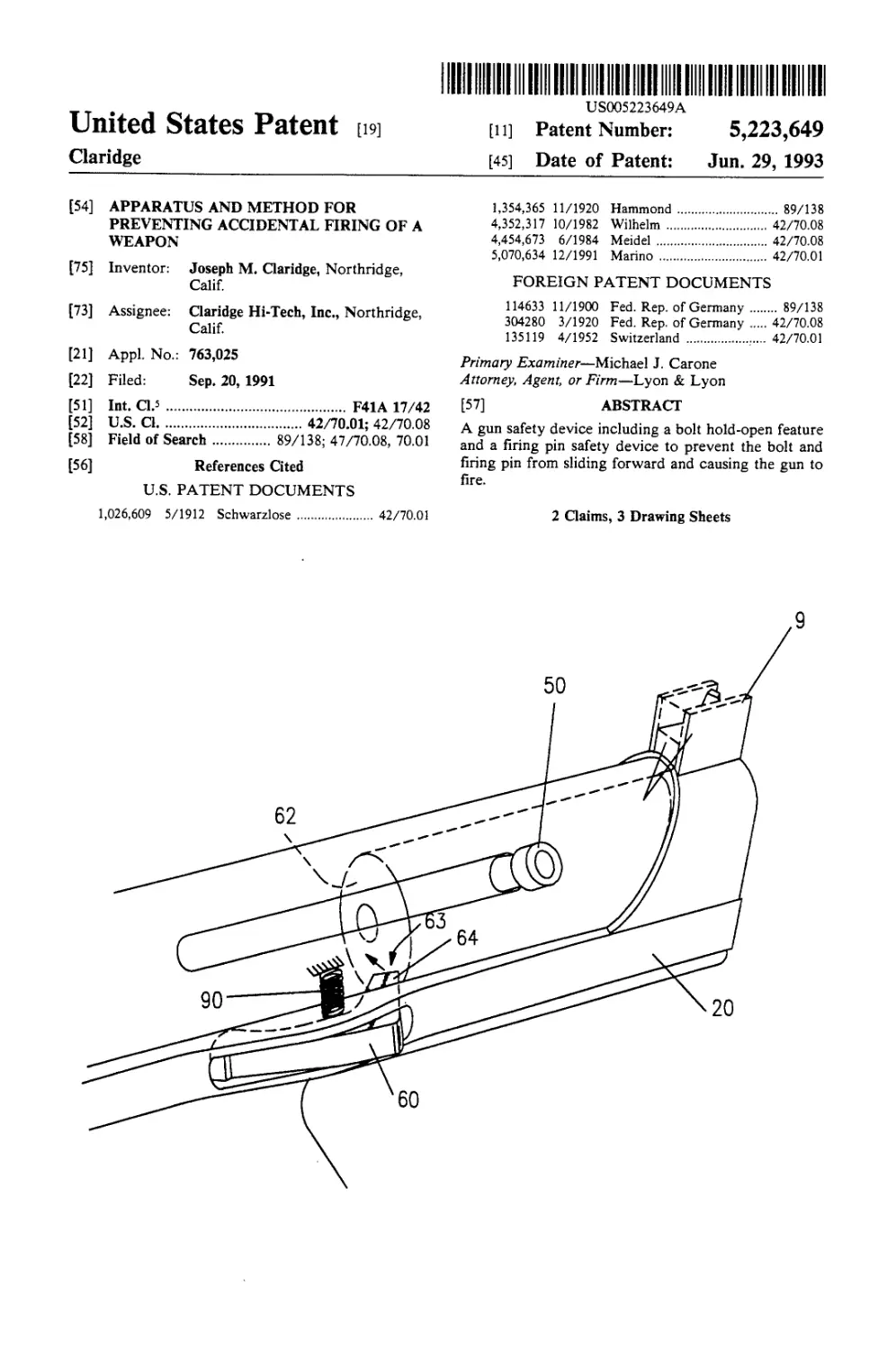
[57] ABSTRACT
A gun safety device including a bolt hold-open feature
and a firing pin safety device to prevent the bolt and
firing pin from sliding forward and causing the gun to
fire.
1,026,609 5/1912 Schwarzlose ........... 42/70.01
2 Claims, 3 Drawing Sheets
60
U.S. Patent
June 29, 1993
Sheet 1 of 3
5,223,649
Oj
o>
5,223,649
1
APPARATUS AND METHOD FOR PREVENTING
ACCIDENTAL FIRING OF A WEAPON
BACKGROUND OF THE INVENTION
The present invention relates to the field of guns.
In guns, especially automatic and semi-automatic
weapons which have a reciprocating bolt and automatic
and semiautomatic feed of bullets from an ammunition
clip, there is always a danger of accidental firing, either
by virtue of the weapon being dropped or the accidental
release of the bolt as it is being pulled back into a cocked
position. Accordingly, there has been a need for mini-
mizing the possibility of accidentally firing such weap-
ons. The presently claimed firing safety devices go a
long way towards preventing such accidental firing.
SUMMARY OF INVENTION
The present invention is directed to safety devices for
guns and specifically a bolt hold-open device which
engages the bolt causing it to remain in open or cocked
position so it cannot cause the firing of the weapon.
This advance, in addition to the firing pin safety stop
or notch apparatus, minimizes accidental firing should
the firing pin move forward for any reason other than
deliberately firing the weapon by pulling the trigger.
It is accordingly an object advantage of this invention
to prevent the accidental firing of such a weapon.
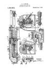
BRIEF DESCRIPTION OF THE DRAWINGS
This and other objects and advantages of the present
invention will become better understood through a
consideration of the following description taken in con-
junction with the drawings in which:
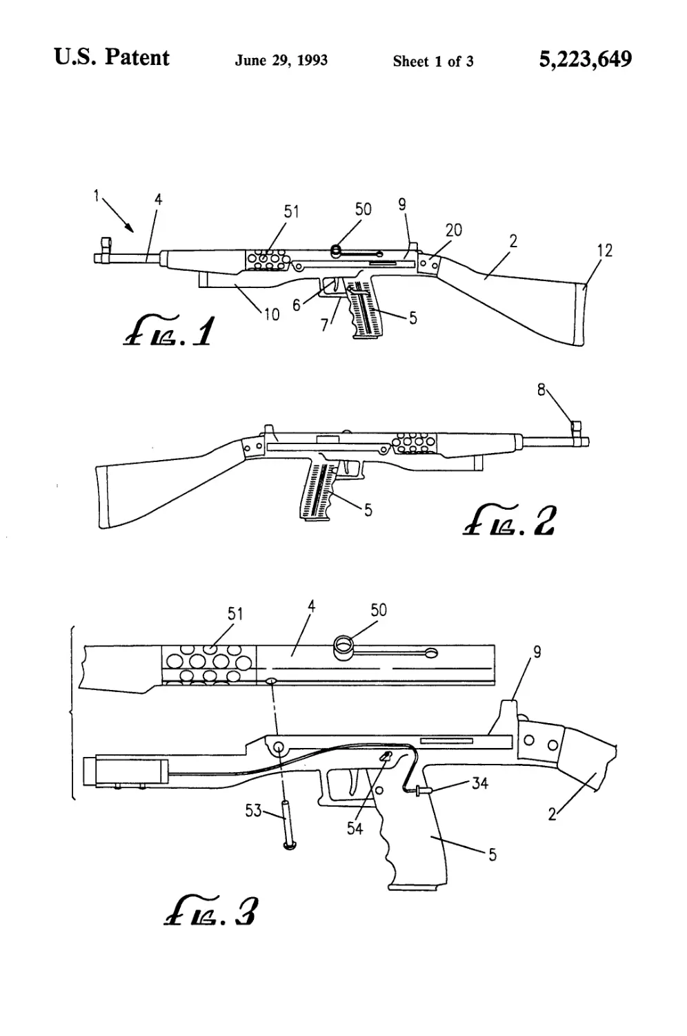
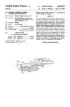
FIGS. 1 and 2 are side views of a rifle or carbine
incorporating the inventions claimed herein.
FIG. 3 is a partially schematic and cut out view of the
central portion of the carbine or rifle which incorpo-
rates the inventions claimed herein.
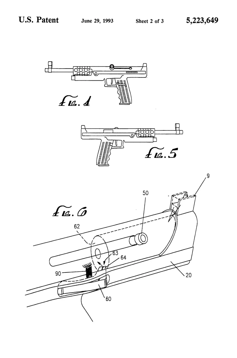
FIGS. 4 and 5 show a side view of pistols incorporat-
ing the inventions claimed herein.
FIG. 6 shows a schematic of the bold hold-open
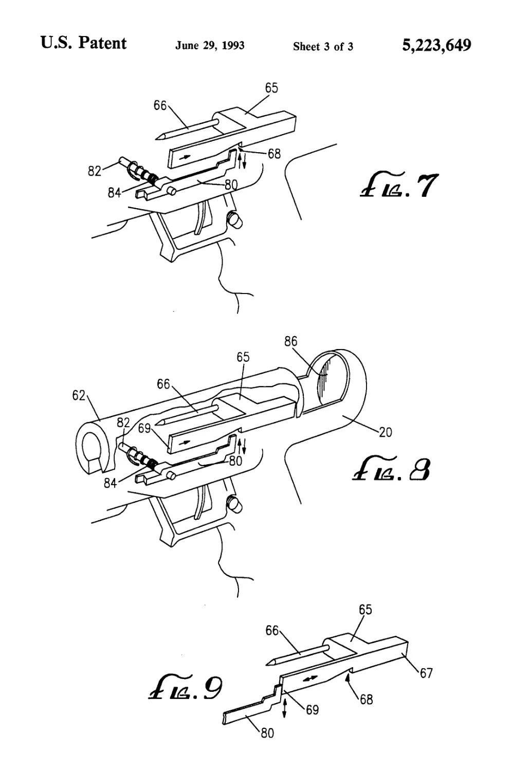
apparatus.
FIG. 7 shows another schematic illustrating the firing
pin safety notch invention. Both the firing pin and the
rocker are indicated therein.
FIG. 8 indicates an assembly schematic indicating the
relationship between the various elements.
FIG. 9 also indicates the relationship between the
rocker and firing pin in a cocked position.
DETAILED DESCRIPTION OF THE
PREFERRED EMBODIMENT
Turning now to the drawings, and specifically FIGS.
1 and 2, the rifle or carbine embodiment of the present
invention is shown. Each carbine typically has a hous-
ing 20, stock 2, barrel 4, pistol grip 5, which in the
present embodiment is integrally constructed in the
housing 20. The housing also contains the laser assem-
bly 10. The housing attaches to (and in the preferred
embodiment is integral with) trigger guard 7. Trigger 6
fires the weapon. Cocking knob 50 is attached to the
bolt which is spring-loaded so as to slide forwards and
backwards. (See FIG. 6 for more detail). The firing pin
assembly 65 (FIGS. 7-9) is slidably attached to housing
20 and moves back and forth in relation to the barrel.
When the cocking knob and bolt are pulled back, the
firing pin assembly is arrested by a rocker and trigger
5
10
15
20
25
30
35
40
45
50
55
60
65
2
mechanism (See FIG. 9) which can be disengaged by
the pulling of the trigger 6.
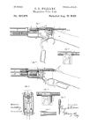
Turning to FIG. 6, the present invention contem-
plates a bolt hold-open lever 60 which can additionally
prevent the bolt 62 from proceeding forward and pre-
vents the firing pin from moving fully forward to strike
the cap and primer on the bullet. The lever 60 has a bolt
or dog 64 in its periphery capable of pivotally extending
in the path of the bolt. When the bolt is retracted to its
furthermost backward position, the rear of the bolt
hold-open lever can be depressed. This allows it to
engage bolt at position 63, causing the bolt to remain
open and locked in open position.
The bolt hold-open lever 60 is pivotally mounted and
spring loaded so that, during the normal operation of
the gun, it is forced out of the way of the bolt. To disen-
gage the bolt hold-open lever, one retracts the bolt
allowing the hold-open lever 60 to disengage and be
displaced from the path of the bolt thus allowing the
bolt to return to its closed position. The bolt hold-open
device can thereafter be activated by manual operation
if one wishes to restart the cycle and immobilize the bolt
to remain open and not fire.
We now proceed to the embodiment of the invention
in FIGS. 8 and 9 which illustrate the firing pin safety
notch feature. This apparatus provides additional safety
protection should the firing pin move forward for any
reason other than to deliberately fire the weapon when
the trigger is pulled. By its operation, the forward mo-
tion of the firing pin can be stopped by the rocker stop
80 sliding into intermediate notch 68. The firing pin
assembly 65 with the pointed striker 66 hits the cap and
primer on the shell. The firing pin assembly has a sub-
stantially rectangular element or flange 67 which slid-
ably moves forward and backward between locked and
unlocked positions. The flange 67 has an intermediate
notch or stop 68 machined in its intermediate portion. If
the firing pin is allowed to slide forward during the
cocking process for any reason, accidental or otherwise,
the forward motion of the firing pin is stopped by the
rocker sliding into the notch. In other words, the rocker
is pivotally mounted to engage said firing pin. Rocker
assembly 80 is a substantially horizontal and elongated
section which pivots on pivot pin 82. Rocker spring 84
urges the rear portion of the rocker arm (which engages
the notch) in a downward position away from the firing
pin assembly. The gun can only discharge if the trigger
is pulled back which (through a sear or cam assembly,
which is not shown) lowers the rocker out of the path of
the firing pin which can then slide forward and set off
the cartridge. After cocking the weapon, the firing pin
is in firing position. If for any reason (for example; drop-
ping the gun, lack of strength in pulling back the bolt,
etc.) the firing pin accidentally moves the safety notch
forward, the weapon is prevented from accidentally
discharging or “slap firing”, as this is sometimes called
in the industry.
Thus, a novel bolt hold-open device and firing pin
safety stop has been disclosed. While specific embodi-
ments and applications of this invention have been
shown and described, it would be apparent to those
skilled in the art that many more modifications are pos-
sible without departing from the inventive concepts
herein. The invention, therefore is not to be restricted
except in the spirit of the appended claims.
I claim:
5,223,649
3
1. A bolt hold-open device for a gun having a housing
comprising:
an elongated lever mounted in a slot in the housing of
said gun having a backward portion oriented
towards the rear of said gun; and
a bolt slidably engaged in said housing;
said lever having a dog at its backward portion capable
of pivotally extending in the path of said bolt;
5
10
15
20
25
30
35
40
45
50
55
60
4
said lever being pivoted with said backward portion
being urged outwardly by a spring;
wherein said outward urging by said spring tends to
disengage said lever from the bolt.
2. The bolt hold-open device of claim 1 wherein said
elongated lever is capable of being manually selectively
engaged with said bolt at all times.
65