/


Tags: weapons military affairs patent
Year: 1919

Text
J. C. STURGEON.
AUTOMATIC RAPID FIRE GUN.
APPLICATION FILED MAY 5. 1917.
1,290,854.
Patented Jan. 7,1919.
UNITED STATES PATENT OFFICE.
JOHN C. STUBGEON, OF EBIE, PENNSYLVANIA.
AUTOMATIC BAEID-FTBE GUN.
1,290,854. Specification, of Letters Patent. Patented Jan. 7,1919.
Application filed May 5,1917. Serial No. 166,623.
To all whom it may concern:
Be it known that I, John C. Sturgeon,
a citizen of the United States, residing at
Erie, in the county of Erie and State of
5 Pennsylvania, have invented certain new and
useful Improvements in Automatic Rapid-
Fire Guns; and I do hereby declare the fol-
lowing to be a full, clear, and exact descrip-
tion of the invention, such as will enable
10 others skilled in the art to which it apper-
tains to make and use the same, reference
being had to the accompanying drawings,
and to the letters of reference marked there-
on, forming part of this specification.
15 This invention relates to automatic rapid-
fire guns, and has for its principal objects
the improvements in the cartridge-feeding
mechanism, in the mechanism for prevent-
ing the premature discharge of the arm
20 prior to the complete locking of the breech-
bolt, and in gas regulating and sediment
trapping mechanism.
It also consists in the structure of the
parts of the operative mechanism of the arm
25 and their cooperative combination in the
arm substantially as hereinafter described.
These and other features of my invention
are hereinafter fully set forth and described
and illustrated in the accompanying draw-
30 ings in which—
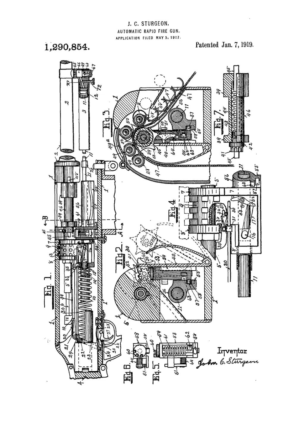
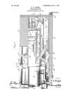
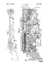
Figure 1, is a longitudinal vertical section
of the frame and parts of the device, with
parts in elevation.
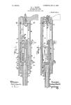
Fig. 2, is an enlarged transverse section of
35 the same on the line A in Fig. 1 looking in
the direction of the arrow.
Fig. 3, is an enlarged transverse section
on the line В in Fig. 1 looking in the direc-
tion of the arrow. —~
40 Fig. 4, is an enlarged view in elevation of
a section of the breech-bolt locking mecha-
nism when unlocked.
Fig. 5, is a view in elevation of the
vertically movable sprocket spring winding
45 mechanism.
Fig. 6, is a top or plan view of the same.
Fig. 7, shows the cartridge conveying
sprocket partially in elevation and partially
in section.
50 In these drawings 1 indicates the gun
frame, 2 portions of the barrel, 3 the gas-
cylinder, 4 a section of the gun-butt, 5 the
breech-bolt, 6 the firing-pin, 7—8 the breech-
bolt locking frame, 9 the vertically movable
55 locking-lug mounted and operating in said
frame, 10 the spring for moving the breech-
bolt locking-lug mechanism and the breech-
bolt forward, 11 the rod extending from the
piston 12 in the gas-cylinder 3 to and com-
municating with the locking-lug 9 and lock- 60
ing-lug frame 7—8 to unlock the breech-
bolt 5 by moving the locking-lug 9 down-
ward to disengage it from the locking-lugs
13 on the frame, and then move it, the lock- •
ing-lug frame 7—8 and the breech-bolt 5 65
backward, and 14 a spring carried by the
locking-lug frame 7—8, engaging the end
15 of the rod 11 for moving the rod 11 for-
ward in the locking-lug frame 7—8, and
engaging the locking-lug 9 with the lugs 70
13 on the frame to lock the breech-bolt 5
when in its forwardmost position ready for
firing. This movement of the locking-lug
9 with relation to the locking-lug frame
7—-8 is effected by a stud 16 on the rod 11, 75
which engages an inclined slot 17 in the
lower part of the locking-lug 9; the move-
ment forward and backward of the stud 16
in the slot 17 operates to raise and lower
the locking-lug 9 as illustrated in Figs. 1 80
and 4.
On the rear end of the firing-pin. 6 which
is mounted in the breech-bolt 5, and spring
actuated (not shown) in the usual manner,
I secure a block 18 provided with a sear- 85
notch 19 adapted to be engaged during the
rearward movement of the breech-bolt by
sears 20—21, pivoted in the gun-frame, and
to retain the firing-pin during the forward
movement of the breech-bolt until released 90
by the operation of the sears 20—21. One
of these sears 20 is provided with a down-
wardly extending arm 22 (shown in dotted
lines) adapted to be engaged by an up-
wardly extending arm 23 (shown in dotted 95
lines) mounted on a rock-shaft 24 remov-
ably mounted in the lower part of the frame
1. The rock-shaft 24 is provided with a
forwardly extending arm 25 adapted to be
engaged by the heel 26 of a trigger 27 re- 100
movably pivoted in the lower part of the
gun-frame 1.
To retain these parts in the normal posi-
tions there is a flat spring 28 secured to the
frame and engaging the arm 25 as illus- 105
trated in Fig. 1. The sear 21 is provided
with a downwardly extending arm 29 to
which is pivoted a forwardly extending rod
30 which extends through a guide 31 on the
side of the part 8 of the locking-frame, so as 110
to slide freely therein; and on the side of
the locking-lug 9 there is a centrally pivoted
1,290,864
lever 32 provided with a spring 33 for mov-
ing its lower end into the path of the stud
16, as illustrated in Fig. 4, so that when
the stud 16 moves forward to the end of
the slot 17 in the locking lug, thereby com-
pleting the locking movement of the lug,
it engages the lever 32, which meanwhile
has been raised into contact with the end
of the rod 30 by the upward movement of
the locking-lug 9, and operates the lever 32
to move the, rod 30 rearwardly and thereby
disengage the sear 21; thus, it will be ob-
served that if the operator by means of the
trigger 27 holds the sear 20 out of engage-
ment with the sear-notch 19, the completion
of the locking movement of the locking-
lug 9 actuating the lever 32 will automati-
cally release the sear 21 and permit the auto-
matic repetition of the firing operation, so
long as the operator retains the sear 20 out
of engagement, until the cartridge supply
is exhausted. To prevent premature firing
of the arm there is an extension 34 on the
sear-notch block 18 which extends forward
under the fear portion of the breech-bolt 5.
In the path of this part 34 there is pro-
vided a rocking lever stop 35 pivoted in the
part 8 of the locking frame; one arm 36 of
this lever stop extends inward between the
parts of the locking-lug 9 where it is en-
gaged when the locking-lug 9 is. raised, by
a transverse pin 37 therein, which operates
to lower the stop 35 on the other arm there-
of so as to permit the end of the part 34
to pass over it. In Fig. 4 I show the parts
of this mechanism in their positions when
the, breech-bolt is unlocked; a spring 38
operating on the stop to retain it in oper-
ative position as shown in Fig. 4 while the
breech-bolt is unlocked.
For feeding cartridges to the arm there
is a sprocket-wheel 39 mounted in suitable
bearings preferably on the side-plate 40
hinged to the gun-frame 1, as illustrated in
FigsvS and 4. This sprocket-wheel 39 (see
Fig. 7) is provided at its rear end with a
gear 41, the hub 42 of which extends into
and rotates freely'Tn~a chamber 4-3 in the
sprocket-wheel 39; and in this chamber 43
there is a spiral sprocket-motor spring 44,
one end of which engages the gear hub 42,
and the other a recess in the sprocket-wheel
39 at the opposite end of the chamber 43.
To retain these parts in their proper posi-
tions there is a central removable pintle 45
which extends sufficiently beyond the ends
of the gear 41 and of the opposite end of the
sprocket 39 to form a bearing for all parts
thereof on which they will freely rotate as
desired. The intermediate portion 46 of
the sprocket 39 is cut away, as clearly
shown, to form a bearing for a cartridge
belt 47, as clearly shown in Figr 3, to which
cartridge belt 47, clips. 48 are secured to
clamp cartridges 49 thereto* which car-
tridges are engaged by the teeth 50 of the
sprocket; the cartridges 49 being preferably
held in contact with the sprocket by a
hinged spring actuated plate 49a bearing
thereon as the “sprocket 39 is rotated by the 70
action of the spring 44 to move the car-
tridges in front of the retracted breech-bolt
5, as illustrated in Fig. 3, from whence the
bolt on its forward movement pushes the
cartridge in front of it through the clips 75
48 and into the barrel. This operation of
the sprocket occurs only after the breech-
bolt 5 has fully completed its rearward trav-
erse, and its rotation is controlled so as
to leave the cartridge in front of the bolt 80
by a receding stop 51 hereinafter more
fully described, which engages one of the
sprocket-teeth 50 as illustrated in Fig. 3.
For retaining the sprocket spring 44 at
suitable tension to operate the sprocket- 85
wheel 39 there is a dog 52 which engages the
teeth of the gear wheel 41 as illustrated in
Fig. 2; and to rotate the gear wheel 41 and
wind up the spring 44 what it relaxes at
each forward movement of the sprocket 90
wheel 39 there is provided a vertically
movable frame. 53 clearly shown in Figs.
5 and 6. This frame is mounted in guides
54 on the gun frame directly under the
gear 41 so that it will move freely up and 95
down therein. On the front part 7 of the
locking-lug frame there is a forwardly pro-
jecting cam surface 55 having on its upper
part a sleeve 56 through which the rod 11
operates, and in this cam surface 55 there 100
. is a cam groove 57, the central part of which
is depressed below the end parts thereof,
and on the frame 53 there is a laterally pro-
jecting stud 58 which engages said cam
groove and operates to lower the frame 53 105
midway of the traverse of the cam surface
55 and raise the frame 53 at each end of
the traverse of the cam surface 55 which
travels in unison with the breech-bolt 5.
In this frame there is piounted a vertical 110
shaft 59 provided with a segment of gear
teeth 60 adapted to engage the teeth of the
. gear 41 when the frame 53 is in a raised
position.
The shaft 59 is provided' with a spiral 115
spring 61 for rotating the shaft in one
direction, and an. arm 62 adapted to be
engaged by a projection 63 on the cam sur-
face 55 near its rear end, which operates
to rotate the shaft 59 in the opposite direc- 120
tion, and as at the time when the projec-
tion 63 engages the arm 62 the segment of
teeth 60 is in engagement with the teeth of
the gear wheel 41, it operates to rotate the
gear wheel 41 “and wind up the sprocket 125
spring 44 the proper amount to maintain
its normal tension, while when the stud 58
is traversing the central part of the cam
slot 57, the gear segment 60 is lowered out
of contact with the gear 41, and the spring 130
1,980,864 A
61 then operating on the shaft 59 returns
the gear segment 60 to its normal position
ready to be again engaged by the projection
63 operating on the arm 62 as above noted.
5 On the front side of the frame 53 there
is provided the sprocket wheel stop 51 above
referred to, which stop moves up and down
with the frame 53 so as to permit the upper
end thereof to be withdrawn from in front
10 of the sprocket tooth 50 with which it is
engaged and raised behind it so as to en-
gage the next tooth 50 of the sprocket when
it is rotated. This rearward movement of
the stop is caused by the spring 64 which
. is acts thereon when the frame 53 is at the
lowermost point of traverse, and when the
rearward traverse of the cam is completed
the frame 53 is again raised so that the stop
is in operative position as above noted.
20 In conducting the gas from the bore of
the barrel 2 to the cylinder 3 there is a ver-
tical passage 65 which discharges into a
chamber 66 directly below the passage 65;
the bottom of this chamber is preferably
25 closed by a removable screw plug 67 and
extending upward from the center of this
screw plug there is a standard 68 having
preferably a conical top 69 thereon, which
receives the blast of gas as it comes from
30 the passage 65 and spreads it, allowing the
sediment carried therewith to pass below
the conical head 69 while. the gas passes
from the chamber 66 through a passage 70
into the cylinder 3 and against the piston 12
35 on the end of the rod 11. For controlling
and regulating the flow of gas through the
passage 70 there' is an adjustable thumb-
screw 72 provided, the end of which enters
the passage 70 and can be operated to con-
40 -strict the same.
On the rod 11 there is preferably provided
a collar 73 adapted to receive a wrench for
rotating the rod 11 when it is desired to
detach it from the bolt-locking mechanism;
45 it also performs the function of contacting
with the end of the sleeve 56 when the rod
11 has been moved far enough to operate the
bolt-locking mechanism, and thereafter the
rod 11 and sleeve 56 move on backward in
50 unison, until the breech-bolt and the bolt-
locking mechanism have completed their
rearward traverse.
In operation as the gun is discharged, a
portion of the gases pass from the barrel
5Б into the cylinder, contacting with the piston
12 therein forcing it rearwardly until the
collar 73 on the rod 11 contacts with the end
of the sleeve 56; this operates to compress
the spring 14 and release the locking-lug 9
60 from the gun-frame. These parts, the lock-
ing-lug frame and the breech-bolt secured
thereto, then move on backward compressing
the spring 10 until the backward traverse of
these parts is completed1. Meanwhile the
C6 cam-slot 57 acts on the vertically movable
frame 53 to move it downward and upward
as hereinbefore described. At the comple-
tion of the backward traverse of the breech-
bolt 5, it has withdrawn the spent cartridge
shell from the barrel, and the sprocket then 70
being free to rotate, is rotated one tooth,
which moves a fresh cartridge in front of
the breech-bolt, and pushes the spent car-
tridge shell out of the way, the forward move-
ment of the breech-bolt, actuated by the spring 75
10 then takes place, pushing the fresh car-
tridge out of the clips on the cartridge belt,
and into the barrel; this forward movement
of the breech-bolt being completed, the
spring 14 operates to move the locking-lug 80
upward into engagement with projections 13
on the gun-frame, securely locking the
breech-bolt in firing position; and just as
this movement of the locking-lug is com-
pleted, the stud 16 acting on the lever 32 op- 85
erates to automatically release the sear 20
from the sear-notch 19 allowing the firing-
pin 6 to move forward and explode the car-
tridge; and this series of operations con-
tinues so long as the sear 21 is retained out 90
of engagement, until the cartridge supply is
exhausted.
I have thus shown and described my in-
vention so as to enable others skilled in the
art to which the invention appertains to 95
construct and utilize the same. I do not,
however, confine myself to the exact con-
struction, arrangement and combination of
the several parts of the mechanism shown
and described, as many modifications can be 100
made therein without departing from the
spirit of the invention. Therefore what I
claim as new and desire to secure by Let-
ters Patent is:
1. In a gun, a frame, a reciprocating 105
breech-bolt mounted therein, a locking-lug
frame on the breech-bolt, a locking-lug there-
in, means for operating the breech-bolt and
locking mechanism, and means on the lock-
ing-lug frame operatable by the locking-lug 110
for preventing the discharge of the gun be-
fore the breech-bolt is completely locked.
2. In a gun, a frame, a reciprocating
breech-bolt mounted therein, a locking-lug
frame secured to the breech-bolt, a recipro- 115
eating locking-lug mounted in said locking-
lug frame, gas and spring actuated mecha-
nism for operating said locking-lug and
means on the locking-lug operatable only
when the breech-bolt is fully locked for re- 120
leasing the firing-pin.
3. In a gun, a frame, a reciprocating
breech-bolt mounted therein, a locking-lug
frame secured thereto, a vertically movable
locking-lug mounted in said frame, gas and 125
spring mechanism operating said locking-lug
and reciprocating the locking mechanism
and breech-bolt, a reciprocating firing-pin
in the breech-bolt, a lever on the locking-lug
frame, movable into the path of the traverse ISO
1,980,864
of the firing-pin mechanism when the breech-
bolt is unlocked, and means on the locking
lug for removing the lever fixnn the path
of the firing-pin mechanism when the bolt
is locked,.
4. In a gun, a frame, a reciprocating
breech - bolt mounted therein, a locking - lug
frame thereon, a locking-lug in said frame,
a firing-pin mounted in the breech-bolt, a
gas cylinder under the barrel and communi-
cating with the bore thereof, a piston in
said cylinder, a rod from said piston com-
municating with the locking-lug frame, a
stud thereon operating in an inclined slot
in the locking-lug, and a spring on the lock-
ing-lug engaging the rear end of said rod,
a lever mounted on the locking-lug so that
the lower end of it will be engaged by said
stud, a rod extending from the sear mecha-
nism adapted to be eilgaged by the upper
end of said lever when the locking-lug is in
a locked position.
5. In a gun, a frame, a reciprocating
breech-bolt therein, a firing-pin in said
breech-bolt, a sear for engaging said firing-
pin, a locking-lug frame secured to said
breech-bolt, a vertically movable locking-lug
therein, means for operating said locking-
lug, a rod extending from the sear to the
। locking-lug and means on the locking-lug
adapted to engage said rod, and operate said
sear as the locking movement of the locking-
lug is completed.
6. In a gun, a frame, a reciprocating
i breech-bolt therein, a firing-pin in the
breech-bolt, sear mechanism for the firing-
pin, a locking-lug frame secured to the
breech-bolt, a vertically movable locking-lug
in said frame, a centrally pivoted leyer stop
) on the locking-lug frame movable into the
path of the firing-pin mechanism when the
breech-bolt is unlocked, and out of said path
when the breech-bolt is locked, means for
operating the locking-lug, a centrally piv-
5 ot-ed lever on the locking-lug, the upper end
of which communicates with the firing-pin
sear mechanism and operates it when the
breech-bolt is fully locked, and means on
the locking-lug operating means engaging
0 the lower end of said lever and operating it
when the breech-bolt is fully locked.
7. In a gun having cartridge inlet and
outlet openings, a reciprocating breech-bolt,
a sprocket-wheel mounted in the cartridge
5 inlet opening parallel with the breech-bolt,
a stop adapted to limit the rotation of the
sprocket-wheel, a spiral motor spring for
rotating the sprocket, a gear wheel con-
nected to said spring, a segmental gear in-
0 termittently engaging said gear wheel, a
cam for raising and lowering said segmen-
tal gear, and a reciprocating stud intermit-
tently operating said segmental gear.
8. A gun, a frame, a reciprocating breech-
& bolt and breech-bolt locking mechanism
mounted in said frame, a sprocket wheel
parallel with the breech-bolt, a motor spring
in said sprocket wheel, a gear wheel con-
nected with said motor spring, a vertically
movable member under said gear wheel, a 70
reciprocating cam, a stud on said member
engaging said cam, a segmental gear on the
top of said member, a shaft supporting said
segmental gear, an arm on said shaft, and
a stud on said reciprocating cam, adapted to 75
engage said arm
9. In a gun, a frame, a reciprocating
breech-bolt, a cam surface below the
breech - bolt reciprocating in unison there-
with, and having a cam slot therein de- 80
pressed at its central portion below the end
portions thereof, a vertically movable mem-
ber engaged-by said cam-slot, and moved up
and down thereby, a segmental gear mount-
ed on said member, and a stud on said cam- 85
surface adapted to rotate said segmental
gear.
10. In a gun, a frame, a breech-bolt, a
cartridge feeding sprocket parallel there-
with, a spiral spring for rotating said 90
sprocket, a spur gear connected to one end of
said spiral spring, a vertically movable
member, a segmental gear thereon adapted
to intermittently engage said spur gear and
rotate it, a dog on said member engaging 95
said spur gear, a cam surface below the
breech-bolt moving in unison therewith, a
cam-slot in said cam-surface, a stud on said
vertically movable member engaging said
cam-slot, a lug on said cam-surface adapted 100
to operate said segmental gear, and a stop
on said member adapted to be moved by the
action of said member into and out of the
path of the teeth of the sprocket.
11. In a gun, a frame, a cartridge carry- Ю5
ing sprocket wheel mounted thereon, a ver-
tically movable member, cam mechanism
raising and lowering said member, and a
stop pivoted to said member, so as to be
brought into and out of the path of the 110
teeth of the sprocket to limit the intermit-
tent rotation thereof.
12. In a gun, a frame, a reciprocating
breech-bolt, a locking-lug frame secured
thereto, a locking-lug operating in said П5
frame, means for operating said locking-lug,
a cartridge moving sprocket-wheel, a cam on
said locking-lug frame projecting forward
under the breech-bolt and reciprocating in
unison therewith, and means connecting the 120
cam and sprocket-wheel for operating the
sprocket-wheel.
13. In a gun, a frame, a reciprocating
breech-'bolt mounted therein, a firing-pin in
said breech-bolt, a sear for engaging the 125
firing-pin, a locking-lug frame secured to
the breech-bolt, a vertically movable locking-
lug therein, means for operating said lock-
ing-lug, and means on the locking-lug frame
operatable by the locking-lug for interfer- 130
1,290,864
ing with the forward travel of the firing-
pin when the locking-lug is unlocked.
14. In a gun, a frame, a reciprocating
breech-bolt mounted therein, a locking-lug
frame secured to the breech-bolt, means for
operating the locking-lug frame and the
breech-bolt, a sprocket-wheel mounted ad-
jacent to the line of travel of the breech-
bolt, a cam secured to the locking-lug frame
and extending forward under the breech-
bolt and moving in unison therewith, and
means connecting the sprocket-wheel with
said cam whereby the sprocket-wheel is op-
erated.
15. In a gun, a frame, a breech-bolt and
breech-bolt locking mechanism, a sprocket
wheel parallel with the breech-bolt having
the teeth on its central part cut away to
receive a cartridge carrying belt,- a spring in
the body of said sprocket for rotating it, a
spur gear connected with said spring tor
winding it up, a segmental gear adapted to
intermittently engage and operate said spur
gear, means for operating said segmental
gear, a stop adapted to intermittently en-
gage the teeth of said sprocket, a flexible
cartridge carrying belt operating in the de-
pression in said sprocket wheel, clips on said
belt to removably hold cartridges, to be en-
5.
gaged by the teeth of the sprocket, and a 30
hinged lever contacting with the cartridges
between the teeth of said sprocket to retain
them in contact therewith.
16. In a gas operated gun, a barrel, a
cylinder under the barrel, a support con- 35
necting the barrel with one end of the cylin-
der thereunder having a chamber therein,
and a passage from said chamber to the
bore of the barrel, a screw closure in -the
bottom of the chamber, an upright stud 40
thereon, a conical head on said stud and a
passage from the upper part of said cham-
ber into the cylinder.
17. In a gas operated gun, a barrel, a
cylinder thereunder, a support connecting 45
the barrel and cylinder, a chamber in said
support, a passage from the top thereof to
the bore of the barrel, a screw-plug for clos-
ing the bottom of the chamber, a standard
on said screw-plug approximately in line 50
with the passage to the bore of the barrel,
a conical head on said standard, a passage
from the chamber into the cylinder, and a
thumb-screw between the chamber and the
end of the cylinder for adjusting the ca- 55
pacity of said passage.
In testimony whereof I affix my signature.
JOHN C. STURGEON.