/
Tags: weapons military affairs patent
Year: 2010
Similar
Text
US 20100205846A1
(19) United States
(12) Patent Application Publication («» Pub. No.: US 2010/0205846 Al
Fitzpatrick et al. (43) Pub. Date: Aug. 19,2010
(54) MODULAR GUNSTOCK
Related U.S. Application Data
(75) Inventors: Richard M. Fitzpatrick, Denver,
CO (US); Michael T. Mayberry,
Denver, CO (US); Brian L.
Nakayama, Arvada, CO (US); Eric
S. Nakayama, Broomfield, CO
(US)
Correspondence Address:
GEOFFREY E. DOBBIN, PATENT ATTORNEY
4278 SOUTH 6220 WEST
WEST VALLEY CITY, UT 84128-6501 (US)
(73) Assignee: MAGPUL INDUSTRIES CORP,
Boulder, CO (US)
(21) Appl.No.: 12/028,758
(22) Filed: Feb. 8, 2008
(60) Provisional application No. 60/889,244, filed on Feb.
9, 2007.
Publication Classification
(51) Int.Cl.
F41C 23/14 (2006.01)
F41C 23/06 (2006.01)
(52) U.S. Cl.......................... 42/73; 42/74
(57) ABSTRACT
The present invention is a modular gunstock utilizing a two-
piece mounting structure and a stock module. The structure
comprises a weapon attachment, in the case of anAR15/M16
rifle a receiver extension tube, and a sleeve slidable over said
attachment and containing mounting structure for the stock
module. The disclosed stock module is adjustable for length
and features a length pre-set system, a latch with independent
dual-pawls and an integrated impact buffer, modular tail-
piece, and storage. The sleeve also features a position select-
able fixed cheek plate.
64
Patent Application Publication
Aug. 19,2010 Sheet 1 of 16
US 2010/0205846 Al
Patent Application Publication Aug. 19, 2010 Sheet 2 of 16
US 2010/0205846 Al
FIG. 2
Patent Application Publication Aug. 19, 2010 Sheet 3 of 16 US 2010/0205846 Al
Patent Application Publication Aug. 19, 2010 Sheet 4 of 16
US 2010/0205846 Al
48b
Patent Application Publication Aug. 19, 2010 Sheet 5 of 16
US 2010/0205846 Al
Patent Application Publication Aug. 19, 2010 Sheet 6 of 16
US 2010/0205846 Al
88а
FIG. 6a
Patent Application Publication Aug. 19, 2010 Sheet 7 of 16
US 2010/0205846 Al
ю
88а
Patent Application Publication Aug. 19, 2010 Sheet 8 of 16
US 2010/0205846 Al
89а
FIG. 8c
Patent Application Publication Aug. 19, 2010 Sheet 9 of 16
US 2010/0205846 Al
88а
88b
Patent Application Publication Aug. 19, 2010 Sheet 10 of 16 US 2010/0205846 Al
FIG. 10a
Patent Application Publication Aug. 19, 2010 Sheet 11 of 16 US 2010/0205846 Al
AG. 118
Patent Application Publication Aug. 19, 2010 Sheet 12 of 16 US 2010/0205846 Al
88а
Patent Application Publication
Aug. 19,2010 Sheet 13 of 16 US 2010/0205846 Al
Patent Application Publication Aug. 19, 2010 Sheet 14 of 16 US 2010/0205846 Al
FIG. 14
Patent Application Publication Aug. 19, 2010 Sheet 15 of 16 US 2010/0205846 Al
FIG. 15a
FIG. 16
FIG. 16a
Patent Application Publication Aug. 19, 2010 Sheet 16 of 16 US 2010/0205846 Al
FIG 17
FIG. 17a
US 2010/0205846 Al
Aug. 19, 2010
1
MODULAR GUNSTOCK
CROSS-REFERENCES TO RELATED
APPLICATIONS
[0001] This application claims priority on prior filed U.S.
Provisional Application No. 60/889,244, filed Feb. 9, 2007
and incorporates the same by reference in its entirety.
FIELD OF THE INVENTION
[0002] The present invention relates to the field of firearms
and more particularly relates to a gunstock with enhanced
modularity and adjustment functions.
BACKGROUND OF THE INVENTION
[0003] Gunstocks or “buttstocks” as they are commonly
known, are well known in the art of firearms. These devices
have been used with “long arms” as a means for resting and
securing the weapon against the shoulder of the user when
firing. Gunstocks have also been used as a weapon in and of
themselves in a melee fight. As such, gunstocks have been
developed along many different shapes and designs and using
various materials to increase durability, reduce the effects of
recoil, or “kick”, provide adjustability and customization,
increase shooter accuracy, provide storage for gear, and other
goals too myriad to mention.
[0004] One recent goal, however, is to provide a modular
gunstock such that a single stock, or portion of a stock, may be
used as a platform upon which user customizations may be
mounted. However, previous modular gunstocks present a
number of difficulties. The first of which is that the mounting
components for such systems tends to be bulky, as they con-
tain additional mounting features not present in other stocks.
Second, a structural failure in a mounting component tends to
render the weapon useless until a costly part is replaced. As
such, a new modular gunstock is needed that presents a lower
profile, with a simpler mounting paradigm, and is cost effec-
tive to replace in the event of structural failure.
[0005] The present invention is a modular gunstock that
provides a two-piece mounting platform as a new modular
paradigm. The present invention represents a departure from
the prior art in that the modular gunstock of the present
invention allows for a durable two-piece mounting platform
upon which stock options may be mounted. As a two-piece
platform, the design draws upon the inherent strength of
having two or more pieces working on concert, a layering
approach, and also allows for the replacement of one of such
pieces should either fail with lesser cost both to the user and
the manufacturer.
[0006] The present invention is described as a preferred
embodiment with an adjustable for length stock attachment.
Particular problems with such systems include lack of stabil-
ity, insufficient strength, and cheek weld disruption where the
pieces join.
SUMMARY OF THE INVENTION
[0007] In view of the foregoing disadvantages inherent in
the known types of modular gunstocks, this invention pro-
vides a new modular gunstock utilizing a two-piece mounting
platform. As such, the present invention’s general purpose is
to provide a new and improved modular gunstock that is
durable, lower cost and achieves the goal of modular customi-
zation with greater efficiency. To these ends, the modular
gunstock comprises a receiver extension tube, or “buffer
tube”, upon which a sleeve is slid into place and secured to the
tube by conventional means. The sleeve has on its external
surface mounting hardware for the remainder of the stock, in
the form of a rail. Other hardware is provided to provide
interface with the remainder of the weapon. Since the modu-
lar gunstock is primarily mounted upon a buffer tube, it pre-
sents an instant advantage over prior modular systems and
earlier carbine systems as previous systems had to be “timed”
to properly engage the receiver with their interface when
screwed into the receiver. This modular system required no
such estimation. It should be noted that the gunstock as
depicted is foraU.S. standard M-16/AR-15 style rifle. How-
ever, it should be appreciated that other weapon platforms
which use a gunstock will benefit from the present invention
and that the only changes necessary will be in the interface of
the stock with the weapon. As such, such changes should be
read into and considered as a within the scope of this inven-
tion.
[0008] Other features of this gunstock, as disclosed in the
preferred embodiment, include an adjustable for length stock
with a quick extension pre-set system and a dual, independent
pawl latch. The adjustable for length stock also features a
shock cushion for the latching mechanism, so as to minimize
kick and bludgeon shock to the latch, a storage compartment,
a modular tail-piece and a customizable fixed cheek piece. It
should also be appreciated that this disclosure is only describ-
ing one possible stock module to interface with the system
that is the invention. Other stock types, including fixed stocks
and precision shooting stocks, may be manufactured for this
system and still be considered within the scope of this inven-
tion.
[0009] The more important features of the invention have
thus been outlined in order that the more detailed description
that follows may be better understood and in order that the
present contribution to the art may better be appreciated.
Additional features of the invention will be described here-
inafter and will form the subject matter of the claims that
follow.
[0010] Many objects of this invention will appear from the
following description and appended claims, reference being
made to the accompanying drawings forming a part of this
specification wherein like reference characters designate cor-
responding parts in the several views.
[0011] Before explaining at least one embodiment of the
invention in detail, it is to be understood that the invention is
not limited in its application to the details of construction and
the arrangements of the components set forth in the following
description or illustrated in the drawings. The invention is
capable of other embodiments and of being practiced and
carried out in various ways. Also it is to be understood that the
phraseology and terminology employed herein are for the
purpose of description and should not be regarded as limiting.
[0012] As such, those skilled in the art will appreciate that
the conception, upon which this disclosure is based, may
readily be utilized as a basis for the designing of other struc-
tures, methods and systems for carrying out the several pur-
poses of the present invention. It is important, therefore, that
the claims be regarded as including such equivalent construc-
tions insofar as they do not depart from the spirit and scope of
the present invention.
BRIEF DESCRIPTION OF THE DRAWINGS
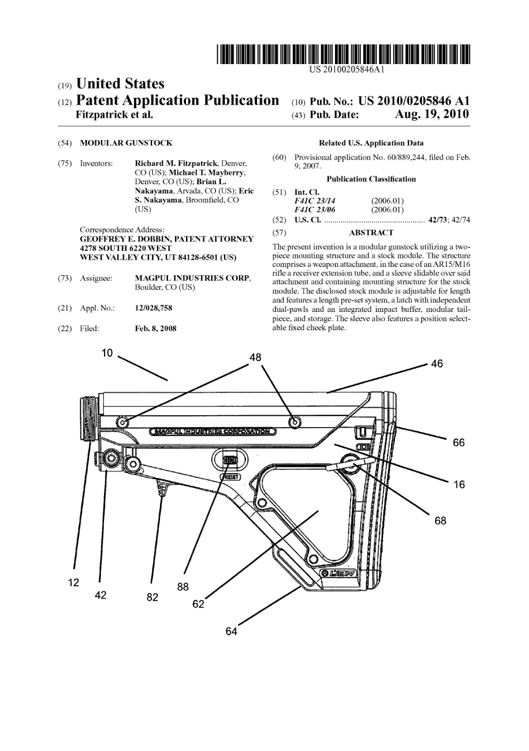
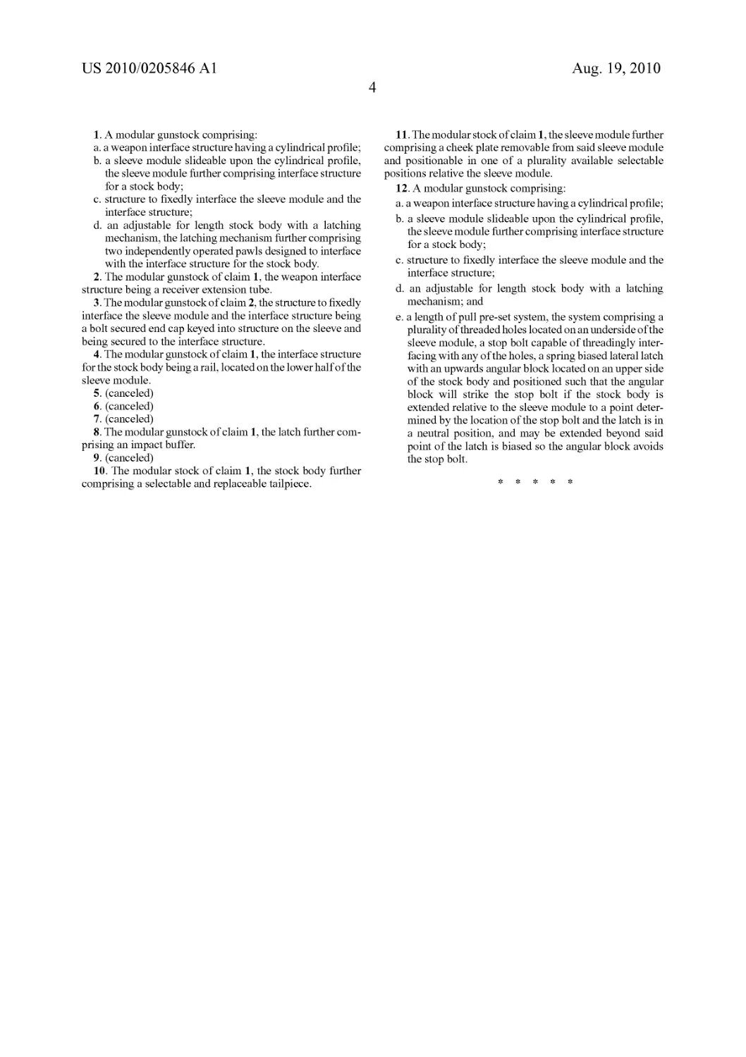
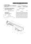
[0013] FIG. 1 is a left plan view of the gunstock using an
adjustable for length stock module.
US 2010/0205846 Al
Aug. 19, 2010
2
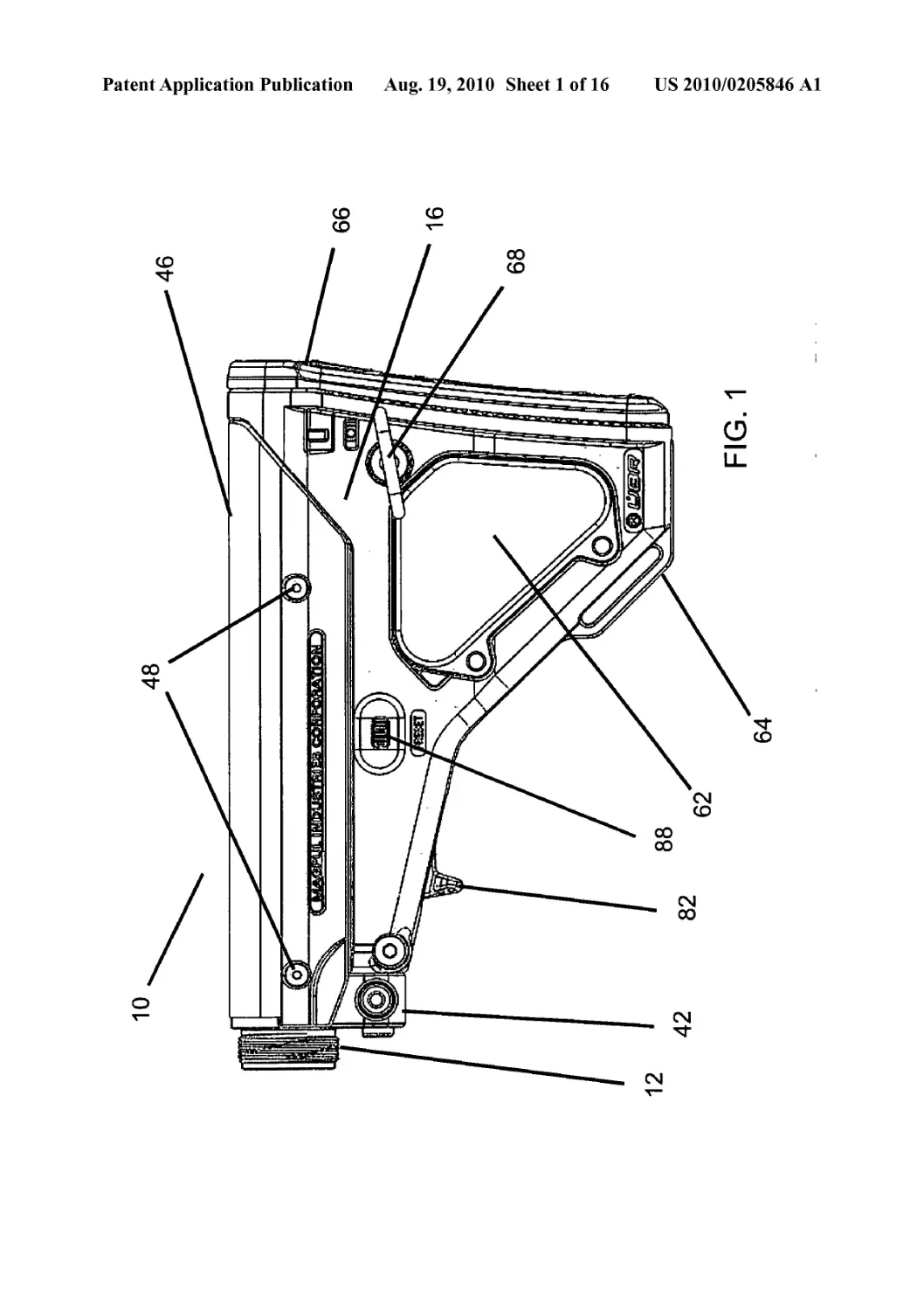
[0014] FIG. 2 is a cross-sectional view of the stock of FIG.
1.
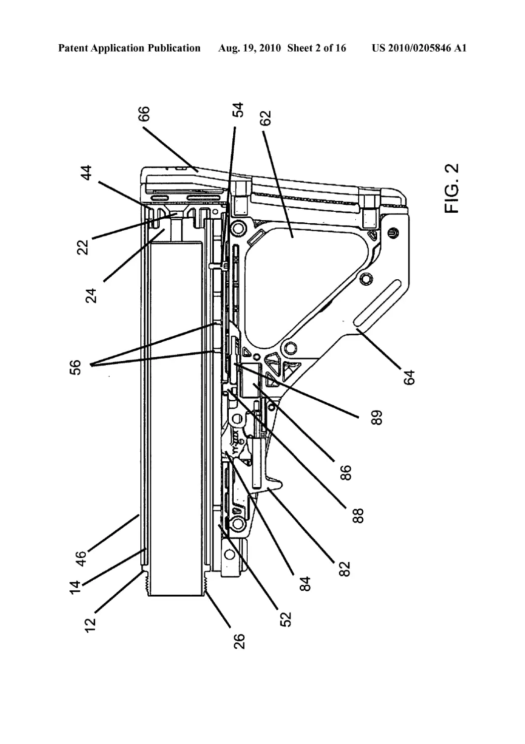
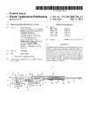
[0015] FIG. 3 is a perspective view of the gunstock’s exten-
sion tube module installed on an AR-15 lower receiver.
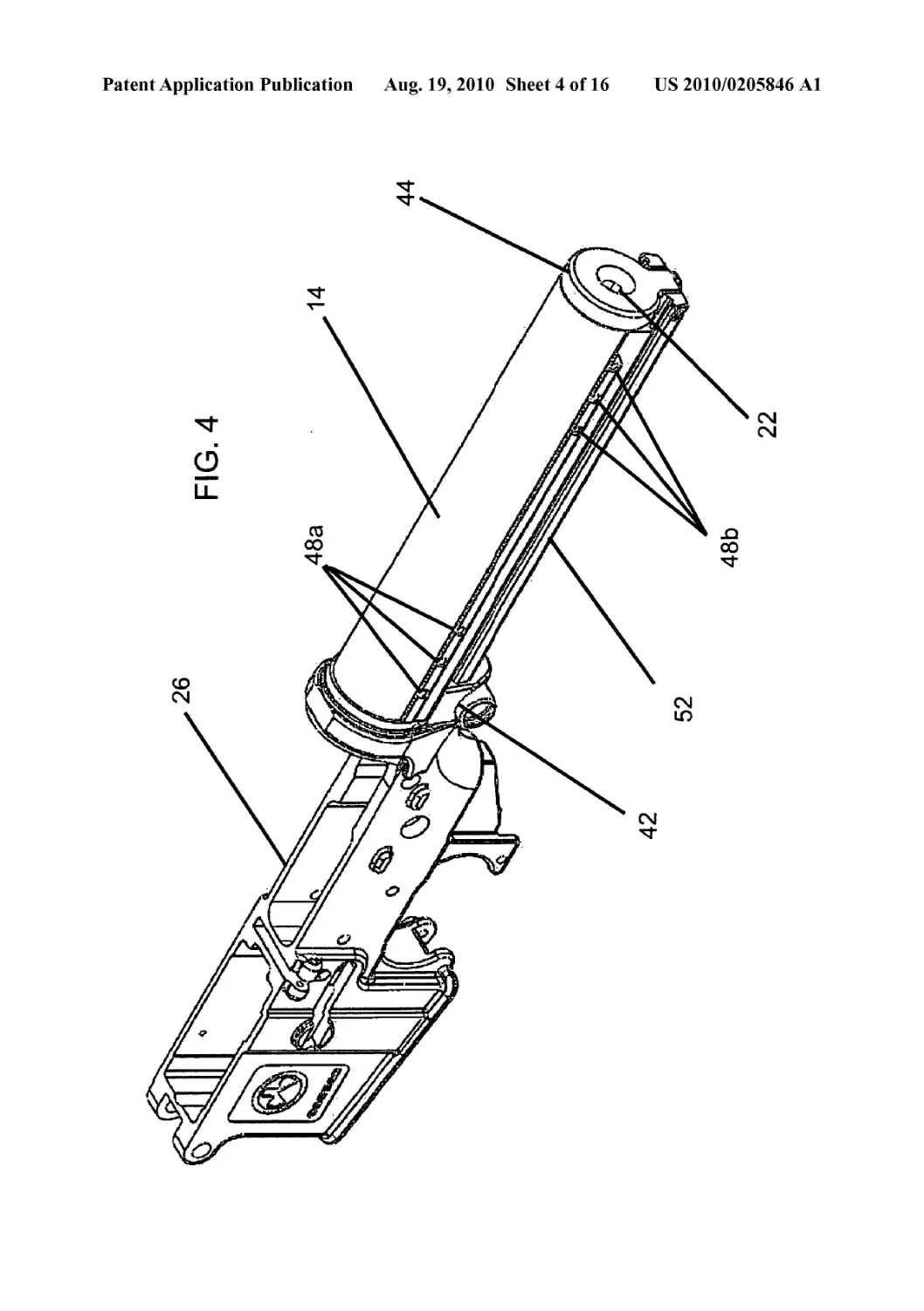
[0016] FIG. 4 is a perspective view depicting the gunstock’s
sleeve module installed.
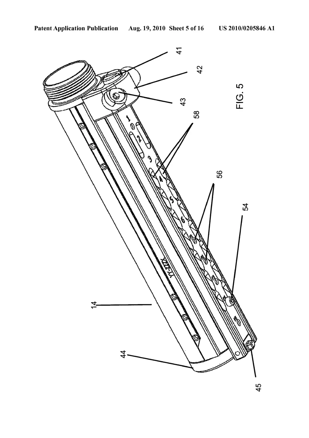
[0017] FIG. 5 is a perspective view of the assembled
mounting structure’s underside.
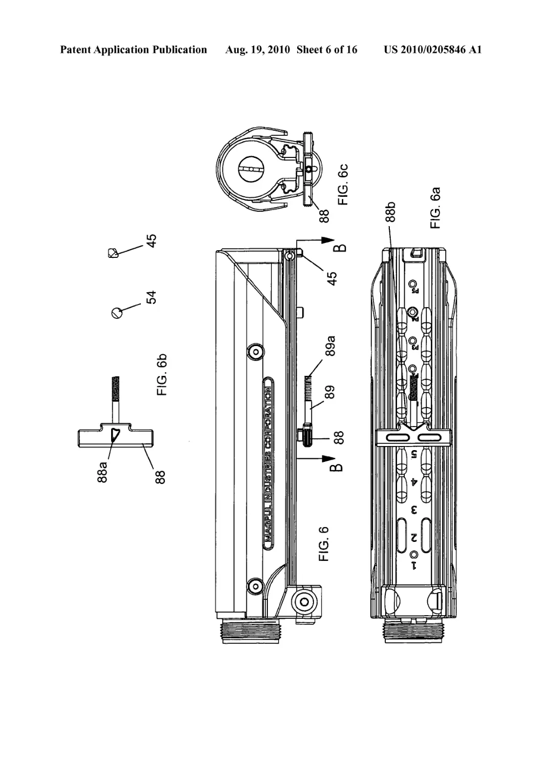
[0018] FIG. 6 is a right plan view of the assembled mount-
ing and the length of pull preset system, taken when the stock
(not shown) is in a collapsed position.
[0019] FIG. 6a is a bottom plan view of the system depicted
in FIG. 6.
[0020] FIG. 6b is a sectional view, taken along line B-B of
FIG. 6.
[0021] FIG. 6c is a rear plan view of the system depicted in
FIG. 6.
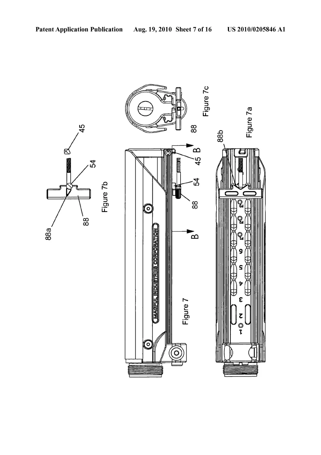
[0022] FIG. 7 is a right plan view of the assembled mount-
ing and the length of pull preset system, taken when the stock
(not shown) is in an extended to the pre-set position.
[0023] FIG. la is a bottom plan view of the system depicted
in FIG. 7.
[0024] FIG. 1b is a sectional view, taken along line B-B of
FIG. 7.
[0025] FIG. 7c is a rear plan view of the system depicted in
FIG. 7.
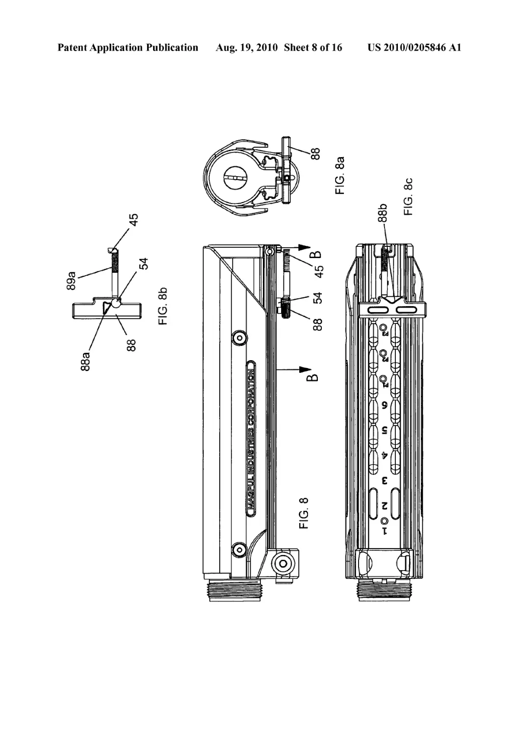
[0026] FIG. 8 is a right plan view of the assembled mount-
ing and the length of pull preset system, taken when the stock
(not shown) is in an extended to the pre-set position and the
release latch is biased to avoid the pre-set.
[0027] FIG. 8a is a bottom plan view of the system depicted
in FIG. 8.
[0028] FIG. 8b is a sectional view, taken along line B-B of
FIG. 8.
[0029] FIG. 8c is a rear plan view of the system depicted in
FIG. 8.
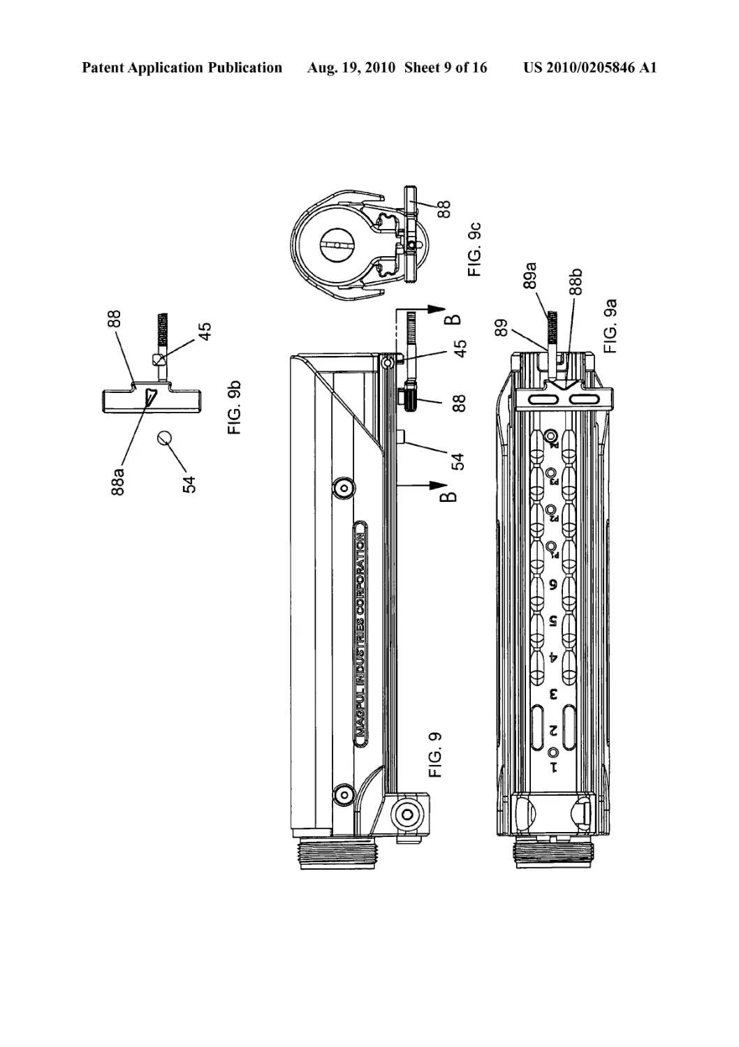
[0030] FIG. 9 is a right plan view of the assembled mount-
ing and the length of pull preset system, taken when the stock
(not shown) is in a position between the pre-set and the end
stop, maintaining the latch bias of FIG. 8.
[0031] FIG. 9 a is a bottom plan view of the system depicted
in FIG. 9.
[0032] FIG. 9b is a sectional view, taken along line B-B of
FIG. 9.
[0033] FIG. 9c is a rear plan view of the system depicted in
FIG. 9.
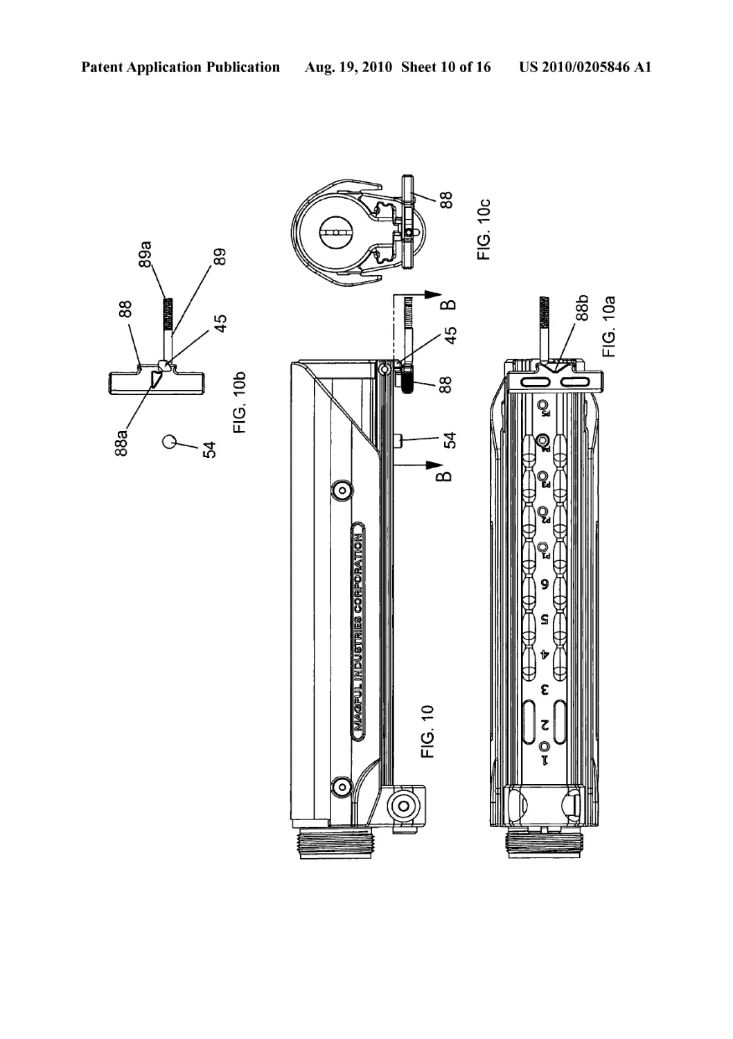
[0034] FIG. 10 is a right plan view of the assembled mount-
ing and the length of pull preset system, taken when the stock
(not shown) is in an extended position to the end stop, main-
taining the latch bias of FIG. 8.
[0035] FIG. 10c is a bottom plan view of the system
depicted in FIG. 10.
[0036] FIG. 10/? is a sectional view, taken along line B-B of
FIG. 10.
[0037] FIG. 10c is a rear plan view of the system depicted in
FIG. 10.
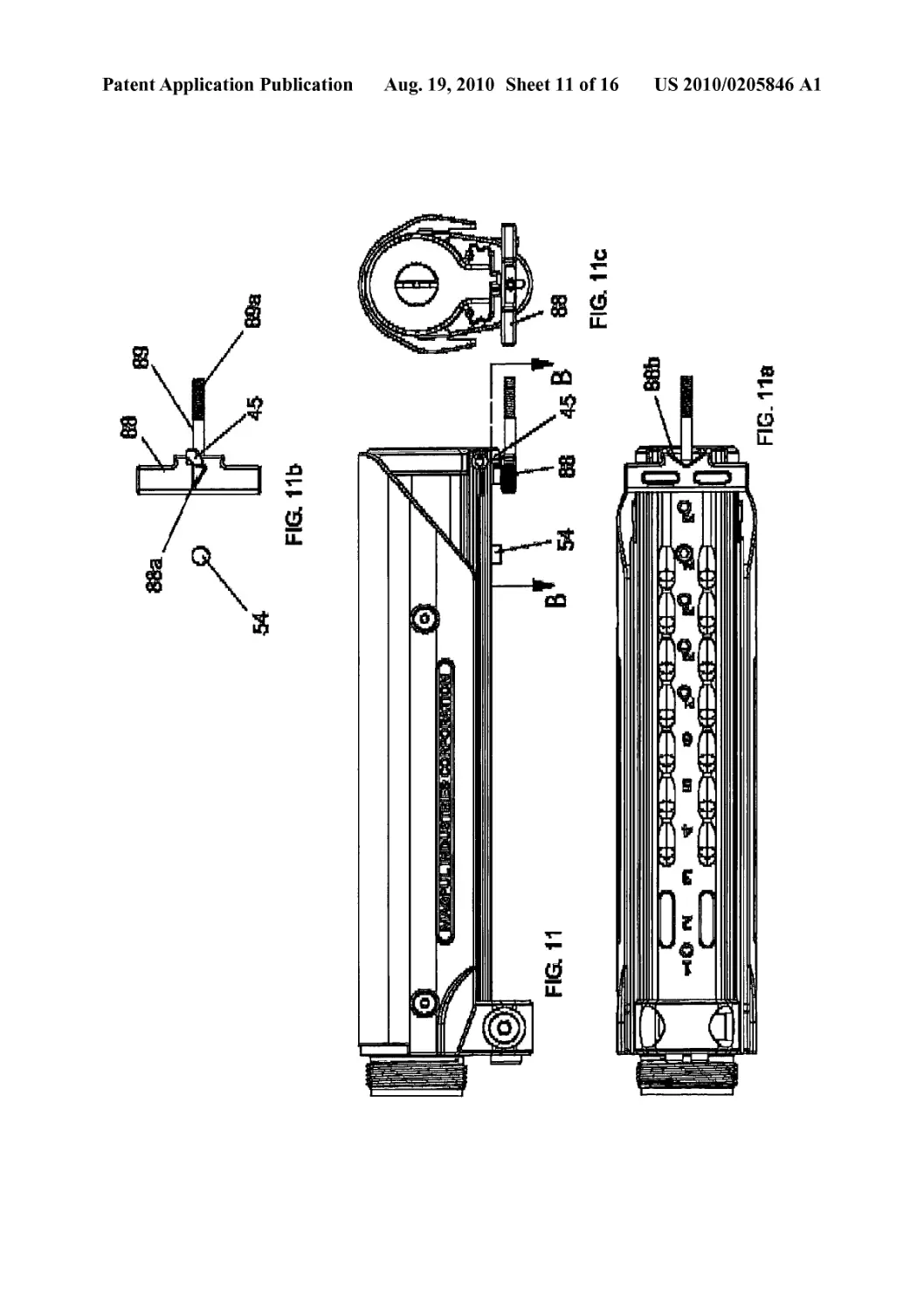
[0038] FIG. 11 is a right plan view of the assembled mount-
ing and the length of pull preset system, taken when the stock
(not shown) is in an extended position to the end stop, releas-
ing the latch bias of FIG. 8.
[0039] FIG. Ila is a bottom plan view of the system
depicted in FIG. 11.
[0040] FIG. 11b is a sectional view, taken along line B-B of
FIG. 11.
[0041] FIG. llcisarearplanviewofthesystemdepictedin
FIG. 11.
[0042] FIG. 12 is a right plan view of the assembled mount-
ing and the length of pull preset system, taken when the stock
(not shown) is in an extended position to the end stop, revers-
ing the latch bias of FIG. 8.
[0043] FIG. 12c is a bottom plan view of the system
depicted in FIG. 12.
[0044] FIG. 12/? is a sectional view, taken along line B-B of
FIG. 12.
[0045] FIG. 12c is a rear plan view of the system depicted in
FIG. 12.
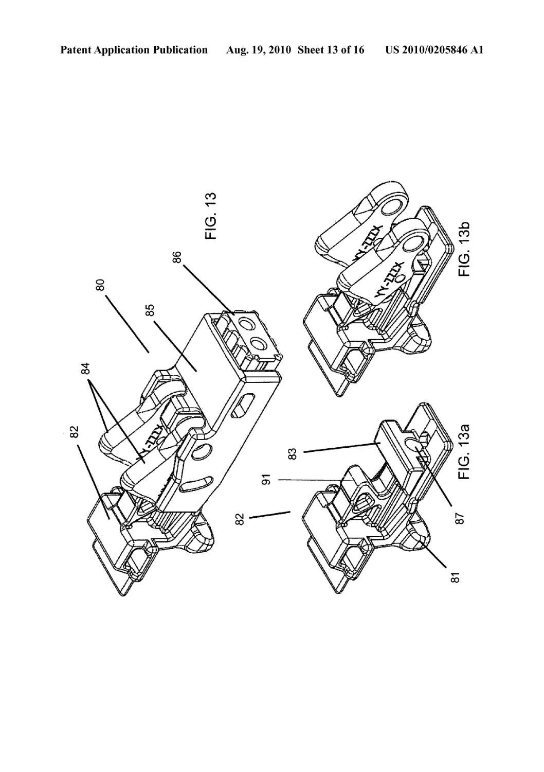
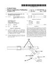
[0046] FIG. 13 is a perspective view of the latch mechanism
for the stock, according to the present invention.
[0047] FIG. 13c is a perspective view of the trigger mecha-
nism of the latch depicted in FIG. 13.
[0048] FIG. 13/? is a perspective view of the trigger mecha-
nism and pawls for the latch of FIG. 13.
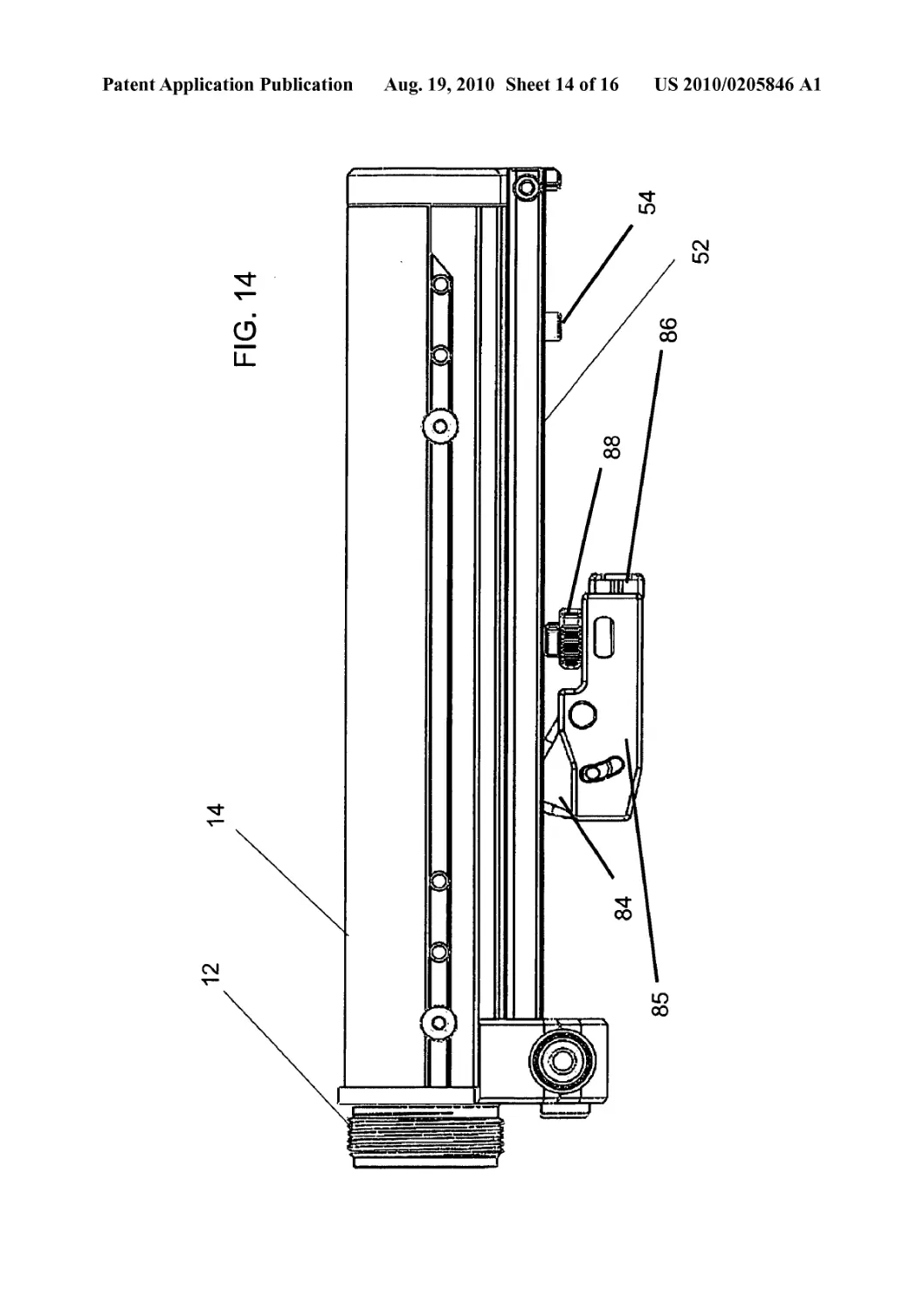
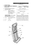
[0049] FIG. 14 is a left plan view of the mounting structure,
sleeve module, and latch mechanism, without trigger, of the
invention.
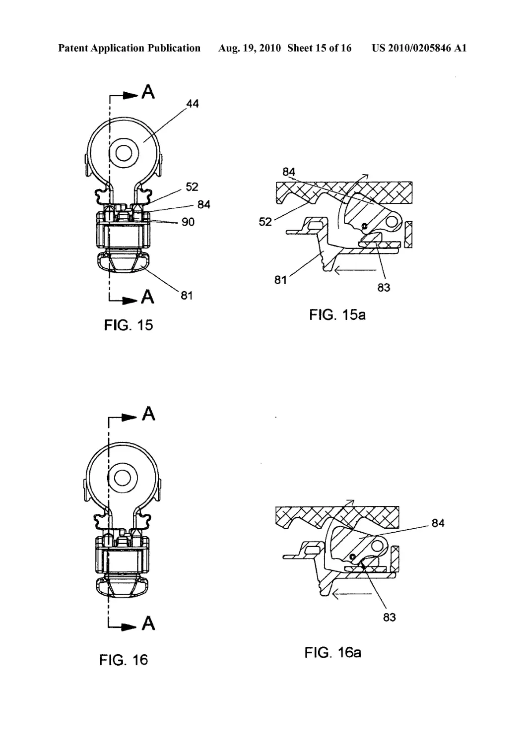
[0050] FIG. 15 is a rear plan view of the mounting structure,
sleeve module and latch mechanism in a locked state.
[0051] FIG. 15c is a partial sectional view of the system
depicted in FIG. 15, taken along line A-A.
[0052] FIG. 16 is a rear plan view of the mounting structure,
sleeve module and latch mechanism in an intermediate state.
[0053] FIG. 16c is a partial sectional view of the system
depicted in FIG. 16, taken along line A-A.
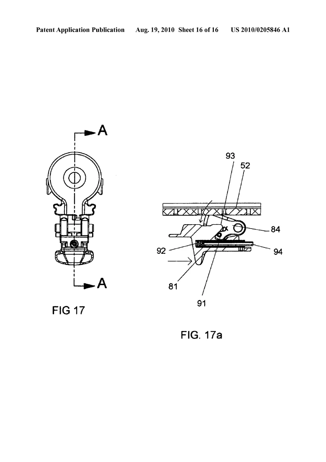
[0054] FIG. 17 is a rear plan view of the mounting structure,
sleeve module and latch mechanism in an unlocked state.
[0055] FIG. 17c is a partial sectional view of the system
depicted in FIG. 17, taken along line A-A.
DETAILED DESCRIPTION OF THE PREFERRED
EMBODIMENT
[0056] With reference now to the drawings, the preferred
embodiment of the modular gunstock is herein described. It
should be noted that the articles “a”, “an”, and “the”, as used
in this specification, include plural referents unless the con-
tent clearly dictates otherwise.
[0057] With reference to FIGS. 1 and 2, the modular gun-
stock comprises three main components. The first is a weapon
mounting structure 12 which is the actual attachment to the
weapon (See, FIG. 3). In the case of an AR15/M16 model
weapon, the structure is actually a replacement receiver
extension tube. However the only requirement is that the
mounting structure 12 be cylindrical (either round or polygo-
nal) so that sleeve module 14 may slide over it. As such,
references to the mounting structure 12 as being an extension
tube should be construed as only relating to this preferred and
disclosed embodiment as alteration of the structure for other
weapon platforms that do not need a receiver extension tube
will be obvious permutations of the present invention and
should be read as included within this invention. Weapon
mounting structure features actual interfacing structure, in the
case of this preferred embodiment a threaded open end 26,
and a threaded nut 24 at its distal end. The preferred embodi-
ment then simply screws onto the weapon’s lower receiver 30,
shown in FIG. 3. It should be noted that the key slot 32 is
avoided by the invention at this stage.
[0058] The second component is the sleeve module 14,
which slides over the mounting module 12, shown in FIGS. 2
and 4. ON the lower half of sleeve module 14, is rail 52 which
US 2010/0205846 Al
Aug. 19, 2010
3
serves as structure for the stock body. Rail also provides
interface structure for yoke 42 and end cap 44. End cap 44 is
attached and keyed into sleeve 14 between two prongs of rail
52. Bolt 22 is then used to secure end cap 44 to threaded nut
24 on the mounting structure 12. Sleeve 14 is thereby secured
to mounting structure 12 in a maimer that prevents rotation.
Yoke 42 is positioned at a forward end of sleeve 14, on rail 52.
It provides structure 41 to key into the receiver’s key slot 32,
thereby preventing rotation in relation to lower receiver 30.
Yoke 42 is secured as a vice, biased by bolt 43, and may
provide additional useful structure as a quick-detach point for
certain accessories such as slings.
[0059] Sleeve module 14 also features a plurality of sets of
threaded holes 48a, 48Z> along its sides. These holes provide
mounting structure for cheek plate 46, as it is secured by
threading bolts 48 into one of each set 48a, 48/? of holes,
depending on the location the user desires the cheek plate 46,
as shown. It should be understood that matching sets of holes
are ideally placed on the side not shown in the figures. As
shown, the sleeve module 14 provides three placement
options for positioning the cheek plate 46.
[0060] Rail 52, shown in FIG. 5, provides structure for
mounting the stock body and contains structure for the pre-set
system utilized by stock bodies which are adjustable for
length. The length of pull system comprises a series of pre-
drilled threaded holes 56, which are off-set from a center axis
of the rail (shown in better detail in FIG. 6a). A stop bolt 54 is
provided to interface with whichever hole 56 a user desires.
End cap 44 also provides a terminal stop 45, which is also
off-set but opposite holes 56. Angled detents 58 are provided
for pawls in the latch mechanism.
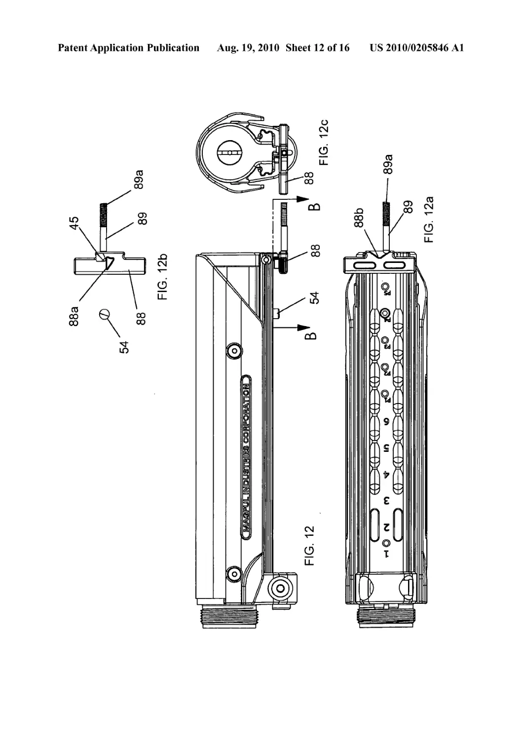
[0061] The length of pull pre-set system works as follows,
shown in FIGS. 6-12c. The stock is in a normal state, shown
in FIGS. 6-6c, where a stop bolt 54 is inserted in one threaded
hole 56 and the terminal stop 45 is in place. Release latch 88
is situated just underneath the rail and is biased in a central
orientation by plunger 89, which is so biased by spring 89a.
On top of release latch 88, is an angled block 88a which will
interface with stop bolt 54 and terminal stop 45. In FIGS.
1-lc, the stock is depicted as having been extended (moved
back) until the block 88a abuts stop bolt 54. As can be seen,
the wide portion of the angled block 88a actually abuts the
stop bolt 54 and prevents the stock from being further
retracted. However, it should be noted that if the release latch
was on the other side of the stop bolt 54, the angled portion of
the block 88a would interface with the stop bolt 54 (if being
pushed forward) and would actually act as a lever, moving the
release latch 88 out of the way so that the stock could be
collapsed without engaging the release latch 88.
[0062] In order to avoid the stop bolt 54, the user presses the
release latch 88 to one side (FIGS. 8-8c). As the block 88a
circumvents the stop bolt 54, the stock may be retracted
further (FIGS. 9-9c) without hindrance, until it reaches the
point of terminal stop 45 (FIGS. 10-10c). It should be noted
that in both its natural stage (FIGS. 11-llc) and the biased
stage (FIGS. 10-10c), the block 88a interfaces with the ter-
minal stop 45. Instead, to avoid the terminal stop 45, the
release latch 88 must be biased in the opposite direction as to
avoid the bolt stop 54. This is done intentionally so as to avoid
accidental removal of the stock from the system which only
trying to avoid the bolt stop 54. The release latch 88 maintains
its central bias via spring loaded plunger 89 which interfaces
with a “V” shaped notch 88/? on the underside of the release
latch 88. When the release latch 88 is biased to one side or the
other by the user, plunger 89 is displaced by the walls of notch
88b and spring 89a is compressed (FIGS. 8a, 9a, 10a, 12a).
When the bias is released, spring 89a decompresses, forcing
plunger 89 forward and restoring release latch 88 to its central
orientation (FIGS. 6a, 7a, Ila) by pressure against the notch
88b.
[0063] The latching mechanism is depicted in FIGS.
13-17a. As seen in FIGS. 13-13/?. the latch components are
the latch housing 85, which contains the shock cushion 86 and
trigger structure 82. Lock pawls 84 are mounted on the top of
the housing 85. Lock pawls 84 are biased by springs 90
(FIGS. 15 & 16) in an upward orientation. Trigger structure is
also spring biased in an extended position by latch spring 92,
mounted upon post 94 in the housing (FIG. 17a). Latch spring
92 rests inside orifice 87 in the trigger structure (FIG. 13a).
Trigger structure comprises the actual trigger body 81 and
two bias wedges 83,93, to actuate lock pawls 84. As shown in
FIG. 14, the latch mechanism resides below the rail 52 on the
sleeve module 14. Pre-set latch 88 resides between the latch
mechanism and the rail 52.
[0064] In operation, the latch is usually in its locked posi-
tion, shown in FIGS. 15 and 15a, with lock pawls 84 resting
within detents in the rail 52. Lower wedge 83 provides a
mechanical stop to prevent the lock pawls 84 from acciden-
tally being compressed. In intermediate stages, the front slope
of the wedge 83 actually provides an assist to effectively and
securely move the lock pawls 84 into their locked position
(FIGS. 16 and 16a). To unlatch the stock (FIGS. 17 and 17a),
trigger body 81 is compressed against trigger spring 92. This
motion causes upper wedge 93 to approach a pawl pin 91 that
extends from each pawl 84 and push the pin 91 downward,
compressing pawl springs 90 (not shown in FIGS. 17 and
17a) and lowering the lock pawls 84. This then allows the
stock body to slide transversely along the rail 52, subject to
the pre-set system. It should be noted that the lock pawl pins
91 do not join the lock pawls 84 together. The lock pawls 84
operate independently of each other so that failure of one,
especially in the open position, may be compensated by the
action of the other.
[0065] Other features of the stock body, in its preferred
embodiment and shown in FIGS. 1 and 2, include a storage
compartment 62, formed by having a hollow body enclosed
by attachable walls. One of said walls may be capable of
opening without removal. The stock also features a remov-
able tailpiece 64. Tailpiece 64 provides structural support and
may be designed to protrude from the stock body (as shown in
FIG. 2) with a sling loop or with other useful structure, like a
glass strike plate. A rubberized butt pad 66 may also be
provided to provide some shock absorption when impacts
occur, either intentionally or unintentionally. It should be
noted that other stock bodies, each with their own set of
desirable features, may be designed and used with the
described mounting system. As such, no limitation in the
claims to the preferred stock body as described herein should
be inferred, but only read into the claims where the specific
structures of the preferred stock body are directly claimed.
[0066] Although the present invention has been described
with reference to preferred embodiments, numerous modifi-
cations and variations can be made and still the result will
come within the scope of the invention. No limitation with
respect to the specific embodiments disclosed herein is
intended or should be inferred.
US 2010/0205846 Al
Aug. 19, 2010
4
1. A modular gunstock comprising:
a. a weapon interface structure having a cylindrical profile;
b. a sleeve module slideable upon the cylindrical profile,
the sleeve module further comprising interface structure
for a stock body;
c. structure to fixedly interface the sleeve module and the
interface structure;
d. an adjustable for length stock body with a latching
mechanism, the latching mechanism further comprising
two independently operated pawls designed to interface
with the interface structure for the stock body.
2. The modular gunstock of claim 1, the weapon interface
structure being a receiver extension tube.
3. The modular gunstock of claim 2, the structure to fixedly
interface the sleeve module and the interface structure being
a bolt secured end cap keyed into structure on the sleeve and
being secured to the interface structure.
4. The modular gunstock of claim 1, the interface structure
for the stock body being a rail, located on the lower half of the
sleeve module.
5. (canceled)
6. (canceled)
7. (canceled)
8. The modular gunstock of claim 1, the latch further com-
prising an impact buffer.
9. (canceled)
10. The modular stock of claim 1, the stock body further
comprising a selectable and replaceable tailpiece.
11. The modular stock of claim 1, the sleeve module further
comprising a cheek plate removable from said sleeve module
and positionable in one of a plurality available selectable
positions relative the sleeve module.
12. A modular gunstock comprising:
a. a weapon interface structure having a cylindrical profile;
b. a sleeve module slideable upon the cylindrical profile,
the sleeve module further comprising interface structure
for a stock body;
c. structure to fixedly interface the sleeve module and the
interface structure;
d. an adjustable for length stock body with a latching
mechanism; and
e. a length of pull pre-set system, the system comprising a
plurality of threaded holes located on an underside of the
sleeve module, a stop bolt capable of threadingly inter-
facing with any of the holes, a spring biased lateral latch
with an upwards angular block located on an upper side
of the stock body and positioned such that the angular
block will strike the stop bolt if the stock body is
extended relative to the sleeve module to a point deter-
mined by the location of the stop bolt and the latch is in
a neutral position, and may be extended beyond said
point of the latch is biased so the angular block avoids
the stop bolt.