/
Tags: weapons military affairs patent
Year: 2010

Text
US 20100077643A1
(19) United States
(12) Patent Application Publication («» Pub. No.: US 2010/0077643 Al
KERBRAT et al. (43) Pub. Date: Apr. 1,2010
(54) FIREARM WITH ENHANCED RECOIL AND
CONTROL CHARACTERISTICS
(76) Inventors: Renaud KERBRAT, Gland (CH);
Timothy Lindsay, Woodstock, MD
(US)
Correspondence Address:
WILEY REIN LLP
1776 K. STREET N.W
WASHINGTON, DC 20006 (US)
(21) Appl.No.: 12/501,247
(22) Filed: Jul. 10, 2009
Related U.S. Application Data
(63) Continuation of application No. PCT/US08/00336,
filed on Jan. 10, 2008, Continuation-in-part of appli-
cation No. 11/783,380, filed on Apr. 9, 2007, which is
a continuation of application No. 10/454,780, filed on
Jun. 5, 2003, now Pat. No. 7,201,094.
(60) Provisional application No. 60/879,530, filed on Jan.
10, 2007, provisional application No. 60/459,969,
filed on Apr. 4, 2003.
(30)
Foreign Application Priority Data
Jun. 7, 2002 (CH) ...................... 0975/02
Jul.31,2002 (CH) ..................... 1343/02
Apr. 15, 2003 (CH) ..................... 0679/03
Publication Classification
(51) Int.Cl.
F41A 25/00 (2006.01)
F41A 3/50 (2006.01)
F41A 35/00 (2006.01)
(52) U.S. Cl.................................... 42/1.06
(57) ABSTRACT
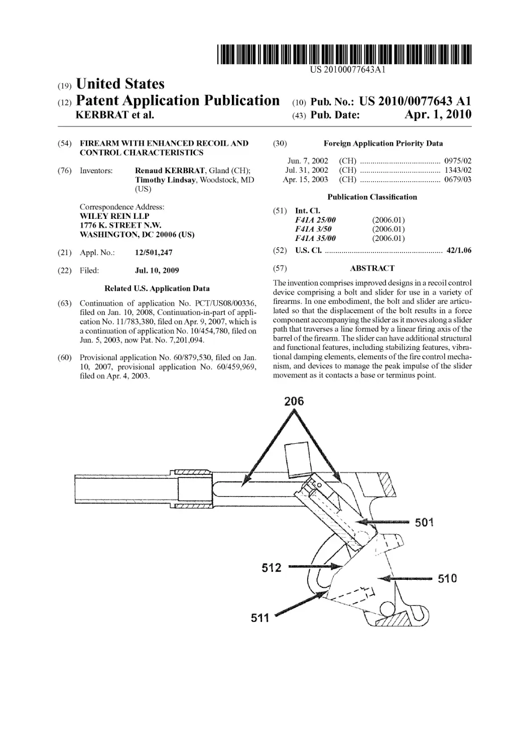
The invention comprises improved designs in a recoil control
device comprising a bolt and slider for use in a variety of
firearms. In one embodiment, the bolt and slider are articu-
lated so that the displacement of the bolt results in a force
component accompanying the slider as it moves along a slider
path that traverses a line formed by a linear firing axis of the
barrel of the firearm. The slider can have additional structural
and functional features, including stabilizing features, vibra-
tional damping elements, elements of the fire control mecha-
nism, and devices to manage the peak impulse of the slider
movement as it contacts a base or terminus point.
s92 SOS
Ра^АРрИсаНопрць)1.саНоп
APr-1,2010 «».
10 Sheet 3 of30
VS 2010/0077643 Al
206c
6
LU
и«2010/00776434)
SU 513
xv
TateM^“WnV
ф
V
in
Patent Application Publication Apr. 1, 2010 Sheet 6 of 30 US 2010/0077643 Al
Patent Application Publication Apr. 1, 2010 Sheet 7 of 30
US 2010/0077643 Al
FIG. 8
Patent Application Publication
Apr. 1, 2010 Sheet 8 of 30 US 2010/0077643 Al
FIG. 10
Patent Application Publication Apr. 1, 2010 Sheet 9 of 30
US 2010/0077643 Al
FIG. 12
Patent Application Publication Apr. 1,2010 Sheet 10 of 30 US 2010/0077643 Al
Patent Application Publication Apr. 1, 2010 Sheet 11 of 30 US 2010/0077643 Al
Patent Application Publication Apr. 1, 2010 Sheet 12 of 30 US 2010/0077643 Al
FIG. 18
Patent Application Publication
Apr. 1, 2010 Sheet 13 of 30 US 2010/0077643 Al
a /
Patent Application Publication Apr. 1,2010 Sheet 14 of 30 US 2010/0077643 Al
FIG. 22
Patent Application Publication Apr. 1, 2010 Sheet 15 of 30 US 2010/0077643 Al
103
102
FIG. 24
Patent Application Publication Apr. 1, 2010 Sheet 16 of 30 US 2010/0077643 Al
109
FIG. 26
Patent Application Publication Apr. 1, 2010 Sheet 17 of 30 US 2010/0077643 Al
Patent Application Publication Apr. 1, 2010 Sheet 18 of 30 US 2010/0077643 Al
FIG. 30
FIG. 31
Patent Application Publication Apr. 1, 2010 Sheet 19 of 30 US 2010/0077643 Al
FIG. 32
APPUcati
t>0U Рнк,.
bbc^iOtl
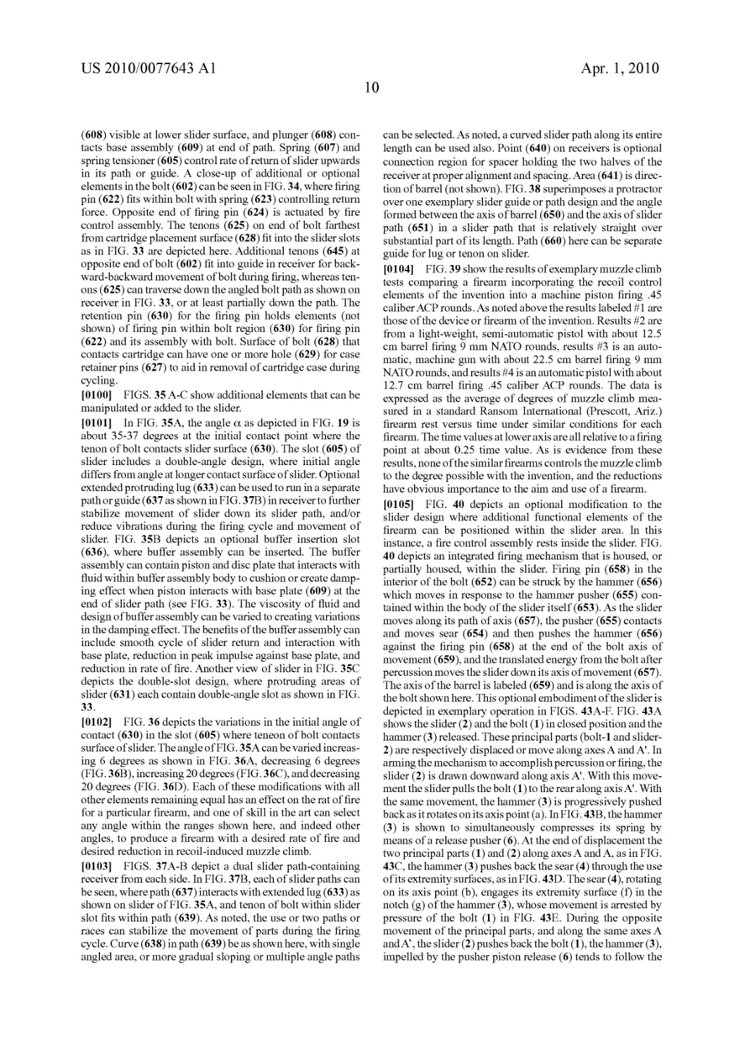
1 ?л
0,0 Sft.
°f30
Vs2°io/Oi
SOg
Patent Application Publication Apr. 1, 2010 Sheet 21 of 30 US 2010/0077643 Al
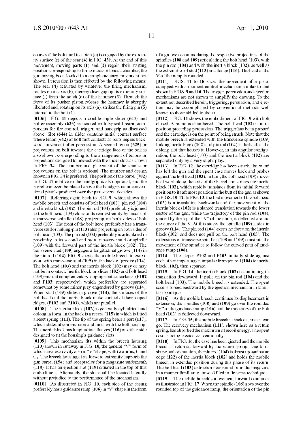
FIG. 34
Patent Application Publication Apr. 1,2010 Sheet 22 of 30 US 2010/0077643 Al
FIG. 35C
Patent Application Publication Apr. 1,2010 Sheet 23 of 30 US 2010/0077643 Al
Patent Application Publication Apr. 1,2010 Sheet 25 of 30 US 2010/0077643 Al
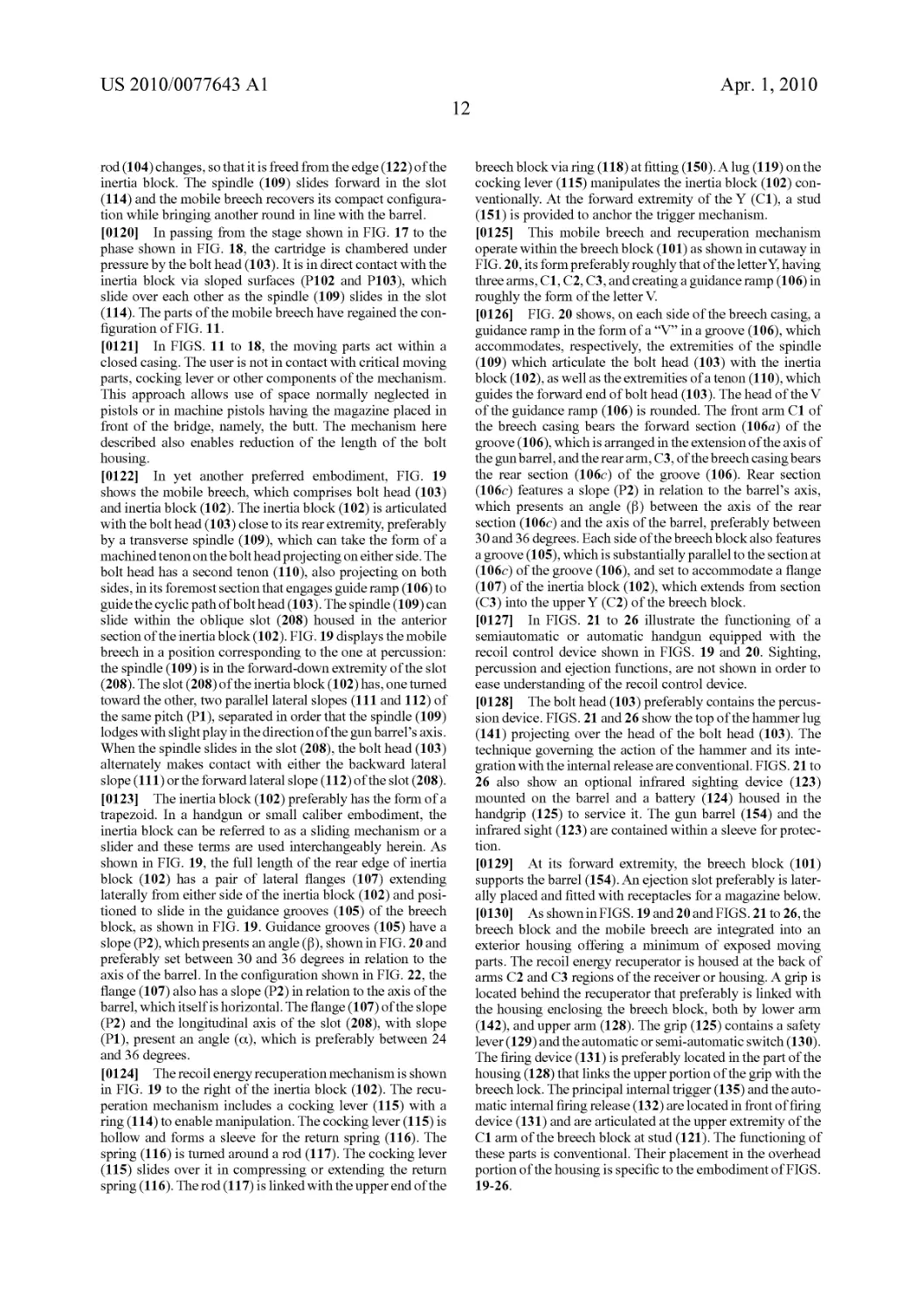
FIG. 38
651
Patent Application Publication Apr. 1,2010 Sheet 26 of 30 US 2010/0077643 Al
TIME
FIG. 39
FIG. 40
М"’’
svcc'
<р
Patent Application Publication Apr. 1,2010 Sheet 28 of 30 US 2010/0077643 Al
631
609
FIG. 42
Patent Application Publication Apr. 1,2010 Sheet 29 of 30 US 2010/0077643 Al
6
Patent Application Publication Apr. 1,2010 Sheet 30 of 30 US 2010/0077643 Al
US 2010/0077643 Al
Apr. 1,2010
1
FIREARM WITH ENHANCED RECOIL AND
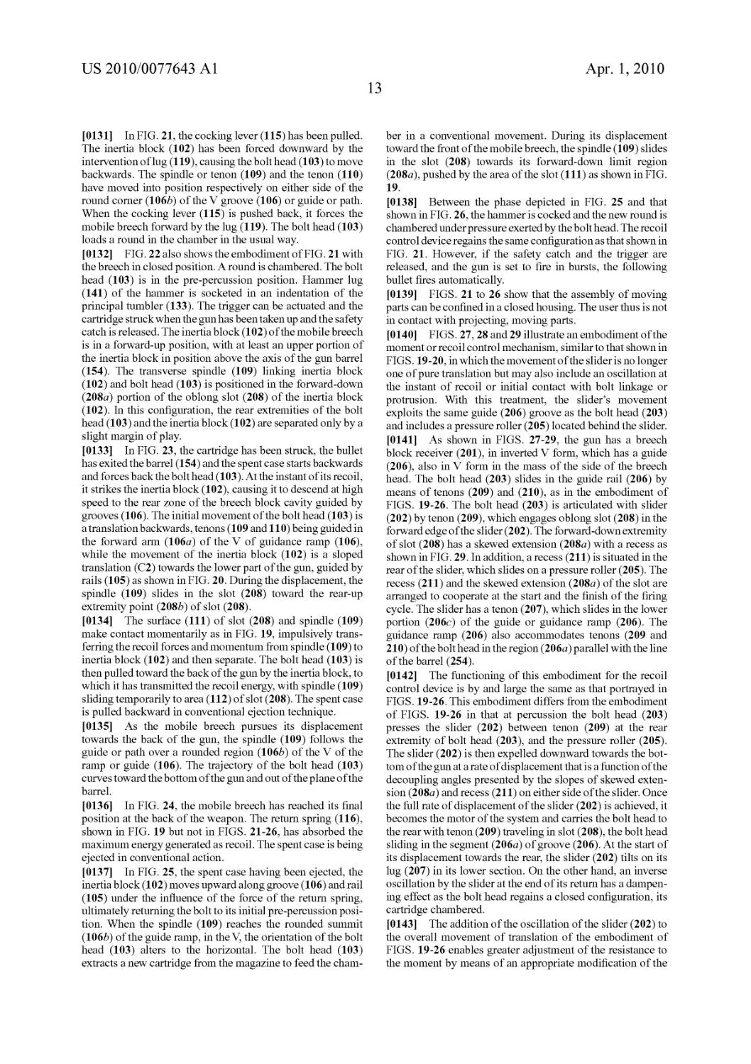
CONTROL CHARACTERISTICS
RELATED APPLICATIONS
[0001] This application is a Continuation application of
PCT/US2008/000336, filed Jan. 10, 2008, which claims pri-
ority benefit to U.S. Provisional application 60/879,530, filed
Jan. 10, 2007. This application is also a continuation-in-part
of pending U.S. application Ser. No. 11/783,380, filed Apr. 9,
2007, which is a continuation of Ser. No. 10/454,780, filed
Jun. 5, 2003 (now U.S. Pat. No. 7,201,094). This application
is also a continuation-in-part of pending U.S. application Ser.
No. 10/454,778, filed Jim. 5, 2003. Each of 10/454,778 and
10/454,780 claim priority benefit to U.S. Provisional Appli-
cationNo. 60/459,969, filed Apr. 4,2003, and priority benefit
of Swiss Application No. 0975/02, filed Jun. 7, 2002, Swiss
Application No. 1343/02, filed Jul. 31, 2002, and Swiss
Application No. 0679/03, filed Apr. 15, 2003. Each of the
above-listed prior applications are specifically incorporated
herein by reference in their entirety.
FIELD OF INVENTION
[0002] This invention relates to small and heavy caliber
firearms and machine firearms as well as to improved meth-
ods and devices for reducing the consequences of recoil and
improving performance of firearms. In a particular embodi-
ment, the device relates to the control or management of the
recoil forces for small caliber semiautomatic or automatic
firearms.
BACKGROUND FOR AND INTRODUCTION TO
THE INVENTION
[0003] Historically, automatic weapons were intended to
be loaded mechanically and, therefore, fired much faster than
hand-loaded firearms. However, the rapid firing of successive
cartridges induces various side effects that proved detrimen-
tal both to accuracy and the effectiveness of an automatic
weapon. Traditionally, a gun was considered to work like a
heat engine, in which about thirty percent of the energy devel-
oped by the propellant powder is dissipated as heat, forty
percent as muzzle blast and recoil, and only the remaining
thirty percent was effectively used to propel the bullet out of
the barrel. Successive designs of automatic weapons tried to
make use of the vast amount of wasted energy to help make
the automatic cycling operate better. Three general systems
were used. Hiram Maxim was the first to use recoil forces to
mechanize the ejection and loading actions in a machine gun,
Browning put the muzzle blast to effective use, and Bergman
devised the simple blowback action. Thus, the three basic
ways of obtaining an automatic operation were developed
from the use of recoil, gas, or blowback actuation. Later
applications of the blowback operation used either simple
blowback or assisted blowback, with or without locked,
delayed, hesitation or retarded blowback, and even blowback
with advance primer ignition. Gas operation leads to the use
of long and short-stroke pistons and even, in more modern
weapons, direct gas action, where the derived gas directly
activates a bolt carrier in which an adequate recess is man-
aged. Recoil operation traditionally provided the locking
mechanism of the bolt to the barrel so that they can slide
together under the thrust of the pressure when firing, either
under a short or long recoil operation and with or without
muzzle boosters or recoil intensifiers.
[0004] Throughout the time these improvements were
made a main issue was safety. Depending on the design,
operators were susceptible to explosive forces from an
improperly chambered round or an incomplete breech lock on
the chambered round. Therefore, all systems were engineered
in order to secure an accurate locking duration for the breech
to the barrel, until the gas pressure falls to a safe level once the
projectile has exited the barrel. The main breech locking
systems developed employed separate revolving chambers,
the rotation of which provides an adequate duration of pro-
tection, or toggle systems, rotating bolts, tilting breech
blocks, lug systems, or even non-ramming breech blocks. A
common but unsatisfactory feature among all these mecha-
nisms is that they do not prevent the undesirable side effects
during automatic firing, which accounts for the adverse
effects on accuracy and ease of use.
[0005] Thus, the mechanisms found on current firearms,
although reliable and widely employed, nevertheless suffer
from a number of deficiencies. For example, some mecha-
nisms increase the length of the housing of the breech, result-
ing in interior clutter and increased weight. The amplitude of
recoil is relatively critical due to its effect on accuracy, and the
existing mechanisms fail to provide a satisfactory or optimum
reduction in recoil, which permits the resulting upward move-
ment of the barrel—muzzle climb or muzzle rise. More par-
ticularly, the direction of the recoil forces generally coincides
with the longitudinal axis of the gun barrel. The gun barrel is
generally located above the shoulder in a person firing a rifle
or above the hand in a handgun, and more precisely above the
gap between the thumb and index finger of a person firing a
handgun. This configuration generates a moment that causes
the upward jerking of the gun familiar to every user. Heavy
caliber firearms and camions experience the same upward
forces upon firing. For these and other reasons, improvements
in the design and operation of small and heavy caliber fire-
arms and camions are desired in the art.
[0006] The innovative approaches taken here make a more
effective use of the available energy and, in particular,
recycle, as much as practicable, the wasted energy by depart-
ing from the traditional and historical mechanisms. In one
aspect, this invention provides new solutions, mechanisms,
and systems for operating the firing action of a firearm and
allows revolutionary changes in the ergonomics applicable to
firearm design and use.
[0007] Taking into account all these adverse or secondary
effects that impede the use of all firearms, and in particular
automatic firearms, in which energy is essentially wasted
beyond that necessary for propelling the projectile, the
present approach is new and innovative. In general and in one
aspect, the invention is aimed at addressing the design of a
new firearm by taking advantage of available energy to help
operate the firearm and consequently minimize and/or com-
pensate for the adverse effects and improve control. A first
innovation is the deliberate use and control of energy to
address all the adverse effects during operation. This allows
one to conceive of a new firearm design and organization, still
dependable, but vastly improved. This new approach also
allows a firearm designer to address concerns and constraints
as part of a whole rather than as individual problems, so as to
take into account the advantages and interfaces between fire-
arm components during operation. Considering the operation
as a whole, as this invention exemplifies, allows completely
US 2010/0077643 Al
Apr. 1,2010
2
new concepts and expands the universe of designs, configu-
rations, and mechanisms possible for firearms.
SUMMARY OF THE INVENTION
[0008] The present invention addresses the problems and
disadvantages associated with conventional firearms and
weapon systems and provides improved devices for reducing
recoil effects in a variety of firearms, camions, and systems.
Whether for handguns, rifles, pistols, machine pistols, mili-
tary rifles, or camions, one aspect of the invention is to reduce
the amplitude or consequences of recoil and/or eliminate, for
all practical purposes, the weapon’s reactive upward jerking.
The invention also facilitates the design and production of a
more compact weapon and/or allows substantial reductions in
the weight of the frame, which results in many new design
possibilities and improvements in ergonomics. Thus, incor-
porating one or more of the many aspects of the invention into
a firearm improves accuracy and/or reduces the total weight.
[0009] One of the fundamental principles of the present
invention is the transfer of mechanical recoil forces to a
direction outside of the longitudinal axis of the gun barrel. As
can be seen in each of the exemplary embodiments disclosed
herein, the transfer of forces disperses or dissipates recoil
forces and thereby reduces the moment responsible for the
upward jerking characteristic of conventional firearms. The
mechanism that transfers forces can be oriented to counteract
the recoil forces along the longitudinal axis of the gun barrel
to effectively eliminate or compensate for the upward jerking
of the weapon. For example, a pair of inertia blocks of sub-
stantially equal mass can be oriented such that their respective
movements in response to firing will be synchronized, equal
in magnitude, and with corresponding but opposite compo-
nents of momentum oriented outside the longitudinal axis of
the barrel. The net effect is that the opposite movement or
displacement of the inertia blocks first absorbs the recoil
forces and prevents the weapon from being pushed rearward.
Second, the lateral momentum of one moving inertia block
cancels the other, thereby inducing no net lateral force or even
agitation of the firearm. Thus, the portion of the recoil forces
beyond those used to operate the novel mechanisms or system
of the invention is transferred in a direction outside the lon-
gitudinal axis of the barrel and effectively disposed of by
being cancelled out, thereby significantly reducing or even
eliminating the component of recoil forces along the longi-
tudinal axis of the barrel that is responsible for the reactive
jerking or muzzle rise of the weapon when fired. One of skill
in the art will recognize that the embodiments disclosed
herein are exemplary and that one or more of the foregoing
principles can be applied in many variations to firearms of
various calibers and applications.
[0010] In one particular embodiment of the present inven-
tion, a recoil control device for use in a firearm comprises a
bolt head configured to alternate between a forward position
and a rearward position in response to the firing of one or
more cartridges and an inertia block connected to the bolt
head such that said bolt head imparts an impulse to the inertia
block as it alternates between the forward position and the
rearward position. The impulse imparted to the inertia block
may have a component lateral or perpendicular to the firing
axis of the barrel of the firearm. Alternately, the movement of
the inertia block may have a component lateral to or perpen-
dicular to the firing axis of the barrel of the firearm. In either
case, the lateral transfer of momentum substantially reduces
the reactive recoil forces.
[0011] In another particular embodiment, the invention
comprises a mobile breech made up of articulated parts
including an inertia block and a bolt head. In this embodi-
ment, the action of the mobile breech is unconventional in that
it causes the inertia block to alternate out of and into align-
ment with the longitudinal axis of the barrel. This is contrary
to the action of conventional mechanisms in which the parts
that compose a mobile breech move in translation along the
longitudinal axis of the barrel. The present invention transfers
the recoil forces generated by firing to the inertia block, M, by
means of a bolt head, m, moving backward at an initial veloc-
ity, v,. In a particular aspect of the invention, for example, this
transfer of recoil forces from the bolt head to the inertia block
is preferably made using corresponding angled surfaces of
the bolt head and the inertia block. An impulse transferred to
the inertia block translates to a force in a direction other than
along the longitudinal axis of the gun barrel thanks first to the
configuration of the contact surfaces, and second to the articu-
lated parts connecting to the inertia block, and third the path
that guides the movement of the inertia block. The inertia
block is thus imparted with a momentum, MvM, and the
velocity vector, vM, has a component parallel to the longitu-
dinal axis of the gun barrel, oriented toward the back or front
of the weapon, while the other component is oriented in a
lateral direction from the axis of the gun barrel, either below
or above the weapon.
[0012] Thus, the mobile breech comprises an inertia block
that operates to transfer momentum or forces generated by the
firing of one or more cartridges or rounds of ammunition to a
direction outside of the longitudinal axis of the gun barrel. In
a more basic aspect, the inertia block is a component part of a
firearm, or more particularly a mobile breech, that moves in
response to the force of firing and/or moves in response to the
movement of a bolt head. The inertia block or masses allows
for the absorption of recoil forces and directs those forces in
the form of momentum in a direction outside the longitudinal
axis of the barrel. Throughout this disclosure, the use of the
term “inertia block” can refer either to a single or to multiple
parts or masses. The component masses of the inertia blocks
may optionally serve additional functions, such as providing
armor protection to or housing components for gun or camion
emplacements equipped with the present invention. Further-
more, the terms “bolt” and “bolt head” are used interchange-
ably.
[0013] In a system where the bolt head absorbs the recoil
forces directly through contact with the spent casing of the
cartridge, the bolt head is imparted with a rearward momen-
tum along the longitudinal axis of the barrel. When the inertia
block moves in response to the movement of the bolt head, the
bolt head impulsively strikes the inertia block, either directly
or through a linkage, and the momentum of the bolt head is
then transferred to the inertia block. The bolt head is typically
of significantly smaller mass than the inertia block or blocks.
Because of the relative masses of the bolt head and inertia
block, the inertia block will move with a different velocity
than the bolt head.
[0014] An aspect of the present invention is the use of
inertia block guides to constrain the movement that the inertia
block follows to a direction other than along the longitudinal
axis of the barrel, thereby transferring the recoil forces out of
the axis of the gun barrel and reducing the reactive jerking
described above. Alternately, the initial impulse on the inertia
block or blocks may be driven not by direct mechanical con-
nection to the bolt head, but by a gas injection system. In that
US 2010/0077643 Al
Apr. 1,2010
3
case, the expanding gases created by the firing of one or more
cartridges are used to pressurize a gas injection system and
the pressure is selectively applied to the inertia block or
blocks to cause their movement in a direction other than along
the longitudinal axis of the barrel. In any embodiment, the
inertia block or blocks serve the same basic function—to
absorb recoil forces and/or re-direct recoil forces out of the
longitudinal axis of the barrel.
[0015] The path of the inertia block in response to the recoil
impulse leaves the longitudinal axis of the gun barrel, thereby
translating recoil forces out of this axis. Part of the space
occupied by the inertia block during its back and forth trajec-
tory can be located below the axis of the gun barrel, while the
rest of the trajectory of the inertia block in its alternating
action, as well as the corresponding part of the breech block,
can be situated above the barrel axis.
[0016] The inertia block can move along a path defined by
its guide. The guide can be a slot in a part of the firearm, or can
be a rod or articulated part, or any other component designed
to allow the inertia block to move back and forth from a
loaded position to an end point of its movement. An inertia
block guide can be configured so that the movement of the
inertia block in response to the impulse can be one of pure
translation or the movement can be more complex in nature.
In other words, there can be a direct connection possible
between the bolt head and the inertia block that causes the
movement of the inertia block to move along its guide, or
there can be a simple linkage, such as pin rod, or there can be
more complex linkages, such as multiple rods and/or articu-
lated parts. The inertia block’s movement in turn governs the
movement of the bolt head and/or vice versa, due to the
maimer of their linkage.
[0017] In one aspect, a phase displacement can be achieved
by engineering the linkage between bolt head and inertia
block with a slight play, for example in the longitudinal direc-
tion. In another aspect, the phase displacement can be
achieved through a delay in the direct contact of the bolt head
with the inertia block enabled by the shape or configuration of
the contact surfaces. The degree of phase displacement is a
matter of design option, but some phase displacement is pre-
ferred.
[0018] The recoil moment can be further controlled or man-
aged through the positioning of the barrel of the weapon
relative to the grip or stock of the weapon. For example, a
conventional handgun grip can be placed behind a breech
block of the present invention. In certain embodiments of the
invention, the axis of the barrel is not found above the grip, as
it is conventionally in handguns, but in front of it, typically at
mid-height or at two-thirds the height of the grip. Preferably,
the gun barrel axis is in line with the forearm of the person
aiming the gun and not above it, the effect of which is to
eliminate the upward jerking characteristic of the recoil
response of conventional guns. However, one can design
embodiments of the invention where the barrel can be placed
below the grip or stock, above the grip or stock, or at any
height relative to the grip or the stock. In combination with the
use of one or more inertia blocks, a number of improvements
in design, weight, accuracy, and recoil characteristics are
possible.
[0019] The recoil control device’s components can be
advantageously prepared with comparatively large parts or
large diameter spindles or rods, which simplifies manufac-
ture. This advantage of the present invention greatly improves
the reliability in service and the resistance to jamming by
sand, mud, and other environmental contaminants and sim-
plifies cleaning and dismantling of the firearm.
[0020] The mechanisms and aspects of the invention can be
used to complement or improve existing or conventional fire-
arms and can be combined with various arrangements, attach-
ments, and combinations, including without limitation inter-
nal release systems, loading systems, ejection systems, gas
injection systems, recoil reduction systems, muzzle brakes,
sighting systems, tripods, mounting systems, and firing
mechanisms.
[0021] In one general aspect, the invention comprises an
improved and novel recoil control device for use in a firearm,
such as a semiautomatic or automatic firearm, in which, for
example, a bolt head is configured to alternate between a
forward position and a rearward position in response to the
firing of one or more cartridges; and an inertia block is con-
nected to the bolt head such that the bolt head imparts an
impulse to the inertia block as it alternates between its for-
ward position and its rearward position, the impulse having a
component, or force distribution or vectorial force compo-
nent, lateral to the firing axis of the barrel of the firearm. The
force transferred to the inertia block can be in any one of
several directions and the inertia block can therefore traverse
one of a variety of paths from the impulse imparted through
the bolt head, including, but not limited to: a downward
sloping, straight path toward the anterior of the firearm; a
curved or curvi-linear path; a path extending outward from
the barrel; a path moving inward toward the barrel; andapath
crossing over the barrel. The path chosen relates to the design
characteristics of the firearm desired.
[0022] Similarly, the inertia block or mass appropriate for a
particular firearm relates to the design characteristics of the
firearm. In one embodiment, the inertia block comprises a
sloped or angled surface, or a leading sloped surface, that can
be contacted by the bolt head to transmit the impulse from
firing. In other embodiments, the inertia block comprises a
part or parts that reciprocates between two or more positions
and moves in response to the impulse from the bolt head.
Multiple inertia blocks can also be used so that they move
together in response to the bolt head. In another preferred
embodiment, the recoil control device of the present inven-
tion can be incorporated into heavy caliber firearm and can-
non mechanisms. For example, a heavy caliber rifle, suchas a
vehicle-mounted rifle or portable rifle of between .50 caliber
and 105 mm, or even higher as in a 155 mm camion, can be
produced with an inertia block to translate forces out of the
axis of the barrel. In still other embodiments, the recoil con-
trol device can be incorporated into a shotgun or automatic
shotgun.
[0023] The transfer of the impulse of percussion from the
bolt head to the inertia block can be through direct contact
between the two parts or through a simple or even a complex
linkage. In one embodiment, one or more pin and rod assem-
blies are used. In another embodiment, a pin connected to the
bolt head moves within a slot connected to the inertia block.
In other embodiments, one or more reciprocating rods con-
nect the bolt head to the inertia block. In one embodiment, the
slider is designed to oscillate during its movement and inter-
act with a roller or recoil dampening point in the receiver. In
another embodiment, the design of the bolt, slider and guides
in the receiver or housing are specifically designed to reduce,
and optionally reduce to a substantial degree, the oscillation
or vibration of the slider during its movement. Multiple inter-
actions between the bolt and the slider, additional guides for
US 2010/0077643 Al
Apr. 1,2010
4
controlling the slider, and optionally a buffer assembly incor-
porated into the slider to interact with a fixed element at the
terminal end of the slider movement, can each reduce vibra-
tion in the operation. A reduction in the vibrational movement
of the slider can advantageously improve the operation of a
firearm in general and the serviceable life of certain parts.
[0024] For most firearms of the invention, the inertia block
and bolt head are designed to automatically return to their
resting or chambered position. A variety of mechanisms can
be used to move the bolt head and/or inertia block in the return
path. A preferred embodiment employs a spring operably
connected to or contacting the inertia block, which can be
referred to as the return spring. A variety of spring types can
be adapted for this purpose. Alternative return or recovery
mechanisms can be designed by one of skill in the art.
[0025] The recoil control device can be manifested as in
one of the numerous Figures accompanying this disclosure.
Also, numerous embodiments and alternatives are disclosed
in the accompanying claims. In another aspect, the invention
provides a method for making a recoil control device of the
invention and/or incorporating into a firearm a recoil control
device comprising one or more inertia blocks operably con-
nected to a bolt head, or moving in response to other forces, in
order to move in a maimer that directs momentum outside of
the longitudinal axis of the barrel.
[0026] Other embodiments and advantages of the invention
are set forth in part in the description that follows, and in part,
will be obvious from this description, or may be learned from
the practice of the invention.
BRIEF DESCRIPTION OF THE DRAWINGS
[0027] For a more complete understanding of the invention
and some advantages thereof, reference is now made to the
following descriptions taken in connection with the accom-
panying drawings in which
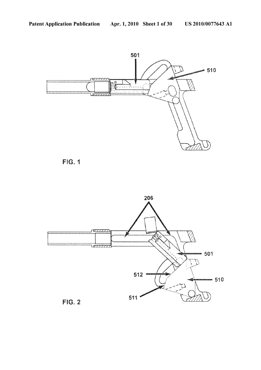
[0028] FIG. 1 is a schematic of the mobile breech and the
reciprocating operation of a preferred double-angled slider
embodiment of the recoil control device according to the
invention. The slider (510) and bolt (501) are shown at the
chambered or loaded position in FIG. 1.
[0029] FIG. 2 shows a schematic as in FIG. 1, after the
cartridge has fired and the bolt (501) and slider (510) have
moved backward and downward. The cartridge case can be
seen being ejected from the bolt head. The initial angle (511)
or first sloped surface of the slider can be seen in this double-
angled slider configuration, where sloped surface (512)
makes up the remaining part of the slider surface in contact
with bolt (501) or bolt linkage device. The bolt or an integral
part of the bolt may contact the slider surfaces, or a linkage
part or combination of linkage parts, such as rods and pins,
may contact the slider surface.
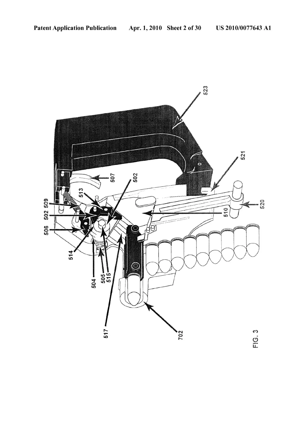
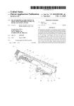
[0030] FIG. 3 shows a cutaway view of a semi-automatic or
automatic handgun equipped with a slider similar to that
shown in the embodiment of FIG. 1. FIG. 3 also shows a
trigger (507) and trigger mechanisms connecting the trigger
action to the firing mechanism. In this view, hammer (502)
has been cocked, for example, by pulling manual cocking
lever (520), and a cartridge is chambered.
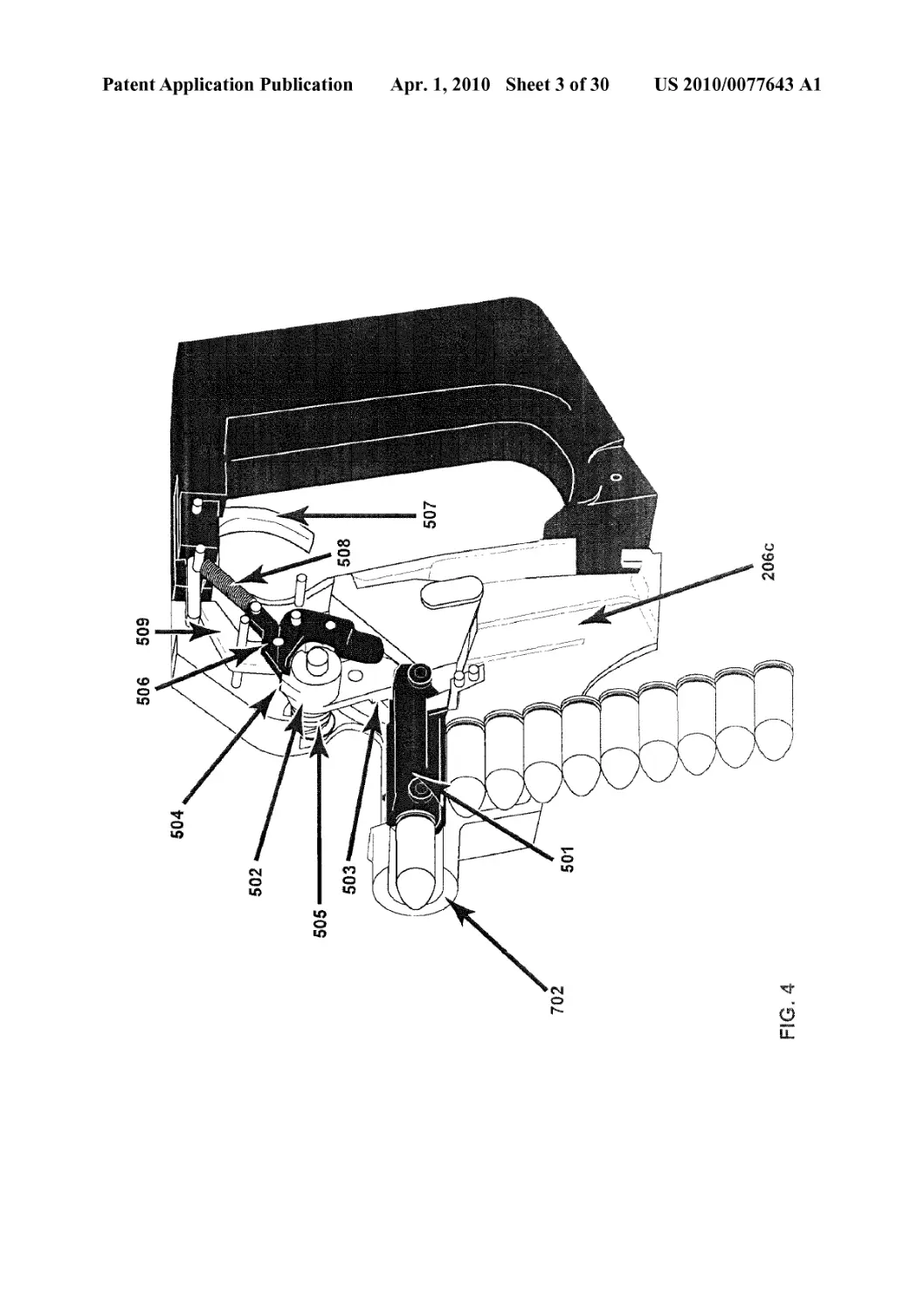
[0031] FIGS. 4-6 show a series of cutaway views of the
operation of the mobile breech and slider in a handgun or rifle
embodiment.
[0032] FIG. 4 shows a cartridge chambered and the ham-
mer (502) cocked.
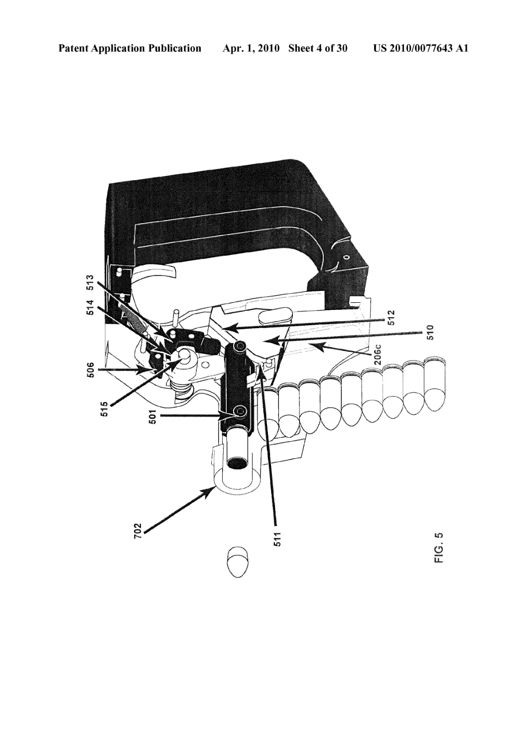
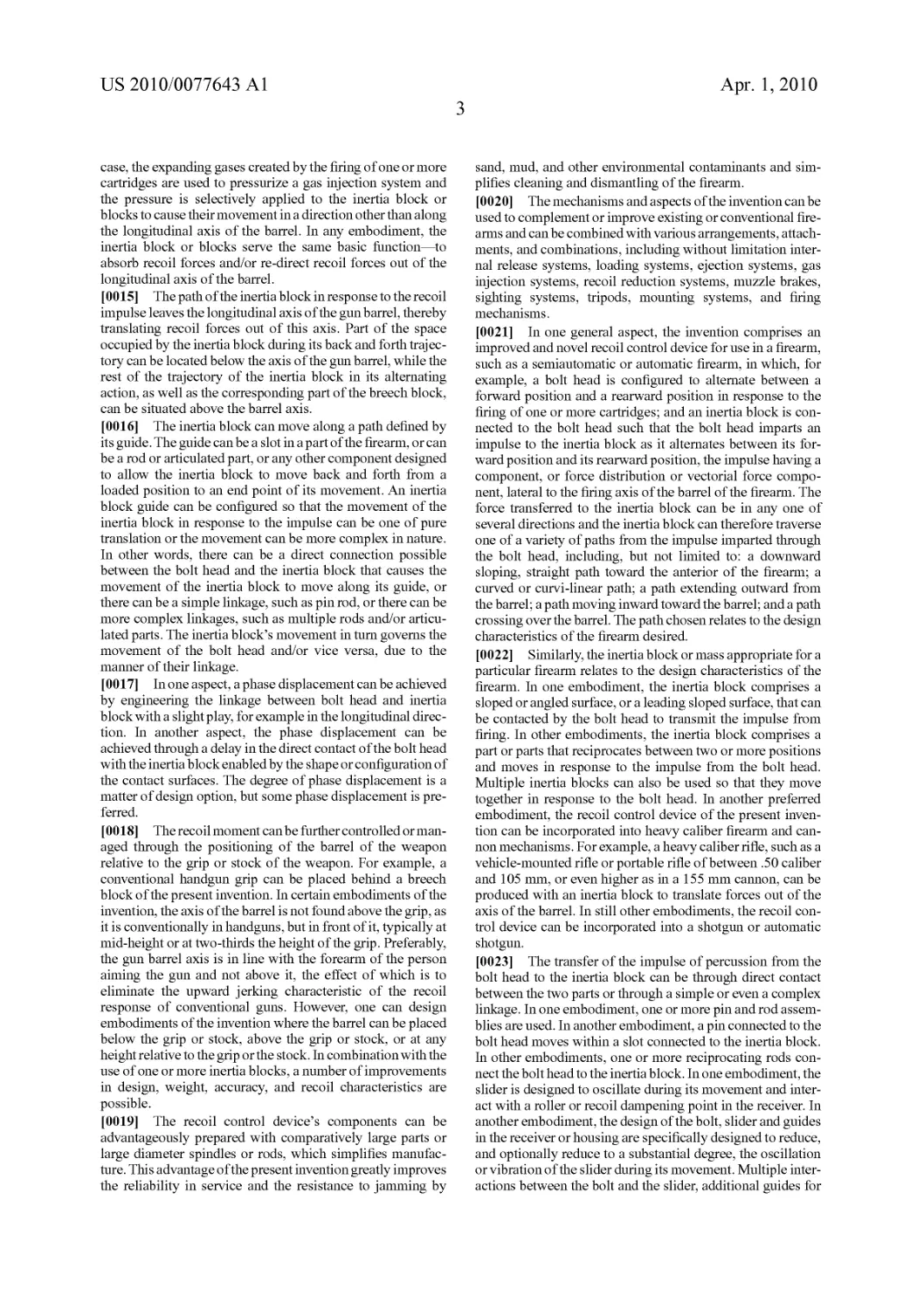
[0033] FIG. 5 shows the configuration of parts just after
firing, where bolt (501) has moved onto secondary sloped
surface (512) of slider (510), and slider has begun movement
downward.
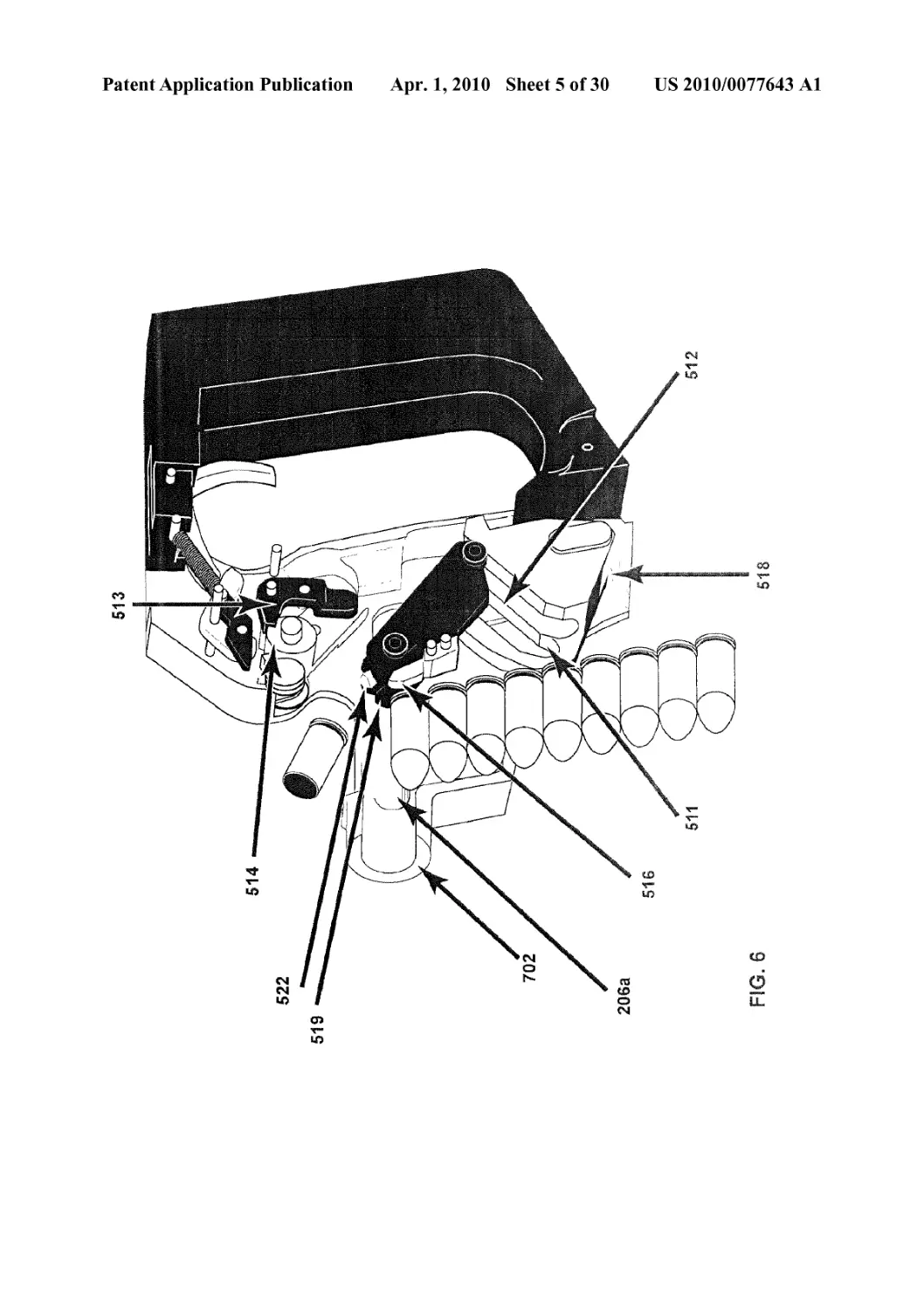
[0034] FIG. 6 shows the configuration of parts at the end
(518) of the slider movement downward. The spent cartridge
case is ejected.
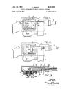
[0035] FIGS. 7-8 show a cutaway view of an alternative
embodiment, where a slider is placed above the barrel and
slides downward from a position in front of and to the side of
the breech.
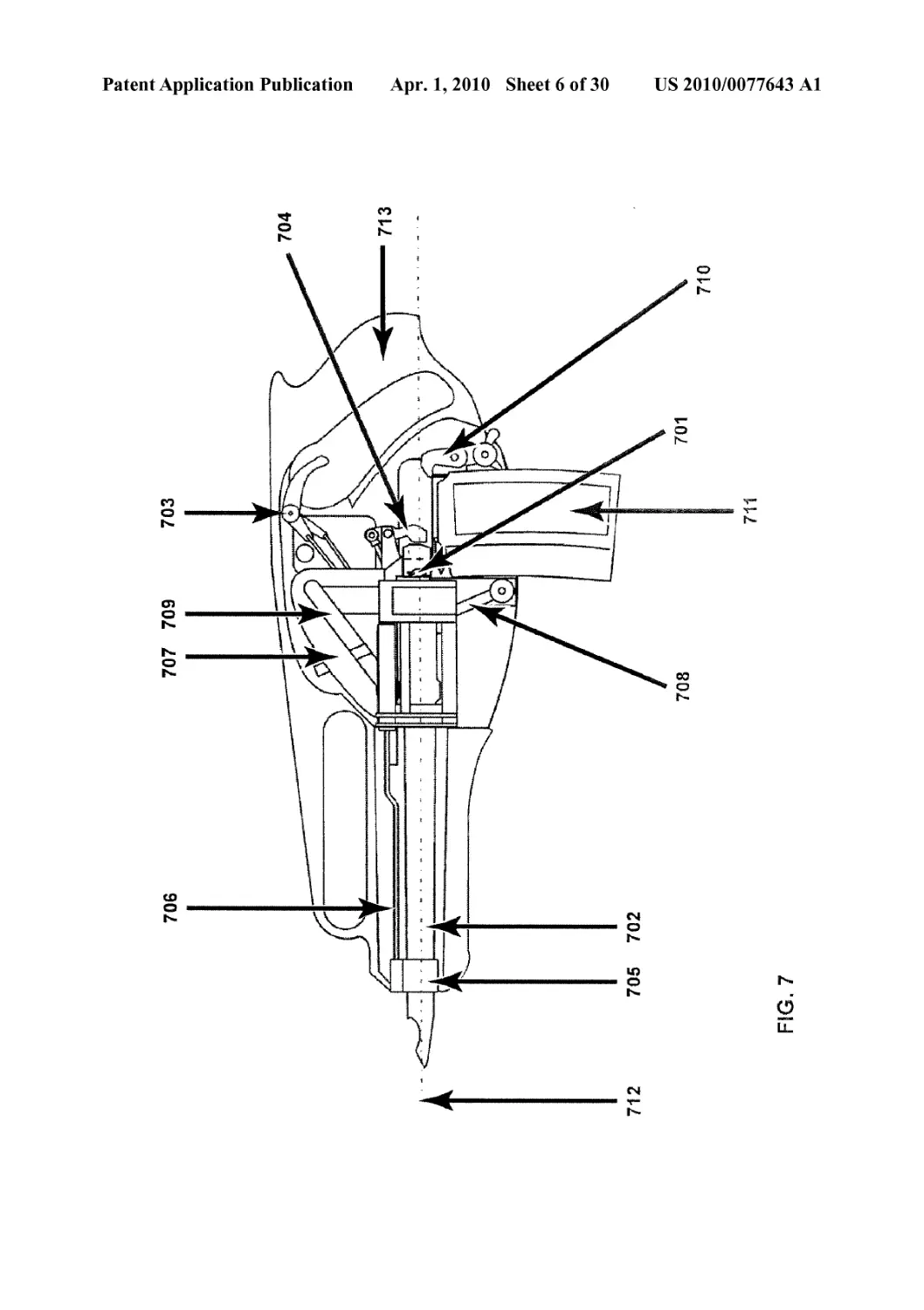
[0036] FIG. 7 shows the slider (707) before firing, posi-
tioned above the barrel and in front of the bolt (701).
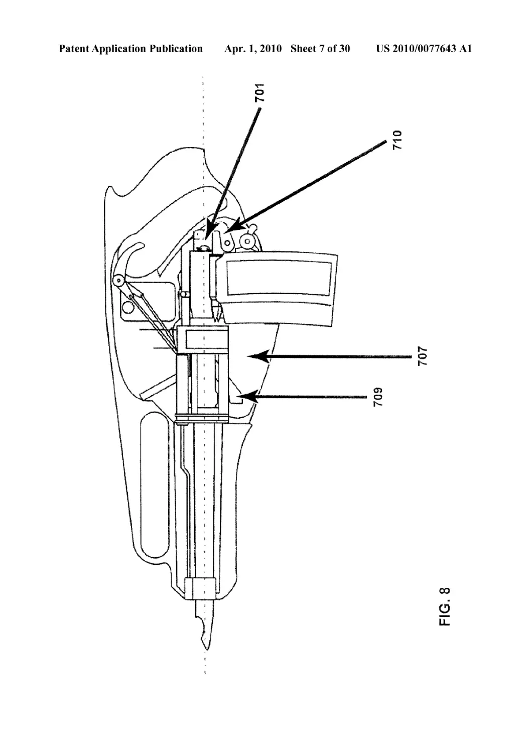
[0037] FIG. 8 shows the slider at the end of its movement
and positioned to be returned by return device (708).
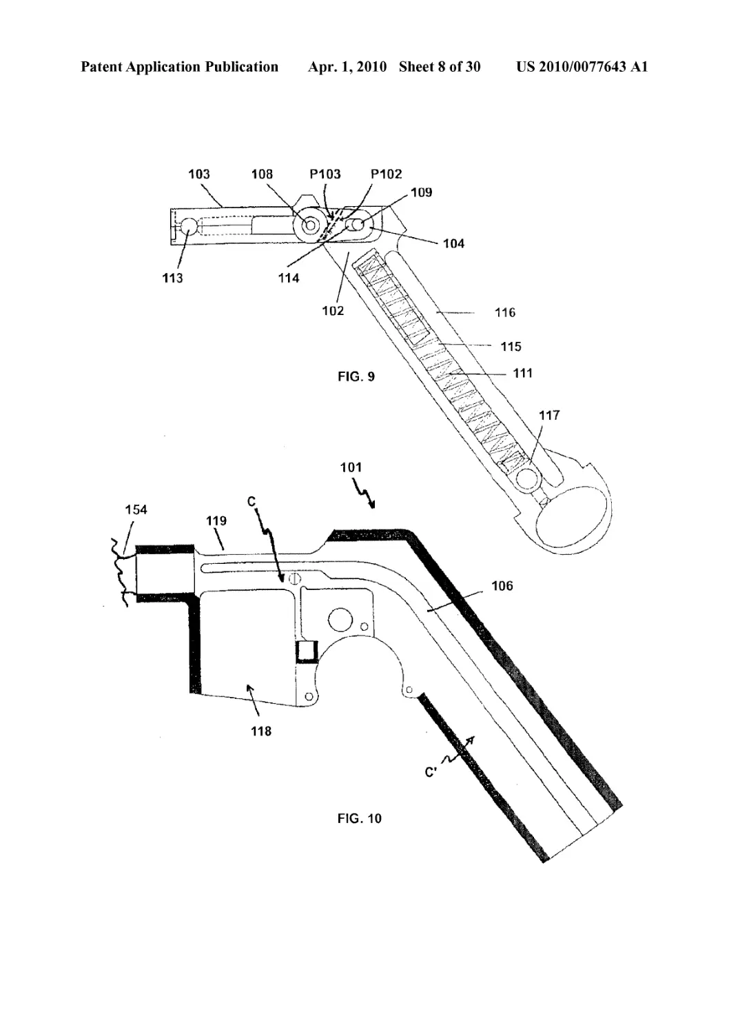
[0038] FIG. 9 shows the mobile breech for another pre-
ferred embodiment of the recoil control device, with an alter-
native type of action.
[0039] FIG. 10 shows a longitudinal cutaway of the hous-
ing for the embodiment of FIG. 9.
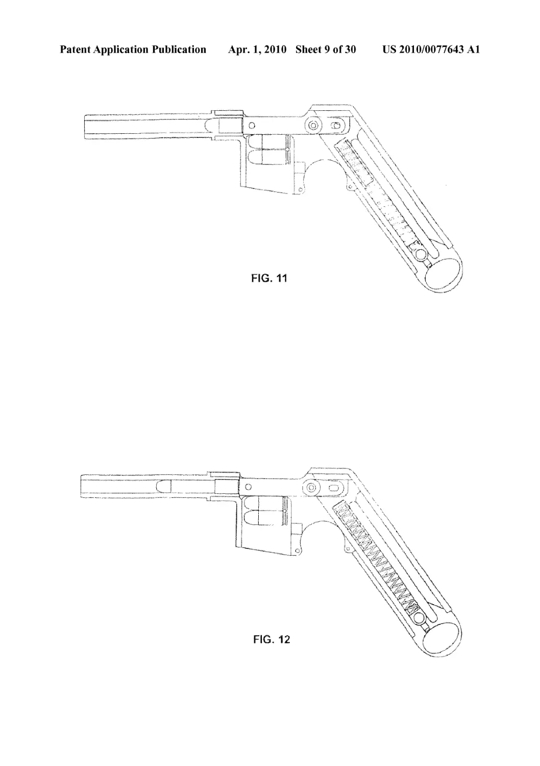
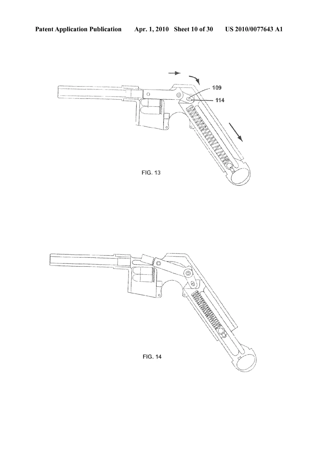
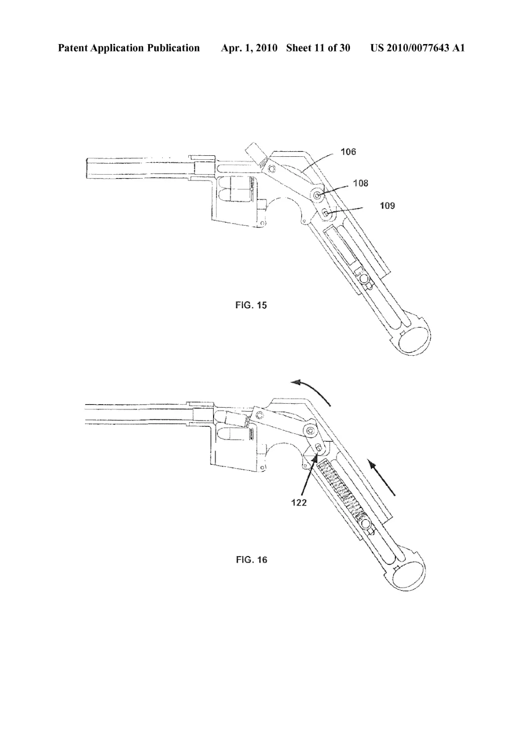
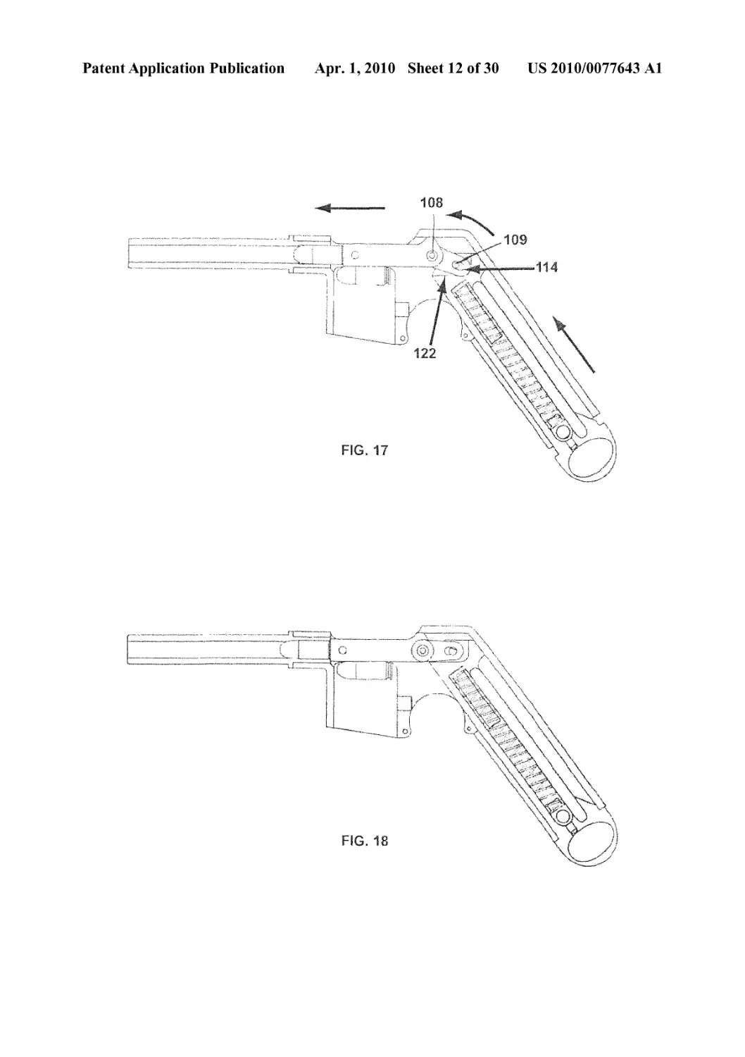
[0040] FIGS. 11-18 show the functioning of the embodi-
ment of FIG. 9. FIGS. 12 and 13 show the movement in
response to the percussion, where a bolt head and rod act upon
the downward sliding inertia block. FIGS. 13 and 14 show the
ejection of the spent cartridge and compression of the return
spring as the sliding inertia block moves. FIG. 15 shows the
end of the downward movement of the inertia block. FIG. 16
shows the reciprocating inertia block returning to the loaded
position through the action of the compressed return spring,
and where the bolt head catches and begins to chamber a fresh
round. FIG. 17 shows the inertia block and bolt head near its
completed return. FIG. 18 again shows the loaded cartridge
and bolt head and inertia block in complete rest or passive
attitude.
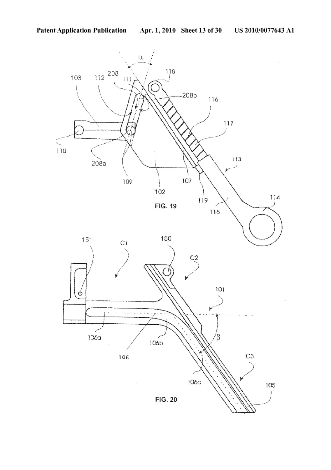
[0041] FIG. 19 is a schematic of the mobile breech and the
reciprocating operation of a preferred single-angled slider
embodiment of the recoil control device according to the
invention.
[0042] FIG. 20 is a longitudinal cutaway view of the hous-
ing or guide for the mobile breech showing the path of move-
ment for the mobile breech shown in FIG. 19.
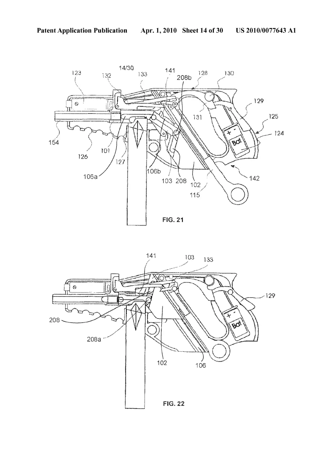
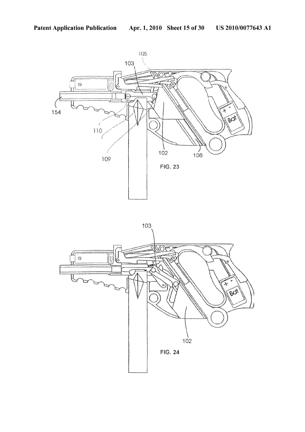
[0043] FIGS. 21-26 illustrate the action of a single-angled
slider similar to the embodiment shown in FIGS. 19 and 20.
Here, the firing mechanism is electrically powered.
[0044] FIG. 21 shows, in longitudinal cutaway, the loading
of a semiautomatic or automatic handgun, as the cartridge is
in position to be chambered.
[0045] FIG. 22 shows the firearm of FIG. 21 in closed or
loaded configuration, a cartridge chambered.
[0046] FIG. 23 shows the firearm of FIG. 21 after firing, the
bolt head at the beginning of its backward, recoil movement.
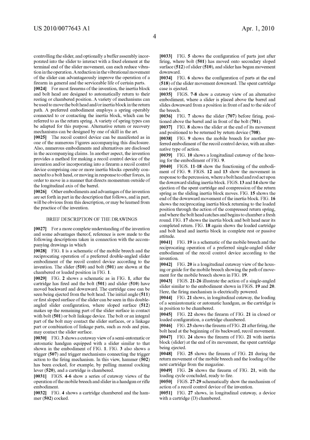
[0047] FIG. 24 shows the firearm of FIG. 21 with inertia
block (slider) at the end of its movement, the spent cartridge
being ejected.
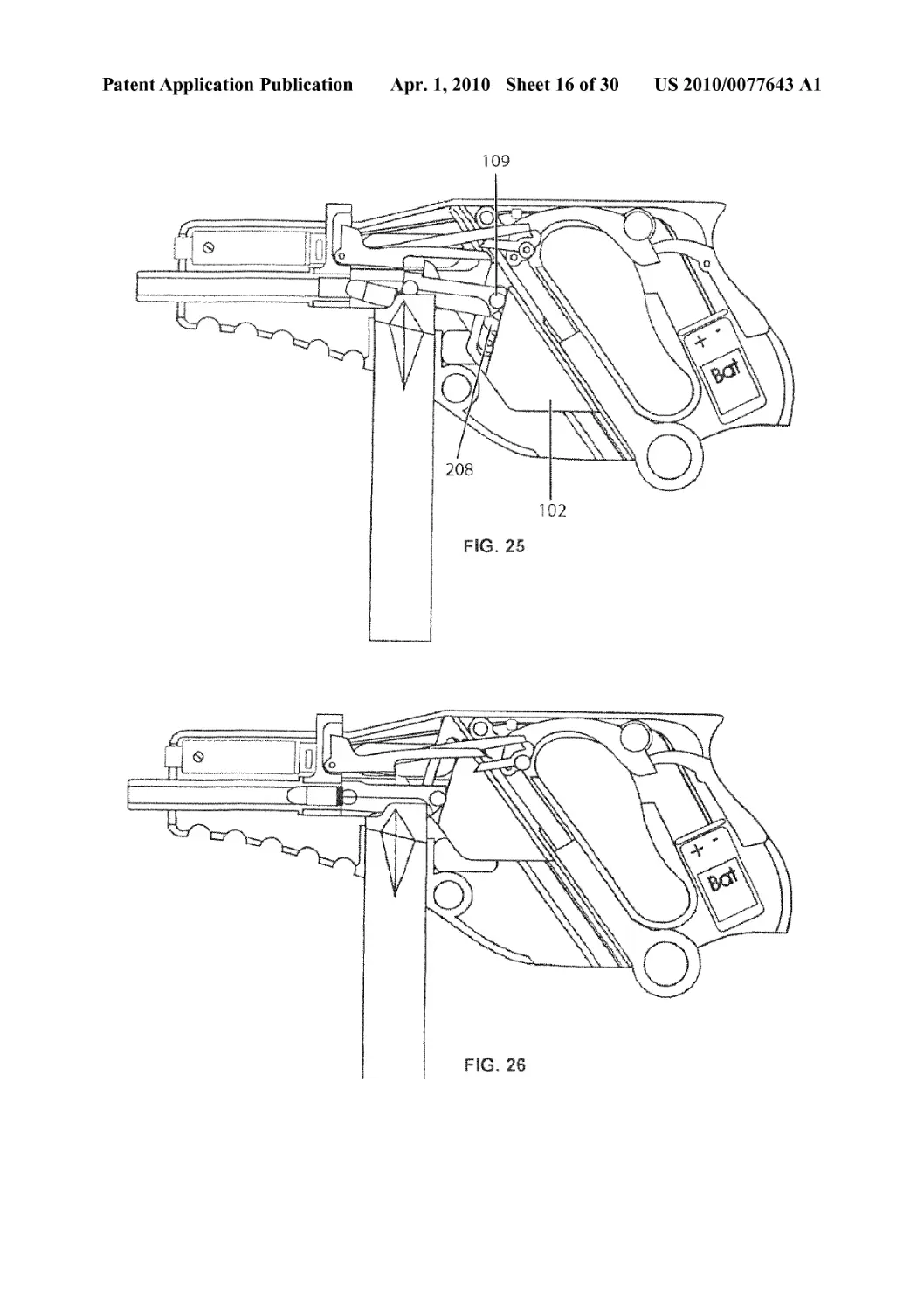
[0048] FIG. 25 shows the firearm of FIG. 21 during the
return movement of the mobile breech and the loading of the
next cartridge from the magazine.
[0049] FIG. 26 shows the firearm of FIG. 21, with the
loading cycle concluded, ready to fire.
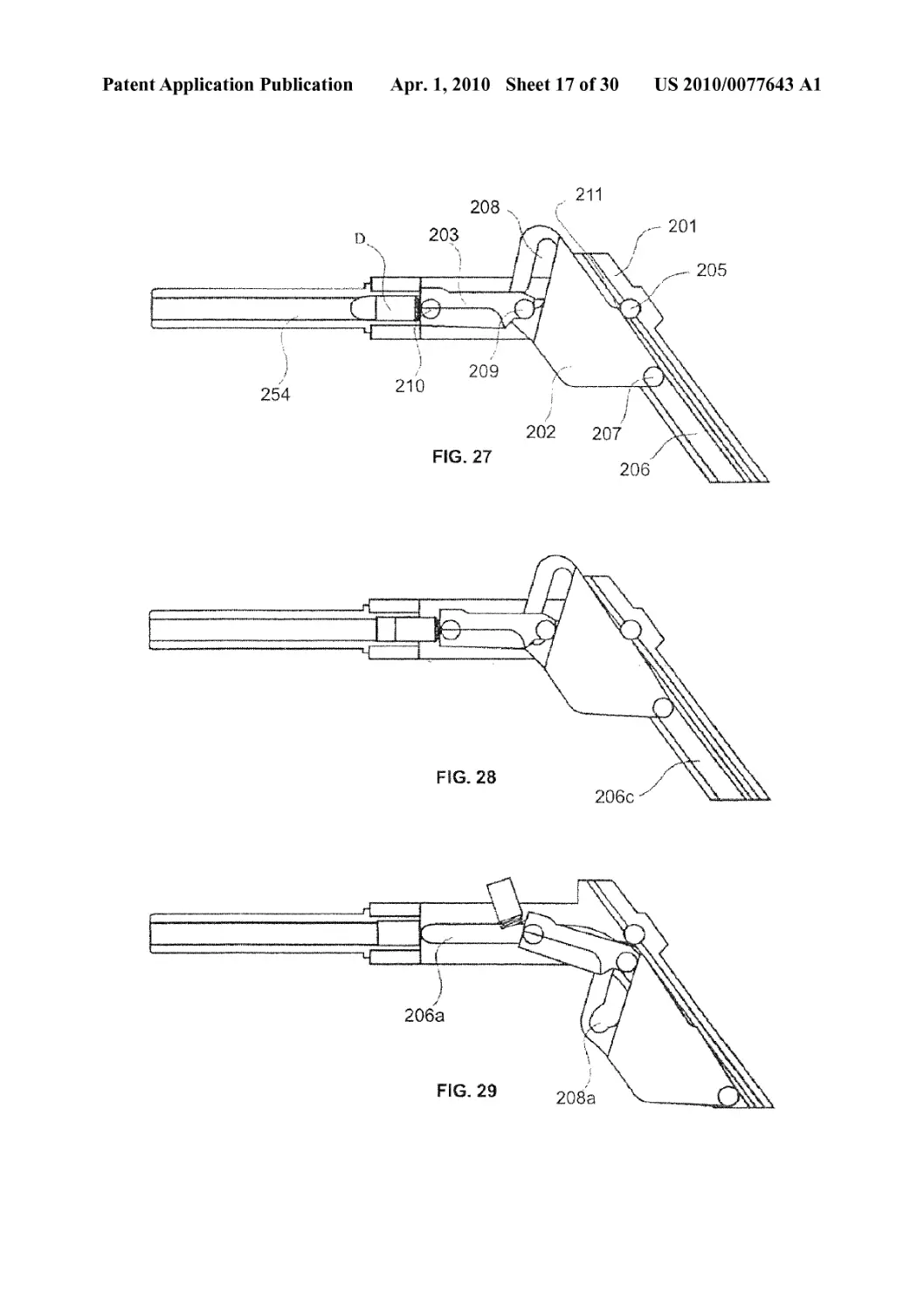
[0050] FIGS. 27-29 schematically show the mechanism of
action of a recoil control device of the invention.
[0051] FIG. 27 shows, in longitudinal cutaway, a device
with a cartridge (D) chambered.
US 2010/0077643 Al
Apr. 1,2010
5
[0052] FIG. 28 shows the embodiment of FIG. 27 at the
moment of firing.
[0053] FIG. 29 shows the embodiment of FIG. 27 at the end
of the movement, the spent cartridge case being ejected. The
slider surface shown here (208a) depicts an additional
embodiment, for example, to allow a phase displacement. As
explained herein, the surface or surfaces of the slider that
contact the bolt or are linked to the movement of the bolt can
be selected from a number of angles, shapes, and combina-
tions of angles and shapes.
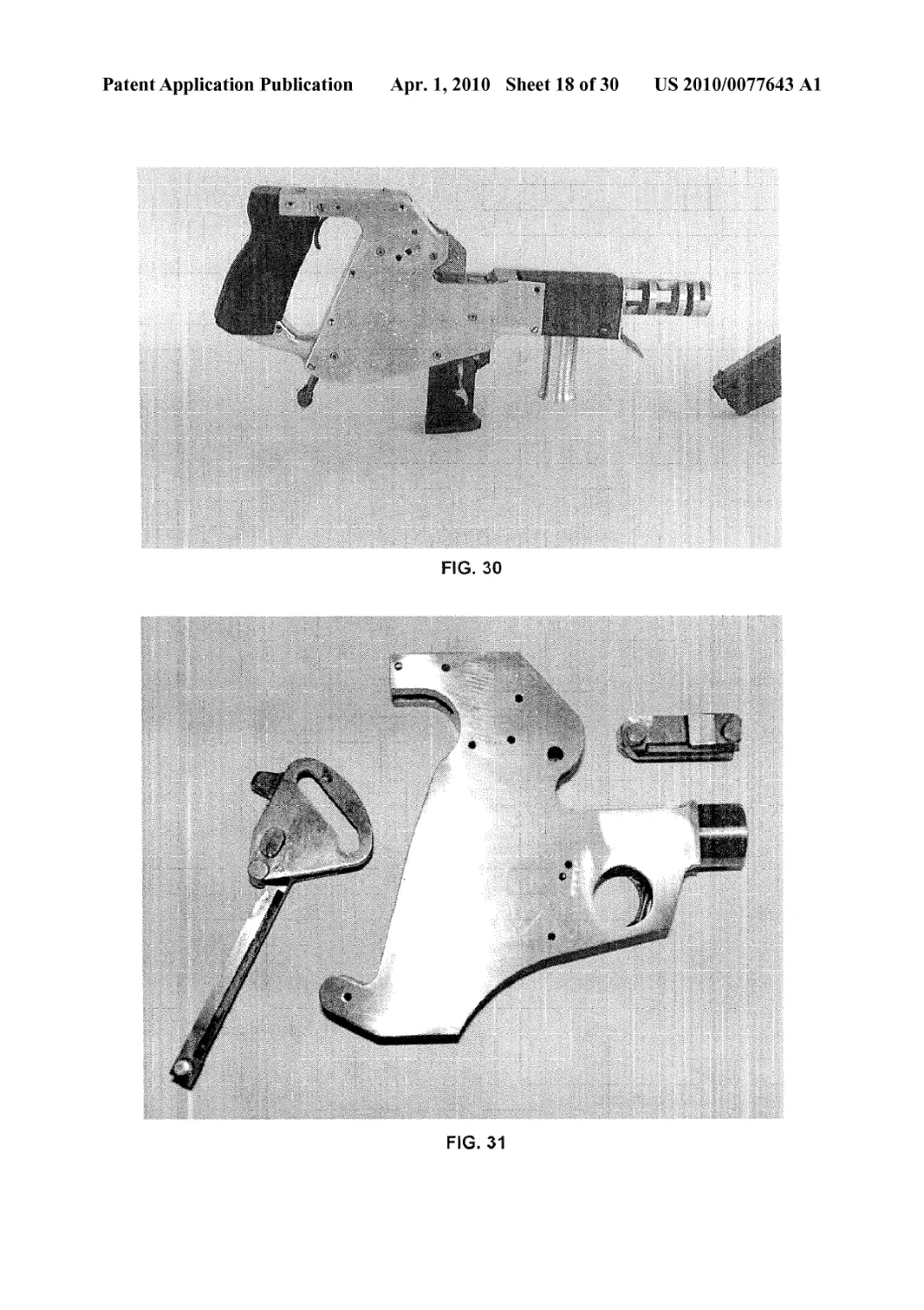
[0054] FIG. 30 is a photograph of an embodiment of the
invention enclosed in a metal case.
[0055] FIG. 31 is a photograph of a preferred embodiment
of the invention comprising a slider with manual cocking
lever (at left), a frame with integral guide or path for slider and
bolt head (center), and bolt head (right). The protruding ten-
ons or elements on slider and bolt head fit within the integral
bolt head receiver element and slider guide element of the
frame (not visible). The slot in slider also shows double-angle
surface of slider that contacts bolt head. Tenon or element at
end of bolt head fits within slot in slider. As noted in the
description, the novel aspects of the invention allow easily
manufactured parts such as these. Furthermore, the large size
and robust character of the moving parts shown here allow for
more reliable use, easier cleaning and maintenance of a fire-
arm.
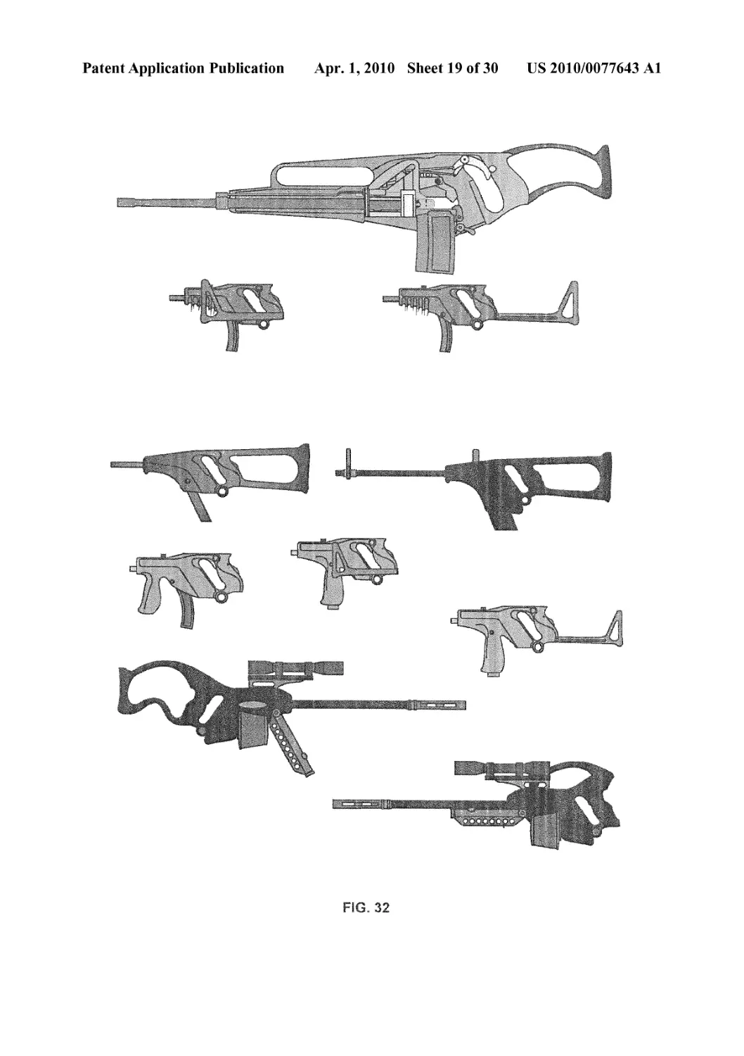
[0056] FIG. 32 shows a number of design alternatives in the
configuration of a small caliber firearm incorporating the
invention. These variations show, inter alia, the options in
placing the handgrip relative to the middle of the axis of the
barrel and the design freedoms allowed by the compact and
reliable operation of a firearm of the invention. In one
embodiment, the inertia block, with slot for connecting to or
linking to the bolt head, is seen above the barrel of the firearm.
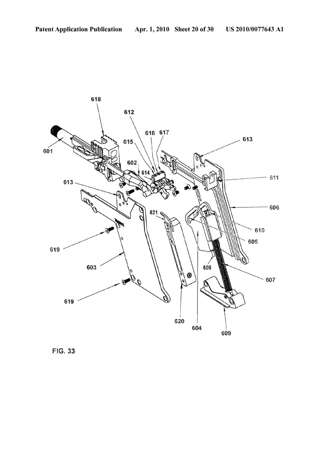
[0057] FIG. 33 shows an exemplary machine pistol or auto-
matic or semi-automatic rifle embodiment incorporating a
single slider with associated parts in an exploded view.
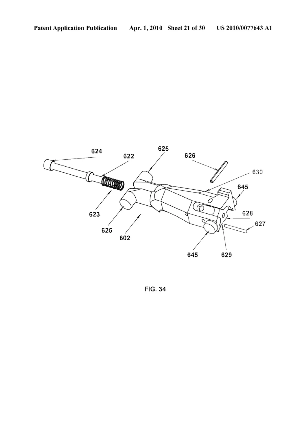
[0058] FIG. 34 depicts a bolt assembly as shown in the
embodiment of FIG. 33, here including several optional ele-
ments.
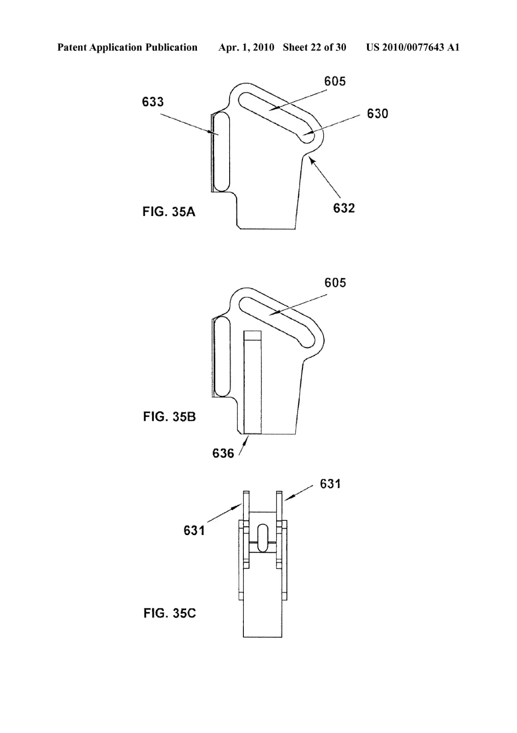
[0059] FIGS. 35A-C show different views of optional slider
designs for use in an embodiment as shown in FIG. 33. In
FIG. 35A, a particular initial angle for contacting the bolt or
connection on bolt and a particular second angle of the slider.
FIG. 35B depicts an optional slider with internal buffer
assembly opening to manage or control response of slider
against base. FIG. 35C depicts a preferred double-slot slider
design, where slots on two extended elements of slider each
connect with bolt or connection on bolt.
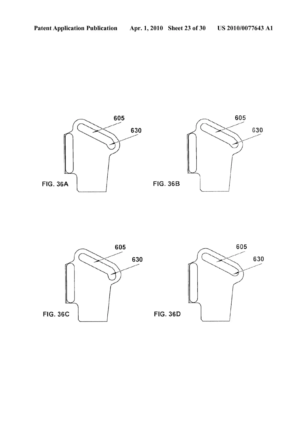
[0060] FIGS. 36A-D show various initial contact angle
designs, varying from an a angle of about 37 degrees (as in
FIG. 35A), to about 43 degrees (FIG. 36A), to about 30
degrees (FIG. 36B), to about 55 degrees (FIG. 36C), and
about 16 degrees (FIG. 36D). These figures show changes
from about ±6 degrees form the initial a angle shown, and
about ±20 degrees. Changes of ±3-25 degrees from the pre-
ferred 36-37 degrees can be made, as well as other changes.
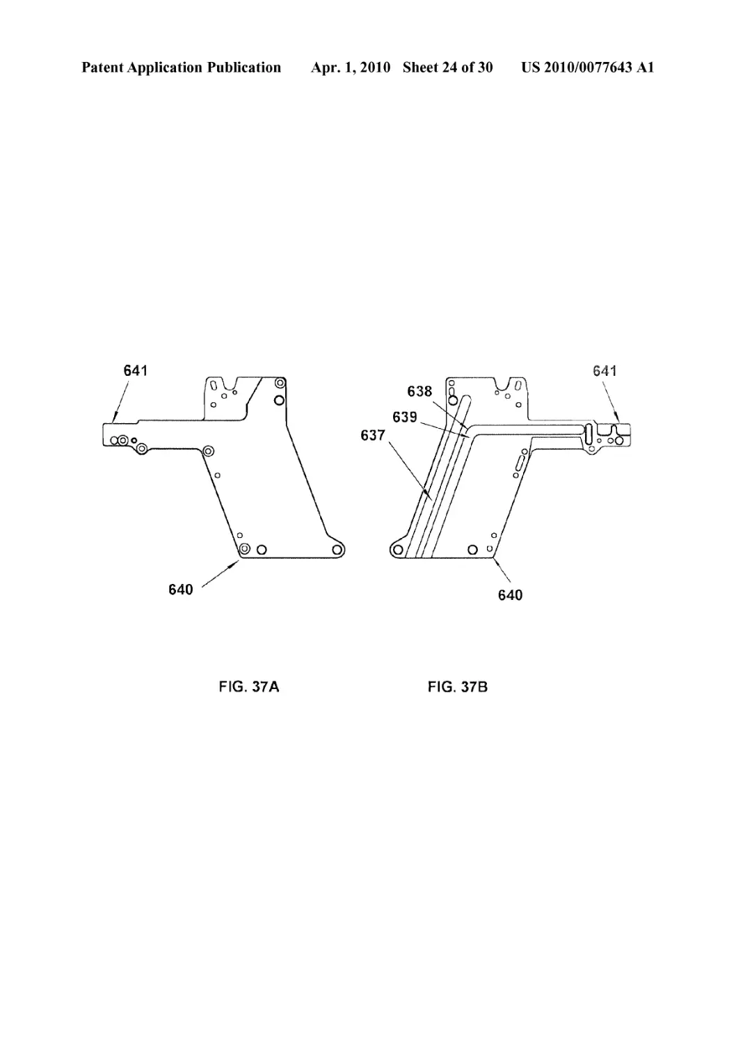
[0061] FIGS. 37 A-В depict two sides of a receiver in an
embodiment where a dedicated slider guide (637) is separate
from the previously shown slider and bolt guide (638).
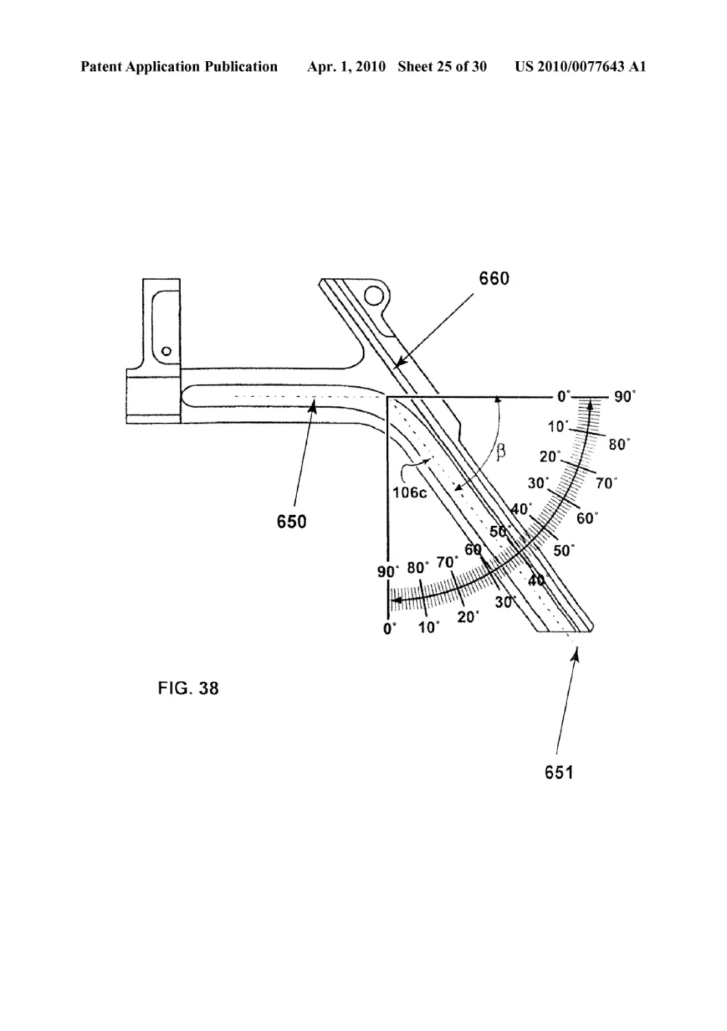
[0062] FIG. 38 depicts the angle |> showing superimposed
degrees.
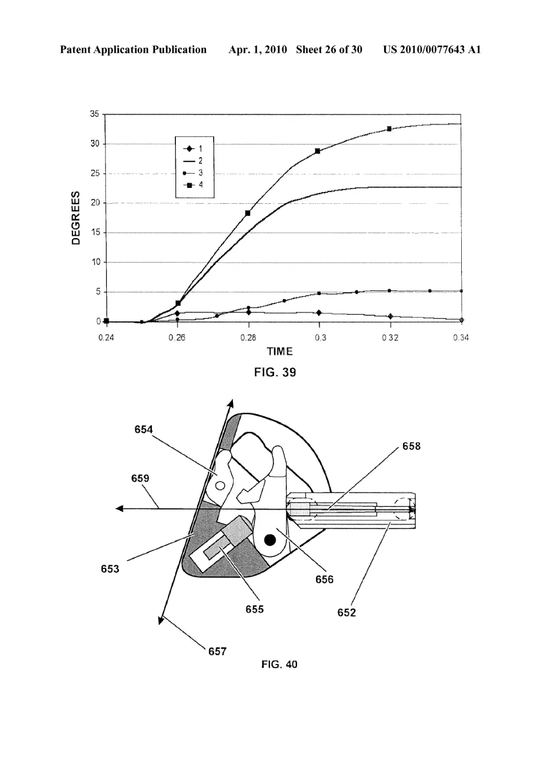
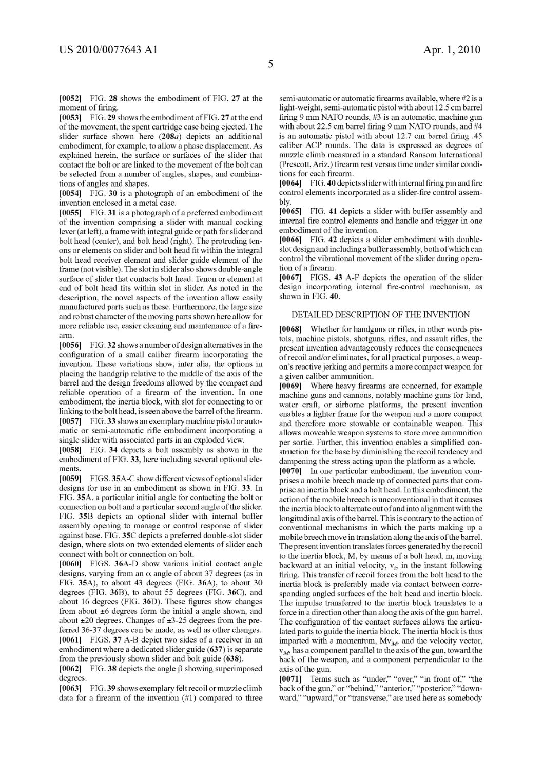
[0063] FIG. 39 shows exemplary felt recoil or muzzle climb
data for a firearm of the invention (#1) compared to three
semi-automatic or automatic firearms available, where #2 is a
light-weight, semi-automatic pistol with about 12.5 cm barrel
firing 9 mm NATO rounds, #3 is an automatic, machine gun
with about 22.5 cm barrel firing 9 mm NATO rounds, and #4
is an automatic pistol with about 12.7 cm barrel firing .45
caliber ACP rounds. The data is expressed as degrees of
muzzle climb measured in a standard Ransom International
(Prescott, Ariz.) firearm rest versus time under similar condi-
tions for each firearm.
[0064] FIG. 40 depicts slider with internal firing pin and fire
control elements incorporated as a slider-fire control assem-
bly.
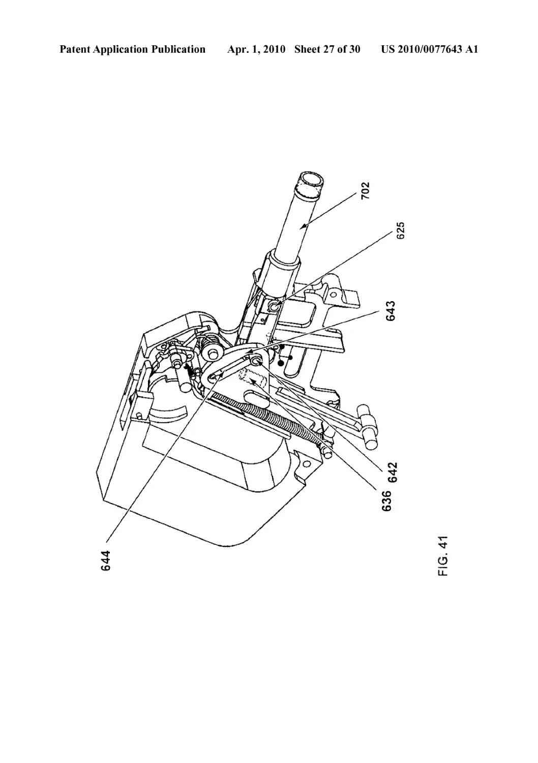
[0065] FIG. 41 depicts a slider with buffer assembly and
internal fire control elements and handle and trigger in one
embodiment of the invention.
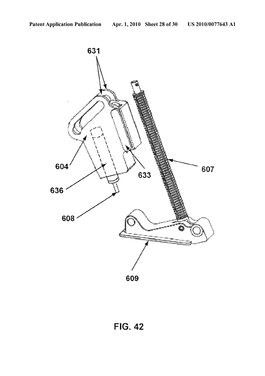
[0066] FIG. 42 depicts a slider embodiment with double-
slot design and including a buffer assembly, both of which can
control the vibrational movement of the slider during opera-
tion of a firearm.
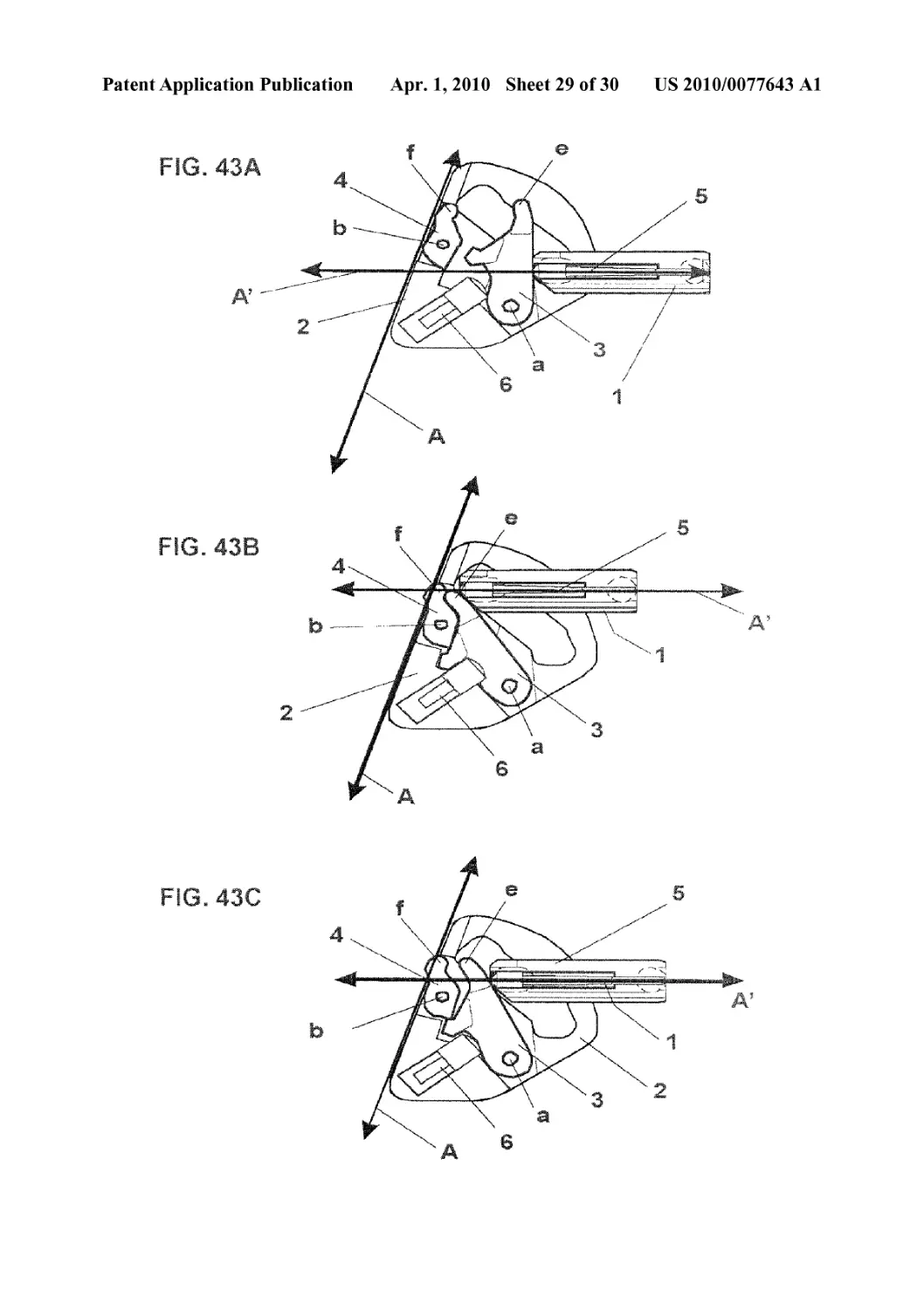
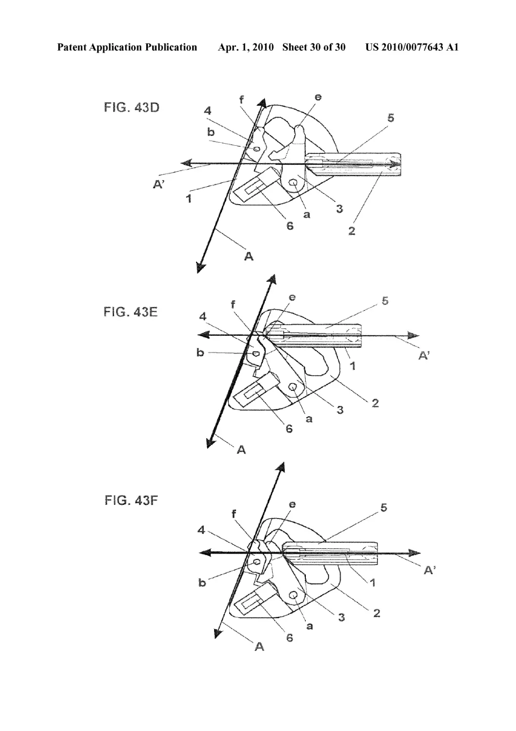
[0067] FIGS. 43 A-F depicts the operation of the slider
design incorporating internal fire-control mechanism, as
shown in FIG. 40.
DETAILED DESCRIPTION OF THE INVENTION
[0068] Whether for handguns or rifles, in other words pis-
tols, machine pistols, shotguns, rifles, and assault rifles, the
present invention advantageously reduces the consequences
of recoil and/or eliminates, for all practical purposes, a weap-
on’s reactive jerking and permits a more compact weapon for
a given caliber ammunition.
[0069] Where heavy firearms are concerned, for example
machine guns and camions, notably machine guns for land,
water craft, or airborne platforms, the present invention
enables a lighter frame for the weapon and a more compact
and therefore more stowable or containable weapon. This
allows moveable weapon systems to store more ammunition
per sortie. Further, this invention enables a simplified con-
struction for the base by diminishing the recoil tendency and
dampening the stress acting upon the platform as a whole.
[0070] In one particular embodiment, the invention com-
prises a mobile breech made up of connected parts that com-
prise an inertia block and a bolt head. In this embodiment, the
action of the mobile breech is unconventional in that it causes
the inertia block to alternate out of and into alignment with the
longitudinal axis of the barrel. This is contrary to the action of
conventional mechanisms in which the parts making up a
mobile breech move in translation along the axis of the barrel.
The present invention translates forces generated by the recoil
to the inertia block, M, by means of a bolt head, m, moving
backward at an initial velocity, v„ in the instant following
firing. This transfer of recoil forces from the bolt head to the
inertia block is preferably made via contact between corre-
sponding angled surfaces of the bolt head and inertia block.
The impulse transferred to the inertia block translates to a
force in a direction other than along the axis of the gun barrel.
The configuration of the contact surfaces allows the articu-
lated parts to guide the inertia block. The inertia block is thus
imparted with a momentum, Mvw. and the velocity vector,
nm, has a component parallel to the axis of the gun, toward the
back of the weapon, and a component perpendicular to the
axis of the gun.
[0071] Terms such as “under,” “over,” “in front of,” “the
back of the gun,” or “behind,” “anterior,” “posterior,” “down-
ward,” “upward,” or “transverse,” are used here as somebody
US 2010/0077643 Al
Apr. 1,2010
6
firing a gun would understand them, which is by reference to
the longitudinal or firing axis of the barrel when the gun is
held in the usual horizontal attitude. Furthermore, “firearm”
as used here encompasses handguns, pistols, heavy caliber
guns, rifles, sniper rifles, guns with automatic and semiauto-
matic action, mountable and portable camions, camions
mounted on aircraft or naval vessels, camions mounted on
armored personnel carriers or other armored vehicles, and
machine guns or camions mounted on armored or non-ar-
mored vehicles or vessels. Also, a force component perpen-
dicular to or lateral to the longitudinal axis of the barrel refers
to a vectorial component or part of a force or momentum
vector directed outside the longitudinal axis of the barrel.
[0072] Inertia block guides can be configured so that the
movement of the inertia block in response to the impulse can
be one of pure translation or more complex in nature. The
inertia block’s movement in turn governs the movement of the
bolt head or vice versa, due to the maimer of their linkage.
[0073] In one aspect, the present invention in particular
allows two parameters to be varied: the ratio between the
mass of the inertia block and the bolt head, and the angle
between movement of the inertia block and the axis of the
gun. As discussed more particularly below, the angles formed
by parts of the mobile breech can be manipulated to optimize
recoil reduction, firing rate, and other operational character-
istics in a variety of firearm styles and sizes. Control or
variance of such factors is not typical of present firearms
technology. The recoil control device notably enables con-
struction of automatic firearms of particular compactness for
their caliber.
[0074] As shown in the some of the embodiments of the
Figures, the trajectory of the inertia block leaves the longitu-
dinal axis of the gun barrel. In one of many optional configu-
rations, part of the space occupied by the inertia block during
its back-and-forth trajectory is located below the gun barrel,
while the rest of the trajectory described by the inertia block
in its alternating action, as well as the corresponding part of
the breech block, is situated above the barrel axis.
[0075] The positioning of the barrel of the weapon relative
to the grip or stock of the weapon can effectively allow one to
manage part of the recoil moment. For example, a conven-
tional handgun grip can be placed behind a breech block of
the present invention. In one embodiment of this invention,
the barrel is not found above the grip, as it is conventionally in
handguns, but in front of it, preferably at mid-height or at
two-thirds the height of the grip. Preferably, the middle of the
gun barrel axis is in line with the middle of the forearm of the
person aiming the gun and not above it, the effect of which is
to eliminate the upward jerking characteristic of the recoil
response of conventional guns. As described in this invention,
the placement of the barrel relative to the height of a grip, if a
handgrip is used, can vary, but it is preferably placed at about
5% to about 95% of the height of the grip, or about 40% to
about 80%, or about 50% to about 70%, or about 60% to about
70%. As statedherein, any particular configuration of the axis
of the barrel relative to the grip or stock can be selected.
[0076] For semiautomatic or automatic handguns and/or
rifles, the present invention preferably uses the handgrip as
part of the housing for the inertia block and return device or
spring, and this arrangement substantially eliminates the
upward jerking of the gun from recoil. However, as shown in
the F igures and described here, embodiments of the invention
encompass heavy and light machine guns and camions as well
as handguns. Thus, handgrips are not required.
[0077] Other characteristics and advantages of the inven-
tion will be apparent to those skilled in the art from the
description of embodiments designed specifically for hand-
guns and of embodiments designed for heavy automatic
weapons and camions.
[0078] The following Examples, and forgoing description,
are intended to show merely optional configurations for the
devices of the invention. Variations, modifications, and addi-
tional attachments can be made by one of skill in the art. Thus,
the scope of the invention is not limited to any specific
Example or any specific embodiment described herein. Fur-
thermore, the claims are not limited to any particular embodi-
ment shown or described here.
Exemplary Small Caliber Firearms, Rifles, and Handguns
[0079] The following discussion addresses optional fea-
tures and design factors one of ordinary skill in the art may
employ in producing a smaller caliber firearm. Nothing in this
discussion should be taken as a limitation to the scope of the
invention and the parameters defined here are merely
examples of the many embodiments possible. While the
optional features and design factors of the smaller caliber
firearm noted here can also be used with heavy caliber fire-
arms, typical firing conditions may make the discussion
below more appropriate for smaller caliber firearms.
[0080] A variety of configurations can be used to produce a
recoil control device in small caliber firearms. As noted
above, the preferred embodiment comprises a bolt head oper-
ably linked to an inertia block so that the bolt head imparts an
impulse to the inertia block upon firing the firearm. In the
small caliber embodiment, the inertia block can be referred to
as a “slider” since it can be designed and produced as a sliding
mechanism that travels in a fixed path. The selection of the
weight, shape, and path of the slider will depend on a number
of design factors, including, but not necessarily limited to: the
desired placement of the barrel relative to the handgrip or
stock, the part of the frame that is stabilized by a person firing
the firearm, or the part of the frame connecting the firearm to
a tripod or other support device; the degree of recoil reduction
or counteracting of the upward jerking recoil forces desired;
the barrel length; the weight of the bolt head; the weight of the
firearm; the presence or absence of a muzzle brake; and, of
course, the ammunition used in the firearm. One of skill in the
art can routinely measure the recoil characteristics of any
selected design in order to modify one or more of the design
factors noted here to achieve a particular result.
[0081] For any particular path for the slider, for example,
the weight can be designed to effectively eliminate the
upward jerking recoil forces. In a simple and preferred
design, a single slider with a slider path is chosen, where the
slider path forms a straight line downward from the barrel at
a certain angle (referred to as (3 in FIG. 20, for example)
relative to the longitudinal axis of the barrel, in preferred
embodiments for a .45 caliber firearm set between the
complement of 30 to 36 degrees, or about 60 to about 54
degrees, with about 54 degrees shown in the superimposed
protractor over the embodiment in FIG. 38. A second angle
(referred to as a in FIG. 19, for example) is formed by the
slider path and the sloped surface of the slider that initially
contacts the backward-moving bolt or linkage to the bolt. This
angle can be varied to select an optimum firing rate of the
firearm. In an embodiment of the Figures, an oblique slot is
designed to accept a transverse spindle or pin that connects
the bolt head to the slider to impulsively transfer the recoil
US 2010/0077643 Al
Apr. 1,2010
7
forces in a direction lateral to the longitudinal axis of the
barrel. The optimum value for this second angle depends
primarily on the caliber of firearm chosen. Angles less than
six degrees result in mechanical limitations to the unassisted
movement of the slider in reaction to the bolt head. Angles
greater than 45 degrees will reduce the effectiveness of the
counteracting forces that control the upward jerking move-
ment, but can be selected nonetheless. An angle ranging from
about 36 to about 37 degrees allows a firing rate of approxi-
mately 900 rounds per minute with .45 caliber ammunition.
Preferred ranges of this angle can be selected from about 20
degrees to about 45 degrees. As noted herein, the slider can
comprise a double-angle configuration, so that an initial
angled surface contacts the bolt or linkage to the bolt, while a
second angled surface contacts the bolt or bolt linkage for a
majority of the contact area. It is the angle of the initial angled
or sloped surface that is used to calculate the angle a (alpha)
in the invention. Generally, one will select a higher angle (i.e.
an angle closer to a perpendicular line from the gun barrel) of
this initial angle of the slider with a high energy round. Some
rounds, for example 9 mm rounds, may not use a double-
angle configuration in the slider or may use an initial angle
that is parallel or close to parallel to the gun barrel in order to
generate more speed to transfer recoil energy from the bolt to
the slider. The shape of the surface or surfaces of the slider can
also vary, so that rounded areas, angled surfaces, or combi-
nations of the two, for example, can be selected. Thus,
depending on desired product features, a straight slider path
and an unassisted slider movement, a preferred angle can be
selected from an angle greater than 6 degrees to an angle of
less than about 40 or about 45 degrees. As described below, a
double-angled slider with two slopes in the slot of the slider
alternatively can be used to allow the designer to vary the rate
of fire and to reduce the mass of the slider for a given caliber
ammunition. Also, a decreased weight of the bolt can increase
firing rate.
[0082] Preferably, the slider path is concealed within the
body of the firearm in a part or mechanism that can be referred
to as a “guide,” “receiver,” or “path.” Whether or not con-
cealed, the guide can be designed so that the slider can be fit
into the slider path and linked to the bolt head by hand, to
facilitate cleaning and maintenance of the firearm. While not
required, a linking part can be used to translate the impulse
from the percussion of a chambered round from the bolt head
to the slider. A simple pin and/or rod can be used, for example.
Preferably, some play in the movement of the slider can be
designed in either the selection of the linking part or its
connection to the slider or the bolt head. This play can facili-
tate the rapid removal of spent rounds and/or loading of new
rounds. The recoil spring can also be selected for a particular
slider weight and rate of fire characteristics desired. One of
skill in the art can determine the type of spring configuration
or slider return device for a particular embodiment.
[0083] Of course, a firearm incorporating or using the
devices or methods of the invention can also be combined
with any known firearm modification or control devices or
systems available. For example, a counterpoise system can be
used, a muzzle brake, recoil pads, and gas injection systems
can be incorporated into a design, either individually or in any
combination. In comparison to alternative or previous recoil
control devices, such as the counterpoise or any of a number
of spring systems on handguns and rifles, the recoil control
mechanism of this invention provide vastly improved char-
acteristics. A direct comparison of the upward movement of
the end of the gun barrel after firing a high powered .45 caliber
round shows that the firearm incorporating the invention
results in very little or no measurable upward movement. This
result is also demonstrated by the pattern of rounds into a
target in automatic firing, where there is no upward drift when
the mechanisms or methods of the invention are used. A
conventional firearm displays marked and measurable
upward movement of the barrel on firing. Existing recoil
control devices can perhaps reduce recoil to a level equivalent
to a muzzle brake. The improvement afforded by the devices
and methods of the invention are significantly greater. For
example, about a 50% reduction in recoil as measured by
upward movement of the barrel, or about 50-60% reduction,
or about 60-70% reduction, or about 70-80% reduction, or
about 80-90% reduction, and even, depending on the design,
a 90-100% reduction in upward movement upon firing.
Exemplary Embodiments in the Figures
[0084] Having generally described the invention above and
the design factors one can consider, what follows refers to
specific embodiments of the Figures and Examples. As noted
previously, the invention is not limited by the scope of the
embodiments listed, the Figures, or the Examples. Rather,
one of skill in the art can employ the principles and examples
to design, make, and use a number of embodiments not spe-
cifically shown here that are fully within the scope of the
present invention.
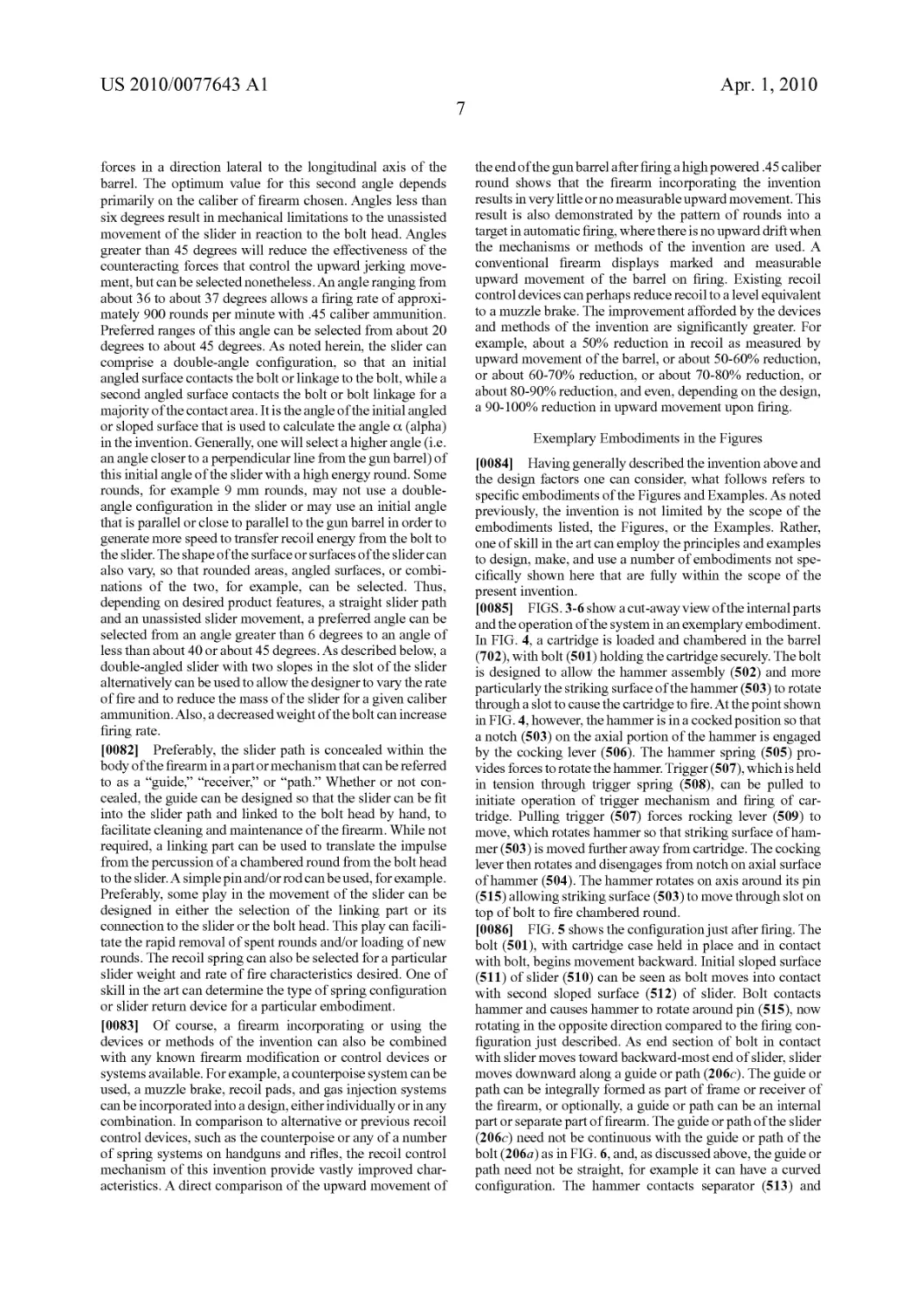
[0085] FIGS. 3-6 show a cut-away view of the internal parts
and the operation of the system in an exemplary embodiment.
In FIG. 4, a cartridge is loaded and chambered in the barrel
(702), with bolt (501) holding the cartridge securely. The bolt
is designed to allow the hammer assembly (502) and more
particularly the striking surface of the hammer (503) to rotate
through a slot to cause the cartridge to fire. At the point shown
in FIG. 4, however, the hammer is in a cocked position so that
a notch (503) on the axial portion of the hammer is engaged
by the cocking lever (506). The hammer spring (505) pro-
vides forces to rotate the hammer. Trigger (507), which is held
in tension through trigger spring (508), can be pulled to
initiate operation of trigger mechanism and firing of car-
tridge. Pulling trigger (507) forces rocking lever (509) to
move, which rotates hammer so that striking surface of ham-
mer (503) is moved further away from cartridge. The cocking
lever then rotates and disengages from notch on axial surface
of hammer (504). The hammer rotates on axis around its pin
(515) allowing striking surface (503) to move through slot on
top of bolt to fire chambered round.
[0086] FIG. 5 shows the configuration just after firing. The
bolt (501), with cartridge case held in place and in contact
with bolt, begins movement backward. Initial sloped surface
(511) of slider (510) can be seen as bolt moves into contact
with second sloped surface (512) of slider. Bolt contacts
hammer and causes hammer to rotate around pin (515), now
rotating in the opposite direction compared to the firing con-
figuration just described. As end section of bolt in contact
with slider moves toward backward-most end of slider, slider
moves downward along a guide or path (206c). The guide or
path can be integrally formed as part of frame or receiver of
the firearm, or optionally, a guide or path can be an internal
part or separate part of firearm. The guide or path of the slider
(206c) need not be continuous with the guide or path of the
bolt (206a) as in FIG. 6, and, as discussed above, the guide or
path need not be straight, for example it can have a curved
configuration. The hammer contacts separator (513) and
US 2010/0077643 Al
Apr. 1,2010
8
separator rotates to engaged position on a second notch (514)
on axial surface of hammer. If the trigger remains in pulled
position, cocking lever (506) remains up so that it does not
engage notch (504). The bolt tilts as it moves back (FIG. 6) so
that ejector (516) and extractor (522) displace cartridge case
from bolt and the projections on bolt (519). Slider moves
downward to redirect recoil forces and counteract upward
jerk of barrel. FIG. 6 shows bolt and slider at end of move-
ment (518). Bolt and slider can be formed with one or more
projections or tenons that are designed to move along or in
paths defining a range of motion, as shown in slider or inertia
block guide (206c) in FIG. 4 and bolt or bolt head guide or
path (206a) in FIG. 6. The projections, tenons, or other fea-
ture designed to move in a guide or path can also be connected
via a linkage between the bolt and slider, so that the part that
interacts with slider is connected to the bolt rather than being
directly formed onto or an aspect of the bolt. A recoil spring
or return device, not shown, forces slider up guide or path.
Slider, in connection with bolt, pushes bolt upward and for-
ward to engage next round from magazine. Bolt with engaged
cartridge moves into chambered position for firing. Slider
surface (512) contacts separator (513) to disengage separator
from second notch (514) on axial part of hammer assembly,
freeing hammer to again rotate on axis around its pin (515),
allowing striking surface (503) to move through slot on top of
bolt to fire chambered round.
[0087] The operation just described is for automatic action.
Semi-automatic, burst firing, and single round action can also
be designed using available devices and technology. For
semi-automatic action, a second cocking lever, with cocking
lever spring, can engage a separate or existing notch on axial
surface of hammer to catch hammer before it rotates down to
fire cartridge. Thus, after each cycle of the slider and bolt, the
second cocking lever for semi-automatic will prevent auto-
matic firing and allow only one round to fire per trigger pull.
One of skill in the art can adapt the cocking lever or add an
additional cocking lever so that it engages a notch on the axial
surface of the hammer after each time the hammer moves
backward after firing. The cocking lever used for the semi-
automatic action can be connected to a switch on the frame or
a switch extending through the frame so that the operator can
select between semi-automatic or automatic action. The
switch effectively places the appropriate cocking lever in
connective position with the notch on the hammer, or allows
repeated firing through the movement of the separator. A burst
firing mechanism can also be adapted, as known in the art, so
that a certain number of rounds are fired automatically.
[0088] Additional safety options can also be implemented,
as known in the art. For example, the handgrip and trigger, or
handgrip and part of the trigger mechanism, can be designed
to separate from the frame in order to prevent firing of the
firearm. The handgrip and trigger components can further be
equipped with personal security devices so that only desig-
nated users can assemble or operate the firearm.
[0089] FIG. 3 shows a cutaway view of the same embodi-
ment of FIGS. 4-6, except that an optional manual cocking
lever (520) extends through the bottom of the frame. In the
position shown in FIG. 3, the separator (513) is engaged in the
second notch on axial surface of hammer (512), and the slider
(510) is in position to contact separator from below to disen-
gage it from notch (514) and release hammer (502) so that
striking surface of hammer can fire cartridge. At top of hand-
grip (523) optional pins for connecting and quickly removing
handgrip and part of trigger mechanism can be seen. Here,
slider is linked to bolt (501) through pin (not shown) extend-
ing through slot (517) in slider.
[0090] FIGS. 1-2 show schematically a double-angled
slider (510) and its movement in a guide or path (206) of a
receiver. Bolt or bolt head (501) is linked to slider via tenon on
bolt and slot in slider as shown in FIGS. 3-6, and initial
surface of slider (511) and second sloped surface of slider
(512) are visible. In FIG. 2, the spent cartridge case is being
ejected from bolt head.
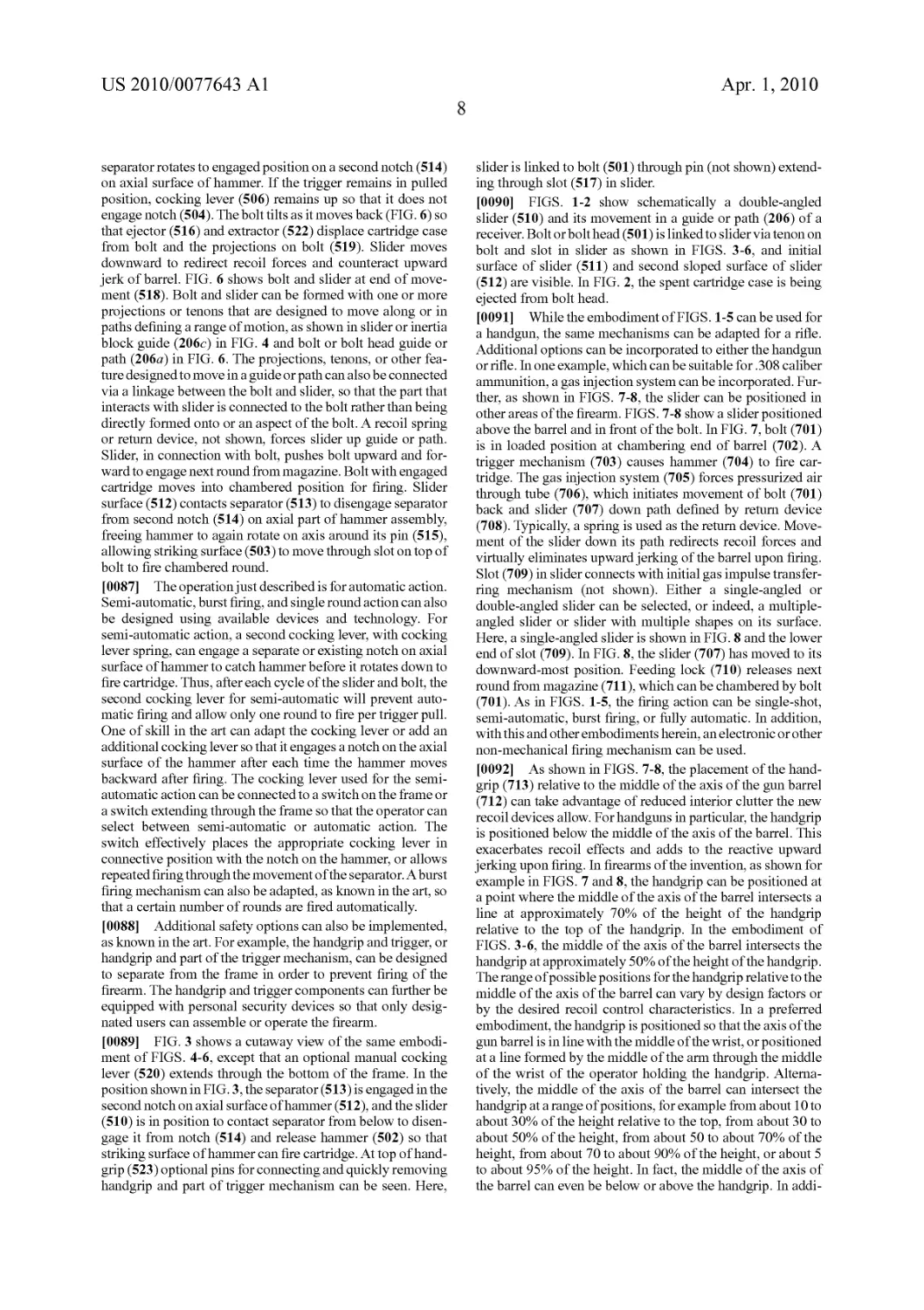
[0091] While the embodiment of FIGS. 1-5 can be used for
a handgun, the same mechanisms can be adapted for a rifle.
Additional options can be incorporated to either the handgun
or rifle. In one example, which can be suitable for .308 caliber
ammunition, a gas injection system can be incorporated. Fur-
ther, as shown in FIGS. 7-8, the slider can be positioned in
other areas of the firearm. FIGS. 7-8 show a slider positioned
above the barrel and in front of the bolt. In FIG. 7, bolt (701)
is in loaded position at chambering end of barrel (702). A
trigger mechanism (703) causes hammer (704) to fire car-
tridge. The gas injection system (705) forces pressurized air
through tube (706), which initiates movement of bolt (701)
back and slider (707) down path defined by return device
(708). Typically, a spring is used as the return device. Move-
ment of the slider down its path redirects recoil forces and
virtually eliminates upward jerking of the barrel upon firing.
Slot (709) in slider connects with initial gas impulse transfer-
ring mechanism (not shown). Either a single-angled or
double-angled slider can be selected, or indeed, a multiple-
angled slider or slider with multiple shapes on its surface.
Here, a single-angled slider is shown in FIG. 8 and the lower
end of slot (709). In FIG. 8, the slider (707) has moved to its
downward-most position. Feeding lock (710) releases next
round from magazine (711), which can be chambered by bolt
(701). As in FIGS. 1-5, the firing action can be single-shot,
semi-automatic, burst firing, or fully automatic. In addition,
with this and other embodiments herein, an electronic or other
non-mechanical firing mechanism can be used.
[0092] As shown in FIGS. 7-8, the placement of the hand-
grip (713) relative to the middle of the axis of the gun barrel
(712) can take advantage of reduced interior clutter the new
recoil devices allow. For handguns in particular, the handgrip
is positioned below the middle of the axis of the barrel. This
exacerbates recoil effects and adds to the reactive upward
jerking upon firing. In firearms of the invention, as shown for
example in FIGS. 7 and 8, the handgrip can be positioned at
a point where the middle of the axis of the barrel intersects a
line at approximately 70% of the height of the handgrip
relative to the top of the handgrip. In the embodiment of
FIGS. 3-6, the middle of the axis of the barrel intersects the
handgrip at approximately 50% of the height of the handgrip.
The range of possible positions for the handgrip relative to the
middle of the axis of the barrel can vary by design factors or
by the desired recoil control characteristics. In a preferred
embodiment, the handgrip is positioned so that the axis of the
gun barrel is in line with the middle of the wrist, or positioned
at a line formed by the middle of the arm through the middle
of the wrist of the operator holding the handgrip. Alterna-
tively, the middle of the axis of the barrel can intersect the
handgrip at a range of positions, for example from about 10 to
about 30% of the height relative to the top, from about 30 to
about 50% of the height, from about 50 to about 70% of the
height, from about 70 to about 90% of the height, or about 5
to about 95% of the height. In fact, the middle of the axis of
the barrel can even be below or above the handgrip. In addi-
US 2010/0077643 Al
Apr. 1,2010
9
tion, other parts of the frame can be modified to allow both
hands to grip the firearm. FIG. 32 shows a number of
examples.
[0093] FIG. 1 is a schematic of the mobile breech and the
reciprocating operation of a preferred double-angled slider
embodiment of the recoil control device according to the
invention. In FIG. 2 the slider is at the lowest end of its cycle
and the bolt head is at the back-most end of its cycle. FIG. 1
shows the same slider embodiment at its closed position,
where the slider is at it upper end of its cycle and the bolt head
is furthest forward.
[0094] In FIGS .1-29, the mobile breech comprises a bolt or
bolt head and an inertia block or slider. As noted above, in a
handgun, firearm, or other embodiment of the invention, the
inertia block can be referred to as a sliding mechanism or a
“slider” and these terms are used interchangeably. The slider
can take various forms, for example a trapezoid, but many
other forms and shapes are possible. The slider is articulated
with the bolt head close to its rear extremity, optionally by a
transverse spindle, which can take the form of a machined
tenon or pin on the bolt head projecting on either side. The
bolt head can have a second tenon or pin, also projecting on
both sides, in its foremost section that engages a guidance
ramp to guide the cyclic path of bolt head. In this preferred
embodiment, the performance of a semi-automatic or auto-
matic firearm can be improved by using a double-angled
slider, characterized by an oblique slot (517 in FIG. 3), com-
prising two sloped surfaces (511 and 512 of FIG. 6 or FIG. 2).
The length of each sloped surface can vary. The forward-most
sloped surface engages the bolt head or bolt head articulation
mechanism when the round is chambered and/or when the
bolt head is locked, so that the bolt head is prevented from
moving backward (the configuration of FIGS. 1 and 4, for
example). While not required, the double-angled slider can
perform more reliably in preventing the bolt head from mov-
ing than a slider having a single sloped surface. Also shown in
FIGS. 3-8 is a trigger mechanism in operating linkage to the
hammer, which strikes the cartridge on the bolt or the car-
tridge contacting the bolt. Conventional mechanisms can be
adapted for use with the invention or in designing a firearm.
[0095] As shown in the figures, it is preferred to use large
parts and integrated pins and receiving slots so that assembly,
cleaning, and maintenance characteristics are improved.
However, other operating or triggering mechanisms can be
used with a firearm of the invention. One of ordinary skill in
the art is familiar with the selection and use of a variety of
triggering mechanisms for a variety of ammunition sizes and
types, including those that can accommodate multiple sizes of
ammunition.
[0096] The action of the mobile breech and bolt head can be
controlled within its movement to appropriately chamber and
eject successive rounds. As shown in the FIGS. 4-6 and 11-18,
for example, the bolt head tilts relative to the barrel. At a point
near or at the end of its backward and downward movement,
the spent round is ejected using conventional ejector and
extractor devices. As the magazine pushes the next round
toward the barrel, here the magazine pushes upward but other
directions can be selected depending on the placement of the
magazine with respect to the barrel, the forward moving bolt
head catches the end of the cartridge and inserts the round into
the chamber.
[0097] In FIGS. 7-8, a configuration designed preferably
for a .308 caliber or 7.62 NATO round is shown. The slider
(707) here is positioned above and forward of the bolt head
(701), and the cycle action takes the slider through a down-
ward and upward trajectory. The slider and bolt head articu-
lating mechanisms are located above the bolt head to con-
serve space for a magazine below the barrel. However,
optional design configurations can also include slider and bolt
head articulating mechanisms below the bolt head, to allow
for magazines on the top of the barrel or above or to the side
of the barrel. In the embodiment of FIGS. 7-8, a safety clip or
feeding lock (710) is optionally included to prevent loading or
firing of rounds at other than the desired time. The safety clip
(710) moves inresponse to the cartridge and clips the top edge
of each cartridge. These Figures also show a triggering
mechanism. As before, the layout and design of the triggering
mechanism can be selected from many available options and
one of ordinary skill can devise an appropriate or preferred
triggering mechanism. FIG. 7 shows the round chambered
and locked, with the slider (707) at its utmost position. After
firing, the slider moves to its fully displaced position (FIG. 8),
partially or largely below the barrel. The slot (709) for con-
necting the slider to the bolt head can be seen in both Figures.
In FIG. 8, the optional double-angled surface of the slider is
visible.
[0098] In a preferred embodiment, the performance of a
semi-automatic or automatic firearm can be improved by
using a double-angled slider. As shown in FIGS. 3-6, the rear
edge of slider (510) has a pair of lateral flanges extending
from either side of the slider and positioned to slide in the
guidance grooves of the guide or receiver. The guidance
grooves have a slope relative to the axis of the barrel, which
presents an angle (P), shown in FIG. 20, and preferably set
between 30 and 36. In FIG. 19, the slope of the parts shown
presents an angle (a), the variance of which changes the firing
rate of the firearm. The angle (a) preferably is between 24 and
36 degrees. For a .45 caliber embodiment, an angle (a) of
about 36 to about 37 degrees allows a firing rate of approxi-
mately 900 rounds per minute. An angle (a) of approximately
32.5 degrees can correspond to a firing rate of approximately
2000 rounds per minute. There is a practical minimum value
for angle (a) below which mechanical blockage occurs and
little or no articulation is possible. This minimum angle is a
function of the power of the ammunition used, and is approxi-
mately 6 degrees for the standard .45 AGP ammunition of the
Examples below. The use of two slopes in the slot or surface
of the slider allows the designer to vary the rate of fire, to
reduce or alter the mass of the slider, or reduce or alter the
mass of the bolt for a given caliber ammunition.
[0099] An additional preferred embodiment is depicted in
FIG. 33, where a slider (604) has two slots (605) with angled
surface to fit and contact the tenons on either side of bolt
(602). Reference to the axis created by barrel (601) can be
made and trunnion (618). The receiver (603) with its attach-
ments (619) hold two sides of the complete receiver assembly,
and spacer (611) acting as trigger bar support for trigger (not
shown) and protruding element (614) on spring block assem-
bly (612) fitting into slots (613) in receiver as additional
spacer elements. Spring block assembly (612) contains
springs (615, 616, 617) that control fire control assembly and
different springs are actuated for single fire, burst fire, and
fully automatic fire, for example. Additional spacing element
(620) contains optional ejector (621) for blocking cartridge
and ejecting as bolt moves backward during cycle. Slider path
in region (606) of receiver allows downward progress of bolt
on its back-and-down movement and downward path of
slider. Slider is fitted with buffer and pin or plunger element
US 2010/0077643 Al
Apr. 1,2010
10
(608) visible at lower slider surface, and plunger (608) con-
tacts base assembly (609) at end of path. Spring (607) and
spring tensioner (605) control rate of return of slider upwards
in its path or guide. A close-up of additional or optional
elements in the bolt (602) can be seen in FIG. 34, where firing
pin (622) fits within bolt with spring (623) controlling return
force. Opposite end of firing pin (624) is actuated by fire
control assembly. The tenons (625) on end of bolt farthest
from cartridge placement surface (628) fit into the slider slots
as in FIG. 33 are depicted here. Additional tenons (645) at
opposite end of bolt (602) fit into guide in receiver for back-
ward-backward movement of bolt during firing, whereas ten-
ons (625) can traverse down the angled bolt path as shown on
receiver in FIG. 33, or at least partially down the path. The
retention pin (630) for the firing pin holds elements (not
shown) of firing pin within bolt region (630) for firing pin
(622) and its assembly with bolt. Surface of bolt (628) that
contacts cartridge can have one or more hole (629) for case
retainer pins (627) to aid in removal of cartridge case during
cycling.
[0100] FIGS. 35 A-C show additional elements that can be
manipulated or added to the slider.
[0101] In FIG. 35A, the angle a as depicted in FIG. 19 is
about 35-37 degrees at the initial contact point where the
tenon of bolt contacts slider surface (630). The slot (605) of
slider includes a double-angle design, where initial angle
differs from angle at longer contact surface of slider. Optional
extended protruding lug (633) can be used to run in a separate
path or guide (637 as shown in FIG. 37B) in receiver to further
stabilize movement of slider down its slider path, and/or
reduce vibrations during the firing cycle and movement of
slider. FIG. 35B depicts an optional buffer insertion slot
(636), where buffer assembly can be inserted. The buffer
assembly can contain piston and disc plate that interacts with
fluid within buffer assembly body to cushion or create damp-
ing effect when piston interacts with base plate (609) at the
end of slider path (see FIG. 33). The viscosity of fluid and
design of buffer assembly can be varied to creating variations
in the damping effect. The benefits of the buffer assembly can
include smooth cycle of slider return and interaction with
base plate, reduction in peak impulse against base plate, and
reduction in rate of fire. Another view of slider in FIG. 35C
depicts the double-slot design, where protruding areas of
slider (631) each contain double-angle slot as shown in FIG.
33.
[0102] FIG. 36 depicts the variations in the initial angle of
contact (630) in the slot (605) where teneon of bolt contacts
surface of slider. The angle of FIG. 35A can be varied increas-
ing 6 degrees as shown in FIG. 36A, decreasing 6 degrees
(FIG. 36B), increasing 20 degrees (FIG. 36C), anddecreasing
20 degrees (FIG. 36D). Each of these modifications with all
other elements remaining equal has an effect on the rat of fire
for a particular firearm, and one of skill in the art can select
any angle within the ranges shown here, and indeed other
angles, to produce a firearm with a desired rate of fire and
desired reduction in recoil-induced muzzle climb.
[0103] FIGS. 37A-B depict a dual slider path-containing
receiver from each side. In FIG. 37B, each of slider paths can
be seen, where path (637) interacts with extended lug (633) as
shown on slider of FIG. 35A, and tenon of bolt within slider
slot fits within path (639). As noted, the use or two paths or
races can stabilize the movement of parts during the firing
cycle. Curve (638) in path (639) be as shown here, with single
angled area, or more gradual sloping or multiple angle paths
can be selected. As noted, a curved slider path along its entire
length can be used also. Point (640) on receivers is optional
connection region for spacer holding the two halves of the
receiver at proper alignment and spacing. Area (641) is direc-
tion of barrel (not shown). FIG. 38 superimposes a protractor
over one exemplary slider guide or path design and the angle
formed between the axis of barrel (650) and the axis of slider
path (651) in a slider path that is relatively straight over
substantial part of its length. Path (660) here can be separate
guide for lug or tenon on slider.
[0104] FIG. 39 show the results of exemplary muzzle climb
tests comparing a firearm incorporating the recoil control
elements of the invention into a machine piston firing .45
caliber ACP rounds. As noted above the results labeled #1 are
those of the device or firearm of the invention. Results #2 are
from a light-weight, semi-automatic pistol with about 12.5
cm barrel firing 9 mm NATO rounds, results #3 is an auto-
matic, machine gun with about 22.5 cm barrel firing 9 mm
NATO rounds, and results #4 is an automatic pistol with about
12.7 cm barrel firing .45 caliber ACP rounds. The data is
expressed as the average of degrees of muzzle climb mea-
sured in a standard Ransom International (Prescott, Ariz.)
firearm rest versus time under similar conditions for each
firearm. The time values at lower axis are all relative to a firing
point at about 0.25 time value. As is evidence from these
results, none of the similar firearms controls the muzzle climb
to the degree possible with the invention, and the reductions
have obvious importance to the aim and use of a firearm.
[0105] FIG. 40 depicts an optional modification to the
slider design where additional functional elements of the
firearm can be positioned within the slider area. In this
instance, a fire control assembly rests inside the slider. FIG.
40 depicts an integrated firing mechanism that is housed, or
partially housed, within the slider. Firing pin (658) in the
interior of the bolt (652) can be struck by the hammer (656)
which moves in response to the hammer pusher (655) con-
tained within the body of the slider itself (653). As the slider
moves along its path of axis (657), the pusher (655) contacts
and moves sear (654) and then pushes the hammer (656)
against the firing pin (658) at the end of the bolt axis of
movement (659), and the translated energy from the bolt after
percussion moves the slider down its axis of movement (657).
The axis of the barrel is labeled (659) and is along the axis of
the bolt shown here. This optional embodiment of the slider is
depicted in exemplary operation in FIGS. 43A-F. FIG. 43A
shows the slider (2) and the bolt (1) in closed position and the
hammer (3) released. These principal parts (bolt-1 and slider-
2) are respectively displaced or move along axes A and A. In
arming the mechanism to accomplishpercussion or firing, the
slider (2) is drawn downward along axis A. With this move-
ment the slider pulls the bolt (1) to the rear along axis A. With
the same movement, the hammer (3) is progressively pushed
back as it rotates on its axis point (a). In FIG. 43B, the hammer
(3) is shown to simultaneously compresses its spring by
means of a release pusher (6). At the end of displacement the
two principal parts (1) and (2) along axes A and A, as in FIG.
43C, the hammer (3) pushes back the sear (4) through the use
ofits extremity surfaces, as in FIG. 43D. The sear (4), rotating
on its axis point (b), engages its extremity surface (!) in the
notch (g) of the hammer (3), whose movement is arrested by
pressure of the bolt (1) in FIG. 43E. During the opposite
movement of the principal parts, and along the same axes A
and A’, the slider (2) pushes back the bolt (1), the hammer (3),
impelled by the pusher piston release (6) tends to follow the
US 2010/0077643 Al
Apr. 1,2010
11
course of the bolt until its notch (e) is engaged by the extrem-
ity surface (f) of the sear (4) in FIG. 43F. At the end of this
movement, moving parts (1) and (2) regain their starting
position corresponding to firing mode or loaded chamber, the
gun having been loaded in a complementary movement not
shown. Percussion is then effected by the following means:
The sear (4) activated by whatever the firing mechanism,
rotates on its axis (b), thereby disengaging its extremity sur-
face (f) from the notch (e) of the hammer (3). Through the
force of its pusher piston release the hammer is abruptly
liberated and, rotating on its axis (a), strikes the firing pin (5)
internal to the bolt (1).
[0106] FIG. 41 depicts a double-angle slider (643) and
buffer assembly (636) associated with typical firearm com-
ponents for fire control, trigger, and handgrip as discussed
above. Slot (644) in slider contains initial contact surface
where tenon (642) of bolt first contacts as bolts begins back-
ward movement after percussion. A second tenon (625) or
projections on bolt towards the cartridge face of the bolt is
also shown, corresponding to the arrangement of tenons or
projections designed to interact with the slider slots as shown
in FIG. 34. The number and placement of the tenons or
projections on the bolt is optional. The number and design
shown in FIG. 34 is preferred. The position of the barrel (702)
in FIG. 41 relative to the handgrip is also optional, and the
barrel can even be placed above the handgrip as in conven-
tional pistols produced over the past several decades.
[0107] Referring again back to FIG. 9, which shows the
mobile breech and consists of bolt head (103), pin rod (104)
and inertia block (102). The pin rod (104) preferably is joined
to the bolt head (103) close to its rear extremity by means of
a transverse spindle (108) projecting on both sides of bolt
head (103). The front of the bolt head preferably has a trans-
verse stud or linking-pin (113) also projecting on both sides of
bolt head (103). The pin rod (104) preferably is articulated in
proximity to its second end by a transverse stud or spindle
(109) with the forward part of the inertia block (102). The
transverse stud (109) engages a longitudinal groove (114) in
the pin rod (104). FIG. 9 shows the mobile breech in exten-
sion, with transverse stud (109) in the back of groove (114).
The bolt head (103) and the inertia block (102) may or may
not be in contact. Inertia block or slider (102) and bolt head
(103) present complementary sloping contact surfaces (P102
and P103, respectively), which preferably are separated
somewhat by some minor play engendered by groove (114).
When stud (109) slides in groove (114), the surfaces of the
bolt head and the inertia block make contact at their sloped
ridges, (P102 and P103), which are parallel.
[0108] The inertia block (102) is generally cylindrical and
oblong in form. In the back is a recess (115) in which is fitted
a reset spring (111). The tip of the spring bears a part (117),
which slides at compression and links with the bolt housing.
The inertia block has longitudinal flanges (116) on either side
designed to fit the housing’s guidance slots.
[0109] This mechanism fits within the breech housing
(120) shown in cutaway in FIG. 10, the general “V” form of
which creates a cavity also in “V” shape, with two arms, C and
Cx. The breech housing at its forward extremity supports the
gun barrel (154) and receptacles for a magazine underneath
(118). It has an ejection slot (119) situated in the top of this
embodiment. Alternately, the slot could be located laterally
without prejudice to the performance of the mechanism.
[0110] As illustrated in FIG. 10, each side of the casing
preferably has a guidance ramp (106) in “V” shape in the form
of a groove accommodating the respective projections of the
spindles (108 and 109) articulating the bolt head (103), with
the pin rod (104) and with the inertia block (102), as well as
the extremities of stud (113) and flange (116). The head of the
V of the ramp is rounded.
[0111] FIGS. 11 to 18 show the movement of a pistol
equipped with a moment control mechanism similar to that
shown in FIGS. 9 and 10. The trigger, percussion and ejection
mechanisms are not shown to simplify the drawing. To the
extent not described herein, triggering, percussion, and ejec-
tion may be accomplished by conventional methods well
known to those skilled in the art.
[0112] FIG. 11 shows the embodiment of FIG. 9 with bolt
closed. A round is chambered. The bolt head (103) is in its
position preceding percussion. The trigger has been pressed
and the cartridge is on the point of being struck. Note that the
mobile breech is extended with the transverse spindle (109)
linking inertia block (102) and pin rod (104) in the back of the
oblong slot that houses it. However, in this angular configu-
ration, the bolt head (103) and the inertia block (102) are
separated only by a very slight play.
[0113] In FIG. 12, the cartridge has been struck, the round
has left the gun and the spent case moves back and pushes
against the bolt head (103). In turn, the bolt head (103) moves
backward along the axis of the barrel and strikes the inertia
block (102), which rapidly translates from its initial forward
position to its aft most position in the butt of the gun as shown
in FIGS. 10-12. In FIG. 13, the first movement of the bolt head
(103) is a translation backwards and the movement of the
inertia block (102) is a slanted translation towards the lower
sector of the gun, while the trajectory of the pin rod (104),
guided by the top of the “V” of the ramp, is deflected around
the curve of the V. At this stage, the spindle (109) slides in
groove (114). The pin rod (104) exerts no force on the inertia
block (102) and does not pull on the bolt head (103). The
extensions of transverse spindles (108 and 109) constrain the
movement of the spindles to follow the curved path of guid-
ance ramp (106).
[0114] The slopes P102 and P103 initially slide against
each other, imparting an impulse from pin rod (104) to inertia
block (102), then separate.
[0115] In FIG. 14, the inertia block (102) is continuing its
translation downward. It pulls on the pin rod (104) and the
bolt head (103). The mobile breech is extended. The spent
case is forced backward by the ejection mechanism in famil-
iar technique.
[0116] As the mobile breech continues its displacement in
extension, the spindles (108) and (109) go over the rounded
“V” of the guidance ramp (106) and the trajectory of the bolt
head (103) is deflected downward.
[0117] In FIG. 15, the mobile breech is back as far as it can
go. The recovery mechanism (111), shown here as a return
spring, has absorbed the maximum of recoil energy. The spent
case is being ejected conventionally.
[0118] In FIG. 16, the case has been ejected and the mobile
breech is returned forward by the return spring. Due to its
shape and orientation, the pin rod (104) is thrust up against an
edge (122) of the inertia block (102) and holds the mobile
breech in extended position during this phase of its return.
The bolt head (103) extracts a new round from the magazine
in a maimer familiar to those skilled in firearms technique.
[0119] The mobile breech’s movement forward continues
as illustrated in FIG. 17. When the spindle (108) goes over the
rounded top of the guidance ramp, the orientation of the pin
US 2010/0077643 Al
Apr. 1,2010
12
rod (104) changes, so that it is freed from the edge (122) of the
inertia block. The spindle (109) slides forward in the slot
(114) and the mobile breech recovers its compact configura-
tion while bringing another round in line with the barrel.
[0120] In passing from the stage shown in FIG. 17 to the
phase shown in FIG. 18, the cartridge is chambered under
pressure by the bolt head (103). It is in direct contact with the
inertia block via sloped surfaces (P102 and P103), which
slide over each other as the spindle (109) slides in the slot
(114). The parts of the mobile breech have regained the con-
figuration of FIG. 11.
[0121] In FIGS. 11 to 18, the moving parts act within a
closed casing. The user is not in contact with critical moving
parts, cocking lever or other components of the mechanism.
This approach allows use of space normally neglected in
pistols or in machine pistols having the magazine placed in
front of the bridge, namely, the butt. The mechanism here
described also enables reduction of the length of the bolt
housing.
[0122] In yet another preferred embodiment, FIG. 19
shows the mobile breech, which comprises bolt head (103)
and inertia block (102). The inertia block (102) is articulated
with the bolt head (103) close to its rear extremity, preferably
by a transverse spindle (109), which can take the form of a
machined tenon on the bolt head proj ecting on either side. The
bolt head has a second tenon (110), also projecting on both
sides, in its foremost section that engages guideramp (106) to
guide the cyclic path of bolt head (103). The spindle (109) can
slide within the oblique slot (208) housed in the anterior
section of the inertia block (102). FIG. 19 displays the mobile
breech in a position corresponding to the one at percussion:
the spindle (109) is in the forward-down extremity of the slot
(208). The slot (208) of the inertia block (102) has, one turned
toward the other, two parallel lateral slopes (111 and 112) of
the same pitch (Pl), separated in order that the spindle (109)
lodges with slight play in the direction of the gun barrel’s axis.
When the spindle slides in the slot (208), the bolt head (103)
alternately makes contact with either the backward lateral
slope (111) or the forward lateral slope (112) of the slot (208).
[0123] The inertia block (102) preferably has the form of a
trapezoid. In a handgun or small caliber embodiment, the
inertia block can be referred to as a sliding mechanism or a
slider and these terms are used interchangeably herein. As
shown in FIG. 19, the full length of the rear edge of inertia
block (102) has a pair of lateral flanges (107) extending
laterally from either side of the inertia block (102) and posi-
tioned to slide in the guidance grooves (105) of the breech
block, as shown in FIG. 19. Guidance grooves (105) have a
slope (P2), which presents an angle (P), shown in FIG. 20 and
preferably set between 30 and 36 degrees in relation to the
axis of the barrel. In the configuration shown in FIG. 22, the
flange (107) also has a slope (P2) in relation to the axis of the
barrel, which itself is horizontal. The flange (107) of the slope
(P2) and the longitudinal axis of the slot (208), with slope
(Pl), present an angle (a), which is preferably between 24
and 36 degrees.
[0124] The recoil energy recuperation mechanism is shown
in FIG. 19 to the right of the inertia block (102). The recu-
peration mechanism includes a cocking lever (115) with a
ring (114) to enable manipulation. The cocking lever (115) is
hollow and forms a sleeve for the return spring (116). The
spring (116) is turned around a rod (117). The cocking lever
(115) slides over it in compressing or extending the return
spring (116). The rod (117) is linked with the upper end of the
breech block via ring (118) at fitting (150). A lug (119) on the
cocking lever (115) manipulates the inertia block (102) con-
ventionally. At the forward extremity of the Y (Cl), a stud
(151) is provided to anchor the trigger mechanism.
[0125] This mobile breech and recuperation mechanism
operate within the breech block (101) as shown in cutaway in
FIG. 20, its form preferably roughly that of the letter Y, having
three arms, Cl, C2, C3, and creating a guidance ramp (106) in
roughly the form of the letter V.
[0126] FIG. 20 shows, on each side of the breech casing, a
guidance ramp in the form of a “V” in a groove (106), which
accommodates, respectively, the extremities of the spindle
(109) which articulate the bolt head (103) with the inertia
block (102), as well as the extremities of a tenon (110), which
guides the forward end of bolt head (103). The head of the V
of the guidance ramp (106) is rounded. The front arm Cl of
the breech casing bears the forward section (106a) of the
groove (106), which is arranged in the extension of the axis of
the gun barrel, and the rear arm, C3, of the breech casing bears
the rear section (106c) of the groove (106). Rear section
(106c) features a slope (P2) in relation to the barrel’s axis,
which presents an angle (P) between the axis of the rear
section (106c) and the axis of the barrel, preferably between
30 and 36 degrees. Each side of the breech block also features
a groove (105), which is substantially parallel to the section at
(106c) of the groove (106), and set to accommodate a flange
(107) of the inertia block (102), which extends from section
(C3) into the upper Y (C2) of the breech block.
[0127] In FIGS. 21 to 26 illustrate the functioning of a
semiautomatic or automatic handgun equipped with the
recoil control device shown in FIGS. 19 and 20. Sighting,
percussion and ejection functions, are not shown in order to
ease understanding of the recoil control device.
[0128] The bolt head (103) preferably contains the percus-
sion device. FIGS. 21 and 26 show the top of the hammer lug
(141) projecting over the head of the bolt head (103). The
technique governing the action of the hammer and its inte-
gration with the internal release are conventional. FIGS. 21 to
26 also show an optional infrared sighting device (123)
mounted on the barrel and a battery (124) housed in the
handgrip (125) to service it. The gun barrel (154) and the
infrared sight (123) are contained within a sleeve for protec-
tion.
[0129] At its forward extremity, the breech block (101)
supports the barrel (154). An ejection slot preferably is later-
ally placed and fitted with receptacles for a magazine below.
[0130] As shown in FIGS. 19 and 20 and FIGS. 21 to 26, the
breech block and the mobile breech are integrated into an
exterior housing offering a minimum of exposed moving
parts. The recoil energy recuperator is housed at the back of
arms C2 and C3 regions of the receiver or housing. A grip is
located behind the recuperator that preferably is linked with
the housing enclosing the breech block, both by lower arm
(142), and upper arm (128). The grip (125) contains a safety
lever (129) and the automatic or semi-automatic switch (130).
The firing device (131) is preferably located in the part of the
housing (128) that links the upper portion of the grip with the
breech lock. The principal internal trigger (135) and the auto-
matic internal firing release (132) are located in front of firing
device (131) and are articulated at the upper extremity of the
Cl arm of the breech block at stud (121). The functioning of
these parts is conventional. Their placement in the overhead
portion of the housing is specific to the embodiment of FIGS.
19-26.
US 2010/0077643 Al
Apr. 1,2010
13
[0131] In FIG. 21, the cocking lever (115) has been pulled.
The inertia block (102) has been forced downward by the
intervention of lug (119), causing the bolt head (103) to move
backwards. The spindle or tenon (109) and the tenon (110)
have moved into position respectively on either side of the
round comer (106/?) of the V groove (106) or guide or path.
When the cocking lever (115) is pushed back, it forces the
mobile breech forward by the lug (119). The bolt head (103)
loads a round in the chamber in the usual way.
[0132] FIG. 22 also shows the embodiment of FIG. 21 with
the breech in closed position. A round is chambered. The bolt
head (103) is in the pre-percussion position. Hammer lug
(141) of the hammer is socketed in an indentation of the
principal tumbler (133). The trigger can be actuated and the
cartridge struck when the gun has been taken up and the safety
catch is released. The inertia block (102) of the mobile breech
is in a forward-up position, with at least an upper portion of
the inertia block in position above the axis of the gun barrel
(154). The transverse spindle (109) linking inertia block
(102) and bolt head (103) is positioned in the forward-down
(208a) portion of the oblong slot (208) of the inertia block
(102). In this configuration, the rear extremities of the bolt
head (103) and the inertia block (102) are separated only by a
slight margin of play.
[0133] In FIG. 23, the cartridge has been struck, the bullet
has exited the barrel (154) and the spent case starts backwards
and forces back the bolt head (103). At the instant of its recoil,
it strikes the inertia block (102), causing it to descend at high
speed to the rear zone of the breech block cavity guided by
grooves (106). The initial movement of the bolt head (103) is
a translation backwards, tenons (109 and 110) being guidedin
the forward arm (106a) of the V of guidance ramp (106),
while the movement of the inertia block (102) is a sloped
translation (C2) towards the lower part of the gun, guided by
rails (105) as shown in FIG. 20. During the displacement, the
spindle (109) slides in the slot (208) toward the rear-up
extremity point (208/?) of slot (208).
[0134] The surface (111) of slot (208) and spindle (109)
make contact momentarily as in FIG. 19, impulsively trans-
ferring the recoil forces and momentum from spindle (109) to
inertia block (102) and then separate. The bolt head (103) is
then pulled toward the back of the gun by the inertia block, to
which it has transmitted the recoil energy, with spindle (109)
sliding temporarily to area (112) of slot (208). The spent case
is pulled backward in conventional ejection technique.
[0135] As the mobile breech pursues its displacement
towards the back of the gun, the spindle (109) follows the
guide or path over a rounded region (106/?) of the V of the
ramp or guide (106). The trajectory of the bolt head (103)
curves toward the bottom of the gun and out of the plane of the
barrel.
[0136] In FIG. 24, the mobile breech has reached its final
position at the back of the weapon. The return spring (116),
shown in FIG. 19 but not in FIGS. 21-26, has absorbed the
maximum energy generated as recoil. The spent case is being
ejected in conventional action.
[0137] In FIG. 25, the spent case having been ejected, the
inertia block (102) moves upward along groove (106) and rail
(105) under the influence of the force of the return spring,
ultimately returning the bolt to its initial pre-percussion posi-
tion. When the spindle (109) reaches the rounded summit
(106/?) of the guide ramp, in the V, the orientation of the bolt
head (103) alters to the horizontal. The bolt head (103)
extracts a new cartridge from the magazine to feed the cham-
ber in a conventional movement. During its displacement
toward the front of the mobile breech, the spindle (109) slides
in the slot (208) towards its forward-down limit region
(208a), pushed by the area of the slot (111) as shown in FIG.
19.
[0138] Between the phase depicted in FIG. 25 and that
shown in FIG. 26, the hammer is cocked and the new round is
chambered under pressure exerted by the bolt head. The recoil
control device regains the same configuration as that shown in
FIG. 21. However, if the safety catch and the trigger are
released, and the gun is set to fire in bursts, the following
bullet fires automatically.
[0139] FIGS. 21 to 26 show that the assembly of moving
parts can be confined in a closed housing. The user thus is not
in contact with projecting, moving parts.
[0140] FIGS. 27, 28 and 29 illustrate an embodiment of the
moment or recoil control mechanism, similar to that shown in
FIGS. 19-20, in which the movement of the slider is no longer
one of pure translation but may also include an oscillation at
the instant of recoil or initial contact with bolt linkage or
protrusion. With this treatment, the slider’s movement
exploits the same guide (206) groove as the bolt head (203)
and includes a pressure roller (205) located behind the slider.
[0141] As shown in FIGS. 27-29, the gun has a breech
block receiver (201), in inverted V form, which has a guide
(206), also in V form in the mass of the side of the breech
head. The bolt head (203) slides in the guide rail (206) by
means of tenons (209) and (210), as in the embodiment of
FIGS. 19-26. The bolt head (203) is articulated with slider
(202) by tenon (209), which engages oblong slot (208) in the
forward edge of the slider (202). The forward-down extremity
of slot (208) has a skewed extension (208a) with a recess as
shown in FIG. 29. In addition, a recess (211) is situated in the
rear of the slider, which slides on a pressure roller (205). The
recess (211) and the skewed extension (208a) of the slot are
arranged to cooperate at the start and the finish of the firing
cycle. The slider has a tenon (207), which slides in the lower
portion (206c) of the guide or guidance ramp (206). The
guidance ramp (206) also accommodates tenons (209 and
210) of the bolt head in the region (206a) parallel with the line
of the barrel (254).
[0142] The functioning of this embodiment for the recoil
control device is by and large the same as that portrayed in
FIGS. 19-26. This embodiment differs from the embodiment
of FIGS. 19-26 in that at percussion the bolt head (203)
presses the slider (202) between tenon (209) at the rear
extremity of bolt head (203), and the pressure roller (205).
The slider (202) is then expelled downward towards the bot-
tom of the gun at a rate of displacement that is a function of the
decoupling angles presented by the slopes of skewed exten-
sion (208a) and recess (211) on either side of the slider. Once
the full rate of displacement of the slider (202) is achieved, it
becomes the motor of the system and carries the bolt head to
the rear with tenon (209) traveling in slot (208), the bolt head
sliding in the segment (206a) of groove (206). At the start of
its displacement towards the rear, the slider (202) tilts on its
lug (207) in its lower section. On the other hand, an inverse
oscillation by the slider at the end of its return has a dampen-
ing effect as the bolt head regains a closed configuration, its
cartridge chambered.
[0143] The addition of the oscillation of the slider (202) to
the overall movement of translation of the embodiment of
FIGS. 19-26 enables greater adjustment of the resistance to
the moment by means of an appropriate modification of the
US 2010/0077643 Al
Apr. 1,2010
14
slider’s decoupling angles, which present slopes that differ
from the slope of groove (206).
[0144] In contrast to the designed oscillation or movement
in the slider possible with the embodiment in FIGS. 27-29, the
embodiment depicted in FIGS. 33-37 is designed to prevent
the oscillation and/or vibration of an inertia block or slider
during its movement. This design prevents unnecessary wear
on the parts and allows for an extended life of the operating
mechanism. For example, and as explained above, the slider
contains two regions with slots (631) to interact with bolt as
shown in FIG. 35C and FIG. 42. As shown in FIG. 42, the
slider (604) may optionally have extended lug (633) on one or
more sides of slider in order to control the movement in a
separate slider guide or path as discussed above. To improve
the vibrational control aspect additionally, FIG. 42 also incor-
porates the buffer assembly (636) within body of slider, with
pin or plunger (608) acting against plate (609) to reduce
vibration as the terminus of the slider movement. The buffer
assembly (636) can also advantageously reduce the weight of
the slider depending on its composition, which can effect the
rate of fire characteristics of the firearm. One of skill in the art
is familiar with various buffer assemblies that can be selected
for this purpose, and any available system can be adopted into
the system or firearm of the invention. In preferred embodi-
ments, the pin or plunger (608) pushes against a fluid-filled
chamber having flow-resistant internal design for a damping
effect. The pin can therefore move up and down within the
slider to some degree. Various hydraulic fluids or similar
compositions can be used inside the buffer assembly. Alter-
natively or additionally, damping elements can be inserted
into the buffer assembly to interact with the moving pin as it
strikes against a plate or other fixed element at the end of the
slider movement.
[0145] In certain specific embodiments, a series of exem-
plary .45 caliber machine pistols or handguns is produced,
wherein the slider has a weight of between about 150 grams to
about 175 grams, the bolt head has a weight of between about
50 grams to about 70 grams. The return device or recoil spring
used has a 8.5 kg tare to about 11 kg tare.
[0146] One example employs a double-angle slider, similar
to the embodiments of FIGS. 3-6 and incorporating one or
more elements of the invention, and is presented with the
following characteristics: length of barrel: approx 3-4 inches;
initial angle of sloped surface of slider relative to barrel axis:
36 degrees or 44.5 degrees; weight of bolt head 52 g; weight
of inertia block 152 g; tare, recoil spring 8.4 kg. The opera-
tional characteristics give a theoretical firing rate: 950-1000
rounds/min.
[0147] Firing tests gave subjective impression of very
smooth working part movement, with a noticeable reduction
or quasi-total absence of the phenomenon of recoil. Addi-
tional testing with single rounds and eight round bursts (auto-
matic action) also showed remarkable reduction of recoil with
.45 caliber rounds and an elimination of upward jerking
forces compared to a conventional .45 caliber handgun.
[0148] Another example incorporates the embodiments of
FIGS. 7-8 and one or more elements of the invention and is
presented by the following characteristics:
[0149] (i) Length of barrel: 603 mm
[0150] (ii) Total length: 978 mm
[0151] (iii) Weight (without magazine): 3.5 kg
[0152] (iv) System: gas and locked bolt
[0153] (v) Caliber: 7.62 NATO
[0154] (vi) Theoretical firing rate: up to 950 rounds/min
[0155] A .45 caliber automatic machine gun is produced
using a double-angled slider having a downward slider path
similar to those shown in FIGS. 3-6. The weight of the bolt
head is 56 g and the weight of the inertia block is 172 g.
[0156] The firearm was discharged in 5 round bursts and
compared to the M3-3A1 automatic submachine gun (“grease
gun”) and a handheld Colt Ml 911 .45 caliber pistol. The
upward jerking forces produce a noticeable and pronounced
upward movement of the end of the barrel for the grease gun
and pistol. In contrast, the firearm employing the device of the
invention shows relatively little or no upward movement
when handled and fired in similar circumstances.
[0157] One skilled in the art can devise and create numer-
ous other examples according to this invention. Examples
may also incorporate additional firearm elements known in
the art, including muzzle brake, multiple barrels, blow sensor,
barrel temperature probe, electronic firing control, mechani-
cal firing control, electromagnetic firing control, and target-
ing system, for example. One skilled in the art is familiar with
techniques and devices for incorporating the invention into a
variety of firearm examples, with or without additional fire-
arm elements know in the art, and designing firearms that take
advantage of the improved force distribution and recoil
reduction characteristics of the invention.
What is claimed is:
1. A bolt and slider assembly for use as a mobile breach in
a firearm, said assembly comprising:
a bolt configured to alternate between a forward position
and a rearward position in response to the firing of one or
more cartridges, and where the bolt leaves the axis of the
barrel of the firearm at the rearward position, and the bolt
having a tenon or projection to link to the slider;
a slider comprising at least one surface to contact the bolt or
tenon of the bolt and optionally having a lug on one or
more side surfaces;
at least one guide or path, where one or more of the tenon
of the bolt and optional lug on the slider move during the
movement of the bolt from forward position to rearward
position;
wherein the slider contains multiple slots or regions to link
to the tenon or projection of the bolt and thereby reduce
the vibration of the slider during its movement from an
initial position corresponding to the forward position of
the bolt and a terminal position corresponding to the
rearward position of the bolt.
2. The assembly of claim 1, wherein the bolt is connected
to the slider by one or more transverse spindles or tenons
projecting from the bolt that fits into a slot on the slider, where
the spindle or tenon is transverse to the axis of the barrel of the
firearm when the assembly is in the loaded position corre-
sponding to having a cartridge chambered in a firearm.
3. The assembly of one of claims 1-2, wherein the slider
comprises a first sloped portion and a second sloped portion
and wherein the transverse spindle or tenon is perpendicular
to the axis of the barrel, the spindle or tenon is connected to or
integral to the bolt and arranged to slide between the first
sloped portion and a second sloped portion when the bolt
moves from a forward loaded position to a rearward position.
4. The assembly of one of claims 1-3, wherein the guide or
path comprises a first guide and second guide, and the
optional lug on the slider moves within the second guide.
US 2010/0077643 Al
Apr. 1,2010
15
5. The assembly of claim 4, wherein the second guide is
designed to control the movement of the slider alone, and the
first guide is designed to control the movement of the bolt and
optionally the slider.
6. The assembly of claim 4, wherein the second guide
forms a straight line.
7. The assembly of one of claims 1-5, wherein the slider
further comprises a buffer element, the buffer element com-
prising a moving pin that strikes a fixed element at the end of
the movement of the slider, and the pin in turn strikes a
vibration- or recoil-reducing buffer.
8. The assembly of claim 1, wherein the slider further
comprises an element of a fire control mechanism in a fire-
arm.
9. The assembly of claim 8, wherein the slider comprises
the hammer of a fire control mechanism.
10. The assembly of claim 1, wherein the slider contains
two regions each having a slot or receiving area for linking
with one or more spindles or tenons of the bolt or one or more
connections to the bolt.
11. A firearm having a recoil-reducing assembly incorpo-
rated therein, the firearm comprising:
a barrel;
a handgrip;
one or more housing or receiver elements having integrated
thereon a guide or path to direct the movement of a slider
and a bolt;
a bolt, having multiple side projections to fit inside the
guide or path;
a slider, capable of being linked to the bolt through the side
projections of the bolt by multiple slots or receiving
regions in the slider, the slider further comprising mul-
tiple lugs or side projections to fit inside the guide or
path;
wherein the movement of the bolt is confined by a first
region of the guide or path from a forward position to a
rearward position of the bolt movement, and wherein the
first region of the guide or path directs the bolt outside of
the linear axis formed by the barrel at the rearward
position, and wherein the movement of the slider is
confined by a second region of the guide or path, the
second region controlling the upward and downward
movement of the slider in response to an impulse from
the bolt after firing, and wherein the linear axis of the
barrel of the firearm intersects the handgrip at from
about 96% to about 5% of the height of the handgrip.
12. The firearm of claim 11, wherein the angle formed
between the first region of the guide or path forms an angle
with the second region of the guide or path that is between
about 16 degrees and about 56 degrees.
13. The firearm of claim 12, wherein the slider further
comprises a buffer assembly having a pin or plunger that
moves in reaction to the slider reaching the terminus of it
movement.
14. The firearm of claim 12, wherein the buffer assembly
comprises a damping fluid or composition.
15. The firearm of claim 12, further comprising a second
guide or path incorporated into the one or more housing or
receiver elements, the second guide or path designed to con-
trol only the upward and downward movement of the slider.
16. The firearm of claim 15, wherein the slider comprises
one or more extended regions or lugs to fit inside the second
guide of path, thereby reducing the ability of the slider to
oscillate or vibrate out of a linear axis in its downward move-
ment.
17. A method of reducing or increasing the rate of fire in a
firearm, the firearm comprising the bolt and slider assembly
of claim 1, the method comprising providing receiver or
housing having a selected angle between the a first linear axis
of the barrel corresponding to the forward position of the bolt,
and second linear axis formed substantially by the diction of
the slider movement, the angle selected to be within the range
of about 16 degrees and about 56 degrees, altering the angle in
a modified firearm, and measuring the rate of fire in a firearm
having the modified angle.