/

Tags: weapons military affairs patent
Year: 2010

Text
US 20100126053A1
(19) United States
(12) Patent Application Publication («» Pub. No.: US 2010/0126053 Al
Fitzpatrick et al. (43) Pub. Date: May 27,2010
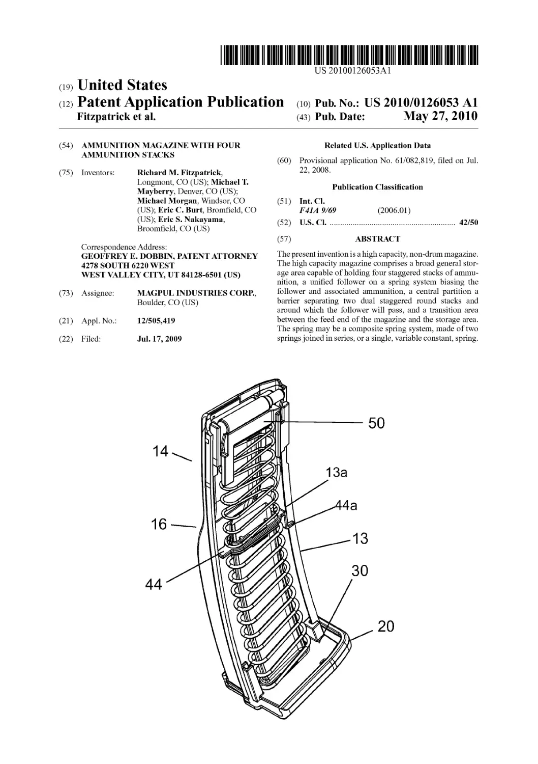
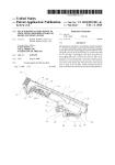
(54) AMMUNITION MAGAZINE WITH FOUR AMMUNITION STACKS (75) Inventors: Richard M. Fitzpatrick, Longmont, CO (US); Michael T. Mayberry, Denver, CO (US); Michael Morgan, Windsor, CO (US); Eric C. Burt, Bromfield, CO (US); Eric S. Nakayama, Broomfield, CO (US) Correspondence Address: GEOFFREY E. DOBBIN, PATENT ATTORNEY 4278 SOUTH 6220 WEST WEST VALLEY CITY, UT 84128-6501 (US) (73) Assignee: MAGPUL INDUSTRIES CORP., Boulder, CO (US) (21) Appl.No.: 12/505,419 (22) Filed: Jul. 17, 2009 j|| S 14^ 16—/|Г^^ 44^ \ \\\Ж/ Related U.S. Application Data (60) Provisional application No. 61/082,819, filed on Jul. 22, 2008. Publication Classification (51) Int.Cl. 1'41.4 9/69 (2006.01) (52) U.S. Cl 42/50 (57) ABSTRACT The present invention is a high capacity, non-drum magazine. The high capacity magazine comprises a broad general stor- age area capable of holding four staggered stacks of ammu- nition, a unified follower on a spring system biasing the follower and associated ammunition, a central partition a barrier separating two dual staggered round stacks and around which the follower will pass, and a transition area between the feed end of the magazine and the storage area. The spring may be a composite spring system, made of two springs joined in series, or a single, variable constant, spring. Ж 50 j 133 ^)\\ 30
20
!>a,e”,APPlKatio„pHM(,at.oii
М“У27,2<!10 Sheet! of8
US 2010/0126053 Al
Patent Application Publication May 27, 2010 Sheet 2 of 8
US 2010/0126053 Al
FIG. 5
tV£S09^0l0ZS!1
Siot,^^elv u
One3!Iqndt,One3nddViu
Patent Application Publication May 27, 2010 Sheet 4 of 8
US 2010/0126053 Al
Patent Application Publication May 27, 2010 Sheet 5 of 8
US 2010/0126053 Al
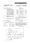
FIG. 13
pa,en,A№ationpubl.
rublication
^^,2010
,и sbeetSofs
VS201«'01260S3A1
Patent Application Publication May 27, 2010 Sheet 7 of 8
US 2010/0126053 Al
58b
co
Ю
Patent Application Publication
May 27, 2010 Sheet 8 of 8
US 2010/0126053 Al
58а
US 2010/0126053 Al
May 27, 2010
1
AMMUNITION MAGAZINE WITH FOUR
AMMUNITION STACKS
CROSS-REFERENCES TO RELATED
APPLICATIONS
[0001] This application claims priority as a perfection of
prior filed U.S. Provisional Application No. 61/082,819, filed
Jul. 22, 2008 and incorporates the same by reference in its
entirety herein.
FIELD OF THE INVENTION
[0002] The present invention relates to the field of firearms
and more particularly relates to a large capacity ammunition
magazine utilizing four varied stacks of ammunition.
BACKGROUND OF THE INVENTION
[0003] The present invention is a high capacity magazine
utilizing four staggered stacks of ammunition with a single
follower and it represents a departure from the prior art in that
the high capacity magazine of the present invention allows for
four staggered stacks of ammunition to be simultaneously fed
through the magazine as each round is sequentially loaded
into the firearm. Most high capacity magazines in the prior art
are “drum” magazines, where the ammunition is stored in a
round chamber. Others are made of a number of pieces that
require assembly before use. The present invention also uti-
lizes a simple spring drive system, similar to lower capacity
magazines, where other prior art high capacity magazines
tend to utilize more complicated systems
SUMMARY OF THE INVENTION
[0004] In view of the foregoing disadvantages inherent in
the known types of firearm magazines, this invention pro-
vides a four round stack ammunition magazine that is com-
patible with current firearm platforms. As such, the present
invention’s general purpose is to provide a new and improved
magazine that utilizes a single unified follower to move four
staggered stacks of ammunition from a storage area, through
a transition area and into the weapon as needed.
[0005] To accomplish these objectives, the high capacity
magazine comprises a broad general storage area capable of
holding four staggered stacks of ammunition, a unified fol-
lower on a spring system biasing the follower and associated
ammunition, a dividing wall to provide a barrier separating
two dual staggered round stacks, and a transition area
between the feed end of the magazine and the storage area.
[0006] The more important features of the invention have
thus been outlined in order that the more detailed description
that follows may be better understood and in order that the
present contribution to the art may better be appreciated.
Additional features of the invention will be described here-
inafter and will form the subject matter of the claims that
follow.
[0007] Many objects of this invention will appear from the
following description and appended claims, reference being
made to the accompanying drawings forming a part of this
specification wherein like reference characters designate cor-
responding parts in the several views.
[0008] Before explaining at least one embodiment of the
invention in detail, it is to be understood that the invention is
not limited in its application to the details of construction and
the arrangements of the components set forth in the following
description or illustrated in the drawings. The invention is
capable of other embodiments and of being practiced and
carried out in various ways. Also it is to be understood that the
phraseology and terminology employed herein are for the
purpose of description and should not be regarded as limiting.
[0009] As such, those skilled in the art will appreciate that
the conception, upon which this disclosure is based, may
readily be utilized as a basis for the designing of other struc-
tures, methods and systems for carrying out the several pur-
poses of the present invention. It is important, therefore, that
the claims be regarded as including such equivalent construc-
tions insofar as they do not depart from the spirit and scope of
the present invention.
BRIEF DESCRIPTION OF THE DRAWINGS
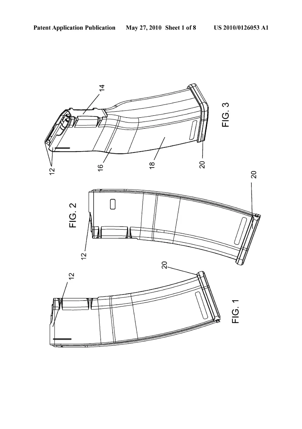
[0010] FIG. lisa right plan view of an ammunition maga-
zine according to the present invention.
[0011] FIG. 2isaleft plan view of the magazine of FIG. 1.
[0012] FIG. 3 is a top front perspective view of the maga-
zine of FIG. 1.
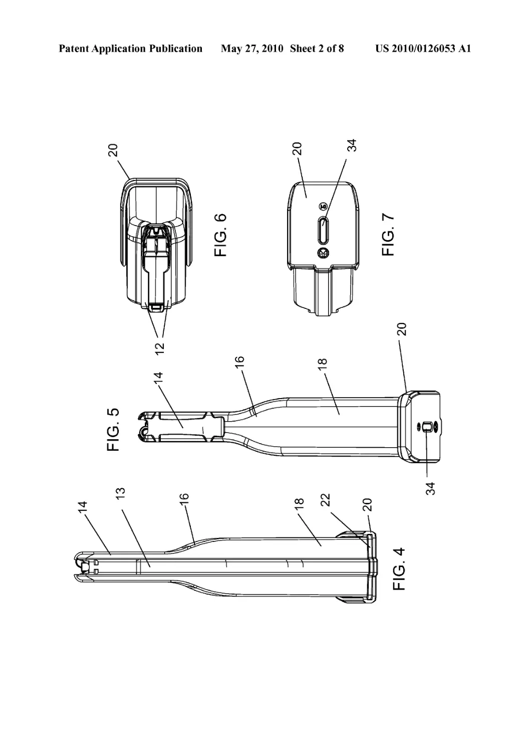
[0013] FIG. 4 is a rear plan view of the magazine of FIG. 1
[0014] FIG. 5 is a front plan view of the magazine of FIG.
1
[0015] FIG. 6 is a top plan view of the magazine of FIG. 1.
[0016] FIG. 7 is a bottom plan view of the magazine of FIG.
1.
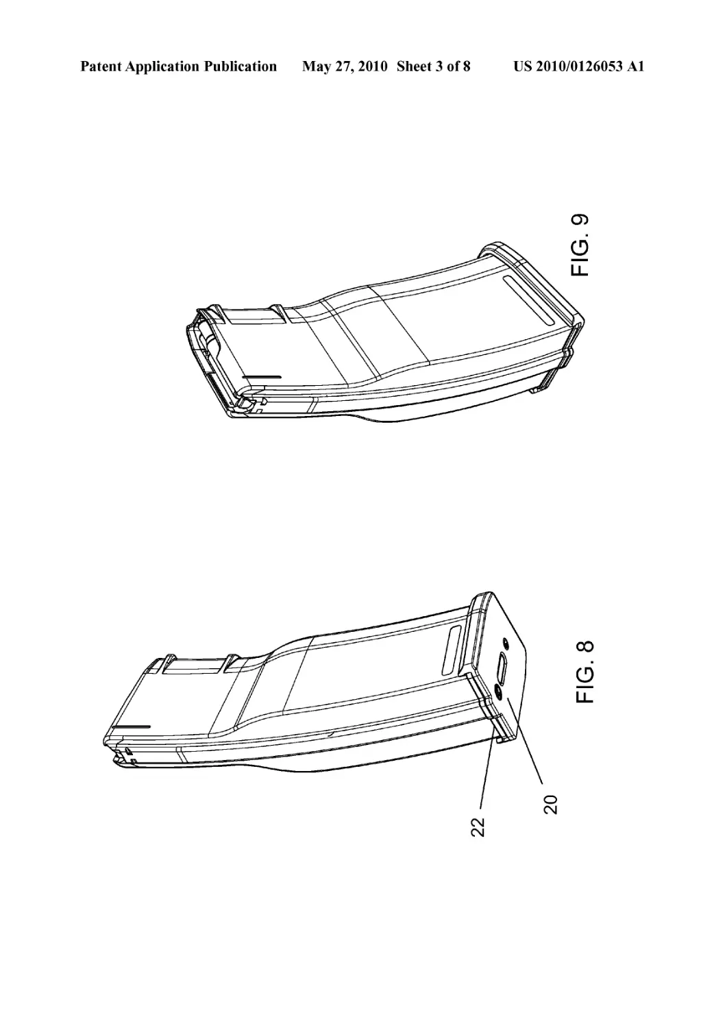
[0017] FIG. 8 is a bottom perspective view of the magazine
of FIG. 1.
[0018] FIG. 9 is a top rear perspective view of the magazine
of FIG. 1.
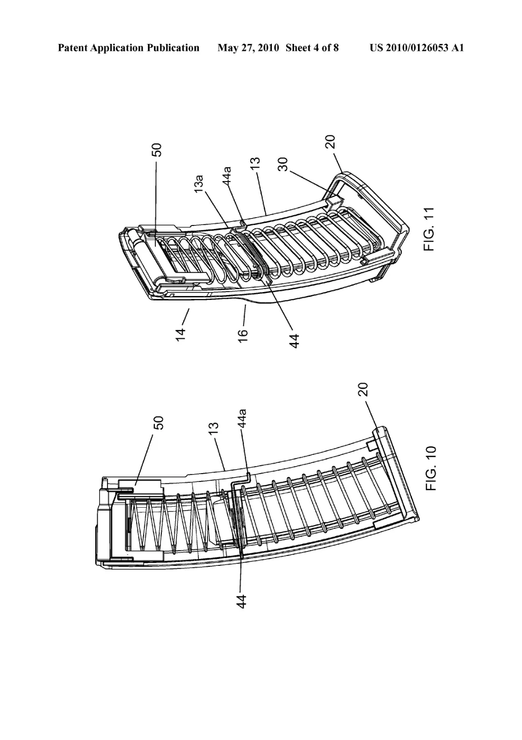
[0019] FIG. 10 is a partial cut-away view of the magazine in
the same orientation of FIG. 1.
[0020] FIG. 11 is a partial cut-away view of the magazine in
the same orientation of FIG. 9.
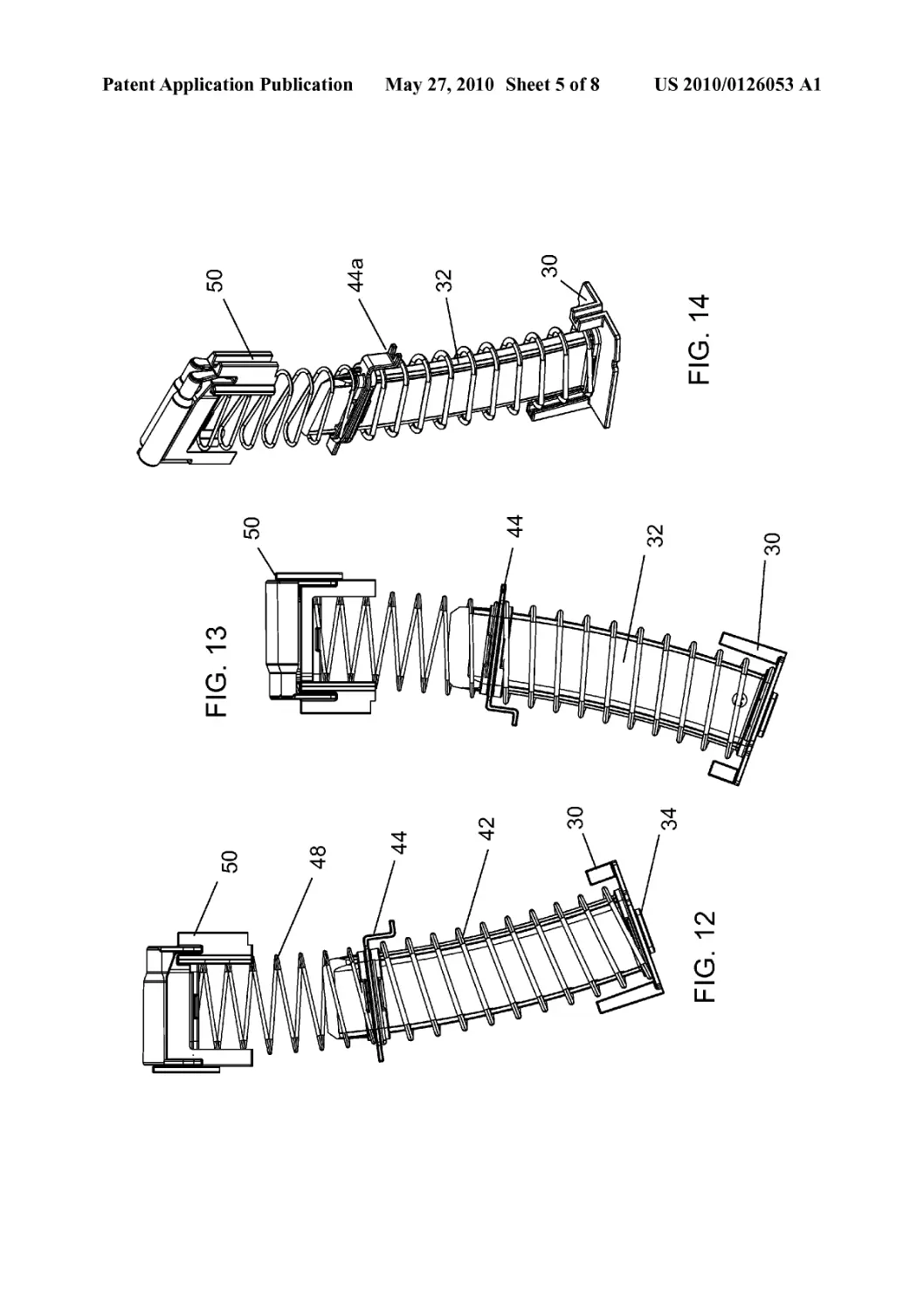
[0021] FIG. 12 is right plan view of the internal assembly of
the magazine of FIG. 1.
[0022] FIG. 13 is a left plan view of the internal assembly of
FIG. 12.
[0023] FIG. 14 is a perspective view of the internal assem-
bly of FIG. 12.
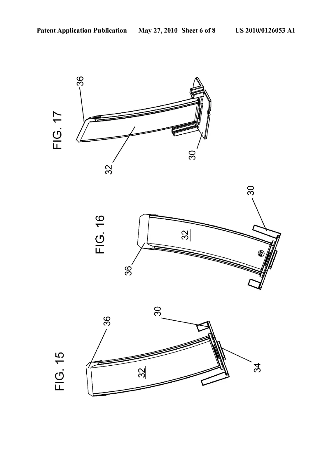
[0024] FIG. 15 is a right plan view of a lock plate according
to the present invention.
[0025] FIG. 16 is a left plan view of the lock plate of FIG.
15.
[0026] FIG. 17 is a perspective view of the lock plate of
FIG. 15.
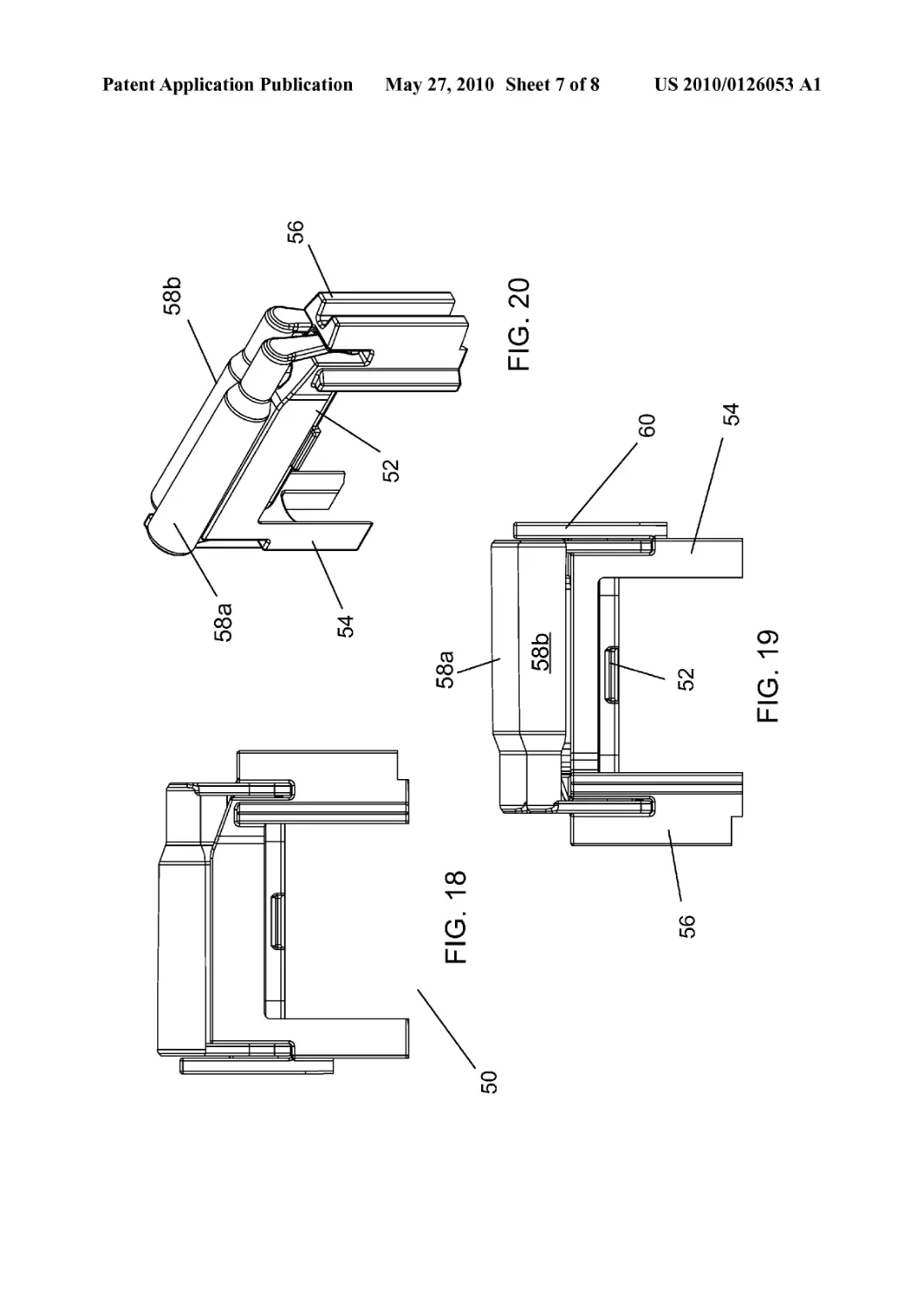
[0027] FIG. 18 is a right plan view of a magazine follower
according to the present invention.
[0028] FIG. 19 is a left plan view of the follower of FIG. 18
[0029] FIG. 20 is a perspective view of the follower of FIG.
18.
[0030] FIG. 21 is a rear plan view of the follower of FIG. 18.
[0031] FIG. 22 is a front plan view of the follower of FIG.
18.
[0032] FIG. 23 is a top plan view of the follower of FIG. 18.
[0033] FIG. 24 is a bottom plan view of the follower of FIG.
18.
DETAILED DESCRIPTION OF THE PREFERRED
EMBODIMENT
[0034] With reference now to the drawings, the preferred
embodiment of the ... is herein described. It should be noted
US 2010/0126053 Al
May 27, 2010
2
that the articles “a”, “an”, and “the”, as used in this specifi-
cation, include plural referents unless the content clearly dic-
tates otherwise.
[0035] With reference to FIGS. 1-9, the magazine com-
prises three regions, the feed region 14, the flared transition
region 16, and the wider storage region 18. The feed region 14
is designed to interface with a desired weapon platform, such
as the AR15/M16, and ejects rounds of ammunition into the
weapon system as needed to reload the weapon. Feed lips 12
are present at the opening of the magazine feed region 14 so
as to control feeding of the ammunition. The storage region
comprises the “floor end” of the magazine and presents a
ridge 22 upon which floor plate 20 slides to seal the compo-
nents of the magazine inside and to provide a force platform
for the follower spring system. Floor plate 20 interfaces with
tab 34 of the lock plate to stay in position.
[0036] One of the important features of the magazine body
itself is that it is in one piece, rather than a number of pieces
as is found with the prior art, and presents a constant internal
curve to lessen disadvantageous follower tilt. It also provides
guides for the use of “stripper clips” in order to reload the
magazine. The transition region 16 is also asymmetrical,
accounting for variations in the round stacks as they travel
through the transition region 16. The transition region 16 is
also lower on the magazine (relative the feed lips 12) than
other high capacity magazines, which allows the magazine to
be backwards compatible with common weapon systems cur-
rently in use, which includes the ability to drop the magazine
out of the weapon without manipulation.
[0037] The internal structure of the magazine is simple. As
with most magazines and as shown in FIGS. 10 and 11, the
present invention utilizes a follower 50 and spring system to
incrementally move stacks of ammunition through the tran-
sition region 16 and into the feed region 14. The preferred
embodiment utilizes a lock plate 3 0 residing within the maga-
zine to provide a base for the spring system and to project a tab
34 through the floor plate 20 and so lock it in place as the lock
plate is continually biased outward from the spring and into
the floor plate 20 (FIG. 7). This biasing prevents the tab 34
from being removed from the floor plate 20 and arrests lateral
motion of the floor plate, thereby keeping it in position. The
internal pieces are more clearly depicted in FIGS. 12-14. The
preferred spring system is a dual series spring system. Base
spring 42 is heavier than top spring 48 and has a larger spring
constant. Top spring 48 interfaces with follower 50 while base
spring 42 interfaces with lock plate 30. They are joined at
spring splicer 44. Spring splicer 44 has a travel guide 44a that
follows the inside 13a of the spine of the magazine 13 (FIG.
11) when inserted into the magazine. The structure of the
spring system provides maximum power to move ammuni-
tion through the magazine at the lower regions and through
the transition, where it is most needed. It also provides a less
powerful spring in the feed region 14, where a more powerful
spring could disrupt the feeding cycle. Alternatively, a paral-
lel spring system may be utilized, or a combination of parallel
and serial springs, or a single, variable constant spring could
be utilized.
[0038] The lock plate, shown in FIGS. 15-17, provides a
base for the spring system. A long dividing partition 32
extends upwards and centrally from the lock plate 30. The
partition 32 provides support in the storage region for the
ammunition by dividing the storage region into two sections
and provides a wall upon which two sets of ammunition
stacks may rest. At the top of the partition is a blade 36 that
parts the round stacks into two sets of two stacks as the
magazine is loaded and also provides a slope for travel of the
stacks during deployment. The spring system also encom-
passes the partition 32 as it uncoils, so the partition also
supports the springs, particularly the upper spring 48 when
the spring system is compressed into the storage region 18.
[0039] The follower 50 (FIGS. 18-24) is unitary and spe-
cially constructed with a platform 52 having two leg exten-
sions 54, 56 depending there from. Two pivoting bails 58a,
58b provide support for the ammunition stacks. The bails 58a,
58b pivot at the follower 50 travels up and down along the
interior of the magazine and part when the follower contacts
blade 36 of the lock plate 30. Normally, bails 58a, 58b are
spring biased together to better enable supporting ammuni-
tion stacks. Platform 52 has an orifice 62 through which the
partition 32 may pass and a rim 64 whereby it may rest on the
top spring 48. Rear leg 54 also presents a bolt block 60 so that
the bolt of the firearm will not interact with the bails 58a, 58b
when the magazine is empty. Bolt block 60 also interfaces
with the spine of the magazine 13 as the follower 50 travels
through the magazine. Both legs 54, 56 are configured to
maximize interface with the interior of the magazine.
[0040] Although the present invention has been described
with reference to preferred embodiments, numerous modifi-
cations and variations can be made and still the result will
come within the scope of the invention. No limitation with
respect to the specific embodiments disclosed herein is
intended or should be inferred.
What is claimed is:
1. An ammunition magazine comprising:
a. A casing, further comprised of:
i. a lower storage section with a cross-sectional area;
ii. an upper feed section with a cross-sectional area
narrower than that of the lower storage section; and
iii. a medial transitional area with a variable and asym-
metrical cross-sectional area gradually decreasing
from the cross-sectional area of the storage section to
the cross-sectional area of the feed section
b. a floor plate, capable of interface about an orifice of the
storage section;
c. a locking plate, residing internal of an orifice of the
storage section and being capable of secure interface
with the floor plate while also further comprising a par-
tition extending from the lock plate into an interior of the
storage section of the casing;
d. a follower spring; and
e. a follower having a slit such that it is capable of strad-
dling the partition.
2. The magazine of claim 1, the follower having at least one
pivotable bail.
3. The magazine of claim 1, the follower spring being a
composite spring comprising a plurality of springs, represent-
ing at least two different spring constant, connected in series
to each other.
4. The magazine of claim 3, the follower having at least one
pivotable bail.
5. The magazine of claim 3, the plurality of springs being
joined by a spring splicing apparatus, said apparatus having a
guide to interface with a trough located internally along a
narrow side of the casing.
6. The magazine of claim 5, the follower having at least one
pivotable bail.
7. The magazine of claim 1, the casing being of one piece,
having no separable parts.
US 2010/0126053 Al
May 27, 2010
3
8. The magazine of claim 7, the follower having at least one
pivotable bail.
9. The magazine of claim 7, the follower spring being a
composite spring comprising a plurality of springs, represent-
ing at least two different spring constant, connected in series
to each other.
10. The magazine of claim 9, the follower having at least
one pivotable bail.
11. The magazine of claim 9, the plurality of springs being
joined by a spring splicing apparatus, said apparatus having a
guide to interface with a trough located internally along a
narrow side of the casing.
12. The magazine of claim 11, the follower having at least
one pivotable bail.
13. The magazine of claim 7, the casing having a constant
internal curve.