/


Tags: pulimet small arms weapons


Text
TECHNICAL MANUAL
Operation, Maintenance, Repair
and
Replacement Parts
TJLTIMAX1OO
LMG 5.56 MM
MARK III
CHARTERED INDUSTRIES OF SINGAPORE
A member of the Singapore Technology Corporation ]
FIREARMS SAFETY
SAFETY MUST BE THE FIRST AND CONSTANT CONSIDERATION OF EVERY
PERSON WHO HANDLES FIREARMS AND AMMUNITION.
This Technical Manual is designed to assist you in learning the proper use and care of
your Ultimax 100 Mark III LMG.
Read the instructions and warnings in this manual carefully before using the LMG..
Do not handle any firearm without having a complete understanding of its peculiar charact-
eristics and safe usage.
Note : Due to the continuous efforts spent in upgrading the design, it is possibble that
certain descriptions contained in this manual may vary from the actual weapon.
CONTENTS
PAGE
SECTION 1 - INTRODUCTION 3
1.1 DESCRIPTION OF THE ULTIMAX 100 MARK III
1.2 PHYSICAL AND PERFORMANCE CHARACTERISTICS
SECTION 2 - OPERATING INSTRUCTIONS 5
2.1 SAFETY PROCEDURES
2.2 PREPARATIONS BEFORE FIRING
2.3 LOADING, FIRING AND UNLOADING
2.4 SIGHTS ADJUSTMENT
2.5 ADJUSTMENT OF GAS REGULATOR
2.6 HANDLING OF THE BIPOD
2.7 IMMEDIATE ACTION, STOPPAGES AND REMEDIES
SECTION 3 - STRIPPING AND ASSEMBLING 16
3.1 MAIN GROUPS
3.2 FIELD DISASSEMBLYAND ASSEMBLY
3.3 DISASSEMBLY AND ASSEMBLY BY ARMOURER
SECTION 4 - MAINTENANCE 26
4.1 GENERAL
4.2 CLEANING
4.3 LUBRICATION
SECTION 5 - AMMUNITION 28
5.1 AMMUNITION
5.2 DESTRUCTION OF MATERIAL TO PREVENT ENEMY USE
SECTION 6 - ACCESSORIES (OPTIONAL) 30
6.1 BLANK FIRING ATTACHMENT
6.2 SLING
6.3 MAGAZINES
6.4 REAR SLING CLIP
6.5 CANVAS BAG
APPENDICES 33
APPENDIX 1 - EXPLODED VIEW
APPENDIX 2 - RECEIVER BODY AND TRIGGER MECHANISM
APPENDIX 3 - BOLT CARRIER ASSEMBLY
APPENDIX 4 - BARREL AND GAS SYSTEM ASSEMBLY
APPENDIX 5 - BUTT ASSEMBLY
APPENDIX 6 - REAR SIGHT ASSEMBLY
APPENDIX? - BIPOD ASSEMBLY
2
SECTION 1
INTRODUCTION
1.1 DESCRIPTION OF THE ULTIMAX 100 MARK III
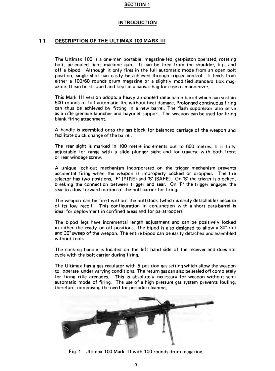
The Ultimax 100 is a one-man portable, magazine-fed, gas-piston operated, rotating
bolt, air-cooled light machine gun. It can be fired from the shoulder, hip, and
off a bipod. Although it only fires in the full automatic mode from an open bolt
position, single shot can easily be achieved through trigger control. It feeds from
either a 100/60 rounds drum magazine or a slightly modified standard box mag-
azine. It can be stripped and kept in a canvas bag for ease of manoeuvre.
This Mark III version adopts a heavy air-cooled detachable barrel which can sustain
500 rounds of full automatic fire without heat damage. Prolonged continuous firing
can thus be achieved by fitting in a new barrel. The flash suppressor also serve
as a rifle grenade launcher and bayonet support. The weapon can be used for firing
blank firing attachment.
A handle is assembled onto the gas block for balanced carriage of the weapon and
facilitate quick change of the barrel.
The rear sight is marked in 100 metre increments out to 600 metres. It is fully
adjustable for range with a slide plunger sight and for traverse with both front
or rear windage screw.
A unique lock-out mechanism incorporated on the trigger mechanism prevents
accidental firing when the weapon is improperly cocked or dropped. The fire
selector has two positions, 'F' (FIRE) and 'S' (SAFE). On 'S' the trigger is blocked,
breaking the connection between trigger and sear. On 'F' the trigger engages the
sear to allow forward motion of the bolt carrier for firing.
The weapon can be fired without the buttstock (which is easily detachable) because
of its low recoil. This configuration in conjunction with a short para-barrel is
ideal for deployment in confined areas and for paratroopers.
The bipod legs have incremental length adjustment and can be positively locked
in either the ready or off positions. The bipod is also designed to allow a 30° roll
and 30° sweep of the weapon. The entire bipod can be easily detached and assembled
without tools.
The cocking handle is located on the left hand side of the receiver and does not
cycle with the bolt carrier during firing.
The Ultimax has a gas regulator with 5 position gas setting which allow the weapon
to operate under varying conditions. The return gas can also be sealed off completely
for firing rifle grenades. This is absolutely necessary for weapon without semi
automatic mode of firing. The use of a high pressure gas system prevents fouling,
therefore minimising the need for periodic cleaning.
Fig. 1 Ultimax 100 Mark III with 100 rounds drum magazine.
3
1.2
1.2.1
PHYSICAL AND PERFORMANCE CHARACTERISTICS
1.2.2
PHYSICAL DATA
Lengths :
Gun overall with buttstock
Gun overall without buttstock
Receiver (without barrel and
buttstock)
Barrel (without flash suppressor)
Weights :
Gun empty without bipod
Spare barrel
Bipod
Empty 100-round drum magazine
Loaded 100-round drum magazine
Gun with fully loaded magazine,
buttstock, bipod and sling
Barrel :
Calibre
Rifling
Cooling
PERFORMANCE DATA
Type of operation
Recoil
Locking system
Muzzle Velocity (m/s)
Cycle rate of fire (RPM)
Effective range (m)
Accuracy (max. dispersion at 100 yards)
1030 mm (40.6 inch)
800 mm (31.5 inch)
485 mm (19.09 inch)
508 mm (20.0 inch)
4.4 kg (9.68 lb)
1.56 kg (3.75 lb)
0.45 kg (0.99 lb)
0.57 kg (1.25 lb)
1.76 kg (3.88 lb)
6.78 kg (14.91 lb)
5.56 x 45 mm
6 grooves, right hand twist, 1 turn
in 305 mm (for M193 ball) or 1 turn
in 178 mm (for SS 109 round)
Air
Gas (with piston cyclinder and gas
regulator)
Constant reaction
Rotary Bolt
990 (for M193 ball round)
945 (for SS 109 round)
400 - 600
460 (with 1 turn in 305 mm barrel
and M193 round
1300 (with 1 turn in 178 mm barrel
and SS 109 round)
8 inch
NOTE
1 turn in 305 mm rifling is the standard barrel for the Ultimax 100.
1 turn in 178 mm rifling barrel will only be available on special request.
4
SECTION 2
OPERATING INSTRUCTIONS
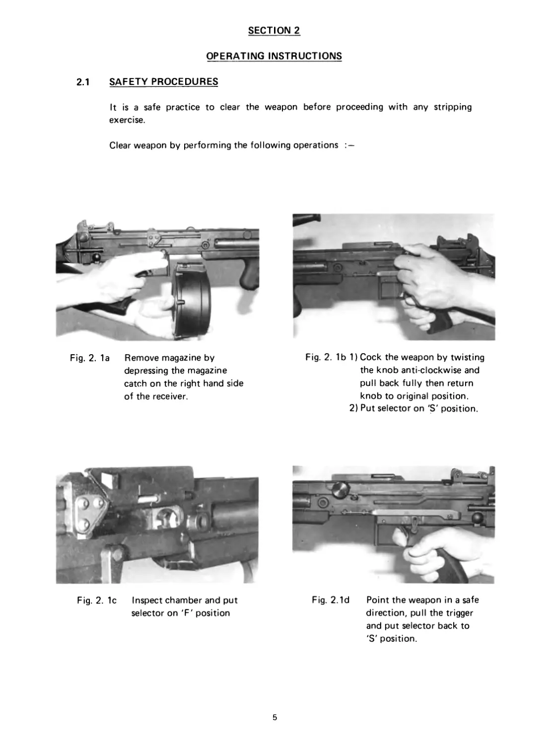
2.1 SAFETY PROCEDURES
It is a safe practice to clear the weapon before proceeding with any stripping
exercise.
Clear weapon by performing the following operations : —
Fig. 2. 1a Remove magazine by
depressing the magazine
catch on the right hand side
of the receiver.
Fig. 2. 1 b 1) Cock the weapon by twisting
the knob anti-clockwise and
pull back fully then return
knob to original position.
2) Put selector on 'S' position.
Fig. 2.1d Point the weapon in a safe
direction, pull the trigger
and put selector back to
'S' position.
Fig. 2. 1c Inspect chamber and put
selector on 'F' position
5
2.2 PREPARATIONS BEFORE FIRING
Before firing, clean and lubricate weapon as instructed in SECTION 4.
Before loading, always check to ensure that the barrel is clear and the bore un-
obstructed. Firing the weapon with any obstruction in the barrel may result in
severe damage to the weapon and serious injury to the firer.
If the bipod is to be used, the bipod legs should be adjusted to the position which
suits the terrain.
2.3 LOADING, FIRING AND UNLOADING
2.3.1 Clear weapon as described in SECTION 2.1.
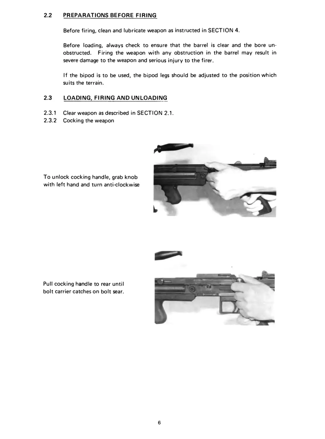
2.3.2 Cocking the weapon
To unlock cocking handle, grab knob
with left hand and turn anti-clockwise
Pull cocking handle to rear until
bolt carrier catches on bolt sear.
6
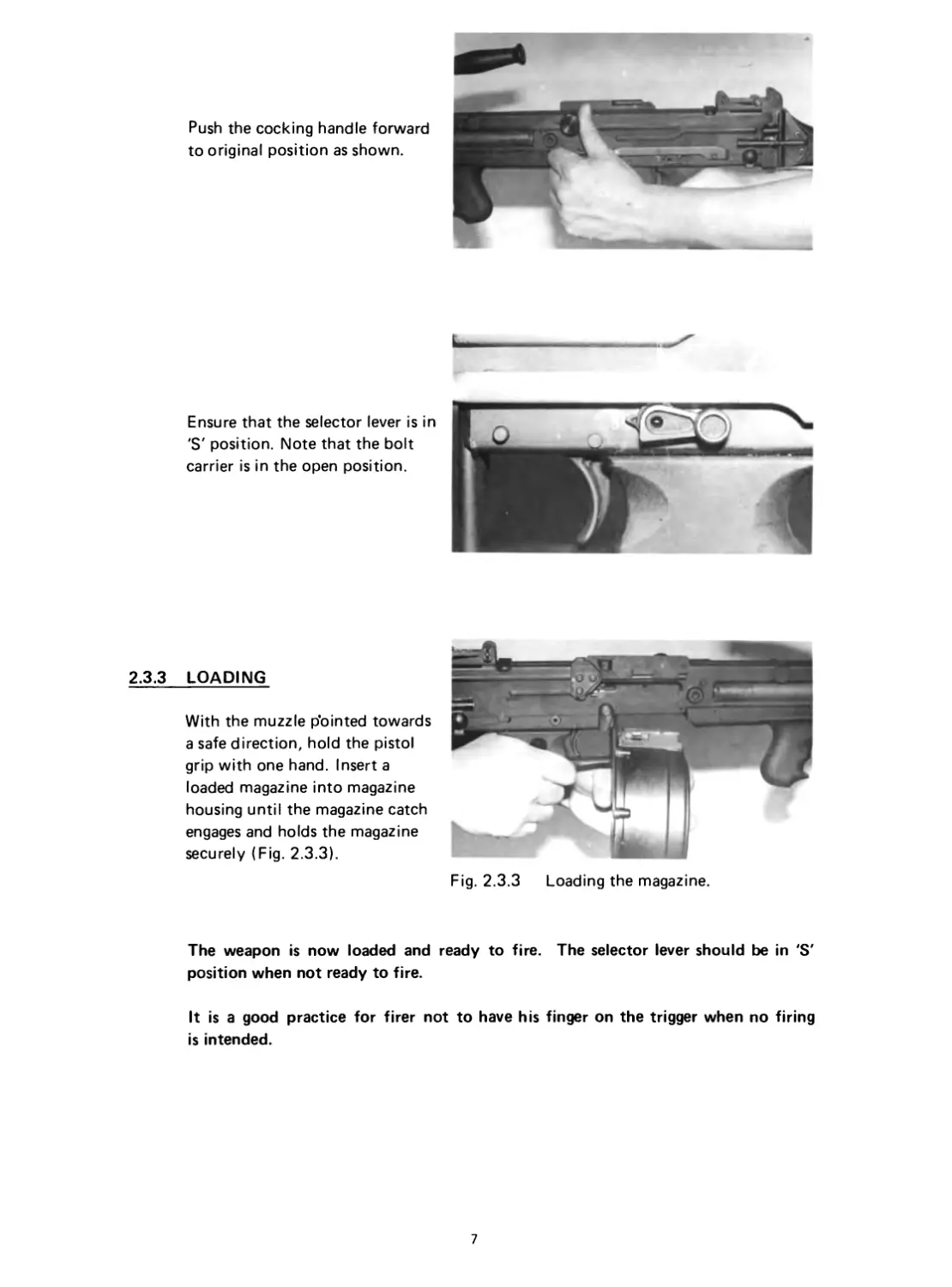
Push the cocking handle forward
to original position as shown.
Ensure that the selector lever is in
'S' position. Note that the bolt
carrier is in the open position.
2.3.3 LOADING
With the muzzle p’ointed towards
a safe direction, hold the pistol
grip with one hand. Insert a
loaded magazine into magazine
housing until the magazine catch
engages and holds the magazine
securely (Fig. 2.3.3).
Fig. 2.3.3 Loading the magazine.
The weapon is now loaded and ready to fire.
The selector lever should be in 'S'
position when not ready to fire.
It is a good practice for firer not to have his finger on the trigger when no firing
is intended.
7
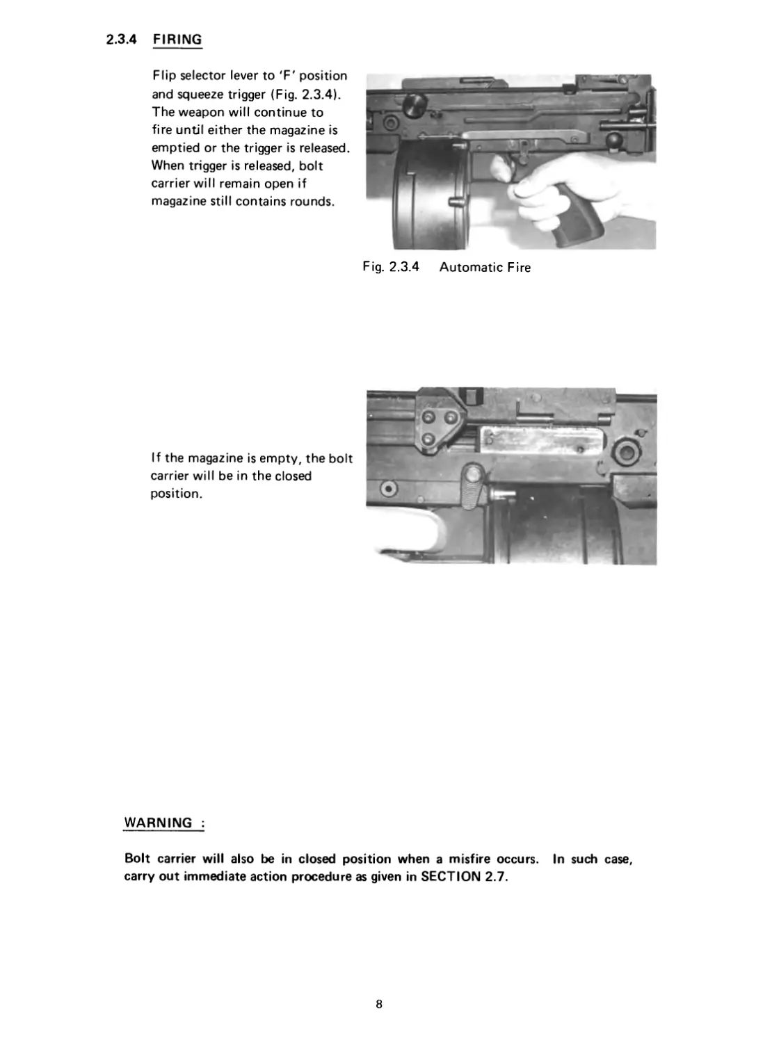
2.3.4 FIRING
Flip selector lever to 'F' position
and squeeze trigger (Fig. 2.3.4).
The weapon will continue to
fire until either the magazine is
emptied or the trigger is released.
When trigger is released, bolt
carrier will remain open if
magazine still contains rounds.
If the magazine is empty, the bolt
carrier will be in the closed
position.
Fig. 2.3.4 Automatic Fire
WARNING :
Bolt carrier will also be in closed position when a misfire occurs. In such case,
carry out immediate action procedure as given in SECTION 2.7.
8
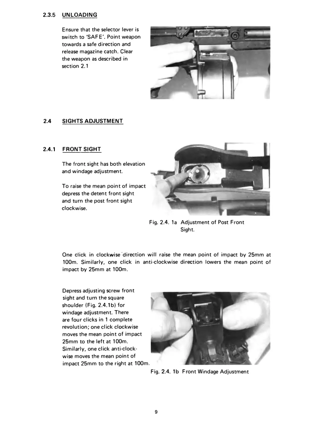
2.3.5 UNLOADING
Ensure that the selector lever is
switch to 'SAFE'. Point weapon
towards a safe direction and
release magazine catch. Clear
the weapon as described in
section 2.1
2.4 SIGHTS ADJUSTMENT
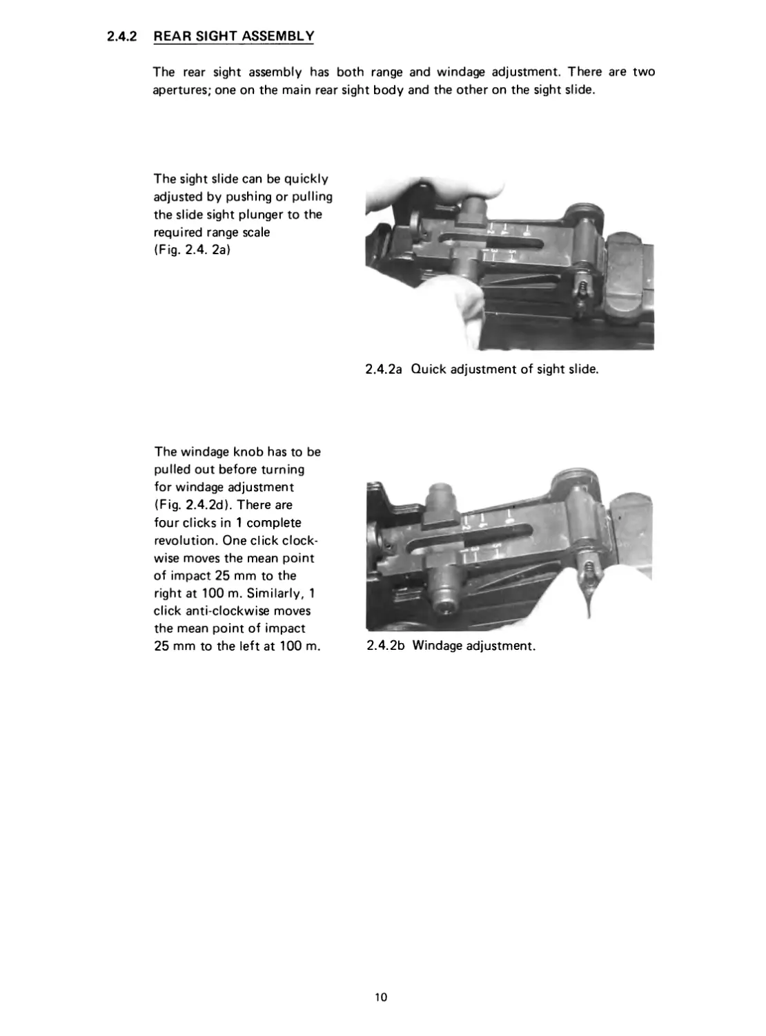
2.4.1 FRONT SIGHT
The front sight has both elevation
and windage adjustment.
To raise the mean point of impact
depress the detent front sight
and turn the post front sight
clockwise.
Fig. 2.4. 1a Adjustment of Post Front
Sight.
One click in clockwise direction will raise the mean point of impact by 25mm at
100m. Similarly, one click in anti clockwise direction lowers the mean point of
impact by 25mm at 100m.
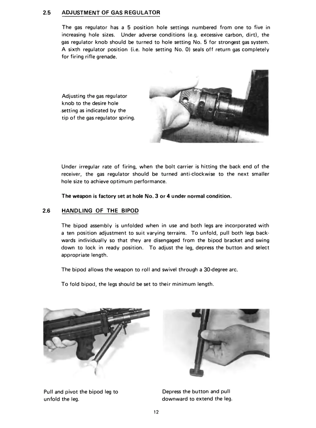
Depress adjusting screw front
sight and turn the square
shoulder (Fig. 2.4.1b) for
windage adjustment. There
are four clicks in 1 complete
revolution; one click clockwise
moves the mean point of impact
25mm to the left at 100m.
Similarly, one click anti-clock-
wise moves the mean point of
impact 25mm to the right at 100m.
Fig. 2.4. 1b Front Windage Adjustment
9
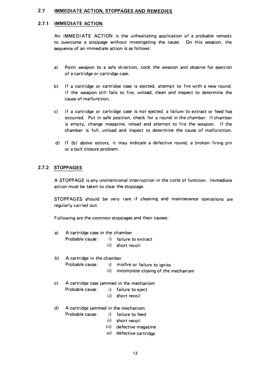
2.4.2 REAR SIGHT ASSEMBLY
The rear sight assembly has both range and windage adjustment. There are two
apertures; one on the main rear sight body and the other on the sight slide.
The sight slide can be quickly
adjusted by pushing or pulling
the slide sight plunger to the
required range scale
(Fig. 2.4. 2a)
The windage knob has to be
pulled out before turning
for windage adjustment
(Fig. 2.4.2d). There are
four clicks in 1 complete
revolution. One click clock-
wise moves the mean point
of impact 25 mm to the
right at 100 m. Similarly, 1
click anti-clockwise moves
the mean point of impact
25 mm to the left at 100 m.
2.4.2a Quick adjustment of sight slide.
2.4.2b Windage adjustment.
10
With the 1 in 305 mm twist
barrel and the use of
M193 ball ammunition, the
rear sight is calibrated
for ranges up to 600 m.
OPTION:
With the 1 in 178 mm twist
barrel and the use of SS109
ammunition, the rear sight
is marked for ranges up to
1000 m.
2.4.2c Marking up to 600 m
2.4.2d Marking up to 1000 m.
11
2.5 ADJUSTMENT OF GAS REGULATOR
The gas regulator has a 5 position hole settings numbered from one to five in
increasing hole sizes. Under adverse conditions (e.g. excessive carbon, dirt), the
gas regulator knob should be turned to hole setting No. 5 for strongest gas system.
A sixth regulator position (i.e. hole setting No. 0) seals off return gas completely
for firing rifle grenade.
Adjusting the gas regulator
knob to the desire hole
setting as indicated by the
tip of the gas regulator spring.
Under irregular rate of firing, when the bolt carrier is hitting the back end of the
receiver, the gas regulator should be turned anti clockwise to the next smaller
hole size to achieve optimum performance.
The weapon is factory set at hole No. 3 or 4 under normal condition.
2.6 HANDLING OF THE BIPOD
The bipod assembly is unfolded when in use and both legs are incorporated with
a ten position adjustment to suit varying terrains. To unfold, pull both legs back-
wards individually so that they are disengaged from the bipod bracket and swing
down to lock in ready position. To adjust the leg, depress the button and select
appropriate length.
The bipod allows the weapon to roll and swivel through a 30-degree arc.
To fold bipod, the legs should be set to their minimum length.
Pull and pivot the bipod leg to
unfold the leg.
Depress the button and pull
downward to extend the leg.
2J IMMEDIATE ACTION, STOPPAGES AND REMEDIES
2.7.1 IMMEDIATE ACTION
An IMMEDIATE ACTION is the unhesitating application of a probable remedy
to overcome a stoppage without investigating the cause. On this weapon, the
sequence of an immediate action is as follows:
a) Point weapon to a safe direction, cock the weapon and observe for ejection
of a cartridge or cartridge case.
b) If a cartridge or cartridge case is ejected, attempt to fire with a new round.
If the weapon still fails to fire, unload, clean and inspect to determine the
cause of malfunction.
c) If a cartridge or cartridge case is not ejected, a failure to extract or feed has
occurred. Put in safe position, check for a round in the chamber. If chamber
is empty, change magazine, reload and attempt to fire the weapon. If the
chamber is full, unload and inspect to determine the cause of malfunction.
d) If (b) above occurs, it may indicate a defective round, a broken firing pin
or a bolt closure problem.
2.7.2 STOPPAGES
A STOPPAGE is any unintentional interruption in the cycle of function. Immediate
action must be taken to clear the stoppage.
STOPPAGES should be very rare if cleaning and maintenance operations are
regularly carried out.
Following are the common stoppages and their causes:
a) A cartridge case in the chamber
Probable cause: i) failure to extract
ii) short recoil
b) A cartridge in the chamber
Probable cause: i) misfire or failure to ignite
ii) incomplete closing of the mechanism
c) A cartridge case jammed in the mechanism
Probable cause: i) failure to eject
ii) short recoil
d)
A cartridge jammed in the mechanism
Probable cause: i) failure to feed
ii) short recoil
iii) defective magazine
iv) defective cartridge
13
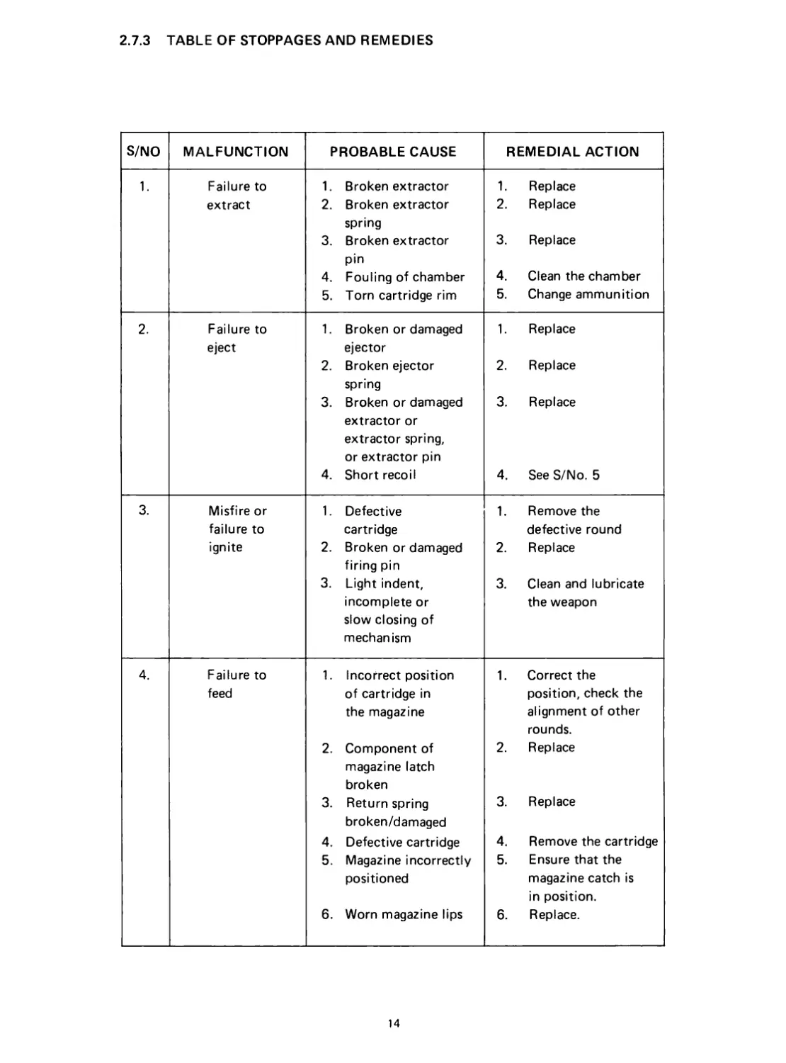
2.7.3 TABLE OF STOPPAGES AND REMEDIES
S/NO MALFUNCTION PROBABLE CAUSE REMEDIAL ACTION
1. Failure to extract 1. Broken extractor 2. Broken extractor spring 3. Broken extractor pin 4. Fouling of chamber 5. Torn cartridge rim 1. Replace 2. Replace 3. Replace 4. Clean the chamber 5. Change ammunition
2. Failure to eject 1. Broken or damaged ejector 2. Broken ejector spring 3. Broken or damaged extractor or extractor spring, or extractor pin 4. Short recoil 1. Replace 2. Replace 3. Replace 4. See S/No. 5
3. Misfire or failure to ignite 1. Defective cartridge 2. Broken or damaged firing pin 3. Light indent, incomplete or slow closing of mechanism 1. Remove the defective round 2. Replace 3. Clean and lubricate the weapon
4. Failure to feed 1. Incorrect position of cartridge in the magazine 2. Component of magazine latch broken 3. Return spring broken/damaged 4. Defective cartridge 5. Magazine incorrectly positioned 6. Worn magazine lips 1. Correct the position, check the alignment of other rounds. 2. Replace 3. Replace 4. Remove the cartridge 5. Ensure that the magazine catch is in position. 6. Replace.
14
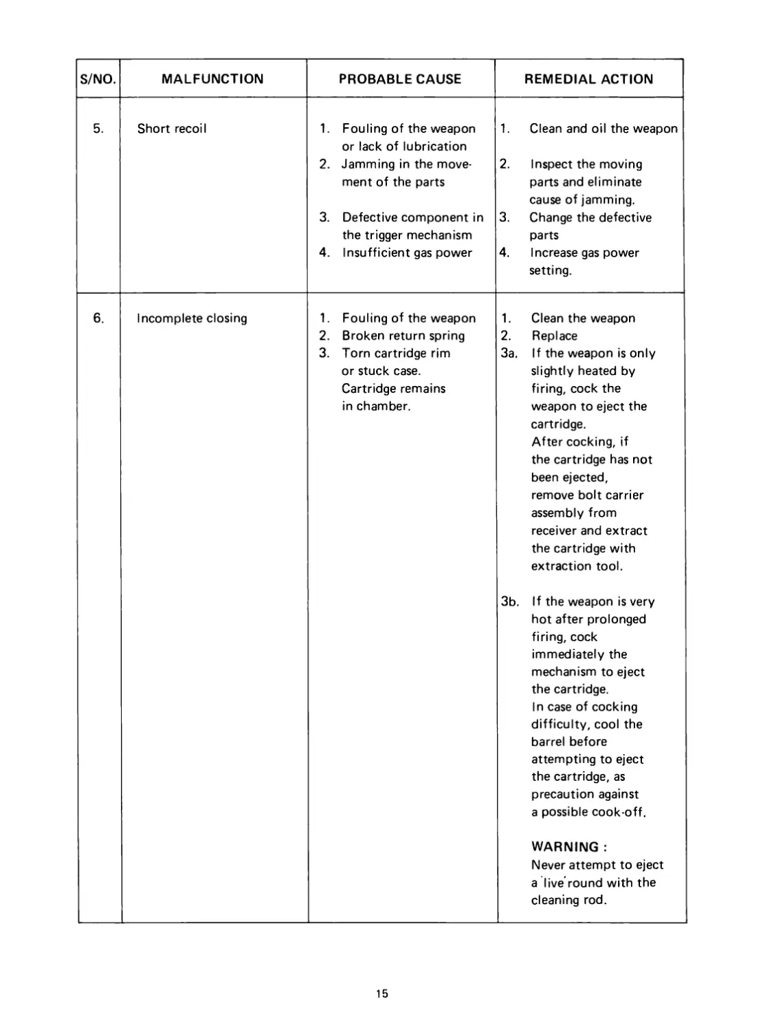
S/NO. MALFUNCTION PROBABLE CAUSE REMEDIAL ACTION
5. Short recoil 1. Fouling of the weapon or lack of lubrication 2. Jamming in the move- ment of the parts 3. Defective component in the trigger mechanism 4. Insufficient gas power 1. Clean and oil the weapon 2. Inspect the moving parts and eliminate cause of jamming. 3. Change the defective parts 4. Increase gas power setting.
6. Incomplete closing 1. Fouling of the weapon 2. Broken return spring 3. Torn cartridge rim or stuck case. Cartridge remains in chamber. 1. Clean the weapon 2. Replace 3a. If the weapon is only slightly heated by firing, cock the weapon to eject the cartridge. After cocking, if the cartridge has not been ejected, remove bolt carrier assembly from receiver and extract the cartridge with extraction tool. 3b. If the weapon is very hot after prolonged firing, cock immediately the mechanism to eject the cartridge. In case of cocking difficulty, cool the barrel before attempting to eject the cartridge, as precaution against a possible cook-off. WARNING : Never attempt to eject a live round with the cleaning rod.
15
SECTION 3
STRIPPING AND ASSEMBLING
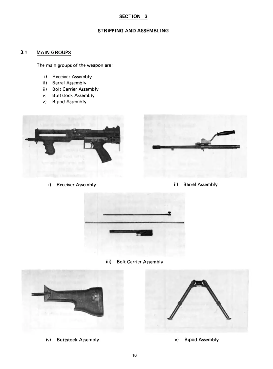
3.1 MAIN GROUPS
The main groups of the weapon are:
i) Receiver Assembly
ii) Barrel Assembly
iii) Bolt Carrier Assembly
iv) Buttstock Assembly
v) Bipod Assembly
i) Receiver Assembly
ii) Barrel Assembly
iii) Bolt Carrier Assembly
iv) Buttstock Assembly
v) Bipod Assembly
16
3.2 FIELD DISASSEMBLY AND ASSEMBLY
The Ultimax 100 Mark III can be quickly field stripped to their basic main groups.
Most of the operations described later can be done by the soldier without the aid
of special tools.
Assembly is generally done in reverse sequence.
Note: It is mandatory to clear the weapon before proceeding with the stripping
exercise.
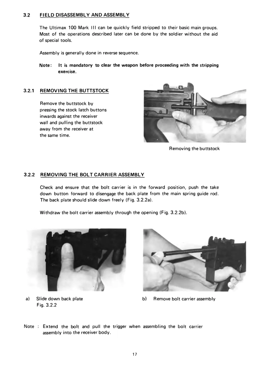
3.2.1
REMOVING THE BUTTSTOCK
Remove the buttstock by
pressing the stock latch buttons
inwards against the receiver
wall and pulling the buttstock
away from the receiver at
the same time.
Removing the buttstock
3.2.2 REMOVING THE BOLT CARRIER ASSEMBLY
Check and ensure that the bolt carrier is in the forward position, push the take
down button forward to disengage the back plate from the main spring guide rod.
The back plate should slide down freely (Fig. 3.2.2a).
Withdraw the bolt carrier assembly through the opening (Fig. 3.2.2b).
b) Remove bolt carrier assembly
a) Slide down back plate
Fig. 3.2.2
Note : Extend the bolt and pull the trigger when assembling the bolt carrier
assembly into the receiver body.
17
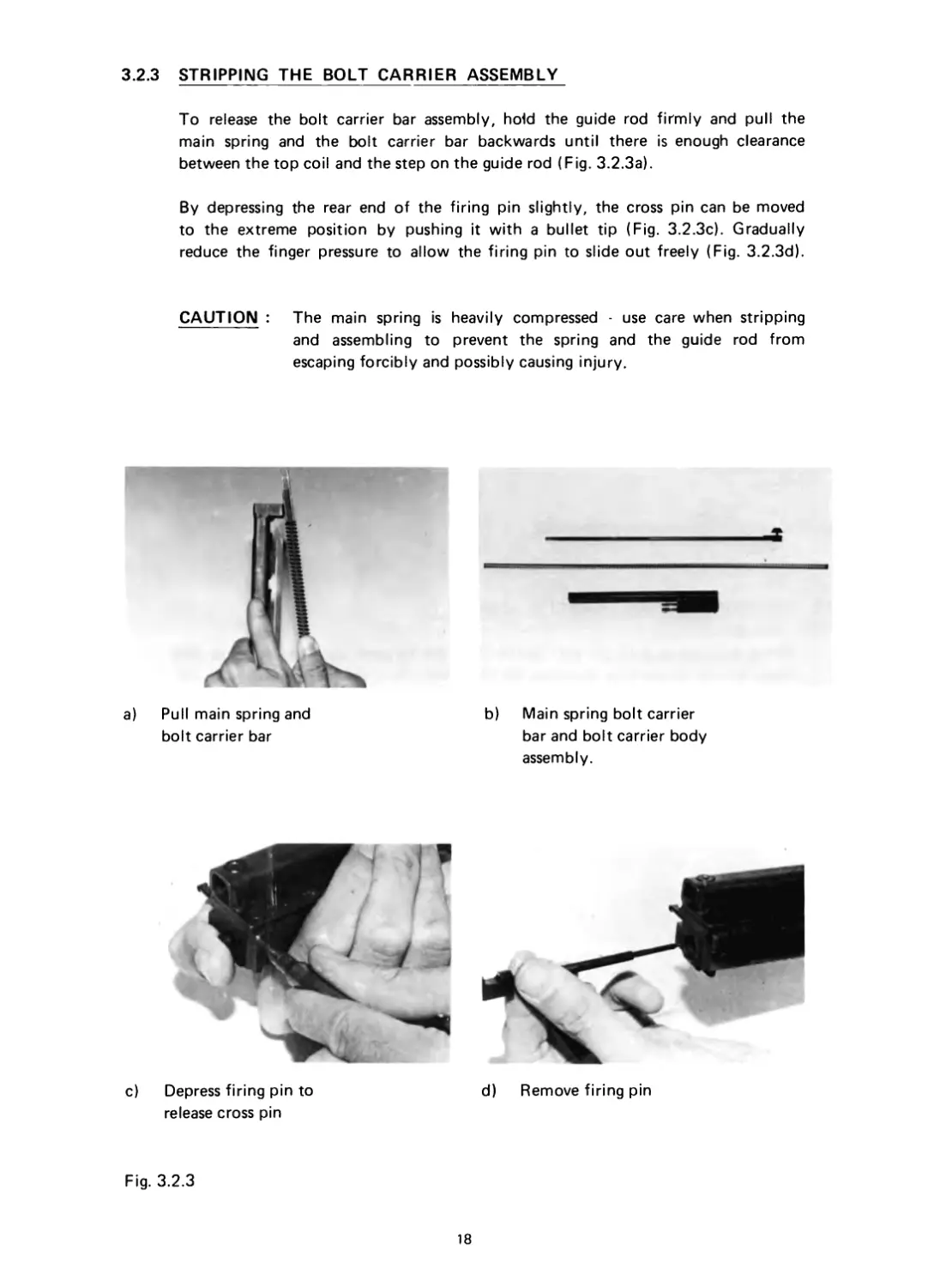
3.2.3 STRIPPING THE BOLT CARRIER ASSEMBLY
To release the bolt carrier bar assembly, hold the guide rod firmly and pull the
main spring and the bolt carrier bar backwards until there is enough clearance
between the top coil and the step on the guide rod (Fig. 3.2.3a).
By depressing the rear end of the firing pin slightly, the cross pin can be moved
to the extreme position by pushing it with a bullet tip (Fig. 3.2.3c). Gradually
reduce the finger pressure to allow the firing pin to slide out freely (Fig. 3.2.3d).
CAUTION : The main spring is heavily compressed - use care when stripping
and assembling to prevent the spring and the guide rod from
escaping forcibly and possibly causing injury.
Л
a) Pull main spring and
bolt carrier bar
b) Main spring bolt carrier
bar and bolt carrier body
assembly.
d) Remove firing pin
c) Depress firing pin to
release cross pin
Fig. 3.2.3
18
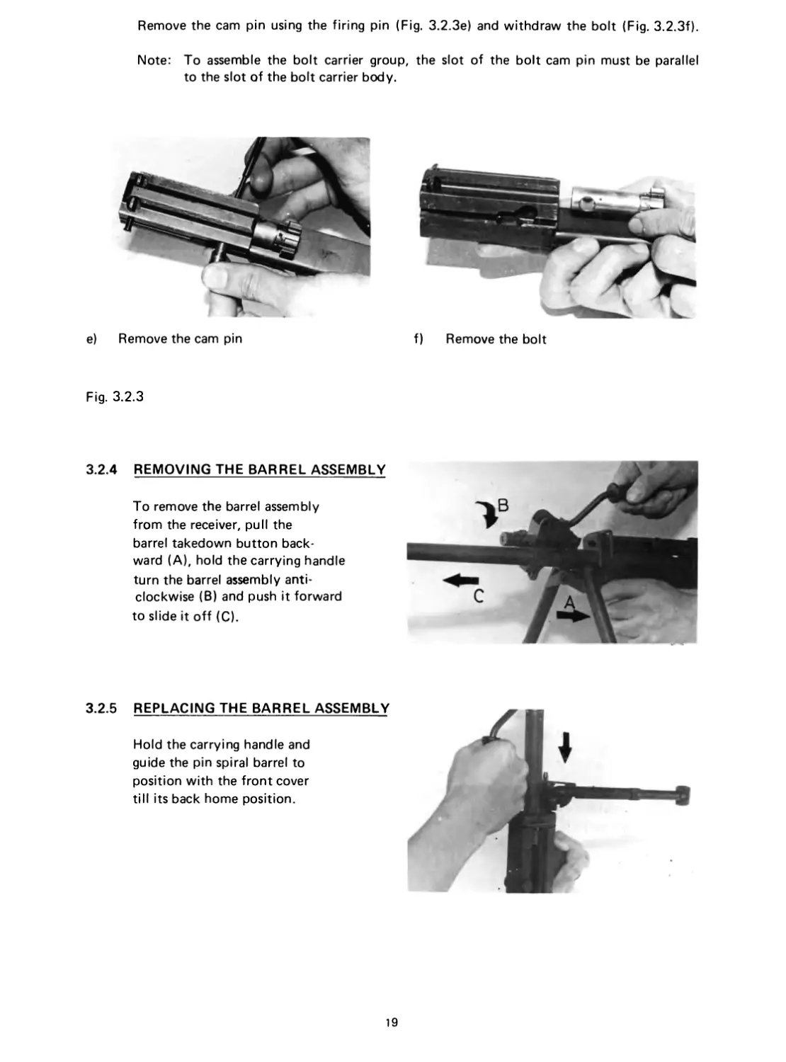
Remove the cam pin using the firing pin (Fig. 3.2.3e) and withdraw the bolt (Fig. 3.2.3f).
Note: To assemble the bolt carrier group, the slot of the bolt cam pin must be parallel
to the slot of the bolt carrier body.
f) Remove the bolt
e) Remove the cam pin
Fig. 3.2.3
3.2.4 REMOVING THE BARREL ASSEMBLY
To remove the barrel assembly
from the receiver, pull the
barrel takedown button back-
ward (A), hold the carrying handle
turn the barrel assembly anti-
clockwise (B) and push it forward
to slide it off (C).
3.2.5 REPLACING THE BARREL ASSEMBLY
Hold the carrying handle and
guide the pin spiral barrel to
position with the front cover
till its back home position.
19
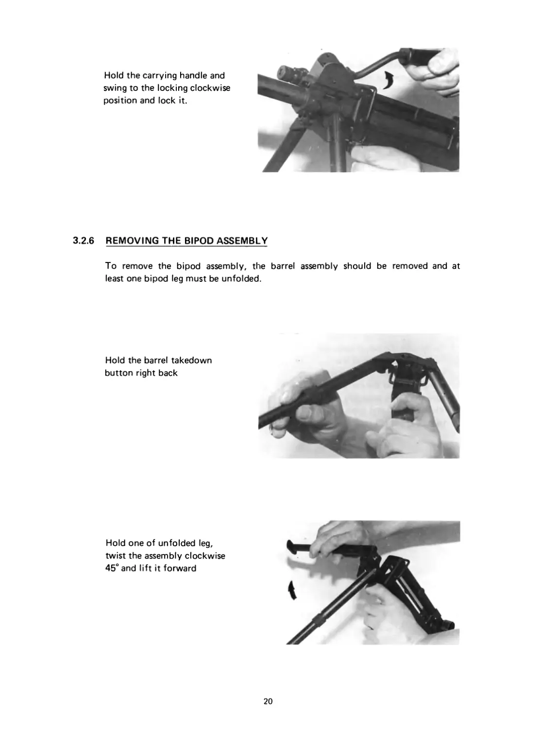
Hold the carrying handle and
swing to the locking clockwise
position and lock it.
3.2.6 REMOVING THE BIPOD ASSEMBLY
To remove the bipod assembly, the barrel assembly should be removed and at
least one bipod leg must be unfolded.
Hold the barrel takedown
button right back
Hold one of unfolded leg,
twist the assembly clockwise
45° and lift it forward
20
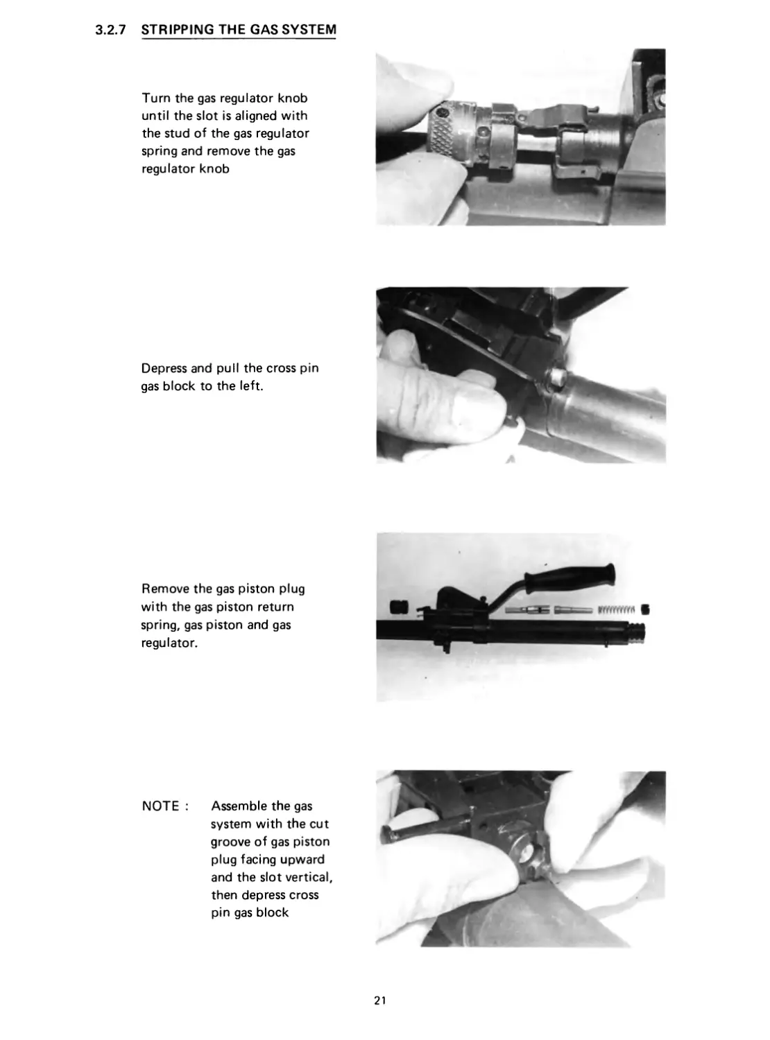
3.2.7 STRIPPING THE GAS SYSTEM
Turn the gas regulator knob
until the slot is aligned with
the stud of the gas regulator
spring and remove the gas
regulator knob
Depress and pull the cross pin
gas block to the left.
Remove the gas piston plug
with the gas piston return
spring, gas piston and gas
regulator.
NOTE :
Assemble the gas
system with the cut
groove of gas piston
plug facing upward
and the slot vertical,
then depress cross
pin gas block
21
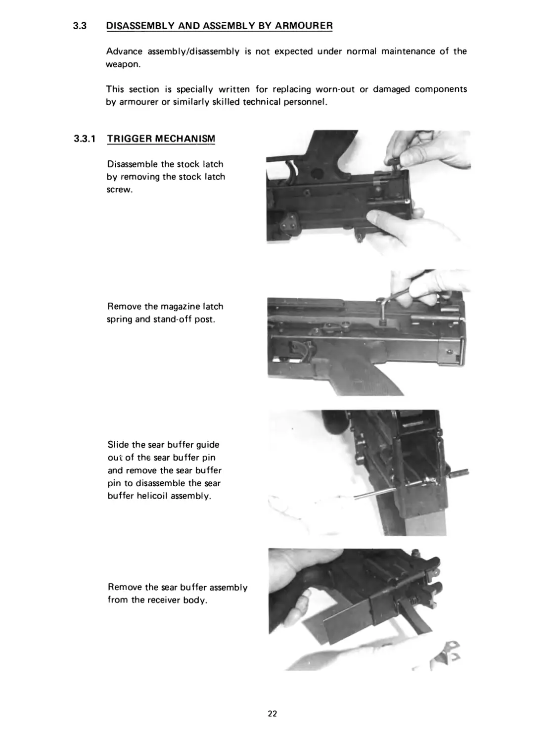
3.3 DISASSEMBLY AND ASSEMBLY BY ARMOURER
Advance assembly/disassembly is not expected under normal maintenance of the
weapon.
This section is specially written for replacing worn-out or damaged components
by armourer or similarly skilled technical personnel.
3.3.1 TRIGGER MECHANISM
Disassemble the stock latch
by removing the stock latch
screw.
Remove the magazine latch
spring and stand-off post.
Slide the sear buffer guide
out of the sear buffer pin
and remove the sear buffer
pin to disassemble the sear
buffer helicoil assembly.
Remove the sear buffer assembly
from the receiver body.
22
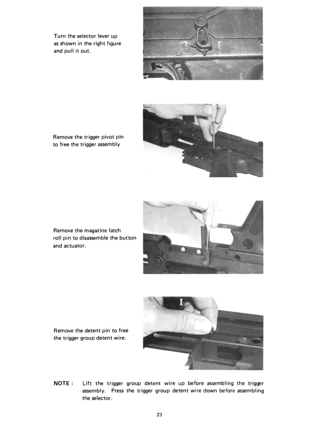
Turn the selector lever up
as shown in the right figure
and pull it out.
Remove the trigger pivot pin
to free the trigger assembly
Remove the magazine latch
roll pin to disassemble the button
and actuator.
Remove the detent pin to free
the trigger group detent wire.
NOTE : Lift the trigger group detent wire up before assembling the trigger
assembly. Press the trigger group detent wire down before assembling
the selector.
23
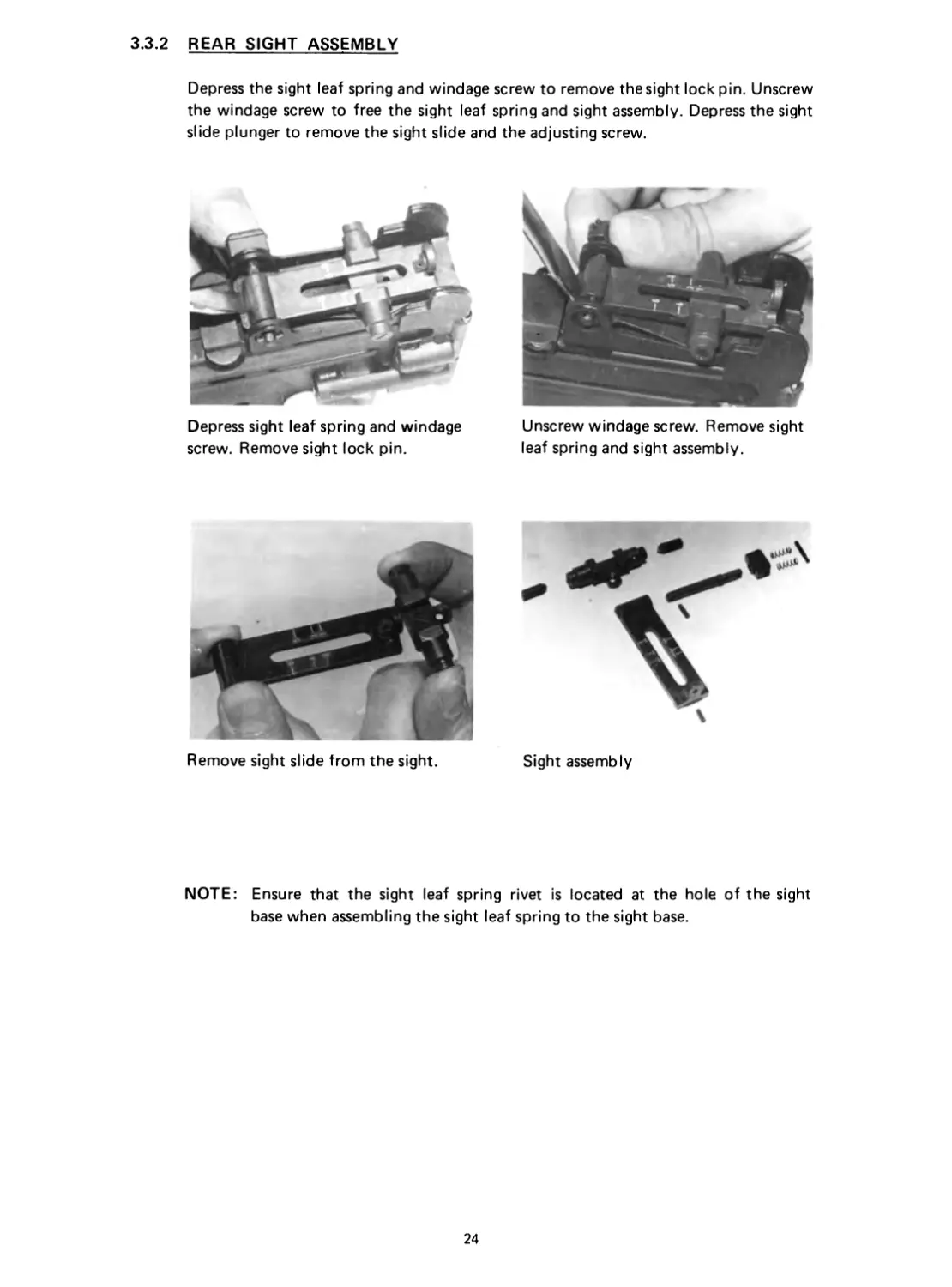
3.3.2 REAR SIGHT ASSEMBLY
Depress the sight leaf spring and windage screw to remove the sight lock pin. Unscrew
the windage screw to free the sight leaf spring and sight assembly. Depress the sight
slide plunger to remove the sight slide and the adjusting screw.
Depress sight leaf spring and windage
screw. Remove sight lock pin.
Unscrew windage screw. Remove sight
leaf spring and sight assembly.
Remove sight slide from the sight.
Sight assembly
NOTE: Ensure that the sight leaf spring rivet is located at the hole of the sight
base when assembling the sight leaf spring to the sight base.
24
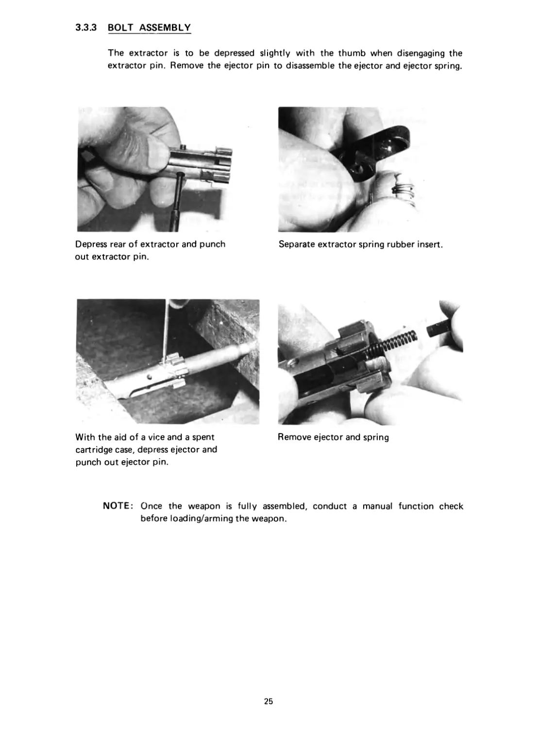
3.3.3 BOLT ASSEMBLY
The extractor is to be depressed slightly with the thumb when disengaging the
extractor pin. Remove the ejector pin to disassemble the ejector and ejector spring.
Depress rear of extractor and punch
out extractor pin.
Separate extractor spring rubber insert.
Remove ejector and spring
With the aid of a vice and a spent
cartridge case, depress ejector and
punch out ejector pin.
NOTE: Once the weapon is fully assembled, conduct a manual function check
before loading/arming the weapon.
25
SECTION 4
MAINTENANCE
4.1 . GENERAL
A clean, properly lubricated and well maintained weapon loaded with good
ammunition will fire reliably when it is needed.
The weapon should always be thoroughly cleaned after every exercise to remove the
carbon, sand and powder residues in order to minimise corrosion.
In combat, the main parts to be cleaned are the cycling mechanism (bolt carrier), the
barrel bore, the chamber and the gas system.
For lubrication, a special oil (Military spec.: VV-L-800 or equivalent) should be
used (See 4.3)
4.2 CLEANING THE WEAPON
4.2.1 BARREL
The barrel bore and the chamber must always be thoroughly cleaned; before firing,
a check should be made to see that there is no barrel obstruction.
To clean the barrel, attach the bore brush to the cleaning rod. Dip the brush in a
cleaning solvent and pull the brush in straight strokes through the bore until it
extends beyond the muzzle. Remove the bore brush and replace with a clean and
dry flannelette. Pull through the bore to dry the bore with a fresh flannelette.
Repeat this until the flannelette comes out clean and dry. Clean also the locking
lugs of the barrel, just to the rear of the chamber with a wire brush.
On completion of cleaning, lubricate the bore and locking lugs at the barrel with a
lightly oiled flannelette to prevent corrosion and pitting.
4.2.2 BOLT CARRIER GROUP
Field strip the bolt carrier group and clean all external surfaces with flannelettes.
4.2.3 GAS SYSTEM
Field strip the gas system as described in para 3.2.7. Clean the piston, the gas regu-
lator and the internal surface of the gas block thoroughly to remove carbon deposits.
Scrub also the piston for carbon deposits.
Upon completion of cleaning, apply a light coat of oil to all surfaces of components
comprising the gas system.
26
4.3 LUBRICATION
When reassembling or after every 2000 rounds lubricate where required.
Apply lubricant to sliding surfaces such as bolt barrier, guide rod, main spring
guide rod, cam path, bolt mechanism, gas regulator and gas piston.
The bipod legs, the bipod head and all pivot points in the trigger mechanism should
also be lubricated.
Parts to be or not to be lubricated:
Lubricated: Bolt
Bolt carrier keyway
Bolt carrier guide rod
Barrel extension
Return spring
Bipod legs and bipod head
Cocking handle
Gas regulator
Gas piston
Receiver
Trigger mechanism
Unlubricated: Barrel
Plastic components
NOTE: Only a very small amount of lubricant is needed to provide adequate
lubrication of moving parts and to prevent rust. Accumulation of lubricant
tend to attract particles of dust and dirt which can interfere with the safe
and reliable function of the mechanism of the weapon.
27
SECTION 6
ACCESSORIES (OPTIONAL)
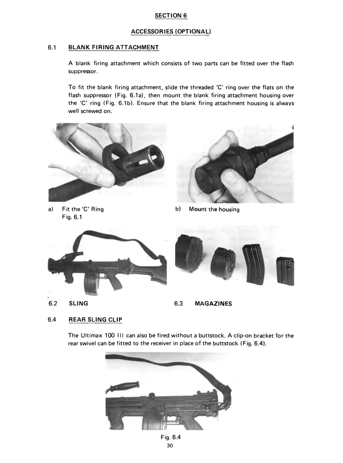
6.1 BLANK FIRING ATTACHMENT
A blank firing attachment which consists of two parts can be fitted over the flash
suppressor.
To fit the blank firing attachment, slide the threaded 'C' ring over the flats on the
flash suppressor (Fig. 6.1a), then mount the blank firing attachment housing over
the 'C' ring (Fig. 6.1b). Ensure that the blank firing attachment housing is always
well screwed on.
a) Fit the 'C' Ring b) Mount the housing
Fig. 6.1
6.2 SLING 6.3 MAGAZINES
6.4 REAR SLING CLIP
The Ultimax 100 III can also be fired without a buttstock. A clip-on bracket for the
rear swivel can be fitted to the receiver in place of the buttstock (Fig. 6.4).
Fig. 6.4
30
6.5 CANVAS BAG
The canvas bag has the capacity for one ULTIMAX 100 MARK III weapon (.Carbine
barrel) with bipod, one spare short barrel, accessories cleaning kits, and two units of
100 rounds drum magazine.
31
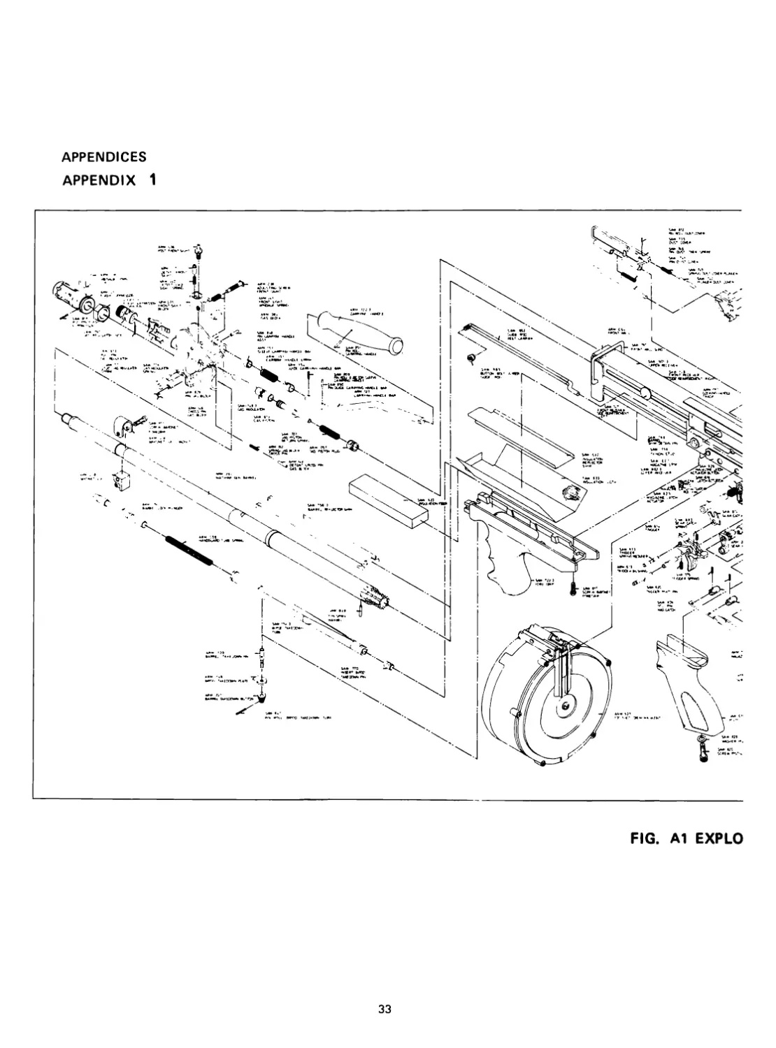
APPENDICES
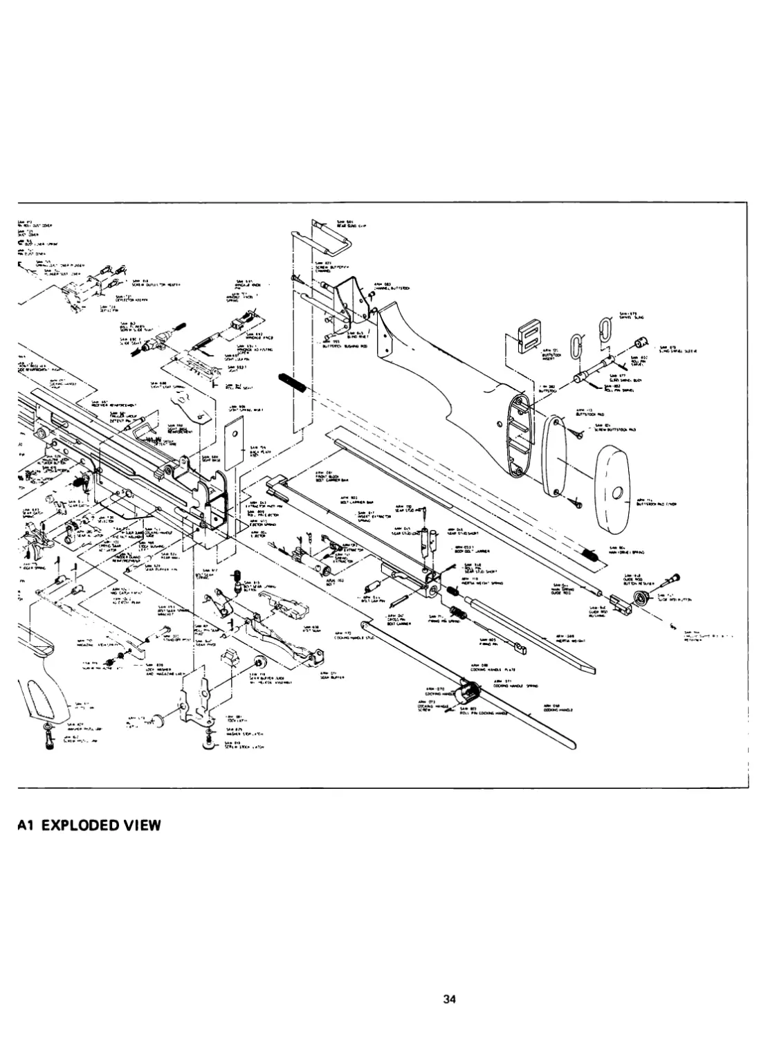
APPENDIX 1
FIG. Al EXPLO
33
Al EXPLODED VIEW
34
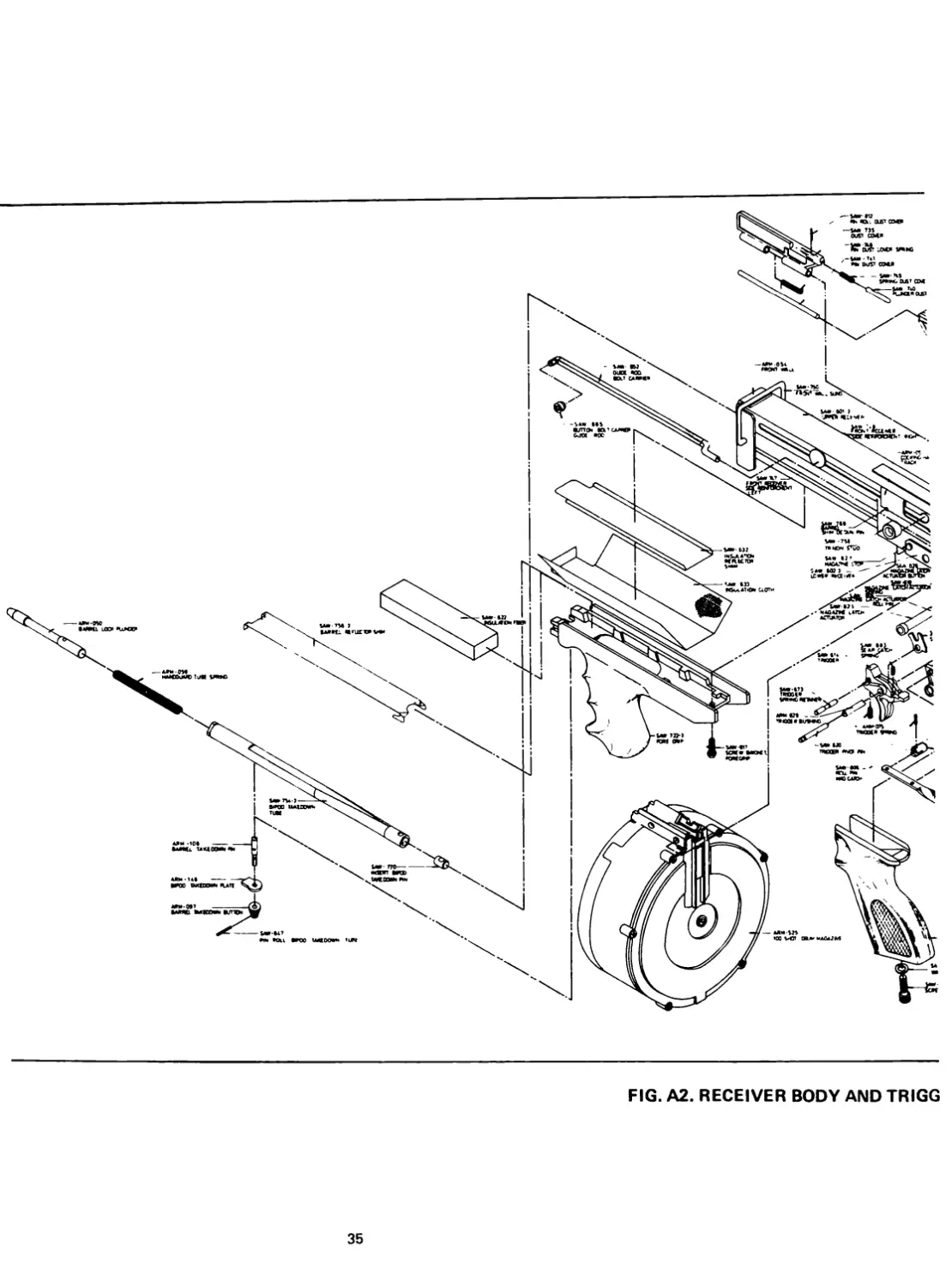
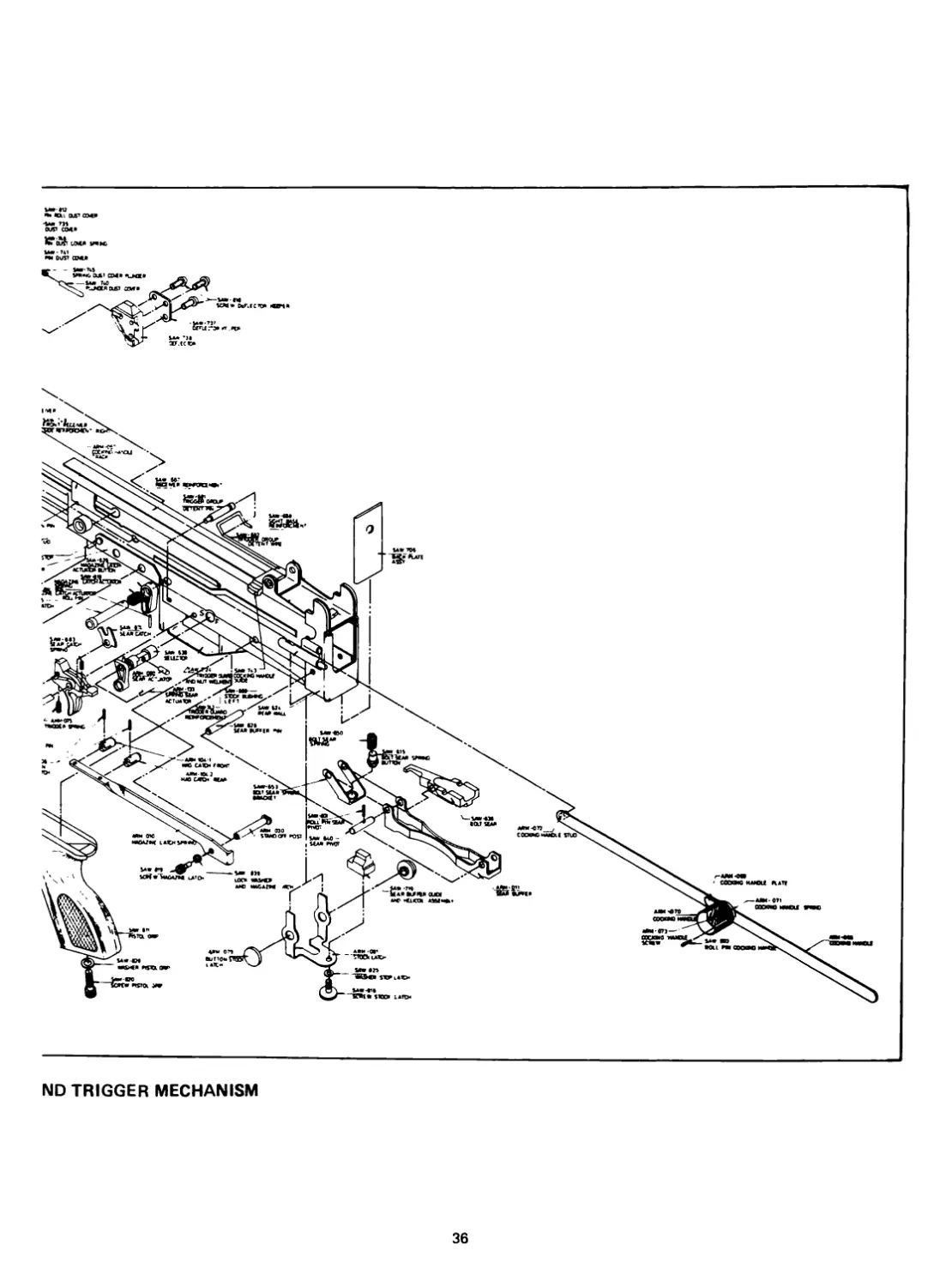
FIG. A2. RECEIVER BODY AND TRIGG
35
•м* m
our ам»
UM* SHIIC
MW* Uf
pm our awt
ND TRIGGER MECHANISM
36
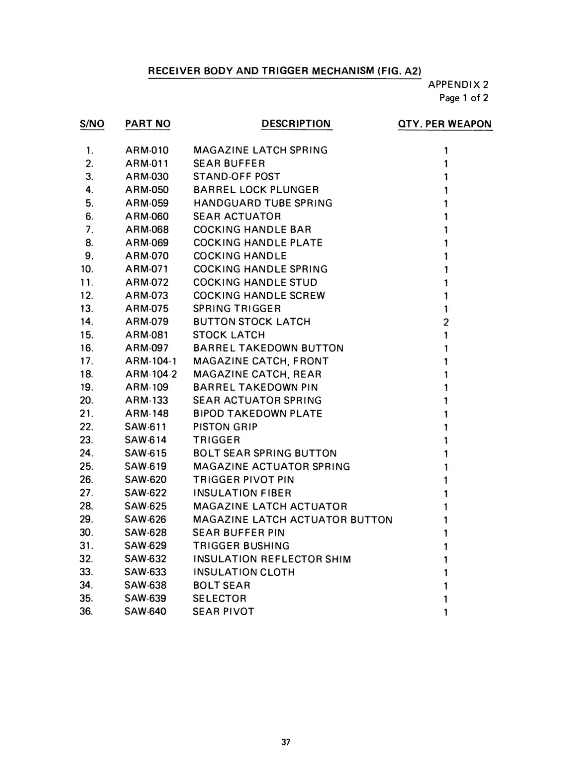
RECEIVER BODY AND TRIGGER MECHANISM (FIG. A2)
APPENDIX 2
Page 1 of 2
S/NO PART NO DESCRIPTION QTY. PER WEAPON
1. ARM-010 MAGAZINE LATCH SPRING 1
2. ARM-011 SEAR BUFFER 1
3. ARM-030 STAND-OFF POST 1
4. ARM-050 BARREL LOCK PLUNGER 1
5. ARM-059 HANDGUARD TUBE SPRING 1
6. ARM-060 SEAR ACTUATOR 1
7. ARM-068 COCKING HANDLE BAR 1
8. ARM-069 COCKING HANDLE PLATE 1
9. ARM-070 COCKING HANDLE 1
10. ARM-071 COCKING HANDLE SPRING 1
11. ARM-072 COCKING HANDLE STUD 1
12. ARM-073 COCKING HANDLE SCREW 1
13. ARM-075 SPRING TRIGGER 1
14. ARM-079 BUTTON STOCK LATCH 2
15. ARM-081 STOCK LATCH 1
16. ARM-097 BARREL TAKEDOWN BUTTON 1
17. ARM-104-1 MAGAZINE CATCH, FRONT 1
18. ARM-104-2 MAGAZINE CATCH, REAR 1
19. ARM-109 BARREL TAKEDOWN PIN 1
20. ARM-133 SEAR ACTUATOR SPRING 1
21. ARM-148 BIPOD TAKEDOWN PLATE 1
22. SAW-611 PISTON GRIP 1
23. SAW-614 TRIGGER 1
24. SAW-615 BOLT SEAR SPRING BUTTON 1
25. SAW-619 MAGAZINE ACTUATOR SPRING 1
26. SAW-620 TRIGGER PIVOT PIN 1
27. SAW-622 INSULATION FIBER 1
28. SAW-625 MAGAZINE LATCH ACTUATOR 1
29. SAW-626 MAGAZINE LATCH ACTUATOR BUTTON 1
30. SAW-628 SEAR BUFFER PIN 1
31. SAW-629 TRIGGER BUSHING 1
32. SAW-632 INSULATION REFLECTOR SHIM 1
33. SAW-633 INSULATION CLOTH 1
34. SAW-638 BOLT SEAR 1
35. SAW-639 SELECTOR 1
36. SAW-640 SEAR PIVOT 1
37
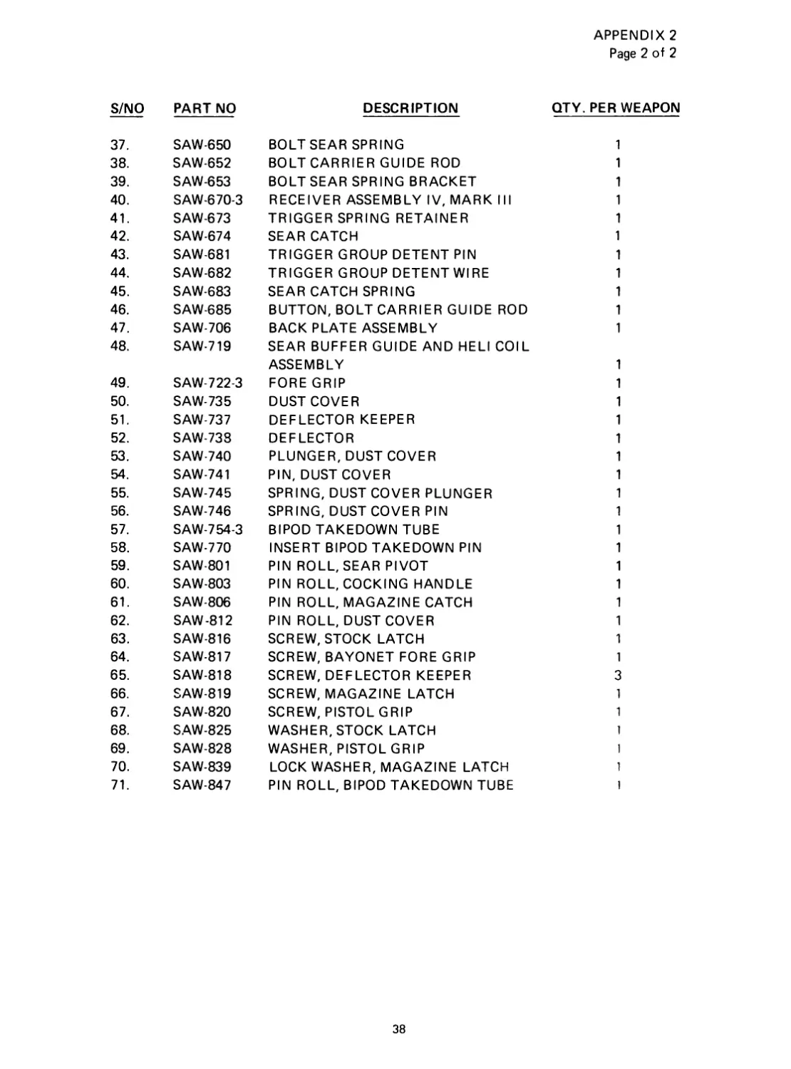
APPENDIX 2
Page 2 of 2
S/NO PART NO DESCRIPTION QTY. PER WEAPON
37. SAW-650 BOLT SEAR SPRING 1
38. SAW-652 BOLT CARRIER GUIDE ROD 1
39. SAW-653 BOLT SEAR SPRING BRACKET 1
40. SAW-670-3 RECEIVER ASSEMBLY IV, MARK III 1
41. SAW-673 TRIGGER SPRING RETAINER 1
42. SAW-674 SEAR CATCH 1
43. SAW-681 TRIGGER GROUP DETENT PIN 1
44. SAW-682 TRIGGER GROUP DETENT WIRE 1
45. SAW-683 SEAR CATCH SPRING 1
46. SAW-685 BUTTON, BOLT CARRIER GUIDE ROD 1
47. SAW-706 BACK PLATE ASSEMBLY 1
48. SAW-719 SEAR BUFFER GUIDE AND HELI COIL
ASSEMBLY 1
49. SAW-722-3 FORE GRIP 1
50. SAW-73 5 DUST COVER 1
51. SAW-737 DEFLECTOR KEEPER 1
52. SAW-738 DEFLECTOR 1
53. SAW-740 PLUNGER, DUST COVER 1
54. SAW-741 PIN, DUST COVER 1
55. SAW-745 SPRING, DUST COVER PLUNGER 1
56. SAW-746 SPRING, DUST COVER PIN 1
57. SAW-754-3 BIPOD TAKEDOWN TUBE 1
58. SAW-770 INSERT BIPOD TAKEDOWN PIN 1
59. SAW-801 PIN ROLL, SEAR PIVOT 1
60. SAW-803 PIN ROLL, COCKING HANDLE 1
61. SAW-806 PIN ROLL, MAGAZINE CATCH 1
62. SAW-812 PIN ROLL, DUST COVER 1
63. SAW-816 SCREW, STOCK LATCH 1
64. SAW-817 SCREW, BAYONET FORE GRIP 1
65. SAW-818 SCREW, DEFLECTOR KEEPER 3
66. SAW-819 SCREW, MAGAZINE LATCH 1
67. SAW-820 SCREW, PISTOL GRIP 1
68. SAW-825 WASHER, STOCK LATCH 1
69. SAW-828 WASHER, PISTOL GRIP 1
70. SAW-839 LOCK WASHER, MAGAZINE LATCH 1
71. SAW-847 PIN ROLL, BIPOD TAKEDOWN TUBE 1
38
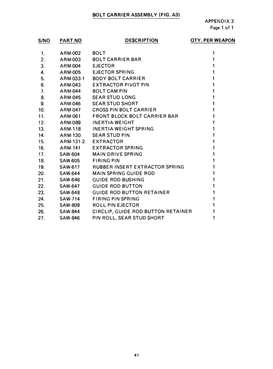
BOLT CARRIER ASSEMBLY (FIG. A3)
APPENDIX 3
Page 1 of 1
S/NO PART NO DESCRIPTION QTY. PER WEAPON
1. ARM-002 BOLT 1
2. ARM-003 BOLT CARRIER BAR 1
3. ARM-004 EJECTOR 1
4. ARM-005 EJECTOR SPRING 1
5. ARM-033-1 BODY BOLT CARRIER 1
6. ARM-043 EXTRACTOR PIVOT PIN 1
7. ARM-044 BOLT CAM PIN 1
8. ARM-045 SEAR STUD LONG 1
9. ARM-046 SEAR STUD SHORT 1
10. ARM-047 CROSS PIN BOLT CARRIER 1
11. ARM-061 FRONT BLOCK BOLT CARRIER BAR 1
12. ARM-089 INERTIA WEIGHT 1
13. ARM-118 INERTIA WEIGHT SPRING 1
14. ARM-130 SEAR STUD PIN 1
15. ARM-131-2 EXTRACTOR 1
16. ARM-141 EXTRACTOR SPRING 1
17. SAW-604 MAIN DRIVE SPRING 1
18. SAW-605 FIRING PIN 1
19. SAW-617 RUBBER INSERT EXTRACTOR SPRING 1
20. SAW-644 MAIN SPRING GUIDE ROD 1
21. SAW-646 GUIDE ROD BUSHING 1
22. SAW-647 GUIDE ROD BUTTON 1
23. SAW-648 GUIDE ROD BUTTON RETAINER 1
24. SAW-714 FIRING PIN SPRING 1
25. SAW-809 ROLL PIN EJECTOR 1
26. SAW-844 CIRCLIP, GUIDE ROD BUTTON RETAINER 1
27. SAW-846 PIN ROLL, SEAR STUD SHORT 1
41
м*-»эв
PIN SPIRAL
BARRS I
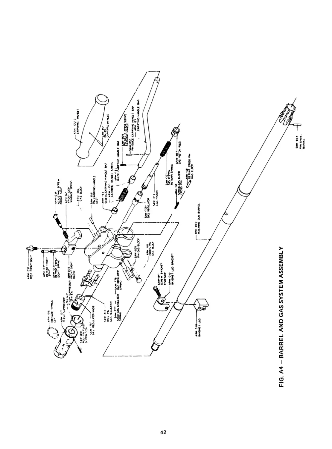
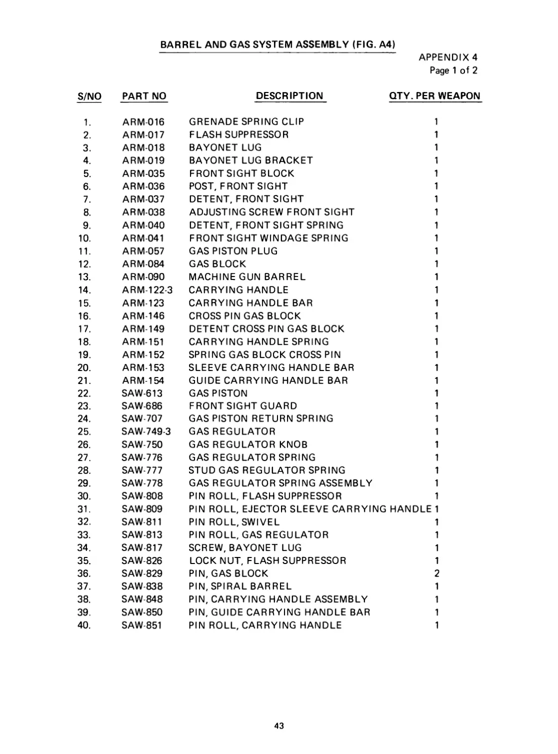
BARREL AND GAS SYSTEM ASSEMBLY (FIG. A4)
APPENDIX 4
Page 1 of 2
S/NO PART NO DESCRIPTION QTY. PER WEAPON
1. ARM-016 GRENADE SPRING CLIP 1
2. ARM-017 FLASH SUPPRESSOR 1
3. ARM-018 BAYONET LUG 1
4. ARM-019 BAYONET LUG BRACKET 1
5. ARM-035 FRONT SIGHT BLOCK 1
6. ARM-036 POST, FRONT SIGHT 1
7. ARM-037 DETENT, FRONT SIGHT 1
8. ARM-038 ADJUSTING SCREW FRONT SIGHT 1
9. ARM-040 DETENT, FRONT SIGHT SPRING 1
10. ARM-041 FRONT SIGHT WINDAGE SPRING 1
11. ARM-057 GAS PISTON PLUG 1
12. ARM-084 GAS BLOCK 1
13. ARM-090 MACHINE GUN BARREL 1
14. ARM-122-3 CARRYING HANDLE 1
15. ARM-123 CARRYING HANDLE BAR 1
16. ARM-146 CROSS PIN GAS BLOCK 1
17. ARM-149 DETENT CROSS PIN GAS BLOCK 1
18. ARM-151 CARRYING HANDLE SPRING 1
19. ARM-152 SPRING GAS BLOCK CROSS PIN 1
20. ARM-153 SLEEVE CARRYING HANDLE BAR 1
21. ARM-154 GUIDE CARRYING HANDLE BAR 1
22. SAW-613 GAS PISTON 1
23. SAW-686 FRONTSIGHTGUARD 1
24. SAW-707 GAS PISTON RETURN SPRING 1
25. SAW-749-3 GAS REGULATOR 1
26. SAW-750 GAS REGULATOR KNOB 1
27. SAW-776 GAS REGULATOR SPRING 1
28. SAW-777 STUD GAS REGULATOR SPRING 1
29. SAW-778 GAS REGULATOR SPRING ASSEMBLY 1
30. SAW-808 PIN ROLL, FLASH SUPPRESSOR 1
31. SAW-809 PIN ROLL, EJECTOR SLEEVE CARRYING HANDLE 1
32. SAW-811 PIN ROLL, SWIVEL 1
33. SAW-813 PIN ROLL, GAS REGULATOR 1
34. SAW-817 SCREW, BAYONET LUG 1
35. SAW-826 LOCK NUT, FLASH SUPPRESSOR 1
36. SAW-829 PIN, GAS BLOCK 2
37. SAW-838 PIN, SPIRAL BARREL 1
38. SAW-848 PIN, CARRYING HANDLE ASSEMBLY 1
39. SAW-850 PIN, GUIDE CARRYING HANDLE BAR 1
40. SAW-851 PIN ROLL, CARRYING HANDLE 1
43
r- SAW- 823
/ sckfw Buttstock
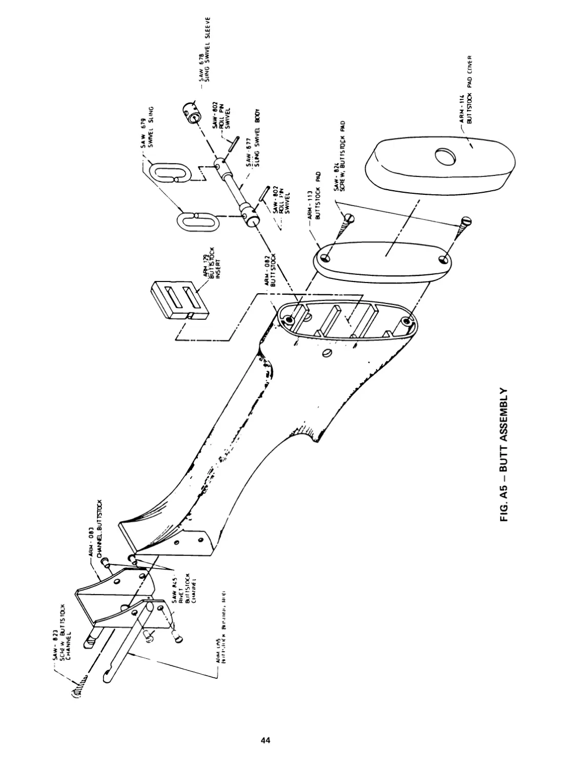
FIG. A5 - BUTT ASSEMBLY
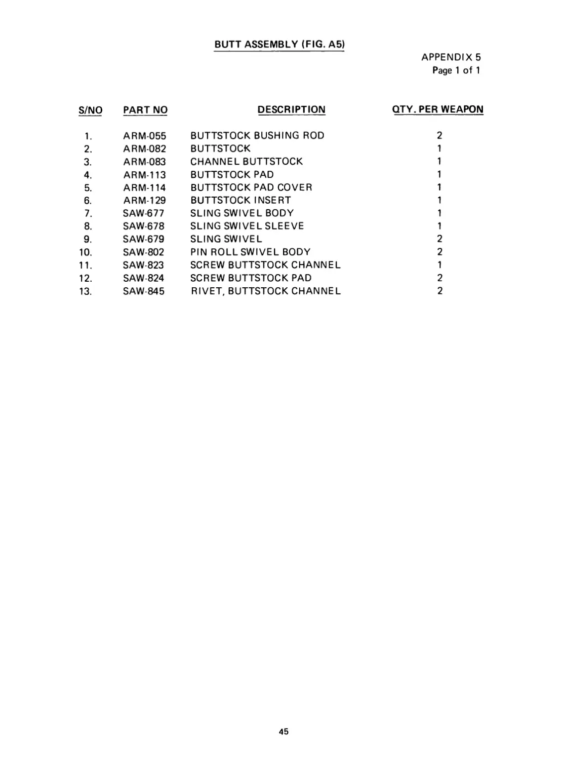
BUTT ASSEMBLY (FIG. A5)
APPENDIX 5
Page 1 of 1
S/NO PART NO DESCRIPTION QTY. PER WEAPON
1. ARM-055 BUTTSTOCK BUSHING ROD 2
2. ARM-082 BUTTSTOCK 1
3. ARM-083 CHANNEL BUTTSTOCK 1
4. ARM-113 BUTTSTOCK PAD 1
5. ARM-114 BUTTSTOCK PAD COVER 1
6. ARM-129 BUTTSTOCK INSERT 1
7. SAW-677 SLING SWIVEL BODY 1
8. SAW-678 SLING SWIVELSLEEVE 1
9. SAW-679 SLING SWIVEL 2
10. SAW-802 PIN ROLLSWIVEL BODY 2
11. SAW-823 SCREW BUTTSTOCK CHANNEL 1
12. SAW-824 SCREW BUTTSTOCK PAD 2
13. SAW-845 RIVET, BUTTSTOCK CHANNEL 2
45
SAW- 695
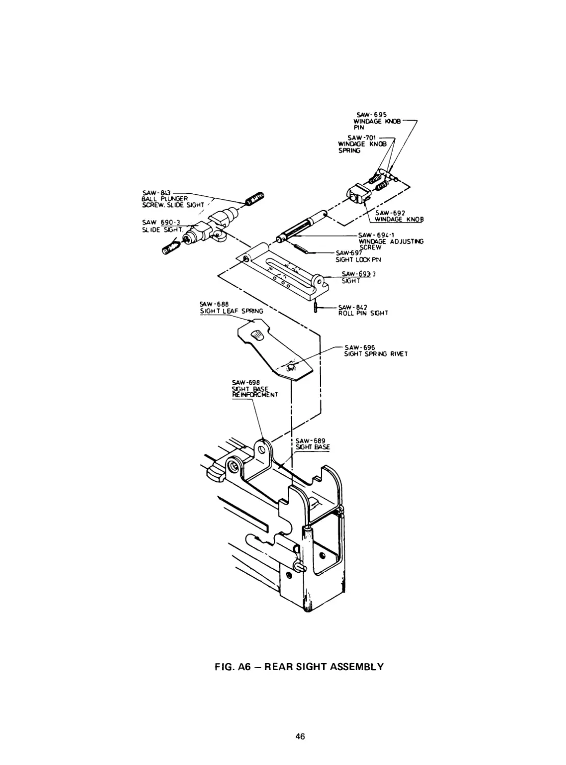
FIG. A6 - REAR SIGHT ASSEMBLY
46
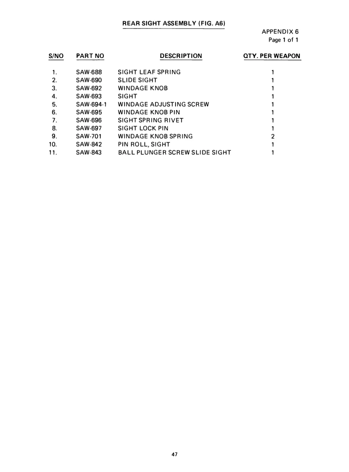
REAR SIGHT ASSEMBLY (FIG. A6)
APPENDIX 6
Page 1 of 1
S/NO PART NO DESCRIPTION QTY. PER WEAPON
1. SAW-688 SIGHT LEAF SPRING 1
2. SAW-690 SLIDE SIGHT 1
3. SAW-692 WINDAGE KNOB 1
4. SAW-693 SIGHT 1
5. SAW-694-1 WINDAGE ADJUSTING SCREW 1
6. SAW-695 WINDAGE KNOB PIN 1
7. SAW-696 SIGHT SPRING RIVET 1
8. SAW-697 SIGHT LOCK PIN 1
9. SAW-701 WINDAGE KNOB SPRING 2
10. SAW-842 PIN ROLL, SIGHT 1
11. SAW-843 BALL PLUNGER SCREW SLIDE SIGHT 1
47
(Р
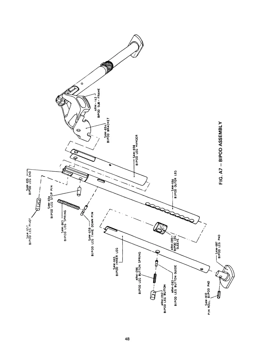
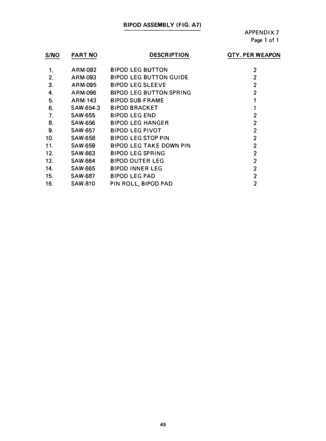
BIPOD ASSEMBLY (FIG. A7)
APPENDIX 7
Page 1 of 1
S/NO PART NO DESCRIPTION QTY. PER WEAPON
1. ARM-092 BIPOD LEG BUTTON 2
2. ARM-093 BIPOD LEG BUTTON GUIDE 2
3. ARM-095 BIPOD LEG SLEEVE 2
4. ARM-096 BIPOD LEG BUTTON SPRING 2
5. ARM-143 BIPOD SUB-FRAME 1
6. SAW-654-3 BIPOD BRACKET 1
7. SAW-655 BIPOD LEG END 2
8. SAW-656 BIPOD LEG HANGER 2
9. SAW-657 BIPOD LEG PIVOT 2
10. SAW-658 BIPOD LEG STOP PIN 2
11. SAW-659 BIPOD LEG TAKE DOWN PIN 2
12. SAW-663 BIPOD LEG SPRING 2
13. SAW-664 BIPOD OUTER LEG 2
14. SAW-665 BIPOD INNER LEG 2
15. SAW-687 BIPOD LEG PAD 2
16. SAW-810 PIN ROLL, BIPOD PAD 2
49
Symbol of Reliability
CHARTERED INDUSTRIES OF SINGAPORE
PO BOX 1334. SINGAPORE 9026 TEL 2651066
249. JALAN BOON LAY SINGAPOPt 2261
Cable Address DOBERMAN" SINGAPORE
Telex OS RS 21419
Printed by Savoy Printers
Date V84