/


Text
Enhanced Carbine & Rifle System
HK416
Caliber 5.56 mm x 45
OPERATOR’S MANUAL
August 2007 Edition
HK416 ops manual (HKO979 435) DUST rev 8-27-07.qxp 9/4/07 9:21 AM Page A
Enhanced Carbine & Rifle System
HK416
Caliber 5.56 mm x 45
Operatoŕs Manual
Before handling the weapon, read and adhere to the safety instructions!
HK416 ops manual (HKO979 435) DUST rev 8-27-07.qxp 9/4/07 9:21 AM Page B
Table of contents
Table of contents
2
3
1. Short description ....................................................................................................................4
2. Weapon models ......................................................................................................................5
3.
HK416 Clearing procedures & safety rules .................................................................6
3.1
Clearing / unloading the HK416....................................................................................6
3.2 Safety Rules ...................................................................................................................6
3.3
Warnings ........................................................................................................................7
3.4
Notes .............................................................................................................................7
4. Technical Data .........................................................................................................................8
5. Operating controls and parts identification .....................................................................9
5.1
External parts nomenclature........................................................................................10
5.2
Internal parts nomenclature ........................................................................................12
6. HK416 Weapon Variants ......................................................................................................13
7. Handling and operation .......................................................................................................15
7.1
Assembly groups .........................................................................................................15
7.2 Operating controls ......................................................................................................15
7.3
Loading the HK416 .....................................................................................................17
7.4
Reloading the HK416 ..................................................................................................17
7.5
Unloading the HK416 ..................................................................................................17
8. Disassembly of the HK416 .................................................................................................18
8.1
Disassembly into the assembly groups (Field-Stripping) ............................................18
9. Cleaning the HK416.............................................................................................................22
9.1
Care and cleaning of the HK416 .................................................................................22
9.2
Lubrication Guide ........................................................................................................23
9.3
Lubrication plan ...........................................................................................................24
9.3
Lubrication plan in sandy environments ......................................................................25
9.4
Inspection ....................................................................................................................26
10. Reassembly of the HK416 ..................................................................................................27
10.1 Function check of the HK416 ......................................................................................27
11. HK High reliability 30-rd steel magazine ........................................................................28
11.1 Disassembly of the HK High reliability 30-rd steel magazine .....................................28
11.2 Nomenclature (HK High reliability 30-rd steel magazine) ...........................................................28
11.3 Cleaning (HK High reliability 30-rd steel magazine) ....................................................................29
11.4 Inspection (HK High reliability 30-rd steel magazine) ..................................................................30
11.5 Assembly (HK High reliability 30-rd steel magazine) ...................................................................31
11.6 Proper loading procedures for the HK Magazine .......................................................30
12. Sight adjustment ..................................................................................................................33
12.1 Installing the optional HK Diopter rotary sight set .....................................................33
12.2 Installing the fold down front sight .............................................................................33
12.3 Sight adjustments ........................................................................................................34
13. SBFA & ammunition .............................................................................................................35
13.1 Safety Blank Firing Adapter (SBFA) .............................................................................35
13.2 Ammunition .................................................................................................................35
14. Use of the HK416 Multi-purpose sling ............................................................................36
15. Functional description of the HK416 ...............................................................................37
15.1 Steps of functioning ....................................................................................................37
16. Troubleshooting ....................................................................................................................40
16.1 HK416 - Malfunctions and corrections ........................................................................40
16.2 HK High reliability 30-rd steel magazine - Malfunctions and corrections ...................41
16.3 Troubleshooting list .....................................................................................................42
17. Accessories ............................................................................................................................45
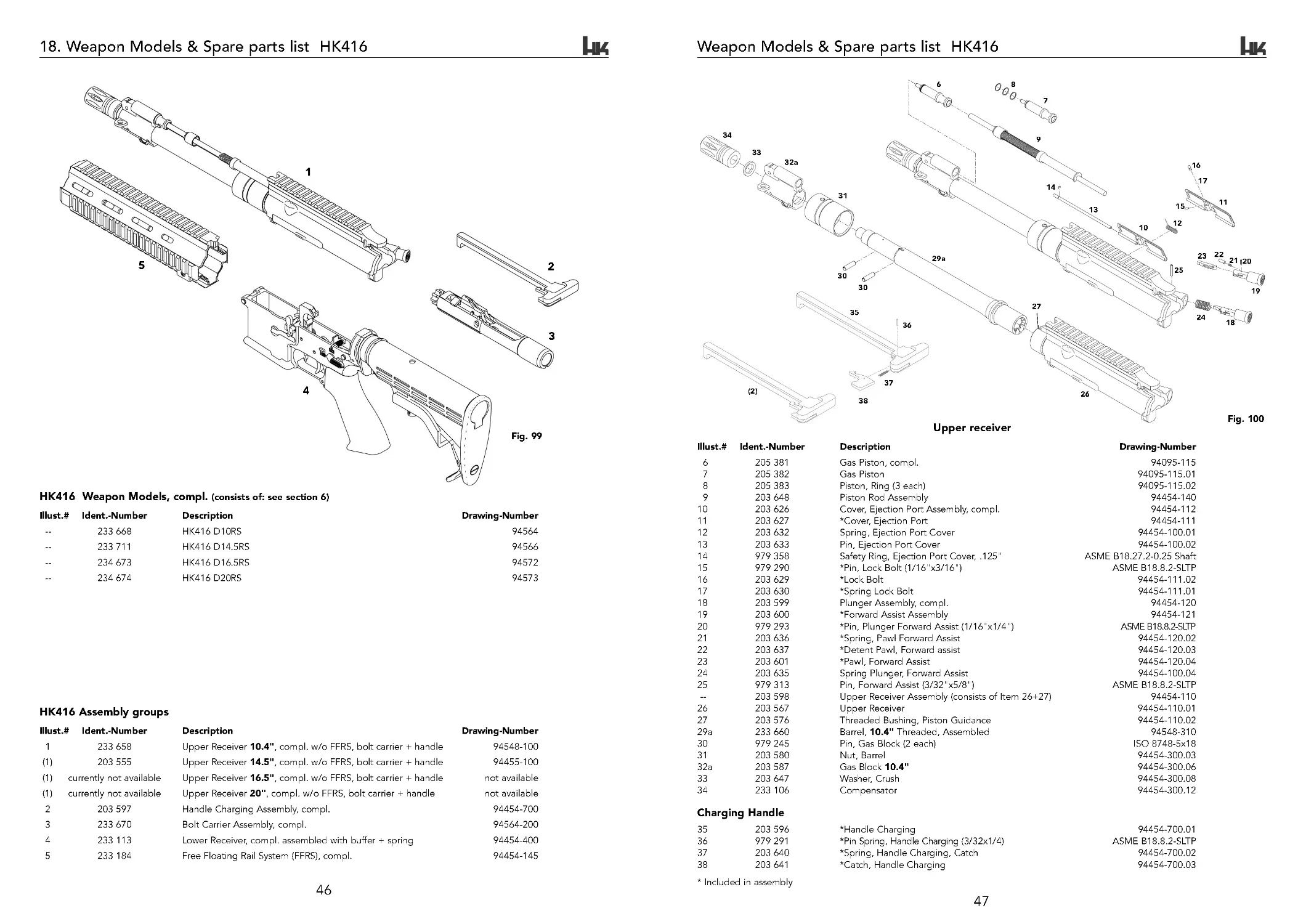
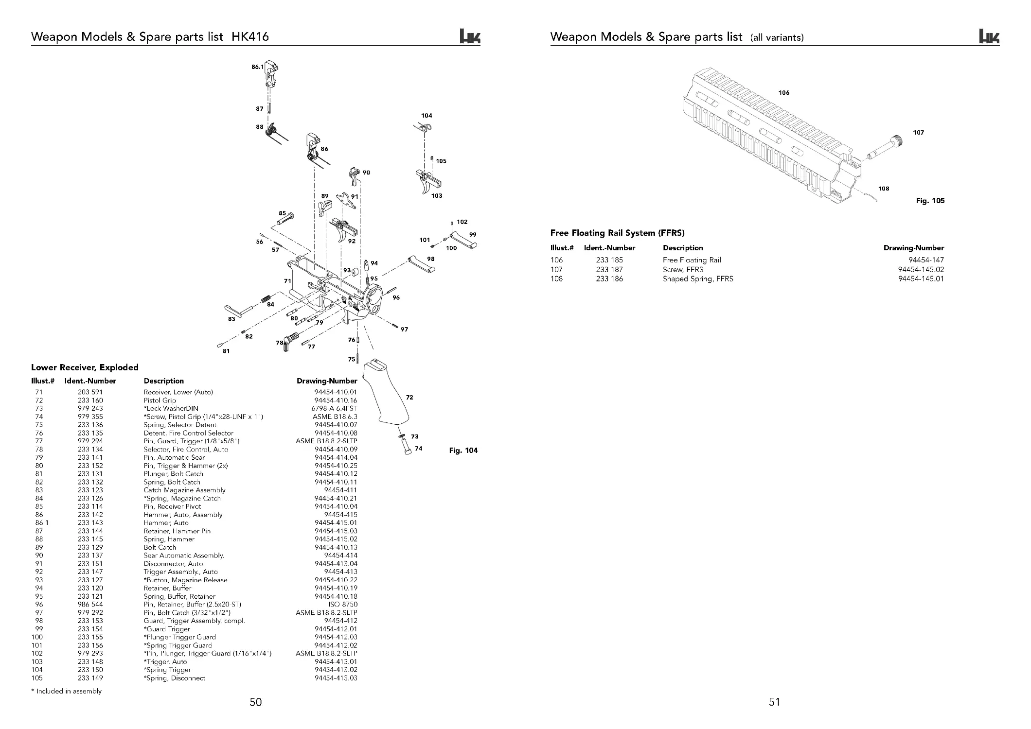
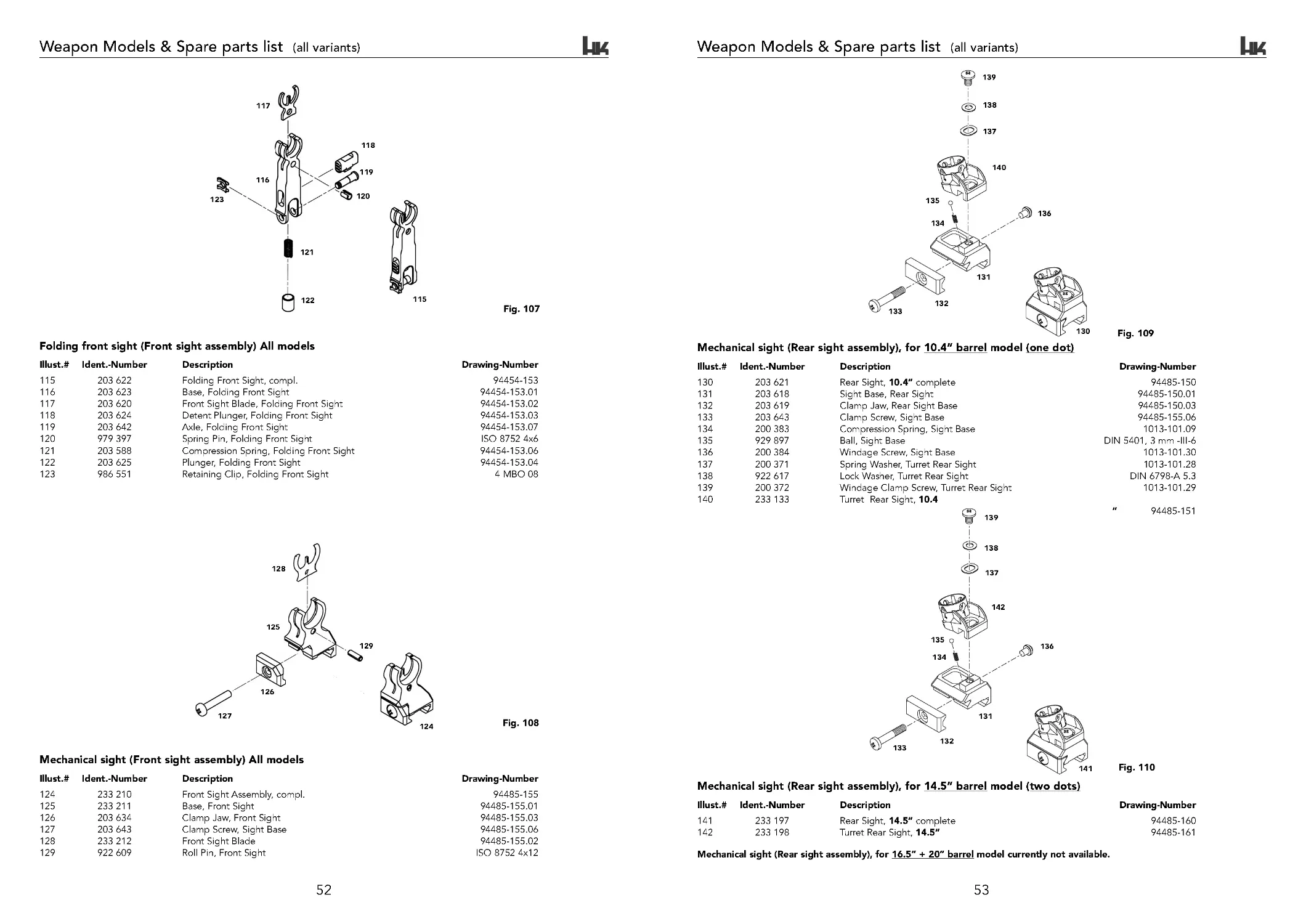
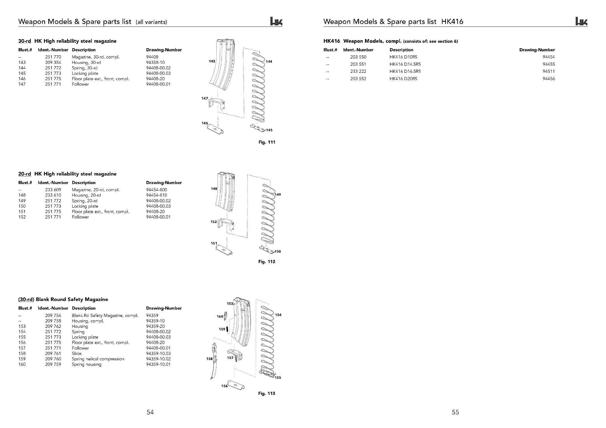
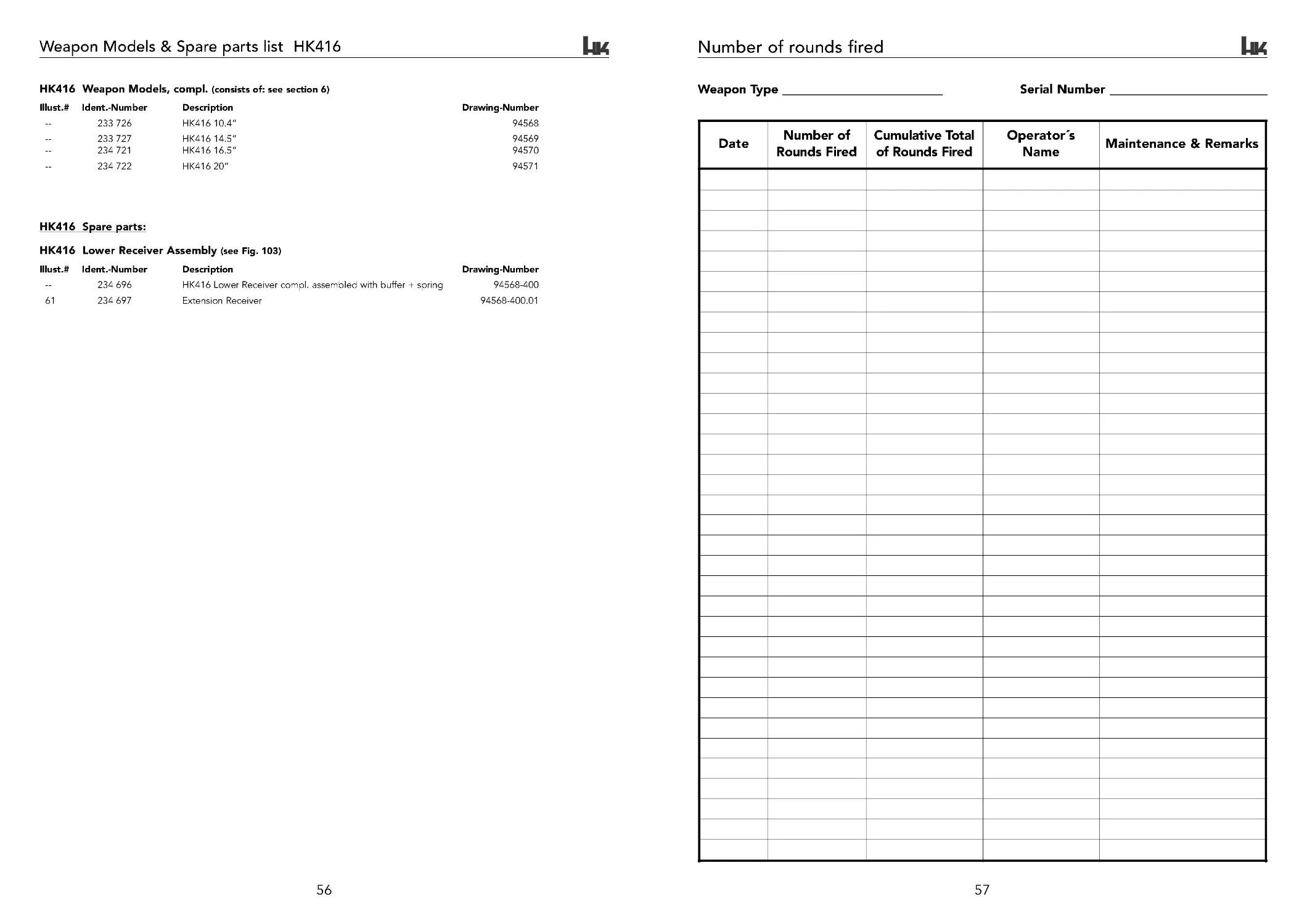
18. Weapon Models & Spare parts list...................................................................................45
19. Number of rounds fired ......................................................................................................57
HK416 ops manual (HKO979 435) DUST rev 8-27-07.qxp 9/4/07 9:21 AM Page 2
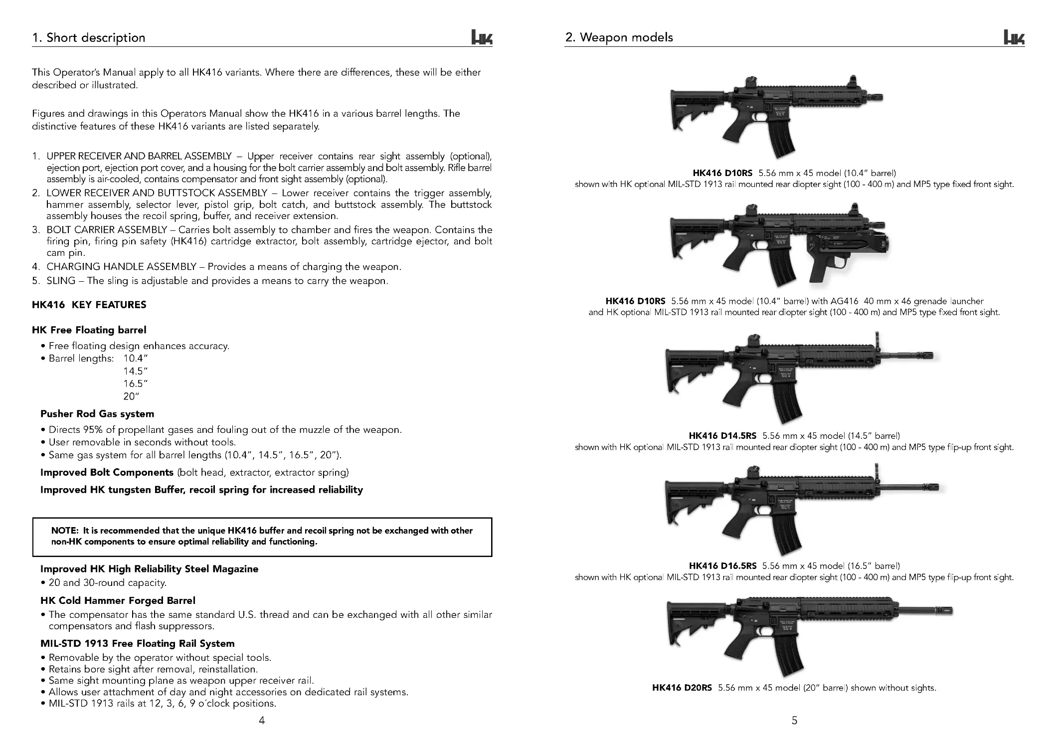
2. Weapon models
HK416 D10RS 5.56 mm x 45 model (10.4” barrel)
shown with HK optional MIL-STD 1913 rail mounted rear diopter sight (100 - 400 m) and MP5 type fixed front sight.
HK416 D10RS 5.56 mm x 45 model (10.4” barrel) with AG416 40 mm x 46 grenade launcher
and HK optional MIL-STD 1913 rail mounted rear diopter sight (100 - 400 m) and MP5 type fixed front sight.
HK416 D14.5RS 5.56 mm x 45 model (14.5” barrel)
shown with HK optional MIL-STD 1913 rail mounted rear diopter sight (100 - 400 m) and MP5 type flip-up front sight.
HK416 D16.5RS 5.56 mm x 45 model (16.5” barrel)
shown with HK optional MIL-STD 1913 rail mounted rear diopter sight (100 - 400 m) and MP5 type flip-up front sight.
HK416 D20RS 5.56 mm x 45 model (20” barrel) shown without sights.
1. Short description
4
5
1. UPPER RECEIVER AND BARREL ASSEMBLY – Upper receiver contains rear sight assembly (optional),
ejection port, ejection port cover, and a housing for the bolt carrier assembly and bolt assembly. Rifle barrel
assembly is air-cooled, contains compensator and front sight assembly (optional).
2. LOWER RECEIVER AND BUTTSTOCK ASSEMBLY – Lower receiver contains the trigger assembly,
hammer assembly, selector lever, pistol grip, bolt catch, and buttstock assembly. The buttstock
assembly houses the recoil spring, buffer, and receiver extension.
3. BOLT CARRIER ASSEMBLY – Carries bolt assembly to chamber and fires the weapon. Contains the
firing pin, firing pin safety (HK416) cartridge extractor, bolt assembly, cartridge ejector, and bolt
cam pin.
4. CHARGING HANDLE ASSEMBLY – Provides a means of charging the weapon.
5. SLING – The sling is adjustable and provides a means to carry the weapon.
HK416 KEY FEATURES
HK Free Floating barrel
• Free floating design enhances accuracy.
• Barrel lengths: 10.4 ”
14.5 ”
16.5 ”
20”
Pusher Rod Gas system
• Directs 95% of propellant gases and fouling out of the muzzle of the weapon.
• User removable in seconds without tools.
• Same gas system for all barrel lengths (10.4”, 14 .5 ”, 1 6 .5” , 2 0”) .
Improved Bolt Components (bolt head, extractor, extractor spring)
Improved HK tungsten Buffer, recoil spring for increased reliability
NOTE: It is recommended that the unique HK416 buffer and recoil spring not be exchanged with other
non-HK components to ensure optimal reliability and functioning.
Improved HK High Reliability Steel Magazine
• 20 and 30-round capacity.
HK Cold Hammer Forged Barrel
• The compensator has the same standard U.S . thread and can be exchanged with all other similar
compensators and flash suppressors.
MIL-STD 1913 Free Floating Rail System
• Removable by the operator without special tools.
• Retains bore sight after removal, reinstallation.
• Same sight mounting plane as weapon upper receiver rail.
• Allows user attachment of day and night accessories on dedicated rail systems.
• MIL-STD 1913 rails at 12, 3, 6, 9 óclock positions.
This Operator’s Manual apply to all HK416 variants. Where there are differences, these will be either
described or illustrated.
Figures and drawings in this Operators Manual show the HK416 in a various barrel lengths. The
distinctive features of these HK416 variants are listed separately.
HK416 ops manual (HKO979 435) DUST rev 8-27-07.qxp 9/4/07 9:21 AM Page 4
7
6
HK416 Clearing procedures & safety rules
3.3 Warnings
• When handling the HK416, special caution is necessary as the position and direction of the HK416
can be easily changed.
• Only use the HK416 after you have fully reviewed and understood these instructions.
• Observe all notes on handling and operation. Failure to do so may result in injury or death to the
operator and/or bystanders.
• Do not operate the HK416 if you are under the influence of alcohol, drugs or medication.
• When passing the HK416 between personnel, the weapon must be “CLEAR”, with the magazine
removed, the bolt should be locked to the rear and the weapon on safe.
• Always treat the HK416 as if it were loaded and ready to fire.
• To avoid damage to the weapon, allow it to cool to ambient temperature after firing 250 rounds in
rapid fire (less than 3 minutes).
• Never fire the HK416 without the gas piston and pusher rod installed.
• Ensure hands and fingers are clear of the muzzle during firing.
3.4 Notes
1. The HK416 utilizes component parts that ARE NOT interchangeable with M16-style weapons. Unique
HK components such as the buffer (with red dot and HK marking), recoil spring (red coil spring), bolt
group (HK engraved on the bolt carrier) and piston and gas system must never be fitted to other M16-
style weapons. The HK416 must only be fitted and fired with original factory components.
2. While the HK416 will function with US issue aluminum magazines in good condition, the reliability
of the HK416 is improved and can only be guaranteed when using HK High reliability steel
magazines. The use of any magazine other than the HK magazine may reduce the reliability of the
HK416 and is thus not covered under the warranty for the HK416.
3. The use of non-HK416 parts in the HK416 is not recommended. While in some cases these parts may
fit they may not be made to the same dimensions or level of quality as the original HK416 parts. Use
of inter nal non-HK416 parts to replace unique HK416 parts will void the warranty.
4. Since the HK416 is manufactured in Germany, the European standard is to serialize the part that is
attached to the barrel, which in this case is the upper receiver. The upper receiver is stamped with
a number which is located in the seam of the upper and lower receiver and below the forward assist.
This number in no way applies to US standards. The lower receiver serial number will be for US
record keeping in accordance with BATF regulations.
3.
HK416 Clearing procedures & safety rules
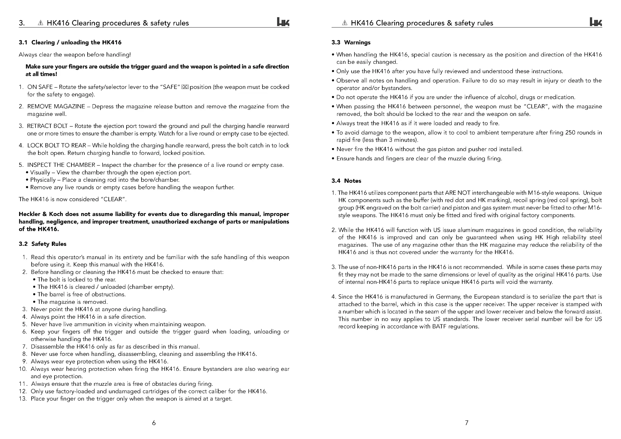
3.1 Clearing / unloading the HK416
Always clear the weapon before handling!
Make sure your fingers are outside the trigger guard and the weapon is pointed in a safe direction
at all times!
1. ON SAFE – Rotate the safety/selector lever to the “SAFE” position (the weapon must be cocked
for the safety to engage).
2. REMOVE MAGAZINE – Depress the magazine release button and remove the magazine from the
magazine well.
3. RETRACT BOLT – Rotate the ejection port toward the ground and pull the charging handle rearward
one or more times to ensure the chamber is empty. Watch for a live round or empty case to be ejected.
4. LOCK BOLT TO REAR – While holding the charging handle rearward, press the bolt catch in to lock
the bolt open. Return charging handle to forward, locked position.
5. INSPECT THE CHAMBER – Inspect the chamber for the presence of a live round or empty case.
• Visually – View the chamber through the open ejection port.
• Physically – Place a cleaning rod into the bore/chamber.
• Remove any live rounds or empty cases before handling the weapon further.
The HK416 is now considered “CLEAR”.
Heckler & Koch does not assume liability for events due to disregarding this manual, improper
handling, negligence, and improper treatment, unauthorized exchange of parts or manipulations
of the HK416.
3.2 Safety Rules
1. Read this operator’s manual in its entirety and be familiar with the safe handling of this weapon
before using it. Keep this manual with the HK416.
2. Before handling or cleaning the HK416 must be checked to ensure that:
• The bolt is locked to the rear.
• The HK416 is cleared / unloaded (chamber empty).
• The barrel is free of obstructions.
• The magazine is removed.
3. Never point the HK416 at anyone during handling.
4. Always point the HK416 in a safe direction.
5. Never have live ammunition in vicinity when maintaining weapon.
6. Keep your fingers off the trigger and outside the trigger guard when loading, unloading or
otherwise handling the HK416.
7. Disassemble the HK416 only as far as described in this manual.
8. Never use force when handling, disassembling, cleaning and assembling the HK416.
9. Always wear eye protection when using the HK416.
10. Always wear hearing protection when firing the HK416. Ensure bystanders are also wearing ear
and eye protection.
11 . Always ensure that the muzzle area is free of obstacles during firing.
12. Only use factory-loaded and undamaged cartridges of the correct caliber for the HK416.
13. Place your finger on the trigger only when the weapon is aimed at a target.
HK416 ops manual (HKO979 435) DUST rev 8-27-07.qxp 9/4/07 9:21 AM Page 6
9
8
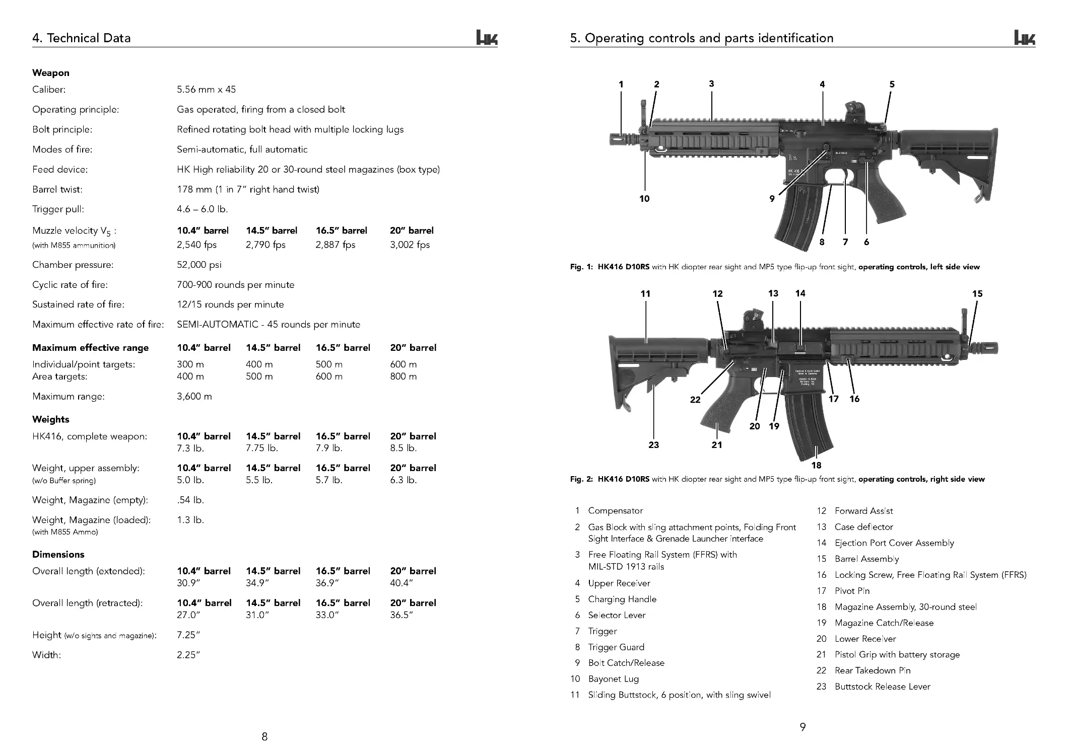
5. Operating controls and parts identification
1 Compensator
2 Gas Block with sling attachment points, Folding Front
Sight Interface & Grenade Launcher interface
3 Free Floating Rail System (FFRS) with
MIL-STD 1913 rails
4 Upper Receiver
5 Charging Handle
6 Selector Lever
7 Trigger
8 Trigger Guard
9 Bolt Catch/Release
10 Bayonet Lug
11 Sliding Buttstock, 6 position, with sling swivel
12 Forward Assist
13 Case deflector
14 Ejection Port Cover Assembly
15 Barrel Assembly
16 Locking Screw, Free Floating Rail System (FFRS)
17 Pivot Pin
18 Magazine Assembly, 30 -round steel
19 Magazine Catch/Release
20 Lower Receiver
21 Pistol Grip with battery storage
22 Rear Takedown Pin
23 Buttstock Release Lever
Fig. 1: HK416 D10RS with HK diopter rear sight and MP5 type flip-up front sight, operating controls, left side view
Fig. 2: HK416 D10RS with HK diopter rear sight and MP5 type flip-up front sight, operating controls, right side view
10
76
5
4
3
2
1
9
8
11
12
13 14
15
16
17
20
18
19
21
22
23
4. Technical Data
Weapon
Caliber:
5.56mmx45
Operating principle:
Gas operated, firing from a closed bolt
Bolt principle:
Refined rotating bolt head with multiple locking lugs
Modes of fire:
Semi-automatic, full automatic
Feed device:
HK High reliability 20 or 30-round steel magazines (box type)
Barrel twist:
178 mm (1 in 7” right hand twist)
Trigger pull:
4.6 –6.0lb.
Muzzle velocity V5 :
10.4” barrel 14.5” barrel 16.5” barrel
20” barrel
(with M855 ammunition)
2,540 fps
2,790 fps
2,887 fps
3,002 fps
Chamber pressure:
52,000 psi
Cyclic rate of fire:
700-900 rounds per minute
Sustained rate of fire:
12/15 rounds per minute
Maximum effective rate of fire: SEMI-AUTOMATIC - 45 rounds per minute
Maximum effective range
10.4” barrel 14.5” barrel 16.5” barrel 20” barrel
Individual/point targets:
300 m
400 m
500 m
600 m
Area targets:
400 m
500 m
600 m
800 m
Maximum range:
3,600 m
Weights
HK416, complete weapon:
10.4” barrel 14.5” barrel 16.5” barrel 20” barrel
7.3 lb.
7.75 lb.
7.9 lb.
8.5 lb.
Weight, upper assembly:
10.4” barrel 14.5” barrel 16.5” barrel 20” barrel
(w/o Buffer spring)
5.0 lb.
5.5 lb.
5.7 lb.
6.3 lb.
Weight, Magazine (empty):
.54lb.
Weight, Magazine (loaded):
1.3 lb.
(with M855 Ammo)
Dimensions
Overall length (extended):
10.4” barrel 14.5” barrel 16.5” barrel 20” barrel
30.9”
34.9 ”
36.9 ”
40.4”
Overall length (retracted):
10.4” barrel 14.5” barrel 16.5” barrel 20” barrel
27.0”
31.0 ”
33.0 ”
36.5”
Height (w/o sights and magazine): 7.25”
Width:
2.25”
HK416 ops manual (HKO979 435) DUST rev 8-27-07.qxp 9/4/07 9:21 AM Page 8
11
10
Operating controls and parts identification
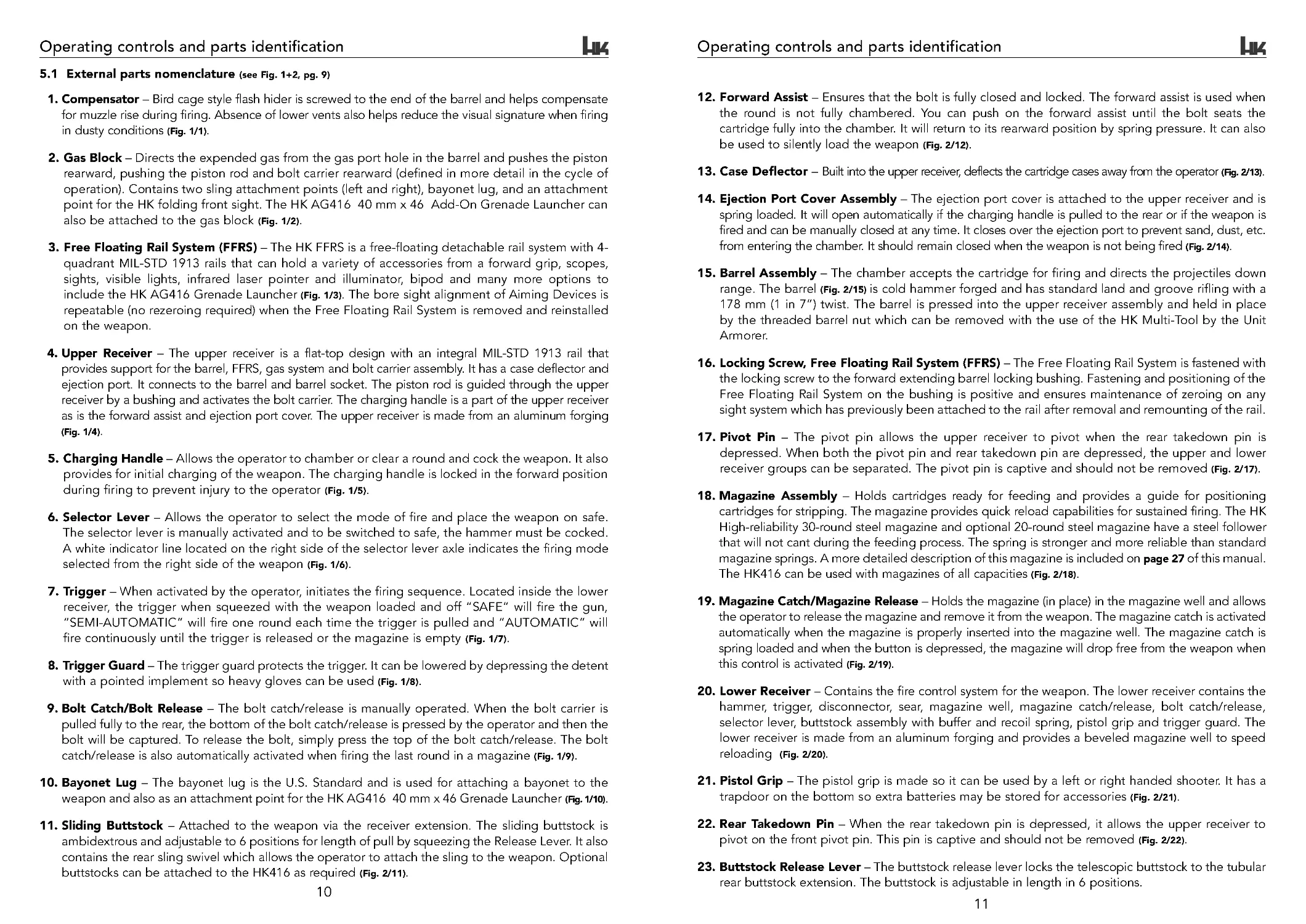
12. Forward Assist – Ensures that the bolt is fully closed and locked. The forward assist is used when
the round is not fully chambered. You can push on the forward assist until the bolt seats the
cartridge fully into the chamber. It will retur n to its rearward position by spring pressure. It can also
be used to silently load the weapon (Fig. 2/12).
13. Case Deflector – Built into the upper receiver, deflects the cartridge cases away from the operator (Fig. 2/13).
14. Ejection Port Cover Assembly – The ejection port cover is attached to the upper receiver and is
spring loaded. It will open automatically if the charging handle is pulled to the rear or if the weapon is
fired and can be manually closed at any time. It closes over the ejection port to prevent sand, dust, etc.
from entering the chamber. It should remain closed when the weapon is not being fired (Fig. 2/14).
15. Barrel Assembly – The chamber accepts the cartridge for firing and directs the projectiles down
range. The barrel (Fig. 2/15) is cold hammer forged and has standard land and groove rifling with a
178 mm (1 in 7”) twist. The barrel is pressed into the upper receiver assembly and held in place
by the threaded barrel nut which can be removed with the use of the HK Multi-Tool by the Unit
Armorer.
16. Locking Screw, Free Floating Rail System (FFRS) – The Free Floating Rail System is fastened with
the locking screw to the forward extending barrel locking bushing. Fastening and positioning of the
Free Floating Rail System on the bushing is positive and ensures maintenance of zeroing on any
sight system which has previously been attached to the rail after removal and remounting of the rail.
17. Pivot Pin – The pivot pin allows the upper receiver to pivot when the rear takedown pin is
depressed. When both the pivot pin and rear takedown pin are depressed, the upper and lower
receiver groups can be separated. The pivot pin is captive and should not be removed (Fig. 2/17).
18. Magazine Assembly – Holds cartridges ready for feeding and provides a guide for positioning
cartridges for stripping. The magazine provides quick reload capabilities for sustained firing. The HK
High-reliability 30-round steel magazine and optional 20-round steel magazine have a steel follower
that will not cant during the feeding process. The spring is stronger and more reliable than standard
magazine springs. A more detailed description of this magazine is included on page 27 of this manual.
The HK416 can be used with magazines of all capacities (Fig. 2/18).
19. Magazine Catch/Magazine Release – Holds the magazine (in place) in the magazine well and allows
the operator to release the magazine and remove it from the weapon. The magazine catch is activated
automatically when the magazine is properly inserted into the magazine well. The magazine catch is
spring loaded and when the button is depressed, the magazine will drop free from the weapon when
this control is activated (Fig. 2/19).
20. Lower Receiver – Contains the fire control system for the weapon. The lower receiver contains the
hammer, trigger, disconnector, sear, magazine well, magazine catch/release, bolt catch/release,
selector lever, buttstock assembly with buffer and recoil spring, pistol grip and trigger guard. The
lower receiver is made from an aluminum forging and provides a beveled magazine well to speed
reloading (Fig. 2/20).
21. Pistol Grip – The pistol grip is made so it can be used by a left or right handed shooter. It has a
trapdoor on the bottom so extra batteries may be stored for accessories (Fig. 2/21).
22. Rear Takedown Pin – When the rear takedown pin is depressed, it allows the upper receiver to
pivot on the front pivot pin. This pin is captive and should not be removed (Fig. 2/22).
23. Buttstock Release Lever – The buttstock release lever locks the telescopic buttstock to the tubular
rear buttstock extension. The buttstock is adjustable in length in 6 positions.
Operating controls and parts identification
5.1 External parts nomenclature (see Fig. 1+2, pg. 9)
1. Compensator – Bird cage style flash hider is screwed to the end of the barrel and helps compensate
for muzzle rise during firing. Absence of lower vents also helps reduce the visual signature when firing
in dusty conditions (Fig. 1/1).
2. Gas Block – Directs the expended gas from the gas port hole in the barrel and pushes the piston
rearward, pushing the piston rod and bolt carrier rearward (defined in more detail in the cycle of
operation). Contains two sling attachment points (left and right), bayonet lug, and an attachment
point for the HK folding front sight. The HK AG416 40 mm x 46 Add-On Grenade Launcher can
also be attached to the gas block (Fig. 1/2).
3. Free Floating Rail System (FFRS) – The HK FFRS is a free-floating detachable rail system with 4-
quadrant MIL-STD 1913 rails that can hold a variety of accessories from a forward grip, scopes,
sights, visible lights, infrared laser pointer and illuminator, bipod and many more options to
include the HK AG416 Grenade Launcher (Fig. 1/3). The bore sight alignment of Aiming Devices is
repeatable (no rezeroing required) when the Free Floating Rail System is removed and reinstalled
on the weapon.
4. Upper Receiver – The upper receiver is a flat-top design with an integral MIL-STD 1913 rail that
provides support for the barrel, FFRS, gas system and bolt carrier assembly. It has a case deflector and
ejection port. It connects to the barrel and barrel socket. The piston rod is guided through the upper
receiver by a bushing and activates the bolt carrier. The charging handle is a part of the upper receiver
as is the forward assist and ejection port cover. The upper receiver is made from an aluminum forging
(Fig. 1/4).
5. Charging Handle – Allows the operator to chamber or clear a round and cock the weapon. It also
provides for initial charging of the weapon. The charging handle is locked in the forward position
during firing to prevent injury to the operator (Fig. 1/5).
6. Selector Lever – Allows the operator to select the mode of fire and place the weapon on safe.
The selector lever is manually activated and to be switched to safe, the hammer must be cocked.
A white indicator line located on the right side of the selector lever axle indicates the firing mode
selected from the right side of the weapon (Fig. 1/6).
7. Trigger – When activated by the operator, initiates the firing sequence. Located inside the lower
receiver, the trigger when squeezed with the weapon loaded and off “SAFE” will fire the gun,
“SEMI-AUTOMATIC” will fire one round each time the trigger is pulled and “AUTOMATIC” will
fire continuously until the trigger is released or the magazine is empty (Fig. 1/7).
8. Trigger Guard – The trigger guard protects the trigger. It can be lowered by depressing the detent
with a pointed implement so heavy gloves can be used (Fig. 1/8).
9. Bolt Catch/Bolt Release – The bolt catch/release is manually operated. When the bolt carrier is
pulled fully to the rear, the bottom of the bolt catch/release is pressed by the operator and then the
bolt will be captured. To release the bolt, simply press the top of the bolt catch/release. The bolt
catch/release is also automatically activated when firing the last round in a magazine (Fig. 1/9).
10. Bayonet Lug – The bayonet lug is the U.S. Standard and is used for attaching a bayonet to the
weapon and also as an attachment point for the HK AG416 40 mm x 46 Grenade Launcher (Fig. 1/10).
11. Sliding Buttstock – Attached to the weapon via the receiver extension. The sliding buttstock is
ambidextrous and adjustable to 6 positions for length of pull by squeezing the Release Lever. It also
contains the rear sling swivel which allows the operator to attach the sling to the weapon. Optional
buttstocks can be attached to the HK416 as required (Fig. 2/11).
HK416 ops manual (HKO979 435) DUST rev 8-27-07.qxp 9/4/07 9:21 AM Page 10
13
12
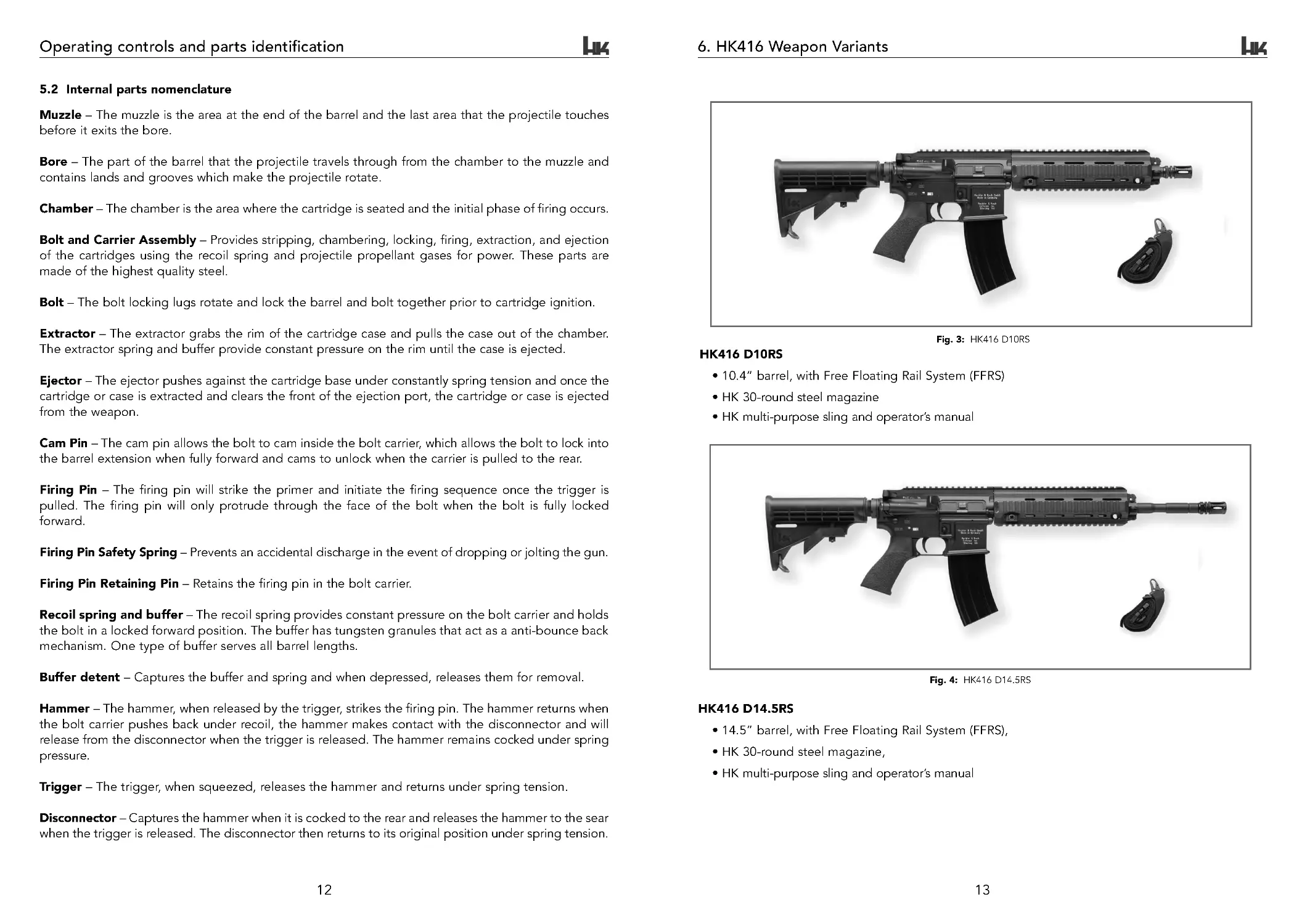
6. HK416 Weapon Variants
Fig. 3: HK416 D10RS
HK416 D10RS
• 10.4” barrel, with Free Floating Rail System (FFRS)
• HK 30-round steel magazine
• HK multi-purpose sling and operator’s manual
Fig. 4: HK416 D14.5RS
HK416 D14.5RS
• 14.5” barrel, with Free Floating Rail System (FFRS),
• HK 30-round steel magazine,
• HK multi-purpose sling and operator’s manual
Operating controls and parts identification
5.2 Internal parts nomenclature
Muzzle – The muzzle is the area at the end of the barrel and the last area that the projectile touches
before it exits the bore.
Bore – The part of the barrel that the projectile travels through from the chamber to the muzzle and
contains lands and grooves which make the projectile rotate.
Chamber – The chamber is the area where the cartridge is seated and the initial phase of firing occurs.
Bolt and Carrier Assembly – Provides stripping, chambering, locking, firing, extraction, and ejection
of the cartridges using the recoil spring and projectile propellant gases for power. These parts are
made of the highest quality steel.
Bolt – The bolt locking lugs rotate and lock the barrel and bolt together prior to cartridge ignition.
Extractor – The extractor grabs the rim of the cartridge case and pulls the case out of the chamber.
The extractor spring and buffer provide constant pressure on the rim until the case is ejected.
Ejector – The ejector pushes against the cartridge base under constantly spring tension and once the
cartridge or case is extracted and clears the front of the ejection port, the cartridge or case is ejected
from the weapon.
Cam Pin – The cam pin allows the bolt to cam inside the bolt carrier, which allows the bolt to lock into
the barrel extension when fully forward and cams to unlock when the carrier is pulled to the rear.
Firing Pin – The firing pin will strike the primer and initiate the firing sequence once the trigger is
pulled. The firing pin will only protrude through the face of the bolt when the bolt is fully locked
forward.
Firing Pin Safety Spring – Prevents an accidental discharge in the event of dropping or jolting the gun.
Firing Pin Retaining Pin – Retains the firing pin in the bolt carrier.
Recoil spring and buffer – The recoil spring provides constant pressure on the bolt carrier and holds
the bolt in a locked forward position. The buffer has tungsten granules that act as a anti-bounce back
mechanism. One type of buffer serves all barrel lengths.
Buffer detent – Captures the buffer and spring and when depressed, releases them for removal.
Hammer – The hammer, when released by the trigger, strikes the firing pin. The hammer returns when
the bolt carrier pushes back under recoil, the hammer makes contact with the disconnector and will
release from the disconnector when the trigger is released. The hammer remains cocked under spring
pressure.
Trigger – The trigger, when squeezed, releases the hammer and returns under spring tension.
Disconnector – Captures the hammer when it is cocked to the rear and releases the hammer to the sear
when the trigger is released. The disconnector then returns to its original position under spring tension.
HK416 ops manual (HKO979 435) DUST rev 8-27-07.qxp 9/4/07 9:21 AM Page 12
14
15
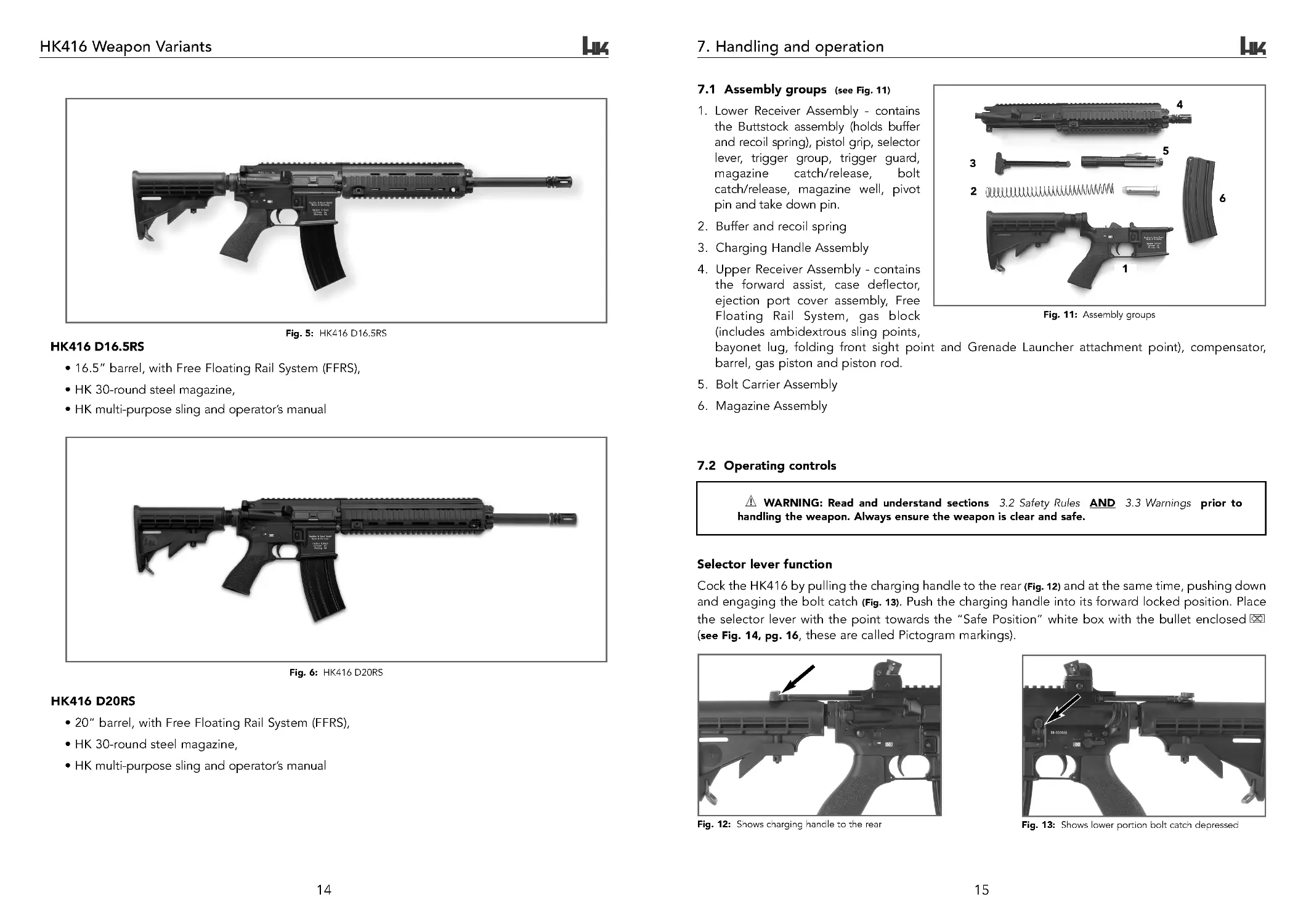
7. Handling and operation
7.1 Assembly groups (see Fig. 11)
1. Lower Receiver Assembly - contains
the Buttstock assembly (holds buffer
and recoil spring), pistol grip, selector
lever, trigger group, trigger guard,
magazine
catch/release,
bolt
catch/release, magazine well, pivot
pin and take down pin.
2. Buffer and recoil spring
3. Charging Handle Assembly
4. Upper Receiver Assembly - contains
the forward assist, case deflector,
ejection port cover assembly, Free
Floating Rail System, gas block
(includes ambidextrous sling points,
bayonet lug, folding front sight point and Grenade Launcher attachment point), compensator,
barrel, gas piston and piston rod.
5. Bolt Carrier Assembly
6. Magazine Assembly
Fig. 11: Assembly groups
7.2 Operating controls
WARNING: Read and understand sections 3.2 Safety Rules AND 3.3 Warnings prior to
handling the weapon. Always ensure the weapon is clear and safe.
Selector lever function
Cock the HK416 by pulling the charging handle to the rear (Fig. 12) and at the same time, pushing down
and engaging the bolt catch (Fig. 13). Push the charging handle into its forward locked position. Place
the selector lever with the point towards the “Safe Position” white box with the bullet enclosed
(see Fig. 14, pg . 16, these are called Pictogram markings).
Fig. 12: Shows charging handle to the rear
Fig. 13: Shows lower portion bolt catch depressed
3
2
5
6
4
1
HK416 Weapon Variants
Fig. 5: HK416 D16.5RS
HK416 D16.5RS
• 16.5 ” barrel, with Free Floating Rail System (FFRS),
• HK 30-round steel magazine,
• HK multi-purpose sling and operator’s manual
Fig. 6: HK416 D20RS
HK416 D20RS
• 20” barrel, with Free Floating Rail System (FFRS),
• HK 30-round steel magazine,
• HK multi-purpose sling and operator’s manual
HK416 ops manual (HKO979 435) DUST rev 8-27-07.qxp 9/4/07 9:21 AM Page 14
17
16
Handling and operation
7.3 Loading the HK416
Method: No magazine is in the weapon. The bolt is in its forward
(locked) position.
1. Pull the charging handle all the way to the rear and hold it in position
(Fig. 17).
2. Push the bolt catch in with the index finger to lock the bolt to the
rear (Fig. 18).
3. Push the charging handle back fully into the receiver (Fig. 19).
4. Set the selector lever on “SAFE” (Fig. 14).
5. Insert a loaded magazine into the magazine well until the
magazine catch engages the magazine. Tug on the magazine to
ensure it is securely engaged.
6. Push the bolt catch button in, the bolt will move forward and feed
a round into the chamber (Fig. 18).
7. The weapon is now loaded and set on “SAFE”.
Fig. 19
Fig. 17
Fig. 18
Fig. 20
7.4 Reloading the HK416
Method: The magazine in the weapon is empty. The bolt is held to
the rear by the bolt catch. Same procedure as above, except
the bolt is already locked to the rear and you must first set
the selector to “SAFE”.
1. Set the selector lever to “SAFE” (Fig. 14).
2. Depress the magazine release button with the right index finger or
thumb (Fig. 21). Remove the empty magazine from the magazine
well. Store the empty magazine in a magazine pouch.
3. Insert a loaded magazine into the magazine well until the magazine
catch engages the magazine. Tug on the magazine to ensure it is
securely engaged.
4. Push the bolt catch in to release the bolt and to chamber a round (Fig. 18).
5. The weapon is now loaded and set on “SAFE”.
NOTE: Instead of using the bolt release to release the bolt, the
charging handle can be pulled fully to the rear; this releases the
bolt catch and bolt. Release the charging handle at the rear
position. DO NOT RIDE THE CHARGING HANDLE FORWARD; THE
BOLT MAY NOT COMPLETELY LOCK FORWARD. If the bolt does
not fully close, press the forward assist until it closes completely.
Fig. 21
WARNING: Before firing the HK416, ensure that:
1. The bore is clear of obstructions.
2. The weapon is pointed only at your intended target.
3. You are sure of your backstop and the impact area beyond.
4. Your hands and fingers are away from the muzzle.
WARNING: To avoid damage to the weapon, allow it to cool to ambient temperature after
firing 250 rounds in rapid cadence (less than 3 minutes).
Handling and operation
“ SAFE POSITION”
–
Place the selector lever with the point facing
towards the closed white box containing a bullet symbol with an “X ”
over it (towards the muzzle) (Fig. 14).
Fig. 16: Selector set on
“A UTO MATI C”
Fig. 15: Selector set on “SEMI-
AUTOMATIC”
Fig. 14: Selector set on “SAFE”
“ SEMI-AUTOMATIC POSITION”
–
Place the selector lever with the
point towards the closed red box containing a red bullet symbol in it
(straight up position) (Fig. 15).
“AUTOMATIC POSITION”
–
Place the selector lever with the
point facing towards the open red box containing a red bullet symbol
and the number “30 ” in it (to the rear) (Fig. 16).
7.5 Unloading the HK416
See section 3.1, pg. 6 Clearing / unloading the HK416.
HK416 ops manual (HKO979 435) DUST rev 8-27-07.qxp 9/4/07 9:21 AM Page 16
18
19
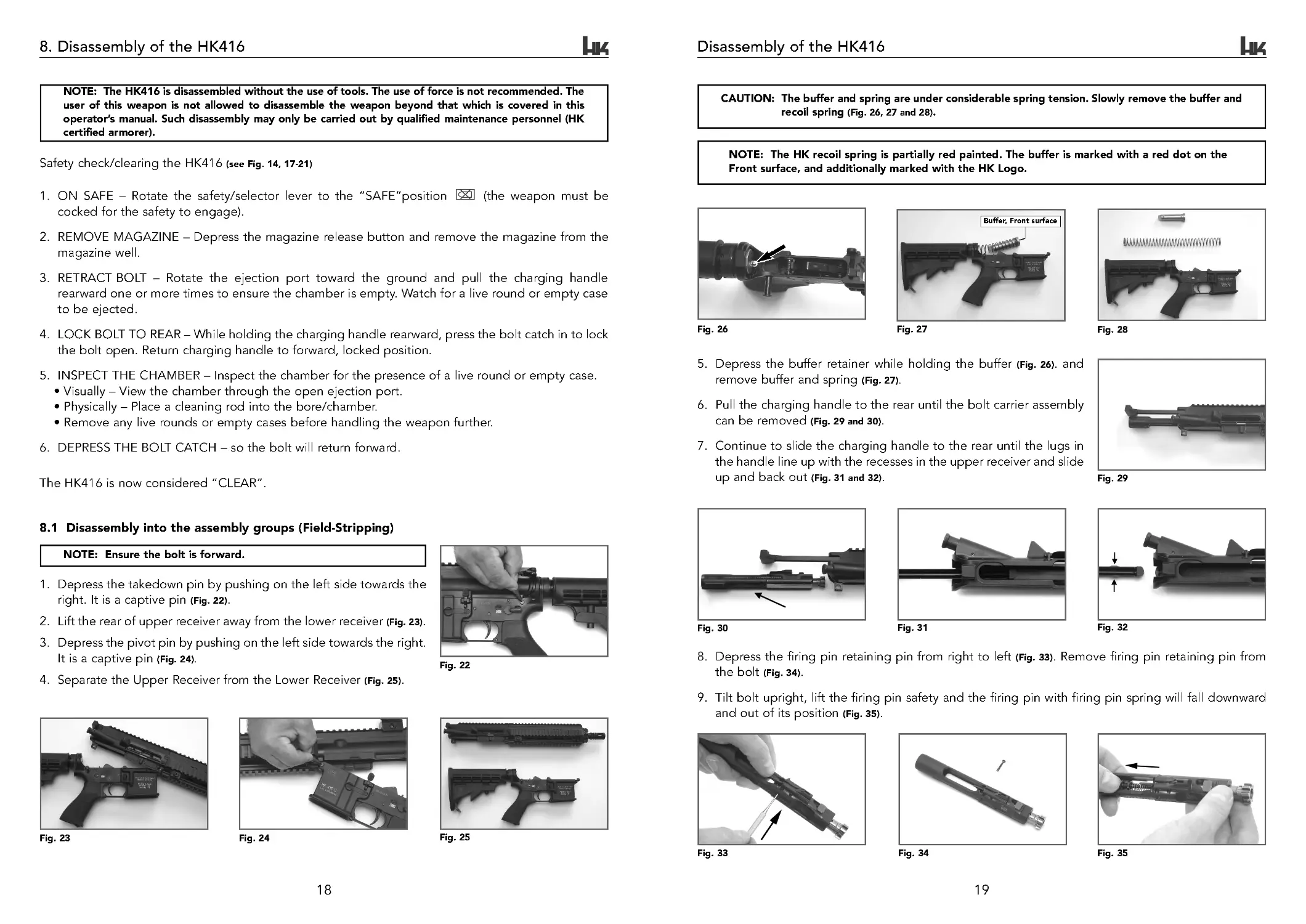
Disassembly of the HK416
5. Depress the buffer retainer while holding the buffer (Fig. 26). and
remove buffer and spring (Fig. 27).
6. Pull the charging handle to the rear until the bolt carrier assembly
can be removed (Fig. 29 and 30).
7. Continue to slide the charging handle to the rear until the lugs in
the handle line up with the recesses in the upper receiver and slide
up and back out (Fig. 31 and 32).
Fig. 29
Fig. 30
Fig. 31
Fig. 32
8. Depress the firing pin retaining pin from right to left (Fig. 33). Remove firing pin retaining pin from
the bolt (Fig. 34).
9. Tilt bolt upright, lift the firing pin safety and the firing pin with firing pin spring will fall downward
and out of its position (Fig. 35).
Fig. 33
Fig. 34
Fig. 35
CAUTION: The buffer and spring are under considerable spring tension. Slowly remove the buffer and
recoil spring (Fig. 26, 27 and 28).
NOTE: The HK recoil spring is partially red painted. The buffer is marked with a red dot on the
Front surface, and additionally marked with the HK Logo.
Fig. 27
Fig. 28
Buffer, Front surface
8. Disassembly of the HK416
Safety check/clearing the HK416 (see Fig. 14 , 17 -21)
1. ON SAFE – Rotate the safety/selector lever to the “SAFE”position
(the weapon must be
cocked for the safety to engage).
2. REMOVE MAGAZINE – Depress the magazine release button and remove the magazine from the
magazine well.
3. RETRACT BOLT – Rotate the ejection port toward the ground and pull the charging handle
rearward one or more times to ensure the chamber is empty. Watch for a live round or empty case
to be ejected.
4. LOCK BOLT TO REAR – While holding the charging handle rearward, press the bolt catch in to lock
the bolt open. Return charging handle to forward, locked position.
5. INSPECT THE CHAMBER – Inspect the chamber for the presence of a live round or empty case.
• Visually – View the chamber through the open ejection port.
• Physically – Place a cleaning rod into the bore/chamber.
• Remove any live rounds or empty cases before handling the weapon further.
6. DEPRESS THE BOLT CATCH – so the bolt will return forward.
The HK416 is now considered “CLEAR”.
NOTE: The HK416 is disassembled without the use of tools. The use of force is not recommended. The
user of this weapon is not allowed to disassemble the weapon beyond that which is covered in this
operator’s manual. Such disassembly may only be carried out by qualified maintenance personnel (HK
certified armorer).
8.1 Disassembly into the assembly groups (Field-Stripping)
NOTE: Ensure the bolt is forward.
1. Depress the takedown pin by pushing on the left side towards the
right. It is a captive pin (Fig. 22).
2. Lift the rear of upper receiver away from the lower receiver (Fig. 23).
3. Depress the pivot pin by pushing on the left side towards the right.
It is a captive pin (Fig. 24).
4. Separate the Upper Receiver from the Lower Receiver (Fig. 25).
Fig. 22
Fig. 23
Fig. 24
Fig. 25
Fig. 26
HK416 ops manual (HKO979 435) DUST rev 8-27-07.qxp 9/4/07 9:21 AM Page 18
21
20
Disassembly of the HK416
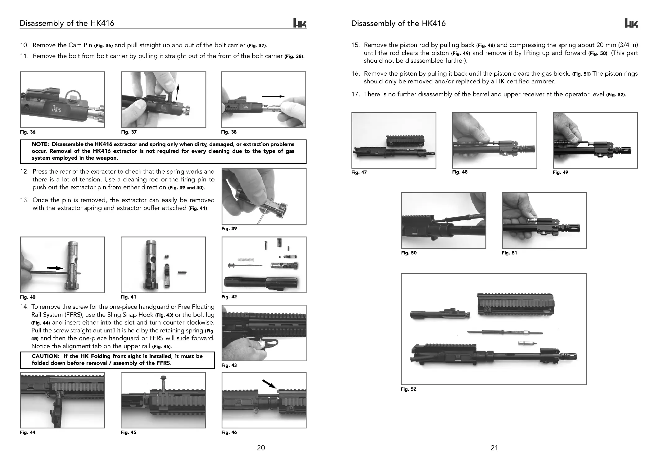
15. Remove the piston rod by pulling back (Fig. 48) and compressing the spring about 20 mm (3/4 in)
until the rod clears the piston (Fig. 49) and remove it by lifting up and forward (Fig. 50). (This part
should not be disassembled further).
16. Remove the piston by pulling it back until the piston clears the gas block. (Fig. 51) The piston rings
should only be removed and/or replaced by a HK certified armorer.
17. There is no further disassembly of the barrel and upper receiver at the operator level (Fig. 52).
Fig. 47
Fig. 48
Fig. 49
Fig. 50
Fig. 51
Fig. 52
12. Press the rear of the extractor to check that the spring works and
there is a lot of tension. Use a cleaning rod or the firing pin to
push out the extractor pin from either direction (Fig. 39 and 40).
13. Once the pin is removed, the extractor can easily be removed
with the extractor spring and extractor buffer attached (Fig. 41).
Fig. 39
Fig. 40
Fig. 41
Fig. 42
14. To remove the screw for the one-piece handguard or Free Floating
Rail System (FFRS), use the Sling Snap Hook (Fig. 43) or the bolt lug
(Fig. 44) and insert either into the slot and tur n counter clockwise.
Pull the screw straight out until it is held by the retaining spring (Fig.
45) and then the one-piece handguard or FFRS will slide forward.
Notice the alignment tab on the upper rail (Fig. 46).
Fig. 43
Fig. 44
Fig. 45
Fig. 46
10. Remove the Cam Pin (Fig. 36) and pull straight up and out of the bolt carrier (Fig. 37).
11. Remove the bolt from bolt carrier by pulling it straight out of the front of the bolt carrier (Fig. 38).
Fig. 36
Fig. 37
Fig. 38
NOTE: Disassemble the HK416 extractor and spring only when dirty, damaged, or extraction problems
occur. Removal of the HK416 extractor is not required for every cleaning due to the type of gas
system employed in the weapon.
Disassembly of the HK416
CAUTION: If the HK Folding front sight is installed, it must be
folded down before removal / assembly of the FFRS.
HK416 ops manual (HKO979 435) DUST rev 8-27-07.qxp 9/4/07 9:21 AM Page 20
22
23
Cleaning the HK416
4. A light coat of oil should be applied to the receiver extension, buffer and recoil spring.
5. A generous coat of oil should be applied to outside of the cam pin, firing pin retaining pin, outside
of bolt, outside of bolt carrier, takedown pin, and pivot pin and inside parts of the lower receiver.
6. A function check should be completed on the selector, trigger group and bolt group when cleaning
is completed (page 26).
All firearms require proper lubrication to function as designed and the HK416 is no exception. Absence
of lubrication may impede the operation of the HK416, particularly in load-bearing or friction contact
areas. Excessive lubrication may also cause function problems by acting as a magnet for dirt, grit, sand,
and fouling. Any type of high quality, medium weight lubricant (oil) specifically designed for use on
firearms will work well on the HK416. Do not use lubricants that boast of their ability to penetrate metal
as these substances may deaden cartridge primers.
9.2 Lubrication Guide
NO Lubrication: (surface is dry and not slippery to the touch)
• Plastic or rubber components,
• Sling webbing,
• Optics.
Lubrication:
• Gas Piston and Gas Cylinder,
• Buffer and recoil spring,
• Bolt, Bolt carrier, Cam pin and Firing Pin Safety,
• Extractor,
• Ejector,
• Barrel extension,
• Bore, chamber, locking surfaces of the chamber and bolt lugs,
• Receiver take down and pivot pin,
• Hammer, trigger, disconnector springs and selector in trigger group,
• Piston rod,
• All metal parts and/or any area where metal contacts metal.
Severe conditions
Extreme temperature lubrication procedures: If the HK416 is to be used or fired in temperatures below
- 35 degrees F (-37°C), thoroughly remove all other types of lubricant from all internal and exter nal surfaces
of the firearm, and apply LAW (Lubricating oil, Arctic, Weapon) lubricant, NSN 9150-00-292-9689.
Refer to the lube guide below for further guidance on selecting the correct lubricant for all temperature
ranges.
Under all but the coldest Arctic conditions, CLP is the lubricant to use on your weapon.
• Between +10 degrees F (-12°C) and -10 degrees F (-23°C) either CLP or LAW may be used.
• Below -10 degrees F (-23°C) use LAW.
9. Cleaning the HK416
9.1 Care and cleaning of the HK416
There are no special requirements, cleaners, or lubricants required for cleaning the HK416. The standard
HK cleaning kit that is used for all 5.56 mm HK rifles and carbines may be used for this weapon.
Cleaning may be completed using dry cleaning solvent, bore cleaner, wiping with a cloth or an all
purpose nylon brush. Using these guidelines will determine which applies. Cleaning materials are pipe
cleaners, swabs, all purpose nylon brush and rags.
NOTE: If cleaning is completed using a solvent, then a coat of lubricant must be applied for protection
against rust and the elements. Dry cleaning solvent may be used to completely remove lubricants. For
example, when moving to extreme cold weather operations, dry cleaning solvent may be used to
remove traces of CLP before applying LAW.
The following lubricants can be used on this weapon CLP (Breakfree, TW25 B), LSA, LAW or OX24.
Always shake CLP before use.
CLP does three things at once:
1. It contains solvents to dissolve firing residue and carbon.
2. It lays down a layer of Teflon as it dries to provide lubrication.
3. It prevents rust from forming.
Use CLP as follows:
1. Always shake bottle well before use.
2. Place a few drops on a swab or rag.
3. Clean the weapon with these swabs and rags until they come out clean.
4. Take a swab or rag and apply a fresh, light coat.
CAUTION: Don’t “dry clean” your weapon. Do not use hot water or other solvents or you will wash
away the Teflon lubricant that has been building up as a result of your using CLP. If CLP is not used,
RBC may be used to remove carbon.
General Cleaning is required under normal conditions and the following procedures apply.
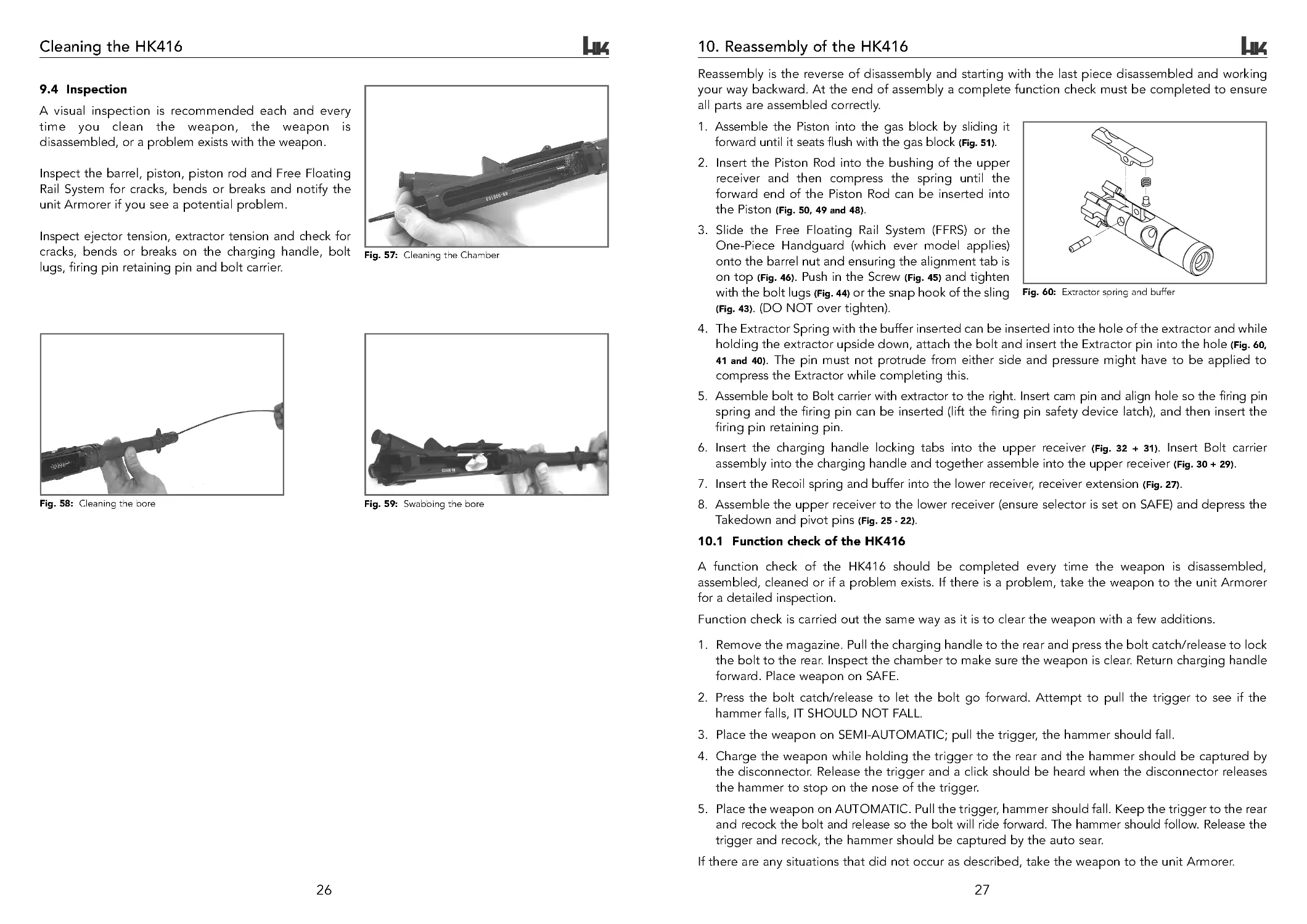
1. Always clean after firing, after the weapon is wet or in adverse weather conditions. Remove areas
of powder fouling, debris and grit, corrosion and dirt. Clean the bore with a bore brush and the
cable cleaning rod (Fig. 58). Pull the brush from the chamber to the muzzle. Complete this several
times with bore cleaner and let soak several minutes if time permits. Clean the chamber with the
chamber brush and a solid cleaning rod handle (Fig. 57). Rotate the chamber brush with bore cleaner
by pushing and twisting and also let it soak for several minutes while the upper receiver, piston,
piston rod and bolt carrier group are cleaned with the all purpose brush using bore cleaner. Wipe
excess cleaner off with a rag and then run several patches through the bore with the cable rod from
the chamber to the muzzle until there is no residue on the patch (Fig. 59).
2. Use an all purpose nylon brush or swab and apply a light coat of lubrication with a clean swab to
all the metal surfaces, including the bore, the locking lugs in the chamber and on the bolt. A drop
of oil should be placed on the ejector, extractor, cam pin, trigger pin, hammer pin, charging handle
spring and forward assist.
3. If the weapon has been disassembled, then all parts should be thoroughly cleaned and lubricated
before assembly. This is the best time to inspect all the parts before assembly.
NOTE: Do not mix lubricants on the same parts of the weapon. The weapon must be thoroughly
cleaned during the change from one lubricant to another. Dry cleaning solvent (SD) is recommended
for cleaning during the change from one lubricant to another.
HK416 ops manual (HKO979 435) DUST rev 8-27-07.qxp 9/4/07 9:21 AM Page 22
25
24
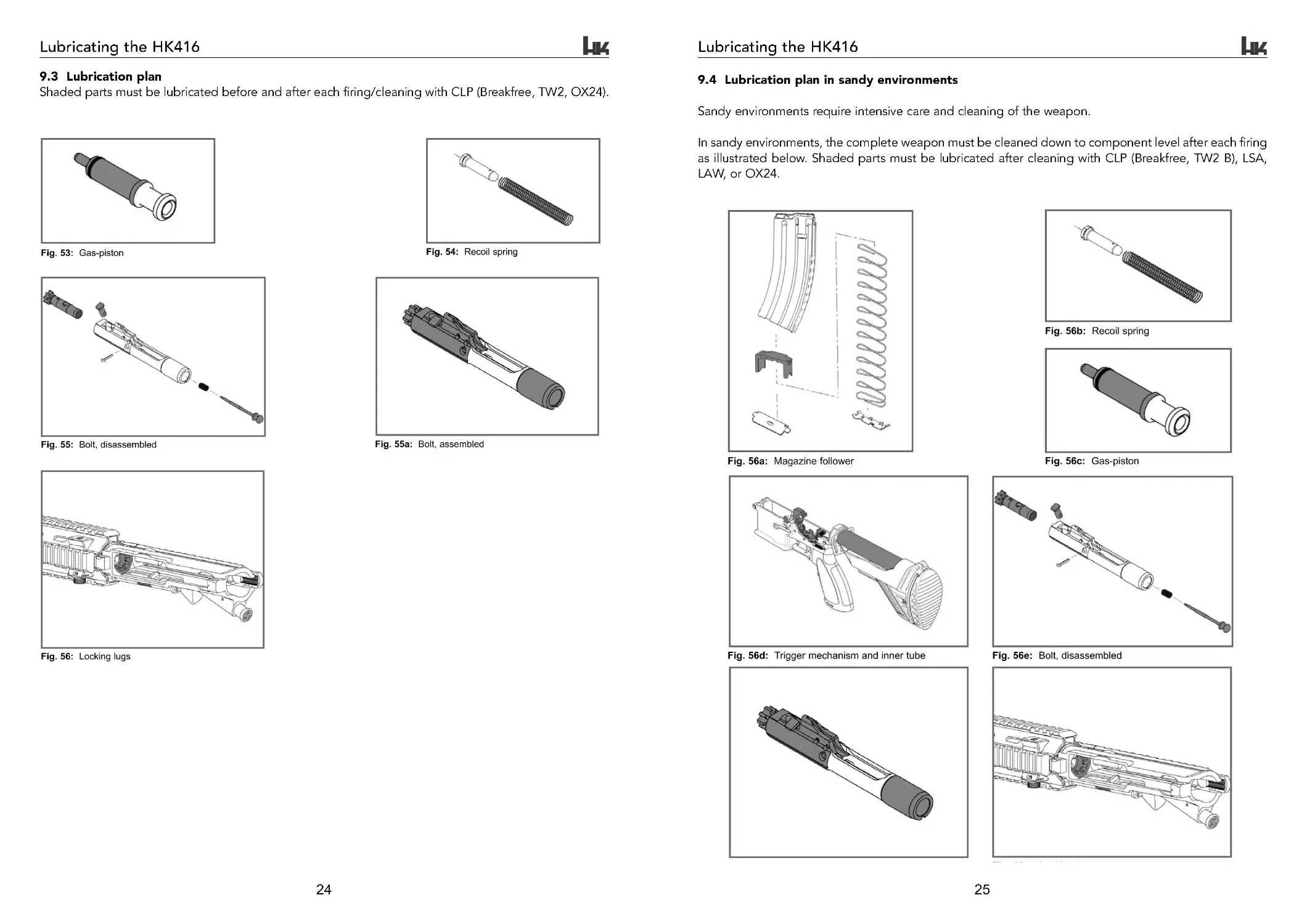
9.3 Lubrication plan
Shaded parts must be lubricated before and after each firing/cleaning with CLP (Breakfree, TW2, OX24).
9.4 Lubrication plan in sandy environments
Sandy environments require intensive care and cleaning of the weapon.
In sandy environments, the complete weapon must be cleaned down to component level after each firing
as illustrated below. Shaded parts must be lubricated after cleaning with CLP (Breakfree, TW2 B), LSA,
LAW, or OX24.
Lubricating the HK416
Lubricating the HK416
HK416 ops manual (HKO979 435) DUST rev 8-27-07.qxp 9/4/07 9:21 AM Page 24
27
Reassembly is the reverse of disassembly and starting with the last piece disassembled and working
your way backward. At the end of assembly a complete function check must be completed to ensure
all parts are assembled correctly.
10. Reassembly of the HK416
1. Assemble the Piston into the gas block by sliding it
forward until it seats flush with the gas block (Fig. 51).
2. Insert the Piston Rod into the bushing of the upper
receiver and then compress the spring until the
forward end of the Piston Rod can be inserted into
the Piston (Fig. 50 , 49 and 48).
3. Slide the Free Floating Rail System (FFRS) or the
One-Piece Handguard (which ever model applies)
onto the barrel nut and ensuring the alignment tab is
on top (Fig. 46). Push in the Screw (Fig. 45) and tighten
with the bolt lugs (Fig. 44) or the snap hook of the sling
(Fig. 43). (DO NOT over tighten).
4. The Extractor Spring with the buffer inserted can be inserted into the hole of the extractor and while
holding the extractor upside down, attach the bolt and insert the Extractor pin into the hole (Fig. 60,
41 and 40). The pin must not protrude from either side and pressure might have to be applied to
compress the Extractor while completing this.
5. Assemble bolt to Bolt carrier with extractor to the right. Insert cam pin and align hole so the firing pin
spring and the firing pin can be inserted (lift the firing pin safety device latch), and then insert the
firing pin retaining pin.
6. Insert the charging handle locking tabs into the upper receiver (Fig. 32 + 31). Insert Bolt carrier
assembly into the charging handle and together assemble into the upper receiver (Fig. 30 + 29).
7. Insert the Recoil spring and buffer into the lower receiver, receiver extension (Fig. 27).
8. Assemble the upper receiver to the lower receiver (ensure selector is set on SAFE) and depress the
Takedown and pivot pins (Fig. 25 - 22).
Fig. 60: Extractor spring and buffer
10.1 Function check of the HK416
A function check of the HK416 should be completed every time the weapon is disassembled,
assembled, cleaned or if a problem exists. If there is a problem, take the weapon to the unit Armorer
for a detailed inspection.
Function check is carried out the same way as it is to clear the weapon with a few additions.
1. Remove the magazine. Pull the charging handle to the rear and press the bolt catch/release to lock
the bolt to the rear. Inspect the chamber to make sure the weapon is clear. Return charging handle
forward. Place weapon on SAFE.
2. Press the bolt catch/release to let the bolt go forward. Attempt to pull the trigger to see if the
hammer falls, IT SHOULD NOT FALL.
3. Place the weapon on SEMI-AUTOMATIC; pull the trigger, the hammer should fall.
4. Charge the weapon while holding the trigger to the rear and the hammer should be captured by
the disconnector. Release the trigger and a click should be heard when the disconnector releases
the hammer to stop on the nose of the trigger.
5. Place the weapon on AUTOMATIC. Pull the trigger, hammer should fall. Keep the trigger to the rear
and recock the bolt and release so the bolt will ride forward. The hammer should follow. Release the
trigger and recock, the hammer should be captured by the auto sear.
If there are any situations that did not occur as described, take the weapon to the unit Armorer.
26
Cleaning the HK416
9.4 Inspection
A visual inspection is recommended each and every
time you clean the weapon, the weapon is
disassembled, or a problem exists with the weapon.
Inspect the barrel, piston, piston rod and Free Floating
Rail System for cracks, bends or breaks and notify the
unit Armorer if you see a potential problem.
Inspect ejector tension, extractor tension and check for
cracks, bends or breaks on the charging handle, bolt
lugs, firing pin retaining pin and bolt carrier.
Fig. 57: Cleaning the Chamber
Fig. 58: Cleaning the bore
Fig. 59: Swabbing the bore
HK416 ops manual (HKO979 435) DUST rev 8-27-07.qxp 9/4/07 9:21 AM Page 26
29
HK High reliability 30-rd steel magazine
11.3 Cleaning (HK High reliability 30-rd steel magazine)
There are no special requirements, cleaners or lubricants for cleaning this magazine. The standard
cleaning equipment that is used for the rifle may be used for this magazine. Refer to the care and
cleaning section of this Operatoŕs Manual for more detailed information. Do not use metal bristle
(brass or steel) or wire brushes to clean the Maritime components as damage may occur to the
protective qualities of the surface finish.
Cleaning may be completed using dry cleaning solvent, bore cleaner, wiping with a cloth or an all
purpose nylon brush. Using these guidelines will determine which applies. Cleaning materials are pipe
cleaners, swabs, all purpose nylon brush and rags.
NOTE: If cleaning is completed using a solvent, then a coat of lubricant must be applied for protection
against rust and the elements. Dry cleaning solvent may be used to completely remove lubricants. For
example, when moving to extreme cold weather operations, dry cleaning solvent may be used to remove
traces of CLP before applying LAW.
The following lubricants can be used on this magazine CLP, LSA or LAW. Always shake CLP before use.
CLP does three things at once:
1. It contains solvents to dissolve firing residue and carbon.
2. It lays down a layer of Teflon as it dries to provide lubrication.
3. It prevents rust from forming.
Use CLP as follows:
1. Always shake bottle well before use.
2. Place a few drops on a swab or rag.
3. Clean the magazine with these swabs and rags until they come out clean.
4. Take a swab or rag and apply a fresh, light coat.
CAUTION: Don’t “dry clean” your magazines. Do not use hot water or other solvents or you will
wash away the Teflon lubricant that has been building up as a result of your using CLP. If CLP is not
used, RBC may be used to remove carbon.
General cleaning is required under normal conditions and the following procedures apply:
1. Always clean after firing, after magazine is wet or in adverse weather conditions. Remove areas of
powder fouling, debris and grit, corrosion and dirt.
2. If magazine is assembled, clean carbon off of follower and feed lips with the all purpose nylon brush
or swab and apply a light coat of lubrication with a clean swab.
3. If the magazine has been disassembled, then all parts should be thoroughly cleaned and lubricated
before assembly.
NOTE: Do not use metal bristle brushes (brass or steel) to clean the surfaces of the magazine housing
or damage to the protective finish not covered by warranty may occur.
NOTE: Do not mix lubricants on the same magazine. The magazine must be thoroughly cleaned
during the change from one lubricant to another. Dry cleaning solvent (SD) is recommended for
cleaning during the change from one lubricant to another.
Lube guide
Under all but the coldest Arctic conditions, CLP is the lubricant to use on your magazine. Between +10
degrees F (-12°C) and -10 degrees F (-23°C) either CLP or LAW may be used. Below -10 degrees F (-
23°C) use LAW.
28
11. HK High reliability 30-rd steel magazine
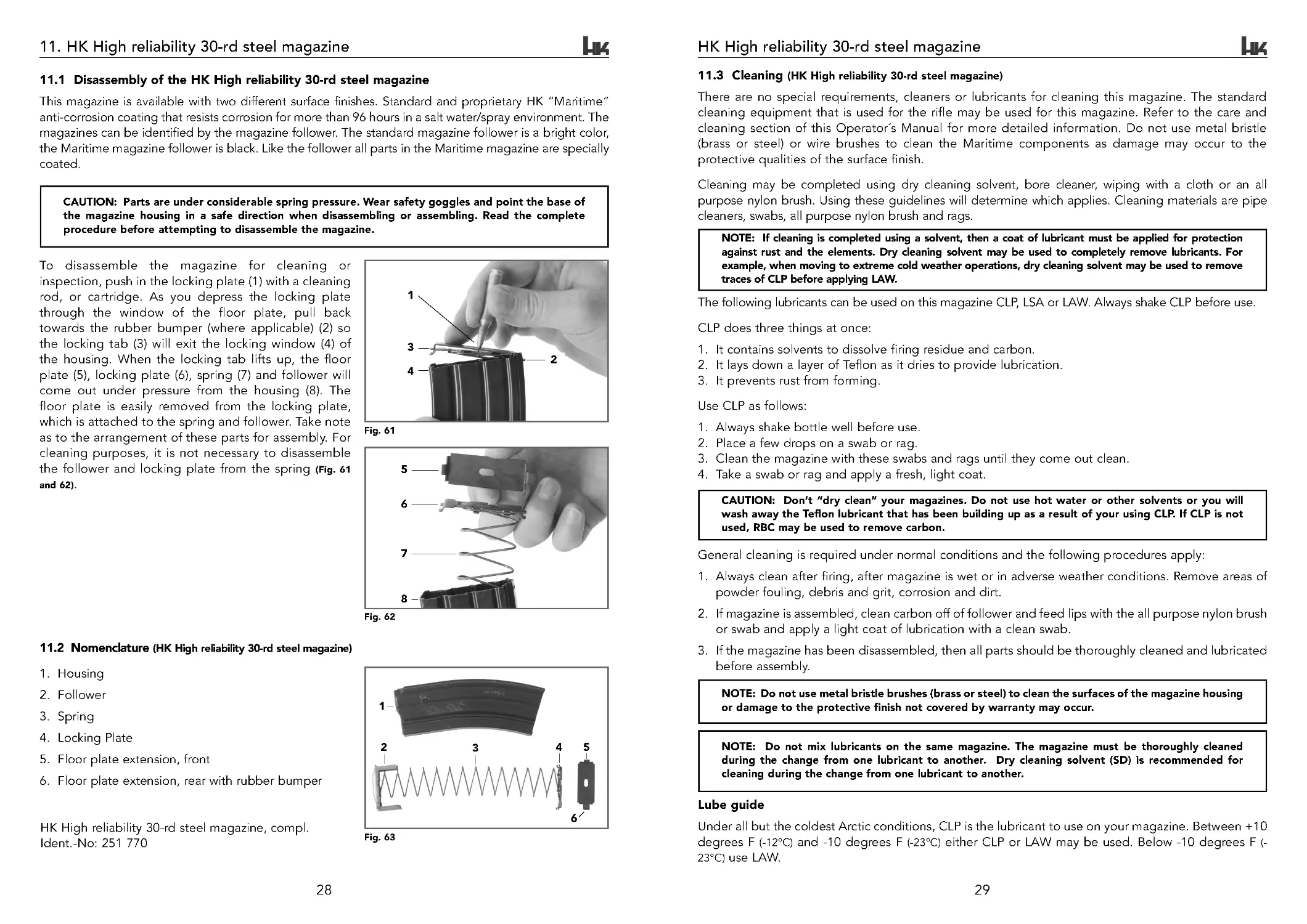
11.1 Disassembly of the HK High reliability 30-rd steel magazine
This magazine is available with two different surface finishes. Standard and proprietary HK “Maritime”
anti-corrosion coating that resists corrosion for more than 96 hours in a salt water/spray environment. The
magazines can be identified by the magazine follower. The standard magazine follower is a bright color,
the Maritime magazine follower is black. Like the follower all parts in the Maritime magazine are specially
coated.
CAUTION: Parts are under considerable spring pressure. Wear safety goggles and point the base of
the magazine housing in a safe direction when disassembling or assembling. Read the complete
procedure before attempting to disassemble the magazine.
To disassemble the magazine for cleaning or
inspection, push in the locking plate (1) with a cleaning
rod, or cartridge. As you depress the locking plate
through the window of the floor plate, pull back
towards the rubber bumper (where applicable) (2) so
the locking tab (3) will exit the locking window (4) of
the housing. When the locking tab lifts up, the floor
plate (5), locking plate (6), spring (7) and follower will
come out under pressure from the housing (8). The
floor plate is easily removed from the locking plate,
which is attached to the spring and follower. Take note
as to the arrangement of these parts for assembly. For
cleaning purposes, it is not necessary to disassemble
the follower and locking plate from the spring (Fig. 61
and 62).
Fig. 61
Fig. 62
11.2 Nomenclature (HK High reliability 30-rd steel magazine)
1. Housing
2. Follower
3. Spring
4. Locking Plate
5. Floor plate extension, front
6. Floor plate extension, rear with rubber bumper
HK High reliability 30-rd steel magazine, compl.
Ident. -No: 251 770
Fig. 63
5
6
7
8
1
2
3
45
6
1
2
3
4
HK416 ops manual (HKO979 435) DUST rev 8-27-07.qxp 9/4/07 9:21 AM Page 28
31
HK High reliability 30-rd steel magazine
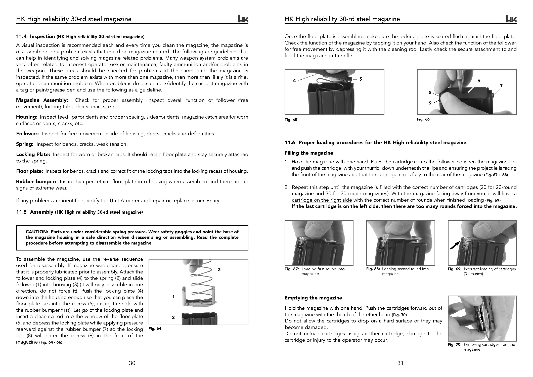
Once the floor plate is assembled, make sure the locking plate is seated flush against the floor plate.
Check the function of the magazine by tapping it on your hand. Also check the function of the follower,
for free movement by depressing it with the cleaning rod. Lastly check the secure attachment to and
fit of the magazine in the rifle.
Fig. 65
Fig. 66
11.6 Proper loading procedures for the HK High reliability steel magazine
Filling the magazine
1. Hold the magazine with one hand. Place the cartridges onto the follower between the magazine lips
and push the cartridge, with your thumb, down underneath the lips and ensuring the projectile is facing
the front of the magazine and that the cartridge rim is fully to the rear of the magazine (Fig. 67 + 68).
2. Repeat this step until the magazine is filled with the correct number of cartridges (20 for 20-round
magazine and 30 for 30-round magazines). With the magazine facing away from you, it will have a
cartridge on the right side with the correct number of rounds when finished loading (Fig. 69).
If the last cartridge is on the left side, then there are too many rounds forced into the magazine.
Fig. 67: Loading first round into
magazine
Fig. 68: Loading second round into
magazine
Fig. 69: Incorrect loading of cartridges
(31 rounds)
Emptying the magazine
Hold the magazine with one hand. Push the cartridges forward out of
the magazine with the thumb of the other hand (Fig. 70).
Do not allow the cartridges to drop on a hard surface or they may
become damaged.
Do not unload cartridges using another cartridge, damage to the
cartridge or injury to the operator may occur.
Fig. 70: Removing cartridges from the
magazine
5
4
6
7
8
9
30
HK High reliability 30-rd steel magazine
11.4 Inspection (HK High reliability 30-rd steel magazine)
A visual inspection is recommended each and every time you clean the magazine, the magazine is
disassembled, or a problem exists that could be magazine related. The following are guidelines that
can help in identifying and solving magazine related problems. Many weapon system problems are
very often related to incorrect operator use or maintenance, faulty ammunition and/or problems in
the weapon. These areas should be checked for problems at the same time the magazine is
inspected. If the same problem exists with more than one magazine, then more than likely it is a rifle,
operator or ammunition problem. When problems do occur, mark/identify the suspect magazine with
a tag or paint/grease pen and use the following as a guideline.
Magazine Assembly: Check for proper assembly. Inspect overall function of follower (free
movement), locking tabs, dents, cracks, etc.
Housing: Inspect feed lips for dents and proper spacing, sides for dents, magazine catch area for worn
surfaces or dents, cracks, etc.
Follower: Inspect for free movement inside of housing, dents, cracks and deformities.
Spring: Inspect for bends, cracks, weak tension.
Locking Plate: Inspect for worn or broken tabs. It should retain floor plate and stay securely attached
to the spring.
Floor plate: Inspect for bends, cracks and correct fit of the locking tabs into the locking recess of housing.
Rubber bumper: Insure bumper retains floor plate into housing when assembled and there are no
signs of extreme wear.
If any problems are identified, notify the Unit Armorer and repair or replace as necessary.
11.5 Assembly (HK High reliability 30-rd steel magazine)
CAUTION: Parts are under considerable spring pressure. Wear safety goggles and point the base of
the magazine housing in a safe direction when disassembling or assembling. Read the complete
procedure before attempting to disassemble the magazine.
To assemble the magazine, use the reverse sequence
used for disassembly. If magazine was cleaned, ensure
that it is properly lubricated prior to assembly. Attach the
follower and locking plate (4) to the spring (2) and slide
follower (1) into housing (3) (it will only assemble in one
direction, do not force it). Push the locking plate (4)
down into the housing enough so that you can place the
floor plate tab into the recess (5), (using the side with
the rubber bumper first). Let go of the locking plate and
insert a cleaning rod into the window of the floor plate
(6) and depress the locking plate while applying pressure
rearward against the rubber bumper (7) so the locking
tab (8) will enter the recess (9) in the front of the
magazine (Fig. 64 - 66).
Fig. 64
1
2
3
HK416 ops manual (HKO979 435) DUST rev 8-27-07.qxp 9/4/07 9:21 AM Page 30
33
12. Sight adjustment
12.1 Installing the optional HK Diopter rotary sight set
The HK Diopter sights are installed on the MIL-STD 1913 rail with a Phillips #2 screwdriver or the HK
sight tool. Do not over tighten the screws. Sight adjustment is as follows.
12.2 Installing the fold down front sight
Press front sight onto front sight holder until the axes holes of front sight and front sight holder are
aligned. Push trough front sight axles all the way, from the right to the left and secure the front sight
axles by snapping the retaining clip. Check function of foldable front sight.
Sight Adjustment
• The HK416 diopter sights are calibrated for US M855 or NATO SS109 type ammunition. Results
may vary with other types of ammunition.
• The rear sight drum has diopters marked “1 ”, “ 2”, “3 ” and “4”
• The rifle should be sighted-in at 100 meters using the #1 diopter. The top of the front sight blade
should be centered in the diopter.
• If the shooter’s target is at 200 meters, the drum should be rotated so the “2 ” diopter is now facing
the shooter’s eye. The diopter has been moved up to compensate for the extra 100 meters.
• The “3” diopter should be used for 300 meters and the “4 ” for 400 meters.
• In effect, once the rifle is sighted-in at 100 meters with the #1 diopter, the rifle is also sighted-in @
200, 300 and 400 meters.
• Sighting through any of the diopters, the shooter should obtain an equal halo of light around the
front sight mount positioning the front sight blade in the center.
NOTE: Below the #2 on the diopter, there is a single dot that signifies it is for the 10.4” HK416 and
a double dot signifies it is for the 14.5” and/or 16.5” HK416.
The sights on the HK rifles can be adjusted for elevation and windage.
Sight adjustment tool
There are two parts to the sight adjustment tool.
• A short shank Phillips head screwdriver
• The spring loaded tab assembly
Fig. 74 Correct position of the front sight
32
HK High reliability 30-rd steel magazine
Single rounds
Magazines may be loaded with one round at a time by inserting the cartridge case in while depressing
the follower and seating the case in until the projectile clears the front of the magazine. Continue this
each time until the magazine is full. During and when finished filling the magazine gently tap the back
of the magazine against the palm of your hand to ensure the rounds are seated properly (Fig. 67 + 68).
10-round stripper clip
The magazine may be loaded quickly using the 10-round stripper clips and the stripper clip guide that
is provided with each bandoleer of ammunition. W ith the magazine filler in place on the magazine,
place a 10-round stripper clip in position (Fig. 71 + 72).
CAUTION: It is possible to improperly load the cartridges if the guide is not positioned correctly,
the rim of the cartridge could possibly get caught in the rear groove. Constantly check spring tension
in between stripper clips. Unload magazine if in doubt. Replace the stripper clip guides regularly as
they wear with use.
Fig. 71: Correct guide location
Fig. 72: Stripper clip correctly
centered
Using thumb pressure on the rear of the top cartridge (Fig. 72), press down firmly until all ten rounds are
below the feed lips of the magazine. Remove the empty stripper clip while holding the stripper clip
guide in place. Repeat until the magazine is full. Remove stripper clip guide and retain it for future use.
Speed loader
Heckler & Koch does not warrant the use of alternate filling devices. Care should be taken when using
non-approved devices in that damage may occur to the magazine that is not covered under warranty.
NOTE: Do not slam the magazine on a table or a fixed hard surface during filling or damage to the
feed lips may occur. Instead apply gradual pressure to accomplish this task.
NOTE: Protect the magazines from drop-induced damage on hard surfaces (concrete, metal, etc.)
during training by covering the ground with cardboard or carpet to cushion the impact. While the HK
magazine is extremely durable even during rough handling, protecting arguably the most important
component of the weapons system is wise and strongly recommended. Many weapon stoppages
begin in feed devices that are not properly cared for or that are abused unnecessarily. Dedicated
training magazines for practicing combat reloads wherein the magazine is repeatedly dropped are
also highly recommended.
Fig. 73: Stripper clip off center
HK416 ops manual (HKO979 435) DUST rev 8-27-07.qxp 9/4/07 9:21 AM Page 32
35
13. SBFA & ammunition
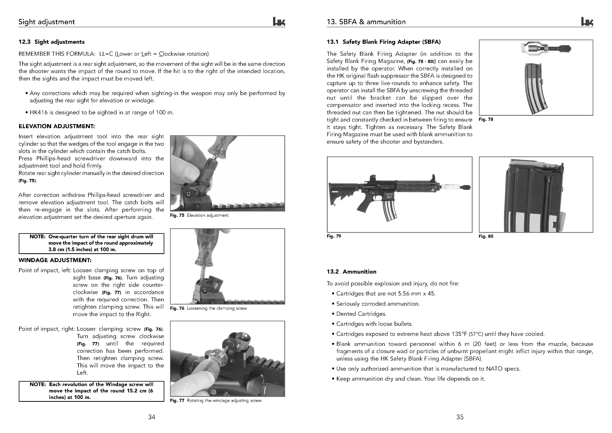
13.1 Safety Blank Firing Adapter (SBFA)
The Safety Blank Firing Adapter (in addition to the
Safety Blank Firing Magazine, (Fig. 78 - 80)) can easily be
installed by the operator. When correctly installed on
the HK original flash suppressor the SBFA is designed to
capture up to three live-rounds to enhance safety. The
operator can install the SBFA by unscrewing the threaded
nut until the bracket can be slipped over the
compensator and inserted into the locking recess. The
threaded nut can then be tightened. The nut should be
tight and constantly checked in between firing to ensure
it stays tight. Tighten as necessary. The Safety Blank
Firing Magazine must be used with blank ammunition to
ensure safety of the shooter and bystanders.
Fig. 78
Fig. 80
Fig. 79
13.2 Ammunition
To avoid possible explosion and injury, do not fire:
• Cartridges that are not 5.56 mm x 45.
• Seriously corroded ammunition.
• Dented Cartridges.
• Cartridges with loose bullets.
• Cartridges exposed to extreme heat above 135°F (57°C) until they have cooled.
• Blank ammunition toward personnel within 6 m (20 feet) or less from the muzzle, because
fragments of a closure wad or particles of unburnt propellant might inflict injury within that range,
unless using the HK Safety Blank Firing Adapter (SBFA).
• Use only authorized ammunition that is manufactured to NATO specs.
• Keep ammunition dry and clean. Your life depends on it.
34
Sight adjustment
12.3 Sight adjustments
REMEMBER THIS FORMULA: LL=C (Lower or Left = Clockwise rotation)
The sight adjustment is a rear sight adjustment, so the movement of the sight will be in the same direction
the shooter wants the impact of the round to move. If the hit is to the right of the intended location,
then the sights and the impact must be moved left.
• Any corrections which may be required when sighting-in the weapon may only be performed by
adjusting the rear sight for elevation or windage.
• HK416 is designed to be sighted in at range of 100 m.
ELEVATION ADJUSTMENT:
Insert elevation adjustment tool into the rear sight
cylinder so that the wedges of the tool engage in the two
slots in the cylinder which contain the catch bolts.
Press Phillips-head screwdriver downward into the
adjustment tool and hold firmly.
Rotate rear sight cylinder manually in the desired direction
(Fig. 75).
After correction withdraw Phillips-head screwdriver and
remove elevation adjustment tool. The catch bolts will
then re-engage in the slots. After performing the
elevation adjustment set the desired aperture again.
Fig. 75 Elevation adjustment
WINDAGE ADJUSTMENT:
Point of impact, left: Loosen clamping screw on top of
sight base (Fig. 76). Tur n adjusting
screw on the right side counter-
clockwise (Fig. 77) in accordance
with the required correction. Then
retighten clamping screw. This will
move the impact to the Right.
Point of impact, right: Loosen clamping screw (Fig. 76).
Turn adjusting screw clockwise
(Fig. 77) until the required
correction has been performed.
Then retighten clamping screw.
This will move the impact to the
Left.
NOTE: Each revolution of the Windage screw will
move the impact of the round 15.2 cm (6
inches) at 100 m.
NOTE: One-quarter turn of the rear sight drum will
move the impact of the round approximately
3.8 cm (1.5 inches) at 100 m.
Fig. 76 Loosening the clamping screw
Fig. 77 Rotating the windage adjusting screw
HK416 ops manual (HKO979 435) DUST rev 8-27-07.qxp 9/4/07 9:21 AM Page 34
37
15. Functional description of the HK416
15.1 Steps of functioning
The eight steps of functioning begin after the loaded magazine has been inserted into the weapon and
is a re-occurring sequence of mechanical events, which take place in the operation of an automatic-
loading firearm. The HK416 is designed to function in either the semi-automatic or automatic mode.
1. LOADING: Inserting a loaded magazine into the magazine well.
A loaded magazine can be inserted into the magazine well with the bolt forward or to the rear, unless
31 rounds are loaded in the magazine. When the magazine is seated fully into the magazine well, the
magazine catch/release will engage the recess in the magazine. If the bolt is not to the rear, pull the
charging handle to the rear and press the bolt catch/release to lock the bolt to the rear or to start
feeding, release the charging handle (Fig. 86).
NOTE: Do not ride the charging handle forward or the bolt may not fully chamber the round.
Fig. 86
Fig. 87
Fig. 88
2. FEEDING: Removing a round from the magazine.
As the bolt moves forward under the pressure of the
expanding recoil spring, the bottom locking lugs on
the bolt head ride between the lips of the magazine
stripping a round out of the magazine and feeding
it into the chamber (Fig. 87).
3. CHAMBERING: Placing the round into the
chamber of the barrel and seating it fully.
The bolt pushes the round forward into the chamber
until the shoulder of the cartridge comes to rest at
the end of the chamber (headspace). As the round
is in the final stages of chambering the bolt carrier
contacts the release lever of the trigger group and
the hammer starts to fall, but the sear is in the way
and the sear notch of the hammer engages the sear
(Fig. 88).
36
14. Use of the HK416 Multi-purpose sling
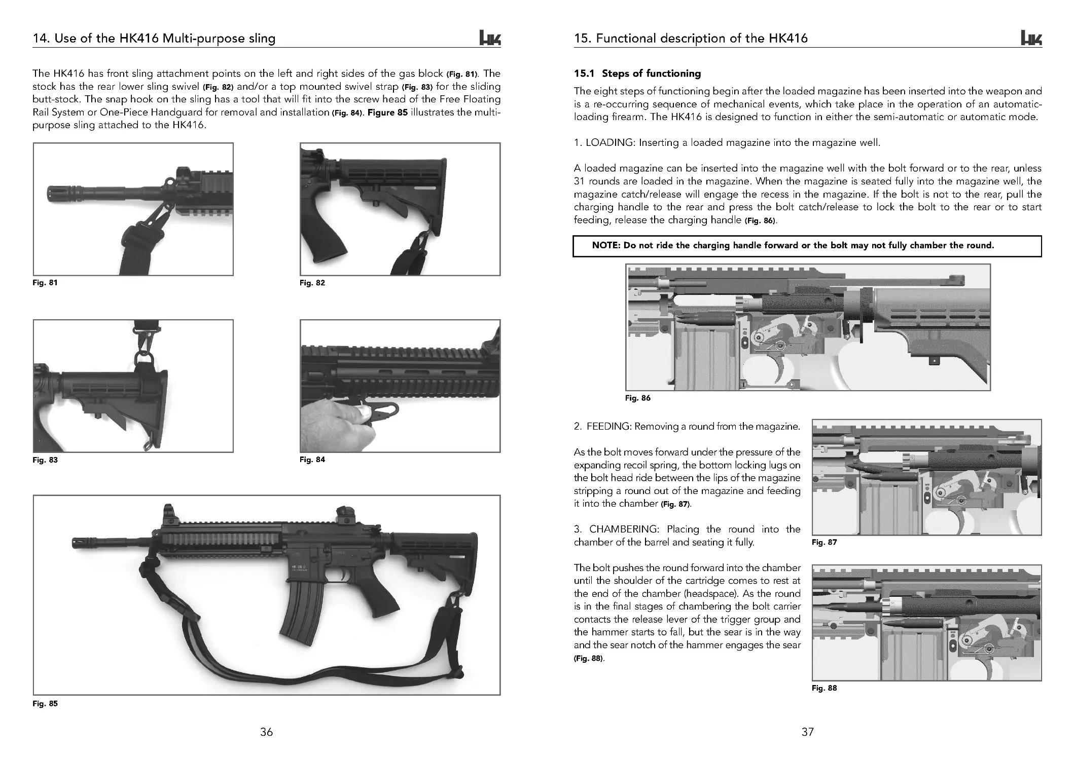
The HK416 has front sling attachment points on the left and right sides of the gas block (Fig. 81). The
stock has the rear lower sling swivel (Fig. 82) and/or a top mounted swivel strap (Fig. 83) for the sliding
butt-stock. The snap hook on the sling has a tool that will fit into the screw head of the Free Floating
Rail System or One-Piece Handguard for removal and installation (Fig. 84). Figure 85 illustrates the multi-
purpose sling attached to the HK416.
Fig. 81
Fig. 82
Fig. 83
Fig. 84
Fig. 85
HK416 ops manual (HKO979 435) DUST rev 8-27-07.qxp 9/4/07 9:21 AM Page 36
39
Functional description of the HK416
Fig. 93
Fig. 92
SETTING THE SAFETY/FIRE SELECTOR LEVER AT "SAFE"
Setting the safety/fire selector lever at "SAFE" is only possible when the hammer is cocked.
When the safety/fire selector lever is set at "SAFE" a cam on the selector axle pushes down the rear
extension of the trigger and prevents the front of the trigger from being disengaged from the hammer
notch.
6. UNLOCKING: As the bolt carrier moves to the
rear, the bolt cam pin follows the path of the cam
track (located on the bolt carrier). This action
causes the cam pin and bolt assembly to rotate at
the same time until the locking lugs of the bolt are
no longer behind the locking lugs of the barrel
extension (Fig. 91).
7. EXTRACTION: The removal of a fired cartridge
case, or a round from the chamber.
As the bullet is leaving the cartridge case,
expanding gases pressurize the inside of the case
and push it against the chamber. Once the bolt
cycles to the rear during the unlocking phase, the
extractor holds the cartridge/case on its rim and
pulls the case to the rear until it is ejected by the
spring loaded plunger (Fig. 92).
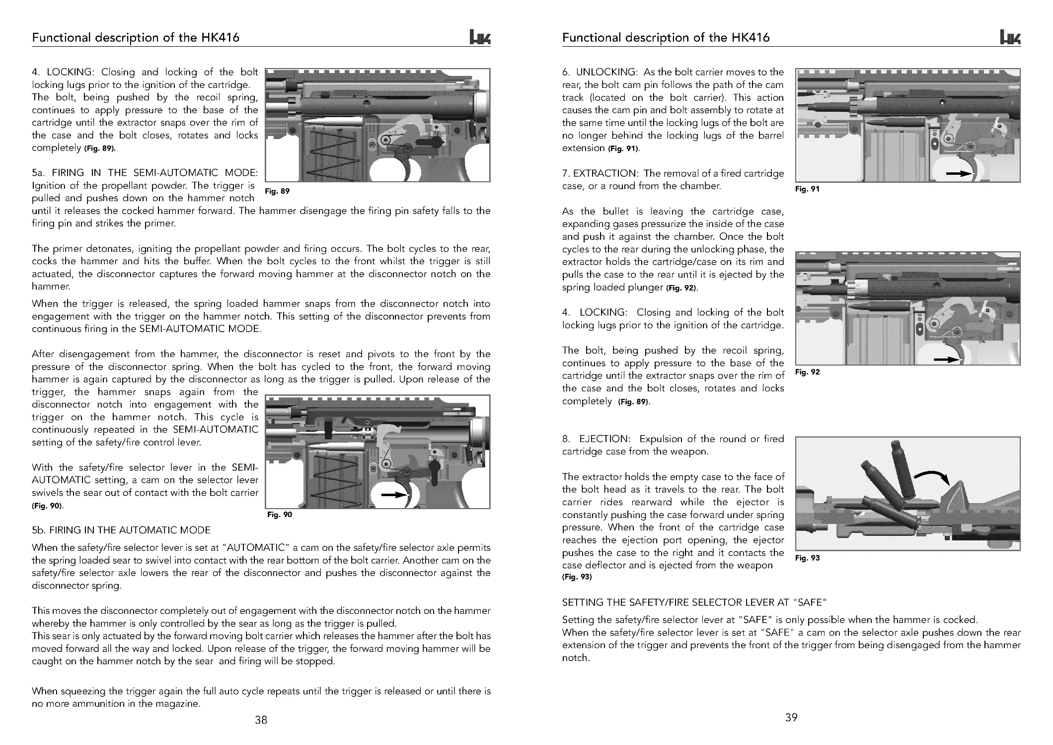
4. LOCKING: Closing and locking of the bolt
locking lugs prior to the ignition of the cartridge.
The bolt, being pushed by the recoil spring,
continues to apply pressure to the base of the
cartridge until the extractor snaps over the rim of
the case and the bolt closes, rotates and locks
completely (Fig. 89).
8. EJECTION: Expulsion of the round or fired
cartridge case from the weapon.
The extractor holds the empty case to the face of
the bolt head as it travels to the rear. The bolt
carrier rides rearward while the ejector is
constantly pushing the case forward under spring
pressure. When the front of the cartridge case
reaches the ejection port opening, the ejector
pushes the case to the right and it contacts the
case deflector and is ejected from the weapon
(Fig. 93)
Fig. 91
38
Functional description of the HK416
4. LOCKING: Closing and locking of the bolt
locking lugs prior to the ignition of the cartridge.
The bolt, being pushed by the recoil spring,
continues to apply pressure to the base of the
cartridge until the extractor snaps over the rim of
the case and the bolt closes, rotates and locks
completely (Fig. 89).
5a. FIRING IN THE SEMI-AUTOMATIC MODE:
Ignition of the propellant powder. The t rigger is
pulled and pushes down on the hammer notch
until it releases the cocked hammer forward. The hammer disengage the firing pin safety falls to the
firing pin and strikes the primer.
The primer detonates, igniting the propellant powder and firing occurs. The bolt cycles to the rear,
cocks the hammer and hits the buffer. When the bolt cycles to the front whilst the trigger is still
actuated, the disconnector captures the forward moving hammer at the disconnector notch on the
hammer.
When the trigger is released, the spring loaded hammer snaps from the disconnector notch into
engagement with the trigger on the hammer notch. This setting of the disconnector prevents from
continuous firing in the SEMI-AUTOMATIC MODE.
After disengagement from the hammer, the disconnector is reset and pivots to the front by the
pressure of the disconnector spring. When the bolt has cycled to the front, the forward moving
hammer is again captured by the disconnector as long as the trigger is pulled. Upon release of the
trigger, the hammer snaps again from the
disconnector notch into engagement with the
trigger on the hammer notch. This cycle is
continuously repeated in the SEMI-AUTOMATIC
setting of the safety/fire control lever.
With the safety/fire selector lever in the SEMI-
AUTOMATIC setting, a cam on the selector lever
swivels the sear out of contact with the bolt carrier
(Fig. 90).
5b. FIRING IN THE AUTOMATIC MODE
When the safety/fire selector lever is set at "AUTOMATIC" a cam on the safety/fire selector axle permits
the spring loaded sear to swivel into contact with the rear bottom of the bolt carrier. Another cam on the
safety/fire selector axle lowers the rear of the disconnector and pushes the disconnector against the
disconnector spring.
This moves the disconnector completely out of engagement with the disconnector notch on the hammer
whereby the hammer is only controlled by the sear as long as the trigger is pulled.
This sear is only actuated by the forward moving bolt carrier which releases the hammer after the bolt has
moved forward all the way and locked. Upon release of the trigger, the forward moving hammer will be
caught on the hammer notch by the sear and firing will be stopped.
When squeezing the trigger again the full auto cycle repeats until the trigger is released or until there is
no more ammunition in the magazine.
Fig. 90
Fig. 89
HK416 ops manual (HKO979 435) DUST rev 8-27-07.qxp 9/4/07 9:21 AM Page 38
41
Troubleshooting
16.2 HK High reliability 30-rd steel magazine - Malfunctions and corrections
Problems that could exist between the rifle and magazine, areas of inspection and remedies:
Filled magazine cannot be inserted and locked in place in the rifle with the bolt forward:
31-rounds are present in the magazine. Remove one round.
Rounds do not feed from magazine/follower stuck in housing:
Improper loading procedure applied with stripper clip and guide. Remove all rounds and refill the
magazine correctly.
Maritime surface coating is worn:
The Maritime coating is a 3-part finish. In the event the top painted finish is scratched or worn the
material coating will continue to protect the magazine against corrosion.
Magazine does not stay in rifle, or falls out when firing:
Check magazine catch on rifle and insure it is screwed in to the magazine release button and adjusted
properly, check for worn or damaged parts (see applicable Operator Manual). Inspect magazine catch
area of magazine for burrs and excessive wear. Turn into Unit Armorer for repair.
NOTE: On this magazine the engagement notches for the magazine catch is CLOSED to prevent the
intrusion of sand and dust. This improves reliability in harsh environments.
Bolt will not lock to the rear after last round is fired:
Check bolt catch on rifle for worn or damaged part. Check follower at the rear contact area, replace if
defective. Check magazine spring tension and replace if weak. Turn into Unit Armorer for repair.
Magazine will not hold specified number of rounds of ammunition:
Check that the magazine is properly assembled and there is no debris inside of the magazine. Check
for dents on magazine housing. Turn into Unit Armorer for repair/replacement.
Failure to properly feed ammunition into the chamber (failure to feed, double feed):
Inspect rifle as per Operatoŕs Manual. Rifle should be clean, properly lubricated; (bolt rings are adjusted
and serviceable). If problem only exists with one magazine, inspect the feed lips for bends, cracks or
incorrect spacing. Check spring tension; check for free movement of follower in housing or dents in
sides of housing or more than 30-rounds of ammunition in magazine. Check for dirty and/or corroded
ammunition. Turn into Unit Armorer for repair.
Floor plate pops off while shooting or if magazine is dropped:
Check for proper assembly and presence of rubber bumper (Contact HK if bumper is missing). Make
sure floor plate is not bent and locking plate locks in place. Insure rubber bumper is not worn or
deformed. Turn into Unit Armorer for repair.
40
16. Troubleshooting
16.1 HK416 - Malfunctions and corrections
Operators are responsible for keeping their HK416 clean and operational at all times – in training and
in combat. Therefore, the operator should be issued an operator’s manual and cleaning equipment for
the assigned weapon.
The following are guidelines that can help in identifying and solving problems. Many weapon system
problems are very often related to incorrect operator use or maintenance, faulty ammunition and/or
problems in the weapon. These areas should be checked for problems at the same time the magazine
is inspected. If the same problem exists with more than one magazine, then more than likely it is a rifle,
operator or ammunition problem. When problems do occur, mark/identify the suspect magazine with a
tag or paint/grease pen and use the chart in the magazine section of this manual (section 16.2 , pg . 40) as a
guideline.
Stoppage
A stoppage is a failure of an automatic or semi-automatic firearm to complete the cycle of operation.
The operator can apply immediate or remedial action to clear the stoppage. Some stoppages that
cannot be cleared by immediate or remedial action could require weapon repair to correct the problem.
A complete understanding of how the weapon functions is an integral part of applying immediate-
action procedures.
Immediate Action
This involves quickly applying corrective actions to reduce a stoppage based on initial observation or
indicators but without deter mining the actual cause. To apply immediate action, the operator would
perform these steps:
• Gently slap upward and tug downward on the magazine to ensure it is fully seated.
• Pull the charging handle fully to the rear and check the chamber (observe for the ejection of a live
or expended cartridge).
• Release the charging handle (do not ride it forward).
• Strike the forward assist assembly to ensure bolt closure.
• Try to fire the rifle.
Apply immediate action only one time for a given stoppage. Do not apply immediate action a second
time. If the rifle still fails to fire, clear the weapon and inspect it to determine the cause of the stoppage
or malfunction and take appropriate remedial action.
Remedial Action
Remedial action is the continuing effort to determine the cause for a stoppage or malfunction and to
try to clear the stoppage once it has been identified.
WARNING: If an audible “pop” or reduced recoil occurs during firing, immediately cease firing.
This pop or reduced recoil can be the result of a round being fired without enough force to send
the projectile out of the barrel. Do not apply immediate action. Remove the magazine, lock the
bolt to the rear, and place the selector lever in the safe position. Visually inspect the bore to
ensure a projectile is not lodged in the barrel. If a projectile is lodged in the barrel, do not try
to remove it. Tur n the weapon in to the armorer.
HK416 ops manual (HKO979 435) DUST rev 8-27-07.qxp 9/4/07 9:21 AM Page 40
43
Troubleshooting
Malfunction
Probable Cause
Corrective Action
Failure to unlock.
Short recoil.
Refer to short recoil.
Burred locking lugs on bolt assembly.
Evacuate to unit armorer.
Burred lugs on barrel extension.
Evacuate to unit armorer.
Failure to extract.
Defective extractor pin, extractor,
and/or extractor spring assembly.
Evacuate to unit armorer.
Failure to eject.
Short recoil.
Refer to short recoil.
Ejector stuck in bolt body.
Evacuate to unit armorer.
Broken ejector.
Evacuate to unit armorer.
Weak or broken ejector spring.
Evacuate to unit armorer.
Failure to cock.
Short recoil.
Refer to short recoil.
Worn, broken, or missing parts of firing
mechanism.
Evacuate to unit armorer.
Short recoil.
Unlubricated or dirty recoil spring and
receiver extension.
Clean and lubricate.
Broken or damaged recoil spring.
Evacuate to unit armorer.
Worn, missing, or broken piston rings. Evacuate to unit armorer.
Rifle cannot be zeroed.
Loose front/rear sight base.
Tighten bases down.
Defective rear sight assembly.
Evacuate to unit armorer.
Defective front sight.
Evacuate to unit armorer.
Defective barrel assembly.
Barrel assembly out of alignment with
rear sight assembly on upper receiver.
Loose barrel.
Evacuate to unit armorer.
Failure to cycle with selector
lever set on AUTOMATIC.
Faulty selector lever.
Evacuate to unit armorer.
Faulty Auto sear.
Evacuate to unit armorer.
Fires two rounds with one pull
of trigger with selector lever
set on SEMI-AUTOMATIC
(double firing).
Soft primer on Ammo.
Use only NATO Ammo.
Worn, broken, or missing parts of firing
mechanism.
Evacuate to unit armorer.
F ires with selector lever on SAFE
or when trigger is released with
selector lever on SEMI-AUTO
Worn, broken, or missing parts of firing
mechanism.
Evacuate to unit armorer.
42
Troubleshooting
16.3 Troubleshooting list
This section contains operator level troubleshooting information for locating and correcting most of
the operating troubles which may develop in the HK416 family. Each malfunction for the individual part
or assembly is followed by a list of tests or inspections which will help you to determine the corrective
actions in the order listed. This manual cannot list all malfunctions that may occur, or all tests or
inspections and corrective actions.
If a malfunction is not listed or is not corrected by listed corrective actions, see individual repair sections
in the maintenance procedures on each major assembly. Refer to troubleshooting table for malfunctions,
tests, and corrective actions. The symptom index is provided for a quick reference of the malfunctions
covered in the table. The HK416 must always be treated as if loaded until the stoppage has been
cleared. The following list does not include all potential causes and/or corrective actions. Other causes
than those indicated below may be encountered.
Malfunction
Probable Cause
Corrective Action
Failure of magazine to lock in
rifle.
Dirty or corroded magazine catch.
Disassemble and clean.
Worn or broken magazine catch.
Evacuate to unit armorer.
Defective magazine catch spring.
Evacuate to unit armorer.
Failure to feed.
Short recoil.
Refer to short recoil.
Magazine catch out of adjustment (will
not retain magazine).
Refer to operatoŕs manual, adjust
magazine catch.
Magazine catch spring weak or broken. Evacuate to unit armorer.
Magazine catch defective.
Magazine improperly filled.
Evacuate to unit armorer.
Remove rounds and reinsert (Sec.11.6)
Failure to chamber.
Short recoil.
Refer to short recoil.
Weak or broken recoil spring.
Evacuate to unit armorer.
Failure to lock.
Improperly assembled extractor spring
assembly.
Assemble correctly.
Bolt cam pin missing.
Evacuate to unit armorer.
Bent piston rod.
Evacuate to unit armorer.
Weak or broken recoil spring.
Evacuate to unit armorer.
Failure to fire.
Carbon buildup in firing pin recess
inside bolt assembly.
Remove firing pin & clean recess with pipe
cleaner.
Refer to operator’s manual under cleaning.
Broken or chipped firing pin.
Evacuate to unit armorer.
Broken, defective, or missing firing pin
retaining pin.
Evacuate to unit armorer.
Firing mechanism and or lower receiver
assembly improperly assembled or has
worn, broken, or missing parts.
Evacuate to unit armorer.
HK416 ops manual (HKO979 435) DUST rev 8-27-07.qxp 9/4/07 9:21 AM Page 42
45
17. Accessories
1. Cleaning Kit (Fig. 94/1)
2. Blank Firing Safety Magazine (Fig. 94/2)
3. HK High reliability 30-rd steel magazine (Fig. 94/3)
4. Folding Front Sight (Fig. 94/4)
5. HK Diopter Rotary Front and Rear Sight Set
(for 10.4” and 14.5” + 16.5” Barrels (Fig. 94/5))
6. HK Sight Adjustment Tool (Fig. 94/6)
7. Safety Blank Firing Attachment (SBFA) (Fig. 94/7)
8. HK Sling with hand guard removal tool and strap
(sling; Ident.- No. 233 158, strap; Ident. -No. 979 450) (Fig. 94/8)
9. Forward Grip (Fig. 95)
10. Scope Mount (for Aimpoint M68 red dot scope (Fig. 96))
11. Tactical Light (Fig. 97)
12. HK AG416 Add-On Grenade Launcher (Fig. 98)
Fig. 94
Fig. 95
Fig. 96
Fig. 97
Fig. 98
1
3
2
76
5
8
4
9
10
12
11
44
Troubleshooting
Malfunction
Probable Cause
Corrective Action
Bolt assembly fails to lock to
rear after firing last round.
Magazine improperly loaded.
Remove and replace rounds.
Magazine lips bent or broken.
Replace magazine.
Magazine follower binds during
operation.
Replace magazine.
Magazine follower worn or broken.
Replace magazine.
Magazine catch spring weak or broken. Evacuate to unit armorer.
Broken bolt catch and/or spring.
Evacuate to unit armorer.
Magazine follower binds
during operation.
Magazine housing dented.
Magazine improperly loaded.
Replace magazine.
Remove rounds and reinsert (Sec 11.6)
NOTE: Only authorized personnel may perform armorer procedures outlined in the manual.
HK416 ops manual (HKO979 435) DUST rev 8-27-07.qxp 9/4/07 9:22 AM Page 44
47
Weapon Models & Spare parts list HK416
7
8
6
9
10
11
12
13
14
15
16
17
24
18
21
19
22
23
20
25
32a
33
26
29a
31
34
Upper receiver
Illust.# Ident.-Number
Description
Drawing-Number
6
205 381
Gas Piston, compl.
94095-115
7
205 382
Gas Piston
94095-115 .01
8
205 383
Piston, Ring (3 each)
94095-115 .02
9
203 648
Piston Rod Assembly
94454-140
10
203 626
Cover, Ejection Port Assembly, compl.
94454-112
11
203 627
*Cover, Ejection Port
94454-111
12
203 632
Spring, Ejection Port Cover
94454-100 .01
13
203 633
Pin, Ejection Port Cover
94454-100 .02
14
979 358
Safety Ring, Ejection Port Cover, . 1 25 "
ASME B18.27 .2 -0 .25 Shaft
15
979 290
*Pin, Lock Bolt (1/16"x3/16")
ASME B18.8 .2 -SLTP
16
203 629
*Lock Bolt
94454-111 .02
17
203 630
*Spring Lock Bolt
94454-111 .01
18
203 599
Plunger Assembly, compl.
94454-120
19
203 600
*Forward Assist Assembly
94454-121
20
979 293
*Pin, Plunger Forward Assist (1/16"x1/4")
ASME B18.8.2-SLTP
21
203 636
*Spring, Pawl Forward Assist
94454-120 .02
22
203 637
*Detent Pawl, Forward assist
94454-120 .03
23
203 601
*Pawl, Forward Assist
94454-120 .04
24
203 635
Spring Plunger, Forward Assist
94454-100 .04
25
979 313
Pin, Forward Assist (3/32"x5/8")
ASME B18.8 .2 -SLTP
--
203 598
Upper Receiver Assembly (consists of Item 26+27)
94454-110
26
203 567
Upper Receiver
94454-110 .01
27
203 576
Threaded Bushing, Piston Guidance
94454-110 .02
29a
233 660
Barrel, 10 .4 " Threaded, Assembled
94548-310
30
979 245
Pin, Gas Block (2 each)
ISO 8748-5x18
31
203 580
Nut, Barrel
94454-300 .03
32a
203 587
Gas Block 10.4 "
94454-300 .06
33
203 647
Washer, Crush
94454-300 .08
34
233 106
Compensator
94454-300 .12
Charging Handle
35
203 596
*Handle Charging
94454-700 .01
36
979 291
*Pin Spring, Handle Charging (3/32x1/4)
ASME B18.8 .2 -SLTP
37
203 640
*Spring, Handle Charging, Catch
94454-700 .02
38
203 641
*Catch, Handle Charging
94454-700 .03
* Included in assembly
(2)
36
37
38
35
30
Fig. 100
30
27
46
18. Weapon Models & Spare parts list HK416
Fig. 99
1
2
3
4
5
HK416 Assembly groups
Illust.# Ident.-Number
Description
Drawing-Number
1
233 658
Upper Receiver 10.4", compl. w/o FFRS, bolt carrier + handle
94548-100
(1)
203 555
Upper Receiver 14.5", compl. w/o FFRS, bolt carrier + handle
94455-100
(1) currently not available
Upper Receiver 16.5", compl. w/o FFRS, bolt carrier + handle
not available
(1) currently not available
Upper Receiver 20", compl. w/o FFRS, bolt carrier + handle
not available
2
203 597
Handle Charging Assembly, compl.
94454-700
3
233 670
Bolt Carrier Assembly, compl.
94564-200
4
233 113
Lower Receiver, compl. assembled with buffer + spring
94454-400
5
233 184
Free Floating Rail System (FFRS), compl.
94454-145
HK416 Weapon Models, compl. (consists of: see section 6)
Illust.# Ident.-Number
Description
Drawing-Number
--
233 668
HK416 D10RS
94564
--
233 711
HK416 D14.5RS
94566
--
234 673
HK416 D16.5RS
94572
--
234 674
HK416 D20RS
94573
HK416 ops manual (HKO979 435) DUST rev 8-27-07.qxp 9/4/07 9:22 AM Page 46
49
Weapon Models & Spare parts list HK416
Fig. 103
53
59
60
61
68
69
70
55
56
57
58
62
63
64
65
66
67
Lower Receiver Assembly
Illust.# Ident.-Number
Description
Drawing-Number
--
233 113
Lower Receiver, compl. assembled with buffer + spring
94454-400
53
233 181
Lower Receiver HK416D, Assembled
94454-410
54
203 570
Buffer, compl.
94454-600
55
233 117
Pin, Takedown
94454-410 .05
56
233 115
Detent, Takedown Pin (2 each)
94454-410 .03
57
233 116
Spring, Takedown (2 each)
94454-410 .02
58
233 164
Plate, Receiver End
94454-400 .03
59
233 165
Nut, Receiver Extension
94454-400 .02
60
233 166
Spring, Recoil
94454-400 .04
61
233 167
Extension Receiver
94454-400 .01
62
233 171
Sliding Buttstock Assembly, compl.
94454-501 .00 .
63
233 172
*Buttstock Sliding
94454-501 .01
64
233 179
*Screw, Swivel
94454-501 .08
65
233 178
*Swivel
94454-501 .07
66
233 175
*Lever, Release
94454-501 .04
67
233 176
*Nut, Lock Pin
94454-501 .05
68
979 295
*Pin, Nut (5/64"x3/8")
ASME B18.8 .2 -SLTP
69
233 174
*Spring, Lock Index
94454-501 .02
70
233 173
*Pin, Lock Index
94454-501 .03
* Included in assembly
54
48
Weapon Models & Spare parts list HK416
Fig. 102
39
41
42
43
44
45
46
47
48
49
50
51
52
Bolt Carrier Assembly
Illust.# Ident.-Number
Description
Drawing-Number
--
233 670
Bolt Carrier Assembly, compl.
94564-200
39
233 673
Bolt Carrier
94564-201
40
233 674
Compression Spring, Firing Pin
94564-200 .01
41
233 703
Firing Pin
94564-200 .03
42
203 564
Pin, Retaining, Firing Pin
94454-200 .04
43
233 112
Bolt Cam Pin
94454-200 .02
44
233 672
Bolt Assembly, compl.
94564-220
45
233 709
Bolt, Head
94564-220 .01
46
233 110
Spring, Ejector
94454-220 .07
47
233 109
Ejector
94454-220 .08
48
929 081
Pin, Ejector (5x10)
ISO 8752-1 , 5x10
49
203 569
Pin, Extractor
94454-220 .05
50
233 108
Extractor, Cartridge
94454-220 .04
51
205 407
Compression Spring, Extractor
94095-123 .03
52
207 779
Buffer, Extractor
94316-412 .06
40
HK416 ops manual (HKO979 435) DUST rev 8-27-07.qxp 9/4/07 9:22 AM Page 48
51
Weapon Models & Spare parts list (all variants)
Fig. 105
106
107
108
Free Floating Rail System (FFRS)
Illust.# Ident.-Number
Description
Drawing-Number
106
233 185
Free Floating Rail
94454-147
107
233 187
Screw, FFRS
94454-145 .02
108
233 186
Shaped Spring, FFRS
94454-145 .01
Weapon Models & Spare parts list HK416
72
73
71
74
76
77
78
80
81
79
82
83
84
56
85
57
86.1
87
88
90
91
92
89
94
95
96
98
99
100
101
102
103
104
105
97
93
Lower Receiver, Exploded
Illust.# Ident.-Number
Description
Drawing-Number
71
203 591
Receiver, Lower (Auto)
94454-410.01
72
233 160
Pistol Grip
94454-410.16
73
979 243
*Lock WasherDIN
6798-A 6 .4FST
74
979 355
*Screw, Pistol Grip (1/4"x28-UNF x 1")
ASME B18.6 .3
75
233 136
Spring, Selector Detent
94454-410.07
76
233 135
Detent, Fire Control Selector
94454-410.08
77
979 294
Pin, Guard, Trigger (1/8"x5/8")
ASME B18.8 .2 -SLTP
78
233 134
Selector, Fire Control, Auto
94454-410.09
79
233 141
Pin, Automatic Sear
94454-414 .04
80
233 152
Pin, Trigger & Hammer (2x)
94454-410.25
81
233 131
Plunger, Bolt Catch
94454-410.12
82
233 132
Spring, Bolt Catch
94454-410.11
83
233 123
Catch Magazine Assembly
94454-411
84
233 126
*Spring, Magazine Catch
94454-410.21
85
233 114
Pin, Receiver Pivot
94454-410.04
86
233 142
Hammer, Auto, Assembly
94454-415
86.1
233 143
Hammer, Auto
94454-415 .01
87
233 144
Retainer, Hammer Pin
94454-415 .03
88
233 145
Spring, Hammer
94454-415 .02
89
233 129
Bolt Catch
94454-410.13
90
233 137
Sear Automatic Assembly.
94454-414
91
233 151
Disconnector, Auto
94454-413.04
92
233 147
Trigger Assembly., Auto
94454-413
93
233 127
*Button, Magazine Release
94454-410.22
94
233 120
Retainer, Buffer
94454-410.19
95
233 121
Spring, Buffer, Retainer
94454-410.18
96
986 544
Pin, Retainer, Buffer (2.5x20-ST)
ISO 8750
97
979 292
Pin, Bolt Catch (3/32"x1/2")
ASME B18.8 .2 -SLTP
98
233 153
Guard, Trigger Assembly, compl.
94454-412
99
233 154
*Guard Trigger
94454-412.01
100
233 155
*Plunger Trigger Guard
94454-412.03
101
233 156
*Spring Trigger Guard
94454-412.02
102
979 293
*P in, Plunger, Trigger Guard (1/16"x1/4")
ASME B18.8 .2 -SLTP
103
233 148
*Trigger, Auto
94454-413.01
104
233 150
*Spring Trigger
94454-413.02
105
233 149
*Spring, Disconnect
94454-413.03
* Included in assembly
Fig. 104
75
50
86
HK416 ops manual (HKO979 435) DUST rev 8-27-07.qxp 9/4/07 9:22 AM Page 50
53
Weapon Models & Spare parts list (all variants)
Fig. 109
139
138
131
130
137
136
135
134
133
132
140
Mechanical sight (Rear sight assembly), for 10.4” barrel model (one dot)
Illust.# Ident.-Number
Description
Drawing-Number
130
203 621
Rear Sight, 10 .4” complete
94485-150
131
203 618
Sight Base, Rear Sight
94485-150 .01
132
203 619
Clamp Jaw, Rear Sight Base
94485-150 .03
133
203 643
Clamp Screw, Sight Base
94485-155 .06
134
200 383
Compression Spring, Sight Base
1013-101 .09
135
929 897
Ball, Sight Base
DIN 5401, 3 mm -III -6
136
200 384
Windage Screw, Sight Base
1013-101 .30
137
200 371
Spring Washer, Turret Rear Sight
1013-101 .28
138
922 617
Lock Washer, Turret Rear Sight
DIN 6798-A 5 .3
139
200 372
Windage Clamp Screw, Turret Rear Sight
1013-101 .29
140
233 133
Turret Rear Sight, 10 .4
”
94485-151
Fig. 110
137
142
136
134
132
131
133
135
138
139
141
Mechanical sight (Rear sight assembly), for 14.5” barrel model (two dots)
Illust.# Ident.-Number
Description
Drawing-Number
141
233 197
Rear Sight, 14 .5” complete
94485-160
142
233 198
Turret Rear Sight, 14 .5”
94485-161
Mechanical sight (Rear sight assembly), for 16.5 ” + 20” barrel model currently not available.
52
Weapon Models & Spare parts list (all variants)
Fig. 107
121
120
116
122
115
117
118
119
123
Folding front sight (Front sight assembly) All models
Illust.# Ident.-Number
Description
Drawing-Number
115
203 622
Folding Front Sight, compl.
94454-153
116
203 623
Base, Folding Front Sight
94454-153 .01
117
203 620
Front Sight Blade, Folding Front Sight
94454-153 .02
118
203 624
Detent Plunger, Folding Front Sight
94454-153 .03
119
203 642
Axle, Folding Front Sight
94454-153 .07
120
979 397
Spring Pin, Folding Front Sight
ISO 8752 4x6
121
203 588
Compression Spring, Folding Front Sight
94454-153 .06
122
203 625
Plunger, Folding Front Sight
94454-153 .04
123
986 551
Retaining Clip, Folding Front Sight
4MBO08
Fig. 108
129
128
127
126
125
124
Mechanical sight (Front sight assembly) All models
Illust.# Ident.-Number
Description
Drawing-Number
124
233 210
Front Sight Assembly, compl.
94485-155
125
233 211
Base, Front Sight
94485-155 .01
126
203 634
Clamp Jaw, Front Sight
94485-155 .03
127
203 643
Clamp Screw, Sight Base
94485-155 .06
128
233 212
Front Sight Blade
94485-155 .02
129
922 609
Roll Pin, Front Sight
ISO 8752 4x12
HK416 ops manual (HKO979 435) DUST rev 8-27-07.qxp 9/4/07 9:22 AM Page 52
Weapon Models & Spare parts list HK416
HK416 Weapon Models, compl. (consists of: see section 6)
Illust.# Ident.-Number
Description
Drawing-Number
--
203 550
HK416 D10RS
94454
--
203 551
HK416 D14.5RS
94455
--
233 222
HK416 D16.5RS
94511
--
203 552
HK416 D20RS
94456
55
54
Weapon Models & Spare parts list (all variants)
Fig. 111
30-rd HK High reliability steel magazine
Illust.# Ident.-Number Description
Drawing-Number
--
251 770
Magazine, 30-rd, compl.
94408
143
209 354
Housing, 30 -rd
94358-10
144
251 772
Spring, 30 -rd
94408-00 .02
145
251 773
Locking plate
94408-00 .03
146
251 775
Floor plate ext. , front, compl.
94408-20
147
251 771
Follower
94408-00 .01
144
143
145
146
147
Fig. 112
Fig. 113
149
148
150
151
152
154
153
155
156
157
159
158
160
20-rd HK High reliability steel magazine
Illust.# Ident. -Number Description
Drawing-Number
--
233 609
Magazine, 20-rd, compl.
94454-800
148
233 610
Housing, 20 -rd
94454-810
149
251 772
Spring, 20 -rd
94408-00 .02
150
251 773
Locking plate
94408-00 .03
151
251 775
Floor plate ext. , front, compl.
94408-20
152
251 771
Follower
94408-00 .01
(30-rd) Blank Round Safety Magazine
Illust.# Ident. -Number Description
Drawing-Number
--
209 756
Blank Rd Safety Magazine, compl. 94359
--
209 758
Housing, compl.
94359-10
153
209 762
Housing
94359-20
154
251 772
Spring
94408-00 .02
155
251 773
Locking plate
94408-00 .03
156
251 775
Floor plate ext. , front, compl.
94408-20
157
251 771
Follower
94408-00 .01
158
209 761
Slide
94359-10 .03
159
209 760
Spring helical compression
94359-10 .02
160
209 759
Spring housing
94359-10 .01
HK416 ops manual (HKO979 435) DUST rev 8-27-07.qxp 9/4/07 9:22 AM Page 54
Number of rounds fired
57
Date
Number of
Rounds Fired
Cumulative Total
of Rounds Fired
Operatoŕs
Name
Maintenance & Remarks
Weapon Type
Serial Number
56
Weapon Models & Spare parts list HK416
HK416 Lower Receiver Assembly (see Fig. 103)
Illust.# Ident.-Number
Description
Drawing-Number
--
234 696
HK416 Lower Receiver compl. assembled with buffer + spring
94568-400
61
234 697
Extension Receiver
94568-400 .01
HK416 Weapon Models, compl. (consists of: see section 6)
Illust.# Ident.-Number
Description
Drawing-Number
--
233 726
HK416 10.4 ”
94568
--
233 727
HK416 14.5 ”
94569
--
234 721
HK416 16.5 ”
94570
--
234 722
HK416 20”
94571
HK416 Spare parts:
HK416 ops manual (HKO979 435) DUST rev 8-27-07.qxp 9/4/07 9:22 AM Page 56
59
Number of rounds fired
58
Date
Number of
Rounds Fired
Cumulative Total
of Rounds Fired
Operatoŕs
Name
Maintenance & Remarks
Weapon Type
Serial Number
Date
Number of
Rounds Fired
Cumulative Total
of Rounds Fired
Operatoŕs
Name
Maintenance & Remarks
Weapon Type
Serial Number
Number of rounds fired
HK416 ops manual (HKO979 435) DUST rev 8-27-07.qxp 9/4/07 9:22 AM Page 58
60
Date
Number of
Rounds Fired
Cumulative Total
of Rounds Fired
Operatoŕs
Name
Maintenance & Remarks
Weapon Type
Serial Number
HK416 ops manual (HKO979 435) DUST rev 8-27-07.qxp 9/4/07 9:22 AM Page 60
HECKLER & KOCH
19980 Highland Vista Drive, Suite #190
Ashburn, Virginia 20147-4189
United States of America
Telephone: (703) 450-1900
Telefax:
(703) 450-8160
www.heckler-koch.com
© Copyright September 2006
August 2007 revision (08232007)
Subject to modification
HECKLER & KOCH GMBH
P.O .BOX 1329
D - 78722 Oberndorf / Neckar
Germany
Telephone: +49 (0) 74 23 / 79-0
Telefax: +49 (0) 74 23 / 79-24 97
www.heckler-koch.de
Ident.- No. 979 435
HK 1-0906 (rev. 082307 USA)
OD XXXX
HK416 ops manual (HKO979 435) DUST rev 8-27-07.qxp 9/4/07 9:22 AM Page 62