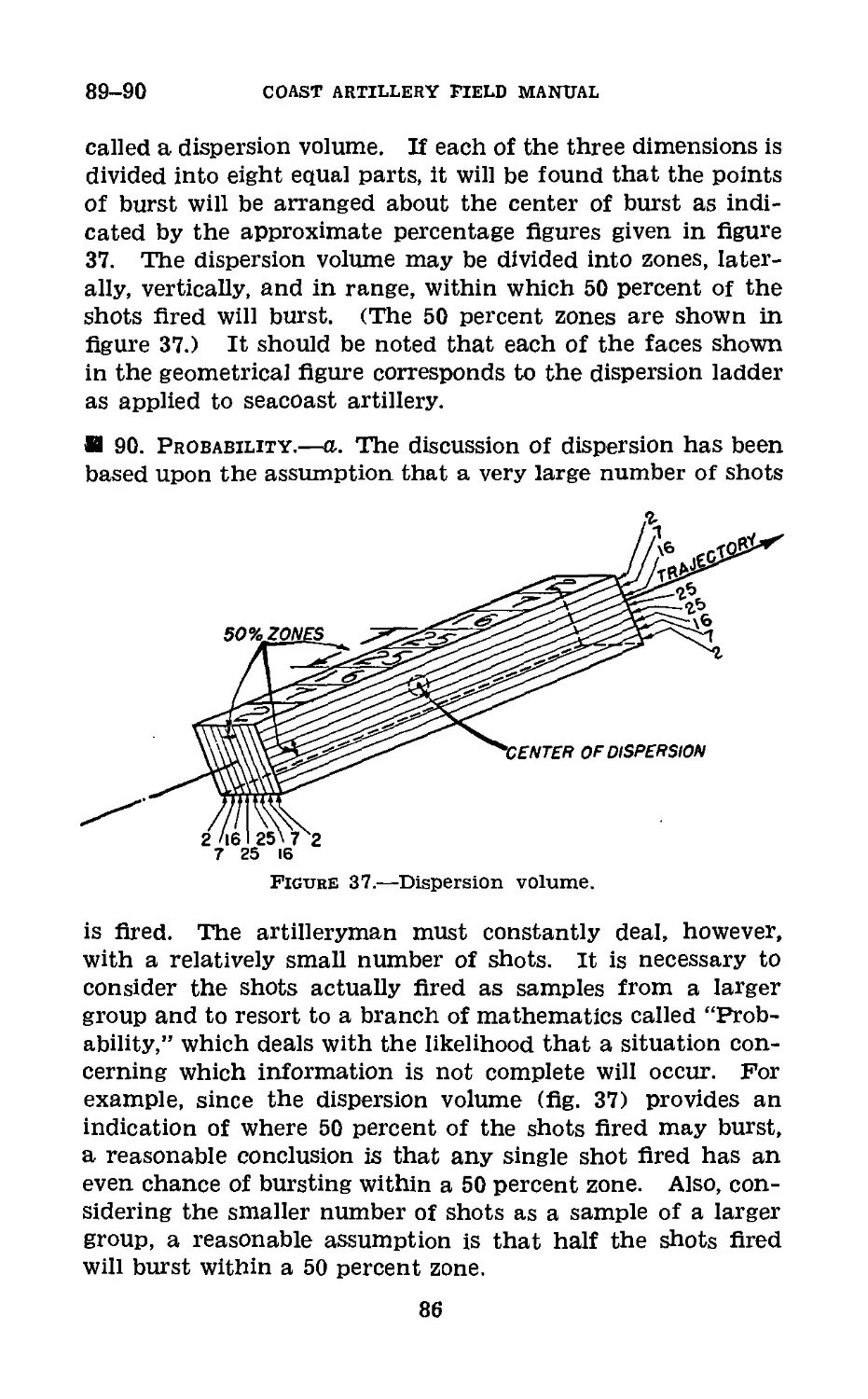
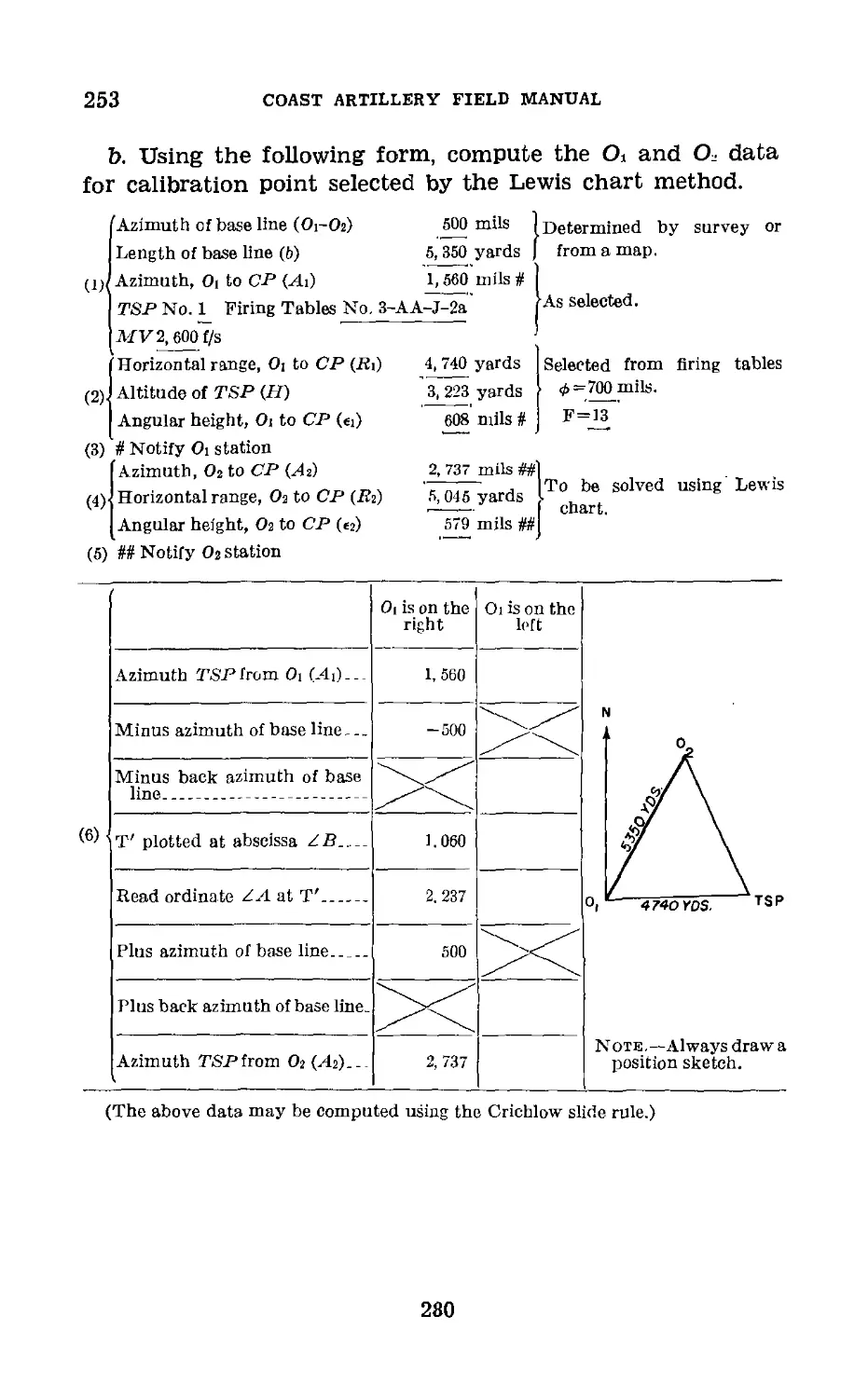
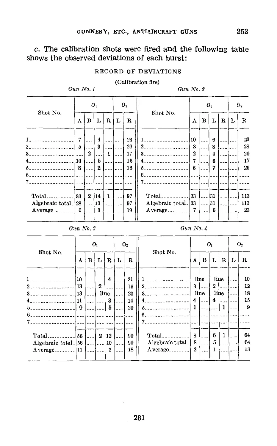
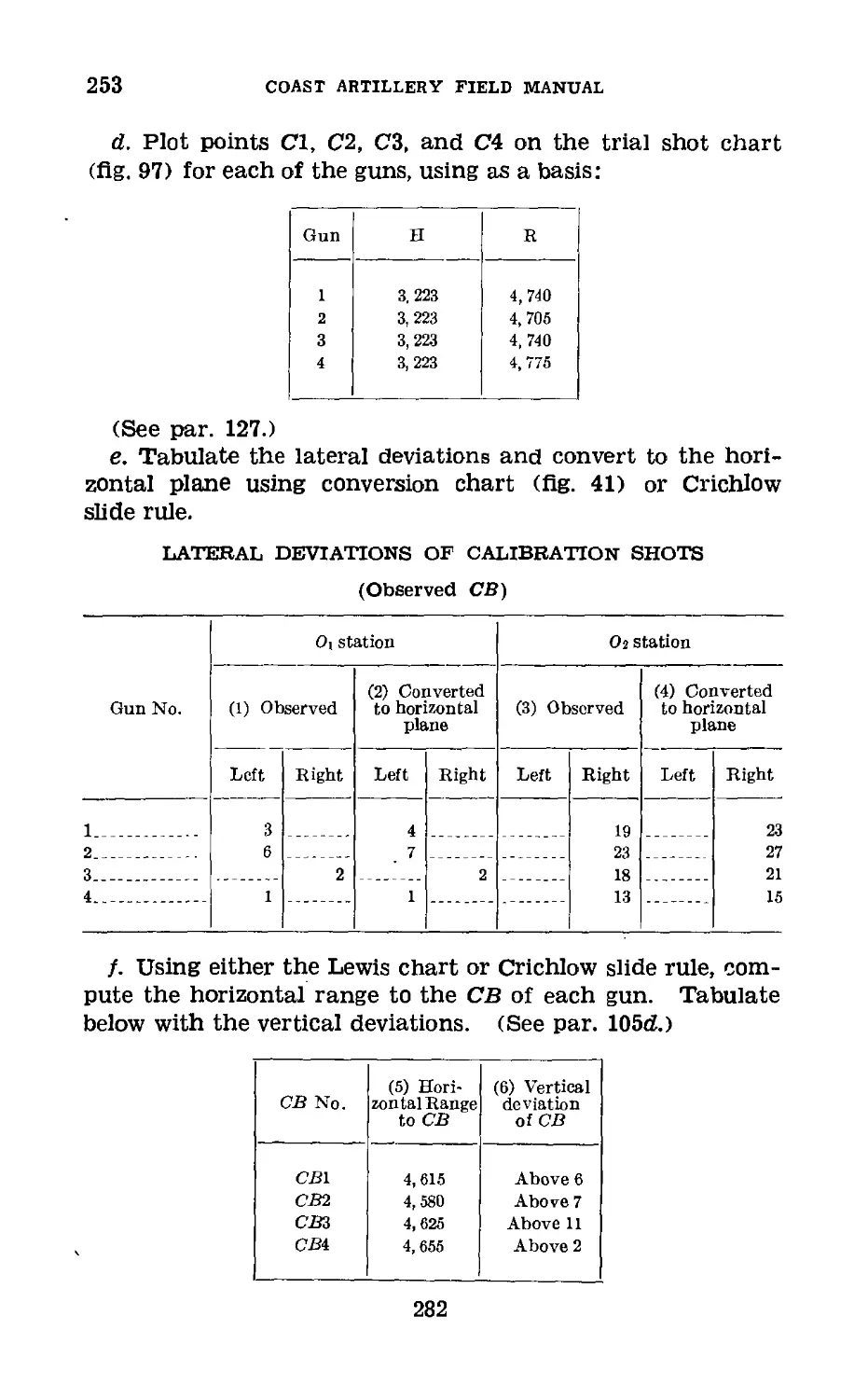
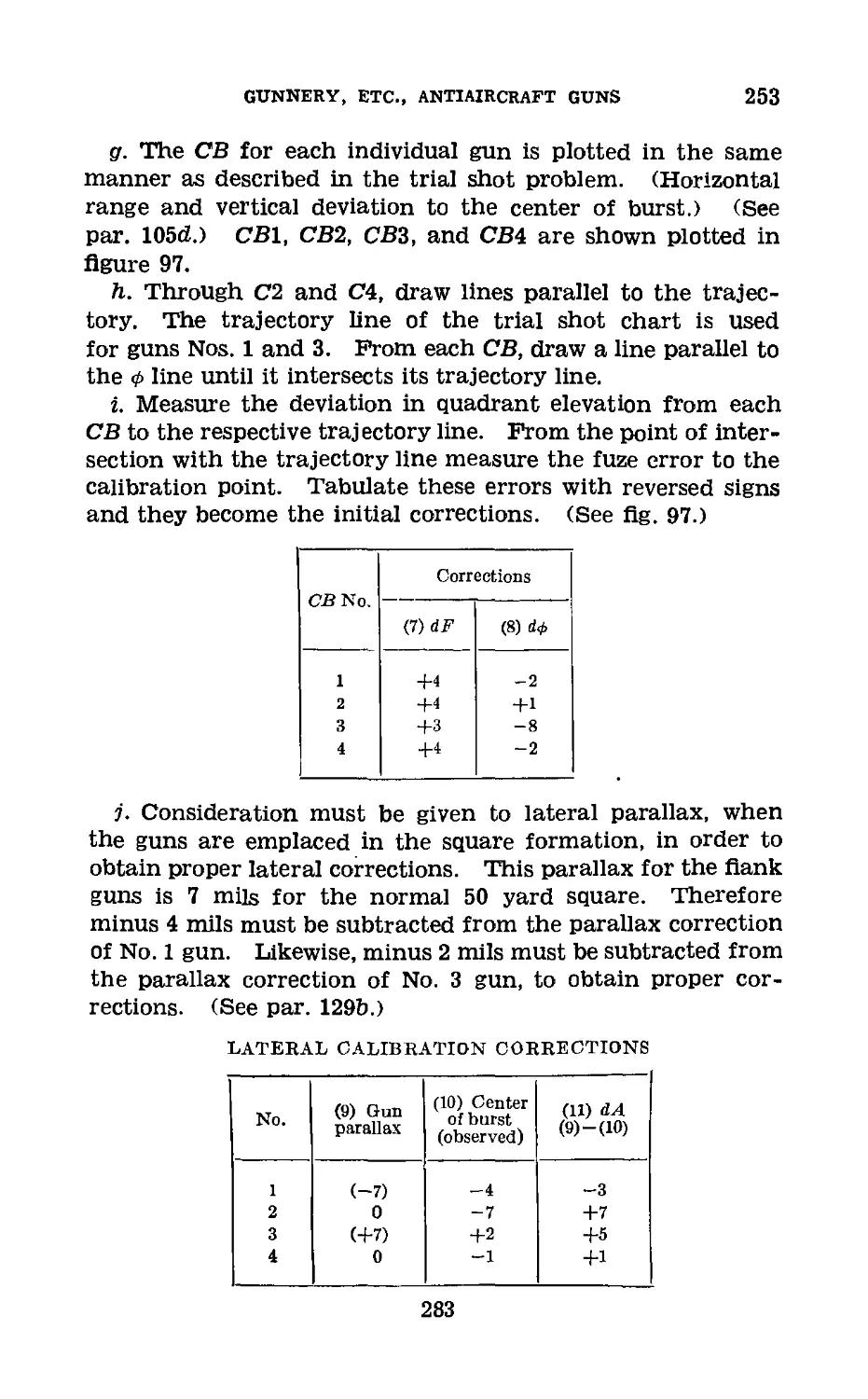
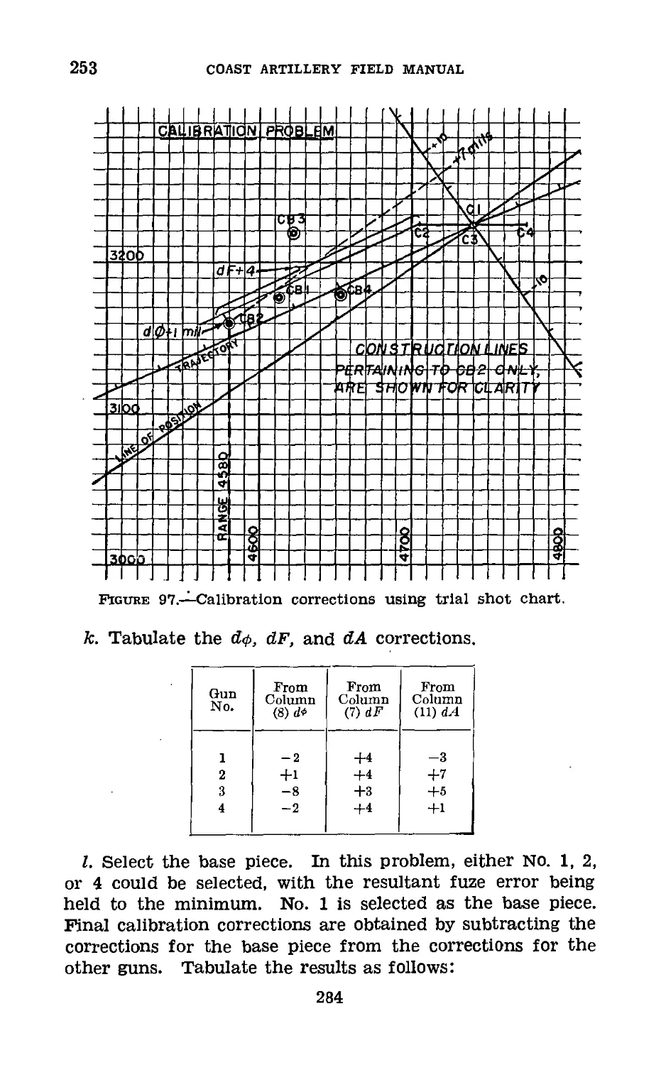
/

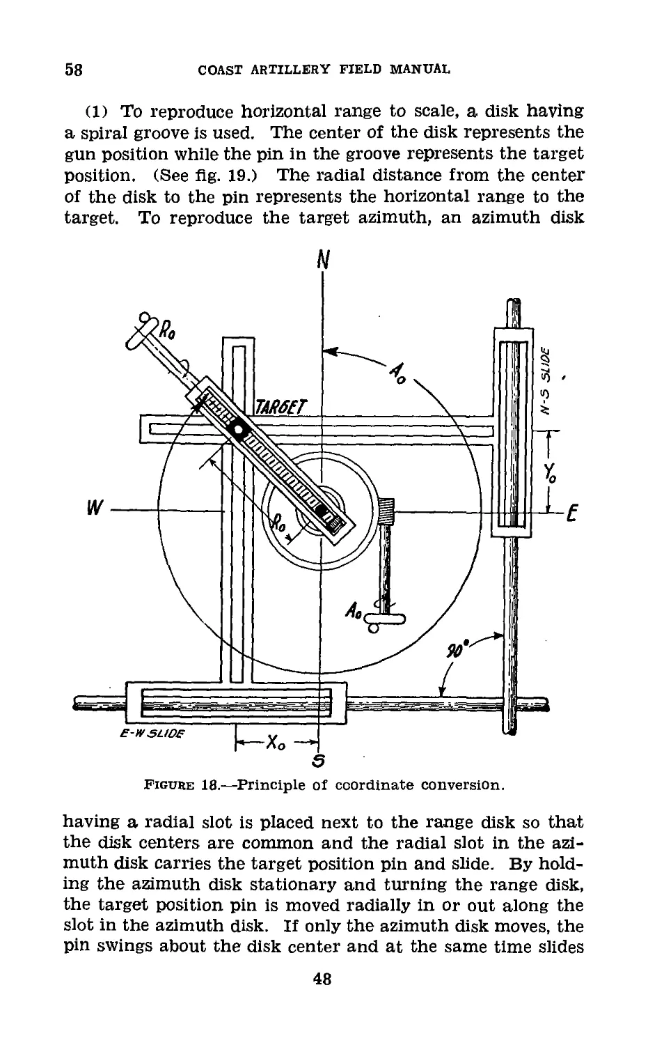
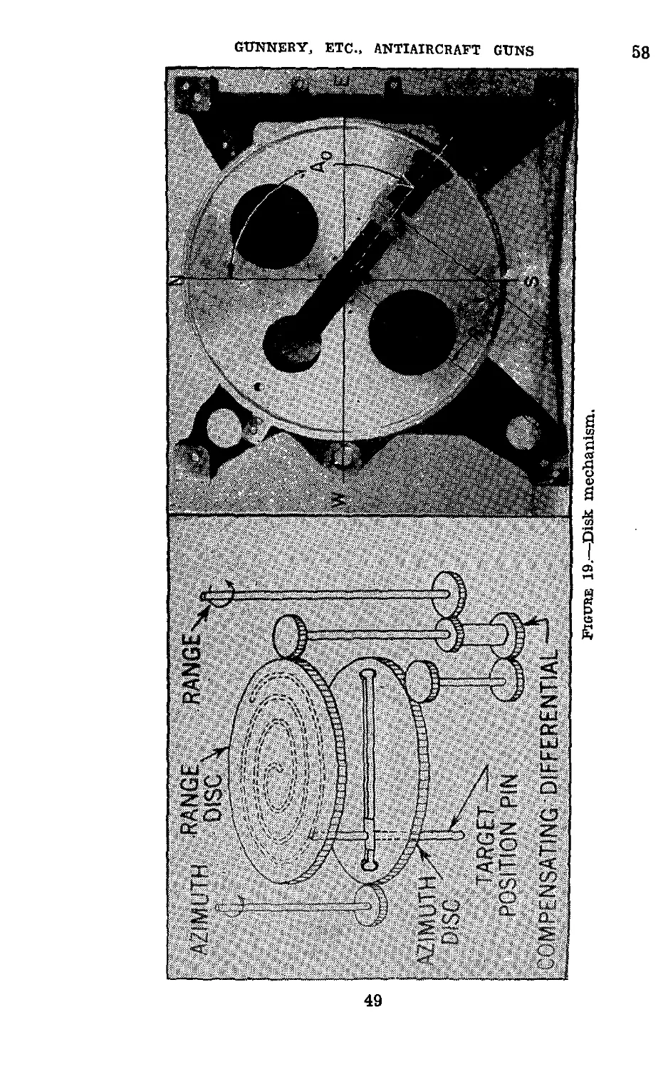
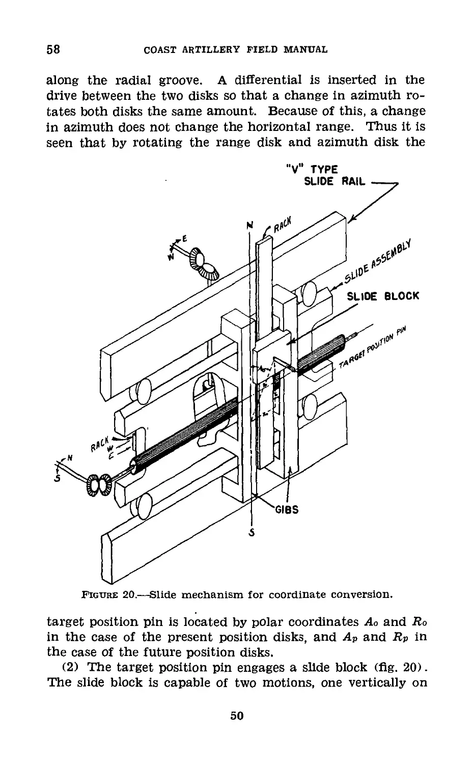

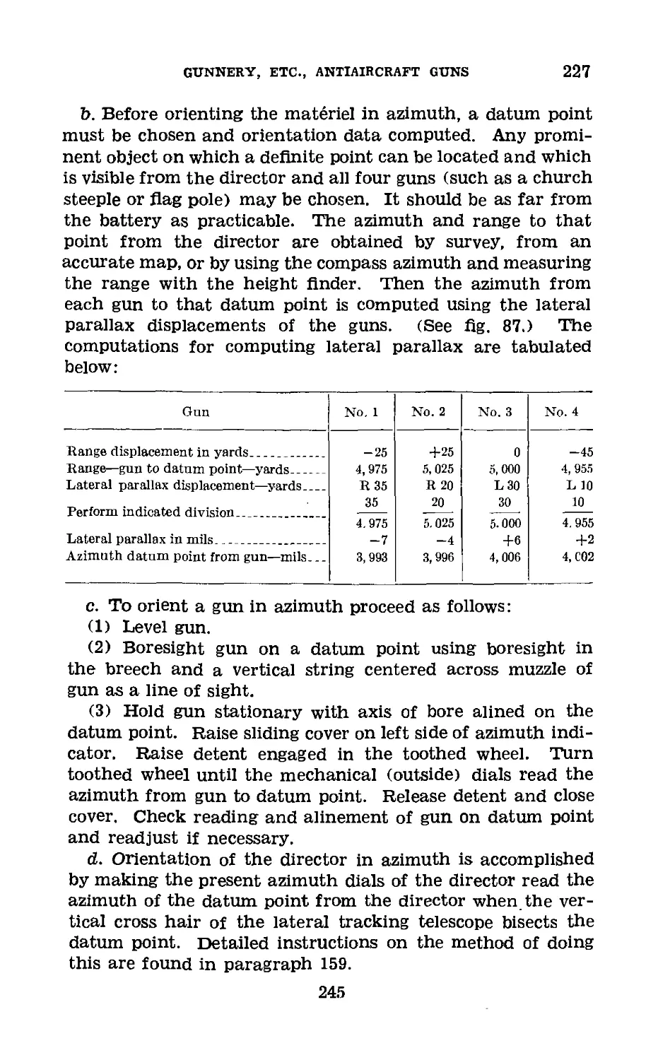
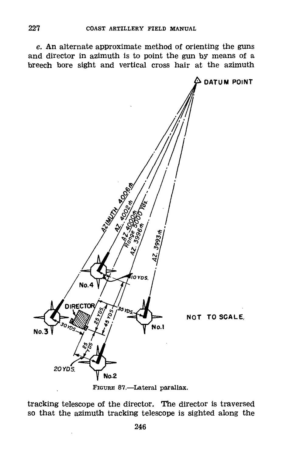
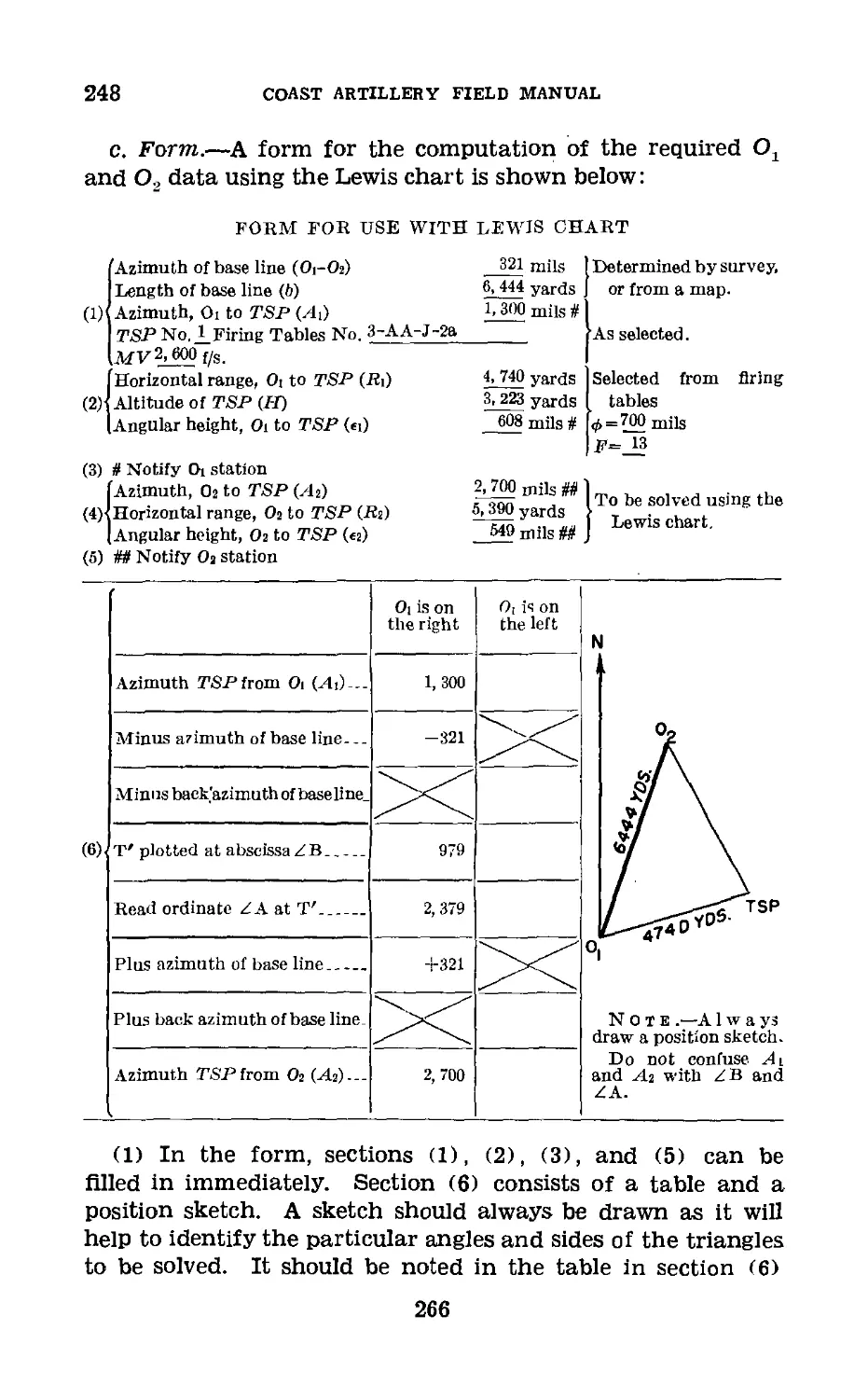

Similar


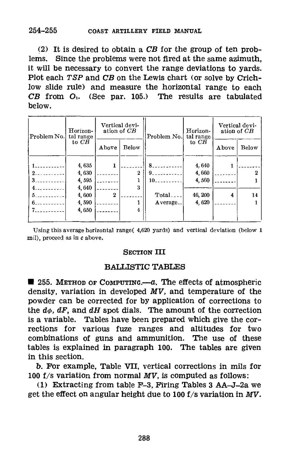
Text
MHI ваашреяш
СоруЗ FM 4-U0
WAR DEPARTMENT
COAST ARTILLERY
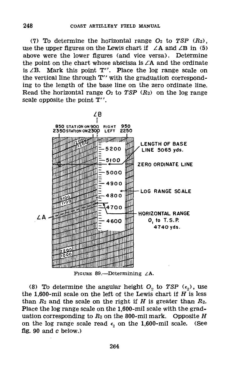
FIELD MANUAL
&
ANTIAIRCRAFT ARTILLERY
GUNNERY, FIRE CONTROL,
AND POSITION FINDING,
ANTIAIRCRAFT GUNS
ГМ 4-110
С 2
COAST ARTILLERY FIELD MANUAL
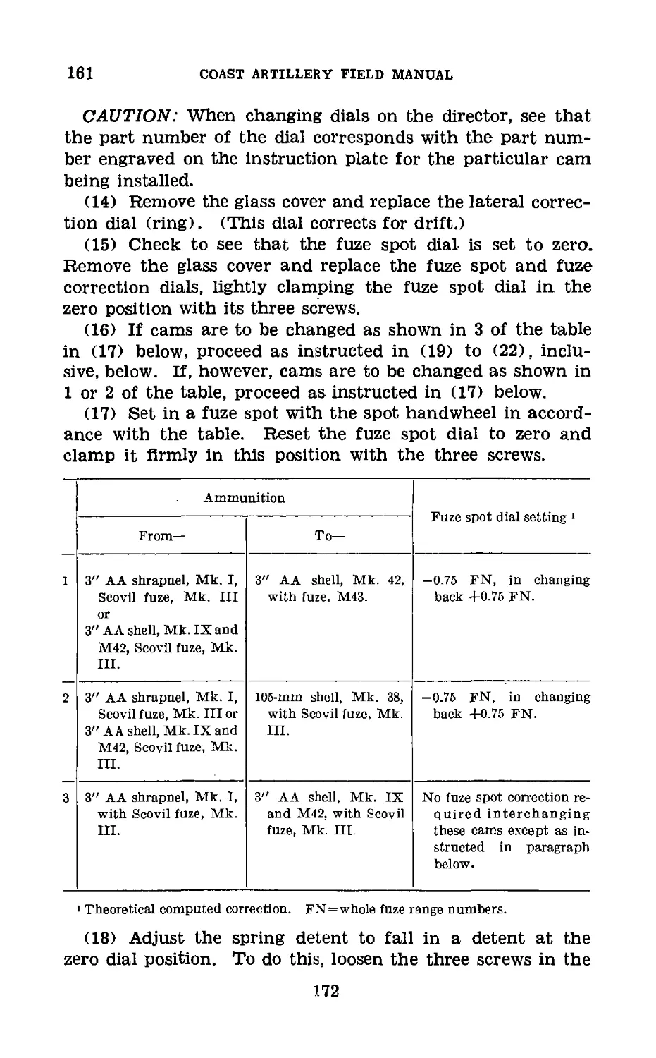
ANTIAIRCRAFT ARTILLERY
GUNNERY, FIRE CONTROL, AND POSITION
FINDING, ANTIAIRCRAFT GUNS
Changes! WAR DEPARTMENT,
No. 2 J Washington, May 2, 1942.
EM 4-110, August 10, 1940, Is changed as follows:
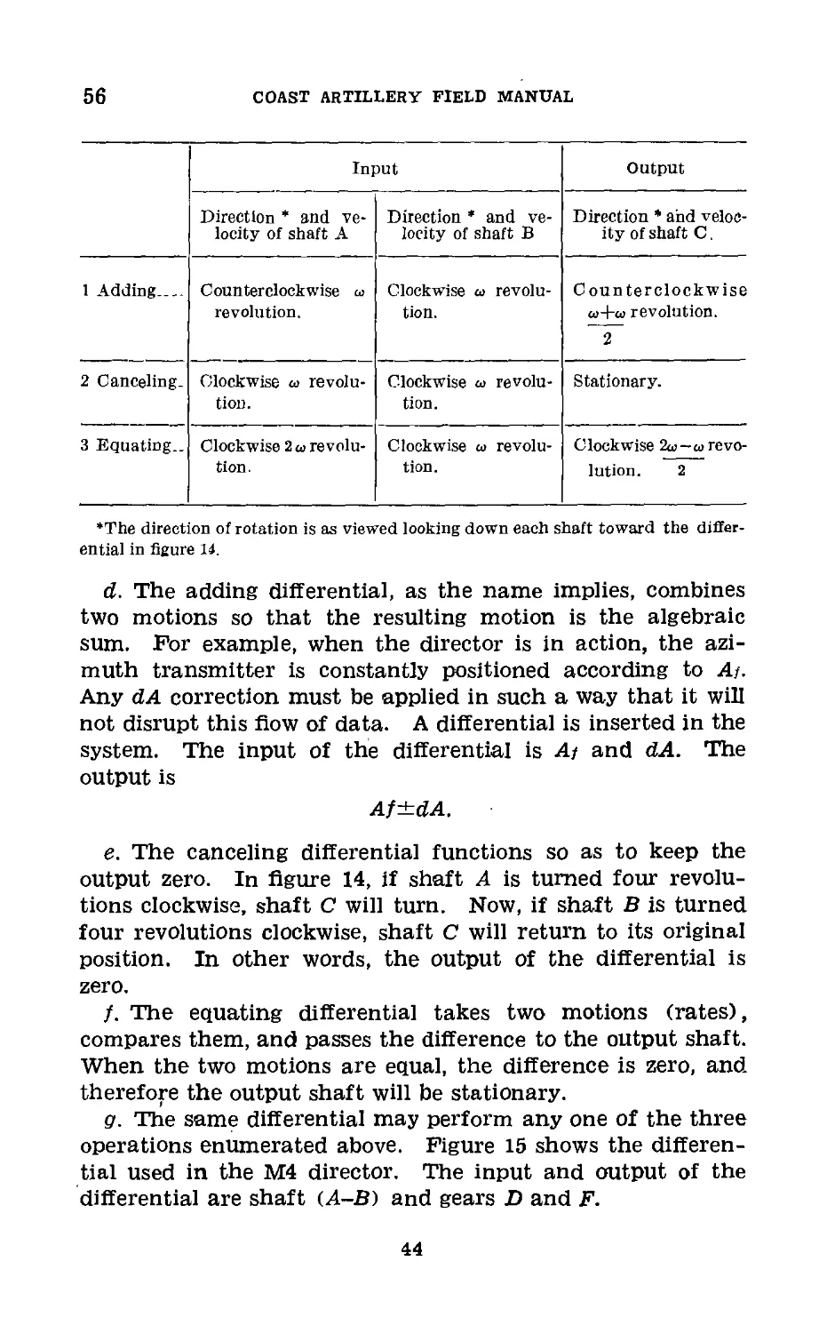
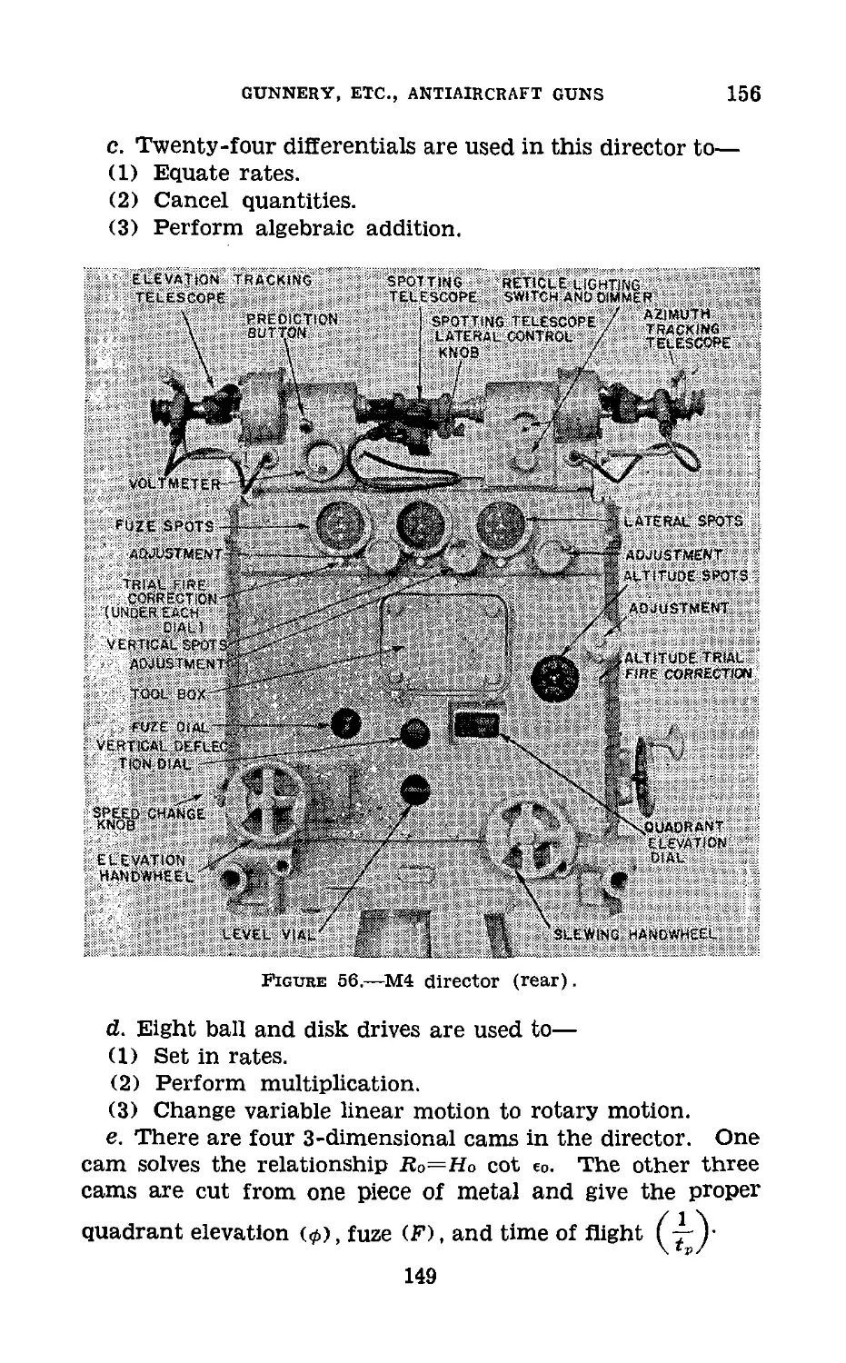
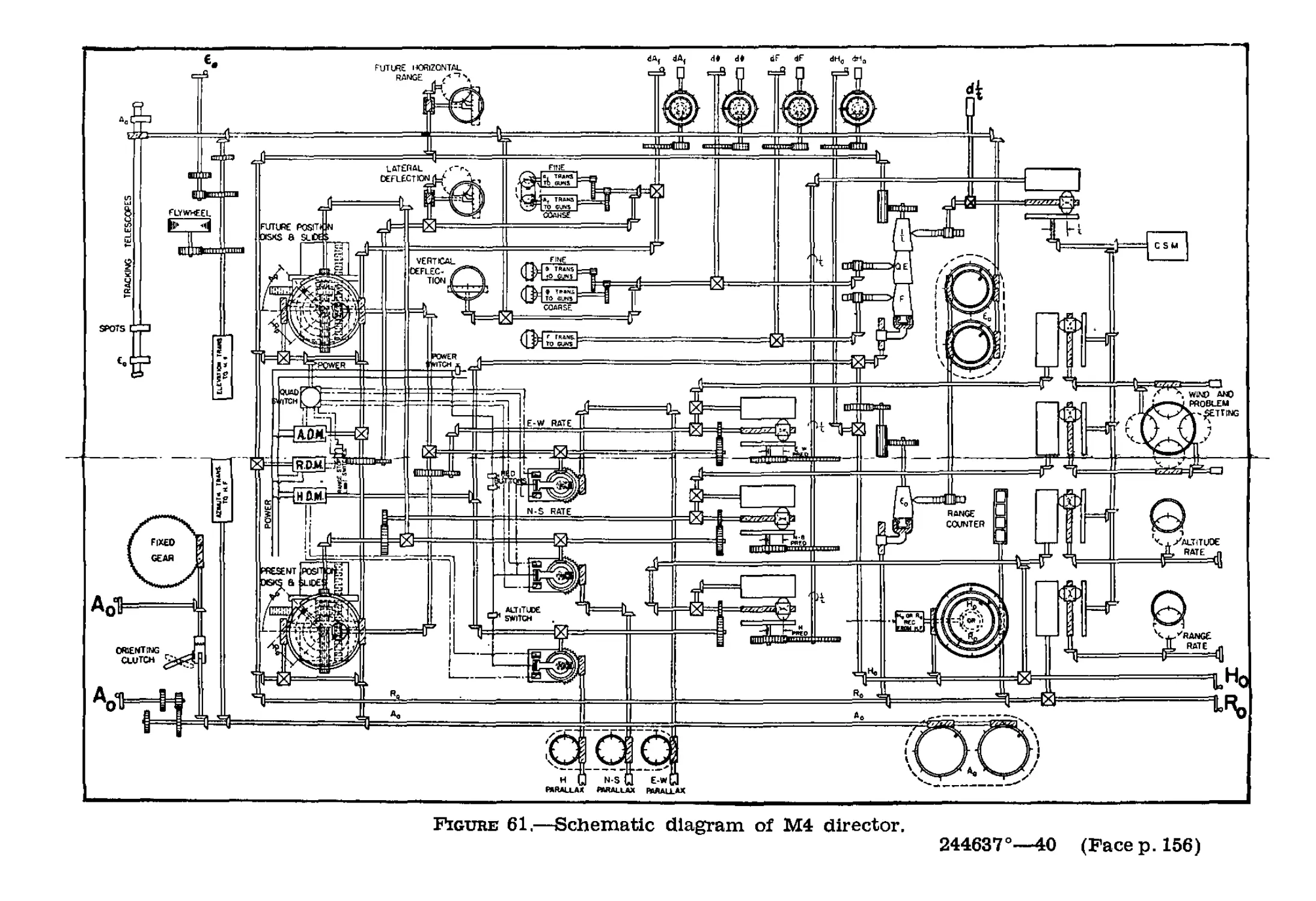
И 160. Opebation of Dibectob, M4, When Fibing.
f. Procedure in case of interlock.
• «*«««•
(2) If the first case of locked condition occurs, restore the
director to normal as follows;
(a) Turn power “OFF.”
(b) With power “OFF,” turn the range hand wheel to in-
crease future horizontal range several thousand yards (If
possible, 5,000 yards should be obtained).
(c) Set wind, target velocity, and-rate dials to zero.
(d) With the azimuth handwheel, increase present azimuth
1,800 mils.
(e) Turn power “ON” and director will clear itself of the
locked condition; after all prediction has settled out, the direc-
tor is ready for operation.
(3) If the second case of locked position occurs, restore the
director to normal as follows:
(a) Turn power “OFF.”
(6) Remove right cover plate. (This should be done in a
place free from floating particles of dust. Care must be taken
to prevent dirt from entering the mechanism.)
(c) Set wind, target velocity, and rate dials to zero.
(d) Disconnect lead R2 on terminal block M.
(e) Connect a wire jumper between terminals 14 and R1 on
the quadrant switch.
(f) With the azimuth handwheel, Increase present azimuth
1,800 mils.
465788"—42
COAST ARTILLERY HEID MANUAL
(g) Watching the future range dial, connect a jumper be-
tween terminals 15 and 5 on terminal blocks H and L and
when future range is approximately 5,000 yards, remove this
jumper. This closes the circuit to the constant speed and
difference motors.
(A) Remove wire jumper from terminals 14 and Bl. Be-
place terminal R2.
(i) With the range handwheel, decrease present range about
1,500 yards. Set the range rate dial to zero.
(J) Turn power “ON” and director will clear itself. After
prediction has settled out, replace right cover plate and
director is ready for operation.
[A. G. 0G2.11 (1-30-42).] (C 2, May 2, 1842.)
Вт obueb of the Secbetaey or Wab :
G. C. MARSHALL,
Chief of Staff.
Official :
J. A. ULIO,
Major General,
The Adjutant General.
3
v. * GOVERNMENT FRINTIM3 OFFICE i fMl
FM 4-110
COAST ARTILLERY
FIELD MANUAL
*
ANTIAIRCRAFT ARTILLERY
GUNNERY, FIRE CONTROL,
AND POSITION FINDING,
ANTIAIRCRAFT GUNS
Prepared under direction of the
Chief of Coast Artillery
UNITED STATES
government printing office
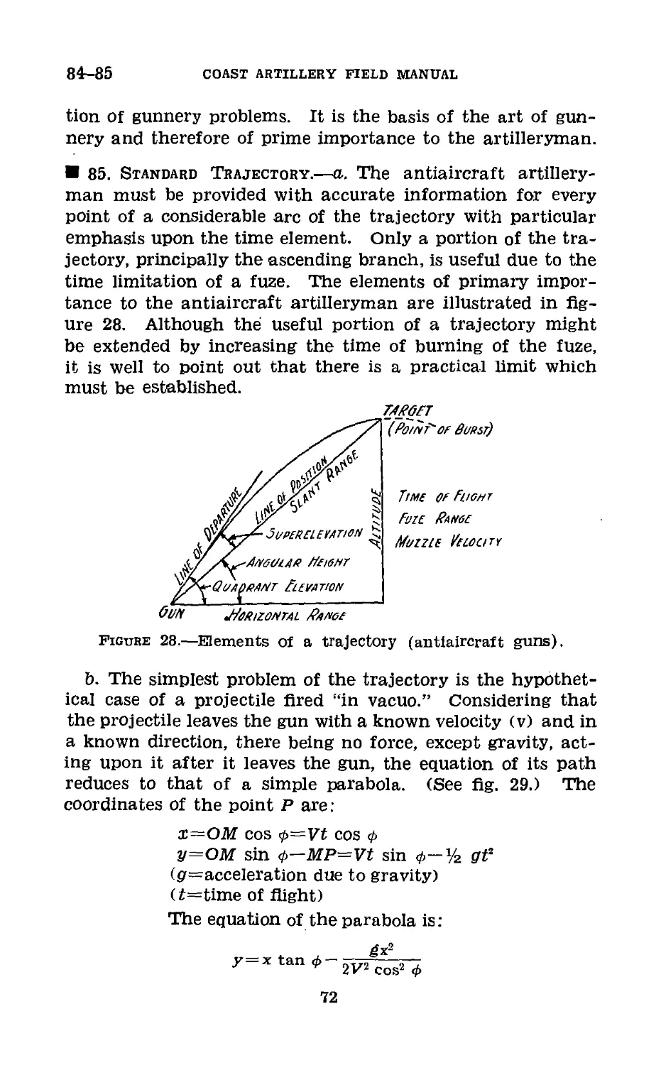
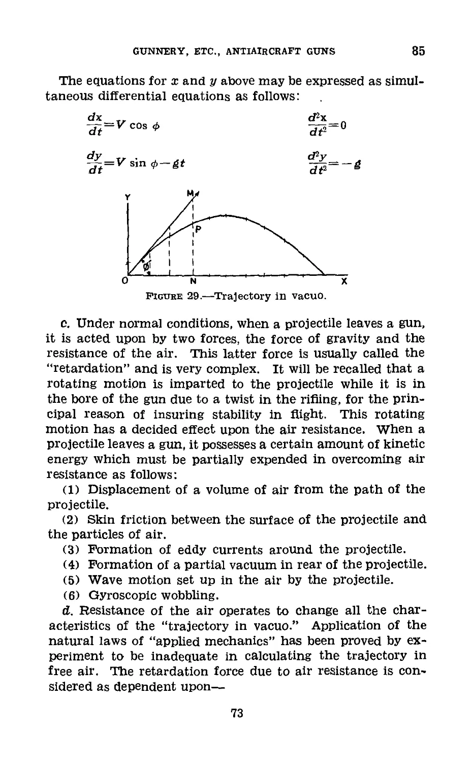
WASHINGTON : 1940
WAR DEPARTMENT,
Washington, August 10, 1940.
FM 4-110, Coast Artillery Field Manual, Antiaircraft Artil-
lery, Gunnery, Fire Control, and Position Finding, Antiair-
craft Guns, is published for the information and guidance of
all concerned.
[A. G. 062.11 (5-10-40).]
By order of the Secretary of War:
G. C. MARSHALL,
Chief of Staff.
Official :
E, S. ADAMS,
Major General,
The Adjutant General.
n
TABLE OF CONTENTS
Chapter 1. General. Paragraphs Page
Section I. General_____________________________ 1-7 1
II. Elements of data______________________ 8 7
III. Linear speed method_______________ 9-25 12
IV. Angular travel method_____________ 26-34 1Э
Chapter 2. Position Finding, Fire Control, and
Gunnery.
Section I. Position finding__________________ 35-37 25
II. Determination of altitude_____ 38-44 29
III. Prediction; future position____ 45-53 35
IV. Mechanical solutions______________ 54—61 40
V. Firing data_______________________ 62-68 56
VI. Data transmission systems______ 69-77 61
VII. Application of firing data to
guns____________________________________ 78-80 67
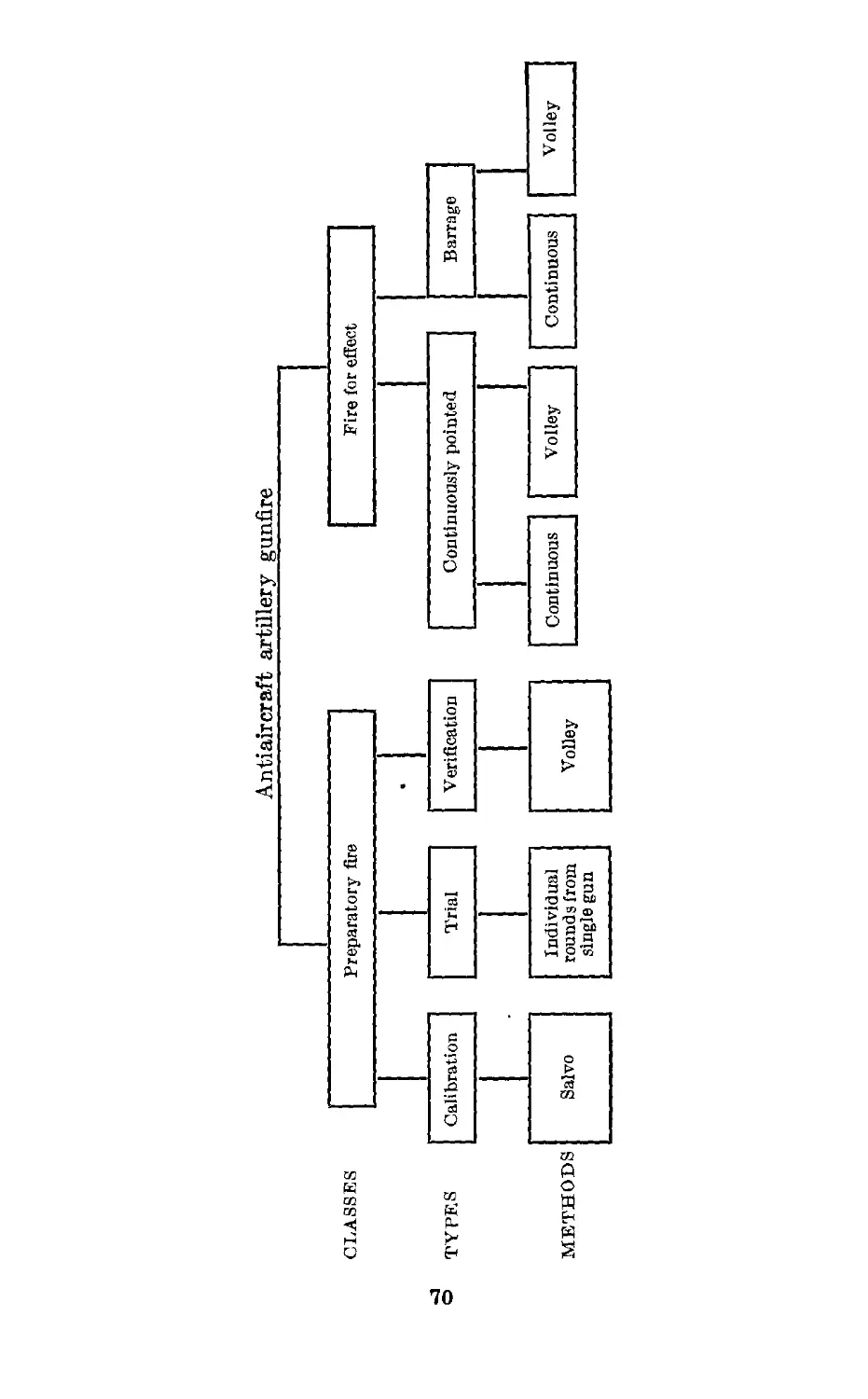
VIII. Classes, types, and methods of
fire_____________________________________ 81-82 69
IX. Exterior ballistics_______________ 83-88 71
X. Errors and probabilities__________ 89—91 84
XI. Preparatory fire_________________ 92-136 90
XII. Fire for effect________________ 137-139 119
XIII. Spotting and adjustment of fire_ 140-154 122
Chapter 3. Instruments and Accessories for
Antiaircraft Guns.
Section I. Directors_______________________ 155-162 146
II. Height finders and altimeters_ 163-189 174
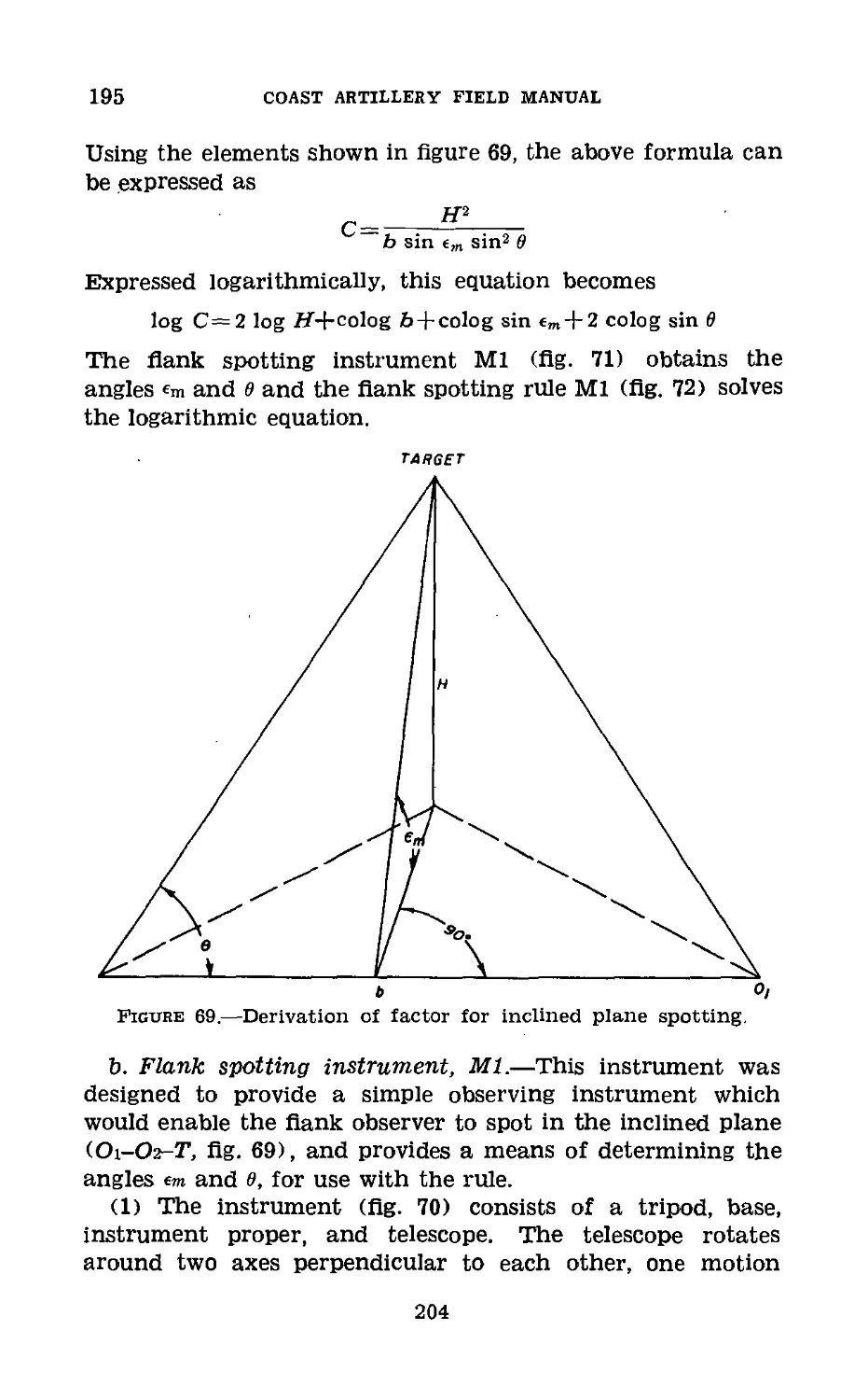
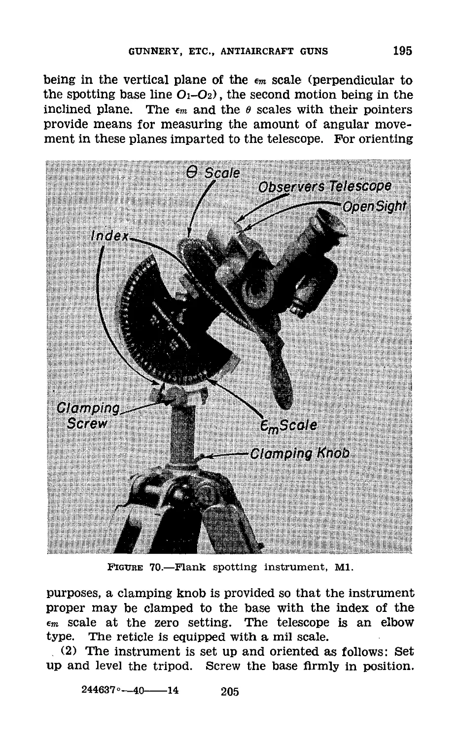
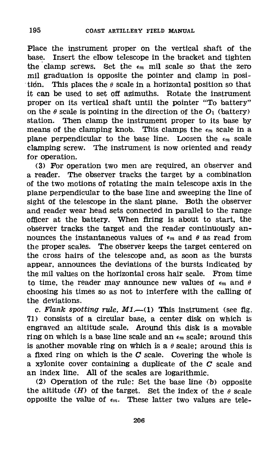
III. Observation instruments_________ 190-199 197
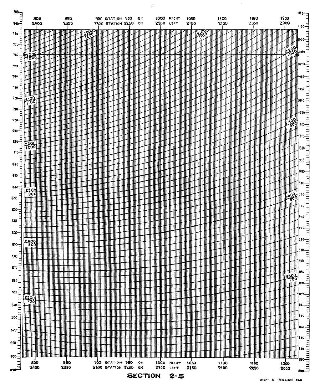
IV. Lewis chart_____________________ 200-203 213
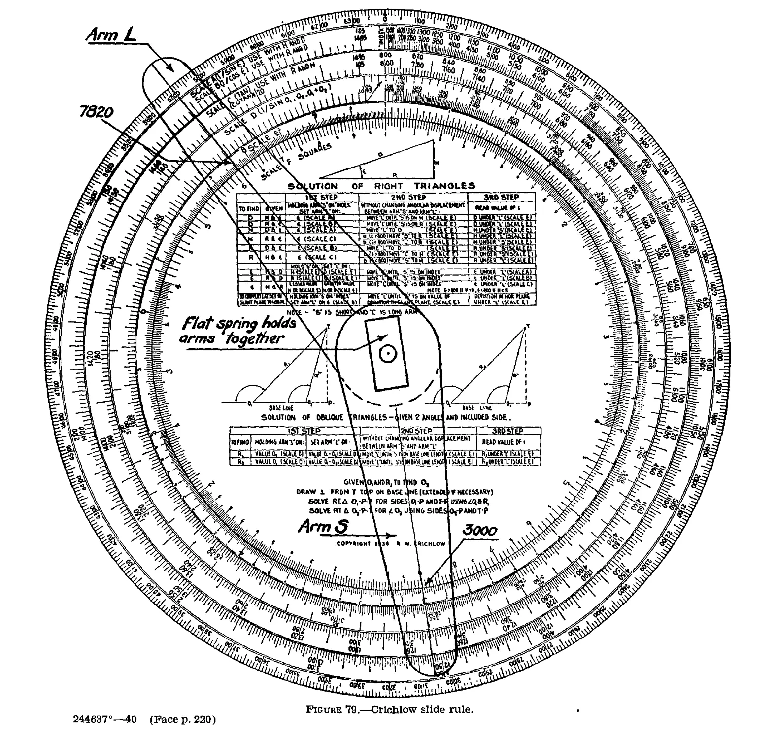
V. Crichlow slide rule_____________204-207 219
VT. Fuze setters_____________________ 208-212 225
VII. Data transmission______________ 213-218 231
VIII. Stereoscopic training instru-
ments_________________________ 219-222 238
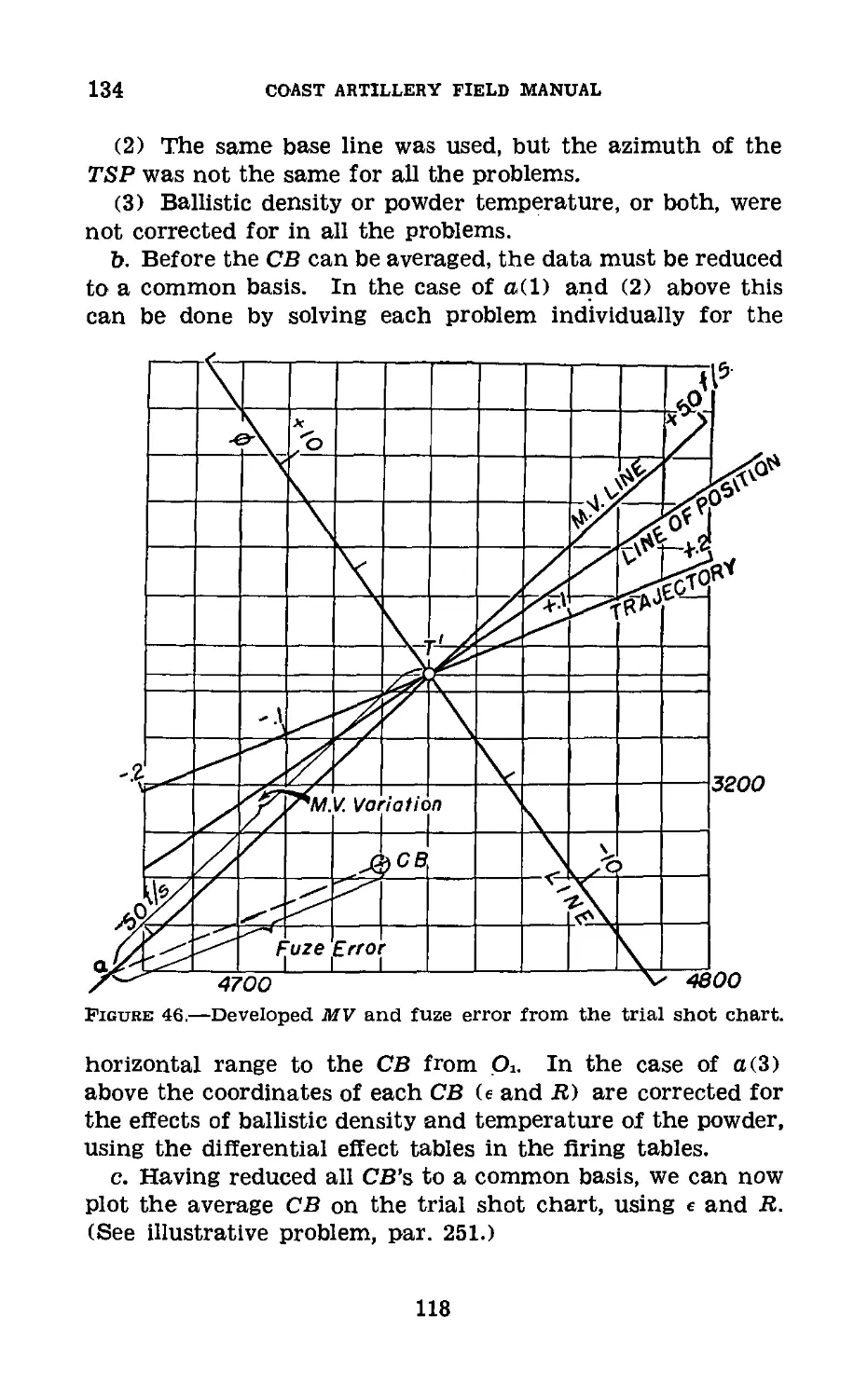
Chapter 4. Orientation, Synchronization, and
Application of Calibration Cor-
rections.
Section I. General_________________________ 223-225 243
II. Orientation____________________ 226-230 244
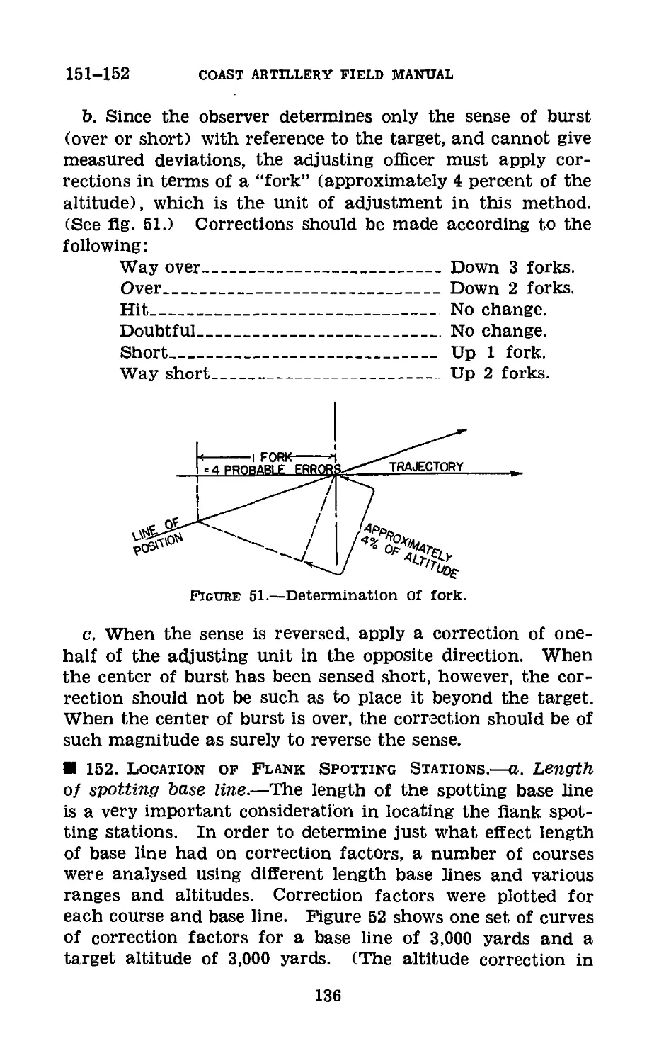
III. Synchronization_________________ 231-235 249
IV. Application of calibration cor-
rections______________________ 236-239 251
Chapter 5. Target Practice; Organization and
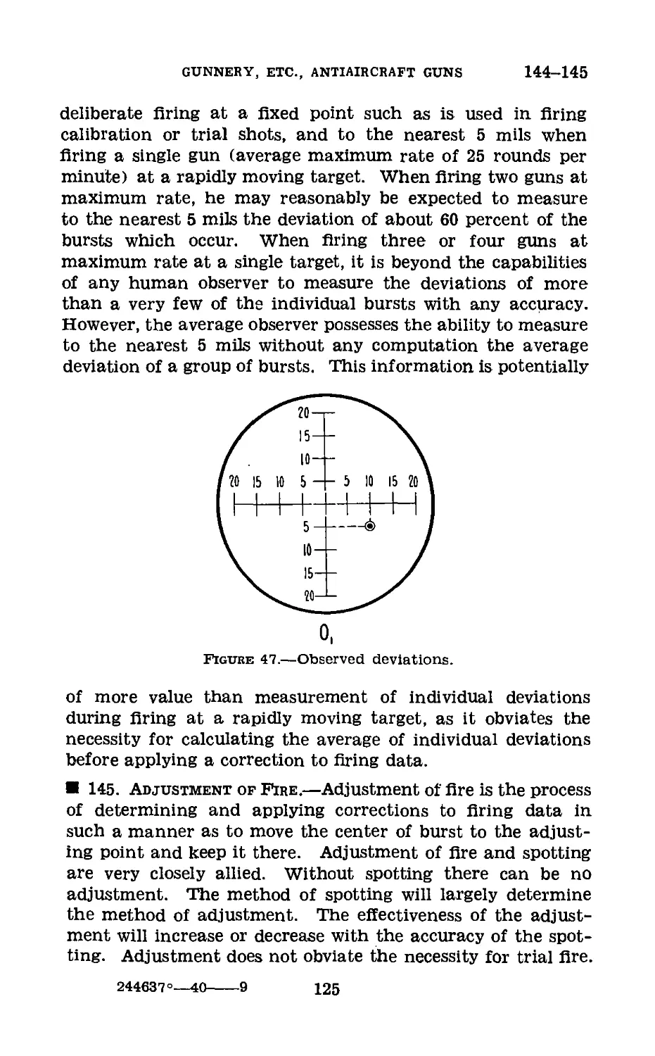
Duties of the Record and the
Range Sections.
Section I. Target practice_________________ 240-241 253
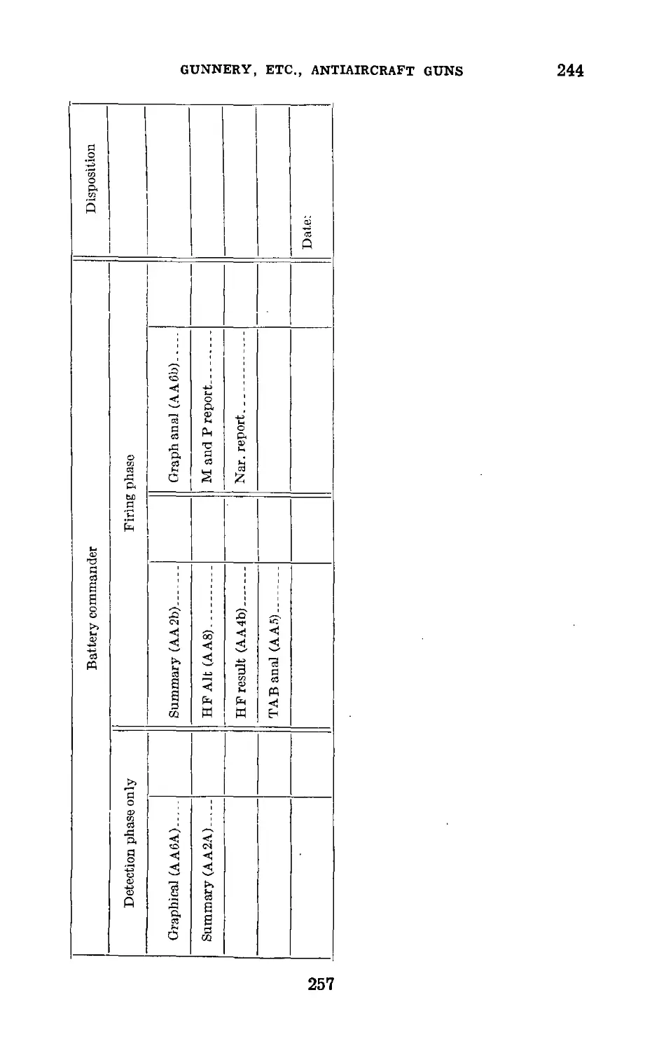
II. Record section_________________ 242-245 254
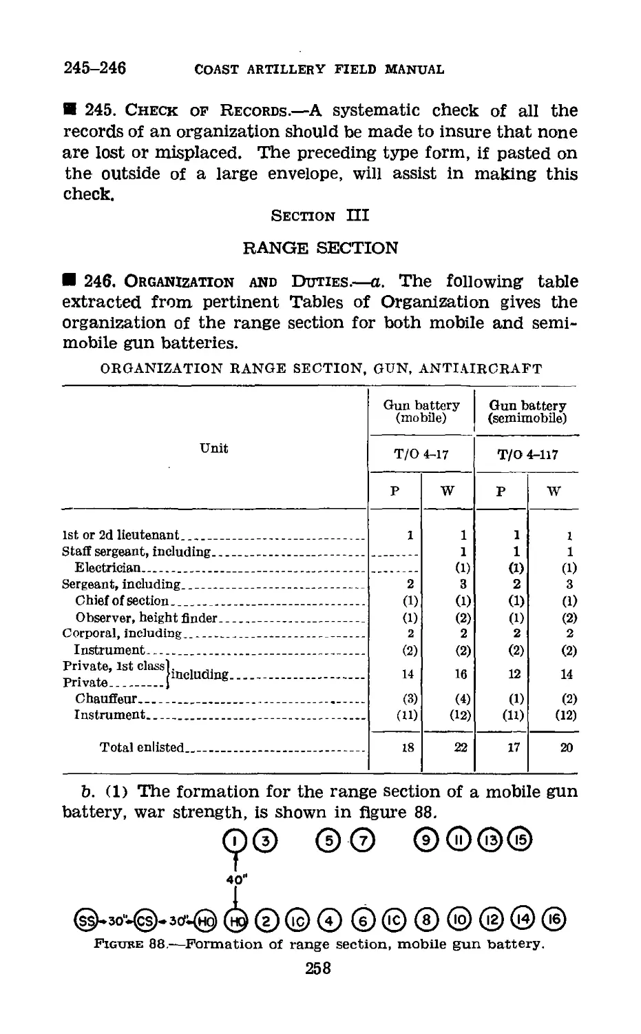
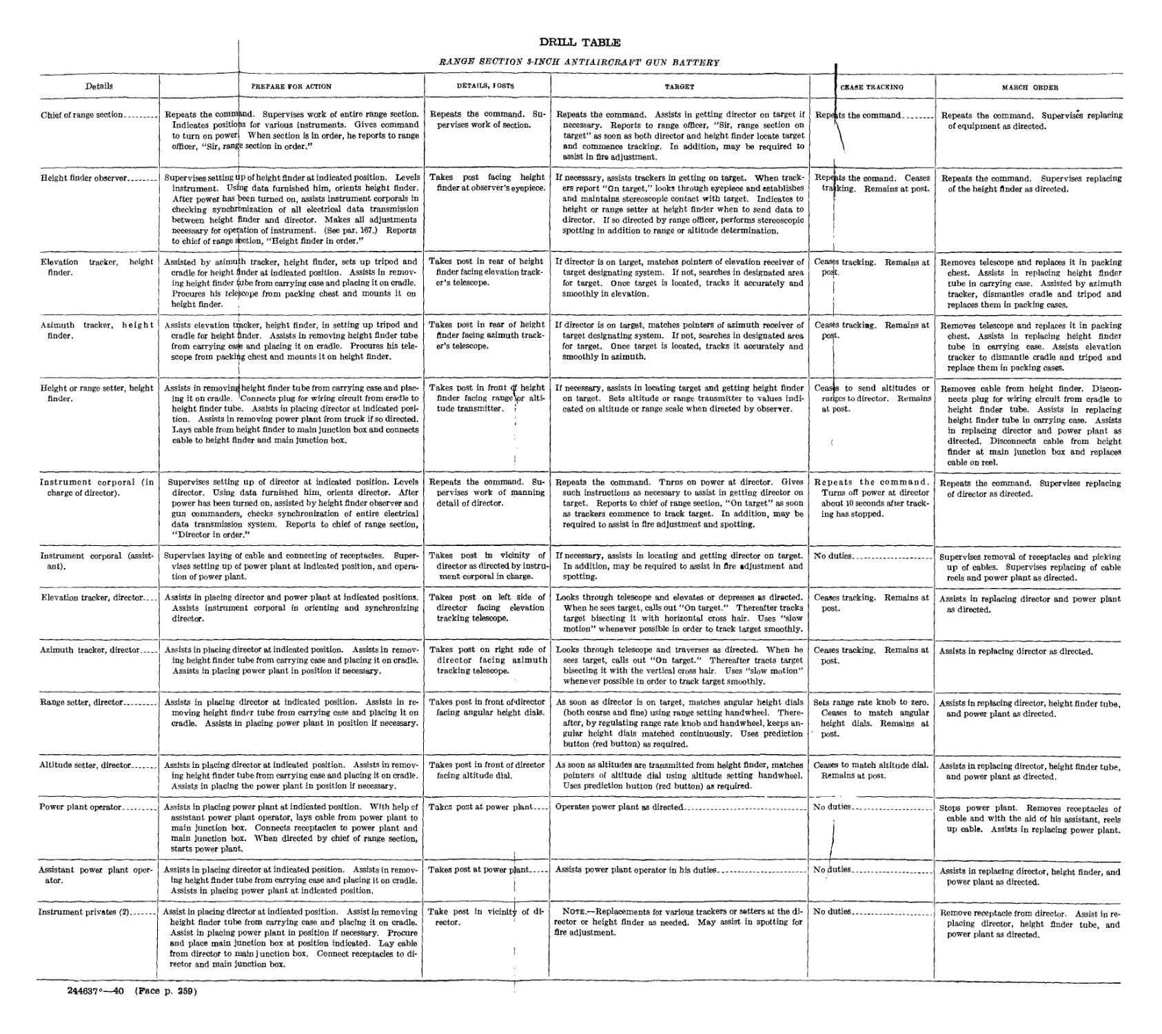
III. Range section_______________________ 246 258
Chapter 6. Reference Data.
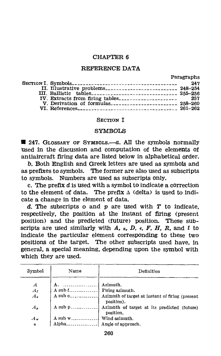
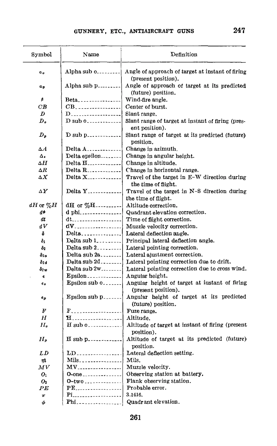
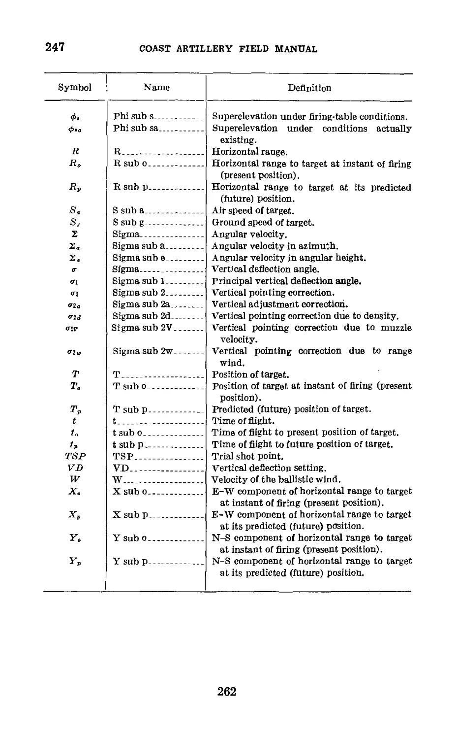
Section I. Symbols_____________________________ 247 260
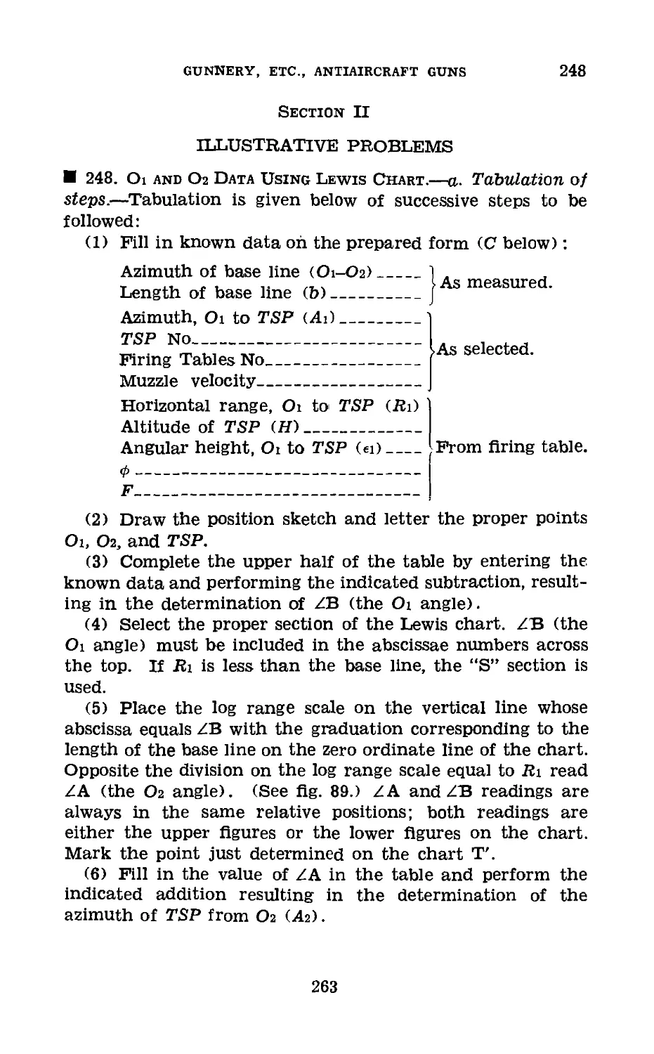
II. Illustrative problems__________ 248-254 263
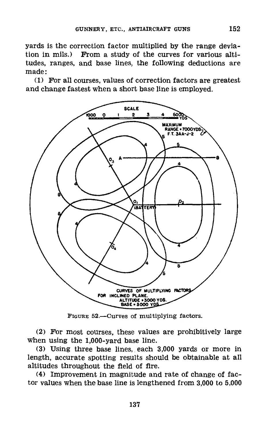
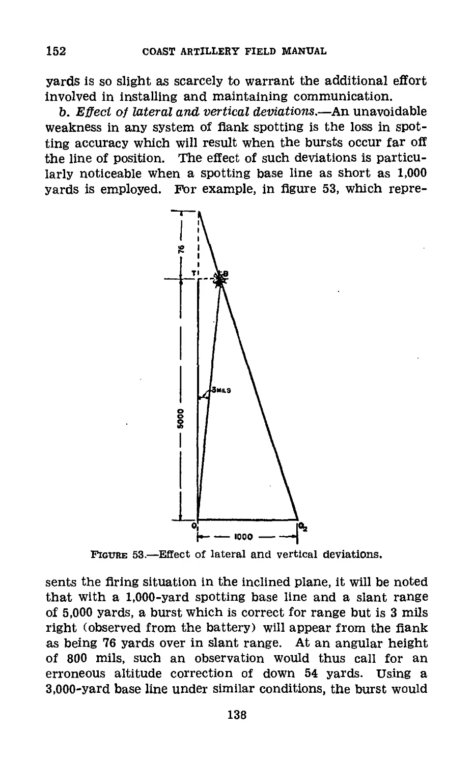
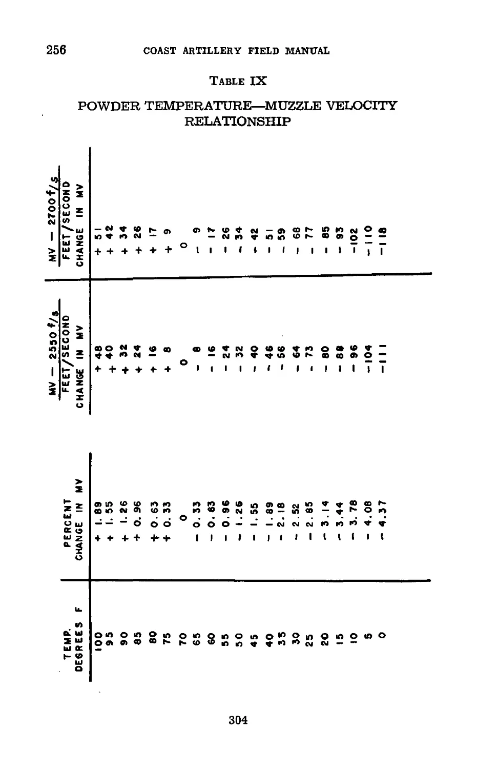
III. Ballistic tables____:__________ 255-256 288
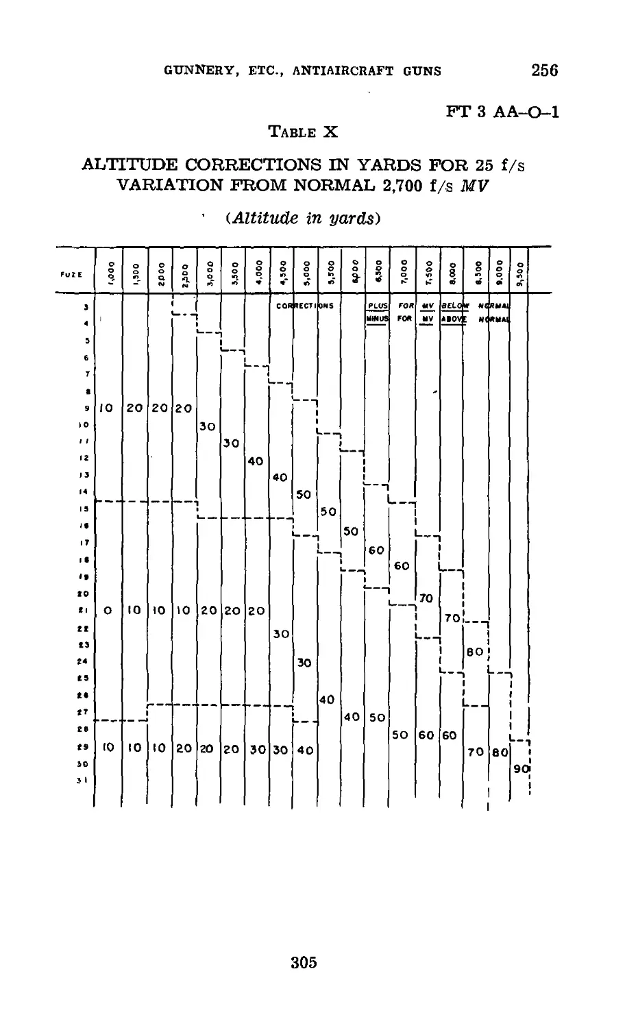
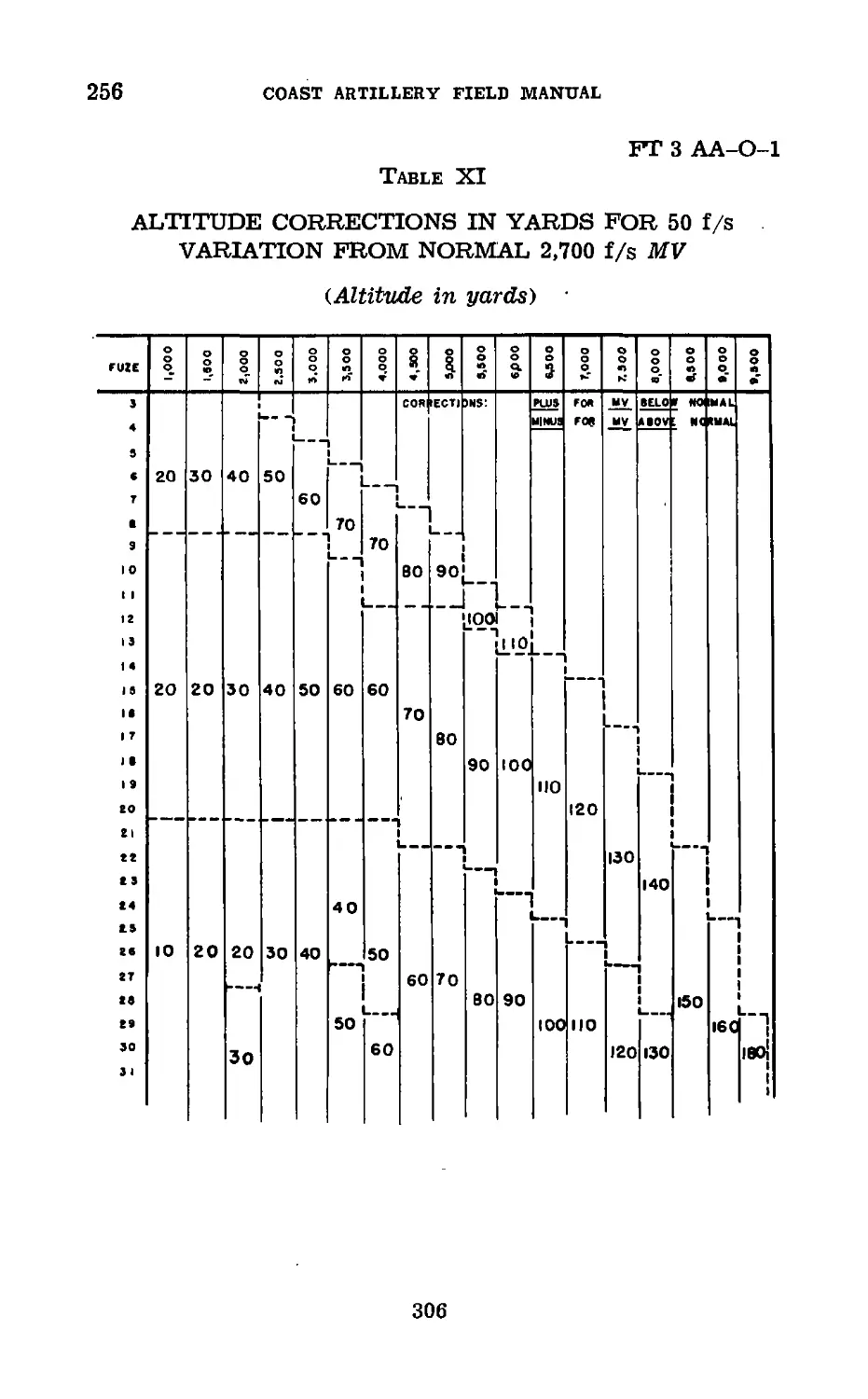
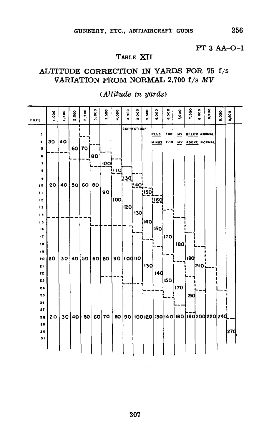
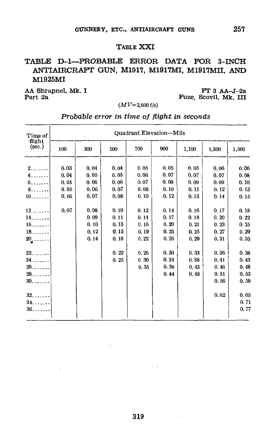
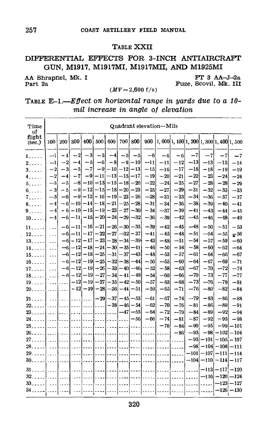
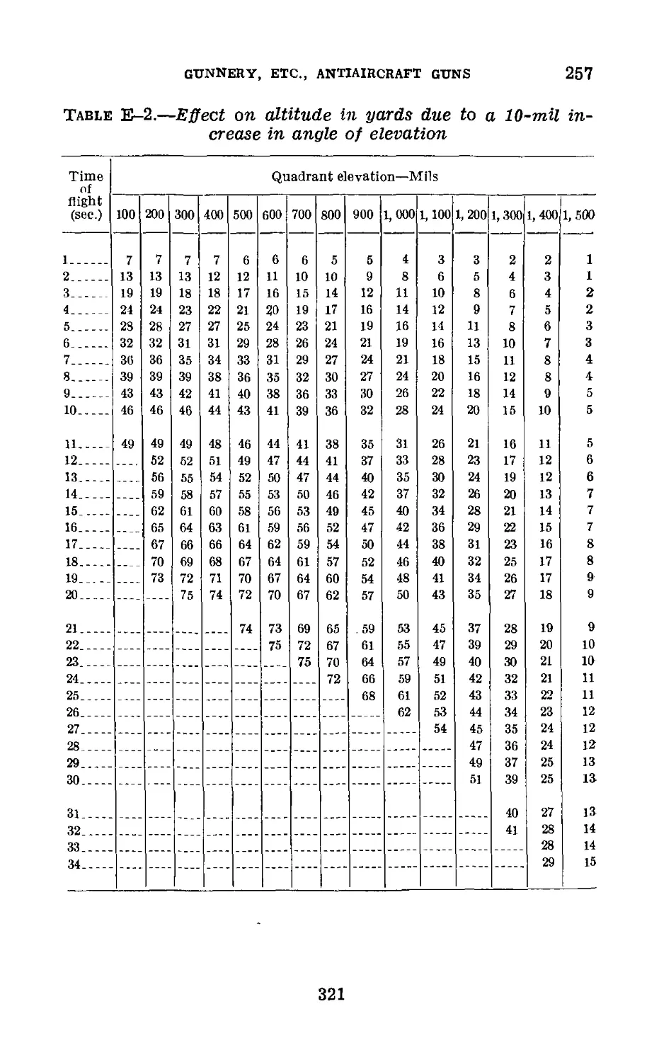
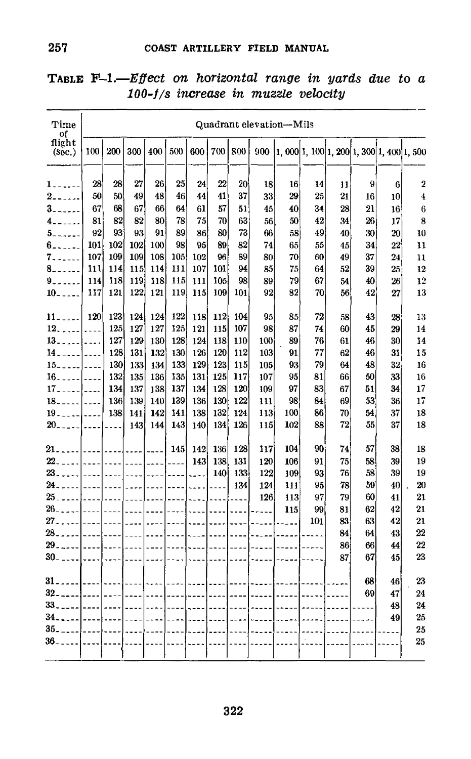
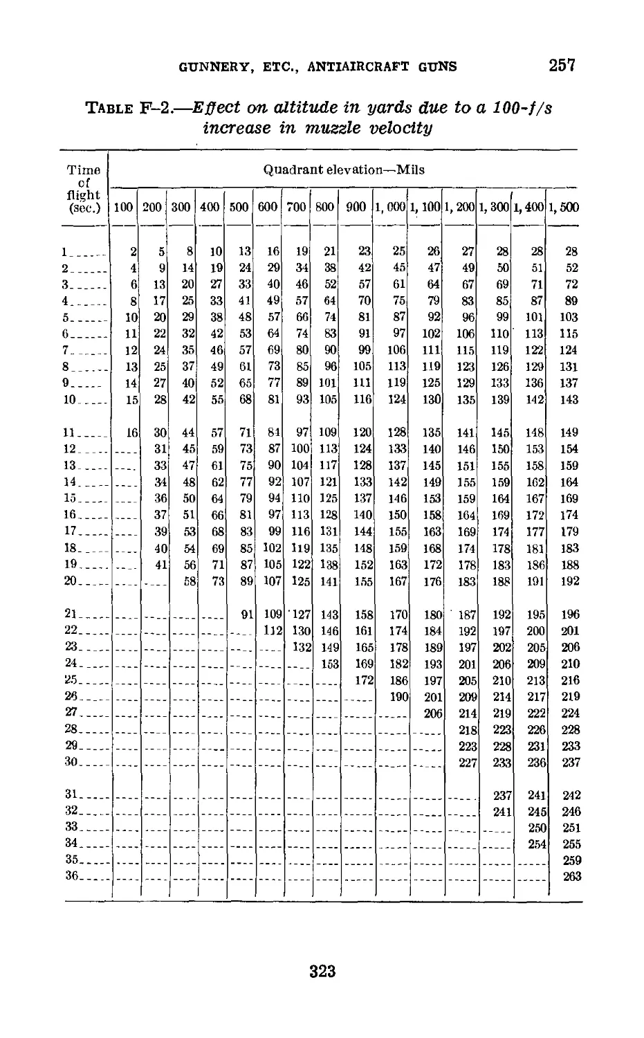
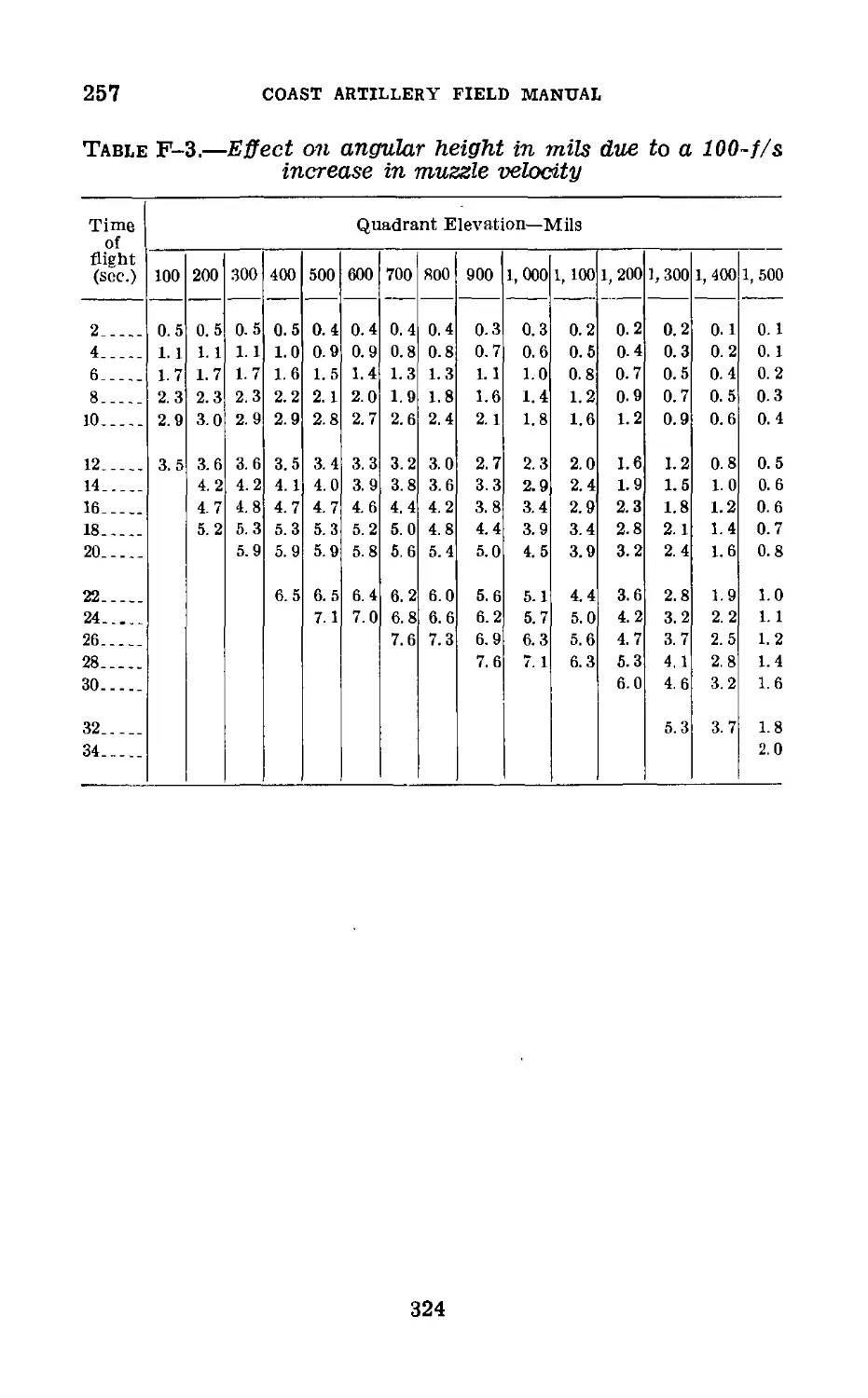
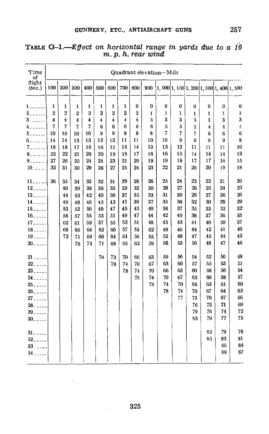
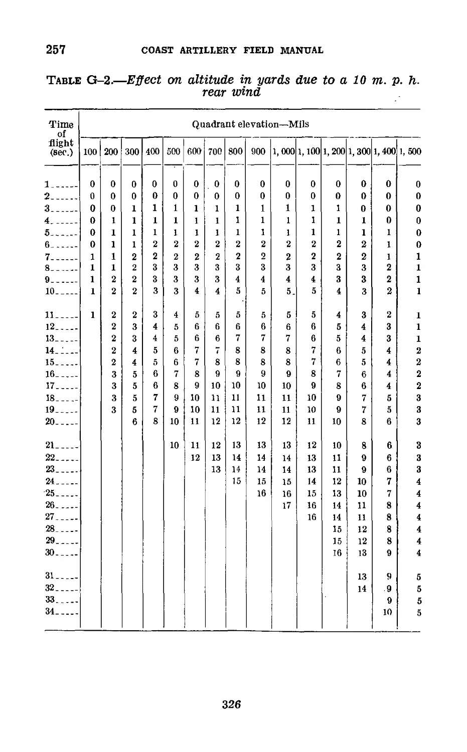
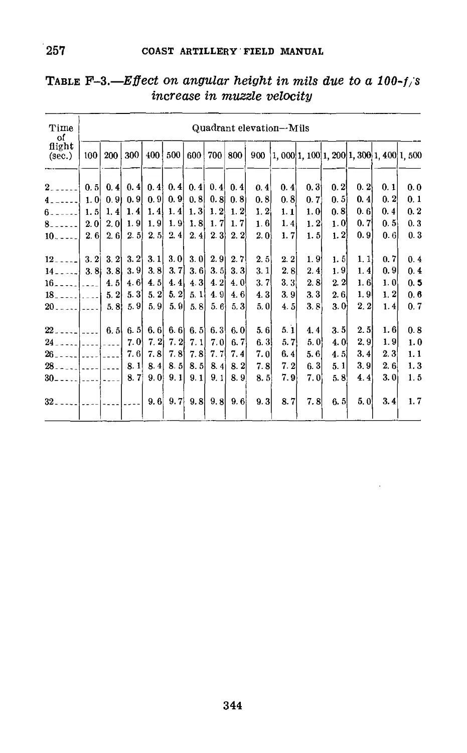
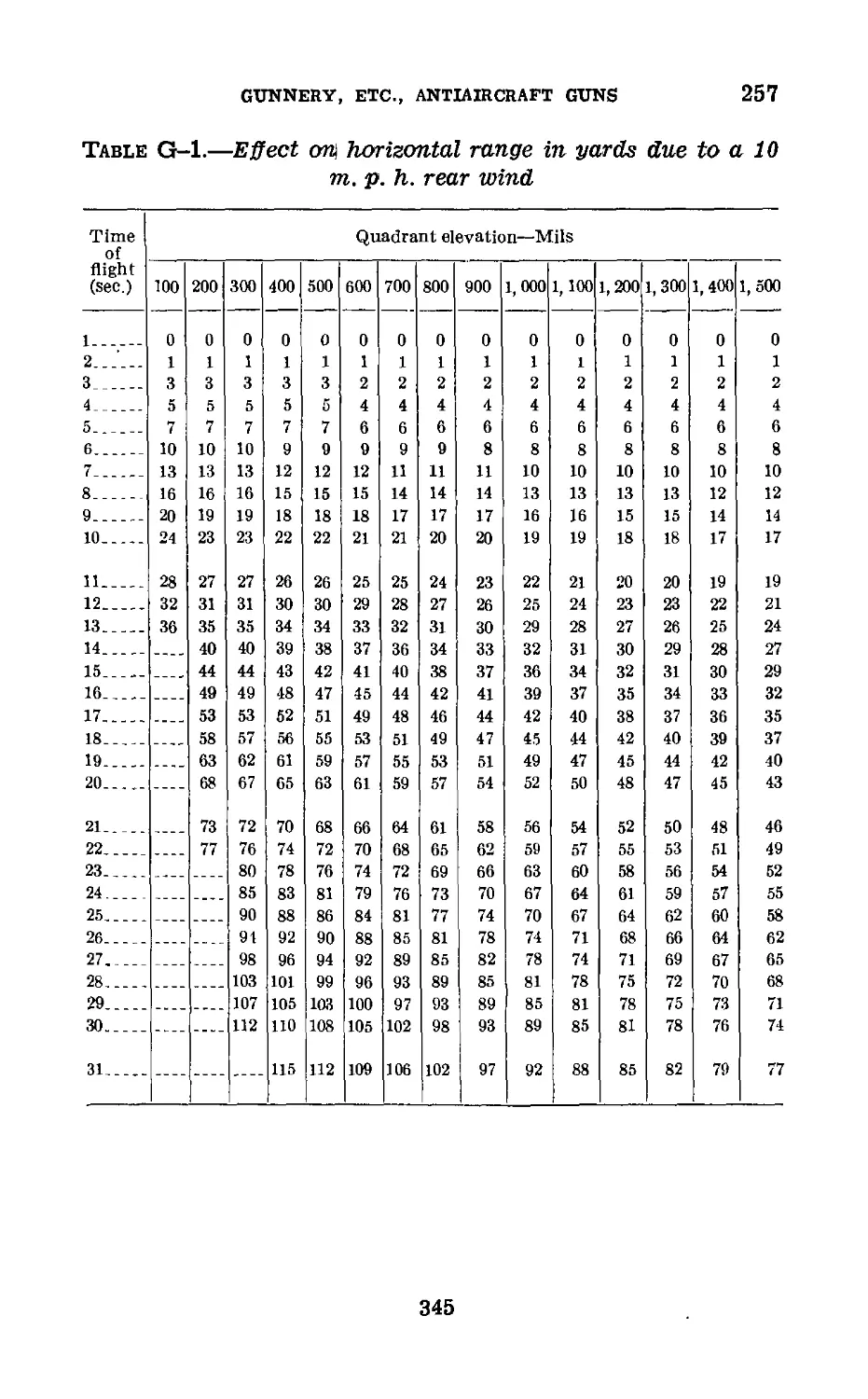
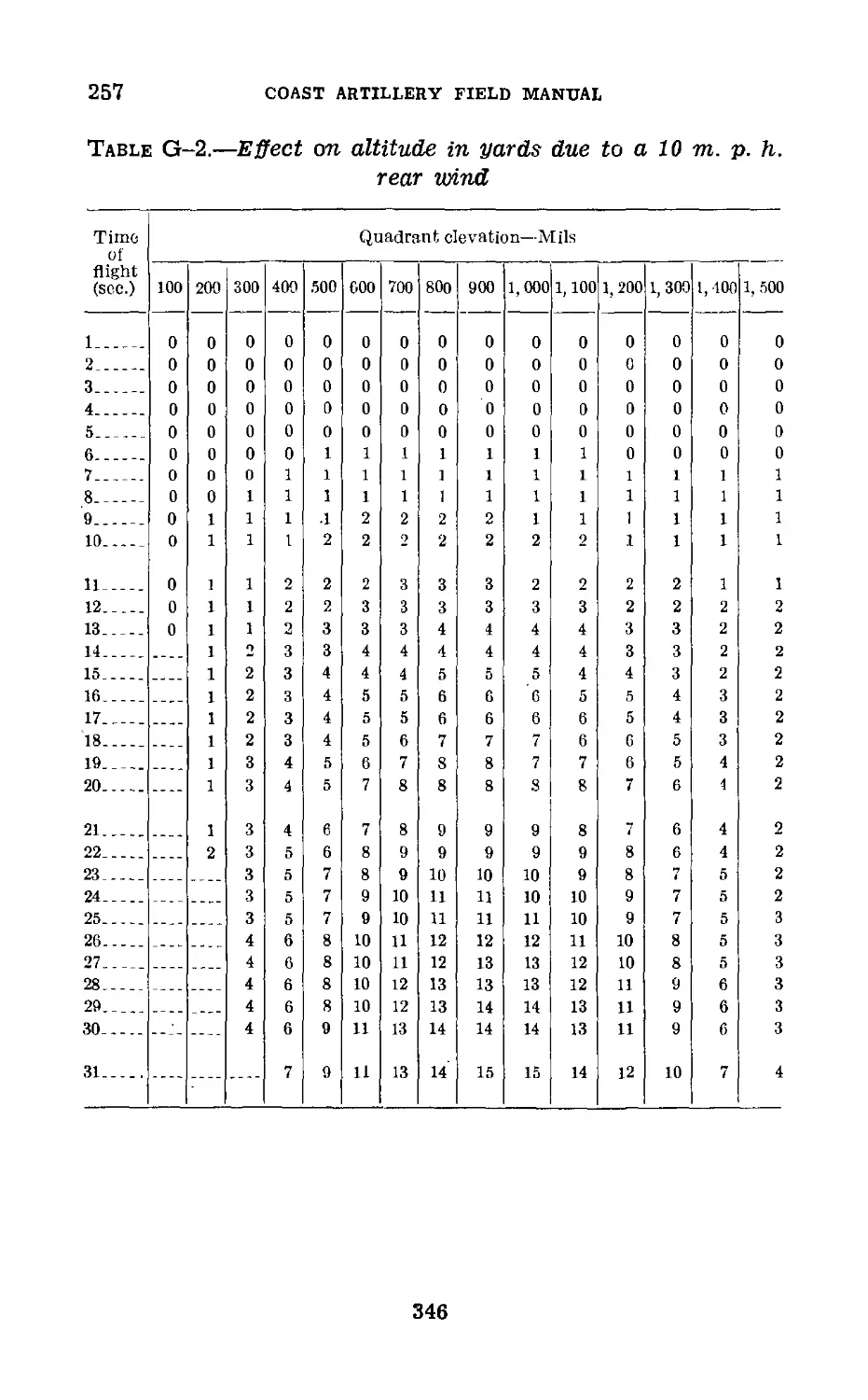
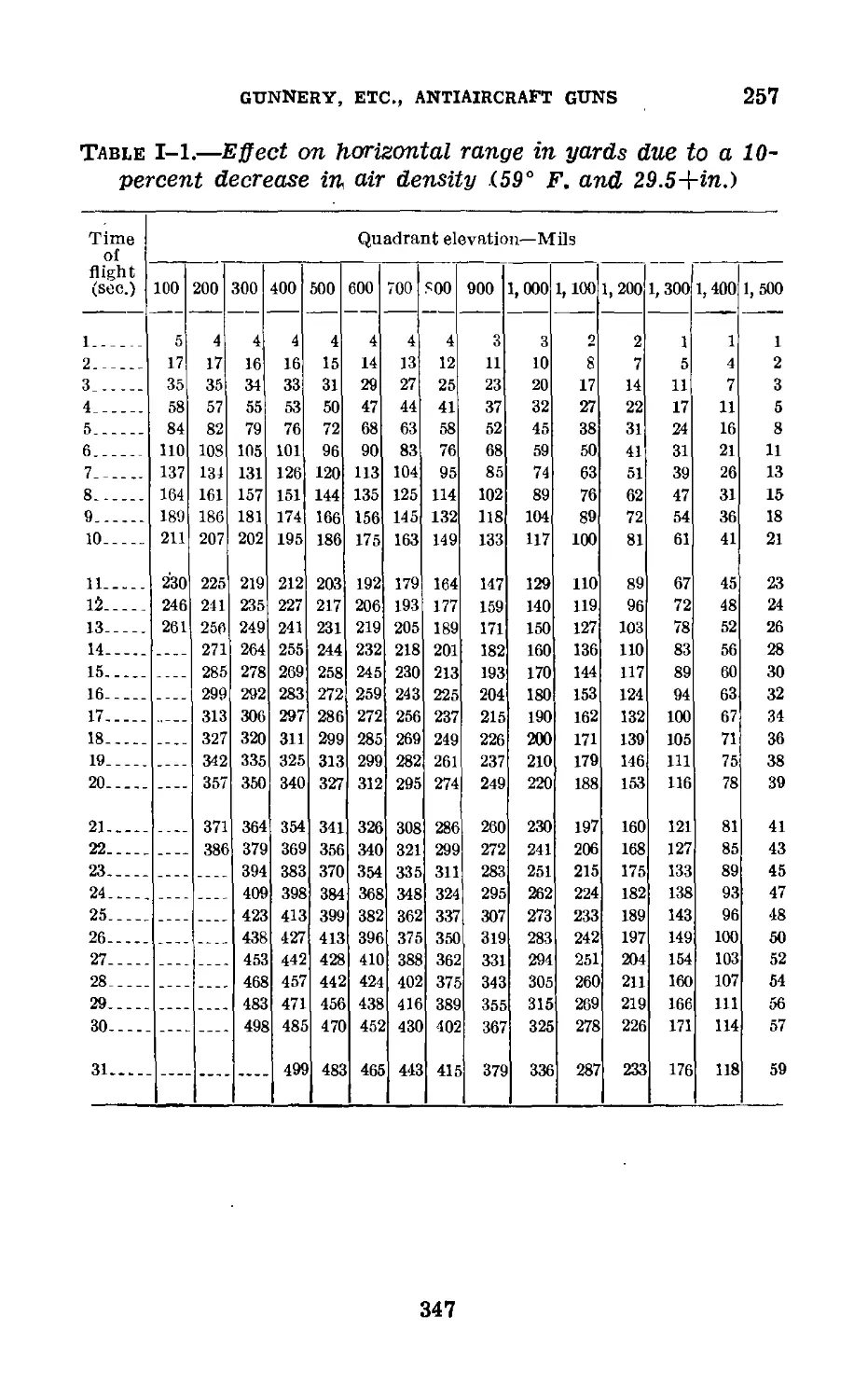
IV. Firing tables (extracts)___________ 257 313
V. Derivation of formulas_________ 258-260 351
VI. Additional references__________ 261-262 360
Index___________________________________________________ 361
III
FM 4-110
COAST ARTILLERY FIELD MANUAL
ANTIAIRCRAFT ARTILLERY
GUNNERY, FIKE CONTROL, AND POSITION FINDING
(The matter contained herein supersedes chapter 1, part two, and
Tables J, K, L, and M, chapter 2, part three, Coast Artillery Field
Manual, Volume II, February 1, 1933.)
CHAPTER 1
GENERAL
Paragraphs
Section I. General_______________________________________ 1-7
II. Elements of data_______________________________ 8
III. Linear speed method__________________________ 9-25
IV. Angular travel method_______________________26-34
Section I
GENERAL
1. Scope.—This manual treats of the theory and practice of
gunnery, fire control, and position finding for antiaircraft
artillery guns. A knowledge of the fundamentals of exterior
ballistics and gunnery as covered in FM 4-10 will be helpful
in understanding similar fundamentals as applied to anti-
aircraft gunnery. Pertinent definitions and symbols should
be studied and a thorough understanding should be had of
the picture in space of the various elements of data.
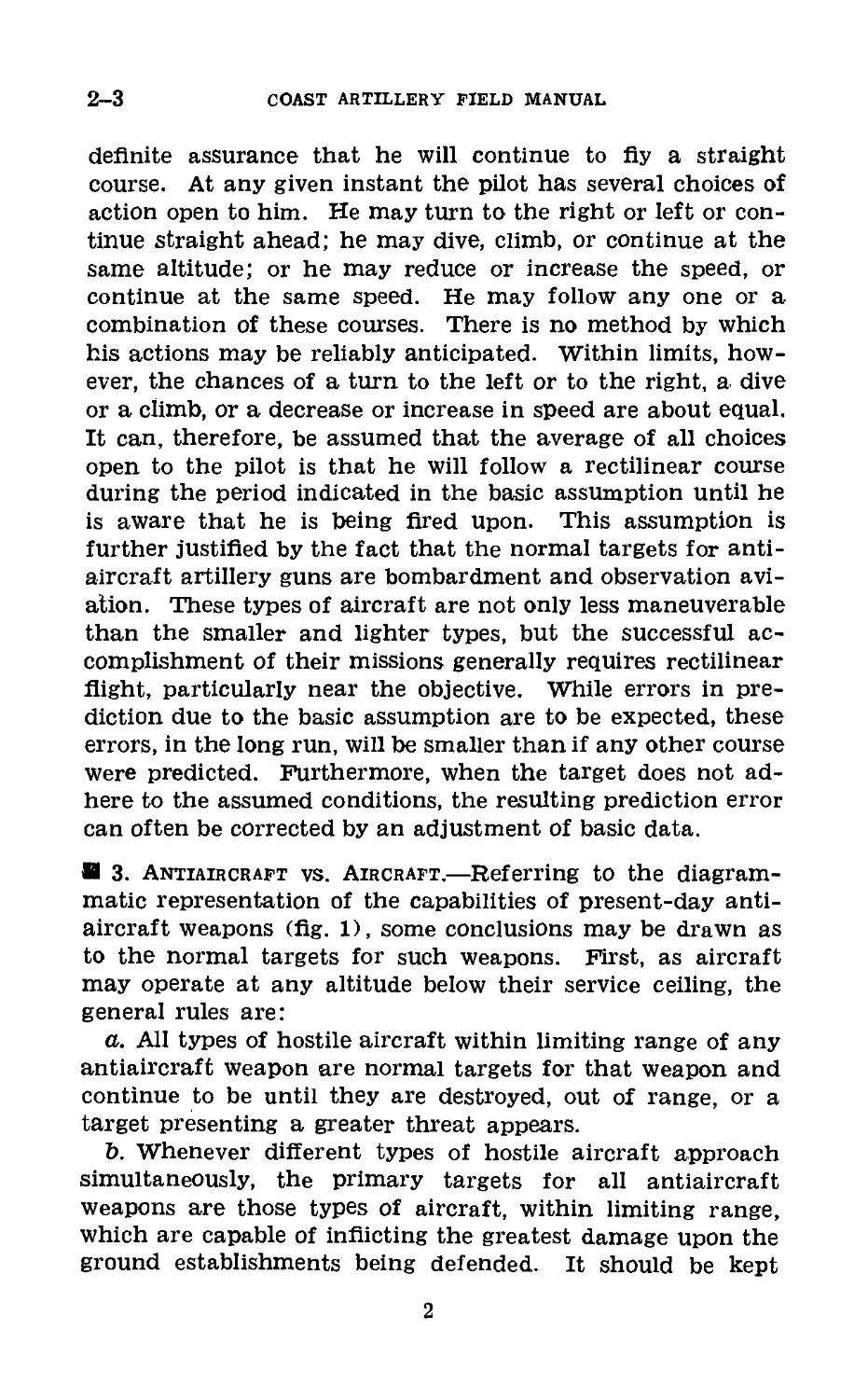
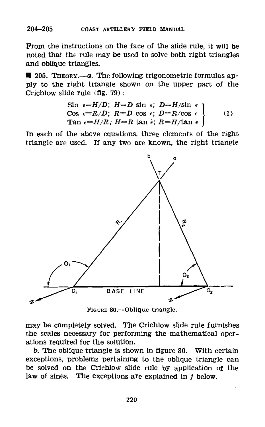
И 2. Basic Assumption.—The design of present fire-control
instruments and present fire-control methods for antiair-
craft artillery guns are based on the assumption that the tar-
get will fly in a straight line, at a constant speed, at a con-
stant altitude, or with a constant change of altitude during
the time required to determine and apply data, fire the gun,
and during the time of flight of the projectile. This assump-
tion is based principally on a consideration of the possible
courses of action open to the individual pilot. The direction
of flight is largely subject to his control, and there is no
1
2-3
COAST ARTILLERY FIELD MANUAL
definite assurance that he will continue to fly a straight
course. At any given instant the pilot has several choices of
action open to him. He may turn to the right or left or con-
tinue straight ahead; he may dive, climb, or continue at the
same altitude; or he may reduce or increase the speed, or
continue at the same speed. He may follow any one or a
combination of these courses. There is no method by which
his actions may be reliably anticipated. Within limits, how-
ever, the chances of a turn to the left or to the right, a dive
or a climb, or a decrease or increase in speed are about equal.
It can, therefore, be assumed that the average of all choices
open to the pilot is that he will follow a rectilinear course
during the period indicated in the basic assumption until he
is aware that he is being fired upon. This assumption is
further justified by the fact that the normal targets for anti-
aircraft artillery guns are bombardment and observation avi-
ation. These types of aircraft are not only less maneuverable
than the smaller and lighter types, but the successful ac-
complishment of their missions generally requires rectilinear
flight, particularly near the objective. While errors in pre-
diction due to the basic assumption are to be expected, these
errors, in the long run, will be smaller than if any other course
were predicted. Furthermore, when the target does not ad-
here to the assumed conditions, the resulting prediction error
can often be corrected by an adjustment of basic data.
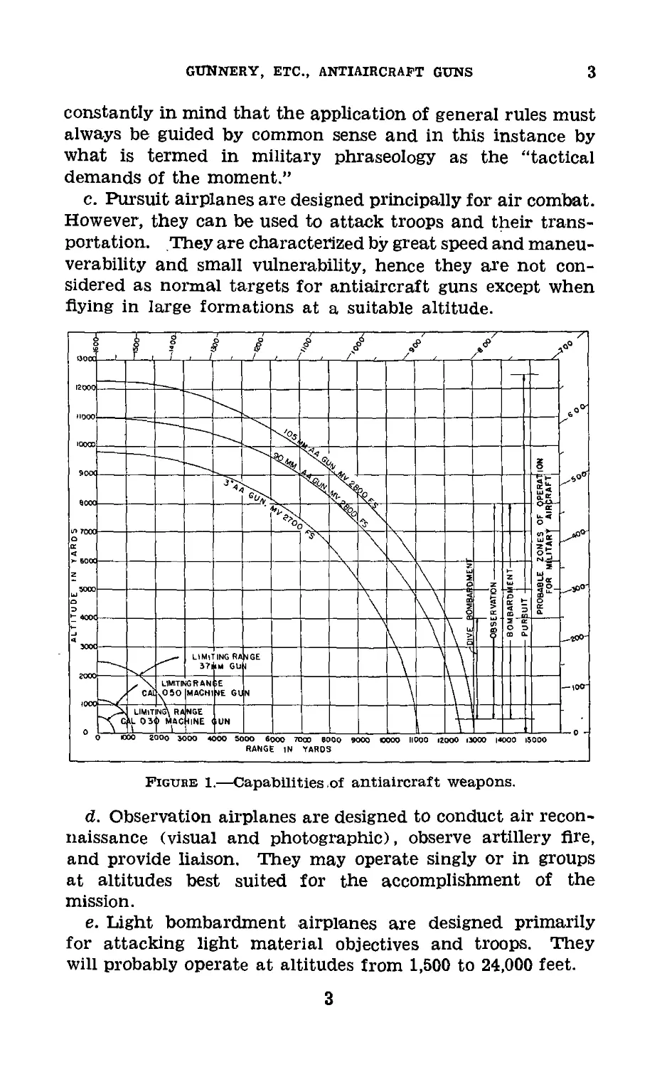
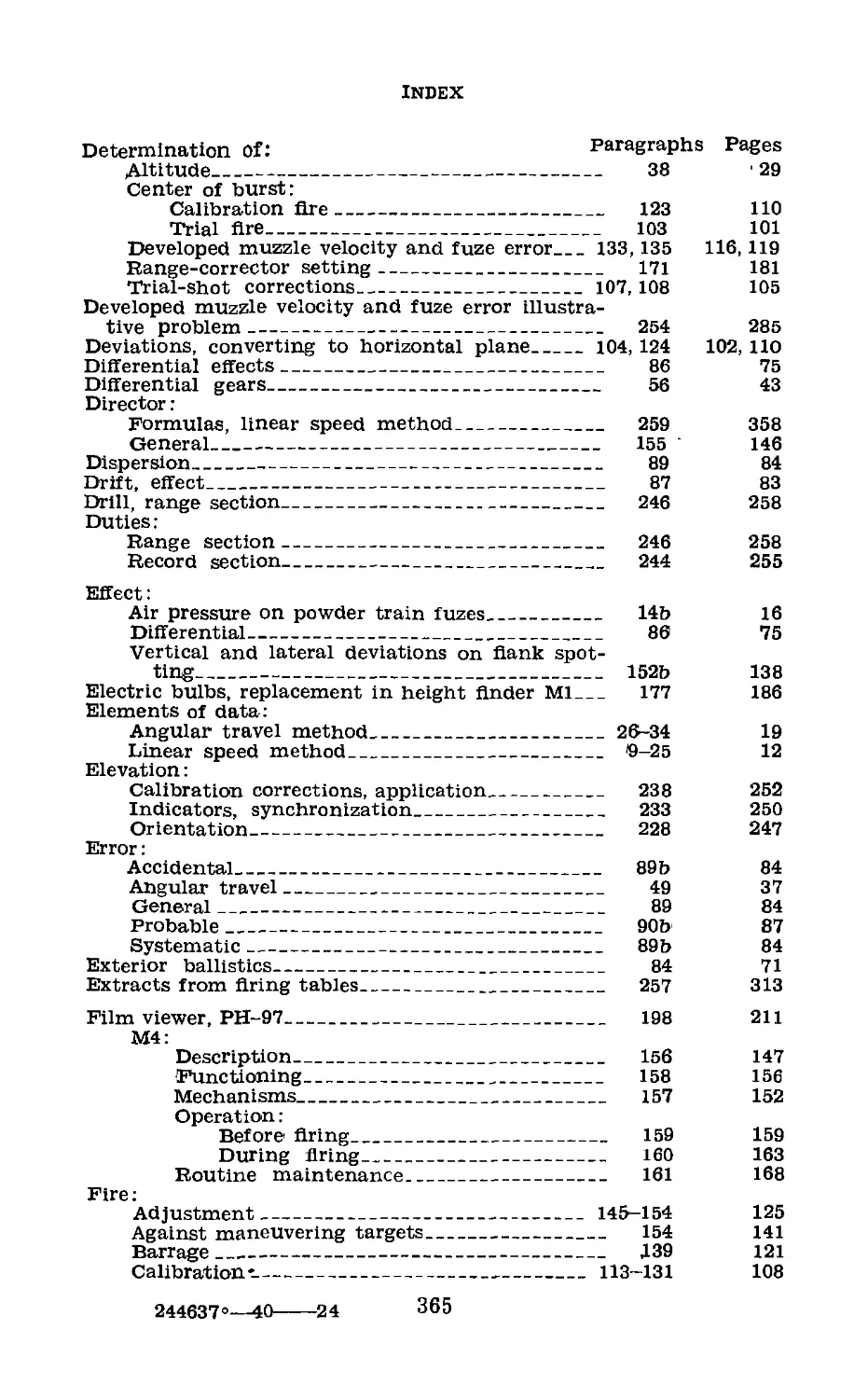
И 3. Antiaircraft vs. Aircraft.—Referring to the diagram-
matic representation of the capabilities of present-day anti-
aircraft weapons (fig. 1), some conclusions may be drawn as
to the normal targets for such weapons. First, as aircraft
may operate at any altitude below their service ceiling, the
general rules are:
a. All types of hostile aircraft within limiting range of any
antiaircraft weapon are normal targets for that weapon and
continue to be until they are destroyed, out of range, or a
target presenting a greater threat appears.
b. Whenever different types of hostile aircraft approach
simultaneously, the primary targets for all antiaircraft
weapons are those types of aircraft, within limiting range,
which are capable of inflicting the greatest damage upon the
ground establishments being defended. It should be kept
2
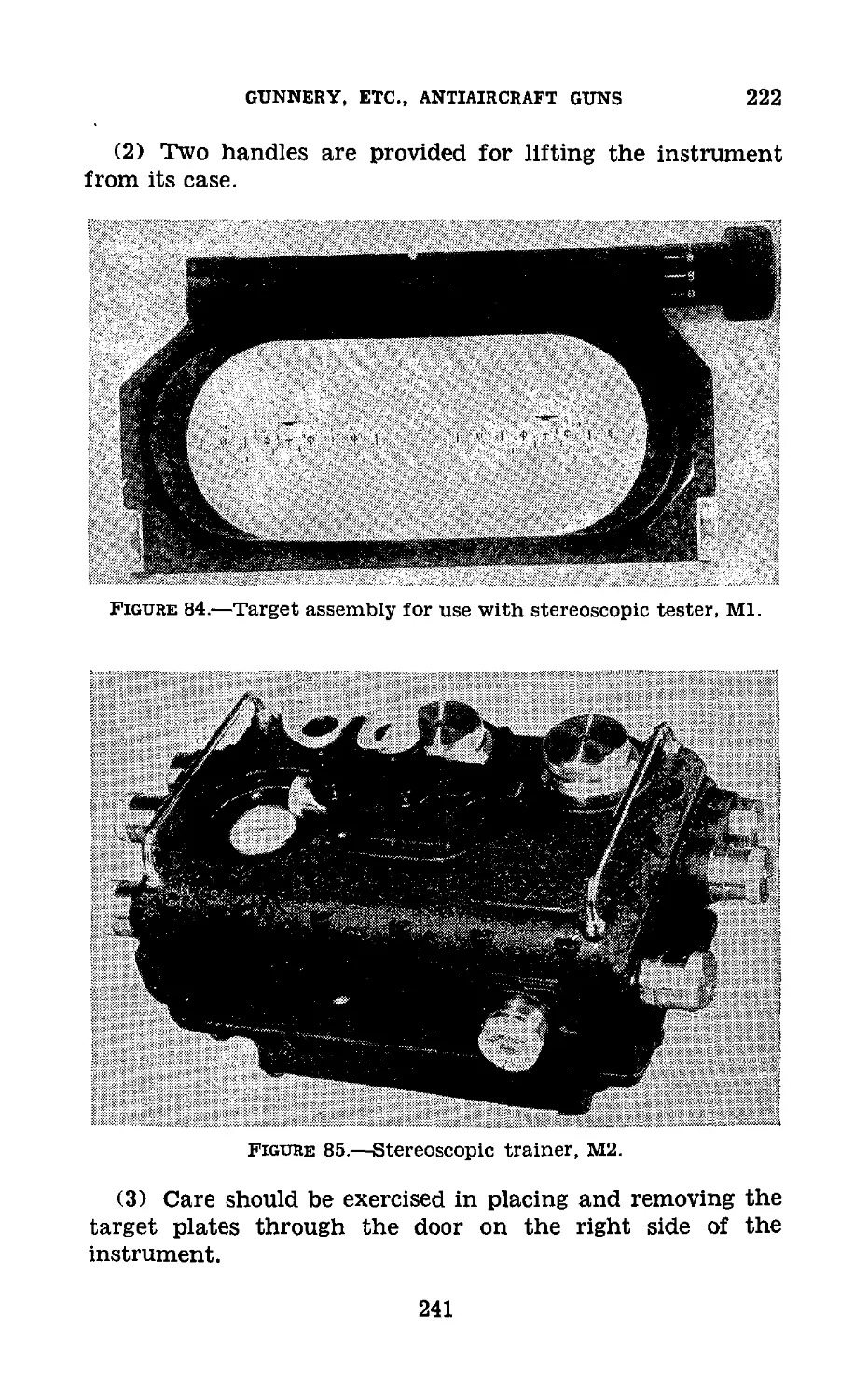
gunnery, etc., antiaircraft guns
3
constantly in mind that the application of general rules must
always be guided by common sense and in this instance by
what is termed in military phraseology as the “tactical
demands of the moment.”
c. Pursuit airplanes are designed principally for air combat.
However, they can be used to attack troops and their trans-
portation. They are characterized by great speed and maneu-
verability and small vulnerability, hence they are not con-
sidered as normal targets for antiaircraft guns except when
Figure 1.—Capabilities of antiaircraft weapons.
d. Observation airplanes are designed to conduct air recon-
naissance (visual and photographic), observe artillery fire,
and provide liaison. They may operate singly or in groups
at altitudes best suited for the accomplishment of the
mission.
e. Light bombardment airplanes are designed primarily
for attacking light material objectives and troops. They
will probably operate at altitudes from 1,500 to 24,000 feet.
3
3-5
COAST ARTILLERY FIELD MANUAL
f. Dive bombers are designed for attacking material objec-
tives. A dive is generally made at an angle of about 70“
and is started at altitudes above 12,000 feet, if possible. The
bombs are released and the airplane pulled out of the dive
before it enters the zone of small-arms fire—that is, 1,500
feet altitude.
g. Medium and heavy bombardment airplanes are designed
primarily for attacking heavy material objectives. They may
operate at altitudes from 1,500 to 24,000 feet.
h. It will therefore be concluded that normal targets for
antiaircraft guns are bombardment and observation aviation.
Normal targets for the automatic weapons are all types of
aviation encountered at low and medium altitudes.
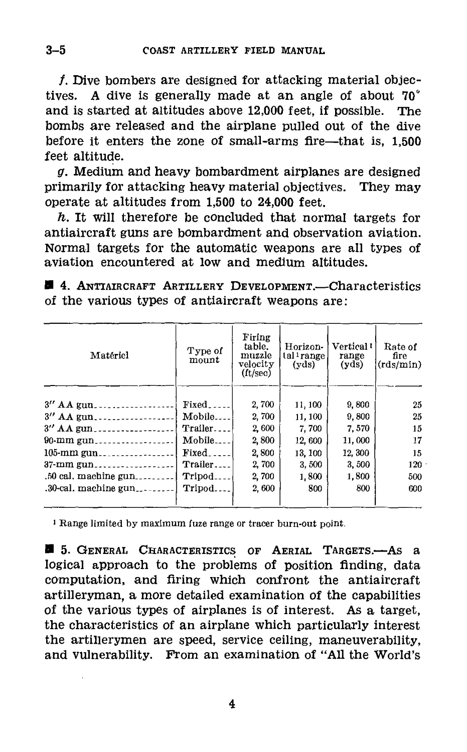
4. Antiaircraft Artillery Development.—Characteristics
of the various types of antiaircraft weapons are:
MatSriel Type of mount Firing table, muzzle velocity (ft/sec) Horizon- t al1 range (yds) Vertical 1 range (yds) Rate of fire (rds/min)
3" AA gun .. . Fixed .... 2,700 11,100 9, 800 25
3" AA gun -- - Mobile. 2, 700 11,100 9, 800 25
3" AA gun . Trailer. 2, 600 7, 700 7, 570 15
60-mm gun Mobile.... 2, 800 12, 600 11,000 17
105-mm gun Fixed 2, 800 13,100 12, 300 15
37-mm gun Trailer.... 2,700 3, 500 3, 500 120
.50 cal. machine gun Tripod.... 2, 700 1,800 1,800 500
,30-cal. machine gun.. Tripod 2, 600 800 800 600
i Range limited by maximum fuze range or tracer burn-out point.
5. General Characteristics of Aerial Targets.—As a
logical approach to the problems of position finding, data
computation, and firing which confront the antiaircraft
artilleryman, a more detailed examination of the capabilities
of the various types of airplanes is of interest. As a target,
the characteristics of an airplane which particularly interest
the artillerymen are speed, service ceiling, maneuverability,
and vulnerability. From an examination of “All the World’s
4
GUNNERY, ETC., ANTIAIRCRAFT GUNS
5-6
Aircraft” by Jane, considering all types of aircraft, it appears
that the artillerymen must be prepared to fire at aerial tar-
gets whose combined capabilities will cover the following wide
ranges:
a. Speed (normal), 60 to 350 miles per hour.
b. Altitude, 25 to 35,000 feet.
c. Maneuverability:
(1) Change in speed, from 50 percent to 150 percent of nor-
mal cruising speed.
(2) Climb, 100 to 2,500 feet/minute.
(3) Dive, up to 40,000 feet/minute.
(4) Change direction:
90° in less than 15 seconds.
130° in less than 30 seconds.
d. Vulnerable area, very small and normally considered to
be engines, fuel tanks, and personnel.
6. Antiaircraft Gunnery Problem.—a. From the capabili-
ties of military aircraft listed in paragraph 5, it may be con-
cluded that time is the basis of the antiaircraft gunnery prob-
lem. Consideration of a few specific examples will strengthen
this conclusion. The results of the following computations
are approximate:
(1) A bombing airplane flying a straight line course at a
constant altitude of 15,000 feet with a constant speed of 250
miles per hour will enter the field of Are of a 3” antiaircraft
gun at a horizontal range of 9,350 yards. If the airplane pro-
ceeds directly over the battery, it will remain in the field of fire
for 2.5 minutes.
(2) The same airplane flying at a constant altitude of 3,000
feet directly over the battery will remain in the field of fire of
the 37-mm gun for 0.91 minute.
(3) If the airplane is flying at an altitude of 1,500 feet or
less directly over the battery it will remain in the field of fire
for the 37-mm gun for 0.94 minute and in the field of fire of
the caliber .50 machine gun for 0.46 minute.
(4) A dive bomber commencing its dive at 12,000 feet and
leveling off at 1,500 feet altitude will remain in the field of
Are of a 37-mm gun for 0.61 minute and in the field of fire of
the caliber .50 machine gun for 0.28 minute.
5
6-7
COAST ARTILLERY FIELD MANUAL
(5) The above times are the optimum and will rarely be
realized, as such factors as increase in speed and altitude,
multiple targets, and displacement of guns from the defended
area will tend to decrease the time available to fire.
b. Reviewing briefly the cycles of operation in firing a gun
at a moving naval target, it will be recalled that a “dead time”
of from 20 to 40 seconds can be tolerated without material
loss in accuracy for position finding and data calculation, due
to the comparatively slow movement of the target. Mani-
festly, such a “dead time” interval cannot be tolerated in
firing at a moving aerial target. It must be reduced or
entirely eliminated. Ideally, the operations of position finding
and data calculation should be instantaneous and continuous.
c. The time factor also exerts a marked influence upon the
methods of solving the problem. Referring to the specific
examples given in a above, a simple calculation will show that
in (1) the airplane will pass through a vertical angle of about
2,200 mils measured at the gun in 2.5 minutes, or an average
angular travel of about 14 mils per second, with a maximum
rate of about 25 mils per second; in (2) the average angular
travel rate is about 48 mils per second and the maximum rate
about 124 mils per second; in (3) the average angular travel
rate is about 51 mils per second with a maximum of 244 mils
per second for the 37-mm gun and 95 mils per second average
rate with a maximum of 244 mils per second for the caliber
.50 machine gun.
d. A consideration of the mechanical principles involved
will demonstrate that none of the current fire-control equip-
ment for antiaircraft guns is mechanically capable of operat-
ing when the angular travel of the target varies between such
wide limits. (The rate varies between 0 mil and 250 mils or
more per second.) In addition, the relatively heavy guns are
not flexible enough to use the data, if such data were calcu-
lated. The 37-mm gun and the caliber .50 machine gun,
which have sufficient flexibility to operate at high angular
velocities, have been developed to fire on the low-altitude,
high-speed airplanes using different methods of computing
and applying the firing data.
7. General Doctrines of Antiaircraft Fire.—a. Considera-
tion of the relative capabilities of aircraft and antiaircraft
6
GUNNERY, ETC., ANTIAIRCRAFT GUNS
7-8
artillery leads to some definite conclusions regarding the
solution of the antiaircraft artillery gunnery problem.
(1) The relatively high speed of airplanes and the “fleeting
moments” available’ for firing dictate that position finding
and data computation must be rapid, approaching as an ideal,
the instantaneous and continuous application of firing data
to the weapons employed, with a projectile meeting a target
the instant it comes within limiting range.
(2) The small vulnerable area presented by an airplane
target dictates first that position finding and data computa-
tion be accurate, and second, since a great many shots fired
in a minimum time increase the probability of hitting, that
weapons be fired at the maximum practicable rate.
(3) The wide variation of angular travel rate, coupled with
the mechanical limitations of both the fire-control equipment
and guns, necessitates that a different solution of the problem
be used for low-altitude, high-speed aircraft.
b. In its essential features, the problem of firing at an air-
plane is the same as firing at any moving land or water tar-
get. In its details, it is more complex, due to the greater speed
of the airplane and its ability to move in three dimensions.
In all cases it is desired to make the projectile meet the target
at some point in space. In antiaircraft-gun firing, the small
vulnerable area presented by an airplane target makes it
desirable to cause the projectile to burst, not upon impact as
with seacoast artillery, but on or just short of the expected
position of the target in order to increase the probability of
hitting. The elementary problem consists of predicting the
future location of the target on the basis of its behavior dur-
ing some interval of time just prior to the prediction, and
calculating data necessary to pass a trajectory through this
point.
Section II
ELEMENTS OF DATA
8. Methods of Computing Firing Data.—a. Firing data
may be computed by two different methods—the linear speed
method and the angular travel method. At present the
linear speed method has superseded the angular travel
method. However, at some future date it is entirely possible
7
8
COAST ARTILLERY FIELD MANUAL
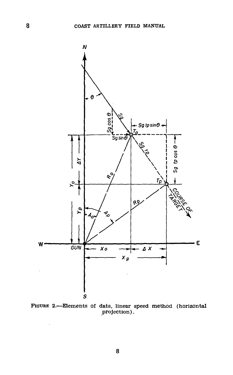
Figure 2.—Elements of data, linear speed method (horizontal
projection).
8
gunnery, etc., antiaircraft guns
8
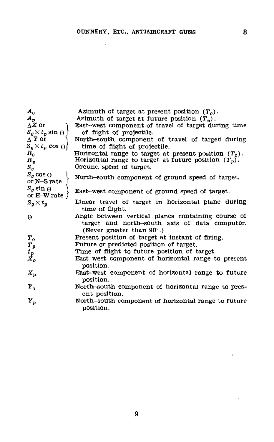
Ao Azimuth of target at present position (To).
Ap Azimuth of target at future position (T„).
ДХ or 1 East-west component of travel of target during time
SBXt„sin0j of flight of projectile.
Д Y or S North-south component of travel of target' during
Sg X tp cos ej time of flight of projectile.
Ro Horizontal range to target at present position (To).
Horizontal range to target at future position (Tp).
Sg Ground speed of target.
orN-Vrate } Nor1;h—south component of ground speed of target.
> East-west component of ground speed of target.
or E-W rate J
SgXtp Linear travel of target in horizontal plane during
time of flight.
0 Angle between vertical planes containing course of
target and north—south axis of data computer.
(Never greater than 90°.)
To Present position of target at instant of firing.
Tp Future or predicted position of target.
tp Time of flight to future position of target.
Xo East-west component of horizontal range to present
position.
Xp East-west component of horizontal range to future
position.
Yo North-south component of horizontal range to pres-
ent position.
Yp North-south component of horizontal range to future
position.
9
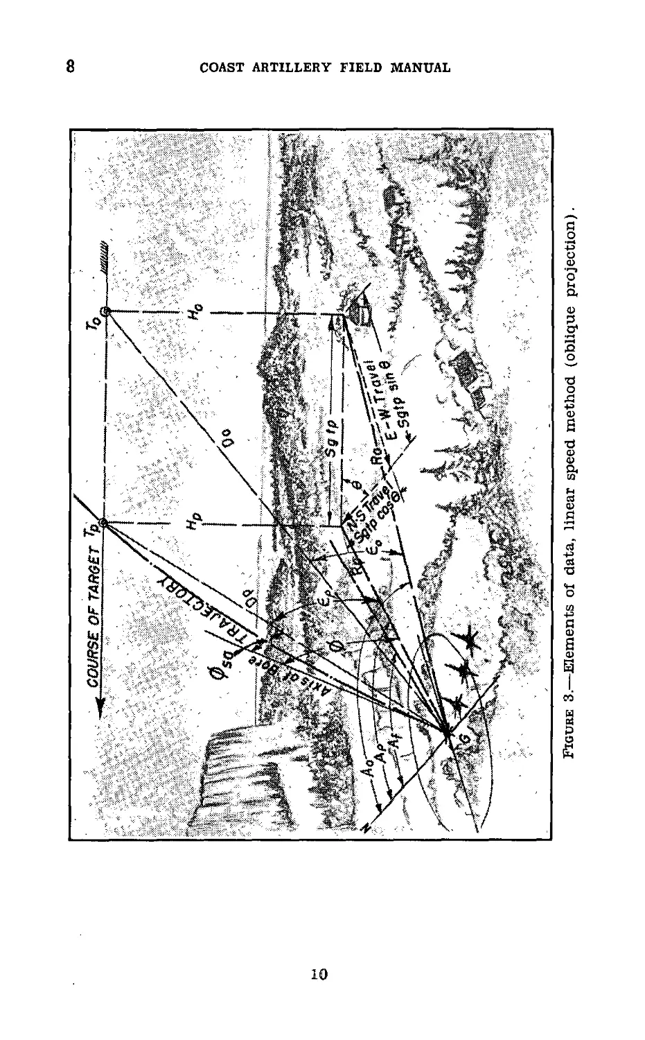
©
Figure 3.—Elements of data, linear speed method (oblique projection).
co
COAST ARTILLERY FIELD MANUAL
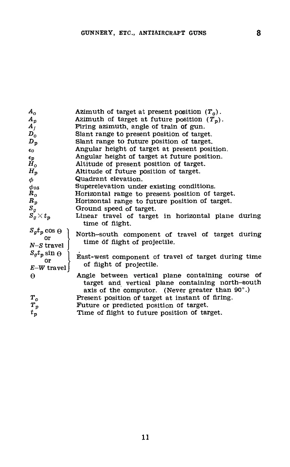
GUNNERY, ETC., ANTIAIRCRAFT GUNS
8
Ao
Ap
A)
Do
Dp
€0
€P
Ho
Hp
Ф
фза
Ro
Rp
Sg
SsXtp
Sgtp COS e
or
N-S travel
Sgtp sin e
or
E-W travel
e
Azimuth of target at present position (To).
Azimuth of target at future position (Tp).
Firing azimuth, angle of train of gun.
Slant range to present position of target.
Slant range to future position of target.
Angular height of target at present position.
Angular height of target at future position.
Altitude of present position of target.
Altitude of future position of target.
Quadrant elevation.
Superelevation under existing conditions.
Horizontal range to present position of target.
Horizontal range to future position of target.
Ground speed of target.
Linear travel of target in horizontal plane during
time of flight.
North-south component of travel of target during
time Of flight of projectile.
East-west component of travel of target during time
of flight of projectile.
Angle between vertical plane containing course of
target and vertical plane containing north-south
axis of the computer. (Never greater than 90°.)
Present position of target at instant of firing.
Future or predicted position of target.
Time of flight to future position of target.
11
8-10
COAST ARTILLERY FIELD MANUAL
that the angular travel method may replace or supplement
the linear speed method, and for this reason the angular
travel method is included in this manual.
b. The basic elements of firing data and the corresponding
symbols for each of the two methods are defined and dis-
cussed in sections П1 and IV. Certain elements of data are
applicable to both methods, even though they are discussed
under the section heading of either linear speed method or
angular travel method. A consolidated list of symbols, with
definitions, is located for convenience in paragraph 247.
Section 1П
LINEAR SPEED METHOD
9. General.—Figures 2 and 3 show graphically the ele-
ments of data for the linear speed method.
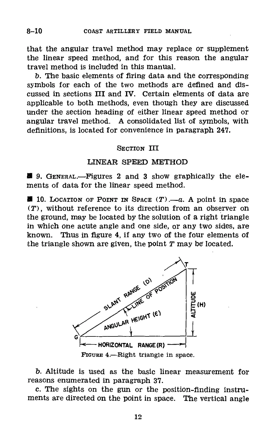
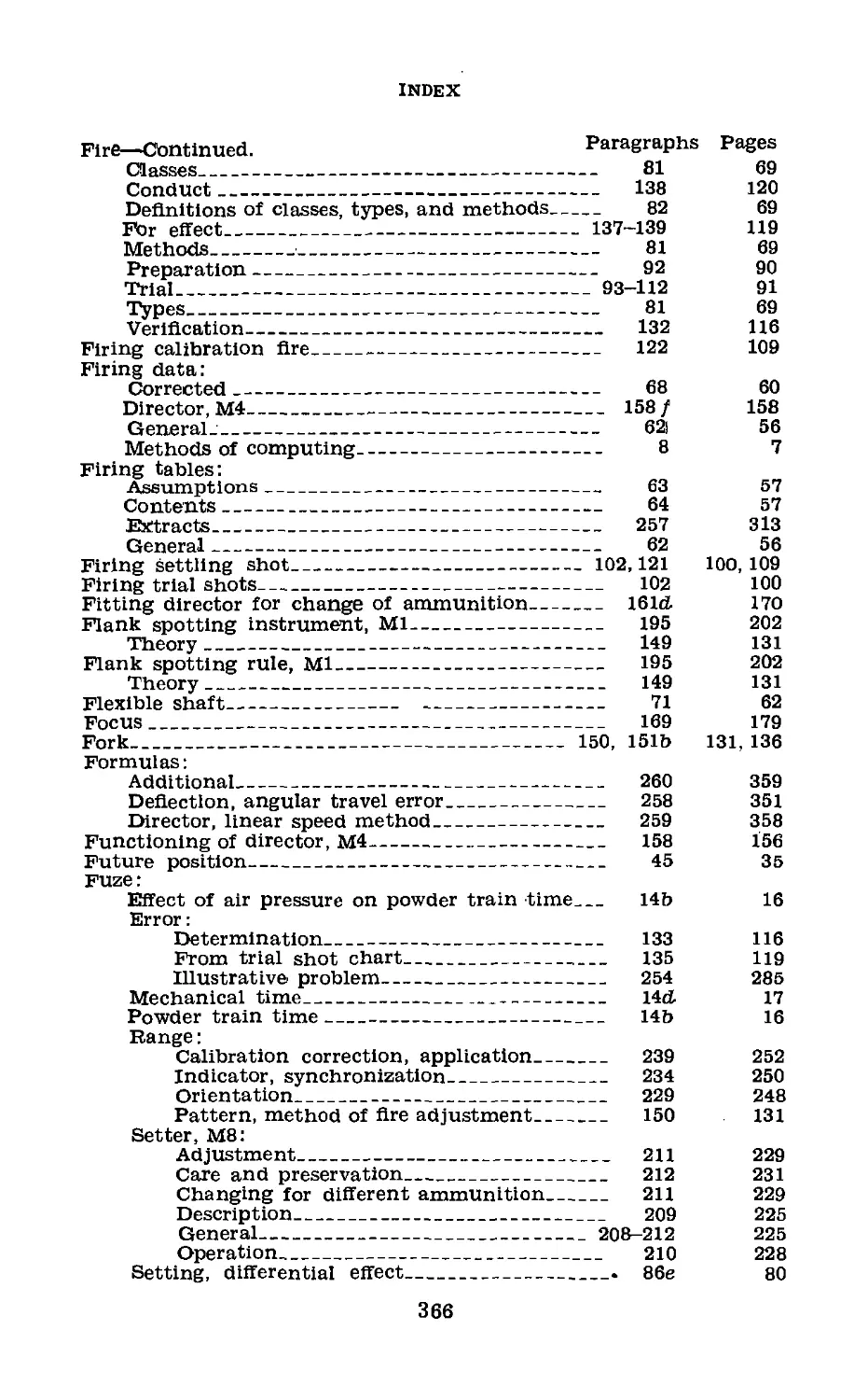
10. Location of Point in Space (T).—a. A point in space
(T), without reference to its direction from an observer on
the ground, may be located by the solution of a right triangle
in which one acute angle and one side, or any two sides, are
known. Thus in figure 4, if any two of the four elements of
the triangle shown are given, the point T may be located.
-<---HORIZONTAL RANGE (R) -->“
Figure 4.—Right triangle in space.
b. Altitude is used as the basic linear measurement for
reasons enumerated in paragraph 37.
c. The sights on the gun or the position-finding instru-
ments are directed on the point in space. The vertical angle
12
GUNNERY, ETC., ANTIAIRCRAFT GUNS
10-12
thus obtained (angular height) combined with the measured
altitude of the point will determine the horizontal range to
the point (T). In practice this is done by some type of
mechanical calculating device.
d. To and Tp are, respectively, the present position of the
target (at instant of firing) and the future (predicted) posi-
tion of the target.
11. Angular Height.—(e).—There is an angular height
corresponding to each of the two positions of the target (To
and Tp). It is obvious that, considering an airplane moving
in space with reference to a point on the ground, the angular
height of the airplane will vary from instant to instant for
nearly all conditions of flight. The most notable exceptions
are those when the target flies at a constant altitude on the
circumference of a circle whose center is directly above the
observer, or dives or climbs along the line of position.
a. Present angular height (eo).—This is the angular height
of the target at the instant the gun is fired.
b. Future angular height (ep).—This is the angular height
of the target in its future position; that is, the point where
it is predicted to be at the end of the time of flight.
12. Altitude of Target (H).—Corresponding to each of the
positions of the target To and Tp are the altitudes of these
points (all altitudes are based on a horizontal plane which
passes through the data computer) called Ho and HP, respec-
tively. Unless the target is executing a dive or a climb, these
two quantities are equal.
a. Present altitude (Ha).—Data computers are supplied
with the altitude obtained from one of three sources: estima-
tion, two-station altimeter system, or self-contained range
finder or height finder.
b. Future altitude (Hp).—Originally the problem of deter-
mining future altitude (Hp) was ignored by the assumption
that the airplane did not change altitude during the time of
flight of the projectile. The latest data computers, however,
have made provision for shallow dives and climbs by the air-
plane. Based on a rate of change of altitude obtained either
by estimation or by use of some mechanical device, the data
computer predicts the future altitude (Hp) and calculates
firing data for this altitude.
244637°—40-
-2
13
13
COAST ARTILLERY FIELD MANUAL
13. Superelevation (</>sa).—a. Definition.—A projectlie does
not move in a straight line in the direction and elevation in
which it is fired, but describes a curve. Superelevation is
that part of the quadrant elevation which allows for the
curvature of the trajectory and represents the combined effect
of ballistic conditions and gravity in deflecting the projectile
downward from its line of departure.
b. Factors affecting superelevation.—(1) The curvature oi
the trajectory is dependent upon the initial direction of the
projectile, for the forces which act upon it exert their effect
according to the relation between the direction of motion of
the projectile and the direction in which the resultant force
acts. Thus a projectile fired straight up meets with forces
acting in a direction different from the direction of the forces
which will act on a projectile fired at a comparatively low
angle of departure.
(2) The superelevation necessary to cause a trajectory to
pass through a particular point in space is dependent also
upon the muzzle velocity of the projectile. If the muzzle
velocity developed is less than the assumed (firing table)
muzzle velocity, then for a given quadrant elevation, the
range and altitude attained at the end of a given time of
flight will be less than those shown by the firing table. Thus
for a particular horizontal range and altitude, if the muzzle
velocity were less than the firing table muzzle velocity, the
superelevation necessary to cause a trajectory to pass through
the predicted position would be greater than if the assumed
muzzle velocity were developed.
(3) For a given point, atmospheric conditions will affect
the amount of superelevation which must be given to the gun.
The wind which is blowing may accelerate or retard the
projectile. The existing density may increase or decrease the
range, as may also the temperature elasticity effect of the
atmosphere.
(4) Furthermore, the condition of the materiel will directly
affect the superelevation which must be given to the gun. A
new gun will fire with a greater velocity than an old one, and
as the gun wears, in order to obtain the same range, a greater
elevation must be given to the gun.
14
GUNNERY, ETC., ANTIAIRCRAFT GUNS
13-14
(5) Summarized, the superelevation which must be applied
to the gun is dependent upon—
(a ) The position of the target.
(b ) The existing atmospheric and ballistic conditions.
c. Superelevation value.—If the atmospheric and ballistic
conditions enumerated in b above were constant, then for any
particular horizontal range and altitude, superelevation would
be a constant value. But for varying atmospheric and ballis-
tic conditions, superelevation will have different values. In
order to distinguish between these two, the symbol фз is used
to designate the superelevation under firing table conditions,
and the symbol фза to designate the superelevation under
conditions actually existing.
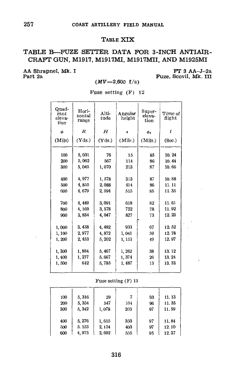
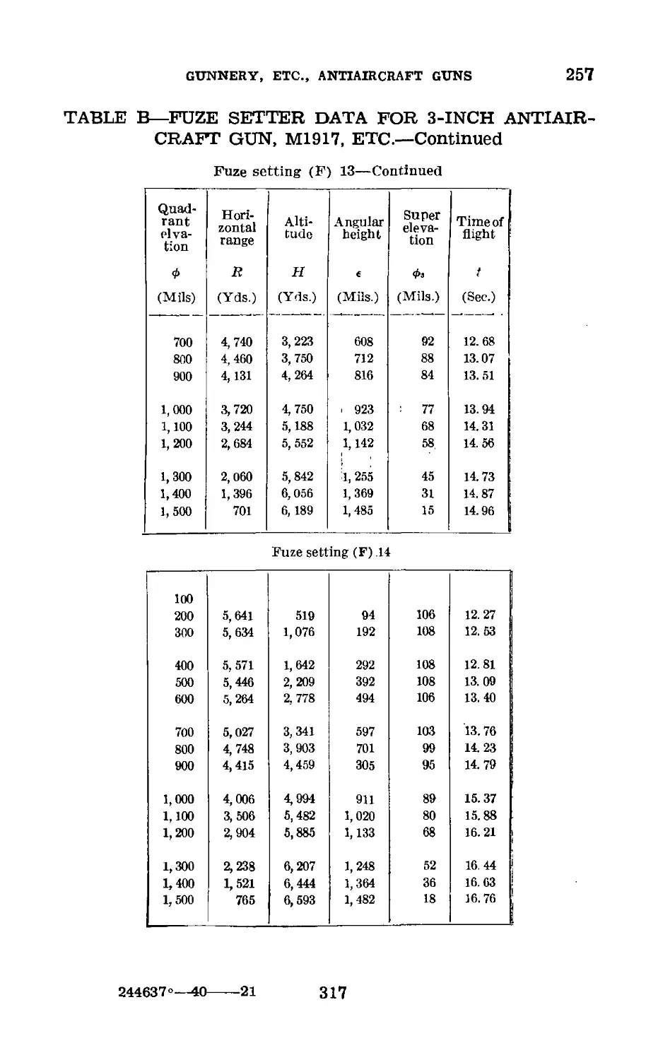
d. Firing table superelevation (</>s).—(1) Firing tables give
the superelevation in table В using fuze setting and quadrant
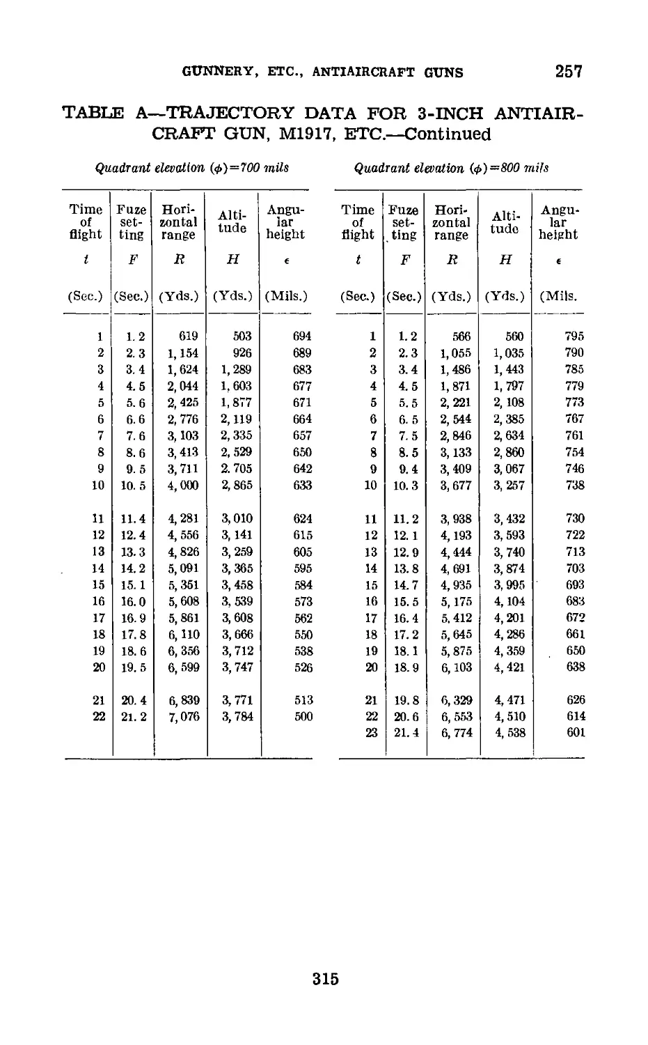
elevation as arguments. In table A, which uses time of flight
and quadrant elevation as arguments, the superelevation can
be obtained by subtracting angular height from quadrant ele-
vation. Extracts of tables A and В from Firing Tables
3 AA-J-2a and 3 AA-O-1 are found in paragraph 257.
(2) This value of фз is used for the purpose of constructing
curves or cams or graduating drums in data computers. It is
subject to correction for the variation between existing
conditions and the firing table conditions.
e. Superelevation under nonstandard conditions (.фза).—
Cl) When conditions existing at the time of firing vary from
firing table conditions, then the firing table data must be cor-
rected. The correction depends upon the effects of the varia-
tions in conditions.
(2) The vertical pointing correction (<гз) is a correction of
the superelevation made necessary by variations between
standard and actual conditions. The factors affecting и are
discussed in paragraph 29b.
Thus, under actual conditions—
and since Ф„а=Фз±^г,
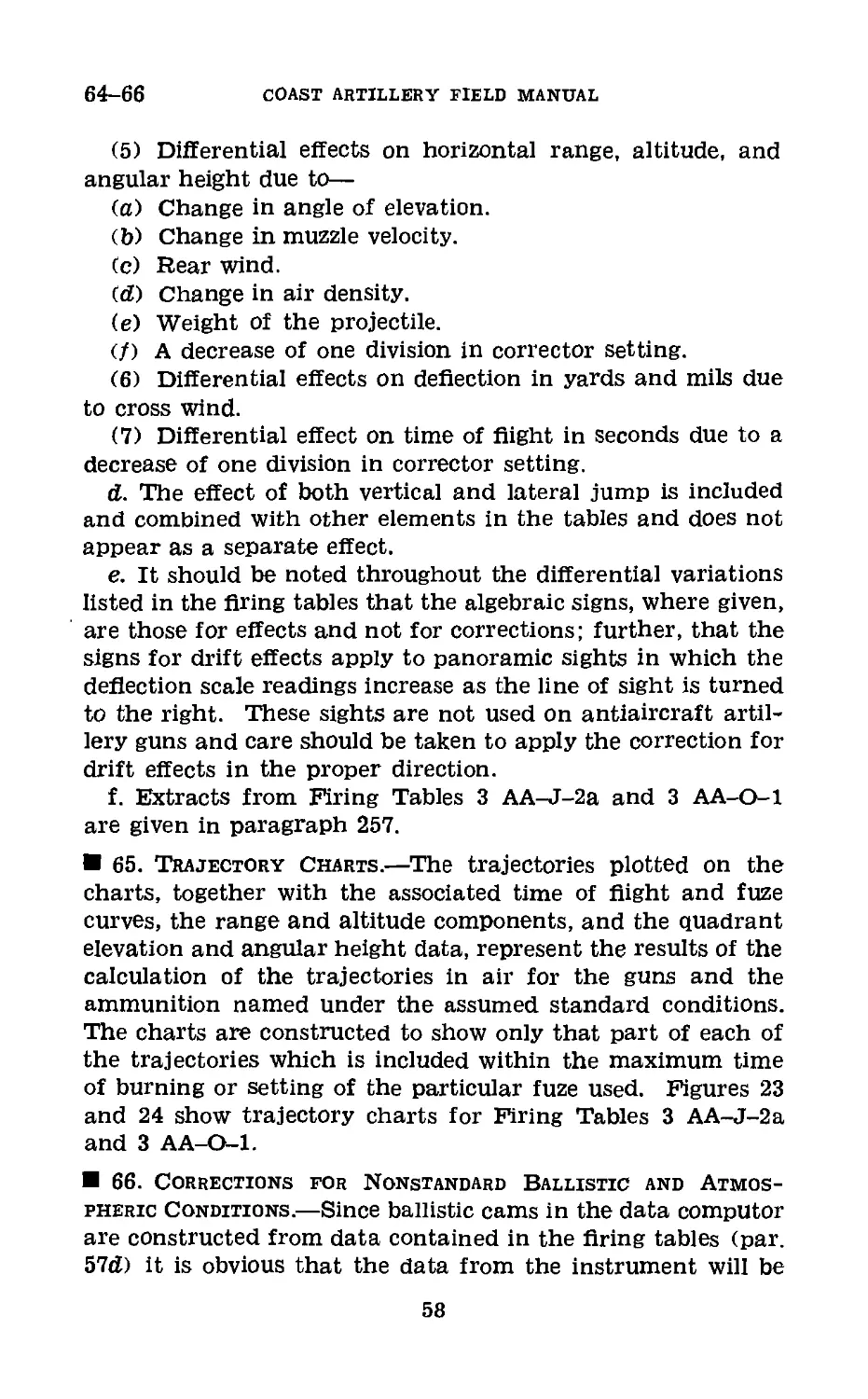
14. Fuze Range (F).—a. From an examination of tra-
jectory chart (fig. 23 or 24), it Is evident that by changing
15
14
COAST ARTILLERY FIELD MANUAL
the quadrant elevation <Ф) the trajectory can be passed
through any point in space within range. All that remains
to be done is to burst the projectile at some definite position
along the trajectory. This is done by means of the time
fuze. In other words, by varying the quadrant elevation (</>)
and the fuze range (F), the projectile can be made to burst
at any particular point in space within range. Fuze range
can therefore be defined as the fuze setting necessary to
burst the projectile at a particular point along the trajectory.
Fuze range for any particular point can be ascertained by
reference to either the trajectory chart or firing tables for
the particular gun and ammunition used. The data com-
puter calculates the fuze range to the future position (Tp).
b. Nonstandard atmospheric and ballistic conditions affect
the shape of the trajectory (due to changes in superelevation,
see par. 13c) passing through a particular point in space.
Therefore the time of flight and consequently the fuze range
to the particular point will vary with the atmospheric and
ballistic conditions. Certain ammunition now in general use
in antiaircraft artillery is equipped with a 21-second powder
train time fuze. The fuze is graduated in terms of fuze
range from 0 to 21.2. Theoretically each of the whole
divisions represents 1 second time of burning, but actually it
does not. As a result of experimental tests and firings, the
time of fuze burning (which is actually the time of flight (tp))
for different fuze ranges and quadrant elevations has been
computed and tabulated. These same data are also shown
graphically on the trajectory chart. These tests have also
demonstrated that at least three physical factors affect the
burning of a powder train time fuze.
(1) Pressure under which it burns.—Since the air pressure
decreases as the altitude increases, the time of burning will
vary with the altitude attained by the projectile. (It will
also vary with the atmospheric density. This effect of density
on fuze burning is discussed in paragraph 86c.) A specific
example from the firing tables will show how much of a dif-
ference altitude makes on the time of burning of the fuze.
Referring to table XIX, paragraph 257, using as arguments
F=13, and 0=700 mils; ip=12.68 seconds, and the altitude
of the burst is 3,223 yards. Using as arguments F=13, and
16
GUNNERY, ETC., ANTIAIRCRAFT GUNS
14-15
0=1,500 mils; ip=14.96 seconds and H=6,189 yards. A dif-
ference of 2,966 yards in altitude has increased the time of
burning of the fuze for the same fuze setting 2.28 seconds.
(2) Temperature of the fuze.—While the temperature of
the fuze affects its rate of burning, the magnitude of this
effect has not been determined satisfactorily.
(3) Speed of rotation of the projectile.—The speed of ro-
tation, or spin of the projectile, has an effect on the rate of
burning of the fuze. It has been found by experiment that
there are limits of rate of spin beyond which powder-train
fuzes may not be expected to function except with extreme
inaccuracy and unreliability.
c. From the above discussion it will be seen that the fuze
range varies according to the ballistic and atmospheric con-
ditions of the moment, with the altitude of the burst, and
with the quadrant elevation of the gun. If we assume certain
values for H and Ф, we select a certain point in space. This
same point can be identified equally as well by a combination
of (HP and Bp), or (ep and tP). HP and RP are used in the
M4 director to determine the fuze range (F).
d. Mechanical time fuzes will ultimately replace the
powder train time fuze. They are graduated in terms of fuze
range from 0 to 30 seconds. The factors which affect the
functioning of the powder train time fuze do not have any
effect on the mechanical time fuze. Consequently, F equals tP
in the mechanical time fuze.
15. Azimuth of Target (A).—For each position of the
target, there is a horizontal angle called the azimuth of target
(A). This angle is measured in a clockwise direction from a
reference axis to the horizontal projection of the target. The
reference axis is usually made to coincide with either grid
north or true north. The azimuths of the target at each of
the two positions of the target To and TP are called, respec-
tively, Ao and Ap.
a. Azimuth of target at present position (Ao).—Ao is the
azimuth of the target at the instant the gun is fired,
b. Azimuth of target at future position (AP).—AP is the
azimuth of TP. It is the azimuth at which the burst should
meet the target.
17
16-23
COAST ARTILLERY FIELD MANUAL
16. Firing Azimuth (A/).—4/ Is the azimuth at which the
gun is laid in order that the burst will occur at TP. Af=AP±
52. The factors affecting o2 are discussed in paragraph 28b.
17. Horizontal Range (R).—For each of the positions of
the target, there is a corresponding horizontal range. The
horizontal ranges to To and TP are called, respectively,
Ro and RP.
18. Ground Speed of Target (Sg).—Ground speed of target
is the velocity of the target expressed in distance per interval
of time, usually yards per second. The distance is measured
in the horizontal plane.
19. Time of Flight (tp).—tP is the time in seconds that it
will take the projectile to reach the future position (Tp).
For the same point, it will vary depending upon the combina-
tion of gun and ammunition and the atmospheric and ballistic
conditions of the moment.
20. Slant Range to Target (B).—For each position of the
target in space, the distance measured from gun to target in
the inclined plane is called the slant range to target. For
each position of the target To and TP, there is a corresponding
slant range called Do and DP, respectively.
21. Quadrant Elevation (</>).—ф is the elevation at which
the gun is laid in order that the trajectory will pass through
the future position, ф is a function of HP and RP.
22. Xo and Yo.—The horizontal range to the present posi-
tion of the target is resolved into a component in the E-W
direction (called Xo) and a component in the N-S direction
(called Yo). It will be seen that Xo and Yo are the coordinates
of the present position of the target using as reference axes,
the E-W and N-S directions. The gun is considered as being
at the origin.
23. E-W and N-S Rates.—The continuous tracking of the
target establishes an instantaneous rate Sg. This rate is re-
solved into a component in the E-W direction (called E-W
rate=Sg sin e), and a component in the N-S direction (called
N-S rate=Sg cos 6). These rates are the instantaneous rates
of change of Xo and Yo.
18
GUNNERY, ETC., ANTIAIRCRAFT GUNS
24-28
24. E-W and N-S Travel (a X and a Y).—The E-W and
N-S rates multiplied by the time of flight, give the travel of
the target in the E-W and N-S directions during the time of
flight of the projectile.
A X=E-W rateXip=SB sin OX ip
A Y=N-S rateXfp=SB cos eXtp
25. Xp and Yp.—If the E-W and N-S travel of the target are
added algebraically to the coordinates of the present position
of the target, we have the coordinates of the future position of
the target Xp and Yp.
Xp X ) ' A X
Yp=Yo±A Y
Section IV
ANGULAR TRAVEL METHOD
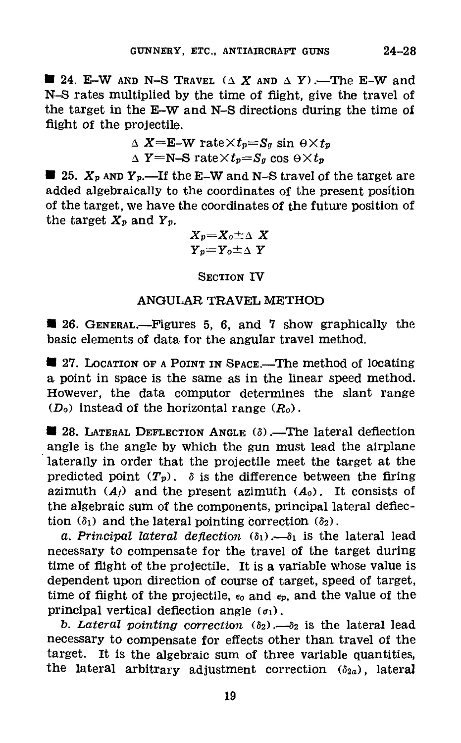
26. General.—Figures 5, 6, and 7 show graphically the
basic elements of data for the angular travel method.
27. Location of a Point in Space.—The method of locating
a point in space is the same as in the linear speed method.
However, the data computer determines the slant range
(Do) instead of the horizontal range (Ro).
28. Lateral Deflection Angle (5).—The lateral deflection
angle is the angle by which the gun must lead the airplane
laterally in order that the projectile meet the target at the
predicted point (Tp). 5 is the difference between the firing
azimuth (A/) and the present azimuth (Ao). It consists of
the algebraic sum of the components, principal lateral deflec-
tion (5i) and the lateral pointing Correction (5г).
a. Principal lateral deflection (Si).—8i is the lateral lead
necessary to compensate for the travel of the target during
time of flight of the projectile. It is a variable whose value is
dependent upon direction of course of target, speed of target,
time of flight of the projectile, e0 and ep, and the value of the
principal vertical deflection angle (<n).
b. Lateral pointing correction (3a).—5г is the lateral lead
necessary to compensate for effects other than travel of the
target. It is the algebraic sum of three variable quantities,
the lateral arbitrary adjustment correction (02a), lateral
19
28
COAST ARTILLERY FIELD MANUAL
GUN
HORIZONTAL PROJECTION
Figure 5.—Elements of data, angular travel method (horizontal
projection).
Ap Azimuth of target at future position (Tp).
Ao Azimuth of target at present position (To).
Af Firing azimuth.
ap Angle of approach at future position (Tp).
ao Angle of approach at present position (To).
|3 Wind-fire angle.
5 Lateral deflection angle.
S, Principal lateral deflection angle.
32 Lateral pointing correction.
83a Lateral adjustment correction (arbitrary).
32d Lateral pointing correction due to drift.
32Ш Lateral pointing correction due to cross wind.
Bp Horizontal range to target at future position (Tp).
Ro Horizontal range to target at present position (To).
Sg Ground speed of target.
Sg x tp Linear travel of target in horizontal plane during time of
flight.
Tp Predicted position of target (future position).
To Present position of target (instant of firing).
tp Time of flight to future position of target (Tp).
20
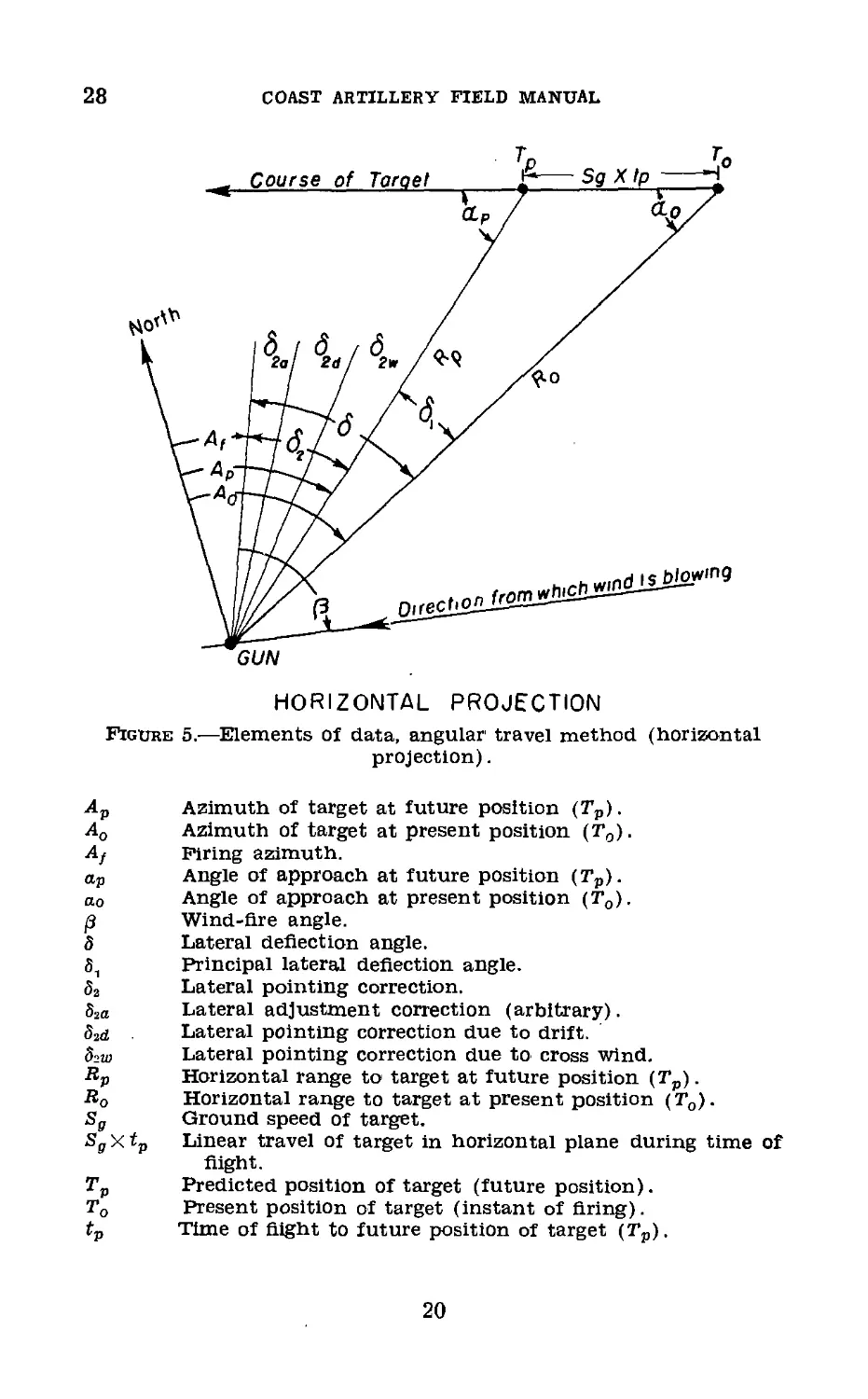
VERTICAL PROJECTION
(Visualized) airplane approaching directly over the battery
Figure 6.—Elements of data, angular travel method (vertical
projection).
Dp Slant range to target at future position (TP).
Do Slant range to target at present position (To).
Angular height of target at future position (Tp).
e0 Angular height of target at present position (To).
H Altitude of target.
ф Quadrant elevation.
< f>s Superelevation under firing table conditions.
фза Superelevation under actual conditions.
Horizontal range to target at future position (Tp).
Bo Horizontal range to target at present position (To).
Sg Ground speed of target.
Sg x tp Linear travel of target in horizontal plane during time of
flight.
ax Principal vertical deflection angle.
az Vertical pointing correction.
< 72<j Vertical adjustment correction (arbitrary).
a2a Vertical pointing correction due to density.
< 72p Vertical pointing correction due to muzzle velocity.
< 72W Vertical pointing correction due to range wind.
Tp Predicted position of target (future position).
T„ Present position of target (instant of firing).
tp Time of flight to future position of target (Tp).
21
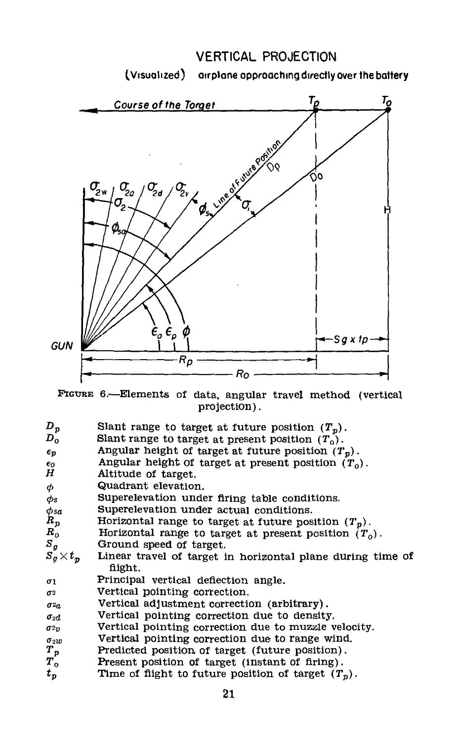
Figure 7.—Elements of data, angular travel method (oblique projection).
to
oo
COAST ARTILLERY FIELD MANUAL
GUNNERY, ETC., ANTIAIRCRAFT GUNS
28-32
pointing correction due to cross wind (S2w), and lateral point-
ing correction due to drift (ог<г).
29. Vertical Deflection Angle Co-).—The vertical deflec-
tion angle is the angle (exclusive of superelevation) by which
the gun must lead the target vertically in order that the
projectile meet the target at the predicted point (.Tp). It is
the algebraic sum of the principal vertical deflection (<n) and
the vertical pointing correction (0-2).
a. Principal vertical deflection (at).—0-1 Is the vertical lead
necessary to compensate for the travel of the target during
time of flight of the projectile. This variable is dependent
upon the direction of the course of the target, speed of the
target, time of flight of the projectile, e0 and ep, and value of
the principal lateral deflection angle (5z).
b. Vertical pointing correction (аг).—аг is the vertical lead
necessary to compensate for effects other than travel of the
target. It is the algebraic sum of four variable quantities,
vertical arbitrary adjustment correction (ага), vertical point-
ing correction due to range wind (azm), vertical pointing cor-
rection due to variation in muzzle velocity (ага), and vertical
pointing correction due to variation of atmopsheric density
(a2d).
30. Angle of Approach (a).—For each of the two positions
of the target, To and Tp, there is a corresponding angle of
approach called ao and ap, respectively. The angle of ap-
proach in each case is the acute angle between the horizontal
projections of the course of the target and line of position.
31. Wind-Fire Angle (/3).—/3 is the horizontal angle
measured between the vertical planes containing the axis
of the bore and the ballistic wind. It is obtained by sub-
tracting At from Aw. Aw, the azimuth of the ballistic wind,
is the direction from which the wind is blowing. Add 6,400
mils to Aw, if necessary, in order to avoid a negative value
of p.
32. Angular Velocity (S).—This element of data is not
shown in the figures. It is the angle swept over by the target
per unit of time. In the operation of tracking, the data com-
puter resolves the angular velocity (S) into two components
23
32-34
COAST ARTILLERY FIELD MANUAL
(Se) which is the rate of change in angular height and (sa)
which is the rate of change in azimuth.
33. Altitude (H).—Unlike the linear speed method, the
angular travel method formulas developed to date are based
on the assumption of constant altitude of the target. As a
result HP always equals Ho.
34. Elements Similar to Linear Speed Method.—The fol-
lowing elements of data are identical with those discussed
under the linear speed method (sec. Ill): Azimuth of target
(Ao, AP); position of the target (To, Tp); slant range to target
(Do, Dp); angular height (eo, (p); time of flight (tp); ground
speed of target (Sg); quadrant elevation (ф); superelevation
(Феа); fuze range (F); and firing azimuth (Aj).
24
CHAPTER 2
POSITION FINDING, FIRE CONTROL, AND GUNNERY
Paragraphs
Section I. Position finding_________________________________ 35- 37
II. Determination of altitude_______________________ 38- 44
III. Prediction; future position_____________________ 45- 53
IV. Mechanical solutions_____________j______________ 54- 81
V. Firing data_____________________________________ 62- 68
VI. Data transmission systems_______________________ 69- 77
VII. Application of firing data to guns______________ 78— 80
VIII. Classes, types, and methods of fire_____________ 81- 82
IX. Exterior ballistics_____________________________ 83- 88
X. Errors and probabilities________________________ 89- 91
XI. Preparatory fire________________________________ 92-136
XII. Fire for effect--.______________________________ 137-139
XIII. Spotting and adjustment of fire_________________ 140-154
Section I
POSITION FINDING
35. General.—Position finding is the process of determining
the position of a target in space with reference to the battery
and the determination of a future position of the target. In
paragraph 7, it was emphasized that position finding should
be accomplished instantaneously and that the small vulner-
able area presented by an airplane demands the greatest
accuracy in observation and in the calculation of firing data.
36. Use of Instruments.—a. In proceeding to study the
aspects of position finding by instrumental observation, it is
well to recall that all observation instruments used for pre-
cise measurements are essentially the same as the surveyor’s
transit, which measures horizontal and vertical angles. A
primary requirement for accuracy with such instruments is
that the angles they measure are truly vertical and truly
horizontal. The observing instruments used in the Coast Ar-
tillery Corps are so constructed that this requirement for
accuracy is satisfied by leveling. While the actual process of
leveling may vary with different instruments, the principles
are identical, and the procedure will usually be apparent
25
36-37
COAST ARTILLERY FIELD MANUAL
from an examination of the instrument or by consulting the
handbook accompanying the instrument.
b. The location of the target with reference to the gun
or observer requires the measurement of angles from very
definite reference axes or reference planes. Therefore, as a
general rule, all instruments must be oriented or so pointed
that the horizontal angles measured will be in terms of angu-
lar units (azimuth) from an arbitrarily chosen reference di-
rection. For uniformity, the reference direction, or direction
of zero azimuth, is customarily chosen as north. As in the
case of leveling, the actual methods of orienting may vary,
but the procedure will usually be apparent. In addition, it
is essential that vertical angles be measured from a horizontal
plane. Therefore instruments must be adjusted or the scale
which indicates the vertical angle must read zero when the
line of sight is truly horizontal. The procedure in adjusting
an instrument varies with different instruments and will not,
as a rule, be readily apparent; hence a handbook must be
consulted or competent assistance must be obtained.
c. Instruments are generally quite rugged in construction,
but they must be carefully handled and should not be sub-
jected to unnecessary shocks, jars, or strains. Screws, hand-
wheels, and other moving parts should never be forced if
they do not operate freely. Instruments are provided with
weatherproof covers, packing boxes, carrying straps or han-
dles, and other impedimenta for protection against weather
and to facilitate careful handling. To avoid scratching the
surfaces of lenses, prisms, and other optical elements, they
should be cleaned only with a soft linen cloth or with optical
paper especially furnished for the purpose. Instruments
should be disassembled under the supervision of a competent
technician.
37. Target Location.—a. With the foregoing in mind, the
position-finding problem and means and methods employed
in its solution will now be considered. The accurate location
of a point which is inaccessible to the observer presents the
usual triangulation problem. Referring to figure 8, it is clear
that a properly oriented instrument, continuously directed
at the target, will continuously and instantaneously furnish
an azimuth (Ao) and an angular height (e0).
26
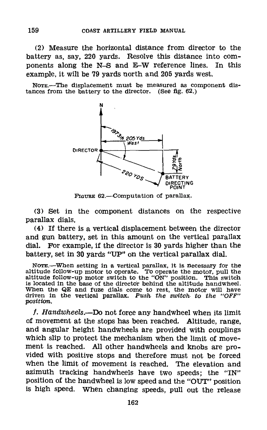
t\D
Figure 8.—Location of an airplane target; present position (To).
GUNNERY, ETC., ANTIAIRCRAFT GUNS
37
COAST ARTILLERY FIELD MANUAL
b. In order to solve the right triangle GToN (fig. 8), it is
necessary that one angle and one side be known. e0 is in-
stantly and continuously available at the data computer. H
or R must be determined in order to solve the triangle.
c. In selecting the side of the triangle to be measured, brief
consideration of a specific example will be helpful. For an
airplane flying toward the observer at 300 miles an hour at
a constant altitude (H) of 10,000 feet, the horizontal range
CR) will be changing uniformly at the rate of 150 yards per
second and the slant range (D) will be changing nonuni-
formly from slightly less than 150 yards per second to 0 yards
per second.
As the example assumes that the target was flying at con-
stant altitude (H), there is no question as to the proper side
of the triangle to measure. However, before making a final
decision, the possibilities that a target will not fly at constant
altitude (H) should be examined. The modern bombing air-
plane is capable of climbing, fully loaded, at a rate of about
8 yards per second. Compared to the rate of change in the
horizontal (K) or slant (Z>) ranges, this rate of change In
altitude (H) appears insignificant. Considering the possibil-
ity of a negative change in altitude (H), or “dive,” dive bomb-
ers are suitable targets for automatic weapons, their suit-
ability as gun targets being limited to that Interval of time
just preceding the “dive.” The M4 director is capable of com-
puting firing data for a target whose altitude is changing at
a rate of not more than 50 yards per second.
d. Thus it is concluded, first, that the physical limitations
of both the Instruments and the operators make it desirable
that the side of the triangle which changes at the slowest rate
be selected for measurement; and second, that the capabilities
of the normal targets for antiaircraft guns (military bombing
and observation airplanes) are such that the altitude (H)
“leg” of the triangle actually may change the least rapidly.
e. Having decided that H is the logical side of the triangle
to measure, we can proceed with the determination of the
present position of the target. We have three elements avail-
able, Ao, eOj and H. The present position of the target may be
located by the coordinates Ao, Ro, and H; or Ao, eo, and Do; or
Xo, Yo, and Ho.
28
GUNNERY, ETC., ANTIAIRCRAFT GUNS
37-40
f. When e0 is less than +10°, the calculation of data is
more accurate if D is the measured side of the triangle. In
this case, the slant range to the target (Do) is determined by
the height finder and Ho is computed by the director. Do is
assumed to be equal to Ro and the present position of the
target is located by the coordinates Ao, Ro, and Ho.
Section II
DETERMINATION OF ALTITUDE
38. General.—a. There are two general systems of in-
strumental determination of altitude—the two-station system
and the single-station system. In our service the altimeter,
M1920, is used in the two-station system and a stereoscopic
height finder is used in the single-station system.
b. Regardless of the method of altitude determination used,
it is of primary importance that the data are accurate. The
first determination should be obtained in a minimum of time
after the assignment of a target, and successive determina-
tions should be made as rapidly as possible.
39. Single-Station System.—The single-station system
employs an instrument which is entirely self-contained. The
unit consists of the following principal parts:
a. A self-contained stereoscopic range or height finder
mounted on a cradle and tripod in order to enable it to be
traversed and elevated as necessary.
b. Two auxiliary sighting systems for the trackers, who
assist the observer by keeping the height finder directed at
the target.
c. A data transmission system for instantaneously trans-
mitting to the director the determined range or altitude.
d. A target designating system—that is, electrical trans-
mission of Ao and e0 from the director to the height finder—
to insure that both instruments are on the same target.
40. Principle of Stereoscopic Height Finder.—Stereo-
scopic height finding is based on the faculty of the eyes to
determine when two objects (target and reticle) are in the
same distance plane. This faculty is aided in the height
finder by increasing the effective base line of the eyes to the
244637°—40---3 29
40-43
COAST artillery field manual
length of the height finder and increasing the sharpness of
vision by the magnifying power of the lenses of the instru-
ment. In the height finder, the adjustment necessary to move
the target image to the target reticle distance plane is a
measure of the range to the target. The instrument can
convert this range to altitude. (See TM 4-250.)
41. References to Stereoscopic Height Finding.—Further
detailed information on the height finder Ml will be found
in section II, chapter 3, and in the handbook Height Finder
Ml, issued with the instrument. For information on stereo-
scopic training devices, see section VIII, chapter 3.
42. Two-Station System.—The two-station system of alti-
tude determination employs one optical instrument at each
end of a measured base line. The instrument contains charts
and mechanical devices for the rapid and accurate solution
of triangles. Communication by telephone must be main-
tained between the two instruments during the determina-
tion of altitudes. The accurate determination of altitude is
dependent upon the accurate operation and orientation of
the instruments.
43. Two-Station Principles.—a. Consider the triangle
AB'B" (fig. 9) in the vertical plane. Designate the base line
as b, the altitude as H, the angles at B' and B" as </>i and 02,
respectively.
Figured.—Determination of altitude (two stations).
30
GUNNERY, ETC., ANTIAIRCRAFT GUNS
43
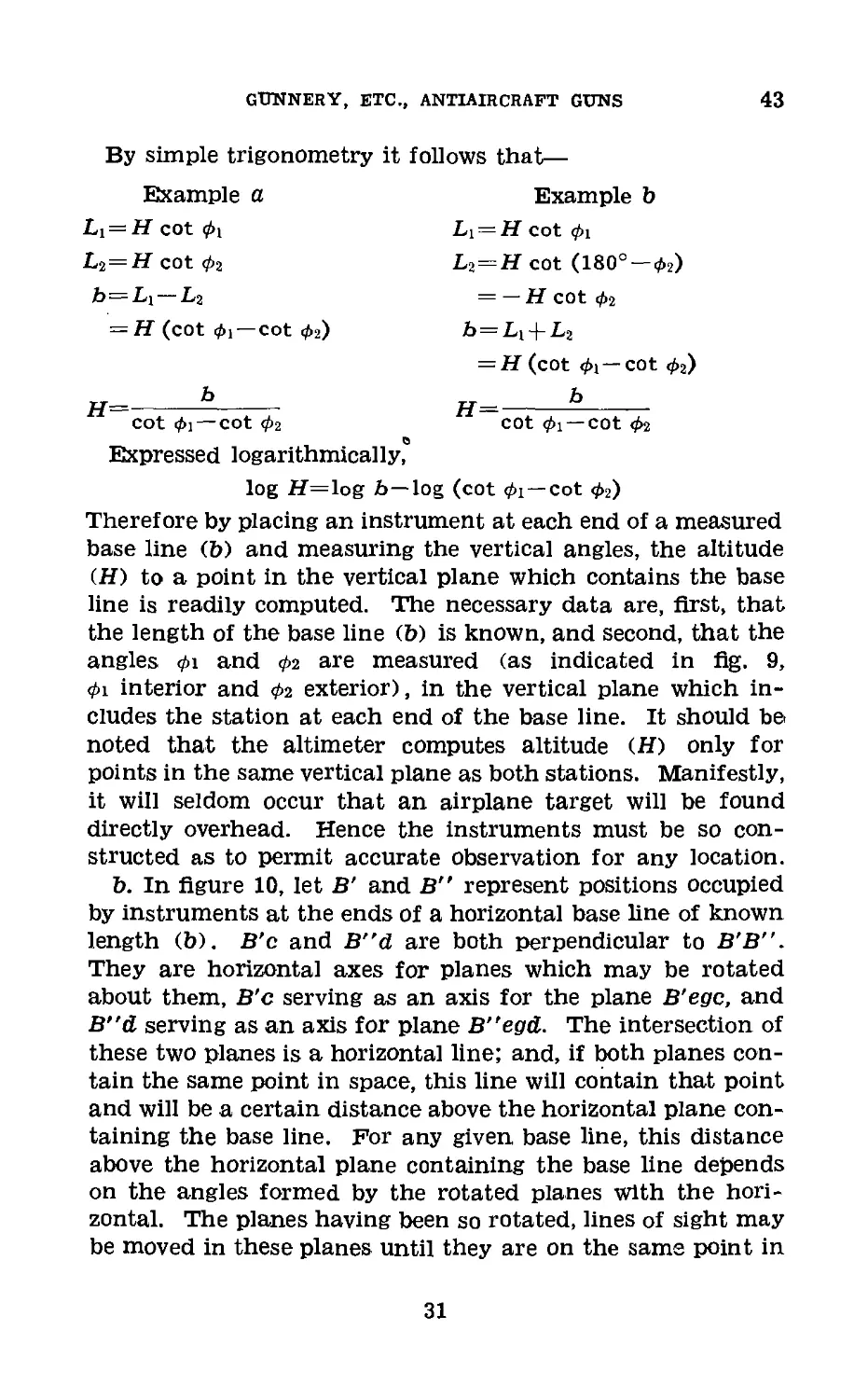
By simple trigonometry it follows that—
Example a Example b
Li = H cot Li = H cot 0i
Li = H cot 02 L^ = H cot (180° —02)
b=Li —L2 = — H cot 02
= H (cot 0i — cot 0a) h = Li + L2
= H (cot 0i —cot 02)
cot 01 — cot 02 cot 01 —cot 02
Expressed logarithmically,
log H=log b—log (cot 0i—cot 02)
Therefore by placing an instrument at each end of a measured
base line (b) and measuring the vertical angles, the altitude
(H) to a point in the vertical plane which contains the base
line is readily computed. The necessary data are, first, that
the length of the base line (b) is known, and second, that the
angles 0i and 02 are measured (as indicated in fig. 9,
0i interior and 02 exterior), in the vertical plane which in-
cludes the station at each end of the base line. It should be,
noted that the altimeter computes altitude (H) only for
points in the same vertical plane as both stations. Manifestly,
it will seldom occur that an airplane target will be found
directly overhead. Hence the instruments must be so con-
structed as to permit accurate observation for any location.
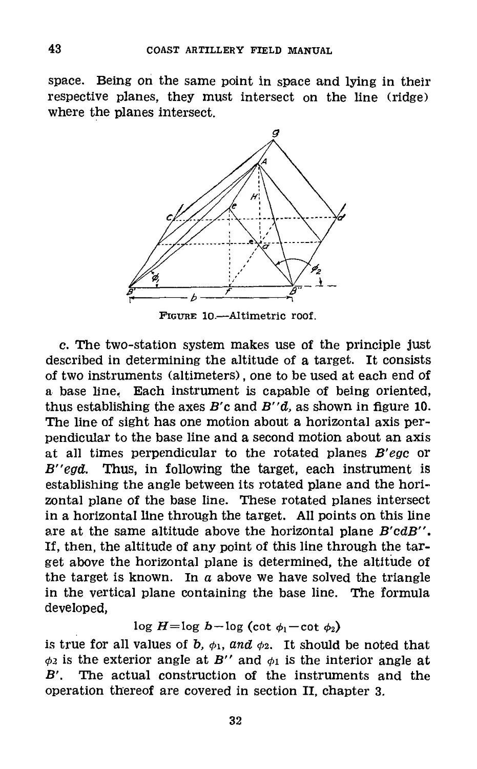
b. In figure 10, let B’ and B" represent positions occupied
by instruments at the ends of a horizontal base line of known
length (b). B'c and B”d are both perpendicular to B'B".
They are horizontal axes for planes which may be rotated
about them, B'c serving as an axis for the plane B'egc, and
B"d serving as an axis for plane B"egd. The intersection of
these two planes is a horizontal line; and, if both planes con-
tain the same point in space, this line will contain that point
and will be a certain distance above the horizontal plane con-
taining the base line. For any given base line, this distance
above the horizontal plane containing the base line depends
on the angles formed by the rotated planes with the hori-
zontal. The planes having been so rotated, lines of sight may
be moved in these planes until they are on the same point in
31
43
COAST ARTILLERY FIELD MANUAL
space. Being on the same point in space and lying in their
respective planes, they must intersect on the line (ridge)
where the planes intersect.
Figure 10.—Altimetric roof.
c. The two-station system makes use of the principle just
described in determining the altitude of a target. It consists
of two instruments (altimeters), one to be used at each end of
a base line. Each instrument is capable of being oriented,
thus establishing the axes B'c and B"d, as shown in figure 10.
The line of sight has one motion about a horizontal axis per-
pendicular to the base line and a second motion about an axis
at all times perpendicular to the rotated planes B’egc or
B"egd. Thus, in following the target, each instrument is
establishing the angle between its rotated plane and the hori-
zontal plane of the base line. These rotated planes intersect
in a horizontal line through the target. All points on this line
are at the same altitude above the horizontal plane B’cdB”.
If, then, the altitude of any point of this line through the tar-
get above the horizontal plane is determined, the altitude of
the target is known. In a above we have solved the triangle
in the vertical plane containing the base line. The formula
developed,
log 77=log b—log (cot </>!—cot </>2)
is true for all values of Ъ, ф\, and Фг. It should be noted that
Ф2 is the exterior angle at B" and </>i is the interior angle at
B'. The actual construction of the instruments and the
operation thereof are covered in section II, chapter 3.
32
GUNNERY, ETC., ANTIAIRCRAFT GUNS
43
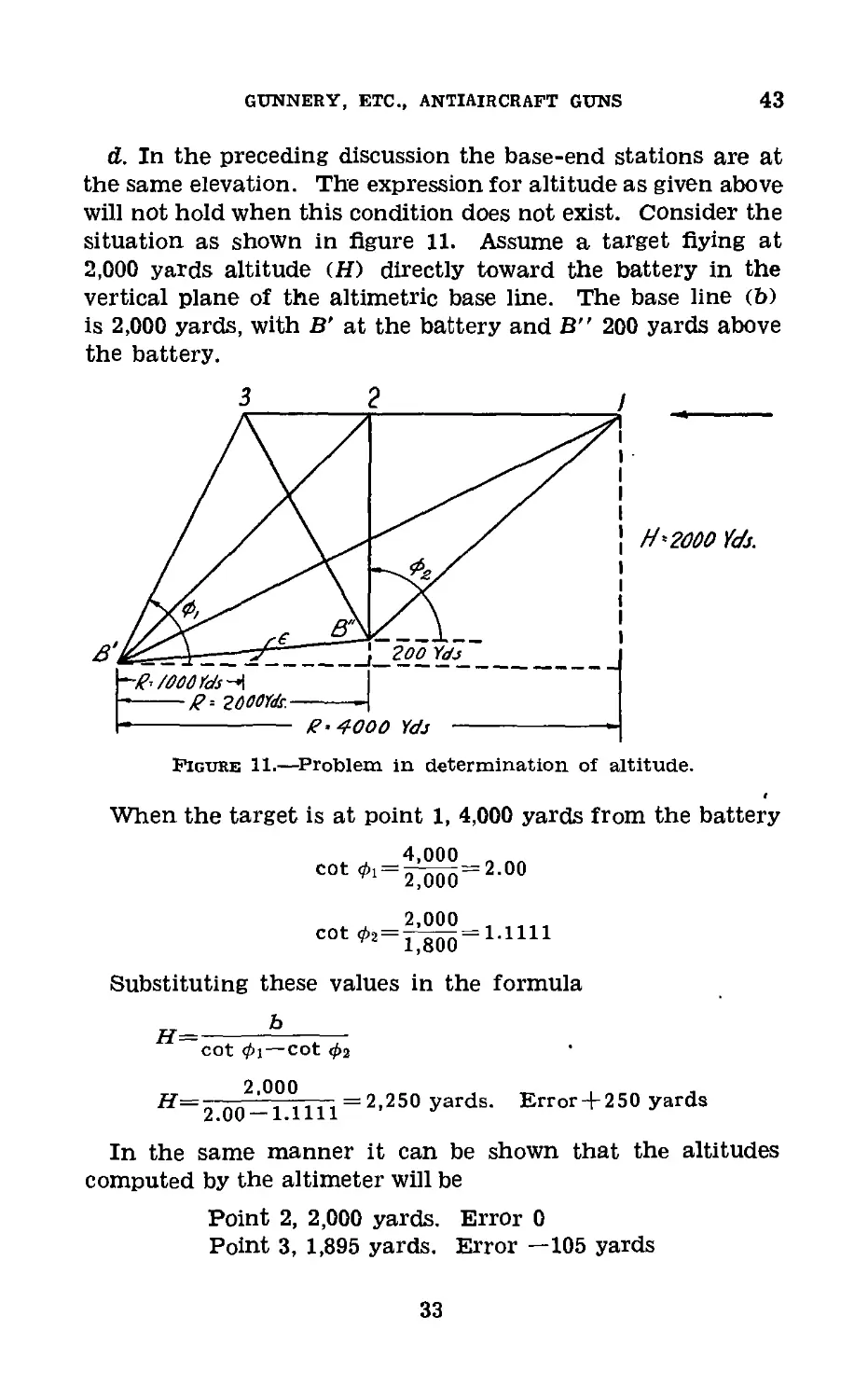
d. In the preceding discussion the base-end stations are at
the same elevation. The expression for altitude as given above
will not hold when this condition does not exist. Consider the
situation as shown in figure 11. Assume a target flying at
2,000 yards altitude (H) directly toward the battery in the
vertical plane of the altimetric base line. The base line (b)
is 2,000 yards, with B’ at the battery and B” 200 yards above
the battery.
Figure 11.—Problem in determination of altitude.
When the target is at point 1, 4,000 yards from the battery
4,000
COt 01= 2^00 = 2-00
2,000
cot ^=1^00=1Л111
Substituting these values in the formula
H=—b___________
cot Ф1 — cot <f>2
оо2-Г11~Т~Г1~ 2,250 yar^s- Error + 250 yards
In the same manner it can be shown that the altitudes
computed by the altimeter will be
Point 2, 2,000 yards. Error 0
Point 3, 1,895 yards. Error —105 yards
33
43-44
COAST ARTILLERY FIELD MANUAL
Thus it will be seen that the error is neither constant in
amount nor in direction and varies with the position of the
target.
e. There is no provision on the altimeter, M1920, for making
a mathematically accurate correction for the error introduced
when the B' and B" stations are not at the same level; hence
the application of an approximate correction must be resorted
to. In the example given (fig. 11), it will be noted that the
line joining the two stations makes an angle with the hori-
zontal whose tangent is equal to
difference in elevation
length of base line
tan €=^ooo=°-100
e=100 mils
If the vertical angles read at each station are reduced by one-
half this amount (50 mils) and again substituted in the
fomula for H, the following values of altitude (H) will be
computed
Point 1, 1,920 yards.
Point 2, 1,900 yards.
Point 3, 1,895 yards.
Realizing that 1,900 yards represents the altitude (H) of the
target above the midpoint of the line joining B' and B", it is
clear that a correction of one-half the angular height (e)
from B' to B", applied to each instrument, will provide a
reasonably accurate computation of altitude (H) for all posi-
tions of the target, with a small constant error of one-half
the difference in elevation between B" and B', which can be
removed by a fiat scale correction. The method of applying
corrections for the difference in elevation of B' and B" sta-
tions is discussed in paragraph 188.
44. Comparison of Single-Station and Two-Station Sys-
tems.—a. Availability of instruments.—The present two-sta-
tion altimeter, M1920, is an adaptation of a World War in-
strument. It is available in considerable quantities, and addi-
tional instruments can be procured quickly at a relatively low
cost. The stereoscopic height finder, as an antiaircraft
instrument, is a post-war development in this country, is diffi-
cult to manufacture, and is costly.
34
GUNNERY, ETC., ANTIAIRCRAFT GUNS
44-45
b. Accuracy.—Theoretically, the two-station system is the
more accurate. Practically, the necessary “cramping” of
scales to reduce the size of instruments and unavoidable per-
sonnel errors in operation offer little choice in accuracy
between the two systems under normal conditions of opera-
tion.
c. Installation and control.—With respect to installation
and control, the stereoscopic height finder is superior to the
two-station system. It can be placed in operation much more
quickly than the two-station system and operates under the
direct control of the battery commander. The two-station
system requires the establishment of a base line and the in-
stallation and maintenance of telephone communication.
The lack of direct control over the distant station introduces
an element of uncertainty as to whether both stations will
“track” the same target in those situations where a number
of potential targets are in the field of fire.
d. Transportation.—The 4-meter base stereoscopic height
finder is a large bulky instrument weighing about 2,200 pounds
when packed and requires wheeled transportation for move-
ment over any considerable distance. The two-station, sys-
tem, including two altimeter instruments, telephones, and
field wire, has about one-fourth the weight and may be
“broken down” into loads convenient for handling.
e. Training of personnel.—The two-station system offers
advantages over the stereoscopic height finder with respect to
training of personnel. The required proficiency for altimeter
operators is quickly reached, and no special qualifications for
the operators are required. Proficiency, once attained, will
seldom suffer appreciably through lack of continuous train-
ing. In contrast, stereoscopic observers must be carefully
selected, carefully trained, and their proficiency maintained
by continuous drill and practice.
Section III
PREDICTION; FUTURE POSITION
45. Definitions.—a. Prediction is the process of deter-
mining the location of the target at some future instant based
on the past performance of the target.
35
45-47
COAST ARTILLERY FIELD MANUAL
b. Future position of the target is that position in space at
which it is expected the target will arrive at the end of the
time of flight of the projectile.
46. The Prediction Problem.—In paragraph 37, the meth-
ods of locating the present position of the target were ex-
plained. Briefly the present position may be located by cer-
tain combinations of the following elements: Ao, H, Xo, Yo,
eo, Do, and Ro, all of which are either instantly available by
the operation of tracking or are computed by some mecha-
nism. The performance of the target is measured at the
present position, and based on these data, performance of the
target during time of flight of the projectile is predicted. The
target occupies the present position only instantaneously.
The relations between the various elements enumerated above
exist only at that moment and are different from those exist-
ing the instant before and the instant after. As the data
computer measures the performance at a certain instant,
the prediction is based on what the plane is doing at that
moment. If, for instance, the plane is flying on a rectilinear
course, the prediction is made along the course extended in
the same direction. If, however, the plane is flying a curvi-
linear course, the situation is different. Data computers can-
not predict a curved course. All predictions are made along
a straight line. Therefore, all predictions made on a curvi-
linear course will be along the tangent to the course at the
present position of the target.
47. Methods of Prediction.—There are two general meth-
ods of predicting the location of the future position of a
target; the angular travel method and the linear speed
method. As the names imply, the predictions of data com-
puters which employ the angular travel method are based
upon the observed angular speed of the target, while the pre-
dictions of data computers which employ the linear speed
method are based on computed values of the target’s ground
speed and direction of flight. The standard antiaircraft di-
rector, M4, employs the linear speed method of prediction.
However, some older types of directors employ the angular
travel method of prediction. The design of future directors
may be based on either method.
36
GUNNERY, ETC., ANTIAIRCRAFT GUNS
48-49
48. Angular Travel Method.—The basis of the angular
travel method is the measurement of the instantaneous angu-
lar speed or velocity of the target in azimuth and in eleva-
tion, and the multiplication of these instantaneous angular
velocities by the time of flight. The Quantities obtained by
these multiplications will be the approximate lateral and ver-
tical deflection angles. When suitable correction factors are
introduced in the products, the principal lateral and vertical
deflection angles will be obtained. The final form in which
these predictions are utilized in pointing the gun depends
upon the method of pointing used.
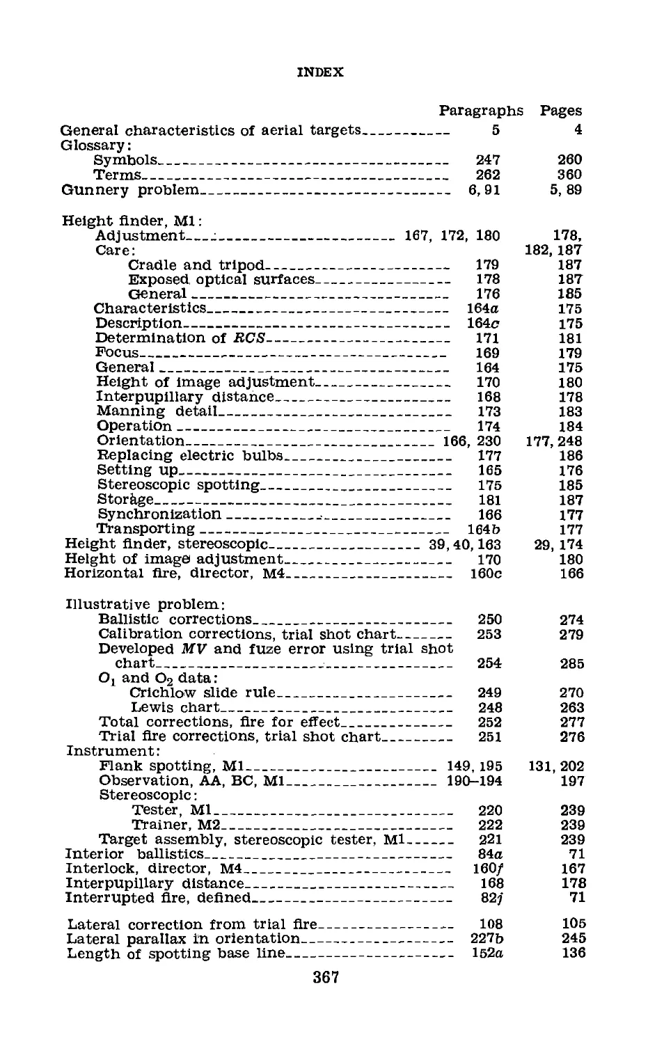
49. Angular Travel Error.—The multiplication of in-
stantaneous angular velocity by time of flight instead of aver-
Figure 12.—Vertical angular travel error.
age angular velocity by time of flight, or the solution of an
equation which, in effect, accomplishes this, results in the
determination of an approximate deflection angle (<rx or 8X)
and the introduction of an error. This error is called the
angular travel .error. Referring to figure 12, consider as a
specific example that an instantaneous vertical angular ve-
locity has been measured at the point a, and that multiplica-
tion by the time of flight (() has resulted in a line of direc-
tion through the point b, the arc o-b representing the angular
travel of a target (vertically) during the time of flight. If
this is correct, the target must be traveling on the arc of a
37
49-50
COAST ARTILLERY FIELD MANUAL
great circle at constant speed. However, the basic assumption
made in antiaircraft gunnery is that the target moves in
rectilinear flight. Therefore the path a-c represents the
actual travel of the target during the time of flight (t), and
the true line of direction should be through the point c.
Hence, the prediction must be refined to correct for the
angular travel error which is introduced by multiplying the
angular velocity at the point a, which differs materially from
that at the point c, by the time of flight. The correction may
be accomplished in three general ways. If the instantaneous
angular velocity (S) is multiplied by the true time of fight
(tP), first, a correcting multiplier may be used; or, second,
a correction term of proper value (negative or positive) may
be added to the result; and, third, the instantaneous angular
velocity (S) may be multiplied by a fictitious time of flight
(t') factor. Any one of these methods may be adapted to
mechanical processes.
Certain courses exist where either one or both of the angu-
lar velocities are constant, for instance, a plane diving directly
at the battery. But, it will be found that in nearly all condi-
tions of flight, both the lateral angular velocity and the verti-
cal angular velocity vary continuously, thereby introducing
angular travel errors.
И 50. Principal Lateral Deflection Angle (5i).—The prin-
cipal lateral deflection angle (01) is the horizontal angle,
measured at the gun position, through which the target will
move in the time intervening between the firing of the gun
and the arrival of the target and projectile at the future
position. The magnitude of this angle is subject to exact
mathematical determination under the basic assumptions of
target flight. The general expression for this value is as
follows:
where Sa (the instantaneous lateral angular velocity of the
target in its present position) is expressed in radians per
second. It is to be noted that the value of 5i depends upon
the size of the principal vertical deflection angle as will be
seen from the appearance of e0 and eP above. Similarly, it
38
gunnery, etc., antiaircraft guns
50-52
will be found that the value of the principal vertical deflection
angle is dependent upon lateral deflection. Thus, the equa-
tions for 5i and for ai are simultaneous equations, neither of
which may be solved without the other. The derivation of
the above formula is found in paragraph 258.
51. Principal Vertical Deflection Angle (<ri).—The prin-
cipal vertical deflection angle (<n) is the vertical angle, meas-
ured at the gun position, through which the target will move
during the time intervening between the firing of the gun and
the arrival of the target and the projectile at the future
position. The magnitude of this vertical angle, like that of
the principal lateral deflection angle, is subject to exact
mathematical determination. The general expression for
this value is as follows:
where Se (the instantaneous vertical angular velocity of the
target at the present position) is expressed in radians per
second. It should be noted that the expression for the value
of the sine of n is made up of two parts. The first,
sin
PSin €0
represents the product of future time of flight and the
instantaneous vertical angular velocity corrected for the major
part of the angular travel error (since it is multiplied by the
ratio of
sin
sin
The second part of the expression for sin ai is called the
complementary term, since it varies with the value of lateral
deflection. The sign of this term is negative when the sign
of ai is positive and vice versa, but the effect of the comple-
mentary term is always to decrease the angular height to the
future position regardless of the sign of <n. The derivation of
the above formula is found in paragraph 258.
52. Use of Si and «.—The values of Si and <ri determined by
the formulas in paragraphs 50 and 51 above are used in two
39
52-54
COAST ARTILLERY FIELD MANUAL
different ways depending upon the method of pointing. In
case 1Уг pointing (par. 78) and <n are the principal deflec-
tions which are set on the sights of the guns. With 5i and <n
only set on the sight and the sight of the gun tracking the
target, the axis of the bore is pointed at the future position of
the target (Tp).
In case III pointing (par. 78), 3i and « are added alge-
braically to 40 and eo in order to get Ap and ep. Tp is located
then in terms of Ap, ep, and H.
53. Linear Speed Method.—a. As used in our service, the
linear speed method is based upon the continuous measure-
ment of the ground speed (Sg) of the target and its direction
of flight. As in the angular travel method, the present posi-
tion of the target (To) is determined by the continuous track-
ing of the target thereby measuring Ao and eo, and the meas-
uring of the altitude (H), Ro is computed mechanically from
the data eo and H. To is then located to scale using the polar
coordinates Ao and Ro. These polar coordinates are converted
to rectangular coordinates Xo and Yo. (See figs. 2 and 3.)
b. A device measures the instantaneous rates of change of
Xo and Yo. These rates are the E-W and N-S rates. The
E-W and N-S rates are multiplied by the time of flight (tp)
to the future position (Tp) giving the E-W travel (AX) and
the N-S travel (AY) during the time of flight. AX and AY
are added algebraically to the coordinates of the present posi-
tion Xo and Yo giving Xp and YP. (See figs. 2 and 3.) Xp
and Yp are converted to polar coordinates AP and Rp. Thus
Tp is located in terms of Ap, Rp, and Hv.
Section TV
MECHANICAL SOLUTIONS
54. General.—Mechanical computing devices are not un-
common; slide rules, adding machines, and cash registers
are in everyday use. It is possible to obtain either a graphical
or mechanical solution, or both, for almost any law of mathe-
matics. Mechanical computing devices obtain answers very
rapidly and in some cases instantaneously. This section
considers the mechanical computing devices employed in the
M4 director.
40
GUNNERY, ETC., ANTIAIRCRAFT GUNS
55
55. Variable Speed Drive.—a. The variable speed drive Is
also known as the ball and disk integrator. It is used in the
standard director—
(1) To perform multiplication or division.
(2) To change linear distance to rotary motion.
(3) As a variable speed drive.
b. The variable speed drive consists primarily of a flat disk
(M), a cylinder (R), and two steel balls (IV) mounted in a
carriage one over the other and in contact with the disk and
cylinder. The disk is rotated at a given angular velocity (w).
Rotation of the disk is transmitted through the steel balls to
the cylinder. (See fig. 13.)
Figure 13.—Variable speed drive.
c. The operating principle of the variable speed drive is:
the angular velocity of the cylinder is proportional to the
angular velocity of the disk (ш) and to the displacement of
the steel balls (r) from the center of the disk; that is.
Angular velocity of disk
X displacement of balls
from center of disk
radius of cylinder
Angular velocity of cylinder =
ы times r
constant
41
55
COAST ARTILLERY FIELD MANUAL
Referring to figure 13, if the rotation of the disk (1И) is in
the direction shown, the rotation of the cylinder (Л) will be
shown. If the displacement of the balls (O is zero, that is
the balls are at the center of the disk (Af) then
Angular velocity of cylinder=-^^^^ = 0
If the balls are moved to the left side of the disk (AT), the
rotation of the cylinder (R) will be in the direction opposite
to that shown.
d. In the M4 director, the automatic prediction mechanism
uses a variable speed drive to perform division. The disk is
made to revolve at an angular velocity proportional to the
reciprocal of the time of flight (i) • The displacement of the
balls (r) is made proportional to prediction (ДХ, дY, or ДН).
Then the
Angular velocity of cylinder ~ X prediction X congtarlt
But rate =
distance
time
Therefore the angular velocity of cylinder is proportional to
the rate (either E-W, N-S, or altitude).
e. The automatic prediction mechanism also uses a varia-
ble speed drive to convert linear distance to rotary motion,
(ш) must be constant. If the disk is driven by a constant
speed motor, (w) is constant, r is made proportional to the
quantity which is to be converted from a linear distance to
a rotary motion, the reciprocal of the time of flight
Then the
constant X
Angular velocity of cylinder =-COnstant—~
That is, the angular velocity of the cylinder is proportional
to the reciprocal of the time of flight (tP).
Likewise in the ballistic wind mechanism of the M4 director,
r is made proportional to the E-W or N-S component of the
42
GUNNERY, ETC., ANTIAIRCRAFT GUNS
55-56
ballistic wind. Then the angular velocity of the cylinder is
proportional to the E-W or N-S component of the ballistic
wind.
/. The range rate and altitude rate drives are used to sup-
plement the manual operation of matching pointers in the
M4 director. The disk is driven by a constant speed motor.
The angular velocity of the cylinder is therefore proportional
to the displacement of the balls. By adjusting the displace-
ment, the operators can make either Ro or Ho change at a
certain specified rate, or at a rate so as to keep the dials con-
tinuously matched. Such an operation can be done manually,
but a power drive has the advantage of resulting in a smoother
rate of change.
56. Differential Gears.—a. The differential provides a
method of combining two motions into one resulting motion
which is the algebraic sum of the other two motions.
b. Essentially, a differential consists of three shafts inter-
connected by a train of gears. Figure 14 shows schematically
what happens in a differential. Motion is imparted to shafts
A and B. These motions are combined and result in the
motion of the housing, which in turn is taken off by the shaft
C. Any two of the shafts may be used for the input of data
and the output will come out on the third shaft.
SHAFT A
SHAFT В
HOUSING
SHAFT C
Figure 14. —Differential action.
c. The principle of the differential is best known in its
application to the automobile. The same action takes place
in the differentials of a director as in the differential of a
car. All differential actions can be classified in three groups
as follows:
43
56
COAST ARTILLERY FIELD MANUAL
Input Output
Direction * and ve- locity of shaft A Direction * and ve- locity of shaft В Direction * and veloc- ity of shaft C,
1 Adding..-- Counterclockwise w revolution. Clockwise ы revolu- tion. Counterclockwise w+w revolution.
2 Canceling. Clockwise ы revolu- tion. Clockwise ы revolu- tion. Stationary.
3 Equating.. Clockwise 2 ы revolu- tion. Clockwise ы revolu- tion. Clockwise revo- lution. 2
*The direction of rotation is as viewed looking down each shaft toward the differ-
ential in figure 14.
d. The adding differential, as the name implies, combines
two motions so that the resulting motion is the algebraic
sum. For example, when the director is in action, the azi-
muth transmitter is constantly positioned according to At.
Any dA correction must be applied in such a way that it will
not disrupt this flow of data. A differential is inserted in the
system. The input of the differential is At and dA. The
output is
Af±dA.
e. The canceling differential functions so as to keep the
output zero. In figure 14, if shaft A is turned four revolu-
tions clockwise, shaft C will turn. Now, if shaft В is turned
four revolutions clockwise, shaft C will return to its original
position. In other words, the output of the differential is
zero.
f. The equating differentia] takes two motions (rates),
compares them, and passes the difference to the output shaft.
When the two motions are equal, the difference is zero, and
therefore the output shaft will be stationary.
g. The same differential may perform any one of the three
operations enumerated above. Figure 15 shows the differen-
tial used in the M4 director. The input and output of the
differential are shaft (4-B) and gears D and F.
44
GUNNERY, ЕТС.» ANTIAIRCRAFT GUNS
57
Figure 15. —Differential.
57. Three Dimensional Cams.—a. A cam is defined as a
plate, cylinder, or solid having a curved outline or groove,
which rotates or translates about an axis and by its motion
gives motion to another member or follower in contact with it.
b. Cams are used in the standard director for two different
purposes:
(1) The e0 cam solves for the horizontal range to the pres-
ent position (Ko) using Ho and e0 to position it.
(2) The ballistic cams solve for i-, 0, and F using HP and
RP to position them.
c. Any particular point on the surface of the eo cam repre-
sents a point in space whose coordinates are Ro and Ho.
The lift of the cam follower or cam pin—that is, the distance
of the point of the follower from the reference surface—is
made proportional to the angular height (eo) of the point
whose coordinates are Ro and Ho. The cam is rotated accord-
ing to Ho and translated according to Ro. The follower is
constrained by slides so as to have only one motion along its
axis. In operation, the cam is first rotated until positioned
in Ho. The cam is translated until eo measured front the
cam is equal to e0 measured by the elevation tracking tele-
scope. The distance that the cam has been translated Is
proportional to Ro. (See fig. 16.)
244637°—40---4
45
57-58
COAST ARTILLERY FIELD MANUAL
INCREASING
ANGULAR
HEIGHT (€0>
Co DIALS
Co CAM
RANGE (Ro)
(FROM RANGE
DRIVE)
ALTITUDE
(FROM ALTITUDE
--- DRIVE)
ANGULAR
HEIGHT
(Co)
(FROM
TELE-
SCOPE)
Figure 16.—Eo cam.
d. The ballistic cams are mechanical firing tables. A sepa-
rate cam is necessary for each element A-, </>, and F, but for
ease of construction and operation, the three are mounted as
an integral unit. Any particular point on the surface of a
ballistic cam represents a point in space whose coordinates
are Hp and Rp. By reference to firing tables, we can find
the values of </>, and F for any point in space whose coordi-
nates are Hp and Rp. The lift of each cam follower, that is,
the distance from the point of the follower to the reference
surface, is proportional to the values of and F for the
tp
particular values of Hp and Rp. The followers are constrained
by slides so as to have only one motion along their axes. The
cams are rotated in Rp and translated in Hp. (See fig. 17.)
58. Coordinate Conversion Mechanism.—a. Figure 18 illus-
trates the principle of the coordinate conversion mecha-
nism. The present position of the target is located by polar
coordinates Ao and Ro. The rectangular coordinates Xo and
Yo are measured by the displacement of the E-W and N-S
slides from the N-S and E-W axes.
b. The actual mechanism (figs. 19 and 20) used for the
conversion of coordinates employs the same principle illus-
trated in a above.
46
GUNNERY, ETC., ANTIAIRCRAFT GUNS
58
COAST ARTILLERY FIELD MANUAL
(1) To reproduce horizontal range to scale, a disk having
a spiral groove is used. The center of the disk represents the
gun position while the pin in the groove represents the target
position. (See fig. 19.) The radial distance from the center
of the disk to the pin represents the horizontal range to the
target. To reproduce the target azimuth, an azimuth disk
N
s
Figure 18.—Principle of coordinate conversion.
having a radial slot is placed next to the range disk so that
the disk centers are common and the radial slot in the azi-
muth disk carries the target position pin and slide. By hold-
ing the azimuth disk stationary and turning the range disk,
the target position pin is moved radially in or out along the
slot in the azimuth disk. If only the azimuth disk moves, the
pin swings about the disk center and at the same time slides
48
Figure 19
GUNNERY, ETC., ANTIAIRCRAFT GUNS
.—Disk mechanism.
58
COAST ARTILLERY FIELD MANUAL
along the radial groove. A differential is inserted in the
drive between the two disks so that a change in azimuth ro-
tates both disks the same amount. Because of this, a change
in azimuth does not change the horizontal range. Thus it is
seen that by rotating the range disk and azimuth disk the
target position pin is located by polar coordinates Ao and Ro
in the case of the present position disks, and AP and Rp in
the case of the future position disks.
(2) The target position pin engages a slide block (fig. 20).
The slide block is capable of two motions, one vertically on
50
GUNNERY, ETC., ANTIAIRCRAFT GUNS
58-59
the gibs (N-S or Yo) and the other horizontally. For the
horizontal motion (E-W or Xo) the entire slide assembly in-
cluding the slide block and gibs rolls on the two V-type slide
rails. Fastened to the slide block is a rack which engages
with the long pinion. Fastened to the slide assembly is an-
other rack which engages with a pinion. The motions of
these two pinions are measured. The rate at which the pin-
ions are turning is the E-W or N-S rate. The amount that
the pinions have turned is Xo or Yo on the present position
disks and Xp and Yp on the future position disks.
59. Automatic Prediction Mechanism.—a. Ordinarily the
equation for prediction is:
AX= E-W.rateX tp
AY=N-S rateX tp
AH= Altitude rateX tp
In the solution of the prediction problem by the M4 director,
it is more convenient to express the above equations in a
different form which is:
E-W rate = AXX-~
N-S rate = A YX v-
tp
Altitude rate = AH'X-^;
tp
b. In paragraph 58 it is stated that the rate of turning of
the pinions on the present position slides is the E-W or N-S
rate. This rate is known as the “observed rate.’’ In the alti-
tude prediction mechanism the observed rate is set up by
operation of the altitude rate drive. (See par. 55/.)
c. Figure 21 is a schematic diagram of an automatic predic-
tion mechanism. Start at the ~ cam in the lower left corner.
Ip
The lift of the follower positions the ball carriage of the varia-
ble speed drive. According to paragraph 55e, the angular
velocity of the cylinder Is proportional to 7-. This cylinder,
revolving at a rate proportional to —, is driving the disk of
Гр
another variable speed drive in the upper left corner. Assume
51
59-60
COAST ARTILLERY FIELD MANUAL
that the ball carriage has been displaced from the center a
distance which we will call a prediction. Then by paragraph
55d—
Angular velocity of the cylinder=predictionX —
Гр
But by a above:
PredictionX7-=rate (either E-W, N-S, or altitude).
Under the above circumstances, the variable speed drive is
creating a rate which is called the “generated rate.”
d. If we can make the generated rate equal to the observed
rate, the displacement of the ball carriage is then propor-
tional to the true prediction. The observed rate and the
generated rate are the inputs of an equating differential. By
paragraph 56/, the equating differential compares the two
rates .and passes the difference out through the third or out-
put shaft. This output shaft of the equating differential
is geared to the ball carriage of the variable speed drive. If
the two rates (observed and generated) are not equal, the
difference coming out through the output shaft moves the
ball carriage and either increases or decreases the generated
rate. When the two rates become equal, the difference is
zero, and the output shaft is therefore stationary. The pre-
diction is zero when the ball carriage is over the center of the
disk. The amount that the output shaft of the equating dif-
ferential has turned in positioning the ball carriage in order
to equalize the rates is therefore proportional to the displace-
ment of the ball carriage and hence proportional to the
prediction.
60. Ballistic Wind Mechanism.—a. The ballistic wind
causes the projectile to deviate from the normal trajectory.
(See par. 86d.) In the M4 director, the wind is considered
to have moved the future (predicted) position by amounts
equal to the E-W and N-S components of the ballistic wind
multiplied by the time of flight. This correction for ballistic
wind is effected by correcting the generated rate in the auto-
matic prediction mechanism.
b. Figure 21-shows schematically the ballistic wind mecha-
nism. The components of the ballistic wind are obtained by
operation of the wind component solver (fig. 55). Setting
52
GUNNERY, ETC., ANTIAIRCRAFT GUNS
60
Figure 21.—Automatic prediction mechanism—ballistic wind
mechanism.
53
60-61
COAST ARTILLERY FIELD MANUAL
the value of the wind component on the wind dial causes
the ball carriage of the variable speed drive (on the right
side of fig. 21) to be displaced from the center an amount
proportional to that wind component. By paragraph 55e,
the angular velocity of the cylinder is proportional to the
wind component. This wind rate is added algebraically to
the generated rate by a differential before the generated
rate enters the equating differential (par. 56d). The output
of the adding differential is therefore the generated rate ±
the wind component rate. Hence the wind correction is
included in the prediction.
c. The ballistic wind mechanism has another use in that it
supplies rates for static check problems. When the director
is stationary, the observed rate is zero and therefore the pre-
diction is zero. The ballistic wind mechanism can be used to
set up a rate in the automatic prediction mechanism which
will take the place of the observed rate. In figure 21 the
component rate passes through the adding differential to the
equating differential where it causes the prediction shaft to
turn, making a prediction and displacing the ball carriage of
the variable speed drive (upper left). A rate which is fed
into the adding differential is generated. When this gen-
erated rate is equal to the component rate, the rates will be
equated by the differential and no further output will enter
the equating differential to change the prediction. The gen-
erated rate is equal to the component rate. The wind dials
are graduated from 0 to 50 miles per hour. Target velocities
are greater than wind velocities, therefore problem velocity
dials (graduated from 0 to 200 yards per second) are mounted
adjacent to the wind dials. They are set by the same knob
as the wind dials but are used only when setting in problems.
In setting wind rates, the knob is restricted by a stop to ap-
proximately one revolution. In order to set target velocities,
the knob is pulled out to pass the stop.
61. Movable Index Dial.—a. The movable index dial is a
means of adding one quantity to another algebraically. Fig-
ure 22 is a sketch of a spot dial on the M4 director. The
complete dial consists of two concentric rings about a central
disk. The outermost ring, with the words “TRIAL FIRE
CORR.” on it, is fixed. The second ring, called the movable
54
GUNNERY, ETC., ANTIAIRCRAFT GUNS
61
index, is capable of rotation in either direction by using the
movable index knob. The central disk is operated by the
spotting handwheel and indicates the correction applied.
b. Suppose that the movable index is moved to down
(minus) 10 as shown in the figure. If the indices are
matched as shown, there is a spot of down (minus) 10 in the
data computer although according to the spot dial and mov-
able index the correction is 0. This is the procedure followed
Figure 22.—Spot dial.
in making ballistic corrections before opening fire. (See par.
100.) If, as a result of firing, a correction of down (minus)
10 is ordered, the spot dial is turned by means of the spotting
handwheel so that it reads down (minus) 10 with reference
to the movable index. It will be noted that with reference
to the fixed index on the outer ring, the correction is down
(minus) 20. The device has added the two corrections alge-
braically. Its use eliminates mental addition by the operator
55
61-62
COAST ARTILLERY FIELD MANUAL
and thereby reduces the possibility of the occurrence of per-
sonnel errors.
Section V
FIRING DATA
62. General.—a. Instruments used for the computation of
antiaircraft artillery firing data are automatic in their action
and the necessary firing data are obtained without reference
to printed tables or charts. Firing table and trajectory chart
data must be available for the designing of instruments and
computations incident to calibration corrections and to trial
fire. An understanding of the use of firing tables and trajec-
tory charts is essential in connection with the conduct of
antiaircraft fire, including the preparation and observation
of fire.
b. Trajectories are calculated for a gun of given charac-
teristics, developing a stated or assumed muzzle velocity, and
firing a projectile with a given ballistic coefficient. In other
words, each combination of gun and ammunition has its own
characteristics. Therefore, we must use the firing tables,
trajectory chart, and ballistic cams pertaining to the particu-
lar combination of gun and ammunition being used.
C. Firing tables and trajectory charts are available for use
as follows:
Firing tables and trajectory chart No. Nor- mal MV Date Caliber of gun Projectile and fuze
3 AA-I-2 2,400 December 1928. 3" Shell, HE, Mk. I; fuze Mk. HI. Shrapnel, Mk. I; fuze Mk. III.
3 AA-J-2 2,600 October 1928... 3" Shell, HE. Mk. I; fuze Mk. III. Shrapnel, Mk. I; fuze Mk. III.
3 AA-K-2.... 2, 800 February 1929.. 3" Shell HE, Mk. IX; fuze Mk. III.
3 AA-L-1 2, 600 October 1928. . 3" Shell, HE, Mk. IX; fuze Mk. III.
3 AA-N-1---- 2, 800 August 1929. __ 3" Shell, HE, Mk. IX; fuze М2.
g AA-0-1 2. 700 April 1939 3"._ Shell, HE, M42; fuze M43.
105 AA-E-1.. 2, 800 Not available for general circulation. 105-mm. Shell, HE, M38; fuze М2.
105 AA-C-2. 75 M-l 2, 800 do August 1930... 105-mm. 75-mm.. Shell, HE, M38; fuze Mk. IIIAI. Shell, HE, Mk. III.
56
GUNNERY, ETC., ANTIAIRCRAFT GUNS
63-64
63. Firing Table Assumptions.—Firing tables are prepared
by the Ordnance Department for each type of gun and am-
munition under a set of conditions arbitrarily assumed as
standard. Their enumeration will serve to acquaint the
reader with the more important factors which affect the
trajectory.
Standard conditions.
Muzzle velocity (MV) (as listed in the table).
Wind (W), none.
Air density at the battery, 59° F. and 29.53" of mercury.
Air saturation, 78 percent. (525.9 grains per cu. ft.)
Temperature of air at battery, 59° F.
Temperature of powder, 70° F.
Weight of projectile (as listed in table).
In addition, a standard atmosphere aloft is assumed; that is,
atmospheric temperature and density vary with altitude (H)
in a linear relationship. Drift (S2d) and lateral and vertical
jump are determined experimentally.
64. Contents of Firing Tables.—a. The present standard
firing tables are published in book form. The first section
gives general information pertaining to the gun and carriage
and the projectile and fuze. It also contains a detailed expla-
nation of the tables and of the meteorological message.
b. Part 1 of the tables contains charts and tables applicable
to all combinations of projectile, fuze, and powder charge,
and is the same in all antiaircraft artillery firing tables.
c. Part 2 consists of a number of sections, each of which
gives data pertaining to a particular combination of projec-
tile, fuze, and powder charge. This part of the firing tables
includes the following:
(1) Trajectory data.
(2) Fuze setter data.
(3) Drift in yards and in mils.
(4) Probable error—
(a) In time of flight in seconds.
(b) Along the trajectory in yards.
(c) In plane of the trajectory in yards in direction normal
to the trajectory.
(d) In deflection in yards.
57
64-66
COAST ARTILLERY FIELD MANUAL
(5) Differential effects on horizontal range, altitude, and
angular height due to—
(a) Change in angle of elevation.
(b) Change in muzzle velocity.
(c) Rear wind.
(d) Change in air density.
(e) Weight of the projectile.
(/) A decrease of one division in corrector setting.
(6) Differential effects on deflection In yards and mils due
to cross wind.
(7) Differential effect on time of flight in seconds due to a
decrease of one division in corrector setting.
d. The effect of both vertical and lateral jump is included
and combined with other elements In the tables and does not
appear as a separate effect.
e. It should be noted throughout the differential variations
listed in the firing tables that the algebraic signs, where given,
are those for effects and not for corrections; further, that the
signs for drift effects apply to panoramic sights in which the
deflection scale readings Increase as the line of sight is turned
to the right. These sights are not used on antiaircraft artil-
lery guns and care should be taken to apply the correction for
drift effects in the proper direction.
f. Extracts from Firing Tables 3 AA-J-2a and 3 AA-O-1
are given in paragraph 257.
65. Trajectory Charts.—The trajectories plotted on the
charts, together with the associated time of flight and fuze
curves, the range and altitude components, and the quadrant
elevation and angular height data, represent the results of the
calculation of the trajectories In air for the guns and the
ammunition named under the assumed standard conditions.
The charts are constructed to show only that part of each of
the trajectories which is included within the maximum time
of burning or setting of the particular fuze used. Figures 23
and 24 show trajectory charts for Firing Tables 3 AA-J-2a
and 3 AA-O-1.
66. Corrections for Nonstandard Ballistic and Atmos-
pheric Conditions.—Since ballistic cams in the data computer
are constructed from data contained in the firing tables (par.
57d) It is obvious that the data from the instrument will be
58
ALTITUDE (Y1 IN YARDS
8500
8000
7500
7000
6600
60D0
55OD
5000
9000
ТТЛ
C 104
4000
35DD
3000
2500
2000
1500
1000
600
(±111
JLU
0 —
!Яи111НП1№Л11ЦП11ПиП111И1пЯ!!
3 AA-J-2A CHART
О __________________,
О 500 1000 1500 2000 2500 3000 3500 4000 4500 5000 5500 6000 6500 7000 7500 6000 8500 9000
RANGE (X) IN YARDS
Figure 23.—Trajectory chart 3 AA-J-2a.
244637°—40 (Face p. 58) No. 1
TRAJECTORIES AND FUZE SETTER CURVES
FDR
3" ANTI-AIRCRAFT GUNS
MODELS 1917, I9I7MI, I9I7MII ANO I925MI
A.A.SHRAPNEL,MK.I; FUZE, SCOVlLL,MK.Ill
WT. 15 LBS., M.V. 2600 F. S.
A P.O. FEB. 1926
NOTE: DASHES (•) DENOTE TIME OF
FLIGHT IN SECONDS.
ЭОСГ
200-
ALTITUDl IN YARDS
ICOOOl
900®
eooo =
7OOO
eooo
5000
3000
2000
1000
0
9000 iOOOO 11000
2000 3000 4000 5000 5000 7000 5000
Я A N6E IN YARDS
Figure 24.—Trajectory chart 3 AA-O-1.
«оооНы
244637°—40 (Face p. 58) No. 2
1000
GUNNERY, ETC., ANTIAIRCRAFT GUNS
66-67
the same as that which could be extracted from the firing
tables. Therefore these data will be correct only when the
conditions, as enumerated in paragraph 63, are standard.
This will rarely, if ever, be the case. The variation of the dif-
ferent elements from standard conditions must be determined
and corrections for their effect applied. The muzzle velocity
(MV) to be expected may be determined approximately by
studying the results of previous firings and by applying the
effect of a difference in powder temperature from standard.
The variation from standard in the weight of a projectile is
determined at a glance from markings on the projectile. The
actual conditions of the atmosphere remain to be determined.
67. Meteorological Message.—a. The determination of the
atmospheric conditions seldom devolves upon the battery
commander. They are determined by other agencies and the
information is furnished in the form of a coded meteorological
message as indicated in the following example:
Coded message
Translation
MFS MFS
20570
Meteorological message from station FS 2—A A fire. 05—altitude
of station 500 feet. 70—temperature at station 70° F.
Zone
Altitude
in feet
Direction
Of ballistic
wind in
mils from
north
Speed of
wind in
m. p. h.
Density
in per-
cent of
normal
0241698________________________
1231798________________________
2221898________________________
3211898________________________
4211998________________________
5202099________________________
6202099________________________
7192199________________________
8182299________________________
9182200________________________
0
1
2
3
4
5
6
8
9
0
600
1, 500
3,000
4, 500
6, 000
9,000
12,000
15,000
18, 000
2,400
2,300
2,200
2,100
2,100
2,000
2,000
1,900
1,800
1,800
16
17
18
18
19
20
20
21
22
22
98
98
98
98
98
99
99
99
99
100
b. All measurements are made at the meteorological sta-
tion, and if the location of the firing battery differs in alti-
tude, suitable corrections must be made. Azimuth of the
wind is always that from which the wind is blowing. The
groups of figures for each zone contain data for ballistic
59
67-68
COAST ARTILLERY FIELD MANUAL
wind and ballistic density. The term “ballistic” signifies a
wind and density equivalent in effect to the sum of the winds
and densities actually encountered up to the indicated alti-
tude. Use the group of the meteorological message of which
the altitude is nearest to, but not less than, the altitude of the
target. Therefore, if a target at 13,000 feet altitude is being
fired upon, only the group “8182299” need be decoded.
И 68. Corrected Firing Data.—a. The effect of variations
from standard conditions may be illustrated by a specific
example. Present Future
Assume: position position
Altitude (H) (yards)_____________________ 4, 200 4, 200
Angular height (e)----------------------- 672 820
Horizontal range (ft)____________________ 5, 400 4,035
Quadrant elevation (</.)___________________________ 900
Time of flight (tp)-------------------------------- 13.1
Fuze range (F)------------------------------------- 12. 7
Muzzle velocity (MV) 2,500 f/s (previous firings).
Temperature of powder, 70° F.
Azimuth (AP) of target from battery, 1,800 mils.
From the preceding meteorological message for zone 3—
Wind azimuth (Aw)_____________________ 1, 800 mils.
Speed---------------------------------22 m. p. h.
Density_______________________________1% (decrease)
Referring to firing table extracts In paragraph 257, and
trajectory chart, figure 23, the effects of these conditions on
the path of the projectile are readily listed as follows:
Condition Effect
Horizontal range Altitude
Muzzle Velocity (MV) 50 f/s decrease (cams cut for 2,550f/s) . — 50 (4/?„) 0 —73 (ДВИ) +13 -64 (Д7Л) 0 -16 (4Z7W) +16
Temperature of powder 70° F Wind. Head wind 22 m. p. h Note.—From the azimuth of the target and the azimuth of the wind there is no cross-wind effect. Density 1 percent decrease Total . -- --
- НО (ЛЛ) -64 (AH)
60
GUNNERY, ETC., ANTIAIRCRAFT GUNS
68-70
To correct for these effects, the gun must be pointed in eleva-
tion so that the trajectory will pass through a point whose
coordinates are
Uncorrected coordinates, future Horizontal range Altitude
position____________________ 4,035 (K) 4,200 (H)
Correction_______________________ 110 (dR) 64 (dH)
Corrected coordinates_______ 4,145 4, 264
Which requires, from the trajectory chart, the following ap-
proximate firing data:
Quadrant elevation (0)_________________ 898 mils
Fuze (F)______________________________ 13.0
The only lateral effect on the trajectory from the conditions
given Is that of drift (5га) 7 mils right. To correct for this,
the gun must be pointed 7 mils to the left of the target, or at
1,793 mils azimuth.
b. With this convincing example of the necessity for cor-
recting firing data, the question will naturally arise as to
how the instantaneous and continuous calculation and ap-
plication of these corrections may be incorporated with the
mechanically computed uncorrected firing data. It will be
found that methods exist in the calculation and application
of corrections, ranging from the roughest approximations,
applied manually and periodically, to the mechanically com-
plex methods of instantaneous and continuous calculation
and application. The method of applying corrections for
nonstandard conditions is fully explained in paragraph 100.
Section VI
DATA TRANSMISSION SYSTEMS
69. General.—There are three standard data transmission
systems in use in the antiaircraft artillery at the present time;
the telephone, the mechanical flexible cable, and the self-
synchronous alternating current system.
70. Telephone.—The present standard field telephone is
the EE-8. It is a highly efficient type of local battery tele-
phone and is designed to be used with field telephone wire.
It is used where necessary to transmit data over distances
244637°—40-
5
61
70-73
COAST ARTILLERY FIELD MANUAL
that are too great for the other two systems to operate satis-
factorily; that is, distances in excess of 500 yards in the case
of the A. C. system and 100 feet in the case of the flexible
shaft system. It has the disadvantage that transmission of
the desired data is not instantaneous and is subject to error.
И 71. Mechanical Flexible Shaft System.—This system con-
sists of a piece of stiff steel wire encased in a flexible metal
housing. It is similar to the flexible shaft that connects the
drive shaft of an automobile to the speedometer. The system
transmits data instantaneously but has the disadvantage that
it may be used for short distances only. It is relatively inex-
pensive and simple.
72. A. C. Self-Synchronous Data Transmission System.—
This system is used to transmit data from the director to the
guns of a gun battery. It is completely self-synchronous and
transmits data instantaneously. A power plant which fur-
nishes 110-volt, 60-cycle, single-phase alternating current is
required to operate the system. Multiconductor cables, con-
nected by junction boxes, transmit the data and the power.
Electrical data transmitters are included in the director;
electrical data receivers are attached to the guns. The М3
and M4 systems, which are practically identical, are the
present standard systems.
73. Theory of Operation of A. C. Data Transmission
Systems.—a. The transmission of data is accomplished in
the following manner: In figure 25, let Pt and Pr be two
similar coils of wire connected in parallel to a 110-volt, single-
phase, A. C. line. These coils are fixed with respect to a
frame. Let Si and Sr be two similar coils mounted on shafts
in such a manner as to allow them to rotate in the frame.
The alternating current in Pt and Pr will induce alternating
voltages in the coils St and Sr, but these coils are so con-
nected that these voltages are opposite to each other. Since
all parts are similar and similarly positioned, the voltages
are also equal. The voltages therefore cancel each other and
there is no current in the series circuit connecting coils
St and Sr. Suppose, however, that the coil St is rotated in
some manner, the angle of rotation being proportional to
62
GUNNERY, ETC., ANTIAIRCRAFT GUNS
73
the data that it Is desired to transmit. The similarity of
position between the coils Pt and St and Pr and Sr is now
destroyed, and the voltages induced in coils Sr and St will
not be equal. A current will therefore flow in the series
circuit connecting coils Si and Sr. This current produces a
torque which tends to rotate both St and Sr. St, however,
is held by the mechanism which caused its initial rotation
so that only Sr is free to rotate. Sr will rotate as long as
there is a torque on it, and there will be a torque on it as
long as there is current through it. When Sr assumes the
same angular position with respect to Pr that St has with
respect to Pt, the induced voltages will again be equal and
opposite and therefore no current will flow. This angular
position will be a position of stable equilibrium for the coil Sr,
and the angle turned into St will be reproduced by Sr rotat-
Figure 25.—Simple transmitter and receiver.
ing through the same angle. In this system, the coil desig-
nated by the subscript "t" acted as the transmitter, since it
was mechanically rotated proportionally to the data to be
transmitted, while the coil designated by the subscript “r"
acted as the repeater, since it “repeated” the angle set into
the transmitter. Obviously, the two could have been inter-
changed.
b. The above simple system has the serious disadvantage
of having “dead points” at which the magnitude of the
induced voltage is always zero. To eliminate these “dead
points,” the coils St and Sr are replaced by three coils each.
The three coils are placed 120° from each other and con-
nected in “Y” connection as shown in figure 26.
c. It is seen from the above (fig. 25) that the transmitter
and repeater may be identical in every detail. In practice,
however, slight differences exist between these units.
63
73-75
COAST ARTILLERY FIELD MANUAL
(1) The transmitter is made physically larger than the
repeater so that several repeaters may be positioned by one
transmitter.
(2) The repeater is provided with an oscillation damper
to prevent oscillation about the equilibrium point.
______________________lllOv I_____________________
A C f
хшшяшь/ * lawiMfljL
Figure 26.—Principle of the self-synchronous A. C. data transmis-
sion system.
И 74. Single Operation.—In a system consisting of a single
transmitter and repeater, the units are connected as shown
at the top of figure 27. The two primary windings are excited
from a common source of 110-volt, single-phase, A. C. (or
from the same phase, in the case of a multiphase supply) and
the rotor windings are connected phase for phase. Figure 27
also shows the developed torque, excitation (primary) cur-
rent, and induced (secondary) current from various angles of
relative displacement. The torque is zero for both 0° and
180° displacement. For the 180° position, however, both the
primary and secondary currents are a maximum, and this is
a position of unstable equilibrium. The repeater will never
operate of its own accord in this position, but will always
synchronize when the primary windings are excited. Thus,
on the resumption of power after an interruption, the units
will automatically synchronize themselves.
75. Multiple Operation.—a. In a system consisting of a
single transmitter and two or more repeater units, the oper-
ation is, in general, the same as the single operation. There
are, in addition, several features to be noted. The torque
angle characteristics for single operation given in figure 27
are dependent on the size of the transmitter and receivers.
If a given size is taken as standard, then the torque developed
by that size transmitter or repeater may be considered as the
standard torque. If two repeaters are operated from one
64
GUNNERY, ETC., ANTIAIRCRAFT GUNS
75
transmitter of the same size as the repeaters, the torque, de-
veloped In each repeater at any given angular displacement,
will be only % of the standard torque. In general, the
developed torque, Tr, will be
r _ 2T
r n+1
where T=standard torque
n=number of repeaters
In order to bring this developed torque up to the standard
torque, the transmitters are usually made larger than the
repeaters.
Figure 27.—Approximate characteristics of A. C. synchronous units-
65
75-76
COAST ARTILLERY FIELD MANUAL
b. If the load (friction, inertia) on the separate repeater
units differs, the lightly loaded units will help the transmitter
to keep the more heavily loaded units in proper synchronism,
and much greater than standard torques may be developed
in the more heavily loaded unit. This is accompanied, how-
ever, by an increase in the size of the displacement angle of
the entire system. Therefore, if the rotation of a single
repeater is opposed by inertia or friction, all other repeaters
in the same circuit have a displacement error greater than
normal.
76. Effect of External Voltage and Impedance.—The
torque on the coils St and Sr, in figure 25, arises from the
interaction of the magnetic fields due to the current induced
in St and Sr and the current in Pt and Pr.
a. External voltage.—The effect of voltage changes is then
obvious.
E
Since where
^p
Ep = voltage impressed on Pt (or Pr)
Zp = external impedance of circuit 4-internal impedance of Pt
or l°r= constant
Ip = current in Pi or Pr,
we see that the torque will decrease as E? decreases. It is
desirable, therefore, to maintain an equal voltage (110 volts)
on both transmitter and repeater primaries. In order to
accomplish this, an autotransformer or tapped resistor is
included with the generating unit to step up or lower the
voltage at the remote units, thus compensating for the differ-
ences in line drop and equalizing the voltages at the trans-
mitter and repeater primaries.
b. External impedance.—The torque depends also on the
current in the secondary windings. This current will be
—+ z' +'z per phase> where
(Est—Esr) =net induced voltage per phase
(Zst+Zsr) =impedance of the windings
(Ze) = external impedance due to the connecting wires
The term Ze affects the phase of the currents in the second-
aries, and the greater the value of Ze the less the current,
66
GUNNERY, ETC., ANTIAIRCRAFT GUNS
76-78
hence the less the torque. When Ze becomes comparable with
(Zsi+Zsr) serious difficulties may arise. For this reason it is
highly desirable to keep the resistance of the connecting lines
as low as possible, and keep this resistance the same for all
of the secondary windings.
77. Data Transmission for Antiaircraft Batteries.—Three
sets of data must be supplied to an antiaircraft gun; eleva-
tion, azimuth, and fuze range. The mechanisms by which
these data are determined are not pertinent to this section.
It is sufficient to state that in the standard data computers,
the three sets of data are supplied automatically and continu-
ously, and that the gun is kept laid in azimuth and elevation
by the matching of the mechanical gun indices with the data
pointers. Similarly, the fuze setter is kept set by matching its
mechanical fuze-setting index with the transmitted data in-
dicated by the fuze setter receiver’s pointer. The electrical
transmission of altitude from the stereoscopic height finder
and the target designating system (par. 39d) are also in-
cluded in the system.
Section VII
APPLICATION OF FIRING DATA TO GUNS
78. General.—a. Firing data for antiaircraft firing includes
data for pointing the gun and data for setting the time fuze
so that the projectile will burst at the future position of the
target.
b. Pointing the gun includes the application to the gun of
the direction and elevation data required to cause the trajec-
tory to pass through the target. The form in which these data
must be furnished depends upon the method of pointing
employed.
c. There are four general methods of pointing guns:
(1) Case I.—In which the direction and quadrant elevation
are both given by means of the sight.
(2) Case iy2-—In which the direction is given by the sight
and the quadrant elevation is given by a combination of the
sight and an elevation scale or graduated drum.
67
78-80
COAST ARTILLERY FIELD MANUAL
(3) Case II.—In which the direction is given by the sight
and the quadrant elevation is given by means of an elevation
scale or graduated drum.
(4) Case III.—In which the direction is given by means of
an azimuth scale and the quadrant elevation is given by means
of an elevation scale or graduated drum.
d. Case I pointing is no longer a standard method and no
further discussion of it will be made. Case II has never been
used with antiaircraft firings.
e. The two remaining methods, case III and case I, are
described in paragraphs 79 and 80.
И 79. Case III Pointing.—a. The elements of firing data for
case III pointing are firing azimuth (A/), quadrant elevation
(</>), and fuze range (F). Each of these elements of data is
determined by the data computer and transmitted continu-
ously and electrically to the guns. The gun is properly pointed
when the operating personnel elevate and traverse the gun
and operate the fuze setter so that the mechanical pointers of
the receivers coincide with the electrical pointers.
b. Transmission of data by telephone or word of mouth for
case III pointing is possible, but this process is so slow that its
use is precluded except as an emergency method, and then its
use should be confined to guns not equipped with sights.
When sights are available and an electrical data transmission
system is not installed or is not in serviceable condition, case I
pointing is employed.
80. Case I Pointing.—a. In paragraph 156 it is stated that
the director M4 is provided with a means of determining data
for case I firing. It is necessary that the guns be equipped
with sights to use this method. At present, sights are not
standard equipment on the guns. In the future such equip-
ment may become available. Case I pointing will then, in all
probability, be used only as an emergency system of fire
control.
b. The elements of firing data for case I pointing are lateral
deflection, vertical deflection, and fuze range. Each of these
elements is determined by the director and transmitted by
telephone to the guns. At the guns, these data are set on the
appropriate dials. The gun is then properly pointed when the
gun pointer tracks the target with his telescope. It should be
68
GUNNERY, ETC., ANTIAIRCRAFT GUNS
80-82
noted that there is no provision for incorporating dead time
in the computation of data by the director M4. Consequently,
when case I pointing is used the data are only approximate.
Section VIII
CLASSES, TYPES, AND METHODS OF FIRE
81. General.—Antiaircraft artillery gunfire is divided and
subdivided into classes, types, and methods as shown on p. 70.
82. Definitions.—The following definitions apply to the
classes, types, and methods of fire:
a. Preparatory fire.—Fire that is conducted for the purpose
of determining or verifying corrections to firing data.
b. Calibration fire.—Preparatory fire having for its purpose
the determination of the separate corrections to be applied
to the individual guns of a battery in order to cause the bursts
to occur in a definite pattern in the sky.
c. Trial fire.—Preparatory fire having for its purpose the
determination of corrections for the battery as a whole to
compensate for deviations not corrected for in the normal
operations of data computation.
d. Verification fire.—Preparatory fire having for its pur-
pose the test of the mechanical adjustment of all guns and
fire-control equipment of the battery and of the accuracy of
the corrections determined as a result of calibration fire and
trial fire.
e. Salvo fire.—Fire in which the guns of the battery fire
one after another in order, as Nos. 1, 2, 3, and 4.
f. Fire for effect.—Any fire conducted against a hostile
target.
g. Continuously pointed fire.—Fire in which the fire-con-
trol devices are directed on the target and the data vary
continuously with the position of the target.
h. Barrage fire.—Fire having for its purpose the placing
of a curtain or barrier of fire, executed on predetermined
firing data, across the probable course of enemy aircraft.
i. Continuous fire.—Fire conducted at the normal rate
without interruption.
69
CLASSES
TYPES
METHODS
Antiaircraft artillery gunfire
GUNNERY, ETC., ANTIAIRCRAFT GUNS 82-84
j. Volley fire.—Fire in which each gun of the battery fires
a specified number of rounds at the maximum rate without
regard to the other guns of the battery.
Section IX
EXTERIOR BALLISTICS
83. General.—a. In the preceding sections, the funda-
mental operations of locating an airplane target and calcu-
lating firing data have been presented. Despite the care with
which the firing data are calculated and the guns pointed,
it should not be expected that all projectiles fired from a gun
will strike the target. It becomes necessary to investigate
more thoroughly the factors which affect the path of a pro-
jectile. The solution of the various problems may then be
approached with greater understanding.
b. The solution of these problems involves the application
of principles of gunnery, which is defined as “the art and
science of firing guns.” Application of the principles of gun-
nery has for its purpose the reduction or elimination of the
effect of those factors which cause a projectile to deviate
from its intended path. This section presents a consideration
of these factors, together with the methods which have been
evolved for solving the various antiaircraft gunnery problems.
84. Definitions.—Ballistics is defined as "the science of
the motion of projectiles.” It is divided into two main parts—
interior ballistics and exterior ballistics.
a. Interior ballistics is the study of the motion of the pro-
jectile while still in the bore of the gun, together with the
chemical and physical phenomena which cause and attend
this motion. It provides a determination of the relationship
between the projectile, powder, and gun, and the velocity
of the projectile and corresponding powder gas pressures at
any point in the bore, with particular reference to the muzzle
velocity and maximum pressure. Its chief application is
found in problems of design and manufacture.
b. Exterior ballistics is the study of the motion of the
projectile after it has left the gun. Its practical application
is in the calculation of trajectories, construction of firing
tables, and computation of other data essential to the solu-
71
84-85
COAST ARTILLERY FIELD MANUAL
tion of gunnery problems. It is the basis of the art of gun-
nery and therefore of prime importance to the artilleryman.
85. Standard Trajectory.—a. The antiaircraft artillery-
man must be provided with accurate information for every
point of a considerable arc of the trajectory with particular
emphasis upon the time element. Only a portion of the tra-
jectory, principally the ascending branch, is useful due to the
time limitation of a fuze. The elements of primary impor-
tance to the antiaircraft artilleryman are illustrated in fig-
ure 28. Although the useful portion of a trajectory might
be extended by increasing the time of burning of the fuze,
it is well to point out that there is a practical limit which
must be established.
Ttue Of Fughi
Fuze Ranoc
Muzzle 1/uoc.i
SupfRciemoN
•Quap»mt fiemrion
бин JFo/UZONTAL fiouoe
Figure 28.—Elements of a trajectory (antiaircraft guns).
b. The simplest problem of the trajectory is the hypothet-
ical case of a projectile fired “in vacuo.” Considering that
the projectile leaves the gun with a known velocity (v) and in
a known direction, there being no force, except gravity, act-
ing upon it after it leaves the gun, the equation of its path
reduces to that of a simple parabola. (See fig. 29.) The
coordinates of the point P are:
x—OM cos 0=Vt cos ф
y=OM sin ф—MP=Vt sin ф—Vz gt*
^“acceleration due to gravity)
(t=time of flight)
The equation of the parabola is:
x£x2
y=x tan ф — Г775----------
2V2 cos2 ф
72
GUNNERY, ETC., ANTIAIRCRAFT GUNS
85
The equations for x and у above may be expressed as simul-
taneous differential equations as follows:
-j7=V' cos ф
C^X .
dt2~°
Figure 29.—Trajectory in vacuo.
c. Under normal conditions, when a projectile leaves a gun,
it is acted upon by two forces, the force of gravity and the
resistance of the air. This latter force is usually called the
“retardation” and is very complex. It will be recalled that a
rotating motion is imparted to the projectlie while it is in
the bore of the gun due to a twist in the rifling, for the prin-
cipal reason of Insuring stability in flight. This rotating
motion has a decided effect upon the air resistance. When a
projectile leaves a gun, it possesses a certain amount of kinetic
energy which must be partially expended in overcoming air
resistance as follows:
(1) Displacement of a volume of air from the path of the
projectile.
(2) Skin friction between the surface of the projectile and
the particles of air.
(3) Formation of eddy currents around the projectile.
(4) Formation of a partial vacuum in rear of the projectile.
(5) Wave motion set up in the air by the projectile.
(6) Gyroscopic wobbling.
d. Resistance of the air operates to change all the char-
acteristics of the “trajectory in vacuo.” Application of the
natural laws of “applied mechanics” has been proved by ex-
periment to be inadequate in calculating the trajectory in
free air. The retardation force due to air resistance is con-
sidered as dependent upon—
73
85
COAST ARTILLERY FIELD MANUAL
(1) The relative velocity between projectile and air, which
takes into consideration the motion of the air (wind).
(2) The condition of the air, which takes into considera-
tion such factors as temperature, pressure, saturation, and,
from these, density.
(3) (a) The size, weight, and shape of the projectile.
These characteristics of the projectile are combined to fa-
cilitate calculations and expressed by a single number called
the ballistic coefficient” (C), which is considered as a meas-
ure of the power of the projectile to overcome air resistance.
The value C is
C=—
id3
where w is the weight of the projectile in pounds; d, the di-
ameter in inches; г, the coefficient of form.
(b) The value of i is determined empirically and referred
to an arbitrarily chosen standard shape of projectile which
is assigned a coefficient of 1.
e. The calculation of trajectories is performed by the Ord-
nance Department. The standard equations of “applied me-
chanics,” having proved inadequate, are supplemented by
empirical formulae which have been derived as a result of
experimental firings. The equations of the trajectory in air
which are used are as follows:
= —vE cos Ф
d'-y _ .
sin </>-£
where v represents the velocity of the projectile; g, the accel-
eration due to gravity; E, a function of the retardation, R,
(E=R/v).
Note.—Compare the above formulae with the simultaneous dif-
ferential equations in b above, which are the equations of the
trajectory “in vacuo.”
The retardation factor R is determined from the empirical
formula
vG(v)H(y)
R-------C
in which
74
GUNNERY, ETC., ANTIAIRCRAFT GUNS
85-86
G(v), read the “G-function of v,” represents the retarda-
tion of a standard projectile (C=l), and is obtained from
ballistic tables;
H(y), read the “H-function of y," is a function of the
height of the projectile above the muzzle of the gun and intro-
duces into the value of R the change in density of the air
with altitude, H(y)=e->w, where e=2.7182, the base of Na-
perian logarithms, V=altitude, and 7i=constant; C is the
ballistic coefficient.
Formerly, these were solved by the laborious processes of
numerical integration. They are now solved by a computing
machine known as a differential analyzer, which reduces the
time required for the solution of complex differential equa-
tions, in some cases, from a matter of days to a matter of
a few minutes.
f. Starting with an initial set of conditions—that is, ballis-
tic coefficient, muzzle velocity, and angle of departure—the
antiaircraft trajectory is computed, taking successive points,
each of which corresponds to a certain time of flight. The
trajectory thus calculated is known as a standard trajectory.
The calculation of the standard trajectory is the primary
problem in ballistics.
86. Differential Effects.—a. General.—Trajectories are
computed for standard conditions, but seldom, if ever, will
the artilleryman find standard conditions existing at the
time of firing. Therefore the secondary problem in ballistics
is to determine the effect of variations from these standard
conditions. The Ordnance Department calculates the effects
of variations from standard conditions wherever they are of
sufficient magnitude to be appreciable. These calculations
are included in the firing tables in the form of “differential
effects tables” (par. 257). The mathematical equations from
which these effects are calculated are quite complex and
generally only first-order effects are considered. First-order
effects are linear in nature, that is, they may be represented
by a straight line. If at a specific point on the trajectory an
increase of 10 f/s in muzzle velocity increases the horizontal
range attained by a projectile by 25 yards, a decrease of
10 f/s will decrease the range by the same amount, and a
change of 100 f/s in either direction will be ten times that
75
86
COAST ARTILLERY FIELD MANUAL
for a 10 f/s change. A detailed study of these effects is of
the utmost importance since most of the gunnery problems
which confront the antiaircraft artilleryman arise from the
deviation of a projectile from its standard trajectory.
b. JWuzzle velocity.—(1) A point on the trajectory chart,
3 AA-J-2a (fig. 23), at a horizontal range of 4,740 yards
Figure 30.—Differential effect line—muzzle velocity.
and an altitude of 3,223 yards, is arbitrarily selected. The
trajectory through this point may be plotted from data
contained in table XIX of the extracts of Firing Tables
3 AA-J-2a, paragraph 257. From table XXII, paragraph 257,
data may be obtained for plotting a straight line through
this point which represents the differential effects due to a
change in muzzle velocity. The situation is illustrated in
76
GUNNERY, ETC., ANTIAIRCRAFT GUNS
86
figure 30. This is a graphic representation of information
contained in the firing table. If a projectile were fired under
standard conditions, it should be expected to burst at the
point K=4,740, H=3,223. If the muzzle velocity changed
and all other conditions remained unchanged, it would burst
somewhere along the differential effect line. It should be
carefully noted that a variation from standard muzzle velocity
changes the altitude, horizontal range, and angular height
of the expected point of burst, but does not change the time
of flight or the quadrant elevation.
(2) The causes of variations from standard muzzle velocity
are numerous, but those of principal Interest to the artillery-
man are erosion of the gun and varying temperatures of the
powder charge. Antiaircraft guns are classified as high-
velocity guns, and their accuracy life may be considered as
much shorter than that of guns ordinarily used for firing at
land or water targets. For example, a certain combination
of gun, projectile, and powder charge might be designed to
develop a muzzle velocity of 2,600 f/s and would normally be
expected to develop this velocity. However, the wear or ero-
sion in a gun is directly proportional to the number of rounds
fired from it; hence a decrease in developed muzzle velocity
may be expected to accompany continued firing, even though
identical projectiles and powder charges are used. Antiair-
craft guns use fixed ammunition, and in calculating standard
trajectories a powder temperature of 70° F. is assumed.
Variations from this temperature result in appreciable
changes in developed muzzle velocity.
c. Ballistic density.—(1) Continuing consideration of dif-
ferential effects in the vicinity of the point H=3,223,
.R=4,740, the effects of a variation in ballistic density from
standard will be found in table XXII, paragraph 257, and
may be represented graphically as shown in figure 31. A
projectile fired under standard conditions should be expected
to burst at the point K=4,740, H=3,223. With a variation
in ballistic density, all other conditions remaining standard,
it should burst somewhere along the differential effect line,
which results in a change in the altitude, horizontal range,
and angular height of the expected burst.
(2) The standard ballistic density is based upon a tem-
perature of 59° F., a barometric pressure of 29.53 inches of
244637°—40---6 77
86
COAST ARTILLERY FlTELC MANUAL
mercury, and a saturation of 78 percent. It is also assumed
to vary in a standard manner with altitude above the ground.
Wide variations in ballistic density are to be expected Over
an extended period of time. Normally, the changes over
brief periods of time will be small.
Figure 31.—Differential effect line—ballistic density.
(3) In addition to the effect of density on the trajectory
as shown in (1) above, density materially affects the time of
burning of powder-train fuzes. Part 1GB, page 7, of Firing
Tables 3 AA-J-2a shows graphically the effect of density on
the time of burning. These effects are measured along the
trajectory, a greater than normal density causing the time
of burning to decrease. Figure 31 shows both effects of
density, The vectorial sum of the effects of a 10-percent
78
GUNNERY, ETC., ANTIAIRCRAFT GUNS
86
variation in density (ballistic and burning) is also shown in
figure 31. In practice, the effect of variations in muzzle ve-
locity and density are averaged. (See par. 97Л.)
d. Ballistic wind.—(1) Standard trajectories are computed
under the assumption that there is no wind, a condition
which will seldom, if ever, confront the artilleryman. The
effect of wind upon a projectile depends upon the direction of
the wind (Аш), the velocity of the wind (W), the direction of
the plane of fire (A/), and the time of flight (t). For con-
venience, the wind is resolved into two components as illus-
Figvre 32.—Vector diagram of ballistic wind.
trated in figure 32. Considering for the moment only the
effect of a range wind, a differential effect line may be plotted
(fig. 33) from information contained in Table XXII, para-
graph 257, in the same manner as those for variations from
standard muzzle velocity and density.
(2) A projectile fired under the standard conditions of no
wind should be expected to burst at the point K=4,740,
11=3,223. The effect of a range wind is to cause the burst to
occur somewhere along the differential effect line for wind,
thus changing the altitude, horizontal range, and angular
79
86
coast artillery field manual
height of the expected burst. As a general rule, the direction
and velocity of the ballistic wind are not subject to rapid
changes, but the effect of the wind depends upon the direction
of the target from the gun, and hence is subject to very rapid
changes in the case of an airplane target.
Figure 33.—Differential effect line—ballistic wind.
e. Quadrant elevation and fuze setting.—(1) The effects
of two other variations are of importance; a change or an
error in setting quadrant elevation on the gun, or the fuze
range on the projectile. These effects are illustrated in
figure 34. It will be noted that a change in fuze setting moves
the burst along the trajectory and a change in quadrant ele-
vation moves the burst along the Ф line. In either case the
altitude, horizontal range, and angular height of the expected
80
GUNNERY, ETC., ANTIAIRCRAFT GUNS
86
burst are changed. Note that differential effect lines for
these elements, taken from data contained in Table ХХП,
paragraph 257, provide very close approximations of the
trajectory and ф line in the vicinity of the point under
consideration.
(2) Errors in quadrant elevation usually arise from some
maladjustment or malfunctioning of materiel. However, the
-win
icon 0*600 \
hind DIFFERENT) LINE FOR LEFFECT^ ELEVATION-^
n aiuli> differentia . EFFECTS 0*700 О F*I4
PaltitudEj LINE FOR SETTINGS-^ FUZE 0» 700 F » 13
0*600 F* 13
— 42 00 44 ^llllllllllllllll 00 4600 4800 50 1 HORIZONTAL RANGE 00 52 111111111 00 111111111
Figure 34.—Differential effect lines—quadrant elevation and fuze
setting.
time of burning of a powder train fuze is affected by a num-
ber of factors, among which are—
(a) Atmospheric pressure under which it burns.
(b) Temperature of the fuze.
(c) Speed at which it is rotating while burning.
81
86
COAST ARTILLERY FIELD MANUAL
(3) Not infrequently a difference in time of burning will
be noticed between fuzes of different manufacture or different
lots made by the same manufacturer. Conditions of storage
sometimes affect the rate of burning of the powder train.
The mechanical fuze is unaffected by these factors.
/. Altitude.—Although this element, strictly speaking, per-
tains solely to the position-finding problem, the effect of
change of altitude upon the position of the burst is of interest.
The change in the position of the burst is effected through a
change in the calculated firing data, which is based upon
the elements of the target’s position. As illustrated in figure
35, a change in altitude (ДН) with no change in angular
height will move the expected point of burst along the line of
position.
82
GUNNERY, ETC., ANTIAIRCRAFT GUNS
86-88
g. The differential effects due to the earth’s rotation and
variations in weight of projectile, which are of consider-
able magnitude in firing long-range seacoast guns, are not of
particular importance in antiaircraft gunnery problems.
Variations in air temperature affect density and power
temperature corrections.
87. Cross Wind and Drift Effects.—a. The resolution of
the effect of ballistic wind into two components, a range com-
ponent and a deflection component, is discussed in paragraph
86d. The deflection component of the wind manifestly causes
a deviation of the projectile from its standard trajectory in
direction (azimuth). In figure 32 it is clear that the deflection
component of the wind will tend to carry the projectile to the
left. The angular deviation will be proportional to the veloc-
ity of the deflection component, time of flight of the projectile,
and quadrant elevation at which the projectile leaves the gun.
Differential effect tables for cross wind will be found in the
firing tables as in the case of the range wind component. The
magnitude of the cross wind component depends upon the
azimuth of the target and will vary quite rapidly in the case
of an airplane target.
b. Drift is the horizontal angular deviation of the projectile
from its plane of departure from the gun, caused by the rota-
tion of the projectile and the resistance of the air. It varies
with time of flight and quadrant elevation. Tables containing
values of drift are contained in firing tables. (See table XX,
par. 257.)
88. Danger Space of Shell Bursts.—a. The danger space
resulting from the burst of a 3" antiaircraft high-explosive
shell has been found to have a shape approximating the shape
generated by the revolution of the area, shown in figure 36,
about its long axis. It resembles a mushroom. This danger
space has been determined by experiment and represents the
volume which is filled with shell fragments of sufficient size
and velocity to secure penetration of an arbitrarily chosen
standard material.
b. The dimensions of this danger space are of importance
in solving gunnery problems related to securing “hits” on a
moving airplane target. It is to be noted that projectiles
83
88-89
COAST ARTILLERY FIELD MANUAL
bursting beyond the target are ineffective. For effectiveness
projectiles must burst at the target or just short of it.
Figure 36.—Danger space of 3" antiaircraft shell burst.
Section X
ERRORS AND PROBABILITIES
89. Dispersion and Errors.—a. In section IX, the more
important reasons for the deviation of a projectile from its
standard trajectory are briefly analyzed. During the discus-
sion, the behavior of only a single projectile was considered.
Let it now be assumed that a very large number of shots, each
with the same fuze setting, is fired from a gun which is care-
fully pointed at the same azimuth and elevation for each shot
fired and that, as far as can be determined, standard condi-
tions prevail for each shot fired. Experience has shown that
these shots will be scattered in range and in direction, later-
ally and vertically. This scattering is called “dispersion”.
The shots may be expected to arrange themselves about a
definite point, called the “center of dispersion”, in a manner
which may be approximately predicted mathematically. The
center of dispersion will not necessarily coincide with the
point at which fire is directed, and its location can never be
determined precisely as it is the mean point of burst of an'
infinite number of shots. The mean point of burst of a
finite number of shots is called the “center of burst”.
b. The factors which prevent all projectiles from bursting
at the same point and which cause that point to deviate
from the intended target are known as “errors”. A complete
explanation of the causes of errors or the mathematical
theory underlying them is not within the scope of this man-
ual. However, it may be said that the laws of probability
84
GUNNERY, ETC., ANTIAIRCRAFT GUNS 89
and the theory of errors as applied to seacoast artillery firing
(FM 4-10), apply with equal force to fire against aircraft.
The essential difference lies in the fact that in seacoast artil-
lery, dispersion in a horizontal plane only Is considered while
in antiaircraft artillery it is necessary to consider a disper-
sion in volume. Errors are divided into two general classes:
(1) Accidental errors are those errors which cause a dis-
persion of shots about the center of burst. Accidental errors,
such as those arising from inaccurate or careless operation
of fire-control instruments, inaccurate pointing of guns, or
backlash in the mechanism may be largely eliminated through
careful training of the operating personnel and careful ad-
justment of mat6riel. Indeterminate accidental errors are
caused by round-to-round variations in the characteristics
of the materiel, such as variations in the shape and surface of
projectiles and relative location of their centers of gravity and
variations in the action of the gun and carriage. It is because
these indeterminate errors are sometimes compensating and
at other times additive, that dispersion occurs. The disper-
sion of a particular gun is referred to as its armament error.
(2) Systematic errors are those errors which cause the
center of burst to deviate from the point being fired on. Sys-
tematic errors arising from sources which are known and
understood, such as known variations from standard muzzle
velocities, densities, or ballistic winds, are calculable and may
be almost completely eliminated by the application of methods
described below. Indeterminate systematic errors such as
those which arise from an empirical determination of atmos-
pheric conditions and the disregard of second and higher
order differential effects, added to those determinate errors
which cannot be eliminated, are responsible for the deviation
of the center of burst from the point being fired on. The
elimination of this latter class of errors is probably one of
the most difficult problems confronting the antiaircraft artil-
leryman. No complete solution has been found as yet, ap-
proximate methods being resorted to as will be shown later.
c. If a very large number of shots are fired from an anti-
aircraft gun at a fixed point, they will be dispersed about the
center of burst in range along the trajectory, and in deflection
both laterally and vertically. The dispersion can be repre-
sented graphically by a geometrical figure which may be
85
89-90
COAST ARTILLERY FIELD MANUAL
called a dispersion volume. If each of the three dimensions is
divided into eight equal parts, it will be found that the points
of burst will be arranged about the center of burst as indi-
cated by the approximate percentage figures given in figure
37. The dispersion volume may be divided into zones, later-
ally, vertically, and in range, within which 50 percent of the
shots fired will burst. (The 50 percent zones are shown in
figure 37.) It should be noted that each of the faces shown
in the geometrical figure corresponds to the dispersion ladder
as applied to seacoast artillery.
И 90. Probability.—a. The discussion of dispersion has been
based upon the assumption that a very large number of shots
Figure 37.—Dispersion volume.
is fired. The artilleryman must constantly deal, however,
with a relatively small number of shots. It is necessary to
consider the shots actually fired as samples from a larger
group and to resort to a branch of mathematics called “Prob-
ability,” which deals with the likelihood that a situation con-
cerning which information is not complete will occur. For
example, since the dispersion volume (fig. 37) provides an
indication of where 50 percent of the shots fired may burst,
a reasonable conclusion is that any single shot fired has an
even chance of bursting within a 50 percent zone. Also, con-
sidering the smaller number of shots as a sample of a larger
group, a reasonable assumption is that half the shots fired
will burst within a 50 percent zone.
86
GUNNERY, ETC., ANTIAIRCRAFT GUNS
90
b. The physical dimensions of the dispersion volume are
subject to variations which depend upon the time of flight
to, and quadrant elevation of, the point at which the gun is
being fired. These dimensions are determined at the proving
grounds, as a result of a limited number of shots fired at
various points, and tabulated in firing tables in the form of
probable errors in yards along the trajectory, in deflection
laterally, and in deflection vertically. A probable error is
defined as “the error which is as likely as not to be exceeded,
a value which, in the long run, will be exceeded one-half the
time, and not exceeded one-half the time.” By referring
to the diagram of the dispersion volume (fig. 37), it will be
seen that a probable error is one-half of the width of the
50 percent zone.
c. (1) There are several features of the theory of errors
and laws of probability as applied to antiaircraft firing that
are of particular importance. When the deviations of shots
from the target can be measured, the most probable center
of burst is determined by taking the algebraic mean of such
deviations. It will frequently happen, particularly when fir-
ing at a rapidly moving target, that it will be impracticable
to measure deviations. In such a situation sensings may
be obtained and advantage may be taken of a rule of prob-
ability which states: “The most probable position of the
center of impact (or burst) is that which, in a large number
of trials, would produce in the same ratio those outcomes
which have been observed.” For example, consider that of
four shots fired from an antiaircraft gun, three were seen to
burst “short” of the target and one “over.” Under the law
given, the relative frequency of shorts and overs observed is
assumed to be the same as if a very large number of shots
had been fired; that is, 75 percent short and 25 percent over.
The center of burst must be short of the target, since, if it
were at the target, 50 percent of the shots would have burst
on each side. In the problem given 75 percent burst short
of the target, and since it is assumed that 50 percent burst
short of the center of burst, 25 percent must be assumed to
have burst between the center of burst and the target.
Therefore the most probable position of the center of burst
is one probable error short of the target. It must be kept
in mind, however, that in making use of this law the behavior
87
90
COAST ARTILLERY FIELD MANUAL
of a limited number of shots will not always agree with that
of a very large number.
(2) To locate the center of dispersion and to know it as
such would require the firing of an infinite number of shots,
a task impossible of accomplishment. However, it should be
clear that the center of burst determined from even a small
number of shots is a more reliable indication of the center of
dispersion than that determined by any individual shot, but
for any number a probable error exists in locating the center
of dispersion. This error may be determined in a simple
manner from the equation
where
EPc is the probable error in location of the center of
dispersion,
Ep is the probable error of a single shot, and
n is the number of shots.
Consider, for example, that the firing table probable error
along the trajectory for a given point is 50 yards. The follow-
ing table shows the probable error in location of the center
of dispersion (along the trajectory) for various numbers of
shots fired:
No. of shots (n) 1 2 3 4 6 6 8 12 16
Epc 50 35 29 25 22 20 18 14 12
Thus it will be seen that the error, Epc, is halved by firing four
shots instead of one, but that it is necessary to fire twelve
more in order to again halve the error. 50 percent of the
error introduced by assuming the center of burst as the
center of dispersion is eliminated by basing the determination
of the center of burst on four rounds.
(3) By applying the rules of probability, it is possible to
calculate the chances of securing a burst at a target. For
example, assume that the dispersion volume illustrated in
figure 37 is based upon firing table data for </>=700 and F=13.
Consider a target whose center coincides with the center of
burst and whose dimensions are 20 yards along the trajectory,
15 yards laterally, and 18 yards vertically. It can be shown
that the probability of securing a burst in this small volume
is approximately 0.03, which means that of 100 shots fired at
88
GUNNERY, ETC., ANTIAIRCRAFT GUNS
90-91
this target, three might be reasonably expected to burst in
this small volume.
(4) The dispersion volume illustrated in. figure 37 includes
100 percent of all shots fired. This is a close approximation
of the mathematical laws. However, about 1 percent of a
very large number of shots may be expected to burst more
than four probable errors from the target. In firing a smaller
number of shots, there is no assurance that this small per-
centage will not occur early in the series. If such shots did
occur and were taken into consideration in determining the
center of burst of a small group of shots, they would exert an
undue influence on the calculations. Hence it is considered
sound practice, to disregard wild shots, which are defined as
those which burst more than four probable errors from the
center of burst.
(5) One of the hypotheses of a rule of accidental errors is
that “Plus errors and minus errors occur with the same fre-
quency in a large number of trials and hence have equal
probabilities.” An example of the application of this rule
will be found in the operation of laying a gun in elevation with
a quadrant. It is unlikely that a gun can be set precisely
at the same elevation on two successive trials. However, a
justifiable assumption may be made that the average setting
of a large number of trials will be the true elevation, as plus
and minus errors occurring with the same frequency tend to
compensate each other.
91. Application.—a. The ultimate object of all artillery fire
is to hit the target. The foregoing discussion has indicated
that gunnery is not an exact science. However, armed with
the knowledge that errors do exist in firing and that they
tend to follow certain rules, the artilleryman may act to reduce
or eliminate them as far as possible. The principal problems
in gunnery are concerned with the elimination of errors in
firing. The solution of such problems involves the eliminating
of determinate errors, reducing dispersion, and placing the
center of impact on the target and keeping it there.
b. The procedure may be divided into two phases. In the
first phase, by careful preparation, which includes the test and
adjustment of all mat£riel, thorough training of personnel,
and preparatory firings, determinate errors may be largely
89
91-92
COAST ARTILLERY FIELD MANUAL
eliminated and disperson reduced. In the second phase, fire
is directed at the target and the compensation for indeter-
minate errors which cause a deviation of the center of impact
from the target is undertaken. This latter problem is the
more difficult of solution.
c. (1) Preparatory fire is usually directed at fixed points in
space under conditions which permit the maximum degree of
accuracy in determining errors. The elimination of errors is
undertaken by applying corrections to firing data.
(2) Fire for effect is directed at airplane targets which
move at high speed. This situation does not permit a deter-
mination of errors and the application of corrections with a
degree of accuracy comparable to that for preparatory fire,
since the conditions under which shots are fired are continu-
ally and rapidly changing. However, since the accuracy of the
rules of probability increases with the number of shots fired,
the solution of the problem is aided by the fact that generally
the fire of more than one gun is directed at the target. The
solution is further aided by maintaining the highest rate of
fire, consistent with accuracy, from all guns, since by so doing
an approximation results of the condition that all shots should
be fired under conditions as nearly identical as possible.
Section XI
PREPARATORY FIRE
92. Preparation of Fire.—Careful preparation of fire is
essential for all types of artillery. Preparation for fire against
aerial targets is more difficult and complex than for other
types of targets since the antiaircraft problem is one of three
dimensions. It is important that this preparation is made
carefully and accurately because of the short time the target
can be engaged and the difficulty of fire adjustment. Further-
more, the pilot of an enemy airplane can be expected to
maneuver as soon as he sees the first burst. As the adjust-
ment of fire on a maneuvering target is even more difficult,
every possible effort will be made to place the first bursts on
the target. Preparation of fire includes—
a. Training of personnel.
b. Test, adjustment, and check of materiel.
90
GUNNERY, ETC., ANTIAIRCRAFT GUNS
92-94
c. Test and adjustment of pointing system.
d. Preparatory fire.
93. Trial Fire.—a. All fire-control instruments are de-
signed on the basis of firing table data which assume the
existence of standard conditions. The purpose of trial fire
is to determine the magnitude of the errors, due to unknown
causes, and apply corrections to firing data In such a manner
that the center of burst will be moved onto a point called the
trial shot point (TSP).
b. The corrections for errors determined as a result of trial
fire should be—
(1) Equally effective In all parts of the field of fire.
(2) In such a form that they can be applied to any fire-
control system in use.
(3) Applied to correct the basic cause of the error. The
correction should not cause the data computor to make an
error in the calculation of basic data.
c. Extended investigation of all the known methods of de-
termining and applying trial fire corrections has been con-
ducted in the past. None of the methods proved entirely
satisfactory. The method described in paragraph 107 is
theoretically sound and gives good results.
d. The frequency with which trial fire is conducted will
depend upon the tactical situation, availability of suitable
meteorological data, and knowledge possessed by the battery
as to performance of the materiel.
94. Trial Shot Point.—a. The trial shot point (TSP) is a
definite fixed point in space at which trial shots are fired.
The location of this point is determined by its angular height,
horizontal range or altitude, and azimuth.
b. While any point within effective range of the materiel
might be selected as a trial shot point, trial fire usually is
conducted at one of the following points:
TSP No. Firing table Ф F € H R
1 .... 3AA-J-2a__. 700 13 608 3, 223 4,740
2 - . 3 AA-J~2a .... 700 7 661 2, 213 2,914
3. 3 AA-J-2a . . 500 13 403 2,154 5,153
4 3 AA-0-1 900 15 814 5,095 4,957
91
95-96
COAST ARTILLERY FIELD MANUAL
95. Materiel Preparations—Trial Fire.—Emplacement of
the guns is discussed in FM 4-125. Necessary steps for the
preparation of materiel for firing are listed in FM 4-120.
See Technical Manuals or Ordnance Department pamphlets
pertaining to the materiel in question for the methods by
which the tests and adjustments to the guns and mounts are
made. The methods of making the tests and adjustments to
the instruments are explained in sections I, П, and III,
chapter 3. Orientation and synchronization are discussed
in chapter 4.
96. Selection of Trial Shot Point (TSP).—a. Choice of
the trial shot point to be used is governed by the gun and am-
munition being used, visibility, ceiling, and expected altitude
and course of enemy targets. TSP Nos. 1, 2, and 3 are for
use with 3'' AA shrapnel, Mk. I (FT 3 AA-J-2a), MV, 2,600
f/s. TSP No. 1 is at medium altitude and range and is the
TSP most commonly used. TSP No. 2 is at a shorter range
and lower altitude and is used when the visibility does not
permit observation at either of the other points. TSP No. 3
is at a longer range and lower altitude than TSP No. 1 and
should be used in preference to TSP No. 2 when the ceiling is
not high enough to observe TSP No. 1. TSP No. 4 is for use
With 3" AA shell HE, M42 (FT 3 AA-O-1), MV, 2,700 f/s;
other suitable points may be selected.
b. (1) The choice, of a suitable azimuth is governed by the
following considerations:
(a) Safety of the field of fire.
(b) Visibility from the distant (O2) station.
(c) Accuracy of observation from O2.
(d) Probable direction of approach of enemy targets.
(2) The second consideration must be borne in mind par-
ticularly when there are a number of clouds below the TSP.
While there may be perfect visibility from the battery position
(Oi), a cloud may obscure the TSP from O2. In order to
comply with the third consideration, the azimuth of the TSP
should be selected so that the horizontal projections of the
lines of sight from Oi and O2 to the TSP will intersect at an
angle of approximately 90°.
c. Trial fire is not restricted to the four points selected in
paragraph 94. TSP Nos. 1, 2, and 3 were selected as the
92
3-inch AA gun M1917 or М3 (MV 2,700 f/s). Data from Firing Tables 3AA-O-1: ф=900, R=4967, e=814, F=15,
H=5095, t=15; drift=4 mils.
244637°—40 (Facep. 93)
GUNNERY, ETC., ANTIAIRCRAFT GUNS
96-97
result of numerous test firings, and consequently should be
used except when unusual conditions justify the selection of
a different point. Trial shot charts must be constructed from
firing-table data for the TSP selected.
И 97. Construction of Trial Shot Chart.—The following
problem illustrates the method of constructing a trial shot
chart:
a. Assume TSP No. 4.
Ф=900 m F=4,957 yards
F=15 H= 5,095 yards
FT=3 AA-O-1 e=814 mils
MV =2,700 f/s
b. Plot the point for F=15 (the TSP~) on cross-section
paper at 72=4,957 yards and H=5,095 yards as shown in
figure 38.
c. Extracting from tables K-2 and K-3, Firing Tables 3
AA-O-1: At F=15 and 0=900, a minus 0.1 of a unit fuze range
change has the following effects:
Д72= —24 yards
ДН= —17 yards
Multiplying these effects by 10, we get the effect of —1 unit of
fuze range change or Д72= —240 yards and ДН= —170 yards.
Plot a point on the chart (fig. 38) 240 yards to the left and 170
yards below the point F=15. Join this point with the TSP
and extend the line an equal amount on the other side of the
TSP. Subdivide the above line into 10 equal segments on
each side of the TSP and label as shown in the figure. This
line is the trajectory.
d. Extracting from tables E-l and E-2, Firing Tables 3
AA-O-1: At F=15 and 0=900, a +10 mils change in Ф, has
the following effects:
Д72= —57 yards
Д77—= +54 yards
Multiplying the above figures by 3, we get the effects of +30
mils change in 0 or Д72= —171 yards and ДН= +162 yards.
Plot a point on the chart 171 yards to the left and 162 yards
above the TSP. Join this point with the TSP. Extend the
244637°—40---7 93
97
COAST ARTILLERY FIELD MANUAL
line below the trajectory. Subdivide into equal segments and
number as shown. This is the Ф line.
e. Extracting from table B, Firing Tables 3 AA-O-1: At
F=15 and 0=900, e=814 mils.
Through the TSP draw a straight line, making an angle of
814 mils with the horizontal. This is the line of position.
/. On the left edge of the chart draw the altitude correction
scale in yards. The scale is the same as the vertical scale of
the chart.
g. Determine the altitude correction percent scale as fol-
lows: Altitude % Xaltitude=altitude of TSP. In the case of
TSP No. 4—Altitude=
/0
For example: when %H=96% (—4%)
altitude= 5995 =5307 уагс^
.96
Calculating for different %H and tabulating:
Altitude (yds.) Altitude (yds.)
96% -4%. 5307 101% 1%-- 5045
97% —3%_ 5253 102% 2%— 4995
98% —2%. 5199 103% 3%— 4947
99% -1%- 5146 104% 4%_- 4899
100% 0%_ 5095
Plot the above altitudes on the left of the chart and label
each according to the percent as shown in figure 38. The
Units of this scale are not equally divided.
h. Extracting from tables F-l and F-2, Firing Tables 3
AA-O-1: At F=15 and Ф=900, a —100 f/s change in MV, has
the following effect:
ДК=—145 yards
ДН=—185 yards
Multiply each of the above effects by 1.25. Then ДК= —181
yards and ДН=—231 yards. These are the effects for —125
f/s change in MV. Extracting from tables 1-1 and 1-2, FT 3
AA-O-1: At F=15 and Ф=900, a -|-10% change in density has
the following effects:
ДК= —193 yards
ДЯ= —228 yards
94
Figure 39.—Oj and O2 data.
GUNNERY, ETC., ANTIAIRCRAFT GUNS
97-98
COAST ARTILLERY FIELD MANUAL
Averaging the effects for —125 f/s and +10 percent change
In density,
ДК= —187 yards
ДН= —230 yards
Plot a point on the chart 187 yards to the left and 230 yards
below the TSP. Join this point with the TSP and extend the
line an equal amount on the other side of the TSP. Divide
the line into 10 equal segments on each side of the TSP and
label as shown. This line is the MV—density line on which
—125 f/s MV is equivalent to +10 percent change in density.
98. Data for the Oi and O2 Stations.—a. In order to
measure the deviations of the bursts from the TSP, it is
necessary that the instruments be laid on the TSP selected.
The various angles and distances concerned in computing
the Oi and O2 data are shown in figure 39. The problem
is to determine the azimuth and angular height of the TSP
from each observing instrument. Figure 40 shows the two
triangles which must be solved.
Figure 40.—Triangles solved in determining Oj and O2 data.
They can be solved by trigonometric formulas. Two rapid
methods have been developed to solve the problem:
(1) The Lewis chart.
(2) The Crichlow slide rule.
b. The successive steps to be followed when using the Lewis
chart method are tabulated and an illustrative problem is
given in paragraph 248.
c. The successive steps to be followed when using the Crich-
low slide rule method are tabulated and an illustrated prob-
lem is given in paragraph 249.
96
GUNNERY, ETC., ANTIAIRCRAFT GUNS
99-100
99, Pointing Observation Instruments—Trial Fire.—a.
Bilateral observation.—The observation instruments deter-
mine the deviations of a burst from the TSP at which they are
directed. The necessity for accurate pointing of the instru-
ments is obvious, since errors in pointing will result in erro-
neous deviations. Both the Oi and O2 instruments must be
accurately leveled and oriented. After a TSP is selected, the
data for the O2 instrument (A2 and ег) are telephoned to the
O2 station, where they are used to point the instrument at the
TSP. As the Oi instrument is generally at the battery posi-
tion, it is customary to transmit the Oi data (Ai and ei) orally
to the operator, who then points the instrument at the TSP.
b. Unilateral observation.—One observation instrument
located at the Oi (battery position) station is used. It is set
up, oriented, and pointed at the TSP in the same manner as
the Oi instrument described in a above. In addition, the
height finder is pointed at the TSP with data furnished to the
Oi station corrected for parallax, if necessary.
100. Computing Ballistic Corrections—Trial Fire.—a. (1)
The actual MV of the guns will frequently differ from the
standard (powder tag MV) for the following reasons:
(a) Erosion of the bore and deterioration of powder.
(b) Ballistic density is nonstandard.
(c) Temperature of the powder is nonstandard.
(2) In addition, nonstandard ballistic density affects the
time of burning of powder train time fuzes.
b. The effects of the above factors, as given in firing tables,
are difficult to apply to the director. Tables which convert
the firing table data to a form readily applicable to the direc-
tor have been prepared. These tables are given in paragraph
256. Always apply ballistic corrections before firing.
c. All of the factors enumerated above, except time of fuze
burning, are reduced to an effect on MV and then added
algebraically to give the total MV variation.
d. Ballistic cams are cut for MV below standard because
such a value is closer to the average MV developed through-
out the life of the gun. In the M4 director, the cams are cut
for 2,550 f/s for shrapnel and 2,700 f/s for shell.
e. Variation in developed MV from that for which the bal-
listic cams are cut is determined either by the method de-
97
100
COAST ARTILLERY FIELD MANUAL
scribed in paragraph 135, or a value is assumed, based on such
factors as the powder tag ЛГУ and the previous number of
rounds fired from the guns. (Muzzle velocity decreases 3 f/s
for every 100 rounds fired.) This is the variation from the
MV for which the cams are cut.
(1) Effect on MV due to ballistic density is obtained from
table Vin, paragraph 256.
(2) Effect on MV due to temperature of powder is obtained
from table IX, paragraph 256.
f. The total MV variation is corrected for by a vertical
correction (applied to the vertical spot dial) and an altitude
correction (applied to the altitude spot dial). The amount
of the correction (.йф or dHn) is obtained from the ballistic
tables, paragraph 256. These corrections (d</> and dH) are
tabulated for MV variations of 25, 50, 75, and 100 f/s. Select
the table closest to the total MV variation determined in e
above. Extract the correction from the table using the H
and F of the target as arguments. (In the case of trial fire,
use the H and F of the TSP.)
g. The ballistic correction for time of burning of powder
train fuzes due to ballistic density is extracted from either
table I or II, depending upon whether the ballistic density
is above or below normal. The tables give the correction to
fuze (applied to the fuze spot dial) in corrector divisions for
a ±10 percent change in density. Smaller percent changes
are proportional. Enter the proper table using H and F as
arguments and take the proportional amount of the correc-
tion tabulated. (In case of trial fire, use H and F of the
TSP.) This correction is not applied when using mechanical
fuzes.
h. The ballistic corrections obtained in f and g above are
independent of any other corrections which may be applied.
In other words, such corrections as trial fire corrections, cor-
rection for constant fuze error, and adjustment corrections
(sec. Х1П) are made in addition to the ballistic corrections.
The ballistic corrections, as examination of the tables will
disclose, change as the H and F of the target vary.
i. Ballistic corrections are applied before firing trial shots.
They are also applied before fire for effect. The proper alti-
tude and fuze range (H and F) determine the proper correc-
tions. (See illustrative problem, par. 250.)
98
GUNNERY, ETC., ANTIAIRCRAFT GUNS
101
101. Setting Trial Shot Data in Director.—a. The suc-
cessive steps to be followed in determining the corrected
firing data depend upon the type of data computer being
used. In general, as the data computers turn out data based
on standard conditions (par. 66), it is necessary to correct
for nonstandard conditions. Corrections are made on the
data computer for as many of the nonstandard conditions as
are known and which are capable of correction. The succes-
sive steps to be followed in the M4 director are as follows:
(1) Be sure that the data computer is leveled and oriented,
and that the synchronization has been checked. (See ch. 4.)
Check to see that the proper ballistic cams are in place.
(2) Set in the necessary parallax. If no parallax is neces-
sary, check to see that there is no parallax set in the data
computer. (See par. 159.)
(3) Traverse the data computer until the present azimuth
dials indicate the azimuth of the TSP.
(4) Elevate the telescopes of the data computer until the
e0 dials indicate the angular height of the TSP.
(5) Set the altitude of the TSP on the H dial.
(6) Using the wind component solver mounted on the left
side of the data computer, determine the N-S and E-W com-
ponents of the ballistic wind obtained from the meteorological
message.
(7) Set the components of the ballistic wind obtained in
(6) above on the wind rate dials. A ballistic wind from the
NE has a north and an east component. Set the north com-
ponent on the scale marked “north” and the east component
on the scale marked “east.” Likewise a ballistic wind from
the SW has a south and a west component which are set on
the scales marked “south” and “west.”
(8) Determine the ballistic corrections for the TSP. (See
par. 100 and illustrative problem, par. 250.)
(9) Apply the ballistic corrections determined in (8) above
to the spot dials. The corrections are Лф and dH. A dF
correction is necessary if a powder train time fuze is being
used. If no correction to a particular element is needed, be
sure that particular spot dial is set at zero.
(10) Obtain the drift for the TSP from the firing tables.
Add this value, with sign as shown, to -f-10 (6 when firing
shrapnel, and to +7 Ф when firing shell. The result, with
99
101-102
COAST ARTILLERY FIELD MANUAL
sign as determined, is the net drift correction which is applied
to the dA spot dial. (The director makes a flat drift correc-
tion of —10 mils when firing shrapnel and —7 mils when
firing shell.)
(11) Turn on the power.
(12) Match the e0 dials by the Ro handwheel. Check to be
sure that the range rate dial is set at zero. Observe the
present horizontal range counter. If it moves, there is a
range rate set in. Adjust the range rate knob until the
counter does not creep.
(13) Set the altitude rate dial at zero and operate the alti-
tude follow-up motor for a short time so as to remove any
altitude prediction which may have been left in the data
computer. The altitude prediction motor should be turned
off during the firing of trial shots.
(14) Corrected flring data are now available at the guns
which can be laid for firing at the TSP by matching the
pointers at the guns.
b. Methods of determining the corrected firing data for
other types of directors are found in handbooks pertaining
to the particular instrument.
102. Firing Trial Shots.—a. The gun selected to fire the
trial shots must be prepared as outlined in paragraph 95
before firing the trial shot problem.
b. The matching of the elevation and azimuth pointers
should be checked after the gun is loaded for each round.
The setting of the fuze on each projectile should be checked
against the fuze range as determined by the data computer.
It must be remembered that a calibration correction to the
fuze (par. 239) on the gun firing the trial shots will cause
the fuze setting on the projectile to vary by the amount of
the calibration correction. The rounds should be fired with-
out loss of any more time between rounds than is necessary
to observe the bursts accurately, record the deviations, and
perform the duties incidental to firing.
c. Normally, not less than five trial shots are fired, all from
one gun of the battery. The shots upon which corrections are
based must be normal rounds. Rounds that result in abnor-
mal deviations because of defective fuzes or other reasons
should be disregarded. Therefore, prior to firing the trial
100
GUNNERY, ETC., ANTIAIRCRAFT GUNS
102-103
shots from mobile guns in a new position, one or more rounds
should be fired from each gun in order to settle the mounts.
103. Observing Bursts and Determining CB—Trial Fire.—
It is of primary importance that the deviation of the center
of burst (CB) of the trial shots be determined with the great-
est accuracy practicable. There are two methods of observing
the trial shot bursts and determining the coordinates of the
CB; unilateral observation and bilateral observation. The
first is the simpler but is less accurate; the second, while more
accurate, requires the use of an observation base line. Bilat-
eral observation should be used when practicable.
a. Unilateral observation.—(1) Unilateral observation is
frequently necessary when sufficient time for the establish-'
ment of a base line does not exist. Because of the expected
frequency of such situations in time of war, this method, while
less accurate, is of no less importance than the bilateral
method.
(2) The Oi instrument and the height finder are pointed,
using the angular height and azimuth of the TSP.
(3) The following data must be recorded for each shot:
Data: Source
Altitude of burst________________________Height finder.
Angular height of burst 1
Lateral deviation of burst J--------B’ C' telesc°Pe> M •
(4) When the data pertaining to all the trial shots have
been obtained, they are averaged to determine the location of
the CB. The angular height and altitude of the CB are suffi-
cient data to locate the CB on the trial shot chart.
b. Bilateral observation.—(1) Bilateral observation should
be used whenever time and other conditions permit. The
location of the O2 station must be known. It can be deter-
mined either from a survey or from an accurate large-
scale map.
(2) For operation of the bilateral system, two battery com-
mander’s telescopes Ml (or instruments of equal accuracy and
utility), must be available; one at the Oi station (battery
position) and the other at the O2 station (flank position).
The spotting telescope on the M4 director can be used at the
Oi station in lieu of a separate instrument. In general, the
101
103-104
COAST ARTILLERY FIELD MANUAL
distant station O2 should be located so that the horizontal
projection of the angle О2ГО1 is approximately 90°, T being
the trial shot point and Oi the battery station.
(3) The Oi and O2 instruments are pointed on the TSP
using data determined by one of the two methods outlined in.
paragraph 98.
(4) The following data must be recorded for each shot:
Data: Source
Vertical deviation of burst____________Oi instrument
Lateral deviation of burst_____________Oi instrument
Range deviation of burst (in mils)_____O2 instrument
(5) When the deviations of all the trial shots have been
obtained, they are averaged to determine the lateral and ver-
tical deviations of the CB as determined at the Oi position
and the range deviation of the CB as determined at the O2
station. With these data, the location of the CB may be deter-
mined from the Crichlow slide rule or the Lewis chart.
104. Conversion of Deviations to Horizontal Plane—
Trial Fire.—The observation instruments at Oi and O2 meas-
ure the lateral and range deviations, respectively, of the burst
from the TSP in the inclined plane. Before we can use the
deviations of the CB, we must measure these angles in the
horizontal plane because the Lewis chart and the Crichlow
slide rule solve the horizontal triangle. (See par. 98.) These
deviations must be multiplied by the ratio
slant range ____ 1
horizontal range cos e
This conversion can be done by means of the Crichlow slide
rule by following the instructions printed on the face of the
slide rule. Another method is to use the graph shown in
figure 41. A larger chart is furnished with each set of Lewis
charts. It is used as follows: Select the curve on this chart
whose value equals the lateral deviation in the slant plane.
Mark the point where this curve crosses the horizontal line
whose ordinate equals the angular height of the TSP from
the observing station. The abscissa of the point just deter-
mined is the lateral deviation in the horizontal plane. Ver-
tical deviations are never converted to the horizontal plane.
102
GUNNERY, ETC., ANTIAIRCRAFT GUNS
105
105. Plotting CB on Trial Shot Chart—Bilateral Ob-
servation.—It is necessary to determine the horizontal range
to the CB from Oi before the CB can be plotted on the trial
shot chart. This range can be determined by means of either
the Crichlow slide rule or the Lewis chart.
a. Crichlow slide rule method.—Examination of figure 42
will show that the angles used in solving the horizontal tri-
103
105
COAST ARTILLERY FIELD MANUAL
angle Oi—CB—O2 are the interior angle on the right and
the exterior angle on the left end of the base line. Using the
rules given in paragraph 207, right deviations are added to
and left deviations are subtracted from the Oi and O2 angles
to the TSP to get the new Oi and O2 angles to the CB. Devi-
ations are first converted to the horizontal plane. The new T
angle is the difference between the new Oi and O2 angles.
The horizontal triangle Oi—CB—O2 is to be solved for the
horizontal range O2 to CB. Set the arm “S” of the Crichlow
slide rule to the value of the new O2 angle to CB on scale D.
Figure 42.—Determining the Ot and O2 angles to CB.
Without moving the arm “S,” set the arm “L” to the value of
the new target angle (T) (interior angle at CB) on scale D.
Without changing the angular displacement between the
arms “S” and “L,” set the arm “S” to the length of the base
line on scale E. Under the arm “L” on scale E read the hori-
zontal range Oi to CB.
b. Lewis chart method.—Examination of figure 42 shows
that the angles used in solving the horizontal triangle
Oi—CB—O2 with the Lewis chart are one interior and one
exterior angle. Using the rules given in paragraph 203, right
104
ALTITUDE CORRECTION PER CENT
244637°—40 (Face p. 105)
Figure 43.—Use of trial shot chart—trial fire.
GUNNERY, ETC., ANTIAIRCRAFT GUNS
105-108
deviations are added to and left deviations subtracted from
the Oi and O2 angles to the TSP to get the new Oi and O’
angles to the CB. Deviations are first converted to the hori-
zontal plane. The CB is plotted with the new Oi angle to CB
as abscissa and the new O2 angle to CB as ordinate on the
Lewis chart. Mark the point CB. Place the log range scale
on the vertical line passing through CB with the base line
length in line with the zero ordinate line of the chart. Oppo-
site CB read the value of the horizontal range Oi to CB on the
log range scale. (See also fig. 92.)
c. Plot the CB on the trial shot chart as follows: Draw a
vertical line on the chart through the abscissa equal to the
horizontal range Oi to CB. Draw a line parallel to the line
of position through the point on the Ф line corresponding
to the observed vertical deviation of the CB. The inter-
section of these two lines is the CB. Mark it so on the trial
shot chart. (See flg. 43.)
Note.—In drawing the trial shot chart for a trial shot problem,
only the ф line and the line of position need be shown.
106. Plotting CB on Trial Shot Chart—Unilateral Ob-
servation.—Draw a horizontal line on the trial shot chart
through the ordinate equal to the altitude to the CB. Draw
a line parallel to the line of position through the point on
the Ф line which corresponds to the observed vertical devia-
tion of the CB. The intersection of these two lines is the CB.
Mark it so on the trial shot chart.
107. Determining Trial Shot Corrections.—a. Paragraphs
105 and 106 describe the methods of plotting the CB on the
trial shot chart.
b. The trial shot corrections are determined as follows:
The observed vertical deviation of the CB with the sign re-
versed is the dii> correction. Draw a line through the CB
parallel to the ф line until it intersects the line of position.
From this intersection draw a horizontal line to the left until
it intersects the %H scale. This intersection with the
scale is the %H correction. (See flg. 43 arid illustrative prob-
lem, par. 251.)
108. Determination of Lateral Correction From Trial
Fire.—The observed lateral deviation of the CB from Oi,
105
108-111
COAST ARTILLERY FIELD MANUAL
converted to the horizontal plane, with the sign reversed is
the lateral (dA) correction.
109. Removal of Ballistic Corrections.—a. Prior to the
firing of trial shots ballistic corrections were placed on the
spot dials of the director (par. 101a(9)). These corrections
were based on F and H for the TSP and therefore are not
applicable to a target appearing at a different F and H. The
ballistic corrections (exclusive of ballistic wind corrections)
are removed after trial fire is completed because it is easier
and less conducive to errors to apply an entirely new correc-
tion than to correct a correction already applied to the
director. (See illustrative problem, par. 252.)
b. In paragraph lOla(lO), it is stated that prior to the
firing of trial shots a dA spot was placed on the spot dial
of the director in order to refine the flat correction for drift.
This correction is made only so that the CB will be as close to
the TSP as possible. The lateral correction (par. 108) deter-
mined from trial fire corrects for all variations except drift.
It would be unwise to attempt to refine the drift correction at
other points than the TSP, especially since the drift correc-
tion incorporated in the director is an average value selected
for the portion of the field of fire where targets are most
likely to be encountered. Consequently the dA spot (applied
before trial fire for the refinement of the drift correction)
is removed after firing the trial shots and only the dA as a
result of trial shots is used to open fire for effect.
110. Application of Trial Shot Corrections.—a. Regard-
less of the method used, the trial fire corrections determined
are d<}>, dA, and %H. The corrections, d<i> and dA, can be
applied to the spot dials as soon as determined. %H cannot
be applied to the spot dial because it is a percentage correc-
tion. When the altitude of the target is determined, dH
is computed (dH=%HXH) and applied to the spot dial.
b. Figure 22 shows the vertical spot dial (d</>). The other
spot dials are similar. The trial Are correction is set on the
spot dial by turning the spotting handwheel until the proper
value is opposite the movable index.
111. Records.—a. Each time a trial shot problem is fired
the following records should be kept:
(1) Meteorological message.
106
GUNNERY, ETC., ANTIAIRCRAFT GUNS
111-112
(2) Ballistic corrections applied.
(3) Deviations of the CB.
(4) Location of TSP.
b. These data are necessary for the determination of the
fuze error and the developed muzzle velocity. (See par. 133.)
112. Summary of Trial Shot Firing.—The process of firing
trial shots and determining corrections therefrom may be
briefly summarized as follows:
a. Complete all materiel preparations as outlined in para-
graph 95.
b. Select a trial shot point and decide upon a suitable
azimuth for the TSP.
c. Compute the data to point the Oi and Ог instruments
at the TSP, using either the Lewis chart or the Crichlow
slide rule, and the proper firing tables.
d. Orient the observing instruments at the Oi and O2 sta-
tions and point each instrument at the azimuth and eleva-
tion of the TSP.
e. Compute the ballistic corrections for the TSP. (See
par. 100.)
f. Compute the corrected firing data by the procedure
tabulated in paragraph 101.
g. Fire five shots (or more if necessary to obtain five nor-
mal rounds) with the gun set on these data, checking the
laying of the gun and setting of the fuze before each round
is fired,
h. Observe the firing of each shot, using the most accurate
method available. The vertical (above or below) and lateral
(right or left) deviations of each burst are measured at the
Oi station. The range deviation (over or short) of each
burst is measured at the O2 station. Compute the average
vertical and lateral deviations from Oi and the average range
deviation from O2 in order to determine the deviation of the
CB from the TSP.
i. Convert only the lateral deviation of the CB from Oi
and the range deviation of the CB from O2 (both observed
in the slant plane) to deviations in the horizontal plane,
using the conversion chart (flg. 41) or the Crichlow slide
rule.
107
112-113
COAST ARTILLERY FIELD MANUAL
j. Determine the horizontal range to the CB from Oi,
using either the Crichlow slide rule or the Lewis chart.
k. Plot the CB on the trial shot chart, using the observed
vertical deviation of the CB and the horizontal range to CB
from Oi. (See par. 105.)
I. The d ф correction is the observed vertical deviation with
sign reversed. Scale the %H correction from the trial shot
chart.
m. The lateral (d4) correction is the observed lateral
deviation of the CB (corrected to the horizontal plane) with
the sign reversed.
n. Remove the ballistic corrections and the dA spot (re-
finement to the drift correction) applied prior to the firing
of the trial shots. The ballistic corrections will be reapplied
as soon as F and H for the target can be determined.
o. Apply the trial shot corrections d<fi and dA determined
in I and m above to the spot dials of the director. The
correction is applied to the dH spot dial as a fiat correction
as soon as the altitude of the target is determined.
p. Keep a record of the meteorological message, ballistic
corrections, and deviations of the CB for future reference.
q. If unilateral observation was used, vary the above pro-
cedure as follows:
(1) In h, the altitude of the burst is measured by the height
finder instead of measuring the range deviation from O2.
(2) In k, plot the CB on the trial shot chart, using the ob-
served vertical deviation of the CB and the altitude of the
CB. (See par. 106.)
113. Calibration Fire.—The purpose of calibration fire is
to determine from the relative location of the centers of burst
of the several guns of a battery the corrections which must be
applied to each gun in order to obtain either a center of burst
common to all guns of the battery or an arbitrary pattern of
bursts. Calibration fire is undertaken upon receipt of new
guns and when analysis of the results of fire indicates that
the former calibration corrections are no longer effective.
Calibration corrections, when determined, are recorded and
applied to the individual guns and are not changed until
superseded by corrections determined at a later calibration
108
GUNNERY, ETC., ANTIAIRCRAFT GUNS
113-122
firing. Since the corrections are applied to the individual
guns, the corrections must be in terms of А, Ф, and F.
114. Materiel Preparations—Calibration Fire.—The same
materiel preparations as are outlined in paragraph 95 for trial
fire must be completed prior to calibration fire.
115. Removal of Previous Corrections on Guns.—It is
never a good policy to correct a correction if it can be avoided.
Consequently all corrections are removed from the guns before
conducting calibration fire. The calibration corrections com-
pensate for factors which are causing the guns to shoot an
undesirable pattern in the sky.
116. Selection of the Calibration Point.—The choice of
the calibration point is governed by the same considerations
as the choice of the TSP (par. 96). TSP No. 1 or No. 4 is
recommended as the calibration point unless circumstances
prevent their use.
117. Computation of Oi and O2 Data.—The computation of
the data for the Oi and O2 stations is exactly the same as
described in trial fire. (See par. 98.)
118. Pointing Observation1 Instruments—Calibration
Fire.—See paragraph 99 for information concerning the
pointing of observation instruments.
119. Computing Ballistic Corrections—Calibration Fire.—
The same procedure as outlined in trial fire, paragraph 100,
is followed.
120. Computing Corrected Firing Data.—The same pro-
cedure as outlined in trial fire, paragraph 101, is followed.
121. Firing a Settling Shot.—A settling shot should be
fired by each gun prior to the calibration firing so as to settle
the gun.
122. Firing Calibration Fire.—Five rounds should be fired
from each gun. The matching of the elevation and azimuth
pointers is verified after each gun is loaded for each shot. The
fuze setting of each projectile is checked against the fuze
range as determined by the director. The guns are fired alter-
nately so that changing conditions affect all guns in a similar
manner. Only sufficient time to insure the accurate pointing
244637°—40--8 Ю9
122-126
COAST ARTILLERY FIELD MANUAL
and leveling of the guns and the accurate observation and
recording of the bursts from Oi and O2 is allowed to elapse
between rounds. If for any reason any of the bursts have
abnormal deviations, that particular round is disregarded and
additional rounds are fired so as to have recorded data for
five normal shots from each gun.
123. Observing Bursts and Determining CB—Calibration
Fire.—Bilateral observation should always be used for cali-
bration fire. If time and other considerations prohibit bilat-
eral observation, the firing of calibration fire should be de-
deferred until bilateral observation can be obtained. (See
par. 103b for data to be recorded at each station.) The de-
viations of all the shots for each gun are averaged to get the
deviations of the CB for each gun.
124. Conversion of Deviations to the Horizontal Plane—
Calibration Fire.—The deviations of the CB measured in
paragraph 123 are in the inclined plane. Use the conversion
chart (fig. 41) or the Crichlow slide rule to convert the lateral
deviation from Oi and the range deviation from O2 to the
horizontal plant. (See par. 104.)
125. Plotting CB of Each Gun on Trial Shot Chart.—
Using the same methods outlined in paragraph 105, plot the
center of burst for each gun on the trial shot chart. Identify
each CB with the gun which fired it by the notation CB1, CB2,
CB3, and CB4. (See fig. 97.)
Note.—In preparing a calibration chart only three lines need be
shown, the ф line, the line of position, and the trajectory.
126. Parallax Corrections. — a. Calibration corrections
which cause the fire of the battery to converge in one part of
the field of fire will cause it to diverge an equal amount when
firing in the opposite direction. Hence, it is common prac-
tice to apply calibration corrections so that the guns shoot
parallel. In this way, the danger volume of the battery is
increased since the guns are, under service conditions, em-
placed some distance apart; the fiat calibration corrections
will hold equally well in all parts of the field of fire.
b. The CB’s should make a pattern in the sky which will
have the shape and dimensions of the lay-out of the guns on
the ground. The calibration corrections to each gun must be
110
gunnery, etc., antiaircraft guns
126-127
based on the deviation of each CB from points displaced
laterally and in range from the common point T'. (T' is
the point in space at which the director and the observation
instruments at Oi and O2 are pointed.) These displacements
from T' are equal respectively to the lateral and range dis-
placement of each gun from the center of the square which
the guns form on the ground. The computation of calibra-
tion corrections is greatly simplified if the plane of fire is
taken along one of the diagonals of the square. The director
is placed at the center of the square for calibration fire.
NO. 2 NO. 3
Figure 44.—Battery emplacement.
127. Plotting Calibration Point for Each Gun on Trial
Shot Chart.—a. Figure 44 shows a typical battery emplace-
ment. Assume TSP No. 1 is used as the calibration point and
that the plane of fire is along the diagonal of the square
through gun No. 4. The trial shot chart being a vertical
plane through the calibration point, the vertical and range
deviations but not the lateral deviations can be plotted. The
calibration point for each gun (Cl, C2, C3, and C4) will have
the same relative locations around the point T’ as the guns
have around the center of the square. Cl and C3 will there-
fore be coincident with T'. As guns Nos. 2 and 4 are dis-
placed minus and plus 35 yards in range from the center of
111
127-129
COAST ARTILLERY FIELD MANUAL
the square, C2 and C4 will be displaced minus and plus 35
yards along the horizontal line through T’. (See fig. 45.)
b. The lateral deviations of each calibration point from T’
(they cannot be shown on the trial shot chart) are computed
as follows: 35 yards at 4,740 yards range subtends an angle of
mils, equals 7 mils approximately. Therefore the lateral
displacements of the individual calibration points will be Cl
left 7 mils, C2 line, C3 right 7 mils, C4 line.
128. Target Practice Conditions.—Under target practice
conditions the guns may be emplaced so close together that
we can ignore the parallax corrections in computing the cali-
bration corrections. In this case the points Cl, C2, C3, and C4
coincide with T'.
129. Calibration Corrections Using Trial Shot Chart.—a.
Figure 45 shows a trial shot chart on which CB4 and C4 only
have been plotted. Through CB4 draw a line parallel to the
Ф line. Through C4 draw a line parallel to the trajectory.
The distances, which are the and dF corrections, are shown
in figure 45. These distances are measured by the scales
superimposed on the Ф line and the trajectory of the trial
shot chart. As CB4 is below the line parallel to the trajectory
through C4, the d<i> correction is plus. As CB4 is short of C4,
the dF correction is plus.
b. To compute the dA correction, subtract the lateral
deviation of CB4 as observed from Oi (converted to the hori-
zontal plane), from the lateral parallax correction of C4
(which in paragraph 127b was shown to be line for the bat-
tery emplaced as shown in figure 44). In this particular case,
the observed lateral deviation of CB4 with sign reversed is
the dA correction. If the deviation of No. 1 gun were left
(—) 10 mils as spotted from the Oi station, the dA correction
would be —7—(—10) =+3 mils. Similarly, if the deviation of
No. 3 gun were right ( + ) 2 mils as spotted from the Oi
station, the dA correction would be +7—(+2) =+5 mils.
(See fig. 45.) These computations should always be checked
by drawing a figure.
c. Repeat the above computation for each gun.
d. If we applied the calibration corrections as computed
above to the individual guns, we would then have the guns
112
GUNNERY, ETC., ANTIAIRCRAFT GUNS
129
VERTICAL CALIBRATION CORRECTIONS.
LATERAL CALIBRATION CORRECTIONS
*1 =-7-(-IO) = + 3nrt
*3 »+7-(+2) = +5nrt
Figure 45.—Plotting individual calibration, points and center of
burst lor each gun on thei trial shot chart.
113
129-130
COAST ARTILLERY FIELD MANUAL
shooting the correct pattern in the sky and in addition the
center of the pattern would be' at the TSP. It will be found
that such corrections would be relatively large on each gun
because they would include corrections normally made by
trial fire corrections.
e. In paragraph 93b(3), it is stated that the corrections
should not cause the director to make an error in basic data.
Changing the fuze range violates this consideration because
it changes the time of flight of the projectile. In making
calibration corrections, we knowingly violate this considera-
tion because there is no alternative. We can keep the result-
ing error to the minimum, however, by selecting the base
piece with a view to insuring small fuze corrections. For ex-
ample, suppose the fuze corrections determined were No. 1,
+2; No. 2, +4; No. 3, -|-4; and No. 4, -|-6. It is obvious that
with either No. 2 or No. 3 gun as a base piece only two guns
will require corrections and these will be small and of oppo-
site sign. If either No. 1 or No. 4 is taken as the base piece,
there will be three corrections all of the same sign and one
correction much larger than the others.
f. A base piece is selected whose fuze corrections, when
subtracted from the fuze correction of the other guns of the
battery, will cause the least amount of fuze change. The
calibration corrections for the guns are determined by sub-
tracting all of the calibration corrections for the base piece
from the respective calibration corrections for the other guns.
Note that by following this procedure the calibration correc-
tions applied to the base piece are zero. It will be seen that
when done in the above manner the calibration corrections
move three of the guns with respect to the fourth or base
piece. The desired pattern is obtained and no large dF
corrections will be necessary. A simple rule to follow is:
Change the sign of the base piece corrections and add alge-
braically to the respective corrections of the other guns to
obtain the final calibration corrections. (See illustrative
problem, par. 253.)
130. Application of Calibration Corrections.—Calibration
corrections must be applied to the individual guns. The dF
corrections are applied to the fuze setters. When case III
pointing with electrical data transmission is employed, the
114
GUNNERY, ETC., ANTIAIRCRAFT GUNS
130-131
mechanical pointers of the data receivers are displaced from
their normal positions. Complete instructions for applying
calibration corrections to the individual guns are found in
section IV, chapter 4.
131. Summary of Calibration Firing.—The following steps
outline the procedure of calibration fire:
a. Remove all corrections which have been applied to the
individual guns.
b. Complete all materiel preparations as outlined in para-
graph 95.
c. Select a trial shot point to be used as a calibration point.
d. Compute the Oi and O2 data for the TSP selected as de-
scribed in paragraph 98.
e. Point the observation instruments at Oi and O2 on the
TSP.
f. Following the the method prescribed for trial fire (par.
100), compute the ballistic corrections for the calibration
point.
g. Following the methods prescribed for trial fire (par.
101), compute corrected firing data for this point and lay all
instruments on this point.
h. Fire a settling shot from each gun.
i. Fire five rounds from each gun, verifying the laying of
the gun and the setting of the fuze for each round as in trial
fire.
j. Observe the deviations of each burst, using bilateral ob-
servation. Average the deviations of the bursts fired from
each gun and determine the deviations of the individual
centers of burst.
fc. By means of the conversion chart (fig. 41) or the Crich-
low slide rule, convert the lateral deviations from Oi and the
range deviations from O2 (observed in the slant plane) to
deviations in the horizontal plane.
I. Plot the several CB’s on the trial shot chart using the
same methods employed in trial fire. (See par. 105.) Iden-
tify each CB with the gun from which fired by the notation
CB1, CB2, CB3, and CB4.
m. Compute the displacement of the calibration point for
each gun and plot these points on the trial shot chart. Iden-
115
131-133
COAST ARTILLERY FIELD MANUAL
tify each point with the corresponding gun by the notation
Cl, C2, C3, and C4.
n. Determine the йф and dF correction for each gun from
the trial shot chart. (See par. 129a.) Determine the dA
correction as outlined in paragraph 129b.
o. Select a base piece and compute the calibration correc-
tions to be applied to each gun as outlined in paragraph
129d.
p. Apply the individual calibration corrections to the data
receivers on the guns. (See sec. IV, ch. 4.)
132. Verification Fire; the Burst Problem.—a. Verifica-
tion of the corrections which have been determined and
applied as a result of calibration and trial fire is accomplished
through the execution of verification fire commonly called
a burst problem. A burst problem is one in which the four
guns of the battery are fired at a burst placed in the air from
one of the guns. A shot is fired and the burst is assigned as
a target. Its altitude is read and set in the data computer,
data are sent to the guns, and all guns open fire. Two to four
rounds per gun are usually fired.
b. In this type of preparatory fire, the whole position find-
ing service functions and it therefore provides a valuable
check on the efficiency and accuracy of the entire system.
Verification fire discloses errors in orientation, leveling, and
synchronization. It also serves to verify the results of cali-
bration and trial fire. However, verification fire cannot be
considered as a substitute for calibration and trial fire.
c. Care should be taken not to remove the calibration or
trial fire corrections unless the errors are definitely deter-
mined. The positions of the bursts having been determined
with considerable accuracy, the trial shot corrections should
ordinarily not be changed as a result of range deviations
determined in verification fire. The most probable cause
of range deviations is in determination of altitude of the
target burst. The only value of range deviations in verifica-
tion fire is that they show whether or not the battery has
been effectively calibrated.
133. Determination of Developed Muzzle Velocity and
Fuze Error.—a. General.—This discussion deals with the
determination of the value of the fuze error. It also deals
116
GUNNERY, ETC., ANTIAIRCRAFT GUNS
133-134
with the determination of the actual developed muzzle veloc-
ity. It is important that the developed muzzle velocity and
fuze error is known. This information may be determined
without additional firing if proper records of previous trial
fire problems have been kept. With this information and
with an accurate meteorological message, proper settings may
be made and fire for effect opened with a reasonable ex-
pectancy of hits even when there has been no opportunity
to conduct trial fire immediately preceding the action.
b. Theory.—The results of any one trial shot problem may
include errors due to improper leveling of the gun or data
computer, due to incorrect determination or application of
the data contained in the meteorological message and due to
other unknown systematic errors. In a series of trial shot
problems, these errors will all be present in varying quantities.
However, if the results are averaged, the errors which follow
the laws of probability will tend to compensate each other.
Therefore, it may be assumed with considerable confidence
that the averaged results of a series of carefully conducted
trial shot problems will contain only the effects of fuze error
and variation from the expected or assumed muzzle velocity.
If the density and powder temperature in any of these prob-
lems were different from standard and were not corrected at
the time of firing the trial shots, it will be necessary to correct
the coordinates of the center of burst.
c. The average CB for all recorded firings is moved to the
muzzle-velocity line by a correction in fuze setting and thence
to the TSP by a change in the muzzle-velocity setting. The
amount that the CB must be moved parallel to the trajectory
to the MV line is the fuze error. The amount that the CB
must be moved along the MV line to the TSP is the muzzle-
velocity error.
134. Plotting the Average CB of a Group of Trial Shot
Problems.—a. In plotting the average CB of a group of trial
shot problems when determining the developed MV and fuze
error, the following conditions may arise which affect the
problem:
(1) The same base line was not used in all the trial shot
problems.
117
134
COAST ARTILLERY FIELD MANUAL
(2) The same base line was used, but the azimuth of the
TSP was not the same for all the problems.
(3) Ballistic density or powder temperature, or both, were
not corrected for in all the problems.
b. Before the CB can be averaged, the data must be reduced
to a common basis. In the case of a(l) and (2) above this
can be done by solving each problem individually for the
Figure 46.—Developed MV and fuze error from the trial shot chart.
horizontal range to the CB from Oi. In the case of a(3)
above the coordinates of each CB (e and B) are corrected for
the effects of ballistic density and temperature of the powder,
using the differential effect tables in the firing tables.
c. Having reduced all CB’s to a common basis, we can now
plot the average CB on the trial shot chart, using e and R.
(See illustrative problem, par. 251.)
118
GUNNERY, ETC., ANTIAIRCRAFT GUNS
135-137
135. Developed MV and Fuze Error From Trial Shot
Chart.—a. Figure 46 shows the average CB of a group of
trial shot problems plotted on the trial shot chart. Draw
a line through CB parallel to the trajectory until it intersects
the MV line at a. The length of the line CB-a is the fuze
error. Laying off this distance on the trajectory, it measures
approximately 0.2. As the CB was below the MV line, the
correction is minus. The fuze correction is therefore —0.2
or —2 corrector divisions.
b. The intersection of the line with the MV line, that is,
the point a, is the variation of the MV. In figure 46, the
MV variation reads —58 f/s. For points below the TSP the
muzzle velocity is below normal; for points above the TSP
the muzzle velocity is above normal. As the density and
powder temperature effects have already been removed, the
MV variation is from the original computed or assumed MV
under standard conditions. (See illustrative problem, par.
254.)
136. Illustrative Problems.—Problems illustrating the
rules and methods described in paragraphs 98 to 135, inclu-
sive, are found in paragraphs 248 to 254.
Section XII
FIRE FOR EFFECT
137. General.—a. Fire for effect is any fire directed at
hostile targets. The type of fire normally used by antiair-
craft guns against hostile aircraft is designated as continu-
ously pointed fire. In this type of fire all fire-control instru-
ments are continuously pointed at the target and proper
firing data continuously computed, transmitted, and applied
on the guns. Continuous Are is opened at the limiting range,
and the normal rate of fire is maintained by all guns until
the target is destroyed, passes out of range, or a target offer-
ing a greater threat appears. Volley fire is used only in
special situations where it is applicable, as against a maneu-
vering target or to conserve ammunition.
b. In section XI the various types of preparatory Are are
discussed in detail. Although the artilleryman will normally
be concerned with the problems of trial Are more frequently
119
137-138
COAST ARTILLERY FIELD MANUAL
than any other type of preparatory fire, it is essential that
he understand all types. It is also essential that he realize
that complete preparation of fire is not limited to the actual
mechanics of firing trial shots but includes the preparation
of his men by thorough training in their duties, preparation
of matdriel by frequent, careful adjustments and tests, and
careful planning and establishment of a system of observation
and adjustment of fire.
c. A battery commander must be prepared to deal with
situations during fire for effect where the judicious applica-
tion of corrections to firing data will increase the effectiveness
of his fire.
d. Adjustment of fire is the process of placing the center
of burst on the target or adjusting point and keeping it there.
If adjustment is to increase the effectiveness of fire, it is
essential that the artilleryman thoroughly understand the
effect of applying corrections to firing data during fire for
effect, and the methods to be employed must be completely
and carefully planned.
138. Conduct of Fire.—The procedure followed in firing
an antiaircraft artillery gun battery employing the normal
type of continuously pointed fire may be summarized as
follows:
a. The battery receives information of the approach of
enemy aircraft.
b. The battery commander assigns the target.
c. The battery commander or range officer causes the di-
rector and height finder to track the target. At the same
time the target is picked up and tracked by all other fire-
control and spotting instruments in use. The range officer
designates the observer who is to report range deviations.
d. The range officer, or a qualified enlisted assistant, com-
putes the corrections for Are for effect (par. 100) and ap-
plies the necessary corrections to the director. The range
officer signals the battery commander as soon as the data are
being computed smoothly and satisfactorily. Fire is opened
at the command commence firing, normally given by the
battery commander, and maintained at the normal rate until
the command cease firing or suspend firing is given. Offi-
cers or qualified enlisted assistants stationed at the director
120
GUNNERY, ETC., ANTIAIRCRAFT GUNS
138-139
observe the lateral and vertical deviations and make the
necessary adjustments to bring the center of burst on the
line of position. The range officer or qualified enlisted as-
sistant at the director receives the range deviations and
makes the necessary adjustments in altitude.
e. For details of the methods of spotting and adjusting fire,
see section XIII.
139. Barrage Fire.—a. The antiaircraft artillery barrage is
a type of fire which has for its primary purpose the denial of
a point or route to enemy aircraft. It is fired when continu-
ously pointed fire cannot be used. It is an extravagant and
in most cases ineffective method of fire. There are conditions,
however, under which a barrage is the only type of fire which
gives promise of success. The following examples show the
conditions under which barrages may be used:
(1) Where the enemy airplanes have been located approxi-
mately but due to clouds cannot be seen.
(2) At night, when illumination is not available, a barrage
must be fired. Under such circumstances, one method is to
determine the approximate location of the enemy aircraft by
means of sound locators. A barrage is then fired by all avail-
able guns to cover the probable path of the enemy airplanes.
The barrage is placed along this route of approach and held
stationary for a certain prescribed time. At the end of this
time all guns cease firing and another approximate location
of the enemy attacking forces is made. This procedure is
continued until the enemy aircraft has been destroyed or has
left the field of fire of the guns.
(3) Another condition under which barrage Are will be
employed exists when the director has been rendered unserv-
iceable. If only the height finder or one or both altimeters
have been rendered unserviceable, however, barrage Are need
not be resorted to, as continuously pointed fire can be main-
tained by estimating the altitude and then adjusting Are.
b. (1) To employ barrage Are successfully the prospective
path of the target and the location of the probable objective
must be known. The altitude, angular height, and azimuth of
a point in space in the prospective path of the target are then
determined, so that a volume of Are placed about that point
will accomplish the mission desired in the time available.
121
139-140
COAST ARTILLERY FIELD MANUAL
Where barrages are to be fired by numerous batteries for
the purpose of intercepting bombardment or other types of
attack, however, such as during a night attack when no illu-
mination is available, the points at which the various batteries
will fire must as a rule be determined in advance by higher
commanders. In general, a series of barrage points will be
chosen as soon as the units are in position. The points having
been selected and identified, higher authority can then call
upon various batteries or battalions to fire barrages on the
point or points as desired.
(2) A suitable barrage will be secured if a quadrant eleva-
tion, azimuth, and fuze range are selected for each gun so
that the points of burst will fall at the approximate corners
of a vertical square, 200 yards to a side, with the center of the
square at the point selected as indicated above. When the
guns are pointed in this manner, the normal dispersion will
account for a reasonable distribution of shell fragments about
the point selected.
Section XIII
SPOTTING AND ADJUSTMENT OF FIRE
140. Spotting.—a. In the preceding sections the means and
methods have been described by which the position of a
target is determined and firing data calculated and applied
at the gun, to the end that a projectile fired from a properly
pointed gun will burst upon reaching the target. Despite the
thoroughness and care with which these operations are ac-
complished, all projectiles fired from a gun will not burst at
the calculated points. The reasons for this phenomenon are
numerous and some are quite complex in theory, but the fact
remains that deviations of bursts from their expected position
(the target) will frequently occur. Experience in artillery fir-
ing has shown that a knowledge of the magnitude and direc-
tion of these deviations is of considerable importance, in that
it may lead to the judicious application of proper corrections
to firing data and increase the probability of hitting the
target. This gives rise to the necessity for spotting which is
defined as the process of determining deviations. Deviation
is defined as the angular or linear (or both) displacement of
122
GUNNERY, ETC., ANTIAIRCRAFT GUNS
140-142
a burst, or a series of bursts, from the target or the point at
which fire is directed.
b. Spotting methods must not only be adapted to the means
available but also to the methods of firing being employed.
Obviously, the slow, deliberate firing of a single gun at a
fixed point and the rapid continuous firing of four guns at a
rapidly moving target present two entirely different problems
which affect the choice of methods in spotting. As con-
trasted with seacoast artillery spotting, in which deviations in
range and azimuth are measured, antiaircraft artillery spot-
ting must include measurements in three dimensions; in
range, in direction laterally, and in direction vertically.
c. Spotting methods are influenced by the manner in which
corrections to firing data may be applied; for example, if cor-
rections are applied in linear units (yards), deviations should
be determined and expressed in the same units.
d. Spotting must be accomplished at the instant the burst
occurs. Unless this is done, the magnitude of the deviation
will be increasingly in error due to the movement of the
target and the effect of wind on the burst itself.
141. Methods of Spotting.—There are two methods of
spotting; the unilateral method, in which all deviations are
determined at one station usually located at the battery posi-
tion, and the bilateral method, in which lateral and vertical
deviations are determined at the battery and range devia-
tions at a distant station. The location of an antiaircraft
artillery gun battery will generally determine the arrange-
ments for spotting. A battery should take advantage of all
possible means for observation of fire. It may often be
necessary, however, for a battery located in a forward combat
area and operating under conditions requiring frequent move-
ment and denying the use of extensive communication to use
only such means as are available at the battery position. In
all cases, spotting for antiaircraft artillery batteries must be
continuous and the facilities for spotting must be as complete
as conditions permit. In view of the time factor, the method
of spotting used during fire for effect must permit instan-
taneous adjustment of fire.
142. Unilateral Spotting.—Lateral and vertical deviations
are determined at the battery position. The present types of
123
142-144
COAST ARTILLERY FIELD MANUAL
directors are equipped with separate spotting telescopes. Due
to the time factor during fire for effect, the same officers or
assistants who determine lateral and vertical deviations must
also make the necessary adjustment corrections and adjust-
ment must immediately follow the determination of deviations
in each case. This precludes the use of separate angle meas-
uring instruments requiring transmission of the deviation
data. Range deviations are determined by using a stereo-
scopic height finder at the battery position as a spotting
instrument. Ordinarily only sensings are obtained, but the
magnitude, where possible, is given in such general terms as
“Way over,” “Over,” “Hit,” “Doubtful,” “Short,” and “Way
short.” The spotter is connected by telephone with the range
adjusting officer at the data computer and calls out the sens-
ings continuously over his telephone. Stereoscopic spotting
is difficult and is inaccurate if the bursts are not on or close
to the line of position and should not be used when other
methods are available.
143. Bilateral Spotting.—Lateral and vertical deviations
are obtained as in the unilateral method. Range deviations
are obtained with suitable instruments located at distant sta-
tions and are read in angular units (mils) in the slant plane
containing the target and the spotting base line. Range
deviations may also be determined in terms of a fuze range
pattern as read at the distant station. (See par. 150.)
144. Conduct of Spotting.—a. Optical instruments used for
spotting have reticles graduated in mils along the vertical
and horizontal axes as shown in figure 47. The relation be-
tween the burst and the axes determines the deviation read.
In figure 47 the burst is shown at right 10, below 5 mils.
b. When spotting from the flank station, the deviations are
read left or right the same as in the instrument at the battery
position. It is not necessary to read the vertical deviations
from the flank. Due to the restricted field of view in the
telescope at a flank station, it may be necessary to supple-
ment it with a range rake in order to obtain deviations of
bursts which occur outside of the field of view of the telescope.
c. Experience has shown that a mentally alert and experi-
enced observer can measure deviations in one direction only
(right or left) (high or low), to the nearest mil, during slow
124
GUNNERY, ETC., ANTIAIRCRAFT GUNS
144-145
deliberate firing at a fixed point such as is used in firing
calibration or trial shots, and to the nearest 5 mils when
firing a single gun (average maximum rate of 25 rounds per
minute) at a rapidly moving target. When firing two guns at
maximum rate, he may reasonably be expected to measure
to the nearest 5 mils the deviation of about 60 percent of the
bursts which occur. When firing three or four guns at
maximum rate at a single target, it is beyond the capabilities
of any human observer to measure the deviations of more
than a very few of the individual bursts with any accuracy.
However, the average observer possesses the ability to measure
to the nearest 5 mils without any computation the average
deviation of a group of bursts. This information is potentially
0,
Figuke 47.—Observed deviations.
of more value than measurement of individual deviations
during firing at a rapidly moving target, as it obviates the
necessity for calculating the average of individual deviations
before applying a correction to firing data.
145. Adjustment of Fire.—Adjustment of fire is the process
of determining and applying corrections to firing data in
such a manner as to move the center of burst to the adjust-
ing point and keep it there. Adjustment of fire and spotting
are very closely allied. Without spotting there can be no
adjustment. The method of spotting will largely determine
the method of adjustment. The effectiveness of the adjust-
ment will increase or decrease with the accuracy of the spot-
ting. Adjustment does not obviate the necessity for trial fire.
244637=—40---9 125
146
COAST ARTILLERY FIELD MANUAL
146. Time Factor.—a. As in the case of calculating firing
data for antiaircraft guns, the time factor affects profoundly
the fire adjustment problem. Its influence is so marked that
an understanding of the part it plays is essential to the in-
telligent application of adjustment corrections. Consider as
a specific example (using trajectory chart 3 AA-J-2a, fig. 23),
a bombing plane approaching a battery of four 3" antiaircraft
guns whose normal rate of fire is 100 rounds per minute.
Let it be assumed that the airplane is flying directly toward
the battery at a constant altitude of 3,000 yards with a con-
stant speed of 300 miles per hour. From the trajectory chart,
it will be noted that the airplane enters the field of fire at a
horizontal range of 7,300 yards. The time of flight to this
point is about 21 seconds. If fire is opened so that the first
bursts occur when the airplane enters the field of fire, it is a
matter of simple arithmetic to show that the battery will
have fired about 35 rounds before the first bursts are seen,
and as a corollary, before the need for an adjustment cor-
rection will be apparent. If a reasonable allowance of 5 sec-
onds is made for the process of spotting the center of burst
of the first four shots and applying an adjustment correc-
tion (if necessary), the effect of the correction will not be
apparent until the 44th round is seen to burst. During this
period, the plane will travel for 26 second (21-|-5) plus
the time of flight of the 44th round (approximately 7 sec-
onds) . Traveling at 150 yards per second, the airplane will
be at a horizontal range of approximately 2,350 yards when
the first shot fired with adjusted data (the 44th round) is
seen to burst.
b. From the example in a above of the marked influence of
the time factor on the adjustment problem, several conclu-
sions may be drawn.
(1) Opportunities for adjustment of fire will be extremely
limited. As a general rule, it will be useless to attempt ad-
justment during fire for effect unless the target remains in
the field of fire of the battery for a period longer than 30
seconds.
(2) Prompt action is necessary if adjustments are to be
effective. Adjustment cannot be withheld until deviations
are determined for a large number of shots. Adjustment
126
GUNNERY, ETC., ANTIAIRCRAFT GUNS
146-147
should begin with the first few shots observed, but should not
be based on less than four shots.
(3) Readjustment should be made on subsequent shots
where necessary. If in the example given in a above, an
adjustment had been made on the basis of the first four
shots, and the 12th and 14th shots were observed as hits in
range, it would be logical to at once remove any range
adjustment correction that had previously been made.
(4) Adjustment corrections must be made boldly. Each
correction applied should be of such magnitude as to bring
the center of burst onto the target or adjusting point. Time
will not permit of piecemeal adjustment.
147. Application of Corrections to Firing Data.—a. Be-
fore attempting to apply adjustment corrections to firing
data during fire for effect, the artilleryman must be thor-
oughly familiar with the effect of such corrections on the
position of bursts. Summarizing briefly, facilities may be
provided for applying corrections during fire for effect, de-
pending upon the type of fire-control instruments, as follows:
(1) Vertical adjustment correction is normally applied in
terms of mils “Up” or “Down,” and to the full value of the
vertical deviation observed, “Below” or “Above”. Irrespec-
tive of the manner in which it is applied, the net result is to
change the quadrant elevation at which the gun is laid
which moves the burst along the йф line. (See flg. 48.)
(2) Lateral adjustment correction is normally applied in
terms of mils, “Right” or “Left”, and to the value of the
lateral deviation observed, “Left” or “Right”. The observed
deviations must first be converted into the horizontal plane
as prescribed in paragraph 148c. The net result is to change
the lateral pointing (azimuth) of the gun and move the burst
laterally by the amount indicated.
(3) Present altitude correction is normally applied in yards,
“Up” or “Down,” and to the full value of the range deviation
observed, converted into terms of altitude by one of the
methods described in paragraph 148d. The net result is to
change one of the basic elements used in calculating firing
data and thus move the burst along the line of position.
(4) Fuze range correction is normally applied only as a
result of calibration fire or to correct for density effect on the
127
147-148
COAST ARTILLERY FIELD MANUAL
time of burning of powder train time fuzes. It results in
moving the burst along the trajectory. The reason such a
correction is not applied during fire for effect is obvious. The
target’s future position is predicted upon the basis of time
of flight of the projectile. The application of a correction in
fuze range will change the time of flight of the projectile
without changing the calculations for the target’s future posi-
tion, thereby causing a deviation of the projectile from the
line of position both laterally and vertically as well as along
the trajectory.
b. Effects on position of the burst, resulting from correc-
tions to firing data, are illustrated in figure 48.
148. Methods of Adjustment of Fire.—a. With an under-
standing of the effect upon the position of bursts of correc-
tions to firing data, the ground work is laid for a discussion
of methods of adjusting Are during fire for effect. The first
step in adjusting fire, that is, determination of deviations of
bursts from the target, has been presented in paragraph 144.
Influence of the time factor requires that spotting and adjust-
128
GUNNERY, ETC., ANTIAIRCRAFT GUNS
148
ing shall be combined as far as practicable into a single
operation; that is, the observer of the deviations should also
apply the adjustment corrections. All the directors are pro-
vided with facilities for spotting and correcting vertical and
lateral deviations. Range deviations, being observed at the
height finder or at a flank station, must be relayed to the
range officer or qualified assistant usually by telephone.
b. In range spotting during Are for effect, it was assumed
that the burst occurred on the line of position. If adjustment
of Are could be accomplished slowly and deliberately, the first
step would be to apply corrections laterally and vertically to
bring bursts on to the line of position and then observe range
deviations. However, the time factor demands that whatever
corrections are necessary in range or deflection be made
instantaneously and continuously. None of the standard
methods of Are adjustment as used in seacoast or field artillery
can be wholly adapted for use with antiaircraft-. The methods
described below are based upon conditions where the fire-
control instruments are providing an accurate prediction of
the target’s future position and correctly calculating the
necessary firing data. In this situation, such deviations as
occur will be due to normal dispersion and to errors which
could not be eliminated during preparatory fire.
c. The second step in adjusting fire is to place the center
of burst as close to the line of position as possible. This is
accomplished by the application of vertical and lateral deflec-
tion corrections. This adjustment should be instantaneous
and continuous, for unless and until the center of burst is on
or very close to the line of position, spotting from the flank is
apt to be somewhat unreliable and stereoscopic spotting from
the battery position will be impossible. The spotting tele-
scope on the director measures the lateral deviations in an
inclined plane; that is, along a horizontal line through the
target and perpendicular to the line of position. Lateral
deflection corrections, however, are applied to the director in
the horizontal plane. It is therefore necessary to convert
deviations measured in an inclined plane to corresponding
values in the horizontal plane in order that they may be
applied correctly as adjustment corrections in the data com-
puter. In order to simplify the calculation of the magnitude
of the lateral deviation in the horizontal plane, it is sufficiently
129
148
COAST artillery field manual
accurate to accept the full value of the lateral deviation for
angular heights from zero to 600 mils. For other angular
heights, the deviation should be multiplied by factors as indi-
cated below:
600 to 1,000 mils_______________________________1.5
1,000 to 1,200 mils_____________________________2. 0
1,200 to 1,400 mils_____________________________4. 0
The deviations observed are multiplied by the proper factor
and then applied to the data computer in the opposite sense.
Vertical deflection corrections are made by applying in the
opposite sense the full value of the deviations observed.
d. The third step in adjusting fire is the determination and
application of range adjustment correction. Range adjust-
FigurE 49.—Altitude and angular height.
ment corrections are made by altitude corrections (dHo spot).
A change in altitude moves the center of burst along the line
of position, increasing or decreasing the slant range. (See
fig. 49.) The altitude of the center of burst is Нь and that
of the target is H. The application of an altitude correction
equal to (Нь—Н) will move the center of burst along the line
of position and place it on the target. The center of burst
should be placed on or just short of the target. When lateral
and vertical deflections are correct, the most favorable posi-
tion for the center of burst is from 20 to 50 yards short of the
target. Fire may be considered adjusted when mixed overs
and shorts with a preponderance of shorts are obtained on the
130
GUNNERY, ETC., ANTIAIRCRAFT GUNS
148-150
line of position. While altitude corrections can be applied
to the altimeter, M1920, and height finders, it is preferable in
all cases to apply them during fire for effect directly to the
director in order to secure more prompt adjustment. As a
general rule, no attempt should be made to adjust the range
by the application of corrections in fuze range. Range ad-
justments are always applied in a sense opposite to that of the
reported deviation. A decrease in altitude decreases the
range, and an increase in altitude increases the range. The
value of the range adjustment correction (in terms of alti-
tude) is obtained by any one of the following methods which
are described in detail in paragraphs 149, 150, and 151.
(1) Angular unit.
(2) Fuze range pattern.
(3) Modified bracketing.
e. Adjustment corrections for a particular target will prob-
ably hold good for another target in the same general area and
with the same approximate altitude and direction of flight.
For other targets, however, it is generally preferable to
readjust.
149. Angular Unit Method of Fire Adjustment.—a. This is
the most rapid and dependable method of range adjustment
and should be used when practicable.
b. In this method, the distant observer determines the
range deviation in mils, over or short of the target, using the
flank spotting instrument, Ml (par. 195).
c. In order to make an adjustment correction, the angular
deviation read by the observer must be converted into an alti-
tude correction in yards. Since the magnitude of the correc-
tion factor is dependent upon the position of the observer
relative to the gun-target line, we must have a quick, practical
method of determining the correction factor in the field. The
flank spotting rule, Ml (par. 195) converts the deviations from
the flank station in mils to altitude correction in yards.
d. Instructions for use of the flank spotting rule Ml are
given on the face of the rule. (See par. 195c.) Either a
correction factor or the altitude correction can be calculated
by the rule.
150. Fuze Range Pattern Method of Fire Adjustment.—a.
In. the fuze range pattern method, the bursts are made to
131
150
COAST ARTILLERY FIELD MANUAL
occur at different intervals along the trajectory by specified
variations of the fuze settings. One gun will fire with fuze
greater than normal, two guns with normal fuze, and one gun
with fuze less than normal. This variation in fuze setting
will cause the pattern of the bursts of the battery to assume
a form similar to that shown in figure 50. The distance,
seen by the observer, between the burst of greatest range and
least range, forms a unit of measure by which the deviation
132
GUNNERY, ETC., ANTIAIRCRAFT GUNS
150
of the center of the pattern from the target may be estimated.
The only practical advantage of this method lies in the fact
that the unit of measurement of deviations is independent of
the position of the observer, since both the fuze range pattern
and the deviation observed are distorted in the same ratio.
This obviates the necessity of determining the length and
direction of the gun-observer line. The following disadvan-
tages weigh heavily against using this method:
(1) It may be impossible to definitely identify the pattern
due to fuze errors or to a failure of the guns to fire simultane-
ously. This method also requires a greater expenditure of
ammunition and is generally slower than the angular unit
method of adjustment.
(2) Only half the fire volume of the battery is directed at
the target until the adjustment is completed. This distinct
loss of initial fire volume violates one of the rules formulated
in paragraph 7.
b. The firing tables give for each combination of quadrant
elevation and time of flight the probable error (PE) in time
of flight in seconds. These values multiplied by four will give
the value of one fork expressed in time of flight. For prac-
tical purposes, the numerical value of a fork in seconds of
time of flight may be considered equal to the value of a fork
in units of fuze range or corrector divisions. For example,
table D-l, Part 2a, of firing Tables 3 AA-J-2a (see table
XXI, paragraph 257) gives, for a MV of 2,600 f/s, a quadrant
elevation of 700 mils and a time of flight of 10 seconds, a
probable error of 0.10 second in time of flight. The fork for
these data is 0.40 second or four corrector divisions. Under
the normal service conditions a change of 4 percent in altitude
moves a burst along the line of position approximately one
fork or four probable errors in fuze range. This relationship
is utilized in the fuze range pattern method of adjustment.
c. Assuming that a difference of X/ divisions in fuze range
will produce a difference of one fork, a “fuze range pattern”
is established at the target by flring two guns with the fuze
setting determined by the data computer, one gun with this
setting reduced by one-half the value of Xt, and the remaining
gun with the setting increased by one-half the value of Xf.
The length of the pattern will then be equal to Xf divisions in
fuze range, or one fork.
133
150
COAST ARTILLERY FIELD MANUAL
d. Values of Xf will be constant only within certain limits
of fuze range and quadrant elevation. Instead of changing
Xj to meet these varying conditions, Xf is made constant equal
to four corrector divisions. Then the dHo correction is the
variable as fuze range and quadrant elevation change.
e. An expression of the above relationship is the following
simple proportion:
0.4 (actual setting) (actual)
Xf (true) 0.04 H(true)
This may be simplified to
dH
Xf
but Xf=4 PE (seconds) PE=Probable error
hence:
0.4Х0.04Я = 0.004H
4PE(seconds) PE (seconds)
Extracting values for altitude (H) and probable error (PE)
from firing tables for various values of fuze range and quad-
rant elevation, a table of dH directions may be computed.
Extracts of Firing Tables 3AA-J-2a will be found in para-
graph 257.
Values of altitude corrections for 1 fork
Ф (mils) .. . ... 200 400 600 800 1,000
Fuze range Altitude corrections
8. 40 80 110 120 130
10 35 80 105 115 125
12 30 70 95 110 120
14... 25 65 90 100 110
16 55 80 90 105
18 50 70 85 95
20 40 60 75 85
This table is to be used with an offset of +0.2F on the fuze
receiver of one gun and a —0.2F on the fuze receiver of an-
other gun. The other two guns of the battery are fired with
no fuze offset. A simple means to apply the fuze offset is
134
GUNNERY, ETC., ANTIAIRCRAFT GUNS 150-151
to place a piece of adhesive tape on the inner fuze dial. Make
a mark + or —0.2F from the zero pointer. The gunner then
matches the new (offset) pointer on the fuze receiver at a
proper signal from the range officer. In this way, a fuze pat-
tern may be immediately applied or taken off at the will of
the adjusting officer.
f. This standard variation from normal fuze setting by two
of the guns establishes the fuze range pattern in the sky
(called a “fork”). The spread of the pattern in range is a
unit of measure by which the observer at the flank station
estimates the deviation of the center of the pattern over
or short of the target. Estimation of deviations are made to
the nearest one-half fork. The range officer receives the
reports of deviations by telephone. Using the table in e above
he is able to extract directly the altitude correction for the
range deviation. The table gives altitude corrections for
deviations of one fork at different fuze ranges and quadrant
elevations.
Example: Assume the target is at quadrant elevation 800,
and fuze 14. The flank observer reports, “Over one.” The
value of the altitude correction from the table is 100 yards.
The correction applied to the dHo dial of the director would
be “Down 100 yards.”
g. Under certain conditions such as for maneuvering tar-
gets, it may be better to maintain the spread of the guns in
fuze range, merely moving the pattern along the line of posi-
tion by corrections in altitude. Under other conditions, as
soon as the target has been bracketed, all guns should be fired
with the same fuze setting.
151. Modified Bracketing Method of Fire Adjustment.—a.
In the modified bracketing method of adjustment, the range
deviations are determined by the stereoscopic height finder
observed. As was pointed out in paragraph 142, the deviations
are sensings. It is impossible for the observer to obtain
reliable sensings of the bursts until the bursts are on or very
close to the line of position. The method is slower than
the angular unit method of adjustment. If the range adjust-
ment must be delayed until the vertical and lateral correc-
tions take effect, the method is even slower. It is used only
when the other methods are impractical.
135
151-152
COAST ARTILLERY FIELD MANUAL
b. Since the observer determines only the sense of burst
(over or short) with reference to the target, and cannot give
measured deviations, the adjusting officer must apply cor-
rections in terms of a “fork” (approximately 4 percent of the
altitude), which is the unit of adjustment in this method.
(See fig. 51.) Corrections should be made according to the
following:
Way over____________________________Down 3 forks.
Over________________________________Down 2 forks.
Hit_________________________________No change.
Doubtful____________________________No change.
Short_______________________________ Up 1 fork.
Way short___________________________Up 2 forks.
Figure 51.—Determination of fork.
c. When the sense is reversed, apply a correction of one-
half of the adjusting unit in the opposite direction. When
the center of burst has been sensed short, however, the cor-
rection should not be such as to place it beyond the target.
When the center of burst is over, the correction should be of
such magnitude as surely to reverse the sense.
152. Location of Flank Spotting Stations.—a. Length
of spotting base line.—The length of the spotting base line
is a very important consideration in locating the flank spot-
ting stations. In order to determine just what effect length
of base line had on correction factors, a number of courses
were analysed using different length base lines and various
ranges and altitudes. Correction factors were plotted for
each course and base line. Figure 52 shows one set of curves
of correction factors for a base line of 3,000 yards and a
target altitude of 3,000 yards. (The altitude correction in
136
GUNNERY, ETC., ANTIAIRCRAFT GUNS
152
yards is the correction factor multiplied by the range devia-
tion in mils.) From a study of the curves for various alti-
tudes, ranges, and base lines, the following deductions are
made:
(1) For all courses, values of correction factors are greatest
and change fastest when a short base line is employed.
(2) For most courses, these values are prohibitively large
when using the 1,000-yard base line.
(3) Using three base lines, each 3,000 yards or more in
length, accurate spotting results should be obtainable at all
altitudes throughout the field of fire.
(4) Improvement in magnitude and rate of change of fac-
tor values when the base line is lengthened from 3,000 to 5,000
137
152
COAST ARTILLERY FIELD MANUAL
yards is so slight as scarcely to warrant the additional effort
involved in installing and maintaining communication.
b. Effect of lateral and vertical deviations.—An unavoidable
weakness in any system of flank spotting is the loss in spot-
ting accuracy which will result when the bursts occur far off
the line of position. The effect of such deviations is particu-
larly noticeable when a spotting base line as short as 1,000
yards is employed. For example, in figure 53, which repre-
Figure 53.—Effect of lateral and vertical deviations.
sents the firing situation in the inclined plane, it will be noted
that with a 1,000-yard spotting base line and a slant range
of 5,000 yards, a burst which is correct for range but is 3 mils
right (observed from the battery) will appear from the flank
as being 76 yards over in slant range. At an angular height
of 800 mils, such an observation would thus call for an
erroneous altitude correction of down 54 yards. Using a
3,000-yard base line under similar conditions, the burst would
138
GUNNERY, ETC., ANTIAIRCRAFT GUNS
152
appear as being 25 yards over in slant range. At an angular
height of 800 mils such an observation would require an
erroneous altitude correction of down 18 yards. This con-
sideration indicates the necessity for a spotting base line of at
least 3,000 yards in length. Lateral and vertical deviation
from the line of position will each result in spotting errors of
varying amounts, depending on the target angle, slant range,
and inclination of the slant plane. When the inclination of
the slant plane is less than 800 mils, the effect of lateral devia-
tions will be the more serious. When the inclination of the
slant plane is greater than 800 mils, the vertical deviation will
be the more serious. In any case, it should be accepted as a
definite doctrine of antiaircraft gunnery that only when the
center of impact of a group of bursts is within 5 mils of the
target both laterally and vertically (with a spotting base line
of 3,000 yards or more), can full reliance be placed on flank
observations. It may be noted that errors due to lateral and
vertical deviations have exactly the same effect on spotting
accuracy when using the fuze range pattern as when using
the angular unit method. Thus, in the example cited, if the
burst as plotted is considered as the center of the fuze range
pattern, a similarly erroneous altitude correction will be called
for. It appears, therefore, that the flank spotting station
must be at least 3,000 yards from the battery position when
either the angular unit or fuze range pattern method of
spotting is used.
c. Number of flank spotting stations.—Consideration of
figure 52 will show that any number of flank stations less
than three will not be satisfactory as the multiplying fac-
tors become too great for accuracy in certain parts of the
field of fire. The inherent accuracy of the spotting method
employed varies inversely with the correction factor used.
It is important, therefore, that these factors be kept as
small as possible for all points in the field of fire. On the
other hand, more than three flank spotting stations will
complicate the problem by the inclusion of additional equip-
ment, observers, and lines of communication to maintain, and
at the same time, decrease only slightly the correction factors
in certain parts of the field of fire close to the maximum limit
of the guns. The base lines are arranged approximately
139
152-153
COAST ARTILLERY FIELD MANUAL
120° apart, thus giving, a fairly even coverage of all parts of
the field of fire.
153. Comparison of Methods of Fire Adjustment.—
Present accepted doctrine, confirmed by certain tests, ranks
these methods of adjustment in order of effectiveness as
angular unit method using magnitude spots obtained from a
flank station on a measured base line; fuze range pattern
method using observations from a flank station, no measured
base line being required; and modified bracketing method
using a stereoscopic height finder at the battery to obtain
spots by sensing only. The last-named method is generally
regarded as being far less accurate than the other two and
ordinarily would be used solely in those situations where one
of the more effective systems is not available.
a. The angular unit method is admittedly the most ac-
curate of the three standard spotting methods. It requires
the use of at least three flank spotting stations for accurate
Are adjustment in all parts of the field of fire. The length
and azimuth of the spotting base lines must be known. Map
measurement is sufficiently accurate for these data. The
flank spotting station must be equipped with a suitable in-
strument to measure the range deviation along the line of
position from the battery (flank spotting instrument, Ml),
The battery commander’s telescope measures lateral devia-
tions along a horizontal line perpendicular to the line of
position from the station. It also measures vertical devia-
tions in the vertical plane including the line of position.
(Therefore, it cannot be used as a flank spotting instrument
for fire adjustment in conjunction with the flank spotting
rule, Ml, as described in paragraph 149d.) The range of-
ficer or his assistant must convert the angular range devia-
tions, as read at the flank station, to altitude corrections.
b. Adjusting fire by the fuze range pattern method results
in a considerable loss in fire effectiveness particularly insofar
as the first few rounds are concerned. The spread may be
removed after an adjustment has been secured, but by that
time the destructive effect of a number of bursts has been
sacrificed to provide the necessary yardstick for spotting pur-
poses. The method is weak in that it provides for spotting
only in terms of range forks. It is manifestly incapable of
140
GUNNERY, ETC., ANTIAIRCRAFT GUNS
153-154
the accuracy obtainable with the angular unit method. Fur-
thermore, it involves almost as difficult a problem for the
range officer as does the angular unit method in determining
corrections in terms of yards altitude. No special type of
spotting instrument is required when spotting is done by the
fuze range pattern method, observations being made either
with the naked eye or with the assistance of such binoculars
as may be available. The advantage claimed for this method,
that is, that it requires no measurement of base line length,
would seem to bear little weight since map measurement is
sufficiently accurate for a base line used with the angular
unit method. Hence the advantages claimed for the fuze
range pattern method are practically nonexistent; whereas
its disadvantages have become by comparison more serious
than before, in view of the increased accuracy of the angular
unit method with the recently developed devices for inclined
plane spotting.
c. It is believed that the possibilities of stereoscopic spot-
ting have never been fully exploited by the service. In its
present state of development, stereoscopic spotting should
still be regarded as an emergency method for use when failure
of communication, difficulties of target identification, or other
unforeseen troubles render flank-spotting facilities unavail-
able. Moreover, it appears likely that the angular unit
method of flank spotting will always be potentially more
accurate and will provide a quicker adjustment than ever
will be possible with a unilateral system.
154. Adjustment of Fire Against Maneuvering Targets.—
a. Since the adjustment of fire is the process of bringing the
center of burst onto the target or adjusting point and keep-
ing it there, it is necessary to include a consideration of
maneuvering targets. Actually, maneuvering targets do not
require adjustment of fire but rather an adjustment of data
which will serve to bring together the computed and the actual
future position of the target. Since the fire-control instru-
ments provide a linear prediction of the target’s course at
constant speed, it is clear that any deviation of the target
from a rectilinear course, during the time of flight of the
projectile, will result in an erroneous calculation of its future
position. Any deviation observed will include not only the
244637°—40-
10
141
154
COAST ARTILLERY FIELD MANUAL
deviation due to dispersion and ballistic errors but also the
error in prediction due to the target’s maneuvers. The only
tools provided to meet this situation are the various facilities
for correcting firing data which are utilized in adjusting fire.
This necessitates combining adjustments to correct for two
different classes of errors. The adjustment for target ma-
neuvers is purely a temporary one and must be removed as
soon as the target resumes rectilinear flight, taking care not
to remove any adjustment corrections that may have been
properly made.
b. (1) As in the case of adjustment of fire, adjustments
for maneuvering targets must be carefully planned before-
hand so that when a distinctive type of maneuver or com-
bination of maneuvers is recognized, corrections may be ap-
plied promptly. In planning, it is essential that the capacity
of the target for maneuvers is known. Exact figures on
the maneuverability of the most modern airplanes are not
available. However the values stated in paragraph 5 give
basic data for the analysis of specific problems.
(2) One basic assumption is made for the purposes of
analysis as follows: In executing a turn, the airplane follows
the arc of a circle whose radius is proportional to the speed
of the airplane. For turns of not more than 90° the speed of
the airplane remains unchanged.
c. All maneuvers of an airplane can be classified as—change
in direction, change in altitude, change in speed, and combi-
nations of the three.
(1) Change in direction.—(a) Sudden changes in direction
are readily observed from the battery or flank station. As
soon as a change in direction is apparent, estimated lateral,
vertical, and fuze corrections should be applied. These cor-
rections should be removed when the target resumes rectilinear
flight.
(b) Corrections should be computed for various curved
courses in order to obtain a general picture of the direction
and magnitude of the corrections required under various con-
ditions of altitude, speed, and angular height. When a specific
maneuver is recognized, corrections based on the study of the
general characteristics can be applied.
(c) The simplest method of computing the corrections is
by a combination of graphical analysis and static problems
142
GUNNERY, ETC., ANTIAIRCRAFT GUNS
154
set in the director. The course of the target is plotted to
scale. Tangents are drawn to the plotted course at definite
time intervals from the beginning of the maneuver. The
coordinates of the points of tangency are set in the director
as Ao, Ro and Ho. The E-W and N-S component rates of the
target flying along the tangent are computed. These E-W
and N-S rates are set in the director on the problem setting
dials. The director will predict along the tangents and the
values А/, Ф, and F can be read and recorded.
(d) It is necessary to know the time of flight for each of
the predictions along the tangents. In the case of mechanical
fuzes, fuze range equals time of flight. In the case of powder
train fuzes, time of flight can be obtained from the firing
tables or trajectory chart using F and Ф as arguments.
- (e) Multiplying the time of flight by the speed of the target
results in the linear travel of the target during the time of
flight. Lay off the linear travel of the target on the curved
course from each point of tangency. This will locate the
actual or true position of the target for each prediction made
along the tangent.
(/) Place the coordinates (azimuth, horizontal range, and
altitude) of the predicted position along the true course in
the director. (The problem setting dials are set at zero.) The
Af, Ф, and F dials will now indicate the firing data for the
true predicted position of the target. The difference in the
values of At, Ф, and F as computed by the director for the two
different problems will be the required corrections for the
maneuver.
(gOAs it will take an appreciable interval of time for the
adjuster to note that the target is turning, to apply the cor-
rections, and for the corrections to take effect, the adjuster
must take into consideration this dead time when estimating
the corrections. It will be found that the magnitude and
direction of corrections will fluctuate greatly throughout the
maneuver.
(2) Change in altitude.—(a) Consider next a decrease in
altitude, or more commonly a “dive.” Well-trained and ex-
perienced height finder observers should be able to maintain
stereoscopic contact on a diving target. Thus the present
position of the target will be continuously determined.
143
154
COAST ARTILLERY FIELD MANUAL
(b) The director, M4, is equipped with a mechanism to
predict the altitude of the future position. As soon as this
maneuver is discovered, an estimated altitude rate is set into
the director by operating the altitude rate knob and the alti-
tude follow-up motor is turned on. The indices of the alti-
tude dial are kept approximately matched by changing the
altitude rate. When the target “levels off,” the altitude rate is
removed.
(3) Change of speed.—It is not unreasonable to assume that
a bomber traveling at a rate of 300 miles per hour may reduce
its speed to 100 miles per hour in approximately 10 seconds,
with a somewhat longer period required to again resume a
speed of 300 miles per hour. Changes in speed affect the pre-
diction problem in varying degrees, depending upon the angu-
lar height, altitude, and angle of approach of the target.
When the angle of approach is approximately 90°, the prin-
cipal error will be a lateral one. When the angle of approach
is approximately 0°, the principal error will be a vertical one.
When the angle of approach varies between 0° and 90°, errors
will result both laterally and vertically. There is no reliable
rule as to the magnitude of corrections to be applied. Again,
it is a question of working out specific problems for varying
changes in speed and for different speeds of airplanes.
d. The specific examples considered above are simple and
each involve but one type of maneuver. Normally, a fully
loaded bomber will not execute extreme maneuvers but will
usually maneuver on wide curves or on a sinuous course of
short curves, the main axis of its course being in the general
direction of the target to be bombed discussed above. A
maneuvering target may combine any of the changes. The
corrections to be applied under such conditions of flight will
ordinarily consist of a combination of the separate corrections
involved.
e. A target maneuver which is completed in less than 10
seconds will render unnecessary, in the usual case, any effort
to apply corrections, as the fire-control instruments will again
make correct calculations as soon as the maneuver is com-
pleted. When the target pursues a zigzag course (sine curve)
consisting of a series of changes of short duration, no correc-
tions should be applied as the director will predict a mean
course and the paths of the target and the bursts will re-
144
GUNNERY, ETC., ANTIAIRCRAFT GUNS
154
peatedly cross. It devolves upon the antiaircraft artilleryman
to carefully plan his actions in applying corrections to the
end that a target maneuver will not render completely in-
effective the fire from his battery. Careful planning demands
a thorough knowledge of the manner in which his fire-control
instruments function, a well-trained group of operating per-
sonnel, and the analysis of various classes of maneuver which
may be encountered under different conditions of range, alti-
tude, and target speed. In analysis, the! graphical method
offers a guide as to the magnitude of corrections to be applied.
The approximations which are inherent in the method may
be justified when the burst pattern, the normal dispersion of
a four-gun battery, and the danger volume of a bursting shell
are considered. Bombardment tactics should be carefully
studied with a view toward anticipating what maneuvers may
be employed. While the artilleryman is unable to apply cor-
rections before a maneuver starts, close observation of a tar-
get’s movements and prompt action will usually prove valu-
able. It is too much to expect that the center of burst will
follow a maneuvering target continuously and large deviations
must be expected at times. The real problem is to reduce
these deviations as promptly as possible and to improve the
director’s calculations. If the target does not maneuver as
expected, the only course open is to remove the correction as
soon as possible.
145
CHAPTER 3
INSTRUMENTS AND ACCESSORIES FOR ANTIAIRCRAFT
GUNS
Paragraphs
Section I. Directors______________________________________ 155-162
II. Height finders and altimeters_________________ 163-189
III. Observation instruments_______________________ 190-199
IV. Lewis chart___________________________________ 200—203
V. Crichlow slide rule___________________________ 204-207
VI. Fuze setters__________________________________ 208-212
VII. Data transmission______________________________213-218
VIII. Stereoscopic training instruments______________219-222
Section I
DIRECTORS
155. General.—a. Directors may be defined as combined
observing and predicting instruments which determine firing
data pertaining to the future position of the target (Tp).
There are three general types of directors. The ballistic type
contains the means for computing firing data corrected for
variations from “standard” conditions, that is, variations from
standard muzzle velocity, atmospheric density, and wind.
The semiballistic type contains the means for computing fir-
ing data corrected for certain, but not all, variations from
“standard” conditions. The nonballistic type merely com-
putes uncorrected firing data. Data computers are also clas-
sified as to whether their design is based upon the linear
speed or angular travel methods of solving the problem.
This manual does not differentiate between data computers
and directors. Both names are used and refer to the same
instruments.
b. It is beyond the scope of this manual to include com-
plete handbook instructions regarding every type of instru-
ment which may be encountered. The standard director,
M4, only, is described. For further information on all types
of directors, reference is made to the appropriate instruction
handbook.
146
GUNNERY, ETC., ANTIAIRCRAFT GUNS
156
156. Description of Director, M4.—a. The director, M4 (figs.
54 to 58, incl.), is the present standard antiaircraft director.
It is of the semiballistic type and its predictions are based
upon the linear speed method. The basic means of locating
the present position of the target, predicting its future posi-
tion, and computing firing data to hit this future position are
unchanged from previous types of standard linear speed direc-
AZIMUTH TRACKING
ELEVATION TRACKING I
Figure 54.—M4 director (front).
tors, but methods of achieving these data have been altered.
Noteworthy features of this instrument which make it differ-
ent from other linear speed directors are as follows:
(1) A means is furnished for predicting the future posi-
tion of a gliding or climbing target.
(2) An automatic rate mechanism in altitude to apply the
rate of decrease or increase in altitude as transmitted by the
height finder to the director.
147
156
COAST ARTILLERY FIELD MANUAL
(3) A simple means, by matching pointers on proper dials,
to compute the data required for fire at targets under 10°
of elevation (horizontal fire).
(4) Automatic prediction.
(5) Ability to use the director for firing several different
types of ammunition (including 105-mm ammunition). This
ANGULAR HEIGHT TRANSMITTER -
( HEIGHT FINDER!
Figure 55.—M4 director (left side).
change is accomplished by changing various cams and dials
within the director.
(6) Vertical and lateral deflections are computed and the
data exposed on proper dials for case I firing.
b. This director weighs about 725 pounds. The scale of the
azimuth and range disks is 4,000 yards to the inch. This
scale permits the use of the director for 105-mm gun firing
and for horizontal ranges up to 15,750 yards.
143
GUNNERY, ETC., ANTIAIRCRAFT GUNS
156
c. Twenty-four differentials are used in this director to—
(1) Equate rates.
(2) Cancel quantities.
(3) Perform algebraic addition.
TRACKING
FUZE SPOTS
ADJUSTMENT
TOOL eox
ELEVATION
HANDWHEEL
PREDICTION
ELEVATION
TELESCOPE
SPOTTING TELESCOPE
LATERAL CONTROL
KNOB
TRIAL FIRE
CORRECTION
(UNDER EACH
- DIAL)
VERTICAL SPOT
ADJUSTMEN
SPOTTING RETICLE LIGHTING '
TELESCOPE SWITCH AND DIMMER
AZIMUTH
TRACKING
TELESCOPE
LATERAL SPOTS
ADJUSTMENT
SLEWING HANDWHEEL
t Vi V A.
ALTITUDE TRIAL
FIRE CORRECTION
UADRANT
ELEVATION
DIAL
ADJUSTMENT
ALTITUDE SPOTS
Figure 56.—M4 director (rear).
VOLTMETE
VERTICAL
TION DIAL
d. Eight ball and disk drives are used to—
(1) Set in rates.
(2) Perform multiplication.
(3) Change variable linear motion to rotary motion.
e. There are four 3-dimensional cams in the director. One
cam solves the relationship Ro=Ho cot e0. The other three
cams are cut from one piece of metal and give the proper
quadrant elevation (ф), fuze (F), and time of flight ( — )
149
156
COAST ARTILLERY FIELD MANUAL
f. The data computed by this instrument are for use with
guns equipped primarily for case III pointing. The lateral
and vertical deflections shown on the dials may be used for
case I pointing. The altitude and wind rates must be set
into the director before firing. In case of horizontal fire,
the slant range to the target is “set in” in place of the alti-
tude. All other elements of data are solved within the instru-
INSTALLED IN THE DIRECTOR
Figure 57.—M4 director (right side).
ment. The firing data obtained (for case III firing) are
transmitted to the guns through the data transmission sys-
tem, M4 (A. C. self-synchronous). In addition, the instru-
ment is equipped to furnish the present angular height and
present azimuth of the target to the height finder by means
of two additional data transmitters. These latter data insure
that the height finder is tracking the same target as the di-
rector. Space is provided for mounting double receivers for
150
GUNNERY, ETC., ANTIAIRCRAFT GUNS
156
receiving present azimuth and angular height from an ex-
ternal tracking instrument. These receivers would be
mounted directly behind the azimuth and angular height
dials. The coarse receivers are graduated 6,400 mils per
revolution and the fine receivers 400 mils per revolution. A
“dummy” mount is provided for each dial when tracking
receivers are not installed.
FUZE TRANSMITTER ' Q.E. TRANSMITTER
INSPECTION PLATE ; INSPECTION PLATES
TRACKER
SWITCH
DEFLECTION
DIAL LAMP
TRACKER CABLE
HEIGHTFINDER
RECEPTACLE
JUNCTION BOX,
RECEPTACLE
altitude
PREDICTION
SWITCH
RECEPTACLE
(FOR HEATER
LAMP)
INSPECTION PLATE FOR,
RED BUTTON SWITCH
INSPECTION PLATE FOR
CAM PIN SPRING
Figure 58.—M4 director (base plate).
PORTABLE
LIGHT
RECE
g. At the cardinal directions, that is, along the N-S or
along the E-W axes, and at a large time of flight (30 seconds),
the director can handle target speeds up to about 400 miles
per hour. At shorter ranges, or when the target is flying
along other courses (not cardinal directions), greater target
speeds can be accommodated.
151
156-157
COAST ARTILLERY FIELD MANUAL
h. The limits of operation of the director are as follows:
Present azimuth_____________No limit.
Present altitude____________—320 to +8,350 yards.
Present angular height______—175 to +1,600 mils.
Present horizontal range____ 250 to 15,750 yards.
Target speed________________0 to 200 yards per second.
Wind correction-------------0 to 50 m. p. h.
Time of flight-------------- 4 to 33 seconds.
Battery parallax____________0 to 450 yards.
Future horizontal range_____ 250 to 15,750 yards.
Present altitude spot-------±450 yards.
Vertical parallax-----------±450 yards.
Lateral spot________________±140 mils.
Vertical spot_______________ ±50 mils.
Fuze spot___________________±2.5 fuze numbers.
Future azimuth______________No limit.
Quadrant elevation-_________—135 to +1,600 mils.
157. Mechanisms Used in Director, M4.—Before a clear
understanding of the operations of the director can be ob-
tained, a thorough knowledge of the operation, uses, and
limitations of the different types of mechanisms listed below
is essential.
a. Variable speed drives.—(See par. 55.)
b. Differential gears.—(See par. 56.)
c. Three dimensional cams.—(See par. 57.)
d. Disk and slide mechanisms.—(See par. 58.)
e. Automatic prediction mechanism.—(See par. 59.)
f. Ballistic wind mechanism.—(See par. 60.)
g. Quadrant switch and contact controls.—(1) Quadrant
switch.—The predictions have been computed in N-S and
E-W directions. Prediction is added to present position data
to obtain future position data. Due to mechanical limitations,
predictions must be set into future position mechanism in
terms of plus or minus range or azimuth. The difference (or
prediction) motors rotate the future azimuth or range disk
proportional to the proper amount of prediction. The quad-
rant switch connects the N-S and E-W prediction mecha-
nisms to either the range or azimuth difference motors and
determines the proper direction of rotation of each. The
quadrant switch is rotated in future azimuth and its motion
152
GUNNERY, ETC., ANTIAIRCRAFT GUNS
157
controls the throwing of the three switches shown in figure 60.
The tables (fig. 59) show which difference motor operates and
in what direction for predictions (along the cardinal direc-
tions) in the four quadrants. For example, a north prediction
in quadrant I causes the range difference motor to turn in
a direction to increase the future range. Likewise, a west
prediction in quadrant I causes the azimuth difference motor
to turn in a direction to decrease the future azimuth.
(2) Contact controls.—Proper connections having been
made by the quadrant switch, it is necessary to have another
switch to control the amount of the operation of each differ-
ence motor, that is, to turn them on or off at the proper in-
stant. These switches are called the N-S or E-W or altitude
contact controls. When a prediction is computed, the pre-
Quadrant I
North to (+) range
South to (—) range
East to (+) azimuth
West to (—) azimuth
Quardant III
South to ( +) range
North to ( — ) range
West to (+) azimuth
East to (—) azimuth
Quadrant II
East to (+) range
West to (—) range
South to (+) azimuth
North to (—) azimuth
Quadrant IV
West to (+) range
East to (—) range
North to (+) azimuth
South to (—) azimuth
(+) means Increasing
(—) means decreasing
Figure 59.—Quadrant diagram.
diction shaft (fig. 21) is connected to its contact control
through a canceling differential (fig. 60). The closing of the
contact control completes the circuit, through the quadrant
switch, to the proper difference motor. When the motor has
rotated the proper amount (prediction), the contact control
is opened by the action of the other input to the canceling
differential <YP—Yn), (XP—Xo) or AH and the difference
motor is stopped. Suppose that the target is traveling from
east to west in quadrant I. (See fig. 59.) There will be no
N-S prediction and Yo equals Yp. As shown in fig. 59, the
E-W contact controls are connected to the azimuth difference
motor and the N-S contact controls are connected to the
range difference motor. As Ap changes, Rp will remain con-
stant (there being no N-S prediction). It follows, therefore.
153
157
COAST ARTILLERY FIELD MANUAL
that Yp will change. It has been shown above that (Yp—Yo)
is zero. If Yp changes (Yp—Yo) is no longer zero. The posi-
tion difference (Yp—Yo) operates the range difference motor
through the N-S contact controls causing Rp to increase or
decrease so as to maintain Yp equal to Yo. When the position
difference (Yp—Yo) equals N-S prediction (AY) equals zero,
154
GUNNERY, ETC., ANTIAIRCRAFT GUNS
157
the contact controls will open causing the range difference
motor to stop. has been kept equal to Yo by changing RP.
Normally, prediction through the canceling differential turns
on the difference motors. This quantity is “backed off” in the
differential by position difference, thereby shutting off the
difference motors. Since the difference between the present
and future position mechanism is set in by the difference
motors to position the future slides, by rotating the future
range and azimuth disks, the motor selection and direction of
rotation will be different for each quadrant. (See fig. 59.) In
quadrant I, for example, an E-W prediction is controlled by
the E-W contact control, which is connected through the
quadrant switch to the azimuth difference motor. Similarly,
a N-S prediction is controlled by the N-S contact control
and the quadrant switch connects it to the range difference
motor. In quadrant II, it can be seen that an E-W pre-
diction requires the operation of the range difference motor
to control the position of the future slides instead of the azi-
muth motor. When passing from quadrant I to quadrant II,
the quadrant switch, therefore, switches the connections be-
tween the contacts and the motors.
(3) Magnetic brakes.—Each difference motor is equipped
with a magnetic brake which functions to lock the armature of
the motor at the instant the control contact opens. The brake
is operated by a solenoid in series with the field coils. (See
fig. 60.) When the control contact is closed, the field coils are
energized, the solenoid operates to release the brake against
spring pressure, and the armature circuit is closed. The dif-
ference motor then operates. When the control contact is
opened, the solenoid is no longer energized and the spring
immediately applies the brake, opening the armature circuit
and stopping the motor. The functioning of the magnetic
brakes causes the clicking sound heard when the director is
in action. This applies particularly to directors of low serial
numbers.
(4) Summary.—To summarize, it is seen that a N-S or
E-W prediction must be transformed into proper range or
azimuth motion. The quadrant switch mechanism, including
the motors and contact controls, performs the following
functions:
(a) Selects the range or azimuth motor to be energized.
155
157-158
COAST ARTILLERY FIELD MANUAL
(b) Transforms a N-S or E-W prediction into range or
azimuth prediction.
(c) Determines whether a plus or minus range or azimuth
prediction will be transmitted.
(d) Starts or stops the range or azimuth difference motors
at the proper instant.
158. Functioning of Director, M4.—Figure 61 represents
schematically a general explanation of how the individual
mechanisms previously described are tied together within the
director. To understand this operation and the following
explanation, reference should be made to this figure. Start-
ing at the various handwheels, their movements are traced
through the diagram.
a. Ao handwheel.—Following it to the right, it passes to the
4o dial. The first shaft up rotates the director. Follow the
second shaft “up” to the azimuth transmitter to the height
finder. The next shaft “up” turns the present position
azimuth disk in azimuth, and through a differential, the pres-
ent range disk. Follow the shaft up the diagram to the
future position disks. The future azimuth disk is rotated
and the future range disk is given its added motion. Follow
the same shaft to the right as it goes to the transmission
motors, to the guns, and to the dials. When no prediction
has entered into the data, the present azimuth would follow
the above outline. Now consider that prediction is being
made in azimuth. The azimuth prediction motor (marked
A. D. M. in diagram) starts to turn. This motion passes to
the right, enters the differential, is added to Ao, and becomes
future azimuth or Ap. When drift or other corrections are
added, Ap becomes firing azimuth or А/. The differential just
below lateral deflection dial, subtracts (A/—Ao) which equals
lateral deflection.
b. Ho handwheel (lower right corner).—Follow to the left,
matching the present altitude coming from the height find-
er on the altitude dial. Then going to the left and up, the
present altitude passes through a differential where corrections
may be added. Then, through a train of gears, it passes down
and positions the eo cam in rotation. Following it up
through a differential (where altitude prediction may be
156
MfULLAI MRALLM RMALLM
Figure 61.—Schematic diagram of M4 director.
244637°—40 (Face p. 156)
GUNNERY, ETC., ANTIAIRCRAFT GUNS
158
added), present altitude may be seen to be positioning the
, ballistic cams (f, ф, andy) in translation.
c. Ro handwheel—(lower right corner).—Follow it to the
left. At the first differential a range rate is added. This is
the mechanical method of putting into the director a smooth
range rate, which supplements the range rate put in by the
handwheel. The next “up” shaft goes to the range dial
(from height finder). This dial is used during “horizontal
fire.” The next shaft “up” goes to the e0 cam and positions
it in translation. The Ro handwheel is turned continu-
ously so that the pointers on the e0 dial are constantly
matched. Follow the Ro shaft farther to the left and it
passes through the differential to rotate the present range
disk proportional to present range. Follow up to the future
range disk where it positions the future range disk in present
range (neglecting for the moment any prediction). Con-
tinue up and find that it passes into the future horizontal
range dial. To the right it rotates the three ballistic cams
(ф, F, y)' When a prediction is being computed, the range
follow-up motor (marked R. D. M.) begins to turn; its motion
is transmitted to the differential to the left and range predic-
tion is added to Ro giving Rp. The ballistic cams then, in
normal operation, are rotated in Rp.
d. Time of flight data.—Start at the Л ballistic cam. The
tp
lift of the pin passes to a ball and disk drive which converts
the linear motion to a rotary motion. Follow from the
cylinder to the left and down. These r- data pass into three
Гр
sets of ball and disk drives. The top set computes E-W
prediction, the middle one computes N-S prediction, and the
bottom one computes altitude prediction. (See e below.)
e. Prediction.—(1) Follow through the N-S prediction.
(The E-W and altitude predictions are similar.) Start at
the N-S shaft of the present position disk. The N-S
data shafts in both the present and future disks are
the vertical long pinions. The N-S component is called
Yo (present) and Yp (future). The E-W component is Xo
244637°—40---11 157
158
COAST ARTILLERY FIELD MANUAL
(present) and Xp (future). Follow Yo (vertical) shaft from
the present position disk. This shaft carries both rate of ,
movement as well as amount of movement, proportional to '
the movement of the target in present position. At the large
set of gears, Yo “rate” passes up and to the right, while Yo
“amount” passes directly to the right, into the differential.
From the vertical shaft of the future disks comes Yp, which
enters the differential just mentioned. Here, algebraic addi-
tion is performed and the result is “position difference”
(Yp—Yo), which passes to the right and enters another
differential just above the N-S contact switch. Now follow
the Yo rate up and to the right from the set of gears men-
tioned, along the shaft marked N-S rate into and through
the “equating” differential. This rate is the observed rate,
being the rate set up by the actual tracking of the target.
Paragraph 59 explains how the observed rate is equated with
a generated rate by the automatic prediction mechanism,
which sets up the N-S prediction. The N-S prediction is
transmitted through a shaft into the right side of the can-
celing differential just above the N-S contact control.
(2) When the prediction first passes into the canceling
differential, it causes the N-S contact switch to make contact.
This turns on either the range or azimuth difference motor,
as determined by the quadrant switch (par. 157p). On the
left of the canceling differential (YP—Yo) enters, while on
the right the prediction from the automatic prediction mech-
anism enters. (Yp—Yo) actually backs off, through the dif-
ferential, the amount of prediction and when the two are
equal, the electrical contact is broken and the prediction
motor is shut off. Thus, it is seen that the prediction motor
(range or azimuth) is started and stopped by the N-S con-
tact switch, to set in the proper amount of either range or
azimuth prediction.
(3) The E-W and altitude predictions are set into the in-
strument in a similar manner.
f. Firing data.—(1) It has been seen from e above that the
prediction is obtained and added to present data to obtain
future data. The future azimuth (corrected) is transmitted
directly to the guns as previously described. The future range
is used to rotate the ballistic cams, while the future altitude
is used to translate the ballistic cams.
158
GUNNERY, ETC., ANTIAIRCRAFT GUNS
158-159
(2) The pin from the quadrant elevation (</>) cam trans-
mits its motion to the left through a differential, where spots
may be added. Ф then passes into the fine and coarse trans-
mitters to the guns. Before arriving at the transmitters, this
quadrant elevation is also taken to one side of a differential
(located just below the </> transmitters). Into the other side
of this differential comes a value proportional to eo (from the
tracking telescopes). The two are subtracted algebraically
and the result is placed on the dial as vertical deflection
(</>—eo) .
(3) The motion of the pin from the fuze (F) cam is trans-
mitted to the left, where it passes through a differential for
adding spots then to the fuze transmitter to the guns.
159. Operation of Director, M4 Before Firing.—CAUTION:
Always set both N-S and E-W target velocity dials to zero
with power "ON” after completing check problems. If this
caution is not strictly observed, adjustment of the N-S or
E-W contacts may be disturbed if the handwheels are indis-
criminately turned with the power "OFF.” After tracking
always allow an interval of approximately 10 seconds or more
before shutting off power to bring prediction to zero in the
director.
a. Setting-up and leveling.—(1) Set the pedestal in place
on a flrm surface and level approximately by means of the
three leveling screws.
(2) Place the director on the pedestal, using the eight
porter bars supplied, and rotate the director very slowly until
the locking pin is heard to click in place. (When this pin is
in place, the three clamping holes in the director base are lined
up with the clamping screws in the upper part of the ped-
estal.)
(3) Tighten these three clamping screws, thus firmly hold-
ing the director large azimuth gear to the pedestal.
(4) Rotate the director until one of the sides carrying a
level is parallel with any two leveling screws. Adjust these
two screws to center the bubble.
(5) Adjust the third screw to center the bubble of the second
level carried on the adjacent side of the director.
(6) Traverse the director and note at approximately each
quarter revolution any deviation of the level bubbles from
159
159
COAST ARTILLERY FIELD MANUAL
center. If the bubbles move off the center more than one
division, repeat the leveling operation until satisfactory level-
ing is obtained.
(7) Before connecting the cable plugs, place several coils
of the cable inside the pedestal to permit several revolutions
of the director in azimuth without causing undue twisting
strains on the cable. Plug in the cables from the height
finder and junction box in their respective receptacles at the
center of the base of the director. (When an external track-
ing instrument is used, plug its cable in the base also.)
CAUTION: See that power is “OFF” when plugging in
cables.
b. Orienting.—(1) Remove the cover over the orienting
clutch lever and turn to the “IN” position.
(2) Turn the azimuth tracking handwheel until the pres-
ent azimuth dial reads the azimuth angle of the assigned
reference point.
(3) Turn the orienting clutch lever to the “OUT” posi-
tion without disturbing the setting of the present azimuth
dial. (With the orienting clutch in the “OUT” position, the
azimuth tracking handwheel is disconnected with the trav-
ersing drive.)
(4) Rotate the director by means of the sluing handwheel
until the vertical line of the azimuth telescope intersects the
reference point.
(5) Turn the orienting clutch lever to the “IN” position
and check to see that the present azimuth dial reads the
assigned azimuth of the reference point.
(6) Make a few settings to check the performance of the
director, as outlined in the “inspection report” problems, for
the ammunition being used. These problems are included in
the rear of the manual director M4, part I.
CAUTION: Before making cheek settings, pull the altitude
follow-up motor switch to the “ON” position for several sec-
onds and then push it “OFF.” This takes out any altitude
prediction that may have been left in the director. The
switch is to be kept in the “OFF” position for targets flying
at constant altitude.
c. Wind correction.—(1) Obtain the azimuth from which
the wind is blowing and the wind velocity in miles per hour
from the meteorological message.
160
GUNNERY, ETC., ANTIAIRCRAFT GUNS
159
(2) Rotate the wind velocity scale (on the radial arm of the
wind component solver on the director, left side) to this azi-
muth by means of the knob at its lower right.
(3) Read the N-S and E-W components of wind velocity
from the chart and set these values on the respective wind
dials on the left side of the director.
Example: A 10-mile per hour wind from azimuth 533 mils
would thus be set in the director as 8.7 miles per hour north
wind and 5 miles per hour east wind.
Note that as long as the wind remains the same in direction
and velocity, its components as set in the director are constant
regardless of the direction in which the instrument may be
pointed in tracking a target.
d. Synchronization.—(1) Apply power to the system and
check the synchronism of all indicators and transmitters.
This check includes firing azimuth, quadrant elevation, and
fuze range as transmitted from the director to the guns.
Check the transmission of altitude (or range) from height
finder to director and present azimuth and angular height
from director to height finder. If an external tracker is used,
the transmission of present azimuth and angular height from
the tracking instrument to the director also is checked.
(2) All indicator and transmitter units have been electri-
cally zeroed at the time of manufacture and their dial read-
ings should agree. It should not be necessary to reset any of
these units.
(3) If the transmitters at the director and the indicators at
the guns do not agree, make adjustment by means of the elec-
trical synchronizing screws on the gun indicators.
(4) If the director and the height finder are not in syn-
chronism, make the adjustment by rotating the housings of
the self-synchronous units at the height finder.
(5) Refer to the Data Transmission System Handbook for
instructions for synchronization adjustments. (See ch. 4.)
e. Parallax adjustment.—If the director is displaced from
the battery directing point, an adjustment for parallax must
be made. The method of adjusting for parallax is best shown
by an example.
(1) With the orienting clutch lever in the “IN” position,
sight on the directing point of the battery and read the pres-
ent azimuth dial, say 1,973 mils.
161
159
COAST ARTILLERY FIELD MANUAL
(2) Measure the horizontal distance from director to the
battery as, say, 220 yards. Resolve this distance into com-
ponents along the N-S and E-W reference lines. In this
example, it will be 79 yards north and 205 yards west.
Note.—The displacement must be measured as component dis-
tances from the battery to the director. (See fig. 62.)
Figube 62.—Computation of parallax.
(3) Set in the component distances on the respective
parallax dials.
(4) If there is a vertical displacement between the director
and gun battery, set in this amount on the vertical parallax
dial. For example, if the director is 30 yards higher than the
battery, set in 30 yards “UP” on the vertical parallax dial.
Note.—When setting in a vertical parallax, it is necessary for the
altitude follow-up motor to operate. To operate the motor, pull the
altitude follow-up motor switch to the “ON” position. This switch
is located in the base of the director behind the altitude handwheel.
When the QE and fuze dials come to rest, the motor will have
driven in the vertical parallax. Push the switch to the '‘OFF"
position.
f. Handwheels.—Do not force any handwheel when its limit
of movement at the stops has been reached. Altitude, range,
and angular height handwheels are provided with couplings
which slip to protect the mechanism when the limit of move-
ment is reached. All other handwheels and knobs are pro-
vided with positive stops and therefore must not be forced
when the limit of movement is reached. The elevation and
azimuth tracking handwheels have two speeds; the “IN”
position of the handwheel is low speed and the “OUT” position
is high speed. When changing speeds, pull out the release
162
GUNNERY, ETC., ANTIAIRCRAFT GUNS
159-160
knob (located at the left of the handwheel), shift hand-
wheel, then allow release knob to snap back in place. These
two handwheels should be cleaned frequently to insure re-
moval of any dust or sand that may have collected. Oil after
cleaning.
160. Operation of Director, Ma, When Firing.—a. Normal
antiaircraft fire (target flying at constant altitude').—(1) A
manning detail of four operators is required for the director
as follows:
(a) Azimuth tracker.—Tracks the target in azimuth.
(b) Elevation tracker.—Tracks the target in elevation
(present angular height).
(c) Range setter.—Sets range by matching the angular
height dial pointers.
(d) Altitude setter.—Sets altitude by matching the “AA”
pointers on the altitude dial.
(2) Pull the motor switch located on the left side of the
director to the “ON” position. This energizes the constant
speed motor and the range and azimuth follow-up motors.
(3) In picking up a target for tracking, the open sight is
used to direct the azimuth and elevation telescopes to the
target.
Note.—When “sluing” the director to bring the telescopes on
the target, it is advisable to keep the red button “pushed in” for
a period of approximately 5 seconds after picking up the target. The
red button operates a switch stopping the follow-up motors to
“arrest prediction" during any rapid change of azimuth or range,
thus avoiding a temporary excessive prediction being set in. There
are two of these red buttons on the instrument, one on the front
side and one on the rear, either one of which will perform the
operation stated above.
(4) As soon as the target appears in the field of vision of
the telescopes, the azimuth and elevation trackers bring their
telescope reticle lines on the target and follow it. (The
azimuth tracker keeps the vertical line and the elevation
tracker the horizontal line on the target.) Smooth tracking
is important, as any irregularity will cause the firing data to
be erratic. Therefore, the trackers must be especially careful
to maintain a uniform, steady motion of their handwheels.
(5) The altitude setter matches the pointers marked “AA”
on the dial by using the altitude handwheel. The inner
163
160
COAST ARTILLERY FIELD MANUAL
pointer is positioned according to altitude received from the
height finder.
(6) When the trackers report “On target,” the range setter
matches the pointers on the angular height dials with the
range setting handwheel. The pointers of the coarse dial are
matched first. Then after matching the pointers of the fine
dial, he transfers the operation of range setting from the
handwheel to the range rate knob. (One fine and one coarse
adjusting knob are provided for range rate control.) Con-
tinuous adjustment of the range rate knobs is necessary during
matching except on directly incoming and outgoing targets.
The range setter should avoid making sudden changes in
range and must match the angular height dial pointers
smoothly in order to maintain as steady a change in range
as possible.
(7) The range setter should push in the red button when-
ever the pointers separate sufficiently to require a rapid and
appreciable change in range to rematch pointers.
Note.—The red button should not be released until approximately
5 seconds after the setting has been completed.
(8) During the performance of the above operations, the
director is transmitting the required firing data to the guns.
(9) Spotting corrections are applied during the course of
fire in accordance with the doctrines prescribed in this
manual. Spotting corrections have different effects on the
functioning of the M4 director. An analysis of these effects
may readily be made by a study of the schematic diagram
(fig. 61). In making this analysis, the various mechanisms
should be visualized as being in motion and continuously
computing and transmitting firing data to the guns.
(а) йф, dA, and dF corrections are set in through differen-
tials in the gear train to the respective data transmitters,
quadrant elevation, angle of train, and fuze. No other parts
of the director are effected by these corrections.
(b) Present altitude (dHo) corrections are set in through
a differential in the altitude drive to the &> cam. Any dHo
correction will require a change in present horizontal range
to keep the e0 dials matched. The effect of this correction
will be very apparent in the director. Hence, when applying
any dHo correction, the red button (prediction arresting)
164
GUNNERY, ETC., ANTIAIRCRAFT GUNS
160
should be kept “pushed in” until approximately 5 seconds after
the setting has been completed, in order to prevent a tem-
porary excessive prediction with its corresponding erroneous
firing data being transmitted to the guns.
(c) Setting in an altitude rate of change has two effects
on the director. First, Ho is changed at a constant rate de-
pending upon the setting. Until the range rate is readjusted
so that the eo dials remain matched, there will be a temporary
excessive prediction. Second, the altitude prediction mecha-
nism will function and position the ballistic cams according
to Hp. This will result in a new value for 7- which in turn
tp
will result in a new prediction for TP. Holding the red button
“pushed in” until 5 seconds after the «0 dials are matched will
prevent excessive predictions due to the combination of the
two effects mentioned above.
b. Diving or climbing targets.—The operating procedure
for diving or climbing targets is as follows: (The director
provides for vertical velocities up to 50 yards per second.)
(1) The azimuth and elevation trackers and the range set-
ter operate in the same manner as previously outlined for
firing on a target flying at constant altitude.
(2) For diving or climbing targets, the altitude follow-up
motor switch must be pulled to the “ON” position. This
switch is located in the base of the director below the altitude
handwheel.
(3) The changing altitude, as received from the height
finder, is indicated by the movement of the inner “AA” pointer
on the altitude dial. When the altitude change is smooth
and regular, the “AA” pointers are kept matched by ad-
justing the altitude rate knob. This varies the speed of the
outer matching pointer and drives the vertical velocity into
the altitude prediction mechanism. For a smooth altitude
rate during a dive, the height finder operator should keep
continuous stereoscopic contact.
(4) In cases where smooth changes of altitude are not
received, the altitude rate must be determined. This alti-
tude rate must be set on the altitude rate dial by the altitude
setter after setting in the altitude with the altitude hand-
wheel. The changing altitude on the dial should be read at
165
160
COAST ARTILLERY FIELD MANUAL
frequent intervals, as a check. If the pointers do not re-
main approximately matched, change the altitude rate and
rematch the pointers by means of the altitude setting hand-
wheel.
c. Horizontal fire.—(1) The term “horizontal fire” as used
herein includes low-angle firing between the limits of plus
or minus 10° angular height. During horizontal fire, the
range (slant range) is received at the director by the same
receiver as used for altitude in antiaircraft firing and is
set in by matching the “HOR” pointers (instead of the “AA”
pointers).
(2) The elevation and azimuth trackers operate in the same
manner as previously described for antiaircraft firing.
(3) In horizontal fire, the altitude setter must keep the
angular height pointers matched with the altitude handwheel.
(4) The range setter must first match the “HOR” pointers
on the range receiver dial (used for altitude in antiaircraft
firing) with the range setting handwheel, and then keep the
moving pointer matched with the range rate knob. The
range setter must avoid making any sudden changes in range
without first using the red button to arrest prediction. (Use
of the red button in horizontal fire is the same as described
for antiaircraft fire.)
(5) In cases where smooth changes of range are not re-
ceived, the range rate must be determined. This range rate
must be set in on the range rate dial after setting in the range
on the horizontal range dial by the range handwheel. The
changing range on the dial should be read at frequent inter-
vals as a check. If the pointers do not remain approximately
matched, change the range rate and rematch the pointers by
means of the range setting handwheel.
d. Case I firing.—(1) means are provided in the director
for the indication of vertical and lateral deflections on dials
for use when the data transmission system is inoperative, and
with guns equipped with a deflection sighting mechanism.
The vertical deflection dial is located between the fuze and
QE dials at the rear of the director. The lateral deflection
dial is located on the left side of the director. The lamp
switch for illumination of the deflection dials during night
firing is located in the underside of the base at the left.
166
GUNNERY, ETC., ANTIAIRCRAFT GUNS
160
(2) The vertical and lateral deflections and fuze number are
read on the dials and communicated (by telephone or other
means) to the gun operators.
e. Conclusion of tracking.—(1) At the conclusion of track-
ing, push the motor switch on the left side of the director to
the “OFF” position. This stops the constant speed and
follow-up motors. Always allow about 10 seconds after track-
ing ceases for the prediction to return to zero before turning
off the power.
(2) Place the canvas cover on the director when not in use.
f. Procedure in case of interlock.—(1) Certain combinations
of settings may lock the horizontal range drive to make the
director inoperative. This condition will not occur during
service use, but may occur through certain indiscriminate
settings of target velocities or turning of handwheels which
cause the future horizontal range to reach its minimum stop
without restoring prediction to normal. There are two cases
of locked positions as follows:
(a) The first case of a locked position occurs when the
future horizontal range is held at its minimum stop which
opens the difference motor circuits and prevents the predic-
tion from returning to normal after setting target and wind
velocity dials to zero. This condition is indicated when the
future horizontal range dial reads its minimum value of
approximately 250 yards and there is a considerable displace-
ment between angle of train and present azimuth. Verify
this locked position by increasing present horizontal range
(with the motor switch pulled to the “ON” position to apply
power) three or four revolutions of the range handwheel and
noting future horizontal range. If it returns to its minimum
value, it is an indication of the locked condition.
CAUTION: Do not turn the range handwheel more than a
few revolutions with power “ON” when in the first case of
locked position.
(b) The second case of a locked position occurs when future
horizontal range is locked at its minimum stop and present
horizontal range is locked at its maximum stop causing the
range handwheel to become completely inoperative. This
condition can only be reached from the first case by turning
the range handwheel to its maximum stop with the motor
167
160-161
COAST ARTILLERY FIELD MANUAL
switch in the “ON” position or by turning to the maximum
present range stop and then applying power.
(2) If the first case of locked condition occurs, restore the
director to normal as follows:
(a) With power “OFF,” turn the range handwheel to in-
crease future horizontal range several thousand yards (if pos-
sible, 5,000 yards should be obtained).
(b) Set wind and target velocity dials to zero.
(c) Turn the slewing handwheel at about one revolution
per second with the orienting clutch in the “IN” position, and,
while turning, pull the motor switch “ON.” . Continue turn-
ing for approximately ten revolutions. The director will then
clear itself from the locked position and be returned to
normal.
(3) If the second case of locked position occurs, restore the
director to normal as follows:
(a) Turn power “OFF.”
(b) Remove front and right cover plates. (This should be
done in a place free from floating particles of dust, care being
taken to prevent dirt from entering the mechanism.)
(c) Block the N-S and E-W contacts with paper strips.
(d) Connect a wire jumper between terminals 14 and R1
on the quadrant switch.
(e) Watching the future range dial, turn power “ON” and
close the right limit switch contact for a short interval to see
that future range increases. After verifying this connection
for direction, close the contact to run future range to approxi-
mately 5,000 yards and push the motor switch “OFF.”
(f) Remove the wire jumper from the quadrant switch and
the paper from the N-S and E-W contacts.
(g) Proceed as instructed in (b) and (c) above for the
first case of locked position.
(h) When the director has been cleared from the locked
position, replace the cover plates.
161. Routine Maintenance of Director, M4.—The follow-
ing instructions are provided as a guide for the routine main-
tenance of the director. Any servicing of the director should
be done by authorized personnel. Detailed instructions for
servicing are included in the manual, Director M4, part II.
168
GUNNERY, ЁГС., ANTIAIRCRAFT GUNS
161
a. Transport.—(1) The director base is provided with a
“shock mounting” and means for bolting to the floor of the
transporting vehicle. The telescopes are detachable and
a carrying case is provided for their protection during
transportation.
(2) The director is built to withstand all normal service
conditions but undue rough handling should be avoided.
(3) The director should always be lifted by the eight porter
bars provided in the carrying case, special care being taken
to avoid dropping as severe jolts may cause damage.
(4) A canvas cover is provided which should be put on the
director when it is not in use. Although the director is
sealed to prevent rain and dirt from entering the mechanism,
the case must not be set down in water or mud.
(5) Special carrying cases are provided for the ballistic
cams and associated dials.
(6) A tool box, which contains, in addition to the tools,
spare motors, electrical meters, and miscellaneous spare
parts, screws, and taper pins, as listed in the cover of the
box, is provided.
b. Cleaning.—(1) The surfaces of the telescope lenses
should be kept clean. Ordinary dust that collects on these
surfaces may be removed with a soft camel’s hair brush.
Grease may be removed with a soft piece of clean cloth
moistened with alcohol. Any moisture collected on these
surfaces may be removed with a soft piece of clean cloth.
When cleaning any optical surface, care should be taken not
to scratch the glass.
(2) Clean the windows with a soft piece of clean cloth
slightly moistened with benzine or turpentine. The surface
should then be wiped dry with soft linen, silk, or tissue, fre-
quently using a fresh portion of the material so as to avoid
scratching the glass with any grit that may have been col-
lected. Cleaning cloths for glass should be kept separately
and should not be used for any other purpose. They should
be washed frequently, all soap being rinsed out.
(3) Metal surfaces should be cleaned with a dry cloth.
Surfaces from which the paint has been worn off may be
wiped with a slightly oily rag before being thus cleaned.
Abrasives or metal polish must not be used.
169
161
COAST ARTILLERY FIELD MANUAL
(4) Rubber eyeguards should be removed periodically,
washed in warm water and dusted over with french chalk,
or equivalent, as a preservative.
(5) Plugs and receptacles should be kept clean and, when
not in use, covered with their protecting caps.
c. Checks for operation.—Refer to the “inspection report”
problems for the type of ammunition used for settings to
check the adjustment of the director. These problems are
included in the back of the manual, Director M4, part I.
d. Fitting for change in ammunition.—(1) To fit the direc-
tor for a different type of ammunition from the one specified
on the name plate (director right side), it is necessary to
change the ballistic cam and certain dials.
CAUTION: This must be done in a closed room free from
floating particles of dust, care being taken to prevent any dirt
from getting into the mechanism.
(2) Remove rear cover plate, right cover plate, and left
cover plate.
(3) Remove the cover plate in the base of the director
behind the altitude handwheel. This cover plate supports
the altitude follow-up motor switch, the heater lamp plug
receptacle, and the heater lamp. Unscrew the heater lamp
and allow the cover plate to hang supported by the wire
leads to the altitude follow-up motor switch. This allows
access to the cam pin spring and lever arm.
tp
(4) For blocking cam follower pins for removal of the cam,
obtain two pieces of % inch diameter wooden rod 2% inches
long and a third piece 6y2 inches long. Cut a cone-shaped
hole in one end of the long piece approximately yz inch
diameter by % inch deep.
Note.—These blocks should be clean and smooth so that handling
wiU not leave any splinters In the Instrument.
(5) At the rear of the director, pull out the quadrant eleva-
tion and fuze cam pins and block them with the two short
wooden blocks. This is done by pulling out the cam pin
flanges on either side of the vertical deflection dial and insert-
ing the blocks between the cam pin flanges and the brass
guides.
CAUTION: In blocking the quadrant elevation cam pin,
it will be necessary to pull the cam flange out 54 inch beyond
170
GUNNERY, ETC., ANTIAIRCRAFT GUNS
161
the end of the steel guide pin in order to insert the wooden
block. Be very careful during this operation not to pull the
cam pin out any farther than is absolutely necessary to insert
the wooden block, as movement beyond this point may dis-
engage the pinion gear from the rack and disturb the dial
settings.
(6) Unhook and remove the 7- cam pin spring. Push on
Гр
the bottom of the cam pin lever arm to move the cam pin off
the 7- cam. Block the lever arm in this position with the
Гр
long wooden block.
CAUTION: The cam pins must never be allowed to drop on
the cams.
(7) To remove the cam, remove the hexagonal nut, washer,
and clamping tube at the center of the cam carriage bearing.
Take off the cam carriage flange held by the three screws and
withdraw the cam. See that the cam is properly greased
and wrapped in its oil paper as a protection from rust, before
placing in its carrying case.
(8) Coat with grease the surfaces of the cam being installed
and check to see that the end of the cam flange is clean
before inserting. Insert the cam in the carriage, being sure
that the slot in the cam flange engages the locating pin in the
far end of the carriage.
(9) Replace the clamping tube, washer, hexagonal nut, cam
carriage flange, and the three holding screws.
(10) Remove the blocks holding the three cam pins, gently
releasing the cam pins on to the cams as a sudden release
might indent the cam surface. Replace the 7- cam pin
Гр
spring.
(11) Replace the heater lamp in its socket and put on the
base cover plate with its four attaching screws.
(12) Remove the instruction plate on the right side of the
director and replace with the plate supplied with the cam
installed.
(13) Check to see that the wind and problem target ve-
locity dials are set exactly to zero. Remove the two wind
dials and replace with the wind dials supplied with the cam
in the carrying case.
171
161
COAST ARTILLERY FIELD MANUAL
CAUTION: When changing dials on the director, see that
the part number of the dial corresponds with the part num-
ber engraved on the instruction plate for the particular cam
being installed.
(14) Remove the glass cover and replace the lateral correc-
tion dial (ring). (This dial corrects for drift.)
(15) Check to see that the fuze spot dial is set to zero.
Remove the glass cover and replace the fuze spot and fuze
correction dials, lightly clamping the fuze spot dial in the
zero position with its three screws.
(16) If cams are to be changed as shown in 3 of the table
in (17) below, proceed as instructed in (19) to (22), inclu-
sive, below. If, however, cams are to be changed as shown in
1 or 2 of the table, proceed as instructed in (17) below.
(17) Set in a fuze spot with the spot handwheel in accord-
ance with the table. Reset the fuze spot dial to zero and
clamp it firmly in this position with the three screws.
Ammunition
Fuze spot dial setting 1
From—
To—
I 3" AA shrapnel, Mk. I,
Scovil fuze, Mk. Ill
or
3" AA shell, Mk. IX and
M42, Scovil fuze, Mk.
III.
3" AA shell, Mk. 42,
with fuze, M43.
—0.75 FN, in changing
back +0.75 FN.
2 3" AA shrapnel, Mk. I,
Scovil fuze, Mk. Ill or
3" AA shell, Mk. IX and
M42, Scovil fuze, Mk.
III.
105-mm shell, Mk. 38,
with Scovil fuze, Mk.
III.
—0.75 FN, in changing
back +0.75 FN.
3 3" AA shrapnel, Mk. I,
with Scovil fuze, Mk.
III.
3" AA shell, Mk. IX
and M42, with Scovil
fuze, Mk. III.
No fuze spot correction re-
quired interchanging
these cams except as in-
structed in paragraph
below.
i Theoretical computed correction. FN=whole fuze range numbers.
(18) Adjust the spring detent to fall in a detent at the
zero dial position. To do this, loosen the three screws in the
172
GUNNERY, ETC., ANTIAIRCRAFT GUNS
161
flange ring back of the fuze spot handwheel and rotate the
detent ring by means of the pin until the detent falls in
place.
(19) Remove the fuze dial by removing the three screws and
clamping plate with the offset screw driver contained in the
tool box.
(20) Replace the new fuze dial, clamping plate, and screws,
but do not tighten the holding screws at this time.
(21) Set all spot, wind, and parallax dials to zero and apply
power to the director. Pull the altitude follow-up motor switch
to the “ON” position for several seconds to take out any
altitude prediction that may have been left in the instru-
ment, and then push it “OFF.” See that the motor switch
on the left side is pushed “OFF.”
(22) Set in 6,000 yards range on the future horizontal
range dial by turning the range handwheel and 2,500 yards
altitude on the altitude dial with with the altitude hand-
wheel. Holding this setting, set the fuze dial as indicated be-
low for the particular ammunition required and tighten its
clamping screws.
Ammunition used: Fuze setting
3" shrapnel Mk. I, Mk. Ill fuze_______________16. 36
3” shell Mk. IX, Mk. Ill fuze_________________16.68
3” shell M42, M43 fuze________________________ 12. 96
105-mm shell M38, М2 fuze_____________________ 10. 38
Check this setting as follows: Increase and decrease range
approximately 300 yards, each time coming “up” and “down”
on 6,000, and note the fuze reading each time. Reset the
dial if the readings are incorrect. Extend this check to
various points on the cam by setting in several values of
altitude and future range as given in the “inspection report”
test problems in the manual, Director, M4, part I. Reset the
fuze dial to the best average value.
(23) Replace the left, rear, and right cover plates, applying
a sealing compound (e below) to insure watertightness.
Note: Before replacing cover plates, make an inspection of the
director and the cover plates for cleanliness.
(24) Set in several problems contained in the manual,
Director, M4, part I, as a check for data accuracy.
244637»—40-
12
173
161-163
COAST ARTILLERY FIELD MANUAL
(25) It is possible that a slight error in quadrant elevation
and in fuze may be found after changing the cams. Such
errors, if present, may be corrected by turning the spot hand-
wheels to indicate the correct amount on the dials and then
resetting the spot dials to zero.
e. Storage.—(1) The director should be stored in a dry room
at an even temperature and covered with its protective canvas
cover. If there is any dampness present, however, or if the
director is stored in the tropics, plug the socket on the heater
lamp cord into its receptacle in the base of the instrument
and connect to a 110-voIt A. C. source of supply. This should
be left on to suit the storage conditions. The heater lamp is
a standard 40-watt incandescent bulb such as is used for
lighting purposes and will require replacement occasionally.
(2) All moving parts, including handwheels, spot dials,
range and altitude rate dials, prediction and constant speed
motors, should be exercised at least once every two weeks.
The moving part should travel from stop to stop or through
one complete revolution if operation is not limited by a stop.
(3) For sealing the director cover plates, the instructions
issued by the manufacturer should be followed. For coating
the cam surfaces and lubricating the director mechanisms,
the same lubricant should be used (1-pound can in tool box).
Detailed instructions for lubricating the director are given in
the manual, Director M4, part II.
162. Directors М3, M3A1, T8E3, М2, M1A1, Data Com-
putor, M1917 (R. A. Corrector).—A number of these types
of data computers may be encountered in the service. Refer-
ence should be made to the appropriate manuals for informa-
tion concerning these particular instruments.
Section II
HEIGHT FINDERS AND ALTIMETERS
163. General.—There are two types of height finders in
the service, the self-contained (stereoscopic) and the two-
station (altimeters). The standard instrument of each type
will be described in the paragraphs below.
174
GUNNERY, ETC., ANTIAIRCRAFT GUNS
164
164. Characteristics of Height Finder, Ml.—a. This in-
strument has the following general characteristics:
Type--------------------------Self contained (stereoscopic).
Base--------------------------4 meters (13.5 feet).
Magnification_________________12 and 24 power.
Range scale------------------- 550 to 50,000 yards.
Transmitter-------------------0 to 10,000 yards.
Elevation_____________________0° to 90°
Traverse______________________ 360°
Tracking telescopes:
Magnification____________8 power.
Field____________________6°.
Weight of component parts:
Tube_____________________ 575 pounds.
Cradle___________________160 pounds.
Tripod___________________ 185 pounds.
Weight of unit, packed________2,160 pounds.
b. The instrument is disassembled into three major loads
for transporting: the tube, cradle, and tripod. These loads
are packed separately in steel boxes. The cylindrical con-
tainer for the tube is provided with shock mounting for mini-
mizing the road shocks incidental to transportation, is also
airtight, and is provided with the necessary valves for charg-
ing with dry air.
c. The main structural elements of the tube of the height
finder consist of two concentric tubes; a double-walled body
tube and an optical tube or bar. The purpose of the double-
walled tube is to prevent sudden changes in temperature from
affecting the accuracy of the instrument. This body tube
consists of an inner and outer tube of such diameters that
there is a space between them. This space, sealed at the ends,
forms an air chamber which acts as a heat insulator. The
entire instrument is also hermetically sealed, thus preventing
the optical parts from becoming fogged due to condensation
resulting from temperature changes.
(1) The outer tube constitutes the base of, and serves as
a cover or housing for, the instrument proper. It is covered
with a layer of heat insulating material, such as hair felt
covered with canvas, further to prevent temperature changes
in the instrument. It is supported by the cradle through two
175
164-165
COAST ARTILLERY FIELD MANUAL
ball bearing surfaces, one on each side of the center of the
tube, allowing the height finder to rotate freely in elevation
when in use. It is provided with end windows (flg. 64)
through which the rays enter; the eyepiece unit; and other
units which are not sensitive optical parts of the instrument.
The end windows are slightly prismatic or wedge shaped, pro-
viding means whereby a final adjustment of the instrument
may be made before leaving the factory. These windows
should never be readjusted in the field except by an expert
optical repairman. The eyepiece unit consists of two rhom-
boid prisms, the ray filter glasses, and the eyepiece lenses.
The rhomboid prisms have two reflecting surfaces which offset
the rays passing through them but do not change their direc-
tion. They are so mounted that, with the eyepiece lenses,
they can rotate about the fixed centers of the central prisms
thus permitting the eye lenses to be adjusted to the inter-
pupillary distance of the individual observer. The eyepiece
lenses may be focused to fit the observer’s eyes. Various
filters are provided for observing under different conditions of
light or background.
(2) The inner or main tube has attached to it the end
reflectors, compensator (measuring wedges), correction wedge
height adjustment, and the internal adjuster system. (See
TM 4-250.) It is suspended in the outer tube at two places.
The end reflectors consist of two mirrors set at an angle of
45° with each other.
(3) The optical bar carries the objective lenses, reticles,
erecting system, and central prisms, which are the most sensi-
tive optical parts of the instrument. It is made of specially
treated steel, is perfectly balanced, and is supported by the
inner tube.
165. Setting Up Height Finder, Ml.—a. The tripod is un-
clamped and removed from its packing case. In order to
secure the maximum stability, the legs of the tripod should
be spread to the mechanical limit or as far as the conditions of
the ground permit. The sleeve (flg. 64) on the tripod pivot
arm is then clamped firmly in place. The tripod should be
roughly leveled by eye by adjusting the ground plates with
the hand wrench provided. Two men are normally required
to set up the tripod.
176
GUNNERY, ETC., ANTIAIRCRAFT GUNS
165-166
b. The cradle is unclamped and removed from its packing
case. The release lever (fig. 65), which disengages the azi-
muth gears, should be set at the release index. Two men lift
the cradle, one at each end, and carefully set it in position
on top of the tripod so that the locking bolts (fig. 65) engage
their respective holes in the tripod top housing. The locking
bolts are turned with the wrench provided until the cradle is
securely fixed in position. The azimuth release lever is then
turned to the engaged position. The protecting tubes of the
level vials (fig. 65) are turned to expose the level bulbs, and
the cradle is accurately leveled by adjusting the tripod ground
plates. The cradle should be turned through 90° and the
leveling checked and readjusted until the cradle is level at
all azimuths. The data transmission system is plugged in by
removing the plug cap (fig. 65) and inserting the plug on the
end of the transmission line.
c. Eight men mount the tube on the cradle. The hinged
end of the cylindrical carrying case is opened and the tube
pulled out after the carriage clamps on the inside wall of the
case are released. The tube is then removed from the
traveling carriage by loosening the lock screws at each end
and shifting the clamping brackets. Before placing the tube
on the cradle, the elevation receiver should be set to read
zero. The elevation index (fig. 65) should be set to match the
zero line on the tube. If the index and the zero line do not
match, the elevation drive can be turned by the fingers where
it meshes with the elevation drive of the cradle until they
match. Note that the elevation receiver should be zero and
the index matched with the zero line whenever the instrument
is disassembled. The tube is now lifted carefully by means
of the porter bars and seated in place on the cradle. When
the tube is accurately seated, the locking knobs (fig. 65) are
turned down. The plug for the lighting circuit (fig. 64) is
engaged with the socket on the cradle. The light switch
(fig. 65) is turned to the proper setting depending upon the
source of power. All lighting fixtures should be checked for
operation.
166. Orientation and Synchronization.—In order that the
azimuth and elevation receivers on the height finder may be
used to put the height finder on the same target as the direc-
177
166-168
COAST ARTILLERY FIELD MANUAL
tor, these two instruments must be oriented and synchronized
as far as the azimuth and elevation indicators are concerned.
Furthermore, in order that correct altitudes be transmitted,
the altitude transmitter and receiver must be synchronized.
(See ch. 4.)
167. Adjustments of Height Finder, Ml.—a. Before the
height finder can be operated, it is necessary to make certain
adjustments. The operator should be trained to make these
adjustments in the following sequence:
(1) Set in the proper interpupillary distance (par. 168).
(2) Adjust focus of each, eyepiece (par. 169).
(3) Adjust headrest for comfort of the observer.
(4) Make height of image adjustment (par. 170).
(5) Determine and apply range corrector setting (RCS).
This correction may be determined in one of three ways:
(a) By use of the internal adjuster (par. 171a).
(b) By sighting on a -celestial body at night (par. 171b).
(c) By adjustment of a known datum point (par. 171c).
(6) Check height of image adjustment (par. 170).
b. Every precaution should be taken to insure that these
adjustments are made as accurately as possible in order to
prevent eye strain, fatigue, and inaccurate readings. Further-
more, before using the height finder, the temperature within
the instrument should be allowed to stabilize if accurate
results are to be expected. Under normal conditions, the
time necessary will vary from 10 to 30 minutes, depending
upon the difference in temperature between the storage space
and firing position.
168. Interpupillary Distance.—a. An observer’s interpupil-
lary distance remains constant and should be predetermined
under the supervision of an instructor or by an oculist when
the soldier is first selected for observer’s training. It can
be determined by an interpupillary gage provided for the
purpose. (See fig. 63.) The gage is used as follows: The
scale side is placed upon the bridge of the nose and the
observer faces the light with both eyes open. He looks into
the mirror and sees the reflection of the scale on the gage and
his eyes. The zero mark is alined with the center of the left
pupil. The interpupillary distance is then read on the scale
under the center of the right pupil. To obtain a more accurate
178
GUNNERY, ETC., ANTIAIRCRAFT GUNS
168-169
value, the measurement should be repeated at least three
times and the average used for the true interpupillary
distance.
b. Before any attempt is made to obtain readings, the eye-
pieces of the height finder should be adjusted to this correct
interpupillary distance by means of the lever provided. (See
fig. 65.) When this distance has been correctly determined
and applied, the eyepieces should be in the most comfortable
Figure 63.—Interpupillary gage.
position for the observer and the two circular fields should
blend into one. With an incorrect setting, it is not only diffi-
cult to fuse either target or reticle images, but it is also quite
probable that erroneous readings will be obtained.
169. Focus.—a. Each eyepiece should be focused sepa-
rately. The adjustment should be made in the direction from
plus toward minus readings. That is, the eyepiece should be
screwed all the way out to the largest positive diopter setting
179
169-170
COAST ARTILLERY FIELD MANUAL
possible and then gradually screwed in toward a negative set-
ting until the correct focus is obtained. The eye is capable of
an accommodation of approximately one half a diopter. As
a result, when the proper focus is made from a positive set-
ting toward a negative setting, the setting obtained is
actually slightly too much in a positive direction. Thus, if
the eyes become tired after continuous operation, the diop-
ter setting becomes more nearly correct. If, on the other
hand, the original setting is obtained by turning the focus
from the negative direction toward the positive, the result-
ing setting will be slightly too much in a negative direction.
Then, as the eyes become tired from operation; the eyepieces
will become more and more out of focus, which may result in
eye strain and consequent errors unless the eyepieces are
refocused.
b. When focusing the individual eyepieces, it is desirable to
keep both eyes open as this usually gives better results than
covering one eye while focusing with the other. Until the
observer becomes trained, this may be done best by covering
the end window of the eyepiece not being focused. The focus
or diopter setting for any one observer will remain fairly
constant. However, due to different conditions of fatigue or
health of the observer, this setting may vary slightly. For
this reason, the diopter setting for each eyepiece should be
checked frequently.
c. The height finder proper is permanently focused at
infinity. This focus of the eye pieces is merely an adjust-
ment to suit the observer’s eyes so that the image observed
will be clear and distinct.
170. Height of Image Adjustment.—If a vertical error in
collimation of the two sides of the height finder exists, the
target will not be viewed the same distance above the main
symbol on both the right and left reticles and it will be diffi-
cult to fuse the target images and reticle symbols at the
same time. In this instrument, the height of image adjust-
ment plate is located in the left side and, therefore, the image
for the left eye is moved by the adjusting plate. The right-
hand target image should be brought very close, vertically,
to the main symbol, using the elevation and azimuth drives.
The left-hand target image is brought to the same height by
means of the height adjusting knob (fig. 65). This adjust-
180
GUNNERY, ETC., ANTIAIRCRAFT GUNS
170-171
ment should be checked frequently as in some instruments
the height of image adjustment will change slightly with
changes in angular height. This adjustment should always
be made both before and after an internal adjustment is
made.
171. Determination of Range Corrector Setting (RCS).—
A number of factors such as temperature, range, visibility,
and physical condition of the observer affect the accuracy
of the range or altitude readings. The combined effect of all
these variations is corrected by the RCS. It should be
checked at least once each half hour during the operation of
the height finder under normal conditions of temperature.
If the temperature is changing rapidly, it should be checked
more frequently. Furthermore, it has been found that the
first 20 or 30 readings of an observer are likely to be irregular.
Hence, the initial RCS should be determined only after the
observer has had a chance to “warm up” and stabilize his
readings. This setting may be determined in one of the
ways given below. Then, before being applied by the RCS
knob (fig. 65), it should be corrected under the supervision of
the range officer based on the observer’s curve “B.” (See
TM 4-250.)
a. The RCS may be determined by use of the internal ad-
juster after the proper lever (fig. 64) has been turned to
switch-in this system. The range scale is set to read infinity
and the observer then makes stereoscopic contact with the
internal adjuster target and reticle symbol, using the RCS
knob instead of the observer’s measuring knob. The range
scale does not move but remains at infinity. The RCS is
read from its proper scale. At least ten readings should
be taken and the average determined for the correct setting.
b. The RCS may also be determined in a similar manner
by making stereoscopic contact on a celestial body at night.
c. The RCS may also be determined by adjustment on a
known datum point by setting the range to that point on the
range scale and making stereoscopic contact on the point by
turning the RCS knob.
Note.—A record of temperatures, RCS used, method of deter-
mining such settings, and errors resulting when reading ranges
ar altitude should be kept far each combination of observer and
instrument in. order that a careful analysis of the results may be
made.
181
172
COAST ARTILLERY FIELD MANUAL
172. Other Adjustments to Height Finder, Ml.—Under
certain circumstances, other adjustments must be made to
this instrument.
a. Selection of the magnifying power to be used will de-
pend upon the visibility. Theoretically, the accuracy of the
instrument increases with the power. The observer’s ac-
curacy depends upon the brightness and sharpness of the
target image. Brightness decreases with an increase in mag-
nification. The effects of heat waves, poor visibility, and
vibration due to wind are increased with magnification. Ob-
Figube 64.—Height finder Ml (front).
servers should use the higher power whenever sharp definition
will permit.
b. The range height lever (fig. 65) must be positioned de-
pending upon whether ranges or altitudes are to be read. For
ranges, the lever is locked at the index labeled “RANGE”.
For altitudes, the lever is locked at the index labeled
“HEIGHT”. The change over from ranges to altitudes or
vice versa can be accomplished at any angular height. The
range height lever is kept locked in the “RANGE” position
during transportation of the instrument.
c. Filters are provided to aid the observer when light con-
ditions or background are bad. The lever, which inserts the
182
GUNNERY, ETC., ANTIAIRCRAFT GUNS
172-173
various Alters in the optical system, is located just above the
right eyepiece. (See Ag. 65.) The choice of Alter to be used
is largely a personal preference of the observer.
CAUTION: It has been, noted in many cases, that the intro-
duction of a colored filter causes the observer to make errors
in the determination of altitudes. The RCS should be deter-
mined, using the desired filter inserted in the eyepiece unit.
173. Manning Detail, Height Finder, Ml.—A minimum
manning detail of four men is required to operate this instru-
Figure 65.—Height finder Ml (rear center).
ment. Each member of this detail should be a trained stereo-
scopic observer. The duties to be performed are listed below:
a. Elevation tracker.—IdentiAes target by matching point-
ers on the elevation receiver. Tracks the target in the vertical
plane (angular height).
b. Azimuth tracker.—IdentiAes target by matching pointers
on the azimuth receiver. Tracks the target in azimuth.
c. Stereoscopic observer.—Measures range or height by
maintaining stereoscopic contact with the target.
d. Height or range setter.—Reads height or range on the
scale and continuously resets the values in the range or height
transmitter.
183
174
COAST ARTILLERY FIELD MANUAL
174. Operation of Height Finder, Ml.—a. For ease in
getting the director and the height finder on the same target,
a target identification system consisting of an azimuth and
elevation receiver is incorporated in the height finder. Pres-
ent azimuth and angular height are transmitted from the
director to the height finder.
b. When the director gets on the target first, the height
finder observer is aided in getting on the target by matching
the azimuth and elevation receiver pointers on the height
finder. Frequently, however, the height finder will pick up
a target before the director. When this occurs, it is often
advisable for a member of the height finder crew to watch
these azimuth and elevation receivers and notify the director
trackers the direction to turn. With practice, the director
can be put on the target rapidly.
c. The tracking observers should track the target with the
utmost care and smoothness. Slight unevenness in tracking
by these observers will be multiplied several times in the field
of view of the stereoscopic observer. This results in flickering
of the target over the field, thus making stereoscopic contact
difficult or even impossible to obtain.
d. There are two methods in general use for an observer to
establish stereoscopic contact when reading ranges or alti-
tudes. The first method, in which the observer breaks con-
tact between successive readings, is the method most used
and which should be used by all observers in the early period
of training. In obtaining stereoscopic contact by this method,
the observer should oscillate the range knob so that the target
appears to pass in front of and then in rear of the main
reticle symbol, thus obtaining a stereoscopic bracket. He then,
reduces the amount of oscillation until finally the target
comes to rest in the same apparent plane as the main symbol
where stereoscopic contact is obtained. The observer then
calls “Read,” the reader reads the range or altitude, contact is
broken and then remade as before. In the second method,
the observer after once establishing stereoscopic contact main-
tains it throughout. Sufficient data have not yet been obtained
to determine which, if either, of these two methods is more
accurate. However, the latter method is the only one whereby
continuous altitudes may be sent to a director when firing
on a diving target and a rate of change of altitude established
184
GUNNERY, ETC., ANTIAIRCRAFT GUNS
174-176
without introducing a time altitude board or some similar
outside means. If the observer’s accuracy is adversely affected
by the method of continuous contact after a fair test, he
should go back to the method of breaking contact between
observation. Regardless of which method is used, it is ad-
visable for the observer to obtain his first contact by making
the last motion of the range measuring knob in the direction
for increasing the range. As soon as the observer makes
stereoscopic contact, he calls “Read.” The reader sets the
altitude transmitter to the proper value and the reading is
recorded for future comparison and analysis. The readings
normally are not read aloud as it has been found that, fre-
quently, if the observer has knowledge of the readings resulting
from his observations, his performance is affected adversely.
175. Stereoscopic Spotting.—a. The stereoscopic observer
may be called upon td furnish range sensings in addition to
altitudes. A well-trained, experienced observer can do this
successfully provided the deviations of the burst are not too
great. Theoretically, the angular separation of the target and
the burst in the apparent field must not exceed 2°. The
angle in the true field then would be (angle in true
fleid=an— in apparant fleId ) or 1.5 mils for 24 power, and
magnification
3 mils for 12 power. Actual experience has indicated that the
angular separation of the target and burst in the true field
must not exceed 5 mils for 24 power and 10 mils for 12 power.
If sensings are made when the angular separation exceeds
the above limits, the results are entirely unreliable. The
lateral “fence posts” of the reticles are 2.5 mils apart.
b. When spotting is done in addition to altitude determina-
tion, the method of maintaining continuous stereoscopic con-
tact described in paragraph 174d will give the best results.
176. General Care of Height Finder, Ml.—a. This instru-
ment is of stury construction and will withstand normal
handling in transportation and setting up. Care should be
taken, however, to avoid any unnecessary jolting or mis-
handling. The life of the instrument and the satisfactory
service that it will give depend upon the handling it receives.
185
176-177
COAST ARTILLERY FIELD MANUAL
b. The height finder proper, the cradle, and the tripod are
provided with steel carrying cases. When the instrument is
not in use, the units should be replaced in their respective
cases. Whenever it is possible, protect tlje instrument from
the direct rays of the sun and be sure that at no time the rays
of the sun fall directly on any exposed optical surfaces, such
as the eyepiece lenses. Cover the eyepiece with the eyepiece
cover whenever the instrument is not being used. It is in-
jurious to the observer and to the instrument to sight directly
at the sun.
c. Temperature changes cause an unstable condition inside
the instrument which will make reading with the instrument
both difficult and inaccurate. It is advisable, therefore, to
avoid any sudden changes in temperature. It is essential for
accurate results that both ends of the height finder tube are
exposed to the same temperature conditions when in opera-
tion; that is, do not allow one end of the tube to be in the
sun while the other is in the shade, or do not allow a cool
wind to blow on one end of the tube while the other is
protected.
d. It is good practice, especially if the instrument is not in
regular use, to turn all the handwheels and knobs from one
stop to the other at least once a month to prevent gumming or
sticking. Do not force any of the handwheels or knobs. If they
cannot be moved, it is probably an indication that a stop has
been reached. Persons who are not familiar with the opera-
tion of the instrument should not be allowed to manipulate
handwheels or knobs.
177. Replacing Electric Bulbs, Height Finder, Ml.—a.
The electrical system of the height finder has been designed
so that the replacement of bulbs does not involve exposing
any vital part of the instrument. Standard automobile type
double-contact lamps with bayonet sockets. (Mazda No. 64
6-volt, 3 С. P.) are used throughout. See manual, Height
Finder, Ml, for location of the various bulbs and the method
of replacement.
b. Ordinarily, if the illumination on the right side is faulty,
the lamp on the right side requires replacing. In the case of
the internal adjuster, however, the source of light for the tar-
get seen through the right eyepiece is in the left internal ad-
juster mount and vice versa.
186
GUNNERY, ETC., ANTIAIRCRAFT GUNS
178-181
178. Care of Exposed Optical Surfaces, Height Finder,
Ml.—The exposed optical surfaces are the end windows and
the eye lenses on the main instrument, and the objective
lenses and the eye lenses on the tracking telescopes. These
should be kept clean in order to obtain the most satisfactory
results since dirt or moisture collecting on the eye lenses will
annoy an observer. Ordinarily dust that collects on any of
these surfaces must be removed with a soft camel’s hair brush
supplied in the cradle carrying case. If moisture has col-
lected on any of these surfaces, use the selvyt cleaning cloth
that is supplied. Keep the selvyt cleaning cloths clean and
in the dustproof can provided. Grease may be removed if the
selvyt cloth is moistened with alcohol. Care should be taken
when cleaning any optical surface to avoid scratching the
glass.
179. Care of Cradle and Tripod, Height Finder, Ml.—
These parts of the instrument will need lubrication at various
intervals. If the instrument has been out of service for a
considerable time, lubricate it upon reentering service. See
manual, Height Finder, Ml, for further instructions on
lubrication.
180. Miscellaneous Adjustments to Height Finder, Ml.—
a. See manual, Height Finder, Ml, for instructions on the
checking of alinement of tracking telescopes and their
adjustment.
b. See manual, Height Finder, Ml, for the method of check-
ing level vials and adjustment.
c. Except for the adjustments specifically mentioned in the
preceding paragraphs, all repairs, dismantling, and adjust-
ments will be made by ordnance maintenance personnel.
181. Storage, Height Finder, Ml.—a. Temperature changes
cause an unstable condition inside the instrument, making
readings inaccurate and the operation of the instrument
difficult. It is advisable, therefore, to avoid any sudden
changes of temperature. During short periods of storage,
the storage temperature should be as near that of the out-
side as possible. This will permit the immediate use of the
instrument upon taking it from storage and setting it up in
the field without repeated checking of the internal adjuster
187
181-183
COAST ARTILLERY FIELD MANUAL
settings. When the temperature change is 3° or less an hour,
or 12° or less in 4 hours, the temperature is considered stable.
If an instrument has experienced a sudden change of tempera-
ture greater than the conditions of stable temperature, fre-
quent checks of the internal adjuster setting must be made.
As the changes between successive adjuster readings decrease,
the time interval between readings of the internal adjuster
may be increased.
b. The large steel carrying tube for the height finder, Ml, is
equipped with air valves which are similar to those found
on the instrument proper. During prolonged periods of stor-
age, these valves may be used to desiccate the interior of the
carrying tube and thus prevent deterioration. The carrying
tubes for the height finder, Ml, serial numbers 1 to 32, inclu-
sive, do not have air valves, and for prolonged periods of
storage, a tray of calcium chloride should be placed inside
each case before sealing it. This will absorb any moisture
that is present when the case is sealed and help in the pre-
vention of deterioration.
182. Additional References to Stereoscopic Height Find-
ing.—Further detailed information on the theory of optical
principles of the height finder, operation, and methods of
training will be found in TM 4-250.
183. Altimeter, M1920.—a. General.—The altimeter, M1920,
consists of two instruments which determine altitudes by
means of the two-station system (roof principle) described in
paragraph 50. The two instruments are designated B' and B".
Figure 66 shows the principal features of the B' instrument.
Normally, an identical instrument is used for the B” station,
though a few instruments designed only for use at the second-
ary station have been used.
b. Functioning of the system.—(1) Both instruments are
constructed so that the sight on each has but two movements.
The first motion consists of swinging the support (22) of the
sight (20) in the vertical plane containing the base line (in
effect rotating a plane about a horizontal line perpendicular
to the base line at the altimeter station). The second motion
is accomplished by rotating the sight about its inclined axis
(22) (in effect swinging the line of sight in the rotated plane).
Both instruments must be oriented to insure that the axes
188
GUNNERY, ETC., ANTIAIRCRAFT GUNS
183
of rotation of the planes are perpendicular to the base line
and that the zeros of the vertical angles (<M and Фг) are in
the same direction (the direction of the line from B’ to B").
(2) The solution of the altitude formula by the altimeter is
automatic. In operation, the ballistic correction slide (7) is
moved until the base line index (9) is set opposite the proper
base line length on scale (8). This setting moves the altitude
index (4 or 5) on the left edge of the slide (7) a distance from
the origin of graduations (30) equal to log b. On the B'
instrument, the curve disk carries curves of </>2 (10). (See
note below.)
NOTE.—The curves are plotted logarithmically from the formula
log H=log b+log ( — 1———
\COt 01 —COt 02/
= log b — log (cot Ф1—cot Ф2)
The reference circle of graduations (30) is arbitrarily placed ((5) below) and is
established by the conditions when cot 0i — cot фг=1, in which case b = H. All
plotting of logarithmic values above the reference circle is positive in direction
and below, negative. Whenever (cot ф\—cot фг) becomes less than unity, the
logarithm becomes negative, from a consideration of plotting, and the negative
sign in the logarithmic formula causes the value to be plotted positively. As
an example of the positive and negative plotting, consider two points on the
ф2 = 1,200 curve, for conditions of 01=500 and 900 mils, respectively, the constant
of construction being log 10 = 3 inches.
(cot <£i—cot фг)
log (cot 01“ cot Ф2)
— log (cot 01 — cot Ф2)
distance from reference circle (inches)
(cot 01—cot 02)
log (cot 01—cot 02)
— log (cot 0i—cot 02)
distance from reference circle (inches)
01 = 500
(1.871 —0.4142) = I.4568
0.16340 positive
0.16340 negative
0.49 negative
01=900
(0.8207-0.4142)=0.4065
9.60906 — 10=0.39094 negative
0.39094 positive
1.17 positive
0i is determined by pointing the B' instrument (fig. 66). The 02 curves (10) on
the B' disk are so plotted that when the pointer (2) is raised or lowered until it
intersects the curve of the synchronous value of 02, telephoned from Brt the
vertical distance from the origin of graduations to the pointer will be log
(cot 0i—cot 02). The distance from pointer (2) to altitude index (4 or 5), there-
fore, will be log b—log (cot 0i—cot 0г) which, as will be seen from the formula,
equals log H. In the figure, the values of 0i and 02 are such that the log
(cot 0i—cot 0г) is positive. The altitude scale (1) is graduated in values of
log H but marked to read H directly. When (cot 0i—cot 0г)=1, the log
(cot 0i—cot 0г)=О. H is then equal to Ь and the pointer will be at the origin
of graduations.
244637°—40-
•13
189
183
COAST ARTILLERY FIELD MANUAL
See opposite page for legend.
19C
GUNNERY, ETC., ANTIAIRCRAFT GUNS
183
1. Altitude scale (H) (num-
bered in hundreds of
yards).
2. Altitude scale pointer (02).
3. Altitude scale pointer knob.
4. Altitude index (lb), long
base.
5. Altitude index (sb), short
base.
6. Azimuth circle.
7. Base line and ballistic cor-
rections slide.
8. Base line scale (b).
9. Base line index (0%).
10. Curve disk. ф2 angles. Re-
verse side short base.
11. Curve disk retainer.
12. Curve disk support.
13. Declinator.
14. Azimuth index.
15. Elevation compensating in-
dex (slope).
Figure 66.—Altimeter, M1920
16. Level.
17. Leveling screw.
18. Locking pin.
18a. Locking pin hole.
19. Orienting arrow.
20. Sight.
21. Spindle bushing support.
22. Telescope support.
23. Tripod head.
24. Wing nut (curve disk).
25. Spindle bushing support
clamp screw.
26. Azimuth clamp nut.
27. Magnifying glass.
28. Base line slide clamp screw.
29. Line of separation between
telescope supports, upper
and lower.
30. Reference circle (H = b).
31. or graduated in 10
mils.
(3) No graduations are required on the B" instrument
except the mil scale (31) on the periphery of the curve disk.
For the B" instrument the values of 02 are read opposite the
pointer (2) which is depressed for this purpose to the mil
scale on the periphery. It should be noted that the orienting
arrow (19) on the B' type of instrument is based on its use
as a B' instrument only. When used at B" the arrow should
point away from B'.
(4) From the basic formula it can be seen that if 01 and 02
be held constant, H will vary directly with b. Therefore, if
it be desired to use a false altitude a certain percent higher
or lower than the actual altitude (for example, in applying a
correction based on trial shots), it may readily be accom-
plished by applying a false base line greater or less than the
actual base line by the same percent. The ballistic correction
scale on slide (7) accomplishes this purpose.
(5) There are two altitude indices (4 and 5) on the left
side of slide (7), the upper marked “lb” and the lower “sb.”
These indices correspond to the two sets of curves on the disk,
one on either side, marked “LONG BASE” and “SHORT
BASE,” respectively. The two sets of curves are made avail-
able in order that greater accuracy may be obtained under
191
183-185
COAST ARTILLERY FIELD MANUAL
varying conditions. The long base side of the curve disk
(and the lb index) should be used in all situations when the
base line length will be greater than the expected altitude.
Conversely, the short base side of the curve disk (and the sb
index) should be used when the base line will be shorter than
the expected altitude. It is manifestly unsound to change
plates after a target appears, but experience and meteoro-
logical conditions, particularly cloud heights, will enable ex-
pected altitudes of targets to be foretold to some extent in
most cases. (See note below.)
Note.—It has been stated that the situations plotted above the
origin of graduations are those in which cot &t— cot Ф1 is less than
unity. In the formula
H=________b
cot Ф1 — Cot02
it can be seen that whenever cot ф,—cot ф2 is less than unity, the
altitude will be greater than the base line. On the short base curve
disk, the origin of graduations is 1 inch farther from the center
than in the long base curve disk, and hence there is greater space
for plotting and more inherent accuracy in the short base curve disk
for those situations plotted above the reference circle; that is,
when the altitude is greater than the base line. The converse
is true of the long base disk which gives greater accuracy when the
altitude is less than the base line.
184. Manning Detail, Altimeter, M1920.—The personnel
required to operate an altimeter system consists of a noncom-
missioned officer and three men as follows:
a. No. 1.—The B’ reader is the noncommissioned officer in
charge of the detail. He is equipped with a head set and
takes post seated and facing the curve disk of the B'
instrument.
b. No. 2.—The B' observer takes post at the sight of the B'
instrument.
c. No. 3.—The B" reader is equipped with a head set and
takes post seated and facing the curve disk of the B"
instrument.
d. No. 4.—The B” observer takes post at the sight of the B”
instrument.
185. Selection of Altimeter Base Line.—a. The length of
the altimeter base line is of importance. A short base line
will give intersections at the higher altitudes and at the
outer limits of horizontal range which are too acute for the
desired accuracy. On the other hand a very long base line
192
GUNNERY, ETC., ANTIAIRCRAFT GUNS
185-186
has the disadvantages of increased difficulty of control and
communication, and a proportionately longer time is required
for its establishment. It is obvious that, within limits, the
longer the base line the more accurate the result for normal
altitudes of antiaircraft gun targets.
b. The most favorable intersections on a target at any posi-
tion in the field of fire of the battery are the controlling fac-
tors in determining the most efficient length of base line.
Other factors are the desirability of having the B' instru-
ment at the battery position and the B" instrument at ap-
proximately the same elevation. Modifying considerations
will be concerned with the topography of the immediate local-
ity, the time available for preparing the battery to open fire,
and other considerations such as roads, routes, features of
the terrain, and most probable direction of approach of
targets.
c. Considering the usual altitudes of targets for antiair-
craft artillery gunfire, a base line of from 3,500 to 4,500 yards
in length is desirable.
d. The direction of the base line is relatively unimportant,
but local, tactical, and topographical considerations may dic-
tate one direction as being more desirable than another since,
practically, better intersections result when the course of the
target is approximately normal to the base line at its center.
All other things being equal, a direction which affords inter-
visibility between the two base end stations facilitates orienta-
tion of the two instruments.
e. When the positions of the two instruments have been
selected, the distance between them and the direction from
the primary to the secondary station must be determined.
It is sufficiently accurate to scale the distance and azimuth
from an accurate large scale map. The length of the base
line should be accurate to the nearest 10 yards and the
azimuth should be measured to the nearest 5 mils. When the
two stations are intervisible or when a marker can be erected
on the base line in a position which is visible from both sta-
tions, the azimuth of the base line need not be determined.
186. Setting Up the B' and B" Instruments.—a. The tri-
pods are set up at the points designated. The lengths of the
legs are adjusted so that the top will be approximately level
193
186-187
COAST ARTILLERY FIELD MANUAL
and so that the Instrument will be at a convenient height
when assembled.
b. The reader places the stem of the spindle bushing sup-
port in the tripod head and tightens the wing nut. He loos-
ens the leveling screws to prevent the spindle bushing striking
them.
c. The observer removes the instrument from its carrying
case and lowers the spindle bushing carefully into the spindle
bushing support. He holds the instrument as nearly vertical
as possible while the reader tightens the leveling screws until
all three bear firmly.
d. The reader loosens the azimuth clamp nut and turns
the instrument about until one level is parallel to a line join-
ing two leveling screws. He turns these two leveling screws
simultaneously and in opposite directions until the bubble
over them is centered. The second bubble is then centered
by turning the third leveling screw. In order to accomplish
this, it will be necessary to loosen or tighten the first two
screws by an equal amount. After both bubbles are leveled,
the instrument is turned through 180° and checked for level.
If both bubbles do not remain centered, the necessary adjust-
ment must be made to correct the position of the bubble
tubes. Adjustment of the level tubes should be done by
competent Ordnance Department personnel.
187. Orientation of Altimeter, M1920.—The altimeter is
oriented when the curve disks on the two instruments are
fixed in the same vertical plane, when the arrows on the
disks point in the same direction (which must be in the direc-
tion B' to B”), and when a correction for difference in ele-
vation of the two stations has been applied. Any one of
the three methods below may be used to place the curve disks
in the vertical plane of the base line:
a. Stations intervisible.—(1) B' instrument.—(a) The ob-
server inserts the locking pin in the telescope support so that
the sight points in the same direction as the arrow on the
curve disk.
(b ) He releases the azimuth clamp nut and rotates the
instrument until the B” instrument is on the vertical cross
hair. He then tightens the azimuth clamp nut.
194
GUNNERY, ETC., ANTIAIRCRAFT GUNS
187
(2) B" instrument.—(a) The observer inserts the locking
pin in the telescope support so that the sight points in the
same direction as the arrow on the curve disk.
(b) He loosens the azimuth clamp nut and sets the azimuth
at 3,200. He then tightens the azimuth clamp nut.
(c) He loosens one leveling screw and turns the entire
instrument about until the B’ instrument is on the vertical
cross hair. He then tightens the leveling screw, checks the
level of the instrument, and verifies the sighting on the B'
instrument.
(d) He then loosens the azimuth clamp nut, sets the
azimuth at zero, and tightens the azimuth clamp nut.
(e) This method may also be used if the stations are not
intervisible but when a sighting pole or marker can be erected
on the base line in a position so that it is visible from each end-
(/) The arrow on the plate should point in the direction
B'-B".
b. By known azimuths <B’ and B" instruments).—(1)
The observer inserts the locking pin as previously described.
(2) He loosens the azimuth clamp nut, sets off the azimuth
of the datum point, and tightens the azimuth clamp nut.
(3) He then loosens one leveling screw and turns the entire
instrument about until the datum point is on the vertical
cross hair. He tightens the leveling screw and verifies the
level and pointing of the instrument.
(4) He loosens the azimuth clamp nut, sets off the azimuth
of the base line, and tightens the azimuth clamp nut. The
azimuth of the base line (to be set on both instruments) is
the azimuth from B' to B".
c. By compass (B' and: B" instruments).—(1) The observer
sets off the proper magnetic declination on the small scale
near the end of the declinator ((13) fig. 66).
(2) He loosens the azimuth clamp nut, sets the azimuth at
zero, and tightens the azimuth clamp nut.
(3) He loosens one leveling screw and turns the entire
instrument until the compass needle rests opposite its index.
He then tightens the leveling screw and checks the level
of the instrument.
(4) He loosens the azimuth clamp nut, sets off the azimuth
of the base line, and tightens the azimuth clamp nut.
195
187-189
COAST ARTILLERY FIELD MANUAL
Note.—This method of orientation is not accurate and should be
used only when no other method is available.
d. Orientation of instruments.—Orientation of the Instru-
ments must be most carefully performed. The orientation
may be verified by taking simultaneous readings on a celestial
body with the altitude pointers of both instruments completely
depressed. The <t>i and Ф2 angles read should be identical.
188. Preparing Altimeter, M1920 for Operation.—a. B' in-
strument.—(1) The reader sees that the “long base” or
“short base” curve disk is set on the instrument as ordered.
If necessary to reverse the disk, he loosens the wing nut, turns
the disk until it disengages from the curve disk retainer, re-
moves the disk, and replaces it with the proper face exposed.
(2) He sets the elevation compensating index ((15) fig. 66)
at zero unless otherwise ordered by the battery commander.
If the stations are not at the same level, he sets oft half the
angular difference between stations by loosening the wing
nut and turning the curve disk in the direction indicated by
the arrows on the curve disk support until the correction
ordered is set opposite the elevation compensating index. (See
par. 43d.)
(3) The value of the %H correction is set on the ballistic
correction slide opposite the length of the base line. If no
correction is ordered, the zero mark on the ballistic correc-
tion slide is set opposite the base line length.
b. B" instrument.—The reader sets the elevation compen-
sating index as described for the B' instrument. It must be
remembered that the words “distant station” refer to B".
189. Operation of Altimeter, M1920.—a. The B' and B”
observers remove the locking pins. They find the target by
means of the collimator attached to the sight and follow it
continuously by rotating the sight about its axis and elevating
it by means of the elevating handwheel. They warn their
readers “On target” when the target has been found in their
sight. If for any reason the target maneuvers out of the field
of view, they will warn the readers “Oft target.” If the target
disappears behind clouds or other obstructions, they will indi-
cate that fact by saying “Target obscured.”
b. The B” reader depresses the altitude scale pointer com-
pletely. He repeats to the observer the target designations
198
GUNNERY, ETC., ANTIAIRCRAFT GUNS
189-190
received over his telephone. When his observer is “On target,”
he notes the graduation on the periphery of the curve disk
which will be under the pointer in about 5 seconds, for ex-
ample 150, and warns the B' reader “Ready for one-five-zero.”
He again warns, “Ready” when the graduation is almost under
the pointer, and calls, “Take” when the two coincide. After
the B’ reader has announced the altitude or “Reading lost,” he
repeats the operation, continuing until CEASE TRACKING
has been given or the target has disappeared.
c. The B’ reader repeats to the B" reader all designations
of targets. If his observer is “On target,” he notes the warn-
ing received from the B" reader, for example, “Ready for one-
five-zero,” and elevates the altitude scale pointer until it
coincides with the 150 curve on the disk. He continues fol-
lowing that curve until “Take” is given by the B” reader at
which he holds the pointer motionless and reads the altitude
of the target on the altitude scale opposite the index corre-
sponding to the face of the disk in use (sb or Zb). If for any
reason an altitude is not obtained, he calls “Reading lost”
to the B" reader to indicate that he is ready for a new
reading.
Section III
OBSERVATION INSTRUMENTS
190. Observation Instrument, AA, BC, Ml (BC Tele-
scope) .—a. General.—(1) This instrument enables the bat-
tery commander to study and identify possible targets and
to follow the course of firing on a target. It is also used to
determine the coordinates in space of trial shot bursts. It
may be used in lieu of a transit for orienting the battery.
(2) The instrument consists of three parts, the telescope
unit, mount, and tripod. It is packed for transportation in
three wooden carrying cases, one for the telescope unit, one
for the mount, and one for the tripod. The weights of the
parts are as follows:
Pounds
Telescope unit________________________18. 0
Mount_________________________________27.5
Tripod________________________________10. 0
197
190
COAST ARTILLERY FIELD MANUAL
b. Description—The description below, refers to the in-
strument as shown in figure 67.
(1) Optical systems and control.—(a) The instrument is
controlled by the battery commander’s observer by means of
an elevating handwheel and a traversing handwheel. These
two handwheels drive the instrument through the usual worm
and worm gear train. The azimuth train is provided with a
disengaging lever for rapid changes in azimuth.
(b) The instrument comprises two separate optical sys-
tems; the observer’s telescope by means of which he follows
the target, and the battery commander’s telescope available
to the battery commander at all times. The observer’s tele-
scope is a standard М2 elbow telescope with the eyepiece set
along the horizontal axis of rotation. It is an 8-power tele-
scope with a field of 8°45' and is provided with an amber
filter. To aid the observer in locating the target in his field
initially, an open sight is provided.
(c) The battery commander’s telescope is also of the elbow
type with the eyepiece on the horizontal axis of rotation.
This telescope has two powers (10 and 20), the shift being
made by a revolving nut. When set for 20 power, the tele-
scope has a field of 3°5' and an exit pupil of 0.125 inch.
When set for 10 power, it has a field of 6°9' and an exit
pupil of 0.25 inch. The eyepiece is focused by means of an
exterior knurled ring. Two internal filters are provided, one
amber and one blue, which may be thrown into position by an
exterior lever. The reticle bears graduations in mils along
vertical and horizontal axes, the least reading being 5 mils.
(2) Mount.—(a) The instrument is carried on the base of
an azimuth instrument, M1918, with a special trunnion sup-
port attached rigidly thereto. The cap squares of the trunnion
support are hinged on one side and fastened down with
screws on the other, holding the telescope in place. The
mount is screwed onto the tripod in the usual manner and is
provided with four leveling screws and two spirit levels for
leveling the instrument.
(b) The main elevation scale, bearing graduations of 10
mils, is attached to the elevating rack and passes over an index
held by two set screws, permitting a small adjustment. The
elevation subscale, bearing graduations of 1 mil, rotates on
198
GUNNERY, ETC., ANTIAIRCRAFT GUNS
190
the end of the elevating shaft and is read at a fixed index
on the mount.
(c) The main azimuth scale, bearing graduations of 20
mils, appears in a window in the mount and is read opposite
Figure 67.—Observation instrument, AA, BC, Ml (BC telescope).
a fixed index. The azimuth subscale rotates on the shaft
of the traversing handwheel and is read at a fixed index.
The subscale is graduated in tenths of a mil, there being 200
199
190-191
COAST ARTILLERY FIELD MANUAL
graduations, or 20 mils to one complete revolution of the
handwheel. For orienting the instrument, the azimuth re-
lease clamp is provided, and, for fine setting, the tangent
screw and the tangent clamp screw are provided.
(3) Lighting circuit.—A 4-volt circuit is provided with
sockets for illuminating the azimuth scale, the elevation scale,
the observer’s cross hairs, and the battery commander’s cross
hairs, and mil graduations. The amount of illumination may
be varied by a cartridge rheostat.
(4) Tripod.—The tripod is the common wooden type with
threaded head on which the mount is screwed. A tripod
cap is provided for protection of the threads when the instru-
ment is disassembled. A spirit level in the head provides a
means for setting up the tripod so that the head is approxi-
mately level.
191. Setting Up and Orienting Battery Commander’s Tele-
scope.—a. The tripod is removed from its carrying case,
tripod cap removed, and tripod set up with the legs well spread
to give stability and pushed into the ground to a firm bearing,
the head of the tripod being approximately level.
b. The mount is screwed firmly onto the head of the tripod.
The trunnion clamp screws are unscrewed and the cap squares
of the trunnion support opened so as to receive the trunnions
of the telescope unit.
c. The telescope unit is removed from its carrying case, being
grasped at the elbow junction of the battery commander’s
telescope, and placed carefully in the trunnion beds in such
a manner that the objective end of the telescope is on the
same side of the trunnion support as the elevating handwheel.
The trunnion cap squares are folded down and the trunnion
clamp screws are screwed up to a firm bearing, securing the
telescope to the mount.
d. In order to facilitate operation of the instrument, the
traversing handwheel must be to the immediate right of the
observer. To bring the telescope and the mount in the proper
relation, release the azimuth release clamp and turn the tele-
scope unit until the traversing handwheel is in a convenient
position at the right when standing in position for observing
through the observer’s telescope. Then tighten the azimuth
release clamp.
200
GUNNERY, ETC., ANTIAIRCRAFT GUNS
191-193
e. Set the instrument to read the approximate azimuth of
the datum (or orienting) point on the main azimuth dial.
For large changes of azimuth, use the azimuth disengaging
lever.
f. Loosen the leveling screws, grasp the instrument firmly
with both hands about the leveling screws, and rotate the
whole instrument by sliding it on the leveling plate until the
telescope is pointing approximately toward the datum point.
Tighten the leveling screws, release the azimuth release clamp,
and rotate the telescope until one spirit level is parallel to the
line between two opposite leveling screws. Turn these two
screws in opposite directions until the bubble of the spirit
level comes in the center of the level tube, being careful to
maintain a firm bearing of the screws on the plate. Perform
the same operation with the other pair of leveling screws,
bringing the bubble of the other spirit level to the center of
its tube. Repeat these operations until the bubbles of both
spirit levels are exactly centered and the four leveling screws
screwed up to a firm bearing.
g. Set the main azimuth scale and the azimuth subscale to
read the azimuth of the datum (or orienting) point. This
is done by releasing the azimuth disengaging lever, rotating
the instrument until the azimuth to the nearest 20 mils is
set opposite the index in the window, reengaging the azimuth
disengaging lever, and setting to the nearest mil and tenth
on the azimuth subscale by the traversing handwheel., Cen-
ter the vertical cross hair of the observer’s telescope on the
datum (or orienting) point using the tangent screw. Tighten
the tangent clamp screw. The instrument is now leveled and
oriented.
192. Manning Detail.—The instrument is manned by an
observer and such other observers as may be assigned. The
spare observers may be utilized for readers and telephone
operators when necessary. The chief observer is responsible
for setting-up, orienting, and preparing the instrument for
use.
193. Adjustments of Battery Commander’s Telescope.—a.
To adjust the lines of collimation of the two telescopes—
(1) Set up and level the instrument.
201
193-195
COAST ARTILLERY FIELD MANUAL
(2) On a convenient vertical surface normal to the line
of sight, draw a horizontal line at the same height as the
trunnions of the instrument. Make two marks on this line
separated by the distance between the lines of sight of the
two telescopes.
(3) Adjust the cross hairs of the battery commander’s
telescope on the right-hand mark, both horizontally and
vertically.
(4) Adjust the cross hairs of the observer’s telescope on
the left-hand mark, both horizontally and vertically. The
elevation adjustment is accomplished by means of the clamp
which holds the observer’s telescope to the trunnion. The
azimuth adjustment is made by adjusting the spring adjust-
ment at the rear of the observer’s telescope.
b. To adjust the elevation scale and index, with the battery
commander’s telescope centered on a target at the same level
as the trunnions of the instrument, adjust the elevation scale
index so that it is coincident with zero elevation (the holes
in the index are elongated to permit adjustment). Set the
micrometer knob on the elevation worm to zero by loosening
the three clamp screws and slipping the graduated ring to
the zero position.
194. Care of Battery Commander’s Telescope.—This in-
strument should be given the same care as other optical
instruments. (See par. 178.)
195. Flank Spotting Instrument, Ml and Flank Spotting
Rule, Ml.—Both these instruments are described herein as
they are used together to obtain altitude corrections.
a. Theory.—Figure 68 is drawn out of proportion to em-
phasize the small triangles at the T or target position. Delta
sub 2 (32) in the figure is the range deviation as read in mils
from the flank observing station. We wish to evolve a factor
(C) such that, when multiplied by this deviation in mils, the
result will be a deviation in yards of altitude. This deviation
(Tii) with the sign reversed is the altitude correction necessary
to move the burst along the line of position to the target.
The expression of this correction is:
C62 — h\
202
GUNNERY, ETC., ANTIAIRCRAFT GUNS
195
3., lies in the slant plane containing the spotting base line
and the target. A further expression of the C factor is:
\ 2D,D3 J
O2 sin ед
Figure 68.—Computation of conversion factor for deviations meas-
ured in the slant plane.
Di D2 and b are expressed in thousands of yards. This may be
expressed also as:
P2 sin fi
sin a
203
195
COAST ARTILLERY FIELD MANUAL
Using the elements shown in figure 69, the above formula can
be expressed as
c=______*0_____
b sin e,„ sin2 в
Expressed logarithmically, this equation becomes
log C=2 log W+colog Ь + colog sin em + 2 colog sin в
The flank spotting instrument Ml (fig. 71) obtains the
angles tm and о and the flank spotting rule Ml (fig. 72) solves
the logarithmic equation.
Figure 69.—Derivation of factor for inclined plane spotting.
b. Flank spotting instrument, Ml.—This instrument was
designed to provide a simple observing instrument which
would enable the flank observer to spot in the inclined plane
(O1-O2-T, fig. 69), and provides a means of determining the
angles em and 0, for use with the rule.
(1) The instrument (fig. 70) consists of a tripod, base,
instrument proper, and telescope. The telescope rotates
around two axes perpendicular to each other, one motion
204
GUNNERY, ETC., ANTIAIRCRAFT GUNS
195
being in the vertical plane of the em scale (perpendicular to
the spotting base line O1-O2), the second motion being in the
inclined plane. The em and the 6 scales with their pointers
provide means for measuring the amount of angular move-
ment in these planes imparted to the telescope. For orienting
purposes, a clamping knob is provided so that the instrument
proper may be clamped to the base with the index of the
eB scale at the zero setting. The telescope is an elbow
type. The reticle is equipped with a mil scale.
(2) The instrument is set up and oriented as follows: Set
up and level the tripod. Screw the base firmly in position.
244637°—40---14 205
195
COAST ARTILLERY FIELD MANUAL
Place the instrument proper on the vertical shaft of the
base. Insert the elbow telescope in the bracket and tighten
the clamp screws. Set the em mil scale so that the zero
mil graduation is opposite the pointer and clamp in posi-
tion. This places the 9 scale in a horizontal position so that
it can be used to set off azimuths. Rotate the instrument
proper on its vertical shaft until the pointer “To battery”
on the 9 scale is pointing in the direction of the Oi (battery)
station. Then clamp the instrument proper to its base by
means of the clamping knob. This clamps the em scale in a
plane perpendicular to the base line. Loosen the em scale
clamping screw. The instrument is now oriented and ready
for operation.
(3) For operation two men are required, an observer and
a reader. The observer tracks the target by a combination
of the two motions of rotating the main telescope axis in the
plane perpendicular to the base line and sweeping the line of
sight of the telescope in the slant plane. Both the observer
and reader wear head sets connected in parallel to the range
officer at the battery. When firing is about to start, the
observer tracks the target and the reader continuously an-
nounces the instantaneous values of and 9 as read from
the proper scales. The observer keeps the target centered on
the cross hairs of the telescope and, as soon as the bursts
appear, announces the deviations of the bursts indicated by
the mil values on the horizontal cross hair scale. From time
to time, the reader may announce new values of em and 9
choosing his times so as not to interfere with the calling of
the deviations.
c. Flank spotting rule, Ml.—(1) This instrument (see fig.
71) consists of a circular base, a center disk on which is
engraved an altitude scale. Around this disk is a movable
ring on which is a base line scale and an em scale; around this
is another movable ring on which is a 9 scale; around this is
a fixed ring on which is the C scale. Covering the whole is
a xylonite cover containing a duplicate of the C scale and
an index line. All of the scales are logarithmic.
(2) Operation of the rule: Set the base line (b) opposite
the altitude (Я) of the target. Set the index of the 9 scale
opposite the value of e™. These latter two values are tele-
206
GUNNERY, ETC., ANTIAIRCRAFT GUNS
195-196
phoned by the reader at the flank station. Set the index on
the top scale (xylonite) to the value of e and read the correc-
tion factor (C) on the C scale under the index line, or read
the dH correction in yards under the deviation on the top
scale. These instructions are printed on the rule.
Figure 71.—Flank spotting rule, Ml.
196. Theodolite, PH-BC-33.—a. An analysis of the effec-
tiveness of antiaircraft fire requires accurate determination,
in three dimensions, of the positions of the bursts with respect
to the target. “Camera spotting” is accomplished by photo-
graphing the target and bursts simultaneously with two
synchronized motion-picture cameras (recording theodolites,
fig. 72), set up at the ends of a surveyed base line. One
recording theodolite (battery camera) is located at the battery
207
196
COAST ARTILLERY FIELD MANUAL
and the lateral and vertical deviations are obtained by direct
reading from its film. The other (flank camera) is located
at a distant station and from its photographic data together
with that of the “battery camera,” the range deviation is ob-
tained. In addition to the photographic record of the posi-
tion of the bursts with respect to the target, each frame of the
film bears a photographic record of the azimuth of the target
in mils, the angular height in mils, a reference counter which
indicates the instant of time of exposure, and serial number
of the theodolite. The various angles necessary for the solu-
Figure 72.—Recording
theodolite, PH-BC-33.
tion of linear deviations are thus recorded on each frame
of the film.
b. The battery and flank theodolites are identical. No
tripods are furnished for the instruments. Pier mounts,
preferably large iron pipes with flanged tops and set in con-
crete bases, must be constructed locally. The azimuth and
angular height readings, in mils, are read from counters. A
third counter, the time-interval counter, is located adjacent
to the internal azimuth and angular height counters. Its
reading increases normally one unit per second.
c. The film window in each theodolite has a peculiar form
due to the presence of three projections or indicators which
form shadows on the film. Two of these indicators are ver-
208
GUNNERY, ETC., ANTIAIRCRAFT GUNS
196-197
tical and one is horizontal. The intersection of the vertical
line through the two vertical indicators and the line through
the horizontal indicator is the optical axis of the theodolite,
and where the target’s image should be recorded. When
the target’s image cannot be seen, all measurements to the
bursts are taken from this intersection. The angular dis-
tance between the horizontal edges of the two vertical indi-
cators is exactly 100 mils.
d. The time counter in each theodolite is actuated by a pul-
sating current through a solenoid. The current to operate
the solenoid is furnished by a 12-volt storage battery located
at each theodolite. A time-interval device (par. 197) oper-
ates a relay at each instrument which turns the operating
current for the time counter on and off.
197. Time Interval Device, PH-103.—This mechanism is
designed to furnish electrical impulses at definite intervals
of time. It is adjustable from about 32 to 75 impulses per
minute and has an allowable variation of ±5 percent of the
time interval. It is usually adjusted to 60 impulses per min-
FLANK THEODOLITE
T.t DEVICE
P H -103
Figure 73.—Electrical connections, PH-BC-33 and T. I. device,
PH-103.
209
197
COAST ARTILLERY FIELD MANUAL
ute. The impulses are created by the action of two slow
acting relays which require about 65 milliamperes to operate.
Figure 73 shows the electrical connections of the time inter-
val device, PH-103 and the theodolites, PH-BC-33. Included
on the switchboard of the instrument are connections for
the leads from the junction boxes of the two theodolites; con-
Figure 74.—Film viewer, PH-97.
nections for the two 45-volt batteries; and a ground connec-
tion. A rheostat is provided for regulation of the line cur-
rent. The relays at the theodolites operate on about 10
milliamperes. A rheostat is provided for regulating the num-
ber of impulses per minute. Switches and a milliameter
210
GUNNERY, ETC., ANTIAIRCRAFT GUNS
197-198
are provided for testing for opens or shorts in the circuits.
The ground test switch can be utilized to synchronize the time
counters of the theodolites. Operating the ground test switch
to the Oi side will advance the counter in the Oi theodolite
one interval. Likewise, operating the ground test switch to
the O2 side will advance the counter in the O2 theodolite one
interval. Pushing the T. I. short button will advance both
counters one interval each time. The T. I. device is started
Figure 75.—Reticle of eyepiece, film viewer, PH-97.
by turning the switch marked “T. I. START.” It will func-
tion on one 45-volt battery by jumpering the 45-volt termi-
nals on the board in parallel.
198. Film Viewer, PH-97.—a. The exposed film is developed
and placed on reels for examination. A modified commercial
film viewer and editing machine is used to read the deviations
of the bursts from the target directly from the film. Figure 74
shows the film viewer, PH-97.
b. A different eyepiece assembly from that shown in the
figure is used. Figure 75 shows the reticle of the eyepiece
211
198-199
COAST ARTILLERY FIELD MANUAL
assembly. It can be adjusted laterally and vertically so that
the center of the grid can be accurately superimposed on the
target (or the center of the film frame if the target is not
visible). The eyepiece can be rotated to set off the angular
height of the target, as registered by the elevation counter
on the left of the film frame, without removing the eye from
the eyepiece. The deviations are read from the grid on
the reticle.
c. The film viewer is equipped with a shutter so that distinct
images of each frame are seen while the motor is running.
Any particular frame can be examined for any length of time
without danger of burning the film. The speed of the oper-
ating motor is adjustable and the motor is reversible. There
is a foot switch which includes a rheostat for starting and
stopping the motor and controlling the speed. There is also
a toggle switch for operating the motor at constant speed.
199. Spotting Set, PH-32.—a. This set, consisting of the
recording theodolite, PH-BC-32, time interval device, projec-
tor, screen, combination rewinder and splicer, and spare reels,
is still used in the service.
b. The recording theodolite, PH-BC-32 is similar to the one
described in paragraph 196. The major differences are the
operating switches are arranged differently, the camera does
not have all of the refinements and safety devices of the
PH-BC-33, the time counter is operated by the line current
from the T. I. device, and only one ray filter is furnished.
c. The time interval device is a clock driven metronome.
The current from the T. I. device actuates the counters in
the theodolites. The electrical connections are different from
those shown in figure 74. For further information, see the
wiring diagram in the box containing the T. I. device.
d. The film is viewed by projecting it on a special grid
screen which can be rotated to the angular height of the target
as registered by the counter on the left of the film. The
projector is hand-operated.
212
GUNNERY, ETC., ANTIAIRCRAFT GUNS
200-201
Section IV
LEWIS CHART
200. General.—a. The Lewis chart is a nomogram fur-
nished to make possible the rapid and accurate determination
of trial shot data and of corrections based on preparatory
fire. It is practically universal in application for all prob-
lems relating to preparatory fire for antiaircraft artillery.
It is essentially a graphical representation of the law of sines
used in the solution of triangles.
b. The problems relating to trial fire which may be solved
by use of this chart are as follows:
(1) Knowing the horizontal range, azimuth, and altitude
of the TSP from the battery position Oi and the length and
azimuth of the base line, it solves the azimuth and angular
height of the TSP from the distant station O2.
(2) Knowing the lateral and vertical deviations of the trial
shots from Oi, and either the lateral deviations from O2, or
the altitudes of the bursts as measured at Oi, the center of
burst CB may be located with respect to the TSP and the
horizontal range Oi, to CB determined. This horizontal
range is later used to plot the CB on the trial shot chart.
201. Theory.—a. In any triangle (fig. 76), the relation
between the angles and the sides opposite them is given by
the law of sines, which is—
5=—— (1)
c sin C '
But C = 180°-(A + B), or
sin C = sin (A + B), and equation (1) may be written
a sin A
c sin (A + B)
Expressing equation (2) in logarithms, it becomes as follows:
log a—log c=log sin A—log sin (A+B) (3)
b. (1) The Lewis chart and its log range scale serve to
solve equation (3). The chart gives the value of the right-
hand side of the equation and the log range scale gives the
value of the left-hand member. Using the chart and range
scale together, we may solve equation (3) when any three of
the four elements are known.
213
201
COAST ARTILLERY FIELD MANUAL
(2) To obtain a solution of the right-hand member of
equation (3), the Lewis chart bears a group of curves which
are graduated according to the size of angle A. These curves
are plotted with angle В as abscissae and the corresponding
value of the expression log sin A—log sin (A+B) as ordi-
nates. (See fig. 78) When the values of angles A and В
are known, the value of log sin A—log sin (A+B) may be
scaled from the chart.
Conversely, when the values of angle В and the expression
log sin A—log sin (A+B) are known, angle A is found by
determining the curve which passes through the point whose
abscissa is angle В and whose ordinate is equal to log sin
A—log sin (A+B). Thus, in figure 78, if B=900 mils, and
A=l,000 mils, the value of log sin A—log sin (A+B) is given
on the chart as the vertical distance from the zero ordinate
line to the point where the curve corresponding to angle A
intersects the vertical line whose abscissa equals angle B.
(3) The log range scale furnished with the Lewis chart
gives a means of obtaining the value of log a—log c. The
scale is graduated according to ranges and the divisions are
plotted logarithmically to the same scale as the ordinate scale
of the Lewis chart. The distance between any two gradua-
tions represents the difference between the logarithms of the
two ranges. Hence if c=6,000 and a=5,220, log a—log c is
the vertical distance between the two graduations of the range
scale as shown in figure 77, and is a negative quantity.
c. The purpose of the chart now becomes apparent. It
may be used to solve for one of the four elements (side a, side
214
gunnery, etc., antiaircraft guns
201
c, angle A, or angle B) when the other three are known. The
method of solving is illustrated by the following problems:
(1) Problem 1.
Given: c=6,000 yards
a=5,220 yards
Angle B=900 mils
What is the value of angle A?
On the vertical line whose abscissa is 900 mils (angle B),
measure down from the zero ordinate line a distance equal to
log a—log c which is obtained from the range scale. The
value of angle A is found to be equal to 1,000 mils.
215
201-202
COAST ARTILLERY FIELD MANUAL
(2) Problem 2.
Given: c=6,000 yards
Angle В=900 mils
Angle 4=1,000 mils
What is the value of side a?
Determine the intersection of the vertical line whose abscissa
equals angle В and the curve for angle A. Measure the verti-
cal distance between this point of intersection and the zero
ordinate line. Measure down from the 6,000-yard graduation
on the range scale an equal amount and read the value of
side a to be 5,220 yards.
d. In figure 77, the range scale is shown with the chart to
clarify the discussion of its use. It is placed at the side of
the chart so that no portion of the chart will be obscured.
In practice, however, the 1,600-mil scale is placed on either
side of the chart and the range scale is constructed on a sep-
arate piece of paper. In solving a triangle, the range scale is
placed on the chart with its reading edge along the vertical
line whose abscissa is angle B. The range scale is moved up
or down until the zero ordinate line intersects the range
scale at the graduation corresponding to side c. If angle A
is known, then the length of side a may be read directly from
the range scale at the point where the curve for angle A
crosses the reading edge. Conversely, if side a is known,
then the value of angle A is read, interpolating between
curves, if necessary, opposite the graduation of the range
scale corresponding to side a.
e. In order that this chart may be used to solve any tri-
angle, the following general rules must be observed:
(1) In any solution, the data pertain to two angles and
two sides of a triangle. The two angles include one of the
two sides and the two sides include one of the two angles.
(2) The angle included between the two sides must be used
as the abscissa on the chart.
(3) The range scale must be placed on the vertical line
corresponding to this abscissa with the zero ordinate line of
the chart intersecting the range scale at the graduation cor-
responding to the side included between the two angles.
202. Description.—a. To insure accuracy and limit sec-
tions to a convenient size, the Lewis chart is issued in six
216
GUNNERY, ETC., ANTIAIRCRAFT GUNS
202
sections. An overlap has been provided on each section. One
section (2-s) of the Lewis chart with a log range scale is
inserted in the manual opposite this page for the use of stu-
dents in solving problems. The log range scale should be cut
oft and carefully pasted end to end in the proper order before
attempting to use it in solving problems. The determination
of trial fire corrections is made on a very small area of the
particular section used.
b. For convenience in solving right triangles, that is, to de-
termine the angular height when horizontal range and alti-
tude are known or to determine horizontal range when angu-
lar height and altitude are known, a scale, called the 1,600-mil
scale, is placed on each section of the chart. The scale is in
two sections, one section on the right and one section on the
left side of each section of the chart. (See chart facing page
218.) In reality, these scales are representations of the ordi-
nate line of the chart when the abscissa (the angle included
between the two sides) is 1,600 mils. One section of the scale
represents the part above the zero ordinate line and the other
the part below that line. If the range scale is placed on
the proper section of the 1,600-mil scale with the horizontal
range opposite the 800-mil graduation, the angular height
may be read opposite the graduation corresponding to the
altitude or the altitude may be read opposite the graduation
corresponding to the angular height. Use of the 1,600-mil
scale is illustrated in the following problem:
Given: Я=4,000 yards
К=5,200 yards
Determine e. Since R is greater than H, e will be less than
800 mils; hence, use the section of the 1,600-mil scale reading
down from 800 mils (on left side of chart). Place the range
scale on the 1,600-mil scale with 5,200 yards opposite 800 mils.
Opposite 4,000 yards on the range scale, e is found to be
equal to 667 mils.
c. In order to simplify the conversion of azimuths into angles
used on the chart and of angles obtained from the chart into
azimuths, two sets of numbers are used in graduating the
curves and vertical lines of the chart. Each numbered curve
and line bears two numbers. The upper set of figures on the
vertical lines and the lower set of figures on the curves are
217
202-203
COAST ARTILLERY FIELD MANUAL
the true angles. The other figures are the supplements of
these angles. The utility of this method of graduation is
illustrated in figure 78.
The Oi and O2 stations are located as shown in figure 78
with T representing the horizontal projection of the TSP.
The length of the base line (O1-O2) is known as well as the
horizontal range to the TSP (Oi-T). The azimuth of the
base line and the azimuth of the TSP from Oi are known.
The interior angle at Oi (O2-O1-T) is found by subtracting the
azimuth of the base line (ЛГ-О1-О2) from the azimuth of the
TSP (N-Oi-T). Using the Lewis chart with the double set of
numbers, the angle (B-O2-T) is determined. Use the ex-
terior angle (B-O2-T) at the left end of the base line,
never the interior angle. Thus the rules (par. 203) hold in all
cases, thereby eliminating sources of errors. To convert angle
(B-O2-T) into azimuth, it is necessary to add the azimuth
of the base line W-O1-O2) to angle (B-O2-T).
203. Rules for Operation.—a. When Oi is on the right,
subtract the azimuth of the base line from the azimuth of the
TSP to determine the angle В with which to enter the chart.
b. When Oi is on the left, subtract the back azimuth of the
base line from the azimuth of the TSP to determine the
exterior angle В with which to enter the chart.
c. The upper numbers are used when the included angle
is on the right-hand end of the base line.
d. The lower numbers are used when the included angle is
on the left-hand end of the base line.
218
со
со
си
244637°—40 (Face p. 218) No.
iLiJiiliiiiliiiiliiiitiiiiliiiiliiiilHiiliiiiliiiiliii ili и it ни 11 и । li m 1111111111111111111111111111111
SECTION 2-S
244637°—40 (Face p. 218) No. 2
GUNNERY, ETC., ANTIAIRCRAFT GUNS
203-204
e. When Oi is on the right, add the azimuth of the base
line to the angle read on the Lewis chart in order to convert
it to the azimuth of the TSP from O2.
/. When Oi is on the left, add the back azimuth of the base
line to the angle read on the Lewis chart in order to convert
it to the azimuth of the TSP from O2.
g. In plotting the center of burst on the Lewis chart, a right
deviation is added and a left deviation is subtracted from the
respective A and В angles.
Note.—For a complete example showing the use of the Lewis
charts, see paragraph 248.
Section V
CRICHLOW SLIDE RULE
204. Description.—a. The Crichlow slide rule is a circular
slide rule consisting of a series of concentric circular logarith-
mic scales used primarily for the solution of triangles. It has
two arms, a long one, “L”, and a short one, “S”, which are
pivoted at the center. The two arms are set with a certain
angle (which represents a logarithmic quantity) between
them. A flat spring at the pivot holds the arms at the angle
set. Mathematical calculations are made by positioning the
arms. (See fig. 79.)
b. The outside scale of the Crichlow slide rule is a 6,400-mil
protractor. It was used in the construction of the rule and
was left on the perimeter for convenience. All of the other
scales are logarithmic and are lettered successively inward
from A to E, as follows:
Name of scale
Scale A: I/sin e
Scale В: 1/cos e
Scale C: Tan e and cot e
Scale D: 1/sin Oi, O2, or
O1+O2
Scale E: Logarithmic scale of
numbers
Scale F: Logarithmic scale of
squares
Used with elements
e, H, and D
e, R, and D
e, R, and H
Oi, O2, (O1+O2), base line.
Used with values obtained
from scales А, В, C, and D,
to solve triangles.
Used with values on scale E.
219
204-205
COAST ARTILLERY FIELD MANUAL
From the instructions on the face of the slide rule, it will be
noted that the rule may be used to solve both right triangles
and oblique triangles.
205. Theory.—a. The following trigonometric formulas ap-
ply to the right triangle shown on the upper part of the
Crichlow slide rule (fig. 79):
Sin t=H/D; H~D sin Z>==H/sin
Cos e=R/D; R=D cos e; D=R/cos
Tan e—H/R; H=R tan e; K=H/tan
(1)
In each of the above equations, three elements of the right
triangle are used. If any two are known, the right triangle
may be completely solved. The Crichlow slide rule furnishes
the scales necessary for performing the mathematical oper-
ations required for the solution.
b. The oblique triangle is shown in figure 80. With certain
exceptions, problems pertaining to the oblique triangle can
be solved on the Crichlow slide rule by application of the
law of sines. The exceptions are explained in f below.
220
Arm L
7820
Figure 79.—Crlchlow slide rule.
UTION OF RIGHT TAIANOUBS
2ND~STEP Г
шпноит chjnwwg мйийАМ1йПйип
BtTWtEN fcftM‘VMOMMi.4
MWEywyyftMi H lS4lT
Movvi'anicsasoit Rise*
MOVfX’lO 0 <5Ci
0 lfc>800!WC»t S' TO K~1sca
t> v~TcH ts<*u
Смоа'стб о
ийншчцок.
SfST£P
АЙ^оГкСГ
iwsK-
< (SCALE Cl \
ISC ALt fc) ~~
нкЫым'Ь'Оы
MO STEP
Р1^ачч5оГСП;
m QHgtR -ytStAUAk
flMtj 'frtStAL?^
"RUhStft
__—140
«РШЯ
Ж-S.frjN.
XA wott
t иной
-s „v... Я»• ,t'W>h-n
RWUUNIlLXiS'jHviwt c* I (milONWHOAPUNE
jAliMniillIIIFUgLKmt(SCfcttE.) I опту (Ш t>
14.20
arzw together
8*H IM
SOLUTION OF OEUQUE \RIAN6LES-&IYEM2 ANGLE
Hbt L'NL
AND INCLUDED SIDE.
1~~ bNOSUP~t
[wilHOUl CHMOM АЙЖ DIM ALIMENT
_ зкрдер
ЯШ VALUE t*:
T 1ST STEP
HOLDING ДЫУСЯ.
1; MlBtt" «лн l? *Nl'»K"I L
VALUEOilX»Ltbl y»LU( й.‘0,|к>ЦруМ()й1~и1»|й•> IV* W(MUNM JSCAfcEJLl М^уТхЙГеТ
Rt VALUE0, (XALL 0)j — ~ • • ....................... ' • ‘ ........
TDflNO
tfllWl'N: 1 i i
XlWIWtW M p A**MN.T
, V*LUc q-Ot4XAUDI\MOHVW4 yir»DA4iMLfNDI IXAlLLI
МцмтьишГ
givenXo.an&RjTo And o,
DRAW 1 FROM T TAP ON BASEUNL(UTINK V NICESSARV)
SOLVE RT S 0,-P l
SOLVE R1 0 0,-P-
ArmS
UXNOZQSR,
FOR SiOESlA-P ANOFI
FOR ДО, UfelNO SIDES OfPANDT'P
3000
244637°—40 (Face p. 220)
GUNNERY, ETC., ANTIAIRCRAFT GUNS
205
c. (1) Most of the oblique triangles encountered in anti-
aircraft position finding are associated with the use of azi-
muths. Hence, as a matter of convenience, it is desirable to
use the exterior angle at the left end of the base line and
the interior angle at the right end of the base line when
solving triangles of this kind.
(2) In figure 80, by the law of sines:
R, _ base line
sin O2 sin O1TO3
If the figure is reversed .by placing O, on the right and O ,
on the left, equation (2) is still true. From trigonometry,
the sine of an angle is equal to the sine of the supplement
of the angle. Therefore, either the exterior angle or the
interior angle at the left end of the base line may be used
in equation (2). Angle O1TO2 is called the “target angle” and
in this discussion is designated as the angle T. By geometry,
the angle T is equal to the difference between the exterior
angle at the left end of the base line and the interior angle
at the right end of the base line. It can be seen that equation
(2) has four quantities: R2, base line, Oi angle, and the target
angle T. If three are known, we can solve for the fourth.
Since the target angle T is equal to the difference between
the Oi angle and the O2 angle (exterior on left and interior
on right), the O, angle can be determined when the target
angle and the O, angle are known.
(3) Likewise we can set up another equation using the
law of sines:
Ri _ base line
sin Oi sin O1TO2 >
d. Equations (2) and (3) can be used to solve for Oi and O2
data for trial shot problems, and to determine the range to
the center of burst after the trial shots have been fired. For
use of the slide rule for this purpose, see paragraph 249.
e. The above equations (2) and (3) may be used with but
slight modification when it is desired to use the interior angles
at both Oi and O2.
From geometry: ZO2Ta=Oi+O2 (interior angles).
244637°—40-
15
221
205-206
COAST ARTILLERY FIELD MANUAL
From trigonometry: The sine of an angle=the sine of the
supplement of the angle.
O1+O2 is the supplement of angle О1ГО2.
By substitution in equations (2) and (3) (using interior
angles at Oi and O2),
R? _ base line
^sin Oi sin (Oi + O2)
Ri________base line
sin O2 sin (Oi + O2)
f. When Ki, base line, and Oi angle are the known values
and O2 angle is the unknown (or when R2, base line, and O2
angle are known and Oi angle is unknown), it may be seen
from equations (2), (3), (4), and (5) that the value of O2
(or Oi) angle cannot be determined by applying the law of
sines. However, a solution can be obtained by dividing the
oblique triangle into two right triangles and solving each right
triangle in turn by the formulas given for the solution of right
triangles.
g. Refer to the slide rule, figure 79. Scale D is a scale of
logarithms of the reciprocals of the sines. Notice that it is
similar to scale A except that it is graduated for values of
angles from 14 mils to 3,186 mils, instead of from 105 mils to
1,600 mils.
206. Operation.—The operation of the Crichlow slide rule
can best be explained by the solution of a number of type
examples.
a. To multiply two numbers, 2 times 3; set the arm “S” on
the index and the arm “L” on the number 3 on scale E. The
angle between the arms is proportional to the logarithm of 3
from the construction of the rule. Then, with the two arms
clamped together by the fiat spring at the intersection of the
arms, move the arms until the arm “S” coincides with the
graduation for 2 on scale E. The arm “L”, having moved
forward from the index an angular amount which is propor-
tional to the sum of the logarithms of the numbers, 2 and 3,
will indicate the product of the two numbers, or 6.
b. To determine the square of a number, set either of the
arms to the number on scale E and read the square directly
222
GUNNERY, ETC., ANTIAIRCRAFT GUNS
206
on scale F. To determine the square root, reverse the
operation.
c. To determine the slant range D, having given the hori-
zontal range R=6,500 yards, and the angular height, e=750
mils:
First step: Place the arm “S,” on the index and then set
the arm “L” on 750 on scale B. The angle between the arms
is then proportional to the logarithm of the reciprocal of the
cos 750 mils.
Second step.—Without changing the angle between the
arms, move the arm “L” until the arm “S” is over the gradu-
ation for 6,500 on scale E. The logarithm of 1/cos 750 mils
has then been added to the logarithm of 6,500, and the value
of the slant range D appears under the index of arm “L.”
In this example, D is equal to 8,760 yards. Scales A and C
are used in a similar manner with other elements of right
triangles.
d. A type example illustrating the determination of the Oi
and O2 data for trial shot problems is found in paragraph
249.
e. A type example illustrating the determination of hori-
zontal range to CB from Oi is found in paragraph 105a.
f. If the lateral deviations of the trial shots are measured
in the slant plane instead of the horizontal plane, it will be
necessary to convert the deviations into values in the hori-
zontal plane. Conversion charts have been constructed for
this special purpose. The value of the deviation in the slant
plane divided by the cosine of the angular height is the devia-
tion in the horizontal plane. The conversion is a simple
operation on the Crichlow slide rule.
First step.—Hold arm “S” on the index and set the arm
“L” on the value of the angular height on scale B.
Second step.—Without changing the angle between the
arms, move the arm “L” until the arm “S” is on the value of
the lateral deviation in the slant plane on scale E.
Third step.—Read the value of the deviation in the hori-
zontal plane under the index on the arm “L” on scale E.
223
206-207
COAST ARTILLERY FIELD MANUAL
g. The Crichlow slide rule can be used in any mathematical
operation requiring the solution of right and oblique tri-
angles. Scale E is very convenient for performing ordinary
multiplication and division problems. The rule will be found
to be particularly useful in computing ranges and altitudes
for checking the readings of stereoscopic observers within a
very short time after the observations have been made.
207. Rules for Operation.—a. The steps to be followed in
the solution of the various problems will be found printed in
tabular form on the face of each rule.
b. The successive steps to be followed in determining the Oi
and Oi data when the O2 angle is selected are stated below.
These instructions should be placed on the back of the rule
for convenient reference.
(1) Select the azimuth of the TSP from O2.
(2) Make a sketch showing the relative positions of Oi, O2,
TSP, and lines toward North from Oi and O2.
(3) Subtract the azimuth of the base line from the O2
azimuth of the TSP (adding 6,400 mils if necessary), if O2 is
on the left end of base line. If O2 is on right end of the base
line, subtract the back azimuth of the base line from the O2
azimuth of the TSP (adding 6,400 mils if necessary).
(4) Determine the target angle T (interior angle at T) as
follows:
First step Second step Third step
Holding arm “S” on Set arm “L” on Without changing an- gular displacement between arms “S’* and “L** Read value of
Value of base line (Scale E). Value 0 f R\ (Scale E). Set “S” on O2 angle (Scale D). "Target angle T under “L” (Scale D).
"Two values are indicated. See paragraph 249 for explanation of which value to
select.
(5) Determine Oi angle as follows:
(a) If O2 is on the right, add the target angle to the O2
angle.
224
GUNNERY, ETC., ANTIAIRCRAFT GUNS
207-209
(b) If O2 is on the left, subtract the target angle from the
O2 angle.
(6) Determine azimuth of TSP from Oi as follows:
(a) Add azimuth of base line (O1-O2) to the Oi angle ob-
tained in (5) above, if Oi is on the right end of the base line.
If Oi is on the left end of the base line add the back azimuth
of the base line to the angle obtained in (5) above.
(b) If the value obtained in (a) above is greater than
6,400, subtract 6,400.
c. The following rules are applicable when computing data
to plot the CB on the trial shot chart:
(1) A right deviation increases both the Oi angle and the
O2 angle.
(2) A left deviation decreases both the Oi angle and the O2
angle.
Note.—The Crichlow slide rule is being revised. The new rule
will be slightly larger and the scales will be arranged in a different
order. In solving problems, use the rules printed on the face of
the particular slide rule.
Section VI
FUZE SETTERS
208. General.—Fuze setters are devices at each gun for
manually setting time fuzes on antiaircraft projectiles to the
setting corresponding to the fuze range computed by the di-
rector. The fuze setter, M8, only, will be considered in this
section. If other models are encountered in the service, the
reader is referred to the appropriate handbook or TM 4-210
for further information. The M8 is a universal fuze
setter for 3" antiaircraft projectile. It is equipped with
accessories for use when firing either powder train or me-
chanical fuzes or when drilling with dummy projectiles.
The fuze setter, M9 pertains to 105-mm equipment.
209. Description.—a. The fuze setter, M8, is mounted in
an inclined position to the left rear and below the breech
for convenience in the service of the piece. The fuze range
receiver is mounted on and connected mechanically with the
fuze setter. The fuze setter proper has two principal ele-
ments; the fuze-setting mechanism and the adjusting mech-
anism. The function of the former is to set the fuze in
225
209
COAST ARTILLERY FIELD MANUAL
accordance with the setting indicated by the adjusting mech-
anism. The function of the latter is to adjust the setting to
agree with the fuze range transmitted from the director as
indicated by the electrical pointer on the receiver. Both
mechanisms require manual operation. (See figs. 81 and
82.)
b. The fuze range receiver is mounted in the case in such
a manner that its stator (field) may be rotated in either
direction approximately 35°. The stator is rotated to effect
synchronization by turning the slotted head of the shaft
which protrudes into the lamp well on the right side of the
receiver. The inner dial of the receiver is driven electrically
by the director and indicates the computed fuze range.
c. The outer mechanical index of the receiver is geared to
the adjusting mechanism and the adjusting handwheel and
is, therefore, positioned at the fuze range being set by the
fuze setter.
d. One turn of the setting crank causes the socket to make
two revolutions. During the first revolution, the pawls in
the setting ring engage the slot in (or the lug on) the body
of the fuze and begin to rotate the round. During the next
revolution, the adjusting ring pawls engage and position the
lower cap of the fuze to the fuze range Indicated on the
receiver. The socket is restrained from rotation by two
pawls. One is disengaged by striking the release lever adja-
cent to the bell mouth. This allows the setting crank to be
turned in a counterclockwise direction. These pawls limit
the rotation of the socket to one direction and to two com-
plete revolutions, which will set the fuze regardless of the
position of the round when inserted.
Note.—There is no device to hold the projectile in the fuze
setter. Consequently, a cannoneer must hold the projectile by
pressing with his right hand on the base of the round during the
time the fuze is being set.
e. The body is supported on the case by a hinge and eye-
bolt. Loosening the eyebolt permits the body to be swung
about, giving access to the adjusting and setting rings.
f. Illumination for matching the indices and the scale is
provided by two 3 С. P., 6- to 8-volt, double contact, bayonet
base lamps located in lamp wells on opposite sides of the
receiver. The bell mouth is illuminated by light through a
226
GUNNERY, ETC., ANTIAIRCRAFT GUNS
209
small hole from a similar lamp in a lamp well on top of the
body near the upper edge. The current for these lamps is
furnished by a step down transformer (115 volts to 6 volts)
located in the gun junction box. The covers of the lamp
wells are removed for access to these lamps.
Figure 81.—Fuze setter, M8.
g. A 13-conductor flexible cable with a cable receptacle at
one end is provided for connecting the fuze setter into the
circuit of the data transmission system at the gun junction
box. The conductors at the plain end of the cable are con-
nected to the terminal block located in the recess in the
lower portion of the case. This recess is closed by a plate
227
209-210
COAST ARTILLERY FIELD MANUAL
on which is fixed a dummy receptacle for stowing and pro-
tecting the cable receptacle end of the cable when it is not
connected to the gun junction box on the gun mount. For
information on the wiring diagram, the reader is referred
to the handbook on the M8 fuze setter.
h. An accessory chest is provided for storing extra lamps
and the fuze indicator scale, adjusting rings, and setting rings
which are not in use.
Figure 82.—Fuze setter, M8, showing adjusting and setting rings.
210. Operation.—a. The drill is prescribed in FM 4-125.
The following points in the drill should be carefully checked
in order to insure proper functioning of the fuze setter.
(1) No. 4 must maintain pressure against the base of the
round until No. 6 calls, “Cut.”
(2) No. 4 should operate the tripping lever with a glancing
slap so that it will recover and re-arm itself before No. 6 has
completed a full revolution of the setting crank.
(3) No. 6 must maintain a tension on the setting crank in
a counterclockwise direction so that it will start to turn as
soon as the tripping lever is operated.
228
GUNNERY, ETC., ANTIAIRCRAFT GUNS
210-211
Ъ. After a fuze has been, set, it may be reset to any fuze
range by reinserting the round and performing the ordinary
procedure. As long as the round remains in the fuze setter,
the fuze will change as the adjusting handwheel is turned.
c. The accurate setting of fuzes is dependent upon—
(1) Allowing the round to settle in position in the fuze
setter before touching the tripping lever.
(2) Keeping the indices of the fuze indicator matched at
all times while the fuze setter is in operation.
(3) Exercising care not to turn the round when removing
it from the fuze setter until the round has been withdrawn
sufficiently to insure that the pawls are no longer engaged
with the setting elements of the fuze.
(4) Turning the setting crank until it is definitely stopped
by the pawl. Care should be exercised when engaging the
setting and adjusting lugs. If the setting crank is jerked too
hard in the fuze setting operation or allowed to slam into
the stop, the lugs on the fuze are deformed, resulting in
erratic settings. The caution applies particularly to setting
Mk. П1 Scovil fuzes.
(5) Keeping the pawls in the adjusting and setting rings
lubricated and free of chips of metal, paint, or other foreign
substances.
d. To set up the fuze setter, place the guides on the foot
of its attachment bracket into slots in the support on the
gun mount and make sure that it settles to the operating
position. Remove cable receptacle from dummy receptacle
and attach same to the gun junction box. Check the scale
and rings installed on fuze setter to see that they conform
with the ammunition to be fired.
211. Adjustments.—The fuze setter is issued with the scale
for the 21-second powder train fuze and rings for the dummy
fuze installed. It will therefore be necessary to change rings,
and possibly the scale, before fuzes can be set.
a. To equip fuze setter for 21-second powder train fuzes,
remove rings for dummy fuze M42 by opening the body and
removing screws and lock washers. Place adjusting ring
marked “21 second АА fuze Mk. ША1” in lower portion of
fuze setter. The setting ring marked “21 second AA fuze
Mk. 1ПА1” is placed in the body. The screw holes in these
229
211
COAST ARTILLERY FIELD MANUAL
rings are differently spaced so that it is impossible to fit the
rings improperly. (See fig. 82.)
b. To equip fuze setter for 30-second mechanical fuzes,
remove rings and replace with rings marked “mech. time
fuze M43.” If a ring sticks in place after retaining screws
have been removed, insert screws into tapped holes in rings
and pull the rings oft. In addition, the scale on fuze indi-
cator must be replaced. Remove window on receiver, being
careful not to injure the gasket. Remove the six screws and
clamping ring which hold ring scale in place. Remove scale.
Set 30-second scale in place with its outer rim in the
groove in the bracket. Replace clamping ring and six retain-
ing screws. Do not tighten screws but leave them loose
enough to turn the scale. Place a shell in fuze setter, set
fuze, and read setting as closely as possible. Insert a blunt
point in the hole in scale over the zero and slide scale around
under clamping ring until the value set on the fuze is oppo-
site indicating marks on outer or mechanical index. Check
with a different fuze setting. If the check is correct, tighten
six retaining screws on clamping ring. Check, by operating
through a complete cycle, that the dials do not bind at any
place. Replace window.
c. If fuze indicator scale and actual setting of fuze do not
agree, the procedure outlined in b above must be followed
to adjust fuze indicator scale.
d. If the receiver at the fuze setter and the transmitter
at the director are not synchronized, proceed as follows:
(1) In case of a small error, remove cover from lamp well
on the right side of receiver and turn slotted head of pro-
truding shaft until synchronization is accomplished. (See
par. 234.) Replace cover of lamp well.
(2) In case of a large error, remove window of receiver.
Loosen the three screws holding small clamping ring at center
of dial. Rotate inner dial until synchronization is accom-
plished. (See par. 215.) Tighten the three screws holding
clamping ring and replace cover.
e. For a complete discussion of trouble shooting, see sec-
tion VII. The method of adjustment of synchronous units
will be found in chapter 4.
230
GUNNERY, ETC., ANTIAIRCRAFT GUNS
212-215
212. Care and Preservation.—See FM 4-125 and manual,
Fuze Setter, M8, for care and preservation of the fuze setter.
Section VII
DATA TRANSMISSION
213. General.—The data transmission system, M4, is the
standard data transmission system for antiaircraft guns.
214. Data Transmission System, M4.—The principle of the
A. C. self-synchronous data transmission system is explained
in section VI, chapter 2. For further information on the
data transmission system M4, see TM 4-210 or the manual,
Data Transmission Systems, М3 and M4, issued with the
equipment.
CAUTION: The cable connected to the gasoline electric gen-
erating unit must never be plugged into any other receptacle
except the one of the main junction box marked “power
plant" which is painted yellow. This power cable must never,
under any circumstances, be connected to the director, to
the height finder, or to the gun junction box. Failure to
observe this precaution mil result in burning out the syn-
chronous transmitters and indicators in the director, height
finder, and guns, and may otherwise severely damage the
mechanisms in these units.
215. Operating Troubles with Probable Causes and Emer-
gency Corrective Action.—The general procedure outlined
in this section offers the quickest methods for eliminating
certain difficulties that may arise in a data transmission
system. However, the application of these methods will in
many cases restrict the interchangeability of parts and com-
plicate later installations of emergency cable systems. It is
better practice to replace faulty equipment if possible.
Trouble Probable cause and remedy
Transmitter and If an indicator is out of synchronism by
Indicator readings do 120°, it is probably due to an error in wiring,
not agree. Indicators resulting from improper marking of term-
rotate in proper di- Inals, or a mistake In following the color
rection but a con- code in one of the cables. Check all con-
stant error exists nections to the Indicator. If no errors can
between the t w О be found, it will be necessary to interchange
readings. the secondary leads 1, 2, 3, to terminal posts
231
215
COAST ARTILLERY FIELD MANUAL
Trouble
Probable cause and remedy
2, 3, 1 or 3, 1, 2, respectively. This will not
alter the direction of rotation, but will shift
the index 120°.
If an indicator Is out of synchronism by
180°, this may also be due to an error in
wiring. This error can be rectified by revers-
ing the two primary leads 4 and 5 on their
respective terminal posts. This will not alter
the direction of rotation, but will shift the
index 180°.
If an М3 indicator is out of synchronism
with its transmitter by a small constant
amount, it may be adjusted by turning the
black knob on the right side or the bottom
of the indicator housing. (The power must
be on when making this adjustment.) If it
is Impossible to synchronize with this adjust-
ment, it will be necessary, in the case of
the azimuth and elevation indicator, to
remove the entire front cover plate. Before
removing the front, set adjusting knob to its
middle position. To do this, turn knob first
to one end position, then count the number
of turns necessary to reach the opposite end
position, then turn back half this number of
turns to middle position. Do not remove
the smaller bezel which holds the glass to
the cover, but remove the entire front cover
plate, being careful not to Injure the fibre
gasket. Energize the indicator to help pre-
vent the dial from turning during adjust-
ment. Hold dial by gently pressing the fin-
gers against it, and loosen, but do not remove,
the three screws in the adapter at center of
dial. The dial should now be free to rotate
with respect to the armature shaft. Set dial
to approximately the proper reading and
tighten screws. This adjustment need not
be made very accurately, since knobs for
making final adjustments from the outside
of the case are provided. Turn the power off
and spin dial with the fingers to make sure
that the dial has not been bent and is still
free to turn. Never do this with the power
on. Replace front cover plate. Turn the
power on, vary transmitter readings, and
check indicator readings at frequent intervals
over one full revolution of each indicator.
Final and small adjustments of the indi-
cator readings are made by means of the
adjusting knobs on the outside.
If an M4 indicator is out of synchronism
with its transmitter by a small constant
amount, try to synchronize the indicator by
adjusting shafts. If it is impossible to syn-
chronize with adjusting shafts, set them to
middle position and remove entire front cover
232
GUNNERY, ETC., ANTIAIRCRAFT GUNS
215
Trouble
One or more In-
dicators rotate In
wrong direction.
Probable cause and remedy
plate to gain access to the mechanism. Be
careful not to injure the fibre gasket. Ener-
gize indicator to help prevent armature from
turning during adjustment. Hold dial by
gently pressing the fingers against it, and
loosen but do not remove the three screws in
adapter at center of dial. The dial should
now be free to rotate with respect to the
armature shaft. Set dials to approximately
the proper reading and tighten screws. This
adjustment need not be made very accurately
since the slotted shaft ends which protrude
into the cover recesses in the right and left
sides of the case are provided for making the
final adjustments. Turn the power off and
spin dial with the fingers to make sure that
dial has not been bent and is still free to
turn. Never do this with the power on.
Replace front cover plate. Turn the power
on, vary transmitter readings and check in-
dicator readings at frequent intervals over one
full revolution of each indicator.
There is no adjustment provided to elec-
trically synchronize the elevation indicator of
a height finder, T9E1 or Ml. If electrical dial
Index does not agree with corresponding
transmitter in the director, remove rear end
of receiver housing by unscrewing it, back off
clamping ring a little, and turn indicator case
until index indicates the same elevation as
the director.
To synchronize the azimuth indicator elec-
trically, the case must be open and adjust-
ment made as described in preceding sub-
paragraph.
Small errors in the electrical synchroniza-
tion of altitude transmitter with director may
be compensated by means of a spot correction.
Reverse the pair of leads involved as ex-
plained below:
In the azimuth or elevation indicator М3
or M4, the terminal strip is made accessible by
removing the plate held with six screws on
right side of indicator housing. The fine in-
dicator secondary leads are denoted by the
numerals 1, 2, and 3. To reverse rotation,
indicator leads connected to terminals 1 and
3 should be interchanged. The coarse in-
dicator secondary leads are denoted by the
numerals 6, 7, and 8. To reverse direction of
rotation, Indicator leads 6 and 8 should be
interchanged.
In the fuze indicator the terminal strip is
made accessible by removing plate on which
dummy receptacle is mounted. The indi-
cator secondary leads are denoted by the
numerals 1, 2, and 3. To reverse rotation,
233
215
COAST ARTILLERY FIELD MANUAL
Trouble
Probable cause and remedy
Indicators and
transmitters do not
remain in synchro-
nism for a complete
revolution of the dial.
indicator leads connected to terminals 1 and
3 should be interchanged.
In height finder, Ml, changes in trans-
mission system wiring may be made only at
the 19-pole receptacle. To reverse direction
of rotation of azimuth indicator, the leads
going to poles 1 and 6 must be interchanged
with leads going to poles 3 and 8. Similarly,
to reverse direction of rotation of elevation
indicator, the leads going to poles 11 and
16 must be interchanged with leads going to
poles 13 and 18. To reverse direction of ro-
tation of height indicator in the director,
the leads going to poles 9 and 19 (at the
height finder) should be Interchanged.
If all the indicators behave similarly, the
trouble is probably with the transmitter,
director cable, or junction box. If not, the
trouble may be due to the indicators, on-car-
rlage wiring, gun cable, or junction box.
If an Indicator dial is binding at some
point, it will affect the readings of all four
indicators but the faulty Indicator will show
the greatest error.
If the transmitter dial is binding at some
point, its synchronization with the gearing
in the director would be affected only if the
transmitter dial remained stationary. If
this is the case, the dial should be set to
clear where it is binding and made fast to
the rotor shaft.
If one of the brushes on the transmitter
does not make good contact with its collector
ring at some point, thus opening the sec-
ondary circuit for part of a revolution, the
Indicators will all fall out of synchronism
and remain out until the brush again makes
good contact. If one of the brushes of an
indicator does not make good contact with
its collector ring at some point, thus opening
the secondary circuit for part of a revolution,
all four indicators will fall out of synchro-
nism and remain out until the brush again
makes good contact. The error of the good
Indicators will differ from the error of the
faulty indicators in this case.
The secondary circuits may be open inter-
mittently by a loose contact at some point
other than at the brushes. The effect would
then be the same as if the secondary were
open at the brushes. If a cable were at
fault, shaking or twisting the cable should
accentuate the trouble and give an indica-
tion of which cable is faulty and of the ap-
proximate position of the fault. Should the
trouble occur while either the director or
234
GUNNERY, ETC., ANTIAIRCRAFT GUNS
215
Trouble
indicator readings
lag behind transmit-
ter readings in either
direction of rotation.
Indicator spins or
"runs away.”
Probable cause and remedy
height finder is being traversed, the fault
probably lies in the cables in the vicinity of
the instrument or in the plug contact be-
tween the cable and the Instrument. Should
the trouble occur while the gun Is being
traversed, the fault probably Iles in the gun
cable. These cables all contain at least one
spare conductor which may be used if the
faulty conductor is located.
The trouble may arise from Improperly con-
nected or loose plugs and receptacles or
from an Intermittent open circuit in a pri-
mary winding in either the transmitter or
one of the indicators.
The trouble may be due to a short between
two secondary leads. If this Is the case, the
Indicators will tend to assume one of two
positions, 180° apart, swinging suddenly from
one to another as the transmitter is rotated.
Also, in this case, the transmitter will be
very noisy at certain positions, due to ex-
cessive currents. If this condition develops,
the power should be turned off immediately
and the short located and repaired, lest the
excessive currents burn out the transmitter
windings.
This indicates a lack of torque in the in-
dicators. This may be due to a low voltage
at the repeater or transmitter primaries. If
the voltage at the repeater or transmitter
primaries becomes less than 75 volts, or if the
difference of voltage between the transmitter
primary and the receiver primaries becomes
greater than 40 volts, this trouble becomes
very evident. The voltage should be cor-
rectly adjusted at the power plant.
It may be due to an open primary circuit
to either an indicator or the transmitter.
Check the voltage between the 4 and 5 ter-
minals at the indicator and at the trans-
mitter.
It may be due to frictional resistance, such
as a tight bearing, applied at one indicator.
In this case, all four Indicators will be thrown
out of synchronism; the faulty indicator,
however, will show a greater lag than the
others.
Cut off power immediately. This fault is
rarely encountered and will occur usually
when the power is first turned on. If the in-
dicator damper becomes inoperative and the
indicator rotor has sufficient Inertia to carry
out beyond its synchronous position, the in-
dicator will start running as an induction
motor. After the power has been cut off, wait
for the indicator to come to rest and again
235
215-216
COAST ARTILLERY FIELD MANUAL
Trouble Probable cause and remedy
apply power. The damper should be repaired
or replaced.
Indicator fails to This oscillation is characteristic of a de-
come to rest, but os- fective damper. The damper should be
dilates about its syn- repaired.
chronous position.
Summary
Symptoms_____________ Indicator will not follow for a complete revo-
lution but stops and reverses direction.
Check________________ Change data at director so that all trans-
mitters will rotate through at least 180°.
Fault________________ Open phase lead.
Symptons_____________ Low torque and two synchronous positions.
Check_________:______ Turn off power and change data at the direc-
tor so that each of the transmitters (course
and fine) differ by approximately 180° from
their position when the power was shut off.
Then turn on power and see if indicators
are 180° from transmitters.
Fault________________ Open power lead.
Symptoms_____________ Loud humming in both indicator and trans-
mitter, erroneous data with probability
that cam follower will be backed off to
rearmost position.
Check________________ Lack of agreement between transmitter and
indicator by varying amounts.
Fault________________ Two shorted phase leads in one of the gun
indicators.
Symptoms_____________ Indicator 180° from transmitter, same direc-
tion of rotation.
Check________________ Same as In open power lead above except
that In this case the Indicator will remain
180° out from transmitter.
Fault________________ Reversed power leads.
Symptoms_____________ Indicator rotates in opposite direction to
transmitter for a complete revolution.
Check________________ Same as in open phase lead above.
Fault________________ Two phase leads reversed.
Symptoms_____________ Indicator 120° out of phase with transmitter,
same direction of rotation.
Check________________ Lack of agreement between transmitter and
indicator by a constant 120°.
Fault________________ All three phase leads interchanged.
216. Care and Maintenance.—a. The system requires ordi-
nary care and attention to prevent damage. When not in
use, the receptacles on the boxes and the plugs on the ends
of the cables should have their covers screwed up tight to
protect their interior parts from injury and to render them
watertight.
b. When not in use, keep the plug on the end of the fuze
indicator cable connected to the dummy receptacle, with the
236
GUNNERY, ETC., ANTIAIRCRAFT GUNS
216-217
cable carefully coiled about the fuze setter and the collar
screwed up tight to make it watertight.
c. When disconnecting the plugs and receptacles, grasp the
bodies to pull them apart but do not pull on the cable or
spring.
d. When not in use, the cables should be on the reels pro-
vided for them and protected from sunlight.
e. The rear gland followers on the cable plugs should be
screwed up tight at all times. They are provided with lock-
ing springs to prevent their being backed off accidentally
when the plugs and receptacles are disconnected. Consid-
erable force, which may damage the spring, is required to
remove these followers. Therefore, no attempt should be
made to remove them unless it is necessary to repair the
plug or cable. The best way to disassemble is by short and
jerky rotation of the follower in a counterclockwise direction.
217. Care and Testing of Cable.—a. The multiconductor
cable supplied with this system is the highest grade obtain-
able. However, no cable of this type will withstand repeated
kinking or twisting. The importance of giving the cable the
best possible care cannot be overemphasized. Avoid bending
the cable on a short radius or allowing it to chafe against any
moving object. Do not allow dirt of any kind to accumulate
in the plugs or receptacles, as this would impair the connec-
tions. When the cables are not connected, all plugs and
receptacles should be kept closed with the covers provided
so as to exclude moisture from these units.
b. Oil and grease are detrimental to rubber of any kind
and care should therefore be exercised to see that the cables
are kept free of these materials.
c. Store cables in a cool, dark place, as heat and sunlight
cause rapid deterioration of rubber products.
d. Friction tape should not be used to tape the end of any
of the latox conductors of the 20-conductor flexible cable.
Rubber tape only should be used, as the solvent in the satu-
rated cloth of friction tape will in time dissolve the latox
insulation.
e. To check cables for continuity and shorts, remove the
cable from the system and connect one side of a battery or
other power source to conductor No. 1 at one end of the
244637°—40----16 237
217-219
COAST ARTILLERY FIELD MANUAL
cable. Connect one terminal of a suitable voltmeter to the
other side of the battery or power source, and connect, one
at a time, all the conductors of the cable (at the opposite end)
to the second terminal of the voltmeter. If the given con-
ductor (No. 1) is in good condition, the voltmeter will indi-
cate the battery or power source voltage when, and only
when, the No. 1 conductor is connected; in all other cases
the voltage should read zero. If full voltage is not indicated
When the No. 1 conductor (at the opposite end) is touched, the
conductor is broken. If a voltage is indicated when any
other conductor is touched, that conductor is shorted to No. 1.
Each conductor should be tested in turn in the same way.
M 218. Alternate Source of Power.—If the standard A. C.
gasoline electric generating unit, М3 or M4 is not available
to furnish power for the data transmission system, or if for
some reason it is not desired to use this source of power, the
data transmission system may be powered with any source of
115-volt, 60-cycle, single-phase alternating current. However,
if the system is powered by any other source than the standard
power plant furnished with the system, a special connection
must be made in order to power both the director and the
gun indicators. Connect one side of the A. C. line to pole
No. 4 in the receptacle of the main junction box marked
“Power Plant” and the other side of the A. C. line to both
pole No. 5 and to pole No. 19 of this same receptacle.
Section VIII
STEREOSCOPIC TRAINING INSTRUMENTS
219. General.—a. Stereoscopic training instruments are
provided for the following reasons:
(1) They are used for the initial selection of individuals for
further training.
(2) They are beneficial to any observer in assisting him to
reach his maximum efficiency and to maintain that efficiency.
(3) They provide a means of training available at all times,
being independent of such factors as weather conditions, suit-
able targets, and the availability of other members of the
height finder detail or record section. The use of a stereo-
scopic trainer in no way obviates the necessity for actual
practice on the stereoscopic range or height finder. A trainer
238
GUNNERY, ETC., ANTIAIRCRAFT GUNS
219-222
will frequently be the only available means of practice for an
observer. A long period without practice will seriously affect
the observer’s ability. It is therefore essential that an
observer can practice at all times of the year.
b. The battery commander should conduct the training of
stereoscopic observers as given in TM 4-250.
220. Stereoscopic Tester, Ml.—This instrument consists of
a small stereoscope and two sets of slides (stereograms).
(See fig. 83.) It provides a simple and rapid means for the
determination of stereo-acuity, muscle balance, and visual
acuity. It is also suitable for the training of stereo-observers.
A handbook containing a full description of the device and its
uses is issued with each instrument.
221. Target Assembly for Stereoscopic Tester, Ml.—
Figure 84 shows a target assembly for use with the stereo-
scopic tester. It is inserted in the holder and viewed through
the stereoscope' in the same manner as any stereogram. This
device shows approximately what the observer will see
through a height Under. It is adjustable so the target can
be made to appear short, coincident, or over with respect to
the reticle symbols. The adjustment is made by turning the
adjusting nut which moves the target with respect to one
reticle on one side of the stereogram only. Further instruc-
tions on its use will be found in the manual issued with it.
222. Stereoscopic Trainer, М2.—a. Use.—The chief use of
this instrument is the training and eye exercising of stereo-
scopic observers. It can also be used for testing vision.
It is a stereoscope equipped with several slides and reticles
which may be used in various combinations to train an ob-
server in making stereoscopic contact. (See fig. 85.)
b. Optical system.—The optical system consists of two low
power microscopes. The eyepiece arrangement is substan-
tially the same as that of the stereoscopic height finder.
The optical characteristics are as follows:
Real field______________6°.
Exit pupil______________4.0-mm diameter.
Eye distance____________Approximately 22-mm.
Interpupillary distance. _ Variable between 55- and 75-mm.
Focusing range____________From +4 to —4 diopters.
239
222
COAST ARTILLERY FIELD MANUAL
c. Description.—A full description of the instrument and its
uses will be found in manual, Stereoscopic Trainer, М2, issued
with each instrument.
Figure 83.—Stereoscopic tester, Ml.
d. Care.—(1) All movements are provided with positive
stops. Do not force any knob if it turns hard or stops.
240
GUNNERY, ETC., ANTIAIRCRAFT GUNS
222
(2) Two handles are provided for lifting the instrument
from its case.
Figlkc 84—Turner assembly tor ч-.e with sterco-scopic tester. Ml.
Figure 85.—Stereoscopic trainer, М2.
(3) Care should be exercised in placing and removing the
target plates through the door on the right side of the
instrument.
241
222
COAST ARTILLERY FIELD MANUAL
(4) The target plates are photographs on glass and are
protected only by a transparent lacquer. Care should be
taken to avoid scratching the fllm surface. Do not touch
the fllm side with the fingers. Use the handle attached to
each plate. The lower side of the plate can be cleaned with
a lens cloth or paper. The upper or fllm side should be
cleaned only by means of a very soft brush.
(5) The target plates are numbered. When not in use
they should be kept in their numbered slot in the drawers in
the instrument case.
242
CHAPTER 4
ORIENTATION, SYNCHRONIZATION, AND APPLICATION
OF CALIBRATION CORRECTIONS
Paragraphs
Sectton I. General______________________________________ 223-225
II. Orientation__________________________________ 226-230
III. Synchronization______________________________ 231-235
IV. Application of calibration corrections_______ 236-239
Section I
GENERAL
223. Orientation.—a. Orientation of an antiaircraft gun
battery includes—
(1) Adjustment of guns for azimuth, elevation, and fuze
range.
(2) Adjustment of director, height finder, and observation
instruments for azimuth and elevation.
b. It does not include synchronization of the electrical data
transmission system.
224. Orientation Requirements.—a. Orientation of a bat-
tery is accomplished when the following requirements are
met:
(1) Instruments and guns are leveled.
(2) Guns and instruments being set at the same indicated
azimuth, they point in parallel directions.
(3) Guns being set at a given elevation as indicated on the
elevation indicators, the axis of each bore is at that elevation.
(4) Director being set at a given elevation as indicated on
the e0 dials, the line of sight is at that elevation.
(5) Other instruments being set at a given elevation, the
line of sight is at the indicated elevation.
(6) Fuze setter actually sets the fuze on a projectile to the
fuze range indicated on the fuze indicator at the gun.
b. The method of orienting the gun battery is outlined in
section II.
225. Synchronization.—Synchronization is the process of
making certain that the elements of data are being transmitted
243
225-227
COAST ARTILLERY FIELD MANUAL
correctly between the various components of the battery.
This includes the firing data from the director to the guns;
altitude from height finder to director; and data for the target
designating system from, the director to height finder. This
operation is entirely separate from and should not be con-
fused with orientation. The method of synchronizing the
data transmission system is outlined in section Ш. For
further information on this subject consult the manual,
“Notes on Materiel, Data Transmission Systems, М3 and M4.”
Section II
ORIENTATION
226. General.—The process of orienting the gun battery is
divided into three parts; orientation in azimuth, orientation
in elevation, and orientation in fuze range.
227. Azimuth.—a. A battery is properly oriented in azimuth
when, with all four guns and all the instruments pointed in
parallel directions, the same azimuth is set on the azimuth
indicators of each gun and the azimuth dials or scales of the
instruments. (See fig. 86.)
244
GUNNERY, ETC., ANTIAIRCRAFT GUNS
227
b. Before orienting the materiel in azimuth, a datum point
must be chosen and orientation data computed. Any promi-
nent object on which a definite point can be located and which
is visible from the director and all four guns (such as a church
steeple or flag pole) may be chosen. It should be as far from
the battery as practicable. The azimuth and range to that
point from the director are obtained by survey, from an
accurate map, or by using the compass azimuth and measuring
the range with the height finder. Then the azimuth from
each gun to that datum point is computed using the lateral
parallax displacements of the guns. (See fig. 87.) The
computations for computing lateral parallax are tabulated
below:
Gun No. 1 No. 2 No. 3 No. 4
Range displacement in yards -25 +25 0 -45
Range—gun to datum point—yards 4,975 5, 025 5. 000 4, 955
Lateral parallax displacement—yards R 35 R 20 L30 L 10
35 20 30 10
Perform indicated division. __
4.975 5. 025 5.000 4.955
Lateral parallax in mils . —7 —4 +6 +2
Azimuth datum point from gun—mils... 3, 993 3, 996 4, 006 4, C02
c. To orient a gun in azimuth proceed as follows:
(1) Level gun.
(2) Boresight gun on a datum point using boresight in
the breech and a vertical string centered across muzzle of
gun as a line of sight.
(3) Hold gun stationary with axis of bore alined on the
datum point. Raise sliding cover on left side of azimuth indi-
cator. Raise detent engaged in the toothed wheel. Turn
toothed wheel until the mechanical (outside) dials read the
azimuth from gun to datum point. Release detent and close
cover. Check reading and alinement of gun on datum point
and readjust if necessary.
d. Orientation of the director in azimuth is accomplished
by making the present azimuth dials of the director read the
azimuth of the datum point from the director when the ver-
tical cross hair of the lateral tracking telescope bisects the
datum point. Detailed instructions on the method of doing
this are found in paragraph 159.
245
227
COAST ARTILLERY FIELD MANUAL
e. An alternate approximate method of orienting the guns
and director in azimuth is to point the gun by means of a
breech bore sight and vertical cross hair at the azimuth
tracking telescope of the director. The director is traversed
so that the azimuth tracking telescope is sighted along the
246
GUNNERY, ETC., ANTIAIRCRAFT GUNS
227-228
bore of the gun. The azimuth indicator at the gun is then
changed so that it reads the back azimuth of the line of
sight of the director. This method should be used only when
a suitable datum point is not available.
228. Elevation.—a. A battery is properly oriented in ele-
vation when the elevation indicators on the gun indicate
the true elevation of the axis of the bore and the angular
height dials of the director indicate the true elevation of the
tracking telescopes. A primary requisite is that the guns
and the director are level.
b. To orient the gun in elevation proceed as follows:
(1) Level gun.
(2) Set gun at any convenient elevation, such as 800 mils,
by means of the gunner’s quadrant.
(3) Hold elevation wheel stationary. Raise sliding cover
on left side of elevation indicator. Raise detent engaged in
the toothed wheel. Turn toothed wheel until mechanical
(outside) index reads 800 mils. Release detent and close
cover. Check gun at several other elevations with gunner’s
quadrant. Readjust if necessary.
c. To orient the director in elevation, see instructions con-
tained in the manual, Director, M4, part I, issued with the
director.
d. Bore sighting on a celestial body may be used as a
method of orientation and also to check parallelism of lines
of sight of various instruments and axes of bores of the guns.
The operation is performed as follows:
(1) Level guns and all instruments.
(2) Select a celestial body such as the sun, moon, a planet,
or well-defined star, as a datum point at infinite range. If
the sun is selected, a filter must be interposed in the line of
sight.
(3) If the azimuth of the celestial body is known, then
the director can be set with that azimuth on the dials, other-
wise the azimuth dials of the director should be set to read
approximate azimuth as determined by compass or other
means.
(4) A breach bore sight is placed in the breach and vertical
and horizontal cross hairs are centered across the muzzle of
each gun.
247
228-230
COAST ARTILLERY FIELD MANUAL
(5) The guns and instruments are pointed simultaneously
at the celestial body. All track the celestial body.
(6) At the command take, all motion of the guns and
instruments is stopped.
(7) The lines of sight of all instruments and the axes of
the bores are now parallel. If the azimuth and elevation in-
dicators on the guns do not agree with the Ao and eo dials
respectively on the director, change gun indicators to agree
with director dials by the procedure indicated in b above
and in paragraph 227c(3). If the height finder azimuth indi-
cator does not agree, proceed as outlined in paragraph 227d.
229. Fuze Range.—a. A battery is properly oriented in fuze
range when the fuze setter actually sets the fuze on a pro-
jectile to the fuze range indicated on the fuze indicator at
the gun.
b. To orient the fuze setter, proceed as follows:
(1) Set fuze setter at some convenient setting, such as 15.
(2) Insert a round of ammunition in fuze setter and set
fuze.
(3) Take the round out of fuze setter and read setting on
fuze. If this agrees with fuze indicator reading (15), no
further adjustment is necessary. If it does not agree, take
oft window of fuze indicator. Loosen screws which tighten
clamping ring in place on the scale and slip scale around until
mechanical (outer) pointer is opposite the reading that is
on the fuze. Tighten screws in the clamping ring and replace
window. Check at several other settings and readjust if
necessary.
230. Height Finder.—a. Orientation of the height finder
is necessary only because of the target designating system.
Data for orienting the height finder in azimuth is computed
in the same manner as that for orienting guns. (See par.
227.)
b. To orient the height finder in azimuth, proceed as
follows:
(1) Level instrument.
(2) Traverse height finder until center symbol of reticle is
accurately centered on datum point.
(3) Hold instrument stationary. The orienting clutch
(fig. 65) is then turned (unscrew dust cap) until mechanical
248
GUNNERY, ETC., ANTIAIRCRAFT GUNS
230-232
(outer) dial indicates the azimuth of datum point from height
finder. Check alinement on datum point and reading and
readjust if necessary. Replace dust cap on orienting clutch.
c. To orient the height finder in elevation, proceed as
follows: Depress tube of instrument, using elevation drive,
until level on tube is centered. At this point the mechanical
(outer) dial of the elevation indicator should read zero. If it
does not read zero, proceed as indicated in the manual, Height
Finder, Ml.
Section III
SYNCHRONIZATION
231. General.—The process of synchronizing the gun bat-
tery is divided into five parts; synchronization of the azimuth
indicators, elevation indicators, fuze range indicators, altitude
indicator at the director, and target designating system at
the height finder. Synchronization is an entirely separate
process from orientation and may be performed either before
or after orientation. It should seldom be necessary to syn-
chronize after the initial adjustment has been made. Lack
of synchronization usually indicates some fault in the data
transmission system. Primarily as a precaution against
faults, the synchronization should be checked each time the
data transmission system is used. A further discussion of
synchronization will be found in section VII, chapter 3, and
in the manual, Notes on Materiel, Data Transmission Sys-
tems, М3 and M4.
232. Azimuth Indicators.—a. The azimuth indicators at
the guns are said to be synchronized with the firing azimuth
dials at the director when the dials indicate identical read-
ings at all azimuths.
b. To synchronize, proceed as follows:
(1) Energize data transmission system.
(2) Set director so that firing azimuth dials read any even
azimuth, such as 600 mils.
(3) Match pointers at guns and read azimuth of guns.
(4) If reading on any gun differs from the transmitted
azimuth, raise sliding cover on left side of azimuth indicator.
Turn large screw at bottom of cavity until electrical (inner)
fine index reads the transmitted azimuth. Close cover.
249
232-234
COAST ARTILLERY FIELD MANUAL
(5) After the operations described in (3) and (4) above
have been performed, traverse director and change firing
azimuth by at least 1,000 mils. Check to see that azimuth
indicators are still in synchronization. If they are, the fine
dial of azimuth data transmission is synchronized. If they
are not, there is some fault in the system. If azimuth indi-
cators are badly out of synchronization on the first check, it
indicates a probable fault in the system. (See sec. VII,
ch. 3.)
(6) If coarse indicator dials are not in synchronization, ad-
justment is made in the same manner as for fine dials. The
adjusting screw is found by removing the plate which is
screwed on right side of indicator.
233. Elevation Indicators.—a. The elevation indicators at
the guns are synchronized with the quadrant elevation dials
at the director when the dials indicate identical readings at
all elevations.
b. To synchronize, proceed exactly as outlined in paragraph
232 for the azimuth dials, except that the check is made be-
tween the elevation indicators and the quadrant elevation
dials on the director.
234. Fuze Range Indicators.—a. The fuze range indicators
at the guns are synchronized with the fuze range dial at the
director when the dials indicate identical readings at all fuze
ranges.
b. To synchronize, proceed as follows:
(1) Energize data transmission system.
(2) Set director so that fuze dial reads any even fuze
range, such as 14.
(3) Match pointers on fuze setters.
(4) Check fuze reading on each fuze setter with that trans-
mitted by the director. If the readings do not agree, take
off cover plate of lamp well on right side (facing it) of fuze
range indicator, and the electrical synchronizing screw is
found in the cavity. Turn it with a screw driver until the
electrical (inner) dial reads the transmitted fuze range.
Replace the cover plate.
(5) Check fuze range indicators at several other fuze
ranges, both greater and less than the original. If they
check, the fuze range indicators are synchronized. If they
250
GUNNERY, ETC., ANTIAIRCRAFT GUNS
234-237
do not check, there is a fault. If the indicators are badly
out of synchronism on the first check, there is probably a
fault. In either case, consult section VII, chapter 3.
235. Altitude Indicator and Target Designating System.—
a. The altitude indicator at the director is synchronized with
the altitude transmitter at the height finder when the dials
indicate identical readings at all settings.
b. The target designating system is synchronized with the
director when the dials at the height finder and the present
azimuth and present angular height dials at the director
indicate identical readings at all azimuths and elevations.
c. To synchronize proceed as outlined in the manual, Notes
on Materiel, Data Transmission Systems, М3 and M4.
Section TV
APPLICATION OF CALIBRATION CORRECTIONS
236. General.—In paragraph 113 it was stated that the
purpose of calibration fire is to determine the corrections
which must be applied to the individual guns in order that
the battery may shoot a predetermined pattern. This sec-
tion explains the mechanics of applying the calibration
corrections to the guns.
237. Azimuth.—To apply calibration corrections in azimuth
proceed as follows:
a. Set gun at some even azimuth, such as 800 mils.
b. Raise sliding cover on left side of azimuth indicator.
c. Using toothed wheel, move mechanical (outer) fine
pointer to the value of the correction in the opposite sense
to that of the correction. For example, if indicator is set at
800 mils and a plus 5-mil correction is to be applied, make
pointer read 795 mils; if a minus 5-mil> correction is to be
applied make pointer read 805 mils. Close cover.
d. Record amount of correction, and remember that if gun
is checked in orientation, it should be in error by the amount
of calibration correction; for example, if a calibration correc-
tion of plus 5 mils has been applied and the gun is pointed
at a datum point whose azimuth is 1,500 mils, the azimuth
indicator should read 1,495 mils.
251
238-239
COAST ARTILLERY FIELD MANUAL
238. Elevation.—To apply calibration corrections in eleva-
tion, proceed as follows:
a. Set gun at any convenient elevation, such as 900 mils,
by means of a gunner’s quadrant.
b. If calibration correction is, say plus 5 mils, raise sliding
cover on left side of elevation indicator and turn toothed
wheel until mechanical (outer) dial reads 895 mils. If a
minus 5-mil correction is to be made, the indicator dial
should be made to read 905 mils. Check at other elevations
and adjust if necessary. Lower cover. Record amount of
calibration correction. Remember that when orientation of
the gun in elevation is checked at subsequent times, the guns
should be in error by the amount of calibration correction.
For example, if the gun is laid at 400 mils by means of a
gunner’s quadrant and a minus 5-mil correction has been
applied, the mechanical (outer) pointer of the elevation
indicator should read 405 mils.
239. Fuze Range.—To apply calibration corrections in fuze
range, proceed as follows:
a. Energize data transmission system.
b. Set director so that fuze dial reads any fuze range, such
as 12.
c. By means of the electrical synchronizing screw (which is
in lamp well on right side of fuze indicator as you face the
dial), make electrical (inner) dial read fuze range plus or
minus the correction. For example, if it is desired to apply
a correction of plus 2 corrector divisions, make the dial read
12.2.
d. Record amount and sense of calibration correction, re-
membering that when synchronization is checked, the fuze
setter should be out of synchronization by amount of correc-
tion applied. For example, if the fuze dial on the director
reads 10 and a correction of plus 2 corrector divisions has
been applied, the fuze indicator dial on the fuze setter at the
gun should read 10.2.
252
CHAPTER 5
TARGET PRACTICE; ORGANIZATION AND DUTIES OF
THE RECORD AND THE RANGE SECTIONS
Paragraphs
Section I. Target practice____________________________________ 240-241
II. Record section___________________________________ 242-245
III. Range section____________________________________246
Section I
TARGET PRACTICE
240. General.—The purpose of all firing problems is the
training of the command for battle. Target practices serve
the additional purpose of providing a comparative test of such
training. Requirements which must be met by an organiza-
tion conducting target practice and records which must
be kept are prescribed in TM 4-235 (now printed as TM
2160-35) and in training memoranda published from time to
time by the War Department.
241. Records.—The problem of obtaining accurate records
of antiaircraft target practices is greatly complicated by the
time factor. This has led to the development of special de-
vices and methods which are capable of determining and
recording the position of a target moving at high speed and
the deviations of bursts which occur with rapid frequency.
These methods are as follows:
a. Camera records are made by photographing the target
during the firing, with an oriented motion-picture camera
(recording theodolite) located at each end of a measured
base line. All bursts occurring within the field of view of the
camera and the azimuth, angular height, time, and number
of the instrument are also photographed on the film.
b. Past experience has indicated the necessity of supple-
menting the camera records with visual records to take care
of possible failure of camera records. Oriented observing in-
struments are set up at the ends of a measured base line one
end of which should be at the guns. The instruments track
the target continuously during the course. A time interval
244637°—40--17 253
241-243
COAST ARTILLERY FIELD MANUAL
system (usually at 5 seconds’ interval) is employed to syn-
chronize the readings. Readers at each of the instruments
read the azimuth and angular height “on the bell.” Three
instruments are required to read the deviations, two at the
end of the base line near the guns for lateral and vertical
deviations, and one at the other end of the base line to read
range deviations. The deviations of the bursts are recorded
in sequence and according to the record time. Record time
starts with the designation of a certain bell as time zero.
Each bell thereafter is numbered in sequence until tracking
ceases.
c. The functioning of the record section requires close
coordination if satisfactory results are to be obtained. This
coordination can be obtained only by constant practice as a
unit. ,TM 4-235 (now published as TM 2160-35) prescribes
that a record section be organized in each antiaircraft regi-
ment. The officer in charge of this section is responsible for
the training and functioning of the section and that accurate,
synchronized records are obtained. The coordinated train-
ing of the record section cannot be overemphasized. Accu-
rate information on the state of training of an organization
depends, in a large measure, upon the thoroughness, com-
pleteness, and accuracy of the record section’s reports.
Section II
RECORD SECTION
242. General.—The record section is an important part
of an antiaircraft regiment. A measure of an organization’s
preparedness is the manner in which it conducts a target
practice as well as the results of that practice. An accurate
analysis of the results of a practice cannot be made without
accurate records from a thoroughly trained record section.
This training should be concurrent with that of the firing
batteries. An excellent firing battery should be guaranteed
that the records of its practices will be of the same high
standard.
243. Organization.—The organization of the record section
is dependent upon local conditions. A type record section
follows:
254
GUNNERY, ETC., ANTIAIRCRAFT GUNS
243-244
a. Officer in charge.
b. Assistant to the officer in charge.—(In charge of
records.)
c. Communication detail.
1 noncommissioned officer in charge.
1 time interval operator.
Telephone operators.
Linemen.
d. Noncommissioned officer in charge of each station (Oi
and O2).
e. Camera detail.—Noncommissioned officer in charge.
Oi station: O2 station:
1 observer. 1 observer.
1 operator. 1 operator.
1 assistant operator. 1 assistant operator.
1 recorder. 1 recorder.
1 telephone operator. 1 telephone operator.
f. Visual detail.—Noncommissioned officer in charge.
Oi station: O2 station:
2 observers. 1 observer.
2 spotters (1 lateral 1 vertical). 1 spotter.
1 azimuth reader. 1 azimuth reader.
1 angular height reader. 1 angular height reader.
4 recorders. g. Plotting detail. 1 noncommissioned of- ficer in charge. 1 noncommissioned of- ficer film reader. 1 plotter. 1 data, editor. 1 slide rule operator. 1 recorder. 3 recorders.
244. Duties.—The duties of the members of the record
section are indicated by their titles. Other members may be
attached during target practice season for such duties as
umpires, timekeepers, recorders, communication personnel,
and assistants. In some cases it may be necessary to double
up on duties of individuals.
255
Purpose____________
Date______________Time.
___ Course number________________
Direction___________ Rounds fired.
ьэ
Visual records General computations Camera records
Inserted Checked Inserted Checked Inserted Checked
Oi Az (AA8) Time record (AA10) Ot (AA18)
Oi t (A AS) Target position (AA4a) R com- puted—visual. O2 (A Al 8)
O2 A.z (AA8) Target position (AA4a) H and D—visual. Data edited...
O2 e (AA8) Target position (A A4a) R com- puted—camera.
Oi Lat (AA9) Target position (A A4a) H and D—camera.
Ot Ver (AA9) Comp, impacts (AA11)
O2 Lat (AA9)
Data edited
244 COAST ARTILLERY FIELD MANUAL
257
Battery commander Disposition
Detection phase only Firing phase
Graphical (AA6A) Summary (AA2b) Graph anal (A A 6b)
Summary (AA2A) HF Alt (AA8) M and P report
HF result (AA4b) Nar. report
TAB anal (AA5)
Date:
GUNNERY, ETC., ANTIAIRCRAFT GUNS 244
245-246
COAST ARTILLERY FIELD MANUAL
245. Check of Records.—A systematic check of all the
records of an organization should be made to insure that none
are lost or misplaced. The preceding type form, if pasted on
the outside of a large envelope, will assist in making this
check.
Section III
RANGE SECTION
246. Organization and Duties.—a. The following table
extracted from pertinent Tables of Organization gives the
organization of the range section for both mobile and semi-
mobile gun batteries.
ORGANIZATION RANGE SECTION, GUN, ANTIAIRCRAFT
Unit Gun battery (mobile) Gun battery (semimobile)
T/0 4-17 T/O 4-117
P w p W
1st or 2d lieutenant . .. ... 1 1 1 (1) 3 (1) (2) 2 (2) 16 (4) (12) 1 1 (1) 2 (1) (1) 2 (2) 12 (1) (11) 1 1 (1) 3 (1) (2) 2 (2) 14 (2) (12)
Staff sergeant, including
Electrician ...
Sergeant, including ... . . . . 2 (1) (1) 2 (2) 14 (3) (ID
Chief of section . . _
Observer, height finder Corporal, including .. .
Instrument .. _ _ .. .
Private, 1st class). , . . including Private J Chauffeur ..
Instrument.
Total enlisted _ .
18 22 17 20
b. (1) The formation for the range section of a mobile gun
battery, war strength, is shown in figure 88.
40"
Figure 88,—Formation of range section, mobile gun battery.
258
DRILL TABLE RANGE SECTION 3-INCB ANTIAIRCRAFT GUN BATTERY
Details PREPARE FOR ACTION DETAILS, POSTS TARGET CEASE TRACKING MARCH ORDER
Chief of range section Repeats the comm Indicates positio to turn on power officer, “Sir, rang md. Supervises work of entire range section. is for various instruments. Gives command When section is in order, he reports to range e section in order.” Repeats the command. Su- pervises work of section. Repeats the command. Assists in getting director on target if necessary. Reports to range officer, “Sir, range section on target” as soon as both director and height finder locate target and commence tracking, In addition, may be required to assist in fire adjustment. Repe its the command Repeats the command. Supervises replacing of equipment as directed.
Height finder observer Supervises setting i instrument. Us: After power has checking synchr between height necessary for oper to chief of range J p of height finder at indicated position. Levels ng data furnished him, orients height finder. >een turned on, assists instrument corporals in mization of all electrical data transmission inder and director. Makes all adjustments ation of instrument. (See par. 167.) Reports ?ction, “Height finder in order.” Takes post facing height finder at observer’s eyepiece, If necessary, assists trackers in getting on target. When track- ers report “On target,” looks through eyepiece and establishes and maintains stereoscopic contact with target. Indicates to height or range setter at height finder when to send data to director. If so directed by range officer, performs stereoscopic spotting in addition to range or altitude determination. Repi tra its the comand. Ceases king. Remains at post. Repeats the command. Supervises replacing of the height finder as directed.
Elevation tracker, height finder. Assisted by azimu cradle for height ing height finder Procures his tele height finder. h tracker, height finder, sets up tripod and nder at indicated position. Assists in remov- ube from carrying case and placing it on cradle, scope from packing chest and mounts it on Takes post in rear of height finder facing elevation track- er’s telescope. If director is on target, matches pointers of elevation receiver of target designating system. If not, searches in designated area for target. Once target is located, tracks it accurately and smoothly in elevation. Cea» pos s tracking. Remains at t. Removes telescope and replaces it in packing chest. Assists in replacing height finder tube in carrying case. Assisted by azimuth tracker, dismantles cradle and tripod and replaces them in packing cases.
Azimuth tracker, height finder. Assists elevation tr cradle for height from carrying cas scope from packii acker, height finder, in setting up tripod and inder. Assists in removing height finder tube e and placing it on cradle. Procures his tele- .g chest and mounts it on height finder. Takes post in rear of height finder facing azimuth track- er’s telescope. If director is on target, matches pointers of azimuth receiver of target designating system. If not, searches in designated area for target. Once target is located, tracks it accurately and smoothly in azimuth. Cease pof s tracking. Remains at t. Removes telescope and replaces it in packing chest. Assists in replacing height finder tube in carrying case. Assists elevation tracker to dismantle cradle and tripod and replace them in packing cases.
Height or range setter, height finder. Assists in removing height finder tube from carrying case and plac- ing it on cradle. ^Connects plug for wiring circuit from cradle to height finder tube. Assists in placing director at indicated posi- tion. Assists in removing power plant from truck if so directed. Lays cable from height finder to main junction box and connects cable to height finder and main junction box. Takes post in front df height finder facing rangefyr alti- tude transmitter. -J' i If necessary, assists in locating target and getting height finder on target. Sets altitude or range transmitter to values indi- cated on altitude or range scale when directed by observer. Ceas rar at 1 s to send altitudes or ges to director. Remains )OSt. Removes cable from height finder. Discon- nects plug for wiring circuit from cradle to height finder tube. Assists in replacing height finder tube in carrying case. Assists in replacing director and power plant as directed. Disconnects cable from height finder at main junction box and replaces cable on reel.
Instrument corporal (in charge of director). Supervises setting up of director at indicated position. Levels director. Using data furnished him, orients director. After power has been turned on, assisted by height finder observer and gup commanders, checks synchronization of entire electrical data transmission system, Reports to chief of range section, “Director in order.” Repeats the command. Su- pervises work of manning detail of director. Repeats the command. Tnrns on power at director. Gives such instructions as necessary to assist in getting director on target. Reports to chief of range section, "On target” as soon as trackers eommence to track target. In addition, may be required to assist in fire adjustment and spotting. Repeats the command. Turns oft power at director about 10 seconds after track- ing has stopped. Repeats the command. Supervises replacing of director as directed.
Instrument corporal (assist- ant). Supervises laying of cable and connecting of receptacles. Super- vises setting up of power plant at indicated position, and opera- tion of power plant. Takes post in vicinity of director as directed by instru- ment corporal in charge. If necessary, assists in locating and getting director on target. In addition, may be required to assist in fire adjustment and spotting. No duties.. Supervises removal of receptacles and picking up of cables. Supervises replacing of cable reels and power plant as directed.
Elevation tracker, director..__ Assists in placing director and power plant at indicated positions. Assists instrument corporal in orienting and synchronizing director. Takes post on left side of director facing elevation tracking telescope. Looks through telescope and elevates or depresses as directed. When he sees target, calls out “On target.” Thereafter tracks target bisecting it with horizontal cross hair. Uses “slow motion” whenever possible in order to track target smoothly. Ceases tracking. Remains at post. Assists in replacing director and power plant as directed.
Azimuth tracker, director Assists in placing director at indicated position. Assists in remov- ing height finder tube from carrying case and placing it on cradle. Assists in placing power plant in position if necessary. Takes post on right side of director facing azimuth tracking telescope. Looks through telescope and traverses as directed. When he sees target, calls out “On target.” Thereafter tracts target bisecting it with the vertical cross hair. Uses “slow motion” whenever possible in order to track target smoothly. Ceases tracking. Remains at post. Assists in replacing director as directed.
Range setter, director __ Assists in placing director at indicated position. Assists in re- moving height finder tube from carrying case and placing it on cradle. Assists in placing power plant in position if necessary. Takes post in front ofdirector facing angular height dials. As soon as director is on target, matches angular height dials (both coarse and fine) using range setting handwheel. There- after, by regulating range rate knob and handwheel, keeps an- gular height dials matched continuously. Uses prediction button (red button) as required. Sets range rate knob to zero. Ceases to match angular height dials. Remains at ' post. Assists in replacing director, height finder tube, and power plant as directed.
Altitude setter, director Assists in placing director at indicated position. Assists in remov- ing height finder tube from carrying case and placing it on cradle. Assists in placing the power plant in position if necessary. Takes post in front of director facing altitude dial. As soon as altitudes are transmitted from height finder, matches pointers of altitude dial using altitude setting handwheel. Uses prediction button (red button) as required. Ceases to match altitude dial. Remains at post. Assists in replacing director, height finder tube, and power plant as directed.
Power plant operator Assists in placing power plant at indicated position. With help of assistant power plant operator, lays cable from power plant to main junction box. Connects receptacles to power plant and main junction box. When directed by chief of range section, starts power plant. Takes post at power plant Operates power plant as directed No duties Stops power plant. Removes receptacles of cable and with the aid of his assistant, reels up cable. Assists in replacing power plant.
Assistant power plant oper- ator. Assists in placing director at indicated position. Assists in remov- ing height finder tube from carrying case and placing it on cradle. Assists in placing power plant at indicated position. Takes post at power pjant Assists power plant operator in his duties No duties Assists in replacing director, height finder, and power plant as directed.
Instrument privates (2)....... Assist in placing director at indicated position. Assist in removing height finder tube from carrying case and placing it on cradle. Assist in placing power plant in position if necessary. Procure and place main junction box at position indicated. Lay cable from director to main junction box. Connect receptacles to di- rector and main junction box. Take post in vicinitjr of di- rector. 1 1 —————————— r— Note.—Replacements for various trackers or setters at the di- rector or height finder as needed. May assist in spotting for fire adjustment. No duties Remove receptacle from director. Assist in re- placing director, height finder tube, and power plant as directed.
244637°—40 (Face p. 259)
GUNNERY, ETC., ANTIAIRCRAFT GUNS
246
(2) Members of the range section are designated as follows:
SS staff sergeant, electrician
CS Chief of range section
HO Height finder observer
HO Height finder observer
IC Instrument corporal
IC Instrument corporal
No. 1 Elevation tracker,
height finder
No. 2 Azimuth tracker, height
finder
No. 3 Height or range setter,
height finder
No. 4 Elevation tracker, di-
rector
No. 5 Azimuth tracker, di-
rector
No. 6 Range setter, director
No. 7 Altitude setter, director
No. 8 Power plant operator
No. 9 Assistant power plant
operator
No. 10 Instrument
No. 11 Instrument
No. 12 Instrument
No. 13 Chauffeur
No. 14 Chauffeur
No. 15 Chauffeur
No. 16 Chauffeur
(3) The following members of the range section are elim-
inated in the war strength semimobile unit:
Chauffeur No. 15 Chauffeur No. 16
(4) The following members of the range section are elim-
inated in the peace strength mobile unit:
Staff sergeant, electrician Chauffeur No. 16
1 observer, height finder Instrument private No. 12
(5) The following members of the range section are elim-
inated in the peace strength, semimobile unit.
1 observer, height finder Chauffeur No. 16
Chauffeur No. 14 Instrument private No. 12
Chauffeur No. 15
(6) The duties of the members of the range section will
be found in the drill table (c below). Extra members author-
ized in Tables of Organization for a mobile unit, and for war
strengths of both the mobile and semimobile units, are chauf-
feurs and reserve members of the range section.
c. The drill of the range section is shown in the accom-
panying table.
259
CHAPTER 6
REFERENCE DATA
Paragraphs
Section I. Symbols_____________________________________________ 247
II. Illustrative problems__________________________ 248-254
III. Ballistic tables_______________________________ 255-256
IV. Extracts from firing tables________________________ 257
V. Derivation of formulas_________________________ 258-260
VI. References_____________________________________ 261-262
Section I
SYMBOLS
247. Glossary of Symbols.—a. All the symbols normally
used in the discussion and computation of the elements of
antiaircraft firing data are listed below in alphabetical order.
b. Both English and Greek letters are used as symbols and
as prefixes to symbols. The former are also used as subscripts
to symbols. Numbers are used as subscripts only.
c. The prefix d is used with a symbol to indicate a correction
to the element of data. The prefix A (delta) is used to indi-
cate a change in the element of data.
d. The subscripts о and p are used with T to indicate,
respectively, the position at the instant of firing (present
position) and the predicted (future) position. These sub-
scripts are used similarly with A, a, D, e, F, H, R, and t to
indicate the particular element corresponding to these two
positions of the target. The other subscripts used have, in
general, a special meaning, depending upon the symbol with
which they are used.
Symbol Name Definition
A A. Azimuth.
A, A sub f Firing azimuth.
A. A sub о Azimuth of target at instant of firing (present position).
Ap A sub p Azimuth of target at its predicted (future) position.
Av A sub w Wind azimuth.
a Alpha Angle of approach.
260
GUNNERY, ETC., ANTIAIRCRAFT GUNS
247
Symbol Name Definition
Oo Alpha sub о Angle of approach of target at instant of firing (present position).
Alpha sub p Angle of approach of target at its predicted (future) position.
fi Beta Wind-fire angle.
CB CB Center of burst.
D D Slant range.
D. D sub о Slant range of target at instant of firing (pres- ent position).
D, D sub p Slant range of target at its predicted (future) position.
ЛЛ Delta A... Change in azimuth.
A. Delta epsilon.-. Change in angular height.
AH Delta H Change in altitude.
AR Delta R Change in horizontal range.
AX Delta X Travel of the target in E-W direction during the time of flight.
ДУ Delta Y Travel of the target in N-S direction during the time of flight.
dH or %H dH or %H Altitude correction.
d* d phi Quadrant elevation correction.
dt dt Time of flight correction.
dV dV Muzzle velocity correction.
6 Delta Lateral deflection angle.
5i Delta sub 1 Principal lateral deflection angle.
$2 Delta sub 2 Lateral pointing correction.
$2 a Delta sub 2a Lateral ajustment correction.
$2d Delta sub 2d Lateral pointing correction due to drift.
$2w Delta sub 2w Lateral pointing correction due to cross wind.
€ Epsilon Angular height.
(a Epsilon sub о Angular height of target at iustant of firing (present position).
eP Epsilon sub p Angular height of target at its predicted (future) position.
F F Fuze range.
H H Altitude.
II, H sub о Altitude of target at instant of firing (present position).
Up H sub p.-- Altitude of target at its predicted (future) position.
LD LD Lateral deflection setting.
zrt Mils Mils.
MV MV Muzzle velocity.
01 O-one Observing station at battery.
01 O-two Flank observing station.
PE PE Probable error.
7Г Pi 3.1416.
Ф Phi Quadrant elevation.
261
247
COAST ARTILLERY FIELD MANUAL
Symbol Name Definition
Ф» Phi sub s Superelevation under firing-table conditions.
Ф*а Phi sub sa Superelevation under conditions actually existing.
R R Horizontal range.
R, R sub о Horizontal range to target at instant of firing (present position).
Rp R sub p Horizontal range to target at its predicted (future) position.
S„ S sub a Air speed of target.
Sj S sub g - Ground speed of target.
2 Sigma Angular velocity.
Sigma sub a Angular velocity in azimuth.
2. Sigma sub e Angular velocity in angular height.
Sigma Vertical deflection angle.
<n Sigma sub 1 Principal vertical deflection angle.
<T2 Sigma sub 2 Vertical pointing correction.
<72 a Sigma sub 2a Vertical adjustment correction.
<T2d Sigma sub 2d Vertical pointing correction due to density.
<Г2И Sigma sub 2V Vertical pointing correction due to muzzle velocity.
<T2u> Sigma sub 2w Vertical pointing correction due to range wind.
T T Position of target.
Tp T sub о Position of target at instant of firing (present position).
Tp T sub p Predicted (future) position of target.
t t Time of flight.
tn t sub о Time of flight to present position of target.
tp t sub p Time of flight to future position of target.
TSP TSP Trial shot point.
VD V.D Vertical deflection setting.
w W._._ Velocity of the ballistic wind.
X. X sub о E-W component of horizontal range to target at instant of firing (present position).
Xp X sub p E-W component of horizontal range to target at its predicted (future) position.
Yp Y sub о N-S component of horizontal range to target at instant of firing (present position).
Yp Y sub p N-S component of horizontal range to target at its predicted (future) position.
262
GUNNERY, ETC., ANTIAIRCRAFT GUNS
248
Section II
ILLUSTRATIVE PROBLEMS
248. Oi and O2 Data Using Lewis Chart.—a. Tabulation of
steps.—Tabulation is given below of successive steps to be
followed:
(1) Fill in known data oh the prepared form (C below):
Azimuth of base line (O1-O2)____
Length of base line (b)_________
Azimuth, Oi to TSP (Ai)_________
TSP No__________________________
Firing Tables No________________
Muzzle velocity_________________
Horizontal range, Oi to TSP (Ri)
Altitude of TSP (H)______________
Angular height, Oi to TSP (ei)__
Ф--------------------------------
F________________________________
As measured.
•As selected.
From firing table.
(2) Draw the position sketch and letter the proper points
Oi, O2, and TSP.
(3) Complete the upper half of the table by entering the
known data and performing the indicated subtraction, result-
ing in the determination of ZB (the Oi angle).
(4) Select the proper section of the Lewis chart. ZB (the
Oi angle) must be included in the abscissae numbers across
the top. If Ri is less than the base line, the “S” section is
used.
(5) Place the log range scale on the vertical line whose
abscissa equals ZB with the graduation corresponding to the
length of the base line on the zero ordinate line of the chart.
Opposite the division on the log range scale equal to Ri read
ZA (the O2 angle). (See fig. 89.) ZA and ZB readings are
always in the same relative positions; both readings are
either the upper figures or the lower figures on the chart.
Mark the point just determined on the chart T'.
(6) Fill in the value of ZA in the table and perform the
indicated addition resulting in the determination of the
azimuth of TSP from O2 (A2).
263
248
COAST ARTILLERY FIELD MANUAL
(7) To determine the horizontal range O2 to TSP (Rz),
use the upper figures on the Lewis chart if ZA and ZB in (5)
above were the lower figures (and vice versa). Determine
the point on the chart whose abscissa is Z A and the ordinate
is ZB. Mark this point T". Place the log range scale on
the vertical line through T" with the graduation correspond-
ing to the length of the base line on the zero ordinate line.
Read the horizontal range O2 to TSP (R2) on the log range
scale opposite the point T".
ZB
1
(8) To determine the angular height O2 to TSP (e2), use
the 1,600-mil scale on the left of the Lewis chart if H is less
than R2 and the scale on the right if H is greater than f?2.
Place the log range scale on the 1,600-mil scale with the grad-
uation corresponding to R2 on the 800-mil mark. Opposite H
on the log range scale read e2 on the 1,600-mil scale. (See
fig. 90 and c below.)
264
GUNNERY, ETC., ANTIAIRCRAFT GUNS
248
b. Illustrative problem.—Assume the following basic data:
TSP No. 1, using 3" AA shrapnel, Mk. I (normal MV,
2,600 f/s).
Azimuth TSP from Olt 1,300 mils.
Azimuth of base line, 321 mils.
Length of base line, 6,444 yards.
O, and O2 at the same elevation.
1600 MIL
scale ,
860 —
850
LOG RANGE
SCALE
5200
830
62-------
5000
ALTITUDE (HIDE TSP
5095 yds
4900
HORIZONTAL RANGE
-02 TO TSP 4820yds.
---4700
---4600
Figure 90.—Determining e2
81 00
265
248
COAST ARTILLERY FIELD MANUAL
c. Form.—A form for the computation of the required O2
and O2 data using the Lewis chart is shown below:
FORM FOR USE WITH LEWIS CHART
Azimuth of base line (O1-O2)
Length of base line (d)
(l)1 Azimuth, Oi to TSP (Ai)
TSP No,J_Firing Tables No. 3~AA-J~2a
AfV2,e00f/s.
Horizontal range, Oi to TSP (R\)
(2) Altitude of TSP (IT)
Angular height, Oi to TSP (ei)
321 mils Determined by survey,
6,444 yards or from a map.
1,300 mils #
______ As selected.
4,740 yards Selected from firing
3.223 yards tables
608 mils # ф = 700 mils
p=_13
(3) # Notify Oi station
{Azimuth, Oa to TSP (Л2)
Horizontal range, Oa to TSP (Rs)
Angular height, Oa to TSP (<2)
(5) ДО Notify Oa station
2> 700 mils ДО
5,390 yards
549 mils ДО
To be solved using the
Lewis chart.
(1) In the form, sections (1), (2), (3), and (5) can be
filled in immediately. Section (6) consists of a table and a
position sketch. A sketch should always be drawn as it will
help to identify the particular angles and sides of the triangles
to be solved. It should be noted in the table in section (6)
266
GUNNERY, ETC,, ANTIAIRCRAFT GUNS
248
that ZB andZA are the coordinates of the point T' on the
Lewis chart. Also the entire computation in the table is in one
column or the other, but never in both.
(2) The data to complete section (4) of the form is com-
puted on the Lewis chart as follows:
(a) First step.—To determine ZA (fig. 91) and from it the
azimuth of TSP from Os.
1. From the position sketch on the form it will be seen
that Oi is on the right of the base line (facing the
field of fire). Fill in the upper half of the table
section (6) of the form and perform the indicated
subtraction. ZB is now computed as 979 mils.
(See par. 203.)
2. Section 2-S of the Lewis chart is required. (See chart
facing page 218.) Place the log range scale on the
vertical line of the Lewis chart whose abscissa is
ZB (979 pi) with the length of the base line (6,444
yards) on the zero ordinate line. (See fig. 92.)
Opposite the horizontal range to the TSP from Oi
(4,740 yards) mark the Lewis chart and call the
point T'. Read the curve through T'. The value
is the ZA, in this problem 2,379 mils. Fill in the
remainder of the table in section (6) of the form
and perform the indicated addition. The azimuth
of the TSP from O2 has been computed (2.700m).
Fill in the proper line of section (4) of the form.
(b) Second step.—To determine the horizontal range (f?2)
to TSP from O2. (See fig. 91.)
1. The known data are now the base line (6,444 yards)
and the angles at each end of the base line. The
included angle is now at the left of the base line
(facing the field of fire). The lower figures on
both the vertical lines and the curves of the Lewis
chart are used.
2. Place the log range scale on the vertical line whose
abscissa equals ZA (2,379 mils) with the length of
the base line (6,444 yards) on the zero ordinate
line. (See flg. 92.) Read the value on the log
range scale where the curve equal to 979 mils
intersects it. Mark this point T". This value is
267
268
Figure 91.—Three steps in determining O3 data.
248 COAST ARTILLERY FIELD MANUAL
GUNNERY, ETC., ANTIAIRCRAFT GUNS
248
Rs (5,390 yards). Fill in Rs on the proper line of
section (4) of the form.
(c) Third step.—To determine the angular height (ег) Of
TSP from O2. (See flg. 91.)
1. The known data, Rs (5,390 yards) and H (3,223
yards), are two legs of a right triangle. There-
fore use the 1,600-mil scale on the border of the
Lewis chart. Since R2 is greater than H, use the
left-hand scale.
2. Place the log range scale on the 1,600-mil scale with
T?2 (5,390 yards) opposite the 800-mil mark. (See
flg. 92.) Opposite H (3,223 yards) on the log range
scale read the angular height of TSP from O2, on
the 1,600-mil scale. This value is 549 mils. Fill in
«2 on the proper line of section (4) of the form.
Loa
8400
6300
8200
6100
6000
4900
4900
Ronge Scale
6800
4400
4200
4100
]—4000
L-3900
3800
3600
3400 I
3300
3200
З^-ЗбОО
t If- 370°
Figure 92.—Oj and O2 data from the Lewis chart.
244637°—40----18 269
6600
6400
6300
6200
ose fine length, 6444 Sei on Zero
Ordinate line
4900
4600
6000 I
5 900 «
6600 e
z-6700 о
E-6600
6600
6400
6300
6200
6100
6000
6 900
5600
6700
5600
8600
§400
5400
5300
8200
S 0 LUTION
TRIAL SHOT
Jllustrohve Problem
Pori of sechon 2"S
LEWIS CHART
249
coast artillery field manual
249. Oi and O2 Data Using Crichlow Slide Rule (par.
207).—a. Tabulation of steps.—Tabulation is given below of
successive steps to be followed:
(1) Fill in known data on prepared form (c below):
Azimuth of base line (O1-O2)__1
Length of base line (b)_______.j
Approximate azimuth, Oi to TSP—.
TSP No_____________________________
Firing Tables No___________________
Muzzle velocity____________________
As measured.
As selected.
Horizontal range, Oi to TSP (Ri)
Altitude of TSP (H)________________
Angular height, Oi to TSP (ei)_)From firing table.
Ф-----------------------
F_______________________
(2) Draw a position sketch to scale similar to figure 93.
(3) ,Using: the sketch constructed in (2) above, select the
value of the azimuth of TSP from O2 (A2) so that Ai will ap-
proximate the value desired.
(4) Using the prepared form, substract the azimuth of the
base line from the O2 azimuth of the TSP to obtain the O,
angle, when O2 is on the left. If O2 is on the right, subtract the
back azimuth of the base line from the O2 azimuth of the
TSP to obtain the O2 angle.
(5) To determine the Oi angle, set the arm “S” of the slide
rule at the length of the base line on scale E. Without mov-
ing the arm “S”, set the arm “L” at the value of on scale E.
Without changing the angular displacement between the
arms “S” and “L”, set the arm “S” to the value of the O2 angle
on scale D. Under the arm “L” read target angle T on scale
D. (A reference to the position sketch will indicate which of
the two values to read. One is greater than and the other
less than 1,600 mils.) The target angle T is equal to the dif-
ference between the exterior angle on the left and the interior
angle on the right. The Or angle is obtained by performing
the addition or substraction indicated on the form.
(6) Add the azimuth of the base line to the Oi angle to
obtain the azimuth of TSP from Oi, if Oi is on the right.
If Oi is on the left add the back azimuth of the base line to
the Oi angle.
270
GUNNERY, ETC., ANTIAIRCRAFT GUNS
249
(7) To determine the horizontal range O2 to TSP (К=), set
the arm “S” of the slide rule at the value of the Ch angle on
scale D. Without moving the arm “S”, set the arm “L” ait
the value of the target angle (Г) on scale D. Without
changing the angular displacement of the arms “S” and “L”,
set the arm “S” to the length of the base line on scale E.
Under the arm “L” read R2 on scale E.
(8) To determine the angular height O2 to TSP (M, set the
arm “S” of the slide rule on the smaller of the values of H
or on scale E. Without moving the arm “S”, set the arm
“L” on the larger of the values of H or R2 on scale E. With-
out changing the angular displacement of the arms “S” and
“L”, set the arm “S” on the “index”. Read the value of e2
under the arm “L” on scale C. (e2 will be greater than 800'
mils if H is greater than R2.) (See illustrative problem
below.)
271
249
COAST ARTILLERY FIELD MANUAL
b. Illustrative problem.—Assume the following basic data:
TSP No. 1, using 3" AA shrapnel Mk. I (normal MV,
2,600, f/s).
Approximate azimuth of TSP from Oi, 1,400 mils.
Azimuth of base line, 321 mils.
Length of base line, 6,444 yards.
Oi and O2 are at the same elevation.
c. Form.—A form for the computation of the required Oi
and O2 data using the Crichlow slide rule is shown on oppo-
site page. In working problems by this method it is essential
that a position sketch be drawn similar to figure 94. First,
the position sketch assists in selecting the azimuth of TSP
from O2 so that the azimuth of TSP from Oi will be close to
the approximate azimuth selected. Second, as can be seen
from figure 94, the problem has two solutions for given values
of O2 and fti. This is because the sine of the exterior angle
at T is equal to the sine of the interior angle at T. One angle
will be greater than 1,600 mils, the other less than 1,600 mils.
The target angle T, which is the angle desired, is the interior
angle. A reference to the position sketch will show which
value to select.
(1) Fill in the data in sections (1), (2), and (3) of the
form. Using the position sketch select the azimuth of TSP
from O2, and enter this value (2,720 rp) on the proper line
of section (2) of the form.
(2) Fill in the known data in section (4) and perform the
indicated subtraction. The angle at O2 is 2.399 mils.
(3) On the Crichlow slide rule, set the arm “S” to the
length of the base line (6,444 yards) on scale E. Without
moving arm “S”, set arm “L” to (4,740 yards) on scale E.
Without changing angular displacement of arms “S” and “L”,
set arm “S” to the O2 angle (2,399 j^) on scale D. Under arm
“L” read target angle T (1,315 qi) on scale D. (See c above.)
Enter this value on the proper line of section (4) of the form.
Complete the indicated subtraction in section (4). The Oi
angle is therefore 1,084 mils. Complete the indicated opera-
tion of the table in section (4). The azimuth of TSP from
Oi (1,405 i/i) has now been determined.
272
GUNNERY, ETC., ANTIAIRCRAFT GUNS
249
FORM FOR USE WITH CRICHLOW SLIDE RULE
(2)<
(3).
[Azimuth of base line (O1-O2) 321 mils
[Length of base line (b) 6,444 yards
Approximate azimuth Oi to TSP 1,400 mils
## Azimuth O2 to TSP (Л2) (from position
sketch). 2,720 mils
TSP No._l Firing Tables No. 3 AA-J-2a
MV 2,600 f/s
Horizontal range Oi to TSP (Ri)
Altitude of TSP (H)
# Angular height Oi to TSP («0
</> = 700 mils
Determined by survey
or from a map.
As selected.
4,740 yards
3,223 yards
608 mils
F= 13
^Selected from firing
tables.
[Horizontal range O2 to TSP (R2)
(5Q##Angular height Oa to TSP (e2)
(6) ^Notify Oi station
(7) ##Notify O2 station
5,860 yards Ito be solved using the
512 mils I Crichlow slide rule.
273
249-250
COAST ARTILLERY FIELD MANUAL
(4) Next solve for Кг using the rules for the solution of
oblique triangles printed on the face of the slide rule. K2
equals 5,860 yards. Fill in Кг on the proper line of section (5)
of the form.
Figure 94.—Position sketch for
Crichlow slide rule method.
(5) Solve for e2 using the rules for the solution of right
triangles given on the face of the slide rule. «2 equals 512
mils. Fill in e2 on the proper line of section (5) of the form.
250. Ballistic Corrections—a. Assume the following:
TSP No. 1 is being used. (Shrapnel.)
The assumed developed MV is —58 f/s below normal. (See
problem, par. 254.)
274
GUNNERY, ETC., ANTIAIRCRAFT GUNS
250
The assumed fuze correction is —1 corrector division.
(See problem, par. 254.)
Ballistic density (from meteorological message) is 98
(—2%) in the zone where the TSP is located.
Powder temperature is 60° F.
b. Determine—
(1) Ballistic corrections to be applied prior to the trial
fire.
(2) Total corrections to be applied for fire for effect at a
target which appears at an altitude of 4,000 yards and fuze 16.
c. Determination of initial ballistic corrections.
(1) Muzzle velocity deviation.
The developed muzzle velocity variation=—58 f/s
Density effect (for—2%) =+25 f/s
(From table VIII, par. 256)
Powder temp, effect (for 60° F. from
table IX, par. 256) =—16 f/s
Total muzzle velocity deviation = —49 f/s
Tables V and III for—50 f/c are therefore se-
lected.
For TSP No. 1, Я=3,223 yards
F=13.0 (approximately)
Then, dHo=+45 yards (interpolating), and d</>=+ 2pi
(2) Fuze correction.
2
The fuze correction will be of that given in table II,
paragraph 256 since density is —2% and the table is com-
puted for —10%.
2
dF— —jqX10=—2=—2 corrector divisions=—.2 fuze.
The trial shots are then fired with the following corrections
on the proper spot dials of the director:
dHo=+45 yards.
d$ ==+2 pl
dF =—3 divisions (this includes the constant fuze error of
—1 division assumed in a above).
dA =+3 pi (the M4 director, has a fiat correction of 10 mils
for drift, while for TSP No. 1 the drift is only
7 pi).
275
251
COAST ARTILLERY FIELD MANUAL
251. Trial Fire Corrections Using Trial Shot Chart (pars.
103 and 107).—a. Assume that a trial shot problem has been
fired at the TSP determined in paragraph 248. Ballistic
corrections were computed and applied prior to the firing.
(See problem, par. 250.) The average deviations of the CB
were:
DEVIATIONS OF TRIAL SHOTS (Observed)
Oi station
O2 station
Shot No.
Above Below
Left Right Left Right
1.
2
Total_________
Alegbraic total.
Average_________
R-6
L-6
b. Using conversion chart (fig. 41), or the Crichlow slide
rule, the lateral deviations of the CB are converted into cor-
responding deviations measured in the horizontal plane as
follows:
c. Using the Lewis chart or Crichlow slide rule, compute
the horizontal range to the CB from Oi. (See par. 105a.)
Horizontal range to CB=4,795 yards.
d. Plot the CB on the trial shot chart, as shown in figure
95, using the horizontal range to CB (4,795 yards) and. the
vertical deviation of the CB (-|-5 mils).
276
GUNNERY, ETC., ANTIAIRCRAFT GUNS
251-252
e. To determine the altitude correction, draw a line through
the CB parallel to the Ф line and project the point where it
intersects the line of position horizontally to the left-hand
margin and read the %H correction=—1.5% (98.5 on scale).
/. The йФ correction equals the vertical deviation of the
CB with the sign changed.
Figure 95.—Determinations of trial shot corrections from the trial
shot chart.
g. Trial shot corrections:
dA=—7m; d</>=—5цЛ; dH=—1.5%
252. Total Corrections, Fire for Effect.—a. To deter-
mine the total corrections to be applied for fire for effect at a
target at an expected altitude of 6,000 yards and fuze 16.
(1) Assume that the trial shots are fired and that the cor-
rections obtained therefrom are:
Оф %H
—5iji —1.5%
dA
— 7r/i (see previous problem, par. 251).
277
252
COAST ARTILLERY FIELD MANUAL
(2) The total corrections for fire for effect will be the alge-
braic sum of the trial fire corrections and the ballistic cor-
rections for the actual altitude and fuze range of the target.
The ballistic conditions are the same as in the problem,
paragraph 250.
Approximate altitude of target 6,000 yards
Approximate fuze range of target 16.0
Constant fuze error Ballistic correc- tions Trial fire corrections Total corrections
dF d<j> dH dA -i (i)—.. -2 (2) +21/1 (3) + 80 yards (4).-. — 01Д — 1.5 percent о f 6,000 yards —90 yards. —7 pl —3 corrector divi- sions. -3pi. —10 yards. -7i*.
Notes: 1. See problem, paragraph 254.
2. Table II, paragraph 256.
— 10% (at //-6,000 and F-16) dF = —9 corrector divisions.
.-.-2% (at //-6,000 and F-16) dF= —1.8 corrector divisions.
3. Table V, paragraph 256. /7-6,000, F-16.
4. Table III, paragraph 256. MV —50 f/s, /7-6,000.
Ъ. If no opportunity had been afforded to fire trial shots,
fire would have been opened on this target with only the
ballistic corrections for the altitude and fuze range of the
target. (See ballistic corrections above.)
dF=—3 corrector divisions. (Includes constant fuze
error.)
d0=-|-2 mils.
dHo= +80 yards.
278
GUNNERY, ETC., ANTIAIRCRAFT GUNS
253
253. Calibration Corrections Using Trial Shot Chart
(pars. 122, 125, and 129).—a. Assume the following data:
Given a battery of four guns emplaced as in figure 96. It
has been decided to calibrate the guns using the following
data:
Azimuth of base line=500 mils.
Length of base line=5,350 yards.
Azimuth of calibration point from Ch=1,560 mils.
TSP No. 1, using 3" AA shrapnel Mk. 1 (normal MV,
2,600 f/s is selected as the calibration point.
Ox and O2 are at the same elevation.
Figure 96.—Emplacement of battery and lateral parallax corrections.
279
253
COAST ARTILLERY FIELD MANUAL
b. Using the following form, compute the O, and Oj data
for calibration point selected by the Lewis chart method.
(Azimuth of base line (O1-O2)
Length of base line (b)
(1)/ Azimuth, Oi to CP (Ai)
500 mils
5,350 yards
1,560 mils #
TSP No. 1 Firing Tables No. 3-AA-J-2a
MV 2,
Determined by survey or
from a map.
‘As selected.
Horizontal range, Oi to CP (2?i)
(2). Altitude of TSP (H)
Angular height, Oi to CP (ci)
4, 740 yards
3, 223 yards
608 mils #
Selected from firing tables
0 = 700 mils.
F = 13
(3) # Notify Oi station
(Azimuth, O2 to СР (Аг)
(4)-
Horizontal range, O2 to CP (Rz)
Angular height, O2 to СР («)
2, 737 mils
. To be solved using Lewis
5,045 yards
.----- chart.
579 mils ##
(5) ## Notify O2 station
(The above data may be computed using the Crichlow slide rule.)
280
GUNNERY, ETC., ANTIAIRCRAFT GUNS
253
c. The calibration shots were fired and the following table
shows the observed deviations of each burst:
RECORD OF DEVIATIONS
(Calibration fire)
Gun No. 1
Gun No. 9.
3 3
281
253
COAST ARTILLERY FIELD MANUAL
d. Plot points Cl, C2, C3, and C4 on the trial shot chart
(flg. 97) for each of the guns, using as a basis:
Gun И R
1 3, 223 4,740
2 3, 223 4, 705
3 3, 223 4, 740
4 3, 223 4, 775
(See par. 127.)
e. Tabulate the lateral deviations and convert to the hori-
zontal plane using conversion chart (fig. 41) or Crichlow
slide rule.
LATERAL DEVIATIONS OF CALIBRATION SHOTS
(Observed CB)
Gun No. Oi station Оч station
(1) Observed (2) Converted to horizontal plane (3) Observed (4) Converted to horizontal plane
Left Right Left Bight Left Right Left Right
1 3 4 19 23
2 6 — 7 — — 23 — 27
3 2 — 2 18 — 21
4 1 — 1 13 — 15
f. Using either the Lewis chart or Crichlow slide rule, com-
pute the horizontal range to the CB of each gun. Tabulate
below with the vertical deviations. (See par. 105d.)
CB No. (5) Hori- zontal Range to CB (6) Vertical deviation of CB
CB1 4,615 Above 6
CB2 4, 580 Above 7
CB3 4, 625 Above 11
CB1 4, 655 Above 2
282
GUNNERY, ETC., ANTIAIRCRAFT GUNS
253
g. The CB for each individual gun is plotted in the same
manner as described in the trial shot problem. (Horizontal
range and vertical deviation to the center of burst.) (See
par. 105d.) CB1, CB2, CB3, and CB4 are shown plotted in
figure 97.
h. Through C2 and C4, draw lines parallel to the trajec-
tory. The trajectory line of the trial shot chart is used
for guns Nos. 1 and 3. From each CB, draw a line parallel to
the Ф line until it intersects its trajectory line.
i. Measure the deviation in quadrant elevation from each
CB to the respective trajectory line. From the point of inter-
section with the trajectory line measure the fuze error to the
calibration point. Tabulate these errors with reversed signs
and they become the initial corrections. (See fig. 97.)
CB No. Corrections
(7) dF (8) Лф
1 +4 -2
2 +4 +1
3 +3 -8
4 +4 -2
j. Consideration must be given to lateral parallax, when
the guns are emplaced in the square formation, in order to
obtain proper lateral corrections. This parallax for the flank
guns is 7 mils for the normal 50 yard square. Therefore
minus 4 mils must be subtracted from the parallax correction
of No. 1 gun. Likewise, minus 2 mils must be subtracted from
the parallax correction of No. 3 gun, to obtain proper cor-
rections. (See par. 129b.)
LATERAL CALIBRATION CORRECTIONS
No. (9) Gun parallax (10) Center of burst (observed) (11) dA (9)-(10)
1 (-7) -4 ~3
2 0 -7 +7
3 (+7) +2 +5
4 0 -1 +1
283
253
COAST ARTILLERY FIELD MANUAL
Figure 97,—Calibration corrections using trial shot chart.
k. Tabulate the йф, dF, and dA corrections.
Gun No. From Column (8) d* From Column (7) dF From Column (11) dA
1 -2 +4 -3
2 +1 +4 +7
3 -8 +3 +5
4 —2 +4 +1
Z. Select the base piece. In this problem, either No. 1, 2,
or 4 could be selected, with the resultant fuze error being
held to the minimum. No. 1 is selected as the base piece.
Final calibration corrections are obtained by subtracting the
corrections for the base piece from the corrections for the
other guns. Tabulate the results as follows:
284
GUNNERY, ETC., ANTIAIRCRAFT GUNS
253-254
Gun No. dA
Base piece 1 0 0 0
Gun No. 1 2 +3 0 +10
3 -6 -1 +8
4 0 0 +4
Apply these corrections to the indicators on the guns and
record them for future use with orientation and synchroniza-
tion procedure. (See par. 236.)
254. Developed MV and Fuze Error Using the Trial Shot
Chart (pars. 133 and 135).—a. Assume the following data:
Oi and O2 stations are located as in the trial shot problem
above (pars. 248 and 251).
The following trial shot problems have been selected and
the necessary data extracted. TSP No. 1, using 3" AA shrap-
nel, Mk. I (normal MV 2,600 f/s) was used in each case. All
problems were fired at the same azimuth.
Problem No. Density Powder tempera- ture Deviations
Vertical Horizontal range to CB
Percent °P. J 1 U.S Yards
1 100 80 0 4, 710
2 102 70 -4 4,630
3 100 65 -3 4,680
4 98 64 -5 4, 755
5 104 50 — 2 4, 530
6 corrected -3 4, 733
7 corrected 0 4, 730
8 corrected — 5 4,685
9 corrected -6 4, 688
10 corrected -5 4, 710
b. It is desired to obtain a CB for the group of problems.
Since some of the problems were fired without corrections
for density and powder temperature, it is necessary to cor-
rect the location of the CB before plotting the CB on the
244637°—40----19 285
254
COAST ARTILLERY FIELD MANUAL
trial shot chart. The computation of corrected horizontal
range to CB and vertical deviation of CB follows:
Problem No.
1________________
2________________
3________________
4________________
5________________
6________________
7________________
8________________
9________________
10_______________
4, 710
4,630
4, 680
4, 755
4, 530
4, 733
4, 730
4,685
4,688
4, 710
Total.
Average.
Corrected
range
Den-
sity
correc-
tion
0
4-83
0
—83'
+166
0
0
0
0
0
Corrected Vertical
Deviation
Tem-
perature
correc-
tion
Cor-
rected
range
Den-
sity
correc-
tion
Tem-
perature
correc-
tion
Correc-
tion
d<f>
-19
0
+9
4-10
4-38
0
0
0
0
0
4, 691
4, 713
4, 689
4,682
4,734
4, 733
4, 730
4, 685
4, 688
4, 710
47,027
4,703
0
4-4
-3
-5
— 2
-3
0
-5
-6
-5
0
-1
0
4-1
-3
0
0
0
0
0
-1
0
0
0
4-1
0
0
0
0
0
-1
4-3
-3
-4
-4
-3
0
-5
-6
-5
-28
-3
In determining the above density and temperature correc-
tions, the density and temperature variations from standard
are reduced to MV effects using tables VIII and IX, paragraph
256. Effect of total MV variation on R and Ф are obtained
from differential effects in Firing Tables 3 AA-J-2a (F-l and
F-3).
c. The values of the corrected range (4,703 yards) and the
corrected vertical deviation (—3 mils) are used to plot the
center of burst on the trial shot chart. (See fig. 98.) The
CB is plotted at a horizontal range of 4,703 yards and 3
mils below the line of position. (The 3 mils being measured
parallel to the quadrant elevation (0) line.) Draw a line
through the CB parallel to the trajectory until it intersects
the muzzle velocity line. The length of this line applied to
the scale on the trajectory indicates that a minus 0.1 fuze
correction is needed to move the CB to the muzzle velocity
line. The point of intersection on the muzzle velocity line
corresponds to a developed muzzle velocity of 58 f/s below
normal.
286
GUNNERY, ETC., ANTIAIRCRAFT GUNS
254
Figure 98.—Determination of developed MV and fuze error using
the trial shot chart.
d. In case the retained records verified the fact that all
of the trial shot problems had not been fired at the same
azimuth, the procedure below may be used for obtaining the
horizontal range to each center of burst.
(1) Assume the following data:
Oi and O2 stations are located as in problem in paragraph
248.
The following trial shot problems have been selected and
the necessary data extracted. TSP No. 1 using 3" AA shrap-
nel, Mk. I, (normal MV—2,600 f/s) was used in each case.
Prob- lem No. Azimuth of TSP from Oi Density in % Powder tempera- ture Oi lateral deviations Oi vertical deviations Ot range devia- tions
1 1,450 Corr. Corr. L-6 A-l R-13
2 1, 450 Corr. Corr. L-4 B-2 R-15
3 1, 450 Corr. Corr. line B-l R-20
4 1,300 Corr. Corr. R-2 B-3 R-16
3 1,300 Corr. Corr. L-2 A-2 R-22
6 1,300 Corr. Corr. R-4 B-l R-25
7 1,300 Corr. Corr. L-6 B-4 R-14
8 1,100 Corr. Corr. L-4 A-l R-19
9 1,100 Corr. Corr. L-2 B-2 R-15
10 1,100 Corr. Corr. L-2 B-l R-35
287
254-255
COAST ARTILLERY FIELD MANUAL
(2) It is desired to obtain a CB for the group of ten prob-
lems. Since the problems were not fired at the same azimuth,
it will be necessary to convert the range deviations to yards.
Plot each TSP and CB on the Lewis chart (or solve by Crich-
low slide rule) and measure the horizontal range to each
CB from Oi. (See par. 105.) The results are tabulated
below.
Problem No.
Horizon-
tal range
to CB
Vertical devi-
ation of CB
Problem No.
Above Below
Horizon-
tal range
to CB
Vertical devi-
ation of CB
Above Below
1__________ 4,635 1 _________
2______________ 4,630 2
3_______________ 4,595 1
4______________ 4,640 3
5__________ 4,600 2 _________
6_______________ 4,590 1
7______________ 4,650 4
8__________
9__________
10_________
Total____
Average—
4,640
4,660
4, 560
46,200
4, 620
Using this average horizontal range( 4,620 yards) and vertical deviation (below 1
mil), proceed as in c above.
Section III
BALLISTIC TABLES
255. Method of Computing.—a. The effects of atmospheric
density, variation in developed MV, and temperature of the
powder can be corrected for by application of corrections to
the d0, dF, and dH spot dials. The amount of the correction
is a variable. Tables have been prepared which give the cor-
rections for various fuze ranges and altitudes for two
combinations of guns and ammunition. The use of these
tables is explained in paragraph 100. The tables are given
in this section.
b. For example, Table VII, vertical corrections in mils for
100 f/s variation from normal MV, is computed as follows:
(1) Extracting from table F-3, Firing Tables 3 AA-J-2a we
get the effect on angular height due to 100 f/s variation in MV.
288
GUNNERY, ETC., ANTIAIRCRAFT GUNS
255
Time of flight Quadrant elevation
500 600 700 800
10 2.8 2. 7 2. 6 2.4
11. . . 3.1 3.0 2.9 2.7 Values for odd times
12 3.4 3.3 3. 2 3.2 of flight are inter-
13 . 3.7 3.6 3. 5 3.3 polated.
14 4.0 3.9 3.8 3.6
(2) Insert the above values on the trajectory chart 3
AA-J-2a. A portion of the chart is shown in figure 99.
(3) Extract from the trajectory chart the vertical cor-
rections by interpolation for the various fuzes and altitudes,
that is, the points circled on figure 99.
Fuze Altitude in yards
2,500 3,000 3,500
11 2.8 2.8
12 3.1 3.1 3.0
13 3.4 3.4 3.4
14 3.7 3.7 3.7
(4) The smallest correction made in d<t> is 2 mils. The
above table is changed to read to the nearest 2 mils.
Fuze Altitude in yards
2,500 3,000 3,500 .
11 2 2
12 4 ' 4 4
13 4 4 4
14 4 4 4
c. Tables IV, V, and VI are constructed by taking propor-
tional parts of the table in b(3) above and then changing all
values to read to the nearest 2 mils.
289
255
COAST ARTILLERY FIELD MANUAL
d. Tables XIV, XV, XVI, and XVII are constructed in the
same manner as shown in b and c above, using Firing Tables
and trajectory chart 3 AA-O-1.
e. Table III, altitude corrections in yards for 100 f/s varia-
tion from normal MV, is computed as follows:
(1) Extracting from table F-2, Firing Tables 3 AA-J-2a,
we get the effect on altitude due to 100 f/s variation in MV.
Time of flight Quadrant elevation
500 600 700 800
10 68 81 93 105
11 71 84 97 109
12 73 87 100 113
13 75 98 104 117
14 77 92 107 121
(2) Insert the above values on the trajectory chart 3 AA-
J-2a. A portion of the chart is shown in figure 100.
290
GUNNERY, ETC., ANTIAIRCRAFT GUNS
255
(3) Extract from the trajectory chart, by interpolation,
the effect of variation in MV on altitude for various fuze
ranges and altitudes, that is, the points circled on figure 100.
Fuze Altitude in yards
2,500 3,000 3,500
11 83 97
12 82 97 111
13 82 97 111
14 82 —
(4) The vertical corrections for variation in MV have an
effect on the altitude also, and are always in such a direction
so as to reduce the amount of the altitude correction neces-
sary. Extracting from table E-2, Firing Tables 3 AA-J-2a,
we get the effect of 10 mils change in ф on the altitude.
Time of flight Quadrant elevation
500 600 700 800
10 43 41 39 36
11 46 44 41 38
12 49 47 44 41
13 52 50 47 44
14 55 53 50 46
(5) Insert the above values on the trajectory chart 3 AA-
J-2a. A portion of the chart is shown in figure 100.
291
255
COAST ARTILLERY FIELD MANUAL
(6) Extract from the trajectory chart, by interpolation, the
effect of 10 mils change in ф on altitude for various fuzes and
altitudes, that is, the points circled on figure 100.
Fuze Altitude in yards
2,500 3,000 3,500
11 12 13 14 42 45 48 52 40 43 47 41 45
292
GUNNERY, ETC., ANTIAIRCRAFT GUNS
255
(7) Combining the tables in (3) and (6) above:
Fuze Altitude in yards
2,500 3,000 3,500
11 Altitude effect. 83 —2 42 -8 75 97 —2 40 -8 89 From (3) above (1) FromTableVIl(2) From (6) above (3) (2)X(3)X(.l) (4) (l)+(4) (5)
d<$> effect in mils .
Effect of 10 тД on H
A 2-mil proportional effect of on H. Algebraic sum. . .
12 Altitude effect 82 -4 45 -18 64 97 -4 43 -17 80 111 —4 41 -16 95
йф effect
Effect of 10 т/i on H ...
A 4-mil proportional effect of. d<t> on H. Algebraic sum ..
13 Altitude effect .. . - 82 -4 48 -19 63 97 —4 47 -19 78 111 -4 45 -18 93
dd> effect -
Effect of 10 гД on H
A 4-mil proportional effect of on H. Algebraic sum. ....
14 Altitude effect 82 -4 -52 -21 61
йфeffect . .... .
Effect of 10 1/1 on H . A 4-mil proportional effect of d<f> on H. Algebraic sum..
293
255
COAST ARTILLERY FIELD MANUAL
(8) Extracting from the table in (7) above:
Fuze Altitude in yards
2,500 3,000 3, 500
11 75 89
12 64 80 95
13 63 78 93
14 61
Examination of the entire table above will show that an aver-
age value for all fuze ranges at a particular altitude can be
taken without introducing excessive errors. The portion of
table III pertaining to 100 f/s variation in MV is made in
this manner.
(9) The remainder of table III is completed by duplicat-
ing the process in (7) above using proportional parts for the
altitude effect and table TV, V, or VI for the d<t> effect.
/. Tables X, XI, XU, and ХП1 are constructed in the same
manner as illustrated in e above using Firing Tables and
trajectory chart 3 AA-O-1. However the final form of the
table is different. In table III, an average value for all fuze
ranges at a particular altitude was sufficiently accurate for
the purpose. But tables X, XI, XII, and XIII, if constructed
in this manner, would not have the accuracy desired. Hence,
a proportional part of each altitude correction, for each
variation of 25 f/s muzzle velocity at all fuze ranges, will
cause erroneous results. This is caused primarily by the d<t>
variation at different fuze ranges. Therefore, a separate
table is made for each 25 f/s MV variation and corrections
are given for fuze ranges and altitudes.
g. Table VIII. MV correction for atmospheric density.
The density effect has a proportional relationship to a vari-
ation in MV. 4+10 percent change in density is equivalent
to —125 f/s variation in MV. Other density effects are ob-
tained by taking proportional parts. This table should not
be confused with tables I and II which are the corrections
for burning of the powder train fuzes due to atmospheric
density. The table is applicable to all muzzle velocities.
294
GUNNERY, ETC., ANTIAIRCRAFT GUNS
255-256
h. Table IX. MV correction for temperature of the pow-
der. The data for this table were obtained from part 1H,
page 6, Firing Tables 3 AA-O-1. (See fig. 102.) This chart
gives the change in MV direct for 2,700 f/s MV. The values
for the different powder temperatures are changed to per-
cent as shown in the table by the solution of the formula:
per cent change in MV= ctl^ge -n f/s
Л» । vO
The percentage is applicable to all muzzle velocities.
CAUTION: Do not use the charts given in some firing tables
in which the percentage change in MV due to powder tem-
perature is plotted as a curved line.
256. Tables.—a. Tables I to VII, inclusive, are for shrapnel
Mk. I with fuze Mk. Ill (powder train), normal cam MV,
2,550 f/s, Firing Tables 3 AA-J-2a.
b. Tables VIII and IX are applicable to all 3" AA am-
munition.
c. Tables X to XVII, inclusive, are for M42 HE shell with
fuze, M43 (mechanical), normal cam MV, 2,700 f/s, Firing
Tables 3 AA-O-1.
295
256
COAST ARTILLERY FIELD MANUAL
FT 3 AA-J-2a
Table I
FUZE CORRECTIONS NEEDED FOR 10 PERCENT
INCREASE IN DENSITY
Corrections are plus corrector divisions
(Altitude in yards)
Fuze
6
»O
IO
12
0
ia
g
я-
в
0
Io
13
It
13
9
10
10
io
IO
296
GUNNERY, ETC., ANTIAIRCRAFT GUNS
256
FT 3 AA-J-2a
Table II
FUZE CORRECTIONS NEEDED FOR 10 PERCENT
DECREASE IN DENSITY
Corrections are minus corrector divisions
(.Altitude in yards')
Fuze 1 о о S- i § & 1 о & о о 3- О о о о & 8 В о о & о а о 7,000 о о Л.
3 - 3 - 3
4 - 3 - 3 -3
S - 4 - 4 -4 -3
6 -5 - 5 -4 - 4 -4
7 -6 -5 -5 -5 -5 -5
8 -7 -6 -6 -6 -6 - 5 -5
9 - 7 -7 -7 -7 -6 - 6 -6 -5
10 - 9 -8 8 -a -6 -7 -7 -7 -7
Ik -10 -9 -9 -9 -9 -8 -7 - 7 - 7
12 -11 -ко -ko -10 -9 -9 - 8 - 8 - 7 -7
13 -13 -11 -kk -11 -11 -10 - 9 - 8 -8 -8 -7
14 -14 -13 -13 -13 -12 -11 -ко -10 -9 -8 -8 -6
15 -15 -14 -14 -14 -14 -13 -12 -к1 -10 -9 -а -0 -7
16 -15 -15 -15 -15 -14 -14 -15 -12 - 11 -10 -9 - 9 -а
17 -16 -16 -16 -16 -14 -14 -14 -13 -12 -к1 -10 - 9 -в -8
IB -17 -17 -16 -16 -15 -15 -15 -14 -13 42 -11 -10 -9 -8 -7
19 -IB -18 -17 -16 -16 -15 -15 -15 -14 43 -12 -kl -10 -В -7
20 -18 -18 -17 -17 -17 -16 -15 -15 -14 -14 -13 -12 40 -9 -7
2k -19 -19 -18 17 -17 -16 -16 -16 -кз 44 -14 -кЗ 4.1 -9 - 7
297
256
COAST ARTILLERY FIELD MANUAL
FT 3 AA-J-2a
Table III
ALTITUDE CORRECTION IN YARDS FOR VARIATIONS
IN MUZZLE VELOCITY
From 2,550 f/s
(Altitude)
MUZZLE VELOCITIES BELOW NORMAL THE CORRECTION IS PLUS.
MUZZLE VELOCITIES ABOVE NORMAL THE CORRECTION IB MINUS.
CORRECTIONS: Plus for MV below normal
Minus for MV above normal
298
GUNNERY, ETC., ANTIAIRCRAFT GUNS
256
FT 3 AA-J-2a
Table TV
VERTICAL CORRECTIONS IN MILS FOR 25 f/s
VARIATION FROM NORMAL 2,550 f/s MV
(Altitude in yards')
299
256
COAST ARTILLERY FIELD MANUAL
FT 3 AA-J-2a
Table V
VERTICAL CORRECTIONS IN MILS FOR 50 f/s
VARIATION FROM NORMAL 2,550 f/s MV
(Altitude in yards)
:00
GUNNERY, ETC., ANTIAIRCRAFT GUNS
256
FT 3 AA-J-2a
Table VI
VERTICAL CORRECTIONS IN MILS FOR 75 f/s
VARIATION FROM NORMAL 2,550 f/s MV
(Altitude in yards')
244637"—40
20
301
256
COAST ARTILLERY FIELD MANUAL
FT 3 AA-J-2a
Table VII
VERTICAL CORRECTIONS IN MILS FOR 100 f/s
VARIATION FROM NORMAL 2,500 f/s MV
(Altitude in yards)
302
GUNNERY, ETC., ANTIAIRCRAFT GUNS
256
FT 3 AA-J-2 or FT 3 AA-O-1
Table VIII
MUZZLE VELOCITY—DENSITY RELATIONSHIP
(Applies to high explosive or shrapnel)
An increase of 10 per cent in density has the same effect as
a decrease of 125 f/s in muzzle velocity.
О
303
256 COAST ARTILLERY FIELD MANUAL
Table IX
POWDER TEMPERATURE—MUZZLE VELOCITY
RELATIONSHIP
GUNNERY, ETC., ANTIAIRCRAFT GUNS
256
FT 3 AA-O-1
Table X
ALTITUDE CORRECTIONS IN YARDS FOR 25 f/s
VARIATION FROM NORMAL 2,700 f/s MV
' (Altitude in yards)
COR IECTI INS
MINUS
9,SOO
20 20
305
256
COAST ARTILLERY FIELD MANUAL
FT 3 AA-O-1
Table XI
ALTITUDE CORRECTIONS IN YARDS FOR 50 f/s
VARIATION FROM NORMAL 2,700 f/s MV
(Altitude in yards')
306
GUNNERY, ETC., ANTIAIRCRAFT GUNS
256
FT 3 AA-O-1
Table XII
ALTITUDE CORRECTION IN YARDS FOR 75 f/s
VARIATION FROM NORMAL 2,700 f/s MV
(Altitude in yards')
307
256
COAST ARTILLERY FIELD MANUAL
FT 3 AA-O-1
Table XIII
ALTITUDE CORRECTIONS IN YARDS FOR 100 f/s
VARIATION FROM NORMAL 2,700 f/s MV
(Altitude in yards')
308
GUNNERY, ETC., ANTIAIRCRAFT GUNS
256
FT 3 AA-O-1
Table XIV
VERTICAL CORRECTIONS IN MILS FOR 25 f/s
VARIATION FROM NORMAL 2,700 f/s MV
(Altitude in yards')
309
256
COAST ARTILLERY FIELD MANUAL
FT 3 AA-O-1
Table XV
VERTICAL CORRECTIONS IN MILS FOR 50 f/s
VARIATION FROM NORMAL 2,700 f/s MV
(Altitude in yards)
310
GUNNERY, ETC., ANTIAIRCRAFT GUNS
256
FT 3 AA-O-1
Table XVI
VERTICAL CORRECTIONS IN MILS FOR 75 f/s
VARIATION FROM NORMAL 2,700 f/s MV
(Altitude in yards)
311
256
COAST ARTILLERY FIELD MANUAL
FT 3 AA-O-1
Table XVII
VERTICAL CORRECTIONS IN MILS FOR 100 f/s
VARIATION FROM NORMAL 2,700 f/s MV
(.Altitude in yards')
312
Wl ID CO 4P0 IE N1 'CH T Part A
П “! £
Vo
WIND DIMINISHES THE RANGE AND CARRIES THE PROJECTILE TO THE RIGHT
л Ш C£
5 IS!
N 11.1
7 К у л ®r ч wr 1 zl
J Я л
/ К ID!
s \ UH
g К IB!
SI
я 1
Sooo
)< i
ft’ ft
Jr
CROSS WIND <*M4g00-ip i 1 - > > - t X 4
fl
AfetO / 4j t
v
i T
z1
. itAA- V" L J;
3
к к
WIND INCREASES THE RANGE AND CARRIES THE PROJECTILE TO THE RIGHT
J ♦
X
о
" Z
+ DIRECTIONS^
1ST. SUBTRACT AZIMUTH OF PLAH <S7
OrnRc FROM AZIMUTH OF WIND ADDIH664QOTO AZIMUTH OF WIND IF NECESSARY*. THUS OBTAINING CHART • z
_2
DIRECTION OF WIND. 2ND FIND INTERSECTION OF CHART DIRE 1ПЫПГ WIND WITH Wtun tfFIAHTV ftM P fi 0/ §
II- ar
W, FOR RAN6E COMPONENT 0 R W» FOR DEFLECTION
COMPONENT. 3RD THESIGN5 1 ARE FDR THE SIGNS OF THE EFFECTS TO RANGE AND DEFLECTION.
L г г □ L L 1 □ L u_ L
Wil D COM >0 N .NT C HAR Part Ia
О Г
Л 1,
WIND DIMINISHES THE RANGE AND CARRIES THE PROJECTILE TO THE LEFT
?) h
•fl 4
Г&/
Я1
II
SHI z £
!i
Я1 У
IBI
IBI K12 ад
(
•> 1
1Я u
aiumie .1600
«saai'i
+ 3 + * +< + +( + CR05S WlN0(Wt)
WIND INCREASES THE RANGE ANO CARRIES THE PROJ-
T *
U:
Д -
1.
5 7
X z
£ ,y
Si' г IS
ЯН1! V
H R
1. V Z 4
EXAMPLE J- Azimuth of tot. = ьгоо низ GIVEN AZ OF WINO = 450 - VELOCITYOF WINO = 5m/hr CHART DIRECTION OFWINO»4SOt««M >6200x650 HENCE FROM CHART: RANGE WIHD(W«) = -4m/hr. CT0«WIN0(Wy). +3m/hc
2..
*Лг<э
Й
О СЧ» 1°
*>
Figube 101.—Wind component cbart (part la)
244637»—40 (Face p. 313)
GUNNERY, ETC., ANTIAIRCRAFT GUNS
257
Section IV
FIRING TABLES (EXTRACTS)
257. Extracts From Firing Tables.—Portions of Firing
Tables 3 AA-J-2a and 3 AA-O-1, have been extracted for
the convenience of the student in working problems. For
data not given in these tables see appropriate firing table.
a. Figure 101 is a wind component chart, applicable to all
guns and ammunition.
b. Tables XVin to XXII, inclusive, pertain to 3” AA shrap-
nel, Mk. I, with fuze, Mk. Ill (FT 3 AAA-J-2a).
c. Figure 102 is a chart for variation in MV due to tem-
perature of powder, applicable to 2,700 f/s MV only.
d. Tables ХХ1П to XXVI, inclusive, pertain to 3” AA
shell HE, M42 with fuze, M43 (FT 3 AA-O-1).
313
257
COAST ARTILLERY FIELD MANUAL
Table XVHI
TABLE A—TRAJECTORY DATA FOR 3-INCH ANTIAIR-
CRAFT GUN, M1917, M1917MI, М1917МП, AND M1925MI
AA Shrapnel, Mk. I FT 3 AA-J-2a
Part 2a Fuze, Scovil, Mk. Ill
(MV=2,600 f/s)
Quadrant elevation (Ф) =500 mils Quadrant elevation (Ф) =600 mils
Time of flight Fuze set- ting Hori- zontal range Alti- tude Angu- lar height
t F R H $
(Sec.) (Sec.) (Yds.) (Yds.) '(Mils.)
1 1.2 706 372 494
2 2.4 1,316 683 488
3 3.5 1,850 946 481
4 4.6 2, 325 1,169 474
5 5.7 2, 755 1, 360 467
6 6.8 3,149 1,526 460
7 7.8 3, 515 1,670 452
8 8.8 3,860 1, 795 443
9 9.8 4,191 1,904 434
10 10.9 4,511 1,998 425
11 11.9 4, 822 2,079 415
12 12.9 5,124 2,148 405
13 13.9 5, 419 2, 205 394
14 14.9 5,708 2, 250 382
15 15.9 5,992 2, 284 371
16 16.9 6, 270 2, 306 359
17 17.8 6, 544 2, 317 347
18 18.7 6, 813 2, 318 334
19 19.6 7, 078 2, 308 321
20 20.5 7, 339 2,287 308
21 21.4 7,595 2, 256 294
Time Fuze Hori- Alti- tude AngU-
of set- zontal Jar
flight ting range height
t F R H e
(Sec.) (Sec.) (Yds.) (Yds.) (Mils.)
1 1.2 666 440 594
2 2.4 1, 239 809 588
3 3.5 1, 745 1,123 582
4 4.6 2,196 1,393 576
5 5.6 2,603 1,627 569
6 6.7 2,977 1,832 562
7 7.7 3, 326 2,013 555
8 8.7 3,656 2,173 547
9 9.7 3,972 2, 316 538
10 10.7 4,278 2,444 529
11 11.7 4, 576 2, 558 519
12 12.6 4,867 2,659 509
13 13.6 5,152 2, 747 499
14 14.6 5, 431 2, 822 488
15 15.5 5,705 2,885 477
16 16.5 5, 974 2,937 466
17 17.4 6, 239 2,977 454
18 18.3 6,500 3,006 441
19 19.2 6,757 3,025 429
20 20.0 7, 011 3, 033 416
21 20.9 7, 262 3, 029 403
22 21.7 7, 509 3,014 389
314
gunnery, etc., antiaircraft guns
257
TABLE A—TRAJECTORY DATA FOR 3-INCH ANTIAIR-
CRAFT GUN, M1917, ETC.—Continued
Quadrant elevation (Ф)=700 mils
Time of flight i (Sec.) Fuze set- ting F (Sec.) Hori- zontal range n (Yds.) Alti- tude H (Yds.) Angu- lar height € (Mils.)
1 1.2 619 503 694
2 2.3 1,154 926 689
3 3.4 1,624 1,289 683
4 4.5 2, 044 1,603 677
5 5.6 2, 425 1,877 671
6 6.6 2, 776 2,119 664
7 7.6 3,103 2, 335 657
8 8.6 3, 413 2, 529 650
9 9. 5 3, 711 2. 705 642
10 10. 5 4,000 2,865 633
11 11.4 4, 281 3,010 624
12 12.4 4, 556 3,141 615
13 13.3 4, 826 3, 259 605
14 14.2 5,091 3, 365 595
15 15.1 5, 351 3, 458 584
16 16.0 5, 608 3, 539 573
17 16.9 5, 861 3,608 562
18 17.8 6, no 3, 666 550
19 18.6 6, 356 3,712 538
20 19. 5 6, 599 3, 747 526
21 20.4 6, 839 3,771 513
22 21.2 7,076 3,784 500
Quadrant elevation (&)=800 mils
Time Fuze Hori- Alti- tude Angu-
of set- zontal lar
flight , ting range height
t F n H €
(Sec.) (Sec.) (Yds.) (Yds.) (Mils.
1 1.2 566 560 795
2 2.3 1,055 1,035 790
3 3.4 1, 486 1, 443 785
4 4.5 1,871 1, 797 779
5 5.5 2, 221 2,108 773
6 6. 5 2, 544 2, 385 767
7 7.5 2, 846 2,634 761
8 8.5 3,133 2,860 754
9 9.4 3, 409 3,067 746
10 10.3 3, 677 3,257 738
11 11.2 3, 938 3, 432 730
12 12.1 4,193 3, 593 722
13 12.9 4, 444 3, 740 713
14 13.8 4, 691 3,874 703
15 14.7 4, 935 3, 995 693
16 15. 5 5,175 4,104 683
17 16.4 5, 412 4,201 672
18 17.2 5,645 4,286 661
19 18.1 5, 875 4, 359 650
20 18.9 6,103 4, 421 638
21 19.8 6, 329 4, 471 626
22 20.6 6, 553 4,510 614
23 21.4 6, 774 4, 538 601
315
257
COAST ARTILLERY FIELD MANUAL
Table XIX
TABLE B—FUZE SETTER DATA FOR 3-INCH ANTIAIR-
CRAFT GUN, M1917, M1917MI, M1917MII, AND M1925MI
AA Shrapnel, Mk. I
Part 2a
(MV=2,600 f/s)
FT 3 AA-J-2a
Fuze, Scovil, Mk. Ill
Fuze setting (F) 12
Quad- rant eleva- tion Hori- zontal range Alti- tude Angular height Super- eleva- tion Time of flight
Ф R H e Фз i
(Mils) (Yds.) (Yds.) (Mils.) (Mils,) (Sec.)
100 5, 031 76 15 85 10.24
200 5, 062 567 114 86 10. 44
300 5, 045 1, 070 213 87 10. 66
400 4, 977 1, 578 313 87 10. 88
500 4, 855 2,088 414 86 11.11
600 4, 679 2, 594 515 85 11. 35
700 4,449 3,091 618 82 11. 61
800 4,169 3, 578 722 78 11.92
900 3, 834 4, 047 827 73 12.23
1, 000 3, 438 4, 482 933 67 12.52
1,100 2, 977 4, 872 1,041 59 12. 78
1, 200 2, 453 5, 202 1,151 49 12. 97
1,300 1,884 5, 467 1,262 38 13.12
1, 400 1, 277 5, 667 1,374 26 13. 24
1, 500 642 5, 785 1, 487 13 13. 33
Fuze setting (F) 13
100 5, 316 29 7 93 11.13
200 5, 354 547 104 96 11.35
300 5, 342 1,078 203 97 11.59
400 5, 276 1,615 303 97 11.84
500 5.153 2,154 403 97 12.10
600 4, 973 2, 692 505 95 12. 37
316
GUNNERY, ETC., ANTIAIRCRAFT GUNS
257
TABLE B—FUZE SETTER DATA FOR 3-INCH ANTIAIR-
CRAFT GUN, M1917, ETC.—Continued
Fuze setting (F) 13—Continued
Quad- rant el ra- tion Hori- zontal range Alti- tude Angular height Super eleva- tion Time of flight
Ф n H € Фз t
(Mils) (Yds.) (Yds.) (Mils.) (Mils.) (Sec.)
700 4,740 3, 223 608 92 12.68
800 4, 460 3, 750 712 88 13.07
900 4,131 4, 264 816 84 13. 51
1,000 3,720 4, 750 < 923 77 13.94
1,100 3,244 5,188 1, 032 68 14.31
1, 200 2,684 5, 552 1,142 58, 14.56
1, 300 2, 060 5, 842 1, 255 45 14. 73
1,400 1,396 6,056 1, 369 31 14. 87
1, 500 701 6,189 1, 485 15 14.96
Fuze setting (F) .14
100 200 300 5,641 5, 634 519 1,076 94 192 106 108 12. 27 12.53
400 5, 571 1, 642 292 108 12. 81
500 5,446 2, 209 392 108 13.09
600 5,264 2,778 494 106 13.40
700 5,027 3, 341 597 103 13. 76
800 4,748 3, 903 701 99 14. 23
900 4, 415 4,459 305 95 14.79
1,000 4, 006 4,994 911 89 15. 37
1,100 3,506 5, 482 1, 020 80 15.88
1,200 2,904 5,885 1,133 68 16. 21
1,300 2,238 6,207 1,248 52 16. 44
1, 400 1, 521 6,444 1,364 36 16.63
1,500 765 6,593 1, 482 18 16. 76
244637
317
257
COAST ARTILLERY FIELD MANUAL
Table XX
TABLE C-2—DEFLECTION DUE TO DRIFT FOR 3-INCH
ANTIAIRCRAFT GUN, M1917, M1917MI, M1917MII, AND
M1925MI
AA Shrapnel, Mk. I FT 3 AA-J-2a
Part 2a Fuze, Scovil, Mk. Ill
(MV=2,600 f/s)
1 Deflection due to drift—Mils
Fuze set- Quadrant Elevation—Mils
ting (sec.) 100 200 300 400 500 600 700 800 900 1,000 1,100 1,200 1,300 1,400 1,500
1 -1 -1 -1 -1 -1 —1 —1 —1 -1 -1 -1 —1 —1 -1 -1
2 -2 —2 -2 —2 —*2 — 2 -2 -2 -2 —2 -2 —2 —2 -2 -2
3 -2 —2 —2 —2 —2 -2 —2 —2 -2 -2 -2 -3 -3 -3 -3
4 ~3 -3 -3 -3 -3 -3 -3 -3 -3 -3 -3 -3 -3 -3 -3
5 -3 -3 -3 -3 -3 -3 -3 -3 -3 —3 -3 -3 -4 -4 -4
6 -3 —4 -4 -4 -4 -4 -4 -4 —4 —4 —4 -4 -4 -4 -4
7 -4 —4 -4 -4 -4 -4 -4 -4 —4 -4 -4 -4 -4 -4 -4
8 -4 — 4 -4 -4 -4 -4 -4 -4 -4 -4 —4 -4 -4 -5 —5
9 -4 — 4 -4 -4 -5 -5 -5 -5 —5 -5 -5 -5 -5 -5 -5
10 -5 -5 -5 -5 -5 -5 -5 -5 -5 -5 -5 -6 -6 —*6 -6
11 -5 -5 -5 -5 —5 —6 -6 -6 6 -6 -6 —6 -7 -7 -7
12 -5 -5 -6 -6 -6 -6 -6 -6 -7 -7 -7 -7 -7 -7 -7
13 -6 -6 -6 -6 -6 -7 —7 -7 -8 -8 -8 --8 —8 -8
14 -6 -6 -6 —7 -7 -7 - 7 -7 —8 -8 -9 -9 -9 -9 -9
15 -7 —7 —7 -7 -7 —8 -8 -9 -9 -9 -10 -10 -10 -10
16 — 7 —7 -7 -8 —8 -8 -8 -9 -9 -9 -10 -11 -11 -11
17 — 7 —7 -8 -8 -8 -9 —9 -9 —9 -10 -10 —11 -11 -11
18 -8 -8 -8 -8 -9 —9 -9 -10 —10 -10 -11 -11 -12 -12
19 -8 -8 -8 -8 -9 -9 -9 -10 -10 -10 -11 -12 -13 -13
20 -8 -8 -8 -9 -9 -9 —9 -10 -10 -10 -11 -13 —14 - 16
21 -8 -8 -9 -9 -9 -9 -9 -10 -10 -11 -12 -14 -18 -24
The minus sign indicates that the drift is to the right.
318
gunnery, etc., antiaircraft guns
257
Table XXI
TABLE D-l—PROBABLE ERROR DATA FOR 3-INCH
ANTIAIRCRAFT GUN, M1917, M1917MI, М1917МП, AND
M1925MI
AA Shrapnel, Mk. I FT 3 AA-J-2a
Part 2a Fuze, Scovil, Mk. Ill
(MV=2,600 f/s)
Probable error in time of flight in seconds
Time of
flight
(sec.)
2_______
4_______
6_______
8______
10_______
12_______
14_______
16_______
18_______
20.______
22_______
24_______
26_______
28_______
30_______
32_______
34_______
36_______
Quadrant Elevation—Mils
100 300 500 700 900 1,100 1,300
0.03 0. 04 0.04 0. 05 0. 05 0. 05 0. 06
0.04 0. 05 0. 05 0.06 0. 07 0.07 0.07
0. 05 0. 06 0. 06 0.07 0.08 0. 09 0.09
0. 05 0- 06 0. 07 0. 08 0.10 0.11 0.12
0.06 0.07 0.08 0.10 0,12 0.13 0.14
0.07 0.08 0.10 0.12 0.14 0.16 0.17
0.09 0.11 0.14 0.17 0.18 0. 20
0.10 0.13 0.16 0.20 0. 21 0. 23
0.12 0.15 0.19 0. 23 0. 25 0.27
0.14 0.18 0.22 0. 26 0.29 0. 31.
0.22 0.26 0.30 0.33 0. 36
0. 25 0-30 0. 34 0. 38 0.41
0. 35 0.39 0. 43 0. 46
0.44 0.48 0. 51
0.56
0.62
1,500
8 8
0.
0.
0.10
0.13
0.15
0-18
0-22
0. 25
0.29
0.33
0.38
0. 43
0. 48
0.53
0.59
0.65
0. 71
0. 77
319
257
COAST ARTILLERY FIELD MANUAL
Table XXII
DIFFERENTIAL EFFECTS FOR 3-INCH ANTIAIRCRAFT
GUN, M1917, M1917MI, М1917МП, AND M1925MI
AA Shrapnel, Mk. I FT 3 AA—J—2a
Part 2a Fuze, Scovil, Mk. Ill
(AfF = 2,600 f/s)
Table E-l.—Effect on horizontal range in yards due to a 10-
mil increase in angle of elevation
Time
Quadrant elevation—Mils
of
flight (sec.) 100 200 300 400 500 600 700 800 900 1,000 1,100 1,200 1,300 1,400 1, 500
1 —1 -1 —2 -3 -3 -4 -5 -5 -6 -6 -6 -7 —7 -7 -7
2 -1 -2 -4 -5 -6 -8 -9 -10 —11 -11 -12 -13 -13 -13 -14
3 —2 -3 -5 -7 -9 -10 -12 -13 -15 -16 -17 -18 -18 -19 -19
4 —2 -4 -7 -9 -11 -13 -15 -17 -19 -20 -21 -22 -23 -24 -24
5 —3 -5 -8 -10 -13 -15 -18 -20 -22 -24 -25 -27 -28 -28 -29
6 -3 - 5 -9 -12 -15 -18 -20 -23 -25 -27 -29 -31 -32 -33 -33
7 -3 -6 -9 -13 -16 -19 -23 -26 -28 -31 -33 -34 -36 -37 -37
8 -4 -6 -10 -14 -18 -21 -25 -28 -31 -34 -36 -38 -39 -40 -41
9 —4 - 6 -10 -15 — 19 -23 -27 -30 -34 —37 -39 -41 -43 -44 -45
10 -4 -6 -11 -15 -20 -24 -29 —32 -36 -39 -42 —*45 -46 -48 -49
11 __ -6 -11 -16 -21 -26 -30 -35 -39 -42 -45 -48 -50 -51 -53
12 -6 -11 -17 -22 -27 —*32 -37 -41 -45 -48 -51 —54 -55 —56
13 -6 -12 -17 -23 -28 -34 -39 -43 -48 -51 -54 -57 -59 -60
14 -6 -12 -18 -24 -30 -35 -41 -46 -50 -54 -58 -60 -62 -64
15 -6 -12 -18 -25 -31 -37 -43 -48 -53 -57 -61 -64 -66 -67
16 -6 -12 -19 -25 -32 -38 —44 -50 -55 -60 -64 -67 -69 -71
17 -6 -12 -19 -26 -33 -40 -46 -52 -58 -63 -67 -70 -72 -74
18 -6 -12 -19 -27 -34 -41 -48 -54 -60 -66 -70 -73 -77 -77
19 — -12 -19 -27 -35 -42 -50 -57 -63 -68 -73 -76 -79 -81
20 — -12 -19 -28 -36 -44 -51 -59 -65 -71 -76 -80 -82 -84
21 -29 -37 -45 -53 -61 -67 -74 -79 -83 -86 -88
22 -38 -46 -54 -62 -70 -76 -81 -86 -89 -91
23 — -47 -55 -64 -72 -79 -84 -89 -92 -94
24 — -56 -66 -74 -81 -87 -92 -95 -98
25 -76 -84 -90 -95 -99 -101
26 -86 -93 -98 -102 -104
27 -95 -101 -105 -107
28 -98 -104 -108 -111
29 -101 -107 -111 -114
30 ---- -104 -110 -114 -117
31 .... -113 -117 -120
32 -116 -120 —124
33 — — —123 -127
34 .... — — -126 -130
320
gunnery, etc., antiaircraft guns
257
Table E-2.—Effect on altitude in yards due to a 10-mil in-
crease in angle of elevation
Time of Quadrant elevation—Mils
flight (sec.) 100 200 300 400 500 600 700 800 900 1, 000 1,100 1, 200 1, 300 1,400 1,500
1 7 7 7 7 6 6 6 5 5 4 3 3 2 2 1
2 .... 13 13 13 12 12 11 10 10 9 8 6 5 4 3 1
3 . 19 19 18 18 17 16 15 14 12 11 10 8 6 4 2
4 24 24 23 22 21 20 19 17 16 14 12 9 7 5 2
5 .... 28 28 27 27 25 24 23 21 19 16 14 11 8 6 3
6 .... 32 32 31 31 29 28 26 24 21 19 16 13 10 7 3
7 ... 36 36 35 34 33 31 29 27 24 21 18 15 11 8 4
8. 39 39 39 38 36 35 32 30 27 24 20 16 12 8 4
9 43 43 42 41 40 38 36 33 30 26 22 18 14 9 5
10 46 46 46 44 43 41 39 36 32 28 24 20 15 10 5
11 49 49 49 48 46 44 41 38 35 31 26 21 16 11 5
12 52 52 51 49 47 44 41 37 33 28 23 17 12 6
13 56 55 54 52 50 47 44 40 35 30 24 19 12 6
14 59 58 57 55 53 50 46 42 37 32 26 20 13 7
15 .... 62 61 60 58 56 53 49 45 40 34 28 21 14 7
16 65 64 63 61 59 56 52 47 42 36 29 22 15 7
17 67 66 66 64 62 59 54 50 44 38 31 23 16 8
18 70 69 68 67 64 61 57 52 46 40 32 25 17 8
19 73 72 71 70 67 64 60 54 48 41 34 26 17 9
20 — — 75 74 72 70 67 62 57 50 43 35 27 18 9
21 74 73 69 65 . 59 53 45 37 28 19 9
22 .... 75 72 67 61 55 47 39 29 20 10
23 75 70 64 57 49 40 30 21 10
24 .... 72 66 59 51 42 32 21 11
25 68 61 52 43 33 22 11
26 62 53 44 34 23 12
27 54 45 35 24 12
28 .... 47 36 24 12
29 49 37 25 13
30 51 39 25 18
31 ... 40 27 13
32 41 28 14
33 28 14
34 29 15
321
257
COAST ARTILLERY FIELD MANUAL
Table F-l.—Effect on horizontal range in yards due to a
100-f/s increase in muzzle velocity
Time of flight (sec.) Quadrant elevation—Mils
100 200 300 400 500 600 700 800 900 1,000 1, 100 1, 200 1,300 1, 400 1,500
1 28 28 27 26 25 24 22 20 18 16 14 11 9 6 2
2 50 50 49 48 46 44 41 37 33 29 25 21 16 10 4
3 67 68 67 66 64 61 57 51 45 40 34 28 21 16 6
4 81 82 82 80 78 75 70 63 56 50 42 34 26 17 8
5 92 93 93 91 89 86 80 73 66 58 49 40 30 20 10
6 101 102 102 100 98 95 89 82 74 65 55 45 34 22 11
7 107 109 109 108 105 102 96 89 80 70 60 49 37 24 11
8 111 114 115 114 111 107 101 94 85 75 64 52 39 25 12
9 114 118 119 118 115 111 105 98 89 79 67 54 40 26 12
10 117 121 122 121 119 115 109 101 92 82 70 56 42 27 13
11 120 123 124 124 122 118 112 104 95 85 72 58 43 28 13
12 125 127 127 125 121 115 107 98 87 74 60 45 29 14
13 127 129 130 128 124 118 110 100 89 76 61 46 30 14
14 128 131 132 130 126 120 112 103 91 77 62 46 31 15
15 130 133 134 133 129 123 115 105 93 79 64 48 32 16
16 132 135 136 135 131 125 117 107 95 81 66 50 33 16
17 134 137 138 137 134 128 120 109 97 83 67 51 34 17
18 136 139 140 139 136 130 122 111 98 84 69 53 36 17
19 138 141 142 141 138 132 124 113 100 86 70 54 37 18
20 .... 143 144 143 140 134 126 115 102 88 72 55 37 18
21 145 142 136 128 117 104 90 74 57 38 18
22 143 138 131 120 106 91 75 58 39 19
23 — 140 133 122 109 93 76 58 39 19
24 134 124 111 95 78 59 40 . 20
25 126 113 97 79 60 41 21
26 115 99 81 62 42 21
27 — 101 83 63 42 21
28 — 84 64 43 22
29 86 66 44 22
30 ----- 87 67 45 23
31 .... 68 46 23
32 33. .. .... 69 47 48 24 24
34 35 .... 49 25 25
36 25
322
GUNNERY, ETC., ANTIAIRCRAFT GUNS
257
Table F-2.—Effect on altitude in yards due to a 100-f/s
increase in muzzle velocity
Time of flight (sec.) Quadrant elevation—Mils
100 200 300 400 500 600 700 800 900 1,000 1,100 1, 200 1, 300 1,400 1,500
1 2 5 8 10 13 16 19 21 23 25 26 27 28 28 28
2 4 9 14 19 24 29 34 38 42 45 47 49 50 51 52
3 6 13 20 27 33 40 46 52 57 61 64 67 69 71 72
4 _ .. 8 17 25 33 41 49 57 64 70 75 79 83 85 87 89
5. 10 20 29 38 48 57 66 74 81 87 92 96 99 101 103
6 11 22 32 42 53 64 74 83 91 97 102 106 110 113 115
7_ 12 24 35 46 57 69 80 90 99 106 111 115 119 122 124
8 13 25 37 49 61 73 85 96 105 113 119 123 126 129 131
9 14 27 40 52 65 77 89 101 111 119 125 129 133 136 137
10 15 28 42 55 68 81 93 105 116 124 130 135 139 142 143
11 16 30 44 57 71 84 97 109 120 128 135 141 145 148 149
12 31 45 59 73 87 100 113 124 133 140 146 150 153 154
13 33 47 61 75 90 104 117 128 137 145 151 155 158 159
14 34 48 62 77 92 107 121 133 142 149 155 159 162 164
36 50 64 79 94 110 125 137 146 153 159 164 167 169
16 37 51 66 81 97 113 128 140 150 158 164 169 169 172 174
17 39 53 68 83 99 116 131 144 155 163 174 178 177 179 183
18. 40 54 69 85 102 119 135 148 159 168 174 181
19 . 41 56 71 87 105 122 138 152 163 172 178 183 183 188 186 188
20 58 73 89 107 125 141 155 167 176 191 192
21 91 109 127 143 158 170 180 ' 187 192 195 196
22 112 130 146 161 174 184 192 197 197 202 200 201
23 132 149 165 178 189 193 205 206
24 153 169 182 201 206 209 210
25__ __ 172 186 197 205 210 213 216
26 190 201 209 214 217 219
27- _ 206 214 219 222 224
28 218 223 226 228
29 223 228 231 233
30 227 233 236 237
31 237 241 242
32 241 245 246
33 250 251
34 254 255
35 259
36 263
323
257
COAST ARTILLERY FIELD MANUAL
Table F-3.—Effect mi angular height in mils due to a 100-f/s
increase in muzzle velocity
Time Quadrant Elevation—Mils
of
flight
(sec.) 100 200 300 400 500 600 700 800 900 1,000 1,100 1, 200 1,300 1, 400 1, 500
2 0.5 0.5 0-5 0.5 0.4 0.4 0.4 0.4 0.3 0.3 0.2 0.2 0.2 0.1 0.1
4 1.1 1.1 1.1 1.0 0.9 0.9 0.8 0-8 0.7 0.6 0.5 0.4 0.3 0.2 0.1
6 1.7 1.7 1.7 1.6 1. 5 1.4 1.3 1.3 1.1 1.0 0.8 0.7 0.5 0.4 0.2
8 2.3 2.3 2.3 2.2 2.1 2.0 1.9 1.8 1.6 1.4 1.2 0.9 0.7 0.5 0.3
10 2.9 3.0 2.9 2.9 2.8 2.7 2.6 2.4 2.1 1.8 1.6 1.2 0.9 0.6 0.4
12 3.5 3.6 3.6 3.5 3.4 3.3 3.2 3.0 2.7 2.3 2.0 1.6 1.2 0.8 0.5
14 4.2 4.2 4.1 4.0 3.9 3.8 3.6 3.3 2.9 2.4 1.9 1.5 1.0 0.6
16 4.7 4.8 4.7 4.7 4.6 4.4 4.2 3.8 3.4 2.9 2.3 1.8 1.2 0.6
18 5.2 5.3 5.3 5.3 5.2 5.0 4.8 4.4 3.9 3.4 2.8 2.1 1.4 0.7
20 5.9 5.9 5.9 5.8 5.6 5.4 5.0 4.5 3.9 3.2 2.4 1.6 0.8
22 6.5 6.5 6.4 6.2 6.0 5.6 5.1 4.4 3.6 2.8 1.9 1.0
24 7.1 7.0 6.8 6.6 6.2 5.7 5.0 4.2 3.2 2.2 1.1
26.... 7.6 7.3 6.9 6.3 5.6 4.7 3.7 2.5 1.2
28 7.6 7.1 6.3 5.3 4,1 2.8 1.4
30.... 6.0 4.6 3.2 1.6
32 .. 5.3 3.7 1.8
34 2.0
324
gunnery, etc., antiaircraft guns
257
Table G-l.—Effect on horizontal range in yards due to a 10
m. p. h. rear wind
Time of flight (see.) Quadrant elevation—Mils
100 200 300 400 500 600 700 800 900 1,000 1,100 1, 200 1,300 1, 400 1,500
1 1 1 1 1 1 1 1 0 0 0 0 0 0 0 0
2 2 о 2 2 2 2 2 2 1 1 1 1 1 1 1
3 4 4 4 4 4 4 4 4 3 3 3 3 3 3 3
4 7 7 7 7 6 6 6 6 6 5 5 5 4 4 4
5 10 10 10 10 9 9 8 8 8 7 7 7 6 6 6
6 14 14 13 13 12 12 11 11 10 10 9 9 9 9 8
7 18 18 17 16 16 15 14 14 13 13 12 11 11 11 10
8 23 22 21 20 20 19 18 17 16 16 15 14 14 14 13
9_ _ _ 27 26 25 24 24 23 21 20 19 19 18 17 17 16 15
10 32 31 30 29 28 27 25 24 23 22 21 20 20 19 18
11 36 35 34 33 32 31 29 28 26 25 24 23 22 21 20
12 40 39 38 36 35 33 32 30 28 27 26 25 24 23
13 44 43 42 40 39 37 35 33 31 30 29 27 26 26
14 49 48 46 45 43 41 39 37 35 34 32 30 29 29
15 53 52 50 49 47 45 43 40 38 37 35 33 32 32
16 58 57 55 53 51 49 47 44 42 40 38 37 36 35
17 62 61 59 57 55 53 51 48 45 43 41 40 39 37
18 68 66 64 62 60 57 55 52 49 46 44 42 41 40
19 72 71 69 66 64 61 58 55 52 49 47 45 44 43
20 76 74 71 68 65 62 59 56 53 50 48 47 46
21 76 73 70 66 63 59 56 54 52 50 48
22 78 74 70 67 63 60 57 55 53 51
23 78 74 70 66 63 60 58 56 54
24 78 74 70 67 63 60 58 57
25 78 74 70 66 63 61 60
26 78 74 70 67 64 63
27 77 73 70 67 66
28 76 73 71 69
29 79 76 74 72
30 83 79 77 75
31 82 79 78
32 85 82 81
33 85 84
34 89 87
325
257
COAST ARTILLERY FIELD MANUAL
Table G-2.—Effect cm altitude in yards due to a 10 m. p. h.
rear wind
Time of flight (sec.) Quadrant elevation—Mils
100 200 300 400 500 600 700 800 900 1,000 1,100 1,200 1,300 1.400 1, 500
1 0 0 0 0 0 0 0 0 0 0 0 0 0 0 0
2 0 0 0 0 0 0 0 0 0 0 0 0 0 0 0
3 0 0 1 1 1 1 1 1 1 1 1 1 0 0 0
4 0 1 1 1 1 1 1 1 1 1 1 1 1 0 0
5 0 1 1 1 1 1 1 1 1 1 1 1 1 1 0
6 0 1 1 2 2 2 2 2 2 2 2 2 2 1 0
7 1 1 2 2 2 2 2 2 9 2 2 2 2 1 1
8 1 1 2 3 3 3 3 3 3 3 3 3 3 2 1
9 . .. 1 2 2 3 3 3 3 4 4 4 4 3 3 2 1
10 1 2 2 3 3 4 4 5 5 5. 5 4 3 2 1
11 1 2 2 3 4 5 5 5 5 5 5 4 3 2 1
12 2 3 4 5 6 6 6 6 6 6 5 4 3 1
13 2 3 4 5 6 6 7 7 7 6 5 4 3 1
14_2_._ 2 4 5 6 7 8 8 8 7 6 5 4 2
15 2 4 5 6 7 8 8 8 8 7 6 5 4 2
16 3 5 6 7 8 9 9 9 9 8 7 6 4 2
17 3 5 6 8 9 10 10 10 10 9 8 6 4 2
18 - 3 5 7 9 10 И 11 11 11 10 9 7 5 3
19 3 5 7 9 10 11 11 11 11 10 9 7 5 3
20 6 8 10 11 12 12 12 12 11 10 8 6 3
21 10 11 12 13 13 13 12 10 8 6 3
22 12 13 14 14 14 13 11 9 6 3
23 13 14 14 14 13 11 9 6 3
24 15 15 15 14 12 10 7 4
25 16 16 15 13 10 7 4
26 17 16 14 11 8 4
27 16 14 11 8 4
28 15 12 8 4
29 15 12 8 4
30 16 13 9 4
31 13 9 5
32 14 9 5
33 9 5
34 10 5
326
GUNNERY, ETC., ANTIAIRCRAFT GUNS
257
Table H-2.—Effect on deflection in mils due to a 10 m. p. h.
cross wind
Time of Quadrant Elevation—Mils
flight
(sec.) 100 200 300 400 500 600 700 800 900 1,000 1,100 1, 200 1, 300 1, 400 1, 500
1 0.5 0-5 0-5 0.5 0.6 0-6 0.6 0.7 0.8 0.9 1.0 1.2 1.6 2.5 4.9
2 1.0 1.0 1-0 1-0 1.1 1.1 1.2 1.3 1.5 1.7 2.0 2.4 3.2 4.8 9.5
3 1.5 1.5 1.5 1.5 1.6 1.7 1.8 2.0 2.2 2.5 2.9 3.6 4.7 7.0 13.9
4 1.9 1.9 1.9 2.0 2.1 2.2 2.4 2.6 2.8 3.2 3.8 4.7 6.2 9.1 18.1
5 2.4 2.4 2.4 2.5 2.6 2.7 2.9 3.2 3.5 3.9 4.6 5.7 7.6 11.1 22.0
6 2.8 2.8 2.8 2.9 3.0 3.2 3.4 3.7 4.1 4.6 5.4 6.7 8.8 13.0 25.7
7 3. 2 3. 2 3. 2 3. 3 3. 4 3. 6 3. 9 4. 2 4. 6 5. 2 6.1 7. 6 9. 9 14. 7 29.1
8 3.6 3.6 3.6 3.7 3.8 4.0 4.3 4.7 5.1 5.8 6.8 8.4 10.9 16.3 32.2
9 4.0 4.0 4.0 4. 1 4.2 4.4 4.7 5.1 5.6 6.3 7.4 9-0 11.8 17.7 34.9
10 4.3 4.3 4.3 4.4 4.6 4.8 5.1 5.5 6.0 6.8 7.9 9.6 12.7 18.9 37.4
11 4.6 4.6 4.6 4.7 4.9 5.1 5.4 5.8 6.4 7.2 8.4 10.2 13.5 20.0 40
12 4. 9 4. 9 5. 0 5. 2 5. 4 5. 7 6. 2 6. 8 7. 6 8. 9 10- 8 14. 3 21.1 42
13 5.2 5.2 5.3 5.5 5.7 6.0 6.5 7.1 8.0 9.3 11.4 15.0 22.1 44
14 5.5 5.5 5.6 5.7 5.9 6.3 6.8 7.5 8.4 9.7 11.9 15.6 23.0 46
15 5.8 5.8 5.9 6.0 6.2 6.6 7.1 7.8 8.7 10.1 12.4 16.2 23.8 47
16 6. 0 6. 0 6. 1 6. 2 6. 4 6. 8 7. 3 8.0 9.0 10. 5 12. 8 16. 7 24. 6 49
17-. 6. 3 6. 3 6 4 6. 5 6. 7 7 1 7. 6 8. 3 9. 3 10. 8 13. 2 17. 2 25. 3 50
18 6.5 6.5 6.6 6.7 6.9 7.3 7.8 8.5 9.5 11.1 13.5 17.6 26.0 52
19 6.7 6.7 6.8 6.9 7.1 7.5 8.0 8.7 9.8 11.4 13.9 18.1 26.7 53
20 6.9 7.0 7.1 7.3 7.6 8.2 9.0 10.0 11.7 14.2 18.5 27.3 54
21 7.3 7.5 7.8 8.4 9.2 10.3 11.9 14. 5 18.9 27.9 55
22 7. 7 8.1 8. 6 9. 4 10. 5 12. 1 14. 8 19. 3 28. 5 56
23 8.3 8.8 9.6 10.7 12.4 15.1 19.7 29.0 57
24 9.0 9.8 10.9 12.7 15.3 20.0 29.5 58
25.. 10. 0 11.1 12. 9 15. 6 20- 3 30- 0 59
26. . . 11. 3 13.1 15. 8 20. 6 30. 4 60
27 13. 3 16.1 20. 9 30. 9 61
28_._ 16.3 21.2 31.3 62
29 16.6 21.5 31.7 63
30 16. 8 21. 8 32.1 63
31 22.1 32.5 64
32.. 22.3 32.8 65
33 33.1 65
34 33.4 66
327
257
COAST ARTILLERY FIELD MANUAL
Table 1-1.—Effect on horizontal range in yards due to a 10-
percent decrease in air density (59 я F. and 29.5+in.)
Time
of
flight
(sec.)
1______
2_______
3_______
4_______
5_______
6_______
7_______
8_______
9_______
10_____
П_______
12_____
13_____
14_____
15_____
16_____
17_____
18_____
19_____
20_____
21______
22______
23______
24______
25_____
26_____
27_____
28_____
29______
30______
31______
32______
33______
34______
Quadrant elevation—Mils
100 200 300 400 500 600 700 800 900 1,000 1,100 1, 200 1,300 1,400 1, 500
6 6 5 5 5 4 4 4 3 3 2 2 2 1 1
20 19 18 18 17 16 15 14 12 11 9 7 6 4 2
38 37 36 35 33 30 28 26 23 21 17 14 10 7 4
60 58 56 54 51 48 45 41 37 32 27 22 16 11 6
80 78 76 73 70 66 61 56 50 43 37 30 23 16 8
100 98 96 93 88 83 77 70 63 55 47 38 29 20 10
119 116 114 110 105 99 92 84 75 66 56 45 34 23 12
134 132 129 125 120 113 105 96 86 76 64 52 39 26 13
148 146 143 138 132 125 116 106 96 84 71 58 44 29 15
161 158 155 150 144 136 127 116 105 92 78 63 48 32 16
174 170 166 161 154 146 137 126 113 99 84 68 52 35 17
181 177 171 164 156 146 135 121 106 90 74 56 37 18
191 187 181 174 166 155 143 129 113 96 79 60 40 20
201 197 191 184 175 164 152 137 120 102 84 64 43 21
211 207 201 194 185 174 160 144 127 109 89 67 45 22
221 217 211 204 195 183 168 152 134 115 94 71 47 23
231 227 221 214 204 192 177 160 141 121 99 75 50 25
240 236 230 223 213 201 186 168 148 126 103 78 53 26
250 246 240 233 222 209 194 176 155 132 108 82 56 28
256 250 243 232 218 202 183 162 138 113 86 58 29
252 241 227 211 191 169 145 118 90 61 31
251 237 220 199 176 151 123 94 64 32
247 229 207 184 157 128 98 67 34
238 216 191 163 133 102 69 35
224 198 169 138 106 72 36
205 175 143 110 74 37
181 148 114 77 39
153 117 79 40
158 121 82 41
164 125 84 42
129 87 44
133 90 45
93 46
95 47
328
GUNNERY, ETC., ANTIAIRCRAFT GUNS
257
Table 1-2.—Effect on altitude in yards due to a 10-percent
decrease in air density (59° F. and 29.5+in.)
Time of Quadrant elevation—Mils
flight t
(sec.) 100 200 300 400 500 600 700 800 900 1,000 1,100 1, 200 1, 300 1,400 1, 500
1 .... 1 1 1 2 2 3 3 4 6
2 2 3 5 7 9 10 12 13 14 15 16 17 18 19 19
3 ... 3 6 10 14 17 20 23 28 32
4 5 10 16 22 27 31 36 40 44 47 50
5 6 13 21 29 36 42 49 55 60 64 68 71 74 76 77
6 7 17 27 36 45 53 61 68 75 81 86 90 93 95 96
7 s 20 32 43 53 63 72 81 89 96 102
8 10 23 36 49 61 72 83 93 102 109 116 122 127 130 132
9 11 26 40 54 67 80 92 103 113 121 129 136 142 145 147
10... 13 28 43 58 73 88 101 113 124 133 142 149 155 159 162
11 14 31 47 63 79 95 109 122 134 145 154 162 168 173 176
12 33 51 68 85 102 117 131 144 156 166 174 181 186 189
13 35 54 73 91 109 125 140 154 166 177 186 194 199 202
14 37 58 78 97 115 133 149 164 177 188 198 206 212 215
15.... 39 61 82 102 121 140 158 174 187 199 210 219 225 228
16.... . 42 64 86 107 128 148 167 183 198 211 222 231 238 241
17 44 67 90 113 134 155 175 193 209 222 234 244 251 255
18..... 46 70 94 118 141 163 133 202 219 233 246 256 264 268
19.... 48 73 98 123 147 170 191 211 229 244 257 268 277 281
20..... 76 102 128 153 177 200 220 239 255 269 281 289 294
21 133 159 185 209 230 249 266 281 293 302 307
22 165 191 217 239 259 277 292 306 315 320
23... 198 225 248 269 288 304 318 328 333
24.... 233 257 279 299 316 330 340 346
25 266 289 310 328 343 353 359
26 299 321 340 355 366 371
27 332 351 367 378 384
28 362 379 391 397
29 374 392 404 410
30 386 404 416 422
31 416 428 434
32 . 428 440 446
33 452 459
34 465 472
-
329
257
COAST ARTILLERY FIELD MANUAL
Table K-2.—Effect on horizontal range in yards due to a
decrease of 1 division in corrector setting
Fuze setting (sec.) Quadrant elevation—Mils
100 200 300 400 500 600 700 800 900 1,000 1,100 1, 200 1, 300 1, 400 1, 500
1 ... - 61 61 61 59 57 54 50 46 42 37 31 25 19 13 7
2 55 55 54 53 51 48 45 42 38 33 ' 28 23 18 12 6
3 50 49 49 48 46 44 42 39 35 31 26 21 17 11 5
4 ... 46 45 45 44 42 41 39 36 33 29 24 20 16 10 5
5 42 42 41 41 40 39 37 34 31 27 23 19 15 10 5
6 39 39 39 39 38 37 35 32 29 26 22 18 14 10 5
7 36 36 37 37 37 35 33 31 28 25 22 18 14 10 5
8 34 35 35 35 35 33 32 30 28 25 22 18 14 10 5
9 32 33 33 33 33 32 31 30 28 25 22 18 14 10 5
10 31 32 32 32 32 31 30 30 28 26 23 19 15 10 5
11 30 31 31 31 31 30 30 29 28 27 25 21 16 11 5
12 29 30 30 30 30 30 29 29 28 28 26 22 17 11 6
13 28 29 30 30 30 29 29 29 28 28 26 23 18 12 6
14 29 29 29 29 29 29 29 28 28 26 23 18 13
15 28 29 29 29 29 29 28 28 27 25 23 19 14 7
16 28 28 29 29 29 29 28 27 26 25 24 20 14 8
17 27 28 28 29 29 29 28 27 25 25 25 21 15 8
18 27 27 28 29 29 29 28 26 25 25 24 22 16 9
19 26 27 28 29 29 29 27 26 25 25 24 23 18 9
20 26 27 28 29 29 29 27 25 25 25 24 23 19 10
21 25 26 27 29 29 29 27 25 25 25 24 23 21 11
330
GUNNERY, ETC., ANTIAIRCRAFT GUNS
257
Table K-3.—Effect on altitude in yards due to a decrease of
1 division in corrector setting
Fuze Quadrant elevation—Mils
setting (sec.) 100 200 300 400 500 600 700 800 900 1,000 1,100 1,200 1, 300 1, 400 1, 500
1 6 12 18 24 29 35 40 45 50 54 58 61 63 65 66
2 4 10 15 21 26 31 36 40 45 48 51 54 56 58 59
3 3 8 13 18 23 28 32 36 40 43 46 49 51 52 53
4 2 6 11 16 20 25 29 33 37 40 43 45 47 48 49
5 1 5 10 14 18 22 26 30 34 37 39 42 44 45 46
6 0 4 8 12 16 20 24 28 31 34 37 39 41 43 44
7 0 3 7 11 14 18 22 26 29 32 35 37 39 41 42
8 -1 2 6 9 13 16 20 24 27 31 34 36 38 40 41
9 -2 1 4 8 11 15 18 22 26 . 29 33 36 38 40 41
10 -3 0 3 6 10 13 17 21 25 29 33 36 38 39 41
11 -3 -1 . 2 5 8 12 15 19 24 28 33 36 38 39 40
12 -4 — 2 1 4 7 10 14 18 22 27 32 35 38 39 40
13 -5 -2 0 3 6 9 12 15 20 26 30 34 37 39 40
14 -3 -1 2 5 8 11 14 18 23 28 32 35 38 40
15 -4 -2 1 4 7 10 13 16 20 24 29 33 36 39
16 -5 -3 0 3 6 8 11 14 17 21 26 31 34 36
17 -6 -3 -1 2 4 7 10 12 15 19 23 28 30 33
18 -7 -4 —2 1 3 6 8 10 13 16 20 24 26 28
19 -8 -5 -3 -1 2 4 7 9 11 13 16 19 21 21
20 —8 -6 -4 -2 0 3 5 7 9 21 12 13 15 14
21 -9 -7 -5 -3 -1 1 3 5 7 8 8 8 8 7
331
257
COAST ARTILLERY FIELD MANUAL
Directions: Enter chart with temperature of powder. Fol-
low vertical line to the slanting line representing given
muzzle velocity; from there follow the horizontal line either
to the left or right edge of the chart, where the change in
muzzle velocity may be read. The chart is based on the
formula AV=1.68 (temperature 70°).
Example: Suppose temperature of powd’er=59° F. Muzzle
velocity for powder of standard temperature (70° F.) =2,700
f/s. From the chart, the change in muzzle velocity is —18 f/s.
The muzzle velocity to be expected is 2,682 f/s.
TEMPERATURE OF POWDER-DEGREES FAHRENHEIT
Figure 102.—MV variation due to temperature of powder (part 1H,
FT3-AA-O—1).
332
gunnery, etc., antiaircraft guns
257
Table XXIII
TABLE A—TRAJECTORY DATA FOR 3-INCH ANTIAIR-
CRAFT GUN, M1917A2, M1917A3, M1917MIA2, M1917MIA3,
M1917MII, M1925MI; ALSO Ml, М2, М3, AND M4
AA Shell, M42 FT 3 AA-O-1
Part 2 Fuze, M43
(MV-2,700 f/s)
Quadrant elevation (ф) 700 mils Quadrant elevation (Ф) - 800 mils
Time of flight i Hori- zontal range Alti- tude Angular height Time of flight i Hori- zontal range Alti- tude Angular height
i R H e t Л H €
(Sec.) (Yds.) (Yds.) (Mils) (Sec.) (Yds.) (Yds.) (Mils)
1 648 525 694 1 593 586 794
2 1, 228 985 689 2 1,124 1,101 789
3 1, 751 1,390 683 3 1,604 1, 556 784
4 2,228 1, 749 678 4 2,042 1,961 779
5 2, 665 2, 068 672 5 2, 444 2, 324 774
6 3, 070 2, 353 666 6 2, 817 2, 650 769
7 3, 447 2, 608 660 7 3,165 2, 943 763
8 3, 799 2, 837 654 8 3, 491 3, 208 757
9 4, 132 3, 043 647 9 3, 800 3, 449 751
10 4, 452 3, 229 639 10 4,097 3, 669 744
11 4, 762 3, 399 631 11 4, 385 3, 873 737
12 5, 065 3, 555 623 12 4, 667 4, 062 729
13 5, 361 3, 697 615 13 4, 944 4, 236 722
14 5, 650 3, 825 606 14 5, 214 4, 396 714
15 5, 933 3, 940 597 15 5, 478 4, 542 705
16 6, 210 4,041 587 16 5, 737 4, 674 696
17 6, 480 4,129 578 17 5, 991 4, 792 687
18 6, 745 4, 204 568 18 6, 239 4,896 678
19 7, 005 4, 266 557 19 6, 484 4,988 668
20 7,261 4,317 546 20 6, 725 5, 068 658
21 7, 512 4, 357 535 21 6, 962 5,137 647
22 7, 760 4,386 523 22 7,196 5,194 636
23 8, 004 4, 404 512 23 7,428 5,240 625
24 8, 245 4, 411 500 24 7, 656 5, 274 614
25 8, 482 4, 407 488 25 7, 881 5, 297 603
26 8, 716 4, 392 476 26 8,103 5, 309 591
27 8, 946 4, 367 463 27 8, 323 5, 310 579
28 9, 173 4, 331 449 28 8, 540 5, 301 566
29 9, 397 4, 285 436 29 8,754 5, 281 553
30 9, 618 4,230 422 30 8, 965 5, 251 540
31 9, 835 4,164 408 31 9,174 5, 210 526
1 Time of flight and fuze setting have the same value.
244637”—40---22
333
257
COAST ARTILLERY FIELD MANUAL
TABLE A—TRAJECTORY DATA FOR 3-INCH ANTIAIR-
CRAFT GUN, M1917A2, ETC.—Continued
Quadrant elevation (ф) = SOO mils Quadrant elevation (ф) = 1,000 mils
Time of flight i I (Sec.) Hori- zontal range n (Yds.) Alti- tude H (Yds.) Angular height e (Mils) Time of flight i i (See.) Hori- zontal range Fl (Yds.) Alti- tude IF (Yds.) Angular height e (Mils)
1 533 641 894 1 468 690 995
2 1,010 1, 206 890 2 886 1, 299 991
3 1,441 1, 707 886 3 1,264 1, 841 987
4 1, 835 2,154 881 4 1,610 2, 326 983
5 2,198 2, 557 877 5 1,929 2, 764 979
6 2, 535 2, 920 872 6 2, 226 3,160 975
7 2, 850 3, 248 866 7 2, 504 3, 520 970
8 3,146 3, 547 861 8 2, 765 3, 849 965
9 3, 427 3, 820 855 9 3,014 4,152 960
10 3, 696 4, 072 849 10 3, 253 4, 432 955
11 3, 958 4, 307 843 11 3, 485 4, 695 950
12 4, 215 4, 526 836 12 3,713 4, 942 944
13 4, 468 4, 730 829 13 3, 938 5,174 937
14 4,715 4, 920 822 14 4, 158 5, 391 931
15 4,957 5, 095 814 15 4, 374 5, 593 924
16 5,194 5, 256 806 16 4, 586 5, 780 917
17 5, 427 5, 403 798 17 4, 794 5,953 910
18 5, 655 5, 535 789 18 4, 998 6,112 902
19 5, 880 5,655 780 19 5,199 6, 258 894
20 6,102 5, 763 771 20 5, 398 6, 391 886
21 6, 321 5,859 761 21 5, 594 6, 512 877
22 6, 537 5,943 751 22 5, 788 6, 621 868
23 6, 751 6,015 741 23 5, 980 6, 718 859
24 6, 962 6,076 731 24 6,170 6, 804 850
25 7,171 6,125 720 25 6, 358 6, 878 840
26 7, 377 6,163 709 26 6,544 6, 940 830
27 7, 582 6,190 698 27 6, 729 6, 991 820
28 7, 784 6, 207 686 28 6, 912 7, 032 809
29 7, 984 6, 213 673 29 7, 093 7, 062 797
30 8,181 6, 208 661 30 7, 273 7, 081 786
31 8, 376 6,191 648 31 7, 451 7, 088 774
1 Time of flight and fuze setting have the same value.
334
GUNNERY, ETC., ANTIAIRCRAFT GUNS
257
Table XXIV
TABLE B—FUZE SETTER DATA FOR 3-INCH ANTIAIR-
CRAFT GUN, M1917A2, M1917A3, M1917MIA2, M1917MIA3,
M1917MII, M1925MI; ALSO Ml, М2, М3, AND M4
AA Shell, M42 FT 3 AA-O-1
Part 2 Fuze, M43
(MV=2,700 f/s)
Fuze selling (F) 14 Time of flight —14
Quadrant elevation Ф (Mils) Horizontal range R (Yds.) Altitude H (Yds.) Angular height € (Mils) Superele- vation Ф» (Mils)
100
200 6, 802 577 86 114
300 6,710 I, 252 188 112
400 6, 550 1,922 291 109
500 6,320 2, 580 395 105
600 6, 020 3. 217 500 100
700 5, 650 3, 825 606 94
800 5, 214 4, 396 714 86
900 4, 715 4, 920 822 78
1, 000 4,158 5, 391 931 69
1,100 3, 549 5, 803 1, 041 59
1, 200 2, 895 6,149 1,152 48
1, 300 2, 206 6,424 1, 263 37
1, 400 1,490 6, 624 1,375 25
1,500 755 , 6,746 1,487 13
335
257
COAST ARTILLERY FIELD MANUAL
TABLE B—FUZE SETTER DATA FOR 3-INCH ANTIAIR-
CRAFT GUN, M1917A2, ETC.—Continued
Fuze setting (F) 16 Time of flight=16
Quadrant elevation Ф (Mils) Horizontal range R (Yds.) Altitude II (Yds.) Angular height c (Mils) Super ele- vation Ф» (Mils)
100
200 7,115 529 75 125
300 7,025 1, 235 177 123
400 6,863 1,937 280 120
500 6, 627 2, 628 385 115
600 6,317 3, 299 490 110
700 5, 933 3, 940 597 103
800 5, 478 4, 542 705 95
900 4, 957 5, 09o 814 86
1,000 4, 374 5, 593 924 76
1,100 3, 735 6, 028 1,035 65
1, 200 3, 048 6, 395 1,147 53
1,300 2, 323 6, 687 1, 259 41
1, 400 1,569 6, 898 1, 372 28
1,500 7Э5 7, 026 1, 485 15
336
gunnery, etc., antiaircraft guns
257
TABLE В—FUZE SETTER DATA FOR 3-INCH ANTIAIR-
CRAFT GUN, M1917A2, ETC.—Continued
Fuze setting (F) 16
Time of flight—16
Quadrant elevation Ф (Mils) Horizontal range R (Yds.) Altitude H (Yds.) Angular height e (Mils) Super ele- vation Фе (Mils)
100
200 7, 418 470 64 136
300 7, 330 1,207 166 134
400 7,167 1,941 269 131
500 6, 926 2,664 374 126
600 6, 607 3,368 480 120
700 6, 210 4,041 587 113
800 5, 737 4,674 696 104
900 5,194 5,256 806 94
1,000 4, 586 5, 780 917 83
1,100 3, 918 6,239 1, 029 71
1,200 3,198 6,626 1,142 58
1,300 2, 43S 6,934 1,256 44
1,400 1, 647 7,157 1, 370 30
1, 500 835 7, 292 1, 484 16
337
257
COAST ARTILLERY FIELD MANUAL
TABLE B—FUZE SETTER DATA FOR 3-INCH ANTIAIR-
CRAFT GUN, M1917A2, ETC.—Continued
Fuze setting (F) 17 Time of flight = 17
Quadrant elevation Ф (Mils) Horizontal range R (Yds.) Altitude H . (Yds.) Angular height € (Mils) Super ele- vation Ф» (Mils)
100
200 7,711 402 53 147
300 7, 626 1,169 155 145
400 7, 462 1,934 258 142
500 7,217 2. 689 363 137
600 6, 890 3, 424 470 130
700 6, 480 4,129 578 122
800 5, 991 4, 792 687 113
900 5, 427 5, 403 798 102
1,000 4, 794 5, 953 910 90
1,100 4, 097 6, 435 1, 023 77
1, 200 3, 345 6, 842 1,137 63
1,300 2, 550 7,166 1,252 48
1,400 1, 723 7, 401 1,367 33
1, 500 874 7, 543 1, 482 18
338
GUNNERY, ETC., ANTIAIRCRAFT GUNS
257
Table XXV
TABLE C-2—DEFLECTION DUE TO DRIFT FOR 3-INCH
ANTIAIRCRAFT GUN, M1917A2, M1917A3, M1917MIA2,
M1917MIA3, M1917MII, M1925MI; ALSO Ml, М2, М3, AND
M4
AA Shell, M42 , FT 3 AA-Ol-1
Fart 2 Fuze, M43
(AfV=2,700 f/s)
1 Deflection due to drift—Mils
Fuze setting Quadrant elevation—Mils
(sec.) 100 200 300 400 500 600 700 800 900 1,000 1,100 1,200 1,300 1,400 1,500
1 00000000 +1 2 4 6 10 15 22
2 00000000 0 1 3 6 10 15 22
3 00000000 0 1 3 6 10 15 22
4 00000000 0 +1 2 5 9 15 22
5 0 0 0 0 0 -1 -1 -I -1 0.2 5 9 14 21
6 0 0 0 0 -1 -1 -1 -1 -1 0 2 5 9 14 21
7 0 -1 -1 -1 -1 -1 -1 -1 —1 0 1 4 8 14 21
8 -1 -1 -1 -1 -1 -1 —2 -2 -1 -1 1 4 8 13 20
9 -1 -1 -1 -1 -1 —2 —2 -2 —2 —1+1 3 7 12 19
10 -1 -1 -1 -1 -2 —2 —2 -2 -2 -2 0 3 7 12 19
11 -1 -1 -1 -1 —2 —2 —2 -3 -3 -2-1 2 6 11 18
12 -1 -1 -1 -2 -2 —2 -3 -3 -3 —2 -1 +1 5 10 17
13 -1 -1 —2 -2 —2 -3 -3 -3 -3 -3 -2 0 4 9 15
14 —2 —2 —2 -3 -3 -4 -4 - 4 -3 -2 0 3 8 14
15 -2 —2 -3 -3 —4 -4 -4 —4 -4 -3-1 2 7 13
16 —2 -2 -3 -3 -4 -4 -5 -5 -4 -3 -2 +1 5 11
17 —2 ~3 -3 —4 —4 -5 -5 -5 -5 -4 -2 0 4 9
18 -3 -3 -4 —4 -5 -5 -6 -6 —6 -5 —3-1 3 8
19 -3 -3 -4 -5 -5 -6 -6 -6 -6 -5 -4 -2 +1 6-
20 -3 —4 —4 -5 -6 -6 -6 —7 —7 -6 -5-3 0 4
21 -4 -4 -5 -5 -6 —7 —7 —7 —7 -7 -6 -4 -1 +2
22 -4 ~4 -5 -6 -6 —7 -8 -8 -8 -8 -7 -5 -3 0
23 24 25 26 27 28 29 30 31 -5 -6 -6 —7 -8 -8 -8 -8 -8 -8 -7 -5 -3 -6 -6 —7 -8 -8 -9 -9 -9 -9 —9 -8 —7 -5 -6 —7 —7 -8 -9 -9 -10 -10 -10 -10 -9 -8 -7 -6 —7 -8 -9 -9 -10 -10 -10 -11 -11 -10 -10 —9 —7 -8 -8 -9-10-10 -11 -11 -12 -12 -12 -12 -11 -8 -8 -9-10-10-11 -11 -12 -12 -13 -13 -13 -13 -8 -9 -10 -10 -11 -11 -12 -12 -13 -14 -14 -15 -15 -9-10-10-11—11-12 -12 —13 -14 —15 -15 -16 -17 -10-11-11-12—12 -13 —14 -15 -16 -16 -17 -19
1 This includes also the effects of side-jump and initial yaw. A positive sign,
means that the total effect is to the left; a negative, that it is to the right.
339
257
COAST ARTILLERY FIELD MANUAL
Table XXVI
DIFFERENTIAL EFFECTS FOR 3-INCH ANTIAIRCRAFT
GUN, M1917A2, M1917A3, M1917MIA2, M1917MIA3,
M1917MII, M1925MI; ALSO Ml, М2, М3, AND M4
AA Shell, M42 FT 3 AA-O-1
Part 2 Fuze, M43
(AfV=2,700 f/s)
Table E-l.—Effect on horizontal range in, yards due to a
10-mil increase in angle of elevation
Tim© of flight (sec.) Quadrant elevation—Mils
100 200 300 400 500 600 700 800 900 1,000 1,100 1, 200 1, 300 1, 400 1, 500
1 -1 —2 -3 -3 -4 -5 -5 -6 -6 -7 — 7 -8 -8 -8 -8
2 -1 -3 -5 -6 -7 -9 -10 -11 -12 -13 -14 -15 -15 -16 -16
3 — 2 -4 -6 -8 -10 -12 -14 -16 -17 -19 -20 -21 -22 -23 -23
4 —2 -5 -8 -10 -т-13 -16 -18 -20 -22 -24 -26 -27 -28 -29 -29
5 —2 -6 -9 -12 -16 -19 -21 -24 -27 -29 -31 - 32 -34 -35 -35
6 — 2 -6 -10 -14 -18 -21 -24 -28 -31 -33 -35 -37 -39 -40 -41
7_-___ -2 -6 -11 -15 -19 -23 -27 -31 -34 -37 -40 -42 -44 -45 -46
8 —2 -6 -11 -16 -21 -26 -30 -34 -37 -41 -44 -46 -48 -49 -50
9 -1 -6 -12 -17 -22 -27 -32 -36 -40 -44 -47 -50 -52 -54 -55
10 0 -6 -12 -18 -23 -29 -34 -39 -43 -47 -51 -54 -56 -58 -60
11 0 -6 -12 -18 -24 -30 -36 -41 -46 -51 -55 -58 -61 -63 -64
12 +1 -6 -12 -19 -25 -32 -38 -44 -49 -54 -58 -62 -65 -67 -68
13 +1 -6 -13 -19 -26 -33 -40 -46 -52 -57 -61 -65 -68 -71 -72
14 — 5 -13 -20 -27 -34 -41 -48 -54 -60 -65 -69 -72 —75 -76
15 -5 -13 -20 -28 -36 -43 -50 -57 -63 -68 -72 -76 -79 -80
16 -5 -12 -20 -29 -37 -45 -52 -59 -65 -71 -76 -80 -83 -84
17 -4 -12 -21 -29 -38 -46 -54 -61 -68 -74 -79 -83 -86 -88
18 —4 -12 -21 -30 -39 -47 -56 -64 -71 -77 -82 -87 -90 -92
19__Z? -3 -12 -21 -30 — 40 -49 -58 -66 -73 -80 -86 -91 -94 -96
20 -2 -11 -21 -31 -41 -50 -59 -68 -76 -83 -89 -94 -98 -100
21 -2 -11 -21 -31 -41 -51 -61 -70 -78 -86 -92 -97 -101 -103
22 -1 -11 -21 -32 - 42 - 52 -62 -72 -81 -89 -95 -100 -104 -107
23 -10 -21 -32 -43 -53 -64 -74 -83 -91 -98 -104 -108 -111
24 -10 -21 -32 -43 -54 -65 -76 -86 -94 -101 -107 -111 -114
25 -9 -20 -32 -44 -55 -67 -78 -88 -97 —104 -110 —115 -118
26 -8 -20 -32 -44 -56 -68 -80 -90 -99 -107 -113 -118 -121
27 -8 -20 -32 -45 -57 -69 -81 -92 —102 -110 -117 -122 -125
28 —7 -19 -32 -45 -58 -71 -83 -94 -104 -113 -120 -125 -129
29 -6 -19 -32 -46 -59 -72 -84 -96 -107 -116 -123 -128 -132
30 -5 -18 -32 -46 -59 -73 -86 -98 -109 -118 -126 -132 —136
31 -17 -32 -46 -60 -74 -88 -101 -112 -121 -129 -135 -139
340
GUNNERY, ETC., ANTIAIRCRAFT GUNS
257
Table E-2.—Effect on altitude in yards due to a 10-mil
increase in angle of elevation
Time of flight (sec.) Quadrant elevation—Mils
100 200 300 400 500 600 700 800 900 1,000 1,100 1, 200 1,300 1,400 1,500
1 8 8 8 8 7 7 7 6 5 5 4 3 3 2 1
2 16 15 15 15 14 13 13 12 10 9 8 6 5 3 2
3 23 22 22 21 20 19 18 17 15 13 11 9 7 5 2
4 29 28 28 27 26 25 23 21 19 17 14 12 9 6 3
5 34 34 33 32 31 30 28 25 23 20 17 14 10 7 4
6 39 39 38 37 36 34 32 29 26 23 20 16 12 8 4
7 44 44 43 42 41 39 36 33 30 26 22 18 14 10 5
8 48 48 47 46 45 43 40 37 33 29 25 20 16 11 5
9 52 52 51 50 49 47 44 40 36 32 27 22 17 12 6
10 56 56 55 54 52 50 47 43 39 35 30 24 19 13 6
11 59 59 59 58 56 54 51 47 42 37 32 26 20 14 7
12 63 63 62 61 59 57 54 50 45 40 34 28 22 15 7
66 66 66 65 63 60 57 53 48 43 37 30 23 16 8
14 69 69 68 66 63 60 56 51 45 39 32 25 17 8
15 73 73 72 70 67 63 59 54 48 41 34 26 18 9
16____ 76 76 75 73 70 66 62 57 51 44 36 28 19 9
17.____ 79 79 78 76 73 70 66 60 53 46 38 29 20 10
18 82 82 81 79 76 73 69 63 56 48 40 31 21 11
19 84 85 85 83 80 76 71 65 58 50 42 33 22 11
20 87 88 88 86 83 79 74 68 61 53 44 34 23 12
21 89 90 90 89 86 82 77 71 64 55 45 35 24 12
22 92 93 93 92 89 85 80 74 66 57 47 36 25 13
23 95 96 95 92 88 83 76 68 59 49 38 26 13
24 98 98 97 95 91 86 79 70 61 51 39 26 13
25 100 101 100 98 94 88 81 73 63 52 40 27 14
26 102 103 103 101 97 91 84 75 65 54 41 28 14
27 105 106 105 103 99 94 87 78 68 56 43 29 15
28 107 108 108 106 102 96 89 80 70 58 44 30 15
29 109 110 110 108 104 99 92 83 72 60 46 31 16
30 111 112 112 110 107 102 94 85 74 61 47 32 16
31 115 115 113 109 104 97 87 76 63 48 33 17
341
257
COAST ARTILLERY FIELD MANUAL
Table F-l.—Effect on horizontal range in yards due to a
100-f/s increase in muzzle velocity
Time of Quadrant elevation—Mils
flight (sec.) 100 200 300 400 500 600 700 800 900 1, 000 1,100 1,200 1, 300 1,400 1, 500
1 31 31 30 29 27 25 24 22 20 17 14 11 9 6 3
2 58 57 56 54 51 48 45 41 37 32 27 22 17 12 9
3 81 80 78 76 73 69 64 58 52 46 39 32 24 17 6
4 102 101 98 95 92 87 80 73 66 58 50 41 31 21 11
5 120 119 116 112 108 102 95 87 78 69 59 48 37 25 13
6 135 134 131 127 122 116 108 99 89 78 67 55 42 29 15
7 147 147 145 141 135 129 120 110 99 87 75 62 47 32 16
8 157 15S 157 153 147 140 131 120 108 96 83 68 51 34 17
9 166 168 167 163 157 149 140 129 117 104 89 73 55 37 19
10 173 175 174 171 165 157 147 136 124 110 94 77 59 40 20
11 178 180 180 177 171 163 153 142 129 114 98 81 62 42 21
12 181 184 184 181 176 168 158 146 133 118 102 84 65 44 22
13 184 187 187 185 180 172 162 150 137 122 105 87 67 46 23
14 191 191 189 184 177 167 155 141 125 108 89 69 47 24
15 194 195 193 188 181 171 159 145 129 111 92 71 49 25
16 197 199 197 192 185 175 162 148 132 114 95 74 51 26
17 200 202 201 196 188 178 166 152 135 117 98 76 52 27
18 203 205 204 199 192 182 170 155 138 120 100 78 54 28
19 206 208 207 202 195 185 173 158 141 122 102 80 56 29
20 208 211 210 206 199 189 176 161 144 125 105 82 57 30
21 210 214 213 209 202 192 179 164 147 128 107 84 58 30
22 213 217 216 212 205 196 183 167 150 131 110 86 59 30
23 221 220 216 209 199 186 170 153 134 112 88 61 31
24 _ 224 223 219 212 202 190 174 156 137 115 90 62 32
25. 227 226 222 215 206 193 177 159 139 117 92 64 33
26.... 229 229 225 218 209 196 180 162 142 120 94 65 34
27 231 232 228 221 212 199 183 165 145 122 96 67 35
28---__ 234 235 231 224 215 202 186 168 147 124 98 68 35
29.... 238 238 234 227 218 205 189 171 150 126 99 69 36
30 244 241 236 230 221 208 192 173 152 128 101 70 36
31 244 239 233 224 211 195 176 154 130 103 72 37
342
GUNNERY, ETC., ANTIAIRCRAFT GUNS
257
Table F-2.—Effect on altitude in yards due to a 100-f/s
increase in muzzle velocity
Time of flight (sec.) Quadrant elevation—Mils
100 200 300 400 500 600 700 800 900 1, 000 1,100 1, 200 1, 300 1, 400 1, 500
1 3 6 8 11 14 17 19 21 23 26 28 29 30 30 31
2 i 6 11 16 21 26 32 37 41 45 49 52 55 57 58 59
3 8 16 23 30 38 46 53 59 65 70 74 78 81 83 84
4 10 20 29 39 49 58 67 75 82 88 93 98 102 105 106
5 12 24 35 47 58 69 79 88 97 104 111 116 120 124 126
6 14 27 40 53 66 78 89 100 110 119 127 133 138 142 144
7 15 30 44 59 73 86 99 111 122 133 142 149 155 159 161
8 - 16 32 48 64 79 94 108 121 134 145 155 164 170 174 177
9... . 17 34 51 68 85 101 116 131 144 156 167 176 183 188 191
10 18 36 54 72 90 107 123 139 153 166 177 186 194 200 203
11. _ 19 38 57 75 94 112 129 145 160 174 186 196 204 210 214
12 20 40 59 78 97 116 134 151 167 181 194 205 214 220 224
13 21 42 62 81 101 120 138 156 173 188 201 213 222 229 233
14 43 64 84 104 124 143 162 179 195 209 221 230 237 242
15 45 66 87 108 128 148 167 185 201 216 228 238 246 251
16 47 69 90 111 132 152 172 191 208 223 236 246 254 259
17 49 71 93 114 136 157 177 196 214 230 243 254 262 267
18 51 73 95 118 140 161 182 202 220 236 250 261 270 276
19 53 75 98 121 143 165 187 207 226 243 257 269 278 284
20 55 77 100 124 147 169 191 212 232 249 264 276 286 293
21 56 79 103 127 150 173 196 217 237 255 271 284 294 301
56 81 106 130 154 177 200 222 243 262 278 291 302 309
23 83 .108 133 157 180 204 227 249 268 284 298 309 317
24 84 110 135 160 184 208 232 254 274 291 305 317 325
25. 86 112 138 163 188 213 237 260 280 298 313 325 333
26.. 87 114 140 166 192 218 242 265 286 305 320 332 341
27-___- 89 116 143 169 196 222 247 271 292 311 327 340 349
28.--- 91 118 145 172 199 226 252 276 298 317 334 347 356
29 92 120 148 175 203 230 256 281 304 324 341 354 364
30 93 122 150 178 206 234 261 287 310 330 348 362 372
31 124 153 1S1 210 238 266 292 316 337 355 370 381
343
257
COAST ARTILLERY FIELD MANUAL
Table F-3.—Effect on angular height in mils due to a 100-f/s
increase in muzzle velocity
Time of Quadrant elevation—Mils
flight (sec.) 100 200 300 400 500 600 700 800 900 1, 000 1,100 1, 200 1, 300 1,400 1, 500
2 0.5 0.4 0.4 0.4 0.4 0.4 0.4 0.4 0.4 0.4 0.3 0.2 0.2 0.1 0.0
4 1.0 0.9 0.9 0.9 0.9 0.8 0.8 0.8 0.8 0.8 0.7 0.5 0.4 0.2 0.1
6 1.5 1.4 1.4 1.4 1.4 1.3 1.2 1.2 1.2 1.1 1.0 0.8 0.6 0.4 0-2
8 2.0 2.0 1.9 1.9 1.9 1.8 1. 7 1.7 1.6 1.4 1.2 1.0 0.7 0.5 0.3
10 2.6 2.6 2. 5 2.5 2.4 2.4 2.3 2.2 2.0 1.7 1.5 1.2 0.9 0.6 0.3
12 3.2 3.2 3,2 3.1 3.0 3.0 2.9 2.7 2.5 2. 2 1.9 1. 5 1.1 0. 7 0.4
14 3.8 3.8 3-9 3.8 3.7 3.6 3.5 3.3 3.1 2.8 2.4 1.9 1.4 0.9 0.4
16 4.5 4.6 4.5 4.4 4.3 4.2 4.0 3.7 3.3 2.8 2.2 1.6 1.0 0-5
18 5.2 5.3 5.2 5. 2 5. 1 4.9 4.6 4.3 3.9 3.3 2.6 1.9 1.2 0.6
20 .... 5.8 5.9 5.9 5.9 5.8 5.6 5.3 5.0 4.5 3.8 3.0 2.2 1.4 0.7
22 6.5 6. 5 6.6 6.6 6.5 6.3 6.0 5.6 5.1 4.4 3.5 2.5 1.6 0.8
24_ 7.0 7.2 7.2 7. 1 7.0 6.7 6.3 5.7 5.0 4.0 2.9 1.9 1.0
26_____ 7.6 7.8 7.8 7.8 7.7 7.4 7.0 6.4 5.6 4.5 3.4 2.3 1.1
28____ — 8.1 8.4 8. 5 8.5 8.4 8.2 7.8 7.2 6.3 5.1 3.9 2.6 1.3
30 ---- 8. 7 9.0 9.1 9.1 9.1 8.9 8.5 7.9 7.0 5-8 4.4 3.0 1.5
32 .... 9.6 9.7 9.8 9.8 9.6 9.3 8.7 7.8 6.5 5.0 3.4 1.7
344
GUNNERY, ETC., ANTIAIRCRAFT GUNS
257
Table G-l.—Effect on. horizontal range in yards due to a 10
m.p. h. rear wind
Time Quadrant elevation—Mils
of
flight
(sec.) 100 200 300 400 500 600 700 800 900 1,000 1,100 1, 200 1,300 1,400 1, 500
1 0 0 0 o 0 0 o o o o o o о o 0
2 ’ .. 1 1 1 1 1 1 1 1 1 1 1 1 1 1 1
3 3 3 3 3 3 2 2 2 2 2 2 2 2 2 2
4 5 5 5 5 4 4 4 4 4 4 4 4 4 4
5. 7 7 7 7 7 6 6 6 6 6 6 6 6 6 6
6 10 10 10 9 9 9 9 9 8 8 8 8 8 8 8
7 13 13 13 12 12 12 11 11 11 10 10 10 10 10 10
8 16 16 16 15 15 15 14 14 14 13 13 13 13 12 12
9 20 19 19 18 18 18 17 17 17 16 16 15 15 14 14
10 24 23 23 22 22 21 21 20 20 19 19 18 18 17 17
11 28 27 27 26 26 25 25 24 23 22 21 20 20 19 19
12 32 31 31 30 30 29 28 27 26 25 24 23 23 22 21
13 36 35 35 34 34 33 32 31 30 29 28 27 26 25 24
14 40 40 39 38 37 36 34 33 32 31 30 29 28 27
15 44 44 43 42 41 40 38 37 36 34 32 31 30 29
16_ __ 49 49 48 47 45 44 42 41 39 37 35 34 33 32
17 53 53 52 51 49 48 46 44 42 40 38 37 36 35
18_. .. 58 57 56 55 53 51 49 47 45 44 42 40 39 37
19. _. 63 62 61 59 57 55 53 51 49 47 45 44 42 40
20 68 67 65 63 61 59 57 54 52 50 48 47 45 43
21. 73 72 70 68 66 64 61 58 56 54 52 50 48 46
22 77 76 74 72 70 68 65 62 59 57 55 53 51 49
23 80 78 76 74 72 69 66 63 60 58 56 54 52
24 85 83 81 79 76 73 70 67 64 61 59 57 55
25. 90 88 86 84 81 77 74 70 67 64 62 60 58
26... . 91 92 90 88 85 81 78 74 71 68 66 64 62
27 98 96 94 92 89 85 82 78 74 71 69 67 65
28. 103 101 99 96 93 89 85 81 78 75 72 70 68
29 107 105 103 100 97 93 89 85 81 78 75 73 71
30. 112 110 108 105 102 98 93 89 85 81 78 76 74
31 115 112 109 106 102 97 92 88 85 82 79 77
345
257
COAST ARTILLERY FIELD MANUAL
Table G-2.—Effect on altitude in yards due to a 10 m. p. h.
rear wind
Time of Quadrant elevation—Mils
flight
(sec.) 100 200 300 400 500 GOO 700 800 900 1,000 1,100 1,200 1, 300 1, 100 1, 500
1 0 0 0 0 0 0 0 0 0 0 0 0 0 0 0
2 0 о о 0 0 0 0 o o 0 0 G 0 0 0
3 0 о 0 0 0 0 0 0 0 0 0 0 0 0 0
4 0 0 0 0 0 0 0 0 0 0 0 0 0 0 0
5 0 0 0 0 0 0 0 0 0 0 0 0 0 0 0
6 0 0 0 0 1 1 1 1 1 1 1 0 0 0 0
7 0 0 0 1 1 1 1 1 1 1 1 1 1 1 1
8 - 0 0 1 1 1 1 1 1 1 1 1 1 1 1 1
9 0 1 1 1 .1 2 2 2 о 1 1 1 1 1 1
10 0 1 1 1 2 2 2 2 2 2 2 1 1 1 1
11 0 1 1 2 2 2 3 3 3 2 9 2 2 1 1
12 0 1 1 2 2 3 3 3 3 3 3 2 2 2 2
13 0 1 1 2 3 3 3 4 4 4 4 3 3 2 2
14 1 о 3 3 4 4 4 4 4 4 3 3 2 2
15 ... 1 2 3 4 4 4 5 5 4 4 3 2 2
16 1 2 3 4 5 5 6 6 G 5 5 4 3 2
17 1 2 3 4 5 5 6 6 6 6 5 4 3 2
18-_._ 1 2 3 4 5 6 7 7 6 G 5 3 2
19 1 3 4 5 6 7 8 8 7 7 6 5 4 2
20 1 3 4 5 7 8 8 8 8 8 6 4 2
21 1 3 4 6 7 8 9 9 9 8 6 4 2
22 2 3 5 6 8 9 9 9 9 9 8 6 4 2
23 3 5 7 8 9 10 Ю 10 9 8 5 2
24 3 5 7 9 10 11 11 10 10 9 7 5 2
25.... 3 5 7 9 10 11 11 11 10 9 7 5 3
26 4 6 8 10 11 12 12 12 11 10 8 5 3
27_._ 4 6 8 10 11 12 13 13 12 10 8 5 3
28 4 6 8 10 12 13 13 13 12 11 9 6 3
29 4 6 8 10 12 13 14 14 13 11 9 6 3
30 4 6 9 11 13 14 14 14 13 11 9 6 3
31 7 9 11 13 14 15 15 14 12 10 7 4
346
GUNNERY, ETC., ANTIAIRCRAFT GUNS
257
Table 1-1.—Effect on horizontal range in yards due to a 10-
percent decrease in air density (59° F. and 29.5+in.)
Time of flight (sec.) Quadrant elevation—Mils 1, 500
100 200 300 400 500 600 700 SOO 900 1, 000 1,100 1,200 1, 300 1,400
1 5 4 4 4 4 4 4 4 3 3 0 2 1 1 1
2 17 17 16 16 15 14 13 12 11 10 8 7 5 4 2
3. 35 35 34 33 31 29 27 25 23 20 17 14 11 7 3
4_ 58 57 55 53 50 47 44 41 37 32 27 22 17 11 5
5 84 82 79 76 72 68 63 58 52 45 38 31 24 16 8
6 110 108 105 101 96 90 83 76 68 59 50 41 31 21 11
7_ 137 134 131 126 120 113 104 95 85 74 63 51 39 26 13
8 164 161 157 151 144 135 125 114 102 89 76 62 47 31 15
9 189 186 181 174 166 156 145 132 118 104 89 72 54 36 18
10 211 207 202 195 186 175 163 149 133 117 100 81 61 41 21
11 230 225 219 212 203 192 179 164 147 129 110 89 67 45 23
ii 246 241 235 227 217 206 193 177 159 140 119 96 72 48 24
13 261 256 249 241 231 219 205 189 171 150 127 103 78 52 26
14 271 264 255 244 232 218 201 182 160 136 110 83 56 28
15 285 278 269 258 245 230 213 193 170 144 117 89 60 30
16 299 292 283 272 259 243 225 204 180 153 124 94 63 32
17 313 306 297 286 272 256 237 215 190 162 132 100 67 34
18 327 320 311 299 285 269 249 226 200 171 139 105 71 36
19 342 335 325 313 299 282 261 237 210 179 146 111 75 38
20 357 350 340 327 312 295 274 249 220 188 153 116 78 39
21 371 364 354 341 326 308 286 260 230 197 160 121 81 41
22 386 379 369 356 340 321 299 272 241 206 168 127 85 43
23 394 383 370 354 335 311 283 251 215 175 133 89 45
24 409 398 384 368 348 324 295 262 224 182 138 93 47
25 423 413 399 382 362 337 307 273 233 189 143 96 48
26 438 427 413 396 375 350 319 283 242 197 149 100 50
27 453 442 428 410 388 362 331 294 251 204 154 103 52
28 468 457 442 424 402 375 343 305 260 211 160 107 54
29 483 471 456 438 416 389 355 315 269 219 166 111 56
30 ---- 498 485 470 452 430 402 367 325 278 226 171 114 57
31 .... 49S 483 465 443 415 379 336 287 233 176 118 59
347
257
COAST ARTILLERY FIELD MANUAL
Table 1-2.—Effect on altitude in yards due to a 10-per cent
decrease in air density (59° F. and 29.5-j-in.)
Time of Quadrant elevation—Mils
flight (sec.) 100 200 300 400 500 600 700 800 900 1,000 1,100 1, 200 1, 300 1, 400 1, 500
1 1 1 1 2 2 3 3 3 4 4 4 4 4 4 4
2 2 3 5 7 8 10 11 12 13 14 15 15 15 16 16
3 6 10 14 17 20 22 25 27 29 30 31 32 33 33
4 4 10 16 22 27 32 36 40 44 47 48 50 52 53 54
5 5 14 22 30 38 45 51 57 62 66 69 72 74 76 77
6 7 18 29 39 49 58 66 74 81 86 91 95 98 100 102
7 9 22 35 48 60 71 82 92 101 108 114 119 123 126 128
8 11 26 41 56 71 85 98 110 121 130 137 143 148 152 154
9 12 30 47 64 82 99 114 127 139 150 159 166 172 176 178
13 33 53 72 92 111 128 143 156 168 179 187 193 198 201
11 14 36 58 80 101 121 140 157 172 185 197 236 213 218 222
12 15 39 63 87 HO 131 151 170 187 201 213 223 231 237 241
13 16 42 68 93 118 141 163 183 201 216 229 240 249 256 260
14 46 73 99 125 150 174 195 214 231 245 257 267 274 279
15 49 77 105 132 159 184 207 228 246 261 274 284 292 298
16 52 82 111 139 167 194 219 242 261 277 291 302 310 316
17 55 86 117 147 176 204 231 255 276 293 307 319 328 '334
18_____ 57 90 122 154 185 215 243 268 290 309 324 336 345 352
19 59 94 128 161 194 225 254 281 305 325 341 353 362 369
20 ---- 61 97 133 168 202 235 266 294 319 340 357 370 380 387
21 62 100 138 175 211 245 278 308 334 356 374 387 397 405
22 64 103 142 181 219 255 289 321 349 372 390 404 415 423
23 106 147 187 227 265 301 334 363 387 406 421 433 441
24 109 151 193 235 275 313 347 377 402 422 438 450 459
25 111 155 199 242 284 324 360 391 417 438 455 468 477
26 113 159 205 250 294 335 372 405 433 455 472 485 495
27 116 163 210 257 303 346 385 419 448 471 489 503 512
28 — 118 167 216 265 312 357 398 433 463 487 506 520 529
29 — 120 171 222 272 321 368 410 447 478 503 523 537 546
30 .... — 121 174 227 279 330 378 422 461 494 520 540 555 564
31 --- 177 232 286 339 389 435 475 509 536 557 572 582
348
GUNNERY, ETC., ANTIAIRCRAFT GUNS
257
Table K-2.—Effect cm horizontal range in yards due to in-
crease of 0.1 of a unit of fuze range
puze Quadrant elevation—Mils
(sec.) 100 200 300 400 500 600 700 800 900 1,000 1,100 1, 2Oojl, 300 1, 400 1,500
1 82 81 79 76 72 67 62 57 52 46 39 32 24 16 8
2 73 72 70 68 65 61 57 52 47 41 35 29 22 15 8
3 65 64 63 61 59 56 52 48 43 37 32 26 20 13 7
4 59 58 57 55 53 51 48 44 39 34 29 24 18 12 6
5 53 53 52 51 49 47 44 40 36 32 27 22 17 11 6
6 48 48 48 47 45 43 40 37 34 30 25 21 16 11 5
7 44 44 44 43 42 40 37 35 32 28 24 19 15 10 5
8 41 41 41 40 39 37 35 33 30 26 22 18 14 10 5
9 . 38 39 39 38 37 35 33 31 28 25 21 18 14 9 5
10 36 37 37 36 35 34 32 30 27 24 21 17 13 9 4
11 35 35 35 35 34 33 31 29 26 23 20 17 13 9 4
12 34 34 34 34 33 32 30 28 26 23 20 16 12 8 4
13 33 33 33 33 32 31 30 28 25 22 19 16 12 8 4
14 32 32 32 32 31 29 27 25 22 19 16 12 8 4
15 31 31 31 31 30 28 26 24 22 19 15 12 8 4
16 30 30 30 30 29 28 26 24 21 18 15 12 8 4
17 29 30 30 29 28 27 25 23 21 18 15 11 8 4
18 28 29 29 29 28 27 25 23 21 18 15 11 8 4
19_ 28 28 28 28 27 26 25 23 20 18 15 11 8 4
20 27 27 28 28 27 26 24 22 20 17 14 11 8 4
21 26 27 27 27 26 25 24 22 20 17 14 11 7 4
22 25 26 26 26 26 25 24 22 20 17 14 11 7 4
23 25 26 26 25 24 23 21 19 17 14 11 7 4
24 25 25 25 25 24 23 21 19 17 14 11 7 4
25 24 25 25 25 24 23 21 19 17 14 11 7 4
26 24 24 24 24 23 22 21 19 16 14 11 4
27 23 24 24 24 23 22 20 18 16 13 10 7 4
28 23 23 23 23 23 32 20 18 16 13 10 4
29 22 23 23 23 22 21 20 18 16 13 10 7 4
30 21 22 23 23 22 21 20 18 16 13 10 7 4
31 22 22 22 22 21 20 18 15 13 10 7 3
244637°—40---23 349
257
COAST ARTILLERY FIELD MANUAL
Table K-3.—Effect an altitude in yards due to increase of 0.1
of a unit of fuze range
Quadrant elevation—Mils
(see.) 100 200 300 400 500 600 700 800 900 1, 000 1,100 1, 200 1,300 1, 400 1, 500
1 7 15 23 30 38 45 51 57 63 68 72 75 78 80 81
2 5 12 19 26 33 39 45 51 56 60 64 67 69 71 72
3 3 10 16 23 29 34 40 45 49 53 57 60 62 64 65
4 2 8 14 20 25 30 35 40 44 48 51 54 56 58 59
5 1 6 12 17 22 27 31 36 40 43 46 49 51 53 54
6 0 5 10 14 19 24 28 32 36 39 42 45 47 48 49
7 -1 3 8 12 17 21 25 29 33 36 39 41 43 44 45
8 -2 2 6 10 15 19 23 26 30 33 36 38 40 41 42
9 -3 1 5 9 13 17 20 24 27 30 33 35 37 38 39
10 -4 0 4 7 11 15 18 22 25 28 31 33 35 36 37
11 -5 -1 2 6 10 13 17 20 23 26 29 31 33 34 35
12 -6 -2 1 5 8 12 15 19 22 25 27 29 31 32 33
13 -7 -3 0 4 7 11 14 17 20 23 26 28 29 30 31
14 -4 —1 3 6 9 13 16 19 22 24 26 28 29 30
15 -5 -2 1 5 8 11 14 17 20 22 24 26 27 28
16 -6 -3 0 3 7 10 13 16 19 21 23 25 26 27
17 -7 —4 -1 2 5 9 12 14 17 20 22 23 24 25
18 -8 -5 -2 1 4 7 10 13 16 18 20 22 23 24
19 -9 -6 -3 0 3 6 9 12 15 17 19 20 21 22
20 -10 -7 -4 -1 2 5 8 11 13 16 18 19 20 21
21 -10 -8 -5 -2 1 4 7 10 12 14 16 18 19 20
22 -11 -9 -6 -3 0 3 6 8 11 13 15 17 18 19
23 -10 —7 -4 -1 2 4 7 10 12 14 16 17 17
24 -10 -8 -5 -2 0 3 6 9 11 13 14 15 16
25 -11 -9 -6 -3 -1 2 5 7 10 12 13 14 15
26 -12 -10 —7 — 4 —2 1 4 6 8 10 12 13 14
27 -13 -11 -8 -5 -3 0 3 5 7 9 11 12 13
28 -14 -11 -9 -6 — 4 -1 2 4 6 8 10 11 12
29 -14 -12 -10 —7 -5 -2 0 3 5 7 9 10 11
30 -15 -13 -11 -8 -6 -3 -1 2 4 6 8 9 10
31 -14 -12 -9 —7 -4 -2 1 3 5 7 8 9
350
GUNNERY, ETC., ANTIAIRCRAFT GUNS
258
Section V
DERIVATION OF FORMULAS
258. Deflection Formulas for Antiaircraft Guns (Angu-
lar Travel Method).—a. (1) The elements of the problem
to be solved are shown in figure 103. The target is traveling
along the line ToTp at a known altitude (H) (above the hori-
zontal plane of the gun) at a constant speed over the ground,
Sg. The angular height of the target at To is e0 and the angu-
lar height of the target at Tp is ep. The time of flight of a
projectile to the point Tp is tp seconds. The length of the line
ToTp is Sgtp. The horizontal projection of this line makes
Figure 103.—Oblique projection.
the angle ao with the horizontal projection of tlie line of posi-
tion to To. The horizontal angle between the plane GaoTo
and the plane GapTp is the principal lateral deflection angle,
8i. The angular difference between the angular height «о and
the angular height is the principal vertical deflection
angle ai.
(2) At each instant during the travel of the target along
the line ToTp, its azimuth and its angular height as seen from
the gun are continually changing. The rate of change in azi-
muth is called the lateral angular velocity and is represented
by the symbol, Sa. The rate of change of angular height is
called the vertical angular velocity and is represented by the
symbol, Se. These symbols will be used in the following dis-
cussion, to represent the respective angular velocities of the
target at its To position.
351
258
COAST ARTILLERY FIELD MANUAL
(3) Figure 104 shows the problem to be solved in its hori-
zontal and vertical projections, with the vertical projection of
the plane through Gao (present position) rotated into the
vertical projection of the plane through Gap (future position)
in order that vertical angles may be compared by inspection.
(4) The magnitude of the principal lateral deflection angle
can be determined mathematically under the basic assump-
tions of target flight. Referring to the horizontal projection.
Figure 104.—Vertical and horizontal projections.
Sgtp is the length of the line ToTp, since the target is moving
at a speed Sg during tp seconds. The line subtends the angle
which is the principal lateral deflection, oi. The value of this
angle may be represented by the equation:
Sin g| = 'S°t-’g)in «„ (1)
XVp
This equation, however, is not in a convenient form for prac-
tical use. It is necessary first that the quantity Sgtp, repre-
senting distance, be expressed in terms of angular velocity.
352
GUNNERY, ETC., ANTIAIRCRAFT GUNS
258
The lateral angular velocity at To is represented by the
symbol 2a. The formula for the rate of angular travel in
radians per second, for the conditions considered, is
S„ sin a„
Ro
Solving this equation for Ss and substituting in equation (1),
that equation becomes
Sin (2)
Ro
The quantity Ro/Rp is in terms of horizontal range. Since
these values are not, in practice, easily determined, it be-
comes desirable to convert the term into an expression involv-
ing angular height, which is readily determinable. From
figure 104 it may be seen that
Ro — H cot to
and,
— R cot Cp
Substituting these values in (2), the equation becomes
Sin
or
which is the equation for the principal lateral deflection angle.
The part of the formula (sm —s corrects the approxi-
\sin to cos e„/
mate deflection for the angular travel error.
(5) It is to be noted that the value of и depends upon the
rate of change of angular height, and that the vertical angular
velocity must be considered in determining <n, as will be seen
from the appearance of to and in (3) above. Similarly, it
will be found that the value of the principal vertical deflection
angle is dependent upon lateral deflection.
b. The principal vertical deflection angle, и is the vertical
angle, as measured at the gun position, through which the
target will move during the time intervening between the
firing of the gun and the arrival of the target and the projec-
tile at the future position. The magnitude of this vertical
353
258
COAST ARTILLERY FIELD MANUAL
angle, like that of the principal lateral deflection angle, can
be determined mathematically.
(1) The principal vertical deflection angle « is the amount
that the angular height of the target changes during the time
of flight, that is <n=eo—In figure 104, it is the angle
To G Tp. Its value may be determined as follows:
In the triangle To G Tp
sin o-i _Т0Т„
sin TOT„G Do
but the angle To Tp G is equal to eP, therefore
T T
• * о * и • / ч \
SIH O’) =—SIH (1)
*-'o
From the figure ,
ToT^TcM+MT»
and equation (1) may be written
T„M . , MT„ . . .
sin <T1— n sin —=— sin (2)
*-*0 -*-*0
Also, from the figure,
ToM --Sgtp COS ao
Substituting this expression of T0M in equation (2)
sino’i= n cos a0 sin n— sin (3)
X/o X/o
(2) Since the angular velocity of the target is more easily
measured than the linear velocity it is preferable that the
term, Sg in equation (3) be replaced by its equivalent ex-
pressed in terms of 2e. The instantaneous vertical angular
velocity (expressed in radians per second) may be deter-
mined by dividing the component of the target’s linear
velocity, perpendicular to the line of present position and
contained in the same vertical plane, by the distance to the
target. The horizontal component of the target’s linear
speed lying in the same vertical plane as the line of present
position is Sg cos a0 (horizontal projection, fig. 104). Con-
sidering this component now as a resultant and further
resolving it into its two components, one perpendicular and
the other parallel to the line of position (vertical projection),
the component desired is equal to Sg cos ao sin e0. The other
component Sg cos ao cos ep, acts along the line of position and
354
GUNNERY, ETC., ANTIAIRCRAFT GUNS
258
therefore has no effect upon either lateral or vertical deflec-
tion. Therefore the angular velocity may be expressed as
follows:
— COS a0 sin e0 .
2„=-----------— (4) where 2e is in rads/sec
Solving equation (4) for the value of Sg, we find
S =----------- /5)
° cos a0 sin eo ' '
Substituting equation (5) in equation (3) and simplifying
sin eB AfTB
sin <n = 2etB^—— + n sin eB (6)
Olli to *-'0
(3) From figure 104 it may be seen that
MTp=Rp—GL
In the triangle apGL, GL=RP cos Si
Therefore MTp=Rp—Rp cos Si
=Rp (1— cos Si)
From trigonometry, 1—cos3=sin 5 tan
= R„ sin tan у (7)
Substituting equation (7) in the last part of equation (6),
1WTB , Rp 3i
-yy sin eB=^y sin 3i tan у sin eB (8)
Rp=H cot
Do=H7sin e„
Therefore
H cot eB . ,
—-------- sin e„ = cot eB sin €„ (9)
Substituting equation (9) in equation (8)
MT, . . „ Si .
—yj— sin eB = sin 31 tan у sin eB cot eB sin e0
The term sin eP cot ep may be written cos ep.
Equation (6) may now be written,
sin ai = 2,,tB-r2-^4-sin Si tan cos eB sin e„ (10)
sin
It should be noted that in the figure the horizontal range is
increasing and the angular height is decreasing. Hence, л
355
258
COAST ARTILLERY FIELD MANUAL
will be negative in this case. If the formula were derived for
an approaching target, the same formula would be obtained
except that the last expression of the right-hand member
would have a negative sign. This expression,
sin o-1=SetpS?n-6l>— sin 51 tan sin e„ cos ev (11)
sin a
is the general form of the equation for the principal vertical
deflection angle. Reconciling these two equations involves a
discussion of the second term of the equation which is called
the complementary term.
c. (1) The complementary term varies with the principal
lateral deflection angle and corrects the principal vertical
deflection equation for that part of the angular travel error
due to the change in horizontal range (ЛГТР in fig. 104) not
considered in the first part of equations (10) and (11). It
should be noted that when the principal lateral deflection is
zero (a target coming directly toward or going directly away
from the battery), no error will be made, MTp will be zero, and
ToTp will equal a0L regardless of the target’s ground speed.
(2) The horizontal projection of this situation is shown
in figure 105 with the present position at To and the future
position at Tp or T’p, depending upon whether the target is
coming in or going out.
If the target’s course changes from the line GTo and if the
component of its linear velocity measured in a direction along
the line GTo remains unchanged, its future position will lie
somewhere along the lines AB or A'B', regardless of how
much it may have been turned away from the course GTo.
Furthermore, the horizontal range to the new future position
is certain to be greater than GTp or GT'P, as the case may be,
and with the assumption of constant altitude, the future an-
gular height is certain to be less than it would be if the target
had not turned off the line GTo. Thus, regardless of its sign,
the complementary term must act to decrease future angular
height. In equation (10), the target is going out, vertical
deflection is negative, and the positive sign indicates that the
complementary term increases the value of the principal
vertical deflection angle, thus serving to still further decrease
the future angular height. In equation (11), the target is
coming in, vertical deflection is positive, and the negative
356
GUNNERY, ETC., ANTIAIRCRAFT GUNS
258
sign of the complementary term shows that it acts to decrease
vertical deflection and thus decrease the future angular
height.
Note.—It was assumed above that the linear velocity of the
target along the line GTO remains constant as the target changes
direction. If this velocity does change, the value of the first term
of the expression for principal vertical deflection will change cor-
respondingly, and the above proof will be modified only in that it
will refer to two new lines AB and A’B'.
A' Tp 8*
к---------—T
Figure 105.
d. The approximate vertical deflection angle is equal to
the product of the instantaneous angular velocity and the
time of flight. __
ax— 2etp
It should be noted by comparing this equation with equa-
tions (10) and (11) that the complementary term corrects
for only a part of the vertical angular travel error. The
effect of the complementary term is usually small (5 mils or
less). The major part of the vertical angular travel error
is corrected by the terms sin in the left-hand sides and
sin ep
sin e0
in the first terms of the right-hand sides of equations (10)
and (11). It will be seen that the equations for Si and for n
are simultaneous equations, neither of which may be solved
without the other. Practically, these simultaneous equations
are solved mechanically by the method of successive approxi-
mations. •
357
259
COAST ARTILLERY FIELD MANUAL
259. Director Formulas (Linear Speed Method).—a. Di-
rector, M4.—(1) The target’s present position is determined
in the horizontal plane by a mechanism which solves the
following equation:
Ro=Ho cot to
The input elements are Ho and e0, and the output is Ro.
(2) The target’s future position is predicted in the hori-
zontal plane by mechanisms which solve the following set of
simultaneous equations:
Xp=Xo~\~Sgtp sin в
Ур—Уо4"Sgtp COS 0
The target’s future azimuth is determined from the preced-
ing pair of equations by converting the rectangular coordi-
nates into polar coordinates.
b. In the director, M4, the effect of wind is corrected for
by assuming that each component of the wind, N-S and
E-W, has an effect on each component of the target’s
ground speed. For example, the effect of a 10-mile-an-hour
358
GUNNERY, ETC., ANTIAIRCRAFT GUNS
259-260
north wind on the point of burst is nearly the same as the
change in prediction caused by an addition of 2.4 yards per
second to the north rate.
260. Additional Formulas.—The following mathematical
expressions are given for academic interest. They apply to
data computors which are no longer standard, but may per-
tain in part to directors of the future.
a. Director, M1A1.—(1) The director mechanism correctly
solves the following equation for lateral deflection:
(2) The director mechanism provides a solution for the
vertical deflection which closely approximates the true value:
, ч • - > sin . 5i .
(true value) sin a-i = 2cfB ——sin 3, tan — cos eB sin e„
SIH €0 2
(Director solution) sin o-i = Sefj, Sjn — sin 5i tan cos sin
p sin 2»
In addition, for case III firing, the assumption is made that
<n=sin oi
(3) The mechanism which corrects for drift provides a
solution for the following empirical equation which closely
approximates true firing table values:
(in mils) =1.75+0.4 t
(4) The mechanism which corrects for the effect of ballistic
wind provides a solution for the following empirical formulas
which closely approximate true firing table values:
(in mils) =0.280 W sin ft (H—0.6)
a2w (in mils) =0.092 W cos /3 (Я—0.6)
where W is expressed in miles per hour and H in thousands of
yards.
b. AA data computer, M1917.—(1) The computer provides
a solution of the following equations:
For lateral deflection—
31=2ia ti Iff
. cos2ei . .
where M= —y—r- ——г X
Sin2(ei+ 1.25ai)
[1 + sin (ei + 1.25ai)] tan (ei + 1.25<n) tan (ei + 0.25<u)
(1+sin ei)
359
260-262
COAST ARTILLERY FIELD MANUAL
In deriving the equation for M, the assumption is made that
ta/ti=0.25 (See note below)
For vertical deflection—
<n = Sletl+X
, „ sin e, cos eiT 1 1 , „„
where X= - .-------M —— sin et ——
1 + sm с, |_144 36 1
<0.25 sin3ei — sin2ei — sin ei + 0.25)^
In deriving the equation for X, the assumption is made that
td/tp=0.25
(See note below)
(2) The computer mechanism is designed to solve the fol-
lowing equation in computing fuze range. The fuze range
cylinder is rotated in altitude and the pointer is positioned in
angular height according to the equation
ep = ei + <n(l + td/ti)
(See note below)
where td=8 seconds.
Note.—td is dead time. is time of flight to observed position
of target.
Section VI
REFERENCES
261. Standard Tables.—a. See FM 4-155 for the following
tables:
(1) Trigonometric functions, formulas, and fundamental
relations.
(2) Conversion tables for degrees and minutes to mils or
vice versa.
(3) Natural functions of angles in degrees or mils.
b. See TM 5-236 for the following tables:
(1) Logarithmic functions of angles in degrees or mils.
(2) Logarithms of numbers.
262. Glossary of Terms.—See FM 4-155.
360
INDEX
Paragraphs Pages
Accidental errors_______________________________ 89
Adjustment of fire:
Against maneuvering targets__________________ 154
Angular unit method__________________________ 149
Comparison of methods________________________ 153
Fuze range pattern method____________________ 150
General__________________________________ 137d, 145
Methods______________________________________ 148
Modified bracketing method___________________ 151
Time factor__________________________________ 146
Adjustments:
Battery commander’s telescope________________ 193
Fuze setter, M8______________________________ 211
Height finder, Ml____________________________ 167
Aerial targets_____________________________________ 5
Aircraft, capabilities_____________________________ 3
Alternate source of power, data transmission sys-
tems_____________________________________________ 218
A. C. self-synchronous data transmission________72-77
Altimeter, M1920:
General_______________________________________ 43
Manning detail_______________________________ 184
Operation____________________________________ 189
Orientation__________________________________ 187
Preparing for operation______________________ 188
Selection of base line_________,____________ 185
Setting up instruments______________________ 186
Altitude:
Determination___________________________________ 38
Comparison of single- and two-station
systems___________________________________ 44
Single-station system____________________ 39
Two-statlon system_______________________ 42
Differential effect__________________________ 86/
Altitude indicator, synchronization______________ 235
Altitude rate drive______________________________ 55/
Angular travel:
Deflection formulas_______________________________ 258
Error_________________________________________ 49
84
141
131
140
131
120, 125
128
135
126
201
229
178
4
2
238
62
30
192
196
194
196
192
193
29
34
29
30
82
251
43
351
37
Method:
Elements of data______________________________ 26-34 19
Prediction__________________________________ 48 37
Angular unit method of fire adjustment_____________ 149 131
Antiaircraft fire:
General doctrines_________________________________ 7 6
Gunnery problem___________________________________ 6 5
Antiaircraft weapons:
Capabilities_____________________________________ 3 2
Characteristics___________________________________ 4 4
Application of corrections:
Calibration________________________________ 130,236-239 114,251
Fire for effect_____________________________________ 147 127
Trial fire__________________________________________ 110 106
361
INDEX
Paragraphs Pages
Automatic prediction mechanism_______________________ 59 51
Azimuth:
Calibration corrections, application____________ 237 251
Indicators, synchronization_____________________ 232 249
Orientation_____________________________________ 227 244
Ball and disk integrator_____________________________ 55 41
Ballistic corrections:
Computation for calibration fire________________ 119 109
Computation for trial fire______________________ 100 97
Illustrative problem____________________________ 250 274
Powder train fuzes, time of burning___________ 100<7 98
Removal_________________________________________ 109 106
Ballistic tables____________________________________ 256 295
Method of computing----------------------------- 255 288
Ballistic wind mechanism_____________________________ 60 52
Ballistics:
Definitions______________________________________ 84 71
Density, differential effect____________________ 86c 77
General_______________________________________ 83, 84 71
Wind, differential effect---------------------- 86<i 79
Barrage fire________________________________________ 139 121
Definition____________________________________ 8271. 69
Base line:
Altimeter, selection---------------------------- 185 192
Spotting, length_______________________________ 152a 136
Basic assumption______________________________________ 2 1
Battery commander’s telescope:
Adjustment__________________________________________ 193 201
Care____________________________________________ 194 202
General_____________________________________ 190-194 197
Manning detail__________________________________ 192 201
Orienting_______________________________________ 191 200
Setting up______________________________________ 191 200
Bilateral spotting__________________________________ 143 124
Bore Sighting_______________________________ 227c, 228(1 245, 247
Burst problem, verification fire-------------------- 132 116
Calculation of trajectories-----------------------85e, f
Calibration:
Application of corrections:
Azimuth____________________________________ 237
Elevation__________________________________ 238
Fuze range_________________________________ 239
Corrections:
Application_________________________ 130, 236-239
Illustrative problem----------------------- 253
Using trial-shot chart--------------------- 129
Fire:
Ballistic corrections, computation__________________ 119
Corrected firing data, computation_______ 120
Data for Oi and Ch stations, computation __ 117
Deflnitidn_________________________________ 82b
Determining center of burst________________ 123
Materiel preparations______________________ 114
Observation instruments, pointing-------- 118
Observing the bursts_______________________ 123
Parallax corrections----------------------- 126
74
251
252
252
114, 251
279
112
109
109
109
69
110
109
109
110
110
362
INDEX
Calibration—Continued.
Fire—Continued. Paragraphs Pages
Plotting calibration point for each gun__ 127 ill
Purpose____________________________________ 113 108
Removal of previous corrections_____________ 115 109
Selection of calibration point______________ 116 109
Settling shot_______________________________ 121 109
Summary_____________________________________ 131 115
Cam:
Ballistic___________________________________________ 57(1 46
eo----------------------------------------------- 57c 45
Three dimensional_________________________________ 57 45
Camera records-------------------------------------- 241a 253
Capabilities of antiaircraft weapons and aircraft_ 3 2
Care of materiel:
Data transmission systems, М3 and M4__________ 213-217 231
Battery commander’s telesoope____________________ 194 202
Fuze setter, M8__________________________________ 212 231
Height finder, Ml____________________________ 176-179 185
Case I firing, director, M4------------------------- 160d 166
Case I pointing_______________________________________ 80 68
Case III pointing_____________________________________ 79 68
Characteristics:
Aerial targets_____________________________________ 5 4
Antiaircraft weapons_______________________________ 4 4
Height finder, Ml_______________________________ 164a 175
Charts, trajectory________________________________ 62, 65 56, 58
Check of records, record section_____________________ 245 258
Checks for operation of director, M4________________ 161c 170
Classes of fire____________________________________ 81,82 69
Classification of target maneuvers__________________ 154c 142
Cleaning of director, M4____________________________ 161b 169
Comparison:
Methods of fire adjustment_______________________ 153 140
Single- and two-station systems of altitude
determination____________________________________ 44 34
Computation:
Ballistic corrections for trial fire_________________ 100 97
Ballistic corrections for calibration fire____ 119 109
Ballistic tables_________________________________ 255 288
Data for O, and O2 stations, trial fire___________ 98 96
Data for Ch and O2 stations, calibration fire— 117 109
Computing devices, mechanical:
Automatic prediction______________________________ 59 51
Ballistic wind____________________________________ 60 52
Coordinate conversion_____________________________ 58 46
Differential gear__-______________________________ 56 43
Movable index dial________________________________ 61 54
Three dimensional cam----------------------------- 57 45
Variable speed drive______________________________ 55 41
Conduct of:
Fire_____________________________________________ 138 120
Spotting_________________________________________ 144 124
Construction of trial shot chart______________________ 97 93
Contact controls, director, M4_____________________ 156<? 151
Contents of firing tables----------------------------- 64 57
Continuous fire, defined_____________________________ 82i 69
Continuously pointed fire, defined------------------ 82<? 69
363
INDEX
Paragraphs Pages
Converting deviations to the horizontal plane____ 104,124 102, 110
Coordinate conversion mechanism______'_______________ 58 46
Corrected firing data________________________________ 68 60
Correction, wind, director, M4_____________________ 159c 160
Corrections:
Calibration fire, application___________________ 236-239 251
Fire for effect, application____________________ 147 127
Trial fire, application------------------------- 110 106
Nonstandard ballistic and atmospheric con-
ditions ________________________________________ 66 58
Corrective action, operating troubles of data trans-
mission systems, М3 and M4_______________________ 215 231
Crichlow slide rule:
Operation________________________________________ 206 222
Rules___________________________________________ 207 224
Theory__________________________________________ 205 220
Use:.
Determining center of burst____________________ 105b 104
Determining O, and O, data__________________ 98c 96
Cross wind, effects________________________________ 87a 83
Danger volume of shell bursts________________________ 88 83
Data, elements________________________________________ 8 7
Angular travel method_________________________ 26-34 19
Linear speed method____________________________ 9-25 12
Firing:
Corrected_______________________________________ 68 60
General______________________________________ 62 56
O, and O, stations:
Calibration fire________________________________ 117 109
Crichlow slide rule, illustrative problem_ 249 270
Lewis chart, Illustrative problem___________ 248 263
Trial fire___________________________________ 98 96
Transmission:
A. C. self-synchronous system_________________ 72-77 62
General______________________________________ 69 61
Mechanical flexible shaft system_____________ 71 62
Systems, М3 and M4:
Alternate source of power___________________ 218 238
Care and maintenance___________________ 216 236
Care and testing of cable______________ 217 237
Emergency corrective action____________ 215 231
Operating troubles_____________________ 215 231
Telephone____________________________________ 70 61
Trial shot, setting in director_________________ 101 99
Deflection:
Formulas, angular travel method________•_____ 258 351
Lateral______________________________________ 50 38
Vertical_____________________________________ 51 39
Use__________________________________________ 52 39
Density, ballistic, differential effect_____________ 86c 77
Derivation of formulas__________________________ 258-260 351
Description:
Crichlow slide rule_________________________________ 204 219
Director, M4____________________________________ 156 147
Fuze setter, M8_________________________________ 209 225
Height finder, Ml______________________________ 164c 175
Lewis chart_____________________________________ 202 216
364
INDEX
Determination Of: Paragraphs Pages
Altitude_________________________________________ 38 129
Center of burst:
Calibration fire________________________________ 123 110
Trial fire__________________________________ 103 101
Developed muzzle velocity and fuze error____ 133, 135 116,119
Range-corrector setting------------------------- 171 181
Trial-shot corrections______________________ 107, 108 105
Developed muzzle velocity and fuze error illustra-
tive problem____________________________________ 254 285
Deviations, converting to horizontal plane______ 104, 124 102, 110
Differential effects--------------------------------- 86 75
Differential gears___________________________________ 56 43
Director:
Formulas, linear speed method_______________________ 259 358
General_________________________________________ 155 ' 146
Dispersion___________________________________________ 89 84
Drift, effect________________________________________ 87 83
Drill, range section-------------------------------- 246 258
Duties:
Range section----------------------------------- 246 258
Record section---------------------------------- 244 255
Effect:
Air pressure on powder train fuzes______________ 14b 16
Differential_____________________________________ 86 75
Vertical and lateral deviations on flank spot-
ting__________________________________________ 152b 138
Electric bulbs, replacement in height finder Ml__ 177 186
Elements of data:
Angular travel method_________________________ 26-34 19
Linear speed method____________________________ 9-25 12
Elevation:
Calibration corrections, application------------ 238 252
Indicators, synchronization_____________________ 233 250
Orientation_____________________________________ 228 247
Error:
Accidental______________________________________ 89b 84
Angular travel___________________________________ 49 37
General_________________________________________ 89 84
Probable_______________________________________ 90b 87
Systematic_____________________________________ 89b 84
Exterior ballistics---------------------------------- 84 71
Extracts from firing tables_________________________ 257 313
Film viewer, PH-97---------------------------------- 198 211
M4:
Description________________________________ 156 147
Functioning________________________________ 158 156
Mechanisms_________________________________ 157 152
Operation:
Before firing___________________________ 159 159
During firing___________________________ 160 163
Routine maintenance________________________ 161 168
Fire:
Adjustment_________________________________ 145-154 125
Against maneuvering targets-------------------- 154 141
Barrage________________________________________ 139 121
Calibration*_______________________________ 113—131 108
244637°—40-----24 365
INDEX
Fire—Continued. Paragraphs Pages
Classes_________________________________________ 81 69
Conduct________________________________________ 138 120
Definitions of classes, types, and methods-- 82 69
For effect_________________________________ 137-139 119
Methods----------------------------------------- 81 69
Preparation------------------------------------- 92 90
Trial_______________________________________ 93-112 91
Types___________________________________________ 81 69
Verification----------------------------------- 132 116
Firing calibration fire____________________________ 122 109
Firing data:
Corrected___________________________________________ 68 60
Director, M4________________________________ 158 f 158
General.________________________________________ 62 56
Methods of computing_____________________________ 8 7
Firing tables:
Assumptions------------------------------------- 63 57
Contents________________________________________ 64 57
Extracts_______________________________________ 257 313
General_________________________________________ 62 56
Firing settling shot____________________________ 102,121 100, 109
Firing trial shots--------------------------------- 102 100
Fitting director for change of ammunition_______ 161d. 170
Flank spotting instrument, Ml---------------------- 195 202
Theory_________________________________________ 149 131
Flank spotting rule, Ml____________________________ 195 202
Theory_________________________________________ 149 131
Flexible shaft------------------------------------ 71 62
Focus______________________________________________ 169 179
Fork_________________________________________ 150, 151b 131, 136
Formulas:
Additional_________________________________________ 260 359
Deflection, angular travel error_______________ 258 351
Director, linear speed method__________________ 259 358
Functioning of director, M4------------------------ 158 156
Future position_____________________________________ 45 35
Fuze:
Effect of air pressure on powder train time_ 14b 16
Error:
Determination_____________________________ 133 116
From trial shot chart_____________________ 135 119
Illustrative problem______________________ 254 285
Mechanical time______________________________ 14d. 17
Powder train time______________________________ 14b 16
Range:
Calibration correction, application________ 239 252
Indicator, synchronization________________ 234 250
Orientation_______________________________ 229 248
Pattern, method of fire adjustment_____ 150 131
Setter, M8:
Adjustment________________________________ 211 229
Care and preservation_____________________ 212 231
Changing for different ammunition______ 211 229
Description_______________________________ 209 225
General------------------------------- 208-212 225
Operation_________________________________ 210 228
Setting, differential effect_______________. 86e 80
366
INDEX
Paragraphs Pages
General characteristics of aerial targets_____________ 5 4
Glossary:
Symbols_________________________________________ 247 260
Terms___________________________________________ 262 360
Gunnery problem_________________________________ 6, 91 5, 89
Height finder, Ml:
Adjustment. _______________________________ 167, 172, 180 178,
Care: 182,187
Cradle and tripod__________________________ 179 187
Exposed optical surfaces___________________ 178 187
General____________________________________ 176 185
Characteristics________________________________ 164a 175
Description____________________________________ 164c 175
Determination of RCS---------------------------- 171 181
Focus___________________________________________ 169 179
General_________________________________________ 164 175
Height of image adjustment______________________ 170 180
Interpupillary distance_________________________ 168 178
Manning detail__________________________________ 173 183
Operation_______________________________________ 174 184
Orientation_________________________________ 166, 230 177, 248
Replacing electric bulbs________________________ 177 186
Setting up______________________________________ 165 176
Stereoscopic spotting___________________________ 175 185
Storage_________________________________________ 181 187
Synchronization________________________________ 166 177
Transporting___________________________________ 164b 177
Height finder, stereoscopic__________________ 39,40,163 29, 174
Height of image adjustment__________________________ 170 180
Horizontal fire, director, M4______________________ 160c 166
Illustrative problem:
Ballistic corrections_______________________________ 250 274
Calibration corrections, trial shot chart___ 253 279
Developed MV and fuze error using trial shot
chart_________________________________________ 254 285
O, and O2 data:
Crichlow slide rule____________________________ 249 270
Lewis chart________________________________ 248 263
Total corrections, fire for effect______________ 252 277
Trial fire corrections, trial shot chart________ 251 276
Instrument:
Flank spotting, Ml__________________________ 149, 195 131, 202
Observation, AA, BC, Ml_____________________ 190-194 197
Stereoscopic:
Tester, Ml_____________________________________ 220 239
Trainer, М2________________________________ 222 239
Target assembly, stereoscopic tester, Ml____ 221 239
Interior ballistics_________________________________ 84a 71
Interlock, director, M4____________________________ 160/ 167
Interpupillary distance_____________________________ 168 178
Interrupted fire, defined___________________________ 82? 71
Lateral correction from trial fire__________________ 108 105
Lateral parallax in orientation____________________ 227b 245
Length of spotting base line_______________________ 152a 136
367
INDEX
Lewis chart: Paragraphs Pages
Description___________________________________ 202 216
Determination:
Center of burst_______________________________ 105c 105
O, and O2 data_____________________________ 98b 96
Rules__________________________________________ 203 218
Theory----------------------------------------- 201 213
Limits of operation, director M4_________________ 156Л. 152
Linear speed:
Director formulas______________________________ 259 358
Method:
Elements of data______________________________ 9-25 12
General_____________________________________ 53 40
Location:
Flank spotting station------------------------- 152 136
Target__________________________________________ 37 26
Magnetic brake, director, M4------------------- 157gr 152
Maneuvering targets, adjustment of fire____________ 154 141
Manning detail:
Altimeter, M1920_______________________________ 184 192
Battery commander’s telescope__________________ 192 201
Director, M4__________________________________ 160a 163
Height finder, Ml______________________________ 173 183
Materiel preparations:
Calibration fire___________________________________ 114 109
Trial fire______________________________________ 95 92
Mechanical:
Computing devices------------------------------- 54 40
Flexible shaft---------------------------------- 71 62
Time fuze_____________________________________ 14<i 17
Meteorological message------------------------------ 67 59
Methods of prediction------------------------------- 47 36
Modified bracketing method of fire adjustment___ 151 135
Movable index dial------------------------------- 61 54
Muzzle velocity:
Developed, illustrative problem________________ 254 285
Differential effect__________________________ 86b 76
Nonstandard conditions, corrections_________________ 66 58
Normal target___________________________________ 3a, h 2, 4
Number of flank spotting stations_________________ 152c 139
Observation instrument, A A, BC, Ml__________ 190-194 197
Observing bursts and determining CB:
Calibration fire___________________________________ 123 110
Trial fire____________________________________ 103 101
Operating troubles, data transmission systems,
М3 and M4____________________________________________ 215 231
Operation:
Altimeter, M1920________________________________ 189 196
Crichlow slide rule_____________________________ 206 222
Flank spotting instrument, Ml__________________ 195b 204
Flank spotting rule, Ml________________________ 195c 206
Fuze setter, M8--------------------------------- 210 228
Height finder, Ml_______________________________ 174 184
Organization:
Range section___________________________________ 246 258
Record section__________________________________ 243 254
368
INDEX
Orientation: Paragraphs Pages
Altimeter, M1920________________________________ 187 194
Azimuth_________________________________________ 227 244
Elevation_______________________________________ 228 247
Fuze range______________________________________ 229 248
Height finder, Ml______________________________ 230 248
Requirements____________________________________ 224 243
Orienting:
Battery commander’s telescope___________________ 191 200
Director, M4___________________________________ 159b 160
Flank spotting instrument, Ml__________________ 195b 204
Height finder, Ml_______________________________ 166 177
Parallax:
Adjustment, director, M4_______________________ 159e 161
Correction, calibration fire____________________ 126 110
Lateral, in orientation________________________ 227b 245
Plotting:
Calibration points on trial-shot chart________ 127 111
Center of burst, trial-shot chart:
Average of a group of trial-shot problems. 134 117
Bilateral observation_______________________ 105 103
Calibration fire____________________________ 125 110
Unilateral observation______________________ 106 105
Pointing:
Case I____________________________________________ 80 68
Case III__________________________________________ 79 68
Observation instruments:
Calibration fire________________________________ 118 109
Trial fire__________________________________ 99 97
Position finding:
Definition_______________________________________ 35 25
Use of instruments_______________________________ 36 25
Position, future______________________________________ 45 35
Powder-train time fuze_______________________________ 14b 16
Prediction:
Definition___________________________________________ 45 35
Director, M4___________________________________ 158e 157
Mechanism, automatic____________________________ 59 51
Methods, general________________________________ 47 36
Problem_________________________________________ 46 36
Preparation of fire__________________________________ 92 90
Preparatory fire defined____________________________ 82a 69
Preparing for operation; altimeter, M1920__________ 188 196
Principle of—
A. C. self-synchronous data transmission_____ 73 62
Antiaircraft fire____’___________________________ 7 6
Automatic prediction mechanism__________________ 59 51
Coordinate conversion mechanism________________ 58a 46
Crichlow slide rule____________________________ 205 220
Differential gear______________________________ 56c 43
Lewis chart________________________,_________ 201 213
Stereoscopic height finder______________________ 40 29
Two-station system of altitude determination. 43 30
Variable-speed drive____________________________ 55c 41
Probability__________________________________________ 90 86
Probable error______________________________________ 90b 87
369
INDEX
Problem: Paragraphs
Antiaircraft gunnery__________________________ 6, 91
Prediction____________________________________ 46
Problems, Illustrative_______________,____________248—254
Purpose of—
Calibration fire_________________________________ 113
Target practice__________________________________ 240
Trial fire_______________________________________ 93a
Verification fire________________________________ 132
Pages
5, 89
36
263
108
253
91
116
Quadrant elevation, differential effect_____________ 86e 80
Quadrant switch, director, M4______________________ 157g 152
Range-corrector setting_____________________________ 171 181
Range-rate drive____________________________________ 55/ 43
Range section:
Drill__________________________________________ 246c 259
Duties_________________________________________ 246b 258
Organization___________________________________ 246a 258
Record section:
Check of records________________________________ 245 258
Duties__________________________,____________ 244 255
General_____________________________________ 242-245 254
Organization____________________________________ 243 254
Records:
Camera_____________________________________________ 241a 253
General_____________________________________ 111,241 106,253
Visual_________________________________________ 241b 253
References_______________________________________ 261,262 360
Removal:
Ballistic corrections__________________________ 109 106
Previous corrections on guns prior to calibra-
tion fire_______________________________________ 115 109
Routine maintenance of director, M4____________ 161 168
Rule, flank spotting, Ml_______________________ 149, 195c 131, 206
Rules for operation:
Crichlow slide rule_____________________________ 207 224
Lewis chart____________________,___________ 203 218
Salvo fire__________________________________________ 82e 69
Selection:
Base line for altimeter, M1920________________ 185 192
Calibration point______________________________ 116 109
Trial-shot point________________________________ 96 92
Self-synchronous A. C. data transmission system_ _ 72-77 62
Setting up—
Altimeter, M1920_______________________________ 186 193
Battery commander's telescope__________________ 191 200
Flank-spotting Instrument, Ml_________________ 195b 204
Height finder, Ml______________________________ 165 176
Setting trial-shot data in director________________ 101 99
Single-station system of altitude determination._ 39 29
Spotting:
Bilateral______________________________________ 143 124
Conduct of_____________________________________ 144 124
Corrections, director, M4_____________________ 160a 163
Instrument, flank, Ml__________________________ 195 202
Methods________________________________________ 141 123
Set, PH-32_____________________________________ 199 212
370
INDEX
Spotting—Continued.
Stations:
Paragraphs Pages
Location____________________________________ 152 136
Number_____________________________________ 152c 139
Unilateral______________________________________ 142 123
Standard:
Conditions_______________________________________ 63 57
Tables__________________________________________ 261 360
Trajectory_______________________________________ 85 72
Stereoscopic:
Height finder________________________________ 39, 40 29
Spotting________________________________________ 175 185
Training instruments:
Target assembly for tester, Ml______________ 221 239
Tester, Ml__________________________________ 220 239
Trainer, М2_________________________________ 222 239
Storage:
Director, M4___________________________________ 161e 174
Height finder, Ml_______________________________ 181 187
Summary:
Calibration firing______________________________ 131 115
Trial shot firing_______________________________ 112 107
Symbols, glossary___________________________________ 247 260
Synchronization:
Altitude indicator______________________________ 235 251
Azimuth Indicator_______________________________ 232 249
Director, M4___________________________________ 159d 161
Elevation indicator_____________________________ 233 250
Fuze range Indicator____________________________ 234 250
General______________________________________ 225, 231 243, 249
Height finder, Ml_______________________________ 166 177
Target designating system_______________________ 235 251
Systematic errors___________________________________ 89b 84
Tables:
Ballistic____________________________________________ 256
Firing________________________________________ 62
Standard_____________________________________ 261
Target designating system; synchronization- 235
Target:
Aerial, general characteristics________________ 5
Location______________________________________ 37
Normal______________________________________ 3a, h
Practice:
Conditions, parallax_____________________ 128
Purpose__________________________________ 240
Records__________________________________ 241
Telephonic transmission of data____________________ 70
Telescope, battery commander’s________________ 190-194
Terms, glossary___________________________________ 262
Theodolite:
PH-BC-32__________________________________ 199b
PH-BC-33_____________________________________ 196
Time factor in adjustment of fire_________________ 146
Time Interval device, PH-103______________________ 197
Total corrections, fire for effect, illustrative prob-
lem ______________________________________________ 252
295
56
360
251
4
26
2,4
112
253
253
61
197
360
212
207
126
209
277
371
INDEX
Trajectory: Paragraphs Pages
Calculation__________________________________ 85e, f 74, 75
Chart-------------------------------:-------- 62, 65 ' 56, 58
In vacuo_______________________________________ 85b 72
Standard________________________________________ 85 72
Transmission of data:
A. C. self-synchronous system_______ 72-77,213-218 62,231
General_________________________________________ 69 61
Mechanical flexible shaft______________________ 71 62
Telephone_______________________________________ 70 61
Transportation:
Director, M4__________________________________ 161a 169
Height finder, Ml____________________________ 164ib 175
Trial fire:
Application of corrections__________________________ 110 106
Computing ballistic corrections_______________ 100 97
Corrections, illustrative problem______________ 251 276
Determining lateral corrections________________ 108 105
General_____________________________________ 93-112 91
•Observing burst and determining CB------------ 103 101
Pointing observation Instruments________________ 99 97
Purpose________________________________________ 93a 91
Trial shot—
Chart:
Calibration corrections from___________________ 129 112
Construction_______________________________ 97 93
Developed MV and fuze error from________ 135 119
Plotting:
Calibration point_____________________ 127 111
Center of burst:
Bilateral observation_________________ 105 103
Calibration fire__________________ 125 110
Unilateral observation____________ 106 105
Corrections, determination_____________________ 107 105
Data, setting in director______________________ 101 99
Firing_______________________________________ 102,112 100,107
Materiel preparations for firing________________ 95 92
Point, selection_____________________________ 94, 96 91, 92
Two-station:
Principle of altitude determination-------------- 43 30
System of altitude determination________________ 42 30
Unilateral spotting________________________________ 142 123
Use of instruments in position finding______________ 36 25
Use of principal lateral and vertical deflection_ 52 39
Variable speed drive_________________________________ 55 41
Verification fire:
Burst problem__________________________________ 132 116
Defined_______________________________________ 82d, 69
Purpose________________________________________ 132 116
Visual records____________________________________ 241b 253
Volley fire defined________________________________ 82; 71
Weapons, antiaircraft________________________________ 4 4
Wind:
Correction, director, M4______________________ 159c 160
Mechanism, ballistic____________________________ 60 52
О
372