/


Text
FM 4-125
MHI
copy з
WAR DEPARTMENT
COAST ARTILLERY
FIELD MANUAL
ANTIAIRCRAFT ARTILLERY
SERVICE OF THE PIECE
3-INCH ANTIAIRCRAFT GUN
January 17, 1942
FM 4-125
COAST ARTILLERY
FIELD MANUAL
ANTIAIRCRAFT ARTILLERY
SERVICE OF THE PIECE
3-INCH ANTIAIRCRAFT GUN
Prepared under direction of the
Chief of Coast Artillery
UNITED STATES
GOVERNMENT PRINTING OFFICE
WASHINGTON : 1942
For eale by the Superintendent of Documents, Washington, D. C.
WAR DEPARTMENT,
Washington, January 17, 1942.
FM 4-125, Coast Artillery Field Manual, Antiaircraft Artil-
lery, Service of the Piece, 3-inch Antiaircraft Gun, is pub-
lished for the information and guidance of all concerned.
|A. G. 062.11 (3-1-41).]
By order of the Secretary of War:
G. C. MARSHALL,
Chief of Staff.
Official :
E. S. ADAMS,
Major General,
The Adjutant General.
Distribution:
В 1 (2); В and H 4 (3); IBn and H 4 (5) ; IC 4 (25).
' (For explanation of symbols see FM 21-6.)
n
TABLE OF CONTENTS
Chapter 1. General. Paragraph Page
Scope__________________________________ 1 1
References_____________________________ 2 1
Chapter 2. Organization of gun section.
Gun section___________________________________________ 3 2
Gun squad______________________________ 4 2
Ammunition squad, mobile units__ 5 2
Ammunition squad, semlmobile units. 6 2
Formation______________________________ 7 2
Chapter 3. Duties of personnel.
Battery executive____________________________________ 8 4
Assistant battery executive____________ 9 5
' Gun commander________________________ 10 5
Chief of Ammunition___________________ 11 7
Artillery mechanics___________________ 12 8
Chapter 4. Notes on service of the piece.
General instructions________________________________ 13 9
Operation of breech mechanisms_____ 14 9
Method of ramming cartridge___________ 15 9
Method of handling ammunition and
fuze setter M8________________________ 16 10
Service of drill ammunition___________ 17 12
Elevating gun (M1917, M1917MI, and
М1917МП)___________________________ 18 13
Chapter 5. Safety precautions.
General_____________________________________________ 19 14
Ammunition____________________________ 20 14
Misfires______________________________ 21 14
Fuzes_________________________________ 22 14
Unloading live rounds_________________ 23 14
General precautions for drill and
firing________________________________ 24 15
Chapter 6. Maintenance of materiel.
Section I. General.
Care of materiel____________________________________ 25 16
Instructions______________________ 26 16
Daily Inspection__________________ 27 16
Weekly Inspection_________________ 28 17
П. Maintenance of particular parts and
assemblies.
Gun______________________________________ 29 18
Breech mechanism__________________ 30 18
Firing mechanism__________________ 31 18
Recoil mechanism__________________ 32 19
Gun slides________________________ 33 20
Mount_____________________________ 34 20
Chapter 7. Emplacement and preparation for march
of М3 gun on M2A1 or M2A2 mount.
General_____________________________________________ 35 21
Procedure to prepare for action____ 36 21
Duties of gun commander in emplac-
ing mount_____________________________ 37 22
Procedure to take up march order__ 38 23
Duties of gun commander in taking up
march order___________________________ 39 24
Precautions___________________________ 40 25
Ш
Table of contents
Chapter 8. 3-inch antiaircraft gun М3 on mobile
Section I.mGeneral. Paragraph Page
General_____________________________ 41 27
II. Disassembly of breech and firing
mechanisms.
Latch plate--------------------------- 42 27
Breechblock___________________________ 43 27
Firing case___________________________ 44 32
Firing pin holder assembly____________ 45 32
Operating handle and operating
shaft _________________________________ 46 32
Ш. Assembly of breech and firing
mechanisms.
Firing pin holder assembly____________ 47 32
Firing case___________________________ 48 33
Breechblock___________________________ 49 33
Operating handle______________________ 50 34
Operating shaft_______________________ 51 34
Breech mechanism______________________ 52 34
Latch plate--------------------------- 53 35
IV. Check and replacement of oil and gas
in recuperator and equilibrators.
General_______________________________ 54 35
To check and establish oil reserve,- 55 36
To inject oil with oil screw filler_ 56 38
lb fill buffer________________________ 57 38
To check gas pressure in re-
cuperator _____________________________ 58 38
To charge recuperator with gas______ 59 38
To charge equilibrators with gas____ 60 39
To adjust equilibrators for minor
variations In pressure_________________ 61 40
V. Installation of chain connecting floats
of jacks.
General_______________________________ 62 40
VI. Lubrication.
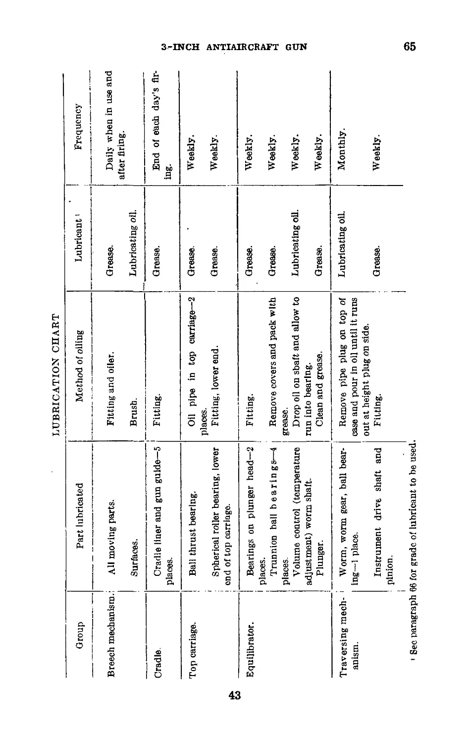
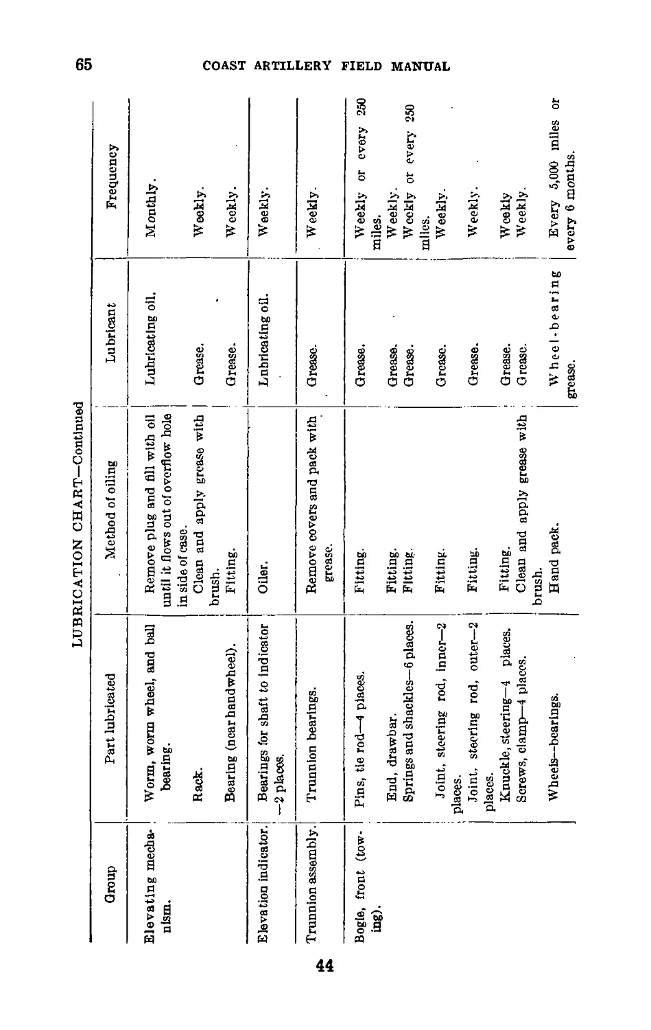
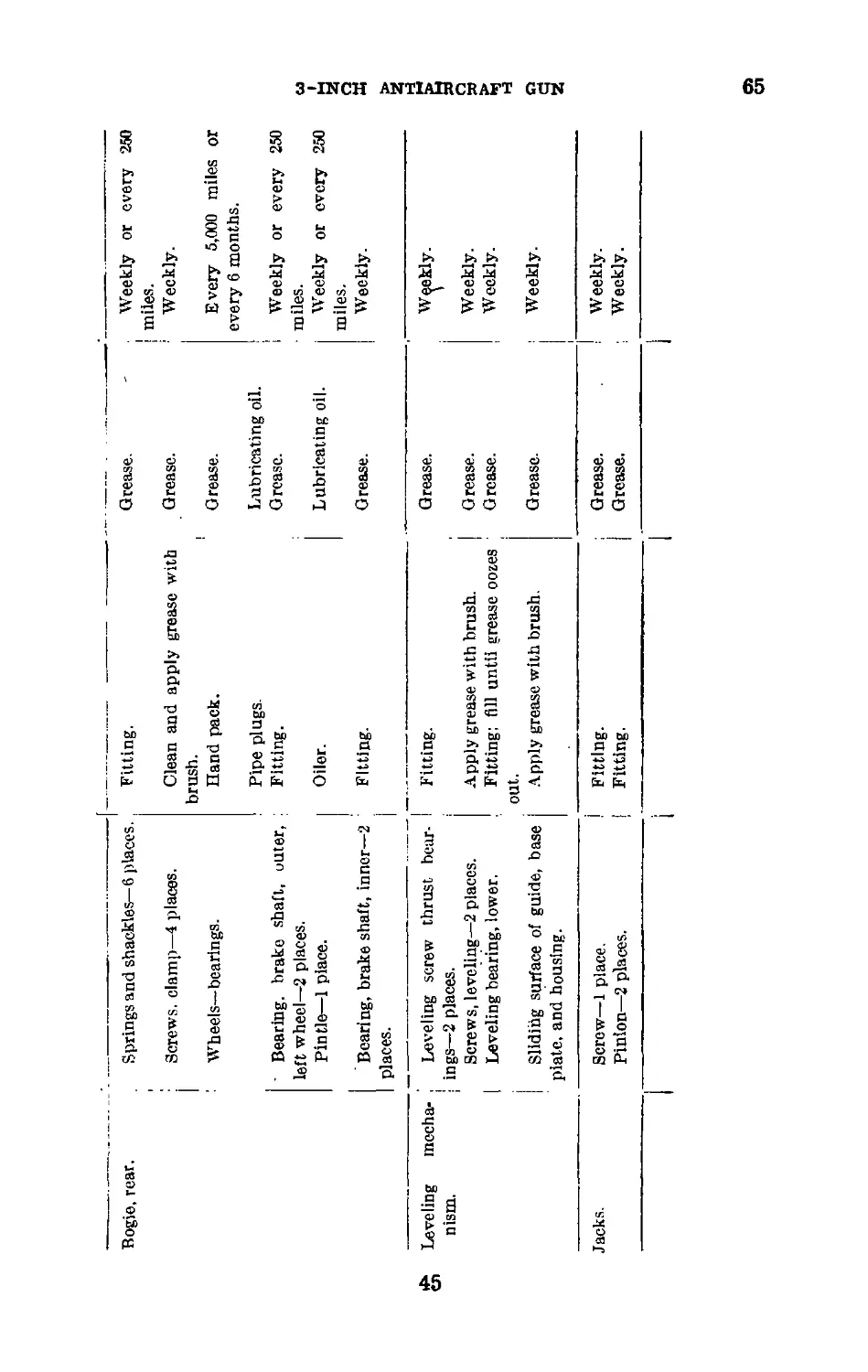
General_______________________________ 63 41
Instructions__________________________ 64 42
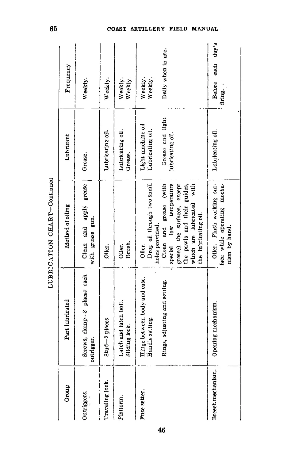
Lubrication chart_____________________ 65 42
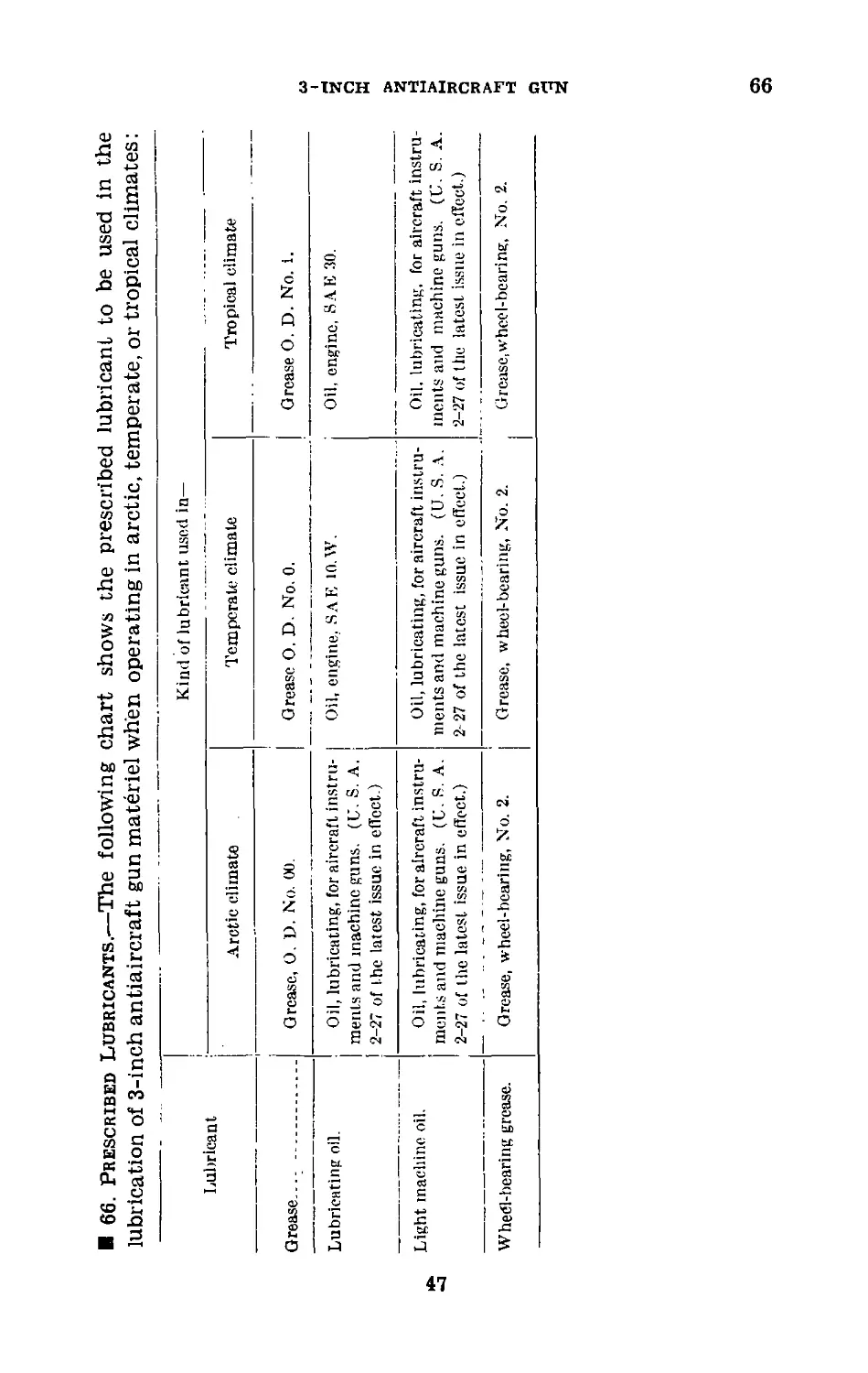
Prescribed lubricants_________________ 66 47
Chapter 9. 3-inch antiaircraft guns on fixed mounts.
Section I. 3-inch antiaircraft gun M1917 on
pedestal mount M1917.
To disassemble breech mechanism____ 67 48
To assemble breech mechanism________ 68 50
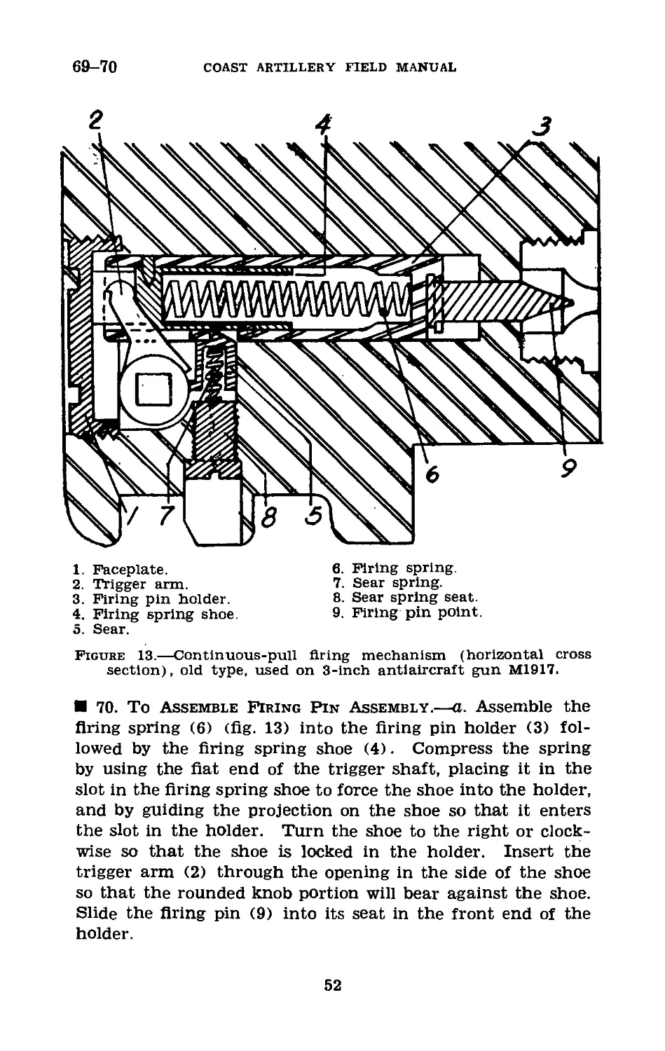
To disassemble firing mechanism____ 69 51
To assemble firing pin assembly_____ 70 52
To drain and refill recoil cylinder, _ 71 53
Lubrication ________________________ 72 54
П. 3-lnch antiaircraft gun M4 on ped-
estal mount.
To assemble and disassemble breech
mechanism _____________________________ 73 54
To drain and refill recoil cylinders. 74 54
Lubrication___________________________ 75 54
IV
TABLE OF CONTENTS
Chapter 10. M8 fuze setter. -
Section I. General. Paragraph Page
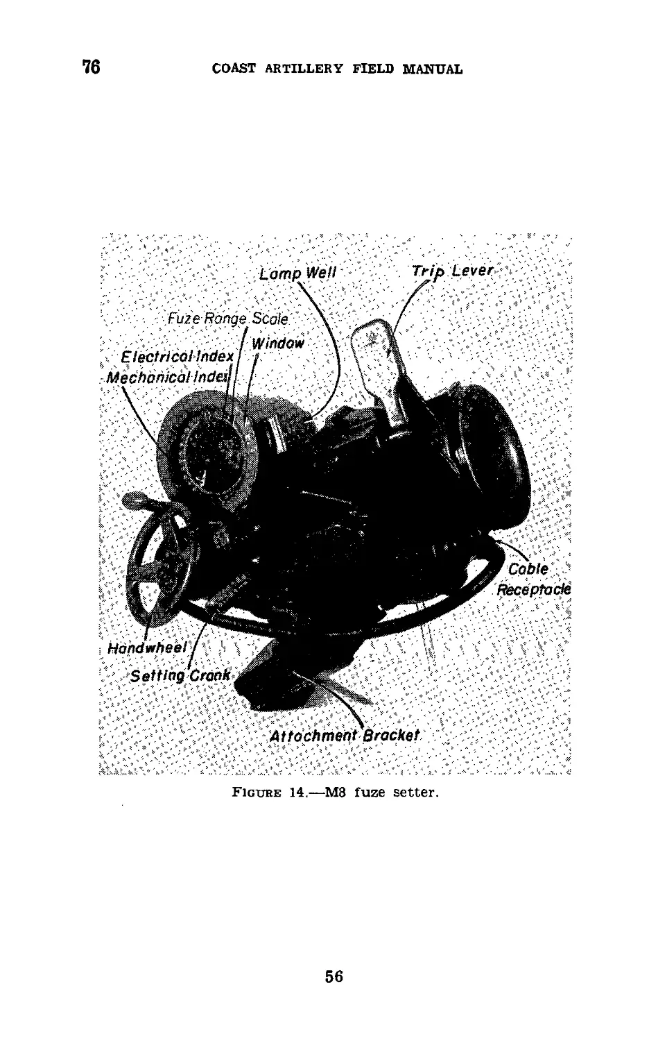
Description _________________________ 76 55
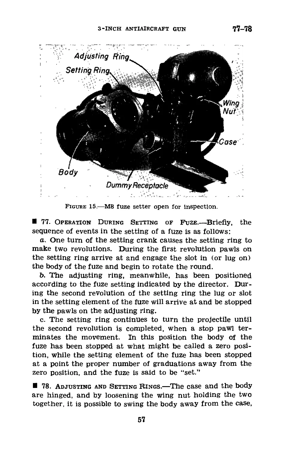
Operation during setting of fuze__ 77 57
Adjusting and setting rings_______ 78 57
II. Adjustments.
To change rings in fuze setter____ 79 58
To synchronize mechanical index
with fuze range scale on face
of indicator______________________' 80 59
To synchronize electrical index
with director__________________ 81 59
III. Care and preservation.
General_______________________________ 82 59
Chapter 11. Drill tables_________________________________ 61
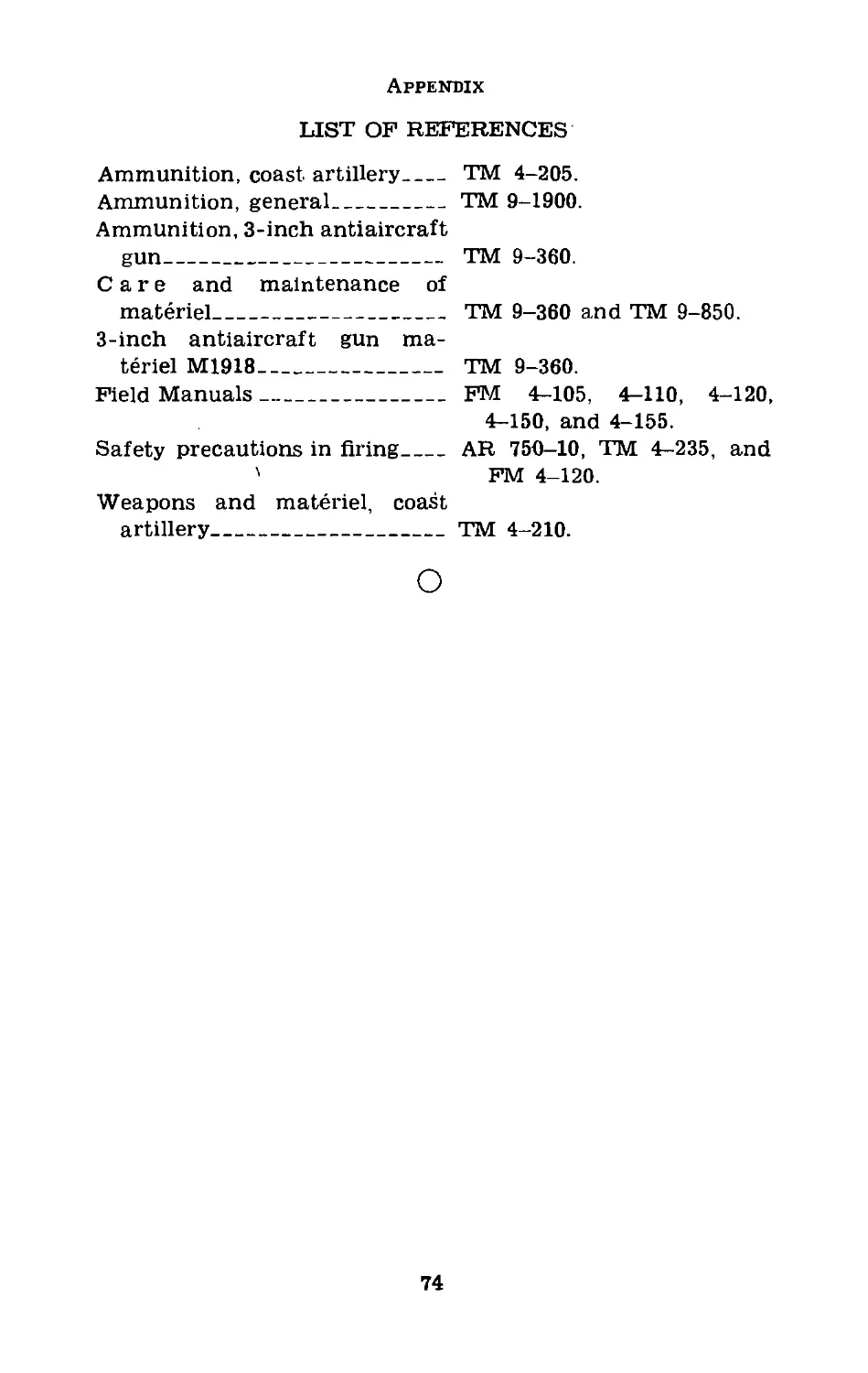
Appendix. List of references._____________________________ 74
FM 4-125
COAST ARTILLERY FIELD MANUAL
ANTIAIRCRAFT ARTILLERY
SERVICE OF THE PIECE
3-INCH AITIAIRCRAFT GUN
(This manual supersedes FM 4-125, May 27, 1940, including sec-
tion П, Training Circular No. 4, War Department, 1941.)
CHAPTER 1
GENERAL
1. Scope.—a. This manual prescribes a systematic proced-
ure to be followed by gun crews of 3-inch antiaircraft guns
manning materiel of the following types:
(1) The 3-inch antiaircraft guns M1917, M1917MI, and
М1917МП on the fixed mounts M1917, M1917MI, and
М1917МП.
(2) The 3-inch antiaircraft gun М3 on the mobile mounts
M2A1 and M2A2.
(3) The 3-inch antiaircraft gun M4 on the fixed mount
M3A1.
b. The matter contained in this manual is intended only
as a guide in the assignment of individuals and duties;
changes may be made to meet variations in the materiel
manned.
2. References.—The references listed in the appendix
should be consulted, especially those pertaining to ammuni-
tion and to the operation, care, and maintenance of materiel.
1
3-7
COAST ARTILLERY FIELD MANUAL
CHAPTER 2
ORGANIZATION OF GUN SECTION
3. Gun Section.—The gun section is a part of the firing
section, which consists of four gun sections and a machine-
gun and executive officer’s detail. Two artillery mechanics
are assigned to the firing section and are part of the machine-
gun and executive officer’s detail for purposes of supervision
and formation. Each antiaircraft gun is manned by a gun
section consisting of a gun squad and an ammunition squad.
The gun commander, who is included in the gun squad, serves
as chief Of section.
4. Gun Squad.—The gun squad (11 enlisted men) consists
of the gun commander (a sergeant), the fuze range setter
(a corporal), the gunner (a corporal), the azimuth setter,
the elevation setter, and 6 cannoneers numbered from 1 to 6,
inclusive. It includes the number of men required to man
the 3-inch antiaircraft gun (mobile or fixed).
5. Ammunition Squad, Mobile Units.—In mobile units the
ammunition squad consists of the chief of ammunition (a
corporal) and 9 cannoneers numbered from 7 to 15, inclusive.
Nos. 11, 12, and 13 are chauffeurs in addition to being can-
noneers. Nos. 14 and 15 are basics.
6. Ammunition Squad, Semimobile Units.—In semimobile
units the ammunition squad consists of the chief of ammuni-
tion (a corporal) and 6 cannoneers, numbered from 7 to 12,
inclusive.
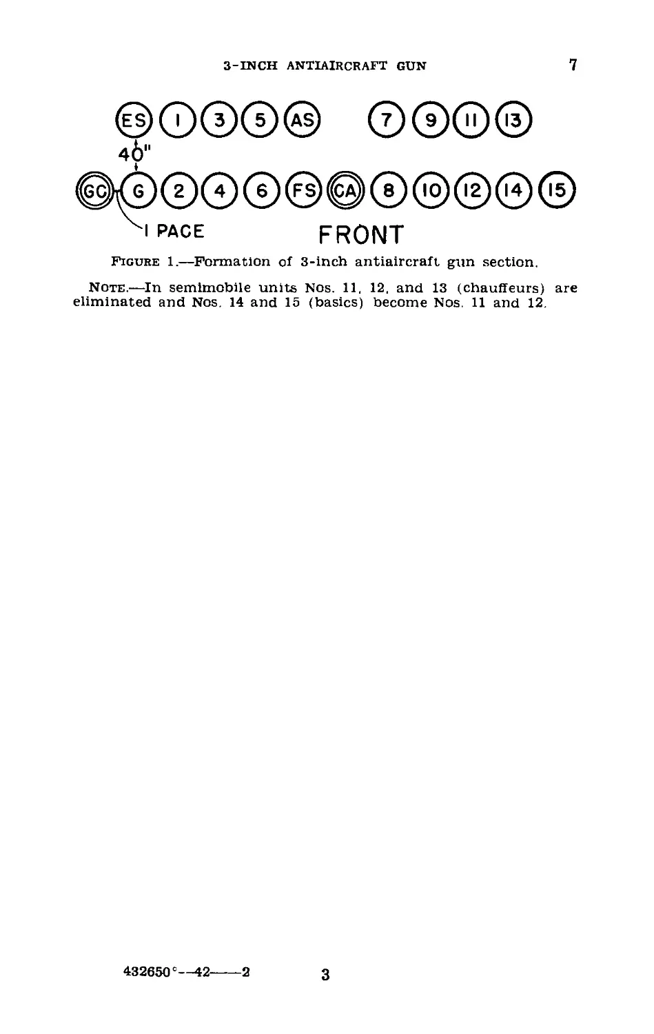
7. Formation (fig. 1).—The battery is formed as prescribed
in FM .4-120. The gun section assembles in two ranks with
4 inches between files and 40 inches between ranks. After
forming the section, the gun commander takes post in the
front rank 1 pace to the right of his section.
2
3-INCH ANTIAIRCRAFT GUN
7
Figure 1.—Formation of 3-inch antiaircraft gun section.
Note.—In semlmobile units Nos. 11. 12. and 13 (chauffeurs) are
eliminated and Nos. 14 and 15 (basics) become Nos. 11 and 12.
432650 е—42----2
3
8
COAST ARTILLERY FIELD MANUAL
CHAPTER 3
DUTIES OF PERSONNEL
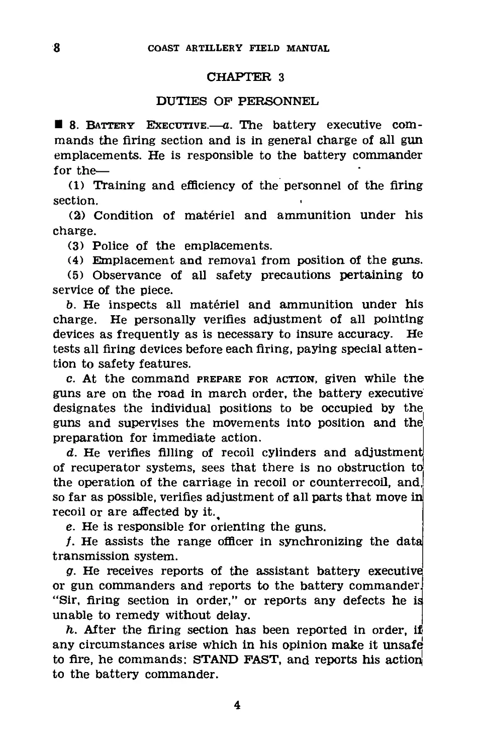
8. Battery Executive.—a. The battery executive com-
mands the firing section and is in general charge of all gun
emplacements. He is responsible to the battery commander
for the—
(1) Training and efficiency of the personnel of the firing
section.
(2) Condition of materiel and ammunition under his
charge.
(3) Police of the emplacements.
(4) Emplacement and removal from position of the guns.
(5) Observance of all safety precautions pertaining to
service of the piece.
b. He inspects all materiel and ammunition under his
charge. He personally verifies adjustment of all pointing
devices as frequently as is necessary to insure accuracy. He
tests all firing devices before each firing, paying special atten-
tion to safety features.
c. At the command prepare for action, given while the
guns are on the road in march order, the battery executive
designates the individual positions to be occupied by the
guns and supervises the movements into position and the
preparation for immediate action.
d. He verifies filling of recoil cylinders and adjustment
of recuperator systems, sees that there is no obstruction to
the operation of the carriage in recoil or counterrecoil, and,
so far as possible, verifies adjustment of all parts that move in
recoil or are affected by it.,
e. He is responsible for orienting the guns.
f. He assists the range officer in synchronizing the data
transmission system.
g. He receives reports of the assistant battery executive
or gun commanders and reports to the battery commander.
“Sir, firing section in order,” or reports any defects he is
unable to remedy without delay.
h. After the firing section has been reported in order, if
any circumstances arise which in his opinion make it unsafe
to fire, he commands: STAND FAST, and reports his action
to the battery commander.
4
3-INCH ANTIAIRCRAFT GUN
8-10
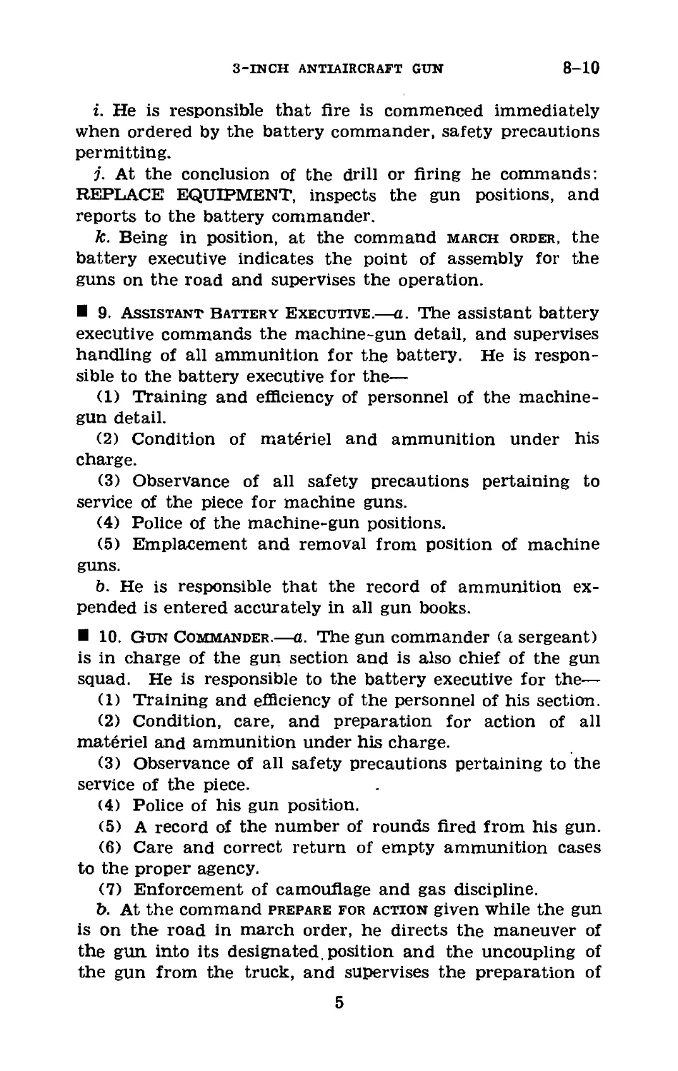
i. He is responsible that Are is commenced immediately
when ordered by the battery commander, safety precautions
permitting.
j. At the conclusion of the drill or firing he commands:
REPLACE EQUIPMENT, inspects the gun positions, and
reports to the battery commander.
k. Being in position, at the command march order, the
battery executive indicates the point of assembly for the
guns on the road and supervises the operation.
9. Assistant Battery Executive.—a. The assistant battery
executive commands the machine-gun detail, and supervises
handling of all ammunition for the battery. He is respon-
sible to the battery executive for the—
(1) Training and efficiency of personnel of the machine-
gun detail.
(2) Condition of materiel and ammunition under his
charge.
(3) Observance of all safety precautions pertaining to
service of the piece for machine guns.
(4) Police of the machine-gun positions.
(5) Emplacement and removal from position of machine
guns.
b. He is responsible that the record of ammunition ex-
pended is entered accurately in all gun books.
10. Gun Commander.—a. The gun commander (a sergeant)
is in charge of the gun section and is also chief of the gun
squad. He is responsible to the battery executive for the—
(1) Training and efficiency of the personnel of his section.
(2) Condition, care, and preparation for action of all
materiel and ammunition under his charge.
(3) Observance of all safety precautions pertaining to the
service of the piece.
(4) Police of his gun position.
(5) A record of the number of rounds fired from his gun.
(6) Care and correct return of empty ammunition cases
to the proper agency.
(7) Enforcement of camouflage and gas discipline.
b. At the command prepare for action given while the gun
is on the road in march order, he directs the maneuver of
the gun into its designated, position and the uncoupling of
the gun from the truck, and supervises the preparation of
5
10
COAST ARTILLERY FIELD MANUAL
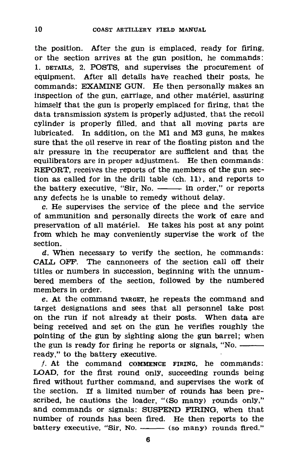
the position. After the gun is emplaced, ready for firing,
or the section arrives at the gun position, he commands:
1. details, 2. POSTS, and supervises the procurement of
equipment. After all details have reached their posts, he
commands: EXAMINE GUN. He then personally makes an
inspection of the gun, carriage, and other materiel, assuring
himself that the gun is properly emplaced for firing, that the
data transmission system is properly adjusted, that the recoil
cylinder is properly filled, and that all moving parts are
lubricated. In addition, on the Ml and М3 guns, he makes
sure that the oil reserve in rear of the floating piston and the
air pressure in the recuperator are sufficient and that the
equilibrators are in proper adjustment. He then commands:
REPORT, receives the reports of the members of the gun sec-
tion as called for in the drill table (ch. 11), and reports to
the battery executive, “Sir, No. ------- in order,” or reports
any defects he is unable to remedy without delay.
c. He supervises the service of the piece and the service
of ammunition and personally directs the work of care and
preservation of all materiel. He takes his post at any point
from which he may conveniently supervise the work of the
section.
d. When necessary to verify the section, he commands:
CALL OFF. The cannoneers of the section call off their
titles or numbers in succession, beginning with the unnum-
bered members of the section, followed by the numbered
members in order.
e. At the command target, he repeats the command and
target designations and sees that all personnel take post
on the run if not already at their posts. When data are
being received and set on the gun he verifies roughly the
pointing of the gun by sighting along the gun barrel; when
the gun is ready for firing he reports or signals, “No.-------
ready,” to the battery executive.
j. At the command commence firing, he commands:
LOAD, for the first round only, succeeding rounds being
fired without further command, and supervises the work of
the section. If a limited number of rounds has been pre-
scribed, he cautions the loader, “(So many) rounds only,”
and commands or signals: SUSPEND FIRING, when that
number of rounds has been fired. He then reports to the
battery executive, “Sir, No. ------ (so many) rounds fired.”
6
3-INCH ANTIAIRCRAFT GUN
10-11
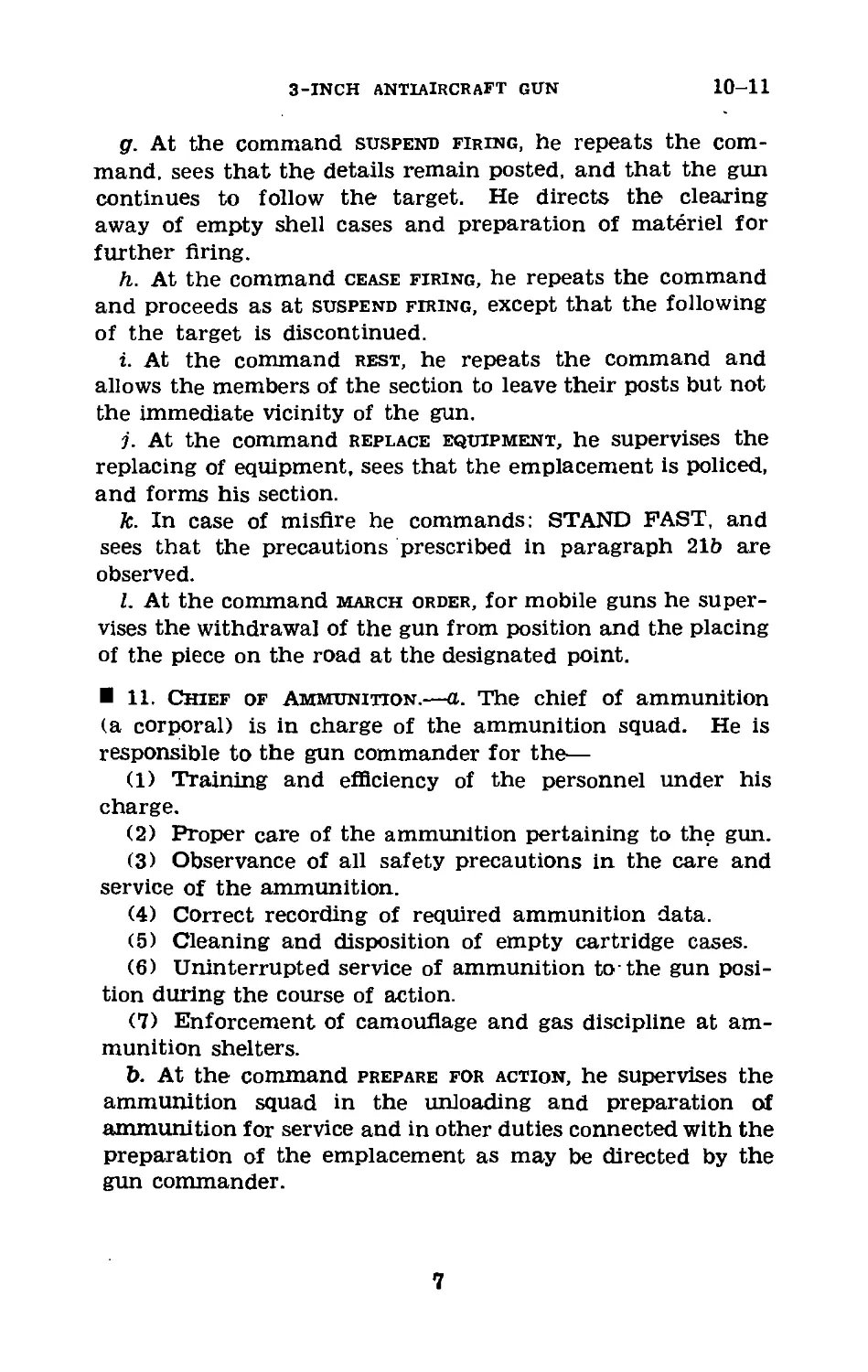
g. At the command suspend firing, he repeats the com-
mand. sees that the details remain posted, and that the gun
continues to follow the target. He directs the clearing
away of empty shell cases and preparation of materiel for
further firing.
h. At the command cease firing, he repeats the command
and proceeds as at suspend firing, except that the following
of the target is discontinued.
i. At the command rest, he repeats the command and
allows the members of the section to leave their posts but not
the immediate vicinity of the gun.
j. At the command replace equipment, he supervises the
replacing of equipment, sees that the emplacement is policed,
and forms his section.
k. In case of misfire he commands: STAND FAST, and
sees that the precautions prescribed in paragraph 21b are
observed.
I. At the command march order, for mobile guns he super-
vises the withdrawal of the gun from position and the placing
of the piece on the road at the designated point.
11. Chief of Ammunition.—a. The chief of ammunition
(a corporal) is in charge of the ammunition squad. He is
responsible to the gun commander for the—
(1) Training and efficiency of the personnel under his
charge.
(2) Proper care of the ammunition pertaining to the gun.
(3) Observance of all safety precautions in the care and
service of the ammunition.
(4) Correct recording of required ammunition data.
(5) Cleaning and disposition of empty cartridge cases.
(6) Uninterrupted service of ammunition to-the gun posi-
tion during the course of action.
(7) Enforcement of camouflage and gas discipline at am-
munition shelters.
b. At the command prepare for action, he supervises the
ammunition squad in the unloading and preparation of
ammunition for service and in other duties connected with the
preparation of the emplacement as may be directed by the
gun commander.
7
11-12
COAST ARTILLERY FIELD MANUAL
c. At the command 1. details, 2. POSTS, he posts the mem-
bers of the ammunition squad and assigns them duties to
facilitate ammunition handling.
d. At the command examine gun, he inspects the ammu-
nition for possible defects (especially the fuzes for missing
lugs, corrosion, and injury), gives the necessary instructions
for preparing and arranging the ammunition for firing, and
reports to the gun commander, “Ammunition service in
order,” or reports defects he is unable to remedy without
delay.
e. During practice or action he supervises the ammuni-
tion squad in replenishing the ammunition supply at the
gun position, in disposing of empty cases, and in the handling
and storing of any additional supply received. He should
be prepared at airtimes to furnish replacements for the gun
squad when members of that squad become casualties.
f. He is prepared to furnish information as to powder
temperature when called upon by the battery officers to
do so.
g. At the command replace equipment, he directs the am-
muntion squad in the securing and covering of all ammu-
nition pertaining to the gun, makes certain that all fuzes
that have been cut but not fired have been set back to posi-
tions of “safe,” helps in the police of the equipment, and
forms his squad unless otherwise directed.
h. At the command march order, he supervises the ammu-
nition squad in their normal duties in connection with pack-
ing and loading ammunition and in such other duties as
may be ordered by the gun commander.
12. Artillery Mechanics.—The chief artillery mechanic is
the custodian of the supplies pertaining to the emplace-
ments to which assigned. He is responsible to the battery
executive for the condition and serviceability of the supplies
and tools under his charge. He maintains an up-to-date
inventory of all tools, equipment, spare parts, and supplies
under his charge. He or his assistant issues such equipment,
tools, oils, paints, and cleaning materials to the members
of the gun sections as may be necessary for the service
and care of the guns and accessories. The artillery me-
chanics, assisted by members of the gun sections, make such
minor repairs as can be made with the means at hand.
8
3-INCH ANTIAIRCRAFT GUN
13-15
CHAPTER 4
NOTES ON SERVICE OF THE PIECE
13. General Instructions.—The service of the piece should
be conducted with dispatch and precision and with as few
orders as possible. Except for the necessary orders, reports,
and instructions, no talking should be permitted. Can-
noneers change positions at a run. Loading with dummy
ammunition and pointing the piece as for firing is the normal
practice at drills. The commands or signals elevate, de-
press, right, and left refer to the direction of motion of the
muzzle of the gun. Commands should be given in the pre-
scribed form but should be replaced by signals whenever
practicable.
14. Operation of Breech Mechanisms.—a. The breech
mechanisms on all guns discussed in this manual are fully
automatic. Inserting a cartridge trips the extractors and
allows the block to close. The breechblock is opened by the
action of the operating cam and the operating shaft in
counterrecoil.
b. The breech mechanisms are furnished with operating
handles and may be set for hand operation by rotating the
operating cam so that it does not come in contact with the
operating shaft. In normal operation the operating handle
is fastened to the shaft in such a way that when the handle
is rotated to the rear and down it causes the breechblock to
open. Movement of the handle back to the vertical position,
however, does not move the block. A clutch is provided to
fasten the operating handle rigidly to the shaft if desired.
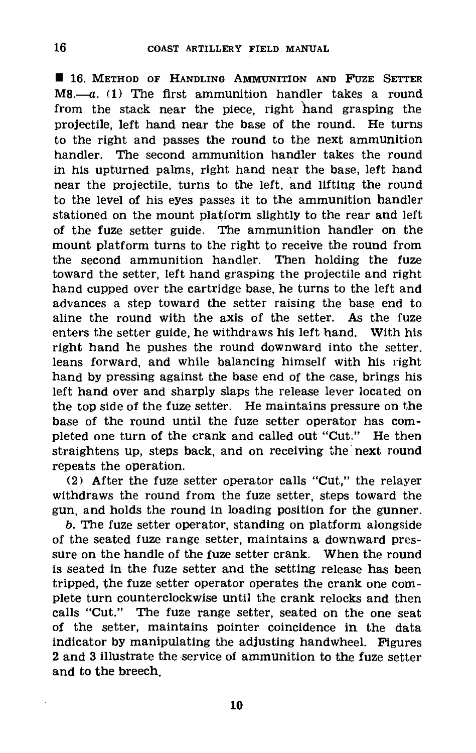
15. Method of Ramming Cartridge.—The cartridge is
rammed into the gun with the left hand. Place the gloved
fist on the base of the cartridge case, wrist practically vertical,
and sweep the round smartly into the breech, applying con-
tinuous pressure, until the closing breechblock knocks the
hand clear. The cartridge is rammed with the side of the
fist, the pressure being applied through the back of the
thumb and the side of the index finger. In this manner con-
tinuous pressure can be applied and the hand cannot be
caught in the breech. Figure 2 illustrates the proper method
of ramming.
9
16
COAST ARTILLERY FIELD MANUAL
16. Method of Handling Ammunition and Fuze Setter
M8.—a. (1) The first ammunition handler takes a round
from the stack near the piece, right band grasping the
projectile, left hand near the base of the round. He turns
to the right and passes the round to the next ammunition
handler. The second ammunition handler takes the round
in his upturned palms, right hand near the base, left hand
near the projectile, turns to the left, and lifting the round
to the level of his eyes passes it to the ammunition handler
stationed on the mount platform slightly to the rear and left
of the fuze setter guide. The ammunition handler on the
mount platform turns to the right to receive the round from
the second ammunition handler. Then holding the fuze
toward the setter, left hand grasping the projectile and right
hand cupped over the cartridge base, he turns to the left and
advances a step toward the setter raising the base end to
aline the round with the axis of the setter. As the fuze
enters the setter guide, he withdraws his left hand. With his
right hand he pushes the round downward into the setter,
leans forward, and while balancing himself with his right
hand by pressing against the base end of the case, brings his
left hand over and sharply slaps the release lever located on
the top side of the fuze setter. He maintains pressure on the
base of the round until the fuze setter operator has com-
pleted one turn of the crank and called out “Cut.” He then
straightens up, steps back, and on receiving the next round
repeats the operation.
(2) After the fuze setter operator calls “Cut,” the relayer
withdraws the round from the fuze setter, steps toward the
gun, and holds the round in loading position for the gunner.
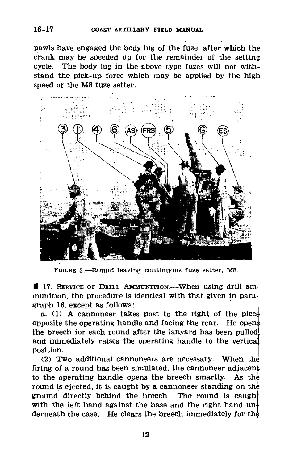
b. The fuze setter operator, standing on platform alongside
of the seated fuze range setter, maintains a downward pres-
sure on the handle of the fuze setter crank. When the round
is seated in the fuze setter and the setting release has been
tripped, the fuze setter operator operates the crank one com-
plete turn counterclockwise until the crank relocks and then
calls “Cut.” The fuze range setter, seated on the one seat
of the setter, maintains pointer coincidence in the data
indicator by manipulating the adjusting handwheel. Figures
2 and 3 illustrate the service of ammunition to the fuze setter
and to the breech.
10
3-INCH ANTIAIRCRAFT GUN
16
c. Points of particular importance in the foregoing pro-
cedures are as follows:
(1) When the round is in the fuze setter, pressure should
be maintained against the base of the cartridge case until
the call “Cut” is heard. The use of a heavy glove on the
right hand of the ammunition handler who maintains such
Pressure will greatly reduce the friction against his hand
produced by the rotating case.
(21 The release lever on the fuze setter should be tripped
with a glancing slap at the release lever so that the latter
will instantly recover and rearm itself before a full revolu-
tion of the crank has been completed.
(3) Sufficient downward pressure must be maintained on
the crank of the fuze setter so that the rotation will start the
instant the release is tripped. Otherwise the release lever
would have to be held down and the release would probably
fail to rearm in time for the crank at the end of its one revo-
lution. When setting original or reconditioned Mk. Ill or
Mk. IIIAI powder train fuzes, the setting crank of the fuze
setter should be turned at a moderate speed until the setting
432650°—42---з
11
16-17
COAST ARTILLERY FIELD MANUAL
pawls have engaged the body lug of the fuze, after which the
crank may be speeded up for the remainder of the setting
cycle. The body lug in the above type fuzes will not with-
stand the pick-up force which may be applied by the high
speed of the M8 fuze setter.
Figure 3.—Round leaving continuous fuze setter, M8.
17. Service of Drill Ammunition.—When using drill am-
munition, the procedure is identical with that given in para-
graph 16, except as follows:
a. (1) A cannoneer takes post to the right of the piece
opposite the operating handle and facing the rear. He open;
the breech for each round after the lanyard has been pulled
and immediately raises the operating handle to the vertica
position.
(2) Two additional cannoneers are necessary. When the
firing of a round has been simulated, the cannoneer adjaceni,
to the operating handle opens the breech smartly. As the
round is ejected, it is caught by a cannoneer standing on the
ground directly behind the breech. The round is caugh
with the left hand against the base and the right hand un-
derneath the case. He clears the breech immediately for the
12
3-INCH ANTIAIRCRAFT GUN
17-18
insertion of another round, and places the ejected dummy
round on the ammunition rack.
b. An alternate method is as follows: a cannoneer takes
position on the ground behind and slightly to the right of
the breech in such a way that he can catch each round as it
is ejected and pass it to another cannoneer. The round is
relayed from one cannoneer to another until it reaches the
ammunition rack. The gunner operates the operating handle
to open the breech after each round has been placed in the
breech and the breechblock returned to firing position. In
this method the lanyard is not pulled.
18. Elevating Gun (M1917, M1917MI, and М1917МП).—
When the gun mounted on the 3-inch antiaircraft gun mount
M1917 is depressed with a perceptible jar against the stop
which limits depression, it is very difficult to start the gun in
elevation. This is caused by the elevating worm becoming
locked with the worm gear. The elevation setter should
depress gently when approaching this stop.
13
19-23
COAST artillery field manual
CHAPTER 5
SAFETY PRECAUTIONS
19. General.—a. Safety precautions to be observed in time
of peace are discussed in FM 4-120.
b. The more important safety precautions pertaining to
the gun section are described in this chapter.
c. The principles indicated in the precautions referred to
in a and b should be applied under war conditions where
circumstances permit.
20. Ammunition.—a. All ammunition at the firing point
must be so placed that it will be protected against explosion
in case of an accident at the gun position. It should be in
a dry place and protected from the direct rays of the sun
by a tarpaulin or other covering. Erratic shots and possible
dangerously high powder pressures may result from over-
heated ammunition.
b. Any alteration of loaded ammunition, except in accord-
ance with specific instructions from the chief of the supply
service concerned, is hazardous and is therefore prohibited
Specifically, the alteration of time fuzes assembled to ammu-
nition is forbidden.
21. Misfires.—a. A misfire is said to occur when the piece
fails to discharge when an attempt to fire it has been made
b. In case of a misfire, at least three attempts to fire the
primer will be made. The breechblock will not be opened
until at least 2 minutes after the last attempt to fire the
piece, and the gun will be kept laid on a safe place in the
field of fire.
22. Fuzes.—a. When checking the accuracy of fuze setting
by cutting trial fuzes, do not cut the fuze on any one
projectile more than twice.
b- After a fuze has been set, if the round is not fired, it
must be set back to “safe” (powder train fuzes are set back
to S, and mechanical fuzes to position with “set” line on lower
cap in line with edge of slot in body). This is done by setting
the fuze setter to that reading and then resetting the fuze
23. Unloading Live Rounds.—If a round cannot be ex-
tracted in the normal manner, it should be fired, safety pre-
14
3-INCH ANTIAIRCRAFT GUN
23-24
cautions permitting. If this is impossible, it should be re-
moved under the direct supervision of an officer, a rammer
being used which bears only on the projectile and provides
for clearance around the fuze (see TM 9-360).
24. General Precautions for Drill and Firing.—a. No live
ammunition will be allowed near the emplacements except
when firing is to take place.
b. The gun will be unloaded except when firing or about
to fire.
c. Members of the gun section will be trained always to
pass in rear of the gun and well clear of the breech in going
from one side to the other.
15
25-27
COAST ARTILLERY FIELD MANUAL
CHAPTER 6
MAINTENANCE OF MATERIEL
Paragraphs
Section I. General________________________________25-28
II. Maintenance of particular parts and assemblies. _ 29-34
Section I
GENERAL
25. Care of Materiel.—The proper maintenance of ma-
teriel is the direct responsibility of battery personnel. The
gun and mount should be thoroughly cleaned and lubricated
at intervals not exceeding 2 weeks and as soon as possible
after firing. Care should be taken to keep all parts free
from rust, as rust is the starting point of serious injury. All
bearing surfaces, elevating racks and screws, and unpainted
parts must be kept clean at all times.
26. Instructions.—a. Disconnecting the gun from the
recoil mechanism will not be attempted by the using
personnel.
b. Replace and open cotter pins after replacing nuts.
c. Do not strike any metal parts directly with a hammer;
interpose a buffer of wood or copper.
d. Oil holes which have become clogged with oil should be
opened with a piece of wire. Wood should never be used
for this purpose, as splinters are likely to break off in the
hole.
e. As an aid to ready identification, grease and oil fittings
and oil holes are painted red. Oil holes have a red ring
painted around them.
f. In case the gun and carriage are to be stored or left
unused for any considerable length of time, all bright and
unpainted surfaces should be thoroughly cleaned with dry-
cleaning solvent so as to be free from rust, water, and lubri-
cating oil, and coated with rust-preventive compound.
Dry-cleaning solvent is used in preference to kerosene for
cleaning the materiel as it is difficult to remove all traces
of kerosene, the presence of which tends to cause the
formation of rust underneath the rust-preventive compound.
27. Daily Inspection.—When guns are in position a daily
check should be made by members of the gun section to dis-
16
3-INCH ANTIAIRCRAFT GUN
27-28
cover any parts which need cleaning, oiling, repair, or adjust-
ment. The inspection Is supervised by the gun commander.
The procedure is as follows:
a. Open and close breech to see that it operates freely, and
check its automatic closing mechanism.
b. Examine breech recess and bore to see that they are
clean.
c. See that the firing mechanism works freely and that the
firing pin is in serviceable condition.
d. Check amount of oil reserve present in recoil mechanism
and examine recoil system for oil leaks.
e. Check air pressure in recoil and equilibrator
mechanisms.
/. Elevate and depress the gun to see that the mechanism
operates easily and without binding or undue lost motion,
and that equilibrators are properly adjusted.
g. Traverse the gun to the right and to left through 360° to
see that the mechanism operates easily and that the data
transmission plug is in order.
h. See that sliding surfaces of the gun and cradle are clean
and well lubricated.
i. See that all working parts are properly lubricated.
j. See that tools and accessories are in good condition, that
they are in their proper places, and that none are missing.
fc. Check shafts and gears connecting data receivers to the
gun.
28. Weekly Inspection.—Each week, and more often if
amount of firing warrants, the gun and carriage should be
thoroughly inspected by the battery commander. The in-
structions given for daily inspection by the gun section should
be carried out and in addition the following directions should
be observed:
a. Examine bore with extreme care to see that erosion has
not set in. If there are any signs of erosion, that fact should
be reported.
b. Operate all moving parts and see that they work freely
and correctly.
c. Examine all nuts to see that they are tight and that
split pins are in place where required.
d. Examine data transmission system to see that it is in
proper operating condition.
17
28-31
COAST ARTILLERY FIELD MANUAL
e. Examine condition of paint.
f. Examine all small parts such as keys and hinges to see
that they are in serviceable condition.
Section П
MAINTENANCE OF PARTICULAR PARTS AND
ASSEMBLIES
29. Gun.—a. As soon as possible after firing, the bore
must be cleaned to remove all powder fouling and then
thoroughly oiled. Using the sponge covered with burlap,
wash the bore with a solution made by dissolving */2 to 1
pound of soda ash (depending on strength desired) to 1
gallon of boiling water. Special attention should be given
that portion of the bore extending from the origin of the
rifling to a point about 24 inches forward, as most of the
fouling takes place in that area. After cleaning the bore,
wipe it thoroughly dry, using the sponge covered with bur-
lap. Then oil the bore with a light coating of rust-preventive
compound applied with the slush brush.
b. The surfaces of the leveling plates sunk into the top
of the breech ring should be protected from injury. Tools
or other articles must never be laid upon them.
c. When the gun is not in use the various covers provided
for protecting it must be placed in position.
30. Breech Mechanism.—a. The breech mechanism should
be kept clean and well lubricated at all times with oil, engine
SAE 10 W or SAE 30 (depending on whether temperature i:
above or below 32° F.). The mechanism should be disas-
sembled periodically (and always immediately after firing)
and cleaned and oiled. In case the mechanism is to be left
unused for a considerable length of time all bright surface:
should be coated with rust-preventive compound.
b. Vigilance must be maintained to detect any abrasion:
forming on the pressure side of the wearing surfaces in the
various grooves of the breechblock and the breech recess
and on the trunnions of the extractors. The removal o:
such abrasions must be done at once by ordnance personnel.
31. Firing Mechanism.—a. The firing mechanism shoulc.
be disassembled frequently from the breechblock for the
purpose of cleaning and for oiling with light lubricating oil.
18
3-INCH ANTIAIRCRAFT GUN
31-32
b. The use of an oil that is thicker than authorized will
cause the mechanism to absorb the energy of the firing spring
and result in misfires. This is especially true in cold weather
when unsuitable oil congeals and becomes gummy.
32. Recoil Mechanism.—a. Under no circumstances will
an attempt be made to take the recoil mechanism apart.
Adjustment of the recoil valve (10) (fig. 10) may be under-
taken only by competent ordnance personnel; the removal of
the throttling valve cover by the using service is prohibited.
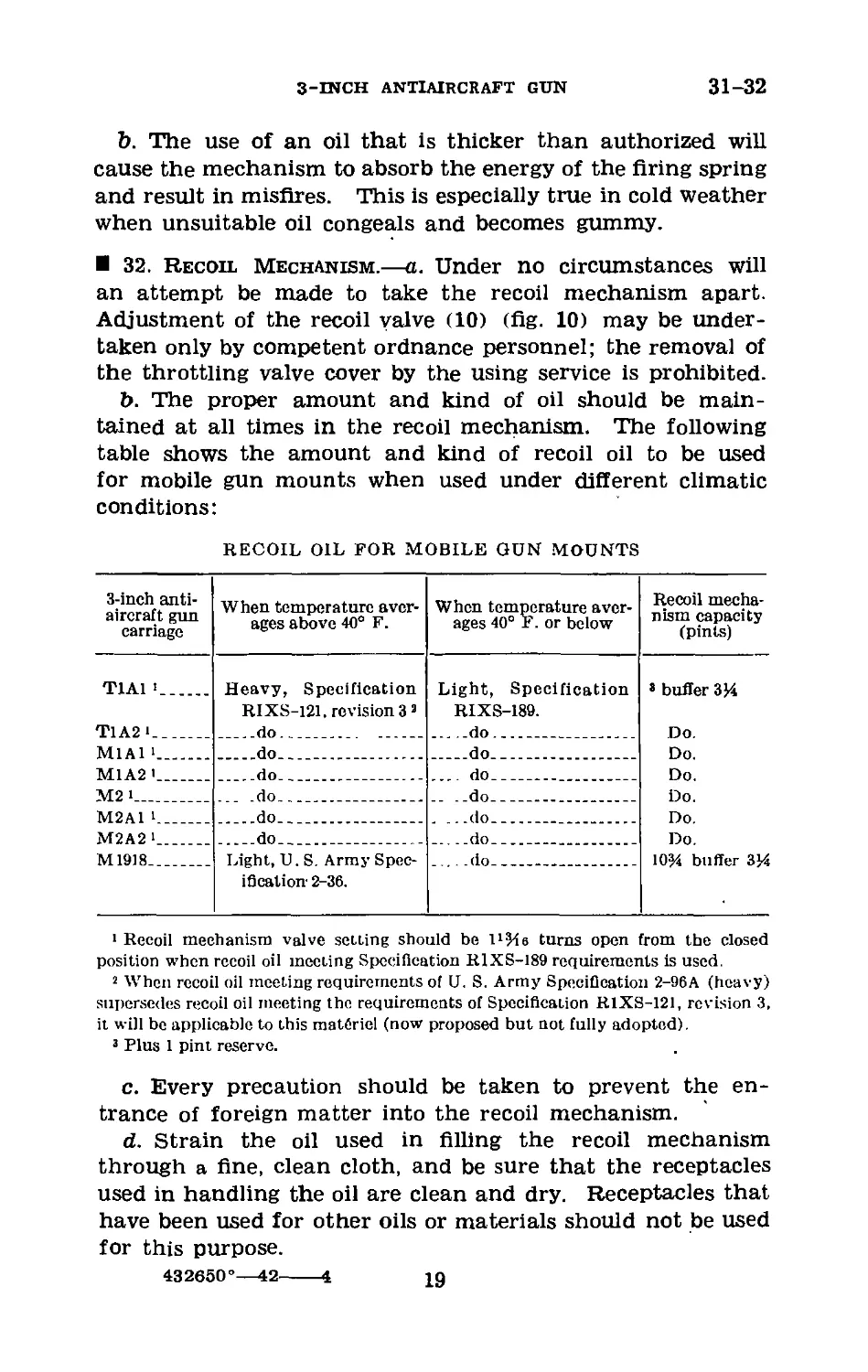
b. The proper amount and kind of oil should be main-
tained at all times in the recoil mechanism. The following
table shows the amount and kind of recoil oil to be used
for mobile gun mounts when used under different climatic
conditions:
RECOIL OIL FOR MOBILE GUN MOUNTS
3-inch anti-
aircraft gun
carriage
When temperature aver-
ages above 40° F.
When temperature aver-
ages 40° F. or below
Recoil mecha-
nism capacity
(pints)
T1A1 i
T1A2 *___
M1A1 i.__.
M1A2 ’___
М2 i_____
M2A1 i.___
M2A2 i_._.
M1918____
Heavy, Specification
RIXS-121, revision 33
____do___________ __
____do__________________
____do___________
... .do__________
____do__________________
____do__________________
Light, U.S. Army Spec-
ification 2-36.
Light, Specification
RIXS-189.
.....do________________
____do................
... do_________________
. ..do_________________
, ...do________________
____do_________________
....do_________________
8 buffer 3J4
Do.
Do.
Do.
Do.
Do.
Do.
10% buffer 3%
1 Recoil mechanism valve setting should be ll 2%e turns open from the closed
position when recoil oil meeting Specification RIXS-189 requirements is used.
2 When recoil oil meeting requirements of U. S. Army Specification 2-96A (heavy)
supersedes recoil oil meeting the requirements of Specification RIXS-121, revision 3,
it will be applicable to this materiel (now proposed but not fully adopted).
3 Plus 1 pint reserve.
c. Every precaution should be taken to prevent the en-
trance of foreign matter into the recoil mechanism.
d. Strain the oil used in filling the recoil mechanism
through a fine, clean cloth, and be sure that the receptacles
used in handling the oil are clean and dry. Receptacles that
have been used for other oils or materials should not be used
for this purpose.
432650°—42-------4 19
32-34
COAST ARTILLERY FIELD MANUAL
e. The gun commander should constantly verify the com-
plete return of the gun into battery. If the gun does not
return to battery, or does so irregularly by jerks or jumps, he
should command cease firing and look for the cause.
33. Gun Slides.—The gun slides will be thoroughly cleaned
frequently and covered with a film of grease, general purpose.
No. 0.
34. Mount.—The exposed portions of the elevating rack,
and on mobile mounts the exposed parts of the leveling
screws and guides, will be kept clean and covered with a film
of grease. Great care will be taken to make sure that the
traversing and elevating mechanisms are clean and properly
lubricated.
20
3-INCH ANTIAIRCRAFT GUN
35-36
CHAPTER 7
EMPLACEMENT AND PREPARATION FOR MARCH OF
М3 GUN ON M2A1 OR M2A2 MOUNT
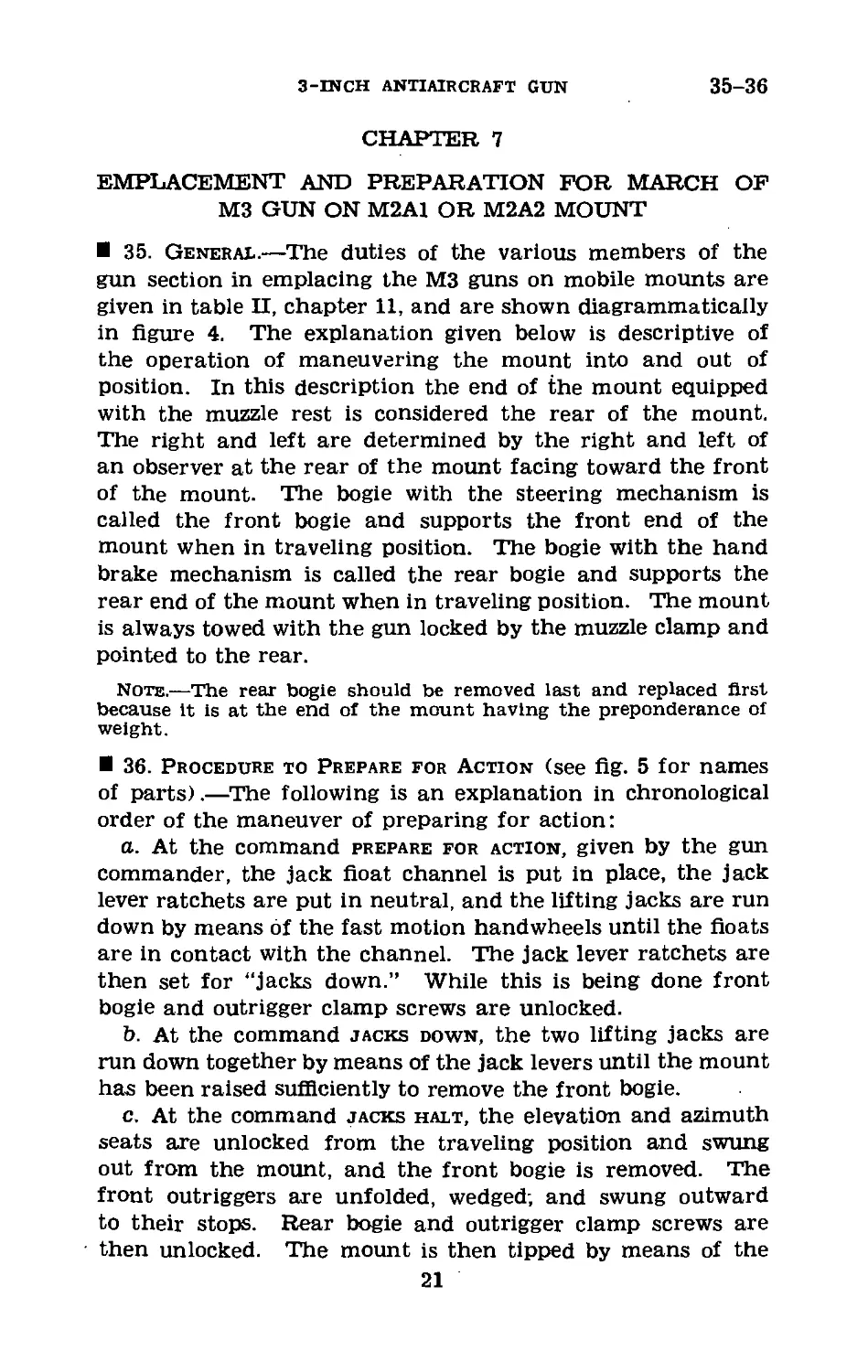
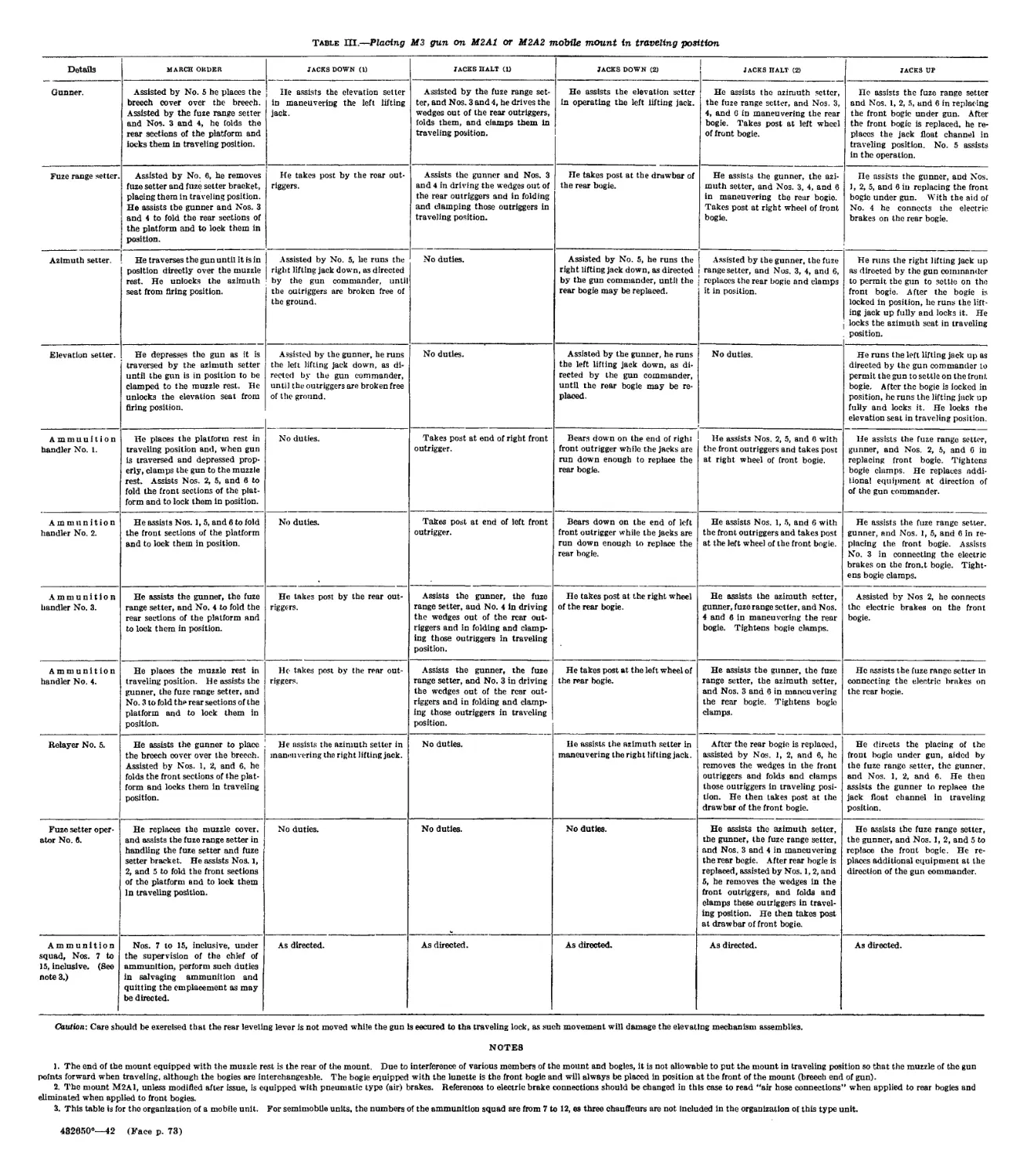
35. General.—The duties of the various members of the
gun section in emplacing the М3 guns on mobile mounts are
given in table П, chapter 11, and are shown diagrammatically
in figure 4. The explanation given below is descriptive of
the operation of maneuvering the mount into and out of
position. In this description the end of the mount equipped
with the muzzle rest is considered the rear of the mount.
The right and left are determined by the right and left of
an observer at the rear of the mount facing toward the front
of the mount. The bogie with the steering mechanism is
called the front bogie and supports the front end of the
mount when in traveling position. The bogie with the hand
brake mechanism is called the rear bogie and supports the
rear end of the mount when in traveling position. The mount
is always towed with the gun locked by the muzzle clamp and
pointed to the rear.
Note.—The rear bogie should be removed last and replaced first
because it is at the end of the mount having the preponderance of
weight.
36. Procedure to Prepare for Action (see fig. 5 for names
of parts).—The following is an explanation in chronological
order of the maneuver of preparing for action:
a. At the command prepare for action, given by the gun
commander, the jack float channel is put in place, the jack
lever ratchets are put in neutral, and the lifting jacks are run
down by means of the fast motion handwheels until the floats
are in contact with the channel. The jack lever ratchets are
then set for “jacks down.” While this is being done front
bogie and outrigger clamp screws are unlocked.
b. At the command jacks down, the two lifting jacks are
run down together by means of the jack levers until the mount
has been raised sufficiently to remove the front bogie.
c. At the command jacks halt, the elevation and azimuth
seats aj’e unlocked from the traveling position and swung
out from the mount, and the front bogie is removed. The
front outriggers are unfolded, wedged; and swung outward
to their stops. Rear bogie and outrigger clamp screws are
then unlocked. The mount is then tipped by means of the
21
36-37
COAST ARTILLERY FIELD MANUAL
unfolded outriggers, and the rear bogie is removed. The
rear outriggers are then unfolded, wedged, and swung outward
to their stops.
37. Duties of Gun Commander in Emplacing Mount.—At
the command prepare for action, the gun commander re-
peats the command, directs the maneuvering of the gun
into the designated place and the uncoupling of the gun
from its truck, and supervises the emplacing of the gun.
When both lifting jacks are down with the floats in contact
22
3-INCH ANTIAIRCRAFT GUN
37-38
with the jack float channel and the bogie clamp screws
are released, he commands: JACKS DOWN. After the mount
has been raised sufficiently to remove the front bogie, he
commands: JACKS HALT. When the bogies have been
withdrawn and the outriggers unfolded, wedged, and swung
to their stops, he commands: JACKS UP, and sees that the
mount is kept level during the operation. When the mount
is resting on the ground, he directs the details of complet-
ing the emplacement and leveling the mount.
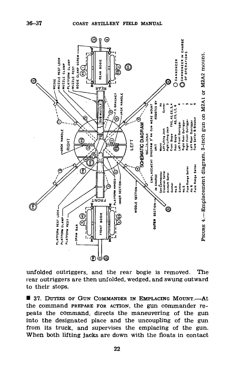
1. Lunette.
2. Outrigger, intermediate sec-
tion.
3. Outrigger, outer section.
4. Platform.
5. Gun (М3).
6. Platform traveling support
and gun lock.
7. Rear (trailing) bogie.
8. Bogie clamp screws.
9. Platform support bracket.
10. Pedestal spade.
11. Jack.
12. Front (towing) bogie.
13. Jack ratchet wrench.
Figure 5.—3-inch antiaircraft gun М3
position.
on M2A1 mount in traveling
38. Procedure to Take Up March Order.—It may be
stated as a general principle that the details handle the same
elements of materiel in preparing the gun for the road (march
order) as they handle in preparing it for firing. The follow-
23
38-39
COAST artillery field manual
ing is an explanation in chronological order of the maneuver
of taking up march order:
a. At the command march order, given by the gun com-
mander, the fuze setter and fuze setter bracket are removed
from their firing positions and replaced in their traveling
positions, and the azimuth and elevation seats are unlocked
from their firing positions. The muzzle and platform rests
are replaced and locked into their traveling positions, and
the gun is traversed and depressed until the muzzle clamp
can be locked. The platform sections are unlocked from their
firing positions, folded up, and locked to the muzzle and plat-
form rests. The lifting jack lever ratchets are shifted, and
at the command jacks down the jacks are run down until
the mount has been raised sufficiently to break the outriggers
loose from the ground. At the command jacks halt, the
wedges are driven from the rear outriggers, which are folded,
swung against the mount, and locked.
b. At the further command, jacks down, both lifting jacks
are run down together until the mount has been raised suffi-
ciently to allow replacing of the bogies.
c. At the command jacks halt, the lifting jacks are
stopped and the rear bogie is run into position and locked
to the mount. The front outriggers are then folded, swung
against the mount, and locked. The front bogie is then
run into position.
d. At the command jacks up, the mount is lowered until
it rests on the front bogie, and is locked thereto. If the
mount is equipped with air brakes (M1A1 and M2A1 mounts),
the rear bogie is coupled to the mount air line. When the
mount is equipped with electric brakes (M2A2 mount), the
electric cable is connected to the sockets in each of the
bogies. The jacks are then raised by means of the fast
motion handwheels until the stops are reached. The jack
float channel and the azimuth and elevation seats are secured
in their traveling positions.
39. Duties of Gun Commander in Taking Up March Or-
der.—At the command march order, the gun commander
repeats the command and supervises the maneuver. After
the platform sections have been locked in their traveling
positions, he commands: JACKS DOWN. When the outrig-
gers are broken loose from the ground, he commands: JACKS
24
3-INCH ANTIAIRCRAFT GUN
39-40
HALT. After the rear outriggers have been locked in their
traveling position, he commands: JACKS DOWN. When the
mount has been raised sufficiently to allow replacing the
bogies, he commands: JACKS HALT. When the bogies have
been locked into position, he commands: JACKS UP. He
then directs the details of completing the maneuver and
the moving of the gun to its designated place in the column.
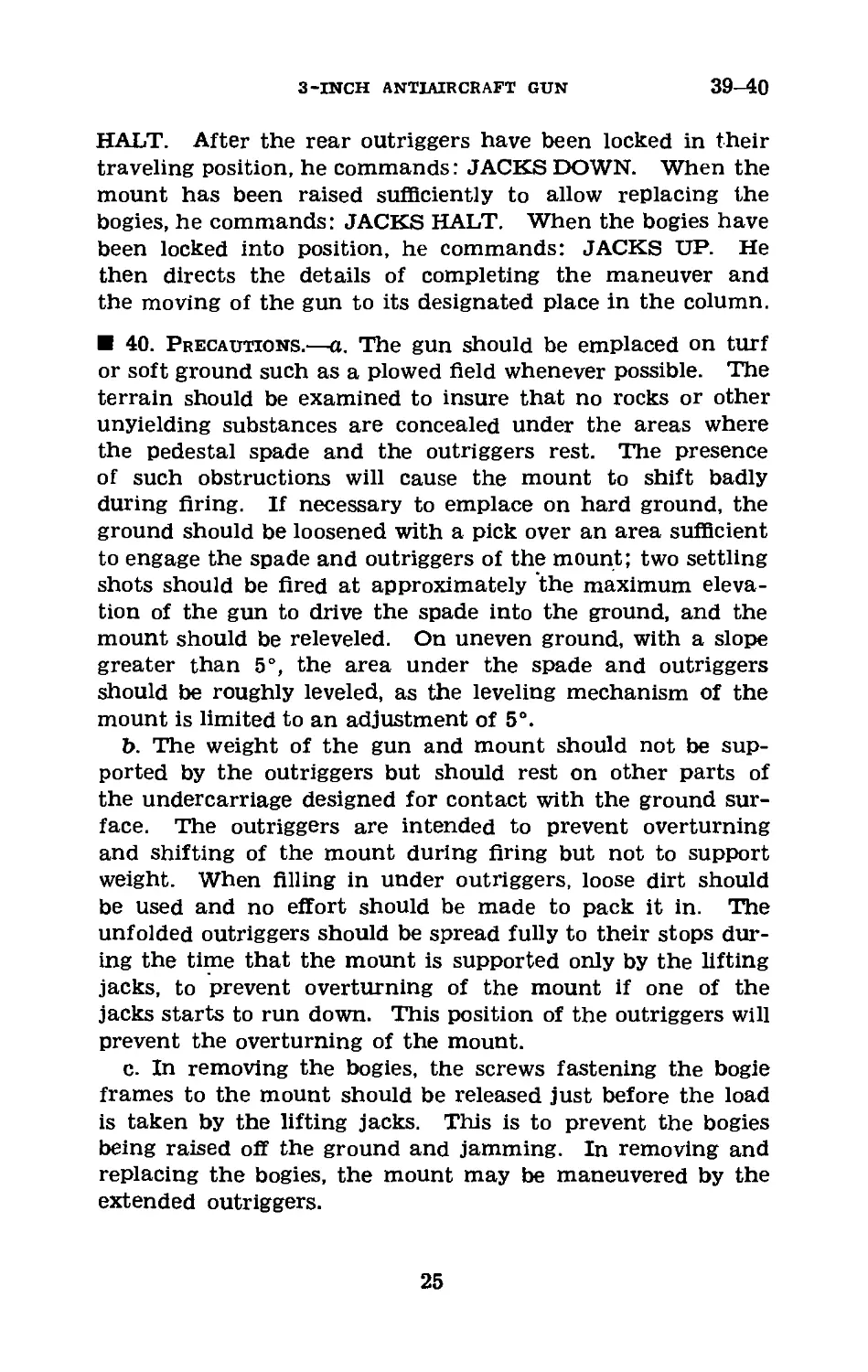
40. Precautions.—a. The gun should be emplaced on turf
or soft ground such as a plowed field whenever possible. The
terrain should be examined to insure that no rocks or other
unyielding substances are concealed under the areas where
the pedestal spade and the outriggers rest. The presence
of such obstructions will cause the mount to shift badly
during firing. If necessary to emplace on hard ground, the
ground should be loosened with a pick over an area sufficient
to engage the spade and outriggers of the mount; two settling
shots should be fired at approximately the maximum eleva-
tion of the gun to drive the spade into the ground, and the
mount should be releveled. On uneven ground, with a slope
greater than 5°, the area under the spade and outriggers
should be roughly leveled, as the leveling mechanism of the
mount is limited to an adjustment of 5°.
b. The weight of the gun and mount should not be sup-
ported by the outriggers but should rest on other parts of
the undercarriage designed for contact with the ground sur-
face. The outriggers are intended to prevent overturning
and shifting of the mount during firing but not to support
weight. When filling in under outriggers, loose dirt should
be used and no effort should be made to pack it in. The
unfolded outriggers should be spread fully to their stops dur-
ing the time that the mount is supported only by the lifting
jacks, to prevent overturning of the mount if one of the
jacks starts to run down. This position of the outriggers will
prevent the overturning of the mount.
c. In removing the bogies, the screws fastening the bogie
frames to the mount should be released just before the load
is taken by the lifting jacks. This is to prevent the bogies
being raised off the ground and jamming. In removing and
replacing the bogies, the mount may be maneuvered by the
extended outriggers.
25
40
COAST ARTILLERY field manual
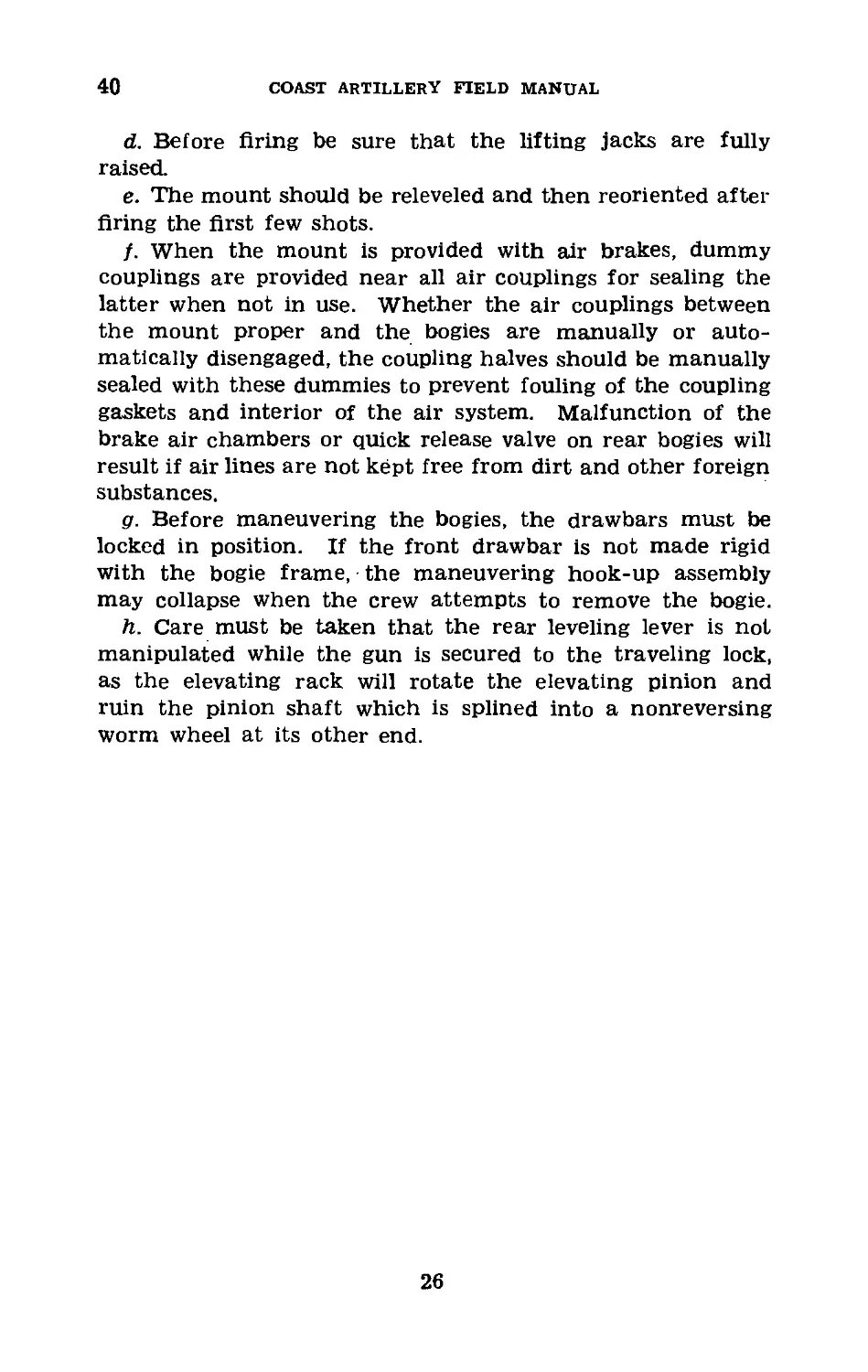
d. Before firing be sure that the lifting jacks are fully
raised.
e. The mount should be releveled and then reoriented after
firing the first few shots.
f. When the mount is provided with air brakes, dummy
couplings are provided near all air couplings for sealing the
latter when not in use. Whether the air couplings between
the mount proper and the bogies are manually or auto-
matically disengaged, the coupling halves should be manually
sealed with these dummies to prevent fouling of the coupling
gaskets and interior of the air system. Malfunction of the
brake air chambers or quick release valve on rear bogies will
result if air lines are not kept free from dirt and other foreign
substances.
g. Before maneuvering the bogies, the drawbars must be
locked in position. If the front drawbar is not made rigid
with the bogie frame, the maneuvering hook-up assembly
may collapse when the crew attempts to remove the bogie.
h. Care must be taken that the rear leveling lever is not
manipulated while the gun is secured to the traveling lock,
as the elevating rack will rotate the elevating pinion and
ruin the pinion shaft which is splined into a nonreversing
worm wheel at its other end.
26
3-INCH ANTIAIRCRAFT GUN
41-43
CHAPTER 8
3-INCH ANTIAIRCRAFT GUN М3 ON MOBILE MOUNT
Paragraphs
Section I. General_________________________________________ 41
П. Disassembly of breech and firing mechanisms_____42-46
Ш. Assembly of breech and firing mechanisms_________47-53
IV. Check and replacement of oil and gas in re-
cuperator and equilibrators__________________ 54-61
V. Installation of chain connecting floats of Jacks. _ 62
VT. Lubrication_____________________________________63-66
Section I
GENERAL
41. General.—This chapter contains special information
for the use of gun crews of antiaircraft batteries manning М3
guns on mobile mount. It is intended that the instructions
be used as a guide in the proper care and handling of this
particular type of materiel.
Section II
DISASSEMBLY OF BREECH AND FIRING MECHANISMS
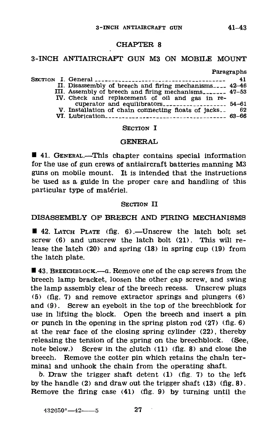
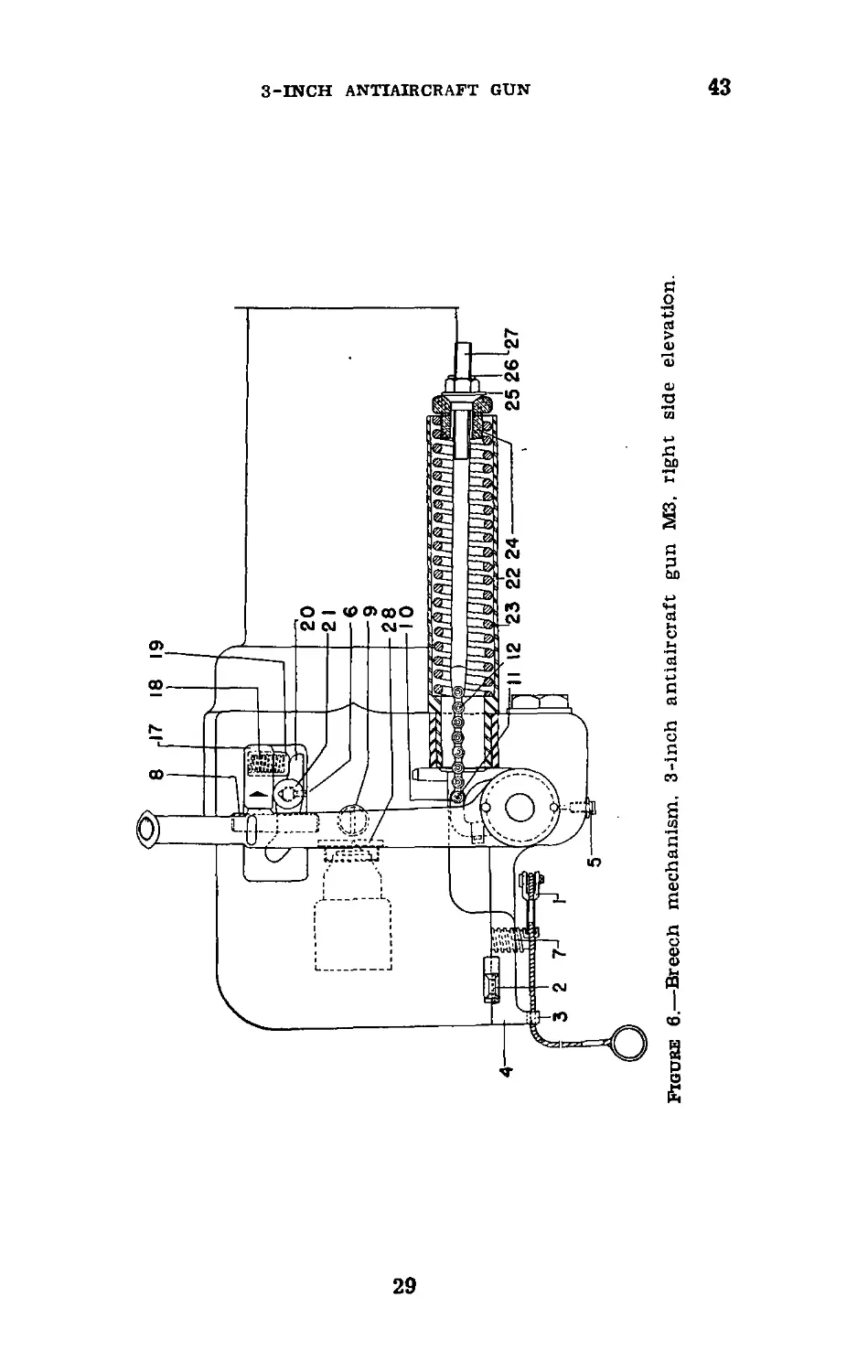
42. Latch Plate (fig. 6).—Unscrew the latch bolt set
screw (6) and unscrew the latch bolt (21). This will re-
lease the latch (20) and spring (18) in spring cup (19) from
the latch plate.
43. Breechblock.—a. Remove one of the cap screws from the
breech lamp bracket, loosen the other cap screw, and swing
the lamp assembly clear of the breech recess. Unscrew plugs
(5) (fig. 7) and remove extractor springs and plungers (6)
and (9). Screw an eyebolt in the top of the breechblock for
use in lifting the block. Open the breech and insert a pin
or punch in the opening in the spring piston rod (27) (fig. 6)
at the rear face of the closing spring cylinder (22), thereby
releasing the tension of the spring on the breechblock. (See,
note below.) Screw in the clutch (11) (fig. 8) and close the
breech. Remove the cotter pin which retains the chain ter-
minal and unhook the chain from the operating shaft.
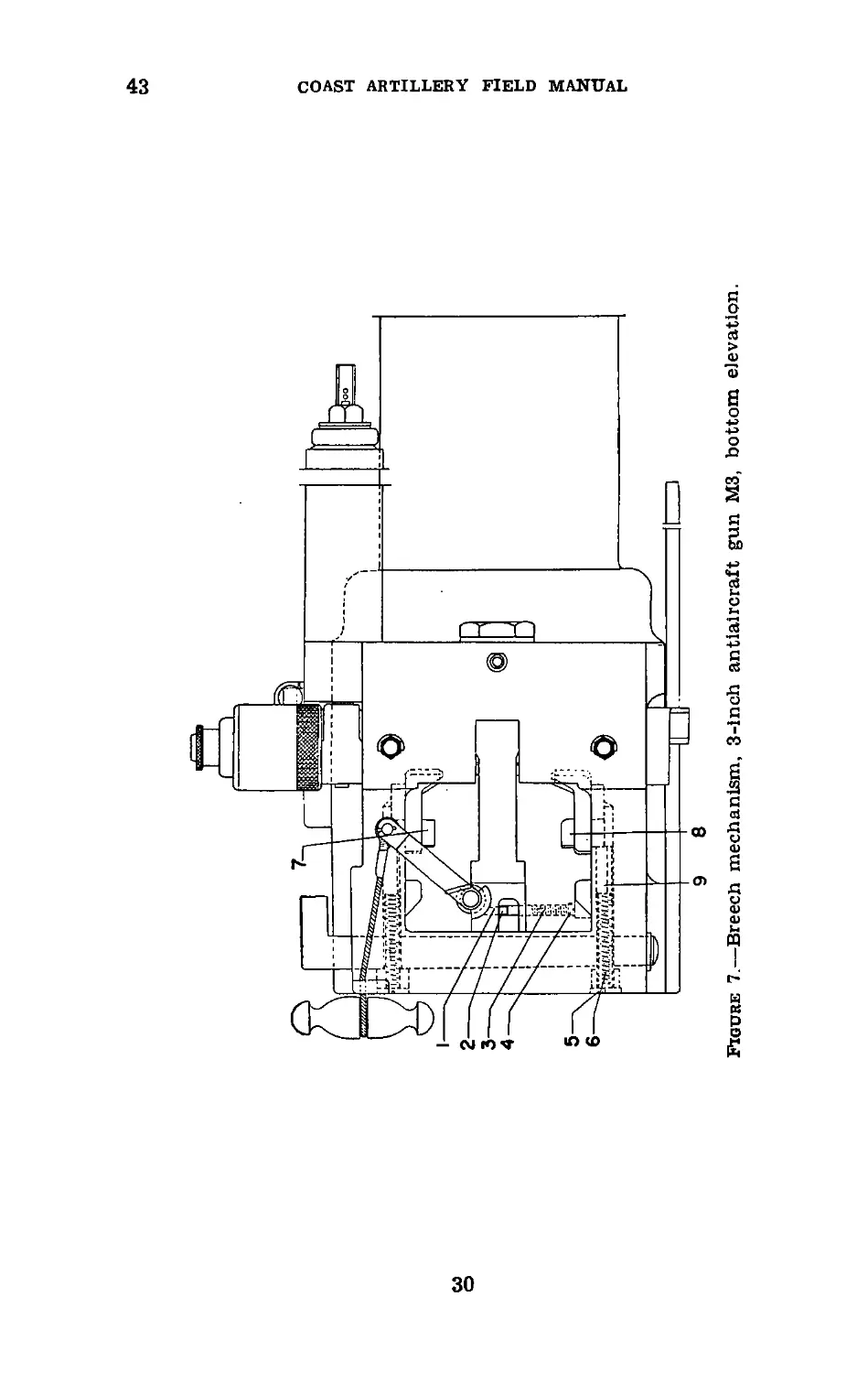
b. Draw the trigger shaft detent (1) (fig. 7) to the left
by the handle (2) and draw out the trigger shaft (13) (fig. 8).
Remove the firing case (41) (fig. 9) by turning until the
432650°—42----5
27
43
COAST ARTILLERY FIELD MANUAL
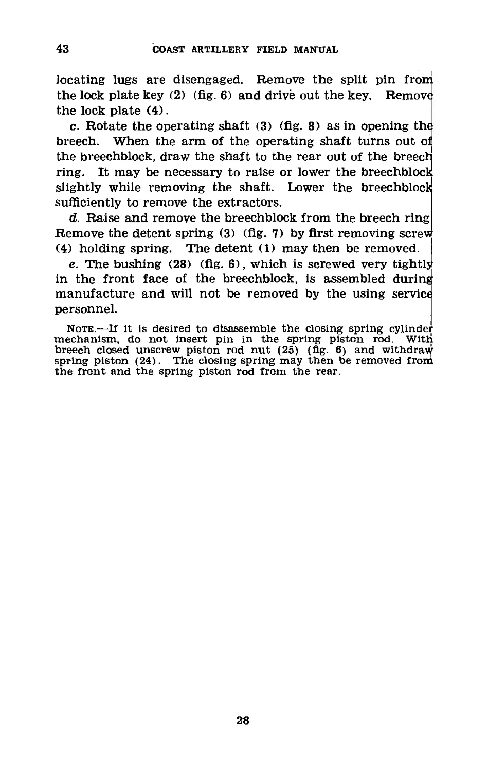
locating lugs are disengaged. Remove the split pin from
the lock plate key (2) (fig. 6) and drive out the key. Remove
the lock plate (4).
c. Rotate the operating shaft (3) (fig. 8) as in opening the
breech. When the arm of the operating shaft turns out ol
the breechblock, draw the shaft to the rear out of the breect
ring. It may be necessary to raise or lower the breechblock
slightly while removing the shaft. Lower the breechblock
sufficiently to remove the extractors.
d. Raise and remove the breechblock from the breech ring
Remove the detent spring (3) (fig. 7) by first removing screw
(4) holding spring. The detent (1) may then be removed.
e. The bushing (28) (fig. 6), which is screwed very tightlj
in the front face of the breechblock, is assembled during
manufacture and will not be removed by the using service
personnel.
Note.—If it is desired to disassemble the closing spring cylinder
mechanism, do not insert pin in the spring piston rod. Witt
breech closed unscrew piston rod nut (25) (fig. 6) and withdraw
spring piston (24). The closing spring may then be removed fron.
the front and the spring piston rod from the rear.
28
Figure 6.—Breech mechanism, 3-inch antiaircraft gun М3, right side elevation.
-INCH ANTIAIRCRAFT GUN
w
ы
9 8
Figure 7.—Breech mechanism, 3-inch antiaircraft gun М3, bottom elevation.
COAST ARTILLERY FIELD MANUAL
3-INCH ANTIAIRCRAFT GUN
43
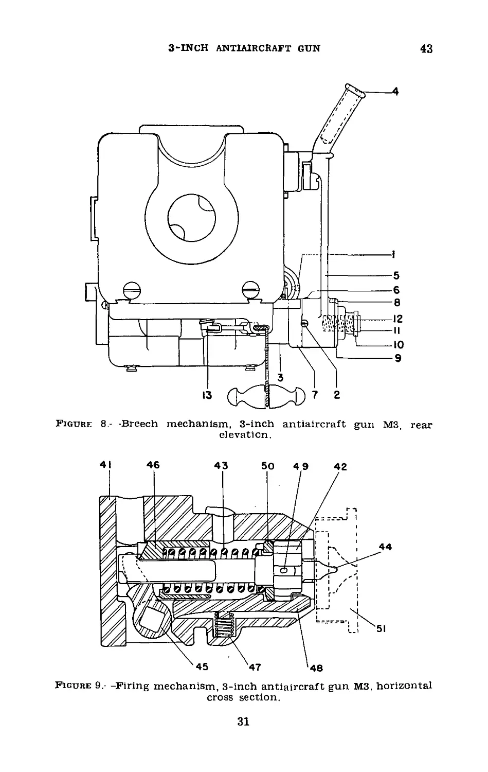
Figure 8,- -Breech mechanism, 3-inch antiaircraft gun М3, rear
elevation.
Figure 9,- -Firing mechanism, 3-inch antiaircraft gun М3, horizontal
cross section.
31
44-47
COAST ARTILLERY FIELD MANUAL
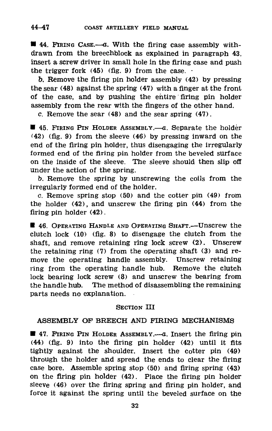
44. Firing Case.—a. With the firing case assembly with-
drawn from the breechblock as explained in paragraph 43,
insert a screw driver in small hole in the firing case and push
the trigger fork (45) (fig. 9) from the case. •
b. Remove the firing pin holder assembly (42) by pressing
the sear (48) against the spring (47) with a finger at the front
of the case, and by pushing the entire firing pin holder
assembly from the rear with the fingers of the other hand.
c. Remove the sear (48) and the sear spring (47).
45. Firing Pin Holder Assembly.—a. Separate the holder
<42) (fig. 9) from the sleeve (46) by pressing inward on the
end of the firing pin holder, thus disengaging the irregularly
formed end of the firing pin holder from the beveled surface
on the inside of the sleeve. The sleeve should then slip off
under the action of the spring.
b. Remove the spring by unscrewing the coils from the
irregularly formed end of the holder.
c. Remove spring stop (50) and the cotter pin (49) from
the holder (42), and unscrew the firing pin (44) from the
firing pin holder (42).
46. Operating Handle and Operating Shaft.—Unscrew the
clutch lock (10) (fig. 8) to disengage the clutch from the
shaft, and remove retaining ring lock screw (2). Unscrew
the retaining ring (7) from the operating shaft (3) and re-
move the operating handle assembly. Unscrew retaining
ring from the operating handle hub. Remove the clutch
lock bearing lock screw (8) and unscrew the bearing from
the handle hub. The method of disassembling the remaining
parts needs no explanation.
Section III
ASSEMBLY OF BREECH AND FIRING MECHANISMS
47. Firing Pin Holder Assembly.—a. Insert the firing pin
(44) (fig. 9) into the firing pin holder (42) until it fits
tightly against the shoulder. Insert the cotter pin (49)
through the holder and spread the ends to clear the firing
case bore. Assemble spring stop (50) and firing spring (43)
on the firing pin holder (42). Place the firing pin holder
sleeve (46) over the firing spring and firing pin holder, and
force it against the spring until the beveled surface on the
32
3-INCH ANTIAIRCRAFT GUN
47-49
inner part of the sleeve and the irregularly formed end of
the firing pin holder hook together, retaining the parts.
b. Pressing the parts together can be best accomplished in
the following manner: grasp the holder in one hand, guiding
the sleeve with the other. Then place the rear edge of the
sleeve against the sharp edge of a bench or convenient part
of the carriage, and push the parts together by leaning the
weight of the body against the hand holding the front end
of the firing pin holder.
48. Firing Case.—a. Turn the spring stop (50) (fig. 9) on
the firing pin holder (42) until the flat edges of the fork are
in a plane parallel to that of the flat surface at the forward
edge of the firing pin holder. Failure to do this will make
it almost impossible for the forward end of the sear (48) to
engage the firing pin holder (42) as shown in the diagram
of the assembled mechanism.
b. Insert the sear spring (47) into its seat inside the firing
case (41). Insert the sear (48) into the case, placing the
stud on the bottom of the sear into the sear spring (47).
With the finger hold the rear end of the sear (48) up, and
with the other hand insert the firing pin holder assembly
about halfway into the case. Then press the rear end of
the sear down and push the firing pin holder assembly fully
into the case.
c. Insert the trigger fork (45) into the opening in the side
of the case, with the rounded projections on the fork ends
toward the front of the case, in which position the ends
rest against the rear face of the firing pin holder sleeve (46).
Push the trigger fork in as far as it will go, slapping it with
the palm of the hand if necessary.
49. Breechblock.—a. Assemble the trigger shaft detent (1)
(fig. 7) into the detent hole in the lower left-hand side of the
block. As the detent passes into the slot in the bottom of
the block, slip the detent handle (2) over the small diameter
of the detent up to the shoulder. Place the detent spring (3)
in the hole and insert screw (4).
b. Insert the firing case assembly into the breechblock and
turn it until the indicating lines or the words “top” on the
firing case and breechblock coincide. Do not assemble the
trigger shaft until after the breechblock has been assembled
to the gun.
33
50-52
COAST ARTILLERY field manual
50. Operating Handle.—a. The grip position is made hol-
low to reduce its weight, the hole in the end being closed by
screwing in the handle plug (4) (fig. 8). The oil cup (6) is
pressed into the hub of the handle. These parts are assem-
bled during manufacture and are not intended to be removed.
b. Screw the clutch lock (10) (fig. 8) through the clutch
spring (12) into the clutch (11), and insert them into the
handle, locating the key and keyway together. Now screw
the bearing fully into the handle. Locate the nearest hole
in the bearing directly over the tapped hole in the handle hub,
and secure the bearing with the clutch lock bearing lock
screw (8).
c. Screw the retaining ring on the hub of the handle until
it strikes the shoulder. It must then be unscrewed nearly
one full turn (lacking about one-half inch measured on the
circumference) in order to locate the ring so that the handle
will slide on the operating shaft without interference.
51. Operating Shaft.—Slide the operating handle assembly
on the operating shaft, pushing it on until the projections
on the shaft pass through the openings in the retaining
ring (7). Retain the handle on the shaft by screwing the
retaining ring fully against the shoulder, and insert the re-
taining ring lock screw (2). The lock screw should seat in
the depressions ir the ring and handle. Screw the clutch
lock fully to the right to engage the clutch with the shaft.
52. Breech Mechanism.—a. Insert the operating shaft into
its bearings and allow it to rest with the operating handle
down.
b. Place the extractors (7) and (8) (fig.-7) in position in
the breech recess, and press upward from the bottom so that
they lie fiat against the face of the breech. '
c. Grip the eyebolt screwed in the top of the breechblock
and lower the block about halfway into the breech recess.
d. Slowly raise the operating handle, at the same time
lowering the breechblock, working the arm of the operating
shaft into the T-slot in the breechblock during the operation.
It will be necessary to withdraw partially the operating shaft
from its bearing seat while engaging the arm of the operat-
ing shaft into its position in the T-slot. Then close the
breech.
34
3-INCH ANTIAIRCRAFT GUN
52-54
e. Slide the lock plate into its seat in the bottom face of
the breech ring and secure it by driving in the lock plate key.
Insert the cotter pin in the key.
/. With the breech open, insert the extractor plungers (9)
(fig. 7) in the holes in the breech face, small end of the
plunger to the rear, followed by the extractor plunger springs.
Screw plugs (5) in position.
g. Attach the chain terminal to the operating shaft. (In
case the closing spring assembly has been disassembled,
place the closing springs (23) (fig. 6) in the closing spring
cylinder (22). Insert the spring piston rod (27) through the
spring and spring cylinder from the rear end and attach the
chain terminal to the operating shaft. Place the spring pis-
ton (24) on the rod and screw the piston rod nut (25) on the
rod until the end protrudes through the nut about % inch.)
h. Close the breech and insert the trigger shaft (1) (fig. 6),
first placing the spring (7) in position on the trigger shaft.
Press the trigger shaft detent handle to the left to allow the
trigger shaft to enter, and then allow the detent (1) (fig. 7)
to move back into the annular groove in the shaft.
53. Latch Plate (fig. 6).—Place the latch spring (18) into
the spring cup (19), and hold the parts in position in latch
plate (17). At the same time assemble the latch (20) in
the plate by forcing the boss on the latch into its seat in the
latch plate, holding it in position until the latch bolt (21) can
be entered several threads. Screw, the latch bolt (21) home
and insert the latch bolt set screw (6).
Section IV
CHECK AND REPLACEMENT OF OIL AND GAS IN
RECUPERATOR AND EQUILIBRATORS
54. General.—The personnel of the using service will check
and reestablish the pil reserve in the recoil system. The pur-
pose of the oil reserve is to move the floating piston from its
seat and suspend it between the gas and the oil in the cyl-
inder. An oil reserve must at all times be maintained;
otherwise damage to the system will occur if the gun is fired.
Leakage of a few drops of oil from the system will not hinder
its operation.
35
55
COAST ARTILLERY FIELD MANUAL
55. To Check and Establish Oil Reserve.—a. Check of oil
reserve.—With the gun In a horizontal position remove the
oil filling'plug (19) (fig. 10) at the lower left rear of the
cradle. Insert the oil release tool and screw It in until the
oil filling valve is unseated. If any reserve oil is in the sys-
tem, it will be forced out through the oil release by the action
of the gas on the floating piston. (If the escaping oil has an
emulsified appearance, notify the ordnance maintenance
company.) If no oil flows through the oil release, there is
insufficient gas pressure in the system, a void in the oil side
of the system, or both. ,
b. Establishment of an oil reserve when oil flows.—When
a flow of oil is obtained from the test made in a above, the oil
is allowed to run out through the oil release tool until it
ceases to flow or the stream drops at right angles to the flow.
This eliminates all of the old reserve, preventing the build-
ing up of an excessive reserve. The proper oil reserve is then
established by injecting the contents of an oil screw filler full
of oil twice, as explained in paragraphs 56 and 57.
c. Establishment of an oil reserve when oil does not flow.—
When no flow of oil is obtained from the test made in a above,
have the gas pressure checked. If there is sufficient gas pres-
sure, the lack of reserve oil must be caused by a void in the
oil side of the system. Manipulate the elevating and leveling
mechanisms to obtain a definite depression of the gun muz-
zle as indicated by a spirit level placed on the top surface
of the breech ring. With the gun thus depressed, purge the
reserve oil by inserting the oil release tool as described in
a above, and then withdraw the release tool to permit the
oil valve to close. Remove the plug from the oil filling hole
located on the left side of the cradle (visible through a small
hole in the top carriage), and pour in the prescribed recoil
oil through a funnel until the cylinder is completely full.
Replace the plug, leaving it about two turns short of hard
home. Prepare and attach a filled oil screw filler to the
system and slowly charge reserve oil into the mechanism.
As soon as bubble-free oil starts to emerge from around the
lightly screwed-in plug, firmly seat the plug. The proper oil
reserve is then established by injecting the contents of an
oil screw filler full of oil twice, as explained in paragraphs
56 and 57.
36
1. Gas reservoir cylinder.
2. Recoil cylinder.
3. Counterrecoil buffer cylin-
der.
4. Floating piston cylinder.
5. Breech ring.
6. Recoil piston rod.
7. Recoil piston.
Figure 10.—Recoil system, 3-lnch antiaircraft mount M2A1 (top elevation).
8. Oil passageway.
9. Counterrecoil valve.
10. Recoil valve.
11. Floating piston.
12. Counterrecoil buffer piston
rod.
13. Guide for counterrecoil
buffer piston rod.
14. Counterrecoil buffer piston.
15. Countercoil buffer spring.
16. Gas filling plug.
17. Cylinder head.
18. Bypass connection.
19. Oil ailing valve and plug.
20. Recoil valve spring.
-INCH ANTIAIRCRAFT GUN
Note.—The expedient of charging more than two oil screw ailerfulls of reserve oil into a ailed recoil
mechanism to obtain increases in the gas pressure is d efinitely prohibited. Failure to observe this restriction
may result in serious damage to the recon mechanism during firing.
сл
сл
56-59
COAST ARTILLERY FIELD MANUAL
56. To Inject Oil With Oil Screw Filler.—a. Withdraw
the piston of the oil screw filler and fill the body of the filler
with recoil oil, preventing the loss of oil by holding a finger
over the end of the tube. Replace piston and cap. Hold the
filler with pipe up and turn the screw until a small amount
of oil flows from it. This will expel the air from the filler.
b. Place the oil screw filler in the bracket provided at the
rear left side of the cradle. Connect the tube of the filler
to the oil filling inlet. Turn the handle of the oil screw filler,
forcing the oil into the cylinder. When the handle has been
completely turned down, refill the oil screw filler without
detaching it from the oil filling inlet, and repeat the opera-
tion. Then replace the oil filling plug. In case there is leak-
age of oil around the piston rod stuffing box, adjustment
should be made by ordnance personnel.
57. To Fill Buffer.—Set the gun at 0° elevation. Remove
the oil filling plug at the top of the buffer and fill to over-
flowing with the prescribed recoil oil. Replace plug.
58. To Check Gas Pressure in Recuperator.—After estab-
lishing an oil reserve as explained above, the gas pressure is
checked by means of the jacking device on the cradle just
above the trunnion on the right side of the piece. With the
gun still in a horizontal position, force the gun out of battery
about 1 inch with the jacking device, using the wrench pro-
vided. Upon release of the jack, the gun should follow back
into battery. Now elevate the gun to maximum elevation
(normally 1,420 to 1,430 mils) and repeat the jacking opera-
tion. If the gun does not return to battery when the jack
has been released, depress slowly and note the angle at which
the gun does return to battery. If this angle is below 900
mils, the gas supply must be replenished.
59. To Charge Recuperator With Gas.—Although the re-
cuperator is normally recharged by ordnance personnel, the
operation may be performed by the using personnel if neces-
sary. The procedure is as follows: Remove the closing plug
(16) (fig. 10) over the gas filling valve in the gas bypass at
the front of the recuperator and attach the gas filling device
with gage attached. Remove the cap (fig. 11) below the gage
and attach the filling tube which is also connected to a gas
bottle. Close the release valve and turn the handle of the
38
3-INCH ANTIAIRCRAFT GUN
59-60
plunger until the lifting of the closing valve from its seat can
be felt. Then open the gas bottle valve a small amount,
allowing the gas to flow into the recuperator very slowly.
Close the gas bottle valve when the pressure on the gage
registers approximately 1,100 pounds per square inch. After
the desired pressure has been reached, turn the plunger han-
dle and allow the valve to seat. Disconnect the tube from the
gas filling device and replace the cap. Again turn the plunger
handle to open the valve and observe the pressure on the
gage. If the pressure is above 1,080 pounds per square inch
in the recuperator, open the release valve and allow a slow
escape of the gas until the proper pressure is indicated, then
seat the valve by turning the plunger handle. Remove the
filling device and replace the closing plug.
Figure 11.—Method of replenishing gas in
recuperator cylinder.
60. To Charge Equilibrators With Gas.—This operation is
normally performed by ordnance personnel but if necessary
may be done by the using personnel. The procedure is as
follows:
a. Place the gun at approximately 20° elevation and adjust
both volume control indices to 90 on their respective scales.
Remove the closing plug over the valve at the lower end of
one of the equilibrators and attach the gas filling device with
gage attached. The method of manipulation of valves is the
same as described for charging the recuperator. The gas
bottle valve is closed when the pressure on the gage registers
600 pounds. Turn .the plunger handle and allow the gas
filling valve to close on its seat. Detach the filling equip-
39
60-62
COAST ARTILLERY FIELD MANUAL
ment, replace the filling valve plug, and attach the filling
equipment to the second equilibrator.
b. A moderate effort for elevating the gun should be ap-
plied on the elevating handwheels while the second equilibra-
tor is being slowly charged. As soon as the handwheels start
to turn, the flow of gas should be stopped and the elevating
and depressing efforts at the handwheels should be observed
for equal balance. The gas pressure should be adjusted by
manipulating the filling and release valves of the charging
apparatus until approximately equal handwheel efforts are
obtained at that angle of elevation.
c. If a pressure of over 600 pounds is required in the second
equilibrator to obtain balanced handwheel loads at 20° eleva-
tion of gun, it indicates that either the first equilibrator has
leaked since filling or an abnormal condition exists in the
balancing of the tipping parts which should be investigated
rather than arbitrarily increasing the equilibrator pressure.
d. When balanced handwheel loads have been obtained, the
gas filling tube should be detached from the gas filling valve
and the plug reassembled firmly on the gasket.
61. To Adjust Equilibrators for Minor Variations in
Pressure.—To compensate for changes in pressure due to
temperature variations or minor leaks, the equilibrators may
be adjusted by turning the squared shaft at the top of the
volume control which connects the middle of each equilibra-
tor to the top carriage. This shaft should be turned until the
gun may be elevated or depressed easily at all angles of eleva-
tion. However, the pressures should be replenished in the
equilibrators when an adjustment of the volume control to
the 40 graduation has failed to provide the desired hand-
wheel loads. (Due to variations in top-carriage construc-
tion, an adjustment to the 30 graduation on some mounts will
result in the contact of the equilibrator case and the top
carriage when the gun is at 80° elevation and may seriously
damage the equilibrators.)
Section V
INSTALLATION OF CHAIN CONNECTING FLOATS OF
JACKS
i
62. General—a. The purpose of the chain connecting the
floats of the two jacks is to keep the inner and outer screws
40
3-INCH ANTIAIRCRAFT GUN
62-63
of each jack in their proper relation when operating. If
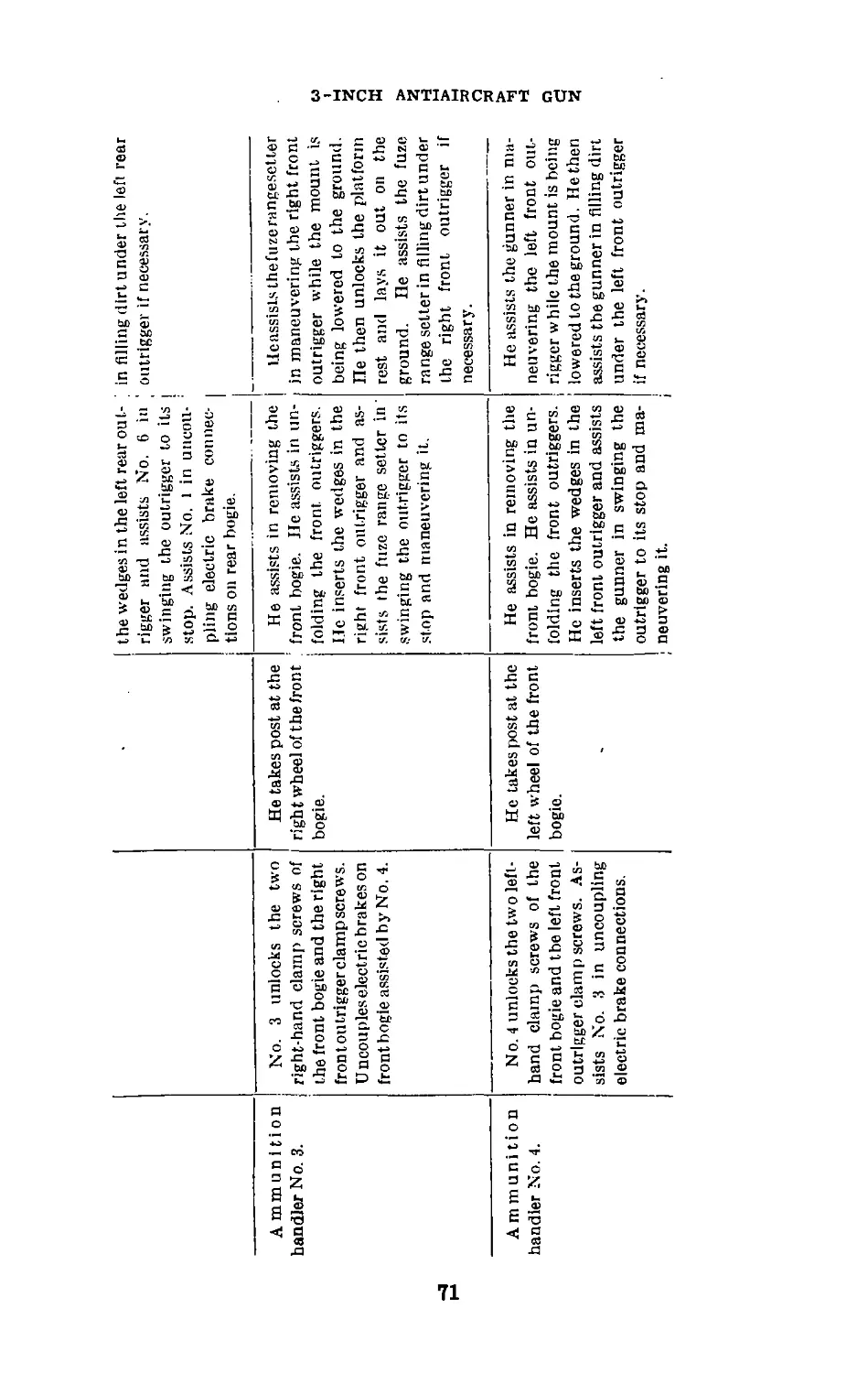
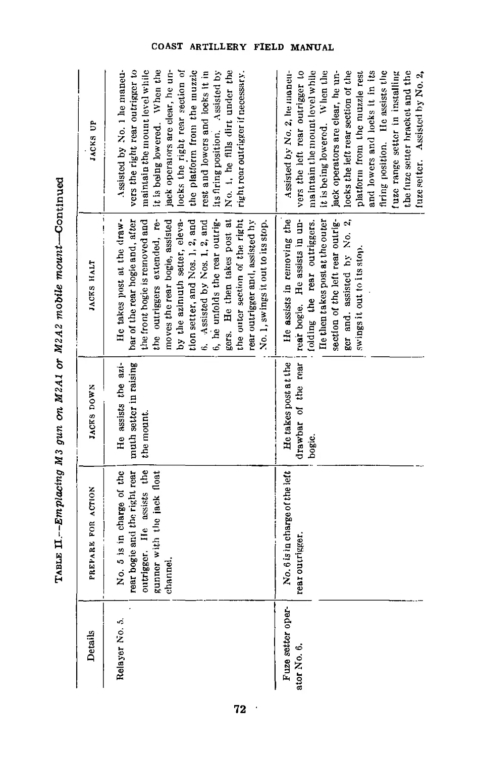
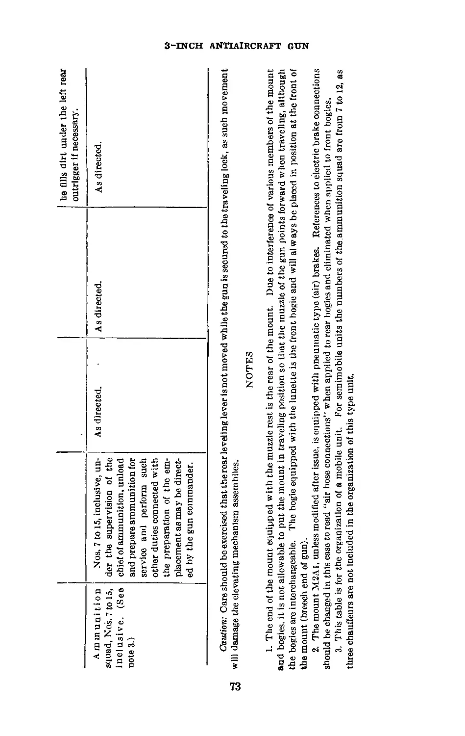
this chain becomes broken, a new chain must be installed.
Before this is done, however, the proper relation between the
inner and outer screws of each jack must be obtained. Oper-
ate the fast motion jack mechanism hand wheel or the ratchet
wrench to extend the threaded portion of the outer screw of
each jack below the lower machined surface of the pedestal
a distance of 5’4 inches. The threaded portion of the inner
screw is then adjusted to extend below the lower face of the
outer screw a distance of 6 inches. The two floats thus set
now can be connected with the chain.
b. In installing a new chain, sufficient slack will be provided
so that the float of one jack can be raised about 10 inches
higher than the float of the other, and so that, with both
floats at the same level, the float of one jack cannot be re-
volved more than one-quarter of a turn without bringing the
chain taut.
Section VI
LUBRICATION
63. General.—a. The life of the gun and mount depends
to a great extent on proper lubrication. Particular atten-
tion will be given to sliding'and bearing surfaces, such as the
sliding surfaces of the gun and cradle, roller bearings, ball
bearings, elevating rack, traversing rack, and breech
mechanism.
b. Industrial type grease fittings and oil plugs are pro-
vided on the'gun and mount. The fittings are painted red
and the oil holes are marked by a red ring.
c. Care must be taken when cleaning gear cases or sliding
surfaces to insure the complete removal of all residue or
sediment. Dirt or other foreign matter should not be allowed
to drop into any of the gear cases.
d. Battery personnel, when cleaning the gun, are cau-
tioned to refrain from using water from a high-pressure hose
since this will result in water entering the bearings, causing
corrosion and nonfunction of the operating parts.
e. Lubrication frequencies are based on continuous use of
the materiel with frequent firing.
f. No lubricants other than those prescribed will be used
without the authority of the Ordnance Department.
g. Every 5,000 miles or 6 months, remove wheels, clean and
41
63-65 COAST ARTILLERY FIELD MANUAL
repack bearings, and wipe off excessive grease. Do not All
hub caps with grease. It is important that the bearings be
properly adjusted when replaced. Failure will result if the
bearings are adjusted too tightly.
h. Oil and grease should be applied while the parts are
being maneuvered to insure distribution of the lubricant to
all moving parts.
i. The teeth of the elevating rack and traversing gear will
be cleaned with dry-cleaning solvent before new grease is
applied.
j. For storage or shipment of this materiel, follow the in-
structions in TM 9-850.
64. Instructions.—Because of the different climates in
which this materiel may be expected to operate, special in-
structions are necessary for three regions: arctic, temperate,
and tropical. By arctic is meant a climate usually experienced
in Alaska, Newfoundland, Labrador, Iceland, etc. By tem-
perate is meant a climate usually experienced in continental
United States, Hawaii, etc., and by tropical is meant that
usually experienced in Panama, the Philippines, and Cuba.
In certain cases the prescribed instructions may not apply;
for example, a tropical climate may be experienced in tem-
perate regions. In cases of this nature the instructions as to
the classification of climate in which the materiel is oper-
ating is left to the judgment of the ordnance officer. The
materiel will be lubricated for different climatic conditions
as follows:
a. Manufacturing arsenals and plants will lubricate the
materiel on assembly with lubricants prescribed for the tem-
perate climate.
b. Materiel previously lubricated for the arctic climates
and which is to be used in temperate or tropical regions will
be relubricated with lubricants prescribed for its use in these
regions.
c. Materiel previously lubricated for a tropic climate and
which is to be used in temperate or arctic regions will be com-
pletely cleaned of all lubricants and relubricated with the
lubricants prescribed for its use in these regions.
65. Lubrication Chart.—The following chart gives the type
and location of lubricator and lubricant and the frequency
and method of application for the various lubricating points
on the gun and mount:
42
LUBRICATION CHART
Group Part lubricated Method of oiling
Breech mechanism. AU moving parts. Fitting and oiler.
Surfaces. Brush.
Cradle. Cradle liner and gun guide—5 places. Fitting.
Top carriage, co Ball thrust bearing. Spherical roller bearing, lower end of top carriage. Oil pipe in top carriage—2 places. Fitting, lower end.
Equilibrator. Bearings on plunger head—2 places. Trunnion ball bearings—4 places. Volume control (temperature adjustment) worm shaft. Plunger. Fitting. Remove covers and pack with grease. Drop oil on sbaft and allow to run into bearing. Clean and grease.
Traversing mech- anism. Worm, worm gear, ball bear- ing—1 place. Instrument drive, shaft and pinion. Remove pipe plug on top of case and pour in oil until it runs out at height plug on side. Fitting.
' Sec paragraph 66 for grade of lubricant to be used.
Lubricant1 Frequency
Grease. Daily when in use and after firing.
Lubricating oil.
Grease. End of each day’s fir- ing.
Grease. Weekly.
Grease. Weekly.
Grease. Weekly.
Grease. Weekly.
Lubricating oil. Weekly.
Grease. Weekly.
Lubricating oil. Monthly.
Grease. Weekly.
3-INCH ANTIAIRCRAFT GUN
сл
LUBRICATION CHART—Continued as
__________________________________________ ______________________ СЛ
Group Part lubricated Method of oiling Lubricant Frequency
Elevating mecha- nism. Worm, worm wheel, and ball bearing. Remove plug and fill with oil until it flows out of overflow hole in side of case. Lubricating oil. Monthly.
Rack- Clean and apply grease with brush. Grease. Weekly.
Bearing (nearhandwheel). Fitting. Grease. Weekly.
Elevation indicator. Bearings for shaft to indicator —2 places. Oiler. Lubricating oil. Weekly.
Trunnion assembly, rf* rf* Trunnion bearings. Remove covers and pack with grease. Grease. Weekly.
Bogie, front (tow- ing). Pins, tie rod—4 places. Fitting. Grease. W eekly or every 250 miles.
End, drawbar. Fitting. Grease. Weekly.
Springs and shackles—6 places. Fitting. Grease. Weekly or every’ 250 miles.
Joint, steering rod, inner—2 places. Fitting. Grease. Weekly.
Joint, steering rod, outer—2 places. Fitting. Grease. Weekly.
Knuckle, steering—4 piaces. Fitting. Grease. Weekly
Screws, clamp—4 places. Clean and apply grease with brush. Grease. Weekly.
Wheels—bearings. Hand pack. Wheel-bearing grease. Every 5,000 miles or every 6 months.
COAST ARTILLERY FIELD MANUAL
Bogie, rear. Springs and shackles—6 places. Screws, clamp—4 places. Wheels—bearings. • Bearing, brake shaft, outer, left wheel—2 places. Pintle—1 piace. Bearing, brake shaft, inner—2 places. .. -- .... Fitting. Clean and apply grease with brush. Hand pack. Pipe plugs. Fitting. Oiler. Fitting. Grease. Grease. Grease. Lubricating oil. Grease. Lubricating oil. Grease. Weekly or every 250 miles. Weekly. Every 5,000 miles or every 6 months. Weekly or every 250 miles. Weekly or every 250 miles. Weekly.
*£} Leveling mecha- nism. Leveling screw thrust bear- ings—2 places. Screws, leveling—2 places. Leveling bearing, lower. Slidihg surface of guide, base piate, and housing. Fitting. Apply grease with brush. Fitting: fill untii grease oozes out. Apply grease with brush. Grease. Grease. Grease. Grease. Weekly. Weekly. Weekly. Weekly.
Jacks. Screw—1 place. Pinion—2 places. Fitting. Fitting. Grease. Grease. Weekly. Weekly.
3-INCH ANTIAIRCRAFT GUN
LUBRICATION CHART—Continued os
________________ _______ m
Group Part lubricated Method of oiling Lubricant Frequency
Outriggers. Screws, clamp—3 places each outrigger. Clean and apply grease with grease gun. Grease. Weekly.
Traveling lock. Stud—2 places. Oiler. Lubricating oil. Weekly.
Platform. Latch and latch bolt. Sliding lock. Oiler. Brush. Lubricating oil. Grease. Weekly. Weekly.
Fuze setter. 0? Hinge between body and case. Handle setting. Rings, adjusting and setting. Oiler. Drop oil through two small holes provided. Clean and grease (with special low temperature grease), the surfaces, except the pawls and their guides, which are lubricated with the lubricating oil. Light machine oil Lubricating oil. Grease and light lubricating oil. Weekly. Weekly. Daily when in use.
Breech mechanism. Opening mechanism. Oiler. Flnsb working sur- face while operating mecha- nism by hand. Lubricating oil. Before each day's firing. /
COAST ARTILLERY FIELD MANUAL
66. Prescribed Lubricants.—The following chart shows the prescribed lubricant to be used in the
lubrication of 3-inch antiaircraft gun materiel when operating in arctic, temperate, or tropical climates:
Lubricant Kind of lubricant used in—
Arctic climate Temperate climate Tropical climate
Grease Grease, 0. 1). No. 00. Grease 0. D. No. 0. Grease 0. D. No. i.
Lubricating oil. Oil, lubricating, for aircraft instru- ments and machine guns. (U. S. A. 2-27 of l-he latest issue in effect.) Oil, engine, SAE 10.W. Oil, engine, SAE 30.
Light machine oil. Oil, lubricating, for aircraft instru- ments and machine guns. (C. S. A. 2-27 of the latest issue in effect.) Oil, lubricating, for aircraft instru- ments and machine guns. (U. S. A. 2-27 of the latest issue in effect.) Oil. lubricating, for aircraft instru- ments and machine guns. (C‘. S. A. 2-27 of tiie latest issue in effect.)
Whetfl-bearing grease. Grease, wheel-bearing, No. 2. Grease, wheel-bearing, No. 2. Grease,wheel-bearing, No. 2.
-INCH ANTIAIRCRAFT
ci
67
COAST ARTILLERY FIELD MANUAL
CHAPTER 9
3-INCH ANTIAIRCRAFT GUNS ON FIXED MOUNTS
Paragraphs
Section I. 3-inch antiaircraft gun M1917 on pedestal mount
M1917_____________________________________ 67-72
П. 3-lnch antiaircraft gun M4 on pedestal mount_73-75
Section I
3-INCH ANTIAIRCRAFT GUN M1917 ON PEDESTAL
MOUNT M1917
67. To Disassemble Breech Mechanism.—a. The trigger
shaft detent pin Is removed, followed by the trigger shaft.
The clutch is screwed in and the breechblock opened by the
operating handle. The plunger plugs are then removed, fol-
lowed by the extractor plungers and their springs. The
lock plate key is taken out. A small clip similar to a pair of
tweezers, held together by a bolt and nut, is placed over the
spring piston rod just forward of its connection with the
chain. The nut is screwed up so that it will clamp the clip
tightly to the rod. The extractors are then tripped with an
empty cartridge case put in rim first, and the breechblock is
allowed to close slowly, the speed being regulated by the man
operating the handle. As soon as the clip comes against
the face of the cradle, the pull of the closing spring ceases
and the block is closed by the operating handle. Conse-
quently, the chain terminal is freed from its lug on the
operating lever. The chain is then twisted upward and
forward out of the way. The locking plate is next removed
by pulling to the rear.
b. An eyebolt is screwed in the top of the breechblock and
a rope attached thereto. The lock screw for retaining ring
(fig. 12) is removed, and the retaining ring turned clockwise
(forward) until the operating handle is free to be pulled off
the operating lever. After the handle is removed, the breech-
block is raised. Meanwhile, another man takes a firm hold
on both ends of the operating lever and, as the breechblock
rises, pushes the operating lever as far to the rear as the
breechblock will allow, thereby disengaging the T-shaped
cam from its groove in the breechblock. The breechblock is
pulled up as far as it will go and the operating lever removed
48
OPERATING CAM COVER LATCH PLUG
OPERATING CAM STOP
TORSION SPRING
OPERATING CAM
оДЭД'Йо
CAM COVER LATCH PLUNGER
-COVER LATCH SPRING
BREECH BLOCK
JACKET------
LATCH SPRING
SPRING CUP-
LATCH BOLT-
LATCH—
LATCH PLATE
LATCH PLATE BOLT
LEVELING PLATE
HANDLE PLUG
OPERATING HANDLE
OPERATING HANDLE
RETAINING RING
Seclion of ComSlide
Showing Operating Com
OPERATING САМ COVER
&|,ы.щы,;,вдмр
TUBE
CLOSING SPRING CASE
CLOSING SPRING
PISTON ROD LOCK NUT
Showing Operating
Lever Handle Clutch
RETAINING RING
LOCK PLATE ।
LOCK PLATE-
TRIGGER SHAFT
CHAIN--------
CHAIN TERMINAL
FACE PLATE
BREECH RING
CLUTCH LOCK BEARING
CLUTCH SPRING
CLUTCH LOCK
CLUTCH
SPRING PISTON
PISTON ROD NUT
SPRING PISTON
-INCH ANTIAIRCRAFT GUN
Figure 12.—Breech mechanism assembly, 3-lnch antiaircraft gun, M1917.
67-68
COAST ARTILLERY FIELD MANUAL
from its seat. With two men to catch it as it drops clear, the
breechblock is lowered completely out of the breech recess.
c. To remove the operating cam, the cam cover latch plunger
is pulled up and the operating cam cover is turned counter-
clockwise (forward and downward) until the cover latch
plunger rests in a notch provided for it. The plunger will then
be pointed forward and downward. With the plunger pulled
out, the cam cover may be taken off by pulling straight away
from its seat. By pushing on the end of the operating cam,
now exposed, it may be pushed from its seat, the torsion spring
with it. It will be necessary to twist the cam with the fingers
into a position somewhat similar to that for hand operation
before it can be pushed all the way out, due to the small
amount of clearance between the gun and the cam slides.
68. To Assemble Breech Mechanism.—a. It is assumed that
the clip is on the spring piston rod and an eyebolt on the
breechblock as described above. The extractors are first
covered with light oil and placed in position, with their outer
lugs resting in the grooves cut for them in the jacket. The
lugs being as far forward as possible, the oil causes the
extractors to cling to the sides of the recess and prevents
their falling out. The breechblock then should be placed
directly under its proper position and lifted until the inner
extractor lugs have entered their grooves in the breechblock.
The breechblock should be pulled up until the inner extractor
lugs are seated on their seats in the breechblock; the ex-
tractors are tripped by hand and the breechblock is pulled
up to its highest position; the operating lever then is placed
in its seat. The block is slowly dropped and, without remov-
ing the operating lever from its seat, the T-shaped cam on
the lever is inserted in the slot on the breechblock, after
which the breechblock is allowed to drop to its lowest posi-
tion. To insert the operating cam, the torsion spring is placed
over the cam and the spring twisted sufficiently to permit the
eye in the end of the spring to enter the recess of the operating
cam seat provided for it. The breechblock should be closed
and the lock plate removed for this operation. The operat-
ing cam can then be inserted. Care must be taken that this
cam is all the way in its seat. The operating cam cover is
replaced by reversing the operations described for removing
it. It is twisted clockwise to the position desired for auto-
50
3-INCH ANTIAIRCRAFT GUN
68-69
matic or hand operation. The operating cam is then ready
for use. Under no circumstances should the operating cam
cover be left in the position for assembling or dismounting.
The lock plate is pushed into place and the lock plate key
inserted. The operating handle should be put on the end of
the operating lever and the retaining ring ^crewed up against
the operating handle. The lock screw for retaining ring
should be put in and the clutch screwed in. The chain should
then be brought down into position and the breechblock
slowly opened, so that the chain terminal will catch on the lug
on the operating lever. The breechblock should then be
pulled completely open, care being taken that the extractors
seat. If they do not seat they should be pulled to the rear
at the top by hand until they do. The tension of the closing
spring is now off the clip and the clip can be removed; also
the eyebolt can be removed from the breechblock. The ex-
tractor plungers and springs and the plunger plugs are then
put in place. It is advisable not to stand directly in rear of
these plugs when putting them in or taking them out, as the
plunger springs are likely to throw them to the rear with
considerable force.
b. The clutch should then be screwed out and the oper-
ating handle placed in a vertical position. The trigger shaft
is inserted and held in position by the trigger shaft detent.
The breech mechanism is then ready for use.
69. To Disassemble Firing Mechanism.—With the trigger
shaft removed, unscrew the faceplate (1) (fig. 13) on the
breechblock and draw out the firing pin holder assembly. If
the ramp on the front of the sear (5) does not release the
holder so that it may be pulled out with the fingers, insert a
small screw driver between the trigger arm (2) and the firing
spring shoe (4) and draw to the rear. Remove the sear (5)
and sear spring (7), drawing them into the firing pin hole.
Separate the parts of the firing pin holder assembly by insert-
ing the fiat end of the trigger shaft in the slot of the firing
spring shoe and pushing it down, turning the shoe to the
left, or counterclockwise, to disengage the lug on the shoe
from the slot in the firing pin holder (3); then allow the
firing spring to push the shoe out.
51
69-70
COAST ARTILLERY FIELD MANUAL
1. Faceplate.
2. Trigger arm.
3. Firing pin holder.
4. Firing spring shoe.
5. Sear.
6. Firing spring.
7. Sear spring.
8. Sear spring seat.
9. Firing pin point
Figure 13.—Continuous-pull firing mechanism (horizontal cross
section), old type, used on 3-inch antiaircraft gun M1917.
70. To Assemble Firing Pin Assembly.—a. Assemble the
firing spring (6) (fig. 13) into the firing pin holder (3) fol-
lowed by the filing spring shoe (4). Compress the spring
by using the fiat end of the trigger shaft, placing it in the
slot in the firing spring shoe to force the shoe into the holder,
and by guiding the projection on the shoe so that it enters
the slot in the holder. Turn the shoe to the right or clock-
wise so that the shoe is locked in the holder. Insert the
trigger arm (2) through the opening in the side of the shoe
so that the rounded knob portion will bear against the shoe.
Slide the firing pin (9) into its seat in the front end of the
holder.
52
3-INCH ANTIAIRCRAFT GUN
70-71
b. Insert the sear (5), containing the sear spring, into its
seat in the block with the ramp or bevel of its inner end
toward the muzzle. In doing this, the sear may be suspended
on the end of a small screw driver forced between the coils
of the spring. With the small screw driver force the sear
outward and insert the firing pin assembly (without the trig-
ger arm) until the front end of the holder holds the sear
in place; then take out the screw driver and push the firing
pin assembly home, replacing and guiding the trigger arm
into its seat in the block. Retain the parts in position by
screwing in the faceplate. Put the trigger shaft in and
prove the correctness of the assembly by pulling the lanyard
several times and observing its functioning.
71. To Drain and Refill Recoil Cylinders.—a. To drain
the recoil cylinders, remove the filling and drain plugs and
let the oil drain out. With the gun in a horizontal position
and the drain plugs replaced tightly, fill the recoil cylinders
with the prescribed recoil oil through the filling hole. Leave
a void of not in excess of one-fourth of a pint of oil in the
cylinder to allow for expansion of the oil as it becomes heated
during firing. The recoil cylinders should be emptied and
refilled at least once every 3 months, and should be thoroughly
cleaned by ordnance personnel as often as conditions warrant.
Once every 6 months is suggested as a minimum.
b. The following table shows the amount and kind of
recoil oil to be used for guns on fixed mounts when used
under different climatic conditions:
RECOIL OIL FOR FIXED OUN MOUNTS
3-inch antiaircraft gun carriage When temperature averages above 40° F. When temperature averages 10° F. or below Recoil mech- anism capac- ity (pints)
М3 Light, U. S. Army Specifica- Light, Specification RIXS- 16 .
tion 2-36. 189.
M.1917 ... .do. . . ... .do . . 6H
1M1917MI ... .do ... .do 16
M1917MI1 do ..(io .
M3A1 . do ... .do .. 16
53
72-75
COAST ARTILLERY FIELD MANUAL
72. Lubrication.—A regular schedule of lubrication should
be maintained. All sliding contact surfaces should be kept
clean and well lubricated, and proper precautions taken to
prevent rust. Oil holes and grease fittings are provided for
lubricating the various mechanisms.
Section П
3-INCH ANTIAIRCRAFT GUN M4 ON PEDESTAL MOUNT
73. To Assemble and Disassemble Breech Mechanism.—
The breech mechanism of this gun is very similar to that
of the М3 gun on mobile mount, and the instructions relative
to assembly and disassembly of the breech mechanism of the
М3 gun may, in general, be followed by personnel manning
the M4 gun. (See pars. 43 to 53, incl.)
74. To Drain and Refill Recoil Cylinders.—For instruc-
tions in filling and draining the recoil cylinders, see para-
graph 71.
75. Lubrication.—A regular schedule of lubrication should
be maintained. All sliding contact surfaces should be kept
clean and well lubricated, and proper precautions taken to
prevent rust. Oil holes and grease fittings are provided for
lubricating the various mechanisms. (See pars. 29 to 34,
incl.)
54
3-INCH ANTIAIRCRAFT GUN
76
CHAPTER 10
M8 FUZE SETTER Paragraphs
Section I. General_______________________________________76-78
П. Adjustments___________________________________79-81
III. Care and preservation-------------------------- 82
Section I
GENERAL
76. Description.—a. The fuze setter consists principally of
the fuze indicator, the adjusting mechanism, and the setting
mechanism. The indicator and adjusting mechanism are
inclosed within the case (fig. 15) while the setting mechanism
is housed within the body.
b. (1) The fuze indicator includes a fuze range scale, a
mechanical (outer) index, an electrical (inner) index, and
a standard a-c synchronous electrical unit.
(2) The electrical unit positions the electrical index at the
position on the fuze range scale corresponding to the fuze
setting transmitted from the director.
c. The adjusting mechanism is that mechanism which
causes the fuze to be set at the particular fuze setting desired.
A handwheel (fig. 14) is geared both to the mechanical index
and to an adjusting ring (fig. 15) whose function is to engage
and hold fast the lug or slot on the setting element of the
fuze on the projectile. By turning the handwheel the me-
chanical index is made to indicate a particular fuze setting,
and the adjusting ring is revolved to such a position that its
pawls will stop the setting element on the fuze at the same
fuze setting that is indicated by the mechanical index.
d. The setting mechanism, driven by the setting crank (fig.
14), contains a setting ring (fig. 15). which engages the lug
or slot on the body of the fuze and turns the projectile until
the fuze body is properly positioned with respect to the setting
element of the fuze.
55
76
COAST ARTILLERY FIELD MANUAL
Figure 14.—MS fuze setter.
56
3-INCH ANTIAIRCRAFT GUN
77-78
Figure 15.—MB fuze setter open for Inspection.
77. Operation During Setting of Fuze.—Briefly, the
sequence of events in the setting of a fuze is as follows:
a. One turn of the setting crank causes the setting ring to
make two revolutions. During the first revolution pawls on
the setting ring arrive at and engage the slot in (or lug on)
the body of the fuze and begin to rotate the round.
b. The adjusting ring, meanwhile, has been positioned
according to the fuze setting indicated by the director. Dur-
ing the second revolution of the setting ring the lug or slot
in the setting element of the fuze will arrive at and be stopped
by the pawls on the adjusting ring.
c. The setting ring continues to turn the projectile until
the second revolution is completed, when a stop pawl ter-
minates the movement. In this position the body of the
fuze has been stopped at what might be called a zero posi-
tion, while the setting element of the fuze has been stopped
at a point the proper number of graduations away from the
zero position, and the fuze is said to be “set.”
78. Adjusting and Setting Rings.—The case and the body
are hinged, and by loosening the wing nut holding the two
together, it is possible to swing the body away from the case,
57
78-79
COAST ARTILLERY FIELD MANUAL
giving access to the adjusting and setting rings. Three sets
of rings are provided, one for the 21-second powder train
fuze, one for the 30-second mechanical fuze, and one for use
with dummy cartridges. The rings are easily changed, and
the rings of a particular set cannot be assembled improperly
because the screw holes in the rings are spaced differently.
For the two different time fuzes, different range scales for
the face of the fuze indicator are provided.
Section П
ADJUSTMENTS
79. To Change Rings in Fuze Setter.—a. Open the fuze
setter as shown in figure 15, remove the screws and the lock
washers in each ring already assembled in the fuze setter,
and remove this set of rings. If the rings stick in place in
the fuze setter after the fastening screws have been removed,
insert the screws into the tapped holes in the rings and pull
the rings loose. Select from the accessory chest the proper
set of rings to be used; then assemble the adjusting rings to
the adapter in the case or lower portion of the fuze setter, and
the setting ring to the socket in the body or upper portion.
b. In case the fuze range scale on the fuze indicator does
not correspond to the fuze to be used, the scale must be re-
placed with the proper one from the accessory chest. Care-
fully remove the window frame from the indicator face so
as not to injure the gasket. Next remove the six screws and
the ring which clamps the scale in place. Remove the scale,
wrap it in soft tissue paper, and secure it in place behind the
block in the lid of the accessory chest. Place the new scale
in place, replace the clamping ring, and insert the six retain-
ing screws, leaving the ring just loose enough to allow the
scale to be moved. Place a round in the fuze setter, set the
fuze, and read the setting on the fuze as closely as possible.
Insert a blunt point in the hole in the scale over the zero
and slide the scale around under the ring until the value
set on the fuze is opposite the indicating marks on the outer
or mechanical index. Recheck at another fuze setting, then
tighten the clamping ring screws evenly and firmly. Replace
the window and its fastening screws.
58
3-INCH ANTIAIRCRAFT GUN
80-82
80. To Synchronize Mechanical Index With Fuze Range
Scale on Face of Indicator.—If the outer or mechanical in-
dex does not indicate on the fuze range scale the fuze setting
to which the fuze setter actually sets the fuze, it will be nec-
essary to adjust the fuze range scale as explained in para-
graph 79. In this connection, before any changes are made,
any calibration corrections which are to be or have been
made in fuze range must be taken into consideration. See
FM 4-110 for application of calibration corrections.
81. To Synchronize Electrical Index With Director.—
For synchronization of the electrical index with the fuze dial
on the director see FM 4-110.
Section П1
CARE AND PRESERVATION
82. General.—The following instructions should be care-
fully observed in the care and preservation of the fuze setter:'
a. The adjusting and setting .rings should be removed fre-
quently from the fuze setter, cleaned thoroughly, lubricated,
and then replaced. These rings should be handled carefully
to prevent the bending of the thin metal sides adjacent to the
pawls, because any interference with the action of these
pawls may cause erroneous fuze settings. In lubricating the
rings, the surfaces except the pawls and their guides should
be greased with petrolatum (U. S. A. Spec. 2-67) to prevent
rust. The pawls and their guides should be oiled with
lubricating oil for aircraft instruments and machine guns
(U. S. A. Spec. 2-27).
b. The screws which fasten the adjusting and setting
rings in place should be kept tight, with the lock washers
under the screw heads to prevent the screws from loosening.
c. Rings which are not being used should be kept in the
accessory chest.
d. Great care should be exercised in handling the scales
and rings, especially when adjusting or changing them, as
they are easily deformed or damaged. The alternate fuze
range scale should be wrapped in tissue paper and kept in the
recess in the-block fastened in the lid of the accessory chest.
e. No provision has been made for lubricating in the field
any of the internal moving parts, as the entire device should
59
82
COAST ARTILLERY FIELD MANUAL
be torn down and serviced at regular intervals by ordnance
maintenance personnel.
/. Care should be exercised, when handling the fuze setter,
not to bump any part of the device. The wing nut on the eye-
bolt should be tight at all times, especially when the fuze set-
ter is to be picked up. Always grasp the large main castings
when handling. The fuze setter should not be laid down; it
should be placed in its support on the gun mount or in the
traveling bracket.
g. The fuze setter should be kept covered with the canvas
cover when it is not in use.
h. Whenever the cable receptacle (fig. 14) is not connected
to the gun junction box, it should be stowed on the dummy
receptacle with the cable wrapped around in front of the
fuze indicator.
60
3-INCH ANTIAIRCRAFT GUN
CHAPTER 11
DRILL TABLES
Table I. Guns equipped with automatic data transmission system
and M8 fuze setter.
II. Emplacing М3 gun on M2A1 or M2A2 mobile mount.
Ш. Placing М3 gun on M2A1 or M2A2 mobile mount in travel-
ing position.
61
Table I.—Guns equipped with automatic data transmiss ion system and M8 fuze setter (3-inch AA gun М3 on
mobile mounts M2A1 and M2A2 and 3-inch. AA gun M4 On fixed mount M3A1
Details Details, Posts (a) Examine Gun ((>) Kepobt Target Commence Firing (a) Suspend Firing (d) Cease Firing
Gunner. The gunner procures a wiper of cotton waste and a can of oil; he places the wiper and oil in convenlent'place, removes the breech cover, assisted by No. 5, disposes of it at the designated place, and (a) Assisted by No. 5, he examines, cleans, and oils the breech- block and breech mechanism, tests the firing mechanism, ex- amines the chamber and bore and, if neces- sary, calls upon Nos. 1, He opens the breech by bearing down on the operating handle until the breechblock is locked open and im- mediately raises the operating handle to its vertical position. He assumes a position fac- As soon as the first round is placed in loading position by No. 5 he rams the cartridge. As soon as the closing breech has knocked his left band clear he fires the gun by pulling (a) If an unfired round is in the gun he unloads it by bearing down on the operating handle as soon as No. 5 is ready to re- ceive the cartridge, and remains at his post. (6) Same as suspend
takes post to the right rear of the gun op- posite and facing the breech. 2, 3, and 5 for assist- ance in sponging and cleaning the chamber and bore. (6) He reports to the gun commander, “Breech in order,” or reports any defects he is unable to remedy without delay. ing the breech con- venient for loading yet clear of the recoil with his feet well braced and the lan yard grasped In his right hand. the lanyard with his righthand. He con- tinues ramming and firing without shift- ing position or re- leasing the lanyard. In case of misfire he calls, “Misfire,” to the gun commander and keeps all can- noneers clear of the breech while the pre- scribed safoty pre- cautions are taken. firing.
COAST ARTILLERY FIELD MANUAL
Fuze range set-
ter (fuze setter).
He takes i>os I seated
on the fuze setter’s
seat, facing the fuze
setter.
(a) Assisted by No.
6, lie examines, cleans,
and oils (where neces-
sary) the fuze setter,
fuze range indicator
and connections there-
to. Assisted by No. 4,
he tests the operation
hy setting and check-
ing a fuze at several
values.
(d) He reports to the
gun commander,
“Fuze setter in order,’
or reports such defects
as he Is unable to rem-
edy without delay.
Lie turns the fuze I
range handwheel so '
as to match the me-
chanical pointer with
the electrical pointer
of the fuze range indi-
cator and thereafter
keeps them matched.
He continues to I (a) He continues to
keep libs pointers I keep his pointers
matched.
matched.
I (d) Be turns his me-
chanical pointer to
“safe” and directs No.
4 to remove the round
from the setter. He
supervises the setting
at “safe” of any other
checking each fuze as
it is removed from his
setter. Thereafter he
remains at his post.
Azimuth setter.
He takes post seated
on the left side of the
gun, facing the azi-
muth indicator.
(я) He examines the
traversing mechanism
and azimuth indicator
and connections.
(d) He reports to the
g n n commander,
“Traversing in order,”
or reports any defects
he is unable to remedy
without delay.
He traverses the gun
so as to match the
mechancial pointers
with the electrical i
pointers of the indica-
tor and thereafter
keeps those poiniers •
matched.
He continues to
keep his pointers
: matched.
(a) He continues to
keep his pointers
matched.
(b) He stops match
ing his pointers but
remains at his post.
-INCH ANTIAIRCRAFT GUN
Table I.—Guns equipped with automatic data transmission system and M8 fuze setter (3-inch AA gun М3 on
mobile mounts M2A1 and M2A2 and 3-inch AA gun M4 on fixed mount M3A1)—Continued
Details Details, Posts (a) Examine Gun (6) Report Target Commence Firing (a) Suspend Firing (d) Cease Firing
Elevation setter. rf* Tie takes post seated on the right side of the gun, facing the eleva- tion indicator. (a) He examines the elevating mechanism and elevation indica- tor and the connec- tions thereto. Should a dUliculty in elevating indicate the need of a temperature adj ust- ment to the equilibra- tor, he reports that fact to the gun com- mander at once. (d) Пе reports to the gun commander, “Ele- vating in order.” or reports any defects he is unable to remedy without delay. Пе elevates or de- presses the gun so as to match the mechani- cal pointers with the electrical pointers of the elevation ind icator and thereafter keeps those pointers matched. Пе continues to keep his pointers matched. (a) He continues to keep bis pointers matched. (6) He stops match ing his pointers but remains at his post.
Ammuni tion handlers, Nos. 1, 2, 3, and 4. No. 4 removes, then folds up the gun cover, assisted by No. 2, de- posits it. at the desig- nated place, and takes (a) No. 4 inserts a round in the fuze set- ter, when called for by No. 6. for the purpose of testing the fuze set- No. 4 takes a round from No. 1 and inserts it in the fuze setter, presses down on the base end of the case No. 4 continues loading the fuze set- ter as fast as rounds are removed there- from by No. -5, re- (a) If no round is in the fuze setter, No. 4 inserts one and stands ready to continue load- ing the fuze setter.
COAST ARTILLERY FIELD MANUAL
Ui
post immediately In
rear of the fuze setter,
facing it, standing on
the gunner’s platform.
No. 1, assisted by No.
3, uncovers the ammu-
nition and takes post
on the ground about 3
feet behind No. 4. No.
3 takes post at the
stack of ammunition.
No. 2 assists No. 4 in
removing and folding
up the gun cover and
takes post to the rear
of the gunner, stand-
ing on the ground and
facing the breech, just
clear of the gunner’s
platform.
ter, and examines the
ammunition, assisted
by Nos. Iand3. Nos.
1 and 3 assist No. 4 in
inspecting and arrang-
ing the ammunition
near the gun. If nec
essary, they assist the
gunner in cleaning and
sponging the bore.
No. 2 assists the gun-
ner, if necessary, in
cleaning and sponging
the bore, and examines
the emplacement, re-
moving and disposing
of any obstructions
and covering soft spots
on the ground that
might interfere with
the smooth function-
ing of Nos. 1, 3, and 4.
(6) No. 4 reports to
the gun commander,
“Ammunition in or-
der,” or reports any
defects he is unable to
remedy without delay.
with his right hand,
brings his left hand
over and strikes a
quick slap against the
release lever on top
side of fuze setter.
After No. 6 has com-
pleted one turn of the
setting crank No. 4
removes his right hand
pressure from the base
of the projectile, turns
to receive another
round from No. i, and
stands ready to load
the fuze setter again.
No. I takes a round
from No. 3 and passes
it to No. 4. He re-
peats the operation.
No. 3 takes a round
from the stack and
passes it to No. 1. He
repeats the operation.
No. 2 has no duties.
(For target practice
see note 1.)
ceiving the rounds
from No. 1. Nos. 1
and 3 continue serv-
ing ammunition to
No. 4. No. 2 clears
the empty cases
from the emplace-
ment.
Nos. 1 and 3 stand
ready to serve ammu-
nition to No. 4. No.
2, if an unflred round
remains in the gun,
receives it from No. 5,
lays it aside, and con-
tinues clearing the
empty cases from the
emplacement.
(b) Nos. 1, 3, and 4
procure and assist in
setting at “safe” such
rounds as have been
set and remain unflred,
return them to the
stack, and remain at
their posts. No. 2 con-
tinues clearing the
empty cases from the
emplacement. When
the emplacement is
cleared he remains at
his post.
w
-INCH ANTIAIRCRAFT gun
Table I.—Guns equipped with automatic data transmission system and M8 fuze setter (3-inch AA gun М3 on
mobile mounts M2A1 and M2A2 and 3-inch AA gun M4 on fixed mount M3A1—Continued
Details Details, Posts (a) Examine Gun (ft) Report Target Commence Firing (a) Suspend Firing (b\ Cease Firing
о Relayer No. 5. No. 5 procures the chamber and bore sponges and a wiper of cotton waste, dis- poses of the sponges in the designated place, assists the gunner in removing the breech cover, and takes post about 2 feet to the left and rear of the breech, facing the breech. (a) He assists the gunner in examining, cleaning, and oiling the breech mechanism, firing mechanism, chamber, and bore of tbe gun. He is re- sponsible that the breech operating cam pl unger is set for auto- matic or hand opera- tion of the breech as directed by the gun commander. (5) No duties. No duties. He removes a round from the fuze setter and holds tt in the loading position at the breech. As soon as the round is loaded (by the gun- ner) he repeats the operation. (a) If an unfired round is in the gun, he places his right palm behind the breechblock at the signai of the gunner, catches the ejected round and passes it to No. 2, and remains at his post. (ft) Same as suspend FIRING.
Fuze setter oper- ator No. 6. No. 6 removes the muzzle cover and de- posits it at the desig- nated place. He takes post standing at the right rear of the fuze range setter, facing the fuze setter. (a) He assists the fuze range setter in examining, cleaning, and oiling the fuze setting mechanism. Checks to see proper rings are in fuze setler. (6) No duties. He places his hand on handle so that as soon as the release lever is struck by No. 4, the crank will start. He turns the handle until it comes in con- tact. with the stop, at. which time he calls He continues set- tingfuzes as quickly as projectiles are in- serted in the fuze setter, calling “Cut” as each fuze is set. (a) He sets the fuze if an unset round is in the fuze setter or if a round is placed in the fuze setter after receipt of the command. (6) По remains at his post prepared to set such fuzes back l о
COAST ARTILLERY FIELD MANUAL
“Cut” to signify that the fuze is set and the round can be with- drawn. (For target practice see note 1.) “safe” as may be neces- sary.
Ammunition squad. Nos. 7 to 15 inclusive. (See note 2.) Nos. 7 to i5. inclu- sive, are posted by the chief of ammunition in such manner as to expedite the supply of ammunition and |>er- form such other duties as may be directed. (a) Nos. 7 to 15, in- clusive, under the di- rection of the chief of ammunition, remove from the boxes or crates and prepare the necessary ammuni- tion for the contem- plated practice or ac- tion. If practice or action is imminent, they place an ammu- nition supply in a stack at the gun em- placement. (b) No duties. Nos. 7 to 15, inclu- sive, stand ready to replenish the ammuni- tion supply at the gun position. They continue the supply of ammuni- tion to the gun po- sition. (a) After collecting all empty cases and re- plenishing the ammu- nition supply at the gun, they remain at their posts unless oth- erwise directed. (ft) Same as Suspend Firing.
-INCH ANTIAIRCRAFT GUN
NOTES
1. The service of the piece, ns written, prescribes that the continuous fuze setter be loaded at the command Target. This is logical for all
service firings; however, in target practice it is not desirable that the fuze setter be loaded and the fuze set until the target has reached approxi-
mately safe firing conditions. Therefore, for target practice, Nos. 4 and 6should have no duties at the command Target, but the battery com-
mander should give a warning command Stand by as the safe field is approached, at which time No. 4 loads the fuze setter, No. 6 sets
the fuze as prescribed herein, and No. 5 awaits the command Commence Firing before removing the round from the setter.
2. This table is for the organization of a mobile unit. For semimobile units the numbers of the ammunition squad are from 7 to 12, as
three chauffeurs are not included in the organization for this type unit.
Table II.—Emplacing М3 gun on M2A1 mobile mount
00
Details PREPARE FOR ACTION JACKS DOWN JACKS HALT jacks UP
Gunner. The gunner is in charge of the jack float channel, the front bogie, and the left front outrigger. Assisted by No. 5, he procures the jack float channel, puts it in place, and centers it under the jack floats. He assists the eleva- tion setter in raising the mount. He takes post at the draw- bar of the front bogie and re- moves the bogie assisted by the fuze range setter, the azi- muth setter, elevation setter, and Nos. 3 and 4. Assisted by the fuze range setter and Nos. 3 and 4, he unfolds the front outriggers. He then takes post at the outer section of the left front outrigger and, assisted by No. 4, swings it out to its stop and maneuvers it to assist in the removal of the rear bogie. Assisted by No. 4, he man- euvers the left front outrigger to maintain the mount level while it is being lowered. When the jack operators are clear, he unlocks the left front section of the piatform from the platform rest, and lowers and locks it in its firing posi- tion. Assisted by No. 4 he fills dirt under the left front outrigger if necessary.
Fuze range setter. The fuze range setter is In charge of the right front outrigger, the fuze setter bracket, and the fuze setter. He takes post at the drawbar of the front bogie. He assists in removing the front bogie. He assists in un- folding the front outriggers. He then takes post at the outer section of the right front outrigger and, assisted by No. 3, swings it out to its stop and maneuvers it to assist in the removal of the rear bogie. Assisted by No. 3, he man- euvers the right front outrigger to maintain the mount level while it is being lowered. When the jack operators are cledr, he unlocks the right front section of the platform from the platform rest and lowers and locks it in its firing position. Assisted by No. 6, he moves
COAST ARTILLERY FIELD MANUAL
Azimuth setter. О co He is in charge of the right lifting jack and the azimuth seat. He runs the right lifting jack down by means of the fast motion hand- wheel until the float is in contact, with the jack float channel and sets the jack lever ratchet for jacks down. Assisted by No. 5 he runs the right jack down by means of the jack lever, raising the mount.
Elevation setter. He is in charge of the left lifting jack and the eleva- tion seat. He runs the left lifting jack down by means of the fast motion hand- wheel until the float is in contact with the jack float channel (which has been put in place by the gunner and No. 5) and sets the jack lever ratchet for jacks down. Assisted by the gunner, he runs the left jack down by means of the jack lever, raising the znount.
He unlocks the azimuth
seat from its traveling position
and swings it out from the
mount. He assists in the re-
moval of the front and rear
bogies.
He unlocks the elevation
seat from its traveling position
and swings it out from the
mount. He assists in the re-
moval of the front and rear
bogies.
the fuze setter bracket from its
traveling position, installs it
in its firing position, unfolds
the fuze setter’s seat, and in-
stalls the fuze setter on its
bracket. Assisted by No. 3,
he fills dirt under the right
front outrigger if necessary .
He runs the right jack up
until the mount is resting on
the ground and continues the
operation until the jack is fully
retracted. He locks the azi-
muth seat in its firing position
and operates one leveling
handle as directed by the gun
commander.
He runs the left jack up until
the mount rests on the ground
and continues the operation
until the jack is fully retracted.
He locks the elevation seat in
its firing position and elevates
-INCH ANTIAIRCRAFT
the gun as necessary to free
the muzzle from its clamp.
He operates one leveling handle
as directed hy the gun com-
mander.
Table П.—Emplacing М3 gun on M2A1 or M2A2 mobile mount—Continued
Details PREPARE FOR ACTION JACKS DOWN JACKS HALT JACKS UP
Ammunition handler No. 1. No dntles. He takes post at the right wheel of the rear bogie. After the front outriggers have been extended and wedged, No. 1 unlocks the two right-hand clamp screws of the rear hogie and the right rear outrigger clamp screws. He assists in removing the rear bogie. He assists in unfolding the rear outriggers. He inserts the wedges in the right rear outrigger and assists No. 5 in swinging the outrigger to its stop. Uncoupleselectric brake connections on rear bogie as- sisted by No. 2. He assists No. 5 in maneuver- ing the right rear outrigger while the mount is being low- ered to the ground. He assists No. 5 in filling dirt under the right rear outrigger if necessary.
A ni m unition handler No. 2. No duties. He takes post at the left wheel of the rear bogie. After the front outriggers have boen extended and wedged, No. 2 unlocks the two ieft-hand clamp screws of the roar bogie and the left rear out- rigger clamp screws. He as- sists in removing the rear bogie. He assists In unfolding the rear outriggers. He inserts He assists No. 6 in maneuver- ing the left rear outrigger while the mount is being lowered to the ground. He unlocks the muzzle clamp and directs the elevation setter to elevate the gun. He unlocks the muzzle rest and lays it out on the ground. He then assists No. 6
COAST ARTILLERY FIELD MANUAL
the wedges in the left rear ou l- rigger and assists No. 6 in swinging the outrigger to its stop. Assists No. 1 in uncou- pling electric brake connec- tions on rear bogie. in filling dirt under the left rear outrigger if necessary.
Ammunition handler No. 3. No. 3 unlocks the two right-hand clamp screws of the front bogie and the right fron t outrigger clamp screws. U ncoupleselectric brakes on front bogie assisted by No. 4. He takes post at the right wheel of the front bogie. He assists in removing the front bogie. Be assists in un- folding the front outriggers. He inserts the wedges in the right front outrigger and as- sists the fuze range setter in’ swinging the outrigger to its stop and maneuvering it. He assists the fuze rangesetter in maneuvering the right front outrigger while the mount is being lowered to the ground. Be then unlocks the platform rest and lays it out on the ground. He assists the fuze range setter in filling dirt under the right front outrigger if necessary.
Ammunition handier No. 4. No. 4 unlocks the two left- hand damp screws of the front bogie and the left front outrigger clamp screws. As- sists No. 3 in uncoupling electric brake connections. He takes post at the left wheel of the front bogie. He assists in removing the front bogie. He assists in un- folding the front outriggers. He inserts the wedges in the left front outrigger and assists the gunner in swinging the outrigger to its stop and ma- neuvering it. He assists the gunner in ma- neuvering the left front out- rigger while the mount is being lowered to the ground. Hethen assists the gunner in filling dirt under the left front outrigger if necessary.
-INCH ANTIAIRCRAFT GUN
Table II.—Emplacing М3 gun on M2A1 or M2A2 mobile mount—Continued
Details PREPARE FOR ACTION JACKS DOWN jacks halt JACKS UP
Relayer No. 5. No. 5 is in charge of the rear bogie and the right rear outrigger. He assists the gunner with the jack float channel. He assists the azi- muth setter in raising the mount. He takes post at the draw- bar of the rear hogieand, after the front bogie is removed and tbe outriggers extended, re- moves the rear bogie, assisted by the azimuth setter, eleva- tion setter, and Nos. 1, 2, and 6. Assisted by Nos. 1, 2, and 6, he unfolds the rear outrig- gers. He then takes post at the outer section of the right rear outrigger and, assisted hy No. 1, swings it out to its stop» Assisted by No. 1 he maneu- vers the right rear outrigger to maintain the mount level while it is being lowered. When the jack operators are clear, he un- locks the right rear section of the platform from the muzzle rest and lowers and locks it in its firing position. Assisted by No. i, he fills dirt under the right rear outrigger if necessary.
Fuze setter oper- ator No. 6. No. 6 is in charge of the left rear outrigger. He takes post a t the drawbar of the rear bogie. He assists in removing the rear bogie. He assists in un- folding the rear outriggers. Пе then takes post at the outer section of the left rear outrig- ger and, assisted by No. 2, swings it out to Its stop. Assisted by No. 2, he maneu- vers the left rear outrigger to maintain the mount level while it is being lowered. When the jack operators are clear, he un- locks the ieft rear section of the platform from the muzzle rest and lowers and locks it in its firing position. He assists the fuze range setter in installing the fuze setter bracket and the fuze setter. Assisted by No, 2,
COAST ARTILLERY FIELD MANUAL
be fills dirt under the left rear outrigger if necessary.
Ammunition squad, Nos. 7 to 15, inclusive. (See note 3.) Nos. 7 to 15, inclusive, un- der the supervision of the chief of ammunition, unload and prepare ammunition for service and perform such other duties connected with the preparation of the em- placement as may be direct- ed by the gun commander. As directed. As directed. As directed.
Caution: Care should be exercised that the roar leveling lever is not moved while the gun is secured to the traveling lock, as such movement
will damage the elevating mechanism assemblies.
NOTES
1. The end of the mount equipped with the muzzle rest is the rear of the mount. Due to interference of various members of the mount
and bogies, it is not allowable to put the mount in traveling position so that the muzzle of the gun points forward when traveling, although
the bogies are interchangeable. The bogie equipped with the lunette is the front bogie and will always be placed in position at the front of
the mount (breech end of gun).
2. The mount М2 AL unless modified after issue, is equipped with pneumatic type (air) brakes. References to electric brake connections
should be changed in this case to read “air hose connections’’ when applied to rear bogies and eliminated when applied to front bogies.
3. This table is for the organization of a mobile unit. For semimobile units the numbers of the.ammunition squad are from 7 to 12, as
three chauffeurs are not included in the organization of this type unit.
•“INCH ANTIAIRCRAFT
Appendix
LIST OF REFERENCES
Ammunition, coast artillery___
Ammunition, general___________
Ammunition, 3-inch antiaircraft
gun---------------------------
Care and maintenance of
materiel______________________
3-inch antiaircraft gun ma-
teriel M1918________________
Field Manuals_________________
Safety precautions in firing__
Weapons and materiel, coast
artillery_____________________
О
TM 4-205,
TM 9-1900.
TM 9-360.
TM 9-360 and TM 9-850.
TM 9-360.
FM 4-105, 4-110, 4-120,
4-150, and 4-155.
AR 750-10, TM 4-235, and
FM 4-120.
TM 4-210.
74
Table Ш.—Placing М3 gun on M2A1 от M2A2 mobile mount in traveling position
Details MARCH ORDER JACKS DOWN (1) JACKS HALT (1) JACKS DOWN (2) JACKS HALT (2> JACKS UP
Gunner. Assisted by No. 5 he places the breech cover over the breech. Assisted by the fuze range setter and Nos. 3 and 4, he folds the rear sections of the platform and locks them In traveling position. He assists the elevation setter in maneuvering the left lifting jack. Assisted by the fuze range set- ter, and Nos. 3 and 4, he drives the wedges out of the rear outriggers, folds them, and ciamps them in traveling position. He assists the elevation setter In operating the left lifting jack. He assists the azimuth setter, the fuze range setter, and Nos. 3, 4, and 0 in maneuvering the rear bogie. Takes post at left wheel of front bogie. He assists the fuze range setter and Nos. 1, 2, 5, and 6 in replacing the front bogie under gun. After the front bogie is replaced, he re- places the jack float channel in traveling position. No. 5 assists in the operation.
Fuze range setter. Assisted by No. 6, he removes fuze setter and fuze setter bracket, placing them in traveling position. He assists tbe gunner and Nos. 3 and 4 to fold the rear sections of the platform and to lock them in position. He takes post by the rear out- riggers. Assists the gunner and Nos. 3 and 4 in driving the wedges out of the rear outriggers and in folding and clamping those outriggers in traveling position. He takes post at the drawbar of the rear bogie. He assists the gunner, the azi- muth setter, and Nos. 3, 4, and 6 in maneuvering the rear bogie. Takes post at right wheel of front bogie. He assists the gunner, and Nos. 1, 2, 5, and 6 in replacing the front bogie under gun. With the aid of No. 4 he connects the electric brakes on the rear bogie.
Azimuth setter. He traverses the gun until it is in position directly over the muzzle rest. He unlocks the azimuth seat from firing position. Assisted by No. 5, he runs the right lifting jack down, as directed by the gun commander, until the outriggers are broken free of the ground. No duties. Assisted by No. 5, he runs the right lifting jack down, as directed by the gun commander, until the rear bogie may be replaced. Assisted by the gunner, the fuze range setter, and Nos. 3, 4, and 6, replaces the rear bogie and clamps it in position. He runs the right lifting jack up as directed by the gun commander to permit the gun to settle on the front bogie. After the bogie is locked in position, he runs the lift- ing jack up fully and locks it. He locks the azimuth seat in traveling position.
Elevation setter. He depresses the gun as it is traversed by the azimuth setter until the gun is in position to be clamped to the muzzle rest. He unlocks the elevation seat from firing position. Assisted by the gunner, he runs the left lifting jack down, as di- rected by the gun commander, until the outriggers are broken free of the ground. No duties. Assisted by the gunner, he runs the left lifting jack down, as di- rected by the gun commander, until the rear bogie may be re- placed. No duties. He runs the left lifting jack up as directed by the gun commander to permit the gun to settle on the front bogie. After the bogie is locked in position, he runs the lifting jack up fully and locks it. He locks the elevation seat in traveling position.
Ammunition handler No. 1. He places the platform rest in traveling position and, when gun is traversed and depressed prop- erly, clamps the gun to the muzzle rest. Assists Nos. 2, 5, and 6 to fold the front sections of the plat- form and to lock them in position. No duties. Takes post at end of right front outrigger. Bears down on the end of right front outrigger while the jacks are run down enough to replace the rear bogie. He assists Nos. 2, 5, and 6 with the front outriggers and takes post at right wheel of front bogie. He assists the fuze range setter, gunner, and Nos. 2, 5, and C in replacing front bogie. Tightens bogie clamps. He replaces addi- tional equipment at direction of of the gun commander.
Ammunition handler No. 2. He assists Nos. 1,5, and 6 to fold the front sections of the platform and to lock them in position. No duties. Takes post at end of left front outrigger. Bears down on the end of left front outrigger while the jacks are run down enough to replace the rear bogie. He assists Nos. 1, 5, and 6 with the front outriggers and takes post at the left wheel of the front bogie. He assists the fuze range setter, gunner, and Nos. 1, 5, and 6 in re- placing the front bogie. Assists No. 3 in connecting the electric brakes on the fron.t bogie. Tight- ens bogie clamps.
Ammunition handler No. 3. He assists the gunner, the fuze range setter, and No. 4 to fold the rear sections of the platform and to lock them in position. He takes post by the rear out- riggers. Assists the gunner, the fuze range setter, aud No. 4 in driving the wedges out of the rear out- riggers and in folding and clamp- ing those outriggers in traveling position. He takes post at the right wheel of the rear bogie. He assists the azimuth setter, gunner, fuze range setter, and Nos. 4 and 6 in maneuvering the rear bogie. Tightens bogie clamps. Assisted by Nos 2, he connects the electric brakes on the front bogie.
Ammunition handler No. 4. He places the muzzle rest in traveling position. He assists the gunner, the fuze range setter, and No. 3 to fold the rear sections of the platform and to lock them in position. Ho takes post by the rear out- riggers. Assists the gunner, the fuze range setter, and No. 3 in driving the wedges out of the rear out- riggers and in folding and clamp- ing those outriggers in traveling position. He takes post at the left wheel of the rear bogie. He assists the gunner, the fuze range setter, the azimuth setter, and Nos. 3 and 6 in maneuvering the rear bogie. Tightens bogie clamps. He assists the fuze range setter in connecting the electric brakes on the rear bogie.
Relayer No. 5. He assists the gunner to place the breech cover over the breech. Assisted by Nos. 1, 2, and 6, he folds the front sections of the plat- form and locks them in traveling position. He assists the azimuth setter in maneuvering the right lifting jack. No duties. He assists the azimuth setter in maneuvering the right lifting jack. After the rear bogie is replaced, assisted by Nos. 1, 2, and 6, he removes the wedges in the front outriggers and folds and clamps those outriggers in traveling posi- tion. He then takes post at the drawbar of the front bogie. He directs the placing of the front bogie under gun, aided by the fuze range setter, the gunner, and Nos. 1, 2, and 6. He then assists the gunner to replace the jack float channel in traveling position.
Fuze setter oper- ator No. в. He replaces the muzzle cover, and assists the fuze range setter in handling the fuze setter and fuze setter bracket. He assists Nos. 1, 2, and 5 to fold the front sections of the platform and to lock them In traveling position. No duties. No duties. No duties. He assists the azimuth setter, the gunner, the fuze range setter, and Nos. 3 and 4 in maneuvering the rear bogie. After rear bogie is replaced, assisted by Nos. 1,2, and 5, he removes the wedges in the front outriggers, and folds and clamps these outriggers in travel- ing position. He then takes post at drawbar of front bogie. He assists the fuze range setter, the gunner, and Nos. 1, 2, and 5 to replace the front bogie. He re- places additional equipment at the direction of the gun commander.
Ammunition squad, Nos. 7 to 15, inclusive. (See note 3.) Nos. 7 to 15, inclusive, under the supervision of the chief of ammunition, perform such duties in salvaging ammunition and quitting the emplacement as may be directed. As directed. As directed. As directed. As directed. As directed.
Caution: Care should be exercised that the rear leveling lever is not moved while the gun Is eecured to tha traveling lock, as such movement will damage the elevating mechanism assemblies.
NOTES
1. The end of the mount equipped with the muzzle rest is the rear of the mount. Due to interference of various members of the mount and bogles, it is not allowable to put the mount in traveling position so that the muzzle of the gun
points forward when traveling, although the bogies are interchangeable. The bogie equipped with the lunette is the front bogie and will always be placed in position at the front of the mount (breech end of gun).
2. The mount M2A1, unless modified after issue, is equipped with pneumatic type (air) brakes. References to electric brake connections should be changed in this case to read “air hose connections’’ when applied to rear bogies and
eliminated when applied to front bogies.
3. This table is for the organization of a mobile unit. For semimobile units, the numbers of the ammunition squad are from 7 to 12, es three chauffeurs are not Included in the organization of this type unit.
482650°—42 (Face p. 73)