/
Text
FM 4-130
MHi
СоруЗ
WAR DEPARTMENT
COAST ARTILLERY
FIELD MANUAL
ANTIAIRCRAFT ARTILLERY
SERVICE OF THE PIECE
105-MM ANTIAIRCRAFT GUN
FM 4-130
COAST ARTILLERY
FIELD MANUAL
ANTIAIRCRAFT ARTILLERY
SERVICE OF THE PIECE
105-MM ANTIAIRCRAFT GUN
Prepared under direction of the
Chief of Coast Artillery
UNITED STATES
GOVERNMENT PRINTING OFFICE
WASHINGTON: 1940
For sale by the Superintendent of Documents, Washington, D. C. - Price 15 cents
WAR DEPARTMENT,
Washington, June 17, 1940.
FM 4-130, Coast Artillery Field Manual, Antiaircraft Ar-
tillery, Service of the Piece, 105-mm Antiaircraft Gun, is pub-
lished for the information and guidance of all concerned.
[A. G. 062.11 (4-27-40).]
By order of the Secretary of War :
G. C. MARSHALL,
Chief of Staff.
Official :
E. S. ADAMS,
Major General,
The Adjutant General.
и
TABLE OF CONTENTS
Chapter 1. General. Paragraph Page
Scope_________________________________ 1 1
References____________________________ 2 1
Chapter 2. Organization.
Gun section___________________________ 3 2
Gun squad_____________________________ 4 2
Ammunition squad__________________ 5 3
Formation_____________________________ 6 3
Chapter 3. Duties of Personnel.
Battery executive_____________________ 7 4
Assistant battery executive___________ 8 4
Gun commander_________________________ 9 5
Chief of ammunition^_________________ 10 7
Artillery mechanic___________________ 11 8
Chapter 4. Notes on the Service of the Piece.
General______________________________ 12 10
Signals_______________________________ 13 10
Operation of breech mechanism______ 14 10
Operation of pneumatic rammer______ 15 11
Method of handling ammunition______ 16 13
Service of drill ammunition________ 17 14
Chapter 5. Safety Precautions.
General____________________________________________ 18 16
Ammunition___________________________ 19 16
Misfires______________________________ 20 16
Unloading live rounds_________________ 21 16
Chapter 6. Maintenance of Matebiel.
Section I. General:
Cleaning and lubrication________ 22 17
Additional general instructions_ 23 17
Daily inspection__________________ 24 18
II. Maintenance of particular parts and
assemblies:
Gun_______________________________ 25 18
Breech mechanism__________________ 26 19
Firing mechanism__________________ 27 19
Recall mechanism__________________ 28 19
Gun slides________________________ 29 20
Traversing rollers and roller paths. 30 20
Elevating rack____________________ 31 20
Fuze setter, M9___________________ 32 20
III. Malfunctions:
Malfunctions of gun--------------------- 33 23
Malfunctions of mount_____________ 34 24
Ш
TABLE OF CONTENTS
Chapter 7. Assembly and Disassembly of Breech-
block and Fibing Mbchanism. Paragraph Page
Disassembly of firing lock, T7, from
breechblock __________________________ 35 25
Disassembly of breechblock from
gun___________________________________ 36 25
Disassembly of firing lock, T7____ 37 28
Assembly of firing lock, T7___________ 38 28
Assembly of breechblock in gun____ 39 29
Chapteb 8. Service of Recoil and Rammer Mech-
anisms.
Section I. Recoil mechanism:
Filling recoil cylinder-------- 40 30
Draining recoil cylinder_______ 41 30
II. Rammer mechanism:
Replenishing oil seal in floating
piston__________________________ 42 30
Replenishing air pressure to in-
itial pressure______________________ 43 32
Filling front buffer cylinder__ 44 32
Draining front buffer cylinder_ 45 32
Filling rear buffer cylinder___ 46 33
Chapter 9. Lubrication.
General______________________________ 47 34
Lubrication chart____________________ 48 34
Chapter 10. Drill Table______________________________ 38
Appendix. List of References_________________________ 39
IV
FM 4-130
COAST ARTILLERY FIELD MANUAL
ANTIAIRCRAFT ARTILLERY
SERVICE OF THE PIECE
105-MM ANTIAIRCRAFT GUN
CHAPTER I
GENERAL
1. Scope.—a. This manual prescribes the service of the
piece for the 105-mm antiaircraft gun, М3, on 105-mm anti-
aircraft gun mount, Ml.
b. The matter contained herein is intended only as a
guide in the assignment of individuals and duties. Minor
changes may be made in order to meet local conditions.
2 References.—The references listed in the Appendix
should be consulted, especially those pertaining to ammuni-
tion and to the care and maintenance of materiel.
1
3-4
COAST ARTILLERY FIELD MANUAL
CHAPTER 2
ORGANIZATION
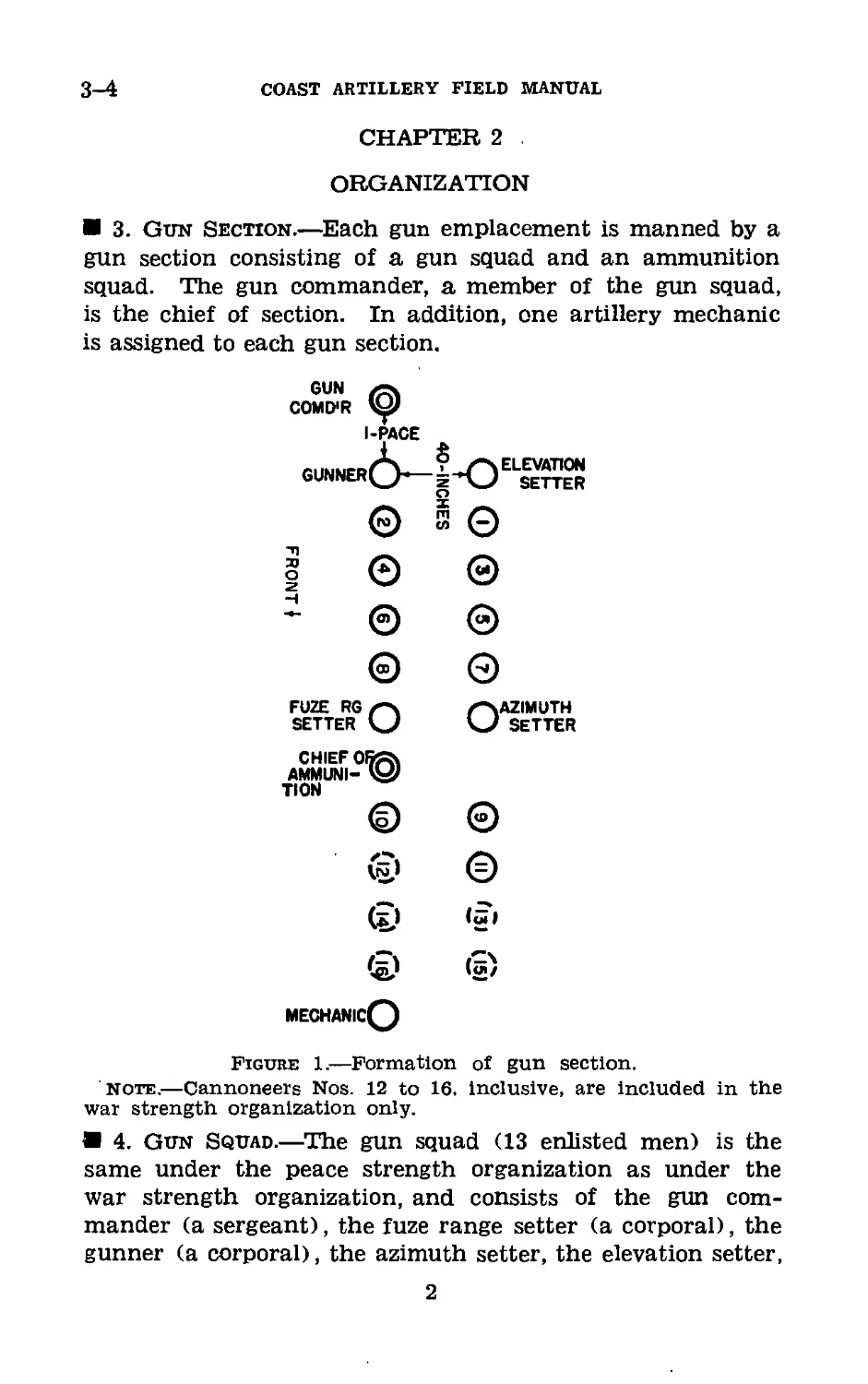
3. Gun Section.—Each gun emplacement is manned by a
gun section consisting of a gun squad and an ammunition
squad. The gun commander, a member of the gun squad,
is the chief of section. In addition, one artillery mechanic
is assigned to each gun section.
FUZE RG z-SAZIMUTH
SETTER kJ kJ SETTER
CHIEF
AMMUNI-
TION
(a) («/
mechanicQ
Figure 1.—Formation of gun section.
Note.—Cannoneers Nos. 12 to 16. inclusive, are included in the
war strength organization only.
4. Gun Squad.—The gun squad (13 enlisted men) is the
same under the peace strength organization as under the
war strength organization, and consists of the gun com-
mander (a sergeant), the fuze range setter (a corporal), the
gunner (a corporal), the azimuth setter, the elevation setter,
2
105-MM ANTIAIRCRAFT GUN
4-6
and eight cannoneers numbered from 1 to 8, inclusive. Men
are assigned to permanent positions according to their apti-
tude, but will be interchanged frequently in drill positions
to develop flexibility and facilitate replacement.
5. Ammunition Squad.—a. Under the war strength organi-
zation the ammunition squad (9 enlisted men) consists of the
chief of ammunition (a corporal) and eight cannoneers num-
bered from 9 to 16, inclusive.
b. Under the peace strength organization the ammunition
squad (4 enlisted men) consists of the chief of. ammunition
and three cannoneers numbered from 9 to 11, inclusive.
6. Formation (fig. 1).—The battery is formed as prescribed
in FM 4-120. Each gun section assembles in two ranks with
4 inches between flies and 40 inches between ranks. After
forming the section, the gun commander takes post in the
front rank 1 pace to the right of his section. At the firing
point, at the command fall in, the section normally forms
facing the piece.
3
CHAPTER 3
DUTIES OF PERSONNEL
7. Battery Executive.—a. The battery executive commands
the firing section (normally 3 gun sections) and is in general
charge of all gun emplacements. He is responsible to the
battery commander for—
(1) Training and efficiency of personnel.
(2) Condition of materiel under his charge.
(3) Police of emplacements.
(4) Observance of all safety precautions.
b. He inspects the materiel under his charge and per-
sonally verifies the adjustment of all data receivers as fre-
quently as necessary to insure accuracy (and always prior to
firing). (See FM 4-110.)
c. He supervises the boresighting and orientation of the
guns and the synchronization of the data transmission system.
(See FM 4-110.)
d. He receives the reports of the gun commanders and re-
ports to the battery commander, “Sir, gun sections in order,”
or reports any defects he is unable to remedy without delay.
e. After the emplacements have been reported ready, should
circumstances arise which in his opinion would make it unsafe
to fire, he commands: STAND FAST, and reports his action
to the battery commander.
f. At the command dismissed, given by the battery com-
mander, the executive commands: REPLACE EQUIPMENT,
inspects the gun positions, and reports to the battery com-
mander.
8. Assistant Battery Executive.—a. During the prepara-
tion for firing, the assistant battery executive is normally in
charge of the service of ammunition for the battery.
b. During firing he is normally assigned to supervise one or
more guns, while the battery executive supervises the others.
c. At other times he performs such duties as may be dele-
gated to him by the battery executive.
4
105-MM ANTIAIRCRAFT GUN
9
И 9. Gun Commander.—a. The gun commander (a sergeant)
Is in charge of the gun section and is also chief of the gun
squad. He is responsible to the battery executive for—
(1) Training and efficiency of the personnel of his section.
(2) Condition, care, and preparation for action of all ma-
teriel, including ammunition, under his charge.
(3) Observance of all safety precautions pertaining to the
service of the piece and the handling of ammunition.
(4) Police of the emplacement pertaining to his section.
(5) Care and proper disposal of empty cartridge cases.
(6) Keeping of a record of the number of rounds fired by
his gun during a practice or action and of all other data
necessary to keep the gun book accurate and up to date.
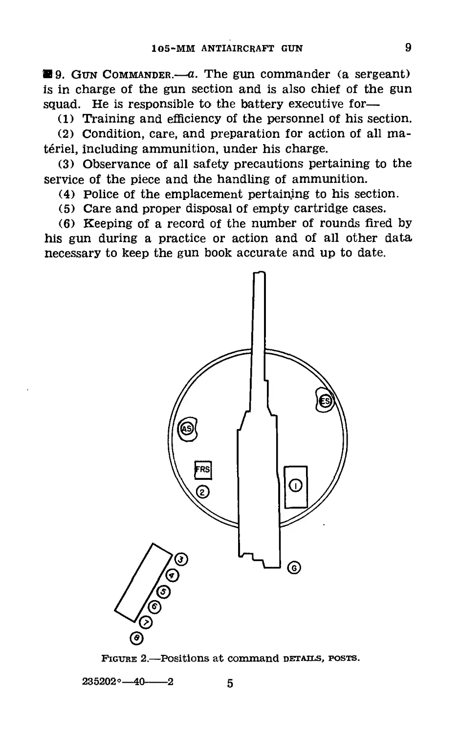
Figure 2.—Positions at command details, posts.
235202°—40---2 5
9
COACT ARTILLERY FIELD MANUAL
b. When the section arrives at the gun emplacement, he
commands: 1. details, 2. POSTS, and supervises the pro-
curement of equipment. After all details have reached their
posts (see fig. 2) he commands: EXAMINE GUN. He then
personally makes an inspection of the gun, mount, and other
materiel, assuring himself that the power is turned on in
the data transmission system, that all mechanical pointers
are properly adjusted (see FM 4-110), that all electrical
pointers are synchronized with their respective transmitters
in the director (see FM 4-110), that the pressure in the
rammer cylinder is correct, that the oil in the packing seal
and In the front and rear rammer buffer cylinders has been
replenished, that firing mechanisms and safety devices are
in order, that the recoil cylinder and the front and rear
buffer cylinders are properly filled, that all moving parts are
lubricated, that the breech operating cam has been set for
automatic (or hand) operation, that the rammer release
tripping cam has been set for proper operation of the rammer,
and that the operation of the rammer has been tested by
ramming a drill cartridge with the gun at elevations of ap-
proximately 800 and 1,100 mils. He then commands: RE-
PORT, receives the reports of the members of the gun section
as called for by the drill table (ch. 10), and reports to the
battery executive, “Sir, No.-------in order,” or reports any
defects he is unable to remedy without delay.
c. He boresights and orients his gun under the supervision
of the battery executive. (See FM 4-110.)
d. He supervises the service of the piece and the service of
ammunition and personally directs the work of care and
preservation of all materiel. He takes his post at any point
from which he may conveniently supervise the work of the
section.
e. When necessary to verify the section, he gives the com-
mand: CALL OFF. The cannoneers of the section call off
their titles or numbers in succession, beginning with the un-
numbered members of the section, followed by the numbered
members in order.
/. At the command target, he repeats the command and
target designation and sees that all personnel take post on
the run if not already at their posts. He makes sure that
6
105-MM ANTIAIRCRAFT GUN
9-10
data are being received from the range section, verifies the
matching of the pointers on the coarse dials of the azimuth
and of the elevation indicators, and if possible verifies roughly
the pointing of the gun by sighting along the gun barrel.
When the gun is ready for firing he reports or signals to the
battery executive, “Sir, No.------ready.”
g. At the command commence firing, he commands: LOAD,
for the first round only, succeeding rounds being fired with-
out further command, and supervises the work of the sec-
tion. If a limited number of rounds has been prescribed, he
cautions the gunner and the loading detail, “-----(so many)
rounds,” and commands or signals: SUSPEND FIRING, when
that number of rounds has been fired. He then reports to
the battery executive, “Sir, No. -------- (so many) rounds
fired.”
h. At the command suspend firing, he repeats the com-
mand, sees that the details remain posted, and that the gun
continues to follow the target. He directs the clearing away
of empty shell cases and the preparation of materiel for
further firing.
i. At the command cease firing, he repeats the command
and proceeds as at suspend firing, except that the following
of the target is discontinued.
1. At the command rest, he repeats the command and al-
lows the members of the section to leave their posts but
requires them to remain in the immediate vicinity of the
gun.
fc. At the command replace equipment, he repeats the
command, supervises the replacement of equipment, sees that
the emplacement is policed, and forms his section.
I. In case of misfire he commands: STAND FAST, and
sees that the precautions prescribed in paragraph 20 are
observed.
10. Chief of Ammunition.—a. The chief of ammunition (a
corporal) is in charge of the ammunition squad. He is re-
sponsible to the gun commander for—
(1) Training and efficiency of the personnel under his
charge.
(2) Condition and serviceability of the ammunition per-
taining to the gun.
7
10-11 coast artillery field manual
(3) Observance of all safety precautions in the care and
service of the ammunition.
(4) Correct recording of required ammunition data.
(5) Cleaning and disposition of empty cartridge cases.
(6) Uninterrupted service of ammunition to the gun em-
placement during the course of a practice or action.
b. He supervises the ammunition squad in the placing of
the ammunition racks, the preparation of ammunition for
service, and in such duties in connection with the prepara-
tion of the emplacement as may be directed by the gun com-
mander.
c. At the command details, posts, he posts the members
of the ammunition squad and assigns them duties to facilitate
ammunition handling.
d. At the command examine gun, he inspects the ammuni-
tion under his charge for possible defects (especially the fuzes
for looseness, corrosion, and injury), gives the necessary in-
structions for preparing and arranging the ammunition for
possible firing, and reports to the gun commander, “Ammuni-
tion service in order,” or reports defects he is unable to
remedy without delay.
e. During firing he supervises the ammunition squad in
replenishing the ammunition racks, disposing of empty cases,
and handling and storing of any additional supply received.
He should be prepared at all times to furnish from the am-
munition squad replacements for the gun squad when mem-
bers of that squad become casualties.
f. At the command replace equipment, he supervises the
ammunition squad in the securing and covering of all am-
munition pertaining to the gun, makes certain that all fuzes
that have been cut but not fired have been set back to the
setting of 15, helps in the police of the emplacement, and
forms his squad unless otherwise directed.
11. Artillery Mechanic.—The artillery mechanic, assisted
by other members of the gun section, makes such minor
repairs as can be made with the means at hand. He is re-
sponsible for the proper lubrication of the gun and mount
and maintains a lubrication record showing the dates on
which the various parts of the gun and mount were lubri-
8
105-MM ANTIAIRCRAFT GUN
11
cated. He is custodian of the supplies pertaining to the
emplacement. He is responsible to the chief of section for
the condition and serviceability of the supplies and tools under
his charge. He maintains an up-to-date inventory of all
tools, equipment, spare parts, and supplies under his charge.
He issues such equipment, tools, oils, paints, and cleaning
materials to the members of the gun section as may be neces-
sary for the service and care of the guns and accessories.
9
CHAPTER 4
NOTES ON THE SERVICE OF THE PIECE
12. General.—a. The service of the piece should be con-
ducted with dispatch and precision and with as few orders as
possible. Cannoneers change positions at a run. Commands
should be given in the prescribed form, but should be replaced
by signals whenever practicable. Except for the necessary
orders, reports, and instructions, no talking should be per-
mitted.
b. Loading with drill ammunition as described in paragraph
17 and pointing the piece as for firing are normal practices
at drill.
c. The commands or signals elevate, depress, right, or left
refer to the direction of motion of the muzzle of the gun.
13. Signals.—The following whistle signals are authorized:
a. details, posts—a series of short blasts.
b. commence firing—one long blast.
c. suspend firing—one or more long blasts until the firing
has been stopped.
14. Operation of Breech Mechanism.—a. For hand opera-
tion, No. 3 pulls the cam cover latch plunger outward and
turns the operating cam cover to the rear and downward,
thereby placing the operating cam in such position that it
does not touch the lug on the operating lever during recoil
or counterrecoil. No. 1 grasps the handle grip and rotates
the operating handle to the rear and downward until the
extractors lock the breechblock open, and then returns the
handle to the locked vertical position. The breech is closed
when the rim of the base of the cartridge case trips the
extractors, thus freeing the breechblock from the extractor
trunnions, and allowing the closing spring to rotate the
operating shaft and carry the breechblock up and into the
closed position.
10
105-MM ANTIAIRCRAFT GUN
14-15
b. For automatic operation of the block, No. 3 places the
operating cam in position by reversing the details given in. a
above. The breech is first opened as indicated for hand opera-
tion and the handle raised. Thereafter the breech will open
automatically during counterrecoil, ejecting the empty case.
c. The firing mechanism is of the self-cocking continuous
pull type; on release of the lanyard, the firing pin auto-
matically returns to the cocked position.
15. Operation of Pneumatic Rammer.—a. The pneumatic
rammer is operated by the action of compressed air between
a cylinder in the rammer piston (attached to the rammer
body) and a hollow plunger (assembled to the stationary
cradle extension). In ramming a cartridge, the breechblock
in closing strikes the rammer head and pushes it into the
upper latched position. Having rammed a cartridge into
the gun, the rammer is automatically retracted by the action
of the “kicker” during the recoil of the gun. For high angle
fire when it is desired to stop the ejected cartridge case in
the loading tray, the rammer tripping cam is engaged by
lifting the knob of the plunger from the shallow notch,
turned 90° into the deep notch, and pulled back until the
plunger engages the hole in the cam. When the rammer
tripping cam is in this position, it acts to trip the rammer
release lever and permit the rammer spring to push the
rammer down into the loading position. In this position,
the rammer stops the ejected cartridge case in the loading
tray; the empty case is removed from the tray by No. 9,
who is equipped with asbestos gloves for that purpose. For
medium and low angle fire, however, the rammer tripping
cam is placed in the disengaged position and the ejected
cartridge case is thrown clear of the mount.
b. Before firing, the air pressure is checked by the gun
commander. The reading, with rammer forward and the
gun cool (not recently fired), should be approximately 80
pounds per square inch. If the gun is well warmed up
through firing, the pressure will normally increase due to
temperature rise as the rammer is exercised. Failure of the
rammer to latch back indicates that the pressure has in-
creased beyond the operating limits, in which case it should
11
15
COAST ARTILLERY FIELD MANUAL
be reduced to approximately 90 pounds. The proper pressure
should be obtained, if the gun is cool, by replenishing or
relieving the pressure. Replenishment of pressure is made
by the gunner and No. 1 with the hand air pump. To re-
lieve the pressure (see fig. 7), remove the cap from the pump
connection valve (4); then screw handwheel (5) in until the
air valve is unseated; push down the inside valve by means
of the cap and allow air to escape. The rammer should be
tested by ramming a drill cartridge with the gun at eleva-
tions of approximately 800 and 1,100 mils. If it does not
work satisfactorily when the prescribed pressure is regis-
tered on the gage, the ordnance officer should be notified.
Before firing commences, the gage cock should be closed;
otherwise, the high pressure built up when the rammer is
retracted will damage the gage.
c. The sequence of events in the operation of the rammer
is as follows:
(1) When it is desired to eject the empty cartridge case
clear of the mount, No. 1 opens the breech by pulling the
operating handle to the rear. He returns the handle to the
vertical position and pushes the rammer into the upper
latched position by hand. He places the knob of the rammer
tripping cam in the shallow notch. This disengages the trip-
ping cam and permits the rammer to remain in the upper
position at the end of the retracting stroke, thereby permit-
ting the ejected cartridge case to slide under the rammer
and clear of the mount. No. 3 sets the operating cam in posi-
tion to engage the operating shaft and thereby drop the
breechblock during counterrecoil. The gunner lifts the ram-
mer retracting lever while No. 1 retracts the rammer by
hand, by means of the rammer retracting handwheel, until
the rammer latches back into the sixth notch. For this re-
traction, the elevation setter lays the piece at a convenient
angle of elevation, as directed by the gunner. The gunner
lowers the rammer to the loading position by a pull on the
rammer release lever. No. 3 (4, 5, 6, 7, or 8) places a car-
tridge (on which the fuze has been set) in the loading tray in
front of and as close to the rammer head as his right hand
will permit, slides the cartridge backward into contact with
12
105-MM ANTIAIRCRAFT GUN
15-16
the rammer head, steps away quickly to avoid injury to arms
or hands from the released rammer, and commands: RAM.
Note.—If the rammer head has been modified by the installation
of an adequate buffer to absorb the impact, the cartridge need not
be adjusted to contact with the rammer head.
The gunner pulls the rammer latch release lever, permitting
the rammer to push the cartridge into the gun. After the
breechblock has closed, the gunner fires the gun by a pull
on the lanyard. After firing and during counterrecoil, the
breechblock is dropped automatically; the empty cartridge
case is ejected, slides under the rammer, and is thrown clear
of the mount. The gunner drops the rammer, and the opera-
tions of loading proceed as before.
(2) When it is desired to have the ejected cartridge case
stopped in the loading tray, the operations are the same as
given in (1) above except that No. 1 places the knob of the
rammer tripping cam in the deep notch and pulls back the
knob until the plunger seats in its hole provided in the cam.
This engages the rammer tripping cam in a position such that
it causes the rammer to drop at the end of the retracting
stroke, and thereby stops the ejected cartridge case in the
loading tray. Thus it is not necessary for the gunner to drop
the rammer for the next round.
d. In the event of injury to the rammer, it may be left in
the retracted position, and each round rammed by hand,
using the special rammer provided. A cannoneer from the
ammunition squad should be assigned this duty.
16. Method of Handling Ammunition.—a. Ammunition is
served from the ammunition rack to the fuze setter and from
the fuze setter to the gun by the loading detail. Nos. 3, 4,
5, 6, 7, and 8 form in column at the ammunition rack facing
the breech of the gun. At the command target, No. 3 takes
a round, right hand grasping the base of the cartridge case
with the rotating band of the projectile resting in the crook
of his left arm, and proceeds by the most direct route to the
fuze setter. The round is deposited in the fuze setter in the
manner described in the drill table (ch. 10). Nos. 4, 5, 6,
7, and 8 each grasp a round as prescribed for No. 3 and
proceed to the left of the fuze setter, where they stand in
readiness to deposit their rounds, in turn, in the setter.
235202°—40---3 13
16-17 COAST ARTILLERY FIELD MANUAL
b. At the command load, No. 2 sets the fuze and calls
“Cut.” No. 3 removes the round from the fuze setter, grasp-
ing it as described above, and places it in the loading tray
near the rammer head. He then returns to the ammunition
rack, obtains another round, and falls in behind No. 8 on the
left of the fuze setter. Nos. 4, 5, 6, 7, and 8, in turn, perform
the operations just described for No. 3 until the command
suspend firing or cease firing is received.
c. (1) At the command suspend firing, if an unfired round
is in the gun, it is ejected onto the loading tray under the
direction of the gunner. This round is then removed from
the loading tray and laid aside by that member of the load-
ing detail who placed it therein. If there is no round in the
fuze setter, the next succeeding member of the loading detail
inserts one, and the remaining members of the loading detail
stand ready to continue the service of ammunition when fir-
ing is resumed.
(2) At the command cease firing, the procedure described
in (1) above is followed, and, in addition, if there is a round
in the fuze setter or in the gun, the fuze range setter sets
his fuze range pointer to 15; No. 2 then sets the fuzes on
those rounds, and on any other rounds necessary, to 15.
17. Service of Drill Ammunition.—a. When using drill
ammunition, the loading cycle is as prescribed in paragraph
16 a and b, except that each member of the loading detail
(Nos. 3, 4, 5, 6, 7, and 8) removes his round from the loading
tray (without its having been rammed into the gun) im-
mediately after placing it therein. The rammer head remains
latched in the upper position, and the rounds are slid out the
rear of the loading tray. Rounds thus removed are returned
to the ammunition rack where they are used again by the
loading detail.
b. Just prior to the loading of one of the last four rounds
of each drill series or group ordered, the gun commander
signals the gunner to ram the next round. Immediately after
the next round is placed in the loading tray, the gunner drops
the rammer head, rams the round into the gun, and pulls
the lanyard. No. 1 retracts the rammer so that the head will
drop directly behind the breech, drops the rammer head, opens
14
105-MM ANTIAIRCRAFT GUN
17
the breech, and eases the round back into the loading tray
by retracting the rammer until it is latched back in the loading
position. The round is removed and replaced on the ammuni-
tion rack by the member of the loading detail who loaded it.
The gunner raises the rammer head to its upper latched posi-
tion, and the remainder (if any) of the rounds ordered are
loaded as prescribed in a above. During different drill
courses, the gun commander should signal the gunner to drop
the rammer head while different men are placing their rounds
in the loading tray; the members of the loading detail should
not know which round is to be rammed and fired.
15
CHAPTER 5
SAFETY PRECAUTIONS
18. General.—The safety precautions described herein are
prescribed for peacetime, but under war conditions should be
interpreted by the proper officers according to the circum-
stances.
19. Ammunition.—a. All ammunition at the firing point
must be so placed that it will be protected against explosion in
case of an accident at the gun position. It should be in a
dry place, and protected from the direct rays of the sun by a
tarpaulin or other covering. Erratic shots and possibly dan-
gerously high powder pressures may result from overheated
ammunition.
b. Any alteration of loaded ammunition, especially time
fuzes, except in accordance with specific instructions from the
Chief of Ordnance, is hazardous and is therefore prohibited.
c. When checking the accuracy of fuze setting by cutting
trial fuzes, do not cut the fuze on any one projectile more
than twice.
20. Misfires.—In case of a misfire, at least three attempts
to fire the primer will be made. The gun will be kept laid
on a safe place in the field of fire, and the breechblock will
not be opened until at least 2 minutes after the last attempt
to fire the piece.
21. Unloading Live Rounds.—a. After unloading unfired
rounds, set the fuzes to 15.
b. If a round cannot be extracted in the normal manner,
it should be fired, safety precautions permitting. If this is
impossible, it should be removed under the direct supervision
of an officer, a rammer being used which bears only on the
projectile and provides for clearance around the fuze. (See
*TM 9-1900.)
*See Appendix.
16
CHAPTER 6
MAINTENANCE OF MATERIEL
Paragraphs
Section I. General__________________________22-24
П. Maintenance of particular parts and as-
semblies ________________________ 25-32
HI. Malfunctions ---------------------33-34
’ Section I
GENERAL
22. Cleaning and Lubrication.—The proper maintenance of
materiel is the direct responsibility of battery personnel. The
gun and mount should be thoroughly cleaned and lubricated
at intervals not exceeding 2 weeks and, when fired, as soon
as possible after firing. Care should be taken to keep all parts
free from rust and dirt. Particular attention should be given
to sliding and bearing surfaces of the breechblock, gun, and
cradle, the rammer piston body slide in the right cradle ex-
tension, roller and ball bearings, elevating rack, and travers-
ing rack. If the gun and mount are not to be used for short
intervals, all bright and bearing surfaces should be covered
with a coat of light class D lubricating oil. If they are to be
left unused for a considerable length of time, all bright and
unpainted surfaces should be cleaned thoroughly with dry-
cleaning solvent (not kerosene) so as to be free from rust,
water, and lubricating oil, and coated with rust-preventive
compound; and the rammer should be operated once every
2 weeks.
23. Additional General Instructions.—a. Disconnecting
the gun from the recoil mechanism will not be attempted
by the using personnel.
b. Replace and open cotter pins after replacing nuts.
c. Do not strike any metal part directly with a hammer;
interpose a buffer of wood or copper.
d. Oil holes which have become clogged with oil should
be opened with a piece of wire. Wood should never be used
for this purpose, as splinters are likely to break off in the
hole.
17
23-25
COAST ARTILLERY FIELD MANUAL
e. As an aid to ready identification, grease and oil nozzles
and oil hole covers are painted red. Oil holes have a red
ring painted around them.
/. When any part starts to show wear, steps should be
taken to have on hand a replacement part.
24. Daily Inspection.—Daily inspection should be made
by the gun crew to discover any parts which need adjustment
or attention. This includes the following:
a. Open and close the breech to see that it operates freely.
b. Examine the breech recess and bore to see that they
are clean.
c. See that the firing mechanism works freely.
d. Elevate and depress the gun to see that the mechanism
operates without binding or undue lost motion.
e. Traverse the gun to the right and left through the full
extent of its travel to see that the mechanism operates with-
out binding or undue lost motion.
/. See that the sliding surfaces of the gun and cradle are
clean and well-lubricated.
g. See that all working parts are thoroughly lubricated.
h. Examine recoil system for oil leaks.
i. Examine all keys, thongs, and hinges to see that they
are in serviceable condition.-
j. Check tools and accessories to see that they are in their
proper position and that none are missing.
Section П
MAINTENANCE OF PARTICULAR PARTS AND
ASSEMBLIES
25. Gun.—a. As soon as possible after firing, the bore
should be washed with a solution of 14 pound of soda ash
or 1 pound of sal soda per gallon of boiling water, a sponge
being used for swabbing purposes. Special attention should
be given to that portion of the bore extending from the origin
to a point about 24 inches forward, as most of the fouling
takes place in that area. Cleaning should be followed by
thorough drying with the sponge covered with burlap, after
which the bore should be oiled with a light coat of rust-pre-
ventive compound applied with the bore slush brush.
18
105-MM ANTIAIRCRAFT GUN
25-28
Ь. The surfaces of the leveling plates mounted in the breech
ring should be protected from injury. Tools or other articles
should never be laid upon them. In case of accidental injury,
repairs should be made by ordnance personnel.
26. Breech Mechanism.—a. The breech mechanism should
be kept clean and well lubricated at all times with light lubri-
cating oil, class D. It should be disassembled periodically
(and always immediately after firing) and cleaned and oiled.
In case the mechanism is to be left unused for a considerable
length of time, all bright surfaces should be coated with rust-
preventive compound.
b. Vigilance must be maintained to detect any abrasions
forming on the pressure side of the wearing surfaces in the
various ribs and grooves of the breechblock and the breech
recess and on the trunnions of the extractors. Such abra-
sions must be removed at once by ordnance personnel.
c. The breech should be kept covered to prevent dust and
grit from getting into the mechanism.
27. Firing Mechanism.—a. The firing mechanism should be
disassembled frequently (and always after each firing pe-
riod). All burs and rough surfaces should be removed with
a smooth file. The parts should be washed in dry-cleaning
solvent and wiped dry. When reassembling, the parts should
be lightly coated with light class D lubricating oil (Fed. Spec.
W-O-496).
b. The use of oil thicker than authorized will cause the
mechanism to absorb the energy of the firing spring and will
result in misfires. This is especially true in cold weather
when unsuitable oil congeals and becomes gummy.
c. Examination should be made for wear on the front and
rear faces of the trigger fork, and also at the edge of the
opening in the firing pin holder where the trigger fork passes
through.
28. Recoil Mechanism.—a. Under no circumstances should
an attempt be made to take the recoil mechanism apart.
b. The proper kind and amount of oil (heavy recoil oil,
low pour point, U. S. A. Spec. 2-96) should be maintained at
all times in the recoil mechanism.
c. Every precaution should be taken to prevent the en-
trance of foreign matter into the recoil mechanism.
19
28-32
COAST ARTILLERY FIELD MANUAL
d. The oil used in filling the recoil mechanism should be
strained through a fine clean cloth, and the receptacles used
in handling the oil should be clean.
e. The gun commander should constantly verify the com-
plete return of the gun into battery. If the gun does not
return to battery, or does so irregularly by jerks or jumps,
he should command: CEASE FIRING, and look for the cause
of trouble.
f. If the mount is to remain unused for long periods, the
gun should be elevated to its maximum elevation and the re-
coil cylinder filled to capacity to prevent the walls from be-
coming dry and rusty.
29. Gun Slides.—The gun slides will be thoroughly cleaned
frequently and covered with a film of grease, medium.
30. Traversing Rollers and Roller Paths.—The cover
plate outside the working platform and the dust guards
should be removed and the traversing rollers and roller paths
should be thoroughly cleaned at least once a year. The rollers
and paths are wiped with a cloth dampened with dry-cleaning
solvent. All rust spots are removed with crocus cloth. A
coating of light class D lubricating oil is spread on the rollers
and paths. The bearings of the rollers are lubricated by pour-
ing light class D lubricating oil into the oil pipes. The mount
is then traversed slowly through 360°, and examination is
made to see that oil is flowing in the oil groove of the dis-
tance ring.
31. Elevating Rack.—The teeth of the elevating rack
should be cleaned and coated with graphite grease. Raised or
rough surfaces should be removed with a smooth file.
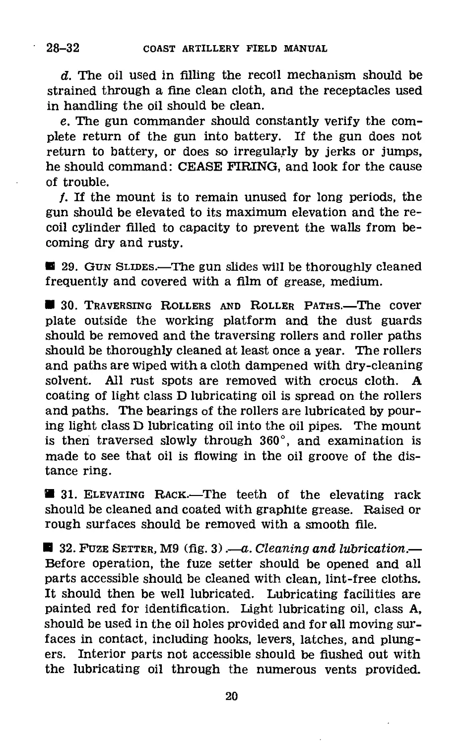
32. Fuze Setter, M9 (fig. 3).—a. Cleaning and lubrication.—
Before operation, the fuze setter should be opened and all
parts accessible should be cleaned with clean, lint-free cloths.
It should then be well lubricated. Lubricating facilities are
painted red for identification. Light lubricating oil, class A,
should be used in the oil holes provided and for all moving sur-
faces in contact, including hooks, levers, latches, and plung-
ers. Interior parts not accessible should be flushed out with
the lubricating oil through the numerous vents provided.
20
105-MM ANTIAIRCRAFT GUN
32
The ball bearings in the hub of the indicator bracket are
packed with a mixture of 60 percent petrolatum (U. S. A.
Spec. 2-67) and 40 percent rust-preventive compound, grade
“B” medium (U. S. A. Spec. 2-78A). They are packed during
initial assembly and should not require further attention for
several years. Repacking should be done by ordnance per-
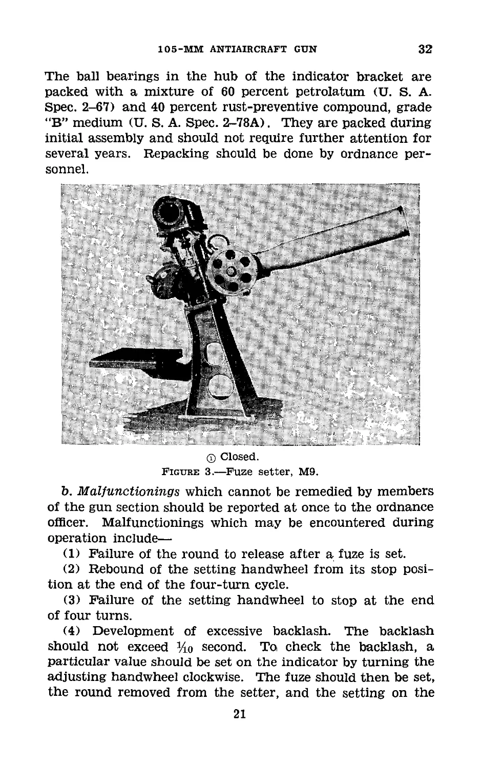
® Closed.
Figure 3.—Fuze setter, M9.
b. Malfunctionings which cannot be remedied by members
of the gun section should be reported at once to the ordnance
officer. Malfunctionings which may be encountered during
operation include—
(1) Failure of the round to release after a fuze is set.
(2) Rebound of the setting handwheel from its stop posi-
tion at the end of the four-turn cycle.
(3) Failure of the setting handwheel to stop at the end
of four turns.
(4) Development of excessive backlash. The backlash
should not exceed %o second. To check the backlash, a
particular value should be set on the indicator by turning the
adjusting handwheel clockwise. The fuze should then be set,
the round removed from the setter, and the setting on the
21
32
COAST ARTILLERY FIELD MANUAL
fuze read. The indicator should then be turned past the
original setting by turning the handwheel in the same direc-
tion as before (clockwise), then returned to the original set-
ting by turning the handwheel in the opposite direction
(counterclockwise). The fuze should then be set again and
the setting read. The difference between the two readings of
the fuze is an indication of the amount of backlash.
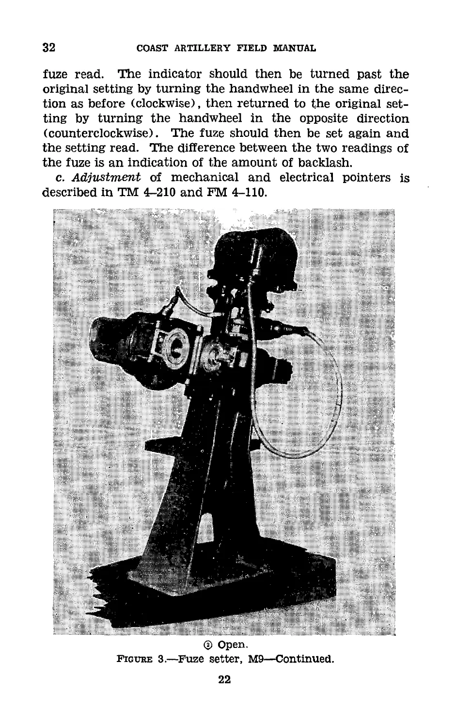
c. Adjustment of mechanical and electrical pointers is
described in TM 4-210 and FM 4-110.
@ Open.
Figure 3.—Fuze setter. M9—Continued.
22
105-MM ANTIAIRCRAFT GUN
33
Section in
MALFUNCTIONS
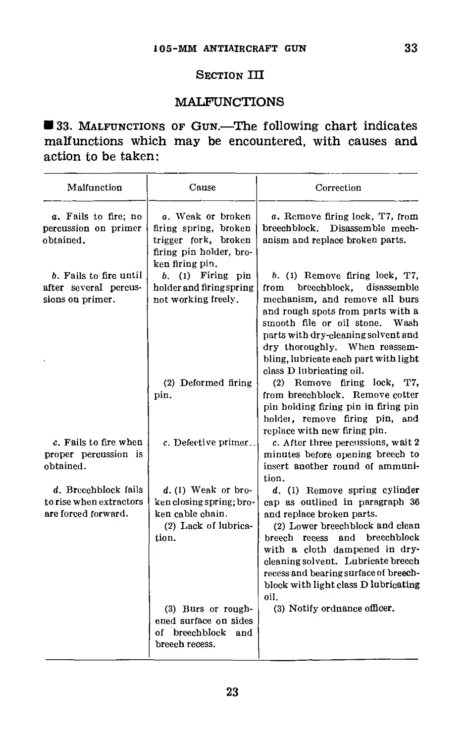
33. Malfunctions of Gun.—The following chart indicates
malfunctions which may be encountered, with causes and
action to be taken:
Malfunction Cause Correction
a. Fails to fire; no a. Weak or broken a. Remove firing lock, T7, from
percussion on primer firing spring, broken breechblock. Disassemble mech-
obtained. trigger fork, broken firing pin holder, bro- ken firing pin. anism and replace broken parts.
b. Fails to fire until b. (1) Firing pin b. (1) Remove firing lock, T7,
after several percus- holder and firingspring from breechblock, disassemble
sions on primer. not working freely. (2) Deformed firing pin. mechanism, and remove all burs and rough spots from parts with a smooth file or oil stone. Wash parts with dry-cleaning solvent and dry thoroughly. When reassem- bling, lubricate each part with light class D lubricating oil. (2) Remove firing lock, T7, from breechblock. Remove cotter pin holding firing pin in firing pin holdei, remove firing pin, and replace with new firing pin.
e. Fails to fire when proper percussion is obtained. c. Defective primer.. c. After three percussions, wait 2 minutes before opening breech to insert another round of ammuni- tion.
d. Breechblock fails d. (1) Weak or bro- d. (1) Remove spring cylinder
to rise when extractors ken closing spring; bro- cap as outlined in paragraph 36
are forced forward. ken cable chain. (2) Lack of lubrica- tion. (3) Burs or rough- ened surface on sides of breechblock and breech recess. and replace broken parts. (2) Lower breechblock and clean breech recess and breechblock with a cloth dampened in dry- cleaningsolvent. Lubricate breech recess and bearing surface of breech- block with light class D lubricating oil. (3) Notify ordnance officer.
23
34
COAST ARTILLERY FIELD MANUAL
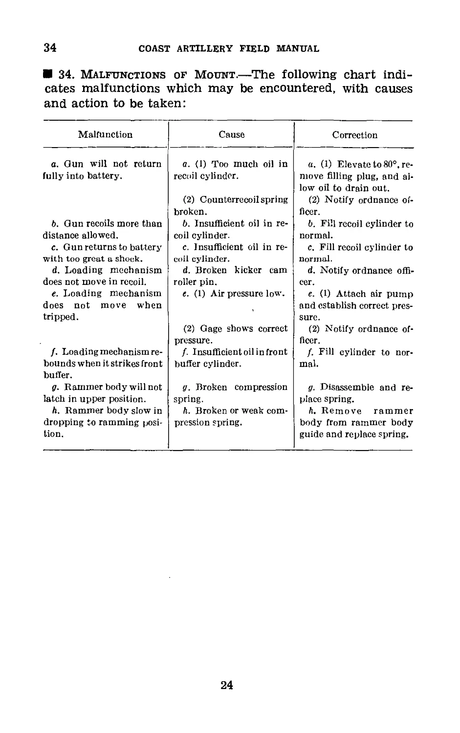
34. Malfunctions of Mount.—The following chart indi-
cates malfunctions which may be encountered, with causes
and action to be taken:
Malfunction Cause Correction
a. Gun will not return a. (1) Too much oil in a. (1) Elevate to 80°, re-
fully into battery. recoil cylinder. (2) Counterrecoilspring broken. move filling plug, and al- low oil to drain out. (2) Notify ordnance of- ficer.
b. Gun recoils more than b. Insufficient oil in re- b. Fill recoil cylinder to
distance allowed. coil cylinder. normal.
c. Gun returns to battery c. Insufficient oil in re- c. Fill recoil cylinder to
with too great a shock. coil cylinder. normal.
d. Loading mechanism d. Broken kicker cam d. Notify ordnance offi-
does not move in recoil. roller pin. cer.
e. Loading mechanism e. (1) Air pressure low. e. (1) Attach air pump
does not move when tripped. (2) Gage shows correct pressure. and establish correct pres- sure. (2) Notify ordnance of- ficer.
/. Loadingmechanismre- f. Insufficient oil in front /. Fill cylinder to nor-
bounds when it strikes front buffer. buffer cylinder. mal.
g. Rammer body will not g. Broken compression g. Disassemble and re-
latch in upper position. spring. place spring.
h. Rammer body slow in Л. Broken or weak com- Л. Remove rammer
dropping to ramming posi- tion. pression spring. body from rammer body guide and replace spring.
24
CHAPTER 7
ASSEMBLY AND DISASSEMBLY OF BREECHBLOCK AND
FIRING MECHANISM
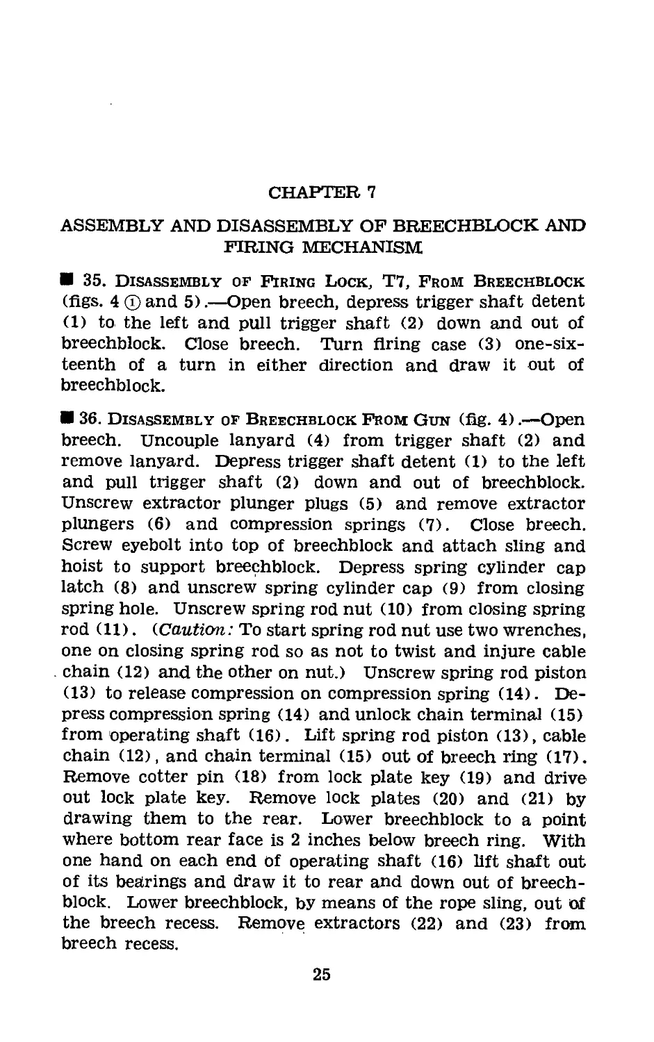
35. Disassembly of Firing Lock, T7, From Breechblock
(figs. 4 ® and 5).—Open breech, depress trigger shaft detent
(1) to the left and pull trigger shaft (2) down and out of
breechblock. Close breech. Turn firing case (3) one-six-
teenth of a turn in either direction and draw it out of
breechblock.
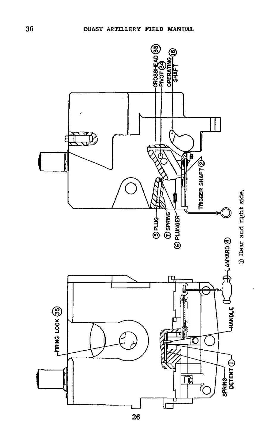
36. Disassembly of Breechblock From Gun (fig. 4).—Open
breech. Uncouple lanyard (4) from trigger shaft (2) and
remove lanyard. Depress trigger shaft detent (1) to the left
and pull trigger shaft (2) down and out of breechblock.
Unscrew extractor plunger plugs (5) and remove extractor
plungers (6) and compression springs (7). Close breech.
Screw eyebolt into top of breechblock and attach sling and
hoist to support breechblock. Depress spring cylinder cap
latch (8) and unscrew spring cylinder cap (9) from closing
spring hole. Unscrew spring rod nut (10) from closing spring
rod (11). (Caution: To start spring rod nut use two wrenches,
one on closing spring rod so as not to twist and injure cable
chain (12) and the other on nut.) Unscrew spring rod piston
(13) to release compression on compression spring (14). De-
press compression spring (14) and unlock chain terminal (15)
from operating shaft (16). Lift spring rod piston (13), cable
chain (12), and chain terminal (15) out of breech ring (17).
Remove cotter pin (18) from lock plate key (19) and drive
out lock plate key. Remove lock plates (20) and (21) by
drawing them to the rear. Lower breechblock to a point
where bottom rear face is 2 inches below breech ring. With
one hand on each end Of operating shaft (16) lift shaft out
of its bearings and draw it to rear and down out of breech-
block. Lower breechblock, by means of the rope sling, out of
the breech recess. Remove; extractors (22) and (23) from
breech recess.
25
се
о
Ф Rear and right side.
coast artillery field manual
Figure 4.—Breech mechanism assembly.
105-MM ANTIAIRCRAFT GUN
w
о
37-38
COAST ARTILLERY FIELD MANUAL
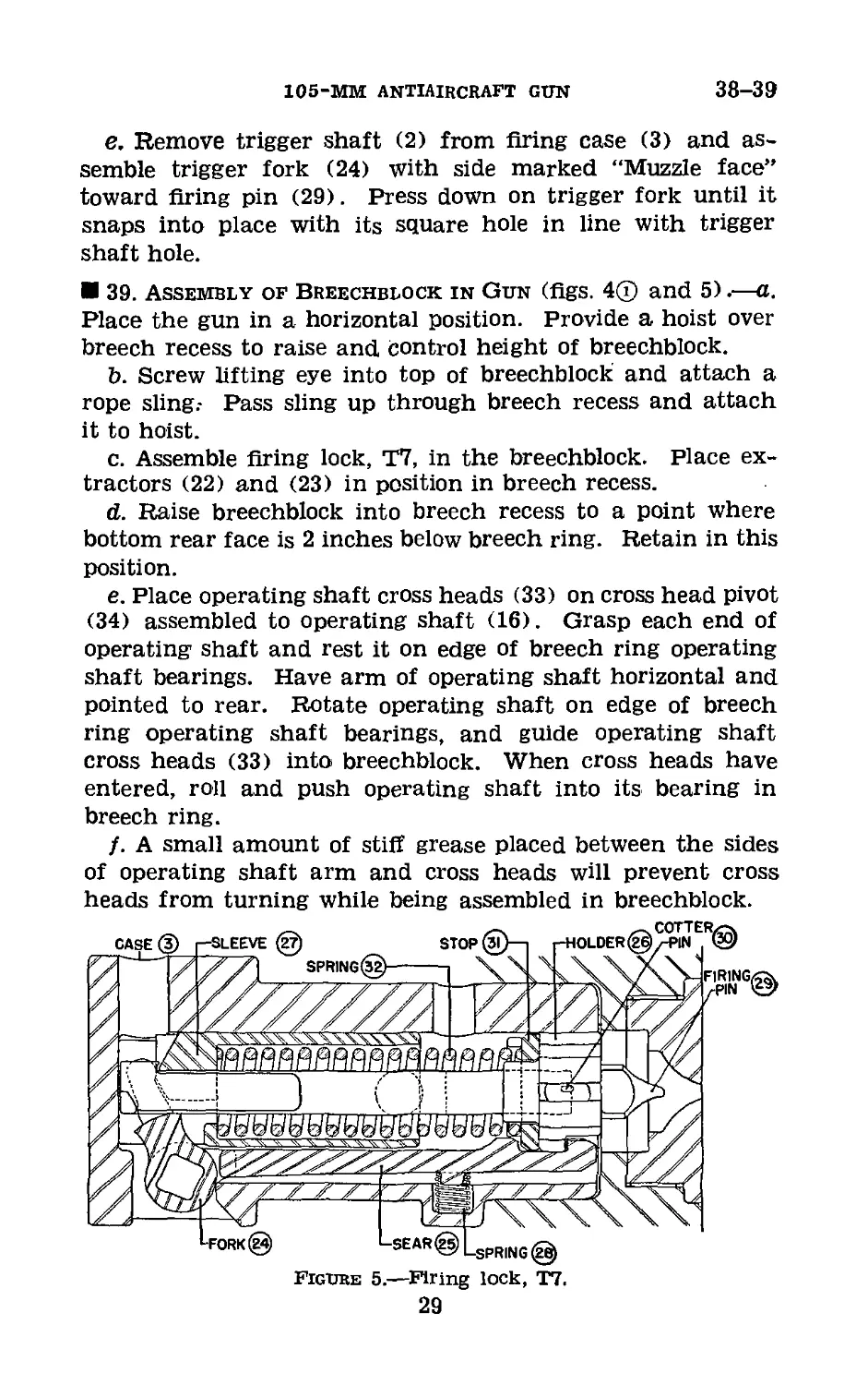
37. Disassembly of Firing Lock, T7 (flgs. 4 @ and 5).—
Remove trigger fork (24) by placing the blade of a screwdriver
through the round hole opposite the square hole in firing
case (3) and push on one end of trigger fork. Insert trigger
shaft (2) far enough into flring case to engage fork end of
sear (25). Turn trigger shaft in the direction to disengage
sear from firing pin holder (26). Bump firing case lightly
against a wood block to start firing pin holder out of firing
case. Place screwdriver through square hole and pry against
firing pin holder sleeve (27) until it can be drawn out by
hand. Remove trigger shaft (2), sear (25), and compression
spring (28). To remove firing pin (29), draw out cotter pin
(30), and unscrew firing pin from firing pin holder (26).
Note.—In assembling operations, all bearing surfaces should be
given a coating of light class D lubricating oil.
38. Assembly of Firing Lock, T7 (flgs. 4 ® and 5).—a.
Screw firing pin (29) into firing pin holder (26) to the shoul-
der. Insert cotter pin (30) through firing pin holder and
spread ends of cotter pin.
b. Place spring stop (31) on firing pin holder with long
guides to rear.
c. Assemble compression spring (32) over firing pin holder.
Guide firing pin holder sleeve (27) over compression spring
(32) and aline firing pin holder sleeve with hook of firing
pin holder; place firing pin holder sleeve against a block or
bench and press in firing pin holder until hook on firing pin
holder engages firing pin holder sleeve.
d. Place compression spring (28) into its seat in firing case
(3). Assemble sear (25) in firing case with spring knob of
sear engaging compression spring (28). Insert trigger shaft
(2) into firing case and sear. Depress sear with a screw-
driver through hole in side of firing case opposite compression
spring (28) and assemble firing pin holder sleeve assembly
(as assembled in c above) into firing case with fiat side
of firing pin holder sleeve toward sear. Push firing pin
holder sleeve assembly into firing case, guiding spring stop
guides into guide slots in firing case. When firing pin holder
(26) reaches bottom of firing case, sear will snap into
engaged position and hold assembly in firing case.
28
105-MM ANTIAIRCRAFT gun
38-39
e. Remove trigger shaft (2) from firing case (3) and as-
semble trigger fork (24) with side marked “Muzzle face”
toward firing pin (29). Press down on trigger fork until it
snaps into place with its square hole in line with trigger
shaft hole.
39. Assembly of Breechblock in Gun (figs. 4® and 5).—a.
Place the gun in a horizontal position. Provide a hoist over
breech recess to raise and control height of breechblock.
b. Screw lifting eye into top of breechblock and attach a
rope sling.- Pass sling up through breech recess and attach
it to hoist.
c. Assemble firing lock, T7, in the breechblock. Place ex-
tractors (22) and (23) in position in breech recess.
d. Raise breechblock into breech recess to a point where
bottom rear face is 2 inches below breech ring. Retain in this
position.
e. Place operating shaft cross heads (33) on cross head pivot
(34) assembled to operating shaft (16). Grasp each end of
operating shaft and rest it on edge of breech ring operating
shaft bearings. Have arm of operating shaft horizontal and
pointed to rear. Rotate operating shaft on edge of breech
ring operating shaft bearings, and guide operating shaft
cross heads (33) into breechblock. When cross heads have
entered, roll and push operating shaft into its bearing in
breech ring.
f. A small amount of stiff grease placed between the sides
of operating shaft arm and cross heads will prevent cross
heads from turning while being assembled in breechblock.
Figure 5.—Firing lock, T7.
29
CHAPTER 8
SERVICE OF RECOIL AND RAMMER MECHANISMS
Paragraphs
Section I. Recoil mechanism_________________40-41
II. Rammer mechanism__________________42-46
Section I
RECOIL MECHANISM
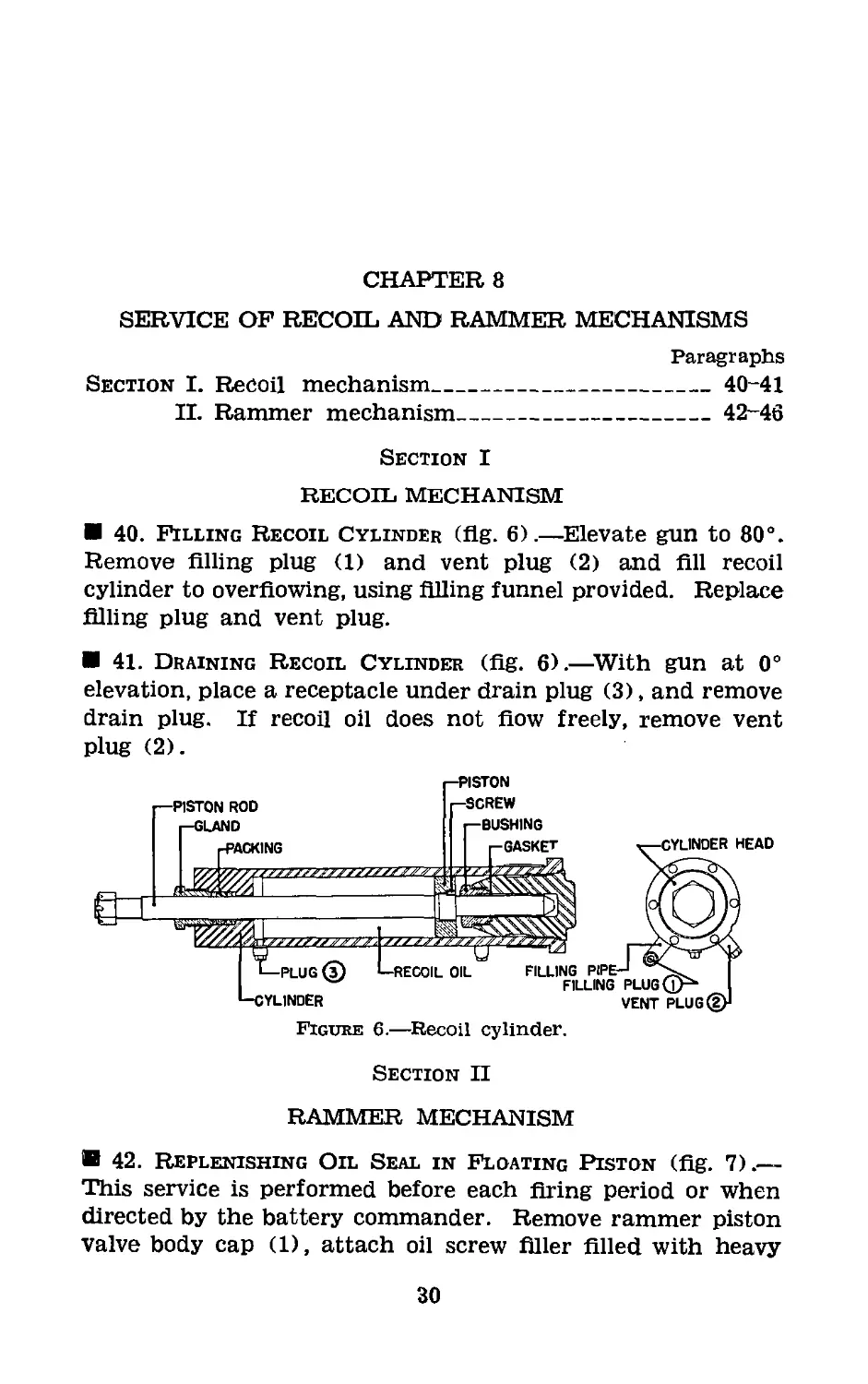
40. Filling Recoil Cylinder (flg. 6).—Elevate gun to 80°.
Remove filling plug (1) and vent plug (2) and fill recoil
cylinder to overflowing, using filling funnel provided. Replace
filling plug and vent plug.
41. Draining Recoil Cylinder (flg. 6).—With gun at 0°
elevation, place a receptacle under drain plug (3), and remove
drain plug. If recoil oil does not flow freely, remove vent
plug (2).
Figure 6.—Recoil cylinder.
Section II
RAMMER MECHANISM
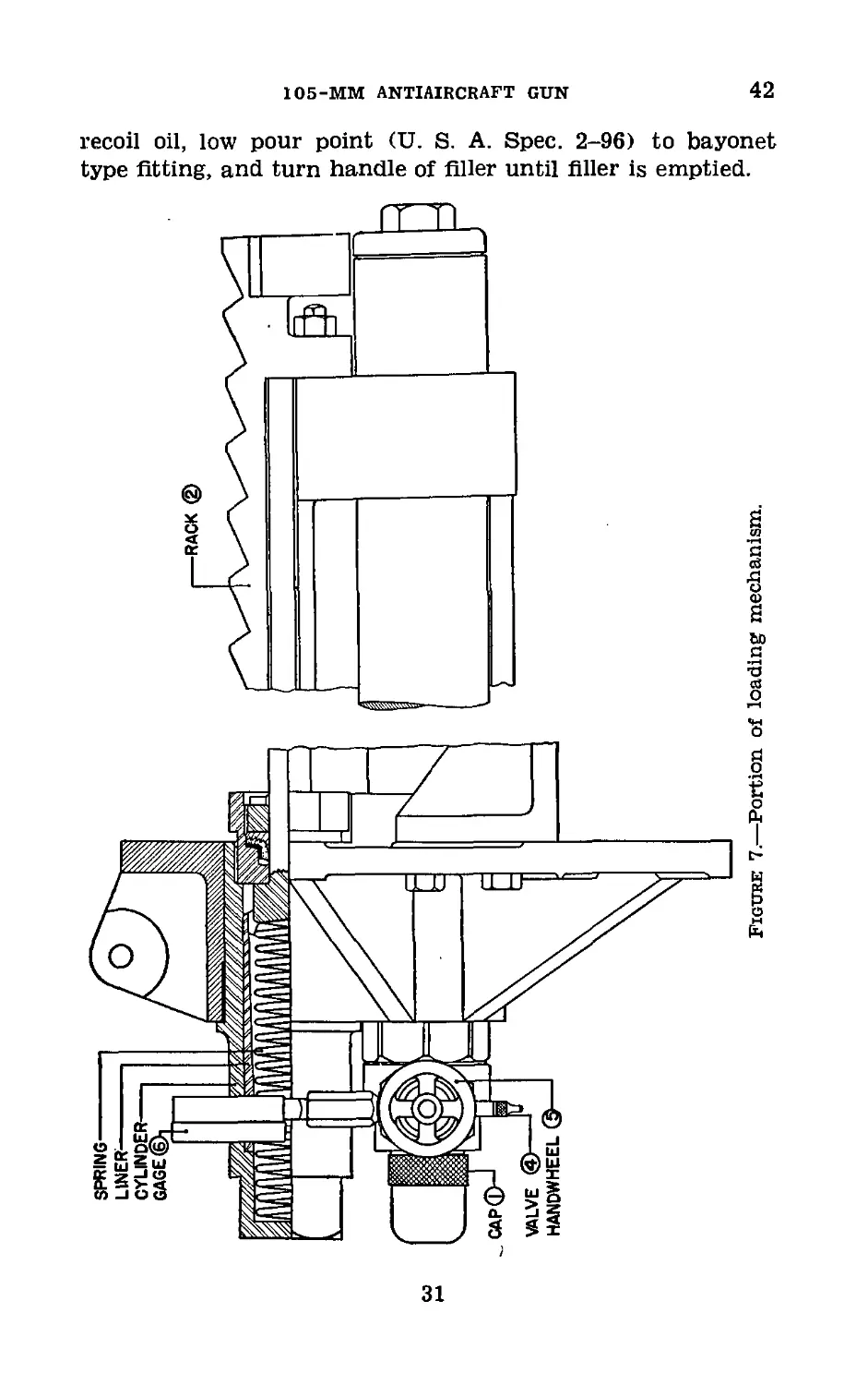
42. Replenishing Oil Seal in Floating Piston (flg. 7).—
This service is performed before each firing period or when
directed by the battery commander. Remove rammer piston
valve body cap (1), attach oil screw filler filled with heavy
30
105-MM ANTIAIRCRAFT GUN
42
recoil oil, low pour point (U. S. A. Spec. 2-96) to bayonet
type fitting, and turn handle of filler until filler is emptied.
Figure 7.—Portion of loading mechanism.
31
43-45
COAST ARTILLERY FIELD MANUAL
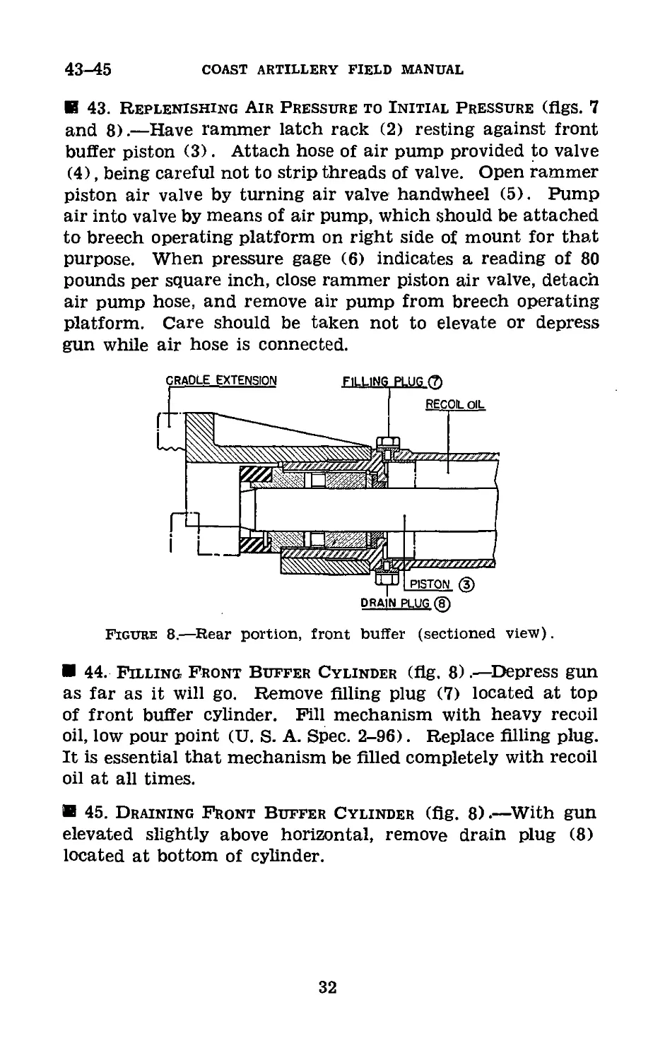
В 43. Replenishing Air Pressure to Initial Pressure (flgs. 7
and 8).—Have rammer latch rack (2) resting against front
buffer piston (3). Attach hose of air pump provided to valve
(4), being careful not to strip threads of valve. Open rammer
piston air valve by turning air valve handwheel (5). Pump
air into valve by means of air pump, which should be attached
to breech operating platform on right side of mount for that
purpose. When pressure gage (6) indicates a reading of 80
pounds per square inch, close rammer piston air valve, detach
air pump hose, and remove air pump from breech operating
platform. Care should be taken not to elevate or depress
gun while air hose is connected.
Figure 8.—Rear portion, front buffer (sectioned view).
В 44. Filling Front Buffer Cylinder (flg. 8).—Depress gun
as far as it will go. Remove filling plug (7) located at top
of front buffer cylinder. Fill mechanism with heavy recoil
oil, low pour point (U. S. A. Spec. 2-96). Replace filling plug.
It is essential that mechanism be filled completely with recoil
oil at all times.
В 45. Draining Front Buffer Cylinder (flg. 8).—With gun
elevated slightly above horizontal, remove drain plug (8)
located at bottom of cylinder.
32
105-MM ANTIAIRCRAFT GUN
46
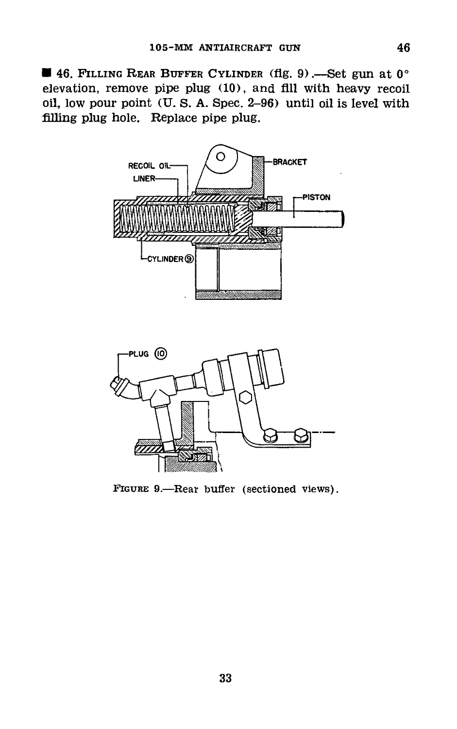
46. Filling Rear Buffer Cylinder (flg. 9).—Set gun at 0°
elevation, remove pipe plug (10), and All with heavy recoil
oil, low pour point (U. S. A. Spec. 2-96) until oil is level with
filling plug hole. Replace pipe plug.
Figure 9.—Rear buffer (sectioned views).
33
CHAPTER 9
LUBRICATION
47. General.—a. The various lubricants and cleaning and
preserving materials issued by the Ordnance Department are
described in *TM 9-850. No lubricants will be used other
than those authorized nor will any lubricant be used in a
manner other than as prescribed.
b. (1) The breech mechanism is not provided with oil holes,
and many of the bearing surfaces may be oiled only after
disassembly. See also paragraphs 25 and 26.
(2) The mount is provided with bayonet type fittings, with
oil plugs, and with oil holes. Fittings and plugs are painted
red and each oil hole is marked by a red ring. See also para-
graphs 28 to 31, inclusive.
c. Care must be taken when cleaning oil and grease com-
partments to insure the complete removal of residue or sedi-
ment and to prevent the entrance of dirt or other foreign
matter.
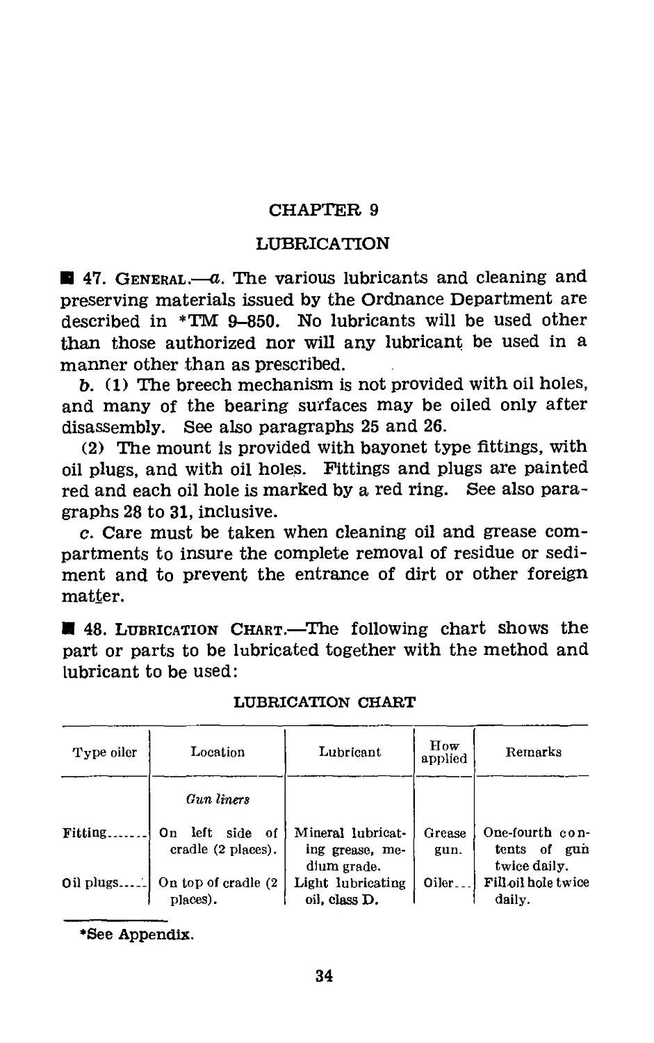
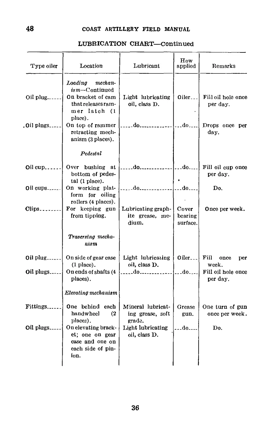
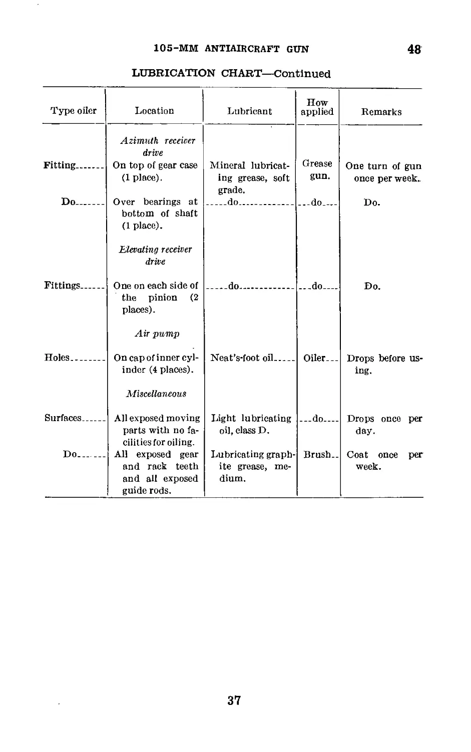
48. Lubrication Chart.—The following chart shows the
part or parts to be lubricated together with the method and
lubricant to be used:
LUBRICATION CHART
Type oiler Location Lubricant How applied Remarks
Fitting Oil plugs Gun liners On left side of cradle (2 places). On top of cradle (2 places). Mineral lubricat- ing grease, me- dium grade. Light lubricating oil, class D. Grease gun. Oiler... One-fourth con- tents of gun twice daily. Filloil hole twice daily.
•See Appendix.
34
105-MM ANTIAIRCRAFT GUN
48
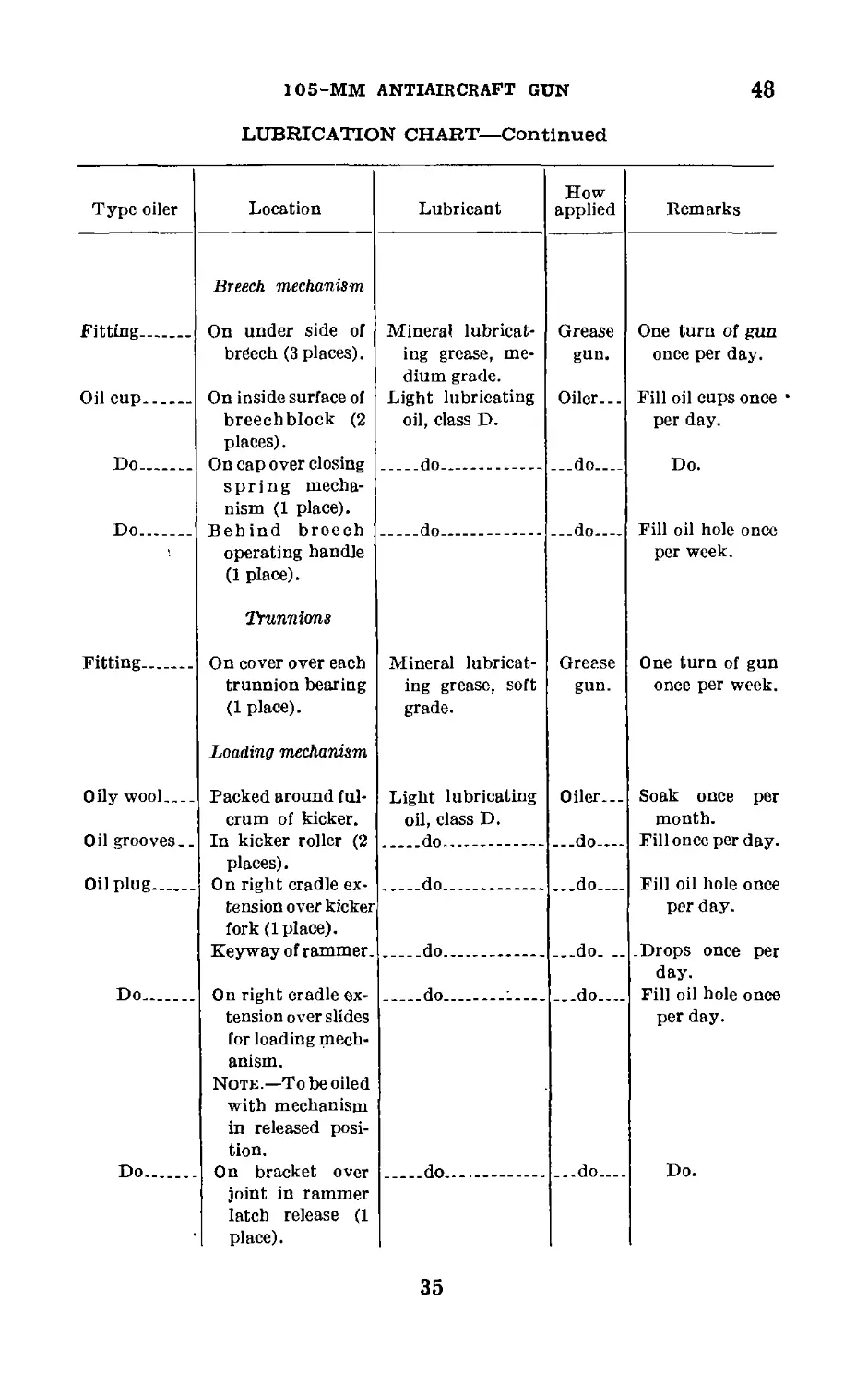
LUBRICATION CHART—Continued
Type oiler Location Lubricant How applied Remarks
Breech mechanism
Fitting.. On under side of Mineral lubricat- Grease One turn of gun
brCech (3 places). ing grease, me- dium grade. gun. once per day.
Oil cup On inside surface of breechblock (2 places). Light lubricating oil, class D. Oiler... Fill oil cups once per day.
Do On cap over closing spring mecha- nism (1 place). do ___do Do.
Do... Behind breech do do Fill oil hole once
operating handle (1 place). Trunnions per week.
Fitting On cover over each Mineral lubricat- Grease One turn of gun
trunnion bearing (1 place). Loading mechanism ing grease, soft grade. gun. once per week.
Oily wool.... Packed around ful- crum of kicker. Light lubricating oil, class D. Oiler... Soak once per month.
Oil grooves.. In kicker roller (2 places). do ...do— Fill once per day.
Oil plug On right cradle ex- tension over kicker fork (1 place). do. __.do Fill oil hole once per day.
Keyway of rammer. do ___do .Drops once per day.
Do On right cradle ex- tension over slides for loading mech- anism. Note.—To be oiled with mechanism in released posi- tion. do ........ ..-do.-— Fill oil hole once per day.
Do On bracket over joint in rammer latch release (1 place). do _..do Do.
35
48
COAST artillery field manual
LUBRICATION CHART—Continued
Type oiler Location Lubricant How applied Remarks
Oil plug Oil pings Loading mechan- ism—Continued On bracket of cam that releases ram- mer latch (1 place). On top of rammer retracting mech- anism (3 places). Light lubricating oil, class D. do Oiler... ...do Fill oil hole once per day. Drops once per day.
Pedestal
Oil cup Oil cups Clips Over bushing at bottom of pedes- tal (1 place). On working plat- form for oiling rollers (4 places). For keeping gun from tipping. do do Lubricating graph- ite grease, me- dium. ...do ...do Cover bearing surface. Fill oil cup once per day. Do. Once per week.
Traversing mecha- nism
Oil plug Oil plugs On side of gear case (1 place). On ends of shafts (4 places). Light lubricating oil, class D. do Oiler... ...do Fill once per week. Fill oil hole once per day.
Elevating mechanism
Fittings Oil plugs One behind each handwheel (2 places). On elevating brack- et; one on gear case and one on each side of pin- ion. Mineral lubricat- ing grease, soft grade. Light lubricating oil, class D. Grease gun. ...do One turn of gun once per week. Do.
36
105-MM ANTIAIRCRAFT GUN
48
LUBRICATION CHART—Continued
Type oiler Location Lubricant How applied Remarks
Fitting Azimuth receiver drive On top of gear case Mineral lubricat- Grease One turn of gun
(1 place). ing grease, soft gun. once per week..
Do Over bearings at grade. do Do.
Fittings bottom of shaft (1 place). Elevating receiver drive One on each side of do .„do Do.
Holes the pinion (2 places). Air pump On cap of inner cyl- inder (4 places). Miscellaneous All exposed moving Neat's-foot oil - Oiler Drops before us- ing. Drops once per
Surfaces Light lubricating ...do
Do parts with no fa- cilities for oiling. All exposed gear oil, class D. Lubricating graph- Brush.. day. Coat once per
and rack teeth and all exposed guide rods. ite grease, me- dium. week.
37
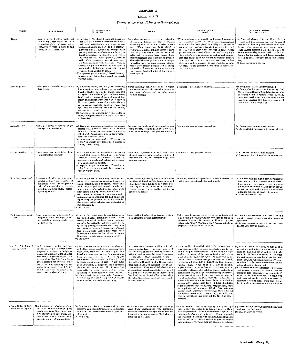
CHAPTER 10
DRILL TABLE
Service of the piece, 105-mm antiaircraft gun
Details DETAILS, POSTS (a) EXAMINE GXJN (b) REPORT TARGET COMMENIE FIRING (LOAD) (a) SUSPEND FIRING (6) CEASE FIRING
Gunner ... Procures wiper of cotton waste and can of oil; places wiper and oil in convenient place, and takes post to right rear of piece opposite to and facing end of loading tray. (a) Assisted by Nos. 1 and 3, examines, cleans, and oils breechblock, breech mechanism, and rammer mechanism; tests firing and rammer mechanisms; examines chamber and bore; and, if necessary, calls upon Nos. 2 to 8, inclusive, for assistance in Sponging and cleaning chamber and bore. As- sisted by No. 1, inspects oil level in recoil cylinder and front and rear buffer cylinders, under di- rection of gun commander, and, when necessary, fills those cylinders with recoil oil. When so directed by gun commander, obtains hand air pump and replenishes air pressure in rammer cylinder, being assisted by No. 1. (b) Reports to gun commander, “Breech in order,” or reports any defects he is unable to remedy without delay. Supervises opening of hreech and retraction of rammer, holding up end of rammer retracting cam while No. I retracts ram- mer. When rounds are being placed in loading tray broadside (at high angles of eleva- tion), as soon as rammer has been retracted, pulls back on rammer head release lever, dropping rammer head to its loading position. When ejected cartridge cases are to be stopped in loading tray, he turns rammer tripping cam to its “engaged” position so that, during last portion of movement of rammer body to rear, rammer head will be forced down into its lower position. When rounds are being placed in loading tray from rear (at low or medium angles of elevation), drops rammer head after ronnd has been placed in loading tray in front of rammer head. At the command ram, given by No. 3 (4, 5, 6, 7, or 8) after round has slipped back or been pushed back into contact with rammer head (at any angle of elevation), he trips rammer by pulling back on ram- mer latch release lever and immediately grasps lanyard in his right hand. As soon as breech has closed, he fires piece by a pull on lanyard. In case of misfire he calls, “Misfire,” to gun commander and keeps all cannoneers clear of breech. (a) If an unfired round is in gun, directs No. 1 to retract and drop rammer head just to rear of breech and then drop breechblock with hand lever. After extractors have thrown round back against rammer head, directs No. 1 to continue retracting rammer until it is latched back in loading position, and directs a member of loading detail to remove round from loading tray. (b) same as suspend fiiuno.
Fuze range setter. Takes post seated on left of gun facing : fuze setter. (a) Examines, cleans, and oils (when necessary) fuze setter, fuze range indicator, and connections thereto, assisted by No. 2. Makes sure that swing bolt nuts are both tight. Releases setting handwheel by means of knob at rear of fuze setter, pulling knob directly to rear. As soon as No. 2 has operated unloaded fuze setter through one or more cycles, tests operation of fuze setter by setting and checking fuze at several values, assisted by No. 2 and No. 4. (b) Reports to gun commander, “Fuze setter in order,” or reports defects he is unable to remedy without delay. Turns adjusting handwheel so as to match mechanical pointer with electrical pointer of fuze range indicator, and thereafter keeps pointers matched. Continues to keep pointers matched (a) Continues to keep pointers matched. (b) Sets mechanical pointer to fuze setting “15” (for mechanical fuze, М2) and directs a member of loading detail to remove round in setter. Supervises setting to 15 of any other rounds necessary, checking each fuze as it is removed from setter. Remains at post.
Azimuth setter Takes post seated on left side of gun facing azimuth indicator. (a) Examines traversing mechanism and assures himself that power is turned on in azimuth indicator. Assists gun commander in checking adjustment of mechanical pointer and synchro- nization of electrical pointer. (b) Reports to gun commander, “Traversing in order,” or reports any defects he is unable to remedy without delay. Traverses gun so as to match mechanical pointers with electrical pointers of azimuth indicator, and thereafter keeps those pointers matched. Continues to keep pointers matched (a) Continues to keep pointers matched. (b) Stops matching pointers but remains at post.
Elevation setter... Takes post seated on right side of gun facing elevation indicator. (a) Examines elevating mechanism and assures himself that power <is turned on in elevation indicator. Assists gun commander in checking adjustment of mechanical pointer and synchro- nization of electrical pointer. (6) Reports to gun commander, “Elevating in order,” or reports any defects he is unable to remedy without delay. Elevates or depresses gnn so as to match me- chanical pointers with electrical pointers of elevation indicator, and thereafter keeps those pointers matched. Continues to keep pointers matched (a) Continues to keep pointers matched. (b) Stops matching pointers b ut remains at post.
No. 1 (breech operator).. Removes and folds up gun cover, assisted by No. 6, and deposits it at designated place. Takes post on right of gun standing on breech- operating platform facing hreech- operating handle. (a) Assists gunner in examining, cleaning, and oiling breech mechanism, rammer, firing mech- anism, chamber, and bore of gun. Assists gun- ner in Inspecting oil level in recoil cylinder and front and rear buffer cylinders, and, when neces- sary, assists in filling those cylinders with recoil oil. When so directed by gun commander, assists gunner in obtaining hand air pump and replenishing air pressure in rammer cylinder. Sets rammer release tripping cam as directed by gun commander. (b) No duties. Opens breech by bearing down on operating handle until breechblock is locked open, and immediately raises handle to its vertical posi- tion. By means of rammer retracting wheel, retracts rammer to its loading position as directed by gunner. No duties, unless hand operation of breech Is ordered, In which case, opens breech after each round. (a) If unfired round is in gun, retracts rammer so that head will drop directly behind breech, drops rammer head, opens breech, and eases unfired round back into loading tray by retract- ing rammer head until rammer is latched back in loading position, as directed by gunner. (b) Same as suspend firing.
No. 2 (fuze setter opera- ator). Removes muzzle cover and puts it in designated place. Takes post stand- ing to right of fuze range setter fac- ing fuze setter. (a) Assists fuze range setter in examining, clean- ing, and oiling fuze setting mechanism. When setting handwheel has been released, operates unloaded fuze setter through one or more setting cycles (by turning handwheel clockwise) to see that handwheel stops and locks at end of fourth turn of each cycle. Assists fuze range setter in setting and checking fuze at several values. If necessary, assists gunner in sponging bore. (b) No duties. Locks setting handwheel by turning it clock- wise until it is stopped automatically. With a round in the fuze setter, rotates setting handwheel quickly until it brings up against stop, turning handle in clockwise direction. On completion of fuze setting oper- ation, calls “Cut.” Continues to set fuzes asquickly as projectiles are inserted in fuze setter. (a) Sets fuze if unset round is in fuze setter or If round is placed in fuze setter after receipt of command. (b) Remains at post prepared to set such fuzes back to 15 as may be necessary.
Nos. 3, 4, 5, 6, 7, and S (loading detail). No. 3 procures chamber and bore sponge and wiper of cotton waste, disposes of sponges in designated place, and takes post at the ammuni- tion rack facing breech of gun. No. 4, assisted by Nos. 5, 6, 7, and 8, un- covers ammunition on rack. No. 6 assists No. 1 in removing and dis- posing of gun cover. Nos. 4, 5, 6, 7. and 8 take posts at ammunition rack, in column behind No. 3. (a) No. 3 assists gunner in examining, cleaning, and oiling breech mechanism, rammer, firing mechanism, chamber, and bore of gun. Sets breech operating cam plunger for automatic or hand operation of breech, as directed by gun commander. No. 4, assisted by Nos. 5, 6, 7, and 8, checks ammunition on rack. When called upon by gunner, all six men assist in sponging chamber and bore of gun. No. 4 assists fuze range setter in testing operation of fuze setter by setting and checking fnze at several values. (b) No. 4 reports to gnn commander, “Ammuni- tion handling in order,” or reports such defects as he is unable to remedy without delay. No. 3 takes round from ammunition rack, right hand grasping base of cartridge case, with rotating band of projectile resting in crook of left arm, and proceeds by most direct route to fuze setter. Rests projectile on edge of mouth of fuze setter and then inserts round into setter with right hand with one contin- uous motion and with sufficient force to com- plete seating. When round is locked in fuze setter, releases round immediately. Nos. 4, 5, 6, 7, and 8 each grasp round as prescribed for No. 3 and proceed to left of fuze setter, where they stand in readiness to deposit their rounds, in turn, in setter. As soon as No. 2 has called “Cut,” No. 3 grasps base of cartridge case with both hands and starts round to rear with quick pull without rotation. When firing is at high angles of elevation, catches rot ating band of projectile in crook of his left arm, with right hand remaining under base end of case, steps toward gun, and deposits round, broadside, in loading tray with right hand just clearing rammer head. When firing is at low or medium angles of elevation, when loading tray is too high for broadside loading, catches rotating band of projectile in palm of left hand, with right band remaining under base end of case, steps toward gun, inserts nose of round in rear of loading tray, and pushes round forward until base of case is in front of rammer head. In either method of loading, after rammer head has been dropped, adjusts round backward into contact with rammer head, steps away quickly, and commands: RAM. Returns to am- munition rack, obtains another round, and falls in behind No. 8 on left of fuze setter. Nos. 4, 5, 6, 7, and 8, in turn, perform operations just described for No. 3 as firing proceeds. (я) If nnflred round is in gun, as soon as it is ejected onto loading tray, it is removed and laid aside by that member of loading detail who loaded it. If there is no round in fuze setter, the next succeeding member of loading detail insertsone, and remaining members of loading detail stand ready to continue service of ammu- nition when firing is resumed. (b) If th«re is a round In fuze setter, It is removed and returned to ammunition rack by membei of loadng detail as soon as it has been set to 15. Other -ounds which have been laid aside with their fjzcs set are inserted in fuze setter by membsrs of loading detail; when fnzes are set to 15, nunds are returned to ammunition rack
Nos. 9 to 16, inclusive (ammunition squad). No. 9 obtains pair of asbestos gloves and puts them in convenient place near breech of gun. Nos. 9 to 16, inclu- sive, are posted by chief of ammuni- tion squad in such manner as to expedite supply of ammunition. (a) Remove from boxes or crates and prepare necessary ammunition for contemplated practice or action. Fill ammunition racks at gun em- placement. (b) No duties. No. 9 stands ready to remove empty cartridge cases from emplacement. The remaining members of ammunition squad stand ready to keep rack at gun emplacement filled with am- munition as it is used. No. 9 catches (or takes from loading tray) empty cartridge cases as they are ejected from gun and removes them from emplacement. Remaining members of squad con- tinue supply of ammunition to rack. Whenever practi- cable without interfering with gun squad, or during lulls in firing, collect and place at designated point all empty cases preparatory to decapping and cleaning for salvage. (a) Collet all empty cases, fill ammunition racks, and reurn to their posts. (b) Sam« as suspend firing.
235202’—10 (Face p. 38)
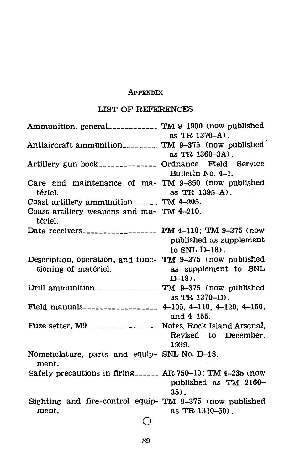
Appendix
LIST OF REFERENCES
Ammunition, general____________TM 9-1900 (now published
as TR 1370-A).
Antiaircraft ammunition________TM 9-375 (now published
as TR 1360-3A).
Artillery gun book_____________Ordnance Field Service
Bulletin No. 4-1.
Care and maintenance of ma- TM 9-850 (now published
t6riel. as TR 1395-A).
Coast artillery ammunition_____TM 4-205.
Coast artillery weapons and ma- TM 4-210.
teriel.
Data receivers_________________FM 4-110; TM 9-375 (now
published as supplement
to SNL D-18).
Description, operation, and func- TM 9-375 (now published
tioning of materiel. as supplement to SNL
D-18).
Drill ammunition_______________TM 9-375 (now published
as TR 1370-D).
Field manuals__________________ 4-105, 4-110, 4-120, 4-150,
and 4-155.
Fuze setter, M9________________Notes, Rock Island Arsenal,
Revised to December,
1939.
Nomenclature, parts and equip- SNL No. D-18.
ment.
Safety precautions in firing---AR 750-10; TM 4-235 (now
published as TM 2160-
35).
Sighting and fire-control equip- TM 9-375 (now published
ment. as TR 1310-50).
О
39