/


Tags: weapons military affairs machine gun patent
Year: 1936
Text
April 12, 1938.
C. A. LARSSON ET AL
2,113,793
MACHINE GUN AND DRUM MAGAZINE THEREFOR
Filed June 24, 1936
3 Sheets-Sheet 1
INVENTORS:
CARL ALFRED LARSSON
PERCY REUBEN HIGSON
ATTORNEYS
April 12, 1938. c. A. LARSSON ET AL 2,113,793
MACHINE GUN AND DRUM MAGAZINE THEREFOR
Filed June 24, 1936 3 Sheets-Sheet 2
INVENTORS-
CARL ALFRED LAR55ON
PERCY REUBEN HI&50N
ATTORNEYS
April 12, 1938. c. A. LARSSON ET AL 2,113,793
MACHINE GL’N AND DRUM MAGAZINE THEREFOR
Filed June 24, 1936 3 Sheets-Sheet 3
INVENTORS:
CARL ALFRED LARSSON
PERCY REUBEN HIBSON
ATTORNEYS
Patented Apr. 12, 1938
2,113,793
UNITED STATES PATENT OFFICE
2,113,793
MACHINE GUN AND DRUM MAGAZINE
THEREFOR
Carl Alfred Larsson and Percy Reuben Higson,
Westminster, England, assignors to Vickers-
Armstrongs Limited, Westminster, England, a
British company
Application June 24, 1936, Serial No. 86,970
In Great Britain June 28, 1935
8 Claims. (Cl. 89—33)
This invention relates to machine guns and to
drum magazines therefor and an important
object is to provide a large capacity drum whilst
maintaining the size of the drum as small as
5 practicably possible.
According to the Invention the magazine is
adapted to receive the cartridges in substantial-
ly annular disposition with adjacent cartridges
in contact with each other and having means
10 adapted for separating the so-arranged car-
tridges and feeding them singly through an out-
let or mouth-piece. When the cartridges having
rims are used, they may be arranged with their
rims outermost and with the rim of each car-
15 tridge overlapping the rim of the next cartridge
on one side of it and beneath the next cartridge
at the other side of it, and the drum is made
circular and of such diameter that it contacts
with the outermost points of the bases of the
cartridges arranged in this manner. The rim of
each cartridge preferably overlaps the rim of
the cartridge in front outwardly with respect to
the drum and overlaps the rim of the cartridge
behind it inwardly and the cartridge cases con-
25 tact with each other near the bullet. The car-
э tridges in these positions are slightly offset from
the radial with respect to the drum and the
apexes of the angles made by the centre lines of
successive pairs of cartridges are at a constant
30 radius from the centre of the drum. With such
an arrangement it is not possible for the rim
of a following cartridge to get in front of the
rim of a leading cartridge which would cause a
misfeed on reaching the outlet or mouthpiece of
35 the drum.
In order that the invention may be clearly
understood and readily carried into effect the
same will now be described more fully with ref-
erence to the accompanying drawings, where-
40 in:—
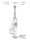
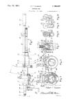
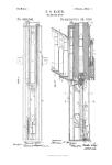
Figure 1 is a vertical sectional view of a drum
magazine made in accordance with the inven-
tion ;
Figure 2 is a plan view thereof;
45 Figure 3 is a part elevational view thereof
looking in the direction of the arrow 3 in Fig-
ure 2;
Figure 4 is a view of part of Figure 3 but
showing certain parts in different positions; and
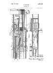
50 Figures 5 and 6 are an elevational and plan
view respectively of a movable lip comprising
part of the feeding means; and
Figures 7 and 8 are an elevational and plan
view respectively of a pawl associated with the
55 movable lip of Figures 5 and 6.
The magazine has a sleeve A or centre post
which fits over the upstanding spigot pin of the
machine gun and has recesses a at its upper end
comprising ratchet teeth. Surrounding the
sleeve A is an outer sleeve or driver В which 5
carries pivotally mounted pawls b pressed by
springs Ы into engagement with the ratchet
teeth a. The outer sleeve В has flat surfaces
b2 at its upper end for engagement by a span-
ner or winding lever so that it can be rotated 10
relatively to the sleeve A for winding up a spring
D. The inner end of the spring D is attached
to the outer sleeve В and the outer end of the
spring D is attached to a rotary member D1
carrying radial arms D2, the outer ends of which 15
carry blades D3 which press against the car-
tridges E to press them yieldingly towards the
outlet indicated generally at F. The cartridges
are mounted in outer and inner grooves E1 and
E2, respectively which are substantially helical,
formed in a shallow pan E3 attached to the in- 20
ner sleeve A. The grooves E1, E2, are continuous
and lead down to the outlet or mouthpiece F.
A hole E4 in the side of the drum or pan E3
facilitates loading the last few cartridges. The
pawls b serve as a safety device when winding
up the spring and obviate the necessity for the
key heretofore provided for locking the driver
to the centre post. When the spring has been
tensioned by a winding lever, this lever is re-
moved and a small locking plate may be screwed
on to the inner sleeve A to lock the pawls in po-
sition and to hold down all of the other mech-
anism in position. Should it be desired to re-
move the tension of the spring this can be done 3-
by removing the locking plate, replacing winding '’°
lever, taking the force of the spring on the lever,
and then releasing the ratchet pawls and un-
winding the spring.
As can be seen in Figure 2, the cartridge cases 40
e are in contact with each other at the position
e1 near the bullets e2 and each of the bases or
rims e3 overlaps the base or rim of the cartridge
in front of it on the outside thereof and overlaps
the base or rim of the cartridge behind it on the 45
inside. This arrangement as hereinbefore de-
scribed is such that the cartridges are slightly
offset from the radial rimless cartridges will be
arranged in substantially the same disposition.
The radius of the drum or pan E3 is made so as 50
just to accommodate the cartridges arranged in
this manner. The arrow 3 indicates the centre
line of the machine gun. The machine gun ac-
cordingly is constructed so as to support the
drum in this offset position. For instance, the 55
2,113,793
5
10
15
20
25
30
35
40
45
50
GO
65
70
75
2
usual upstanding spigot for engagement in the
inner sleeve A may be arranged at such a dis-
tance from the centre line of the gun that the
cartridge Ex next to be fed into the gun is ap-
proximately parallel with the centre line of the
gun.
The outlet or mouthpiece F comprises an open-
ing in the bottom of the drum or pan E3 a fixed lip
F1 on the drum or pan, and a movable lip F2
mounted on a pivot F3 carried by a bracket F4
which also is mounted on the drum or pan. The
fixed lip F1 has an inclined surface f1 to form
a sort of chute for the cartridges and the movable
lip F2 has an oscillating motion on the pivot pin
F3 for separating the cartridges and for prevent-
ing the pressure from the spring D from being
transmitted to the cartridge at the moment when
it is fed into the gun. The pivot pin F3 is parallel
with the cartridge Ex. The movable lip F2 has a
tail piece f2 between which and the bracket F4 is
a spring f3 to actuate the movable lip and has an
upper nose F5 and a lower nose F7. In the posi-
tions shown in Figure 3 the cartridge Ex is in the
recess F5 and in the position for extraction. The
upper edge or nose F5 prevents the next cartridge
E° from pressing on the cartridge Ex so that the
movement of the cartridge Ex which is the next
to be fed into the gun is not hindered by the
pressure of the cartridges in the drum. The rear
of the following cartridge E°, however presses on
the rim of the cartridge Ex. When the cartridge
Ex is pushed out of the mouthpiece the spring f3
actuates the movable lip F2 into the position
shown in Figure 4 in which the top edge or nose
F5 clears the next cartridge E°. The cartridge E°
is then forced into the recess F5 and presses on
the nose F7 to push the movable lip back again
into the position of Figure 3 in which this upper
edge or nose F5 holds back the following cartridge.
The movable lip thus oscillates on the pin F3
to separate the cartridges, its motion being ef-
fected by the spring f3 in one direction and by the
pressure of the cartridges on the nose F7 in the
other direction. A pawl H is rotatably mounted
on the same pivot F3 and assists in bringing the
nose of the cartridge down into the desired posi-
tion and holding it in that position. The pawl H
is connected to the lip F2 by a small pin H1 fixed
to the pawl and protruding into a slightly elon-
gated hole H2 in the lip so that the pawl can move
upwardly in relation to the movable lip a short
distance. The pawl is held in its downward posi-
tion relatively to the lip by a light fiat spring H3
whereby it presses lightly on the front end of the
cartridge. The pawl oscillates with the movable
lip.
What we claim and desire to secure by Letters
Patent of the United States is:—
1. A drum cartridge-magazine, of the type set
forth, for machine guns, including a pan-shaped
portion limited by an inner and outer wall, both
walls being spaced apart to provide less than one
cartridge length of free radial space therebetween
and thereby cause the cartridges when placed in
said pan to automatically assume a position
wherein they are displaced from the radial at an
angle such that the intersections of the projected
centre lines of successive pairs of cartridges will
be spaced a constant radial distance from the
centre of the drum, and also cause the cartridge
cases to contact with each other at a point near
the bullets.
2. In a drum cartridge-magazine for machine
guns wherein the cartridges are provided with
rims, a pan-shaped portion limited by an inner
and outer wall, both walls being spaced apart to
provide less than one cartridge length of free
radial space therebetween and thereby cause the
rims of said cartridges when placed in the pan to
automatically overlap each other whereby the 5
cartridge cases are caused to contact with each
other at a point near the bullets while the outer-
most point of the rim of each cartridge contacts
with the outer wall of the pan shaped portion
and the bullet nose contacts with the inner wall 10
of said portion.
3. In a drum cartridge-magazine for machine
guns, a pan-shaped portion limited by an inner
and outer wall, said inner wall having peripherally
extending grooves formed therein, both walls be- 15
ing spaced apart to provide less than one cartridge
length of free radial space therebetween and
thereby cause the cartridges when placed in said
pan to automatically assume a position wherein
they are displaced from the radial at an angle 20
such that the intersections of the projected cen-
tre lines of successive pairs of cartridges will be
spaced a constant radial distance from the cen-
tre of the drum, the outermost point of the base
of each cartridge contacting with the outer wall 25
of said pan-shaped portion and the bullet nose
being inserted into said grooves and caused to
contact with the inner wall of the pan-shaped
portion.
4. A drum cartridge-magazine for machine 30
guns, including a pan-shaped portion limited by
an inner and outer wall, both walls being
spaced apart to provide less than one cartridge
length of free radial space therebetween and
thereby cause the cartridges when placed in said 35
pan to automatically assume a position wherein
they are displaced from the radial at an angle
such that the intersections of the projected centre
lines of successive pairs of cartridges will be
spaced a constant radial distance from the centre 40
of the drum, the outermost point of the base of
the cartridge contacting with the outer wall of
said pan-shaped portion and the bullet nose con-
tacting with the inner wall of said portion, in
combination with a cartridge outlet opening hav- 45
ing a fixed lip and a movable lip disposed on op-
posite sides of said outlet opening so as to cause
the cartridge next to the one being fed to be held
back by the movable lip and thereafter cause
said movable lip to move to permit feeding of 50
the next cartridge.
5. In a drum-cartridge-magazine wherein the
cartridges used are provided with rims, said
magazine including in combination a pan-shaped
portion limited by an inner and outer wall, both 55
walls being spaced apart to provide less than one
cartridge length of free radial space therebetween
and thereby cause the rims of the cartridges in
said pan to automatically overlap each other
whereby they are displaced from the radial at an 60
angle such that the intersections of the pro-
jected centre lines of successive pairs of cartridges
will be spaced a constant radial distance from the
centre of the drum, the outermost point of the
rim contacting with the outer wall of said pan- G5
shaped portion and the bullet nose contacting
with the inner wall of said portion, of a cartridge
outlet opening having a fixed lip and a movable
lip, a recess formed in said movable lip, said lips
being disposed on opposite sides of said outlet 70
opening so as to cause the cartridge next to the
one being fed to be held back by the movable lip
and thereafter cause said movable lip to move to
permit feeding of the next cartridge.
6. In a drum-cartridge-magazine wherein the 75
2,113,793
cartridges used are provided with rims, said
magazine including in combination a pan-shaped
portion limited by an inner and outer wall, both
walls being spaced apart to provide less than one
5 cartridge length of free radial space therebetween
and thereby cause the rims of the cartridges
in said pan to automatically overlap each other
whereby they are displaced from the radial at an
angle such that the intersections of the pro-
10 jected centre lines of successive pairs of cartridges
will be spaced a constant radial distance from
the centre of the drum, the outermost point of
the rim contacting with the outer wall of said
pan-shaped portion and the bullet nose contact-
15 ing with the inner wall of said portion, of a
cartridge outlet opening having a fixed lip and a
movable lip, a recess formed in said movable lip,
said lips being disposed on opposite sides of said
outlet opening so as to cause the cartridge next
20 to the one being fed to be held back by the
movable lip and thereafter cause said movable lip
to move to permit feeding of the next cartridge,
the cartridge next to be fed engaging in the recess
in the movable lip so as to prevent the latter from
25 moving over the following cartridge, and a spring
actuating said movable lip when the first men-
tioned cartridge is removed, so as to admit
the following cartridge which enters said recess
and pushes the lip down again to cause the up-
30 per part of the lip to hold back the next cartridge.
7. A drum cartridge-magazine for machine
guns, including a pan-shaped portion limited by
an inner and outer wall, both walls being spaced
apart to provide less than one cartridge length
35 of free radial space therebetween and thereby
cause the cartridges when placed in said pan to
automatically assume a position wherein they are
displaced from the radial at an angle such that
the intersections of the projected centre lines
40 of successive pairs of cartridges will be spaced
a constant radial distance from the centre of the
drum, the outermost point of the base of the
cartridge contacting with the outer wall of said
pan-shaped portion and the bullet nose contact-
45 ing with the inner wall of said portion, in com-
bination with a cartridge outlet opening having
a fixed lip and a movable lip disposed on oppo-
site sides of said outlet opening so as to cause the
3
cartridge next to the one being fed to be held back
by the movable lip and thereafter cause said mov-
able lip to move to permit feeding of the next
cartridge, a pawl being provided which oscillates
with the movable lip and has an additional in- 5
dependent movement in relation to the lip and
serves to press on the nose of the cartridge and
assist in bringing the nose down to the desired
position.
8. A drum cartridge-magazine, of the type set 10
forth, for machine guns, including a pan-shaped
portion limited by an inner and outer wall, both
walls being spaced apart to provide less than-
one cartridge length of free radial space there-
between and thereby cause the cartridges when 15
placed in said pan to automatically assume a
position wherein they are displaced from the
radial at an angle such that the intersections of
the projected centre lines of successive pairs of
cartridges will be spaced a constant radial dis- 23
tance from the centre of the drum, and also
cause the cartridge cases to contact with each
other at a point near the bullets, in combina-
tion with a cartridge feed mechanism including
a fixed lip and a movable lip, forming an outlet 25
opening, a recess formed in said movable lip, said
lips being disposed on opposite sides of said out-
let opening so as to cause the cartridge next to
the one being fed to be held back by the movable
lip and thereafter cause said movable lip to move 30
to permit feeding of the next cartridge, and the
cartridge next to be fed engages in said recess
in the movable lip so as to prevent the latter from
moving over the following cartridge, and a spring
is included which actuates the movable lip when 35
the first mentioned cartridge is removed, so as to
admit the following cartridge which enters the
recess and pushes the lip down again to cause
the upper part of the lip to hold back the next
cartridge, and wherein a pawl is provided which 40
oscillates with the movable lip and has an addi-
tional independent movement in relation to the
lip and serves to press on the nose of the car-
tridge and assist in bringing the nose down to the
desired position. 45
CARL ALFRED LARSSON.
PERCY REUBEN HIGSON.