/


Author: Held G.
Tags: programming languages programming networks wireless networks wireless mesh networks auerbach publications
ISBN: 0-8493-9846-0
Year: 2006


Text
AU9846_title page 4/4/06 8:52 PM Page 1
Understanding
Broadband over
over
Power Line
Gilbert Held
Boca Raton New York
Auerbach Publications is an imprint of the
Taylor & Francis Group, an informa business
© 2006 by Taylor & Francis Group, LLC
AU9846_Discl.fm Page 1 Thursday, January 12, 2006 3:15 PM
Published in 2006 by
Auerbach Publications
Taylor & Francis Group
6000 Broken Sound Parkway NW, Suite 300
Boca Raton, FL 33487-2742
© 2006 by Taylor & Francis Group, LLC
Auerbach is an imprint of Taylor & Francis Group
No claim to original U.S. Government works
Printed in the United States of America on acid-free paper
10 9 8 7 6 5 4 3 2 1
International Standard Book Number-10: 0-8493-9846-0 (Hardcover)
International Standard Book Number-13: 978-0-8493-9846-9 (Hardcover)
Library of Congress Card Number 2005058919
This book contains information obtained from authentic and highly regarded sources. Reprinted material is
quoted with permission, and sources are indicated. A wide variety of references are listed. Reasonable efforts
have been made to publish reliable data and information, but the author and the publisher cannot assume
responsibility for the validity of all materials or for the consequences of their use.
No part of this book may be reprinted, reproduced, transmitted, or utilized in any form by any electronic,
mechanical, or other means, now known or hereafter invented, including photocopying, microfilming, and
recording, or in any information storage or retrieval system, without written permission from the publishers.
For permission to photocopy or use material electronically from this work, please access www.copyright.com
(http://www.copyright.com/) or contact the Copyright Clearance Center, Inc. (CCC) 222 Rosewood Drive,
Danvers, MA 01923, 978-750-8400. CCC is a not-for-profit organization that provides licenses and registration
for a variety of users. For organizations that have been granted a photocopy license by the CCC, a separate
system of payment has been arranged.
Trademark Notice: Product or corporate names may be trademarks or registered trademarks, and are used only
for identification and explanation without intent to infringe.
Library of Congress Cataloging-in-Publication Data
Held, Gilbert, 1943Understanding broadband over power line / Gilbert Held.
p. cm.
Includes bibliographical references and index.
ISBN 0-8493-9846-0 (alk. paper)
1. X10 (Power line control protocol) I. Title.
TK5103.4.H45 2006
621.382--dc22
2005058919
Visit the Taylor & Francis Web site at
http://www.taylorandfrancis.com
Taylor & Francis Group
is the Academic Division of Informa plc.
© 2006 by Taylor & Francis Group, LLC
and the Auerbach Publications Web site at
http://www.auerbach-publications.com
AU9846_book.fm Page v Tuesday, March 14, 2006 3:53 PM
Dedication
Over the past two decades I have had the privilege to teach a series
of graduate courses focused on communications technology for Georgia College and State University. Teaching graduate school has enabled
me to both convey information as well as learn from the inquisitive
minds of students.
Long ago, when I commenced my first full-time job at IBM Corporation, many desks were most notable by the placement of a sign that
simply stated the word, “Think.” For more than 20 years, my graduate
school students have made me remember the information that sign at
IBM conveyed. In recognition of their inquisitive nature, this book is
dedicated to the students of Georgia College and State University.
v
© 2006 by Taylor & Francis Group, LLC
AU9846_book.fm Page vii Tuesday, March 14, 2006 3:53 PM
Contents
Acknowledgments........................................................................................... xiii
Preface .............................................................................................................. xv
1
Understanding Broadband over Power Lines ...........................1
1.1 Overview .......................................................................................... 1
Evolution...................................................................................... 2
Mechanical Switches ................................................................... 2
Electric Wiring ............................................................................. 2
The HomePlug Standard.............................................................. 3
Broadband Over Power Lines...................................................... 3
1.2 Fundamental Concepts .................................................................... 5
Digital Subscriber Lines............................................................... 6
Power Line Operation ................................................................. 7
Overcoming High Voltages .......................................................... 8
Medium- and Low-Voltage Line Operation.................................. 8
The Home and Office Connection.............................................. 8
Modulation Methods.................................................................... 9
CDMA ...................................................................................... 9
OFDM .................................................................................... 10
Current Problems ...................................................................... 10
1.3 Competitive Internet Access Technologies.................................... 11
Advantages of BPL ..................................................................... 11
PSTN .......................................................................................... 12
Cable Modem............................................................................. 13
DSL............................................................................................. 14
Satellite....................................................................................... 15
WiMax........................................................................................ 16
2
Power Line Operations ..............................................................19
2.1 Understanding Electricity .............................................................. 19
Atoms and Electrons.................................................................. 20
Electric Generators.................................................................... 20
Turbines ..................................................................................... 22
vii
© 2006 by Taylor & Francis Group, LLC
AU9846_book.fm Page viii Tuesday, March 14, 2006 3:53 PM
viii
2.2
3
Contents
Circuit Measurements................................................................ 22
Circuits....................................................................................... 23
Electrical Power......................................................................... 24
Direct Current versus Alternating Current ............................... 25
Ground....................................................................................... 26
Communications Measurements ............................................... 26
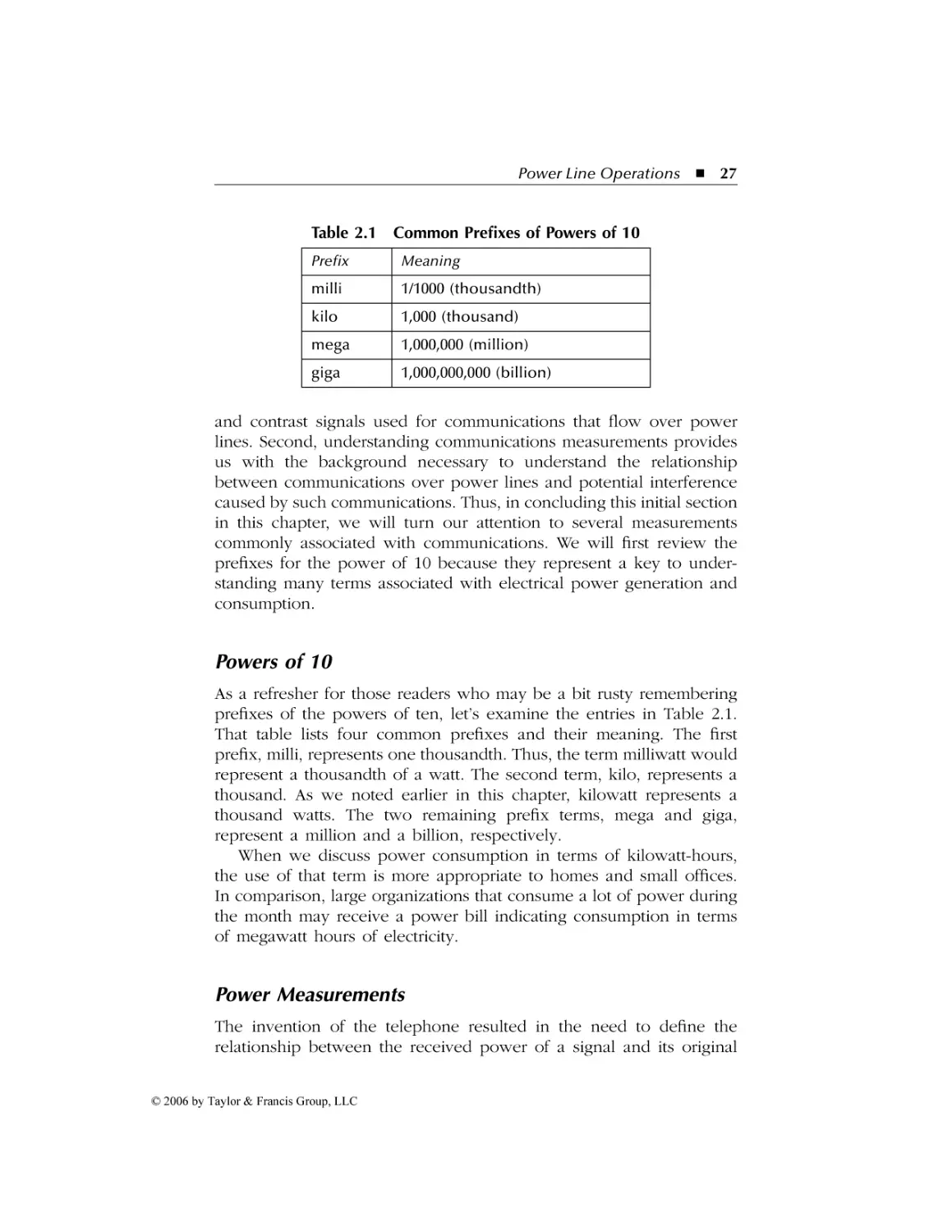
Powers of 10.............................................................................. 27
Power Measurements ................................................................ 27
The bel .................................................................................. 28
The Decibel........................................................................... 29
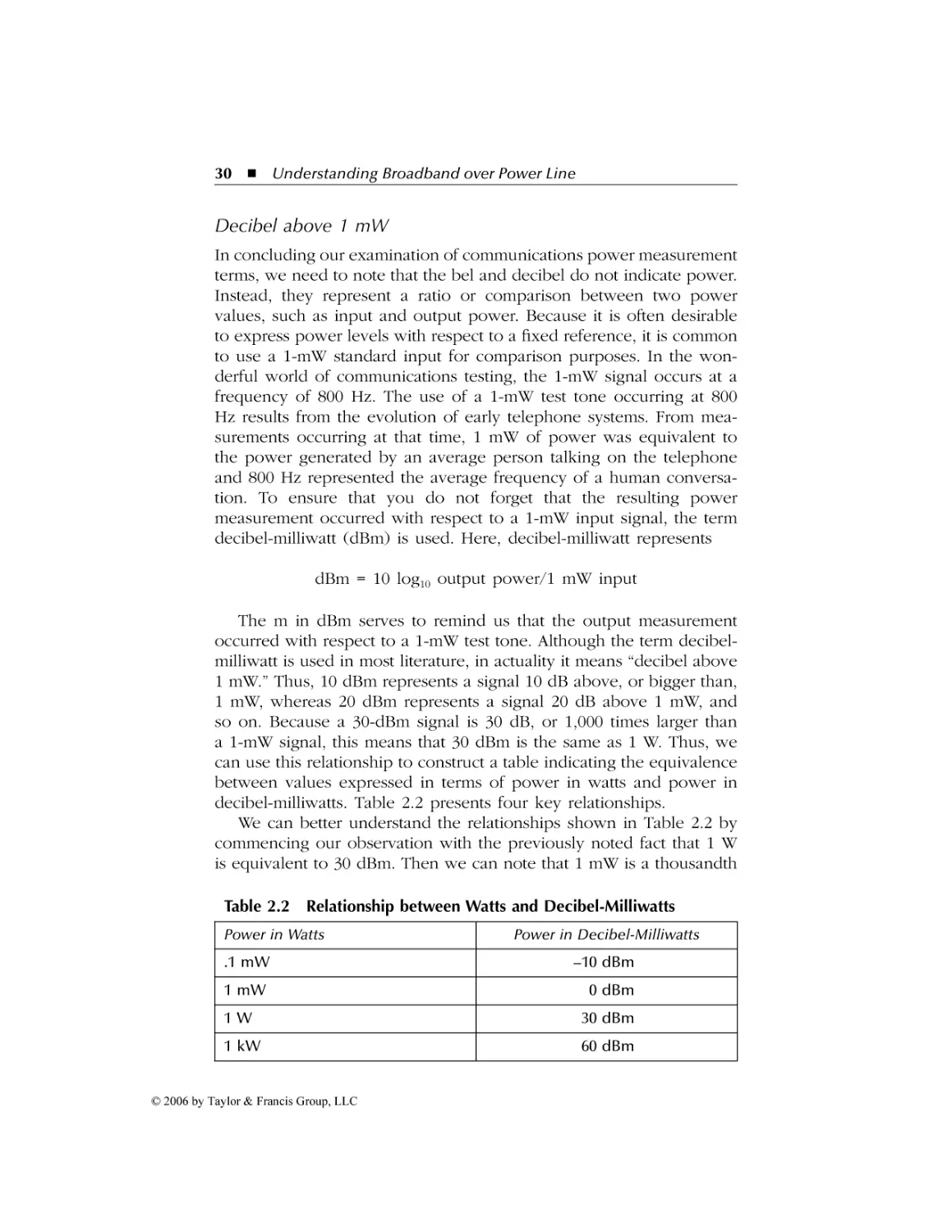
Decibel above 1 mW ............................................................ 30
Electricity Distribution................................................................... 31
The Power Plant ........................................................................ 31
Transformers .............................................................................. 32
Types of Transformers........................................................... 34
Transformer Wiring ............................................................... 34
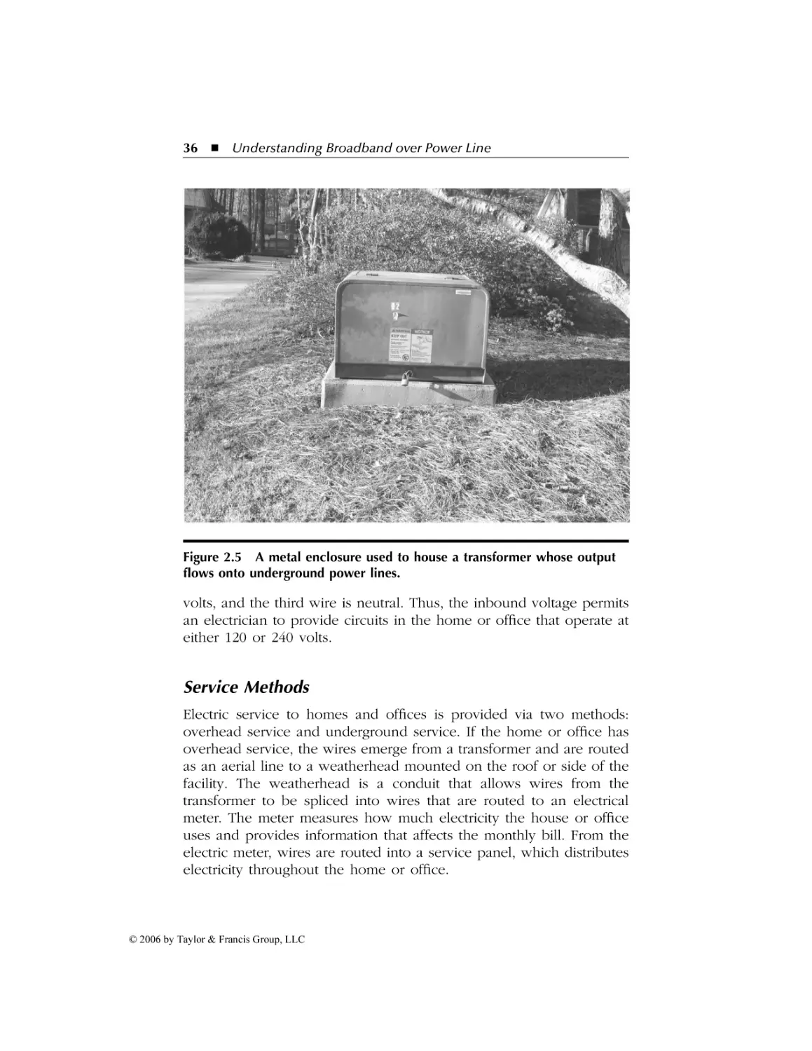
Service Methods ........................................................................ 36
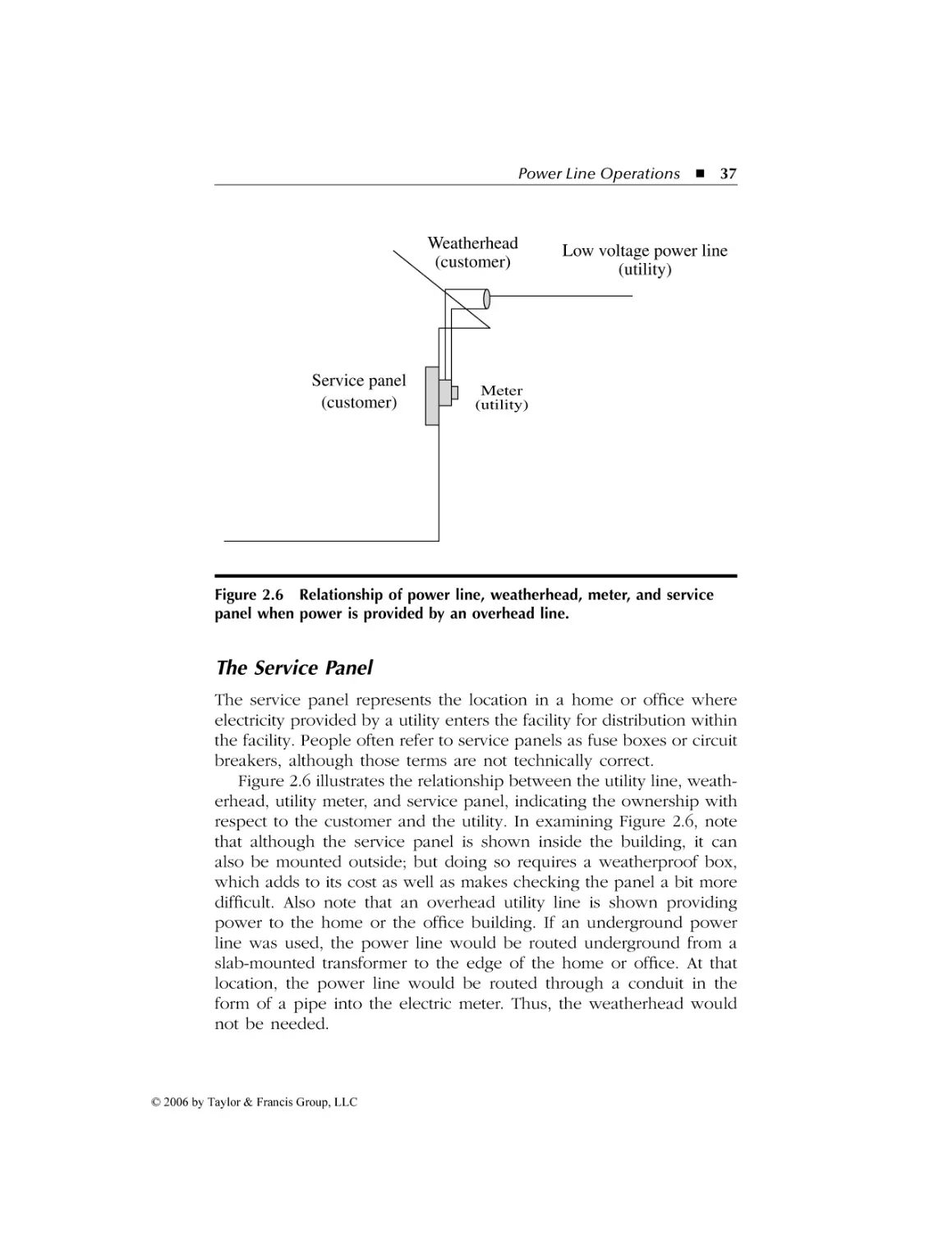
The Service Panel ...................................................................... 37
Types of Service Panels ........................................................ 38
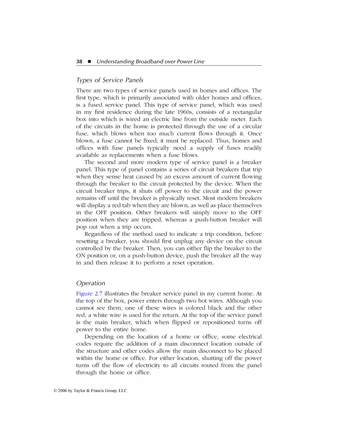
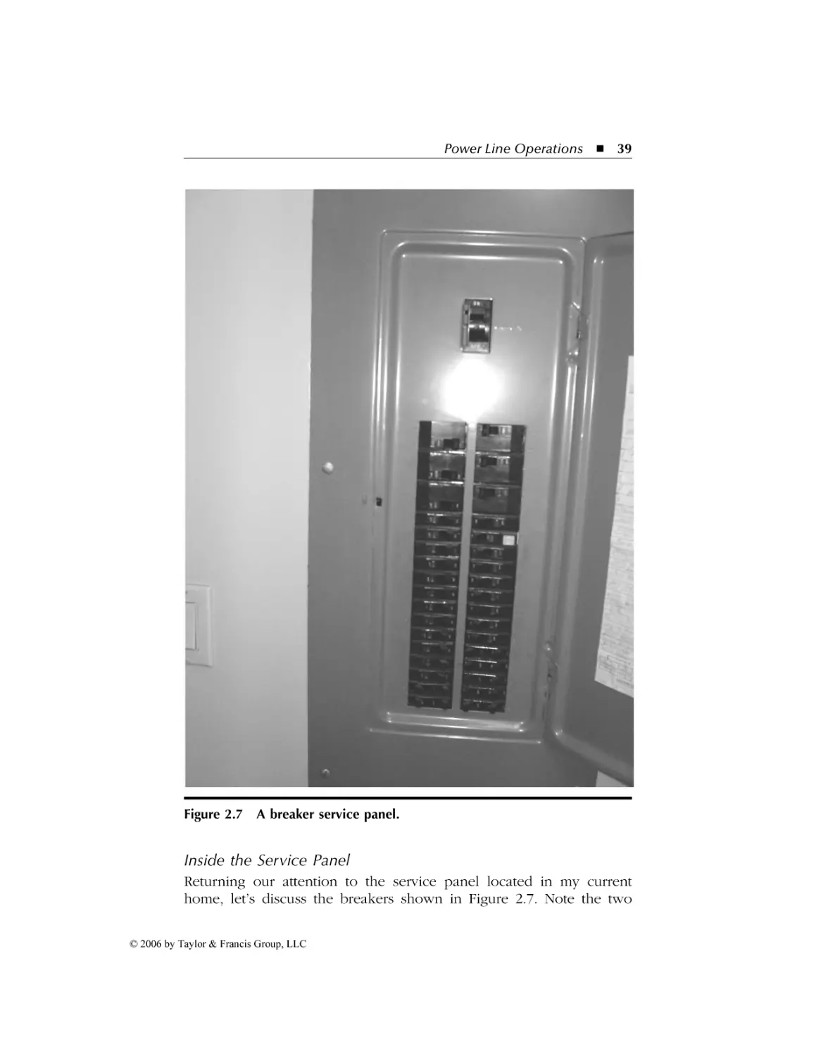
Operation .............................................................................. 38
Inside the Service Panel........................................................ 39
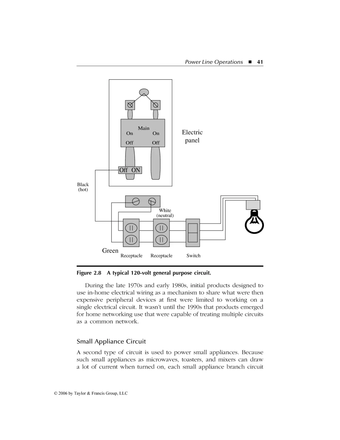
Circuits .................................................................................. 40
Data over Power Line Operations ............................................43
3.1 BPL System Architecture ................................................................ 44
Power Grid versus In-Building Wiring....................................... 44
Architecture Overview .............................................................. 45
High-Voltage Lines................................................................. 46
Medium-Voltage Lines ........................................................... 46
Low-Voltage Lines ................................................................. 46
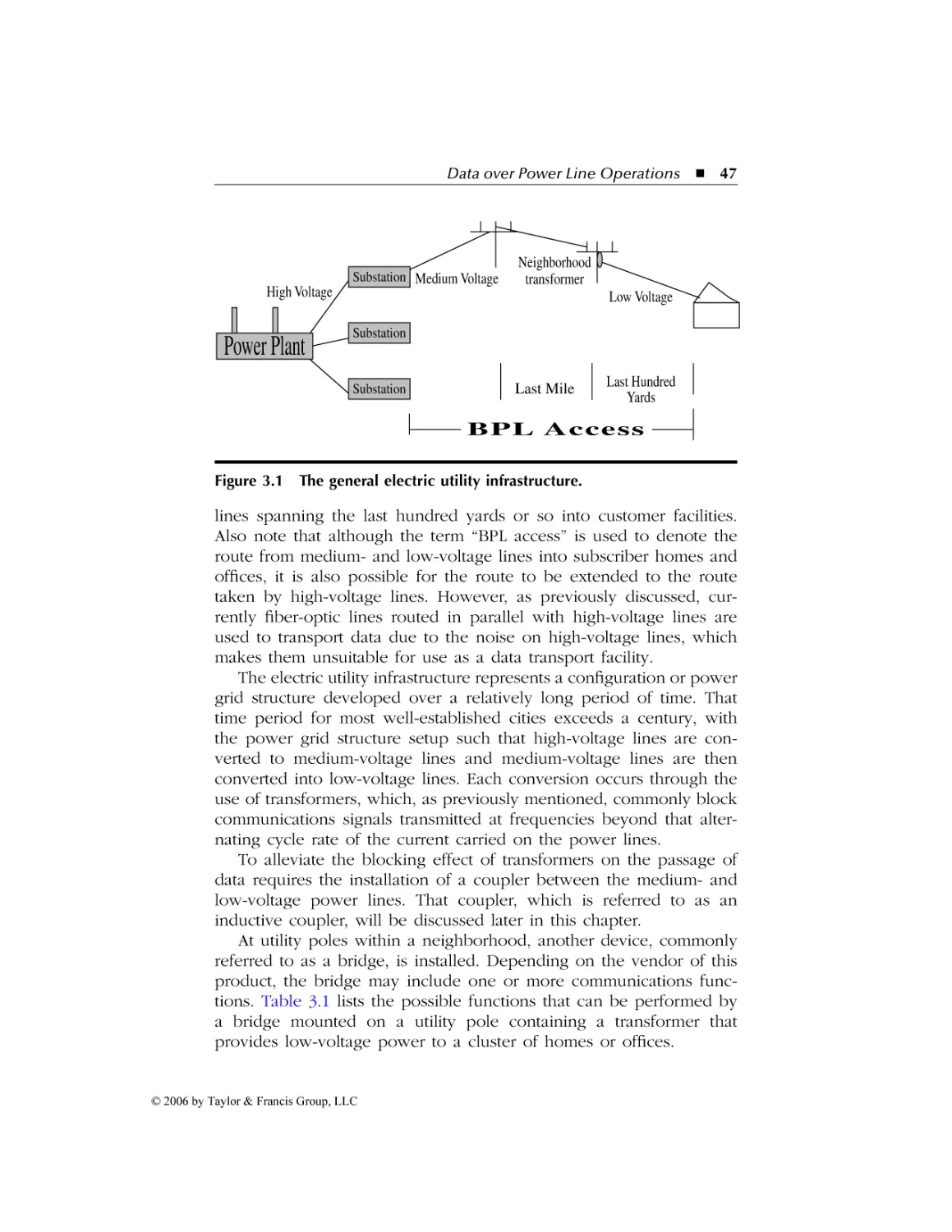
The Electric Utility Infrastructure ............................................. 46
Grid Problems............................................................................ 48
Line Noise and Attenuation .................................................. 48
Fault-Tolerance Equipment ................................................... 49
Grid Connection Method...................................................... 49
BPL Terminology........................................................................ 50
Backbone or Backhaul .......................................................... 50
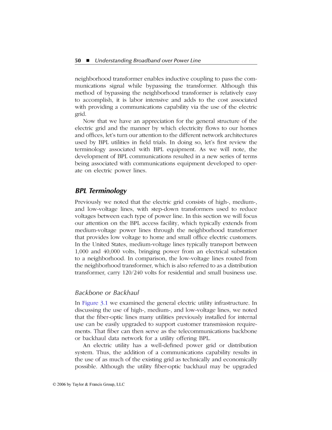
Network Components........................................................... 51
BPL Network Architectures ....................................................... 53
OFDM-Based System ............................................................. 53
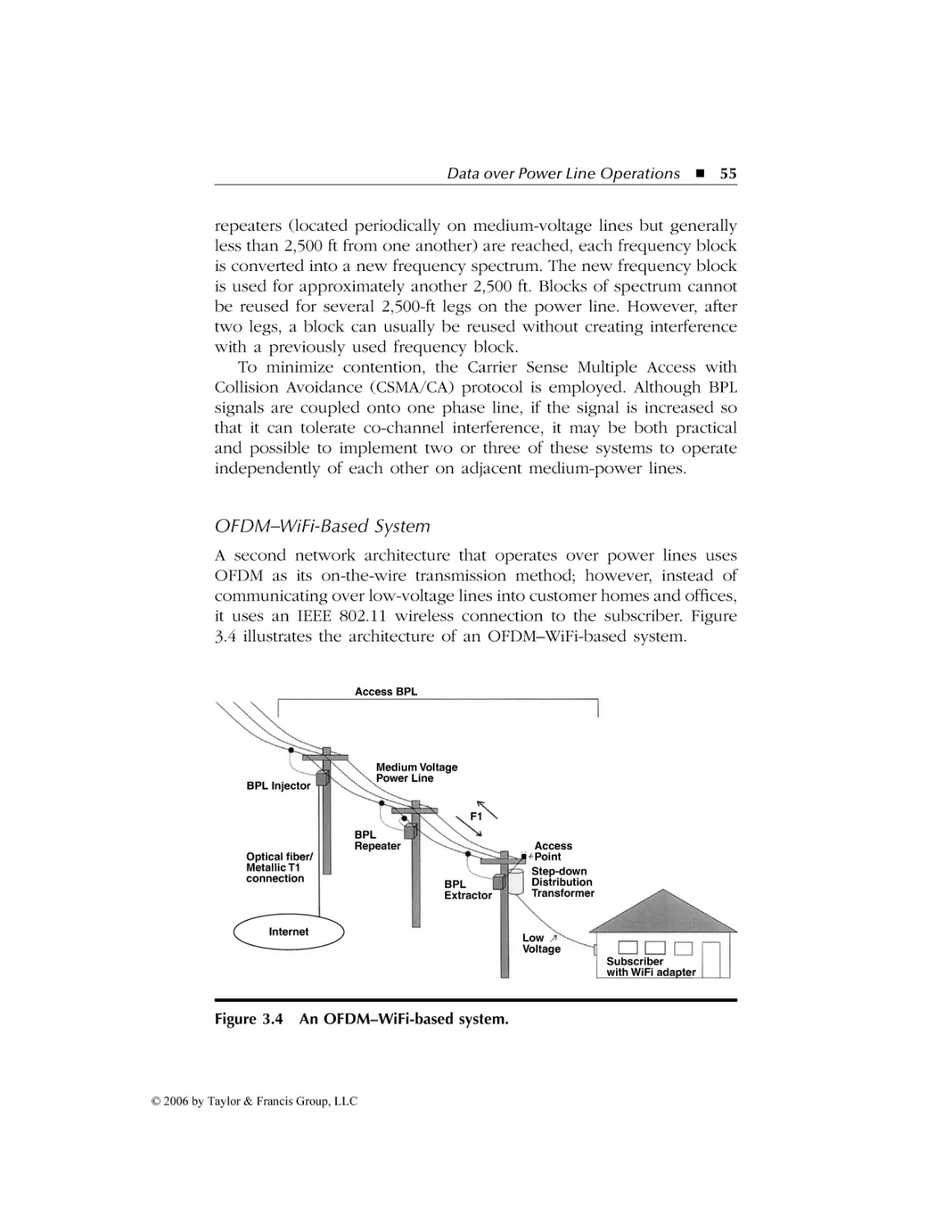
OFDM–WiFi-Based System .................................................... 55
DSSS-Based System ................................................................ 56
Summary .................................................................................... 58
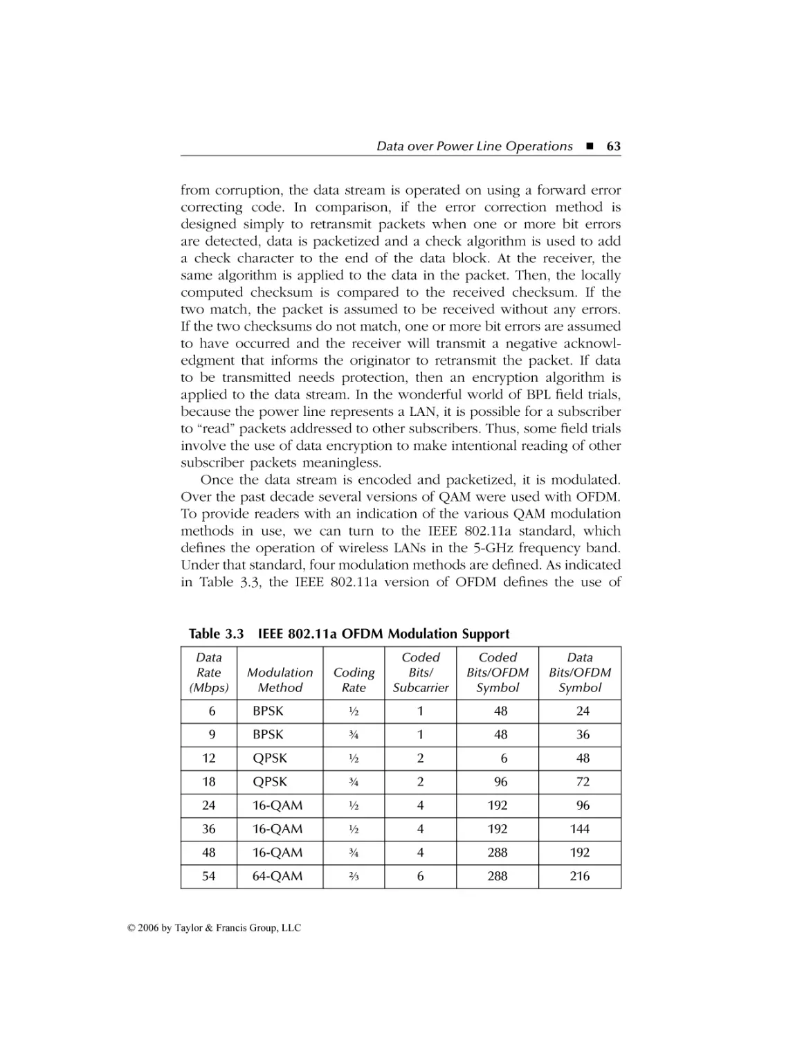
3.2 Transmission Methods, Modulation Techniques, and
Network Access.............................................................................. 58
© 2006 by Taylor & Francis Group, LLC
AU9846_book.fm Page ix Tuesday, March 14, 2006 3:53 PM
Contents
ix
Transmission Methods ............................................................... 58
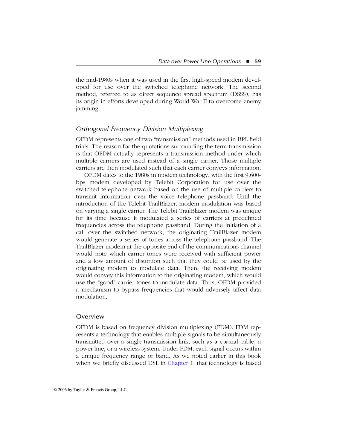
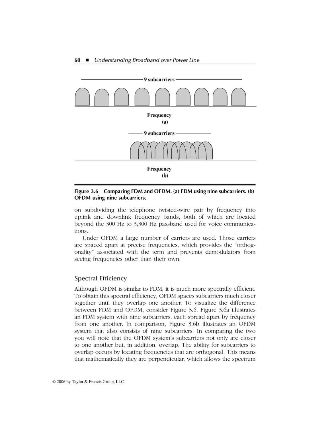
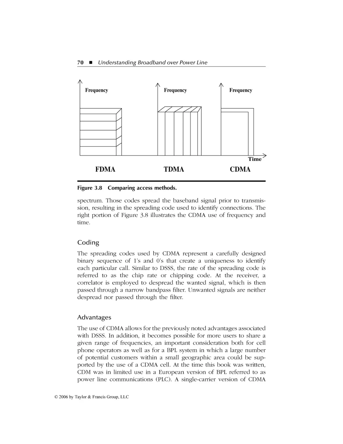
Orthogonal Frequency Division Multiplexing ...................... 59
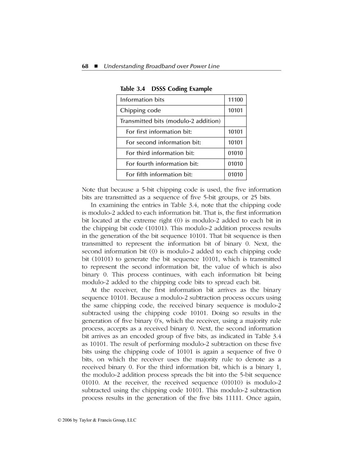
Direct Sequence Spread Spectrum ....................................... 64
Code Division Multiple Access ............................................. 69
4 Interference and FCC Action ....................................................73
4.1
4.2
BPL Interference ............................................................................ 73
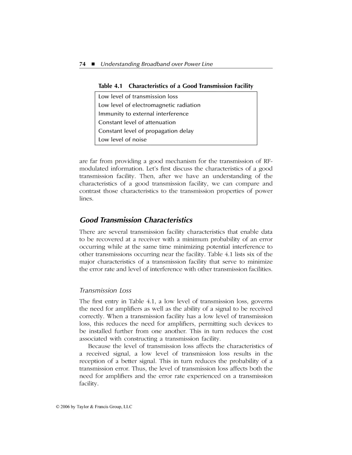
Good Transmission Characteristics............................................ 74
Transmission Loss ................................................................. 74
RF Radiation .......................................................................... 75
Attenuation............................................................................ 75
Propagation Delay ................................................................. 76
Noise ..................................................................................... 76
Power Line Transmission Properties ......................................... 77
Noise ..................................................................................... 77
Attenuation............................................................................ 78
Propagation Delay ................................................................. 79
The Transformer Effect ......................................................... 79
Power Line Problems ............................................................ 80
Lack of Symmetry ................................................................. 80
Antenna Effect....................................................................... 80
ARRL Opposition to BPL ........................................................... 80
Interference Prevention............................................................. 82
Power Level........................................................................... 82
Avoidance of Locally Used Frequencies ............................... 83
Differential-Mode Signal Injection ........................................ 83
Using One Active Device per Area ....................................... 84
Selection of Signal Carrier .................................................... 84
The Regulatory Effort .................................................................... 84
Role of the FCC ......................................................................... 84
FCC Action................................................................................. 85
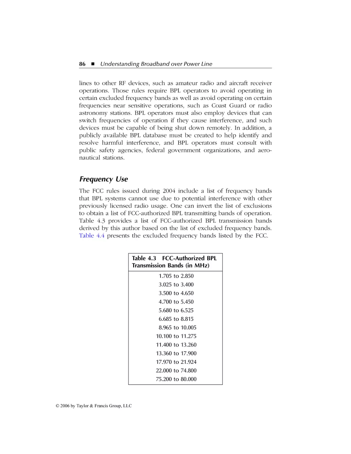
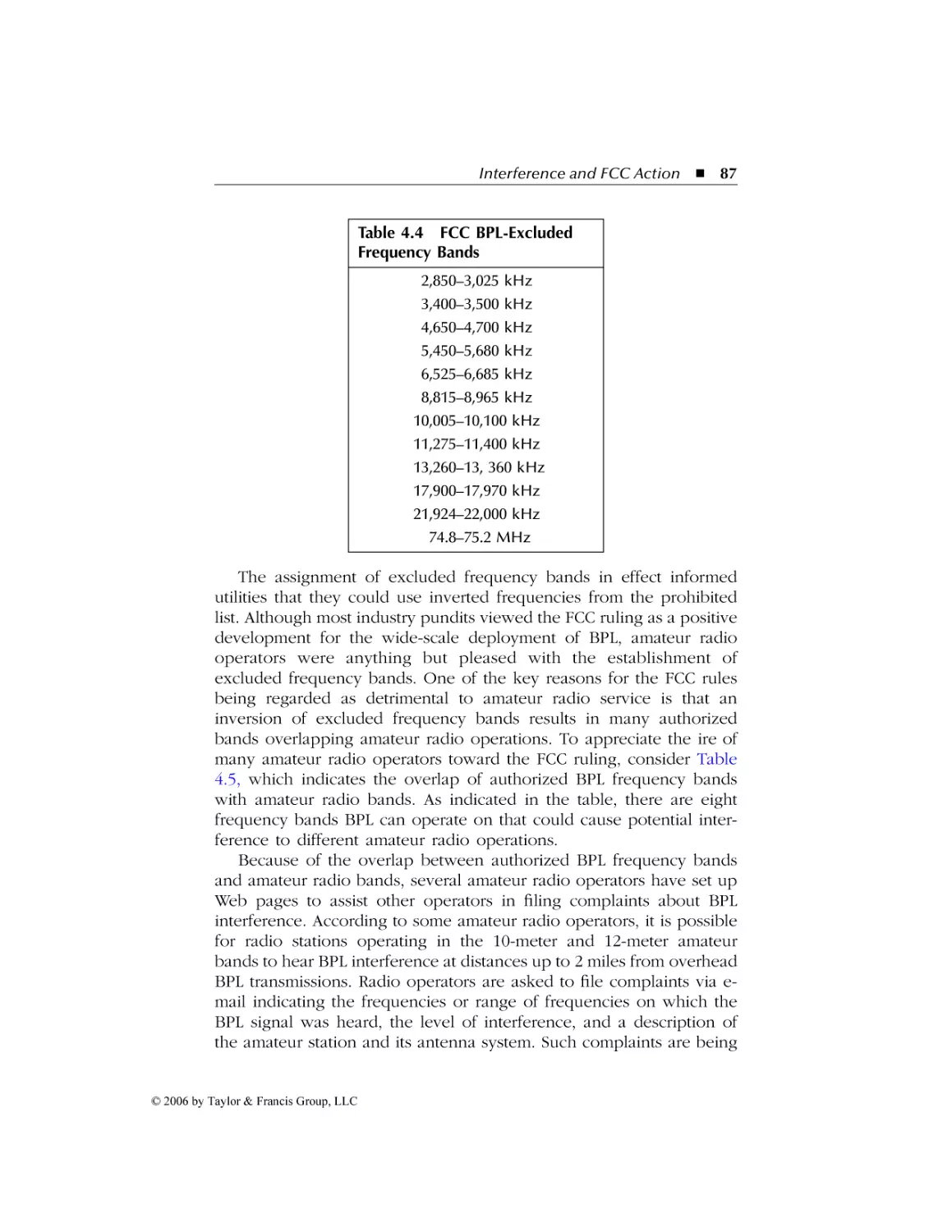
Frequency Use ........................................................................... 86
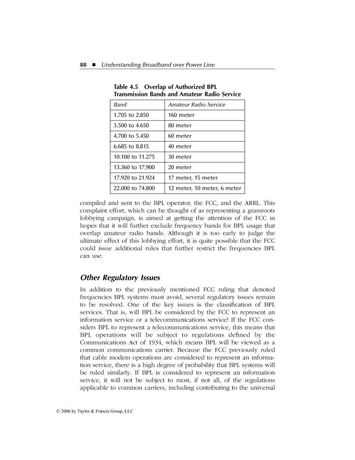
Other Regulatory Issues ............................................................ 88
5 BPL in the Home and Office .....................................................91
5.1
The HomePlug Standard ................................................................ 92
Evolution.................................................................................... 92
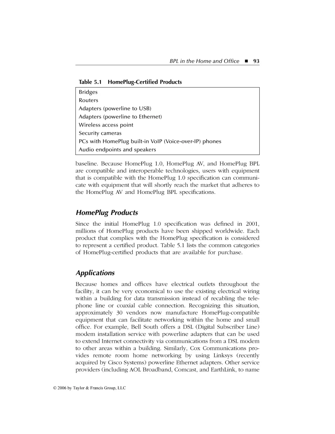
HomePlug Products ................................................................... 93
Applications ............................................................................... 93
The HomePlug 1.0 Specification............................................... 94
Physical Layer........................................................................ 95
Forward Error Correction ..................................................... 97
Performance .......................................................................... 97
Adaptive Channel Allocation................................................. 98
MAC Layer ............................................................................. 98
© 2006 by Taylor & Francis Group, LLC
AU9846_book.fm Page x Tuesday, March 14, 2006 3:53 PM
x
Contents
5.2
5.3
5.4
6
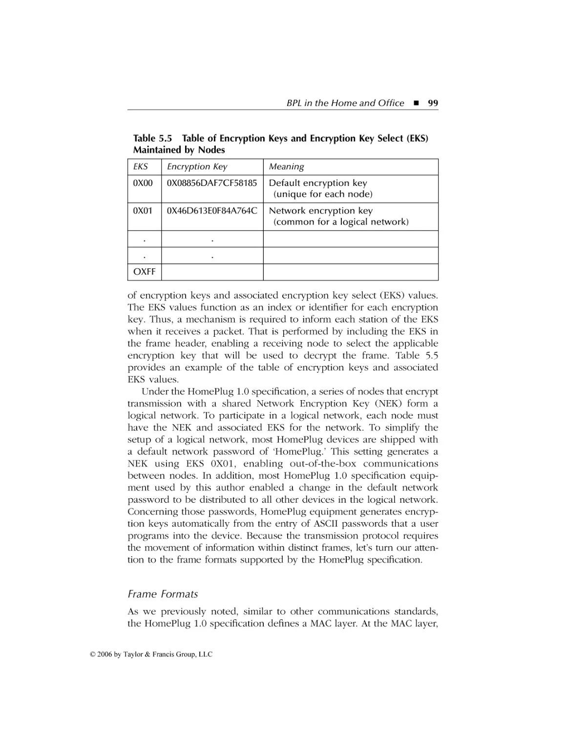
Encryption............................................................................. 98
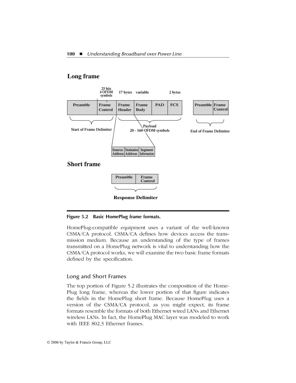
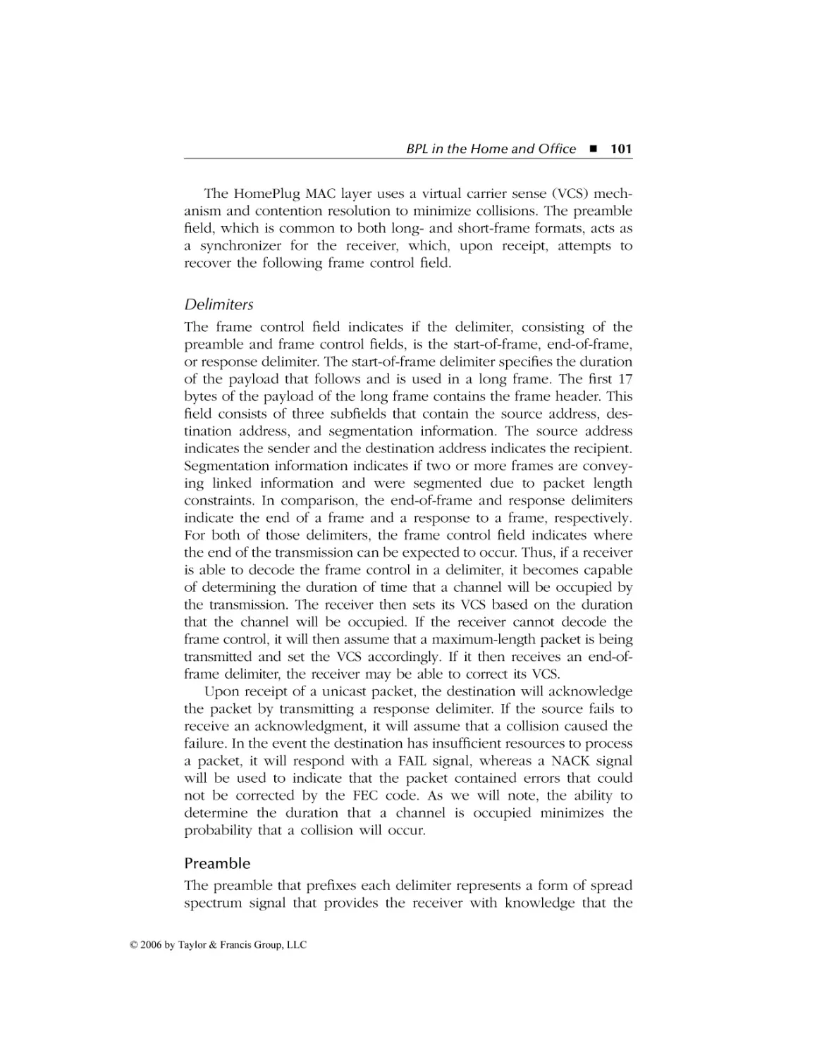
Frame Formats....................................................................... 99
Delimiters............................................................................ 101
Channel Access ................................................................... 102
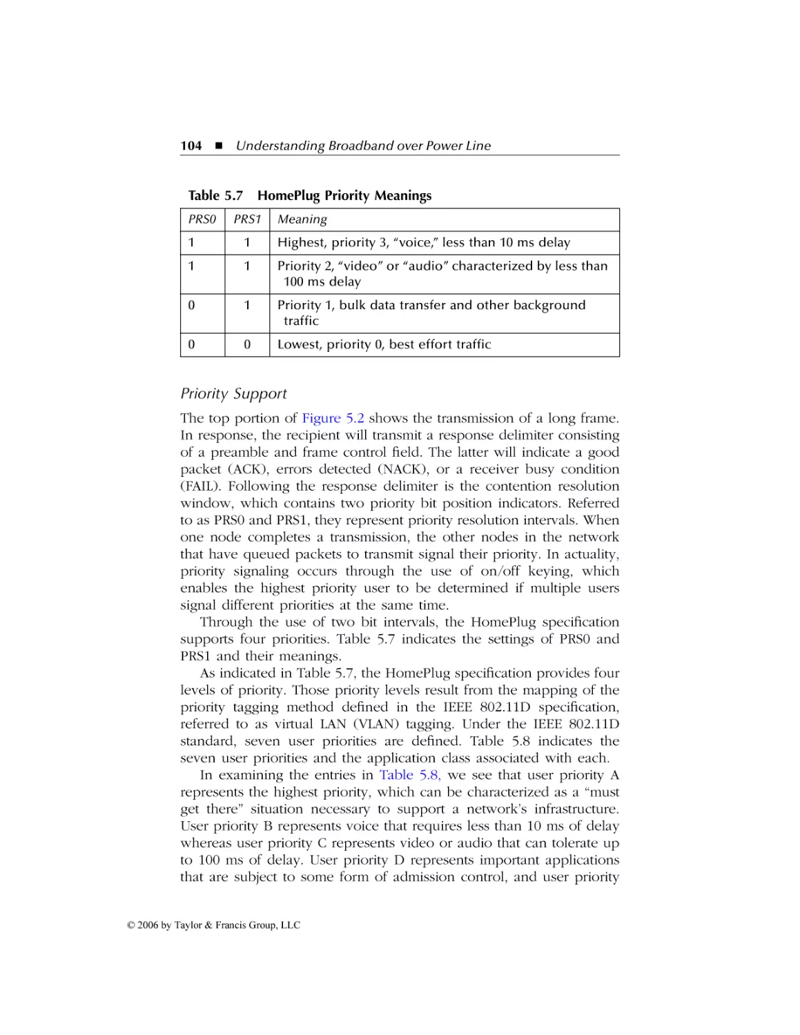
Priority Support .................................................................. 104
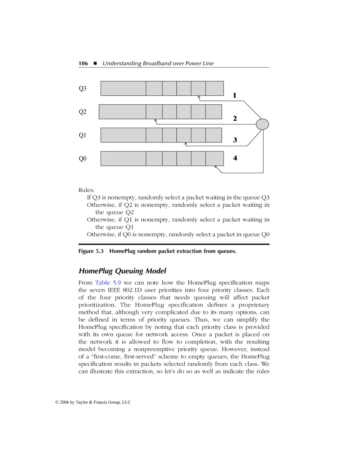
HomePlug Queuing Model ...................................................... 106
Retries ................................................................................. 107
Working with Powerline Adapters............................................... 107
Overview ................................................................................. 108
Software Installation ................................................................ 108
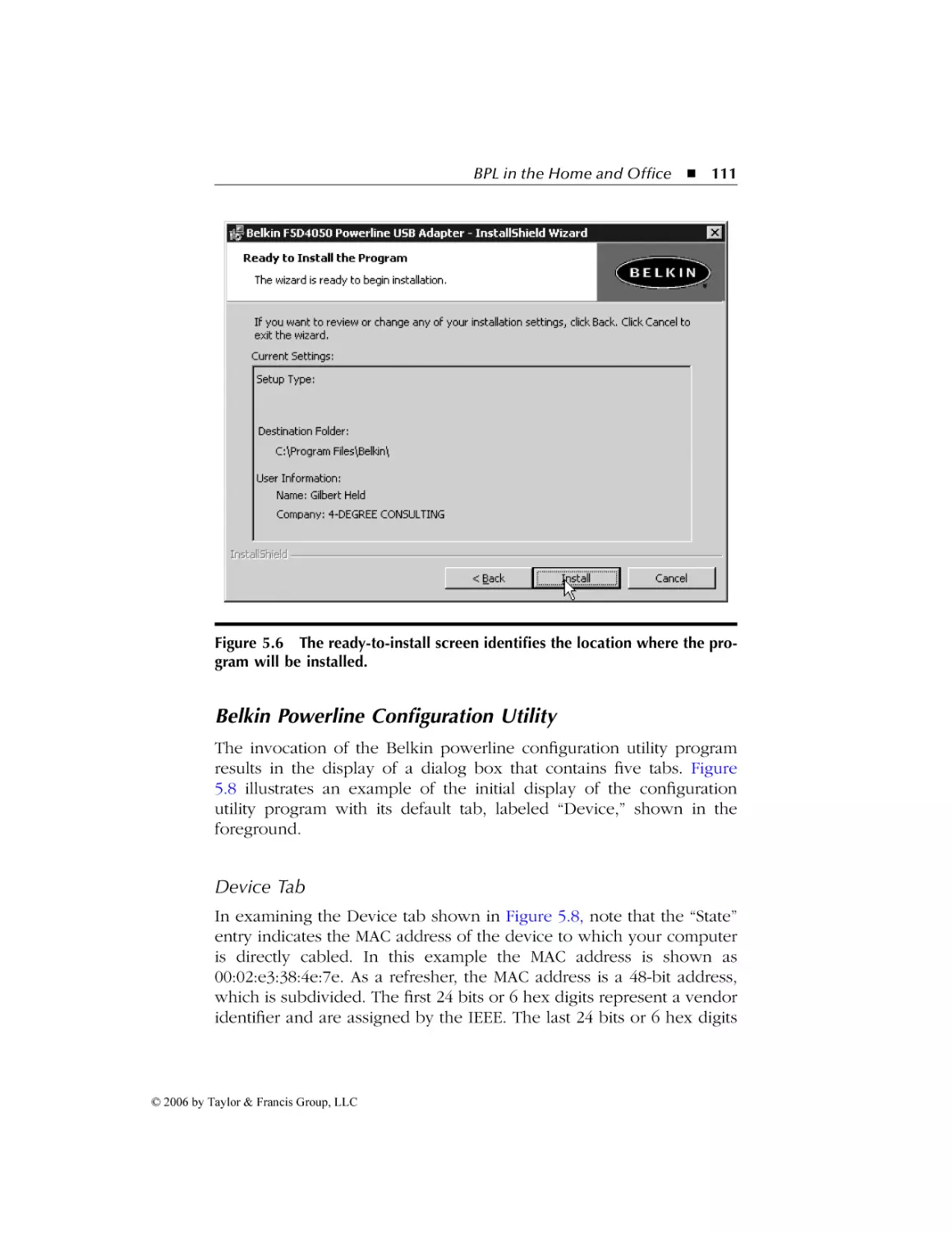
Belkin Powerline Configuration Utility ................................... 111
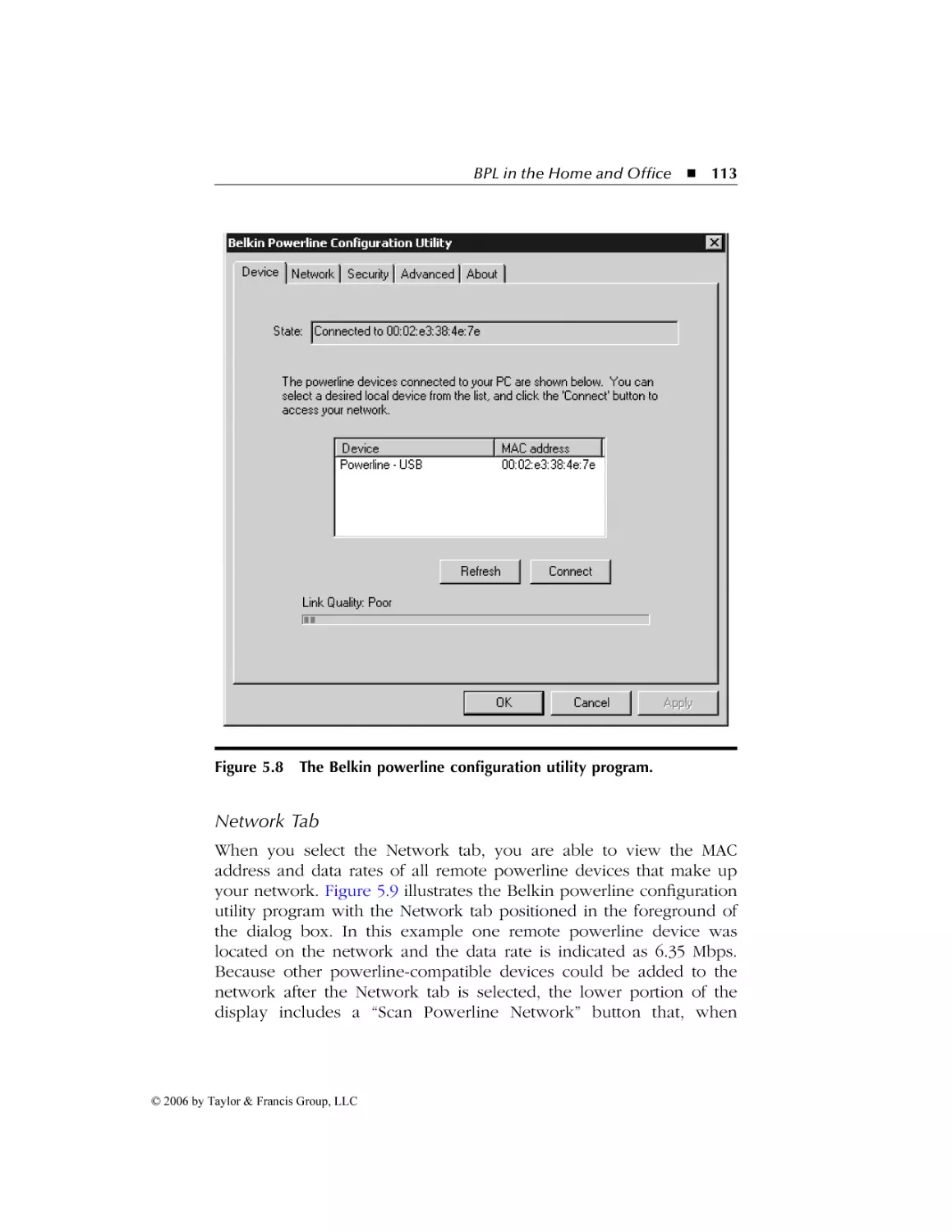
Device Tab........................................................................... 111
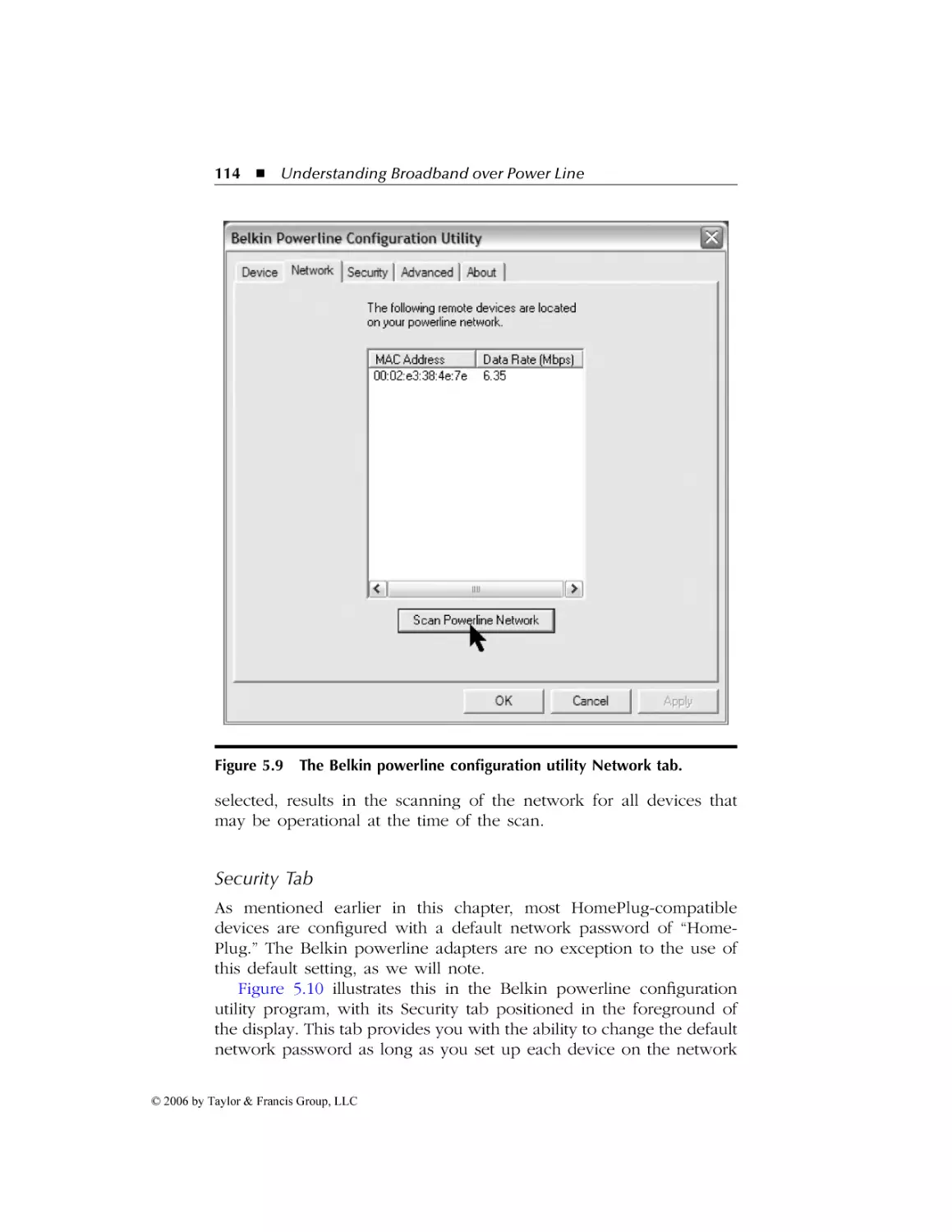
Network Tab........................................................................ 113
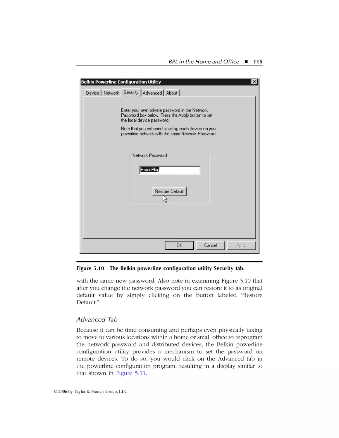
Security Tab ......................................................................... 114
Advanced Tab ...................................................................... 115
HomePlug AV................................................................................ 117
Overview ................................................................................. 117
Operational Characteristics ..................................................... 117
Compatibility ........................................................................... 118
IEEE Wireless LANs ...................................................................... 118
Overview ................................................................................. 118
The Wireless LAN Infrastructure ............................................. 119
Communications Methods....................................................... 119
Medium Access ........................................................................ 119
IEEE 802.11 Extensions ........................................................... 121
802.11a................................................................................ 121
802.11b ............................................................................... 121
802.11g................................................................................ 122
802.11n ............................................................................... 122
Equipment Vendors and Field Trials ......................................123
6.1 Equipment Vendors ...................................................................... 124
Ambient Corporation............................................................... 124
Network Layer Components............................................... 125
Physical Layer Components ................................................ 126
Amperion, Inc. ......................................................................... 127
Product Lines ...................................................................... 127
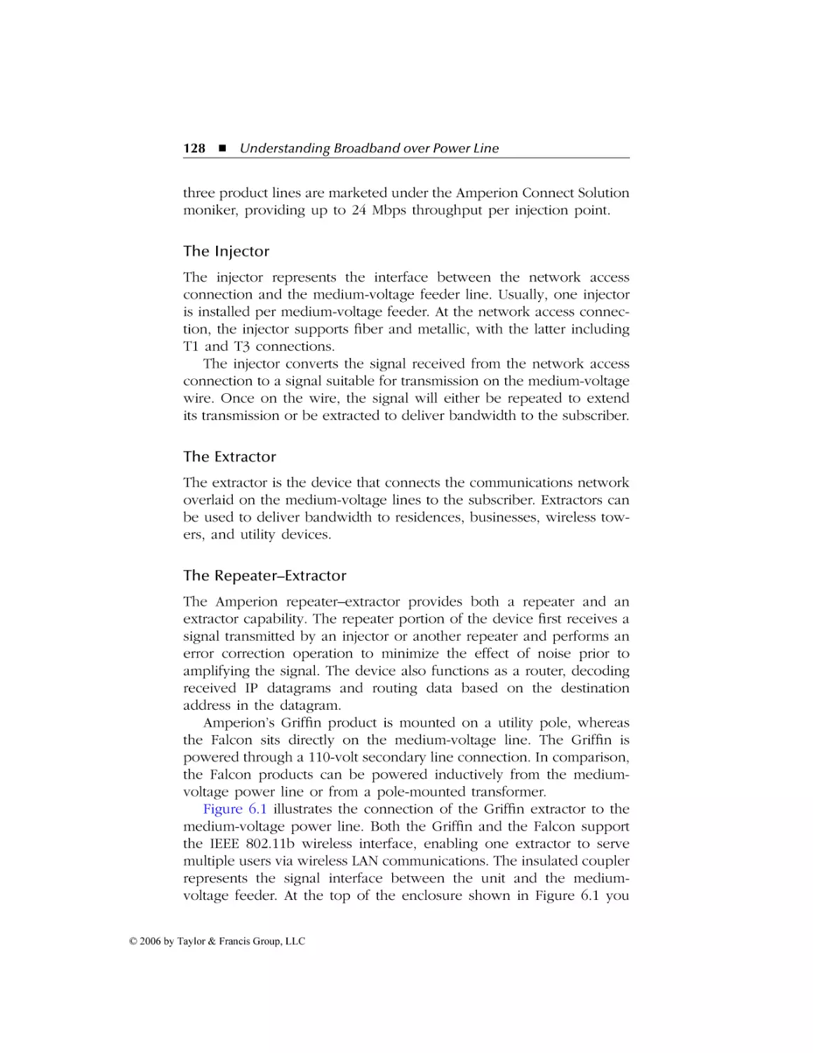
Corinex Communications Corporation................................... 129
Powerline Ethernet Wall Mount.......................................... 129
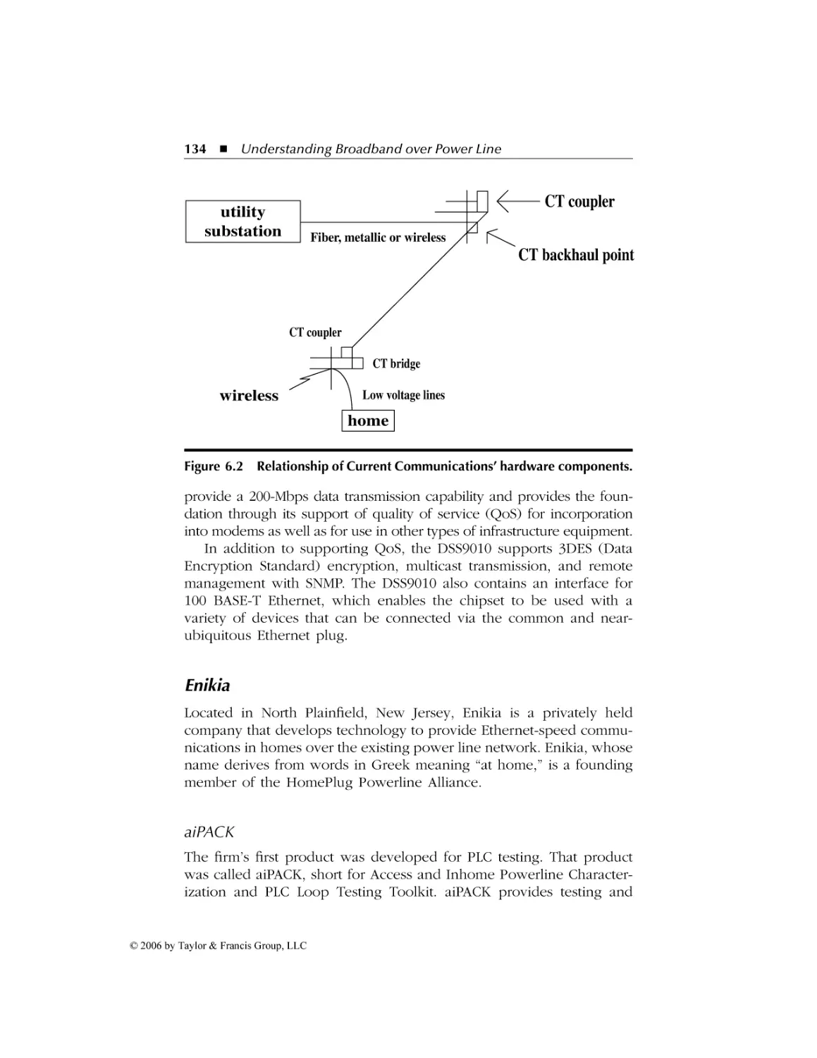
Current Communications Group ............................................ 132
CT Coupler.......................................................................... 132
CT Backhaul-Point ............................................................... 132
CT Bridge ............................................................................ 132
Powerline Modem ............................................................... 133
CT View............................................................................... 133
© 2006 by Taylor & Francis Group, LLC
AU9846_book.fm Page xi Tuesday, March 14, 2006 3:53 PM
Contents
6.2
7
xi
DS2........................................................................................... 133
Enikia ....................................................................................... 134
aiPACK................................................................................. 134
Power Bridge....................................................................... 135
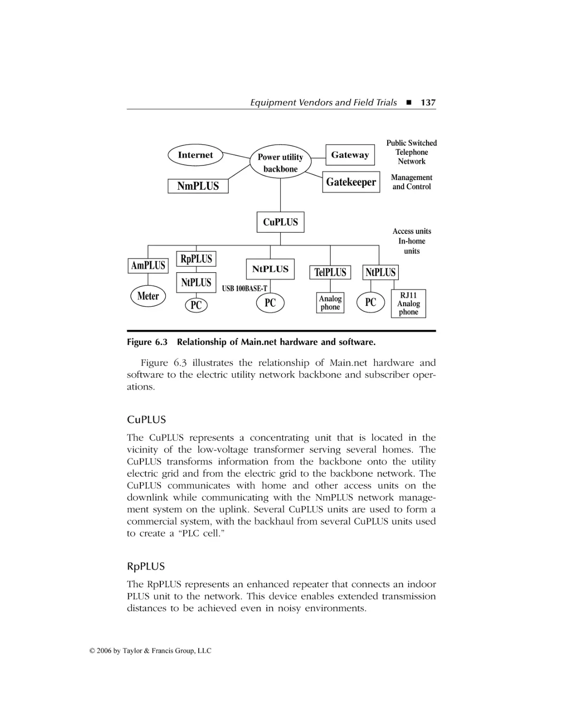
Main.net Communications Group........................................... 135
Main.net PLUS Solution....................................................... 136
Smart Repetition ................................................................. 136
PLUS Architecture ............................................................... 136
Customers ........................................................................... 139
Siemens Corporation ............................................................... 139
Speed Stream Powerline 2501 USB Adapter....................... 140
Speed Stream Powerline 2502 Ethernet Adapter ............... 140
Speed Stream Powerline 2521 Wireless Access Point ........ 140
Speed Stream Powerline 2524 Wireless DSL/Cable
Router.................................................................................. 140
BPL Field Trials ............................................................................. 141
Alliant Energy .......................................................................... 143
Background ......................................................................... 143
Interference Issue ............................................................... 143
City of Manassas ...................................................................... 144
Pilot Project......................................................................... 144
The Franchise Agreement ................................................... 144
City Infrastructure............................................................... 145
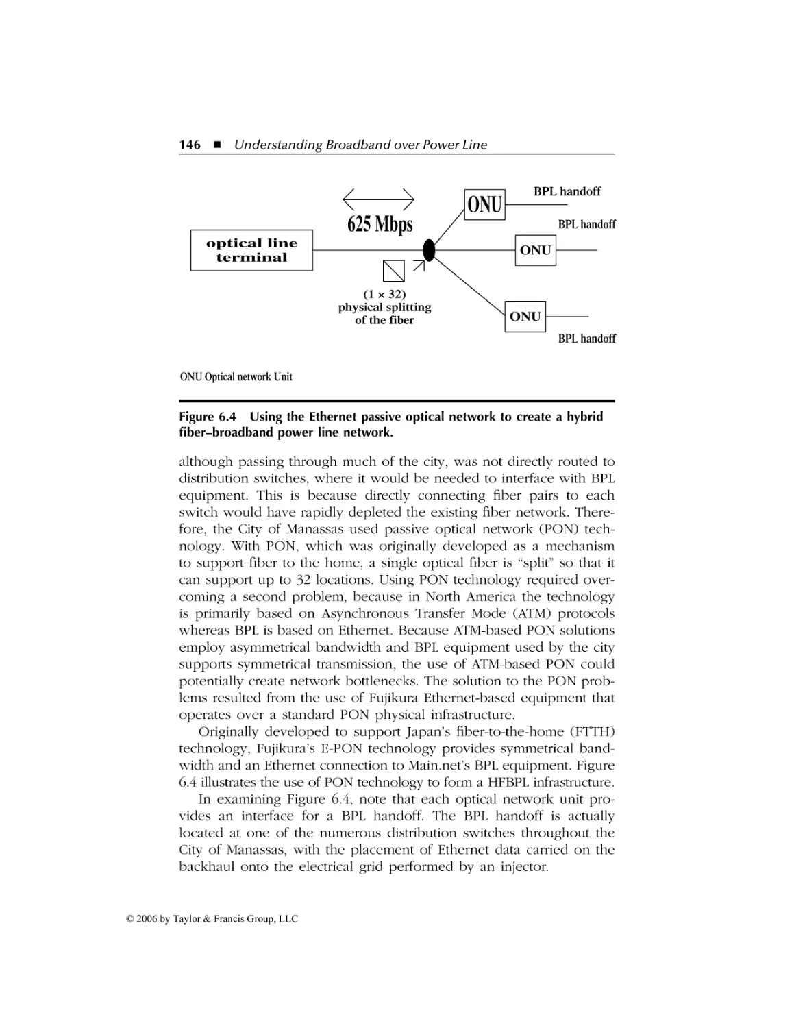
Use of Existing Fiber........................................................... 145
Injector Operation .............................................................. 147
Repeater Utilization ............................................................ 147
Construction Cost ............................................................... 147
Technical Issues .................................................................. 147
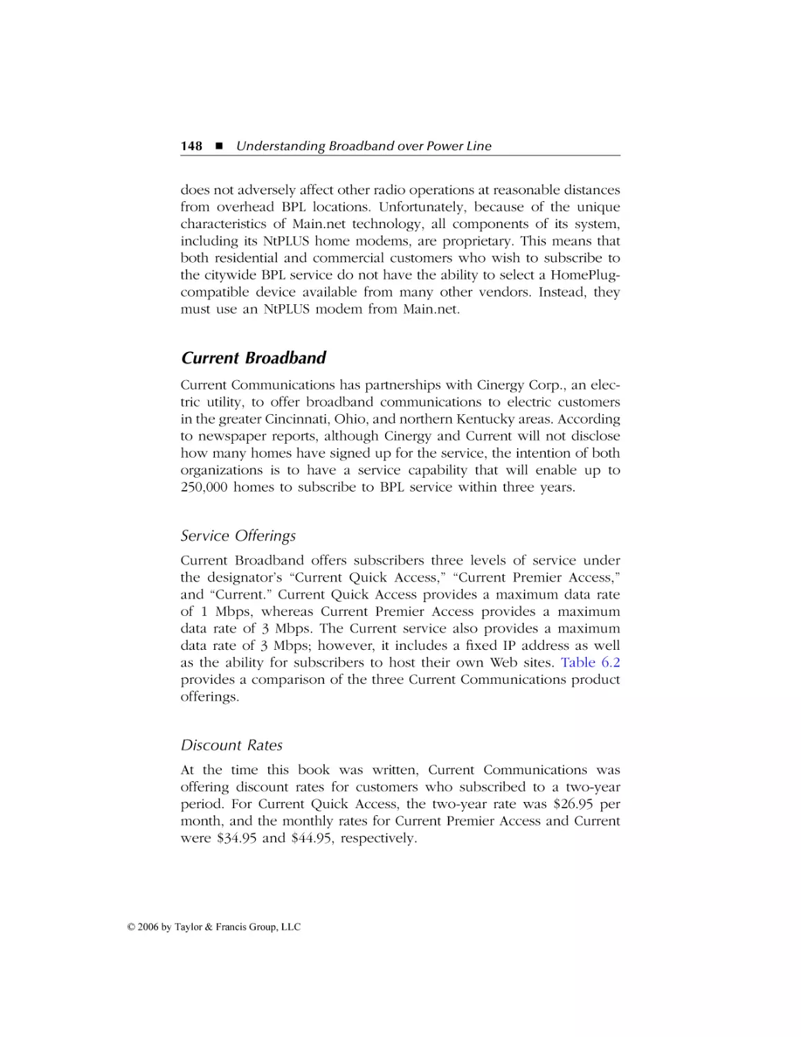
Current Broadband .................................................................. 148
Service Offerings................................................................. 148
Discount Rates .................................................................... 148
Progress Energy ....................................................................... 150
Overview............................................................................. 150
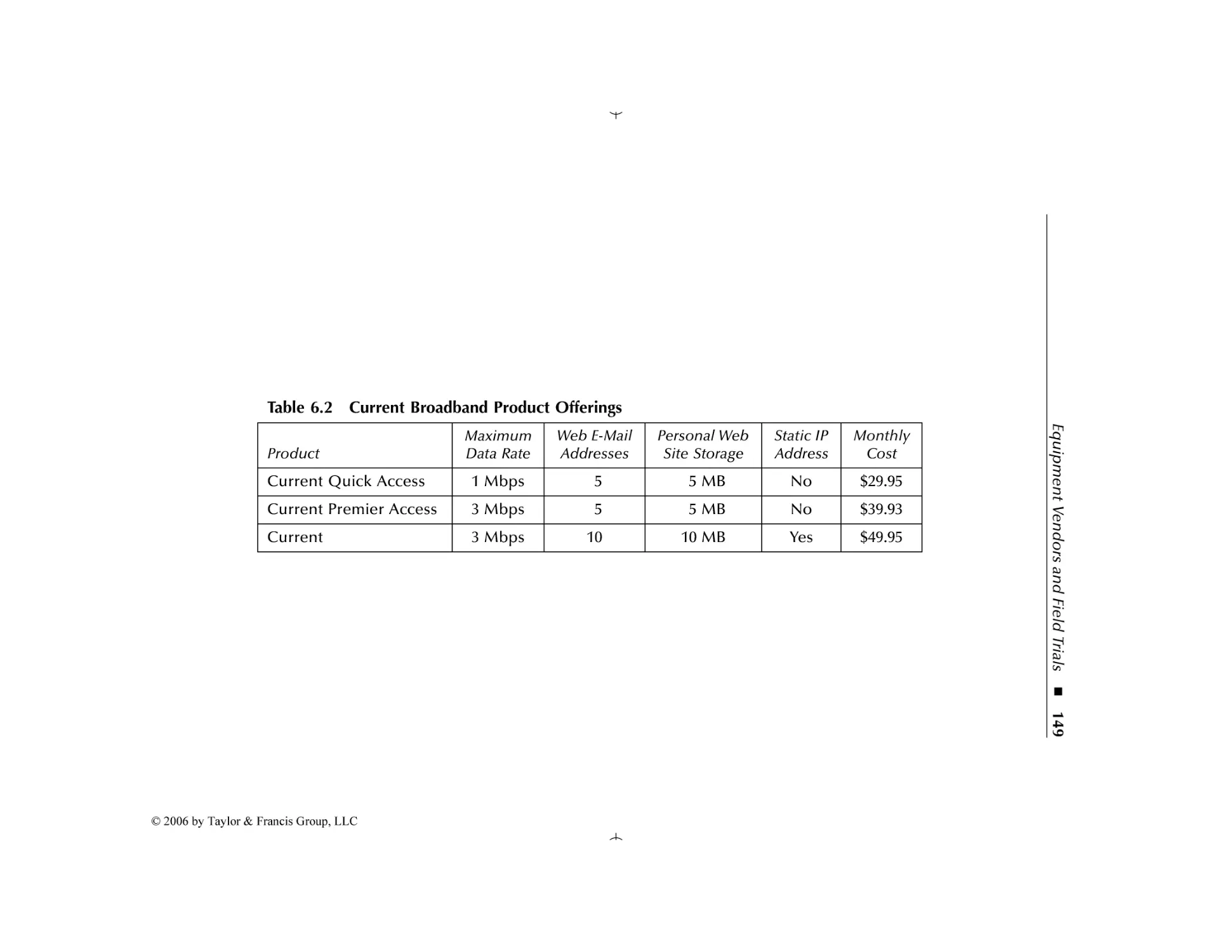
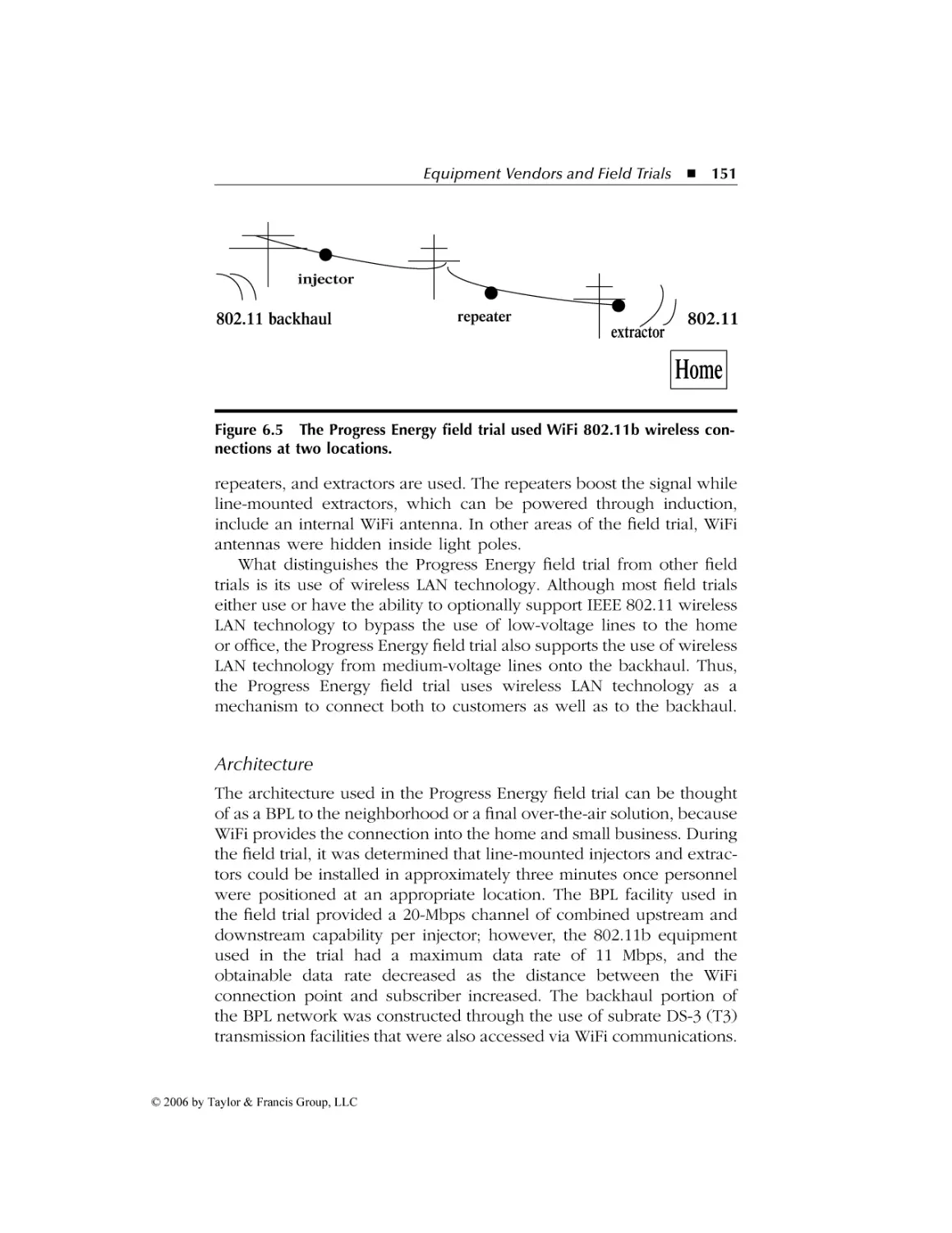
Technology.......................................................................... 150
Architecture ........................................................................ 151
Evolving Standards and Organizing Bodies...........................153
7.1 IEEE Standards.............................................................................. 153
Overview ................................................................................. 153
P1675 .................................................................................. 154
Focus ................................................................................... 155
Interference Issues and PAR 1775 ...................................... 155
P1675 Group Meetings............................................................ 156
June 2004 Meeting.............................................................. 156
July 2004 Meeting ............................................................... 157
© 2006 by Taylor & Francis Group, LLC
AU9846_book.fm Page xii Tuesday, March 14, 2006 3:53 PM
xii
Contents
7.2
October 2004 Meeting........................................................ 159
January 2005 Meeting ......................................................... 161
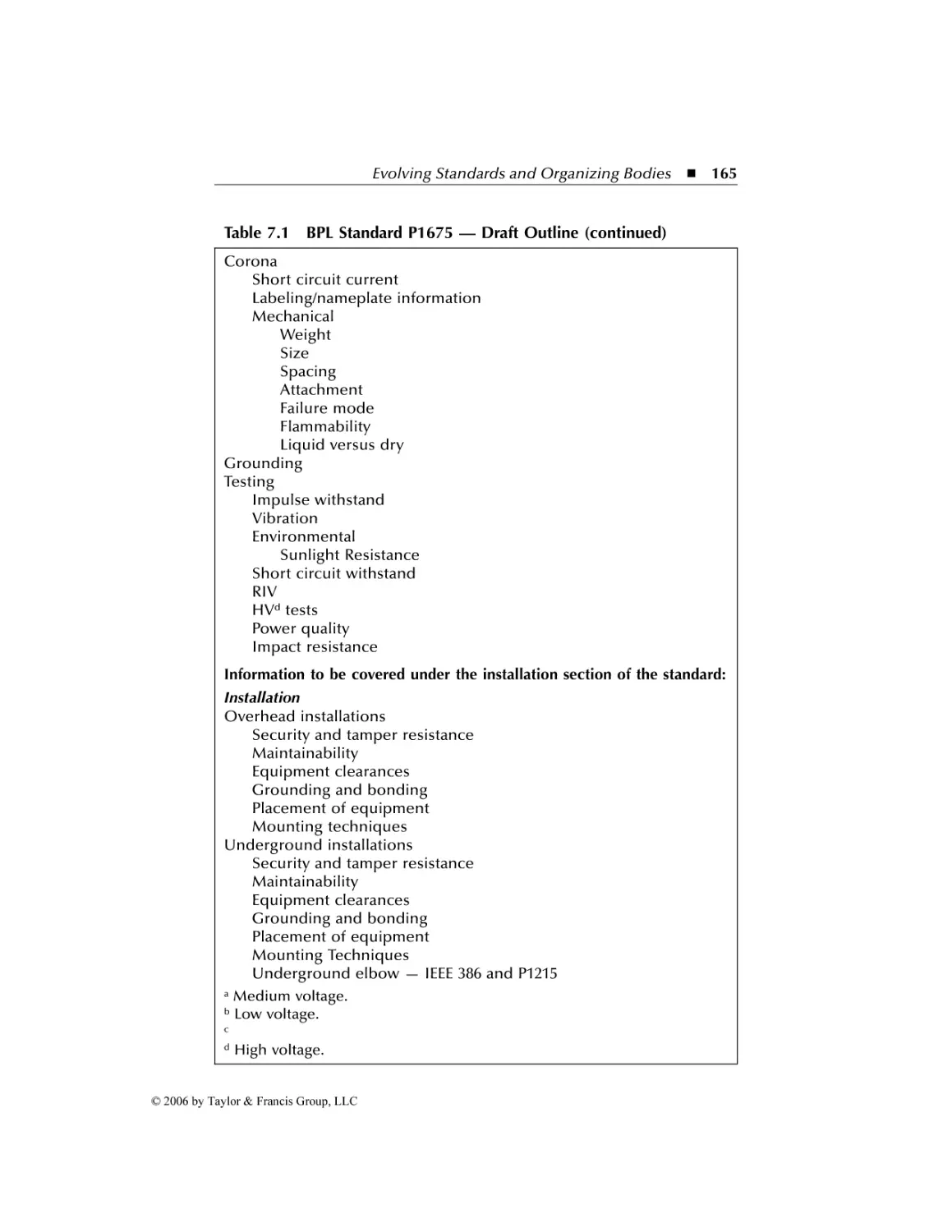
Current Status of the Standard ........................................... 163
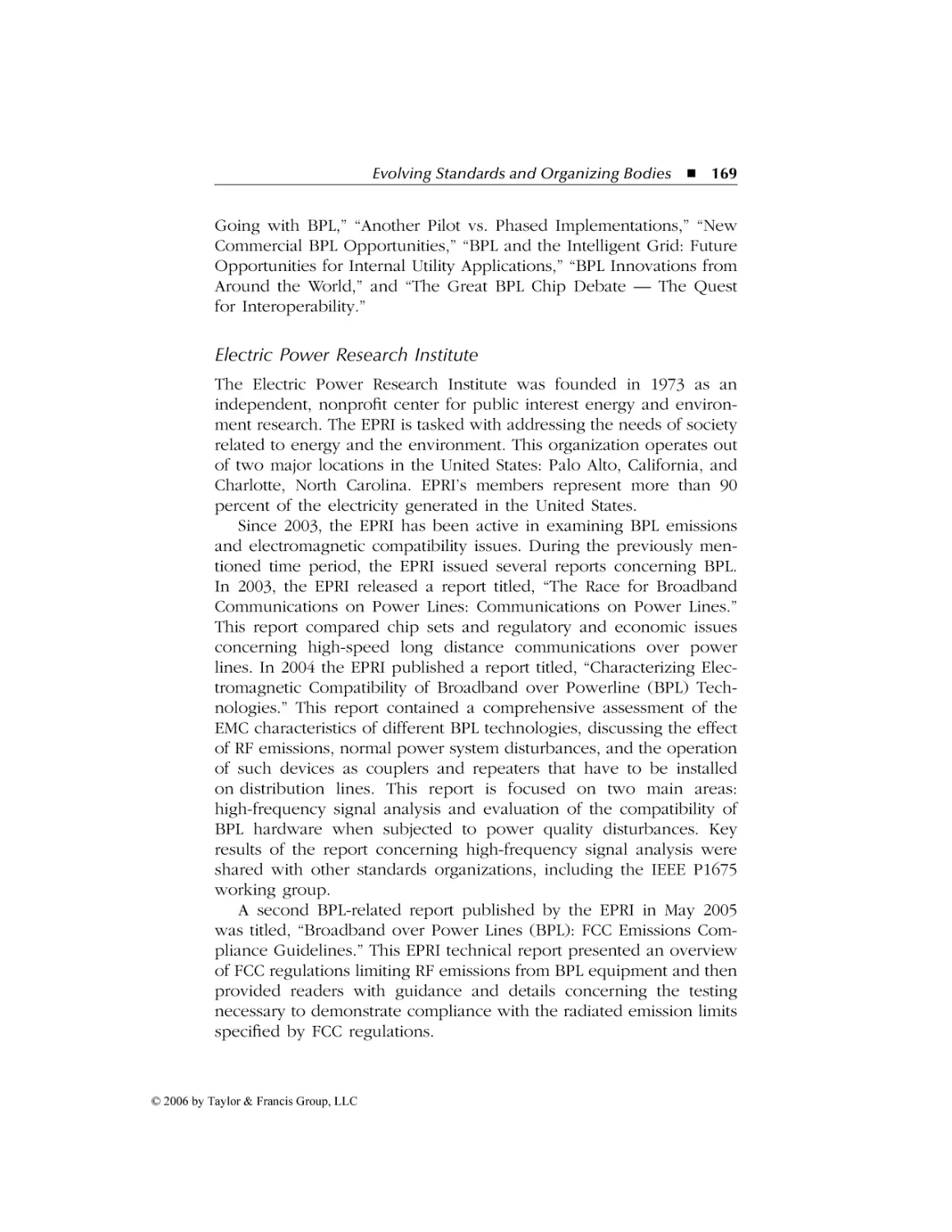
Other Standards and Organizations to Note ............................... 163
HomePlug Powerline Alliance Specifications.......................... 163
HomePlug 1.0...................................................................... 166
HomePlug AV....................................................................... 166
HomePlug BPL .................................................................... 167
Compatibility....................................................................... 167
Other Organizing Bodies......................................................... 168
United Power Line Council ................................................ 168
Electric Power Research Institute....................................... 169
Summary ............................................................................. 170
8 The Future of BPL.....................................................................171
8.1
8.2
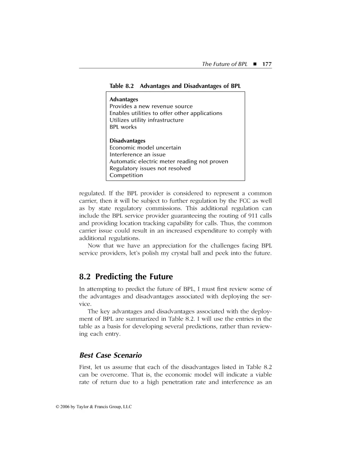
Challenges Facing BPL ................................................................. 171
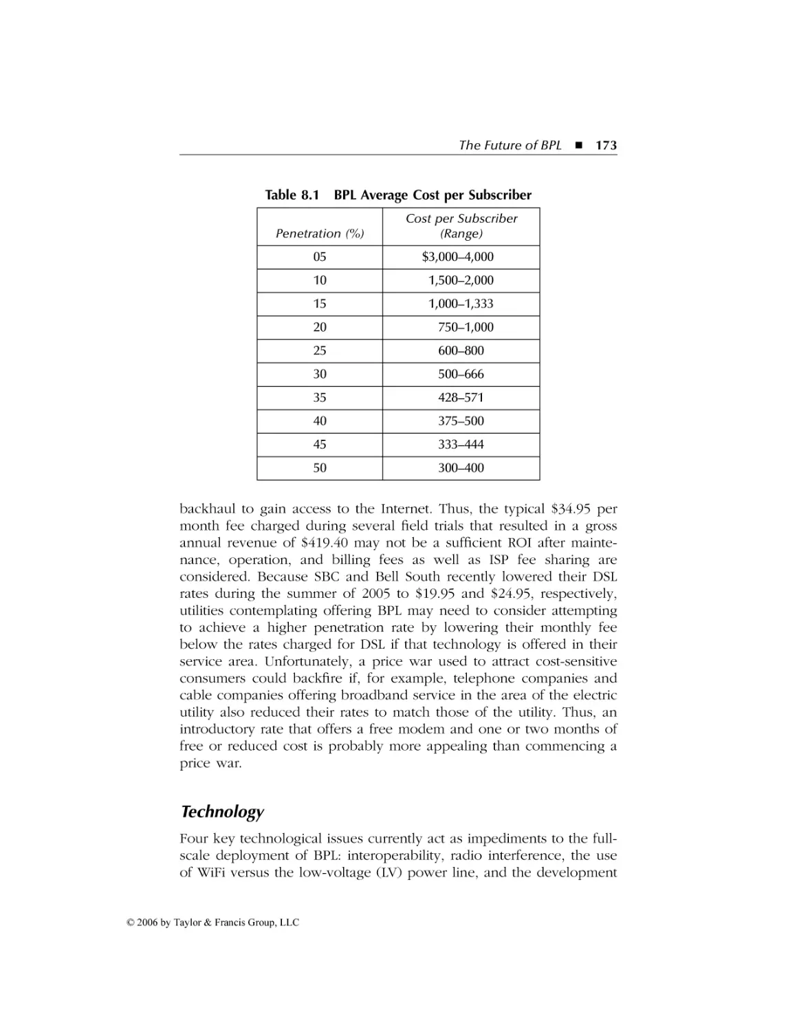
Economics ............................................................................... 172
Technology .............................................................................. 173
Interoperability ................................................................... 174
Radio Interference .............................................................. 174
WiFi versus the LV Power Line........................................... 174
Automatic Electric Meter Capability................................... 174
Regulatory................................................................................ 176
Taxes ................................................................................... 176
QoS and Common Carrier Issues ....................................... 176
Predicting the Future ................................................................... 177
Best Case Scenario................................................................... 177
Worst Case Scenario ................................................................ 178
Author’s Prediction.................................................................. 178
© 2006 by Taylor & Francis Group, LLC
AU9846_book.fm Page xiii Tuesday, March 14, 2006 3:53 PM
Acknowledgments
A long time ago, after I completed my first manuscript, I became aware
of the many persons involved in the book production process. From
the typing of an initial manuscript to the editing process and galley
page production, through the cover design process and binding effort,
there is a literal army of men and women whose efforts are crucial in
producing the book you are now reading. I would be remiss if I did
not acknowledge their efforts.
First and foremost, every book idea will come to naught unless an
author works with an editor who has the foresight and vision to back
an effort focused on an emerging technology. Once again, I am
indebted to Rich O’Hanley at CRC Press for supporting my writing
efforts.
The preparation of a manuscript is a long and lengthy process.
Although this author has many laptop and notebook computers, long
ago he gave up modern technology for pen and paper. Regardless of
where one travels, the differences in electrical outlets and airline
policies do not have an effect on pen and paper. Although this method
of manuscript generation may appear awkward in today’s era of
electronic gadgets, as long as I have paper and pen I do not have to
worry about whether or not I can use my computer on an airline or
if my outlet converter will mate to the receptacle used in a hotel. Of
course, my penmanship leaves a lot to be desired and makes me truly
grateful for the efforts of my wife, soul mate, and excellent typist,
Beverly. Commencing her effort on a 128-kB Macintosh to type my
first book almost 30 years ago, Beverly now uses Microsoft Word under
Windows XP on both desktop and notebook computers to not only
type this author’s manuscripts, but also type the index for each book.
xiii
© 2006 by Taylor & Francis Group, LLC
AU9846_book.fm Page xiv Tuesday, March 14, 2006 3:53 PM
xiv
Acknowledgments
Once a manuscript reaches the publisher, a number of behind the
scenes efforts occur. Once again, I am indebted to Claire Miller for
guiding the manuscript through the book production process. Concerning that process, I would also like to thank the CRC Press team
in Boca Raton, Florida, for their efforts in reviewing and editing my
manuscript as well as for guiding the galley pages into the book you
are reading.
© 2006 by Taylor & Francis Group, LLC
AU9846_book.fm Page xv Tuesday, March 14, 2006 3:53 PM
Preface
Just when you thought high-speed Internet access was limited to cable
television and the local telephone company, you now have an additional option to consider. Broadband over power lines (BPL) represents
an emerging technology that enables electric utilities to provide support
for high-speed data communications over their infrastructure into our
homes and offices. To paraphrase Barry Goldwater, we now have a
choice instead of an echo.
As I will note in this book, BPL represents a technology that dates
to the late 1970s and early 1980s, when several vendors developed
products to enable electric wiring in homes and offices to be used to
share what were then expensive printers and plotters. Although the
first generation of BPL products developed for home and office use
never achieved a degree of success, advances in microelectronics and
filter design resulted in the development of two similar technologies
that enable high-speed data communications in both the home and
office over existing electrical wiring and over power lines, which make
up the infrastructure of electric utilities. In this book I will examine
both technologies, because the two are closely interrelated and the
ability to transmit data over power lines is not particularly useful if a
connection method is not available to enable home and business
subscribers to easily make an Internet connection through the utility
infrastructure. Concerning the connection method, at the time this book
was researched and written, there were two methods being used in
field trials. The most popular method was to use the electrical wiring
in the home or office as a mechanism to communicate to and from
the power line bringing electricity into the facility. A second method
involved the use of a wireless LAN (local area network) access point
connected to the electric utility infrastructure. By placing the access
xv
© 2006 by Taylor & Francis Group, LLC
AU9846_book.fm Page xvi Tuesday, March 14, 2006 3:53 PM
xvi
Preface
point at a centralized location within a cluster of homes or offices, the
utility can provide a communications capability to many subscribers,
allowing each subscriber to use relatively low-cost IEEE 802.11compliant client wireless LAN cards to connect to the access point.
I will make only one assumption as we investigate the operation
of BPL communications. That assumption is that my readers have a
variety of backgrounds, ranging in scope from network engineers to
life science majors as well as other persons who may not have a
scientific background. Thus, to make this book as practical as possible
for an audience with a diverse background, I have written several
chapters to provide tutorial information. For example, in this book we
will examine the manner by which electric circuits and wireless LANs
can be used to provide access to power lines operated by electric
utilities. In addition, to ensure all readers have a common level of
knowledge concerning the electric utility infrastructure and home
wiring, we will review power line operations. In doing so, we will
examine how electricity is generated and delivered into our homes
and offices as well as how the wiring inside our structures forms
individual circuits that are routed to a common circuit breaker or fuse
box. An appreciation for how several technologies operate will allow
for a greater appreciation for the manner by which BPL technology
has the potential to represent an emerging ubiquitous communications
technology that, when deployed, can provide individual consumers,
network managers, and LAN administrators with another solution to
satisfy their high-speed networking requirements.
As a professional author, I highly value reader feedback. You can
contact me either through my publishers, whose address is on the
jacket of this book, or directly via e-mail at gil_held@yahoo.com. Let
me know if I dwelt too long on a particular topic or if I did not devote
enough information concerning a particular area, or just provide me
with your general comments concerning this book. Because I frequently travel, I may not immediately answer your letter or e-mail;
however, I will answer all persons within a week or two.
Gilbert Held
Macon, GA
© 2006 by Taylor & Francis Group, LLC
AU9846_book copy.fm Page 1 Tuesday, March 14, 2006 8:17 PM
Chapter 1
Understanding
Broadband over
Power Lines
Similar to the first chapter in any technical-oriented book, the purpose
of this chapter is to acquaint the reader with the topic of the book.
In this chapter we will turn our attention to obtaining an appreciation
for how data communications can occur over power lines installed to
transport electricity. In addition, we will examine the potential use of
broadband over power lines (BPL) as a mechanism for providing
Internet access to both homes and offices. Because there are several
methods that can be used to obtain Internet access, we will also review
the competition to broadband communications over power line technology. This information will then be used as a mechanism to better
understand the rationale for obtaining another method of high-speed
communications, which is the focus of this book. Because new technology cannot be expected to be problem free, we will also discuss
problems associated with the transmission of data over circuits originally intended to convey electricity.
1.1 Overview
Broadband over power lines, which is the title of this book, represents
an emerging technology that can provide high-speed Internet access
1
© 2006 by Taylor & Francis Group, LLC
AU9846_book copy.fm Page 2 Tuesday, March 14, 2006 8:17 PM
2
Understanding Broadband over Power Line
to the home or office through the use of an electrical outlet. Referred
to as BPL, broadband over power lines theoretically has the ability to
enable data to be transmitted over power lines into homes and offices
at data rates between 500 kbps and 3 Mbps, which is equivalent to
most Digital Subscriber Line (DSL) and cable modem transmission rates.
Thus, BPL provides an emerging alternative to conventional methods
of obtaining high-speed Internet access.
The key reason for the excitement concerning BPL technology is the
fact that virtually every home and office is connected to a power grid
and contains electrical wiring. Thus, any mechanism that provides the
potential to transmit high-speed data over existing electrical wiring has
the potential to provide a truly ubiquitous method to access the Internet.
That said, let’s turn our attention to how this technology evolved.
Evolution
Although most readers may think of BPL as a relatively recent technology, in actuality it dates back approximately 25 years to the development of the personal computer. At that time local area networks
(LANs) were still in their infancy and the most common method used
to share what were then costly printers and plotters was through the
use of parallel and serial mechanical switches.
Mechanical Switches
The use of serial and parallel interface switches enabled two or three
computers to be connected to a printer or plotter, although obviously
only one computer could access the printer or plotter at any point in
time. In addition, manual intervention was required to change the
setting on a switch to enable a different computer to access the shared
plotter or printer.
Electric Wiring
Recognizing the need for an automatic method to share peripheral
devices in the home or small office over extended distances, several
vendors introduced communications products during the late 1970s
and early 1980s that used existing electric wiring as a transport mechanism. Such devices consisted of a plug that was connected to the
serial port of a computer and inserted into an electrical outlet. The
© 2006 by Taylor & Francis Group, LLC
AU9846_book copy.fm Page 3 Tuesday, March 14, 2006 8:17 PM
Understanding Broadband over Power Lines 3
oversized plug contained a digital-to-radio frequency modulator and
demodulator. Through the use of radio frequency (RF) communications, digital data transmitted via the computer’s serial port was modulated and transmitted over the power line to another plug-type device.
That device was connected to a printer or plotter in the same or a
different room, in effect providing a home networking capability over
existing electrical wiring.
The initial series of products developed during the late 1970s and
early 1980s to enable data transmission over home power lines never
achieved any significant degree of success. The reasons varied by
product, but can probably be summed up in two areas: a lack of
miniaturization, which resulted in rather bulky adapters, and the relatively slow data rate provided by the use of a connection to the serial
port of a computer.
The HomePlug Standard
The low data rate reflected limits on the serial port of computers during
the 1970s and 1980s, which limited the transfer rate to, at best, 19,200
bps during the 1970s and 115,000 bps during the l980s, with the higher
transfer rate resulting from the introduction of buffered universal
asynchronous receiver-transmitters (UARTs).
Since the introduction of BPL adapters, advances in microelectronics
and the development of the USB port have resulted in a renewed
interest in home networks over the electrical circuits in the home and
small office. USB ports provide a data transfer capability ranging from
ten to a hundred times greater than the most capable UART. Concerning
advances in microelectronics, instead of the bulky adapters used during
the 1970s and 1980s, more modern adapters for use in the home and
small office are relatively small and simple to insert into a standard
electrical outlet. The combination of microelectronics and the ability
to connect to the higher speed USB port now standard on desktop
and laptop computers resulted in several vendors forming the HomePlug Powerline Alliance, which released its specification for high-speed
power line networking products that enable Ethernet-class operations
over standard home electrical wiring.
Broadband Over Power Lines
Although the HomePlug standard represents an important step for the
future of transmission over electrical circuits, home networking represents
© 2006 by Taylor & Francis Group, LLC
AU9846_book copy.fm Page 4 Tuesday, March 14, 2006 8:17 PM
4
Understanding Broadband over Power Line
a different technology from BPL where the existing power grid infrastructure is used to provide high-speed broadband Internet access to
homes and businesses. As we will note later in this book, transformers
are used to raise the voltage on power lines routed from power
generation plants. As high voltages are transmitted over long distances,
transformers are also located where branch lines carrying lower voltages are routed to geographic locations containing clusters of homes
and offices. At those locations, additional transformers are employed
to reduce voltage to 120 volts, which is then routed into homes and
offices.
Due to high-voltage lines and transformer coupling presenting a
different environment from the home or office, a different technology
emerged to solve the problem associated with moving data over power
lines. Although many principles associated with transmitting data over
power lines outside the home and electrical circuits within the home
are similar, equipment used on power lines differs from equipment
used within the home. One of the most obvious differences concerns
the fabrication of equipment to withstand the elements. When designed
for outdoor use, equipment requires shielding from the elements to
include fabrication that makes the devices waterproof. When used
indoors, similar performing equipment does not require the ability to
withstand rain, snow, fog, and other weather conditions. Another
obvious difference concerns the transport mechanism. In a home or
office, data will be modulated to flow over a specific type of electrical
wiring. In comparison, when data is modulated to flow over power
lines, the type of modulation used will vary based on the transport
facility. As we will note later in this chapter as well as later in this
book, electric utilities have installed tens of thousands of miles of
optical fiber along their high-voltage power lines. Originally used
exclusively for power line monitoring and internal communications,
those optical fiber facilities can also be used to provide a data transport
facility for customers by increasing the capacity of the fiber through
the use of wavelength division multiplexing (WDM) and dense wavelength division multiplexing (DWDM). Because optical fiber is usually
not available on electrical branches where medium- and low-voltage
lines are distributed toward residential and commercial customers,
electric utilities will convert optical transmission into electrical transmission via RF modulation over their power lines routed to homes
and offices. Thus, BPL technology represents multiple modulation
methods, whereas internal home or office use of electrical wiring
represents a single modulation method.
© 2006 by Taylor & Francis Group, LLC
AU9846_book copy.fm Page 5 Tuesday, March 14, 2006 8:17 PM
Understanding Broadband over Power Lines
5
During the 1990s, several European utilities conducted trials involving the transmission of data over power lines. Although the initial trials
produced mixed results, advances in technology resulted in additional
trials occurring during the turn of the new century. In the United States
the momentum associated with transmission of data over utility power
lines significantly increased as the use of the Internet increased. Unfortunately, many large utility operators expanded their operations into
the so-called merchant energy field during the years of the so-called
Western energy crisis. When the energy crisis abated, many utility
operators were left owing billions of dollars for power plants that were
not economical to operate, which resulted in an electrical utility financial crisis. Between 2000 and 2004 several power plant operators went
belly-up, declaring bankruptcy, and large utility operators who
expanded their power plant portfolios had significant liquidity problems, forcing them to curtail their investments in noncore operations.
Fortunately, as the recession of 2001 receded and demand for power
increased, utilities in the United States and other locations once again
examined the use of their infrastructure for the transmission of data.
As we will note later in this book, utility operators initiated a number
of field trials as the economy rebounded, and some organizations now
offer Internet access in competition with cable and telephone companies.
As we build on our knowledge as we move from one chapter to
the next in this book, we will become aware of the similarities and
differences between the home networking and power line environments. That said, let’s turn our attention to the basic technology that
enables data to be transmitted over power lines.
1.2 Fundamental Concepts
The ability to transmit data over power lines in many ways is based
on the concept by which telephone companies observed that the
standard wire pair routed into homes and offices could be used to
transmit data at rates up to and beyond 1 Mbps. The telephone
companies recognized the fact that the twisted-pair telephone line
routed into homes and offices was capable of supporting a frequency
range up to approximately 1 MHz. Because a telephone conversation
uses only approximately 3 kHz of bandwidth, it becomes possible to
transmit data by modulation occurring at frequencies beyond those
used to convey voice. This technique, with which voice is transported
at one set of frequencies while data is transported by modulation
© 2006 by Taylor & Francis Group, LLC
AU9846_book copy.fm Page 6 Tuesday, March 14, 2006 8:17 PM
6
Understanding Broadband over Power Line
Data
Uplink
Voice
300 3300
Figure 1.1
Data
Downlink
Frequency Hz
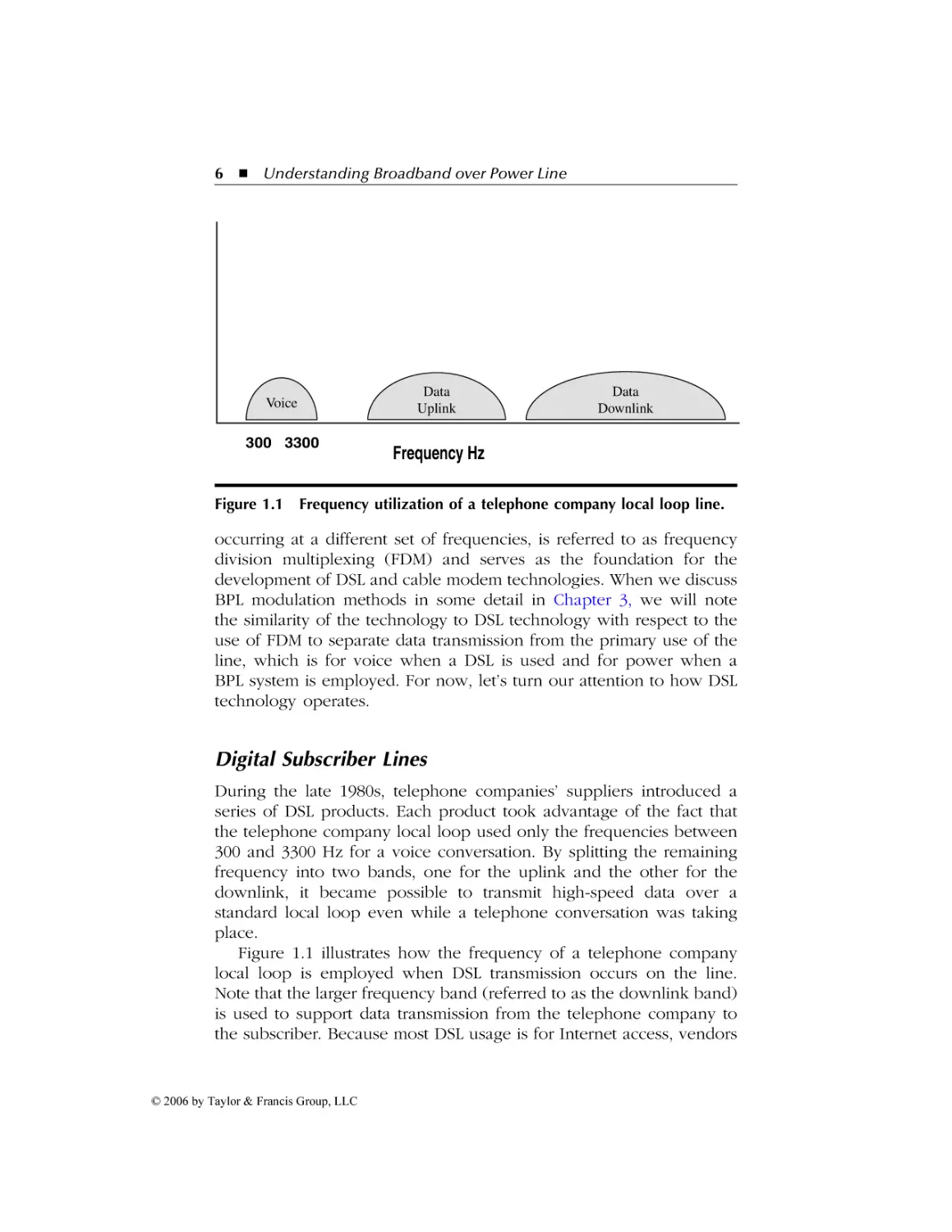
Frequency utilization of a telephone company local loop line.
occurring at a different set of frequencies, is referred to as frequency
division multiplexing (FDM) and serves as the foundation for the
development of DSL and cable modem technologies. When we discuss
BPL modulation methods in some detail in Chapter 3, we will note
the similarity of the technology to DSL technology with respect to the
use of FDM to separate data transmission from the primary use of the
line, which is for voice when a DSL is used and for power when a
BPL system is employed. For now, let’s turn our attention to how DSL
technology operates.
Digital Subscriber Lines
During the late 1980s, telephone companies’ suppliers introduced a
series of DSL products. Each product took advantage of the fact that
the telephone company local loop used only the frequencies between
300 and 3300 Hz for a voice conversation. By splitting the remaining
frequency into two bands, one for the uplink and the other for the
downlink, it became possible to transmit high-speed data over a
standard local loop even while a telephone conversation was taking
place.
Figure 1.1 illustrates how the frequency of a telephone company
local loop is employed when DSL transmission occurs on the line.
Note that the larger frequency band (referred to as the downlink band)
is used to support data transmission from the telephone company to
the subscriber. Because most DSL usage is for Internet access, vendors
© 2006 by Taylor & Francis Group, LLC
AU9846_book copy.fm Page 7 Tuesday, March 14, 2006 8:17 PM
Understanding Broadband over Power Lines
7
realized that Web pages would flow downstream toward the subscriber.
In comparison, because relatively short page requests in the form of
URLs flow toward the Internet, the uplink band uses less frequency
than the downlink band. Because the data rate is proportional to
available bandwidth, the downlink band supports a higher data transfer
rate than the uplink frequency band. At the subscriber’s home or office,
a DSL modem is used to modulate and demodulate data transmitted
over the two frequency bands. Because the two bands are not symmetrical, this technology is referred to as an Asymmetrical Digital
Subscriber Line (ADSL). Note that the three frequency bands shown
in Figure 1.1 represent an FDM system occurring over a twisted-wire
circuit routed from a telephone company office to a subscriber.
Power Line Operation
Using the telephone line as a familiar point of reference, let’s turn our
attention to power line operations and the manner by which data can
be transmitted concurrent with electricity. Standard alternating current
(AC) is transmitted at a frequency of 60 Hz in North America and at
50 Hz in Europe and many other locations throughout the world. This
means that, similar to a telephone company local loop, electrical lines
have almost all of their frequency available for utilization for other
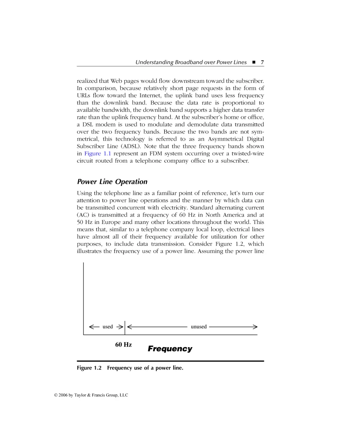
purposes, to include data transmission. Consider Figure 1.2, which
illustrates the frequency use of a power line. Assuming the power line
used
unused
60 Hz
Figure 1.2
Frequency
Frequency use of a power line.
© 2006 by Taylor & Francis Group, LLC
AU9846_book copy.fm Page 8 Tuesday, March 14, 2006 8:17 PM
8
Understanding Broadband over Power Line
is used in North America, frequencies beyond 60 Hz are unused. Thus,
the evolution of data transmission over the unused frequencies of
power lines is based on the same concepts that enable DSL to provide
millions of subscribers with high-speed Internet access.
Overcoming High Voltages
Unlike the telephone local loop, which has a limited transmission
distance, power lines allow for data transmission over extended distances. However, this results in the degradation of analog signals used
to modulate data. This problem can be further exacerbated when
power lines transport high voltages. To overcome the problem associated with high-voltage lines, many electric utilities are using fiberoptic cables running in parallel with those lines. Originally, the fiberoptic lines were installed for power monitoring and control purposes.
Although most utilities use only a small fraction of the capacity of their
fiber, it is relatively simple to expand the capacity of existing fiber by
many orders of magnitude through the use of WDM equipment.
Because the data is transmitted in the form of light pulses, it is not
disturbed by the high voltage of the power lines. At distribution
locations the optical signals are converted to electrical signals, which
are then carried over medium-voltage and low-voltage lines.
Medium- and Low-Voltage Line Operation
As data flows over medium- and low-voltage metallic conductors,
transmission distance becomes an issue. In addition, unlike telephone
company lines that are shielded, power lines are not. Because data is
modulated for transmission using analog technology over mediumand low-voltage lines, at periodic distances the analog signals must be
amplified. This amplification process is similar to the manner by which
telephone companies use amplifiers to boost analog signals. However,
instead of being called amplifiers, BPL terminology refers to such
devices as repeaters. In Chapter 3 we will examine some of the
technical terms associated with BPL technology.
The Home and Office Connection
Once the analog signal arrives within the vicinity of its ultimate
destination, there are two methods being used in trials to provide a
© 2006 by Taylor & Francis Group, LLC
AU9846_book copy.fm Page 9 Tuesday, March 14, 2006 8:17 PM
Understanding Broadband over Power Lines
9
communications connection into homes and offices. Those methods
are wired and wireless transmission. When the wired option is used,
residential and business customers must obtain a power line modem
that, when plugged into an electrical outlet, modulates and demodulates data flowing over the power line routed into the building. As we
will note later in this book, the modulation method used on lowvoltage lines provides an access method that is used to support
transmission from many users over medium-voltage lines. When a
wireless connection is employed, the electric utility typically installs
an IEEE 802.11b or g access point on a utility pole at a location where
it can serve multiple homes or offices. Then, each user in a home or
office that subscribes to the service uses a wireless network adapter
in a desktop or notebook computer to connect to the access point.
This type of infrastructure bypasses the need for a modulation method
on low-voltage lines as well as allows a node on the medium-voltage
line to serve many customers via over-the-air transmission, referred to
as WiFi or wireless fidelity.
Modulation Methods
Although the IEEE is working on a standard that will cover the lower
two layers of the protocol suite used for transmission of data over
power lines, that standard will probably be promulgated in a year or
two. In the interim, field trials performed in North America and Europe
have used several modulation methods selected by developers as being
responsive to the conditions associated with transmitting data over
low- and medium-voltage power lines. The two primary modulation
methods selected for many field trials are code division multiple access
(CDMA) and orthogonal frequency division multiplexing (OFDM).
Although we will review modulation methods in some detail in Chapter
3, a few words are now in order concerning the difference between
the two.
CDMA
Code division multiple access (CDMA) represents a modulation method
employed with cellular phones. Originally, mobile telephone technology was developed using analog techniques, and early systems were
referred to as analog mobile phone systems, or AMPS for short. Due
to the need to support a growing base of mobile phone users, equipment vendors developed technologies that enabled the spectrum
© 2006 by Taylor & Francis Group, LLC
AU9846_book copy.fm Page 10 Tuesday, March 14, 2006 8:17 PM
10
Understanding Broadband over Power Line
licensed for mobile telephone operations to be used more efficiently.
One of the technologies developed was CDMA.
OFDM
A second modulation method used in field trials of systems developed
to transmit data over low- and medium-voltage power lines is orthogonal frequency division multiplexing (OFDM). The evolution of OFDM
can be traced to what at one time was high-speed 9600 bps modem
technology, developed by a vendor named Telebit Corporation. Telebit
introduced the first 9600 bps modem designed for use over the public
switched telephone network (PSTN) during the 1980s. Since then,
OFDM has evolved and is primarily used in IEEE 802.11a and 802.11g
wireless LANs to provide a high-speed data communications capability
in both the 2.4-GHz and 5-GHz frequency bands.
When comparing CDMA and OFDM, one must consider several
tradeoffs, which we will focus on in Chapter 3. For the moment, we
can note that CDMA can provide a higher data transmission capability
than OFDM. However, because OFDM uses multiple carriers orthogonal
to one another, it has more resilience to noise than CDMA. In Chapter
3 we examine each modulation method.
Current Problems
The development of a BPL transmission facility requires utilities to use
their power lines to transmit data over those facilities. Although the
use of fiber-optic lines routed along the main utility high-voltage
transmission route does not present an interference problem due to
the use of optical transmission, the same cannot be said for the use
of analog modulation over medium- and low-voltage metallic facilities.
In such situations a utility faces a minimum of two problems. First,
the cost of bypassing transformers and adding equalizers to overcome
attenuation problems needs to be considered. Second, because power
lines are not shielded, they act as antennas when data is modulated
and transmitted over those facilities. This results in the power line
functioning as a radiating antenna, which results in interference that
can render certain types of radio systems unusable if they are located
in close proximity to a power line. In Chapter 2 we will examine the
structure and routing of utility power lines to include the use of
transformers, and in Chapter 3 we will discuss how power lines emit
© 2006 by Taylor & Francis Group, LLC
AU9846_book copy.fm Page 11 Tuesday, March 14, 2006 8:17 PM
Understanding Broadband over Power Lines
11
electromagnetic radiation. In Chapter 4 we will discuss a relatively
recent FCC (Federal Communications Commission) ruling that can be
expected to promote the use of BPL technology as a competitor to
DSL, cable modem, and other high-speed networking technologies.
Concerning those other networking technologies, in the next and
concluding section of this chapter we will review competitive Internet
access technologies.
1.3 Competitive Internet Access Technologies
In this concluding section of this chapter, we will turn our attention
to both existing and emerging Internet access technologies. In doing
so, we will compare each technology to the use of BPL, because the
latter is the focus of this book. However, prior to discussing competitive
Internet access technologies, a few words are in order concerning BPL.
Once we obtain an appreciation for the benefits of BPL technology,
then we can easily compare and contrast it with other Internet access
technologies.
Advantages of BPL
The use of BPL offers several advantages. First, because the technology
enables existing power lines outside the home to function as a data
transmission medium, the utility operator can use its existing infrastructure. Although amplifiers are required as well as equipment to
bypass transformers, converting power lines so that they can carry
data does not require the degree of an upgrade that cable TV infrastructure upgrades required to support cable modem technology. Inside
the home, data can be carried over the existing electrical wiring, which
means that every room in the house has the capability to access the
Internet. Thus, the use of inside and outside electrical wiring for data
transmission provides the ability for homeowners or small businesses
to use the electrical wiring within their facilities without modification.
In fact, it becomes possible for a utility that signs up a customer to
use its BPL technology to simply mail the customer a BPL modem that
can be plugged into an outlet within the home or office. Thus, the
customer does not have to wait for the service provider to install
equipment nor does the customer have to modify their existing wiring
because the electrical codes followed in all modern locations require
several outlets in each room. Now that we have an appreciation for
© 2006 by Taylor & Francis Group, LLC
AU9846_book copy.fm Page 12 Tuesday, March 14, 2006 8:17 PM
12
Understanding Broadband over Power Line
Table 1.1
Competitive Internet Access Technologies
PSTN
Cable modem
DSL
Satellite
WiMax
some of the advantages associated with BPL technology, let’s turn our
attention to competitive Internet access technology. As we do so, we
will compare and contrast each technology to the use of BPL technology.
Table 1.1 lists five Internet access technologies that can be considered as being competitors to BPL. The first Internet access technology,
PSTN, has a limited data rate in comparison to the other competitive
technologies. However, because access to the PSTN is available from
just about every home and office, it provides a foundation for discussing other competitive technologies.
PSTN
The use of the public switched telephone network (PSTN) to obtain
a communications capability is as ubiquitous as homes and offices that
have electrical service. Although V.92 modems designed for use over
the PSTN are stated as having a 56-kbps data transfer capability, in
reality the maximum data transfer rate one obtains is typically between
41 and 44 kbps.
The key advantage associated with the use of the PSTN is its
availability. A subscriber to an online PSTN Internet access plan can
obtain a connection from any location that has a PSTN connection.
Thus, it becomes possible to access the Internet from the home and
office as well as when traveling, with a single Internet account.
Concerning the cost of PSTN Internet access accounts, they are the
most economical of all Internet access technologies. Although AOL,
Microsoft, and other premium Internet access provider costs are in the
low $20s per month range, several nationwide vendors now offer
unlimited Internet access via the PSTN at monthly rates under $10.
Thus, Internet access via the PSTN, although providing the lowest data
transfer capability among the competitive methods listed in Table 1.1,
is also the lowest cost method.
© 2006 by Taylor & Francis Group, LLC
AU9846_book copy.fm Page 13 Tuesday, March 14, 2006 8:17 PM
Understanding Broadband over Power Lines
13
Cable Modem
Currently high-speed Internet access is dominated by the use of cable
modem technology. During the late 1990s through the turn of the
millennium, cable operators spent tens of billions of dollars upgrading
their infrastructure to support two-way amplification of signals, which
enabled the support of cable modem technology. Although cable
modem service is now offered by just about every medium- and largescale cable operator in North America, it is not ubiquitous. In fact,
cable service is available to only 60–65 percent of homes in North
America, which means that approximately 30–35 percent of homeowners cannot subscribe to a cable modem service. In addition, cable
service usually bypasses businesses in shopping malls, strip shopping
centers, and stand-alone business structures. This means that small
businesses may have difficulty subscribing to a cable modem service.
Because power lines are routed into every home and business, BPL
represents a ubiquitous offering that has the potential to reach every
home and business. This means that for approximately 30–35 percent
of homes that are currently bypassed by cable TV, BPL’s competitors
are primarily dial-up via the PSTN or DSL. As we will note when we
discuss DSL technology, there are certain distance limits which typically
removes it from being available for use by a significant percentage of
homes and offices.
Even when cable modem service is available to the home or office,
one needs to consider the layout of cable outlets in the facility. For
example, most homes have cable TV outlets in the den, kitchen, and
perhaps one or two bedrooms. If the homeowner has a built-in desk
in the kitchen, which would be a good location for a home computer,
chances are relatively high that the cable TV outlet is located on a
wall by an island or another location that, although suitable for
supporting a television, could not be easily used for a cable modem
connection. Thus, the use of a cable modem commonly requires the
installation of a new cable outlet in the home or office. This also
means that someone must be in the home or office to allow the cable
technician to gain access to the structure to install the new outlet.
Thus, there is typically a degree of inconvenience associated with the
initial installation of cable modem service that may not be present if
one was to select a BPL service to obtain a high-speed Internet access
capability.
Another difference between BPL and cable modem service that
warrants discussion is the data rate supported by each technology. As
© 2006 by Taylor & Francis Group, LLC
AU9846_book copy.fm Page 14 Tuesday, March 14, 2006 8:17 PM
14
Understanding Broadband over Power Line
mentioned at the beginning of this chapter, BPL technology commonly
supports data rates between 500 kbps and 3 Mbps. In comparison,
many cable operators now offer a fast access data rate up to approximately 5 Mbps. Although this data rate is significantly above the highest
data rate obtained from existing BPL field trials, it should be mentioned
that one pioneer of BPL — Media Fusion — amazed both potential
customers and Internet Service Providers with a promise of achieving
data rates up to 2.5 Gbps. Although the company has not yet been
able to achieve anywhere near its projected data rate, it is currently
working with the technology to increase the data rate. Thus, the
maximum BPL data rate can be considered a work in progress.
Current cable modem rates vary between $24 per month for approximately 500-kbps service to $49 per month for high-speed access. This
rate is approximately the cost associated with several BPL trials that
will be discussed later in this book.
DSL
Digital Subscriber Line (DSL) technology currently represents the second most popular method for obtaining a high-speed Internet access
capability in North America, serving about half the number of cable
modem users. Although DSL subscribers exceed ten million, some key
limitations preclude the service offering from becoming ubiquitous.
One key limitation is the fact that the subscriber must be located no
further than approximately 18,000 ft, or about 3 miles, from a telephone
office. This limits the number of homes and offices capable of being
supported by DSL service. In comparison, the fact that every home
and office has electrical service means that BPL has the potential to
be ubiquitous whereas DSL does not.
For homes and offices that can be serviced via DSL, this service is
similar to cable service with respect to the fact that telephone outlets
may not be in close proximity to the area where a computer will
reside. However, because a typical home has slightly more telephone
outlets, the ability to connect computer equipment to the telephone
company DSL service is probably easier than establishing a cable
modem connection. In comparison, DSL is a bit more difficult than
when BPL is used because a home has more electrical outlets than
telephone outlets.
Until recently, most DSL installations required a telephone company
technician to visit the subscriber location to install filters required to
separate data from the 300-Hz to 3,300-Hz voice conversation frequency.
© 2006 by Taylor & Francis Group, LLC
AU9846_book copy.fm Page 15 Tuesday, March 14, 2006 8:17 PM
Understanding Broadband over Power Lines
15
Recently, a new generation of DSL modems includes adaptive filters
that alleviate the necessity for a telephone technician to visit the
subscriber’s premises. In fact, several telephone companies now mail
the DSL modem to new subscribers because it can be easily installed.
Thus, DSL is probably equal in customer convenience and ease of
setup to BPL modems provided to customers during field trials.
Concerning data transmission capability, DSL’s maximum achievable
data rate decreases as the distance between the subscriber’s premises
and the serving telephone office increases. Currently the maximum
data rate obtainable through the use of the most popular type of DSL
service, ADSL, is approximately 1.5 Mbps. However, the average DSL
user more than likely experiences a maximum data transmission rate
of approximately 1 Mbps. It should also be noted that some telephone
companies offer a low-cost data transmission DSL service that is
typically limited to 256 kbps. Although approximately five times faster
than dial-up PSTN usage, the so-called “DSL Lite” represents the lowest
high-speed Internet access technology.
The monthly cost of DSL services when first offered a few years
ago was approximately $40 per month. Since its initial offering, large
communications carriers have reduced the monthly cost of the service
to the prices charged by cable modem providers to be more competitive.
Satellite
Currently, Internet access via satellite represents a niche market, with
less than a few percent of all Internet access occurring using this
technology. Satellite Internet access is commonly used in rural areas
where neither cable modem nor DSL services are available. Although
Dish Networks spent approximately a billion dollars for the creation
of a satellite that was to provide a significant increase in Internet
access, according to the Wall Street Journal, the company decided to
use the satellite for video operations, which put a damper on its
expected growth in the data services area.
One of the more unusual aspects associated with satellite Internet
access is its integration with a wireless mesh network to provide highspeed Internet access to small communities. The wireless mesh network
consists of a series of IEEE 802.11a, b, or b/g network adapters typically
housed in a box, which in turn is mounted on light poles that relay
transmissions to and from one or more access points. By connecting
the access points to satellite stations linked to the Internet, the mesh
© 2006 by Taylor & Francis Group, LLC
AU9846_book copy.fm Page 16 Tuesday, March 14, 2006 8:17 PM
16
Understanding Broadband over Power Line
network provides users within transmission distance of different meshenabled devices with access to the Internet.
Each station that participates in the mesh functions as a simple
router, forwarding packets that are not destined for the station. Stations
can enter and leave the mesh dynamically, with the routing protocol
used by stations dynamically adjusting to such changes.
Because a wireless mesh network provides the ability for a group
of users to access the Internet, it can be more cost effective than the
use of individual connections. This economic advantage becomes
possible when the cost of the high-speed Internet connection is amortized over a sufficient base of users. Although the BPL trials in effect
when this book was written did not use a wireless mesh network to
support a group of customers, there is no reason why the technology
could not do so. Thus, the economic advantage associated with the
connection of a wireless mesh network to a satellite station in comparison to the cost of individual high-speed Internet access would be
eliminated if the mesh network was connected to an electric utility
company power line that provided high-speed Internet access.
On an individual basis, a comparison between the use of a satellite
and BPL for Internet access is anything but simple. Some satellite
providers offer an integrated dish that enables a subscriber to obtain
both video and data transmission capability, whereas other providers
require separate satellite dishes. Because the use of satellite for highspeed Internet access is primarily located in rural areas and represents
a few percent of all high-speed Internet access methods, it is unlikely
to have any material effect on BPL once the latter is offered in rural
areas.
WiMax
In concluding our discussion of competitive Internet access technologies, we will turn our attention to WiMax, an acronym that stands for
worldwide interoperability for microwave devices. WiMax represents
a wide area networking technology that can be used to transmit
broadband signals over the air at distances up to approximately 30
miles. Although WiMax was standardized by the IEEE as the 802.16
standard in April 2002, its original specification resulted in several
deployment problems. As we will note, a newer version of WiMax,
referred to as the IEEE 802.16a standard, is presently being examined
for use in several upcoming field trials.
© 2006 by Taylor & Francis Group, LLC
AU9846_book copy.fm Page 17 Tuesday, March 14, 2006 8:17 PM
Understanding Broadband over Power Lines
17
WiMax has some similarities to wireless LANs (local area networks);
however, it is also significantly different from the IEEE series of 802.11
wireless LAN standards. Concerning similarities, like the 802.11-compliant products, WiMax involves the use of client stations that use
antennae to communicate with a centralized station. That centralized
station is referred to as a central radio base station under IEEE 802.16
terminology and is designed to provide an alternative to cabled access
networks, such as coaxial-based systems operated by your cable company in which you use a cable modem to access the Internet and a
DSL for Internet access commonly offered by your local telephone
company.
Although the original 802.16 standard was defined for use in the
10- to 66-GHz frequency band that represents spectrum available on
a global basis, such high frequencies represent a significant deployment
problem. This problem results from the fact that high frequencies have
short periods, which restricts transmission to line-of-sight operations.
Although 802.16 devices might be suitable for rural areas, where there
are no tall buildings or other obstacles, field trials are typically performed to obtain a large base of users. Because this would require
field trials to occur in metropolitan areas, the line-of-sight problem
associated with the 802.16 standard in effect resulted in a delay in
fielding such trials. Recognizing the line-of-sight problem associated
with the 802.16 standard, the IEEE developed an extension to that
standard, which became the 802.16a standard. This new standard
defines an extension of WiMax to operate at lower frequencies, in the
2- to 11-GHz band, to include operations in both licensed and unlicensed frequency bands.
WiMax supports point-to-point and point-to-multipoint transmission
methods similar to the IEEE series of 802.11 wireless LAN standards.
The key difference between the two is the fact that wireless LANs can
communicate only within a limited distance of a few hundred feet
within a building to approximately a thousand feet outdoors, whereas
WiMax supports transmission distances up to 30 miles.
At the time this book was prepared, several field trials based on
the 802.16a standard were either being conducted or planned for future
operation. One of the reasons for the delay in field trials was a lack
of 802.16a chips. Although Intel had expressed keen interest in the
technology, it may be late 2006 before 802.16a chip production occurs
on a scale sufficient to result in cost-effective products.
Although WiMax can be viewed as a competitor to BPL, it can also
be viewed as a supplemental technology. This results in the fact that
© 2006 by Taylor & Francis Group, LLC
AU9846_book copy.fm Page 18 Tuesday, March 14, 2006 8:17 PM
18
Understanding Broadband over Power Line
the deployment of 802.16 central radio base stations in rural areas
would require a mechanism to connect each base station to the
Internet. Because power lines reach virtually every community regardless of their size or location, in the future it may be possible to use
WiMax to serve clusters of homes and offices in rural areas and use
BPL technology to connect central radio base stations via power lines
to the Internet. This may be especially true for rural areas, where cable
and DSL are not offered due to the low density of potential customers
within a geographic area. In such situations the use of WiMax connected to a high-speed data transmission system provided through the
use of low- and medium-voltage power lines could represent a mechanism to provide economical Internet access to homes and offices
spread out over a large area.
© 2006 by Taylor & Francis Group, LLC
AU9846_book.fm Page 19 Tuesday, March 14, 2006 3:53 PM
Chapter 2
Power Line Operations
One of the most basic errors an author can make is to assume readers
are familiar with the underlying technology associated with the topic
of the book. After making this mistake a few times when I was still
“wet behind the pen,” I vowed not to make this mistake again. Thus,
the purpose of this chapter is to acquaint readers with the operation
of electrical power lines. To accomplish this goal, I will first focus our
attention on understanding basic electricity; examining how circuits
operate; the difference between alternating current (ac) and direct
current (dc); the significance of the volt (V), ampere (I), ohm (Ω), and
watt (W); as well as the manner by which electricity reaches the home
or office. Because many emerging power line operation standards as
well as compatibility issues require knowledge of specific terminology,
such as the decibel milliwatt (dBm) and carrier frequency expressed
in terms of kilohertz (kHz) or megahertz (MHz), we will also discuss
the significance of those terms to ensure all readers have the same
minimum level of background information required to benefit from
the information provided in this book.
2.1 Understanding Electricity
In this section we will focus our attention on obtaining an appreciation
of electricity. Commencing with a review of atoms and their electrons,
we will discuss conductors, how current flows in a wire, the manner
19
© 2006 by Taylor & Francis Group, LLC
AU9846_book.fm Page 20 Tuesday, March 14, 2006 3:53 PM
20
Understanding Broadband over Power Line
by which electricity is generated, basic circuit measurements, and the
difference between alternating current and direct current.
Atoms and Electrons
Electricity represents a form of energy that occurs due to the flow of
electrons. Every atom, which represents a microscopic structure found
in all matter, contains one or more electrons that have a negative
charge. Those electrons rotate around the atom similar to the manner
by which planets rotate around the sun. In some materials, such as
rubber, plastic, glass, and even air, electrons are tightly bound to the
atoms. Because the electrons in effect do not move, they cannot
conduct electricity and are referred to as electrical insulators. In comparison, most metals have electrons that can be easily detached from
their atoms. Such electrons are referred to as free electrons and provide
the ability for electricity to flow through different types of material.
Copper, gold, silver, aluminum, and other metals that have electrons
that can be easily detached from their atom are known as electrical
conductors because they conduct electricity. Although electricity
requires a conductor to move, it also requires something to make it
flow through the conductor. That something is an electric generator.
Electric Generators
An electric generator converts mechanical energy into electrical energy
based on the relationship between magnetism and electricity. Physics
instructors often show their classes a small experiment during which
a wire is moved across an electric field, resulting in the flow of an
electrical current in the wire. A similar but reverse experiment sometimes used by physics instructors is to move electrons through a wire
and observe how their flow results in the creation of a magnetic field
around the wire. An example of the latter is illustrated in Figure 2.1,
where a battery is used to generate the flow of electrons when the
switch is closed. At that time the compass needle will move due to
the magnetic field created by the flow of electrons. As we will note,
the relationship between magnetism and the flow of electricity paved
the way for the construction of power plant generators, which, in
effect, to borrow an old tune, will “light up our lives.”
Returning our attention to Figure 2.1, we can use that illustration
as a mechanism to state the “right-hand law” discussed in many physics
classes. That is, first clasp together the four fingers on your right hand
© 2006 by Taylor & Francis Group, LLC
AU9846_book.fm Page 21 Tuesday, March 14, 2006 3:53 PM
Power Line Operations 21
Switch
Compass
B
a
t
t
e
r
y
Figure 2.1 The relationship between electricity and magnetism can be
observed by closing the switch and viewing the change in the direction of
the needle of the compass.
and move them inward toward your palm. As you do so, extend your
thumb upright. You can use your hand to view the relationship between
the flow of current and the induced electromagnetic field. That is, the
thumb indicates the direction of the flow of electricity, whereas the
position of the four fingers indicates the direction of the electromagnetic force. For example, if the thumb is pointing upward, then the
electromagnetic force flows counterclockwise. In comparison, if the
thumb points down to indicate a reversal of polarity, that causes current
to flow in the opposite direction; then the electromagnetic force flows
in the clockwise direction. Unfortunately, if you are left handed, you
should not favor that hand but instead use your right hand to comply
with the right-hand rule. Now that we have an appreciation for the
relationship between an electromagnetic force and the flow of current,
let’s turn our attention to how generators operate.
The large generators used by an electric utility have a stationary
conductor formed in a ring shape. A magnet attached to the end of a
rotating shaft is located inside the stationary conducting ring, and the
conducting ring is wrapped with wire. As the magnet rotates, it induces
© 2006 by Taylor & Francis Group, LLC
AU9846_book.fm Page 22 Tuesday, March 14, 2006 3:53 PM
22
Understanding Broadband over Power Line
a small electric current as it passes each section of wire. Cumulatively,
the series of electric currents results in one current of considerable
size. The shaft positioned within the stationary conducting ring is
driven by a turbine whose blades usually are turned by water or steam.
Thus, let’s discuss the role of the turbine in the electric generator
process.
Turbines
The most basic type of turbine is a water-powered device, with water
from a dam falling over its edge, causing the blades of a turbine to
spin. A second type of turbine is a fossil-fueled steam turbine, in which
natural gas, oil, coal, or nuclear power is used to heat water in a boiler
to produce steam. The resulting steam is pressurized and flows through
the turbine, resulting in its blades spinning, which in turn spins the
shaft that generates electricity. Because the turbine and generator are
closely related, many manufacturers, such as General Electric, produce
what is referred to as a turbine generator.
Circuit Measurements
The magnitude of the generated current resulting from the flow of
electrons is referred to as amperage, which is measured in amps and
denoted by the symbol I. In comparison, the pressure used to push
electrons is referred to as voltage, which is measured in volts and
denoted by the symbol V.
As electrons flow in a conductor, they encounter resistance. Resistance represents the ratio of voltage to current and is measured in
ohms; 1 ohm is defined as the resistance when 1 volt is applied to a
material and the current is 1 amp. Resistance is denoted by the symbol
R. The relationship between voltage, current, and resistance is referred
to as ohm’s law, where:
R (ohms) = voltage/current = volts/amps = V/I
Using ohm’s law, we need to know only two of three measurements
to compute the third. For example, assume we measure the current
in a circuit to be 5 amps when 120 volts is applied. From ohm’s law
we obtain:
R = V/I = 120 V/ 5 I = 24 ohms
© 2006 by Taylor & Francis Group, LLC
AU9846_book.fm Page 23 Tuesday, March 14, 2006 3:53 PM
Power Line Operations 23
Similarly, if we know the resistance of a circuit is 24 ohms and we
measure the current flowing through the circuit, we can compute the
voltage. That is, again from ohm’s law, we have:
R = V/I or V = I * R
Then,
V = 5 amps * 24 ohms = 120 volts
Circuits
Although electrical circuits can become quite complex, we can obtain
an appreciation for how they operate by focusing our attention on
their common components, using as a frame of reference the simple
series circuit shown in Figure 2.2. Regardless of the type of electrical
circuit, all circuits have several factors in common. First, the source of
electricity, which is shown as a battery in Figure 2.2, has two terminals:
a positive terminal and a negative terminal. Second, the source of
electricity, which can be a simple battery or can result from a generator
located hundreds of miles away, pushes electrons at a certain voltage.
In the example shown in Figure 2.2, a typical AA battery will push
electrons out at 1.5 volts. As electrons flow from the negative terminal
to the positive terminal through the conductor, the path forms a circuit.
Switch
+
Battery
Load
_
Figure 2.2 All circuits have a source of electricity, a load, and two wires
used to transport electricity between the source and the load.
© 2006 by Taylor & Francis Group, LLC
AU9846_book.fm Page 24 Tuesday, March 14, 2006 3:53 PM
24
Understanding Broadband over Power Line
The load on the circuit can be a light bulb, television, stereo, or motor
and will be powered by the electricity flowing through the circuit.
From the preceding example you might be a bit puzzled by the
statement “as electrons flow from the negative terminal…” because
many people view current flow as occurring from the positive terminal
of a battery. For many years it was assumed that current flowed in
this manner, until the development of equipment that showed the
reverse was true. Thus, current flows from the negative terminal to
the positive terminal and not vice versa.
Electrical Power
Power can be considered to represent the rate of doing work. In an
electrical circuit, power is the rate of using energy and is measured
in watts, denoted by the symbol W.
Power is also the product of volts and current in a circuit, such that:
Power (watts) = voltage × current = volts × amps = V * I
In North America, the power outlets in the walls of homes and
offices are configured so that they are delivering 120 volts. If you
locate a portable space heater and view its label, you might note that
it operates at 120 volts and draws 10 amps. This means that its power
in watts is
Power (watts) = 120 volts × 10 amps = 1,200
If, instead of a space heater, you locate a 60-watt light bulb and
plug it into a lamp, which in turn is connected to a 120-volt receptacle,
you can use the preceding equation to compute the current that flows
in the circuit that illuminates the light bulb. Because P = V * I, then:
I = P/V = 60/120 = .5 amp
Thus, a 60-watt light bulb placed in a 120-volt socket draws .5 amps
when illuminated.
Because electricity is consumed over time, power companies measure consumption in terms of power used over a period of time. For
example, a 60-watt bulb lit for a period of 8 hours results in the use
of 60 watts times 8 hours, or 480 watt-hours (Wh). Because the watt
represents a relatively small amount of power, electric utilities bill
© 2006 by Taylor & Francis Group, LLC
AU9846_book.fm Page 25 Tuesday, March 14, 2006 3:53 PM
Power Line Operations
25
customers based on the number of kilowatt-hours of electricity consumed; the kilowatt-hour (kWh) represents 1,000 Wh. Exceptions to
the preceding are factories and other large consumers of electrical
power. Such consumers may receive their monthly utility bills indicating
consumption in terms of megawatt-hours (MWh); the megawatt-hour
represents 1,000 kWh or 1,000,000 Wh.
Electric rates in the United States commonly vary from approximately 5 cents per kilowatt-hour to 15 cents per kilowatt-hour. Typically, the kilowatt-hour cost is lower in locations where electricity is
generated through the use of water flowing across different types of
barriers, referred to as hydro-electric generation. Of course, when an
area that depends on hydro-electric generation experiences a drought,
the utility is forced to import more expensive fossil-fuel or nucleargenerated electricity.
If we use an average of 10 cents per kilowatt-hour for electricity,
we can note the bargain it provides in comparison to the functions it
allows. For example, a 100-watt bulb left on during an 8-hour day
consumes 100 watts times 8 hours, or 0.8 kWh of electricity. At a cost
of 10 cents per kilowatt-hour, it costs just 8 cents to light up a desk
throughout the workday. Because you cannot buy much in a candy
store for under a dime and probably consume your purchase in less
than a minute, the ability to light your desk for 8 cents during the
workday is truly a bargain.
For a second example of the bargain of electricity, consider the 25cubic-foot refrigerator installed in most homes. A modern 25-cubicfoot refrigerator will consume approximately 575 kWh of power during
its full year of operation. At a cost of 10 cents per kilowatt-hour, this
works out to $57.50 to operate your refrigerator throughout the year.
Direct Current versus Alternating Current
Batteries, solar panels, and fuel cells generate current that always flows
in the same direction between their terminals. Thus, these types of
power generators produce direct current (dc).
Because power plants generate electricity by moving a shaft that
turns a magnet inside a stationary conducting ring, the direction of
current periodically reverses, or alternates, resulting in power referred
to as alternating current. In North America, current reverses direction
60 times per second, whereas in Europe, generators produce power
that alternates the direction of current 50 times per second. This
explains why we refer to current in North America being produced at
© 2006 by Taylor & Francis Group, LLC
AU9846_book.fm Page 26 Tuesday, March 14, 2006 3:53 PM
26
Understanding Broadband over Power Line
60 cycles per second (cps), whereas current in Europe is produced at
50 cps.
The major advantage of alternating current is the fact that it is very
easy to change the voltage of the power produced by a generating
plant. As we will note in the second section in this chapter, a transformer can be used to increase or decrease voltage. The key reason
for the use of ac in homes and offices is one of economics. It is more
economical for a power plant generating several million watts (MW)
of power to transmit a high voltage with low amperage instead of a
low voltage with high amperage. For example, a power plant capable
of generating 1 million watts of power could transmit 1 MV at 1 amp.
Sending 1 amp requires only a thin wire. In comparison, transmitting
1 M amps at 1 volt would require a very large-diameter wire and
would result in a considerable loss of power due to the heat associated
with moving a million amps through a large conductor. Thus, it’s more
economical to transmit power at high voltage and relatively low
amperage.
Power plants use transformers to convert lower-voltage-generated
alternating current to very high voltages for transmission. Because high
voltage can literally fry both humans and equipment, a series of
transformers is used to reduce the voltage that flows from main feeder
lines onto branch lines, whereas other transformers reduce the voltage
on branch lines down to the 120 volts that typically enters the home
or office.
Ground
Ground, as the term implies, refers to a connection to the earth. A
ground acts similar to a reservoir of charge and functions as a mechanism to prevent shock. On a transmission line you can see electric
poles where a bare wire is connected from the upper portion of the
pole to a coil placed in the base of the pole. The coil is in direct
contact with the earth, which provides a ground. If you carefully look
at a series of electric poles in your neighborhood, you can see the
ground wire running between poles as well as attached to the coil at
the base of each pole.
Communications Measurements
We need to review communications measurements for two basic reasons. First, we need an understanding concerning how we can compare
© 2006 by Taylor & Francis Group, LLC
AU9846_book.fm Page 27 Tuesday, March 14, 2006 3:53 PM
Power Line Operations
27
Table 2.1 Common Prefixes of Powers of 10
Prefix
Meaning
milli
1/1000 (thousandth)
kilo
1,000 (thousand)
mega
1,000,000 (million)
giga
1,000,000,000 (billion)
and contrast signals used for communications that flow over power
lines. Second, understanding communications measurements provides
us with the background necessary to understand the relationship
between communications over power lines and potential interference
caused by such communications. Thus, in concluding this initial section
in this chapter, we will turn our attention to several measurements
commonly associated with communications. We will first review the
prefixes for the power of 10 because they represent a key to understanding many terms associated with electrical power generation and
consumption.
Powers of 10
As a refresher for those readers who may be a bit rusty remembering
prefixes of the powers of ten, let’s examine the entries in Table 2.1.
That table lists four common prefixes and their meaning. The first
prefix, milli, represents one thousandth. Thus, the term milliwatt would
represent a thousandth of a watt. The second term, kilo, represents a
thousand. As we noted earlier in this chapter, kilowatt represents a
thousand watts. The two remaining prefix terms, mega and giga,
represent a million and a billion, respectively.
When we discuss power consumption in terms of kilowatt-hours,
the use of that term is more appropriate to homes and small offices.
In comparison, large organizations that consume a lot of power during
the month may receive a power bill indicating consumption in terms
of megawatt hours of electricity.
Power Measurements
The invention of the telephone resulted in the need to define the
relationship between the received power of a signal and its original
© 2006 by Taylor & Francis Group, LLC
AU9846_book.fm Page 28 Tuesday, March 14, 2006 3:53 PM
28
Understanding Broadband over Power Line
power. Initially, this relationship was given the name bel (B) in honor
of Alexander Graham Bell, the inventor of the telephone.
The bel
The bel uses logarithms to the base 10 to express the ratio of power
transmitted to power received. The resulting gain or loss for a circuit
is given by the following formula:
B = log10 PO/PI
where B is the power ratio in bels, PO represents the output or received
power, and PI is the input or transmitted power.
The rationale for the use of logarithms can be traced to the manner
by which humans hear. That is, our ears perceive sound or loudness
on a logarithmic scale. For example, if we estimate that a signal doubled
in loudness, the transmission power actually increased by approximately a factor of 10. A second reason for the use of logarithms in
power measurements is the fact that changes to a signal in the form
of a power boost from an amplifier or a signal loss due to resistance
are additive. Thus, the ability to add and subtract when performing
power measurements based on a log scale simplifies computations.
For example, a 15-B signal that encounters a 10-B loss and is then
passed through a 15-B amplifier results in a total signal strength of 15
– 10 + 15, or 20 B.
For those readers who are a bit rusty concerning the use of
logarithms, note that the logarithm to the base 10 (log10) of a number
is equivalent to how many times 10 is raised to a power to equal the
number. For example, log10 100 is 2, log10 1,000 is 3, and so on.
Because output or received power is normally less than the input or
transmitted power, the denominator in the preceding equation is
normally larger than the numerator. To simplify computations, note
that a second important property of logarithms is the fact that the
reciprocal of a logarithm is equal to its negative value. That is,
log10 1/X = –log10 X
As an example of the use of the bel for computing the ratio of
power received to power transmitted, assume that the received power
is one-tenth the transmitted power.
© 2006 by Taylor & Francis Group, LLC
AU9846_book.fm Page 29 Tuesday, March 14, 2006 3:53 PM
Power Line Operations
29
Then,
B = log10 1/10/1 = log10 1/10
Because, from the properties of logarithms,
log10 1/X = –log10 X
we obtain
B = –log10 10 = –1
From the preceding computation you will note that a negative value
indicates a power loss, whereas a positive value would indicate a
power gain.
Although the bel was used for many years to categorize the quality
of transmission on a circuit, a more precise measurement was required
by industry. This need resulted in the adoption of the decibel as the
preferred power measurement.
The Decibel
The decibel (dB) represents the standard measurement used today to
denote power gains and losses. The decibel is a more precise measurement because it represents one-tenth of a bel. The power measurement in decibels is computed as follows:
dB = 10 log10 PO/PI
where dB is the power ratio in decibels, PO is the output or received
power, and PI is the input or transmitted power. Returning to the
preceding example covered during the discussion of the bel, where
the received power was measured to be one-tenth of the transmitted
power, the power ratio in decibels becomes
dB = 10 log10 1/10/1 = log10 1/10
Because log10 1/X = –log10X, we obtain
dB = –10 log10 10 = –10
© 2006 by Taylor & Francis Group, LLC
AU9846_book.fm Page 30 Tuesday, March 14, 2006 3:53 PM
30
Understanding Broadband over Power Line
Decibel above 1 mW
In concluding our examination of communications power measurement
terms, we need to note that the bel and decibel do not indicate power.
Instead, they represent a ratio or comparison between two power
values, such as input and output power. Because it is often desirable
to express power levels with respect to a fixed reference, it is common
to use a 1-mW standard input for comparison purposes. In the wonderful world of communications testing, the 1-mW signal occurs at a
frequency of 800 Hz. The use of a 1-mW test tone occurring at 800
Hz results from the evolution of early telephone systems. From measurements occurring at that time, 1 mW of power was equivalent to
the power generated by an average person talking on the telephone
and 800 Hz represented the average frequency of a human conversation. To ensure that you do not forget that the resulting power
measurement occurred with respect to a 1-mW input signal, the term
decibel-milliwatt (dBm) is used. Here, decibel-milliwatt represents
dBm = 10 log10 output power/1 mW input
The m in dBm serves to remind us that the output measurement
occurred with respect to a 1-mW test tone. Although the term decibelmilliwatt is used in most literature, in actuality it means “decibel above
1 mW.” Thus, 10 dBm represents a signal 10 dB above, or bigger than,
1 mW, whereas 20 dBm represents a signal 20 dB above 1 mW, and
so on. Because a 30-dBm signal is 30 dB, or 1,000 times larger than
a 1-mW signal, this means that 30 dBm is the same as 1 W. Thus, we
can use this relationship to construct a table indicating the equivalence
between values expressed in terms of power in watts and power in
decibel-milliwatts. Table 2.2 presents four key relationships.
We can better understand the relationships shown in Table 2.2 by
commencing our observation with the previously noted fact that 1 W
is equivalent to 30 dBm. Then we can note that 1 mW is a thousandth
Table 2.2 Relationship between Watts and Decibel-Milliwatts
Power in Watts
Power in Decibel-Milliwatts
.1 mW
–10 dBm
1 mW
0 dBm
1W
30 dBm
1 kW
60 dBm
© 2006 by Taylor & Francis Group, LLC
AU9846_book.fm Page 31 Tuesday, March 14, 2006 3:53 PM
Power Line Operations
31
of a watt. Because 0 dBm means that output power equals input power,
the only way to obtain a 0 dBm power level is for the output power
to be 1 mW. Thus, the output power divided by a 1-mW input power
value produces a 0-dBm power level and indicates that 1 mW is equal
to 0 dBm. If you perform the previously mentioned computation, it’s
important to remember that we are working with logs. Thus, the
equation for the decibel-milliwatt measurement is
dBm = 10 log10 PO/1 mW
When we set PO equal to 1 mW, we obtain
dBm = 10 log10 1
Because log10 1 is equivalent to determining that 10 raised to the
power of 0 results in 1, the value of log10 1 is 0. Thus, dBm must be
0 for the output power to equal 1 mW. Now let’s examine the .1 mW
value. A .1 mW value is one-tenth of a milliwatt. Similarly, a –10 dBm
value represents a tenth of 0 dBm. Thus, –10 dBm is equivalent to a
power of .1 mW. We can now examine the last entry in Table 2.2,
which indicates 1 kW is equal to 60 dBm. Because 1 kW is 1,000 times
a watt and 60 dBm is 1,000 times greater than 30 dBm, then 1 kW is
equal to 60 dBm.
2.2 Electricity Distribution
Most homeowners and office workers take electricity for granted; unless
a storm knocks out our power lines, we really do not place much
emphasis on how power is distributed to our location. In this section
we will not wait for a sudden storm or for an automobile or truck to
crash into a power company facility to impede the flow of electricity
to appreciate how it arrives at our door. Instead, we will turn our
attention to the manner by which electricity travels into our home or
office.
The Power Plant
Electricity begins its travel to our home or office at a power plant.
That plant uses water, coal, natural gas, or nuclear fuel to generate
steam, which is used to make a turbine spin. The spinning of the
© 2006 by Taylor & Francis Group, LLC
AU9846_book.fm Page 32 Tuesday, March 14, 2006 3:53 PM
32
Understanding Broadband over Power Line
turbine in turn generates electricity. In the case where water is used,
typically a dam is constructed to gather water into a narrow channel.
As water flows into the channel it moves toward locks that can be
raised or lowered and control the flow of water across the dam. As
water flows through the locks, its pressure is used to spin the blades
of a turbine. In effect, the force of gravity and the motion of the water
cause the turbine to spin. When a nonrenewable fuel such as coal or
natural gas is used, combustion is employed to heat water into steam.
Similarly, when nuclear fuel is used, uranium control rods are inserted
into a reactor to generate heat via a controlled nuclear fusion process,
which is used to turn water into steam. For both nuclear- and nonnuclear-generated steam, the result is similar, with the steam pressurized and used to turn the blades of turbines connected to a shaft
placed in a magnetic coil that generates electricity.
Transformers
Electricity is generated by a turbine installed at a power plant that is
normally located at a distance from the majority of the plant’s customers. For example, a large power plant located at 4 Corners, where the
borders of Arizona, Utah, Nevada, and New Mexico meet, is located
hundreds of miles from major population centers. To facilitate the flow
of electricity over long distances, the power plant uses transformers
to increase voltage so that electricity can flow on high-voltage lines
with a minimal loss.
A transformer makes use of Faraday’s law and the ferromagnetic
properties of an iron core to either raise or lower ac voltage. As a
refresher for readers who may have skipped a physics class that
discussed magnetic properties, Faraday’s law states that any change in
the magnetic environment of a coil of wire will cause a voltage to be
induced in the coil. By adjusting the area of an iron core and the
number of turns of a wire on each side of the core, we can either
raise or lower a secondary or output voltage with respect to the primary
or input voltage.
Figure 2.3 illustrates the operation of a transformer. In this example
the primary voltage is produced by the power plant generator. The
output or secondary voltage is then transported via a high-voltage
power line to a metropolitan area.
From Faraday’s law:
Vs/Vp = Ns/Np
© 2006 by Taylor & Francis Group, LLC
AU9846_book.fm Page 33 Tuesday, March 14, 2006 3:53 PM
Power Line Operations
Ip
Is
Vp
Vs
33
R
Ns
Np
Figure 2.3
A transformer can be used to increase or decrease voltage.
where
Vs = secondary voltage
Vp = primary voltage
Ns = secondary number of turns
Np = primary number of turns
Although a transformer can be used to raise or lower voltage, it
cannot increase or decrease power. Thus, for an ideal transformer we
have
P p = V p Ip = V s I s = P s
where
Pp = primary power
Ps = secondary power
Vp = primary voltage
Vs = secondary voltage
Ip = current primary
Is = current secondary
When the voltage is raised by a transformer, the transformer is
referred to as a step-up device. Because the power cannot increase,
when the voltage is raised, the current is proportionally lowered. Thus,
Is = VpIp/Vs
In actuality, both the primary and secondary transformer circuits
have resistance that affects the output of the device. Thus, the previously presented computations can be considered to represent an ideal
transformer that has no resistance. Although transformers do indeed
© 2006 by Taylor & Francis Group, LLC
AU9846_book.fm Page 34 Tuesday, March 14, 2006 3:53 PM
34
Understanding Broadband over Power Line
have resistance, for the purpose of this section, which explains the
flow of electricity from a power station to a home or office, we can
assume a perfect world and an ideal transformer. Thus, for the purpose
of understanding the role of transformers, we need to note that the
ratio of primary and secondary windings and primary voltage affects
the resulting secondary voltage. If the number of primary windings
(Np) is greater than the number of secondary windings (Ns), then the
secondary voltage (Vs) will be less than the primary voltage (Np). If
the number of secondary windings (Ns) is greater than the number of
primary windings (Np), then the opposite will be true. That is, the
secondary voltage (Vs) will be greater than the primary voltage (Vp).
From the power plant’s transformer, electricity is coupled onto highvoltage lines to enable power to flow relatively long distances. Where
groups of customers are located, the high-voltage line is coupled to a
transformer in a facility referred to as a substation. The transformer in
the substation is a step-down device with a lesser number of secondary
coils than primary coils. Thus, the substation reduces the voltage via
a step-down transformer for distribution on power lines that can run
either overhead or underground.
Types of Transformers
As the power lines reach a particular area where homes or offices are
within close proximity, the voltage is further reduced by the use of
smaller transformers. These transformers are easily recognized as circular containers mounted on utility poles or as small rectangular metal
enclosures set on concrete pads. Figure 2.4 illustrates a pole-mounted
transformer operated by Georgia Power in Macon, Georgia. Figure 2.5
shows a rectangular metal enclosure set on a concrete pad in my
neighborhood. The metal enclosure contains a transformer whose
output is placed onto power lines that run underground to homes in
the neighborhood. Either type of transformer typically reduces the
voltage provided by the regional transformer to 120 volts for use in
the home or office.
Transformer Wiring
Because electricity flows in a circuit, there must be at least two wires
routed from the last transformer that produced 120-volt output into
the home or office. One wire represents a hot wire and the second
represents a neutral wire. Older homes and offices that have only two
© 2006 by Taylor & Francis Group, LLC
AU9846_book.fm Page 35 Tuesday, March 14, 2006 3:53 PM
Power Line Operations
Figure 2.4
35
A utility pole–mounted transformer.
wires entering the facility can provide only 120-volt current. In comparison, more modern homes and offices commonly have three wires
entering the facility. Two of those wires are hot, each carrying 120
© 2006 by Taylor & Francis Group, LLC
AU9846_book.fm Page 36 Tuesday, March 14, 2006 3:53 PM
36
Understanding Broadband over Power Line
Figure 2.5 A metal enclosure used to house a transformer whose output
flows onto underground power lines.
volts, and the third wire is neutral. Thus, the inbound voltage permits
an electrician to provide circuits in the home or office that operate at
either 120 or 240 volts.
Service Methods
Electric service to homes and offices is provided via two methods:
overhead service and underground service. If the home or office has
overhead service, the wires emerge from a transformer and are routed
as an aerial line to a weatherhead mounted on the roof or side of the
facility. The weatherhead is a conduit that allows wires from the
transformer to be spliced into wires that are routed to an electrical
meter. The meter measures how much electricity the house or office
uses and provides information that affects the monthly bill. From the
electric meter, wires are routed into a service panel, which distributes
electricity throughout the home or office.
© 2006 by Taylor & Francis Group, LLC
AU9846_book.fm Page 37 Tuesday, March 14, 2006 3:53 PM
Power Line Operations
Weatherhead
(customer)
Service panel
(customer)
37
Low voltage power line
(utility)
Meter
(utility)
Figure 2.6 Relationship of power line, weatherhead, meter, and service
panel when power is provided by an overhead line.
The Service Panel
The service panel represents the location in a home or office where
electricity provided by a utility enters the facility for distribution within
the facility. People often refer to service panels as fuse boxes or circuit
breakers, although those terms are not technically correct.
Figure 2.6 illustrates the relationship between the utility line, weatherhead, utility meter, and service panel, indicating the ownership with
respect to the customer and the utility. In examining Figure 2.6, note
that although the service panel is shown inside the building, it can
also be mounted outside; but doing so requires a weatherproof box,
which adds to its cost as well as makes checking the panel a bit more
difficult. Also note that an overhead utility line is shown providing
power to the home or the office building. If an underground power
line was used, the power line would be routed underground from a
slab-mounted transformer to the edge of the home or office. At that
location, the power line would be routed through a conduit in the
form of a pipe into the electric meter. Thus, the weatherhead would
not be needed.
© 2006 by Taylor & Francis Group, LLC
AU9846_book.fm Page 38 Tuesday, March 14, 2006 3:53 PM
38
Understanding Broadband over Power Line
Types of Service Panels
There are two types of service panels used in homes and offices. The
first type, which is primarily associated with older homes and offices,
is a fused service panel. This type of service panel, which was used
in my first residence during the late 1960s, consists of a rectangular
box into which is wired an electric line from the outside meter. Each
of the circuits in the home is protected through the use of a circular
fuse, which blows when too much current flows through it. Once
blown, a fuse cannot be fixed; it must be replaced. Thus, homes and
offices with fuse panels typically need a supply of fuses readily
available as replacements when a fuse blows.
The second and more modern type of service panel is a breaker
panel. This type of panel contains a series of circuit breakers that trip
when they sense heat caused by an excess amount of current flowing
through the breaker to the circuit protected by the device. When the
circuit breaker trips, it shuts off power to the circuit and the power
remains off until the breaker is physically reset. Most modern breakers
will display a red tab when they are blown, as well as place themselves
in the OFF position. Other breakers will simply move to the OFF
position when they are tripped, whereas a push-button breaker will
pop out when a trip occurs.
Regardless of the method used to indicate a trip condition, before
resetting a breaker, you should first unplug any device on the circuit
controlled by the breaker. Then, you can either flip the breaker to the
ON position or, on a push-button device, push the breaker all the way
in and then release it to perform a reset operation.
Operation
Figure 2.7 illustrates the breaker service panel in my current home. At
the top of the box, power enters through two hot wires. Although you
cannot see them, one of these wires is colored black and the other
red; a white wire is used for the return. At the top of the service panel
is the main breaker, which when flipped or repositioned turns off
power to the entire home.
Depending on the location of a home or office, some electrical
codes require the addition of a main disconnect location outside of
the structure and other codes allow the main disconnect to be placed
within the home or office. For either location, shutting off the power
turns off the flow of electricity to all circuits routed from the panel
through the home or office.
© 2006 by Taylor & Francis Group, LLC
AU9846_book.fm Page 39 Tuesday, March 14, 2006 3:53 PM
Power Line Operations
Figure 2.7
39
A breaker service panel.
Inside the Service Panel
Returning our attention to the service panel located in my current
home, let’s discuss the breakers shown in Figure 2.7. Note the two
© 2006 by Taylor & Francis Group, LLC
AU9846_book.fm Page 40 Tuesday, March 14, 2006 3:53 PM
40
Understanding Broadband over Power Line
rows of breakers running vertically inside the panel. If you look
carefully at Figure 2.7, you will note that on some rows there are two
miniature breakers. Those minibreakers control low-amperage circuits
whereas the normal-sized breakers control higher amperage circuits.
If you remove the metal panel in the circuit breaker box, which
by the way should be done only by an experienced and licensed
electrician, you will be able to see two hot wires, each carrying 120
volts, referred to as hot bus bars, routed to the main disconnect. A
120-volt breaker is attached to one wire, and a 240-volt breaker is
attached to both wires. The hot wire for each circuit in my home is
attached to each breaker, whereas a neutral bus bar has green or bare
copper ground wires attached to the bar. In addition, you would note
a thick ground wire attached to the neutral bus bar that represents the
main ground wire. That wire is routed out of the service panel to
either a cold-water pipe or rod, with the latter commonly required to
be driven at least eight feet into the ground. If a cold-water pipe is
used, because it leads into the ground via other pipes, it can also serve
as a ground. In addition to the main ground, each individual circuit
must be grounded. This is commonly accomplished by the use of a
green or bare copper wire attached to the neutral bar.
Circuits
From the service panel each breaker or fuse protects a circuit routed
throughout the home or office. Those circuits are referred to as branch
circuits and can be subdivided into three categories: general purpose,
small appliance, and individual circuits.
General Purpose Circuits
General purpose circuits are used to provide electricity to several
receptacles used for lighting and small electrical appliances, such as
fans, computers, and similar devices. As we noted earlier in this chapter,
a single 100-watt light bulb draws approximately 1 ampere of current.
Due to the low amperage requirement of lighting, a 120-volt general
purpose circuit that commonly uses a 15- or 20-amp circuit breaker is
wired to several receptacles, allowing a group of table lamps, fans,
and a computer to use one branch circuit. Figure 2.8 illustrates the
routing of wires from a circuit breaker to provide electricity for two
receptacles and a switch that controls the flow of current to a light.
© 2006 by Taylor & Francis Group, LLC
AU9846_book.fm Page 41 Tuesday, March 14, 2006 3:53 PM
Power Line Operations
Main
On
On
Off
Off
41
Electric
panel
Off ON
Black
(hot)
White
(neutral)
Green
Figure 2.8
Receptacle
Receptacle
Switch
A typical 120-volt general purpose circuit.
During the late 1970s and early 1980s, initial products designed to
use in-home electrical wiring as a mechanism to share what were then
expensive peripheral devices at first were limited to working on a
single electrical circuit. It wasn’t until the 1990s that products emerged
for home networking use that were capable of treating multiple circuits
as a common network.
Small Appliance Circuit
A second type of circuit is used to power small appliances. Because
such small appliances as microwaves, toasters, and mixers can draw
a lot of current when turned on, each small appliance branch circuit
© 2006 by Taylor & Francis Group, LLC
AU9846_book.fm Page 42 Tuesday, March 14, 2006 3:53 PM
42
Understanding Broadband over Power Line
is connected to only a few receptacles. Because appliances are primarily located in a kitchen or cafeteria area, the small appliance circuit
is installed in those locations.
Individual Circuits
The purpose of an individual circuit is to provide electricity to a location
where a lot of power will be consumed. Typically, individual circuits
are used to provide power to a dishwasher, trash compactor, and
similar appliances in the home. When large appliances, such as washers, dryers, electric ranges, and ovens are powered by individual
circuits, such circuits provide 240-volt current.
Now that we have a general appreciation of electricity from its
generation to its distribution within the home or office, we are ready
to move on. Thus, grab a soda and your favorite munchies and let’s
continue our investigation into the use of power lines for communications.
© 2006 by Taylor & Francis Group, LLC
AU9846_book copy.fm Page 43 Tuesday, March 14, 2006 8:17 PM
Chapter 3
Data over Power Line
Operations
In the first chapter we briefly noted that broadband over power line
(BPL) operations can be viewed as operating similar to the manner in
which Digital Subscriber Lines (DSLs) operate. In the second chapter
we examined how electricity is generated and distributed. Using the
information presented in those two chapters as a base or foundation
of knowledge, we will now examine the different architectures associated with moving data over power lines as well as how data is
actually transmitted over power lines. In doing so, we will first focus
our attention on the different architectures used to provide a BPL
capability over an electric utility infrastructure. As we review the
architectures associated with different BPL systems, we will initially
confine our discussion of transmission methods and modulation techniques to a brief description of the techniques and methods employed.
However, in the second section in this chapter, we will focus our
attention on several more popular transmission methods and modulation techniques used in several BPL field trials. As we describe and
discuss each transmission method and modulation technique, we will
also note the advantages and disadvantages associated with their use.
Thus, the first section of this chapter will be focused on the system
architectures associated with providing a BPL service and the second
section will examine specific methods used to transport data over
different architectures.
43
© 2006 by Taylor & Francis Group, LLC
AU9846_book copy.fm Page 44 Tuesday, March 14, 2006 8:17 PM
44
Understanding Broadband over Power Line
3.1 BPL System Architecture
Broadband over power line represents a technology that enables data
to be transmitted over electric utility power lines. Subscribers residing
in residential homes and offices commonly install a special type of
modem that plugs into an ordinary electric wall outlet to obtain the
ability to use electric utility power lines to access the Internet. Similar
to DSL and cable modem subscribers, the BPL subscriber pays a
monthly subscription fee and, in general, is not too concerned about
the service provider’s infrastructure until they either lose their communications capability or need information about the service to make
an intelligent acquisition decision. For both of the preceding reasons,
as well as the fact that this book was written to provide detailed BPL
information, we need to examine both the network architecture used
to provide the mechanism for a data transport facility as well as the
transmission methods and modulation techniques used in several field
trials in more detail.
Power Grid versus In-Building Wiring
BPL can be considered to represent a local area networking (LAN)
technology due to the fact that the same transmission flows to each
station residing on an electric circuit. Similar to a LAN, only the station
with the destination address of a frame flowing on an electric circuit
“reads” the frame flowing on the wire. In fact, CSMA/CA is used as
the access protocol on most BPL systems. Thus, from a physical
perspective, transmission over the power grid is similar to transmission
in the home over in-building electric wiring because both types of
wiring use a LAN access protocol. Although there is no clear distinction
between the two, the Federal Communications Commission (FCC) has
attempted to define one. When BPL operates within a building, it is
referred to as in-building BPL. In comparison, when BPL occurs over
the power grid, it is referred to as access BPL. Here the term “access
BPL” can be considered in recognition of the fact that the power grid
provides the access mechanism to the Internet. Viewed another way,
in-building BPL can be considered to represent a LAN whereas access
BPL represents a LAN technology viewed by the FCC as a wide area
network (WAN). Although the underlying technologies are similar, the
two are used and regulated differently. In this chapter we will focus
our attention on access BPL, which we will, for simplicity, refer to as
BPL. Later in this book we will discuss in-building BPL, which can be
© 2006 by Taylor & Francis Group, LLC
AU9846_book copy.fm Page 45 Tuesday, March 14, 2006 8:17 PM
Data over Power Line Operations 45
considered to represent a home networking technology and is standardized by the HomePlug Powerline Alliance.
Architecture Overview
Currently, BPL equipment vendors and electric utilities use several
network architectures to provide data transmission through an electric
utility power line infrastructure. Although considerable differences exist
in the manner by which transmission occurs from the nearest point of
the utility infrastructure into a subscriber’s home or office, as we move
upward in the infrastructure toward the power-generation plant, differences become negligible. For each architecture, BPL works by
modulating high-frequency radio waves; however, as we will note, the
transmission method and modulation technique can vary based on the
architecture employed. Once modulated, radio waves are inserted into
the electric utility grid at specific locations. Those modulated waves
travel along the power lines until they reach a transformer or a location
where the waves require amplification. Concerning transformers, they
were designed to pass low frequencies near 60 Hz in North America
and 50 Hz in Europe. Thus, they would appear as an open circuit to
the passage of higher frequency signals and adversely affect the flow
of data across power lines.
To provide telecommunications services, a utility must bypass the
transformer, which can be expensive. Thus, one architecture we will
examine in this section uses wireless LAN access points positioned at
strategic locations to alleviate the need to bypass transformers that are
installed by an electric utility to lower voltage on power lines routed
into homes and offices. Another factor that governs network architecture relates to the manner by which neighborhood transformers service
customers. As we will note in this section, in North America a neighborhood transformer may provide a low-voltage connection to only a
handful of homes, whereas a similar transformer in Europe can provide
service to a hundred homes. This difference can also affect the network
architecture used to support communications over power lines.
Prior to discussing each specific BPL architecture, let’s focus our
attention on the general infrastructure of an electric utility. A utility
transmits electric power at approximately 60 Hz in North America and
50 Hz in Europe, with varying voltages. The utility infrastructure can
be divided into three voltage categories that correspond to the voltages
placed on their power lines. Those voltage categories are high voltage
(HV), medium voltage (MV), and low voltage (LV), resulting in the
© 2006 by Taylor & Francis Group, LLC
AU9846_book copy.fm Page 46 Tuesday, March 14, 2006 8:17 PM
46
Understanding Broadband over Power Line
infrastructure of an electric utility consisting of high-, medium-, and
low-voltage lines.
High-Voltage Lines
High-voltage lines are routed from a power-generating station to a
substation. The high-voltage lines form the electric utility backbone
power distribution system and commonly carry from 155,000 to 765,000
volts. Because that amount of power is very noisy, high-voltage lines
are usually not used for data transmission. Instead, the excess capacity
of traditional fiber-optic lines installed by electric utilities for monitoring
and control purposes are used to bypass high-voltage power lines;
however, some third-party vendors are developing equipment that
could allow transmission over noisy high-voltage lines in the future.
Medium-Voltage Lines
Medium-voltage lines are routed from a substation to a neighborhood
transformer. Because medium-voltage lines carry a more manageable
7,000 to 15,000 volts, they commonly form the backbone of an electric
utilities data over power line infrastructure. In fact, some field trials
involve connecting each utility medium-voltage line to the Internet
instead of connecting the medium-voltage lines to fiber-optic lines that
run in parallel with many high-voltage lines.
Low-Voltage Lines
From the neighborhood transformer, voltage is stepped down to the
120-volt, low voltage that is routed to and within homes and small
businesses. Thus, it is the low-voltage line that is routed to the
customer.
The Electric Utility Infrastructure
Figure 3.1 illustrates the general electric utility infrastructure that
evolved during the past century. In examining the power line structure
shown in Figure 3.1, note that the high-voltage lines commonly run
directly from a power-generating facility to substations. The substations
distribute power to neighborhoods via the use of medium-voltage lines,
whereas the use of neighborhood transformers results in low-voltage
© 2006 by Taylor & Francis Group, LLC
AU9846_book copy.fm Page 47 Tuesday, March 14, 2006 8:17 PM
Data over Power Line Operations 47
High Voltage
Power Plant
Substation Medium Voltage
Neighborhood
transformer
Low Voltage
Substation
Substation
Last Mile
Last Hundred
Yards
BPL Access
Figure 3.1
The general electric utility infrastructure.
lines spanning the last hundred yards or so into customer facilities.
Also note that although the term “BPL access” is used to denote the
route from medium- and low-voltage lines into subscriber homes and
offices, it is also possible for the route to be extended to the route
taken by high-voltage lines. However, as previously discussed, currently fiber-optic lines routed in parallel with high-voltage lines are
used to transport data due to the noise on high-voltage lines, which
makes them unsuitable for use as a data transport facility.
The electric utility infrastructure represents a configuration or power
grid structure developed over a relatively long period of time. That
time period for most well-established cities exceeds a century, with
the power grid structure setup such that high-voltage lines are converted to medium-voltage lines and medium-voltage lines are then
converted into low-voltage lines. Each conversion occurs through the
use of transformers, which, as previously mentioned, commonly block
communications signals transmitted at frequencies beyond that alternating cycle rate of the current carried on the power lines.
To alleviate the blocking effect of transformers on the passage of
data requires the installation of a coupler between the medium- and
low-voltage power lines. That coupler, which is referred to as an
inductive coupler, will be discussed later in this chapter.
At utility poles within a neighborhood, another device, commonly
referred to as a bridge, is installed. Depending on the vendor of this
product, the bridge may include one or more communications functions. Table 3.1 lists the possible functions that can be performed by
a bridge mounted on a utility pole containing a transformer that
provides low-voltage power to a cluster of homes or offices.
© 2006 by Taylor & Francis Group, LLC
AU9846_book copy.fm Page 48 Tuesday, March 14, 2006 8:17 PM
48
Understanding Broadband over Power Line
Table 3.1 Bridge Functions
Support data routing
Manage subscriber information
Support DHCPa assignment of IPb addresses
Support encryption
Support symmetric data transmission to all electrical outlets
in subscriber home or office
Support WiFi access
a
b
Dynamic Host Configuration Protocol
Internet Protocol
In examining the functions listed in Table 3.1, it’s apparent that the
bridge represents the heart of a BPL transmission system. This device,
when supporting the IEEE 802.11 WiFi standard, enables a low-cost
commodity such as wireless LAN adapters to be used by customers.
When the bridge manages symmetric data transmission, it enables
power line modems that plug into electric outlets in the home or office
to directly communicate via the electrical wiring infrastructure. Thus,
the bridge can be considered as the mechanism that controls the basic
network architecture on which data flows to and from homes and
offices.
Grid Problems
In addition to the need to bypass transformers, there are several
additional problems associated with attempting to communicate over
the electric infrastructure or grid of a utility. Those problems, which
we will examine in this section, include the noise resulting from electric
lines transporting high voltage, the built-in safety and fault-tolerance
features embedded into the electric grid, and the manner by which
homes and offices are connected to the grid.
Line Noise and Attenuation
High-voltage lines create noise and attenuate communications, resulting
in most electric utilities either installing or using existing fiber-optic
lines that are run in parallel along the high-voltage line paths that form
a communications backbone for most utility power grids. The installation of fiber-optic lines usually occurred as a mechanism to provide
© 2006 by Taylor & Francis Group, LLC
AU9846_book copy.fm Page 49 Tuesday, March 14, 2006 8:17 PM
Data over Power Line Operations 49
the utility with a communications monitoring and control facility.
Because advances in wavelength division multiplexing and dense
wavelength division multiplexing increased the data communications
capacity of optical fiber by several orders of magnitude, most electric
utilities have a communications backbone in place that can be easily
upgraded to support the communications requirements of their customers without having to install additional optical fiber.
Fault-Tolerance Equipment
A second problem associated with electric power grids involves the
safety and fault-tolerance features built into the modern electric power
grid. Those features can result in a high level of signal attenuation,
which may require the use of additional amplifiers. Because amplifiers
are costly, overcoming signal attenuation can be expensive.
Grid Connection Method
A third problem associated with the structure of the electric utility grid
concerns the manner by which homes and offices are connected to
neighborhood transformers. In Europe, most utilities have structured
their power grids such that there are hundreds of homes and offices
served by a neighborhood transformer. This structure enables an
economic connection to be made from a communications backhaul,
which is usually a fiber-optic line, to the low-voltage line below the
neighborhood transformer. Thus, the European grid structure avoids
the need to bypass the neighborhood transformer. In comparison, in
North America the electric utility grid has only a dozen or fewer homes
and small businesses per transformer. Thus, the backhaul must hook
into the medium-voltage line, which then requires power line communications to bypass the neighborhood transformer.
In field trials conducted in the United States, the primary method
used to bypass neighborhood transformers is commonly accomplished
through the use of inductive coupling. In technical terms, inductive
coupling represents the transfer of energy from one circuit to another
due to the mutual inductance between the circuits. Inductive coupling
is caused by the movement of current in a wire or on the metal of
equipment. Similar to transformer theory described in the previous
chapter of this book, moving currents generate magnetic fields, which
create other moving currents in adjacent wires or conductors. Thus,
the placement of a wire near the medium-voltage line behind the
© 2006 by Taylor & Francis Group, LLC
AU9846_book copy.fm Page 50 Tuesday, March 14, 2006 8:17 PM
50
Understanding Broadband over Power Line
neighborhood transformer enables inductive coupling to pass the communications signal while bypassing the transformer. Although this
method of bypassing the neighborhood transformer is relatively easy
to accomplish, it is labor intensive and adds to the cost associated
with providing a communications capability via the use of the electric
grid.
Now that we have an appreciation for the general structure of the
electric grid and the manner by which electricity flows to our homes
and offices, let’s turn our attention to the different network architectures
used by BPL utilities in field trials. In doing so, let’s first review the
terminology associated with BPL equipment. As we will note, the
development of BPL communications resulted in a new series of terms
being associated with communications equipment developed to operate on electric power lines.
BPL Terminology
Previously we noted that the electric grid consists of high-, medium-,
and low-voltage lines, with step-down transformers used to reduce
voltages between each type of power line. In this section we will focus
our attention on the BPL access facility, which typically extends from
medium-voltage power lines through the neighborhood transformer
that provides low voltage to home and small office electric customers.
In the United States, medium-voltage lines typically transport between
1,000 and 40,000 volts, bringing power from an electrical substation
to a neighborhood. In comparison, the low-voltage lines routed from
the neighborhood transformer, which is also referred to as a distribution
transformer, carry 120/240 volts for residential and small business use.
Backbone or Backhaul
In Figure 3.1 we examined the general electric utility infrastructure. In
discussing the use of high-, medium-, and low-voltage lines, we noted
that the fiber-optic lines many utilities previously installed for internal
use can be easily upgraded to support customer transmission requirements. That fiber can then serve as the telecommunications backbone
or backhaul data network for a utility offering BPL.
An electric utility has a well-defined power grid or distribution
system. Thus, the addition of a communications capability results in
the use of as much of the existing grid as technically and economically
possible. Although the utility fiber-optic backhaul may be upgraded
© 2006 by Taylor & Francis Group, LLC
AU9846_book copy.fm Page 51 Tuesday, March 14, 2006 8:17 PM
Data over Power Line Operations
51
Access BPL
BPL Injector
Optical fiber/
Metallic T1
connection
Medium Voltage
Power Line
BPL
Repeater
Internet
BPL
Extractor
Step-down
Distribution
Transformer
Low
Voltage
Subscriber
Figure 3.2
General BPL access infrastructure.
and used, in some cases it may be more economical to connect leased
high-speed lines from third-party communications vendors to mediumvoltage lines and bypass the backhaul. Thus, there is no single architecture suitable for all electric utilities. Instead, several architectures
can be considered by most utilities.
Network Components
Similar to a conventional communications network, the transmission
of data over power lines requires the use of several types of network
components. Those components have specific terminology when referring to communications occurring over power lines. In this section we
will examine the role of the injector, the repeater, and the extractor.
Figure 3.2 illustrates the basic structure of the BPL access infrastructure, which enables both electricity and communications to flow into
the home and small business. As previously noted in this chapter, the
medium- and low-voltage lines are referred to as “access BPL” by the
FCC as a mechanism to separate transmission over power lines from
in-building communications. We will use this illustration as a reference
to denote the terms injector, repeater, and extractor associated with
moving data over power lines as well as the terms single phase and
three phase.
© 2006 by Taylor & Francis Group, LLC
AU9846_book copy.fm Page 52 Tuesday, March 14, 2006 8:17 PM
52
Understanding Broadband over Power Line
BPL Injector
In examining Figure 3.2, note the BPL injector on the left. The BPL
injector, which is also known as a concentrator, is typically mounted
in plain view on power poles located within a curb area in a community. A fiber-optic or metallic T1 line, which is connected to the
Internet, is routed as an input connection to the injector, the latter
commonly housed within a large gray or black box mounted on a
utility pole. Inside the injector is a transmitter and receiver section as
well as a signal converter. The transmitter and receiver operate on
different frequencies, which in effect enables full duplex transmission
over the power line. The injector converts the signal on the fiber or
metallic T1 line into the signal format used for transmission over the
medium-voltage power line. Typically, this action results in the generation of an orthogonal frequency division multiplexing (OFDM)
signal, which consists of a series of carriers modulated using binary
phase shift keying (BPSK) or another modulation method. The carriers
are placed onto the power line in two blocks of frequency, with one
block used for downlink transmission and the other to provide an
uplink transmission capability. The BPL injector also couples the OFDM
signal onto one phase of the medium-voltage power line. This is shown
in Figure 3.2 by the connection of the BPL injector housing to one of
the three lines on the leftmost telephone pole. Because the injector is
bidirectional, it also converts OFDM signals flowing on the mediumvoltage line into the format used by the Internet backbone.
BPL Repeater
The BPL repeater is installed approximately every 1,000 to 2,500 ft
along the medium-voltage power line. The purpose of the repeater is
to amplify and stabilize the signals transporting data over the mediumvoltage power line.
Although most BPL literature refers to the device that amplifies
and stabilizes signals as a repeater, this is not technically correct. In
the wonderful world of communications, a repeater is normally
thought of as a data regenerator, receiving a digital signal, discarding
the signal, and then regenerating the signal so that any distortion is
eliminated. Because OFDM and other modulation methods result in
the transmission of analog signals, amplifiers are used. Although it
is not technically correct, I will refer to devices that boost signal
power as repeaters to remain consistent with the terminology used
by BPL equipment vendors.
© 2006 by Taylor & Francis Group, LLC
AU9846_book copy.fm Page 53 Tuesday, March 14, 2006 8:17 PM
Data over Power Line Operations
53
BPL Extractor
The third major device used under access BPL is the extractor. Extractors provide the interface between the medium-voltage power lines
carrying BPL signals and homes and small businesses within the service
area. BPL extractors are typically located at each low-voltage transformer, which provides low-voltage feeder lines to a group of homes.
Some extractors include a built-in repeater, which boosts the signal
strength to a sufficient level to enable transmission to occur through
the low-voltage transformer.
In comparison, extractors without a built-in repeater relay the BPL
signal around transformers via the use of couplers on the mediumand low-voltage lines. A third type of extractor interfaces with a nonBPL device, such as an IEEE 802.11 wireless LAN access point, which
enables the BPL network to be extended to a group of customers.
Phase Lines
If you look carefully at Figure 3.2, you will note there are three wires
used to deliver medium voltage on the electric grid. The use of three
wires is based on three-phase electrical generation, which is now very
common and is a more efficient use of commercial generators. As a
refresher, electrical energy is generated by rotating a coil inside a magnetic
field in large generators that have a very high capital cost. However, it
is relatively simple and cost effective to include three separate coils on
a single shaft instead of a single coil. Each coil is located on the generator’s
shaft but is physically separate and at an angle of 120° to each other.
This placement results in the generation of three current waveforms that
are 120° out of phase with each other but of equal magnitude, with each
current flowing on a separate line; this is referred to as a three-phase
distribution system. At the step-down distribution transformer, a single
phase and neutral is normally routed to the subscriber.
Now that we have an appreciation for BPL network components
to include the terminology of equipment used to provide communications over power lines, let’s turn our attention to specific BPL network
architectures commonly used in field trials.
BPL Network Architectures
OFDM-Based System
The first network architecture we will examine is based on the use of
orthogonal frequency division multiplexing (OFDM) to distribute the
© 2006 by Taylor & Francis Group, LLC
AU9846_book copy.fm Page 54 Tuesday, March 14, 2006 8:17 PM
54
Understanding Broadband over Power Line
Access BPL
BPL Injector
Medium Voltage
Power Line
F1
BPL
Repeater
Optical fiber/
Metallic T1
connection
BPL
Extractor
Step-down
Distribution
Transformer
F2
Internet
Low
Voltage
Subscriber
Figure 3.3
OFDM-based network architecture.
BPL signal over a wideband using numerous narrowband subcarriers.
Because it uses OFDM, we will refer to this architecture as an OFDMbased system.
Figure 3.3 illustrates the OFDM-based system architecture. In examining the flow of data shown in Figure 3.3, we see the backhaul or
backbone network connection to the Internet is converted into the
OFDM signal format at the BPL injector. The output of the BPL injector
is coupled onto one phase of the medium-voltage power line. In the
opposite direction, BPL signals on the medium-voltage power line are
converted to the format used on the backbone connection to the
Internet.
As data flows on the medium-voltage lines toward the customer,
extractors are used to route and convert data signals between the
OFDM signal and the in-home BPL signal format. Depending on the
distance between the BPL injector and the extractors it serves, one or
more repeaters may be required to periodically boost the signal.
Both the injector and the extractors it serves share a common
frequency band on the medium power lines. This frequency band,
which is denoted as F1 in Figure 3.3, differs from the frequency used
by the customer’s in-house BPL devices, which is shown as F2 flowing
on the low-voltage power lines. In actuality, if OFDM is used, the
frequencies shown in Figure 3.3 represent blocks of spectrum. As
© 2006 by Taylor & Francis Group, LLC
AU9846_book copy.fm Page 55 Tuesday, March 14, 2006 8:17 PM
Data over Power Line Operations
55
repeaters (located periodically on medium-voltage lines but generally
less than 2,500 ft from one another) are reached, each frequency block
is converted into a new frequency spectrum. The new frequency block
is used for approximately another 2,500 ft. Blocks of spectrum cannot
be reused for several 2,500-ft legs on the power line. However, after
two legs, a block can usually be reused without creating interference
with a previously used frequency block.
To minimize contention, the Carrier Sense Multiple Access with
Collision Avoidance (CSMA/CA) protocol is employed. Although BPL
signals are coupled onto one phase line, if the signal is increased so
that it can tolerate co-channel interference, it may be both practical
and possible to implement two or three of these systems to operate
independently of each other on adjacent medium-power lines.
OFDM–WiFi-Based System
A second network architecture that operates over power lines uses
OFDM as its on-the-wire transmission method; however, instead of
communicating over low-voltage lines into customer homes and offices,
it uses an IEEE 802.11 wireless connection to the subscriber. Figure
3.4 illustrates the architecture of an OFDM–WiFi-based system.
Access BPL
Medium Voltage
Power Line
BPL Injector
F1
BPL
Repeater
Optical fiber/
Metallic T1
connection
BPL
Extractor
Internet
Access
Point
Step-down
Distribution
Transformer
Low
Voltage
Subscriber
with WiFi adapter
Figure 3.4
An OFDM–WiFi-based system.
© 2006 by Taylor & Francis Group, LLC
AU9846_book copy.fm Page 56 Tuesday, March 14, 2006 8:17 PM
56
Understanding Broadband over Power Line
In examining Figure 3.4, you will note that a BPL extractor is used
to convert the BPL signal flowing on the medium-voltage line into an
IEEE 802.11 signal. The latter provides a wireless signal to customers.
In a number of field trials conducted during late 2004 through 2005,
IEEE 802.11b access points were used to provide the wireless signal
to a group of closely co-located customers. Although IEEE 802.11g
access points will probably be used in the future due to the higher
data rate and extended transmission distance provided by this newer
standard, regardless of the WiFi method used, the important point of
this architecture is the fact that it does not use BPL on low-voltage
power lines. In addition, because an access point has a circular radius
of transmission, it is capable of providing a broadband connection to
a group of subscribers, which can reduce the service cost to the utility.
The OFDM–WiFi communications network architecture is overlaid
on the same power line structure as previously illustrated in Figure
3.3. However, there are several differences between the two. First, the
OFDM–WiFi system may use both repeaters and extractors to provide
a connection to a WiFi access point. When a repeater provides a
connection to a WiFi access point, it includes the capability of an
extractor within its housing. A second difference between an OFDM
system and a combined OFDM–WiFi system concerns the use of lowvoltage lines. Because the OFDM–WiFi system uses access points, it
does not use the low-voltage lines. This means that this network
architecture does not have to employ a scheme to bypass the neighborhood transformer, which reduces the cost of the architecture. In
addition, the WiFi access point can be used to support more than one
customer, which further reduces the cost associated with this architecture. Although the OFDM–WiFi network architecture also couples BPL
signals onto one phase of the medium-voltage power line, similar to
an all-OFDM network architecture, it’s possible to transmit over multiple phases on the three-phase medium-voltage power line. In fact,
the next network architecture we will examine does this; however, it
uses a different signaling method to transmit data over medium-voltage
power lines. Because the next network architecture we will discuss
uses direct sequence spread spectrum (DSSS), we will refer to this as
a DSSS-based system.
DSSS-Based System
A third network architecture used to transmit data over power lines
uses DSSS transmission. DSSS represents a transmission method
© 2006 by Taylor & Francis Group, LLC
AU9846_book copy.fm Page 57 Tuesday, March 14, 2006 8:17 PM
Data over Power Line Operations
57
Access BPL
Medium Voltage
Power Line
BPL Injector
Neutral
F1
BPL
Repeater
Optical fiber/
Metallic T1
connection
Step-down
Distribution
Transformer
BPL
Extractor
F1
Internet
Low
Voltage
Subscriber
Figure 3.5
DSSS-based network architecture.
whereby a signal is modulated and spread over a range of frequencies,
with multiple copies of each information bit transmitted. At the receiver,
“majority rules” occurs. That is, if a “0” bit is transmitted on five
frequencies and the receiver’s demodulation results in four “0” bits
and one “1” bit being demodulated, the receiver will assume the bit
transmitted was a “0” bit.
Figure 3.5 illustrates in schematic form a DSSS network architecture
under which that protocol is used to transmit BPL data over mediumvoltage power lines. Under this network architecture, all users within
a BPL cell share a common frequency band. Similar to the OFDM
network architecture, CSMA/CA is used to minimize contention for a
channel. Each BPL cell consists of an injector (concentrator) that
provides an interface to the fiber or metallic connection to the Internet,
a number of repeaters that compensate for signal loss as data flows
over electric power lines, and neighborhood transformers that feed
clusters of homes and offices.
Several field trials associated with the DSSS network architecture
were implemented with slight modifications. Although some DSSS
network architecture field trials coupled the BPL signal onto the
medium-voltage power line using a pair of couplers on a phase and
neutral line, one trial deployment resulted in the BPL service provider
using two phases of the same run of a three-phase medium-voltage
power line.
© 2006 by Taylor & Francis Group, LLC
AU9846_book copy.fm Page 58 Tuesday, March 14, 2006 8:17 PM
58
Understanding Broadband over Power Line
Summary
The three network architectures we previously reviewed are similar
with respect to the use of the medium-voltage power lines. The OFDM
network architecture uses different frequencies on medium- and lowvoltage power lines for networking into a neighborhood and then
extending the network to customers via low-voltage power lines. In
the second network architecture, which represents a combination of
OFDM and WiFi, BPL is limited to operating on medium-voltage power
lines whereas WiFi provides the transport mechanism into the subscriber’s premises. In the third network architecture, DSSS is used as
a data modulation and transport method, with the same frequencies
used on medium- and low-voltage power lines to provide a network
capability directly into the user premises. Now that we have an
appreciation for the three basic network architectures used to deliver
data over the electric utility infrastructure, we will conclude this chapter
by examining transmission methods, modulation techniques, and the
network access protocol used to deliver information to power line
customers.
3.2 Transmission Methods, Modulation Techniques,
and Network Access
In this section we will cover a troika of interrelated topics. First, we
will examine the operation of the two transmission methods used in
conveying information over power lines: OFDM and DSSS. Then, as
we discuss each transmission method, we will also discuss applicable
modulation methods.
The third major topic we will discuss in this chapter is the manner
by which multiple users located in different residences gain access to
the power line network. As previously noted in this book, BPL uses
the CSMA/CA protocol, which can be considered to represent a version
of Ethernet that uses collision avoidance instead of Ethernet’s collision
detection scheme.
Transmission Methods
BPL field trials resulted in the use of two transmission methods to
convey information over power lines. One method, referred to as
orthogonal frequency division multiplexing (OFDM), can be traced to
© 2006 by Taylor & Francis Group, LLC
AU9846_book copy.fm Page 59 Tuesday, March 14, 2006 8:17 PM
Data over Power Line Operations
59
the mid-1980s when it was used in the first high-speed modem developed for use over the switched telephone network. The second
method, referred to as direct sequence spread spectrum (DSSS), has
its origin in efforts developed during World War II to overcome enemy
jamming.
Orthogonal Frequency Division Multiplexing
OFDM represents one of two “transmission” methods used in BPL field
trials. The reason for the quotations surrounding the term transmission
is that OFDM actually represents a transmission method under which
multiple carriers are used instead of a single carrier. Those multiple
carriers are then modulated such that each carrier conveys information.
OFDM dates to the 1980s in modem technology, with the first 9,600bps modem developed by Telebit Corporation for use over the
switched telephone network based on the use of multiple carriers to
transmit information over the voice telephone passband. Until the
introduction of the Telebit TrailBlazer, modem modulation was based
on varying a single carrier. The Telebit TrailBlazer modem was unique
for its time because it modulated a series of carriers at predefined
frequencies across the telephone passband. During the initiation of a
call over the switched network, the originating TrailBlazer modem
would generate a series of tones across the telephone passband. The
TrailBlazer modem at the opposite end of the communications channel
would note which carrier tones were received with sufficient power
and a low amount of distortion such that they could be used by the
originating modem to modulate data. Then, the receiving modem
would convey this information to the originating modem, which would
use the “good” carrier tones to modulate data. Thus, OFDM provided
a mechanism to bypass frequencies that would adversely affect data
modulation.
Overview
OFDM is based on frequency division multiplexing (FDM). FDM represents a technology that enables multiple signals to be simultaneously
transmitted over a single transmission link, such as a coaxial cable, a
power line, or a wireless system. Under FDM, each signal occurs within
a unique frequency range or band. As we noted earlier in this book
when we briefly discussed DSL in Chapter 1, that technology is based
© 2006 by Taylor & Francis Group, LLC
AU9846_book copy.fm Page 60 Tuesday, March 14, 2006 8:17 PM
60
Understanding Broadband over Power Line
9 subcarriers
Frequency
(a)
9 subcarriers
Frequency
(b)
Figure 3.6 Comparing FDM and OFDM. (a) FDM using nine subcarriers. (b)
OFDM using nine subcarriers.
on subdividing the telephone twisted-wire pair by frequency into
uplink and downlink frequency bands, both of which are located
beyond the 300 Hz to 3,300 Hz passband used for voice communications.
Under OFDM a large number of carriers are used. Those carriers
are spaced apart at precise frequencies, which provides the “orthogonality” associated with the term and prevents demodulators from
seeing frequencies other than their own.
Spectral Efficiency
Although OFDM is similar to FDM, it is much more spectrally efficient.
To obtain this spectral efficiency, OFDM spaces subcarriers much closer
together until they overlap one another. To visualize the difference
between FDM and OFDM, consider Figure 3.6. Figure 3.6a illustrates
an FDM system with nine subcarriers, each spread apart by frequency
from one another. In comparison, Figure 3.6b illustrates an OFDM
system that also consists of nine subcarriers. In comparing the two
you will note that the OFDM system’s subcarriers not only are closer
to one another but, in addition, overlap. The ability for subcarriers to
overlap occurs by locating frequencies that are orthogonal. This means
that mathematically they are perpendicular, which allows the spectrum
© 2006 by Taylor & Francis Group, LLC
AU9846_book copy.fm Page 61 Tuesday, March 14, 2006 8:17 PM
Data over Power Line Operations
61
of each subchannel to overlap another without causing channel interference. As you can note by comparing Figure 3.6b with Figure 3.6a,
OFDM also reduces the amount of bandwidth required to transport
information.
The overlapping of signals under OFDM presents a demodulation
challenge. To demodulate the signal requires a discrete Fourier transform (DFT). Fortunately, many chip makers now offer fast Fourier
transform (FFT) chips, the use of which within modems facilitates the
demodulation process.
Because OFDM is based on multiple carriers, it is sometimes referred
to as multicarrier or discrete multitone modulation. It is the modulation
technique used for digital television in Europe, Japan, and Australia
as well as in the IEEE 802.11 series of high-speed wireless LANs and
forms the basis for the Asymmetrical DSL (ADSL) standard.
Modulation
Modulation represents the process whereby a carrier wave operating
at a particular frequency is modified to impress information. There are
three basic kinds of modulation — amplitude, frequency, and phase
shifting. Under amplitude modulation, the carrier wave is modulated
in step with the digital message, which consists of a stream of 1’s and
0’s. That is, one amplitude is used to represent a binary “1” and a
second amplitude is used to represent a binary “0.” Because the
amplitude shifts between two values, this technique is also referred to
as amplitude shift keying (ASK).
Frequency modulation represents the first method used by modem
designers to modulate information. Under frequency modulation, one
frequency is used to represent a binary “1” whereas a second frequency
is used to represent a binary “0.” Because frequencies shift from one
to another based on the composition of the bits in a message, this
modulation technique is also referred to as frequency shift keying
(FSK).
A third modulation method results in the phase of the carrier wave
being shifted based on the content of the message stream. Because a
carrier wave can be in phase or out of phase, based on varying the
phase angle, it becomes possible to represent multiple bit values with
each phase change. For example, consider a phase modulation method
that varies phase by 0°, 90°, 180°, and 270°; with four phase changes,
it becomes possible to represent two bits per phase change, as indicated in Table 3.2. This technique, in which two bits are assigned to
© 2006 by Taylor & Francis Group, LLC
AU9846_book copy.fm Page 62 Tuesday, March 14, 2006 8:17 PM
62
Understanding Broadband over Power Line
Table 3.2 Dibit Encoding
Phase
Bits encoded
0
00
90
01
180
10
270
11
each phase change, is referred to as dibit encoding. As you might
expect, a technique in which three bits are assigned to each phase
change is referred to as tribit encoding.
When dibit encoding is used, the modulation rate is one-half the
data rate and 22, or 4, phase angles are required to represent all bit
combinations. Similarly, if we pack three bits per phase change we
would require 23, or 8, phase changes and the modulation rate would
be one-third the bit rate.
If you think of the possible phase angles as representing a pie, as
the number of phases used to represent groups of bits increases, the
size of the slice of the pie decreases. This means that it becomes
harder to discriminate small phase changes from large phase changes
and places an upper limit on the number of phase changes that can
be used to modulate data prior to slight variances in line noise, resulting
in a relatively high error rate.
Combined Modulation Methods
One of the more interesting types of modulation overcomes some of
the problems associated with too many phase angle changes by
combining amplitude modulation with phase modulation. The resulting
modulation method, which is referred to as quadrature amplitude
modulation (QAM) or amplitude–phase keying (APK), results in the
ability to encode many bits into each signal change that represents
both an amplitude and a phase change.
OFDM Implementations
There are several methods commonly employed to implement OFDM.
Most methods commence with the use of an error correction scheme
to protect the data elements from corruption or recognize the occurrence of one or more errors within a packet. To protect data elements
© 2006 by Taylor & Francis Group, LLC
AU9846_book copy.fm Page 63 Tuesday, March 14, 2006 8:17 PM
Data over Power Line Operations
63
from corruption, the data stream is operated on using a forward error
correcting code. In comparison, if the error correction method is
designed simply to retransmit packets when one or more bit errors
are detected, data is packetized and a check algorithm is used to add
a check character to the end of the data block. At the receiver, the
same algorithm is applied to the data in the packet. Then, the locally
computed checksum is compared to the received checksum. If the
two match, the packet is assumed to be received without any errors.
If the two checksums do not match, one or more bit errors are assumed
to have occurred and the receiver will transmit a negative acknowledgment that informs the originator to retransmit the packet. If data
to be transmitted needs protection, then an encryption algorithm is
applied to the data stream. In the wonderful world of BPL field trials,
because the power line represents a LAN, it is possible for a subscriber
to “read” packets addressed to other subscribers. Thus, some field trials
involve the use of data encryption to make intentional reading of other
subscriber packets meaningless.
Once the data stream is encoded and packetized, it is modulated.
Over the past decade several versions of QAM were used with OFDM.
To provide readers with an indication of the various QAM modulation
methods in use, we can turn to the IEEE 802.11a standard, which
defines the operation of wireless LANs in the 5-GHz frequency band.
Under that standard, four modulation methods are defined. As indicated
in Table 3.3, the IEEE 802.11a version of OFDM defines the use of
Table 3.3 IEEE 802.11a OFDM Modulation Support
Data
Rate
(Mbps)
Modulation
Method
Coding
Rate
Coded
Bits/
Subcarrier
Coded
Bits/OFDM
Symbol
Data
Bits/OFDM
Symbol
6
BPSK
½
1
48
24
9
BPSK
¾
1
48
36
12
QPSK
½
2
6
48
18
QPSK
¾
2
96
72
24
16-QAM
½
4
192
96
36
16-QAM
½
4
192
144
48
16-QAM
¾
4
288
192
54
64-QAM
⅔
6
288
216
© 2006 by Taylor & Francis Group, LLC
AU9846_book copy.fm Page 64 Tuesday, March 14, 2006 8:17 PM
64
Understanding Broadband over Power Line
binary phase shift keying (BPSK), quadrature phase shift keying
(QPSK), and two versions of QAM. Depending on the modulation
method, coding rate, and number of coded bits per subcarrier, the
IEEE 802.11a versions of OFDM can support data rates ranging from
6 Mbps to 54 Mbps.
From Table 3.3, the IEEE 802.11a OFDM modulation method
involves the division of a serial data stream into groups of one, two,
four, or six bits, with the number of bits based on the data rate. For
example, if a data rate of 48 Mbps is selected, each set of four bits in
the serial data stream is mapped into a 16-QAM constellation.
Multiple Access Capability
One of the additional advantages associated with the use of OFDM is
the fact that it allows subcarriers to be assigned to different users. For
example, subcarriers 1, 3, 5, and 7 could be assigned to user A, and
subcarriers 2, 4, 6, and 8 could be assigned to user B. Thus, OFDM
can also be considered to represent a multiple access technique
because an individual tone or group of tones can be assigned to
different users. Users can be assigned to a predefined number of tones
when they have information to be transmitted or they can be assigned
to a variable number of tones based on the amount of information to
be transmitted. The assignment of tones is controlled at the Media
Access Control (MAC) layer, which uses a scheduling algorithm to
assign resources based on user demands.
Direct Sequence Spread Spectrum
Direct sequence spread spectrum (DSSS) represents one of two transmission methods the origins of which date to the early 1940s and
which were developed to overcome the effects of enemy jamming. Both
DSSS and frequency hopping spread spectrum (FHSS) can be traced to
the Hollywood actress Hedy Lamarr and pianist George Antheil, who
described the use of a spread spectrum communications method to
control torpedoes in 1941 and subsequently received a U.S. patent for
it. Unfortunately, spread spectrum communications were not taken seriously by the U.S. government and it was essentially glossed over until
the 1980s when its considerable advantages were recognized. Since then,
spread spectrum communications have been adopted for use in wireless
LANs, satellite positioning systems, Bluetooth, and other applications.
Whereas FHSS has been adopted for low-speed communications, DSSS
© 2006 by Taylor & Francis Group, LLC
AU9846_book copy.fm Page 65 Tuesday, March 14, 2006 8:17 PM
Data over Power Line Operations
65
has found considerable use in higher speed communications, such as
the IEEE 802.11a, 802.11b, and 802.11g wireless LAN transmission
methods.
Overview
Spread spectrum communications to include DSSS represents a transmission method, not a modulation technique. That is, using DSSS, you
can transmit a signal using FSK, PSK, or another modulation method.
DSSS combines each data signal at the transmitting station with a
higher data rate bit sequence. That sequence is referred to as the
chipping code and functions as a redundant bit pattern for each bit
that is transmitted. Thus, instead of transmitting a single data bit at a
time, a series of redundant bits is transmitted. Then, if one or more
bits in the bit pattern is damaged during transmission, the original
composition of the bit can be recovered due to the redundancy of the
bit’s transmission. In fact, a simple majority rule can be used. Thus, if
the data bit is a binary 0 and a chipping code of 5 results in the
transmission of five binary 0’s, which are received due to noise as
10010, because there are three binary 0’s and two binary 1’s, the
receiver would assume that a binary 0 was transmitted.
Justification for Use
Because DSSS transmits a signal spread over a much wider frequency
than the minimum bandwidth required for transmitting only data bits,
an obvious question is if this spreading is justified. We can commence
our investigation using Shannon’s law, which describes channel capacity in terms of the signal-to-noise ratio (SNR) on a channel. That is,
C = W log2 (1 + S/N)
where
C = channel capacity in bps
W = bandwidth in Hz
S = signal power
N = noise power
From the above equation we can note that by increasing the
bandwidth (W) we can decrease the SNR without decreasing the
channel capacity (C). Thus, the process gain (G), which represents the
© 2006 by Taylor & Francis Group, LLC
AU9846_book copy.fm Page 66 Tuesday, March 14, 2006 8:17 PM
66
Understanding Broadband over Power Line
Power
Signal prior to spreading
Broadband spreading
Baseband
Frequency
Figure 3.7
Comparing a baseband signal to its broadband spreading.
performance increase for a wideband system and is described mathematically as
G = B/I
where
B = radio frequency (RF) bandwidth in Hz
I = information rate in bps
shows that performance can be increased without requiring a high SNR.
Under spread spectrum communications, the baseband signal,
which represents the original data modulated at a particular frequency,
is spread out over a broad frequency range. Figure 3.7 illustrates the
relationship between a baseband signal and its spreading over a range
of frequencies.
Once a signal is spread over a range of frequencies, the receiver
despreads the received signal. In doing so, the receiver uses the same
spreading algorithm to recover the data.
Advantages
From Figure 3.7 it’s obvious that a spreading technique requires the
use of a wider frequency band than when a baseband signal is directly
© 2006 by Taylor & Francis Group, LLC
AU9846_book copy.fm Page 67 Tuesday, March 14, 2006 8:17 PM
Data over Power Line Operations
67
modulated. Fortunately, the requirement for more frequency is compensated for by a series of advantages associated with spread spectrum
communications. Those advantages include resistance to interference,
resistance to fading, and resistance to jamming.
Because spread spectrum uses a spreading algorithm, transmission
is spread over a range of frequencies, which minimizes any potential
interference, because interference normally occurs within a close range
of frequencies. Concerning fading, wireless transmission can reflect off
various objects, which can result in multiple paths by which a signal
propagates toward a receiver. Those reflected paths can interfere with
the direct transmission path, resulting in a phenomenon called fading.
Because a spread spectrum receiver uses the same spreading algorithm
as the transmitter, it becomes possible to accept the direct path and
reject reflected signals, thus providing resistance to fading.
A third major advantage of spread spectrum concerns its resistance
to jamming. Because the transmitted signal is spread over a range of
frequencies, it becomes harder to jam than a signal transmitted on a
fixed frequency. This resistance to jamming is more pronounced when
the military uses spread spectrum because spreading by frequency
occurs based on the use of a pseudorandom number generator. When
used in a commercial application, the need for interoperability means
that all equipment must use the same method of frequency spreading.
Operation
The DSSS process is based on the generation of a sequence of
pseudorandom numbers (PRNs). The PRN is subdivided into groups
of bits that are referred to as the chipping code, which is applied to
each data bit. This application normally occurs via the use of modulo2 addition of each chipping code bit with each data bit. Once the
single data bit is spread into a sequence of bits, those are then
modulated using one of several modulation methods, such as FSK
or PSK. Then, a mixer is used to multiply the RF carrier and the
result of XORing the data bit by the PRN bit sequence. This process
causes the concentrated RF signal to be replaced with a wideband
signal.
To illustrate the operation of DSSS communications, let’s assume
that a 5-bit chipping code is applied to each information bit. Under
DSSS, each information bit is modulo-2 added to each bit in the
chipping code and then transmitted. Table 3.4 illustrates the transmission of the information bits 11100 based on a chipping code of 10101.
© 2006 by Taylor & Francis Group, LLC
AU9846_book copy.fm Page 68 Tuesday, March 14, 2006 8:17 PM
68
Understanding Broadband over Power Line
Table 3.4
DSSS Coding Example
Information bits
11100
Chipping code
10101
Transmitted bits (modulo-2 addition)
For first information bit:
10101
For second information bit:
10101
For third information bit:
01010
For fourth information bit:
01010
For fifth information bit:
01010
Note that because a 5-bit chipping code is used, the five information
bits are transmitted as a sequence of five 5-bit groups, or 25 bits.
In examining the entries in Table 3.4, note that the chipping code
is modulo-2 added to each information bit. That is, the first information
bit located at the extreme right (0) is modulo-2 added to each bit in
the chipping bit code (10101). This modulo-2 addition process results
in the generation of the bit sequence 10101. That bit sequence is then
transmitted to represent the information bit of binary 0. Next, the
second information bit (0) is modulo-2 added to each chipping code
bit (10101) to generate the bit sequence 10101, which is transmitted
to represent the second information bit, the value of which is also
binary 0. This process continues, with each information bit being
modulo-2 added to the chipping code bits to spread each bit.
At the receiver, the first information bit arrives as the binary
sequence 10101. Because a modulo-2 subtraction process occurs using
the same chipping code, the received binary sequence is modulo-2
subtracted using the chipping code 10101. Doing so results in the
generation of five binary 0’s, which the receiver, using a majority rule
process, accepts as a received binary 0. Next, the second information
bit arrives as an encoded group of five bits, as indicated in Table 3.4
as 10101. The result of performing modulo-2 subtraction on these five
bits using the chipping code of 10101 is again a sequence of five 0
bits, on which the receiver uses the majority rule to denote as a
received binary 0. For the third information bit, which is a binary 1,
the modulo-2 addition process spreads the bit into the 5-bit sequence
01010. At the receiver, the received sequence (01010) is modulo-2
subtracted using the chipping code 10101. This modulo-2 subtraction
process results in the generation of the five bits 11111. Once again,
© 2006 by Taylor & Francis Group, LLC
AU9846_book copy.fm Page 69 Tuesday, March 14, 2006 8:17 PM
Data over Power Line Operations
69
using the majority rule, the receiver assumes that the third bit received
was a binary 1.
Because the chipping code adds redundancy to the information
being transmitted, this permits a receiver to recover the original data
if one or more bits is damaged or corrupted during transmission. Of
course, the ability to recover from transmission impairments depends
on the length of the chipping code used and the duration of each
transmission impairment. However, when data can be recovered, it is
done so without the necessity to have the origination retransmit. Now
that we have an appreciation for DSSS, we can turn our attention to
a version of that transmission method that has proved popular in cell
phones and that may gain equal popularity when used in BPL systems.
That transmission method is code division multiple access (CDMA), a
digital cellular technology that uses spread spectrum techniques.
Code Division Multiple Access
CDMA represents a transmission method where individual data streams
are encoded with PRNs and transmitted over the full spectrum allocated
for this digital cellular technology. CDMA was originally known as IS95 and competes with GSM (Global System for Mobile) technology for
dominance in cellular communications. The original version of CDMA
is now referred to as cdmaOne, and the wideband version of CDMA
forms the basis for the evolving third-generation (3G) network. In
between, there are several variations of CDMA. In examining CDMA,
we will focus our attention on how it operates in comparison to
frequency division and time division systems and the advantages
associated with its use.
Overview
In an RF environment, two resources can be used to separate transmissions from individual users — frequency and time. When frequency
division is used, each communicator is assigned to a particular frequency. This method of communications is referred to as frequency
division multiple access (FDMA) and is illustrated in the left portion
of Figure 3.8. The second RF resource, time, can be subdivided into
slots that are allocated to different communicators. This type of system
is referred to as time division multiple access (TDMA) and is shown
in the middle portion of Figure 3.8. In comparison to FDMA and TDMA,
CDMA uses unique spreading to spread the signal over the entire
© 2006 by Taylor & Francis Group, LLC
AU9846_book copy.fm Page 70 Tuesday, March 14, 2006 8:17 PM
70
Understanding Broadband over Power Line
Frequency
Frequency
Frequency
Time
FDMA
Figure 3.8
TDMA
CDMA
Comparing access methods.
spectrum. Those codes spread the baseband signal prior to transmission, resulting in the spreading code used to identify connections. The
right portion of Figure 3.8 illustrates the CDMA use of frequency and
time.
Coding
The spreading codes used by CDMA represent a carefully designed
binary sequence of 1’s and 0’s that create a uniqueness to identify
each particular call. Similar to DSSS, the rate of the spreading code is
referred to as the chip rate or chipping code. At the receiver, a
correlator is employed to despread the wanted signal, which is then
passed through a narrow bandpass filter. Unwanted signals are neither
despread nor passed through the filter.
Advantages
The use of CDMA allows for the previously noted advantages associated
with DSSS. In addition, it becomes possible for more users to share a
given range of frequencies, an important consideration both for cell
phone operators as well as for a BPL system in which a large number
of potential customers within a small geographic area could be supported by the use of a CDMA cell. At the time this book was written,
CDM was in limited use in a European version of BPL referred to as
power line communications (PLC). A single-carrier version of CDMA
© 2006 by Taylor & Francis Group, LLC
AU9846_book copy.fm Page 71 Tuesday, March 14, 2006 8:17 PM
Data over Power Line Operations
71
was being used to provide a data transmission rate of approximately
1 Mbps. In the use of CDMA in Europe, it occurred as a transmission
method over the power line instead of as a wireless technology.
Currently, a number of different proposals are being considered for a
multicarrier version of CDMA that, when implemented, could result in
higher data rates. In fact, engineers are working on developing a
version of CDMA based on OFDM; however, the technology may not
be available until the end of this decade.
Network Access
We can view both the electric utility company power line and the
internal electric wiring in a home or office as representing a network.
Thus, we need a network control protocol that regulates traffic from
terminal devices onto the electric wiring that forms the network. In
regulating traffic, the network protocol should prevent multiple devices
from communicating at the same time, because this action would result
in the collision of data. Because there is no limit to the distance
between transmitting devices, the network protocol used by Ethernet
LANs, Carrier Sense Multiple Access with Collision Detection
(CSMA/CD), cannot be used. Instead, the CSMA/CA network protocol
widely used in IEEE 802.11 wireless LANs as well as by Apple’s Local
Talk wired LAN was selected by many electric utility company equipment vendors as their network protocol. Thus, in this section we will
turn our attention to the operation of the CSMA/CA network access
protocol.
CSMA/CA Overview
The Carrier Sense Multiple Access with Collision Avoidance (CSMA/CA)
network protocol represents a layer 2 protocol that controls access to
a network. Under CSMA/CA, collision avoidance is used to improve
the performance of the network by attempting to reserve its use at a
particular point in time to a single device. To do so, it employs a
carrier-sensing scheme in which the modulation of data on the network
indicates that the network is in use. A device that has data to transmit
would first listen to the network. If no carrier is sensed, this would
indicate that there is no activity on the network. Then, the device with
data to transmit would transmit a jam signal to indicate to other devices
that it intends to transmit. After waiting a sufficient period of time for
all other devices on the network to receive the jam signal, the device
© 2006 by Taylor & Francis Group, LLC
AU9846_book copy.fm Page 72 Tuesday, March 14, 2006 8:17 PM
72
Understanding Broadband over Power Line
with data to transmit would then begin its transmission. While transmitting, if the device detects the presence of a jam signal issued by
another device, it will cease transmission for a random period of time
and then repeat the previously described process.
Each device on a CSMA/CA network is technically referred to as a
station. Ideally, the overhead introduced by the collision avoidance
scheme should be as small as possible while keeping the number of
collisions to a minimum. To accomplish this, the range of the random
delay, which is also referred to as the contention window, is varied
with the traffic load on the network. For example, in the event a
collision occurs, the delay is doubled progressively until a successful
transmission occurs. Then, the delay is reset to its initial minimal value.
Because the overhead associated with the use of the CSMA/CA network
access protocol increases as the number of stations on a network
increases, it would be ill advised for a utility to use the protocol to
cover its entire infrastructure. Instead, in several electric utility field
trials, it appears that the substation provides a convenient delimiter,
with homes and businesses served by the substation becoming a subnet
that uses the CSMA/CA protocol and that is terminated from other
subnets via the use of a layer 3 router. Thus, limiting the potential
number of BPL subscribers on a network to the number of homes and
offices served by a substation ensures that CSMA/CA network delays
are minimized.
© 2006 by Taylor & Francis Group, LLC
AU9846_book.fm Page 73 Tuesday, March 14, 2006 3:53 PM
Chapter 4
Interference and
FCC Action
Electric utility power lines were not designed for data transmission.
Instead, as we are well aware, they were constructed to transport
power at 50 Hz in Europe and at 60 Hz in North America. This design,
which dates back approximately a hundred years, resulted in power
lines constructed without considering the need for insulating radio
frequency (RF) energy associated with data transmission. Thus, the
transmission of data over a power line results in the line turning into
an antenna, generating unwanted radio frequency interference (RFI).
In this chapter we will turn our attention to the broadband over
power line (BPL) RFI problem, examining why power lines act as
antennas and how certain frequencies used for communications are
adversely affected by the transmission of data over power lines.
Because the Federal Communications Commission (FCC) is responsible
for regulating communications in the United States, we will also
examine their actions with respect to the transmission of data over
power lines to include a recent FCC ruling.
4.1 BPL Interference
The technology behind the use of power lines must operate over
facilities designed to move power at 50 Hz or 60 Hz. Those facilities
73
© 2006 by Taylor & Francis Group, LLC
AU9846_book.fm Page 74 Tuesday, March 14, 2006 3:53 PM
74
Understanding Broadband over Power Line
Table 4.1 Characteristics of a Good Transmission Facility
Low level of transmission loss
Low level of electromagnetic radiation
Immunity to external interference
Constant level of attenuation
Constant level of propagation delay
Low level of noise
are far from providing a good mechanism for the transmission of RFmodulated information. Let’s first discuss the characteristics of a good
transmission facility. Then, after we have an understanding of the
characteristics of a good transmission facility, we can compare and
contrast those characteristics to the transmission properties of power
lines.
Good Transmission Characteristics
There are several transmission facility characteristics that enable data
to be recovered at a receiver with a minimum probability of an error
occurring while at the same time minimizing potential interference to
other transmissions occurring near the facility. Table 4.1 lists six of the
major characteristics of a transmission facility that serve to minimize
the error rate and level of interference with other transmission facilities.
Transmission Loss
The first entry in Table 4.1, a low level of transmission loss, governs
the need for amplifiers as well as the ability of a signal to be received
correctly. When a transmission facility has a low level of transmission
loss, this reduces the need for amplifiers, permitting such devices to
be installed further from one another. This in turn reduces the cost
associated with constructing a transmission facility.
Because the level of transmission loss affects the characteristics of
a received signal, a low level of transmission loss results in the
reception of a better signal. This in turn reduces the probability of a
transmission error. Thus, the level of transmission loss affects both the
need for amplifiers and the error rate experienced on a transmission
facility.
© 2006 by Taylor & Francis Group, LLC
AU9846_book.fm Page 75 Tuesday, March 14, 2006 3:53 PM
Interference and FCC Action 75
RF Radiation
A conductor can be viewed as a potential antenna based on its balance
and shielding. For example, in Chapter 2 we discussed the Faraday
effect, which results in electromagnetic radiation occurring when current flows through a conductor. In that chapter we discussed the righthand rule, with current flowing in a conductor in the direction of a
person’s upright thumb, resulting in radiating energy flowing in the
direction of a person’s other four fingers, which are bent to touch the
palm.
RF radiation represents a two-way street. External radiation can
induce current into a conductor, which can adversely affect transmission. Similarly, transmission on a conductor can result in the radiation
of energy, which can disturb certain types of transmissions within close
proximity of the conductor.
There are two primary methods used to minimize the effects of
electromagnetic radiation. One method results in shielding a conductor,
whereas the second method attempts to balance unshielded conductors, typically by twisting the conductor so that the electromagnetic
radiation at different locations on the twisted conductor cancels itself.
If you examine certain types of conductors, such as CAT 5 wiring, you
will note that these types of conductors have pairs of wires that are
twisted. In fact, the CAT 5 specification defines the number of twists
such that the wiring provides a good balance in the proximity of other
conductors. Thus, both shielding and twisting of conductors can be
used to minimize electromagnetic radiation from a conductor as well
as provide the conductor with immunity to external interference.
Attenuation
Attenuation represents a reduction of signal strength due to the resistance, inductance, and capacitance of a conductor. A good transmission
characteristic of a circuit is a uniform level of attenuation across the
frequency spectrum. The reason a uniform level of attenuation is a
good characteristic is that it enables an amplifier to boost a signal by
a set amount over the range of frequencies used by the signal.
Otherwise, an amplifier would need to boost certain portions of a
signal differently than other portions of a signal, resulting in a rather
burdensome and costly method.
One physics principle states that high frequencies attenuate more
rapidly than lower frequency signals. Thus, the amount of attenuation
experienced on a circuit varies over the frequency spectrum. This
© 2006 by Taylor & Francis Group, LLC
AU9846_book.fm Page 76 Tuesday, March 14, 2006 3:53 PM
76
Understanding Broadband over Power Line
uneven level of attenuation provides a challenge for enhancing data
transmission because an amplifier would have to be designed to boost
high frequencies more than low frequencies. Because the selective boosting of frequencies would be cost prohibitive, it is common to use an
amplitude equalizer prior to using an amplifier. The amplitude equalizer
places an inverse mirror image of the signal loss across the frequency
spectrum, resulting in a total near-uniform loss occurring across the set
of frequencies. Thus, after the signal is equalized, it is then amplified.
Propagation Delay
Signals flowing on a conductor consist of a series of frequencies that
experience different delays. For example, low and high frequencies
commonly experience more delay than frequencies near the center of
the spectrum being used. This propagation delay effect can result in
data errors due to some signals inadvertently arriving at a receiver
prior to other signals. For example, consider an elementary frequency
shift keying (FSK) modulation method, in which a “1” bit is modulated
by placing a tone at 1,030 Hz on a transmission line while a “0” bit
is modulated by placing a tone at 1,230 Hz on the line. Let’s also
assume that the baud or signaling rate is 1,000 signals per second, or
.001 seconds per signal. Then, if the delay experienced by a tone
occurring at 1,030 Hz is just slightly more than 1 ms above the delay
experienced by a tone occurring at 1,230 Hz, it becomes possible for
a binary 1 to be misinterpreted as a binary 0. When we consider the
characteristics of a good transmission facility, its propagation delay
should be as near uniform as possible across the frequency spectrum.
Similar to attenuation, variances in propagation delay can be
resolved through the use of a delay equalizer. The delay equalizer
induces a delay that represents a reverse mirror image of the delay
encountered over the frequency band, in effect resulting in a nearuniform delay over the spectrum. Because the delay is now near a
uniform level, the delay equalizer prevents the previously mentioned
problems whereby one modulated bit can inadvertently arrive at a
receiver ahead of a previously modulated bit, resulting in the occurrence of a bit error.
Noise
Another characteristic of a good transmission facility is a low level of
noise. To understand why the level of noise is an important consideration,
© 2006 by Taylor & Francis Group, LLC
AU9846_book.fm Page 77 Tuesday, March 14, 2006 3:53 PM
Interference and FCC Action
77
we can turn our attention to the meaning of the signal-to-noise ratio
(SNR). If the signal is below the level of noise, a receiver cannot
distinguish the signal from the noise, resulting in an inability to recover
the transmitted signal. If the signal increases or the level of noise
decreases, the signal will eventually be above the level of noise,
allowing the receiver to be able to distinguish the signal from the
noise. Thus, the level of noise on a conductor plays an important role
concerning the ability of a receiver to correctly interpret transmitted
signals.
Although the degree that the level of a signal is above that of noise
enables certain signals to be received better than other signals, one
cannot arbitrarily continue increasing the power level of a signal. The
FCC places limits on signal power to prevent signals at certain frequencies from interfering with signals transmitted at other frequencies.
After all, you wouldn’t want a CB (citizen’s band) radio operator talking
about a sale at a local department store to interfere with a pilot making
his final approach when landing at a nearby airport.
Now that we have an appreciation for the general good characteristics of a transmission facility, let’s examine those characteristics when
data is transmitted over electrical power lines. In doing so, let’s also
discuss what is probably the major cause of interference generated by
the transmission of data over power lines: the composition of mediumand low-voltage lines. Because the power lines do not have RF
shielding, they function as a long antenna that radiates unwanted
signals when data is transmitted over them and also picks up unwanted
signals.
Power Line Transmission Properties
An electric power line was designed to deliver power at 50 Hz to 60
Hz. Although data can be modulated and transmitted over the same
power line at different frequencies, a series of obstacles needs to be
overcome to enable data transmission to occur with a relatively low
error rate. In this section we will examine the effect of power line
properties on the transmission of data, including interference resulting
from transmitting data over power lines.
Noise
A variety of factors influence the generation of randomly occurring
electrical noise on power lines. First, atmospheric conditions, including
© 2006 by Taylor & Francis Group, LLC
AU9846_book.fm Page 78 Tuesday, March 14, 2006 3:53 PM
78
Understanding Broadband over Power Line
solar flaring (sunspots) and lightning, randomly generate noise. Second,
when air conditioners, heat pumps, regular household appliances, and
other energy-consuming devices are turned on, this results in a surge
of current, which generates noise. A third source of noise can include
nearby power lines as well as arcing and discharge at locations where
there are faulty connectors or dirty insulators. Perhaps the most prominent cause of noise on a power line is the current flowing over the
line. As previously mentioned in this book, high-voltage lines are very
noisy, which currently precludes their use for data transmission.
Although medium- and low-voltage lines have a degree of inherent
noise, they are less noisy than high-voltage lines. Because power lines
are not RF shielded, the line functions as a long antenna. Thus, power
lines will receive over-the-air RF transmission, such as broadcast radio
stations as well as other fixed and mobile radio sources. This means
that the antenna effect can result in a power line functioning as a
receiver, with received signals acting as noise with respect to data
transmitted on the line.
Because power lines are not shielded, they normally have considerably more noise than a line specifically used for data transmission.
Thus, the primary method to minimize interference caused by various
sources of noise upon data transmission over power lines is to select
frequencies that minimize interference. Later in this chapter, we will
note frequencies selected by the FCC for BPL operations.
Attenuation
As noted earlier in this chapter, attenuation represents a reduction in
signal strength that occurs due to the resistance, inductance, and
capacitance encountered as a signal flows on a transmission facility.
Although transmission distance represents a major cause of attenuation,
other factors, including changes in a feeder line from an overhead to
an underground facility and spliced and tapped connections, also affect
attenuation. In addition, because high frequencies attenuate more
rapidly than lower frequencies, the level of attenuation is not uniform.
One way to minimize the effect of attenuation is to reduce transmission distances. Another method is to use amplifiers that boost an
attenuated signal. In the United States, the implementation of BPL field
trials resulted in data signals traveling less than a mile. This is because
the substation typically serves as a delimiter for each BPL subnet and
the distance between a substation and the home or office served by
the substation is at most approximately 1 mile. Because high frequencies
© 2006 by Taylor & Francis Group, LLC
AU9846_book.fm Page 79 Tuesday, March 14, 2006 3:53 PM
Interference and FCC Action 79
attenuate more than low frequencies over longer distances, the relatively short BPL transmission distance generally alleviates the need for
attenuation equalizers, enabling amplifiers to be used at distances
between 1,000 ft and 2,500 ft to boost the modulated signal.
Propagation Delay
Similar to our discussion of high-frequency attenuation, experiencing
different delays with different frequencies is relatively insignificant
when transmission distances are short. Thus, the structure of the BPL
infrastructure enables electric utilities to overlook propagation delay,
which would be a more serious issue if transmission distances were
hundreds or thousands of miles instead of typically under a mile.
The Transformer Effect
The neighborhood or distribution transformer closest to the BPL subscriber represents a major barrier to providing data services. Although
low-frequency signals to include 60-Hz alternating current can easily
pass through a step-down transformer, high frequencies are either
severely attenuated or obstructed, resulting in the transformer appearing as an open circuit with respect to the flow of data modulated at
high frequencies.
There are three methods currently used to compensate for the opencircuit effect associated with distribution transformers. First, the transformer can be bypassed through the use of couplers. A second method
involves amplifying the signal to a sufficient level so that it can pass
through the transformer. The third method is to use a WiFi access
point, which eliminates the need to either bypass or go through the
transformer.
Both bypassing and amplifying a signal to flow through the neighborhood transformer represent a two-headed sword. That is, although
each technique is designed to enable signals carried on medium-voltage
power lines to flow over low-voltage lines, they also create a degree
of magnetic interference. Although the use of a WiFi access point also
results in the generation of RF signals, those signals occur in the 2.4GHz unlicensed industrial, scientific, and medical (ISM) band. Thus,
those signals interfere only with other devices that operate in the ISM
band, such as cordless telephones and microwave ovens. However,
because IEEE 802.11 WiFi signals are primarily based on the DSSS
transmission method, most interference is minimized.
© 2006 by Taylor & Francis Group, LLC
AU9846_book.fm Page 80 Tuesday, March 14, 2006 3:53 PM
80
Understanding Broadband over Power Line
Power Line Problems
Previously we noted that shielded cables can be used to minimize
radiation. Unfortunately, power lines are not RF shielded, so the use
of shielding does not represent a solution to the power line radiation
problem.
Lack of Symmetry
Another method to reduce or minimize RFI is to balance unshielded
conductors. We can note this by examining twisted-pair telephone and
LAN cable, where pairs of conductors are twisted to minimize RFI. If
you look at an overhead power line, you will easily observe that such
lines are far from being ideal balanced lines for reducing RFI. This is
because low-voltage power lines lack the symmetry of the mediumvoltage lines. In fact, some of the branches off the main distribution
power line that provide electricity for street lights add further to a lack
of symmetry, while the neutral conductor typically grounded via a
metal rod inserted into the earth at the base of a telephone pole further
reduces power line symmetry. Thus, the neighborhood power lines
that provide the transmission path into homes and offices can be
expected to produce RFI.
Antenna Effect
Due to power lines behaving similarly to an antenna, the transmission
of modulated data can result in a considerable amount of RFI, which
diminishes as the distance from the power line increases. Some BPL field
tests resulted in RFI occurring at distances up to 75 meters for mobile
radios and at distances of up to 150 meters for fixed-location radios. In
addition, various elements or structures associated with power lines, such
as street lamps, can become RF radiators at the high frequencies used
in BPL field trials. Needless to say, unwanted transmissions from BPL
field trials resulted in many individuals as well as organizations becoming
vocal concerning the potential interference caused by BPL.
ARRL Opposition to BPL
One of the more vocal groups against the spread of BPL is the American
Radio Relay League (ARRL), a worldwide organization of amateur radio
operators headquartered in Newington, Connecticut. The ARRL noted
© 2006 by Taylor & Francis Group, LLC
AU9846_book.fm Page 81 Tuesday, March 14, 2006 3:53 PM
Interference and FCC Action 81
100kHz 1MHz 10MHz 100MHz 1GHz 10GHz 100GHz
VLF
LF
Figure 4.1
MF
HF
VHF
UHF
SHF EHF INFRARED
The bands in the frequency spectrum.
Table 4.2 Common Communications Applications and
Their Frequencies
Application
Frequency
AM radio
535 kHz to 1.7 MHz
Short-wave radio
5.9 MHz to 26.1 MHz
CB radio
26.96 MHz to 27.41 MHz
Television
54 MHz to 88 MHz (for channels 2 through 6)
FM radio
88 MHz to 108 MHz
Television
174 MHz to 220 MHz (for channels 7 through 13)
early on that BPL systems can cause interference to licensed services,
including amateur radio transmission. In fact, the ARRL sponsored
monitoring of several BPL field trials to determine the level of interference occurring from such trials. During 2005, ARRL documented
interference caused by many BPL trials as well as recorded the interference caused by such systems operating between 2 and 80 MHz,
which resulted in considerable problems occurring in the amateur radio
high-frequency (HF) band. The HF band is between 3 and 30 MHz
and is referred to as shortwave frequencies. Figure 4.1 illustrates the
frequency spectrum, which includes the frequency bands from very
low frequency (VLF) through infrared. To better understand the relationship between BPL frequencies set aside by the FCC, which we will
discuss, and other common communications, see Table 4.2. The table
indicates frequencies used by six common communications applications.
One of the key problems concerning interference caused by BPL
is its operating frequencies that can adversely affect transmission in
the HF frequency band. As indicated in Figure 4.1, the HF band, resides
between the medium-frequency (MF) and very high-frequency (VHF)
© 2006 by Taylor & Francis Group, LLC
AU9846_book.fm Page 82 Tuesday, March 14, 2006 3:53 PM
82
Understanding Broadband over Power Line
bands. The HF band has some special properties not found in other
frequency bands. One such property is the ability to communicate at
very low power levels around the world without needing repeating
devices, such as satellites or towers. This key property is based on the
fact that HF signals can bounce off the ionosphere multiple times to
reach their destination. Due to BPL adversely affecting the HF frequency band, which is used by tens of thousands of amateur radio
operators, the ARRL became one of the leading opponents of BPL. In
addition, because BPL interference also adversely affects CB operators,
shortwave radio listeners, and other radio users, other organizations
and individuals became vocal against the use of BPL. One of the
problems mentioned by both groups and individuals was the noise
generated from the use of spread spectrum transmission. The use of
orthogonal frequency division multiplexing (OFDM) modulation was
found to create a series of “radio blips” at approximately every 1 kHz
across the radio spectrum, with each blip sounding like a ringing or
clicking sound. In fact, the ARRL placed recorded sounds monitored
near several BPL field trials on their Web site to indicate the interference
caused due to the transmission of data over power lines. The organization has become a proponent for the FCC placing strict limits on
BPL to minimize its level of interference.
Interference Prevention
Several methods can be used to either prevent or reduce BPL interference to other RF services. Those methods include minimizing the
RF power allowed for BPL transmission, avoidance of locally used
frequencies, differential-mode signal injection, the use of filters and
signal terminators, and the design of BPL systems such that only one
active device occurs in a given area. In this section we will examine
the potential of each method to prevent or minimize the effect of BPL
interference on other RF services within the general area of power lines.
Power Level
The power level associated with the modulation of carriers over BPL
represents the major factor that governs the level of potential BPL
interference with other RF services. Simply put, a low level of power
results in minimal interference, whereas a high level of power can
potentially result in harmful interference. The U.S. Communications Act
of 1934 and FCC rules have long required that unlicensed transmitters,
© 2006 by Taylor & Francis Group, LLC
AU9846_book.fm Page 83 Tuesday, March 14, 2006 3:53 PM
Interference and FCC Action 83
such as BPL, must protect licensed services, such as radio and television, from interference. In addition, unlicensed transmitters must accept
any interference to their operations that results from the normal operation of licensed communications services. Under FCC Part 15 regulation, 15.15(c) states “… the limits specified in this part will not prevent
harmful interference under all circumstances. Because the operators
of Part 15 devices are required to cease operations should harmful
interference occur to authorized users of the radio frequency spectrum,
the parties responsible for equipment compliance are encouraged to
employ the minimum field strength necessary for communications ….”
Thus, BPL systems must cease operations if they cause harmful interference to other RF systems.
The design of a BPL system represents a tradeoff with respect to
its power level. If too little power is used, data throughput may be
significantly reduced, whereas a higher power level that enhances
throughput may also increase the potential of interference with other
RF systems. One way to accommodate FCC 15.15(c) is to increase the
use of repeaters, which enables BPL systems to use a lower power level.
Avoidance of Locally Used Frequencies
A second method that can minimize the potential of BPL interference
on other RF systems is to avoid certain frequencies and frequency
bands used by other RF systems. As we will note, the FCC issued a
list of excluded frequencies that cannot be used by BPL. BPL systems
can use modulation techniques that avoid excluded frequencies as well
as filtering to minimize the potential of harmonics from causing interference.
Differential-Mode Signal Injection
As we noted earlier in this chapter, one method that can be used to
minimize interference is to have a balanced transmission system.
Although power lines are not balanced, it is theoretically possible to
inject signals of equal magnitude and opposite phase that are simultaneously transmitted on a pair of lines. This action in effect would
result in the cancellation of radiation due to transmission, causing a
balance in the lines. Although not required by FCC rulings, it is possible
for BPL manufacturers to develop differential-mode signal injection
products that could reduce signal radiation, which in turn would reduce
potential interference with other RF systems.
© 2006 by Taylor & Francis Group, LLC
AU9846_book.fm Page 84 Tuesday, March 14, 2006 3:53 PM
84
Understanding Broadband over Power Line
Using One Active Device per Area
During BPL field trials it was noted that BPL devices located within a
given area tend to transmit one at a time. When this situation occurs,
BPL signals do not aggregate and therefore produce less potential
interference. Thus, if BPL operations were relegated to using one power
line phase in a given area and only one signal injection point per
wire, this configuration would minimize potential interference.
Selection of Signal Carrier
One additional technique that could be used to minimize potential
BPL interference involves the applicable selection of a signal carrier.
Doing so may make it possible to locate one or more frequency bands
at which BPL signal radiation is relatively low, reducing potential RFI.
Unfortunately, this method of interference minimization requires making detailed frequency measurements to identify where certain frequencies should be avoided. In addition to selecting an applicable
signal carrier, this technique also requires careful consideration of
coupler placements. Thus, although this method could permit BPL
devices to operate at higher signal power levels while minimizing
potential interference, its significant implementation requirements have
precluded its use in field trials.
4.2 The Regulatory Effort
At the federal level, one of the goals of the Telecommunications Act
of 1996 was to promote universal access to broadband services. To
accomplish this goal, potential subscribers to broadband services must
be offered the service and it must also be affordable. Because DSL
(Digital Subscriber Line) requires subscribers to be within 18,000 ft of
a telephone company central office, and cable service is available to
only a little over half of the homes in the United States, BPL can be
viewed as a viable alternative to meet the goals of the previously
mentioned legislation.
Role of the FCC
The FCC is tasked with the regulation of the communications spectrum.
Its regulatory task includes the assignment of frequency usage by
various RF services such that one service does not interfere with
© 2006 by Taylor & Francis Group, LLC
AU9846_book.fm Page 85 Tuesday, March 14, 2006 3:53 PM
Interference and FCC Action
85
transmission on another service. Although BPL represents a wired
communications system, because its transmission over power lines
results in the generation of interference that can adversely affect other
licensed services, the FCC established so-called “excluded frequency
bands.” As we will note later in this section, the excluded frequency
bands represent frequencies where BPL cannot operate due to the
potential interference to other licensed services.
The regulatory history associated with BPL in the United States
spans less than three years, a relatively short period in the history of
communications regulation. The regulatory process commenced with
the release of a notice of inquiry (NOI) in April 2003, ET 03-104 titled,
“Inquiry Regarding Carrier Current Systems, including Broadband over
Power Line Systems.” The purpose of the NOI was to obtain comments
from the public concerning how existing FCC rules should be revised
to promote the deployment of BPL systems while protecting existing
licensed services. The NOI was followed by a notice of proposed
rulemaking, ET 04-37 titled, “Carrier Current Systems, including Broadband over Power Line Systems: Amendment of Part 15 regarding New
Requirements and Measurement Guidelines for Access Broadband over
Power Line Systems.” The proposed rule was intended to reduce
regulatory uncertainty by BPL adopters, thereby facilitating the use of
the technology while protecting other FCC licenses from harmful
interference caused by BPL operations. A final rule was issued in
October 2004. That ruling was in the form of the adoption of a report
and order. As we will note, the final rule, although supporting BPL as
a “third wire” for broadband service, did not make everyone happy.
In fact, the number of comments received by the FCC exceeded 6000,
which is probably a record. Another interesting fact was that a significant majority of comments were against the deployment of BPL.
However, in spite of the potential interference to licensed services, the
FCC final rule gave BPL a significant boost and can be viewed as a
green light to utilities sitting on the sidelines waiting to see if the
interference problem will be a significant barrier to the rollout of
services.
FCC Action
Because of the interference caused by data transmission over power
lines, the FCC studied the problems associated with BPL transmission.
During the latter part of 2004, the FCC approved a series of rules
designed to limit interference from the transmission of data over power
© 2006 by Taylor & Francis Group, LLC
AU9846_book.fm Page 86 Tuesday, March 14, 2006 3:53 PM
86
Understanding Broadband over Power Line
lines to other RF devices, such as amateur radio and aircraft receiver
operations. Those rules require BPL operators to avoid operating in
certain excluded frequency bands as well as avoid operating on certain
frequencies near sensitive operations, such as Coast Guard or radio
astronomy stations. BPL operators must also employ devices that can
switch frequencies of operation if they cause interference, and such
devices must be capable of being shut down remotely. In addition, a
publicly available BPL database must be created to help identify and
resolve harmful interference, and BPL operators must consult with
public safety agencies, federal government organizations, and aeronautical stations.
Frequency Use
The FCC rules issued during 2004 include a list of frequency bands
that BPL systems cannot use due to potential interference with other
previously licensed radio usage. One can invert the list of exclusions
to obtain a list of FCC-authorized BPL transmitting bands of operation.
Table 4.3 provides a list of FCC-authorized BPL transmission bands
derived by this author based on the list of excluded frequency bands.
Table 4.4 presents the excluded frequency bands listed by the FCC.
Table 4.3 FCC-Authorized BPL
Transmission Bands (in MHz)
1.705
3.025
3.500
4.700
5.680
6.685
8.965
10.100
11.400
13.360
17.970
22.000
75.200
© 2006 by Taylor & Francis Group, LLC
to
to
to
to
to
to
to
to
to
to
to
to
to
2.850
3.400
4.650
5.450
6.525
8.815
10.005
11.275
13.260
17.900
21.924
74.800
80.000
AU9846_book.fm Page 87 Tuesday, March 14, 2006 3:53 PM
Interference and FCC Action
87
Table 4.4 FCC BPL-Excluded
Frequency Bands
2,850–3,025 kHz
3,400–3,500 kHz
4,650–4,700 kHz
5,450–5,680 kHz
6,525–6,685 kHz
8,815–8,965 kHz
10,005–10,100 kHz
11,275–11,400 kHz
13,260–13, 360 kHz
17,900–17,970 kHz
21,924–22,000 kHz
74.8–75.2 MHz
The assignment of excluded frequency bands in effect informed
utilities that they could use inverted frequencies from the prohibited
list. Although most industry pundits viewed the FCC ruling as a positive
development for the wide-scale deployment of BPL, amateur radio
operators were anything but pleased with the establishment of
excluded frequency bands. One of the key reasons for the FCC rules
being regarded as detrimental to amateur radio service is that an
inversion of excluded frequency bands results in many authorized
bands overlapping amateur radio operations. To appreciate the ire of
many amateur radio operators toward the FCC ruling, consider Table
4.5, which indicates the overlap of authorized BPL frequency bands
with amateur radio bands. As indicated in the table, there are eight
frequency bands BPL can operate on that could cause potential interference to different amateur radio operations.
Because of the overlap between authorized BPL frequency bands
and amateur radio bands, several amateur radio operators have set up
Web pages to assist other operators in filing complaints about BPL
interference. According to some amateur radio operators, it is possible
for radio stations operating in the 10-meter and 12-meter amateur
bands to hear BPL interference at distances up to 2 miles from overhead
BPL transmissions. Radio operators are asked to file complaints via email indicating the frequencies or range of frequencies on which the
BPL signal was heard, the level of interference, and a description of
the amateur station and its antenna system. Such complaints are being
© 2006 by Taylor & Francis Group, LLC
AU9846_book.fm Page 88 Tuesday, March 14, 2006 3:53 PM
88
Understanding Broadband over Power Line
Table 4.5 Overlap of Authorized BPL
Transmission Bands and Amateur Radio Service
Band
Amateur Radio Service
1.705 to 2.850
160 meter
3.500 to 4.650
80 meter
4.700 to 5.450
60 meter
6.685 to 8.815
40 meter
10.100 to 11.275
30 meter
13.360 to 17.900
20 meter
17.920 to 21.924
17 meter, 15 meter
22.000 to 74.800
12 meter, 10 meter, 6 meter
compiled and sent to the BPL operator, the FCC, and the ARRL. This
complaint effort, which can be thought of as representing a grassroots
lobbying campaign, is aimed at getting the attention of the FCC in
hopes that it will further exclude frequency bands for BPL usage that
overlap amateur radio bands. Although it is too early to judge the
ultimate effect of this lobbying effort, it is quite possible that the FCC
could issue additional rules that further restrict the frequencies BPL
can use.
Other Regulatory Issues
In addition to the previously mentioned FCC ruling that denoted
frequencies BPL systems must avoid, several regulatory issues remain
to be resolved. One of the key issues is the classification of BPL
services. That is, will BPL be considered by the FCC to represent an
information service or a telecommunications service? If the FCC considers BPL to represent a telecommunications service, this means that
BPL operations will be subject to regulations defined by the
Communications Act of 1934, which means BPL will be viewed as a
common communications carrier. Because the FCC previously ruled
that cable modem operations are considered to represent an information service, there is a high degree of probability that BPL systems will
be ruled similarly. If BPL is considered to represent an information
service, it will not be subject to most, if not all, of the regulations
applicable to common carriers, including contributing to the universal
© 2006 by Taylor & Francis Group, LLC
AU9846_book.fm Page 89 Tuesday, March 14, 2006 3:53 PM
Interference and FCC Action
89
service fund (USF). The USF, which is added to telephone bills to
subsidize telephone service for rural and low-income customers, can
make BPL more cost effective if operators do not have to add it to
customer bills. Other issues that remain to be resolved include whether
Voice-over-IP (VoIP) offered via BPL will be regulated and if such
services will have to comply with 911 requirements for emergency
communications. In all probability, we can expect a series of rulings
from the FCC over the next few years that will resolve these issues.
© 2006 by Taylor & Francis Group, LLC
AU9846_book.fm Page 91 Tuesday, March 14, 2006 3:53 PM
Chapter 5
BPL in the Home and
Office
No discussion of broadband over power line (BPL) transmission would
be complete without an examination of how residences and offices
can communicate with the BPL infrastructure created by an electric
utility. Because electric utilities offering BPL use two methods to cover
the last few hundred feet from medium-voltage lines into homes and
offices, this chapter will focus on those two methods. As a refresher,
one method is to use the low-voltage line routed into the home or
office for transmission, and the other method involves the use of
wireless over-the-air transmission. The first method requires the use
of a power line modem within the home or office to provide compatibility with the BPL equipment used by the electric utility. Because the
majority of field trials conducted in North America use BPL equipment
at the low-voltage line that is compatible with the HomePlug standard,
we will discuss the existing standard as well as an evolving higher
speed standard in the first portion of this chapter. In the second part
of this chapter, we will discuss the key IEEE 802.11 series extensions,
to include the basic 802.11 specification and the 802.11a, 802.11b, and
802.11g extensions as well as the emerging 802.11n extension. This
will increase our familiarity with wireless LAN (local area network)
technology used by BPL providers as well as make us aware of
emerging technology that can be expected to be used to facilitate the
bypassing of low-voltage lines in the near future.
91
© 2006 by Taylor & Francis Group, LLC
AU9846_book.fm Page 92 Tuesday, March 14, 2006 3:53 PM
92
Understanding Broadband over Power Line
5.1 The HomePlug Standard
Readers who have followed the powerline industry may remember a
technology called PassPort. A company named Intelogis was responsible for developing PassPort technology, which was based on the use
of frequency shift keying (FSK) to send data over electrical wiring.
FSK is a relatively simple technology under which a digital “1” is
modulated by transmitting a tone at one frequency and a digital “0”
is modulated by transmitting a tone at a second frequency. Although
it is inexpensive and supports transmission over electrical wiring, it is
limited to supporting data rates up to 350 kbps and should not be
confused with the technology developed by a company named Intellon, whose transmission scheme is based on the use of orthogonal
frequency division multiplexing (OFDM), which was selected by the
HomePlug alliance as the standard for powerline networking. The
HomePlug standard was developed as an in-home network technology
that would allow for existing electrical circuits to provide the transmission medium for interconnecting electronic devices. As we will
note, the basic HomePlug specification dates to 2000; work on a new
specification can be expected to boost the 14-Mbps data rate of the
earlier specification to 200 Mbps.
Evolution
The HomePlug standard dates to March 2000, when the HomePlug
Powerline Alliance was founded by 13 industry companies and work
commenced on selecting a baseline technology and developing specifications for transmission of data over power lines. This effort resulted
in the release of the HomePlug 1.0 specification in June 2001. This
specification defined the technology and operation required to transmit
data at 14 Mbps over the electrical wiring found in homes and small
offices.
The release of the HomePlug 1.0 specification was followed in
February 2003 with work on developing a higher speed version of the
technology that would enable data rates up to 200 Mbps. That effort
is referred to as HomePlug AV. At the time this book was prepared,
the HomePlug AV specification was nearing completion.
A third specification being worked on by the HomePlug alliance is
the HomePlug BPL specification. This specification denotes the technical and operational characteristics of equipment to be used by service
providers and utility companies on low-voltage lines to obtain compatibility with HomePlug equipment, with the latter selected as a
© 2006 by Taylor & Francis Group, LLC
AU9846_book.fm Page 93 Tuesday, March 14, 2006 3:53 PM
BPL in the Home and Office
93
Table 5.1 HomePlug-Certified Products
Bridges
Routers
Adapters (powerline to USB)
Adapters (powerline to Ethernet)
Wireless access point
Security cameras
PCs with HomePlug built-in VoIP (Voice-over-IP) phones
Audio endpoints and speakers
baseline. Because HomePlug 1.0, HomePlug AV, and HomePlug BPL
are compatible and interoperable technologies, users with equipment
that is compatible with the HomePlug 1.0 specification can communicate with equipment that will shortly reach the market that adheres to
the HomePlug AV and HomePlug BPL specifications.
HomePlug Products
Since the initial HomePlug 1.0 specification was defined in 2001,
millions of HomePlug products have been shipped worldwide. Each
product that complies with the HomePlug specification is considered
to represent a certified product. Table 5.1 lists the common categories
of HomePlug-certified products that are available for purchase.
Applications
Because homes and offices have electrical outlets throughout the
facility, it can be very economical to use the existing electrical wiring
within a building for data transmission instead of recabling the telephone line or coaxial cable connection. Recognizing this situation,
approximately 30 vendors now manufacture HomePlug-compatible
equipment that can facilitate networking within the home and small
office. For example, Bell South offers a DSL (Digital Subscriber Line)
modem installation service with powerline adapters that can be used
to extend Internet connectivity via communications from a DSL modem
to other areas within a building. Similarly, Cox Communications provides remote room home networking by using Linksys (recently
acquired by Cisco Systems) powerline Ethernet adapters. Other service
providers (including AOL Broadband, Comcast, and EarthLink, to name
© 2006 by Taylor & Francis Group, LLC
AU9846_book.fm Page 94 Tuesday, March 14, 2006 3:53 PM
94
Understanding Broadband over Power Line
but a few) use powerline Ethernet or powerline USB adapters from
various manufacturers to extend networking from a central location in
the home or small office to other rooms in a building.
In addition to their use by service providers, powerline adapters
are available for purchase from vendor Web sites as well as from a
large number of electronics stores, distributors, and national retail
outlets, such as Best Buy, Radio Shack, and Wal-Mart. By purchasing
such equipment, the homeowner or small business proprietor expands
his or her communications network at minimal cost. In fact, I used
two powerline Ethernet adapters to extend communications from an
access point located in the kitchen of my home to an office located
on the second floor over a garage area, where it was difficult to use
wireless communications. To extend communications, I simply plugged
a powerline Ethernet adapter into an electrical outlet in my office and
connected the adapter to the Ethernet port built into the computer in
my office. Then, a second powerline Ethernet adapter built into a
wireless LAN router/access point was plugged into an electrical outlet
downstairs, with the access point cabled to a cable modem that
provides access to the Internet. Because the access point was connected to a cable modem, this configuration enabled my wife to use
a laptop downstairs to obtain over-the-air connectivity while I worked
in my home office upstairs and gained Internet access by communicating with the access point via the electrical wiring in my home. Now
that we have an appreciation for the evolution of the HomePlug
specifications and some of its applications, let’s turn our attention to
its underlying technology. In doing so we will discuss the modulation
method, frame formats, and the channel access mechanism defined by
the HomePlug 1.0 specification.
The HomePlug 1.0 Specification
Similar to other communications specifications, the HomePlug 1.0
specification defines how communications flow over the medium used,
to enable different vendors to manufacture devices that will be compatible with one another. To ensure compatibility, the HomePlug 1.0
specification defines the physical layer operation to include the use of
OFDM, the Media Access Control (MAC) layer protocol to include
frame formats, and such additional features as priority classes or quality
of service (QoS), forward error correction, and the use of DES (Data
Encryption Standard) for privacy.
© 2006 by Taylor & Francis Group, LLC
AU9846_book.fm Page 95 Tuesday, March 14, 2006 3:53 PM
BPL in the Home and Office
95
Physical Layer
Under the HomePlug 1.0 specification, OFDM is defined as the basic
transmission technique used by compatible devices. As a review, under
OFDM the available frequency spectrum is subdivided into many
narrowband, low-data-rate subcarriers, with each subcarrier perpendicular or orthogonal to the other subcarriers. Because the frequency
responses of the subcarriers are overlapping, the result is a high level
of spectral efficiency.
Each of the subcarriers used for transmission of data can be modulated through the use of various techniques. The version of OFDM
specified for use by the HomePlug 1.0 specification uses 84 equally
spaced subcarriers in the frequency band from 4.5 MHz to 21 MHz.
Under OFDM, packets of data are simultaneously transmitted over
multiple carrier frequencies, providing increased transmission and reliability. Concerning the latter, if noise or a surge in power usage disrupts
one or more of the carrier frequencies, the disruption is detected and
data transmission is switched to another “good” carrier. This technique
is referred to as a rate-adaptive design because the data rate varies in
tandem with the number of good carriers in use. Modulation methods
specified by the HomePlug 1.0 specification include versions of differential binary phase shift keying (DBPSK) and differential quadrature
phase shift keying (DQPSK). Here the term “differential” references
the fact that data is encoded as the difference in phase between the
present and the previous symbol in time on the same subcarrier. This
use of differential modulation enhances performance in environments
where rapid changes in phase can occur.
Figure 5.1 illustrates the use of frequency by the HomePlug specification in comparison to the use of frequency by voice telephone
and DSL services. As indicated in Figure 5.1, the use of the 4.5 MHz
to 21 MHz frequency band minimizes interference with voice telephone
and DSL communications that can occur on telephone wires routed
near electrical wiring initially installed to deliver power at 60 Hz.
Although DSL also uses OFDM, HomePlug uses this modulation
method in a burst mode for full mesh communications. In comparison,
DSL uses OFDM for point-to-point communications between the user
and the telephone company central office.
Tables 5.2 and 5.3 indicate the encoding techniques used by DBPSK
and DQPSK modulation methods, respectively. As indicated in Table
5.2, each input is modulated by either leaving the phase of a carrier
unchanged (“0” bit input) or changing the phase of the carrier by 180°
© 2006 by Taylor & Francis Group, LLC
AU9846_book.fm Page 96 Tuesday, March 14, 2006 3:53 PM
96
P
o
w
e
r
Understanding Broadband over Power Line
Voice
300
DSL
3300
25 k
HomePlug 1.0
1.1M
4.5M
21M
Frequency (Hz)
Figure 5.1 Comparing frequency use between telephone wiring and the
HomePlug 1.0 specification.
Table 5.2 DBPSK Encoding
Bit Input
Phase Change
0
0
1
180
Table 5.3 DQPSK Encoding
Bit Input
Phase Change
00
0
01
90
11
180
10
270
(“1” bit input). As indicated in Table 5.3, DQPSK operates on pairs of
bits, encoding each pair into one of four predefined phase changes.
Because DQPSK encodes two bits at a time, this technique is also
referred to as dibit encoding.
© 2006 by Taylor & Francis Group, LLC
AU9846_book.fm Page 97 Tuesday, March 14, 2006 3:53 PM
BPL in the Home and Office
97
Table 5.4 Physical Layer Throughput
Modulation
Method
FEC Method
Physical Layer
Throughput (Mbps)
DQPSK
¾ convolution code and
Reed–Solomon code
13.78
DQPSK
½ convolution code and
Reed–Solomon code
9.91
DBPSK
Convolution code and
Reed–Solomon code
4.58
DBPSK
½ convolution code and
Reed–Solomon code with each
bit repeated four times
1.02
Forward Error Correction
To protect the integrity of data, the HomePlug specification defines
four methods of forward error correction (FEC). Each method employs
a different usage of convolution code and Reed–Solomon code or a
different repetition of the bits in the codes, with different throughputs
resulting from the use of each FEC method. Because FEC methods are
associated with a modulation scheme, we need to look at both the
modulation scheme and FEC method to determine the physical layer
throughput. Table 5.4 indicates the physical layer throughput based
on the modulation and FEC methods used.
Performance
From Table 5.4 it’s obvious that at the physical layer throughput can
vary dramatically. However, when 84 carriers are used per OFDM
symbol with Ω convolution code and Reed–Solomon code, the physical
layer provides a throughput of 13.78 Mbps (referred to as 14 Mbps in
most literature). According to the HomePlug Powerline Alliance, this
translates into a throughput of 8.2 Mbps at the MAC layer and a
throughput of 6.2 Mbps at the TCP (Transmission Control Protocol)
layer. Because Web pages are transported via TCP, let’s perform a few
computations to determine how long it will take to transmit a typical
Web page over the electrical wiring in a home or office using HomePlug
1.0–compatible equipment.
© 2006 by Taylor & Francis Group, LLC
AU9846_book.fm Page 98 Tuesday, March 14, 2006 3:53 PM
98
Understanding Broadband over Power Line
The typical Web page consists of approximately 150,000 bytes of
data. At 8 bits per byte, this results in the need to transport 150,000
bytes * 8 bits/byte, or 1,200,000 bits. At a throughput of 6.2 Mbps, the
typical Web page can be transported in 1,200,000/6,200,000 = .19
seconds. Thus, the HomePlug specification is capable of delivering
approximately five Web pages per second, which should be satisfactory
for most home users and many small offices.
Adaptive Channel Allocation
To minimize the effect of noise on the electrical wires used for
transmission, the HomePlug 1.0 specification defines an adaptive channel allocation scheme. Under this channel allocation scheme, each
device samples the transmission on the electrical wiring and turns off
heavily impaired carriers. This technique, also referred to as tone
allocation, significantly reduces the bit error rate of the transmission.
To further reduce errors, the HomePlug 1.0 specification defines the
use of a concatenation of Viterbi and Reed–Solomon FEC, and sensitive
frame control is encoded through the use of turbo product codes. The
latter is a relatively new type of correction code that represents a
significant improvement over previously developed error correcting
codes. Turbo codes break down a complex decoding problem into a
series of simple steps; each step is repeated until a solution is reached.
According to several studies, turbo codes provide between 1.5 and 3.0
dB bit energy-to-noise improvement over standard Reed–Solomon and
Reed–Solomon Viterbi error correction codes. Thus, the use of turbo
codes to protect sensitive frame control provides a high degree of
error-free re-creation of critical control information transmitted over
electric wiring.
MAC Layer
Moving up the protocol stack, the HomePlug 1.0 specification defines
the use of Carrier Sense Multiple Access with Collision Avoidance
(CSMA/CA) for the MAC layer protocol. The use of CSMA/CA is
supplemented by features that add priority classes, control latency,
and enable support for QoS.
Encryption
Because electrical wiring represents a shared medium, HomePlug
defines the use of the DES for privacy. Each station maintains a table
© 2006 by Taylor & Francis Group, LLC
AU9846_book.fm Page 99 Tuesday, March 14, 2006 3:53 PM
BPL in the Home and Office
99
Table 5.5 Table of Encryption Keys and Encryption Key Select (EKS)
Maintained by Nodes
EKS
Encryption Key
Meaning
0X00
0X08856DAF7CF58185
Default encryption key
(unique for each node)
0X01
0X46D613E0F84A764C
Network encryption key
(common for a logical network)
.
.
.
.
OXFF
of encryption keys and associated encryption key select (EKS) values.
The EKS values function as an index or identifier for each encryption
key. Thus, a mechanism is required to inform each station of the EKS
when it receives a packet. That is performed by including the EKS in
the frame header, enabling a receiving node to select the applicable
encryption key that will be used to decrypt the frame. Table 5.5
provides an example of the table of encryption keys and associated
EKS values.
Under the HomePlug 1.0 specification, a series of nodes that encrypt
transmission with a shared Network Encryption Key (NEK) form a
logical network. To participate in a logical network, each node must
have the NEK and associated EKS for the network. To simplify the
setup of a logical network, most HomePlug devices are shipped with
a default network password of ‘HomePlug.’ This setting generates a
NEK using EKS 0X01, enabling out-of-the-box communications
between nodes. In addition, most HomePlug 1.0 specification equipment used by this author enabled a change in the default network
password to be distributed to all other devices in the logical network.
Concerning those passwords, HomePlug equipment generates encryption keys automatically from the entry of ASCII passwords that a user
programs into the device. Because the transmission protocol requires
the movement of information within distinct frames, let’s turn our attention to the frame formats supported by the HomePlug specification.
Frame Formats
As we previously noted, similar to other communications standards,
the HomePlug 1.0 specification defines a MAC layer. At the MAC layer,
© 2006 by Taylor & Francis Group, LLC
AU9846_book.fm Page 100 Tuesday, March 14, 2006 3:53 PM
100
Understanding Broadband over Power Line
Long frame
Preamble
25 bits
4 OFDM
symbols
17 bytes variable
Frame
Control
Frame
Header
Frame
Body
2 bytes
PAD
Payload
20 - 160 OFDM symbols
Start of Frame Delimiter
FCS
Preamble Frame
Control
End of Frame Delimiter
Source Destination Segment
Address Address Information
Short frame
Preamble
Frame
Control
Response Delimiter
Figure 5.2
Basic HomePlug frame formats.
HomePlug-compatible equipment uses a variant of the well-known
CSMA/CA protocol. CSMA/CA defines how devices access the transmission medium. Because an understanding of the type of frames
transmitted on a HomePlug network is vital to understanding how the
CSMA/CA protocol works, we will examine the two basic frame formats
defined by the specification.
Long and Short Frames
The top portion of Figure 5.2 illustrates the composition of the HomePlug long frame, whereas the lower portion of that figure indicates
the fields in the HomePlug short frame. Because HomePlug uses a
version of the CSMA/CA protocol, as you might expect, its frame
formats resemble the formats of both Ethernet wired LANs and Ethernet
wireless LANs. In fact, the HomePlug MAC layer was modeled to work
with IEEE 802.3 Ethernet frames.
© 2006 by Taylor & Francis Group, LLC
AU9846_book.fm Page 101 Tuesday, March 14, 2006 3:53 PM
BPL in the Home and Office
101
The HomePlug MAC layer uses a virtual carrier sense (VCS) mechanism and contention resolution to minimize collisions. The preamble
field, which is common to both long- and short-frame formats, acts as
a synchronizer for the receiver, which, upon receipt, attempts to
recover the following frame control field.
Delimiters
The frame control field indicates if the delimiter, consisting of the
preamble and frame control fields, is the start-of-frame, end-of-frame,
or response delimiter. The start-of-frame delimiter specifies the duration
of the payload that follows and is used in a long frame. The first 17
bytes of the payload of the long frame contains the frame header. This
field consists of three subfields that contain the source address, destination address, and segmentation information. The source address
indicates the sender and the destination address indicates the recipient.
Segmentation information indicates if two or more frames are conveying linked information and were segmented due to packet length
constraints. In comparison, the end-of-frame and response delimiters
indicate the end of a frame and a response to a frame, respectively.
For both of those delimiters, the frame control field indicates where
the end of the transmission can be expected to occur. Thus, if a receiver
is able to decode the frame control in a delimiter, it becomes capable
of determining the duration of time that a channel will be occupied by
the transmission. The receiver then sets its VCS based on the duration
that the channel will be occupied. If the receiver cannot decode the
frame control, it will then assume that a maximum-length packet is being
transmitted and set the VCS accordingly. If it then receives an end-offrame delimiter, the receiver may be able to correct its VCS.
Upon receipt of a unicast packet, the destination will acknowledge
the packet by transmitting a response delimiter. If the source fails to
receive an acknowledgment, it will assume that a collision caused the
failure. In the event the destination has insufficient resources to process
a packet, it will respond with a FAIL signal, whereas a NACK signal
will be used to indicate that the packet contained errors that could
not be corrected by the FEC code. As we will note, the ability to
determine the duration that a channel is occupied minimizes the
probability that a collision will occur.
Preamble
The preamble that prefixes each delimiter represents a form of spread
spectrum signal that provides the receiver with knowledge that the
© 2006 by Taylor & Francis Group, LLC
AU9846_book.fm Page 102 Tuesday, March 14, 2006 3:53 PM
102
Understanding Broadband over Power Line
start of a delimiter follows. The following frame control field, due to
the importance of information it conveys, is encoded using a turbo
product code. As previously mentioned, the use of a turbo product
code represents an FEC mechanism that enables reliable data transmission to occur even at power levels several decibels below the level
of noise.
Frame Control Fields
There are three types of frame control fields defined by the HomePlug
specification, corresponding to the three frames shown in Figure 5.2.
Each frame control field includes a type subfield and one to three
additional subfields. Table 5.6 indicates the control subfields within
each type of HomePlug frame. Because each HomePlug frame includes
a delimiter, the frame control information fields listed in Table 5.6 are
listed with respect to the type of delimiter that contains the control field.
Channel Access
Under the HomePlug specification, a combination of physical carrier
sense (PCS) and VCS are used to determine if the medium is idle or
busy and for how long. PCS occurs at the physical layer and indicates
if the preamble signal is detected on the medium. In comparison, VCS
is maintained at the MAC layer and is updated by information contained
in delimiters that contain duration information. In addition, delimiters
can contain information on which priority traffic can contend for the
medium. Both PCS and VCS information is maintained by the MAC
layer to enable the exact state of the medium to be determined.
Under the HomePlug channel access mechanism, the medium is
first sensed to see if it is idle or busy. If the medium is busy, nodes
will defer from transmitting until the medium becomes idle. When the
medium becomes idle, nodes wait a randomly selected duration as
part of the collision avoidance mechanism. If the node does not hear
other traffic on the medium during the random duration, it can then
transmit data. Similar to other CSMA/CA algorithms, the backoff algorithm used by the HomePlug specification selects a random integer
between 0 and the contention window size. The algorithm functions
as a mechanism to disperse the transmission times of frames that were
queued as a result of needing to be retransmitted when the circuit was
busy as well as provides a mechanism to ensure clients obtain access to
the network in order of their priority. Because the priority mechanism
© 2006 by Taylor & Francis Group, LLC
AU9846_book.fm Page 103 Tuesday, March 14, 2006 3:53 PM
BPL in the Home and Office 103
Table 5.6 Frame Control Information Fields
Type of
Delimiter
Start of frame
(SOF)
End of frame
(EOF)
Response
(Resp)
Fields
Description
Type
Can be an SOF with response
expected or no response expected,
depending on whether a shortframe delimiter is expected at the
end of this long frame
Contention
control
When set to 1, prevents all nodes
with packets of priority level equal
to or less than the current long
frame’s priority from accessing the
channel
Frame length
Indicates the length of the payload
in multiples of OFDM symbol
blocks
Tone map index
An index to the channel adaptation
information stored at the receiver
Type
Can be an EOF with response
expected or no response expected,
depending on whether a shortframe delimiter is expected at the
end of this long frame
Contention
control
Same meaning as for SOF delimiter
Channel access
priority
Indicates the priority of the current
long frame
Type
Can be an ACK (positive
acknowledgment), NACK (negative
acknowledgment indicating faulty
reception), or FAIL (negative
acknowledgment indicating a lack
of resources)
Channel access
priority
Indicates the priority of the long
frame
used by the HomePlug specification provides a QoS capability as well
as occurs within the contention window, let’s probe deeper into the
manner by which the HomePlug specification supports priority.
© 2006 by Taylor & Francis Group, LLC
AU9846_book.fm Page 104 Tuesday, March 14, 2006 3:53 PM
104
Understanding Broadband over Power Line
Table 5.7 HomePlug Priority Meanings
PRS0
PRS1
Meaning
1
1
Highest, priority 3, “voice,” less than 10 ms delay
1
1
Priority 2, “video” or “audio” characterized by less than
100 ms delay
0
1
Priority 1, bulk data transfer and other background
traffic
0
0
Lowest, priority 0, best effort traffic
Priority Support
The top portion of Figure 5.2 shows the transmission of a long frame.
In response, the recipient will transmit a response delimiter consisting
of a preamble and frame control field. The latter will indicate a good
packet (ACK), errors detected (NACK), or a receiver busy condition
(FAIL). Following the response delimiter is the contention resolution
window, which contains two priority bit position indicators. Referred
to as PRS0 and PRS1, they represent priority resolution intervals. When
one node completes a transmission, the other nodes in the network
that have queued packets to transmit signal their priority. In actuality,
priority signaling occurs through the use of on/off keying, which
enables the highest priority user to be determined if multiple users
signal different priorities at the same time.
Through the use of two bit intervals, the HomePlug specification
supports four priorities. Table 5.7 indicates the settings of PRS0 and
PRS1 and their meanings.
As indicated in Table 5.7, the HomePlug specification provides four
levels of priority. Those priority levels result from the mapping of the
priority tagging method defined in the IEEE 802.11D specification,
referred to as virtual LAN (VLAN) tagging. Under the IEEE 802.11D
standard, seven user priorities are defined. Table 5.8 indicates the
seven user priorities and the application class associated with each.
In examining the entries in Table 5.8, we see that user priority A
represents the highest priority, which can be characterized as a “must
get there” situation necessary to support a network’s infrastructure.
User priority B represents voice that requires less than 10 ms of delay
whereas user priority C represents video or audio that can tolerate up
to 100 ms of delay. User priority D represents important applications
that are subject to some form of admission control, and user priority
© 2006 by Taylor & Francis Group, LLC
AU9846_book.fm Page 105 Tuesday, March 14, 2006 3:53 PM
BPL in the Home and Office
105
Table 5.8 IEEE 802.1D User Priority
Defined Classes
User Priority
Application Class
A
Network control
B
Voice
C
Video or audio
D
Controlled load
E
Excellent effort
F
Best effort
G
Background
Table 5.9 Mappings of IEEE 802.1D
Priorities to HomePlug Priority Classes
IEEE User Priority
HomePlug Priority Class
A
3
B
3
C
2
D
2
E
1
F
1
G
0
E represents the best-effort type of service that an information services
organization would deliver to its most important customers. The sixth
user priority, F, represents a best-effort application, such as LAN traffic,
and the lowest priority, user priority G, represents bulk data transfers
or other applications that can run on the network without impacting
other applications.
Although the IEEE 802.1D standard defines seven priority classes,
the HomePlug specification uses only four. The HomePlug specification
mapped the seven IEEE 802.1D user priorities into four priority classes.
Table 5.9 indicates the mapping and, when used in conjunction with
Table 5.7, provides an indication of the evolution of the meanings
associated with HomePlug priority classes.
© 2006 by Taylor & Francis Group, LLC
AU9846_book.fm Page 106 Tuesday, March 14, 2006 3:53 PM
106
Understanding Broadband over Power Line
Q3
1
Q2
2
Q1
3
4
Q0
Rules:
If Q3 is nonempty, randomly select a packet waiting in the queue Q3
Otherwise, if Q2 is nonempty, randomly select a packet waiting in
the queue Q2
Otherwise, if Q1 is nonempty, randomly select a packet waiting in
the queue Q1
Otherwise, if Q0 is nonempty, randomly select a packet in queue Q0
Figure 5.3
HomePlug random packet extraction from queues.
HomePlug Queuing Model
From Table 5.9 we can note how the HomePlug specification maps
the seven IEEE 802.1D user priorities into four priority classes. Each
of the four priority classes that needs queuing will affect packet
prioritization. The HomePlug specification defines a proprietary
method that, although very complicated due to its many options, can
be defined in terms of priority queues. Thus, we can simplify the
HomePlug specification by noting that each priority class is provided
with its own queue for network access. Once a packet is placed on
the network it is allowed to flow to completion, with the resulting
model becoming a nonpreemptive priority queue. However, instead
of a “first-come, first-served” scheme to empty queues, the HomePlug
specification results in packets selected randomly from each class. We
can illustrate this extraction, so let’s do so as well as indicate the rules
© 2006 by Taylor & Francis Group, LLC
AU9846_book.fm Page 107 Tuesday, March 14, 2006 3:53 PM
BPL in the Home and Office
107
associated with the packet extraction. The top portion of Figure 5.3
illustrates the packet formation within the four priority queues and the
random extraction of packets from each queue. The lower portion of
Figure 5.3 indicates the packet extraction rules.
Under the HomePlug specification, nodes that have the highest
priority available in a network contend for access during the contention
window period, whereas all other nodes defer an access attempt. All
traffic with a priority less than the maximum availability traffic in effect
wait until all higher priority traffic is transmitted.
Retries
Once a packet gains access to the network, there is a high probability
it will flow to its intended recipient. However, if the packet is not
received or if it is received in error, where one or more bits cannot
be corrected by the FEC scheme, the packet will be retransmitted.
Unfortunately, too many retries increase the delay of a packet, which
can play havoc with the transmission of real-time information, such
as digitized voice transported using VoIP. To avoid this, the original
vendor who developed the equipment, Intellion, enabled users to
adjust the number of times a packet can be retransmitted prior to it
being dropped. Normally, the value is set to 6, but it can be changed
on a node-by-node basis. By changing the retransmission value to 0
(no retransmissions) or 1, you can significantly improve the quality of
real-time data flowing over electrical wiring. In fact, most implementations of VoIP simply discard erroneous packets because the delay
associated with a retransmission can adversely affect the quality of
reconstructed voice at a receiver. Under the HomePlug specification, a
user cannot set a retry level, based on several vendor products I examined. However, because HomePlug supports up to four different priority
classes based on the IEEE 802.1Q VLAN tag and includes a variable
packet discard timer and maximum retry limit that is transparent to the
user, this ensures that excessively delayed packets are discarded and
reduces latency for higher priority traffic, such as voice and audio.
5.2 Working with Powerline Adapters
To provide readers with an indication of the ease of use of working
with powerline adapters, I installed and used two Belkin USB powerline
© 2006 by Taylor & Francis Group, LLC
AU9846_book.fm Page 108 Tuesday, March 14, 2006 3:53 PM
108
Understanding Broadband over Power Line
adapters. In this section we will examine the setup and communications
of those adapters.
Overview
Belkin Corporation manufactures both Ethernet and USB powerline
adapters, with the prefix referring to the manner by which the powerline adapter is cabled to a computer. Both types of powerline
adapters are compatible with the HomePlug 1.0 specification, providing
a maximum throughput of 14 Mbps at the physical layer, although the
actual data rate at the MAC layer can be expected to be between
approximately 40 and 50 percent of that obtainable at the physical layer.
Software Installation
The installation of software bundled on a CD-ROM with the hardware
to include the operational setup of the device is relatively straightforward. Similar to most modern programs written for Windows operating
system, the Belkin software uses the InstallShield Wizard to install the
hardware on your computer. Figure 5.4 illustrates the initial welcome
screen, which includes copyright information. Simply clicking on the
button labeled “Next” calls up a new screen that will prompt you to
enter your username and organization.
Figure 5.5 illustrates the customer information screen display when
software is installed on a Windows XP–based computer. Because
applications can be either restricted for the use of the person who
installed the software or for all users of the computer, the installation
program provides two options concerning the installation of the application. That is, you can choose to install the application for use by
anyone who uses the computer, which is the default setting, or for
exclusive use by the person who installed the application. This is
shown in the lower portion of Figure 5.5.
Once you enter customer information and again click on a button
labeled “Next,” the program will display a screen indicating it is ready
to install. This screen, which is shown in Figure 5.6, provides a
summary of the settings that will be used to install the software.
Because the software program appears to have been written to minimize user interaction, the default location of c:\Program Files\Belkin\
represents the location where the program will be installed. Unfortunately, there is no provision on the screen to change the default
location or user information.
© 2006 by Taylor & Francis Group, LLC
AU9846_book.fm Page 109 Tuesday, March 14, 2006 3:53 PM
BPL in the Home and Office
Figure 5.4
109
The initial Belkin welcome screen.
As the Wizard installs the program for the Belkin powerline USB
adapter, a new screen will be displayed. This screen includes a status
bar in the form of horizontal blocks that fill a rectangular area in
tandem with the progress of the installation. Once the software is
installed, another new screen display will appear that shows you how
to complete the installation of the hardware. This screen, which is
shown in Figure 5.7, both lists the three steps you need to perform
as well as shows graphically what the steps refer to. If you carefully
examine the person’s left hand shown in Figure 5.7, you can note that
the Belkin powerline USB adapter is smaller than a pack of cigarettes.
Also note that the person’s right hand holds a USB cable that is to be
plugged into the adapter. Once this action occurs, Windows will
automatically detect the adapter and launch the operating system’s
“Found New Hardware Wizard,” which will associate the software and
its hardware driver program with the hardware.
The Windows Found New Hardware Wizard will briefly display the
message “Found New Hardware,” indicating the hardware to be a
USB–powerline bridge. Right after the display of the previously
© 2006 by Taylor & Francis Group, LLC
AU9846_book.fm Page 110 Tuesday, March 14, 2006 3:53 PM
110
Understanding Broadband over Power Line
Figure 5.5
The Belkin customer information screen.
described message, you will be prompted to restart your computer to
enable changes made to the Belkin powerline adapter to take effect.
One interesting item to note concerning the installation of the Belkin
software concerns the use of some spyware detection programs. The
Belkin software adds a new layered service provider (LSP), which
represents a method to intercept or modify network data. Although
most Winsock LSPs are created by legitimate programs, on occasion
they are manipulated by some software applications referred to as
Winsock Hijackers. Thus, if your computer is running an antispyware
program, it will more than likely detect the new LSP and provide you
with several options to include ignoring its presence. Because the
Belkin program is a legitimate application, you can safely select the
ignore option on your antispyware display. Once you restart your
computer, you can access the Belkin powerline configuration utility
program in one of two ways — either through the Start menu by
selecting Start>Programs>Belkin or by double-clicking on the Belkin
icon displayed on your screen. Either action will result in the invocation
of the Belkin powerline configuration utility program.
© 2006 by Taylor & Francis Group, LLC
AU9846_book.fm Page 111 Tuesday, March 14, 2006 3:53 PM
BPL in the Home and Office
111
Figure 5.6 The ready-to-install screen identifies the location where the program will be installed.
Belkin Powerline Configuration Utility
The invocation of the Belkin powerline configuration utility program
results in the display of a dialog box that contains five tabs. Figure
5.8 illustrates an example of the initial display of the configuration
utility program with its default tab, labeled “Device,” shown in the
foreground.
Device Tab
In examining the Device tab shown in Figure 5.8, note that the “State”
entry indicates the MAC address of the device to which your computer
is directly cabled. In this example the MAC address is shown as
00:02:e3:38:4e:7e. As a refresher, the MAC address is a 48-bit address,
which is subdivided. The first 24 bits or 6 hex digits represent a vendor
identifier and are assigned by the IEEE. The last 24 bits or 6 hex digits
© 2006 by Taylor & Francis Group, LLC
AU9846_book.fm Page 112 Tuesday, March 14, 2006 3:53 PM
112
Understanding Broadband over Power Line
Figure 5.7 The Belkin “Connect Hardware” screen shows users how to connect the USB cable to the powerline USB adapter.
are assigned by the vendor and ensure that each adapter has a unique
MAC address. The window located in the middle of the dialog box
includes a heading labeled “Device.” This will initially show the same
powerline device as that shown in the rectangular box labeled “State.”
However, if there are multiple powerline devices connected to your
computer, you will be able to select the device you would like to
configure by highlighting it in the list and clicking the button labeled
“Connect.” In addition, you can use the “Refresh” button to scan for
powerline adapters directly connected to your computer. At the bottom
of the dialog box you will note a rectangular area labeled “Link
Quality.” This bar indicates the signal strength at the time of the scan.
When you first install one adapter, the link quality will be displayed
as “Poor” because the single adapter cannot communicate with another
adapter to determine the quality of the connection. As we will note,
when we set up a second powerline adapter, which has the first to
communicate with, the link quality will appear as excellent.
© 2006 by Taylor & Francis Group, LLC
AU9846_book.fm Page 113 Tuesday, March 14, 2006 3:53 PM
BPL in the Home and Office
Figure 5.8
113
The Belkin powerline configuration utility program.
Network Tab
When you select the Network tab, you are able to view the MAC
address and data rates of all remote powerline devices that make up
your network. Figure 5.9 illustrates the Belkin powerline configuration
utility program with the Network tab positioned in the foreground of
the dialog box. In this example one remote powerline device was
located on the network and the data rate is indicated as 6.35 Mbps.
Because other powerline-compatible devices could be added to the
network after the Network tab is selected, the lower portion of the
display includes a “Scan Powerline Network” button that, when
© 2006 by Taylor & Francis Group, LLC
AU9846_book.fm Page 114 Tuesday, March 14, 2006 3:53 PM
114
Understanding Broadband over Power Line
Figure 5.9
The Belkin powerline configuration utility Network tab.
selected, results in the scanning of the network for all devices that
may be operational at the time of the scan.
Security Tab
As mentioned earlier in this chapter, most HomePlug-compatible
devices are configured with a default network password of “HomePlug.” The Belkin powerline adapters are no exception to the use of
this default setting, as we will note.
Figure 5.10 illustrates this in the Belkin powerline configuration
utility program, with its Security tab positioned in the foreground of
the display. This tab provides you with the ability to change the default
network password as long as you set up each device on the network
© 2006 by Taylor & Francis Group, LLC
AU9846_book.fm Page 115 Tuesday, March 14, 2006 3:53 PM
BPL in the Home and Office
Figure 5.10
115
The Belkin powerline configuration utility Security tab.
with the same new password. Also note in examining Figure 5.10 that
after you change the network password you can restore it to its original
default value by simply clicking on the button labeled “Restore
Default.”
Advanced Tab
Because it can be time consuming and perhaps even physically taxing
to move to various locations within a home or small office to reprogram
the network password and distributed devices, the Belkin powerline
configuration utility provides a mechanism to set the password on
remote devices. To do so, you would click on the Advanced tab in
the powerline configuration program, resulting in a display similar to
that shown in Figure 5.11.
© 2006 by Taylor & Francis Group, LLC
AU9846_book.fm Page 116 Tuesday, March 14, 2006 3:53 PM
116
Understanding Broadband over Power Line
Figure 5.11
The Belkin powerline configuration utility Advanced tab.
In examining the Advanced tab screen shown in Figure 5.11, note
that setting a network password for a remote powerline device requires
the user to first enter the device ID into an applicable box on the
right-hand side labeled “Device ID.” The device ID is located on a
printed label on each powerline device and represents a 16-digit
alphanumeric value consisting of four groups of numbers separated
from one another by dashes. The device ID should not be confused
with the MAC address of the device, with the latter representing a 12digit hexadecimal number.
Returning our attention to Figure 5.11, once you enter a remote
device ID and press the “Set” button, the current network password
will be applied to the remote device. The device ID will then be added
to the “Remote Powerline Devices” text list box, with its status indicated
in the box. Below the text box you will note the buttons labeled “Set
© 2006 by Taylor & Francis Group, LLC
AU9846_book.fm Page 117 Tuesday, March 14, 2006 3:53 PM
BPL in the Home and Office
117
All” and “Remove.” You would click the “Set All” button to apply your
current network password to all devices listed in the text box or click
the “Remove” button to remove a previously highlighted device ID
from the text box.
5.3 HomePlug AV
The HomePlug Powerline Alliance several years ago recognized the
need for supporting audio and video multistream entertainment via inbuilding ac electrical wiring. The result of this recognition of the need
to support the transmission of evolving multimedia applications, to
include high-definition television (HDTV), was the beginning of a new
specification referred to as HomePlug AV.
Overview
The HomePlug Power Alliance issued its market requirements document (MRD) for the HomePlug AV specification during February 2003.
The objective of the evolving specification was to support high-quality
video distribution, secure connectivity, and robust control of QoS, and
be compatible with existing HomePlug 1.0 devices. The MRD was
developed as a guide for vendors submitting technical proposals to
the HomePlug Technical Working Group, which is the organization tasked
with selecting HomePlug AV’s base technology. As of late 2005, the
completion of the AV specification was expected to occur in early 2006;
however, certain aspects of the emerging specification were known.
Operational Characteristics
In addition to being compatible with the HomePlug 1.0 specification,
the emerging HomePlug AV specification adds advanced functionality
to move digital audio and video data streams over electrical wiring.
In doing so, the HomePlug AV specification is designed to provide a
200-Mbps data rate, which is sufficient to transport multiple HDTV
programs around a home. Other functions included in the preliminary
HomePlug AV specifications are an advanced physical layer that provides near-capacity throughput performance as well as robust communications over noisy power lines, a highly efficient MAC layer that
includes both scheduled access via time division multiple access
(TDMA) with QoS guarantees and contention access via the use of
© 2006 by Taylor & Francis Group, LLC
AU9846_book.fm Page 118 Tuesday, March 14, 2006 3:53 PM
118
Understanding Broadband over Power Line
CSMA/CA, and advanced network management capabilities. The latter
facilitates plug-and-play operations, which will enable both users and
service providers to easily make Home Plug AV equipment operational.
Compatibility
One of the more interesting aspects of the HomePlug troika of existing
and evolving specifications is the fact that they are planned to interoperate with one another. To accomplish interoperability, the HomePlug AV evolving specification includes co-existence modes, which
provide backward compatibility with HomePlug 1.0 devices and forward compatibility with devices that will eventually operate according
to the BPL specification.
5.4 IEEE Wireless LANs
In concluding this chapter we will turn our attention to the series of
IEEE wireless LAN standards developed by the 802.3 committee of that
organization. The reason for concluding this chapter by focusing our
attention on the IEEE 802.11 series of wireless LAN standards results
from several BPL developers using wireless LANs as an alternative to
powerline modems for communications into homes and small offices.
Because one access point can serve several homes and offices, the
economics associated with providing an over-the-air transmission facility for the last few hundred feet may be more attractive than using
several BPL modems.
Overview
The original IEEE 802.11 standard for wireless LANs was finalized
during 1997. This standard defined three different physical layer specifications. Two specifications are radio frequency (RF) based, operating
in the 2.4-GHz frequency band, and the third is for infrared communications. The two RF-based specifications defined the use of direct
sequence spread spectrum (DSSS) and frequency hopping spread
spectrum (FHSS) at data rates of 1 and 2 Mbps. Similarly, infrared
communications were defined for data rates of 1 and 2 Mbps. Although
several vendors have manufactured 802.11 RF-compatible products, to
this author’s best knowledge the infrared version of the IEEE 802.11
wireless LAN has not been marketed.
© 2006 by Taylor & Francis Group, LLC
AU9846_book.fm Page 119 Tuesday, March 14, 2006 3:53 PM
BPL in the Home and Office
119
Both DSSS and FHSS represent transmission techniques originally
developed for military applications. Referred to as “wideband” transmission, both transmission methods made jamming difficult. FHSS
results in each portion of a transmission hopping from frequency to
frequency, whereas DSSS results in data bits being spread over a range
of frequencies. It wasn’t until the 1980s that their ability to withstand
jamming was also viewed as a mechanism to boost throughput as well
as ensure that a signal reached its destination.
The Wireless LAN Infrastructure
The IEEE 802.11 specification defined a series of wireless LAN components and how they interoperated with one another. The basic
service set (BSS) represents the smallest building block of an 802.11
wireless LAN. The BSS is formed by two or more wireless LAN stations
executing the same MAC protocol and using the same shared media.
The connection of two BSSs occurs via a distribution system (DS),
which, although the transmission method for the DSS is not defined,
can be a wired backbone LAN, another wireless LAN, or based on a
yet-to-be-developed technology. The connection of two or more BSSs
via a DS forms an extended service set (ESS). Figure 512 illustrates
the relationship between BSSs, a DS, and an ESS.
Communications Methods
There are two methods by which stations can communicate within an
IEEE 802.11 wireless LAN. The first method enables stations to communicate directly with one another and is referred to as ad hoc
transmission. The second method requires all communications to flow
through an access point and is referred to as infrastructure communications. Because the access point can be connected to a cable or DSL
(Digital Subscriber Line) modem or another network, most wireless
LANs use the second method of communications.
Medium Access
Wireless LAN stations use the CSMA/CA protocol to gain access to the
medium. Two different MAC techniques are defined —PCS and VCS.
Under the PCS method, a station that has data to transmit first listens
to the medium to make sure that the transmitting station has completed
its activity. Then, the station with data to transmit waits a short period
© 2006 by Taylor & Francis Group, LLC
AU9846_book.fm Page 120 Tuesday, March 14, 2006 3:53 PM
120
Understanding Broadband over Power Line
Extended Service Set (ESS)
Server
Distribution (DS)
Basic Service Set (BSS)
Basic Service Set (BSS)
AP
AP
S
S
S
S
Legend: AP - access point, S - station
Figure 5.12
The wireless LAN infrastructure.
of time defined by a field in a previously transmitted frame. Each frame
is transmitted using a stop-and-wait Automatic Repeat-reQuest (ARQ),
so by waiting, the listening station can detect that the transmitting
station is finished and can then begin its transmission. Both ACK and
NAK signals responding to a prior frame are transmitted a short time
after a frame is received, whereas stations wishing to transmit a frame
wait a little longer to ensure that no collisions can occur.
The second method of medium access is the VCS method. When
a station is near the edge of the transmission range of an access point
and another station is at the opposite edge of the transmission range
of the access point, both stations can transmit to the access point, but
more likely than not, they cannot detect each other’s signal. This
condition is referred to as a “hidden node” problem and results in the
inability to use the PCS method of medium access. The VCS method
solves the hidden node problem by having a transmitting station first
© 2006 by Taylor & Francis Group, LLC
AU9846_book.fm Page 121 Tuesday, March 14, 2006 3:53 PM
BPL in the Home and Office
121
transmit a request-to-send (RTS) frame to the access point. If the access
point responds with a clear-to-send (CTS) signal, the station with data
to send can then begin its transmission. By default, most wireless LAN
hardware is set up so that the use of RTS and CTS signaling is disabled.
IEEE 802.11 Extensions
The original IEEE 802.11 series of wireless LAN specifications did not
achieve a significant degree of utilization. Perhaps the main problem
was their maximum operating rate of 2 Mbps. Recognizing this limitation, the IEEE developed a series of extensions to the original 802.11
specification. These extensions altered the frequency band, the data
rate, and the modulation method from the original specification. The
four extensions are referred to as 802.11a, 802.11b, 802.11g, and
802.11n.
802.11a
The 802.11a extension defines the use of the 5-GHz frequency band
and uses OFDM to obtain a maximum data rate of 54 Mbps. Because
high frequencies attenuate more rapidly than low frequencies, the
transmission range of stations compliant with the 802.11a extension is
narrower than stations operating in the 2.4-GHz frequency band specified for RF operations by the original specification. Due to its relatively
short range in comparison to other IEEE extensions, to this author’s
knowledge, no BPL field trials use this technology.
802.11b
A second extension to the 802.11 specification is referred to as the
802.11b extension. The 802.11b extension specifies the use of DSSS at
data rates of 11, 5.5, 2, and 1 Mbps. Because the 802.11b extension
operates in the 2.4-GHz frequency band, its range is between two and
four times that of 802.11a devices; high frequencies attenuate more
rapidly than lower frequencies. Although some vendors market dual
802.11a/b devices, such devices operate as either an 802.11a or an
802.11b device at a particular point in time. Examination of five BPL
field trials involving the use of wireless LANs for transmission into
homes revealed that each trial used 802.11b equipment.
© 2006 by Taylor & Francis Group, LLC
AU9846_book.fm Page 122 Tuesday, March 14, 2006 3:53 PM
122
Understanding Broadband over Power Line
802.11g
The 802.11g extension can be viewed as an extension to the 802.11b
extension. The 802.11g extension also supports operations in the 2.4GHz frequency band and is backward compatible with the 802.11b
extension. In addition, it supports the use of OFDM in the 2.4-GHz
frequency band, which enables a maximum data transmission rate of
54 Mbps. Since its introduction during 2003, several vendors have
developed 802.11a/b/g products, which enable a station to become
compatible with three different types of access points.
Currently, the 802.11g extension provides for the support of more
simultaneous users and a greater signal range than the older extensions.
This will more than likely change when the 802.11n specification is
finalized during 2006. Although I was not able to locate the use of
802.11g technology in BPL field trials, I expect vendors to migrate to
this technology because of the higher data rate and extended range
of the technology in comparison to the 802.11b specification.
802.11n
The 802.11n specification builds on previous 802.11 standards by
adding a multiple-input, multiple-output (MIMO) capability.
During 2005, several vendors introduced MIMO products that can
be considered proprietary because the specification will more than
likely be completed during the following year. MIMO is based on the
use of multiple antennas and exploits such phenomena as multipath
propagation to increase throughput. True MIMO requires a 2×3 antenna
configuration, with two antennas used for transmission and three used
for reception. This explains why several vendors introduced “pre-n”
products with three antennas during 2005. Such products are designed
to work according to the draft IEEE 802.11n specification and provide
a throughput of up to 108 Mbps at distances up to 300 ft. However,
because the final specification may differ from the draft specification,
the possibility exists that current pre-n products may lack an interoperability capability with products built to comply with the finalized
specification. In spite of this problem, I expect the IEEE 802.11n
specification to eventually become the most popular wireless LAN due
to its higher throughput and extended transmission range. As more
standardized 802.11n products reach the market, it is highly likely that
BPL providers who use wireless LAN technology in place of the lowvoltage line into homes and small offices will begin to use products
compliant with the 802.11n specification once that specification is
finalized during 2006.
© 2006 by Taylor & Francis Group, LLC
AU9846_book.fm Page 123 Tuesday, March 14, 2006 3:53 PM
Chapter 6
Equipment Vendors and
Field Trials
In previous chapters in this book, we examined power line operations
from generators to the home or office, how data transmission can
occur over power lines, and the interference caused by such transmission. Although we also examined broadband over power line (BPL)
equipment when discussing the major architectures used by vendors,
for the most part our reference to hardware was for generic devices.
In this chapter we will probe much deeper into the operation of BPL
hardware by turning our attention to equipment vendor product offerings. Thus, in the first section of this chapter we will focus our attention
on the operational capability of BPL equipment vendors. Although we
can reasonably expect additional vendors to manufacture BPL equipment as usage expands, this section should provide readers with a
solid background concerning the product offerings of several vendors
at the time this book was written. However, readers should understand
that the products mentioned are representative of current offerings and
the evolution of technology can be expected to result in some changes
to product operations. In the second section of this chapter, we will
turn our attention to several BPL field trials, examining the structure
or architecture used to deliver a data transmission capability as well
as how vendor equipment was used. All product offerings and field
trials discussed in this chapter will be presented in alphabetical order.
123
© 2006 by Taylor & Francis Group, LLC
AU9846_book.fm Page 124 Tuesday, March 14, 2006 3:53 PM
124
Understanding Broadband over Power Line
Concerning the second section of this chapter, because one field trial
resulted in the first deployment of BPL technology in the United States,
we will examine both the field trial and the deployment associated
with the City of Manassas, Virginia, as an entity.
6.1 Equipment Vendors
As previously mentioned, our examination of equipment vendors is
presented in alphabetical order. Because in many instances BPL equipment provides transmission into the home or office over low-voltage
lines, it becomes necessary to use power line modems at the subscriber
location. Thus, in this section we will also examine a few vendor
products developed for in-home use that enables communications not
only through the home or office but, in addition, over low-voltage
lines to BPL equipment installed by the electric utility on their infrastructures. As we investigate equipment vendors, we will note that
although there are some similarities between several product lines,
different terms are used to reference similar-functioning equipment.
Ambient Corporation
At the time this book was prepared, Ambient Corporation was the
only publicly traded company located in the United States dedicated
solely to manufacturing power line communications (PLC) technology
products. The company’s PLC technology was developed to allow
utilities to deploy a communications network over their existing power
line infrastructure of low- and medium-voltage lines. To accomplish
this task, Ambient defined a two-part system architecture. The first part
overlays a utility distribution network, whereas the second portion of
the architecture consists of the backhaul data network, which connects
the PLC network to the Internet and the utility data center. The latter
represents a location where the utility can manage the network as well
as enable and disable the operation of equipment used by subscribers.
The architectural design developed by Ambient enables the sequential installation of devices to correspond to customer demand. Because
this architecture minimizes installation cost, it also shortens the time
for a utility to recover its cost through monthly subscriber revenues.
The Ambient network architecture defines the use of network and
physical layer components. Network layer components are connected
to the utility distribution network to route data traffic over power lines,
© 2006 by Taylor & Francis Group, LLC
AU9846_book.fm Page 125 Tuesday, March 14, 2006 3:53 PM
Equipment Vendors and Field Trials
125
whereas physical components are attached to utility power lines to
transmit and receive data over those lines as well as to address utility
devices, such as transformers, that pose a challenge to the flow of
high-frequency data signals.
Network Layer Components
Under the Ambient network architecture, electronic devices referred
to as “nodes” are deployed at selected locations in the utility distribution network. This deployment in effect results in an overlay of a
communications network onto the utility power lines. Such devices,
or nodes, are located at substations, transformers, and customer premises, and at selected distances on power lines. We will examine four
distinct network layer components defined by Ambient.
S-Node
The S-node is located at a utility substation and can be considered to
represent a substation node. Because a substation has many feeder
power lines routed into neighborhoods, it represents an optimum
location from which the data flow over feeder lines can be connected
to a backhaul network. Because some utilities may have fiber connections to substations whereas other utilities may lack such connections,
the Ambient S-node was designed to support both fiber and metallic
connections, including T1 connections. In addition, the S-node also
supports multiple power line interfaces, which enables the device to
connect to all of the feeder lines at a substation. This is accomplished
by the ability of the S-node to support multiple power line modems.
In addition to supporting multiple feeder power lines, the S-node
also supports multiple connections to backhaul facilities. Thus, the Snode can be used to connect to a backhaul via a fiber or metallic line
as well as to a utility data center or to other networks.
X-Node
A second electronic device defined under the Ambient network architecture is the X-node. The X-node is located at a transformer and is
also referred to as a transformer node. This node is designed to transfer
data between medium- and low-voltage lines as well as to function as
a repeater along the medium-voltage line.
© 2006 by Taylor & Francis Group, LLC
AU9846_book.fm Page 126 Tuesday, March 14, 2006 3:53 PM
126
Understanding Broadband over Power Line
R-Node
A third Ambient network layer component is the R-node. This device,
which is also known as a repeater node, can be considered to represent
a modified X-node that lacks a connection to a low-voltage line. Thus,
the R-node is designed for use on medium-voltage lines to alleviate
the effect of high attenuation of data transmission signals.
GW-Node
A fourth Ambient network layer component is the GW-node, which
is also referred to as a gateway node. The GW-node is installed at the
customer’s premises. This device contains a PLC interface to the lowvoltage line and Ethernet and plain old telephone service (POTS)
interfaces to support an in-home data network as well as Voice-overIP (VoIP) telephony. The GW-node is designed as a modular device
that can enable support for additional utility services to include meter
reading as well as in-home wireless networking. Thus, the GW-node
can be viewed as the equivalent of a Swiss Army knife due to its
support for a variety of network interfaces.
Physical Layer Components
Under the Ambient network architecture, the physical layer represents
devices that are connected to power lines to add or extract data signals.
There are three physical layer interface components: modems, coupling
devices, and line conditioners.
Modems
PLC modems are similar to conventional modems in that they modulate
and demodulate data. Modems used by Ambient are positioned at
locations within the utility power distribution network where they can
effectively receive signals from other modems. Due to noise and other
impairments, modems include an error correction capability.
Couplers
Couplers are devices that enable the transmission and reception of
modem signals from the power line. Ambient uses a proprietary passive
inductive coupler that facilitates coupling data signals to and from
© 2006 by Taylor & Francis Group, LLC
AU9846_book.fm Page 127 Tuesday, March 14, 2006 3:53 PM
Equipment Vendors and Field Trials
127
power lines. Ambient was issued a patent during late 2002 for the
technology used in its coupler.
Ambient inductive couplers are designed to operate in both overhead and underground systems. The medium-voltage overhead coupler
provides signal transmission and reception on power lines with 2.4
kV to 35 kV. This coupler is installed directly onto an overhead
medium-voltage line at a substation; it connects with an S-node near
an electric pole on which one or more distribution transformers are
mounted. In comparison, the medium-voltage underground coupler is
used to provide an attachment to the phase wire on the primary side
of pad-mounted transformers. Similar to the overhead coupler, the
underground coupler is capable of operating with voltages up to 35 kV.
Line-Conditioning Devices
The third physical layer component is the line-conditioning device.
This device operates on both medium- and low-voltage distribution
lines and functions to either pass or block signals based on the
composition of predefined signals. Thus, the line-conditioning device
functions as a mechanism to subdivide or sectionalize the utility
distribution network. Line-conditioning devices are typically installed
near such utility devices as switches and capacitor banks.
Amperion, Inc.
This Lowell, Massachusetts, based company specializes in mediumvoltage PLC technology. Amperion was founded in 2001 with initial
funding of $12.5 million and represents a joint venture backed by
Cisco Systems, Redleaf Group, and American Electric Power; the latter
a major electric utility. The company develops network hardware and
software to enable the delivery of broadband communications over
the electric utility infrastructure.
Product Lines
At the time this book was researched, Amperion offered three product
lines. The firm’s Lynx enables PLC service on an underground utility
infrastructure, and Amperion’s Griffin and Falcon product lines enable
service on an overhead utility infrastructure. Each product line consists
of an injector, an extractor, and a combined repeater–extractor. The
© 2006 by Taylor & Francis Group, LLC
AU9846_book.fm Page 128 Tuesday, March 14, 2006 3:53 PM
128
Understanding Broadband over Power Line
three product lines are marketed under the Amperion Connect Solution
moniker, providing up to 24 Mbps throughput per injection point.
The Injector
The injector represents the interface between the network access
connection and the medium-voltage feeder line. Usually, one injector
is installed per medium-voltage feeder. At the network access connection, the injector supports fiber and metallic, with the latter including
T1 and T3 connections.
The injector converts the signal received from the network access
connection to a signal suitable for transmission on the medium-voltage
wire. Once on the wire, the signal will either be repeated to extend
its transmission or be extracted to deliver bandwidth to the subscriber.
The Extractor
The extractor is the device that connects the communications network
overlaid on the medium-voltage lines to the subscriber. Extractors can
be used to deliver bandwidth to residences, businesses, wireless towers, and utility devices.
The Repeater–Extractor
The Amperion repeater–extractor provides both a repeater and an
extractor capability. The repeater portion of the device first receives a
signal transmitted by an injector or another repeater and performs an
error correction operation to minimize the effect of noise prior to
amplifying the signal. The device also functions as a router, decoding
received IP datagrams and routing data based on the destination
address in the datagram.
Amperion’s Griffin product is mounted on a utility pole, whereas
the Falcon sits directly on the medium-voltage line. The Griffin is
powered through a 110-volt secondary line connection. In comparison,
the Falcon products can be powered inductively from the mediumvoltage power line or from a pole-mounted transformer.
Figure 6.1 illustrates the connection of the Griffin extractor to the
medium-voltage power line. Both the Griffin and the Falcon support
the IEEE 802.11b wireless interface, enabling one extractor to serve
multiple users via wireless LAN communications. The insulated coupler
represents the signal interface between the unit and the mediumvoltage feeder. At the top of the enclosure shown in Figure 6.1 you
© 2006 by Taylor & Francis Group, LLC
AU9846_book.fm Page 129 Tuesday, March 14, 2006 3:53 PM
Equipment Vendors and Field Trials
129
Insulated
copper
Griffin 1000
enclosure
Figure 6.1 The Amperion Griffin 1000 provides data rates up to 24 Mbps
per medium-voltage feeders.
will note the wireless antenna, which enables subscribers within overthe-air range of the Griffin 1000 to obtain broadband communication
without having a power line modem in the home or office.
Corinex Communications Corporation
This Vancouver, British Columbia, headquartered company claims to
be the world’s leader in deploying networking solutions based on
power line, cable, phone line, wireless, and VoIP technologies. Corinex
Communications is a privately held company that was founded in 1989.
It performs its R&D engineering in Bratislava in the Slovak Republic,
and manufacturing occurs in China and Taiwan. The company currently
markets several power line products for use in the home and office.
Those products include a Powerline Ethernet Wall Mount, a Powerline
Ethernet Adapter, and a Wireless to Powerline Router that uses OFDM
technology and complies with the HomePlug 1.0 standard that supports
data rates up to 14 Mbps.
Powerline Ethernet Wall Mount
The Powerline Ethernet Wall Mount has the shape of a miniature
mouse, with dual plugs for insertion into an electrical outlet. This
© 2006 by Taylor & Francis Group, LLC
AU9846_book.fm Page 130 Tuesday, March 14, 2006 3:53 PM
130
Understanding Broadband over Power Line
device uses the 110/120- or 220/240-V electrical outlet as a medium
for communications at a data rate up to 14 Mbps. The Powerline
Ethernet Wall Mount includes an Ethernet jack that enables the device
to be cabled to an Ethernet slot or card in a PC and is bundled with
a CD. The CD contains a setup tool that enables the device to be
programmed with private and personal encryption keys to prevent
unauthorized persons from intercepting and understanding data flowing over the electric wires in a home or office. All devices in a network
must be programmed with the same network encryption key, including
the Corinex Wireless to Powerline Access Point and other Corinex
power line products.
Each Powerline Ethernet Wall Mount has a transmission range of
approximately 200 meters. Various versions of the device come
equipped with U.S., U.K., and Euro ac plugs as well as models for
100/120- and 220/240-V ac operations.
AV 200 Powerline Ethernet Adapter
The Corinex AV 200 Powerline Ethernet Adapter can be considered to
represent an enhanced version of the vendor’s Powerline Ethernet Wall
Mount. The AV 200 includes a 10/100 BASE-T fast Ethernet interface
and is capable of transmitting data at distances up to 300 meters at
data rates up to 200 Mbps. Because the AV 200 supports the IEEE
802.1P and 802.1Q standards, it can support priorities and VLAN (virtual
local area network) operations, including the ability to stream several
high-quality video signals, such as high-definition television (HDTV)
while providing high-speed Internet access.
Wireless to Powerline Router G
The Corinex Wireless to Powerline Router G provides home and
business users with the ability to connect computers by utilizing both
electrical wiring and wireless over-the-air transmission. This router
supports the IEEE 802.11g standard, providing a data rate up to 54
Mbps for over-the-air transmission. In addition, the router also has an
Ethernet WAN (wide area network) port for connection to a DSL (Digital
Subscriber Line) or cable modem, an Ethernet LAN port for connection
to stationary equipment, and a HomePlug 1.0 powerline interface for
connection to other devices via electrical wiring at data rates up to 14
Mbps at distances up to 200 meters.
© 2006 by Taylor & Francis Group, LLC
AU9846_book.fm Page 131 Tuesday, March 14, 2006 3:53 PM
Equipment Vendors and Field Trials 131
The Corinex Wireless to Powerline Router G can be used to form
the backbone of a home or small office network. Because it supports
wireless and wired LAN connections as well as access via electrical
wiring within the home or small office, it can function as a central
point of network connectivity. Thus, transmission limitations associated
with wireless LANs used in buildings can be overcome by using power
lines to enable out-of-reach devices to communicate via electrical
wiring. In addition, this device includes support for legacy WEP (Wired
Equivalent Privacy) as well as the more modern IEEE 802.11i security
standard. Because the router functions as both a router and an access
point, it includes support for network address translation (NAT),
Dynamic Host Configuration Protocol (DHCP), Routing Information
Protocol (RIP) versions 1 and 2, as well as static routing. For management, the Wireless to Powerline Router G includes a SNMP (Simple
Network Management Protocol) agent.
Wireless to Powerline Access Point
The Corinex Wireless to Powerline Access Point can be viewed as a
similar but less functional product than the Wireless to Powerline
Router G. This is because the Wireless to Powerline Access Point does
not include a routing capability and its wireless interface supports the
IEEE 802.11b standard, which is limited to a maximum data transfer
rate of 11 Mbps. However, because this device supports both powerline and wireless communications, it enables communications with
other computers both over the air and via electrical wiring. The
Powerline Access Point is compatible with the HomePlug Powerline
Alliance Industry Specification 1.0.1 in that it supports transmission
over electrical wiring at distances up to 200 meters at data rates up
to 14 Mbps.
Other Powerline Adapters
To round out its product line, Corinex produces a family of powerline
adapters that can be used to connect to computers with different
interfaces. Those products include a Powerline Ethernet Adapter and
a Powerline USB Adapter. As their names imply, the Powerline Ethernet
Adapter permits a computer with an Ethernet point to become a
participant on a power line network and the Powerline USB Adapter
provides similar functionality for computers with an USB connector.
© 2006 by Taylor & Francis Group, LLC
AU9846_book.fm Page 132 Tuesday, March 14, 2006 3:53 PM
132
Understanding Broadband over Power Line
Current Communications Group
Current Communications Group of Germantown, Maryland, has three
subsidiaries involved with partnering with utilities to provision technology and equipment that enable broadband transmission over power
lines. The subsidiaries of Current Communications Group include
Current Technologies, which develops technology and equipment;
Current Link, which establishes joint ventures with utilities to offer BPL
capability and services; and Current International, which is tasked with
seeking international opportunities.
As an equipment developer, Current Technologies provides five
principal components that are employed to create a BPL overlay on
an existing electric utility infrastructure. Those components include the
CT Coupler, CT Backhaul-Point, CT Bridge, Powerline modem, and
network management system.
CT Coupler
The CT Coupler functions as a transformer bypass, allowing broadband
signals to travel to the CT Bridge and CT Backhaul-Point. Current
Technologies has a stated goal of 20 minutes for the installation of a
CT Coupler.
CT Backhaul-Point
The CT Backhaul-Point functions similar to a multiplexer, aggregating
traffic from multiple CT Bridges. The aggregated traffic can then be
transmitted via a powered Ethernet or fiber-optic port interface onto
the backhaul network, which connects to an Internet Service Provider
(ISP). The CT Backhaul-Point uses a CT Coupler to communicate across
medium-voltage lines.
CT Bridge
The CT Bridge is installed next to a transformer and functions as a
gateway between low- and medium-voltage lines. The CT Bridge
provides a symmetric transmission capability to a group of homes
served by a transformer. The CT Bridge provides routing, security,
subscriber management, and a DHCP capability. The device also
includes a powered Ethernet option, which allows the device to be
interfaced to an access point and functions as a WiFi hot spot.
© 2006 by Taylor & Francis Group, LLC
AU9846_book.fm Page 133 Tuesday, March 14, 2006 3:53 PM
Equipment Vendors and Field Trials
133
Powerline Modem
The Powerline modem, although a critical component of the Current
Communications BPL system, represents a third-party product. The
Powerline modem can be obtained from any vendor that manufactures
a HomePlug 1.0 standard modem, such as Belkins, Linksys, Netgear,
and Siemens. Under the HomePlug 1.0 standard, Powerline modems
have a raw data rate of 14 Mbps, with actual throughput between 2
and 6 Mbps.
Depending on the manufacturer, customers can select a Powerline
modem that supports common interfaces. Currently available interfaces
include a USB port, a 10/100-Mbps Ethernet port, and a wireless 802.11
interface.
CT View
The last component of the Current Communications network is its CT
View network management system. Referred to as CT View, this
network management system provides configuration, fault, accounting,
performance, and security-related functions. CT View includes an autodiscovery feature that enables this network management system to
locate each device once it is installed. In addition, CT View supports
alarm generation to alert operators to abnormal conditions and constructs a database that enables operators to examine various device
parameters.
Figure 6.2 illustrates the relationship between Current Communications’ five principal hardware components. In examining Figure 6.2,
note that Current supports BPL directly over low-voltage lines into
homes or via IEEE 802.11b wireless LAN communications. The former
requires the home user to install a Powerline modem whereas the
latter allows the use of a wireless adapter connected to a user’s PC.
DS2
DS2 is a Valencia, Spain, supplier of semiconductor chipsets and
software for power line communications. The company markets a
series of chipsets that supports 200-Mbps data transmission over power
lines. The firm’s DSS9010 represents a chip optimized to support highspeed video and data communications over existing “domestic power
cables,” a term used by DS2 to reference in-building electrical power
lines. The DSS9010 chipset supports the use of OFDM modulation to
© 2006 by Taylor & Francis Group, LLC
AU9846_book.fm Page 134 Tuesday, March 14, 2006 3:53 PM
134
Understanding Broadband over Power Line
CT coupler
utility
substation
Fiber, metallic or wireless
CT backhaul point
CT coupler
CT bridge
wireless
Low voltage lines
home
Figure 6.2
Relationship of Current Communications’ hardware components.
provide a 200-Mbps data transmission capability and provides the foundation through its support of quality of service (QoS) for incorporation
into modems as well as for use in other types of infrastructure equipment.
In addition to supporting QoS, the DSS9010 supports 3DES (Data
Encryption Standard) encryption, multicast transmission, and remote
management with SNMP. The DSS9010 also contains an interface for
100 BASE-T Ethernet, which enables the chipset to be used with a
variety of devices that can be connected via the common and nearubiquitous Ethernet plug.
Enikia
Located in North Plainfield, New Jersey, Enikia is a privately held
company that develops technology to provide Ethernet-speed communications in homes over the existing power line network. Enikia, whose
name derives from words in Greek meaning “at home,” is a founding
member of the HomePlug Powerline Alliance.
aiPACK
The firm’s first product was developed for PLC testing. That product
was called aiPACK, short for Access and Inhome Powerline Characterization and PLC Loop Testing Toolkit. aiPACK provides testing and
© 2006 by Taylor & Francis Group, LLC
AU9846_book.fm Page 135 Tuesday, March 14, 2006 3:53 PM
Equipment Vendors and Field Trials
135
characterization for utility companies with preliminary PLC implementations designed for operating on the low-voltage segment of the power
line network, enabling measurements at the subscriber’s premises.
Power Bridge
A recently introduced Enikia product is its Power Bridge. The Power
Bridge uses an Enikia-developed semiconductor chip to provide both
low-latency and QoS capability. The Power Bridge is plugged into a
home or office 110-V ac power line to both derive power for the unit
as well as use coupling circuits for transmission and reception of data.
The Power Bridge includes two RJ45 10 BASE-T Ethernet ports as well
as two optional POTS connectors, the latter supporting the direct
connection of two conventional telephones. The front of the Power
Bridge includes two 16-character LCD display lines, enabling monitoring and the display of status messages.
Through the use of the Enikia Power Bridge, customers of power
line providers can obtain the ability to support such real-time services
as telephony via VoIP, audio, and video. With a transmission distance
of up to 300 ft, this device can be used at the subscriber premises to
provide support for real-time applications through the low-voltage
power line connection of the utility providing electric service.
Main.net Communications Group
Main.net is an Israel-based company that has developed power line
communication solutions that combine both home networking and the
aspects of PLC into a unified communications solution used by several
electric utilities. Marketed under the name PLUS, as an acronym for
Power Line Ultimate System, the PLUS system enables high-speed
Internet, telephony, and home networking as well as supporting such
additional services as burglar and fire alarms, surveillance cameras,
energy management, and asset tracking. The Main.net group includes
Main.net Communications Ltd., located in Israel; Power Plus Communications AG, which represents a joint venture with the German power
utilities MW and ABB; and its American subsidiary, Main.net Power
Line Communications, Inc., which is located in Virginia. Main.net Power
Line Communications is the first equipment vendor to have its products
move from a field trial to deployment in the United States. When we
discuss field trials in the second section of this chapter, we will note
© 2006 by Taylor & Francis Group, LLC
AU9846_book.fm Page 136 Tuesday, March 14, 2006 3:53 PM
136
Understanding Broadband over Power Line
how this vendor’s products are used by the City of Manassas, Virginia,
to provide a citywide BPL capability.
Main.net PLUS Solution
Main.net’s PLUS solution was developed to facilitate the installation of
equipment necessary to overlay an electric utility infrastructure to
support data communications. The Main.net PLUS solution represents
a fully operational solution that connects every outlet in a subscriber’s
home to the electric utility backbone and includes the PLUS Network
Management (NmPLUS), which provides the utility with the ability to
manage and control tens of thousands of PLUS units deployed to end
users.
Smart Repetition
The Main.net PLUS solution is built on the concept of using a minimal
signal level instead of the strongest possible transmission signal to
reach the end user. To perform this technique, which minimizes the
level of potential interference, each device transmits the lowest possible
signal required to reach the next device in the network. The PLUS
system uses smart repetition to regenerate signals and the attenuation
encountered in the electric lines to create “cells” similar to those used
in mobile telephone technology, which enables the reuse of the same
frequencies by nonadjacent cells without causing interference between
cells. The PLUS system also uses a proprietary Point-to-Multipoint
Protocol to support communications between PLUS devices. For the
subscriber, the operation of the PLUS system is a transparent operation.
PLUS Architecture
The Main.net PLUS system was developed to support both North
American and European utility systems. The PLUS system consists of
three categories of equipment. The first category is access units, which
are installed by the power utility along the power lines and form the
network backbone. The second category is in-home units, which are
plug-and-play modems that are installed by the end user, and the third
category is network management hardware and software installed at
a utility’s regional control center.
© 2006 by Taylor & Francis Group, LLC
AU9846_book.fm Page 137 Tuesday, March 14, 2006 3:53 PM
Equipment Vendors and Field Trials
Internet
Power utility
backbone
NmPLUS
137
Gateway
Public Switched
Telephone
Network
Gatekeeper
Management
and Control
CuPLUS
AmPLUS
RpPLUS
NtPLUS
NtPLUS
Meter
Figure 6.3
Access units
In-home
units
PC
TelPLUS
NtPLUS
USB 100BASE-T
PC
Analog
phone
PC
RJ11
Analog
phone
Relationship of Main.net hardware and software.
Figure 6.3 illustrates the relationship of Main.net hardware and
software to the electric utility network backbone and subscriber operations.
CuPLUS
The CuPLUS represents a concentrating unit that is located in the
vicinity of the low-voltage transformer serving several homes. The
CuPLUS transforms information from the backbone onto the utility
electric grid and from the electric grid to the backbone network. The
CuPLUS communicates with home and other access units on the
downlink while communicating with the NmPLUS network management system on the uplink. Several CuPLUS units are used to form a
commercial system, with the backhaul from several CuPLUS units used
to create a “PLC cell.”
RpPLUS
The RpPLUS represents an enhanced repeater that connects an indoor
PLUS unit to the network. This device enables extended transmission
distances to be achieved even in noisy environments.
© 2006 by Taylor & Francis Group, LLC
AU9846_book.fm Page 138 Tuesday, March 14, 2006 3:53 PM
138
Understanding Broadband over Power Line
CtPLUS
A third component is the CtPLUS, which represents a communications
transformer solution for the 110/120-V ac market in North America.
The CtPLUS enables electric utilities to transmit data over mediumvoltage lines that have 110/120-V ac grids.
AmrPLUS
The AmrPLUS is an automatic meter reading (AMR) unit. This device,
as its name implies, enables an electric utility to automatically read a
customer’s meter. The AmrPLUS includes an interface that enables a
series of AmrPLUS devices to be connected to AMR concentrating units.
In-Home Devices
In the lower portion of Figure 6.3 several devices to the left of the
AmrPLUS were omitted to simplify the diagram. Those devices represent in-home units that provide connectivity between the electric
outlets in a home and the backbone network. The NtPLUS network
termination represents the basic power line modem that provides a
connection between the electrical outlet to the network and a computer
or peripheral device in the home. The NtPLUS includes USB and
Ethernet connectors and an optional RJ11 telephony connector, the
latter enabling a standard telephone to obtain a VoIP capability. The
TelPLUS can be viewed as a simplified NtPLUS developed for telephony
because it has only an RJ11 connector.
NmPLUS
In the upper left portion of Figure 6.3 you will note NmPLUS, which
represents Main.net’s network management product. NmPLUS provides
an electric utility with both network monitoring and diagnostic capability, enabling the utility to manage and monitor all PLUS units from
a central location. Through the use of NmPLUS, the utility can remotely
enable, disable, or terminate service to a customer.
NmPLUS includes several features associated with conventional
network management products. Those features include providing basic
statistics, traffic counting that can be used to create billing records, the
display of the topology of the components in the network, and an
online display of PLUS units in the network. The PLUS system includes
© 2006 by Taylor & Francis Group, LLC
AU9846_book.fm Page 139 Tuesday, March 14, 2006 3:53 PM
Equipment Vendors and Field Trials
139
a self-learning capability and, as previously mentioned, has the ability
to enable and disable system components, including blocking services
to customers who fail to pay their bills.
Customers
Main.net has an international customer base, ranging in scope from
Poland to India and the United States. In Poland, Main.net’s technology
was used for piloting PLC services over the power grids of Energetyka
Poznanska S.A. and Lubelski Zaklady Energetyczny S.A. Energetyka
Poznanska S.A. is the second largest electricity distributor in Poland;
Lubelski Zaklady Energetyczny S.A. serves 500,000 customers in southeastern Poland and is the 12th largest electricity distributor in that
country.
In India, Main.net Communications Ltd. provides PLC to the State
Secretariat of Assam. Together with the Hyderabad-based company
Apind Online and the U.S. company 22Northtech, Main.net installed
a PLC system in the State Secretariat of Assam to provide Internet
access through electrical outlets.
In the United States, Main.net Communications Ltd. announced a
feasibility study on the electric grid of PPL Electric Utilities Corporation,
a large utility headquartered in Allentown, Pennsylvania, which has
11,500 MW of generating capacity in the United States. In addition, as
previously mentioned, Main.net is the first provider of BPL equipment
to have its products move from a field trial to actual deployment in
the United States. Currently, Main.net’s worldwide customer base
includes more than 40 electric utilities located in more than 15 countries. Due to the extensive number of worldwide tests and deployments
of Main.net equipment, this organization is considered to represent a
global market leader in PLC technology solutions.
Siemens Corporation
This large-scale electronics company headquartered in Germany manufactures a number of products designed to facilitate communications
over power lines. Beginning in 2002, Efficient Networks Inc., a subsidiary of Siemens Corporation that later became a new global unit of
the corporation called Siemens Subscriber Networks, released a series
of power line home networking products referred to as Speed Stream.
Members of the Speed Stream family include the Speed Stream Powerline USB Adapter (2501), the Speed Stream Powerline Ethernet
© 2006 by Taylor & Francis Group, LLC
AU9846_book.fm Page 140 Tuesday, March 14, 2006 3:53 PM
140
Understanding Broadband over Power Line
Adapter (2502), the Speed Stream Powerline 802.11b Access Point
(2521), and the Speed Stream Powerline Wireless DSL/Cable Router
(2524). In this section we will briefly discuss each member of the
Speed Stream family.
Speed Stream Powerline 2501 USB Adapter
The Siemens Speed Stream Powerline 2501 USB Adapter enables users
to connect a PC to a home network via a USB cable. This device is
then plugged into an electrical socket to enable communications over
the electrical wiring in a home or office. To prevent unauthorized
reading of data, all Powerline devices support 56-bit DES encryption
and comply with the HomePlug 1.0 standard to achieve 14 Mbps
throughput capability.
Speed Stream Powerline 2502 Ethernet Adapter
The Speed Stream Powerline 2502 Ethernet Adapter connects any
computer having an Ethernet port to the network operating over inbuilding electrical wiring. Similar to the Siemens’ 2501, the 2502 consists
of an Ethernet jack and electrical plug.
Speed Stream Powerline 2521 Wireless Access Point
The Siemens Speed Stream Powerline 2521 Wireless Access Point
combines the ability to transmit and receive data over in-building
electrical wiring with over-the-air wireless transmission. Concerning
the latter, the Siemens 2521 product supports the IEEE 802.11b standard, which enables wireless transmission at data rates up to 11 Mbps.
It should be mentioned that Siemens introduced a gateway that combines DSL access with 802.11g wireless and power line networking
capability, referred to as the Speed Stream 6400. Thus, this newer
product combines three popular networking technologies into one
package.
Speed Stream Powerline 2524 Wireless DSL/Cable Router
The Siemens Speed Stream Powerline 2524 Wireless DSL/Cable Router
represents a device that can be used to form a network hub within a
home or small office. The 2524 functions as a wireless access point
© 2006 by Taylor & Francis Group, LLC
AU9846_book.fm Page 141 Tuesday, March 14, 2006 3:53 PM
Equipment Vendors and Field Trials
141
to support IEEE 802.11b over-the-air transmission while offering power
line connectivity that turns the electrical wiring in the home or office
into another transmission medium. Through the integration of four
Ethernet ports, the 2524 is able to support conventional wired Ethernet
connectivity, while a WAN port enables the device to be connected
to either a DSL or cable modem to provide Internet connectivity for
users to access the device via electrical wiring, Ethernet cabling, or
over-the-air transmission.
6.2 BPL Field Trials
At the time this book was researched, most BPL operations in the
United States occurred through field trials that were limited to providing
service in a small neighborhood, ranging in scope from a few blocks
to a suburban area where homes are clustered. Such field trials were
performed as a mechanism to test the technology, to obtain familiarity
with the operation of the technology and such issues as billing and
maintenance, or to better understand the economic issues facing a
utility prior to reaching a decision concerning an expanded rollout of
the technology.
One side effect of several field trials was related to interference
caused by transmission over power lines. As previously noted in this
book, BPL can result in interference to high-frequency bands. During
2004, approximately 40 official complaints related to BPL interference
with amateur radio operations were filed with the Federal Communications Commission (FCC). Although such complaints were considered
by the FCC in its promulgation of rules that excluded BPL systems
from using certain frequencies, BPL can still use certain frequencies
that can adversely affect amateur radio operations. Thus, it is quite
possible that the results of ongoing and future field trials could result
in a modification to the list of frequencies that BPL systems cannot use.
When this book was researched, there were a number of utilities
using equipment from four vendors during their field trials. Table 6.1
indicates the relationship between utilities and vendors with respect to
the use of a particular vendor’s equipment. Readers should note that just
because a particular electric utility was using equipment from a vendor
to perform a BPL field trial does not mean that the utility would continue
to use equipment from that vendor if it decides to expand the scope of
the field trials or conduct a major deployment of BPL technology. In fact,
as you examine the use of vendor equipment, you will note several
utilities are using equipment from different vendors.
© 2006 by Taylor & Francis Group, LLC
AU9846_book.fm Page 142 Tuesday, March 14, 2006 3:53 PM
142
Understanding Broadband over Power Line
Table 6.1 Utility Field Trials
and Equipment Vendors
Ambient Corporation
ConEd
Southern Company
Idaho Power
Orange & Rockland
Amperion
American Electric Power
Alliant
Bowling Green
Hawaiian Electric
Idaho Power
PG&E
PPL
Progress Energy
Southern Company
TXU
Current Technologies
Cinergy
Hawaiian Electric
Kissimmee Power Authority
Pepco
Main.net
Ameren
Avista
City of Manassas
Dominion
FPL
PG&E
PPL
Southern Company
TECO
© 2006 by Taylor & Francis Group, LLC
AU9846_book.fm Page 143 Tuesday, March 14, 2006 3:53 PM
Equipment Vendors and Field Trials
143
Perhaps a key exception to the potential use of different vendor
equipment from a field trial to a deployment is the City of Manassas.
The City of Manassas used equipment from Main.net for its field trial
and continued to use such equipment when it moved from a field trial
environment into a citywide deployment.
In addition to the vendors listed in Table 6.1, a number of vendors
can be considered to represent emerging powers in the BPL market.
Some vendors manufacture chipsets that are used in other vendor
products; other vendors, such as DB2, a Spain-based manufacturer,
recently introduced a series of products developed for facilitating
communications over power lines.
Alliant Energy
Alliant Energy Corporation is an energy holding corporation that provides
customers in the Midwest with electric and natural gas services. In March
2004, Alliant Energy began a pilot BPL test in Cedar Rapids, Iowa.
Background
The Cedar Rapids pilot BPL test went live on March 30, 2004, and was
expected to remain active until August or September of 2004. The pilot
test involved the use of overhead power lines in an area that was
previously recognized as a source of radio frequency interference (RFI)
from power lines. The system used included both overhead and
underground BPL connections that were connected to 2.4-GHz wireless
hot spots for end-user access.
Interference Issue
During the pilot test, an amateur radio station located approximately
180 meters from a power line transporting BPL transmission immediately noticed increased interference. Alliant Energy cooperated with
the American Radio Relay League (ARRL) and turned the BPL system
on and off while a spectrum analyzer made measurements of the level
of interference. The resulting data indicated that the BPL system
resulted in signals that were significantly above the level of sensitivity
of amateur radio receivers installed at the amateur radio operator’s
fixed location. Using equipment provided by Amperion, several notching
schemes were attempted by Alliant Energy to minimize BPL interference, with limited success.
© 2006 by Taylor & Francis Group, LLC
AU9846_book.fm Page 144 Tuesday, March 14, 2006 3:53 PM
144
Understanding Broadband over Power Line
Alliant Energy terminated its pilot BPL test prematurely, shutting
down the trial on June 25, 2004. According to the Alliant Energy BPL
project leader, Alliant Energy was able to “accomplish the majority of
its objectives” ahead of schedule because the primary purpose of the
Cedar Rapids evaluation was to gain an understanding of BPL technology, including any problems that might occur. The Alliant Energy
project leader also mentioned that the topology of the area presented
challenges, especially with respect to the use of IEEE 802.11 wireless
hot spots. In addition, the project leader suggested that Cedar Rapids
might not have been the best location for a field trial. Interestingly,
the Alliant Energy project leader felt that significant progress has
occurred with respect to interference and that the company might take
another look at BPL once the FCC places BPL rules and regulations
into effect and the technology further evolves.
City of Manassas
The City of Manassas, Virginia, was the first major location in the
United States to commercially offer high-speed Internet access through
electric power lines. It also represents the first major location in the
United States to move from a field trial into a full-scale deployment
based on lessons learned from the field trial.
Pilot Project
The initial deployment of equipment to provide Internet services
occurred in late 2003 and was made possible by a grant awarded
through the American Public Power Association (APPA) in 2001. The
APPA grant was for the initiation of a pilot project to evaluate the
delivery of high-speed Internet service via the city’s electrical distribution system. During the pilot project, the City of Manassas made use
of its existing 30 miles of previously installed fiber-optic wiring for use
as a backbone. The backbone was supplemented by BPL equipment
provided by Main.net Communications, an Israel-based company, to
construct an end-to-end communications network.
The Franchise Agreement
The pilot project received favorable reviews from city residents, who
were able to receive high-speed Internet access by simply plugging a
© 2006 by Taylor & Francis Group, LLC
AU9846_book.fm Page 145 Tuesday, March 14, 2006 3:53 PM
Equipment Vendors and Field Trials
145
modem into any electrical outlet in their home. As a result of the
favorable view of the pilot project, in October 2003, the Manassas City
Council voted unanimously to award a ten-year franchise agreement
to Communications Technology, Inc. (COMTek), a private organization,
to develop Internet access citywide. The franchise agreement with
COMTek represents the first full-scale commercial deployment of Internet access over power lines to occur within the United States.
Under the franchise agreement, the City of Manassas operates the
fiber-optic and BPL network as “open access” and shares in the
subscription revenues from the sale of broadband services. City engineers are responsible for installing and maintaining BPL and fiber-optic
network components necessary to provide Internet services to city
residents; COMTek, which is the network owner and operator, is
responsible for acquiring BPL equipment, performing network engineering, and monitoring activities, customer support, and account
billing. COMTek, in turn, uses BPL equipment from Main.net Communications.
City Infrastructure
The City of Manassas is located approximately 30 miles southwest of
Washington, D.C. The city has a population of approximately 36,000
residents within the ten square miles of its boundary. Within the city
are 15,000 electric meters, 12,470 volt distribution units, and 1,965
transformers, with approximately 80 percent of power lines running
underground. Based on the routing of low-voltage lines from transformers to customers, there are 7.5 customers per transformer, which
is approximately double that of suburban locations. The extensive
underground infrastructure made the deployment of any new cable,
such as fiber, to the home a daunting task, making BPL very attractive
because transmission occurs over the existing power line infrastructure.
Use of Existing Fiber
Because the City of Manassas had previously installed more than 30
miles of fiber-optic cable, the fiber was used for the backhaul. This
resulted in the creation of a hybrid fiber–broadband power line
(HFBPL) technology; BPL was used to extend communications to
homes and offices at minimal cost because it would be extremely
expensive to route fiber directly to the subscriber. The fiber backhaul,
© 2006 by Taylor & Francis Group, LLC
AU9846_book.fm Page 146 Tuesday, March 14, 2006 3:53 PM
146
Understanding Broadband over Power Line
625 Mbps
optical line
terminal
ONU
BPL handoff
BPL handoff
ONU
(1 × 32)
physical splitting
of the fiber
ONU
BPL handoff
ONU Optical network Unit
Figure 6.4 Using the Ethernet passive optical network to create a hybrid
fiber–broadband power line network.
although passing through much of the city, was not directly routed to
distribution switches, where it would be needed to interface with BPL
equipment. This is because directly connecting fiber pairs to each
switch would have rapidly depleted the existing fiber network. Therefore, the City of Manassas used passive optical network (PON) technology. With PON, which was originally developed as a mechanism
to support fiber to the home, a single optical fiber is “split” so that it
can support up to 32 locations. Using PON technology required overcoming a second problem, because in North America the technology
is primarily based on Asynchronous Transfer Mode (ATM) protocols
whereas BPL is based on Ethernet. Because ATM-based PON solutions
employ asymmetrical bandwidth and BPL equipment used by the city
supports symmetrical transmission, the use of ATM-based PON could
potentially create network bottlenecks. The solution to the PON problems resulted from the use of Fujikura Ethernet-based equipment that
operates over a standard PON physical infrastructure.
Originally developed to support Japan’s fiber-to-the-home (FTTH)
technology, Fujikura’s E-PON technology provides symmetrical bandwidth and an Ethernet connection to Main.net’s BPL equipment. Figure
6.4 illustrates the use of PON technology to form a HFBPL infrastructure.
In examining Figure 6.4, note that each optical network unit provides an interface for a BPL handoff. The BPL handoff is actually
located at one of the numerous distribution switches throughout the
City of Manassas, with the placement of Ethernet data carried on the
backhaul onto the electrical grid performed by an injector.
© 2006 by Taylor & Francis Group, LLC
AU9846_book.fm Page 147 Tuesday, March 14, 2006 3:53 PM
Equipment Vendors and Field Trials
147
Injector Operation
An injector is installed at each of the 600-amp distribution switches.
Each injector injects Ethernet data onto the electrical grid. From each
distribution switch, between 50 and 75 customers are able to receive
500-kbps service with existing Main.net equipment; however, it is
anticipated that next-generation equipment will enable data rates up
to 1.5 Mbps to be achieved.
Repeater Utilization
Between the distribution switches and subscribers, repeaters are
installed at step-down street-level transformers. In addition, depending
on the distance between the subscriber’s home and the serving transformer, a repeater may also be installed in a home’s electrical meter
base.
Construction Cost
With an average of 7.5 customers per transformer, it cost from $400
to $600 per customer to construct the BPL network from the distribution
switch into the subscriber’s home (assuming a 20 percent penetration
rate). The cost includes providing the home user with a modem that
can be used at any electrical outlet in the city where service is offered.
The cost is rapidly regained from subscription fees of $28.95 per month
for residential service and $39.95 per month for commercial service.
Once next-generation BPL equipment is installed that can provide
higher data rates, COMTek may offer Manassas customers tiered services, so that customers will pay different rates to obtain higher data
transfer capabilities.
Technical Issues
As indicated several times in this book, BPL faces a number of technical
issues. One key issue is interference. Because BPL in the City of
Manassas is primarily on underground electrical cables, the major area
of interference results from data signals being broadcast over transformers if the signals are allowed to traverse the transformer switches
directly. However, because Main.net Communications equipment is
based on the concept of smart repetition, in which signals are repeated
only if necessary, low signal levels result in minimal interference that
© 2006 by Taylor & Francis Group, LLC
AU9846_book.fm Page 148 Tuesday, March 14, 2006 3:53 PM
148
Understanding Broadband over Power Line
does not adversely affect other radio operations at reasonable distances
from overhead BPL locations. Unfortunately, because of the unique
characteristics of Main.net technology, all components of its system,
including its NtPLUS home modems, are proprietary. This means that
both residential and commercial customers who wish to subscribe to
the citywide BPL service do not have the ability to select a HomePlugcompatible device available from many other vendors. Instead, they
must use an NtPLUS modem from Main.net.
Current Broadband
Current Communications has partnerships with Cinergy Corp., an electric utility, to offer broadband communications to electric customers
in the greater Cincinnati, Ohio, and northern Kentucky areas. According
to newspaper reports, although Cinergy and Current will not disclose
how many homes have signed up for the service, the intention of both
organizations is to have a service capability that will enable up to
250,000 homes to subscribe to BPL service within three years.
Service Offerings
Current Broadband offers subscribers three levels of service under
the designator’s “Current Quick Access,” “Current Premier Access,”
and “Current.” Current Quick Access provides a maximum data rate
of 1 Mbps, whereas Current Premier Access provides a maximum
data rate of 3 Mbps. The Current service also provides a maximum
data rate of 3 Mbps; however, it includes a fixed IP address as well
as the ability for subscribers to host their own Web sites. Table 6.2
provides a comparison of the three Current Communications product
offerings.
Discount Rates
At the time this book was written, Current Communications was
offering discount rates for customers who subscribed to a two-year
period. For Current Quick Access, the two-year rate was $26.95 per
month, and the monthly rates for Current Premier Access and Current
were $34.95 and $44.95, respectively.
© 2006 by Taylor & Francis Group, LLC
Current Broadband Product Offerings
Web E-Mail
Addresses
Personal Web
Site Storage
Static IP
Address
Monthly
Cost
Current Quick Access
1 Mbps
5
5 MB
No
$29.95
Current Premier Access
3 Mbps
5
5 MB
No
$39.93
Current
3 Mbps
10
10 MB
Yes
$49.95
Equipment Vendors and Field Trials
Maximum
Data Rate
Product
149
© 2006 by Taylor & Francis Group, LLC
AU9846_book.fm Page 149 Tuesday, March 14, 2006 3:53 PM
Table 6.2
AU9846_book.fm Page 150 Tuesday, March 14, 2006 3:53 PM
150
Understanding Broadband over Power Line
Progress Energy
This Raleigh, North Carolina, based utility holding company conducted
a two-phase BPL field trial during 2004. Progress Energy teamed up
with EarthLink, the second largest ISP in the United States, to test
broadband Internet service in several Wake County, North Carolina,
neighborhoods via power lines. The two-phase field trial represented
the first time that high-speed Internet service was commercially offered
via power lines in North Carolina. However, in contrast to the City of
Manassas, the North Carolina trials at this time do not represent a full
BPL deployment.
Overview
During the two-phase field trial, Progress Energy used technology
developed by Amperion, Inc., of Massachusetts. Amperion equipment
in this field trial used a combination of fiber optics and power lines
to transmit data to a relay point in certain neighborhoods. At the relay
point, IEEE 802.11 equipment was used to service subscribers via
wireless transmission. Approximately 500 homes had the opportunity
to participate in the field trial, with service costing $19.95 per month
for the first three months and $39.95 per month thereafter. As part of
the trial, Progress Energy also upgraded some electric meters so they
could be remotely monitored through the BPL system. In addition,
monitoring equipment enabled outages in the area of the field trial to
be tracked, and line and service personnel working within the area
of the field trial could use the BPL technology to access the company
intranet and send and receive e-mail.
Technology
Progress Energy’s field trial was based on technology provided by
Amperion, Inc. The phase 1 trial performed during 2002 included both
residential and commercial customers and demonstrated the technical
feasibility of BPL. The company’s phase 2 trial, which commenced in
early 2004, was designed to test the economics associated with BPL.
Under the phase 2 trial, Progress Energy used IEEE 802.11b connections
at the service injection point for medium-voltage lines and at the
subscriber drop as indicated in Figure 6.5.
In examining the architecture shown in Figure 6.5, note that, similar
to other field trials performed using different vendor equipment, injectors,
© 2006 by Taylor & Francis Group, LLC
AU9846_book.fm Page 151 Tuesday, March 14, 2006 3:53 PM
Equipment Vendors and Field Trials
151
injector
802.11 backhaul
repeater
extractor
802.11
Home
Figure 6.5 The Progress Energy field trial used WiFi 802.11b wireless connections at two locations.
repeaters, and extractors are used. The repeaters boost the signal while
line-mounted extractors, which can be powered through induction,
include an internal WiFi antenna. In other areas of the field trial, WiFi
antennas were hidden inside light poles.
What distinguishes the Progress Energy field trial from other field
trials is its use of wireless LAN technology. Although most field trials
either use or have the ability to optionally support IEEE 802.11 wireless
LAN technology to bypass the use of low-voltage lines to the home
or office, the Progress Energy field trial also supports the use of wireless
LAN technology from medium-voltage lines onto the backhaul. Thus,
the Progress Energy field trial uses wireless LAN technology as a
mechanism to connect both to customers as well as to the backhaul.
Architecture
The architecture used in the Progress Energy field trial can be thought
of as a BPL to the neighborhood or a final over-the-air solution, because
WiFi provides the connection into the home and small business. During
the field trial, it was determined that line-mounted injectors and extractors could be installed in approximately three minutes once personnel
were positioned at an appropriate location. The BPL facility used in
the field trial provided a 20-Mbps channel of combined upstream and
downstream capability per injector; however, the 802.11b equipment
used in the trial had a maximum data rate of 11 Mbps, and the
obtainable data rate decreased as the distance between the WiFi
connection point and subscriber increased. The backhaul portion of
the BPL network was constructed through the use of subrate DS-3 (T3)
transmission facilities that were also accessed via WiFi communications.
© 2006 by Taylor & Francis Group, LLC
AU9846_book.fm Page 152 Tuesday, March 14, 2006 3:53 PM
152
Understanding Broadband over Power Line
The Progress Energy field trials lasted six months and cost approximately $500,000 through August 2004, when it was terminated. During
the six-month phase 2 trial, approximately 400 customers subscribed
to the service. Although Progress Energy has stated that it has no
immediate plans to offer high-speed Internet service via its power
lines, according to the company, the trial was successful and they
“gathered valuable information about broadband over power lines and
its potential.” According to a Progress Energy spokesperson, the company is examining whether it should develop a business model to plan
a large-scale deployment of BPL.
© 2006 by Taylor & Francis Group, LLC
AU9846_book copy.fm Page 153 Tuesday, March 14, 2006 8:17 PM
Chapter 7
Evolving Standards and
Organizing Bodies
In writing a book on broadband over power lines (BPL), which
represents an evolving technology, I cannot fail to discuss two emerging Institute of Electrical and Electronics Engineers (IEEE) standards
as well as their relationship to other standards and the efforts of several
organizing bodies. Thus, the initial focus of this chapter is on the work
of the IEEE to standardize BPL technologies. Then we will turn our
attention to a brief discussion of other standards and the work of
several organizing bodies that can be expected to affect the manufacture of BPL equipment and their operational capability.
7.1 IEEE Standards
This section highlights the emerging role of the IEEE in the BPL
standardization process. We will discuss two IEEE working groups and
the results of a series of meetings that occurred during 2004 and 2005.
Overview
The efforts of the IEEE date back to April 26, 2004, when a Project
Authorization Request (PAR) was filed and assigned Project Number
1675. Now referred to as P1675, the formal title of the PAR is “Standard
153
© 2006 by Taylor & Francis Group, LLC
AU9846_book copy.fm Page 154 Tuesday, March 14, 2006 8:17 PM
154
Understanding Broadband over Power Line
for Broadband over Power Line Hardware.” The referenced PAR is
sponsored by the IEEE Power Engineering Society Power System
Communications Committee (PES/PSCC). When completed, the IEEE
P1675 effort will provide electric utilities with a comprehensive standard for installing hardware on both overhead and underground power
distribution lines, which form the infrastructure for constructing and
operating BPL systems. The P1675 project represents one of two related
standards efforts undertaken by the IEEE. The second effort, which
was assigned project number P1775, is more formally referred to as
“Powerline Communications Equipment — Electromagnetic Compatibility (EMC) Requirements — Testing and Measurement Methods.” The
PAR for this project was approved on May 10, 2005, and is also
sponsored by the IEEE PES/PSCC. According to the P1775 PAR, the
proposed standard is part of a planned IEEE series of BPL standards
that will cover such major aspects of BPL technology as equipment
operation, interoperability, safety, EMC, media, and even education.
Because of the recent approval of the P1775 project and its orientation
toward developing EMC criteria and test and measurement procedures
for BPL, which are due for submission for an initial ballot in 2007, this
chapter will focus primarily on the P1675 project.
P1675
The IEEE P1675 PAR form indicates that the project will result in the
development of a new standard. The scope of the project is to provide
for the development of standards for the testing and verification of
commonly used hardware associated with the installation of BPL systems. Such hardware will include injection and extraction couplers and
enclosures; however, the project is not designed to cover repeaters,
node hardware, data transmission protocols, and other aspects of BPL
that are related to the internal workings of the technology.
The stated purpose of the P1675 effort is to develop standards that
will allow both utilities and equipment vendors to acquire and manufacture standardized equipment that enables use of such equipment
without worrying about safety and usability. Because the standard will
also define who will perform equipment installation, such as linemen
installing couplers on medium-voltage lines, another goal of the standard is to define the boundaries of the working areas associated with
qualified linemen and other personnel.
According to the original PAR form, the completion date of the
projects submittal is May 1, 2006. Once completed, the IEEE P1675
© 2006 by Taylor & Francis Group, LLC
AU9846_book copy.fm Page 155 Tuesday, March 14, 2006 8:17 PM
Evolving Standards and Organizing Bodies
155
standard will provide electric utilities with a common method for
installing hardware on both underground and overhead power distribution lines as well as define the installation requirements for the
protection of personnel who install BPL equipment. Through the use
of this evolving standard, electric utilities will be able to assess both
the performance and safety of devices intended to be used on mediumand low-voltage lines that provide the infrastructure for a BPL capability. In addition, the P1675 standard is expected to tackle such issues
as how to keep installed equipment operating and prevent such
equipment from interfering with the primary purpose of the power
system, which is the delivery of electricity.
Focus
The focus of the evolving P1675 standard is not on specific types of
hardware nor on a particular design. Instead, the standard is focused
on determining the specifications of equipment that enable devices to
be installed so that they operate correctly under different environments
and do not adversely affect other devices nor result in a hazard to
utility personnel or customers. For example, a coupler will be required
to have a particular surge withstand capability and certain environmental characteristics, such as the ability to withstand ultraviolet rays,
vibration, and resistance to the elements. In addition, the standard can
be expected to define a basic insulation level (BIL), which, in effect,
will denote a minimum level of device protection as well as tests
required to verify the operation of equipment. The standard will include
an installation section that will supplement the hardware portion,
denoting the specifications required to properly install hardware. For
example, for overhead power lines, the installation section could
include information concerning the best method for grounding and
bonding equipment. In an underground environment, where transformers are mounted on concrete pads, it becomes very important to
keep people away from harmful voltages; thus, the standard may define
the housing required for transformers as well as the safest method for
coupling the primary and secondary voltages inside a pad-mounted
transformer.
Interference Issues and PAR 1775
Perhaps the key omission in the P1675 PAR regards the issue of
electromagnetic interference. As previously noted in this book, BPL
© 2006 by Taylor & Francis Group, LLC
AU9846_book copy.fm Page 156 Tuesday, March 14, 2006 8:17 PM
156
Understanding Broadband over Power Line
transmission over medium- and low-voltage lines results in the use of
orthogonal frequency division multiplexing (OFDM), under which data
signals occur on carriers spread over a range of frequencies. Some of
those frequencies originally interfered with various ham radio operations, baby monitors, and other types of radio operations. This interference resulted in the U.S. Federal Communications Commission (FCC)
issuing a list of frequencies that BPL equipment must avoid.
Electromagnetic interference represents a valid issue that is not
addressed by the P1675 emerging standard. Perhaps because of this,
another PAR 1775 was initiated. As mentioned earlier in this chapter,
P1775 is more formally referred to as “Powerline Communications
Equipment — Electromagnetic Compatibility (EMC) Requirements —
Testing and Measurement Methods” and is oriented toward EMC issues.
P1675 Group Meetings
Similar to other IEEE projects intended to develop standards, the P1675
effort involves a series of project meetings that can be expected to
result in the development of a standard. In this section we turn our
attention to several IEEE BPL study group meetings that transpired
during the middle to latter portion of 2004 and early 2005. We will
discuss the goals of each meeting, different presentations that occurred
during those meetings, if applicable, and any deliverables and schedules that resulted from the meetings. This information will provide
readers with an understanding of the evolution of the P1675 standard.
June 2004 Meeting
The first meeting came about because of a “Call for Interest in Standards
on Broadband over Power Lines.” Occurring June 7, 2004, in Denver,
Colorado, the meeting focused on understanding how the standardization of BPL technologies will accelerate development in this field
as well as determining what resources are available from industry and
IEEE societies to develop applicable standards.
The June 7, 2004, meeting began at 10 a.m. and was adjourned at
3 p.m. After an introduction and overview of the goals for the meeting,
the IEEE PES provided a presentation, followed by a series of approximately 15-minute presentations from electric utilities, vendors, the
American Radio Relay League (ARRL), and the HomePlug Powerline
Alliance.
© 2006 by Taylor & Francis Group, LLC
AU9846_book copy.fm Page 157 Tuesday, March 14, 2006 8:17 PM
Evolving Standards and Organizing Bodies
157
Presentations
One of the more interesting presentations at the June 7, 2004, meeting
was given by Amperion, concerning regulatory considerations. The
speaker noted that power line vendors must comply with the FCC’s
radio frequency (RF) emission standards, which is not exactly new
news. However, the presenter then went on to mention that BPL
vendors must determine the method to proportion fees between regulated utilities and service providers, which, although not a standards
issue in my opinion, represents an issue that needs to be addressed
by any electric utility that plans to offer a BPL capability. Although an
electric utility needs to be compensated for the use of its infrastructure
and the installation and maintenance of BPL equipment, its fees should
not reach a point such that they discourage the deployment of a
communications capability. To the best of my knowledge, this portion
of the presentation was the only time this important issue was raised.
A second informative presentation at the June 2004 meeting was
from a member of AT&T Laboratories. This presenter discussed interference and its mitigation in BPL from the perspective of a service
provider. Topics covered during this presentation included the relevant
Code of Federal Regulations (Part 15, Title 47), which provides FCC
rules and regulations, the causes of interference, and the potential of
adaptive interference management. The June meeting concluded with
a discussion concerning the next steps that should occur. Several key
points were made. One point was that the utilities would play a major
role in the standardization process, and it would be necessary to
coordinate the effort with the HomePlug Powerline Alliance and other
standards organizations. In addition, a potential layout of the standardization effort was proposed. That suggestion indicated that the standards effort should focus on four areas: (1) construction, to include
safety and reliability, (2) media, (3) the physical layer, to include the
interface to the media, and (4) Media Access Control (MAC).
One of the key points raised during the discussion of the next steps
to take was that the IEEE should not take too long to develop BPL
standards. A delay in the standardization process could stall the marketplace. At the conclusion of this preliminary meeting, a follow-up
two-day meeting was proposed for July 20–21 at the IEEE operations
center, located in Piscataway, New Jersey.
July 2004 Meeting
The second IEEE BPL meeting occurred July 20, 2004, at the IEEE
headquarters in Piscataway, New Jersey. Although it was originally
© 2006 by Taylor & Francis Group, LLC
AU9846_book copy.fm Page 158 Tuesday, March 14, 2006 8:17 PM
158
Understanding Broadband over Power Line
planned as a two-day meeting, the meeting was conducted during a
single day. This meeting involved the formulation of a mission statement, position statements on relevant BPL issues, a discussion of
whether to produce a white paper on BPL, a series of presentations,
and a discussion of future steps. The meeting concluded with the
selection of October 13, 2004, as the date of the next meeting, which
would also be held at the IEEE headquarters in Piscataway, New
Jersey.
Mission Statement
One of the more important outcomes of the second study group
meeting was the development and agreement of attendees to the
formulation of a mission statement. The mission statement can be
viewed as a road map for the development of BPL standards and is
as follows:
The mission of this group is to draft BoPL R&D scenarios
and establish a scope and produce recommendations for
standardization at IEEE-SA and relevant positioning with
respect to other industry and standards bodies.
Position Statements
After formulating the mission statement, attendees devoted a good
portion of the second IEEE BPL meeting to position statements and
presentations from utilities, other IEEE groups, the ARRL, and other
standardization bodies, such as the HomePlug Powerline Alliance. Both
position statements and presentations noted that HomePlug 1.0 technology is already operational on in-home electrical wiring and needs
to be taken into consideration. The HomePlug presenter noted that
HomePlug AV is positioned for launch in the near future and that it
is important to collaborate with other organizations to build the industry. The ARRL presentation focused on the issue of interference,
whereas a Telcordia Technologies presentation mentioned that safety
issues need to be examined and suggested that existing standards and
their revision process could be used to address new issues. Similarly,
a presentation from a representative of Ambient also addressed existing
safety standards and recommended the adoption of sections of those
standards, such as insulators and surge withstand levels.
© 2006 by Taylor & Francis Group, LLC
AU9846_book copy.fm Page 159 Tuesday, March 14, 2006 8:17 PM
Evolving Standards and Organizing Bodies
159
October 2004 Meeting
The IEEE BPL study group’s next meeting occurred October 13, 2004.
This meeting had four primary goals. The first two goals were the
development of a set of recommendations for the IEEE and the
compilation of a report that would include study group recommendations. The third goal of the meeting was to “move forward with a
unified effort,” and the last goal recognized the need for a road map.
During the October 2004 meeting, the role of the IEEE Standards
Association (IEEE-SA) was discussed. This discussion included the
requirement of a sponsor or sponsors for a standards project and the
fact that a defined scope of work would be required before an IEEESA could commit resources. The IEEE-SA president-elect provided
information about trade issues and the need to avoid a discussion
concerning costs, industry alliances, and similar types of information
when developing the BPL standards.
Collaboration
Because the development of BPL standards can affect many other areas
of communications, collaboration within the IEEE society structure was
recognized. This recognition resulted in a discussion concerning the
need to involve the Power Engineering Society’s PSCC, Power System
Relaying Committee (PSRC), and Transmission and Distribution (T&D)
Committee, the IEEE Communications Society (ComSoc), the EMC
Society, and the Antennas and Propagation (AP) Society. As work
progressed on BPL, it was determined that the appropriate areas within
the IEEE structure would require various degrees of collaboration.
White Paper Discussion
To facilitate the road map goal of the meeting, attendees discussed
the development of a white paper. It was agreed that a white paper
would be necessary to provide a road map for the standardization
process. Furthermore, it was determined that the BPL Web site hosted
by the IEEE should be easier to locate on the IEEE-SA Web site. At
the time of this writing, the URL for the BPL Web site was http://grouper.ieee.org/groups/bpl/.
Presentations
During the October 2004 meeting, there were several presentations
from industry, the IEEE PES/PSCC, and a representative of the HomePlug Powerline Alliance.
© 2006 by Taylor & Francis Group, LLC
AU9846_book copy.fm Page 160 Tuesday, March 14, 2006 8:17 PM
160
Understanding Broadband over Power Line
ARRL Presentation — The presenter from the ARRL discussed the
need for protection from harmful interference and the fact that BPL
standards need to address EMC issues. Concerning the latter, the ARRL
presenter stressed the fact that the IEEE EMC Society should be directly
involved in the EMC aspects of any IEEE standard that would affect
the BPL industry. The ARRL presenter felt that the EMC components
of a standard would need to balance the requirement of the BPL
industry to have a workable environment for the manufacture and
marketing of BPL technology against the need for licensed radio
services to operate within a home environment without harmful interference becoming an issue.
Panasonic Presentation — A second presentation was from Panasonic Corporation. The presenter noted that the electric power meter
could be considered to represent a logical candidate for use as a
residential gateway. In this presentation, the Panasonic presenter also
mentioned that quality of service (QoS) needs to be preserved in the
home, with home networking having priority regardless of what additional applications use the remaining bandwidth.
Panasonic views BPL as being divided into three levels. An economy
level would provide data rates from 64 to 384 kbps and be oriented
toward the mass market. A business class would provide a data rate
of 1 to 2 Mbps and be oriented toward selected markets, whereas a
premium class of BPL service would operate at 10 Mbps and provide
a QoS capability. The premium class of BPL service, according to
Panasonic, would not be practical for the mass market.
According to the Panasonic presenter, because approximately 90
percent of consumers do not network devices, BPL provides the ability
to achieve a mass market for products greater than other access
technologies. In concluding his presentation, the Panasonic representative proposed that a report should be completed for the IEEE-SA
that would include the BPL MAC and physical layers, interference
management, and safety standards.
IEEE PES/PSCC Presentation — During the October 2004 meeting, a
representative of the IEEE PES/PSCC identified four key areas that are
needed for standardization. Those areas are construction and safety,
media, physical and MAC layer, and emissions.
PPL Presentation — A representative of the electric utility PPL discussed the goals of an electric utility and interfacing BPL with the
© 2006 by Taylor & Francis Group, LLC
AU9846_book copy.fm Page 161 Tuesday, March 14, 2006 8:17 PM
Evolving Standards and Organizing Bodies
161
electric grid. The presenter mentioned that broadband is treated as a
foreign attachment and needs to acquire its own right of way. The
PPL presenter went on to discuss integration standards, equipment
standards, product testing, installation issues, and service restoration
and maintenance.
HomePlug Powerline Alliance Presentation — The last presentation at the October 2004 meeting was provided by a representative of
the HomePlug Powerline Alliance. The presenter discussed co-existence as a level of service and noted that “standards provide the
fundamental framework within which all of these competing services
can co-exist without interfering with one another.” The HomePlug
Powerline Alliance presenter also discussed the emerging HomePlug
AV standard, noting that it is in the final stage of its development.
Deliverables
During the October 2004 study group meeting, it was determined that
the group would pursue the development of two deliverables. The
first would be a recommendation to the IEEE outlining the work to
be pursued. The second deliverable would be a white paper on BPL.
Prior to adjournment, the next meeting of the IEEE BPL study group
was scheduled for January 14, 2005, in San Diego, California, in
conjunction with the IEEE PES/PSRC meeting.
January 2005 Meeting
The January 14, 2005, IEEE BPL study group meeting took place at
the Marriot Del Mar hotel in San Diego, California. This meeting began
with opening remarks concerning the prior meeting of October 14,
2004, and the goals for the current meeting. This was followed by a
discussion of recommendations that included such areas as emissions,
RF characterization of power lines, standards work being performed
by other bodies, RF measurements, and standards for obtaining immunity from interference. Following that discussion, a Q&A portion of
the meeting brought out the opinion that the IEEE should not be
assuming the role of regulatory bodies; participants discussed the need
to balance the interests of licenses and industry.
Presentations
Similar to prior study group meetings, the January 2005 meeting
included a series of presentations, some of which included several
© 2006 by Taylor & Francis Group, LLC
AU9846_book copy.fm Page 162 Tuesday, March 14, 2006 8:17 PM
162
Understanding Broadband over Power Line
recommendations. There were presentations on behalf of the Universal
Powerline Association and the IEEE ComSoc, as well as a discussion
of safety issues that covered both overhead and underground mediumvoltage hardware. A discussion of stakeholder positions, including
service management, technology suppliers, and security, privacy, and
authentication occurred. Concerning the latter, this resulted in the
question of whether security should cover vandalism due to interference knocking out a BPL network. Other presentations covered compatibility with wireless services, consumer use, business use, and
potential service architectures.
Recommendations
The January 2005 study group meeting can be viewed as a significant
milestone. At this meeting, the participants agreed to divide the group
into a series of subgroups to address issues for recommendations and
white papers. The subgroups would be responsible for developing
their own PARs, as applicable, and would then finalize submissions
for the white papers that are relevant to each subgroup. Subgroups
were established for emissions/ECM, MAC, and PHY layers, safety and
construction, media, and education. The study group had planned for
the next meeting to occur concurrently with the UTC Telecom 2005
Conference May 25 and May 26, 2005, at the Long Beach Conference
Center, in Long Beach, California. Unfortunately, that meeting was
canceled in conjunction with UTC Telecom 2005. However, two of the
three working groups were not affected and met. The IEEE P1675
working group met on May 25 and the IEEE P1775 working group
met on May 26. At the time this book was prepared, the results of
those two meetings had not been posted on the IEEE BPL Web site,
nor was there any mention on the Web site of a subsequent meeting.
However, because the goal of the P1675 working group was to
complete its standardization effort within 18 months, it is quite possible
that one or more additional meetings were expected to occur during
2005 to complete the project by 2006. In fact, the United Power Line
Council (UPLC) Conference meeting that was scheduled for September
2005 in Dallas was selected as the venue for the second IEEE P1675
meeting of 2005. The interesting fact about this meeting is that it was
listed on the UPLC Web site prior to its inclusion on the IEEE BPL
Web site.
© 2006 by Taylor & Francis Group, LLC
AU9846_book copy.fm Page 163 Tuesday, March 14, 2006 8:17 PM
Evolving Standards and Organizing Bodies
163
Current Status of the Standard
To determine the current status of the IEEE P1675 standard, I contacted
the chairperson of the BPL standards working group. Table 7.1 contains
the draft outline of the IEEE BPL standard. Note that the draft standard
is divided into two parts: hardware and installation. The hardware
portion of the standard covers BPL hardware characteristics on overhead and underground medium-voltage and low-voltage transmission
lines as well as the testing of such hardware. In comparison, the
installation portion of the standard covers both overhead and underground equipment, including security, maintainability, equipment
clearances, bonding and grounding, placement of equipment, and
mounting techniques.
Now that we have an appreciation for the efforts of the IEEE, let’s
turn our attention to both de facto and de jour standards that can have
a bearing on BPL operations on a worldwide basis.
7.2 Other Standards and Organizations to Note
In this section we turn our attention to both existing and emerging
standards that can have a bearing on the operation of BPL as well as
other organizations whose efforts can be expected to promote BPL
standards. We discussed the three HomePlug Powerline Alliance specifications in Chapter 5. This organization and its existing and evolving
standards provide a good starting point for both a discussion of other
standards as well as a review of existing and evolving HomePlug
Powerline Alliance specifications. Thus, we begin this section by
reviewing current and evolving HomePlug Powerline Alliance specifications.
HomePlug Powerline Alliance Specifications
The HomePlug Powerline Alliance represents a group or alliance of
organizations involved in each level of the value chain, from services
and content to retail, hardware, software, silicon, and technology. The
mission of the HomePlug Powerline Alliance is to enable and promote
the rapid availability, adoption, and implementation of cost-effective,
interoperable, and standards-based home power line networks and
products.
© 2006 by Taylor & Francis Group, LLC
AU9846_book copy.fm Page 164 Tuesday, March 14, 2006 8:17 PM
164
Understanding Broadband over Power Line
Table 7.1 BPL Standard P1675 — Draft Outline
Overhead Devices
MV*
Couplers
Capacitive (shunt)
Inductive (series)
Other line hardware
Fused Cutouts
LV**
Couplers
Capacitive (shunt)
Inductive (series)
Other line hardware
Fuses
Underground Devices
MV
Couplers
Capacitive (shunt)
Inductive (series)
Other line hardware
Fuses
LV
Couplers
Capacitive (shunt)
Inductive (series)
Other line hardware
Fuses
Information to be covered in the coupler section of the standard:
Couplers
BIL
Surge-withstand characteristics
Weather resistance
Environmental
Temperature range
Humidity
Waterproof
Shock/vibration
Dielectric
Contamination
Mounting
LVc
Compatibility with existing hardware
© 2006 by Taylor & Francis Group, LLC
AU9846_book copy.fm Page 165 Tuesday, March 14, 2006 8:17 PM
Evolving Standards and Organizing Bodies
165
Table 7.1 BPL Standard P1675 — Draft Outline (continued)
Corona
Short circuit current
Labeling/nameplate information
Mechanical
Weight
Size
Spacing
Attachment
Failure mode
Flammability
Liquid versus dry
Grounding
Testing
Impulse withstand
Vibration
Environmental
Sunlight Resistance
Short circuit withstand
RIV
HVd tests
Power quality
Impact resistance
Information to be covered under the installation section of the standard:
Installation
Overhead installations
Security and tamper resistance
Maintainability
Equipment clearances
Grounding and bonding
Placement of equipment
Mounting techniques
Underground installations
Security and tamper resistance
Maintainability
Equipment clearances
Grounding and bonding
Placement of equipment
Mounting Techniques
Underground elbow — IEEE 386 and P1215
a
b
Medium voltage.
Low voltage.
c
d
High voltage.
© 2006 by Taylor & Francis Group, LLC
AU9846_book copy.fm Page 166 Tuesday, March 14, 2006 8:17 PM
166
Understanding Broadband over Power Line
HomePlug 1.0
The HomePlug Powerline Alliance’s first specification, referred to as
the HomePlug 1.0 specification, defines a combination of an 84-channel
OFDM, forward-error correction, interleaving, and automatic repeat
request (ARQ) to obtain a data transmission rate of 14 Mbps over
electrical wiring. This specification was released in June 2001, approximately 15 months after the HomePlug Powerline Alliance was founded.
HomePlug AV
The release of the HomePlug Powerline Alliance 1.0 specification was
followed in February 2003 with commencement of work on a highspeed version of the technology that would enable data rates up to
200 Mbps. This effort is referred to as HomePlug AV, with the designator
“AV” referencing “audio-visual” as well as the capability of the evolving
specification to transport high-definition television (HDTV) signals over
the electrical wiring in a home. The HomePlug AV specification represents a mechanism to extend the data transmission rate over electrical
wiring to 200 Mbps while providing backward compatibility with
equipment operating in compliance with the HomePlug 1.0 specification.
The HomePlug AV specification is expected to result in the availability of hardware that will enable support for many applications that
require additional data transmission beyond the 14 Mbps of HomePlug
1.0-compatible products, as well as all versions of WiFi, to include the
evolving 802.11n standard. The finalization of the HomePlug AV specification, which is expected to occur during 2006, will enable both
standard-definition television (SDTV) and HDTV, including IPTV, to be
supported. In addition, higher speed Internet sharing via support of
data streams received via ADSL2 and VDSL can also be supported. To
achieve this capability, the emerging HomePlug Powerline Alliance AV
specification supports 917 usable OFDM carriers whereas the prior
HomePlug 1.0 specification is limited to the support of 84 OFDM
carriers. This enables the AV specification to achieve a 200-Mbps
channel rate and a 150-Mbps information rate. Other physical layer
characteristics that can be expected to be included in the HomePlug
Powerline Alliance AV specification include a power line cycle adaptation capability, which enables adaptation to time-variant line cycle
noise; a robo mode, which enables broadcast communications at 5
Mbps and 10 Mbps; a point-to-point channel adaptation capability,
which uses a modulation density of BPSK to 1024 QAM per tone; and
© 2006 by Taylor & Francis Group, LLC
AU9846_book copy.fm Page 167 Tuesday, March 14, 2006 8:17 PM
Evolving Standards and Organizing Bodies
167
the use of forward-error correction to include turbo codes and convolution codes to minimize bit errors. At the MAC layer, the HomePlug
Powerline Alliance AV specification defines the use of TDMA channel
access with contention-free and contention-based CSMA/CA periods.
In addition, the emerging AV specification employs a basic service set
(BSS) type of architecture with a central coordinator similar to the
wireless LAN BSS that uses an access point. Under the emerging AV
specification, all new stations joining the BSS are both associated and
authenticated. Perhaps taking a page from conventional Token Ring
LANs, the emerging AV specification uses a beacon-based design. The
ac line cycle functions as a synchronization for the beacon generation
process, with CSMA allocations occurring during each beacon period.
This results in the ability of the AV specification to provide QoS
guarantees, including bandwidth reservation and tight control of
latency and jitter. Because the emerging AV specification is currently
more than 300 pages in length and growing, it represents a comprehensive document that will need to be carefully considered by the
IEEE P1675 working group when developing standards.
HomePlug BPL
In addition to considering the HomePlug 1.0 and emerging HomePlug
AV specifications, the IEEE P1675 working group will need to consider
a third evolving HomePlug Powerline Alliance specification. That specification is currently referred to as HomePlug BPL and is oriented
toward defining the operation of equipment on the infrastructure of
electric utilities. Because work recently commenced on developing this
new specification, it will more than likely be well into the next year
or perhaps longer until this specification is completed.
Compatibility
The previously mentioned troika of existing and evolving HomePlug
Powerline Alliance specifications are designed to interoperate with one
another. To accomplish interoperability, the evolving AV and BPL
specifications include co-existence modes that provide backward compatibility with HomePlug 1.0 devices and forward compatibility with
devices that will comply with the eventual issuance of the two more
recent specifications. Because several million devices are currently
installed that operate according to the HomePlug Powerline Alliance
1.0 specification, I believe that the emerging IEEE standard will need
© 2006 by Taylor & Francis Group, LLC
AU9846_book copy.fm Page 168 Tuesday, March 14, 2006 8:17 PM
168
Understanding Broadband over Power Line
to take into consideration all three of the previously mentioned HomePlug specifications.
Other Organizing Bodies
In addition to the HomePlug Powerline Alliance, three other organizing
bodies are involved in BPL with respect to operations occurring over
the electric utility infrastructure. Those organizing bodies are the UPLC,
the Power Line Communications Association (PLCA), and the Electric
Power Research Institute (EPRI).
United Power Line Council
The United Power Line Council is a division of the United Telecom
Council. The UPLC was specifically created to address power line
communications and represents an alliance of electric utilities and
technology companies working together to promote the development
of BPL such that it helps both utilities and their partners. UPLC’s efforts
are focused in four areas. Those areas include business opportunities,
regulatory and legislative advocacy, technical operability, and utility
applications.
As part of its mission to provide both members and nonmembers
with comprehensive data about BPL, the UPLC distributes a monthly
newsletter called Powerline. Each issue of the Powerline newsletter
reports on significant business, technical, and regulatory developments
related to BPL. The UPLC also issues periodic information bulletins
that are distributed only to members. Such members-only BPL Information Bulletins provide timely data concerning many aspects of BPL,
ranging from legal to technical issues.
In addition to the previously mentioned publications, the UPLC
conducts conferences to include exhibits of BPL equipment. When this
book was prepared, the UPLC Annual Conference had just occurred
at the Omni Dallas Park West Hotel from September 11 through
September 14, 2005. What was extremely noteworthy about this conference was the fact that the UPLC Web site promoting the conference
indicated that the IEEE BPL study group was also meeting there from
September 14 through September 16, 2005.
The UPLC Annual Conference included approximately 20 sessions.
The following are just some of the topics that were covered: “What
the Heck Is Going On with BPL Standards,” “The Best Way to Get
© 2006 by Taylor & Francis Group, LLC
AU9846_book copy.fm Page 169 Tuesday, March 14, 2006 8:17 PM
Evolving Standards and Organizing Bodies
169
Going with BPL,” “Another Pilot vs. Phased Implementations,” “New
Commercial BPL Opportunities,” “BPL and the Intelligent Grid: Future
Opportunities for Internal Utility Applications,” “BPL Innovations from
Around the World,” and “The Great BPL Chip Debate — The Quest
for Interoperability.”
Electric Power Research Institute
The Electric Power Research Institute was founded in 1973 as an
independent, nonprofit center for public interest energy and environment research. The EPRI is tasked with addressing the needs of society
related to energy and the environment. This organization operates out
of two major locations in the United States: Palo Alto, California, and
Charlotte, North Carolina. EPRI’s members represent more than 90
percent of the electricity generated in the United States.
Since 2003, the EPRI has been active in examining BPL emissions
and electromagnetic compatibility issues. During the previously mentioned time period, the EPRI issued several reports concerning BPL.
In 2003, the EPRI released a report titled, “The Race for Broadband
Communications on Power Lines: Communications on Power Lines.”
This report compared chip sets and regulatory and economic issues
concerning high-speed long distance communications over power
lines. In 2004 the EPRI published a report titled, “Characterizing Electromagnetic Compatibility of Broadband over Powerline (BPL) Technologies.” This report contained a comprehensive assessment of the
EMC characteristics of different BPL technologies, discussing the effect
of RF emissions, normal power system disturbances, and the operation
of such devices as couplers and repeaters that have to be installed
on distribution lines. This report is focused on two main areas:
high-frequency signal analysis and evaluation of the compatibility of
BPL hardware when subjected to power quality disturbances. Key
results of the report concerning high-frequency signal analysis were
shared with other standards organizations, including the IEEE P1675
working group.
A second BPL-related report published by the EPRI in May 2005
was titled, “Broadband over Power Lines (BPL): FCC Emissions Compliance Guidelines.” This EPRI technical report presented an overview
of FCC regulations limiting RF emissions from BPL equipment and then
provided readers with guidance and details concerning the testing
necessary to demonstrate compliance with the radiated emission limits
specified by FCC regulations.
© 2006 by Taylor & Francis Group, LLC
AU9846_book copy.fm Page 170 Tuesday, March 14, 2006 8:17 PM
170
Understanding Broadband over Power Line
Because FCC regulations concerning RF emissions from BPL equipment are confusing, due to their use of “excluding frequencies” instead
of listing allowable frequencies and because they lack clarity concerning
recommended or required emission levels, the EPRI report translates the
FCC’s report and order concerning BPL into terms that are better understood by utility personnel and EMC specialists. Included in the EPRI
report is a series of worksheets that enable readers to quickly format
data into reports that satisfy FCC requirements. Because violations of FCC
emission limits could subject electric utilities operating BPL systems to
potential fines as well as costly modifications to their communications
infrastructure and an interruption of service during the period required
to perform the modifications, this EPRI report minimizes RF emission risk
factors associated with the installation of BPL systems.
Summary
The two organizing bodies involved in BPL are actively working on
various issues that affect the ability of electric utilities to provide an
overlay communications infrastructure on existing power lines. The
rapid evolution of BPL from a concept a few years ago to pilot projects
and a deployment in the City of Manassas has resulted in each
organization working on some aspect of BPL, either independently or
in association with other standards bodies. Thus, readers are encouraged to check the Web sites of each of the previously mentioned
organizing bodies as well as the IEEE P1675 working group Web site
for the latest information concerning the efforts of each organization. To
facilitate Web site checking, I have listed in Table 7.2 the Web site URL
for each of the previously mentioned organizing bodies as well as for
the IEEE P1675 working group and the HomePlug Powerline Alliance.
Table 7.2 Web Site URLs of Organizations Involved in BPL
Organization
Web Site URL
IEEE P1675 Working Group
http://grouper.ieee.org/groups/bop
HomePlug Powerline Alliance
http://www.homeplug.org
United Power Line Council
http://www.uplc.org
Electric Power Research Institute
http://www.epri.com
© 2006 by Taylor & Francis Group, LLC
AU9846_C008.fm Page 171 Tuesday, March 14, 2006 8:42 PM
Chapter 8
The Future of BPL
Once in a while an author will go out on a limb and predict the future.
In concluding this book on an evolving network technology, I would
be remiss if I did not take out my old and trusty crystal ball and
examine the potential future of broadband over power lines (BPL). In
this chapter we will first focus our attention on the economic, technological, and regulatory issues that represent challenges to the deployment of BPL. Once this is accomplished, I will use the preceding
information as a basis for predicting the future of BPL in certain
economic, technological, and regulatory environments. Although making such predictions puts me out on a limb, hopefully, the limb will
be sturdy enough that the prediction will not collapse onto the ground.
8.1 Challenges Facing BPL
In this section we will discuss challenges to the movement of BPL
field trials and pilot tests to full-scale deployment by electric utilities.
As noted, those challenges fall into economic, technological, and
regulatory categories. By understanding the challenges faced by utilities, we can better understand what needs to be accomplished to
provide a realistic basis for the widespread deployment of the technology. Thus, let’s first turn our attention to the challenges facing BPL.
Those challenges commonly reside in the areas of economics, technology, and regulation at the federal, state, and municipal levels.
171
© 2006 by Taylor & Francis Group, LLC
AU9846_C008.fm Page 172 Tuesday, March 14, 2006 8:42 PM
172
Understanding Broadband over Power Line
Economics
Currently, the economic model for a major BPL deployment has yet
to be verified. Although the City of Manassas represents the first major
deployment of BPL to occur in North America, one must note that
although the deployment occurred under contract with a commercial
organization, the contract was issued by a municipality. Normally,
municipalities are not concerned with obtaining a return on investment
(ROI) nor are they subject to municipal fees and taxes that commercial
organizations need to consider. Thus, the economics that allowed the
City of Manassas to justify deployment of BPL are probably not applicable to investor-owned electric utilities that, although regulated, need
to answer to their stockholders if they fail to obtain a given rate of
return that causes their share price to fall or their dividend to be
reduced.
We can obtain an indication of the viability of BPL from an economic
perspective by considering the results of several field trials. The results
of a series of BPL field trials indicate that the cost of deploying a BPL
infrastructure is between $150 and $200 per home passed. Because
only a portion of homes provided with a BPL capability will actually
subscribe to the service, the actual cost per subscriber is far higher.
For example, if 20 percent (or 1 out of every 5) of homes provided
with a BPL service capability actually subscribe to the service, then
the actual cost per subscriber would be between $750 ($150 × 5) and
$1,000 ($200 × 5). Table 8.1 indicates the potential cost per subscriber
at penetration rates ranging from 5 percent to 50 percent based on
the cost per home passed averaging between $150 and $200.
In examining the entries in Table 8.1, note that a 5 percent penetration rate corresponds to 1 per 20 homes passed subscribing to a
BPL service. Similarly, a 50 percent penetration rate corresponds to
every other home passed actually subscribing to a BPL service. As the
penetration rate increases, the cost per subscriber or, as more accurately
shown in Table 8.1, the range of costs per subscriber decreases.
At a very low penetration rate of 10 percent, which corresponds
to one home in ten that can use BPL actually subscribing, the cost per
subscriber is between $1,500 and $2,000. If a utilities target rate of
return is 10 percent, then it needs between $150 and $200 per year
in income to justify the deployment of a BPL infrastructure. That income
is after deducting maintenance and operational costs associated with
a BPL deployment as well as billing expenses, allowance for deadbeats,
and some type of Internet access fee splitting arrangement with an
Internet Service Provider (ISP). Here the latter enables the utility
© 2006 by Taylor & Francis Group, LLC
AU9846_C008.fm Page 173 Tuesday, March 14, 2006 8:42 PM
The Future of BPL
173
Table 8.1 BPL Average Cost per Subscriber
Penetration (%)
Cost per Subscriber
(Range)
05
$3,000–4,000
10
1,500–2,000
15
1,000–1,333
20
750–1,000
25
600–800
30
500–666
35
428–571
40
375–500
45
333–444
50
300–400
backhaul to gain access to the Internet. Thus, the typical $34.95 per
month fee charged during several field trials that resulted in a gross
annual revenue of $419.40 may not be a sufficient ROI after maintenance, operation, and billing fees as well as ISP fee sharing are
considered. Because SBC and Bell South recently lowered their DSL
rates during the summer of 2005 to $19.95 and $24.95, respectively,
utilities contemplating offering BPL may need to consider attempting
to achieve a higher penetration rate by lowering their monthly fee
below the rates charged for DSL if that technology is offered in their
service area. Unfortunately, a price war used to attract cost-sensitive
consumers could backfire if, for example, telephone companies and
cable companies offering broadband service in the area of the electric
utility also reduced their rates to match those of the utility. Thus, an
introductory rate that offers a free modem and one or two months of
free or reduced cost is probably more appealing than commencing a
price war.
Technology
Four key technological issues currently act as impediments to the fullscale deployment of BPL: interoperability, radio interference, the use
of WiFi versus the low-voltage (LV) power line, and the development
© 2006 by Taylor & Francis Group, LLC
AU9846_C008.fm Page 174 Tuesday, March 14, 2006 8:42 PM
174
Understanding Broadband over Power Line
of IP-addressable electric meters. In this section we will examine each
of these technological impediments.
Interoperability
Although injectors, extractors, and repeaters have been used for numerous field trials, products manufactured by different vendors currently
do not interoperate. Part of the problem concerning the lack of
interoperability results from a lack of standards. Hopefully, the efforts
of the HomePlug Powerline Alliance and the IEEE P1675 study group
will alleviate the interoperability issue once standards are issued and
vendors manufacture standard-compliant products.
Radio Interference
A second issue related to technology is radio interference caused by
the use of orthogonal frequency division multiplexing (OFDM) equipment. Utilities need to consider applicable shielding as well as ensure
compliance with Federal Communications Commission (FCC) regulations. Fortunately, the Electric Power Research Institute’s report, discussed in Chapter 7, indicates how to minimize radio frequency risk
factors associated with a BPL installation.
WiFi versus the LV Power Line
A third technological area that requires further study is the use of WiFi
versus the LV power line to provide access from homes and offices
onto the BPL infrastructure. The jury is still out on which method is
better; however, the expected standardization of the IEEE 802.11n
MIMO (multiple-in, multiple-out) technology may influence some utilities to consider WiFi, due to the extended transmission range afforded
by the 802.11n standard over the 802.11b standard used in most WiFi
field trials.
Automatic Electric Meter Capability
A fourth technological issue concerning BPL is its capability to provide
an automatic electric meter reading. Currently there are several ways
a meter reading capability can be accomplished. First, a utility can
install a BPL modem on the customer’s premises that uses an IP
© 2006 by Taylor & Francis Group, LLC
AU9846_C008.fm Page 175 Tuesday, March 14, 2006 8:42 PM
The Future of BPL
175
network address translation (NAT) capability to access an IP-addressable electric meter. Under this scenario, the customer would have to
subscribe to the utility’s BPL service and the utility would provide an
IP-addressable electric meter and a NAT.
Because the use of IP-addressable electric meters would reduce the
cost of meter reading, this application could provide a higher rate of
return and increase the economic viability of BPL. Currently, reliable
IP-addressable electric meters are in the prototype stage of development. Thus, this application is more than likely several years away
from field trials. In addition, using a BPL modem on the subscriber’s
premises will require wiring to the meter, which is labor intensive and
the cost of which could reduce any potential gains from automatically
reading electric meters for a considerable period of time.
A second method a utility can consider to obtain an automated
electric meter reading capability during a BPL rollout is to install a
BPL modem and IP-addressable meter at each utility customer site that
does not subscribe to the utility’s BPL service. Although the co-location
of the BPL modem and electric meter would reduce the cost of wiring
the two together and eliminate the need for NAT, the utility would still
face the cost of the modem and IP-addressable meter as well as the
installation of the two devices. In addition, because the electric meter is
normally mounted outdoors, the BPL modem would be required to be
weatherproofed, further increasing the cost of the modem.
Similar to the argument concerning the use of IP-addressable electric
meters installed at BPL subscriber premises, currently IP-addressable
electric meters are in the development stage. Thus, this option is not
presently available for utilities but could be a viable candidate for
consideration within a few years.
A third option electric utilities can consider concerning addressable
electric meters is a WiFi-based electric meter. Although this type of
electric meter does not presently exist, it offers a mechanism to
incorporate an IEEE 802.11n chip set into a solid-state electric meter
that could be read at distances up to 300 feet from a utility power
line. Thus, a rollout of BPL using a WiFi capability to service homes
and small businesses would enable electric meters to be replaced on
a gradual basis without requiring customers to subscribe to a BPL
service. Because this potential method of eliminating the manual
reading of meters also reduces personnel costs, it represents a mechanism for BPL providers to use the BPL infrastructure for minimizing
other costs associated with operating a utility. In addition, for all
automatic meter reading options discussed, a utility can conceivably
© 2006 by Taylor & Francis Group, LLC
AU9846_C008.fm Page 176 Tuesday, March 14, 2006 8:42 PM
176
Understanding Broadband over Power Line
offer new applications to their regular electric customers, such as timeof-day variances in the cost of electricity or using higher rates during
peak consumption periods as a mechanism to discourage consumption
that could require the utility to purchase power on the open market.
Because such open market power purchases can be as high as $1,000
per megawatt, or five to ten times the normal wholesale cost of
electricity, the ability to curb customer demand could have a significant
effect on the bottom line of an electric utility.
Regulatory
Previously we noted that FCC regulations concerning emissions represent one example of the regulatory process that affects all types of
transmission, including BPL, that radiate energy. In addition to FCC
regulations concerning radiated energy and the list of frequencies that
cannot be used by BPL modems, there are several potential regulatory
areas that can affect both the deployment of BPL as well as the
applications that can be offered by a BPL service. The regulatory issues
we will discuss include taxes, quality of service (QoS) capability to
provide Voice-over-IP (VoIP), and common carrier regulations.
Taxes
Regulators at both the federal and state levels may decide to treat BPL
as another telecommunications business. If this occurs, all you need to
do is look at your last telephone bill to determine the potential effect
on BPL operators. In my geographic area, where telephone service is
provided by Bell South, a $26 monthly bill includes approximately $10
of taxes and regulatory fees! If BPL service is regulated at the municipal
level, then the possibility exists for additional fees. Needless to say,
the additional costs in the form of taxes could easily damage the ability
of utilities to achieve market penetration. On the other hand, if BPL
is considered to represent an information service, it would not face
many of the fees and taxes imposed on telecommunications services.
QoS and Common Carrier Issues
A second regulatory area that has not been addressed concerns applications that require a QoS capability, such as VoIP or Internet Telephony. First there is the question of how this service should be
© 2006 by Taylor & Francis Group, LLC
AU9846_C008.fm Page 177 Tuesday, March 14, 2006 8:42 PM
The Future of BPL
177
Table 8.2 Advantages and Disadvantages of BPL
Advantages
Provides a new revenue source
Enables utilities to offer other applications
Utilizes utility infrastructure
BPL works
Disadvantages
Economic model uncertain
Interference an issue
Automatic electric meter reading not proven
Regulatory issues not resolved
Competition
regulated. If the BPL provider is considered to represent a common
carrier, then it will be subject to further regulation by the FCC as well
as by state regulatory commissions. This additional regulation can
include the BPL service provider guaranteeing the routing of 911 calls
and providing location tracking capability for calls. Thus, the common
carrier issue could result in an increased expenditure to comply with
additional regulations.
Now that we have an appreciation for the challenges facing BPL
service providers, let’s polish my crystal ball and peek into the future.
8.2 Predicting the Future
In attempting to predict the future of BPL, I must first review some of
the advantages and disadvantages associated with deploying the service.
The key advantages and disadvantages associated with the deployment of BPL are summarized in Table 8.2. I will use the entries in the
table as a basis for developing several predictions, rather than reviewing each entry.
Best Case Scenario
First, let us assume that each of the disadvantages listed in Table 8.2
can be overcome. That is, the economic model will indicate a viable
rate of return due to a high penetration rate and interference as an
© 2006 by Taylor & Francis Group, LLC
AU9846_C008.fm Page 178 Tuesday, March 14, 2006 8:42 PM
178
Understanding Broadband over Power Line
issue will be favorably resolved; an economical solid-state electric
meter with an IP addressing capability will be developed; regulatory
issues will be resolved favorably for BPL service providers; and competition from cable and DSL will not undercut BPL service prices.
Under this best case scenario we can probably expect a rapid deployment of BPL services over the next few years, resulting in approximately five to ten million homes and offices being served by 2010.
Worst Case Scenario
For a worst case prediction, let’s assume that the disadvantages listed
in Table 8.2 continue for the foreseeable future. Under this scenario,
BPL will more than likely represent a limited service offered by
municipalities that already have an infrastructure suitable for BPL, such
as the City of Manassas (previously described in this book). In this
situation, BPL can be expected to provide service to between 30 and
50 municipalities, with each municipality having between 2,000 and
5,000 potential subscribers. Thus, under this scenario, I believe the
number of BPL subscribers could range between 60,000 and 250,000,
or a very small fraction of broadband users.
Author’s Prediction
In all likelihood, the deployment of BPL service will fall between the
two previously mentioned scenarios. I believe that semirural areas that
contain clusters of homes and offices will provide the best opportunity
for the initial deployment of BPL, because such areas are more than
likely not served by DSL nor cable modem providers. Later, I believe
BPL providers could expand service to more rural areas and by 2010
have an installed base of customers ranging between 2.5 million and
5 million subscribers. Although this may appear low in comparison to
the 20 million cable modem subscribers and 16 million DSL subscribers
in the United States in 2005, from a revenue stream standpoint, it will
significantly increase utility revenues. At a subscription fee of $30 per
month, this would result in a gross revenue gain of $9 billion for
utilities if the subscriber base expands to 2.5 million and $18 billion
if the subscriber base expands to 5 million. Thus, a reasonable level
of BPL penetration of the broadband market could provide electric
utilities with a significant new source of revenue.
© 2006 by Taylor & Francis Group, LLC