/


Text
Dsc. 10, 1940. н. scHMEissER 2,224,524
STRIKER COUPLING FOR SELF-LOADING WEAPONS
Filed March 8, 1938
Jn ven tor :
<ScK
Patented Dec. 10, 1940
2,224,524
UNITED STATES PATENT OFFICE
2,224,524
STRIKER COUPLING FOR SELF-LOADING
WEAPONS
Hugo Schmeisser, Suhl, Thuringia, Germany
Application March 8,1938, Serial No. 194,646
In Germany March 12,1937
3 Claims. (Cl. 42—1)
This invention relates to a striker coupling for
self-loading weapons, and has for its object to
couple the striker with the striker support by ex-
tremely simple means.
5 As compared with the previously known em-
bodiments of striker couplings of this character
the arrangement according to the invention pos-
sesses the advantage that when replacing the
actual striker support, the striker can be readily
10 removed without the necessity for tools of any
kind. The striker coupling according to the in-
vention also possesses in comparison with the
previously existing arrangements the advantage
that it is simple to manipulate and produce.
15 According to the invention, the striker, which
is mounted on a tubular support by means of
a thread or by grooves and recesses, is secured
against accidental.release by means of a locking
disk; which is shiftable in the support and is
20 acted uppn by a spring, and prevents undesir-
able rotation and consequent release of the
striker.
An embodiment of the striker coupling accord-
ing to the invention is illustrated by way of ex-
25 ample in the accompanying drawing, in which—
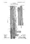
Fig. 1 is an elevational view of the striker with
the striker support in longitudinal Section.
Fig. 2 is a view of the locking disk from the
front.
30 Fig. 3 is a cross-section through the striker
support, and
Fig. 4 is an elevational view of the locking disk.
The striker 2 is secured in the support I, either
by means of a thread or by recesses or grooves.
35 The support I possesses oppositely disposed lon-
gitudinal grooves la, which open out into an an-
nular groove lb. In the annular groove lb
there is mounted so as to be longitudinally shift-
able a locking disk 3, which is furnished on the
4Q side directed towards the striker with two pro-
jections 3a adapted to engage in the grooves la
in the support and in corresponding grooves 2a
in the striker.
So long as the spring 4 acting against the lock-
40 ing disk 3 presses the projections 3a on the latter
Into the grooves la of the support i and the
grooves 2a of the striker 2, the latter is unable
to perform a rotary movement on the support,
and the striker and the support are accordingly
firmly coupled together.
To release the striker from the support the 5
locking disk 3, by means of a pointed article
introduced into the slot Ic in the support I, is
pressed back to such extent in the direction of
the annular groove la that the projections 3a
move out of engagement with the grooves la and ю
2a. In this position of the locking disk the striker
can be readily unscrewed or otherwise removed
from the support.
To be able by means of a pointed article again
to move the locking disk 3 into the proper posi- 15
tion with relation to the grooves la and 2a after
the striker has again been fitted in the support,
the locking disk 3 is provided on its periphery
with recesses 3b.
What I claim as new and desire to secure by 20
Letters Patent is:
1. In a striker coupling for self-loading weap-
ons, a tubular support, a striker mounted on the
said support, a locking disk slidable in the said
support, in the longitudinal direction of the sup- 25
port and striker and also capable of turning
therein, projections on the said disk adapted to
engage in grooves in the said'support and the said
striker to secure the said striker against rotation
relatively to the said support, and a spring for 33
holding the said projections in engagement with
the said grooves.
2. A striker coupling according to claim 1, in
which the spring is the actuating spring of the
striker. 35
3. in a striker coupling for self-loading weap-
ons, a tubular support, a striker secured in said
support, a locking disc centrally mounted in the
support and slidable.in the support in the longi-
tudinal direction, said disc having means secur- ...
ing said striker against rotation relative to the
support, and means operative in the longitudinal
direction of the striker for holding the disc in
operative engagement with the support and the
striker.
HUGO SCHMEISSER.