/
Tags: weapons military affairs

Text
HANDBOOK OF
THE PEDERSEN
SELF-LOADING RIFLE
MODEL P.A.
(With Description and Data)
VICKERS-ARMSTRONGS
LIMITED
Head Office: VICKERS HOUSE, BROADWAY, LONDON, S.W.i.
Telegrams:
VICASTRONG, SOWEST,
LONDON
Telephone :
VICTORIA 6900
Cablegrams :
VICASTRONG
LONDON
HANDBOOK OF THE
PEDERSEN SELF-LOADING RIFLE
Model P.A. Calibre 0-276 in. (7 m/m)
Manufactured by
VICKERS-ARMSTRONGS Limited
TABLE OF CONTENTS
General Description Groups of the Rifle Components Operating Instructions • PAGE 3 6—10 11—13
Mechanical Functioning .. 13—16
To Remove the Breech Closure from the Body 16
To Assemble the Breech Closure to the Body 17
To Remove the Guard Group from the Body 17
To Assemble the Guard Group to the Body 18
To Strip and Assemble the Breech Closure 18
To Strip and Assemble the Bolt .. .. 18—19
To Strip and Assemble the Conrod 20
To Strip and Assemble the Crank 20—21
To Remove and Attach the Cage 21
To Strip and Assemble the Backsight ~ 22
To Strip the Guard Group 23—26
To Assemble the Guard Group 27—29
To Strip and Assemble the Body and Stock Group 29
(This is only necessary when it is desired to replace a worn barrel
and is not to be done by the Soldier)
Accessories .. 30
General Data 31
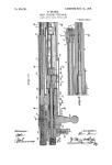
1. GENERAL DESCRIPTION.
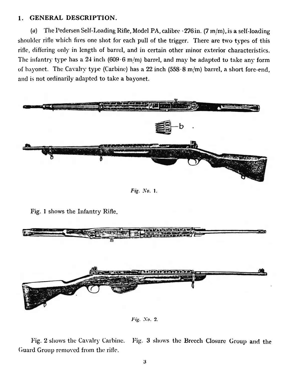
(a) The Pedersen Self-Loading Rifle, Model PA, calibre -276in. (7 m/m),is a self-loading
shoulder rifle which fires one shot for each pull of the trigger. There arc two types of this
rifle, differing only in length of barrel, and in certain other minor exterior characteristics.
The infantry type has a 24 inch (609-6 m/m) barrel, and may be adapted to take any form
of bayonet. The Cavalry type (Carbine) has a 22 inch (558-8 m/m) barrel, a short fore-end,
and is not ordinarily adapted to take a bayonet.
b
Fig. No. 1.
Fig. 1 shows the Infantry Rifle.
Fig. No. 2.
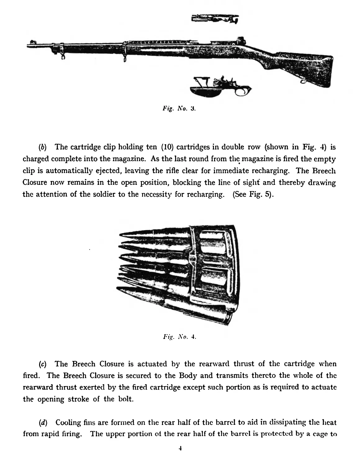
Fig. 2 shows the Cavalry Carbine. Fig. 3 shows the Breech Closure Group and the
Guard Group removed from the rifle.
3
Fig. No. 3.
(6) The cartridge clip holding ten (10) cartridges in double row (shown in Fig. 4) is
charged complete into the magazine. As the last round from the magazine is fired the empty
clip is automatically ejected, leaving the rifle clear for immediate recharging. The Breech
Closure now remains in the open position, blocking the line of sight' and thereby drawing
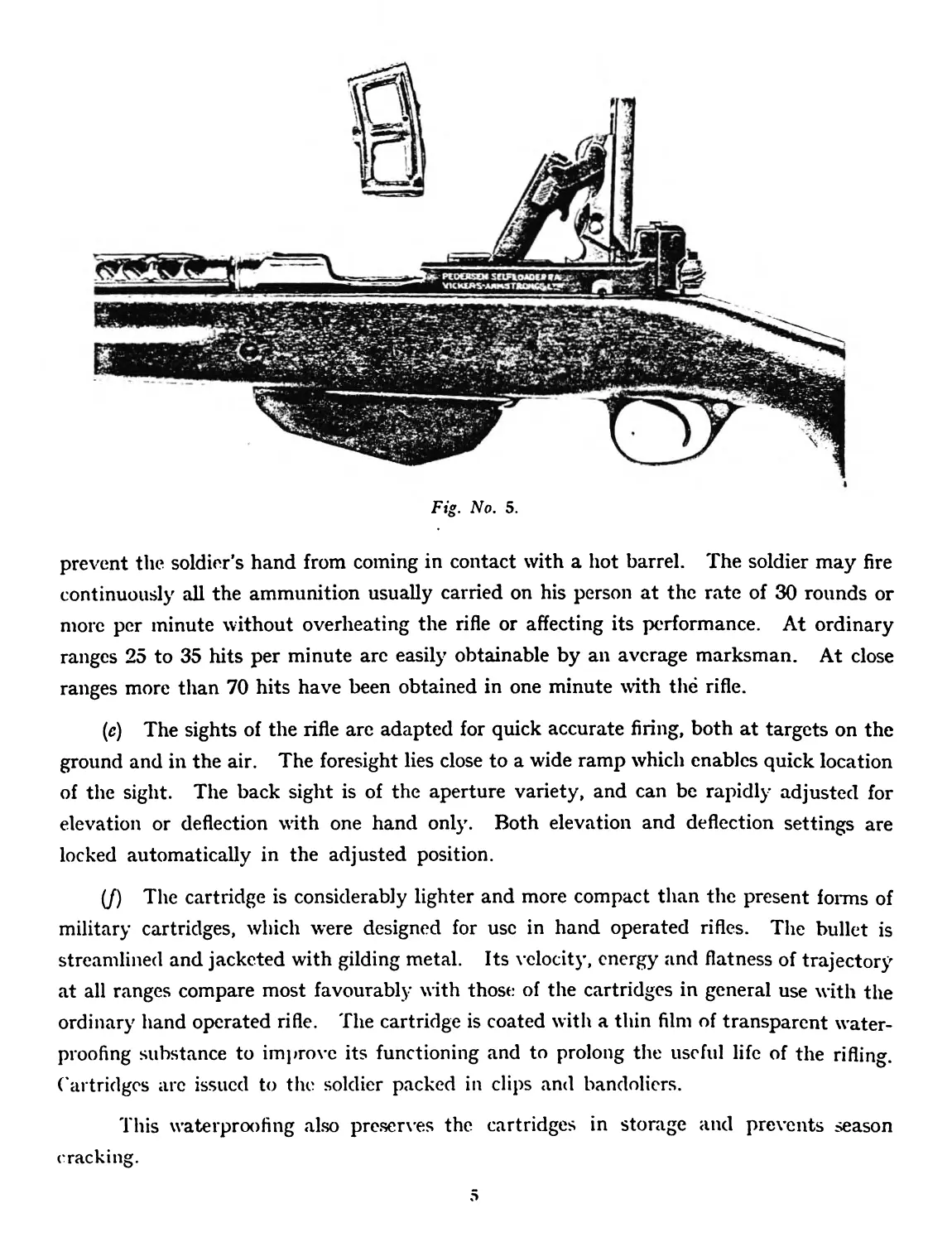
the attention of the soldier to the necessity for recharging. (See Fig. 5).
I:ig. .No. 4.
(c) The Breech Closure is actuated by the rearward thrust of the cartridge when
fired. The Breech Closure is secured to the Body and transmits thereto the whole of the
rearward thrust exerted by the fired cartridge except such portion as is required to actuate
the opening stroke of the bolt.
(d) Cooling fins are formed on the rear half of the barrel to aid in dissipating the heat
from rapid firing. The upper portion of the rear half of the barrel is protected by a cage to
4
Fig. No. 5.
prevent the soldier’s hand from coming in contact with a hot barrel. The soldier may fire
continuously all the ammunition usually carried on his person at the rate of 30 rounds or
more per minute without overheating the rifle or affecting its performance. At ordinary
ranges 25 to 35 hits per minute are easily obtainable by an average marksman. At close
ranges more than 70 hits have been obtained in one minute with the rifle.
(e) The sights of the rifle are adapted for quick accurate firing, both at targets on the
ground and in the air. The foresight lies close to a wide ramp which enables quick location
of the sight. The back sight is of the aperture variety, and can be rapidly adjusted for
elevation or deflection with one hand only. Both elevation and deflection settings are
locked automatically in the adjusted position.
(/) The cartridge is considerably lighter and more compact than the present forms of
military cartridges, which were designed for use in hand operated rifles. The bullet is
streamlined and jacketed with gilding metal. Its velocity, energy and flatness of trajectory
at all ranges compare most favourably with those of the cartridges in general use with the
ordinary hand operated rifle. The cartridge is coated with a thin film of transparent water-
proofing substance to improve its functioning and to prolong the useful life of the rifling,
(’artridges arc issued to the soldier packed in clips and bandoliers.
This waterproofing also preserves the cartridges in storage and prevents season
cracking.
2. GROUPS OF THE RIFLE COMPONENTS.
(a) For convenience the component parts of the rifle have been separated into the
groups in which they are most intimately related.
1. BARREL AND BODY GROUP
I I
75. 76.SIGHT RACK
SIGHT RACK. SET SCREW.
33. FRONT SIGHT PIN 21. CRANK PIN.
5. BODY SCREW. OUARDPIN GUARO PIN
i FRONT. REAR.
Fig. No. 6. .
1 I 1
37. 68.SIGHT 67 SIGHT
Guard screw, friction spring, friction plunger
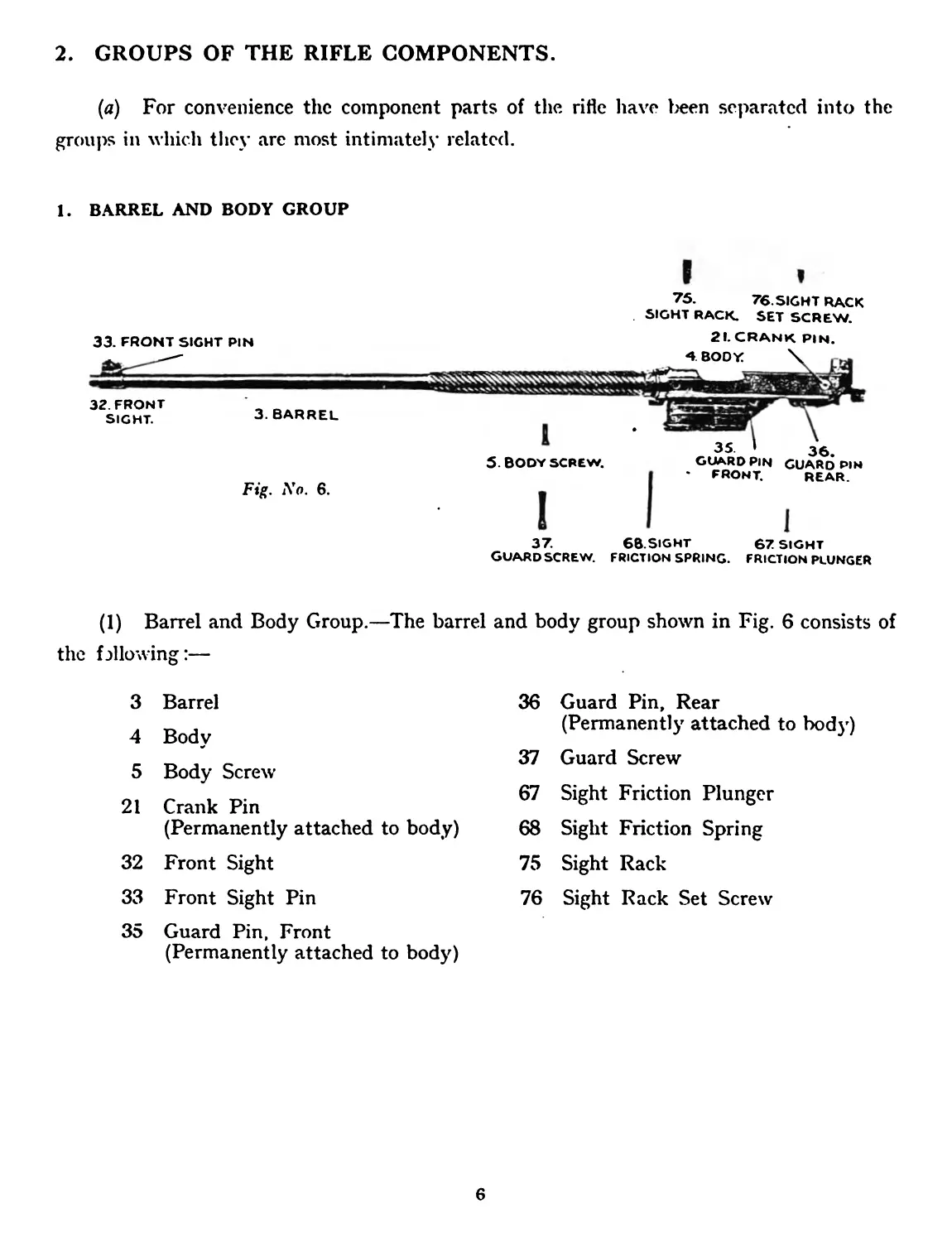
(1) Barrel and Body Group.—The barrel and body group shown in Fig. 6 consists of
the fallowing:—
3 Barrel 4 Body 5 Body Screw 21 Crank Pin (Permanently attached to body) 32 Front Sight 33 Front Sight Pin 35 Guard Pin, Front (Permanently attached to body) 36 Guard Pin, Rear (Permanently attached to body) 37 Guard Screw 67 Sight Friction Plunger 68 Sight Friction Spring 75 Sight Rack 76 Sight Rack Set Screw
6
GROUPS OF THE RIFLE COMPONENTS-CbntfwW
2. BREECH CLOSURE GROUP
79. SLIDE ROLL PIN.
4-7. LINK.
60. SEAR BAR
58.
57.
RETRACTOR
SAFETY SPRING.
CATCH.
62.
SEAR PIN.
18. CLOSING
SPRING STOP
17. CLOSING
SPRING PLUNGER.
5?,
25.
EXTRACTOR.
6. BOLT.
16. CLOSING SPRING.
61.
SEAR BAR
SPRING.
*59.SEAR.
f
7
BOLT DETENT.
26. EXTRACTOR
PLUNGER.
27. EXTRACTOR
SPRING.
19. CONROD.
56. RETRACTOR.
3O.FIRING SPRING PLUG.
23
EJECTOR SPRING
29. FIRING SPRING.
t
22.
EJECTOR.
28. FIRING PIN.
Fig. No. 7
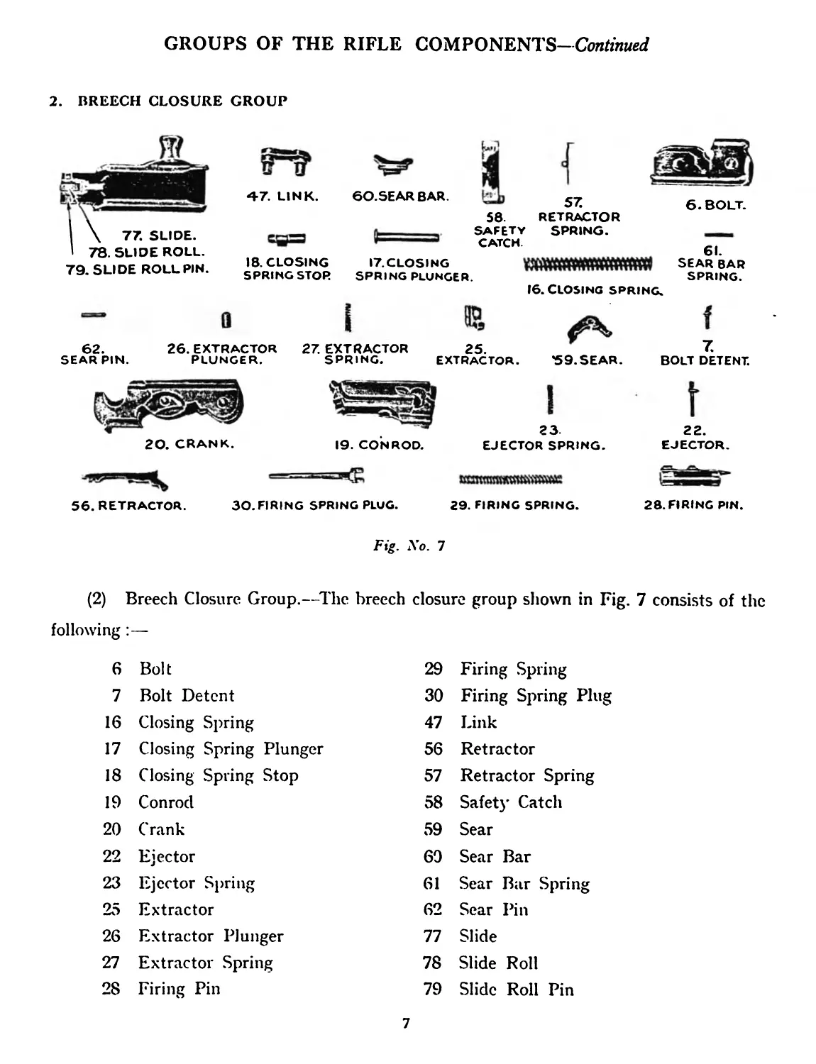
(2) Breech Closure Group.—The breech closure group shown in Fig. 7 consists of the
following:—
6 Bolt 29 Firing Spring
7 Bolt Detent 30 Firing Spring Plug
16 Closing Spring 47 Link
17 Closing Spring Plunger 56 Retractor
18 Closing Spring Stop 57 Retractor Spring
19 Conrod 58 Safety Catch
20 Crank 59 Sear
22 Ejector 60 Sear Bar
23 Ejector Spring 61 Sear Bar Spring
25 Extractor 62 Sear Pin
26 Extractor Plunger 77 Slide
27 Extractor Spring 78 Slide Roll
28 Firing Pin 79 Slide Roll Pin
7
GROUPS OF THE RIFLE COMPONENTS—Continued
3. GUARD GROUP
51. MAGAZINE COVER.
14-
C AR RIER LEVER PIN
use о ALSO
POP BOLT STOP PIN.
8Z
TRIGGER SPRING.
31. FOLLOWER.
39.
ROOK.
HOOK SPRING. HOOK PLUNGER.
Fig. No. 8.
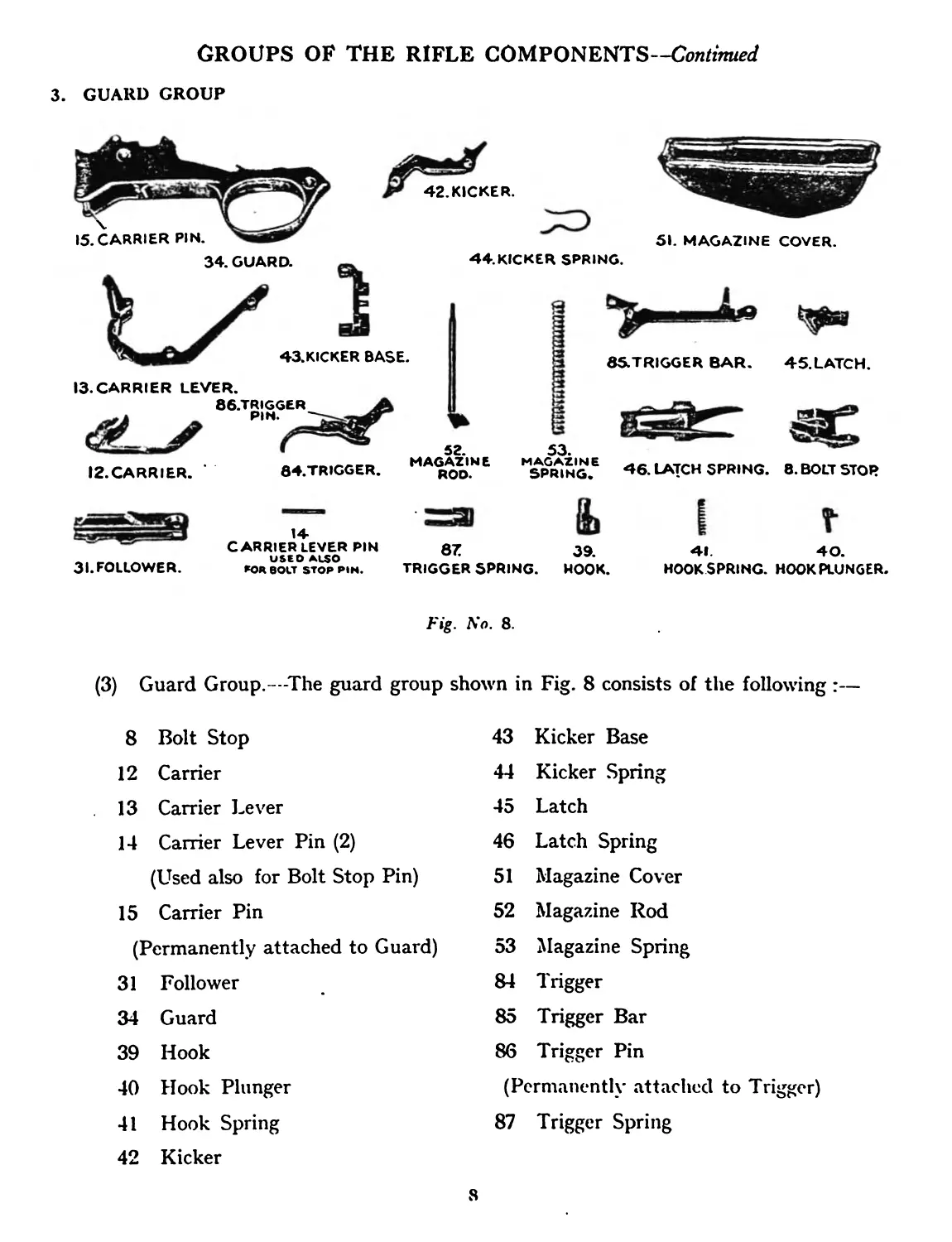
(3) Guard Group.—The guard group shown in Fig. 8 consists of the following:—
8 Bolt Stop
12 Carrier
13 Carrier Lever
14 Carrier Lever Pin (2)
(Used also for Bolt Stop Pin)
15 Carrier Pin
(Permanently attached to Guard)
31 Follower
34 Guard
39 Hook
40 Hook Plunger
41 Hook Spring
42 Kicker
43 Kicker Base
44 Kicker Spring
45 Latch
46 Latch Spring
51 Magazine Cover
52 Magazine Rod
53 Magazine Spring
84 Trigger
85 Trigger Bar
86 Trigger Pin
(Permanently attached to Trigger)
87 Trigger Spring
GROUPS OF THE RIFLE COMPONENTS—Continued
4. BACKSIGHT GROUP
69. SIGHT LEAF.
66.
SIGHT DEFLECTION
SPRING.
74. SIGHT PLUNGER.
63.
SIGHT DEFLECTION
PLUNGER.
65. SIGHT DEFLECTION SLIDE.
71.
TO.
SIGHT NUT.
64.
SIGHT DEFLECTION SCREW.
73.
SIGHT NUT SPRING.
72.
SIGHT NUT SPINDLE.
Fig. No. 9.
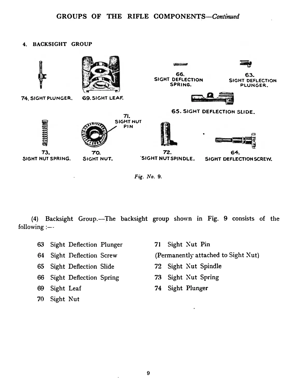
(4) Backsight Group.—The backsight group shown in Fig. 9 consists of the
following :—
63 Sight Deflection Plunger 71 Sight Nut Pin
64 Sight Deflection Screw (Permanently attached to Sight Nut)
65 Sight Deflection Slide 72 Sight Nut Spindle
66 Sight Deflection Spring 73 Sight Nut Spring
69 Sight Leaf 74 Sight Plunger
70 Sight Nut
9
GROUPS OF THE RIFLE COMPONENTS—Continued
5. STOCK GROUP.
II. CAGE.
IO. BUTT PLATE SCREW
50 <\ 49.
LOWER I J LOWER
BAND \ BAND
SWIVEL. SCREW.
48.LOWER BAND.
Fig. No. 10.
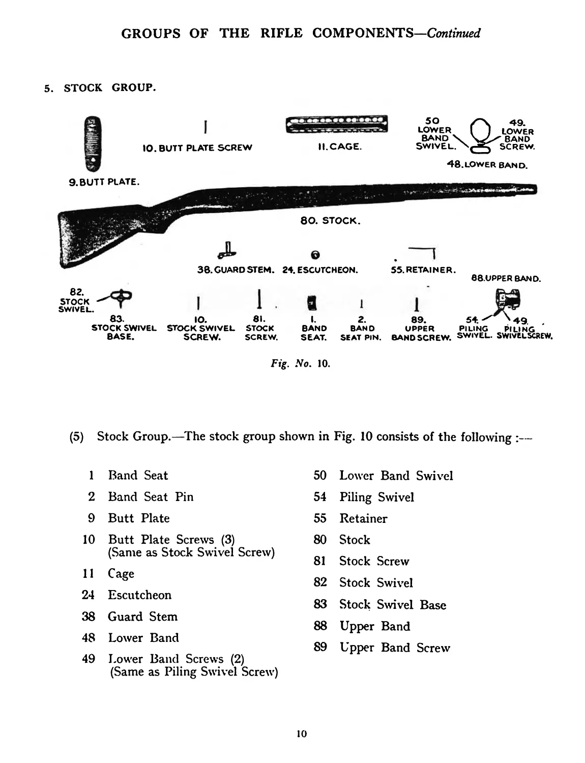
(5) Stock Group.—The stock group shown in Fig. 10 consists of the following :—
1 Band Seat
2 Band Seat Pin
9 Butt Plate
10 Butt Plate Screws (3)
(Same as Stock Swivel Screw)
11 Cage
24 Escutcheon
38 Guard Stem
48 Lower Band
49 Lower Band Screws (2)
(Same as Piling Swivel Screw)
50 Lower Band Swivel
54 Piling Swivel
55 Retainer
80 Stock
81 Stock Screw
82 Stock Swivel
83 Stock Swivel Base
88 Upper Band
89 Upper Band Screw
io
3. OPERATING INSTRUCTIONS.
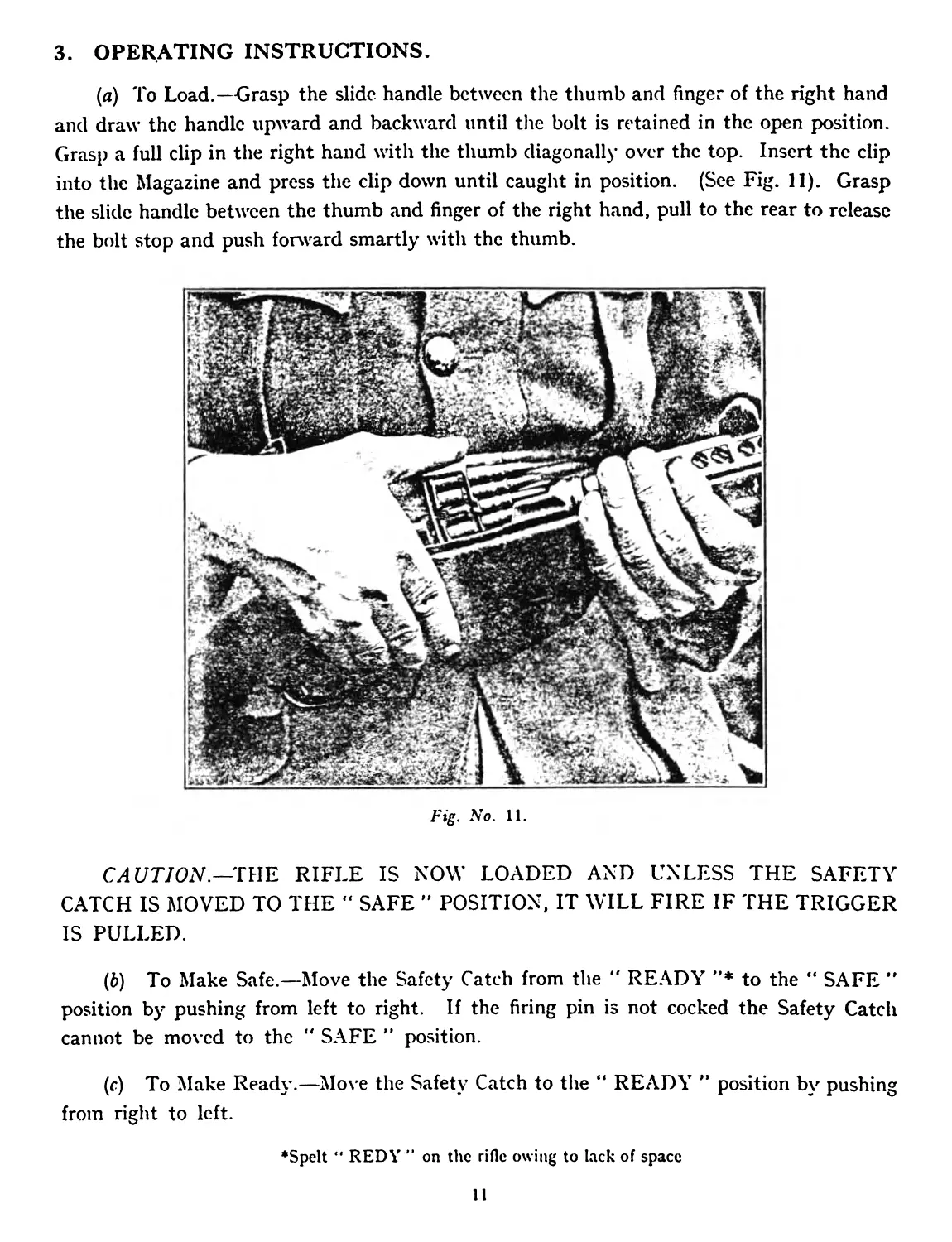
(a) To Load.—Grasp the slide handle between the thumb and finger of the right hand
and draw the handle upward and backward until the bolt is retained in the open position.
Grasp a full clip in the right hand with the thumb diagonally over the top. Insert the clip
into the Magazine and press the clip down until caught in position. (See Fig. 11). Grasp
the slide handle between the thumb and finger of the right hand, pull to the rear to release
the bolt stop and push forward smartly with the thumb.
Fig. No. 11.
CAUTION.—THE RIFLE IS NOW LOADED AND UNLESS THE SAFETY
CATCH IS MOVED TO THE " SAFE ” POSITION, IT WILL FIRE IF THE TRIGGER
IS PULLED.
(b) To Make Safe.—Move the Safety Catch from the “ READY ”* to the “ SAFE ”
position by pushing from left to right. If the firing pin is not cocked the Safety Catch
cannot be moved to the ” SAFE ” position.
(c) To Make Ready.—Move the Safety Catch to the “ READY ” position by pushing
from right to left.
‘Spelt “ REDY ” on the rifle owing to lack of space
11
(<Z) To Fire.—With a cartridge in the chamber and the magazine charged, one shot
only will be fired if the trigger is pressed. Firing may be continued by releasing the trigger,
and again pressing it for each shot. Upon firing the last round in the magazine the breech
remains open, and the empty clip is automatically ejected, thus leaving the rifle so that its
magazine may be immediately recharged.
Fig. No. 12.
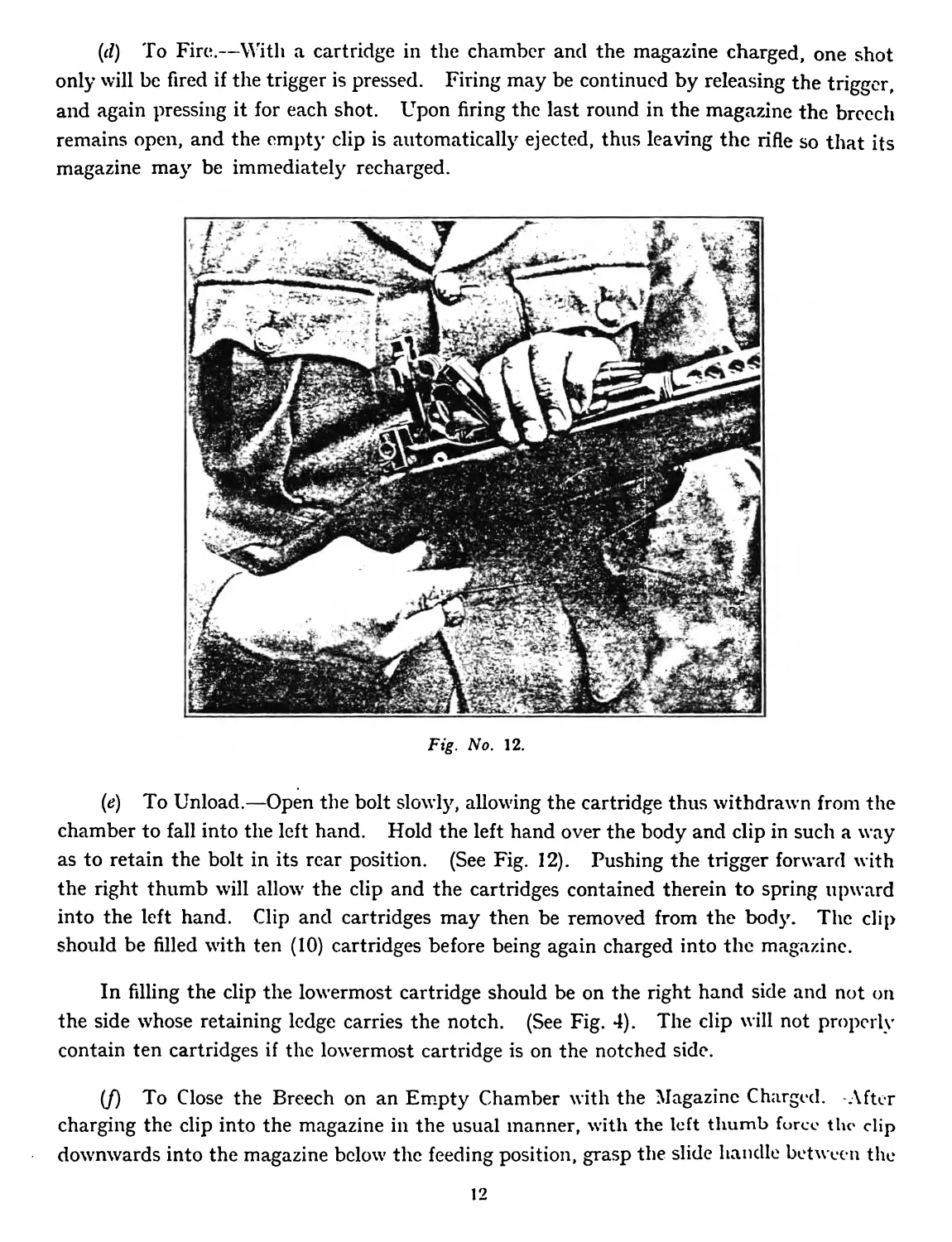
(e) To Unload.—Open the bolt slowly, allowing the cartridge thus withdrawn from the
chamber to fall into the left hand. Hold the left hand over the body and clip in such a way
as to retain the bolt in its rear position. (See Fig. 12). Pushing the trigger forward with
the right thumb will allow the clip and the cartridges contained therein to spring upward
into the left hand. Clip and cartridges may then be removed from the body. The clip
should be filled with ten (10) cartridges before being again charged into the magazine.
In filling the clip the lowermost cartridge should be on the right hand side and not on
the side whose retaining ledge carries the notch. (See Fig. 4). The clip will not properly
contain ten cartridges if the lowermost cartridge is on the notched side.
(/) To Close the Breech on an Empty Chamber with the Magazine Charged. -After
charging the clip into the magazine in the usual manner, with the left thumb force the clip
downwards into the magazine below the feeding position, grasp the slide handle between the
12
thumb and forefinger of the right hand, pull the slide handle to the rear and allow the bolt
to move forward slowly over the topmost cartridge. Opening and closing the bolt once
by hand will now load the chamber from the magazine.
(g) To Close the Breech with the Magazine Empty.—While holding the follower
depressed with the left thumb, move the slide handle back to release the bolt stop, and ease
the bolt forward over the follower. Remove the left thumb and allow the bolt to close.
(Л) To set elevation on the Back Sight.—While holding the sight nut spindle depressed
with the index finger, rotate the sight nut between the thumb and second finger until the
desired graduation on the nut is opposite the reference mark adjacent to the graduated
portion of the nut. Upon removal of the pressure, the sight nut spindle snaps up to lock
the nut in the adjusted position. Figures on the nut represent hundreds of yards (or
metres) ; the intermediate graduations, the evident fractions of the same. The backsight
elevation is compensated for drift.
(i) To Adjust the Vertical zero of the Backsight.—-Slacken the sight rack set screw
which appears just forward of the sight on the right side of the body. Turn the sight rack,
by means of a screw driver in the exposed slotted end which appears just forward of the
sight on the top lug of the body. This will move the backsight up or down as desired
without changing the adjustment of the backsight nut. Tighten the sight rack set screw
firmly to hold the sight rack in place.
Note.—If vertical adjustment is desired to an extent greater than that given by a
partial turn of the sight rack, remove the back sight, loosen the sight rack set screw and
revolve the sight rack a complete turn. Replace the sight and finally adjust by a partial
rotation of the sight rack. Tighten the sight rack set screw.
(У) To adjust Deflection.—Holding the sight deflection plunger depressed with the
index finger, rotate the head of the sight deflection screw between the thumb and second
finger, a notch or two at a time to the desired position. Releasing the pressure allows the
sight deflection plunger to lock the screw in the adjusted position. Each notch of the sight
deflection screw gives a lateral adjustment of one half minute in angle or approximately one
half inch for each 100 yards of range. Each complete turn of the deflection screw is equal
to a single division on the sight deflection slide, right or left, and gives a lateral adjustment of
4 minutes in angle or approximately 4 inches per each 100 yards of range.
4. MECHANICAL FUNCTIONING.
(a) The pressing of the trigger pushes the trigger bar forward. If the breech closure
is correctly in its closed position, the sear bar is pushed forward by the trigger bar. The
13
sear bar in turn moves the lower arm of the sear to disengage the bent of the sear from the
bent of the firing pin and so releases it, permitting it to fly forward and fire the cartridge.
At the moment of firing, the base of the cartridge case exerts a rearward pressure on the
face of the bolt. Interposed between the bolt and the crank pin (which is permanently
secured to the body) are the conrod and the crank. The pressure exerted upon the face of
the bolt is transmitted to the two last named members, and this pressure, with the exception
of a small portion, which is utilised in the operation of the breech mechanism as described
below, is in turn transmitted to the body through the crank pin.
The broad cam surfaces on the abutting ends of the conrod and crank are in contact
at the instant of firing along a line which is eccentric to the line of action of the pressure
transmitted to these two members through the bolt. With the increase of the pressure
the abutting ends of the conrod and crank are started moving upward. During the
" peak ” of the pressure the eccentricity of the contact between the conrod and the crank
has become substantially nil, and the previously acquired momentum of these members
continues their movement through this phase.
When the pressure in the bore is reduced to a lower value this eccentricity again increases
and thus imparts the final energy to perform the opening cycle of the breech closure.
During the initial movement of the breech closure, or until the cessation of pressure in
the bore, the arrangement of the crank pin, crank, conrod and bolt is such that only rolling
contacts are made between these members. After the bullet has left the barrel, the continued
opening movement of the parts changes to pivotal movements about the articulated joints.
The extractor serves to withdraw the cartridge from the chamber and holds one edge
of the cartridge head to the face of the bolt, so that the ejector tips the cartridge upwards
when the bolt has moved a sufficient distance to the rear to clear the cartridge from the
chamber.
When the opening stroke of the bolt is nearly complete, it uncovers the cartridge in
the magazine, after which the bolt comes in contact with the crank. Then the bolt, crank
and conrod in a triangular organisation as a unit, move back on the crank pin and against
the closing spring which now acts as a buffer. Contact with the crank pin and the rear
end of the body terminates the opening stroke.
(b) During the first part of the opening stroke, the retractor in the conrod retracts,
and then completes the cocking of the firing pin. The sear mounted in the bolt -with the
firing pin and energised also by the firing spring, engages with, and retains the firing pin
in its cocked position. The opening stroke compresses the closing spring, mounted
in the crank, which bears against the slide also mounted in the crank. The rear end of
14
the slide is provided with a roller bearing which travels on a cam track in the rear end of
the body. The closing spring at all times tends to close the breech.
(c) On the closing stroke the face of the bolt drives the topmost cartridge from the
magazine into the chamber. The opening and closing strokes arc so rapid that they are
completed before the soldier has had time to release his pressure on the trigger. The
closing of the conrod depresses the front end of the trigger bar. When the trigger is released
the trigger bar moving backward under the influence of its spring, snaps upward behind the
sear bar in the conrod and the mechanism is again ready to be fired by another pressure of
the trigger.
(d) When a clip of cartridges is charged into the magazine the act of depressing the.
follower and the carrier lever also depresses the spring controlled kicker. The latch urged
by the latch spring snaps over the lug on the clip and retains the clip in the body against
the tension of the kicker and magazine springs. As the clip of cartridges is charged into the
magazine the front jaws of the clip are spread by suitable ledges in the bod}- to relieve the
cartridges from side pressure of the clip. The follower is constantly acted upon bj' the
magazine spring to elevate the stack of cartridges in the clip. The follower is mounted
upon a pair of levers which govern the constantly changing inclination of the follower in its
various positions in such a way that the topmost cartridge in the magazine is always
correctly presented for feeding into the chamber.
(e) The bottom of the magazine opening is closed by the magazine cover. The rear
end of the cover is hinged to the guard in such a way that the cover is drawn to the rear
by the magazine spring. The front end of the cover snaps into the notch at the front end
of the magazine well of the body.
(J) When the bolt opens upon firing the last cartridge from the magazine, the follower
rises to its bolt stop operating position. The carrier lever which controls the follower, at
this time rocks the real- end of the bolt stop upward against its spring to secure the bolt in
its rear position. The carrier which also controls the follower, withdraws the latch from the.
lug on the clip and the clip is now free to be ejected upward by the kicker. The arrangement
is such that the clip cannot be released until the bolt is drawn back clear of the clip, and
locked in that position by the bolt stop. The magazine spring which energises the follower
has sufficient power to overcome the tensions of the springs on the latch and on the bolt
stop. The engagement between the bolt stop and the bolt is undercut so that the forward
urge of the closing spring on the bolt holds the bolt stop in engagement with the bolt, even
though the follower be now depressed by charging a clip or otherwise.
15
(g) To release the bolt while the follower is depressed it is necessary to draw the bolt
slightly to the rear by means of the slide handle. A clip containing cartridges may be
released from the magazine by holding the bolt to the rear, while pushing forward the
trigger. Pushing the trigger forward to release the clip, moves the latch and bolt stop
through the same motions that are automatically caused by the rising of the follower when
the magazine is empty.
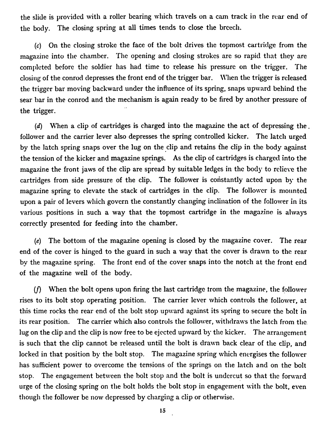
Fig. No. 13.
5. TO REMOVE THE BREECH CLOSURE FROM THE BODY.
Open the bolt; with butt against the inside of the right knee and left palm over the
body, grasp the slide handle and slide between the thumb and fingers of the right hand and
pull the slide strongty upward to compress completely the closing spring. While in this
position, with the left forefinger push the closing spring stop in the crank from the right to
left. (See Fig. 13). This secures the closing spring fully compressed. Depress the follower
with the left thumb, hold the slide between the thumb and forefinger and move it forward
parallel with itself until the crank is clear of the crank pin. Swing the rear end of the crank
upward, move the bolt back to the crank pin, tilt the front end of the bolt upward, and
while holding the follower depressed, slide the bolt forward out of the body through the
upwardly inclined slots.
16
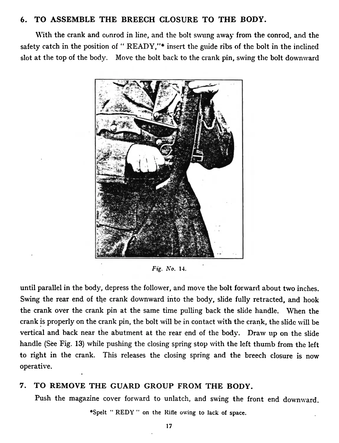
6. TO ASSEMBLE THE BREECH CLOSURE TO THE BODY.
With the crank and conrod in line, and the bolt swung away from the conrod, and the
safety catch in the position of “ READY,”* insert the guide ribs of the bolt in the inclined
slot at the top of the body. Move the bolt back to the crank pin, swing the bolt downward
Fig. No. 14.
until parallel in the body, depress the follower, and move the bolt forward about two inches.
Swing the rear end of the crank downward into the body, slide fully retracted, and hook
the crank over the crank pin at the same time pulling back the slide handle. When the
crank is properly on the crank pin, the bolt will be in contact with the crank, the slide will be
vertical and back near the abutment at the rear end of the body. Draw up on the slide
handle (See Fig. 13) while pushing the closing spring stop with the left thumb from the left
to right in the crank. This releases the closing spring and the breech closure is now
operative.
7. TO REMOVE THE GUARD GROUP FROM THE BODY.
Push the magazine cover forward to unlatch, and swing the front end downward.
•Spelt “ REDY ” on the Rifle owing to lack of space.
17
Depress the stud (the Hook) at the left side of the trigger guard with the head of a cartridge
and slowly swing the rear end of the guard away from the stock about half an inch only
(See Fig. 14), keeping the guard parallel to the stock, remove from the rifle.
8. TO ASSEMBLE THE GUARD GROUP TO THE BODY.
Before assembling the guard group to the body make sure the ends of the cross pins in
the guard do not project beyond the sides of the guard.
Swing the magazine cover downward and insert the front end of the guard into the
body as shown in Fig. 14. The round groove across the front end of the guard should
engage the front guard pin in the body. To indicate this correct engagement, the hinged
end of the magazine cover should be nearly touching the under-side of the stock. Snap
the rear end of the guard upward to engage the hook. Push the magazine cover up and
forward to snap home.
Note.—If the breech closure is in the body to properly engage the guard with the
guard pin, an inward pressure on the front end of the guard will be required to overcome the
tension of the follower against the underside of the bolt.
9. TO STRIP AND ASSEMBLE THE BREECH CLOSURE.
Remove the breech closure from the body as in para. 5. With the bolt, conrod and crank
held in alignment, move the slide a short distance back on the crank. Slide the crank off
the link to the right. Move the safety catch to the “ SAFE ” position. Swing the conrod
upward on the bolt as far as it will go and slide the front end of the conrod out of the bolt
to the right. When stripping or assembling the conrod from or to the bolt the safety catch
should be in the “ SAFE ” position. This draws back the retractor in the conrod to avoid
interference with the firing pin.
To assemble, reverse the above order. When assembling the conrod to the bolt, the
firing pin in the bolt must be cocked ; this can be done if necessary by levering back the
lug on the firing pin with the bullet point of a cartridge.
10. TO STRIP AND ASSEMBLE THE BOLT.
(a) With the bullet point of a cartridge or other pointed instrument, press the extractor
plunger in and slide the extractor laterally out of the bolt with the thumb. Remove the
extractor plunger, spring and bolt detent. Place the point of a bullet forward of the flange
18
on the ejector and force the ejector to the rear until its front end clears the ejector slot.
Swing the front end of the ejector out of the bolt and remove it together with the spring.
With a bullet point push the sear pin partially out, from the left side, press lightly downward
on the sear and remove the pin. Press rearward against the cocking lug of the firing pin,
which is exposed just ahead of the sear and push out the firing pin assembly, consisting of
the firing pin, sear, firing spring and firing spring plug.
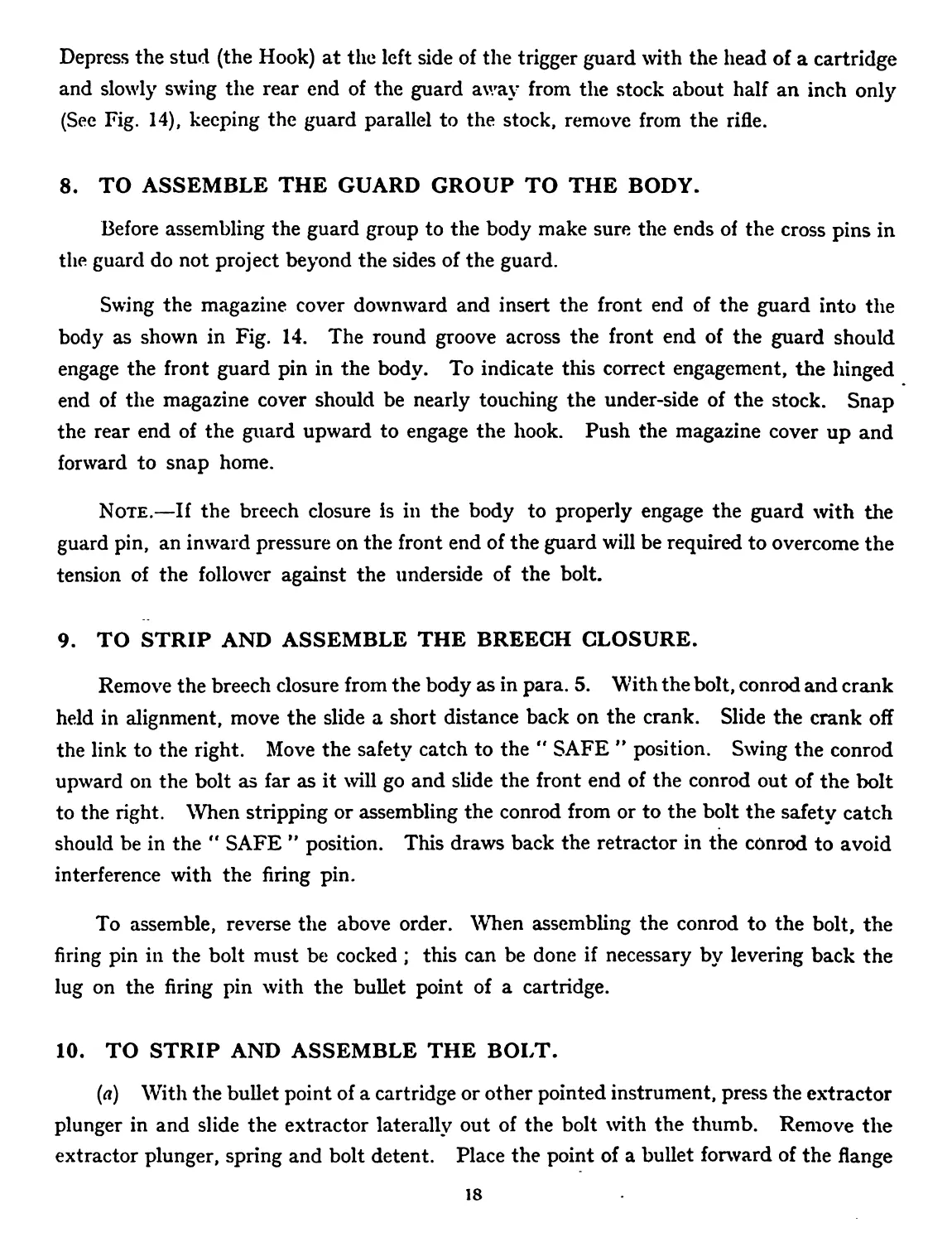
Enter the front end of the firing pin into the rear end of the bolt with the cocking lug
of the firing pin stopping against the slot on the underside rear end of the bolt. Grasping
the bolt and the firing pin as shown by Fig. 15, and holding the sear against a firm surface,
press the firing pin toward the sear and swing out of the sear notch.
(b) To assemble, reverse the above order.
Fig. No. 15.
Note.—When inserting the sear pin press downwards lightly on the sear to align the
holes properly.
Note.—In assembly of the ejector, pressure is required on the head of the ejector
instead of the flange.
19
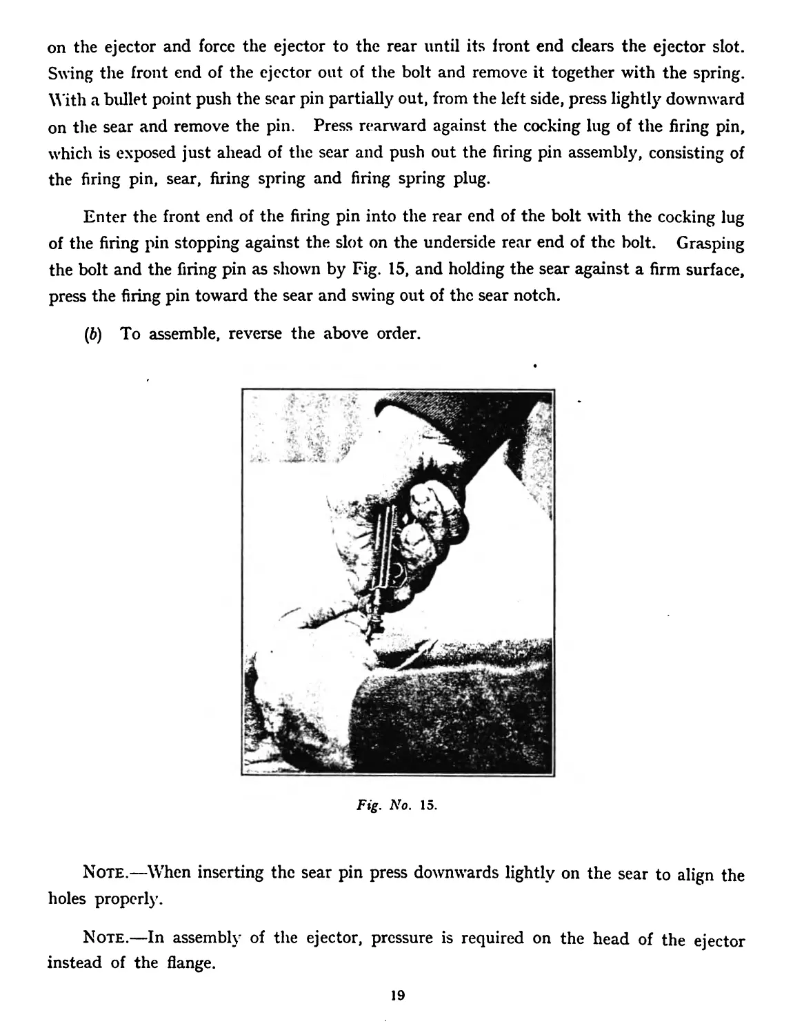
11. TO STRIP AND ASSEMBLE THE CONROD.
(a) Move the safety catch to the “ READY ”* position, while pushing the sear bar
fully to the rear, slide the link to the left out of the conrod. Remove the sear bar and the
spring toward the front. Move the safety catch to the “SAFE” position as far as it will
go. Move the retractor forward out of the conrod and push out the safety catch together
with the retractor spring.
(b) To assemble, reverse the above order.
Fig. No. 16.
12. TO STRIP AND ASSEMBLE THE CRANK.
(л) Hook the prongs of the crank in the swivel on the rifle (See Fig. 16), and while
pulling strongly downward on the slide to compress the closing spring, push in the closing
spring stop in the crank from the left to the right and allow the slide to move slowly upward.
This allows the closing spring to move from full to partial compression. Move the slide off
the crank to the rear. Holding the crank strongly as in Fig. 17, slightly compress and move
the rear end of the closing spring and plunger upward and out of the crank. Push the
closing spring stop from the right to the left. Rotate the closing spring stop lug forward and
pull out the closing spring stop from the left side of the crank.
*Spclt " REDY ” on the Rifle owing to lack of space.
20
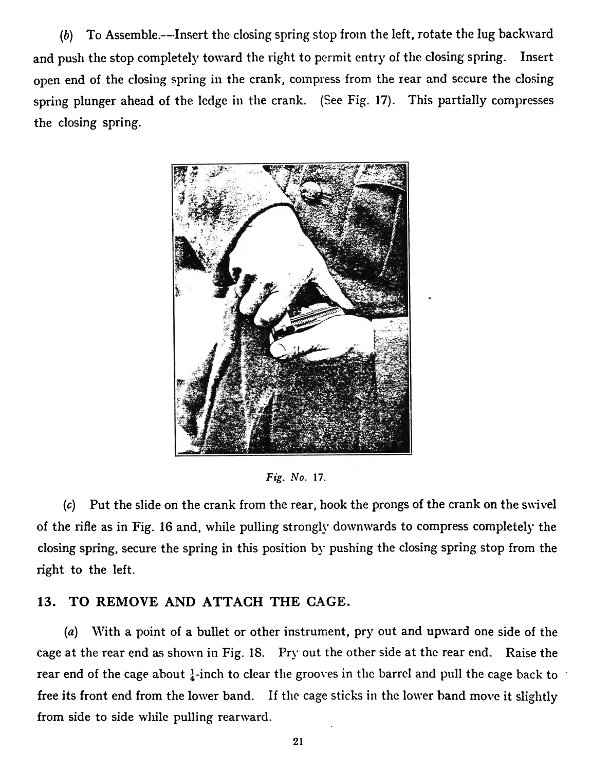
(&) To Assemble.—Insert the closing spring stop from the left, rotate the lug backward
and push the stop completely toward the right to permit entry of the closing spring. Insert
open end of the closing spring in the crank, compress from the rear and secure the closing
spring plunger ahead of the ledge in the crank. (See Fig. 17). This partially compresses
the closing spring.
Fig. No. 17.
(c) Put the slide on the crank from the rear, hook the prongs of the crank on the swivel
of the rifle as in Fig. 16 and, while pulling strongly downwards to compress completely the
closing spring, secure the spring in this position by pushing the closing spring stop from the
right to the left.
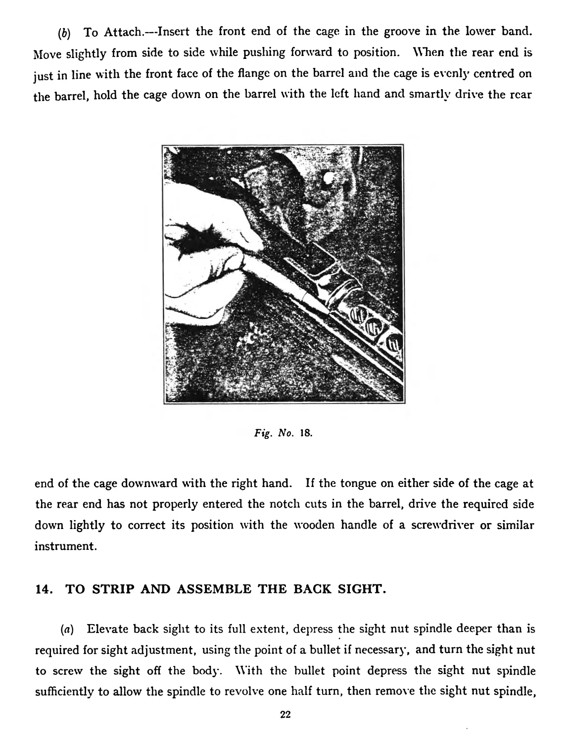
13. TO REMOVE AND ATTACH THE CAGE.
(a) With a point of a bullet or other instrument, pry out and upward one side of the
cage at the rear end as shown in Fig. 18. Pry out the other side at the rear end. Raise the
rear end of the cage about |-inch to clear the grooves in the barrel and pull the cage back to
free its front end from the lower band. If the cage sticks in the lower band move it slightly
from side to side while pulling rearward.
21
(&) To Attach.—Insert the front end of the cage in the groove in the lower band.
Move slightly from side to side while pushing forward to position. When the rear end is
just in line with the front face of the flange on the barrel and the cage is evenly centred on
the barrel, hold the cage down on the barrel with the left hand and smartly drive the rear
Fig. No. 18.
end of the cage downward with the right hand. If the tongue on either side of the cage at
the rear end has not properly entered the notch cuts in the barrel, drive the required side
down lightly to correct its position with the wooden handle of a screwdriver or similar
instrument.
14. TO STRIP AND ASSEMBLE THE BACK SIGHT.
(a) Elevate back sight to its full extent, depress the sight nut spindle deeper than is
required for sight adjustment, using the point of a bullet if necessary, and turn the sight nut
to screw the sight off the body. With the bullet point depress the sight nut spindle
sufficiently to allow the spindle to revolve one half turn, then remove the sight nut spindle,
22
sight nut spring, plunger and nut from the sight. Holding the sight Reflection plunger
depressed, unscrew the sight deflection screw and remove the screw with Hie sight deflection
slide. Separate the screw from the slide and remove the sight deflection spring and
plunger.
(b) To assemble, reverse the above order.
Note.—When assembling back sight to the body, set the sight nut at figure 8. This
starts the correct engagement of the sight nut with the sight rack in the body.
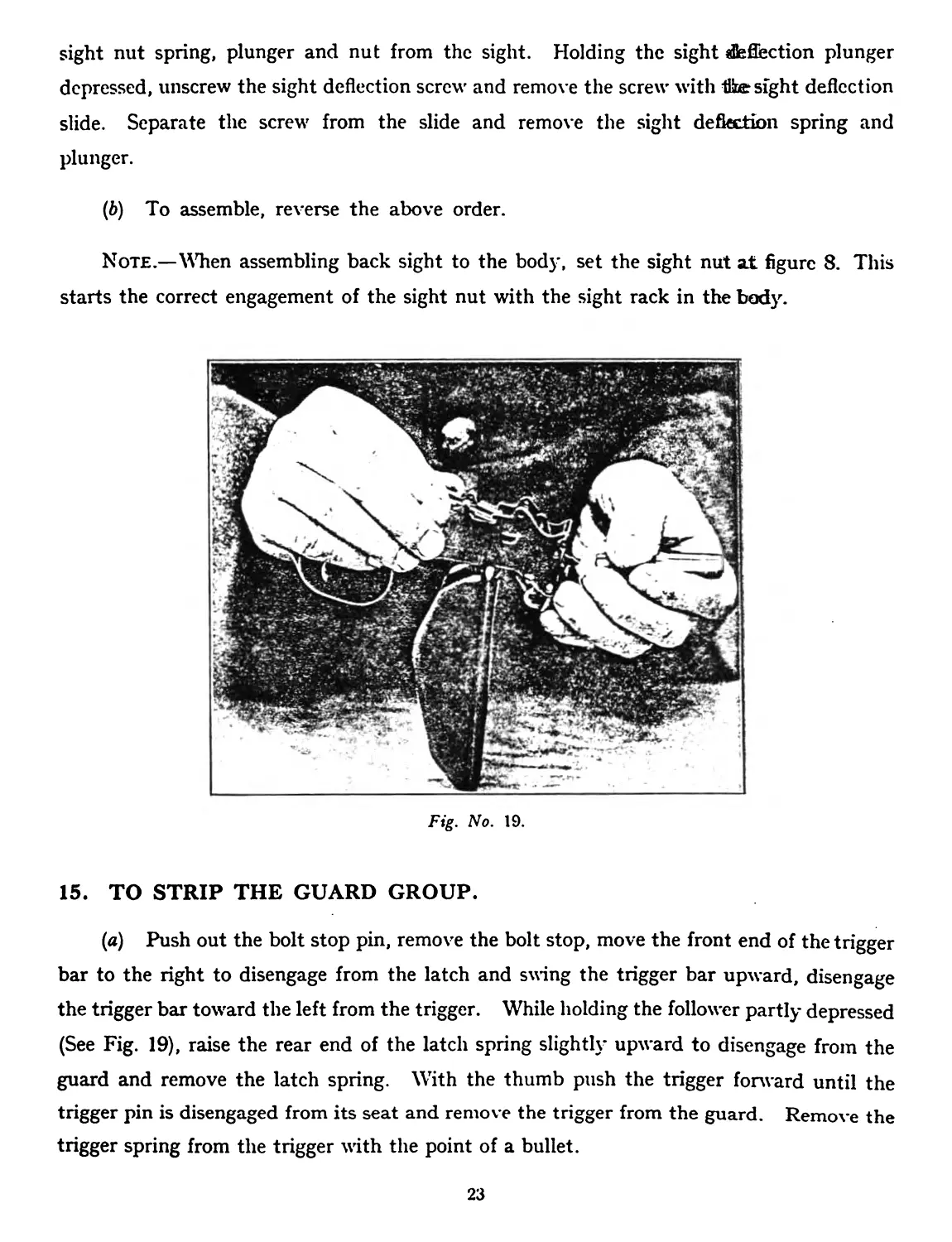
Fig. No. 19.
15. TO STRIP THE GUARD GROUP.
(a) Push out the bolt stop pin, remove the bolt stop, move the front end of the trigger
bar to the right to disengage from the latch and swing the trigger bar upward, disengage
the trigger bar toward the left from the trigger. While holding the follower partly depressed
(See Fig. 19), raise the rear end of the latch spring slightly upward to disengage from the
guard and remove the latch spring. With the thumb push the trigger forward until the
trigger pin is disengaged from its seat and remove the trigger from the guard. Remove the
trigger spring from the trigger tri th the point of a bullet.
23
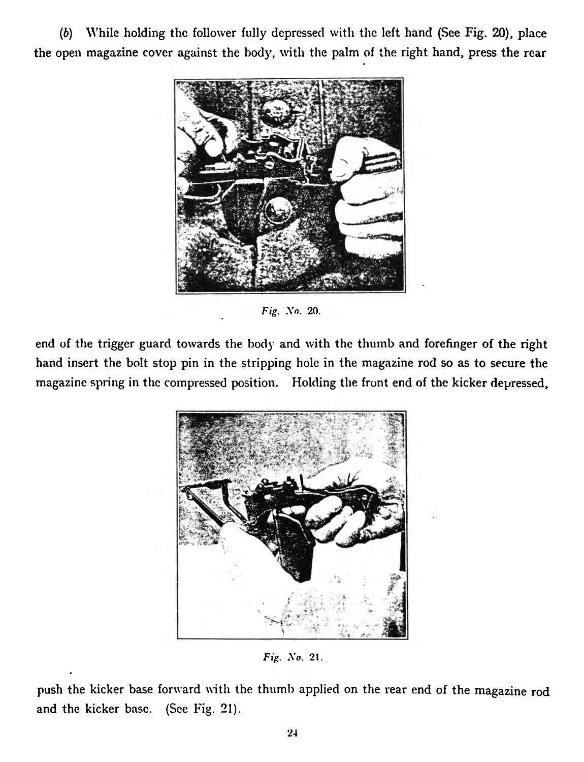
(b) While holding the follower fully depressed with the left hand (See Fig. 20), place
the open magazine cover against the body, with the palm of the right hand, press the rear
Fig. No. 20.
end of the trigger guard towards the bod}- and with the thumb and forefinger of the right
hand insert the bolt stop pin in the stripping hole in the magazine rod so as to secure the
magazine spring in the compressed position. Holding the front end of the kicker depressed,
Fig. No. 2!.
push the kicker base forward with the thumb applied on the rear end of the magazine rod
and the kicker base. (See Fig. 21).
24
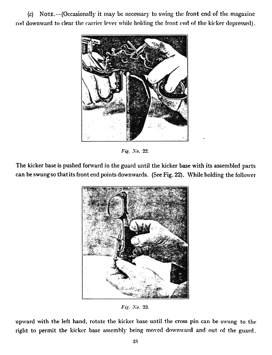
(c) Note.—(Occasional!}' it may be necessary to swing the front end of the magazine
rod downward to clear the carrier lever while holding the front end of the kicker depressed).
Fig. No. 22.
The kicker base is pushed forward in the guard until the kicker base with its assembled parts
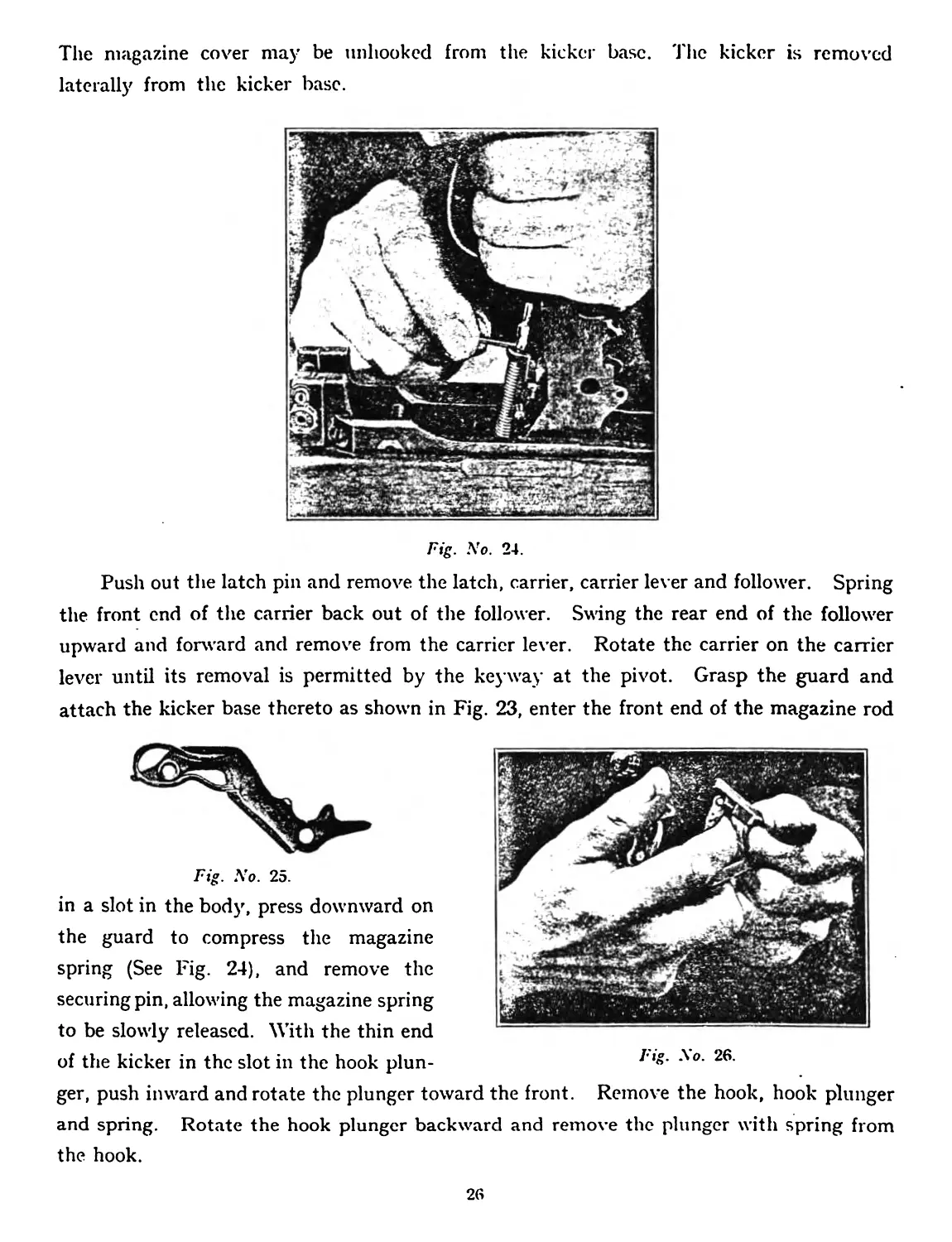
can be swung so that its front end points downwards. (See Fig. 22). While holding the follower
Fi". No. 23.
upward with the left hand, rotate the kicker base until the cross pin can be swung to the
right to permit the kicker base assembly being moved downward and out of the guard.
25
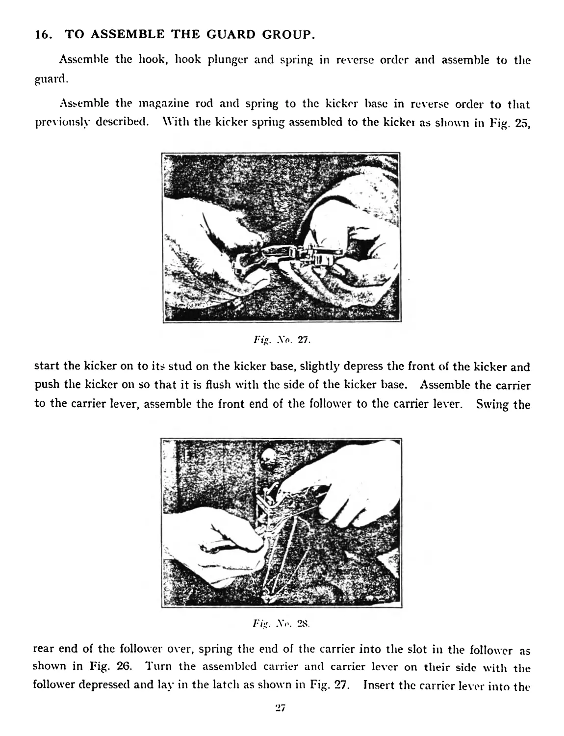
The magazine cover may be unhooked from the kicker base. The kicker is removed
laterally from the kicker base.
Fig. No. 24.
Push out the latch pin and remove the latch, carrier, carrier lever and follower. Spring
the front end of the carrier back out of the follower. Swing the rear end of the follower
upward and forward and remove from the carrier lever. Rotate the carrier on the carrier
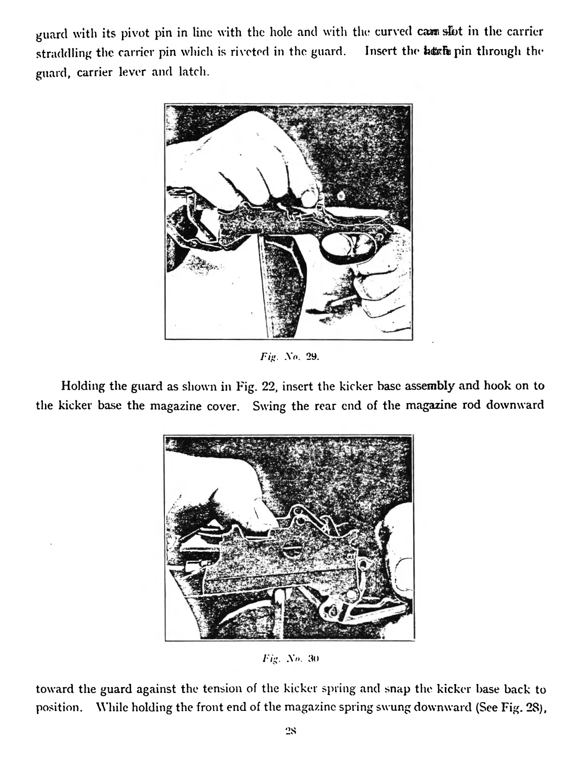
lever until its removal is permitted by the keyway at the pivot. Grasp the guard and
attach the kicker base thereto as shown in Fig. 23, enter the front end of the magazine rod
Fig. No. 25.
in a slot in the body, press downward on
the guard to compress the magazine
spring (See Fig. 24), and remove the
securing pin, allowing the magazine spring
to be slowly released. With the thin end
of the kicker in the slot in the hook plun-
Fig. No. 26.
ger, push inward and rotate the plunger toward the front. Remove the hook, hook plunger
and spring. Rotate the hook plunger backward and remove the plunger with spring from
the hook.
26
16. TO ASSEMBLE THE GUARD GROUP.
Assemble the hook, hook plunger and spring in reverse order and assemble to the
guard.
.Assemble the magazine rod and spring to the kicker base in reverse order to that
previously described. With the kicker spring assembled to the kickei as shown in Fig. 25,
/•'»". .Vo. 27.
start the kicker on to its stud on the kicker base, slightly depress the front of the kicker and
push the kicker on so that it is flush with the side of the kicker base. Assemble the carrier
to the carrier lever, assemble the front end of the follower to the carrier lever. Swing the
Fit;. .Vo. 2S.
rear end of the follower over, spring the end of the carrier into the slot in the follower as
shown in Fig. 26. Turn the assembled carrier and carrier lever on their side with the
follower depressed and lay in the latch as shown in Fig. 27. Insert the carrier lever into the
guard with its pivot pin in line with the hole and with the curved саи> slbt in the carrier
straddling the carrier pin which is riveted in the guard. Insert the iafofvpin through the
guard, carrier lever and latch.
Fig. Xo. 29.
Holding the guard as shown in Fig. 22, insert the kicker base assembly and hook on to
the kicker base the magazine cover. Swing the rear end of the magazine rod downward
Fig. .Vo. 3<>
toward the guard against the tension of the kicker spring and snap the kicker base back to
position. While holding the front end of the magazine spring swung downward (See Fig. 28),
depress the follower until the semi-circular lug on the carrier lever is seated in the corres-
ponding notch at the front end of the magazine rod. Then depress the follower more fully
draw out the pin securing the magazine spring, and allow the follower slowly to rise. Depress
the follower to see that the magazine spring is properly engaged.
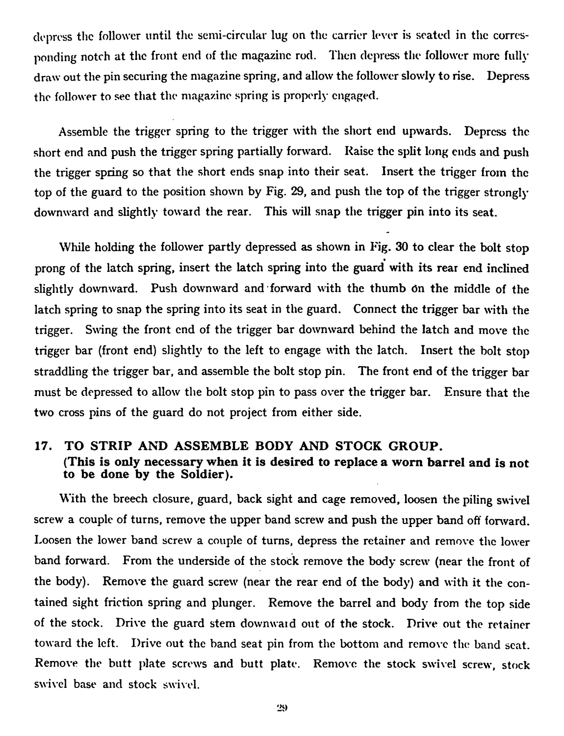
Assemble the trigger spring to the trigger with the short end upwards. Depress the
short end and push the trigger spring partially forward. Raise the split long ends and push
the trigger spring so that the short ends snap into their seat. Insert the trigger from the
top of the guard to the position shown by Fig. 29, and push the top of the trigger strongly
downward and slightly toward the rear. This will snap the trigger pin into its seat.
While holding the follower partly depressed as shown in Fig. 30 to clear the bolt stop
prong of the latch spring, insert the latch spring into the guard with its rear end inclined
slightly downward. Push downward and forward with the thumb On the middle of the
latch spring to snap the spring into its seat in the guard. Connect the trigger bar with the
trigger. Swing the front end of the trigger bar downward behind the latch and move the
trigger bar (front end) slightly to the left to engage with the latch. Insert the bolt stop
straddling the trigger bar, and assemble the bolt stop pin. The front end of the trigger bar
must be depressed to allow the bolt stop pin to pass over the trigger bar. Ensure that the
two cross pins of the guard do not project from either side.
17. TO STRIP AND ASSEMBLE BODY AND STOCK GROUP.
(This is only necessary when it is desired to replace a worn barrel and is not
to be done by the Soldier).
With the breech closure, guard, back sight and cage removed, loosen the piling swivel
screw a couple of turns, remove the upper band screw and push the upper band off forward.
Loosen the lower band screw a couple of turns, depress the retainer and remove the lower
band forward. From the underside of the stock remove the body screw (near the front of
the body). Remove the guard screw (near the rear end of the body) and with it the con-
tained sight friction spring and plunger. Remove the barrel and body from the top side
of the stock. Drive the guard stem downwaid out of the stock. Drive out the retainer
toward the left. Drive out the band seat pin from the bottom and remove the band scat.
Remove the butt plate screws and butt plate. Remove the stock swivel screw, stock
swivel base and stock swivel.
29
Note.—The stock screw and the escutcheon are not to be dismantled from the stock.
Note.—For carbines the assembly and stripping are the same as the above except for
the upper band, upper band screw, piling swivel and piling swivel screw. These parts are
not present in the carbine.
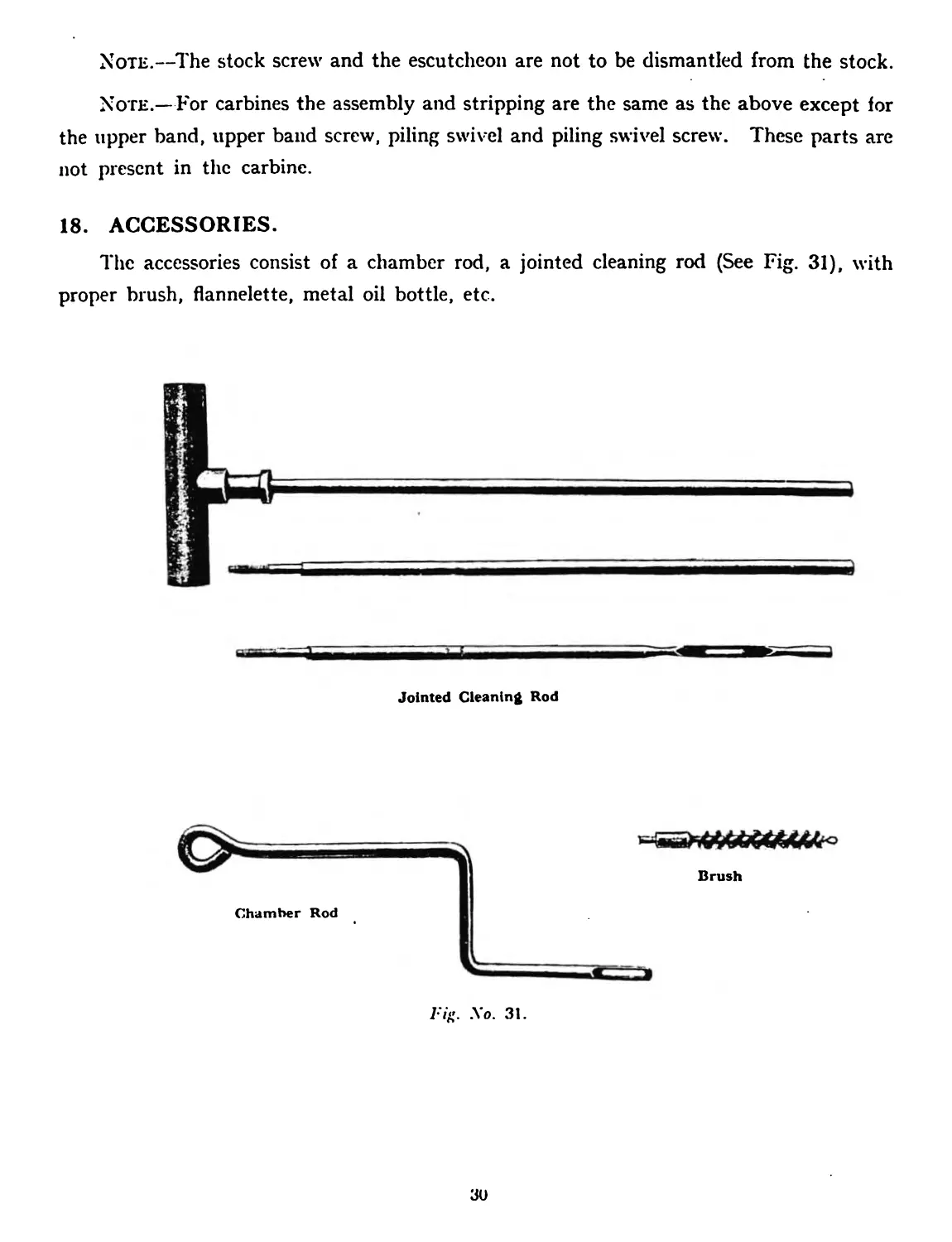
18. ACCESSORIES.
The accessories consist of a chamber rod, a jointed cleaning rod (See Fig. 31), with
proper brush, flannelette, metal oil bottle, etc.
Jointed Cleaning Rod
Brush
Chamber Rod
1ч<> .Vo. 31.
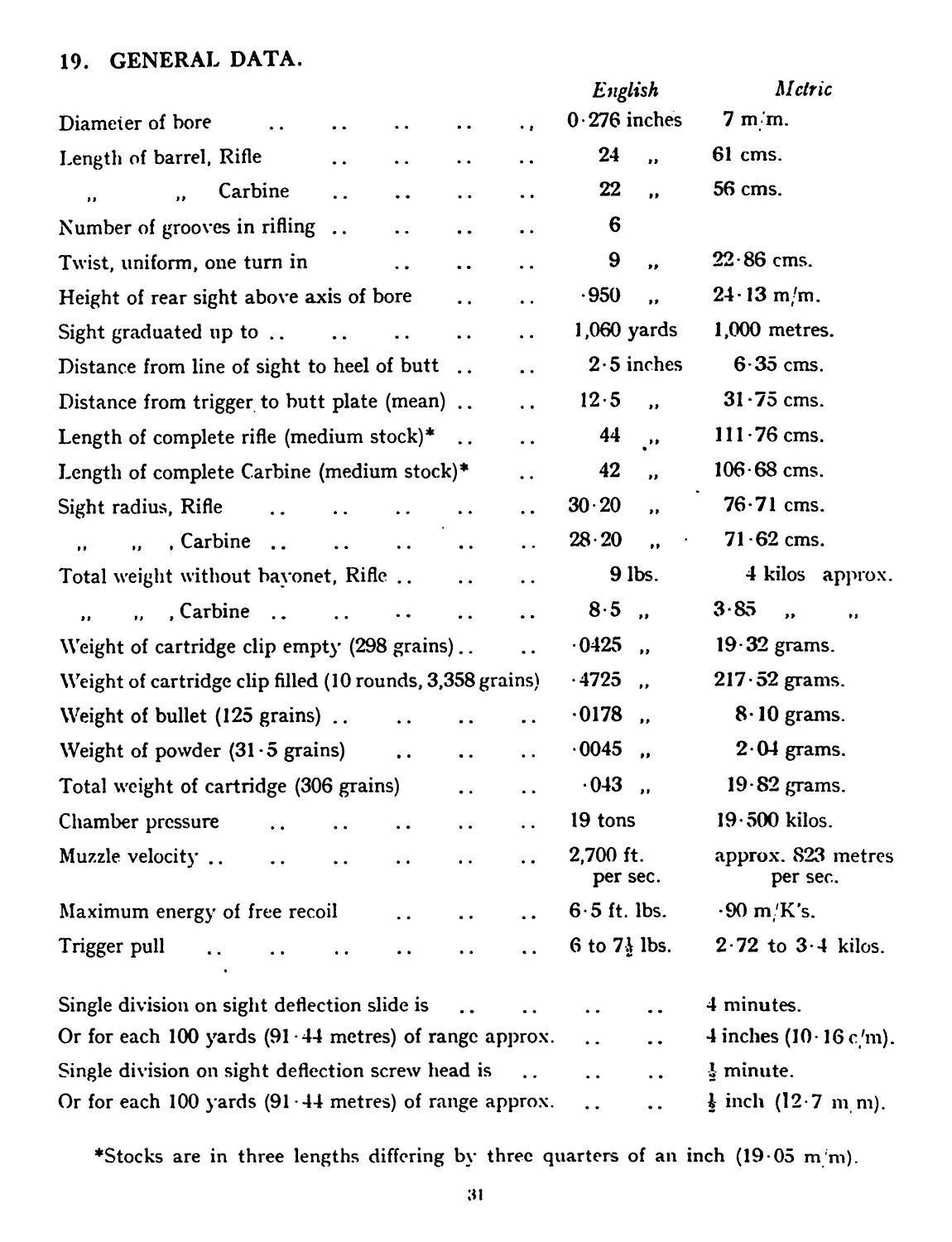
19. GENERAL DATA.
English Metric
Diameter of bore .. .. .. .. ., 0 • 276 inches 7 m Tn.
Length of barrel, Rifle 24 „ 61 cms.
„ „ Carbine 22 „ 56 cms.
Number of grooves in rifling .. 6
Twist, uniform, one turn in 9 „ 22-86 cms.
Height of rear sight above axis of bore •950 „ 24-13 m'm.
Sight graduated up to .. 1,060 yards 1,000 metres.
Distance from line of sight to heel of butt .. 2 • 5 inches 6-35 cms.
Distance from trigger to butt plate (mean) .. 12-5 „ 31 -75 cms.
Length of complete rifle (medium stock)* .. 44 „ 111-76 cms.
Length of complete Carbine (medium stock)* 42 „ 106-68 cms.
Sight radius, Rifle 30-20 „ 76-71 cms.
,, „ , Carbine .. 28-20 „ 71 -62 cms.
Total weight without bayonet, Rifle .. 9 lbs. 4 kilos approx.
„ „ , Carbine .. 8-5 „ 3-85 „
Weight of cartridge clip empty (298 grains).. •0425 „ 19-32 grams.
Weight of cartridge clip filled (10 rounds, 3,358 grains) •4725 „ 217-52 grams.
Weight of bullet (125 grains) .. •0178 „ 8-10 grams.
Weight of powder (31 -5 grains) •0045 „ 2-04 grams.
Total weight of cartridge (306 grains) •043 ,, 19-82 grams.
Chamber pressure 19 tons 19-500 kilos.
Muzzle velocity .. 2,700 ft. per sec. approx. 823 metres per sec.
Maximum energy of free recoil 6-5 ft. lbs. -90 m/K’s.
Trigger pull 6 to 7| lbs. 2-72 to 3-4 kilos.
Single division on sight deflection slide is • . • • 4 minutes.
Or for each 100 yards (91 -44 metres) of range approx. • • • • 4 inches (10-16 c'm).
Single division on sight deflection screw head is . • • • J minute.
Or for each 100 yards (91-44 metres) of range approx. • • • • | inch (12-7 m m).
♦Stocks are in three lengths differing by three quarters of an inch (19-05 m'm).
31