/

Tags: operating instructions telecommunications communications general description
Year: 1991


Text
,,..._----
- - - - - - -- --
-
--
-
-
---- -- ----
-
-
--
~-
-
SIEMENS
Hicom 300
General description
,-~
I
-i.
I
Contents
ISDN and Hicom® 300
A
B
Bl
B2
B3
B3.1
B3.1.1
B3.1.2
B3.2
B3.3
ISDN technology for future office communication requirements
ISDN Communication System Hicom 300
Structure of the Hicom 300 System
Basic systems for future innovations
Features of the ISDN Communication System Hicom 300
Switching unit
Individual services
Service integration
Features of the integrated Hicom servers
Features of the adapted servers
1
3
5
8
9
9
9
10
12
15
Hicom 300 System
1
1.1
1.1.1
1.1.2
1.1.3
1.2
1.2.1
1.2.2
1.2.3
1.3
1.3.1
1.3.2
1.3.3
1.4
1.4.1
1.4.2
1.5
1.5. 1
1.5.2
1.6
System architecture
Switching unit SWU Hicom 300 with :5 960 ports
Periphery
Switching network SN
Common control CC Hicom 300 with :5 960 ports
Switching unit SWU Hicom 300 with :5 5120 ports
Line trunk group LTG
Central devices
Common control CC Hicom 300 with :5 5120 ports
Integrated Hicom servers
IHS for administration and data service ADS
IHS for voice mail service VMS
IHS for Tele Communications Service TCS
Adapted servers
S3510, server for the Hicom 3510 Multiterminal
Other adapted servers
Hicom adapters and network terminations
Hicom adapters
Network terminations
Remote switch RMS
16
17
17
18
18
19
19
20
21
22
22
23
24
25
25
25
26
26
28
29
2
2.1
2.2
Hardware technology and design
Hardware technology
Design
32
32
33
3
3.1
3.2
3.3
3.3.1
3.3.2
3.3.3
3.4
3.4.1
3.4.2
3.4.3
3.4.4
3.4.5
3.5
3.6
3.6.1
Upgraded system architecture
General
Syste m structure
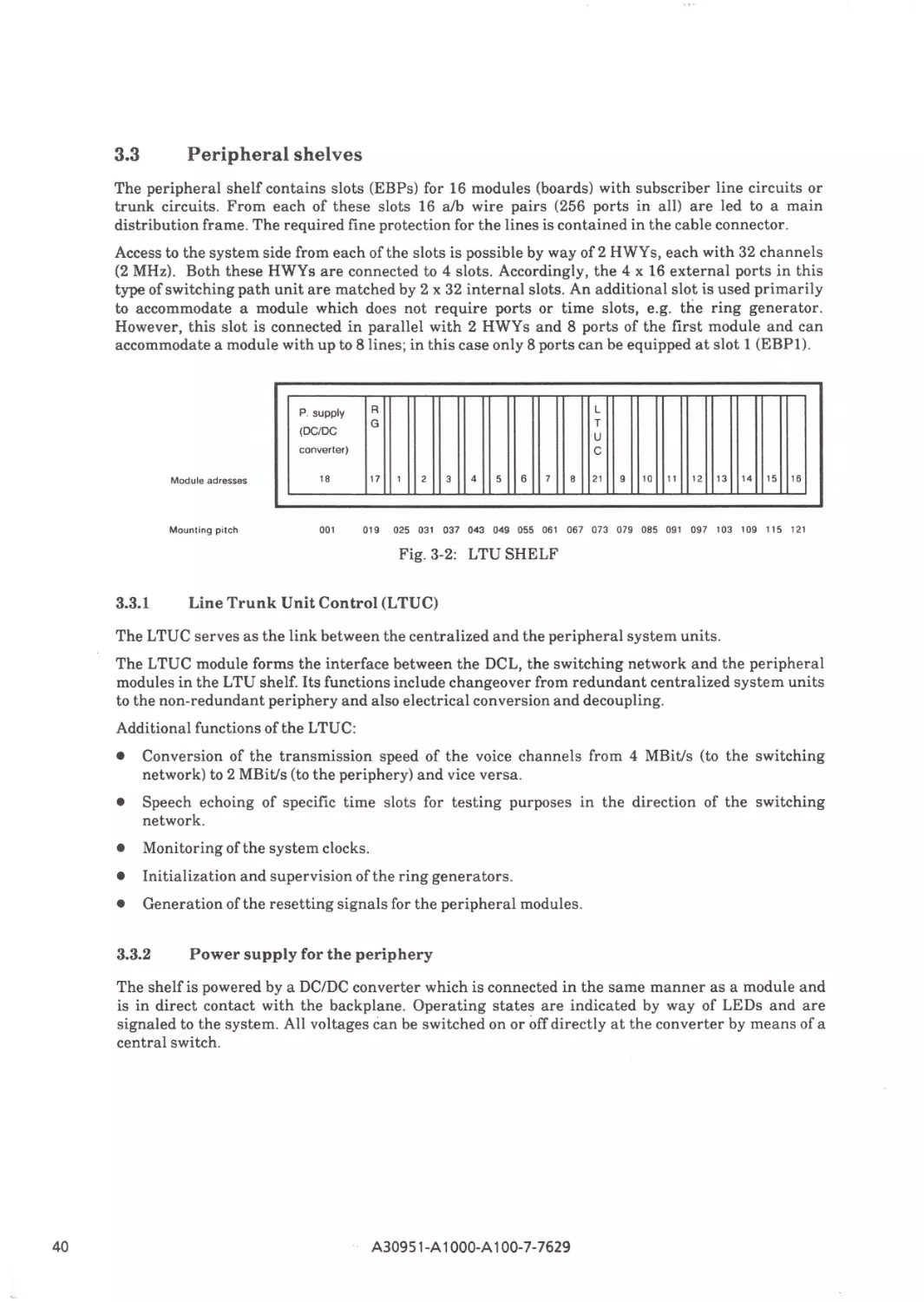
Peripheral shelves
Line trunk unit control (LTUC)
Power supply for periphery
Integrated server extension shelf(ISEC)
Central shelf
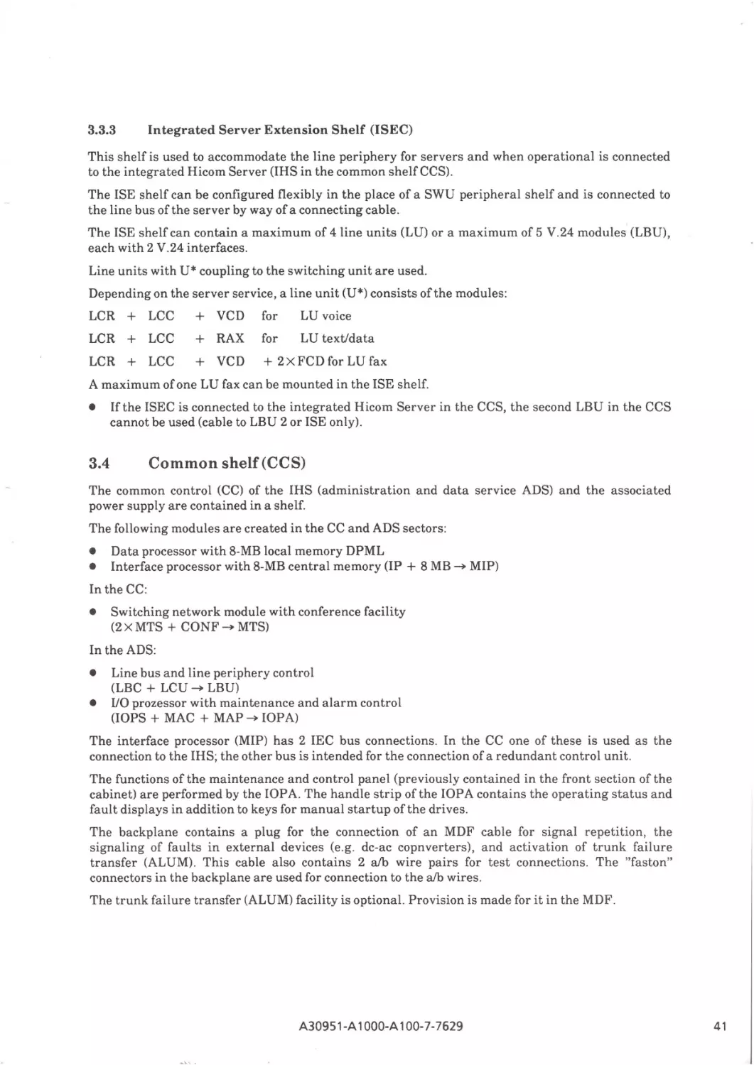
Common control and server s helf (CCS) (Fig. 2-3)
Switching network/conference
Memory/interface processor (MIP)
IN/OUT processor and alarm control (IOPA)
Line bus unit (LBU)
Power supply
Design
Design variants
38
38
38
40
40
40
41
41
42
42
43
43
44
45
46
46
A30951 -A 1OOO-A100- 7-7629
0/1
r
4
4.1
4.1 .1
4.1.2
4.1.3
4.2
4.2.1
4.2.2
4.2.3
4.3
Operational features
Administration and maintenance system
Putting the system into operation
Administration and maintenance functions
Traffic metering
Dependability system
Error detection
Error analysis
Error handling
Duplex mode
49
49
50
50
51
51
52
52
52
53
5
5.1
5.2
5.3
5.4
5.5
5.6
5.7
Software architecture
Operating system
Call processing software
Administration and maintenance software
Dependability software
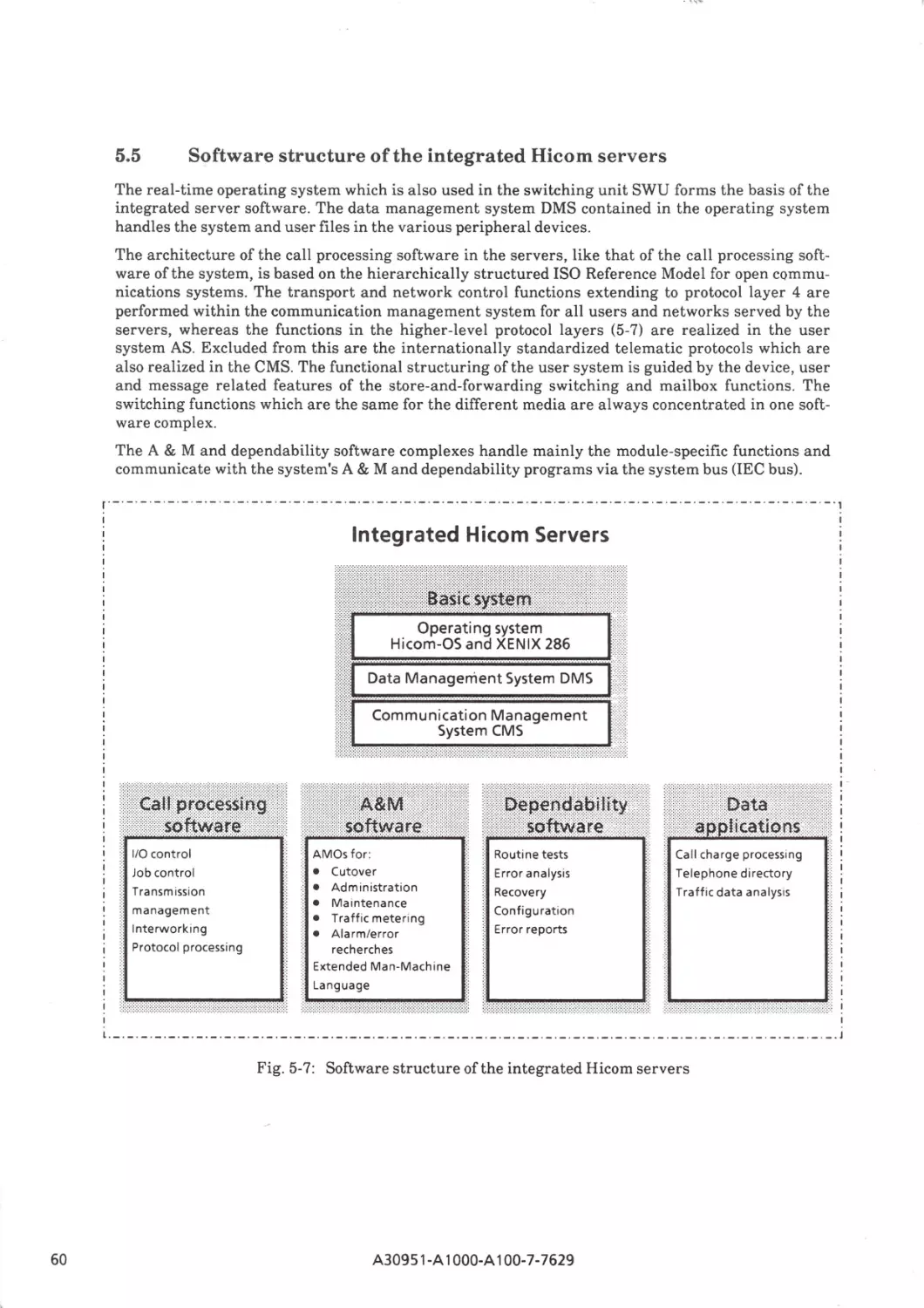
Software structure of the integrated Hicom servers
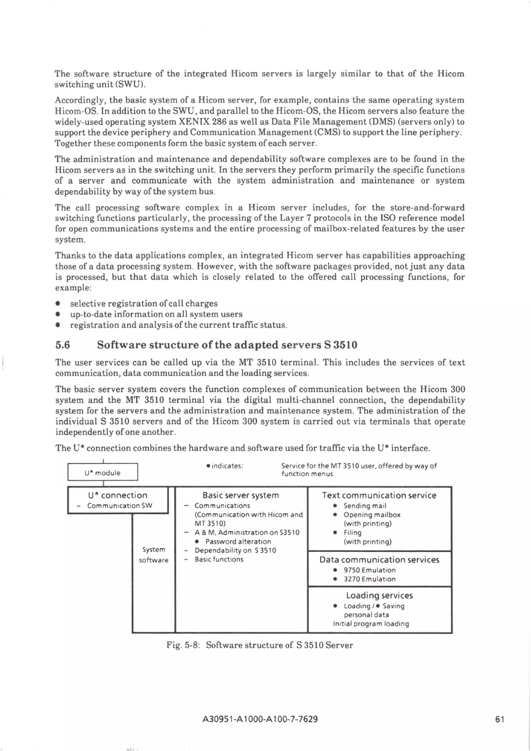
Software structure of the adapted servers S 3510
Data base
54
55
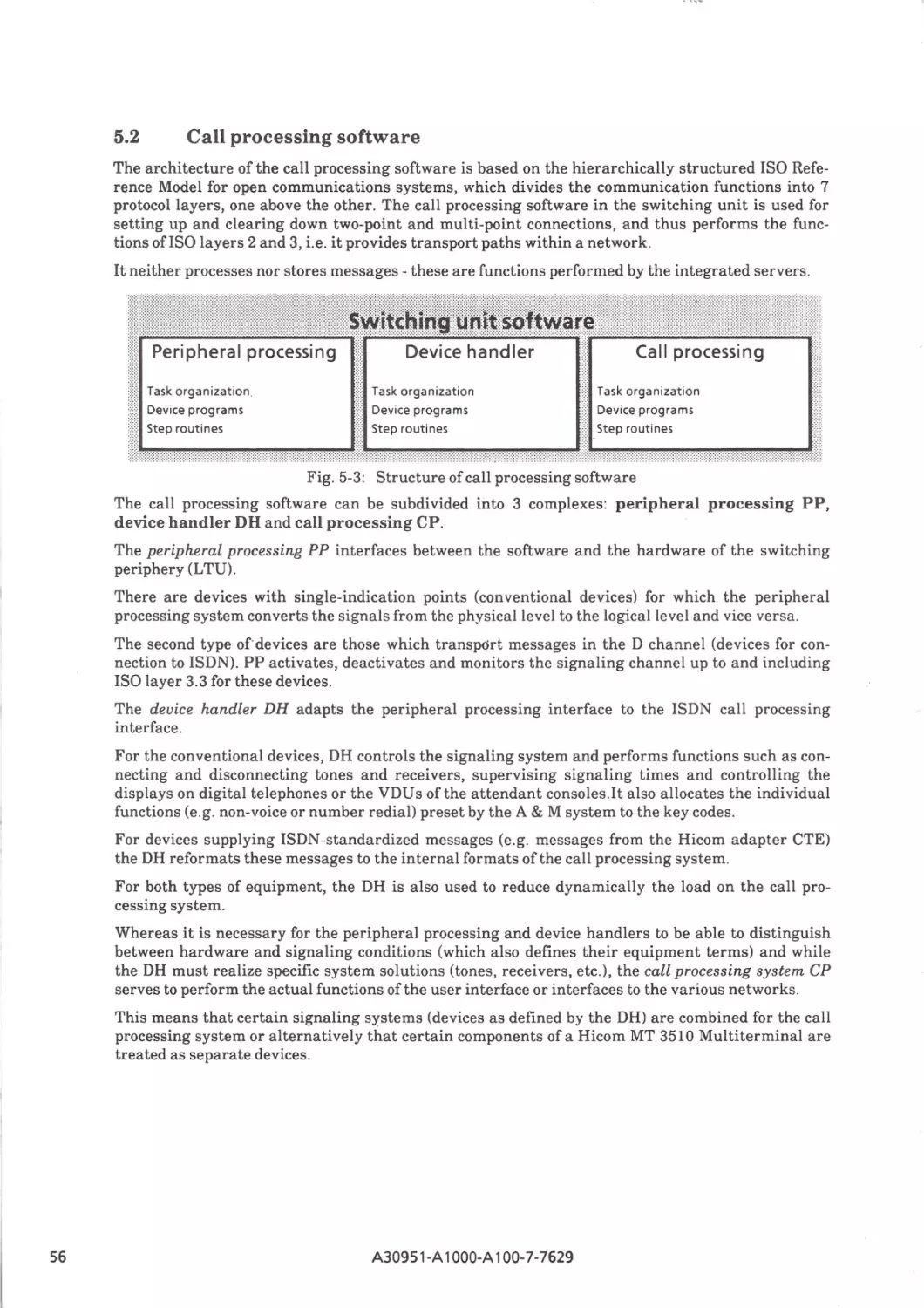
56
58
59
56
61
62
6
63
6.4
Terminals
Hicom attendant console AC
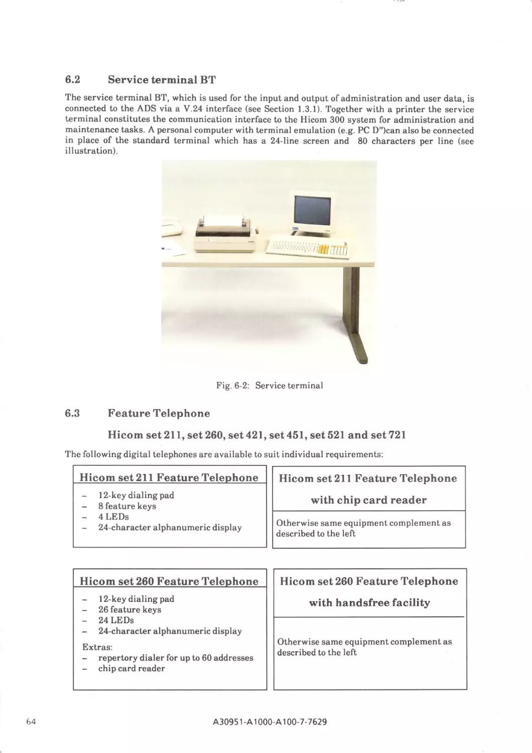
Service terminal BT
Feature telephone H
icom set 211 and Hicom set 260, set 400, set 421,set 521, set 721
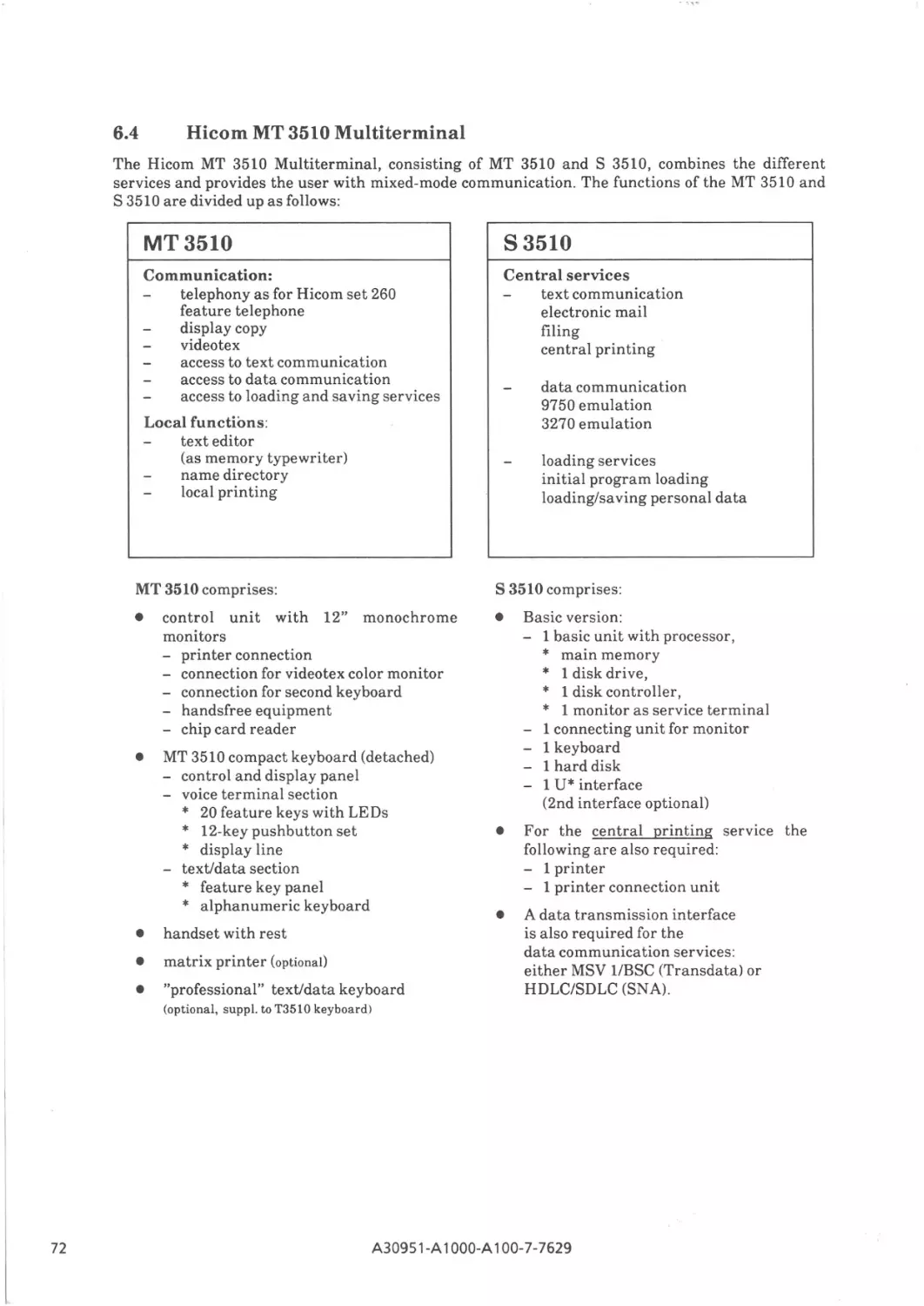
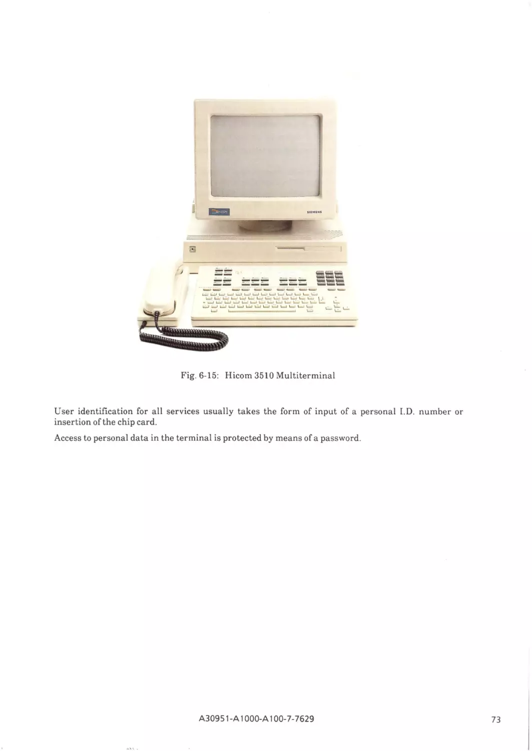
Hicom Multiterminal MT 3510
7
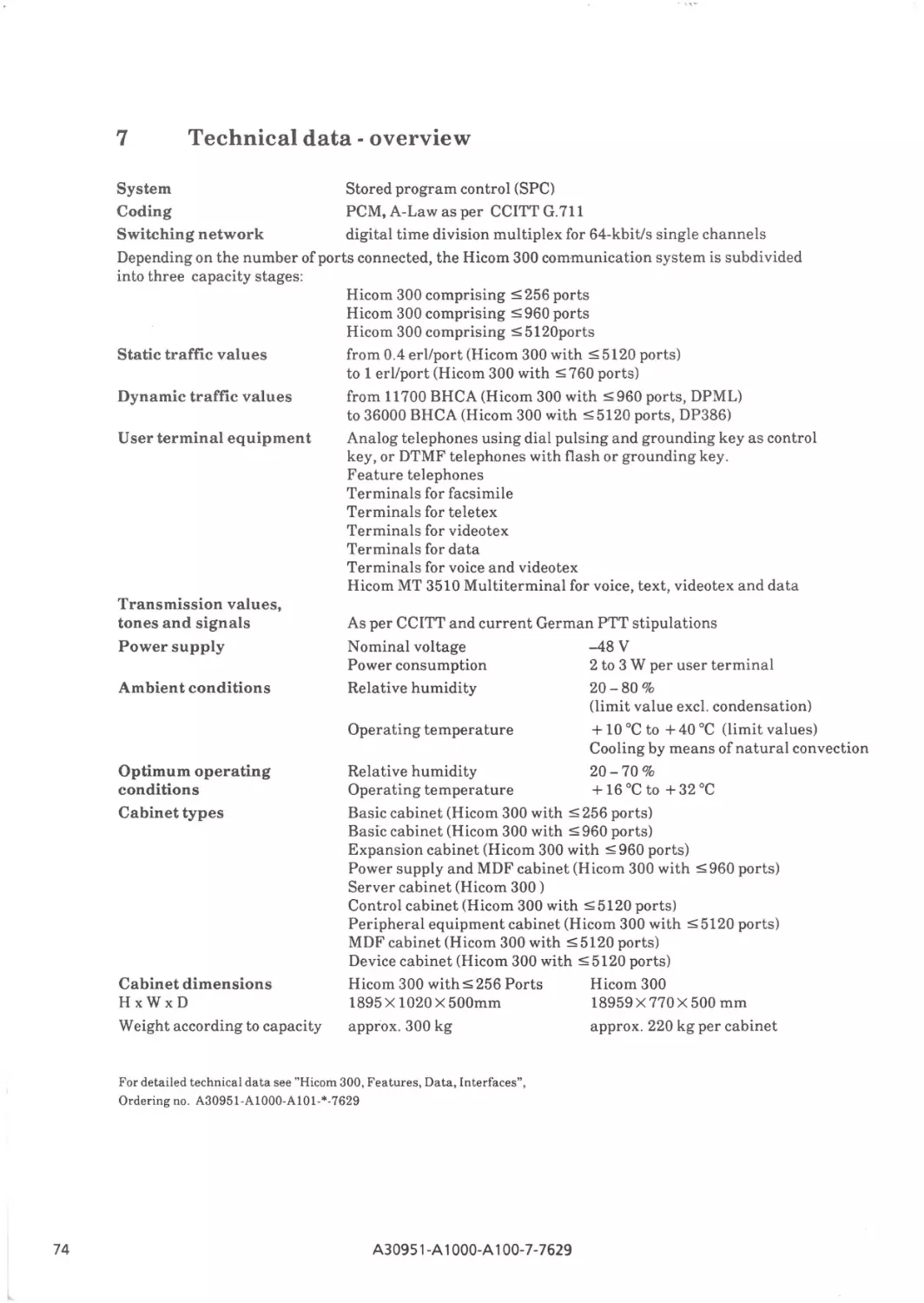
Technical data - overview
74
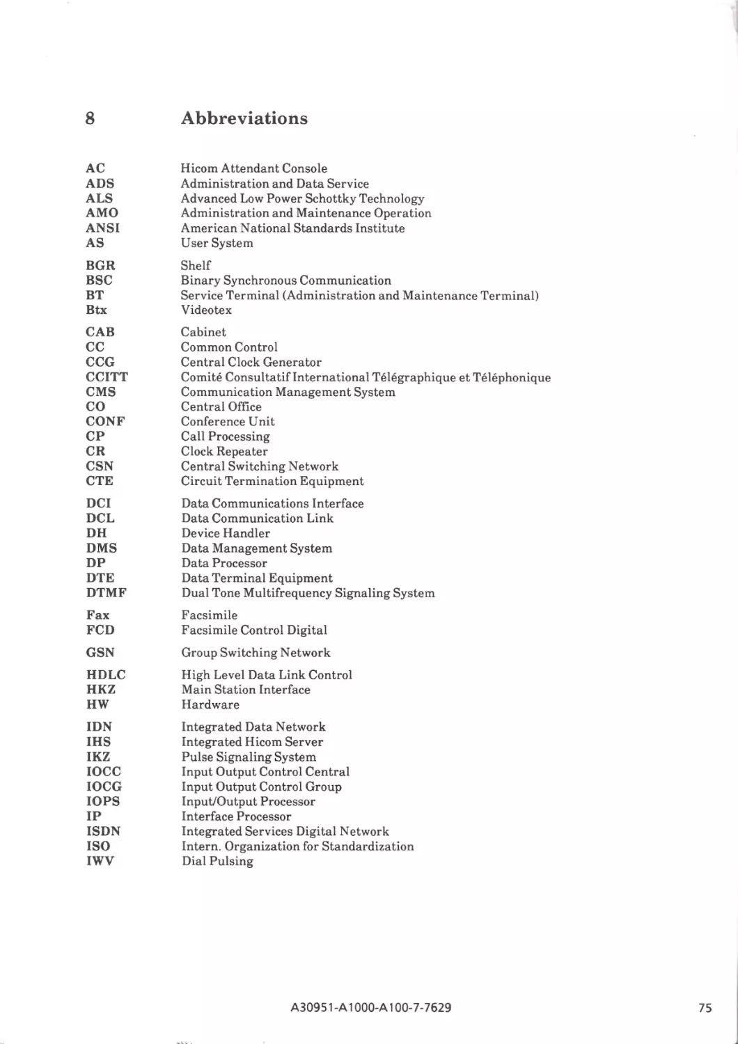
8
Abbreviations (fold-out)
75
6.1
6.2
6.3
012
A30951-A 1ooo~A1oo-7- 7629
63
64
64
72
Figures
Fig. B-1:
Fig. Bl-1:
Fig. Bl-2:
Fig. B3-l:
Fig. 1-1:
Fig. 1-2:
Fig. 1-3:
Fig. 1-4:
Fig. 1-5:
Fig. 1-6:
Fig. 1-7:
Fig. 1-8:
Fig. 1-9:
Fig. 1-10:
Fig. 1-11:
Fig. 1-12:
Fig. 1-13:
Fig. 1-14:
Fig. 1-15:
Fig. 1-16:
Fig. 2-1:
Fig. 2-2:
Fig. 2-3:
Fig. 2-4:
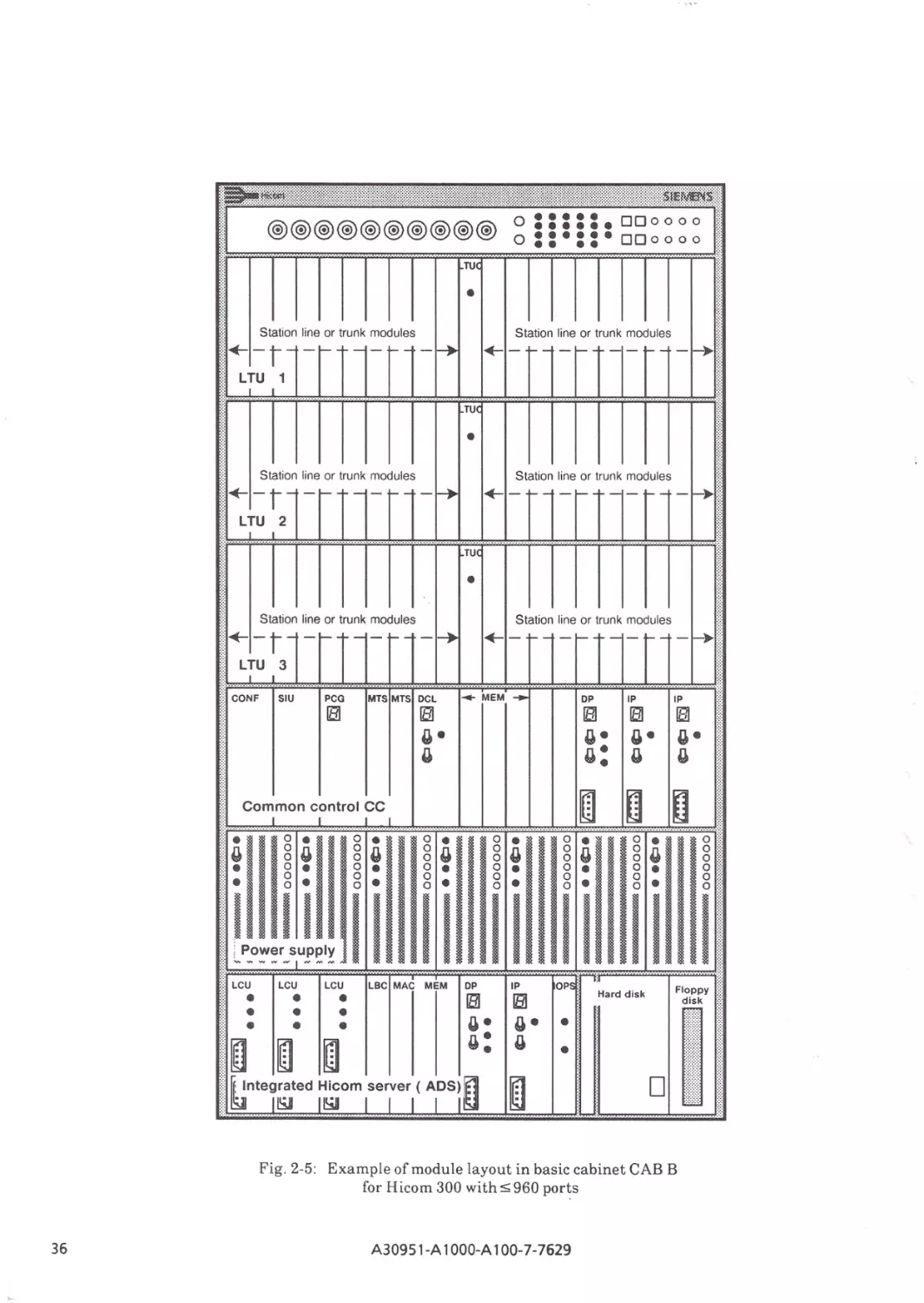
Fig. 2-5:
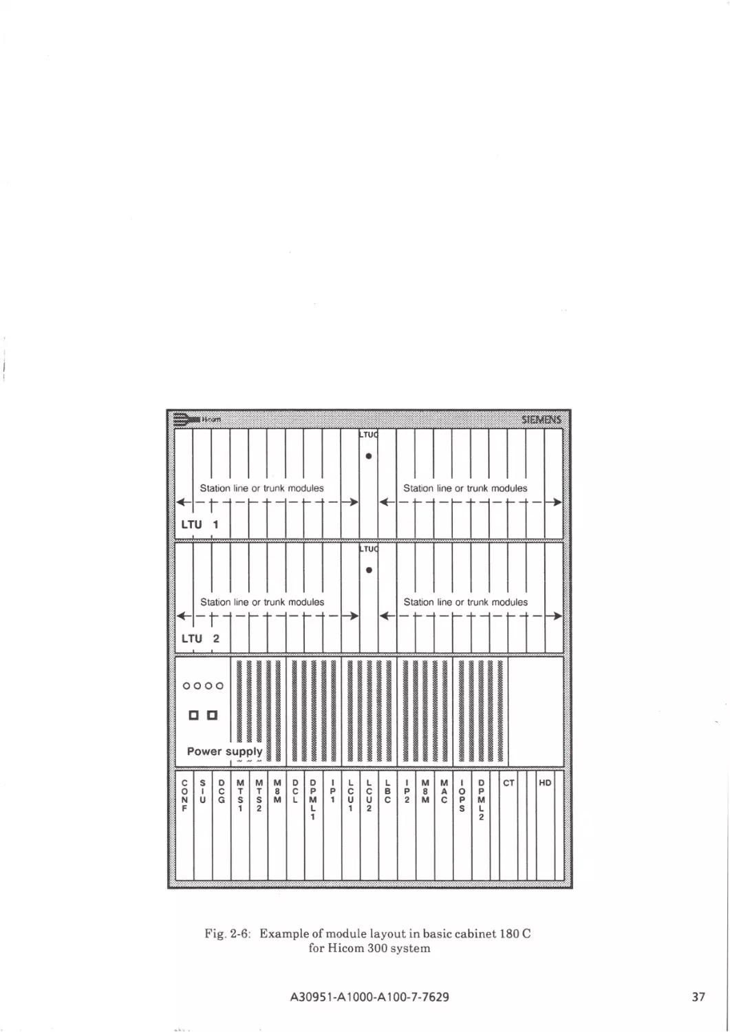
Fig. 2-6:
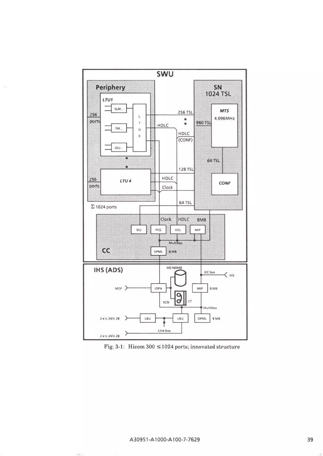
Fig. 3-1:
Fig. 3-2:
Fig. 3-3:
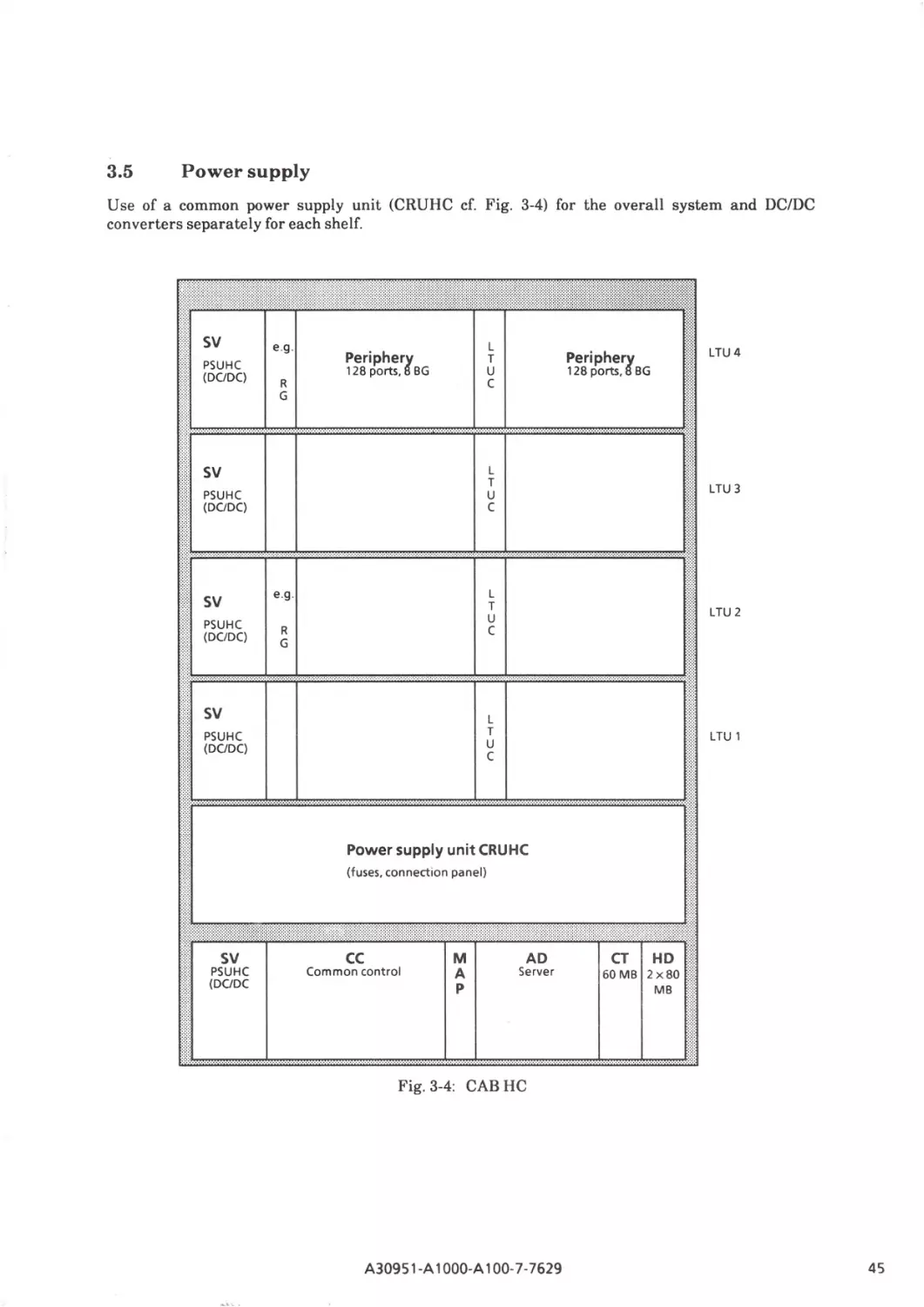
Fig. 3-4:
Fig. 3-5:
Fig. 3-6:
Fig. 3-7:
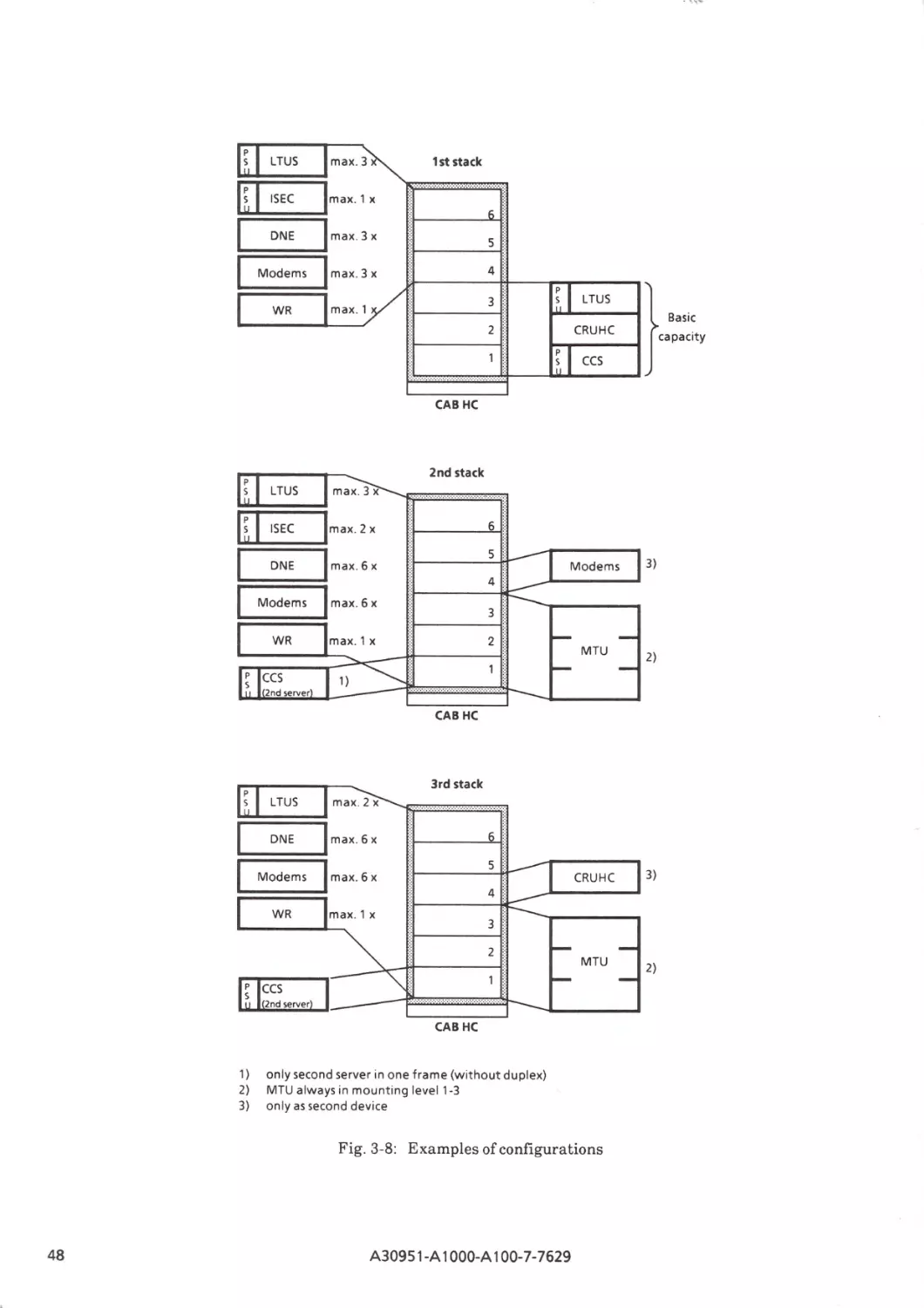
Fig. 3-8:
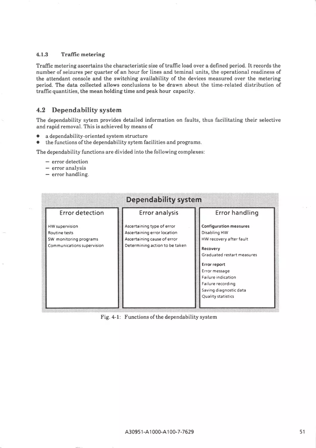
Fig.4-1:
Fig. 5-1:
Fig. 5-2:
Fig. 5-3:
Fig. 5-4:
Fig. 5-5:
Fig. 5-6:
Fig. 5-7:
Fig. 5-8:
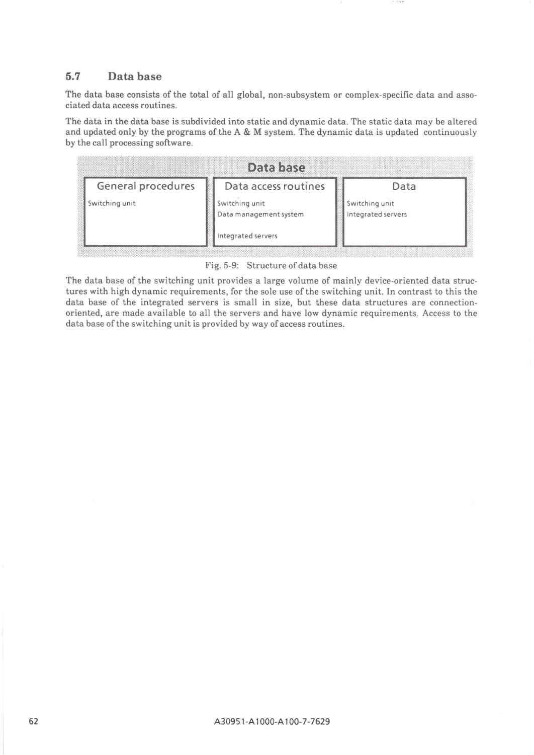
Fig. 5-9:
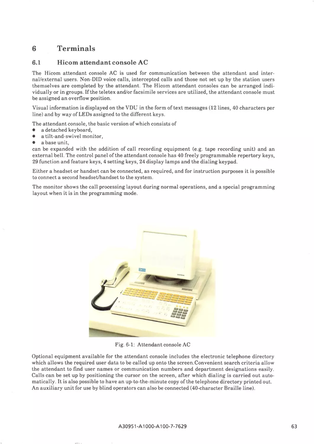
Fig. 6-1:
Fig. 6-2:
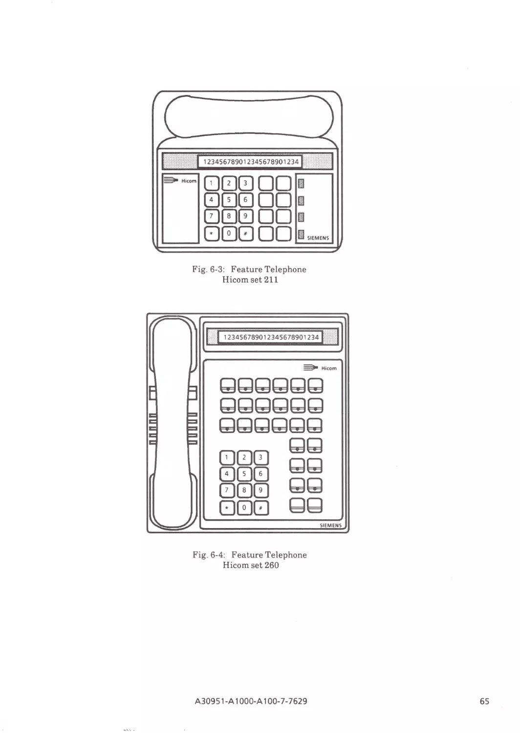
Fig. 6-3:
Fig. 6-4:
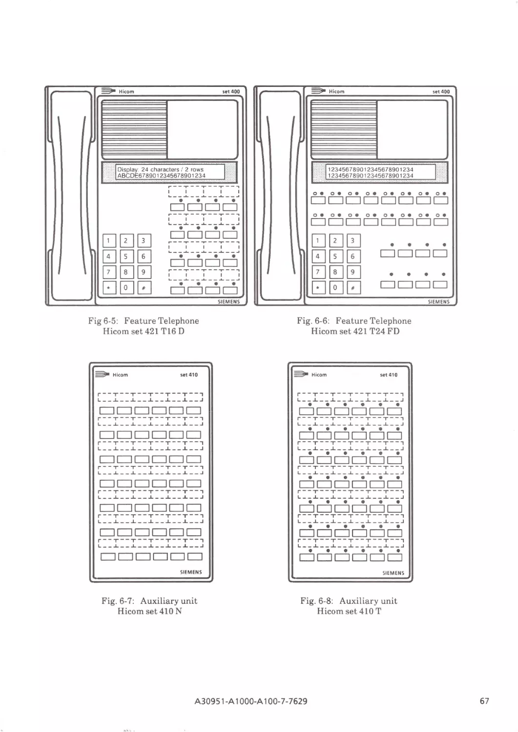
Fig. 6-5:
Fig. 6-6:
Fig. 6-7:
Fig. 6-8:
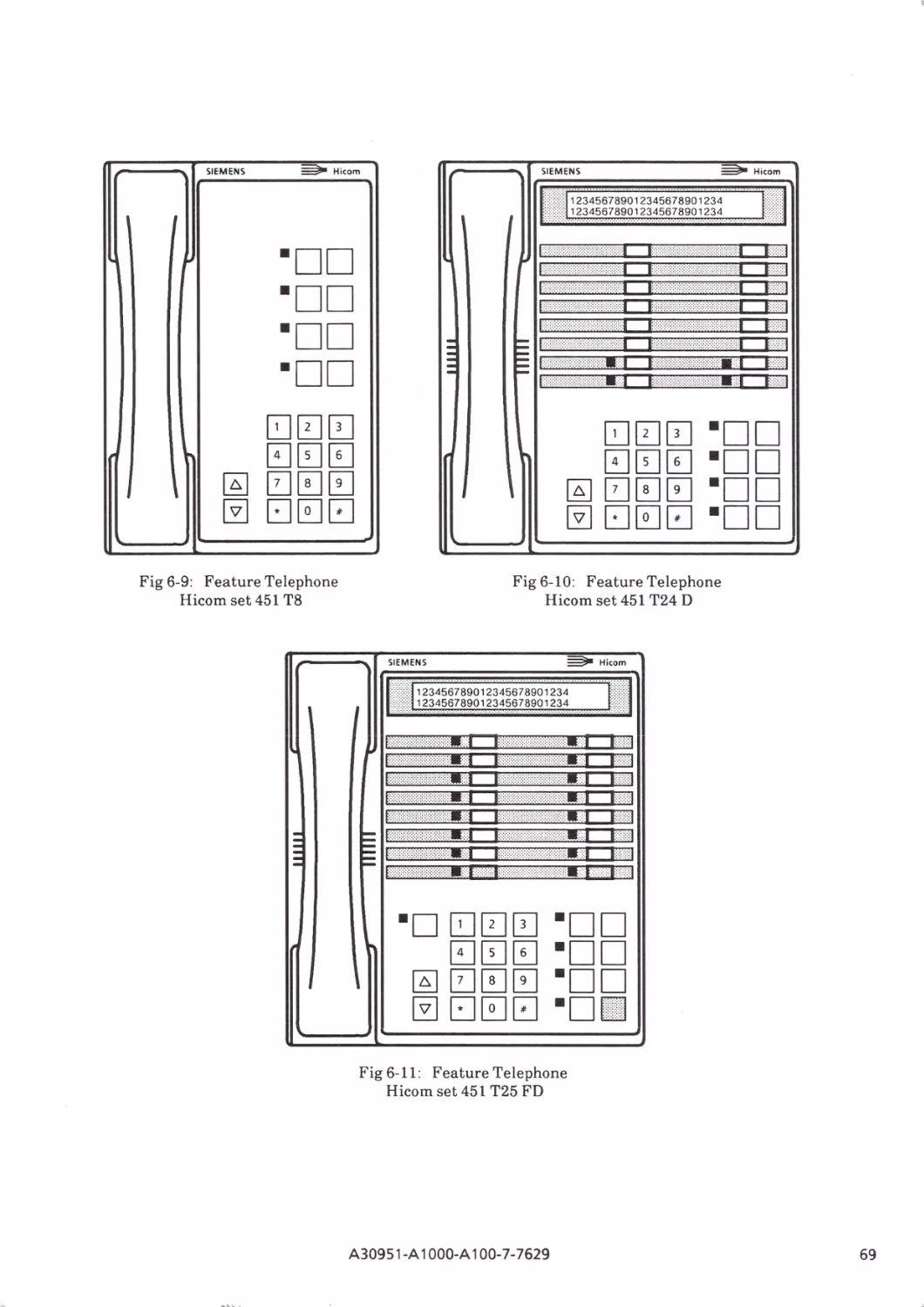
Fig. 6-9:
Fig. 6-10:
Fig. 6-11 :
Incorporation of the ISDN Communication System Hicom 300 in present
and future networks and examples of compatible terminal devices
Block diagram of the Hicom 300 Communication System
New Hicom 300 user/server interfaces
Service integration
Basic structure of the Hicom 300 system
Functional units of the SWU Hicom 300 with :5 960 ports
Functional units of the switching network SN Hicom 300 with :5 960 ports
Functional units of the common control CC
Functional units of the line trunk group LTG
Functional units of the central devices
Functional units of the common control CC
Functional units for the administration and data service ADS
Functional units for the voice mail service VMS
Functional units for the Tele Communications Service
Connection of the Hicom 3510 Multi terminal
Hicom adapters and network terminations
Remote switch RMS
Block diagram of the Hicom 300 system with :5 256 ports
Block diagram of the Hicom 300 system with :5960 ports
Block diagram of the Hicom 300 system with :55120 ports
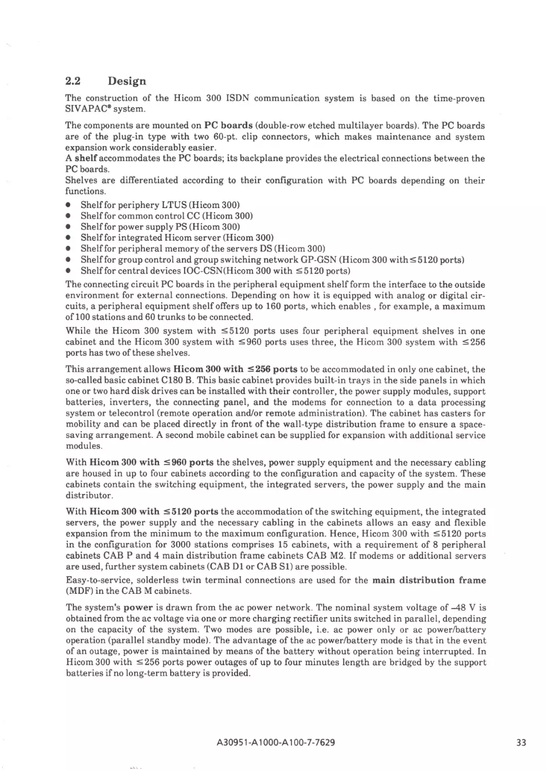
Hicom 300 system with :5 256 and :5 960 ports
Hicom 300 system with :55120 ports
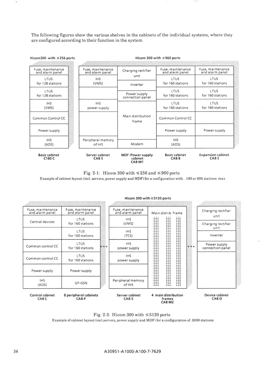
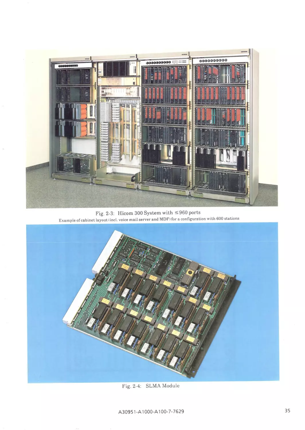
Hicom 300 System with :s: 960 ports
SLMA module
Example of module layout in basic cabinet for Hicom 300 with :5 960 ports
Arrangement of basic cabinet Cl80 for Hicom 300 with :5 256 ports
Hicom 300 :S: 1024 ports
LTUSHELF
CCSSHELF
CABHC
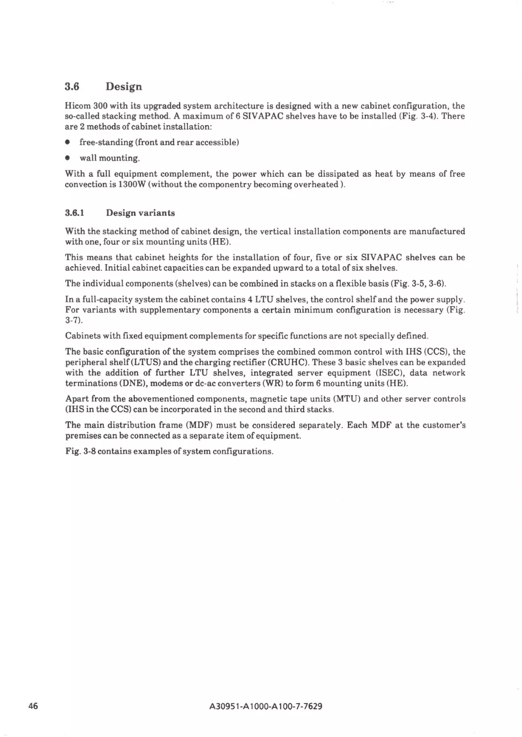
Stacking configurations
Installation heights
Examples of equipment complements
Examples of system layout
Functions of the dependability system
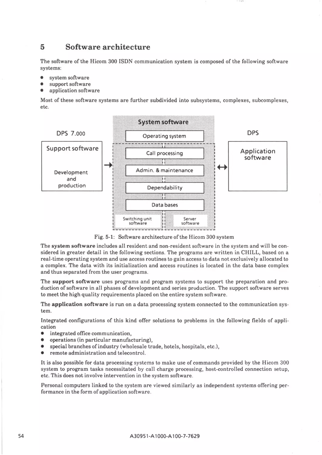
Software arcfiitecture of the Hicom 300 system
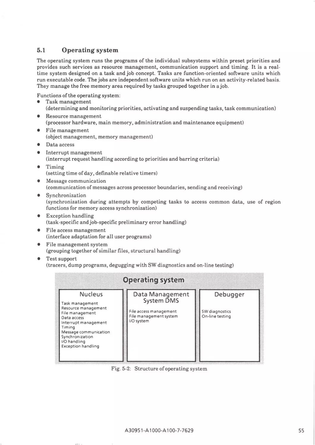
Structure of operating system
Structure of call processing software
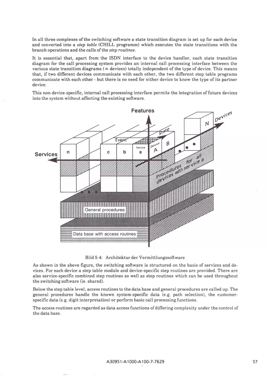
Architecture of call processing software
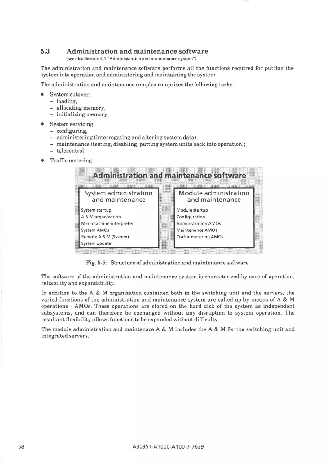
Structure of administration and maintenace software
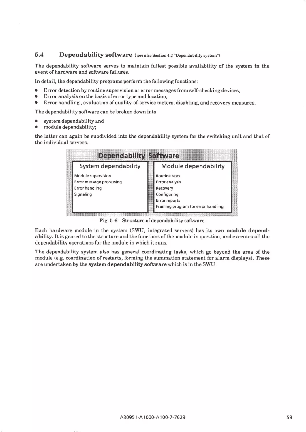
Structure of dependability software
Software structure of the integrated Hicom servers
Software structure of the adapted servers S 3510
Structure of data base
Attendant console AC
Service terminal
Hicom set 211 feature telephone
Hicom set 260 feature telephone with repertory dialer and chip card reader
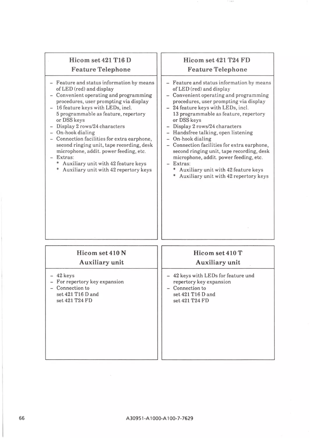
Feature Telephone Hicom set 421 Tl6 D
Feature Telephone Hicom set 421 T24 FD
Auxiliary unit Hicom set 410 N
Auxiliary unit Hicom set 410 T
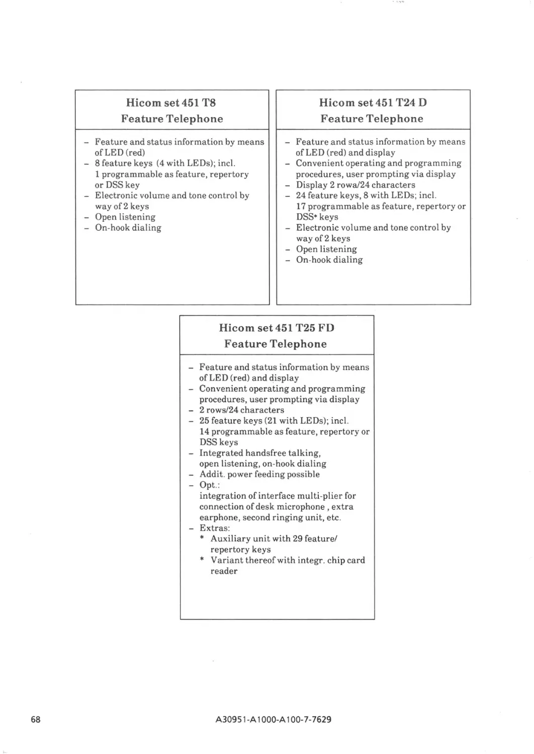
Feature Telephone Hicom set 451 TB
Feature Telephone Hicom set 451 T24D
Feature Telephone Hicom set 451 T25FD
A30951-A 1OOO-A100-7-7629
4
5
7
10
16
17
18
18
19
20
21
22
23
24
25
27
29
30
30
31
34
34
35
35
36
37
39
40
42
45
47
47
47
48
51
54
55
56
57
58
59
60
61
62
63
64
65
65
67
67
67
67
69
69
69
013
r
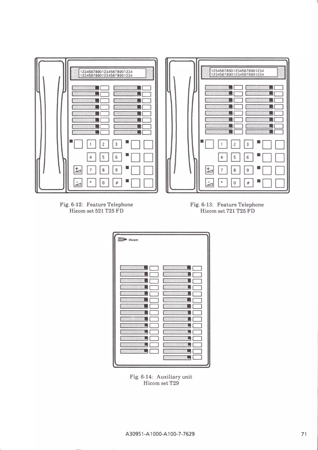
Fig. 6-12:
Fig. 6-13:
Fig. 6-14:
Fig. 6-15:
0/4
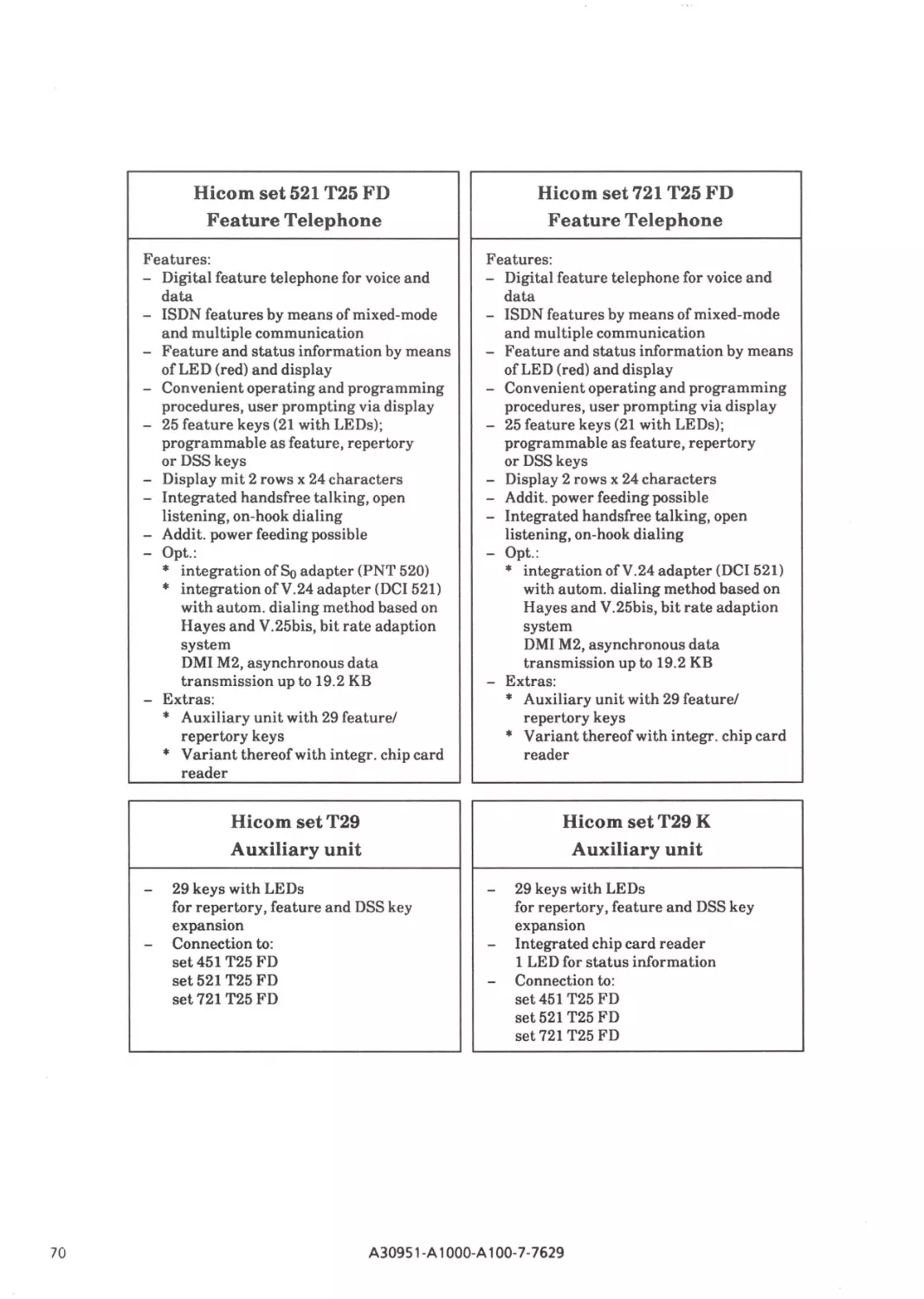
Feature Telephone Hicom set 521 T25FD
Feature Telephone Hicom set 721 T25FD
Auxiliary unit Hicom set T29
Hicom 3510 Multiterminal
A30951-A 1OOO-A100-7-7629
71
71
71
73
ISDN and Hicom 300
A
ISDN technology
for future office communication requirements
As a result of rapid advances in the field of electronics, it became economically feasible to introduce
transmission systems based on PCM technology in the early 1970s. A fundamental factor in the
worldwide introduction of PCM was CCITT's recommendation of a bit rate of 64 kbit/s per channel.
In view of the trend toward digitization of telephone networks, this is an ideal prerequisite for the
integration of all telecommunications services (voice, text, data, image) into one network, the
ISDN - Integrated Services Digital Network.
The principles and standards on which the ISDN is based can be used to particular effect in the business sector, whether in the local area of an ISDN communication system or in a private digital
network.
Previously, the different transmission and switching systems used in a variety of networks, and the
broad range of largely incompatible terminal equipment, resulted in a considerable amount of unnecessary expenditure. The communications networks formed "communication islands" each with
its individual characteristics. A user required several lines for the different services, and combined
access to services was both difficult and expensive.
Numerous workstations in the office already have word processors, desk-top computers or powerful
video display units in addition to straightforward or more sophisticated telephone sets. These stations should all be able to communicate not only with one another but also with computers, data
bases and printers. Moreover, different forms of communication should be possible from the one
workstation - whether they are activated in parallel, alternately or simultaneously. The aim, therefore is to achieve mixed-mode communications.
With the rapidly increasing demand for mixed-mode communications in the office sector it is clearly
advisable to digitize future transmission and switching sytems on a standard basis. Interconnection
of the different types of equipment and the standardization and integration of the communications
systems and networks are goals which must be pursued as a matter of urgency.
An ISDN communication system links all terminals and office systems internally, permits
so-called mixed-mode communication and provides the interface to public communication
networks.
A30951-A 1OOO-A100-7-7629
The trend toward office communication with ISDN has the following advantages:
•
Standardization of the interface and architecture of user access in the form of digital multichannel connection, with high transmission capacity on a pair of connecting wires
•
Utilization of the existing copper cable network - which is now a global network with the ability
to reach every office - on the basis of all-digital connections
•
Ability to access a user's voice, text, and data terminals under a single call number and with service-related handling procedures, whether the terminals are individual units or multi-terminals
•
Standardization of a universal medium of transmission and transport, with the addition of such
services as are required, to form a universal communications system
•
Initial standardization of service and network interworking
•
Comprehensive range of services:
- Standard services, such as qualitatively improved and more convenient telephony, teletex,
facsimile, etc.;
- Transmission services, such as circuit-switched and packet-switched data communication
services;
- Higher-level services, (so-called Value Added Services) such as PC mail, voice mail and text
mail;
- Special services, including alarm and emergency services, telemetering, and telecontrol.
ISDN will also provide the transition from present-day to future services on the basis of existing
interfaces and others which have yet to be standardized. Interworking functions, i.e. devices which
allow traffic between otherwise incompatible services, will increase ISDN's potential even further.
2
A30951-A 1OOO-A100-7-7629
B
ISDN Communication System Hicom 300
The demand for a broad range of peripheral and functional facilities with a high degree of modularity and expandability led to the development of the Hicom 300 ISDN communication system.
Hicom brings together existing communication methods in digital, service-integrating private
branch exchanges. All its operating functions are software-controlled.
Three of the system's features deserve special mention:
•
Integration of circuit switching and store-and-forward switching functions for voice, text, data,
and image communication.
•
All switching functions are performed on a digital basis for all forms of communication.
•
Because of its hardware and software architecture the Hicom 300 communications system can be
adapted to suit future service features and/or technologies; it constitutes the basic system which
is geared to all possible innovations.
The Hicom 300 system incorporates the features of present-day telephone PABXs and of new
'
integrated voice/data PABXs.
It also offers the following ISDN features:
•
Support of the standard ISDN interfaces to the lines and to the terminal units, in the case of
connection via basic access resp.primary multiplex access.
•
Features for the standard ISDN services;
•
Higher-level services which are needed if the ISDN concept is to be applied usefully to the
requirements of future office automation: printing, mailbox, archiving services, etc.
These ISDN functions require:
-
Standard processing of all forms of communication, such as voice, text, image, data,
- Not only switching facilities, but also storage and processing of information as weli as storeand-forward functions for voice, text, images and data.
And more specifically,
- Personalized call numbers, with facilities for users to transfer their own station data to various other lines by means of chip card identification,
- Combination of several terminals for different services under a single number,
- Service-related connection handling, e.g. supervision of terminal compatibility,
- Facilities for mixed-mode communication. With the two information channels at his disposal,
each user can communicate via two media at the same time (e.g. speech accompanied by facsimile).
A30951-A 1OOO-A100-7-7629
3
ITT=i
~
Public
networks:
ISDN Communication System
Hicom©3QO
50 -Bus connection for terminals
-
llEll
Gateway
Local area network
Private networks
for voice, text
and data communication
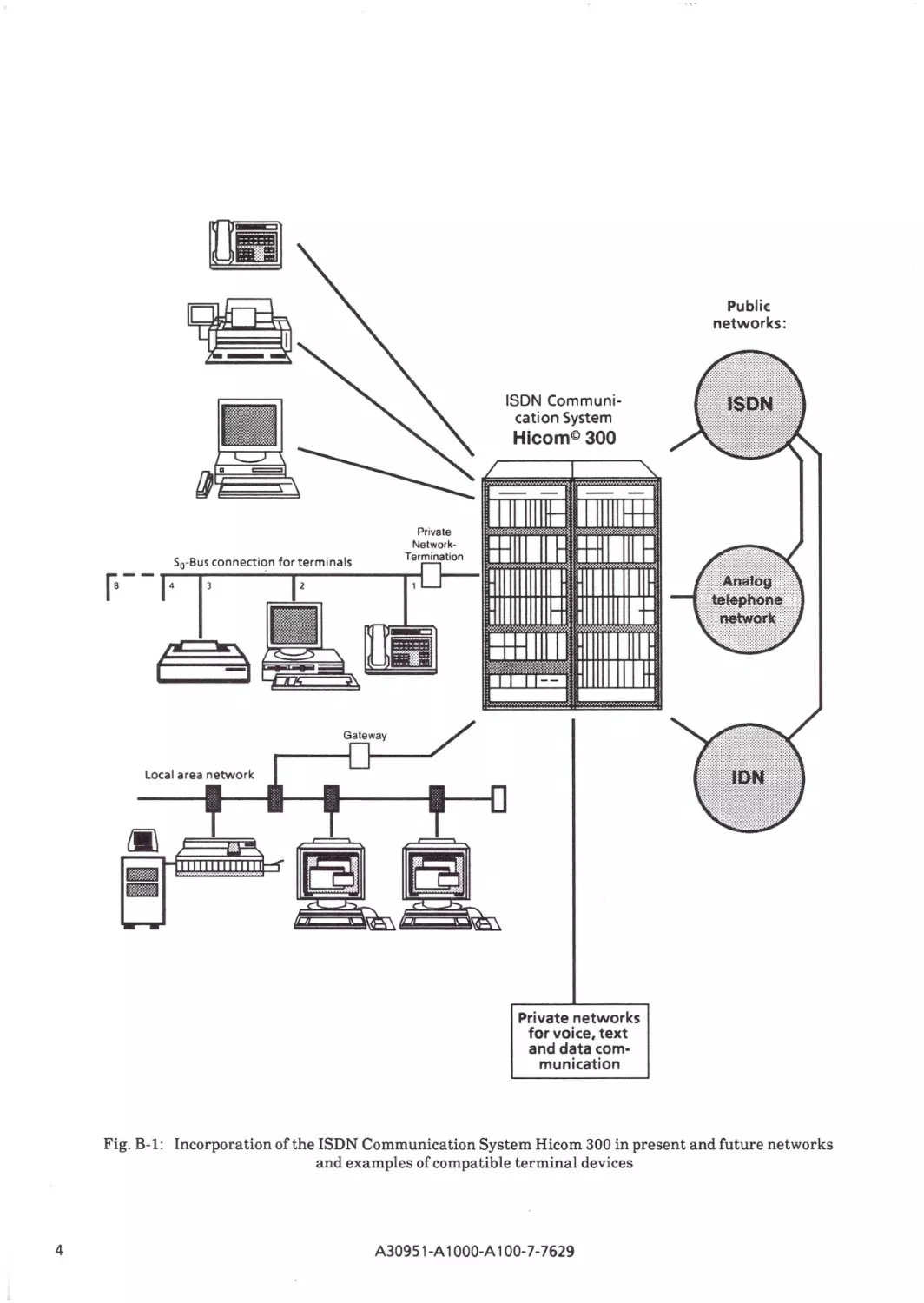
Fig. B-1: Incorporation of the ISDN Communication System Hicom 300 in present and future networks
and examples of compatible terminal devices
4
A30951-A 1OOO-A100-7-7629
B1
Structure of the Hi corn 300 System
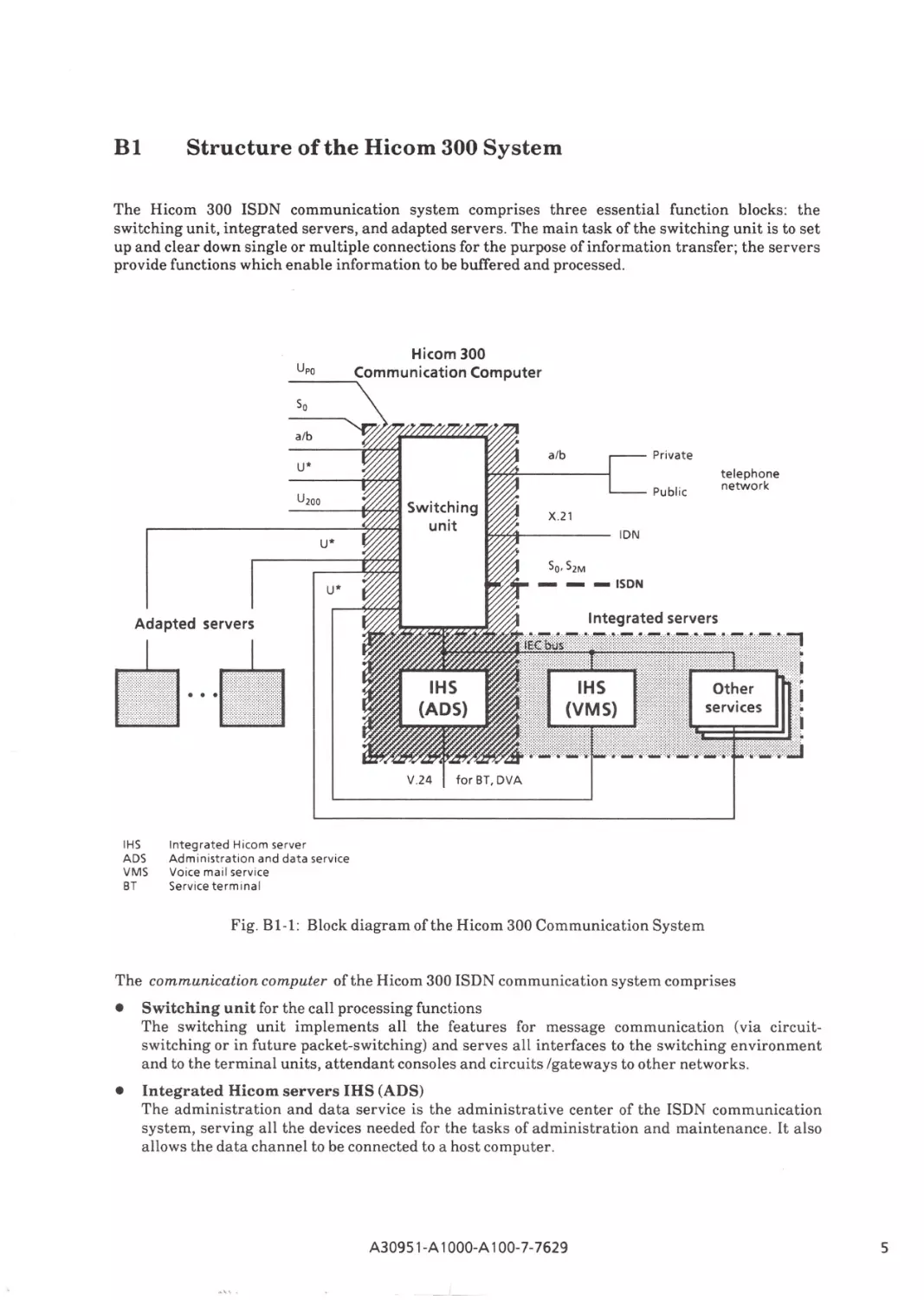
The Hicom 300 ISDN communication system comprises three essential function blocks: the
switching unit, integrated servers, and adapted servers . The main task of the switching unit is to set
up and clear down single or multiple connections for the purpose of information transfer; the servers
provide functions which enable information to be buffered and processed.
Hicom 300
Private
a/b
U*
Public
U200
telephone
network
X.21
IDN
U*
-
Sa, S2M
U*
-ISDN
Adapted servers
•····
V.24
IHS
ADS
VMS
BT
for BT, DVA
Integrated Hicom server
Administration and data service
Voice mail service
Service terminal
Fig. B 1-1: Block diagram of the Hicom 300 Communication System
The communication computer of the Hicom 300 ISDN communication system comprises
•
Switching unit for the call processing functions
The switching unit implements all the features for message communication (via circuits witching or in future packet-switching) and serves all interfaces to the switching environment
and to the terminal units, attendant consoles and circuits /gateways to other networks.
•
Integrated Hicom servers IHS (ADS)
The administration and data service is the administrative center of the ISDN communication
system, serving all the devices needed for the tasks of administration and maintenance . It also
allows the data channel to be connected to a host computer.
A30951-A 1OOO-A100-7-7629
5
There are specific servers for higher-level information processing, such as
~ store-and-forward features for voice, text, images, data,
~ processing functions in connection with text communication services,
~ industry-specific and general application programs
(closely linked to the wide-ranging communications functions of the system) .
A distinction is drawn between integrated and adapted servers.
•
Integrated servers are expansions of the communication computer - on the basis of the same
hardware and software - for mailbox and store-and-forward features. Structural and functional
integration with the communication computer means that there is a straightforward, uniform
user interface for the numerous circuit-switching and store-and-forward functions. Functional
integration is achieved by way of a system bus (IEC bus) and the U* interface.
•
Adapted servers are used for processing and filing both text and data. They too are optional expansions of the communication computer. This type of independent server interoperates with
the communication computer in a system network via U* or a/b station lines.
Depending on the number of ports connected, the Hicom 300 communication system is subdivided
into three capacity stages:
Hicom 300 comprising '5 256 ports
Hicom 300 comprising -5 960 ports
Hicom 300 comprising '5 5120ports
Specific software facilities enable each circuit of a module to be blocked or deblocked. Thus the
capacity of a system is continuously adjustable through its ports within preset limits.
The above subdivision chiefly effects the architecture of the switching unit, whose centralized
functional units - the switching network and the controller - are designed in the same technology on
a modular basis.
As far as the servers are concerned, larger-size systems are implemented by using a number of units
of the same type.
The Hicom 300 ISDN communication systems has a broad range of interfaces which enable it to
interoperate with various networks and a variety of peripheral devices:
•
a/b interface
These interfaces connect analog devices and handle services via modems. On the network side
trunk lines of public and private networks are connected which operate with the HKZ and IKZ
signaling systems.
•
U* interface
This interface, the digital multi-channel interface, is used to operate multifunction devices such
as multiterminals and servers.
•
U200 interface
The U200 interface is used to operate digital voice terminals, the switching terminal, and data
terminals with V.24 interfaces via Hicom adapter DCI.
•
So/S2M interface
The public ISDN is connected to the So/S2M interface.
Implementation of the CorN et-N protocol permits convenient networking of Hicom 300 Systems.
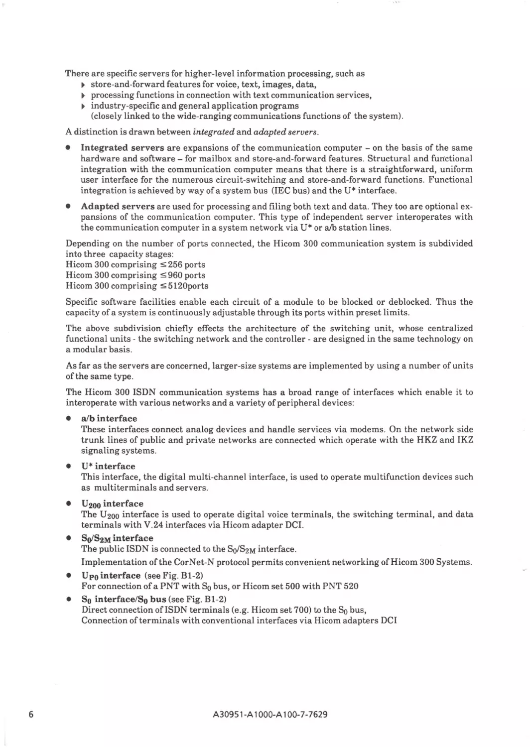
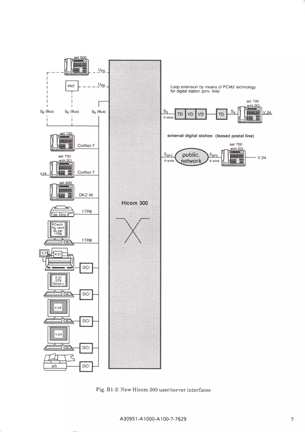
Upointerface (seeFig.Bl-2)
For connection of a PNT with So bus, or Hicom set 500 with PNT 520
So interface/So bus (see Fig. Bl-2)
Direct connection ofISDN terminals (e.g. Hicom set 700) to the So bus,
Connection of terminals with conventional interfaces via Hicom adapters DCI
•
•
6
A30951-A 1OOO-A100-7-7629
r
Loop extension by means of PCM2 technology
for digital station (priv. line)
s0 (Bus)
s 0 (Bus)
(leased postal line)
set 700
Di'i1]_c_o_r_N_e_t-T---t
set 700
~
YiL~
V.24
CorNet-T
~~
DKZ-M
Fig. Bl-2: New Hicom 300 user/server interfaces
A30951-A 1OOO-A100-7-7629
7
B2
Basic system for future innovations
The Hicom 300 communication system is a basic system designed for future innovations. The
standard interfaces between all units of the system allow the addition or replacement of new system
units.
Within these system units either special system interfaces or standard interfaces (multibus, SCSI
interface) are used.This permits system innovations on the scale of complete system units, or individual modules.
The same applies to the software. Between each of the software complexes there are message interfaces which are standardized for the whole system. In the case of the switching software, for example, these message interfaces separate the hardware-linked programs for the transport layers (peripheral process) from the equipment-specific and signaling-specific programs (line signal processing)
and these, in turn, from the programs which actually control the connections (call processing). The
call processing programs also have message interfaces between their service-specific and equipment-specific parts.
This results in an upward and downward modularity, which facilitates the addition of new services,
equipment and features to supplement the existing call processing software functions.
The other software complexes have a similar modular configuration, e.g. the administration and
maintenance programs and the dependability programs.
8
A30951-A 1OOO-A100-7-7629
B3
Features of the ISDN Communication System Hicom 300
The features of the Hicom 300 ISDN communication system are provided by three function blocks the switching unit, integrated servers and adapted servers - corresponding to the structural design
of the systems.
Switching unit
B3.1
The call processing features enable services for voice, text, image and data to be implemented. The
features are divided up according to these services and may differ within the various services
depending on the unit involved (e.g. code procedures or key procedures). A distinction is made
between the following services:
~
~
~
~
~
telephony,
facsimile (Fax),
teletex (Ttx),
videotex (Vtx),
data.
In addition to th~ connection capabilities of the units associated with these services, particular
importance must be attached to their functional integration - even if they are distinct units - and to
the integration of services within one unit: the Hicom 3510 multiterminal.
83.1.1
Individual services
The telephony service is handled:
•
by means of terminal units with an analog interface
(analog telephone with dial pulsing or DTMF),
•
by means of trunk circuits to the public telephone network
(pulse signaling system IKZ, main station interface HKZ) and to private networks,
•
by means of an innovative attendant console with a VDU, and with facilities for utilization of
the electronic telephone directory,
•
by means of the digital telephone in different variants (Hicom set 211, set 260, set 421, set 451,
set 521 and set 721 feature telephones) with graded complements offeatures and facilities
•
by means of the Hicom Multiterminals.
The scope of these features for the telephony service corresponds basically to that of existing analog
SPC systems. The feature telephones, which are also integrated in the Hicom MT 3510, MT 3520
Multiterminals, offer enhanced features. The feature telephones and the Hicom Multiterminals
have operator prompting; dialog with the user is shown on the display line of the feature telephones,
and on the VDU in the case of the Hicom MT 3510, MT 3520 Multiterminals. The feature telephones
can also be supplied with chip card readers, which give them additional operating facilities, as with
the Hicom MT 3510 Multiterminal:
When the chip card is inserted, the terminal adopts the communication number of the party identified by the card. Users with chip card identification can "transport" their personal data to any
Hicom Multiterminal.
With the facsimile service, both attended and unattended Group 2/3 or 4 units can be connected.
The videotex service can be accessed either directly at the system via an a/b interface or on the So
bus by means of an adapter. Both inhouse and public videotex databases can be accessed.
The data service can be accessed either directly at the system via an a/b interface using a modem or
on the So bus by means of an adapter. This service can also be realized by means of data terminating
equipment on the basis of an X.21 or V.24 interface. Adapters with V.24 interfaces can be wired
directly at the system or on the So bus, or else they are integrated in the telephone (H icom set
500/set 700).
A30951-A 1OOO-A100-7-7629
9
B3.1.2
Service integration
There are various forms of service integration, i.e. procedural integration or integration at the user
interface:
Integration of discrete devices for the So bus
The S0 bus offers up to eight terminal ports suitable for a maximum of four voice terminals (different
call numbers) and one terminal each for the following non-voice services: fax, vtx,.ttx, data.
Terminals capable of handling ISDN are directly connected to the So bus, terminals with conventional interfaces are connected via Hicom adapters DCI .
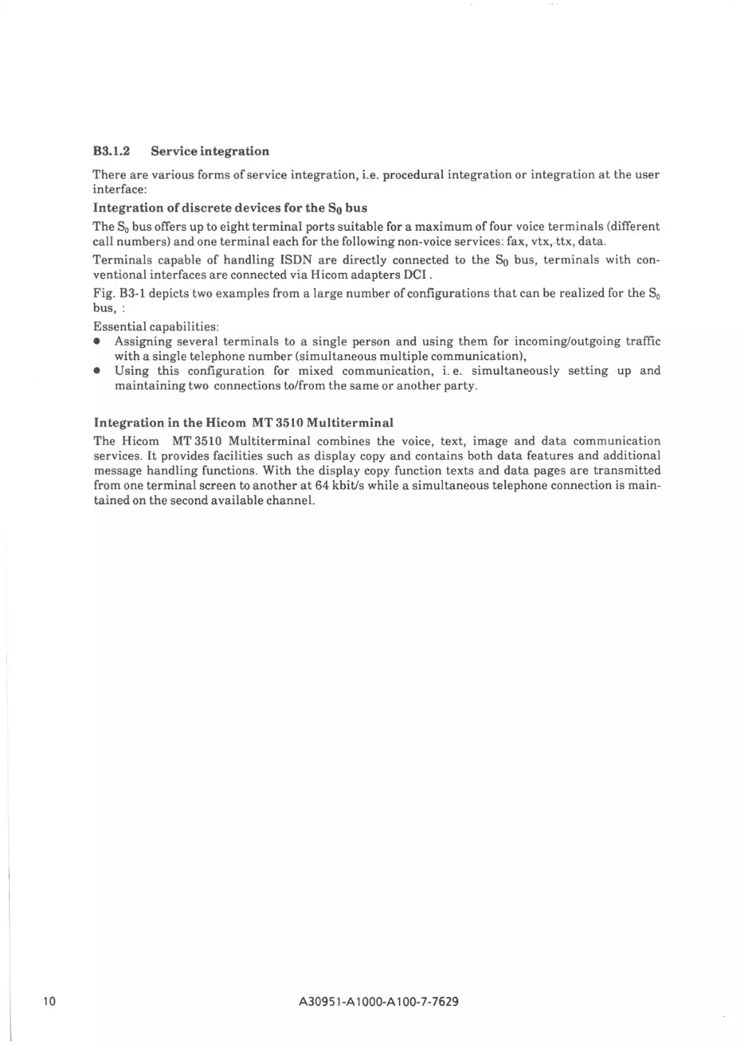
Fig. B3-l depicts two examples from a large number of configurations that can be realized for the S0
bus, :
Essential capabilities:
• Assigning several terminals to a single person and using them for incoming/outgoing traffic
with a single telephone number (simultaneous multiple communication),
• Using this configuration for mixed communication, i. e. simultaneously setting up and
maintaining two connections to/from the same or another party.
Integration in the Hicom MT 3510 Multiterminal
The Hicom MT 3510 Multiterminal combines the voice, text, image and data communication
services. It provides facilities such as display copy and contains both data features and additional
message handling functions. With the display copy function texts and data pages are transmitted
from one terminal screen to another at 64 kbit/s while a simultaneous telephone connection is maintained on the second available channel.
10
A309 51-A 1OOO-A100-7-7629
set 500 with
PNT 520
Call Nr. 4711
1 11,____
1
U"'-'p'--"
DCI
Ttx
47 1 1
Fax
Public
Gr. 4
Hicom 300
Communication
Computer
47 11
5712
Btx
DCI
a/b
Telephone
network
5712
set 700
5712
5
set 700
Switching unit
and
Integrated Hicom Server
IHS
for
administration and
data service
Private
-
S0 /52M
ISDN
4811
Fax
X.21
Gr. 4
IDN
Ttx
DCI
Btx
DCI
DEE
DCI
Hicom
MultiTerminal
and Server
•
•
U*
(J~a~=~----,
a
=
U*
U*
IHS
for
Voice mail service
Other
IHS
Fig. B3-l: Service integration
A30951-A 1OOO-A100-7-7629
l1
B3.2 Features of the integrated Hicom servers
The integrated Hicom servers supplement the features of the switching unit with the addition of
communications functions which require the buffering of information; on the other hand, these
servers provide information processing functions that are closely linked to the communications
functions of the system.
Some of the function complexes of the servers are mandatory, some optional, and they have the
following major characteristics:
Administration and maintenance and data applications
•
System administration and maintenance functions
This function complex covers system startup and maintenance. The components and functions
are controlled (with masks) by way of a directly connected service terminal and/or optionally via
a test and diagnostics center which can be connected to the system by dedicated or dial-up lines.
A distinction is drawn between remote administration and remote maintenance:
- Remote administration (optional)
The remote administration facility allows the Hicom 300 communication system to be
administrated from an external center.
- Remote maintenance (optional)
If any irregularities occur in systems which have the remote maintenance facility,
information is passed automatically to the Siemens service center via the public network. The
results of continuous test routines are transferred regularly, allowing the service center to
respond even before a fault becomes noticeable in system operation.
12
•
Data aquisition functions
The data management system DMS of a Hicom server permits the creation, processing and
deletion of data files on different data media (e.g. magnetic disks, cartridges, floppy disks) for
data collection purposes, e.g. connection data recording for charge registration or compilation of
traffic statistics for monitoring the system load.
•
Transport functions
The communication management system CMS of the Hicom server performs all the functions
associated with the transfer of information between the Hicom Communication System and the
processing systems (hosts). Different communication protocols are used to transmit both
complete data files and individual items of information effectively and safely in dialog
applications . The transport functions of the CMS include the segmentation of messages and the
multiplexing and checking of data flows .
•
Call charge processing functions (optional)
One of the system's most important data applications is the logical editing of charge data on the
basis of various user-specific criteria, with subsequent output on terminals, data media or
processing systems.
User-related charge registration - based on the medium of communication (e.g. voice, text) and
the PTT specifications - also forms part of this function complex.
•
Controlled connection setup (optional)
By way of the Hicom switching channel (ACL), a data processing installation (host computer)
hooked up to the system can call down and set user features, monitor devices, and set up
connections under program control between internal and external terminals on the data
channel.
•
Telephone data service (optional)
This Hicom feature enables digital telephone terminals to enter into a direct dialog with
applications in a connected data processing system.
A30951-A 1OOO-A100-7-7629
•
Telephone directory (optional)
The Electronic Telephone Directory (ETD) data application is an information system specifically
designed for attendant personnel and other Hicom users with a suitable terminal; it can contain
all Hicom network users and facilitates call setup considerably.
•
Network Management Center (optional)
This permits operation of a network of telecommunications systems in the form of a corporate
network. The following functions are incorporated:
- maintenance functions
- administration functions
- database/software administration
- security functions, recherche functions in connection with alarms
--network administration
•
Analysis of load measurement (optional)
The load measurement data on hard disk is compressed to form valuable information and is
printed out in tabular form or displayed at the service terminal. Multiple evaluation of the
measuring data on the basis of different criteria is also feasible. Analysis can be based on
measrement days, measurement intervals, measuring points, directions of seizure, and services.
Voice mail service (optional)
This service adds to the voice transmission functions of the switching unit by storing voice messages
for specific recipients.
The reasons for this type of information storage include.
- temporary non-availability of the recipient,
- multiple transmission of the same item of information to different recipients,
- delivery required to a certain person at a specific point in time, e.g. to save charges and/or to
restrict access to certain information.
The duration of the storage period is largely dependent on the actual application or the user and
access to the stored information is primarily organized according to user requirements.
There are two basic types of storage function complexes:
•
•
Store-and-forward functions
Delivery of a message to a receiving station addressed by the sender constitutes a directed, active delivery in which due consideration can be given to delivery times and priorities.
This function complex also includes:
- broadcasting of messages to a number of different recipients,
- transmission at a preset time,
- UO journal, etc.
Hicom mailbox service
Unlike the store-and-forward service, the message is not actively delivered; instead, it is deposited in a user/person-related voice mailbox (infobox) in the server for subsequent retrieval.
Access to the message by the recipient is allowed after a password check and is possible from
almost any place or at any time. The infobox functions include a visual and/or audible indication
(depending on the terminal unit) for the user that messages have been deposited in his mailbox,
with information as to the sender and the time and date ofreception.
A30951-A 1OOO-A100-7-7629
13
Tele Communications Service (optional)
This group of services expands the call processing functions of the Hicom switching unit through the
addition of storage functions for text and facsimile messages.
The functions offered are roughly the same as those associated with a voice mail service.
Access to text mailboxes is possible by way of PCs and original teletex devices; access to fax
mailboxes is likewise ensured by way of PCs and combinations of devices (telephones/fax machines).
There are additional facilities for automatic conversion/adaptation between fax group 2 and 3
messages and interworking of text messages in T61 format in fax messages and also for precise
tracing of all messages which have passed through the storage.
14
A30951-A 1OOO-A100-7-7629
B3.3 Features of the adapted servers
The Hicom MT 3510 Multiterminal is used for voice, text, image and data communication. It
provides its features in conjunction with the Hicom 300 ISDN communication system. Its functions
are divided between the MT 3510 terminal and the adapted server S 3510. One server processes the
instructions of several multifunctional terminals simultaneously.
S 3510, Server for the Hicom MT 3510 Multiterminal
•
Text communication service
This service incorporates the functions of filing, electronic mail and central printing. The filing
facility comprises the storage of text messages in a personal file location in the server. Text
messages are exchanged via the mailbox for electronic mail, and the arrival of a message is signaled at the multiterminal of the receiving user. All Hicom MT 3510 Multiterminals allow
access to a central print facility for the provision of hard copy, and a local printer can also be
connected up to the server.
•
Data communication service
The data communication service enables the user of the Hicom MT 3510 Multiterminal to access
data processing systems. The Hicom MT 3510 Multiterminal then behaves like a data display
terminal. Two types of data communication which operate on separate servers are offered:
- Emulation 9750 for dialog with Siemens data processing systems,
- Emulation 3270/SN A for dialog with IBM data processing systems.
•
Loading service
The entire loadable software for the Hicom MT 3510 Multiterminal is loaded via the S 3510
server. Personal data, such as a telephone directory, can be saved in the server and loaded again
from there into the terminal.
•
Administration
This service is offered to the user of the Hicom MT 3510 Multiterminal via the basic server
system; amongst other things it can be used to alter the password.
Additional servers
The videotex server is a further adapted server. It performs the control and storage operations necessary for handling the videotex functions. The Vtx server means that all the functions of the videotex service already introduced into the public telephone network will be possible in the PBX sector;
moreover special emphasis is placed on having the same operator inputs. The universal server will
have a special control unit which ensures optimum connection to the Hicom 300 system.
Vtx is accessible by means of Vtx terminals or the Hicom MT 3510 Multiterminal. When the Hicom
MT 3510 Multiterminal is used, mixed-mode communication will provide a substantial enhancement to the videotex service.
The standard interface design of the Hicom 300 ISDN communication system will allow future requirements to be met by the implementation of additional servers for corresponding functions.
A30951 -A 1OOO-A100-7-7629
15
r
ISDN Communication System
Hicom 300
1
System architecture
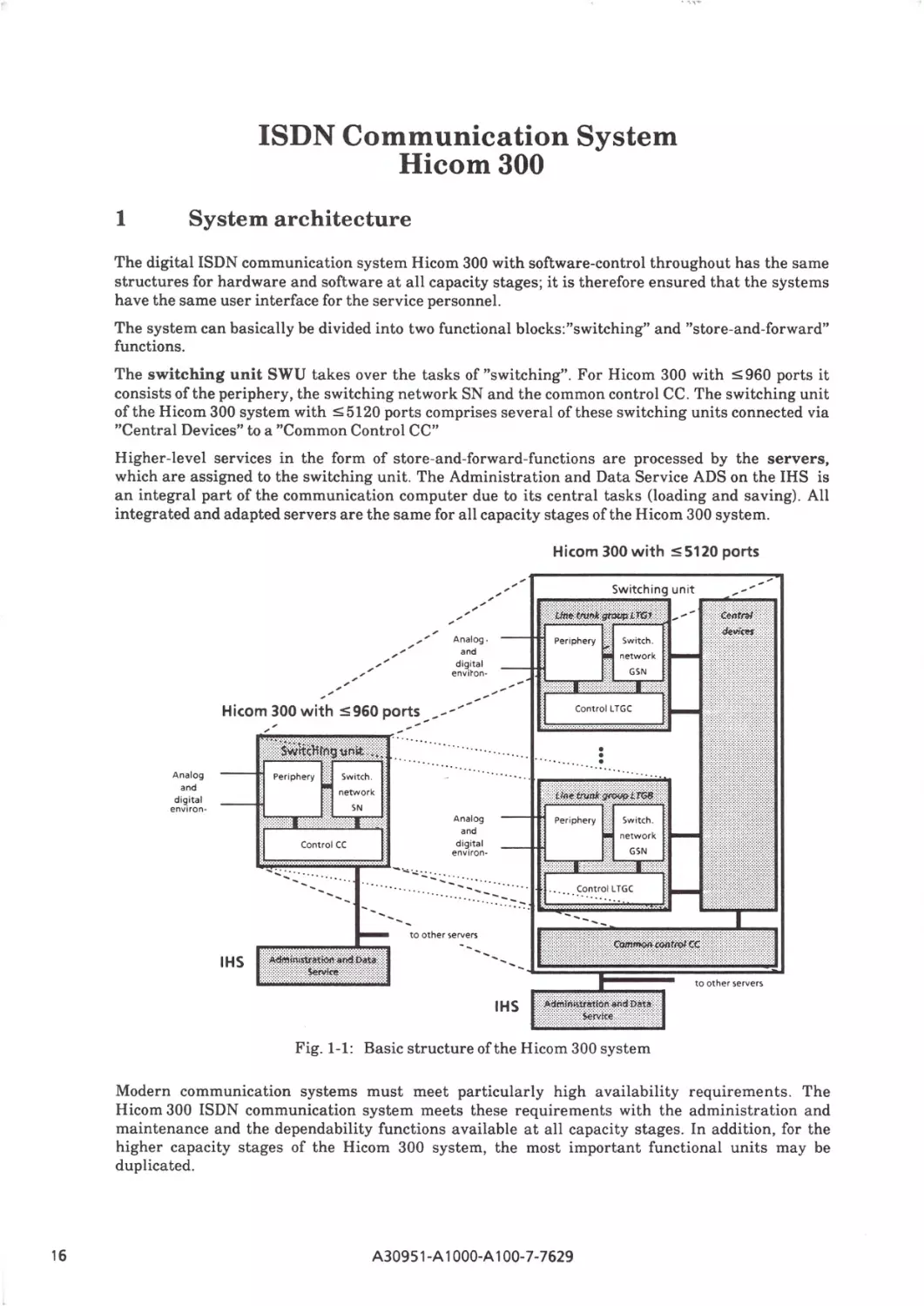
The digital ISDN communication system Hicom 300 with software-control throughout has the same
structures for hardware and software at all capacity stages; it is therefore ensured that the systems
have the same user interface for the service personnel.
The system can basically be divided into two functional blocks:"switching" and "store-and-forward"
functions.
The switching unit SWU takes over the tasks of "switching". For Hicom 300 with $ 960 ports it
consists of the periphery, the switching network SN and the common control CC. The switching unit
of the Hicom 300 system with $ 5120 ports comprises several of these switching units connected via
"Central Devices" to a "Common Control CC"
Higher-level services in the form of store-and-forward-functions are processed by the servers,
which are a ssigned to the switching unit. The Administration and Data Service ADS on the IHS is
an integral part of the communication computer due to its central tasks (loading and saving) . All
integrated and adapted servers are the same for all capacity stages of the Hicom 300 system.
Hicom 300 with ::s; 5120 ports
,
,"
_,,'"
_
A nalog.
and
d ig ita l
env i ~on -
, ,, ""
~, ' '
Hicom 300 with ::s;960 port~--/""
;'
-
,
······
A nalog
and
dig ita l
envi ro n-
network
SN
Control CC
A nalog
and
d igita l
enviro n-
GSN
-·...;.·._;~:.::..::..::..,: · ··
· - -~-."":.~:: ..
. . c.o ntrol l TGC
to oth er servers
IHS
IHS
Fig. 1-1: Basic structure of the Hicom 300 system
Modern communication systems must meet particularly high availability requirements. The
Hicom 300 ISDN communication system meets these requirements with the administration and
maintenance and the dependability functions available at all capacity stages. In addition, for the
higher capacity stages of the Hicom 300 system, the most important functional units may be
duplicated.
16
A30951 -A 1OOO-A100-7-7629
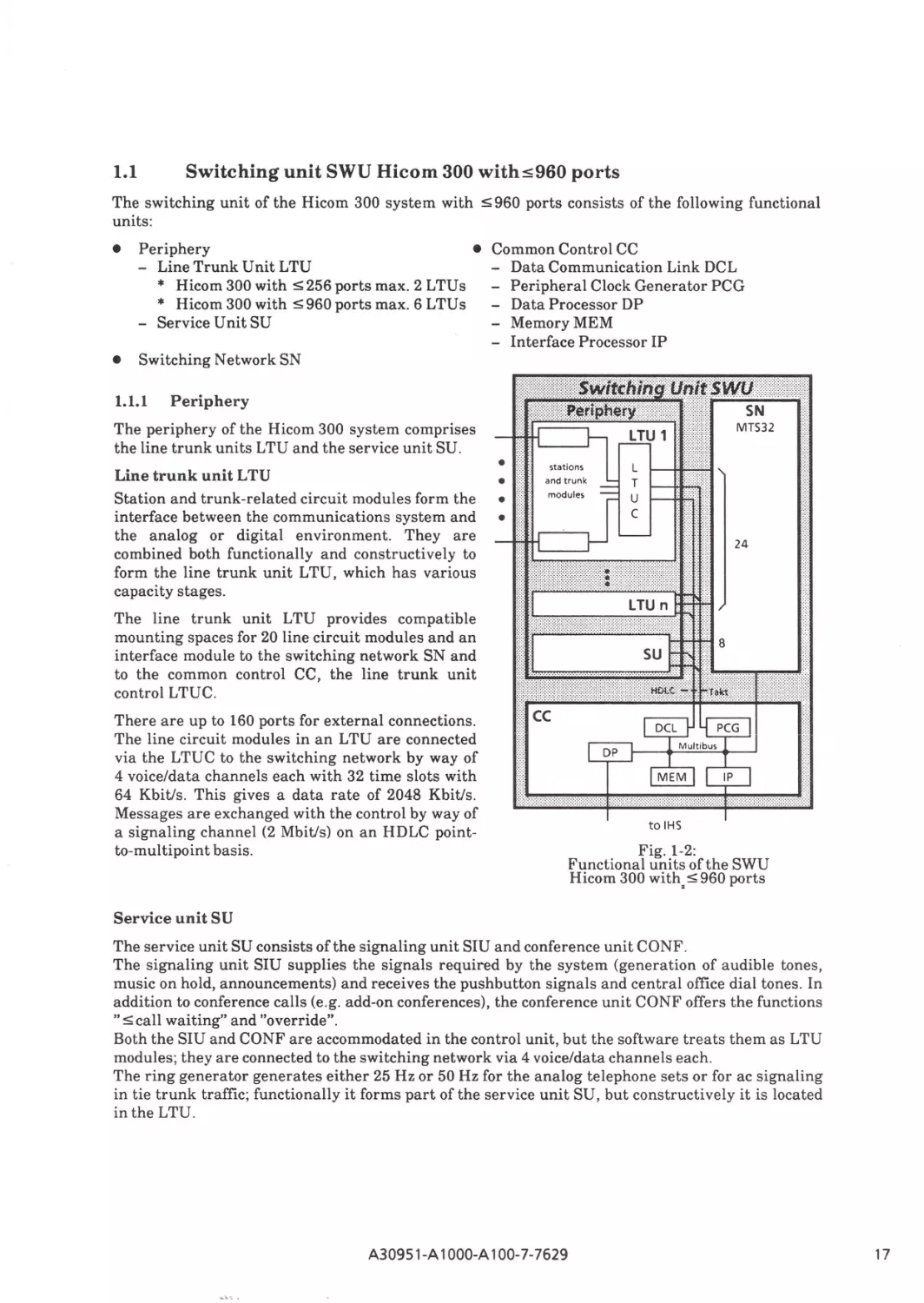
1.1
Switching unit SWU Hicom 300 with$960 ports
The switching unit of the Hicom 300 system with S 960 ports consists of the following functional
units:
•
•
Periphery
• Common Control CC
- Data Communication Link DCL
- Line Trunk Unit LTU
* Hicom 300 with S256 ports max. 2 LTUs - Peripheral Clock Generator PCG
* Hicom 300 with s 960 ports max. 6 LTU s - Data Processor DP
- Service Unit SU
- MemoryMEM
- Interface Processor IP
Switching Network SN
1.1.l
Periphery
The periphery of the Hicom 300 system comprises
the line trunk units LTU and the service unit SU.
Line trunk unit L TU
Station and trunk-related circuit modules form the
interface between the communications system and
the analog or digital environment. They are
combined both functionally and constructively to
form the line trunk unit LTU, which has various
capacity stages.
The line trunk unit LTU provides compatible
mounting spaces for 20 line circuit modules and an
interface module to the switching network SN and
to the common control CC, the line trunk unit
control LTUC.
There are up to 160 ports for external connections.
The line circuit modules in an LTU are connected
via the LTUC to the switching network by way of
4 voice/data channels each with 32 time slots with
64 Kbit/s. This gives a data rate of 2048 Kbit/s.
Messages are exchanged with the control by way of
a signaling channel (2 Mbit/s) on an HDLC pointto-multipoint basis.
Fig. 1-2:
Functional units of the SWU
Hicom 300 with= :-:;; 960 ports
Service unit SU
The service unit SU consists of the signaling unit SIU and conference unit CONF.
The signaling unit SIU supplies the signals required by the system (generation of audible tones,
music on hold, announcements) and receives the pushbutton signals and central office dial tones. In
addition to conference calls (e.g. add-on conferences), the conference unit CONF offers the functions
"Scall waiting" and "override".
Both the SIU and CONF are accommodated in the control unit, but the software treats them as LTU
modules; they are connected to the switching network via 4 voice/data channels each.
The ring generator generates either 25 Hz or 50 Hz for the analog telephone sets or for ac signaling
in tie trunk traffic; functionally it forms part of the service unit SU, but constructively it is located
in the LTU.
A30951-A 1OOO-A100-7-7629
17
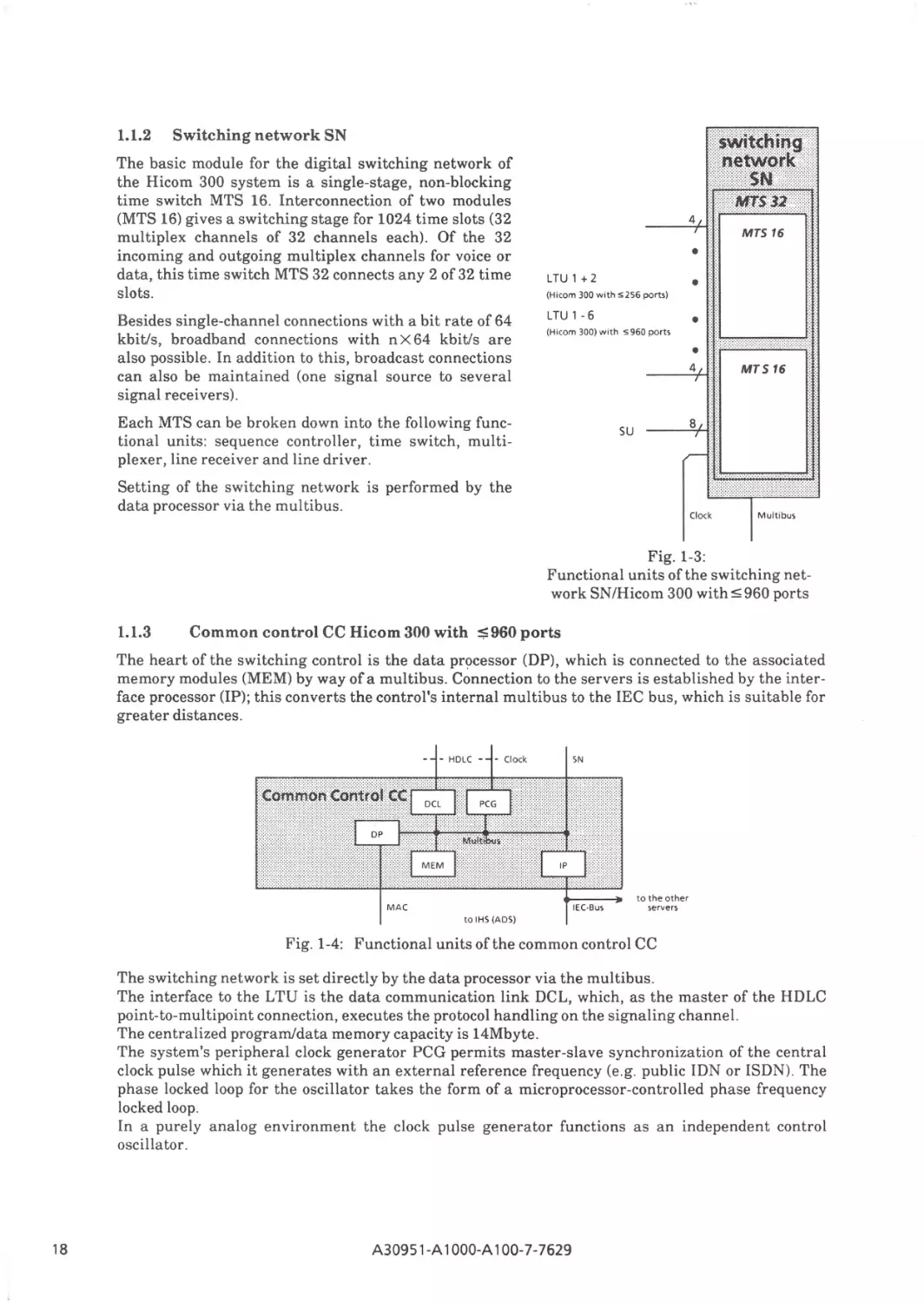
1.1.2
Switching network SN
The basic module for the digital switching network of
the Hicom 300 system is a single-stage, non-blocking
time switch MTS 16. Interconnection of two modules
(MTS 16) gives a switching stage for 1024 time slots (32
multiplex channels of 32 channels each). Of the 32
incoming and outgoing multiplex channels for voice or
data, this time switch MTS 32 connects any 2 of 32 time
slots.
Besides single-channel connections with a bit rate of 64
kbit/s, broadband connections with n X 64 kbit/s are
also possible. In addition to this, broadcast connections
can also be maintained (one signal source to several
signal receivers).
•
LTU 1+2
(Hicom 300 wit h S256 ports)
LTU 1 - 6
(Hicom 300) w it h ,; 960 ports
•
•
•
4
Each MTS can be broken down into the following functional units: sequence controller, time switch, multiplexer, line receiver and line driver.
MTS 16
8
SU
Setting of the switching network is performed by the
data processor via the multibus.
Clock
Multibus
Fig. 1-3:
Functional units of the switching network SN/Hicom 300 with ~ 960 ports
1.1.3
Common control CC Hicom 300 with $960 ports
The heart of the switching control is the data processor (DP), which is connected to the associated
memory modules (MEM) by way of a multibus. Connection to the servers is established by the interface processor (IP); this converts the control's internal multibus to the IEC bus, which is suitable for
greater distances.
-
- HDLC -
- Clock
SN
to the other
servers
Fig. 1-4: Functional units of the common control CC
The switching network is set directly by the data processor via the multibus.
The interface to the LTU is the data communication link DCL, which, as the master of the HDLC
point-to-multipoint connection, executes the protocol handling on the signaling channel.
The centralized program/data memory capacity is 14Mbyte.
The system's peripheral clock generator PCG permits master-slave synchronization of the central
clock pulse which it generates with an external reference frequency (e.g. public IDN or ISDN). The
phase locked loop for the oscillator takes the form of a microprocessor-controlled phase frequency
locked loop.
In a purely analog environment the clock pulse generator functions as an independent control
oscillator.
18
A30951-A 1000-A 100-7-7629
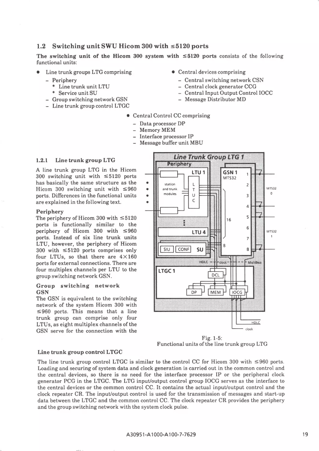
1.2
Switching unit SWU Hicom 300 with :55120 ports
The switching unit of the Hicom 300 system with :5 5120 ports consists of the following
functional units:
•
• Central devices comprising
- Central switching network CSN
- Central clock generator CCG
- Central Input Output Control IOCC
- Message Distributor MD
Line trunk groups LTG comprising
- Periphery
* Line trunk unit LTU
* Service unit SU
- Group switching network GSN
- Line trunk group control LTGC
• Central Control CC comprising
- Data processor DP
- MemoryMEM
- Interface processor IP
- Message buffer unit MBU
1.2.1
111erruokfirgle!l'i! . ]. u
Line trunk group L TG
•• • ·•· · •·.••\ . .•~r. P.•.gry
A line trunk group LTG in the Hicom
300 switching unit with :5 5120 ports
has basically the same structure as the
Hicom 300 switching unit with :5 960
ports. Differences in the functional units
are explained in the following text.
Periphery
The periphery of Hicom 300 with :5 5120
ports is functionally similar to the
periphery of Hicom 300 with :5960
ports. Instead of six line trunk units
LTU, however, the periphery of Hicom
300 with :5 5120 ports comprises only
four LTUs, so that there are 4X 160
ports for external connections. There are
four multiplex channels per LTU to the
group switching network GSN.
<••••••>••••·• .... ...·.·.·.·
.l!!l::::!:ZZ:ZWI
·Wi
· ·
LTU 1
GSN 1
MT532
•
•
•
•
LTGC 1
Group switching network
GSN
The GSN is equivalent to the switching
network of the system Hicom 300 with
:5 960 ports. This means that a line
trunk group can comprise only four
LTU s, as eight multiplex channels of the
GSN serve for the connection with the
HDLC
Fig. 1-5:
Functional units of the line trunk group LTG
Line trunk group control LTGC
The line trunk group control LTGC is similar to the control CC for Hicom 300 with :5 960 ports.
Loading and securing of system data and clock generation is carried out in the common control and
the central devices, so there is no need for the interface processor IP or the peripheral clock
generator PCG in the LTGC. The LTG input/output control group IOCG serves as the interface to
the central devices or the common control CC. It contains the actual input/output control and the
clock repeater CR. The input/output control is used for the transmission of messages and start-up
data between the LTGC and the common control CC. The clock repeater CR provides the periphery
and the group switching network with the system clock pulse.
A30951-A 1OOO-A100-7-7629
19
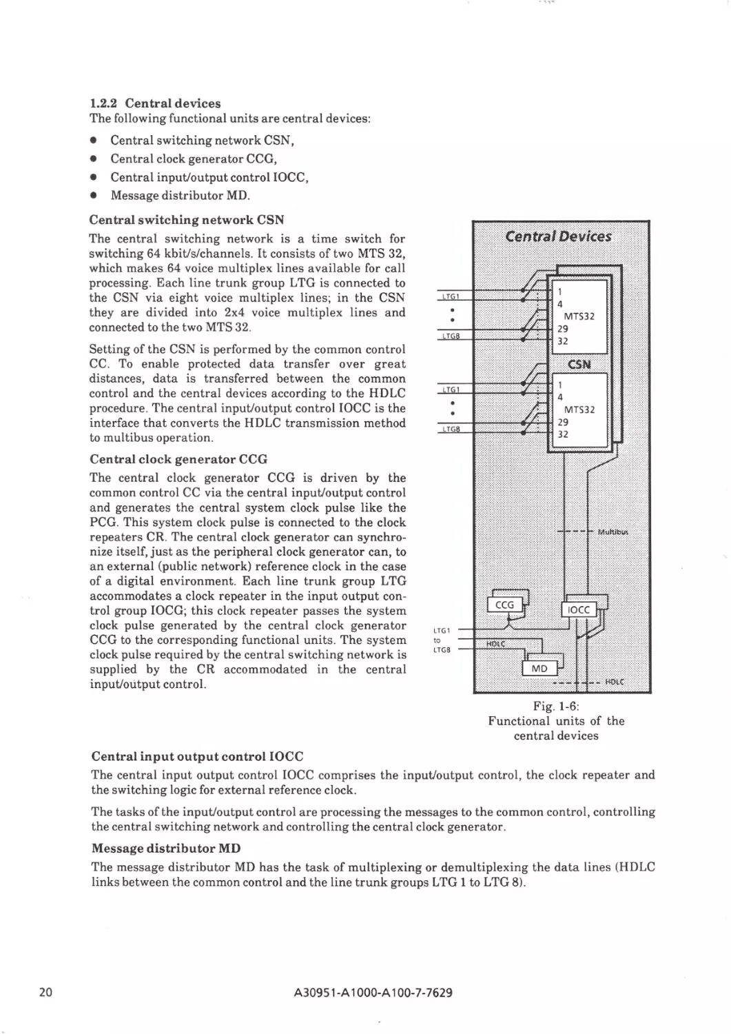
1.2.2 Central devices
The following functional units are central devices:
•
•
•
•
Central switching network CSN,
Central clock generator CCG,
Central input/output control IOCC,
Message distributor MD.
Central switching network CSN
The central switching network is a time switch for
switching 64 kbit/s/channels. It consists of two MTS 32,
which makes 64 voice multiplex lines available for call
processing. Each line trunk group LTG is connected to
the CSN via eight voice multiplex lines; in the CSN
they are divided into 2x4 voice multiplex lines and
connected to the two MTS 32.
Setting of the CSN is performed by the common control
CC. To enable protected data transfer over great
distances, data is transferred between the common
control and the central devices according to the HDLC
procedure. The central input/output control IOCC is the
interface that converts the HDLC transmission method
to multibus operation.
Central c lock generator CCG
The central clock generator CCG is driven by the
common control CC via the central inputloutput control
and generates the central system clock pulse like the
PCG. This system clock pulse is connected to the clock
repeaters CR. The central clock generator can synchronize itself, just as the peripheral clock generator can, to
an external (public network) reference clock in the case
of a digital environment. Each line trunk group LTG
accommodates a clock repeater in the input output control group IOCG; this clock repeater passes the system
clock pulse generated by the central clock generator
CCG to the corresponding functional units . The system
clock pulse required by the central switching network is
supplied by the CR accommodated in the central
input/output control.
•
LTG
•
•
LTG
LTG l
to
LTGS
Fig. 1-6:
Functional units of the
central devices
Central input output control IOCC
The central input output control IOCC comprises the input/output control, the clock repeater and
the switching logic for external reference clock.
The tasks of the inputloutput control are processing the messages to the common control, controlling
the central switching network and controlling the central clock generator.
Message distributor MD
The message distributor MD has the task of multiplexing or demultiplexing the data lines (HDLC
links between the common control and the line trunk groups LTG 1 to LTG 8) .
20
A30951-A 1OOO-A100-7-7629
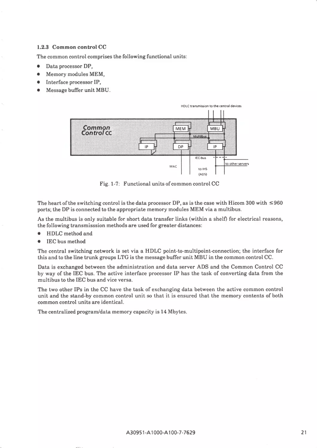
1.2.3 Common control CC
The common control comprises the following functional units:
•
•
•
•
Data processor DP,
Memory modules MEM,
Interface processor IP,
Message buffer unit MBU.
HDLC transmission to the central devices
MAC
to other servers
to IHS
(ADS)
Fig. 1-7: Functional units of common control CC
The heart of the switching control is the data processor DP, as is the case with Hicom 300 with
ports; the DP is connected to the appropriate memory modules MEM via a multibus.
~ 960
As the multibus is only suitable for short data transfer links (within a shelD for electrical reasons,
the following transmisssion methods are used for greater distances:
• HDLC method and
• IEC bus method
The central switching network is set via a HDLC point-to-multipoint-connection; the interface for
this and to the line trunk groups LTG is the message buffer unit MBU in the common control CC.
Data is exchanged between the administration and data server ADS and the Common Control CC
by way of the IEC bus. The active interface processor IP has the task of converting data from the
multibus to the IEC bus and vice versa.
The two other IPs in the CC have the task of exchanging data between the active common control
unit and the stand-by common control unit so that it is ensured that the memory contents of both
common control units are identical.
The centralized program/data memory capacity is 14 Mbytes.
A30951-A 1OOO-A100-7-7629
21
1.3
Integrated Hicom servers (IRS)
The various integrated Hicom servers - consisting of up to three modules of the same type - have a
standard basic structure, comprising:
•
•
•
server common control SM-CC,
peripheral memory,
line periphery.
The server common control SM-CC essentially consists of the same entities (data processor, main
memory, interface processor) as the control of the switching unit (SWU). Peripheral bulk storage
facilities, such as hard disks and floppy disks, are served by an I/O processor IOPS via the standard
ANSI interface SCSI (max. 4 storage units) . The line periphery of the servers is accessed by way of a
bus interface for up to 7 line modules.
The servers are connected to the SWU via the IEC bus. Connection to an LTU is established by way
of the U* interface.
The special demands placed on the individual servers result in a specific line periphery and different
peripheral memory configurations.
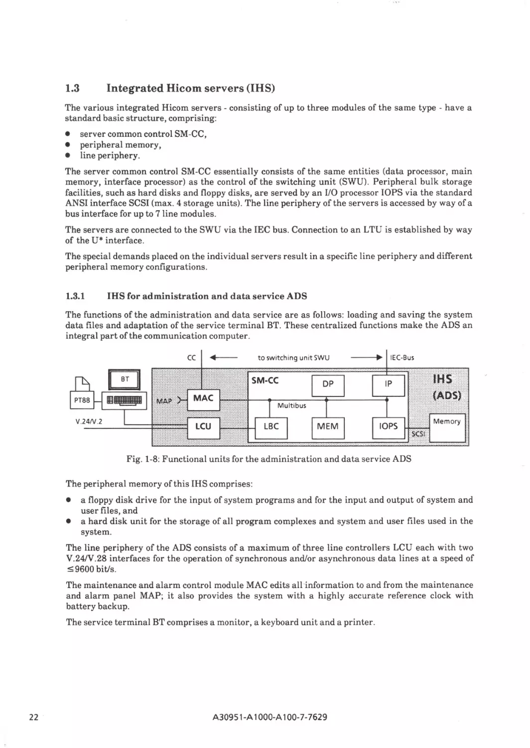
1.3.1
IHS for administration and data service ADS
The functions of the administration and data service are as follows: loading and saving the system
data files and adaptation of the service terminal BT. These centralized functions make the ADS an
integral part of the communication computer.
cc
to switching unit SWU
---'••
IEC-Bus
DP
IP
MEM
IOPS
Fig. 1-8: Functional units for the administration and data service ADS
The peripheral memory of this IHS comprises:
•
•
a floppy disk drive for the input of system programs and for the input and output of system and
user files, and
a hard disk unit for the storage of all program complexes and system and user files used in the
system.
The line periphery of the ADS consists of a maximum of three line controllers LCU each with two
V.24/V.28 interfaces for the operation of synchronous and/or asynchronous data lines at a speed of
~9600 bit/s.
The maintenance and alarm control module MAC edits all information to and from the maintenance
and alarm panel MAP; it also provides the system with a highly accurate reference clock with
battery backup.
The service terminal BT comprises a monitor, a keyboard unit and a printer.
22
A30951-A 1OOO-A100-7-7629
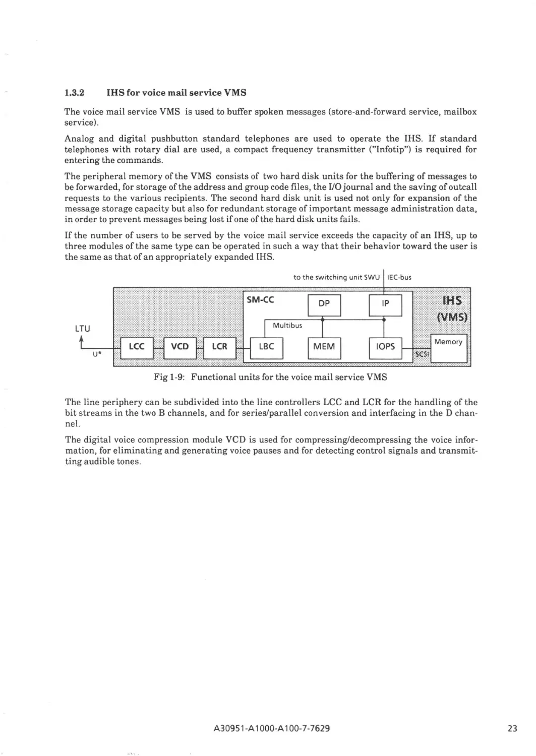
1.3.2
IHS for voice mail service VMS
The voice mail service VMS is used to buffer spoken messages (store-and-forward service, mailbox
service).
Analog and digital pushbutton standard telephones are used to operate the IHS. If standard
telephones with rotary dial are used, a compact frequency transmitter ("Infotip") is required for
entering the commands.
The peripheral memory of the VMS consists of two hard disk units for the buffering of messages to
be forwarded, for storage of the address and group code files, the I/O journal and the saving of outcall
requests to the various recipients. The second hard disk unit is used not only for expansion of the
message storage capacity but also for redundant storage of important message administration data,
in order to prevent messages being lost if one of the hard disk units fails.
If the number of users to be served by the voice mail service exceeds the capacity of an IHS, up to
three modules of the same type can be operated in such a way that their behavior toward the user is
the same as that of an appropriately expanded IHS.
to the switching unit SWU
IEC-bus
DP
LTU
U*
MEM
IOPS
Fig 1-9: Functional units for the voice mail service VMS
The line periphery can be subdivided into the line controllers LCC and LCR for the handling of the
bit streams in the two B channels, and for series/parallel conversion and interfacing in the D channel.
The digital voice compression module VCD is used for compressing/decompressing the voice information, for eliminating and generating voice pauses and for detecting control signals and transmitting audible tones.
A30951-A 1OOO-A100-7-7629
23
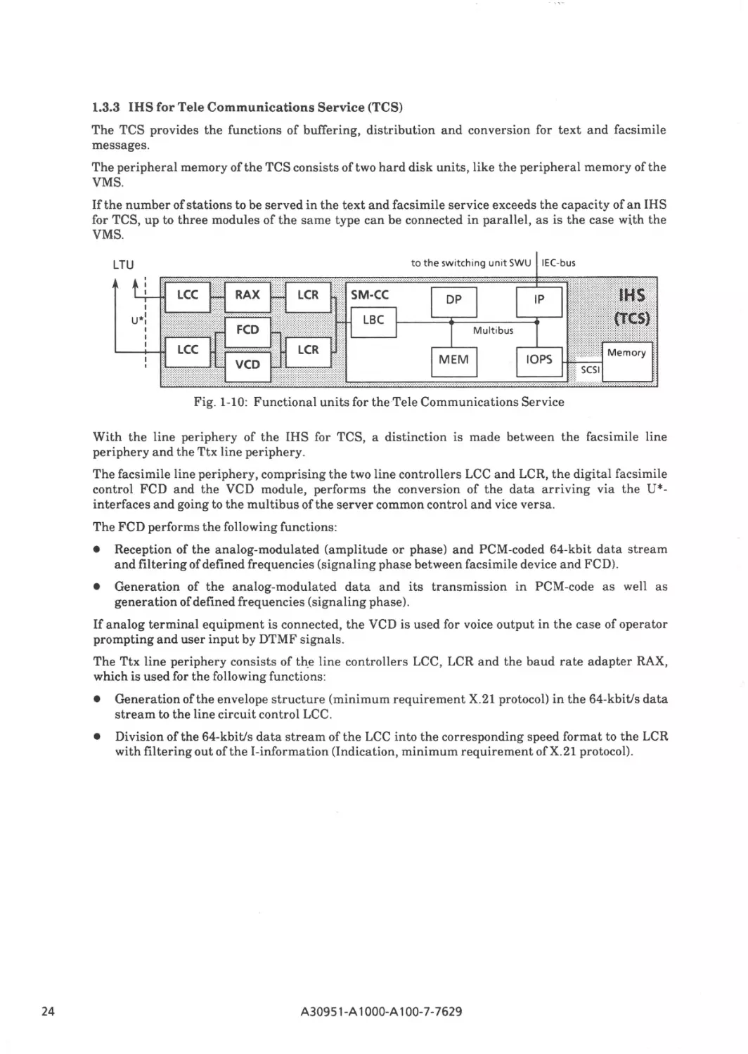
1.3.3 IHS for Tele Communications Service (TCS)
The TCS provides the functions of buffering, distribution and conversion for text and facsimile
messages.
The peripheral memory of the TCS consists of two hard disk units, like the peripheral memory of the
VMS.
If the number of stations to be served in the text and facsimile service exceeds the capacity of an IHS
for TCS, up to three modules of the same type can be connected in parallel, as is the case with the
VMS.
to the switch in g un it SW U
LTU
IEC-bus
DP
Mu ltibus
MEM
IOPS
Fig. 1-10: Functional units for the Tele Communications Service
With the line periphery of the IHS for TCS, a distinction is made between the facsimile line
periphery and the Ttx line periphery.
The facsimile line periphery, comprising the two line controllers LCC and LCR, the digital facsimile
control FCD and the VCD module, performs the conversion of the data arriving via the U*interfaces and going to the multibus of the server common control and vice versa.
The FCD performs the following functions:
•
Reception of the analog-modulated (amplitude or phase) and PCM-coded 64-kbit data stream
and filtering of defined frequencies (signaling phase between facsimile device and FCD) .
•
Generation of the analog-modulated data and its transmission in PCM-code as well as
generation of defined frequencies (signaling phase).
If analog terminal equipment is connected, the VCD is used for voice output in the case of operator
prompting and user input by DTMF signals.
The Ttx line periphery consists of th_e line controllers LCC, LCR and the baud rate adapter RAX,
which is used for the following functions:
24
•
Generation of the envelope structure (minimum requirement X.21 protocol) in the 64-kbit/s data
stream to the line circuit control LCC .
•
Division of the 64-kbit/s data stream of the LCC into the corresponding speed format to the LCR
with filtering out of the I-information (Indication, minimum requirement of X.21 protocol).
A30951-A 1OOO-A100-7-7629
1.4
Adapted servers
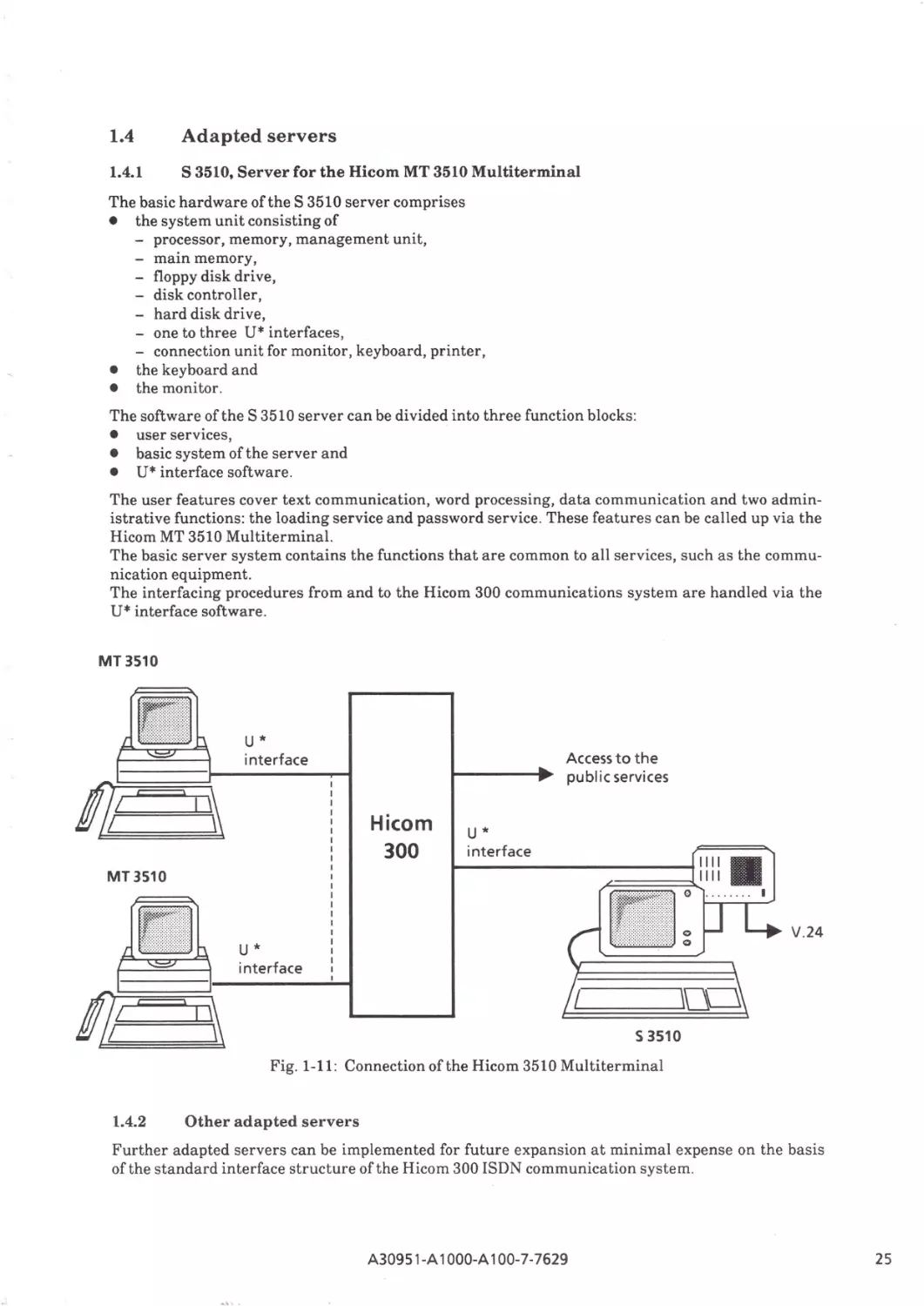
1.4.1
S 3510, Server for the Hicom MT 3510 Multiterminal
The basic hardware of the S 3510 server comprises
• the system unit consisting of
- processor, memory, management unit,
- main memory,
- floppy disk drive,
- disk controller,
- hard disk drive,
- one to three U* interfaces,
- connection unit for monitor, keyboard, printer,
• the keyboard and
• the monitor.
The software of the S 3510 server can be divided into three function blocks:
• user services,
• basic system of the server and
• U* interface software.
The user features cover text communication, word processing, data communication and two administrative functions: the loading service and password service. These features can be called up via the
Hicom MT 3510 Multiterminal.
The basic server system contains the functions that are common to all services, such as the communication equipment.
The interfacing procedures from and to the Hicom 300 communications system are handled via the
U* interface software.
MT 3510
II
Ill =1,~
U*
Access to the
public services
interface
Hicom
300
U*
interface
1111
II
~===~""
. ... .. . .
MT 3510
'91111
I
V.24
U*
interface
\Qc::J
s 3510
Fig. 1-11: Connection of the Hicom 3510 Multiterminal
1.4.2
Other adapted servers
Further adapted servers can be implemented for future expansion at minimal expense on the basis
of the standard interface structure of the Hicom 300 ISDN communication system.
A30951-A 1OOO-A100-7-7629
25
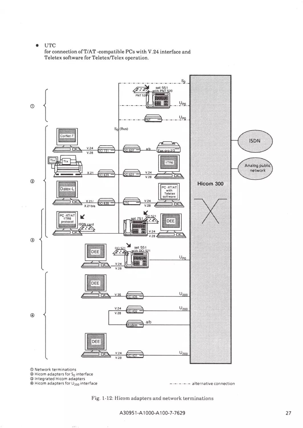
1.5
Hicom adapters and nework terminations
Hicom adapters are used to connect terminal equipment not conforming to the ISDN interface standard. These adapters are designed to convert the powerful, future-proof digital single-channel and
two-channel interfaces of the Hicom 300 system to the conventional interfaces of data processors,
data terminals, personal computers, facsimile servers group 2 and 3, vtx terminals, teletex terminals etc.
Network terminations afford the advantages of So bus operation also at locations remote from the
Hicom 300 system. They enable physical conversion from U PO to So and hence a flexible network topology to be realized; i.e. terminal equipment may, for instance, be installed at a distance of up to 2.5
km from the Hicom 300 system.
Users of a Hicom two-channel telephone (Hicom set 551 or Hicom set 751) can be provided with
telephoneplug-in cards performing adapter or network terminating functions .
Hicom adapters
The adapters used for Hicom 300 are subdivided into:
• Adapters (separate units) for the So interfaces (two-channel interface - see Fig. 1-12/@);
• Adapters (separate units) for the U200 interfaces (single-channel interface - see Fig. 1-12/©);
• Integrated adapters (see Fig. 1-12/®).
Network terminations (see Fig. 1-12/©)
The following So network terminations are used for Hicom 300:
• PNT (Private Network Termination) with supply to So terminals and
• PNT 520 (pluggable in Hicom set 551) without supply to So terminals.
1.5.1
Hicom adapters
All Hicom adapters comprising a V.24 interface are capable of communicating with each other, provided they use the same bit rate adaption procedure (e. g. DMI mode 2). Adapters for telematic terminals can communicate only within their service.
Hicom adapters for the So interface (two-channel interface)
For operation with the two-channel So interface, the adapter ranges DCI 700, DCI 600 and the UTC
adapters are provided.
•
•
26
DCI 731 with V.24/V .28 interface, with the future CorNet-T protocol, permits all existing Hicom
features to be utilized for data communication; connection for point-to-point and bus operatin
being provided. Aside from the commonly used bit rate adaption procedure DMI mode 2 asynchronous, DCI 731 also implements bit rate adaptations as per CCITT I.463 (V.110, ECMA 102)
and X.30 .
The DCI-600 range connects terminals with main-station capability (one terminal for each service) to Hicom via the So-station line, utilizing the Hicom concentrator function. This is based on
the public protocol 1TR6 of the Deutsche Bundespost Telekom.
- DCI 639
for connection ofTtx terminals,
Bit rate adaption by flag stuffing,
- DCI 638
for connection of Datex-L terminals with X.21 interface or conventional V interfaces,
Bit rate adaption as per X.30,
- DCI 637
for facsimile server groups. 2/3 and vtx servers with a/b interface,
- DCI 631,
for connection of data terminals and PCs with V.24/V.28 interface,
Data saving procedure in B-channel,
Bit rate adaption procedure DMI mode 2 asynchronous, as well as ECMA 102, V.110 and
X.30,
A30951-A 1OOO-A100-7- 7629
•
UTC
for connection of TIAT-compatible PCs with V.24 interface and
Teletex software for Teletex/Telex operation.
·- · -·-·--~~·-·----~P~.
@
PC · XT/AT
with
Teletex
software
V.24
PC ·XTIAT
1TR6
protocol
~:::-~=~~~~~==*::
@
El
a
V.3
4
V.24
V.28
@
a/b
<D Network terminations
@ Hicom adapters for 50 interface
® Integrated Hicom adapters
© Hicom adapters for U200 interface
-·-·-·-·-alternative con nection
Fig. 1-12: Hicom adapters and network terminations
A30951-A 1OOO-A100-7-7629
27
Hicom adapters for U200 interface (single-channel interface)
Adapter range DCI 400 is provided for operation at the single-channel U 200 interface:
•
DCI 431
for connection of data terminals with V.24/V.28 interface
•
DCI432
for implementation of a modern pool on the basis ofV.24/V.28
for DCI connections to analog internal and external data ports.
•
DCI 435
for connection of data terminals with V.35 inerfaces for bus link
for synchronous transmission at high speeds.
All DCl-400 adapters offer the commonly used bit rate adaption DMI modes 0, 1, 2 and 2L for different synchronizing procedures and speeds.
Integrated Hicom adapters
Hicom uses the following integrated adapters:
•
DCI 521 (pluggable in Hicorn set 551 and Hicorn set 751)
for connection of an asynchronous data terminal with V.24/V.28 interface,
Bit rate adaption procedure DMI mode 2 asynchronous.
•
ISDN card (pluggable in XT/AT compatible PCs)
for connection of XT/AT compatible PCs with V.24 interface to the So bus.
1.5.2
Network terminations
Hicom 300 uses the following network terminations for connection of So terminal equipment:
•
PNT (seperate unit)
for connection of terminals with So interface,
U PO interfaces to Hicorn 300 system,
Remote feed of all connected terminals and
performance of operating functions, e.g. loops.
PNT is neutral to protocols.
•
PNT 520 (pluggable in Hicorn set 551)
for connection of terminals with So interface and separate power supply,
Hicorn set 551 also supports protocol 1TR6 in addition to the Cor N et-T protocol for the terminals
wired on the So bus .
Simultanous operation on the So bus
One So bus of the Hicorn 300 system can be used to operate up to eight terminals using CorNet-T,
DKZ-E, and 1TR6 protocols in mixed fashion (the So bus being connected directly to subscriber line
module SLMS, or PNT, or Hicom set 551 with PNT 520).
28
•
Using the TR6 protocol, one terml.nal per service can be employed
•
Using the CorNet-T protocol, up to four terminals each can be employed for the "voice" and "data" services
A30951-A 1000-A 100-7-7629
1.6
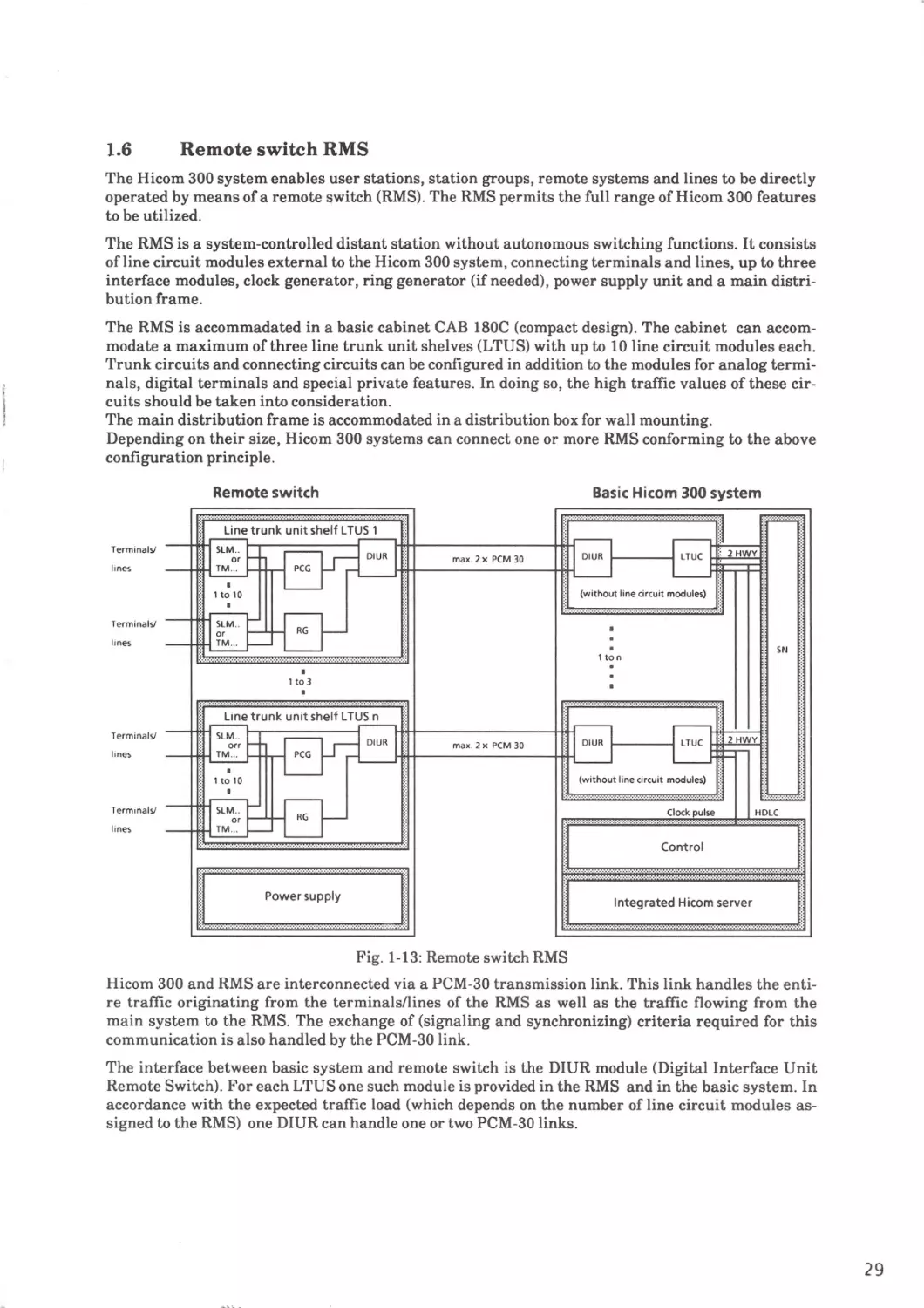
Remote switch RMS
The Hicom 300 system enables user stations, station groups, remote systems and lines to be directly
operated by means of a remote switch (RMS). The RMS permits the full range of Hicom 300 features
to be utilized.
The RMS is a system-controlled distant station without autonomous switching functions. It consists
ofline circuit modules external to the Hicom 300 system, connecting terminals and lines, up to three
interface modules, clock generator, ring generator (if needed), power supply unit and a main distribution frame.
The RMS is accommadated in a basic cabinet CAB 180C (compact design). The cabinet can accommodate a maximum of three line trunk unit shelves (LTUS) with up to 10 line circuit modules each.
Trunk circuits and connecting circuits can be configured in addition to the modules for analog terminals, digital terminals and special private features. In doing so, the high traffic values of these circuits should be taken into consideration.
The main distribution frame is accommodated in a distribution box for wall mounting.
Depending on their size, Hicom 300 systems can connect one or more RMS conforming to the above
configuration principle.
Remote switch
Basic Hicom 300 system
Line trunk unit shelf LTUS 1
Terminals/
max. 2 x PCM 30
lines
(without line circuit modules)
Terminals/
lines
SN
1 ton
I
1 to3
Terminals/
ma x. 2 x PCM 30
lines
(without line circuit modules)
Terminals/
Clock pulse
HDLC
lines
Control
Integrated Hicom server
Fig. 1-13: Remote switch RMS
Hicom 300 and RMS are interconnected via a PCM-30 transmission link. This link handles the entire traffic originating from the terminals/lines of the RMS as well as the traffic flowing from the
main system to the RMS. The exchange of (signaling and synchronizing) criteria required for this
communication is also handled by the PCM-30 link.
The interface between basic system and remote switch is the DIUR module (Digital Inter face Unit
Remote Switch). For each LTUS one such module is provided in the RMS and in the basic system. In
accordance with the expected traffic load (which depends on the number of line circuit modules assigned to the RMS) one DIUR can handle one or two PCM-30 links.
29
Depending on the cabling, the RMS can be installed at a distance of up to 1300 m from the basic system.
When using PCM line equipment of the Deutsche Bundespost (DBP), the maximum line length depends
on the permissible delays.
The RMS is fully integrated in the basic system as regards operation and dependability. Example: the
RMS is actually configured from the basic system. Dependability system messages are regularly exchanged with the basic system.
Switching unit SWU
Switching unit SWU
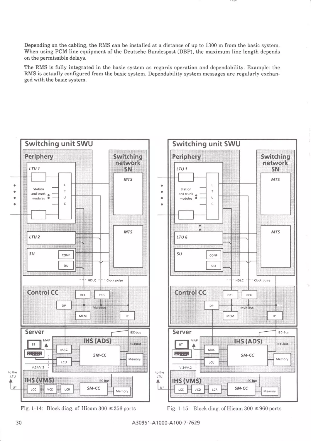
Fig. 1-14: Block diag. of Hicom 300 :5 256 ports
30
Fig. 1-15: Block diag. ofH icom 300 :5 960 ports
A30951 -A 1OOO-A1 00-7-7629
Switching unit SWU
PABX
IHS (ADS)
MAP
LCU
'
V.24N.28
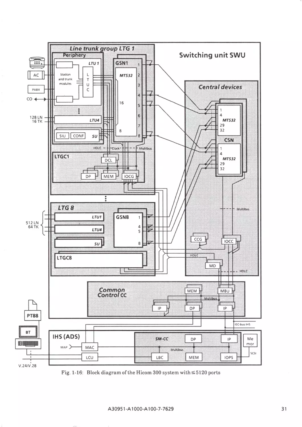
Fig. 1-16: Block diagram of the Hicom 300 system with ::; 5120 ports
A309 51-A 1OOO-A100-7-7629
31
2
Hard ware technology and design
2.1
Hardware technology
The technology of the Hicom 300 ISDN communication system is characterized by the use of telecom
chips in the periphery and the switching network and by powerful processors and memories in the
control area.
These chips are supplemented by standard componentry featuring ALS technology. Small-type
relays for switching the ringing and feeding currrent are used at line interfaces.
Both hard disks and floppy disks are used for storing large datasets.
The following technological features have been employed in order to develop future-oriented and
cost-effective communications systems:
- The use of highly integrated components (VLSI) with matching functions has enabled the
implementation of optimally designed compact systems.
- The use of standard interfaces allowing incorporation of technological innovations without
affecting the system architecture.
·
- The use of microprocessors in all system units permits flexible adaptation to differing applications and reduces specialized hardware requirements .
Examples of various state-of-the-art applications in the Hicom 300 system :
Telecom chips
•
For analog ports (lines or trunks) the voice signals are converted to digital 64-kbitls channels
using the signal processor codec and filter SICOFI; the use of a digital filter in a programmable
signal processor permits flexible adaptation to different national and international transmission
requirements.
• Analog and digital connection modules and the modules of the service unit SU are connected to
the PCM switch and control via a standard interface, the peripheral board controller PBC. The
chosen form of the interface allows the incorporation of technological upgrades without disruption of the system architecture.
Switching network
•
All the time stages in the switching network are built from modules of the same type. The digital
time switch MTS provides non-blocking switching of the 64-kbit/s channels through a PCM
switching network. The high degree of integration of the MTS chip allows a time switch for 32 x
32 = 1024 channels to be concentrated on 2 PC boards.
Memories and processors
•
•
32
The main memory (programs and data) of the central processors is made up of dynamic RAMs.
The VLSI memory chips (256 kbit) - supported by high-integration controller chips for addressing and error correction - enable a packing density of 2 Mbyte per main memory module to
be achieved.
In the central processing area the 8086 or the instruction-compatible, high-power microprocessor versions 80186, 80286 and 80386 are used. The addressing volume and performance of
this family of processors cover the entire range of system capacities.
A30951-A1000-A100-7-7629
2.2
Design
The construction of the Hicom 300 ISDN communication system is based on the time-proven
SIVAPAC® system.
The components are mounted on PC boards (double-row etched multilayer boards) . The PC boards
are of the plug-in type with two 60-pt. clip connectors, which makes maintenance and system
expansion work considerably easier .
A shelf accommodates the PC boards; its backplane provides the electrical connections between the
PC boards.
Shelves are differentiated according to their configuration with PC boards depending on their
functions.
• Shelf for periphery LTUS (Hicom 300)
• Shelf for common control CC (Hicom 300)
• Shelf for power supply PS (Hicom 300)
• Shelf for integrated Hicom server (Hicom 300)
• Shelf for peripheral memory of the servers DS (Hicom 300)
• Shelf for group control and group switching network GP-GSN (Hicom 300 with 5 5120 ports)
• Shelf for central devices IOC-CSN(Hicom 300 with 5 5120 ports)
The connecting circuit PC boards in the peripheral equipment shelf form the interface to the outside
environment for external connections. Depending on how it is equipped with analog or digital circuits, a peripheral equipment shelf offers up to 160 ports, which enables , for example, a maximum
of 100 stations and 60 trunks to be connected.
While the Hicom 300 system with 55120 ports uses four peripheral equipment shelves in one
cabinet and the Hicom 300 system with 5 960 ports uses three, the Hicom 300 system with 5 256
ports has two of these shelves.
This arrangement allows Hicom 300 with ~ 256 ports to be accommodated in only one cabinet, the
so-called basic cabinet C180 B. This basic cabinet provides built-in trays in the side panels in which
one or two hard disk drives can be installed with their controller, the power supply modules, support
batteries, inverters, the connecting panel, and the modems for connection to a data processing
system or telecontrol (remote operation and/or remote administration) . The cabinet has casters for
mobility and can be placed directly in front of the wall-type distribution frame to ensure a spacesaving arrangement. A second mobile cabinet can be supplied for expansion with additional service
modules.
With Hicom 300 with ~960 ports the shelves, power supply equipment and the necessary cabling
are housed in up to four cabinets according to the configuration and capacity of the system. These
cabinets contain the switching equipment, the integrated servers, the power supply and the main
distributor.
With Hicom 300 with ~5120 ports the accommodation of the switching equipment, the integrated
servers, the power supply and the necessary cabling in the cabinets allows an easy and flexible
expansion from the minimum to the maximum configuration. Hence, Hicom 300 with 55120 ports
in the configuration for 3000 stations comprises 15 cabinets, with a requirement of 8 peripheral
cabinets CAB P and 4 main distribution frame cabinets CAB M2. If modems or additional servers
are used, further system cabinets (CAB Dl or CAB Sl) are possible.
Easy-to-service, solderless twin terminal connections are used for the main d istribution frame
(MDF) in the CAB M cabinets.
The system's power is drawn from the ac power network. The nominal system voltage of -48 V is
obtained from the ac voltage via one or more charging rectifier units switched in parallel, depending
on the capacity of the system. Two modes are possible, i.e. ac power only or ac power/batter y
operation (parallel standby mode). The advantage of the ac power/battery mode is that in the event
of an outage, power is maintained by means of the battery without operation being interrupted. In
Hicom 300 with 5 256 ports power outages of up to four minutes length are bridged by the support
batteries if no long-term battery is provided.
A30951-A 1OOO-A100-7-7629
33
The following figures show the various shelves in the cabinets of the individual systems, where they
are configured according to their function in the system.
Hicom 300 with :5960 ports
Hicom300 with :5256 ports
Fus~
an
maintenance
alarm panel
Fus~
Charging rectifier
an
unit
LTUS
for 128 stations
IHS
(VMS)
Inverter
LTUS
for 128 stations
Power supply
connection panel
IHS
(VMS)
IHS
power supp ly
Main distribution
Common Control CC
maintenance
alarm panel
LTUS
for 160 stations
LTUS
for 160 stations
LTUS
for 160 stations
LTUS
for 160 stations
LTUS
for 160 stations
LTUS
for 160 stations
Common Control CC
frame
Power supply
Power supply
IHS
(ADS)
Peripheral memory
of IHS
Basic cabinet
C180 C
Server cabinet
CABS
Power supply
IHS
(ADS)
Modem
Basic cabinet
CABB
MDF /Power supply
cabinet
CABM1
Expansion cabinet
CABE
Fig. 2-1: Hicom 300 with :5256 and :5960 ports
Example of cabinet layout (incl. servers, power supply and MDF) for a configuration with. 180 or 600 stations max
Hicom 300with:55120 ports
Main distrib. frame
unit
LTUS
for 160 stations
IHS
(VMS)
LTUS
for 160 stations
IHS
(TCS)
Common control CC
LTUS
for 160 stations
IHS
power supply
Common control CC
LTUS
for 160 stations
IHS
power supply
Power supply
Power supply
IHS
(ADS)
GP-GSN
Peripheral memory
of IHS
Control cabinet
CABC
8 peripheral cabinets
CABP
Server cabinet
CABS
Central devices
..
... ...
....
...
...
... ...
...
... ...
......
4 main distribution
frames
CABM2
Charging rectifier
unit
Inverter
0
Power supply
connection panel
Device cabinet
CABD
Fig. 2-2: Hicom 300 with :55120 ports
Example of cabinet layout <incl.servers, power supply and MDFl for a co nfiguration of. 3000 stations
34
A30951-A 1OOO-A100-7-7629
Fig. 2-3: Hicom 300 System with ~ 960 ports
Example of cabinet layout line!. voice mail server and MDFl for a configuration with 600 stations
Fig . 2-4: SLMA Module
A30951-A 1OOO-A100-7- 7629
35
®®®®®®®®®®
0 : : : : : • DO o o o o
0 : : • : : • DO o o o o
TUC
•
Station line or trunk modules
+- - t - --- -LTU
i--
Station line or trunk modules
_
+- - -- --- -- -- --·
_.
1
TU<
•
Station line or trunk modules
+- - t- --- - - -LTU
Station line or trunk modules
-~
+--~--r--
--~-- ~
2
TU<
•
Station line or trunk modules
+--t- ----- ---LTU
Station line or trunk modules
+--1-- ----
-~
--i--
-~>-
3
I
CONF
PCG
SIU
MTS MTS DCL
IBJ
.._ MEM .....,
IBJ
".
DP
IP
IP
IBJ
!BI
!BI
~
Common control CC
I
•
I
0
~•
•
I
0
•
g
0 "
•
g•
I II
; Power supply
~~~--1---
LCU
•
••
LCU
••
•
LCU
••
•
~
m rn
lSJ
Its.I
•
0
•
•
0
•
0
•
g0 ~•
g•
g0 if•
g•
g0 ~•
g•
g0 4'•
g•
0
0
0
0
0
0
II
II
II
II
II
I
LBC MAC
MEM
DP
IP
IBJ
4}•
IBJ
41:
~ Integrated Hicom server ( ADS)
l&I
0
g {f
0 •
g•
f:1
~·
"
OPS·
'"
Floppy
Hard disk
disk
•
•
I I I I l!SJ
D
Fig. 2-5 : Example of module layout in basic cabinet CAB B
for Hicom 300 withS:960 ports
36
A30951-A 1000-A 100-7-7629
- - :=:- ··· · · 1::1
TUC
•
Station line or trunk modules
Station line or trunk modules
TU<
•
I
I I
Station line or trunk modules
+- - t - - - --- - - - - LTU
Station line or trunk modules
e--)>
....._ -
-
-
-
to- -1- -
-
-
-
-
~
2
0000
aa
Power supply
---
c s D M M
I
c T T
u G s s
0
N
F
1
2
M
8
M
D
c
L
D
p
M
L
1
I
p
1
L
L
u u
L
c
c c
1
2
B
I
p
2
M
8
M
M
A
c
I
0
p
s
D
p
M
L
2
CT
HO
Fig. 2-6: Example of module layout in basic cabinet 180 C
for Hicom 300 system
A30951-A 1OOO-A100-7-7629
37
3
Upgraded System Architecture
The system architecture of the Hicom 300 basic system has been completely upgraded by means of
the concept described in the following,
3.1
General
The main features of the new system architecture are as follows:
•
•
•
•
•
•
3.2
Cabinets with stackable units.
Variable, customized system capacities, ranging from 1 cabinet with 4 units to 4-cabinet systems
each with 6 units.
Flexible system configurations based on the combination of different shelf units.
Increased numbers of ports in the case offrequently used modules.
New shelves for the periphery with increased numbers of ports.
Combination of the functions of several common control modules and administration and data
service modules to form a new unit.
System structure
The common control CC has connection facilities for a redundant unit and for integrated Hicom
servers. The latter are connected to the common control by way of the IEC bus .
The common switching network is designed as a memory time switch (MTS) for 16 highways
(HWYs), each with 64 B-channels .
The periphery is divided into 4 line trunk units (LTUs). Communication with the common control is
processed via one HDLC channel in each case, the transmission speed being 2.048 MBitJs.
LTUs 1 to 3 are connected to the switching network by 4 HWYs each (4 MHz, 256 time slots); 2
HWYs (128 TSLs) are routed to the 4th LTU (Fig. 3-1). The 4 LTUs each have 256 external ports. In
the case of connections with 64 kBitis channels to these ports, there are no traffic restrictions for the
first 3 LTU s. Each port can carry a load of one erlang. A traffic intensity of 0.5 erlangs per port is
permitted for the 4th LTU. This reduction in the load is insignificant for systems with full capacity,
if the 4th LTU is used primarily for subscriber line modules and analog trunk modules.
The system can accept a total load of 896 erlangs, i.e . 896 two-way 64-kBit/s channels can be
switched without loss.
The common signaling unit (SIU) and the conference facility (CONF) each have access to 64 TSLs
(20 add-on conferences or override connections possible simultaneously).
38
A30951-A 1OOO-A100-7-7629
swu
2 xV.24N.28
Fig. 3-1: Hicom 300 :51024 ports; innovated structure
A30951-A 1OOO-A100-7-7629
39
3.3
Peripheral shelves
The peripheral shelf contains slots (EBPs) for 16 modules (boards) with subscriber line circuits or
trunk circuits. From each of these slots 16 a/b wire pairs (256 ports in all) are led to a main
distribution frame. The required fine protection for the lines is contained in the cable connector.
Access to the system side from each of the slots is possible by way of 2 HWY s, each with 32 channels
(2 MHz). Both these HWYs are connected to 4 slots. Accordingly, the 4 x 16 external ports in this
type of switching path unit are matched by 2 x 32 internal slots. An additional slot is used primarily
to accommodate a module which does not require ports or time slots, e .g. the ring generator.
However, this slot is connected in parallel with 2 HWYs and 8 ports of the first module and can
accommodate a module with up to 8 lines; in this case only 8 ports can be equipped at slot 1 (EBPl).
R
G
P. supply
{DC/DC
L
T
u
c
converter)
Module adresses
18
Mounting pitch
001
17
019
1
2
025 031
3
4
5
6
7
037 043 049 055 061
8
21
9
10
11
067 073 079 085 091
14
15
16
12
13
097
103 109 115 121
Fig. 3-2: LTU SHELF
3.3.1
Line Trunk Unit Control (LTUC)
The LTUC serves as the link between the centralized and the peripheral system units.
The LTUC module forms the interface between the DCL, the switching network and the peripheral
modules in the LTU shelf. Its functions include changeover from redundant centralized system units
to the non-redundant periphery and also electrical conversion and decoupling.
Additional functions of the LTUC:
•
Conversion of the transmission speed of the voice channels from 4 MBit/s (to the switching
network) to 2 MBit/s (to the periphery) and vice versa.
•
Speech echoing of specific time slots for testing purposes in the direction of the switching
network.
•
Monitoring of the system clocks.
•
Initialization and supervision of the ring generators.
•
Generation of the resetting signals for the peripheral modules.
3.3.2
Power supply for the periphery
The shelf is powered by a DC/DC converter which is connected in the same manner as a module and
is in direct contact with the backplane. Operating states are indicated by way of LEDs and are
signaled to the system. All voltages can be switched on or
directly at the converter by means of a
central switch.
off
40
A30951-A 1OOO-A100-7-7629
3.3.3
Integrated Server Extension Shelf (ISEC)
This shelf is used to accommodate the line periphery for servers and when operational is connected
to the integrated Hicom Server (IHS in the common shelfCCS).
The ISE shelf can be configured flexibly in the place of a SWU peripheral shelf and is connected to
the line bus of the server by way of a connecting cable.
The ISE shelf can contain a maximum of 4 line units (LU) or a maximum of 5 V.24 modules' (LBU),
each with 2 V.24 interfaces.
Line units with U* coupling to the switching unit are used.
Depending on the server service, a line unit (U*) consists of the modules:
LCR +
LCC
+
VCD
for
LU voice
LCR +
LCC
+
RAX
for
LU text/data
LCR +
LCC
+
VCD
+2XFCDforLUfax
A maximum of one LU fax can be mounted in the ISE shelf.
•
If the ISEC is connected to the integrated Hicom Server in the CCS, the second LBU in the CCS
cannot be used (cable to LBU 2 or ISE only).
3.4
Common shelf (CCS)
The common control (CC) of the IHS (administration and data service ADS) and the associated
power supply are contained in a shelf.
The following modules are created in the CC and ADS sectors:
•
•
Data processor with 8-MB local memory DPML
Interface processor with 8-MB central memory (IP + 8 MB~ MIP)
In the CC:
•
Switching network module with conference facility
(2 x MTS + CONF ~ MTS)
In the ADS:
•
•
Line bus and line periphery control
(LBC + LCU ~ LBU)
I/O prozessor with maintenance and alarm control
OOPS + MAC + MAP~ IOPA)
The interface processor (MIP) has 2 IEC bus connections. In the CC one of these is used as the
connection to the IHS; the other bus is intended for the connection of a redunda nt control unit .
The functions of the maintenance and control panel (previously contained in the front section of the
cabinet) are performed by the IOPA. The handle strip of the IOPA contains the operating status and
fault displays in addition to keys for manual startup of the drives.
The backplane contains a plug for the connection of an MDF cable for signal repetition , the
signaling of faults in external devices (e.g. dc-ac copnverters), and activation of trunk failure
transfer (ALUM). This cable also contains 2 a/b wir e pairs for test connections. The "faston"
connectors in the backplane are used for connection to the a/b wires.
The trunk failure transfer (ALUM) facility is optional. Provision is made for it in the MDF.
A30951-A 1OOO-A100-7-7629
41
3.4.1
Common Control and Server Shelf (CCS) (Fig. 3-3)
The CCS shelf or basic shelf contains the common switching unit (SWU) in addition to the control
for the processing programs and the storage media of the system data CADS). The shelf can also be
used as a redundant control and/or supplemented with the addition of an integrated server
expansion ISEC (line bus). Advance provision is made for connections for further server shelves
(IHS) (VMS, TCS). The basic shelf has provision for 2 trurik modules, each with 2 V24/V28
interfaces.
In each server expansion shelf (ISEC) a maximum of 5 additional trunk modules or trunk module
circuits can be controlled by the server control via the line bus cable.
The following devices with 5 1/4" format and SCSI interface are used as storage drives :
•
Cartridge; 5 I" full height, Type PEREX HCD 75
•
Hard disk; 3 I" half height (2 X 80 MB)
The storage drives, which are installed on special drive mounts, are plugged into the backplane.
3.4.2
Switching network/conference
The functions of a 32 X 32 time slot switching network and the features of a conference facility are
implemented with the MTS module . The module is housed in the common control shelf.
Features
•
Switching network functions
- Non-blocking switching of 16 4Mbit/s speech highways (1024 time slots)
- Single-channel connections
- Broadcast connections for the distribution of tones/ announcements
All the functions of the switching network unit are controlled by the common processor module by
way of the multibus.
•
Conference functions
- Override ( $ 18 connections)
- Camp-on ( $ 28 connections)
- Conferences with 3 parties ( $ 18)
- Variable attenuation and noise suppression for individual users
- Generation of audible tones and tone rhythms for override, camp-on, conference
P.supply
s
(DC/DC
I
M
T
u
s
converter
M
I
p
D
c c
p
L
M
L
I
M
1
p
1
D
G
p
L
B
L
B
u
u
M
I
D
p
p
I
M
8
p
8
M
2
M
2
1
Fig. 3-3: CCS SHELF
42
A30951-A 1OOO-A100-7-7629
M
L
2
.
MAP
••
•I
0
p
A
CT
HO
60 MB
2X80 MB
3.4.3
Memory/Interface Processor (MIP)
The MIP module combines the functions of the interface processor IP and those of the memory
linked to the multibus.
• Provision is made for partial expansion with 2-Mbyte storage capacity; provision is also made for
the use of 4-Mbit chips, with the result that if the devices are available a memory capacity of 16
Mbyte is achieved.
• By means of two IEC bus controllers, the MIP module can function as a cross channel and as a
server IP. For this dual function two IEC bus connectors are required in the shelf.
• The EPROM capacity is 128 KBytes; the capacity of the local RAMS is 64 KBytes, comprising
static memory chips. Provision is made for the 80C186 microprocessor, which can be operated in
the module with a maximum working clock frequency of 12.5 MHz.
• The front strip of the module contains a 7-segment display which indicates the different
operating states.
3.4.4
I/O Processor and Alarm Control (IOPA)
•
General:
The IOPA module is a multifunctional device.
Functions:
- Activation of SCSI drives
- Fault-free coupling of SCSI drives for test and maintenance purposes
- Signaling of operating states and alarms
- Battery-supported clock
- Keys:
LDH : Load cutover system (from cartridge)
CT:
Control and interrogation ofIOPA operating state
- V.24 monitor interface for trace and control purposes.
•
Design:
The IOPA module features:
SIVAPAC module format, 2 rows in length, equipped primarily with SMD devices, suitable
for 25-mm mounting pitch.
Accessible on front strip:
7 -segment display
2 keys (LDH, CT),
50-pole connector strip (SCSIA)
25-pole spring contact strip for the V.24 monitor connection.
Hardware interfaces:
Multibus - as IOPS
SCSI bus permits the connection of up to 7 SCSI drives
2 means of connection:
- directly via cable to SCSI backplane connector
- transparently (buffer amplifier) via cable to SCSI front connector for fault-free connection
of SCSI devices (SCSIA).
V.24/V.28 25-pole plug for monitor connection.
•
A30951 -A 1OOO-A100-7-7629
43
•
•
Signaling and display of alarms:
Alarms are signaled on the 7-segment display of the IOPA module. They are subdivided into 4
categories as follows:
PAL
- Peripheral alarm
- Trunk failure transfer
ALUM
- System alarm
SYS
ZAL
- Central alarm
By means of relays, these 4 types of alarms can be forwarded to other locations and then
repeated.
Keys: "LDH", "CT"
By actuating
- "LDH" cutover system can be loaded (loading from cartridge)
- "CT" test and/or control functions can be activated.
- "LDH" + "CT" (simultaneously) an NMI (non mask. interr.) is initiated in the IOPA µP. The
interrupt leads to RESTART but not RESET.
3.4.5
Line Bus Unit (LBU)
The LBU module offers 2 system interfaces (line bus, multibus) and 2 user interfaces V.24.
If 2 X V.24 is not sufficient, an additional LBU (with a further 2 x V.24) must be connected at the
line bus interface (see Fig. 3-1).
44
A30951 -A 1OOO-A100-7-7629
3.5
Power supply
Use of a common power supply unit (CRUHC cf. Fig. 3-4) for the overall system and DC/DC
converters separately for each shelf.
sv
PSUHC
{DC/DC)
e.g.
L
T
Periphery
128 ports, 8 BG
c
R
LTU4
Periphery
u
128 ports. 8 BG
G
sv
L
T
sv
PSUHC
{DC/DC)
LTU 3
u
PSUHC
{DC/DC)
c
e.g.
L
T
LTU2
u
c
R
G
sv
L
T
PSUHC
{DC/DC)
LTU 1
u
c
Power supply unit CRUHC
(fuses, connection panel)
sv
PSUHC
{DC/DC
cc
Common control
M
AD
A
Server
p
CT
HO
60MB 2x80
MB
Fig. 3-4: CAB HC
A30951-A 1OOO-A100-7-7629
45
3.6
Design
Hicom 300 with its upgraded system architecture is designed with a new cabinet configuration, the
so-called stacking method. A maximum of 6 SIV APAC shelves have to be installed (Fig. 3-4). There
are 2 methods of cabinet installation:
•
free-standing (front and rear accessible)
•
wall mounting.
With a full equipment complement, the power which can be dissipated as heat by means of free
convection is 1300W (without the componentry becoming overheated) .
3.6.1
Design variants
With the stacking method of cabinet design, the vertical installation components are manufactured
with one, four or six mounting units (HE).
This means that cabinet heights for the installation of four, five or six SIV APAC shelves can be
achieved. Initial cabinet capacities can be expanded upward to a total of six shelves.
The individual components (shelves) can be combined in stacks on a flexible basis (Fig. 3-5, 3-6).
In a full-capacity system the cabinet contains 4 LTU shelves, the control shelf and the power supply.
For variants with supplementary components a certain minimum configuration is necessary (Fig.
3-7).
Cabinets with fixed equipment complements for specific functions are not specially defined .
The basic configuration of the system comprises the combined common control with IHS (CCS), the
peripheral shelf(LTUS) and the charging rectifier (CRUHC) . These 3 basic shelves can be expanded
with the addition of further LTU shelves, integrated server equipment (ISEC), data network
terminations (DNE), modems or dc-ac converters (WR) to form 6 mounting units (HE).
Apart from the abovementioned components, magnetic tape units (MTU) and other server controls
(IHS in the CCS) can be incorporated in the second and third stacks.
The main distribution frame (MDF) must be considered separately. Each MDF at the customer's
premises can be connected as a separate item of equipment.
Fig. 3-8 contains examples of system configurations.
46
A30951-A 1000-A100-7- 7629
1-.· ···.·.··.·.·.·.·.·.·.·.·.·-·.·.·.·.·.·.·.·-·.·.·.·.·.·.·.·.·.·.·.·.·.·.·I
I ·.·.·.· . .·.· ·.·.·.·-···-·.·.· ·-·-··.·.·.·.·.·.· ·-·.·.·.·.·.·.·.·.·.·.·.I
II
1
-
~
-
-
-
-
-
5_
-
4
-
3
-
3
-
2
2
-
II
6 HE
4 HE
1 m o unti ng unit (HE)
(m ax. he ight)
(min . he ig ht )
Fig. 3-5: Stacking heights
I·.·.·.· ··
. · ·· ·· · · ·.·.·.I
II
I I
II
II
k·······..·.·.· ··.··.·.·.··.· ·...··.·.-...·.·.I
II
4 HE
4+1HE
4+1+1HE
6HE
Fig. 3-6: Installation heights
p
s
u
LTUS
6
p
s
LTUS
lJ
p
s
ISEC
II
p
s
LTU S
II
CRUHC
p
s
lJ
ccs
5
p
4
s
p
3
s
CRUHC
p
SWU 256 ports
SWU 256 ports
(m in. cap.)
Servers
LTUS
II
2
1
LTUS
s
lJ
ccs
4
3
2
1
SWU 1024 ports
Fig. 3-7: Examples of system layout
A30951-A 1OOO-A100-7-7629
47
LTUS
H1I
max. 3 x
ISEC
lmax. 1 x
ONE
I
1 st stack
max. 3 x
5
4
Modems
WR
max.1
3
LTUS
2
CRUHC
ccs
}
'"''
capacity
CABHC
2nd stack
LTUS
max. 3 x
6
ISEC
5
ONE
Modems
3)
MTU
2)
CRUHC
3)
4
Modems
WR
3
max. 1 x
2
1)
2nd server
CABHC
3rd stack
LTUS
max. 2 x
6
ONE
Modems
WR
I
5
max. 6 x
4
max. 1 x
3
2
MTU
CABHC
1)
2)
3)
only second server in one frame (without duplex)
MTU always in mou nting level 1-3
only as second device
Fig. 3-8: Examples of configurations
48
A30951-A 1OOO-A100-7-7629
2)
4
Operational features
Operational features such as the administration and maintenance system and the dependability
system ensure the integrity of the service features as well as the high degree of availability of the
Hicom 300 system. In addition, such facilities as the switching network and common control may be
duplicated (duplex mode) as from a specific capacity stage of the Hicom 300 system.
The administration and maintenance system performs the functions required to put the system
into service and to maintain operation.
The dependability system ensures the highest possible degree of availability, even in the event of
system failures. It also contributes to accurate and rapid fault removal by providing detailed fault
information.
In the duplex mode all functional units except the line periphery are duplicated; the duplicated
parts are operated in the standby mode. This means that both functional units are supplied with the
same data. If a failure occurs, operation can be switched to the standby functional unit without
affecting the system or existing connections.
4.1
Administration and maintenance system
The tasks of the administration and maintenance sytem are:
•
•
•
•
putting the system into operation
administration
maintenance
traffic metering.
To put the system into operation or to carry out maintenance and administrative tasks, the·
following means of communication are available to the system operator:
-
service terminal (local and remote)
NMC (in connection with networked systems)
call processing terminals
functional switches, displays and service plugs on PC boards for special functions.
The processing of individual tasks by the administration and maintenance system is initiated by
entering MML commands (commands in man-machine language), which call up administration and
maintenance operations (AMOs) in the sytem:
Cutover AMOs
- transfer of system program (SP) on to hard disk
- module startup
- system startup
Administration AMOs
- data memory generation/regeneration
- system configuration
- customer-related data
- call charge registration (creating, changing, deleting, displaying)
- administration of the integrated server data.
A30951-A 1OOO-A100-7-7629
49
Maintenance AMOs
- manual enablemenUdisablement/changeover of system units
- manual testjobs
- fault signaling (plain text output ands tgnallng of error messages)
identification of faults
- compatibility check (software-software and software-hardware).
Traffic metering AMOs
These are used to obtain system traffic data in order to make optimum use of all parts of the sytem
and/or to ascertain where congestion arises.
AMO operating area
The system service terminal is the standard 110 device.
Input of all the parameters of an MML command for an administration and maintenance job is
carried out in blocks (direct input) or by way of operator prompting (interactive input) .
Selected operating tasks (e.g. changing user classes of service) can be performed with EMML
(extended man-machine language) with the support of masks.
This involves the internal chaining of AMO commands; the user remains unaware of this procedure.
The administration and maintenance is accessed with EMML by way of codes which are protected
with the aid of passwords. The AMOs and operating tasks which can be executed with the different
codes can be specified on an individual basis.
4.1.1
Putting the system into operation
"Putting the system into operation" means running those processes on the sytem which are necessary for call processing operations to start. A distinction is made between cutover (initial loading)
and system recovery.
Initial loading takes place after the system has been supplied to the customer; its objective is to put
the system into operation for the first time, using customer-specific data.
Sy~tem recovery (system restart) takes place after a power failure, for instance, or after system
failure or manual intervention; the data stored in the system before it was taken out of service is reused.
System recovery can be invoked either automatically under program control or by means of manual
intervention.
4.1.2
Administration and maintenance functions
Functions necessary to modify the system with regard to its customer data are summarized under
the term "administration"; functions for locating and removing faults come under the heading
"maintenance".
These functions are implemented either automatically under program control or by means of programs started manually by the operating personnel, and include:
50
•
configuration programs, which note the currrent system configuration and control the call processing operations accordingly;
•
updating programs which save static system data at definable time intervals;
•
all administrative and maintenance AMOs previously referenced.
A30951-A1000-A100-7-7629
4.1.3
Traffic metering
Traffic metering ascertains the characteristic size of traffic load over a defined period. It records the
number of seizures per quarter of an hour for lines and teminal units, the operational readiness of
the attendant console and the switching availability of the devices measured over the metering
period. The data collected allows conclusions to be drawn about the time-related distribution of
traffic quantities, the mean holding time and peak hour capacity.
4.2
Dependability system
The dependability sytem provides detailed information on faults, thus facilitating their selective
and rapid removal. This is achieved by means of
•
•
a dependability-oriented system structure
the functions of the dependability sytem facilities and programs.
The dependability functions are divided into the following complexes:
- error detection
error analysis
- error handling.
HW supervision
Ascertaining type of error
Routine tests
Ascertaining error location
Configuration measures
Disabling HW
SW monitoring programs
Ascertaining cause of error
HW recovery after fault
Communications supervision
Determining action to be taken
Graduated restart measures
Failure indication
Fai lure recording
Saving diagnostic data
Quality statistics
Fig. 4-1: Functions of the dependability system
A30951-A 1OOO-A100-7-7629
51
4.2.1
Error detection
Errors in the Hicom 300 system are detected by both the hardware and software:
•
HW supervision circuits perform two tasks:
- They keep key system areas operational which cannot be reached by software means.
Depending on the importance of the supervised functions, the supervision circuits have been
designed to either generate an interrupt or to set an indication point which can be interrogated by software.
- They support testing at such points in the sytem where testing via normal service functions is
not possible.
•
Routine test programs, which execute as background tests without affecting system operation,
ensure that the system hardware is checked regularly.
•
Software monitoring programs facilitate the detection of hardware and software errors by way of
plausibility checks in the operating system and user processes.
•
Suitable communication procedures enable the exchange of messages to be supervised, thus enhancing system security.
4.2.2
Error analysis
Error analysis comprises functions for
•
ascertaining the type of error,
i.e. whether an error is sporadic or stationary.
•
ascertaining the location or cause of an error;
different measures are applied here depending on the faulty function. The error can be located
by means of test loops and reference measurements, for instance, triggered via message
interfaces in the routine test controller, error analysis or the administration and maintenance
system. The logical sequence of search steps is defined by the addressing catalog of test jobs.
•
Ascertaining the remedial action to be taken;
this determines the response to a detected error. Measures may vary between a statistical count
in the case of sporadic hardware faults and a hard restart in the event of serious hardware
failures or corruption of write-protected memory areas.
4.2.3
Error handling
Error handling consists of
• Configuration measures
The changes in configuration initiated by the dependability system cause faulty equipment to be
automatically taken out of operation. This is done by disabling the corresponding hardware unit.
Hardware units that were disabled due to failures but which have become operational again are
automatically restored to service.
•
52
Recovery
Recovery returns the system to a defined state; the effects of faults are removed where possible .
The source of the defect itself, however, is not necessarily removed.
A30951-A 1000-A 100-7-7629
e
Error report
The functions of the error report are
- reporting errors to higher-level programs,
- accumulated failure indication,
- logging of fault data,
- saving diagnostic data
- quality metering (system failure statistics).
4.3
Duplex mode
As soon as a connection goes into a protected status or a protected connection goes into an
unprotected status, the call processing system CP passes on the data describing this connection to
the standby control via the interface processor.
In the standby control the call processing data is kept up-to-date , and the standby switching
network is set (paths are through-connected or released for protected connections) .
The control which was previously in standby operation becomes active: error analysis activates the
soft restart duplex in this control. Soft restart duplex disconnects all unprotected paths in the
periphery and acknowledges this to error analysis. At this stage call processing can be resumed. All
devices that are not involved in a protected connection and that are not blocked, are cleared down.
Error analysis triggers a hard restart or reload in the control that was previously active; this control
becomes the standby control; the data and the switching network are updated.
A30951-A 1OOO-A100-7-7629
53
5
Software architecture
The software of the Hicom 300 ISDN communication system is composed of the following software
systems:
•
•
•
system software
support software
application software
Most of these software systems are further subdivided into subsystems, complexes, subcomplexes,
etc.
DPS
DPS 7.ooo
Support software
Application
software
Development
and
production
Fig. 5-1: Software architecture of the Hicom 300 system
The system software includes all resident and non-resident software in the system and will be considered in greater detail in the following sections. The programs are written in CHILL, based on a
real-time operating system and use access routines to gain access to data not exclusively allocated to
a complex. The data with its initialization and access routines is located in the data base complex
and thus separated from the user programs.
The support software uses programs and program systems to support the preparation and production of software in all phases of development and series production. The support software serves
to meet the high quality requirements placed on the entire system software.
The application software is run on a data processing system connected to the communication system.
Integrated configurations of this kind offer solutions to problems in the following fields of application
• integrated office communication,
• operations (in particular manufacturing),
• special branches of industry (wholesale trade, hotels, hospitals, etc.),
• remote administration and telecontrol.
It is also possible for data processing systems to make use of commands provided by the Hicom 300
system to program tasks necessitated by call charge processing, host-controlled connection setup,
etc. This does not involve intervention in the system software.
Personal computers linked to the system are viewed similarly as independent systems offering performance in the form of application software.
54
A30951-A 1OOO-A100-7-7629
5.1
Operating system
The operating system runs the programs of the individual subsystems within preset priorities and
provides such services as resource management, communication support and timing. It is a realtime system designed on a task and job concept. Tasks are function-oriented software units which
run executable code. The jobs are independent software units which run on an activity-related basis.
They manage the free memory area required by tasks grouped together in a job.
Functions of the operating system:
• Task management
(determining and monitoring priorities, activating and suspending tasks, task communication)
• Resource management
(processor hardware, main memory, administration and maintenance equipment)
• File management
(object management, memory management)
•
•
Data access
Interrupt management
(interrupt request handling according to priorities and barring criteria)
•
Timing
(setting time of day, definable relative timers)
Message communication
(communication of messages across processor boundaries, sending and receiving)
Synchronization
(synchronization during attempts by competing tasks to access common data, use of region
functions for memory access synchronization)
Exception handling
(task-specific and job-specific preliminary error handling)
File access management
(interface adaptation for all user programs)
File management system
(grouping together of similar files, structural handling)
•
•
•
•
•
•
Test support
(tracers, dump programs, degugging with SW diagnostics and on-line testing)
Task management
Reso urce management
File management
Data access
Interrupt management
Tim ing
Message co mm u nication
Synchron ization
I/O hand ling
Exception handling
Data Management
System DMS
File access management
Fi le management system
I/O system
Fig. 5-2: Structure of operating system
A309S 1-A 1OOO-A100-7-7629
SS
5.2
Call processing software
The architecture of the call processing software is based on the hierarchically structured ISO Reference Model for open communications systems, which divides the communication functions into 7
protocol layers, one above the other. The call processing software in the switching unit is used for
setting up and clearing down two-point and multi-point connections, and thus performs the functions ofISO layers 2 and 3, i.e. it provides transport paths within a network.
It neither processes nor stores messages - these are functions performed by the integrated servers.
Task organization
Device programs
Device programs
Step routines
Fig. 5-3: Structure of call processing software
The call processing software can be subdivided into 3 complexes: peripheral processing PP,
device handler DH and call processing CP.
The peripheral processing PP interfaces between the software and the hardware of the switching
periphery (LTU).
There are devices with single-indication points (conventional devices) for which the peripheral
processing system converts the signals from the physical level to the logical level and vice versa.
The second type of devices are those which transport messages in the D channel (devices for connection to ISDN). PP activates, deactivates and monitors the signaling channel up to and including
ISO layer 3.3 for these devices.
The device handler DH adapts the peripheral processing interface to the ISDN call processing
interface.
For the conventional devices, DH controls the signaling system and performs functions such as connecting and disconnecting tones and receivers, supervising signaling times and controlling the
displays on digital telephones or the VDUs of the attendant consoles.It also allocates the individual
functions (e.g. non-voice or number redial) preset by the A & M system to the key codes.
For devices supplying ISDN-standardized messages (e.g. messages from the Hicom adapter CTE)
the OH reformats these messages to the internal formats of the call processing system.
For both types of equipment, the DH is also used to reduce dynamically the load on the call processing system.
Whereas it is necessary for the peripheral processing and device handlers to be able to distinguish
between hardware and signaling conditions (which also defines their equipment terms) and while
the DH must realize specific system solutions (tones, receivers, etc.), the call processing system CP
serves to perform the actual functions of the user interface or interfaces to the various networks.
This means that certain signaling systems (devices as defined by the DH) are combined for the call
processing system or alternatively that certain components of a Hicom MT 3510 Multiterminal are
treated as separate devices.
56
A30951-A 1000-A 100-7-7629
In all three complexes of the switching software a state transition diagram is set up for each device
and converted into a step table (CHILL programm) which executes the state transitions with the
branch operations and the calls of the step routines.
It is essential that, apart from the ISDN interface to the device handler, each state transition
diagram for the call processing system provides an internal call processing interface between the
various state transition diagrams ( = devices) totally independent of the type of device. This means
that, if two different devices communicate with each other, the two different step table programs
communicate with each other - but there is no need for either device to know the type of its partner
device.
This non-device-specific, internal call processing interface permits the integration of future devices
into the system without affecting the existing software.
Features
Bild 5-4: Architektur der Vermittlungssoftware
As shown in the above figure, the switching software is structured on the basis of services and devices. For each device a step table module and device-specific step routines are provided. There are
also service-specific combined step routines as well as step routines which can be used throughout
the switching software (ie. shared).
Below the step table level, access routines to the data base and general procedures are called up. The
general procedures handle the known system-specific data (e.g. path selection), the customerspecific data (e.g. digit interpretation) or perform basic call processing functions.
The access routines are regarded as data access functions of differing complexity under the control of
the data base.
A30951-A 1OOO-A100-7-7629
57
5.3
Administration and maintenance software
(see also Section 4.1 "Administration and maintenance system")
The administration and maintenance software performs all the functions required for putting the
system into operation and administering and maintaining the system.
The administration and maintenance complex comprises the following tasks:
•
System cutover:
- loading,
- allocating memory,
- initializing memory;
•
System servicing:
- configuring,
- administering (interrogating and altering system data),
- maintenance (testing, disabling, putting system units back into operation);
- telecontrol
•
Traffic metering.
System administration
and maintenance
Module administration
and maintenance
System startup
A & M organization
Ma n-mach i ne-i nterpreter
System AMOS
Maintenance AMOs
Remote A & M (System)
Traffic metering AMOs
Fig. 5-5: Structure of administration and maintenance software
The software of the administration and maintenance system is characterized by ease of operation,
reliability and expandability.
In addition to the A & M organization contained both in thP- switching unit and the servers, the
varied functions of the administration and maintenance system are called up by means of A & M
operations - AMOs. These operations are stored on the hard disk of the system as independent
subsystems, and can therefore be exchanged without any disruption to system operation. The
resultant flexibility allows functions to be expanded without difficulty.
The module administration and maintenace A & M includes the A & M for the switching unit and
integrated servers.
58
A30951-A 1OOO-A100-7-7629
5.4
Dependability software
(see also Section 4.2 "Dependability system")
The dependability software serves to maintain fullest possible availability of the system in the
event of hardware and software failures .
In detail, the dependability programs perform the following functions:
•
•
•
Error detection by routine supervision or error messages from self-checking devices,
Error analysis on the basis of error type and location,
Error handling, evaluation of quality-of-service meters, disabling, and recovery measures.
The dependability software can be broken down into
•
•
system dependability and
module dependability;
the latter can again be subdivided into the dependability system for the switching unit and that of
the individual servers.
Modu le supervision
Error message processing
Error handling
Error reports
Framing program for error handling
Fig. 5-6: Structure of dependability software
Each hardware module in the system (SWU, integrated servers) has its own module dependability. It is geared to the structure and the functions of the module in question, and executes all the
dependability operations for the module in which it runs.
The dependability system also has general coordinating tasks, which go beyond the area of the
module (e.g. coordination of restarts, forming the summation statement for alarm displays). These
are undertaken by the system dependability software which is in the SWU.
A3095 1-A 1OOO-A100-7-7629
59
5.5
Software structure of the integrated Hicom servers
The real-time operating system which is also used in the switching unit SWU forms the basis of the
integrated server software. The data management system DMS contained in the operating system
handles the system and user files in the various peripheral devices.
The architecture of the call processing software in the servers, like that of the call processing software of the system, is based on the hierarchically structured ISO Reference Model for open communications systems. The transport and network control functions extending to protocol layer 4 are
performed within the communication management system for all users and networks served by the
servers, whereas the functions in the higher-level protocol layers (5-7) are realized in the user
system AS. Excluded from this are the internationally standardized telematic protocols which are
also realized in the CMS. The functional structuring of the user system is guided by the device, user
and message related features of the store-and-forwarding switching and mailbox functions. The
switching functions which are the same for the different media are always concentrated in one software complex.
The A & M and dependability software complexes handle mainly the module-specific functions and
communicate with the system's A & Mand dependability programs via the system bus (IEC bus).
r·- ·- ·-·- ·-·-·- ·-·-·-·-·- -·- ·- ·-·- ·-· -·-·-·-·-·-·-·-·-·-·-· - ·- ·-·- ·-·-·-·-·-·-·-·- ·-·-·-·-·- ·- ·- ·- ·- ·- ·- ·1
I
Integrated Hicom Servers
• • •••·•·•••••
IT
· · · · · · · · ·Operating
·• 11~·~·~··~1~111•
system• · · ·
If !!
I Dat:i:.:~:::n~:~:;~:~s:MS ·
•·•••••·•• • • •• • .. .... ... .:
111
Communication Management
System CMS
~i~ :i~:
::::::::::::::::::::::::::::::::::::::::::::::::::::::::::::::::::::::::::::::::::::::::::::::::;:::::::::::::::::::;:;:::::::::::::;:;:::;:::::::::::::::::::::::::::::;:::::'.:::::::::::i
11
I/O control
Job control
Transmission
management
Interwork ing
Protocol processing
Error analysis
•
•
•
•
Administration
Maintenance
Traffic metering
A larm /error
recherches
Extended Man-Mach ine
Recovery
Tra f fic data analysis
Configuration
Error reports
La nguage
l.-·-·-·-·-·- · -·-·-·-·-·- · -·- ·- · - ·-·- · -·-·-·-·-·- ·-·-·- ·-·- · - · -·- ·- · -·- · -·- · - · - ·-·- · - · - · -· - ·- ·-·- ·- · - · -·- · J
Fig. 5-7: Software structure of the integrated Hicom se rvers
60
A30951 -A 1OOO-A100-7-7629
The software structure of the integrated Hicom servers is largely similar to that of the Hicom
switching unit (SWU).
Accordingly, the basic system of a Hicom server, for example, contains the same operating system
Hicom-OS. In addition to the SWU, and parallel to the Hicom-OS, the Hicom servers also feature the
widely-used operating system XENIX 286 as well as Data File Management (OMS) (servers only) to
support the device periphery and Communication Management (CMS) to support the line periphery.
Together these components form the basic system of each server.
The administration and maintenance and dependability software complexes are to be found in the
Hicom servers as in the switching unit. In the servers they perform primarily the specific functions
of a server and communicate with the system administration and maintenance or system
dependability by way of the system bus.
The call processing software complex in a Hicom server includes, for the store-and-forward
switching functions particularly, the processing of the Layer 7 protocols in the ISO reference model
for open communications systems and the entire processing of mailbox-related features by the user
system.
Thanks to the data applications complex, an integrated Hicom server has capabilities approaching
those of a data processing system. However, with the software packages provided, not just any data
is processed, but that data which is closely related to the offered call processing functions, for
example :
•
•
•
selective registration of call charges
up-to-date information on all system users
registration and analysis of the current traffic status.
5.6
Software structure of the adapted servers S 3510
The user services can be called up via the MT 3510 terminal. This includes the services of text
communication, data communication and the loading services.
The basic server system covers the function complexes of communication between the Hicom 300
system and the MT 3510 terminal via the digital multi-channel connection, the dependability
system for the servers and the administration and maintenance system. The administration of the
individual S 3510 servers and of the Hicom 300 system is carried out via terminals that operate
independently of one another.
The U* connection combines the hardware and software used for traffic via the U* interface.
I
U* mod ule
I
•indicates:
I
U* con nection
-
Service for the MT 3510 user, offered by way of
function menus
Basic server system
-
Commu nicatio n SW
System
-
softwa re
-
Comm unications
(Com mu nication wit h Hicom and
MT 3510)
A & M , Ad m in istration on S3510
Password alteratio n
Dependability on S 35 1O
Basic f unctions
•
Text communication service
•
•
•
Sen di ng ma il
Opening ma il box
(with printing)
Fili ng
(with printing)
Data communication services
•
•
9750 Emulation
3270 Emulatio n
Loading services
•
Load ing I • Saving
personal data
Initial program loading
Fig. 5-8: Software structure of S 3510 Server
A30951-A 1OOO-A100-7-7629
61
5.7
Data base
The data base consists of the total of all global, non-subsystem or complex-specific data and associated data access routines.
The data in the data base is subdivided into static and dynamic data. The static data may be altered
and updated only by the programs of the A & M system. The dynamic data is updated continuously
by the call processing software.
Sw itching unit
Switching un it
Data management system
Integrated servers
Integrated servers
Fig. 5-9: Structure of data base
The data base of the switching unit provides a large volume of mainly device-oriented data structures with high dynamic requirements, for the sole use of the switching unit. In contrast to this the
data base of the integrated servers is small in size, but these data structures are connectionoriented, are made available to all the servers and have low dynamic requirements. Access to the
data base of the switching unit is provided by way of access routines.
62
A30951-A 1OOO-A100-7-7629
6
Terminals
6.1
Hicom attendant console AC
The Hicom attendant console AC is used for communication between the attendant and internal/external users. Non-DID voice calls, intercepted calls and those not set up by the station users
themselves are completed by the attendant. The Hicom attendant consoles can be arranged individually or in groups. If the teletex and/or facsimile services are utilized, the attendant console must
be assigned an overflow position.
Visual information is displayed on the VDU in the form of text messages (12 lines, 40 characters per
line) and by way of LEDs assigned to the different keys.
The attendant console, the basic version of which consists of
• a detached keyboard,
• a tilt-and-swivel monitor,
• a base unit,
can be expanded with the addition of call recording equipment (e.g. tape recording unit) and an
external bell. The control panel of the attendant console has 40 freely programmable repertory keys,
29 function and feature keys, 4 setting keys, 24 display lamps and the dialing keypad.
Either a headset or handset can be connected, as required, and for instruction purposes it is possible
to connect a second headset/handset to the system.
The monitor shows the call processing layout during normal operations, and a special programming
layout when it is in the programming mode.
Fig. 6-1: Attendant console AC
Optional equipment available for the attendant console includes the electronic telephone directory
which allows the required user data to be called up onto the screen.Convenient search criteria allow
the attendant to find user names or communication numbers and department designations easily.
Calls can be set up by positioning the cursor on the screen, after which dialing is carried out automatically. It is also possible to have an up-to-the-minute copy of the telephone directory printed out.
An auxiliary unit for use by blind operators can also be connected (40-character Braille line).
A30951-A 1OOO-A100-7-7629
63
6.2
Service terminal BT
The service terminal BT, which is used for the input and output of administration and user data, is
connected to the ADS via a V.24 interface (see Section 1.3.1). Together with a printer the service
terminal constitutes the communication interface to the Hicom 300 system for administration and
maintenance tasks. A personal computer with terminal emulation (e.g. PC D")can also be connected
in place of the standard terminal which has a 24-line screen and 80 characters per line (see
illustration).
.·: .' ·" ' I /-
.. t
.,.. 11 ~omw
Fig. 6-2: Service terminal
6.3
Feature Telephone
Hicom set 211, set 260, set 421, set 451, set 521 and set 721
The following digital telephones are available to suit individual requirements:
Hicom set 211 Feature Telephone
Hicom set 211 Feature Telephone
12-key dialing pad
8 feature keys
4LEDs
24-character alphanumeric display
with chip card reader
Hicom set 260 Feature Telephone
Hicom set 260 Feature Telephone
12-key dialing pad
26 feature keys
24 LEDs
24-character alphanumeric display
with handsfree facility
Extras:
repertory dialer for up to 60 addresses
chip card reader
64
Otherwise same equipment complement as
described to the left
Otherwise same equipment complement as
described to the left
A30951-A 1OOO-A100-7-7629
I:
<I
:-:-:-:-:-:-:-:-:-:->:·:.:-:-:-:·
~
Hicom
123456789012345678901234
i
800 OD rn
800 DO rn
000 DO rn
000 OD B
D
I
.. . ... . .. ....
.
.
.
SIEMENS
Fig. 6-3: Feature Telephone
Hicom set 211
'I'
'\~
I
~
E
:;;;
c
c
c
,
\.\..
>1 1234 5678901234567890 12341
]I
§ - Hicom
B QQQQQQ
QQQQQQ
= QQQQQQ
=
=
=
=
~
/,)
QQ
800 gg
800 QQ
000
000 QQ
SIE MENS
Fig. 6-4: Feature Telephone
Hicom set 260
A30951 -A 1OOO-A100-7-7629
65
Hicom set 421 T16 D
Feature Telephone
- Feature and status information by means
of LED (red) and display
- Convenient operating and programming
procedures, user prompting via display
- 16 feature keys with LEDs, incl.
5 programmable as feature, repertory
or DSS keys
- Display 2 rows/24 characters
- On-hook dialing
- Connection facilities for extra earphone,
second ringing unit, tape recording, desk
microphone, addit. power feeding, etc.
- Extras:
* Auxiliary unit with 42 feature keys
* Auxiliary unit with 42 repertory keys
- Feature and status information by means
of LED (red) and display
- Convenient operating and programming
procedures, user prompting via display
- 24 feature keys with LEDs, incl.
13 programmable as feature, repertory
or DSS keys
- Display 2 rows/24 characters
- Handsfree talking, open listening
- On-hook dialing
- Connection facilities for extra earphone,
second ringing unit, tape recording, desk
microphone, addit. power feeding, etc.
Extras:
* Auxiliary unit with 42 feature keys
* Auxiliary unit with 42 repertory keys
Hicom set 410 N
Auxiliary unit
Hicom set 410 T
Auxiliary unit
- 42 keys
- For repertory key expansion
- Connection to
set 421 Tl6 D and
set 421 T24 FD
66
Hicom set 421 T24 FD
Feature Telephone
- 42 keys with LEDs for feature und
repertory key expansion
- Connection to
set 421 Tl6 D and
set 421 T24 FD
A30951-A 1OOO-A100-7-7629
~ Hicom
I
~ Hicom
set 400
•
set 400
I
I
Display: 24 characters I 2 rows
ABCDE6789012345678901234
~ 123456789012345678901 234
I
J
123456789012345678901 234
>I
.- ---.- - -.,.----.---.,
I.._
I
I
I
I
_ _ ....... _ _ ...&... _ _ . , L _ _ _,
• • •
DODD
•
r---...,..--...,..--.,.---...,
I
I
I
I
I
~00
EJ[D~
'
0~~
D~GJ
•
•
•
DODD
I
I
L,. _ _ ...._ _ _ ....... _ _
I
I
~
...L.. _ _ _,
• • • •
DODD
.----.----.----.----,
I
I
I
I
o •
o •
o •
o e
o •
o •
o •
o •
o •
o •
o •
o •
o •
o•
•
•
~0 0
r-- -...,..--...,..--.,..--...,
I
o e
DDDDDCJDD
L.--...J...--...L.--~---'
•
o •
DDCJDDCJDD
I
&---...L.--...&...--...&...--..1
• • •
DODD
•
I
EJ[D~
0~~
0~0
'
• • • •
DODD
SIEMENS
F ig 6-5: Feature Telephone
Hicom set 421 T16 D
~ Hicom
set 410
r- -T- - T --T- -T--T--,
L __ ..L __ _L _ _ _L _ _ _L _ _ _L _ _ J
DDDDDD
r--,--T--T--T--T--,
L __ _L _ _ _L _ _ _L _ _ _L _ _ _L _ _ J
DDDDDD
r--T--T--T- - T--T--,
L- _ _L _ _ _L _ _ ..L __ _L _ _ _L _ _ .J
DDDDDD
SIEMENS
Fig. 6-6: Feature Telephone
Hicorn set 421 T24 FD
~ Hicom
set 410
r--T--T--T--T--T--,
_L _ _ _L _ _ _L _ _ _L _ _ _L _ _ .J
L __
•
•
•
• • •
DDCJDDD
r- - T--T-- T --,-- , --,
L __ _L _ _ _L _ _ _L _ _ _L _ _ _L _ _ .J
•
•
• •
•
•
DDDDDD
r- -T- -T- -T- - T - - T --,
L __ _L _ _ _L _ _ _L _ _ _L _ _ _L _ _ .J
• • • • • •
DDCJDDD
r--,- -,--T- -T--T--,
L--..L __ _L _ _ _L _ _ _L _ _ _L _ _ .J
r--T--,--,--,--,--,
L __ _L _ _ ..L __ _L _ _ _L _ _ _L _ _ .J
DDDDDD
DDDDDD
r--,--,--,--,--,--,
L- - ..L __ ..L_ - ..L - _
J
r--T--,--,--,--,--,
L--..L--..L--..L--..L--..L-_.J
DDDDDD
r--T--T--T--T--T--,
L __ _L _ _ _L _ _ _L _ _ _L _ _ _L _ _ .J
DDDDDD
r--T--T--T--T--,--,
L--..L--..L--..L--..L--..L--.J
DDDDDD
• • • • • •
•
•
• •
_L _ _ _L _ _
• •
DDCJCJDD
r - -T--T--T - -T- -T --,
L __ _L _ _ _L _ _ _L _ _ _L _ _ _L _ _ .J
• • • • • •
CJDCJDDD
r --T--T--T--T--,--,
L __ _L _ _ _L _ _ _L _ _ _L _ _ _L _ _ J
• • • • • •
DDDDDD
SIEMENS
F ig. 6-7: Auxiliary unit
Hicorn set 410 N
• •
DODD
SIEMENS
Fig. 6-8: Auxiliary unit
Hicorn set 410 T
A30951-A 1OOO-A100-7-7629
67
Hicom set 451 T8
Feature Telephone
Hicom set 451 T24 D
Feature Telephone
- Feature and status information by means
of LED (red)
- 8 feature keys (4 with LEDs); incl.
1 programmable as feature, repertory
or DSS key
- Electronic volume and tone control by
way of2 keys
- Open listening
- On-hook dialing
- Feature .and status information by means
of LED (red) and display
- Convenient operating and programming
procedures, user prompting via display
- Display 2 rowa/24 characters
- 24 feature keys, 8 with LEDs; incl.
17 programmable as feature, repertory or
DSS+ keys
- Electronic volume and tone control by
way of2 keys
- Open listening
- On-hook dialing
Hicom set 451 T25 FD
Feature Telephone
- Feature and status i·nformation by means
of LED (red) and display
- Convenient operating and programming
procedures, user prompting via display
- 2 rows/24 characters
- 25 feature keys (21 with LEDs); inc l.
14 programmable as feature, repertory or
DSS keys
- Integrated handsfree talking,
open listening, on-hook dialing
- Addit. power feeding possible
- Opt.:
integration of interface multi-plier for
connection of desk microphone , extra
earphone, second ringing unit, etc .
- Extras:
* Auxiliary unit with 29 feature/
repertory keys
* Variant thereof with integr. chip card
reader
68
A30951-A 1OOO-A 100-7- 7629
SIEMENS
l
~ Hicom
,
•
~ Hicom
SIEMENS
I
·oo
·oo
·oo
·oo
,
l i0::.>?112345678901234567890 1234
J<<<•·l123456789012345678901234
:::;::::::::::;::: :::::::::;:::::::::;;;:::I
---
I :•:•:•::::::::::::::::.:::::::::::::::::::::::::::I
:::::::::::::::•:•:•:•:•:•:>:•:•:•:•:•:::::::::::!
I::::;::;::: ::;:·:;:-:-:;:·:-:;::;:;::::::::::::::::::::I
r::::• ::::::::::::::::::::::::::::::::::::::::::::1
I: :>:>:•:•:•:•:::::::::::•:•:•::::::::::::::::::I
Fq
I:I
f•I
I A
I:: :d
I: I
=
~0~
E]~EJ
I
'
~ 0~~
~ 8~8
Fig 6-9: Feature Telephone
Hicom set 451 T8
Fig 6-10: Feature Telephone
Hicom set 451 T24 D
~ Hicom
SIEMENS
1
1234567890123456 78901234
123456789012345678901234
:::::::::;::;:::;::::::::::: a :::I
I :;:::::::::::::::::::::::••::::::: :• : ::!
I ::;::!
::::::::::::::::::::::::::::•:•:::::a ::::I
I: :::::::::::::::::::: :::;::::::: :::•.::!
I
!••••<•• • ••>:::•• • •I
! :•:•:::::•:::::::::::::::::::::•:•:•:••••••I
=
--
-=- r:::.·;:.·;.:;·.:·;.:·;:.·;.:·;:.·;:.·;:.;·:.·;.·: :·;.·:.;·:.;:·.;:··•·.;.··1;
_ I ::;::::::::::;:::;::: :::::W::::I
-
I <••• • •<••? ••·••• I I
I:::::• ::::::::::::::::::::::•:•:•:•:•:•:•::a :::]
•• I
n
I:: : I
<I
1. . . d
I•:: :d
. -·~
••••••••••:::::::::•:•••••••••••:•::::::•••• ••:.:!
I: ::::::::::::: :::;:o:;::::::::a::!
1:::•:::;:::::::::::::::•:1 :1 : :::::: :::::::>:•:••····;· ·· :::l :::d
Fig 6-11 : Feature Telephone
Hicom set 451 T25 FD
A30951-A 1000-A 100-7-7629
69
Hicom set 521 T25 FD
Feature Telephone
70
Hicom set 721 T25 FD
Feature Telephone
Features:
- Digital feature telephone for voice and
data
- ISDN features by means of mixed-mode
and multiple communication
- Feature and status information by means
of LED (red) and display
- Convenient operating and programming
procedures, user prompting via display
- 25 feature keys (21 with LEDs);
programmable as feature, repertory
or DSSkeys
- Display mit 2 rows x 24 characters
- Integrated handsfree talking, open
listening, on-hook dialing
- Addit. power feeding possible
- Opt.:
* integration of So adapter (PNT 520)
* integration of V.24 adapter (DCI 521)
with autom. dialing method based on
Hayes and V.25bis, bit rate adaption
system
DMI M2, asynchronous data
transmission up to 19.2 KB
- Extras:
* Auxiliary unit with 29 feature/
repertory keys
* Variant thereof with integr. chip card
reader
Features:
- Digital feature telephone for voice and
data
- ISDN features by means of mixed-mode
and multiple communication
- Feature and status information by means
of LED (red) and display
- Convenient operating and programming
procedures, user prompting via display
- 25 feature keys (21 with LEDs);
programmable as feature, repertory
or DSSkeys
- Display 2 rows x 24 characters
- Addit. power feeding possible
- Integrated handsfree talking, open
listening, on-hook dialing
- Opt.:
* integration ofV.24 adapter (DCI 521)
with autom. dialing method based on
Hayes and V.25bis, bit rate adaption
system
DMI M2, asynchronous data
transmission up to 19.2 KB
- Extras:
* Auxiliary unit with 29 feature/
repertory keys
* Variant thereof with integr. chip card
reader
Hicom set T29
Auxiliary unit
Hicom set T29 K
Auxiliary unit
29 keys with LEDs
for repertory, feature and DSS key
expansion
Connection to:
set 451 T25 FD
set 521 T25 FD
set 721 T25 FD
29 keys with LEDs
for repertory, feature and DSS key
expansion
Integrated chip card reader
1 LED for status information
Connection to:
set 451 T25 FD
set 521 T25 FD
set 721 T25 FD
A30951-A 1000-A 100-7-7629
1234567890 12345678901234
123456789012345678901234
123456789012345678901234
123456789012345678901234
r: ''''/'::::::•''•:':::::::::W D
D
p ''•:::::<'::::::: : :::': I D
I•
' '•' '•"'•' ' :::::'"' '•::•:•:•-•CJ
• •••'' '•'•''•'•'• :•:: : ::'•• <•ID
' ' •' '•••••''•••:•:•:•:•::<:':::::WO
: '•''""::::::::•'ID
k ,, : ::::::::'""' '::• D
:•:':•:•:•>:::::/>:>::•'•I D F ' ' '""' '"""" •I D
::::::::::::::::::::::::::::1 D h ::::::::::::::::::::::::::1 D
:::::::::: : : : ::::::•:•::: I D I• ' •''•'•:::::::::::::::::::::'I D
k •: •:: ':•• :::':>: /'ID I:•: •"'"'""'::::'::• •:ID
l:':':':':'-''' ' ' ''''' '''"'•• 1 01'•:•:':•:•:::::•:•:•:•:>:':':':•'''1 0
k: :•::•:•:::::::':::::'/ >:''I D I ::::::::::/::'::::•, •ID
·ouo~·oo
~~~·oo
~~~EJ · oo
~c:J~0·00
·oGJo~·oo
GJ~~·oo
~ ~~EJ·oo
~ c:J~0·00
Fig. 6-12: Feature Telephone
Hicom set 521 T25 FD
:/ ': / :::::'/>:>:I D F: :::::•:::':'/ >::::I D
h• •:•: ::::•:/::>: :'• D
: :•:':•:•:•:•:•:•:::::::::::::::::: •ID
:•:':•: :•:'/:::::::::::::• CJ l ::':: :::'::::::::••:•:••:• I D
:•:•/ •:••:•: : : :•:•:•:•:•:•:•'• • D k::::::::::::::::::::::::::•:•::•I D
:::::::::::::::::':•::::/::::::•ID
r:•:• ::::::::::::::::::::::::::':•••• D
l::::::::::::,: :,:,:: : ::: : : •:WD k:::: : : : : : : : : : ': : ::::':I D
I::::: :•:•:•:•:•:•:•:::::::::::::::::::••
Fig. 6-13: Feature Telephone
Hicom set 721 T25 FD
ll
l' ••::::•::::::::::: : •
k ::: , ::::::::::::::::::::: 1
D
D
''' "''•' ""'' 'D
h,,,, • ::::::::::::1 D
1:•:•:•:•:':•:•:•:•:•:•:•:•:•:•:•:::::1 0
•• ,•• ••,••••,. . . . . ,. . .. 0
t:::•:•:•:•:•:•:•:•: : ::::::::::ICJ
• ,,. . . . ..::.. . ,. . . . .. 0
!:::•:•'••::::::::•:•:::::•CJ
r•: • • • ''•::::: : :: : ::• •'•:•:I D
L•• ::: : : : :••:: : : ••o
• • • •::•:•'•••••:::':•'' •• ••'•• • o
::::::::::::::::::/::':•:•::::::::• C J
:•:•::::: :•:•: •::::':•:•:•':•:•WO
I '::'::::::::'>:'::::•:::::••••• D
•'•'•'••••:•:::::::•'•'••'•• D
D r :•,•: : : ':::::::: : •D
b::::' :-:-::-:-:-:-:-·-:-: •::':'::J! D
k '''''''''''::::::::::'I D
• • •• : : :•:•:•:•::::::•'••! D •:::::•:•:::':•:•:•:::::•:•:::::::•:•••••••!! D
,:::::::::::::::•:•:•:•:::•:•:! CJ :•:•:•::::•:•:•::::<'•::::::::•::! D
:::•:•:•:•:•:•: : :':•:•:•:•:•:•::•:•:! CJ
::::::::::::::::::::'•!!!! D
k:' ::::''::::>:•'•''••••••'':!'!!! D
:•'••••••• '••••••/:::•! ID
::•:: : : : :::::::::•:I
:•:•:•:•:• :::::::::,:•:•:•: :::::!!ID
Fig. 6-14: Auxiliary unit
Hicom set T29
A30951-A 1OOO-A100-7-7629
71
6.4
Hicom MT 3510 Multiterminal
The Hicom MT 3510 Multiterminal, consisting of MT 3510 and S 3510, combines the different
services and provides the user with mixed-mode communication. The functions of the MT 3510 and
S 3510 are divided up as follows:
MT3510
83510
Communication:
telephony as for Hicom set 260
feature telephone
display copy
videotex
access to text communication
access to data communication
access to loading and saving services
Central services
text communication
electronic mail
filing
central printing
data communication
9750 emulation
3270 emulation
Local functfons:
text editor
(as memory typewriter)
name directory
local printing
loading services
initial program loading
loading/saving personal data
MT 3510 comprises:
S 3510 comprises:
•
control unit with 12" monochrome
monitors
- printer connection
connection for videotex color monitor
connection for second keyboard
handsfree equipment
- chip card reader
•
•
MT 3510 compact keyboard (detached)
- control and display panel
- voice terminal section
* 20 feature keys with LEDs
* 12-key pushbutton set
* display line
- text/data section
* feature key panel
* alphanumeric keyboard
Basic version:
- 1 basic unit with processor,
* main memory
* 1 disk drive,
* 1 disk controller,
* 1 monitor as service terminal
- 1 connecting unit for monitor
- 1 keyboard
- 1 hard disk
- 1 U* interface
(2nd interface optional)
•
For the central printing service the
following are also required:
- 1 printer
- 1 printer connection unit
•
A data transmission interface
is also required for the
data communication services:
either MSV 1/BSC (Transdata) or
HDLC/SDLC (SNA).
•
handset with rest
•
matrix printer (optional)
•
"professional" text/data keyboard
(optional, suppl. to T3510 keyboard)
72
A30951-A 1OOO-A100- 7-7629
---- -----
/
.J
~.;;m
· --.~-~.~;;.;;._
-'- ~- ~ --.. .......,, ......;~
~ b=.1 1=.1 b..-1 L...:.J ~ L_i l:.a:;.1 L..I L ....J°' L.1 L-i L - G
..
~/~l~l~l~~~~~~~it.~~
~~~~~~~~~--W~
-.....0 - -
~
G~G
Fig. 6-15: Hicom 3510 Multiterminal
User identification for all services usually takes the form of input of a personal I.D. number or
insertion of the chip card.
Access to personal data in the terminal is protected by means of a password.
A30951-A 1OOO-A100-7-7629
73
... ...,,
,.
'
7
Technical data - overview
System
Stored program control (SPC)
Coding
PCM, A-Law as per CCITT G.711
Switching network
digital time division multiplex for 64-kbit/s single channels
Depending on the number of ports connected, the Hicom 300 communication system is subdivided
into three capacity stages:
Hicom 300 comprising :5 256 ports
Hicom 300 comprising :5960 ports
Hicom 300 comprising :5 5120ports
Static traffic values
from 0.4 erl/port (Hicom 300 with :5 5120 ports)
to 1 erl/port (Hicom 300 with :5760 ports)
Dynamic traffic values
from 11700 BHCA (Hicom 300 with :5 960 ports, DPML)
to 36000 BHCA (Hicom 300 with :5 5120 ports, DP386)
User terminal equipment
Analog telephones using dial pulsing and grounding key as control
key, or DTMF telephones with flash or grounding key.
Feature telephones
Terminals for facsimile
Terminals for teletex
Terminals for videotex
Terminals for data
Terminals for voice and videotex
Hicom MT 3510 Multiterminal for voice, text, videotex and data
Transmission values,
tones and signals
As per CCITT and current German PTT stipulations
Power supply
Nominal voltage
-48 V
Power consumption
2 to 3 W per user terminal
Ambient conditions
Relative humidity
20 - 80 %
(limit value excl. condensation)
+ 10 °C to + 40 °C (limit values)
Operating temperature
Cooling by means of natural convection
Optimum operating
Relative humidity
20 - 70 %
conditions
Operating temperature
+ 16 °C to + 32 °C
Cabinet types
Basic cabinet (Hicom 300 with :5 256 ports)
Basic cabinet (Hicom 300 with :5 960 ports)
Expansion cabinet (Hicom 300 with :5 960 ports)
Power supply and MDF cabinet (H icom 300 with :5 960 ports)
Server cabinet (Hicom 300 )
Control cabinet (Hicom 300 with :5 5120 ports)
Peripheral equipment cabinet (Hicom 300 with :5 5120 ports)
MDF cabinet (Hicom 300 with :5 5120 ports)
Device cabinet (Hicom 300 with :5 5120 ports)
Cabinet dimensions
Hicom 300 with :5 256 Ports
Hicom 300
HxWxD
1895 X 1020 X 500mm
18959 X 770 X 500 mm
Weight according to capacity
approx. 300 kg
approx. 220 kg per cabinet
For detailed technical data see "Hicom 300, Features, Data, Interfaces",
Ordering no. A30951-A1000-Al01 -*-7629
74
A30951-A 1OOO-A100-7-7629
8
Abbreviations
AC
ADS
ALS
AMO
ANSI
AS
Hicom Attendant Console
Administration and Data Service
Advanced Low Power Schottky Technology
Administration and Maintenance Operation
American National Standards Institute
User System
BGR
BSC
BT
Btx
Shelf
Binary Synchronous Communication
Service Terminal (Administration and Maintenance Terminal)
Videotex
CAB
CONF
CP
CR
CSN
CTE
Cabinet
Common Control
Central Clock Generator
Comite Consultatifinternational Telegraphique et Telephonique
Communication Management System
Central Office
Conference Unit
Call Processing
Clock Repeater
Central Switching Network
Circuit Termination Equipment
DCI
DCL
DH
OMS
DP
DTE
DTMF
Data Communications Interface
Data Communication Link
Device Handler
Data Management System
Data Processor
Data Terminal Equipment
Dual Tone Multifrequency Signaling System
Fax
FCD
Facsimile
Facsimile Control Digital
GSN
Group Switching Network
HDLC
HKZ
HW
High Level Data Link Control
Main Station Interface
Hardware
ION
IHS
IKZ
IOCC
IOCG
IOPS
IP
ISDN
ISO
IWV
Integrated Data Network
Integrated Hicom Server
Pulse Signaling System
Input Output Control Central
Input Output Control Group
Input/Output Processor
Interface Processor
Integrated Services Digital Network
Intern. Organization for Standardization
Dial Pulsing
cc
CCG
CC ITT
CMS
co
A30951-A 1OOO-A100-7-7629
75
76
LBC
LCC
LCR
LCU
LGG
LTG
LTGC
LTU
LTUC
LTUS
Line Bus Controller
Line Circuit Control
Line Controller R
Line Controller Universal
Charging Rectifier Unit
Line Trunk Group
Line Trunk Group Control
Line Trunk Unit
Line Trunk Unit Control
Line Trunk Unit Shelf
MAC
MAP
MBU
MD
MDF
MEM
MML
MSVl
MTS
Maintenance and Alarm Control
Maintenance and Alarm Panel
Message Buffer Unit
Message Distributor
Main Distribution Frame
Memory
Man Machine Language
Middle Speed Version 1
Memory Time Switch
NMC
Network Management Center
PBC
PC
PCM
PCG
PNT
pp
Peripheral Board Controller
Personal Computer
Pulse Code Modulation
Peripheral Clock Generator
Private Network Termination
Peripheral Processing
RAX
RMS
Rate Adapter X
Remote Switch
SCSI
SDLC
SIU
SM-CC
SN
SU
SW
swu
Small Computer System Interface
Synchronous Data Link Control
Signaling Unit
Server Common Control
Switching Network
Service Unit
Software
Switching Unit
TCS
TFS
Ttx
Tele Communications Service
Text Fax Service
Teletex
VCD
VMS
Vtx
Voice Compression Digital
Voice Mail Service
Videotex
A30951 -A 1OOO-A100-7-7629
'
I
/
///
lssu~d,.,.6y Private Communication Systems Group
Hofmannstrasse 51 , D-8000 Munchen 70
©Siemens AG 1991 All righ ts reserved .
Subject to availability.
Right of modification reserved
/_,,,- ·"/'
t.---
Siemens Aktiengesellschaft
Reference No. A3095 1-A1 000-A 100-I 76?g
Printed in the Federal Republic of Germany
4850 BS 591 1 5
.