/


Author: Hobbs M.
Tags: computer science telecommunications communications
ISBN: 0-8306-1278-5
Year: 1981

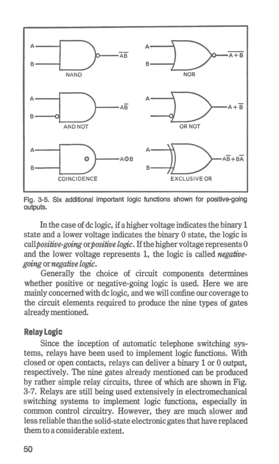
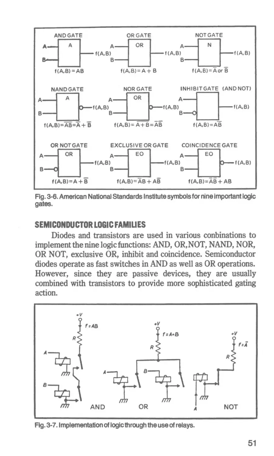
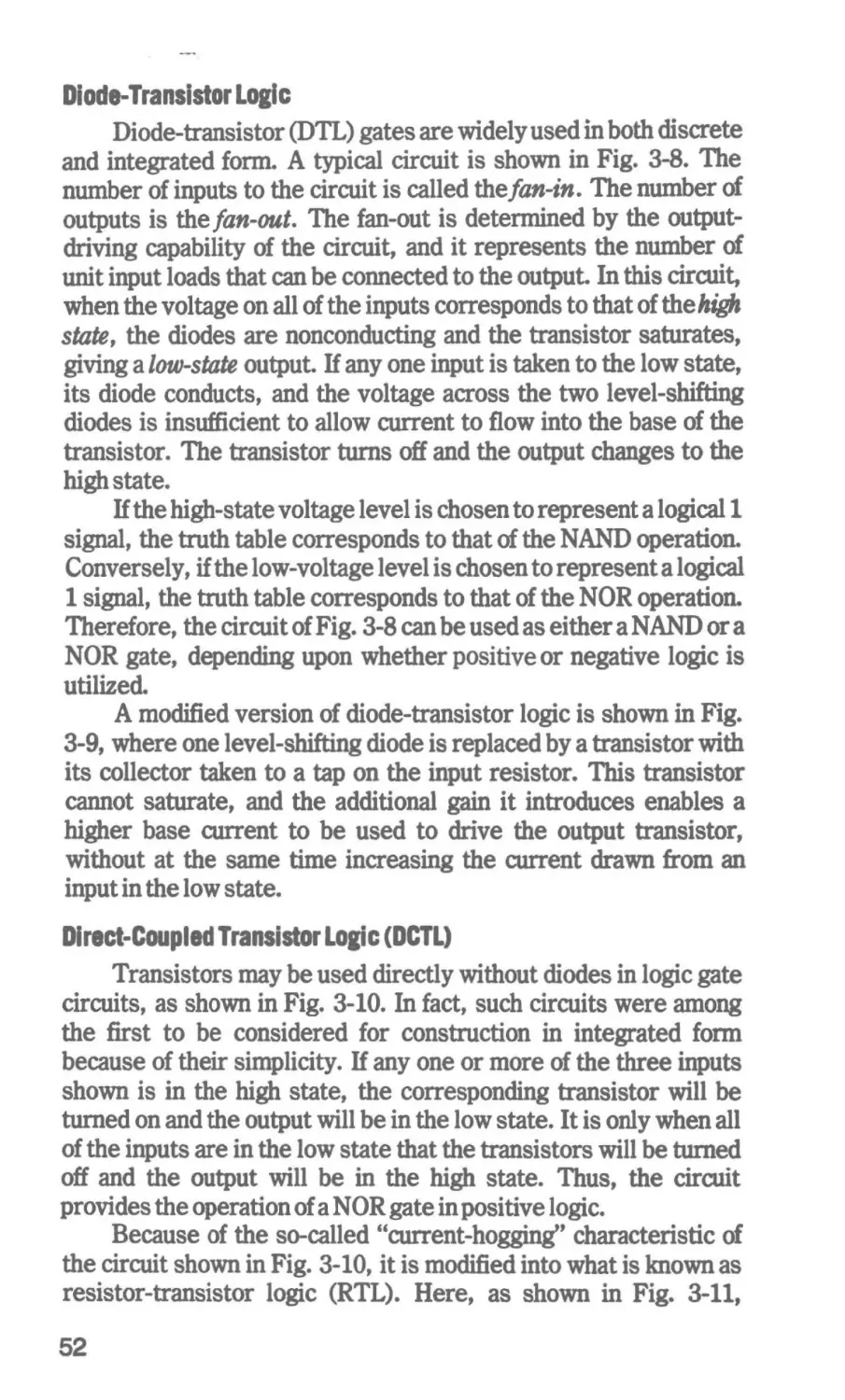
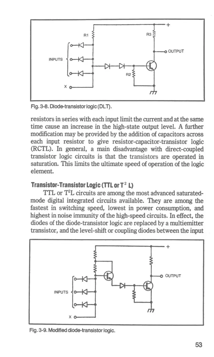
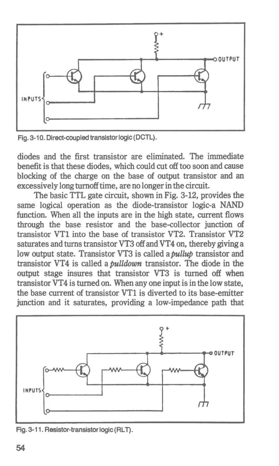
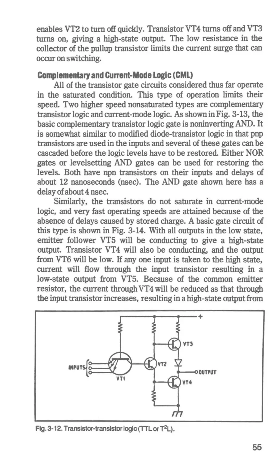
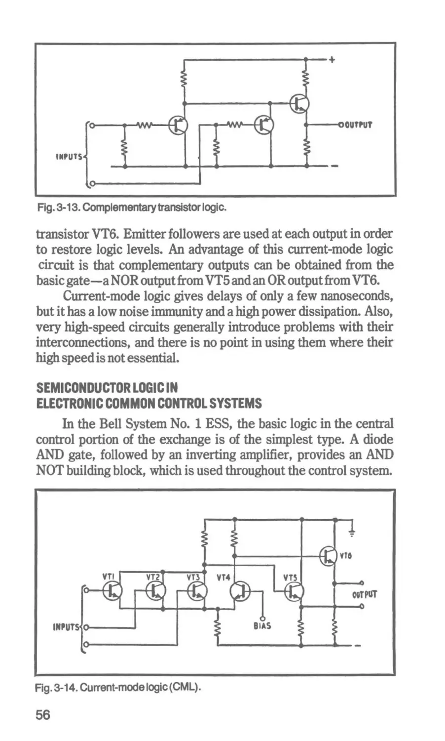
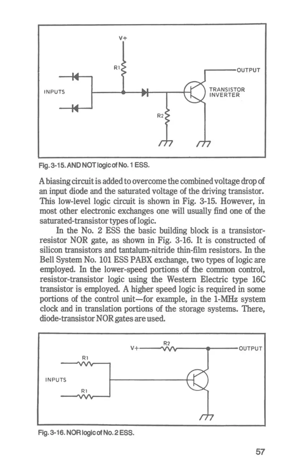
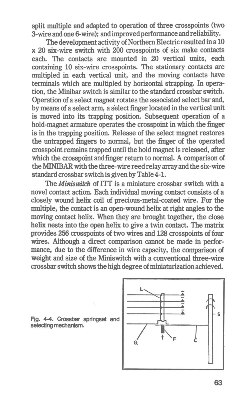
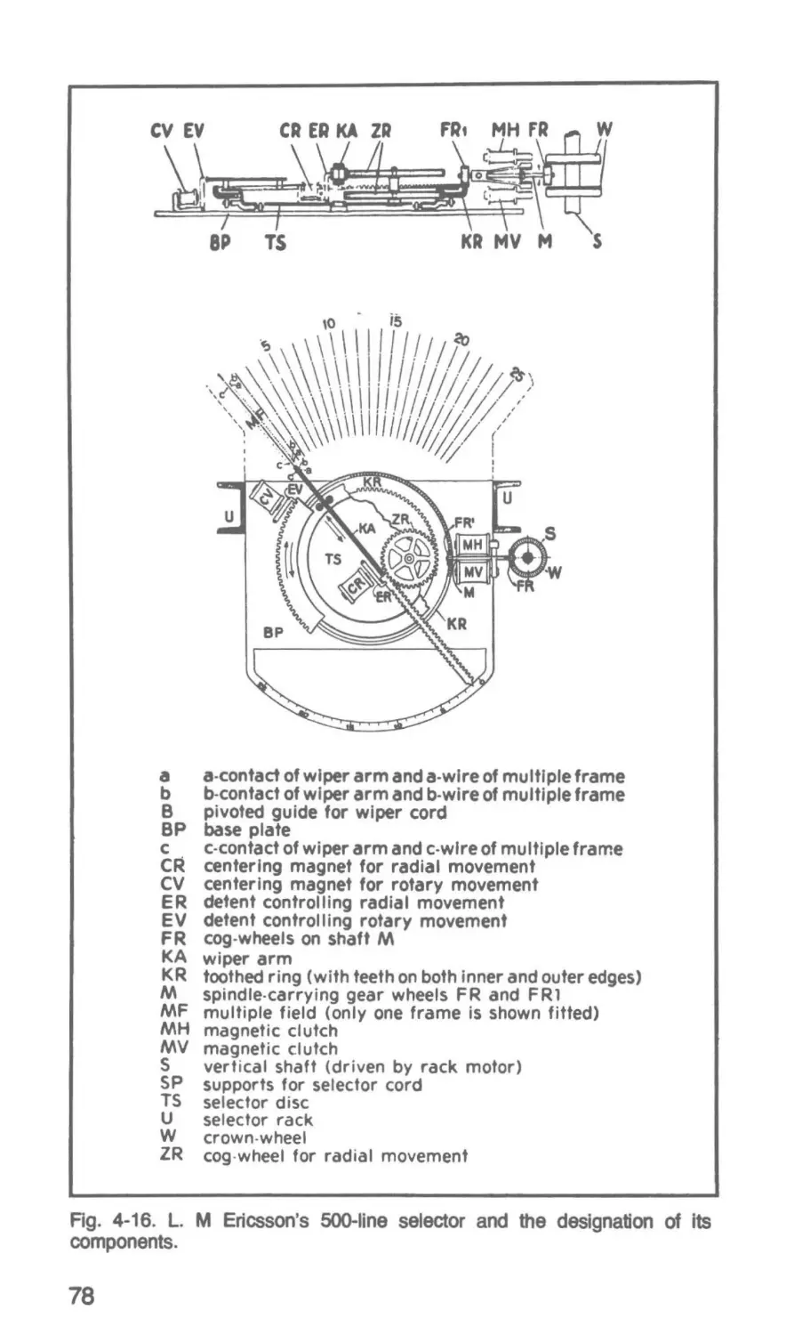
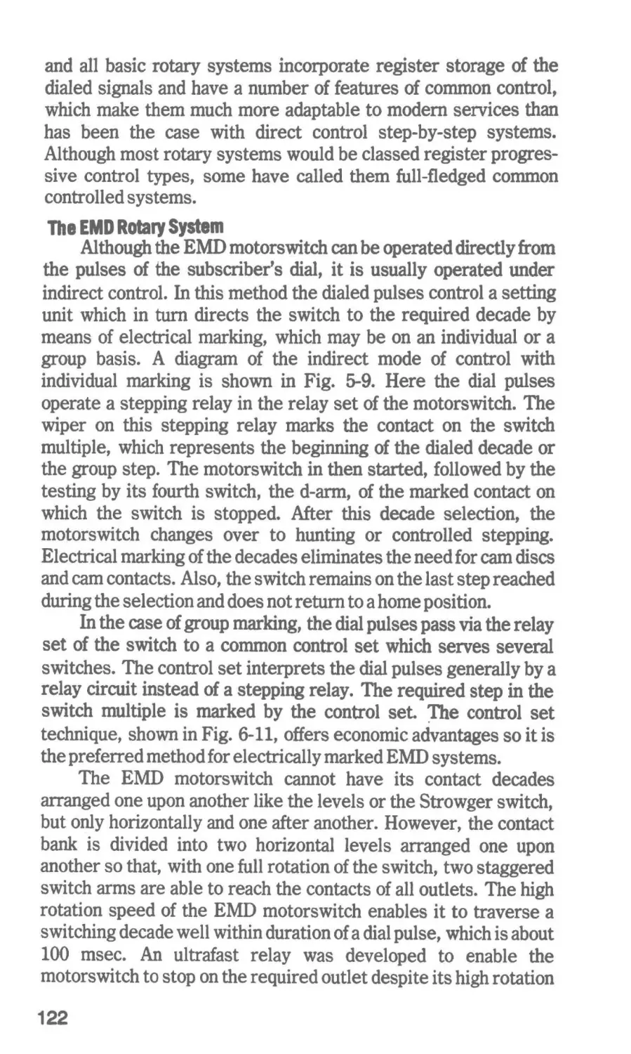
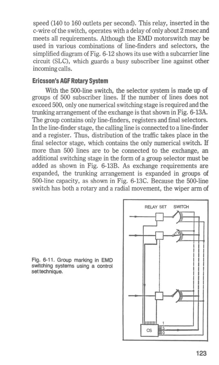
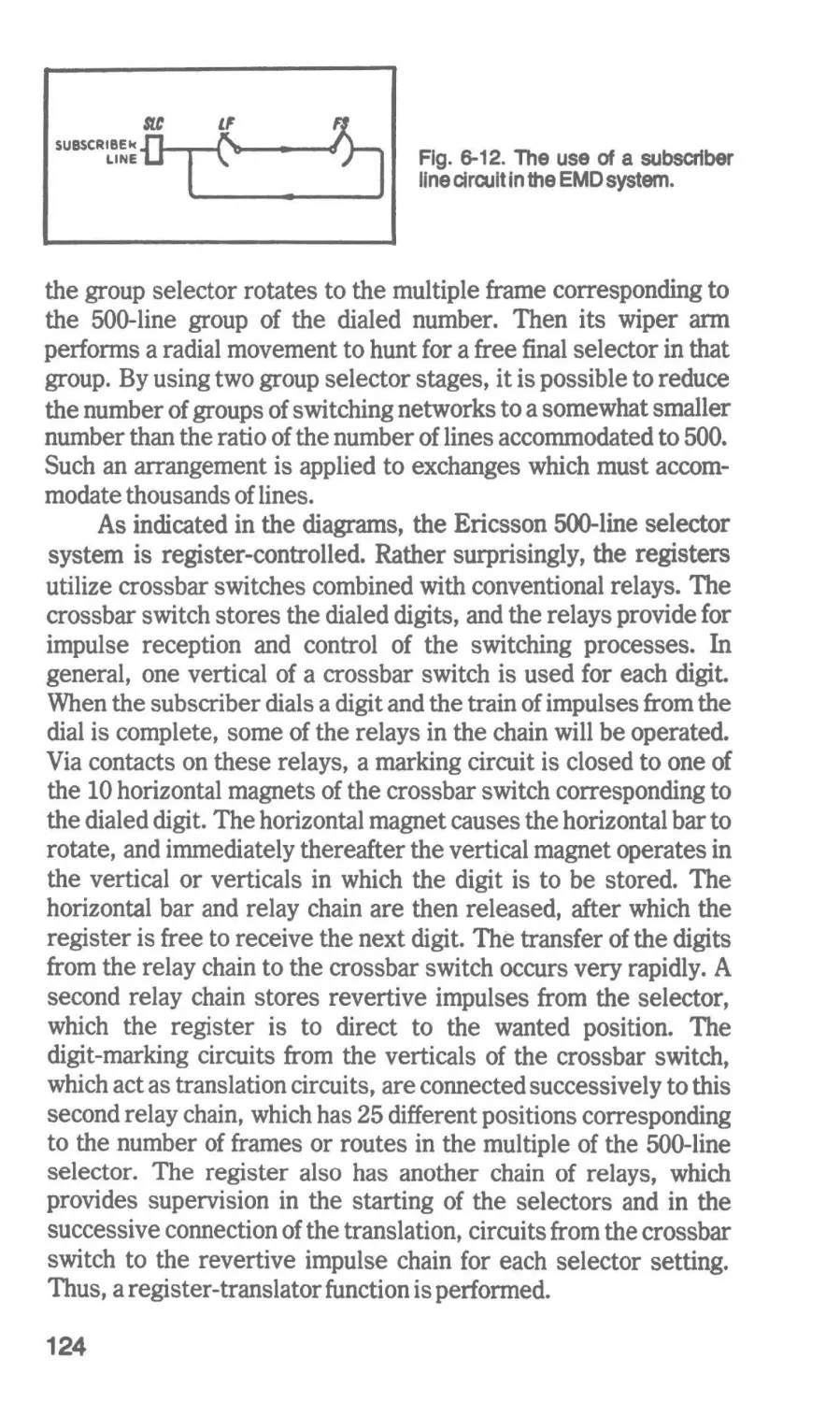
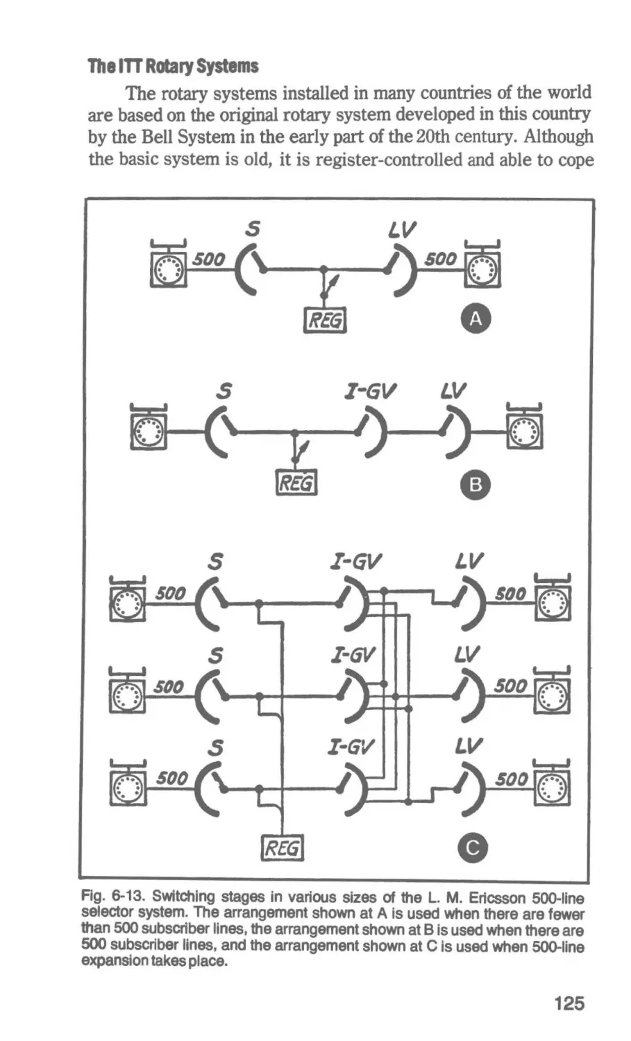
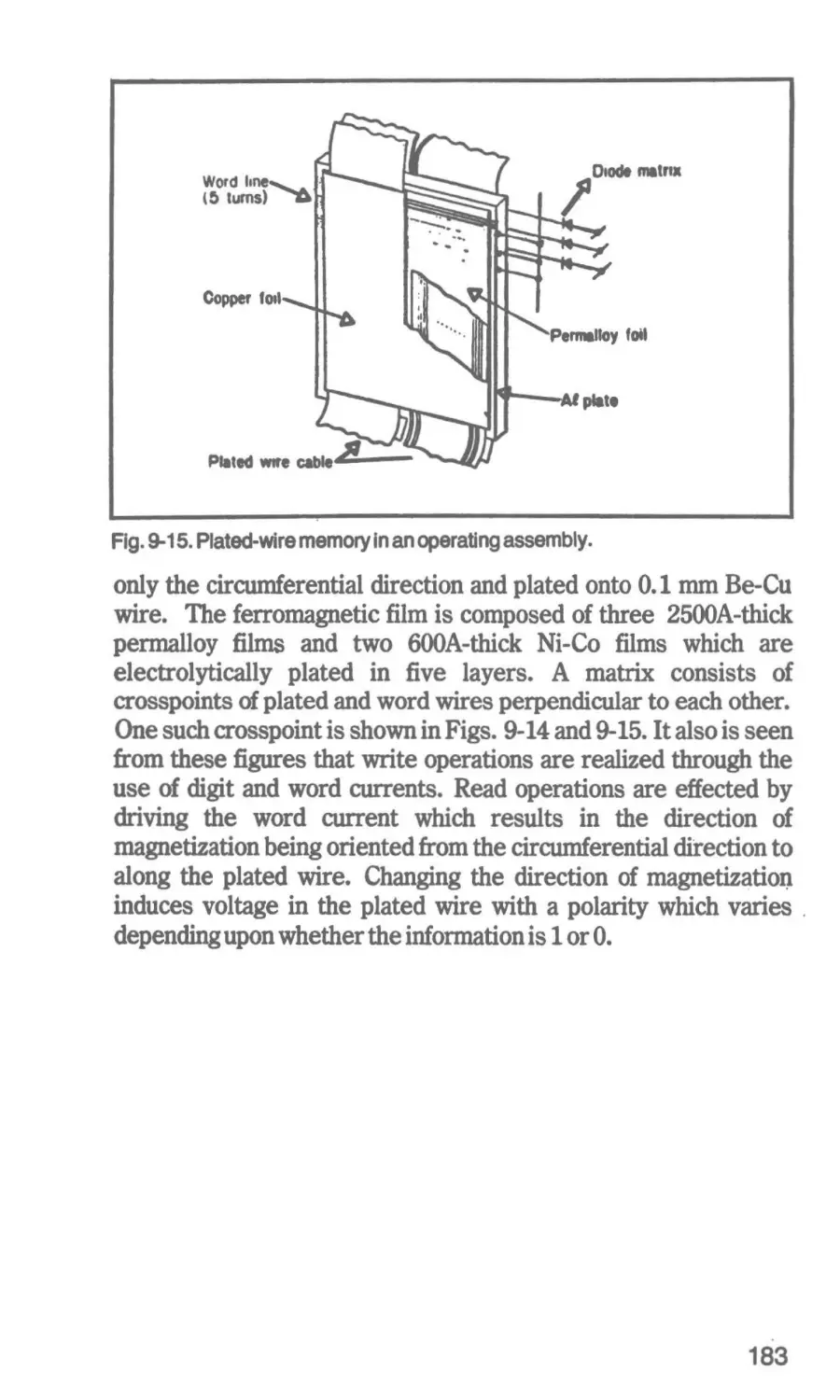
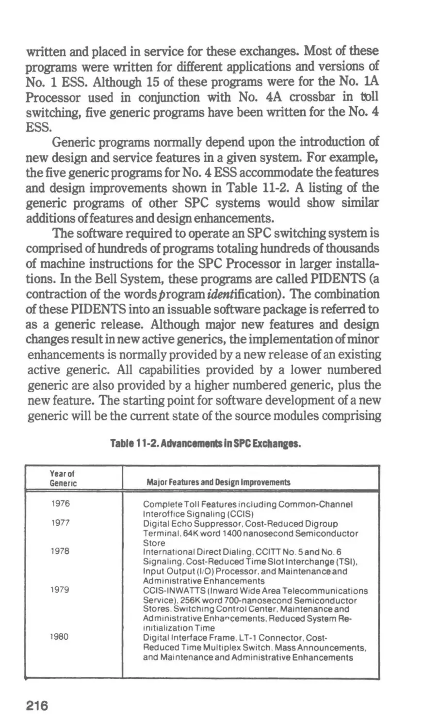
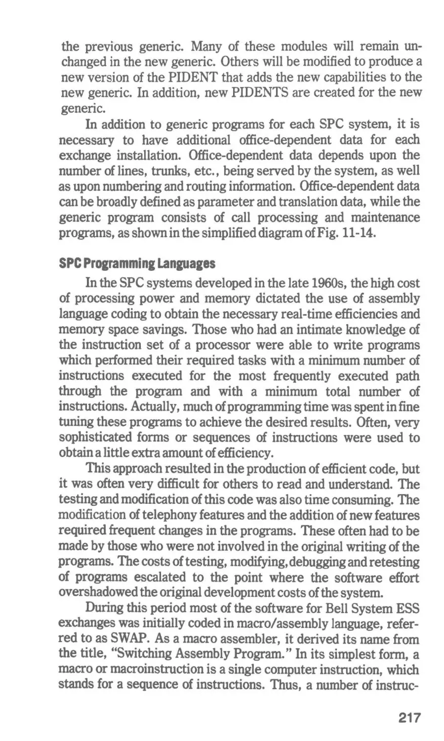
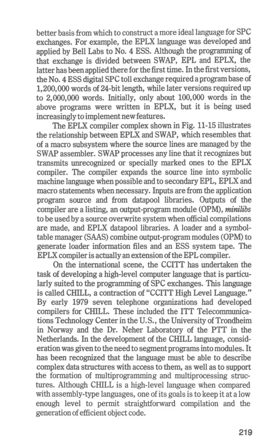
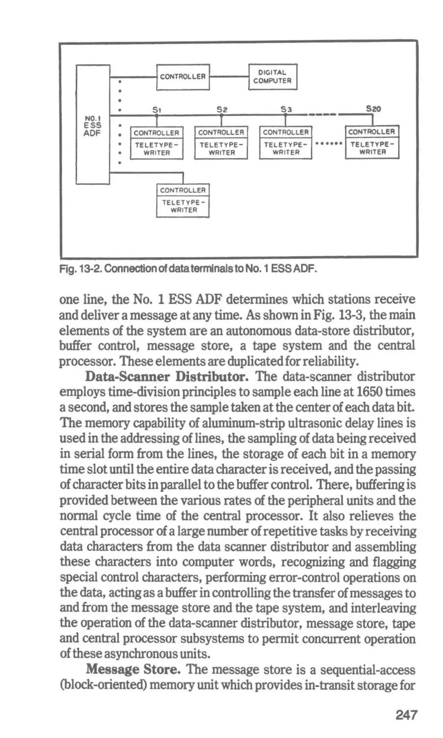
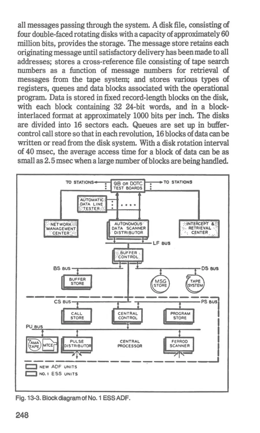
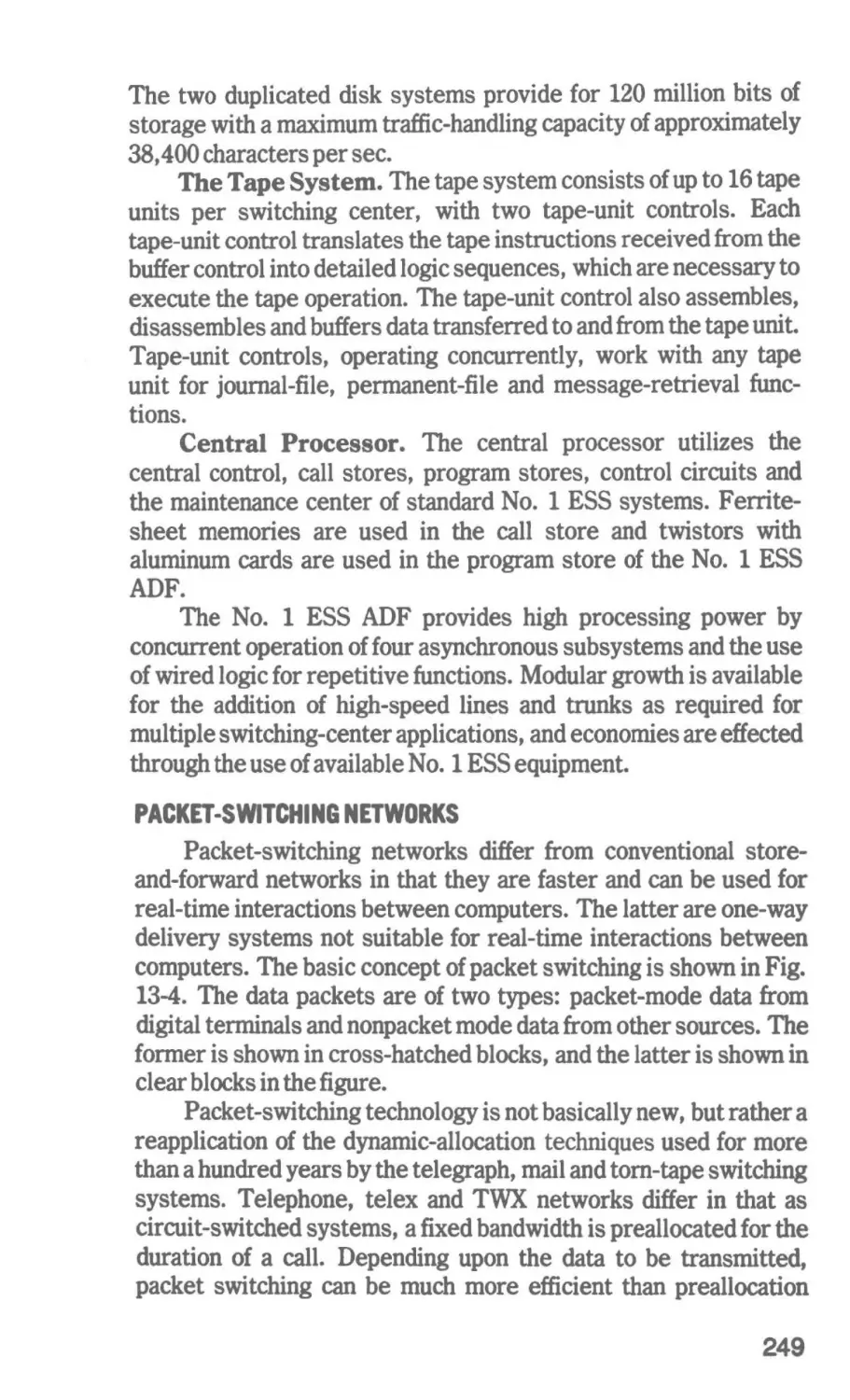
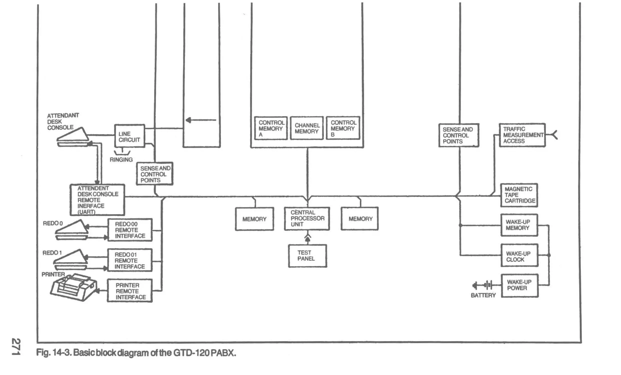
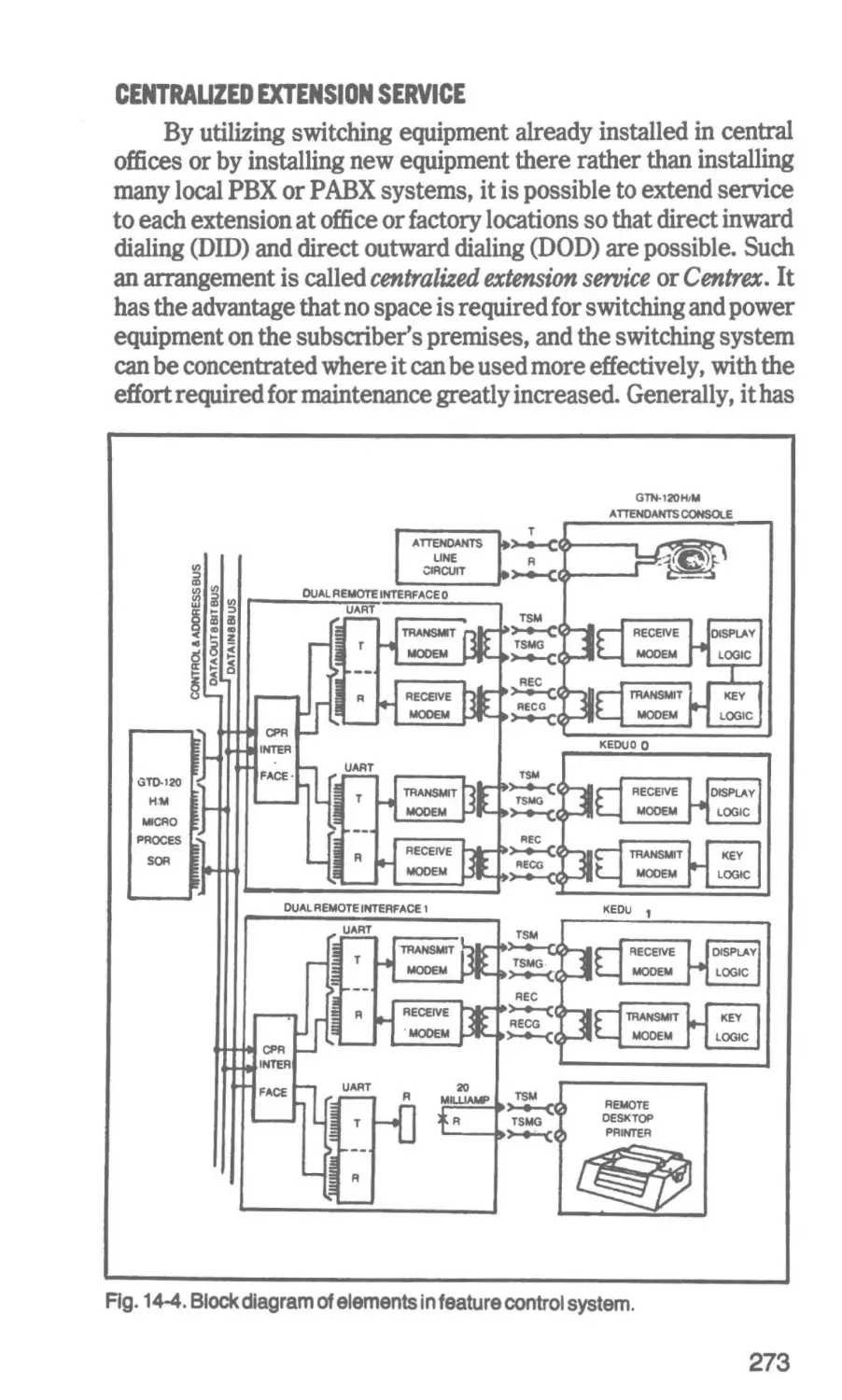
Text
Modern Communications
Switching Systems-2nd Edition
by Marvin Hobbs
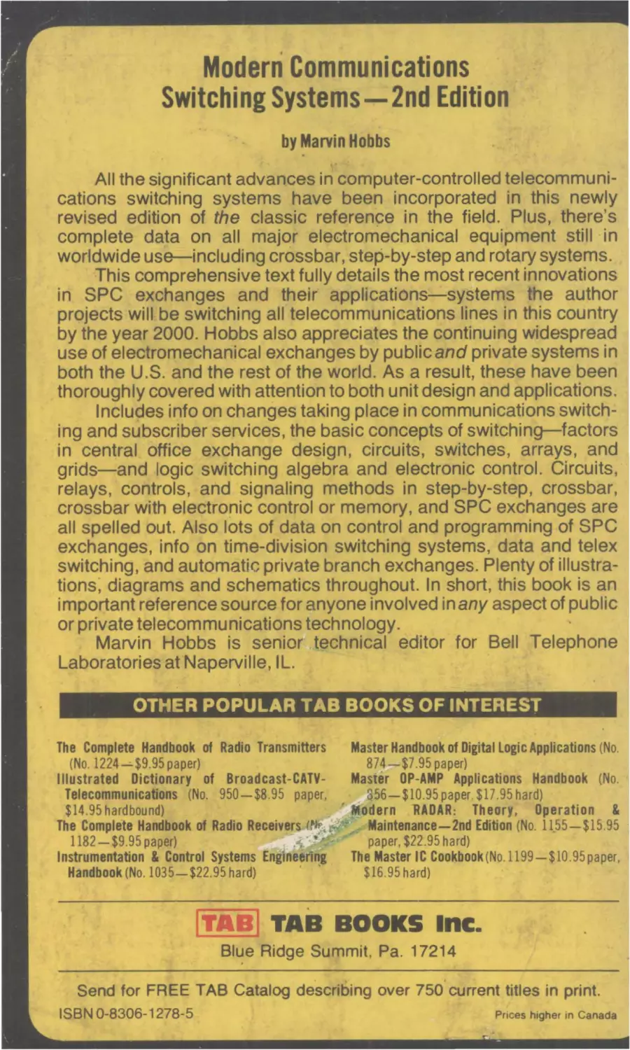
All the significant advances in computer-controlled telecommunications switching systems have been incorporated in this newly
revised edition of the classic reference in the field. Plus, there's
complete data on all major electromechanical equipment still ·in
worldwide use-including crossbar, step-by-step and rotary systems.
This comprehensive text fully details the most recent innovations
in SPC exchanges and their applications-systems the author
projects will be switching all telecommunications lines in this country
by the year 2000. Hobbs also appreciates the continuing widespread
use of electromechanical exchanges by public and private systems in
both the U.S. and the rest of the world. As a result, these have been
thoroughly covered with attention to both unit design and applications.
Includes info on changes taking place in communications switching and subscriber services, the basic concepts of switching-factors
in central office exchange design, circuits, switches, arrays, and
grids-and logic switching algebra and electronic control. Circuits,
relays, controls, and signaling methods in step-by-step, crossbar,
crossbar with electronic control or memory, and SPC exchanges are
all spelled out. Also lots of data on control and programming of SPC
exchanges, info on time-division switching systems, data and telex
switching, and automatic private branch exchanges. Plenty of illustrations, diagrams and schematics throughout. In short, this book is an
important reference source for anyone involved in any aspect of public
or private telecommunications technology.
Marvin Hobbs is senior technical editor for Bell Telephone
Laboratories at Naperville, IL.
OTHER POPULAR TAB BOOKS OF INTEREST
The Complete Handbook of Radio Transmitters
Master Handbook of Digital Logic Applications (No.
874-$7.95 paper)
(No. 1224-$9.95 paper)
Illustrated Dictionary of Broadcast-CATVMaster OP-AMP Applications Handbook (No.
Telecommunications (No. 950-$8.95 paper,
356-$10.95 paper. $1 7.95 hard)
$14.95 hardbound)
' Modern "RADAR: Theory, Operation &
The Complete Handbook of Radio Receivers lNi.:ii#ffe Maintenance-2nd Edition (No. 1155-$15.95
1182-$9.95 paper)
• !~r:•
paper, $22.95 hard)
Instrumentation & Control Systems Engineering
The Master IC Cookbook(No.1199-$10.95 paper,
Handbook (No. 1035-$22.95 hard)
· '
$16.95 hard)
ITAB] TAB BOOKS Inc.
Blue
. Ridge Summit, Pa. 17214
Send for FREE TAB Catalog describing over 750, current titles in print.
ISBN 0-8306-1278-5
Pnces higher in Canada
-r \t\""!.)i c. .. y, ,
~
I
rI
I
~
8263897
't
I
r-_· 2
'~
-
I
'
I
'
Modern Communications
Switching Systems
-2nd Edition
:
by Marvin Hobbs
'-
111111111~
. E8263897
:or,..
Po •~
" fll!'.
~
\ ..t,''. K.... t"'"
~... • .,,
.I
•
... ..
• C'
•
l
•
.,...
f'
-.a.
f ..)..I I':' . .,. t..... .~
FIRST PRINTING
SECOND EDITION
MAY1981
Copyright C 1981 by TAB BOOKS Inc.
Printed in the United States of America
Reproduction or publication of the content In any manner, without express
permission of the publisher, is prohibited. No llablllty Is assumed with respect to
the use of the Information herein.
Ubrary of Congress Cataloging In Publication Data
Hobbs, Marvin.
Modern communications switching systems.
Includes index.
1. Telephone, Automatic. 2. Telephone switching
systems, Electronic. 3. Electric switchgear.
I. Title.
TK6397.H62 1981
621.385'7
80-28236
ISBN o-8306-9635-0
ISBN 0-8306-1278-5 (pbk.)
Cover photo courtesy of Augat, Inc.
8263897
~ :i. _.ontents
_, ...
Preface
1 TheSlowPushforProgress
"/~..
j;'··..
f].
..;; ~
'
~f..
·
<""
~
. ,.
c-·.
Ji
Telecommunications Switching-Subsl"ri"a·~jf\,{~·~: -*
7
11
,. ..,.r" I./
2 Basic Switching and Traffic Concepts
24
3 Logic Switchin1 Algebra and Control
43
Factors in Central Office Exchange Desig~Telephone Traffic
Terms and Concept&-Connecting Circuits-Switches, Arrays
and Grids
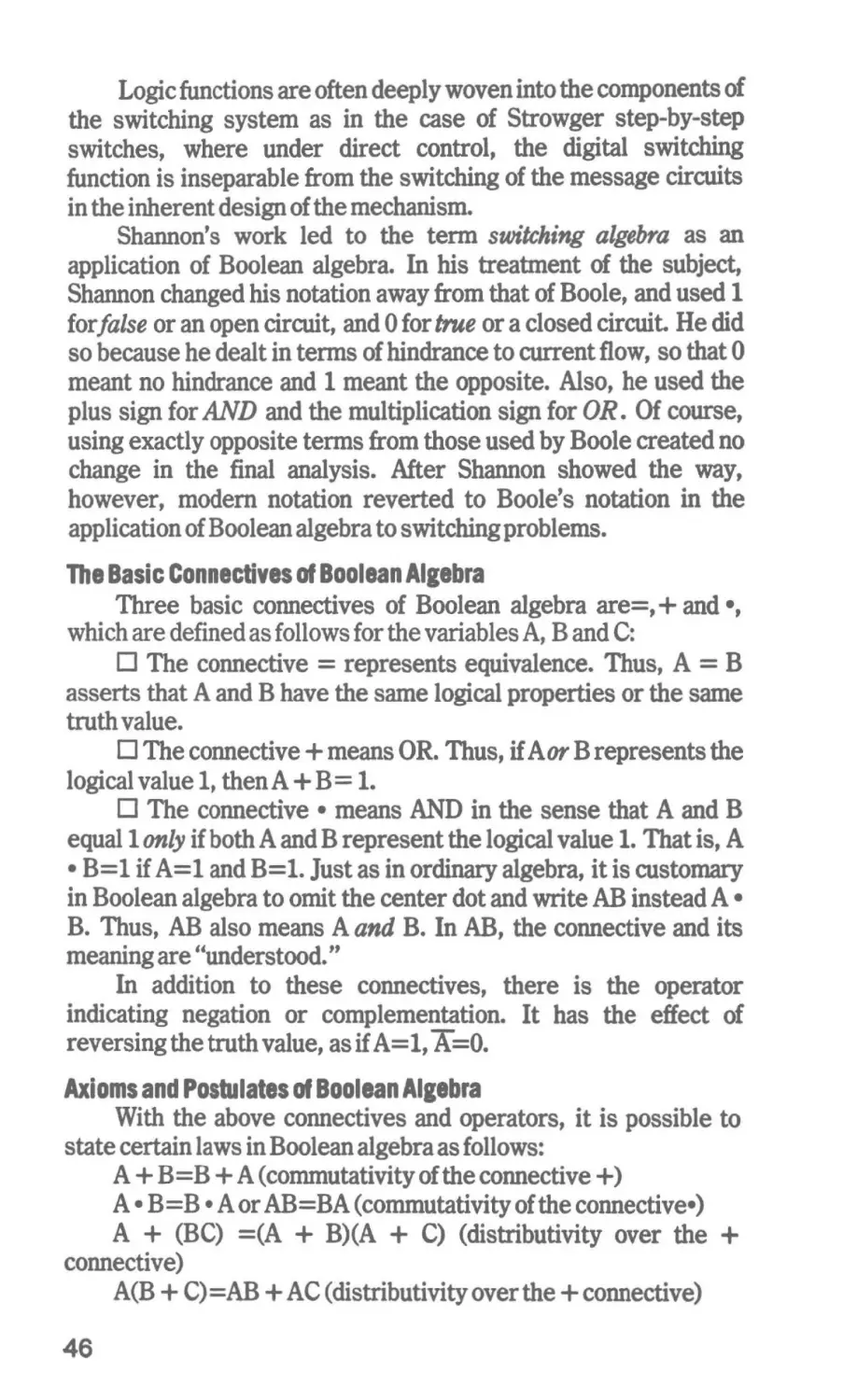
Boolean Algebra and Circuit Switching-Logic GatesSemiconductor Logic Families Semiconductor Logic In Electronic Common Control Systems
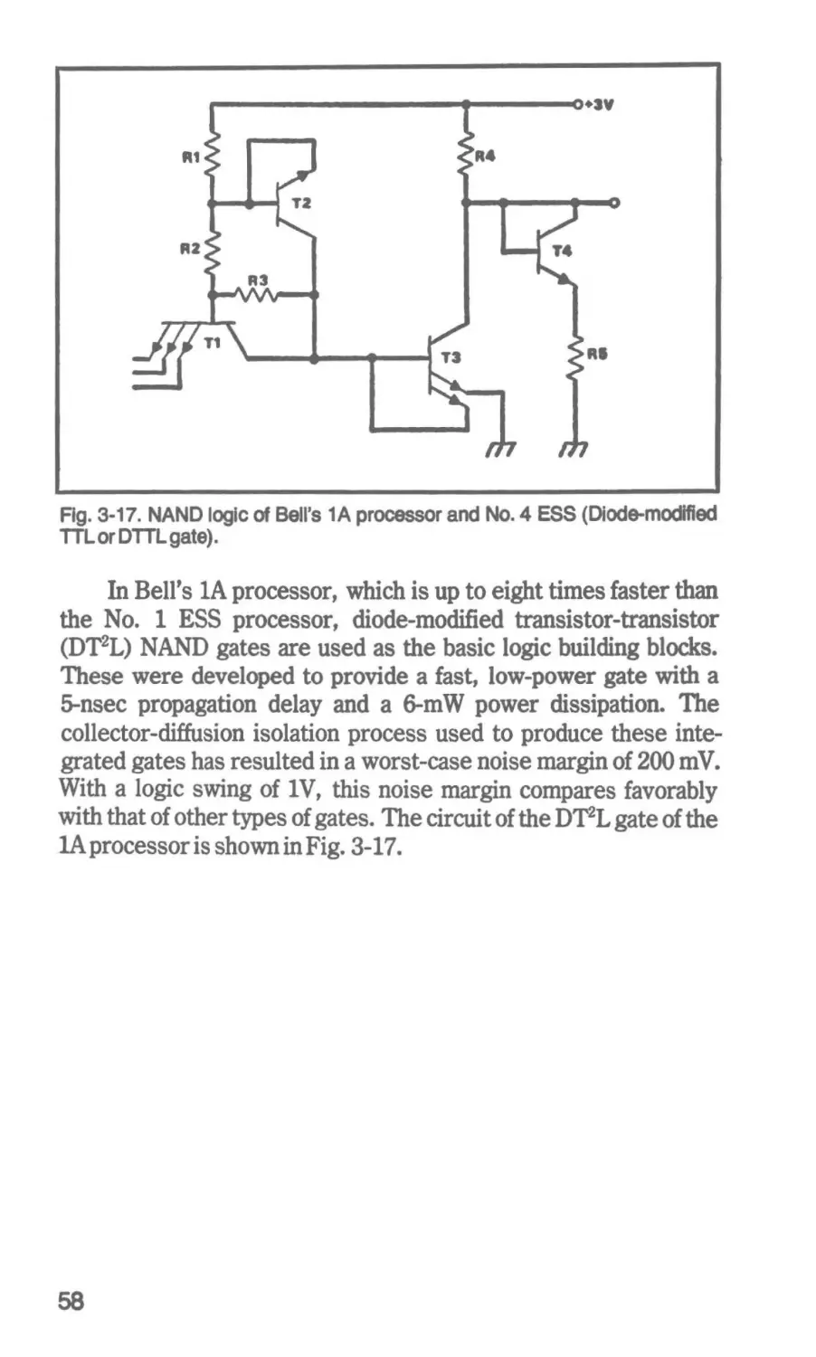
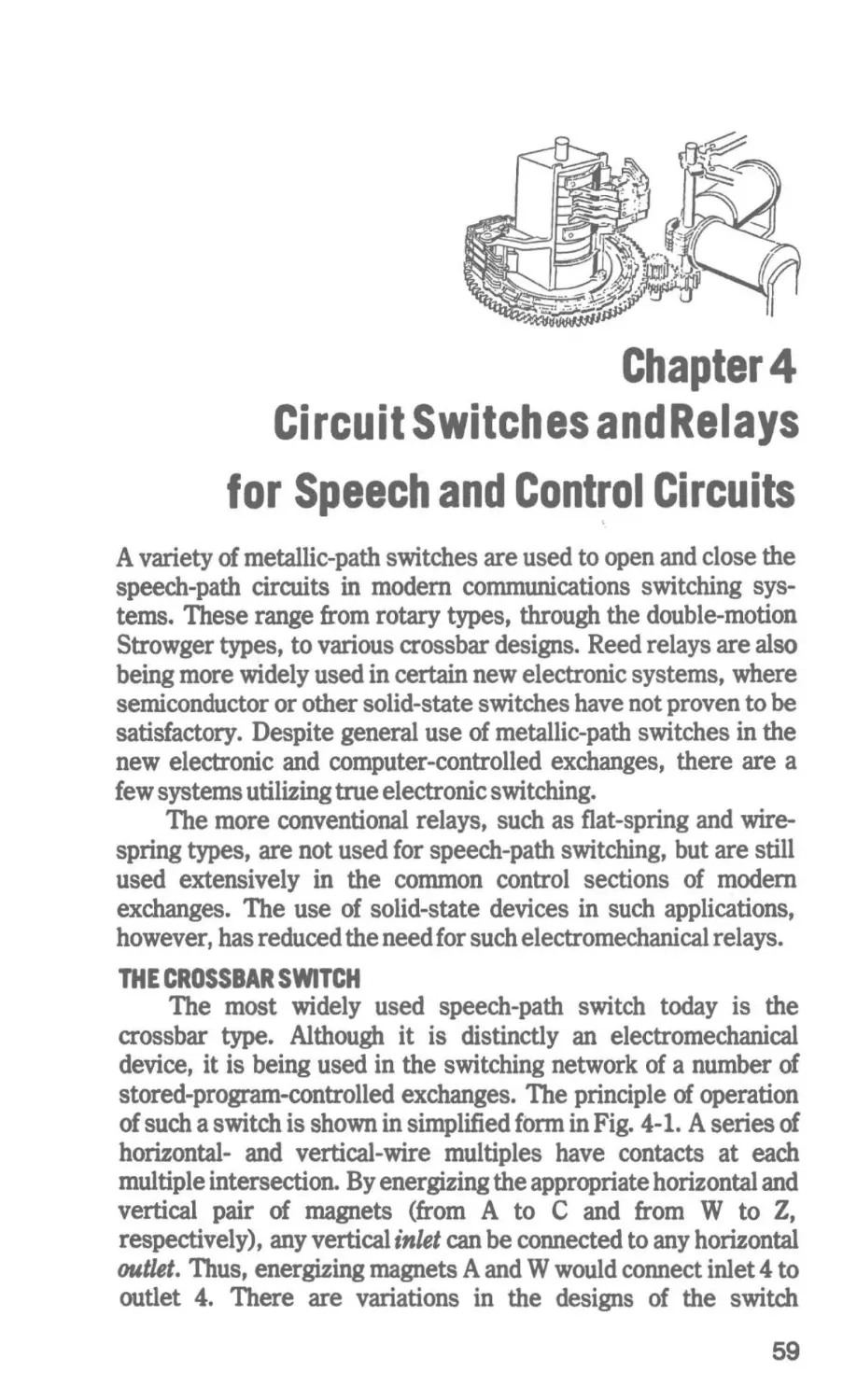
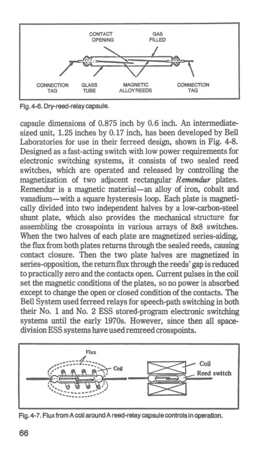
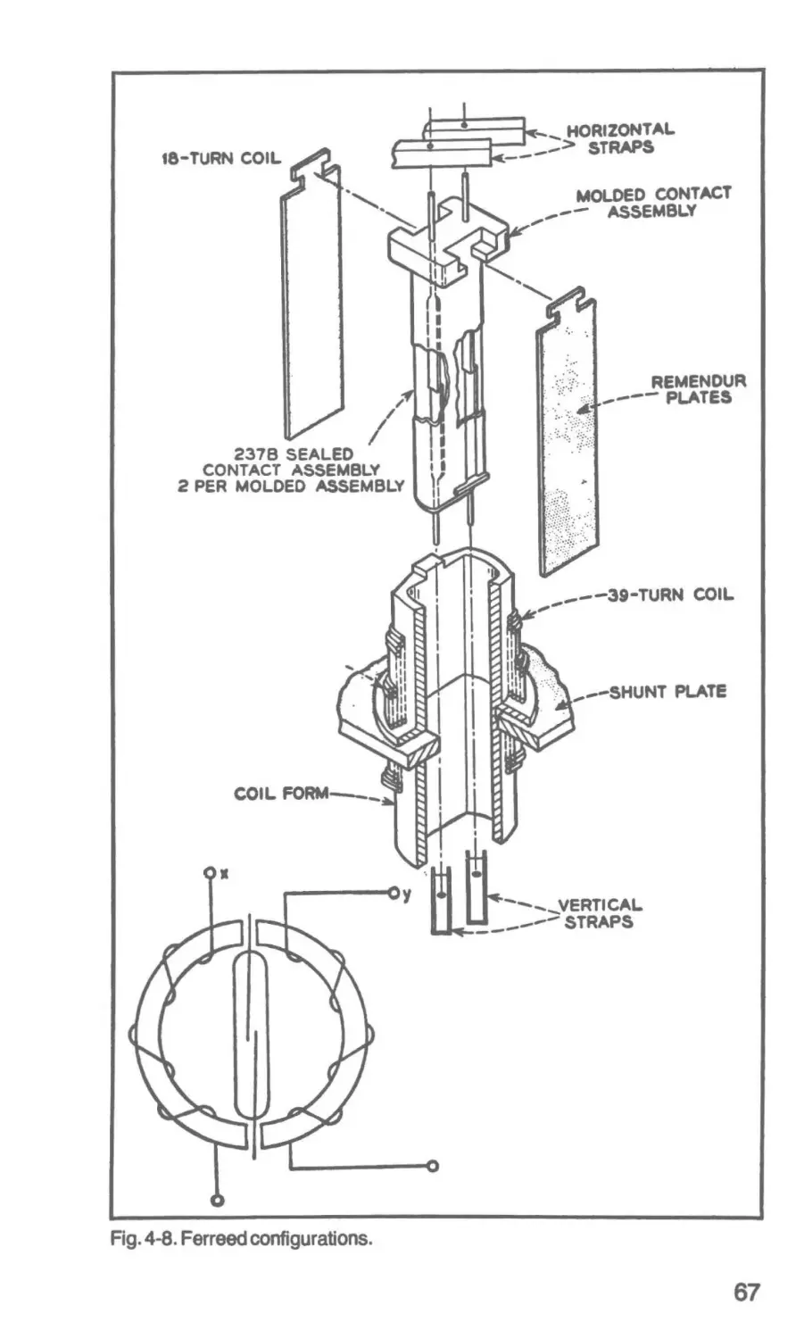
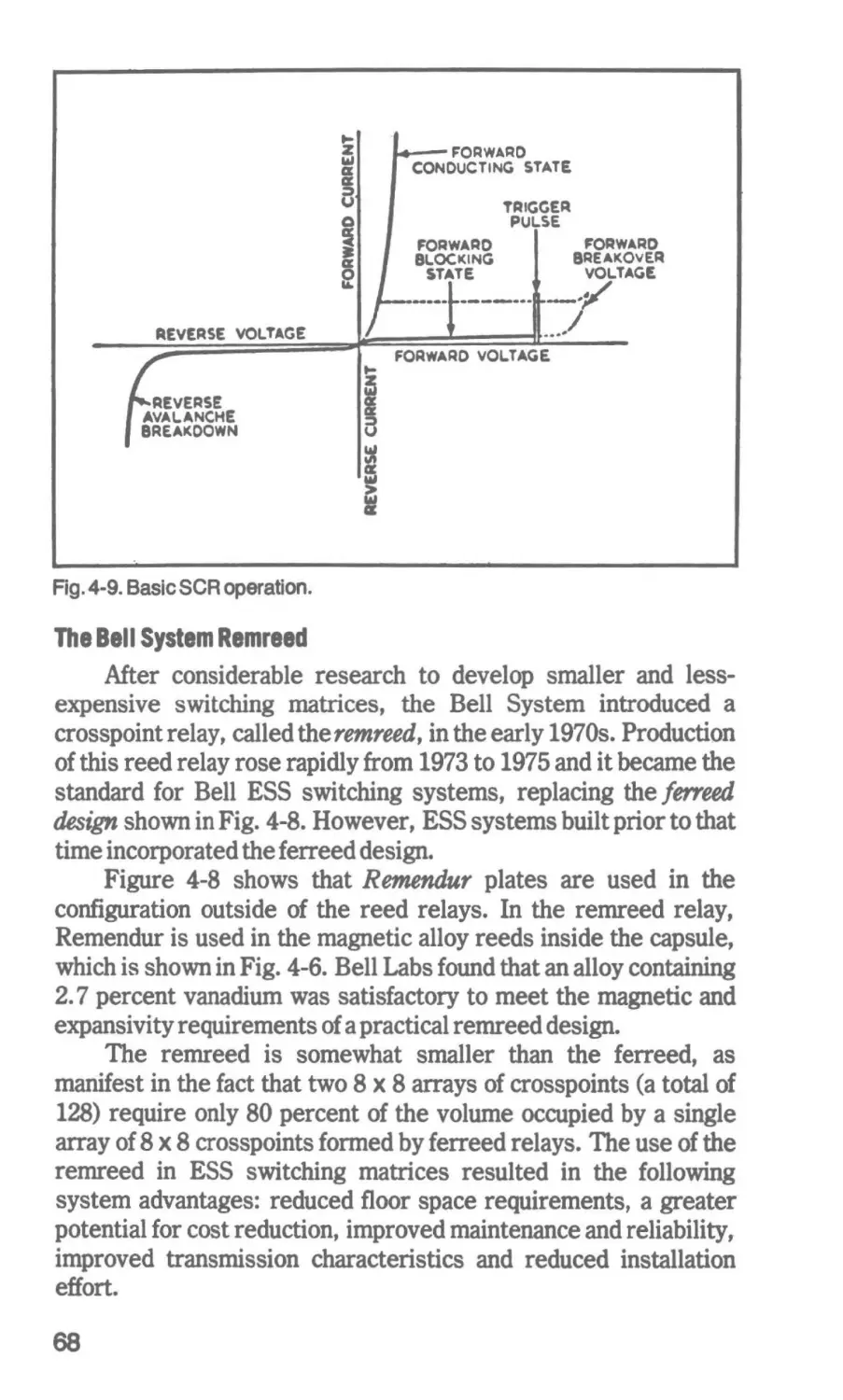
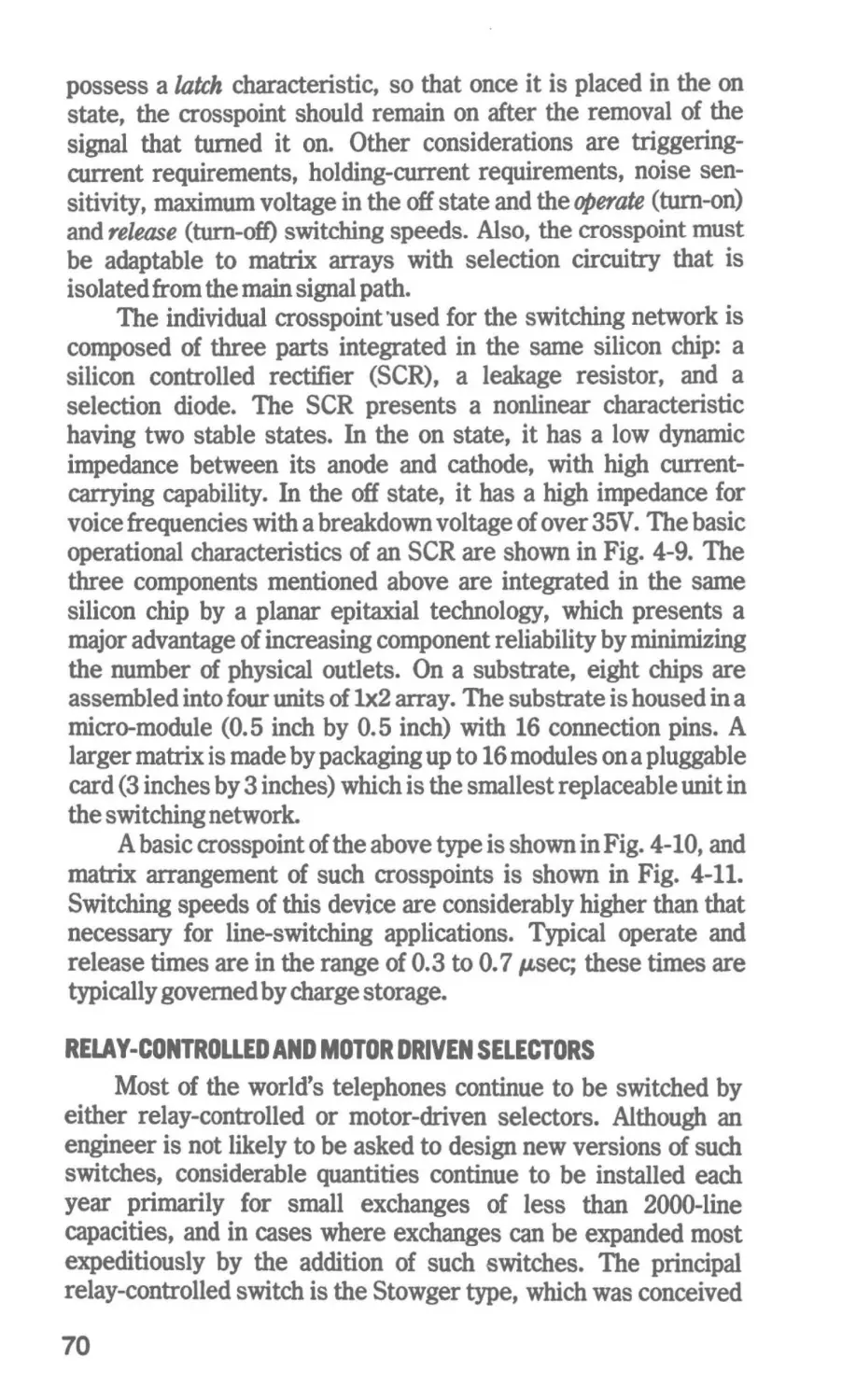
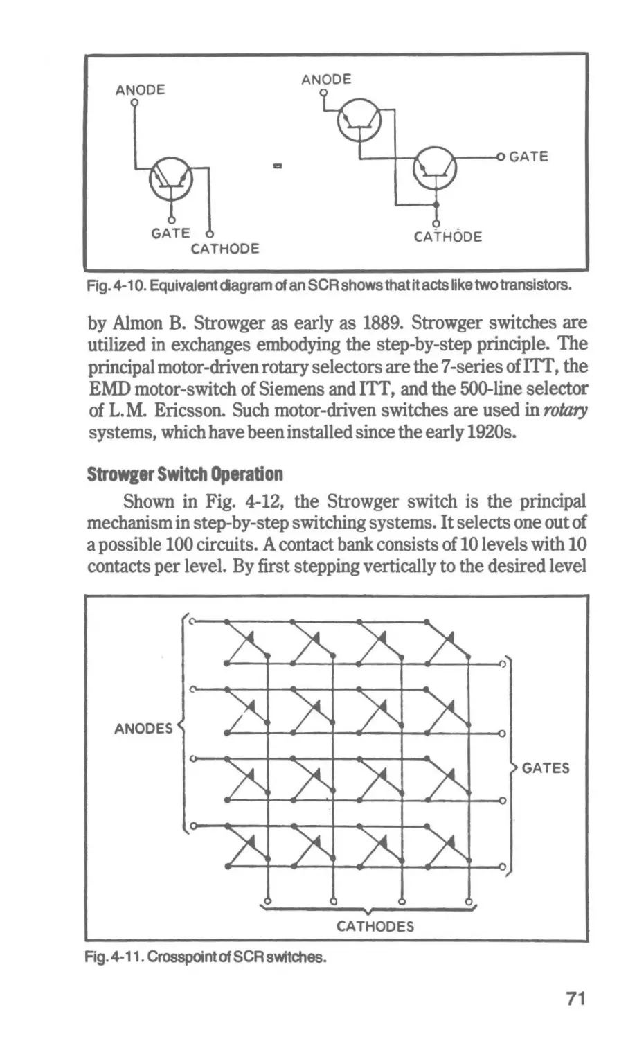
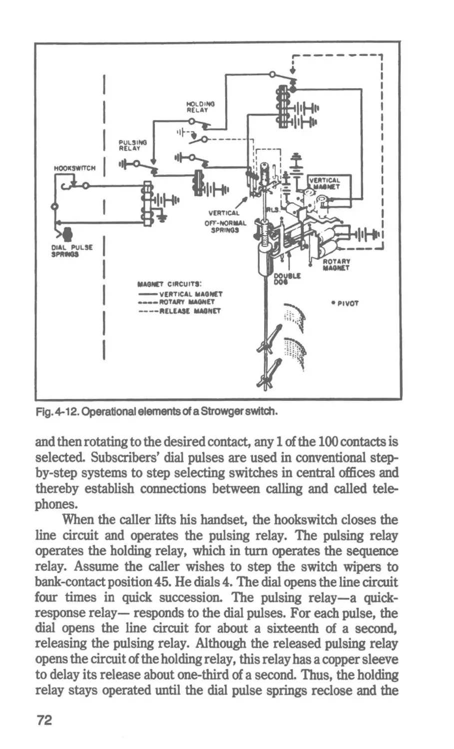
4 Circuit Switches and Relays for Speech and Control Circuits 59
The Crossbar Switch-Reed Relays-Solid-State Electronic
Crosspoints-Relay-Controlled and Motor Driven Selectors
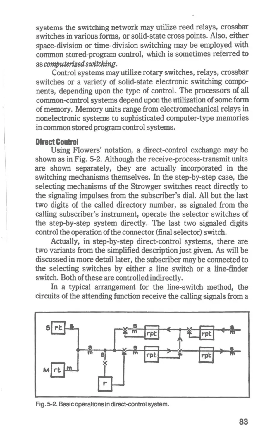
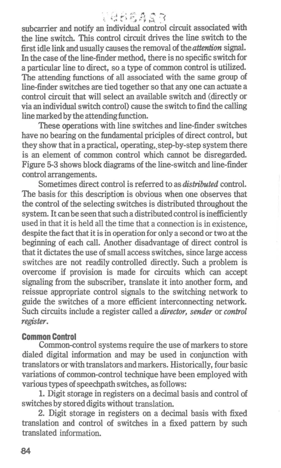
5 Control and Signal Methods
80
Processing-Types of Control-Common Stored-Program
Control-Signaling Methods
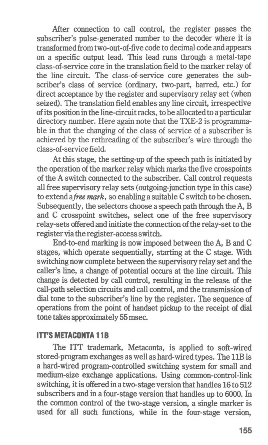
8 Modern Exchanges
105
Basic Step-by-Step Switching Systems-Rotary Switching Systems
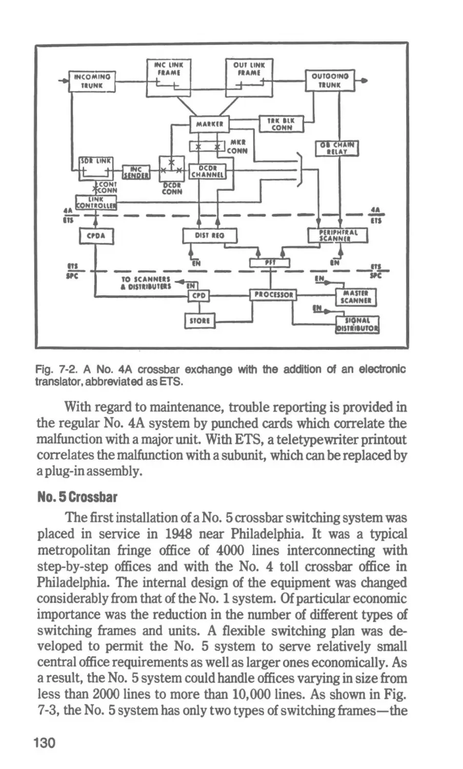
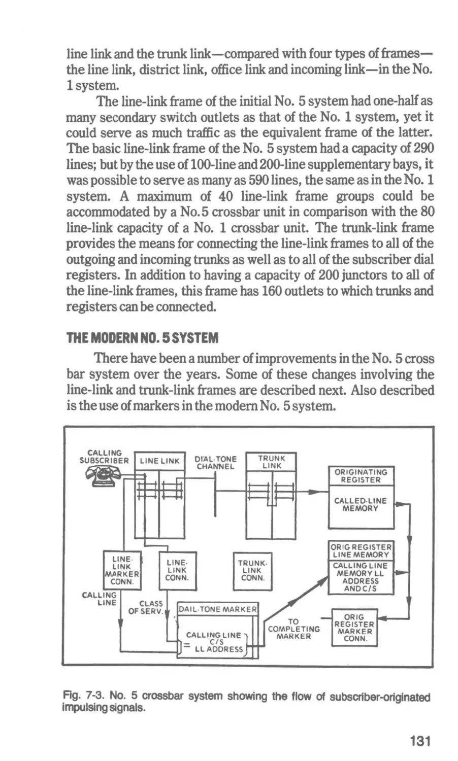
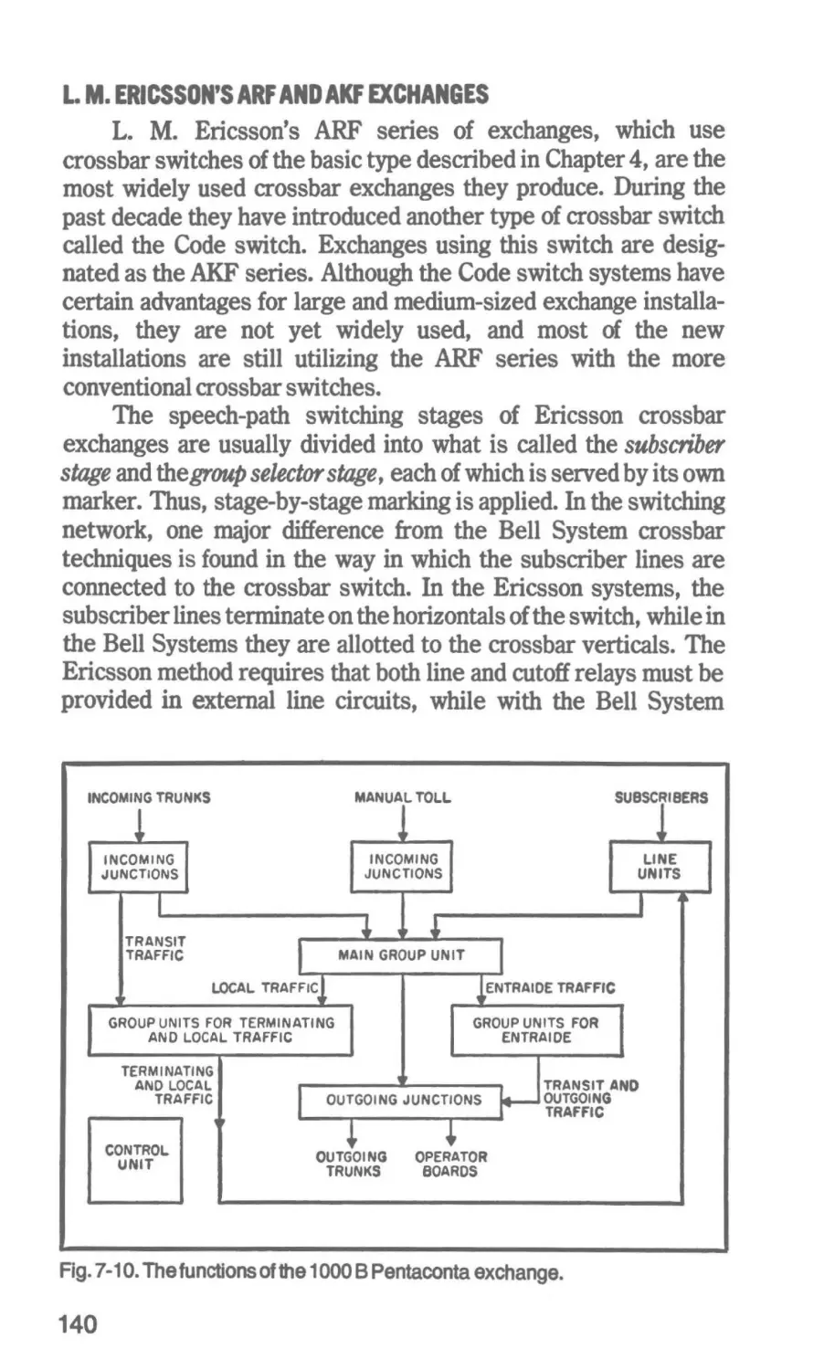
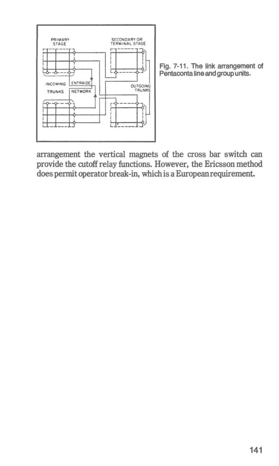
7 Electromechanical Crossbar Systems
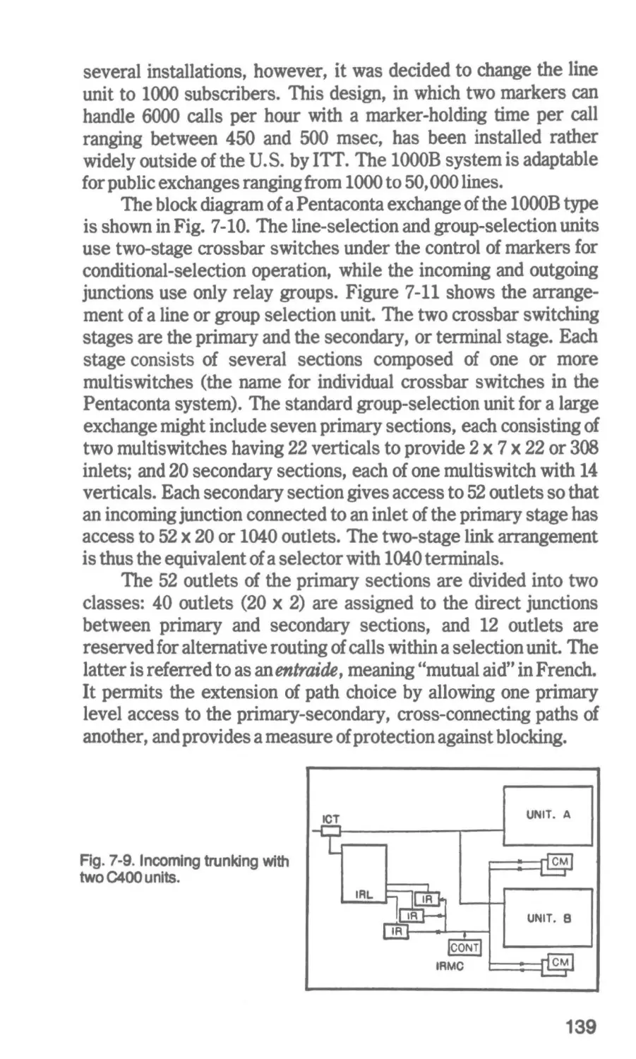
Older Crossbar Systems-The Modern No. 5 System-Japan's
C400 Crossbar System-ITT's Pentaconta Crossbar System-L.
M. Ericsson's ARF and AKF Exchanges
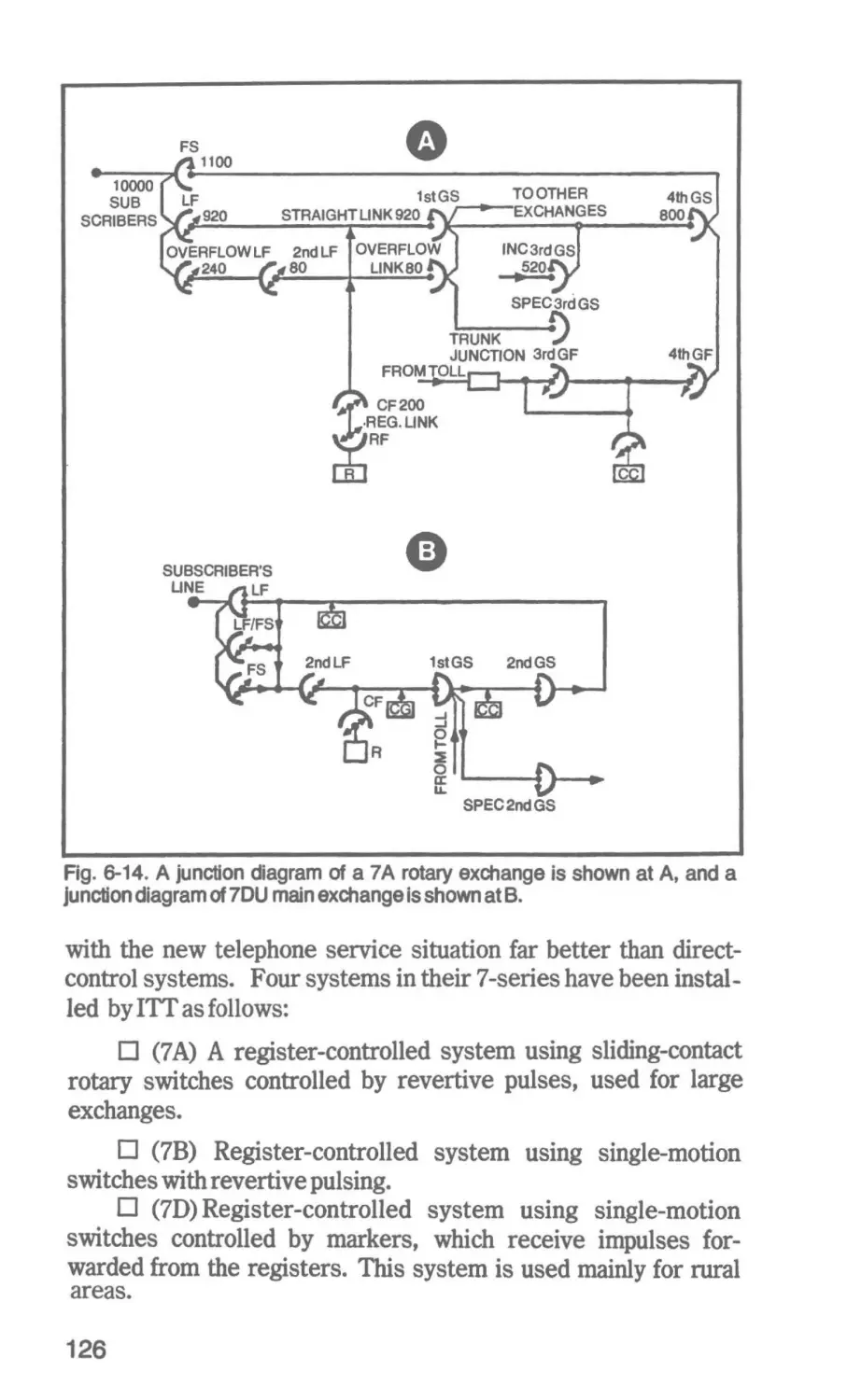
128
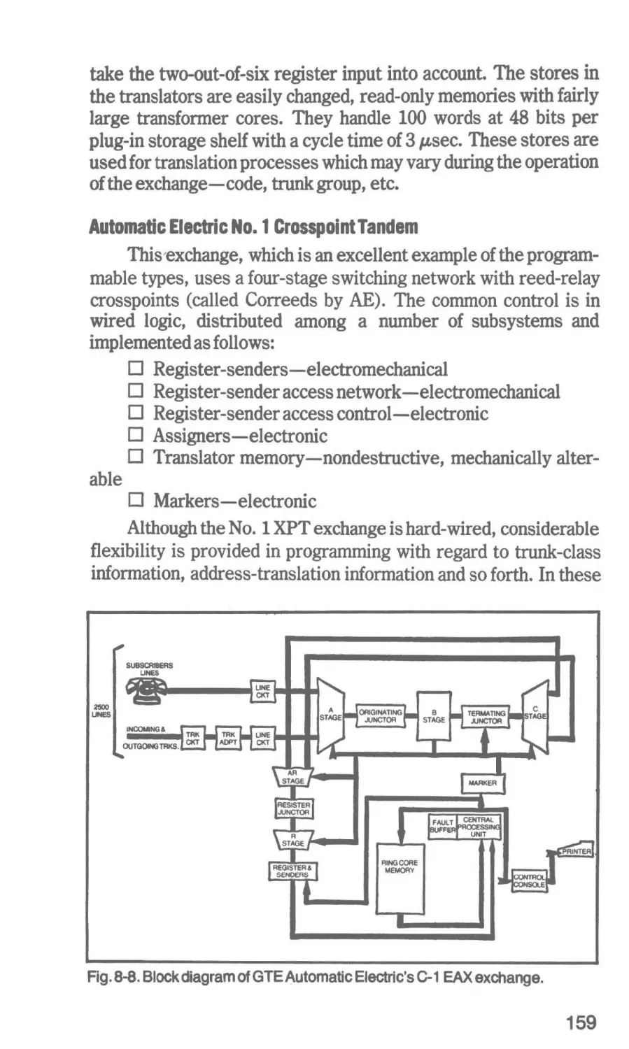
8 Electronic Exchan1es with Wired LOlic
142
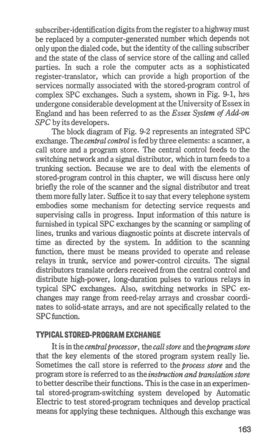
8 The Elements of Stared-Pl'Olflm Contol
162
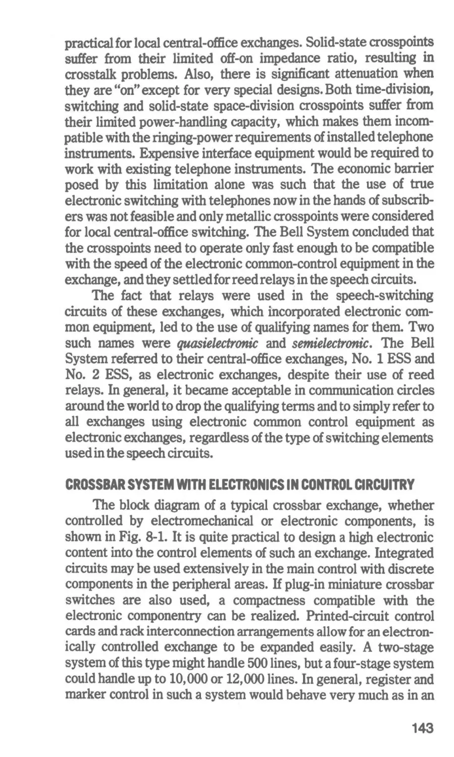
Crossbar System With Electronics in Control Circuitry-Crossbar
Systems with Electronic Memory Only-Electronic Common
Control-A Reed-Relay Exchange with Register Control-ITT's
Metaconta 11 B-Automatic Electric's C-1 EAX
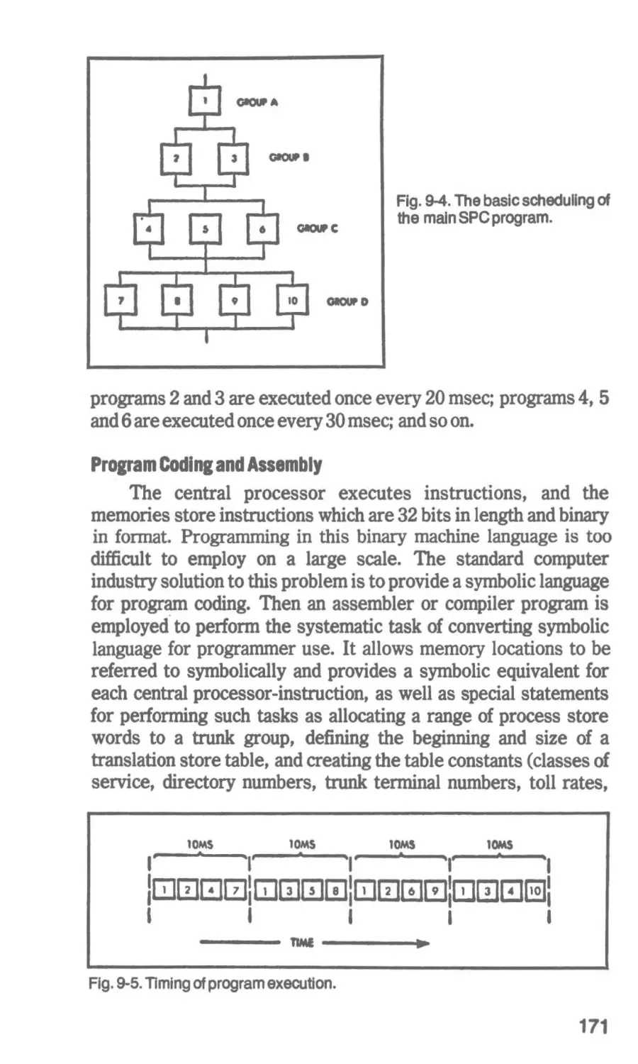
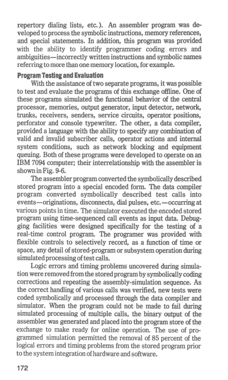
Typical Stored-Program Exchange-The Stored Program-SPC
Memory Technology
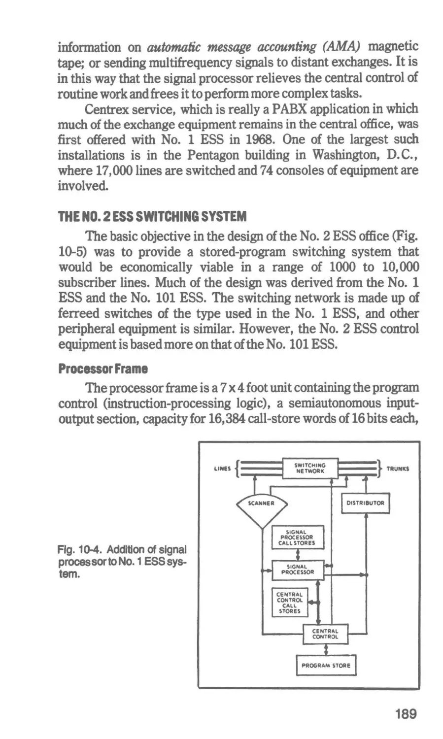
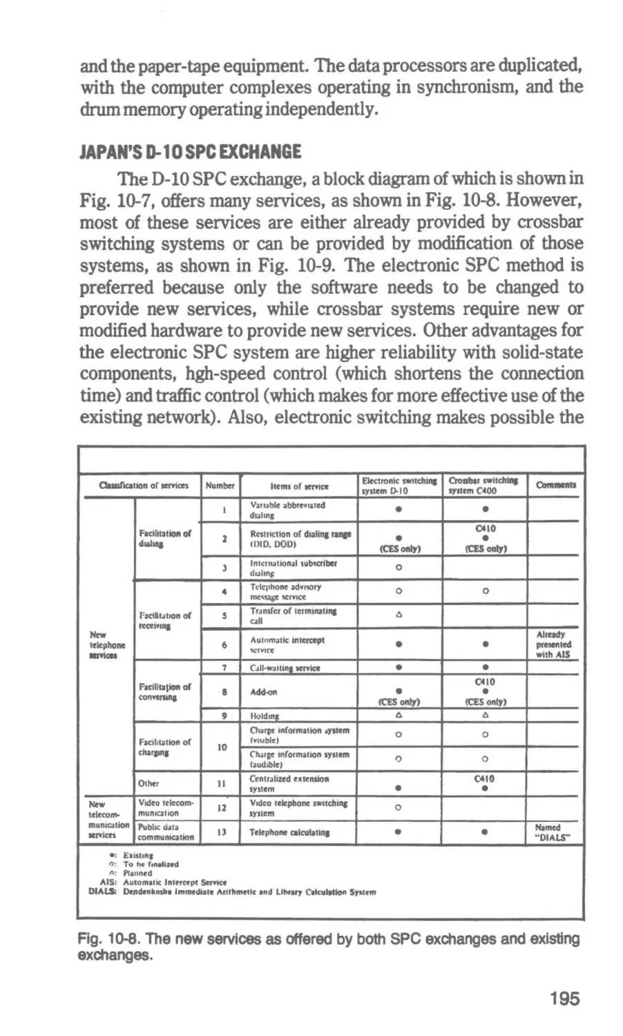
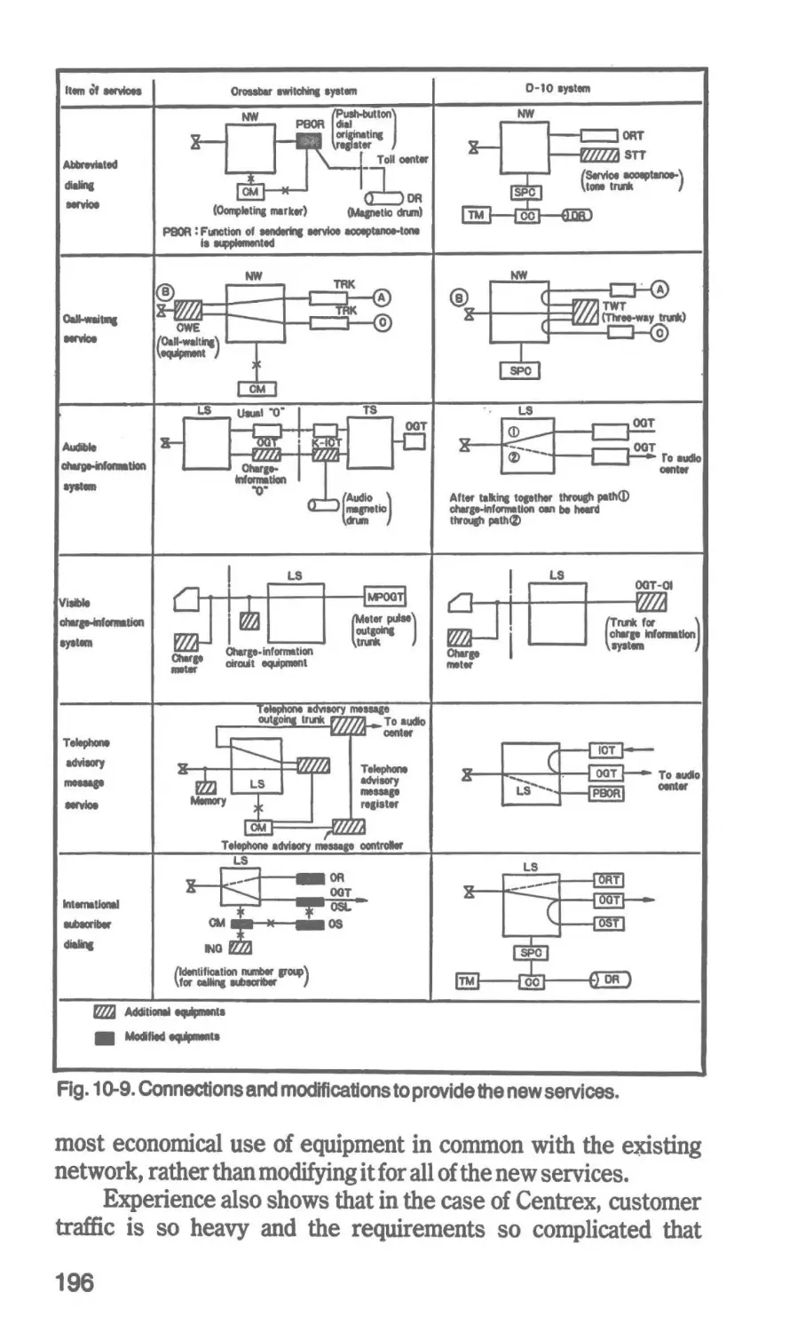
10 Typical SPC Excban1es and the New Services
184
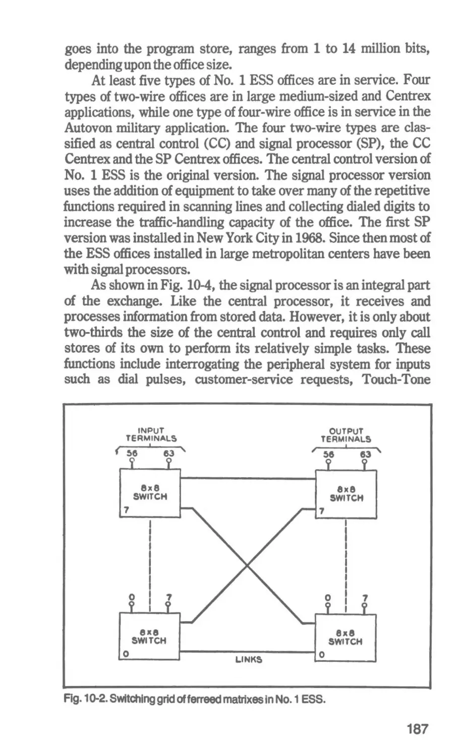
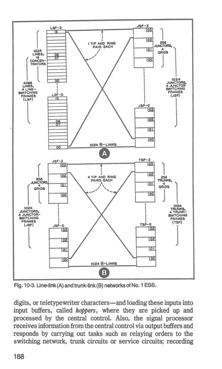
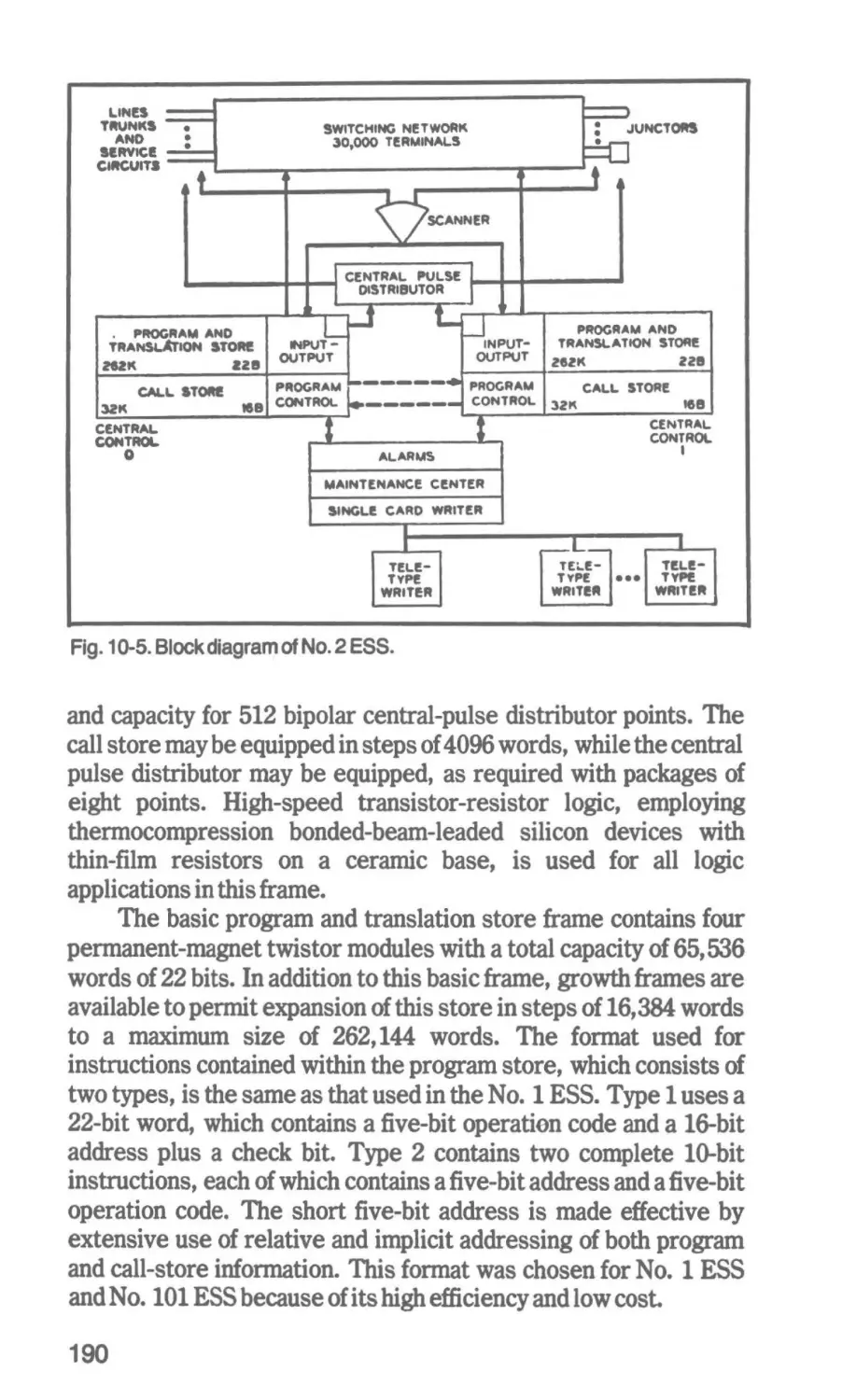
The No. 1 ESS Switching System-The No. 2 ESS Switching
System-Automatic Electric's No. 1 EAX--Japan's D-1 O SPC
Exchange
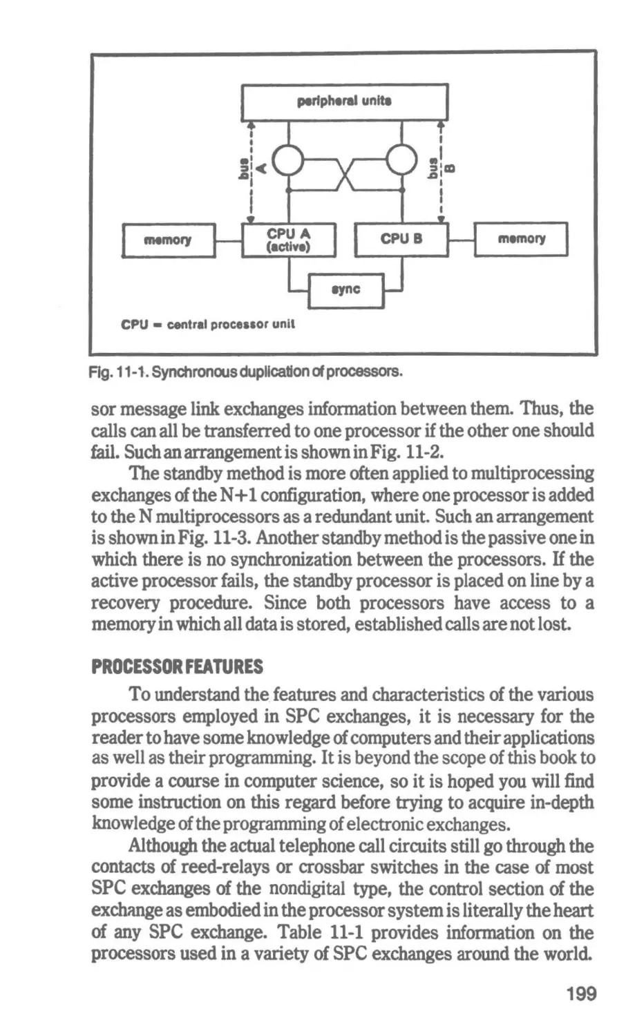
11 The Control and Prosrammln1 of SPC Exchan1es
198
12 Time-Division Switchin1 Systems
222
Processor Features How the Processor Controls the Switching
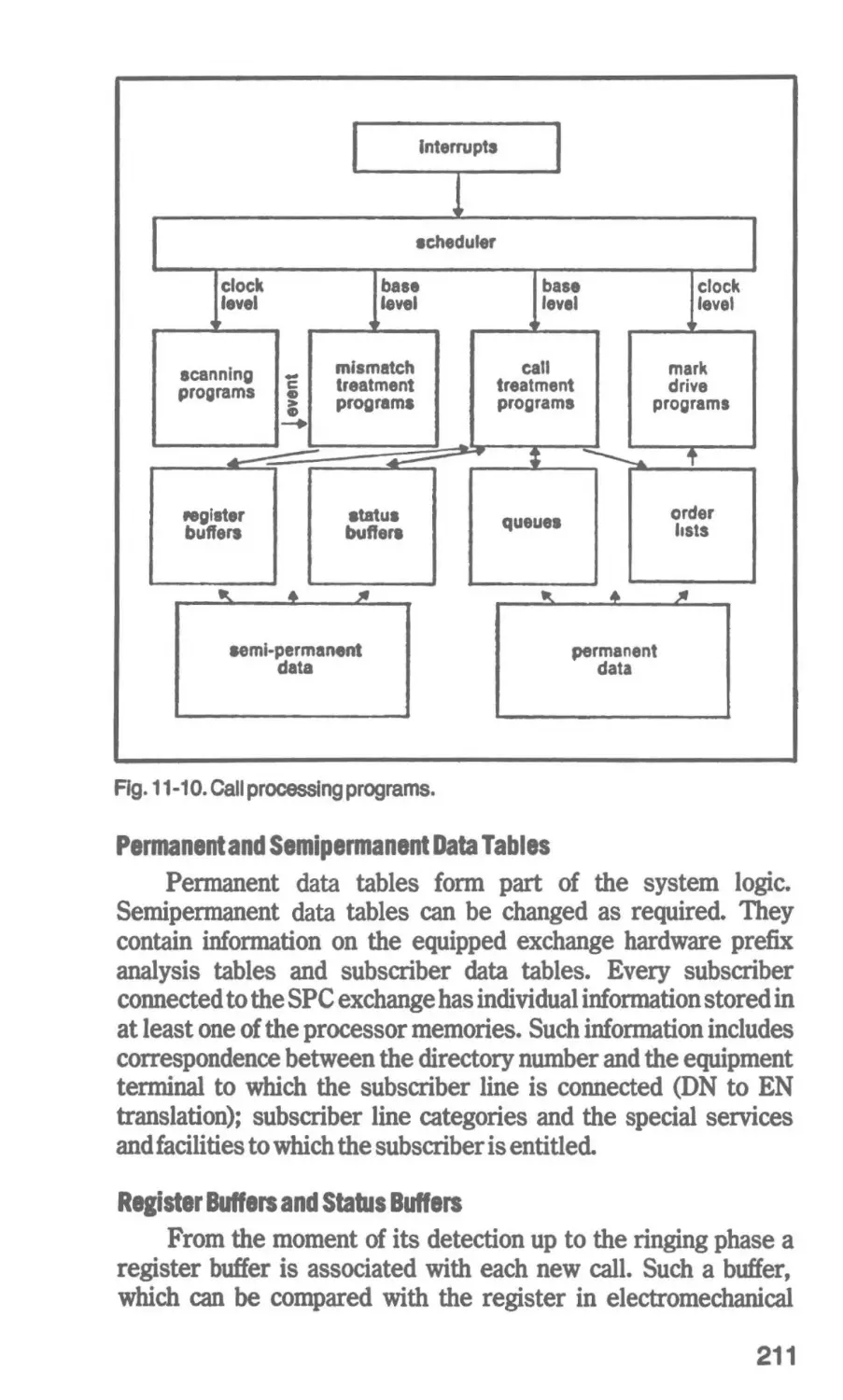
Network-Call Processing Program&--The Establishment of a
Local Call-Classfflcation of SPC Programs
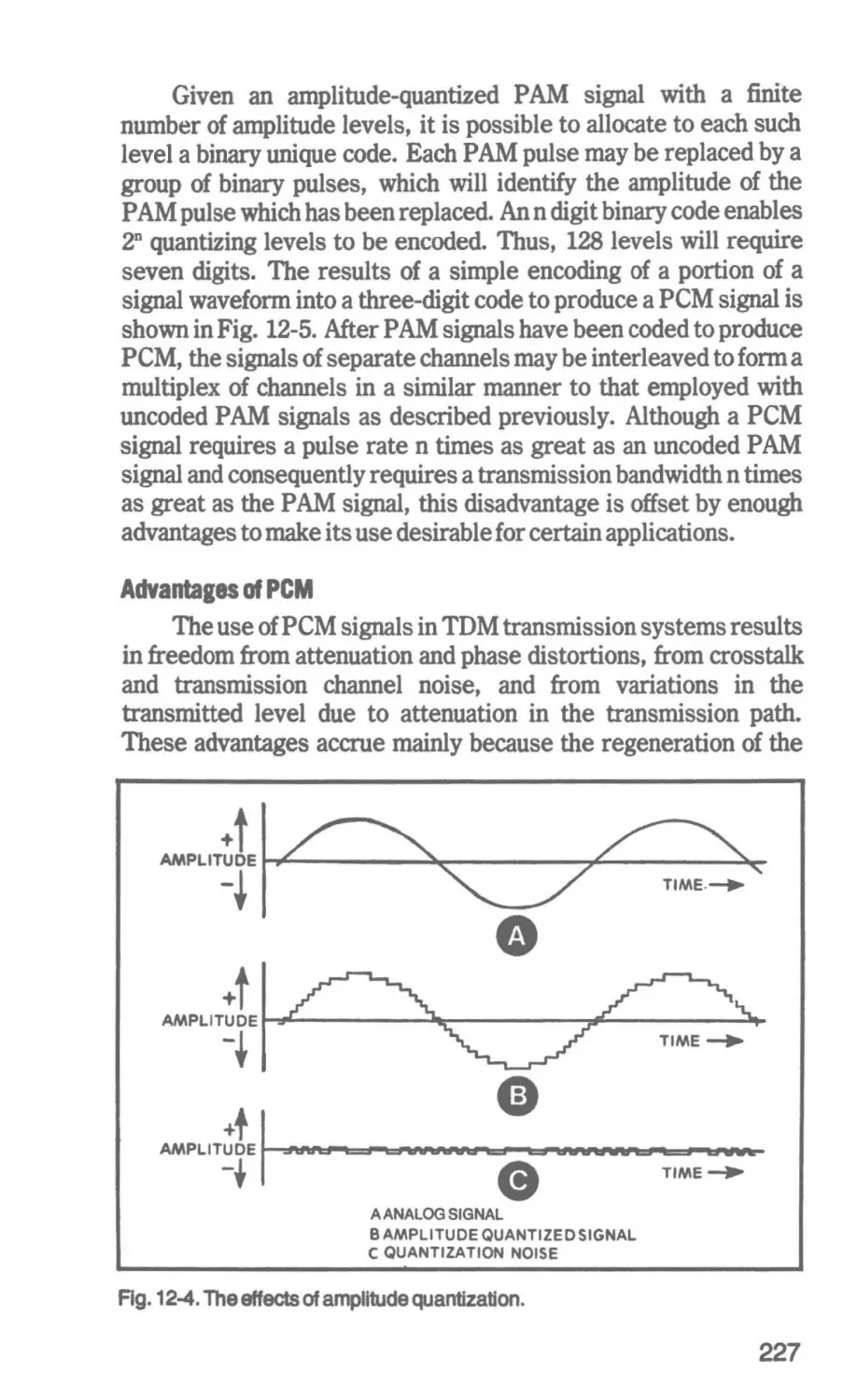
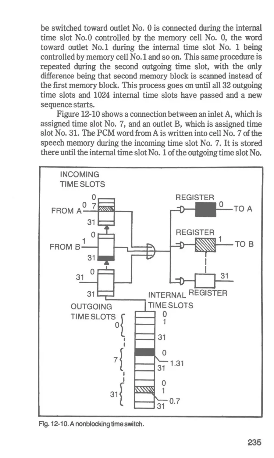
Time Sampllng-Tlme-Divlslon Multiplexing-Pulse-Code
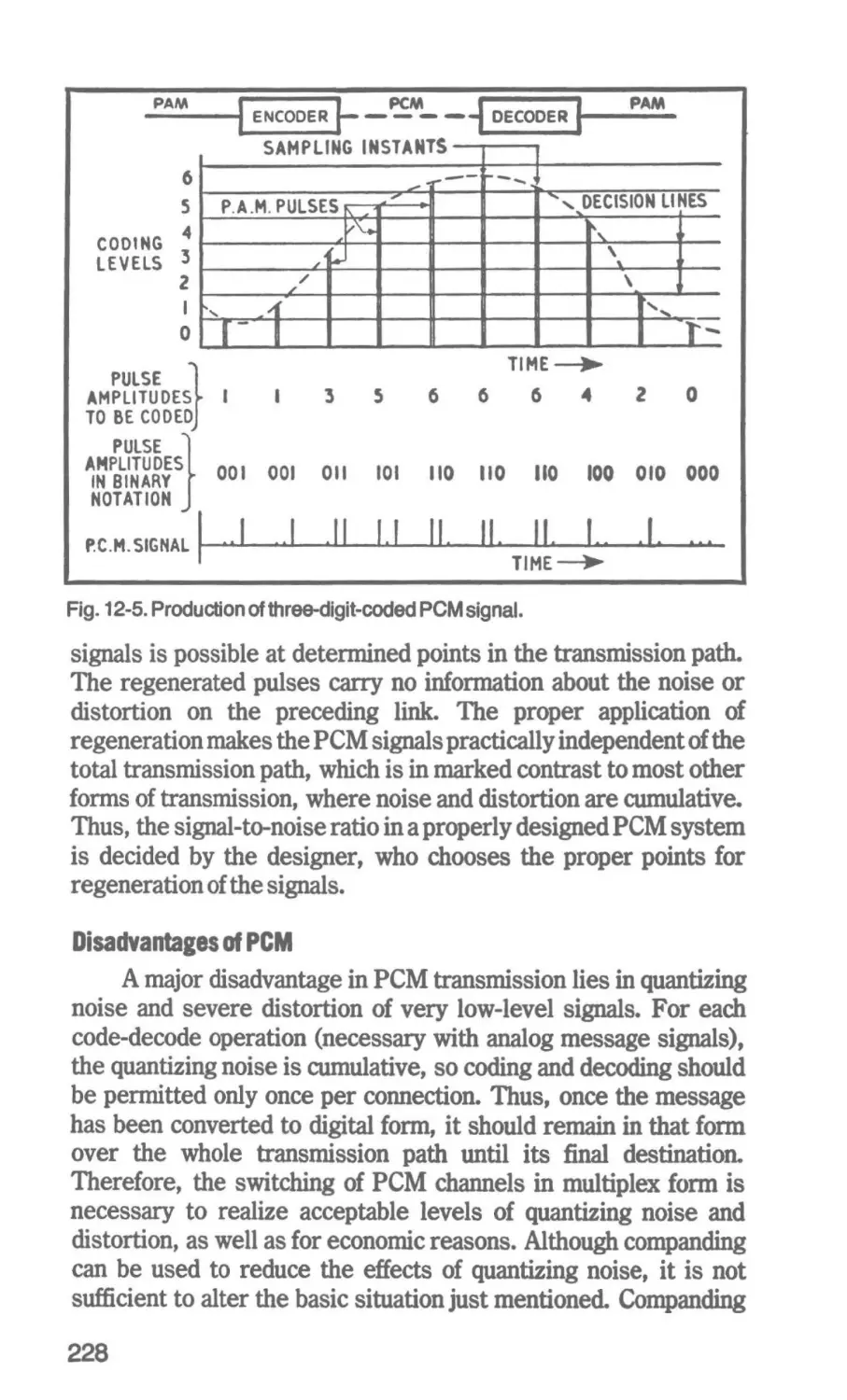
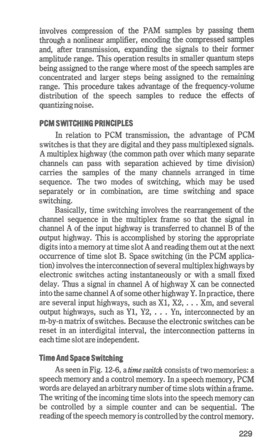
Modulation-PCM Switching Principles-Application of PCM
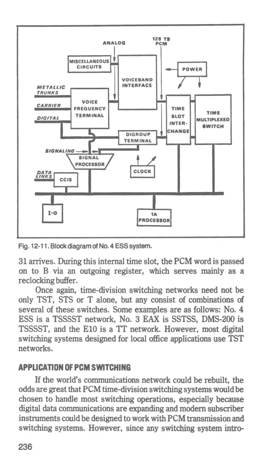
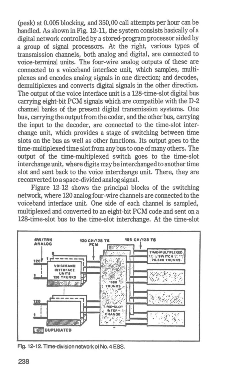
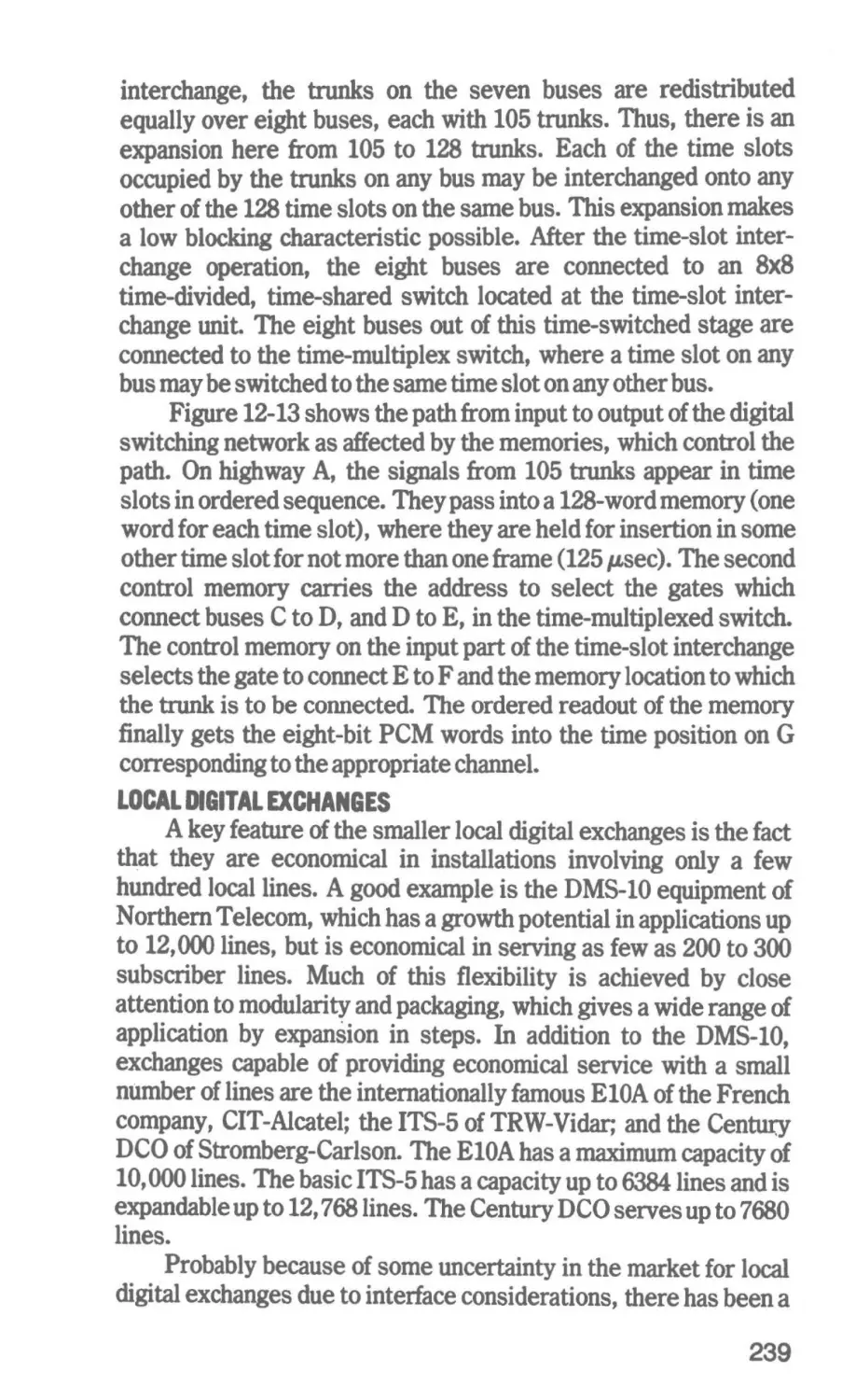
Switching-PCM Toll Exchang~ocal Digital Exchanges
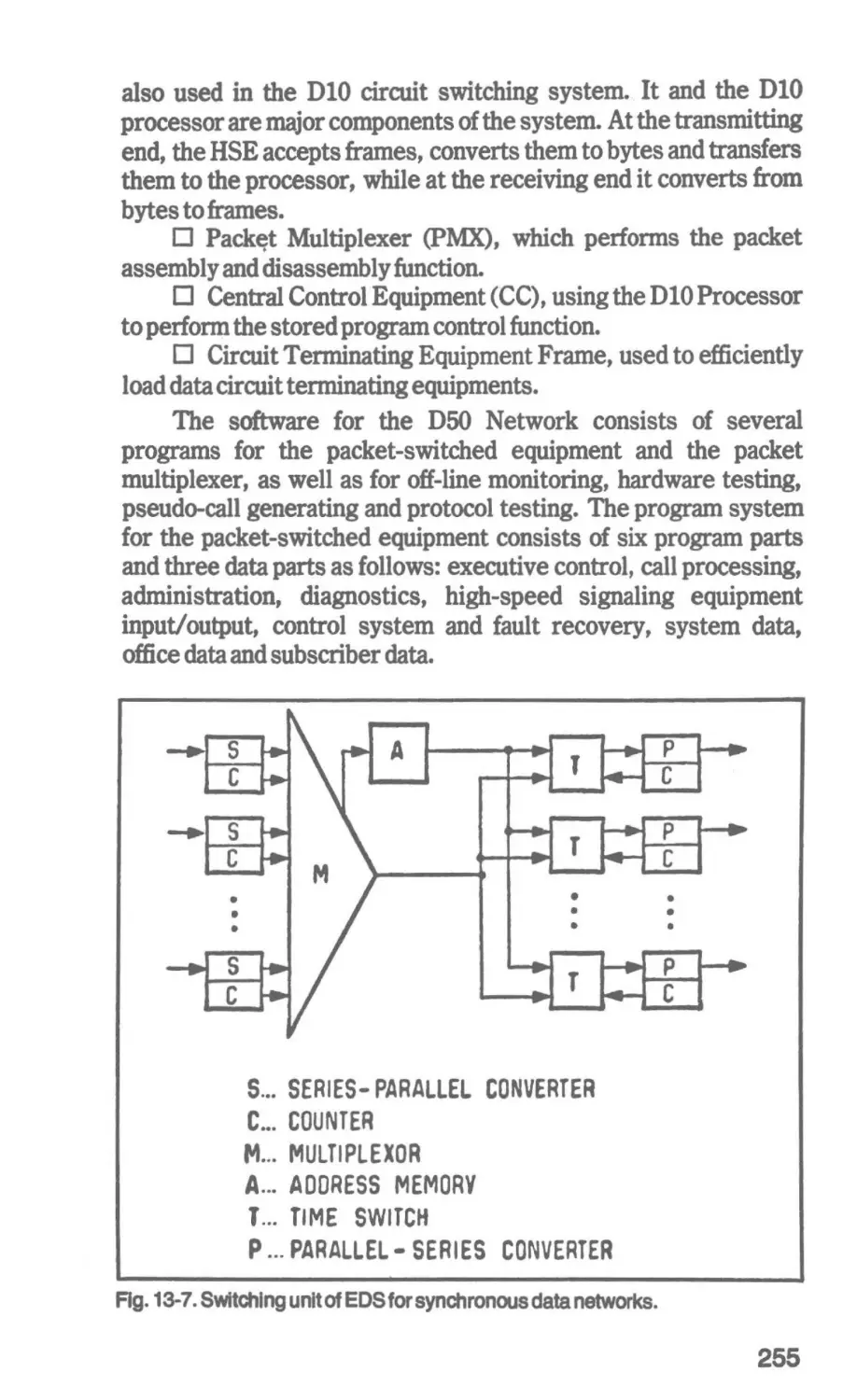
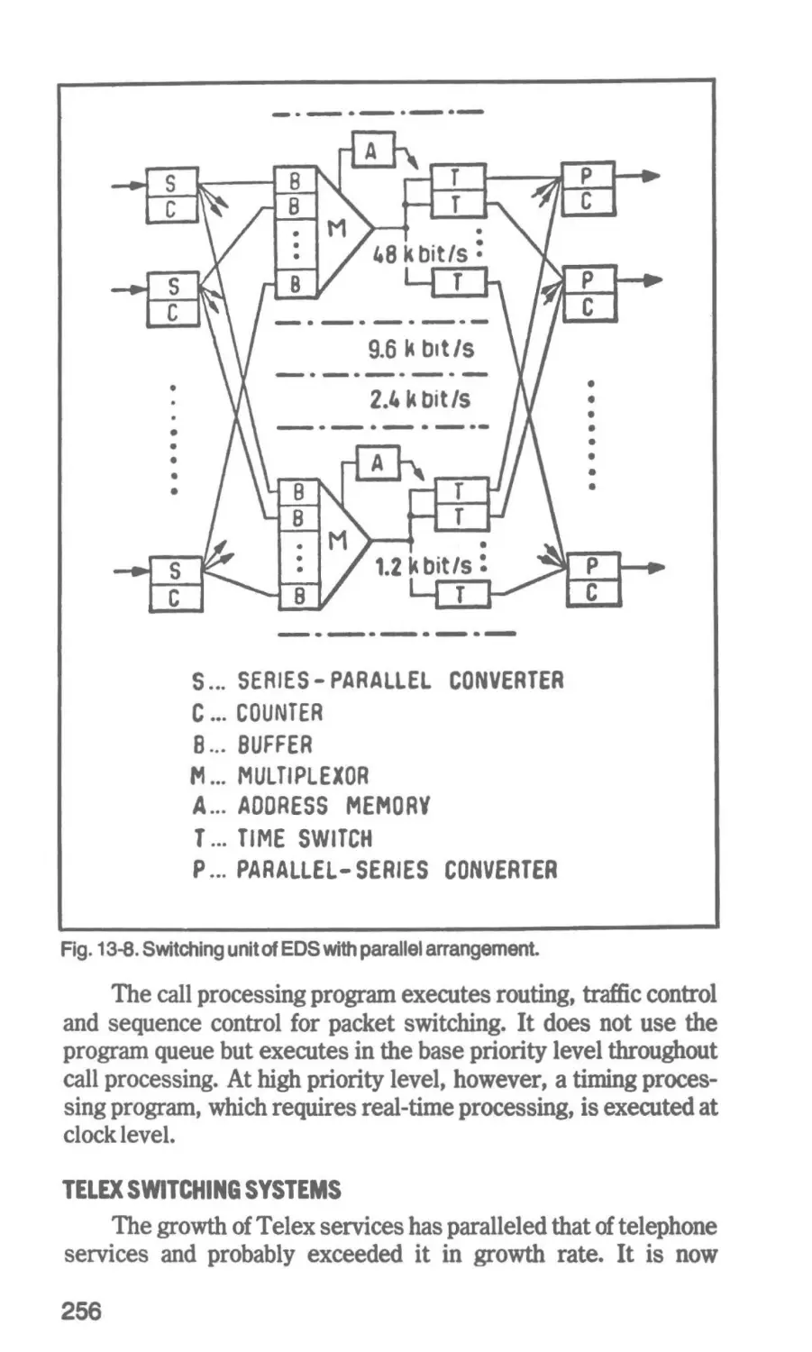
13 Data and Telex Swttchln1
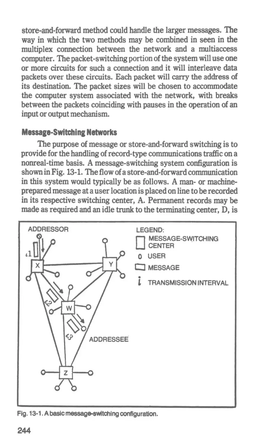
241
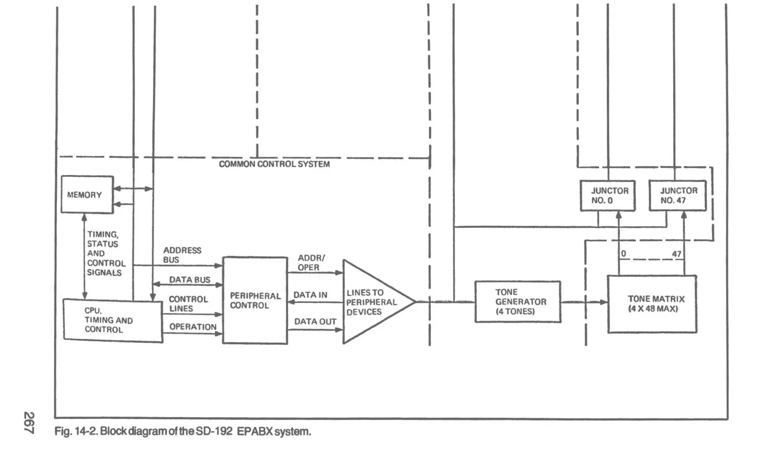
14 Automatic Private Branch Exchanges
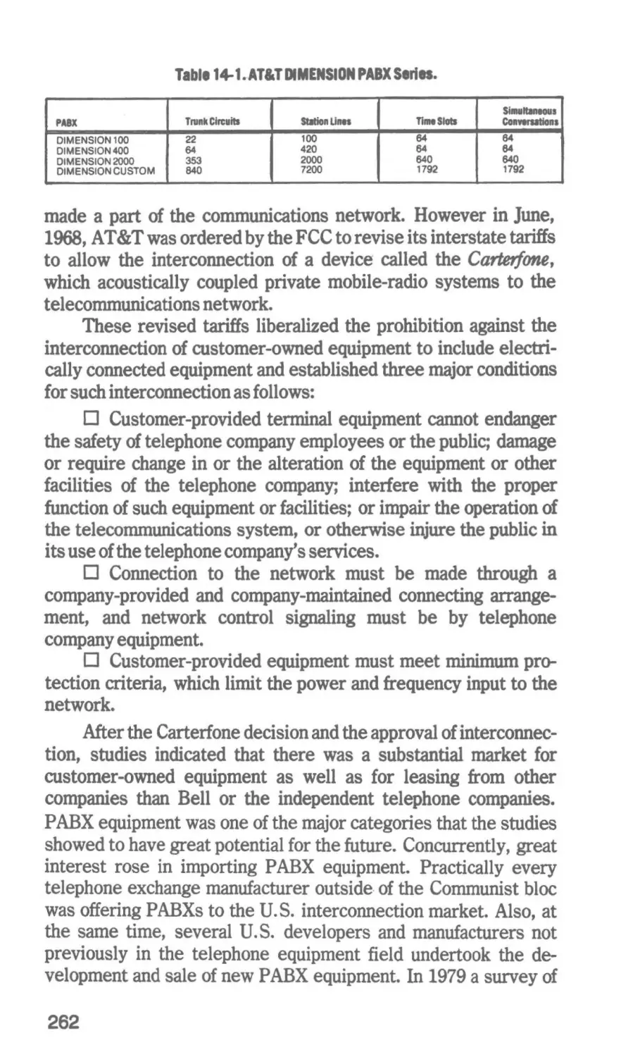
258
Characteristics of Data Communications-Data Communication
Methods-Operational Message-Switching Systems-PacketSwitching Network&--Telex Switching Systems
PBX Functions-PABX Switching Systems-The Interconnection
of Privately Owned PABXs-Typlcal PABX SystemsCentralized Extension Service
Glossary
281
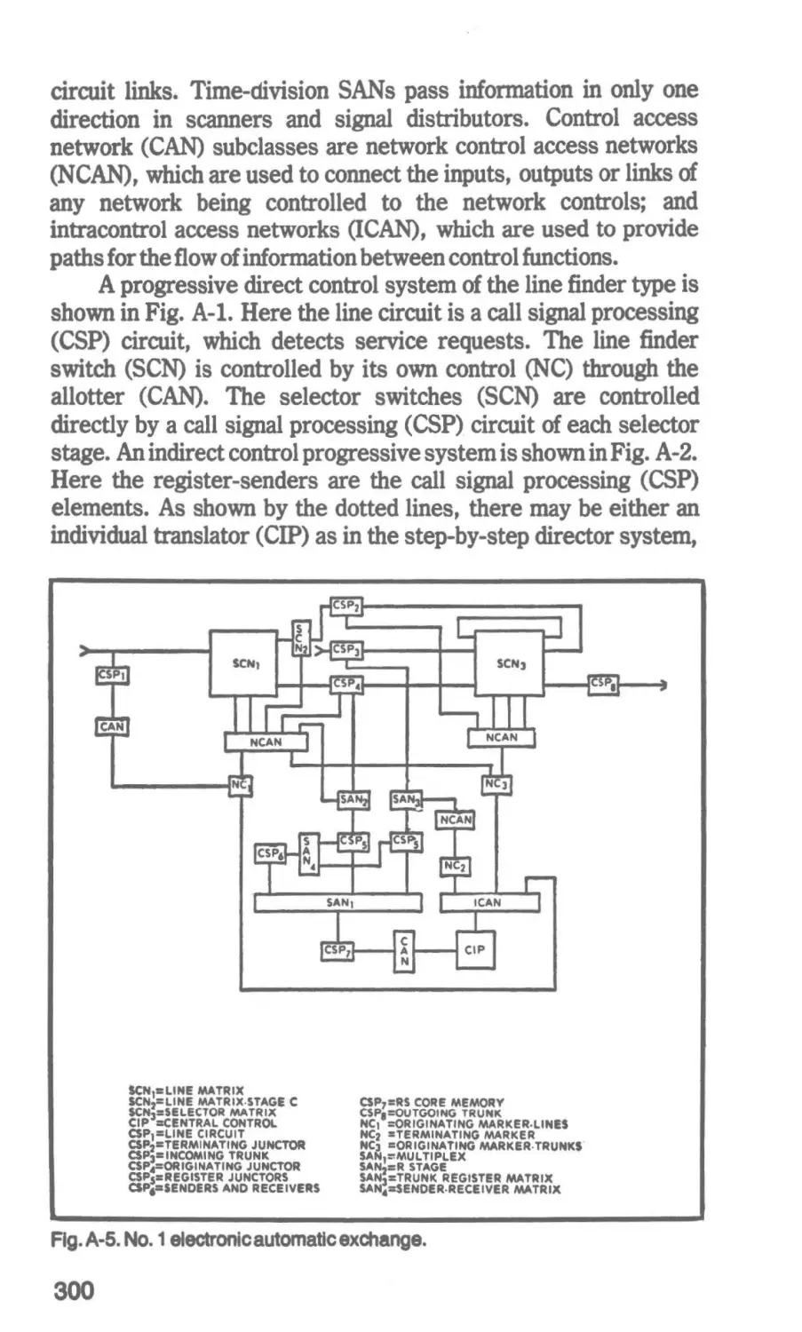
Appendix Symbol au and Nomenclature
297
Credits
302
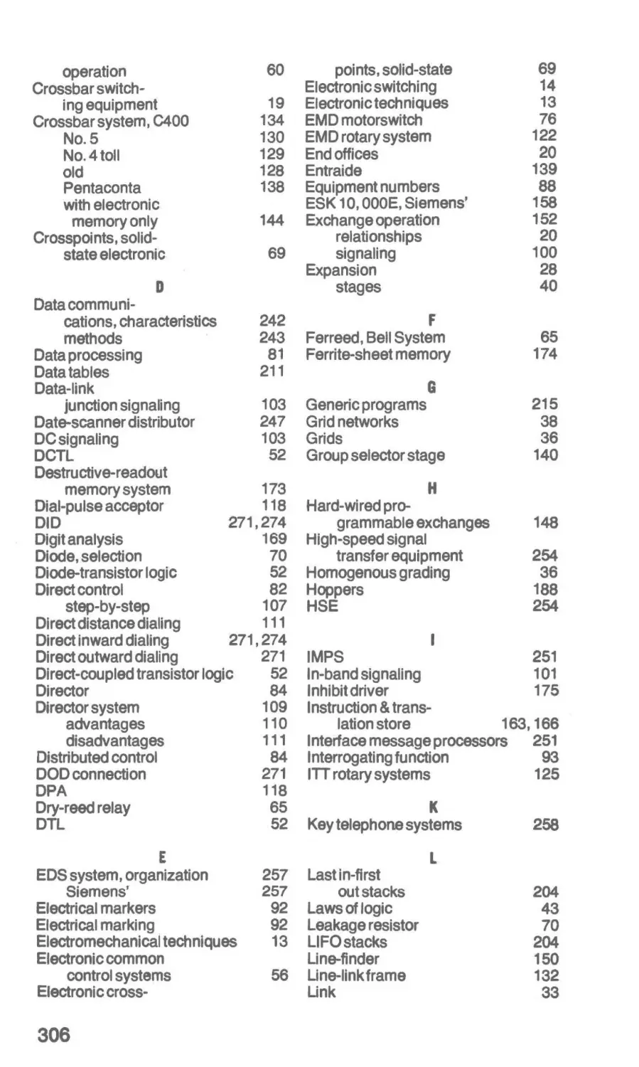
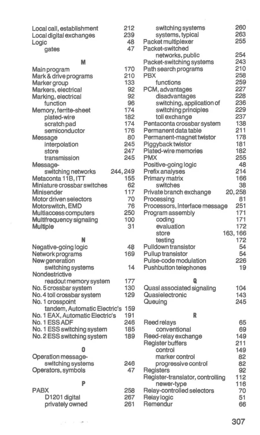
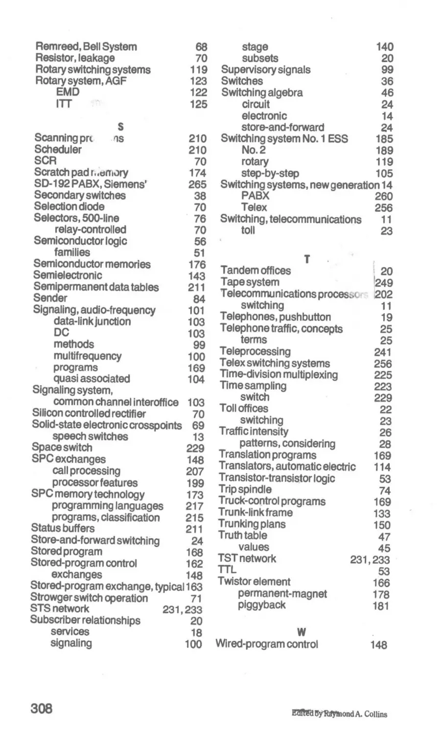
Index
305
Preface
Some 80 years ago telephone switching began to change ftom
manual to automatic operation, but this change did not come
overnight with the invention of the Strowger switch. Decades were
required for its full impact to be realized. It is likely that no change
since then has been of equal importance in its effect on the
structure of telecommunications services until the recent advent of
computer-controlled switching techniques. In the years ahead, the
application of digital central processor techniques (with their
inherent software flexibility) to the control of switching elements
can be expected to equal or exceed the impact on telecommunication operations created by the historic change from manual to
automatic switching systems. The control of switching equipment
based on fast operating, high-density digital memories to store
readily changed programs marks the beginning of a new era in
communications switching.
Unfortunately, the economics of capital investment and the
demands for telephone service have made it impossible for this
new era to be spawned as rapidly as technology would otherwise
permit. Here again, it appears that decades will be required to
replace the automatic equipment of an earlier vintage. Nevertheless, certain electronic features are being added to the existing
equipment while a modest percentage of telephone lines are being
equipped for service by completely new electronic systems. In the
U.S., large urban centers are being served first by the new
technology due mainly to the fact that it is more adaptable to large
numbers of lines. In some countries, development has led in the
direction of equipment to serve medium-sized communities first.
7
On a worldwide basis, much of the activity in electronic switching
for telecommunications is still largely in the developmental or
field-trial stages, but most major industrial countries have definite
plans to produce and install a significant number of electronic
switching systems over the next several years. In some cases
military systems have been the first to benefit from the new
switching technology because economic considerations have not
played as great a role in dictating decisions in this area.
The rapidly increasing activity in digital data transmission, as
well as the benefits derived from converting analog signals to
digital form prior to transmission, has emphasized the need for
digital switching. Since both time-division and message-switching
techniques lend themselves to this phase of communications,
developments in these directions have been accelerated. Digital
switching lends itself well to digital transmission networks and will
be seen there increasingly in the future. However, it cannot
interface economically with existing analog telephone instruments
and therefore cannot be expected to penetrate the entire communications hierarchy in the foreseeable future.
Modem Communications Switching Systems might logically
encompass only those employing the new techniques of computerized control and digital switching. However, in view of the
reality of the situation as stated, one must at least include crossbar
and step-by-step systems as well, especially since both of these
types, being modernized through the application of electronic
control techniques, are likely to serve the public for some time in
the future.
This book deals with the basic principles of telecommunications switching techniques ranging from step-by-step and rotary
systems to the most modem stored-program control electronic
systems, as well as time-division switching and those systems
used in the switching of digital data. It is intended for use primarily
by technical schools and colleges offering courses in telecommunications and related subjects and by engineers and technicians
interested in learning more about this field of switching.
Since the first edition of this book was written, significant
advances in the use of stored-program controlled (S/C) exchanges
have been made in the U.S. As we enter the 1980s, approximately
one-third of the lines in this country are switched by such systems.
Projections indicate that by the year 2000, all of the lines in this
country will be switched by computer-controlled exchanges. In
other major developed countries, the percentages of lines switched
8
by such systems are much lower. However, all of the major
manufacturers of telephone exchanges throughout the world have
developed SPC exchanges, and projections indicate that during the
next decades the percentage of electronically switched lines will
rise rapidly.
Digital switching has also made rapid progress in its application to toll exchanges in the U.S. Digital exchanges have been
developed or are being developed by major telephone companies of
the world and their application to local central office switching is
making progress particularly outside the U.S. Some countries are
pushing harder than others for its application at all exchange levels
and have already made significant progress in that direction.
Despite all of this progress, the majority of the lines in the
U.S. and in the rest of the world are still switched by electromechanical exchanges. Practically all major electromechanical
systems, such as crossbar and step-by-step, are still in widespread
use. Therefore, while an attempt has been made to update this
book in SPC and digital-switching as much as necessary, it does not
appear desirable to delete material about electromechanical
switching systems.
A chapter on the control and programming of SPC exchanges
has been added. The statistics have been updated and the chapters
on time division switching systems, data and telex switching and
automatic private branch exchanges have been expanded. I wish to
acknowledge the assistance of the/TU Telecommunication Journal, the Institute of Electrical and Electronics Engineers IMC., the
Japan Telecommunications Review of the Nippon Telegraph and
Telephone Public Corp. and the National Engineering Consortium.
For their enthusiastic support and material contributions, I
wish to thank also the American Telephone and Telegraph
Company; Bell Laboratories; GTE Automatic Electric
Laboratories Inc.; The Institute of Electrical and Electronics
Engineers Inc.; The Institution of Electrical Engineers (London);
The International Telephone and Telegraph Corp.; L M Ericsson;
Nippon Telegraph and Telephone Public Corp.; Philco-Ford; The
Plessey Company Ltd.; The Postoffice Electrical Engineers'
Journal; Siemens AG; Stromberg-Carlson Corp.; The University
of Essex; and the Western Electric Company.
Marvin Hobbs
9
Chapter 1
The Slow Push for Progress
During the 10 years between 1970 and 1980 the number of
telephones in the world has doubled. The number of countries with
more than a million telephones has risen to 36. During this same
period, the number of countries with over 200 annual conversations per person has reached an all-time high. Through cables, land
lines, and satellite relays, the U.S. resident has access to more
than 98 percent of the world's nearly 400 million telephones.
Nineteen of the world's major cities had more than a million
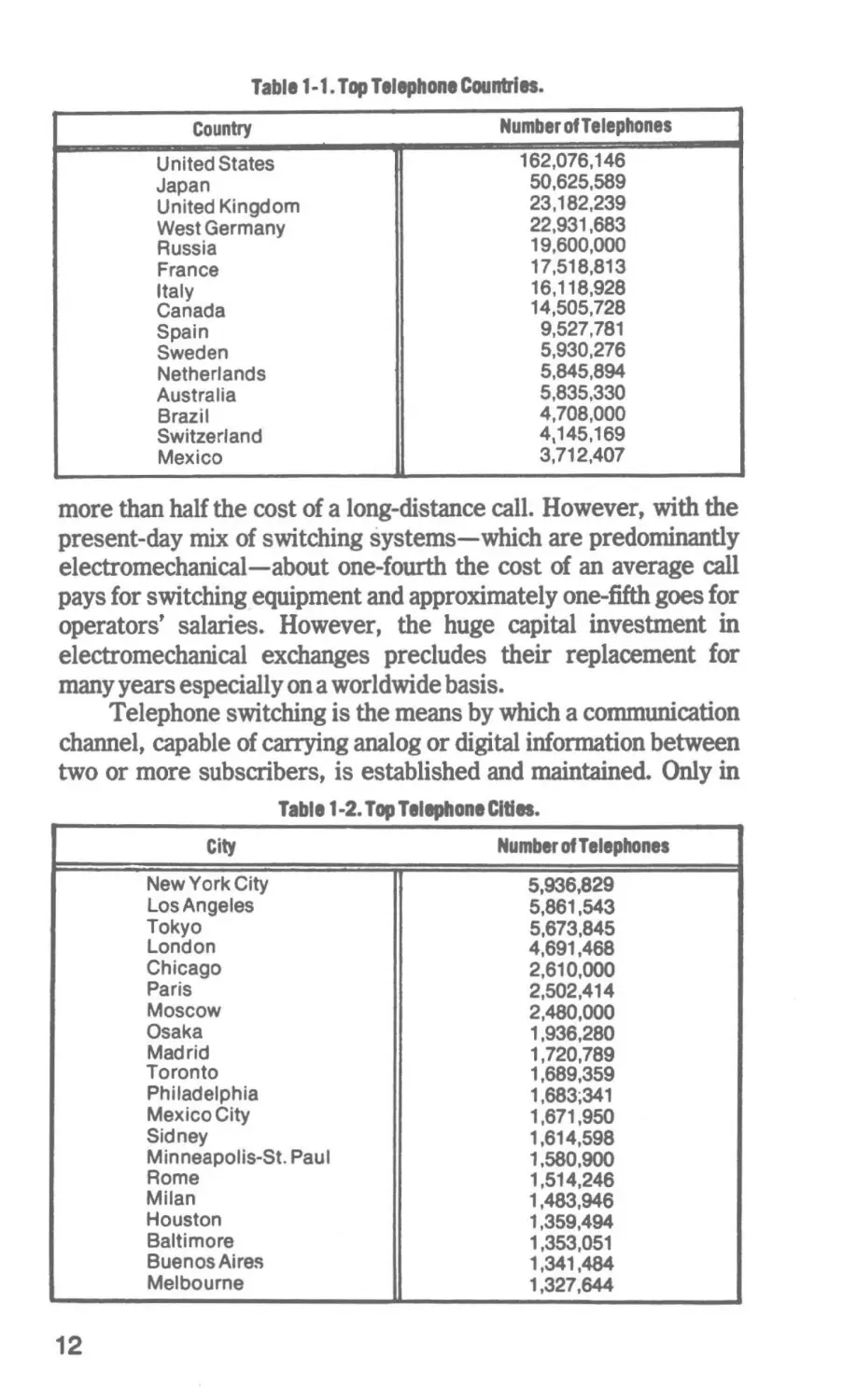
telephones each by 1972. In Table 1-1 the top 15 countries in
numbers of telphones are listed and in Table 1-2,20 of the cities and
urban areas with more than 1, 000, 000 telephones each are listed in
the order of their number of phones. In addition to the transmission
of voice, the telephone system was called upon increasingly to
send and receive data from computers, facsimile equipment, video
devices and other data sources.
TELECOMMUNICATIONS SWITCHING
Because relatively few telephones can provide contact without switching from a multitude of local lines to a much smaller
number of trunks between exchanges, the demands for service
have not only increased the amount of switching required but have
emphasized the need for greater dependability, faster connections,
and new conveniences. The.importance of switching to telecommunications can be measured to a degree by comparing its costs to
that of the other elements of the overall systems. In that regard it
represents nearly hali the cost of an average telephone call and
11
Table 1-1. Top Telephone Countries.
Number of Telephones
Country
United States
Japan
United Kingdom
West Germany
Russia
France
Italy
Canada
Spain
Sweden
Netherlands
Australia
Brazil
Switzerland
Mexico
162,076,146
50,625,589
23,182,239
22,931,683
19,600,000
17,518,813
16,118,928
14,505,728
9,527,781
5,930,276
5,845,894
5,835,330
4,708,000
4,145,169
3,712,407
more than haH the cost of a long-distance call. However, with the
present-day mix of switching systems-which are predominantly
electromechanical-about one-fourth the cost of an average call
pays for switching equipment and approximately one-fifth goes for
operators' salaries. However, the huge capital investment in
electromechanical exchanges precludes their replacement for
many years especially on a worldwide basis.
Telephone switching is the means by which a communication
channel, capable of carrying analog or digital information between
two or more subscribers, is established and maintained. Only in
Table 1-2. Top Telephone Cities.
City
New York City
Los Angeles
Tokyo
London
Chicago
Paris
Moscow
Osaka
Madrid
Toronto
Philadelphia
Mexico City
Sidney
Minneapolis-St. Paul
Rome
Milan
Houston
Baltimore
Buenos Aires
Melbourne
12
Number of Telephones
5,936,829
5,861,543
5,673,845
4,691,468
2,610,000
2,502,414
2,480,000
1,936,280
1,720,789
1,689,359
1,683;341
1,671,950
1,614,598
1,580,900
1,514,246
1,483,946
1,359,494
1,353,051
1,341,484
1,327,644
the case of private lines is it not required. Any modem telecommunications switching system consists of a great many intricate
equipment and components combined into a overall system
operating along certain well defined principles. A typical electromechanical automatic switching system contains several master
control circuits, each of which consists of some 1500 relays. Such
circuits are able to select particular paths and establish a desired
connection in less than one second. In doing this, some 700 relays
operate and about 10,000 electrical contacts are closed and
opened. As an example, a single telephone call from Ann Arbor,
Michigan, to downtown Detroit through an electromechanical
exchange requires 37,000 relay contacts to make connection. To
link any U.S. telephone with any other, the Bell System switching
network provides a staggering 2. 5 million billion possible connections. The installation of electronic exchanges will reduce the
number of relay contact operations considerably-especially in the
control portion of the system. But there are still 15 reed relay
crosspoints for each subscriber's line in the No. 1 ESS offices.
Even when a majority of the subscribers have such electronic
switching service, it can be seen that the number of connections to
be made for many calls will not be minor.
Present-day telephone-circuit switching equipments are
based on either electromechanical techniques (employing
crossbar, Strowger, or rotary switches) or electronic techniques
(employing either electromechanical or solid-state speech
switches and some form of electronic common control). The
development of most of these systems has required years of time
due largely to the extreme requirements for dependability and
reliability. Even a "negligible" amount of downtime of a network
cannot be tolerated by the telephone operating companies. There
would be a much higher percentage of program-controlled electronic exchanges in use today if the demands for service in the late
1950s had not forced the installation of many crossbar exchanges
while the full development of practical electronic exchanges was
awaited Also, at the present time stored-program electronic
exchanges are economical only in medium to large central offices
and for large private branch exchanges (PABXs). For these
reasons, Western Electric produced more electromechanical
crossbar switches annually 20 years after the invention of the
transistor than ever before; and Japan (a major source of telephone
switching systems in the international market) exported only
exchanges with crossbar and step-by-step switches during the past
'
13
decade. Even more surprisingly, Western Electric manufactured
more stepping equipment in 1969 and 1970 than ever before and
installed the ancient panel system equipment in the world's largest
telephone city to cope with the service crisis in the city of New
York.
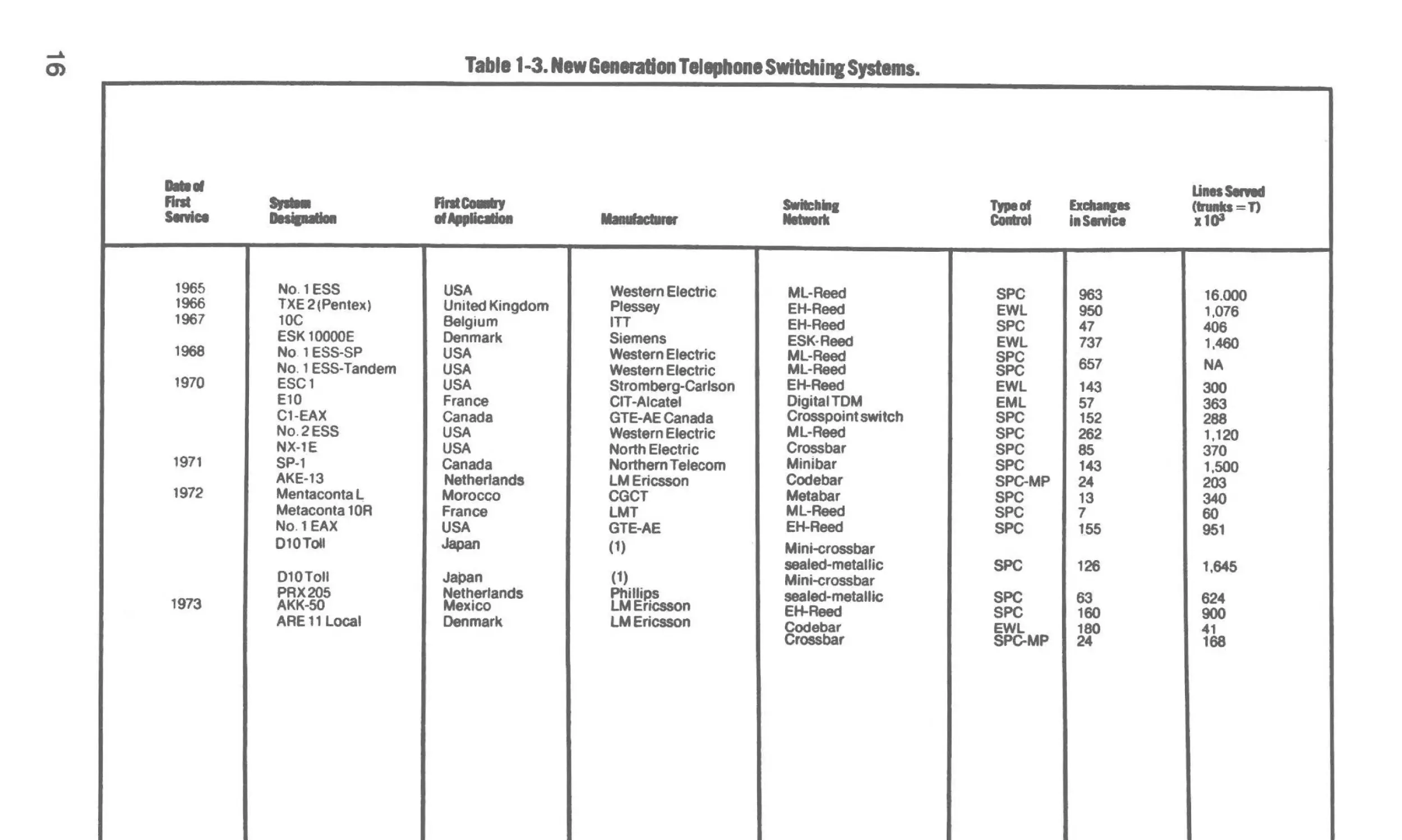
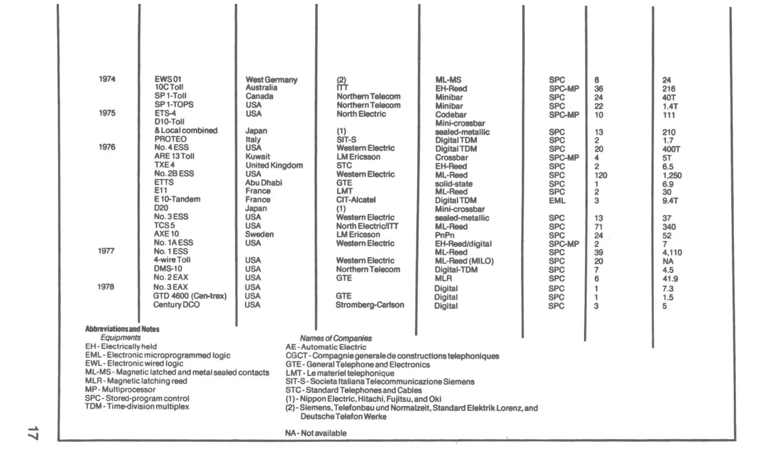
..New Generation" Switching Systems in Service
Table 1-3 shows the "New Generation" Telephone Switching
System in service as of mid-1978 listed by the first country of
application. As indicated in the table, most of these exchanges
featured stored program control (SPC).
Electronic Switchin1 in the U.S.
As of mid-1979, more than 30 percent of the Bell System lines
were being served by electronic switching systems. The number of
their lines being switched by such systems was growing at the rate
of about 6 million lines per year. New ESS offices were being
cutover at a rate of about one per day. Despite all of this progress
Bell's No. 5 Crossbar System continued to switch about 40 percent
of their lines. The remaining 30 percent was served by other
crossbar and step-by-step systems of earlier vintage. However, it
was projected that about 60 percent of the Bell System lines would
be switched electronically by 1985. Among the independent
telephone companies it is estimated that not more than 10 percent
of their lines are served by electronic switching systems produced
mainly by General Telephone. The remaining 90 percent was
switched by a relatively small number of crossbar exchanges and a
large number of step-by-step (Strowger) exchanges. The latter
were also produced by General Telephone.
In the BeH System, digital switching was being applied only to
high-capacity toll exchanges. Here the No. 4 ESS, a large
digital-switching exchange, is employed. One-half of the trunk
circuits terminating at these e~changes will soon be handling
pulse-code modulation of 24-channel capacity. No. 4 ESS exchanges now serve 30 percent of the toll circuits in the Bell System
and are projected to serve 90 percent of them within five years.
Toll service is also provided with lower capacity digital exchanges
by the independent telephone companies. The No. 3 EAX of
General Telephone and the DMS-series of Northern Telecom are
examples of such exchanges.
By 1980, at least six companies, outside of the Bell System,
had introduced digital switching systems for local exchange
application. The prices of these exchanges appeared to offer
14
considerable promise toward the replacement of the many electromechanically switched exchanges now in use by the Independent Telephone Companies. By the end of 1979, the Bell System
had not placed any local digital exchange in regular service, but an
announcement had been made that a No. 5 ESS system was to fill
this role. At the PABX level, most of the new equipment
incorporated digital switches.
Electronic Switching Outside the U.S.
Outside the U.S., Japan led in the application of
electronically-switched SPC systems, with about 7 percent of their
local subscriber lines and 24 percent of their toll circuits being
switched by such systems by mid-1979. According to their present
five-year plan, the percentage of local subscriber lines served by
SPC switching systems would more than double by mid-1981.
Japan still depended upon crossbar-switching systems to handle
the bulk of its telephone traffic with a small percentage still
switched by step-by-step exchanges.
In mid-1979, England was second after Japan switching about
6 percent of its local lines with electronically-switched exchanges.
However, they used primarily a system-initially developed in
1966-with wired logic rather than the computer software control
of typical modem SPC systems. Just the opposite ofJapan, England
still depended upon step-by-step (Strowger) switching systems to
handle most of its telephone circuits with a small percentage
switched by crossbar systems.
Although all of the world's telephone exchange manufacturers
have various models of SPC exchanges available, and most
countries, including several of the lesser developed ones, have
plans for extensive if not total use of electronic switching systems
by the year 2000, the amount of their use outside of the U.S., Japan
and Britain was comparatively small in 1979. Large numbers of
step-by-step (Strowger) and crossbar systems continued to carry
the telephone traffic in many parts of the world.
In so far as the application of digital (time-division) sWitching
at the local exchange level is concerned, the U.S. is not the leader.
France now holds the distinction of being in first place. Proceeding
from a military application, France has promoted the use of digital
switching with vigor. At the end of 1979, more than 500, 000 lines
were being switched at the local level in France. Through export
efforts as well as domestic efforts, the French company, CITAlcatel, had 3, 000, 000 lines in service or on order for digital
15
.....
Table 1-3. New Sensation Telepllone Switching Systems•
O>
......
Flnt
Slllicl
1965
1966
1967
1968
1970
1971
1972
1973
......
...........
FlntCGaty
,,,Applicaliall
No.1 ESS
TXE2(Pentex)
10C
ESK10000E
No 1 ESS-SP
No. 1 ESS-Tandem
ESC1
E10
C1-EAX
No.2ESS
NX-lE
SP-1
AKE-13
Mentaconta L,
Metaconta 1OR
No.1 EAX
010Toll
Japan
010Toll
PRX205
AKK-50
ARE 11 Local
Japan
Netherlands
Mexico
Denmark
USA
United Kingdom
Belgium
Denmark
USA
USA
USA
France
Canada
USA
USA
Canada
Netherlands
Morocco
France
USA
.......
Western Electric
Ptessey
ITI
Siemens
Western Electric
Western Electric
Stromberg-Carlson
CIT-Alcatel
GTE-AE Canada
Western Electric
North Electric
Northern Telecom
LMEricsson
CGCT
LMT
GTE-AE
(1)
(1)
PhifliP.S
LMEricsson
LMEricsson
SWilcfllas
Nllwll1l
ML-Reed
EH-Reed
EH-Reed
ESK·Reed
ML-Reed
ML-Reed
EH-Reed
Digital TOM
Crosspoint switch
ML-Reed
Crossbar
Minibar
Codebar
Metabar
ML-Reed
EH-Reed
Mini-crossbar
sealed-metallic
Mini-crossbar
sealed-metallic
EH-Reed
Codebar
Crossbar
Uness.wd
lJpeDf
CanlrOI
&dlalll•
l1S11Vic1
(trunl=T)
x1C>1
SPC
EWL
SPC
EWL
SPC
SPC
EWL
EML
SPC
SPC
SPC
SPC
SPC-MP
SPC
SPC
SPC
143
24
13
7
155
203
340
SPC
126
1,645
SPC
63
SPC
EWL
SPC-MP
160
180
624
900
963
16.000
1,076
950
47
737
406
657
NA
143
57
152
262
300
85
24
1,460
363
288
1,120
370
1,500
60
951
41
168
1974
1975
1976
I
I
I
EWS01
10CToll
SP 1-Totl
SP1-TOPS
ETs-4
010-Toll
& Local combined
PROTEO
No.4ESS
~RE 13Toll
TXE4
No.2BESS
ETTS
Ell
19n
1978
I
I
E10-Tandem
020
No.3ESS
TCS5
AXE10
No. 1AESS
No. 1ESS
4-wireToll
DMS-10
No.2EAX
No.3EAX
GTD 4600 (CerHrex)
CenturyOCO
West Germany
Australia
Canada
USA
USA
Northern Telecom
Northern Telecom
North Electric
Japan
Italy
USA
Kuwait
United Kingdom
USA
Abu Dhabi
France
France
Japan
USA
USA
Sweden
USA
USA
USA
USA
USA
USA
USA
m
(1)
SIT-S
Western Electric
LMEricsson
STC
Western Electric
GTE
LMT
CIT-Alcatel
(1)
WestemElectrtc
North Electric/ITT
LMEricsson
Western Electric
Western Electric
Northern Telecom
GTE
GTE
Stromberg-Cartson
Ml-MS
EH-Reed
Minibar
Minibar
Codebar
Mini-crossbar
1881ed-meta1Uc
Digital TOM
Digital TOM
Crossbar
EH-Reed
ML-Reed
solid-state
ML-Reed
Digital TOM
Mini-crossbar
sealed-metallic
ML-Reed
PnPn
EH-Reed/digital
Ml-Reed
ML-Reed (MILO)
Digital-TOM
MLR
Digital
Digital
Digital
I
I
Ablnviationsand Notes
Equipments
EH· Electrically held
EML ·Electronic microprogrammed logic
EWL- Electronic wired logic
ML-MS· Magnetic latched and metal sealed contacts
MLR- Magnetic latching reed
MP- Multiprocessor
SPC ·Stored-program control
TOM- Time-division multiplex
~
~
I
Names of Companies
AE-Automatic Electric
CGCT - Compagniegeneraledeconstructions telephoniques
GTE- General Telephone and Electronics
LMT - Le materiel telephonique
SIT-S- Societa Italians Telecommunicazione Siemens
STC- Standard Telephones and Cables
(1 )- Nippon Electric, Hitachi, Fujitsu, and Oki
(2)-Siemens, Telefonbau und Normalzelt, Standard EJektrtk Lorenz, and
DeutscheTelefon Werke
NA- Not available
SPC
8
SPC-MP
SPC
SPC
SPC-MP
36
24
22
10
SPC
13
2
20
4
2
120
1
2
3
SPC
SPC
SPC-MP
SPC
SPC
SPC
SPC
EML
SPC
SPC
SPC
SPC-MP
SPC
SPC
SPC
SPC
SPC
SPC
SPC
13
71
24
2
39
20
7
6
1
1
3
24
216
40T
1.4T
111
210
1.7
400T
5T
6.5
1,250
6.9
30
9.4T
37
340
52
7
4,110
NA
4.5
41.9
7.3.
1.5
5
switching exchanges to be used in 16 countries going into 1980. In
addition, CIT-Alcatel had licensed the manufacture of such exchanges in Poland, Finland and Syria.
France projects that 50 percent of its exchanges will be digital
and one-third of them will be SPC systems by 1982. In a longer
range projection, Bell Canada plans for 50 percent of its local
exchanges to be digitized by 1995. Italy projects 50 percent digital
by the year 2000. In both Canada and Italy, the digital exchanges
will be of local design and origin.
It is well recognized that a major problem for most countries in
replacing existing electromechanical equipment is an economic
one. This is especially true in the case of small exchanges serving a
limited number of subscribers. There is some indication that the
judicious use of microprocessors in small digital exchanges may at
least bring the cost of the exchange within reach of the smallest
communities. Another possibility is the remote control of small
centers from remote processors; even then, there will remain the
question of whether replacement can be afforded if the existing
exchange still provides basic service. Perhaps those lesser
developed countries with only a small number of telephones at
present, but who can afford a whole new national system, have the
best prospect to realize a high percentage of electronicallyswitched SPC lines within a short time.
SUBSCRIBER SERVICES
It has been said that the ultimate goal of telephone switching
systems is that every telephone subscriber in the world be able to
call any other subscriber without the intervention of a telephone
operator. The world's first international direct-dial route was
placed in operation in September 1955, between Germany and
Switzerland. Although this goal has not yet been realized between
many countries, the public has been exposed to many new services
beyond the establishment of basic connections between subscribers during the past few years.
Starting with centralized extension service in private branch
exchanges in the early 1960s, unique features were offered
business subscribers who could afford them in the so-called
Centrex service packages of the Bell System. Such PABXs provide
for direct inward dialing of calls to their extensions and for message
accounting of outgoing toll calls for billing purposes, either
automatically or by an operator. The latter feature is referred to as
identification of outward toll dialing. By furnishing these services,
Centrex systems provided the significant advantage of increasing
18
the speed with which incoming calls could be completed to the
dialed station extension without operator assistance. The operator
workload was reduced, fewer operators were required, and an
accounting record of each outgoing call was available for the benefit
of the business customer in analyzing the telephone expenses of
his various departments.
Crossbar switching equipment has been utilized in Centrex
systems throughout the past decade. For instance, in the U.S. one
No. 5 crossbar office can serve as a common switching medium for
as many as 100 private branch exchanges. Such crossbar equipment is modified to generate and recognize 100 so-called "class of
service" marks and 20 rate treatments. The class of service marks
identify the PBX and the rate treatments identify the dialing
restrictions for each station-assuming that each variation requires a separate rate treatment. The details of Centrex systems,
as applied in the U.S. and other countries, will be described more
fully in a later chapter.
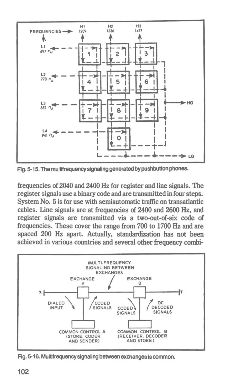
The introduction of pushbutton telephones has facilitated the
expansion of other new subscriber services to include variable
abbreviated dialing, call waiting, visible and audible charge
information service, add-on, holding, temporary transfer, call
transfer on busy, message service and telephone calculating, as
well as international direct dialing and various other Centrex
functions. Although it is possible to supply most of these services
through an electromechanical crossbar switching system, its
expansion to include many of these services inevitably leads to
complications in circuit and equipment arrangements and excessive increase in the physical size of the installation. The introduction of electronic circuitry and memory into the control section of
the exchange offers the best means to introduce the new subscriber
services. These can be accommodated more flexibly if storedprogram control can be afforded. In that case services can be
changed readily by altering software. Even if stored-program
control cannot be afforded due to the size of the exchange,
electronic componentry is most effective in the translation and
memory functions of the exchange.
In addition to providing new subscriber services on a more
economical basis, electronic control makes possible highly concentrated maintenance by providing for the replacement of faulty
packages rather than requiring the repairing of hardware. Also,
only about one-third of the floor space is required for the equipment
when compared with the conventional electromechanical crossbar
19
systems due to the use of integrated circuitry and other miniature
and subminature components. Because of computer capabilities,
electronic switching systems are capable of performing store and
forward switching-a technique applicable to data handling. Thus,
an electronic switching system can serve as a data-switching
center by concentrating and distributing various data at different
speeds; that is, it can concentrate traffic from terminating devices
at low speed and transmit it to a data-processing center at high
speed. The process is reversed in the distribution of data. These
are some of the reasons why the use of electronic switching in
telecommunication systems is bound to grow and why more
significant percentages of the total number of local lines will be
switched by such equipment in the future.
Subscriber and Exchan11 Relatlonshlps
Within a given urban or city area, the telephone system is
characterized by a combination of subscriber subsets (individual
telephone instruments), private branch exchanges (PBXs or
PABXs), end offices (central offices), tandem offices and a toll
center from which calls are routed to and from subscribers beyond
the given city area. These instruments, exchanges and offices are
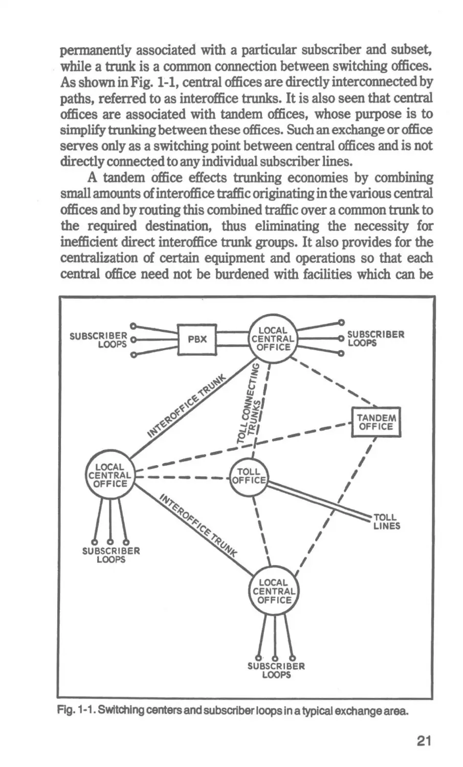
interconnected as shown in tbe simplified system of Fig. 1-1. The
many subscriber subsets feed to the central offices. In transmitting, the subsets modulate a direct current (usually transmitted
from the central office or private exchange) with the acoustic
speech message. In receiving, they demodulate the received signal
back into its acoustic form. The subsets also generate supervisory
signals (on-hook and off-hook) and switching signals (dial pulses or
frequencies). There are a variety of subsets in use, ranging from
the simplest dial types to pushbuttons. Of course, data modulatordemodulators (modems) are also a form of subset. The subscriber's
circuit to the central office provides a two-way path for the
message signals and the ringing, switching, and supervisory
signals. This circuit is referred to as the subscriber's loop. It is
obvious that many calls will be made between subscribers attached
to the same central office or private exchange. So, switching of
so-called "intraexchange" calls is the first category in any such
network.
As soon as· subscribers' calls go beyond the local central
office, it becomes necessary to transmit to another central office.
Connections between exchanges are referred to as trunks. Thus,
the difference between a loop and a trunk is seen to be that a loop is
20
permanently associated with a particular subscriber and subset,
. while a trunk is a common connection between switching offices.
As shown in Fig. 1~1, central offices are directly interconnected by
paths, referred to as interoffice trunks. It is also seen that central
offices are associated with tandem offices, whose purpose is to
simplify trunking between these offices. Such an exchange or office
serves only as a switching point between central offices and is not
directly connected to any individual subscriber lines.
A tandem Office effects trunking economies by combining
small amounts of interoffice traffic originating in the various central
offices and by routing this combined traffic over a common trunk to
the required destination, thus eliminating the necessity for
inefficient direct interoffice trunk groups. It also provides for the
centralization of certain equipment and operations so that each
central office need not be burdened with facilities which can be
;::~ I
ld I
l~I
8~/
~~/
~
-- ----
_._..
,__
_..--.-
-- --
TANDEM
_.. _.. _.'" OFFICE
I
I
,
I
I
I
I
I
I
TOLL
LINES
I
SUBSCRIBER
LOOPS
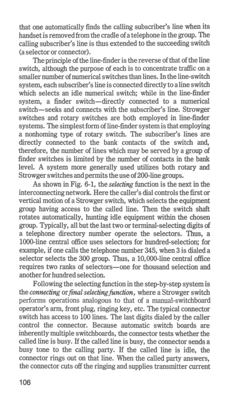
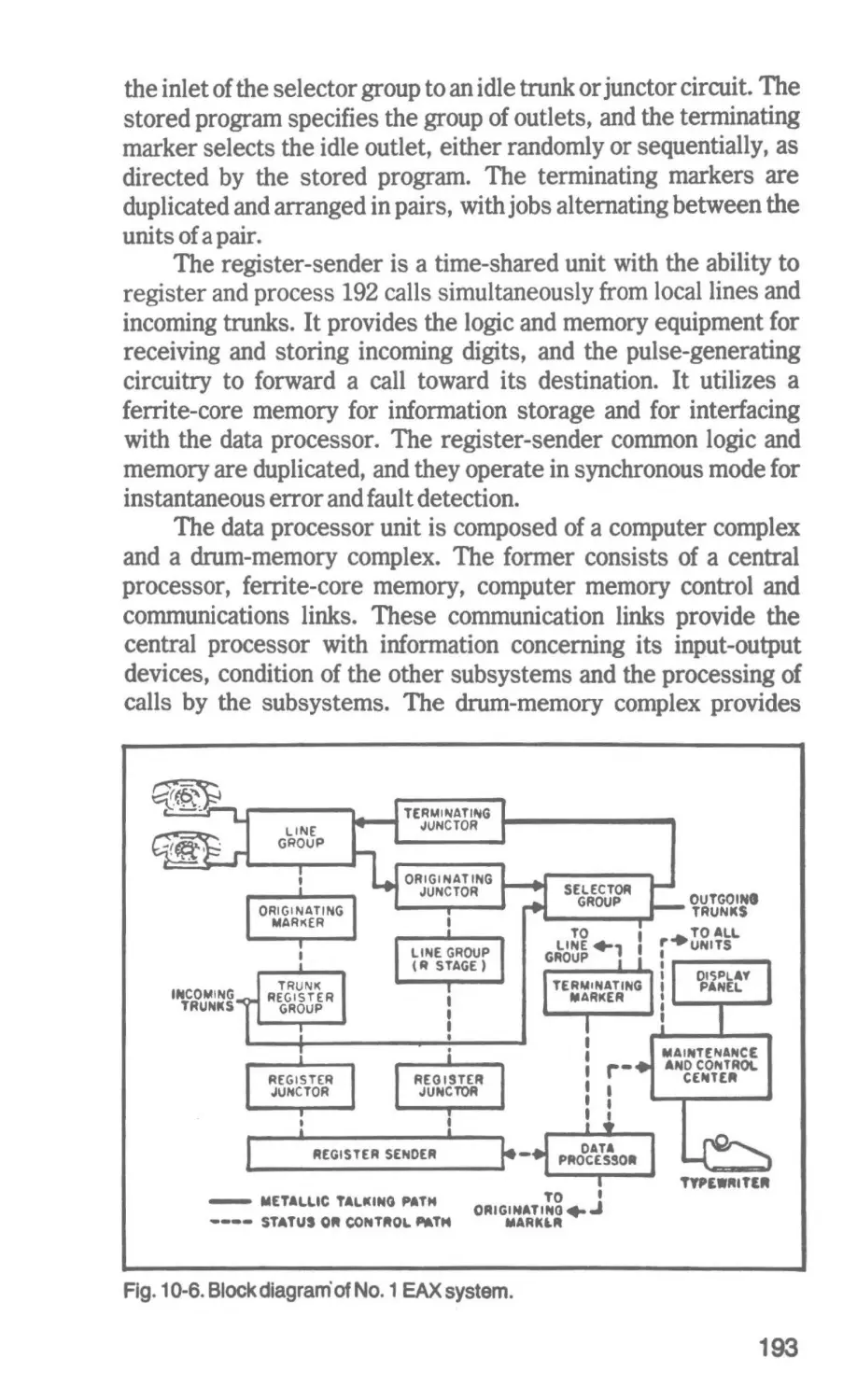
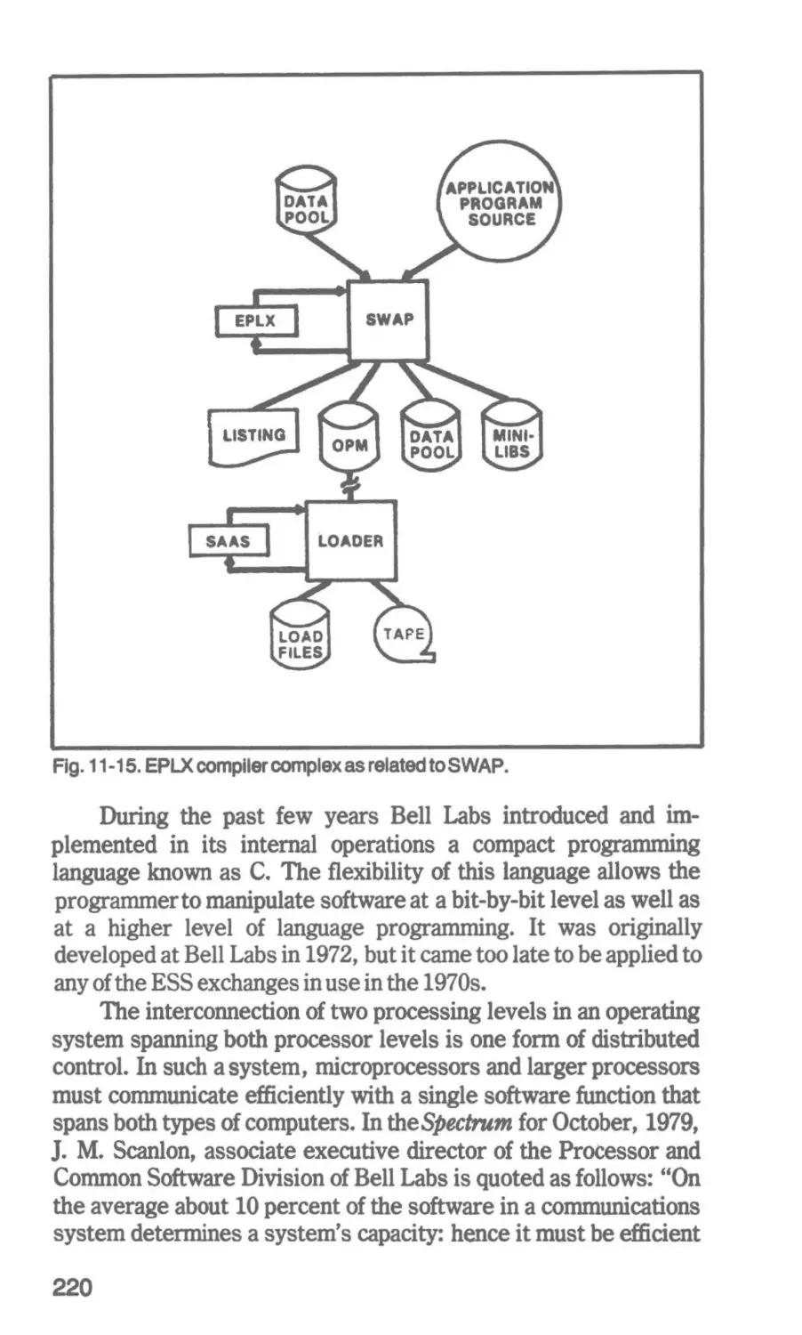
Fig. 1-1. Switching centers and subscriber loops in a typical exchange area.
21
TOLL
CONNECTING
TRUNK
SUBSCRIBER
LOOP
--
~
SUBSET
--
LOCAL
CENTRAL
OFFICE
2-WIRE
TRANSMISSION
~
~
-
--
2-WIRE
TRANSMISSION
TOLL
CENTER
....1-J_,
I
I
I
... t
t
I
L.- -
TOLL TRUNK
'
~
_.
,, If
4-WIRE
T ERMINATING
sET
~
4.WIRE
TR ANSMISSION
TOLL
SWITCHING
CENTER
TOLL TRUNK
'
,, ,
~
-
4.WIRE
T RANSMISSION
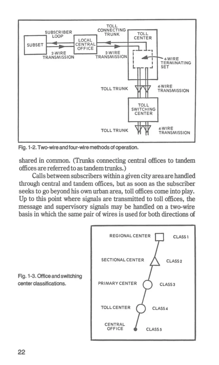
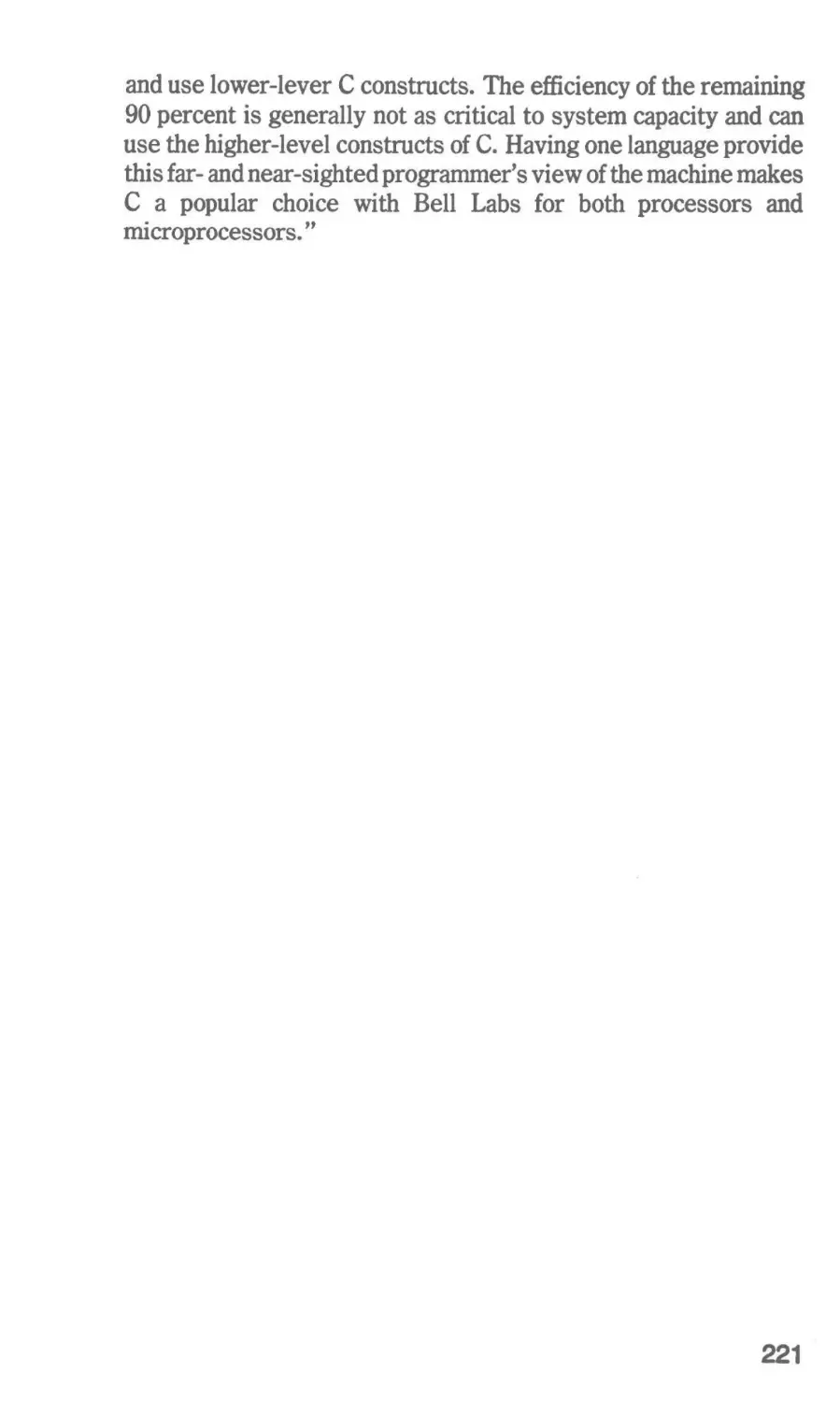
Fig. 1-2. Two-wire and four-wire methods of operation.
shared in common. (Trunks connecting central offices to tandem
offices are referred to as tandem trunks.)
Calls between subscribers within a given city area are handled
through central and tandem offices, but as soon as the subscriber
seeks to go beyond his own urban area, toll offices come into play.
Up to this point where signals are transmitted to toll offices, the
message and supervisory signals may be handled on a two-wire
basis in which the same pair of wires is used for both directions of
REGIONAL CENTER
CLASS 1
SECTIONAL CENTER
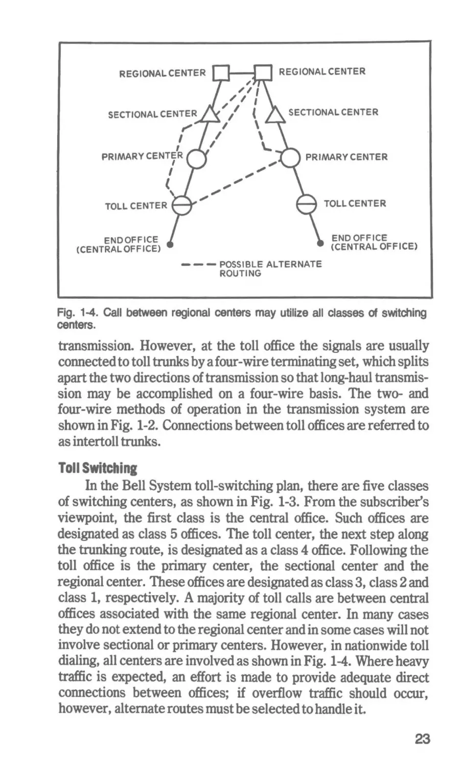
Rg. 1-3. Office and switching
center classifications.
PRIMARY CENTER
TOLL CENTER
CENTRAL
OFFICE
22
CLASS2
CLASS3
CLASS4
CLASSS
REGIONAL CENTER
REGIONAL CENTER
,,,.,,.._
SECTIONAL CENTER
SECTIONAL CENTER
""'
I
I
PRIMARY CENTER
PRIMARY CENTER
I
I
(
TOLL CENTER
'
TOLL CENTER
END OFFICE
(CENTRAL OFFICE)
END OFFICE
(CENTRAL OFF ICE)
-
-
-
POSSIBLE ALTERNATE
ROUTING
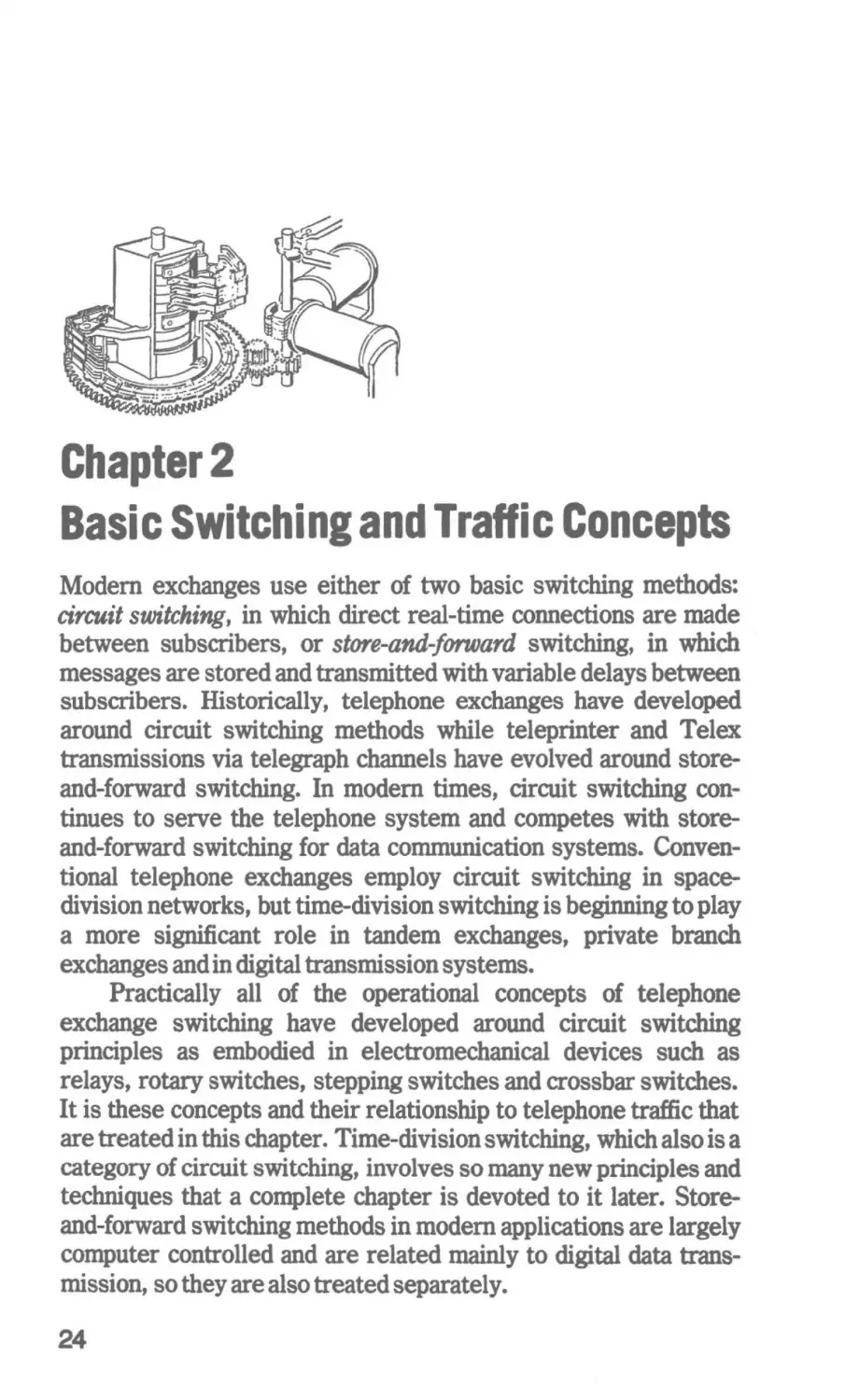
Fig. 1-4. Call between regional centers may utilize all classes of switching
centers.
transmission. However, at the toll office the signals are usually
connected to toll trunks by a four-wire terminating set, which splits
apart the two directions of transmission so that long-haul transmission may be accomplished on a four-wire basis. The two- and
four-wire methods of operation in the transmission system are
shown in Fig. 1-2. Connections between toll offices are referred to
as intertoll trunks.
Toll Switching
In the Bell System toll-switching plan, there are five classes
of switching centers, as shown in Fig. 1-3. From the subscriber's
viewpoint, the first class is the central office. Such offices are
designated as class 5 offices. The toll center, the next step along
the trunking route, is designated as a class 4 office. Following the
toll office is the primary center, the sectional center and the
regional center. These offices are designated as class 3, class 2 and
class l, respectively. A majority of toll calls are between central
offices associated with the same regional center. In many cases
they do not extend to the regional center and in some cases will not
involve sectional or primary centers. However, in nationwide toll
dialing, all centers are involved as shown in Fig. 1-4. Where heavy
traffic is expected, an effort is made to provide adequate direct
connections between offices; if overflow traffic should occur,
however, alternate routes must be selected to handle it.
23
Chapter2
Basic Switching and Traffic Concepts
Modem exchanges use either of two basic switching methods:
circuit switching, in which direct real-time connections are made
between subscribers, or store-and-forward switching, in which
messages are stored and transmitted with variable delays between
subscribers. Historically, telephone exchanges have developed
around circuit switching methods while teleprinter and Telex
transmissions via telegraph channels have evolved around storeand-forward switching. In modem times, circuit switching continues to serve the telephone system and competes with storeand-forward switching for data communication systems. Conventional telephone exchanges employ circuit switching in spacedivision networks, but time-division switching is beginning to play
a more significant role in tandem exchanges, private branch
exchanges and in digital transmission systems.
Practically all of the operational concepts of telephone
exchange switching have developed around circuit switching
principles as embodied in electromechanical devices such as
relays, rotary switches, stepping switches and crossbar switches.
It is these concepts and their relationship to telephone traffic that
are treated in this chapter. Time-division switching, which also is a
category of circuit switching, involves so many new principles and
techniques that a complete chapter is devoted to it later. Storeand-forward switching methods in modem applications are largely
computer controlled and are related mainly to digital data transmission, so they are also treated separately.
24
Circuit switching of speech and data paths in electronic
exchanges is very little different in principle from that in electromechanical exchanges. It is in the area of common control of the
circuit switching that a marked difference exists. All types of
exchanges are confronted with traffic engineering problems.
FACTORS IN CENTRAL OFFICE EXCHANGE DESIGN
Central offices provide most of the circuit switching equipment for local lines, which are connected directly with subscribers.
Such offices handle from less than 100 lines in small rural
communities to well over 10, 000 lines in urban areas. However,
there is a top limit to the number of local lines which can be handled
by one central office beyond which it is necessary to provide
additional offices.
For a given number of subscribers, a particular type of
switching system is chosen and varied in detail to meet the specific
requirements. Engineering of the central office involves selection
of the proper quantities of switching equipment, trunks, and
related apparatus. To design a central office, it is necessary to have
a knowledge of the telephone habits of the subscribers-the
frequency and duration of their calls as well as daily and seasonal
variations in the traffic load as well as contemplated future changes
in the number of subscribers.
In a reasonably efficient office, it is necessary to provide only
for the anticipated maximum number of simultaneous calls, which
in practice is always much less than the total number of subscribers. All practical telecommunications switching systems of any
size are based on the principle of sharing switching paths by a group
of subscribers. In their design, the economies of traffic engineering
must be closely coordinated with the capabilities of switching
devices and the basic means for controlling them.
TELEPHONE TRAFFIC TERMS AND CONCEPTS
Some knowledge of the more important traffic engineering
terms and concepts is necessary to compare and evaluate switching
arrangements. The number of connections required in the central
office would be equal to half the number of subscribers if all of them
wished to talk at the same time. Such a situation is not likely to
occur. .Normally, only a relatively small percentage of the
subscribers use the telephone at a given time; consequently, the
switching system is required only to complete connections
simultaneously for this number of subscribers. In a typical
example, it might be assumed that no more than 10 percent of the
25
subscribers would make simultaneous calls, so the system would
be designed to serve this traffic load. Of course, if a greater
percentage of subscribers should then try to use this exchange
simultaneously, connections would not be established for some
calls. These calls would be lost or blocked and certain probability
of lost or blocked calls would become a significant factor.
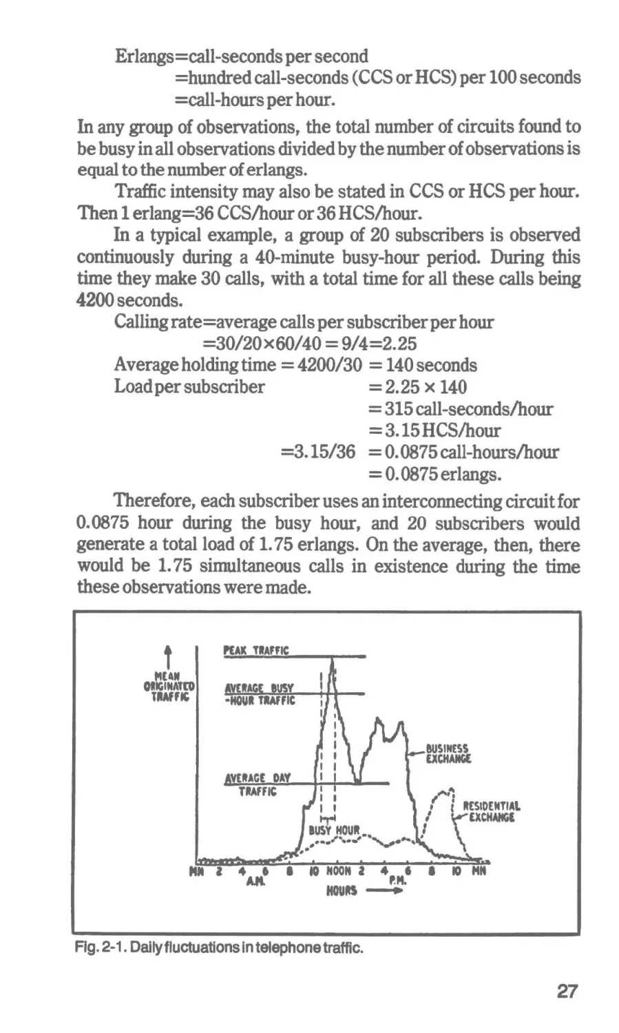
The hour of the day and the season of the year affect the traffic
presented to an office. During certain hours of the day, the traffic
will be heavier than the average hourly level, as shown in Fig. 2-1.
Such daily fluctuations will be affected by seasonal variations.
Telephone systems are not designed to handle maximum peak
loads; rather, they are not designed to handle typical busy-hour
loads (the period during the day that the most calls occur is defined
as the busy hour). During this hour, some calls are expected to be
blocked. ~s mentioned, there is a definite probability of lost calls
during this period, expressed as a decimal, "probability of loss or
blockage," such asP.01. Such a probability figure means that one
call out of a hundred will be blocked during the busy hour. Also, it
expresses the grade of service, which will deteriorate when the
traffic load is above the busy-hour figure for which the sytem is
designed. Overloads are expected to occur during emergencies
and on special occasions.
__....__
Traffic Intensity and Grade of Service
For engineering purposes, the characteristics of telephone
traffic must be given specific numerical values. Significant terms
are the calling rate, the average holding time and the traffic
intensity. The calling rate, expressed as calls per hour, is the rate
at which the subscriber originates calls or the average number of
calls placed by a subscriber during a period of one hour. The
average holding time is the average duration of one call and may be
given in seconds or minutes. For the telephone usage of one or
more subscribers making a number of calls, the unit of call-seconds
(defined as one call for one second) is used. Measured in hundreds
of seconds or hours, other units used are hundred-call-seconds and
call-hours.
A measurement essential to the engineering of telephone
circuits is the traffic intensity. Measured in erlangs (named after
the Danish engineer and mathematician, A.K, Erlang), it represents the circuit usage during an interval of time divided by the
time interval. Thus,
26
Erlangs=call-seconds per second
=hundred call-seconds (CCS or HCS) per 100 seconds
=call-hours per hour.
In any group of observations, the total number of circuits found to
be busy in all observations divided by the number of observations is
equal to the number of erlangs.
Traffic intensity may also be stated in CCS or HCS per hour.
Then 1 erlang=36 CCS/hour or 36 HCS/hour.
In a typical example, a group of 20 subscribers is observed
continuously during a 40-minute busy-hour period. During this
time they make 30 calls, with a total time for all these calls being
4200 seconds.
Calling rate=average calls per subscriber per hour
=30/20x60/40 = 9/4=2.25
Average holding time = 4200/30 = 140 seconds
Loadpersubscriber
=2.25x140
= 315 call-seconds/hour
= 3.15 HCS/hour
=3.15/36 = 0. 0875 call-hours/hour
= 0. 0875 erlangs.
Therefore, each subscriber uses an interconnecting circuit for
0.0875 hour during the busy hour, and 20 subscribers would
generate a total load of 1. 75 erlangs. On the average, then, there
would be 1. 75 simultaneous calls in existence during the time
these observations were made.
PEAK TIAfFIC
'
MUN
OllGINATEO
TllAff"
I
I
'
I
8USIN£SS
I I
1 I
I
I
I
I
EXCHAMGt
,,_,-.
: :
f
.,..
IUSY HOUR ...
,•'····'·....Mii I
4 .a ,.6
ft.no
I
IO NOON I
HOURS
v•-,
4
6
P.M.
JI
I
l ltES10£NTIAt.
\EXCHAHGI
IO MM
•
Fig. 2-1. Daily fluctuations in telephone traffic.
27
Considering Traffic Patterns
In planning new central office installations, the history of
groups of subscribers must be considered. For instance, most
residential telephones have relatively low calling rates and long
holding times, while most business telephones have high calling
rates and short average holding times. The total average traffic
load offered to a central office is determined by adding the erlang
load presented by each subscriber. H sufficient switching equipment is not provided to handle the average traffic loads, too many
lost calls may result during temporary peak loads. In a typical case,
32 trunks carrying a 20-erlang load will provide a grade of service
of P. 01 but 36 trunks carrying the same load can provide a grade of
service of P. 001 (only one call lost in a thousand). However, the 32
trunks operate more efficiently at 63 percent compared with 56
percent for the 36 trunks.
CONNECTING CIRCUITS
In any communications switching system, connecting circuits
are essential. Such circuits provide the means for establishing
interconnecting paths for the transmission of messages, but do not
necessarily include within themselves the means for controlling
their actions. In fact, except for direct control systems, the
controlling elements are distinctly separate. Connecting circuits
are used where:
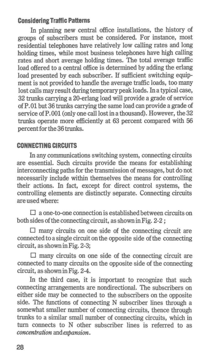
D a one-to-one connection is established between circuits on
both sides of the connecting circuit, as shown in Fig. 2-2 ;
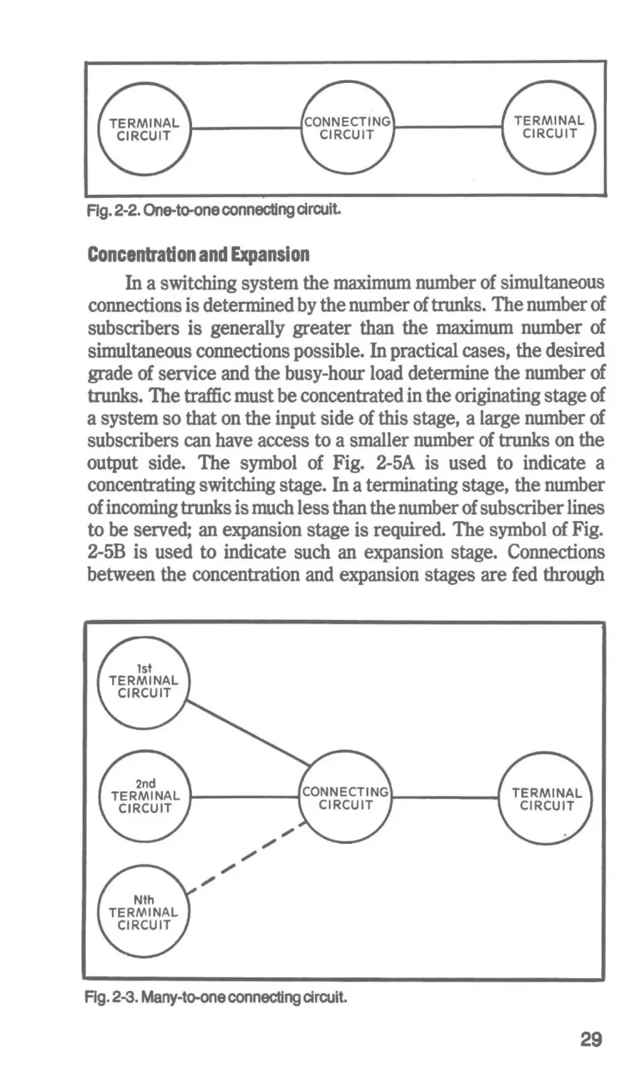
D many circuits on one side of the connecting circuit are
connected to a single circuit on the opposite side of the connecting
circuit, as shown in Fig. 2-3;
D many circuits on one side of the connecting circuit are
connected to many circuits on the opposite side of the connecting
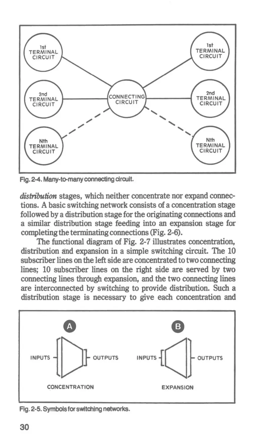
circuit, as shown in Fig. 2-4.
In the third case, it is important to recognize that such
connecting arrangements are nondirectional. The subscribers on
either side may be connected to th~ subscribers on the opposite
side. The functions of connecting N subscriber lines through a
somewhat smaller number of connecting circuits, thence through
trunks to a similar small number of connecting circuits, which in
turn connects to N other subscriber lines is referred to as
concentrati.on andexpansion.
28
Ag. 2-2. One-to-one connecttng circuit.
Concentration and Expansion
In a switching system the maximum number of simultaneous
connections is determined by the number of trunks. The number of
subscribers is generally greater than the maximum number of
simultaneous connections possible. In practical cases, the desired
grade of service and the busy-hour load determine the number of
trunks. The traffic must be concentrated in the originating stage of
a system so that on the input side of this stage, a large number of
subscribers can have access to a smaller number of trunks on the
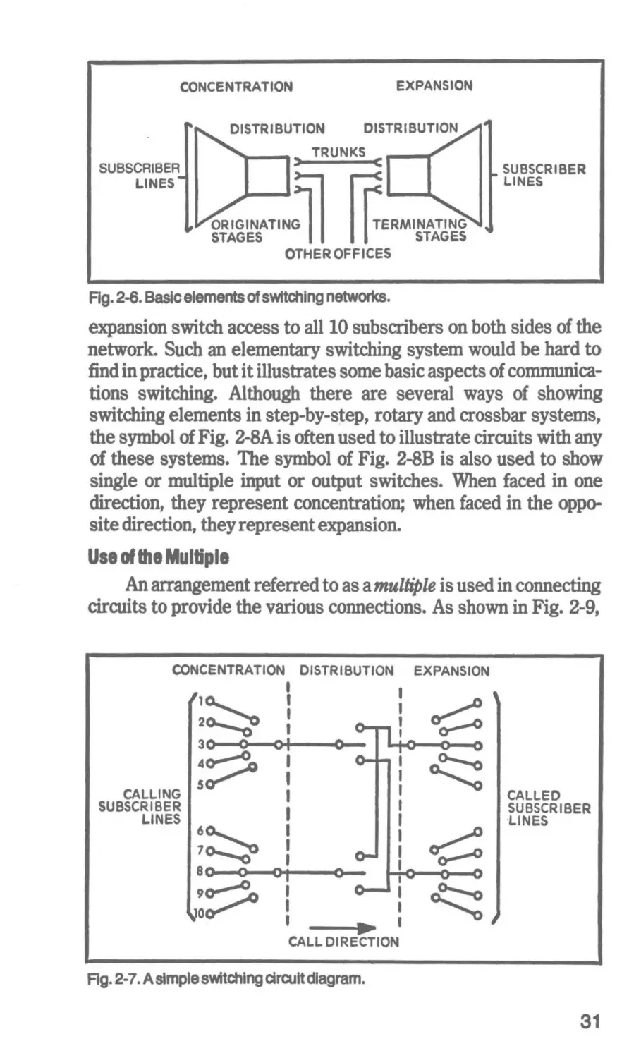
output side. The symbol of Fig. 2-5A is used to indicate a
concentrating switching stage. In a terminating stage, the number
of incoming trunks is much less than the number of subscriber lines
to be served; an expansion stage is required. The symbol of Fig.
2-5B is used to indicate such an expansion stage. Connections
between the concentration and expansion stages are fed through
Rg. 2-3. Many-to-one connecting circuit.
29
''
'''
Fig. 2-4. Many-to-many connecting clra.alt.
distribution stages, which neither concentrate nor expand connections. A basic switching network consists of a concentration stage
followed by a distribution stage for the originating connections and
a similar distribution stage feeding into an expansion stage for
completing the terminating connections (Fig. 2-6).
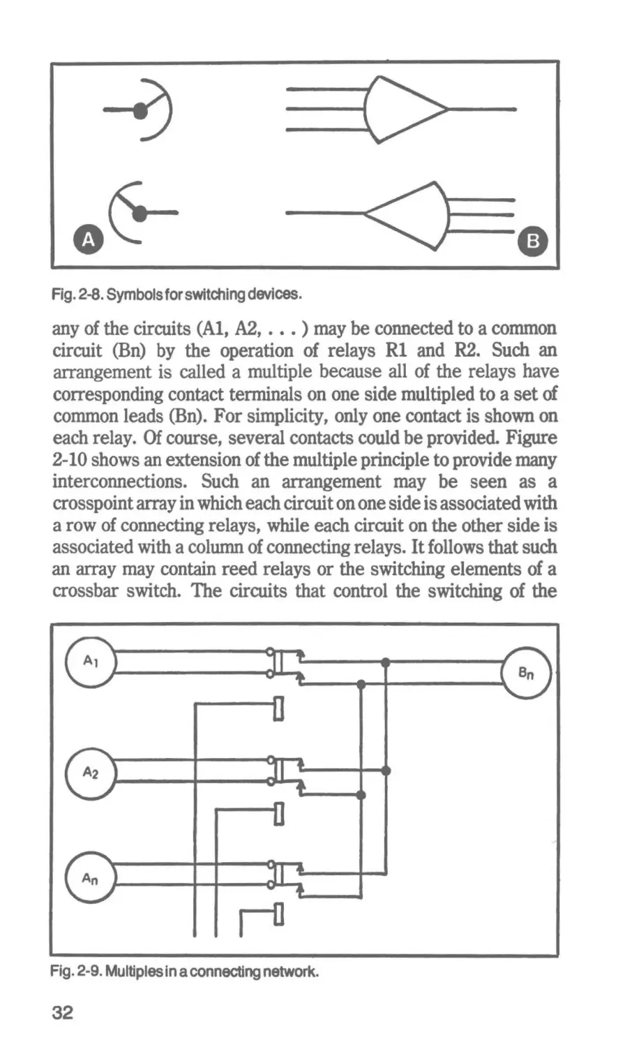
The functional diagram of Fig. 2-7 illustrates concentration,
distribution and expansion in a simple switching circuit. The 10
subscriber lines on the left side are concentrated to two connecting
lines; 10 subscriber lines on the right side are served by two
connecting lines through expansion, and the two connecting lines
are interconnected by switching to provide distribution. Such a
distribution stage is necessary to give each concentration and
INPUTS
CONCENTRATION
Fig. 2-5. Symbols for swttehing networks.
30
OUTPUTS
EXPANSION
EXPANSION
CONCENTRATION
DISTRIBUTION
SUBSCRIBER
LINES
ORIGINATIN~~I
STAGES
~ERMINATING
ITI
OTHER OFFICES
SUBSCRIBER
LINES
STAGES
Fig. 2-6. Basic elements of switching networks.
expansion switch access to all 10 subscribers on both sides of the
network. Such an elementary switching system would be hard to
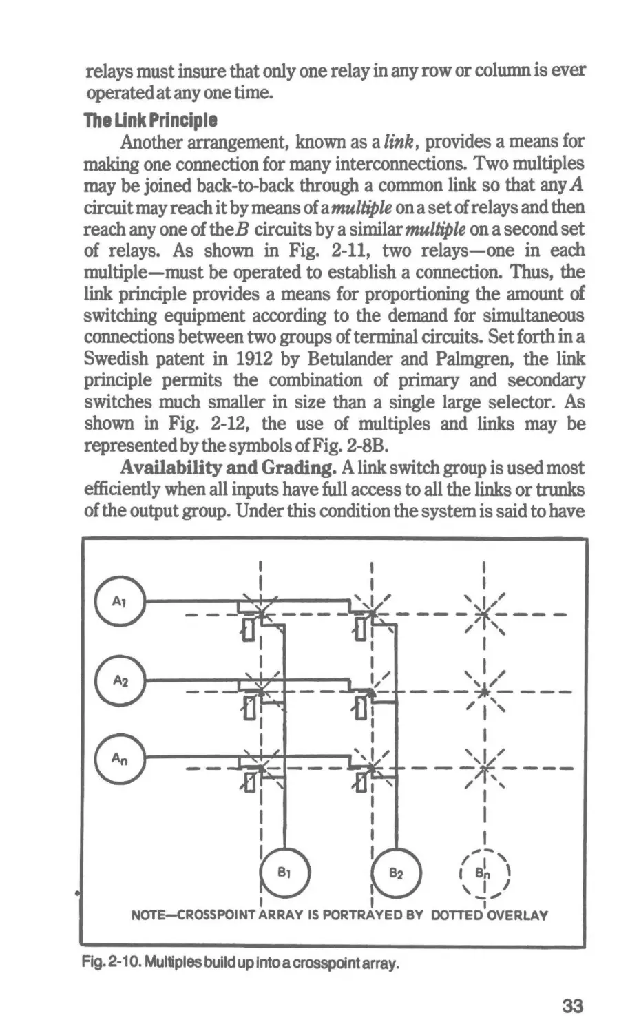
find in practice, but it illustrates some basic aspects of communications switching. Although there are several ways of showing
switching elements in step-by-s~ep, rotary and crossbar systems,
the symbol of Fig. 2-SA is often used to illustrate circuits with any
of these systems. The symbol of Fig. 2-8B is also used to show
single or multiple input or output switches. When faced in one
direction, they represent concentration; when faced in the opposite direction, they represent expansion.
Use of Ille Multiple
An arrangement referred to as a multiple is used in connecting
circuits to provide the various connections. As shown in Fig. 2-9,
CONCENTRATION
DISTRIBUTION
EXPANSION
I
~~
'O
30
0
I
I
I
01
I
0
I
CALLING
SUBSCRIBER
LINES
I
CALLED
SUBSCRIBER
LINES
I
I
I
I
u---..)11-.--c:OMl-~0"'-
I
I
o -..
I
CALL DIRECTION
Fig. 2-7. A simple switching circuit diagram.
31
Fig. 2-8. Symbols for switching devices.
any of the circuits (Al, A2, ••• ) may be connected to a common
circuit (Bn) by the operation of relays Rl and R2. Such an
arrangement is called a multiple because all of the relays have
corresponding contact terminals on one side multipled to a set of
common leads (Bn). For simplicity, only one contact is shown on
each relay. Of course, several contacts could be provided. Figure
2-10 shows an extension of the multiple principle to provide many
interconnections. Such an arrangement may be seen as a
crosspoint array in which each circuit on one side is associated with
a row of connecting relays, while each circuit on the other side is
associated with a column of connecting relays. It follows that such
an array may contain reed relays or the switching elements of a
crossbar switch. The circuits that control the switching of the
Fig. 2-9. Multiples in a connecting network.
32
relays must insure that only one relay in any row or column is ever
operated at any one time.
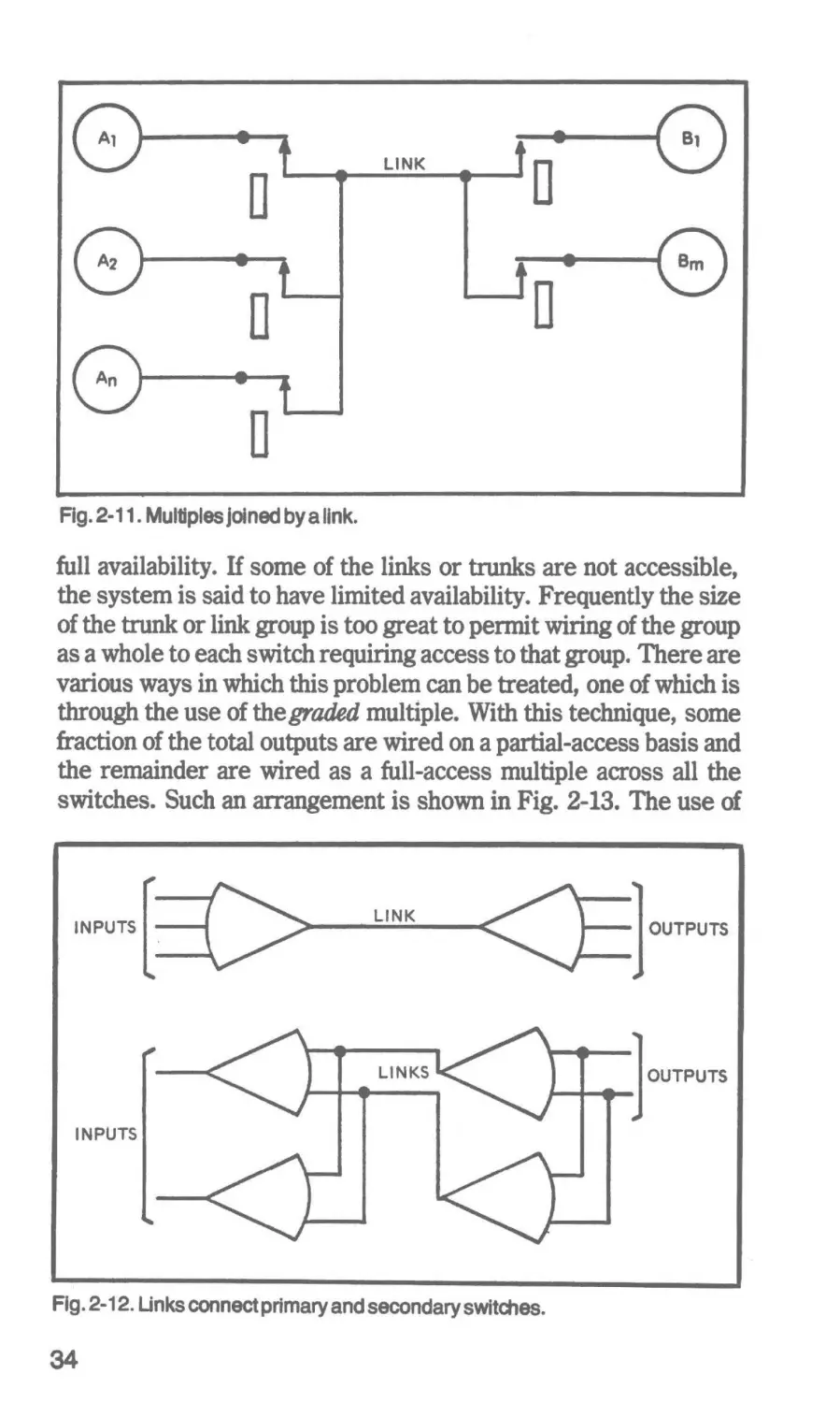
The Unk Principle
Another arrangement, known as a link, provides a means for
making one connection for many interconnections. Two multiples
may be joined back-to-back through a common link so that any A
circuit may reach it by means of a multiple on a set of relays and then
reach any one of theB circuits by a similar multiple on a second set
of relays. As shown in Fig. 2-11, two relays-one in each
multiple-must be operated to establish a connection. Thus, the
link principle provides a means for proportioning the amount of
switching equipment according to the demand for simultaneous
connections between two groups of terminal circuits. Set forth in a
Swedish patent in 1912 by Betulander and Palmgren, the link
principle permits the combination of primary and secondary
switches much smaller in size than a single large selector. As
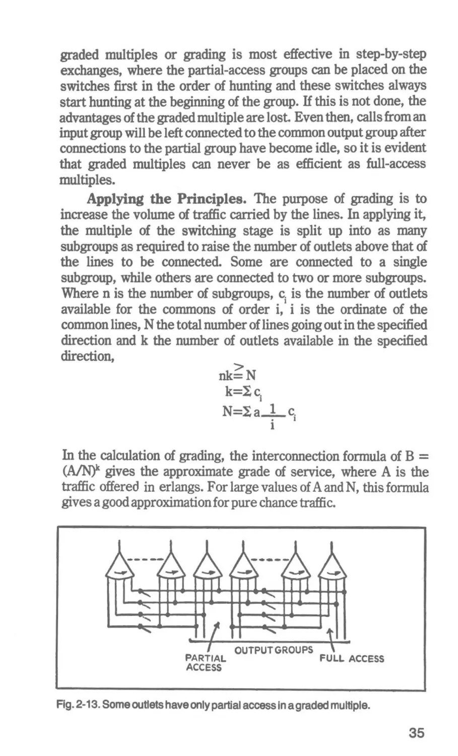
shown in Fig. 2-12, the use of multiples and links may be
represented by the symbols of Fig. 2-SB.
Availability and Grading. A link switch group is used most
efficiently when all inputs have full access to all the links or trunks
of the output group. Under this condition the system is said to have
I
I
_____.....,.....,__....,.,,,,
I
I
',1~'
--- - ,-,- -- -__,¥,:-- I
:"
------~
I
' I""
---~---"I ' '
I
' I,
---;*,----
'
I
I
111' -
I
I
I
II BnI ' \
\. I I
I"'
NOTE-CROSSPOINT ARRAY IS PORTRAYED BY DOTTED OVERLAY
Fig. 2-1 o. Multiples build up into a crosspOint array.
33
LINK
D
D
D
D
Fig. 2-11. Multiples Joined by a link.
full availability. If some of the links or trunks are not accessible,
the system is said to have limited availability. Frequently the size
of the trunk or link group is too great to permit wiring of the group
as a whole to each switch requiring access to that group. There are
various ways in which this problem can be treated, one of which is
through the use of the graded multiple. With this technique, some
fraction of the total outputs are wired on a partial-access basis and
the remainder are wired as a full-access multiple across all the
switches. Such an arrangement is shown in Fig. 2-13. The use of
INPUTS
LINK
LINKS
INPUTS
Fig. 2-12. Unks connect primary and secondary switches.
34
OUTPUTS
OUTPUTS
graded multiples or grading is most effective in step-by-step
exchanges, where the partial-access groups can be placed on the
switches first in the order of hunting and these switches always
start hunting at the beginning of the group. If this is not done, the
advantages of the graded multiple are lost. Even then, calls from an
input group will be left connected to the common output group after
connections to the partial group have become idle, so it is evident
that graded multiples can never be as efficient as full-access
multiples.
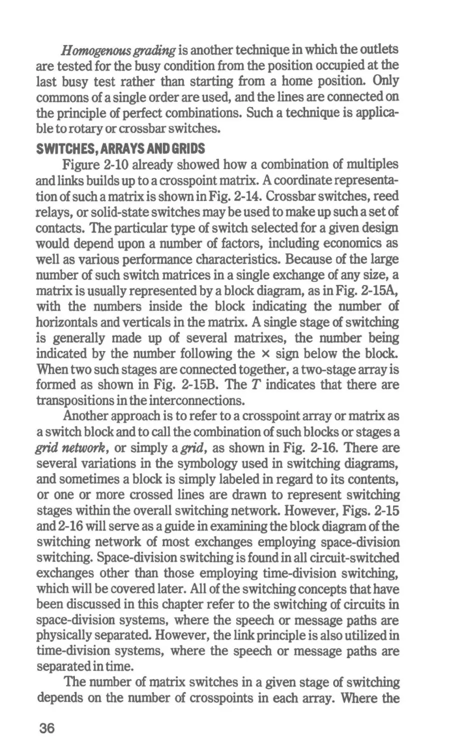
Applying the Principles. The purpose of grading is to
increase the volume of traffic carried by the lines. In applying it,
the multiple of the switching stage is split up into as many
subgroups as required to raise the number of outlets above that of
the lines to be connected. Some are connected to a single
subgroup, while others are connected to two or more subgroups.
Where n is the number of subgroups, c.l is the number of outlets
available for the commons of order i, i is the ordinate of the
common lines, N the total number of lines going out in the specified
direction and k the number of outlets available in the specified
direction,
nk~N
k=Ic.
N=Ia 1. c.I
I
1
In the calculation of grading, the interconnection formula of B =
(A/Nf gives the approximate grade of service, where A is the
traffic offered in erlangs. For large values of A and N, this formula
gives a good approximation for pure chance traffic.
. II
PARTIAL
ACCESS
OUTPUTGROUPS
~
-
FULL ACCESS
Fig. 2-13. Some outlets have only partial access in a graded multiple.
35
H omogenous grading is another technique in which the outlets
are tested for the busy condition from the position occupied at the
last busy test rather than starting from a home position. Only
commons of a single order are used, and the lines are connected on
the principle of perfect combinations. Such a technique is applicable to rotary or crossbar switches.
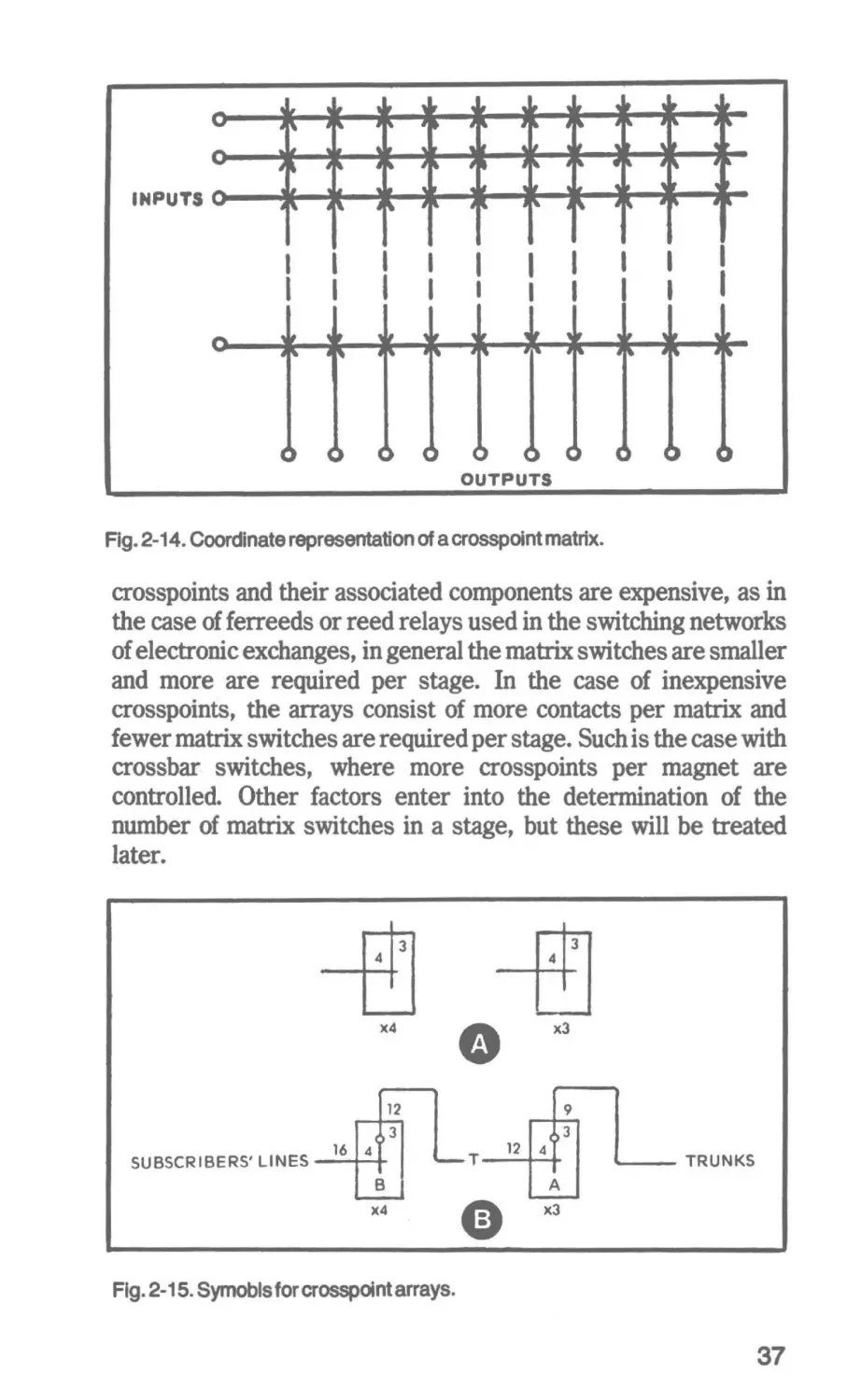
SWITCHES, ARRAYS AND GRIDS
Figure 2-10 already showed how a combination of multiples
and links builds up to a crosspoint matrix. A coordinate representation of such a matrix is shown in Fig. 2-14. Crossbar switches, reed
relays, or solid-state switches may be used to make up such a set of
contacts. The particular type of switch selected for a given design
would depend upon a number of factors, including economics as
well as various performance characteristics. Because of the large
number of such switch matrices in a single exchange of any size, a
matrix is usually represented by a block diagram, as in Fig. 2-15A,
with the numbers inside the block indicating the number of
horizontals and verticals in the matrix. A single stage of switching
is generally made up of several matrixes, the number being
indicated by the number following the x sign below the block.
When two such stages are connected together, a two-stage array is
formed as shown in Fig. 2-15B. The T indicates that there are
transpositions in the interconnections.
Another approach is to refer to a crosspoint array or matrix as
a switch block and to call the combination of such blocks or stages a
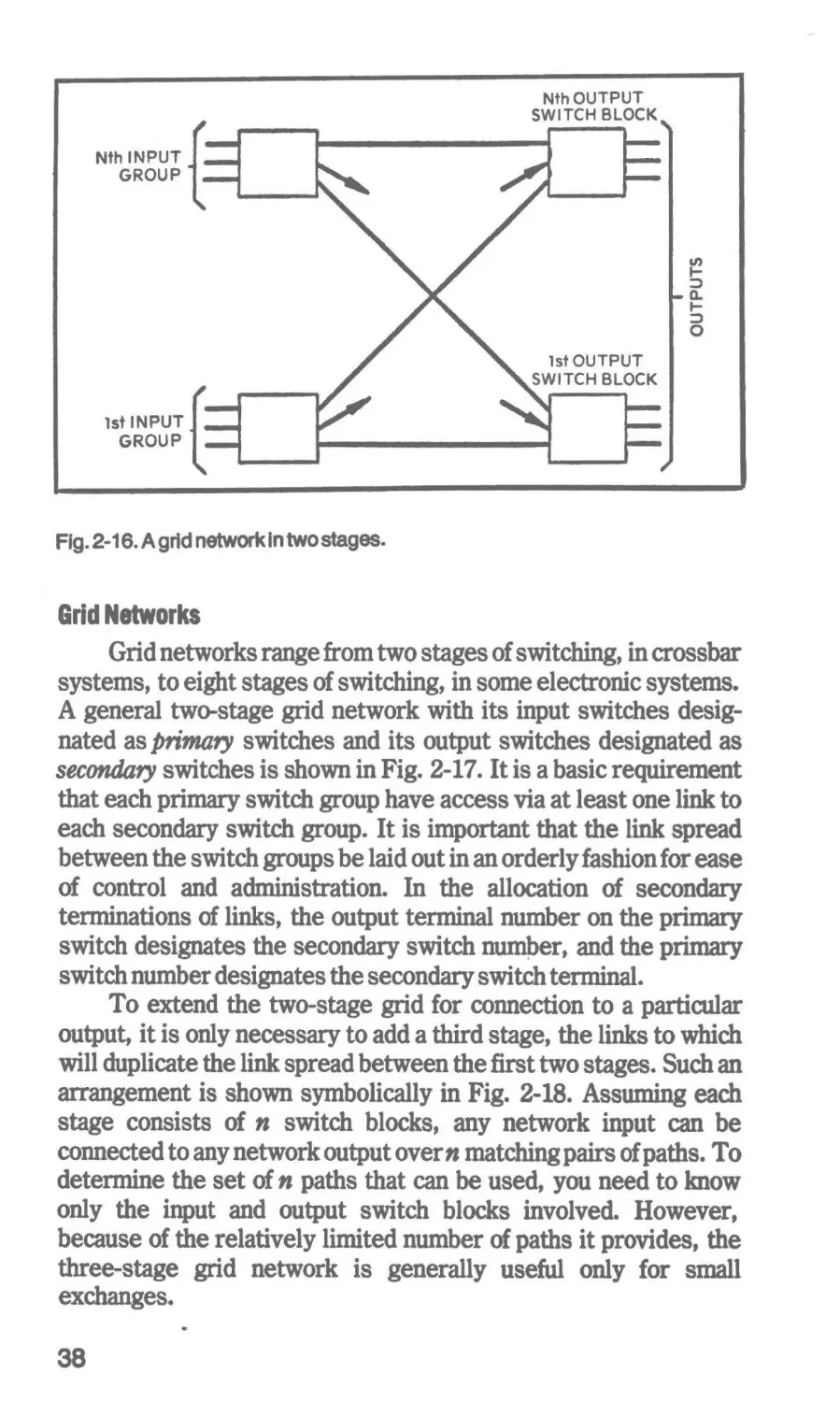
grid network, or simply a grid, as shown in Fig. 2-16. There are
several variations in the symbology used in switching diagrams,
and sometimes a block is simply labeled in regard to its contents,
or one or more crossed lines are drawn to represent switching
stages within the overall switching network. However, Figs. 2-15
and 2-16 will serve as a guide in examining the block diagram of the
switching network of most exchanges employing space-division
switching. Space-division switching is found in all circuit-switched
exchanges other than those employing time-division switching,
which will be covered later. All of the switching concepts that have
been discussed in this chapter refer to the switching of circuits in
space-division systems, where the speech or message paths are
physically separated. However, the link principle is also utilized in
time-division systems, where the speech or message paths are
separated in time.
The number of matrix switches in a given stage of switching
depends on the number of crosspoints in each array. Where the
36
I
I
I
I
I
I
I
I
I
I I
I
I
I
I
I
I
I
I
I
OUTPUTS
Fig. 2-14. Coordinate representation of a crosspoint matrix.
crosspoints and their associated components are expensive, as in
the case of ferreeds or reed relays used in the switching networks
of electronic exchanges, in general the matrix switches are smaller
and more are required per stage. In the case of inexpensive
crosspoints, the arrays consist of more contacts per matrix and
fewer matrix switches are required per stage. Such is the case with
crossbar switches, where more crosspoints per magnet are
controlled. Other factors enter into the determination of the
number of matrix switches in a stage, but these will be treated
later.
3
3
4
4
•
><4
12
SUBSCRIBERS' LINES
16
o3
4
-T
B
><4
e
xl
12
9
o3
4
TRUNKS
A
><3
Fig. 2-15. Symobls for crosspoint arrays.
37
Nth OUTPUT
SWITCH BLOCK
Nth INPUT
GROUP
1st OUTPUT
SWITCH BLOCK
1st INPUT
GROUP
Fig. 2-16. A grid network In two stages.
Grid Networks
Grid networks range from two stages of switching, in crossbar
systems, to eight stages of switching, in some electronic systems.
A general two-stage grid network with its input switches designated as primary switches and its output switches designated as
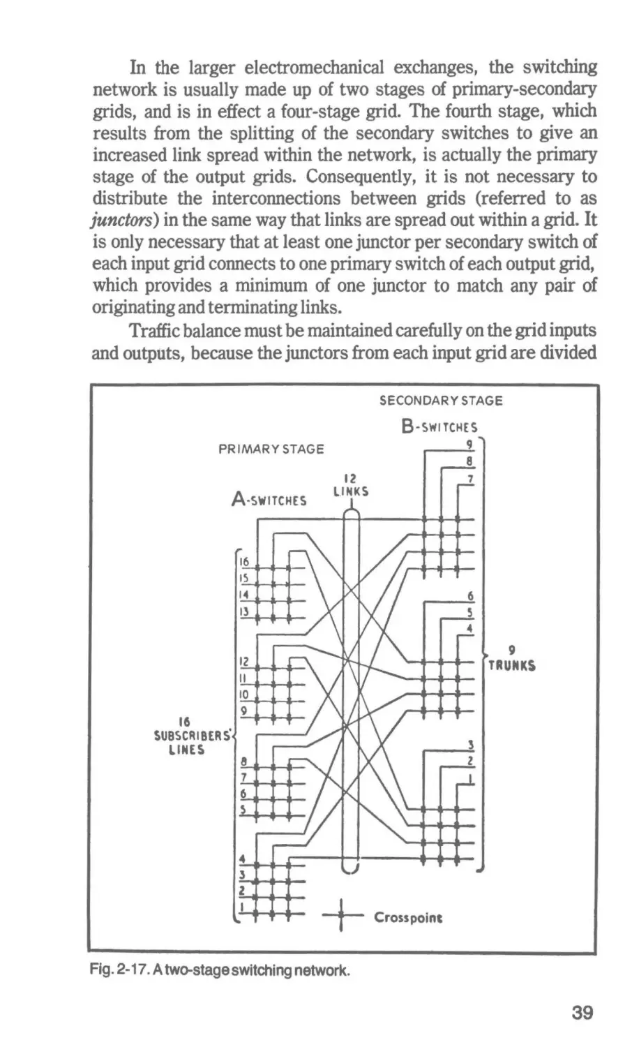
secondary switches is shown in Fig. 2-17. It is a basic requirement
that each primary switch group have access via at least one link to
each secondary switch group. It is important that the link spread
between the switch groups be laid out in an orderly fashion for ease
of control and administration. In the allocation of secondary
terminations of links, the output terminal number on the primary
switch designates the secondary switch numper, and the primary
switch number designates the secondary switch terminal.
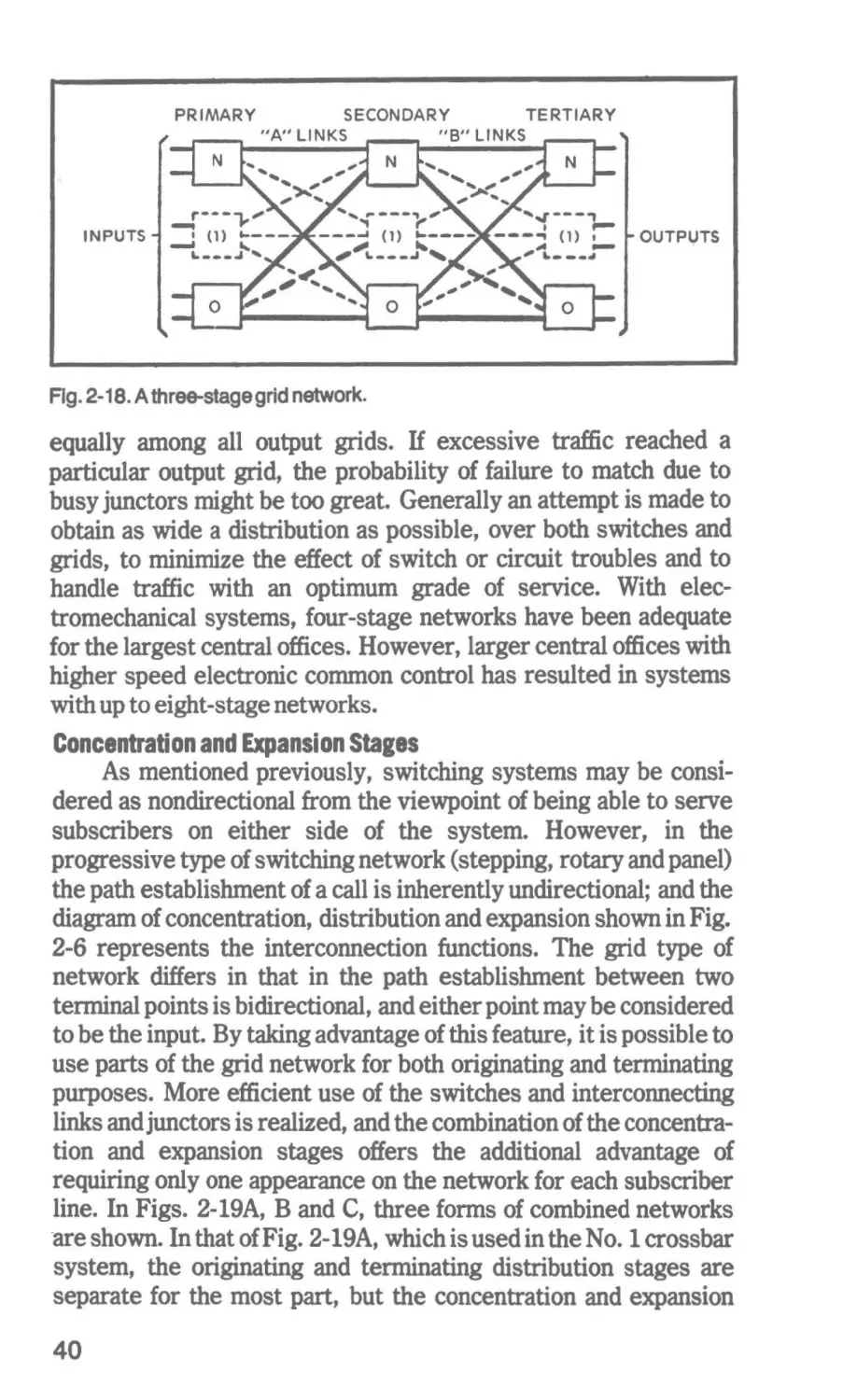
To extend the two-stage grid for connection to a particular
output, it is only necessary to add a third stage, the links to which
will duplicate the link spread between the first two stages. Such an
arrangement is shown symbolically in Fig. 2-18. Assuming each
stage consists of n switch blocks, any network input can be
connected to any network output overn matching pairs of paths. To
determine the set of n paths that can be used, you need to lmow
only the input and output switch blocks involved. However,
because of the relatively limited number of paths it provides, the
three-stage grid network is generally useful only for small
exchanges•
•
38
In the larger electromechanical exchanges, the switching
network is usually made up of two stages of primary-secondary
grids, and is in effect a four-stage grid. The fourth stage, which
results from the splitting of the secondary switches to give an
increased link spread within the network, is actually the primary
stage of the output grids. Consequently, it is not necessary to
distribute the interconnections between grids (referred to as
junctors) in the same way that links are spread out within a grid. It
is only necessary that at least one junctor per secondary switch of
each input grid connects to one primary switch of each output grid,
which provides a minimum of one junctor to match any pair of
originating and terminating links.
Traffic balance must be maintained carefully on the grid inputs
and outputs, because the junctors from each input grid are divided
SECONDARY STAGE
B·SWITCHES
9
PRIMARY STAGE
8
A-SWITCHES
12
l.INKS
7
16
I~
14
6
I~
5
..
9
TRUNKS
IZ
16
SUBSCRIBERS•
LINES
II
10
9
1
l
8
7
6
J
z
+
Crosspoinc
Fig. 2-17. A two-stage switching network.
39
PRIMARY
SECONDARY
TERTIARY
''A'' LINKS
"B" LINKS
N
INPUTS
OUTPVTS
0
Fig. 2-18. A three-stage grid network.
equally among all output grids. H excessive traffic reached a
particular output grid, the probability of failure to match due to
busy junctors might be too great. Generally an attempt is made to
obtain as wide a distribution as possible, over both switches and
grids, to minimize the effect of switch or circuit troubles and to
handle traffic with an optimum grade of service. With electromechanical systems, four-stage networks have been adequate
for the largest central offices. However, larger central offices with
higher speed electronic common control has resulted in systems
with up to eight-stage networks.
Concentration and Expansion Stages
As mentioned previously, switching systems may be considered as nondirectional from the viewpoint of being able to serve
subscribers on either side of the system. However, in the
progressive type of switching network (stepping, rotary and panel)
the path establishment of a call is inherently undirectional; and the
diagram of concentration, distribution and expansion shown in Fig.
2-6 represents the interconnection functions. The grid type of
network differs in that in the path establishment between two
terminal points is bidirectional, and either point may be considered
to be the input. By taking advantage of this feature, it is possible to
use parts of the .grid network for both originating and terminating
purposes. More efficient use of the switches and interconnecting
links andjunctors is realized, and the combination of the concentration and expansion stages offers the additional advantage of
requiring only one appearance on the network for each subscriber
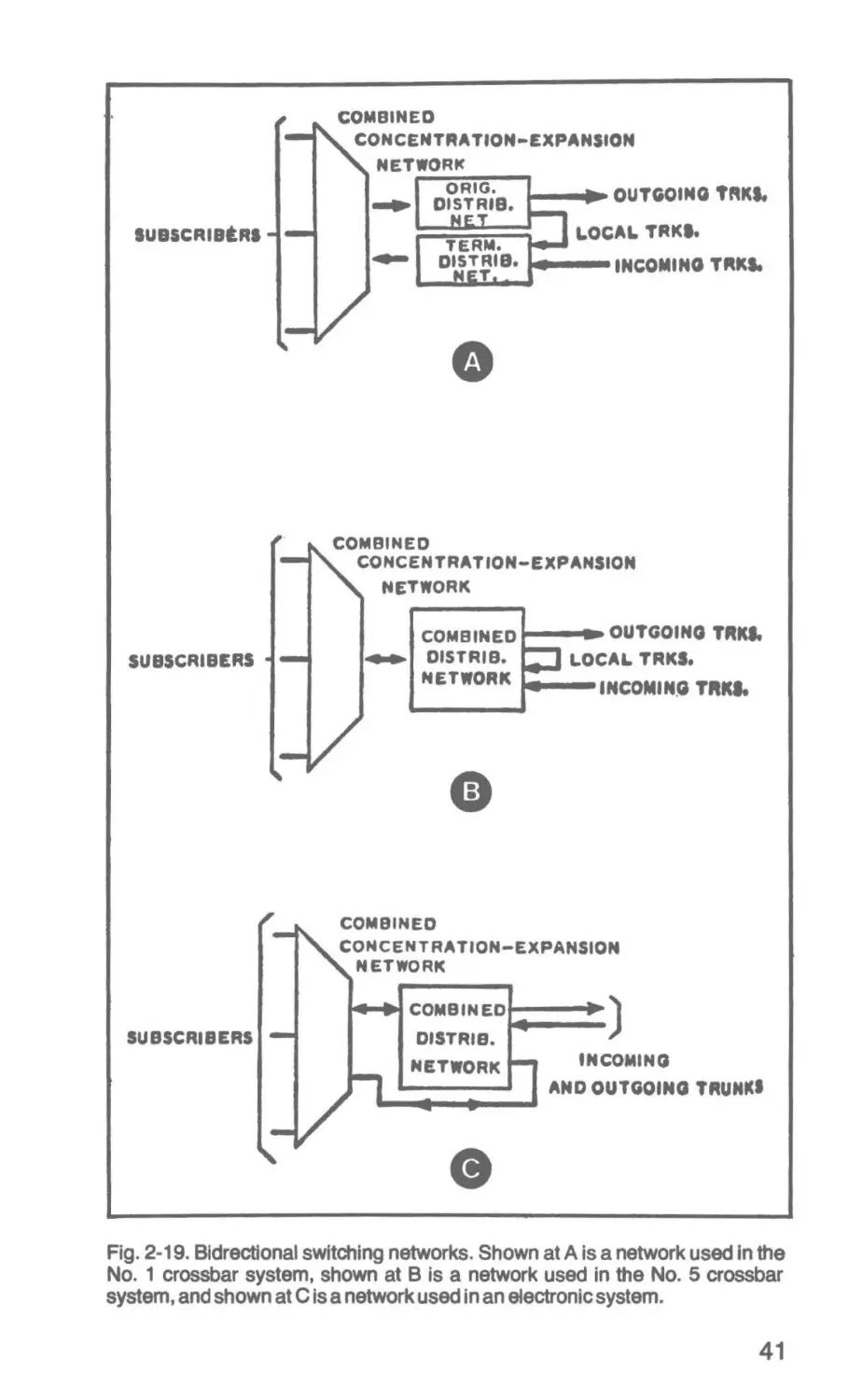
line. In Figs. 2-19A, B and C, three forms of combined networks
·are shown. In that of Fig. 2-19A, which is used in the No. 1 crossbar
system, the originating and terminating distribution stages are
separate for the most part, but the concentration and expansion
40
COMBINED
CONCENTRATION-EXPANSION
NETWORK
.__.._.._.OUTGOING TAKI.
LOCAL TRKI.
IU8SCRIBtAI
. . - - - INCOMING TRKS.
•
COMBINED
CONCENTRATION-EXPANSION
NETWORK
SUBSCRIBERS
COMBINED a---~ OUTGOING TRICI.
.._. DISTRIS.
LOCA&. TAKS.
NETWORK
INCOMING TRICI.
COMBINED
CONCENTRATION-EXPANSION
NETWORK
COMBINED
SUBSCRIBERS
...__)
DISTRIB.
NETWORK
INCOMING
AND OUTGOING TRUHICI
Fig. 2-19. Bldrectional switching networks. Shown at A is a network used in the
No. 1 crossbar system, shown at B is a network used in the No. 5 crossbar
system, and shown at C is a network used in an electronic system.
41
~
R EMOTE UNIT
r;.ETWORK.....
4--10 x 10
CROSSBAR
SWITCH
100
CUSTOMER•
s
~
..
,.}
20 TALKING TRUNK
~ 2CONTROLTRUNKS .
l.,....---'"
..
...
t
• •CO
I
LINE
IDENTIFICATION
...
CONTROL
t
SIGNALING
POWER (2..V)
RESERVOIR
(NICKEL-CADMIUM
BAnERY)
...
.......
Fig. 2-20. A crossbar line concentrator.
stages are common. In that of Fig. 2-19B, which is used in.the No. 5
crossbar system, all stages are bidirectional and inputs and outputs
appear at both ends of the network. In that of Fig. 2-19C, which is
used in an electronic system, only one connection is normally used
through the distribution stage on each call. The connection may be
established in either direction-that is, either side of the distribution network may be the originating side. This type of operation is
possible because the supervision and battery supply are functions
of the line circuits, in this case, so that there is no need for
intraoffice trunk circuits.
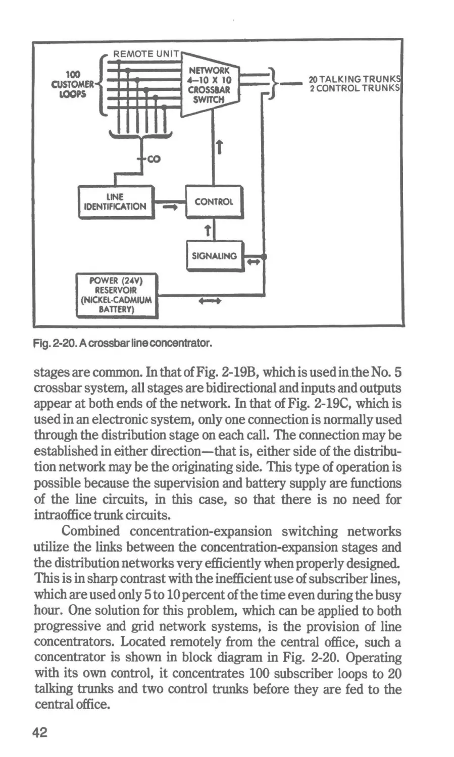
Combined concentration-expansion switching networks
utilize the links between the concentration-expansion stages and
the distribution networks very efficiently when properly designed.
This is in sharp contrast with the inefficient use of subscriber lines,
which are used only 5to10 percent of the time even during the busy
hour. One solution for this problem, which can be applied to both
progressive and grid network systems, is the provision of line
concentrators. Located remotely from the central office, such a
concentrator is shown in block ·diagram in Fig. 2-20. Operating
with its own control, it concentrates 100 subscriber loops to 20
talking trunks and two control trunks before they are fed to the
central office.
42
Logic Switching Algebra and Control
Logic is considered to have started with Aristotle (384-322 BC),
who laid down certain formal rules for use in reasoning, called the
laws of logic. These include the rule of detachment and the rule of
the syllogism. The former may be stated briefly as, "If Pis true and
P implies Q, then Q is true." The latter may be stated briefly as, "If
P implies Q and Q.implies R, then P implies R." Many of the
classical syllogisms take this form. Logic as set forth by Aristotle
was the first attempt to present the general form of language and
argument in a systematic fashion. Little change in this approach
took place for more than 2000 years, and the subject of logic
remained associated with the authority and prestige of Aristotle.
However, the 17th century mathematician and philosopher, Liebniz, began to seek an algebra for reasoning to replace the use of
statements. Much of this work was not published until long after
others had duplicated his conclusions.
Around the middle of the 19th century, George Boole
published a book on the mathematical analysis of logic, in which he
presented logic as a form of nonquantitative algebra. His mathematics was an algebra of classes and of processes of selecting and
conjoining classes. Boole expressed what he called the laws of
thought in an algebraic form, which was illustrated by the English
mathematician Venn in the late 19th century in a form that utilizes
the concept of sets and subsets. The four forms of traditional logic
can be shown as in Fig. 3-1 by Venn diagrams. Using the same
method, one can present the solution of a syllogism as shown in
Fig. 3-2.
43
1-B
08
UNIVERSAL NEGATIVE
NOAsARE Bs
ab= O
UNIVERSAL AFFIRMATIVE
ALL As ARE Bs
a(l -b)
=o
PARTICULAR NEGATIVE
SOME As ARE NOT Bs
PARTICULAR AFFIRMATIVE
SOME As ARE Bs
c -. ab
c:a(l -b)
Fig. 3-1. Four forms of traditional logic.
Besides applying to classes, Boolean algebra applies to
propositions. For the statement, "H proposition A is true, then
proposition Bis true," the algebraic expression A(l-B)=O may be
written. For the conditional proposition, "If A is true then B is
true,"·a(l-b)=O;but A is true, that is a=l. Therefore, Bis true;
that is, b=l. For the disjunctive proposition, either A is true-that
is, a(l-b)-or Bis true-that is, b(l-a). Then their sum is given by
a-2ab + b=l. However, if A is true, a=l; soBisnottrue, b=O. By
such mathematics Boole showed that his algebra deals first with
classes, and second with propositions where the values are limited
to true or false (1or0).
ALL BsAREAs
b( 1-a> = o
ALL Cs ARE Bs
c< 1-b) =a.or c =cb
CONCLUSION:
b( l·a > o
=
c =cb
c(l-a)
=0
ALL Cs ARE As
Fig. 3-2. The solution of a syllogism.
44
BOOLEAN ALGEBRA AND CIRCUIT SWITCHING
In 1938 Claude Shannon ofBell Telephone Laboratories showed
that Boolean algebra could be applied to the analysis of switching
circuits. It is true that switching systems in various fields were
developed prior to Mr. Shannon's work; and certainly step-bystep, rotary, panel and crossbar systems evolved without the use
of his theory. However, Boolean algebra has provided a more
systematic approach to all types of switching problems, and all of
the above systems can be analyzed by its methods. It has been
particularly useful in the computer field. Because electronic
switching in the telecommunications field is based on computer
techniques, Boolean algebra is of equal importance there as well.
Boolean algebra, a mathematics dealing with truth values,
provides the symbology for representing the truth or falsity of
propositional statements and, as described above, is seen to deal
with propositional logic. Since truth values may be represented by
1 and 0, so that true is represented by 1 and/alse is represented by
0, it is logical to associate them with closed and open switches. In
the case of the closed switch, the value of 1 is established, while in
the case of the open switch, the value of 0 is established. However,
here 1 and 0 are not used in any numerical sense, but as logical
values. In the binary number system, there are only two symbols, 1
and 0, so we see a compatibility between Boolean algebra, binary
numbers and digital systems in general.
In fact, in the design of digital systems, the usual procedure is
to develop a set of logic equations describing the operation of the
required system. These logic equations are written according to
the rules of Boolean algebra, so a proper understanding of this
algebra and the methods of simplifying its expressions is essential
for the designer of logical switching systems. Simplification of
logic equations is of great importance in most digital systems using
large numbers of logic elements, since it is only in this way that the
economical implementation of the switching system design can be
realized. The development of most telephone switching systems
now in use preceded the wide application of digital techniques in
computer systems. However, the control portion of all telephone
switching systems is digital, despite the fact that the message
signals have been analog in their nature until the advent of data
transmission by digital methods. Therefore, the same basic
techniques are applicable to the control portion of communication
switching systems as to digital computers and other digital
systems.
45
Logic functions are often deeply woven into the components of
the switching system as in the case of Strowger step-by-step
switches, where under direct control, the digital switching
function is inseparable from the switching of the message circuits
in the inherent design of the mechanism.
Shannon's work led to the term switching algebra as an
application of Boolean algebra. In his treatment of the subject,
Shannon changed his notation away from that of Boole, and used 1
for false or an open cirruit, and 0 for true or a closed circuit. He did
so because he dealt in terms of hindrance to current flow, so that 0
meant no hindrance and 1 meant the opposite. Also, he used the
plus sign for AND and the multiplication sign for OR. Of course,
using exactly opposite terms from those used by Boole created no
change in the final analysis. After Shannon showed the way,
however, modem notation reverted to Boole's notation in the
application of Boolean algebra to switching problems.
The Basic Connectives of Boolean Al1ebra
Three basic connectives of Boolean algebra are=,+ and •,
which are defined as follows for the variables A, Band C:
D The connective = represents equivalence. Thus, A = B
asserts that A and B have the same logical properties or the same
truth value.
D The connective+ means OR. Thus, if Aor B represents the
logical value 1, then A+ B= 1.
D The connective • means AND in the sense that A and B
equal 1only if both Aand B represent the logical value 1. That is, A
• B=1 if A=1 and B=l. Just as in ordinary algebra, it is customary
in Boolean algebra to omit the center dot and write AB instead A •
B. Thus, AB also means A and B. In AB, the connective and its
meaning are "understood."
In addition to these connectives, there is the operator
indicating negation or complementation. It has the effect of
reversing the truth value, as if A=l, A=O.
Axioms and Postulates of Boolean Al1ebra
With the above connectives and operators, it is possible to
state certain laws in Boolean algebra as follows:
A+ B=B +A (commutativity of the connective+)
A• B=B •A or AB=BA (commutativity of the connective•)
A + (BC) =(A + B)(A + C) (distributivity over the +
connective)
A(B + C) =AB +AC (distributivity over the + connective)
46
A+ A =A (idempotent law)
AB=A+lf
A+O=A
A+A=l; _A_+-A=O
A•l=A
AA~o
(A+ BJ + C=A + (B + C) (distributive law)
Symbols for the Basic Connectives and Operators
While there are a number of systems used to represent the
connectives and operators of Boolean algebra, there has been some
standardization in the U.S., and the diagrams in Fig. 3-3 are typical
for AND, OR and NOT as applied to positive logic. The logical
action of these block symbols can be illustrated by a truth table
(Table 3-1) in which the logical value of any given function of the
Boolean variables is tabulated in terms of all possible values of the
variables involved By definition, the logical value of a function can
only be 0or1.
Basic Theorems
- Boolean algebra is so related to set theory in mathematics that
the AND, OR and NOT functions may be represented by Venn
diagrams as shown in Fig. 3-4. With the aid of Venn diagrams or
truth tables, or by propositional algebra, the following theorems
may be deduced. Their derivations are interesting mathematical
exercises, but it is not necessary for us to derive them here.
D Commutation
D Association
D Distribution
DUnion and Intersection
D Indempotency
D Absorption
D De Morgan's Theorems
A+B=B+A
AB=BA
A+ (B+C)=(A + B) + C
A(BC)=(AB)C
A+ (BC)=(A +B) (A +C)
A(B + C)=AB +AC
A +OA; A•lA;A + 1=1; A•O=O
AA=A
A+A=A
A+AB-A
A(A+B)=A
A+B=AB
AB=A+B
LOGIC GATES
Out of 16 possible logic functions that can be realized from two
Boolean variables, in addition to the AND, OR and NOT functions,
47
ANO
OR
NOT
Fig. 3-3. Basic positive loglcfunetion symbols.
the following six are of significance in digital circuit designs:
NAND, NOR, AND NOT (inhibit), OR NOT, coincidence and
exclusive OR. These functions are shown in Fig. 3-5.
The functions that we have just described are represented in
hardware by logic gates, which control the propagation of signals
through them and produce outputs in accordance with the logic
function represented. The inputs and outputs of the gates are a set
of two-state signals or pulses. The American National Standards
Institute has adopted the block symbols shown in Fig. 3-6 to
represent gates for the nine types of logic functions mentioned.
Any of these gates, except the inhibit and OR NOT gates, may have
any number of inputs; all of them have just one output, however.
Posltlv•6oln1 and N91ativ•Gotn1 Logic
When signal levels are used to convey information, the logic is
defined as direct-current or de logic. When changes in signal level
are used to convey information, the logic is defined as alternatingcurrent or ac logic.
Table 3-1. Tnath Table for AND, OR and NOT Functions.
A
B
AB
A+B
A
0
0
0
0
1
0
1
0
1
1
1
0
0
1
0
1
1
1
1
0
.
48
THE AND OPE.RATION
AB
THE OR OPERATION
THE NOTOPERATION
Fig. 3-4. Venn diagrams of AND, OR and NOT operations.
49
A--'"""
e---1
NOR
NANO
AND NOT
OR NOT
a---Ac::>B
B
__
B----+1
...._
COINCIDENCE
AB+BA
_.
EXCLUSIVE OR
Fig. 3-5. Six additional important logic functions shown for positive-going
outputs.
In the case of de logic, if a higher voltage indicates the binary 1
state and a lower voltage indicates the binary 0 state, the logic is
callpositive-going orpositive logic. ff the higher voltage represents 0
and the lower voltage represents 1, the logic is called negativegoing or negative logic.
Generally the choice of circuit components determines
whether positive or negative-going logic is used. Here we are
mainly concerned with de logic, and we will confine our coverage to
the circuit elements required to produce the nine types of gates
already mentioned.
RelayLolic
Since the inception of automatic telephone switching systems, relays have been used to implement logic functions. With
closed or open contacts, relays can deliver a binary 1 or 0 output,
respectively. The nine gates already mentioned can be produced
by rather simple relay circuits, three of which are shown in Fig.
3-7. Relays are still being used extensively in electromechanical
switching systems to implement logic functions, especially in
common control circuitry. However, they are much slower and
less reliable than the solid-state electronic gates that have replaced
them to a considerable extent.
50
AND GATE
A-
NOT GATE
OR GATE
A-_.
A
OR
A-_.
...,__f(A,B)
....,__ f(A,B)
-
e-....
B-_.
A
A--1
A -... OR
:-t<A,B)
A
A-_.
..-
e -...
e -....
INHIBIT GATE (AND NOT)
NOR GATE
NANDGA'TE
f(A,0)
f(A,B>= A+ B=AB
ORNOTGATE
EXCLUSIVE OR GATE
OR
A -....
EO
A--1 EO
0--1
f(A,B)=A + B
COINCIDENCE GATE
~f(A,B)
t---f(A,8)
t---f(A,8)
e---
t---fCA,B)
B . ·:,....
f(A,B)=AB
f(A,B)=AB=A + B
A
..--f(A,B)
f(A,B)=Aor B
f(A,8)= A+ B
f(A,B)=AB
N
0--1
f(A,B)=AB +AB
f(A,B)=AB +AB
Fig. 3-6. American National Standards Institute symbols for nine important loglc
gates.
SEMICONDUCTOR LOGIC FAMILIES
Diodes and transistors are used in various conbinations to
implement the nine logic functions: AND, OR,NOT, NAND, NOR,
OR NOT, exclusive OR, inhibit and coincidence. Semiconductor
diodes operate as fast switches in AND as well as OR operations.
However, since they are passive devices, they are usually
combined with transistors to provide more sophisticated gating
action.
.v
•V
f:A8
.v
f:A ..8
f:i
R
A~
R
A
B
B~
AND
OR
A
NOT
Fig. 3-7. Implementation of logic through the use of relays.
51
Diode-Transistor LOllc
Diode-transistor (DTL) gates are widely used in both discrete
and integrated form. A typical circuit is shown in Fig. 3-8. The
number of inputs to the circuit is called the fan-in. The number of
outputs is the fan-out. The fan-out is determined by the outputdriving capability of the circuit, and it represents the number of
unit input loads that can be connected to the output. In this circuit,
when the voltage on all of the inputs corresponds to that of the high
state, the diodes are nonconducting and the transistor saturates,
giving a low-state output. If any one input is taken to the low state,
its diode conducts, and the voltage across the two level-shifting
diodes is insufficient to allow current to flow into the base of the
transistor. The transistor turns off and the output changes to the
high state.
If the high-state voltage level is chosen to represent a logical 1
signal, the truth table corresponds to that of the NAND operation.
Conversely, if the low-voltage level is chosen to represent a logical
1 signal, the truth table corresponds to that of the NOR operation.
Therefore, the circuit of Fig. 3-8 can be used as either a NAND or a
NOR gate, depending upon whether positive or negative logic is
utilized.
A modified version of diode-transistor logic is shown in Fig.
3-9, where one level-shifting diode is replaced by a transistor with
its collector taken to a tap on the input resistor. This transistor
cannot saturate, and the additional gain it introduces enables a
higher base current to be used to drive the output transistor,
without at the same time increasing the current drawn from an
input in the low state.
Direct-Coupled Transistor I.Diie (DCTL)
Transistors may be used directly without diodes in logic gate
circuits, as shown in Fig. 3-10. In fact, such circuits were among
the first to be considered for construction in integrated form
because of their simplicity. If any one or more of the three inputs
shown is in the high state, the corresponding transistor will be
turned on and the output will be in the low state. It is only when all
of the inputs are in the low state that the transistors will be turned
off and the output will be in the high state. Thus, the circuit
provides the operation of a NOR gate in positive logic.
Because of the so-called "current-hogging'' characteristic of
the circuit shown in Fig. 3-10, it is modified into what is known as
resistor-transistor logic (RTL). Here, as shown in Fig. 3-11,
52
-----..-r-+
R1
J
A3 ='
..--41 OUTPUT
INPUTS
R2
x
o----
Fig. 3-8. Diode-transistor logic (DLT).
resistors in series with each input limit the current and at the same
time cause an increase in the high-state output level. A further
modification may be provided by the addition of capacitors across
each input resistor to give resistor-capacitor-transistor logic
(RCTL). In general, a main disadvantage with direct-coupled
transistor logic circuits is that the transistors are operated in
saturation. This limits the ultimate speed of operation of the logic
element.
Transistor-Transistor Logic (TIL or T2 L)
TTL or T2L circuits are among the most advanced saturatedmode digital integrated circuits available. They are among the
fastest in switching speed, lowest in power consumption, and
highest in noise immunity of the high-speed circuits. In effect, the
diodes of the diode-transistor logic are replaced by a multiemitter
transistor, and the level-shift or coupling diodes between the input
, . . - - - - - - -.....-
+
INPUTS
x
o----
Fig. 3-9. Modified diode-transistor logic.
53
INPUTS
Fig. 3-1 O. Direct-coupled transistor logic (DCTL).
diodes and the first transistor are eliminated. The immediate
benefit is that these diodes, which could cut off too soon and cause
blocking of the charge on the base of output transistor and an
excessively long turnoff time, are no longer in the circuit.
The basic TTL gate circuit, shown in Fig. 3-12, provides the
same logical operation as the diode-transistor logic-a NAND
function. When all the inputs are in the high state, current flows
through the base resistor and the base-collector junction of
transistor VTl into the base of transistor VT2. Transistor VT2
saturates and turns transistor VT3 off and VT4 on, thereby giving a
low output state. Transistor VT3 is called a pullup transistor and
transistor VT4 is called apulldown transistor. The diode in the
output stage insures that transistor VT3 is turned off when
transistor VT4 is turned on. When any one input is in the low state,
the base current of transistor VTl is diverted to its base-emitter
junction and it saturates, providing a low-impedance path that
r
INPUTS .
Fig. 3-11. Resistor-transistor logic (RLT).
54
enables VT2 to tum off quickly. Transistor VT4 turns off and VT3
turns on, giving a high-state output. The low resistance in the
collector of the pullup transistor limits the current surge that can
occur on switching.
Complementary and Current-Mode Logic (CML)
All of the transistor gate circuits considered thus far operate
in the saturated condition. This type of operation limits their
speed. Two higher speed nonsaturated types are complementary
transistor logic and current-mode logic. As shown in Fig. 3-13, the
basic complementary transistor logic gate is noninverting AND. It
is somewhat similar to modified diode-transistor logic in that pnp
transistors are used in the inputs and several of these gates can be
cascaded before the logic levels have to be restored. Either NOR
gates or levelsetting AND gates can be used for restoring the
levels. Both have npn transistors on their inputs and delays of
about 12 nanoseconds (nsec). The AND gate shown here has a
delay of about 4 nsec.
Similarly, the transistors do not saturate in current-mode
logic, and very fast operating speeds are attained because of the
absence of delays caused by stored charge. A basic gate circuit of
this type is shown in Fig. 3-14. With all outputs in the low state,
emitter follower VT5 will be conducting to give a high-state
output. Transistor VT4 will also be conducting, and the output
from VT6 will be low. H any one input is taken to the high state,
current will flow through the input transistor resulting in a
low-state output from VT5. Because of the common emitter
resistor, the current through VT4 will be reduced as that through
the input transistor increases, resulting in a high-state output from
.------------...---+
Fig. 3-12. Transistor-transistor logic (TTL or T2L).
55
,,__------------...--+
INPUTS
________,.._.,._,..________________ _
Fig. 3-13. Complementary transistor logic.
transistor VT6. Emitter followers are used at each output in order
to restore logic levels. An advantage of this current-mode logic
circuit is that complementary outputs can be obtained from the
basic gate-a NOR output from VT5 and an OR output from VT6.
Current-mode logic gives delays of only a few nanoseconds,
but it has a low noise immunity and a high power dissipation. Also,
very high-speed circuits generally introduce problems with their
interconnections, and there is no point in using them where their
high speed is not essential.
SEMICONDUCTOR LOGIC IN
ELECTRONIC COMMON CONTROL SYSTEMS
In the Bell System No. 1 ESS, the basic logic in the central
control portion of the exchange is of the simplest type. A diode
AND gate, followed by an inverting amplifier, provides an AND
NOT building block, which is used throughout the control system.
-.
YT6
VT5
ourpUT
BIAS
Fig. 3-14. Current-mode logic (CML).
56
V+
Rl
---OUTPUT
TRANSISTOR
INVERTER
INPUTS
Rg. 3-15. AND NOT logic of No. 1 ESS.
Abiasing circuitis added to overcome the combined voltage drop of
an input diode and the saturated voltage of the driving transistor.
This low-level logic circuit is shown in Fig. 3-15. However, in
most other electronic exchanges one will usually find one of the
saturated-transistor types of logic.
In the No. 2 ESS the basic building block is a transistorresistor NOR gate, as shown in Fig. 3-16. It is constructed of
silicon transistors and tantalum-nitride thin-film resistors. In the
Bell System No. 101 ESS PABX exchange, two types of logic are
employed. In the lower-speed portions of the common control,
resistor-transistor logic using the Western Electric type 16C
transistor is employed. A higher speed logic is required in some
portions of the control unit-for example, in the 1-MHz system
clock and in translation portions of the storage systems. There,
diode-transistor NOR gates are used
R2
V+-~
\,...------OUTPUT
Rl
INPUTS
Rl
Rg. 3-16. NOR logic of No. 2 ESS.
57
....,._ _ _ _ _ _ _.,.__ _-O+IV
R1
A2
Fig. 3-17. NANO logic of Bell's 1A processor and No. 4 ESS (Diode-moclfled
TILor DITL gate).
In Bell's lA processor, which is up to eight times faster than
the No. 1 ESS processor, diode-modified transistor-transistor
(DT2L) NAND gates are used as the basic logic building blocks.
These were developed to provide a fast, low-power gate with a
5-nsec propagation delay and a 6-mW power dissipation. The
collector-diffusion isolation process used to produce these integrated gates has resulted in a worst-case noise margin of 200 mV.
With a logic swing of 1V, this noise margin compares favorably
with that of other types of gates. The circuit of the DT2L gate of the
1A processor is shown in Fig. 3-17.
58
for Speech and Control Circuits
'
A variety of metallic-path switches are used to open and close the
speech-path circuits in modem communications switching systems. These range from rotary types, through the double-motion
Strowger types, to various crossbar designs. Reed relays are also
being more widely used in certain new electronic systems, where
semiconductor or other solid-state switches have not proven to be
satisfactory. Despite general use of metallic-path switches in the
new electronic and computer-controlled exchanges, there are a
few systems utilizing true electronic switching.
The more conventional relays, such as flat-spring and wirespring types, are not used for speech-path switching, but are still
used extensively in the common control sections of modem
exchanges. The use of solid-state devices in such applications,
however, has reduced the need for such electromechanical relays.
THE CROSSBAR SWITCH
The most widely used speech-path switch today is the
crossbar type. Although it is distinctly an electromechanical
device, it is being used in the switching network of a number of
stored-program-controlled exchanges. The principle of operation
of such a switch is shown in simplified form in Fig. 4-1. A series of
horizontal- and vertical-wire multiples have contacts at each
multiple intersection. By energizing the appropriate horizontal and
vertical pair of magnets (from A to C and from W to Z,
respectively), any vertical inlet can be connected to any horizontal
outlet. Thus, energizing magnets A and Wwould connect inlet 4 to
outlet 4. There are variations in the designs of the switch
59
Fig. 4-1. Principle of the crossbar
switch.
x
y
z
w
mechanisms in use-a main one having to do with whether the
contacts are latched mechanically or electrically when in use.
The first crossbar offices in the U.S. were placed in operation
in 1938. By 1943 a long-distance exchange was introduced and by
1947 the Bell System was fully committed to crossbar switching as
it introduced its No. 5 crossbar system. Although the Strowger
switch remained rather strongly in the picture, Bell replaced panel
and step-by-step switching systems wherever possible with
crossbar systems, until about 50 percent of their local lines were
handled by such switches 25 years later. The independent
telephone companies in the U.S. did not change appreciably from
step-by-step switching during the same period, except for those
served by the North Electric Company. By 1973 more than 850,000
independent lines were being served by crossbar switches, either
imported from Swedish concerns or manufactured in this country
under their license by North Electric. More recently, additional
crossbar systems have been imported from Japan, where a large
number of such switches have been made during the past decade•.
Operation of a Basic Crossbar Switch
A crossbar switch manufactured by L.M. Ericsson, with 10
vertical and six horizontal select bars, is shown in Fig. 4-2. Despite
its unique construction the crossbar switch belongs to the relay
type of selectors, because its contacts are opened and closed by
relay action. The vertical unit, shown in Fig. 4-3, consists of a
magnet, D, and armature, E, and 12 springsets as determined by
the number of horizontals-six in this case. There are moving
springs for every springset, but the fixed springs are in the form of
a contact strip common to all springsets. When the springset is
actuated, all moving springs are moved simultaneously by a lifting
card.
60
Fig. 4-2. Typical crossbar switch made by L. M. Ericsson.
The bars are mounted horizontally across the switch. Each bar
armature can be attracted by one or the other of two magnets (A in
Fig. 4-3), and the bar rotates in one or the other direction according
to which of the two magnets operates. Note that a six-bar switch
has 12 horizontal magnets. Every springset in a vertical unit has
one horizontal magnet which, however, is common to the corresponding springsets in all vertical units. When a horizontal magnet
is energized, followed by a vertical magnet, the springset located
a HORIZONTAL MAGNET
b HORIZONTAL ARMATURE
c SELECTING FINGER
d VERTICAL MAGNET
e VERTICAL ARMATURE
f HOLDING BAR
g LIFTING SPRING
Fig. 4-3. Upper right-hand view Of crossbar switch showing the construction and
major parts.
61
at the junction of the horizontal and vertical rows is actuated and
thereafter remains closed until the vertical magnet releases. The
horizontal magnet is used only for the actual closing of the contacts;
it releases as soon as the vertical magnet has operated.
A springset and selecting mechanism are shown Fig. 4-4. The
method of arranging for the closing of a springset in a vertical unit is
as follows: Every horizontal bar is equipped with a selecting finger,
C, for every vertical unit. When horizontal magnet-ff for
example-operates, bar 1 rotates and the selecting fingers come
into a position between the lifting card, L, of the first springset,
with its associated lifting spring, G, and a holding bar, F. The
vertical magnet, on operation, moves the holding bar in the
direction of the lifting card and lifting spring. The shape of the
lifting spring is such that the selecting finger is clamped by the
holding bar at the same time as the lifting card is actuated, closing
the contacts of the springset.
After the vertical magnet has operated, the horizontal magnet
can release and the bar returns to its normal position. Owing to the
resilience of the selecting finger, the bar can still move and may be
used for the making of contacts in another vertical unit. H the
selecting finger is not in position in front of the lifting card when the
vertical magnet operates, holding bar F enters the U-shaped
depression of lifting spring G, but it cannot reach the lifting card to
operate it.
Miniature Crossbar Switches
In recent years a main trend has been the development of
crossbar switches somewhat smaller than the conventional types.
These range from a Bell Labs unit requiring only 40 percent of the
panel space of the conventional switch assembly and with 240
crosspoints, to a Japanese NTT unit only about one-eighth the size
of a conventional switch with mechanical latching. Two other
examples are ITTs Miniswitch and N~ Electric's Minibar
switch.
When Northern Electric (Canadian affiliate of Bell Labs)
embarked on the development of the Minibar switch, they decided
that the new small switch had to meet the following requirements:
a significantly faster switching speed than the large crossbar
switch; a cost per crosspoint no greater than the large crossbar
switch; electrical compatibility with the standard crossbar switch;
increased switch capability to reduce the number of crossbar
switch codes being manufactured; provision of vertical units with a
62
split multiple and adapted to operation of three crosspoints (two
3-wire and one 6-wire); and improved performance and reliability.
The development activity of Northern Electric resulted in a 10
x 20 six-wire switch with 200 crosspoints of six make contacts
each. The contacts are mounted in 20 vertical units, each
containing 10 six-wire crosspoints. The stationary contacts are
multipled in each vertical unit, and the moving contacts have
terminals which are multipled by horizontal strapping. In operation, the Minibar switch is similar to the standard crossbar switch.
Operation of a select magnet rotates the associated select bar and,
by means of a select arm, a select finger located in the vertical unit
is moved into its trapping position. Subsequent operation of a
hold-magnet armature operates the crosspoint in which.the finger
is in the trapping position. Release of the select magnet restores
the untrapped fingers to normal, but the finger of the operated
crosspoint remains trapped until the hold magnet is released, after
which the crosspointandfinger return to normal. A comparison of
the MINIBAR with the three-wire reed relay array and the six-wire
standard crossbar switch is given by Table 4-1.
The Miniswitch of ITT is a miniature crossbar switch with a
novel contact action. Each individual moving contact consists of a
closely wound helix coil of precious-metal-coated wire. For the
multiple, the contact is an open-wound helix at right angles to the
moving contact helix. When they are brought together, the close
helix nests into the open helix to give a twin contact. The matrix
provides 256 crosspoints of two wires and 128 crosspoints of four
wires. Although a direct comparison cannot be made in performance, due to the difference in wire capacity, the comparison of
weight and size of the Miniswitch with a conventional three-wire
crossbar switch shows the high degree of miniaturization achieved.
L
s
Fig. 4-4. Crossbar springset and
selecting mechanism.
G.
F
c
63
Table4-1. Comparison of Metallic-Pall Switches.
Per Crosspoint Ratio
6-wire
Minibar
Cost
Volume
Weight
Operate Time
1.1 to0.88
0.48to0.33
0.43to0.34
0.5
3-wire
Reed Array
6-wire
Standard
Crossbar
2.5
0.5
0.44
0.01'5
1.0
1.0
1.0
1.0
The conventional switch weighs 44. 75 pounds and has a volume of
about 1450 cubic inches, while the Miniswitch weighs 2.8 pounds
and has a volume of about 80 cubic inches. An inside view of the
Miniswitch is shown in Fig. 4-5.
The Crossbar Code Switch
Another approach to reducing the size and weight of the
crossbar switch is that used by L. M. Ericsson in their code switch,
which introduces binary code-bar selecting similar to that used in
teleprinters. The multiples are placed in a row one after the other
with code bars below the multiples, instead of in the conventional
Fig. 4-5. Inside view of IITs miniswitch.
64
arrangement with vertical units and traversing horizontal selecting
bars which obstruct observation and accessibility. In this design
the vertical magnets receive only a short current impulse, when
the selected multiple position is connected, and are consequently
dead during a call. This results in a reduction in power consumption, which is important in some applications.
In the code switch, V contacts are introduced. The multiple is
built up of single-wire springs provided with sleeves of contact
material which, with twin action, make contact with V-shaped
contact strips. The wire springs provide compact multiple banks
with small dimensions but adequate observation facilities. They
are efficiently self-cleaning and are locked against the V contact in
the connected position.
The height of the code switch is one-half that of the
conventional switch. Also, the volume is less than one-third and
the weight is about one-third
REED RELAYS
Reed relays have become popular as circuit switches in the
speech paths of electronic exchanges, due to their high operating
speed They also have the advantages of low operating-power
requirements and excellent crosstalk characteristics. The sealed
dry-reed switch was developed by Bell Laboratories for telephone
switching applications, and its first application was in the center
conductor of a coaxial line. Reed-relay development at Bell
Laboratories led in two basic directions-one in which the reed
capsule was filled with hydrogen, helium, nitrogen, or other gases,
depending upon the application, and the other in which the capsule
was wetted internally with mercury. To distinguish the former
type from the latter, it was called a dry-reed relay.
Figure 4-6 shows a dry-reed relay in its simplest form, while
Fig. 4-7 shows the principle of action of a reed switch. One method
of actuating a reed switch utilizes a current through a coil wound
around the switch. Another way involves the introduction of a
magnetic field in close proximity to the relay. In either case the
principle of action is the same. The reed switch is magnetized in
the axial direction by the effect of the coil or magnet so that the
reeds attract each other. As the attraction overcomes the resilience of the reeds, the contacts close in a snap action.
Bell System Ferreed
The original standard-sized reed capsule has dimensions of
2.1 inches by 0.22 inches, while the miniature reed switch has
65
CONTACT
OPENING
CONNECTION
TAG
GLASS
TUBE
GAS
FILLED
MAGNETIC
ALLOY REEDS
CONNECTION
TAG
Fig. 4-6. Dry-reed-relay capsule.
capsule dimensions of 0.875 inch by 0. 6 inch. An intermediatesized unit, 1.25 inches by 0.17 inch, has been developed by Bell
Laboratories for use in their ferreed design, shown in Fig. 4-8.
Designed as a fast-acting switch with low power requirements for
electronic switching systems, it consists of two sealed reed
switches, which are operated and released by controlling the
magnetization of two adjacent rectangular Remendur plates.
Remendur is a magnetic material-an alloy of iron, cobalt and
vanadium-with a square hysteresis loop. Each plate is magnetically divided into two independent halves by a low-carbon-steel
shunt plate, which also provides the mechanical structure for
assembling the crosspoints in various arrays of 8x8 switches.
When the two halves of each plate are magnetized series-aiding,
the flux from both plates returns through the sealed reeds, causing
contact closure. Then the two plate halves are magnetized in
series-opposition, the return flux through the reeds' gap is reduced
to practically zero and the contacts open. Current pulses in the coil
set the magnetic conditions of the plates, so no power is absorbed
except to change the open or closed condition of the contacts. The
Bell System used ferreed relays for speech-path switching in both
their No. 1 and No. 2 ESS stored-program electronic switching
systems until the early 1970s. However, since then all spacedivision ESS systems have used remreed crosspoints.
Fig. 4-7. Flux from A coil around A reed-relay capsule controls in operation.
66
t8-TURN COIL
- - HORIZONTAL
1---.s..--r--__ __ > STRAPS
MOLDED CONTACT
ASSEMBLY
2378 SEALED
CONTACT ASSEMBLY
2 PER MOLDED ASSEMBLY
'~f;
.. ·.
----39-TURN COIL
""
COIL FORM---
'I
Fig. 4-8. Ferreed configurations.
67
....-- F'ORWARO
CONDUCTING STATE
TRIGGER
PULSE
FORWARD
FORWARD
BLOCKtNG
BREAKOVER
VOLTAG£
STATE
REVERSE VOLTAGE
---- ------· --;/
I
...-
FORWARD V01.TAGE
REVERSE
AVALANCHE
BREAKDOWN
Fig. 4-9. Basic SCA operation.
The Bell System Remreed
After considerable research to develop smaller and lessexpensive switching matrices, the Bell System introduced a
crosspoint relay, called theremreed, in the early 1970s. Production
of this reed relay rose rapidly from 1973 to 1975 and it became the
standard for Bell ESS switching systems, replacing the ferreed
design shown in Fig. 4-8. However, ESS systems built prior to that
time incorporated the ferreed design.
Figure 4-8 shows that Remendur plates are used in the
configuration outside of the reed relays. In the remreed relay,
Remendur is used in the magnetic alloy reeds inside the capsule,
which is shown in Fig. 4-6. Bell Labs found that an alloy containing
2. 7 percent vanadium was satisfactory to meet the magnetic and
expansivity requirements of a practical remreed design.
The remreed is somewhat smaller than the f erreed, as
manifest in the fact that two 8 x 8 arrays of crosspoints (a total of
128) require only 80 percent of the volume occupied by a single
array of 8 x 8 crosspoints formed by ferreed relays. The use of the
remreed in ESS switching matrices resulted in the following
system advantages: reduced floor space requirements, a greater
potential for cost reduction, improved maintenance and reliability,
improved transmission characteristics and reduced installation
effort.
68
Conventional Reed Relays
Wherever reed relays are used in other systems, a simple
surrounding coil supplied by continuous current is employed. Reed
relays in general are inherently fast-acting devices with operate
times in the low-millisecond range. While ferreeds have operate
times of 200 to 500 µ,sec, the average open-type-contact reed relay
has operate times of 1 to 4 msec, and the average closed-contact
reed relay has operate times less than 1 msec. Because of the slow
operate times of other components in electronic switching systems, operate times of the average reed relay are adequate.
Although miniature crossbar switches and reed relays offer little to
choose between them in most respects for electronic switching
systems, some feel that the faster switching speed, the greater
bandwidth capability and the better crosstalk characteristics of the
reed relay will make it more desirable in future systems. However,
the miniature crossbar switch does offer a component which can be
standardized and widely used not only in stored-program electronic exchanges, but in wired-logic and electromechanical systems as well.
Reed relays are combined in groups of two or more per
switching unit, depending upon the number of wires to be switched
per call. In tum the individual switching units are assembled into
crosspoint arrays, such as the 8x8 array of ferreeds mentioned
above, to form a coordinate pattern.
SOLID-STATE ELECTRONIC CROSSPOINTS
In general, transistor crosspoints have been found to be poor
in power handling and high in attenuation when in the on position,
as well as high in cost. Therefore, there is very little application of
such devices in the speech-path switching of present-day exchanges. One of the few examples of such applicationisfound in the
2750 system of IBM. The experimented with transistors, including
FETs, and came to the conclusion that silicon controlled rectifiers
(thyristors) wovided a practical crosspoint for application in their
PABX designed to handle both speech and data signaling.
In line switching functions, it was concluded that the
crosspoint must have two stable conditions-the on and off
states-and a high impedance in the off state with respect to the
impedance in the on state. Since the impedance in the off state is
generally capacitive, it determines the bandwidth of the system. A
figure of merit for such a crosspoint is the ratio of the off impedance
to the on resistance at audio frequencies. The crosspoint should
I
69
possess a latch characteristic, so that once it is placed in the on
state, the crosspoint should remain on after the removal of the
signal that turned it on. Other considerations are triggeringcurrent requirements, holding-current requirements, noise sensitivity, maximum voltage in the off state and the operate (tum-on)
and release (tum-off) switching speeds. Also, the crosspoint must
be adaptable to matrix arrays with selection circuitry that is
isolated from the main signal path.
The individual crosspoint ·used for the switching network is
composed of three parts integrated in the same silicon chip: a
silicon controlled rectifier (SCR), a leakage resistor, and a
selection diode. The SCR presents a nonlinear characteristic
having two stable states. In the on state, it has a low dynamic
impedance between its anode and cathode, with high currentcarrying capability. In the off state, it has a high impedance for
voice frequencies with a breakdown voltage of over 35V. The basic
operational characteristics of an SCR are shown in Fig. 4-9. The
three components mentioned above are integrated in the same
silicon chip by a planar epitaxial technology, which presents a
major advantage of increasing component reliability by minimizing
the number of physical outlets. On a substrate, eight chips are
assembled into four units of lx2 array. The substrate is housed in a
micro-module (0. 5 inch by 0. 5 inch) with 16 connection pins. A
larger matrix is made by packaging up to 16 modules on a pluggable
card (3 inches by 3 inches) which is the smallest replaceable unit in
the switching network.
A basic crosspoint of the above type is shown in Fig. 4-10, and
matrix arrangement of such crosspoints is shown in Fig. 4-11.
Switching speeds of this device are considerably higher than that
necessary for line-switching applications. Typical operate and
release times are in the range of 0.3 to 0. 7 µ,sec; these times are
typically governed by charge storage.
RELAY-CONTROLLED AND MOTOR DRIVEN SELECTORS
Most of the world's telephones continue to be switched by
either relay-controlled or motor-driven selectors. Although an
engineer is not likely to be asked to design new versions of such
switches, considerable quantities continue to be installed each
year primarily for small exchanges of less than 2000-line
capacities, and in cases where exchanges can be expanded most
expeditiously by the addition of such switches. The principal
relay-controlled switch is the Stowger type, which was conceived
70
ANODE
ANODE
GATE
CATHODE
CATHODE
Fig. 4-1 o. Equivalent diagram of an SCA shows that it acts like two transistors.
by Almon B. Strowger as early as 1889. Strowger switches are
utilized in exchanges embodying the step-by-step principle. The
principal motor-driven rotary selectors are the 7-series of ITT, the
EMD motor-switch of Siemens and ITT, and the 500-line selector
of L. M. Ericsson. Such motor-driven switches are used in rotary
systems, which have been installed since the early 1920s.
Strowger Switch Operation
Shown in Fig. 4-12, the Strowger switch is the principal
mechanism in step-by-step switching systems. It selects one out of
a possible 100 circuits. A contact bank consists of 10 levels with 10
contacts per level. By first stepping vertically to the desired level
ANODES
GATES
~-------¥~--------'
CATHODES
Fig. 4-11. Crosspoint of SCA switches.
71
re- __ _. ___ .... - - ,
•
....-.--o.-•
I
HOLDING
I
I
HOOICSWITCH
I
I
OIAL PULSE
9""'81
I
I
I
I
RELAY
PULSING
RELAY
__
·~._
VERTICAL
Of'F-NOAllAL
SPRINGS
MA8NET CIRCUITS:
-VERTICAL MAGNET
·---ROTARY MAGNET
----RELEAH MAGNET
•PIVOT
I
Fig. 4-12. Operational elements of a Strowger switch.
and then rotating to the desired contact, any 1 of the 100 contacts is
selected. Subscribers' dial pulses are used in conventional stepby-step systems to step selecting switches in central offices and
thereby establish connections between calling and called telephones.
When the caller lifts his handset, the hookswitch closes the
line circuit and operates the pulsing relay. The pulsing relay
operates the holding relay, which in turn operates the sequence
relay. Assume the caller wishes to step the switch wipers to
bank-contact position 45. He dials 4. The dial opens the line circuit
four times in quick succession. The pulsing relay-a quickresponse relay- responds to the dial pulses. For each pulse, the
dial opens the line circuit for about a sixteenth of a second,
releasing the pulsing relay. Although the released pulsing relay
opens the circuit of the holding relay, this relay has a copper sleeve
to delay its release about one-third of a second. Thus, the holding
relay stays operated until the dial pulse springs reclose and the
72
pulsing relay reoperates. Each time the pulsing relay restores, it
sends a pulse of current through one of the sequence-relay
windings and the vertical magnet in parallel. The first verticalmagnet pulse raises the switch shaft so that the vertical off-nonnal
springs open the circuit of the second sequence-relay winding.
However, the pulsing relay pulses through the first sequence-relay
winding, and the induced currents in the sequence relay sleeve
keep the sequence relay operated throughout the string of dial
pulses-four in this example. The four pulses into the vertical
magnet cause it to raise the switch shaft and contact wipers
opposite the fourth bank-contact level. After the last pulse, the dial
pulse springs remain closed, the pulsing-relay springs remain
closed, the pulsing relay remains operated, and, after about
one--tenth of a second, the sequence relay restores.
In this example of Strowger switch operation, the caller
wishes to connect to the bank contacts of line 45. Now, with the
sequence relay released, when the caller dials 5, his dial opens the
line circuit five times, and the pulsing relay restores five times and
sends five pulses of current into the rotary-stepping magnet. This
turns the shaft and wipers to line 45.
When the call has been concluded and the connection is no
longer required, the caller hangs up. This time, instead of being
briefly opened by dial pulses, the line cirruit is opened for a longer
time by the hookswitch. The pulsing relay restores immediately
and opens the circuit of the holding relay. The holding-relay sleeve
keeps it operated for another one-third of a second; then the
holding relay restores. As the pulsing relay responds to the dial
pulses, the holding relay responds to the caller's hookswitch. In
other words, the holding relay distinguishes brief breaks (i.e., dial
pulses) from prolonged open circuits (i.e., hookswitch signals).
The released holding relay closes the release-magnet cirruit.
The release-magnet armature withdraws the double dog teeth that
have held the shaft and wipers in place. The helical spring on top of
the shaft turns the shaft and the wipers back to the left, and off the
bank contacts. Then gravity pulls the shaft down to its nonnal
position. A shaft extension operates the off-normal contacts, which
open the release-magnet circuit. Figure 4-13 shows a typical
Strowger selector switch manufactured by Automatic Electric,
Inc., a subsidiary of General Telephone and Electronics Corp.
The 7-Serles Rotary Switch
In the switch used in the I'IT 7-series rotary system, the
wipers or brushes are mounted in a die-cast frame called a brush
73
carriage, which rotates in a clockwise direction and carries the
brushes over the bank terminals. The 10 sets of brushes are
positioned so that nonnally they do not make contact with the bank
terminals during rotation of the brush carriage. Any one set of
brushes can be tripped and unlatched so that during the rotation of
the brush carriage, this set will make contact with the bank
terminals. The rotary level-selecting mechanism is called a trip
spindle. It has 10 sets of fingers, and when positioned under the
control of the sender, will cause a set of brushes-corresponding
with the level or group of lines in which the calling subscriber
number is found-to be unlatched. The trip spindle and the brush
Fig. 4-13. Strowger selector used in step-by-step systems.
74
carriage are driven by flexible gears and the driving power is
derived from an electric motor, which drives a vertical shaft on
which the driving gears are mounted. An outline of a final selector
of the 7A rotary system is shown in Fig. 4-14. Selectors of the first,
second, third and fourth groups are identical to the final selector
except they do not have the commutator INTl.
The selector is provided with two control magnets, one that
controls the meshing and unmeshing of the trip-spindle driving
gears and one that performs the same function on the brushcarriage driving gears. The trip spindle rotates in a clockwise
direction with each 30 degrees of movement being called a step.
The speed of rotation is 14 steps per second, with each step
bringing into operation a level-trip finger. A commutator, INT2,
mounted on the trip spindle, creates revertive pulses which are
received and counted by the sender to control the number of steps
the trip spindle must make to determine the particular group of
circuits. When the trip spindle has completed its movement and a
set of brushes is unlatched at the required level, the brush carriage
is rotated. The rotation of the brush carriage is to find an idle circuit
in the particular group. These are the functions of group selectors.
The final selectors select the tens and units and connect through to
the called number.
DRIVE TRAIN FOR TRIP SHAFT
--...
MOTOR-OR I VEN
SHAFT
TRIP
FINGERS
FOR
10
BRUSH
CARRIAGE
LEVELS
llVT2
4
DRIVE TRAIN FOR
BRUSH CARRIAGE
Fig. 4-14. A 7A rotary final selector.
75
The EMD Motorswitch
Recognizing that precious-metal contacts should be provided
for the speech path in rotary switching systems, the Siemens
Company of West Germany introduced in 1955 its EMD
motorswitch. EMD is an abbreviation of Edelmetall-MotorDrehwahler, which translates into noble-metal uniselector
motorswitch. This device has the qualities of having no rubbing
contact with the speech-path contacts during rotation, being able to
stop without vibration, and being able to operate at very high
speeds for a mechanically rotated device. It accomplishes the first
of these features by being arranged so that only after it has stopped
on a required contact does a press-on magnet in the switch column
press the switch arms of the speech wires against the mating bank
contacts. An outline of an EMD motorswitch is shown in Fig. 4-15
with the two magnets which enable it to stop without vibration as
well as control its rotation. H the two magnet coils are energized
alternately at appropriate intervals, the Z-shaped armature assumes a continuous impact-free rotary motion. H both magnets are
energized simultaneously, the switch mechanism stops without
mechanical locking and vibration. The EMD motorswitch has a
iotat of 112 outlets and rotates at such a high speed that it traverses
140 to 160 outlets· per second. This means that it traverses a
decade of switch contacts within the duration of a dial pulse, or
within about 100 msec.
Usually, EMO motorswitches employ silver-palladium contacts in the voice circuits and silver in control circuits. These
metals do not develop objectionable oxidizing films, and contact
resistance is held to a minimum. In addition, they exhibit elasticity
combined with strength under compression-which is necessary
due to the maximum pressure of 40 kg/cm2 exerted on the
speech-path contacts. In the EMD motorswitch, the wipers differ
somewhat from the knife-edge type found in the conventional
stepping and motor-driven uniselectors. They are therefore called
contact arms, rather .than wipers. Their rounded shape helps
greatly to reduce wear on both the bank contacts and the
con~ct-arm tips. Switches with four contact arms, as shown in Fig.
4-15, are used in the local telephone networks; switches with eight
contact arms are used in the long-distance networks.
L. M. Ericsson's 500-Une Selector
L. M. Ericsson's 500-line selector is another rotary switching
device. As indicated in Fig. 4-16, the selector mechanism can
76
rotate around an axis and also move radially outward.There are 25
possible angular positions, each of which places wipers opposite a
row or level of bank contacts. Subsequent radial movements
outward from the center cause the wipers to pass over a level
comprising 20 sets of bank contacts. The bank contacts, which also
form the bank multiple, are constructed from radial rows of vertical
bare wires with each level comprising 20 sets of negative, positive
and private wires. All motion is in a horizontal plane, so the
selectors are relatively flat and wide, allowing them to be mounted
close together in vertical stacks. Figure 4-16 shows both top and
side views of the 500-line selector.
The power shafting runs vertically up each stack of selectors
and is parallel to their axes. The drive is from a pair of small,
toothed, bevel wheels on the shaft, via a short spindle with toothed
wheels at each end, to a pair of large bevel wheels on the selector.
The small spindle is normally idling but can be tilted by electromagnets to either of two positions to impart forward or reverse
rotary motion to the selector wipers. During the rotary levelselecting action, the wiper carriage is unlatched by a magnet and
carried around with the large wheel until the wiper arm is
positioned opposite the desired level. The magnet then releases to
latch the carriage in that position. The wiper arm is next unlatched
by another magnet and, because the wiper carriage is now locked in
position, the drive is conveyed via the large wheel and the teeth on
Ag. 4-15. The four-armed EMO rotary motorswitch.
77
w
BP
a
b
8
BP
c
CR
CV
ER
EV
FR
KA
KR
M
MF
MH
MV
S
SP
TS
U
W
ZR
TS
s
a-contad of wiper arm and a-wire of multiple frame
b-contact of wiper arm and b-wire of multiple frame
pivoted guide for wiper cord
base plate
c-contact of wiper arm and c-wfre of multiple frame
centering magnet for radial movement
centering magnet for rotary movement
detent controlling radial movement
detent controlling rotary movement
cog-wheels on shaft M
wiper arm
toothed ring (with teeth on both inner and outer edges)
spindle-carrying gear wheels FR and FRl
multiple field (only one frame is shown fitted)
magnetic ct utch
magnetic clutch
vertical shaft (driven by rack motor)
supports for selector cord
selector disc
selector rack
crown-wheel
cog-wheel for radial movement
Fig. 4-16. L. M Ericsson's 500-line selector and the designation of Its
components.
78
its inner rim to a pinion which drives a rack at the rear of the wiper
arm. The rack in turn drives the wiper into and along the level.
Be-cause the selector has 25 levels, they are not arranged in
decimal order. The decimal number dialed by the subscriber must
be translated in a register to a form which identifies the levels to be
used. However, the register does not pass this information
forward, but receives revertive pulses from the selector to
determine when it should send forward a stop signal to arrest the
rotary drive. This action is taken when the number of revertive
pulses received in the register corresponds to the level to be used
Both the rotary disc and the wiper arm are equipped with cams to
operate springsets during each step or stage of the power drive to
take off the information required by the register. The system
utilizing this 500-line selector was designed for local-exchange
operation in large and medium-sized towns and cities but is said to
have proved well adapted to smaller exchange areas, where
multiples of 500 subscriber lines are accommodated. In large
exchanges, it has permitted a considerable reduction in the total
number of selectors required. For multiexchange areas, local calls
may be routed via one group; selector stage to 500-line final
selector units, while junction calls are routed via an additional
group-selector stage. In a very large installation of 60, 000 lines, 20
levels of the first selector group would serve 10, 000 local lines
with levels from 21 to 25 available for serving five similar
10,000-line units. No call would be required to pass through more
than two selector stages.
79
Chapters
Control and Signal Methods
Consideration of control and signaling methods requires that the
signaling portion of the communications system be viewed separately from the remainder of the system. However, signaling
information shares the transmission media with whatever else may
be presented to the switching system. For a long time it was
common practice to refer to the remainder of the input as the
speech or talking input, but today computer data, video, facsimile
and Telex are becoming increasingly important as inputs to
switching systems. Therefore a more universal term, such as
message, is more acceptable as descriptive of the remainder of the
input to the system. So, as seen in Fig. 5-1, one may look upon the
system as being fed by two separate sources: a signal transducer,
s, and a message transducer, m. Each of these may comprise a
number of devices for transducing in both directions-they may
receive and transmit information. Hence, they can be designated
as rlunits, and both message and signal information are fed along a
subscriber line to the first switch point, marked by a cross at the
right. The solid arrowhead pointing at the switch indicates
selective control.
Communications-switching control systems vary from complex to extremely complex when examined in detail, but an attempt
is made here to illustrate functionally the various types of control
systems without undue complication. The primary method we shall
use is one originated by T.H. Flowers of the British Post Office.
Accordingly, various main items or portions of exchanges may be
classified as receiving (r); receiving and transmitting (rt); and
80
receiving, processing and transmitting (rpt). In addition, there are
such items as random (ra) switches, access-send (a-s) switches,
access-receive (ar) switches and order wires (ow). Unfortunately,
if one used only these designations, some units could not be
identified specifically be their more common names-registers,
markers and central processors, for example-so both designations will be used where the need for clarification demands it.
PROCESSING
The terms processing and data processing have been widely
used in the computer field. The terms processing and central
processor are similarly used in conjunction with electronic exchanges which employ computer techniques in their control
functions. When one considers the fact that the termprocessing was
not used in describing the operation of nonelectronic exchanges, it
might be assumed that such exchanges do not have processing
functions involved in their control. However, in any communications switching system, the orders for its control are derived from
instructions in the form of signals received over local lines from
subscribers and from instructions provided by the telephone
operating company and stored in the exchange. The derivation of
such controlling orders from signals and stored information is
processing regardless of the type of switching system. Such a
derivation of orders involves logical operations performed by logic
switches. Any unit of an exchange which includes logic switches is
called a processor. When viewed in this light it is seen that all
M
m
m
t------------------------------x
s
s
s
Fig. 5-1. Message and signal transducers in telecommunications systems.
81
communications switching systems, whether they are electromechanically or electronically controlled, contain processing
functions at one or more points in their circuitry. It is easier to
understand the operation of all types of exchanges if processing
functions are recognized in conventional systems as well as
electronic systems. In effect, it is seen that all types of exchanges
which work with rotary telephone dials incorporate digital processors, especially since the signaling currents generated by such
dials are digital in character.
The ways in which processing functions are incorporated in
electromechanical exchanges and electronic exchanges differ
widely and, of course, the circuit elements that enter into the
processing operations are very different. However, the basic
objectives are the same in that orders are generated to make and
break connections of the switches that intercept message paths or
to control the switching network.
TYPES OF CONTROL
The control systems used in communications exchanges may
be classified into three major types and some subtypes as follows:
D Direct control (also referred to as direct progressive
control)
D Common control
-Register progressive control
- Register marker control
D Common stored-program control
The control method is related to some extent to the type of
switching network employed. Direct control is associated with only
progressive switching systems and primarily with step-by-step
(Strowger) systems, although it can be applied to some rotary·
systems. Registerprogressive control has been applied to step-bystep systems through the use of directors and register-senders,
and is generally used with rotary switching systems and the panel .
switching system-both of which have always depended upon
registers to store the dialed digital-signaling information before it
is processed and applied to control the switches in the network.
With some rotary systems, marking operations are also added to
register progressive control. However, the use of registers and
markers has found its principal applications in the control of
crossbar switching systems and electronic switching systems,
which employ wired logic control. Common stored-program control
is found only in electronic switching systems. However, in such
82.
systems the switching network may utilize reed relays, crossbar
switches in various forms, or solid-state cross points. Also, either
space-division or time-division switching may be employed with
common stored-program control, which is sometimes referred to
as computerized switching.
Control systems may utilize rotary switches, relays, crossbar
switches or a variety of solid-state electronic switching components, depending upon the type of control. The processors of all
common-control systems depend upon the utilization of some form
of memory. Memory units range from electromechanical relays in
nonelectronic systems to sophisticated computer-type memories
in common stored program control systems.
. i
Direct Control
Using Flowers' notation, a direct-control exchange may be
shown as in Fig. 5-2. Although the receive-process-transmit units
are shown separately, they are actually incorporated in the
switching mechanisms themselves. In the step-by-step case, the
selecting mechanisms of the Strowger switches react directly to
the signaling impulses from the subscriber's dial. All but the last
two digits of the called directory number, as signaled from the
calling subscriber's instrument, operate the selector switches rJ..
the step-by-step system directly. The last two signaled digits
control the operation of the connector (final selector) switch.
Actually, in step-by-step direct-control systems, there are
two variants from the simplified description just given. As will be
discussed in more detail later, the subscriber may be connected to
the selecting switches by either a line switch or a line-finder
switch. Both of these are controlled indirectly.
In a typical arrangement for the line-switch method, the
circuits of the attending function receive the calling signals from a
s
¥m htl c t LJ~tl c a
,.
,
'" lrpt] ' lrptl I
,.t
8
~
m
M
rt
I
,.
Fig. 5-2. Basic operations in direct-control system.
83
••
• "'
~· •
~
..c;f°';
\
... J ,,., ' .?.....
•:
" •"
.;.,(
... :t . : .f) "
.........
: • '
y. ,;.\
~
• _1
subcarrier and notify an individual control circuit associated with
the line switch. This control circuit drives the line switch to the
first idle link and usually causes the removal of the attention signal.
In the case of the line-finder method, there is no specific switch for
a particular line to direct, so a type of common control is utilized.
The attending functions of all associated with the same group of
line-finder switches are tied together so that any one can actuate a
control circuit that will select an available switch and (directly or
via an individual switch control) cause the switch to find the calling
line marked by the attending function.
These operations with line switches and line-finder switches
have no bearing on the fundamental priciples of direct control, but
they show that in a practical, operating,. step-by-step system there
is an element of common control which cannot be disregarded.
Figure 5-3 shows block diagrams of the line-switch and line-finder
control arrangements.
Sometimes direct control is referred to as distributed control.
The basis for this descripti~ is obvious when one observes that
the control of the selecting switches is distributed throughout the
system. It can be seen that such a distributed control is inefficiently
used in that it is held all the time that a connection is in existence,
despite the fact that it is in operation for only a second or two at the
beginning of each call. Another disadvantage of direct control is
that it dictates the use of small access switches, since large access
switches are not readily controlled directly. Such a problem is
overcome if provision is made for circuits which can accept
signaling from the subscriber, translate it into another form, and
reissue appropriate control signals to the switching network to
guide the switches of a more efficient interconnecting network.
Such circuits include a register called a director, sender or control
register.
Common Control
Common-control systems require the use of markers to store
dialed digital information and may be used in conjunction with
translators or with translators and markers. Historically, four basic
variations of common-control technique have been employed with
various types of speechpath switches, as follows:
1. Digit storage in registers on a decimal basis and control of
switches by stored digits without translation.
2. Digit storage in registers on a decimal basis with fixed
translation and control of switches in a fixed pattern by such
translated information.
84
8263897
I
I
I
3. Digit storage in registers on a decimal basis with readily
alterable translation for any item of traffic, and control of switches
by such translated information.
4. A variation of 2 or 3 in which markers are introduced to
perform the function of hunting for idle paths in the switching
network and completing the connection.
SWITCH
CONTROL
MEANS
SUBSCRIBER
LINES
•
LINE.SWITCHCONTROL
ATTENOINGt------~
FUNCTION
r-
SUBSCRIBER
I
LINES
-~
SWITCH
I
'CONTROL'
'--
t
_;,a
LINKS
- ...
1
SWITCH
I
CONTROL 1
'--
--'
I
COMMON
CONTROL I
e
LINE FINDER CONTROL
Fig. 5-3. Common in-line sWitch and line-finder systems.
85
Methods 1 and 2 were used in early systems and methods 3
and 4 are used in modem systems. Most power-driven rotary and
crossbar electromechanical switching systems use the basic
method of 4, but with considerable variations. Electronic switching
systems with wired logic use method 4 in a somewhat similar
manner to that used by 4 electromechanical crossbar systems, but
with solid-state components and some relays instead of all relays.
Register Progressive Control. A control register may be
applied to a progressive system by locating it ahead of the first
selecting stage. As discussed under "Direct Control" the line
finder in a progressive system operates independently of direct
control by the dialed signals of the subscriber. Therefore, the
control register may be inserted in the link between the line finder
and first selector stage as shown in the block diagram of Fig. 5-4A.
However, since it will be operating for only a fraction of the holding
time for each call, it is not necessary to provide a control register
for each link. Hence, it is more practical to use the arrangment of
Fig. 5-4B by providing a small number of control registers with
separate access from several links ahead of the first selection
stage. The number of control registers can be proportional to the
links to provide the grade of service required.
After receiving the signaling information from the calling
subscriber, the control register converts the received code into a
form suitable for use by the control signaling circuits in a function
referred to as translation. The register receives the signaling in
the form of the directory number of the called subscriber, which
identifies the trunk group to the desired central office and the
called line in the central office. In general, two separate translations of the line number and the office code are required. The
translating function, which is described in greater detail later, may
be an integral part of the control register or may be a separate unit.
Generally, it is a separate unit in modem systems because the
translation process occupies but a short period of the the overall
holding time of the control register. Thus, separate translators
may be shared by the control registers having access to them. For
this reason, we find register-translators, rather than just control
registers, in modem progressive switching systems.
Register control of progressive switching systems provides
greater flexibility for switching through tandem offices and for
alternate routing of calls. It is also possible to use switches with
greater speed and access than in direct-control systems. The
service requirements of metropolitan multioffice areas demand the
86
trunking flexibility of register-translator translator control in
progressive switching systems. Unfortunately, progressive
switching systems are limited in that full use of alte
Png
and second trial attempts are not possible becau O(Wi~
factor. Economics often dictates against the
~lization~of
register-translator techniques with resulting li ·tation)1-in ~
range and speed of interoffice signaling.
l!!J ~~~ f ,:. , . /
Register-Marker Common Control. AltH ugh rohllnohcontrol principles are used in register progressive
afStems, the selection of idle trunks in such switching systems
requires the actual hunting by a switch. In the early 1920s thought
was given to the selection or marking of a trunk by other means.
Probably, the marker was developed originally to control switching networks with link systems. The various switching stages in a
link system are interdependent, making it necessary to have a
common unit which can supervise the state of the switching
network and then select a switching path. Crossbar switches
entered the picture during the 1930s in the U.S. It was necessary to
ORIGINATING
CALLING
LINE
'
v~>-- I
...
TERMINATING
CONTROL
REGISTER
•
J..-i<:
'
CONTROL. REGISTER PER LINK
CALLING
LINE
,
'
~CONNECTOR
I
'-r'
CONTROL
REGISTER
e
CONTROL REGISTER WITH ACCESS TO LINK
Fig. 5-4. The control register as applied to register progressive control.
87
group them into link systems, where marker control could be
applied very effectively, in order to produce competitive exchanges.
In the basic register-marker common-control system of Fig.
5-5, subscriber lines have access to signal receiving-processingtransmitting units which are held only briefly during the setting up
of each call. These units are common processors of registers, R,
and markers, M. Equipment of this kind initially receives the
dialed digits and subsequently sets up the connection through the
exchange. Similarly, junctions at the incoming ends connect to
common receiver-processor-transmitter (rpt) equipment which
receives called-number signals and controls the exchange
switches. A more conventional block diagram showing register,
marker and translator with access to an interconnecting switching
network is given in Fig. 5-6. The arrangement of these functions in
electromechanical crossbar systems is covered in more detail in
Chapter7.
Translation
In a broad sense the translator in a telephone exchange might
be like a language translator if one limits the language to the
signaling information from the subscriber's telephone dial. The
switching-control code in modem exchanges differs from the
numerical code of the dialed directory number. The switches
obtain access to the called subscribers by connecting to terminals
for line equipment numbers or simply equipment numbers. In
abbreviated form, one refers to the directory number as DN and the
equipment number as EN. The line equipment corresponds to
subscribers' lines and is associated with subscribers' numbers on
a purely arbitrary basis. The equipment numbers (EN) are not
four-digit numbers but each is in a series of five one-digit or
two-digit numbers (a mixed number base) which indicate the
locations of the equipments on the frames of the speech-path
switching network.
Translation is used to convert the dialed decimal directory
number to the nondecimal number forming the switching instructions, which the common equipment must have in order to reach a
called subscriber. Such a conversion is referred to as DN-to-EN
translation. Since the association of input and output codes is
entirely arbitrary and must be changed from time to time to allow
for changes in number assignments, it is apparent that a readily
alterable arrangement is required. It is possible to use various
combinations of relays to provide code translations, and some very
elaborate translators have been and are being used with electromechanical crossbar systems. Since they usually accommodate
at least 1000 numbers, a diagram will not be shown. In some
designs 1000 coding relays are required, but by using a relay tree
and separate cross connections it is possible to use resistors for
output coding elements and thus reduce the complexity.
One translator which lends itself to better illustration is the
ring type shown in Fig. 5-7. It has been used in the No. 5 crossbar
system and is used in the electronic exchange that is described in
greater detail later in this chapter. Here a relay selection tree,
under control of the input code, causes the connection of a one-wire
circuit to 1 of 1000 equipment-number terminals, each of which has
a cross-connection wire that serves directly as the coding
element for translating the associated equipment number. Each
wire is threaded through a common array of ring-type cores with
one core for each digit in each place of the output numbering
scheme. After each equipment number selection has been made, a
surge of current is passed through each wire. Acting as a
single-tum primary for all the coils through which it is threaded,
the wire causes a voltage to be induced in the multiturn secondary
coils associated with the core. This voltage operates a gate to place
a mark on the corresponding output code marking lead. The
translation for any equipment number may be changed by simply
threading the associated wire through different coils. Many wires
may be threaded through the same cores. The wires thus act as
Mk
s rt
~
m
M
rt
*
"'
x
r
*
,. pt
f~
~
,.
~
Mk r pt
f
~
p
t
·x
I
[rpt]R
L
r
p
t
lrp~
)
"
r
[rcitJR f
Fig. 5-5. Basic operation in a register-maker common-control system.
89
individual coding devices and the cores as a reading equipment
common to all coding elements. Because the translation in this
case is from the equipment number to directory number of a calling
subscriber, it is abbreviated as an EN-to-DN translation. The
above coding method was proposed by T.L. Dimond of the Bell
Labs, and the system is known as theDimond-ring translator. It is
quite flexible and is useful for either DN-to-EN or EN-to-DN
translations.
,._._._________.•.N--1
SUBSCRIBER 'LINES
COMBINED
NETWORK
OTHER
OFFICES
______ .._........__..J
OUT
_,
INCOMING
REGISTER
SUB
REGISTER
CONTROL
ANO ROUTE
TRANSLATOR
COMBINED
MARKER
LINE NO..
TRANSLATOR
NUMBER
GROUP
SENDER
Fig. 5-6. More conventional diagram of common-control elements.
90
In the handling of toll calls, translation is an extremely
important feature, especially where the networks are large and
complicated. In large toll switching systems, the ingenious use of
translation makes possible the realization of many important
features within reasonable economic limits. Beyond the typical
central office requirements already covered switching instructions
must be provided for interswitch paths and intertoll routes of the
preferred combination as well as alternate route indications. The
output code of the translator of a large toll crossbar exchange
consists of many different numbers in various bases, providing the
information required to complete the long-distance call. Direct
distance dialing has, of course, placed additional requirements
upon toll exchange translators. Translators suitable for toll center
switching present special design problems because of the large
number of codes they must handle. Punched cards which interrupt
light beams in various patterns are used in some toll switching
systems to provide the translation function.
Translation and coding are closely related and, needless to
say, many codes can be utilized. However, it is sufficient here to
mention one called the two-out-of-five code. Since there are 10
• • •••
e-··-----··9 EQUIPMENT
NUMUA
lPMINA&.S
Fig. 5-7. The Dimond-ring core transistor.
91
digits available from the telephone dial, it is necessary to have a
code with at least five elements to provide 10 self-checking
combinations. This code uses 10 combinations of five elements
taken two at a time, as its name implies. Table 5-1 shows the
relationship of this code to the dial digits. The elements of the code
are designated 0, 1, 2, 4 and 7. Thus, the combinations are all
additive to the corresponding digit, except 4 and 7, which do not
add to zero. In practice each digit is represented by two out of five
available frequencies, and in one application enables the marker to
determine the equipment number to which a connection should be
extended.
Registers
Although the basic purpose of the regi.ster is to store the
subscriber dialed digits in a form which can be utilized for the
control of the speech-path switching network, the term has been
used loosely to include the translation function as well in some
cases. Also, the register has sometimes been related to the term,
sender as in register-sender. Here it refers to the function of not only
storing information but sending it on for control purposes.
The register was the first component to appear in the
development of common-control systems. Both the early rotary
and panel switching systems utilized registers and registersenders which included the translation function. The componentry
of registers has taken a variety of forms during the past 65 years.
The major differences in the early designs of rotary and panel
systems was due to the methods of controlling the selectors and
the different access of these systems. Both used revertive pulsing
rather than marking to control the selection process. As the
selectors progressed, they sent back pulses, which were counted
by the sender or register. When a selector reached the desired
position, the sender opened the pulsing circuit stopping it.
The block diagram of a register with pulse detector and
counter circuits as used in a wired logic electronic exchange is
shown in Fig. 5-8. It is seen that after signal processing by
electronic methods, the pulse information is stored in reed relays.
Electrical Markin1 and Markers
The simple function of electrical marking can be illustrated ·
rather simply as it is applied to rotary switches. For instance, in
the indirect control of an EMD motorswitch the group steps are
electrically marked in one method, as shown in Fig. 5-9. The dial
pulses operate a stepping relay in the relay set of the motorswitch.
92
The contact points in the relay set are connected to the contacts in
the switch multiple, which represent the beginning of the dialed
decade (the group step). As the motorswitch rotates, its fourth
switch arm tests the marked contact on which the switch is then
stopped. After selection of the marked decade, the motorswitch
begins to hunt within the group step. Rather than using the
stepping relay to set the marking of the EMD motorswitches, it is
usually preferable to do so through a control set that concentrates
the control elements of several switches for greater economy.
In a modem electronic exchange using wired logic, as in the
British TXE-2, marking plays about the same role as in crossbar
exchanges. Each connection through the speech-path switches
consists of three or four wires or leads-the two speech wires, a
hold wire or sleeve lead to hold the network path during a
conversation, and a fourth wire if required for signaling. The
marking function is combined with an interrogating function, with
both using electrical and electronic techniques. The interrogating
function involves simultaneous inspection of all switching stages
fromendtoendofadesiredconnection--connectionsof subscriber
to register, calling subscriber to called subscriber and register to
auxiliary equipment. Since these interrogating operations can take
place .only one at a time at each exchange, they must be done
rapidly. In the case of the TXE-2, about four interrogations per
second are made during the busy hour. Interrogation involves the
sampling of potentials on the hold wires of switch inlets and outlets
to determine whether they are free or busy. Voltagediscriminating circuits are used to accomplish these operations.
Although larger exchanges require the use of several interrogators distributed throughout the switching network, the TXE-2
switching network is served by one interrogator which is dupli-
Digit
I
Table 5-1. The Two-Out-of-Five Code.
Two-out-of five
0-1-2-4-7
1
0-1
2
3
4
0-2
5
1-4
1-2
0-4
I
Digit
6
I
Two-out-of-five
0-1-2-4-7
2-4
7
0-7
8
1-7
9
0
2-7
4-7
93
SUPERVISORY RELAY·SET
VIA REGISTER SWITCH
,..---_,A.___---...,
LINE IN
,
PULSE OUT
~ I
I
-
DIAL·
lO·BIT
PULSE
~
COUNTER
DETECTOR
I
-
-
2·0UT OF·S
CODER
I
--
DISTRI·
BUTOR
..:
~
~
REED
RELAY
STORES
•
READ OUT
•
INTER DIGIT
PAUSE
DETECTOR
Fig. 5-8. Pulse-detector and counter Circuits in a register.
cated to insure continuity of service. A common voltagediscriminating element per interrogating function, which is relay
switched to indicate inlets and outlets during interrogation, is used
in this exchange. Figure 5-10 shows the method used. The access
Harking wi~s
Fig. 5-9. Electrical marking on the EMO motorswitch by stepping relay.
94
relays are operated from marking relays associated with the
network terminal points between which a connection is required,
and these are operated by signals maintained continously by the
control system for the duration of the interrogation. Different
terminal points require interrogation of different switch inlets and
outlets through the operation of different access relays. The
discriminating circuit indicates free when a positive potential is
observed, and busy when a negative potential is present. The
negative potential is produced when hold current is flowing in the
crosspoint relay coils. When a switch is removed from the rack, the
positive bias potential will be absent, producing an effect similar to
a busy condition.
In a typical call-selection operation of the TXE-2 (Fig. 5-10),
the common control first instructs a C-switch selector to choose a
C switch, which has a free supervisory relay set connected to it.
The C switch access-relay contacts then close and the B-C link test
wires (CT 1-5) are connected to the path-choice equipment
(B-switch selector). At the same time, the five A-B links
associated with the subscriber are also extended to the B-switch
selector. The path-choice equipment then chooses complementary
A ·SWITCH
B·SWITCH
C-SWITCH
SUPERVISORY
RELAY.SET
........ ~~ii-+--+-~ .,_-1:;;1_.,_.a-.u~- -
~-c:J....___...
-
A
-c
B
...L
C SWITCH
,IACCESS.....,._ ACCESS RELAY
~RELAYS
CONTROL
-
.%.
ACCESS
RELAY
CONTROL
......
ACCESS
RELAYS
Tl
en
B ·SWITCH SELECTOR
TS
CT5
NON HOMING SE QUE NT IAL ,....___ _ _ _--w..,----:....--.;.J
l OUT OF 5 SELECTOR
MARKING FUNCTION
Fig. 5-10. The interrogation in the TXE-2 exchange.
95
A-B and B-C links; that is, one complete connection between the
subscriber and the selected C switch. This selection is accomplished by a nonhoming, sequential, one-out-of-five selector
which consists of interconnected diode gates and memory elements. When the selection has been made and signaled to the
marker, the selector takes one step, which is to insure that if the
selected connection is faulty, a different path can be selected when
an automatic second attempt is made to establish the call.
Once a path is selected, the next step is to operate reed-relay
crosspoints to establish it. The process in this case is defined as
the marking function. However, by some definitions, the interrogation function just described is also considered to be a part of the
marker. In any case, the marking equipment needs to know the
identities of the two points to be connected through the network for
which it is responsible. One point will be a calling or called
subscriber, junction, etc., and the other will be a supervisory or
link circuit chosen by the path-choice equipment. The marking of
the path to be switched is shown in Fig. 5-11. The selected
supervisory relay set is marked by the common control equipment,
and accordingly the supervisory relay set applies positive battery
potential to the hold wire. The line' circuit, having been marked,
has ground applied to the mark wire of its A-switch crosspoint
relays. Positive potentials are applied to the mark wires of the B
switch and C switch by the selector and access circuits. Thus, the
C-switch crosspoint operates in the C switch, followed by the
B-switch crosspoint and the A-switch crosspoint. The operation of
the A-switch crosspoint relay replaces the marking ground with
negative potential. The initial end-to-end holding potential is thus
100 volts, but the positive battery is subsesquently removed,
leaving the crosspoint relays holding in series to a ground at the
supervisory relay set. The supervisory relay set operates the K
relay in the line circuit by applying a ground to the signal wire,
thereby disconnecting the LR relay from the line. The line is
extended from the supervisory relay set into the register by means
of a full-availability register switch. The register supplies line-feed
current, returns dial tone, and awaits dial pulses. These operations
by the supervisory relay are not shown in Fig. 5-10.
The interrogation and marking operations described here are
comparable to those in a crossbar switching system, except that
the holding relays would be on the crossbar switch instead of in the
reed relays. The programming of an exchange with a Dimond ring
translator is described in Chapter 8.
96
COMMON STORED-PROGRAM CONTROL
Using Flowers' notation, a basic common stored-program
exchange is diagrammed in Fig. 5-12. Subscriber lines carrying
message and signal information enter a receive-transmit apparatus, which can be accessed by a common processor (rpt) over a
random-access (ra) switch. This switch is random access in that
every item of rt equipment and switch control equipment has an
address by which it an be accessed by the common processor at any
time. The exchange switches carry only messages from the
subscribers. From each junction group to another exchange there
is a data link (dl) over which coded signals are passed to control the
continuing of the message path in the other exchange. The data
links are accessed via a random-access switch. The operation of
the exchange consists of each receive-transmit unit being accessed
frequently to determine its condition. Memorizing of the previous
history of the rt units and switches takes place within the common
processor. By the selective accessing of switch control and rt
units, the switches are operated and the signals transmitted as the
determined states of the equipment indicate. By examining each rt
unit more frequently than its signaling condition can change, any
need for the common control equipment to anticipate events is
eliminated. By its operation, the common stored-program processor eliminates all logic proccesses from the equipment distributed
throughout the exchange and places all decision-making and
controlling functions in the common processor. Thus, the common
,- -A-1
I
A
I
•
-c
B
I
··t-1_..... 01 rw1..E•
4
8
4
H·WIRE
LINE CIRCUITtt
ANO
I A·SWITCH
I
I
L_ _J
I
I
I
T
I ACCESS RELAYS
I
H·WIRE
- 1_ _ _.___
I
.
-l: 1
• 7.SV
____ ...J'
't
I ACCESS RELAYS
I
H·WIRE
-a
i
• ISV
------
B·SWITCH SELECTOR
--,
I
~_~J
Fig. 5-11. The marking function in the TXE-2 exchange.
97
s
m
rt
s
r
M
t
di
rt
rpt
COMMON PROCESSOR
Rg. 5-12. Basic operations in common stored-program control.
stored-program processor is the ultimate development of common
control in that all of the processing is concentrated in a common
processor with none remaining distributed throughout the exchange as has been the case with all prior common control systems.
It appears on the surface that the removal of all processing
from equipments in trunks and junctions, which also removes the
need for signaling through the exchange switches and removes all
signaling equipment from trunks and junctions, would result in
considerable economies. However, the simple concept of lodging
all control functions in a common processor leads to some
complications which shift the economics in the other direction.
First, it is necessary to duplicate the common processor and the
random-access switch because the whole exchange is dependent
upon them. Also, an elaborate means of fault-detection is required
to insure that even the duplicated equipment will be in service if
need. Second, the receive-transmit equipment at the exchange end
of each line must be capable of sending and receiving all of the
signals needed by the peripheral equipment which involves a
considerable amount of apparatus per line. Such an arrangement
would be far too expensive, so it is necessary to transfer as many
receive-transmit functions as possible to less numerous equipment, using the exchange line-terminal equipment to detect only
the calling signal and using concentration switches to connect
receive-transmit switches as required. As a result some signals
must remain in the line-terminal equipments to be handled by
receive-transmit equipment as shown in Fig. 5-13.
Another complication is that due to the large number of
operations to be performed by the processor, it can dwell for only a
few microseconds on each equipment which it must scan. This is
98
too short a time for any control or signaling operations to be
completed. Solutions to this problem involve slowing the scan
rate, or giving instructions on successive scans for a sufficient
number of times to be effective, or giving instruction only to the
receive-transmit units and letting them carry out the instruction.
All of these solutions may require that processing functions be
removed from the common processor and be distributed into the
exchange. Another difficulty is that the common processor can give
instructions for signals and operations to be carried out, but it
cannot by itself execute the orders. As a result, receive-transmit
units employing bistable and monostable circuits must be operated
by the common processor. These in turn control gates, relays, and
so on to operate switches, apply signals and perform other
functions. It is for these reasons that stored-program control has
not found its way into all levels of exchange switching. However,
store-program-control systems are being installed in considerable
quantities in the U.S. as large exchanges, and the benefits of
computer processing in other facilities are being realized by the
Bell System.
SIGNALING METHODS
Signaling for the purpose of controlling exchange switching
falls into two categories: signaling between subscribers and their
exchange and signaling between exchanges. Within each category
there are two main classes-address signals and supervisory
signals. The former direct the call to its proper destination and
rt unit
m
s
s
m
C
to spc
rptunit
s
m
M
rt unit
s
exchange
'
s
rpt
.. unit
._
Ag. 5-13. Basic operations in semi-stored-program common control.
99
assure that it is charged to the correct subscriber. The latter
convey information about the progress of a call. For example, when
the calling subscriber lifts his handset off hook, a connect signal is
generated; when the called subscriber lifts his handset, an answer
signal is generated; and when either subscriber places his handset
back on hook, a disconnect signal is generated. In the control of
communications switching systems, one is primarily concerned
with address signaling because it has the main effect upon the
switching network in making the desired connection between
subscribers. However, the supervisory signaling is essential to the
proper progress of the calls.
Signaling Between the Subscriber and the Exchange
When a subscriber initiates a call by using a rotary dial, he
generates loop-disconnect pulsing at a rate of approximately 10
pulses per second. Thus, each dial pulse has a period of about 100
msec, with the break interval about 60 to 64 percent of the total
pulse period. These intervals vary slightly in the telephone
instruments used in different countries as well as within manufacturing tolerances. For instance, the break interval in England is
about 66 percent of the total period of 100 msec. As shown in Fig.
5-14, there is an interdigital pause about four times as long as the
dial pulse duration due to the windup time and lost motion of the
dial mechanism.
Rotary dial telephone instruments have been available since
the end of the 19th century and are still widely used. Although the
multifrequency signaling of pushbutton telephone instruments is
preferred for operation with electronic exchanges, it is necessary
to design such exchanges to accommodate rotary-dial signaling as
well.
Multifrequency Signaling by the Subscriber
A telephone number can be keyed about twice as fast as it can
be dialed by a rotary unit. Keying is made possible in pushbutton
telephone instruments by having each button key the transmission
of two audio-frequency signals simultaneously. At the central
office exchange, a receiver accepts and translates these tones for
storage in registers to perform essentially the same functions as
the loop-disconnect pulses just mentioned. Table 5-2 shows the
relationship between the digit to be transmitted and the frequency
combinations which are sent. Signals of 770 Hz and 1336 Hz are
transmitted for the digit 5, for example.
100
LOOP
---
CURRENT
r-
INTER· ~
DIGITAL
PAUSE
----
Fig. 5-14. Loop-dlsconnectpulsesignalingorordlnaryrotarytelephonedlal.
Encodm with keyboards of the type shown in Fig. 5-15
incorporate the necessary circuits to generate the frequencies
indicated adjacent to each button. Multifrequency signaling of this
type is referred to as in-band signaling, because it is within the
voice frequency range of the transmitted message.
Audio-Frequency Signaling Between Exchanges
For signaling between exchanges (Fig. 5-16), both singlefrequency and multifrequency in-band and out-of-band systems are
employed. The International Telephone and Telegraph Consultative Committee (CCITT) has recommended 2280 Hz for singlefrequency in-band signaling. However, other frequencies are used
for SF signals-for example, 2600 Hz. It is common practice to use
out-of-band signaling in carrier systems serving short-haul toll
circuits. Examples are Lenkurt's use of 3400 and 3550 Hz and the
Bell System's use of 3700 Hz in its 0, N and ON carrier systems. In
the case of single-frequency in-band signaling, it is necessary to
take special precautions to achieve immunity from speech-signal
interference. By taking into account the differences in the
characteristics of speech frequencies and single audio frequencies
at the signal reciever, satisfactory performance is realized.
In the case of multifrequency interoffice signaling, the CCITI'
has recommended systems No. 4 and No. 5. System No. 4 uses the
Table 5-2. Frequencies Used In Multlfrequency Sl1nalln1.
HIGH TONE
LOW TONE
1205 Hz
1336 Hz
1447 Hz
697 Hz
1
4
7
2
5
8
0
3
770 Hz
852 Hz
941 Hz
*
6
9
#
101
FREQUENCIES~
+.
H3
1477
H2
1336
Hl
1209
+
+
.&- -,.,
' 3 I
t_-l. 1
......--.' I
r~ I
+--
l2
770"'
6 I
I
--t -'
I
L3
852
+ - "'
+-M-*
-L. - "
17 I
I 8 I
I 9 I
l--
I
•~--!~PHG
I
i-1--i--1-~
I 1
II II
I 0 I
t.-+ -- -T-J
·------1-igj]
l
I
L•
9~1
"'
I
L-----'----..---+
LG
Fig. 5-15. The multifrequency signaling generated by pushbutton phones.
frequencies of 2040 and 2400 Hz for register and line signals. The
register signals use a binary code and are transmitted in four steps.
System No. 5 is for use with semiautomatic traffic on transatlantic
cables. Line signals are at frequencies of 2400 and 2600 Hz, and
register signals are transmitted via a two-out-of-six code of
frequencies. These cover the range from 700 to 1700 Hz and are
spaced 200 Hz apart. Actually, standardization has not been
achieved in various countries and several other frequency combiMULTl-FREQUENCY
SIGNALING BETWEEN
EXCHANGES
EXCHANGE
EXCHANGE
B
A
I
•-----t
'
It--
DIALED'\
INPUT
..
~ODED
(
S~GNALS
'~-'
COMMON CONTROL A
(STORE. CODER
AND SENDER)
1o----1•y
'\CODED\
SIGNALS
I DC
I DECODED
SIGNALS
l_ _I
COMMON CONTROL 8
(RECEIVER. DECODER
ANO STORE)
Fig. 5-16. Multifrequency signaling between exchanges is common.
102
'
nations are in use. A considerable amount of low frequency AC and
DC signaling is also used between changes.
DC Signaling Between Exchanges
Switching offices may convert subscriber-dialed signals to
other forms, such as E-lead, M-lead, and battery-ground forms to
operate over greater distances than is possible with loopdisconnect methods. Other forms, such as duplex (DX) signaling
utilize both DC and AC. In such methods, the AC signal is often out
of band, below the voice frequency range. Direct-current signaling
is often used in PABXs, where it has the advantage of low cost in
signal production (by diodes and switch contacts) and simple
detection by relay circuits. Unfortunately, DC signaling cannot be
passed beyond the local network-at least without translation to
some other form-as can audio frequencies in the multifrequency
ranges just mentioned.
Data-Unk Junction Signalin1
The increasing installation of common-processor exchanges,
especially in the U.S., has emphasized the need for data-links
between them to handle signaling in the future. Data links can
provide unlimited signaling capacity at a low cost per junction
where large groups of junctions are involved. An example of data
link signaling is found in Bell System's common channel interoffice
signaling system (CCIS). The signaling terminal interfaces with
SIGNALING LINK
DATA LINK
f~~rf
IX
0Cl)
Cl)
w
8IX
VOICE-FREQUENCY LINK
-.. ~
~
II)
~
Q.
I----
~
~
•
I- ~
-
cx
w
w
-
""
I
SW
••NET'•
""
0
0
~
I
VOICE
1
FREQUENCY
CHANNELS
'------
-
~
w
0
0
~
-
- ...
- -8
1-'9
•
l"9
C>~
- ex
..,,
w
t-
IX
~
Cl)
w
ex
Q.
,.
DATA CHANNELS
~
SIGNALING CHANNELS
Fig. 5-17. Common channel interoffice signaling system, abbreviated CCIS.
103
the electronic processor of the switching office and with a modem
for transmitting and receiving signals to and from the distant office.
A voice-frequency link can be used, with some conditioning, to
operate at a minimum of 2400 bits per second and a maximum of
4800 bits per second. Another plan would utilize a digital link,
eliminating the need for a modem. Signaling information generated
in the processor is transmitted in parallel form to the signaling
terminal, which in tum transmits the information to the modem in
serial form using a 28-bit word, of which 20 bits are data and eight
bits are for error checking.
The CCIS system is very compatible with the CCITI' system
No. 6, which is also a separate-channel data-signaling system. As
shown in Fig. 5-17, a data link connects the processors of
exchanges A and B to handle a signal of about the same format as
that of the CCIS. The signaling and message paths are completely
separated, which enables the processor and data channels to handle
signals relating to calls on speech circuits not switched at a given
center. Known as quasi associated signaling, this concept enables a
network to operate without having data links between every pair of
exchanges and provides important economies. Order-wire signaling, where all signals for a group of junctions (which carry only
messages) are .carried over one bothway circuit, has many of the
characteristics of a data link and can be a viable substitute in some
cases.
104
Chapter&
Modern Exchanges
The operation of step-by-step Strowger switches and various type
of rotary switches was described in Chapter 4. However, the
manner in which such switches are utilized in switching networks
was not shown there. Because all forms of rectangular and rotary
switches are old in concept and design and no longer the subject of
new development, it might be thought that little of a new or modem
nature could be ascribed to systems using such designs. Nevertheless, millions of subscriber lines are still being served by Strowger
or rotary switches around the world, while new services such as
direct distance dialing (subscriber trunk dialing) have appeared on
an international basis. Consequently, it has become essential to
either replace or modernize step-by-step and rotary switching
systems. This has led to the introduction of new common-control
techniques and equipment-particularly in the form of registertranslators, which in many cases are either completely or substantially electronic in design.
BASIC STEP-BY-STEP SWITCHING SYSTEMS
The basic functional switching elements of step-by-step
exchanges are classified as line-finders, selectors and connectors
(final selectors). Prior to 1928, each subscriber line had it own line
switch, but since then the line-finder technique has minimized the
equipment associated with each individual line. Analogous to a
manual switchboard operator's arm and plug, the line-finder switch
literally reaches up to find the caliing line. A small pool of
line-finder switches, common to a group of lines, is available so
105
that one automatically finds the calling subscriber's line when its
handset is removed from the cradle of a telephone in the group. The
calling subscriber's line is thus extended to the succeeding switch
(a selector or connector).
The principle of the line-finder is the reverse of that of the line
switch, although the purpose of each is to concentrate traffic on a
smaller number of numerical switches than lines. In the line-switch
system, each subscriber's line is connected directly to a line switch
which selects an idle numerical switch; while in the line-finder
system, a finder switch-directly connected to a numerical
switch-seeks and connects with the subscriber's line. Strowger
switches and rotary switches are both employed in line-finder
systems. The simplest form of line-finder system is that employing
a nonhoming type of rotary switch. The subscriber's lines are
directly connected to the bank contacts of the switch and,
therefore, the number of lines which may be served by a group of
finder switches is limited by the number of contacts in the bank
level. A system more generally used utilizes both rotary and
Strowger switches and permits the use of 200-line groups.
As shown in Fig. 6-1, the selecting function is the next in the
interconnecting network. Here the caller's dial controls the first or
vertical motion of a Strowger switch, which selects the equipment
group having access to the called line. Then the switch shaft
rotates automatically, hunting idle equipment within the chosen
group. Typically, all but the last two or terminal-selecting digits of
a telephone directory number operate the selectors. Thus, a
1000-line central office uses selectors for hundred-selection; for
example, if one calls the telephone number 345, when 3 is dialed a
selector selects the 300 group. Thus, a 10, 000-line central office
requires two ranks of selectors-one for thousand selection and
another for hundred selection.
Following the selecting function in the step-by-step system is
the connecting orfinal selectingfunction, where a Strowger switch
performs operations analogous to that of a manual-switchboard
operator's arm, front plug, ringing key, etc. The typical connector
switch has access to 100 lines. The last digits dialed by the caller
control the connector. Because automatic switch boards are
inherently multiple switchboards, the connector tests whether the
called line is busy. lithe called line is busy, the connector sends a
busy tone to the calling party. H the called line is idle, the
connector rings out on that line. When the called party answers,
the connector cuts off the ringing and supplies transmitter current
106
to both the calling and called parties. When both parties hang up,
the connector releases itself and other equipment used during the
conversation.
A virtually self-sufficient switch, the connector supplies busy
tone, ringing current, transmitter current and disconnect control.
If the exchange does not require selectors, a complete central
office can be built by only line-finders and connectors. Outside the
U.S., the connector switch is referred to as the final selector. The
arrangement of line-finders, selector and connectors in a typical
1000-line system is shown in Fig. 6-2A. In a 10, 000-line system an
additional selector is required as shown in Fig. 6-2B.
Direct Control in a Basic Step-by-Step System
In a direct-control system-sometimes referred to as a
direct-progressive-control system-the selecting switches of the
interconnecting network are under the direct control of the
subscriber, operating directly from the pulses dialed into them.
Thus, signals representing the directory number not only drive the
appropriate switching mechanism, but control interoffice signaling
as well, within limited areas. The functions of receiving pulses,
controlling selection, performing busy tests, hunting, returning
busy tone and cutting through are all built into each step-by-step
switch. Also, many specialized switches are provided in each
exchange to handle dial tone, ringing, ta1king, battery and
supervision connections. During the talking condition, all of the
various selection and hunting functions·and many of the auxiliary
functions are kept out of service because the switches are fully
occupied in handling the message connections.
LINE rtHOllt
;
STAii
I
,
'
llLECT•MUNf ITAGI
I
\
ATTINDllll
w
z
I!)
~
_,
c
_...__a
....._
LINE
__. FINOElt
CONTROL
HUNTING
SELECTION
,. _
___ ,
CONTROL
_..
'"FORMATION
I ltlCl,flON
t
I
L-------'
CONTROL
r- - - - -,
I
:
L -
IUSY
TEST
- -
1
1
- ..I
Ag. 6-1. The selection function follows the line-finder in step-by-step systems.
107
,.
tf_:j-'?:3
~
I
I'
I
I
I
I
I
Llll[FINO(lt
Il
I
l[L[CfC)lt
I
!
'
'
I
I
I ,,
llLlCfOft
~
( I H~l~Oft ... I
.
I
COMllCTOll
.
-
""'
,
I
I
,
•
:
I
I
I
"
I ........... I I
I
I
CO...ECTC)lt
-
I
I
I
II
.
I
I
I
I
•
Fig. 6-2. The arrangement of line-finders, selectors and connectors In 1000and 10,000-llne step-by-step systems.
Despite the fact that such direct control operation has the
inflexibility of requiring that the subscriber lines be located on the
switches of the connector stages in strict correspondence with
their directory numbers, direct-control step-by-step systems are
very attractive for certain exchange applications. This is especially
true in the case of smaller installations, where they can be quite
economical and efficient. Step-by-step systems have handled most
of the rural and small town switching in the U.S. for decades and
have been used in many small and medium installations throughout
the world. Although direct-control step-by-step systems have
been installed in some large metropolitan areas, some disadvantages become more apparent in the larger exchange applications.
These are the need for considerable spare capacity to provide a
satisfactory grade of service because the systems must hunt for and
choose an idle trunk in an early stage of the network without having
determined the possibility of blocking due to links being busy in
later stages, the need for a relatively large number of switching
stages, and the inflexibility in trunk assignments due to the
necessity of conforming to the office code digits, which are part of.
the directory number.
The routing of a call under the direct control of the subsaiber
requires the use of direct trunking, which is uneconomical in a
108
metropolitan network due to the fluctuations in traffic volume. An
excessive number of idle trunks can be avoided through the use of
tandem switching centers, but such operation cannot be accommodated with direct trunking. The simplest way to overcome this
problem without installing completely different switching systems
was to dissociate the fixed office-code numbering system from the
trunking system and to substitute translated directing numbers for
the office codes, thereby permitting the switch and trunks. A
system designed to accomplish this became known as a director.
The dissociation of the telephone directory office code from
the trunking system offered several advantages in addition to
permitting interoffice trunk routing in the most economical
manner. It took advantage of the efficiency obtainable by the use of
larger trunk groups, provided a simple means of rerouting calls as
traffic conditions change, and served in facilitating the transition
from manual to step-by-step operation. Also, the choice of office
designations was simplified, since trunk routing no longer affected
their selection.
The Director System
To effect economies through the use of translated directing
digits in the exchange trunk plant, the director system was
introduced in 1923. It was a successful compromise between
step-by-step and common-control principles, since the directors (a
form of electromechanical register-translators) were designed to
work with the existing Strowger equipment. Figure 6-3 illustrates
the elementary principles of the system. The subscriber, on lifting
his handset, is connected through a relay set at the first code
selector to a uniselector, known as anA-digit hunter. This hunting
switch finds a free A-digit selector. The first digit dialed steps the
selector to the director group level required, and a disengaged
director is found by automatic rotation.
The director receives and registers the remaining two digits
of the route code and the four digits of the numerical code. As soon
as the route code has been received (after the third digit), the
director starts to send out the translated code. The first digit
operates the first code selector, which hunts in the usual manner in
the selected level. The remaining digits of the translated code
operate the succeeding selectors, which extend the call to the
destination exchange. After the translated route code, the director
sends out the numerical code without translation. The impulses
operate numerical selectors of the usual type, which complete the
109
lSTCODE SELECTOR
DIAL
ABCxxxx
---
=)
=.-~
INCOMING
TERMINATING
JUNCTIONS
1ST
~
0
NU:ERICAL
DIOITS ONLY
SEL~~~i
;:;;
A-DIGIT
HUNTER - -
-
FINAL SELECTOR=
A-DIGIT
SELECTOR
-----
~
-
SENDER
-
DIRECTOR
'
~
TRANSLATOR
..
BC SWITCH
u
~
D
c
H
<NUMERICAL
DIGITS ONLY)
Fig. 6-3. The director system in a step-by-step exchange.
connection to the called subscriber in the exchange to which the
call has been extended.
As soon as the director has completed its sending functions, it
releases. The A-digit switch also releases. The calling line is
connected at the circuit of the first code selector to the established
connection, which is thereafter controlled by the calling subscriber
as though it has been set up in the usual way. The A-digit selector
and the director immediately become available for other calls.
Advantages of the Director System. In this way, the
principle of code translation was introduced into the British
telephone system. Instead of the subscriber having to dial every
digit needed to route a call, it was provided that he should merely
actuate an internal reference device which would seek out the full
code and translate from his key. This enabled the establishment of
a uniform code system over the whole of the London area and the
110
consequent extension of tandem switching for the increasingly
complex routing patterns within the metropolis.
So the "pure" Strowger principle of direct pulsing was
modified. The step-by-step system, designed to eliminate the need
for translation services of human operators, had been changed to
operate with machine intervention in interpreting the exchange
code. A limited start had been made toward a system of registertranslation.
Disadvantages of the Director System. The maximum
number of direct groups is eight (since 1and0 are not used for
director selection) and each group translates up to 100 codes. A
register-translation system not employing the A-digit for group
selection (i.e., one translating all the dialed information) would
enable more codes to be dealt with and would offer greater director
availability.
Furthermore, the director system necessarily involves an
extension of tandem switching, which in turn may mean the higher
incidence of lost calls-failure of switching contacts being the
major cause of imperfect connections. The problem is rather
smaller nowadays, with the improvement of modem switches and
their reliability, but may still be a factor to be considered in the
planning of amendments to a network.
Finally, because the directors are a compromise insertion in
the established routing pattern, they involve the acceptance of
former routing methods. Only the destination exchange is found by
the directors, the four-digit numerical code being retained at the
local routing stage. Hthe desired route is not available, the system
lacks sufficient flexibility to reroute the call another way, so the
connection is lost.
The Effect of New Se1Yices
The introduction of direct distance dialing-or as it is called in
England and some other parts of the world, subscriber trunk
dialing-brought new problems for step-by-step exchanges. In
particular in England, where step-by-step is the national system,
the need arose for register-translator equipment that went beyond
the director. Both a national and a local type of equipment had to be
added to the system. The national device, called a controlling
register-translator, was required to hold the complete national
number as dialed and a large proportion of the national routing
information. Such large controllers communicate with each other
and cooperate in the routing of a national call through sequential
111
areas in the same way that human operators call on each other in a
manual service. The local device, called an incoming registertranslator, is designed to process signals entering a smaller local
area, whether from an adjacent system or over the national trunk
network. Of course, it is smaller than the controlling registertranslator. Provision for call-charging is included in both the
national and local equipments.
Those who wished to extend step-by-step exchanges for
direct distance dialing in the U.S. were confronted with similar
problems, and register-senders and register-translators were also
introduced here by companies such as Automatic Electric and
Stromberg-Carlson, who had been supplying step-by-step equipment to the independent telephone companies. It was necessary to
add such equipment to step-by-step installations in large metropolitan areas first, but the demand for extended area service in
smaller communities required the installation of such equipment
there as well.
A further development is Touch-Tone• or pushbutton dialing,
which appeared in the 1960s. It also required the modification of
step-by-step installations if they were to provide such service.
Actually, this service could be accommodated by either registersender equipment or equipment added only to provide specifically
for it.
Controlling Register-Translator
A controlling register-translator (Fig. 6-4) may be considered
as composed of four sections as follows:
D A storage section, in which the received information at the
input is stored digit by digit.
D A code-identification section, in which the received code is
distinguished from all other possible codes.
D A translation section, in which all the required translators
are available.
D A sending section, which is required to transmit charging
and routing information derived from the translation, and also to
repeat some or all of the original information held in the storage
section.
A typical British electromechanical translator (Fig. 6-5)
operates in the following manner. The register applies start and
mark conditions to the translator, which is common to a group of
registers, when the first digits have been received and stored. The
register-finder hunts for, and switches to the calling register.
112
COii +•VMUICAL
COD[·
MUMUUCU.•
DICITS
DICITS
llllTI
OUTPUT
sr111•..-----
COD£·
IDUITtftCATIOM
TRAISlATIOI
A•O
AIPlTITlll
T"AllSUTIOI . - - - - -
Ag. 6-4. The basic sections in a controlling register-translator.
Simultaneous or overlapping demands from registers served by the
same translator are dealt with in the order in which they appear on
the register-finder banks.
When found by the translator, a group of relays in the register
is operated to couple the equipments together. The three digits
stored in the register are marked into the translator and identified
by a group of relays. In most cases, translation is possible from a
three-digit code, with the translator operating a translation-relay
appropriate to the particular combination of routing and charging
information. Following this, two digits are returned to the
register. One indicates which digits of the stored national number
REGISTER
. .'-I•·
TO OTH£R
"£GISTERS
, .. GAOU,
"
L~
UA"T
.
~·····.!
•
I
CO'tNCCTING ,_HAYS
CAll CMA"51MG
RAH ROUTUt5
Dl51TS
CODE D"ITS
1,l AHO l
(4 ANDS)
'
IMSTRUCTIO"S
NU1i41l"
FfHOl"
'""'
CAO SS
c"oss
CONltlCTtO•
fllLD
r1cu
ro o- TAANSlATIOll -0 0- TAAMSLATIO"
01,IT
CONNfChON
1
AEGIStU
flNOU
COHT"OL
SENDING
OOOMO
UGI STU
COO£
IDUUlflCATION
IULAY
-0 <>-
c
I
Al LAYS
t
D
... 0-
COOIN&
RUAYS
TRANSLATOft
Fig. 6-5. An electromechanical controlling register-translator.
113
should be sent following the routing digits, and the other indicates
the call-charging rate. H three digits are insufficient to permit
translation, a translation relay is not operated, but a signal is
returned to the register indicating that another try should be made
on the receipt of the fourth, or the fourth and fifth digits.
Upon receipt of the charging-digit and the sending instruction,
the register releases the translator, which can then deal with
demands from other registers. Only one translation digit is
returned to the register upon each demand after the register has
indicated to the translator which digit is required. The fee or
charging digit is sent by the register to the access relay set which
selects the appropriate metering rate. Succeeding digits returned
to the translator are for routing and are sent by the register via the
access relay set to step the trunk selectors. When the final routing
digit is reached, the translator sends an additional signal with it to
denote that it is the last digit. Upon making a demand to the
translator, each register checks the delay in receiving a reply
against a 6-second time pulse. H no reply is received within this
period, it is assumed that a fault exists; the translator is switched
out of service and an alarm is sounded.
The translator uses a cross-connection field (C) on which
translations are set up by soldering connections, which are
changed from time to time because of the need to make additions
and changes to the translations. A second cross-connection field
(Q) is used to determine the code used to transfer information from
the translator to the register. The code may be a two-out-of-six
code, which is inherently self-checking, or a system based on
binary signaling on four wires supplemented by two additional
wires for checking purposes.
Automatic Electric Translators
Early in the 1960s the Automatic Electric Company introduced its Series 100 directors, which are really registertranslators designed to cope with essentially the same problems in
step-by-step systems as the equipment which was installed in
England. These Automatic Electric register-translators are electromechanical in their register-sender portion and electronic in
their translator section. As shown in the block diagram of Fig. 6-6,
the access relays are added between the local line finder and the
first selector switches of existing step-by-step exchanges without
modification of existing switches or shelves. By 1965 the 100
series director was offered in two types-the type 101 director for
114
.i
1ST
----
SfL
--
CLASS 0' SEIWIC!
--= r-
REGISTER SENDER
- , r;:---
•REGISTER .......CAU.ED N~
L - --'
L-_!TO~ -SEQ.
-SW
osc.
TO OTHER
REGISTER
SENDERS
[
TIME
DIV
TRANSLATOR.--..~~
MONITOR
a-------;-1L-_J
Fig. 6-6. Automatic Electrlc's series 100 director (register-translator) connected
to an existing step-by-step exchange.
local offices and a newer type 102 for toll offices. However, the
circuitry of both was similar, with electromechanical registersenders and electronic translators. In the register-sender, the
dialed digits are stored in reed relays mounted on printed cards
with a capacity of two digits per card. The storage system utilizes a
two-out-of-five parity code for error detection. Translated routing
information is not stored, but is sent directly from the translator.
An open loop to the selector is provided to absorb the first dialed
digit. By appropriate strapping, the register-sender can be arranged to repeat the first dialed digit to the route selector;
subsequent dialed digits can be repeated under control of the
translator.
The type 101 register-translator provides for early release, if
the dialed number indicates that it is not required. Then succeeding digits are dialed directly into the step-by-step switch train.
Early release is a means fer reducing the number of registersenders required in an office by allowing certain types of calls to be
completed on a direct-dial basis. All calls to be completed within
the local office provide for early release of the register-sender.
Access equipment for the register-senders consists of access
relays (one for each line finder), link-finder control (one for each
100 access relays), and crosspoint relay-switch link-finders (two
per register-sender). The control circuit has the capacity to control
100 access circuits into 12 register-senders. The type 101
115
register-translator is for use with local central-office step-by-step
systems and in such a role adds sufficient common-control features
to provide for extended area service in the form of direct distance
dialing, operation with pushbutton telephones, trunking to offices
requiring multifrequency signaling and the maximum use of
selector-level assignments.
ANewer-Type Re1ister-Translator
The type 102 register-translator plays a somewhat similar
role to the controlling register-translator which is associated with
toll centers (group switching centers) in England. It was developed
to aid in the completion of outgoing calls from toll switchboards to
higher level exchanges and to aid in the completion of incoming
calls through the intertoll network from class 4-or-higher-level
offices to class 5 offices. The main functions of the register-sender
are: to receive the digital signaling from an operator or sender in
the preceding office; to provide storage and routing on the basis of
the information received; and to serve as the communication link to
the translator. Signaling to and from the equipment can be either
dial pulses or two-out-of-six multifrequency signals. The
register-sender can receive either of these signals from trunks or
operators, but the use of MF signals from the toll board is preferred
because it greatly simplifies the work of the operator. The
equipment outpulses a prearranged number of dial-pulse digits to
seize the trunk routes through its associated selectors. However,
once the toll trunk is seized, the director can shift to MF signals if
the distant office is arranged to receive MF signaling.
Up to 14 digits can be stored in the register-sender, where
they are changed to a two-out-of-five code and stored in reed
relays. Figure 6-7 shows how the reed-relay contacts are extended
to a highway connecting the register-sender to the translator,
which consists of logic circuits (mostly ANDs, ORs, inverters and
amplifiers) and route diodes that meet the various translation
requirements. The translator contains a program panel, which is
used to interconnect the various logic circuits within the system
and to allow for changing the translations. Normally two translators are provided per office, one of which is a duplicate for the
sake of reliability. One tr~nslator can handle up to 100 registersenders on a time-division basis. Because the translator is an
electronic type, the register-translator can handle such special
features as digit deletion, digitprefixing, and alternate rou.ting.
116
Normally, more than three digits must be translated in toll
operation. Hthe translator has a number of routes to an area code,
it can perform~ six-digit translation on the area and office codes.
Six code gates in the home area toll equipment rack of the translator
provide for six-digit translations. H a six-digit translation is
required, the second set of three digits and class-of-service marks
are presented to the foreign area toll equipment rack of the
translator. There are 80 route treatments possible in this rack, but
any number of codes can be translated. One of the outstanding
features of the type 102 register-translator is its ability to select
alternate routes by means of its translator. If the high-usage group
to which it is first routed is busy, the call is then routed to another
trunk group. This function demands highly flexible code conversions, and in some cases, the ability to prefix digits ahead of the
called office code.
The Minisender
Since register-translators are added mainly to step-by-step
offices already in existence, it is obvious that equipment occupying
TRANSLATED
- - - . INFORMATION
CODELREED
RELAYS
SEQUENCE
CHAIN
RELAYS
---~---
--- - ---·--.. ---- . --.
REGISTERSENOER
TRANSLATOR
TRANSLATOR
COMMONS
TB
TG
ROUTE
COMMONS
TIME DIVISION
POWER SUPPLY
AND
Fig. 6-7. Extension of reed-relay contacts to a highway connecting the
register-sender to the translator in a Automatic Electric type 102 registertranslator.
117
the minimum amount of space would be highly desirable especially
in small offices. With a floor space requirement of only 8 square
feet, a very compact unit called the Minisender has been introduced by Stromberg-Carlson. Although referred to as a sender, it
is actually a register-translator for small step-by-step offices of up
to 1000 lines in the smallest version and up to 2000 lines with an
added 3-foot cabinet. It performs essentially the functions already
described. Although it has separate electromechanical and electronic equipment bays, the fonner contains only the access
equipment and space for optional features while the latter contains
two complete electronic register-translators. Up to 10 calls can be
processed simultaneously with the two bays of equipment and up to
20 calls with the addition of an optional electromechanical bay.
The register-sender, which can store up to 12 subscriberdialed digits, has a special reflexing arrangement which permits it
to handle up to 15 subscriber-dialed digits. Up to three of the first
digits can be acted upon and then erased from memory, leaving a
storage space for 12 additional digits. For example, a three-digit
direct distance dialing access code can be erased from memory,
leaving the register-sender with a capability of storing up to 12
additional digits. The electronic translator section is capable of
examining the digit train and then providing appropriate callrouting infonnation or instructions to perform special functions
prior to the outpulsing of the dialed digits. For a particular code or
group of codes, the translator can provide routing instructions for
one primary route and up to three alternate routes.
The register-translator is a time-division multiplex device
that allots sequential time periods for up to 10 simultaneous calls.
The time period for any particular call is referred to as the cell
address time. This period recurs every 2.8 msec and is of sufficient
duration to permit storage of 32 four-bit binary words into memory,
as needed, to process the call. Cell address, as referred to in this
case, signifies the gating or steering signal used for any one
specific call during the process time. The on-to-off hook transitions
for any one of 10 dial-pulse acceptors are presented through an
interface circuit to a logic NAND gate where they are combined
with the cell address. This is because there are 10 cells in the
dynamic recirculating memory. Cell address represents the time
allotted to a particular dial-pulse acceptor (DPA). Therefore, about
357 times a second or every 2.8 msec, cell address appears to
determine the presence of a ground or open from relay CB of the
DPA (Fig. 6-8). With standard dial pulses, the impulse analyzer is
118
allowed to sample the off-hook bus many times during a normal
impulse of a digit. These intervals are·presented to the on/off hook
detector, which operates in conjunction with an electronic timing
clock. For any cell, the impulse analyzer, via the on-off-hook
detection and the timing clock, determines the number of impulses
which have been received for a digit.
The translator is accessed at the end of every subscriberdialed digit (from the first to the sixth) until it sees a valid routing
request. Capable of being accessed up to 350 times per second, the
translator operates in conjunction with the outpulsing circuitry to
provide information with a constant 640 msec interdigital period,
regardless of the speed of subscriber dialing. The two operating
modes of the translator are the route-hunting mode and the
automatic mode. Digit distribution and translation are diagrammed
in Fig. 6-9. A complete block diagram of the Minisender is shown in
Fig. 6-10.
The translator uses a digit or digits of a dialed code to gain
access to a route card, which is programmed with routing
instructions used to direct the call to its destination. All working
codes are associated with such a route card If alternate routing is
provided, the code is associated with a second route card which has
been programmed to provide routing instructions necessary to
direct the call to its destination over an alternate route. Minisenders are generally programmed at the factory, but a strapping panel
is available at the equipment to permit reprogramming of the route
cards for routing changes or rearrangements that require a change
in routing instructions, a change in class of service, or the addition
of a new route.
ROTARY SWITCHING SYSTEMS
About 10 percent of the world's local telephone lines are
switched by rotary switching systems, which differ from step-bystep Strowger switches in that they do not have vertical motion as
INTERFAct
IWULSE ANAL YZEA
ON OFF
CA
HOOIC
DETECTOR
ELECTMO'ltlC BAY
IMPULSE
GAOU"'O
TIMER
Rg. 6-8. The use of cell address in the Stromberg-Carlson Minisender.
119
SELECTED TIME
/SLOT
PART OF INCOMING
DIGIT DISTRIBUTOR
ENO OF
IMPULSE
IMPULSE
ANALYZER
_____
.,_EOO
MEMORY
_,.
TRANSLATOR
ACCESS
TRANSLATOR
TRANSLATOR
BUFFER
OUTPUT
Fig. 6-9. Digit distribution and translation in the Minisender.
well as rotary motion. There are three distinct types of rotary
switches in use, although they are applied in circuitry which does
not differ basically in principle. One is the Siemens EMD
uniselector, which was introduced in 1955. Another is the ITT
rotary switch, a form of which was installed first as early as 1923 in
Belgium. The third type is the 500-line rotary switch of L.M.
Ericsson, which was also brought into service in 1923.
All rotary systems are of the progressive-type, with linefinders and selectors following in progression in a somewhat
similar layout to step-by-step systems. However, they differ in
two major ways: the switches are power-driven, resulting generally in continuous running of the machinery in contrast with the
dialed-stepping of the Strowger switches in step-by-step systems,
120
r------,
I
I
.'
STOPllW.
....
I
~.,
11£QI
I
OffNOI*
DP.l
llO I
••••
I
~·
lllCTROlllC
tllTlRUCf
NO i
I
NOIO
L-f
-A
1 INCOMING
DIGIT
OISTR•8UTOA
I
n•ulSl
AlllAlYZER
-r
-I
I
__ JI
t
CEUAllDll£SS
_,
T
I
I
lUCTROllC
lllTUfACE
11010
OPA
llUS
I
I
11£CH
Offtt00«
I
i
4
''
~
'
llUff(R
STORE
I
,...
••
-
1.-
6 BIT lllll'UT
0
::ELL AOOllHS
I GflllfRATOR
TS 119
lmllWTOR
TS t i
t
Cl
I
TlllllG
~~
MEMORY
'
IHITOUTPUT
SHIFT
REGISTER
--
--
---
...•" i"~
... ...
IOOBIT
MEMORY
...
.-
.-- -------I
I
'
I WIT
'ROCESSING
5"1fT
REGISTER
... 6
Ir
rLa
~
£!:.....,
-~
LOCAL
r
I-
"IOCUS ING
STORE
OPTIONAL FEATURES
1 Intercept Routing
2 Time Out Routing
3 Alternate Routing
4 Parallel to Binary Converter
_..
-e-
•I
I
I
I
COOE POINTS
- -----I
~I
'
'8
&BC
r-i
I
I
OPTIONAi FUTURE~
INTERCEPT ROUTillL
Sil DIGITTAAllSLATIOll
TOll TICUTINLCODI
Ci111TR01
Fig. 6-1 O. A block diagram of the complete Stromberg-Carlson Minisender.
~
ROUH
!
ROUTING
lllSTRUC1101b
~TIUPPING o
-1- 1RAlllSLA10R
BUHE R
-S MF outpulslng
6 Toll Ticketing Code Control
7 Six Digit Translation
8 Class of Service
.
C<llROS
TRANSLATOR
L._ -- - - - - - - - - -
~
~
TRAllSlATOA
I
OUTPULS•NG
T
••
I
lt
-
TRANSLATOR
ACCESS
Cl__,
1440 BIT MEMORY
'-
mu
S[OT
•
llOO BIT
SHIFT
REGISTER
OU1''lJl
TlST
l'OIHT
SCAHNEfll
fRC.G4SY$TlM
TEST POINTS
I
I
I
I
I
I
I
I
I
I
_J
i
and all basic rotary systems incorporate register storage of the
dialed signals and have a number of features of common control,
which make them much more adaptable to modem services than
has been the case with direct control step-by-step systems.
Although most rotary systems would be classed register progressive control types, some have called them full-fledged common
controlled systems.
The EMD Rotary System
Although the EMD motorswitch can be operated directly from
the pulses of the subscriber's dial, it is usually operated under
indirect control. In this method the dialed pulses control a setting
unit which in turn directs the switch to the required decade by
means of electrical marking, which may be on an individual or a
group basis. A diagram of the indirect mode of control with
individual marking is shown in Fig. 5-9. Here the dial pulses
operate a stepping relay in the relay set of the motorswitch. The
wiper on this stepping relay marks the contact on the switch
multiple, which represents the beginning of the dialed decade or
the group step. The motorswitch in then started, followed by the
testing by its fourth switch, the d-arm, of the marked contact on
which the switch is stopped. After this decade selection, the
motorswitch changes over to hunting or controlled stepping.
Electrical marking of the decades eliminates the need for cam discs
and cam contacts. Also, the switch remains on the last step reached
during the selection and does not return to a home position.
In the case of group marking, the dial pulses pass via the relay
set of the switch to a common control set which serves several
switches. The control set interprets the dial pulses generally by a
relay circuit instead of a stepping relay. The required step in the
switch multiple is marked by the control set. rite control set
technique, shown in Fig. 6-11, offers economic advantages so it is
the preferred method for electrically marked EMD systems.
The EMD motorswitch cannot have its contact decades
arranged one upon another like the levels or the Strowger switch,
but only horizontally and one after another. However, the contact
bank is divided into two horizontal levels arranged one upon
another so that, with one full rotation of the switch, two staggered
switch arms are able to reach the contacts of all outlets. The high
rotation speed of the EMD motorswitch enables it to traverse a
switching decade well within duration of a dial pulse, which is about
100 msec. An ultrafast relay was developed to enable the
motorswitch to stop on the required outlet despite its high rotation
122
speed (140 to 160 outlets per second). This relay, inserted in the
c-wire of the switch, operates with a delay of only about 2 msecand
meets all requirements. Although the EMD motorswitch may be
used in various combinations of line-finders and selectors, the
simplified diagram of Fig. 6-12 shows its use with a subcarrier line
circuit (SLC), which guards a busy subscriber line against other
incoming calls.
Ericsson's AGF Rotary System
With the 500-line switch, the selector system is made up of
groups of 500 subscriber lines. If the number of lines does not
exceed 500, only one numerical switching stage is required and the
trunking arrangement of the exchange is that shown in Fig. 6-13A.
The group contains only line-finders, registers and final selectors.
In the line-finder stage, the calling line is connected to a line-finder
and a register. Thus, distribution of the traffic takes place in the
final selector stage, which contains the only numerical switch. If
more than 500 lines are to be connected to the exchange, an
additional switching stage in the form of a group selector must be
added as shown in Fig. 6-13B. As exchange requirements are
expanded, the trunking arrangement is expanded in groups of
500-line capacity, as shown in Fig. 6-13C. Because the 500-line
switch has both a rotary and a radial movement, the wiper arm of
RELAY SET
SW1TCH
I'
I I
:I
II
I1
I
Fig. 6-11. Group marking in EMO
switching systems using a control
set technique.
I
I
I
I
I
123
Ill
SU8SCRt8Ek { ]
LINE
•
•
Fig. 6-12. The use of a subscriber
line circuit In the EMO system•
the group selector rotates to the multiple frame corresponding to
the 500-line group of the dialed number. Then its wiper arm
performs a radial movement to hunt for a free final selector in that
group. By using two group selector stages, it is possible to reduce
the number of groups of switching networks to a somewhat smaller
number than the ratio of the number of lines accommodated to 500.
Such an arrangement is applied to exchanges which must accommodate thousands of lines.
As indicated in the diagrams, the Ericsson 500-line selector
system is register-controlled. Rather surprisingly, the registers
utilize crossbar switches combined with conventional relays. The
crossbar switch stores the dialed digits, and the relays provide for
impulse reception and control of the switching processes. In
general, one vertical of a crossbar switch is used for each digit.
When the subscriber dials a digit and the train of impulses from the
dial is complete, some of the relays in the chain will be operated.
Via contacts on these relays, a marking circuit is closed to one of
the 10 horizontal magnets of the crossbar switch corresponding to
the dialed digit. The horizontal magnet causes the horizontal bar to
rotate, and immediately thereafter the vertical magnet operates in
the vertical or verticals in which the digit is to be stored. The
horizontal bar and relay chain are then released, after which the
register is free to receive the next digit. The transfer of the digits
from the relay chain to the crossbar switch occurs very rapidly. A
second relay chain stores revertive impulses from the selector,
which the register is to direct to the wanted position. The
digit-marking circuits from the verticals of the crossbar switch,
which act as translation circuits, are connected successively to this
second relay chain, which has 25 different positions corresponding
to the number of frames or routes in the multiple of the 500-line
selector. The register also has another chain of relays, which
provides supervision in the starting of the selectors and in the
successive connection of the translation, circuits from the crossbar
switch to the revertive impulse chain for each selector setting.
Thus, a register-translator function is performed.
124
The ITT Rotary Systems
The rotary systems installed in many countries of the world
are based on the original rotary system developed in this country
by the Bell System in the early part of the 20th century. Although
the basic system is old, it is register-controlled and able to cope
s
LV
•
s
Z-GV
LV
e
s
I-GV
LV
s
I-6V
LV
s
I-G'~
LV
REG
Fig. 6-13. Switching stages in various sizes of the L. M. Ericsson 500-line
selector system. The arrangement shown at A is used when there are fewer
than 500 subscriber lines, the arrangement shown at B is used when there are
500 subscriber lines, and the arrangement shown at C is used when 500-line
expansion takes place.
125
FS
1100
1st GS
TO OTHER
STRAIGHT LINK 920
--EXCHANGES
4th GS
800
SPEC 3rd GS
_r\
TRUNK
:J
JUNCTION 3rd GF
FROM TOLL
4thGF
SPEC 2nd GS
Fig. 6-14. A junction diagram of a 7A rotary exchange is shown at A, and a
junction diagram of 7DU main exchange is shown at B.
with the new telephone service situation far better than direct-
control systems. Four systems in their 7-series have been installed by ITf as follows:
D (7A) A register-controlled system using sliding-contact
rotary switches controlled by revertive pulses, used for large
exchanges.
D (7B) Register-controlled system using single-motion
switches with revertive pulsing.
D (7D) Register-controlled system using single-motion
switches controlled by markers, which receive impulses forwarded from the registers. This system is used mainly for rural
areas.
126
5 (7E) Register-controlled using single-motion switches. The
use of permanent AC phase marking for the positioning of the
selectors avoids impulse counting. A static line circuit is used.
In these systems, the rotary switches are capable of finding
only a detennined arc terminal, which has to be marked by the
application of a marking voltage. In the case of the line-finder,
marking is effected by the subscriber's line circuit, and in the case
of group selection by the circuits of the passing free lines. In the
case of group selection the direction to be selected is detennined
by the trip spindle in the 7A system and by the marker circuit in the
7D system. The former allows only the brushes associated with the
direction to be selected to contact the arc. The marker effects a
second marking, which together with the marking coming from the
free line determines the arc terminal where the switch is to stop. In
the case of line selection, the register of the 7A system or the
marker of the 7D system provides for the marking of the called
subscriber.
The junction diagram of a 7A exchange, capable of handling
10, 000 lines, is shown in Fig. 6-14A and the junction diagram of a
7DU main exchange is shown in Fig. 6-14B. About 50 percent of
the local lines served by ITT's rotary exchanges are switched by
the 7A system and about 30 percent by the 7D system.
127
Chapter7
Electromechanical Crossbar Systems
The introduction of a crossbar system in the U.S. occurred because
of the advantages it offered over the panel system, which was
widely used in the Bell System during the 1930s. The crossbar
switch offered shorter call completing times, better transmission
characteristics, reduced maintenance, a single appearance of each
line on the frames for both originating and terminating traffic, and
the ability to add PBX-hunting lines without number changes.
OLDER CROSSBAR SYSTEMS
Crossbar switching was introduced to the United States in
1938, with the advent of the No. 1 crossbar system. The No. 1
crossbar system utilizes common control with a combined
concentration-expansion switching network for both originating
and terminating traffic. Originating and terminating registers and
markers at the originating and terminating offices, respectively,
are major elements in the common-control portion of the system.
Crossbar switches made up of a 10x20 array of contacts are
utilized in this system. One switch can normally be used for as
many as 10 simultaneous talking paths. Frames consisting of, in
general, 20 such switches each are designated: line link, district
link, office link and incoming link. The switches of each frame are
interconnected so that a large number of internal paths or links
interconnect any of the input cirruits to any of the output circuits.
Figure 7-1 shows a basic No. 1 crossbar system. Although it
continues to serve millions of local lines, the No. 1 crossbar
128
system was superseded in the 1940s by the No., 4 and No. 5
crossbar systems.
No. 4 Toll Crossbar System
The No. 4 crossbar system with provision for four-wire
operation in toll circuits was installed first in August, 1943, in
Philadelphia. It has undergone many changes since, and has been
designated as No. 4A crossbar since 1950.
One of the most significant additions to the No. 4 crossbar
system is the electronic translator. When combined with the
translator, the system is designated4A/ETS, as shown in Fig. 7-2.
The use of an electronic translator with the No. 4A crossbar
system is primarily intended to replace electromechanical decoders and card translators used to perform route translation functions. It provides greater flexibility of routing strategies, improved
maintenance facilities and the capacity for the introduction of new
direct distance dialing service features through the use of storedprogram control. With the ETS, the translation speed is reduced
from 150 msec to about 10 msec. Route translation changes in the
standard No. 4A system require the manual replacement of cards,
while with ETS they are electrically alterable via teletypewriter
input. Also, with ETS major translation changes are electrically
alterable via magnetic tape input. Emergency translation changes
can be made from key inputs in a network management console
with ETS, while manual procedures are required without it.
The code translation capacity of the No. 4A system is limited
to 1200 three digit and 19, 000 six-digit codes, while with ETS it is
virtually unlimited. Normally two classes of service are available
per office. But with ETS, 16 classes of service are available per
office with a capability of easily expanding beyond this number.
Fig. 7-1. A basic No. 1 crossbar
trunking diagram.
129
INC UNK
OUf UNK
flAMI
OUfOOtNC>
4-.rt--i
tlUNK
INCOMING
PIAMI
HUNK
t--~-+-
"'"--4~-...-..
fH ILK
CONN
----- -Plll'
j
'
"
L
I
---___ _
4A
l fl
SCANN
-
ltl
.,c
_.
IN
IN
ITS
SIC
. . - - - . . PIOCISSOI..---.
SfOll . __
_,
Fig. 7·2. A No. 4A crossbar exchange with the addition Of an electronic
translator, abbreviated as ETS.
With regard to maintenance, trouble reporting is provided in
the regular No. 4A system by punched cards which correlate the
malfunction with a major unit. With ETS, a teletypewriter printout
correlates the malfunction with a subunit, which can be replaced by
a plug-in assembly.
No. 5 Crossbar
The first installation of a No. 5 crossbar switching system was
placed in service in 1948 near Philadelphia. It was a typical
metropolitan fringe office of 4000 lines interconnecting with
step-by-step offices and with the No. 4 toll crossbar office in
Philadelphia. The internal design of the equipment was changed
considerably from that of the No. 1 system. Of particular economic
importance was the reduction in the number of different types of
switching frames and units. A flexible switching plan was developed to permit the No. 5 system to serve relatively small
central office requirements as well as larger ones economically. As
a result, the No. 5 system could handle offices varying in size from
less than 2000 lines to more than 10,000 lines. As shown in Fig.
7-3, the No. 5 system has only two types of switching frames-the
130
line link and the trunk link-compared with four types of framesthe line link, district link, office link and incoming link-in the No.
!system.
The line-link frame of the initial No. 5 system had one-half as
many secondary switch outlets as that of the No. 1 system, yet it
could serve as much traffic as the equivalent frame of the latter.
The basic line-link frame of the No. 5 system had a capacity of 290
lines; but by the use of 100-line and 200-line supplementary bays, it
was possible to serve as many as 590 lines, the same as in the No. 1
system. A maximum of 40 line-link frame groups could be
accommodated by a No.5 crossbar unit in comparison with the 80
line-link capacity of a No. 1 crossbar unit. The trunk-link frame
provides the means for connecting the line-link frames to all of the
outgoing and incoming trunks as well as to all of the subscriber dial
registers. In addition to having a capacity of 200 junctors to all of
the line-link frames, this frame has 160 outlets to which trunks and
registers can be connected.
THE MODERN NO. 5 SYSTEM
There have been a number of improvements in the No. 5 cross
bar system over the years. Some of these changes involving the
line-link and trunk-link frames are described next. Also described
is the use of markers in the modem No. 5 system.
CALLING
SUBSCRIBER
TRUNK
LINK
orAL-TONE
LINE LINK
CHA~EL
ORIGINATING
REGISTER
CALLEO-LINE
MEMORY
LINE·
LINK
MARKER
CONN.
CALLING
LINE
CLASS
OF SERV.
LINE·
LINK
CONN.
ORIG REGISTER
LINE MEMORY
CALLING LINE
MEMORY LL
ADDRESS
ANDC/S
TRUNK.
LINK
CONN.
DAIL-TONE MARKER
CALLING LINE
C/S
LLADORESS
-----u-
TO
COMPLETING
MARKER
ORIG
REGISTER
MARKER
CONN.
Fig. 7-3. No. 5 crossbar system showing the flow of subscriber-originated
impulsing signals.
131
Un•Unk Frame
There are two general types of line-link frames currently used
in the modem No. 5 system. The newer design, which employs
wire-spring relays instead of flat-spring relays for certain
nonspeech-path functions, has been provided since 1955. The
versions of the line-link frame are available in two sizes: 190 lines
and 290 lines. The 290-line frame, which is most commonly used,
is a two-bay framework with 10 200-point crossbar switches in
each bay. One and one-haH switches on each level are used as line
switches. Each vertical on a line switch is used for a subscriber
line, except one which is used for no-test access to the remaining
29. One advantage of using a vertical for each subscriber line is that
the off-normal springs of the hold magnet of the crossbar switch can
be used as a cutoff relay. The haH switches not used as line
switches are used for junctors; thus, 10 verticals are provided for
terminating the junctors on each level. Line links appear on the
horizontals of the switches with 10 line links on each switch. These
line links are distributed among the 10 junctor switches with one
line link to one horizontal on each of the 10 junctor switches. This
system of line links permits each line on a line link frame to reach
any one of the 100 junctors serving that frame.
Because each common basic line switch is made up of 1lh
200-point crossbar switches, the 290-line basic line link frame has
a capacity of 300 line-switch verticals (30 to each switch) and 100
line links. However, the actual number of subscriber lines on this
frame is 290 because 10 line-switch verticals (one on each line
switch) are required for no-test operation, such as obtaining access
to busy lines from the local test desk and verfication of busy lines.
Greater line capacity is provided by the addition of supplementary
bays of switches, as in the initial design of the No. 5 system.
Line-link frames of any size available are universal in that all
classes of subscriber lines may be assigned to any frame. The No. 5
exchange can accommodate a maximum of 60 or 100 service
classes if all of the markers are of the wire-spring relay type, and 30
service classes if flat-spring-relay type completing or combing
markers are employed. The engineering capacity of a No. 5
crossbar line-link frame is 1260 busy-hour CCS. The first step in
establishing frame size for a new office is to estimate the total
busy-hour CCS of the line-link frame office. Following this
estimate, the next step is to calculate the theoretical number of line
terminations per line-link frame which will load the frames to 1260
CCS. The number of line-link frames required is determined by
132
dividing the estimated total, working, line-link frame terminations
at the end of the engineering period by the theoretical terminations
required to load the frames as estimated. When the result indicates
a fractional frame requirement beyond the closest whole number, a
decision must be made whether to reduce or raise the number of
frames to the nearest whole number.
Tiie Trunk-Unk Frame
The fundamental trunk-link frame is a two-bay framework
having 10 200-point, three-wire crossbar switches in the junctor
bay and 10 200-point, six-wire crossbar switches in the trunk bay.
The frame has capacity for terminating 200 junctors, which are
used to interconnect the trunk-link frames and line-link frames.
The trunk switches provide terminations for a maximum of 160
circuits. In general this frame is very similar in design to the initial
one.
The Marker Group
Markers are the principal elements of common-control
equipment in the No. 5 crossbar system. They are used in the
completion of every call. The number of markers required in an
office varies according to the size of the office and the amount of
traffic to be handled. A marker group consists of a maximum of 12
markers and their associated equipment, which may serve a
maximum of 40,000 numbers. In the original design of the No. 5
system, only one type of marker was provided. Called the combined
marker, it handled all marker tasks. These included dial-tone,
intraoffice, outgoing, incoming, tandem, toll-computing, intermarker group, junctor, reverting and pulse-conversion calls. Since
the initial No. 5 design, the combined marker has been abandoned
and gradually replaced by a more efficient separate subgroup of
dial-tone and completing markers.
These separate markers were developed as part of a cost
reduction program, after operating experience had shown that
about 35 percent of the total combined marker usage was required
by dial-tone calls and that the other 65 percent was used by the
call-completing call operations. As a result, the marker group was
divided into two subgroups. One consists of a maximum of four
dial-tone markers, and the other consists of a maximum of eight
call-completing markers. The purpose of the dial-tone marker in
the No. 5 crossbar system is to set up connections between the
133
calling-subscriber line and an originating register. The register
then returns dial tone as a start dialing signal to the subscriber.
This involves connections between the dial-tone marker and a
line-link frame through the line-link marker connector and line-link
connector, to the trunk-link frame through the trunk-link connector
and to the originating register line memory frame as shown in Fig.
7-3.
Call-completing markers are associated with most of the other
switching operations of the No. 5 crossbar system. The completing
marker common equipment frame accommodates the functional
units associated with trunk-link frame and trunk selection, identification of calling-line and called-~ine locations on line-link frames,
channel test and selection, junctor group and pattern control,
ringing-switch control, sender and sender-connector selection,
route advance and recycle control, sender-link control, trunk
charge infonnation on intraoffice or outgoing call, identification of
trunk class on incoming call, identification of AMA recorder
number for AMA charging, pulse-conversion class control, overall
timing, cross detection and master-test-frame connector and
trouble-recorder control. Several other frames of equipment
associated with the completing marker common equipment frame
are translator and code-treatment frame, route-relay frame,
code-conversion frame, supplementary-service-treatment relay
frame, PBX allotter frame, foreign-area translator frame and
foreign-area-translator connector frame, and a four-wire frame
provided on an optional basis when the marker group is arranged
for four-wire network traffic. Figures 7-4 through 7-6 show the
connections required for establishing intraoffice connection, outgoing trunk connection and incoming trunk connection, respectively. They are numbered to indicate the order in which the
connections take place.
JAPAN'S C400 CROSSBAR SYSTEM
As shown in Fig. 7-7, the trunking scheme of the speech-path
switches of the C400 is similar in general to that of No. 5 crossbar.
Also, the common control is characterized by dial-tone and ·
completing markers. As an overall system, however, the C400 has
a wider range of applications-from small local central offices to
tandem and toll operation. With this broad range of applications,
the C400, shown in Fig. 7-8, is the standard crossbar-switching
system in Japan. In a small-exchange application (800 to 3000
subscribers), a combined marker is used. The main switching
134
-----
LINE -LINK FRAME
CALLING
SUB .,__.......
..,__.
TRUNK-LINK FRAME
DIALING CONNECTION
-----------
,---..
ORIG
REG
BUSY
TONE
INTRA
OFFICE
TRUNK
CALLEO._....,
SUB
-LINE -LINK
CONN.
TRUNK·
LINK
CONN
RING
RINGING
SELECT
SWITCH
MARKER
(1)
ORIG REG·
MARKER CONN.
(3)
NUMBER·
GROUP CONN
NUMBER ·
GROUP
ITRANSLATORl
Fig. 7-4. Connections required in establishing an intraoffice connection in No. 5
crossbar exchange.
.......
TRUNK-LINK FRAME
,...-DIALING CONNECTION
ORIG
------- - --
REG
BUSY
TONE
SENDER
LINK---
MARKER
ORIG.
(U
REG-MARKER
CONN.
Fig. 7-5. An outgoing trunk connection in No. 5 crossbar.
135
TLF
LLF
(1)
l/C REG
LINK
RINGING·
SELECT
RING SWl'fCH
f/C REG
MARKER ..------4
1/C REG
MARKER
HG
CONN
(2)
CONN
NUMBER GROUP
Fig. 7-6.An Incoming trunk connection In No. 5 crossbar.
network is made up of four stages of switching-that is, with link
frames of two stages each. A line-link frame has a 1240 HCS
capacity and an accommodation for 760 subscriber lines, while a
trunk-link frame can accommodate as many as 180 trunk lines. One
exchange unit consists of 16 frames. Other equipment-trunks,
registers, etc. -is the same as that used in larger offices. In the
large system, a line-link frame has a 3100 HCS capacity and can
accommodate 1920 subscriber lines, while a trunk-link frame can
accommodate as many as 360 trunks. Of course, the number of
frames in an exchange unit determines its overall capacity.
In its tandem application, the C400 provides regular centraloffice switching functions as well as a tandem switching service. In
this case, it is desirable that incoming trunks or outgoing trunks
arranged for handling tandem traffic shall also handle traffic for
completion to or origination from this office, since it is generally
economical to combine these two types of traffic over the same
trunk group. To permit this dual use, it is necessary to provide
such outgoing or incoming trunks with both trunk-link and line-link
frame locations. In the C400 type crossbar office with a tandem
switching function, outgoing trunks are provided with both trunklink and line-link frame locations. When the tandem traffic is less
than the terminating traffic, it is economical to provide the
outgoing trunks with both trunk-link and line-link locations. The
136
trunk-link location is used when a call going out on a tandem trunk
originates from this office. When the incoming call is to be
switched to a connecting office through this office, the line-link
frame location is used Because there are at least two C400
crossbar units in the same installation for the sake of continuity of
service, the incoming trunk serves both units as shown in Fig. 7-9.
The determination of which unit shall handle the call is made by the
common-control circuit of the incoming register-marker connector
from the number received from the incoming register. This
a
ICT
~---
..____.. ~ tn tRL
- - 1 OGT·L
'"
TNO
•
LLF:
TLF:
tR:
OGT:
ICT:
IOT:
IUT:
SPT:
DM:
CM:
OR:
OS:
IR:
IRL:
IUR:
LMC:
LFC:
LLF
Une link Frame
Trunk Unk Frame
Un1R1lay
OutaDina Trunk
lncomin& Trunk
Intraoffice Trunk
lnterunit Trunk
s,eclal Trunk
Dialtone Marker
Complltina Marker
Orilf natin1 Re1ister
Outaoina Sender
lncomiq R11ister
1ncomin1 R11ister Unk
lnterunlt Re1ister
line Marker Connector
Une link Frame Connector·
TFC:
ORC:
TBC:
ORMC:
OSC:
IRMC:
IURMC:
NGC:
TLRC:
TNGC:
NG:
TLF:
TNG:
SUB:
MET:
Trunk Unk Frame Connector
Orilfnatin1 Reatster Connector
Trunk Block Connector
Ori1inat1111 R91ister Marker
Connector
Outgoin& Sender Con11ector
lncomln1 Reatster Marker
Connector
Jnterunit Relfster Marker
Connector
Nullber Group Connector
Translator Connector
Trunk Number Group Connector
Number Group
Translator
Trunk Number Group
Subscriber
Subscriber's Meter
Fig. 7-7. The trunking scheme of Japan's C400 crossbar switching system.
137
Fig. 7-8. C-400 type crossbar switching system.
operation results in the connection of the incoming register and
completing marker in the selected unit.
A special feature of the C400 is its two-stage sender link,
which results in the efficiency of the outgoing sender being
improved to 70 percent in comparison with 45 percent in a
conventional one-stage link. Actually, the C400 system is a
relatively new one, having gone into general service in 1967.
ITT'S PENTACONTA CROSSBAR SYSTEM
The Pentaconta system was developed in 1953, and the first
exchange was cut over at Cento, Italy, in 1954. Its basic element is
a crossbar switch with 22 verticals and 14 horizontal bars, one of
which is used as a changeover bar to provide for switching 52
outlets. In the first design, 500-subscriber units were each served
by two markers. After about four years of field experience with
138
several installations, however, it was decided to change the line
unit to 1000 subscribers. This design, in which two markers can
handle 6000 calls per hour with a marker-holding time per call
ranging between 450 and 500 msec, has been installed rather
widely outside of the U.S. by I'IT. The lOOOB system is adaptable
for public exchanges rangingfrom 1000 to 50,000 lines.
The block diagram of a Pentaconta exchange of the lOOOB type
is shown in Fig. 7-10. The line-selection and group-selection units
use two-stage crossbar switches under the control of markers for
conditional-selection operation, while the incoming and outgoing
junctions use only relay groups. Figure 7-11 shows the arrangement of a line or group selection unit. The two crossbar switching
stages are the primary and the secondary, or terminal stage. Each
stage consists of several sections composed of one or more
multiswitches (the name for individual crossbar switches in the
Pentaconta system). The standard group-selection unit for a large
exchange might include seven primary sections, each consisting of
two multiswitches having 22 verticals to provide 2 x 7 x 22 or 308
inlets; and 20 secondary sections, each of one multiswitch with 14
verticals. Each secondary section gives access to 52 outlets so that
an incoming junction connected to an inlet of the primary stage has
access to 52 x 20 or 1040 outlets. The two-stage link arrangement
is thus the equivalent of a selector with 1040 terminals.
The 52 outlets of the primary sections are divided into two
classes: 40 outlets (20 x 2) are assigned to the direct junctions
between primary and secondary sections, and 12 outlets are
reserved for alternative routing of calls within a selection unit. The
latter is referred to as an entraide, meaning "mutual aid" in French.
It permits the extension of path choice by allowing one primary
level access to the primary-secondary, cross-connecting paths of
another, and provides a measure of protection against blocking.
UNIT. A
Fig. 7-9. Incoming trunking with
two C400 units.
IAL
UNIT. B
lcoNrl
IRMC
~--'"
139
L M. ERICSSON'S ARF AND AKF EXCHANGES
L. M. Ericsson's ARF series of exchanges, which use
crossbar switches of the basic type described in Chapter 4, are the
most widely used crossbar exchanges they produce. During the
past decade they have introduced another type of crossbar switch
called the Code switch. Exchanges using this switch are designated as the AKF series. Although the Code switch systems have
certain advantages for large and medium-sized exchange installations, they are not yet widely used, and most of the new
installations are still utilizing the ARF series with the more
conventional crossbar switches.
The speech-path switching stages of Ericsson crossbar
exchanges are usually divided into what is called the subscriber
stage and th.egroup selector stage, each of which is served by its own
marker. Thus, stage-by-stage marking is applied. In the switching
network, one major difference from the Bell System crossbar
techniques is found in the way in which the subscriber lines are
connected to the crossbar switch. In the Ericsson systems, the
subscriber lines terminate on the horizontals of the switch, while in
the Bell Systems they are allotted to the crossbar verticals. The
Ericsson method requires that both line and cutoff relays must be
provided in external line circuits, while with the Bell System
INCOMING TRUNKS
MANUAL TOLL
INCOMING
JUNCTIONS
INCOMING
JUNCTIONS
TRANSIT
TRAFFIC
LINE
UNITS
MAIN GROUP UNIT
ENTRAIOE TRAFFIC
LOCAL TRAFFIC
GROUP UNITS FOR TERMINATING
AND LOCAL TRAFFIC
TERMINATING
ANO LOCAL
TRAFFIC
CONTROL
UNIT
GROUP UNITS FOR
ENTRAIOE
OUTGOING JUNCTIONS
OUTGOING
OPERATOR
TRUNKS
BOARDS
TRANSIT ANO
OUTGOING
TRAFFIC
Fig. 7-1 O. The functions of the 1000 B Pentaconta exchange.
140
PRIMARY
STAGE
SECONDARY OR
TERMINAL STAGE
Fig. 7-11. The link arrangement of
Pentaconta line and group units.
OUTGOING
TRUNKS
arrangement the vertical magnets of the cross bar switch can
provide the cutoff relay functions. However, the Ericsson method
does permit operator break-in, which is a European requirement
141
Chapters
Electronic Exchanges
With Wired Logic
The possibilities of utilizing electronic components and circuitry in
telephone switching systems was not given serious consideration
until after World War Il, and no significant developmental activity
was undertaken until after the invention of the transistor in the late
1940s. Because switching logic circuits can be realized with either
electromechanical components in the form of relays, or electronic
components in the form of diodes, transistors or magnetic
elements, it would seem natural to simply substitute electronic
components for all of the electromechanical components in an
exchange and thus construct electronic telephone exchanges in this
fashion. Actually, a certain amount of development of this type
occurred, as in the case of electronic directors and registertranslators which were associated with the step-by-step and rotary
system already installed. However, the mere substitution of
electronic switching elements for electromechanical ones does not
take advantage of the main benefits to be derived through the use of
electronic techniques. In addition, it has not been found practical
up to this time to use solid-state components as the speech-path or
data-path switching elements in local central-office exchanges,
although the remainder of the exchange can be almost completely
electronic.
Electronic switching offers several advantages over electromechanical switching, one of which is much higher switching
speeds. The highest switching speeds would be attained by using
either solid-state crosspoints or time-division switching of the
speech circuits. However, neither of these approaches has proved
142
practical for local central-office exchanges. Solid-state crosspoints
suffer from their limited off-on impedance ratio, resulting in
crosstalk problems. Also, there is significant attenuation when
they are "on" except for very special designs. Both time-division,
switching and solid-state space-division crosspoints suffer from
their limited power-handling capacity, which makes them incompatible with the ringing-power requirements of installed telephone
instruments. Expensive interface equipment would be required to
work with existing telephone instruments. The economic barrier
posed by this limitation alone was such that the use of true
electronic switching with telephones now in the hands of subscribers was not feasible and only metallic crosspoints were considered
for local central-office switching. The Bell System concluded that
the crosspoints need to operate only fast enough to be compatible
with the speed of the electronic common-control equipment in the
exchange, and they settled for reed relays in the speech circuits.
The fact that relays were used in the speech-switching
circuits of these exchanges, which incorporated electronic common equipment, led to the use of qualifying names for them. Two
such names were quasielectronic and semielectronic. The Bell
System referred to their central-office exchanges, No. 1 ESS and
No. 2 ESS, as electronic exchanges, despite their use of reed
relays. In general, it became acceptable in communication circles
around the world to drop the qualifying terms and to simply refer to
all exchanges using electronic common control equipment as
electronic exchanges, regardless of the type of switching elements
used in the speech circuits.
CROSSBAR SYSTEM WITH ELECTRONICS IN CONTROL CIRCUITRY
The block diagram of a typical crossbar exchange, whether
controlled by electromechanical or electronic components, is
shown in Fig. 8-1. It is quite practical to design a high electronic
content into the control elements of such an exchange. Integrated
circuits may be used extensively in the main control with discrete
components in the peripheral areas. If plug-in miniature crossbar
switches are also used, a compactness compatible with the
electronic componentry can be realized. Printed-circuit control
cards and rack interconnection arrangements allow for an electronically controlled exchange to be expanded easily. A two-stage
system of this type might handle 500 lines, but a four-stage system
could handle up to 10, 000 or 12, 000 lines. In general, register and
marker control in such a system would behave very much as in an
143
SUBSCRIBER_.......-t
LINES
. __
r.:-it===::::;:;:::;--i
TR K .....t--------., LJ
_,. LB
L.--.-r-i
--t
I
M
Fig. 8-1. Block diagram of a typical crossbar exchange.
electromechanically controlled exchange, but switching speeds
would definitely be faster. The miniaturized electromechanical
components would be the limiting elements in the overall speed of
the exchange.
In addition to the smaller physical volume of a modular design,
there is the matter of ease of installation and maintenance. The
integrated circuits, discrete components and miniature relays may
be soldered to printed cards, which are mounted in subracks.
Connections are then made by plug and connector arrangements.
Defective assemblies may be replaced readily in the case of failure
of any of the components. Also, the modular arrangement allows
flexibility in the exact configuration of racks and subracks used in
the installation.
Although this design offers some advantages through the use
of electronic componentry, it does not incorporate some of the
principal elements of a more sophisticated electronic exchange. It
does not incorporate a full-fledged memory section and it has wired
logic, although modules of the logic can be changed more readily
through plugs and connectors than comparable electromechanical
components.
Wired logic is not as disadvantageous as it might appear at
first sight. If the exchange incorporates a computer-type memory,
it may be designed so that such a memory is programmable without
the necessity of interchanging large amounts of hardware when
new programs are required. Such a design may be far more
economical for a particular size of exchange than one incorporating
software features for changing the program stored in the memory.
CROSSBAR SYSTEMS WITH ELECTRONIC MEMORY ONLY
Although conventional electromechanical crossbar systems
can provide most of the new subscriber services, complications
arise in the amount of associated equipment and devices that must
144
be added to such exchanges to achieve such results. The key
element to the provision of such services without undue complications is an electronic computer-type memory. Obviously, the
programs stored in such a memory can be in the form of wired logic,
or the memory might incorporate electronically alterable storage
components, which could be reprogrammed through external
software. Either way, the electronic memory offers a more flexible
VIS
(~W)
"'""
VH
VOS
,,..,,
swu
HEH
VISa Vidoo Switch
VOS a Voice Switch
VMa Video Marker
Ms
Marker
MEMa Memory
ORa Originating Register
IR1
Incoming Register
GSa Outgoing Sender
SVUa Switch Unit
Call Waiting Link
CWEa
Call Vaitins
&iuipmcnt
CONT& Controller
VTRK: Video Trunk
IOT:
Intraoff iee Trunk
ICTt
Incoming Trunk
OGT1 Outgoing Trunk
NST1
Nev Service• Trunk
CWL1
Fig. 8-2. Connection of an electronic memory to an existing crossbar exchange.
145
arrangement for adding the new subscriber services. If it can be
programmed through software, it allows changes or addition to
service features without any changes in hardware. If it is a
wired-logic type, some flexibility can still be realized by making
the memory programmable through·interchangeable units, or by
rethreading wires through cores so that major hardware changes
need not be made.
If one tried to add electronic memory to an electromechanical
crossbar exchange, and there may be a real basis for sucll a
modification due to the large number of existing crossbar exchanges with decades of service life ahead of them, the following
factors would be significant
D Amemory system capable pf being reprogrammed through
software. (so-called stored program control) requires extensive
alterations in the control and trunking system of the existing
exchange.
D The wired logic approach is more economical.
D The prospective future demands for subscriber service
features are not extensive enough to make a software-controlled
memory system essential.
D It appears that a satisfactory degree of flexibility can be
realized with a wired-logic control system.
The introduction of a wired-logic electronic memory into a
conventional crossbar exchange would permit the following functions to be performed:
1. Translating a subscriber number into information of
subscriber line location in the line-link frame or into subscriber
class.
2. Translating an office code into the associated outgoingroute information.
3. Functions that permit information of subscriber line
location in the line-link frame to be translated into information of
the corresponding video-line location in the video-link frame or of
the location terminated in the call-waiting switch.
4. Functions that permit a subscriber line location in the
line-link frame to be translated into the subscriber directory
number.
5. Functions that permit an abbreviated dial number to be
translated into an ordinary directory number.
6. Memorizing of information that varies with time and
providing such information to the common-control equipment, as
146
required in memorizing the correspondence between subscribers
and the associated trunks and memorizing the subscriber line
status.
7. Memorizing various kinds of information inherent to the
office or the subscribers, such as subscriber class information.
8. Memorizing information stored in each individual equipment such as trunks, registers, and senders.
In conventional crossbar exchanges, registers or senders are
employed to store subscriber numbers and information of subscriber line location in the line-link frame, and some of the trunks
store subscriber class information. The memory function referred
to here is that of centralizing into a memory the above information.
A memory system can be introduced into an existing conventional crossbar system to perform functions 1 to 7 by connecting it
to the markers as shown in Fig. 8-2. However, considerable
rearrangement of the electromechanical circuitry would be necessary to introduce function 8 unless the memory system was
designed into the exchange initially. Acutally, two memories could
be used to reduce the waiting time for the memory-equipment start
of the marker. Aferrite-core memory of 300, 000 bits could be used
for an exchange with 1500 subscribers and 500 trunks, and could
provide the following service classes in addition to its number
group and translator functions: automatic call back, call forwarding, call waiting, call holding or add-on (3-way conference),
recorder message, dial transfer (Centrex) and video-phone as well
as subscriber control of customer services, allowing the control of
such services as call forwarding and recorded message by dialing a
special number from another telephone.
ELECTRONIC COMMON CONTROL
The substitution of electronic components for electromechanical ones or the attachment of electronic computer-type memories
to conventional crossbar exchanges can offer considerable advantages, but they do not provide full electronic common control. It is
in the full use of electronics in the control of exchanges that the
most revolutionary possibilities exist. Here, as mentioned above,
it is possible to store a control program in fast-operating,
high-density digital memories, which can be changed readily as
computer software. Thus, the need to modify hardware to provide
new services is eliminated.
147
Stored-Program Control Exchanges
Such stored-program control (SPC) exchanges, as they are
referred to, utilizing software techniques to the fullest extent, can
be installed and programmed to serve a given areawithout concern
that later expansion in that area will require additional hardware,
as long as the expansion is within the upper limit of the line capacity
of the exchange. In the past, in electromechanical exchanges, it
was necessary to install large sections of new hardware to
accommodate expansion. With electronic exchanges, it is only
necessary to reprogram the software and introduce the new
program into the exchange to accommodate the expansion. It is
also possible to reprogram in the same way for new types of service
to the existing subscribers even when expansion in terms of the
number of subscribers is not involved.
With such advantages it would appear the SPC exchanges
would soon replace all existing exchanges. However, there is a
matter of cost. Existing installations of electromechanical.equipment cannot be replaced before a certain period of service unless
an expensive sacrifice is to be made. Furthermore, the cost of SPC
exchanges is such that they are not competitive for central offices
serving less than a few thousand lines. In view of these economics,
various versions of electronic exchanges without the readily
changeable software features have been developed especially to
accommodate situations involving a smaller number of lines.
Due to the heavy emphasis placed upon a technique of
stored-program control by the Bell System, the use of the term has
become practically synonymous with the term electronic switchi-ng.
Actually, in a broader sense stored-program control can refer to
the use of high-density memories to store the programs required
for controlling the switching network of an exchange either in a
software or hardware form. In the hardware form it is referred to as
wired-program control (WPC), while in the software form it is
referred to as stored-program control. Both are forms of storedprogram control. However, the term "stored-program control" has
been established through usage by its advocates to refer only to
softwired programs.
Hard-Wired Programmable Exchan1es
For the smaller exchanges, the most economical approach is
to use a hard-wired program. Of course, if such logic could only be
changed by rewiring operations comparable in scope to those
148
required for electromechanical exchanges, it would appear to offer
little advantage. This consideration has led to the development of a
type of electronic exchange intermediate between that with fully
wired logic and that with fully software-stored logic. Such
exchanges are referred to as programmable systems. Since
software-stored logic dominates the design of large electronic
exchanges and since its features are so extensive, the elements of
stored-program control (the term now most widely used to
describe software-programmed systems) are covered in a following chapter. The remainder of this chapter is devoted to the smaller
electronic exchanges, which are all programmable to a degree. In
programmable exchanges, it is possible to change the sequence of
events in the common-control section by the rethreading of wires
through ferrite cores in the memory system, by a revised strapping
of connections, or by replacing units in the memory. The most
widely used method in programmable electronic exchanges involves the rerouting of wire through cores or the removal or
addition of wires which pass through cores. Memory systems in
which such revisions can be practiced are usually the Dimondring-core type.
Typical examples of hardwired programmable electronic exchanges and their line capacities are the British TXE-2 (200-2000),
the 11T Metaconta llB (100-2000), the Automatic Electric C-1
EAX (400-2500), the Siemens 10,000E (300-le-000) and the
Automatic Electric No. 1 Crosspoint Tandem exchange (6000).
It should be noted that all of the above systems, except the
TXE-4 and the No. 1 Crosspoint Tandem, are capable of operating
economically in exchange installations with comparatively small
numbers of lines. However, they are extend.able to overlap the
lower limit of softwired SPC exchanges, which ranges from 1000 to
2000lines.
AREED-RELAY EXCHANGE WITH REGISTER CONTROL
The British TXE-2 exchange is manufactured by more than
one company in England. The one manufactured by the Plessey
Company, Ltd., underthenamePENTEX, isdescribedhere. Itisa
register-controlled, multilink, space-division system, providing a
discrete physical path for each established speech-path connection. Calls through the switching network are directed for all lines
by one centralized control consisting of magnetic cores, semiconductors and reed relays. The central-control equipment processes
calls on a one-at-a-time basis but, because of electronic speeds, it
can handle calls in this sequential manner without appreciable
149
delay, even on effectively simultaneous calls. If the primary route
is assumed to be an outgoing junction and the dialed information
indicates a local call, the register discriminates during an interdigital pause and the original connection is released to be reestablished
to an own-exchange supervisory relay set. Discrimination and
rerouting similarly occur when the initial route is to an ownexchange supervisory relay set and the subscriber requires an
outgoing-junction call. Originating calls are switched via a threestage (A,B,C) network (see Fig. 8-3). The same three stages are
used for incoming and own-exchange terminating calls, in association with a fourth switching stage, D. When tandem switching is
required, an additional path is provided, as illustrated, from the
incoming route to the A-switching stage.
Each stage of switching except D is made up of multiples of a
basic switch which consists of 25 reed relays in a square 5x5 array.
The D switch has a 5x4 array. Each relay assembly has four
reed-contact units-two of which are used for switching the speech
path, the third for switching the private Wire, and the fourth for
switching the operate and hold circuits.
Basic T111nkln1 Plan
The basic switch at the A stage will allow five subscribers to
share five links to the next switching stage, B. These five A-Blinks
are taken to one of each of five five-inlet B switches. The column of
five basic A switches shown in Fig. 8-3 will allow 25 subscribers to
have access to the five B switches. Additional columns of basic A
switches are interconnected with the first column in such a way
that no two switches share more than one A-B link. This
arrangement results in a good traffic-handling capability and
permits a mixture of high- and low-calling-rate subscribers to be
allocated at random to a group of A switches. The maximum
number of basic A-switch columns which can be connected d~nds
upon the traffic-carrying capacity of the 25 A-B links. Each B
switch has 10 outlets serving 10 C switches. The B switch size is
therefore 5x10. For terminating traffic, the 5x4 D switch allows
four own-exchange or incoming junction supervisory relay sets to
share five links to five C switches.
The trunking plan for the TXE-2 demonstrates some interesting points about a small exchange system:
D The subscribers are low-traffic sources, and traffic concentration is needed between them and supervisory circuits or
150
registers, which are relatively expensive. Typical supervisory or
register occupancy of about 0. 6 erlang or more is the aim.
Concentration via two switching stages is possible, but three are
preferable in order to keep the A stages small for economy. A
fourth stage is possible, but the extra cost and complication are
usually not worthwhile.
D Incoming circuits are high-traffic sources and can be
connected directly to supervisory circuits.
D Terminating calls from own-exchange and incoming
supervisory circuits pass over four stages to subscribers' lines.
The three stages, C, Band A, perform in reverse the function of the
A, B and C stages for originating calls; but the D switch is added to
improve access to the C switches from the incoming and ownexchange supervisory circuits and thereby reduce traffic blocking.
D Access to registers is given from the supervisory circuits
and requires the provision of a register-access switch. Since
registers are costly, they are connected to a point where traffic is
high. Even so, register traffic from each supervisory circuit is less
than 0.1 erlang, and concentration is needed before connection to
the registers. As register costs rise, more crosspoints can be used
for the register-access switch to improve the register load. Typical
limited-function registers seldom justify more than a single stage
of access-especially since both register and supervisory costs can
be reduced by using more wires between registers and their access
circuits. However, access-switch costs are increased.
IASIC 'A' SWITCHES
'I' SWITCHES
'C' SWITCHES
'0' SWITCHlS
OUTGOlllG
OWN IQllllQ
--@_
TO
IUPtHtSOllT
lllUMUI
OWi flCM1151
Fig. 8-3. Basic trunking arrangements of the TXE-2 electronic exchange.
151
D Own-exchange calls are treated as one-half outgoing and
one-half incoming calls to simplify the control system. The plan is
in fact folded back on itself so that the same A switches, B switches
and C switches carry traffic both outgoing from, and incoming to,
the subscribers.
D Security of the switching network depends upon the
availability of alternative paths via the network, and relies upon the
control system to steer calls meeting trouble via switches not
showing faulty behavior.
Exchanse Operation
For convenience of this description it is assumed that the
majority of the calls are outgoing from the electronic exchange. All
originating calls therefore are initially routed via outgoing supervisory relay sets. The control of path selection and the setup
procedure require that the directory number of both the calling and
the called subscriber be stored in a register. A first step toward
this end is the generation of the caller's directory number by the
calling-number generator, where EN to DN translation takes place
through a Dimond-ring store. This store is composed of an array of
metal-type transformer cores arranged in four rows of 10, each row
representing a digit (0-9) of the subscriber's number. A wire from
the subscriber's line circuit is threaded through the appropriate
cores defining the subscriber's directory number. When the
subscriber lifts his handset, a current pulse is produced in his line
circuit and fed along the wire through the cores, resulting in the
generation of an induced pulse in the secondary winding of each
core threaded. The resulting pulse pattern is written into a queuing
store and subsequently passed to a free register on instructions
from the store control.
The process of selecting a register, connecting it to and
releasing it from the queuing store takes approximately 10 msec.
The queuing store will discriminate between pulse patterns
arriving not less than 200 µ,sec apart. The probability of two
subscribers calling the exchange within 200 µsec is on the order of
1in5000, and there is the same probability of a third calling pulse
within 10 msec for exchanges with 180-erlang traffic.
Figure 8-4 shows a simplified diagram of the calling-number
generator, queuing store and the registers, as well as the method
of EN-to-DN translation with a Dimond-ring store. Note that when
a subscriber's directory number requires alteration, the corres152
ponding output from the calling-number generator can be easily
changed by a simple rethreading of a wire through the metal tape
cores. This feature illustrates the programmable character of the
TXE-2 system.
Ori1inatln1 a Call
A general control diagram of the TXE-2 exchange is shown in
Fig. 8-5. It should be referred to in connection with the following
description of calling techniques.
In order for a path to be set up from the subscriber's line
circuit to a supervisory relay set, the register (now containing the
calling subscriber's number) must have exclusive access to the
call-control circuit. This is provided by a register-finder arrangement which deals with register demands one at a time-connecting
simultaneously demanding registers in an arbitrarily predetermined sequence.
U•E
CllCUIT
\
I
\
, .,
/ , .., ,_/
I
\ ....
_.
\
I
I
QUEUrNG
STORE
______ __
,._
REGISTER
REGISTER
I
STORE
CONTROL
t----t
"
REGISTER
SELECTOR
Rg. 8-4. Wires through cores of Dimond-ring translator in the TXE-2 make it
programmable.
153
-A
~
...
...
......
OUTGOING
IUNCTIOll
IUAY·SH
I
.....
1--
UNE
CllCUIT
.,
~
...
...
....
--i I
IDf ~
,i.
.....--
STORE
CONTROL
""'"
EN
CALLING
NUHRER
GtNERATOR
ANO QUEUING
STORE
Olli• Dll
......
am1t
•Mn•
M 1/1 CCIII
REGISTER
W.EOOR
r•-~-
Ulft
Ofl•
••
... ... ..
--··, ,
....
....
'l
HICOMlllG
IUNOIOtl
IWY·SO
~
....
.....
....
...
T
OWN·
EXCHANGE
RELAY·SET
--
.___Gil* . . .
ftauml
II
CALL
COllTROL
t
mlr
1l1K1lll
rt't
..-
-
-.
SUlatOll
OROJITS
-~
mAf.111
i
t
~
''
'
~
I
!
Mldalllft
......,_
IEGISTU
,_OIONl•CISTll
....
~
I
' Ulllll
.,..
..
A, I, CANO 0
SWITCHING NETWORK
"""
~-~---~-~~-~--------
IEGISTH
ACWS
SWITCH
-
I
I
--~-....,_,I
ii-.-_.. _..., ________,
111/1 COii
0[(00[1
.
-
Cl ASS
Of
S£RVIU
AHPllfU A
-
.....,
SPUOI AID DtMU. PA111
~
___..,_ ___ DIALUll PATI
mAYollf
r
Fig. 8-5. General control diagram of the TXE-2 exchange.
CDIRIOI. •••
After connection to call control, the register passes the
subscriber's pulse-generated number to the decoder where it is
transformed from two-out-of-five code to decimal code and appears
on a specific output lead. This lead runs through a metal-tape
class-of-service core in the translation field to the marker relay of
the line circuit. The class-of-service core generates the subscriber's class of service (ordinary, two-part, barred, etc.) for
direct acceptance by the register and supervisory relay set (when
seized). The translation field enables any line circuit, irrespective
of its position in the line-circuit racks, to be allocated to a particular
directory number. Here again note that the TXE-2 is programmable in that the changing of the class of service of a subscriber is
achieved by the rethreading of the subscriber's wire through the
class-of-service field.
At this stage, the setting-up of the speech path is initiated by
the operation of the marker relay which marks the five crosspoints
of the A switch connected to the subscriber. Call control requests
all free supervisory relay sets (outgoing-junction type in this case)
to extend afree mark, so enabling a suitable C switch to be chosen.
Subsequently, the selectors choose a speech path through the A, B
and C crosspoint switches, select one of the free supervisory
relay-sets offered and initiate the connection of the relay-set to the
register via the register-access switch.
End-to-end marking is now imposed between the A, B and C
stages, which operate sequentially, starting at the C stage. With
switching now complete between the supervisory relay set and the
caller's line, a change of potential occurs at the line circuit. This
change is detected by call control, resulting in the releast. of the
call-path selection circuits and call control, and the transmission of
dial tone to the subscriber's line by the register. The sequence of
operations from the point of handset pickup to the receipt of dial
tone takes approximately 55 msec.
ITI"'S METACONTA 118
The ITI' trademark, Metaconta, is applied to soft-wired
stored-program exchanges as well as hard-wired types. The llB is
a hard-wired program-controlled switching system for small and
medium-size exchange applications. Using common-control-link
switching, it is offered in a two-stage version that handles 16 to 512
subscribers and in a four-stage version that handles up to 6000. In
the common control of the two-stage version, a single marker is
used for all such functions, while in the four-stage version,
155
separate line and trunk markers function under the control of a
central marker with an associated clock generator. As shown in
Fig. 8-6, the four-stage version has two switching units-lineswitching unit LSU and a trunk-switching unit TSU, each of which
has primary and secondary stages. The LSU handles 256 lines with
heavy traffic or 512 lines with light traffic. Up to 24 LSUs may be
used in an exchange to provide for a maximum of 12,228
subscribers. The TSUs are built up accordingly.
The selection of 256-line capacities in the LSU is based on the
use of the ITT Miniswitch, already described. It has 512 singlecrosspoint contacts which operate in pairs. The resulting 256 pairs
are arranged-in a 16x16 square form.
The number-class translator consists of ferrite cores so
arranged that a directory number, originating class of service
(COS) and a terminating COS are obtainable for every subscriber.
The cores and their associated driving circuits are mounted on the
same unit-each unit catering to 64 subscribers and giving each
subscriber a four-digit number, one out of 32 originating classes of
service and one out of 16 terminating classes. Upon receipt of
instructions from the line marker, the scanner and the associated
drivers find the equipment or directory number of the calling or
called line and the appropriate class of service information. All
units, including the Miniswitches, are in plug-in form to provide for
ease of maintenance (see Fig. 8-7).
AUTOMATIC ELECTRIC'S C-1 EAX
The C-1 EAX (Fig. 8-8) employs a three-stage switching
network to serve a maximum of 2500 lines. Automatic Electric
crosspoint switches are arranged so that the A stage comprises a
maximum of 25 matrices, each of which has 100 inlets and a
maximum of 12 outlets; the B stage consists of 12 matrices, each of
which has a maximum of 25 inlets and 25 outlets; and the C stage
contains the same switches as the A stage. The A stage concentrates the lines to the B stage, which serves as a distribution stage
to the expansion C stage. The EAX employs a central processor,
which supplies coded instructions to an electronic marker circuit.
The marker decodes these instructions and applies potentials to
the desired crosspoint switches to establish connections.
The central processor is associated with a ring-core memory
utilizing the Dimond principle. This memory contains the following
numerical information: the status of every line, originatingjunctor,
register junctor, terminating junctor and register; the class-of156
service of these devices; directory-number (DN) to equipment
number (EN) translations; tables of trunk-hunting groups,
abbreviated-dialing codes, etc.; and the program which sequences
the operations of the central processing unit.
The ring-core memory makes possible the programmable
features of this exchange. A schematic diagram shown in Fig. 8-9
illustrates the principle of operation of the memory. This memory
consists of relatively large ferrite cores, through which and around
which a large number of wires (called word wires) pass. Each core is
equipped with a sense winding, whose output is amplified as
required If a wire passing through a core is fed with an electrical
pulse, this pulse will be induced in the sense winding. ·A wire
passing outside the core, when pulsed, will not induce a pulse in its
sense winding. Thus, a word of information may be stored by
pulsing wires passing through the cores. A pulse through a wire
passing through a core will generate a binary 1, while a pulse
through a wire outside a core will generate a binary 0. A relatively
large amount of information may be stored in this type of memory
by the use of many wires. Any word of it is accessible at any time by
pulsing the appropriate wire.
The ring-core memory is mounted on a number of modules,
each of which contains 20 cores, 720 word wires, two terminal
arrays, and 36 diode cards. With this method of construction, it is
easy to remove, add or change a word wire. For example, when a
subscriber moves and changes his line and wishes to keep the same
directory number, it is necessary to change a word wire.
LSU
LA
Lt
SWITCH 4NO OUTLET CONTROl
TM
LM
CM
Fig. 8-6. The four-stage version of the Metaconta 11 B with hard-Wired common
control.
157
Fig. 8-7. A plug-in printed-Circuit card with Integrated Circuits that Is used In the
Metaconta 11 B exchange.
TheSiemensESK 10,000E
This exchange is another programmable one. Its subscriberswitching and route-switching networks are composed of ESK
relays. An ESK relay is a small crosspoint unit with palladiumsilver contacts. It is used not only as a local exchange, but as a
transit exchange as well. Either two-stage or four-stage trunking
units are available depending upon the application.
The common-control equipment, although hard-wired, follows computer principles. Transistor-transistor logic is employed
in this equipment, which performs its functions in accordance with
a stored program. Markers connect inlets to outlets. Programming
is effected in the microprogram area by inserting wires in the
read-only memories with transformer cores. The programs are 2 x
1024 words at 12 bits per device with a cycle time of 1 µsec. An
instruction word comprising 12 bits is made up as follows: six bits
for the address of the switching point, five for one of 27
instructions, and one for parity check. All information is processed
serially, character by character. The character format is six bits to
158
take the two-out-of-six register input into account The stores in
the translators are easily changed, read-only memories with fairly
large transformer cores. They handle 100 words at 48 bits per
plug-in storage shelf with a cycle time of 3 µsec. These stores are
used for translation processes which may vary during the operation
of the exchange-code, trunk group, etc.
Automadc Electric No. 1 Crosspoint Tandem
This/exchange, which is an excellent example of the programmable types, uses a four-stage switching network with reed-relay
crosspoints (called Correeds by AE). The common control is in
wired logic, distributed among a number of subsystems and
implemented as follows:
D Register-senders-electromechanical
D Register-sender access network-electromechanical
D Register-sender access control-electronic
D Assigners-electronic
D Translator memory-nondestructive, mechanically alterable
D Markers-electronic
Although the No. 1 XPT exchange is hard-wired, considerable
flexibility is provided in programming with regard to trunk-class
information, address-translation information and so forth. In these
SUBSCRIBERS
LINES
2900
UNES
RING CORE
MEMORY
Fig. 8-8. Block diagram of GTE Automatic Electric's C-1 EAX exchange.
159
SELECTION
&
PULSING LOGIC
OUTPUT
A
DIODES
----
FERRITE
CORE
SENSE
AMPLIFIERS
B
01
-02
03
- - - WORD WIRES
SELECTION&
PULSING LOGIC
Fig. 8-9. The C-1 EAX ring-core memory system which makes It programmable.
instances, the information is stored in the non~estructive-readout
memory of the translator, which is programmable through diodepinboard matrices.
These pinboards, which are the main element of the translator, are mounted on logic-size cards in configurations of 3, 6 and
10 pinboards to a card. Three types of pins are used. One is a
shorting type with a white handle, and the other two are diode-type
pins with red or blue handles, depending upon the polarity of the
diode. Several functional logic cards havd been developed specifically for this translator as follows: converter from two-out-of-five
to decimal, with parity checking; group-select card; major-groupselection card; code and class combination card; and subgroupselection card.
The hardware programming of the translator involves the
physical insertion of pins into the various pinboards. In the class
encoder, each 50x40 pinboard card corresponds to 100 inlet
locations or incoming trunks. For each inlet location there is
160
pinned a three-digit class mark in two-out-of-five code. In the code
and class-selection circuit there is pinned, in decimal format, every
combination of codes and class marks needed to generate the
desired number of outgoing trunk groups.
161
Chapters
The Elements of
Stored-Program Control
The term, stored-program control, may be a misnomer, but is it now
almost universally accepted to describe a type of electronic
switching control in which the controlling programs are stored in
software which can be readily changed, or at least changed
somewhat faster than hardware. The idea of stored programs in
telephone switching is not new. For instance, in electromechanical
crossbar systems, memory may be considered to reside in the
registers and senders, and logic in the markers. The memory
knows which telephones to connect and the logic decides the paths
to be taken between them. Thus, it is seen even before the
computer age telephone switching systems embodied the elements of computer control. However, it was not until much
computer development had evolved that the full potential of
stored-program control with software programs could manifest
itself.
Although the complexity of most stored-program exchanges
would lead one to believe otherwise, it must be recognized that
stored-program computer control can be added to any electromechanical exchange having a marker system in its commoncontrol section. It is only necessary to monitor the state of some
relays in the marker, transmission relay sets and in the calling-line
identification relays. As the marker operates on a calling line, the
identification of that line, transmission register and allocated
register may be stored in the computer. The dialed-in digits stored
in the register may also be monitored and fed to the computer.
Then under computer control, the normal transfer of the stored
162
subscriber-identification digits from the register to a highway must
be replaced by a computer-generated number which depends not
only upon the dialed code, but the identity of the calling subscriber
and the state of the class of service store of the calling and called
parties. In such a role the computer acts as a sophisticated
register-translator, which can provide a high proportion of the
services normally associated with the stored-program control of
complex SPC exchanges. Such a system, shown in Fig. 9-1, ht1s
undergone considerable development at the University of Essex in
England and has been referred to as the Essex System of Add-on
SPC by its developers.
The block diagram of Fig. 9-2 represents an integrated SPC
exchange. The central control is fed by three elements: a scanner, a
call store and a program store. The central control feeds to the
switching network and a signal distributor, which in tum feeds to a
trunking section. Because we are to deal with the elements of
stored-program control in this chapter, we will discuss here only
briefly the role of the scanner and the signal distributor and treat
them more fully later. Suffice it to say that every telephone system
embodies some mechanism for detecting service requests and
supervising calls in progress. Input information of this nature is
furnished in typical SPC exchanges by the scanning or sampling of
lines, trunks and various diagnostic points at discrete intervals of
time as directed by the system. In addition to the scanning
function, there must be means provided to operate and release
relays in trunk, service and power-control circuits. The signal
distributors translate orders received from the central control and
distribute high-power, long-duration pulses to various relays in
typical SPC exchanges. Also, switching networks in SPC exchanges may range from reed-relay arrays and crossbar coordinates to solid-state arrays, and are not specifically related to the
SPC function.
TYPICAL STORED-PROGRAM EXCHANGE
It is in the central processor, the call store and theprogram store
that the key elements of the stored program system really lie.
Sometimes the call store is referred to the process store and the
program store is referred to as the instruction and translation store
to better describe their functions. This is the case in an experimental stored-program-switching system developed by Automatic
Electric to test stored-program techniques and develop practical
means for applying these techniques. Although this exchange was
163
...............
:
REGISTER ACCESSSwrra-t
,...._----~
-_.,.
,.
SWITOi
LINE
IDENTIFICATION
RELAYS
:;
t
It>
I
••
t···· -;
~-------
TRANSMISSION .,___, ,__,_. REGISTERS
RELAY SETS
,
'
:
···--··'
·-----·+ r··-----------
t ________\.________
,
i
•'
t
I
:
J
~
Fig. 9-1. The Essex system of add-on SPC.
not produced and installed in any quantity, its elements illustrate
very well those of a stored program system and have been chosen
for our purposes of describing typical units of an SPC system. The
common-control of this system is straightforward in design and can
be presented in some detail to illustrate the operation of an SPC
system without going into many distracting side effects. It consists
of a central processor, an instruction and translation (program)
store, and a process (call store), as shown in Fig. 9-3. This system
was designed to handle a maximum of 10, 000 lines and trunks in a
central-office application.
The Central Processor
In this system, the central processor is a specialized digital
computer, which continuously executes instructions-at the rate
of some 180, 000 per second-of a program stored in the instruction
and translation (program) store. Every 5. 5 µ,sec, the program
places an address on bus B6, receives the instruction stored at this
address via B7 and executes the instruction. Thus, the stored
program governs the entire behavior of the central office.
A number of flip-flop storage registers and a number of logic
circuits execute the various instructions inside the central processor, which has a repertoire of some 45 different instructions.
These may be grouped into three categories: instructions that
manipulate the contents of the internal storage registers, instructions transmitting commands to and receiving responses from
other units, and instructions to make decisions.
Decision instructions differ from nondecision instructions in
that when executing a decision instruction, the central processor
1.64
makes a test and chooses the next instruction from one of two
places in the program store, depending upon the outcome of the
test. After executing a nondecision instruction, the central processor has no choice as to what instruction is to be executed next.
The logic system in the central processor uses conventional
diode-transistor-logic (DTL) NAND gates. In construction, it is an
interconnected group of standard printed-wiring-card types, capable of communicating with the other subsystems via cable drivers
and receivers. In terms of active components, it consists of
approximately 6000 transistors and 25, 000 diodes, and is implemented with 385 printed wiring cards. These cards are housed
in files mounted in groups of 12 in 7-foot-tall racks. In the central
processor, 10 card files are used for electronic circuitry and two
card files for power. Thus, one 7-foot rack houses the central
...
~
SUBSCRIBER '
OTHEI
OfflCU
SWITCHING
NETWORK
LINES
/
la
~
'
'~
ICANND~
~
+
'~
~
,,
.{ADDRESS
,-
ADDRESl'
,,..
/DISTlllUTOI
-
CENTRAL
....._.-N CONTROL ....-.P-ROC-ESSOA
.
-
CALL
STORE
TEMPORARY
MEMORY
+
~
~1,•
.
J
ADDIESS
.. PER:'~ENT
MEMORY
PROGRAM
STORE
Rg. 9-2. The basic elements of a stored-program control exchange.
165
8x8 CROSSPOINT MATRICES
11x3? INDIVIDUAL
CORRE ED PACKAGES>
a:;
...,
.
-
.~
,
..
-
'
~
..
-~
-~
"
SWITCHING
NETWORK
,.... ,,
INTRA
OFFICE
TRUNK
CIRCUIT
"
.,,. .,. ..
,, .
..,
-~
~
-- - ----- --I•
INPUT
DETECTOR
I
I
Bl
B.1
s~
INSTRUCTION
AND
TRANSLATION
STORE
86
-~
,,____
-
TELEPHONY
_____ - --..,_
~-
OUTPUT
GENERATOR
NETWORK
CONTROL L ER
-------4-PROGRAM
STORE
·•
.
..
DIALING
RECEIVER
CIRCUIT
I
01
(-1~
- . ----------88
CENTRAL
PROCESSOR
87
MECHAN I CALLY
SPECIALIZED
ALTERAB L E.
DIGITAL
<CARD CHANGEABLE I .
COMPUTER
NONDESTRUCTIVE READOUT.
TWISTOR MEMORY
~9.
PROCESS
STORE
CALL
STORE
INTERFACE
BETWEEN
TELEPHONY
CIRCUITS
AND COMPUTER
STORED
PROGRAM
COMMON
CONTROL
B10
107.i WORD. 37 BIT WORD.
LINEAR SELECT . RANDOM
ACCESS. FERRITE CORE MEMORY
Fig. 9-3. An exchange which demonstrates all the basic features of storedprogram-control operation.
processor. The printed wiring cards plug into 46-pin connectors,
which are wired together using wire-wrap techniques.
The Pro1ram Store
The program, or instmction and translati.on store, is a
mechanically alterable (card-changeable), nondestructive readout,
twistor memory. This store is a 20,480-word 32-bit-per-word
-system. Here the information is stored by punching holes in copper
code sheets, which are inserted into the memory modules. The
twistor element is used to sense the presence or absence of copper
in the immediate vicinity of the bit location. The memory is
organized as 10,240 double-length words of 64 bits each. There are
10,240 tape-wound switch cores, and each core is assigned to
select a double-length word. These switch cores are organized in a
biased switch-core matrix, called aprimary matrix, the cores of
which are selected by four secondary matrixes using the same type
of core.
The program store communicates with the central processor
on a private bus system. Because the memory is a read-only type,
its contents cannot be altered by the central processor. A program
instruction is brought to the central processor when it flashes the
address of a desired location on bus B6. The store replies in about 2
166
µsec by placing the contents of this location on bus B7. Thus, the
buses B6 and B7 are the most heavily used buses in the entire
system. The 16 address bits are decoded to select the proper cores
in the secondary matrixes, which in turn activate circuits to select
the proper core in the primary matrix. The output of the core in the
primary matrix addresses its double-length word. One of the
address bits is used to select which of the two groups of 32 bits
making up the double-length word that is to be placed in the 32-bit
data register.
Not all store locations contain instructions. In addition, a part
of the program store is used for translation tables. The conventional translations from directory numbers to the terminal appearance of subscriber lines, as well as translation tables containing
class-of-service information and abbreviated dialing lists of individual subscribers, are included. In general, translation tables
would include all of the necessary information to implement any
new service features to be offered by the system.
The code sheets for the memory of the program store are
produced on an electromechanical punch capable of X-Y (horizontal
and vertical) movement. Each of the 16 punches is used to
selectively punch an 8x8 array of bits. Circuitry for the control and
selection of punches is controlled by coded IBM cards which are
read on an IBM card reader.
The Process (Call) Store
The call store is a 1024-word, 32-bit-per-word, linear select,
random-access, ferrite-core memory capable of operating in two
modes: read-restore and clear-write. The cycle time of this
memory in either mode of operation is 5. 5 µ,sec and the access time
to any word is 2 µsec. The 32-bit locations in this store are
addressed by the central processor via bus BS. In contrast with the
program store, the contents of the call store can be changed by the
central processor.
A call-store cycle begins with a command from the central
processor. Upon recognizing this command, the call store decodes
the first 10 bits of the 16-bit address generated by the central
processor to select the driver and switch combination for the
desired word. H the central processor requests a read-restore
operation, the driver-switch pair pulses a read current through the
selected word line. This causes all cores that were ls to change
state, inducing output signals on these sense lines; the bits that
were Os do not switch, giving negligible output. When executing a
167
write-call-store instruction, the central processor places the contents of one of its registers on B9, and the call store writes this
information in the location designated by the address on BS. For
each bit, there is a sense amplifier, which amplifies the signal and
sets the output information in the data register.
A clear-write sequence is similar, except the sense amplifiers
are not used and the new information is placed in the data register
from the central processor. The new information is written into the
memory by using the contents of the data register to control the
digit drivers. On a read-call-store instruction, the call store puts the
contents of the storage location addressed by bus BS on bus BlO,
and the central processor accepts this information in an internal
register.
The call store is an extension of the central processor storage
registers. At the end of some small job, it is often necessary for the
central processor to move information out of the way for future
reference. In the call store, we find information about dialed digits,
availability of trunk and service circuits and many other forms of
data which change frequently. The importance of the call store is
indicated by the fact that 20 percent of the central processor
instructions are reads and writes for that store.
THE STORED PROGRAM
In a fully stored-program exchange, all communication
functions-from the initial detection of a call origination to the final
release of network connections-are performed under the control
of stored program. Subsystems and telephonic devices are designed to facilitate program control and to provide a convenient
interface between the stored program and the real-time environment. The entire program is placed in the directly addressable
instruction store, which is also referred to as the program store.
The central processor communicates directly with the network
control and with all other telephony-related devices through the
input detector and the output generator subsystems. Each line,
trunk, receiver, sender, operator position, perforator and typewriter has input detector scanpoints associated with it. Inputs to the
program (state changes) are collected from these devices via the
scanpoints. The program controls the actions (states) of each
device by manipulating the appropriate flip-flop associated with it
in the output generator subsystem. The size of the stored program
is primarily a function of the number of features designed into it and
is practically independent of hardware quantities-that is, number
168
of lines, trunks, etc. The call-processing portion consists of a little
less than 12, 000 instructions.
Orl1lnatlon and Si1nalin1 Pro1rams
Calls enter the exchange via incoming toll trunks, extended
area service trunks, operator trunks and local subscriber lines.
Each source is treated as a separate trunk, or line group, whose
busy-idle status is monitored periodically by scans. In the scanning
process, appropriate input detector scanpoints are sampled to
detect service requests and initiate network connections to the
proper data-receiving devices. To accommodate the variety of
signaling modes, the exchange contains multifrequency, dualfrequency, Touch-Tone and DC receivers, as well as multifrequency and DC senders. Outputs of receivers are fed to input
detector scanpoints and the inputs to senders originate from
output-generator flip-flops. Separate programs collect digits from
multifrequency, dual-frequency, and Touch-Tone receivers and
from dial pulses from DC sources. Outpulsing is performed by
other programs in two ways. For multifrequency sending, an entire
digit is set up on a group of output generator flip-flops for a
specified interval. DC outpulsing consists of setting and resetting a
single flip-flop the proper number of times for each digit at
specified make-break intervals and interdigital pauses.
DllitAnalysls and Translation Pr11rams
All digits collected by the exchange are analyzed by a
digit-analysis section of the stored program to detect valid and
invalid digit combinations. The program recognizes prefix digits,
area codes, office codes, directory numbers and special-service
codes. With the assistance of translation programs, the equipment
required to extend or complete the call is identified and selected.
Also the program sets the proper network connections in motion.
Processing the broad range of system call types involves a number
of common conversion and equipment selection functions. The
stored program contains the following translation programs: line
translation; trunk or service circuit group translation; and programs of translation for area codes, office codes, directory
numbers, toll rates and recent changes, as well as for trunk
terminal numbers, automatic number identification, memory location, automatic call transfer and repertory dialing.
Network and Trunk-Control Pr11rams
Operational requirements are met with six connect programs
and five disconnect programs, each of which presents the network
169
control with an order to perform an operation in the sequence. With
other programs, they maintain data on existing connections in the
process store, retry a connection in the event of blocking and
maintain waiting queues of connects and disconnects during
periods of heavy traffic. Trunk types in the exchange consist of
tone, revertive ringing, operator, intraoffice, extended area
service and toll trunks. Calling- and called-end supervision is
provided for these trunks by a collection of programs which
perform the following state-detection, timing and control functions: answer and hang-up detection, answer-grace timing, noanswer timing, coin-toll initial-fee timing, coin-collect and return
control, permanent signal with partial dial timing, disconnect
timing, guard timing, no-hangup timing, code ringing and operator
rering and flashing control. A portion of the stored program
performs automatic toll-ticketing functions. Single-entry ticketing
data is punched on paper tape in standard fonnat, with slight
modifications to accommodate third-party and credit card numbers. Thus, no physical ticketer or tabulator hardware is
employed
Main Program
An executive program which controls the time-sharing of the
central processor among the various sections of the stored
program also performs all program scheduling, priority selections
and time distribution functions. Much of the stored program is
implemented as a collection of periodically executed programs,
each of which performs a small telephony task for all members of a
particular type of equipment. For example, one program detects
origination on subscriber lines, another collects tones from
Touch-Tone receivers, and another performs disconnect timing of
trunks. Altogether there are approximately 40 such programs with
execution rates ranging from once every 10 msec to once every 30
seconds. The basic scheduling technique used by the main program
is illustrated symbolically in Fig. 9-4. Each lettered rectangle
represents a periodically executed program. These programs are
grouped according to frequency of execution and ordered in a list.
Every 10 msec, the main program sequences through the list from
top to bottom, passing control to one program in each group.
Figure 9-5 shows the effect as a function of time. Programs are
shown in their order of execution, and 10 msec intervals are
indicated. Thus, program 1 is executed once every 10 msec;
170
OIOUPI
•
.,
6
I
9
Fig. 9-4. The basic scheduling of
the main SPC program.
GIOUPC
10
OllOUP 0
programs 2 and 3 are executed once every 20 msec; programs 4, 5
and 6 are executed once every 30 msec; and so on.
Pro1ram Codln1 and Assembly
The central processor executes instructions, and the
memories store instructions which are 32 bits in length and binary
in format. Programming in this binary machine language is too
difficult to employ on a large scale. The standard computer
industry solution to this problem is to provide a symbolic language
for progr~ coding. Then an assembler or compiler program is
employed to perform the systematic task of converting symbolic
language for programmer use. It allows memory locations to be
referred to symbolically and provides a symbolic equivalent for
each central processor-instruction, as well as special statements
for performing such tasks as allocating a range of process store
words to a trunk group, defining the beginning and size of a
translation store table, and creating the table constants (classes of
service, directory numbers, trunk terminal numbers, toll rates,
lOMS
10MS
10MS
10MS
I
I
I
I
I
I
I
I
I
I
1mm001mmmm1mmmm:mmrrm~11
- - - TIMI
----4.._.
Fig. 9-5. Timing of program execution.
171
repertory dialing lists, etc.). An assembler program was developed to process the symbolic instructions, memory references,
and special statements. In addition, this program was provided
with the ability to identify programmer coding errors and
ambiguities-incorrectly written instructions and symbolic names
referring to more than one memory location, for example.
Program Testing and Evaluation
With the assistance of two separate programs, it was possible
to test and evaluate the programs of this exchange offline. One of
these programs simulated the functional behavior of the central
processor, memories, output generator, input detector, network,
trunks, receivers, senders, service circuits, operator positions,
perforator and console typewriter. The other, a data compiler,
provided a language with the ability to specify any combination of
valid and invalid subscriber calls, operator actions and internal
system conditions, such as network blocking and equipment
queuing. Both of these programs were developed to operate on an
IBM 7094 computer; their interrelationship with the assembler is
shown in Fig. 9-6.
The assembler program converted the symbolically described
stored program into a special encoded form. The data compiler
program converted symbolically described test calls into
events-originations, disconnects, dial pulses, etc. -occurring at
various points in time. The simulator executed the encoded stored
program using time-sequenced call events as input data. Debugging facilities were designed specifically for the testing of a
real-time control program. The programer was provided with
flexible controls to selectively record, as a function of time or
space, any detail of stored-program or subsystem operation during
simulated processing of test calls.
Logic errors and timing problems uncovered during simulation were removed from the stored program by symbolicWly coding
corrections and repeating the assembly-simulation sequence. As
the correct handling of various calls was verified, new tests were
coded symbolically and .processed through the data compiler and
simulator. When the program could not be made to fail during
simulated processing of multiple calls, the binary output of the
assembler was generated and placed into the program store of the
exchange to make ready for online operation. The use of programmed simulation permitted the removal of 85 percent of the
logical errors and timing problems from the stored program prior
to the system integration of hardware and software.
172
SYMIOUC
STOllED
fllOGW4
ASS!Mllfl
PIOGIAM
SfATfMINfS
5YMIOUC
TEST CAlt
$1Al(M(NI$
.,_..,.DATA COMPIUI -.-~
NOOIAM
Rg. 9-6. The interrelationship of test programs with the assembler.
SPC MEMORY TECHNOLOGY
In common stored-program-controlled exchanges, three basic
types of memory systems are of interest:
D In the dtstructive readout type, the contents of the memory
are destroyed when it is interrogated by a read pulse. The insertion
of information into this system requires the use of a write pulse
with information available from input registers. In such memories,
toroidal ferrite cores are commonly used, but in the future,
semiconductor memories using MOS techniques may compete for
this application.
D In the nondestructive-readout, mechanically alterable type,
the information is inserted, stored and changed by some mechanical operation. A read pulse and an input address are required to
interrogate this memory, but no write pulse is required. An
example of such a memory is the card-changeable twistor magnetic
memory found in the ESS exchanges of the Bell System.
D In the nondestructive-readout, electrically alterable type,
only a read pulse and an address are required as in the second type
listed here. However, this memory differs from that type in that its
stored information can be changed electrically instead of mechanically. Examples of such memories are the piggyback twistor and
the plated-wire memory. The former is used in Bell's TSPS system
and the Canadian SP-1 SPC exchange, while the latter is used in the
Japanese D-10 system.
The Destructive-Readout Type
In all SPC exchanges currently in use or in field trials, the
destructive-readout type of memory is used in the call store,
because it requires only a temporary memory-sometimes refer173
\'
I.~ J~ ~-,
·~ ~t..'
~· •{"°
r·~
/"
..
·i. • •
...
...
'· ~_,
~ 'It
,...
•
~·
red to as a scratch pad memory. As just mentioned, most SPC
exchanges use ferrite cores for this purpose; however, in Bell's
No. 2 ESS and in the early production of the No. 1 ESS, a
ferrite-sheet memory was used in this application. The basic device
here is a 1-inch square ferrite sheet approximately 30 mils thick,
with a 16x16 array of 25-mil-diameter holes located on 50-mil
centers. The material used is a mixed magnesium-manganese
ferrite similar to that used in square-loop toroids but with a higher
Curie point, which provides an extended temperature range. Each
hole, when excited by coincident-current pulses of about 250 mA,
acts as a square-loop memory core with a field constrained to the
annular region immediately surrounding each hole. Thus, in
principle the ferrite sheet does not differ from those memories
using separate ferrite cores. Four electrical conductors are
associated with the ferrite sheet. One serves to link all of the holes
on a sheet, while the other three combine to form a standard
coincident-current access explained in more detail below.
Backpound for Core Stora11
The fundamental operation of a magnetic memory element can
be described best by referring to its hysteresis loop, which is a plot
of the relationship between the applied magnetic field and the
magnetization state of a core. In a typical hysteresis loop, shown in
Fig. 9-7, it is seen that the magnetization can take one of two stable
states Oabeled a and b) in the absence of an applied magnetic field.
These two states can be used to store information as a logic 1 or 0.
To use the core as a memory element, the toroid is linked by two or
more wires threaded through its aperture.
A core is read by the application of a full read current, -13,
which is sufficient to switch the core to reset state a. If the core is
set to the 1 state before application of the read current, there will
be a large change in the flux, which induces a voltage on the wires
linking the core. This voltage is amplified and used to set an
information-register flio-flop. If the core is set to the 0 state, there
will be only a s:nall flux change resulting in the production of a
correspondingly small voltage, which is rejected by a threshold
stage in the sense amplifier. A0 is sensed in this case.
The square-loop properties of the core can be used to allow
the core to perform address selection as well as storage. If a partial
current, 11, which is less than the threshold, 12, is applied,
switching will not occur. If twice the value is applied, the core can
switch. By using the wiring arrangement of Fig. 9-7B and injecting
174
826389'1
a current 11 into both oneX wire and one Y wire, the addition of
these currents at their intersection to a full current, 13, will cause
this core and only this core to switch. Two dimensions of selection
can be achieved by this means. The induced voltage in the sense
wire (Fig. 8-9) will store a 1ora0.
The incoming address information, which is held in an address
register, is used to turn on one selector switch in each of four
groups: positive X, negative X, positive Yand negative Y. Each of
these switches is duplicated for read and write, since current is
required in one direction through the X and Ywires for reading and
in the other direction for writing. After each read operation, all
cores in the selected word will have been switched to the 0 state. A
so-called inhibit driver will be turned on during the write phase of a
store cycle for each bit in which it is required to store a 0. This
causes a further half-select current to oppose the effects of the X
and Y currents. For each bit where there is no such current, the X
•
B
I
I
"'•
I
II
-13
I
I
I
I
I
I
b
11
... I
II •:,
.,
+.11 17
'
II
II
+13
APPLIED
MAGNETIC
FIELD
(CURRENT)
13
tI
a
II
CORE-FLUX DIRECTION
LOGIC 0
11
CORE-FLUX REACTION
Fig. 9-7. The relationship of the hysteresis loop to magnetic-core memory.
175
and Y currents will combine to reverse the effect of the read phase
and leave the selected core in a 1 state.
This background leads us to a so-called 3D system (X, Y and
inhibit-sense), which was described first in 1951. Some years
later, a word-select system (2D), which removed the selection
function from the storage matrix and put it into the peripheral drive
circuitry, was devised. This arrangement resulted in a higher
speed, but costs were increased due to the greatly increased
number of drive circuit components. In the mid-1950s a compromise system called 21hD was developed from the weaving of the
stack and combined with inhibit-sense.
Such systems use three wires per core where high speed is
required, and two where large capacity and low cost are desired.
Either arrangement is attractive as a fast store for several reasons.
Costs are reduced by the removal of the fourth wire; the wires can
be of somewhat larger diameter with lower resistance; wire
terminations are fewer; and cores per wire are fewer, resulting in
lower drive voltages and the use of lower-cost transistors. Also,
faster cycle times are possible for a given core because there is no
digit-noise recovery time. For these reasons, the 21hD organization for core stores has become popular. A typical application is
found in Automatic Electric's No. 1 EAX SPC exchange. Bell
Laboratories has gone even a step further toward simplification and
is using a 2D organization in a redesigned version of the No. 1 ESS.
In this application, they are using some 850, 000 ferrite cores in the
call store to replace the ferrite sheets, which were used in the
initial versions of No. 1 ESS.
Semiconductor Memories
Prior to the advent of LSI (large-scale integration)
technologies, semiconductor memories were too expensive to be
considered as replacements for magnetic-core storage devices.
However, semiconductor memories will play a much greater role
in the not too distant future. They offer significant speed increases
over various magnetic memories, as well as size and compatibility
advantages with the possible provision of logic within the memory.
They have the disadvantages of volatility and higher power
dissipation. However, by using backup stores of the magnetic-disk
or drum type, the fact that memory can be lost with a power failure
can be tolerated.
Although a number of device fabrication techniques are
available to the integrated circuit designer in the production of
176
semiconductor memories, PMOS (p-channel metal-oxide
semiconductor) and NMOS (n-channel, metal-oxide semiconductor) techniques have received the most attention. Note that
semiconductor memories are basically like flip-flops. The diagram
for a p-channel, enhancement-mode, MOS storage bit indicates
this in Fig. 9-8. Figure 9-9 shows what is meant by p-channel MOS
transistor.
It is beyond the scope of this book to go into extensive details
about the production of LSI memories and their equivalent
circuitry. However, it will suffice to say here that in some
applications, the production of p-channel silicon-gate structures is
much the same as that for n-channel devices. In a typical case for
n-channel devices (Fig. 9-10), the starting wafer is boron-doped,
p-type silicon. Fabrication starts with the p-type wafers being
thermally oxidized to a thickness of about 1 micron, followed by
parts of the oxide being removed to define the gate and diffusion
regions in the first five photomasking steps. After this, a gate
dielectric and a polycrystalline silicon are deposited, after which
areas defining the gate regions of the transistors and the silicon
undercrossing are etched out by photomasking. Then there is a
diffusion operation in which n-type impurities form the source and
drain regions and the diffused undercrossing.
At this time it appears that n-channel MOS memories have the
greatest promise to replace magnetic core memories. Compared
with PMOS memories, they are two to three times faster (100
nsec); two to four times denser (4000 to 8000 bits/chip); have a
generally lower threshold voltage than PMOS (2 to 5 V) and are
potentially less expensive (100 bits/cent). The fact that n carriers
have higher mobility than p carriers accounts for the speed ratios.
Because of reduced parasitic conduction, reduced spacing between
memory elements, narrower line widths and smaller contact holes,
memory elements are smaller and can be more closely spaced.
Typically, NMOS had widths and spacings of 0.2 mil, while PMOS
dimensions are 0. 6 mil.
The Nondestructive Readout Type
During the first decade of SPC exchange development, it was
thought that the program store must be of the semipermanent or
so-calledfixed type. Initially, it was necessary to use mechanically
alterable stores for this purpose, because electrically alterable
ones had not yet been developed. The best known example of the
former is the permanent-magnet twistor memory used in the
Fig. 9-8. Circuit diagram of a
PMOS storage bit
............
I
program stores of the Bell System's No. 1 ESS, No. 2 ESS and No.
101 ESS exchanges. Perhaps it is a misnomer to say that it is
mechanically altered. However, the program card must be removed from the program store physically and then altered
magnetically to change the program.
The Permanent-Magnet Twistor. The twistor gets it name
because a current-carrying wire in a magnetic field tends to twist
so that the magnitude and direction of the twist is directly
dependent upon the magnetic field. A typical twistor element is
fabricated by wrapping a thin magnetic tape around a core of copper
wire, as shown in Fig. 9-11. The most basic twistor memory
consists of a short length of twistor surrounded by a wirewound
solenoid The winding of the solenoid is at right angles to the core
of the twistor., as shown in Fig. 9-12. Switching of the tape is
accomplished by a current flowing through the twistor core wire,
current flowing in the solenoid, or a combination of the two in
Source
Gate (-V)
Drain
dielectric
,,.
p•
.....,________
.,__
____
__,
Induced P-type channel
Fig. 9-9. Cross section of a PMOS transistor.
178
IDICED N TYPI
CHANtCL
IATI
SI.ICON OXIOI
IOURCI
Fig. 9-10. Cross section of an
NMOS transistor.
P TYPE SILICON
SLICE
coincidence. However, in the Bell Laboratories ESS design, the
twistor is switched by the absence of the magnetic fields of small
vicalloy magnets on the program cards which are placed in close
proximity to the twistor cells. Magnetic flux in the permalloy tape
wraps helically around the twistor wire and links both the wire and
a copper strap which forms the twistor cell at every intersection.
Because the flux path is closed through the air, the twistor cell is
sensitive to adjacent magnetic fields. Hthe vicalloy magnet on the
program card has a strong magnetic field, it will affect the operation
of the twistor cell. If the spot over the twistor cell is not
magnetized, the field due to a current pulse in the copper strap will
reverse the magnetization and cause the twistor cell to switch.
Then a voltage pulse in the twistor wire will be read as a binary 1.
However, if the spot is magnetized by the presence of a small
vicalloy magnet, its external field saturates the permalloy tape at
the intersection and the pulse in the copper strap cannot reverse
the magnetization of the twistor cell. This voltage is read as a
binaryO.
COPPER CORE ( 0.003" DIA t
(
I
PERMALLOY TAPE (0.003• BY 0.0003" I
PREFERRED DIRECTION
OI MAGNETIZATION
Fig. 9-11. A basic twistor element.
179
SOLENOID
..,_
tz
w
~
~
tI
I DIGIT
SOLENOID
f-
0
z
a o+-----•- - -
WRITE A "ONE"
HALF WRITE
O
CURRENTS APPLIED o
TO SOLENOID
Z
AND DIGIT LINE
~
0
(/)
f-
z
TIME
w
a:
IX
:::> ~-_..._ __._
~
TIME
~
,.
f-
w
READ-OUT
READ CURRENT
APPLIED TO
SOLENOID tN
OPPOSITE
DIRECTION.
OUTPUT SENSED
ON DIGIT LINE
I
IX
-IX __._.______ - ~ 0
u
TIME
o0z
w
z
w
~
~
::>
~----u
TIME
t-
-
C)
0-
.....
0
(/)
f-
z
w
•
f-
z
a:
a:
a_.,.____.__,.- - -
WRITE A "ZERO'''
HALF WRITE
CURRENT APPLIED o O
ONLYTOSOLENOID O
TIME-
w
a:
B
TIME
t:
z
C)
...J
Q
w
_____.
~....._
-
~
Fig. 9-12. One method of utilizing twistor memory.
Random access to any word in the twistor memory is provided
by connecting each copper strap to a ferrite core in a matrix of
biased core switches. These switches operate very much like the
cores of a coincident core memory. Two sets of access windings
(one running parallel to the planes, the other perpendicular to
them) connect the switches to the memory input terminals. The
core selected by the two energized windings acts as a current
transformer to generate the current pulse in the copper strap.
With the permanent-magnet twistor, information is stored in
the tiny vicalloy permanent magnets, which are mounted on
aluminum program cards. To change any information, it is
necessary to remove the appropriate program card and to change
the magnetization of these tiny magnets under writing heads in a
card writer. The card is then replaced. This procedure has the
disadvantage of being slow and of placing stringent requirements
180
on the positioning of the magnets and their corresponding twistor
wires.
The Piggyback Twistor. In a modification of the basic
twistor construction, a magnetic storage tape is wound on top of
the sense tape as shown in Fig. 9-13. Thus, the namepiggyback is
used to describe this type of twistor, and the abbreviation PBT is
employed. Pairs of PBT wires are located between so-called
word-strap conductors. A write operation is accomplished by
applying a word strap current at the same time that bit-current
pulses are circulating around the loops formed by the PBT pairs.
The direction of circulation of each bit current determines the
binary state that will be written at the selected word. Clockwise bit
currents write binary ls, while counterclockwise currents write
binary Os. These bit currents are obtained from write-current
generators·connected to the ends of each PBT loop, and word-strap
access currents are derived from the access matrix.
In a read operation, the bits of binary information stored at a
memory location are used to generate signals at detector circuits
connected to the ends of each PBT pair. The operation is
accomplished by applying about one-half as much current as is used
for write operations to the desired word strap. The magnetic field
generated by this current overcomes the static field from the
storage-tape magnets and causes one of the two sensing segments
of the bit to switch its magnetization. Only one of the sensing
SENSE TAPE~
WORD STRAP
Fig. 9-13. A basic piggyback twistor element is shown at A, and the piggyback
twistor wires associated with word straps is shown at B.
181
elements is switched, because the second one is already aligned
with the read field. This comes about because the sense tape is
magnetically soft enough to be aligned by the field lines emanating
from the storage segment above it. In the very short time (about
one-millionth of a second) required for the segment being switched
to reverse its magnetization, a voltage is generated across the ends
of the PBT pair. The polarity of this voltage depends on which of
the two sensing segments was switched-or on the information
that was stored during the previous write operation. When the read
field is switched off, the static fields from the storage magnets
restore the sensing elements to their original state and the cycle is
complete. The applied field for reading is strong enough to
overcome the static field from a storage magnet, but is not strong
enough to change the magnetization of the magnet itself. This
nondestructive-readout feature makes it unnecessary to rewrite
the original information after reading it. Also, the program is
electrically alterable-the need for program cards is eliminated
and changes may be written in from a teletypewriter with the
proper connecting equipment.
Plated-Wire Memories. Abbreviated asPSM, for platedwire semiperma-nent memory, this is another technique that provides an electrically alterable store. The magnetic material for
PSM is composed of a ferromagnetic thin film, easily magnetized in
Plated
Plated wire
were
tT---""--~-
Word
Word
'611111-_ _ _ _ _. , , , , _
ltne
,,.__--.:ii~,._---J
~tint•on statt
to Magnet1zat1on state
dur"'I readout
after write·•n
D1g1t current
(lo)
Word current
-/ .
'
)
0
\
I
~------J
n
(lw)
Word current
(lw)
1
voltage
(Vs)
Fig. 9-14. Arrangement to utilize plated-wire memory.
--,
I '
Readout
Write-en
182
I \
Readout
• •
Word hne............._...
(6 turns) ~
Otodt matnx
'
Copper foel
Fig. 9-15. Plated-wire memory in an operating assembly.
only the ciraunferential direction and plated onto 0.1 mm Be-Cu
wire. The ferromagnetic film is composed of three 2500A-thick
permalloy films and two 600A-thick Ni-Co films which are
electrolytically plated in five layers. A matrix consists of
crosspoints of plated and word wires perpendicular to each other.
One such crosspoint is shown in Figs. 9-14 and 9-15. It also is seen
from these figures that write operations are realized through the
use of digit and word currents. Read operations are effected by
driving the word current which results in the direction of
magnetization being oriented from the ciraunferential direction to
along the plated wire. Changing the direction of magnetiz~tion
induces voltage in the plated wire with a polarity which varies .
depending upon whether the information is 1 or 0.
183
Chapter 10
Typical SPC
Exchanges and the New Se1Yices
Although the Bell System investigated electronic techniques for
exchange switching from 1945 and employed magnetic-drum
memory in the common control of an experimental exchange in the
early 1950s, a stored-program exchange was not field-tested until
1960. During that year the Morris electronic exchange, which
incorporated all the basic principles of stored-program control,
was placed in operation in Morris, Ill., to serve some 600
subscriber lines. As shown in Fig. 10-1, the major sections of the
switching system are very little different from those found in
present-day SPC exchanges. However, the components in the
sections were considerably different. Gas-tube crosspoints were
used in the speech-path switching network, a barrier-grid electrostatic storage tube provided the temporary memory or call store,
and a flying-spot store provided the semipermanent memory of the
program store. After the test trials of this exchange, only the
stored-program concept remained unchanged in further developments.
As No. 1 ESS emerged from the Bell Laboratories, a fonn of
reed relay called the fe"eed replaced the gas-tubes as crosspoints
in the speech-path network. In the memories, ferrite sheets
replaced the barrier-grid electrostatic storage tube in the call
store, and the twistor replaced the flying-spot memory in the
program store. Also, the system organization and the organization
of the program itself were changed from that of the Morris
installation. The change from the gas-tube crosspoints was made
largely because of their inability to carry either high-amplitude
184
20-Hz ringing signals or direct rurrent from the subscriber lines.
Solid-state crosspoints in the form of PNPN diodes were appealing
substitutes for the gas tubes, but they too suffered from the same
deficiencies relative to ringing signal and direct current from the
telephone lines. The metallic path provided by the reed-relay
combination was the answer to these problems, despite its slower
switching speed.
In the call store, the ferrite sheet memory was chosen over
the barrier-grid tube because it can store a longer word, is more
economical and has greater potential reliability. In the program
store, the twistor memory was chosen because it did not have the
high-voltage and hot-cathode problems of the flying-spot store, its
6-million-bit capacity was adequate and offered the increased
reliability of a solid-state device. In another area of the system, the
line-scanning components of the Morris exchange were replaced
by unique, saturable-ferrite-core transformers-called/errods-in
which two solenoid windings over a rectangular ferrite stick were
connected in a balanced arrangement on each side of a subscriber's
line to sense the off-hook condition. Since the earliest versions of
the No. 1 ESS exchange, the ferreeds and the ferrods have
continued to be used, but there have been some changes·in the
memory components as described in Chapter 9.
THE NO. 1ESS SWITCHING SYSTEM
To realize translation and control economies, speech-path
switch and grid sizes were adopted to fit the binary nature of the
CONCENTRATOR
SWITCHING
NETWORK
MARKER
SCANNER
CENTRAL
TRUNK
SIGNAL
DISTRIBUTION
CONTROL
TEMPORARY
MEMORY
SEMIPERMANENT
MEMORY
AOMINSTRATION
CENTER
Fig. 10-1. Block diagram of Morris electronic SPC exehange.
185
ESS control language. Possible binary switch sizes would be 4x4,
8x8, 16x16, etc. However, 8x8 arrays were chosen as the best
compromise due in part to the cost of the ferreed crosspoints.
These arrays were organized into 16 grids, such as the 8x8 grid of
Fig. 10-2. This configuration provides every line with full access to
the 1024 junctors (8x8x16). From this organization, four stages of
switching are built up on both the line-link network and the
trunk-link networks, as shown in Fig. 10-3, to give a total of eight
stages for the No. 1 ESS system. This plan is a compromise
between economy of crosspoints, complexity and maximal size.
For example, a network of 4x4 arrays would contain fewer
crosspoints, but more stages would be needed to attain the same
maximal network size and equivalent blocking performance. So the
saving in crosspoints would be offset by more complex wiring and
control requirements.
Because the No. 1 ESS system is for large-exchange applications, any network up to a maximum of 64,000 lines and 16,000
trunks may be assembled from these basic units. Link networks are
connected through the junctors to establish paths for the three
common types of central office calls-intraoffice, interoffice and
tandem. A novel feature of the No. 1 ESS network is that intraoffice
calls through intraoffice junctors bypass the trunk-link network.
The junctor circuits extend battery circuits and supervisory
signaling circuits to these calls. All other traffic is connected to the
battery and supervised at the trunk circuits. Line traffic is
concentrated in the first two stages of the line-link network. In a
typical No. 1 ESS office, 64 lines have access to only 16
second-stage links. This two-stage, four-to-one concentrator
configuration is uniquely efficient in its use of crosspoints,
requiring only six per line. Thus, its traffic performance equals or
surpasses that of previous 4-to-1 concentrators, which typically
require 10 crosspoints per line.
Most of the elements of the No. 1 ESS stored-program system
have been described in other parts of this book, so it will suffice
here to say that its operation depends upon the same general
principles as those outlined for the SPC exchange in Chapter 9. Its
central processor, with 13, 000 logic circuits incorporating 60, 000
semiconductors works in conjunction with basic call stores having a
capacity of 196, 608 bits and basic program stores having a capacity
of 131,000 words. However, both stores can be increased to
accommodate larger offices. The storage needs for the data, which
186
goes into the program store, ranges from 1 to 14 million bits,
depending upon the office size.
At least five types of No. 1 ESS offices are in service. Four
types of two-wire offices are in large medium-sized and Centrex
applications, while one type of four-wire office is in service in the
Autovon military application. The four two-wire types are classified as central control (CC) and signal processor (SP), the CC
Centrex and the SP Centrex offices. The central control version of
No. 1 ESS is the original version. The signal processor version
uses the addition of equipment to take over many of the repetitive
functions required in scanning lines and collecting dialed digits to
increase the traffic-handling capacity of the office. The first SP
version was installed in New York City in 1968. Since then most of
the ESS offices installed in large metropolitan centers have been
with signal processors.
As shown in Fig. 10-4, the signal processor is an integral part
of the exchange. Like the central processor, it receives and
processes information from stored data. However, it is only about
two-thirds the size of the central control and requires only call
stores of its own to perform its relatively simple tasks. These
functions include interrogating the peripheral system for inputs
such as dial pulses, customer-service requests, Touch-Tone
INPUT
TERMINALS
' ~e
OUTPUT
TERMINALS
I
I
el '
8x8
SWITCH
8JC8
SWITCH
7
7
I
I
II
II
0
II
I
I
I
I
I
I
7
0
I
7
I
exa
exa
$WITCH
0
I
I
I
$WITCH
LINK&
0
Rg. 10-2. Swltehlng grid of ferreed matrixes in No. 1 ESS.
187
I
I
r
f TIP ANO RING
PAIR EACH
/
_, ,,,/
102•
JUNCTQM.
4JUNCTOR
SWITCHING
fRAM!S
(J$f)
T&fl-3
r
r l
GRIDS
4JUNCTOR&WITCHING
fAAMES
(JSF)
2M
~1
GRr
eACH
4
t024
JUNCTOAS,
l
I
'
4 TIP ANO
' RING
PAIRS
_,,,,,,/\..,_
I
I
I
I
I
I
JP·O
I
TSfl·O
l
1014
TRUNtCS.
4 TRUNK•
SWITCHING
AAAM!S
(TSF)
J
1024 8-LINM&
Fig. 10-3. Une-Hnk (A) and trunk-link (8) networks of No. 1 ESS.
digits, or teletypewriter characters-and loading these inputs into
input buffers, called hoppers, where they are picked up and
processed by the central control. Also, the signal processor
receives information from the central control via output buffers and
responds by carrying out tasks such as relaying orders to the
switching network, trunk circuits or service circuits; recording
188
information on automatic message accounting (AMA) magnetic
tape; or sending multifrequency signals to distant exchanges. It is
in this way that the signal processor relieves the central control of
routine work and frees it to perform more complex tasks.
Centrex service, which is really a PABX application in which
much of the exchange equipment remains in the central office, was
first offered with No. 1 ESS in 1968. One of the largest such
installations is in the Pentagon building in Washington, D.C.,
where 17, 000 lines are switched and 74 consoles of equipment are
involved.
THE NO. 2 ESS SWITCHING SYSTEM
The basic objective in the design of the No. 2 ESS office (Fig.
10-5) was to provide a stored-program switching system that
would be economically viable in a range of 1000 to 10, 000
subscriber lines. Much of the design was derived from the No. 1
ESS and the No. 101 ESS. The switching network is made up of
ferreed switches of the type used in the No. 1 ESS, and other
peripheral equipment is similar. However, the No. 2 ESS control
equipment is based more on that of the No. 101 ESS.
Processor Frame
The processor frame is a 7 x4 foot unit containing the program
control (instruction-processing logic), a semiautonomous inputoutput section, capacity for 16,384 call-store words of 16 bits each,
UNES { - - - '
Fig. 10-4. Addition of signal
processor to No. 1 ESS sys-
SWITCHING
NETWORK
SIGNAL
PROCESSOR
CALL STORES
tem.
CENTRAL
CONTROL
CALL
STORES
.___-I
CENTR"L
CONTROL
PROGRAM STORE
189
LINES
TRUNKS
ANO
SlRYIC!
CMCUITS
••
•
~I
t
•
••
·=u
SWITCHING NETWORK
30,000 TERMINALS
JUNCTORS
t '
'
1.-.1
\.!SCANNER
CENTRAL l'ULSE
OISTAIBUTOR
t
. PROGRAM ANO
TRANSLATION STOfl!
228
HZK
CALL. $TO.
32K
CENTRAL
COHTROL
0
Lu
L~
INPUTOUTPUT
PROGRAM
118 CONTROL
I
------·
~------
I
INPUT•
OUTPUT
PROGRAM
CONTROL
PROGRAM AND
TRANSLATION STOR!
zz9
l9ZK
CALL STOA!
1ee
3ZK
I
CENTRAL
CONTROL
'
ALARMS
MAINTENANC! C!NT!R
SINGLE CARO WRITER
I
I
.--L-
TEL!TYP!
WAITER
TYPE
WAITl!R
n ..e-
I
•••
Tl!LITYPe
WRIT!ft
Fig. 10-5. Block diagram of No. 2 ESS.
and capacity for 512 bipolar central-pulse distributor points. The
call store may be equipped in steps of 4096 words, while the central
pulse distributor may be equipped, as required with packages of
eight points. High-speed transistor-resistor logic, employing
thermocompression bonded-beam-leaded silicon devices with
thin-film resistors on a ceramic base, is used for all logic
applications in this frame.
The basic program and translation store frame contains four
permanent-magnet twistor modules with a total capacity of 65, 536
words of 22 bits. In addition to this basic frame, growth frames are
available to permit expansion of this store in steps of 16,384 words
to a maximum size of 262, 144 words. The format used for
instructions contained within the program store, which consists of
two types, is the same as that used in the No. 1 ESS. Type 1 uses a
22-bit word, which contains a five-bit operation code and a 16-bit
address plus a check bit. Type 2 contains two complete 10-bit
instructions, each of which contains a five-bit address and a five-bit
operation code. The short five-bit address is made effective by
extensive use of relative and implicit addressing of both program
and call-store information. This format was chosen for No. 1 ESS
and No. 101 ESS because of its high efficiency and low cost.
190
A semiautonomous input-output(/10) unit is included in each
central control. This unit shares the call store with the program
control on generally lower-priority basis. This 1/0 unit works
together with the program for the scanning of line originations,
collection of dialed digits and tone signals, outpulsing and data
transmission. The use of the 1/0 unit for digit receiving and
sending functions has allowed the normal interrupt cycle to be set
at 25 msec, rather than the usually required faster cycle of 5 to 10
msec. In addition, the precise timing and short scan intervals
available through the use of the 1/0 unit has allowed simplification
of in circuits, such as incoming trunks from step-by-step offices.
Program Instructions
Microprograms are used for program instructions. With this
kind of instructions, a major feature is that very few bits are wasted
on unused options and unneeded address words, as is often the case
with larger program instruction words. The use of general-purpose
registers within the temporary memory for all types of calls has
resulted in program and administrative simplifications. These
registers consist of a progress mark, which defines the state of the
call, plus other information pertinent to the particular call. All call
registers containing progress marks use the same format and the
same register size, allowing common programs to be used for many
different call states. The progress marks themselves define the
first address of the program required to process the particular call.
The preponderance of call processing can then be described as a
series of transfers to the individual progress-mark programs. In
addition to straightforward call-processing techniques, great emphasis has been placed on the use of subroutines. Many progress-mark programs consist entirely of calls to common subroutines. Some special orders and pushdown-list features have
been included in the basic instruction repertoire to aid in the
writing and facilitate the use of subroutines.
AUTOMATIC ELECTRIC'S NO. 1 EAX
The initial installation of the No. 1 EAX system was
successfully cut into service in 1972. Although it is capable of
serving up to 20, 000 lines and 30, 000 directory numbers, the first
installation serves 4000 lines. This system is structured around
wired-logic markers and register-senders for network control and
interface, and on-line data-proces.sing units for stored-program
control of call-processing and system diagnostics. This system
191
follows more recent trends in the design of the program store in
that core storage with backup is provided. The system divides into
switching network and common-control subsystems.
Swltchln1 Network
In the network subsystem, the line group is a four-stage
switching network of correed crosspoints. The stages are designated A, B, C and R. For an originating call, the A and B stages are
used to set up a path from the line inlet to one of 140 originating
junctors, while the R stage is used to provide a temporary signaling
path between the originating junctors and one of 10 register
junctors. The originating junctors provide a separate path to the
register junctors for receiving and sending, and the register
junctors provide the interface with the originator once the
originating path is established. For a terminating call, the A, B and
C stages are used to set up a path from one of 120 terminating
junctors which provide ringing control, battery feed and call
supervision to one of the 1000 line inlets. The originating and
terminating junctors remain connected in the talking path for the
duration of the call. The remainder of the network subsystem is
composed of the trunk register group and the selector group.
Common Control
Figure 10-6 shows a basic configuration of the No. 1 EAX and
connection of most of the elements of the common-control
subsystem with the switching-network blocks. The originating
marker detects calls for service in the line group and the
trunk-register group, and controls the selection of idle paths and·
the establishment of connections. On incoming trunk calls, this
marker detects calls for service in the incoming trunks connected
to a trunk-register group, and controls path selection between
incoming trunks and register junctors. On both line originations
and incoming trunk originations, the originating marker interfaces
with the data processor and provides to the stored program the
identity of the originator and the identity of the selected junctors.
These markers are duplicated and arranged in pairs, with each
capable of processing separate calls simultaneously under nonfault
conditions.
The terminating marker sets up all calls through the selector
group and, in the case of a line termination, through the line group
as well. Under the direction of the stored program executed
through the central processor, the terminating marker connects
192
the inlet of the selector group to an idle trunk or junctor circuit. The
stored program specifies the group of outlets, and the terminating
marker selects the idle outlet, either randomly or sequentially, as
directed by the stored program. The terminating markers are
duplicated and arranged in pairs, with jobs al temating between the
units of a pair.
The register-sender is a time-shared unit with the ability to
register and process 192 calls simultaneously from local lines and
incoming trunks. It provides the logic and memory equipment for
receiving and storing incoming digits, and the pulse-generating
circuitry to forward a call toward its destination. It utilizes a
ferrite-core memory for information storage and for interfacing
with the data processor. The register-sender common logic and
memory are duplicated, and they operate in synchronous mode for
instantaneous error and fault detection.
The data processor unit is composed of a computer complex
and a drum-memory complex. The former consists of a central
processor, ferrite-core memory, computer memory control and
communications links. These communication links provide the
central processor with information concerning its input-output
devices, condition of the other subsystems and the processing of
calls by the subsystems. The drum-memory complex provides
LINE
..- - - - -.....
..- - I TERMINATING
JUNCTOR
GROUP
ORIGINATING
JU NC TOR
'
I
ORIGINATING
MARi<ER
INCOMING
I
'I
LINE GROUP
TRUNK
I
TO
LINE +1
GROUP
(R STAGE)
MARKER
I
'••
'' .-''
I
JUNCTOR
I
-
I
REGISTER
JUNCTOA
iI
•
I
REGIS TEA SENDER
METALLIC TAUUNG PATH
- - - - STATUS Oft CONTROL'-™
I
I
TERM•NATING
I
REGISTER
OU.TGOtNI
TRUNKS
GROUP
•
REGISTER
GROUP
TRUNKS
SELECTOR
I
I
I
~-
TO ALL
r•uNITS
•
I
''•
DISPLAY
PANEL
•
'
MAINTENANCE
AND CONTROL
CENT["
I
DATA
PROC£SSOll
TO
ORIGINATINO
MARk6."
TYP£WRITlR
+
I
.J
Fig. 10-6. Blockdiagram'of No. 1 EAXsystem.
193
sue
TLN
LLN
so
AC
LSCN
SRO
[SP}
SPAB
SPWB
-- -- --
+--~
- - - - - - - - - _ _, _ _
MAB_..,____.,.__- - 1 1 . - + - -
(10)
MWB-+------1__.----._-
__If ~ Par11al 1tand·by
LLN:
TLN:
TRK:
LSCN:
TSCN:
SRO:
SCNDV:
SD:
LSC:
TSC:
RC:
Line Link Network
Trunk Link Network
Trunk Circuit
Line Scanner
Trunk Scanner
Signal Receiver Dis.t ributor
Scanner Driver
Signal Distributor
LLN Switch Controller
TLN Switch Controller
Relay Controller
SP.AH: Speech Path Addresa Hua
SPWB: Speech Path Anawcr Bua
~
: Ouphcated'
CC:
PM:
TM:
MAB:
MWB:
CHM:
MSCH:
DR:
TPC:
Central Control
Permanent Memory
Temporary Memory
Memory Address Bus
Memory Answer Bus
Channel Multiplexer
Multiplex Sub-Channel
Magnetic Drum
Typewriter Paper Tape
Reader Controller
TYP: Teletypewriter
PTR: Paper Tape Read•
Fig. 10-7. Block diagram of Japan's D-1 OSPC exchange.
mass storage for infrequently executed programs and for translations, utilizing magnetic drums with a capacity of 198, 000 words of
27 bits each. The drum-memory complex provides for the transfer
of programs and data directly to the core memory. Two of the data
processor's input-output devices, the ticketing scanner and the
magnetic tape unit, work in conjunction with the stored program to
provide for local automatic message accounting as an available
option. Other input-output devices include the communication
register for communication with the markers, the teletypewriter
194
and the paper-tape equipment. The data processors are duplicated,
with the computer complexes operating in synchronism, and the
drum memory operating independently.
JAPAN'S D-10 SPC EXCHANGE
The D-10 SPC exchange, a block diagram of which is shown in
Fig. 10-7, offers many services, as shown in Fig. 10-8. However,
most of these services are either already provided by crossbar
switching systems or can be provided by modification of those
systems, as shown in Fig. 10-9. The electronic SPC method is
preferred because only the software needs to be changed to
provide new services, while crossbar systems require new or
modified hardware to provide new services. Other advantages for
the electronic SPC system are higher reliability with solid-:-state
components, hgh-speed control (which shortens the connection
time) and traffic control (which makes for more effective use of the
existing network). Also, electronic switching makes possible the
OallilicaUon or tenic:n
Number
I
Facilltatioft of
dial••
2
J
4
i:actlt..uon of
.....
New
telephone
rccciY••
6
7
Facilltatioft of
convtnifta
New
tclccommuniation
savices
5
CAlO
mc'~oe ~rv1ce
(CESoal,.)
•
(CES onlJ)
0
0
0
6
Automatic Intercept
•
•
•
(CES onlJ)
•
•
•
(CES onlJ)
ti.
6
0
0
"
•
0
~JVICC
Call-w-Jilina service
Olarp infOfmation ~ystem
fvmblc)
C'hJr;t inrormation system
faudible)
Ccntr:illzed extension
system
eo.....
•
Transfer or tcrminatnw
call
tfold1n1
ti
•
•
lntcrnalional sub~lber
d1;1hni
Tcle1lhone adv1'°ry
9
Other
Qollbar IWitdliftl
system C400
Resuiction o( diali"I ra•
fl>IO. 000)
Add-on
10
Electronic nritdlU.
system [).I 0
V:mable abbfeviated
d1:1hn1
·•
Facilitation of
charpn1
Video ttlccom·
mun1cation
Pubhc data
comrnunkation
Items or .mce
12
Video telephone swatchina
sYstem
0
13
Telephone cak:utatins
•
Alread,.
presented
with AIS
C410
C410
•
•
Named
"DIALS"
•: Exiiuns
"' To be fen..lnd
II; Planntd
AIS: Automlllc lntttttpt StfYiCe
DIALS: De11denkosh1 Immediate Arltt11Mtlt 1nd Llhnry C1ltulltlofi Sr11rm
Fig. 1o-a. The new services as offered by both SPC exchanges and existing
exchanges.
195
0-10 system
Item Of..._
NW
NW
ORT
t--fl.l7Z.lA STT
_ _..
(:.:'°'tndlllOOlptallCie-)
CM~,__,
(c>on,leting marker)
PBOR : F111CtiGn of •lider:.11 wvloe llOOlptlnOHone
la aupplemlnttcl
NW
@
SPO
LS
OOT
After
ta•inc topther througtl path(D
chlrp-lnformaUon OWi be hwd
through path(Z
To llldo
Olnlll'
1-----•0R
OOT
OSL •
runber ~)
( ldentificatiGn
forOllq.......,.
Fig. 10-9. Connections and modifications to provide the new services.
most economical use of equipment in common with the existing
network, rather than modifying it for all of the new services.
Experience also shows that in the case of Centrex, customer
traffic is so heavy and the requirements so complicated that
196
expanded service can be supplied easily only by the electronic
switching system. Even with the D-10 local switching system,
where the maximum capacity is about 40,000 subscribers when
operating at 0.1 erlang per subscriber, the processing ability of the
system is substantially absorbed in Centrex service. When
one-half of the processing ability of the system is expended on
Centrex service, the number of general subscribers which can be
accommodated is reduced to about 10 percent, because of the many
new services requiring the release-link operation and control of the
lamps and keys on the attendant console to handle the calls directed
to the operators.
197
Chapter 11
The Control and
Programming of SPC Exchanges
The basic organization of a computer suitable for the control of an
SPC exchange does not differ in principle from that used for other
on-line real-time process control applications. However, the
telephone exchange application demands particular emphasis on
certain features, such as the ability to be updated while in service,
high reliability, long life and the ability to operate in an environment where electrical interference, humidity and dust levels may
not be controlled.
One of the most common configurations involves the use of
two computers, or processors as they are called in SPC exchanges,
working in a duplicated mode (see Fig. 11-1). In this system, two
identical processors carry out the same operation simultaneously.
Both are synchronized by one time clock situated in the master
processor. Permanent comparison between both computers allows
the instantaneous detection of any divergence between the
contents of their registers due to error or failure.
Duplication of common control devices must be provided in
SPC exchanges to ensure that telephone service will be maintained
at all times. One approach is to fully duplicate so that if one
processor should fail, the other can take over the function. The
other approach is to provide standby equipment. Figure 11-1
shows one form of duplication of the processors. Another form is
the load-sharing method in which both processors work independently in such a way that each handles one-half of the traffic load
under normal conditions. To be prepared against an eventual
out-of-service condition of one of the processors, an interproces-
198
peripheral unite
I'
_a,I
II
··-
memory
CPUA
CPUB
(active)
memory
8fnc
CPU • central proceaaor unit
Fig. 11-1·. Synchronous duplication of processors.
sor message link exchanges infonnation between them. Thus, the
calls can all be transferred to one processor if the other one should
fail. Such an arrangement is shown in Fig. 11-2.
The standby method is more often applied to multiprocessing
exchanges of the N+1 configuration, where one processor is added
to the N multiprocessors as a redundant unit. Such an arrangement
is shownin Fig. 11-3. Another standby method is the passive one in
which there is no synchronization between the processors. If the
active processor fails, the standby processor is placed on line by a
recovery procedure. Since both processors have access to a
memory in which all data is stored, established calls are not lost.
PROCESSOR FEATURES
To understand the.features and characteristics of the various
processors employed in SPC exchanges, it is necessary for the
reader to have some knowledge of computers and their applications
as well as their programming. It is beyond the scope of this book to
provide a course in computer science, so it is hoped you will find
some instruction on this regard before trying to acquire in-depth
knowledge of the programming of electronic exchanges.
Although the actual telephone call circuits still go through the
contacts of reed-relays or crossbar switches in the case of most
SPC exchanges of the nondigital type, the control section of the
exchange as embodied in the processor system is literally the heart
of any SPC exchange. Table 11-1 provides information on the
processors used in a variety of SPC exchanges around the world.
199
I\)
0
0
Table 11-1. TlllCOlllllllnications Processors.
I
Country
and System
Date of
Introduction
Number of
Processors
Word
Length
Modes
MicroGeneral
Programmed Registers
Memory
U.S.A. Bell System
No.1 ESS
No. 2ESS
No.3ESS
No.1AESS
GenTel&Elc
C1EAX
No. 2 EAX(2A)
No. 3 EAX(2A)
North Electric
ETS-4(APZ-130)
NX-1 E(Omni4)
Canada Northern Telecom
SP-1
OMS 100/200
United Kinadom GEC
Mark II
Plessey
250
France E10(CS40)
E11 (ITT3200)
E12(CS40)
1965
1970
1976
1976
1967
1977
1978
1 pair
1 pair
1 pair
1 pair
1 pair
1 pair
~4pairs
37/23
10,21/16
16,32;16
24,48/24
20
32
32
1975
1971
~?pairs
~4pairs
16
16
1971
1978/79
1 pair
1 pair
24
~6
16
~12
1970
1976
1973
5
2
2
24
32
32
32
Sync
Sync
no
no
0
0
Stdby
Sync
Stdby
Sync
Sync/
MuIt-Off
Sync/Share
Sync/Share
yes
no
no
16
no
no
no
no
7
8
0
4
4
MOS (dynamic)
Semiconductor
Core&IC
Core
Ferrite Sheet
PB-Twistor
7
Sync
Sync
no
yes
0
Load Share
no
8
Sync
Functional
Load Share
Load Share
yes
yes
no
yes
Ferrite Sheet
Twistor
IGFET
Core&IC
Dimond Ring
8
Plated Wire &
Core
Core
Core
Core
WestGennany ESK 10,000
EDS
EWSC1
EWSF1
Sweden Ericsson
ARE
AXE 10, 11
AKE11
AKE12·
AKE13
Nllberlands Phillips
PRX205 (TCP18)
(TCP36)
Japan 0-10
0-20
In Metaconta
10C
11AJC
TCSS
I\)
0
~
1966
1975
1973
1978
E;36
1 pair
1 pair
1 pair
1973
1975
1968
1969
1971
2-3
1 pair+
1 pair
1 pair
E;8pairs
16
16
16
18
1972
1971
1973
E;4pairs
E;8pairs
E; 2pairs
1 pair
16
32
32
16
Load Share
Sync
Sync
Sync
Share/Fune.
Sync/Share
Sync/Share
Sync/Sep.
Sync/Sep.
1973
1968/72
1974
E;8
2
2
16/32
16/32
16
Load Share
Load Share
Load Share
12
Sync
Sync
Sync
yes
no
no
no
no
no
no
yes
no
Dimond Ring
Core
Core
4
Core
Core
Core
Core
Core
yes
8
Core
no
no
16
4
Core-plated
ware
MOS, Drum
no
no
no
/16
(2
sets)
Core
Core
Core
The designations of the processors vary, so only the designations
of the actual switching systems are given in the table. While many
telecommunications processors are designed specifically to perform the exchange functions, some manufacturers who are in both
the data processing and telecommunications fields use processors
which they also offer as commercial computers. In other cases,
some manufacturers of telephone exchanges use commercial
computers to con~ol their systems.
Telecommunications processors, which have been developed
in recent years, feature refinements in the area of general
registers, microprogramming, the provision of stacks, multiprocessing and memory development. Early processors were limited
to as few internal registers as possible to conserve upon expensive
electronics. Often only an accumulator and an index register or
two-plus a few other registers-were available to programmers.
As they applied pressure for more convenient instruction sets and
as the cost of electronics hardware dropped, a large generalized set
of registers was provided. Such a set usually consists of 16
registers. They may play the role of input/output registers, index
registers and accumulators within limitations. Agreater number of
registers offer to the programmer the convenience of not having to
store intermediate computational results in the main memory;
instead they may be retained in a register and used as operands,
when convenient, via a class of register-to-register instructions.
Thus, fewer instructions need to be stored and executed.
Microprogramming has also been applied in telecommunications processors much as it has been in many commercial
peripheral unlta
j c
memory
-
j
CPUA
-
m
CPUB
IPL
-
memory
-
•--inter-processor link
Fig. 11 ·2. Processor load-sharing.
202
1
peripheral units
<(
al
en
.c
"'
.c
:J
private
memory
:J
CPUA
common
memory
CPUB
private
CPU
private
memory
(N~~
memory
(
1
..
.·;;"...
\
common
memory
I\)
~
Fig. 11-3. (N + 1)multiprocessorsystem.
computers used for other control applications. It does not improve
the performance of the processor as such, but gives itthe capability
of running programs written for other computers. Also, the regular
structure of the control memory when containing microprograms
makes checking and diagnosis easier.
The use of stacks centers around the necessity to defer certain
events because of priority considerations. Last in-first out (LIFO)
stacks are the most significant in this regard. Interrupts may be
facilitated by providing a LIFO stack to accommodate a major part
of the internal register environment. Successive high-priority
interrupts depress all prior interrupt information, and as each
interrupt is satisfied, the next unsatisfied interrupt takes control.
The linkage of subroutines is also aided by storing subroutine
return addresses in stack form.
Multiprocessing has also found wider application in the more
recently developed processors. Figure 11-4 shows the general
structure of a one-level multiprocessor system. In such a system,
the processors work side by side and divide the work between
them. The size and capacity of an exchange can be increased easily
by adding new processors. Each processor has its own individual
store. In addition, it may also share a common store, which is
shared by all n processors. The common store can serve as a means
for communicating best with the processor.
The n processors of a multiprocessor system can divide the
work by function division or by segmenting. In function division,
several processors divide the functions. Only part of the programs
are loaded into each individual store. Translation and call data may
be located in the individual stores or in the common store. In
segmented or sectionalized multiprocessors, each processor carries out all functions but only for a certain segment or section of the
exchange. In function division, each processor has the advantage
that it can be better adapted to carry out those particular functions.
However, the fact that each such processor must be dimensioned
for the final capacity of the exchange is a disadvantage.
In practice, combinations of function division and segmenting
are used. Also, in a variation of function division capacityconsuming, less intelligent tasks are delegated to a number of
smaller processors (such as microprocessors), while the logical
functions are performed by a larger central processor.
Early systems used read-only memories (ROMs) for storing
programs, translation data and office parameters on the theory that
the inadvertent loss of such information would render the office
204
awitching network
common
store
I
I
I
I
CP
CP
1
CP
2
CP
0
I
I
I
I
atore
store
1
atore
2
atore
n
0
n
Fig. 11-4. One-level multiprocessor system.
inoperable. Also, it was reasoned that changes in it would be rare.
Experience has shown that changes are required far more frequently than anticipated and that backup techniques can support the
system when the information is lost. Also, the use of semiconductor memories has made electrically alterable memories (RAMs)
more attractive. However, in the case of microprocessors (which
are being used more widely in distributed processors) ROMs are
again more popular. In general, one can say that modem telecommunications processors employ high-speed magnetic core or
semiconductor stores for active memories with backup from
magnetic discs or drums and tape. However, Table 11-1 shows that
there are some variations.
HOW THE PROCESSOR CONTROLS THE SWITCHING NETWORK
Because the processor or processors must supply control to
various peripherals in an SPC system, it is necessary to effectively
multiplex this control so that the processor can serve various
functions. Several ways exist for communication between the
processor and the peripherals, which may include among others
scanners, networks and trunks.
Input/Output Communication
In the No. 1 ESS system, common parallel buses are used with
an enable signal lead per frame to select the specified peripheral
unit for data transfer via the common buses (see Fig. 11-5). Note
that a pulse distributor is included as part of the processor to
control individual relays and trunk circuits located in the peripheral
frame to accomplish specific state changes in trunks and service
205
PROCESSOR
1·0
BUS
SIGNAL DISTRIBUTOR
• •
••• I
--
PERIPHERAL BUS
3
~
SCANNER
NETWORK
,
ENABLE
SIGNALS
T
TRUNKS
..t··..
' '
PARALLEL BUS WITH ENABLE PER FRAME
Fig. 11-5. Communication with processor via enable per frame.
circuits. This arrangement was used because it is more efficient in
the decoding function at a common point within the processor. In
the development period of No. 1 ESS, the additional leads required
for distribution by this method was the least expensive way.
As hardware costs dropped due to greater circuit integration,
the functions of the pulse distributor were distributed between the
trunk frames and the common distributor. Thus, the central pulse
distributor was reduced in size. The number of leads from the
central pulse distributor (CPD) were also reduced, because output
from the CPD is used to not only select and enable peripheral
frames but also to enable remote pulse distributors (PDs) which
control trunk circuits. Also, some of the CPD leads carry a stream
of data bits in a serial mode to network frames for setting up
connections. This arrangement is used in No. 2 ESS.
Another approach, shown in Fig. 11-6, makes possible the
elimination of a pulse distributor by using a large common bus with
a coded enable. Instead of having one lead with decoded enables,
binary addresses are sent to all units. A decoder gate in each unit is
wired to recognize a unique binary address. Only the addressed
peripheral will respond and will use the other common bus to
communicate with the processor. Such a bus structure is used in
general-purpose computers and in Bell's No. 4 ESS toll exchange.
In more recent designs, shown in Fig. 11-7, the enable pair of
signal leads are used as serial private channels going to each
specific peripheral frame. The data stream is interpreted at each
peripheral completely under the control of the peripheral circuits.
There it is decoded to generate the necessary control to change the
status of trunks and service circuits. Such an arrangement for
peripheral communication from the SPC processors is used in the
No. 2B ESS, where it is applied in the No. 3 processor. Later
versions of this processor are designated 3A and 3B.
206
PEAIPHEAAL IUS
-
PROCESSOR
•
~
~ ~
110
BUS
SCANNER
,
.
4 ~
4 •
~
~
NETWORK
-
-
TRUNKS
PARALLEL BUS WITH CODED ENABLES
Fig. 11-6. Communication with processor via coded enables.
Call Processing
On-line programs located in the main memory of the central
processors of an SPC exchange are for execution control, call
processing, malfunction detection and handling, and some administration functions. Call processing includes the establishment,
control and disconnection of the speech path between a calling line
or junction and a terminating point (either a called line or outgoing
junction). It is important that in this function, the exchange must
work under real-time conditions; the exchange must be ready to
respond quickly to the demand of the subscriber. The subscriber
dial pulses must be monitored for a short regular interval and the
connection completed within a reasonable time. It is necessary to
introduce such concepts as interrupt, event and queue to make
real-time processing possible.
Event and Queue
One of the basic functions of the SPC central processor.is to
collect events from the telephone environment at the input to the
exchange. Such events are external to the exchange and include
such changes as subscribers going off-hook, dialing and the seizer
of trunk lines. The SPC processors must handle the collected
PROCESSOR
SCANNER
&'RIAL CHANNELS
~ ~ ~
.
•••
I
NETWORK
TRUNKS
4 •
4•
I
T
SERIAL CHANNELS
Fig. 11-7. Communication with processor via serial channels.
207
events properly through internal processing and must provide
output to instruct the peripherals of the actions to be taken.
Because the event environment must be treated on a time
constraint basis to accommodate subscribers and render satisfactory service, the internal processing requires less rigorous time
scheduling but more instruction steps. These differences in
requirements between the detection of events and their internal
processing is accommodated by the concept of queuing, which is
illustrated in a general way in Fig. 11-8. When an event is detected,
it is immediately analyzed and put into an appropriate queue
according to the kind of processing which it requires-that is,
according to task. Continuing, the processor proceeds to the
detection and analysis of a next event until that cycle is completely
tested. The queue is a buffer in which events are stacked in the
order in which they arrive. When the time comes for the
treatement of events, a task processing program takes an event out
of the queue, performs the required logical functions on it and puts
the result in another queue either for output or for further
treatment.
Interrupt
Call processing programs are grouped into several interrupt
levels, so that the execution of lower level programs may be
event
detection
and
analysis
,
queue/
.... ()()-+
/
,
event
treatment
'\.
queue/
-<XX)-+
/
'\.
·~
____
,
~~
00-+
/
'
event
treatment
-+
/
/
()-+
'
Fig. 11-8. The concept of queuing events (calls in this case).
208
output
event
treatment
cfock
level
base
level
I
t
'
I
I
I
't,
I
I
:t.
f
f
clock
pulso
clock
pulse
I
I
t
I
't
t
.I
I
!t._
It'
I '
t
----·-·-
clock
pulse
Fig. 11-9. Interrupts provide for priority control.
interrupted by programs from a higher level. There are basically
three interrupt levels: clock level, base level and fault detection
level. Call processing programs lie either in clock level or in a base
level. When an interrupt occurs, the program currently being
executed is stopped and the contents of the registers being used by
the program are saved. After the interrupting program is executed,
the contents of the registers are restored and control is returned to
the interrupted program.
The application of interrupts is shown in Fig. 11-9. When the
clock pulse arrives, a jump is made to clock level and interrogation
of the network is started. This work is finished at t 1, at which time
the program jumps back to the base level and starts handling events
still available from the previous base level or new .events collected
during the clock level period.
CALL PROCESSING PROGRAMS
Figure 11-10 shows the basic parts of call processing programs. They consist of a scheduler; scanning programs; mismatch
treatment programs; call treatment programs, including path
search programs, prefix analysis programs and charging program;
mark and drive programs; permanent and semipermanent data
tables; register buffers; and status buffers.
209
Scheduler
Because processors are serial machines, all programs have to
be handled in a proper sequence. Thus, the task of a scheduler is to
initiate the various programs at the appropriate time depending on
their required frequency of execution.
Scanning Programs
New events in the telephone environment are detected by
scanning programs. The status of several test points in the line or
trunk circuits is interrogated simultaneously at regular intervals.
Typically, there are 16 or 32 of such test points. The central
processor compares the result of the interrogation by means of an
exclusive-OR with the previous status stored in the memory of the
same test points. From this comparison, any changes at the test
points that occur since the previous scanning are indicated.
Path Search Programs
Such programs are used to find a free path between one
determined inlet and a determined outlet for a local connection, or
a free path between one determined inlet and a free outlet
belonging to a group of circuits, such as an outgoing call, transit call
or PABX call. The structure of the path search program depends
upon the architecture of the network. One basic path search
technique used in SPC systems is based on hardware interrogation
by means of network testers. Another method is based on software
interrogation by means of a map-in-memory technique.
Other Call Treatment Programs
The prefix analysis program produces information on the
routing and charging of a call, depending upon the prefix of the
dialed number. This program makes use of prefix analysis tables.
The charging program is used to compute the calling based on one
of three methods or a combination of them. These are unit fee
metering per call, periodic metering or full detailed billing.
Mark and Drive Programs
After the call treatment just outlined, the actions to be taken
by the hardware are determined. The mark and drive programs
send orders to the speech path switching equipment via the
peripherals.
210
Interrupts
,,
acheduler
clock
base
level
level
'
.
base
level
scanning
programs
-=•
c
mismatch
treatment
programs
--+
-
-
18glster
buffers
...
~
atatu1
buftera
•
.
'.
call
treatment
programs
mark
drive
programs
i
'
'
p
fl
aemi-permanent
data
- -
clock
level
order
llsts
queues
...
•
JI
permanent
data
Fig. 11-1 O. Call processing programs.
Permanent and Semipermanent Data Tables
Permanent data tables form part of the system logic.
Semipermanent data tables can be changed as required. They
contain information on the equipped exchange hardware prefix
analysis tables and subscriber data tables. Every subscriber
connected to the SPC exchange has individual information stored in
at least one of the processor memories. Such information includes
correspondence between the directory number and the equipment
terminal to which the subscriber line is connected (DN to EN
translation); subscriber line categories and the special services
and facilities to which the subscriber is entitled.
Register Buffers and Status Buffers
From the moment of its detection up to the ringing phase a
register buffer is associated with each new call. Such a buffer,
which can be compared with the register in electromechanical
211
switching systems, is used to store all relevant information
connected with the call being processed. A status buffer, associated with each trunk circuit, is used to store information on the
status of the call.
THE ESTABLISHMENT OF A LOCAL CALL
The following sequence illustrates the establishment of a local
call by an SPC exchange. Of course, there may be variations
depending upon the specific design of a particular exchange.
Scanning of the Callln1 Una
A line scanning program at clock level interrogates a number
of incoming lines every 10 milliseconds or so. If it is found that a
subscriber has taken his telephone off hook, the identity of the
equipment terminal (EN) is written in a queue. Figure 11-11
illustrates this step, which is sometimes called line exploration.
I
{:~scriber tine scanning
~llrtea per scan)
line
acannlng
program
clock
level
scheduler
..,___interrupt
comparison
E.N.
previous
state
actual
situation
waiting fist
for new calla
Fig. 11-11. Line scanning.
212
E.N.
waiting list
for new calls
''
mismatch
treatment
program
--
base level
acheduler
monitor
ba1e level
T
EN
ON
line category
-·
marking request
lino translati~n
and subscriber
hne tatogory
free
register
buffer
Fig. 11-12. Seizure of register buffers.
The Preselection Phase
The mismatch treatment program at base level seizes a free
register buffer, where it stores the identity of the calling
subscriber using his equipment number (EN) and the line category
of the caller after identifying them. This register buffer remains
associated with the call during the full register phase. The seizure
of the register buffer is shown in Fig. 11-12.
Connection of the Callins Subscriber
The path search program finds a free path between the calling
line and a free dial pulse receiver. The path search results are
passed over to the mark and drive program, which establishes a
path and sends a dial tone. This program runs at clock level.
213
Disit Reception
When the subscriber dials a digit of the called number, the dial
pulses are detected by a mismatch scanning program at clock level.
The pulses are counted in the register buffer. This sequence is
shown in a block diagram in Fig. 11-13.
Prefix Analyses
When a prefixed number of digits is received, prefix analysis
is started followed by the storage of the details about the call in the
register buffer. When all of the digits are received, a program
handling the establishment of local calls examines the equipment
number of the called line and its category. The equipment number
(EN) and the address of the register buffer are stored into a queue.
dial pulse
receiver
.J_
~'
--
receiver
acanning
program
clock level
acheduler
-
0
0
timing
table
digit
atoring
0
register
buffer
timing
program
-
~
base
level
Fig. 11-13. Reception of incoming dialed digits.
214
Control of the Galled Line-Condition
A base level program reads out the request for the called line
connection in the queue. This program controls the called line
categories as well as the real condition of the called line-that is,
whether it is free, busy, etc. If the line is free, the program will
write a marking request into the register buffer.
Called Una Connection
When a free path is found between the calling and called lines,
the identity of the selected terminating junctor is stored in the
outgoing junctor control status buffer, and the identity of the
outgoing junctor is stored in the trunk junctor status buffer. The
path is then established at clock level, and the ringing phase is
started at the called telephone. When the called party answers,
control of the call is made via the status buffers.
CLASSIFICATION OF SPC PROGRAMS
SPC programs may be classed in two categories: on-line and
off-line programs. On-line programs are those used by the
exchange to provide telephone service and maintenance. Off-line
programs are those not needed for the normal telephone switching
operations. They are typically used by the exchange before
cutover. These are generally test programs or software-support
programs.
On-line programs may be divided into resident and nonresident types. The resident programs are located in the main memory
of the central processors and perform such functions as execution
control of the operating system, call processing, malfunction
detection, fault handling and some administration. Nonresident
programs are stored in auxiliary memory systems, such as
magnetic tape, discs, etc., from which they may be transferred to
the main memory upon demand. Most administrative and fault
diagnosis programs are nonresident.
Generic Proarams
Each SPC switching system requires some programs which
relate to its specific design and operation and which are independent of the particular exchange installation in which they are
employed. As of mid-1979 the Bell System had used six different
processors in 13 different SPC exchanges since No. 1 ESS was
introduced in 1965. Sixty-seven generic programs had been
215
written and placed in service for these exchanges. Most of these
programs were written for different applications and versions of
No. 1 ESS. Although 15 of these programs were for the No. 1A
Processor used in conjunction with No. 4A crossbar in tt>ll
switching, five generic programs have been written for the No. 4
ESS.
Generic programs normally depend upon the introduction of
new design and service features in a given system. For example,
the five generic programs for No. 4 ESS accommodate the features
and design improvements shown in Table 11-2. A listing of the
generic programs of other SPC systems would show similar
additions of features and design enhancements.
The software required to operate an SPC switching system is
comprised of hundreds of programs totaling hundreds of thousands
of machine instructions for the SPC Processor in larger installations. In the Bell System, these programs are called PIDENTS (a
contraction of the words program identification). The combination
of these PIDENTS into an issuable software package is referred to
as a generic release. Although major new features and design
changes result in new active generics, the implementation of minor
enhancements is normally provided by a new release of an existing
active generic. All capabilities provided by a lower numbered
generic are also provided by a higher numbered generic, plus the
new feature. The starting point for software development of a new
generic will be the current state of the source modules comprising
Table 11-2. Advancements In SPC Excha11111.
Year of
Generic
1976
1977
1978
1979
1980
216
Major Features and Desi1n Improvements
Complete Toll Features including Common-Channel
Interoffice Signaling (CCIS)
Digital Echo Suppressor. Cost-Reduced Digroup
Terminal. 64K word 1400 nanosecond Semiconductor
Store
International Direct Dialing. CCITI No. 5 and No. 6
Signaling. Cost-Reduced Time Slot Interchange (TSI).
lnput:Output (110) Processor. and Maintenance and
Administrative Enhancements
CCIS-INWATTS (Inward Wide Area Telecommunications
Service}. 256K word 700-nanosecond Semiconductor
Stores. Switching Control Center. Maintenance and
Administrative Enhancements. Reduced System Reinitialization Time
Digital Interface Frame. LT-1 Connector. CostReduced Time Multiplex Switch. Mass Announcements.
and Maintenance and Administrative Enhancements
the previous generic. Many of these modules will remain unchanged in the new generic. Others will be modified to produce a
new version of the PIDENT that adds the new capabilities to the
new generic. In addition, new PIDENTS are created for the new
.
genenc.
In addition to generic programs for each SPC system, it is
necessary to have additional office-dependent data for each
exchange installation. Office-dependent data depends upon the
number of lines, trunks, etc., being served by the system, as well
as upon numbering and routing information. Office-dependent data
can be broadly defined as parameter and translation data, while the
generic program consists of call processing and maintenance
programs, as shown in the simplified diagram of Fig. 11-14.
SPC Programming Languages
In the SPC systems developed in the late 1960s, the high cost
of processing power and memory dictated the use of assembly
language coding to obtain the necessary real-time efficiencies and
memory space savings. Those who had an intimate knowledge of
the instruction set of a processor were able to write programs
which performed their required tasks with a minimum number of
instructions executed for the most frequently executed path
through the program and with a minimum total number of
instructions. Actually, much of programming time was spent in fine
tuning these programs to achieve the desired results. Often, very
sophisticated forms or sequences of instructions were used to
obtain a little extra amount of efficiency.
This approach resulted in the production of efficient code, but
it was often very difficult for others to read and understand. The
testing and modification of this code was also time consuming. The
modification of telephony features and the addition of new features
required frequent changes in the programs. These often had to be
made by those who were not involved in the original writing of the
programs. The costs of testing, modifying, debugging and retesting
of programs escalated to the point where the software effort
overshadowed the original development costs of the system.
During this period most of the software for Bell System ESS
exchanges was initially coded in macro/assembly language, referred to as SWAP. As a macro assembler, it derived its name from
the title, "Switching Assembly Program." In its simplest form, a
macro or macroinstruction is a single computer instruction, which
stands for a sequence of instructions. Thus, a number of instruc-
217
ESS PROGRAM STORE
CALL
PROCESSING PROGRAMS
MAINTENANCE PROGRAMS
PARAMETER DATA
rrRANSLATION DATA
l
f
THE GENERIC
PROGRAM
J
OFFICEDEPENDENT
PROGRAM
Fig. 11-14. Generic and office-dependent programs.
tions can be called up by a single code. Although a programming
language based on macros can not be considered to be at a higher
level than assembly language, it results in greater coding efficiency
by combining many instructions into a single instruction.
With the marked decline in the computer hardware costs
during the 1970s due to the use of integrated technology, software
costs have become an increasingly dominant factor in total system
costs. Reduction in hardware cost meant reduced cost of processing power and memory. In this situation, the inefficiencies of
high-level language coding could be tolerated in view of their
potential cost savings in development, testing and the need for
continual modification of the programs. This turn of events led to a
significant effort to find or develop a suitable high-level programming language to replace the assembly language, which had been
used with the earlier system designs. During the same period the
developers of switching systems had learned much about the
practical in-service aspects of call processing software and its
development. It became clear that not all of the tasks were
real-time critical and that programs could be divided into those that
had severe real-time requirements and those that could be run at a
more relaxed pace.
Examples of higher-level languages that were employed
initially for SPC exchanges were ESPL/1 by ITT, DPL by Japan's
NTT and EPL by the Bell System. Most of these languages are
procedure-oriented and were derived from PL/1, a more common
computer language. Later as the PASCAL language was developed
and used in the commercial computer field, it appeared to be a
218
better basis from which to construct a more ideal language for SPC
exchanges. For example, the EPLX language was developed and
applied by Bell Labs to No. 4 ESS. Although the programming of
that exchange is divided between SWAP, EPL and EPLX, the
latter has been applied there for the first time. In the first versions,
the No. 4 ESS digital SPC toll exchange required a program base of
1,200,000 words of 24-bit length, while later versions required up
to 2,000,000 words. Initially, only about 100,000 words in the
above programs were written in EPLX, but it is being used
increasingly to implement new features.
The EPLX compiler complex shown in Fig. 11-15 illustrates
the relationship between EPLX and SWAP, which resembles that
of a macro subsystem where the source lines are managed by the
SWAP assembler. SWAP processes any line that it recognizes but
transmits unrecognized or specially marked ones to the EPLX
compiler. The compiler expands the source line into symbolic
machine language when possible and to secondary EPL, EPLX and
macro statements when necessary. Inputs are from the application
program source and from datapool libraries. Outputs of the
compiler are a listing, an output-program module (OPM), minilibs
to be used by a source overwrite system when official compilations
are made, and EPLX datapool libraries. A loader and a symboltable manager (SAAS) combine output-program modules (OPM) to
generate loader information files and an ESS system tape. The
EPLX compiler is actually an extension of the EPL compiler.
On the international scene, the CCITT has undertaken the
task of developing a high-level computer language that is particularly suited to the programming of SPC exchanges. This language
is called CIIlLL, a contraction of "CCITT High Level Language."
By early 1979 seven telephone organizations had developed
compilers for CIDLL. These included the ITT Telecommunications Technology Center in the U.S., the University of Trondheim
in Norway and the Dr. Neher Laboratory of the PTT in the
Netherlands. In the development of the CHILL language, consideration was given to the need to segment programs into modules. It
has been recognized that the language must be able to describe
complex data structures with access to them, as well as to support
the formation of multiprogramming and multiprocessing structures. Although CHILL is a high-level language when compared
with assembly-type languages, one of its goals is to keep it at a low
enough level to permit straightforward compilation and the
generation of efficient object code.
219
LISTING
LOADER
Fig. 11-15. EPLX compiler complex as related to SWAP.
During the past few years Bell Labs introduced and implemented in its internal operations a compact programming
language known as C. The flexibility of this language allows the
programmer to manipulate software at a bit-by-bit level as well as
at a higher level of language programming. It was originally
developed at Bell Labs in 1972, but it came too late to be applied to
any of the ESS exchanges in use in the 1970s.
The interconnection of two processing levels in an operating
system spanning both processor levels is one form of distributed
control. In such a system, microprocessors and larger processors
must communicate efficiently with a single software function that
spans both types of computers. In theSpectrum for October, 1979,
J. M. Scanlon, associate executive director of the Processor and
Common Software Division of Bell Labs is quoted as follows: "On
the average about 10 percent of the software in a communications
system determines a system's capacity: hence it must be efficient
220
and use lower-lever C constructs. The efficiency of the remaining
90 percent is generally not as critical to system capacity and can
use the higher-level constructs of C. Having one language provide
this far- and near-sighted programmer's view of the machine makes
C a popular choice with Bell Labs for both processors and
microprocessors."
221
Chapter 12
Time-Division Switching Systems
The introduction of the T-1 carrier by the Bell System marked the
first widespread application of time-division multiplexing and
pulse-code modulation in commercial telephony. Actually, the T-1
carrier system is a transmission application and does not necessarily require time-division exchange switching. However, the rapid
application of the T-1 systems and its associated D-1 channel bank
to voice channels and the growth in the transmission of digital data
make its desirable to utilize digit exchange switching for compatibility and the advantages stemming from it. Using the D-1 channel
bank, the T-1 system is capable of handling 24 voice channels
simultaneously. The D-2 channel bank, which was developed
primarily for toll trunks, provides better fidelity than D-1 and
handles four times as many voice channels. Delivering four
independent outputs, each of which is equivalent to the total output
of a D-1 bank, the D-2 provides four 24-channel groups in a pulse
stream of 1.544 megabits per second. In the No. 4 ESS digital toll
exchange of the Bell System, voice signals will remain in digital
form if they enter from T-1 lines, or will be converted to digital
form if they enter in analog form. Then they will be switched by a
combined space and time-division system. Digital data from
computers or other sources can also be handled directly by such a
switching system without conversions.
Pulse modulation techniques are essential to time-division
switching. It is by pulse modulation that a message can be arranged
222
in time in such a way that several channels can be interleaved and
switching can take place between these channels, which are
separated in time rather than in space. Pulse amplitude, pulse
width, pulse code and delta pulse modulation are used in timedivision switching systems.
Pulse modulation methods require such unique treatment of
message signals that it is well to look at some of the fundamental
aspects of pulse-amplitude modulation and the steps leading to
pulse-code modulation. Time sampling and multiplexing are
essential to the formation of signals which can be subjected to
time-division switching.
TIME SAMPLING
The block diagram of a typical time-sampling circuit is shown
in Fig. 12-1. The message signal, m, is applied to a low-pass filter
(whose purpose will be explained later) followed by termination in
a resistance, Rl. By interposing a gate, Gt, whose output is
controlled by timing pulses, the signal at the input of amplifier A
will result in a series of pulses varying with the amplitude of the
message signal voltage, m, across its output load resistance, R2.
Figure 12-2A shows the message voltage; Fig. 12-2B shows the
timing pulses or sampling function, and Fig. 12-2C shows the
pulse-amplitude modulated (PAM) waveform appearing across R2.
According to Nyquist's sampling theorem, if a message (a
real, continuous function of time with a band-limited spectrum) is
sampled at regular intervals and at a rate slightly higher than twice
its highest frequency, the samples contain all of the information in
the original message. It is for this reason that the low-pass filter is
inserted in the circuit of Fig. 12-1 and the frequency of the timing
GATE
Gt
m
LOW-PASS
FILTER.
LPF
Rl•
...
...
AMPLIFrER
A
I
I
R2
4
.
I
•
~l
TIMING PULSE
Fig. 12-1. Time-sampling circuit.
223
• .----1
·-~
SAMPLING FUNCTION
g(t)
PULSE AMPLITUDE MODULATION
Fig. 12-2. The message signal voltage waveform is shown at A, the timing
pulses are shown at B, and the pulse-amplitude modulated (PAM) waveform is
shown ate.
pulses controlling the sampling gate, Gt, is set at approximately
twice the highest signal frequency appearing at the output of the
filter, LPF.
Mathematically, the sampling process can be considered as
the multiplication of the message function of time, m(t), by the
periodic sampling function, g(t). The latter can be represented by
the general Fourier series as
00
g(t)=
g2° I
n=l
~cos (ncuot0n)
Equation 12-1
where the spacing between pulses is T=l/f0 2 I w0 • Then in linear
pulse modulation, the pulse modulated wave is represented by
u(t)=m(t) g(t). The Fourier series of Eq. 12-1 can represent a
general periodic waveform. For a train of rectangular pulses of
height, h, and width, t, with the origin of time at the midpoint of a
pulse
'tl2
~= ~
f
= 2h sin
l11T
224
hct>sn..01dt=
DedoT
2
-
ir/2
Equation 12-2
Equation 12-3
Equation 12-4
The case of instantaneous sampling is represented by Equation
12-4, which shows that a band-limited signal can be reproduced
from regularly spaced samples taken at a rate exceeding twice the
highest signal frequency.
TIME-DIVISION MULTIPLEXING
After sampling, independent signals can be assigned mutually
exclusive time slots and, if the pulses occupying these slots do not
overlap each other in time, a multiplexed signal may be formed. H
instead of using the single-channel circuit of Fig. 12-1, a very basic
circuit is arranged as shown in Fig. 12-3A, it is possible to
multiplex several channels together. In this example, only four
channels are shown, but the same general principles can be applied
to 24 or 32 channels. In practice, of course, rotating switches No. 1
and No. 2 would be replaced by the necessary electronic switches
with sufficient speed to provide the sampling rates required. H in
this example, the maximum message-signal frequency is 4000 Hz,
four separate channels may be sampled 8000 times per second and
four separate pulse-modulated signals will be transmitted with
their pulse streams interleaved, as shown in Fig. 12-3B.
Note that the sampling frequency is not related to the number
of channels to be sampled and transmitted. There is no fundamental
limitation to the number of channels that may be assembled in this
way. However, there are practical limitations in their transmission. The greater the number of channels examined in this way
within each sampling period, the narrower each pulse must be,
resulting in a greater required transmission bandwidth to prevent
pulse distortion.
Mathematically, the TDM spectrum with all of its interleaved
channels can be represented by
N
u(t)=~U0 (t)~ (t)
n=l
for an n-channel system, where gn(t) is the conductance function of
the switching process for the nth channel.
225
en
<t
..J
z
SAMPLER
1-.......
(!)
-
Fig. 12-3. Time-division multiplexing of PAM signals, with block diagram at A
and waveform at B.
PULSE-CODE MODULATION
In principle, PAM signals contain all of the information in the
original message. Generally the original message amplitudes
occupy a continuous range, so the sample amplitudes will occupy a
continuous range of possible values. By a process called quantization it is possible to approximate this infinite number of signal
amplitudes by a finite number of discrete values in an encoding
operation. Briefly, the signal range is divided into a number of
smaller ranges with a discrete number assigned to each minor
range. In essence, such an operation is like rounding off a number
to a fixed number of decimal points. It is inherent in such a process
that there will be some loss of information, but such a loss can be
kept negligible by the use of a sufficient number of minor ranges or
steps.
Amplitude Quantization
The sine wave signal shown in Fig. 12-4A might appear as
shown in Fig. 12-4B after being subjected to amplitude quantization. This operation is not done without some sacrifice, in that
quantization noise, as shown in Fig. 12-4C, is introduced. This
noise imposes some limitations of PCM systems, which will be
discussed later. However, its presence makes time-division
switching in the PCM mode more desirable than ever.
226
Given an amplitude-quantized PAM signal with a finite
number of amplitude levels, it is possible to allocate to each such
level a binary unique code. Each PAM pulse may be replaced by a
group of binary pulses, which will identify the amplitude of the
PAM pulse which has been replaced. Ann digit binary code enables
2° quantizing levels to be encoded. Thus, 128 levels will require
seven digits. The results of a simple encoding of a portion of a
signal waveform into a three-digit code to produce a PCM signal is
shown in Fig. 12-5. After PAM signals have been coded to produce
PCM, the signals of separate channels may be interleaved to form a
multiplex of channels in a similar manner to that employed with
uncoded PAM signals as described previously. Although a PCM
signal requires a pulse rate n times as great as an uncoded PAM
signal and consequently requires a transmission bandwidth n times
as great as the PAM signal, this disadvantage is offset by enough
advantages to make its use desirable for certain applications.
Advanta1es of PCM
The use of PCM signals in TDM transmission systems results
in freedom from attenuation and phase distortions, from crosstalk
and transmission channel noise, and from variations in the
transmitted level due to attenuation in the transmission path.
These advantages accrue mainly because the regeneration of the
e
~PLI~1~~SM#~~~~~~r~m~%N~W~~'ft'~~=~~-~~~#~#¥~~N~,ft~~~~T~IM~E~:~,~-~AANALOG SIGNAL
8 AMPLITUDE QUANTIZED SIGNAL
C QUANTIZATION NOISE
Ag. 12-4. The effects of amplitude quantization.
227
_P_AM
_
I- _'!£M_ -i
_.., ENCODER
DECODER ...
, __
PAM_
SAMPLING INSTANTS
6
5
P.A.M. PULSES
..
COOtNG
LEVELS 3
2
I
0
PULSE
PULSE }
AMPLITUDES
IN BINARY
NOTATION
P.C.M. SIGNAL
i
~--.
"',...DECISION LINES
.Y\.·
r-,
~
AMPUTUOES
TO BE COOED
r-.
-. .. -.. - -
,-
~
'
'\..
'
io*"
/
/
_, •
TIME
~
' ' ....
...
r0
2
I
3
5
6
6
6
4
OO I
001
011
IOI
110
110
110
100 010 000
I "I
..I
I
I
11
I. I 11. 11. 11. I..
TIME
~
I
I.
I I I
Fig. 12-5. Production of three-digit-coded PCM signal.
signals is possible at determined points in the transmission path.
The regenerated pulses carry no information about the noise or
distortion on the preceding link. The proper application of
regeneration makes the PCM signals practically independent of the
total transmission path, which is in marked contrast to most other
forms of transmission, where noise and distortion are cumulative.
Thus, the signal-to-noise ratio in a properly designed PCM system
is decided by the designer, who chooses the proper points for
regeneration of the signals.
Disadvantages Of PCM
A major disadvantage in PCM transmission lies in quantizing
noise and severe distortion of very low-level signals. For each
code-decode operation (necessary with analog message signals),
the quantizing noise is cumulative, so coding and decoding should
be permitted only once per connection. Thus, once the message
has been converted to digital form, it should remain in that fonn
over the whole transmission path until its final destination.
Therefore, the switching of PCM channels in multiplex form is
necessary to realize acceptable levels of quantizing noise and
distortion, as well as for economic reasons. Although companding
can be used to reduce the effects of quantizing noise, it is not
sufficient to alter the basic situation just mentioned. Companding
228
involves compression of the PAM samples by passing them
through a nonlinear amplifier, encoding the compressed samples
and, after transmission, expanding the signals to their former
amplitude range. This operation results in smaller quantum steps
being assigned to the range where most of the speech samples are
concentrated and larger steps being assigned to the remaining
range. This procedure talces advantage of the frequency-volume
distribution of the speech samples to reduce the effects of
quantizing noise.
PCM SWITCHING PRINCIPLES
In relation to PCM transmission, the advantage of PCM
switches is that they are digital and they pass multiplexed signals.
A multiplex highway (the common path over which many separate
channels can pass with separation achieved by time division)
carries the samples of the many channels arranged in time
sequence. The two modes of switching, which may be used
separately or in combination, are time switching and space
switching.
Basically, time switching involves the rearrangement of the
channel sequence in the multiplex frame so that the signal in
channel A of the input highway is transferred to channel B of the
output highway. This is accomplished by storing the appropriate
digits into a memory at time slot A and reading them out at the next
occurrence of time slot B. Space switching (in the PCM application) involves the interconnection of several multiplex highways by
electronic switches acting instantaneously or with a small fixed
delay. Thus a signal in channel A of highway X can be connected
into the same channel A of some other highway Y. In practice, there
are several input highways, such as Xl, X2, ... Xm, and several
output highways, such as YI, Y2, ... Yn, interconnected by an
m-by-n matrix of switches. Because the electronic switches can be
reset in an interdigital interval, the interconnection patterns in
each time slot are independent.
Time And Space Switchin1
As seen in Fig. 12-6, a time switch consists of two memories: a
speech memory and a control memory. In a speech memory, PCM
words are delayed an arbitrary number of time slots within a frame.
The writing of the incoming time slots into the speech memory can
be controlled by a simple counter and can be sequential. The
reading of the speech memory is controlled by the control memory.
229
CONTROL
MEMORY
I
I
I
COUNTER
F
SPEECH
MEMORY
Rg. 12-6. Basic elements In a time switch.
This memory has as many cells as there are time slots. During each
time slot, it orders the reading of a specific cell in the speech
memory. The effective delay is the time difference between the
writing into the speech memory and the reading out of that
memory.
Aspace swi.tch for time-division switching systems consists of
a crosspoint matrix of digital electronic gates and a control
memory. As shown in Fig. 12-7, each crosspoint column is
assigned a column of the control memory with which the matrix is
associated. The control memory has as many words, F, as there
are time slots. In practice, this number could range from 32 up to
1024. During each individual time slot, this crosspoint matrix
230
works as a normal space-divided matrix with full availability
between incoming and outgoing buses with the crosspoints being
controlled by certain cells in the control memory. As each slot
shifts to another, the control memory is advanced one step, so that
during each new time slot a completely different set of crosspoints
is activated going on in cycles of F steps. Depending upon the
number of steps, this time-divided action increases the utilization
of the crosspoints from 32 to 1024 times compared with a
conventional space-divided switch.
Time-division switching networks are composed of combinations of time and space switches in any order or in time switches
only. It has become common to use the letter T to designate a time
switch and the letter S to designate a space switch. Thus, a system
which consists of a sequence of a time switch, a space switch and
another time switch is designated as a TST network. A system
which consists of a space switch, a time switch and another space
switch in sequence is referred to as an STS network. A network
using time switches only would be designated simply as a T
11etwork, or if several time switches followed in sequence it would
be a TTr . .. 11etwork with the number of Ts equal to the number of
time switches. In a similar way, there can be combinations of time
and space switches of varying numbers to give a variety of letter
combinations, such as TSSSST, etc. When only time switches are
1
N
2
...,___.1
,..___.2
I
I
I
...,__,..FI
CONTROL MEMORY
'-----1
2
2
I
I
I
------N
N------___,
CROSSPOINT MATRIX
Fig. 12-7. Basic elements of a space switch.
231
I\)
(,;)
I\)
SM- SPEECH MEMORY
CM-CONTROL MEMORY
INCOMING
TIMESLOTS
INCOMING
TIME SLOTS
TRANSMIT SIDE
SM-B OUTGOING
SPEECH
TIMESLOTS
MEMORY
RECEIVE SIDE INTERNAL
"~O
~
~J ·~
31.___.
SM-A
9
TIMESLOTS
CONTROL
?MEMORY
""
_31
CM-A
1
'
31
...._. OUTGOING
SM-B
TIMESLOTS
I
LI'\
o• · ,
~t=l
·2
2
31..........
SM-A
31
INCOMING
TIMESLOTS
0
OUTGOING
SM-~
TIMESLOTS
I
1
2
SPEECH
31t=jMEMORY
SM-A
-
7
CM-C
31
31
1 2 3 CONTROL - - MEMORY
Fig. 12-8. Example of time-space-time {TST) network structure.
,.....
7
used in a network, they are of the nonblocking type, which is
described in greater detail following the descriptions of TST and
STS networks.
TST Network. The digital switching network with the TST
structure, shown in Fig. 12-8, has three incoming and three
outgoing buses. In this example, they contain 32 time slots but
couldjust as well contain a much higher number, like 128 or 256, as
is usually found in practice. 1'o explain the functioning of the
switch, it is assumed that the control system orders a connection
between inlet A and outlet B, by assigning incoming time slot No. 2
on incoming bus No. 1 at Al and assigning outgoing slot No. 31 on
the outgoing bus No. 3 at 3B. To realize this, a free path must be
found through the network. This involves searching for an internal
time slot which is idle on the incoming side of A as well as one on
the outgoing side of the space matrix of B. This search is carried
out by the central control memory. Let us say that the first vacant
time slot is No. 7. Then this number and required addresses 2, 31
and 3 are sent to control memories CM-A, CM-B and CM-C. The
addresses are stored in cell No. 7 of these memories.
The PCM word of A is written into cell No. 2 of the speech
memory, SM-A, during incoming time slot No. 2. It is stored here
until internal time slot No. 7 arrives. As incoming time slot
numbers probably will not coincide with internal time slot
numbers, this store time can be anything from 0 to 31 time slots.
During internal time slot No. 7, the address to cell No. 2 is
delivered from CM-A, and PCM word is read out toward the space
matrix. Simultaneously, the address to the appropriate crosspoint
(in this case, No. 3 is delivered from CM-C, and the PCM word is
switched toward the required speech memory, SM-B, where it is
stored in cell No. 31 with the aid of the memory CM-B. In the final
step, when outgoing time slot No. 31 arrives, the PCM word is
sent toward B. This sequence, repeated every frame, sets up a
path from A to B. To establish two-way communication through
such a switching network, either a second path is established
completely independent of the first or two paths are established in
coordination. The call is disconnected when the central control
orders the erasure of the appropriate word in the control
memories.
STS Network. Figure 12-9 shows an STS structure, in which
the same cell in the time switch is used for the two paths. During
time slot TA, the TA-marked crosspoints are activated and the PCM
word from inlet A is written into a specific cell in the time switch.
233
s
FROM A-.,,,,
FROM B---"'
s
10A
~-TOB
S-SPACESWITCH
T - TIME SWITCH
TAt Te-TIME SLOTS
Fig. 12-9. Example of a space- time-space (STS) networkstructure.
This PCM word is stored there until time slot TIi arrives. Then the
crosspoints marked T.P. are activated and the A-word is read out
toward the B outlet, atter which the PCM word from the B inlet is
written into the memory cell. During the next time slot, TA' this
B-word is read toward outlet A, etc.
T Network. The time-division switching method described
here results in a nonblocking network. Referring to Fig. 12-10,
assume that the switch consists of 32 incoming and outgoing buses,
each containing 32 time slots. The internal bit rate is then chosen
so that 32x32, or 1024 internal time slots are obtained The control
memory is chosen to consist of 32 blocks of 32 cells, each giving a
total of 1024 cells. This arrangement results in there being as many
internal time slots and control. memory cells as the number of
required connections through the switch.
rtie functioning of this switch is based on a certain relationship between the cells of the control memory and the outlets. The
aa blocks of cells in the control memory correspond to the 32
outgoing time slots, while the 32 cells per block correspond to the
32 outlets of the switch. The control memory is scanned sequentially. During the first outgoing time slot, the 32 cells of the first
block are scanned in such a way that the PCM word that is going to
234
be switched toward outlet No. 0 is connected during the internal
time slot No.O controlled by the memory cell No. 0, the word
toward outlet No.1 during the internal time slot No. 1 being
controlled by memory cell No.1 and so on. This same procedure is
repeated during the second outgoing time slot, with the only
difference being that second memory block is scanned instead of
the first memory block. This process goes on until all 32 outgoing
time slots and 1024 internal time slots have passed and a new
sequence starts.
Figure 12-10 shows a connection between an inlet A, which is
assigned time slot No. 7, and an outlet B, which is assigned time
slot No. 31. The PCM word from A is written into cell No. 7 of the
speech memory during the incoming time slot No. 7. It is stored
there until the internal time slot No. 1 of the outgoing time slot No.
INCOMING
TIMESLOTS
REGISTER
0....--....
FROM AO
0
--TOA
?IPitft'lwt
31 ...,_.....
a.......-.-
REGISTER
Pfilf"ll....
1
FROM B----...
31
31
1
~'"~--TO B
°.,. __.. .
31
___
~-
.__
31 --.-
INTERNAL REGISTER
OUTGOING
TIME SLOTS
~
TIMESLOTS [
0
I
I
1
{
I
31
3~ 1.31
I
31r
Fig. 12-1 O. A nonblocking time switch.
235
128 TS
PCM
ANALOG
MISCELlANEOUS
CIRCUITS
i.----.
VOICEBAND
INTERFACE
METALLIC
TRUNKS
I
VOICE
••
FREQUENCY
TERMINAL
CARRIER
DIGITAL
- .
TIME
TIME
MULTIPLEXED
SWITCH
SLOT
INTER·
.
I
s
TERMINAL
~MANGE
••
- - . - -....
SIGNAL
/
PROCESSOR/
\
DATA - - LINKS
CCIS
POWER
I t
DIGROUP
SIGNALING~
~
•
------.---
CLOCK
I
I
I-0
1A
PROCESSOR
Fig. 12-11. Block diagram of No. 4 ESS system.,
31 arrives. During this internal time slot, the PCM word is passed
on to B via an outgoing register, which serves mainly as a
reclocking buffer.
Once again, time-division switching networks need not be
only TST, STS or T alone, but any consist of combinations of
several of these switches. Some examples are as follows: No. 4
ESS is a TSSSST network, No. 3 EAX is SSTSS, DMS-200 is
TSSSST, and the ElO is a TI' network. However, most digital
switching systems designed for local office applications use TST
networks.
APPLICATION OF PCM SWITCHING
If the world's communications network could be rebuilt, the
odds are great that PCM time-division switching systems would be
chosen to handle most switching operations, especially because
digital data communications are expanding and modem subscriber
instruments could be designed to work with PCM transmission and
switching systems. However, since any switching system intro-
236
duced into today's communications world must coexist with a
variety of electromechanical and electronic space-division switching systems, the introduction of time-division PCM exchange
switching cannot be made without regard for this environment. In
the area of toll and tandem switching, it has not been necessary to
interface with instruments at the subscriber level, so progress in
that area has been more straightforward. As indicated in Chapter 1,
the introduction of the No. 4 ESS system at the toll level in the Bell
System has been rapid and is expected to continue at a strong pace
until most of the Bell toll circuits are switched by it. Also, No. 4
ESS exchanges are also being installed in a number of locations
outside the U.S. It is in the area of local office switching that digital
switching has made slower progress; however, it is now poised for
more rapid expansion both outside and inside this country. When
combined with microprocessor applications it offers the probable
solution to the introduction of electronic switching for even the
smallest exchanges. The demand already shown for several of the
digital exchanges on the market both here and abroad emphasizes
possibilities. Most of the digital exchanges above the PABX level
are mentioned in Table 1-3 with an indication of the number of lines
which they were serving as of mid-1978.
PCM TOLL EXCHANGE
To keep pace with the growth of digital transmission systems,
Bell Labs has developed a new large toll electronic switching
system employing time-division techniques. The system uses a
solid-state TDM switching network controlled by a storedprogram processor, which is also a newly developed equipment.
The system has been developed with an analog transmission
interface, which allows it to fit directly in place of a No. 4 ETS
crossbar system. Having full compatibility with digital transmission systems, it is capable of switching the digital bit stream from
transmission lines used in the T-1 and T-2 transmission systems.
Analog-to-digital and digital-to-analog converters are required
when the network is used with all analog trunks. However, this
conversion provides economic advantages over the present systems. As digital carrier transmission increases, the direct
switching of digital signals will bring economic advantages,
because the carrier-channel banks and the converters will be
replaced by digital terminals.
The capacity of this exchange is 107,000 terminations of
trunks and service circuits. Traffic capability is 1. 7 million CCS
237
{peak) at 0. 005 blocking, and 350, 00 call attempts per hour can be
handled. As shown in Fig. 12-11, the system consists basically of a
digital network controlled by a stored-program processor aided by
a group of signal processors. At the right, various types of
transmission channels, both analog and digital, are connected to
voice-terminal units. The four-wire analog outputs of these are
connected to a voiceband interface unit, which samples, multiplexes and encodes analog signals in one direction; and decodes,
demultiplexes and converts digital signals in the other direction.
The output of the voice interface unit is a 128-time-slot digital bus
carrying eight-bit PCM signals which are compatible with the D-2
channel banks of the present digital transmission systems. One
bus, carrying the output from the coder, and the other bus, carrying
the input to the decoder, are connected to the time-slot interchange unit, which provides a stage of switching between time
slots on the bus.as well as other functions. Its output goes to the
time-multiplexed time slot from any bus to one of many others. The
output of the time-multiplexed switch goes to the time-slot
interchange unit, where digits may be interchanged to another time
slot and sent back to the voice interchange unit. There, they are
reconverted to a space-divided analog signal.
Figure 12-12 shows the principal blocks of the switching
network, where 120 analog four-wire channels are connected to the
voiceband interface unit. One side of each channel is sampled,
multiplexed and converted to an eight-bit PCM code and sent on a
128-time-slot bus to the time-slot interchange. At the time-slot
tlO
''
,-~·~·
mDUPLICATED
•
Fig. 12-12. Time-division network of No. 4 ESS.
238
interchange, the trunks on the seven buses are redistributed
equally over eight buses, each with 105 trunks. Thus, there is an
expansion here from 105 to 128 trunks. Each of the time slots
occupied by the trunks on any bus may be interchanged onto any
other of the 128 time slots on the same bus. This expansion makes
a low blocking characteristic possible. After the time-slot interchange operation, the eight buses are connected to an 8x8
time-divided, time-shared switch located at the time-slot interchange unit. The eight buses out of this time-switched stage are
connected to the time-multiplex switch, where a time slot on any
bus may be switched to the same time slot on any other bus.
Figure 12-13 shows the path from input to output of the digital
switching network as affected by the memories, which control the
path. On highway A, the signals from 105 trunks appear in time
slots in ordered sequence. They pass into a 128-word memory (one
word for each time slot), where they are held for insertion in some
other time slot for not more than one frame (125 µ,sec). The second
control memory carries the address to select the gates which
connect buses C to D, and D to E, in the time-multiplexed switch.
The control memory on the input part of the time-slot interchange
selects the gate to connect E to F and the memory location to which
the trunk is to be connected. The ordered readout of the memory
finally gets the eight-bit PCM words into the time position on G
corresponding to the appropriate channel.
LOCAL DIGITAL EXCHANGES
A key feature of the smaller local digital exchanges is the fact
~at they are economical in installations involving only a few
hundred local lines. A good example is the DMS-10 equipment of
Northern Telecom, which has a growth potential in applications up
to 12, 000 lines, but is economical in serving as few as 200 to 300
subscriber lines. Much of this flexibility is achieved by close
attention to modularity and packaging, which gives a wide range of
application by expansion in steps. In addition to the DMS-10,
exchanges capable of providing economical service with a small
number of lines are the internationally famous ElOA of the French
company, CIT-Alcatel; the ITS-5 of TRW-Vidar; and the Centucy
DCO of Stromberg-Carlson. The ElOA has a maximum capacity of
10, 000 lines. The basic ITS-5 has a capacity up to 6384 lines and is
expandable up to 12, 768 lines. The Century DCO serves up to 7680
lines.
Probably because of some uncertainty in the market for local
digital exchanges due to interface considerations, there has been a
239
TIME-SLOT .
IMTlllCHANCll
TIME-SLOT
IMTIRCHANGI
101 TRUNKS
IN 121 TIME ILOTI
258. 258
TIME-MULTIPLEXED
IWITCH
CHll
A
c
FIXID
READING
ORDIR
FIXED
WRITING
ORDER
WORD NO.e
WOAD N0 .8
CH95,
XPTON &
CONTROL MEMORY
XPTI ON D
CONTROL MEMORY
XPT ON P
CHIO
CONTROL MIMOllY
128 TIMES ILOTI THROUGHOUT
TIMI ILOT NO.I THROUGH THI NITWOllK
Fig. 12-13. The control memories in No. 4 ESS.
tendency to introduce digital exchanges which are large enough to
provide toll/tandem service as well as local office service. A
typical example is the NEAX-61 of Nippon Electric Co., which is
expandable up to 100,000 lines. Along the same line, the ElOB
exchange of CIT-Alcatel can handle up to 30,000 lines. A good
example of a wide service range of a family of digital exchanges is
that of Northern Telecom's DMS series. Models that are larger
than the previously mentioned DMS-10 include the DMS-100,
which is economical for 2000 lines with a growth capability to
100,000 lines; the DMS-200, which is economical from about 300
trunks to more than 60,000 trunks; and the DMS-300, which is an
international gateway exchange with about the same capacity as
the DMS-200 but with added capabilities to enable it to interface
with international signalling schemes and international translation
and country codes. Another example is the GTD-No. 5 EAX of
GTE Automatic Electric. With its small base unit, it functions as a
stand-alone central office in a size range of 500 to 5000 lines and as
an intermediate Class 5 office capable of serving up to 20, 000 lines.
With its larger base unit, it has a range of 2000 to 145,000 lines and
a capability to serve as a Class 4C toll office.
240
Chapter 13
Data and Telex Switching
The rapid growth of data communications has been influenced
primarily by the increasing need to move information to and from
computers. Modem time-shared computers can communicate with
many data stations simultaneously. Other forms of data transmission which the telephone and telegraph lines are called upon to
handle are batch data transmission, real-time transmission (as in
the case of airline reservatio;n systems), banking and credit data,
man-computer conversation with the aid of graphics, data collection systems and automatic meter reading. The combination of
computers and data communication places such new requirements
on the systems, which must handle them, that one can refer to them
better as teleprocessing rather than telecommunications. Teleprocessing started with the airline reservation systems, where the
distribution of computer data is not as important as the maintenance of an inventory of seats for the whole system and the ability
to access such an inventory rapidly at a number of distant points.
Another example is that of the banks, who desired to centralize
their accounting and provide access to a central file for all their
branches. Basically, there are three reasons for the development
of teleprocessing systems: the requirement for centralized files,
the need to distribute computer services and the advantage gained
by having flexibility in location of the operating staff which utilizes
the system.
Initially, both the airline and banking operations can be
established on a private basis, which would minimize the need for
241
switching operations. But in both cases, the need to expand beyond
private operations soon arises. In the case of the airlines, the need
arises to access the facilities of other airlines; and in the case of the
banks, certain common data facilities may be shared with other
banks. Even though private networks may suffice for many
services, the need to provide data communications between urban
centers leads to regional and national networks. In the U.S., the
Bell System, the independent telephone companies and
specialized data communication networks are-involved as carriers
of such data.
CHARACTERISTICS OF DATA COMMUNICATIONS
The most applicable model for data communications requirements is the central computer conversing with many simple
terminals simultaneously. Differing from telephone communications, a data communications network must be able to interconnect
a wide variety of subscriber's equipment. Several different types of
computer peripherals may appear as network terminals, and so
also can computers functioning in several different ways. Temunal
speeds ranging from 100 bits per sec to 10,000 bits per sec are
likely to be important. Many terminals in current use are
constrained by the available communications services, but many of
them have variable speeds. One approach to this situation is to
provide a buffer store at the terminal, but this approach is
expensive. At present, multiaccess computers usually handle
terminals of only one speed or with a small number of fixed speeds.
It has been proposed that feedback from the output device be used
to permit one simple output program to drive terminals with
different characteristics. Of course, such feedback signals would
have to be handled by the communications network.
At data technology develops, each multiaccess computer is
connected to an increasing number of terminals, making it
expensive and difficult to provide separate lines from the computer
to the network for each of the terminals. Thus, a need for
multiplexed connections between the computer and the terminals
arises. But this need cannot necessarily be met in a straightforward
manner. One characteristic of a data communications network
differing from conventional telephone networks is that the two
ends of the communication link are very different. One end is a
computer capable of flexible behavior, and the other end is a
relatively slow terminal with no intelligence. Since the two ends
are so different, it would appear that the network would communi242
cate differently with them. The flow of information in a data
communication system is intermittent just as it is in the case of
telephone conversations. However, instead of minutes of conversation, only a few seconds will elapse for the information flow in
one direction, followed by a pause and some flow of information in
the opposite direction. The access times for typical computers in
use at this time are about 100 msec, but this will become faster as
better memories are utilized. The time scale for the interchange of
data messages needs to be of this order.
DATA COMMUNICATION METHODS
One approach to communications with the devices just
mentioned is to store the digital information at each stage of its
progress through the network and retransmit it at the highest
possible speed to the following stage. Known as the store-andforward, or message-switching system, it is not dissimilar to a
system used in telegraph message switching. By using storage
along the network path, links of different speeds may be employed,
and the link to a terminal can operate at a different speed than the
link from the computer. When the message unit is a natural unit for
communication between processor and processor or terminal and
processor, the greatest advantage can be taken of this method.
Circuit Switching
Another approach is to use circuit switching, which for digital
information would be a time-division multiplexed system. However, a certain minimum amount of message must be transmitted to
make the method efficient. If the message is about 1000 bits, it is
too short to be sent by circuit switching, and the store-and-forward
method offers the better solution. In order to keep messages at this
level or lower, it is necessary to break them up into short units
called packets. Such fast store-and-forward systems are often
calledpacket-switching systems. Hthe stored unit can be kept down
to 1000 bits, the system delay due to storage can be held to about
lOmsec.
It seems that any extensive data network would require both
packet and circuit switching, because they perform best with
different speeds of traffic-the packet method working best below
1000 bits and the circuit method working best above 10,000 bits.
For intermediate values, it is not clear that one has an advantage
over the other, but if the message is broken into packets the
243
store-and-forward method could handle the larger messages. The
way in which the two methods may be combined in seen in the
multiplex connection between the network and a multiaccess
computer. The packet-switching portion of the system will use one
or more circuits for such a connection and it will interleave data
packets over these circuits. Each packet will carry the address of
its destination. The packet sizes will be chosen to accommodate
the computer system associated with the network, with breaks
between the packets coinciding with pauses in the operation of an
input or output mechanism.
Messa11-Swltchln1 Networks
The purpose of message or store-and-forward switching is to
provide for the handling of record-type communications traffic on a
nonreal-time basis. A message-switching system configuration is
shown in Fig. 13-1. The flow of a store-and-forward communication
in this system would typically be as follows. A man- or machineprepared message at a user location is placed on line to be recorded
in its respective switching center, A. Permanent records may be
made as required and an idle trunk to the terminating center, D, is
ADDRESSOR
LEGEND:
MESSAGE-SWITCHING
CENTER
D
0 USER
CJ MESSAGE
•
L
TRANSMISSION INTERVAL
ADDRESSEE
Fig. 13-1. A basic message-switching configuration.
244
seized. The message is forwarded to D-, where it is recorded and
subsequently sent to the addressee when his line is found to be
idle. The sequential nature of the operation is indicated by
message transmission intervals i1, i2 and i3 in Fig. 13-1. The entire
transmission may involve only one-way communication, but not
necessarily so. Since an end-to-end connection is not involved, an
answer or acknowledgment of receipt of the message will constitute a new message from the former addressee to the addressor. If
all trunks are busy between switching centers A and D, alternate
routing attempts via centers B and C may be made as in the case of
circuit switching.
M1ssa11 Transmission
Such an operation may be controlled by switching-center logic
which responds to the addressee, and with routing information in
the message. The format of the message usually consists of the
following: start of message, message header, text of message and
end of message. The message header would usually contain the
address and routing information. An important feature of message
switching is the ability to arrange outgoing messages in file for any
given output channel. This feature is known as queuing. Messages
may be arranged in the order of their arrival for retransmission, or
they may be arranged for preferential treatment according to
priority. The latter may be indicated in the message header.
Messages are sorted by destination and passed into outgoing line
units. In the line units, a further sorting may take place to place the
messages in stores for high, intermediate or low-priority transmission. Later they will be fed out of the stores onto the output line
in the previous order. In a technique related to queuing, message
interpolation is also possible. In this technique a long message may
be interrupted briefly to send a shorter message. For the
highest-priority messages, it is possible to design the message
center so that the line stores can start retransmission of the
message before the full message has been received. This type of
operation is the closest approach to real-time connections in a
message-switching system. H the message is arranged in blocks,
the.start of registration of a second message block can signal the
beginning of the retrans1nission of the first block. Another feature
can provide for preemption of a desired line being used for a
lower-priority message in favor of a high-priority message.
With store-and-forward systems, it is rather easy to arrange
for the multiaddress transmission of messages. Such an arrange245
ment satisfies the requirement for transmitting a message to
several users. Generally, this operation would be performed
sequentially if there was no need for a real-time result. However,
the same message could be sent to several users simultaneously, if
it is sent to several message centers so that all of them could
transmit at the same time. Message-switching centers can also
provide language and speed conversions. For instance, a teletypewriter might generate Baudot code and a computer might
generate an entirely different code. Translation equipment can be
provided so that code conversions are made within the message
center and both messages could be received at terminations in
Baudot code. Translations between various other codes would also
be possible, but instructional information relative to routing,
priority and so forth would be required in both languages in each
case. Speed conversions are possible by message read-in and
registration at one speed, and readout at another predetermined
speed on another line of trunk. Such conversion makes user
devices of different speeds compatible for intercommunication.
OPERATIONAL MESSAGE-SWITCHING SYSTEMS
One example of a working store-and-forward switching
system is the administrative and data network of American
Telephone and Telegraph's Long Lines Department. It handles
administrative traffic, time and payroll reports, circuit-layout
records and plant-service results records through a nationwide
network. It uses single and multistation lines for transmitting
teletypewriter and data messages. These lines are supervised by
an electronic message switcher, which polls the stations, receives
their messages and queues them for delivery to one or more
destinations. The switcher is designed around the No. 1 ESS
processor, which is supplemented by peripheral units for assembling, storing, and transferring data characters. This system has
beendesignatedasNo.1 ESSADF.
No.1 ESSADF
Figure 13-2 shows the relationship between stations, controllers, lines and the No. 1 ADF. The stations, which may be
computer ports or teletypewriters, have individually associated
electronic controllers. These respond to polling signals from the
No. 1 ESS ADF and register service requests when a customer
offers a message for delivery. Although several stations may be
246
•
DIGITAL
COMPUTER
CONTROLLER
•
•
NO. I
ESS
AOF
•
•
•
•
•
~,
CONTROLLER
TELETYPEWRITER
52
~3
I
I
CONTROLLER
TELETYPEWRITER
---~
520
I
CONTROLLER
CONTROLLER
TELETYPE- • • •••• TELETYPEWRITER
WRITER
•
CONTROLLER
TELETYPEWRITER
Fig. 13-2. Connection of dataterminals to No. 1 ESS ADF.
one line, the No. 1 ESS ADF determines which stations receive
and deliver a message at any time. As shown in Fig. 13-3, the main
elements of the system are an autonomous data-store distributor,
buffer control, message store, a tape system and the central
processor. These elements are duplicated for reliability.
Data-Scanner Distributor. The data-scanner distributor
employs time-division principles to sample each line at 1650 times
a second, and stores the sample taken at the center of each data bit.
The memory capability of aluminum-strip ultrasonic delay lines is
used in the addressing of lines, the sampling of data being received
in serial form from the lines, the storage of each bit in a memory
time slot until the entire data character is received, and the passing
of character bits in parallel to the buffer control. There, buffering is
provided between the various rates of the peripheral units and the
normal cycle time of the central processor. It also relieves the
central processor of a large number of repetitive tasks by receiving
data characters from the data scanner distributor and assembling
these characters into computer words, recognizing and flagging
special control characters, performing error-control operations on
the data, acting as a buffer in controlling the transfer of messages to
and from the message store and the tape system, and interleaving
the operation of the data-scanner distributor, message store, tape
and central processor subsystems to permit concurrent operation
of these asynchronous units.
Message Store. The message store is a sequential-access
(block-oriented) memory unit which provides in-transit storage for
247
all messages passing through the system. A disk file, consisting of
four double-faced rotating disks with a capacity of approximately 60
million bits, provides the storage. The message store retains each
originating message until satisfactory delivery has been made to all
addresses; stores a cross-reference file consisting of tape search
numbers as a function of message numbers for retrieval of
messages from the tape system; and stores various types of
registers, queues and data blocks associated with the operational
program. Data is stored in fixed record-length blocks on the disk,
with each block containing 32 24-bit words, and in a blockinterlaced format at approximately 1000 bits per inch. The disks
are divided into 16 sectors each. Queues are set up in buffercontrol call store so that in each revolution, 16 blocks of data can be
written or read from the disk system. With a disk rotation interval
of 40 msec, the average access time for a block of data can be as
small as 2. 5 msec when a large number of blocks are being handled.
10 STATIONS
98 OR OQTC
TEST BOARDS
•
:
•
TO STATIONS
:
:A(iToMATic:..
. -.....
·DATA LINE .
::)TESTER-:;:~:
. .... ..... ....
~<·· iiiE'fwoRt<\:::
·.MANAGEMENT·
.. ·:.· CE.NTEt:f:::"'::·
•
•
• e • •
AUTONOMOUS"· .
DATA SCANNER
· DISTRIBUTOR.
BUFFER
STORE
--------cs eus
PROGRAM
CONTROi.
STORE
-~-~---------,._-~._
AOF UNITS
ess
UNITS
Fig.13-3. Blockdiagramof No.1 ESSADF.
248
PS eus
CENTRAL
CENTRAL
c:J NO. I
......
-------,
PROCESSOR
c:::::J NEW
·:: tNTEACE.j!»T . & :;~
. ..;.: RETRIEVAL ..·:::
.· : : CENTER
.
.· \
FERROO
SCANNER
__
._,
I
I
__...I
The two duplicated disk systems provide for 120 million bits of
storage with a maximum traffic-handling capacity of approximately
38,400 characters per sec.
The Tape System. The tape system consists of up to 16 tape
units per switching center, with two tape-unit controls. Each
tape-unit control translates the tape instructions received from the
buffer control into detailed logic sequences, which are necessary to
execute the tape operation. The tape-unit control also assembles,
disassembles and buffers data transferred to and from the tape unit.
Tape-unit controls, operating concurrently, work with any tape
unit for journal-file, permanent-file and message-retrieval functions.
Central Processor. The central processor utilizes the
central control, call stores, program stores, control circuits and
the maintenance center of standard No. 1 ESS systems. Ferritesheet memories are used in the call store and twistors with
aluminum cards are used in the program store of the No. 1 ESS
ADF.
The No. 1 ESS ADF provides high processing power by
concurrent operation of four asynchronous subsystems and the use
of wired logic for repetitive functions. Modular growth is available
for the addition of high-speed lines and trunks as required for
multiple switching-center applications, and economies are effected
through the use of available No. 1 ESS equipment.
PACKET-SWITCHING NETWORKS
Packet-switching networks differ from conventional storeand-forward networks in that they are faster and can be used for
real-time interactions between computers. The latter are one-way
delivery systems not suitable for real-time interactions between
computers. The basic concept of packet switching is shown in Fig.
13-4. The data packets are of two types: packet-mode data from
digital terminals and nonpacket mode data from other sources. The
former is shown in cross-hatched blocks, and the latter is shown in
clear blocks in the figure.
Packet-switching technology is not basically new, but rather a
reapplication of the dynamic-allocation techniques used for more
than a hundred years by the telegraph, mail and tom-tape switching
systems. Telephone, telex and TWX networks differ in that as
circuit-switched systems, a fixed bandwidth is preallocated for the
duration of a call. Depending upon the data to be transmitted,
packet switching can be much more efficient than preallocation
249
SUBSCRIBER
LINE
B
Fig. 13-4. Basic concept of a packet-switched network.
techniques in conserving bandwidth resources. To accomplish
this, packet-switching systems require both processing power and
buffer storage resources at each switch in the network for each
packet sent. The net result is that packet switching has the
advantage when computing power is inexpensive, and circuit
switching has the advantage when the transmission medium is
cheap.
To analyze a goal of the U.S. Air Force to produce a totally
survivable communications system, which contained no critical
central components, the Rand Corp. conducted studies which were
published in 1964. These appeared in eleven volumes under the
title, "On Distributed Communications," prepared by Paul Baran.
It is said that the Air Force never acted upon this report. However,
the military's Advanced Research Projects Agency (ARPA)
showed a simultaneous interest in this type of communications and
continued to pursue it after the Rand Report was issued. The result
was the ARPA Network (or ARPANET) described in more detail
next. Starting with less than 10 computer centers in this network in
1969, the ARPA network has grown to the point where it now ties
together well over 100 computer centers.
The ARPA Network
The ARPA network is a long-distance private data network for
interconnecting several multiaccess, time-sharing computer systems. It is an example of a working packet-switching network,
which can be studied for the possible application of similar methods
to comparable situations. The main elements in the ARPAnetwork
are the multiaccess computers (called hosts) and the interface
250
message processors (called IMPs). Each host is a multiaccess
computer complete with local terminals and peripheral equipment.
The network is formed by the provision of interconnected
IMPs, one of which has to be associated in close proximity with
each host. The IMPs, connected by 50 kilobit per sec circuits,
communicate with each other using data packets of variable length
up to 1024 bits. A host communicates with its adjacent IMP via a
short high-speed link operating up to 1 megabit per sec. The host
can dump a complete message of up to 8000 bits into the IMP, with
the message being called for on a bit-by-bit basis. A subsequent
message would not be called for until the appropriate signals are
received. The message-and-packet procedure is shown in Fig.
13-5.
The purpose of the ARPA network is to share files and
programs at all hosts connected to the network, which, subject to
any barring which may be built into the controlling software, are
available at any terminal. In the initial installation terminals could
gain access to the network only via a host multiaccess computer;
but a new form of IMP can provide for a range of standardized
remote-terminal conditions, including connections via modems to
leased circuits and the public telephone system. Although the
capacities of the interconnecting lines and of the IMPs handling
transist traffic would need to be increased to satisfy the demands of
a national communications network, the ARPA network demonstrates the usefulness and practicability of interconnecting
UPT064 REMOTE
TERMINALS
I
I ..---.
I MOST 4
TUIHINAL I M P I
MOST l
IM'
••
- -
--1M
•1t /1l1'o50Ff
.____.HOST t
Flg.13-5. The ARPA network.
251
Fukuoka office
PMX 3
DTE OSU
64 kb/sX6
M/D
Osaka
relay
station
01-
ux
64kb/s
XS
M/D
Na~oya
DTE DSU
. . - - -....mlll!""~-.
relay
station
i------11~
64 kb/s
DTE M/D
X4
PSS
M/D
Yokohama office
DTE OSU
OSU PMX(2)
64 kbls
DTE M/O
X4
M/O
CC:
HSE:
PMX:
STF:
Central Control Unit
High Speed Signal Transfer Equipment
Packet Multiplexer
Supervisory and Test Frame
TRK: Trunk
TYP: Typewriter Unit
Fig. 13-6. Block diagram of Japan's 050 packet-switching network.
252
Sapporo
relay
statton
Sapporo off1co
PMX(2)
osu
OSU DTE
Otemach1 relay
station
MID
x
DTE
01-
MUX
M/O
Sendai
relay
station
TAK HSE(2)
MID
Sendai office
PMX(2)
DSU
64kb/s
OSU DTE
MID
X4
DTE
MID
TYP
DSU DTE
MID
DTE
PMX(4)
TTY:
O!MUX:
DSU:
DTE:
G M/D:
M/D:
Teletypewriter Unit
DMOl·Type Multiplexer
Digital Service Unit
Data Terminal Equipment
Gathered MODEM
MOOEM
253
multiaccess computer systems of various types by the use of a
packet-switching system.
Public Packet-Switched Networks
However, the ARPA network is not a public system. One of
the first packet-switching systems to offer public service was the
Trans-Canada Telephone System's DataPac. In the U.S., a public
packet-switching network called Telenet was established in 1972.
In 1979 this network was acquired by General Telephone and
Electronics Corp. The largest public packet-switching network in
the U.S. is Tymnet of Cupertino, Calif., and 200 data bases are
accessible through its network. In addition to serving 250 computers in this country, it links together computers in 25 other
countries. In Japan, work was started on a packet-switching
network in 1971. Designated the D50 Packet-Switching Network,
equipments were installed in seven major cities of Japan in 1978.
From early 1979, preservice operation tests have been held. They
allow 13 computer terminal manufacturers to access the D50
packet network. Japan's NTT expects nearly 100 cities will form
service areas in 1982, and that by 1987 service will be available
throughout Japan. It is contemplated that the utility of the network
will be enhanced by providing for connection between the public
telephone network and the packet network.
Japan's 050 Packet-Switchln1 Network
In the D50 network, the three basic functions of a packetswitched network are performed-namely, packet switching,
packet assembly and disassembly, and packet concentration. In the
D50, packet assembly, disassembly and packet concentration are
carried out in the packet multiplexer, and switching is carried out
in the packet-switching section. Messages are assembled into
groups of 256 characters, plus address and sequence control
information. Both packet and nonpacket mode tenninals are
supported, as well as both analog and digital transmission circuits.
For rates lower than 1200 bits per sec, analog transmission circuits
are used for economical reasons. For rates greater than 2400 bit
per sec, digital transmission circuits are more economical.
As shown in Fig. 13-6 the D50 hardware consists of the
following equipments:
D High-Speed Signal Transfer Equipment (HSE), whose
function is to control various data link control procedures between
the data transmission circuit and the central processor which is that
254
also used in the DlO circuit switching system.. It and the DlO
processor are major components of the system. At the transmitting
end, the HSE accepts frames, converts them to bytes and transfers
them to the processor, while at the receiving end it converts from
bytes to frames.
D Pack~t Multiplexer (PMX), which performs the packet
assembly and disassembly function.
D Central Control Equipment (CC), using the DlO Processor
to perform the stored program control function.
D Circuit Terminating Equipment Frame, used to efficiently
load data circuit terminating equipments.
The software for the D50 Network consists of several
programs for the packet-switched equipment and the packet
multiplexer, as well as for off-line monitoring, hardware testing,
pseudo-call generating and protocol testing. The program system
for the packet-switched equipment consists of six program parts
and three data parts as follows: executive control, call processing,
administration, diagnostics, high-speed signaling equipment
input/output, control system and fault recovery, system data,
office data and subscriber data.
s
c
-+
A
T
s
c
T
•
••
••
•
s
c
T
p
c
p
c
•
•
•
p
c
S.•. SERIES- PARALLEL CONVERTER
C••. COUNTER
M... MULTIPLEXOR
A..• ADDRESS MEMORY
T... Tl ME SWITCH
P ... PARALLEL- SERIES CONVERTER
Fig. 13-7. Switching unit of EDS for synchronous data networks.
255
--~·~·-·-
s
c
p
s
c
p
••
•
•
•
•
•
c
-·-·-·-·9.6 k b1t/s
-·-·-·-·2.4 k bit/s
-·-·-·-·-
•
•
1.2 k bit/s :
T
c
•
••
•
•
•
•
•
p
c
-·--·--·-·S••. SERIES - PARALLEL CONVERTER
C ••• COUNTER
B..• BUFFER
M... MULTIPLEXOR
A... ADDRESS MEMORY
T ... TIME SWITCH
P•.. PARALLEL- SERIES CONVERTER
Fig. 13-8. Switching unit of EDS with parallel arrangement.
The call processing program executes routing, traffic control
and sequence control for packet switching. It does not use the
program queue but executes in the base priority level throughout
call processing. At high priority level, however, a timing processing program, which requires real-time processing, is executed at
clock level.
TELEX SWITCHING SYSTEMS
The growth of Telex services has paralleled that of telephone
services and probably exceeded it in growth rate. It is now
256
operated in more than 130 countries and has more than 950, 000
subscribers. It has grown as an extension to national communications networks and requires a similar routing and numbering plan.
The switching equipment, which is in the main electromechanical,
is basically similar to that of telephony in present-day installations.
However, its information is in digital form, which lends itself to
electronic switching techniques. Consequently, one finds a growing use of computer-controlled Telex exchanges and one finds
Telex systems considered along with other date communications
systems as a part of any proposed national networks. However, it
is a very slow-speed data system-operating at 66 words per
minute (50 bits per sec) and using the Baudot code. Any teleprinter
or teletypewriter on the system in a given country can dial other
such devices in that country, and international communications
may be had without speed or code conversion.
The Siemens EDS System
A good example of current development in a switching system
designed to cater to Telex as well as higher-speed data requirements is the Siemens EDS system. A study of bit-serial and
bit-parallel TDM switching methods has led to the provision of
different through-connecting techniques for data channels of
different speeds. For low-speed Telex subscribers and mediumspeed data lines, connections are made to switching groups, which
operate bit-serially on the address-code multiplex principle.
High-speed data channels and synchronous data networks are
served by switching groups which provide the bit-parallel switching of bit groups. Another possibility that has been considered is to
insert space-multiplex analog signals or very high bit-rate signals.
Organization of the EDS System
The fact that a wide variety of data speeds were to be
accommodated in the most efficient manner has led to a modular
design of the EDS system, the structure of which is shown in Figs.
13-7and13-8. The need to provide for high-speed data channels
and for the employment in synchronous networks, as well as
handling low-speed data (such as Telex) has led to the introduction
of new features-for example, switching groups utilizing a separate bipolar solid-state memory to relieve the data-traffic load on
the basic memory unit, switching groups inplementing parallel
switching of bit groups for synchronous TDM networks, and
switching groups operating on the space-multiplex switching
principle.
257
Chapter 14
Automatic Private Branch Exchanges
There are more than 10 million private branch exchange (PBX) and
Centrex lines in the U.S. Compared to over 80 million local lines,
this is a relatively small number. However, these PBX and
Centrex lines originate or terminate about 60 percent of all local
and long-distance traffic. In addition, when it is recognized that
about 40 percent of all interoffice trunks are devoted to tie-line
service, which permits PBX internal calls to bypass the public
network, the full magnitude of PBX operations can be appreciated.
It has been estimated that 85 percent of all PBXs serve less than
100 extension lines. However, there are many large-company
installations where thousands of extensions are served by PBX
equipment. In such cases a large proportion of the exchanges will
be capable of serving more than 500 extensions. Although the
abbreviation, PBX, is used to cover either manual or automatic
private branch exchanges, it is more common to refer to an
automatic ezchange as aPABX.
There are three types of private switching equipment: private
branch exchanges (PBXs), community dial offices (CDOs) and key
telephone systems. Community dial office equipment is not greatly
different from PBX equipment, except that is is unattended and
without an operator. PBXs as well as PABXs invariably utilize the
services of an operator to at least greet the outside caller and
exercise a limited amount of control over the system. The basic
difference between PBXs and key telephone systems is that the
258
former has a high ratio of internal to external traffic, while the
latter handles more external traffic than internal traffic. In
large-company installations, the costs of message units, tolls and
tie-line calls may run as high as 50 percent for the key equipment.
In small installations, key equipment may serve the needs of the
customer without a PBX, but in large installations where PBX or
PABX equipment is required, one will also find key equipment in a
support role.
PBX FUNCTIONS
A PBX is in a class above an intercom, because it must provide
for external connections with the public telephone network as well
as handling a volume of internal traffic between extensions.
Connections to the public telephone network are called trunks at
the PBX end, but appear the same as individual subscriber lines at
the central-office exchange. The number of trunks from the PBX
usually ranges from about one-tenth to one-fourth the number of
extensions, but there may be considerable variations due to WATS
lines, tie-lines, etc.
Despite the automatic character of most PBXs, many basic
functions are performed by the operators. These include answering outside calls to the directory number where the PBX is located;
handling of person-to-person, collect and special calls; locating
called parties not at their extension by paging; transferring calls;
assisting internal users with tie-line or long-distance calls; setting
up conference calls; and keeping cost and traffic records. Often the
operator is only essential to these functions in special cases,
because many of them can be performed automatically. Using the
most modem PABX equipment, the operator is relieved to such an
extent that she can function easily as a receptionist or part-time
secretary.
In addition to providing for automatic internal calls, incoming
calls and automatic outgoing calls, typical modern PABX equipment can provide many other features. A number of these are listed
below.
D Camp-on-busy. This allows incoming calls to a busy
extension to be held until the extension is free.
D Call back and transfer. This allows an extension holding
conversation with an exchange line to talk to another extension
while still holding the first exchange line, and to reconnect to the
first exchange line by dialing a prescribed digit.
259
D Night transfer. This permits all calls from exchange lines
to be received by one or more predetermined extensions. In
addition, recall from extensions and connection changes after
transfer are possible.
D Number group. This allows the change of numbers freely
without altering the position of extensions on the switching
equipment by adding special equipment.
D Restricted service. This prevents certain extensions from
having direct access to central-office trunks.
D Add-on conference. This permits the addition of a second
extension to an established incoming exchange call.
D Call advance. This provides for the transfer of an incoming
call to another nearby extension when the desired one is busy.
D Tie-line service. This allows the connection of tie lines to
extensions through an identifying digit without operator assistance.
D Registration of outgoing calls. This provides counting of
the number of outgoing calls from an extension.
D Executive override and preemption. This permits
selected extensions to override an existing conversation and gain
access by dialing an additional digit after receiving a busy tone. A
warning tone is provided to the engaged parties.
D Automatic callback. This allows the caller, when a busy
signal is encountered, to dial a single-digit number and hang up.
When the calling and called parties are free, both are rung
automatically and the call is completed.
D Abbreviated dialing. This permits the calling of a predetermined outside subscriber by dialing two or three digits.
PABX SWITCHING SYSTEMS
Most of the basic circuit-switching methods using in central
offices have been applied in the design of PABX exchanges, and
equipment incorporating them are still in use throughout the
world. Initially, progressive systems such as step-by-step and
rotary types dominated the scene, but during the 1960s, crossbar
switching was applied extensively. Paralleling the development of
electronic switching methods for the central-office applications,
there has been considerable development of electronic switching
systems for PABX applications. Of course, cost has been a factor in
the introductionof such designs and only recently have a number of
such exchanges appeared on the competitive market. These
include space-division systems utilizing reed relays and solid-state
260
crosspoints, as well as time-division systems utilizing pulseswitching techniques. All modem designs incorporate common
control, and many of the latest designs feature stored-program
control using minicomputer processors or microprocessors.
Bell System PABXs
Prior to 1975, most Bell System PABXs utilized either
crossbar switching networks with relay common control or ferreed
switching networks with wired-logic electronic common control.
The exception was Bell's 101 ESS, which employed time-division
of PAM inputs and stored-program control. In 1975, AT&Tintroduced the first of a series of PABXs called DIMENSION.
Exchanges in this series also employed time-division switching of
PAM inputs and stored-program control. The first of this series
was capable of handling up to 400 station lines and had available
almost 60 features. Since that time larger and smaller exchanges
have been offered in the DIMENSION series. These equipments
have the basic capacities shown in Table 14-1.
Programs for various feature packages are offered. In the case
of DIMENSION 100, packages have been offered to make features
more economical for exchanges with less than 100 stations. For
DIMENSION 400, at least six feature packages adapt it to a variety
of applications, such as the hotel/motel industry and the general
business market. Other packages provide for direct inward dialing,
automatic route selection, station message detail recording,
uniform call distribution and centralized attendant service. For
DIMENSION 2000, feature packages are provided to accommodate the lodging industry and to expand the line capacity.
Another feature package equips the DIMENSION 2000
system for electronic tandem switching resulting in a system
known as DIMENSION ETS. This system can link several branch
offices or divisions of a large company to provide least-cost routing
and better administrative control. Combinations of DIMENSION
PABXs, No. 1 ESS Centrex or No. 1A ESS Centrex systems (or
both) form electronic tandem networks. Many business-customer
locations may be linked via one or more ETS tandems to form
nationwide private networks.
THE INTERCONNECTION OF PRIVATELY OWNED PABXS
Prior to 1968, the U.S. telephone companies protected
themselves from competition by stipulating in their tariffs that only
telephone company equipment could be connected, attached, or
261
Tabl• 14-1.-AT&T llMENSION PABX S1n11.
PAIX
Trunk Ctrct1itl
Stltion Unn
Tl111Slotl
Si•ltlnlou•
COIW1rlltiol1
DIMENSION 100
DIMENSION 400
DIMENSION 2000
DIMENSION CUSTOM
22
64
100
420
2000
7200
64
64
640
1792
64
64
640
1792
353
840
made a part of the communications network. However in June,
1968, AT&T was ordered by the FCC to revise its interstate tariffs
to allow the interconnection of a device called the Carter/one,
which acoustically coupled private mobile-radio systems to the
telecommunications network.
These revised tariffs liberalized the prohibition against the
interconnection of customer-owned equipment to include electrically connected equipment and established three major conditions
for such interconnection as follows:
D Customer-provided terminal equipment cannot endanger
the safety of telephone company employees or the public; damage
or require change in or the alteration of the equipment or other
facilities of the telephone company; interfere with the proper
function of such equipment or facilities; or impair the operation of
the telecommunications system, or otherwise injure the public in
its use of the telephone company's services.
D Connection to the network must be made through a
company-provided and company-maintained connecting arrangement, and network control signaling must be by telephone
company equipment.
D Customer-provided equipment must meet minimum protection criteria, which limit the power and frequency input to the
network.
After the Carterfone decision and the approval of interconnection, studies indicated that there was a substantial market for
customer-owned equipment as well as for leasing from other
companies than Bell or the independent telephone companies.
PABX equipment was one of the major categories that the studies
showed to have great potential for the future. Concurrently, great
interest rose in importing PABX equipment. Practically every
telephone exchange manufacturer outside. of the Communist bloc
was offering PABXs to the U.S. interconnection market. Also, at
the same time, several U.S. developers and manufacturers not
previously in the telephone equipment field undertook the development and sale of new PABX equipment. In 1979 a survey of
262
the available PBX system showed 183 such systems from 40
manufacturing sources.
TYPICAL PABX SYSTEMS
Although most of the new PABX designs incorporated
time-division switching and stored program control, there are still
many PABXs with space-division switching and relay common
control in service. In addition, some of the newer designs employ
space-division switching in combination with stored program
control. However, the new designs of that type generally use
either reed relays or semiconductor crosspoints in their switching
networks.
In the PABXs incorporating time-division switching, there
are variations in the pulse modulation methods. These include the
following:
D Pulse amplitude modulation (PAM), which keeps the
signal in an un-encoded or analogue form during the switching
process. The DIMENSION PABXs are examples of the application
of this method.
D Pulse width modulation (PWM), which also keeps the
signal in an un-encoded or analogue form during the switching
process. An example is the Chestel Mini 50-a small PABX which
provides for 10 trunk circuits, 23 station lines, 50 time slots and 25
simultaneous conversations. Chestel also offers PABXs of various
capacities up to 1016 ports.
D Pulse code modulation (PCM), which encodes the
switched signal into digital form as shown in Fig 12-5. This form of
pulse modulation is found in a majority of the new PABXs. A typical
example is the General Telephone model GTD-120, which is
described in more detail later.
D Delta pulse modulation, which codes the difference between the input signal and the approximated signal generated by
the modulator as either positive or negative values. This method is
in the minority among new designs. A typical example is Digital
Telephone's model D1201 described later.
In all cases, where the signal is encoded in the switching
process, means are provided for converting the signal back to
analogue form for transmission to the central office. All of the
PABXs incorporating time-division switching techniques are controlled by stored-program processors.
Obviously there are so many PABXs on the U.S. market that
an entire book would be required to describe them all, so only
263
typical examples can be covered on the following pages. Because of
its continued widespread use, we cover one crossbar example in
addition to three of the newer stored-program types. One of these
utilizes space-division switching, while the other two employ
time-division.
Japan's CP 20 Crossbar Exchange
A popular crossbar type of PABX introduced in Japan in 1968,
which is typical of the crossbar PABXs in general, is the type
CP20. It is a fully common-control type and will work with dial,
battery or magneto systems. It was designed to serve from 70 to
500 extension lines and is suitable for medium-sized offices and
factories. The trunking scheme of the CP 20 in both its cord and
cordless versions is shown in Fig. 14-1. When the attendant board
is the cord type, incoming calls are connected by means of pair
cords. With the cordless type, incoming calls are connected
through the switch frame with the aid of the operator.
The frame composition of the main switching network
consists of a combined two- or three-stage connection system with
an extension-line capacity of 100 per frame. In practice the position
link is composed of a Part of the tertiary switch (TS) of the switch
frame. Dialing speeds of either 10 or 20 pulses per sec can be
accommodated.
The cabinet in which the exchange is housed consists of three
frames, each of which is set on a guide-rail rack in a row, so that
setting up work is easy. Each frame can be turned around on its axis
for ease of inspection. The cabinet is an assembly type, which can
be assembled with bolts and nuts on the subscribers's premises.
The fully equipped switching system in its cabinet weighs only
about 360 pounds.
The cordless attendant board is a pushbutton type, while the
cord attendant board is a typical switchboard type. The power
source facility consists of a constant-voltage silicon rectifier and a
battery box.
With regard to maintenance, it is possible to record trouble
status automatically and to test extension lines by means of plug-in
connections. Alarms are indicated on the faces of the cabinets and
on attendant boards so that remedial action can be taken immediately. Traffic of the trunks and the common-control equipment is recorded by additional counters.
264
ACORD TYPE
AOL: ABBREVIATED DIALSENDER LINK
ADPG: ABBREVIATED DIAL PULSE GENERATOR
TIE LINE
TIELINE
SWF
;ST lss J ITS
SWF
LOBWT
Ps I
UT
LLT
\J
)
(A)
EXT
x----
EXT AMT
(8)
lss I JTs I
LoBWT
---
~sr - - - CENTRAL
OFFICE
LINE
ADA: ABBREVIATED DIAL REGISTER
ADS: ABBREVIATED DIALSENDER
ADTLR:ABBREVIATEDIAL TRANSLATOR
AMT: AUTO-MANUAL TRUNK
ATT: ATTENDANTBOARO
BWT: BOTH-WAYTRUNK
EXT: EXTENSION
ICT: CENTRAL OFFICE INCOMING TRUNK
IOT: INTRAOFFICE TRUNK
LDBWT: LO BOTH-WAY TRUNK
LLT: LONG LINE EXTENSION TRUNK
M:MARKER
NATT: NIGHT TRANSFER ATTENDANT BOARD
ns: CONTACT FOR NIGHTTRANSFER RELAY
NG: NUMBER GROUP
NTT: NIGHTTAANSFEATRUNK
B CORDLESS TYPE
OGT: CENTRAL OFFICE OUTGOING TRUNK
PTCT: OPERATOR CALLING TRUNK
OR: ORIGINATING REGISTER
PL: POSITION LINK
PR: POSITION REGISTER
PS: PRIMARY SWITCH
SS: SECONDARY SWITCH
SWF· SWITCH FRAME
TS: TERTIARY SWITCH
~
OI
Rg. 14-1. Trunking layout of Japan's CP20 PABX.
I\)
O>
O>
I
I
TAPE SYSTEM
TAPE
CASSETIE
I
I
I
TRANSPORT
•
OPERATING
PROGAND
INSTALLATION
DEPENDENT
DATA
•
TAPE
CONTROL
• •
I
SYSTEM USERS
TO/FROM
STATION LINE
USERS
TO/FROM
CENTRAL
OFFICE OR
OTHER PBX
I
I
I
I
I
I
I
I
I
I
I
I
I
ATIENDANT
CONSOLE
(2MAX)
DATA IN.
VOICE AND
DATA OUT
I
I
I
I
TEST PHONE
MAINTENANCE ANO
ADMINISTRATIVE PANEL
OPTIONAL DATA
TERMINAL
I
PERIPHERAL CIRCUITS
STATION
LINE CIRCUIT
(191 MAX)
~
I
TRUNK LINE
CIRCUIT
(54MAX)
--
DTMF
RECEIVER
(8MAX)
- I
ATIENDANT
LINE CIRCUIT
(2MAX)
f
--
-i --
LINE MATRIX
(256 X 48 MAX)
-
I
I1
I
I
I
I
I
I
I
I
I
--
I
MAINT
STATION CIRCUIT CIRCUIT -
I
I
SWITCHING NElWORK
-
.0
~
j
47
~--------
I
~
I
I
I
I
I
I
I
-
I
I
I
I
I
I
I
I
I
L
~
-
,._
',
CPU.
TIMING ANO
CONTROL
ADDRESS
BUS
~
-
.,
AODR/
OPER
.
-
- "'
DATABUS _
CONTROL
LINES
-
OPERATION
PERIPHERAL
CONTROL
_DATA IN
,
DATA OUT
;_
Fig.14-2.BlockdiagramoftheSD-192 EPABXsystem.
I
I
'-
~
I\)
~
I
I
I
L
I
I
-
0
TIMING,
STATUS
ANO
CONTROL
SIGNALS
I
I
I
I
COMMON CONTROL SYSTEM -
MEMORY
I
.-
I
;
-- --
JUN CTOR
NO.O
I
I
TONE
GENERATOR
(4TONES)
-
I
~
-
0 ,-....
..,__.
I
I
JUNCTOR
N0. 47
-
l •
......47-
TONE MATRIX
C4X48MAXt
l
I
_J
Siemens SD-192 PABX
The SD-192 is a small to medium-sized PABX which can
handle 54 trunk circuits with tone-dialing and 59 trunk circuits with
rotary-dialing, 191 station lines, 16 multiple trunk groups, 16
classes of service and two attendant consoles. It employs a
single-stage space division switching network composed of
semiconductor crosspoints consisting of a silicon-controlled
rectifier (SCR), a diode and a resistor. Commands from a
stored-program microprocessor enable triggered pulses and
constant-current sinks which hold a selected SCR in a conducting
state for voice and tone connections. The stored-program control
system consists of an 8080 microprocessor and a random access
memory (RAM) system for program and data storage. The data
processing capacity may be expanded by special overlay programs
from a tape cassette system, which allows the 8080 microprocessor to access more than 100 kilobytes of data.
Operation is effected through a series of stored programs
under the direction of a central processor (CPU). The program
instructions, which are executed by the CPU, control all operations performed by the system. As shown in Fig. 14-2, the system
is divided into four functional areas. These include the tape
system, common control circuits, the peripheral cirruits and the
switching network.
The SD-192 can remain on-line and continue to process traffic
while customer-dependent data is being changed or updated.
During customer memory update, communication with the SD-192
is realized primarily through a small portable device called MAP
(an abbreviation for maintenance and administrative panel). This
device has a 32-character alphanumeric display and keyboard,
whose designated keys are used to enter data into the system for
processing. A specific procedure, such as "Change Station
Number," is selected by keying a code number, usually consisting
of two digits, into the MAP. The alphanumeric display on the MAP
panel enables the customer to determine whether the correct data
has been inserted. Provision is also made for the use of a standard
keyboard/printer data terminal in place of the MAP device to
perform the customer memory updating process.
The GTD-120 Hotel/Motel Di1ital PABX
The GTD-120 digital PABX is an SPC system using an
eight-bit microprocessor as the CPU. Switching between lines,
268
A. ATT£NDAfff RELlTED FUTURES
1 ATTENDANT DESK CONSOLE 1RELEASED
LOOP TYPE)
2 ATTENOANT BREAK-IN
3 ATTENDANTCALLSPLITTING
4 ATTENDANTCAMP-ONWITHINDICATION&
AUTOMATIC RECALL
5 ATTENOANT CLASS OF SERVICE OISPLAY
6 ATTENDANT EXCLUSION 1SECRECYJ
7 ATTENDANT EXTENSION OF INCOMING
TRUNK CALLS
8 ATTENDANT EXTENSION OF STATION CALLS
!LOCAL OP. OUTGOING)
9 ATTENOA~TNIGHT ANSWER CONTROL
10 ATTENDANT PUSHBUTTON DIALING tSERV·
ING CO NEED NOT HAVE DTMF CAPABILITY)
11. ATTENDANT STATION/ROOM NUMBER DISPLAY
12. ATTENDANT TRUNK NUMBER OISPLAY
13. ATTENDANT TRUNK ON HOLD
14. ATTENDANT TYPE OF CALL OISPLAY
15. AUTOMATIC TIMED RECALL ON DON'T ANSWER
16. AUTOMATIC TIMED RECALL ON HOLD
17. FLEXIBLE NIGHT CONNECTIONS
18. ATTENDANT DIRECT TRUNK ACCESS
19. TRUNK STATUS FIELD
20.ATTENDANTCONTROLOFTRUNKGROUP
ACCESS
I. SYSTEM R£LlTtD FUTURES
1. ADD-ON CONFERENCE (2 STATIONS 1
TRUNKAND2TRUNKS 1STATION OR 3
STATIONS)
2. DIRECT OUTWARD DIALING
3. STATION CONSULTATION ANO TRANSFER
4. STATION TO STATION CALLING
5. AC POWERED
6. IMMEDIATE &DISTINCTIVE RING
7. INTERCEPT
8. LINE LOCKOUT
Table 14-2. Features of the QTl)..120
Hotel/Motel PABX.
9 . MUSIC-ON-HOLD& CAMP-ON
10. POWER FAILURE TRANSFER
11. PREDETERMINED NIGHT ANSWER WITH
TRANSFER
12. STATION CLASSES OF SERVICE (TEN)
13. STATION HUNTING
14. DATA LINE SECURITY
15. MAINTENANCETESTPANELACCESS
16. TOLL RESTRICTION (1000 3-DIGIT CODES)
17. TRAFFIC MEASUREMENT INTERFACE
(WIRED ONLY)
18. TRUNK ROUTE SELECTION (TRUNK GROUP
OVERFLOW)
19. UNIVERSAL NIGHT ANSWER
OPTIONAi.FEATURES
1. DIRECTT1 (PCM) TYPE SPAN INTERFACE FOR
TRUNKS ONLY
2. PAGING ACCESS
3. PAGING ACCESS WITH TRUNK EXTENSION
4. STANDBY POWER
5. E&MTIETRUNKS
6. LOOPTIETRUNKS (FUTURE)
7. CCSATIE TRUNKS
8. MAINTENANCE TEST PANEL
9. TOUCH CALLING (OTMF)
10. TRAFFIC MEASUREMENT ACCESS CARD
11.ZONEANOAREAPAGING
HDTWMOllLFUTUIES
1. AUTOMATIC WAKE-UP SERVICE
2. DIRECT ATTENDANT-SIGNALING LINES
3. LONG DISTANCE (CLR) TRUNKS
4. MESSAGE METERING
5. MESSAGE WAITING
6. ROOM NUMBER CORRELATION
7. ROOM·TO·ROOM BLOCKING
8.UNOCCUPIED ROOM RESTRICTION
9. SPECIAL SERVICE CODES
269
I\)
~
1
I
~~----,CIRCUIT
I \.J..J
LINE
~
\
I
Ir-
•I
ANALOG TO
DIGITAL
--•I
r
LINE
CIRCUIT
I
JUlll
....,
RINGING
~-
TIME SWITCH
Hit It
\.....!..J
IUUIL
~
JLINE
~----,,CIRCUIT h
I
F01:}
~
INFORMATION
MEMORY
CONVERTER
(CPDEC)
DIGITALTO
ANALOG
I II
J' J
CIRCUIT
TO
TELEPHONE
COMPANY
CENTRAL
OFFICE OF
EQUIVALENT
A
- yA~
__
-----,..-+-----,1.4--~
l.J..L
DIGITAL
TRUNK
~~·-----1
MUSIC
- SOURCE
DIGITAL
TONE
CIRCUIT
J-'I
RINGING
~
OT
AST
60 IPM
1201PM
TICK TONE
DUET CODE
CAMP-ON BUSY TONE
r:i11==:""1
ANALOG
TRUNK
CIRCUIT
..
TY'
CONVERTER A~
_fill
JU
I
(CODEC)
~~~·DIGITAL
TO
ANALOG
-
DTMF
RECEIVER
I
1
1
1
.....
....
ATTENDANT
I
Z":\,.
'
DESK
CONSOLE
~
LINE
I aRCUIT ,,_.
0
~
RINGING
I
' SENSE ANO L
CONTROL
~~I
REMOTE
al
I
(
PCMNTS
(
INERFACE
tUAATI
REDO~
REDOfr)
j
I
MEMORY
REDOOO
REMOTE
I--
INTERFACE
J5ce .._
PAI~~
~-----..
PRINTER
REMOTE
t-
INTERFACE
I\)
::I
)
Rg. 14-3. Basic block dagram of the GTD-120 PABX.
CHANNEL
MEMORY
=~L
----
t
CENTRAL
PROCESSOR
UNIT
B
SENSE AND
...t MEASUREMENT
ACCESS
POINTS
J-t=ETIC
~
)
MEMORY
k
TRAFFIC
CONTROL
CARTRIDGE
•
I WAKE-UP
MEMORY
r:!-,
WAKE-UP
~
CLOCK
~
t--4
WAKE-UP 1--
+I
BATTERY
~
POWER
I
'
trunks, receivers, etc., is by pulse code modulation (PCM)
techniques. This PABX provides the standard features shown in
Table 14-2, specially adapted to hotel/motel applications. Features said to have been new to the hotel/motel concept are as
follows: automatic wake-up service, direct attendant-signaling
lines, long distance trunks, message metering, message waiting,
number correlation, room-to-room blocking, unoccupied room
restriction and special service codes.
The basic block diagram of this PABX is shown in Fig. 14-3.
Codecs are seen to the right and left of the time switch block for
converting analogue to digital and vice versa. The CPU, together
with the memories, is seen in the lower part of the diagram. The
hotel/motel features are controllable from a service desk through
the key entry display units (KEDUs) shown at the left of the block
diagram above the printer. The block diagram in Fig. 14-4 shows
the elements associated with the KEDUs in greater detail. When
equipped with an optional printer, the GTD-120 provides printouts
of automatic wake-up calls.
The 01201 Dl1ital PABX
Designed primarily to serve as a flexible business switching
system, the D1201 employs time-division switching with adaptive
delta modulation and stored-program control. Delta ·modulation
was chosen by the Digital Telephone Systems Co. because when
compared with pulse-code modulation, it had better noise and
distortion characteristics. A custom LSI chip serves as a deltamodulation coder-decoder for each line and trunk. In this exchange, the delta modulation operates at 56 kilobits per sec. It is
assumed that an additional 8 kilobits per channel will allow
adequate transmission of signaling and control information over a
Tl digital network.
The D1201 system provides 140 full-access two-way conversation paths, with 140 time slots and 512 ports. Also, 52 trunk
circuits and 468 station lines are accommodated. A smaller PABX,
designated D1203, provides for 24 trunk circuits and 120 stations
but also for 140 simultaneous conversations. A larger version, the
D1202, provides for 102 trunk circuits and 922 station lines and
also for 140 simultaneous conversations. A simplified block
diagram of the D1201 system is shown in Fig. 14-5. Some details of
the stored-program control system are shown as well as the
location of the codecs, tone decoders and the conference ports.
272
CENTRALIZED EXTENSION SERVICE
By utilizing switching equipment already installed in central
offices or by installing new equipment there rather than installing
many local PBX or PABX systems, it is possible to extend service
to each extension at office or factory locations so that direct inward
dialing (DID) and direct outward dialing (DOD) are possible. Such
an arrangement is called centralized extension service or Centrex. It
has the advantage that no space is required for switching and power
equipment on the subscriber's premises, and the switching system
can be concentrated where it can be used more effectively, with the
effort required for maintenance greatly increased. Generally, it has
GTN-120HiM
ATIENOANTS CONSOLE
T
Ill
~ ::>
"'
m
mlll
~ i i
Ill
..
R
~ot---
CIRCUIT
::>
~
>-e-Cll>---
ATTENDANTS
LINE
-------OUALREMOTEINTERFACEO
r-----~~~~~:.:.:.:.:.::.:.:..~--..
UART
ID tD
~
z
,.: B ~
iX <
~a 0
RECEIVE
DISPLAY
MODEM
LOOIC
TRANSMIT
KEY
MODEM
LOOIC
RECEIVE
DISPLAY
MODEM
LOOIC
<(
~-<"-C'l':~l.--t
CPR
INTER
131'0-120
TRANSMIT
H.M
MODEM
..-cRO
PROCES
SOR
_________
.._
:::E
. .,..
__.;.;;,___,
__;;...__
DUALREMOTEINTERFACE1
~~d
'"*).....
= H,:c I
KEDU 1
RECEIVE
DISPLAY
MODEM
LOOIC
FACE
REMOTE
DESKTOP
PRINTER
Fig. 14-4. Block diagram of elements in feature control system.
273
been applied primarily to large industrial or commercial subscribers, but it can be applied to smaller users as well.
Actually, Centrex service does not require the development
of new switching systems for use in the central office. It can be
provided by No. 5 crossbar systems or by No. 1 ESS systems, by
adaptations, as has been done for some very large installations
such as that at the Pentagon. Centrex service is being provided
extensively not only in the U.S., but in other countries as well. In
Japan, for example, the Nippon Telegraph and Telephone Corporation has been installing its C410 crossbar switching system (based
on its C400 system described in Chapter 7) especially for Centrex
service. Figure 14-6 shows the general trunking scheme of the
C410 system, with shaded areas indicating the equipment that had
to be added for Centrex.
The following connections are provided: direct outward
dialing from an extension to the outside, direct inward dialing to an
extension, internal connection between extensions within the
subscriber group, incoming connection through the attendant's
console, originating connection through the attendant's console,
through-attendant transfer, and busy-line call-forwarding. The
steps involved in making the first two of these connections, DOD
and DID, will be described here.
DOD Connection from an Extension to the Outside
When an extension user lifts his handset, a dial-tone marker
(DM) is activated in the line-link frame (LLF) and a line-marker
connector (LMC). Dial-tone marker DM selects an idle originating registor (OR) and connects the calling extension line or OR
through LLF and the trunk-link frame (TLF) (see Fig. 14-7). Then
an internal dial tone of 400 Hz intermitted 120 times per minute is
sent back from OR to the calling extension. When the caller dials 0,
the dial tone is changed into a continuous tone.
There are two kinds of originating registers in this system:
OR for receiving dial pulses, and OR for receiving pushbutton
dialing. Register OR can receive and store a maximum of nine
digits exclusive of prefix number in conformity with Japan's
nationwide numbering plan.
When the caller finishes dialing, OR activates a completing
marker (CM) and sends information to CM regarding the called
subscriber's number, etc. Marker CM activates an idle translator
(TLR) and TLR translates the information sent from CM into the
information used by CM for selecting a desired outgoing trunk
274
•
'4
VF INPUTS
8 STATIONS
l ~r
MAIN DISTRIBUTION
FRAME
I
EOUIPMENTCABINETENTRY I
4TONE
DECODERS
TONE-DIAL
PULSE
CONVERSION
TONE
DECODERUNITI
COMMONCKT
CONFERENCE
ASSIGNMENT
T
FLEXIBLE CQN.
FERENCE UNIT
COMMONCKT
~. ~·j • 4~
~
....
....
....
..
~,
O••
o••
~00-79!l
0
8ATTENOANT
LOOPS
j •••
p4)
. ., I
768-799
1 I I)
j
I )
no
T
ATTENDANT~
CONSOLE
....,.... ATTENOANTMANOSET
!HEAOSETOPTIONALI
)
n
Ir
I
R
TR
R
TR
VF LINE-CKTS
~F TRUNKS CK1!
CODECVF-.1M
CONVERSION
CODEDVF-lM
CONVERSION
CODEC VF-lM
CONVERSION
TRUNK UNIT
COMMON CKT
ATTENDANT
STATION UNIT
COMMONCKT
•••
•• • ............4 , l
\..
...
~··
• 4 ~
...
,.,. 4 , •.
l
....
....
4
MEM-ALU
VF LOOPS
, ...-
u 3 LEADS ' •
l
6LEADS
-
'l
j
•
BUS
DRIVEF
-
TIMlti_G..,.
....
,---
I I r:
r
----- ..........
~
...-
........
....
....
........
......
-...
..
~EADS
OE~~RVICE
BUS
...
7 ~3LEADS
SIGNALING
DRIVER~
Fig. 14-5. Simplified block diagram of the 01201 PABX system.
........
...
BUFFER
rlMSPEECH.
SIGNALING g.A~ Tl" I I
AM
SPEECH
....
a:
~
</~
4LEADS....,
I\)
-=--=-:::
g <.?:;._
f:P«-~~
....
....
....
4.
4"' - - -·
r;---.:-::
\.
8
DIVIDER
CHAIN
l 1 I !r:----t
OLES
.......
MASTER CONTROL
CLOCK
VF-lM
LINE UNIT
CIRCUIT ADDRESS
COMMON CKT
---..
\.
....
........
ATTENDA~T
SES
- -
CJt
j.
904-995
41 ••
T R
CONFERENCE
PORTS
COMMON
TOOTH
TRUNK
LINES.Ci
&TONE
DECOD
f~~
~ -
8TRUNKS
1 I (I
32
-------
~~'ti
~
BOARD & CIRCUIT ADDRESS
-
"'!'
:I
..
~
P1
i
I !T
I \
\
.....
~.
4l
·+~
'JJ'v
&'v
~~~
~ \;~~~
: i -TT
h20
I ':"-I Tf
FFER
9x20
~.
lVTONEGEN I
·~
4•
7~
~
"
·~
..._
~
\.
'1
0,,o~
~.
512x20
MEMORY
OI
<O-
-:<D
-<'?.;.
-
N-
......
,..cO~ijj
!.,. ..
'. t. ••
I- iii
01- CD,
••
,_iii
-mo
,
•
~
Note: -
O>
I
I
·~
I
[Qfil]
indicates newly destgned equipment for centralized extension f&Ntlons.
To and exchange
from
Pflvalc
To distant offlct
SUB
1---·To other int
nchlngt
SVT
BWT·PV
Leued hnl
£XT
I
_
.,~
_
~ft: dl11111C
1---+--•FrOfll other
""''t*'*'Ot
SOO.£XT
ADTLR: Abbreviated Dial Tnnsl.cor
AlT: Allcndant Console
· BCIE: Buildina.Control-lnronnation Eqaipmcal
llWT-PV: Both1uy Trunk ror Priva&e U..
CM: ComJ1leting Marker
OM : Oialtone Marker
ICT: Incoming Trunk
ICRE: lncoming-1.amp-lnrormation ReceMat F.qalp•1111
JCSE: lncoming-Lamp-lnronnation Saadial Equlpm.a
JOT: lnlnl-Otficc Trunk
JR : lncominc Register
JRL: Incoming Resister Link
IUR: Inter Unit Resister
JUT: Inter Unit Trunk
NATT: Niaht Attendant Comole
NG: Number Group
OCIE: Offic:e.coatrol-Jnf'onaadoa EaalDM. .
OFT: Ovtrftow Trunk
OGT: Outgolna Trunk
OPL: Opcntor Link
Oft.CONT: ()penlOr Link Controli.
OPT: {}f'Crator Trunk
ICSE
OR: Originating Rei.-is&er
OS: Outctoing Sender
OSL: Out11oin1 Sender Link
PIT: Position lncomin1 Trunk
POS: Position Circuit
POSA : Position Auxiliary Cirmil
POT: Position Outaoina Tnmk
PR: Position Register
PRL: Position Register Link
SCOT: Special Common Bat1al Trunk
~EXT: Special Common 8aUCrJ Eatcmioll
SPT: Special Trunk
OPL
rI
TATT
..
•OPL-OONT
SVT: Service Trunk
1
TATT: Temporary Attendaot 0..011
TFL: Tnnsfer Link
TfR : Transfer Rqi1ter
TFT: Transrer Trunk
TLR : Tramlator
TNG: Tnuak Namber Oroap
TKE: Talkie EqWpmcat
I
I
I
~~i:Cir~-~---------~
TLR NO TNO
Ag. 14-6. Trunking scheme
~
Japan's C410 crossbar system supplyingCentrexservice.
Fig. 14-7. Trunking arrangement for DID Centrex connection.
(OGT) and restricting certain connections-that is, toll originating
connections-to the outside. Marker CM selects an idle OGT
belonging to a route indicated by TLR. Then CM establishe8
connection between the calling extension and the selected OGT
over the main switching network. On the other hand, upon
selection of the OGT, CM selects an idle originating sender (OS),
LLF
TLF
EXT
FROM
ICT ...--ANOTHER
""'-~
- ..... EXCHANGE
...
IRL
IA
LFC
IFC
ICTC
IRMC
CM
NG
TNG ,..__ _ _ _,...
Fig 14-8. Trunking arrangementfor DOD Centrex connection.
and makes a connection between OS and OGT through the OS link
(OSL). Originating sender OS receives the numbers to be sent to
the destination from CM. There are two kinds of originating
senders according to the type of signal to be sent: dial-pulse OS and
multifrequency OS. Finally, OS sends the called number to the
destination.
Direct Inward Dialing to an Extension
This is an automatic connection from the outside to an
extension. First, an incoming trunk (ICT) is activated from the
outside. ICT selects, through an incoming register link (IRL),
either an idle DP incoming register (DPIR) or MFIR, according to ·
the signal type adopted for the incoming trunk. After receiving the
called extension's DID number from the calling exchange, IR
engages an idle CM to which IR transmits the number. Completing
marker CM begins operation by activating the trunk number group
(TNG) to secure information as to ICT's location on TLF and the
kind of service. Then CM seizes the number group (NG) and
determines the called extensions location on LLF. A hunting
operation proceeds in NG when a hunting group number is
received. In preparation for a possible transfer, the subscriber
group number of the called extension is transmitted from CM to the
ICT and stored there. The CM ends its operation by establishing
the speech path between ICT and the called extension over the
main switching network.,
.
278
Glossary
Glossary
access-The existence of paths within a network from an input
terminal to a set of output terminals in the absence of traffic is
indicated by the term, access. Full access permits connecting to
all output terminals by unique paths; multiple access indicates
that all output terminals can be reached in more than one way;
partial access refers to the ability to reach only a fraction of the
output terminals.
accessibility (availability)-The number of trunks of the
required route in· a switching network which can be reached
from an inlet.
adaptor-A device designed to switch a number of voicefrequency telephone channels coming from non-time-division
switching system to a time-division multiplex highway.
alternate routing-A procedure by which several routes are
searched to complete a connection. The various routes involve
different switching stages or switching networks. Usually the
route having the fewest switching stages is tested first.
analog transmission-The transmission of continuously variable signals rather than discretely variable signals. Prior to the
use of digital encoding and PCM, it was the only way of
transmitting voice signals over telephone channels.
area code-A three-digit prefix dialed ahead of the normal
seven-digit telephone number to permit direct distance dialing.
281
asynchronous system-central office
asynchronous system-A system in which the transmission of
each information character is individually synchronized usually
by the use of start and stop elements.
average holding time-The average duration of a call expressed
in seconds or minutes.
bit-The smallest binary unit of information. A contraction of the
words binary digit.
bit rate-The rate or speed at which bits are transmitted. Bits per
second is a common measure.
blocking (congestion)-A condition where the immediate establishment of a new connection is impossible due to the lack of
available paths, or the inability to interconnect two idle network
terminals because some of the applicable links between them
are used for other connections.
Boolean algebra-A form of nonquantitative algebra for dealing
with logic functions, originally expressed by British mathematician George Boole (1815-1864).
Broadband exchange (BEX)-Public switched communication
system featuring full duplex (FOX) connections of various
bandwidths. A Western Unionfacility.
busy hour-An uninterrupted period of 60 minutes in which the
total traffic of a sample is a maximum.
byte-A unit of information in electronic computer terminology
consisting of 8 bits,. referred to as extended binary coded
decimal information of an EBCDIC code.
call congestion ratio-The ratio of the time during which
congestion exists to the total time considered. It is an estimate
of the probability that an external observer will find a system in
a congested condition.
calling rate-Average calls per subscriber per hour.
call store-The memory section of a stored program control
switching system in which temporary information used in the
processing of calls through the exchange is contained. It is also
referred to as the Process Store.
central office-Exchanges where subscriber lines and private
branch exchange lines terminate. There they are switched to
provide the desired connection with other subscribers. Such an
exchange is called an end office and is designated as a Class 5
office in the U.S.
282
central processor-concentration stage
central processor-The main computer element of a stored
program control switching system, which under the direction of
the stored program establishes switching network connections
and also monitors and analyzes the system to insure proper
operation. Routine process testing, maintenance and administrative functions are also carried out.
Centrex-A PABX system in which the switching equipment is
located centrally and away from the location being served.
Direct inward dialing (DID) and direct outward dialing (DOD) as
well as automatic number identification (ANI) are provided by
such a system.
characters-The elements of a message. One computer character consists of 8 bits or 1 byte and is known as an EBCDIC
character.
circuit switching-Telecommunications switching in which the
incoming and outgoing lines are connected by a physical path, as
through crosspoints or switch contacts.
class of service-The services and facilities offered to each
individual terminal connected to a system. This information is
usually stored with the directory or equipment numbers of the
associated terminal, and is accessed by the call processors
when a connection is required to or from that terminal.
clock-Equipment to provide a time base for a switching system.
In time-division switching it is used to control sampling rates,
duration of signal digits, etc.
codec-The combination of a coder and decoder, as used in
time-division switching systems to code the incoming message
and decode the message being returned to the caller. It is a
contraction of the words, coder and decoder.
common control-An exchange control method in which the
dialed signals are received and registered separately from the
switching elements before they are used to control these
switches. Also defined as a control method, which identifies the
input and output terminals of the switching network and then
causes a connecting path to be established between them. Such
systems are also designated as marker systems.
concentration stage-A switching stage in which a number of
input lines are connected to a smaller number of output lines or
trunks, as in the connection of a large number of subscriber lines
to a smaller number of trunks based on the grade of service
desired.
283
congestion function-direct control
congestion function-Any function used to relate the degree of
congestion to the traffic intensity.
connecting row-All those crosspoints directly accessible from
an inlet. Only one connection can be established via a connecting row at any instant.
connecting stage-A connection in a homogeneous switching
network uses a number of crosspoints in series. H the
crosspoints included in a connection are numbered starting with
the closest to the network inlets, then all connecting matrices
containing crosspoints that are used as nth crosspoints in such
connections are said to belong to the nth connecting stage.
crossbar switch-A switch having a plurality of vertical paths, a
plurality of horizontal paths and electromagnetically operated
mechanical means for connecting any of the vertical paths with
the horizontal paths.
crosspoint-A crosspoint comprises a set of contacts that
operates together and extends the speech and signal wires of
the desired connection. Each connection in a space-division
switching network is established by closing one or more
crosspoints.
crosstalk-An unwanted transfer of signals from one circuit to
another
. . as may occur between switching elements or circuit
~ng.
day-to-busy hour ratio-The ratio of the 24 hour day traffic
volume to the busy hour traffic volume. In some countries the
reciprocal of this ratio is used.
delay system-A switching system in which a call attempt, which
occurs when all accessible paths for the required connection are
busy, is pennitted to wait until a path becomes available.
dial pulse-The signaling pulse which is formed by the interruption of the current in the DC loop of a calling telephone. Such
interruptions are produced by the breaking of the dial pulse
contacts of the calling telephone subset during the dialing
process.
Dimond-ring translator-An array of ring-type induction coils
associated with coded wiring in such a manner that the
translation of directory numbers to equipment number or vice
versa can be accomplished in an exchange. It is named after its
originator, T. L. Dimond of the Bell Telephone Laboratories.
direct control-An exchange control method in which pulses,
dialed by the subscribers, control directly the route selection
284
direct control-erlang
switches of the system. For each digit dialed the equivalent of
one set of selector switches is required with this control
method.
director-A control element which provides a measure of common control in step-by-step or Strowger exchanges.
distributing frame-A structure for terminating the wires of a
telephone exchange in such a manner that cross-connections can
be made readily. Examples are the main distribution frame
(MDF) at the entry of an exchange, intermediate distribution
frames (IDF) between sections of an exchange, and power
distribution frames (PDF).
distribution stage-A switching stage between a concentration
stage and expansion stage, which has the same number of inlets
and outlets and serves as a means of selecting trunks to the
desired terminations.
DUV- Data Under Voice (AT&T System).
electromechanical switching system-An exchange system
in which both the speech paths and the control equipment are
switched by electromechanical components-such as relays,
rotary switches, etc.
electronic switching system-An exchange system in which at
least the control equipment is composed of electronic circuits
and components, generally of a solid-state type.
EMD switch-The speech-path switching element used in a
Siemens rotary switching system. EMD is an abbreviation of
Edelmetall-Motor-Drehwahler, which translates in English to
Noble-Metal Motor Switch.
end office-A central office or Class 5 office.
entraide-A switching system in which outlets from a given
connecting stage are connected to inlets of the same or a
previous stage. In such systems calls may traverse a stage more
than once. Usually these reentering links are used as last choice
paths and the resulting network is heterogeneous. Such an
arrangement is used in ITT's Pentaconta Crossbar system.
erlang-The unit of traffic intensity, which is measured in
call-seconds per second or call-minutes per minute. Also, one
erlang equals 3600 call-seconds per hour. It is named after A. K.
Erlang, the Danish engineer and mathematician who first
adopted it.
285
expansion stage-group (supergroup)
expansion stage-A switching stage which gives access to a
larger number of subscriber or output lines from a smaller
number of trunk or input lines ahead of it.
extended area service (EAS)-Service which extends the
subscriber's access to lines beyond his local exchange as in the
case of Direct Distance Dialing.
ferreed-A combination of reed contacts and remanent magnetic
members used to provide crosspoints in the switching networks
ofNo. landNo. 2ESSsystems.
four-wire circuit-A circuit which uses separate pairs of conductors for outgoing and incoming calls. One pair is for the outgoing
channel and the other pair is for the return channel.
frame (equipment)-A structure containing one section of the
equipment in an exchange.
frame (time-division multiplex)-A frame comprises the binary speech digits and signaling bits resulting from a single
sample of each channel of the total multiplex and any additional
distinctive synchronizing signal. A multiframe results from the
submultiplexing of one of the speech channels (or the synchronizing channel) to a lower speed facility. A superframe is
the assembly of digits formed by combining a frame of each
group of a PCM supergroup.
grade of service-Although often defined as the ratio of the
number of lost calls to the number of calls attempted, it is also
defined in terms of the probability of finding all of the circuits
engaged and as any practical interpretation of a congestion
function.
grading (graded multiple)-Grading is obtained by the partial
multipling of the outlets of connecting networks when each
network provides only limited availability to the outgoing group
of trunks. There are several types of grading-such as,
homogeneous grading, transposed multiple, progressive and
O'Dell grading.
grid-A combination of two or more stages of switch blocks
connected together to accommodate numbers of input and
output circuits as needed to meet the speech-path switching
requirements of a given exchange design.
group (supergroup)-ln time-division multiplexing, a group can
consist of the number of channels handled in one TDM
286
group (supergroup)-line switch
multiplex-such as, a 24 voice-channel combination. By a
similar definition, a supergroup consists of a combination of
groups as mention here.
highway-A common path over which by time division a number
of separate channels can pass with adequate separation.
holding time-The total duration of one occupation of a communication channel. The setting-up of a call, conversation, etc.
are all classes of holding time.
hunting-A method of concentrating traffic in which one switch is
required per line, as in the case of the line-switch method which
has been used in step-by-step systems.
interface-The apparatus required to interconnect two equipments having different functions. The type and form of the
signals to be interchanged via those circuits must be taken into
account.
interconnecting number-A number of grading groups connected together in a homogeneous grading, which is a form of
grading in which the outlets of an identical number of grading
groups are connected to each outgoing trunk.
interconnecting number (mean)-The quotient obtained by
dividing the total number of outlets in a grading by the number of
trunks serving the grading.
interconnection-A term applied to the connection of telephone
apparatus and equipment, not furnished by the common carriers, to the telephone system serving a given area.
jitter-A variation with a very short time constant affecting the
discrepancies between two nominally synchronous timing
sources.
junctor-Any link between the central stages of a switching
network-such as, between the line-link frame and the trunklinkframe.
line finder-A two-motion Strowger switch or a single-motion
rotary switch, which searches for the circuit on which the calling
signal originated. Used in step-by-step and rotary systems.
line switch-A single-motion rotary switch, or uniselector, in
each subscriber line which rotates to find a free first selector in a
certain type of step-by-step system.
287
link (trunk)-message switching
link (trunk)-The connection between the terminals of one
switch and the terminals on a switch of the next stage
corresponding to a single transmission path.
link (one-way and two-way)-A one-way link is qsed only for
the establishment of connections in one direction, while a
two-way link is used for the establishment of connections in
either direction.
link system- A system in which: (1) there are at least two
connecting stages; (2) a connection is made over one or more
links; (3) the links are chosen in a single logical operation; and
(4) links are seized only when they can be used in making a
connection.
logic function-The relationship of two or more Boolean variables as expressed by Boolean algebra.
logic gates-Electrical or electronic circuits which control the
transfer of signals and produce the required outputs for specific
input combinations to implement Boolean logic functions.
logic (hard-wired)-Control logic in an exchange, which is wired
in circuit form.
logic (soft-wired)-Control logic in an exchange, which is held in
software computer programs.
loop disconnect pulsing-Subset dial pulsing in which the
subscriber DC loop is interrupted to produce pulses for
signaling an exchange.
marker-Circuits which incorporate the function of busy testing,
locating and finally controlling the establishment of a particular
path through the switching network.
marking-The use of electrical potentials and grounds at certain
points in a switching network to control its operation.
matrix-A simple switching network in which a specified inlet
(matrix row) has access to a specified outlet (matrix column) via
a crosspoint placed at the intersection of the row and column in
question. A complete matrix is one in which each inlet has
access to each outlet, while an incomplete matrix is one in which
each inlet may have access to only some of the outlets.
mean delay of calls delayed-The total waiting time of all calls
divided by the number of delayed calls.
message switching-A method of receiving and storing a
message for a more appropriate time of retransmission. With
288
message switching-public switched network
such a method, no direct connection is established between the
incoming and outgoing lines as in the case of circuit switching.
multifrequency signaling-Signaling between subscribers and
the central office through a combination of audio frequencies, as
with pushbutton dialing. Also, in many cases signaling between
exchanges is accomplished by combinations of frequencies.
multigroup-A combination of two or more PCM multiplex
channels.
occupancy-The average proportion of time that a traffic carrying
facility is busy.
packet switching-Essentially the same as message-switching.
panel-switching system-A common control electromechanical switching system, which was used widely in the U.S. prior to
its virtual replacement by crossbar and other systems. The
banks of selectors take the form of flat vertical panels, from
which the name of the system was derived. Some panel
installations are still in use in the U.S.
path-A set of links joined in series to establish a connection.
Paths differ if one or more links differ.
primary center-A switching center connecting toll centers,
which can also serve as a toll center for its local end offices. In
the U.S. it is defined as a Class 3 office.
private automatic branch exchange (PABX)-A private
automatic telephone exchange which provides for the connection of calls going to and coming from the public telephone
network (usually a central office exchange) as well as intraexchange calls between the served extensions.
probability of delay-The probability that a call attempt, if
offered, cannot be completed immediately.
probability of lost calls (probability of loss)-The probability
that a call attempt, if offered, will be lost.
program store-The memory section of a stored program control
switching system in which semi-permanent instructions and
translations are contained. These are fed to the central
processor to permit it to provide stored program control.
public switched network-Any switching system that provides
circuit switching facilities for use by the public. Telephone,
Telex, TWX, and Broadband switched networks are the public
switched networks in the U.S.
289
pulse amplitude modulation -rotary switching system
pulse amplitude modulation (PAM)-A form of pulse modulation in which a number of channels are multiflexed by time
sampling, but one in which the pulse amplitudes vary in
accordance with the amplitude of the analog signal levels.
pulse code modulation (PCM)-A form of pulse modulation in
which a number of channels are multiplexed by time sampling as
in PAM, but with each amplitude replaced by a group of binary
pulses which identify the amplitude of the PAM pulse which
they have replaced.
pushbutton dialing-An arrangement in which the dialing
function is accomplished by pushbutton control of multifrequency signaling. AT&T refers to this type of dialing as
Touch/Tone. GTE Automatic Electric calls it Touch-Call. It is
also referred to as tonedialing.
reed relay-Small sealed reed relays which are often used in the
speech-path switching networks of electronically controlled
exchanges. In a broader sense, reed relays also have control
circuit applications as well.
regional center-The highest level switching center in intertoll
and direct distance dialing operations, designated as a Class 1
office in the U.S.
register-Pulse receiving and storage circuits in a common
control exchange. In some systems it also perfonns limited
translation functions.
register-translator-A register combined with a translator to
provide the necessary information for effecting the common
control of a switching system, particularly the step-by-step or
Strowger type.
retiming-The process necessary to control the deviations
experienced by PCM signal when it is processed at another
exchange under the control of a different clock than that of the
originating exchange.
revertive pulsing-Ground pulses generated by selector rods or
commutators in panel and rotary selector switches. They are
returned to senders or registers to effect the control of the
system.
rotary switching system-Switching systems in which rotating
selector and line finder switches establish the speech path
through the exchange. Such systems usually utilize registers to
effect a degree of common control.
290
scanner-stored program control
scanner-The equipment used to monitor the state of calls in
progress in a stored program control switching system.
sectional center-Switching Centers between the primary
centers and regional centers, designated as Class 2 offices in the
U.S.
select bar-The horizontal and vertical bars, which carry the
select fingers and which are controlled by electromagnets in a
cross bar switch to position the fingers so that the proper
crosspoint contacts are made.
selecting function-The selection of the speech path by the
operation of one or more two-motion Strowger selector
switches in a step-by-step system. Selecting functions refer to
all operations between the line finder and the output of the
system, including the connector or final selector stage. Rotary
and panel systems also depend upon selecting functions.
selection stage-Switching stages which contain the selector
switches in a step-by-step rotary or panel system.
sender-Digit-storing and pulse-generating circuits which provide signaling information to distant exchanges from step-bystep offices.
signal distributors-Equipment which provide an interface
between the high speed computer output and the low speed
peripheral equipment in stored program control switching
systems.
slip-In PCM systems the difference in clock speeds between the
originating and terminating exchanges causes a slip in the
readout from the retiming store. Thus, the signal is mutilated
accordingly.
space-division switching-That type of communication switching in which distinct physical connections are switched to
provide for each call, as in a crosspoint array.
step-by-step switching-The Strowger system in which twomotion switches under direct or progressive control establish
speech paths in a step-by-step fashion through line finders,
selectors and connector stages.
store and forward-The message or packet-switching
technique in which messages are stored before transmission,
which usually occurs later at a more appropriate time.
stored program control-The form of control applied in electronic switching systems to permit the storage of the necessary
common control information in a software form, which can be
291
stored program control-time-division switching
readily changed to provide for new services and accomrriodate
new requirements.
Strowger switching system-The switching system which
utilizes two-motion selector and connector switches named for
the inventor of the first step-by-step system-Almon B.
Strowger.
subset-The subscriber's telephone instrument.
switching algebra-The application of Boolean algebra to the
analysis of switching circuits as first proposed by Claude B.
Shannon of Bell Laboratories.
switch block-Groups of switching elements, usually arranged in
matrix-like arrays.
switching network (homogeneous and heterogeneous)An arrangement of switches whose function is to connect inlets
to outlets. Generally several connections exist simultaneously
through a switching network. A homogeneous switching network is one in which every connection between an inlet and
outlet uses the same number of crosspoints. A heterogeneous
switching network is one in which different connections between inlets and outlets may use different numbers of
crosspoints.
switching stage-Those switches in a switching network which
have identical parallel functions. A switching stage is composed
of switch blocks.
synchronous system-A system in which the originating and
terminating exchanges are operated continuously at the same
frequency. Such in-phase operation is maintained by corrective
means, if necessary.
tandem office-An exchange to interconnect local central offices
over tandem trunks in densely settled exchange areas, where it
is not economical to provide direct connections between all
central offices.
tariff-The rate for equipment, facilities or types of services as
provided by common communications carriers.
Telex-A dial-up telegraph service available to subscribers to
communicate directly between themselves through circuits of
the public telegraph network. Worldwide service with Baudot
code is provided.
time-division switching-That type of communication in which
voice channels are separated in time and are not switched
292
time-division switching-TWX
through distinct physical connections as contrasted with
space-division switching. With such switching systems digital
data may be switched in its original form.
time sampling-The process, in pulse modulation, where a
series of short pulses of current or voltage are produced so that
their amplitudes correspond to the characteristic ordinates in
the original signal waveform.
toll center-An exchange where outgoing circuits from local
central and tandem offices and toll message curcuits are brought
together. It is designated as a Class 4 office in the U.S.
Touch-Calling (Touch-Tone)-Touch-Calling and Touch-Tone
are the proprietary terms of GTE Automatic Electric and
AT&T, respectively, for pushbutton dialing.
traffic capacity-The traffic volume occurring during a specified
period of time divided by the duration of the period; both
quantities being expressed in the same unit of time. The unit of
measurement is the erlang.
traffic intensity-The traffic intensity which can be handled by a
given group of switching devices for a prescribed value of some
congestion function.
translation-The conversion of information in one code to
as in the conversion of directory number (DN) information to
equipment number (EN) information or vice versa. Such
conversions are necessary to provide flexibility within exchanges as well as between exchanges. In the latter case
signaling information between exchanges may require a different code than that furnished by subscribers to the originating
exchange.
trunk-A circuit connecting exchanges. Examples are interoffice
and intertoll trunks.
twistor-A magnetic storage device used in the program store of
No. 1 and No. 2 ESS stored program control switching systems.
In this application it is used in a card-changeable mechanically
alterable store. Another version of the twistor, known as a
piggyback twistor, makes possible an electrically alterable
store. It is used in TSPS and in the SP-1 system of Northern
Electric. See text for detailed explanation of their operation. In
the above applications a nondestructive readout is provided.
TWX (Teletypewriter exchange service)-A public switched
teletype service in which suitably arranged teletypewriter
293
TMX (Teletypewriter exchange service)-wander
stations are provided with lines to a central office for access to
stations throughout the U.S. and Canada. Both Baudot and
ASCil-coded teletype machines are used. This system was
operated by AT&T until it was acquired by Western Union, who
now operates it as well as the Telex service.
uniselector-A single-motion rotary switch used in step-by-step
and rotary switching systems.
Venn diagram-A graphical method to portray Boolean logic
functions.
waiting time (average delay)-The total waiting time of all
calls divided by the number of calls offered, including those not
delayed. It is equal to the mean delay of calls delayed multiplied
by the probability of delay.
wander-A timing variation in PCM transmission with a long time
constant
294
Appendix
Appendix
Symbology and Nomenclature
Throughout this book a variety of symbols has been used in
the diagraming of switching systems, their subsystems and
components. This variation is due to the use of different symbols
and to some extent different nomenclature by the several equipment manufacturers and developers, and due to the lack of
standardization in the field.
In Chapter 5, the symbology of the British engineer T.H.
Flowers was adopted to diagram the general functions of communications switching systems, because it illustrates the fundamental
concepts of receiving, processing and transmitting of signaling
information. These concepts are of key significance in understanding exchange switching. However, there are other approaches to
the classification and unification of switching system functions. In
this Appendix, a proposal of A. E. Joel Jr. of Bell Laboratories is
presented. In this proposal it is contended that if the industry is to
make progress in understanding principles and finding the basis for
comparing and evaluating switching systems of the future, more
sophisticated analytical methods are needed. It is proposed that
certain functions be recognized as fundamental in the design of
telecommunications switching and that when such functions are
agreed upon, they be utilized to provide high-level descriptions of
switching systems.
A specific set of switching system functions are outlined in
this proposal, and their application to electromechanical and
297
CSP
CAN
Fig. A-1. Direct control system.
electronic switching systems is illustrated. These specific functions are call signal processing, call information processing and
switching networks and their controls. In this proposal, call signal
processing (CSP) includes the receipt, registering or storage, and
transmission of signals by the exchange. The signals consist of
service requests, digital information of calling and called addresses, and call supervision. Call information processing (CIP)
involves the actions necessary to interpret, convert and control the
internal flow of call information and make decisions based on it.
Such information includes the calling and called addresses and the
use of translation data relative to these addresses.
Switching networks and their controls are divided into the
switching center network and access networks. Each such network
has an abbreviated letter designation and the control function for
each network is designated NC. The following switching networks
are defined:
D The switching center (designated SCN) is the principal
network of the exchange and is used to interconnect lines or trunks
to each other. This network may have several separate subdivi>-..,._--1.~CNt--....CSP
NC
CAN
Fig. A-2. Indirect control system.
298
NC SCN------tCSP NC SCM---.
CIP1
CIP?
SCN
esp·
COMBINED MARKER
NUMBER GROUP
LINE AN TRUNK LINK
LINE CIRCUIT
CSP~ INTRA OFF ICE TRUNK
CSP3 INCOMING TRUNK
CSP4 OUTGOING TRUNK
CSPs bRIGINATING REGISTER
CSP6 INCOMING REGISTER
CSP1 OUTGOING SENDER
SAN1 INCOMING RESGISTER LIN
SAN? OUTGOING SENDER LINK
ICAN CONNECTORS
CAN MARKER CONNECTORS
Fig. A-3. No. 5 crossbar system.
sions, such as for switching lines to outgoing trunks or incoming
trunks to lines.
D Access networks (AN) are used in register and commoncontrol systems and are subdivided into signal access networks
(SAN) and control access networks (CAN). The latter is in tum
subdivided into network control access networks (NCAN) and
intracontrol access networks (ICAN). The signal access networks
(SANs) are used to connect the call signal processing portion of a
system to the lines and trunks. Space-division SANs usually pass
information in two directions in register, sender, and service-
SCN1 LINE LINK NETWOltllt
SCN1 TllUNK LINK NETWORK
CIP1 CENTRAL COlllTROl AND PAOGAAM STORE
CSP1 LINE CIRCUIT
Molo--U:~ .....~ CSP1 JUNCTOA CIRCUIT
CSPJ CUSTOMU OIAL PULSE AECEIVElt
CSP• OUTGOING TRUNK CIRCUIT
CSP> INCOMING TRUNK CIRCUIT
CSP• TAANSMITT!R OR RECEIVER CIRCUIT
CSP7 CALL SfORI!
SANI LINE SCANNER
SAN1 JUNCTOA SCANNER
SANJ JUNCTOR SIGNAL DISTRllUTOlt
SAN• TRUNK SCANNER
SANS TRUNK ~IGNAL OISTAllUTOR
NC NETWORK COlllTROLLfR
.~...__...
ICANI PERIPHERAL IUS
Fig. A-4. No. 1 electronic switching system.
299
circuit links. Time-division SANs pass infonnation in only one
direction in scanners and signal distributors. Control access
network (CAN) subclasses are network control access networks
(NCAN), which are used to connect the inputs, outputs or links of
any network being controlled to the network controls; and
intracontrol access networks (ICAN), which are used to provide
paths for the flow of information between control functions.
A progressive direct control system of the line finder type is
shown in Fig. A-1. Here the line circuit is a call signal processing
(CSP) circuit, which detects service requests. The line finder
switch (SCN) is controlled by its own control (NC) through the
allotter (CAN). The selector switches (SCN) are controlled
directly by a call signal processing (CSP) circuit of each selector
stage. An indirect control progressive system is shown in Fig. A-2.
Here the register-senders are the call signal processing (CSP)
elements. As shown by the dotted lines, there may be either an
individual translator (CIP) as in the step-by-step director system,
SCN3
ICAN
,...__,_.~
CIP
N
SCN •LINE
SCN~=LINE
MATRIX
MATRIX.STAGE C
SC~:SELECTOR MATRIX
CIP =CENTRAL CONTROL
CSP1=LINE CIRCUIT
CSP2•TEAMINATING JUNCTOR
CSP3•INCOMING TRUNK
CSP4:0AIGINATING JUNCTOR
CSP5sREGISTER JUNCTORS
CSP,•SENDERS AND RECEIVERS
CSP7sRS CORE MEMORY
CSP1=0UTGOING TRUNK
NC1 =ORIGINATING MARKER.LINES
NC2 •TERMINATING MARKER
NC3 =ORIGINATING MARKEA·TRUNKS.
SAN 1 ~MULTIPLEX
SA~sR STAGE
SAN3:TRUNK REGISTER MATRIX
SAN4=SENDER·RECEIVER MATRIX
Fig. A-5. No. 1 electronic automatic exehange.
300
or a common translator working through a control access network
(CAN).
The application of this symbology and nomenclature to the
No. 5 Crossbar system is shown in Fig. A-3. In this case, the
network control and the call information processing functions are
integrated. Although No. 5 Crossbar uses separate dial tone and
completing markers, they are shown here as one marker (CIPl) for
simplicity. A separate common translator (CIP2) is also used in
this system. The outgoing senders are connected to the outgoing
trunks. The originating register is accessed directly through the
switching center network (SCN). After call registration, the line is
reconnected to the appropriate type of trunk (a call signal
processing function). Two separate network control access networks (NCANs) access the four stages of the switching center
network (SCN) for control purposes.
The No. 1 ESS, shown in Fig. A-4, is of the divided switching
center network type. Here, one-way electronic networks called
scanners and signal distributors perform the signal access network
(SAN) functions. A call information processing (CIP) function and
its access-in this case to combined call signal processing-network
control (CSP/NC)- are brought together by the stored program
control (SPC). The CSPINC functions are implemented in effect in
call stores which carry signal information and a network map in
their memories. Communications functions peripheral to the
stored program control are provided by high-speed electronic
buses. The bus access is an intracontrol access network and is
designatedasanICAN.
In Fig. A-5, Automatic Electric's No. 1 EAX system is shown.
Although in a broad basic senseit resembles No. 1 ESS, it includes
the signal access network (SAN) for controlling the call signal
processing (CSP) junctor circuits. Also, a switching control
network (SCN2) is added for intraoffice calls.
301
Credits
The following companies and organizations furnished art that
appears in this book.
Bell Labs-Figs. 4-8, 5-7, 10-2, 10-3, 10-4, 10-5, 13-2, 13-3
L. M. Ericsson-Figs. 4-1, 4-3, 4-4
GTE Automatic Electric Labs Inc. -Figs. 4-12, 4-14, 8-9, 9-3,
9-4,9-5,9-6,9-11,9-12,10-6
Institute of Electrical and Electronics Engineers Inc.Figs. 5-2, 5-5, 5-12, 5, 5-12, 5-13, 5-17, 7-2, 9-1, 12-11, 12-12,
12-13,13-1,13-7, 13-8
International Telephone and Telegraph Corp.-Figs. 4-14,
6-14, 7-10, 7-11
National Engineering Consortium Inc.-Figs. 14-2, 14-3,
14-4, 14-5
Nippon Telegraph and Telephone Public Corp.-Figs. 7-7,
7-8, 7-9, 8-2, 9-14, 10-7, 10-8, 10-9, 13-4, 13-6, 14-1, 14-6, 14-7,
14-8
Plessey Company, Ltd. -Figs. 8-3, 8-4, 8-5
SiemensAktiengesellschaft-Figs. 5-9, 6-11, 6-12
Stromberg-Carlson Corp. -Fig. 6-9
The following figure is copyrighted by the IEEE
COMPSAC, Chappell: Fig. 11-15
The following figures are copyrighted by the IEEE
Proceedings, Briley and Troy: Figs. 11-5, 11-6, 11-7
The following figures are copyrighted by the ITU
Telecommunications Journal: Figs. 11-1, 11-2, 11-3, 11-4,
11-8, 11-9, 11-10, 11-11, 11-12, 11-13, 12-8, 12-9, 12-10
302
Index
Index
A
Address signals
A-digit hunter
AGF rotary system
AKF exchanges
Amplitude quantization
ARF exchanges
ARPA network
Arrays
Audio-frequency signaling
Automatic electric translators
Average holding time
99
109
123
140
226
140
250
36
101
114
26
8
Basic connectives, symbols
Basic theorems
Sell System Ferreed
Boolean algebra
axioms
basic conneetives
postulates
Buffers
47
47
65
45
46
46
46
211
c
Call processing programs
209
163, 167
store
treatment programs
210
Called line connection
215
Calling rate
26
Calling subscriber, connection Of 213
cc
255
CDOs
258
Cell address time
118
Central control equipment
255
Central office
25
exchange design
Central processor 81, 163, 164,249
Centralized
271
extension service
24,243
Circuit switching
Circuit terminating
255
equipment frame
28
Circuits, connecting
133
Combined marker
Common channel inter103
office signaling system
Common control
82
147
electronic
Common stored82
program control
Community dial offices
258
Complementary and
55
current-mode logic
Computerized switching
83
Concentration
28
40
stages
Connecting Circuits
28
Control, common
register
84
stored-program
97
82
types
69
Conventional reed relays
Core storage, background
174
CP 20 crossbar ex264
hange, Japan's
Crossbar code switch
64
59
Crossbar switch
62
miniature
305
operation
Crossbar switching equipment
Crossbar system, C400
No.5
No.4 toll
old
Pentaconta
with electronic
memory only
Crosspoints, solidstate electronic
60
19
134
130
129
128
138
144
69
D
Data communi242
cations, characteristics
243
methods
81
Data processing
211
Data tables
Data-link
103
junction signaling
247
Date-scanner distributor
103
DC signaling
52
DCTL
Destructive-readout
173
memory system
118
Dial-pulse acceptor
271,274
DID
169
Digit analysis
70
Diode, selection
52
Diode-transistor logic
82
Direct control
107
step-by-step
111
Direct distance dialing
271, 274
Direct inward dialing
271
Direct outward dialing
52
Direct-coupled transi'Stor logic
84
Director
109
Director system
110
advantages
111
disadvantages
84
Distributed control
271
DOD connection
118
DPA
65
Dry-reed relay
52
DTL
points, solid-state
Electronic switching
Electronic techniques
EMO motorswitch
EMO rotary system
End offices
Entraide
Equipment numbers
ESK 10, OOOE, Siemens'
Exchange operation
relationships
signaling
Expansion
stages
F
Ferreed, Bell System
Ferrite-sheet memory
306
65
174
G
Generic programs
Grid networks
Grids
Group selector stage
215
38
36
140
H
Hard-wired programmable exchanges
High-speed signal
transfer equipment
Homogenous grading
Hoppers
HSE
148
254
36
188
254
I
251
IMPS
In-band signaling
101
175
Inhibit driver
Instruction & trans·
163, 166
lation store
Interface message processors
251
Interrogating function
93
ITI rotary systems
125
K
Key telephone systems
E
EDS system, organization
Siemensr
Electrical markers
Electrical marking
Electromechanicai techniques
Electronic common
control systems
Electronic cross-
69
14
13
76
122
20
139
88
158
152
20
100
28
40
258
L
257
257
92
92
13
56
Last in-first
out stacks
Laws of logic
Leakage resistor
LIFO stacks
Line-finder
Line-link frame
Link
204
43
70
204
150
132
33
Local call, establishment
Local digital exchanges
Logic
gates
212
239
48
47
M
170
Main program
210
Mark & drive programs
133
Marker group
92
Markers, electrical
92
Marking, electrical
96
function
174
Memory, ferrite-sheet
182
plated-wire
174
scratch pad
176
semiconductor
80
Message
245
Interpolation
247
store
245
transmission
Message244,249
switching networks
155
Metaconta 11 B, ITT
62
Miniature crossbar switches
117
Minisender
70
Motor driven selectors
76
Motorswitch, EMO
Multlaccess computers
250
Multifrequency signaling
100
31
Multiple
N
Negative-going logic
Network programs
New generation
switching systems
Nondestrictive
readout memory system
No. 5 crossbar system
No. 4 toll crossbar system
No. 1 crosspoint
tandem, Automatic Electric's
No. 1 EAX, Automatic Electric's
No. 1 ESS ACF
No. 1 ESS switching system
No. 2 ESS switching system
48
169
14
177
130
129
159
191
246
185
189
0
Operation messageswitching systems
Operators, symbols
246
47
p
258
PABX
01201 digital
privately owned
f'
•
267
261
switching systems
systems, typical
Packet multiplexer
Packet-switched
networks, public
Packet-switching systems
Path search programs
PBX
functions
PCM, advantages
disadvantages
switching, application of
switching prineiples
toll exchange
Pentaconta crossbar system
Permanent data table
Permanent-magnet twister
Piggyback twister
Plated-wire memories
PMX
260
263
255
254
243
210
258
259
227
228
236
229
237
138
211
178
181
182
255
Positive-going logic
48
Prefix analyses
214
166
Primary matrix
38
switches
20,258
Private branch exchange
81
Processing
Processors, Interface message 251
171
Program assembly
171
coding
evaluation
172
163, 166
store
testing
172
Pu IIdown transistor
54
Pullup transistor
54
Pulse-code modulation
226
Pushbutton telephones
19
Q
Quasi associated signaling
Quasielectronic
Queuing
104
143
245
R
Reed relays
conventional
Reed-relay exchange
Register buffers
control
marker control
progressive contror
Registers
Register-translator, controlling
newer-type
Relay-controlled selectors
Relay logic
Remendur
65
69
149
211
149
82
82
92
112
116
70
51
66
307
Remreed, Bell System
Resistor, leakage
Rotary switching systems
Rotary system, AGF
EMO
ITT
68
70
119
123
122
125
s
Scanning pre
.·' lS
Scheduler
SCA
Scratch pad n ~omury
SD-192 PABX, Siemens"
Secondary switches
Selection diode
Selectors, 500-line
relay-controlled
Semiconductor logic
families
Semiconductor memories
Semielectronic
Semipermanent data tables
Sender
Signaling, audio-frequency
data-link Junction
DC
210
210
70
174
265
38
70
76
70
56
51
176
143
211
84
101
103
103
99
100
169
104
methods
multifrequency
programs
quasi assoeiated
Signaling system,
common channel interoffice 103
Silicon controlled rectifier
70
Solid-state electronic crosspOints 69
speech switches
13
Space switch
229
SPC exchanges
148
call processing
207
processor features
199
SPC memory technology
173
programming languages
217
programs, classification
215
Status buffers
211
Store-and-forward switching
24
Stored program
168
162
Stored-program control
exchanges
148
Stored-program exchange, typical 163
71
Strowger switch operation
STS network
231, 233
20
Subscriber relationships
services
18
signaling
100
308
stage
140
subsets
20
Supervisory signa1s
9~
Switches
3
Switching algebra
46
circuit
24
electronic
14
store-and-forward
24
185
Switching system No. 1 ESS
No. 2
189
rotary
119
105
step-by-step
Switching systems, new generation 14
PABX
260
Telex
256
11
Switching, telecommunications
t~I
23
.
T
Tandem offices
I 20
Tape system
1249
Telecommunications proces&or !202
switching
11
Telephones, pushbutton
19
Telephone traffic, concepts
25
terms
25
Teleprocessing
241
Telex switching systems
256
Time-division multiplexing
225
Time sampling
223
switch
229
Toll offices
22
switching
23
Traffic intensity
26
patterns, considering
28
Translation programs
169
Translators, automatic electric
114
Transistor-transistor logic
53
Trip spindle
74
Truck-control programs
169
Trunk-link frame
133
Trunking plans
150
Truth table
47
values
45
TSTnetwork
231,233
TTL
53
Twistor element
166
permanent-magnet
178
piggyback
181
w
Wired-program control
148
!'8ft!"d ~ondA. Collins
Document generated by Anna’s Archive around 2023-2024 as part of the DuXiu collection
(https://annas-blog.org/duxiu-exclusive.html).
Images have been losslessly embedded. Information about the original file can be found in PDF attachments. Some stats (more in the
PDF attachments):
{
"filename": "TW9kZXJuIENvbW11bmljYXRpb25zIFN3aXRjaGluZyBTeXN0ZW1zLTJuZCBFZGl0aW9uXzQwMzc5NzU1LnppcA==",
"filename_decoded": "Modern Communications Switching Systems-2nd Edition_40379755.zip",
"filesize": 107889994,
"md5": "daeafbd5b42ec45f7e8f81aa31705707",
"header_md5": "0846e7d2765b25986b74e5c481f64f22",
"sha1": "78b6e95d9472b755852f412e322b461c4348b18c",
"sha256": "9c8d34bb2b5f61cfea0d3c2d8418c189615ef8105c7dcc465cb1881848851b44",
"crc32": 4223047812,
"zip_password": "",
"uncompressed_size": 114963986,
"pdg_dir_name": "Modern Communications Switching Systems-2nd Edition_40379755",
"pdg_main_pages_found": 308,
"pdg_main_pages_max": 308,
"total_pages": 309,
"total_pixels": 1033478928,
"pdf_generation_missing_pages": false
}