/


Tags: weapons
Year: 1981


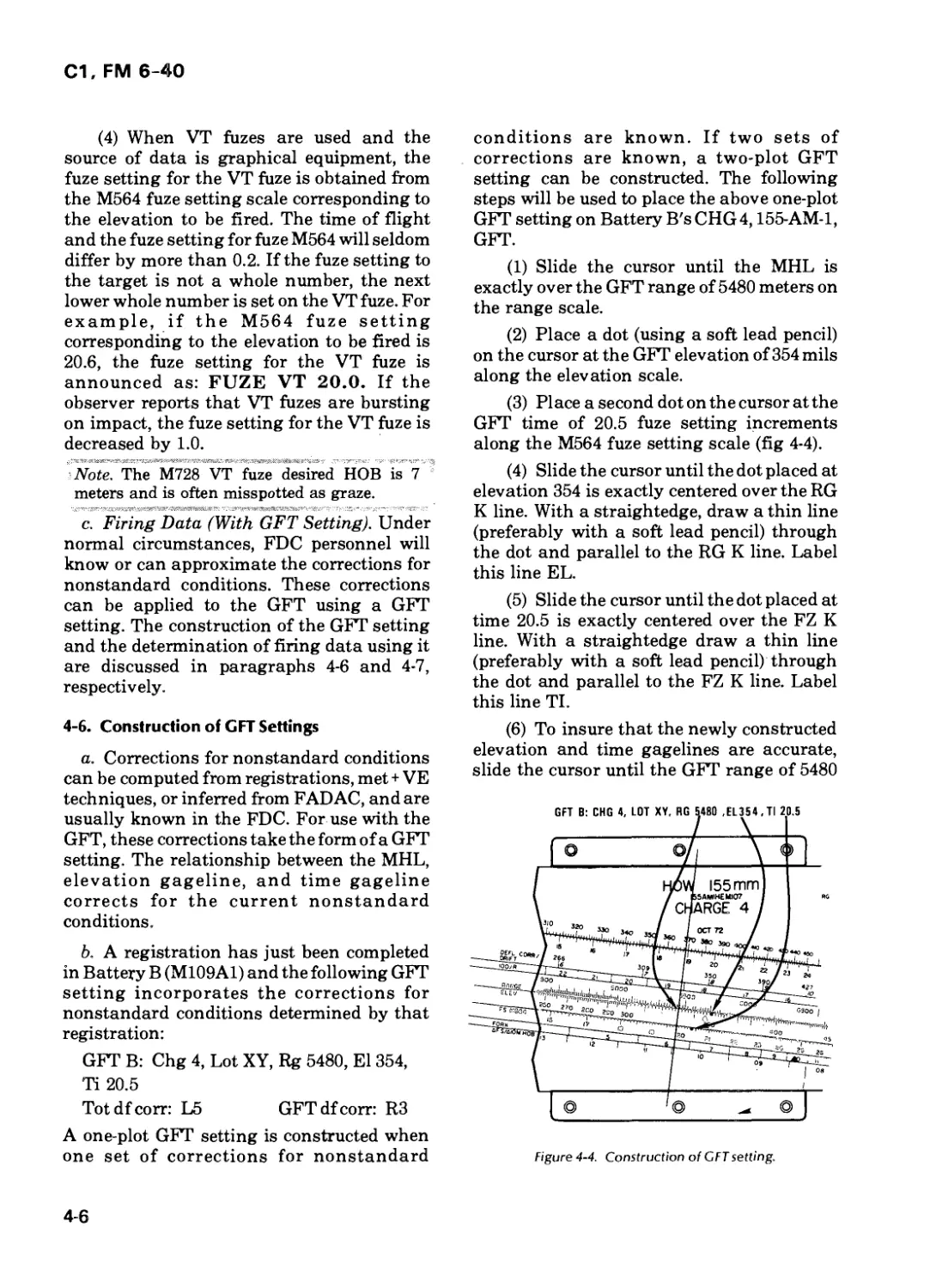
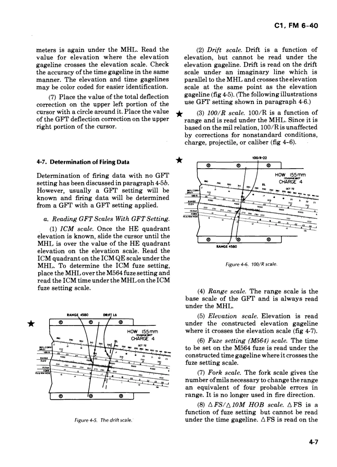
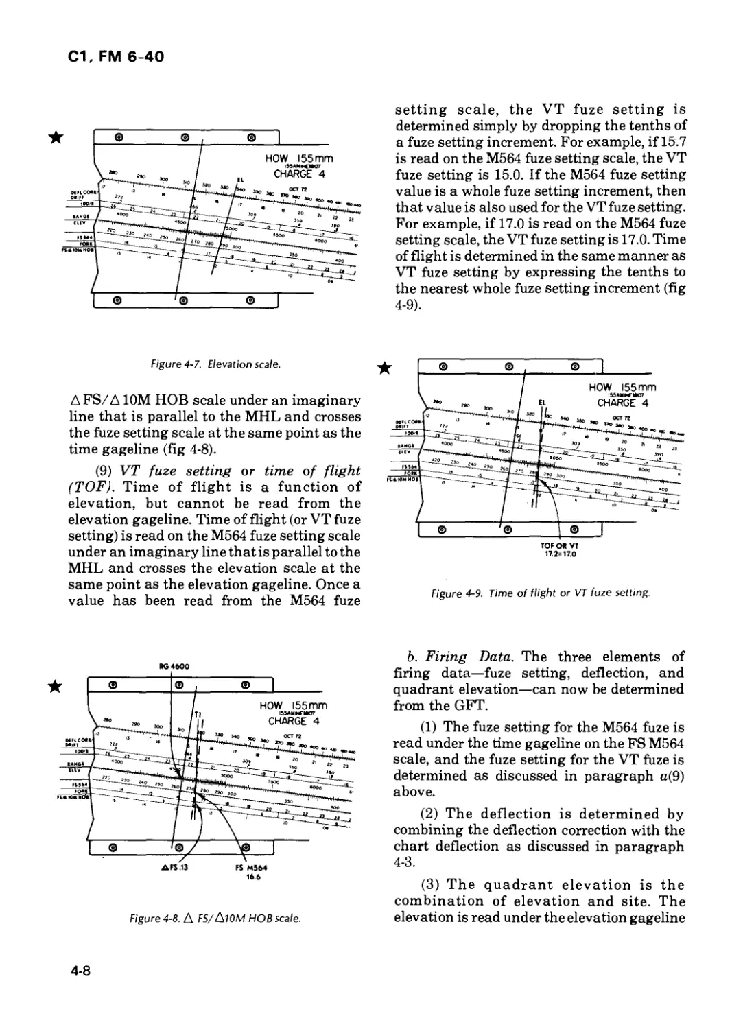
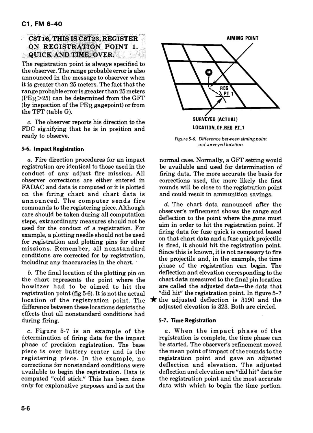
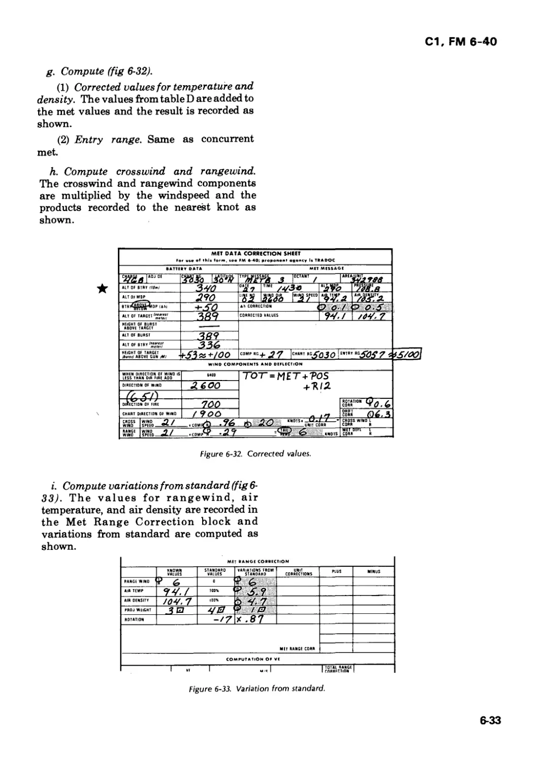
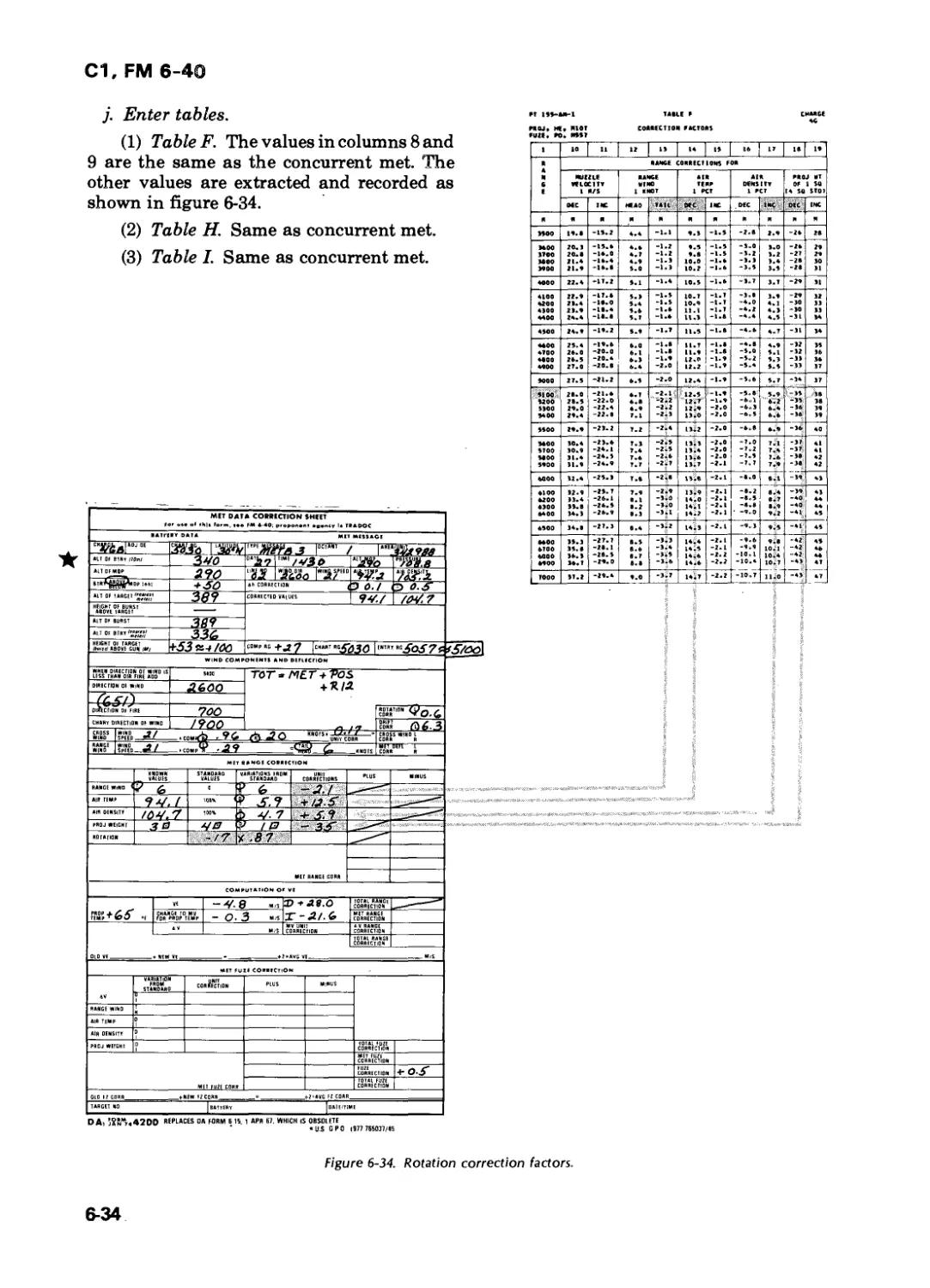
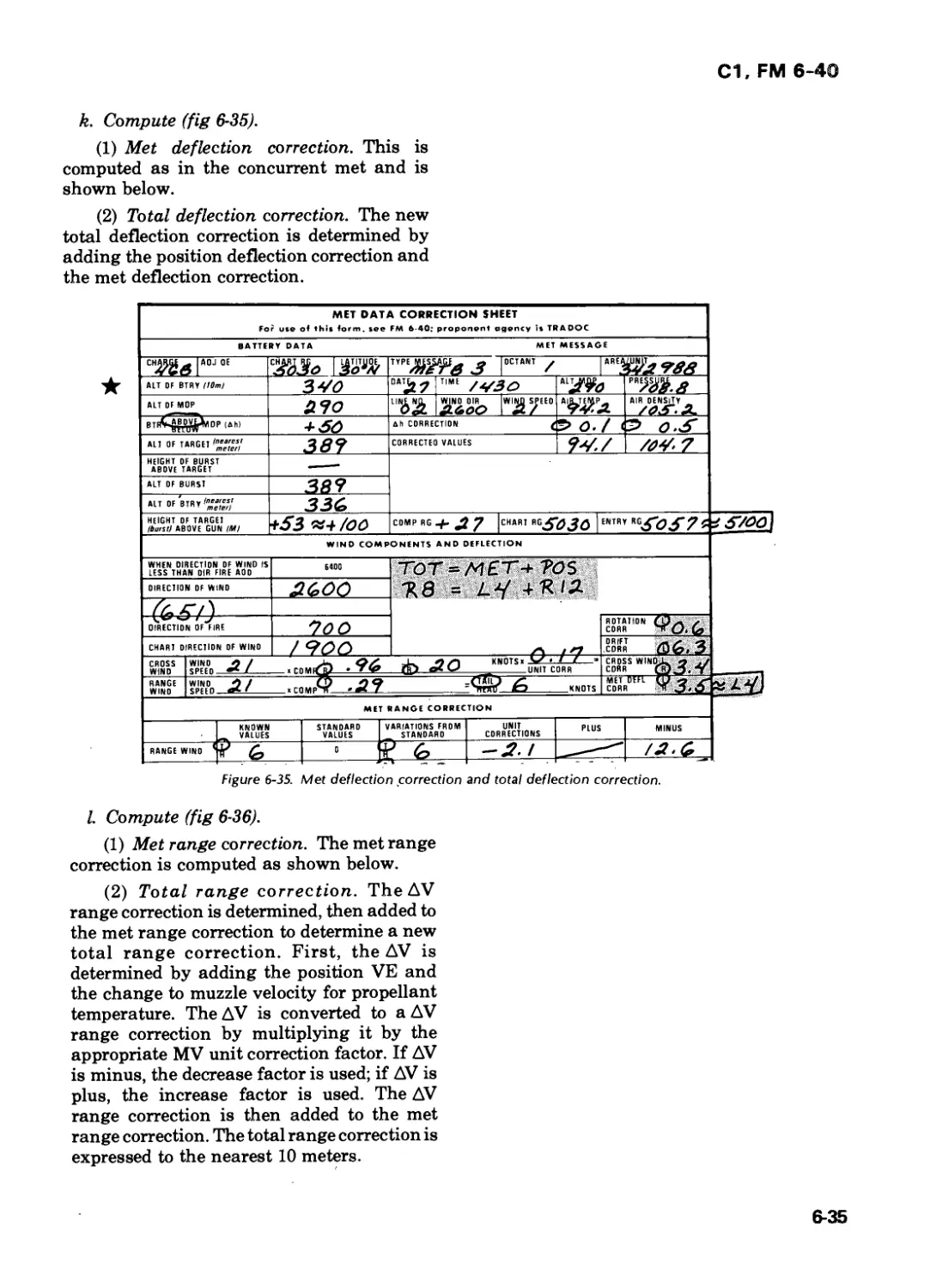
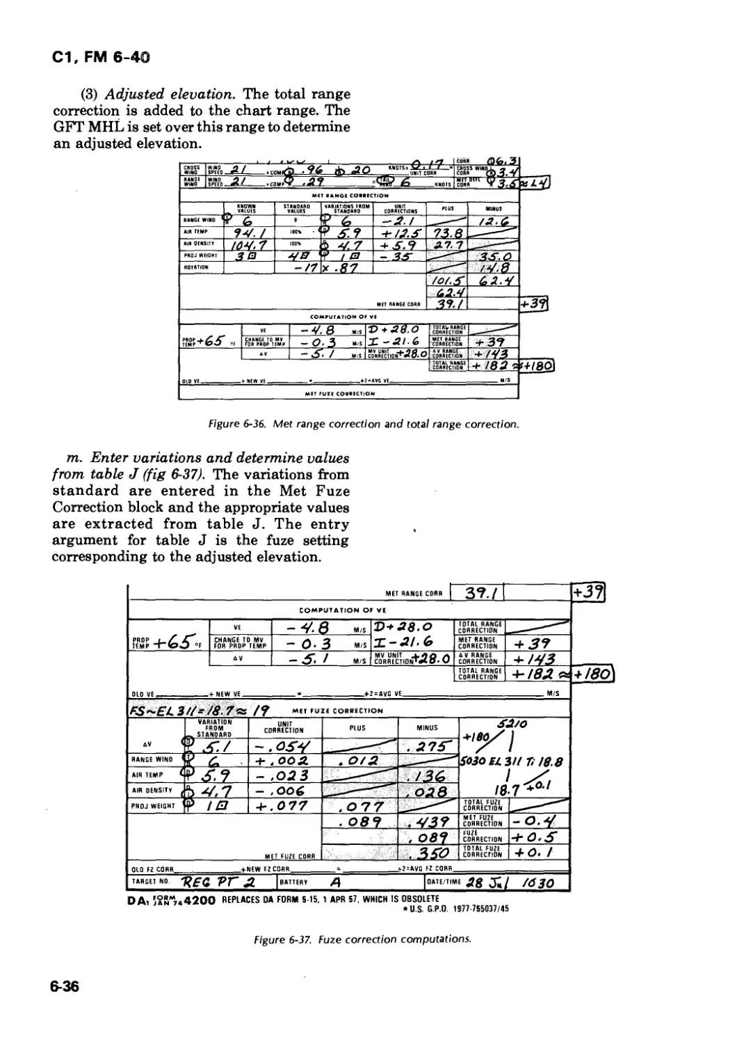
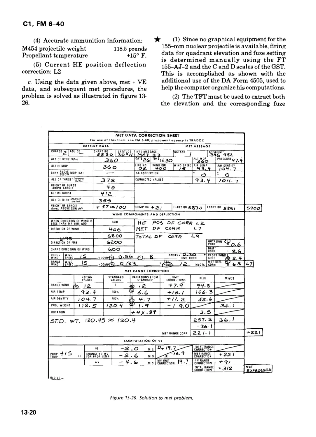
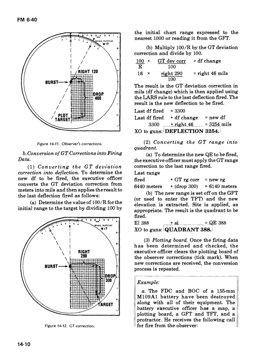
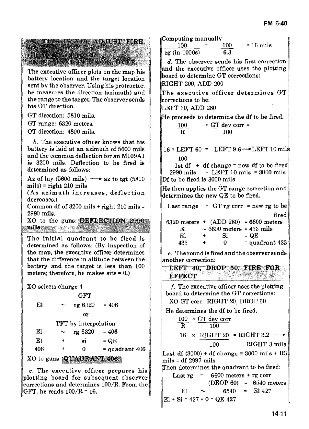
Text
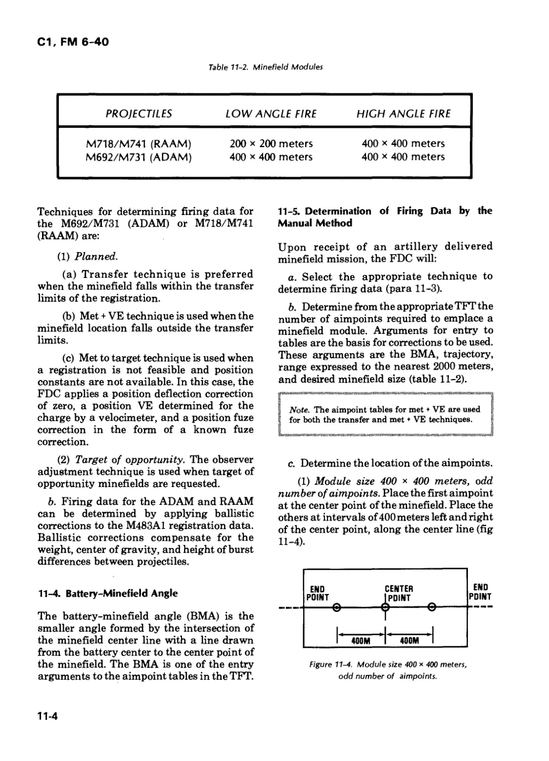
LIBRAS
Д; " R
: г’ и?т
BRARY -
armor SWOOP
STUCKY «VI
FIELD ARTILLERY
GUNNERY
HEADQUARTERS
DEPARTMENT OF THE ARMY
CHANGE
NO. 2
FM 6-40
C2
HEADQUARTERS
DEPARTMENT OF THE ARMY
Washington, DC, 6 November 1981
FIELD ARTILLERY CANNON GUNNERY
1. Effective upon receipt. This change updates FM 6-40, 1 December 1978, with change 1,
3 April 1981. Changed material is indicated by a star (★) preceding the material.
2. Remove old pages 11-5 and 11-6. Insert new pages 11-5 and 11-6.
3. File this change sheet in front of the publication for reference purposes.
By Order of the Secretary of the Army:
E. C. MEYER
General, United States Army
Chief of Staff
Official:
ROBERT M. JOYCE
Brigadier General, United States Army
The Adjutant General
DISTRIBUTION:
Active Army and USAR: To be distributed in accordance with DA Form 12-11 A, Requirements for
Field Artillery Cannon Gunnery (Qty rqr block no. 44); and Field Artillery Cannon Battalions and
Batteries (Qty rqr block no. 72).
ARNG: To be distributed in accordance with DA Form 12-11 A, Requirements for Field Artillery
Cannon Gunnery (Qty rqr block no. 44).
Additional copies can be requisitioned from the US Army Adjutant General Publications Center,
2800 Eastern Boulevard, Baltimore MD 21220.
FM 6-40
Cl
CHANGE
NO. 1
HEADQUARTERS
*1 * DEPARTMENT OF THE ARMY
Washington, DC, 3 April 1981
FIELD ARTILLERY CANNON GUNNERY
1.
2.
Effective upon receipt. This change updates FM 6-40,1 December 1978. Changed material is indi-
cated by a star (^-) preceding the material.
Make the following page changes.
REMOVE INSERT REMOVE INSERT
i through iii i through iii 8-27 through 8-32 8-27 through 8-32
1-1 through 1-6 1-1 through 1-6 9-3 through 9-8 9-3 through 9-8
2-1 and 2-2 2-1 and 2-2 9-11 and 9-12 9-11 through 9-14
2-5 through 2-8 2-5 through 2-8 10-3 through 10-10 10-3 through 10-10
2-11 and 2-12 2-11 and 2-12 11-1 through 11-30 11-1 through 11-32
2-15 through 2-24 2-15 through 2-23 12-1 and 12-2 12-1 and 12-2
3-1 through 3-18 3-1 through 3-18 12-9 through 12-26 12-9 through 12-32
4-1 through 4-30 4-1 through 4-30 13-1 through 13-4 13-1 through 13-4
5-1 through 5-12 5-1 through 5-12 13-9 through 13-20 13-9 through 13-20
5-15 through 5-22 5-15 through 5-22 13-23 and 13-24 13-23 and 13-24
5-25 through 5-37 5-25 through 5-38 14-1 through 14-6 14-1 through 14-6
6-3 and 6-4 6-3 and 6-4 A-1 through A-4 A-1 through A-4
6-11 through 6-26 6-11 through 6-26 A-9 and A-10 A-9 and A-10
6-29 through 6-42 6-29 through 6-42 C-9 through C-16 C-9 and C-10
7-1 through 7-12 7-1 through 7-12 D-1 through D- 6
7-21 and 7-22 7-21 through 7-24 E-1 through E-3 E-1 through E-3
8-3 through 8-6 8-3 through 8-6 F-1 through F-6 F-1
8-11 through 8-14 8-11 through 8-14 1-1 1-1
8-17 and 8-18 8-17 and 8-18 J-1 through J-3 J-1 through J-3
8-23 and 8-24 8-23 and 8-24 Index-1 through Index-3 Index-1 through Index-4
3.
4.
File this change sheet in front of the publication for reference purposes.
The words "he,” "him,", "his,” and "men," when used in this publication, represent both
the masculine and feminine genders, unless otherwise specifically stated.
CHANGE 1, FM 6-40
3 APRIL 1981
By Order of the Secretary of the Army:
E. C. MEYER
General, United States Army
Chief of Staff
Official:
J. C. PENNINGTON
Major General, United States Army
The Adjutant Genera!
DISTRIBUTION:
Active Army and USAR: To be distributed in accordance with DA Form 12-11 A, Requirements for
Field Artillery Cannon Gunnery (Qty rqr block no. 44); and Field Artillery Cannon Battalions and
Batteries (Qty rqr block no. 72).
ARNG:To be distributed in accordance with DA Form 12-11 A, Requirements for Field Artillery
Cannon Gunnery (Qty rqr block no. 44).
Additional copies can be requisitioned from the US Army Adjutant General Publications Center,
2800 Eastern Boulevard, Baltimore MD 21220.
* FM 6-40
Cl
FIELD MANUAL
NO. 6-40
HEADQUARTERS
DEPARTMENT OF THE ARMY
Washington, DC, 1 December 1978
FIELD ARTILLERY CANNON GUNNERY
Page
Chapter 1. INTRODUCTION
Section I. General 1-1
Section II. Gunnery Components 1-2
Section III. Field Artillery Effectiveness and Survivability 1-3
Chapter 2. FIRE DIRECTION ORGANIZATION AND
OPERATION
Section I. Fire Direction Procedures 2-1
Section II. Duties and Organization of FDC Personnel 2-4
Section III. Fire Order 2-7
Section IV. Fire Commands 2-13
Section V. Battery Mission Processing 2-17
Section VI. Battalion Mission Processing 2-22
Chapter 3. CHART DATA
Section I. Firing Chart 3-1
Section II. Plotting Equipment and Preparation of Firing Charts 3-2
Section III. Determination of Chart Data 3-13
Section IV. Chart Verification 3-18
Chapter 4. FIRING DATA
Section I. Elements of Firing Data 4-1
Section II. Graphical Firing Tables 4-3
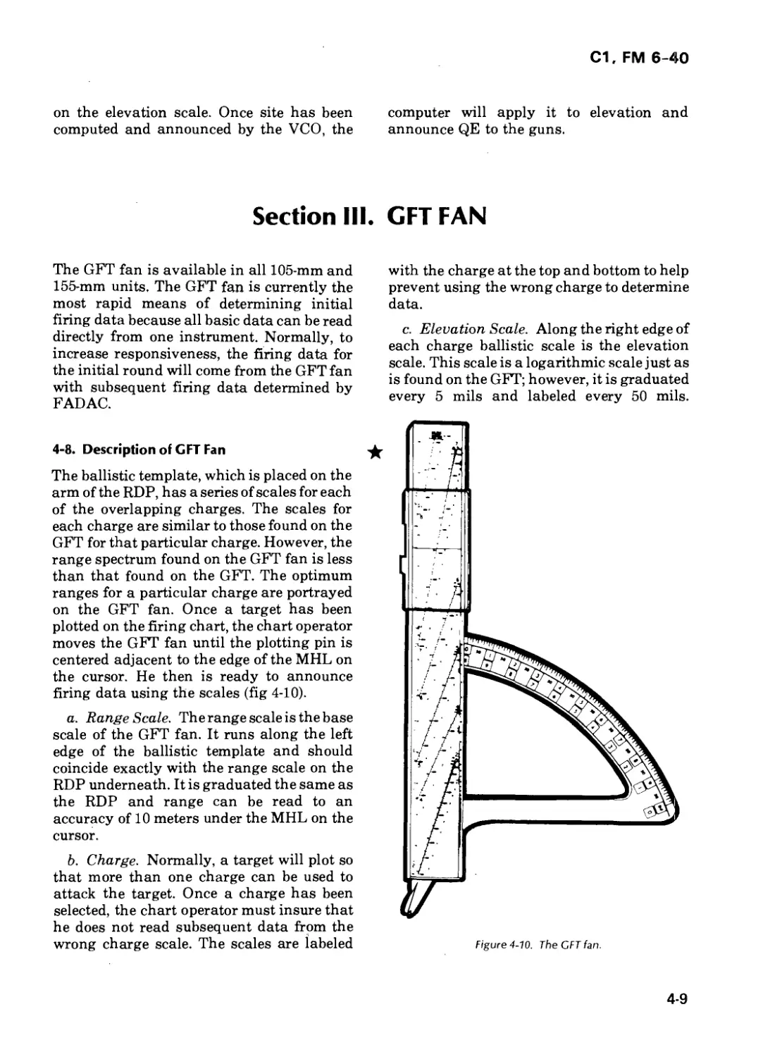
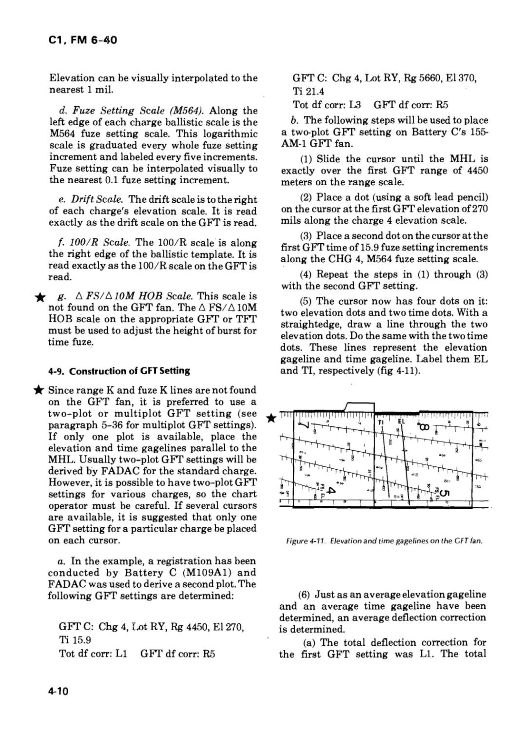
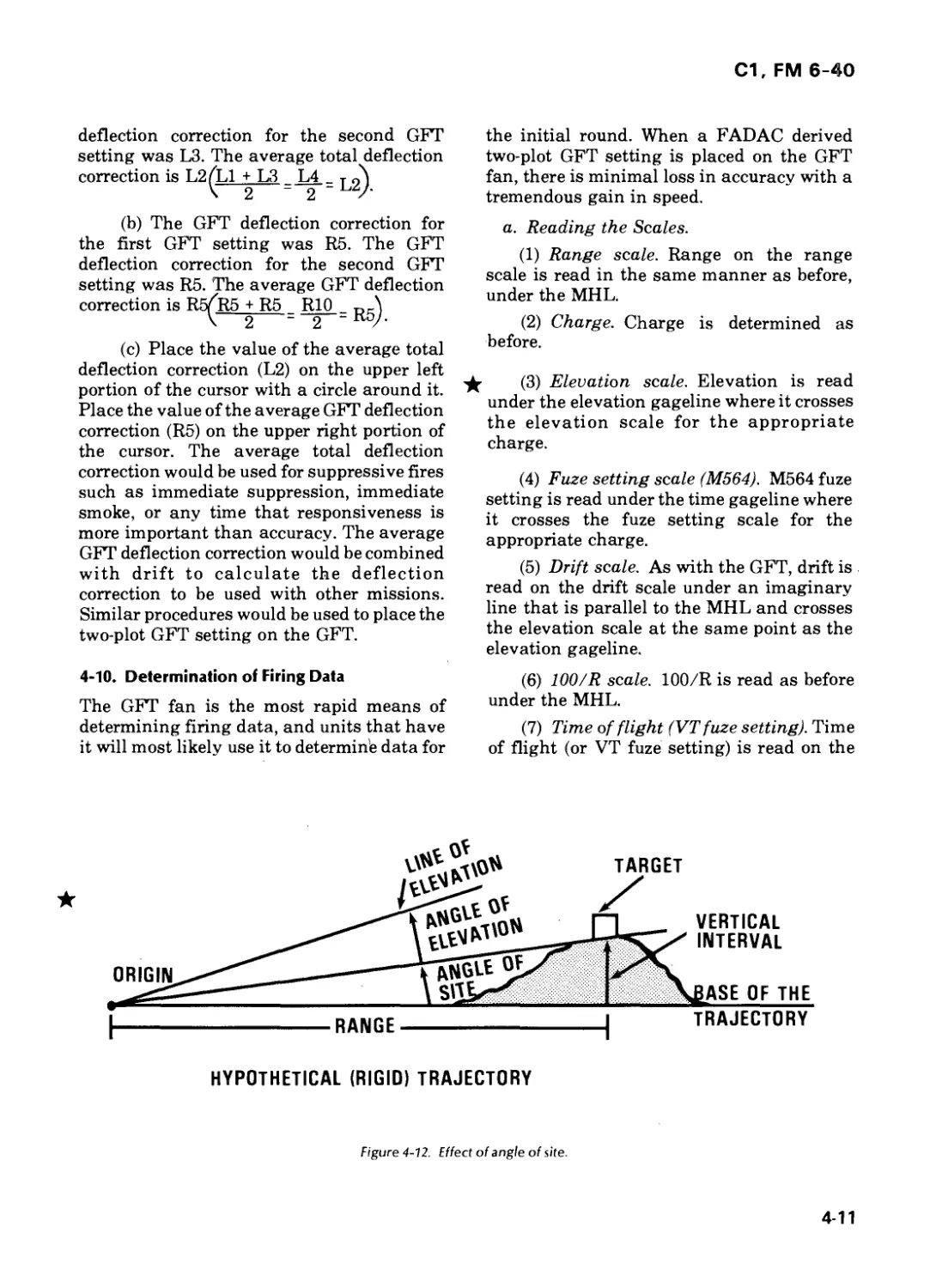
Section III. GFT Fan 4-9
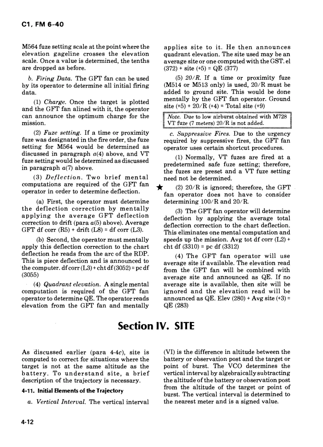
Section IV. Site 4-12
Section V. Record of Fire and Registration/Special Correction 4-21
Worksheet
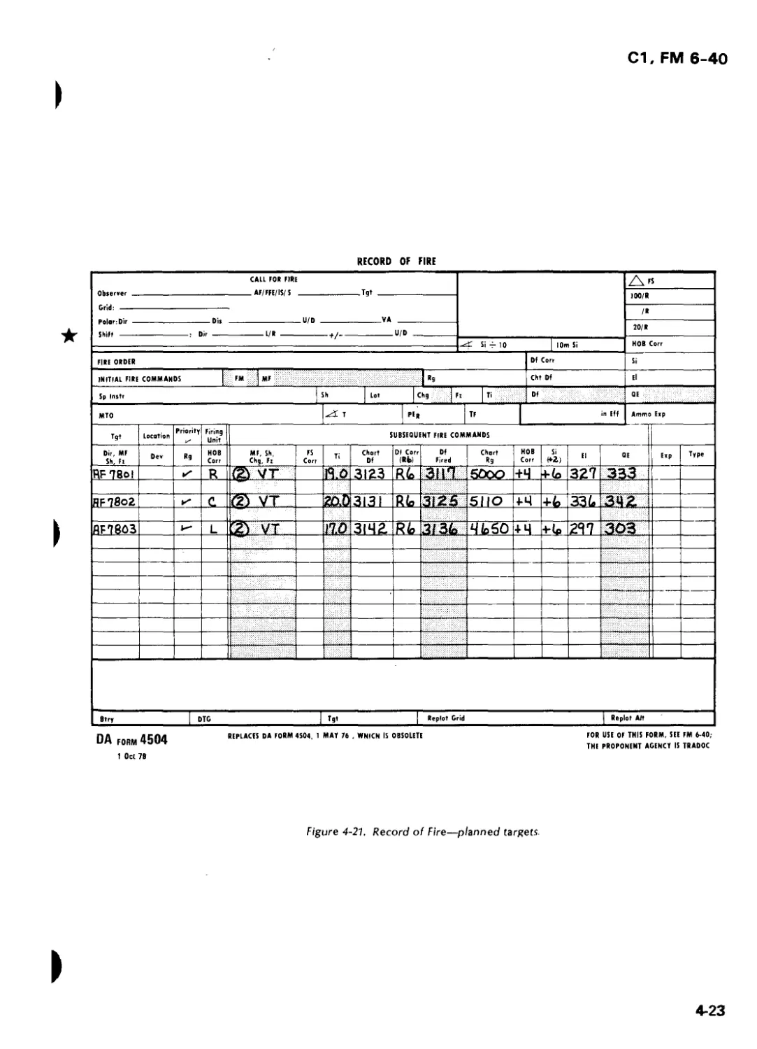
Section VI. Sample Problem 4-25
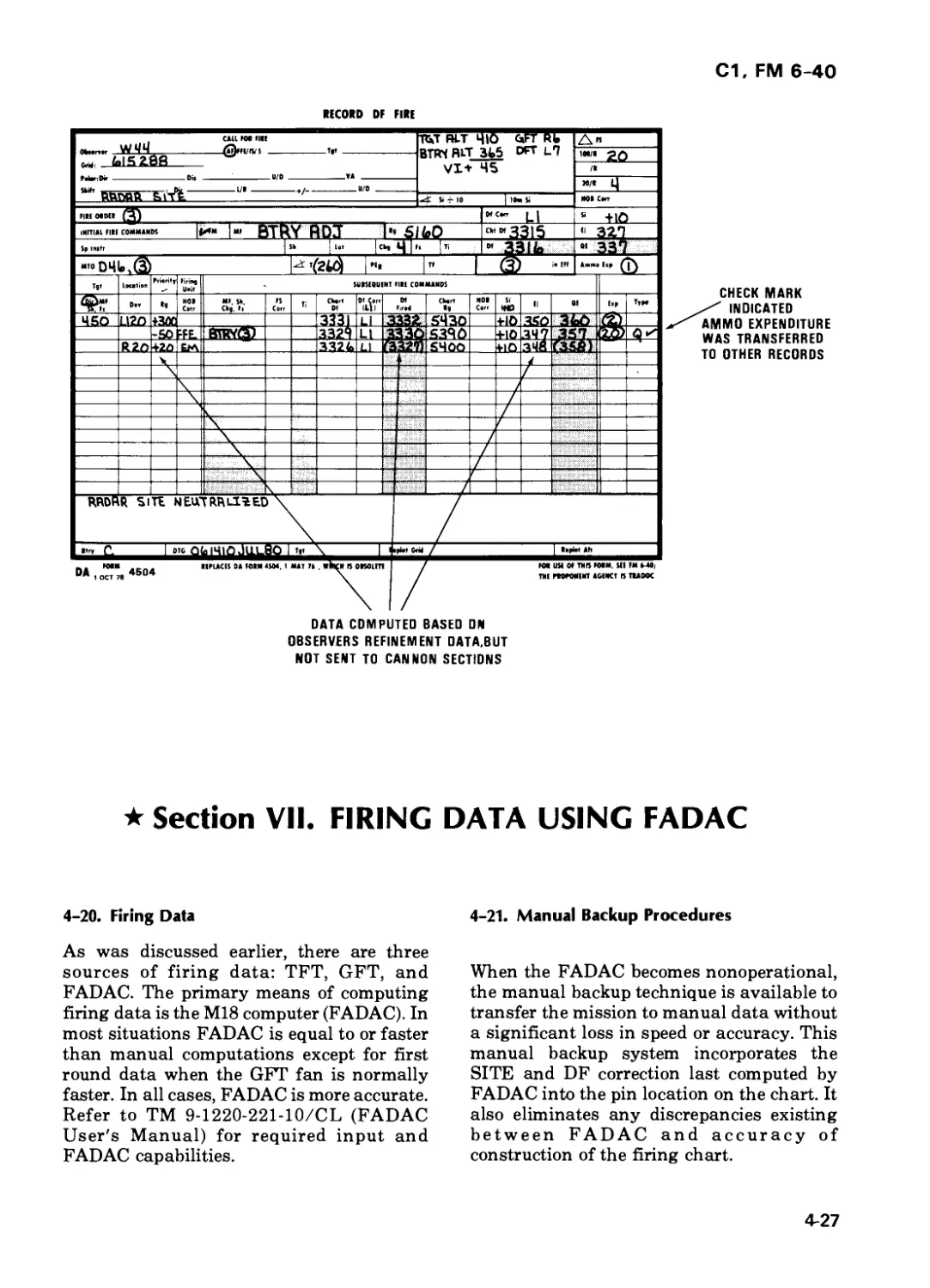
Section VII. Firing Data Using FADAC 4-27
Section VIII. Refinement Procedures 4-28
*This publication, together with FM 6-30,16 August 1978, supersedes FM 6-40-5,1 July 1976, and FM 6-40,
28 June 1974, including all changes. In addition, this publication rescinds DA Form 4208, January 1974.
С1, FM 6-40
Page
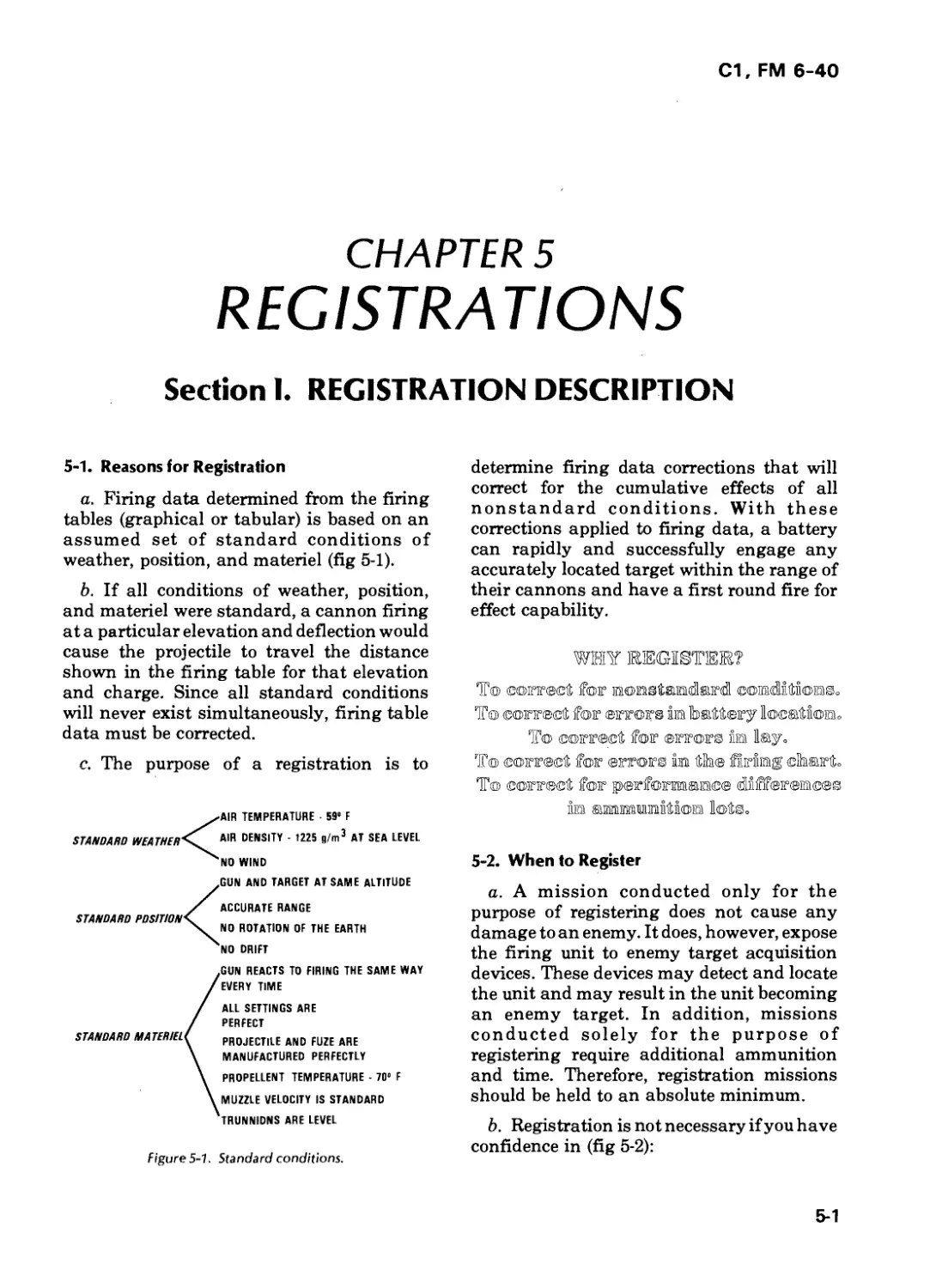
Chapter 5. REGISTRATIONS
Section I. Registration Description 5-1
Section II. Precision Registration 5-5
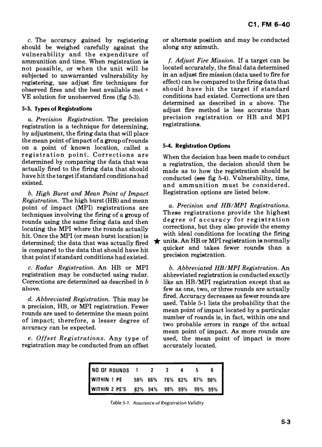
Section III. High Burst (HB) and Mean Point of Impact (MPI) 5-10
Registrations
Section IV. Radar Observed High Burst and Mean Point of Impact 5-24
Registrations
Section V. Special Registrations 5-29
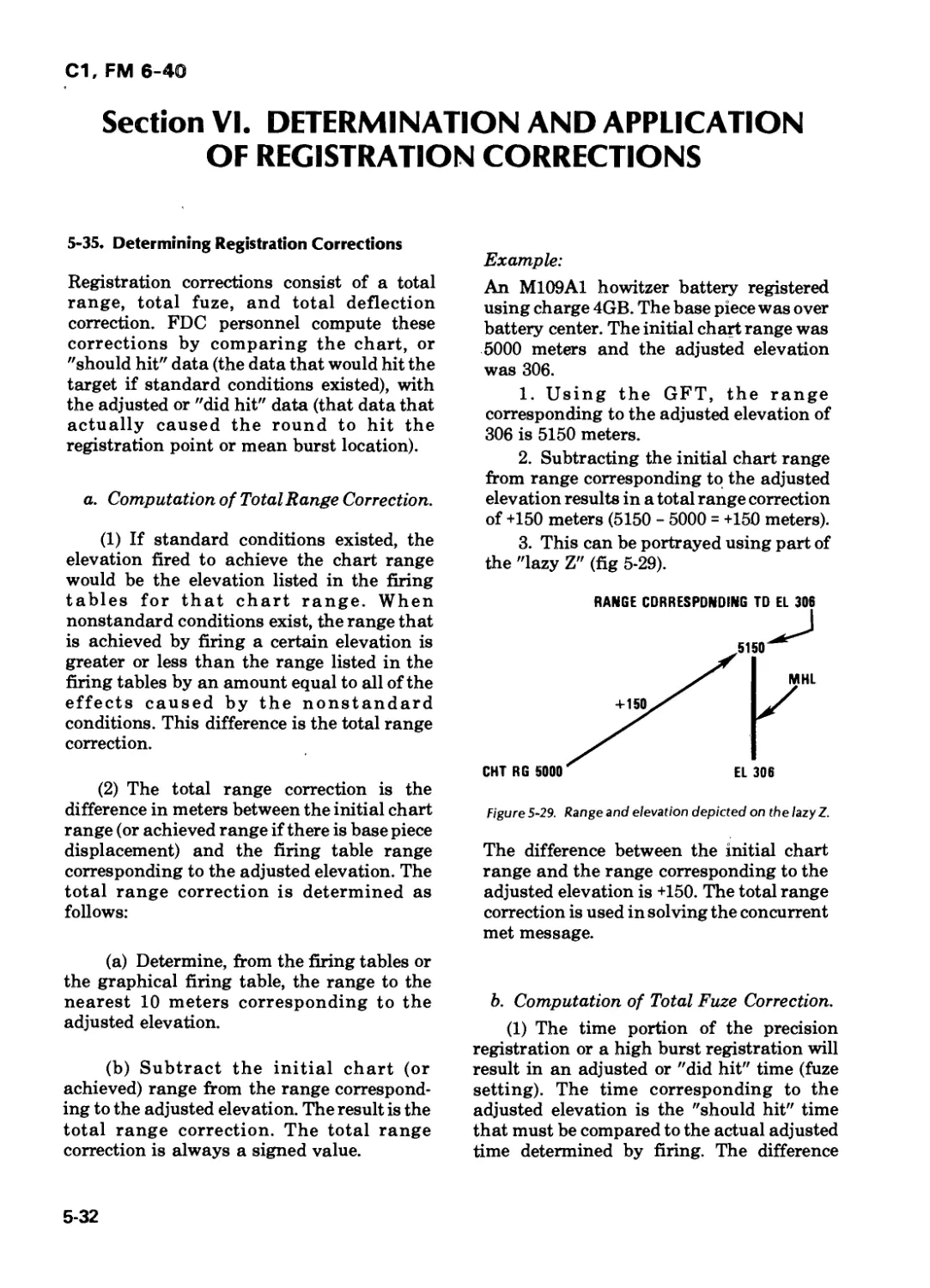
Section VI. Determination and Application of Registration 5-32
Corrections
Section VII. Registration with FADAC 5-37
Chapter 6. MET
Section I. Introduction 6-1
Section II. Met Messages 6-3
Section III. Concurrent Met 6-9
Section IV. Subsequent Met 6-26
Section V. Subsequent Met Application 6-37
Section VI. FADAC Met 6-43
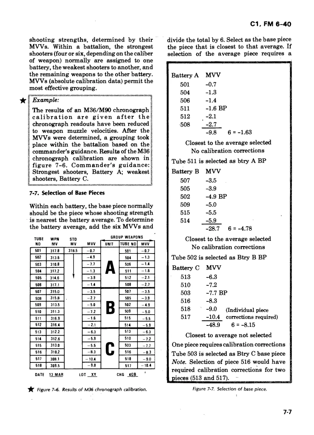
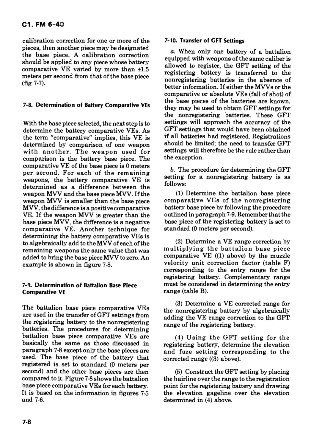
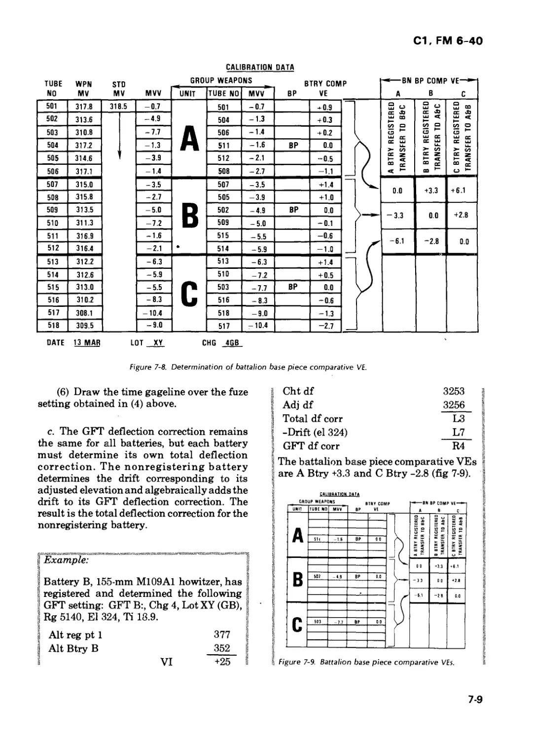
Chapter 7. CALIBRATION
Section I. Calibration Description 7-1
Section II. Chronograph Calibration Computations 7-6
Section III. Fall-of-Shot Comparative Calibration Procedures 7-14
Section IV. Fall-of-Shot Absolute Calibration Procedures 7-19
Section V. Velocimeter and FADAC Procedures 7-22
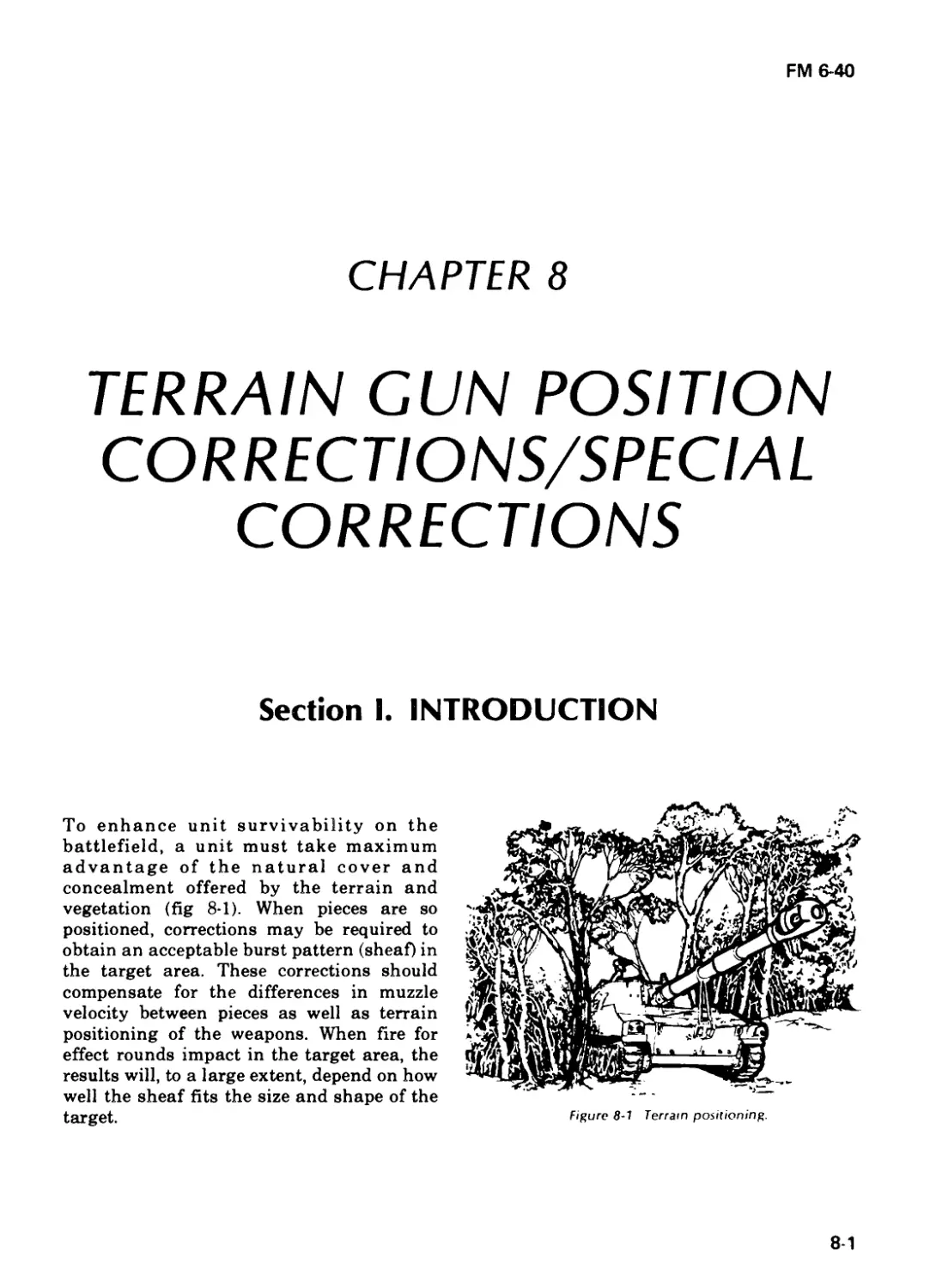
Chapter 8. TERRAIN GUN POSITION CORRECTIONS/
SPECIAL CORRECTIONS
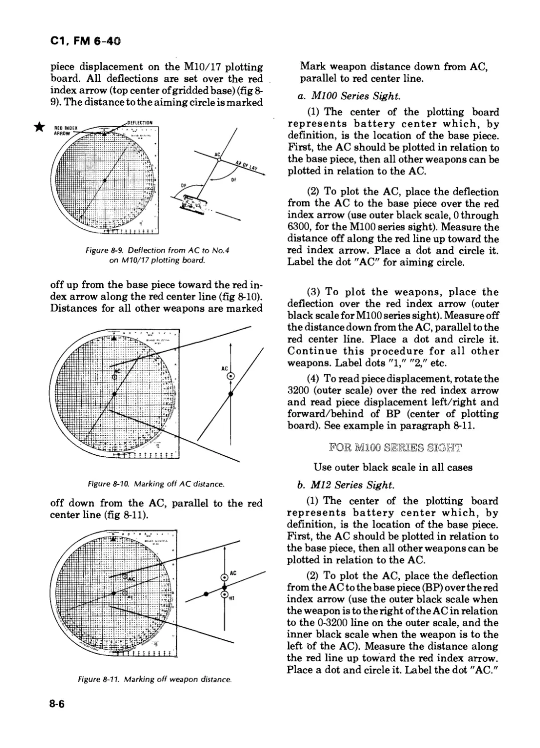
Section I. Introduction 8-1
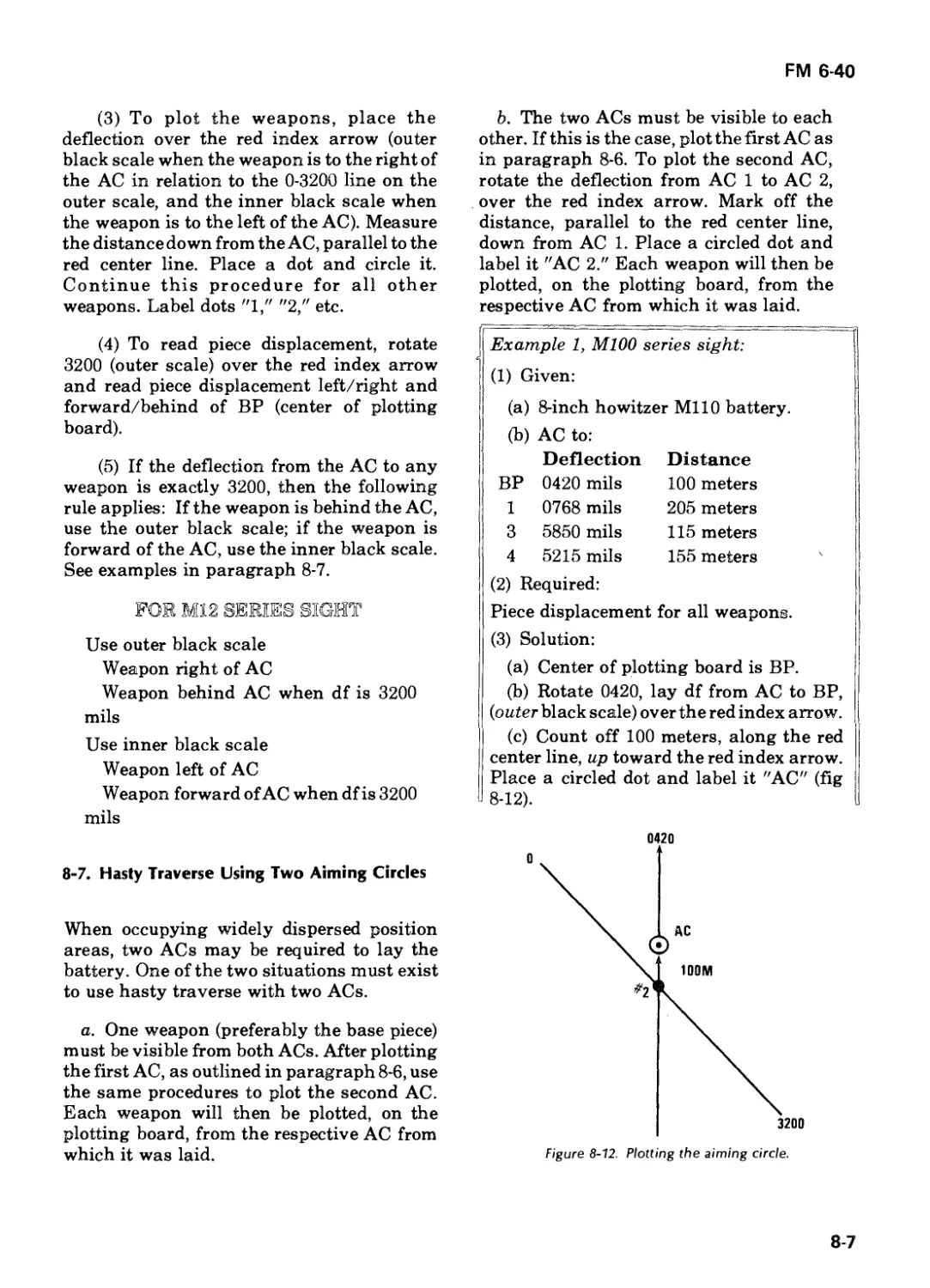
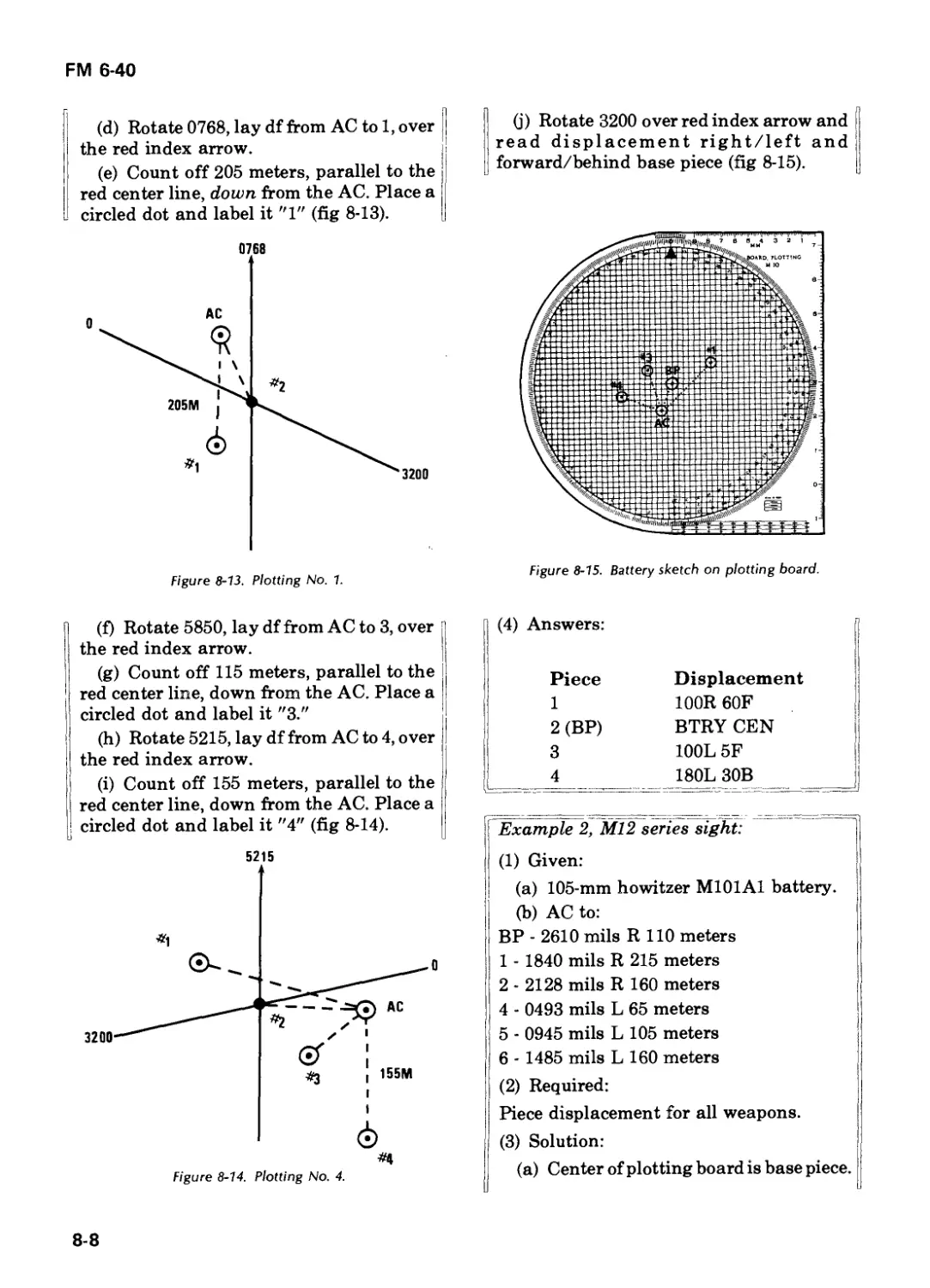
Section II. Hasty Traverse 8-4
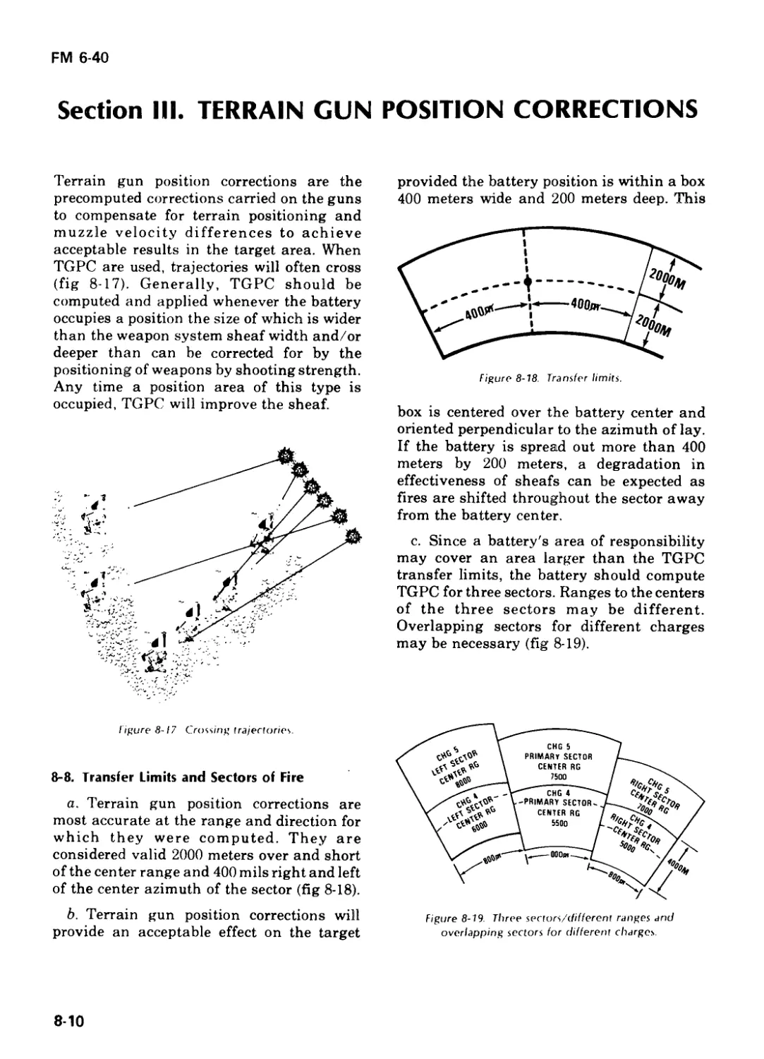
Section III. Terrain Gun Position Corrections 8-10
Section IV. Special Corrections/Position Corrections 8-23
Section V. FADAC 8-33
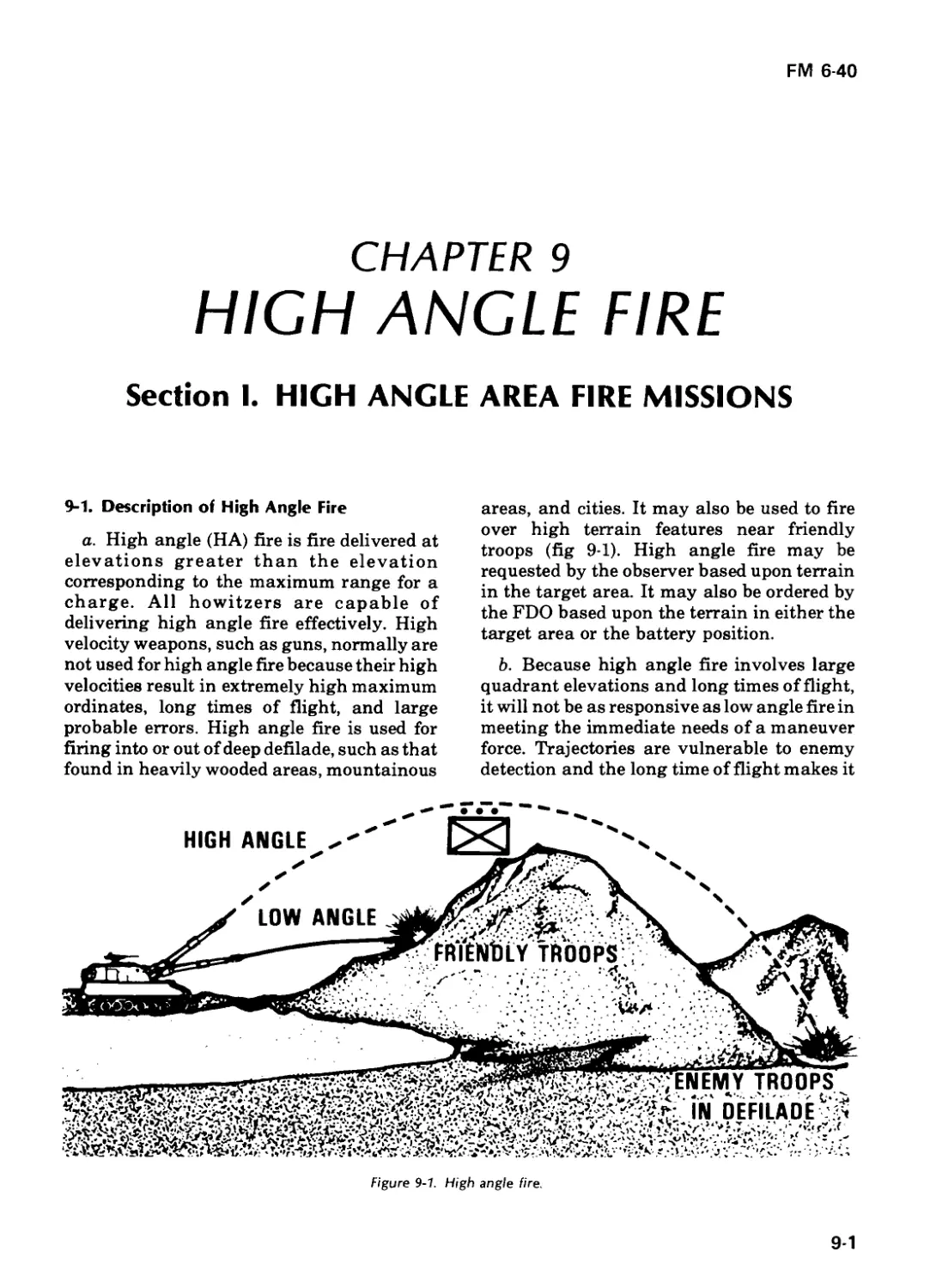
Chapter 9. HIGH ANGLE FIRE
Section I. High Angle Area Fire Missions 9-1
Section II. FDC Procedures for High Angle Registrations 9-7
Chapter 10. REPLOT
Section I. Manual Procedures 10-1
Section II. FADAC Procedures 10-9
Chapter 11. FIRE DIRECTION PROCEDURES FOR SPECIAL
MUNITIONS
Section I. ICM/FASCAM 11-1
Section II. Illumination 11-11
Section III. White Phosphorus 11-20
С1, FM 6-40
Page
Section Section IV. V. Smoke Chemical Projectiles 11-22 11-30
Chapter 12. FIRE DIRECTION PROCEDURES FOR SPECIAL
SITUATIONS
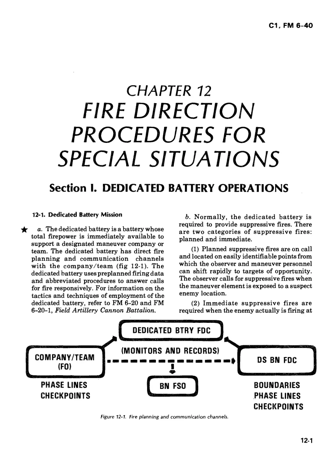
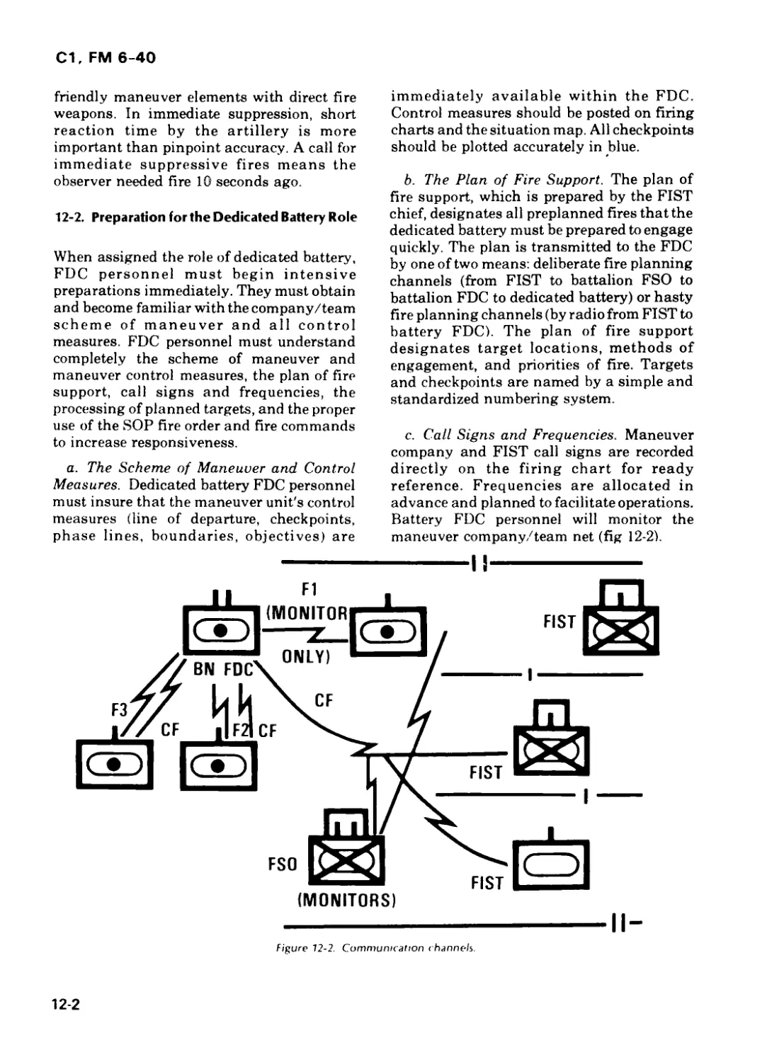
Section I. Dedicated Battery Operations 12-1
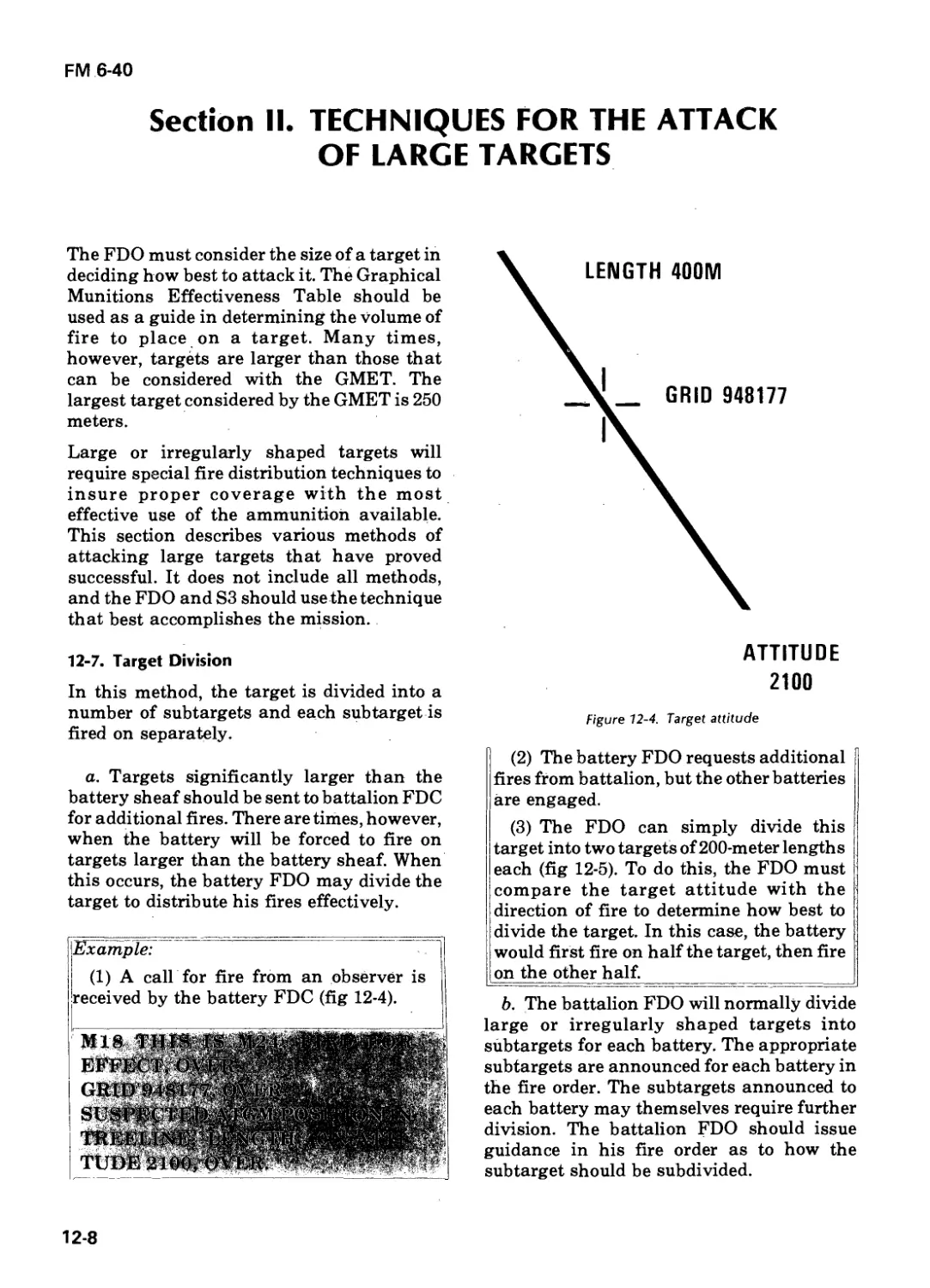
Section II. Techniques for the Attack of Large Targets 12-8
Section III. Final Protective Fires 12-13
Section IV. Aerial Observers and Untrained Observers 12-16
Section V. Assault Fire 12-19
Section VI. Zone-to-Zone Transformation 12-22
Section VII. FDC Procedures for Laser Rangefinders 12-27
Section VIII. Computer Set, Field Artillery, General 12-28
Section IX. Rocket Assisted Projectile (RAP) 12-29
Chapter 13. NUCLEAR DELIVERY
Section I. 8-Inch Nuclear Delivery 13-1
Section II. 155-mm Howitzer Nuclear Delivery 13-13
Chapter 14. EMERGENCY FDC PROCEDURES
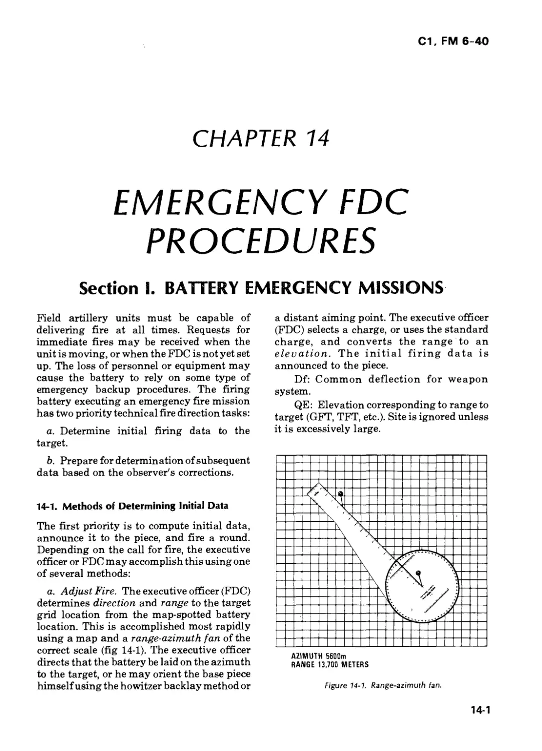
Section I. Battery Emergency Missions 14-1
Section II. Battery Emergency Charts 14-4
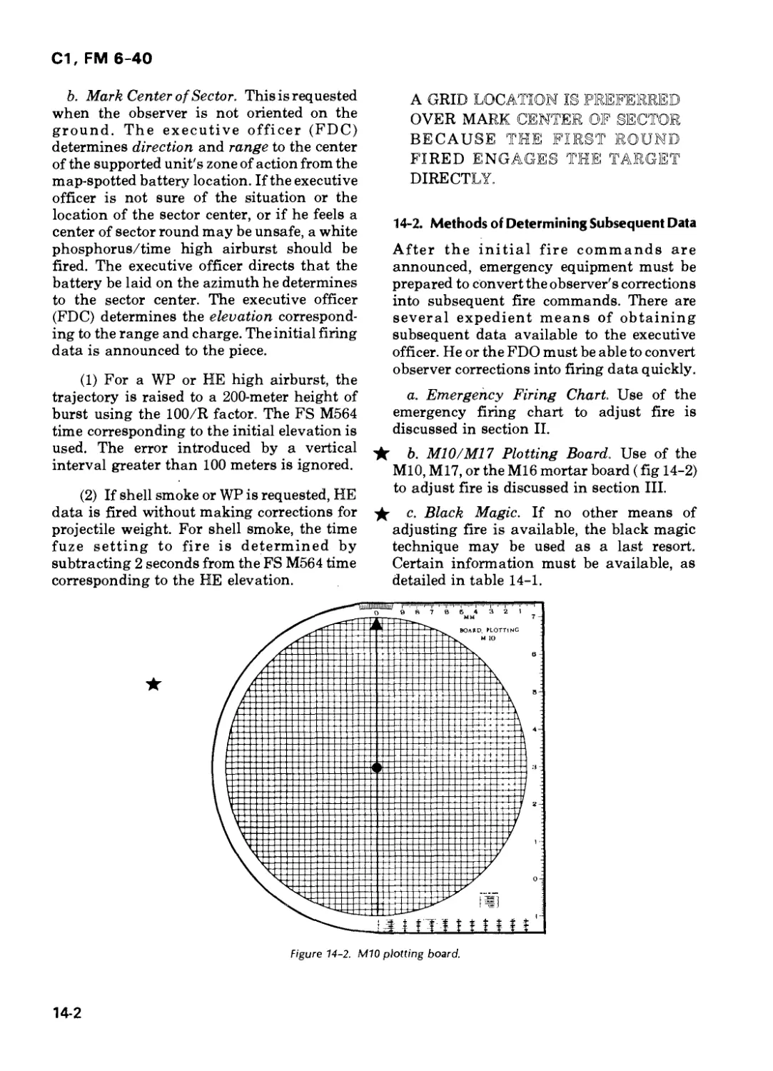
Section III. M10/M17 Plotting Board 14-9
Section IV. FADAC 14-12
Chapter 15. OBSERVED FIRING CHARTS
Section I. Introduction 15-1
Section II. Battery Observed Firing Charts 15-2
Section III. Battalion Observed Firing Charts 15-9
Section IV. Replotting Targets on the Observed Firing Chart 15-13
Section V. Observed Firing Chart with Incomplete Survey 15-14
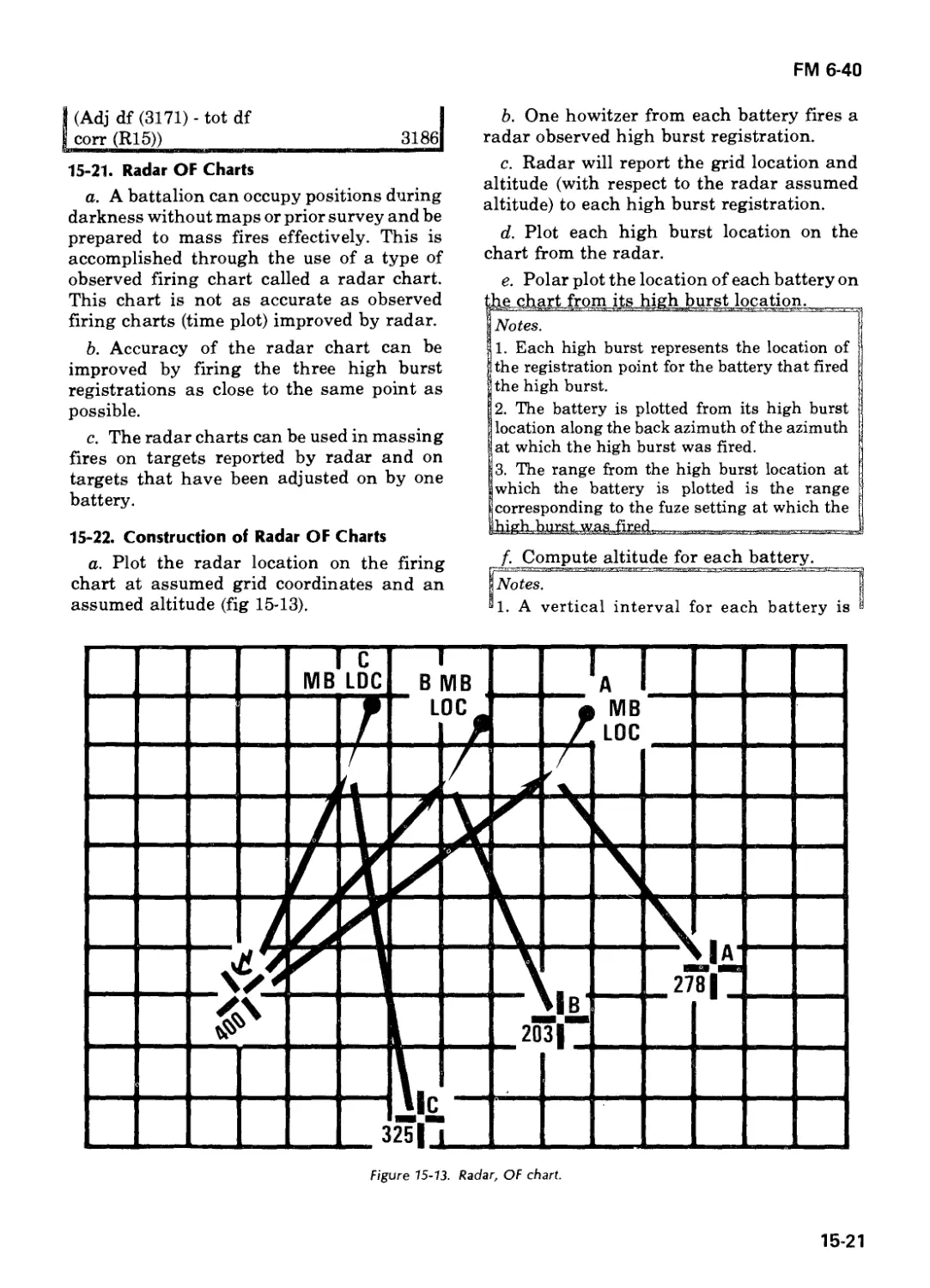
Section VI. Radar Firing Charts 15-17
APPENDIX A. HOW TO TRAIN THE FDC A-l
B. BALLISTICS B-l
C. TARGET ANALYSIS AND MUNITIONS EFFECTS C-l
D. Deleted
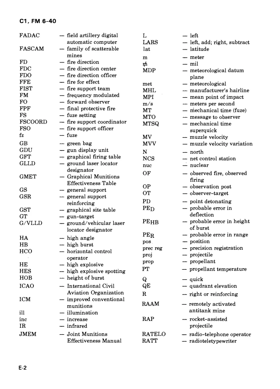
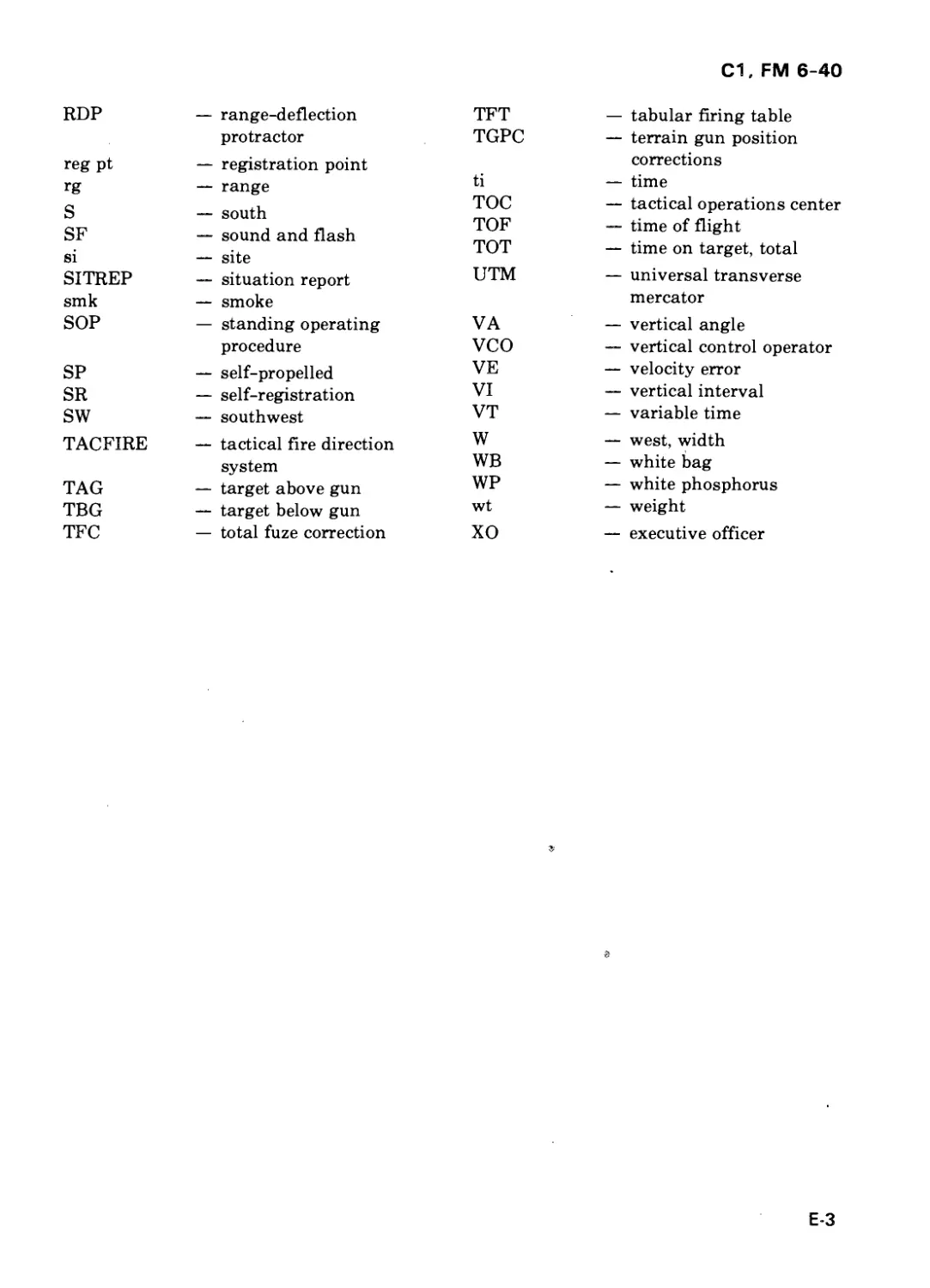
E. GLOSSARY E-l
F. FIRE DIRECTION CENTER STANDARDIZA-
TION (to be published) F-l
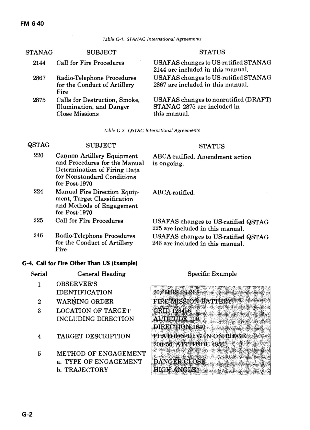
G. INTERNATIONAL STANDARDIZATION
AGREEMENTS G-l
H. EMPLOYMENT OF ARMOR IN A FIELD
ARTILLERY ROLE H-l
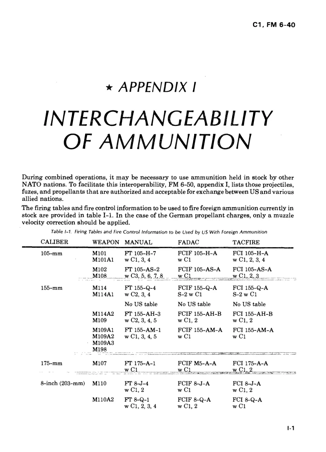
I. INTERCHANGEABILITY OF AMMUNITION 1-1
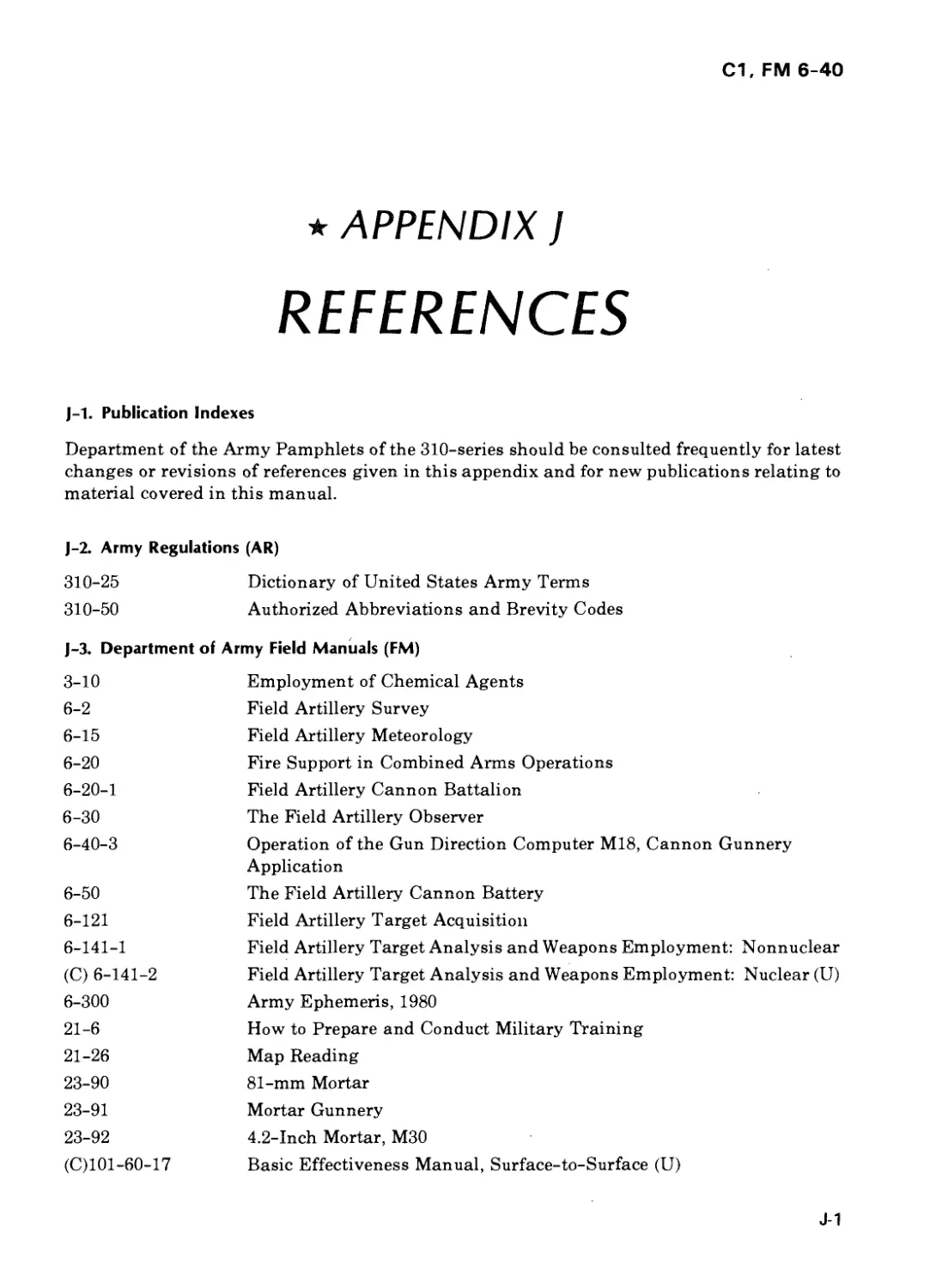
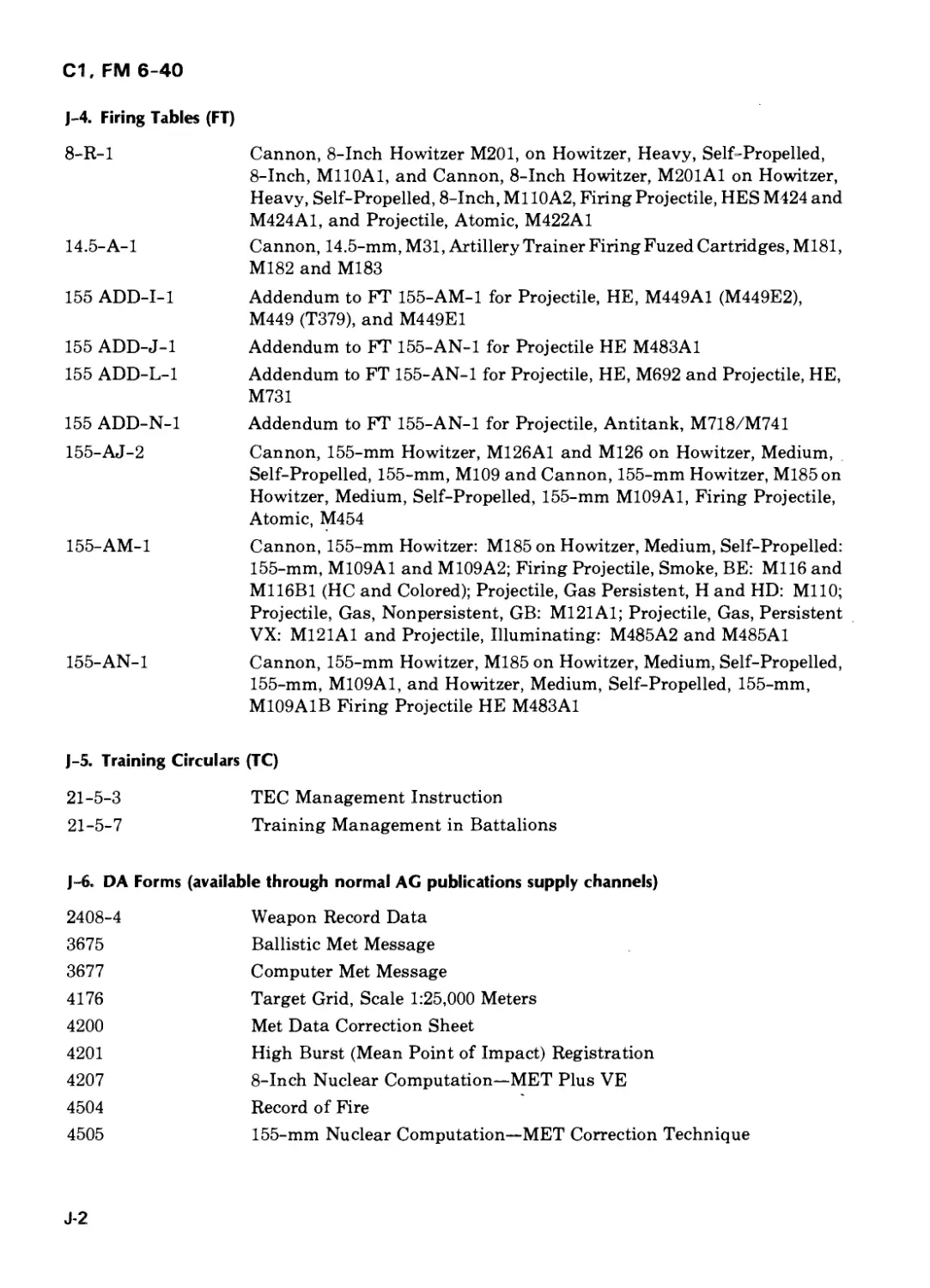
J. REFERENCES J-l
INDEX Index-1
iii
С1, FM 6-40
CHAPTER 1
INTRODUCTION
Section 1. GENERAL
1-1. Purpose
The purpose of this manual is to provide a
document that eliminates the need for
multiple gunnery reference documents and
explains:
a. Fire direction procedures used by
manual/FADAC (field artillery digital
automatic computer) equipped field artillery
cannon units in combat.
b. Fire direction training conducted in
peacetime to meet combat requirements.
1-2. Scope
a. This manual encompasses all aspects of
field artillery cannon gunnery. The material
presented herein applies to both nuclear and
nonnuclear warfare. Hereafter, when the
term "artillery" is used, it relates to field
artillery unless otherwise stated.
b. Integrated manual/FADAC fire
direction procedures are discussed only in
terms of FADAC employment considerations
and capabilities. To determine detailed
FADAC operator procedures, consult the
FADAC User's Manual.
c. Chronograph M90, laser rangefinder,
rocket-assisted projectiles (RAP), hand-held
calculator, and FASCAM (family of
scatterable mines) procedures are
incorporated into this text. Future changes to
FM 6-40 will be programed to support the
development and operational tests of other
field artillery systems (e.g., cannon-launched
guided projectile (Copperhead)).
d. This manual does not address fire
direction procedures under the tactical fire
direction/battery computer system
(TACFIRE/ BCS).
1-3. Target Audience
a. Trainers and supervisors of battery fire
direction center (FDC) personnel.
b. Battalion operations/FDC personnel.
1-4. Changes or Corrections
Users of this manual are encouraged to
submit recommended changes or comments
to improve this manual. Comments should
specify page, paragraph, and line of the text
in which the change is recommended.
Reasons should be provided for each
comment to insure understanding and
complete evaluation. Comments should be
forwarded to Commandant, US Army Field
★ Artillery School, ATTN: ATSF-TD-TL, Fort
Sill, Oklahoma 73503.
1-5. References
See appendix J for list of references.
1-1
С1, FM 6-40
Section II. GUNNERY COMPONENTS
1-6. The Gunnery Problem
Field artillery cannons can engage targets at
great ranges. Normally, they are emplaced in
defilade to conceal them from the enemy and
to protect them from enemy direct fire
weapons. This placement usually precludes
sighting the weapons directly at the target
(direct fire). To attack a target, cannons must
employ indirect fires. The gunnery problem is
to determine aiming and ammunition data
that insures timely, accurate, effective
indirect fire. To solve the gunnery problem, we
must:
a. Know the location of the gun and
determine the location of the target.
b. Determine chart data (azimuth, range,
and vertical interval).
c. Convert chart data to firing data (fuze
setting, deflection, and quadrant).
d. Apply the firing data to the gun and
ammunition.
The solution to the problem provides weapon
and ammunition settings that cause a
projectile to burst on or at a predetermined
height above the target.
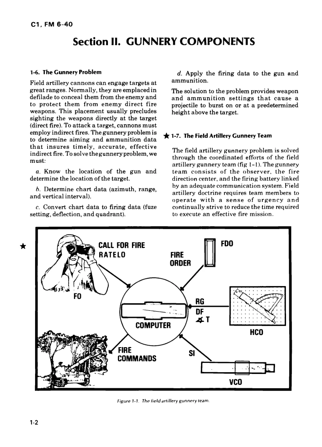
★ 1-7. The Field Artillery Gunnery Team
The field artillery gunnery problem is solved
through the coordinated efforts of the field
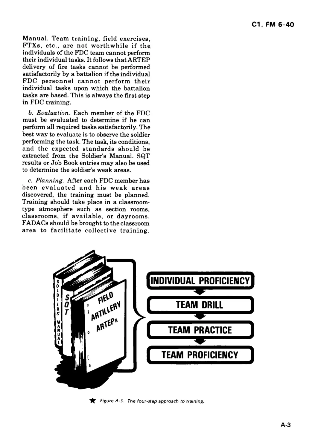
artillery gunnery team (fig 1-1). The gunnery
team consists of the observer, the fire
direction center, and the firing battery linked
by an adequate communication system. Field
artillery doctrine requires team members to
operate with a sense of urgency and
continually strive to reduce the time required
to execute an effective fire mission.
Figure 1-1. The Field artillery gunnery team.
1-2
С1, FM 6-40
a. Observer. The observer serves as the
eyes of all indirect fire systems. Personnel
assigned to a fire support team (FIST)
function as observers. The FIST chief
functions as an observer and as the fire
support coordinator (FSCOORD) for the
maneuver company commander. An
observer detects and locates suitable indirect
fire targets within his zone of observation. To
attack a target, the observer transmits a
request for fire and adjusts the fires onto the
target when necessary. An observer provides
surveillance data of his own fires and any
other fires delivered in his zone of
observation. See FM 6-20, Fire Support in
Combined Arms Operations, for detailed
duties of the FIST chief as a fire support
coordinator. Observed fire procedures are in
FM 6-30, The Field Artillery Observer.
b. Fire Direction Center. The fire direction
center serves as the brain of the artillery
system. The FDC receives the call for fire
from the observer, plots the target location on
the firing charts (or enters target data into
FADAC), determines chart and firing data,
and converts it to fire commands. The FDC
transmits the fire commands to the sections
designated to fire the mission. Because of the
great distance between units on the
battlefield and requirements for improved
responsiveness, technical fire direction
normally is conducted by the battery FDC.
The battalion FDC provides tactical fire
direction, monitors all fire nets, and provides
technical fire direction assistance to battery
FDCs (e.g., fire plan firing data, fire direction
backup, GFT (graphical firing table) setting
transfer).
c. Firing Battery. The firing battery serves
as the brawn of the artillery system. The
firing battery consists of the firing battery
headquarters and four or six howitzer or gun
sections. The normal function of the cannon
section is to deliver fires as directed by the
FDC. Firing battery procedures are in FM
6-50, The Field Artillery Cannon Battery.
Section III. FIELD ARTILLERY EFFECTIVENESS
AND SURVIVABILITY
1-8. Field Artillery Effectiveness
a. System Responsiveness. In addition to
gunnery, the field artillery (FA) system
consists of target acquisition, weapons and
munitions, and command and control. To be
an effective force in the next battle, the field
artillery must be responsive to the needs for
our maneuver forces. To be responsive, we
must streamline our procedures to minimize
the timelag between target acquisition and
rounds on the target. Unnecessary delay can
result in our missing the intended target or
placing fires on our advancing forces.
Responsiveness can be achieved if we
accomplish the following:
(1) Place artillery requirements ahead.
(2) Streamline the call for fire.
(3) Conduct technical fire direction at the
battery level.
(4) Establish SOP fire order and fire
command standards.
(5) Compute initial data by the fastest
means available.
(6) Streamline firing battery procedures
(see FM 6-50).
(7) Limit radio transmission on fire nets
to time-sensitive, mission-essential traffic
only.
b. Effect on Target. The ability of the field
artillery system to place effective fires on a
target will depend in part on the method of
fire and type of ammunition selected to attack
the target. Maximum effect can be achieved
through surprise and mass fires.
1-3
С1, FM 6-40
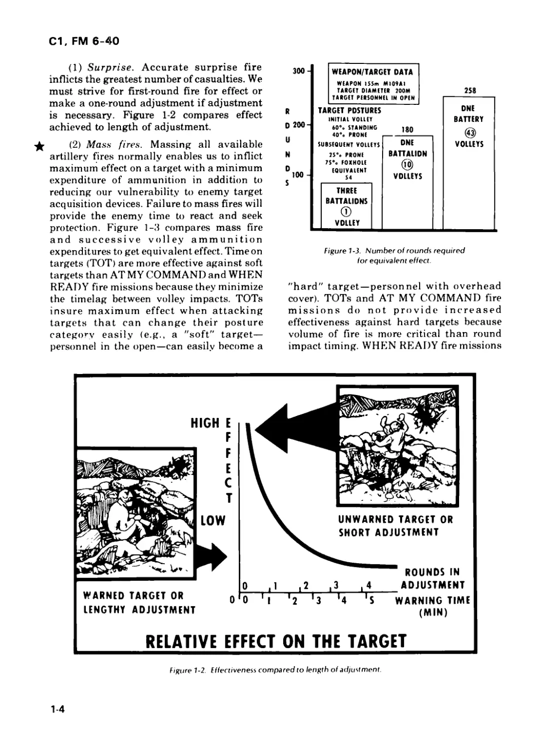
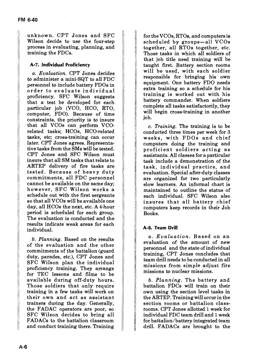
(1) Surprise. Accurate surprise fire
inflicts the greatest number of casualties. We
must strive for first-round fire for effect or
make a one-round adjustment if adjustment
is necessary. Figure 1-2 compares effect
achieved to length of adjustment.
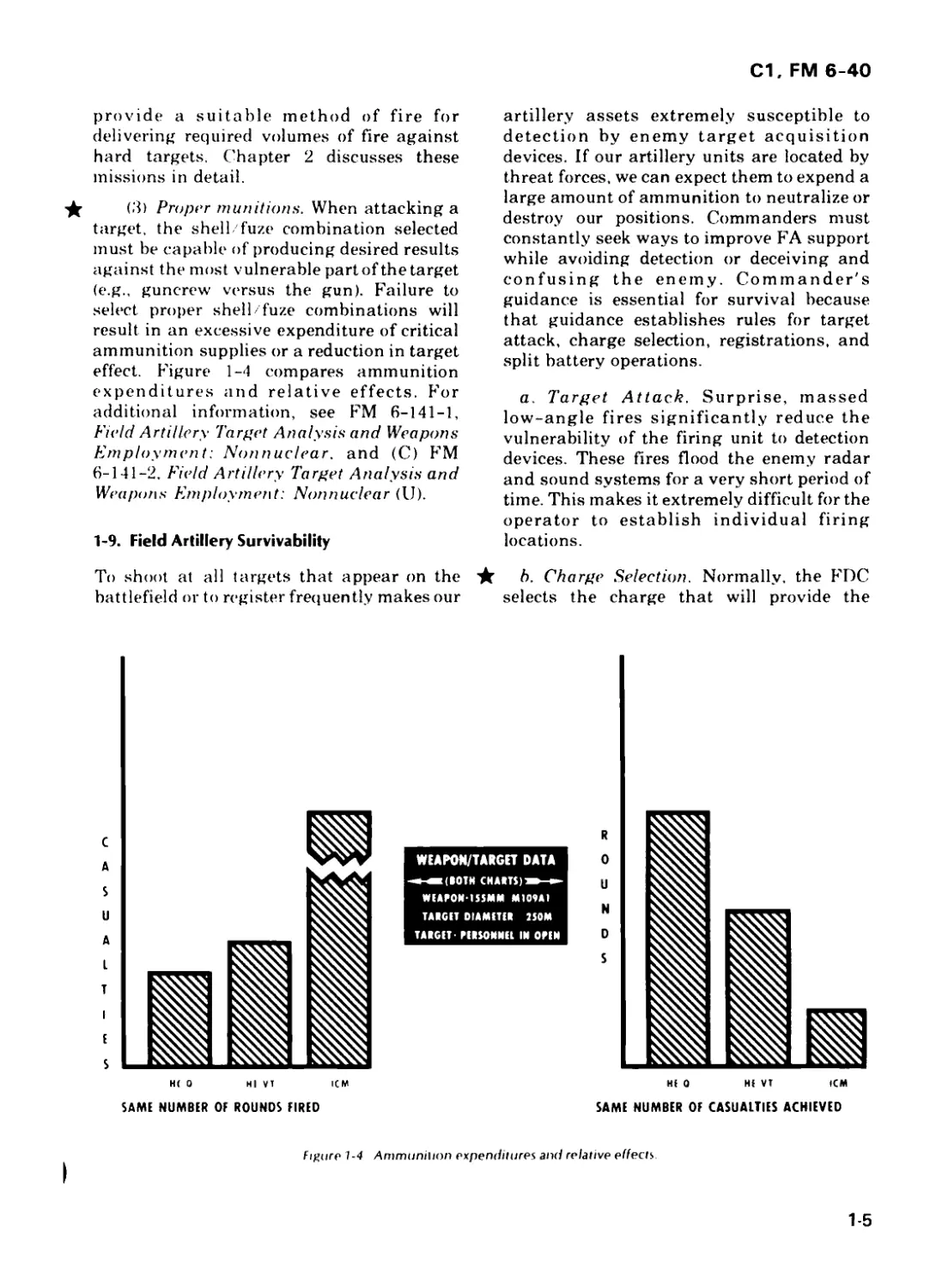
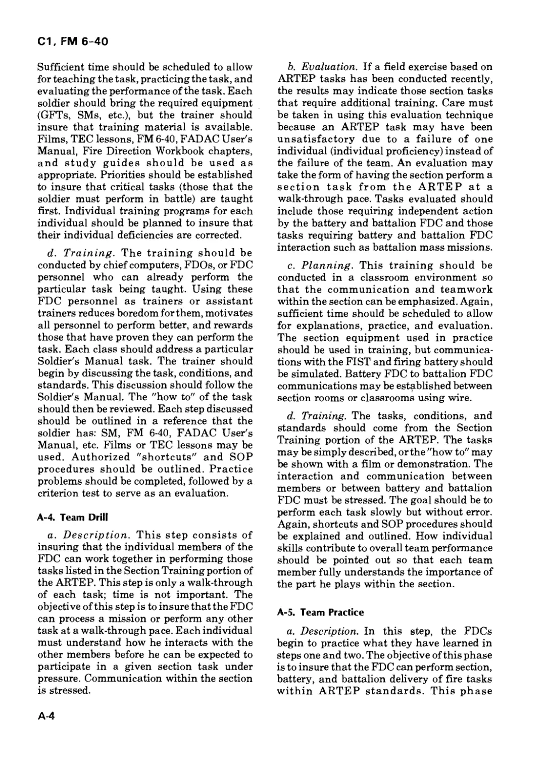
(2) Mass fires. Massing all available
artillery fires normally enables us to inflict
maximum effect on a target with a minimum
expenditure of ammunition in addition to
reducing our vulnerability to enemy target
acquisition devices. Failure to mass fires will
provide the enemy time to react and seek
protection. Figure 1-3 compares mass fire
and successive volley ammunition
expenditures to get equivalent effect. Time on
targets (TOT) are more effective against soft
targets than AT MY COMMAND and WHEN
READY fire missions because they minimize
the timelag between volley impacts. TOTs
insure maximum effect when attacking
targets that can change their posture
category easily (e.g., a "soft" target—
personnel in the open—can easily become a
300
R
D 200-
U
N
WEAPON/TARGET DATA
WEAPON ISSm MI09AI
TARGET DIAMETER 200M
TARGET PERSONNEL IN OPEN
TARGET POSTURES
INITIAL VOLLEY
60°. STANDING
40% PRONE
SUBSEQUENT VOLLEYS
2S% PRONE
7S% FOXHOLE
EQUIVALENT
S4
THREE
BATTALIONS
VDLLEY
2S8
180
DNE
BATTALION
(g)
VOLLEYS
DNE
BATTERY
(43)
VOLLEYS
Figure 1-3. Number of rounds required
for equivalent effect.
"hard" target — personnel with overhead
cover). TOTs and AT MY COMMAND fire
missions do not provide increased
effectiveness against hard targets because
volume of fire is more critical than round
impact timing. WHEN READY fire missions
Figure 1-2. Fffectiveness compared to length of adjustment.
1-4
С1, FM 6-40
provide a suitable method of fire for
delivering required volumes of fire against
hard targets. Chapter 2 discusses these
missions in detail.
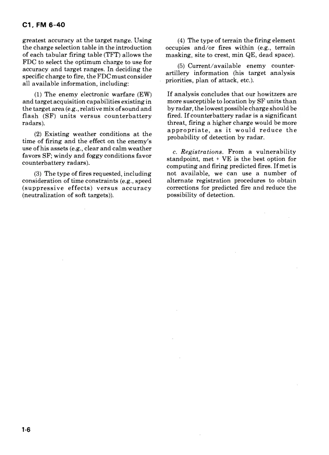
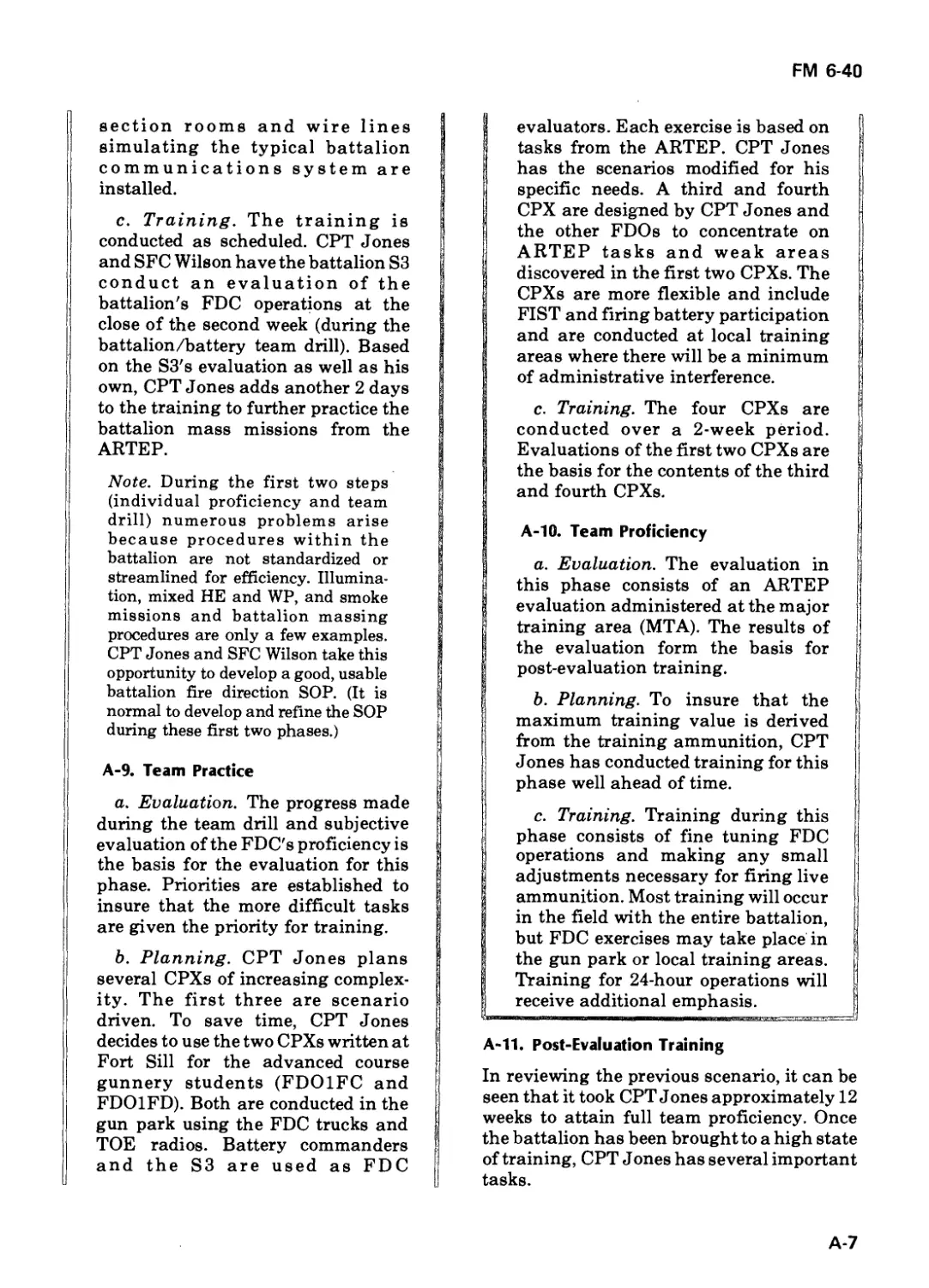
(3) Proper munitions. When attacking a
target, the shell/fuze combination selected
must be capable of producing desired results
against the most vulnerable part of the target
(e.g., guncrew versus the gun). Failure to
select proper shell/fuze combinations will
result in an excessive expenditure of critical
ammunition supplies or a reduction in target
effect. Figure 1-4 compares ammunition
expenditures and relative effects. For
additional information, see FM 6-141-1,
Field Artillery Target Analysis and Weapons
Employment: Nonnuclear, and (C) FM
6-141-2, Field Artillery Target Analysis and
Weapons Employment: Nonnuclear (U).
1-9. Field Artillery Survivability
To shoot at all targets that appear on the
battlefield or to register frequently makes our
artillery assets extremely susceptible to
detection by enemy target acquisition
devices. If our artillery units are located by
threat forces, we can expect them to expend a
large amount of ammunition to neutralize or
destroy our positions. Commanders must
constantly seek ways to improve FA support
while avoiding detection or deceiving and
confusing the enemy. Commander's
guidance is essential for survival because
that guidance establishes rules for target
attack, charge selection, registrations, and
split battery operations.
a. Target Attack. Surprise, massed
low-angle fires significantly reduce the
vulnerability of the firing unit to detection
devices. These fires flood the enemy radar
and sound systems for a very short period of
time. This makes it extremely difficult for the
operator to establish individual firing
locations.
b. Charge Selection. Normally, the FDC
selects the charge that will provide the
WEAPON/TARGET DATA
-*-*(10ТИ CHARTS)*—►
WEAPON'ISSMM MI09AI
TARGIT DIAMETER ISOM
TARGET* PERSONNEL IN OREN
Figure 1-4 Ammunition expenditures and relative elfects
1-5
С1, FM 6-40
greatest accuracy at the target range. Using
the charge selection table in the introduction
of each tabular firing table (TFT) allows the
FDC to select the optimum charge to use for
accuracy and target ranges. In deciding the
specific charge to fire, the FDC must consider
all available information, including:
(1) The enemy electronic warfare (EW)
and target acquisition capabilities existing in
the target area (e.g., relative mix of sound and
flash (SF) units versus counterbattery
radars).
(2) Existing weather conditions at the
time of firing and the effect on the enemy's
use of his assets (e.g., clear and calm weather
favors SF; windy and foggy conditions favor
counterbattery radars).
(3) The type of fires requested, including
consideration of time constraints (e.g., speed
(suppressive effects) versus accuracy
(neutralization of soft targets)).
(4) The type of terrain the firing element
occupies and/or fires within (e.g., terrain
masking, site to crest, min QE, dead space).
(5) Current/available enemy counter-
artillery information (his target analysis
priorities, plan of attack, etc.).
If analysis concludes that our howitzers are
more susceptible to location by SF units than
by radar, the lowest possible charge should be
fired. If counterbattery radar is a significant
threat, firing a higher charge would be more
appropriate, as it would reduce the
probability of detection by radar.
c. Registrations. From a vulnerability
standpoint, met + VE is the best option for
computing and firing predicted fires. If met is
not available, we can use a number of
alternate registration procedures to obtain
corrections for predicted fire and reduce the
possibility of detection.
1-6
С1, FM 6-40
CHAPTER 2
FIRE DIRECTION
ORGANIZATION AND
OPERATION
Section I. FIRE DIRECTION PROCEDURES
2-1. Definitions
a. Fire direction is the employment of
firepower. It consists of both tactical and
technical fire direction.
(1) FA tactical fire direction is the
command of one or more units in the selection
of targets to attack, the choice of the unit or
units to fire, and the allocation of the most
suitable ammunition for each mission.
(2) FA technical fire direction is the
conversion of calls for fire from the observer
into fire commands to the cannon sections.
b. The objectives of fire direction are to
provide continuous, accurate, and responsive
fire support under all conditions, to maintain
flexibility to engage all types of targets over
wide frontages, to mass the fires of all
available units quickly, and to engage a
number and variety of targets simultane-
ously.
c. The fire direction center is the element of
the gunnery team with which the commander
directs artillery firepower. The accuracy,
flexibility, and speed in the execution of fire
missions depend on rapid and accurate
determination of firing data; rapid and clear
transmission of fire commands; integration
of FADAC and manual equipment into an
efficient, mutually supporting system; and
efficient use of communications equipment.
2-2. Relationship Between Battery and
Battalion FDC
a. The wide frontages envisioned on the
next battlefield, coupled with the need for
decreased response time, demand a
decentralized system of fire direction. Under
this system, tactical fire direction is
performed at the battalion FDC; technical
fire direction is performed at the battery FDC.
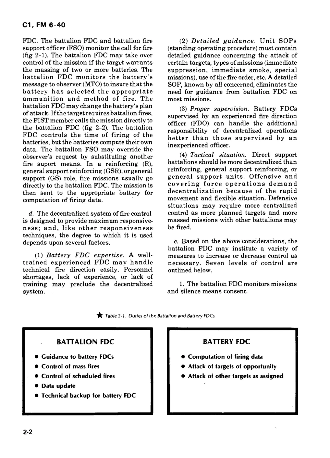
b. The general duties of each FDC are
outlined in table 2-1.
★ c. In a direct support battalion, most
missions on targets of opportunity go directly
from the observer to the appropriate battery
2-1
С1, FM 6-40
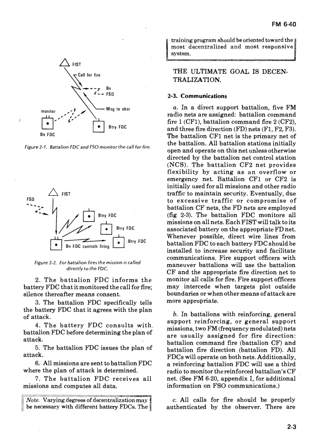
FDC. The battalion FDC and battalion fire
support officer (FSO) monitor the call for fire
(fig 2-1). The battalion FDC may take over
control of the mission if the target warrants
the massing of two or more batteries. The
battalion FDC monitors the battery's
message to observer (MTO) to insure that the
battery has selected the appropriate
ammunition and method of fire. The
battalion FDC may change the battery's plan
of attack. If the target requires battalion fires,
the FIST member calls the mission directly to
the battalion FDC (fig 2-2). The battalion
FDC controls the time of firing of the
batteries, but the batteries compute their own
data. The battalion FSO may override the
observer's request by substituting another
fire suport means. In a reinforcing (R),
general support reinforcing (GSR), or general
support (GS) role, fire missions usually go
directly to the battalion FDC. The mission is
then sent to the appropriate battery for
computation of firing data.
d. The decentralized system of fire control
is designed to provide maximum responsive-
ness; and, like other responsiveness
techniques, the degree to which it is used
depends upon several factors.
(1) Battery FDC expertise. A well-
trained experienced FDC may handle
technical fire direction easily. Personnel
shortages, lack of experience, or lack of
training may preclude the decentralized
system.
(2) Detailed guidance. Unit SOPs
(standing operating procedure) must contain
detailed guidance concerning the attack of
certain targets, types of missions (immediate
suppression, immediate smoke, special
missions), use of the fire order, etc. A detailed
SOP, known by all concerned, eliminates the
need for guidance from battalion FDC on
most missions.
(3) Proper supervision. Battery FDCs
supervised by an experienced fire direction
officer (FDO) can handle the additional
responsibility of decentralized operations
better than those supervised by an
inexperienced officer.
(4) Tactical situation. Direct support
battalions should be more decentralized than
reinforcing, general support reinforcing, or
general support units. Offensive and
covering force operations demand
decentralization because of the rapid
movement and flexible situation. Defensive
situations may require more centralized
control as more planned targets and more
massed missions with other battalions may
be fired.
e. Based on the above considerations, the
battalion FDC may institute a variety of
measures to increase or decrease control as
necessary. Seven levels of control are
outlined below.
1. The battalion FDC monitors missions
and silence means consent.
★ Table 2-1. Duties of the Battalion and Battery FDCs
BATTALION FDC
• Guidance to battery FDCs
• Control of mass fires
• Control of scheduled fires
• Data update
• Technical backup for battery FDC
BATTERY FDC
• Computation of firing data
• Attack of targets of opportunity
• Attack of other targets as assigned
2-2
FM 6-40
training program should be oriented toward the
most decentralized and most responsive
system.
Figure 2-1. Battalion FDC and FSO monitor the call for fire.
Figure 2-2. For battalion fires the mission is called
directly to the FDC.
2. The battalion FDC informs the
battery FDC that it monitored the call for fire;
silence thereafter means consent.
3. The battalion FDC specifically tells
the battery FDC that it agrees with the plan
of attack.
4. The battery FDC consults with,
battalion FDC before determining the plan of
attack.
5. The battalion FDC issues the plan of
attack.
6. All missions are sent to battalion FDC
where the plan of attack is determined.
7. The battalion FDC receives all
missions and computes all data.
Note. Varying degrees of decentralization may
be necessary with different battery FDCs. The
THE ULTIMATE GOAL IS DECEN-
TRALIZATION.
2-3. Communications
a. In a direct support battalion, five FM
radio nets are assigned: battalion command
fire 1 (CF1), battalion command fire 2 (CF2),
and three fire direction (FD) nets (Fl, F2, F3).
The battalion CF1 net is the primary net of
the battalion. All battalion stations initially
open and operate on this net unless otherwise
directed by the battalion net control station
(NCS). The battalion CF2 net provides
flexibility by acting as an overflow or
emergency net. Battalion CF1 or CF2 is
initially used for all missions and other radio
traffic to maintain security. Eventually, due
to excessive traffic or compromise of
battalion CF nets, the FD nets are employed
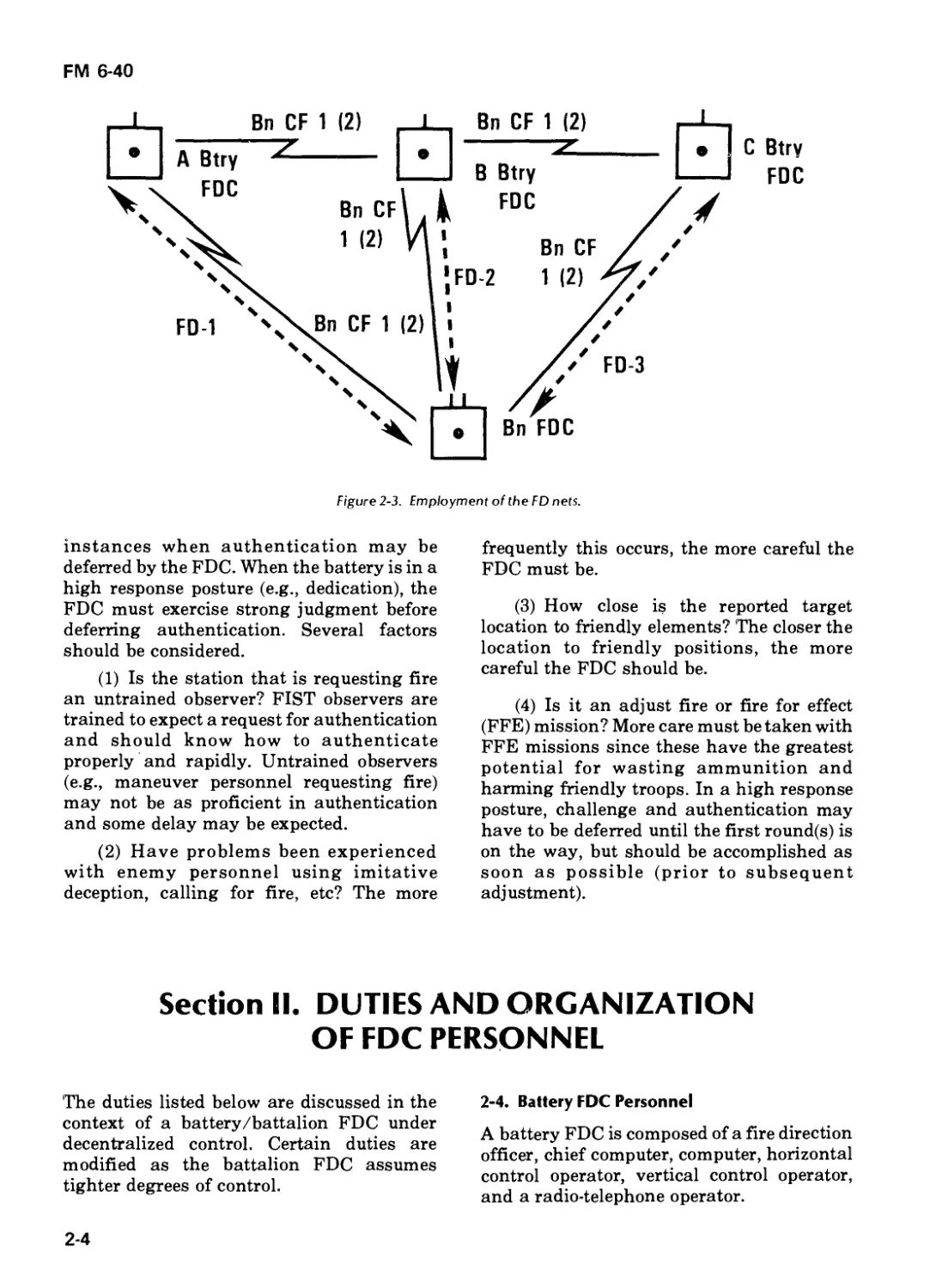
(fig 2-3). The battalion FDC monitors all
missions on all nets. Each FIST will talk to its
associated battery on the appropriate FD net.
Whenever possible, direct wire lines from
battalion FDC to each battery FDC should be
installed to increase security and facilitate
communications. Fire support officers with
maneuver battalions will use the battalion
CF and the appropriate fire direction net to
monitor all calls for fire. Fire support officers
may intercede when targets plot outside
boundaries or when other means of attack are
more appropriate.
b. In battalions with reinforcing, general
support reinforcing, or general support
missions, two FM (frequency modulated) nets
are usually assigned for fire direction:
battalion command fire (battalion CF) and
battalion fire direction (battalion FD). All
FDCs will operate on both nets. Additionally,
a reinforcing battalion FDC will use a third
radio to monitor the reinforced battalion's CF
net. (See FM 6-20, appendix I, for additional
information on FSO communications.)
c. All calls for fire should be properly
authenticated by the observer. There are
2-3
FM 6-40
instances when authentication may be
deferred by the FDC. When the battery is in a
high response posture (e.g., dedication), the
FDC must exercise strong judgment before
deferring authentication. Several factors
should be considered.
(1) Is the station that is requesting fire
an untrained observer? FIST observers are
trained to expect a request for authentication
and should know how to authenticate
properly and rapidly. Untrained observers
(e.g., maneuver personnel requesting fire)
may not be as proficient in authentication
and some delay may be expected.
(2) Have problems been experienced
with enemy personnel using imitative
deception, calling for fire, etc? The more
frequently this occurs, the more careful the
FDC must be.
(3) How close is the reported target
location to friendly elements? The closer the
location to friendly positions, the more
careful the FDC should be.
(4) Is it an adjust fire or fire for effect
(FFE) mission? More care must be taken with
FFE missions since these have the greatest
potential for wasting ammunition and
harming friendly troops. In a high response
posture, challenge and authentication may
have to be deferred until the first round(s) is
on the way, but should be accomplished as
soon as possible (prior to subsequent
adjustment).
Section II. DUTIES AND ORGANIZATION
OF FDC PERSONNEL
The duties listed below are discussed in the
context of a battery/battalion FDC under
decentralized control. Certain duties are
modified as the battalion FDC assumes
tighter degrees of control.
2-4. Battery FDC Personnel
A battery FDC is composed of a fire direction
officer, chief computer, computer, horizontal
control operator, vertical control operator,
and a radio-telephone operator.
2-4
С1, FM 6-40
a. Fire Direction Officer:
(1) Runs the FDC and is responsible for
fire direction operations.
(2) Actively supervises all fire direction
operations.
(3) Establishes the fire order, the fire
command standards, and SOP items.
(4) Inspects the plot of each target,
decides how to attack the target, and
announces that decision in the fire order.
(5) Insures that firing data is computed
and sent to the guns correctly.
(6) Supervises preparation and
execution of preplanned fires.
(7) Controls input of nonstandard
conditions into FADAC.
b. Chief Computer:
(1) Serves as the FDO's technical expert
and the actual supervisor of the FDC.
(2) Insures that all equipment is on hand
and operational.
(3) Supervises the computation of all
data.
(4) Insures that data is put into FADAC
correctly.
(5) Insures that all appropriate records
are maintained.
(6) Assists the FDO in his duties as
necessary.
c. Horizontal Control Operator (HCO):
(1) Operates and maintains the FADAC.
(2) Enters known data as directed by the
battery FDO.
(3) Determines FADAC firing data.
(4) Operates and maintains the FADAC
generators.
I Note. In an FDC where FADAC is not available, the |
j HCO will construct and maintain the primary firing I
I chart and determine chart data. I
1 ' I
d. Vertical Control Operator (VCO):
(1) Constructs and maintains the firing
chart.
(2) Plots targets and announces and
records their altitudes.
(3) Computes site and announces that
site when requested by the computer.
(4) Maintains the battle map/overlays to
include situation, fire capabilities, and dead
space.
(5) Determines and announces angle T
as necessary.
|—^VbtZ"ln*a^FDC where FADAC is not availatZ^”l
| the VCO's chart becomes the "check" chart. In |
f addition to determining site, the VCO provides a
| check of the HCO's chart data. i
e. Computer:
(1) Combines the data provided by other
personnel and produces fire commands.
(2) Records the call for fire, fire order,
firing data corrections, and other data as
directed by the battery FDO.
(3) Maintains all necessary records.
(4) Computes firing data, converts firing
data to fire commands, and transmits the fire
commands to the battery in the proper
sequence.
(5) Computes and records calibrated
muzzle velocities and battery comparative
velocity errors (VE).
(6) Computes registration, met + VE
corrections, and other data as directed by the
battery FDO.
I Note. The hand-held calculator is a component of the I
g computer set, FA, general, and is used by the I
I computer. I
f. Radio-Telephone Operator (RATELO):
(1) Operates a radio or telephone in the
FDC.
(2) Determines and transmits the
message to observer.
(3) Encodes and decodes messages,
target lists, and fire plans as necessary.
(4) Insures proper authentication of
appropriate messages and all fire missions.
2-5
С1, FM 6-40
2-5. Battalion FDC Personnel
A battalion FDC is composed of a fire
direction officer, chief computer, assistant
chief computer, three computers, a horizontal
control operator, vertical control operator,
and a radio-telephone operator.
a. Fire Direction Officer:
(1) Is responsible for the overall
organization and functioning of the battalion
FDC.
(2) Coordinates with the battalion S3 to
insure that all information regarding the
tactical situation, unit mission, ammunition
status, and commander's guidance on the
method of engagement of targets and control
of ammunition expenditures is known; and
insures that all information is passed to
battery FDOs.
(3) Insures that all communications are
properly established.
(4) Coordinates with the chief computer
concerning data input, chart verification,
inferred GFT settings, average site or
altitude, terrain gun position corrections
(TGPC) sectors, and any other special
instructions.
(5) Insures that the situation map is
properly posted to include fire coordination
measures and the current tactical situation.
(6) Inspects target locations and
monitors messages to observer when a
mission is received by a battery FDC and
intercedes when necessary.
(7) Controls all battalion missions.
b. The Chief Computer:
(1) Serves as the battalion FDO's
technical expert—the actual supervisor of
battalion FDC personnel.
(2) Insures that all battalion FDC
equipment is operational and emplaced
correctly.
(3) Insures that ail data is coordinated
throughout the battalion, that GFT settings
are current, and that all data is computed
correctly.
(4) Insures that theVCO's chart includes
all pertinent known data.
c. Assistant Chief Computer:
(1) Monitors all operations performed by
the HCO.
(2) Insures that all data is properly
entered in FAD AC.
(3) Supervises maintenance and care of
FADAC and the generators.
(4) Assumes the duties of the chief
computer when he is absent.
d. Battery Computers:
(1) Provide communications link with
the battery FDCs.
(2) Monitor the appropriate fire direction
net for their battery.
(3) Exchange information with the
battery FDCs and pass battalion fire orders
to the battery.
(4) Record all data pertinent to fire
missions that are sent to their battery.
(5) Compute data for their battery when
directed by the chief computer.
(6) Communicate with the observer
when battalion missions are conducted using
their fire direction net (Fl, F2, or F3).
e. Horizontal Control Operator:
(1) Serves as the FADAC operator.
(2) Enters known data as directed by the
assistant chief computer.
(3) Computes data as appropriate.
(4) Maintains the FADAC and
associated generators.
f. Vertical Control Operator:
(1) Constructs and maintains the firing
chart.
(2) Plots the initial target location when
a mission is received.
(3) Determines data as directed by the
chief computer.
2-6
С1, FM 6-40
g. Radio-Telephone Operator:
(1) Establishes and maintains
communications on the battalion command
fire net.
(2) Determines and transmits the
message to observer when battalion missions
are conducted on the battalion CF net.
(3) Encodes and decodes messages,
target lists, and fire plans.
(4) Insures proper authentication of
appropriate messages and all fire missions.
★ 2-6. Organization of Personnel
The organization of FDC personnel and
equipment is in appendix F.
Section III. FIRE ORDER
2-7. Definition
When a call for fire is received in the battery
or battalion FDC, the VCO immediately plots
the target location on the firing chart. The
FDO then examines the target plot on the
firing chart and the situation map and
conducts a brief analysis to determine how
the target will be attacked. The result of this
tactical fire direction process is announced in
the fire order.
FIRE ORDERS THE EDO'S DECD
SION ON HOW THE TARGET WELL
BE ATTACKED, GIVEN IN A
PRESCRIBED MANNER.
2-8. FDO Considerations in Target Attack
In the FDC to which the mission is sent (btry
or bn), the FDO must consider several factors
in making his decision on how the target will
be attacked.
a. Location of Target. The FDO must check
the location relative to friendly forces, fire
coordination measures, zones of fire, and
registration transfer limits. The range will
affect the choice of units to fire and charge
selection. The terrain around the target may
influence ammunition selection or type of
trajectory. High intermediate crests may
require selection of a lower charge.
b. Nature of Target. The size of the target
will affect the number of units to fire, whether
a special sheaf or spread is necessary, the
selection of ammunition type, and the
number of rounds in fire for effect. The type of
target (troops, vehicles, hard, soft) will
influence the ammunition type and amount,
the priority to be placed on the mission, and
whether surprise fire (e.g., time on target) is
possible.
c. Ammunition Available. The FDO must
consider the amount and type of ammunition
available and the ammunition supply rate
(ASR).
d. Units Available. The number of units
2-7
С1, FM 6-40
available will not only affect which units will
be used but also the type of attack. Sweep
and/or zone fire or other techniques may be
necessary to cover large targets when
sufficient units are not available.
e. Commander's Guidance/SOP.
Restrictions on ammunition, operations
orders, and SOPs may govern the selection of
units and ammunition, target priority, and
method of attack.
f. Call for Fire. The FDO must consider the
observer's request carefully since he is the
man who can see the target and talk directly
to the maneuver commander. The observer's
request should be honored when possible.
g. Munitions Effects. The Joint Munitions
Effectiveness Manual (JMEM) or the
Graphical Munitions Effectiveness Table
(GMET) should be used as a guide to
determine the type and amount of
ammunition to be used against certain
targets (see appendix C).
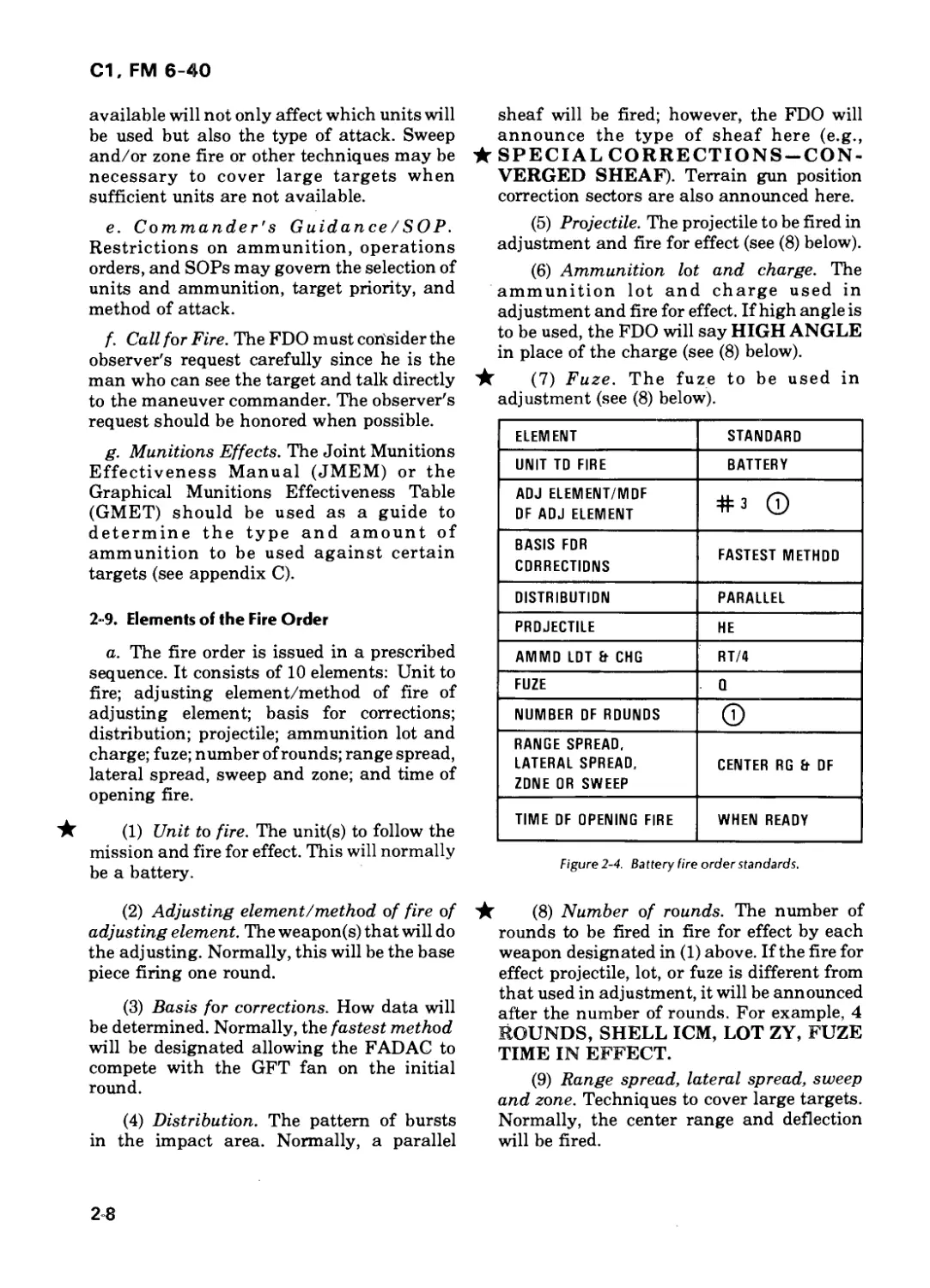
2-9. Elements of the Fire Order
a. The fire order is issued in a prescribed
sequence. It consists of 10 elements: Unit to
fire; adjusting element/method of fire of
adjusting element; basis for corrections;
distribution; projectile; ammunition lot and
charge; fuze; number of rounds; range spread,
lateral spread, sweep and zone; and time of
opening fire.
(1) Unit to fire. The unit(s) to follow the
mission and fire for effect. This will normally
be a battery.
(2) Adjusting element/method of fire of
adjusting element. The weapon(s) that will do
the adjusting. Normally, this will be the base
piece firing one round.
(3) Basis for corrections. How data will
be determined. Normally, the fastest method
will be designated allowing the FADAC to
compete with the GFT fan on the initial
round.
(4) Distribution. The pattern of bursts
in the impact area. Normally, a parallel
sheaf will be fired; however, the FDO will
announce the type of sheaf here (e.g.,
★ SPECIAL CORRECTIONS —CON-
VERGED SHEAF). Terrain gun position
correction sectors are also announced here.
(5) Projectile. The projectile to be fired in
adjustment and fire for effect (see (8) below).
(6) Ammunition lot and charge. The
ammunition lot and charge used in
adjustment and fire for effect. If high angle is
to be used, the FDO will say HIGH ANGLE
in place of the charge (see (8) below).
★ (7) Fuze. The fuze to be used in
adjustment (see (8) below).
ELEMENT STANDARD
UNIT TD FIRE BATTERY
ADJ ELEMENT/MDF DF ADJ ELEMENT #3 ©
BASIS FDR CORRECTIONS FASTEST METHOD
DISTRIBUTION PARALLEL
PROJECTILE HE
AMMD LDT Ft CHG RT/4
FUZE Q
NUMBER DF ROUNDS О
RANGE SPREAD, LATERAL SPREAD, ZONE OR SWEEP CENTER RG Ft DF
TIME DF OPENING FIRE WHEN READY
Figure 2-4. Battery fire order standards.
(8) Number of rounds. The number of
rounds to be fired in fire for effect by each
weapon designated in (1) above. If the fire for
effect projectile, lot, or fuze is different from
that used in adjustment, it will be announced
after the number of rounds. For example, 4
ROUNDS, SHELL ICM, LOT ZY, FUZE
TIME IN EFFECT.
(9) Range spread, lateral spread, sweep
and zone. Techniques to cover large targets.
Normally, the center range and deflection
will be fired.
2-8
FM 6-40
(10) Time of opening fire. When the guns
may commence firing. They may fire WHEN
READY, AT MY COMMAND, or a time on
target may be designated.
b. When issuing the fire order, the FDO
must address each element orally or by using
the standard (fig 2-4).
2-10. Fire Order Standards
a. In most cases, a particular element of
the fire order may not change from one
mission to the next. Based on the tactical
situation, type and amount of ammunition
available, and commander's guidance, the
FDO establishes a standard for each element.
These standards should be displayed
prominently in the FDC. When the FDO does
not address an element in his fire order, the
standard for that element will apply. The
FDO need only announce what has changed
from the standard.
PROPER SELECTION OF
FIRE ORDER STANDARDS
REDUCES THE NEED FOR
LENGTHY FIRE ORDERS,
Examples of established fire order standards
are shown in tables 2-2 through 2-4.
b. The FDO must remember that the fire
order must be clear, concise, and in proper
format. The fire order format is designed to
disseminate information clearly and rapidly
with a minimum of discussion, but if a
situation requires, necessary clarification
should be provided. In other words, the FDO
must "use" the system, not "be used" by it. It
is impossible to provide a textbook solution
for every conceivable situation, but a
combination of technical knowledge and
common sense should be sufficient to avoid
confusion. It is better, if any possibility of
confusion exists, to be redundant rather than
too brief.
2-11. Use of the SOP
The use of a good SOP to clarify certain
missions is essential. Immediate
suppression, immediate smoke, illumination,
and mixed shell missions (HE and WP, for
instance) can be handled more responsively
when governed by SOP. For example, an
FDO need only say IMMEDIATE
SUPPRESSION to mean a platoon will fire
two volleys of HE/VT.
GOOD SOP© AND EXTENSIVE
TRAINING CAN RESULT IN
MORE STREAMLINED FIRE
ORDERS,
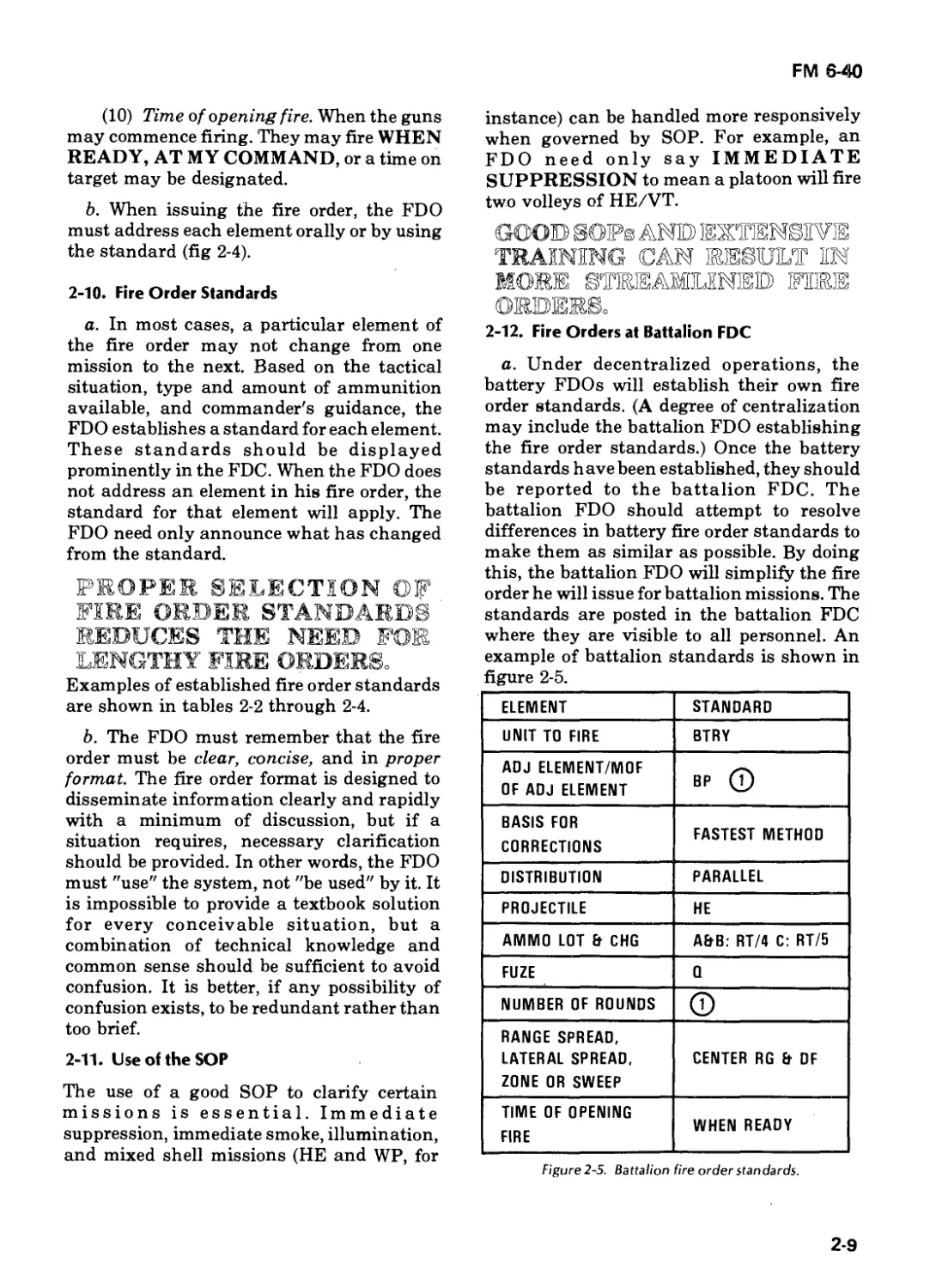
2-12. Fire Orders at Battalion FDC
a. Under decentralized operations, the
battery FDOs will establish their own fire
order standards. (A degree of centralization
may include the battalion FDO establishing
the fire order standards.) Once the battery
standards have been established, they should
be reported to the battalion FDC. The
battalion FDO should attempt to resolve
differences in battery fire order standards to
make them as similar as possible. By doing
this, the battalion FDO will simplify the fire
order he will issue for battalion missions. The
standards are posted in the battalion FDC
where they are visible to all personnel. An
example of battalion standards is shown in
figure 2-5.
ELEMENT STANDARD
UNIT TO FIRE BTRY
ADJ ELEMENT/MOF OF ADJ ELEMENT BP Q
BASIS FOR CORRECTIONS FASTEST METHOD
DISTRIBUTION PARALLEL
PROJECTILE HE
AMMO LOT & CHG A&B: RT/4 C: RT/5
FUZE 0
NUMBER OF ROUNDS
RANGE SPREAD, LATERAL SPREAD, ZONE OR SWEEP CENTER RG & DF
TIME OF OPENING FIRE WHEN READY
Figure2-5. Battalion fire order standards.
2-9
FM 6-40
Note. Ammunition lot and charge may be
different for each battery.
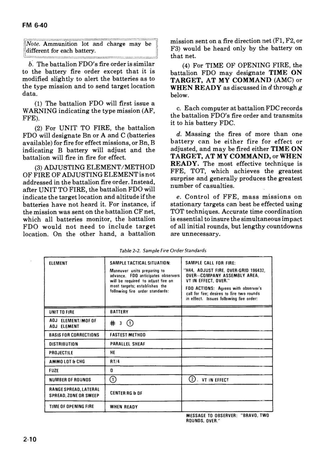
b. The battalion FDO's fire order is similar
to the battery fire order except that it is
modified slightly to alert the batteries as to
the type mission and to send target location
data.
(1) The battalion FDO will first issue a
WARNING indicating the type mission (AF,
FFE).
(2) For UNIT TO FIRE, the battalion
FDO will designate Bn or A and C (batteries
available) for fire for effect missions, or Bn, В
indicating В battery will adjust and the
battalion will fire in fire for effect.
(3) ADJUSTING ELEMENT/METHOD
OF FIRE OF ADJUSTING ELEMENT is not
addressed in the battalion fire order. Instead,
after UNIT TO FIRE, the battalion FDO will
indicate the target location and altitude if the
batteries have not heard it. For instance, if
the mission was sent on the battalion CF net,
which all batteries monitor, the battalion
FDO would not need to include target
location. On the other hand, a battalion
mission sent on a fire direction net (Fl, F2, or
F3) would be heard only by the battery on
that net.
(4) For TIME OF OPENING FIRE, the
battalion FDO may designate TIME ON
TARGET, AT MY COMMAND (AMC) or
WHEN READY as discussed in d through g
below.
c. Each computer at battalion FDC records
the battalion FDO's fire order and transmits
it to his battery FDC.
d. Massing the fires of more than one
battery can be either fire for effect or
adjusted, and may be fired either TIME ON
TARGET, AT MY COMMAND, or WHEN
READY. The most effective technique is
FFE, TOT, which achieves the greatest
surprise and generally produces the greatest
number of casualties.
e. Control of FFE, mass missions on
stationary targets can best be effected using
TOT techniques. Accurate time coordination
is essential to insure the simultaneous impact
of all initial rounds, but lengthy countdowns
are unnecessary.
Table 2-2. Sample Fire Order Slandards
ELEMENT SAMPLE TACTICAL SITUATION: Maneuver units preparing to advance. FDO anticipates observers will be required to adjust fire on most targets; establishes the following fire order standards: SAMPLE CALL FOR FIRE: "H44, ADJUST FIRE, OVER GRID 196432, OVER -COMPANY ASSEMBLY AREA, VT IN EFFECT, OVER." FDO ACTIONS: Agrees with observer's call for fire; desires to fire two rounds in effect. Issues following fire order:
UNIT TO FIRE BATTERY
AOJ ELEMENT/MOFOF ADJ ELEMENT # 3 ©
BASIS FOR CORRECTIONS FASTEST METHOD
DISTRIBUTION PARALLEL SHEAF
PROJECTILE HE
AMMO LOT EtCHG RT/4
FUZE 0
NUMBER OF ROUNDS © @. VT IN EFFECT
RANGESPREAD.LATERAL SPREAD, ZONE OR SWEEP CENTER RG Et DF
TIME OF OPENING FIRE WHEN READY
MESSAGE TO OBSERVER: "BRAVO, TWO
ROUNDS, OVER.”
2 10
С1, FM 6-40
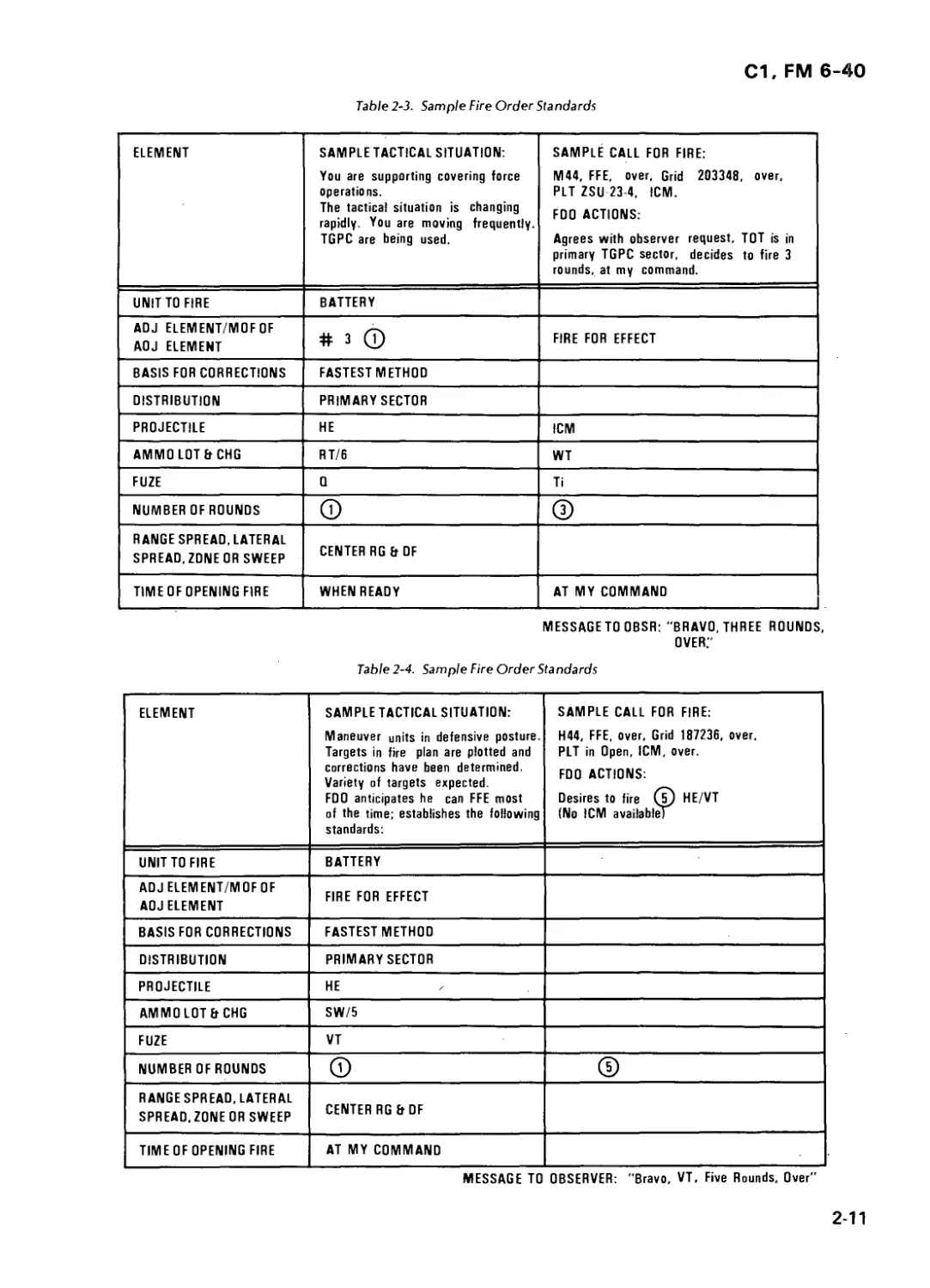
Table 2-3. Sample Fire Order Standards
ELEMENT SAMPLE TACTICAL SITUATION: You are supporting covering force operations. The tactical situation is changing rapidly. You are moving frequently. TGPC are being used. SAMPLE CALL FOR FIRE: M44, FFE, over, Grid 203348, over, PLT ZSU 23-4, ICM. FDO ACTIONS: Agrees with observer request, TOT is in primary TGPC sector, decides to fire 3 rounds, at my command.
UNIT TO FIRE BATTERY
ADJ ELEMENT/MOF OF ADJ ELEMENT # 3 © FIRE FOR EFFECT
BASIS FOR CORRECTIONS FASTEST METHOD
DISTRIBUTION PRIMARY SECTOR
PROJECTILE HE ICM
AMMO LOT В CHG RT/6 WT
FUZE 0 Ti
NUMBER OF ROUNDS (T) @
RANGE SPREAD, LATERAL SPREAD,ZDNEOR SWEEP CENTER RG Et OF
TIME OF OPENING FIRE WHEN READY AT MY COMMAND
MESSAGETO OBSR: "BRAVO, THREE ROUNDS,
OVER."
Table 2-4. Sample Fire Order Standards
ELEMENT SAMPLE TACTICAL SITUATION: Maneuver units in defensive posture. Targets in fire plan are plotted and corrections have been determined. Variety of targets expected. FDO anticipates he can FFE most of the time; establishes the following standards: SAMPLE CALL FOR FIRE: H44, FFE, over. Grid 187236, over. PLT in Open, ICM, over. FDO ACTIONS: Desires to fire (б) HE/VT (No ICM available)
UNIT TO FIRE BATTERY
ADJ ELEMENT/MOF OF ADJ ELEMENT FIRE FOR EFFECT
BASIS FOR CORRECTIONS FASTEST METHOD
DISTRIBUTION PRIMARY SECTOR
PROJECTILE HE
AMMO LOT Er CHG SW/5
FUZE VT
NUMBER OF ROUNDS
RANGE SPREAD, LATERAL SPREAD, ZONE OR SWEEP CENTER RG EtDF
TIME OF OPENING FIRE AT MY COMMAND
MESSAGE TO OBSERVER: "Bravo, VT, Five Rounds, Over"
2-11
С1, FM 6-40
(1) The TOT may be announced as a
specific time (e.g., TOT 0915). The battalion
FDO would cause a time check to be
announced (e.g., time is now 0908) in order to
synchronize the batteries designated to fire.
Each battery would control its own firing.
(2) Another technique to execute a TOT
is to specify the amount of time before it is to
occur (e.g., TOT 5 minutes from . . . NOW).
Each battery FDC would start its stopwatch
at . . . "NOW." From that moment, each
battery FDC would control its own firing.
(3) A third (preferred) technique for
execution of a TOT is to determine the time to
begin a short countdown based on the longest
time of flight of the designated batteries to
fire. After each battery reports ready and
time of flight, the battalion FDO adds 10-15
seconds to the longest time of flight,
expressing his answer to the nearest 10
seconds. He then announces, TIME ON
TARGET ... (so many) SECONDS FROM
. . . NOW. Each battery FDC would start its
stopwatch at... "NOW." From that moment,
each battery FDC would control its own
firing.
f. Control of an FFE, mass mission on
moving targets or targets of a fleeting nature
is best effected using AT MY COMM AND or
WHEN READY, where time consumed
during a TOT countdown may result in the
rounds missing the target.
(1) AT MY COMMAND. All units will
fire simultaneously. The battalion FDO will
select this technique if he is willing to accept
some loss of surprise caused by varying times
of flight in order to get the rounds on the
target quickly. This technique is particularly
effective when unit times of flight are similar.
(2) WHEN READY. Unless otherwise
specified, each battery will fire when ready.
This technique is used more often with adjust
fire missions (particularly those with lengthy
adjustment phases) than with fire for effect
missions. (When surprise has been lost, the
difference in reaction times and times of
flight between units is less significant.) In
fire for effect missions, this technique would
normally be used only if time is critical or the
target has the capability to displace rapidly.
g. Control of the FFE phase of an adjust
fire mass mission can be effected by the same
means as FFE mass missions.
(1) TIME ON TARGET. If the observer
is able to enter FFE with a large correction
and he judges the target has not been warned,
a TOT as discussed in paragraph e above
may be used to control time of firing in effect.
If the battalion FDO decides a TOT is
unsuitable (e.g., loss of time outweighs
simultaneous impacting of all initial FFE
rounds), he will direct use of AT MY
COMMAND or WHEN READY. It is rare
that a target would not be warned during
adjustment. Therefore, TOT to control time of
firing in effect after adjustment is not
normally used.
(2) AT MY COMMAND. The consider-
ations for the selection of this technique are
the same as discussed in paragraph /(1)
above. In addition, it is useful if the observer
is able to enter FFE with a large correction.
(3) WHEN READY. In most adjust fire
mass missions, no control of time of firing in
effect will be used. Since most targets would
be warned during adjustment, the battalion
FDO would allow batteries to fire when
ready.
h. Examples of battalion fire orders are
contained in section VI.
2-12
FM 6-40
$
Section IV. FIRE COMMANDS
2-13. Definition
Fire commands are used by the FDC to give
the cannon sections all information needed to
start, conduct, and cease firing. The initial
fire commands include all elements
necessary for orienting, loading, and firing.
Subsequent fire commands include only the
elements that are changed (except quadrant
elevation, which is always announced
because it gives permission to fire). As in the
fire order, fire commands are always
announced in a standard sequence to save
time and eliminate errors.
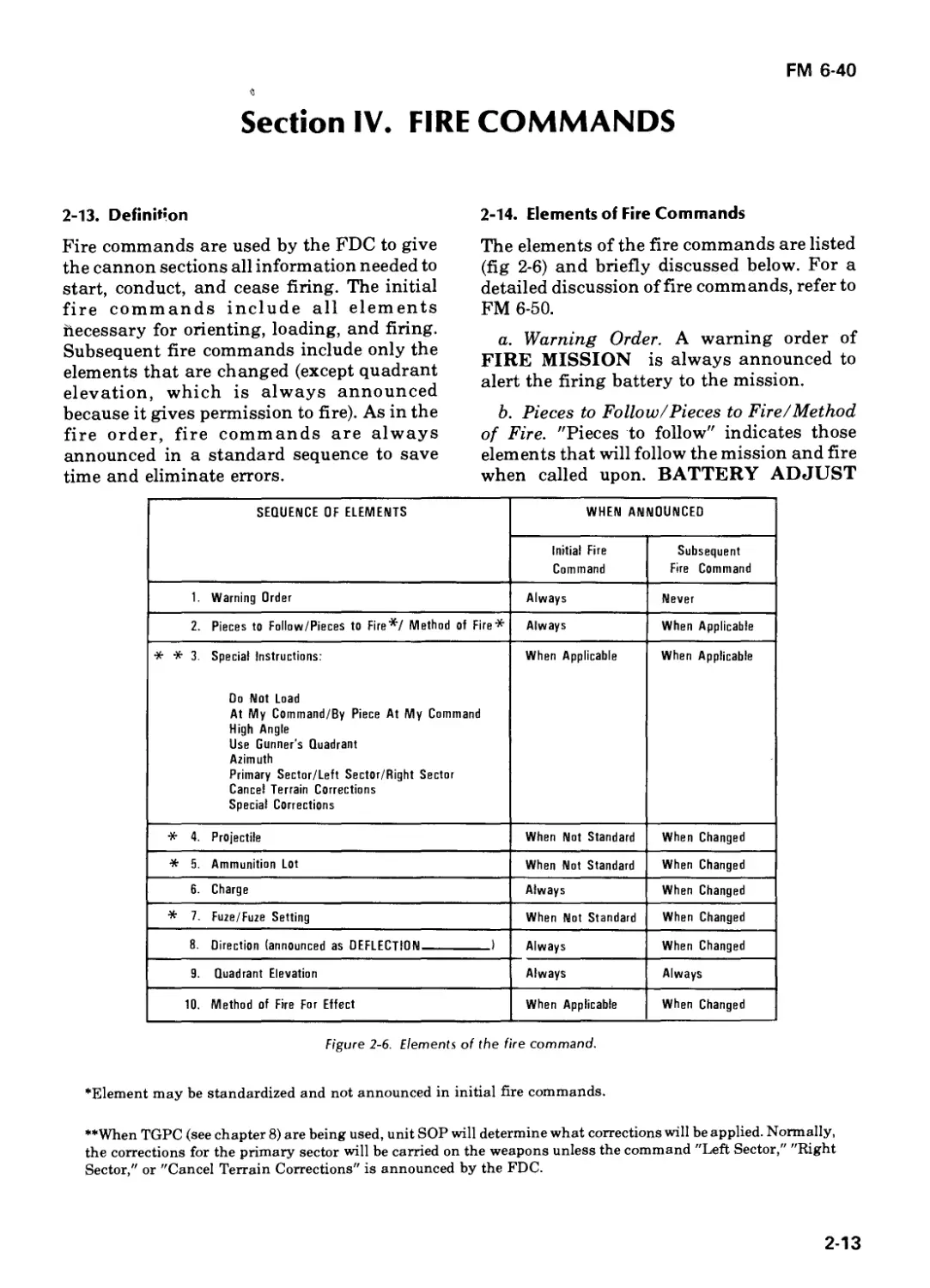
2-14. Elements of Fire Commands
The elements of the fire commands are listed
(fig 2-6) and briefly discussed below. For a
detailed discussion of fire commands, refer to
FM 6-50.
a. Warning Order. A warning order of
FIRE MISSION is always announced to
alert the firing battery to the mission.
b. Pieces to Follow/Pieces to Fire/Method
of Fire. "Pieces to follow" indicates those
elements that will follow the mission and fire
when called upon. BATTERY ADJUST
SEQUENCE OF ELEMENTS WHEN ANNOUNCED
Initial Fire Command Subsequent Fire Command
1. Warning Order Always Never
2. Pieces to Follow/Pieces to Fire*/ Method of Fire* Always When Applicable
* * 3. Special Instructions: Do Not Load At My Command/By Piece At My Command High Angle Use Gunner's Quadrant Azimuth Primary Sector/Left Sector/Right Sector Cancel Terrain Corrections Special Corrections When Applicable When Applicable
* 4. Projectile When Not Standard When Changed
* 5. Ammunition Lot When Not Standard When Changed
6. Charge Always When Changed
* 7. Fuze/Fuze Setting When Not Standard When Changed
8. Direction (announced as DEFLECTION I Always When Changed
9. Quadrant Elevation Always Always
10. Method of Fire For Effect When Applicable When Changed
Figure 2-6. Elements of the fire command.
’Element may be standardized and not announced in initial fire commands.
**When TGPC (see chapter 8) are being used, unit SOP will determine what corrections will be applied. Normally,
the corrections for the primary sector will be carried on the weapons unless the command "Left Sector," "Right
Sector," or "Cancel Terrain Corrections" is announced by the FDC.
2-13
FM 6-40
indicates the battery will follow the mission
and prepare to fire when commanded. "Pieces
to fire/method of fire" indicates the
weapon(s) that will fire the initial data
announced and how many rounds to fire.
Method of fire will also include sweep and/or
zone instructions. NUMBER 3 (or BP) ONE
ROUND indicates that only that piece will
fire one round. BATTERY FIVE ROUNDS
indicates the entire battery will fire five
volleys.
c. Special Instructions. Special
instructions are used whenever actions are
required that are different from normal. They
include:
(1) DO NOT LOAD-a restrictive
command that prohibits loading and firing.
This is used when it is anticipated that
significant time will elapse between loading
and firing. The nonadjusting batteries in a
battalion mission would not load until fire for
effect. To cancel this, announce CANCEL
DO NOT LOAD, QUADRANT--------.
(2) AT MY COMMAND-a restrictive
command that prohibits the battery from
firing until directed to do so by the FDC. This
would be used during TOT missions to insure
that all rounds land simultaneously. The
guns will fire at the command FIRE. AT MY
COMMAND remains in effect until the
command CANCEL AT MY COMMAND is
given.
(3) HIGH ANGLE—announced to alert
the crew that the mission is high angle.
(4) USE GUNNER'S QUADRANT—
announced whenever FDC desires that the
gunner's quadrant be used.
(5) AZIMUTH—announced to alert the
guns to a large shift in direction of fire.
(6) SPECIAL CORRECTIONS —
announced whenever a separate time,
deflection, and/or quadrant will be sent to
one or more gun sections.
(7) LEFT (RIGHT) SECTOR-
announced when terrain gun position
corrections for the left (right) sector are to be
applied.
(8) CANCEL TERRAIN CORREC-
TIONS—announced to direct the gun
sections to reset their gunner's aid counters to
zero.
d. Projectile. This is the type projectile that
is to be prepared and loaded.
e. Ammunition Lot. This is the
ammunition lot to be used. Lot numbers
should be coded for simplicity. Separate-
loading ammunition would have two
designations—one for the projectile and one
for the propellant. Semifixed ammunition
would have only one.
f. Charge. Charge indicates the amount of
propellant to be used and is always
announced in initial fire commands to reduce
the chances of a charge error being fired.
g. Fuze/Fuze Setting. This indicates the
type of fuze/fuze setting to be used.
h. Direction. Direction of fire is always
announced as a four-digit deflection.
i. Quadrant Elevation. The quadrant
elevation is announced in initial and all
subsequent fire commands. The command
QUADRANT (so much) is permission for
the chief of section to load and fire the round
unless otherwise restricted by special
instructions.
j. Method of Fire for Effect. The method of
fire for effect indicates the number of rounds
and type of ammunition to be used in effect.
k. Special Methods of Fire. Special
methods of fire include CONTINUOUS
FIRE and FIRE AT WILL.
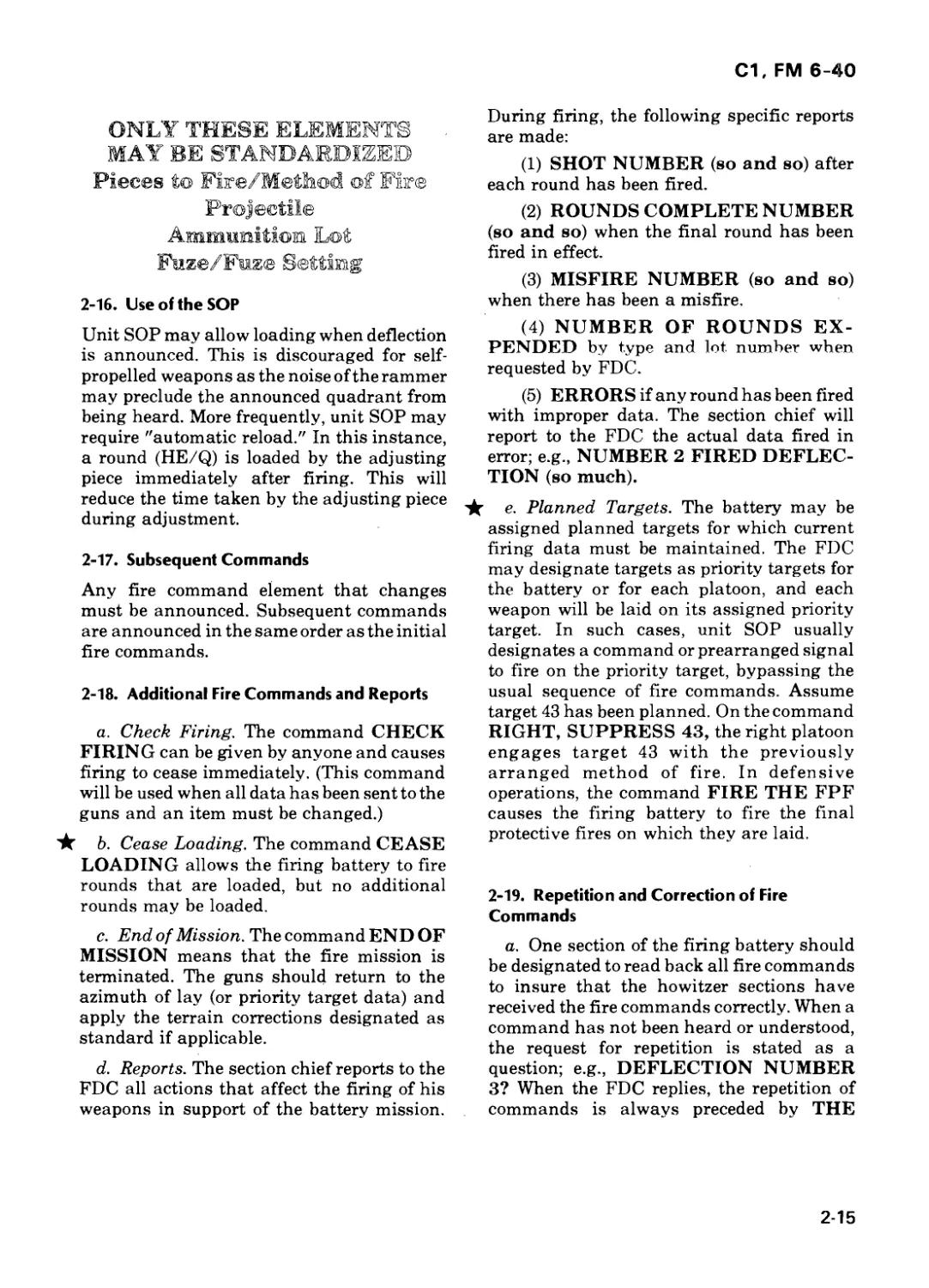
2-15. Fire Command Standards
Once the fire order standards are established,
standard fire commands are established.
Only certain elements of the fire commands
may be standardized. Those elements are
then announced only when they are different
from the standard.
2-14
С1, FM 6-40
ONLY THESE ELEMENTS
MAY BE STANDARDIZED
Pieces to Fire/Method of Fire
Projectile
Ammufflitiom Lot
Faze/Fuze Setting
2-16. Use of the SOP
Unit SOP may allow loading when deflection
is announced. This is discouraged for self-
propelled weapons as the noise of the rammer
may preclude the announced quadrant from
being heard. More frequently, unit SOP may
require "automatic reload." In this instance,
a round (HE/Q) is loaded by the adjusting
piece immediately after firing. This will
reduce the time taken by the adjusting piece
during adjustment.
2-17. Subsequent Commands
Any fire command element that changes
must be announced. Subsequent commands
are announced in the same order as the initial
fire commands.
2-18. Additional Fire Commands and Reports
a. Check Firing. The command CHECK
FIRING can be given by anyone and causes
firing to cease immediately. (This command
will be used when all data has been sent to the
guns and an item must be changed.)
★ b. Cease Loading. The command CEASE
LOADING allows the firing battery to fire
rounds that are loaded, but no additional
rounds may be loaded.
c. End of Mission. The command END OF
MISSION means that the fire mission is
terminated. The guns should return to the
azimuth of lay (or priority target data) and
apply the terrain corrections designated as
standard if applicable.
d. Reports. The section chief reports to the
FDC all actions that affect the firing of his
weapons in support of the battery mission.
During firing, the following specific reports
are made:
(1) SHOT NUMBER (so and so) after
each round has been fired.
(2) ROUNDS COMPLETE NUMBER
(so and so) when the final round has been
fired in effect.
(3) MISFIRE NUMBER (so and so)
when there has been a misfire.
(4) NUMBER OF ROUNDS EX-
PENDED by type and lot number when
requested by FDC.
(5) ERRORS if any round has been fired
with improper data. The section chief will
report to the FDC the actual data fired in
error; e.g., NUMBER 2 FIRED DEFLEC-
TION (so much).
★ e. Planned Targets. The battery may be
assigned planned targets for which current
firing data must be maintained. The FDC
may designate targets as priority targets for
the battery or for each platoon, and each
weapon will be laid on its assigned priority
target. In such cases, unit SOP usually
designates a command or prearranged signal
to fire on the priority target, bypassing the
usual sequence of fire commands. Assume
target 43 has been planned. On the command
RIGHT, SUPPRESS 43, the right platoon
engages target 43 with the previously
arranged method of fire. In defensive
operations, the command FIRE THE FPF
causes the firing battery to fire the final
protective fires on which they are laid.
2-19. Repetition and Correction of Fire
Commands
a. One section of the firing battery should
be designated to read back all fire commands
to insure that the howitzer sections have
received the fire commands correctly. When a
command has not been heard or understood,
the request for repetition is stated as a
question; e.g., DEFLECTION NUMBER
3? When the FDC replies, the repetition of
commands is always preceded by THE
2-15
С1, FM 6-40
COMMAND WAS; e g., THE COMMAND
WAS DEFLECTION 2768.
b. If an incorrect command has been given
but the command QUADRANT has not
been announced, the FDC commands
CORRECTION followed by the correct
command and all subsequent elements. If
QUADRANT has been announced, the FDC
commands CHECK FIRING. Then
CANCEL CHECK FIRING is announced
followed by the corrected element and all
subsequent elements.
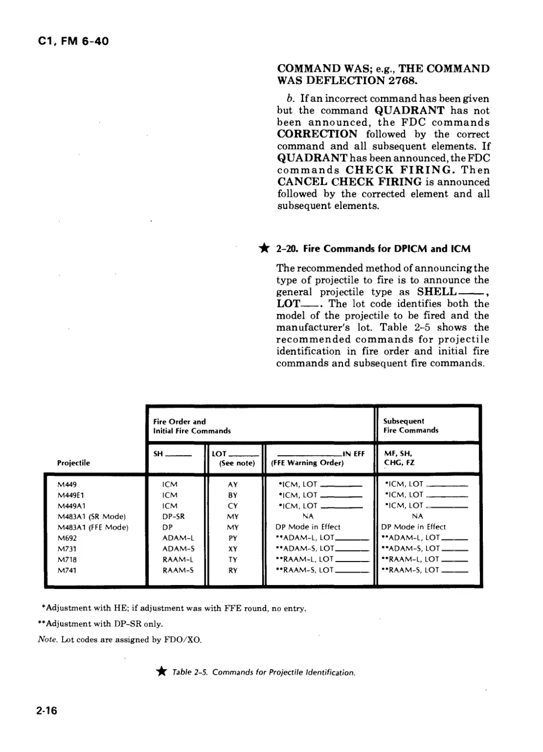
★ 2-20. Fire Commands for DPICM and ICM
The recommended method of announcing the
type of projectile to fire is to announce the
general projectile type as SHELL------,
LOT------The lot code identifies both the
model of the projectile to be fired and the
manufacturer's lot. Table 2-5 shows the
recommended commands for projectile
identification in fire order and initial fire
commands and subsequent fire commands.
Fire Order and Initial Fire Commands Subsequent Fire Commands
Projectile SH LOT (See note) IN EFF (FFE Warning Order) MF, SH, CHC, FZ
M449 ICM AY ♦ICM, LOT •ICM, LOT
M449E1 ICM BY •ICM, LOT •ICM, LOT
M449A1 ICM CY •ICM, LOT •ICM, LOT
M483A1 (SR Mode) DP-SR MY NA NA
M483A1 (FFE Mode) DP MY DP Mode in Effect DP Mode in Effect
M692 ADAM-L PY ••ADAM-L, LOT ••ADAM-L, LOT
M731 ADAM-S XY ••ADAM-S, LOT ••ADAM-S, LOT
M718 RAAM-L TY ••RAAM-L, LOT ••RAAM-L, LOT
M741 RAAM-S RY ••RAAM-S, LOT ••RAAM-S, LOT
•Adjustment with HE; if adjustment was with FFE round, no entry.
**Adjustment with DP-SR only.
Note. Lot codes are assigned by FDO/XO.
★ Table 2-5. Commands for Projectile Identification.
2-16
С1, FM 6-40
Section V. BATTERY MISSION PROCESSING
★ 2-21. FDC Procedures
In the battery FDC all actions must be
oriented toward timely and accurate
computation and transmission of fire
commands. All actions must provide the best
possible flow of information between FDC
personnel. The battery FDC must be trained
to accomplish the responsive and accurate
determination of firing data. To insure
responsiveness, FDC personnel must be
trained as a team to accomplish many
operations simultaneously.
a. Deflection Corrections. For immediate
suppression missions on targets of
opportunity, the computer applies the
registration (or inferred) total deflection
correction, regardless of the amount of drift
change. For an adjust fire mission when more
time is available, the drift change is
considered and applied to the GFT deflection
correction. Regardless of the amount of
deflection correction applied, replot
procedures are as outlined in chapter 10.
b. Transfer From Manual to FADAC
Computations. FADAC is the primary means
of computing firing data and should be used
whenever possible. It is the most accurate
means available and, in most cases, the
fastest. However, data for the initial
adjusting round of a mission often can be
computed faster by manual methods. Thus,
in many cases, the initial data fired will be
computed manually while subsequent rounds
will be fired using FADAC data. When this
occurs, the FDO must evaluate the effect of
any differences between the initial manual
data and the FADAC data and decide which
method will be used to continue the mission.
(1) If a FADAC-derived GFT setting is
being used on the graphical equipment and
FADAC/manual chart checks have been
conducted, there should be no significant
differences between the two sets of data (a
difference of 3 mils or less in deflection or QE
is not considered significant). If the
difference is excessive, the mission should be
continued manually (otherwise, the observer
may not get the correction he requested), and
the FDO should announce USE GFT. If the
difference is acceptable, the FDO announces
USE FADAC and all subsequent rounds are
fired with FADAC data. This decision must
be made quickly and is especially critical if
the first subsequent correction includes
FIRE FOR EFFECT.
(2) This procedure is used for any
time-sensitive mission, including immediate
suppression (since the observer may decide to
continue the mission and neutralize the
target). The FDC must use comparable input
data for both manual and FADAC
computations; e.g., if average site is used
manually, average altitude should be used in
FADAC.
c. Site. On any battery mission that is
adjusted, average site usually will be
sufficiently accurate. On a mass or
first-round fire-for-effect mission, actual site
will be computed. When immediate
suppression (or any other emergency
mission) is requested, site may be ignored if
no average site is available. Otherwise,
average site is included. Replot procedures in
chapter 10 apply.
d. Average Site/Altitude. When average
site (altitude) is used in computation of firing
data, time will be saved only if a verage values
have been determined before they are needed.
Accuracy of the average values is improved
as time allows, in three phases.
(1) Phase I-estimation by map
inspection. This method results in
determination of only one or two values of site
(average altitude for FADAC) for an entire
zone of fire. Site is computed by examining
the map and selecting one or two values of
altitude (which are representative of the
2-17
С1, FM 6-40
entire zone) and computing site for each. This
method will cause significant error if the
terrain is very hilly or if there are large
differences in range.
(2) Phase П-plotting contour intervals.
The VCO colors his map for specified contour
interval, normally 30 meters (100 ft). The
altitude reported to the FADAC operator is
the average altitude for the colored contour
interval in which the target is plotted.
Average site for each contour sector is
precomputed using the average sector
altitude, the average range for all areas
covered by that sector, and the charge that
has been designated as standard.
(3) Phase Ill-refinement. As time is
available (unlikely if frequent moves are
made), average site values are refined by
computing two or three sites for each contour
sector to evaluate those changes caused by
significant differences in range. For example,
site would be computed for the 300-330
contour sector at ranges 5000, 6000, 7000, etc.
e. Multiple Missions. The battery FDC
must be able to process two or more missions
at once. Although FADAC can process
several missions independently, corrections
for one mission cannot be applied while
FADAC is computing data for another
mission.
(1) When a battery receives two
missions, the battery FDC processes both.
The first mission is continued on FADAC.
The second mission is processed on the chart
(until FADAC becomes available after
completion of its current mission). If the
second mission is significantly more complex
(such as a nuclear fire mission), it may be
processed in FADAC. The first mission is
transferred to the chart and manual backup
techniques are used.
(2) A well-trained battery FDC might be
able to compute data for three missions at
once. However, if it cannot and if more than
two missions are sent to the same battery, the
battery FDC continues processing the first
two unless the new mission is more urgent.
Battalion FDC may process the new mission
or allocate it to another battery that is not
overloaded.
(a) If another battery is available and
little time will be lost transferring the
mission, battalion FDC should assign it the
new mission. Two communications methods
are possible.
1. Have the battery FDC assigned the
mission switch its CF radio to the requesting
observer's net (remain responsive to its own
observers on its FD net with the other radio).
2. Have the battalion FDC relay the
observer's call for fire and subsequent
corrections to the battery assigned the
mission using the battalion CF net.
(b) If another battery is not available or
too much time will be lost transferring the
mission, battalion FDC will compute firing
data and send data to the FDC of the original
battery. Sequence of firing of the missions
will depend upon their relative urgency and
how many guns are already involved in other
missions. Several solutions are possible,
including:
1. Suspend a lower priority mission
until completion of the new mission.
2. Delay the latest mission until a
higher priority mission is completed.
Note. Use one gun to adjust each mission,
firing the entire battery in effect as each
mission approaches completion.
★ 2-22. Sample Mission
The battery fire order and fire command
elements in figure 2-7 are in effect for the
following missions.
a. FDC With FADAC. The following
mission is received in the battery FDC from
the FIST:
Жё1ШМ/ eW? S’ WKS®
(1) The RATELO announces
FIRE MISSION
to the FDC. The computer immediately
announces
2-18
Cl, FM 6-40
FIRE MISSION
to the guns.
(2) The RATELO continues to read back
the FIST call for fire insuring that he has
proper authentication.
L-r-y<="-‘--===z-r2сг=--.8-л. -r-zs-s -- = -2
=?sf-m ?f ifSй
:=- A i*T'n M’&li; Й
.< 5< »пЖ<2?.
FIRE ORDER STANDARDS
ELEMENT CURRENT STANDARD
UNIT TO FIRE st/cP
ADJUSTING ELEMENT/METHOD OF FIRE OF ADJUSTING ELEMENT *3 0
BASIS FOR CORRECTIONS C/SCf5T M277POP
DISTRIBUTION PPP./UTZA, 5ША
PROJECTILE
AMMUNITION LOT AND CHARGE
FUZE
NUMBER OF ROUNDS О
RANGE SPREAD, LATERAL SPREAD, ZONE FIRE, OR SWEEP FIRE CT/Z j^Gr / Z>A
TIME OF OPENING FIRE
FIRE COMMAND STANDARDS
ELEMENT CURRENT STANDARD
WARNING ORDER
PIECES TO FOLLOW/PIECES TO FIRE/ METHOD OF FIRE
SPECIAL INSTRUCTIONS
PROJECTILE
AMMUNITION LOT
CHARGE
FUZE/FUZE SETTING GL
DIRECTION
QUADRANT ELEVATION
METHOD OF FFE
Figure 2-7. Battery fire order/fire command standards.
2-19
С1, FM 6-40
(3) The other members of the FDC
monitor the call for fire.
(a) The HCO inputs the grid in FADAC.
(b) The VCO plots the target on the
firing chart and on the map. He determines
and announces the altitude.
(c) The FDO inspects the target plot on
the situation map and firing chart.
(d) The battalion FDO monitors the call
for fire.
(4) The battery FDO decides on his plan
of attack and announces his fire order.
USE FADAC, 6 ROUNDS, VT IN
EFFECT.
(5) The fire order triggers several
simultaneous actions:
(a) The HCO enters appropriate
overrides and computes data with the
FADAC.
(b) Using the fastest method, the
computer determines and announces initial
fire commands (up to fuze setting) to the guns.
(c) The RATELO determines and
transmits the message to observer and
receives ОТ direction from the observer.
(d) The battalion FDO, who has
monitored the mission, will check the MTO. If
he agrees, he will remain silent.
(6) When FADAC data is displayed, the
computer reads it from the display panel and
announces it to the cannon sections.
(7) The VCO determines site and
announces it to the computer when required.
He also determines angle T and announces it
to the RATELO. The RATELO sends angle T
to the observer if it is equal to or greater than
500 mils, and the computer records it on the
record of fire.
(8) When the adjusting piece fires,
SHOT is announced to the computer, who
repeats SHOT. The RATELO then sends
SHOT, OVER to the observer.
(9) The observer sends his subsequent
corrections.
IJ1R El T1 ON +51IHL LEFT fil h D ROP
I m >. M R E FOR E F FF.l T. OVER.
(a) The HCO enters the observer's
corrections in FADAC.
(b) The computer announces the
change in method of fire to the guns.
(10) When FADAC data is displayed, it is
sent to the guns. SHOT is sent to the observer
when the guns fire.
(11) When each gun has fired six rounds,
it announces ROUNDS COMPLETE to the
computer. When all guns have reported, the
computer announces ROUNDS COM-
PLETE to the RATELO who transmits
ROUNDS COMPLETE to the observer.
(12) If the fire is sufficient, the observer
sends refinement, end of mission, and
surveillance to the RATELO.
(13) The FDO annnounces END OF
MISSION. The HCO determines and
announces refinement data and gives end of
mission (EOM) to FADAC, the computer
announces END OF MISSION to guns, the
VCO pulls his pin from the firing chart.
b. FDC Without FADAC. If the FDC does
not have a FADAC capability, the sequence
of duties is altered.
(1) The HCO is the primary chart
operator. As such, he plots the target and
announces chart range and deflection for the
initial grid and for subsequent corrections.
He determines angle T.
(2) The VCO determines site, announc-
ing it to the computer when requested, and
follows the mission on his chart to provide a
positive check on the HCO's data.
(3) Using his GFT, the computer
converts the announced chart data into firing
data and sends it to the guns.
c. FDC Using Fastest Method. Using the
GFT fan is usually faster than using FADAC
in determining initial data. When the FDC
establishes FASTEST METHOD as his basis
for corrections, FDC procedures to determine
initial data outlined below should be used.
2-20
С1, FM 6-40
FDC PROCEDURES
STEP STEP
1 RATELO—Receive warning order for an adjust fire mission. 10 HCO—Enter overrides as appropriate.
11 VCO—Mentally add the GFT deflection correction to the chart deflection. Add the drift correction from the ballistic scale to the sum and announce the result to the computer as DEFLECTION ( ). This is the deflection to fire (CHT DF + GFT DF CORR + DRIFT CORR). Ideally,it shouldbe announced as soon as the computer states CHARGE( ) to the guns but not before, since the computer is busy.
2 FDO—Plot the target on the situation map and analyze the situation.
3 Computer—Alert the guns by announcing FIRE MISSION. Then, if it is a grid mission, pick up the site map, plot the target, and announce the average altitude to the HCO. Record the average site. If it is a polar plot/shift mission, prepare to compute the vertical interval (VI) as soon as the VCO announces the observer/known point altitude.
12 RATELO—Send the MTO.
4 HCO—Enter data according to observer's method of target location. 13 Computer—Announce DEFLECTION ( ) to the guns.
5 VCO—Plot the target on the chart. First, announce the observer/known point altitude to the computer if the mission is polar plot or shift. 14 VCO—Announce the elevation and chart range to the target to the computer as soon as he announces DEFLECTION ( )tothe guns but not before, since he is busy.
15 Computer A—If average site can be used (i.e., if it is a grid mission), mentally add average site to the VCO's elevation and announce QUADRANT ( ) to the guns.
6 RATELO—Read back the mission and authenticate.
7 FDO—Issue the fire order. 16 Computer В—If it is a polar plot/shift mission, use the chart range determined by the VCO in step 5 and the vertical interval determined as part of step 3 to compute site with the GST. Noting that the vertical interval could already be set off on the D-scale as part of step 3, this should enable the computer to rapidly determine site and, hence, quadrant elevation.
8 FDO—Supervise.
9 Computer—Announce fire commands to the guns up to and including charge.
Note. This procedure is written for an adjust fire mission when an average site map is
available. If no average site map is available or if the mission is an FFE mission in which speed
is desirable, the procedure still works except that the computer announces the actual target
altitude (also as part of step 3) to determine and set off the VI he needs. If accuracy is more
important than speed, the FDO might want to specify USE FADAC or USE GFT in his fire
orders. Normal manual procedures would then apply.
2-21
Cl, FM 6-40
Section VI. BATTALION MISSION PROCESSING
2-23. Battalion Responsibilities
a. The battalion FDO must monitor all
calls for fire on all nets. Battalion FDC will
become involved in a mission in one of two
ways:
(1) Missions submitted directly to
battalion FDC. These may come from higher
headquarters, fire support officers, or FISTs.
(2) Missions submitted to battery FDCs.
The battalion FDO may decide to step in and
mass the battalion on a target sent directly to
the battery that is monitored by the battalion
computer on that battery's fire direction net
or the battery FDO may request additional
fires.
b. Subsequent corrections will be sent to
any battery not able to monitor the conduct of
the mission.
2-24. Sample Missions
a. The battalion standard fire order
elements in figure 2-8 are in effect for the
following mission.
b. A fire for effect mission (TOT designated
from division artillery direct to battalion
FDC):
FIRE ORDER STANDARDS
ELEMENT CURRENT STANDARD
UNIT TO FIRE BTRY
ADJUSTING ELEMENT/ METHOD OF FIRE OF ADJUSTING ELEMENT BP ©
BASIS FOR CORRECTION FASTEST METHOD
DISTRIBUTION PARALLEL SHEAF
PROJECTILE HE
AMMUNITION LOT AND CHARGE A:WT/4; B&C WT/5
FUZE 0
NUMBER OF ROUNDS ©
RANGE SPREAD, LATERAL SPREAD, ZONE FIRE, OR SWEEP FIRE CENTER RG & DF
TIME OF OPENING FIRE WHEN READY
★ Figure 2-8. Battalion standard fire order elements.
2-22
С1, FM 6-40
Bn FDC
Btry FDCs
(1) Battalion FDC receives mission from
division artillery on radioteletypewriter
(RATT):
£aKftfс p=E- :M:?’.fevr<rлi:’£??.
1\м nt коk
(2) FDO issues fire order:
ПГТ. Fl ;K I.H I KA Jl AL? A.
। -H 11 f f - vi [; [. :-l '- .
<нп: r-’M r/~ ?:u:u tang«
пт.?: time iv'[/n sxx:.? t:me
i.-V TARGET
(3) А, В, C, computers to batteries (wire
lines):
FIEF. I-1' 'k к: ‘I KATI A;’"N
•.kill ► "A-- =- -v и-г’тч <.
ICM LL'T ZULU TANG-’1.
h7l iimf ixг. т >: s ii.mf
L-:< TARGET >'-lc
(1) All batteries read back:
Шт?1V?|a -f< 7: if f-Z vkri =^<
gig'.
(2) Batteries compute data and send to
guns.
(4) Battalion FDO on battalion CF net.
: '--MA И HkijV-k t C iI ---- "
Note. This time check could have been sent
individually to each battery using the fire
nets or wire lines.
(3) Battery A:
KOCLR. <»l'l.
Battery B:
ROGER, 011’
Battery C:
HOGEK. ol’T.
REMARKS:
The batteries would now control their own firing, reporting SHOT and
ROUNDS COMPLETE to battalion FDC. Battalion FDC would report
firing to div arty.
2-23
С1, FM 6-40
CHAPTER 3
CHART DATA
Section I. FIRING CHARTS
3-1. Definition
The firing chart is normally a grid sheet that
is used to graphically show the location of
batteries, targets, and other details needed to
determine chart data.
3-2. Purpose, Types, and Use of Firing Charts
a. The purpose of a firing chart is to
determine the range and direction from the
guns to the target. Effective artillery fires
require an accurate and complete firing
chart.
★ b. There are three types of firing charts
used in the FDC—the surveyed firing chart,
the observed firing chart, and the emergency
firing chart. This chapter will deal with
surveyed firing charts.
(1) The surveyed firing chart (fig 3-1) is a
chart on which the locations of all critical
points (e.g., battery positions, registration
points, observation posts (OP)) are plotted.
These locations can be based on survey or
map inspection. All plotted points are in
correct relation to one another and reflect
actual map coordinates. When actual map
coordinates are unknown, assumed
coordinates may be used initially to tie
together the points plotted.
(2) Details of construction and use of the
observed firing chart are in chapter 15.
(3) Details of construction and use of the
emergency firing chart are in chapter 14.
c. The firing chart used in an FDC is
normally a grid sheet on which all essential
points are plotted. Essential locations
include:
(1) Firing batteries.
(2) Observation posts.
(NOT TO SCALE)
Figure 3-1. A surveyed firing chart.
3-1
С1. FM 6-40
(3) Registration points.
(4) Field artillery radars.
(5) Final protective fires.
(6) Targets as requested by the observer
or directed by the FDO.
(7) Other points related to the tactical
situation as desired by the commander.
d. In the FADAC integrated FDC (FADAC
and manual backup), the firing chart is
maintained by the VCO and supplemented
by a 1:50,000 map used to determine altitude.
A situation overlay will be maintained with
this map. Based on the tactical situation and
the desires of the commander, additional
overlays (e.g., fire capabilities, dead space
overlays) may be maintained. In a manual
FDC, two firing charts are maintained. The
VCO will maintain his chart and the 1:50,000
supplementary map with the overlay(s), and
the HCO will maintain the other firing chart.
Section II. PLOTTING EQUIPMENT AND
PREPARATION OF FIRING CHARTS
3-3. Plotting Rules
Fire direction personnel must insure the
accuracy of the data shown on the firing
chart. All firing charts in the battalion
should be identical so fires may be massed
accurately. To insure accuracy, plotting
should be done from a standing position
directly above the chart. Plotting pins must
be kept perpendicular to the firing chart.
3-4. Equipment
Special equipment is used to construct and
use a firing chart. This equipment must be
maintained and used properly to insure
maximum accuracy.
a. 6H Pencil. The 6H (hard lead) pencil,
sharpened to a wedge point (fig 3-2), is used to
draw all lines from which measurements will
be made.
b. 4H Pencil. The 4H pencil, sharpened to
a conical point (fig 3-2), is used to letter and to
accentuate tickmarks.
c. Plotting Pins. Plotting pins are used to
mark positions and to plot points on the firing
chart.
d. Aluminum Plotting Scale. The
aluminum plotting scale (fig 3-3(1)) is a
square-shaped scale used to plot or determine
grid coordinates of targets and critical points.
The scale is graduated in meters and yards at
scales of 1:25,000 and 1:50,000. Locations
may be plotted to an accuracy of 1 meter with
the aluminum plotting scale.
e. Plotting Scale. The plotting scale (fig 3-
3(2)) can be used to measure distances and to
plot or determine grid coordinates of critical
points when the aluminum plotting scale is
not available. The scale is graduated in
meters, yards, and inches. The meter and
yard graduations are at scales of 1:25,000,
1:50,000, and 1:62,500. The scale should never
be used as a straightedge to draw lines.
✓ i
Figure 3-2. 6H and 4H pencil points.
3-2
С1, FM 6-40
© PLOTTING SCALE
© PLOTTING SCALE
(ALUMINUM)
© PLOTTING SCALE
(PLASTIC)
Figure 3-3. Scales used in fire direction.
Locations may be plotted to an accuracy of 1
meter with the plotting scale.
★ f. Plastic Plotting Scale. The plastic
plotting scale (fig 3-3 (З) ) may be used to
plot or determine coordinates of targets other
than registration points and locations
determined by survey when an aluminum
plotting scale is not available. The scale is
graduated in meters and yards at scales of
1:25,000 and 1:50,000. Locations may be
plotted to an accuracy of 10 meters with the
plastic plotting scale.
g. Range-Deflection Protractor. The
range-deflection protractor (RDP) (fig 3-4) is
used to measure angles and distances. It is
used to measure range and deflection from a
battery to a target and to measure direction
and distance from an observer to a target.
The left edge of the arm is graduated in 50-
meter increments at a 1:25,000 scale. It is read
to a visually interpolated accuracy of 10
meters. The 1000-mil arc of the RDP is
graduated in 5-mil increments. The 50-mil
increments are indicated by a long line. The
arc is read to a visually interpolated accuracy
of 1 mil.
3-5. Numbering
The firing chart is numbered to correspond to
the mapped area of the zone of action. The
lower left-hand comer of the grid sheet is
assigned easting and northing coordinates
that will insure covering the area of
operations. If applicable, the direction of the
long axis (east-west or north-south) will be
designated. There must be enough space to
plot all necessary points on the chart. The
firing chart is numbered with a 4H pencil.
The rightmost and topmost grid lines are not
labeled.
3-6. Plotting
a. For critical points and points located by
survey, proceed as follows:
(1 ) Grid lines 1000 meters apart (fig 3-5).
(a) Locate and place a plotting pin in
the grid square in which the point is to be
plotted (fig 3-5).
3-3
С1, FM 6-40
Figure 3-5. Square in which point is to be plotted.
Figure 3-6. Use of the plotting scale.
qq. GRID 523394
J w
6 2
Figure 3-7. Plotting the point using the plotting scale.
(b) Place the aluminum plotting scale
along the left edge of the grid square with the
zero of the scale at the lower left corner of the
grid square (fig 3-6).
(c) Slide the scale to the right; read the
easting on the scale using the N-S grid line as
an index (fig 3-7).
(d) Plot the northing on the vertical
scale using a plotting pin. This is the plotted
location (fig 3-8).
(2 ) Grid lines not 1000 meters apart.
(a) When grid lines are closer than
normal, plot the point by inclining the
Figure 3-8. The plotted location.
aluminum plotting scale so that the zero of
the scale is on one grid line and the 1000 is on
the other (fig 3-9).
(b) If the grid lines are farther apart
than normal, incline the aluminum plotting
scale so that the zero of the scale is on one grid
line and 2000 is on the other (fig 3-10).
Multiply the distance to be plotted by 2 and
plot the point. For example, for an easting of
62681, place the pin at 1362 on the scale.
(c) In both cases, only easting or
northing can be plotted at one time.
Therefore, the following four-point plotting
3-4
С1, FM 6-40
Figure 3-9. Grid squares smaller than normal.
Figure 3-10. Grid squares larger than normal.
3-5
С1, FM 6-40
technique must be used to plot a point located
by survey when grid lines are not 1000 meters
apart.
1. Locate the grid square in which the
point is to be plotted.
2. Using plotting pins and the
aluminum plotting scale, plot the easting grid
in the grid squares above and below the grid
square in which the point is to be located.
Remove the pins and connect the points with
a fine line drawn with a 6H pencil through the
3. Plot the northing grid in the grid
squares to the left and right as in step 2 (fig 3-
12). Connect the pinholes with a line drawn
with a 6H pencil.
Figure 3-12. Plot the northing grid.
4. Mark the point where the two lines
meet with a plotting pin (fig 3-13). Erase the
fine lines and identify the location with a
tickmark (fig 3-14).
Figure 3-13. Mark the point where the two lines meet.
Figure 3-14. Identify the location with a tickmark.
b. Noncritical points are plotted in the
same manner as points located by survey
when grid lines are 1000 meters apart (para
a(l) above).
c. The plastic plotting scale may be used in
place of the aluminum plotting scale. When it
is used, the four-point plotting technique as
described in paragraph a(2)(c) above must be
used.
3-7. Tickmarks
The tickmark is the symbol used to mark and
identify the location of installations and
targets plotted on a firing chart.
a. The tickmark is constructed in the form
of a cross starting 40 meters from the pinhole
on the chart and extending 150 meters in
length (1:25,000 scale) (fig 3-15 (1) ). The
3-6
С1, FM 6-40
(4) (SYMBOL IN
| GREEN)
"500j
(DESIGNATOR IN
У I „ APPROPRIATE
_______COLOR)
424 I
©
I REG PT 2
"430|
Q (TICKMARK IN
| CS2131 RED ,F TGT
----- --- IS LOCATED
415 I BY FIRE)
СННД5| (IDENTIFICATION)
376 I (TICKMARK
1 IN BLUE)
(ALT)I VT
1 (FZ IN FFE)
Figure 3-75. Tickmarks.
lines of the tickmark are drawn parallel to the
grid lines unless the point falls on or close to a
grid line, in which case it is plotted at a
45-degree angle to the grid line (fig 3-15
★ (£) ). All tickmarks are drawn with a 4H
pencil except targets located by firing, which
are drawn in red. and maneuver checkpoints,
which are drawn in blue.
b. The identification of the point is placed
in the upper right quadrant. The installation
or activity is designated in the following
manner.
(1) Battery. The letter designation is
shown in the appropriate color (fig 3-15®);
i.e., A-red, В-black, C-blue, D-orange. If more
than four batteries are shown, the color
coding starts over again with red. If the
pieces of the battery are widely dispersed, it
may be necessary to plot piece or platoon
locations.
(2) Radar. The military symbol is shown
in green (fig 3-15 (J)).
(3) Observation post. The military
symbol and call number of the observer are
shown in black (fig 3-15®). If the
observation post is assigned a number, that
number is shown in black in place of the
symbol and call number (e.g., 02).
(4) Registration points. The number
assigned to the point is shown in black; e.g.,
REG PT 2 (fig 3-15(6)).
(5) Targets. The assigned target number
is shown in black; e.g., CS21.31 (fig 3-15
© ).
(6) Checkpoints. The checkpoint
number is shown in black and circled; e.g,, (T)
(fig 315(g)).
c. The altitude, in meters, of the plotted
point is placed in the lower left quadrant in
black (fig 3-15®-®).
IDENTIFICATION AND ALTITUDE
MUST ALWAYS BE GIVEN.
d. If the plotted point has been fired upon,
the fuze used in fire for effect may be placed in
the lower right quadrant (fig 3-15®).
e. If the plotted point has been fired upon
with high angle fire, the letters HA may be
placed in the upper left quadrant (fig 3-15 ®).
f. The charge fired may be placed in the
upper left quadrant (fig 3-15®)).
3-8. Establishing Azimuth Indexes
a. Azimuth indexes are established for
points located on the firing chart from which
the polar plot method (see para 3-146) of
target location may be expected; e.g.,
observation posts and radar sites. The RDP
must be prepared by numbering the 100-mil
graduations in black as shown in figure 3-16.
3-7
Cl, FM 6-40
b. Azimuth indexes are constructed on the
firing chart at 1000-mil intervals throughout
the target area. To construct the azimuth
indexes:
(1) Place the vertex of the RDP against a
pin in the OP or radar location and aline the
arm parallel to a convenient grid line. To
aline the arm parallel to a grid line, plot the
easting of the observer if using a north-south
grid line. If using an east-west grid line, plot
the northing of the observer in a similar
manner. When alined, the arm establishes a
reference line (not drawn) at an azimuth of 0
(north), 1600 (east), 3200 (south), or 4800
(west).
(2) Azimuth is always read as four digits.
The first digit of the azimuth is read from the
azimuth index on the chart. The last three
digits are read on the arc of the RDP. In (1)
above, the RDP was oriented in a cardinal
direction. To establish the azimuth index,
place a pin opposite the number on the arc
corresponding to the last three digits of the
azimuth in which the arm of the RDP is
oriented. The location of the pin represents an
azimuth with the value of the first digit of the
Table 3-1. Indexing Procedures
If RDP is oriented NORTH - 6400 mils = 0 mils,
1 Place pin opposite 400 on ARC, INDEX is 6000.
2 Place pin opposite 0 on ARC, INDEX is 0.
If RDP is oriented EAST = 1600 mils,
Place pin opposite 600 on ARC, INDEX is 1000.
If RDP is oriented SOUTH - 3200 mils,
Place pin opposite 200 on ARC, INDEX is 3000.
If RDP is oriented WEST = 4800 mils,
Place pin opposite 800 on ARC, INDEX is 4000.
3-8
С1, FM 6-40
azimuth in which the arm of the RDP is
oriented. If the arm is oriented toward north,
two azimuth indexes will be constructed,
since north corresponds to 6400 or 0 mils (fig
3-17); e.g., 6000 and 0 AZ indexes. Table 3-1
summarizes indexing procedures for all
orientations of the RDP.
Figure 3-17. Construction of 6400-mil and 0-mil
azimuth indexes.
(3) Move the RDP so the left edge of the
arm is against the pin, remove the pin, and
draw the azimuth index with a 6H pencil. The
index is a fine line extending 1 inch above
and 1 inch below the pinhole. This line can be
measured by drawing a line from range 8250
to range 9520 along the left edge of the arm of
the RDP. Beginning one-eighth inch beyond
the pinhole, label the index with its
identification (01, 24, radar symbol) and
azimuth value along the left side of the line.
★ Lettering is green for the radar symbol and
its azimuth labels and black for OPs and their
azimuth labels (fig 3-18).
(4) Other azimuth indexes can be
constructed by measuring successive 1000-
mil increments to the left and right of the
first. To locate an index for 2000 mils, place a
pin 1000 mils right of the index for azimuth
1000. The arc of the RDP is exactly 1000 mils.
To locate an azimuth index for 5000 mils,
place a pin 1000 mils left of the index for 6000
mils.
Figure 3-18. Labeling the azimuth indexes.
c. The value of the azimuth measured or
plotted is the sum of the azimuth marked on
the azimuth index plus the value read on the
arc opposite the index (fig 3-19). In this
★ example, the azimuth is 0750.
Figure 3-19. Measuring the value of the azimuth.
3-9
С1, FM 6-40
Figure 3-20. Parts of the range-deflection protractor
prepared for measurement of deflection.
Figure 3-21. RDP oriented to the east.
3-9. Establishing Deflection Indexes
Direction from a battery to a target normally
is measured and announced in terms of
deflection. The RDP must be prepared to
measure deflection by numbering the
graduations of the arc in red as shown in
figure 3-20.
a. The deflection index is used with the
RDP to determine chart deflection. The index
is constructed as follows:
(1) With the vertex of the RDP against
the pin in the battery position, orient the left
edge of the arm in the direction of the
battery's azimuth of lay. Using the procedure
outlined in paragraphs 3-8b(l) and (2), place a
pin in the chart where the azimuth index
would be constructed (do not draw the index).
In figure 3-21, the RDP is oriented to the east
(1600 mils), and a pin is placed opposite 600
on the azimuth scale. Now move the RDP
until the last three digits of the azimuth of fire
(read on the azimuth scale of the RDP) are
opposite the pin. The left edge of the RDP is
now oriented in the direction of the battery
azimuth of lay. Figure 3-22 depicts the RDP
Figure 3-22. RDP oriented on azimuth of lay.
3-10
С1, FM 6-40
oriented on an azimuth of lay of 1900 mils. If
the battery is laid on the direction to a
registration point, place the left edge of the
RDP against a pin in the registration point to
orient the RDP.
(2) For the M100 series sight, the
common deflection is 3200 mils. The firing
chart must be constructed so that the azimuth
of lay corresponds to the common deflection.
To do this, orient the RDP on the azimuth of
lay (as above) and place a pin opposite the
200-mil graduation on the deflection scale
(fig 3-23). Move the RDP so the left edge of the
arm is against the pin. Remove the pin and
draw a fine line (with a 6H pencil) along the
range scale, 1 inch above and 1 inch below the
pinhole. Label this index with the
appropriate battery designator and the
★ number 3 in the appropriate color. Draw the
arrowhead as shown in figure 3-24 in the
appropriate color and one-eighth inch above
the pinhole. (For the M12 series sight, with
the common deflections of 2400 or 2800, the
pin would be placed at 4 or 8, respectively, and
the index would be labeled 2.)
Figure 3-23. Construction of a common deflection index.
Figure 3-24. Construction of the deflection index.
b. Locate supplementary deflection
indexes by constructing indexes 1000 mils
left or right of the primary index. Since
deflection increases to the left (LARS) and
azimuth decreases, label the left index one
number higher than the primary index.
Conversely, as azimuth increases, deflection
decreases to the right; therefore, label the
right index one number lower than the
primary index (fig 3-25).
Figure 3-25. Supplementary deflection indexes.
3-11
С1, FM 6-40
3-10. 6400-Mil Charts
a. When firing in a 6400-mil sector is
required, the batteries are plotted in the
center of the firing chart. The indexes are
constructed and numbered as shown in figure
3-26. Fabricated, larger charts may be
necessary to achieve the maximum range
throughout the 6400 mils.
b. When indexing the firing chart for 6400-
mil capability, the chart operator may find
that the RDP will measure a few mils more or
less than 6400 mils. To insure that any errors
are distributed evenly, construct the 4000-,
5000-, and 6000-mil indexes to the left of the
3000-mil index; then construct the 2000-,
1000-, and 0-mil indexes to the right of the
3000-mil index.
Figure 3-26. 6400-mil firing chart.
3-12
С1, FM 6-40
Section III. DETERMINATION OF CHART DATA
3-11. Elements of Chart Data
There are three elements of chart data: chart
range, chart deflection, and angle T. They are
measured as follows:
a. Place the vertex of the RDP against the
pin in the battery position and the left edge of
the arm against the pin in the target location.
b. Read the range in meters opposite the
pin in the target location. Measure and
announce the range to the nearest 10 meters.
c. Read the chart deflection on the arc
opposite the appropriate deflection index.
Combine the 1000-mil designation of the
index with the reading on the arc to obtain
the deflection.
d. Angle T will be discussed in paragraph
3-13.
e. The format used by the HCO or VCO
when announcing chart data to the computer
is:
__________________________
3-12. Target Grid
a. Description.
(1) A target grid is needed to determine
chart data for shift missions, to measure
angle T, and to plot subsequent corrections.
(2) The target grid is a device used to
convert, by plotting, the observer's target
locations and corrections with respect to the
observer-target (ОТ) line (or other line of
known direction) to target locations and
corrections with respect to the gun-target
(GT) line. The arrow extending across the
target grid indicates the direction of the ОТ
line. The azimuth scale is graduated in 10-mil
increments and is numbered every 100 mils.
The scale of the target grid must be made
equal to the firing chart. When a 1:25,000
firing chart is used, each square on the target
grid is 100 meters on a side. The target grid
should be labeled as shown in figure 3-27.
Masking tape should be placed on the reverse
side of the target grid at the center to prevent
tears.
LINES CONNECTING 0-3200 AND 1600-4800
SHOULD BE DRAWN IN BLUE
L, (—) DRAWN IN BLUE R, ( + ) DRAWN IN RED
Figure 3-27. Labeled target grid.
b. Positioning and Orienting the Target
Grid. The center of the target grid is placed
over the location of interest on the firing
chart and fixed in position with a pin. To
orient the target grid, aline the arrow parallel
to a north-south grid line, with the arrow
pointing north. Place a pin opposite zero on
the scale; then rotate the target grid until the
ОТ direction is opposite the pin. The target
grid is now oriented. In figure 3-28, the target
grid is oriented in the direction reported by
the observer, 1100 mils. For locations from
which an observer may locate targets by
shifting from a known point (para 3-14c),
such as registration points or points recorded
3-13
С1, FM 6-40
as targets, a north azimuth index should be
constructed. Position and orient the target
grid toward north as before. Instead of
placing a pin opposite the zero, construct an
index opposite zero (see fig 3-29). The index
extends 1 inch above and 1 inch below the
edge of the target grid. Mark the index "N" as
shown in figure 3-29.
TO CONSTRUCT AN ACCURATE NORTH INDEX:
1. REFERENCE PIN AT SAME OIST. EASTING AS
REG. PT. (USE PLOTTING SCALEI
2. VERTEX OF ROP IN REG. PT. W/ARM AGAINST
NORTH REFERENCE PIN.
3. CONSTRUCT NORTH INDEX. USING SH PENCIL.
ALONG ARM OF ROP FROM RANGE 2050 TO
3300 WHICH IS APPROXIMATELY 2" LENGTH
4. LABEL INDEX "N".
★ 3-13. Angle T
Angle T (fig 3-30) is the horizontal interior
angle formed at the target by the intersection
of the gun-target line and the observer-
target line. It may never be larger than 3200
mils. It is determined after the target grid is
oriented over the initial target location along
the observer's direction and the initial chart
range and chart deflection are announced.
Accuracy of angle T is 10 mils, determined
and announced by the chart operator. It is
measured in the following manner.
a. When the target grid is centered on the
target, oriented along the observer direction,
count the number of mils by increments
between the point where the arm of the RDP
intersects the azimuth scale of the target grid
and 0 or 3200, whichever is visible to the left
of the arm of the RDP.
b. When the pin is not centered on the
target grid, measure angle T by reorienting
the target grid over the plotted target so that
Figure 3-29. Construction of accurate North index.
3-14
С1, FM 6-40
the pin is centered (preferred method) or place
the RDP against the pin and record the
number of mils at the top and bottom of the
target grid between the point where the arms
of the RDP intersect the azimuth scale (fig
3-31). If the RDP crosses the centerline (as in
fig 3-31), add the two angles and divide by 2
to determine angle T. If the RDP does not
cross the centerline, subtract the smaller
angle from the larger angle and divide by 2 to
determine angle T (fig 3-32).
3-14. Initial Chart Data
a. Grid Mission. To determine the chart
range and deflection to a target located by
grid coordinates, first plot the grid
coordinates of the target on the firing chart.
Then determine chart range and deflection as
described in paragraph 3-11.
I Example:
I Known data:
I BTRY В GRID: 60858 32640
TGT GRID: 623 363 |
BTRY AZ OF LAY: 6350 I
Figure 3-32. Angle T when RDP does not cross
the center line.
COMMON DF: 3200
ОТ DIRECTION: 6200
Answers:*
В Range: 3940
Deflection: 2768
*Answers within 30 meters in range
and 3 mils in deflection of these answers
are acceptable.
Figure 3-33. Locating the target by polar plot.
3-15
С1, FM 6-40
Figure 3-34. Locating the target by shift from a known point.
b. Polar Mission. A polar mission is a
mission in which the target location is given
in terms of a direction and distance from an
observer. To determine chart data, the target
must first be located on the firing chart. To
polar plot the target location on the firing
chart, use the following procedure (see fig 3-
33).
(1) Place the vertex of the RDP against
the pin at the OP with the arc opposite the
proper azimuth index.
(2) Aline the RDP in the direction
reported by the observer opposite the azimuth
index. In figure 3-33, the observer (01)
reported a direction of 500.
(3) Place a pin along the left edge of the
arm of the RDP at the reported distance. This
is the location of the target. In figure 3-33, the
observer reported a distance of 7000 meters.
(4) Place the vertex of the RDP against
the pin in the battery position and determine
chart range and deflection as described in
paragraph 3-11.
I) Example:
Known data:
[ BTRY В GRID: 60858 32640 .
BTRY AZ OF LAY: 6350
COMMON DF: 3200
J 01 GRID: 59748 33872
01 REPORTS: DIRECTION 460,
DISTANCE 3200
j Answers:
। В Range: 4130
Deflection: 3078
c. Shift Mission. A shift mission is a
mission in which the target is located in
reference to a known point, using ОТ
direction, a lateral shift, a range shift, and a
vertical shift. To determine chart range and
deflection, first plot the target location as
follows:
(1) Position the target grid on the known
point and orient it on the ОТ direction as
described in paragraph 3-125.
(2) Plot the shift given by the observer
(left or right, add or drop) on the firing chart.
The pin will be in the target location. In figure
“-.-L the-
DIRk(TION 1ИЮ. RIGHT 1 7,0.
DROP 1ОП. m ER.
Figure 3-35. Locating the target when the initial shift
plots off the target.
(3) If the shift plots the point off the
target grid, reposition the target grid so that
both points will fall on the target grid. Orient
3-16
С1, FM 6-40
the target grid in the ОТ direction and plot
the shift (fig 3-35).
Figure 3-36. Observer's initial correction.
(4) The chart range and deflection to the
target location may now be determined as
described in paragraph 3-11.
j Example: I
1 I
< Known data: i
I BTRY GRID: 61321 32489 I
j REG PT 1 GRID: 60553 37465 |
j BTRY AZ OF LAY: 6350 |
j COMMON DF: 3200 I
I SHIFT DATA: SHIFT REGISTRA- I
} TION POINT 1, DIRECTION 260, |
RIGHT 1100, ADD 1000 I
Answers: I
Range: 5740 |
Deflection: 3051 ~
3-15. Subsequent Corrections
a. Once the chart operator has determined
chart range and deflection, he positions and
orients the target grid as described in
paragraph 3-12. Angle T is then determined.
Subsequent observer corrections are plotted
in the same manner as in plotting the shift
from a known point. Once the observer's
correction is plotted, a new chart range and
deflection are determined. Angle T is not
determined for subsequent corrections unless
it appears that the target grid is misoriented
(see paragraph b below). The target grid is not
repositioned unless subsequent corrections
are so large that they cannot be plotted.
b. If it appears the ОТ direction sent by the
observer is incorrect, the observer should be
contacted for verification. If the observer
cannot send a correct ОТ direction, the
following method to correct the direction
should be used:
(1) In figure 3-36, the observer's first
correction is ADD 800 (a line spotting). The
chart operator plots the correction, and a
round is fired at the new data.
Figure 3-37. Correcting a misoriented target grid.
3-17
С1, FM 6-40
(2) The observer's next correction of
RIGHT 500 indicates an incorrect direction.
The chart operator plots the correction and
notes the constructed line shot (fig 3-37).
(3) While a round is fired with this data,
the chart operator rotates the target grid
(without removing the pin) until the arrow is
parallel to the constructed line shot. The
target grid is now oriented in the correct
direction.
(4) This procedure should be used only if
the observer is using the ОТ line to adjust.
Section IV. CHART VERIFICATION
3-16. FADAC to Manual
The M18 gun direction computer (FADAC)
calculates range, distance, direction of fire,
and other geometric data when the required
battery and target information is input. The
mathematically accurate data calculated by
FADAC can be used to check the accuracy of
the manual firing chart by comparing
FADAC ranges and directions with those
determined from the firing chart. The
accuracy requirements are the same as in
paragraph 3-17.
3-17. Manual to Manual
a. One chart will differ slightly from any
other due to small differences in construction
caused by human limitations in reading the
graphical equipment. In recognition of these
differences, the following tolerances between
charts are allowed:
Range: 30 meters
Deflection: 3 mils
To check the accuracy of two or more charts,
the same grid intersection is plotted on all
charts and range and deflection to that point
from the same battery on all charts are
determined. If all ranges agree within 30
meters and all deflections agree within 3 mils,
the charts are accurate. If not, all charts must
be checked for errors.
b. Sufficient points should be checked in
the battery zone of operations to insure
accuracy. For example, an error in plotting
the battery location on one chart could
compensate for an error in construction of the
deflection index on the other chart. Checking
at least two points would reveal the error and
should be done as a matter of unit SOP.
3-18
С1, FM 6-40
CHAPTER 4
FIRING DATA
Section I. ELEMENTS OF FIRING DATA
The data determined from the firing chart
must be converted to settings that can be
placed on the weapon and ammunition.
Firing data is normally computed in the fire
direction center. Firing data consists of the
charge, fuze setting (when applicable),
deflection, and quadrant elevation to be fired.
4-1. Charge
The amount of propellant to be fired with
semifixed or separate-loading artillery
ammunition can be varied by use of
propellant increments called charges. The
propellant is packaged in numbered
increments so that the amount of propellant
to be fired can be reduced to a smaller number
of increments than is contained in the
complete propellant. By announcing a
certain charge (increment) number, the
cannoneers will "cut" or reduce the propellant
so that only the announced charge
(increment) number and all lower numbered
increments remain.
4-2. Fuze Setting
When a projectile with a mechanical time or
proximity fuze is fired, the computer will
determine a fuze setting to be set on the fuze to
cause it to function at the desired point along
the trajectory. The fuze setting is a function of
elevation (el) plus the complementary angle
of site (CAS or comp site). When the
complementary angle of site is small (vertical
interval less than or equal to 100 meters), the
fuze setting may be considered a function of
elevation alone.
a. The fuze setting corresponding to the
elevation (or elevation plus comp site) for
time fuze and proximity fuze may be
determined from the tabular firing tables,
graphical firing tables, or the M18 (FADAC)
computer.
b. The fuze settings are announced as
FUZE TIME, 17.6 or FUZE VT, 17.0.
4-3. Deflection
The deflection to be fired is the piece
deflection. The computer determines and
announces the piece deflection to the guns.
a. Piece deflection is computed by applying
the deflection correction to the announced
chart deflection by using the LARS rule
(LEFT, ADD; RIGHT, SUBTRACT).
b. The deflection correction is determined
by adding the GFT deflection correction to
the drift corresponding to the initial
elevation. See figure 4-1.
c. The piece deflection would be announced
as DEFLECTION 3220.
4-1
С1, FM 6-40
★ LOW ANGLE FIRE ONLY
Figure 4-1. Determination of the deflection correction.
4-4. Quadrant Elevation
Given a certain charge, elevation is the
vertical angle measured from the base of the
trajectory at the muzzle to the extension of
the center axis of the tube that is required to
achieve a prescribed range under standard
conditions. The elevation can be determined
from tabular or graphical firing tables.
a. In table F of the tabular firing tables,
ranges are listed every 100 meters in column 1
and the elevations required to achieve those
ranges under standard conditions are listed
to the tenth of a mil in column 2. Elevations
corresponding to ranges between the listed
ranges can be determined by interpolation.
b. On the GFTs and the GFT fans, the
elevation required to achieve a prescribed
range under standard conditions can be read
from the elevation scale. The manufacturer's
hairline (MHL) on the cursor is placed over
the range on the range scale and the elevation
is read under the MHL on the elevation scale.
c. Range (elevation) and direction
(deflection) are the two basic elements of data
needed to point a piece and cause the
projectile (trajectory) to pass through the
target (level point). If the target or desired
point of burst is at an altitude different from
that of the piece, another element of firing
data, called site, is required. Site is combined
with elevation to cause the trajectory to pass
through a target not at the level point (fig 4-2).
Site usually is computed in the fire direction
center by the vertical control operator.
THE SOLUTION FOR A PLUS ANGLE OF SITE (LOW ANGLE)
1. ANGLE OF SITE
COMPLEMENTARY
RANGE
2. COMPLEMENTARY ANGLE OF SITE
3. SITE
4. ANGLE OF ELEVATION
5. QUADRANT ELEVATION
Figure 4-2. Trajectory to a target not at a level point.
4-2
С1, FM 6-40
d. Quadrant elevation is the algebraic sum
of site and the angle of elevation. Quadrant
elevation is the smaller angle at the origin in
a vertical plane from the base of the
trajectory to the line of elevation. Quadrant
elevation is the angle through which the tube
★ of the piece must be elevated from the base of
the trajectory to cause the trajectory to pass
through the target. The quadrant elevation
would be announced as: QUADRANT 320.
Section II. GRAPHICAL FIRING TABLES
The current tabular firing tables (TFT) for
each cannon constitute the basic source of
ballistic data for that cannon. The tabular
firing tables are based on actual firings of the
piece and its ammunition under, or correlated
to, a set of conditions defined and accepted as
standard. Firing data can be determined
from the TFT as delineated in the
introduction to each TFT; however, this is a
time-consuming process. Graphical firing
tables were derived from the TFT and provide
a simple means of quickly determining firing
data. Where there are overlapping green bag
and white bag charges, the GFT is for green
bag.
4-5. Description of Low Angle GFT (fig 4-3)
The elevation and fuze setting can be read
directly from the graphical firing table. Each
graphical firing table consists of one or more
rules and a cursor, which slides on each rule.
A fine hairline is engraved on the underside
of the cursor and serves as the index for
reading data. The hairline is perpendicular to
the scales. The hairline is called the
manufacturer's hairline. Normally, both
sides of the GFT are used, with data for a
specific charge on each side.
a. Scales on the GFT. The scales on each
rule are drawn at a slant to the base, angling
from upper left to lower right. The scales
appearing on the rule, from top to bottom, are
as follows:
(1) ICM scale. On all new GFTs, an ICM
(improved conventional munitions) scale is
located above the HE (high explosive) scales.
It consists of a quadrant elevation (QE) scale
and a fuze setting scale for determining ICM
firing data. The QE scale is graduatedin mils
and the fuze setting scale to the nearest 0.1
fuze setting increment. This scale is
applicable only for the ICM model number at
the left end of the scale.
Figure 4-3. Low angle CFT.
4-3
С1, FM 6-40
(2) Drift scale. The drift scale, which is
printed in black, gives the projectile drift in
mils. Since the projectile drifts to the right,
drift corrections are made to the left. Each
elevation at which drift changes is printed in
red. Artillery expression would be used to
determine the value of drift at these red
elevations. For example, for the M109A1
charge 4 GB, at elevation 309, the drift
correction changes from L6 to L7. At
elevation 309, the drift correction is L6.
Artillery expression will be used on any scale
where the value read is exactly on a line.
(3) 100/R scale. The 100/R scale gives
the number of mils necessary to shift the
point of burst laterally or vertically 100
meters for a given range. The numbers on this
scale are printed in red. This scale is based on
the mil relation, pi = W/R.
(4) Range scale. The range scale is the
basic scale and all other scales are plotted
with reference to it. Range is expressed
logarithmically in meters and varies for each
charge. The range scale is developed to give
as large a range spread as possible and still
permit graduations large enough for accurate
readings. Range is read to the nearest 10
meters.
(5) Elevation scale. The elevation scale
is graduated in mils; elevation increases from
left to right and is read to the nearest 1 mil.
The numbers on this scale are printed in
black and red. The red numbers denote the
elevations that are within range transfer
limits for a one-plot GFT setting. For a one-
plot GFT setting, a registration point or met
check gagepoint, whose range is between the
leftmost and rightmost red elevation
numbers, is selected.
(6) Fuze setting scale. The fuze setting
scale gives the fuze setting for the M564 fuze
and is read to the nearest 0.1 fuze setting
increment. It is also used to determine time of
flight and VT fuze setting.
(7) Fork scale. The fork scale is
graduated in mils to show the change in
elevation necessary to move the mean point
of impact four range probable errors. The
numbers on this scale are printed in red.
(8) Change to fuze setting for a 10-meter
change in height of burst scale (/\FS//\ 10M
HOB). The change to fuze setting necessary
for a 10-meter change in height of burst
(HOB) scale is graduated in 0.01 increments
and is read to the nearest 0.01 increment. This
scale indicates the amount of correction that
must be applied to the M564 fuze setting to
4-4
С1, FM 6-40
raise or lower the height of burst 10 meters
along the trajectory.
(9) Met check gagepoints. Above the
fuze setting line are red triangular
gagepoints. The apex of each triangle points
at the quadrant elevation that, under
standard conditions, results in the maximum
ordinate of the trajectory passing through a
whole line number of a met message. The
ranges and quadrant elevation at the met
check gagepoints are preferred for met + VE
computations and deriving GFT settings.
(10) Height of burst probable error
gagepoints. Above the fork scale is a red
right-triangular gagepoint. This gagepoint
indicates the range and fuze setting at which
the probable error in height of burst is 15
meters. Larger height of burst dispersion
must be expected when time fuze is used with
a particular charge at ranges exceeding that
indicated by the gagepoint. Some charges
have two triangular gagepoints. The one on
the left indicates the range at which the
probable error in height of burst for the next
lower charge is 15 meters.
(11) Range probable error gagepoint.
Above the AFS/ Д10М HOB scale is a black
triangular gagepoint. This gagepoint
indicates the range at which the range
probable error (PEr) is 25 meters.
(12) Range К line. The range К line is a
broken black line near the right edge of the
rule. The angle that the range К line makes
with the scales geometrically portrays the
predicted rate at which range К varies with
range. An elevation gageline drawn parallel
to the range К line provides elevations that
vary at the same predicted rate as does range
K.
(13) Fuze К line. The fuze К line is a
broken black line near the left edge of the rule.
The angle that the fuze К line makes with the
scales geometrically portrays the predicted
rate at which fuze К varies with range. A time
gageline drawn parallel to the fuze К line
provides fuze settings that vary at the same
predicted rate as does fuze K.
b. Firing Data (No GFT Setting). The
procedure for determining the elevation and
fuze setting with the graphical firing table
when no corrections (no GFT setting) are
known is as follows:
(1) Place the hairline over the measured
chart range.
(2) Read the elevation under the hairline
from the elevation scale.
(3) Read the fuze setting (M564) under
the hairline from the fuze setting scale.
4-5
С1, FM 6-40
(4) When VT fuzes are used and the
source of data is graphical equipment, the
fuze setting for the VT fuze is obtained from
the M564 fuze setting scale corresponding to
the elevation to be fired. The time of flight
and the fuze setting for fuze M564 will seldom
differ by more than 0.2. If the fuze setting to
the target is not a whole number, the next
lower whole number is set on the VT fuze. For
example, if the M564 fuze setting
corresponding to the elevation to be fired is
20.6, the fuze setting for the VT fuze is
announced as: FUZE VT 20.0. If the
observer reports that VT fuzes are bursting
on impact, the fuze setting for the VT fuze is
decreased by 1.0.
Note. The M728 VT fuze desired HOB is 7
meters and is often misspotted as graze.
c. Firing Data (With GFT Setting). Under
normal circumstances, FDC personnel will
know or can approximate the corrections for
nonstandard conditions. These corrections
can be applied to the GFT using a GFT
setting. The construction of the GFT setting
and the determination of firing data using it
are discussed in paragraphs 4-6 and 4-7,
respectively.
4-6. Construction of GFT Settings
a. Corrections for nonstandard conditions
can be computed from registrations, met + VE
techniques, or inferred from FADAC, and are
usually known in the FDC. For use with the
GFT, these corrections take the form of a GFT
setting. The relationship between the MHL,
elevation gageline, and time gageline
corrects for the current nonstandard
conditions.
b. A registration has just been completed
in Battery В (M109A1) and the following GFT
setting incorporates the corrections for
nonstandard conditions determined by that
registration:
GFT B: Chg 4, Lot XY, Rg 5480, El 354,
Ti 20.5
Totdfcorr: L5 GFTdfcorr: R3
A one-plot GFT setting is constructed when
one set of corrections for nonstandard
conditions are known. If two sets of
corrections are known, a two-plot GFT
setting can be constructed. The following
steps will be used to place the above one-plot
GFT setting on Battery B's CHG 4,155-AM-1,
GFT.
(1) Slide the cursor until the MHL is
exactly over the GFT range of 5480 meters on
the range scale.
(2) Place a dot (using a soft lead pencil)
on the cursor at the GFT elevation of 354 mils
along the elevation scale.
(3) Place a second dot on the cursor at the
GFT time of 20.5 fuze setting increments
along the M564 fuze setting scale (fig 4-4).
(4) Slide the cursor until the dot placed at
elevation 354 is exactly centered over the RG
К line. With a straightedge, draw a thin line
(preferably with a soft lead pencil) through
the dot and parallel to the RG К line. Label
this line EL.
(5) Slide the cursor until the dot placed at
time 20.5 is exactly centered over the FZ К
line. With a straightedge draw a thin line
(preferably with a soft lead pencil) through
the dot and parallel to the FZ К line. Label
this line TI.
(6) To insure that the newly constructed
elevation and time gagelines are accurate,
slide the cursor until the GFT range of 5480
Figure 4-4. Construction of CFTsetting.
4-6
С1, FM 6-40
meters is again under the MHL. Read the
value for elevation where the elevation
gageline crosses the elevation scale. Check
the accuracy of the time gageline in the same
manner. The elevation and time gagelines
may be color coded for easier identification.
(7) Place the value of the total deflection
correction on the upper left portion of the
cursor with a circle around it. Place the value
of the GFT deflection correction on the upper
right portion of the cursor.
(2) Drift scale. Drift is a function of
elevation, but cannot be read under the
elevation gageline. Drift is read on the drift
scale under an imaginary line which is
parallel to the MHL and crosses the elevation
scale at the same point as the elevation
gageline (fig 4-5). (The following illustrations
use GFT setting shown in paragraph 4-6.)
(3) 100/R scale. 100/R is a function of
range and is read under the MHL. Since it is
based on the mil relation, 100/R is unaffected
by corrections for nonstandard conditions,
charge, projectile, or caliber (fig 4-6).
4-7. Determination of Firing Data
Determination of firing data with no GFT
setting has been discussed in paragraph 4-5b.
However, usually a GFT setting will be
known and firing data will be determined
from a GFT with a GFT setting applied.
a. Reading GFT Scales With GFT Setting.
(1) ICM scale. Once the HE quadrant
elevation is known, slide the cursor until the
MHL is over the value of the HE quadrant
elevation on the elevation scale. Read the
ICM quadrant on the ICM QE scale under the
MHL. To determine the ICM fuze setting,
place the MHL over the M564 fuze setting and
read the ICM time under the MHL on the ICM
fuze setting scale.
RANGE 4580
Figure 4-6. 100/R scale.
(4) Range scale. The range scale is the
base scale of the GFT and is always read
under the MHL.
RANGE 4580 DRIFT L6
Figure 4-5. The drift scale.
(5) Elevation scale. Elevation is read
under the constructed elevation gageline
where it crosses the elevation scale (fig 4-7).
(6) Fuze setting (M564) scale. The time
to be set on the M564 fuze is read under the
constructed time gageline where it crosses the
fuze setting scale.
(7) Fork scale. The fork scale gives the
number of mils necessary to change the range
an equivalent of four probable errors in
range. It is no longer used in fire direction.
(8) &FS/M0M HOB scale. Д FS is a
function of fuze setting but cannot be read
under the time gageline. Д FS is read on the
4-7
С1, FM 6-40
Figure 4-7. Elevation scale.
Д FS/Д10M HOB scale under an imaginary
line that is parallel to the MHL and crosses
the fuze setting scale at the same point as the
time gageline (fig 4-8).
(9) VT fuze setting or time of flight
(TOF). Time of flight is a function of
elevation, but cannot be read from the
elevation gageline. Time of flight (or VT fuze
setting) is read on the M564 fuze setting scale
under an imaginary line that is parallel to the
MHL and crosses the elevation scale at the
same point as the elevation gageline. Once a
value has been read from the M564 fuze
setting scale, the VT fuze setting is
determined simply by dropping the tenths of
a fuze setting increment. For example, if 15.7
is read on the M564 fuze setting scale, the VT
fuze setting is 15.0. If the M564 fuze setting
value is a whole fuze setting increment, then
that value is also used for the VTfuze setting.
For example, if 17.0 is read on the M564 fuze
setting scale, the VT fuze setting is 17.0. Time
of flight is determined in the same manner as
VT fuze setting by expressing the tenths to
the nearest whole fuze setting increment (fig
4-9).
Figure 4-9. Time of flight or VT fuze setting.
>6 4600
Figure 4-8. Д FS/&10M HOB scale.
b. Firing Data. The three elements of
firing data—fuze setting, deflection, and
quadrant elevation—can now be determined
from the GFT.
(1) The fuze setting for the M564 fuze is
read under the time gageline on the FS M564
scale, and the fuze setting for the VT fuze is
determined as discussed in paragraph a(9)
above.
(2) The deflection is determined by
combining the deflection correction with the
chart deflection as discussed in paragraph
4-3.
(3) The quadrant elevation is the
combination of elevation and site. The
elevation is read under the elevation gageline
4-8
С1, FM 6-40
on the elevation scale. Once site has been
computed and announced by the VCO, the
computer will apply it to elevation and
announce QE to the guns.
Section III. GFT FAN
The GFT fan is available in all 105-mm and
155-mm units. The GFT fan is currently the
most rapid means of determining initial
firing data because all basic data can be read
directly from one instrument. Normally, to
increase responsiveness, the firing data for
the initial round will come from the GFT fan
with subsequent firing data determined by
FADAC.
4-8. Description of GFT Fan
The ballistic template, which is placed on the
arm of the RDP, has a series of scales for each
of the overlapping charges. The scales for
each charge are similar to those found on the
GFT for that particular charge. However, the
range spectrum found on the GFT fan is less
than that found on the GFT. The optimum
ranges for a particular charge are portrayed
on the GFT fan. Once a target has been
plotted on the firing chart, the chart operator
moves the GFT fan until the plotting pin is
centered adjacent to the edge of the MHL on
the cursor. He then is ready to announce
firing data using the scales (fig 4-10).
a. Range Scale. The range scale is the base
scale of the GFT fan. It runs along the left
edge of the ballistic template and should
coincide exactly with the range scale on the
RDP underneath. It is graduated the same as
the RDP and range can be read to an
accuracy of 10 meters under the MHL on the
cursor.
b. Charge. Normally, a target will plot so
that more than one charge can be used to
attack the target. Once a charge has been
selected, the chart operator must insure that
he does not read subsequent data from the
wrong charge scale. The scales are labeled
with the charge at the top and bottom to help
prevent using the wrong charge to determine
data.
c. Elevation Scale. Along the right edge of
each charge ballistic scale is the elevation
scale. This scale is a logarithmic scale just as
is found on the GFT; however, it is graduated
every 5 mils and labeled every 50 mils.
Figure 4-10. The CFT fan.
4-9
С1, FM 6-40
Elevation can be visually interpolated to the
nearest 1 mil.
d. Fuze Setting Scale (M564). Along the
left edge of each charge ballistic scale is the
M564 fuze setting scale. This logarithmic
scale is graduated every whole fuze setting
increment and labeled every five increments.
Fuze setting can be interpolated visually to
the nearest 0.1 fuze setting increment.
e. Drift Scale. The drift scale is to the right
of each charge's elevation scale. It is read
exactly as the drift scale on the GFT is read.
f. 100/R Scale. The 100/R scale is along
the right edge of the ballistic template. It is
read exactly as the 100/R scale on the GFT is
read.
g. A FS/Ы0М HOB Scale. This scale is
not found on the GFT fan. The A FS/A10M
HOB scale on the appropriate GFT or TFT
must be used to adjust the height of burst for
time fuze.
4-9. Construction of GFT Setting
★ Since range К and fuze К lines are not found
on the GFT fan, it is preferred to use a
two-plot or multiplot GFT setting (see
paragraph 5-36 for multiplot GFT settings).
If only one plot is available, place the
elevation and time gagelines parallel to the
MHL. Usually two-plot GFT settings will be
derived by FADAC for the standard charge.
However, it is possible to have two-plot GFT
settings for various charges, so the chart
operator must be careful. If several cursors
are available, it is suggested that only one
GFT setting for a particular charge be placed
on each cursor.
a. In the example, a registration has been
conducted by Battery С (M109A1) and
FADAC was used to derive a second plot. The
following GFT settings are determined:
GFT C: Chg 4, Lot RY, Rg 4450, El 270,
Ti 15.9
Tot df corr: Ll GFT df corr: R5
GFT C: Chg 4, Lot RY, Rg 5660, El 370,
Ti 21.4
Tot df corr: L3 GFT df corr: R5
b. The following steps will be used to place
a two-plot GFT setting on Battery C's 155-
AM-1 GFT fan.
(1) Slide the cursor until the MHL is
exactly over the first GFT range of 4450
meters on the range scale.
(2) Place a dot (using a soft lead pencil)
on the cursor at the first GFT elevation of 270
mils along the charge 4 elevation scale.
(3) Place a second dot on the cursor at the
first GFT time of 15.9 fuze setting increments
along the CHG 4, M564 fuze setting scale.
(4) Repeat the steps in (1) through (3)
with the second GFT setting.
(5) The cursor now has four dots on it:
two elevation dots and two time dots. With a
straightedge, draw a line through the two
elevation dots. Do the same with the two time
dots. These lines represent the elevation
gageline and time gageline. Label them EL
and TI, respectively (fig 4-11).
Figure 4-11. Elevation and time gagelines on the CFT fan.
(6) Just as an average elevation gageline
and an average time gageline have been
determined, an average deflection correction
is determined.
(a) The total deflection correction for
the first GFT setting was Ll. The total
4-10
С1, FM 6-40
deflection correction for the second GFT
setting was L3. The average total deflection
correction is L2/ZL1 + L3 L4 T o ]
X. 2 “ 2 “
(b) The GFT deflection correction for
the first GFT setting was R5. The GFT
deflection correction for the second GFT
setting was R5. The average GFT deflection
correction is R5^R5 + R5 RIO _
(c) Place the value of the average total
deflection correction (L2) on the upper left
portion of the cursor with a circle around it.
Place the value of the average GFT deflection
correction (R5) on the upper right portion of
the cursor. The average total deflection
correction would be used for suppressive fires
such as immediate suppression, immediate
smoke, or any time that responsiveness is
more important than accuracy. The average
GFT deflection correction would be combined
with drift to calculate the deflection
correction to be used with other missions.
Similar procedures would be used to place the
two-plot GFT setting on the GFT.
4-10. Determination of Firing Data
The GFT fan is the most rapid means of
determining firing data, and units that have
it will most likely use it to determin'e data for
the initial round. When a FADAC derived
two-plot GFT setting is placed on the GFT
fan, there is minimal loss in accuracy with a
tremendous gain in speed.
a. Reading the Scales.
(1) Range scale. Range on the range
scale is read in the same manner as before,
under the MHL.
(2) Charge. Charge is determined as
before.
(3) Elevation scale. Elevation is read
under the elevation gageline where it crosses
the elevation scale for the appropriate
charge.
(4) Fuze setting scale (M564). M564 fuze
setting is read under the time gageline where
it crosses the fuze setting scale for the
appropriate charge.
(5) Drift scale. As with the GFT, drift is
read on the drift scale under an imaginary
line that is parallel to the MHL and crosses
the elevation scale at the same point as the
elevation gageline.
(6) 100/R scale. 100/R is read as before
under the MHL.
(7) Time of flight (VTfuze setting). Time
of flight (or VT fuze setting) is read on the
Figure 4-12. Effect of angle of site.
4-11
С1, FM 6-40
М564 fuze setting scale at the point where the
elevation gageline crosses the elevation
scale. Once a value is determined, the tenths
are dropped as before.
b. Firing Data. The GFT fan can be used
by its operator to determine all initial firing
data.
(1) Charge. Once the target is plotted
and the GFT fan alined with it, the operator
can announce the optimum charge for the
mission.
(2) Fuze setting. If a time or proximity
fuze was designated in the fire order, the fuze
setting for M564 would be determined as
discussed in paragraph a(4) above, and VT
fuze setting would be determined as discussed
in paragraph a(7) above.
(3) Deflection. Two brief mental
computations are required of the GFT fan
operator in order to determine deflection.
(a) First, the operator must determine
the deflection correction by mentally
applying the average GFT deflection
correction to drift (para a(5) above). Average
GFT df corr (R5) + drift (L8) = df corr (L3).
(b) Second, the operator must mentally
apply this deflection correction to the chart
deflection he reads from the arc of the RDP.
This is piece deflection and is announced to
the computer, df corr (L3) + cht df (3052) = pc df
(3055)
(4) Quadrant elevation. A single mental
computation is required of the GFT fan
operator to determine QE. The operator reads
elevation from the GFT fan and mentally
applies site to it. He then announces
quadrant elevation. The site used may be an
average site or one computed with the GST. el
(372) + site (+5) = QE (377)
(5) 20/R. If a time or proximity fuze
(M514 or M513 only) is used, 20/R must be
added to ground site. This would be done
mentally by the GFT fan operator. Ground
site (+5) + 20/R (+4) = Total site (+9)
j Note. Due to low airburst obtained with M728 I
I VT fuze (7 meters) 20/R is not added. |
c. Suppressive Fires. Due to the urgency
required by suppressive fires, the GFT fan
operator uses certain shortcut procedures.
(1) Normally, VT fuzes are fired at a
predetermined safe fuze setting; therefore,
the fuzes are preset and a VT fuze setting
need not be determined.
(2) 20/R is ignored; therefore, the GFT
fan operator does not have to consider
determining 100/R and 20/R.
(3) The GFT fan operator will determine
deflection by applying the average total
deflection correction to the chart deflection.
This eliminates one mental computation and
speeds up the mission. Avg tot df corr (L2) +
cht df (3310) = pc df (3312)
(4) The GFT fan operator will use
average site if available. The elevation read
from the GFT fan will be combined with
average site and announced as QE. If no
average site is available, then site will be
ignored and the elevation read will be
announced as QE. Elev (280) + Avg site (+3) =
QE (283)
Section IV. SITE
As discussed earlier (para 4-4c), site is
computed to correct for situations where the
target is not at the same altitude as the
battery. To understand site, a brief
description of the trajectory is necessary.
4-11. Initial Elements of the Trajectory
a. Vertical Interval. The vertical interval
(VI) is the difference in altitude between the
battery or observation post and the target or
point of burst. The VCO determines the
vertical interval by algebraically subtracting
the altitude of the battery or observation post
from the altitude of the target or point of
burst. The vertical interval is determined to
the nearest meter and is a signed value.
4-12
С1, FM 6-40
b. Angle of Site. The angle of site is the
smaller angle in a vertical plane from the
base of the trajectory to the straight line
joining the origin and the target. The angle of
site is plus when the target is above the base
of the trajectory and minus when the target is
below the base of the trajectory. The angle of
site compensates for the vertical interval (fig
4-12).
c. Complementary Angle of Site. The
complementary angle of site is an angle that
is algebraically added to the angle of site to
compensate for the changing shape of the
trajectory. The trajectory may be rotated
vertically about the origin an amount equal
to small angles of site without significantly
affecting its shape. When large angles of site
or the longer ranges for any one charge are
involved, significant error is introduced
because the shape of the trajectory changes.
If comp site is not added to angle of site in low
angle fire on a target at an altitude higher
than the battery, the trajectory will pass
under the target. The trajectory will pass over
a target at an altitude lower than the battery.
The value and sign of comp site depend on the
angle of site, the range, the shape of the
trajectory (low or high angle fire), and the
muzzle velocity. The range corresponding to
comp site is called complementary range (fig
4-13).
d. Site. Site is the algebraic sum of the
angle of site and the complementary angle of
site.
e. Line of Site. The line of site is the
straight line constructed from the origin at
the angular distance from the base of the
trajectory equal to site.
f. Angle of Elevation. The angle of
elevation is the smaller angle at the origin in
a vertical plane from the line of site to the line
of elevation.
4-12. Computation of Site Using the Tabular
Firing Table (TFT)
a. Altitude of Target.
(1) Determination of the target (or point
of burst) altitude is the first step in obtaining
site. The altitudes of the batteries, surveyed
observation posts, and registration points in
the target area usually are provided by the
survey section. The altitude of an observer
whose position is to be plotted on the firing
chart is often determined from a contour map.
The vertical control operator obtains or
determines the altitude of the target to be
engaged in one of the following ways:
(a) The altitude may have been
determined by survey and given to FDC.
(b) The call for fire may contain the
altitude (usually the case when another unit
determines the target location).
(c) The call for fire may locate the target
as a shift from a known point or polar plot
and the altitude is determined as in (2) below.
1 -ANGLE OF SITE
2-COMPLEMENTARY ANGLE OF SITE
3-SITE
4-ANGLE OF ELEVATION
5-QUADRANT ELEVATION
Figure 4-13. Complementary range.
4-13
С1, FM 6-40
(d) The target altitude may be
determined from a map when the observer
has located the target by grid coordinates.
Altitude is determined to the nearest one-half
contour interval. Altitudes and contour
intervals on many maps are still given in feet.
Such altitudes must be converted to meters:
FEET x 0.3048 = METERS
(2) When the call for fire includes the
location of the target as a shift from a known
point or polar plot, the vertical control
operator applies the vertical shift (zero, if
none is specified) to the altitude of the known
point to obtain the target altitude. The map
altitude of the point located by the shift is
disregarded. For example, an observer's call
for fire includes:
SHIFT ПГС1«ТПАТ!п\ РОГЧТ f ’
DIRECTION RIGHT 200/
АННОЮ. ГРЛЧ
The UP 30 indicates that the observer
estimates the target to be 30 meters higher
than registration point 1. Similarly, an
observer whose position is plotted on the
chart may give the altitude of a target in
relation to his own position. For example, the
observer's altitude is 400 meters and the call
for fire includes:
DI REC ITUS 27 if], Ш STANC E
2Vl{i, IMJWS 23
Therefore, the altitude of the target is 375
meters.
b. Vertical Interval. When the altitude of
the target is determined and the altitude of
the battery is known, the next step is to
compute the vertical interval (difference in
altitude) between the battery and the target.
The altitude of the battery is always
subtracted algebraically from the altitude of
the target. Vertical interval (VI) is computed
to 1 meter and must be expressed as plus or
minus. For example, if the battery altitude is
376 meters and the target altitude is 354
meters, the VI is -22 meters (354 - 376). A
vertical interval can also be computed in
reference to an observation post by
algebraically subtracting the altitude of the
OP from the altitude of the target. If the
desired point of burst is to be at an altitude
other than the target altitude, the vertical
interval is computed to the burst altitude
instead of the target altitude.
c. Angle of Site and Vertical Angle.
(1) Angle of site. When the vertical
interval and chart range are known, the
angle of site is determined by the mil
★ relation: yA = W/R, where 0 is the angle of
site, W is the vertical interval in meters
between the piece and the target or point of
burst, and R is the range to the nearest 100
meters expressed in thousands (e.g., range
4060 meters is expressed as 4.1). Angle of site
is computed to the nearest one-tenth mil. The
angle of site is a signed value and has the
same sign as the vertical interval. The angle
of site is plus when the target is above the
piece; it is minus when the target is below the
piece.
(a) For angles of site of ±100 mils or less,
★ the mil relation is sufficiently accurate for the
computation of angle of site or site by use of
the firing tables.
(b) Angles of site greater than ±100 mils
must be computed by use of the following
formula: Tan < Site = VI/R. See the example
in paragraph 4-13.
Example 1:
The altitude of the battery is 397 meters.
fi The altitude of registration point 1 is 414
meters. The chart range to registration
point 1 is 4450 meters. Compute the angle
г of site.
Computation of vertical interval and angle
of site.
| Reg Pt 1 altitude 414 meters
| Subtract battery altitude -397 meters
I Vertical interval +17 meters
। Angle of site = VI/R = +17/4.4 = +3.86
J or +3.9 mils
I The plus sign must be included because
I the altitude of the registration point is
higher than that of the battery.
» Example 2: •;
The altitude of target AF7821 is 4511
j meters. The altitude of the battery is 431 |j
| meters. The observer reports a target |
I location: I
4-14
С1, FM 6-40
SHIFT CLOVER.’ "DIRECTKIN . |
ii .’»71il.’KlGHl 2О1кА1иУ’7Йи. D<jtfV J
>i - - - ' [
а |
The chart range to the plotted target location |
is 4790 meters. Compute the angle of site.
Computation of target altitude:
Target 821 451 meters
Subtract 30 (observer's ]
DOWN 30) - 30 meters
( Target altitude 421 meters (
Computation of vertical interval and angle of j
site: j
I
Target altitude 421 meters (
Subtract battery altitude -431 meters
Vertical interval -10 meters
Angle of site = VI/R = -10/4.8 = -2.08 I
or -2.1 mils й
i
The angle of site is minus because the |
target altitude is lower than the battery |
altitude. J
(2) Vertical angle. The vertical angle is
defined as the smaller angle in a vertical
plane from the horizontal to the straight line
joining the observer and the target (or point
of burst). The vertical angle is plus when the
target is above the horizontal; it is minus
when the target is below the horizontal. The
vertical angle is determined by use of the mil
relation:
ц! = W/R
where is the vertical angle, Wis the vertical
interval in meters from the observer to the
target, and Ris the distance to the nearest 100
meters in thousands from the observer to the
target. The vertical angle is determined to the
nearest mil. The tangent function formula
(tan vertical angle = Vl/distance) should be
used when the vertical angle exceeds ±100
mils.
f Example: ————।
( The FDC desires to identify a target to an I
I observer. The altitude of the OP is 578 J
s meters; the altitude of the target is 543 |
j meters. The distance from the OP to the |
i target is 2650 meters. Compute the vertical j
) angle at the OP. |
j Computation of vertical interval and g
j vertical angle: |
J Target altitude 543 meters |
| Subtract OP altitude -578 meters j
I —----------- ;
( Vertical interval -35 meters
4 Vertical angle = Vl/dis = -35/2.6 = -13.45
j or -13 mils
j (3) Vertical interval. The vertical
[(interval can be computed (VI = piR) when the
([angle of site and range or the vertical angle!
jand distance are known.
I Example: J
I 1
| An observer desires to determine the
j altitude of a target. The altitude of the OP j
j is 263 meters. The vertical angle from the
| OP to the target is -4 mils. The estimated
I distance from the OP to the target is 1600
। meters. Compute the target altitude.
« Computation of vertical interval and
j target altitude:
| Distance to target 1.6 thousand meters
Multiplied by the
j vertical angle x(-4) mils
Vertical interval
OP altitude
Add vertical interval
Target altitude
-6.4 or -6 meters
263 meters
+(-6) meters
257 meters
d. Complementary Angle of Site.
(1) The complementary angle of site is
computed by multiplying a plus (minus)
angle of site times the value of the
complementary angle of site for a plus
(minus) 1 mil angle of site. This value is found
in column 12 (or 13) of the supplementary
data table (table G) of the firing table and is
commonly called the comp site factor. The
comp site factor must be determined by
interpolation for the chart range to the
nearest 100 meters. Comp site, which is
computed to one-tenth mil, is a signed
quantity and takes the sign of the comp site
factor.
(2) A study of listed values for the comp
site factor reveals that for short ranges, the
comp site factor is negligible. As the range
increases, the factor increases for any given
4-15
С1, FM 6-40
COMP SITE
RANGE FACTOR
---------------9000
-------------8600
100
8500
100 _ X
500 -0.022
-0.103 ।
?---------------- -0.022
X
-0.081
X=0.0044 or -0.004 mil
COMP SITE FACTOR, RANGE 8500
ADD VALUE OF X
COMP SITE FACTOR, RANGE 8600
-0.081 mil
+ (-0.004) mil
-0.085 mil
COMPUTATION OF COMPLEMENTARY ANGLE OF SITE:
COMP SITE FACTOR
MULTIPLIED BY ANGLE OF SITE
COMP SITE
-0.085 mil
X 1.2 mil
-0.1020 or -0.1 mil
★ Figure 4-14. Interpolation for chart range 8650.
charge. Thus, at greater ranges, the comp site
factor is significant even for small angles of
site. The comp site factor also varies with the
charge for any given range.
Exa mple 1: j
FT 155-AM-1, charge 4, GB, chart range |
5000 meters, angle of site +7.1 mils (target
above battery position). Compute the comp
site.
Computation of complementary angle of
site:
Comp site factor for a +1 mil angle of
site, range 5000
(col 12, p 110, FT 155-
AM-1) +0.102 mil
Multiplied by angle of
site x7.1 mils
Comp site +0.7242, or
+0.7 mil
Exa mple 2:
FT 155-AM-1, charge 6, chart range 8650
meters, angle of site -1.2 mils (target below
battery position). Compute the comp site.
Computation of the comp site factor for a
-1 mil angle of site (colm 13, p 296, FT
155-AM-l), interpolating for range 8600
(fig 4-14').
e. Site. Site is the algebraic sum of angle of
site and comp site. Site is a signed value and
is expressed to 1 mil.
4-16
С1, FM 6-40
Example:
FT 155-AM-l, charge 4, GB, battery
altitude 270 meters, target altitude 301
meters, chart range 4710 meters. Compute
the site.
Computation of vertical interval: ।
Target altitude 301 meters
Subtract battery altitude -270 meters
Vertical interval +31 meters
Computation of angle of site:
Angle of site = +31/4.7 = +6.6 mils
Comp site = +0.1 (+6.6 * 0.085 CSF = 0.561~
0.6 mil) i
j^Site = +7 (6.6 + 0.6 = 7.2 « +7) j
4-13. Description of and Computations
with the Graphical Site Table (GST)
The computation of site by the use of the
angle of site and the complementary angle of
site factor from the firing table is time
consuming and is not as accurate as the GST.
The graphical site table was developed to
provide a quick, accurate computation of
vertical angle, angle of site, and si th. The GST
can also be used to compute the vertical
interval when the site, the charge, and the
range are known, when the angle of site and
the range are known, or when the vertical
angle and the distance are known. The GST
includes a means for converting yards to
meters or meters to yards without any
additional movement of the slide or cursor.
Each GST is designed for a particular
weapon and site computations are valid only
for the weapon specified on the GST.
a. Description of the GST (fig 4-15). The
GST consists of a base, slide, and cursor. All
GSTs developed between 1961 and 1974
include an FDC spotting table on the base
behind the slide. The observer spotting
column is on both ends of the slide. These
have no current use.
(1) Base. The base is marked with the D
(site and vertical interval) scale. The marking
of the D scale is identical to that of the
logarithmic D scale of the military slide rule.
This scale is used to represent the values of
vertical interval, vertical angle, angle of site,
and site.
(2) Slide. The slide is marked with a C
scale, gagepoints, and site range scales.
(a) C scale. The C (range) scale is
identical to the logarithmic C scale of the
military slide rule and is used with the D scale
to perform multiplication and division. The C
and D scales, along with the M gagepoint, are
used for computing vertical interval, vertical
angle, and angle of site.
(b) Gagepoints. The C scale is also
marked with M (meter) and YD (yard)
gagepoints. The M gagepoint multiplies the
value opposite the C index by 1.0186, which
gives an immediate and precise solution to
the mil relation.
= 1.0186 W/R
The use of the M gagepoint is required when
the vertical interval and range are in the
same unit of measure. The YD gagepoint
multiplies the value opposite the M gagepoint
by 0.9144, which gives an immediate solution
to the formula:
YARDS x 0.9144 = METERS
(c) Site-range scales. The site-range
scales are used to compute site when the
vertical interval and range are known or to
4-17
С1, FM 6-40
compute the vertical interval when the site
and range are known. For each charge
indicated, there are two site-range scales—
one in black, marked TAG (target above gun),
and the other in red, marked TBG (target
below gun). Each scale is placed in relation to
the M gagepoint so that site is read on the D
scale opposite the M gagepoint when vertical
interval on the D scale is divided by range on
the site-range scale. The TAG and TBG scales
are constructed to include comp site and
differ from one another just as the comp site
factor for a plus angle of site differs from the
comp site factor for a minus angle of site. The
TAG scale is used when the VI or site is plus,
and the TBG scale is used when the VI or site
is minus. The value of site is read or placed
opposite the M gagepoint.
(3) Cursor. The cursor has a vertical
hairline and serves the same purpose as the
indicator of a military slide rule; i.e., it
enables the user to place or read a value on the
slide opposite another value on the base.
b. Multiplication and Division With GST.
The scales are read, and multiplication,
division, and rough computation for the
decimal point location are performed, in the
same manner on the GST as they are on the
military slide rule.
c. Yard-Meter Conversion on GST.
(1) Yards to meters. To convert yards to
meters, place the M gagepoint opposite the
known number of yards on the D scale and
read the equivalent number of meters on the
D scale opposite the YD gagepoint. For
example, 2860 yards = 2620 meters.
(2) Meters to yards. To convert meters to
yards, place the YD gagepoint opposite the
known number of meters on the D scale and
read the equivalent number of yards on the D
scale opposite the M gagepoint. For example,
17 meters = 18.6 yards «T9 yards.
vertical interval (D) scale.
(2) By moving the slide, set the range (to
the nearest 10 meters) on the range (C) scale
under the hairline.
(3) Read the value opposite the M
gagepoint on the D scale. Determine the
decimal point location by rough computation
(range is in thousands; e.g., range 4780 = 5).
Express the result to the nearest mil for the
angle of site, which must have the same sign
as that of the VI.
i
★J Example (fig 4-16):
The vertical interval is +37 meters; the
range is 5460 meters. Compute the angle of
site. Move the hairline over 37 on the D
scale. Move the slide until 5460 on the C
scale is
opposite
decimal
vertical
angle of site is +6.87
under the hairline. Read 687
the M gagepoint. Determine the
point location (37 + 5 = 7.4). The
interval is plus; therefore, the
+7 mils.
RG 5460
VI + 37 24- SI + 6.87 % + 7 gf
Figure 4-16. C5T position for angle of site fora
VI of+ 37 at a range of 5460 meters.
d. Computation of Angle of Site. For
computation of angle of site, the range is used
to the nearest 10 meters and the answer is
read opposite the M gagepoint to the nearest 1
mil.
(1) Move the hairline over the VI on the
e. Computation of Vertical Angle. A
vertical angle is computed in the same
manner as an angle of site.
f. Computation of Site. To compute site,
use the appropriate site-range scale instead of
4 18
Cl, FM 6-40
the range (C) scale so that comp site is
automatically added to angle of site.
(1) Move the hairline over the VI on the
vertical interval (D) scale.
(2) By moving the slide, set the range (to
the nearest 10 meters) on the appropriate site-
range scale under the hairline.
(3) Read the value opposite the M
gagepoint. Determine the decimal point
location, express the result to the nearest mil,
and use the same sign as that of the VI.
^Example (fig 4-17): |
I The vertical interval is +37 meters; the range |
is 5480 meters; charge 4 GB, GST 155-AM-l. I
Compute the site. Move the hairline over 37 |
on the D scale. Move the slide until range 5480 j
on the site-range scale (chg 4, TAG) is under |
the hairline. Read 788 opposite the M|
Bgagepoint. Site is therefore +8 mils (+37-+5
rough division). I
Figure 4-17. GST position to compute site of а VI of
+37 at a range of 5480 meters.
★ g. Range Changeover Point. On all GSTs
for all charges there is a point on all TAG and
TBG scales where the scales begin to "double
back;" i.e., the cursor is moved to the left
rather than to the right for an increase in
range for a given VI. The range at which each
scale reverses direction is called the range
changeover point. The location of the
changeover point can be shown by plotting
site as a function of site in mils and range in
meters (fig 4-18).
(1) Recall that site equals the angle of
site plus the complementary angle of site. In
figure 4-18, at the lower ranges (5000-7000
M), the angle of site is decreasing more than
comp site is increasing; thus, site decreases.
At the longer ranges (8000-9000 M), the angle
of site is decreasing less than the comp site is
increasing; thus, site increases. The site curve
shows decreasing values up to a range of
approximately 7600 M and then increasing
values beyond. The range at which site is an
absolute minimum value is 7600 M and is
thus the range changeover point.
RANGE (METERS)
Figure 4-18. Range changeover graph.
(2) Once the range changeover point has
been passed, it is no longer valid to use the
range divided by 1000 for the rough division
used to determine decimal placement. The
best value to use for rough division is the
value read from the C scale underneath the
MHL, when the MHL has been set over the
range on the site-range scale.
h. Computation of Comp Site. Comp site
can be computed to the nearest one-tenth mil
by use of the GST.
(1) Compute the angle of site to the
nearest one-tenth mil.
(2) Compute the site to the nearest one-
tenth mil.
(3) Algebraically subtract the angle of
site from site.
(4) The remainder, with its sign, is comp
site to the nearest one-tenth mil.
4-19
С1, FM 6-40
Example:
The data is the same as that used in the
examples in paragraph f(3), above: VI is
+37 meters’, range is 5480 meters; charge 4
GB, GST 155-AM-l. Angle of site is +6.9
mils. Site is +7.9 mils. Therefore, comp site
★ is (+7.9) - (+6.9) = 1.0 mil.
i. Computation of Vertical Interval. The
vertical interval can be computed with the
GST by a reverse procedure (multiplication
by use of the formula VI = (hR) when the other
factors are known; i.e., the angle of site and
range, the vertical angle and distance, or the
site, range, charge, and weapon.
(1) Move the slide until the M gagepoint
is opposite the value of the angle (angle of
site, vertical angle, or site) on the D scale.
(2) Move the hairline over the range (to
the nearest 10 meters) on:
(a) The C scale when angle of site or
vertical angle is known.
(b) The appropriate site-range scale
when site is known.
(3) Read the value under the hairline on
the D scale. Determine the decimal point
location, express the result to the nearest 1
meter, and affix the same sign as that of the
angle.
Example:
Site, range, and charge known: This site is
+5 mils, the range is 4650 meters, charge 4
GB, GST 155-AM-l. Compute the vertical
interval. Move the slide until the M
gagepoint is opposite 5 on the D scale.
Move the hairline over range 4650 on the
charge 4 TAG site-range scale. Read 211
under the hairline on the D scale. The
vertical interval is therefore +21 meters
((+5) x (4.65)).
Example:
Angle of site and range known: The angle
of site is -11 mils, and the range is 4370
meters. Compute the vertical interval.
Move the slide until the M gagepoint is
opposite 11 on the D scale. Move the
hairline over range 4370 on the C scale.
Read 472 under the hairline on the D scale.
The vertical interval is therefore -47
meters ((-11) x (4.37)).
j. Limitations of the GST. The angle of site
limitations for use of the GST are ±100 mils
because at this point the mil relation begins
to break down and an error exceeding 1 mil is
introduced. When the angle of site exceeds
±100 mils, the following formula must be
used: Tan<Site = VI/R.
Example:
Vertical interval = 600 meters
★ Chart Range - 5000 meters
Tan 4 Si = 600 ± 5000 = 0.12
4 Si tan 0.12 (TM 6-230, table IV) - 122
mils
Site is then computed as described in
paragraph 4-12. The maximum error in
computations obtained with the GST will
not exceed 1 mil ifthe above limitations are
not exceeded.
4-14. Average Site
A considerable amount of time can be saved
in mission processing if average site can be
precomputed for the area of operations. As
time permits after occupation, the VCO
should develop a color-coded average site
map. The average sites and altitudes would
be listed within each color-coded area. Site
will be computed for each 30-meteror 100-foot
vertical interval. The error in site will
normally be small and is an acceptable
VCD MAP COLOR-CODED AND MARKED WITH AVERAGE
SITE ANO CORRESPONDING ALTITUDE
4-20
С1, FM 6-40
tradeoff of accuracy for speed. With the GST,
compute site for each 30-meter interval using
the charge that will be fired and the range
and altitude to the center of each 30-meter
interval. When a target is plotted on the
average site map, the VCO can read the site
and announce the corresponding altitude to
the FADAC operator. This technique may not
be practical in certain situations, for
example, in mountainous terrain or in fast-
moving situations. Here the VCO could use
the altitude of the nearest preplotted target to
compute site or ignore site if speed is
essential.
Section V. RECORD OF FIRE AND REGISTRATION/
SPECIAL CORRECTION WORKSHEET
4-15. Purpose
These forms are multipurpose forms
organized to allow a smooth flow in the
processing and determination of data. They
can be used:
a. To record the call for fire.
b. To compute firing data for all types of
missions.
c. To record planned target information.
4-16. Use of Record of Fire
The record of fire is used for the computation
of data for various missions. It serves as a
permanent record of fire missions. Major
sections are shown with heavy black lines.
Shaded portions show items that must be
sent to the cannon sections. The use of the
form is shown in figures 4-19 through 4-21.
CALL FOR FIRE BLOCK
USED TO RECORD CALL FOR FIRE
THE RTO CIRCLES OR FILLS IN
THE APPROPRIATE DATA DEPENDING
ON WHETHER THE MISSION IS ADJUST
COMPUTATION SPACE
Observer
B_lk
CALL FOR FIRE
^JlFE/IS/S .
FIRE. FIRE FOR EFFECT. IMMEDIATE
SUPPRESSION. OR SUPPRESS
RECORD
OF
FIRE
Tgl
Grid: ----------------
"ьТнвачзг о;. о u©^.
YSL123-4, VT'lp
FIRE ORO» (BX VT HE,
INITIAL FIRE COMMANDS
MF:-:
Sp Instr
МТ0(аЧЧ.СЗ)
_____FIRE ORDER BLOCK
THIS SPACE IS USED BY
THE COMPUTER TO RECORD AND
DETERMINE PERTINENT DATA —
GaFT R3
OFT Lt
100/R 2, |
20/R Li
HOB Corr
\ <58d)fc00
USED BY THE COMPUTER
TO RECORD THE FIRE ORDER
MTO BLOCK
Df Corr
3217
INITIAL FIRE COM
+Jo
USED BY THE COMPUTER TO RECORD AND
TRANSMIT FIRE COMMANDS. THOSE SHADED
PORTIONS INDICATE WHAT MUST BE SENT TO
THE GUNS.
“'/30Z
USED BY THE RTO TO RECORD ANO SEND
THE MESSAGE TO OBSERVER.<TT. PER
(PROBABLE ERROR IN RANGE). TOF (TIM E OF FLIGHT).
IT IS RECORDED WHEN SENT TO THE OBSERVER
OR IT MAY BE RECORDED IN PARENTHESES IF
DETERMINED AND NOT SENT TO THE OBSERVER.
Figure 4-19. Record of Fire—call lor fire and initial computations.
4-21
С1, FM 6-40
SUBSEQUENT CORRECTIONS BLOCK
AMMO EXPENDITURE BLOCK
USED BY THE RTD/COMPUTER TO
RECORD OBSERVER'S SUBSEQUENT
CORRECTIONS. MAY ALSO BE USED TO
RECORD TARGET LIST \
USED FDR COMPUTER TO KEEP
A CUMULATIVE COUNT OF AMMUNITION
BY TYPE. CHECKMARKS INDICATE
THAT THE COUNT WAS TRANSFERRED
TO OTHER RECDRDS/CHARTSbi^^^h
hZQ.
MF. Sh
Chi It
Dir. MF
Sb, It
Chori
01
SUBSEQUENT HRf COMMANDS
...
EM .....
3201
3201
3202
(L3i
L3
Li
Chori
Rg
50
ЧЬЧО
4420
&
HOB
1Ю
2
4-Ч
28Q
2Л&
Z.SUL NECLTRRLIiED
Btty R
I orc oanaosEVftoi
I Replot Grid
DA form 4504
I Oct 78
COMPUTATION SPACE
ADMINISTRATIVE AND REPLOT DATA
USED TO RECORD SURVEILLANCE AND
FOR ANY NECESSARY COMPUTATIONS
BEPLACES DA FOBM 4S04. 1 MAT 76 , W
И IS OBSOEETI
j Replot Alt
FOB USE OF THIS BM. SEE FM MO;
THE PBOPOHEHT AtEHCT IS TBADOC
SUBSEQUENT FIRE COMMANDS
USED TO RECORD ADMINISTRATIVE DATA.
DTG IS WHEN FIRE FOR EFFECT WAS FIRED.
USED TO DETERMINE AND RECORD
SUBSEQUENT FIRE COMMANDS. SHADED
AREAS INDICATE DATA THAT MUST BE SENT.
PARENTHESES INDICATE DATA WAS
DETERMINED BUT NOT SENT
DID NOT CHANGE. OF CORR
RECORDED IN PARENTHESES
AS DATA
AND SITE ARE
AS SHOWN
REPLOT DATA IS RECORDED AS APPROPRIATE
Figure 4-20. Record of Fire—subsequent corrections and fire commands.
4-22
С1, FM 6-40
RECORD OF FIRE
CALL FOR FIRE Observer AF/FFE/IS/S A «
— Tgt 100/R
Grid: Polar: Dir Dis U/D -— VA SFliFf : Dlr L/R +/ /R
U/D 20/R
| 10m Si HOB Corr
FIRE ORDER Df Corr Si
INITIAL FIRE COMMANDS | FM j MF | Rg Cht Df El
Sp Instr j Sh | Lot | Chg | Fz | Ti A Df QE
MTO T Pig TF in Eff Ammo Exp
Tgt Location Priority Firing Unit SUBSEQUENT FIRE COMMANDS
Dir, MF Sh, Fi Dev Rg HOB Corr MF, Sh, Chg, Fi FS Corr Ti Chart Df DI Corr (Rb) Df Fired Chart Rg HOB Corr Si (♦2) El QE Exp Type
RF78ol I/* R Ф VT fi.o 3123 £4 31И 5000 +1_ + (o 32*7 333
HF 7802 C fi) VT 3131 R(o 3iiio 5110 4-Ч +lo 33 (r 342 >
HF78O3 H* L VT 00 31ЧЯ Rk 3/34» 44,50 + 4 4-l₽ 24 7 303
Btry [ DIG | Tgt | Replot Grid | Replot Alt
REPLACES DA FORM 4S04. 1 MAY 76 . WHICH IS OBSOLETE
FOR USE OF THIS FORM. SEE FM 6-40;
THE PROPOHENT AGENCY IS TRADOC
DA form 4504
1 Oct 7B
Figure 4-21. Record of Fire—planned targets.
4-23
С1, FM 6-40
4-17. Use of the Registration/Special
Correction Worksheet
The registration/special corrections
worksheet is used for computation of data for
registrations, transfer of GFT settings,
terrain gun position corrections, and special
corrections. The major sections are shown in
figures 4-22 and 4-23.
REGISTRATION COMPUTATIONS
USED TO DETERMINE AND RECORD REGISTRATION
CORRECTIONS WITH DR WITHOUT BASE
PIECE DISPLACEMENT.
REGISTRATION/SPECIAL CORRECTION WOI
iKSHEET
REGISTRATION COMPUTATIONS f
ACHIEVED RANGE DEFLECTION CORRECTION
Q Chan Rg 5 0 60 (tOM) E Corr Of (Reg) Itjrt)
(3 BP Oispl (F7B+ ) ItOMI E BP Oispl Corr (L+ZR-) itml
[J] Achieved Rg ( Ш+Ш ) ItOM) □ Adj Of I E + Щ) 3320 (ipt)
BP DISPLACEMENT CORRECTION E Chart 01 33 04 Itpfl
Ш Lateral Oispl (L/R) |5M) E Total Of Corr(0-[e])|+L/R) Lie Upii
[Ц Achieved Rg (tOM) [w] Drift Corr ( —- Adj EH IL) L 6 Itpt)
(E BP Oispl Corr (ИтЕ) L/R Itml [Hl GFT Of Corr 1 E-ffl 1 L 1 О (tpf)
GFT___1
GT^^
FADAC ^RESIDUALS |Df<b
Chg____4
Chg
I nt T Z Rg 5 О 60
Lol Rg
El
El
Total
GFT SETTINGS
EXTRA COMPUTATION SPACE
DEFLECTION CORRECTION
GFT
LIO
2. Я t>
3
USED TD RECORD DNE DR
TWD PLOT GFT SETTINGS FROM
REGISTRATIONS DR INFERRED
FROM FADAC.
FADAC RESIDUALS
USED TO RECORD
FADAC RESIDUALS
TRANSFER OF GFT SETTING
© 0 ©
Btry Bn BP Comp VE MV Corr Factor П+ 2t.p 1-1П MV Rg Corr 0X0=
M/S M 10M
C ia.1 -21.6 -50
© © © 0
Achieved Rg |J0?0 | Corr Rg ©+®= EI-© [ Use EL (Gageline Ti~© 1 Use Ti \ I Gagelinel
tOM Юм И FS
5o«O 5030
TRANSFER OF GFT SETTING
USED TD COMPUTE GFT SETTINGS
FDR NON-REGISTERING BATTERIES.
Figure 4-22. Major sections of registration/special correction worksheet.
4-24
С1, FM 6-40
TERRAIN GUN POSITION / SPECIAL CORRECTIONS
L^R Sector TRANSFER LIMITS Chgl^B
LEFT CENTER RIGHT
CEN DF+400Щ OF 3G00 WO 2*00 OF CEN DF-4000
CEN RG 2000M RG 3300 IMinl 5300 73 00 IMax) RG CEN RG + 2000M
О © 0 © © © © © о © © ©
Gun Corr To Burst Line Dir Of Corr Toward -BC — Away -BC- Pos Lateral Corr (L/R) 100/R GFT* T xs Min Rg A 14 Max Rg Pos Df Corr IL/RI Qx© 100 В try Comp VE (1/D) MV Unit Corr Fac (ТЫ F) D + TLO 1-22.3 MV Rg Corr ®x® Pos Rg Corr (F= -) (B= +) Total Rg Corr ®+© Pos El Corr ©-DR Per Ipt D El (Tbl F) (_L3_> Corr Rg ® = 1OM Plus CEN Rg # 1 5300 । Fs~ © Pos Ti Corr @ Minus Fs-CEN Rg (-LTJ ) Gun
it # T/A 5M lot lot 0.1NI/S 0.1 M IM 5M IM tn 10M 0.1 0.1 #
1 I T L6O 25 LIS T1.3 -22 3 -30 -25 -55 -4 5240 '»*? -0.2 1
2 X T L25 25 Lb pot + 2Я.0 + 17 -35 - 3 - 1 5230 Ito - 0. 1 2
3 3 A R2O 14 R3 00 — — — — О 53 00 1‘Ll О 3
4 4 T R 16 25 R 4 10.7 -22.3 -16 + 45 + + 21Ж 5330 13 3 + 0.21Г 4
5 5 A L 10 14 D 1.2 + 24.0 + 35 + 2 0 + 55 + 4 5 3 60 Jt.4 + 0.3 5
6 b T R30 25 I 03] -22.3 -7 -40 -47 - 4 5250 13.«1 -0.2 6
« FOB SPECIAL CORR USE CHART RANGE TO TARGET
TERRAIN GUN POSITION/SPECIAL CORRECTIONS
USED TO DETERMINE DATA AS APPROPRIATE.
SHADED BLOCKS INDICATE THE PROPER SECTOR,
CORRECTION.AND CHARGE.
Figure 4-23. Terrain gun position/special corrections.
★ Section VI. SAMPLE PROBLEM
4-18. Data
The sample problem in this section was processed using FDC equipment for
the M109A1 howitzer (GFT 155-AM-l, GST 155-AM-l). Firing data was
determined with the following one-plot GFT setting:
GFT C: Chg 4, Lot XY, Rg 5240, El 334, Ti 19.3
Tot df corr: LI GFT df corr: R6
4-25
С1, FM 6-40
The following fire order and fire command Standards are in use.
STANDARDS:
BATTERY FDC
FIRE ORDER STANDARDS
ELEMENT CURRENT STANDARD
UNIT TO FIRE
ADJUSTING ELEMENT/METHOD OF FIRE OF ADJUSTING ELEMENT 3
BASIS FOR CORRECTION CASE GFT
DISTRIBUTION RARAAAEL SREAE
PROJECTILE HE
AMMUNITION LOT AND CHARGE ХИ /V
FUZE 6?
NUMBER OF ROUNDS 0
RANGE SPREAD, LATERAL SPREAD, ZONE, OR SWEEP CENTER RCrfDE
TIME OF OPENING FIRE IVREN ready
FIRE COMMAND STANDARDS
ELEMENT STANDARD ELEMENTS BY CURRENT SOP
WARNING ORDER
PIECES TO FOLLOW/PIECES TO FIRE/ METHOD OF FIRE
SPECIAL INSTRUCTIONS
PROJECTILE HE
AMMUNITION LOT XY
CHARGE
FUZE/FUZE SETTING <?
DIRECTION
QUADRANT ELEVATION
METHOD OF FFE
4-19. Adjust Fire Mission (Fuze Q in Effect)
a. The following call for fire is received in
Battery C FDC and the FDO issues his fire
order.
b. The FDC computes the initial fire
commands and sends the message to
observer.
c. The FDC computes the subsequent fire
commands and refinement data.
d. A completed record of fire is shown
below:
4-26
С1, FM 6-40
NOT SENT TO CANNON
SECTIONS
CHECK MARK
INDICATED
AMMO EXPENDITURE
WAS TRANSFERRED
TO OTHER RECORDS
★ Section VII. FIRING DATA USING FADAC
4-20. Firing Data
As was discussed earlier, there are three
sources of firing data: TFT, GFT, and
FADAC. The primary means of computing
firing data is the M18 computer (FADAC). In
most situations FADAC is equal to or faster
than manual computations except for first
round data when the GFT fan is normally
faster. In all cases, FADAC is more accurate.
Refer to TM 9-1220-221-10/CL (FADAC
User's Manual) for required input and
FADAC capabilities.
4-21. Manual Backup Procedures
When the FADAC becomes nonoperational,
the manual backup technique is available to
transfer the mission to manual data without
a significant loss in speed or accuracy. This
manual backup system incorporates the
SITE and DF correction last computed by
FADAC into the pin location on the chart. It
also eliminates any discrepancies existing
between FADAC and accuracy of
construction of the firing chart.
4-27
С1, FM 6-40
a. VCO Actions (With FADAC Derived
GFT Setting on GFT Fan).
(1) The VCO polar plots FADAC target
location on the firing chart by rotating the
arc of the GFT fan until the last deflection
fired is measured at the deflection index.
(2) Then by moving the cursor, he places
the elevation gageline over the last QE fired
(ground QE).
(3) He now places a pin in the chart at the
point opposite the MHL and orients a target
grid over it to pick up the subsequent
corrections.
(4) When additional subsequent
corrections are received, he plots them from
the last pin location. The deflection to fire is
read from the DF index and the QE to fire
(ground QE) is read under the EL gageline
using the GFT fan.
b. Computer Actions (With FADAC
Derived GFT Setting on GFT).
(1) The computer follows current mission
procedures for computing initial firing data
but does not perform any preparation for
manual backup procedures.
(2) The computer records site, 100/R, and
20/R on the Record of Fire based on VI and
initial chart range.
(3) For adjusting rounds and all fuze Q
FFE rounds, the computer passes deflection
and QE to fire, as announced by the VCO, to
the guns.
(4) For fuze time adjustments and FFE
rounds:
(a) The computer subtracts site from
ground QE announced by VCO to determine
elevation.
(b) The computer places elevation
determined under EL gageline of GFT and
reads FS to fire under TI gageline and
determines A FS.
(c) The computer adds 20/R to ground
QE to determine QE to fire.
(d) The deflection to fire is the deflection
announced by the VCO.
(5) For fuze VT:
(a) The computer subtracts site from
ground QE announced by VCO to determine
elevation.
(b) The computer places elevation
determined under the EL gageline of the GFT
and reads FS for fuze VT corresponding to
elevation.
(c) The computer adds 20/R to ground
QE to determine QE to fire.
(d) The deflection to fire is the deflection
announced by the VCO.
* Section VIII. REFINEMENT PROCEDURES
4-22. Refinement Data
a. During the adjustment phase of the
mission, the observer usually adjusts the
trajectory to within 50 meters of the target
before requesting fire for effect rounds. Upon
completion of the FFE phase, the observer
sends refinement data to the FDC. Elements
of refinement may include deflection, range,
and/or HOB (figs 4-24 and 4-25). This
refinement data places the mean point of the
FFE burst over the actual target location,
thereby allowing the FDC to compute
accurate data to the target if future fires are
required.
4-28
С1, FM 6-40
4-23. Fuzes Quick and VT
a. To determine refinement data for fuze
quick and fuze VT, the final observer
corrections are plotted and new chart data is
determined (to the final pin location).
b. Fuze time procedures are slightly
different. During the time adjustment phase
of the mission, the FDC applies Д FS to the
fuze setting to correct for the difference in the
height of burst above the target. Therefore,
when he requests fire for effect, we assume
the observer has adjusted the height of burst
to 20 meters. Time refinement procedures
without an HOB correction are simple (fig
4-24).
(1) The HCO plots any deviation and/or
range correction and determines new chart
data.
(2) The computer determines a new time,
deflection, and elevation.
(3) To determine the refinement time, the
computer applies the total fuze correction
from the time adjustment phase of the
mission to the new time determined.
(4) The refinement deflection is the new
chart deflection plus the total deflection
correction used during the mission.
(5) The refinement quadrant elevation is
the new elevation plus the total site fired.
c. If the observer sends an HOB correction,
the mean bursting point of the FFE time
rounds was not 20 meters in height.
Therefore, the quadrant elevation must be
corrected (fig 4-25).
RECORD OF FIRE
CALL FOR FIRE Observer (af)ffE/I$/$ Tgt Grid: GZ9 3SU — TGT R LT 40t GFT R3 BTRY RLT 3SS OFT L9 VX+SI .15 iOO/R 3O /R
Shift D ZSLL23-4 U/D u
QN HILL, VT1L _ Si 10 I 10m Si NOB Corr
FIRE ORDER (2УТ1ЧЕ °'Corr LU Si +18
INITIAL FIRE COMMANDS ||/+м j Mt BTR.V R D3" |’’ 3840 Chtof 2488 « 395
Sp ln.tr | Sh | Lot | Chg sjjsj Fi | Ti D' 2ЯЯЧ 01 ЗЯЗ
MToQlj Я- //0) pfR ТГ (2) TI "" Ammo Exp ПЛ
Tgt location Priority Firing Unit SUBSEQUENT FIRE COMMANDS
ZdhImf Sh, Fi Dev NOB Corr MF. Sh. Chg, Fz FS Corr Ti Chart Df DF Corr DF Fired Chart HOB Corr Si ♦1Э El QE Exp Type
no -|00 2585 zWs 3460 ±ia_ 365 383 ©
TX *50 Fl T£- 15 1 LU 2994 ЗЯО0 + Zo 390 394
Ul5 HTRYK) -0.2 14,5 394 TX'
FFE.
Rio +20 ЕГЛ 15, l) 2.589 LU (29%) ЗЙ20 +24 faqs)
-0.2
ЫЁМ TZ~J£® Ci ГГ Rt
NEW 1 h EVJ 1 rw CUT R&
Btry С I DTG 22 1 JlAYl BO 1 T9t | Replot Grid | Replot Alt
REPLACES DA FORM 4S04, 1 MAY 74 , WN1CN |S OBSOLETE
FORM
DA 1 OCT 7. 4504
FOR USE OF THIS FORM, SEE FM 6-40;
THE PROPONENT AGENCY l$ TRADOC
Figure 4-24. Refinement procedures, fuzes quick and VT.
4-29
С1, FM 6-40
(1) Use the value of 100/R determined
initially times the HOB refinement correction
divided by 100.
(2) Apply the correction determined to
the total site used during the time adjustment
phase of the mission. Remember, if the
observer sends an UP correction, the HOB
refinement correction is added to the total site
used. If the HOB correction sent is a DOWN
correction, the HOB correction is subtracted.
(3) Add the HOB correction, the total site
used during adjustment, and the new
elevation determined to find the refinement
quadrant elevation.
RECORD OF FIRE
CALL FOR FIRE Observer ГА 4 (a (a^FFE/IS/ S Tgt TS(T RLT ЗИ 6fFT L2 А” 0./Ч
BTRY RLT 344 DFT LT 100/R
Grid: ЗПЯЧЗ
vr +25 /R
ShWt _ _ j Dir n l/R + / ll/D XhF PIT’lo, VT/Е 7 Si r ID | 10m Si 20/R rj HOB Corr
F..ED.DE. Lot BY. CH&2.@.TIЧе / DI Corr Si +I0
INITIAL FIRE COMMANDS ||ZTm MF BTRY RDT I *’ 24 80 Cb-Df 3J|b 11 287
Sp Instr I Sh | lot IC**9 F lTi " 3I28 277
MT<fl3R TL‘/e (2) -A(440) TF (2) TZ Ammo Exp
SUBSEQUENT FIRE COMMANDS
Location
Tgt
HOB
Dl Corr
MF
QE
Dev
El
Chart
>9
FS
Corr
Df
Fired
MF, Sh,
Chg, Ft
Firing
Unit
NDB
Corr
Ь240
R10Q
Rg
-loo
.r5a:
11»
Г1Ч0
БЕ
Chart
DI
3ou
30ЯЧ
30ЧЯ
1SL
J=1
1A
3110
3060
3030.
±ia
____tia
304
газ.
газ
PEL.
+0.2
_31A_
-3dLCL
.21.0
310
J_l£>
EtA) E H 15
+20
115.
M____
-йШ
3043
i=a
Ж1
ГОЧ?
3050
+1Я
HEW ClriTRfr
RtFlOEMgl IT COILH ftR.
HoR CORU US____________
5/r = 2
Btry В
... FORM
DA 4504
1 OCT 78
-O.(o
+0.2
TOTFi_^ -0.4
CORR,____________________________________________
| DTG 24 FEB go Г Tgt | Replot Grid
REPLACES DA FORM 4S04, I MAY 76 , WHICH IS OBSOLETE
| Replot Alt
FOR USE OF THIS FORM, SEE FM MO;
TNE PROPONENT AGENCY IS TRADOC
UD
и
ItHIZCL
Figure 4-25. Refinement procedures, fuze time.
4-30
С1, FM 6-40
CHAPTER 5
REGISTRATIONS
Section I. REGISTRATION DESCRIPTION
5-1. Reasons for Registration
a. Firing data determined from the firing
tables (graphical or tabular) is based on an
assumed set of standard conditions of
weather, position, and materiel (fig 5-1).
b. If all conditions of weather, position,
and materiel were standard, a cannon firing
at a particular elevation and deflection would
cause the projectile to travel the distance
shown in the firing table for that elevation
and charge. Since all standard conditions
will never exist simultaneously, firing table
data must be corrected.
c. The purpose of a registration is to
<AIR TEMPERATURE 59° F
AIR DENSITY - 1225 g/m^ AT SEA LEVEL
NO WIND
GUN AND TARGET AT SAME ALTITUDE
/ ACCURATE RANGE
X. NO ROTATION OF THE EARTH
'no DRIFT
STANDARD POSITION
GUN REACTS TO FIRING THE SAME WAY
EVERY TIME
ALL SETTINGS ARE
PERFECT
PROJECTILE AND FUZE ARE
MANUFACTURED PERFECTLY
PROPELLENT TEMPERATURE - 70° F
MUZZLE VELOCITY IS STANDARD
TRUNNIONS ARE LEVEL
Figure 5-1. Standard conditions.
determine firing data corrections that will
correct for the cumulative effects of all
nonstandard conditions. With these
corrections applied to firing data, a battery
can rapidly and successfully engage any
accurately located target within the range of
their cannons and have a first round fire for
effect capability.
WHY HEGISTEH?
T® eorreeii for laomsteinidlsird c©mdfiiin©iaso
T© eorreeii for error® m battery 1©е®1Й©ш
To eorreeii for errors to lay.
To eorreeii for errors m 4be firfag ©barb
To eorreeii for performainiee dfifferemees
im атшаитййот lota.
5-2. When to Register
a. A mission conducted only for the
purpose of registering does not cause any
damage to an enemy. It does, however, expose
the firing unit to enemy target acquisition
devices. These devices may detect and locate
the unit and may result in the unit becoming
an enemy target. In addition, missions
conducted solely for the purpose of
registering require additional ammunition
and time. Therefore, registration missions
should be held to an absolute minimum.
b. Registration is not necessary if you have
confidence in (fig 5-2):
5-1
С1, FM 6-40
DO YOU HAVE CONFIDENCE IN:
Figure 5-2. Requirements to avoid a registration.
(1) Weapon location and directional
control. Field artillery survey provides the
most accurate location and directional
control for a firing battery. A firing unit can
also be located with confidence using hasty
survey methods outlined in FM 6-50.
(2) Met. If current meteorological data is
not available, the following priorities for use
of other met data apply (current met data is
considered to be data less than 2 hours old
from a station within 20 kilometers of the
trajectory midpoint).
(a) Current met message (less than 2
hours old) from the nearest met station over
20 kilometers from the trajectory midpoint
(upwind, if possible).
(b) Met message greater than 2 hours
old from a met station within 20 kilometers of
the trajectory midpoint. A 4- or 6-hour-old
message may be used except during the
day/night transition (the period of time 1
hour before and 1 hour after sunrise and
sunset) or following obvious weather
changes. The older the message, the less
★ likely that it will provide improvements to
artillery fires. (See paragraph 6-7 for a
detailed discussion of met message validity.)
(3) Muzzle velocity. The main causes for
a change in muzzle velocity are erosion (tube
wear) and changing propellant lots. Erosion
is gradual and depends on the amount of
firing. Wear tables in each tabular firing
table may be used to help estimate when it
will be necessary to perform calibration or
registration.
DO YOU HAVE CONFIDENCE IN:
NO
NO NO
I
IS THE ACCURACY GAINED
BY REGISTRATION WORTH
THE VULNERABILITY?
AMMO? TIME?
I
NO
ADJUST FIRE
(OBSERVED FIRES)
SHOOT BEST
AVAILABLE DATA
(UNOBSERVED FIRES)
Figure 5-3. Actions, other than registration, which may be taken.
5-2
С1, FM 6-40
с. The accuracy gained by registering
should be weighed carefully against the
vulnerability and the expenditure of
ammunition and time. When registration is
not possible, or when the unit will be
subjected to unwarranted vulnerability by
registering, use adjust fire techniques for
observed fires and the best available met +
VE solution for unobserved fires (fig 5-3).
5-3. Types of Registrations
a. Precision Registration. The precision
registration is a technique for determining,
by adjustment, the firing data that will place
the mean point of impact of a group of rounds
on a point of known location, called a
registration point. Corrections are
determined by comparing the data that was
actually fired to the firing data that should
have hit the target if standard conditions had
existed.
b. High Burst and Mean Point of Impact
Registration. The high burst (HB) and mean
point of impact (MPI) registrations are
techniques involving the firing of a group of
rounds using the same firing data and then
locating the MPI where the rounds actually
hit. Once the MPI (or mean burst location) is
determined; the data that was actually fired
is compared to the data that should have hit
that point if standard conditions had existed.
c. Radar Registration. An HB or MPI
registration may be conducted using radar.
Corrections are determined as described in b
above.
d. Abbreviated Registration. This may be
a precision, HB, or MPI registration. Fewer
rounds are used to determine the mean point
of impact; therefore, a lesser degree of
accuracy can be expected.
e. Offset Registrations. Any type of
registration may be conducted from an offset
or alternate position and may be conducted
along any azimuth.
f. Adjust Fire Mission. If a target can be
located accurately, the final data determined
in an adjust fire mission (data used to fire for
effect) can be compared to the firing data that
should have hit the target if standard
conditions had existed. Corrections are then
determined as described in a above. The
adjust fire method is less accurate than
precision registration or HB and MPI
registrations.
5-4. Registration Options
When the decision has been made to conduct
a registration, the decision should then be
made as to how the registration should be
conducted (see fig 5-4). Vulnerability, time,
and ammunition must be considered.
Registration options are listed below.
a. Precision and HB/MPI Registrations.
These registrations provide the highest
degree of accuracy for registration
corrections, but they also provide the enemy
with ideal conditions for locating the firing
★ units. An HB or MPI registration is normally
quicker and takes fewer rounds than a
precision registration.
b. Abbreviated HB/MPI Registration. An
abbreviated registration is conducted exactly
like an HB/MPI registration except that as
few as one, two, or three rounds are actually
fired. Accuracy decreases as fewer rounds are
used. Table 5-1 lists the probability that the
mean point of impact located by a particular
number of rounds is, in fact, within one and
two probable errors in range of the actual
mean point of impact. As more rounds are
used, the mean point of impact is more
accurately located.
NO OF ROUNDS 1 2 3 4 5 6
WITHIN 1 PE 50% 66% 76% 82% 87% 90%
WITHIN 2 PE'S 82% 94% 98% 99% 99% 99%
Table 5-1. Assurance of Registration Validity
5-3
С1, FM 6-40
DO YOU HAVE CONFIDENCE IN:
WEAPON LOCATION
AND DIRECTION?
YES
MET?
YES
MUZZLE
VELOCITY?
YES
SHOOT
MET + VE
ND
ND
ND
IS THE ACCURACY GAINED
BY REGISTRATION WORTH
THE VULNERABILITY?
AMMO? TIME?
ND
REGISTER
REDUCE LOCATION ERROR
DETERMINE POSITION VE
SHDDT
REGISTRATION
CORRECTIONS
ADJUST FIRE
(OBSERVED FIRES)
SHDDT BEST
AVAILABLE DATA
(UNOBSERVED FIRES)
•PREC REG?
•HB/MPI REG?
ABBREVIATED?
OFFSET?
T
•TD THE REAR?
Figure 5-4. Registration options.
c. Abbreviated Precision Registration. A
precision registration may be ended as soon
as the observer believes that his correction
would put the next round fired on the
registration point. Corrections may also be
determined from an area fire mission if the
target is accurately located. Again, fewer
rounds are used to determine the mean point
of impact, so accuracy is decreased.
d. Offset Registration. This is a
registration conducted from a firing position
away from the firing battery location. The
enemy may acquire the gun's location, but
the gun will not be there after the registration
is completed. Simultaneous firings from
other locations may disguise the registration
and decrease the enemy target acquisition
ability. Care must be exercised in selecting
the position used for the registration since
5-4
other friendly units may be operating in the
area where the registration is conducted.
e. Registration to the Rear. This
registration is conducted in a direction away
from the enemy (into friendly areas). This
option will increase the range of the projectile
from any enemy radars and greatly increase
the enemy's target location error. Extreme
care must be taken in selecting the target area
since the rounds are exploding in friendly
areas.
★ f. Dual-Purpose ICM Registration. This is
a registration conducted from either the
firing position or the offset position to
determine corrections to be applied to the new
M483A1 series of projectiles. Registrations
can be conducted by using normal precision
registration procedures or by using high
burst, high angle registration procedures.
С1, FM 6-40
Section II. PRECISION REGISTRATION
A registration will result in corrections
which, when properly applied, will allow
engagement of accurately located targets
without adjustment—fire for effect. Precision
registration is a technique that requires an
observer to adjust a group of rounds fired
from the same gun, so that their mean point
of impact occurs at a point of known location;
the point of known location is called a
registration point. Registration points should
be small, hard targets that are easily
identified, immobile, accurately located, and
not likely to be completely destroyed if hit.
They should be surveyed points and their
locations should be provided by a target area
survey of the intended zone of operations. If a
target area survey has not been conducted,
registration points can be selected and
located by the forward observer.
5-5. Initiation
a. The decision to register is based on the
considerations in section I. After the decision
to register has been made, the FDO
announces a fire order. Like all fire orders, the
fire order for a precision registration is based
on the standards the FDO has designated.
The FDO has established the standards
shown in figure 5-5. Charge 4 will be used to
register. Normally, the charge appearing in
the fire order standards will be the charge
used for registration. The fire order issued by
the FDO is:
PRECISION REGISTRATION.
USE GFT. QUICK AND TIME.
In this example, PRECISION REGIS-
TRATION tells the FDC what type mission
is to be fired. QUICK AND TIME tells them
that corrections for both fuzes, quick and
time, will be determined. If there is more than
one registration point available or if a second
lot is to be registered, that information is also
specified in the fire order. For example:
PRECISION REGISTRATION.
REGISTRATION POINT 11. QUICK
ANO TIME.
or
PRECISIO N RE GI STttAT I UN.
QUICK AND TIME. TWO LOTS.
★ b. Once the RATELO hears the fire order,
he will send a message to observer to alert the
observer.
FIRE ORDER STANDARDS
ELEMENT CURRENT STANDARD
UNIT TO FIRE &T К У
ADJUSTING ELEMENT/METHOD OF FIRE OF ADJUSTING ELEMENT dt 3 0
BASIS FOR CORRECTIONS FASTEST /4£TH0D
DISTRIBUTION SHEAF
PROJECTILE HE
AMMUNITION LOT AND CHARGE yz / V
FUZE GJ.
NUMBER OF ROUNDS CD
RANGE SPREAD, LATERAL SPREAD, ZONE FIRE, OR SWEEP FIRE С£Л/Г£Л WGE ZJ/VP
TIME OF OPENING FIRE \HHZN КЕ-АТЭУ
Figure 5-5. Fire order standards.
5-5
С1, FM 6-40
С8Т16, THIS IS С8Т23, REGISTER
ON REGISTRATION POINT 1.
QUICK AND TIME, OVER.
The registration point is always specified to
the observer. The range probable error is also
announced in the message to observer when
it is greater than 25 meters. The fact that the
range probable error is greater than 25 meters
(PEr>25) can be determined from the GFT
(by inspection of the PEr gagepoint) or from
the TFT (table G).
c. The observer reports his direction to the
FDC signifying that he is in position and
ready to observe.
5-6. Impact Registration
LOCATION.OF REG PIJ
Figure 5-6. Difference between aiming point
and surveyed location.
a. Fire direction procedures for an impact
registration are identical to those used in the
conduct of any adjust fire mission. All
observer corrections are either entered in
FADAC and data is computed or it is plotted
on the firing chart and chart data is
announced. The computer sends fire
commands to the registering piece. Although
care should be taken during all computation
steps, extraordinary measures should not be
used for the conduct of a registration. For
example, a plotting needle should not be used
for registration and plotting pins for other
missions. Remember, all nonstandard
conditions are corrected for by registration,
including any inaccuracies in the chart.
b. The final location of the plotting pin on
the chart represents the point where the
howitzer had to be aimed to hit the
registration point (fig 5-6). It is not the actual
location of the registration point. The
difference between these locations depicts the
effects that all nonstandard conditions had
during firing.
c. Figure 5-7 is an example of the
determination of firing data for the impact
phase of precision registration. The base
piece is over battery center and is the
registering piece. In the example, no
corrections for nonstandard conditions were
available to begin the registration. Data is
computed "cold stick." This has been done
only for explanative purposes and is not the
normal case. Normally, a GFT setting would
be available and used for determination of
firing data. The more accurate the basis for
corrections used, the more likely the first
rounds will be close to the registration point
and could result in ammunition savings.
d. The chart data announced after the
observer's refinement shows the range and
deflection to the point where the guns must
aim in order to hit the registration point. If
firing data for fuze quick is computed based
on that chart data and a fuze quick projectile
is fired, it should hit the registration point.
Since this is known, it is not necessary to fire
the projectile and, in the example, the time
phase of the registration can begin. The
deflection and elevation corresponding to the
chart data measured to the final pin location
are called the adjusted data—the data that
"did hit" the registration point. In figure 5-7
★ the adjusted deflection is 3190 and the
adjusted elevation is 323. Both are circled.
5-7. Time Registration
a. When the impact phase of the
registration is complete, the time phase can
be started. The observer's refinement moved
the mean point of impact of the rounds to the
registration point and gave an adjusted
deflection and elevation. The adjusted
deflection and elevation are "did hit" data for
the registration point and the most accurate
data with which to begin the time portion.
5-6
С1, FM 6-40
RECORD OF FIRE
Okwnar TIL Grid: Polor-.Dir CALL FOB FtBE AF/FFE/IS/S Tgt •e. El/п VA RLT REA PT 374, ftLT ВТЯУ 352 VI. +24 A”
ioo/r |q
/R
ir l/R -+/ U/D »/R Ц
» 4- io | EOm Si HOB Corr
F.RE ORDER PREC REGt. USE. GlFT G 4 TI Df Con- Q « +5
INITIAL FIRE COMMANDS |*/Fm MF • fJQT 1 5420 ch’« 3158 ° 327
Sp Instr 1 h Lot | Chg j . [Ti «3156 ... “ 33fc
M’° RE(x оы RE Sc Pl ri.Qtll kr _л_ L ф ht EH Ammo Eip
Ygf location Priority Firing Unit 0 — ———— SUBSEQUENT FIRE COMMANDS
Dir, MF Sh, Fz Dev Rg HOB Corr MF. Sh, Chg, Fz FS Corr Ti Chart Df Df Corr (0) Df Fired I Chert 1 R9 NOB Corr <♦9 OE Eip Yype
ЗЙ7 0
-inn 3176 f) 3178 534Z) +5 13221Э2Л 11(3}
+50 31ЙЧ 0 534>O
±25l 3184 0 5370
01 3181 О 31$
Rio +10 1 ?EC. 3180 о < 5&7O +5( 3201111
BS.13EG ptl TT R FT
1
/
Replot Grid | Replot Ah
REPLACES DA FORM «04. I MAY 76 , WHICH IS O’"'LETE *us. ого (ш-ш-»вг/ео,6 FOR USE OF-4|S FORM, SEE FM МО;
THE П0РС Л AGENCY IS YRAOOC
NOTE: TWO SETS OF CHART DATA ARE THE SAME, SINCE THE TWO SETS OF DATA ARE FROM THE SAME PIN
LOCATION. THE OBSERVER'S CORRECTION OF (T)-25 PLACES THE PIN IN THE SAME LOCATION AS ROUND 4.
AFTER THE CHART OPERATOR HAS ANNOUNCED THE SECOND SET OF DATA, THE COMPUTER SHOULD CHECK
TO MAKE SURE THE SECOND SET IS THE SAME.
Figure 5-7. Example of the determination of firing data.
The first fuze setting fired corresponds to the
adjusted elevation. If the impact registration
had been conducted using a GFT setting, the
GFT setting would no longer be valid. The
initial fuze setting to fire is determined by
placing the MHL over the adjusted elevation
and reading a fuze setting corresponding to
that adjusted elevation. At the same time, the
computer determines A FS corresponding to
the first fuze setting fired.
b. As with other fuze time missions, a
height of burst correction (20/R) is added to
the ground site to determine a total.site. The
total site is added to the adjusted elevation to
determine the quadrant to fire for the rest of
the mission. The adjusted deflection is fired
for the rest of the mission.
c. Figure 5-8 is a continuation of the
previous impact registration. Normal
procedures for application ofAFS for
UP/DOWN corrections are followed.
d. The adjusted time is determined after
the observer's height of burst refinement is
applied. The adjusted time in figure 5-8 is
★ 19.0; it is circled. With the observer's
correction applied, the adjusted time will
produce an airburst 20 meters above the
5-7
С1, FM 6-40
RECORD OF FIRE
Observer Grid: Pole?: Dir — Shift a CALL FOR FIRE 1 1 (fl AF/FFE/IS/S - Tpt Dis U/D VA Dir L/R j./- U/0 ALT REGlPT 374 ALT BTRY 352 VX ±-24 A" «/ / loe/R jQ /R 20/R R
: i Si -r IB I EBhi Si HOB Corr
FIRE ORDER PftEC RE & 4 (1st & FT, 0 ? TI Of Corr $i + 5
INITIAL FIRE COMMANDS |fcXM ] MF g P Й0СГ I” 5 4 2-0 -“'3158 « 327
Sp Instr | Sh | Lot | Chg. I i Ti 3158 » 332
mtoREGton REtPT 1,Q$TL TF Q 4 TI in E" Ammo Exp
Priority
location
Type
Exp
FS
Corr
H08
Corr
MF, Sh,
Chg, Fz
Tgt
Dir, MF
Sh, Fz
Firing
Unit
NOB
Corr
SUBSEQUENT FIRE COMMANDS
Chart
Df
ЗГ
~Df I Chart
Fired Rg
QE
Dev
130
Rio
«9
=100
±5Q
±25
ЫК
tio.
EEC
Its
£5
±5.
±“
___
вяи:1ва^ж1Г5ип1
мйИ1ганквейяя1
И!сПгк1151»1^1РсТ511
МЗДБЯЖШЮЕЕЙИ
---------1^ЮТИИ1
El
322
5 322 ШД
£323_3&Ё
1МГЖ1
______iseimi
__!»’«
тш№|тш
. — - -ВЩМЩ1Ш
11®
asgESd>TMxffi>T
ЗЭяй’
REC^TRE.(LpT11e>a|| EM
U40
Г31Ч0)
itarai
1МШМЦ JJIIITTIM
|gm*C№traSIIM?EERWI
DA
FORM
1 OCT 7B
4504
REPLACES DA FORM 45B4, I MAY 76 , WHICH IS 0₽'*>LETf
FOR USE OF ’N|$ FORM, SEE FM 6-40;
THE PROPL .T AGENCT IS TRADOC
Figure 5-8. Continuation of impact registration.
registration point. The adjusted time is not
fired.
5-8. Registering Piece Displacement
a. When the registering piece is the base
piece, as in the previous example, the
adjusted deflection, time, and elevation are
determined after the observer's refinement
data has been sent. They are circled on the
record of fire and represent the data that
should hit the registration point if fired. The
range from the battery to the registration
point (measured from the chart) is 5420
meters. The base piece, firing elevation 340,
achieved a range of 5420.
b. When the registering piece is not over
battery center, the chart range measured
from battery center is not the range actually
achieved by the base piece (fig 5-9). With the
registering piece behind the battery center,
the range actually achieved, called achieved
range, is greater than the chart range. To use
the results of the registration on the other
targets, the difference between chart range
and achieved range must be taken into
account.
c. When the registering piece is left or right
of battery center, the correct deflection
(circled on the record of fire) is not the
adjusted deflection. If all pieces of the battery
fired the correct deflection, the sheaf would
not be centered over the registration point.
d. Assume that the registration used in
previous paragraphs was conducted, with the
registering piece not over battery center.
The piece displacement is 40 meters behind
5-8
01. FM 6-40
REG
PT 1
CHART
ACHIEVED RANGE
RANGE
REGISTERING
PIECE
BTRY
CENTER
Figure 5-9. Difference between chart and achieved range.
and 25 meters left of battery center. The steps
to account for piece displacement are shown
on the Registration/Special Correction
Worksheet. (See figure 5-10.)
(1) Determination of achieved range.
(a) Enter the chart range in block 1 of
the registration computation section.
(b) Enter the piece displacement in
block 2.
(c) Add or subtract (as indicated by the
displacement forward or back) the piece
displacement to the initial chart range. The
result is the achieved range—the range that
the projectile actually traveled, which is
entered in block 3.
(d) The achieved range will now be used
instead of the initial chart range in
determining registration corrections.
(2) Determination of adjusted deflection.
(a) The correct deflection (circled on the
record of fire) is entered in block 6.
(b) The lateral displacement is entered
in block 4 and the previously computed
achieved range is used to convert the
displacement in meters to a correction in
mils.
(c) Using the GST (C and D scales, M
gagepoint) divide the lateral displacement by
the achieved range in thousands of meters
and record the result in block 5 (25
meters 4-5.46 =*5 mils).
(d) The correct deflection (block 6) is
added to the piece displacement correction
(block 5) and the result is the adjusted
deflection (block 7).
5-9. Second Lot Registrations
Second lot registrations are conducted in
much the same manner as are single lot
registrations (fig 5-11).
a. After the first lot impact registration
has been completed, a time registration is
conducted, if required.
b. The first round of the second lot
registration is fired with the adjusted
deflection (correct deflection if base piece is
REGISTRATION/SPECIAL CORRECTION WORKSHEET
REGISTRATION COMPUTATIONS
ACHIEVED RANGE Ш Chart Rg I10MI g BP Drspl IF (TJ -e 40 I10MI Д] Achieved Rg I i1 ^"^60 (1DM| BP DISPLACEMENT CORRECTION t?: Laieial Displ(^R) 2*5 I5MI Jj Achieved Rg ПОМ I CL BPDispI Con l': '• l(t)R $ (lull DEFLECTION CORRECTION [6j Corr DI IRegl .3/7^ (Ipll BP Drspl Corr (П) Rg ’ dpi) I’' Ari, Dt 1 s' | ' J/75” dor) I), Chan DI Hoi) Tolal DI Corr (u ,a 1 (• L R) llpil [W Dnf I Corr I —- Adf El) (L) llpi) GE 1 Df Con l - ?n’) (Ipii
GFT Chg l(1, Rg fl J, GFT Chg Lu, Rg fl Ti DEFLECTION CORRECTION Tol.il GFT
FADAC RESIDUALS DI- Fr • Rg К '
Figure 5-10. Registration computations.
5-9
С1, FM 6-40
not over the battery center) and the adjusted
quadrant elevation (adjusted elevation + site)
determined for the first lot. The adjusted
deflection determined for the first lot is also
used as the adjusted deflection for the second
lot.
c. The FDC must announce to the observer:
OBSERVE SECOND LOT, OVER.
The observer must reestablish the
appropriate range bracket and complete the
second lot registration by using the same
procedures as for the first lot.
d. The FDC determines the fuze setting for
the second lot GFT setting by applying the
total fuze correction from the first lot to the
fuze setting corresponding to the adjusted
elevation of the second lot. This allows the
unit to have a fuze correction for the second
lot without having to fire any more rounds at
the target.
5-10. Destruction Mission
a. A destruction mission is simply a
continuation of an impact registration
designed to destroy a point target. Once the
observer's refinement data for the initial
impact portion of the mission has been
completed, the observer will continue to
request additional rounds on the target. The
observer will make additional corrections, as
a minimum, after every third round and will
continue until the target is destroyed or the
mission is stopped for other reasons.
b. FDOs must carefully consider the size of
the target versus the accuracy of their
weapons at the range to the target before
actually beginning the mission. Depending
upon the size and type of target (bunker, tank,
or APC), over 50 rounds could be expended
during this type of mission, exposing the unit
to detection by enemy units for long periods of
time and expending large amounts of
ammunition.
5-11. Example of a Manual Precision
Registration
The registration in figure 5-8 was conducted
using the base piece without a GFT setting. If
a GFT setting had been available, the same
procedures would be used except the values
for elevation and the deflection correction
would be determined using the elevation
gageline until the impact portion was
complete. The fuze setting for the initial time
round would be determined corresponding to
the new adjusted elevation using the MHL
plus any known fuze correction. A FS is
determined corresponding to the first fuze
setting fired.
Section III. HIGH BURST AND MEAN POINT
OF IMPACT REGISTRATIONS
5-12. General
a. When it is necessary to register, clearly
defined and accurately located registration
points may be limited or not available. Dense
vegetation or ground fog may prevent the
observers from seeing the ground. At night,
the adjustment of fire on a registration point
is impossible without some type of
illumination. The high burst or mean point of
impact registrations overcome these
problems.
b. In both the HB and MPI registration, a
number of rounds (usually six) are fired with
the same set of firing data. These rounds are
observed by two observers in surveyed
positions, usually designated 01 and 02, who
have the capability to measure the direction
to each bursting round. Based on the
observer's average directions, the mean burst
location is determined and plotted. Chart
data (should hit) is then determined and
compared to the data that was fired (did hit).
c. The HB registration is fired using time
fuzed rounds and offers an advantage over
the MPI by allowing the FDC to determine a
fuze correction for future missions. The high
burst is also easier to observe, especially at
night, and registration corrections may be
determined in areas where the observers
cannot see the ground.
5-10
С1, FM 6-40
RECORD OF FIRE
ACT ЯЕДРТ 2. 35 0
ALT ВТЙ.У 3S5
Oboorvor F7£
CALL FOR FIRE
_AF/FFE/IS/S .
.Tgt
Ап др
100/R |q
Oil
___________U/D
l/l -----------
U/D
».'l l|
NOR Corr
PRE.C gE&
INITIAL FIRE COMMANDS_К BP ROT___________________h 542
Sp liwtr [ Sh [lot | Chi Fi
Ррлрг р /Мтт 91лтГ|^ ¥<1й0^л1ри<25 111
,s'_ ±7_
11 327
n
с>,и 3303
и 3363
TT ” «'
Tjt location •riority Firing Unit 1 *,**"* 1 i тин SUBSEQUENT Fire commands
Dir. MF Sh, Fi Dev >9 ND8 Corr Mf. Sh, Chg, Ft FS Ti Chart Of Df Corr, lO) NOB Corr Л f( 0< Eip Trae
1?5ИЯ!Г?1 325? о 1 +? 2>4oO
-loo га +? 34 b 353 ГЧ1
±20. —i.lllilR R £h4CL roll
-25 324Z 0 32^2. 54/10 таилзвзягв!
Ф t?5 a5 - 324.0 о. 5&0 ±?_ ,34 j asu. X22_
RW -ID’ ?Ff 3258 Of 54.ЙО _£ r
kbPEfiP •2^-n WT ТЙТХ 1 32SR +4 HI (ТГ
u4n -04 ?л5 &25R) ЕШЛВ1№Л1
(3/ KSWtdREi
DIO w.ll
KC«1 TRfft PT? fftS
2Д Ln' Г 32 68 о (32.S& -4 +?. 34ft 3£S
LIO HOt> 32.51 о S74o 354 C?1
-so 3235 о 3zA S7QQ +7 J35Q 357
T|t (SEE RTTFKHED RECORD pF FlR l) ,
lOtttMR Priortfi firing Unit SUBSEQUENT FIRE COMMANDS I
Dir, MF Sh, Fi Dev Rg HOI Corr MF, Sh. Chg. Fi FS Corr Ti Chert Of Df Corr IO 1 Df Fired Chart >9 Цв CoV El Of Esp Type
7a +?5 3253 о 3253 5910 ±7 351 35Я
ТГ~ -?5 s'sTtifis&s 32SS Q 3255 5?OO +7 350 357 © О и
tin. £££. 21,0 3234 '325’Г S11O iVil
PT?, EM 0.Я ?Л*1
r IM'
-0.4 / + o,l / -0.3 TOT FZ-COWB. < l^REblSTRRTlOhl
‘"L-B x 1 ™ IMIOSOJUMFto REA PT 2 Reflet Grid | | loplot Alt
FOR USE Of THIS FORM. SEE FM 6-U.
THE PROPONENT AGENCY IS TRADOC
REPLACES DA FORM ASM. 1 MAY WNICN IS OBSOLETE
DA,OX 4604
CUMULATIVE FUZE CORRECTION
FROM 1ST LDT
ADJUSTED TIME
ADJUSTED DATA
FOR 2ND LDT
FROM 1ST LDT
Figure 5-11. Second lot registration.
d. The requirement for surveyed observer
locations is the primary limitation of the HB
and MPI registrations.
e. There are six basic steps to an HB/MPI
registration.
(1) Select an orienting point.
(2)
(3)
point.
(4)
(5)
Orient the observers.
Determine firing data to the orienting
Fire the HB/MPI.
Determine the mean burst location.
(6) Determine chart data and registra-
tion corrections.
5-11
C1„ FM 6-40
5-13. Selecting an Orienting Point
a. The S3 or FDO selects an orienting point
at which all of the rounds will be fired. This
point may be located at a grid intersection for
convenience. The orienting point is only a
temporary point on the firing chart. Once the
firing data is determined, the orienting point
is no longer needed.
b. For both an HB and MPI registration,
the orienting point should:
(1) Be visible to both observers.
(2) Be close to the center of the area of
responsibility (unless eight-direction met is to
be used to determine a valid GFT setting).
(3) Insure an apex angle of greater than
150 and preferably 300 mils. The apex angle
is the angle formed by the lines from each
observer to the orienting point.
(4) For an MPI, be in a relatively flat
(level) area, free of obstructions.
(5) For an HB, the orienting point must
be high enough to insure an airburst. Fifty
meters above the ground is usually sufficient,
but the selected height of burst must be at
least two probable errors in height of burst
above the ground.
Example:
The FDO for an M109A1 unit has selected
an orienting point for an HB registration.
The range to the orienting point is 5460
meters. The unit will be firing charge 4GB.
Entering the TFT (table G, column 4) using
charge 4 and the range expressed to the
nearest 500 meters (5460~5500), the
probable error in HB is 11. Two probable
errors would be 22 (2 * 11 = 22), that is
rounded up to the nearest 10 meters
(22 ~30); thus, the lowest HB that should
be selected is 30 meters.
c. The HB or MPI registration starts with
the fire order in which the orienting point is
specified (the standards used in section II are
still in effect). HIGH BURST REGISTRA-
TION AT GRID 4861 notifies the FDC of
the type of mission to be fired (an HB
registration) and the location of the orienting
point (grid 4861); HEIGHT OF BURST 50
METERS tells the VCO the desired HB
above ground level (at grid 4861) for
determining site; FUZE TIME indicates a
change from the standard fuze and AT MY
COMMAND means that the FDO wants to
control the exact time at which each round
will be fired. AMC is used to insure that each
observer sees each round fired.
5-14. Orienting the Observers
a. Once the orienting point has been
selected and the fire order has been issued,
the two observers must be told where to look
in order to observe the rounds. The observer's
locations are plotted on the firing chart and
the direction and distance from each observer
to the orienting point is measured. The VCO
uses the distances and the vertical interval
between each OP and the orienting point to
determine the vertical angle for each
observer. The vertical angle is determined
using the C and D scales of the GST.
b. A message to observer is sent to both
observers. The message to observer contains
the information needed to tell the observers
where to orient their instruments in order to
see the bursts. It is recorded on the HB/MPI
form (DA Form 4201). The message contains
the following parts.
(1) A warning order.
OBSERVE HIGH BURST REGIS-
TRATION.
The warning order informs the observers to
prepare to observe a registration and tells
them for what type of registration they are
preparing.
(2) Orienting data for observer 01.
O1 DIRECTION 510, VERTICAL
ANGLE PLUS 10.
The HCO measured the chart data from 01 to
the orienting point. The direction reported to
the observer is the direction determined on
the firing chart. The VCO determines the
altitude of the grid intersection (grid 4861),
then adds the HOB to determine the altitude
of the orienting point.
5-12
FM 6-40
ORIENTING POINT ALT = GROUND
ALT + HOB
Ground alt 367
+ HOB +50
Orienting point alt 417
The VCO subtracts the altitude of the
observer (400) from the altitude of the
orienting point to determine the vertical
interval (417 - 400 = +17). Using the C and D
scales of the GST, the vertical interval (+17)
and the distance measured by the HCO (1810
meters), the VCO determines Ol's vertical
angle (+10). The vertical angle and direction
reported to 01 will allow him to orient on the
orienting point.
Example:
pi = W4-R
VA = VI-?dis
+17 (D scale) 4-1.81 (C scale) = +9.56 (M
I gagepoint, D scale)»+10
(3) A directive to 01 to measure the
vertical angle.
MEASURE THE VERTICAL
i ANGLE ___________________• J______rj
01 is normally the control observation post,
is more accurately located, and has the most
experienced observer. 01 will measure the
vertical angles that will be used to compute
the altitude of the mean burst location. Only
one observer's vertical angle is required.
(4) Orienting data for observer 02.
02 DIRECTION6130 VERTICAL
ANGLE PLUS 6. J
The HCO measures the chart data from 02 to
the orienting point. The VCO subtracts the
altitude of the observer (405) from the altitude
of the orienting point (417) to determine the
vertical interval (417 - 405 - +12). Using the C
and D scales of the GST, the vertical interval
(+12), and the distance measured by the HCO
(2150 meters), the VCO determines O2's
vertical angle (+6). The vertical angle and
direction for 02 will allow him to orient on the
orienting point.
(5) A directive to the observers to report
when they are ready to observe.
RF-POKT WHEN RFAIH TO
OBSERVE.
When the observers report they are ready to
observe, the FDC can begin the registration.
c. Each observer will orient his instrument
on the direction and vertical angle
announced to him and report to FDC when he
is ready to observe.
d. The survey section will provide the
direction and distance from 01 to 02. The
following was provided:
Direction 01 to 02: 1968.
Distance 01 to 02: 1422.10.
The computer records this information on the
high burst form and determines the direction
from 02 to 01 by adding (or subtracting) 3200
to the directionfrom 01 to 02 (see figure 5-12).
HIGH BURST {MEAN POINT OF IMPACT) REGISTRATION Pei uie el t+it• form, too FM 4.40; rhoertponont oatncy II us Army TrPlnlnj ord Ooc’rlro Commend. COMPUTATION OF HB (MPt| LOCATION
OBSERVE H6 REG 01 D/R 5Ю 'УА +10 MEASURE THE VA 02 D/R £>130 VA +& REPORT +2 HEM READY TO OBSERVE Oio oi-ог IfRE.I Az Ol — 02 /<?6S
© S200
Ai 02 — 01 .5/68
Dole Fi<«4 | Che 10< FS | OE
Figure 5-12. Direction from 02 to O1.
5-15. Determining Firing Data
a. The HCO determines the range and
deflection from the battery to the orienting
point and announces the data to the
computer:
BRAVO RANGE St? 1П,
DEFLECTION 3171.
The computer records the information on the
record of fire.
b. The VCO subtracts the altitude of the
battery (361) from the altitude of the orienting
point (417) to determine the vertical interval
(417 - 361 = +56). Using the D and SLRG
scales (chg 4) of the GST, the vertical interval
(+56), and the range determined by the HCO
(5010 meters), the VCO determines the site to
be +13. The VCO announces the site to the
computer:
5-13
FM 6-40
Г BRAVO SITE PLUS 13. '
c. The computer records the site on the
record of fire and determines and announces
the fire commands to the battery. No GFT
setting is available.
5-16. Firing the HB/MPI
a. After both observers have reported they
are ready to observe and the base piece
announces it is ready to fire, the FDO begins
firing the registration. The first round that is
fired may not be observed by either of the
observers; nonstandard conditions may
cause the round to burst outside the field of
vision of the observer's instrument. After the
first round, both observers should adjust
their instruments so that the actual burst
location of the round is in the center of the
field of vision of their instruments. There
may be cases where the nonstandard
conditions cause the round to land behind a
hill or in a ravine, out of the sight of one or
both observers. If this happens, the firing
data to the orienting point is changed until
both of the observers can see the bursting
rounds. Remember, if the orienting point is
changed to a location that is not near the
original orienting point, new orienting data
must be sent to the observers (a new message
to observer) so they can orient on the new
location. Sometimes graze bursts will occur at
the start of a high burst registration. The
observer's data for these rounds cannot be
used to determine the mean burst location. In
this case, the HOB is raised by at least two
probable errors in HOB (table G of the TFT).
The firing data is recomputed.
Example:
The observers announced that the first
round fired was a graze burst. The
computer uses the chart range (5010 meters
expressed to 5000) and the charge (4) to
enter the TFT. PEHB at 5000 = 9 meters. 2
PEhb ~ 2 x 9 = 18 meters. Express the result
upward to the nearest 10 meters. 18 meters
expresses to 20 meters. Using increments
of 100/R, determine the site increase in
। mils. 100/R = 20 mils; 20/R = 4 mils. The
HOB correction (+4) is added to the old site
(+13) to determine the new site (+4 + (+13) =
+17). The new site is added to the elevation I
to determine the new quadrant elevation to |
fire (el 296 + (+17) = QE 313).
An alternate method would be to raise the I
HOB 50 meters by adding the value for |
50/R to the previous site fired. Remember, I
the important point is to obtain an |
I airburst. j
b. Once the observers have located and
oriented on the actual location of the bursting
rounds, the firing data is not changed. All
rounds used to locate the mean burst location
must be fired with the same set of firing data.
Once the observers have located the actual
burst and are oriented, the method of fire may
be changed to BASE PIECE, 6 ROUNDS
(or however many rounds are required)
AT (so many) SECONDS. The time interval
between rounds must be long enough for the
observers to identify each round and record
the data to that round.
c. When the observers have reported that
they have both observed the bursting round,
the computer transfers the firing data to the
high burst (MPI) form and writes "See
attached record of high burst (MPI)" on the
record of fire. All information for the rest of
the registration is recorded on the high burst
(MPI) form.
d. After each round fired has been
observed, the observers report the direction to
each round from their location and 01 reports
the vertical angle from his location. The
computer records the data on the high burst
form as it is sent by the observers. The FDO
must determine if any rounds fired were
erratic and should be disregarded. There are
no exact rules for determining which rounds
are erratic. The following are three ways in
which erratic rounds may be determined and
are meant as guidelines only:
(1) Determine the mean burst location
using graphic intersection (see paragraph 5-
17). Using the range to the mean burst
location expressed to the nearest 500 meters,
determine the PEr and probable error in
deflection (PEd) and construct a box 8 PEr *
8 PEd centered over the mean burst location
and along the gun-target line. Reject any
rounds that plot outside this box (fig 5-13).
5-14
С1, FM 6-40
ERRATIC
Figure 5-13. PEr box for HB registration.
(2) At the range to the mean burst
location expressed to the nearest 500 meters,
determine the probable error in height of
burst (PEhb)- Using the Ol's reported
vertical angles, the measured distance from
01 to the mean burst location, and the ground
altitude, determine the altitude of the mean
burst location. Determine the altitude of each
round and compare this altitude with the
average altitude. Reject any round that falls
outside the average altitude ± 4 PEHB-
(3) The FDO may use his judgment and
experience in determining if a round should
be rejected. Care must be taken to insure
erratic rounds are not used or usable rounds
rejected. If a round is considered erratic
because of the reported direction from 01 to
02 or because of a vertical angle (VA), the
data from the other observer must also be
disregarded.
5-17. Determining the Mean Burst Location
a. The observer's measured azimuths are
listed, in order for each round, on the High
Burst/MPI form as they are sent to the FDC
by the observers (fig 5-14). As the rounds are
fired, the round number is circled to record the
expenditure of rounds during the
registration. As discussed in paragraph 5-
16d, some rounds may be considered erratic.
They are crossed out and rounds are fired to
replace them.
★ b. Once the data from the six usable rounds
is recorded, the FDC determines the mean
burst location. The location is determined by
using one of three methods. The methods are
I Data Fired CM z/ DI
Observer Readmes
m 01 02 Ol or
C3 Az VA At
s 538 T" 6 6/85 Ar 0 — HB (MPD
§ 5 37 8 6/88 ♦ 6400 necessary
g 542 т 7 6/66 T otoi
g 544 Z 6/90 -Az 02 —HB IMPII
§ 540 6/88 APEX
543 7 6/9/ Al 02 —не IMP1)
7 + 64D0 <f necessary
8 Total
9 — Ar 02 —Ol
10 at 02
3246 42 37/28 Total
54/ T 7 6/88 Avero^o
Distance 01 HB IMP El
Figure 5-14. Observer's measured azimuth.
listed in increasing order of accuracy and
order for time of computation.
(1) Graphic intersection. The observer's
average directions are drawn on the firing
chart; where the directions intersect is the
mean burst location.
(2) Polar plot. The direction and
distance from 01 to the mean burst location is
determined and the mean burst location is
polar plotted on the firing chart.
(3) Grid coordinates. The actual grid
coordinates of the mean burst location are
computed and plotted on the firing chart.
Usually graphic intersection is performed
first, followed by polar plot and grid
coordinates, as time permits.
c. Graphic intersection procedures follow:
(1) The usable observer readings are
totaled on the form and the average reading
is obtained by dividing the total by the
number of usable rounds (in this case 6). The
averages are determined to the nearest mil.
(2) Using the RDP, the HCO sets off the
average direction from 02 to the HB and
5-15
С1, FM 6-40
draws a construction line along the left edge
of the RDP using a 6H pencil. He then sets off
the average direction from 01 to the HB.
Where the two lines intersect is the mean
burst location. A pin is placed at the mean
burst location and the distance 01 to HB is
measured (fig 5-15).
(3) Using the distance from 01 to the
mean burst location and Ol's vertical angle,
the altitude of the mean burst location is
determined.
(a) The HCO uses the RDP and
measures the distance from 01 to the mean
burst location. He announces the result to the
VCO:
O1 DISTANCE 1740.
(b) The VCO uses Ol's average vertical
angle (+7), the distance (1740 meters), and the
GST to determine the vertical interval
between 01 and the mean burst location (+7 *
1740 meters, C and D scale of GST = vertical
interval (+12 meters)).
(c) The VCO adds the vertical interval
(+12) to the altitude of 01 (400 + (+12) = 412).
The altitude of the mean burst location is 412.
d. Polar plot procedures follow:
(1) Determine the average observer
readings as explained in c above.
(2) Determine the interior angles of a
triangle formed by the two observers and the
mean burst location using the next section of
the form (fig 5-16).
5-16
С1, FM 6-40
MEAN BURST
Figure 5-16. Determination of interior angles
formed by observers.
If 01 is on the left of 02, cross out the section
marked 01 ontheright.IfOlis ontherightof
02, cross out the section marked 01 on left.
Note. 01 is left or right of 02 with respect to |
how they are looking at the orienting point, not j
with respect to the gun-target line. I
(3) Completing the appropriate side of
the form, determine the angle at 02 (<at 02)
(fig 5-17).
:t> registration
JS Army Training ond Doctrine Command.
) LOCATION
Di» DI -D2 1Ш.1 At Dl — 02 /768
О 32 DD
At 02 — 01 5/68
3/7/ - /7. 30 7
interior Angles
Oi on Left \ Ol on Right /
Ar Ol — HB (MP!) 54/ A1X2 — не (MPI)
+6400 if necessary 6400 + 64oKif necessor\
Тот 0» 644/ Totoi \
—Ai 02 —HB (MPI) 6/88 -Al Ol —HB (lOU)
APE* 753 APEX '
At 02 —HB (MPI) 6/88 Ai 02 —Ol /
+ 6400 if necessary - + 6400 It / necessary /
To»ol 6/88 Total /
-At 02 — Ol 5/68 -A^2—HB (MPI)
ol 02 /ОЛО A at 02
Figure 5-17. Determination of the angle at 02.
Figure 5-18. Determine O1 distance to mean burst location.
(4) After the angle at 02 is determined,
compute the distance from 01 to the mean
burst location using logarithms found in TM
6-230, Logarithmic and Mathematical
Tables. Use the section of the form labeled
DISTANCE 01 HB (MPI) to determine the
distance 01 to the mean burst location (fig
5-18). The military slide rule or a calculator
may also be used to compute the distance
from 01 to the mean burst location. The
formula in figure 5-19 must be used.
Figure 5-19. To compute the distance from O1
to mean burst location.
(5) The distance from 01 to the mean
burst location is expressed to the nearest 10
meters (1778 meters ^1780 meters).
(6) The HCO places the vertex of the
RDP on 01 and moves the RDP to the average
direction determined for 01 to the mean burst
location (541 mils). A pin is placed at the
5-17
С1, FM 6-40
distance determined for 01 to the mean burst
location (1780 meters). This is the mean burst
location (fig 5-20).
(7) The VCO uses the average vertical
angle determined for 01 (+7), the distance
from 01 to the mean burst location (1780
meters), and the GST to determine the
vertical interval between 01 and the mean
burst location (+7 x 1780 meters, C and D
scales of GST = VI (+12)). The vertical interval
(+12) is added to the altitude of 01 (400) to
determine the altitude of the mean burst
location (400 + (+12) = 412).
e. Grid coordinate procedures follow:
(1) Compute the average directions,
interior angles, and distance from 01 to the
mean burst location as in paragraphs c and d
above.
(2) Determine the bearing angle from 01
to the mean burst location. Using the
diagram, with the top of the form
representing north or 0 mils, draw a line
approximately along the average azimuth
from 01 to the mean burst location. This line
will be drawn in one of the four quadrants of
the diagram. In each quadrant are the
instructions for determining the bearing
angle in that quadrant (fig 5-21).
5-18
С1, FM 6-40
LINE REPRESENTING THE
AZIMUTH FROM 01 (THE
CENTER OF DIAGRAM) TO
THE MEAN BURST LOCATION .
Figure 5-21. Determining the bearing angle.
9 -Az 02-►01 -Az 02^H£\mPD I
IO ot 02 /0 30 02
35V6 & 37/28 Total Bearing « Booring » Ax 6400 -Az Az 01-►HB (MPl)« Beoring^-^ /
54! 7 6/88 Average dE - dN + Ш
Distance Ol HB (MPI)
Log boso Ol 02 3 /55; 930
+ Loq ot 02 7 925\4M
Sum 3'078!35’У Ш и
Beoring
— Lot *'л Арок Angle
diff • Log diet Ol HB (MPI) J dN - dN- N54IE
Diet 01 -►HB (MPI) —J !\778 Bearing • Az - 3200 Bearing • 3200 - Az
Log of dE, dN, ond dH
M'bimpi, 31277 ;86 3 M'b.mpi, 3i5771863 oi^hb (мри 3! 27? 1863
Log tin Booring 7;70У[583 Log cos Bearing <?i93S'i6<2 7 Log Ton Vert 7\837\Ю5-
Sum e Log dE Sum » Log dN 3> 185\49O Sum • Log dH /!o86j 968
Coordinate» of Ol * \47\323\0 - \59 \!G2\0 н ' 4oo\o
I ifoo'y 1 / i532i8 1 / 5L ! 5
Location of HB (MPI) ‘ !V8;253 (L - '60 [674'8 H ; V/5 \2
COMPUTATION OF GFT SETTING
All HB (MPI) QE fired Chart doto to HB (MPI) location nefleetinn aS Ronoe M Of corr
-Alt Btry - Sue Vl/HB (MPI) Rg GFT Hharga 1 nt Range Eievotion Time
VI + Adj Elev
Figure 5-22. Computation of mean burst location.
5-19
С1, FM 6-40
(3) Using the log of dE (difference in
easting), dN (difference in northing), and dH
(difference in height) portion of the form and
the surveyed coordinates of 01, determine the
coordinates of the mean burst location. The
distances z determined for dE and dN are
either subtracted from or added to the
surveyed coordinates of 01 depending on the
quadrant entered by the bearing angle. Each
quadrant lists whether dE and dN are plus (+)
or minus (-). If the average vertical interval is
plus, the value of dH is added to Ol's altitude.
If the average vertical angle is minus, the
value of dH is subtracted from Ol's altitude.
★ A military slide rule or a calculator may be
used to compute the mean burst location and
altitude.
(4) The mean burst location (grid 48223
60695, altitude 412) is plotted on the chart in
the same manner as any surveyed location.
5-18. Determining Chart Data
a. After the location of the mean burst
location has been plotted on the chart, the
HCO measures the range and deflection to
the plotted position from the battery that
fired the mission. The range and deflection
measured are the chart range and chart
deflection and are recorded as shown in
figure 5-23.
b. The VCO determines site by
determining the vertical interval between the
mean burst location and the battery and,
using the GST, divides this value by the chart
range just determined. Site is always
determined using the chart range (fig 5-23).
COMPUTATION OF GFT SETTING
Chart data to HB (MP 1) location Def leet ion 3 / <S 3 Rana» TQ/O M Df corr
GFT ‘ * C h о r g e L о t Range Elevation Time
Figure 5-23. Measured range and deflection.
•fa 5-19. Determining Adjusted Data
a. Adjusted Elevation. The quadrant
elevation used to fire the six usable rounds in
the registration is the adjusted quadrant
elevation. The site (para 5-185) is subtracted
from the adjusted quadrant elevation and the
result is the adjusted elevation (fig 5-24).
COMPUTATION OF GFT SETTING
All HO |N₽J) 412 OEfuee 309 “"гз/мт 4§3q_. GFT ‘ * Ch«it« Lei Of e»ir
-ап ei-, 36/ Vl/HB IMPtl Й) + 12
У 6/ A«1 Elo Й97
Figure 5-24. Determination of the adjusted elevation.
b. Adjusted Deflection.
(1) If the base piece or the firing weapon
is over battery center, the deflection used to
fire the six usable rounds in the registration is
the adjusted deflection.
(2) If the base piece or firing weapon is
not over battery center, the deflection used to
fire the six usable rounds is the correct
deflection. The adjusted deflection is
determined in the same manner as the
adjusted deflection for a precision
registration when the base piece is not over
battery center (see para 5-8d(2)).
c. Adjusted Time.
(1) If the vertical interval between the
battery and the mean burst location is less
than or equal to 100 meters, the fuze setting
used to fire the six usable rounds is the
adjusted time.
(2) If the vertical interval is greater than
100 meters, the adjusted time must be
modified to correct for an inaccuracy
introduced by the large complementary angle
of site. The 100-meter VI is only a rule of
thumb; CAS may affect adjusted time at Vis
less than 100 meters. The FDO should check
the effects of CAS any time he feels it will
affect adjusted time.
(a) Any fuze setting is determined as a
function of the elevation and complementary
angle of site to a target. When the vertical
interval is less than or equal to 100 meters,
the CAS is so small that it has little effect on
the quadrant and fuze setting fired and is
disregarded. The CAS is small when
compared to the elevation and will not affect
the fuze setting.
(b) If the vertical interval is greater
than 100 meters, the value of the
complementary angle of site becomes
5-20
С1, FM 6-40
Figure 5-25. Adjusted time with VI greater than 100.
increasingly large and begins to affect the
fuze setting. In this case, the CAS must be
added to the elevation to determine the proper
fuze setting.
(c) As the CAS increases, the fuze
setting also must be increased to reach the
desired bursting location. If the effect of CAS
is not included in the fuze setting, the
projectile will burst before reaching the
desired location.
(d) The adjusted time when the vertical
interval is greater than 100 meters is
determined as follows:
1. Determine the angle of site and site
to the mean burst location (use the GST).
2. Determine the complementary
angle of site by subtracting the angle of site
from site: Si — <C Si = CAS.
3. Add the complementary angle of
site to the adjusted elevation and determine
the fuze setting corresponding to this
elevation plus comp site:
FS ~ el + CAS
4. Subtract this fuze setting
corresponding to el + CAS from the fuze
setting fired in the registration. The result is
the total fuze correction: (FS fired) - (FS~el +
CAS) = Tot fz corr.
5. Add the total fuze correction to the
fuze setting corresponding to the adjusted
elevation. The result is the proper adjusted
time: (FS~adj el) + (tot fz corr) = adj ti.
(e) Example of the determination of adj
time (VI > 100):
Given: Registration charge: Charge 4
Adjusted elevation: 302
Vertical interval: +150
Chart range: 5000 meters
Fuze setting fired
during registration: 18.1
1. Determine site and the angle of site.
Site. VI + 150, charge 4 at 5000 meters GST.
SI-RG scale = +34.
Angle of site. VI +150, C and D scale of GST at
range 5000 = +31.
2. Determine the complementary
angle of site. Site - angle of site =
complementary angle of site. +34 - (+31) = +3.
3. Determine the elevation + CAS.
Adjusted elevation plus complementary
angle of site = el + CAS. 302 + (+3) = 305.
4. Determine the fuze setting
corresponding to elevation plus comp site.
GFT Place MHL of GFT on 305.
* MHL Read FS of 18.4 under MHL
305
18.4
5. Determine the total fuze correction.
Fuze setting fired in registration - fuze
setting corresponding to the elevation + CAS
= total fuze correction. 18.1 - 18.4 = -0.3.
6. Determine adjusted time. Fuze
setting corresponding to adjusted elevation +
total । fuze correction = adj time.
302 17.9-*—adj time
^^+(-0.3)^
18.12
(3) If the vertical interval to the orienting
point is greater than 100 meters, the fuze
setting to fire the HB should be the fuze
setting corresponding to the elevation plus
complementary angle of site. This procedure
5-21
С1, FM 6-40
will place the burst as close as possible to the
altitude on which the observers are oriented.
5-20. Example of a High Burst Registration
a. A 155-mm howitzer battalion M109A1
has just made a night occupation of a forward
position. Survey has been completed but the
unit has not received any met data for several
hours. The S3 decides to fire a high burst
registration (chg 4) in order to provide
accurate fire during the night. The orienting
point is selected at grid intersection 6242 with
a desired HB of 50 meters. The same
standards are in effect. The VCO determines
that the altitude of grid intersection 6242 is
437 meters. The base piece is over battery
center.
b. Survey has provided the following
information:
Grid В Battery 57085 38148
Altitude В Battery 391 meters
Grid - Ol 61599 39123
Altitude - Ol 436 meters
Grid - 02 60396 39620
Altitude - 02 431 meters
Distance - Ol to 02 1302 meters
Direction - Ol to 02 5199 mils
c. The HCO measures the direction and
distance from Ol to 02 to the orienting point.
Ol to grid 6242: direction 141 mils
distance 2900 meters
02 to grid 6242: direction 604 mils
distance 2870 meters
d. The VCO computes the vertical angles
from 01 to 02 to the orienting point.
(1) Desired altitude of high burst is 487
meters (437 + 50 meters HOB).
(2) Ol vertical interval = +51 (487 meters
- 436 meters) vertical angle=+18 (VI +51/2900
meters distance, GST).
(3) 02 vertical angle = +20 (VA +56/2870
meters distance, GST).
e. The FDC determines and sends the
message to observers using the directions
and vertical angles determined.
OBSERVE HIGH BURST REGIS-
TRATION,
Ol DIRECTION 141, VERTICAL
ANGLE PLUS 18,
MEASURE THE VERTICAL AN-
GLE.
02 DIRECTION 604, VERTICAL
ANGLE PLUS 20,
REPORT WHEN READY TO
OBSERVE.
f. The HCO measures and announces the
following chart data to the computer:
BRAVO RANGE 6240, DEFLEC-
TION 3177.
g. The VCO computes and announces:
SITE BRAVO, PLUS 20.
(Alt OP 487 - 391 = +96; +96/rg 6240,
GST, chg 4: +20)
h. The computer determines and sends the
following fire commands:
BASE PIECE ADJUST, AT MY
COMMAND, CHARGE 4, FUZE
TIME, 23.6, DEFLECTION 3177,
QUADRANT 418.
i. The base piece and both observers report
READY and the firing is begun. FDC
personnel record the direction and vertical
angle announced by the observers. When six
usable rounds have been observed, the
mission is ended. The coordinates of the
mean burst location are computed as shown
in figure 5-26.
j. The HCO plots the mean burst location
on the firing chart (grid 61903 41930, altitude
491) and measures the following chart data:
Range 6130
Deflection 3178
k. The VCO using the altitude of the mean
burst location and the chart range,
determines site. Site = +22 (VI = +500 - 391 =
+109. +109/rg 6130, GST, chg 4 = +22).
I. The computer determines the adjusted
data.
(1) Since there is no base piece
5-22
FM 6-40
HIGH BURST (MEAN POINT OF IMPACT) REGISTRATION
COMPUTATION OF HB (MPI) LOCATION
.......’O65ERVE HE> Я EG
Of D/R HI VA +18
MEASURE THE VA
03. DIR GOH VA+2.0
REPORT WHEN READY TO
OBSERVE
/303
°- 3/77
« лз.<ь
Oil
Ol -»02
Az 01 — 02 5/99
^+^ 3200
Az 02 — 01 /999
QE 7/8
Data Fired
Chg
Observer Readings Interior Angles
ЕИ Ol 02 \ Ol on Left / Ol on Right
СЗ At VA At
/// 23 593 At\| — HB (MPI) AZ 02 — HB (MPtl 58 9
§ /0 7 + 2l 588 + 640\if necessa\ + 6400 if necessary
ЮЯ 4" as 59/ Totoi \ Total 589
§ /08 2/ 585 -At 02—HB (MPI) -Az Ol —HB IMPI) I / 0
HZ 22 587 APEX ' f / APEX Ч7Ч
H3 23 590 At 02 —HB (MWt) bt 02 — Ol /979
7 + 6400 if / necessary / + 6400 if necessary —
8 Totoi / Total /997
9 -A1/62 —Ol -At 02 —HB IMPI) 589
Ю al 02 at 02 /7/ 5
660 138 3537 Totoi Bearing • 6400 - Az Bearing « At Az 01 —HB (MP1I« Bearing jq
//0 •+’ 23 589 Average dE - dN + Ш 4е*+' (^N+J
0 stance Ol HB IMPI)
Lag base Ol * 02 3\HH \G/I
+ Log Sin^pat 02 Я \H00
Ш dE - dN - TT
Sum 3 1107'011 dE + dN -
Bearing
— Log sm Apes Angie 9 [656; 509
diff * Log diSt Oi HB (MPI) 317501805 N I/O E
Diet 01 —HB IMPI) 51833 Beor>ng s Az - 3200 Bearing » 3200 - At
Log of dE, dN, and dH
Ol
Log «in
Bearing
HB IMPI) 3 1 H5o\8oa.
910351578'
Л'Н83\з5О
Ol — HB |MPt)
Log cos
Bearing
Sum ®
317501803
9;997;765
3| 7781367
Ol —HB IMPI)
Log Ton
3iv5oi8Q2.
в! 3531805,
/1807; 607
Log dH
Coordinates of Ol E I 6/ 1577: 0 N i 391/5310 H ! 73610
I \30H\ 3 1 5183712 1 6317
Location of нВ IMP!) E 1 6/ \9O3\ 3 - ;7/;93fl;2 H 1 777; 7
COMPUTATION OF GFT SETTING
Ait HB IMPtl 500 OE fired 7/8 c D G R horf <201aHBJMPI) location О/Л If lection 3 / / О rt Ranas О /JO M Df corr
-Alt Btry 39/ - Site VI/нВ (MPI) Rg +55 FT * - * Charge I nt jnge Elevation Time
VI ®Ю<? Adj Elev 376
DA form 4201
1 Jan 74
Figure 5-26. Sample HB registration.
5-23
FM 6-40
displacement, the deflection fired is the
adjusted deflection.
Adjusted Deflection = 3177
(2) The adjusted elevation is determined
by subtracting the site to the mean burst
location from the quadrant elevation fired
during the high burst.
Adjusted Elevation = QE 418 - (site +22) =
396.
(3) The adjusted time must be computed
since the vertical interval is greater than 100
meters.
(a) Determine complementary angle of
site.
Site -<Si = CAS.
+22 - (+18) = +4
(b) Determine the elevation + CAS and
the corresponding fuze setting.
Adjusted elevation + CAS = elevation + CAS.
396 + (+4) = 400
FS~400 = 23.7
(c) Determine the total fuze correction.
FS fired - FS corresponding to elevation +
CAS = tot fz corr
23.6 - 23.7 = -0.1
(d) Determine adj time.
(FS~adj el) + tot fz corr = adj ti
FS~396 = 23.5
23.5 + (-0.1) = 23.4 (adj ti = 23.4)
Section IV. RADAR OBSERVED HIGH BURST AND
MEAN POINT OF IMPACT REGISTRATIONS
5-21. Employment
a. Employment and position requirements
for the radar set depend on the tactical
mission assigned to the radar section and on
certain technical and tactical factors that
influence the operation of this equipment.
The complete suitability of a radar site can be
determined only by the accomplishment of
the assigned mission from that site.
b. Ideally, the radar should be located
adjacent to one of the firing batteries to
simplify communications, to facilitate survey
and logistics, and to take advantage of an
existing defensive perimeter. However,
because the radar is extremely vulnerable to
enemy electronic countermeasures, it may be
necessary to select the radar position at some
distance from the firing units in order to
minimize the chances of receiving hostile fire
on both the radar and the firing unit
positions. The range capabilities of the radar
should be considered in the selection of the
radar position so that as many units as
possible may take advantage of the
registration capability of the radar without
degradation of the primary countermortar or
counterbattery mission of the radar.
c. The radar should be placed in defilade to
protect personnel and equipment from hostile
fire and to reduce the effects of electronic
countermeasures.
5-22. Advantages
The advantages of a radar registration are
listed below.
a. Requires only one OP, which is the
radar.
b. Requires less survey, fewer communica-
tions facilities, and less coordination.
c. Can be conducted quickly.
d. Can be conducted during periods of poor
visibility with MPI techniques.
e. Can be conducted for high angle fire
with MPI techniques.
f. Can be conducted from a defilade
position.
5-24
С1, FM 6-40
5-23. Considerations
a. A high burst registration can only be
conducted when the selected point is optically
visible from the radar.
b. Ranges measured from the radar to the
high burst (MPI) are slant ranges. For
plotting and computational purposes, the
horizontal range error introduced is
insignificant and the radar slant range is
considered to be horizontal range.
c. A radar registration (AN/MPQ-4,
AN/TPQ-36/37) is similar to the regular
HB/MPI registration except as follows:
(1) The AN/TPQ-36/37 radar is oriented
by providing the radar, through secure
means, with:
(a) Grid of the orienting point.
(b) Altitude of the orienting point.
(c) Angle T.
(d) Maximum ordinate.
(e) Quadrant elevation.
(f) Time of flight.
(g) Target number, if interfaced with
TACFIRE.
(h) Gun to end point range.
(2) The AN/MPQ-4 radar is oriented by
either of two methods:
(a) The preferred method is to send the
radar the grid of the orienting point.
(b) An alternate method is to send the
direction and distance to the orienting point;
however, this method is discouraged because
of the lack of security.
(3) In an HB registration, because the
radar is in defilade, the AN/MPQ-4 radar
determines a height of burst (high enough to
be visible) and reports the altitude to the
FDC.
(4) After registration, the radar reports
the mean burst location to the FDC. The
AN/TPQ-36/37 radar determines if the
orienting data provides sufficient height of
burst. During the registration, the radar
reports the burst location for each round to
the FDC.
d. The six steps used in a regular HB/MPI
registration are also used in a radar
registration.
STEPS IN A RADAR HB/MPI
REGISTRATION
Select an orienting point.
Orient the observers (radar).
Determine firing data to the orienting
point.
Fire the HB/MPI.
Determine mean burst location.
Determine chart data and registration
corrections.
5-24. Selecting an Orienting Point
a. Some coordination and mutual
understanding must exist between the fire
direction center and the radar personnel in
the choice of an orienting point. The FDC
requires that the quadrant elevation and the
vertical interval to the orienting point
computed from the battery center not exceed
the limitations stated on the back of the
appropriate graphical site table. Exceeding
these limitations introduces errors that are
not acceptable. Use the next higher charge if
quadrant is exceeded.
★ b. For a high burst registration, the
selected orienting point must be optically
visible from the radar. For the radar to
optically observe elevation deviations above
and below the selected point, the pointing
elevation of the radar must be at least 10 mils
(AN/MPQ-4) or 15 mils (AN/TPQ-36/37)
above the elevation to the radar screening
crest. The AN/MPQ-4 operator measures the
elevation to the screening crest from the
radar along the azimuth to the selected burst
point by sighting through the optical
telescope. No alinement is required for the
AN/TPQ-36/37 radar, as the onboard
5-25
С1, FM 6-40
DF THE RADAR MPI REGISTRATION
Figure 5-27. The selected datum plane.
computer will indicate if the radar is unable
to intersect the trajectory in case of crest
mask screening. The pointing elevation of
radar, if possible, should not exceed 50 mils
for the AN/MPQ-4 radar, 330 mils for the
AN/TPQ-36 radar, and 210 mils for the
AN/TPQ-37 radar. The need for coordina-
tion between the FDC and the radar
personnel in selection of the orienting point
now becomes apparent.
c. For a radar registration, only an
electrical line of sight is necessary. The
pointing elevation to the orienting point is
determined in the same manner as for the
high burst registration, insuring electrical
beam clearance. A characteristic of the radar
MPI registration is that the rounds usually
cannot be observed at impact, because the
radar usually is sited behind a mask.
Therefore, the radar must observe the rounds
at some place in space where they all pass
through the radar beam or where the radar
can intersect the projectile and continue its
tracking of the projectile as in the case of the
AN/TPQ-36/37 radar systems. This place in
space is called the selected datum plane—the
theoretical horizontal place of the radar beam
from which radar personnel in the
AN/MPQ-4 or AN/TPQ-36/37 radar system
can compute the selected datum plane did hit,
or chart location, of the six usable rounds (fig
5-27).
d. Once the orienting point is selected, the
FDO issues his fire order. (The standards in
section II apply.)
it 5-25. Orienting the Radar
The registration is initiated by a message to
observer. The purpose of this message is to
inform the radar of the mission and to
provide that information required to prepare
the radar set for that mission. The message to
observer for each radar system is slightly
different, but it generally consists of five
elements. These elements are discussed below
in the sequence in which they are transmitted
with the differences between radar systems
identified.
a. Warning Order. The warning order must
always be included. It consists of the order
OBSERVE HIGH BURST (MPI) REGIS-
TRATION FOR___________________________________
This informs the radar of the type of
registration to be fired and the unit firing the
registration so preparations can begin
immediately. The firing unit is identified by
5-26
С1, FM 6-40
either the call sign or the code name of the
unit.
b. Orienting Data. The radar is oriented by
transmitting a properly authenticated
warning order consisting of the grid of the
orienting point or by polar plot as in the
AN/MPQ-4 radar system. When using polar
plot, the following procedures are used:
(1) The AN/MPQ-4 radar is oriented by
sending a direction and a distance to the
orienting point.
(2) The radar may report back either an
altitude or a vertical angle. If radar reports a
vertical angle, the FDC determines the
altitude. In the AN/TPQ-36 or -37 radar
system, the orienting data consists of the
following:
(a) The grid of the orienting point, to
include the altitude.
(b) The grid of the firing unit (incoded
or secure voice).
(c) Maximum ordinate of the trajectory.
(d) The quadrant elevation used to fire
the registration.
(e) The time of flight and a target
number, if the radar is interfaced with
TACFIRE.
c. Altitude Report. The altitude report
consists of the command REPORT
ALTITUDE. The radar section determines
the vertical angle based on the radar
elevation to a point 10 mils above the crest
and in the direction determined to the
orienting point grid. Using the vertical angle
and the distance from the radar to the
orienting point, the radar section determines
the altitude of the orienting point. For a high
burst registration, the orienting point must
be 2 PEHB above the ground. If the altitude
sent by radar is not 2 PEHB above the
ground, the FDC raises the orienting point to
the altitude required by applying the value of
2 PEHB t° the altitude used and announces
the new altitude to the radar.
d. Report Order. The report order must
always be included and consists of the order
REPORT WHEN READY TO OB-
SERVE.
e. Sample Orienting Information.
(1) AN/MPQ-4 radar.
OBS1RVF MPI KI i.TI-
TRATION FOR T6Y4t-Gtt!D =-
XI l О MM Wil. HI 1’OK I
WHIN READY 'I О iJBshHVh,
OVER?..1 - \ z \
(2) AN/TPQ-36 or -37 radar.
^OBSERVE1 R a b A R Й В REG IS-.f
?= TRATlOSi FOR T6Y4TGRID »ЗЗбЬ'-
/ A i;f JTUDE :-37В; .RX MGR .
h ANGl.E . T T43tV MAX ПЙО-ЗСЙЁ: -
I; QU MIRAN I 372. TIME <>b U.K.Hl
Z-.-iST, HU'OHl WHEN HF МП Hl
J: OBS ERA E;- OVER. . .. .:
5-26. Determining Firing Data
The determination of firing data is the same
as a regular HB or MPI registration. In an HB
registration with radar, the vertical interval
is often greater than 100 meters. When this is
the case, the fuze setting to fire should be
determined corresponding to elevation plus
comp site. Chart data is determined as usual;
site is determined after the radar reports an
altitude.
★ 5-27. Firing the HB/MPI
a. The AN/TPQ-36/37 radar uses the
orienting data to check the trajectory and
determine whether it fits the radar's
capabilities. The radar determines whether
the data is acceptable, marginal, or
unacceptable before firing. The radar
section reports when they are ready to
observe. For the AN/TPQ-36/37, the radar
reports READY TO OBSERVE, AT MY
COMMAND (REQUEST SHOT AND
SPLASH). For the AN/MPQ-4 radar, the
report includes the desired altitude of the
orienting point. Usually, it contains a request
5-27
С1, FM 6-40
for splash and firing at their command
(allowing them to turn on the radar set only
when required, lowering the chances of
detection).
ALTITUDE 450, AT MY COM-
MAND, REQUEST SPLASH,
READY TO OBSERVE, OVER.
b. When the radar reports READY TO
OBSERVE and the base piece reports
READY, firing is begun. If the first round is
not visible, the AN/TPQ-36/37 radar
indicates what the problem is. The radar
operator informs the battery as to the exact
problem and requests modification to the
initial firing data. All changes to the firing
data must be forwarded to the AN/TPQ-
36/37 radar operator. If the first round is not
visible in the telescope reticle and on the
В-scope of the AN/MPQ-4 radar, the
antenna is reoriented to the center of the
burst and the round is not used. If the first
round bursts more than 5 mils below the
center of the reticle, the altitude must be
increased and the round is not used. As each
round is fired, the radar operator reports
OBSERVED or UNOBSERVED. If the
report OBSERVED is followed by
REQUEST SITE INCREASE early in the
registration, the burst is occurring too low.
The quadrant elevation must be increased by
the number of mils necessary to raise the
burst approximately 2 РЕдв using the
procedures outlined in paragraph 5-16a.
c. In determining which rounds are usable,
the FDO has a number of options:
(1) For the AN/MPQ-4 radar, he may
allow the radar to determine which rounds
are usable. The radar chief would use the
guidelines in paragraph 5-16d for a regular
high burst registration in determining usable
rounds.
(2) He may issue guidance to the radar
chief as to how to determine usable rounds.
This guidance would be based on the FDO's
experience.
(3) For the AN/TPQ-36/37 radar, the
grid and altitude of each round are reported,
allowing the FDO to determine the usable
rounds. The AN/MPQ-4 radar also has this
capability.
★ 5-28. Determining the Mean Burst Location
The AN/TPQ-36/37 radar reports the burst
location and altitude of each round fired. In
an MPI registration, the radar computes and
reports the mean burst location and altitude
of the selected datum plane. The average of
the reported grid and altitude is used in
computing chart data and registration
corrections.
a. As the rounds are fired, the AN/MPQ-4
radar may report the direction, distance, and
vertical angle to each round or may report the
average direction, distance, and vertical
angle once all rounds have been fired.
b. Using the average direction, distance,
and vertical angle, the FDC plots the mean
burst location and determines the altitude.
c. Because the polar plot method may
reveal the radar's location to the enemy, it
should not be used unless communications
are secure. Furthermore, this technique is
more complicated than the grid coordinate
method.
5-29. Determining Chart Data and Registration
Corrections
Once the mean burst location and altitude are
reported, the procedures for computing chart
data and registration corrections are the
same as a regular HB/MPI registration.
5-30. Example of a Radar MPI
a. An artillery battalion (155-mm how,
M109A1) has just occupied a new position
area during an intense fog. Survey has been
completed but, because of the fog, the
established OPs have a very limited
visibility. An AN/MPQ-4A radar section is
available for registration. Since the battalion
must fire a preparation the following
morning and accurate fire for effect fires
must be delivered, the FDO decides to conduct
a radar observed MPI registration at grid
528
С1, FM 6-40
intersection 6336 (CHG 4 GB). Checking the
established fire order standards, he
announces his fire order. (Standards are the
same as in section II.)
RADAR MPI REGISTRATION AT
GRID 6336, AT MY COMMAND.
The altitude of the battery is 348 and the
altitude of the radar is 358.
b. The HCO measures and announces the
following data from В battery to grid
intersection 6336:
Range . 5180
Deflection 3047
c. The FDC sends the following message to
observer:
OBSERVE MPI REGISTRATION
FOR B8H66, GRID 6336, REPORT
ALTITUDE, REPORT WHEN
READY TO OBSERVE. s
d. The radar section personnel turn the
radar set toward the orienting point and
measure the vertical angle required to see
over the screening crest. Using this vertical
angle and the distance to the orienting point,
they determine the minimum altitude for the
point and send the following report to the
FDC:
ALTITUDE 422, AT MY COM-
MAND, REQUEST SPLASH,
READY TO OBSERVE, OVER.
e. Using the altitude reported by the radar
section, the VCO determines the site to the
orienting point.
Alt Tgt 422
Alt Btry 348
VI +74
f. The computer determines the firing data
based on the chart data and site and
announces the fire commands to the battery.
g. The base piece reports READY and the
radar section is notified that the battery is
ready to begin firing. Firing is initiated and
continued until six usable rounds are fired.
After the rounds are completed, the radar
section personnel determine the mean burst
location and altitude and report that to the
FDC:
MPI REGISTRATION OBSERVED,
MEAN HUHS! LOCATION 62&35
З.Ч4ЭЛ. ALTITUDE 134.
h. The HCO plots the location on the firing
chart and measures the following chart data.
Range 4830
Deflection 3053
i. The VCO uses the altitude and chart
range to the mean burst location and
determines the site.
Alt 434 - alt btry 348 = VI +86
VI +86/rg 4830, chg 4 GB, GST = site +20
j. Using the new chart data, the computer
determines the adjusted data.
(1) The base piece was over battery
center so the deflection fired is the adjusted
deflection, and the chart range to the mean
burst location is the achieved range.
Adjusted deflection = 3047
(2) The adjusted elevation is determined
by subtracting the site to the mean burst
location from the quadrant elevation fired
during the registration:
QE 324 - (+20) = adj el 304
Section V. SPECIAL REGISTRATIONS
5-31. Abbreviated Registrations
a. Definition. An abbreviated registration
is a registration that is halted before all of the
rounds normally required have been fired.
Usually it is conducted whenever the risk of
detection by enemy target acquisition devices
is high or ammunition is critical. The
abbreviated registration may either be a
precision or a high burst (MPI) registration.
Fire direction procedures are the same as for a
full registration.
5-29
С1, FM 6-40
b. Abbreviated Precision Registration.
(1) The abbreviated precision registra-
tion is conducted exactly as the normal
precision registration is except that the
forward observer terminates the registration
as soon as he believes that his next correction
would place the round on the target. The FDC
plots this last correction and determines
chart data to the pin location. The computer
determines a final set of firing data to this
location. This data is not fired but is used as
the adjusted data. If an adjusted time is
required, the final set of firing data (plus
20/R) is fired as in a normal precision
registration. The time portion of the
registration may be abbreviated.
(2) An abbreviated precision registra-
tion may also be conducted while firing at a
target of opportunity. If the target (preferably
a point target) can be accurately located, the
battery assumes that the target location is a
registration point. The fire for effect data is
used as the adjusted deflection, time, and
quadrant as in a precision registration. The
chart data is the data to the actual, accurately
located position of the target. If the forward
observer (FO) sends any refinement data, the
corrections are plotted and a new, modified,
set of fire for effect data is determined and
used as the adjusted data. The final data
must be modified by any base piece
displacement when determining the
corrections.
c. Abbreviated High Burst/MPI. An
abbreviated high burst or MPI registration
requires firing fewer usable rounds. Table 5-1
gives the probability of the resulting mean
burst location being within one or two
probable errors of the actual MPI.
5-32. Offset Registrations
a. Definition and Conduct. An offset
registration is a registration (precision or
high burst/MPI, abbreviated or completed)
conducted by one gun from a position away
from the rest of the battery. Any howitzer of
the battery can conduct the registration. The
registration is conducted following the
normal procedures for the type registration
being fired. The position from which the
registration will be conducted must be
coordinated to insure there are no other
friendly units in the area as the registration
may draw enemy counterbattery fire. The
offset position should be on common survey
with the battery to insure that any
corrections for survey errors in the offset
position are valid in the battery position. In
addition, common directional control should
be established.
b. Adjusted Data.
(1) Adjusted data and resulting
corrections „determined from the offset
position are valid for that position within the
normal range and deflection transfer limits.
If the base piece is the registering weapon, the
same corrections are applied to the battery
position.
(2) If a weapon other than the base piece
is used to conduct the registration, the
resulting corrections and GFT setting for the
offset position must be transferred to the
actual battery position including the
modification for the difference in muzzle
velocity between the weapon and the base
piece. The corrections are computed using the
Registration/Special Correction Worksheet,
using the procedures as explained in
paragraph 7-10. The transfer limits must still
be compared to the unit's zone of fire and
additional GFT settings computed as
required. Caution must be exercised to insure
data is transferred from the registering
weapon to the base piece correctly. The
registering weapon's comparative VE is zero
and base piece is compared to that.
Example: s
No. 1 conducted a registration. No. 1 has я
an MW of -1.2. Base piece has an MW of
-0.2. The battery comparative VE of No. 1
normally would be -1.0 when compared to
base piece. However, when No. 1 conducts
a registration, base piece is compared to it.
The battery comparative VE for base piece
is +1.0 and this value is used to compute the
GFT setting.
(3) The registration corrections are
based on the azimuth and range from the
offset position to the registration point. It is
5-30
С1, FM 6-40
assumed that if a registration were conducted
from the battery area using the same range
and azimuth (as from the offset position), the
adjusted data and resulting corrections
would be the same as those obtained in the
offset position (fig 5-28).
will result in corrections but these corrections
must be modified for the primary zone of fire
using eight-direction met techniques. The
actual area where the rounds will be bursting
must be coordinated by the unit's S3 to insure
there are no friendly units in the area.
ACTUAL RANGE
AND AZIMUTH OF
REGISTRATION
\JREG pt
/I . ASSUMED
/ _I^EG PT
/ 'i
/ /
/ /
/ /
/ /
/ /
/ / ASSUMED RANGE
/ / AND AZIMUTH FOR
' > REGISTRATION
/ CORRECTIONS
OFFSET
REGISTRATION
POINT ACTUAL
BATTERY
LOCATION
Figure 5-28. Transfer of registration data.
it 5-34. DPICM Registrations (М483А1/
M509E1)
a. The dual-purpose ICM (DPICM) may be
fired as a normal ICM round or as a
registration round for other munitions like
the area denial artillery munitions (ADAM)
or remotely activated antitank mine system
(RAAM). The round can be registered using
either the precision or the high burst/mean
point of impact method. Normally, the high
burst method would be selected to conserve
ammunition. The procedures are the same as
those for a regular low angle HB registration
with the following exceptions:
(1) A desired height of burst or at least 2
PEHB is added to the orienting point altitude
for a high burst registration.
(2) Using either the M577 or M724 fuze,
an adjusted time setting can be determined
and used on the GFT setting.
c. Transfer Limits. The transfer limits
from the offset position must be inspected to
insure that the registration corrections are
valid for the battery's assigned zone of fire. If
the entire zone is not within the transfer
limits of the registration, additional GFT
settings must be computed along additional
azimuths using the eight-direction met
technique to insure entire coverage of the
assigned zone of fire.
5-33. Registrations to the Rear
A registration to the rear (or along some other
azimuth significantly different from the
primary azimuth of fire) may be either a
precision or a high burst/MPI registration
and may be abbreviated. The registration
b. Because of large vertical intervals, the
FDO must consider the effects of comp site on
the fuze setting and apply appropriate
corrections listed in paragraph 5-19.
c. If a graze burst occurs on the first round,
the trajectory should be modified by applying
2 PEHB (para 5-16).
d. If a point-detonating (PD) action is
desired as for an MPI registration, both the
M577 and M724 fuzes must be set for PD
action.
e. In all cases, when the round is used in
registrations, it must be prepared for the
self-registration (SR) mode (expulsion
charge removed and spotting charge
attached to fuze). In the SR mode, the entire
round will detonate and destroy the bomblets.
5-31
С1, FM 6-40
Section VI. DETERMINATION AND APPLICATION
OF REGISTRATION CORRECTIONS
5-35. Determining Registration Corrections
Registration corrections consist of a total
range, total fuze, and total deflection
correction. FDC personnel compute these
corrections by comparing the chart, or
"should hit" data (the data that would hit the
target if standard conditions existed), with
the adjusted or "did hit" data (that data that
actually caused the round to hit the
registration point or mean burst location).
a. Computation of Total Range Correction.
(1) If standard conditions existed, the
elevation fired to achieve the chart range
would be the elevation listed in the firing
tables for that chart range. When
nonstandard conditions exist, the range that
is achieved by firing a certain elevation is
greater or less than the range listed in the
firing tables by an amount equal to all of the
effects caused by the nonstandard
conditions. This difference is the total range
correction.
(2) The total range correction is the
difference in meters between the initial chart
range (or achieved range if there is base piece
displacement) and the firing table range
corresponding to the adjusted elevation. The
total range correction is determined as
follows:
(a) Determine, from the firing tables or
the graphical firing table, the range to the
nearest 10 meters corresponding to the
adjusted elevation.
(b) Subtract the initial chart (or
achieved) range from the range correspond-
ing to the adjusted elevation. The result is the
total range correction. The total range
correction is always a signed value.
Example:
An M109A1 howitzer battery registered
using charge 4GB. The base piece was over
battery center. The initial chart range was
5000 meters and the adjusted elevation
was 306.
1. Using the GFT, the range
corresponding to the adjusted elevation of
306 is 5150 meters.
2. Subtracting the initial chart range
from range corresponding to the adjusted
elevation results in a total range correction
of +150 meters (5150 - 5000 = +150 meters).
3. This can be portrayed using part of
the "lazy Z" (fig 5-29).
Figure 5-29. Range and elevation depicted on the lazy Z.
The difference between the initial chart
range and the range corresponding to the
adjusted elevation is +150. The total range
correction is used in solving the concurrent
met message.
b. Computation of Total Fuze Correction.
(1) The time portion of the precision
registration or a high burst registration will
result in an adjusted or "did hit" time (fuze
setting). The time corresponding to the
adjusted elevation is the "should hit" time
that must be compared to the actual adjusted
time determined by firing. The difference
5-32
С1, FM 6-40
between the time corresponding to the
adjusted elevation and the adjusted time is
the total fuze correction.
(2) The total fuze correction is
determined by subtracting the time
corresponding to the adjusted elevation (or
elevation plus comp site if the vertical
interval is greater than 100) from the
adjusted time.
Example:
Continuing the example above, the battery
obtained an adjusted time of 18.9.
The time corresponding to the adjusted
elevation is 18.5.
The time corresponding to the adjusted
elevation (18.5) is subtracted from the
adjusted time (18.9) to determine a total
fuze correction (18.9 - 18.5 = +0.4).
This is portrayed using the other half of
the "lazy Z" (fig 5-30).
RANGE CORRESPONDING
TD ADJUSTED ELEVATION
Figure 5-30. The lazy Z.
(3) The total fuze correction is used in
solving the concurrent met message.
c. Computation of Total Deflection
Correction.
(1) The total deflection correction is the
correction in mils that must be added to the
chart deflection in order to correct for all
nonstandard conditions. The total deflection
correction is determined on the Registration/
Special Correction Worksheet.
(2) The total deflection correction is
determined by subtracting the chart
deflection from the adjusted deflection.
(3) A GFT deflection correction is
determined by subtracting the drift
corresponding to the adjusted elevation from
the total deflection correction. The GFT
deflection correction remains the same for all
elevations fired with the registration charge.
The total deflection correction changes by
drift depending on the elevation being fired.
Example:
The battery had an initial chart deflection ;
of 3165 and an adjusted deflection of 3173.
The total deflection correction is L8. The
drift corresponding to the adjusted
; elevation (306) (from the GFT) is L6. The i
GFT deflection correction is L2 (fig 5-31).
^SPECIAL correction worksheet
COMPUTATIONS
DEFLECTION CORRECTION
dpi)
dpi)
I1pi|
dpi)
11 Pl)
|1pl)
llpl)
DEFLECTION CORRECTION
Total I GFT Л
18 4 Я
Figure 5-31. Deflection correction.
(4) In some cases the adjusted deflection
may require modification. The gunner may
have had an incorrect sight picture or the
piece may have registered prior to
boresighting. In either case, the executive
officer will report the correct adjusted
deflection to the FDC. This adjusted
deflection is then used to determine the total
deflection correction.
5-36. Graphical Firing Table Setting
The corrections determined by the
registration are portrayed on the graphical
firing table in the form of a GFT setting. The
GFT setting may be:
A one-plot (only one set of registration
corrections are available).
A two-plot (two different sets of registration
corrections are available for the same
charge).
A multiplot (more than two sets of
registration corrections available).
5-33
С1, FM 6-40
The GFT setting is recorded on the
Registration/Special Correction Worksheet
and consists of the following items (in order):
Registering unit.
The charge fired in the registration.
Ammunition lot used in the registration.
Chart range (achieved range if there is
piece displacement).
Adjusted elevation.
Adjusted time (if determined).
a. One-Plot GFT Setting. When correc-
tions from only one registration (or one met +
VE computation) are available, the
corrections are shown on the GFT in the form
of a one-plot GFT setting. See paragraph 4-6
for construction of a one-plot GFT setting.
b. Two-Plot GFT Setting.
(1) If two sets of registration corrections
for the same weapon, same lot, and same
charge are known, a more accurate GFT
setting may be constructed. The two different
sets of data may be from two separate
registrations, two met + VE computations, or
a combination of these items.
(2) The range to one of the points where
the corrections are determined should be in
the upper third of the ranges shown on the
GFT for the ch arge, and the range to the other
point should be within the lower third of the
ranges on the GFT for the charge.
| Example:
I For charge 4 the listed ranges on the GFT
are from 1900 meters to 8000 meters. The
I lower third would be between 1900 meters
I and 3930 meters. The upper third would be
I between 5970 meters and 8000 meters.
(3) The construction of a two-plot GFT
setting is discussed in paragraph 4-9.
c. Multiplot GFT Settings.
(1) Since at least three sets of current
registration corrections for the same weapon,
ammunition lot, and charge are required to
construct a multiplot GFT setting, it rarely
will be used. However, if the time and the
situation permit the determination of three or
more sets of corrections, the multiplot GFT
setting will result in the most accurate
determination of firing data. The corrections
may be determined by registration, met + VE
computations, or a combination of both.
Figure5-32. Multiplot CFTsetting.
5-34
С1, FM 6-40
(2) The multiplot GFT setting is
constructed in much the same manner as the
two-plot GFT setting.
(a) Place the manufacturer's hairline
over the chart range for the first set of
corrections. Place a dot at the adjusted
elevation and one over the adjusted time.
(b) Move the manufacturer's hairline
over the chart range for the next set of
corrections. Place a dot over the adjusted
elevation and one over the adjusted time.
(c) Continue moving the manufac-
turer's hairline and plotting elevation and
time dots until all of the corrections have been
placed on the cursor.
(d) Each group of dots (the elevation
dots and time dots) will be formed into
gagelines by connecting the dots.
(3) The total and GFT deflection
correction for the multiplot GFT setting is
determined in the same manner as for the
two-plot GFT setting:
(a) Determine the total deflection
correction and GFT deflection correction for
each set of data used to determine the
multiplot GFT setting.
(b) Average the total deflection
corrections and the GFT deflection
corrections. The averages of these values are
used as the total deflection correction and the
GFT deflection correction for the multiplot
GFT setting.
(4) A multiplot GFT setting would be
similar to that shown in figure 5-32.
d. Multiple Lot GFT Settings. If the same
charge has been used to conduct registrations
of more than one lot of ammunition, two
different GFT settings may be placed on the
cursor or two GFTs or two cursors may be
used. If the GFT setting is placed on the
cursor using the procedures described above,
it may be either marked with the letter
designator for the applicable lot or drawn in a
different color.
★ 5-37. Registration Transfer Limits
The corrections determined from a
registration are valid only within certain
range and deflection limits. The registration
corrections for nonstandard conditions are
valid only when firing toward the
registration point. For example, when firing
on a different azimuth, the wind will not
affect the round in the same manner as it did
along the azimuth to the registration point.
Registration corrections are valid only for the
position from which the registration was
fired (except for offset registrations).
a. Range Transfer Limits.
(1) One-plot GFT setting. The range
limits for a one-plot GFT setting are shown
on the GFT. As long as the chart range of the
registration point is between the leftmost and
rightmost met checkpoints, the target is
within the range transfer limits. The charge 4
GFT range limits are from range
corresponding to elevation 150 (the first
red-numbered elevation) to elevation 630 (the
last red number on the elevation scale).
(2) Two-plot GFT settings. A two-plot
GFT setting is valid only between the two
ranges where the registration or reference
points were conducted. The two-plot GFT
setting is considered more valid than a
one-plot GFT setting for elevations between
the GFT setting ranges. At elevations not
between these two ranges, the registration
corrections tend to break down. Therefore,
the two-plot GFT setting is not the preferred
method.
(3) Multiplot GFT settings. The range
limits for a multiplot GFT setting are
eliminated whenever three or more sets of
corrections are available for the same charge.
When using the multiplot GFT setting, there
are no range transfer limits.
b. Deflection Transfer Limits.
(1) The registration corrections are valid
only within certain deflection transfer limits.
(2) When the chart range to a target is
10,000 meters or less, the deflection
corrections are valid within an area 400 mils
5-35
С1, FM 6-40
left and 400 mils right of a line between the
battery and the registration point (mean
burst location) (fig 5-33).
10.000M
Figure 5-33. Deflection transfer limits.
(3) When the chart range to a target is
greater than 10,000 meters, the registration
corrections are valid within an area 4000
meters left and 4000 meters right of a line
drawn between the battery and the
registration point (mean burst location) (fig 5-
34).
Figure 5-34. Valid'area of registration corrections
when range is greaterthan 10,000 meters.
(4) Registration corrections may be
determined throughout the entire 6400 mils
around the battery by using the eight-
direction met technique.
5-38. Recomputation of GFT Settings
a. When a registration is conducted based
on map spot data for the registration point
and/or battery location, the correction
determined will include corrections for map
spot errors. Once survey data is available, the
registration corrections need to be updated.
b. Manual recomputation of the GFT
setting requires that the surveyed firing chart
be constructed, and new chart data to the
registration point be measured. Specifically,
the chart range, deflection, and vertical
interval are determined. The adjusted data
remains the same. The correct chart data is
then compared to the adjusted data to
determine the corrected GFT setting.
(1) The new chart range becomes the new
GFT setting range.
(2) Recompute site based on the new
chart range and the correct vertical interval.
(3) Algebraically subtract the
recomputed site from the adjusted quadrant
elevation to determine the new adjusted
elevation.
(4) Determine the new total deflection
correction by comparing the new chart
deflection to the adjusted deflection.
(5) Determine drift corresponding to the
new adjusted elevation.
(6) Determine the new GFT deflection
correction by algebraically subtracting the
drift corresponding to the new adjusted
elevation ((5) above) from the new total
deflection correction ((4) above). The adjusted
time will not change, as it was determined by
firing, unless the initial vertical interval was
less than 100 meters, and the corrected
interval is greater than 100 meters. ("VI
greater than 100 M" techniques must be
used.) The adjusted deflection remains the
same because the battery is not relaid.
5-36
С1, FM 6-40
Example:
(1) Known map spot information and GFT setting:
Adjusted df 3184
Adjusted QE 432
Adjusted ti 25.1
Map spot site +4
GFT B: Chg 4, Lot HG, Rg 6240, El 428, Ti 24.4. GFT Df Corr: L12
(2) Survey information following construction of survey chart:
Survey chart range 6090
Survey chart df 3173
Survey altitude of registration point 364
Survey altitude of battery 328
(3) Solution:
(a) Chart range 6090 becomes GFT range:
GFT B: Chg 4, Lot HG, Rg 6090 . . .
(b) Recompute site:
Altitude registration point 364
- Altitude battery 328
= Vertical interval +36
GST: Chg 4, TAG, Rg 6090 = site +7
(c) Compute adjusted elevation:
Adjusted QE 432
- Survey site -(+7)
= Adjusted elevation 425
GFT B: Chg 4, Lot HG, Rg 6090, El 425, Ti 25.1.
Remember: Adjusted time does not change unless VI went from VI<100 to
VI >100.
(d) Determine GFT deflection correction:
Chart df 3173
Adjusted df 3184
Total correction Lil
- Drift (el 425) -(L)9
= GFT df correction L2
(e) The complete GFT setting has now been recomputed:
GFT B: Chg 4, Lot HG, Rg 6090, El 425, Ti 25.1. GFT Df Corr: L2
Section VII. REGISTRATION WITH FADAC
The FADAC can be used to determine firing
data for all registration techniques. Chart
range and deflection must still be determined
from the firing chart. When the computer is
used to determine registration corrections,
the resulting information is known as
5-37
С1, FM 6-40
FADAC residuals. FADAC residuals are the
difference between what FADAC determines
should have hit the registration point and
what actually did hit the registration point
after FADAC accounts for the effects of all
the entered information. This "should hit"
data includes the effects of many
nonstandard conditions (met, muzzle
velocity, propellant temperature, projectile
weight, drift, and the rotation of the earth)
that are not considered in manual
computations. FADAC residuals, therefore,
are more analagous to position corrections
(see chapter 13) than to total corrections.
5-39. FADAC Application of Residuals
a. FADAC does not have the ability to
store multiple corrections for each charge.
The FADAC will only retain one set of
registration corrections (residuals) for each
charge. In addition, the FADAC will only
retain and apply these corrections for one
family of projectiles.
b. A family of projectiles are projectiles
that have similar ballistic characteristics
and travel from the gun to the target along
similar trajectories. Shells HE, WP, gas, and
HC smoke compose one family of projectiles.
Residuals determined for shell HE will
automatically be applied to any mission
being conducted with the other three shells.
The corrections will not be applied to other
prbjectiles without operator action. See the
FADAC User's Manual for a listing of each
family of projectiles and specific instructions
on appropriate procedures.
c. When only one battery has registered,
the residuals determined may be used by the
nonregistering batteries. This technique will
be accurate when all batteries are surveyed
and muzzle velocity information is current.
5-40. Recomputing FADAC Residuals When
Survey or Met Becomes Available
a. FADAC registrations can be conducted
using observed fire (OF) chart procedures, no
current met message, and assumed battery
and target locations. The registration
corrections must be recomputed when a
current met message is received and
whenever the survey is completed.
b. The FADAC User's Manual outlines the
specific actions to be taken to recompute the
corrections. The items that do not change
when recomputing the residuals are the
adjusted values determined by the
registration. The adjusted data is the firing
data that actually hit the target and is based
on the actual location of the battery, target,
and nonstandard conditions that were
present at the time of the registration.
5-41. FADAC-Derived GFT Setting
FADAC can be used to derive a GFT setting—
single or multiplot. The accuracy of this GFT
setting should approach that of a registration
if all nonstandard conditions are known.
Derived GFT settings should always be used
in place of "cold stick" data as they will
compensate for earth rotation, projectile
weight, muzzle velocity, and propellant
temperature.
5-38
FM 6-4©
CHAPTER 6
MET
Section I. INTRODUCTION
6-1. Nonstandard Conditions
a. To place accurate surprise fires on
targets of known location, it is necessary to
apply corrections to firing table data to
compensate for the effects of nonstandard
conditions. The most accurate means of
determining these corrections is from a
current registration. Many times a
registration to determine current corrections
is prohibited or not feasible. In such cases,
approximate corrections can be determined
by measuring deviations from standard
conditions and computing corrections for
these deviations. The techniques used to
measure deviations from standard and
compute corrections for them are called met.
b. The firing tables used to produce firing
data for artillery cannons are based on an
arbitrary set of standard conditions for
weather, position, and materiel. To gain a
better understanding of the gunnery problem
and artillery meteorological procedures, it is
necessary to know the standard conditions
upon which the firing tables and FADAC are
based. It is apparent that some variations to
the standard conditions are quite appreciable
and easy to measure. Such conditions include
air temperature, air density, wind direction
and speed, propellant temperature, projectile
weight, VI, Earth rotation, and drift.
Additional variations also exist that are
often negligible in effect and quite difficult to
measure precisely, such as position survey
and firing chart tolerances, boresight
inaccuracies, and weapon lay. Variations
from these standards create nonstandard
conditions that must be corrected for by
either registration or computation. The
computations performed in the FDC to
compensate for nonstandard conditions are
done on a Met Data Correction Sheet, DA
Form 4200. There are two techniques used to
solve mets: concurrent met and subsequent
met.
6-2. Concurrent Met
a. A concurrent met is solved to separate
the total corrections determined by a
registration into two component parts: those
elements that can be easily measured and
corrected, MET CORRECTIONS, and those
that cannot be easily measured and
corrected, POSITION CORRECTIONS. The
total corrections for range, fuze setting, and
deflection are caused by the total variations
from standard conditions of weather,
position, and materiel existing at the time of
registration. Weather information is
provided to artillery units by artillery met
sections in the format of a met message. To
successfully use the concurren t met
technique, it is important that the
registration be fired very close to the same
time that the met section is measuring the
actual weather conditions.
6-1
FM 6-40
TOTAL CORRECTIONS MET CORRECTIONS + POSITION COMMONS
b. If a registration is fired at the same time
the met section is measuring the existing
weather conditions, it is possible to determine
the amount of the total corrections due to
nonstandard weather conditions. When the
registration is fired, the effects of wind, air
temperature, and air density; the projectile
weight and propellant temperature of the lot
fired; the difference in altitude between the
gun and the target; the drift at the
registration point range; and the effects of
corrections due to met to isolate position
corrections that are considered
constant.
6-3. Subsequent Met
a. Since met corrections are variable, and
easily measured and corrected, they can be
measured at any time and corrections
Total corrections
met corrections
+ position
(variable)
(eowtemt)
earth rotation on both range and deflection
can all be determined. All of these
nonstandard conditions are easy to measure
and correct for, and are conveniently grouped
together under the heading met corrections
(variable). The nonstandard conditions that
cannot be measured are called position
corrections and are usually small in
magnitude, difficult to measure, and
relatively constant. When all the variable
nonstandard conditions have been measured
and corrections computed, it is then possible
to subtract the met (variable) corrections
from the total corrections and identify the
amount of position (constant) nonstandard
conditions.
computed. After a registration has been
conducted, the concurrent met solved, and
position constants isolated, it may be
unnecessary to register again from that
position. Met messages received after the
concurrent met are termed subsequent mets.
New total corrections, and thus new GFT
settings, can be determined using the
subsequent met technique.
b. The subsequent met technique is used to
produce a current GFT setting when a
subsequent registration is not possible. A
subsequent met is solved using a Met Data
Correction Sheet, DA Form 4200. Other
applications of the subsequent met technique
are:
Total corrections - met corrections = position corrections.
The concurrent met technique starts
with total range, total fuze, and total
deflection correction from a registration
and subtracts the portion of those
(1) Eight-direction met.
(2) Met to a target.
(3) Met to a met check gagepoint.
New met corrections + old position corrections K new total eoweetions
(new variables) (constant)
6-2
С1, FM 6-40
Section II. MET MESSAGES
To correct for nonstandard conditions caused
by weather, nonstandard conditions must be
measured. This is done by the artillery met
section, normally located at each division
artillery and FA brigade headquarters. One
of its jobs is to sample the weather at various
altitudes by releasing a balloon with a
transmitter (called a radiosonde) attached.
As the balloon gains altitude, the radiosonde
transmits necessary data to a ground
receiver. This data is converted, manually or
by computer, to give specific weather
information at specific altitudes. This
weather data is transmitted to the artillery
units in a fixed format called a met message.
★ This format consists of the introduction that
identifies the type of met message, the time it
was flown, the altitude of the met station, and
the atmospheric pressure at the met station.
The body contains weather information at
specific altitudes. There are three types of met
messages (ballistic (B), computer (CM), and
fallout (F)) used by the field artillery. The
fallout message is used in nuclear and
chemical fallout predictions and will not be
discussed here.
6-4. Ballistic Meteorological Message
a. The ballistic met message is a coded
message containing information about
current atmospheric conditions. Two types of
ballistic met messages are provided for
artillery fire. The type 2 message is used in air
defense artillery. The type 3 message is used
by field artillery cannon and field artillery
rocket units for firing at surface targets and is
the type used in solving the Met Data
Correction Sheet. The introductory portion of
the firing tables for each weapon specifies
which type of met message is to be used for
the weapon; e.g., paragraph 10D, page
XXVII, FT 155-AM-l, states that type 3
messages will be used at all elevations of all
charges for the M109A1 howitzer.
INTRODUCTION
MET B31 (GROUP 1) 345982 (GROUP 2)
270950 (GROUP 3) 037991 (GROUP 4)
BODY
002107 029957
012208 029954
022309 033954
032410 037954
042610 039956
052812 042957
Figure 6-1. Ballistic met message.
b. The ballistic met message is divided into
an introduction and a body (fig 6-1).
(1) The introduction to the ballistic met
message consists of four six-character
groups.
(a) Group 1. The first three letters
(MET) in group 1 designate the transmission
as a met message. The next letter (B)
indicates that it is a ballistic met message.
The first digit (3) indicates the type of met
message. The last digit (1) designates the
octant of the earth in which the met station is
located. In this case, 1 designates that the met
station is between 90° W and 180° W
longitude and that it is north of the Equator
(north latitude) (fig 6-2). Table 6-1 is the key to
the octant code.
6-3
С1, FM 6-40
Code number
0............. North latitude, 0° to 90° west longitude.
1........... North latitude, 90° to 180° west longitude.
2........... North latitude, 180° to 90° east longitude.
3........... North latitude, 90° to 0° east longitude.
4 Not used.
5........... South latitude, 0° to 90° west longitude.
6 South latitude, 90° to 180° west longitude.
7........... South latitude, 180° to 90° east longitude.
8........... South latitude, 90° to 0° east longitude.
9........... Used for coded identification.
(b) Group 2. Group 2 designates the
center of the area in which the met message is
valid. This is expressed in tens, units, and
tenths of degrees of latitude and longitude
(345 = 34.5° = 34°30' north latitude, and 982 =
98.2° = 98.12' west longitude), or when the
number 9 is used to designate the octant, the
six digits or letters represent the coded
location of the met station that produced the
message.
(c) Group 3. The first two digits (27) in
group 3 represent the day of the month the
met message is valid. The next three digits
(095) indicate the hour, in tens, units, and
tenths of hours (095 = 09.5 hrs = 0930) the met
message becomes valid. The hours refer to
Greenwich mean time. The last digit (0) in
group 3 indicates the number of hours the
message will remain valid. The United States
does not attempt to predict the length of time
a met message will remain valid; instead,
during combat, the United States normally
obtains new met data on a 2-hour schedule.
Therefore, the last digit in group 3 of a
ballistic met message produced by the United
States will always be 0. Some Allied Nations
predict the length of time a met message will
remain valid. These predictions vary from 1
to 8 hours. Code figure 9 indicates 12 hours.
(d) Group 4. The first three digits (037)
of group 4 indicate the altitude of the met
station (meteorological datum plane (MDP))
above mean sea level in multiples of 10 meters
(037 = 370 meters). The next three digits (991)
indicate the atmospheric pressure at the
MDP, expressed as a percentage (to the
nearest 0.1 percent) of the International Civil
Aviation Organization (ICAO) standard
atmosphere pressure at mean sea level (991 =
99.1 percent). When a value is greater than
100 percent, the initial digit 1 is omitted.
(2) The body of the met message can
consist of 16 met message lines (00 through
15), each line consisting of two six-number
groups. Each line contains the ballistic
weather for a particular altitude zone.
Ballistic data is a weighted average of the
conditions that exist from the surface up
through the altitude zone indicated by the
line number and back to the surface (fig 6-3).
(a) The first two numbers (03) of group 1
indicate the met line number that identifies
the altitude zone. The lines are numbered in
6-4
FM 6-40
sequence from 00 (surface conditions)
through 15 (18,000 meters). Line number 03 is
used as an example.
(b) The next two digits (24) in this group
indicate from which direction the ballistic
wind is blowing, expressed in hundreds of
mils true azimuth (24 = 2400 mils).
(c) The last two digits (10) in group 1
indicate the speed of the ballistic wind in
knots (10 = 10 knots).
(d) The first three digits (037) of the
second group indicate the ballistic air
temperature, expressed as a percentage (to
the nearest 0.1 percent) of the ICAO standard
temperature (037 = 103.7 percent). When a
value is greater than 100 percent, for
temperature or pressure, the initial digit 1 is
omitted.
(e) The last three digits (954) of this
group indicate the ballistic air density
expressed as a percentage (to the nearest 0.1
percent) of the ICAO standard density (954 =
95.4 percent).
c. To assist in the use and recording of the
message, DA Form 3075, Ballistic Met
Message, is used (fig 6-4).
6-5. Computer Meteorological Message
The computer met message, like the ballistic
met message, is a coded message that reports
the atmospheric conditions in selected layers
starting at the surface and extending to an
altitude that will normally include the
maximum ordinate of field artillery weapons
that use this data. Unlike the ballistic met
message used in the manual computations
(where the weather conditions existing in one
layer or zone are weighted against the
conditions in lower layers and reported as
percentages of the standard), the computer
met reports actual average windspeed, air
temperature, and pressure in each layer. The
computer met message is used by the FADAC
and TACFIRE computers in the computation
of the equations of motion used in the
computer's program.
a. The computer met message is divided
into an introduction and a body (fig 6-5).
(1) The introduction to the computer met
consists of four six-character groups.
(a) Group 1. The first five letters
(METCM) designate the transmission as a
computer met message. The last figure (digit
BALLISTIC MET MESSAGE
For use of this form, see FM 6-15; the proponent agency is United Slates Continental Army Command
OCTANT
LOCATION
ar
xxx
DATE
Q
MET 8
К
YY
G
Ж 983
f3
MET В
045 !
DURATION
(HDURS)
IDENTIFI-
CATION
TYPE
MSG
^36
ЦДоЦ
ar
xxx
I TIME I
I (GMT) |
j GoGoGo i
STATION I MDP
HEIGHT | PRESSURE
(10's M) । HOF STD
hhh | PPP
BALLISTIC WINDS BALLISTIC AIR
ZDNE HEIGHT (METERS) LINE NUMBER ZZ DIRECTION (100's MILS) dd SPEED (KNOTS) FF TEMPERATURE (% DF STD) TTT DENSITY I (% OF STD) I
SURFACE 00 Л7 /3 0 33 996
200 01 <2 9 / *5^ 035 998
500 02 за~ / S' О 4 Я- 993
1000 03 33 / 7 040 99/
1500- J* —350^
(‘•'""Тбооо 14
18000 15
REPLACES DA FDRM 6-57, 1 MAR 62, WHICH IS DBSDLETE.
DAijmcti3675
Figure 6-4. Ballistic Met Message
8-5
FM 6-40
COMPUTER MET MESSAGE
For use of this form, soe FM 6-15; ths prspsnsnt ogoncy is United Stites Continental Army Commend
IDENTIFI- CATION METCM OCTANT Q LOCATION LaLaLa LqLqLq or or XXX XXX DATE I TIME 1 (GMT) YY 1 G0G0G0 DURATION (HDURS) G STATION I MDP HEIGHT । PRESSURE (10's M) । MB* hhh । pdpdpd
METCM / 5/2 O/8 07 : о 099 : 98 7
ZONE HEIGHT (METERS) LINE NUMBER ZZ ZDNE VALUES
WINO DIRECTION (10's M) ddd WIND SPEED (KNOTS) FFF TEMPERATURE (1/10*K) TTTT PRESSURE (MILLIBARS) PPPP
SURFACE 00 260 0/8 2698 098 7
200 01 220 O/8 268? 0979
500 02 2 7 0 022 2G?9 0959
1000 03 3OO 025 2660 0900
1500 L 0 30 ^898^*
20000 26
FROM TO DATE 6 TIME (GMT) DATE 6 TIME (LST)
MESSAGE NUMBER RECORDER CHECKED
DAifjXi3677
REPLACES DA FORM 6-59, 1 MAR 62, WHICH IS OBSOLETE.
Figure 6-5. Computer met message.
1) is the designation of the octant of the Earth
in which the station is located. The octant
code key is the same as for the ballistic met.
(b) Group 2. Group 2 is the same as
group 2 in the ballistic met.
(c) Group 3. Group 3 is the same as
group 3 in the ballistic met.
(d) Group 4. The first three digits (049)
of group 4 indicate the altitude of the met
station meteorological datum plane above
mean sea level in tens of meters (490). The last
three digits (987) indicate the atmospheric
pressure in millibars at the met station. When
the value is greater than 1000, the first digit 1
is omitted; e.g., 009 = 1009.
(2) The body of the met message consists
of 27 met message lines (00 through 26), each
line consisting of two eight-number groups.
Each line contains the actual average
weather data for a particular altitude zone.
(a) The first two digits of the first group
indicate the met line number that identifies
the zone. The lines are numbered in sequence
from 00 (surface conditions) through 26. Line
00 is used as an example.
(b) The next three digits (260) indicate
the direction from which the wind is blowing
expressed to tens of mils (2600) true azimuth.
(c) The last three digits (018) indicate
the windspeed expressed in knots.
(d) The first four digits of the second
group indicate the actual air temperature
expressed in degrees Kelvin to the nearest
tenth of a degree (269.8° Kelvin).
(e) The last four digits of the second
group indicate the actual air pressure in
millibars (0987) to the nearest millibar.
b. DA Form 3677, Computer Met Message,
is used to record the computer met.
6-6. Met Message Errors
When the met message is received by the
6-6
FM 6-40
FDC, it should be checked to insure that it is
correct. The validity of the met message
should be questioned if any of the following
conditions appear.
a. Ballistic Met (fig 6-6).
(1) Drastic changes (over 1000 mils) or
sudden reverses of wind direction from line to
line; ballistic winds should flow in a fairly
uniform manner.
(2) Severe increases or decreases (10 to 15
knots) in windspeed from line to line.
(3) Temperature and density changing
in the same direction; as temperature
increases, density should decrease.
(4) Drastic changes (2 percent or more) in
density or temperature; ballistic temperature
and density should change smoothly between
zones.
(5) Gross differences in position
constants from registration to registration.
(6) Large changes in recorded quantities
unless weather conditions have changed.
b. Computer Met (fig 6-7).
(1) Drastic wind direction changes (over
1000 mils) or sudden reverses in wind
direction from line to line.
(2) Abrupt increases or decreases (10 to
15 knots) in windspeeds.
(3) Difference in identification line
pressure and surface pressure.
(4) Increase in pressure; pressure should
decrease smoothly from line to line. Pressure
will never increase with height.
(5) Severe increase or decrease (over 20°
Kelvin) in temperature.
6-7. Met Message Space and Time Validity
a. Space Considerations. The accuracy of
a met message may decrease as the distance
from the meteorological sounding site
increases. Local topography has a
pronounced effect on the distance that met
data can be reasonably extended. In
BALLISTIC MET MESSAGE
Far uso of th» form, bbo FM 0-15; the proponent agency io United States Continental Army Command
IDENTIFI- I TYPE CATION | MSG I METB । К I OCTANT I I I Q LOCATION l-aL-aL-a ЦЛоЧг or or XXX XXX DATE YY i time i I (GMT) | [ GoGoGo I DURATION (HOURS) G STATION HEIGHT (10's M) hhh । MDP 1 PRESSURE I % OF STD 1 PPP
METB } 3 ! / V68 29 \023~\ О О 2 s | OO /
BALLISTIC WINDS BALLISTIC AIR
ZONE HEIGHT (METERS) LINE NUMBER ZZ DIRECTION (100's MILS) dd SPEED (KNOTS) FF TEMPERATURE (% OF STD) TTT DENSITY (% OF STD) ▲ ▲▲
SURFACE 00 3 / 0 V 0 V 2 902
200 01 2S / 3 q 3^ Q 90 7
500 02 /Зд\ /2- (>4O\ 9/V
1000 03 16V /2- 920
1500 04 (/£\ / (032- 92 2X
2000 05 \3j) 7 2 V 9//J
3000 06 L ~ 1
4000 07 OVER lOOOjrf OVER 15 KNOTS OVER 2 °7O ^JOTW DECREfAING
5000 08
Figure 6-6. Ballistic met message (errors).
6-7
FM 6-40
COMPUTER MET MESSAGE
For u>o of thn form, seo FM 6-15; tho proponent agency is United States Continental Army Command
JKOTIF!- CATW Й1ЕТСМ OCTANT Q LOCATION LaLaLa L0LqL0 or or xxx xxx DATE 1 TIME I (GMT) 1 YY । GqGqGo DURATION (HOURS) G STATION 1 MDP HEIGHT । PRESSURE (10's M) । MB's hhh । pdpdpd
METCM / <782 /7 ;/75 О _ 03 6 ;
ME HEIGHT PETERS) LINE NUMBER zz ZONE VALUES
WIND DIRECTION (10's Ml ddd WIND SPEED (KNOTS) FFF TEMPERATURE (1/10’K) TTTT PRESSURE 1 (MILLIBARS) / ft
SURFACE 00 3/O 004 5030
200 01 2.55 o/3 30^2
5OT 02 7з/ё\ 0/2 A О5 2 8
1NW 03 1 503 0/3 3/?? f (O88&\
1500 04 \3 7/ft ft о Л 4.882ft 48 ее)
2003 05 / 555 ft 2752
2500 06
ЗЯ 07 OV£S looopf 101 XMOTS , 08V/OU6 DKASTIC CHANGE PRESSURE IMCREASE
35$®^. - £RR0R .
Figure 6-7. Computer met message (errors).
mountainous terrain, distinct variations of
wind occur over short distances. This effect
extends to much greater heights than the
mountain tops. Large bodies of water will
affect both the time and space considerations
of the met message due to the land and sea
breezes and the effect of humidity on density
(increases in humidity decrease air density).
It would be impossible to compute an exact
distance for every combination of weather
and terrain that might exist. Met messages
for artillery are considered valid up to 20 km
from the balloon release point to the
trajectory midpoint over gently rolling
terrain. The validity distance decreases
proportionately with the roughness of the
terrain.
b. Time Consideration. The passage of
time may decrease the accuracy of a message
because of the changing nature of weather.
With the present equipment, it is extremely
difficult for the artillery met section to
provide met messages more frequently than
every 2 hours over an extended period of time.
There are no specific rules for determining
the usable time, since that determination will
depend on the characteristics of the
atmosphere, periods of transition, met
section movement, personnel, supplies and
equipment, and the altitude of the met
message (line number) required by the
artillery firing Units. When the weather
pattern is variable, the usable time is
variable. If a frontal passage is forecast for
the area, the met section will take a new
sounding after the passage of the front. When
the weather pattern is stable, and is forecast
to remain so, time between messages may be
extended up to several hours or longer,
depending on the time of day and existing
weather conditions.
c. Criteria for Use of Meteorological Data.
Results of many studies based on artillery
firing and meteorological data show that the
order of preference of various sources of met
data is as follows: (A current met message is
one that is less than 2 hours old unless an
exchange of airmass has occurred since the
FM 6-40
met message was produced or unless periods
of transition are involved.)
(1) Current met message from a station
within 20 kilometers of the midpoint of the
trajectory (upwind best).
(2) Current met message from the
nearest station more than 20 kilometers from
the midpoint of the trajectory (upwind best).
(3) Met messages over 2 hours old but
from a station within 20 kilometers of the
midpoint of the trajectory. A 4-hour old met
message may be used except when day/night
transitions or frontal passages are occurring.
Section III. CONCURRENT MET
A concurrent met is solved to determine
position constants. Met corrections are
determined, then subtracted from the total
corrections to yield position constants. The
recommended sequence for solving a
concurrent met is to follow the sequence of the
tables. This recommended sequence is
outlined in paragraph 6-8.
6-8. Sequence for Solution of a Concurrent Met
a. Determine and enter total corrections
from the GFT setting.
b. Enter known data.
c. Determine met line number from table A.
d. Enter met message data.
e. Compute Ah, height of target above gun,
chart direction of wind.
f. Enter TFT and determine:
(1) Comp range from table B.
(2) Wind components from table C.
(3) Corrections to temperature and
density from table D.
(4) Correction to muzzle velocity for
propellant temperature from table E.
g. Compute corrected values for
temperature, density, entry range, crosswind,
rangewind, and variations from standard.
h. Enter TFT and determine:
(1) Unit corrections from table F.
(2) Rotation corrections for range from
table H.
(3) Rotation corrections for azimuth
from table I.
i. Compute met deflection correction and
position deflection correction.
j. Compute met range correction and
position VE.
k. Enter variations from standard in Met
Fuze Correction block and determine unit
corrections from table J.
I. Compute met fuze correction and
position fuze correction.
6-9. Solution of a Concurrent Met
a. The following known data is given:
(1) From the registration:
GFT A: Chg 4, Lot XY, Rg 5030, El 304,
Ti 18.7
Adj df 3157
Cht df 3159
6-9
FM 6-40
Adj QE 316
Dir of fire 651
(2) From the executive officer:
Projectile weight 3 □
Propellant temperature +82° F.
(3) From a map or firing chart:
Altitude of registration point 389
Altitude of battery 336
Latitude 30° N
(4) From met station:
METB31 347985 271250 055972
005816 010958
015816 010960
025917 008958
036021 004960
046023 002959
b. Determine and enter the total
corrections from the GFT setting. Total
corrections are determined as described
in paragraph 5-35.
c. Enter known data. The known
data is then entered (fig 6-8). Data
entered consists of the charge, adjusted
QE, chart range, latitude (nearest 10°),
battery altitude (nearest meter and
nearest 10 meters), target altitude,
direction of fire (nearest mil and nearest
100 mils), projectile weight, and
propellant temperature.
6-10
С1, FM 6-40
d. Determine met line number from
table A (fig 6-9). The met line number
indicates the whole line of met through
which the maximum ordinate of the
trajectory passes. This is a function of
adjusted QE and charge. Table A for the
appropriate charge is entered with the
adjusted QE and the line number is
extracted.
FT 155-AM-l TABLE A CHARGE
4G
PROJ, HE, M107 LINE NUMBER
FUZE, PD» M557
LINE NUMBERS OF METEOROLOGICAL MESSAGE
QUADRANT ELEVATION MILS LINE NUMBER
0.0- 144.6 0
144.7- 276.7 1
276.8- 416.3 2
416.4- 554.6 3
554.7- 677.L 4
677.2- 851.7 - ,
851.8-1100.9 , 6
1101.0-1295.0 7 |
NOTE - WHEN THE PROJECTILE MUST HIT THE TARGET ON :;THE ASCENDING BRANCH
OF ITS TRAJECTORY, USE HEIGHT OF TARGET IN METERS TO ENTER THE
TABLE ON PAGE XXV TO DETERMINE LINE NUMBER.
MET DATA CORRECTION SHEET
For use of this form, see FM 6-40; proponent agency is TRADOC
BATTERY DATA MET MESSAGE
TYPE MESSAGE IOCFANT lAREA/UNIT
ALT DF BTRY (10m) DATE TIME ALT MOP PRESSURE
ALT OF MOP |w^d^P!!d Ж7?
BTRY BELOW MDP |lhl Ah CORRECTION 1
AH DF TARGET 359 CORRECTED VALUES
HEIGHT OF BURST ABOVE TARGET
ALT OF BURST
ALI DF BTRY 336
HEIGHT OF TARGET (burstl ABOVE GUN (M) COMP RG |CHART RG^J^^I ENTRV RG
WIND COMPONENTS AND DEFLECTION
WHEN DIRECTION OF WIND IS LESS THAN OIR FIRE ADD 6400
DIRECTION OF WIND
fas/}
DIRECTION of fire 700 ROTATION L CORR R
CHARI DIRECTION OF WINO DRIFT CORR L
CROSS WINO WIND L -L KNDTSi SPEED xCDMP R R . UNIT CORR CROSS WIND L CORR R
RANGE WINO WIND T _ TAIL SPEED x COMP H Z HEAD KNOTS MEt DEFL L CORR R
MET RANGE CORRECTION
KNOWN VALUES STANDARD VALUES VARIATIONS FROM STANDARD UNIT CORRECTIONS PLUS MINUS
RANGE WIND T H 0 T H
AIR TEMP 100% 0
AIR DENSITY 100% 0 1
PROJ WEIGHT 3s 0
RD FAT ION
MEI RANGE CORR
COMPUTATION OF VE
HA FORM
DA1 JAN 74
4200 REPLACES OA FORM 6 15. 1 APR 67. WHICH IS OBSOLF’E
* U.S. G.P.O. 1977-765037/45
Figure 6-9. Entry of met line number.
6-11
С1, FM 6-40
е. Enter met message data (fig 6-10).
The data from the identification line and
the line determined above are recorded
in the Met Message Block. MDP
altitude, wind direction, and windspeed
values are recorded in the other blocks
as indicated.
MET DATA CORRECTION SHEET For use of thit form, tee FM 6-40: proponent agency it TRADOC
BATTERY DATA MET MESSAGE
Tri^ LW 3 l0CTA"T / *SW ?8S
AIT Of BTRY 110ml 346 ^7 "“'/лзо ‘V.^o
ALT OF MDP “bl ’Л& lw7^"°
»’«’ below|4hl Ah CORRECTION t *
ALT OT TARGET 38? CORRECTED VALUES
HEIGHT OF BURST ABOVE TARGET
ALT OF BURST
ALT OF BTRY 33G
HEIGHT OF TARGET tbwstl ABOVE GUN IMI COMPRG JcHART ENTRY AG
WIND COMPONENTS AND DEFLECTION
WHEN DIRECTION OF WINO IS LESS THAN DiR FIRE AOD 6400
DIRECTION OF WINO
6^57?
D|^CHON*OF FIRE 100 ROTATION I CORR R
CHART DIRECTION OF WIND DRIFT CORR L
CROSS WIND WIND L -L KNQTS i • SPEED tCOMP R R UNIT CORR CROSS WINO L CORR R
RANGE WIND WIND T - TAIL SPEED »COMP H * HEAD KNOTS MCI OEH I CORR R
MET RANGE CORRECTION
KNOWN VALUES STANDARD VALUES VARIATIONS FROM STANDARD UNIT CORRECTIONS PLUS MINUS
RANGE WINO T H 0 T H
AIR TEMP 100% 0
AIR DENSITY 100% 0
PROJ WEIGHT 313 0
ROTATION
MET RANGE CORR
DA, 5?ht«
4200 REPLACES OA FORM 6 15. 1 APR 67, WHICH IS OBSOLETE
«U.S. G.P.O. 1577-765037'45
BALLISTIC MET MESSAGE Far use of thio fora, in FM B-1B: tha propoaaat agency to United State* Contmootol Алву Camaaad
IDENTIFI- 1 TYPE 1 OCTANT CATION | MSG 1 1 1 metb i к । a LOCATION or or XXX XXX DATE i TIME 1 DURATION 1 IGMTI I (HOURS) STATION 1 MDP HEIGHT i PRESSURE 110's Ml | HOF STD hhh i PPP
METB [ 3 * 1 ЗЧ-7Я85 a? ; las ; о 055 J 472
BALLISTIC WINDS BALLISTIC AIR
ZONE HEIGHT (METERS) LINE NUMBER DIRECTION (100's MILSI dd SPEED IKNOTSI FF TEMPERATURE (% OF STD) ПТ DENSITY (H DF STDI
SURFACE 00 58 /6 0/0 456
200 01 58 /6 OIO Я 60
500 02 54 /7 008 Я58
1000 03 feO 2/ OOY °|ЬО
1580
Figure 6-10. Entry of met message data.
6-12
С1, FM 6-40
f. Compute ДА, height of target above
gun, chart direction of wind (fig 6-11).
(1) The difference in altitude
between the battery and the MDP must
is determined to the nearest meter, then
expressed to the nearest 100 meters. It
will be used to determine complemen-
tary range.
be determined in order to correct the
values for temperature and density.
(2) Height of target above gun (VI)
(3) Chart direction of the wind is
/ used to divide the wind direction into
/ crosswind and rangewind components.
MET DATA CORRECTION SHEET For мае of thia form, see FM 6-40: proponent agency la TBADOC
BATTERY DATA / MET MESSAGE
38fo ISW з lDCTANT /
ALT OF B1RY flOm) 340 DA’£7 ™7jZ3O Wo PR£sjpeg-
All DFMDP 550 |WlND^PEED M/blo.a AIR^E^ITj^
BIRV<?ffiwT">p l4h| -SL/O Ah CORRECTION ♦
ALT OF TARGEI 38? CORRECTED VALUES
HEIGH! OF BURST ABOVE TARGET /
All DF BURS! tk oo J
ALT OF B1RY GJ lx
HEIGHT OF TARGET • (bwet) ABOVE GUN (M) +too COMP RG IcHART RCZ^ ENTRY RG
WIND COMPONENTS AND DEFLECTION
WHEN DIRECTION OF WIND IS LESS THAN DIR FIRE ADO 6«00
DIRECTION OF WIND 5?oo
\ V* i S DIRECTION OF FIRE 700 ROTATION L CORR R
CHART DIRECTION OF WIND 4ЛОО DRIFT CDRR L
CROSS WIND WINO L _L KNOTS i.— — ’ SPEED iCONIP R R UNIJ CORR CROSS WIND L CORR R
RANGE WIND WIND I - TAIL SPEED «COMP H X HEAD- KNOTS MET DEFL I CORR R
MET RANGE CORRECTION
KNOWN VALUES STANDARD VALUES VARIATIONS FROM STANDARD UNIT CORRECTIONS PLUS MINUS
RANDE WIND T H D T H
AIR 1EMP 100% 0
AIR DENSITY 100% 0 1
PROJ WEIGH! 313 0
ROTATION
MEI RANGE CORR
COMPUTATION OF VE
ж+83, VE M/S TOTAL RANGE CORRECTION
CHANGE TO MV FOR PRQMtMP M/S MET RANGE CORRECTION
M/S MV UNIT тппг rTinri^F -AV RANGE ^BRECTION
1
SIT Y 0 1 1 1
PROJ WEIGHT 0 | 101 AL FUZE CORRECTION
DA, '12£m7.4200 replaces da form e is. 1 apr 67, which is obsolete
* U.S. G.P.O 1977 765037/45
Figure 6-77. Computation of height of target above gun, chart direction of wind.
6-13
С1, FM 6-40
g. Enter tables. (1) Table B. The complementary range is extracted from table В by entering with the chart range to the nearest listed value and the height of target above gun to the nearest 100. It is HAUGE *G TABLE R FT ISS-AM-l COMPLEMENTARY RANGE PROJ, HE, M107 LINE NUMBER FUZE, P0, M55? CHANGE IN RANGE, IN METERS, TO CORRECT FOR COMPLEMENTARY ANGLE OF SITE LINE NUMBERS OF METEOROLOGICAL MESSAGE
L INE NO. RANGE METERS -400 HEIGHT OF T -300 -200 ARGET ABOVE GU -100 0 - METERS 100 200 300
recorded as shown in figure 6-12. 3500 -63 -48 -33 -17 0 17 35 54
0 3600 3700 3800 3900 -65 -67 -70 -72 -50 -51 -53 -55 -34 —TT- -36 -37 -17 -18 -18 -19 0 0 0 0 18 19 19 20 37 38 39 40 56 58 60 61
4000 -7* -57 -38 -20 0 20 41 63
4100 *200 -76 -79 -58 -60 -40 -20 -21 0 0 21 22 *3 65 67
9300 4*oo -81 -8 3 -62 -64 -43 -21 -22 0 0 22 23 45 46 69 71
*500 -86 -65 -44 -23 0 23 48 73
4600 4700 4800 4900 -88 -90 -93 -95 -67 -69 -71 -73 -48 -49 -23 -24 -24 -25 0 0 0 0 24 25 25 26 49 50 52 53 75 77 79 81
1 5000 -98 -75 -51 0 55 83
5100 -101 -77 -26 0 4 56 86
MET DATA CORRECTION SHEET /
For ute of this form, tee FM 6*40; proponent agency it TRADOC
BATTERY DATA MET MESSAGE
Ж? I1» TYPEJJJ5(SAJt^J Ц |DCTANF у |AR4 985
ALT OF OTRY ffffm) ЗУО
ALT OF MOP 5SO та |W!Np J^ED ЖЬ
-Л/О Ah CORRECTION ♦ ♦
ALT DF FAUCET 38? CORRECTED VALUES
HEIGHT OF BURST AODVE TARGET
ALT OF BURST ~38?~
ALT OF BTRV 336
HEIGHT OF TARGET Mursf) ABOVE GUN IM) +53^+100 comp RG 4* Д 7 |CHART entry rg
WIND COMPONENTS AND DEFLECTION
WHEN DIRECTION OF WINO IS LESS THAN OIR FIRE A00 B400
DIRECTION OF WIND ЗУоо
700
CHART DIRECTION OF WINO 5200
CROSS WIND WINO L SPEED «COMP R
RANGE WINO WINO 1 SPEED «COMP H
ROTATION L CORR R
DRIFT CORR L
KNOTS « - UNIT CORR CROSS WIND L CORR R
_ TAIL Z MPAn KNOTS MEV DlH I CORR R
MET RANGE CORRECTION
KNOWN VALUES SI ANOARD VALUES VARIATIONS FROM STANDARD UNIT CORRECTIONS PLUS MINUS
RANGE WINO T H 0 T H
AIR TEMP 100% 0 1
AIR DENSITY 100% 0
PROJ WEIGHT D 1
ROTATION
MEI RANGE CORR
COMPUTATION OF VE
PROP TEMP oF VE M/S 1 TOTAL RANGE ( CORRECTION
CHANGE 10 MV ' FOR " TEMP M'S I MEI RANGE '•’“«ECTION
M/S MV UN’’ СП-
Figure 6-12. Determination of complementary range.
6-14
С1, FM 6-40
(2) Table C. The range and
crosswind are extracted from table C
CHARGE TABLE C FT 155-AM-l
4G
WINO COMPONENTS PROJ. HE» M10T
FUZE. PO. M55T
corresponding to the chart direction of COMPONENTS OF A ONE KNOT WtNO
wind. They are recorded as shown in figure 6-13. CHART DIRECTION OF WINO MIL CROSS WIND KNOT RANGE WINO KNOT CHART DIRECTION OF WINO MIL CROSS WIND KNOT RANGE: WIND' KNOT
0 0 Hl.00 3200 0 T1.00
100 200 300 R. 10 R.20 R.29 H.99 H.98 H.96 3300 3400 3500 L.10 L.20 L.29 T.99 T.98 T.96
400 R.38 H.92 3600 L.38 T.92
500 400 700 R.4T R.56 R.63 H.88 H.83 H.77 ЭТОО 3800 3900 L.56 L.63 T.88 Т.ОЭ
800 R.71 H.71 4000 L.71 T.T1
900 1000 1100 R.7T R.83 R.88 H.63 H.56 H.4T 4100 4200 4300 U83 L.88 T.63 T.56
1200 R.92 H.38 4400 L.92 T.38
1300 1400 1500 R.96 R.98 R.99 H.29 H.20 H.10 4500 4600 4TOO L.96 L.98 C.99 T.29 T.20 T.10
1600 RL.00 0 4800 LI. 00 0
1T00 1800 1900 R.99 R.98 R.96 T.10 T.20 T.29 4900 5000 5100 L.99 L.98 L.96 H.10 H.20 H.29
I 2000 R.92 T.38 5200 ‘\.92 " Н.38/
5300 5400 5500 L.86 L.83 H.47 <H.56 H.63
MET DATA CORRECTION SHEET For uae of thia Form, tee FM 6-40; proponent agency ia TRADOC .56 >63
BATTERY DATA MET MESSAGE / f / / / / / / / / it / / / / / / / / / * if
chW^Iad^4 %№ pro "ЖУЙ 3 I0"”11 /
All OF BTRY (10m) 3W °Ъ7 PRE^U^^2
All DFMBP 550 |W,^^EEO AIR
вт«',И1ЕЙ>мЧи0Р |lhl - 2./0 Ah CORRECTION
All OF TARGET 'X’Jw' 38? CORRECTED VALUES
HEIGHT OF BURST ABOVE TARGET
All OF BURST 38?
All OF BTRV 336
HEIGHT OF TARGET (burst) ABOVE GUN (M) +53&+Ю0 COMP RG^> Д 7 |CR,RT RG 479 3d!N,RY RG
WIND COMPONENTS AND DEFLECTION
WHEN DIRECTION DF WINO IS LESS THAN DIR FIRE ADO 1400
DIRECTION OF WIND 5?oo
DIRECTION OF FIRE 700 v ROTATION L CORR R
CHART DIRECTION OF WINO 5200 DRIFT CORR L
CROSS WINO WIND (Tj Q *5 I ^KNOTSi » SPEED xCDMfHr • Z№i> "H UNIT CORR CROSS WINO L CORR R
RANGE WINO WIND - TAIL SPEED м rnMUfiQ . «Up 2 HEAD KNOTS MET DUL L CORR R
MET RANGE CORRECTION
KNOWN VALUES STANDARD VALUES VARIATIONS FROM STANDARD UNIT CORRECTIONS PLUS MINUS
RANGE WINO T H 0 T H
AIR TEMP 100% D
AIR DENSITY 100% 0
PROJ WEIGHT 30 0 1
ROTATION
MET RANGE CORR
COMPUTATION OF VE
6-15
С1, FM 6-40
(3) Table D. This table lists the
corrections that must be applied to
temperature and density to compensate
for the difference in altitude between the
battery and the MDP. The table is
entered withAh and the values
extracted. If Ah is minus, the values are
plus. If Ah is plus, the values are minus.
The values are recorded as shown in
figure 6-14.
PROJ* HE* M10?
FUZE* PO* M55?
TABLE 0
TEMPERATURE ANO DENSITY CORRECTIONS
CORRECTIONS TO TEMPERATURE IOT) ANO DENSITY (00). IN PER(
TO COMPENSATE FDR THE DIFFERENCE IN ALTITUDE*
IN METERS* BETWEEN THE BATTERY AND THE NOP
OH 0 ♦ 10- ♦ 20- ♦ 10- ♦40- ♦ 50- ♦60- \
0 от 0.0 O.D O.D -0. !♦ -0.И -O.H -О.иУ
00 0.0 -D.l< -0.2* -0.J4 —D.4^ -0.5* -0.6*Л
♦100- от -0.2^ -0.2* -0.2* -0.3* -O.l^ -O.J^ -o.i^/
00 -!•()♦ -!.!♦ -1.2* -!.!♦ -1.4* -1.5* -1.6^K
♦200- ОТ -0*5*. 1-Я-Л* -0.5» -0.6* -0.6* -0.6* -0.6*/
00 “2.0^ -2.2* -2*1* -2.4* -2.5* -2.6^k
♦ JOO- 0? -0.T + -0.Т» -□.?♦ -O.B^ —O.B* -0.8+ -0.8^f
DD -J. !♦ -J.4^ -3.5* -5.6»^
OH IS BATTERY HEIGHT ABOVE OR BELOW THE MOP.
IF ABOVE THE MOP* USE THE SIGN BEFORE THE NUNBER^
IF BELOW THE MOP* USE THE SIGN AFTER THE NUMBER.^
NOTES • 1.
2.
MET DATA CORRECTION SHEET
use of fhi« form, tee FM 6-40: proponent agency I* TRADOC
BATTCRY DATA MET MESSAGE
’Ж Гв _ IOCTANT f |АВЕАЖа79М,4-
ALT DF BTRY (10m) зуо °A£7 "’7^3 О «4^0
ALT DFMDP |wn^ 5JfED ‘Же A,R^XVS
BT"tBeujwFDP |thl -Л/О Ah CORRECTION >0.5* э Л. /
All DF TARGET зет CORRECTED VALUES
HEIGHT OF BURST ABOVE TARGET
ALT OF BURST
AIT DF DIRT <«««' 336
HEIGHT DF TARGET (burst! ABOVE GUN (М/ *33 «*¥-/<00 COMP RG 4- J? 'f |CHART EN,RY RG
WIND COMPONENTS AND DEFLECTION
WHEN DIRECTION DF WIND IS LESS THAN DIR FIRE AOO MOD
DIRECTION OF WIND S?OO
(£</')
DIRECTION OF FIRE 700
CHART DIRECTION OF WINO
CROSS
•WIND
RANGE
WIND
WINO
SPEED
WIND
SPEED
«com
8 COM
ТаТГ
HEAD
KNOTSi___________
UNIT COBB
KNOTS
ROTATION CORR L R
DRIFT CORR L
CROSS WINO I
CORR R
MET OFFL CORR T R
MET RANGE CORRECTION
KNOWN VALUES STANDARD VALUES VARIATIONS FROM STANDARD UNIT CORRECTIONS PLUS MINUS
RANGE WIND T H 0 T H
AIR TEMP 100% 0 1
AIR DENSITY 100% 0 1
PROJ WEIGHT з a 0
ROTATION
MEI RANGE CORR
COMPUTATION OF VE
VE
TOTAL RANGE
CORRECTION
MET RANGE
CORRECTION
AV RANGE
ECTID
Figure 6-14. Temperature and density corrections.
ANGE 10 MV
TEMP
DA, ^£",*4200 REPLACES OA FORM 6-15. 1 APR 67. WHICH IS OBSOLETE
’ jan *us Gpo ig77 765037/45
.+ NEW F
_t?‘AVG FZ CORR
Jdate/time
6-16
С1, FM 6-40
(4) Table E. Standard propellant
temperature is +70° F. An increase in
propellant temperature will increase
muzzle velocity; a decrease will decrease
muzzle velocity. Table E lists the effects
on muzzle velocity of propellant
temperature. The table is entered with
the propellant temperature to the
nearest degree Fahrenheit and the
change to muzzle velocity (MV) is
interpolated. The value is recorded as
shown in figure 6-15.
Note. Interpolation is not necessary if all
values have been interpolated previously
and a supplemental table E constructed
listing muzzle velocity changes for all
temperatures.
TABLE E
PROPELLANT TEMPERATURE
EFFECTS ON MUZZLE VELOCITY DUE TO PROPELLANT TEMPERATURE
TEMPERATURE OF PROPELLANT DEGREES F EFFECT ON VELOCITY M/S TEMPERATURE OF PROPELLANT DEGREES C
-40 -6.1 -40.0
-JO -5.T -34.4
-20 -5.2 -28.9
-10 -4.6 -23.3
0 -4.0 -1T.8
10 -1.4 -12.2
20 -2.9 -6.T
10 -2.5 -1.1
40 -l.T 4.4
50 -1.1 10.0
60 -0.6 15.6
TO 0.0 21.1
> 80 ; 0.6 26.T
90 1.1 32.2
100 l.T 3T.B
110 2.5 43.3
120 2.9 4B.9
130 5.4 54.4
Figure 6-15. Correction for propellant temperature.
SUPPLEMENT TO TABLE E
TFT 155-AM-1
CHARGE 4GB
0 1 2 3 4 5 6 7 0 9
1-40 -6.3
j-30 -5.7 -5.0 -5.0 -5.9 -5.9 -6.0 -6.1 -6.1 -6.2 42
1-20 -5.2 -5.3 -5.3 -5.3 -5.4 -5.5 -5.5 -5.5 -5.Б -5.7
ью -4.6 -4.7 -4.7 -4.0 -4.6 -4.0 -5.0 -5.0 -5.1 -5.1
-0 -4,0 -4.1 -4.1 -4.2 -42 -4.3 -4.4 -4.4 -4.5 -4.5
0 -4.0 -3.9 -3.9 -3.B 3.0 -3.7 -3.6 -3.6 -3.5 -3.5
10 -3.4 -3.4 -3.3 -3.2 -3.2 -3.2 -3.1 -3.0 -3.0 -3.0
20 -2.9 -2.0 -2.0 -2.7 -2.7 -2.6 -2.5 -2.5 -2.4 -2.4
30 -2.3 -2.2 -2.2 -2.1 -2.1 -2.0 -1.9 -1.9 -1.B -1.0
40 -1.7 -1.6 -1.6 -1.5 -1.Б -1.4 -1.3 -1.3 -1.2 -12
50 -1.1 -1.1 -1.0 -6.9 -0.9 -6.9 -6.9 -0.7 -0.7 -6.7
GO -6.6 -0.5 -6.5 -0.4 -6.4 -0.3 -6.2 -62 -0.1 -6.1
70 0.0 0.1 0.1 0.2 0.2 0.3 0.4 0.4 0.5 0.5
00 0.6 0.6 0.7 O.B 0.0 O.B 0.9 1.0 1.0 1.0
90 1.1 1.2 1.2 1.3 1.3 1.4 1.5 1.5 1.6 1.6
100 1.7 1.0 1.0 1.9 1.9 2.0 2.1 2.1 2.2 2.2
110 2.3 2.4 2.4 2.5 2.5 2.6 2.7 2.7 2Л 2.0
120 2.9 2.9 3.0 3.1 3.1 3.1 3.2 3.3 3.3 3.3
130 3.4
6-17
С1. FM 6-40
h. Compute (fig 6-16):
(1) Corrected values for tempera-
ture and density. The values extracted
from table D are applied to the met
message temperature and density to
determine the corrected values.
windspeed from the met message is
multiplied by the crosswind and
rangewind components extracted from
table C to determine the crosswind and
rangewind values. These values are
expressed to the nearest knot.
(4) Variations from standard. The (2) Entry range. Entry range is values for rangewind, air temperature, determined by adding the comp range density, and projectile weight are from table В to the chart range. The entered in the Met Range Correction result is expressed to the nearest 100 blocks and are compared to the standard meters. values listed to determine the variation (3) Crosswind and rangewind. The from standard. \ 'X;
MET DATA CORRECTION SHEET For use of this form, see FM 6-40; proponent agency is TRADOC j i
BATTERY 0АТД MET MESSAGE
ВДо I.W 3 lDCIAI" /
ALT OF 8TRY IWm) ЗУО ,,ME /АЗ 0 ,1Ж> PRE^^
ALT DF MBP 550 та |wl1/ ^ED Жв AIR D^Sjjy q
ВГВ¥ЛЖгор l4hl — 2/0 Ah CORRECTION О - З- ^.2.1
ALT OF TARGET 389 CORRECTED VALUES fOf.3 47.9
HEIGHT OF BURST ABOVE TARGET
ALT OF BURST 389
ALT OF BTRV»’««' 336 EKTPF
HEIGHT DF TARGET /burst) ABOVE GUN IM) <£? ~ + IM CDMP RG 7 |CHART ±57Q0\ j
WIND COMPONENTS ANO DEFLECTION
WHEN DIRECTION OF WINO IS LESS THAN OIR FIRE ADO 6400
DIRECTION OF WIND 5900
L IP «Р • r DIRECTION OF FIRE 700 ROTATION L CORR R
CHART DIRECTION OF WIND 52 00 DRIFT CORR I
CROSS WIND wino //7’ сП 0*3 /Z* knots» • SPEED » СОМГЧГ * Лг . / Р UNIT CORR CROSS WINO L CORR R
RANGE WINO SPEED / 7 > СОМГ'нТ >38 Г “<т!Ёао7 __6 KNOTS mH DEFI I CORR R
MET RANGE CORRECTION
KNOWN VALUES STANDARD VALUES VARIATIONS FROM STANDARD UNIT CORRECTIONS PLUS MINUS .
RANGE WIND ( 3) & D 6
AIR TEMP /О/.3 180% ! 5> /-3
AIR DENSITY 97.9 100% ( ^-7
PROJ WEIGHT 3& -9TE7 < P / /3
ROTATION
MET RANGE CORR
COMPUTATION OF VE
PROP хД W TEMP ** °F VE M/S TOTAL RANGE CORRECTION
CHANGE TO MV FOR PROP TEMP 4* Oe 7 M/s MET RANGE CORRECTION
AV M/S MV UNIT CORRECTION AV RANGE CORRECTION
010 VE - 4ANGE '4
.. . +2 = AVG VE — M/S
"rTION
Figure 6-76. Determination of corrected values.
6-18
С1, FM 6-40
i. Enter tables.
(1) Table F. Columns 8-19 list unit
corrections for drift, crosswind, muzzle
velocity, rangewind, air density, air
temperature, and projectile weight.
Table F is entered with the entry range.
Azimuth corrections for drift and
crosswind are extracted from columns 8
and 9 and recorded. (See figure 6-17.) The
values in columns 10 and 11 are both
extracted and recorded because it is
unknown at this time whether muzzle
velocity variation will be an increase or
decrease. The other values are extracted
and recorded.
FT ISS-AW-l
FROJ, N(. MIOT
FUZE, PO. М91У
MET DATA CORRECTION SHEET
For use of this form, tee FM 6-40; proponent agency it TRAOOC
BATTERY DATA MET MESSAGE
3 lDCTANT / lAREA'^?z?3-
’ALT DF BTRY (fOmJ 3</O оатй7 АЖ> PBESW„2,
ALT OF MDP 53ГО Ж '"'ЧРЙЬгЭ |W,/D^EED /Жя AIR
«"ИаоиУ0"|lhl - 2L/O Ah CORRECTION 1 Lq-5 x? ./
ALT OF TARGET 38? CORRECTED VALUES /01.3 97?
HEIGHT OF BURST ABOVE TARGET
ALT OF BURST 389
ALT OF BTRV%«' 336
HEIGHT OF TARGET /burst) ABOVE GUN (M) +53~+!00 COMP RG-}. £ 7 |CHART R^J^
WIND COMPONENTS AND DEFLECTION
WHEN DIRECTION OF WINO IS LESS THAN OIR FIRE ADD 6400
DIRECTION OF WIND
oiJiectidCof fire 700 ROTATION L CORR 4 R
CHARI DIRECTION OF WINO S20O т /Э /*7 № ИЭ6.3
CROSS WIND WIND / /7 SPEED —Z / KNOTS» • н Z U N1T C 0 R R CROSS WINO L CORR R
RANGE WIND WINO / *7 SPEED—/ / «сом pffe • t3p • fcl 6 ИИПТ5 мН 0!H L CORR R
MET RANGE CORRECTION
KNOWN VALUES STANDARD VALUES VARIATIONS FROM STANDARD UNIT CORRECTIONS PLUS MINUS
RANGE WIND { b D < b 6 + 6.7
AIR TEMP /О/.3 100% . Ъ ЛЗ - /.?
AIR DENSITY 97.9 100% ( £ 2. / -
PROJ WEIGHT .3 0 x/23 < У / is -33-
ROTATION
MEI RANGE CORR
COMPUTATION OF V|
PROP 2 ТЕМр“*-*Л °F VE M s D + Ав.О T.- S.I.G TOTAL RANGE CORRECTION
CHANGE TO MV FOR PROP TEMP + 0.7 m.s MET RANGE CORRECTION
AV M/S MV UNIT CORRECTION AV RANGE CORRECTION
oawGE
OLD VE_
__»2»AVG
Figure 6-77. Entry of basic unit correction factors.
6-19
С1, FM 6-40
(2) Table H. This table lists
corrections that are applied to range to
compensate for Earth rotation. Table H
is entered with the entry range to the
nearest listed value in the lefthand
column and the azimuth of fire (nearest
mil) to the nearest listed value. If the
azimuth is between 0 and 3200, the table
is entered from the top. If it is between
3200 and 6400, it is entered from the
bottom. The sign is minus when
entering from the top and plus when
entering from the bottom. The value
extracted is for 0 degrees latitude and
must be modified by a correction factor
shown below the table. The correction
factors are recorded as shown in figure 6-
18.
FT 155-AM-L TABLE H CHARGE
4G
PROJ, HE, M107 ROTATION - RANGE
FUZE* PD, MS57
LATITUDE (OEG1 10 20 40 SO 60 70
MULTIPLY BY .98 .94 .87 .77 .64 .50 .34
MET DATA CORRECTION SHEET
TRAOOC
MIT MESSAGE
ALT OF BTRY flCml
ALT OF MOP
Ж¥а I.CT
340
ALT OF TARGET*"™'
HEIGHT OF BURST
ABOVE TARGET
ALT OF BURST
ALT OF BTRY *%?/
HEIGHT OF TARGET
(bum) ABOVE GUN /М/
SSQ
Л/О
387
387
336
foo
_ ___________
'ай 1?№о1"7^го| Wg
Ah CORRECTION (д ^~i /
CORRECTED VALUES
/Qf-3
COMP RG
[CHART RGj^3^| ENTRY 4 5/OO\
WHEN DIRECTION OF WIND 1$ LESS THAN DIR FIRE ADD 6400
DIRECTION OF WlNO 5700
fa
Direction of fire 700
CHART DIRECTION OF WlNO s.200
ROTATION
CORR
CROSS
WINO
RANGE
WINO
WIND
SPEED
WIND / *7
SPEED I f
« COMI
'jnjnTRw 0*//^
UNIT CORR
DRIFT
CORR
COM
.KNOTS
CROSS WINO L
CORR R
ТПГПП—Г
CORR R
D,2?^TMi /ЛЗО
-niga <S
MET RANGE CORRECTION
KNOWN
VALUES
STANDARD
VALUES
VARIATIONS FROM
STANDARD
UNIT
CORRECTIONS
RANGE WIND <p £
AIR TEMP
100%
AIR DENSITY
100%
PROJ WEIGHT
ROTATION
Л 6
ib /.3
MET RANGE CORR
< .87
31Я
PROP 4./Э f) „ TEMP °F VE M/S D -г A8-O •x. -Л/.6 TOTAL RANGE CORRECTION
CHANGE TO MV FOR PROP TEMP + 0*7 m/s MET RANGE CORRECTION
A^V M/S MV UNIT CORRECTION AV RANGE CORRECTION
DID,
Figure 6-18. Rotation correction (range).
6-20
С1, FM 6-40
(3) Table I. Table I lists correction
factors to azimuth for rotation. Each
page contains a table for the appropriate
latitude. As with table H, the table is
entered with the entry range and
azimuth. For northern latitudes, the
table is entered from the top; for
southern latitudes, from the bottom. The
sign before the number is used when
entering from the top; the sign after the
number is used when entering from the
bottom. The appropriate value is
extracted and recorded as shown in
figure 6-19.
PROJ. ME. MIO?
FUZE. PO, M557
TABLE I
ROTATION - AZIMUTH
CHARGE
*G
CORRECTIONS TO AZIMUTH, IM MILS. TO COMPENSATE
FOR THE ROTATION OF THE EARTH
30 DEGREES NORTH LATITUDE
RANGE METERS 0 6*00 AZIMUTH OF TARGET - MILS 3200 3200
*00 6000 800 5600 1200 3200 1600 *800 2000 **00 2*00 *000 2800 3600
300 LO. 1R 10.1R LO.IR LO.IR LO.IR LO.IR LO. 1R LO.IR LO.IR
1000 L0.1R L0.1R 10.1R LO.IR LO.IR in 1. LO. 1R LO.IR LO.IR
1300 LO.2R L0.2R L0.2R L0.2R L0.2R L0.2R L0.2R L0.2R L0.2R
2000 L0.2R L0.2R L0.2R L0.2R L0.2R L0.2R L0.2R L0.2R L0.2R
2500 L0.3R LO.BR LO.3R L0.3R LO.BR LO.BR L0.3R L0.3R LO.BR
3000 L0.3R L0.3R L0.3R L0.*R LO.BR LO.BR LO.BR LO.BR LO.BR
3500 LO.*R LO.*R LO.*R LO.BR LO. *R LO.BR L0.5R LO.BR L0.5R
*000 L0.*R LO.*R L0.5R LO. JR L0.5R L0.3R L0.5R LO.BR L0.6R
*500 '.0.5R LO.5R L0.5R L0.3R L0.6R L0.6R LO.BR LO.BR LO.BR
5000 L0.5R L 0.5R L0.6R Д0.6М L0.6R LO.TR LO.TR LO.TR LO.TR
5500 L0.6R LO.BR L0.6R LO.TR LO.TR LO.BR LO.BR LO.BR LO.BR
6000 L0.6R LO.BR L0.7R; LO.TR LO.BR L0.9A L0.9R L0.9R Ll.OR
6500 L0.7R 10.TR L0.7R LO.BR L0.9R Ll.OR Ll.OR L1.1R L1.1R
7000 L0.7R LO.TR LO.BR 4.0.9R Ll.OR L1.1R L1.2R L1.2R LL.3R
NOTES - L. WHEN ENTERING FROM THE TOP USE THE SIGN BEFORE THE NUMBER.
2. WHEN ENTERING FROM THE^BOTTOM USE THE SIGN AFTER THE NUMBER.
3. R OEMOTES CORRECTION Т04ТНЕ RIGHT, L TO THE LEFT.
*. AZIMUTH IS MEASURED CLOCKWISE FROM THE NORTH.
МДТ DATA CORRECTION SHEET
BATTERY DATA MET MESSAGE
c^elADJ^/6 i w 3 |DCTANT /
ALT OF BTRY UOm! t'"7«2 3o RPE^UJ^
ALT OFMOP 35(9 WflD OjT^ IwiND SpEED к?о8.в A'R^V
BIRt®b',DP |4hl - а/о Ah CORRECTION 1 * o.s э h. /
ALT DF TARGET 387 CORRECTED VALUES Ю/.3 97-7
HEIGHT OF BURST ABOVE TARGET
ALT OF BURST 387
ALT DF DIRT 336
HEIGH! OF TARGET fbursfl ABOVE GUN (М/ +53 ~ + foc> COMP RG a 7 |CH#RT rg5<?30|ei‘t'" rg3<J57^ iS'/ooX
WIND COMPONENTS AND DEFLECTION
WHEN DIRECTION OF WIND IS LESS THAN OIR FIRE ADO 6400
DIRECTION OF WIND .£900
{/ J DIRECTION OF FIRE 700
CHART DIRECTION OF WINO saoo
CROSS
WIND
RANGE
WIND
WIND
SPEED
WINO
SPEED
« COM
«COM
»i»nTc. O./-7-
UFIIT CDRR
KNOTS
DRIFT
CORR
ROTATION
CORR
______G1&3
CROSS WIND L
CORR R
met Defl
CORR
MET RANGE CORRECTION
KNOWN VALUES STANDARD VALUES VARIATIONS FROM STANDARD UNIT CORRECTIONS PLUS MINUS
RANGE WINO ( & 6 ° < i) <o + 6. 7
AIR TEMP /О/.3 100% . Ъ /<3 - 1.9
AIR DENSITY 97.9 100% ' г A. / -5.8
PROJ WEIGHT 3 13 T/ZE7 < F / ГЗ 1 1 (м
ROTATION -/7 * .87
MET RANGE CORR
VE M/S D + Я8.О TOTAL RANGE CORRECTION
prdp.i,/?J2 л TEMPTC/e% oF CHANGE TO MV FOR PROP TEMP + O. 7 m/s n - a/.G MET RANGE CORRECTION
AV M/S MV UNIT CORRECTION AV RANGE CORRECTION
. Ы ^WRANGE
Figure 6-19. Rotation correction (azimuth).
6-21
С1, FM 6-40
j. Compute (fig 6-20):
(1) Met deflection correction. The
crosswind unit correction factor (table F,
column 8) is multiplied by the crosswind
value and recorded as shown. The
values for rotation, drift, and crosswind
are then totaled and expressed to the
nearest mil. This value represents that
part of the total deflection correction due
to measurable (met) conditions.
(2) Position deflection correction
(constant). The met deflection correction
is subtracted from the total deflection
correction to determine the position
deflection correction (constant).
MET DATA CORRECTION SHEET
ALT OF BTRY IIOm>
ALT OF MOP
ЗУО
550
"МРРЗ 3 1°”
--------
AIT OF TARGET'"*’*"'
HEIGHT DF BURST
ABOVE TARGET
ALT OF BURST
ALT OF BTRY
HEIGHT OF TARGET
(btittl> ABOVE GUN imp
Л/О
38?
336
f53»+/oo
WHEN DIRECTION OF WlNO IS
LESS THAN OlR FIRE AOO
DIRECTION OF WlNO
(66/У
DIRECTION OF FIRE
CHART DIRECTION Of WlNO
CROSS |W|NO /
WINO SPEED / *
RANGE
WINO
WIND / *7
SPEED • (
Ah CORRECTION o-ZP Л. J
CORRECTED VALUES
/0/3
?7-<?
COMP RG
WIND COMPONENTS ANO DEFLECTION
6»00
5?QQ
JIQQ
। COM
[chart м^озо I mi»' F 57^01
LIO- «/a.
ROTATION Z‘
CORR ЧГ , Q
KHOIS.
UNIT CORR
DRIFT
CORR
___________ /о, 3
CROSS WINfO Л W
CORR ТГ 2. /
Ы£Т 0П1 Пл f.
сини Sry, fo1
/ЛЗО
КЛ
ЗГ/6
KNOWN VALUES STANDARD VALUES VARIATIONS FROM STANDARD UNIT CORRECTIONS PLUS MINUS
RANCE WtNO £ Ь " < t> 6 + 6.7
AIR TEMP /0/, 3 IOU% i> /. 3 - /.?
AIR DENSITY 100% < a. / -5.8
PROJ WEIGHI ¥ZH7 ' F /Д7 -35
ROTATION -/7 *.87
MET RANGE CORA
FfiSt+S 2. ; VE M/S D + Д8.О I -Л/.6 TOTAL RANGE CORRECTION
CHANGE TO MV FOR PROP TEMP + 0.7 M/S MET RANGE CORRECTION
AV M/S MV UNIT CORRECTION AV RANGE CORRECTION
TOTAL RANGE CORRECTION
M/S
NEW VE,
0L0 VE.
AIR TEMP 0
AIR DENSITY 0
PROJ WEIGHT D TOTAL FUZE CORRECTION
MET FUZE CORRECTION
FUZE CORRECTION
TOTAL FUZE CORRECTION
OlOFZCORR fNEWFZCORR - »?~AVG F7 CORR
TARGET NO? (BATTERY |oATE/TIME
DA. ^?£M7.4200 REPLACES DA FORM 6-15. 1 APR 67. WHICH IS OBSOLETE
umi jan «U.S G-P.O 1977 765037/45
Figure 6-20. Met deflection correction.
6-22
С1, FM 6-40
k. Compute (fig 6-21):
(1) Met range correction. The
variations from standard in the MET
RANGE CORRECTION block are
multiplied by the unit correction factors
and these values are recorded in the
proper column (to the nearest 0.1). The
columns are added, the smaller value
algebraically added to the larger and the
result expressed to the nearest meter and
recorded as shown.
(2) Position VE. The total range
correction represents the correction for
all nonstandard conditions. The met
range correction represents the
correction for met nonstandard
conditions. The A V range correction
represents what is left and is determined
by algebraically subtracting the met
range correction from the total range
correction. The symbol A V represents
the total variation from the standard
muzzle velocity and the A V range
correction represents the magnitude of
the correction in meters required to
offset the variation in muzzle velocity.
Since muzzle velocity is measured in
meters per second (m/s), the A V range
correction must be converted from
meters to meters per second to express
the total variation from standard ( A V).
The conversion is accomplished by
dividing the A V range correction by the
appropriate muzzle velocity unit
correction factor extracted from table F.
To determine which correction factor to
use, the A V range correction must be
fully understood. A positive A V range
correction shows that an increase in
range was needed; it follows that the
velocity developed was not enough to
achieve the range desired. Therefore, the
muzzle velocity was less than standard
or a decrease. Since the velocity was a
decrease, the decrease unit correction
factor will be used. The unit correction
factor indicates how many meters
correction is necessary for each 1-meter-
per-second decrease from the standard.
(When the muzzle velocity decreases
from standard, a plus range correction is
needed; when the muzzle velocity
increases from standard, a minus range
correction is necessary.) In this problem,
a plus AV range correction has been
determined (+114) indicating a decrease
in muzzle velocity. To determine how
much of a decrease in muzzle velocity,
the unit correction factor (+28.0) is
divided into +114. The answer is
expressed to the nearest one-tenth of a
meter per second. Since the muzzle
velocity has been determined to be a
decrease from standard, the variation
must be a minus, yielding a-4.1 AV. AV
represents the total variation from the
standard muzzle velocity. This total
variation is made up of two parts,
propellant temperature effect, which
can be measured, and the position
velocity error, which is due to elements
that cannot be easily measured (e.g.,
chart errors, survey errors, tube wear,
and projectile ballistic coefficient). Since
the total (AV) is known (-4.1) and a part
(+0.7) which is due to propellant
temperature is known, the remaining
part (VE) can be determined by
algebraically subtracting the change to
MV for propellant temperature from AV.
The resultant position VE is a
"constant" that may change over an
extended period of time but is considered
a constant until a new position VE is
determined from a later registration and
concurrent met.
6-23
MET DATA CORRECTION SHEET For use of this form, see FM 6-4D; proponent agency is TRADOC
BATTERY DATA MET MESSAGE
W lAD^ 3 l°CTANT /
ALT OF BTRY (10т/ 340 DAT^7 TIME /лзо PRESS|^E^
ALT OF MDP Ti |WU4D^pEED AIR ТЕМR* /00. Q
BTRY MDP (Ah) -2/0 Ah CORRECTION ( *0.5 Э 2- /
ALT OF TARGET 389 CORRECTED VALUES Ю/.3 77.?
HEIGHT OF BURST ABOVE TARGET
ALT OF BURST 38?
ALT OF BTRY 336
HEIGHT OF TARGET (burst/ ABOVE GUN (М/ +53 ~+too COMP "G+ Д *7 CHART ЯС^йЗО ENTRY 4>/0Q\
WIND COMPONENTS AND DEFLECTION
WHEN DIRECTION OF WlNO IS LESS THAN OlR FIRE ADD 6400 TOT-MEr~'POS К 2- L /О- R 12
DIRECTION OF WlNO .5900
fasf)
i Оч/ / X DIRECTION OF FIRE 700 ROTATION C L j X CORR ^IT , &
CHART DIRECTION OF WlNO 52 00 DRIFT /\/ *7 CORR
CROSS WIND WINO //7 60 Q *7 Cl) /Z KNOTS» / 3 SPEED 1. ' 1 COMРТГ • 7__2ТГ 7Ю UNIT CORR CROSS WIN^l)/) /w CORR У
RANGE WIND SPEED l3. »COMp(h) .38 -J/IeEAdS -KNOTS MET DEFL Qo >' CORR "7* fo* SZJO
MET RANGE CORRECTION
KNOWN VALUES STANDARD VALUES VARIATIONS FROM STANDARD UNIT CORRECTIONS PLUS MINUS
RANGE WlNO { 0 & (q 4-6.7
AIR TEMP /Of ,3 T00% \ f.3 - /.? 2.5"
AIR DENSITY 97.7 100% 1 ? <2./ -^.8 /2.2.
PROJ WEIGHT 3/3 4/3 lt3 3^.0
ROTATION -/7 x .87 /4.8
MET RANGE CORR 40.2- /p4. S'
40.2. 24-3^ t-2.4\
COMPUTATION OF VE
Figure 6-21. Met range correction.
С1, FM 6-40
I. Enter tables (fig 6-22). Enter
variations from standard in the Met
Fuze Correction block and determine
corrections from table J. The table is
entered with the fuze setting
corresponding to the adjusted elevation
expressed to the nearest whole fuze
setting increment. The values are
extracted from the appropriate increase
or decrease column.
CHARGE
4G
TABLE J
FUZE CORRECTION FACTORS
FT 155-AM-l
PROJ, НЕ» NIQ7
FUZE» MTSQ, И564
1 г ♦ 6 • 10
FS FUZE CORRECTIONS FOR
NUZZLE VELOCITY 1 M/S RANGE WIND 1 KNOT AIR TEMP 1 PCT DENSITY I PCT PROJ WT OF 1 $Q (4 SQ STD>
DEC INC HEAD TAIL DEC INC DEC INC DEC INC
0
1 2 -.008 • 006 .000 .000 -.001 .000 .000 .000 .010 -.011
3 -.009 .009 -.001 .000 -.002 .000 .000 .000 .015 -.019
4 -.012 .011 -.001 .000 -.003 .001 .000 .000 • 019 -.020
5 -.015 .013 -.002 .000 -.004 .001 .001 -.001 .024 -.025
6 -.018 .016 -.002 .000 -.006 .001 .001 -.001 .028 -.029
7 -.021 .018 -.003 .000 -.007 .001 .001 -.001 .032 -.034
A -.024 .020 -.003 .001 -.009 • 002 .001 -.001 .036 -.038
9 -.028 .023 -.004 .001 -.010 .002 • 002 -.002 .040 -.042
10 -.029 .025 -.004 .001 -.012 .002 .002 -.002 .044 -.046
11 -.032 .027 -.005 .001 -.013 • 002 .002 -.002 .048 -.050
12 -.035 .029 -.006 .001 -.015 .002 .003 -.003 .051 -.055
13 -.038 .032 -.006 .001 -.016 .003 • 003 -.003 .055 -.059
14 -.040 .034 -.007 .001 -.017 .003 .004 -.004 .059 -.063
15 -.043 .036 -.007 .001 -.018 .003 .004 -.004 .063 -.067
to -.046 .039 -.008 .002 -.020 .003 .005 -.005 .066 -.071
1? -.049 .041 -.008 .002 -.021 7rO?3 .005 -.005 .070 -.075
18 -.051 .043 -.009 .002 -.022 .003 .006 -.006 .074 -.079
19 -.054 .046 -i009 .002 -.023 ' ;oo4 • 006 -.006 .077 -.082
20 -.057 • 048. -.009 .002 -.024 .004 • OO7_ -.007 .081 •-.086
21 E^^Q ВП1 g^09^
-.084 .072 -.013 .003 -.032 .005 .014 -.014 • 116 -.124
Э1 -.088 .074 -.013 .004 ^-.032 .005 .015 -.015 .120 -;127
32 -.089 .077 -.013 .004 -.033 • 005 .016 -.016 .123 -.131
33 -.092 .079 -.013 .004 -.034 .005 .01? -.OtT till -.134
34 -.094 .082 -.013 .004 -.034 .005 .018 -.017 .130 -.138
35 -.097 .084 -.013 .004 -.035 .005 .019 .-.018 • 134 -.142
KNOWN VALUES STANDARD VALUES VARIATIONS FROM STANDARD UNIT CORRECTIONS PLUS MINUS
RANGE WINO t) <C> to + 6.7 40. A
AIR TEMP rth 3 100% b /. 3 - /.? 2.5
AIR DENSITY 97.7 100% £ 2.! -5.8 /2.2
PROJ WEIGHT ЗИ V IB -35 35.0
ROTATION -n К .87 /4.8
MET RANGE CORR 4o.a 64-5
40. A
24.3'.
COMPUTATION OF VE
PROP IEMP^L/Л °F VE - 4’. 8 m s D + J8.O X- л 1 .c, TOTAL RANGE CORRECTION + 70
CHANGE TO MV FOR PROP TEMP +• 0 • 7 ms MET RANGE CORRECTION -24
AV • I M S MV UNIT X 90 /1 CORRECTION’ *O«U AV RANGE CORRECTION + //V
TOTAL RANGE CORRECTION
OLD VE — + NEW VE ’ +2=AVG VE M/S :
MH 1U1I CORRECTION
< VARIATION FROM -x STANDARD '•'W: UNIT 'W CORRECTION PLUS MINUS
$4/ -.037
RANGE WINO < to -.004
AIR TEMP / D /.3 + .003
AlR DENSITY 1 ₽ 2.1 +. 006
PROJ WEIGHT 1 V its + .074 TOTAL FUZE CORRECTION
MET FUZE CORR MET FUZE CORRECTION
FUZE CORRECTION
TOTAL FUZE CORRECTION
OLD FZ CORR tNEWfZCORR = ?2:AVGFZC0RR
TARGET NO |bATTERY |oAtE'IIME
DAi jan*44200 REPLACES DA FORM 6 15. 1 APR 67. WHICH IS OBSOLETE
Figure 6-22. Fuze correction factors.
6-24
С1, FM 6-40
т. Compute (fig 6-23).
(1) Met fuze correction. The met
fuze correction is determined in the same
manner as the met range correction. See
figure 6-13.
Note. The position fuze correction
(constant) detemfined should be considered
a fuze characteristic, not a correction for
existing weather conditions.
(2) Position fuze correction
(constant). The position fuze correction
is determined by algebraically
subtracting the met fuze correction from
the total fuze correction as shown.
MET DATA CORRECTION SHEET
wpa л
ALT OF 8TRY 110ml
ALT Of TARGET
HEIGHT OF BURST
ABOVE TARGET
340
550
-2/0
__388
OCTANT
'“'/аза
pres;
______________________“ЯЗЬ . ...
L"&a "Nto ГУТ" Wfl
ah CORRECTION © H *"* - -
CORRECTED VALUES
/0ЛЗ
F a.7
T 47.4
ALT OF BURST
ah of mi
HEIGHT OF TARGET
tbursil ABOVE CUN /Ml
38?
33&
+53ы+1оо
COMP AG4, Д 7 |CHA.T ^S030\ "5057' ( 5^/00}
when direction of wino is
LESS THAN OlR FIRE AOO
6400
DIRECTION OF WiNO
(651)
DIRECTION OF FIRE
5400
TOT- MET =-ROS
L/O = HJ2-
CHART DIRECTION OF WINO
CROSS
WINO
RANGE
WINO
WINO / <7
SPEED • f
WINO / <7
SPEED • /
700
52ОО_
сомрФ .72.
COMP
Т5 77 KNOTS» °
-H / UNIT CORR
.KNOTS
ROTATION (0 Z"
CORR T .fo
DRIFT —. X
CORR QJfe.
CROSS WlNfLl
CORR TaJ.7
’MET DDL
CORR
RANGE WINO
AIR TEMP
AIR DENSITY
PROJ WEIGHT
ROTATION
KNOWN
VALUES
<& &
/0/. 3
47.4
STANDARD
VALUES
100%
100%
VARIATIONS FROM
STANDARD
UNIT
CORRECTIONS
PLUS
Minus
40.2
/4.8
У<?-Д
40-2.--------.
24.3 >.(,-24}
MET RANGE CORR
VE - 4.8 MS D+M. о TOTAL RANGE CORRECTION +4O
№+82 CHANGE TO MV FOR PROP TEMP -¥-0.7 M s T-21.6 MET RANGE CORRECTION -24
AV - 4. / M.-S MV UNIT 4^0 A CORRFCTION^X O.U AV RANGE CORRECTION + H4
TOTAL RANGE CORRECTION
Z = AVG VE.
,+ NEW VE
£S~££.3(W°/8.4te
VARIATION FROM STANDARD UNIT CORRECTION PLUS
?4./ -.os/
RANGE WINO t3 6 -.oo?
AIR TEMP i> /. 3 + .003 .004
AIR DENSITY < P2./ + .006 .O! 3
PROJ WEIGHT < ? //3 + • O7¥ .074
04/
MINUS
51Л0
.204
.057 S»3orL3
ЭОУП /8.7
/8. У
OLO FZ CORR,
TARGET NO
MET FUZE CORR
_+NEW FZ CORR_
[battery
• Д63
.-Z-AVC FZ CORR.
lOATE TIME
o.3
. / 7 #2. j
AL FUZE ’ RECTION + 0.3
' FUZE ARECTlON ? -О-Л
RECTION t + 0.5
AL FUZE : ERECTION '
-f^.87
DAi ja£M744200 REPLACES DA FORM 6 15, 1 APR 67. WHICH IS OBSOLETE
•US G P.O 1977 765037/45
Figure 6-23. Met fuze correction.
6-25
С1, FM 6-40
★ 6-10. Position Constants
The purpose in solving a concurrent met is to
isolate the position constants. These
constants can be used later with subsequent
mete to obtain MET + VE GFT settings
without the need for conducting a subsequent
registration.
a. Any time a registration is fired and a
concurrent met (valid ballistic met) is
available, the met will be solved to determine
position constants. The first time a
concurrent met is solved in a position, there is
one set of position constants. The next time a
concurrent met is solved, there will be two
sets of position constants. Whenever new
position constants are determined, they are
averaged with the old position constants (or
old average position constants) to determine
the new average position constants to be used
to solve subsequent mets.
[5 Example: J
3 Position velocity error (VE) determined at |
0815 is -5.4 m/s. |
I Position VE determined at 1330 is -5.9 m/s. j
h Average position VE to be used after 1330 g
| is -5.6 m/s. j
I (-5.4) + (-5.9) = -11.3 = -5.65«-5.6
2 2 I
Position VE determined at 1730 is -6.8 m/s. I
Average position VE to be used after 1730s
is -6.2 m/s. j
(-5.6) + (-6.8) = -12.4 = -6.2 j
2 2
Position deflection constants and position |
fuze constants are averaged in the same |
manner as the position VE. I
b. Position constants are considered valid
only for the position, weapon, charge, and
ammunition lot for which they are
determined. When a unit has displaced to a
new position and cannot register
immediately, the average position VE and
average position fuze constant from the last
position may be used as a basis to detrmine a
met + VE GFT setting by solving a
subsequent met. Use of this technique may
incur inaccuracies, but it will produce the
most accurate data possible until a
registration can be conducted. As soon as
possible, new position constants should be
determined in the new position. Once a
registration is fired, the average position
constants from the old position should not be
used again.
J Note. The position deflection constant should not |
| be transferred from an old position to a new I
g - position unless common survey directional control j
| exists between positions. I
Section IV. SUBSEQUENT MET
A subsequent met is solved to determine a new GFT setting when registration is not possible.
Solving a subsequent met produces new met corrections, which are added to the position
corrections determined from the concurrent met. Adding the met and position corrections yields
new total corrections that are used to determine a new GFT setting. Paragraph 6-11 lists the
recommended sequence for solving a subsequent met.
6-11. Sequence for Solution of a
Subsequent Met
a. Enter position constants.
b. Enter known data.
c. Enter met line number and met message
data.
*d. Compute Д h and height of target above
gun.
e. Compute chart direction of wind.
6-26
FM 6-40
f. Enter tables and determine:
*(1) Complementary range from table B.
(2) Wind components from table C.
*(3) Corrections to temperature and
density from table D.
(4) Correction to muzzle velocity for
propellant temperature from table E.
*g. Compute corrected values for
temperature, density, and entry range.
h. Compute crosswind and rangewind.
i. Compute variations from standard.
j. Enter tables and determine:
* (1) Unit corrections from table F.
* (2) Rotation corrections for range from
table H.
* (3) Rotation corrections for azimuth
from table I.
k. Compute met deflection correction and
total deflection correction.
I. Compute met range correction, total
range correction, and adjusted elevation.
m. Enter variations from standard in Met
Fuze Correction block and determine
corrections from table J.
n. Compute met fuze correction and total
fuze correction.
o. Determine GFT setting.
Note. Asterisks indicate those values that may
be the same as the concurrent met if the battery
and met station have not moved.
6-12. Solution of a Subsequent Met
The sample problem below describes the
solution of a subsequent met using the steps
outlined in paragraph 6-11. The position
constants and known data from paragraph 6-
9 will be used. The following met message is
valid:
MET31 342988 271450 029088
002216 951036
012320 950040
022621 942052
032921 941051
043125 943050
Prop temp +65° F.
a. Enter position constants. The position
deflection correction, the position VE, and
the position fuze correction are entered as in
figure 6-24.
COMPUTATION Of Vt
PROP VE -у.г - TOTAL RANDI CORRECTION
CHANGE TD MV FOR PROP TEMP M/S MET RANGE CORRECTION
AV Ml$ MV UNIT CORRECTION AV RANGE CORRECTION
TOTAL RANGE CORRECTION
OLOV[_ Vt _+2«AVG VE. M/S
MET FUZE CORRECTION
AV VARIATION FROM STANDARD UNIT CORRECTION PLUS MINUS
11
RANGE WlNO H
AIR TEMP 0
A|R DENSITY 0
PROJ WEIGHT D TOIAL FUZE | CORRECTION |
MET FU2E CORR MET FUZE 1 CORRECTION |
FUZI ’ 4. Л C CORRECTION | f W. О
TOTAL FUZE CORRECTION |
0Ю FZ CORR + NEWFZCORR - r?:AVC fl CORR
TARGET NO JaaTTERV |oATE/TTME
DA, mnM7«42DD REPLACES DA FORM 6 Т5. I APR 67. WHICH IS OBSOLETE
Figure 6-24. Position constants.
6-27
FM 6-40
b. Enter known data. Enter as indicated
in figure 6-25.
(1) The following data is always known
data in a subsequent met if the battery and
met station have not moved: charge, chart
range, latitude, battery altitude, target
altitude, MDP altitude, Ah corrections (table
D), height of target above gun, comp range
(table B) entry range, direction of fire,
crosswind unit correction factor (column 8,
table F), drift correction (column 9, table F),
rotation corrections (tables H and I),
projectile weight, values for a decrease or
increase in muzzle velocity (columns 10 and
11, table F), weight correction (columns 18 or
19, table F), propellant temperature, position
VE, position deflection correction, and
position fuze correction.
(2) If the battery, the MDP, or both have
moved, some of the values listed above may
have to be recomputed. In this case, the MDP
has moved, so a new Ah must be computed
and new Ah corrections (table D) extracted.
D Ai ia£MT342DD REPLACES DA FORM 6-15. 1 APR 67, WHICH IS OBSOLETE
♦ U.S. G P.O 1977-765037/45
Figure 6-25. Known data.
6-28
С1, FM 6-40
с. Enter met line number and met message
data. Since an adjusted quadrant is
unknown, the met line number from the
concurrent met is used. The data is recorded
as shown in figure 6-26.
MET DATA CORRECTION SHEET For use of this form, see FM 6-40; proponent agency Is TRADOC
BATTERY DATA MET MESSAGE
ci^je^ |A0J 0E l0CT,,,T / Пйхла
ALT OF BTRY (10т/ 340 °&7 PfuSSWU — AIR DENSITY _ /Л4Г. «2.
ALT DFMDP 40 lWI5S SPED
""V BELOW M0P l4hl Ah CORRECTION <
ALL OF 1ARGE1 '«««' 383 CORRECTED VALUES
HEIGHT OF BURST ABOVE TARGET
ALT OF BURST 387
All OE B1RV®'««' 336
HEIGHT OF TARGET (burst/ ABOVE GUN (М/ h53« +/<?<? comp rg % 7 |CH,RT ЛС3~03О1 EN,RY RGJ<?5'7i: t> 5/oo\
Figure 6-26. Met message data.
d. Compute&h and height of target above
gun. Since the met station has moved and its
altitude changed, Ah must be computed. The
height of target above gun (VI) has not
changed (fig 6-27).
MET DATA CORRECTION SHEET
For use of this form, see FM 6-40; proponent agency Is TRAOOC
BATTERY DATA MET MESSAGE
даЕм |ADJ 0E гщдеЖ! IocIant/ § 6
ALT OF BTRY (/0m) 340 0ATJ?7 "Ml /V3o
ALT OF MDP Л70 Ll„ |w^^peed
ШРмОР (Ahl + 50 Ah CORRECTION ♦ t
All 0Г TARGET meter/ 38? CORRECTED VALUES
HEIGHT OF BURST ABOVE TARGET ——“
All OF BURST 38?
alt or BiKf'"";"' 336
HEIGHT OF TARGET (burst/ ABOVE GUN (М/ COMP RG +•^7 |c"A»T I EN1RY RGjy^-7
WINO COMPONENTS AND DEFLECTION
WHEN DIRECTION OF WINO IS LESS THAN OlR FIRE ADD 8400 T0r=M£T+?0S
DIRECTION OF WlNO + Ц/Я
(?</)
DIRECTION OF FIRE 7OO ROTATION CD/\ X CORR ТГС/» 0»
CHART DIRECTION OF WINO Л /7 CORR tT>6.3
CROSS WINO WINO SPEED I * COMP R .L ZR KNOTS» •• f ’ UNIT CORR CROSS WINO L CORR R
RANGE WIND WIND SPEED 1 «COMP H _ TAIL " HEAD KNOTS MM №1 L CORR R
MIT RANGE CORRECTION
Figure 6-27. Height of target above gun.
6-29
С1, FM 6-40
е. Compute chart direction of wind. Chart
direction of the wind is computed as shown in
figure 6-28.
MET DATA CORRECTION SHEET
For use of this form, see FM 6-40; proponent agency is TRAOOC
|,°j°e
ALT OF BTRY <t0m)
ALT OF MDP
IDP [Ahl
ALT OF TARGET
HEIGHT OF BURST
ABOVE TARGET
ALT OF BURST
ALT OF BTRY
HEIGHT OF TARGET
(burst) ABOVE GUN IM)
MET MESSAGE
2?0
+ •50
38?
38?
33G
+53**106
WHEN DIRECTION OF WINO IS
LESS THAN DIR FIRE ADO
Direction of wino
DIRECTION OF TIRE
CHART DIRECTION OF WIND
CROSS
WIND
WINO <7 /
SPEED— ‘
RANGE WIND Л f
WIND SPEED •
lin^j^.
Ah CORRECTION
CORRECTED VALUES
iPEED
COMP RG -f-jZ 7 |ciw>t исЗЙ30 I ewtrv
WlNO COMPONENTS AND DEFLECTION
6400
26OCr
E COMP R
«COMP H
~57oo\
T0T= MET* POS
+ P)2
TAIL
HEAD.
имптс. ^. / Z
UNIT CORR
.KNOTS
ROTATION л /
CORR * O.Gl
DRIFT _ , _
CORR
CROSS WINO I
CORR R
MET DEFL Г
CORR R
мь im
"’W&Pa з 1оетаг
7£O
i<too
MET RANGE CORRECTION
KNOWN I STANDARD I VARIATIONS FROM I UNIT
Pl IK I MINUS
Figure 6-28. Chart direction of wind.
f. Enter tables and determine:
(1) Table B. Same as concurrent met.
(2) Table C. The data is extracted as
shown and recorded as shown in figure 6-29.
MET DATA CORRECTION SHEET For use of thi« form, «ее FM 6-4D; proponent agency is TRADOC
BATTERY DATA MET MESSAGE
|.0J0S №> ЮТ 3 Г™’ /
ALT OF TRY (tOm) 3-?0 ”“^7 TIME «IEJ£ ? rKm.6
ALT OF A DP 230 LiNJ^ |wiN^PEED AI^TE^P Л.
sj^Kiop I>h> + 50 Ah CORRECTION ♦ ♦
ALT OF 38? CORRECTED VALUES
HEIGHT ABOVE F BURST ARGET R
ALT OF URST 38?
ALT OF Tttv Interest ,HT mete/l 336,
HEIGHT Iburst) AE F TARGET OVE GUN IM) *53v+ft>0 COMPRG^^^ [CHART RG^^^^ | ENTRY Д
WIND COMP ONENTS AND DEFLECTION
WHEN DI LESS TH RECTION OF WIND IS N DIR FIRE ADD 5400 ToT = MET* POS
OIRECTIO N OF WlNO 2600 + P.12
/z2 > Г/1
JIrTctTon 'of' fire 700 n И ROTATION CJ л , CORR
CHART DIRECTION OF WlNO 1700 CORR fl) 3
CROSS WIND WIND ? / OS jL KNOTS» * SPEED —M-Z « CQMiTgX »7<P ПР UNIT CORR CROSS WINO L CORR R
RANGE WINO Ж 2/ .,27 «rots MET UEH L CORR R
MET RANGE CORRECTION
Figure 6-29. Complementary range and wind components.
6-30
С1, FM 6-40
(3) Table D. The table is entered as
shown and the corrections entered as shown
in figure 6-30.
FT L55-AM-1
PROJ, HE, M107
FUZE, PO, M557
TABLE D
TEMPERATURE ANO DENSITY CORRECTIONS
CORRECTIONS TO TEMPERATURE (DTI ANO DENSITY (DDI, IN PER
TO COMPENSATE FOR THE DIFFERENCE IN ALTITUDE,
IN METERS, BETWEEN THE BATTERY AND THE MDP
он 0 ♦ 10- ♦ 20- ♦ 30- ♦40- ♦ 50- ♦ 60- ♦ 70-
0 от 0.0 0.0 0.0 -0.1 + —0,1* f—r>-13 -0.1 ♦ -0.2*
DD 0.0 -0.1a -0.2a -0.3> -0.4^ -0.6* -0.7> -
♦ 100- от -0.2+ -0.2a -0.2* -0.3+ -0.3+ -0.3a -0.3a -0.4+
DD -1.0+ -!.!♦ -!.?♦ -1.3+ — 1 *4+ -1.5* -1.6* -1.7* -
♦ 200- DT -0.5+ -0.5* -0.5+ -0.6a -0.6+ -0.6+ -0.6a -0.7+
DD -2.0a -2.1 + -2.2* -2.3+ -2.6a -2.5a -2. b* -2.1* -
♦ 300- DT -0.7a -0<7+ -0.1* -O.Ba -0.8* -0.8* -O.Ba -0.9+
DO -3.0* -3.1a -Э.24 -3.3a —3*4+ -Э.5+ -3.6* —3*7 + -
NOTES - I. DH IS BATTERY HEIGHT ABOVE OR BELOW THE MOP.
2. IF ABOVE THE MDP, USE THE SIGN BEFORE THE NUMBER.
3. IF BELOW THE MOP, USE THE SIGN AFTER THE NUMBER.
MET DATA CORRECTION SHEET
OATTERY DATA MET MESSAGE
lADJ DE 1W "''ЖалГ'/ l,RE№ra?
ALT DF BTRY UOm/ 340 D4T^7 ,IME /430 гЖя
ALT OFMOP л?о WINO DIR IWINO SPEED J2 / "ФГ.л
ВТН¥%?пй^0Р (Ahl +36 Ah CORRECTION ( z> 0./ Э OS
ALT OF TARGET '«««' 38? CORRECTED VALUES
HEIGHT OF BURST ABOVE TARGET —
ALT OF BURST 38?
ALT OF BTRY '”'«7 33&
HEIGHT OF TARGET (burst/ ABOVE GUN (Ml ь53&+/оо comprg-J.^/ |chartrg52P30 ENTRY ',5/оо\
WIND COMPONENTS AND DEFLECTION
WHEN DIRECTION OF WINO IS LESS THAN OIR FIRE ADO 6400
DIRECTION OF WINO
DIRECTION OF FIRE
CHART DIRECTION OF WINO
ROTATION
CORR
DRIFT
CORR
CROSS
WIND
WINO
SPEED
x COMP R
RANGE
WINO
WINO
SPEED
x COMP H
TAIL
HEAD
KNOTS x__________
UNIT CORR
CROSS WIND L
CORR R
KNOTS
MET 0#Г
CORR
MET RANGE CORRECTION
KNOWN
VALUES
1 STANDARD I VARIATIONS FROM I UNIT I plus I
| VALUES | STANDARD | CORRECTIONS | I
MINUS
Figure 6-30. Temperature and density corrections.
6-31
Cl, FM 6-40
(4) Table E. The correction to muzzle
velocity for propellant temperature is
interpolated or extracted from the table E
supplement as shown in figure 6-31.
table e
PROPELLANT TEMPERATURE
EFFECTS ON MUttLE VELOCITY DUE TO PROPELLANT TEMPERATURE
TEMPERATURE OF PROPELLANT DEGREES f EFFECT ON VELOCITY M/S TEMPERATURE OF PROPELLANT DECREES C
-AO A -A0.0
-JO — T -3A.A
-20 -5.2 -28.9
-10 -4.6 -23.3
0 -A.0 -IT.8
10 -1-4 -12.2
20 —6. T
30
*0 -l.T 4.4
SO -1.1 10.0
*0 -0.0 1 A |A
TO 0.0 21.1
во 0.0 26. T
RO l.l 32.2
100 l.T ST. 8
110 2.3 A3.3
120 2.» A4 .Ф
130 3.A SA.A
SUPPLEMENT TO TABLE E
TFT 155-AM-l
CHARGE 4GB I
g 1 2 3 4 5 6 7 6 9
-40 -6.3
-30 -5.7 -5.0 -6.B 22 -62 -6.0 -6.1 -6.1 22 22
-20 -52 -5.3 -5.3 -52 -6.4 -5.5 •5,5 -6.5 -5.6 2.7
-10 -4.0 -4.7 -4.7 -42 -4.0 -4.0 -52 -6.0 -5.1 -5.1
-6 -4.0 -4.1 -4.1 -42 -42 -4.3 -4.4 -42 -4.5 -4.5
В -4.0 -3.9 -3.9 -32 -32 -3.7 -32 -32 -3.5 -3.5
10 -3.4 -3.4 -32 -32 -3.2 -32 -3.1 -3.0 -3.0 -32
20 2.9 -2.0 -2.0 -2.7 -2.7 -2.0 -2.5 -2.5 -2.4 -2.4
30 2.3 -22 -22 -2.1 -2.1 -2.0 -1.9 -1.9 12 -1.B
40 -1.7 -1.6 -1.6 -1.5 -1.5 -1.4 •12 -1.3 -12 -12
50 -1.1 -1.1 -1.0 -6.9 -6.9 2.0 -0.0 -0.7 2.7 2.7
* -6.0 -6.5 -6.5 -0.4 -6.4 2.3 -0.2 -02 -0.1 2.1
70 0.0 0.1 0.1 0.2 02 0.3 0.4 0.4 0.5 0,5
00 0.0 0.0 0.7 O.B 0.0 0.0 0.9 1.0 1.0 1.0
90 1.1 1.2 1.2 1.3 1.3 1.4 1.5 1.5 1.6 1.0
100 1.7 1.B 1.0 1.9 1.9 2.0 2.1 2.1 22 2.2
110 2.3 2.4 2.4 2.5 2.5 2.6 2.7 2.7 2.0 2.B
120 22 2.0 JJ 3.1 3.1 3.1 3.2 32 32 3.3
130 3.4
MCT DATA CORRECTION SHEET For use ot this form, see FM 6-40: proponent аяепсу Is TRAOOC
CATTERY DATA MET MESSAGE
,,Г‘ ЩЯМр. g 1ПСТДМТ z I «"»а«гМв
ALT OF BTRY HOmi 5'7 l’“ “5%
ALT OF MDP ляб Wji
ATRYffiOVpMnP (Ahl Ah CORRECTION Pol _? o.3~
MI OF TA»GFI“''S' 387 CORRECTED VALUES
HEIGHT OF BURST ABOVE TARGET
ALT OF BURST 387
»li of bi»» 336
HEIGHT OF TARGET /bunt) ABOVE GUN IM) t33 ss+- foo сом» »a “=3b3O KS03~7f
WIND COMPONENTS AND DEFLECTION - ‘
WHEN DIRECTION OF WlNO IS LESS THAN DIR FIRE A00 6400 T0T= MET-t POS + R/A
direction of wino 2600
* < r direction of fire 400 n i'f ROTATION rJy. x CORR ^0.6»
chart DIRECTION of wino 1706 DRIFT - x 9 CORR
CROSS WINO SPEED.Z «СОМЕ<Я)__• ffil UNIT CORR CROSS WlNO L CORR R
range WINO WlNO * / Cl) 4 9 -СТАЙ /*• SPEED —(. 1СПМРЛТ А Ж 7 • T»WD_ .KNOTS мit om 1 CORR R
MET RANGE CORRECTION
KNOWN VALUES STANDARD VALUES VARIATIONS FROM STANDARD UNIT CORRECTIONS PLUS MINUS
RANGE WINO J 0 Н
AlR TEMP 100% 0 1
AlR DENSITY 100% 0
PROJ WEIGHT 0
ROTATION -17 x.87
MET RANGE CORR
COMPUTATION OF VE
PROP X* TEMP^to^ °l VE -7. в ’ms D +Я8.0 Г-At. 6 TOTAL RANGE CORRECTION
CHANGE TO MV FOR PROP TEMP MET RANGE CORRECTION
AV M/S MV UNIT CORRECTION A V RANGE CORRECTION
TOTAL RANGE CORRECTION
OLD VE_ .+ NEW VE__ *7»AVG VE M/S
MET FUZE CORRECTION
Figure 6-31. Propellant temperature correction.
6-32
С1, FM 6-40
g. Compute (fig 6-32).
(1) Corrected values for temperature and
density. The values from table D are added to
the met values and the result is recorded as
shown.
(2) Entry range. Same as concurrent
met.
h. Compute crosswind and rangewind.
The crosswind and rangewind components
are multiplied by the windspeed and the
products recorded to the nearest knot as
shown.
MET DATA CORRECTION SHEET for ute of (hit form, tee FM 6-40: proponent agency It TRADOC
BATTERY DATA MET MESSAGE
”W!
ALT OF BTRY UOmi 340 TIME /j/ЗО “bVb -ЯГа
ALT OF MDP 210 ‘M 7"° Жд
Ah CORRECTION < Э о-/ э o.s
ALT OF TARGET metet! 389 CORRECTED VALUES 94. / /64. 7
HEIGHT OF BURST ABOVE TARGET
alt of burst 389
ALT OF BTRY ln^f' 334>
HEIGHT OF TARGET Iburst! ABOVE GUN )M) \г53к.^Ю0 COMP RG^. 2*7 jcHART | EMTftV t
WINO COMPONENTS ANO DEFLECTION
WHEN DIRECTION OF WINO IS LESS THAN OlR FlRE AOO Б400 TOT = MET+7>OS +-R/A
DIRECTION OF WlNO 2600
(C 67)
DIRECTION OF FIRE 700 ROTATION (Dy. / CORR ТЕ 0,(ф
chart direction of wino f 9oo DRIFT Z 9 CORK 06,5
cross WIND WIND П/ Z-ч J-Ч KNOTS! Url t ’ speed • icomflbJ— • ffO m unit сияя CROSS WIND L CORR Я
range WINO speed < сомрЧг— TSmrt?. & knots MET OHL I CORR R
Figure 6-32. Corrected values.
i. Compute variations from standard (fig 6-
33). The values for rangewind, air
temperature, and air density are recorded in
the Met Range Correction block and
variations from standard are computed as
shown.
MET RANGE CORRECTION
KNOWN VALUES STANDARD VALUES VARIATIONS FROM STANDARD UNIT CORRECTIONS PLUS MINUS
RANGE WIND p 6 0 p £
AIR TEMP 7У./ 100% 1 S’ s.7
AIR DENSITY J04.1 ,004 S) У.7
proj Weight 40 ? IS
ROTATION -/7 x .87
MET RANGE CORR —
| TOTAL RANGE Г
I CORRECTION I
Figure 6-33. Variation from standard.
6-33
С1, FM 6-40
j. Enter tables.
(1) Table F. The values in columns 8 and
9 are the same as the concurrent met. The
other values are extracted and recorded as
shown in figure 6-34.
(2) Table H. Same as concurrent met.
(3) Table I. Same as concurrent met.
• U.S GPO
3
Figure 6-34. Rotation correction factors.
6-34
С1, FM 6-40
k. Compute (fig 6-35).
(1) Met deflection correction. This is
computed as in the concurrent met and is
shown below.
(2) Total deflection correction. The new
total deflection correction is determined by
adding the position deflection correction and
the met deflection correction.
MET DATA CORRECTION SHEET For use of this form, see FM 6-40; proponent agency is TRADOC
BATTERY DATA MET MESSAGE
|flDJ 0E % 1 OCTANT /
ALT DF BTRY (!0m) 340 oa^7 TIMt //30 AL^
ALT OF MOP Д?О UN^ WINO DIR IwiND SPEED A&oO 1 Д/ AIR DENSITY JL
BTF MOP (Ah) +зо Ah CORRECTION { s> o./ ? oS
«1 OF TARGET meter! 38? CORRECTED VALUES ?4./ /a4 7
height DF BURST ABOVE TARGET
ALT DF BURST 38?
ALT OF BTRY»'""/ 336
height df target (burst! ABOVE GUN (M) +33 «•+ /оо COMP RG J 7 | CH AR 1 RGJ-^ | ENTRY RGJ-^ £ J Г, iS/O0\
WIND COMPONENTS AND DEFLECTION EZ3
WHEN DIRECTION OF WIND IS LESS THAN DIR FIRE ADD 6400 TOT = MET-f 70S К 8 = Z.V
DIRECTION DF WIND Д6ОО
/2.47)
DIRECTION OF FIRE 7 о о A I'T ROTATION C0Z4 ✓ CORR *lT £/,
CHARI DIRECTION OF WINO /900 DRIFT Л /* *2 .CORR 5
CROSS WIND ,ГПМф .96 if) ДО KW0TS,X-r.0,RRZ J CROSS WINOlv «9 а/ CORR 025. ПГ
RANGE WINO SPEED Д ( x Г.ОмЛг -Д? KNOTS MET «И ГО — CORR
MET RANGE CORRECTION
KNOWN — VALUES STANDARD VALUES VARIATIONS FROM STANDARD UNIT CORRECTIONS PLUS MINUS
RANGE WIND * ? 6 0 -X/ /д.о
Figure 6-35. Met deflection correction and total deflection correction.
I. Compute (fig 6-36).
(1) Met range correction. The met range
correction is computed as shown below.
(2) Total range correction. The AV
range correction is determined, then added to
the met range correction to determine a new
total range correction. First, the AV is
determined by adding the position VE and
the change to muzzle velocity for propellant
temperature. The AV is converted to a AV
range correction by multiplying it by the
appropriate MV unit correction factor. If AV
is minus, the decrease factor is used; if AV is
plus, the increase factor is used. The AV
range correction is then added to the met
range correction. The total range correction is
expressed to the nearest 10 meters.
6-35
С1, FM 6-40
(3) Adjusted elevation. The total range
correction is added to the chart range. The
GFT MHL is set over this range to determine
an adjusted elevation.
CROSS
WINO
RANGE
WINO
WINO И /
SPEED—* i
WINO 4 /
SPEED ** f
COMEDO_* ЛО ,
,c=a/L^j?7 ё
,»COMP
KNOWN
RANGE WINO
* VALUIS
STANDARD
VALUES
VARIATIONS EROM
STANOARO
AIR TEMP
AIR DENSITY
PROJ WEIGHT
ROTATION
?V. /
100%
100%
-/7
кыптс, О » ~/7
UNIT CORR
UNIT
CORRECTIONS
.KM01S
_____0^3.
gWWDd)J.V
У
CORR
PIUS
758
/д/.гГ
MINUS
/я.Ц
35-0.
<GJ?-V
MET RANGE CORR
+3'
pROP-r/2 X*
TEMP^P«J
010 VE.
CHANGE TO MV
FOR PROP TEMP
.+ NEW VE
-4.8
-03
M/S
& + Я8.О
o,s X -3I-&
MV UNIT + /-»
CORRECTION*XQ.U
>7«AVC VE.
TOTAV RANGE
CORRECTION
MET RANGE
CORRECTION
AV RANGE
CORRECTION
TOTAL RANGE
/CORRECTION
M/S
4-37
_±/УЗ______,
ч- /33 s ^780]
Figure 6-36. Met range correction and total range correction.
m. Enter variations and determine values
from table J (fig 6-37). The variations from
standard are entered in the Met Fuze
Correction block and the appropriate values
are extracted from table J. The entry
argument for table J is the fuze setting
corresponding to the adjusted elevation.
COMPUTATION OF VE
MET RANGECORR I 37./I
PROP t_ Z 4"* TEMP *T“toO °F VE - v.s M/S Z-J/.6 TOTAL RANGE CORRECTION __ "
CHANGE TO MV FOR PROP TEMP - 0-3 M/S MET RANGE CORRECTION + 57
AV -5. / M/S MV UNIT ±40 /\ CORRECTION»* Р» V AV RANGE CORRECTION + /V5
TOTAL RANGE CORRECTION +-/«» Tied\
DID vf - - + NEW VE . + 2 = AVG VE M/S
FS^EL3t/=/g.7<» f<f
MET FUZE CORRECTION
AV < VARIATION FROM STANDARD UNIT CORRECTION PLUS MINUS 32/0 +180/ j 5030 £13! 1 Г/18.8 187
p .</ -.<53V 275'
RANGE WINO * p & + . 002 . 0/2
AIR TEMP C vs.? - .023 J36
AIR DENSITY a 5 V.7 - .006 . 028
PROJ WEIGHT P /0 + .077 .077 TOTAL FUZE CORRECTION
MET FUZE CORR . 08 7 /437 MET FUZE CORRECTION -o.y
/, O8T FUZE CORRECTION -i-O.S'
.3.50 TOTAL FUZE CORRECTION + /
~2'AVG FZ CORR.
fNEW FZCORR,
OLD FZ CORR__ -_____________.... __
TARGET ND. K?£C РГ 2 [BATTERY
[pATE/TIME ль /азо
D Al janM7a4200 REPLACES DA FORM 5-15. 1 APR 57. WHICH IS OBSOLETE
«U.S. G.P.O. 1977-755037/45
A
Figure 6-37. Fuze correction computations.
6-36
Cl, FM 6-40
n. Compute met fuze correction and total
fuze correction. The met fuze correction is
determined as in the concurrent met (fig 6-37).
The met fuze correction is added to the
position fuze correction to determine a total
fuze correction.
o. Determine GFT setting. The new GFT
setting is the same as the old one except for a
new adjusted time and elevation. The GFT
deflection correction is found by subtracting
drift corresponding to the new adjusted
elevation from the new total deflection
correction.
GFT A: Chg 4, Lot XY, Rg 5030, El 311, Ti
18.8
Tot df corr R8
Drift ~el 311 = L7
GFT df corr R15
Section V. SUBSEQUENT MET APPLICATIONS
6-13. Eight-Direction Met
Current doctrine requires a firing unit to
provide accurate artillery support throughout
a 6400-mil zone. Traditional transfer limits
define an area within which registration
corrections are assumed to be valid. These
transfer limits place a severe limitation on a
6400-mil firing capability. Registration
corrections could be obtained by conducting a
registration in each 800-mil sector of the
unit's area of responsibility, but at a
tremendous cost in ammunition. FADAC
provides corrected firing data throughout
6400 mils and can provide data for use in
determining a GFT setting and GFT
deflection correction for each 800-mil
segment of a unit's area of responsibility.
However, when FADAC is not available, a
manual solution of determining corrections
throughout 6400 mils must be used. The
graphical application of current registration
or met + VE corrections produces accurate
results within certain limits—the range and
deflection transfer limits. The deflection
transfer limits can be eliminated by
determining a registration or MET + VE GFT
setting and GFT deflection correction for
each 800-mil sector of the unit's area of
responsibility.
a. The eight-direction met procedure
provides corrections to range, deflection, and
fuze setting to compensate for the effects of
ballistic wind direction and velocity and for
rotation of the Earth throughout the firing
unit's area of responsibility. When these
corrections are combined with known
position corrections, lateral transfer limits
can be eliminated for ranges 10,000 meters or
less. For ranges greater than 10,000 meters,
because the lateral transfer limits are valid
4000 meters right and 4000 meters left of the
battery registration point line, there will be
areas between the 800-mil segments that are
not covered by valid corrections. When
needed, additional GFT settings must be
computed to cover these areas. The
eight-direction met technique consists of two
steps:
(1) Solution of a met message concurrent
with a registration to determine the position
VE, position deflection correction, and
position fuze correction. (Average position
corrections will be computed when possible.)
(2) Solution of a met message for other
800-mil segments using met + VE technique
and the position VE, position deflection
correction, and position fuze correction to
determine GFT settings for those octants.
r Note. The major change is the direction of fire
•for each octant and its effect on wind and
rotation corrections.
b. Using the data from paragraph 6-12, the
FDO decides to determine a GFT setting for
octant II, 800 mils to the right (fig 6-38).
(1) All shaded blocks indicate data that
is known or unchanged from the subsequent
met.
(2) Target altitude is the same as the
registration point.
6-37
С1, FM 6-40
AZ TO REG PT
(3) Met line number is the same as the
subsequent met.
(4) In this example, fuze setting
corresponding to new adjusted elevation
yields the same entry argument for table J.
This entry argument may change.
(5) GFT setting for octant II is:
GFT A: Chg 4, Lot XY, Rg 5030, El 316, Ti
19.0
★ (6) GFT df corr = total - drift
R15 = R8 - L7
'it 6-14. Met to a Met Checkpoint
a. When data from two registrations, two
met + VE computations, or a combination
thereof are known, a more accurate GFT
setting can be achieved by constructing a
GFT setting from two or more plot points.
When a GFT setting is constructed with two
plot points, it may be used for the full range of
the GFT without regard to range transfer
limits. Solution of the met to the met
checkpoint will yield a total range correction,
a total deflection correction, and a total fuze
correction at the met checkpoint range. The
met checkpoint selected will be the farthest
away (in range) from the registration point
range. If a two-plot GFT setting is to be
constructed, it is preferable to register in
either the upper or lower third of the GFT
range and then solve a met to an opposite met
checkpoint. The result will actually yield two
GFT settings.
b. Using the data from the previous
problem (para 6-13), the FDO decides to
determine a two-plot GFT setting to octant II
using range 3790 (fig 6-39).
(1) All shaded blocks indicate data that
6-38
С1, FM 6-40
8 DIRECTION MET (OCTANT II)
MET DATA CORRECTION SHEET
BATTERY DATA MET MESSAGE
ME * 6 3 I 3VJ7ЙЙ
ALT OF BTRY (10m) 340 '™/УЗО Wp 7^g'.a
ALT OF MDP _29o wJD^lnnlw^7“I> a
BTRY^^^IOP |Ah- '5G Ah CORRECTION DO./ Э 0.5*
ALT DF TARGET '"‘"‘fl 387 CORRECTED VALUES 1 j /04. 7
HEIGHT OF BURST ABOVE TARGET
ALT OF BURST .389
ALT OF BTRY чО Fn tn ill
HEIGHT OF TARGET (burst) ABOVE GUN (М/ +5*3 ar + 100 COMP RG + 2 7 jcHART Rg3(93O| ENTRV *5057^ S/OO\
WIND COMPONENTS AND DEFLECTION
WHEN DIRECTION OF WINO IS LESS THAN DIR FIRE ADO B40D
DIRECTION OF WlNO 3600
DIRECTION OF FIRE (fif 5/) ~/500
CHART DIRECTION OF WINO noo__
K8
MET + POS
cross
wino
RANGE
WINO
WINO
SPEED
WINO £ j
SPEED ** ».
» COMI
« COM
KNOTS» _£2->-Z-2
_______UNIT CORR
KNOTS
ROTATION x
CORR К СЛ ©
TOTAL RANGE
CORRECTION
MET RANGE
CORRECTION
AV RANGE
CORRECTION
TOTAL RANGE
CORRECTION
DRIFT
CORR
CROSS WIN
CORR
-нов
MET DHL
CORR
MET RANGE CORRECTION
KNOWN VALUES STANDARD VALUES VARIATIONS FROM STANDARD UNIT CORRECTIONS PLUS MINUS
RANGE WINO / Ъ/О D ( b /a_ + 6. 7 +67.Q
AIR TEMP 74/ 100% ( 45. 9 + /3.5 73.8
AIR DENSITY /04.7 100% Ъ 4 7 + 5. 7 27.7
PROJ WEIGHT 3D VO V I GJ -35 1— 35.0 35.0
ROTATION -«2 7* .87
MET RANGE CORR /68.4 60.0
60.0.
/08.5
COMPUTATION OF VE
prop4*£
TEMP * V
VE
CHANGE TO MV
FDR PROP TEMP
м* имг .j. ла л
M/S CORRECTION! WO«U
D
Т-Д/.6
OLD VE
,+ NEW VE
>2 = AVG VE.
?S~£L3l(o--l9.0^rf.0
MET FUZE CORRECTION
AV ( VARIATION FROM -4 STANDARD Р.4/ UNIT CORRECTION -.054 PLUS MINUS .275 5280 5030 3/6 /7.0
RANGE WINO , Ь Ю - . 004 .070
AIR TEMP ( P5.7 - .ойз * . /36 /
AIR DENSITY / b 47 - .006 .олз 14. о
PROJ WEIGHT < IE! •+ .077 .077 TOTAL FUZE correction
MET FUZE CORR .077 .527 MET FUZE CORRECTION -0.5
.077 FUZE CORRECTION + 0.5
.453 TOTAL FUZE CORRECTION О
?2;AyG FZ CORR.
,f NEW FZ CORR,
DID FZ CORR.
| DATE/TIME
|BATTER
target no
DAi janM744200 REPLACES DA FDRM Б-15, 1 APR 67. WHICH IS OBSOLETE
Figure 6-38. Octant U (800 mils to the right).
6-39
С1, FM 6-40
is known or unchanged from the previous
met.
(2) Target altitude is the same as the
battery altitude.
(3) Met line number is determined from
table B.
(4) GFT setting is:
GFT A: Chg 4, Lot XY, Rg 3790, El 223, Ti
13.8.
(5) GFT df corr = total - drift
R14 = R9 - L5
6-15. Met to a Target
a. Based on the transfer limits for a GFT
setting, there are areas beyond 10,000 meters
that are not covered by normal eight-
direction met techniques. To place accurate
fire on these areas, a GFT setting must be
determined to each of these areas or a met
must be solved to each target that is located in
one of these areas. If a target appears in one
of these areas that requires accurate surprise
fire, a met to the target is solved using the
same procedure as that used in solving a
subsequent met. The line number of the met
message to use is determined from table В by
using chart range to the target and VI
expressed to the nearest 100 meters. The
direction of fire is the chart direction to the
target.
b. Assume a target is to be engaged in an
octant for which no GFT setting has been
determined. Chart data to the target is as
follows (all known data is the same as
previous examples):
Range 6610
Deflection 3853
Altitude 370
(1) All shaded blocks in figure 6-40
indicate data that is known or unchanged
from the subsequent met in paragraph 6-12.
(2) The firing battery reports no change
in propellant temperature.
(3) Met line number is determined from
table B.
(4) The FDO will shoot charge 4GB, fuze
time.
3200
3853
653
(5) The azimuth to the target is
determined as follows:
Common deflection
Chart deflection to target
Deflection increases
(azimuth decreases 653)
Azimuth of lay
+6400
610
6400
7010
653
6357
-Change in azimuth
Azimuth to target
(6) Data to fire:
Time: 26.7
Deflection: 3850 (3853 + R3 = 3850)
QE: 466 ((el 456) + (si +7) + (20/R +3))
c. There may be instances where only one
battery has registered, thus only one position
VE (that for the registering battery) is
available. If a nonregistering battery is
required to fire on a target outside transfer
limits, position constants must be available
for that battery to compute a met to a target.
If calibration data for the registered charge is
available, accurate position constants for the
nonregistering batteries can be computed.
(1) Position deflection correction. With
common directional control between
batteries, the position deflection correction
from the registering battery can be used for
the nonregistering batteries. With no
common control, a position deflection
correction of zero should be used.
(2) Position fuze correction. The
position fuze correction from the registering
battery may be used for the nonregistering
batteries if all batteries have the same fuze
lot. Batteries having a different fuze lot
should use zero.
(3) Position VE. If calibration data for
the registered charge is available, the
position VE for the registering battery must
be modified for the nonregistering batteries.
This is accomplished by adding the battalion
base piece comparative VE of the
nonregistering battery to the position VE of
the registering battery. The result is the
position VE for the nonregistering battery.
6-40
С1, FM 6-40
MET TO MET CHECK GAGE POINT
MET DATA CORRECTION SHEET
BATTERY DATA
MET MESSAGE
^^|ADJ0E wer AGE IOCTANT |ШМ|Ш
ALT OF BTRY H0m) B%7 time W
ALT OF MDP 290 w r'^sSE0
btr(^S^dp |Ahl Ah CORRECTION ( S’ O. / 9 0.4
AIT Of TARGET <*•«" meiBn 336 CORRECTED VALUES 949 /03. S
HEIGHT OF BURST ABOVE TARGET
ALT OF BURST 336
AIT OF BTRY I""'"/ 336
HEIGHT OF TARGET {bunt) ABOVE GUN (M) ‘ 1 COMP RG Q |CHART Rl!375y |E*TB’ RG379?5^
WIND COMPONENTS AND DEFLECTION
38&
WHEN DIRECTION OF WlNO IS LESS THAN DIR FIRE ADD HOD
DIRECTION OF WINO 2300
/л$«Л
omRTiolTo/rtRE 7 SO О
CHART DIRECTION OF WINO —800
CROSS
WIND
WINO
SPEED
R? = L3 + КЛ2
ROTATION
CORR
RANGE WINO /Л
WINO SPEED
! COM^j}. -К-.7/
»C0MQ>-^-ZZ-
KNOTS»____t /
UNIT CORR
CROSS WlNC
CORR (
MH DHL <
CORR
MET RANGE CORRECTION
KNOWN VALUES STANDARD VALUES VARIATIONS FROM STANOARO UNIT CORRECTIONS PLUS MINUS + 721
RANGE WINO ( 8) /У Sj /4 +V.7 68.6
AIR TEMP 94? 100% ( ¥4./ + /6.O
AIR DENSITY /03.4 3) 3.S + 3.4
PROJ WEIGHT 3ta p /S -A3 28.0
ROTATION -24 x.87 ^/•8
MET RANGE CORR /2/. 5 49-8
49.8
7/.7
COMPUTATION OF VE
PR0P-/-A TEMP TO OF VE — 4.8 m/s T- TOTAL RANGE CORRECTION
CHANGE TO MV FOR PROP TEMP — 0«2 m/s MET RANGE CORRECTION + 72
AV “ • / M/S • MV UNIT x/ CORRECTIONГГМ/«Т AV RANGE CORRECTION + Ю9
TOTAL RANGE CORRECTION + 18/ i+!8Ol
ОШ VF_ _+ NEW VE - *2»AVG VE _ M/S
/3. 6 /4 MET FU*E CORRECTION
AV ( VARIATION FROM -к. STANDARD. UNIT CORRECTION PLUS MINUS 3770 3790 лаз 13.8
?>s./ -.040 .204
RANGE WINO ( b/4 - .00 7 .098
AIR TEMP 4 ¥4./ - .0/7 ** .070 1 X
AIR DENSITY / b3.S -.004 .0/4 13.4
PROJ WEIGHT < p /Е7 + .05? .05? TOTAL FUZE CORRECTION
MET FUZE CORR .059 .386 MEI FUZE CORRECTION -0.3
.059 FUZE CORRECTION + 0-5
.327 TOTAL FUZE CORRECTION + 0.2
OLD FZ CORR fNEW FZCORR = r2 = AVG FZ CORR
TARGET NO PT” -£ |bATTERY Д |DATE/TIMEJ?7 jZJOO
DAi £mta4200 REPLACES DA FORM 6-15. 1 APR 67, WHICH IS OBSOLETE
1 JAN 74 *U.S. G.P.D. 1977-765037/45
Figure 6-39. Met to met check gagepoint.
6-41
С1, FM 6-40
Example:
Given: В Battery registers and has a
position VE of -3.8 m/s
Battalion base piece (BP) comparative VEs
are: A, +1.7 m/s; В, 0 m/s; C, -2.9 m/s.
Required: Position VE for Batteries A and
C
Solution:
A Battery
В Pos VE -3.8 m/s
A Bn BP comp VE+(+1.7 m/s)
A Pos VE -2.1 m/s
C Battery
В Pos VE -3.8 m/s
C Bn BP comp VE+(-2.9 m/s)
C Pos VE -6.7 m/s
I If calibration data for the registered charge
is not available, the accuracy of surprise
I fires for the nonregistering batteries
I cannot be predicted. The nonregistering
I batteries cannot deliver accurate predicted j
| fire. |
MET DATA CORRECTION SHEET
.'Сйа э^н
340
. z«?o ....
•50
. 370
7’374.
t 334.. .
о : о ZiJn "И/о-ы
27 “ /V3o V
viHOD.a |W»o^cco 2900 2/ ‘9V/ Tos.i
* к MMKTIM <5 07 6 0.5
сокасст co мм.»» 44o /04. L,
4>4oo I
TOT- M£.T+P0$
R3 - L4 +RiZ
Z4OQl.
_ч... 430o_
&3si) („чао
24oo ____________________________
21 <29 .tfe. 4>
ffi? ZO
09.7
97.0
/оУ.4>
ЗД
-з.з
у-9.6
-42
vsl
44.0
42.0
мГо
J31.S
708.0
235
+2Ч~|
I -о.з
-5J
D-T3S.3
1-27.7
=^353
_+Z4
Tzool
FS^£L 45L-ZL?*27
„5./
—.Olio
.388
~GBi6
XiuO.
о 4J*
-.030
-.QiZ
t./O(.
44/0 464 .
___
24.?
1 (aIb-
T51
/0.5
LjoZ
DA "5“,. 4200
Figure 6-40. Met to a target.
0
6-42
FM 6-40
Section VI. FADAC MET
6-16. Predicted Fire
a. Predicted fire is the technique of
computing firing data to a specific target
accurately taking into account all factors
that affect the ballistic trajectory.
b. Using FADAC with all ballistic data
known and input, predicted fire computa-
tions can be made to any target that lies
within the range capability of the weapon.
The predicted fire requirements are:
(1) Known battery location that is
normally determined by accurate survey.
(2) Known target location accurately
determined by target acquisition means.
(3) Known weapon-ammunition data of
projectile weight, powder temperature, and
muzzle velocity.
(4) Accurate meteorological data as
required in the computer met message.
(5) Accurate computational capability of
FADAC. When FADAC computes the
ballistic trajectory, using a numerical
integration technique, each zone of the
meteorological data entered is considered in
the computations. The trajectory is solved in
increments for a fraction of time. The
atmospheric effect is calculated for each
increment. The manual determination of
meteorological corrections include
corrections for propellant temperatures,
projectile weight, and rotation to determine
the effect of all known parameters except
muzzle velocity. Using the same technique of
determining the position velocity error, the
FADAC will compute the same data with a
higher degree of accuracy.
6-17. Registration Corrections and
Updating Met
a. When a registration is conducted, the
met used by FADAC should be the latest
weather data and should reflect the weather
conditions as they actually exist during the
firing. Then if a change in the weather occurs
and a new met is received, the only action
necessary is to enter the new met. The
registration corrections will remain
unchanged.
b. If a registration is conducted using an
old met or standard met and the residual
corrections have been computed and applied
and subsequently a met is received that was
valid at the time the registration was fired,
then the valid met should be entered and the
registration corrections recomputed and
reapplied.
c. If a registration is conducted using the
old met or standard met, and a change in the
weather occurs and a new met is received, the
registration corrections are no longer valid.
In this case, corrections must be set to zero,
the new met entered, and another
registration conducted.
6-43
С1, FM 6-40
CHAPTER 7
CALIBRATION
Section I. CALIBRATION DESCRIPTION
7-1. Reasons for Calibration
a. The muzzle velocity developed in a field
artillery weapon is the measure of its
shooting strength. If accurate artillery fire is
to be obtained, shooting strength of a
weapon-ammunition combination must be
known. Firing tables give velocities and
ranges for a standard weapon firing
standard ammunition under standard
conditions. However, ranges and velocities
obtained in actual firing differ from those in
the firing tables because of variations in
manufacture of the weapon and ammunition,
wear in the weapon, nonstandard conditions,
or a combination of these factors. Two pieces
of the same caliber, firing the same charge
and elevation, will seldom deliver fire at
exactly the same range. Calibration is the
comparison of the muzzle velocity of a given
piece with an accepted standard perform-
ance. That standard may be selected
ABSOLUTE CALIBRATION
arbitrarily from the performance of a group of
weapons being calibrated together, as in
comparative calibration, or it may be the
standard defined in the firing tables, as in
absolute calibration (fig 7-1).
b. After the relative shooting strength of
each weapon is known, corrections can be
determined and applied to correct for the
increase or decrease in shooting strength.
7-2. Frequency of Calibration
a. All new pieces of a given caliber and
model will not necessarily develop the same
muzzle velocity because of the tolerances that
are allowed in the size of the powder chamber
and in the dimensions of the bore. If a
battalion armed with new pieces fired all of
them with a common lot of ammunition, a
velocity spread of 3 or 4 meters per second
(m/s) between the piece with the highest
COMPARATIVE CALIBRATION
BRING r
TABLES
M109A1
CHG4GB
I
318.5
WEAPON
(M109A1)
WEAPON
(M109A1)
_ WEAPON
(M109A1)
317.0
315.3
Figure 7-1. Comparative and absolute calibration results.
7-1
С1, FM 6-40
muzzle velocity and the piece with the lowest
muzzle velocity would not be unusual.
Therefore, pieces must be calibrated as soon
as possible after receipt or when retubed.
b. The type and caliber of the weapon that
is being fired and its frequency of firing
determine the need for calibration. With the
issuance of the M90 radar chronograph
(velocimeter), all new tubes should be
calibrated immediately upon receipt.
Thereafter, each weapon would be
recalibrated each 250 erosion EFC
(equivalent full charge) rounds or whenever
the validity of the calibrated muzzle velocity
is questioned. Chief factors contributing to
the loss in muzzle velocity for a piece are the
number of rounds that have been fired
through the tube and the charges used.
Higher charges increase tube wear, which in
turn, tends to decrease muzzle velocity. Guns,
because of their higher velocities, tend to
display tube wear more quickly than
howitzers. If a great deal of firing takes place,
recalibration may be needed more often.
Methods of determining when recalibration
may be necessary are outlined below.
(1) If an accurate record of the changes
in VE determined from concurrent
meteorological data is maintained, it may be
used as a guide for determining the need for
recalibration. When the velocity loss since
the last calibration is equivalent to two range
probable errors, the need for recalibration is
indicated. (An indicator of this is a loss of 1.5
m/s, which closely approximates two range
probable errors.)
Example: I
An M109A1 unit calibrated with charge g
i, 4GB. The average position VE at that time I
| was -3.4 m/s. The FDO needs to know I
what his position VE must be before I
g recalibration may be required. |
Solution: I
(a) Choose an arbitrary midrange for |
• the charge in question: Rg 5000. I
(b) From table G, determine the I
PEr: 17 meters. |
I (c) From table F, column 10, determine I
I the correction in range for a 1 m/s decrease I
I in muzzle velocity: +27.5 meters. I
1(d) Determine the decrease in muzzle I
velocity that will require a correction in |
meters of two PEr . I
2 (PEr)-j-coI 10 correction factor = I
decrease in MV. I
2(17)-r (27.5) = 1.2. j
A 1.2 m/s loss in velocity (-1.2 m/s) is I
equivalent to two PE r. I
(e) Apply the decrease to the current j
average position VE. (-3.4m/s)+(-1.2m/s) |
= -4.6 m/s. j
When the average position VE reaches -4.6 j
m/s, recalibration may be necessary. I
(2) The extent of tube wear near the
beginning of the rifling of the bore gives a fair
indication of the loss in muzzle velocity and
the remaining tube life. Precise measurement
of the distance between the lands in the bore
near the start of the rifling can be made with
a pullover gage. Support maintenance has
this gage and makes the measurement. The
wear measurement, when compared with the
data in the "wear" table (Approximate Losses
in Muzzle Velocity Table) in the introduction
of each firing table, can be used in estimating
the loss in muzzle velocity.
I Example: I
j An M109A1 unit calibrated with CHG |
Is 4GB; the wear measurement was 6.143 I
inches. The FDO needs to determine when I
recalibration is indicated. I
Solution: I
(a) The loss in muzzle velocity equating I
Ito a wear measurement of 6.142 inches is I
-3.1 m/s (table, page XI, TFT 155-AM-l).
(b) The loss in muzzle velocity equating
to 2 PE r is -1.2 (determined in previous
example).
(c) Determine the approximate velocity
I loss when recalibration is indicated (-3.1 I
I m/s) + (-1.2 m/s) = -4.3 m/s. I
1(d) Determine the closest wear I
measurement corresponding to the I
velocity loss from the table on page XI.
When the wear measurement is 6.150
I inches, recalibration is indicated.
7-2
С1, FM 6-40
7-3. Methods of CaRbratkxi
★ Calibration can be accomplished with the aid
of a muzzle velocity measuring device called a
chronograph, by fall-of-shot procedures of
varying complexity, or with a velocimeter.
All techniques measure the variation from
the accepted standard performance
expressed in meters per second. If the
variation is determined by a chronograph or
velocimeter, it is called a muzzle velocity
variation (MVV). If the variation is
determined from fall-of-shot procedures, it is
called a velocity error. The M90 velocimeter is
the preferred technique. The M36
chronograph will be used until the unit
receives the velocimeter. The muzzle velocity
of a given weapon varies from charge to
charge. The only method of determining the
muzzle velocity for a particular charge is to
calibrate with that charge. Normally,
calibration is accomplished for only one or
two charges. The battalion S3 will select the
charges based on the ranges most frequently
fired. Eight rounds per piece per charge is
recommended. This includes two warming
rounds, which are to be disregarded if they
seem erratic. The calibration can be done
with fewer rounds, with a possible reduction
in accuracy and data reliability.
a. M36 Radar Chronograph Method.
Chronographs of the radar doppler type are
organic to division artilleries. They are more
flexible than skyscreen equipment used by
ordnance calibration teams and are capable
of day and night operation. The chronograph
organic to field artillery units is the radar
chronograph set M36 (fig 7-2). It is a portable
electronic instrument that measures weapon-
projectile velocities ranging from 75 to 1860
meters per second; the accuracy attained is
equal to the accuracy attained with the
skyscreen type of chronograph. The M36
operates on the principle that the frequency
of the transmitted waves will change when
reflected from a moving projectile. The
difference in frequencies between the
transmitted and received signals is measured
and is converted by electronic circuitry to an
indicated velocity, which is read directly in
meters per second. The M36 operates from a
Figure Z-Z Radar chronograph set M-36.
vehicle or ground mount to the side of the
weapon and is laid parallel to the weapon.
The chronograph can follow changes in
direction and elevation as fast as the piece
can be laid. This speed and the lack of
intensive preparation permit calibration
whenever firing is being conducted and an
M36 chronograph is available. After each
round is fired, the chronograph displays a
readout velocity, which is the indicated
velocity of the projectile at some point along
the trajectory as determined by the DELAY
selector switch. The readout velocity must be
corrected for all nonstandard conditions
except those of tube wear and propellant
efficiency. The corrected velocity is the
muzzle velocity the weapon achieves with the
propellant lot and charge used for the
calibration. Readout velocities are converted
to muzzle velocities under standard
conditions by means of FADAC or by the use
of extrapolation tables. For manual
computation procedures, extrapolation
tables, and more information on the M36
chronograph, see TM 9-1290-325-12/2.
b. Skyscreen Chronograph Method. The
chronograph used by the ordnance teams is
usually the skyscreen type. More planning
and coordination must be accomplished prior
to calibrating with the skyscreen than with
the radar chronograph M36. This type
calibration is established as a separate firing
7-3
С1, FM 6-40
for the battalion on a given day or days.
Normally, the battalion S3 is responsible for
the planning, coordination, and conduct of
this exercise.
(1) The skyscreen is a set of photoelectric-
cells that are placed along a carefully
surveyed base. The base is established along
the prolongation of the tube. Passage of the
projectile overhead changes the light
intensity striking the cells, which in turn
activates an electric time counter. The
ordnance team computes the mean developed
muzzle velocity of the rounds fired from each
weapon and compensates for the effect of
nonstandard conditions to determine the
muzzle velocity.
(2) The procedures for calibration
conducted by an ordnance team using the
skyscreen are as follows: A bench-checked
(ordnance-tested) gunner's quadrant should
be available, and all propellant thermom-
eters to be used should be calibrated. The
firing point selected must be free of trees,
must have a minimum of underbrush, and
must be as level as possible out to 200 meters
in front of the weapon. An area approxi-
mately 30 meters behind and slightly to one
side of the firing point must be set aside for
the calibration van. A traffic pattern must be
laid out and must be enforced so that no
traffic crosses the calibration team's cables
between the van and the screens. The
deflection and quadrant elevation selected
must be such that all rounds fired will fall
within safety limits. The selection of suitable
firing data is important, since even a small
change in firing data requires repositioning
of the screens, which takes as much time as
the original positioning (fig 7-3).
(3) When more than one weapon is being
calibrated, it is preferable to fire all pieces
Hgure 7-1 Calibration position.
7-4
С1, FM 6-40
successively from the same position while
skyscreens remain in place. The first piece is
moved into position and laid, and the position
is staked so that subsequent pieces will stop
on the same spot. The calibration team then
emplaces the skyscreens by sighting through
the tube. When each weapon is moved to the
position marked by the stake, the crew lays
the tube by sighting through it directly over
the screens, takes a sight picture, and corrects
aiming post displacement. Since the tube is
centered over the skyscreens, which have not
been moved, it is laid on the selected azimuth
and is therefore safe. Logbooks for each
weapon are delivered to the ordnance team as
the piece comes to the firing point. After the
piece is calibrated, the ordnance team records
the muzzle velocity on the DA Form 2408-4
and returns the logbook to the section.
c. Fall-of-Shot Method. The fall-of-shot
method is more complex than any other
method. A group of rounds is fired by each
weapon, and the mean point of impact
determined. Both comparative and absolute
calibration can be accomplished with fall-of-
shot procedures. Detailed procedures are
described in section III.
★ d. Velocimeter Method. The M90 radar
chronograph (velocimeter) method simplifies
the procedures currently used with the M36
chronograph. The velocimeter consists of
three operating units: the antenna, data, and
system test units. The antenna will be
attached to a nonrecoiling part of the
howitzer, transmitting a readout of muzzle
velocity to the display unit after each round is
fired. Data displayed is:
(1) Readout muzzle velocity of the last
round fired.
(2) The average readout muzzle velocity
of the last eight rounds.
(3) The number of rounds used in the
average calculation of readout muzzle
velocity.
from one weapon to another weapon with
ease. Detailed procedures are in section V.
5k" 7-4. Use of Calibration Data
a. Calibration makes it possible to group
cannons of a given caliber and nearly equal
muzzle velocities into one battery to reduce
the frequency with which individual piece
corrections must be applied (fig 7-4).
b. Calibration data can be used for:
(1) Selecting base pieces after the
weapons have been grouped.
(2) Determining the battery comparative
VEs.
(3) Determining the battalion base piece
comparative VEs for the transfer of GFT
settings.
(4) Determining corrections that will
compensate for the variations in muzzle
velocity developed by individual pieces. (The
data determined by calibration, whether
absolute or comparative, can be used.)
(5) Determining the necessary
corrections to compensate for the increased
depth of a battery position encountered when
terrain positioning is used.
(6) Determining data for the attack of
irregularly shaped targets.
BATTERY A
501
504
506
511
512
508
BATTERY В
507
505
502
509
515
514
MW
-0.7
-1.3
-1.4
j -1.6 BP |
-2.1
-2.7
MW
-3.5
-5.9
- 28.7-гб =4.78
CLOSEST TO THE AVERAGE
NO CALIBRATION CORRECTIONS
TUBE 511 IS SELECTED AS
BTRY A BP
CLOSEST TO THE AVERAGE
NO CALIBRATION CORRECTIONS
TUBE 502 IS SELECTED AS
BTRY В BP
The readout MV can be displayed at any QE
fired, and the velocimeter can be switched
Figure 7-4. Grouping of cannons by muzzle velocity,
one piece requiring corrections.
7-5
С1, FM 6-40
(7) Transferring GFT settings to the
nonregistermg batteries and determining
GFT settings when a piece other than base
piece fires a registration.
(8) Determining data for nuclear
missions that require more precise
computations.
(9) Determining GFT settings.
Battlefield conditions may require the use of
MW as determined by absolute calibration
to be used in computing a GFT setting (met +
MW). When a unit has not registered and
has not solved a concurrent met, the MW
can be used as a position VE until one
becomes available. (An absolute VE from
fall-of-shot calibration can also be used.)
Section II. CHRONOGRAPH CALIBRATION
COMPUTATIONS
7-5. Determination of Muzzle Velocity
Variation
After the muzzle velocities have been
determined by absolute calibration, the
muzzle velocity variation must be
determined. As the term implies, it is a
variation in muzzle velocity from the
standard muzzle velocity listed in the firing
tables for each charge. If the muzzle velocity
of a weapon is greater than the firing table
muzzle velocity, the difference is a positive
MW. Conversely, if the muzzle velocity is
less than the firing table muzzle velocity, the
difference is a negative MW (fig 7-5).
7-6. Grouping of Weapons
a. One of the most important uses of
calibration data is for grouping the weapons
of a particular battalion. Proper grouping
will serve to eliminate or reduce the
requirement for individual piece corrections
within a particular battery. Normally, there
is a reluctance on the part of subordinate
commanders and section chiefs to exchange
the weapons required in the grouping
process. The commander makes the decision
of whether or not to group his weapons based
on the following factors:
Figure 7-5. Determination of muzzle velocity
variation (MW).
(1) If he groups his weapons, fewer
weapons should need individual piece
corrections (as discussed in para 7-11).
(2) If he does not group his weapons, the
alternative is to position weapons in the
battery to compensate for their shooting
strength (e.g., no. 6 is a short shooter, and is
always positioned forward). There are two
drawbacks to this approach. First,
corrections by positioning are valid only
close to the azimuth of lay, and for the range
at which the meter correction was
determined. Second, the terrain of the firing
position may not allow such positioning.
b. Ideally, weapons are assigned to the
particular batteries on the basis of their
7-6
С1, FM 6-40
shooting strengths, determined by their
MWs. Within a battalion, the strongest
shooters (four or six, depending on the caliber
of weapon) normally are assigned to one
battery, the weakest shooters to another, and
the remaining weapons to the other battery.
MWs (absolute calibration data) permit the
most effective grouping.
[ Example:
I The results of an M36/M90 chronograph
I calibration are given after the
I chronograph readouts have been reduced
| to weapon muzzle velocities. After the |
I MWs were determined, a grouping took
I place within the battalion based on the
commander's guidance. Results of the M36
chronograph calibration are shown in|
figure 7-6. Commander's guidance: I
Strongest shooters, Battery A; weakest!
shooters, Battery С. I
7-7. Selection of Base Pieces
Within each battery, the base piece normally
should be the piece whose shooting strength
is nearest the battery average. To determine
the battery average, add the six MWs and
divide the total by 6. Select as the base piece
the piece that is closest to that average. If
selection of the average piece requires a
Battery A MW
501 -0.7
504 -1.3
506 -1.4
511 -1.6 BP
512 -2.1
508 ‘ -2.7
-9.8 6 = -1.63
Closest to the average selected
No calibration corrections
Tube 511 is selected as btry A BP
Battery В MW
507 -3.5
505 -3.9
502 -4.9 BP
509 -5.0
515 -5.5
514 -5.9
-28.7 6 = -4.78
GROUP WEAPONS
ND MV MV MW UNIT TUBE ND MW
501 317.8 31B.5 -0.7 A 501 -0.7
502 313.6 -«.9 504 -1.3
503 310.8 -7.7 506 -1.4
504 317.2 -1.3 511 -1.6
505 31 «.6 -3.9 512 -2.1
506 317.1 -1.4 508 -2.7
507 315.0 -3.5 В 507 -3.5
50B 315.B -2.7 505 -3.9
509 313.5 -5.0 502 -4.9
510 311.3 -7.2 509 -5.0
511 316.9 -1.6 515 -5.5
512 316.4 -2.1 514 -5.9
513 312.2 -6.3 C 513 -6.3
514 312.6 -5.9 510 -7.2
515 313.0 — 5.5 503 -7.7
516 310.2 -B.3 516 -B.3
517 30B.1 -10.4 518 -9.0
518 309.5 -9.0 517 -10.4
DATE 13 MAR LDT XY CHG «GB
★ Figure 7-6. Results of M36 chronograph calibration.
Closest to the average selected
No calibration corrections
Tube 502 is selected as Btry В BP
Battery C MW
513 -6.3
510 -7.2
503 -7.7 BP
516 -8.3
518 -9.0 (Individual piece
517 -10.4 corrections required)
-48.9 6 = -8.15
Closest to average not selected
One piece requires calibration corrections
Tube 503 is selected as Btry C base piece
Note. Selection of piece 516 would have
required calibration corrections for two
pieces (513 and 517). -
Figure 7-7. Selection of base piece.
7-7
С1, FM 6-40
calibration correction for one or more of the
pieces, then another piece may be designated
the base piece. A calibration correction
should be applied to any piece whose battery
comparative VE varied by more than ±1.5
meters per second from that of the base piece
(fig 7-7).
7-8. Determination of Battery Comparative VEs
With the base piece selected, the next step is to
determine the battery comparative VEs. As
the term "comparative" implies, this VE is
determined by comparison of one weapon
with another. The weapon used for
comparison is the battery base piece. The
comparative VE of the base piece is 0 meters
per second. For each of the remaining
weapons, the battery comparative VE is
determined as a difference between the
weapon MW and the base piece MW. If the
weapon MW is smaller than the base piece
MW, the difference is a positive comparative
VE. If the weapon MW is greater than the
base piece MW, the difference is a negative
comparative VE. Another technique for
determining the battery comparative VEs is
to algebraically add to the MVV of each of the
remaining weapons the same value that was
added to bring the base piece MW to zero. An
example is shown in figure 7-8.
7-9. Determination of Battalion Base Piece
Comparative VE
The battalion base piece comparative VEs
are used in the transfer of GFT settings from
the registering battery to the nonregistering
batteries. The procedures for determining
battalion base piece comparative VEs are
basically the same as those discussed in
paragraph 7-8 except only the base pieces are
used. The base piece of the battery that
registered is set to standard (0 meters per
second) and the other base pieces are then
compared to it. Figure 7-8 shows the battalion
base piece comparative VEs for each battery.
It is based on the information in figures 7-5
and 7-6.
7-10. Transfer of GFT Settings
a. When only one battery of a battalion
equipped with weapons of the same caliber is
allowed to register, the GFT setting of the
registering battery is transferred to the
nonregistering batteries in the absence of
better information. If either the MWs or the
comparative or absolute VEs (fall of shot) of
the base pieces of the batteries are known,
they may be used to obtain GFT settings for
the nonregistering batteries. These GFT
settings will approach the accuracy of the
GFT settings that would have been obtained
if all batteries had registered. Registrations
should be limited; the need to transfer GFT
settings will therefore be the rule rather than
the exception.
b. The procedure for determining the GFT
setting for a nonregistering battery is as
follows:
(1) Determine the battalion base piece
comparative VEs of the nonregistering
battery base piece by following the procedure
outlined in paragraph 7-9. Remember that the
base piece of the registering battery is set to
standard (0 meters per second).
(2) Determine a VE range correction by
multiplying the battalion base piece
comparative VE ((1) above) by the muzzle
velocity unit correction factor (table F)
corresponding to the entry range for the
registering battery. Complementary range
must be considered in determining the entry
range (table B).
(3) Determine a VE corrected range for
the nonregistering battery by algebraically
adding the VE range correction to the GFT
range of the registering battery.
(4) Using the GFT setting for the
registering battery, determine the elevation
and fuze setting corresponding to the
corrected range ((3) above).
(5) Construct the GFT setting by placing
the hairline over the range to the registration
point for the registering battery and drawing
the elevation gageline over the elevation
determined in (4) above.
7-8
С1. FM 6-40
CALIBRATION DATA
GROUP WEAPONS BTRY COMP Г*—BN BP C0MP VE~*1
NO MV MV MW UNIT TUBE NO MW BP VE A в C
501 317.8 318.5 -0.7 501 -0.7 + 0.9 iTERED ) BBC i 2 о EGISTERED R TO ABB
502 313.6 -4.9 504 -1.3 + 0.3 ш < CO Q CD LU CC
503 310.8 -7.7 Д 506 -1.4 + 0.2 CD
504 317.2 -1.3 511 -1.6 BP 0.0 CC Ш CC Ш u. >• CO QC LU
505 314.6 -3.9 512 -2.1 -0.5 ) cc z cc z cc z
506 317.1 -1.4 508 -2.7 -1.1 ( CO О
507 315.0 -3.5 507 -3.5 +1.4 0.0 +3.3 +6.1
508 315.8 -2.7 505 -3.9 +1.0
509 313.5 -5.0 D 502 -4.9 BP 0.0 -3.3 0.0 +2.8
510 311.3 -7.2 D 509 -5.0 -0.1 /
511 316.9 -1.6 515 -5.5 -0.6 -6.1 -2.8 0.0
512 316.4 -2.1 • 514 -5.9 -1.0
513 312.2 -6.3 513 -6.3 + 1.4
514 312.6 -5.9 510 -7.2 + 0.5
515 313.0 -5.5 503 -7.7 BP 0.0
516 310.2 -8.3 L 516 -8.3 -0.6
517 308.1 -10.4 518 -9.0 -1.3
518 309.5 -9.0 517 -10.4 -2.7
DATE 13 MAR LOT XY CHG 4GB
Figure 7-8. Determination of battalion base piece comparative VE.
(6) Draw the time gageline over the fuze
setting obtained in (4) above.
c. The GFT deflection correction remains
the same for all batteries, but each battery
must determine its own total deflection
correction. The nonregistering battery
determines the drift corresponding to its
adjusted elevation and algebraically adds the
drift to its GFT deflection correction. The
result is the total deflection correction for the
nonregistering battery.
I Example: I
I I
I Battery B, 155-mm M109A1 howitzer, has f
| registered and determined the following I
| GFT setting: GFT B:, Chg 4, Lot XY (GB), |
| Rg 5140, El 324, Ti 18.9. I
i Alt reg pt 1 377 |
Alt Btry В 352 I
VI +25 !
7-9
С1, FM 6-40
The muzzle velocity unit correction factors ]
for the base piece comparative VEs of '
И Batteries A and C are:
Entry rg 5100 (5140 + 0 (comp rg) = ;
5140-5100)
A -21.6 (Increase Column)
C +28.0 (Decrease Column)
The MV range corrections are:
A (+3.3) * (-21.6) =-71.3^-70
C (-2.8) * (+28.0) =+78.4^+80
The corrected ranges for Batteries A and C
are equal to the GFT range for Battery В
plus the respective range corrections:
A 5140 + (-70) = 5070
C 5140 +(+80)= 5220
Using the GFT setting for Battery В and
the corrected ranges determined for
Batteries A and C, read the elevation and
fuze setting under the appropriate gageline 1
(fig 7-10). The reason for each battery using |
the same range as Battery В is that
Batteries A and C are assumed to have
moved to В Battery's position to fire the
registration. Therefore, the GFT range
(CHART RG) is the same for all batteries.
In conjunction with the previous
assumption, each battery requires a
different elevation to place the MPI on the
registration point because of the difference |
in shooting strengths. The GFT deflection j
correction remains the same for each
battery, however, each battery musU
determine its own total deflection|
correction. (
A Tot df corr L3 (R4 + L7
(drift-318) = L3)
C Tot df corr L3 (R4 + L7
(drift-333) = L3)
7-10
С1, FM 6-40
| The GFT settings and GFT deflection
| corrections for all batteries are as follows:
GFT A: Chg 4, Lot XY, Rg 5140 El 318, Ti 18.6; GFT df corr R4
GFT B: Chg 4, Lot XY, Rg 5140, El 324, Ti 18.9; GFT df corr R4
GFT C: Chg 4, Lot XY, Rg 5140, El 330, Ti 19.3; GFT df corr R4
7-11. Development of the Section Chief's Card
SECTION CHIEF'S CARD
Chg 4 GB M109A1 No. 6
QE QE corr Ti corr
133-192 +3 +0.2
193-258 +4 +0.2
259-333 +6 +0.4
334-423 +8 +0.4
424-542 +11 +0.6
Pc No £> SECTION CHIEF'S CARD-COMPUTATION WORKSHEET Chg
Q © © © © © © ©
Range Range Bracket ©t 500M El Brocket at Rg © Btry Comp VE 1 MV Unit Corr Fac 1ТЫ Fl at Rg © Cal Rg Corr © X © (Use Sign of®) DR Per lirt D Elev (ТЫ F) at Rg © QE Corr ©;© (Use Sign of ©I Ti-г- Rg © Tit- Rg © + or-100 •100 if®* 400 rf®y Ti Change Per 100M ®-® Ti Corr © = 2L 100M © (Use Sign of ®)
1000 M 500 M 1 И O.IM/Sec 0.1M 1 M 1 M/trt 1 til D.1 0.1 0.1 0.1
3OOO &5oo/ /3500 />3 / /4Я2. 1 >/? 77 + 3 /0.0 /0.4 0.4 +Q.2L
4ooo 3500/ /4500 1ЯЗ/ /Л58 +22.У +60 /5 4* V 13.7 /V. / 0.4 +0.2
5000 5500/ /5500 425?/ /ззз +27.5 + 74 /3 4~6> /7.8 /8.3 O.5 +O.V
GOOD 5500/ /£>500 ззч/ Алз +32.4 +37 // +8 224 224 O.4 +OA
7000 £500/ /7500 W/ А52. +37.2 +/00 ? + // 27.8 28.4 0.6 +0'6
DA FORM 4758 FOR USE OF THIS FORM, SEE FM 6-40;
I Ocl 70
THE PROPONENT AGENCY IS TRADOC-
Figure 7-11. Comparative VE computations.
7-11
С1, FM 6-40
a. In area fire, a calibration correction
should be applied to any piece whose battery
comparative VE varies by more than ±1.5
meters per second from that of the base piece.
Calibration corrections for the optimum
range of each charge for which calibration
corrections are known are computed on the
Section Chief's Card — Computation
Worksheet (DA Form 4758) and tabulated on
a card furnished to the chief of section by the
fire direction center. The chief of section
extracts the appropriate corrections from the
card an(l applies them to the announced time
and quadrant for each mission fired
thereafter.
b. The procedure for constructing a section
chiefs card is as follows (fig 7-11):
(1) Select the full 1000-meter ranges that
fall within transfer limits for the applicable
charge.
(2) Determine from table F the elevations
(to the nearest mil) corresponding to ranges
500 meters greater than and 500 meters less
than the center whole 1000-meter range. (For
example for the center whole 1000-meter
range of 4000, determine the elevations
corresponding to ranges 3500 and 4500.)
Express the elevations extracted toward the
center of the 1000-meter bracket. This will
preclude two like elevations appearing on the
card.
(3) Determine from table F the MV unit
correction factor for an increase (or decrease)
in shooting strength from the base piece to
the varying piece. If the battery comparative
VE of the varying piece differs by more than
+1.5 meters per second, determine the MV
unit correction factor from the increase
column; if it differs by more than -1.5 meters
per second, determine the MV unit correction
from the decrease column. The MV unit
correction factor is determined at the center
whole 1000-meter range.
(4) Determine the range correction by
multiplying the MV unit correction factor by
the battery comparative VE. The range
correction is expressed to the nearest meter
and takes the sign of the MV unit correction
factor.
(5) Determine the change in range for a
1-mil change in elevation from table F,
column 5, at the center whole 1000-meter
range.
(6) Determine the QE correction to be
applied by dividing the range correction by
the change in range for a 1-mil change in
elevation. Express the QE correction to an
accuracy of 1 mil. The QE correction has the
same sign as that of the MV unit correction
factor.
(7) Determine the time change per 100
meters from table F, column 3, by using
decreasing range if the battery comparative
VE is plus and an increasing range if the
battery comparative VE is minus. If the
battery comparative VE is plus, subtract the
fuze setting corresponding to the center
whole 1000-meter range from the fuze setting
corresponding to the center whole 1000-meter
range minus 100 meters. If the battery
comparative VE is minus, subtract the fuze
setting corresponding to the center whole
1000-meter range from the fuze setting
corresponding to the center whole 1000-meter
range plus 100 meters.
(8) Determine the time correction by
establishing the following proportion:
Range correction
(meters)_________________X________
100 meters Time change per
100 meters
The time correction has the same sign as the
quadrant correction.
c. Only three of the items determined in b
above are shown on the section chiefs
card: elevation brackets, QE correction, and
time correction.
| Example:
| A 155-mm M109A1 howitzer battery (Btry
I C) has one piece (No. 6) whose battery
I comparative VE is greater than +1.5 meters
j per second. The battery comparative VE |
| for piece number 6 is -2.7 meters per |
! second. The FDC computes a section |
| chiefs card for charge 4 green bag as |
f follows: (The example will explain the |
I computations for range 3000 only.) See |
figure 7-11. i
7-12
FM 6-40
(1) The FDO selects the full 1000-meter
ranges that fall within transfer limits for
charge 4GB: 3000 meters, 4000 meters,
5000 meters, 6000 meters, 7000 meters, etc.
(2) Using table F of the TFT, the FDO
determines the elevations that correspond
to the ranges 500 meters greater than and
500 meters less than the whole 1000-meter
range. For the center range of 3000 meters,
the range brackets are 2500 meters and
3500 meters. See column®. The
corresponding elevations are (column^)):
EL (~2500 meters) = 133
EL (~3500 meters) -192
(3) Record the battery comparative
VE (D or I) in column(7). From table F,
TFT, the muzzle velocity unit correction
factor for a decrease (in this example the
battery comparative VE is -2.7 m/s) in
shooting strength is determined to be+17.2
m/s (using column (10), for a range of3000
meters, table F, TFT). Record this value in
(4) The range correction is determined
by multiplying +17.2 (MV unit correction
factor) by -2.7 (btry comp VE) (17.2) (2.7) =
+46 meters. The range correction is
recorded in со1шпп(б).
(5) The change in range for a 1-mil
change in elevation for range 3000 meters
of 17 (table F, TFT) is determined and
recorded in columnQTj.
(6) The QE correction is determined by
dividing +46 (the range correction) by 17
(change in range for 1-mil change in
elevation) and is recorded in column^?).
46-+17 = +3
(7) The time change per 100 meters is
determined by finding the fuze setting
(column 3, table F, TFT) that corresponds
to the center range and recording it in
column(9). Determine the fuze setting that
corresponds to the center range plus 100
meters (this example has a decrease for
comparative VE) and record it in
columnQQ) . Subtract the value in
column(9/from the value in column (10).
Record the result in column (11).
j 10.4 (fuze setting 3100 meters)
-10.0 (fuze setting 3000 meters)
(8) Time correction is determined by
the following proportion and recorded in
+46
100
(Rg corr)
= X
0.4 (time change
per 100 meters)
(46) (0.4)
100
= .184^+0.2
X =
SECTION CHIEF'S CARD
QE QE corr Ti corr
133-192 +3 +0.2
193-258 +4 +0.2
259-333 +6 +0.4
334-423 +8 +0.4
424-542 +11 +0.6
Figure 7-12. Corresponding elevations.
When the FDC sends a QE to the guns, the
section chief determines which elevation
bracket includes the QE and applies the
corresponding QE correction and, if
applicable, the time correction (fig 7-12). J
d. The data maintained by the chief of
section can be drastically reduced by use of
the modified section chiefs card. For this
card, data is determined for the midrange of
the charge used in the calibration; therefore,
one quadrant is determined and placed on the
gunner's aid. The time correction must be
maintained by the chief of section.
Example: j
An M109A1 battery has calibrated with g
charge 4 green bag. One piece (piece 6) has |
a battery comparative VE gfeater than 1.5 I
meters per second. The battery commander H
has directed that corrections be determined |
for charge 4 green bag, range 5000 meters. I
The following data (valid only when I
7-13
FM 6-40
terrain gun position corrections are not in [
effect) is sent to the chief of section, piece 6. |
CHG 4 GB, QE CORR +6, TI CORR +0.4.
Note. Prior to using the modified section chiefs i
card, the battery FDO should work out the
entire section chief's card and carefully
examine the quadrant and time corrections. He
should advise the commander on its use based
on the following consideration:
The actual corrections shown in the full
section chiefs card might be substantially
different from the results obtained in using
the modified section chiefs card. Using a
larger battery comparative VE than in the
above example coupled with a battery that
had not grouped weapons would produce
corrections that would be much larger than
in the example. ___________________
Section 111. FALL-OF-SHOT COMPARATIVE
CALIBRATION PROCEDURES
The procedures for fall-of-shot calibration are
far more complex than those for chronograph
calibrations. The planning, coordination,
and conduct of firing are far more detailed
and require considerable supervision to
insure that the exercise is conducted properly
to determine valid data. The battalion S3
normally is responsible for the conduct of this
exercise from conception to the final
determination of data, whether comparative
or absolute VEs are the desired result.
Normally, eight rounds are fired per tube (two
warmup, six for calibration).
7-12. Preliminary Considerations
Comparative calibration is based on the
premise that the total effects of nonstandard
conditions (except velocity deviation from
standard) have equal influence on the
locations of the mean points of impact. This
premise assumes that the difference in range
between MPIs is an indication of the
difference in velocity. This assumption is
valid only within certain limits. For example,
it does not mean that weather conditions can
be ignored. For calibration, relatively stable
wind conditions must be sought and a fall-of-
shot calibration, either comparative or
absolute, should not be attempted during the
passage of a weather front.
a. Ammunition should be prepared
sufficiently in advance of firing to insure
uniform weather conditioning. Propellant
temperatures of at least four rounds at each
piece are measured and recorded immediately
before firing.
b. If possible, coordination should be
effected with the unit providing the required
flash base from which the mean point of
impact achieved by each weapon is
determined. Organic observation may be
used, provided the observers are trained and
equipped to provide the high degree of
accuracy required for fall-of-shot calibration.
Four observation posts should be installed,
each equipped with a battery commander's
telescope (use aiming circle when BC scopes
are not available) (fig 7-13). The OPs must be
located by accurate survey. Each observer
will record both direction and vertical angle
for each round. Care must be exercised in
recording so that rounds can be related to
their respective pieces.
c. Orienting data (direction and vertical
angle to the desired MPI) for each OP is
determined and announced to the
appropriate observer. Observers are alerted
before firing is begun. For each round fired,
the number of the piece firing and SHOT are
announced when the piece is fired. SPLASH
is announced 5 seconds before impact.
d. All pieces of the unit are calibrated and
7-14
FM 6-40
EACH ROUND - DIRECTION AND VERTICAL ANGLE
Figure 7-13. Observation posts required for
fall-of-shot calibration.
no special selection process is necessary. The
weapons to be calibrated should be emplaced
in a level position area and there should be
about 2 feet between adjacent pieces. Cant
m ust be eliminated. The weapons may be laid
for direction by any of the normal methods.
The target area should be level and, if at all
possible, should be at about the same altitude
as the position area. The weapons should be
located by survey. Weapons are boresighted.
Tubes must be cleaned and dried.
e. Chart data from the center of the
position area to the desired point of impact is
measured from a map. A common deflection
and a common quadrant elevation are
determined and are used for all pieces
throughout the firing. Fuze quick is always
used for calibration.
f. When fall-of-shot calibration is
conducted, the weapon should be calibrated
at a quadrant elevation between the leftmost
and rightmost red-numbered elevations. A
low QE minimizes the effect of nonvelocity
errors absorbed into the velocity error.
g. For maximum accuracy, all personnel
should be briefed on the importance of the
calibration and should be instructed to
exercise extreme care in the performance of
their duties. A reliable system of
communications and exchange of
commands, data, and information should be
worked out. An SOP should be developed for
the conduct of firing. It is especially
important that bubbles be centered exactly
before each round is fired. The pieces should
be serviced and checked to insure that they
are in proper working condition. A bench-
checked (ordnance-tested) gunner's quadrant
should be used on all pieces. At least one
calibrated powder thermometer per piece
should be obtained for the firing.
7-13. Conduct of Firing
a. Each piece is laid forquadrantelevation
by use of the same gunner's quadrant.
Battery right (left) is used in order to equalize
the weather conditions under which each
piece is fired. Sufficient time between rounds
must be allowed to permit the observers to
locate the round, to record the data for that
round, and to change the orienting data for
the next round if necessary (about 30 seconds
is sufficient).
b. The first two rounds from each piece are
conditioning rounds, but the observers
should observe, report, and record data as a
check of the system and procedures.
c. Firing should be completed as rapidly as
possible. If a piece misfires, that piece is
called out, the observers are notified, and
firing of the other piece is continued.
d. Before the pieces are released, a check
with the observers should be made to make
sure that data for all rounds has been
recorded and to see if any rounds were erratic
or if the observers missed any rounds.
e. An erratic round can be defined as one
that falls more than four range probable
errors away from the mean point of impact of
the rounds fired. A round that obviously does
not fit the pattern of the remaining rounds
should be classified as erratic and should not
be included in the location of the mean point
of impact. This necessitates a quick check of
azimuths recorded by the two flank observers
before release of a piece from the calibration
site. If, for the same round, each of these
observers records an azimuth quite different
from that of all other rounds in the group,
then an additional round should be fired from
that piece. The decision to fire additional
rounds is made by the officer in charge.
7-15
FM 6-40
7-14. Determination of Data
a. Determination of Range and Altitude to
Mean Point of Impact for Each Piece.
(1) When a target acquisition unit
provides the flash base, it furnishes the grid
coordinates and the altitude of the MPI for
each piece.
(2) When the unit provides its own
observation, the S3 must examine each
observer's recorded data in order to detect
erratic rounds and questionable observer
data. After the conditioning rounds and
erratic rounds have been deleted, the MPI
range for each piece is determined in the
following manner:
(a) Compute the average azimuth from
each OP for each piece.
(b) Form three target area bases by
using selected pairs of observation posts.
(c) Compute three sets of grid
coordinates for each MPI, one from each of
the three bases (FADAC or manual) (fig 7-14).
BASES USED
.......... DPI & 0P4
..........DPI & 0P3
..........0P2 & 0P4
Figure 7-14. Determination of bases.
(d) If there is an appreciable difference
(20 meters or more radially) in the three sets
of grid coordinates, perform a graphic check
((4) below).
(e) Average the three sets of grid
coordinates to determine the MPI location.
(f) Using the grid coordinates of the
piece and its respective MPI location,
compute the range to the MPI for each piece.
(3) To determine the altitude of the MPI,
compute the altitude of the MPI from each OP
and average the four altitudes to determine
the mean altitude. (If accurate maps are
available, the MPI altitude can be measured
on the map.)
(4) If survey, observer orientation, and
observer readings are correct, all rays, as
plotted from the respective OPs, will
theoretically intersect at a common point.
Normally, however, the rays, either for a
single round or for an MPI, will not intersect
but will form a polygon, referred to as the
polygon of error. If the observer data appears
to be of questionable accuracy, a graphical
check on the magnitude and nature of the
polygon of error may be performed. To
accomplish the graphical check, all OPs are
plotted on a gridded sheet to a scale of 1:6250
and the azimuth to the round or MPI in
question is plotted as a ray from each
observation post. If the graphical check
indicates that only one observer is
appreciably in error, his data is deleted and
the data of the other three observers is used.
If more than one observer is in error, then it is
best to consider equally valid the data from
all observers, because it is not possible to pick
out the specific observers at fault. The size of
the polygon of error accepted is a good
measure of the accuracy of resultant range
data and, hence, of the calibration itself. The
smaller the polygon, the more accurate the
calibration. A graphical check should be
made on the common reference point before
firing begins.
b. Adjustment of Ranges for Differences in
Altitude. :
(1) To obtain a valid comparison of the
ranges achieved by the pieces being
calibrated, all pieces should be at the same
altitude. The pieces are established at the
same altitude by selection of a level position
area. The MPIs cannot be determined
beforehand, and, although a relatively level
impact area is selected, the altitudes of the
MPIs may vary. Before a valid comparison
7-16
FM 6-40
can be made of the ranges achieved by each
piece, the measured ranges must be corrected
to ranges that would have been achieved if all
rounds had landed at a common altitude.
(2) The measured ranges are corrected
for differences in the altitudes of the MPIs as
follows:
(a) Select a reference altitude. Any
convenient altitude may be used. The lowest
MPI altitude is commonly used as a reference
altitude.
(b) Subtract the reference altitude from
the altitude of the mean point of impact.
(c) Multiply the difference in altitude by
the cotangent of the angle of fall. (The
cotangent of the angle of fall is determined
from the supplementary data table (table G
in the TFT) at the computed range to the MPI
to the nearest 100 meters.) The product is the
correction to the range. If the altitude of the
MPI is greater (less) than the reference
altitude, the sign of the correction is plus
(minus).
(d) Add the range correction deter-
mined as in (c) above to the measured range
to determine the corrected range.
7-15. Determination of Battalion Comparative
Velocity Error
a. In a battalion comparative calibration,
the piece that achieved the longest corrected
range is chosen as the standard piece. Its
corrected range is the standard with which
the corrected range of each of the other pieces
is compared. The battalion comparative VE
assigned to the standard piece is 0 meters per
second.
• b. The procedure for determining the
battalion comparative VE is as follows:
(1) Determine the difference between the
corrected range of the piece in question and
the corrected range of the standard piece.
(2) Enter the basic data table (table F in
the TFT) at the corrected range (to the
nearest 100 meters) of the piece in question.
Determine the correction for a decrease in
muzzle velocity of 1 meter per second.
(3) Determine an uncorrected VE by
dividing the difference in range by the
muzzle velocity unit correction factor. The
sign of the battalion comparative VE is
always minus when the longest shooting
piece is the standard.
c. A valid comparative VE can be
determined only if all weapons fire
ammunition of the same propellant
temperature. Precautions should be taken to
keep all propellants at the same temperature.
If there is any variation in the average
propellant temperatures of the individual
weapons, the VEs determined must be
corrected. The final battalion VE of a
particular piece is the VE that would have
been attained if the ammunition fired by that
weapon had the same propellant temperature
as the ammunition of the standard piece. The
procedure for correcting the VE for
propellant temperature variation is as
follows:
(1) Enter the propellant temperature
tables (table E in the TFT) and determine the
change to muzzle velocity for propellant
temperature for each piece.
(2) Determine the correction to VE by
subtracting (algebraically) the change to
muzzle velocity for propellant temperature of
each piece from the change to muzzle velocity
propellant temperature of the standard piece.
(3) Determine the battalion comparative
VEs by adding the correction to the
respective VEs determined as in (2) above.
Example:
A 155-mm M109A1 howitzer battalion has
completed firing a fall-of-shotcomparative
calibration with charge 7, QE 310. All
pieces were at the same altitude. After the
range to and altitude of each MPI have
been computed, the following data is j
available: (Data for only four pieces is '
shown.) ;
J
7-17
FM 6-40
Piece Computed range Altitude of MPI Average propellant
number (meters) (meters) temperature
1 9665 320 83° F.
2 9710 316 80° F.
3 9790 321 80° F.
4 9610 325 78° F.
Determine the corrected ranges by correcting for differences in altitudes of mean points of
impact. The lowest MPI altitude (316) is selected as the reference altitude.
Computed Alt of Cot of Corrected
Piece range MPI Difference angle Range range
number (meters) (meters) in altitude of fall correction (meters)
1 9665 320 +4 2.1 +8 9673
2 9710 316 0 2.1 0 9710
3 9790 321 +5 2.1 +10 9800
4 9610 325 +9 2.2 +20 9630
Piece number 3 is selected as the standard piece because its corrected range (9800) is the greatest.
Determine the uncorrected VEs as follows:
Piece Corrected range Difference Un corrected
number (meters) from std rg MV UCF VE
1 9673 -127 +21.0 -6.0 m/s
2 9710 -90 +21.0 -4.3 m/s
3 9800 0 0 m/s
4 9630 -170 +20.9 -8.1 m/s
Determine the battalion comparative VEs by correcting for propellant temperature (PT).
Piece Change to Correction to Uncorrected Battalion
number PT MV for PT VE for PT VE comparative VE
1 83° F. +1.8 -0.4 -6.0 -6.4 m/s
2 80° F. +1.4 0 -4.3 -4.3 m/s
3 80° F. +1.4 0 0 0 m/s
4 78° F. +1.1 +0.3 -8.1 -7.8 m/s
7-16. Comparative Calibration by Battery c. The different sets of data are adjusted to
At times, calibration of all batteries on the a common level by application of a correction to the VEs of the second and third batteries to
same day may not be practical. In such cases, calibrate. The correction to be applied to the
each battery conducts a separate calibration. VEs of each battery is the number of meters
The data from the separate calibrations is then adjusted to a common level so that the weapons can be grouped properly within the battalion. per second required to bring the VE of the control piece that calibrated with its own battery to the VE of the control piece when calibrated with the first battery.
a. The first battery to calibrate its weapons also calibrates one piece from each Example:
of the other two batteries. These pieces are later used as control pieces by their respective batteries. Battery A is calibrated first; Battery B, second; and Battery C, third. The VEs determined from the separate calibrations are shown in figure 7-15. A correction of
b. The separate calibrations are conducted +1.8 m/s must be applied to the VE for Bl
and data computed. obtained with Battery В to bring it to the l
7-18
FM 6-40
VE obtained with Battery A; hence, +1.8
m/s must be applied to all VEs in Battery
B. Similarly, a correction of-1.2 m/s must
be applied to the VE for Cl obtained with
BatterjPC to bring it to the VE obtained
with Battery A; hence -1.2 m/s must be
applied to all VEs in Battery C. When the
correction factors (6 and c above) have
been applied, the calibration data can be
rewritten (adjusted to a common level) as
follows: A
Weapon VE
Al 0
A2 -1.2
A3 -2.1
A4 -2.4
A5 -3.7
A6 В -4.6
Weapon VE
Bl -0.6
B2 +0.9
B3 +1.8
B4 +0.3
B5 -0.9
B6 C -1.6
Weapon VE
Cl -2.7
C2 -1.5
C3 -3.0
C4 -3.3
C5 -1.2
C6 -2.4
Figure 7-15. Calibration data.
The weapons can now be listed in order of
decreasing shooting strength and the VEs
adjusted so that the longest shooting weapon
has a VE of 0; the correction required to bring
the longest shooting piece to 0 must be
applied similarly to all weapons.
The final adjusted VEs are the basis for
regrouping the weapons. They represent
comparative calibration VEs equal to
battalion calibration VEs.
Order of strength
First adjusted VE Final adjusted VE
B3 +1.8 0
B2 +0.9 -0.9
B4 +0.3 -1.5
Al 0 -1.8
Bl -0.6 -2.4
B5 -0.9 -2.7
A2 -1.2 -3.0
C5 -1.2 -3.0
C2 -1.5 -3.3
B6 -1.6 -3.4
A3 -2.1 -3.9
A4 -2.4 -4.2
C6 -2.4 -4.2
Cl -2.7 -4.5
C3 -3.0 -4.8
C4 -3.3 -5.1
A5 -3.7 -5.5
A6 -4.6 -6.4
Section IV. FALL-OF-SHOT ABSOLUTE
CALIBRATION PROCEDURES
7-17. Preliminary Considerations
The preliminary considerations for absolute
calibration are the same as those for
comparative calibrations except as noted in
a through c below.
a. Nonstandard Conditions. The effects
of muzzle velocity must be isolated from the
effects of all other nonstandard conditions;
however, certain deviations from this basic
requirement are accepted in present
7-19
FM 6-40
techniques and will be noted. Since a met
must be computed, careful preparation must
be made for obtaining and using met data.
Coordination between the officer in charge
of the calibration and the officer in charge of
the met station is essential. Ideally, the met
station is located at a point between the
weapon and the target and at such a
position that the balloon will pass as near
the summit of the trajectory as possible. The
time of the met message and the time of
firing should be coordinated to be as close
together as possible.
b. Quadrant Elevation. The QE fired
should be such that the maximum ordinate
will be equal to an altitude of a whole line
number of the met message. The method of
bringing an acceptable QE (240 to 460 mils)
into agreement with a line number of the
met message involves the use of the supple-
mentary data table (table G) of the firing
tables. The following example illustrates
the method of selecting the QE to be fired in
calibrating a 155-mm howitzer with charge
4 green bag:
Altitudes of met line numbers
Line 2 500 meters
Line 3 1000 meters
Line 4 1500 meters
Line 5 2000 meters
I Example: j
| From the supplementary data table (table I
G, TFT), a maximum ordinate of 500
meters results in a horizontal range of
approximately 5500 meters. The quadrant
elevations for ranges in the vicinity of5500
meters are in the vicinity of 334 mils, a
good QE for calibration. The range
corresponding to a maximum ordinate of
500 meters is 5510 meters. The
corresponding QE is 334.4 mils. For
i convenience, this QE can be expressed to
i 330 mils for firing the calibration.
c. Selection of Weapons. It is sometimes
desirable to bring only a limited number of
pieces into a state of absolute calibration.
Preferably, three pieces of a battalion are
selected, although one is sufficient. The base
piece, if determined, or a piece with an
average wear measurement within each
battery should be selected. If the comparative
calibration data is known or later
determined, all pieces can be brought into an
acceptable state of absolute calibration.
7-18. Conduct of Firing
Firing absolute calibration is conducted in
the same manner as that for comparative
calibration except that firing by battery right
(left) is not used. Each piece will complete the
firing before the next piece fires.
7-19. Determination of Data
a. Total Range Correction. The MPI for
each weapon is located by the method
described in comparative calibration. The
developed MPI range is then computed. Site
is determined by use of the difference in
altitude between the piece and the mean point
of impact. The computed site is subtracted
from the QE fired to determine the elevation
fired. The basic data table (table F) is entered
and the range corresponding to the elevation
is interpolated. This is the standard
horizontal range that would have been
achieved if all conditions had been standard
at the time of firing. By subtracting the
developed MPI range from the standard
(firing table) range, the range correction
necessary to compensate for all nonstandard
conditions at the time of firing is determined.
b. Met Range Correction. Using the met
taken at the time of firing, range corrections
for all known nonstandard conditions except
propellant temperature are computed. All
unit corrections are determined at the entry
range (nearest 100 meters) to the mean point
of impact. The line number is that
corresponding to the QE fired.
7-20. Determination of Absolute Velocity Error
a. The met range correction determined by
completion of the met data correction sheet is
subtracted from the total range correction
determined as in paragraph 7-19a. The result
is the correction in meters to compensate for
AV. The AV is then computed by dividing the
7-20
С1, FM 6-40
AV range correction by the MV unit
correction (determined at MPI range). If
the AV range correction is plus (minus), the
MV unit correction is taken from the decrease
(increase) column. Absolute VE is determined
by subtracting the muzzle velocity change to
propellant temperature from AV. The
propellant temperature used is the average of
all propellant temperatures recorded at the
piece.
I Example (fig 7-16):
j 155-mm howitzer M109A1, charge 4 green
bag:
MPI range 5130 meters
QE fired (computed) 330 mils
Vertical interval +33 meters
Site (GST) +7.3 mils
Elevation 322.7 mils
Propellant temperature (330 - 7.3) +55° F.
j Standard range corresponding to elevation |
| 322.7 mils = 5363 meters. Total range |
I correction to compensate for all |
I nonstandard conditions = +233 meters I
I (5363 - 5130). Met range correction (line |
I number corresponding to QE 330 unit I
I* corrections at range 5100) = +172 meters. I
AV range correction = +61 meters (233 -172) j
Unit correction for muzzle velocity I
| (decrease) rg 5100 = +28.0 |
AV = +61 +- 28.0 = -2.2 m/s (minus sign j
indicates a decrease in velocity) I
Change to muzzle velocity for propellant i
temperature = -0.9 I
j Absolute VE = -1.3 m/s (-2.2 - (-0.9)) |
b. In the fall-of-shot absolute calibration,
the absolute VE of the standard piece can be
determined in relation to the standard muzzle
velocity given in the firing tables. At least one
piece has to participate in both an absolute
and a comparative calibration.
Example: I
j Tube No. Comp VE Abs VE |
I 1 0 -1.3 I
2 -0.3 -1.6
3 -0.9* -2.2
4 -1.2 -2.5
5 -1.5 -2.8
6 -1.5 -2.8
| *Tube 3 fires an absolute calibration and is I
| -2.2 m/s from standard. The difference i
| between the comparative VE and the |
j absolute VE is -1.3 (-2.2 - (-0.9) - -1.3). |
I This difference is applied to all |
। comparative VEs. If more than one ]
j weapon is used when determining absolute s
j VEs, the absolute VEs obtained are
I averaged and .the average is applied to all
j comparative VEs to bring them into an |
I absolute state.
7-21. Comparison of Fall-of-Shot Calibration
and Chronograph Calibration Data
a. The absolute VE of -1.3 meters per
second in the preceding example
approximates absolute calibration for this
weapon-ammunition combination. However,
if such a calibration is conducted in
conjunction with an ordnance chronograph
calibration, the officer in charge should not
be unduly alarmed if the MVV is of a different
magnitude. Primary reasons for this
difference are:
(1) A projectile lot that is more or less
efficient in overcoming air resistance than
the projectile lot used in constructing the
firing tables. This may show up as an
increase or a decrease in range not otherwise
accounted for.
(2) Errors in the met data used.
(3) Limitations of computational
procedures and firing tables.
(4) Errors in survey.
(5) Errors in the QE used (to include
barrel curvature).
b. Fall-of-shot calibration data can be used
to group weapons, select base piece,
determine battery comparative VEs, and
battalion base piece comparative VEs, and
transfer GFT settings as described in section
II.
7-21
С1, FM 6-40
Section V. VELOCIMETER AND FADAC PROCEDURES
7-22. Velocimeter
a. Description. The M90 radar chrono-
graph (velocimeter) is a muzzle velocity
measuring system designed to operate under
field conditions. The velocimeter provides a
readout muzzle velocity for each round fired
or the average readout muzzle velocity for a
number of rounds (up to eight).
b. Muzzle Velocity Variations. The
velocimeter muzzle velocity” readout is the
achieved muzzle velocity extrapolated back
to the muzzle. The calibrated muzzle velocity
is determined by applying corrections for
nonstandard powder temperature and
projectile weight to the MV readout. Using
the techniques shown in section II, an MW
can be computed. All other techniques from
section II apply to the velocimeter.
c. Calibration Validity.
(1) The velocimeter can store eight
muzzle velocity readings. Figure 7-16
contains the statistic data of MV validity
assurance for accepted accuracies of 1 or 2
PER. A six-round calibration is desired, but a
four-round sampling is acceptable.
Calibration data from a sampling of fewer
than four rounds is not recommended but can
be used if it is the best data available.
(2) The velocimeter readouts must be
inspected to determine unusable readings.
The velocimeter will display an E (error
indicator), which indicates only a
poor/inaccurate radar return. When an error
display is indicated, the velocimeter
eliminates the reading from the average. The
velocimeter does not check round-to-round
variations for accuracy. Readings that
exceed the mean by +3.0 m/s should be
discarded. If a readout is excluded by the
FDO, the average muzzle velocity readout
must be manually recomputed.
d. Calibration Processing. The M90
worksheet (fig 7-17) and the FDC MV record
form (fig 7-18) are organized to facilitate
computations and record keeping. If FADAC
is used for application of MV corrections, the
target grid must be recorded on the
worksheet.
(1) The velocimeter operator records the
following information on the worksheet and
forwards it to the FDC:
Administrative information
Start and end powder temperatures
Velocimeter readouts
(2) The FDC:
Averages the powder temperature
NUMBER OF ROUNDS 1 2 3 4 5 6
CALIBRATED MUZZLE VELOCITY 1 PEr 50% 66% 76% 82% 87% 90%
CALIBRATED MUZZLE VELOCITY 2 PEr 82% 94% 98% 99% 99% 99%
Figure 7-16. Assurance of muzzle velocity validity.
7-22
С1, FM 6-40
Inspects readouts for errors
Determines usable rounds
Determines and applies MV corrections
Computes and records calibrated muzzle
velocity and battery comparative VEs
Gives gun sections calibrated MV to be
entered on DA Form 2408-4.
DA Form „49824^ and
DA Form 4982
are available through normal
AG supply channels.
M90 RADAR CHRONOGRAPH/VELOCIMETER WORKSHEET For ute of th It term, tee FM 6-40; the proponent aoncy It TRADOC.
CHARGE/ZONE DATE/TlME //<0,3 /70)830 /Ж /7 SHELL MODEL S/E /Ч/О?
POWDER LOT //-22.3 3 PROJECTILE WEIGHT 5-Z7
ITEMS GUN NUMBERS
1 6 2 3 d 4 5 f 0 в
BUMPER NO. C-22. 014 026 02? 030 C3Z
TUBE NO. /022. 2037 7236 //22. 3030 2.32.3
STARTING POWOER TEMPERATURE 7 66 •9 6$ /70 9-7*/ f?2.
ENOING POWDER TEMPERATURE -968 9 70 9 70 /72 t7*7 9 7C
•AVERAGE POWOER TEMPERATURE 766 9 63 ~/7/ 7-7*/ 9-7*/
M90 READOUT
ROUND NO. 1 320./ 320.6 3/9- 7 3/9.0 320. Q 3-20.9
ROUND NO. 2 3/3-7 320-9 3/7-7, 3/7-7 320./ 320. 7
ROUND NO. 3 3/3.7 32/./ .3/^i 3/9. S’ 320.5- 320-Q
ROUND NO. 4 J’/F-V 320'3,. ^3/Я& 3/7.3 32/, 0 32/ 7
ROUND NO. 5 323. QE '^/7. 6 3/7. 9 32/. 0 32/.*/
ROUND NO. 6 320^^ '3/$’*/£ 3/9. / 3/7.0 320. 320.7
RDUND NO. 7 i'S?*. „ j S' 320.7 327.3£ 3/7.0 327-O£ 320.8
ROUND NO. 8 3/E./E 320. 3 3/7.9 328 ./£ 320.? 32/. 3
READOUT AVERAGE 3/9. 9 320-8 3/96 379. V 320.7 32/. D
•muzzle VELOCITY (MVI CORRECTION for NONSTANDARD CONDITIONS -//9 7/. 8 -YZg -//. 6 9/. 5- 7 /S'
•CALIBRATED MUZZLE VELOCITY (MVI 32/-8 322.6 32/-7 32/. 0 32Л-2 З22.5-
NO. WARMUP ROUNDS FlREO 0 0 О О О О
REMARKS
* Determined by the Fire Direction Center
DA-™ 4982-1
Figure 7-17. M90 Worksheet.
7-23
С1, FM 6-40
MUZZLE VELOCITY RECORD For jvo! Ibi. lorrr», ем FM 6 40 th» prooontat «эасчсу ATRAOOC,
1ST LOT CALIBRATION CHARGE/ZONE /7о8зо PROJECTILE FAMILY 7/E 1ST POWDER LOT NO /М //- 22 3 3
gun numbers
ITEMS 2 d Л t 6
WEAPON BUMPER NO С-1Ч C-2L C-2S c-30 c-3z
WEAPON TUBE № /021 203-7 ^36 //2 2 3030 232.3
STANOARO MUZZLt VELOCITY З/в-S- 3/8. S’ 3/8 S’ 3/8.5 3/8 S’ 3/8 S'
CALIBRATED MUZZLE VELOCITY nP 32/.g 322.C 32/. 7 32/. D 322- 1 322.s~
MUZZLE VE LOClTY VARIATION IMVVI гз.з v -V./ /2 ? /<?. S' 23. 7 •/7.0
MW OF BASE ₽IE CE (-> /з. 3 73-3 /3- 3 3 23.3 7 3-3
BATTERY COMPARATIVE VE !•! о 7O.& * -Z5 8 7 0.7 •f/Э. У
20 LOT CALIBRATION /7/Зоа //M. 8/ 1st lowask P|«CR 32/ S ‘ го L.<h'a*SE Pife-CEiMV 322.3 20 POWDER LOT NO S/322- ЗЗ/2/3
ss'x ss: « «»> 'Я- GUN NUMBERS
* 3 Л 5 t 6
o.fference in muzzle VE LOClTY imvi *0.5 /0-5 fcs + os Y O.$-
1ST LOT CALIBRATION MV 32/? 322 6 32/. У 322 О 322-2 322.5-
го lot mv 322.3 323./ 32/ 3 3г/ S' 332.7 32 3- 47
DA 4982 •Btry comparative VE dow not change until all weapon* are recalibrated
Figure 7-18. FDC MV record.
e. FDC Record Keeping. The velocimeter
provides the field artillery with current,
Figure 7-19. Suggested FDC MV log.
accurate, and readily available muzzle
velocities. This increased MV availability
challenges the FDC's record keeping ability.
Figure 7-19 is a suggested format for a
permanent muzzle velocity record form. This
form is used in conjunction with the
velocimeter worksheet. Muzzle velocities and
battery comparative VEs must be
maintained by charge, powder lot, and
projectile family.
7-23. FADAC
FADAC will compensate for nonstandard
muzzle velocities. The chronograph reduction
routine on matrix 2 can be used to reduce
chronograph data to a muzzle velocity. This
MV can then be entered for each firing unit.
When the firing unit represents a battery, the
base piece muzzle velocity is usually used.
Average muzzle velocities may be used when
platoons are entered as firing units.
7-24
FM 6-40
CHAPTER 8
TERRAIN GUN POSITION
CORRECTIONS/SPECIAL
CORRECTIONS
Section I. INTRODUCTION
To enhance unit survivability on the
battlefield, a unit must take maximum
advantage of the natural cover and
concealment offered by the terrain and
vegetation (fig 8-1). When pieces are so
positioned, corrections may be required to
obtain an acceptable burst pattern (sheaf) in
the target area. These corrections should
compensate for the differences in muzzle
velocity between pieces as well as terrain
positioning of the weapons. When fire for
effect rounds impact in the target area, the
results will, to a large extent, depend on how
well the sheaf fits the size and shape of the
target.
Figure 8-T Terrain positioning.
8 1
FM 6-40
8-1. Types of Corrections
Artillery fires can be computed to fit the size
and shape of the target by computation of
corrections for:
fERRAl -* • I'
SH )( >T.' ' > E
jULARL. i.i.-.yE. .- S
a. Terrain gun position corrections are
precomputed individual piece corrections
applied to the gunner's aid on the panoramic
telescope and the correction counter on the
range quadrant of each piece. Terrain gun
position corrections are computed by the
advance party personnel or the battery FDC.
b. Special corrections are individual piece
corrections applied to time (ti), deflection (df),
and quadrant elevation to place the FFE
bursts in a precise pattern on the target.
Special corrections may be computed by the
battalion or battery FDC.
c. Special corrections and TGPC include
corrections for the location of each weapon in
the battery area (position corrections) and for
the shooting strength of each weapon
(calibration corrections).
TGPC goal = Acceptable sheaf in target
area
Special corrections goal = Sheaf tailored
to fit the target
8-2. Piece Displacement
a. To determine position corrections, the
relative position of pieces in the battery area
must be known (piece displacement). Piece
displacement is the number of meters the
piece is forward or behind and right or left of
battery center. It is measured on a line
parallel (forward or behind) and
perpendicular to (right or left) the azimuth of
fire (fig 8-2).
b. Piece displacement can be determined
by estimation, pacing, or hasty traverse.
Usually, estimation and pacing are not
accurate enough for the large distances
f igure 8-2 Piece ilPjilat emcnt.
encountered in terrain positioning. The hasty
traverse technique is a quick, accurate means
of determining piece displacement using the
M10/M17 plotting board.
8-3. Sheafs
a. A target is covered by fire by controlling
the pattern of bursts (sheaf) on the target.
b. When the battery fires a parallel sheaf,
the rounds impact at the target in generally
the same pattern as formed by the pieces in
the battery area. The width and depth of the
battery sheaf are always measured on a line
perpendicular to the line of fire. As the line of
fire changes, so do the width and depth of the
battery sheaf (fig 8-3).
c. The width of a sheaf is the lateral
distance between the center of the flank
bursts. The sheaf front is the width plus one
effective burst width. The depth of the sheaf
is the lateral distance between the center of
the foremost and rearmost bursts.
d. There are five types of sheafs that may
be obtained with TGPC and special
corrections.
(1) Parallel sheaf. All weapons fire the
same deflection and quadrant elevation.
(2) Converged sheaf. All weapons fire
8-2
С1, FM 6-40
Figure 8-3. Changes, in shea! caused by
a change in the line of fire.
different deflections and quadrant elevations
to hit the same point.
(3) Open sheaf. All weapons may fire
different deflections and quadrant elevations
to achieve a lateral distance between the
centers of two adjacent bursts equal to one
effective burst width (fig 8-4).
EFFECTIVE BURST WIDTH
Figure 8-4. Open sheaf.
Table 8-1. Sheaf Widths
OPEN STANDARD
SHEAFS SHEAFS
(METERS) (METERS)
CAUBER WIDTHS WIDTHS
105mm 150 100
155mm 250 200
8-inch 240 180
175mm 285 180
(4) Standard sheafs. Standard sheafs
are used when computing TGPC. The widths
of standard sheafs are smaller than open
sheafs to compensate for the expansion of the
sheaf as the battery fires at greater ranges
than the center range of the TGPC sector.
Standard sheafs will be explained further in
section III. The comparison of standard and
open sheafs are shown in table 8-1.
(5) Special sheafs. Special sheafs are
any type of sheaf other than parallel,
converged, open, or standard, and must be
specified (e.g., Sheaf 80 meters x 130 meters,
attitude 800) (fig 8-5).
Figure 8-5. Special sheaf.
8-3
С1, FM 6-40
Section II. HASTY TRAVERSE
There are three techniques for determining
piece displacement: estimation, pacing, and
hasty traverse. The estimation technique is
the least desirable method. Using this
technique, the battery commander or
executive officer estimates the displacement
of the pieces about battery center (BC) and
perpendicular to the azimuth of lay. The
pacing technique provides fair accuracy in
small open areas but is time consuming.
Using this technique, the battery commander
or executive officer determines displacement
by pacing from BC parallel and perpen-
dicular to the azimuth of lay. The hasty
traverse technique is a rapid and accurate
technique for determining piece displace-
ment. This technique is a graphic solution of
piece displacement that uses the M10/17
plotting board.
8-4. M10/17 Plotting Board
The M10/17 plotting board is used to compute
TGPC and special corrections.
a. The plotting board consists of three
basic parts: gridded base, clear disk, and
screw or rivet.
(1) Gridded base. The gridded base (fig
8-6) normally represents the target area. The
small red squares may be assigned any value
depending upon the intended use.
Figure 8-6. Cridded base.
Terrain gun position corrections. 10 meters
Special corrections............. 10 meters
Emergency FDC................... 20 meters
Laser hasty adjustment........ 200 meters
The red arrow on the base represents the
direction of fire. The vernier scale at the top
center allows reading azimuth or deflection to
the nearest mil (it is not normally used;
values to the nearest mil are visually
interpolated). Other scales found on the base
are a millimeter scale (top) and an inch scale
(right side). On the bottom is a scale in meters
on the M17 and in yards on the M10 for
scaling distances from maps.
(2) Clear disk. The clear disk (fig 8-7)
normally represents the battery position and
has three scales around the outside edge.
(a) The outermost black scale is used for
azimuths or lay deflections. It is graduated
every 10 mils and numbered every 100 mils
from 0 to 6300. This scale is used for hasty
traverse, when computing TGPC, when the
plotting board is used as an emergency FDC,
and when the plotting board is used for laser
hasty adjustment and angles.
V
у
, vg------INNER SCALE
, . - . . . - JH12 SERIES SIGHT FDR
HASTY TRAVERSE ONLY)
Figure 8-7. Clear disk.
8-4
С1. FM 6-40
(b) The red scale is a deflection scale
and is used when computing special
corrections and TGPCs.
(c) The inner black scale is used
primarily for the Ml 2 series sight for hasty
traverse. It can also be used to measure
angles in the vertical plane.
(3) Screw or rivet. The screw or rivet is
used to hold the disk to the base and may be
used to represent one of the following:
BATTERY CENTER
THE TARGET
LOCATION OF THE LAST BURST
b. A memory aid for hasty traverse (for the
M12 series sight) is shown in figure 8-8.
8-5. Piece Displacement, Deflection,
and Distance
a. The data required to determine
displacement using the hasty traverse
technique are:
Final deflection announced in laying
each piece.
Distance from each piece to the aiming
circle.
Figure 8-8. Memory aid for hasty traverse.
For the M12 series sight, the FDC needs to
know the relationship of each piece to the
aiming circle (AC) in relation to the azimuth
of lay (i.e., left/right or if deflection is exactly
3200 mils forward/behind). This may be sent
to the FDC in either of two formats.
Rough sketch of the battery to include
AC and all weapons plotted in
relationship to the azimuth of lay
or
When weapon deflection and distance is
sent to the FDC, include if weapon is
left/right or when deflection is exactly
3200 forward/ behind AC (e.g., No. 1 df
2660 mils L 40 meters, No. 2 df 3200 mils
В 70 meters).
b. The deflections that are used to plot
weapons on the Ml 0/17 plotting board are
the final deflections announced in laying
each piece. The executive officer or chief of
firing battery, when laying the weapons,
should record the final deflections announced
to each piece. These deflections and the
distance from each piece to the AC are
reported to the FDC.
c. The distance from each piece to the AC
can be determined by the following methods:
(1) Straight-line pacing. Each ^section
provides a man with a known pace, to pace
the distance from his weapon to the AC. He
may be guided on a straight line by the
gunner sighting through his panoramic
telescope.
(2) Subtense. When using subtense for
TGPC computations, the 2-meter rod
(subtense bar) is used. Distances up to 250
meters can be measured to within a fraction
of a meter using this technique. For details on
the use of the subtense bar and the subtense
table, refer to FM 6-50.
8-6. Hasty Traverse Using M100 and M12
Series Sights
Hasty traverse uses the final lay deflections
and distances from BP to the AC and from the
AC to all other pieces to graphically represent
8-5
С1, FM 6-40
piece displacement on the M10/17 plotting
board. All deflections are set over the red
index arrow (top center of gridded base) (fig 8-
9). The distance to the aiming circle is marked
Figure 8-9. Deflection from AC to No.4
on M10/17 plotting board.
off up from the base piece toward the red in-
dex arrow along the red center line (fig 8-10).
Distances for all other weapons are marked
Figure 8-10. Marking off AC distance.
off down from the AC, parallel to the red
center line (fig 8-11).
Figure 8-11. Marking off weapon distance.
Mark weapon distance down from AC,
parallel to red center line.
а. M100 Series Sight.
(1) The center of the plotting board
represents battery center which, by
definition, is the location of the base piece.
First, the AC should be plotted in relation to
the base piece, then all other weapons can be
plotted in relation to the AC.
(2) To plot the AC, place the deflection
from the AC to the base piece over the red
index arrow (use outer black scale, 0 through
6300, for the M100 series sight). Measure the
distance off along the red line up toward the
red index arrow. Place a dot and circle it.
Label the dot "AC" for aiming circle.
(3) To plot the weapons, place the
deflection over the red index arrow (outer
black scale for M100 series sight). Measure off
the distance down from the AC, parallel to the
red center line. Place a dot and circle it.
Continue this procedure for all other
weapons. Label dots "1," "2," etc.
(4) To read piece displacement, rotate the
3200 (outer scale) over the red index arrow
and read piece displacement left/right and
forward/behind of BP (center of plotting
board). See example in paragraph 8-11.
FOR M100 SERIES SIGHT
Use outer black scale in all cases
b. M12 Series Sight.
(1) The center of the plotting board
represents battery center which, by
definition, is the location of the base piece.
First, the AC should be plotted in relation to
the base piece, then all other weapons can be
plotted in relation to the AC.
(2) To plot the AC, place the deflection
from the AC to the base piece (BP) over the red
index arrow (use the outer black scale when
the weapon is to the right of the AC in relation
to the 0-3200 line on the outer scale, and the
inner black scale when the weapon is to the
left of the AC). Measure the distance along
the red line up toward the red index arrow.
Place a dot and circle it. Label the dot "AC."
8-6
FM 6-40
(3) To plot the weapons, place the
deflection over the red index arrow (outer
black scale when the weapon is to the right of
the AC in relation to the 0-3200 line on the
outer scale, and the inner black scale when
the weapon is to the left of the AC). Measure
the distance down from the AC, parallel to the
red center line. Place a dot and circle it.
Continue this procedure for all other
weapons. Label dots "1," "2," etc.
(4) To read piece displacement, rotate
3200 (outer scale) over the red index arrow
and read piece displacement left/right and
forward/behind of BP (center of plotting
board).
(5) If the deflection from the AC to any
weapon is exactly 3200, then the following
rule applies: If the weapon is behind the AC,
use the outer black scale; if the weapon is
forward of the AC, use the inner black scale.
See examples in paragraph 8-7.
FOR M12 SERIES SIGHT
Use outer black scale
Weapon right of AC
Weapon behind AC when df is 3200
mils
Use inner black scale
Weapon left of AC
Weapon forward of AC when dfis 3200
mils
8-7. Hasty Traverse Using Two Aiming Circles
When occupying widely dispersed position
areas, two ACs may be required to lay the
battery. One of the two situations must exist
to use hasty traverse with two ACs.
a. One weapon (preferably the base piece)
must be visible from both ACs. After plotting
the first AC, as outlined in paragraph 8-6, use
the same procedures to plot the second AC.
Each weapon will then be plotted, on the
plotting board, from the respective AC from
which it was laid.
b. The two ACs must be visible to each
other. If this is the case, plot the first AC as
in paragraph 8-6. To plot the second AC,
rotate the deflection from AC 1 to AC 2,
over the red index arrow. Mark off the
distance, parallel to the red center line,
down from AC 1. Place a circled dot and
label it "AC 2." Each weapon will then be
plotted, on the plotting board, from the
respective AC from which it was laid.
Example 1, M100 series sight:
(1) Given:
(a) 8-inch howitzer Ml 10 battery.
(b) AC to:
Deflection Distance
BP 0420 mils 100 meters
1 0768 mils 205 meters
3 5850 mils 115 meters
4 5215 mils 155 meters
(2) Required:
Piece displacement for all weapons.
(3) Solution:
(a) Center of plotting board is BP.
(b) Rotate 0420, lay df from AC to BP,
(outer black scale) over the red index arrow.
(c) Count off 100 meters, along the red
center line, up toward the red index arrow.
Place a circled dot and label it "AC" (fig
8-12).
Figure 8-12. Plotting the aiming circle.
8-7
FM 6-40
(d) Rotate 0768, lay df from AC to 1, over
the red index arrow.
(e) Count off 205 meters, parallel to the
red center line, down from the AC. Place a
circled dot and label it "1" (fig 8-13).
(j) Rotate 3200 over red index arrow and
read displacement right/left and
forward/behind base piece (fig 8-15).
Figure 8-13. Plotting No. 1.
Figure 8-15. Battery sketch on plotting board.
(f) Rotate 5850, lay df from AC to 3, over
the red index arrow.
(g) Count off 115 meters, parallel to the
red center line, down from the AC. Place a
circled dot and label it "3."
(h) Rotate 5215, lay df from AC to 4, over
the red index arrow.
(i) Count off 155 meters, parallel to the
red center line, down from the AC. Place a
circled dot and label it "4" (fig 8-14).
(4) Answers:
Piece Displacement
1 100R 60F
2 (BP) BTRY CEN
3 100L 5F
4 180L 30B
Example 2, Ml2 series sight:
(1) Given:
(a) 105-mm howitzer M101A1 battery.
(b) AC to:
BP - 2610 mils R 110 meters
1 - 1840 mils R 215 meters
2-2128 mils R 160 meters
4 - 0493 mils L 65 meters
5 - 0945 mils L 105 meters
6 - 1485 mils L 160 meters
(2) Required:
Piece displacement for all weapons.
(3) Solution:
(a) Center of plotting board is base piece.
8-8
FM 6-40
(b) Rotate 2610, lay df from AC to BP,
(outer black scale) over the red index arrow.
(c) Count off 110 meters, along the red
center line, up toward the red index arrow.
Place a circled dot and label it "AC."
(d) Rotate 1840, lay df from AC to 1,
(outer black scale) over the red index arrow.
(e) Count off 215 meters, parallel to red
center line, down from AC. Place a circled
dot and label it "1."
(f) Rotate 2128, lay df from AC to 2,
(outer black scale) over the red index arrow.
(g) Count off 160 meters, parallel to the
red center line, down from the AC. Place a
circled dot and label it "2."
(h) Rotate 0493, lay df from AC to 4,
(inner black scale) over the red index
arrow.
(i) Count off 65 meters, parallel to the red
center line, down from the AC. Place a
circled dot and label it "4."
(j) Rotate 0945, lay df from AC to 5,
(inner black scale) over the red index
arrow.
(k) Count off 105 meters, parallel to the
red center line, down from the AC. Place a
circled dot and label it "5."
(1) Rotate 1485, lay df from AC to 6,
(inner black scale) over the red index
arrow.
(m) Count off 160 meters, parallel to the
red center line, down from the AC. Place a
circled dot and label it "6."
Figure 8-16. Battery sketch on plotting board.
(n) Rotate 3200 (outer black scale) over
the red index arrow and read displacement
right/left and forward/behind base piece
(fig 8-16).
(3) Answers:
Piece Displacement
1 150 R 40F
2 75 R 15F
3 (BP) BTRY CEN
4 90 L 35F
5 140 L 30F
6 220 L 75F
8-9
FM 6-40
Section III. TERRAIN GUN POSITION CORRECTIONS
Terrain gun position corrections are the
precomputed corrections carried on the guns
to compensate for terrain positioning and
muzzle velocity differences to achieve
acceptable results in the target area. When
TGPC are used, trajectories will often cross
(fig 8-17). Generally, TGPC should be
computed and applied whenever the battery
occupies a position the size of which is wider
than the weapon system sheaf width and/or
deeper than can be corrected for by the
positioning of weapons by shooting strength.
Any time a position area of this type is
occupied, TGPC will improve the sheaf.
figure 8-17 Crossing traiectorit's
8-8. Transfer Limits and Sectors of Fire
a. Terrain gun position corrections are
most accurate at the range and direction for
which they were computed. They are
considered valid 2000 meters over and short
of the center range and 400 mils right and left
of the center azimuth of the sector (fig 8-18).
b. Terrain gun position corrections will
provide an acceptable effect on the target
provided the battery position is within a box
400 meters wide and 200 meters deep. This
box is centered over the battery center and
oriented perpendicular to the azimuth of lay.
If the battery is spread out more than 400
meters by 200 meters, a degradation in
effectiveness of sheafs can be expected as
fires are shifted throughout the sector away
from the battery center.
c. Since a battery's area of responsibility
may cover an area larger than the TGPC
transfer limits, the battery should compute
TGPC for three sectors. Ranges to the centers
of the three sectors may be different.
Overlapping sectors for different charges
may be necessary (fig 8-19).
Figure 8-19. Three sectors/different ranges and
overlapping sectors for different charges.
8-10
С1, FM 6-40
FIRE ORDER | Ol Cot Si
INITIAL FIRE COMMANDS | FM | MF ВТ/? У [«9 ; Chi Df II
Sp instr RIGHT SE-C-TOF*. | Sh lot | Chg H j Ft | I. i DI 2.&Ч-7 oe 32 g
MTO T PEr TF У ~l~ in Elf Ammo Eip
Inf Locotion F,r,nB SUBSEQUENT FIRE COMMANDS ’ Unit
Figure 8-20. Right sector fire command.
8-9. The Fire Order
a. The fire direction officer must establish
standards that indicate the corrections for
the primary sector are standard. This is done
in the "distribution" section of the fire order
standards.
b. Unit SOP should direct that the primary
TGPC sector is used unless otherwise
indicated. The "special instructions" block of
the fire command standards form will
indicate which TGPC sector will be used for a
mission if other than the primary sector. The
absence of any instructions in the initial fire
commands indicates that corrections for the
primary sector will be fired. The command
LEFT (RIGHT) SECTOR in the "special
instructions" block of the initial fire
commands indicates that the corrections for
the left (right) sector are to be set on the guns.
The command CANCEL TERRAIN
CORRECTIONS indicates that all TGPC
corrections are to be zeroed for the mission
(fig 8-20).
Figure 8-21. Burst lines on base.
8-10. Preparing the Plotting Board
a. To prepare the plotting board for use in
TGPC, remove the clear disk. Use the center
of the base as battery center and draw
vertical burst lines corresponding to the
standard sheaf for the applicable caliber
weapon (fig 8-21). Refer to table 8-2 for the
desired location of each burst line for a
standard sheaf by caliber.
b. Construct burst lines for an open sheaf,
the burst lines on the base may be color coded
to eliminate confusion during the use of the
plotting board. The numbering of the red-
numbered scale on the disk should be
extended. For the M100 series, extend to 64;
for the M12 series, extend to 32.
8-11. Determination of TGPC
a. Piece displacement for individual
weapons should be plotted from hasty
traverse. If they are not and piece
displacement relative to the azimuth of lay is
Table 8-2. Burst Line Locations
DESIRED DISTANCE FROM BATTERY CENTER
NUMBERS
BURST LINE 6 5 4 3 2 1
105 BTRY 50L 30L 10L 10R 30R 50R
155 BTRY 100L 60 L 20L 20R 60R 100R
8" BTRY 90L 30L 30R 90R
175 BTRY 90L 30L 30R 90R
6-Л
С1, FM 6-40
known, the following method is used to plot
the weapons on the plotting board.
(1) Rotate 3200 (inner red scale) over red
index arrow.
(2) Plot weapons right/left and
forward/behind of battery center.
b. After piece displacement (for a given
azimuth) has been determined, corrections
for a TGPC sector are computed on the
Registration/Special Correction Worksheet.
TGPC computations are presented in a step-
by-step format. The data required for the
computations are:
Piece displacement
Center range to each sector
Charge to be fired
Battery comparative VEs
Example:
A 155-mm M109A1 battery is laid on
azimuth of 5360 mils. The center range is
5500 meters. The BP (3) is over battery
center. The information shown below is
available in the FDC. CHG 4 GB will be
used.
Piece Displacement Relative to Battery
the Azimuth of Lay Comparative VEs
1 80R 105F +1.3
2 50R 75F -0.3
3 0 0 0
4 50L 40B -1.0
5 120L 15F -0.4
6 195L 75F +0.2
This information will be used throughout
the problem.
c. Computation of TGPC using the
Registration/Special Correction Worksheet:
(1) In the Transfer Limits block (fig 8-22):
(a) Circle the sector for which the
corrections are to be computed (primary).
(b) Record the charge used for the
corrections (4GB).
(c) Record deflection to the center
(3200), left (3600), and right (2800) limits of
the sector.
(d) Record the minimum (3500),
maximum (7500), and center (5500) range for
the sector.
|ЯдК t
TERRAIN GUN POSITION / SPECIAL CORRECTIONS
Sector TRANSFER LIMITS LEFT CENTER RIGHT
CEN DF+4000 DF 5600 3300 3800 DF CEN DF-4000
CEN RG-2000M RG 3soo (Min) S3oo 7300 (Mai) RG CEN RG+2000M
® © © © © © ©
MVRg Corr ®X® PosRg torr IF= -) (B= ♦ ) Total ng Corr ®+0= Pos El Con ®-DR Per Ipt 0 El (ТЫ F) I I Con Rg ® = 10M Plus CEN Яд • ( 1 Fs — © Pos Ti Con ® Minus Fs-CEN (Яд 1 Gun
1M 5M IM 10M D.1 0.1 9
1
2
3
4
5
6
Figure 8-22. Transfer limits block.
(e) Record battery comparative VEs in
column (4). Record plus VEs as increases (I)
and minus VEs as decreases (D).
(2) To determine the corrections for
TGPC for the center sector:
(a) Set the center of sector df off on the
red scale over the index at the top of the
plotting board.
(b) Determine the burst line to which
each weapon corrects and the direction in
which it must move (toward or away from
battery center). Record this in the correction
to burst line and direction of correction blocks
on the TGPC section. Weapon 1 will not
necessarily correct to burst line 1 and weapon
2 to burst line 2, etc. When determining, the
appropriate burst line for each weapon, start
with the rightmost piece in relation to the line
of fire (the red arrow) and correct it to the
rightmost burst line. Subsequently, correct
the second piece from the right (in relation to
the line of fire) to the second burst line from
the right. In addition, remember that each
weapon is corrected to the nearest burst line
that has not been used by another weapon.
8-12
С1, FM 6-40
PIECE DISPLACEMENT
*1 80R 105F
*2 50R 75F
*3 0 0
*4 50L 40B
*5 120L 15F
*6 195L 75F
WPN *1 CORRECTS TO
BURSTLINE 1
*2--------------2
*3--------------3
#4--------------4
*5--------------5
*6--------------6
Figure 8-23. Weapon to burst line corrections and recording blocks.
(c) Record the position lateral
correction required to move each weapon to
its selected burst line in column (1) to the
nearest 5 meters. Record the required position
range corrections (the number of meters
forward or behind battery center) in
column (7), also to the nearest 5 meters (fig 8-
24). If the weapon is forward of battery center,
the correction is minus; if it is behind, the
correction is plus.
(3) Using a GFT, determine 100/R
values for the minimum and maximum
ranges and record them in the heading of
column (2)(fig 8-25). The largest 100/R value
used is 25; therefore, if 100/R is actually
larger than 25, enter 25 on the Min Rg line.
Enter the appropriate 100/R values in
column (2) (refer to Direction of Correction
block). Now perform the computations shown
in the heading of column (3). Label the
0 0 © © 0 © © L®R Sector TRANSFER LIMITS Chg 4GB LEFT CENTER RIGHT
Btry Bn BP Comp VE MV Corr Factor D* I - MVRg Achieved Corr Rg o«0=l( I Corr Rg ©0 EI-© 1 Use EL ; (Gagelinej Ti~© I Use Ti \ iGagelinel
M/S M 10M 10M 10M * _FS
CEN DF+tOOm DF 3200 2ЙОО OF CEN DF 400p1
— — CEN RG-2000M RG 3500 (Mini 5S0O RG CEN RG+2000M
0 © © © Л D 1 © © © © © ® © ©
Gun Corr To Burst Line Dir Of .Corr Toward -BC — Away -BC — Pos lateral Corr (l/R) 100/R GFT* T Min Rg A Max Rg Pos Df Corr (L/R) ©X© 100 Btry Comp VE 11/DI iv Unit orr Fac ТЫ F) ♦ MVRg Corr ®X® Pos Rg Corr (F = -) (B= +1 Total Rg Corr ©+©= Pos El Corr ®-DR Per lot D El (ТЫ Fl ( 1 Corr Rg ©= ЮМ Plus CEN Rg * ( 1 Fs~ ® Pos Ti Corr ® Minus Fs-CEN Rg Gun
# # Т/Л 5M iBf lot D.1M/S 0.1 M IM 5M 1M 1m 10M 0.1 D.1 #
1 1 R 11.3 1
2 z R 1ДГ31 DO.3 -15 2
3 3 R R20 О 3
4 T 030 DI.0 +40 4
5 T 170.1 -IS 5
6 _ZL_ 6
Figure 8-24. Lateral and range corrections and comparative VEs.
8-13
С1, FM 6-40
TRANSFER OF GFT SETTING TERRAIN GUN POSITION / SPECIAL CORRECTIONS
О © © 0 © © О
L@R Sector TRANSFER LIMITS Chg££2 LEFT CENTER RIGHT
Btry Bn BP Comp VE MV Corr Factor 0* l-_ _ MVRg Corr 0«0= Achieved Rg ( ) Corr Rg ®+© EI-© I Use EL iGageline Ti~(s I Use Ti iGagelin ) el
M/S M 10M 10M 10M of FS
CEN DF + 400pt OF 5600 3200 2800 OF CEN DF 400Щ
CEN RG-2000M RG 3SOO (Min) 5SOO 75"O0 (Max) RG CEN RG+2000M
0 0 © © © © © © 0 ® © ®
Gun Corr To Burst Line Dir Df Corr Toward -BC — Away -BC — Pos Lateral Corr (L/R) 100/R. GFT* Min Rg А_/У„. Max Rg Pos Df Corr (L/R) 0x© 100 Btry Comp VE (I/O) MV Unit Corr Fac (ТЫ F) D + 1- MVRg Corr. ®x® Pos Rg Corr (F= -) (B= Total Rg Corr 0+0= Pos E) Corr 0-OR Per ItM D El (ТЫ F) ( ) Corr Rg ® = 10M Plus CEN Rg ♦ ( i Fs- ® Pos Ti Corr ® Minus Fs~CEN Rg ( i Gun
# # T/A 5M lot 11* D.1M/S D.1 M 1M 5M IM 1pf 10M D.1 0.1 #
1 f A rso /V *3 -/OS' 1
2 z A R/O /V R / Pa? -7S 2
3 3 A R2O /V 1?3 О 3
4 4 T R3O Л6- 'RS D/.o 4
5 5 T R6O 2S Do-4 -/,< 5
6 It T R1S R24 ZO-2 6
Figure 8-25. 100/R and position deflection correction.
corrections L (for left) or R (for right). Express
and record the value to the nearest mil. This
correction will be sent to the guns and carried
on the gunner's aid of the panoramic
telescope. Different values of 100/R are used
depending on whether the correction is
toward or away from battery center. For
pieces correcting away from battery center,
the greater the range fired, the farther away
from the center of the sheaf the burst will
land. If the 100/R value for the minimum
range is used, at the maximum range the
burst may fall too far away from the center of
the sheaf. To insure a satisfactory sheaf at
the maximum range, a smaller than
necessary outward correction at the shorter
TRANSFER DF GFT SETTING TERRAIN GUN POSITION / SPECIAL CORRECTIONS
0 0 © © © © ©
Sector TRANSFER LIMITS Chg*V£ LEFT CENTER RIGHT
Btry Bn BP Comp VE MV Corr Factor D* l_ . MVRg Corr 0«0= Achieved Rg ( ) Corr Rg ©o El-0 I Use EL iGageline Ti~(s / Use Ti IGagelin ) el
M/S M 10M 10M ЮМ Rl FS
CEN DF + 400pt DF 3600 3200 2800 OF CEN DF-400pt
CEN RG 2000M RG 3soo (Min) SSoo 7Soo (Max) RG CEN RG+2000M
0 0 © 0 © © 0 © © ® © ©
Gun Corr To Burst Line Dir Df Corr Toward -BC — Away -BC — Pos Lateral Corr (L/R) 100/R. T.IZ Min Rg А /V Max Rg Pos Df Corr (L/R) px© 100 Btry Comp VE (I/O) MV Unit Corr Fac (ТЫ Fl D+aftfr 1-J3. i MVRg Corr ®x® Pos Rg Corr (F= -) (B = +) Total Rg Corr 0+0= Pos E) Corr 0-OR Per li* 0 El (ТЫ F)..... ( /Д 1 Corr Rg ® = 10M Plus CEN Rg * ( ) Fs- ® Pos Ti Corr ® Minus Fs~CEN Rg ( ) Gun
# # T/A 5M it* Inf 0.1M/S 0.1 M IM 5M IM 1pf ЮМ D.1 D.1 #
1 1 A R20 /V R3 СДЗ \-23.Л\ -30 -!oS 1
2 z A R/O /У RJ раз +_3. -7S 2
3 3 X R20 /V R3 — - О 3
4 4 2S R8 D/.O -27? F3O + 40 4
5 5 T R6O 24 Я/У *a?-7 + / a -/s 5
6 _X R3£ as Н2У I ад И.Л - s -?S 6
Figure 8-26. Muzzle velocity range correction.
8-14
FM 6-40
ranges is accepted. For pieces correcting
toward BC, an insufficient correction may
result at the minimum range; the maximum
value is used and crossing of sheafs at larger
ranges is accepted. A maximum 100/R value
of 25 has been selected since tests have
indicated that the corrections break down
when larger 100/R values are used.
(4) Enter table F of the TFT with the
range to the center of the sector expressed to
the nearest 100 meters. Extract the muzzle
velocity unit corrections for both an increase
and decrease and record them in the heading
of column (§). Also extract the DR per 1 mil D
elevation factor and record it in the heading
of column©. Now enter the appropriate
muzzle velocity unit correction factor in
column©. Multiply the values of
columns (3) and ©and enter the result to the
nearest meter in column ©(fig 8-26). If
calibration data is not available,
columns©,©, and©will not be used.
Completion of the form will yield a solution
for position corrections.
(5) Add the values of columns (6)and(©
and enter the answer in column(8)to the
nearest meter. Divide the value in column©
by the DR per 1 mil D elevation and enter the
answer in column©). This correction will be
sent to the guns and carried on the correction
counter of the range quadrant (fig 8-27).
(6) Express the total range correction in
column©for each weapon to the nearest 10
meters and add it to the center range to
determine the corrected range for each
weapon and enter it in column (П) .
Determine the fuze setting (FS) correspond-
ing to the corrected range for each weapon to
the nearest 0.1 mil and enter it in
column (11) by moving the MHL (using the
appropriate GFT) over the corrected RG (from
column (ft) ) and recording the FS~to that
RG read under the MHL. To determine the
position time correction, subtract the fuze
setting for the center range (col (V2)) from the
fuze setting for the corrected range (col (IS))
and enter the difference in column (12). This
TRAN SFER OF GFT SETTING TERRAIN GUN POSITION / SPECIAL CORRECTIONS
О © © © © © ©
1<P?RSector TRANSFER LIMITS Chg-j'S-S LEFT CENTER RIGHT
Btry Bn BP Comp VE MV Corr Factor 0* l-_ _ MVRg Corr ©«©= Achieved Rg I ) Corr Rg ®+® El~© 1 Use EL l iGagelinei Ti~(s 1 Use Ti I Gagelin ) e]
M/S M IBM 10M IOM Rl FS
CEN 0F + 400pf OF 3600 3400 4800 DF CEN DF-4000
CEN RG-2000M RG 3500 (Min) S5oo 7500 (Max) RG CEN RG+2000M
О © © © © © © © © ® © ©
Gun Con To Burst Line Dir Ot Corr Toward -BC — Away -BC — Pos Lateral Corr (L/R) 100/R. GFT# 14S Min Rg А /V Max Rg Pos Df Corr (L/R) ©*© 100 Btry Comp VE ((/D) MV Unit Corr Fac (Tbl F) o-^?7 \ ZS2 MVRg Corr ©X© Pos Rg torr (F= -) (B= +) Total Rg Corr ©+©= Pos El Corr ®-DR Per Ipf D El (Tbl F) ( 14 Corr Rg © = 10M Plus CEN Rg * I ) Fs — ® Pos Ti Corr ® Minus Fs—CEN Rg ( 1 Gun
# # T/A 5M 1pf 1s>f 0.1M/S 0.1 M 1M 5M 1M ip< 10M 0.1 0.1 #
1 Я ДО /V Г/.3 -43.4 - 30 -/os -ДЗЗ-. -// 1
2 Я /о /У Я / P0.3 9 - 74" - 66 - G 2
3 я 40 /¥ R3 — О » 3
4 Я.ЗО 4 S' K8 D/.O +• 30 +УО + 70 +• £> 4
5 7?6О 4 S' Я /5" t)o.Y + 47? + /4 -/S - 3 — 5
6 ЯДУ -43-Д -7S’ — 80 7 6
Figure 8-27. Total range correction and position elevation correction.
8-15
FM 6-40
TRANSFER OF GFT SETTING TERRAIN GUN POSITION / SPECIAL CORRECTIONS
О © © © © © ©
KEfa Sector TRANSFER LIMITS Chg-i££ LEFT CENTER RIGHT
Btry Bn BP Comp VE MV Corr Factor D* l-_ MVRg Corr ©«©= Achieved Rg ( ) Corr Rg ®+® E(-© 1 Use EL (Gageline Ti~<3 I Use Ti iGagelin el
M/S M IBM 10M 10M Rl FS
CEN DF + 400|>1 DF 3600 32oo 2800 OF CEN DF 400(rt
CEN RG-2000M RG 3500 (Min) SSOO 7500 (Max) RG CEN RG + 2000M
О © © © © © © © © ® © ©
Gun Corr To Burst Line Dir Df Corr Toward -BC — Away -BC — Pos Lateral Corr (L/R) 100/R. GFT* tJJT Min Rg А /У Max Rg Pos Df Corr (L/R) ©X© 100 " Btry Comp VE (1/D) MV Unit Corr Fac (Tb( F) D^ry t-23-Л MVRg Corr ©X® Pos Rg torr (F= -) (B= +) Total Rg Corr ©+©= Pos El Corr ®^-DR Per Inf D El (ТЫ F) \-fA ) Corr Rg ® = 10M Plus CEN Rg ♦ Fs — ® Pos Ti Corr ® Minus Fs—CEN Ro Gun
# # T/A 5M 1rX 1pf 0.1M/S D.1 M 1M 5M 1M im 10M D.1 D.1 #
1 KAO /V 7?3 rz? -23. A -30 -Л>,Г ~/3S - // S3 60 -06 1
2 K/O /V R / Раз +A M + 7 - 7f — ££ - 6 5^30 /77 -0-3 2
3 KAO /V КЗ —— o — - ' SSOO la о о 3
4 K3° as Ив P/<? +A7-7 + so -+ 70 +-G SS70 so.3 + 0.3 4
5 KM aS K/S pay +A9-7 + /a ~/S - 3 — — SSOO Ao.o о 5
6 K?5 AS R AS To-2 -A 3-2 — - 7S -80 - 7 S7AO /7.7 -о- з 6
Figure 8-28. Position time corrections.
correction will be sent to the guns and
recorded by the chief of section who will apply
it to the fuze setting sent down from the FDC
for each HE/TI mission for which TGPC for
the primary sector must be applied (fig 8-28).
(7) The appropriate deflection correction
(colQT)), elevation correction (001(9)), and
time correction (col (12)) are sent to each gun
for the primary sector (fig 8-29).
(8) For the left and right sectors, repeat
the procedures in (1) thru (7) above. Use the
center deflection to the center of each sector to
determine displacement and use the
appropriate sector range, charge, and MV
unit corrections factors (they may differ from
the primary sector).
TRANSFER DF GFT SETTING TERRAIN GUN POSITION / SPECIAL CORRECTIONS
© © © © © ©
L(E)R Sector TRANSFER LIMITS Chg LEFT CENTER RIGHT
Btry Bn BP Comp VE MV Corr Factor D* 1- MVRg Corr ©X©= Achieved Rg ( ) Corr Rg ®+© EI-© | Use EL (Gage)ine Ti — (7 / Use Ti iGagelin ) el
M/S M 10M ЮМ 10M pf' FS
CEN DF +400pt DF 3600 3200 2800 DF CEN DF 400pf
CEN RG-2000M RG 3500 (Min) SSOO 7500 (Max) RG CEN RG-T-2000M
о © © © © ® О ® ® ® © ©
Gun Corr To Bws1 Line Dir Df Corr Toward -BC — Away -BC — Pos Lateral Corr (L/R) 100/R. GFT* T Min Rg A /•/ Max Rg Pos Df Corr IL/R) ©X© 100 ' Blry Comp VE (1/D) MV Unit Corr Fac (Tbl F) nJgy i-^3L2 MVRg Corr ®x® Pos Rg torr (F- -) (B= +) Tola) Rg Corr ®+© = Pos El Corr ®-DR Per Itif 0 El (Tbl F) t._/a ) Corr Rg ® = 10M Plus CEN Rg * tSS<X>} Fs- ® Pos Ti Con ® Minus Fs-CEN iJlLo) Gun
# # T/A 5M 1pf 1pf D.1M/S D.1 M 1M 5M 1M Im 10M D.l D.1 #
1 KAO /V КЗ H-3 -a 3.2 -30 -/os -/35 -// S36O /7.4 -o-c> 1
2 K/0 /У К / vo.3 +27-7 + 9 - 7S - 66 - c. 5530 /7.7 -0.3 2
3 KAO /V к 3 1 — - - — — — — SSOO 20. a 0 3
4 ИЗО as Кд p/.o +A7.9 + 30 + 70 + 70 + 6 S3 70 20.3 +0.3 4
5 KM as П/S pay + 27-7 + /А ~/s - 3 . — SSOO 0 5
6 K75 as к as 10-2 -A3-A — & -75 - 80 - 7 55 A О -0.3 6
Figure 8-29. Completed terrain gun position correction.
8-16
С1, FM 6-40
8-12. Hasty Terrain Gun Position Corrections
Even with well-trained FDC personnel,
computing TGPC is time consuming.
Corrections are required for firing shortly
after occupation of position. If the advance
party has determined displacement and
computed TGPC, corrections will be
available immediately. If the advance party
has not been able to do this, hasty TGPC
solutions must be determined and used until
accurate TGPC are computed.
a. Hasty TGPC computations are designed
to provide a converged sheaf at the center
range of the TGPC sector.
For the hasty solution, piece
displacement is estimated and fuze
corrections are ignored.
b. Tables 8-3 through 8-10 show data for
hasty TGPC. The data presented in these
tables are:
(1) Midrange in 1000-meter increments.
(2) Charge—the charge most likely to be
fired at the listed range.
(3) Deflection correction in mils to
compensate for lateral piece displacement.
These values have been determined to the
nearest mil with the GST for each 20 meters of
lateral displacement (20-200 meters).
Lateral Displacement (D scale)
Range in 1000s (C scale)
Hasty TGPC df corr
(4) Position range correction in mils to
compensate for piece displacement in range.
QE corrections to the nearest mil for each 20
meters of front/rear displacement (20-100
meters) were computed using the range
change per mil for the listed midranges.
Displacement _
Range change per mil
Hasty TGPC position rg corr
(5) MV correction in mils to compensate
for the difference in shooting strengths
(battery comparative VEs). MV corrections
were determined using the formula:
-db-MVUCF x btry comp VE _
Range change per mil
Hasty TGPC MV corr
c. The steps to be followed in using these
tables to determine hasty TGPC for a
particular piece along a given azimuth of fire
are listed below.
(1) Enter the table at the nearest range
listed to the center of the TGPC sector.
(2) Extract the df correction by visually
interpolating (if necessary) between the
lateral displacements listed that bracket the
estimated lateral displacement of the piece. If
the piece is left of BC, the correction is to the
right; if the piece is right of BC, the correction
is to the left. This correction is placed on the
gunner's aid of the panoramic telescope.
(3) Extract the position range correction
in mils by visually interpolating between the
range displacements listed that bracket the
estimated displacement of the piece. If the
piece is behind BC, the correction is plus; if
the piece is forward of BC, the correction is
minus.
(4) Extract the MV correction in mils for
the battery comparative VE by visually
interpolating between the VEs listed that
bracket the VE of the piece. A positive VE will
have a negative correction; a negative VE
will have a positive correction.
(5) Add the position range correction in
mils to the MV correction in mils. The answer
is the elevation correction to be carried on the
correction counter on the range quadrant.
| Example: |
| (1) Given: i
| M109A1 unit !
g (a) Range to center of sector 9000 meters. |
8-17
С1, FM 6-40
(b) The executive officer estimates that 5
is 140 meters left of and 80 meters behind
BC.
(c) Battery comparative VE of 5 is +2.3
m/s.
(2) Solution:
(a) Enter with midrange, 9000 meters.
: Hasty solution will be for charge 6.
(b) Extract df correction based on lateral
[' displacement of 140 meters left. Since 5 is
left of BC, the correction placed on the
gunner's aid is R16.
(c) Extract the position range correction
for the 80 meters displacement in range.
The correction is 5 mils and, since 5 is
behind BC, it is +5 mils.
(d) Extract the MV correction for +2.3
m/s comparative VE. Visually interpolate
between the listed values (if needed). The
correction is -3 mils.
(e) Add the position range correction in
mils to the MV correction in mils to
determine the elevation correction for 5.
+5 + (-3) ~ +2 mils
FDC personnel can plot the estimated
displacement in relation to the azimuth
of lay on the plotting board and
determine the estimated displacement
for the left and right sectors rapidly.
Tab/e 8-3. M707A7 705-mm Hasty TGPC
Mid Range Charge 20 40 60 Deflection 80 100 Correc 120 dons 140 160 180 200 Posidon Correction 20 40 60 80 100 +1.5 -1.5 +2.0 -2.0 MV Correction ((ft) +2.5 +3.0 +3.5 +4.0 -2.5 -3.0 -3.5 -4.0 +4.5 -4.5 +5.0 -5.0
2000 3 10 20 31 41 51 61 71 81 92 102 2 4 6 8 10 -2 +2 -3 +3 -4 +4 4 +5 -5 +6 -6 +6 -6 +7 -7 +13
3000 4 7 14 20 27 34 41 47 54 61 68 2 3 5 7 8 -2 +3 -3 +3 -4 +4 -5 +5 -5 +6 -6 -7 -8 +9
4000 4 5 10 15 20 25 31 36 41 46 51 2 4 6 8 10 -3 +4 -5 +5 -6 -7 +8 -8 +9 -10 +11 -11 +12 -12 +8
5000 5 4 8 12 16 20 24 29 33 37 41 2 3 5 6 8 -2 +2 -2 +3 -3 +4 -4 +5 +6 -5 -5 -6 +8
6000 5 3 7 10 14 17 20 24 27 31 34 2 4 6 7 9 -2 +T -3 +5 -4 +6 -5 +7 -6 +8 -7 +9 -8 +10 -8 +11
7000 6 3 6 9 12 15 17 20 23 26 29 2 3 5 7 8 -2 +2 -2 +3 -3 +3 -4 -4 +4 -5 +5 -6 +6 -6 +6
8000 7 3 5 8 10 13 15 18 20 23 25 1 3 4 5 7 -2 +2 -2 +2 -3 +3 -3 +3 -4 -4 +4 -5 -5 +5
9000 7 2 5 7 9 11 14 16 18 20 23 2 3 5 6 8 -2 +2 -3 +3 -3 +3 -4 +4 -4 +4 -5 +5 -6 +6 -6 +6
10000 7 2 4 6 8 10 12 14 16 18 20 2 4 6 8 10 -3 +3 -4 +4 -4 +4 -5 +5 -6 +6 -7 +7 -8 +8 -9 +9
Table 8-4. M102 105-mm Hasty TGPC
Mid Range Charge 20 40 Deflection Corrections 180 200 Position Correction +1.5 -1.5 MV Correction ((ft) +2.0 +2 5 + 3. П +3.5 +4 ci +4.5 -4.5 +5.0 •5.0
60 80 100 120 140 160 20 40 60 80 100 -2.0 -2.5 -3.0 -3.5 -4.0
2000 3 10 20 31 41 51 61 71 81 92 102 2 4 7 9 11 -3 +3 -3 -4 +5 -5 +6 -6 + 7 -7 +8 -8 +9 -8 +10
3000 4 7 14 20 27 34 41 47 54 61 68 2 4 6 8 10 -3 +3 -4 +4 -5 +6 -6 -7 +8 -8 +9 -9 + 10 -10 +11
4000 4 5 10 15 20 25 31 36 41 46 51 2 5 8 10 12 -5 +5 -7 + 7 -8 +9 -10 +11 -12 +13 -13 +14 -15 +16 -16 +18
5000 5 4 8 12 16 20 24 29 33 37 41 2 4 6 7 9 -4 +4 -5 +6 -6 +7 -7 +8 -8 +10 -10 +11 -11 +12 -12 +14
6000 5 3 7 10 14 17 20 24 27 31 34 3 5 8 10 12 -6 +7 -8 +9 -10 +11 -12 +13 -14 +15 -16 +18 -17 +20 -19 +22
7000 6 3 6 9 12 15 17 20 23 26 29 1 3 4 6 7 -2 +2 -2 +2 -3 +3 -3 +4 -4 -4 +5 -5 +5 -6 +6
8000 7 3 5 8 10 13 15 18 20 23 25 2 5 8 10 12 -3 +3 -4 +4 -5 +6 -6 -7 +8 -8 +9 -9 +10 -10 +11
9000 7 2 5 7 9 11 14 16 18 20 23 2 3 5 7 8 -2 +2 -3 +3 -4 +4 -4 +4 -5 +5 -6 +6 -6 +6 -7 +7
10000 7 2 4 6 8 10 12 14 16 18 20 2 5 8 10 12 -3 +3 -4 +5 -6 +6 -7 +7 -8 +8 -9 +9 -10 +10 -11 +11
8-18
FM 6-40
Table 8-5. M114A1 155-mm Hasty TGPC
Mid Range Charge 20 40 60 Deflection 80 100 Corrections 120 140 160 180 200 Position Correction 20 40 60 80 100 +1.5 -.5. +2.0 -2.0 MV +2.5 -2. 5 Correction (|6) +3.0 +3.5 +4.0 -3.0 -3.5 -4.0 +4.5 4.5 +5.0 -5.0
3000 3 7 14 20 27 34 41 47 54 61 68 2 4 6 7 9 -3 +3 -4 +4 -4 +5 -5 +6 -6 -7 +8 -8 +9 -9 +10
4000 4 5 10 15 20 25 31 36 41 46 51 1 3 4 6 7 -2 +3 -3 +4 -3 +4 -4 -5 +6 -6 -6 +8 -7 +9
5000 4 4 8 12 16 20 24 29 33 37 41 2 3 5 7 8 -3 +4 -4 +5 -5 +6 -6 +8 -7 +9 -8 +10 -9 +11 -10 +12
6000 5 3 7 10 14 17 20 24 27 31 34 1 3 4 5 7 -2 +2 -2 +2 -3 +3 -3 +3 -4 +4 -4 +5 -5 +5 -5 +5
7000 6 3 6 9 12 15 17 20 23 26 29 1 2 3 4 6 -2 +2 -2 +2 -2 +3 -3 +4 -4 -4 +4 -4 +5 -5 +5
8000 6 3 5 8 10 13 15 18 20 23 25 1 2 4 5 6 -2 +2 -2 +2 -3 +3 -4 +4 -4 +4 -5 +5 -5 +5 -6 +6
9000 6 2 5 7 9 11 14 16 18 20 23 1 3 4 6 7 -2 +2 -3 +3 -4 +4 -4 +4 -5 -6 +6 -7 7- +8
10000 7 2 4 6 8 10 12 14 16 18 20 1 2 3 4 6 -2 +2 -2 +2 -3 +3 -4 +4 -4 +4 -5 +5 -5 +5 -6 +6
11000 7 2 4 6 7 9 11 13 15 17 19 1 2 4 5 6 -2 +2 -3 +3 -3 +4 -4 +4 -5 +5 -5 +6 -6 +6 -7 +7
12000 7 2 3 5 7 8 10 12 14 15 17 1 3 4 6 7 -2 +2 -3 +3 -4 +4 -5 -6 +6 -6 +7 -7 +8 -8 +8
13000 7 2 3 5 6 8 9 11 13 14 16 2 4 6 7 9 -3 +3 -4 +4 -5 +6 -6 +7 -8 +8 -9 +9 -10 +10 -11 + 11
14000 7 1 3 4 6 7 9 10 12 13 15 2 5 8 10 12 -5 +5 -6 +6 -8 +8 •S +10 -11 +11 -12 +13 -14 +15 -16 +16
Table 8-6. M109/M114A2 155-mm Hasty TGPC
Mid Range Charge 20 40 60 Deflection 80 100 Corrections 120 140 160 180 200 Position Correction 20 40 60 80 100 +1.5 -1.5 +2.0 -2.0 MV +2.5 -2.5 Correction (j6) +3.0 +3.5 +4.0 -3.0 -3.5 -4.0 +4.5 -4.5 +5.0 -5.0
3000 3 7 14 20 27 34 41 47 54 61 68 2 3 5 7 8 -2 +3 -3 +4 -4 +4 -5 +5 -6 +6 -6 -7 +8 -8 +9
4000 4 5 10 15 20 25 31 36 41 46 51 1 3 4 5 7 -2 +2 -2 +3 -3 +4 -4 +4 -4 +5 -5 +6 -5 -6 +8
5000 4 4 8 12 16 20 24 29 33 37 41 2 3 5 6 8 -2 +3 -3 +4 -4 -5 +6 -5 +8 -7 +8 -8 +10 -8
6000 5 3 7 10 14 17 20 24 27 31 34 1 3 4 5 7 -2 +2 -2 +2 -2 +2 -3 +3 -4 +4 -4 +4 -4 +4 -5 +5
7000 6 3 6 9 12 15 17 20 23 26 29 1 2 3 4 6 -2 +2 -2 +2 -2 +2 -3 +3 -4 +4 -4 +4 -4 +4 -5
8000 6 3 5 8 10 13 15 18 20 23 25 1 2 4 5 6 -2 +2 -2 +2 -3 +3 -4 -4 -5 +5 -5 +5 -6 +6
9000 6 2 5 7 9 11 14 16 18 20 23 1 3 4 6 7 -2 +2 -3 +3 -4 +4 -4 +4 -5 -6 +6 -6 +6 -7
10000 7 2 4 6 8 10 12 14 16 18 20 1 2 3 4 6 -2 +2 -2 +2 -3 +3 -3 +4 -4 +4 -5 -5 -6 +6
11000 7 2 4 6 7 9 11 13 15 17 19 1 2 4 5 6 -2 +2 -3 +3 -3 +3 -4 +4 -5 +5 -5 +6 -6 +6 -6
12000 7 2 3 5 7 8 10 12 14 15 17 1 3 4 6 7 -2 +2 -3 +3 -4 +4 -5 +5 -6 +6 -6 +6 -7 -8 +8
13000 7 2 3 5 6 8 9 11 13 14 16 2 4 6 7 • 9 -3 +3 -4 +4 -5 +5 -6 +6 -7 +7 -8 +8 -10 + 10 -11 +11
14000 7 1 3 4 6 7 9 10 12 13 15 3 6 9 11 14 -5 +5 -7 -9 +9 -11 -12 +13 -14 +14 -16 +16 -18 +18
8-19
FM 6-40
Table 8-7. M109A1 155-mm Hasty TGPC
Mid Range Charge 20 40 60 Deflection 80 100 Corrections 120 140 (*) 160 180 200 Position Correction (tri) 20 40 60 80 100 +1.5 -1.5 +2.0 -2.0 MV Correction (of +2.5 +3.0 +3.5 -2.5 -3.0 -3.5 +4.0 -4.0 +4.5 -4.5 +5.0 -5.0
4,000 2 5 10 15 20 25 31 36 41 46 51 3 7 10 13 17 -7 +8 -10 i+ll -12 +14 -15 +16 -17 +19 -19 +22 -22 +24 -24 +27
5,000 4 4 8 12 16 20 24 29 33 37 41 2 3 5 6 8 -2 +3 -3 +4 -4 +5 -5 +6 -6 +7 -7 +8 -7 +10 -8 +11
6,000 4 3 7 10 14 17 20 24 27 31 34 2 4 5 7 9 -3 -5 +6 -6 -7 +9 -8 +10 -9 +12 -10 +13 -12 +15
7,000 5 3 6 9 12 15 17 20 23 26 29 2 3 5 6 8 -2 +2 -3 +3 -3 +3 -4 +4 -5 +5 -5 +5 -6 +6 •6 +7
8,000 6 3 5 8 10 13 15 18 20 23 25 1 2 4 5 6 -2 +2 -2 +2 -3 +3 -3 +3 -4 +4 -5 +5 -5 +5 -6 +6
9,000 6 2 5 7 9 11 14 16 18 20 23 1 3 4 5 7 -2 +2 -3 +3 -3 +3 -4 +4 •5 +5 -5 +5 •6 +6 -7
iU.OOb 7 2 4 6 8 10 12 14 16 18 20 1 2 3 4 5 -2 +2 -2 +2 -3 +3 -3 +3 -4 •4 +4 •5 +5 -6 +6
11,000 7 2 4 6 7 9 11 13 15 17 19 1 2 4 5 6 -2 +2 -3 +3 -3 +3 -4 -5 +5 -5 +5 -6 +6 -7 +6
12,000 8 2 3 5 7 8 10 12 14 15 17 1 2 3 4 5 -1 -2 +2 -2 +2 -3 +3 -3 +3 -4 +4 -4 •5 +5
13,000 8 2 3 5 6 8 9 11 13 14 16 1 2 3 4 5 -2 +2 -2 +2 •3 +3 -3 +3 -4 +4 -4 +4 -5 +5 -6 +6
14,000 8 1 3 4 6 7 9 10 12 13 15 1 2 3 4 6 -2 +2 -3 +3 -3 +3 -4 +5 -5 +5 -6 +6 -6 +6
15,003 8 1 3 4 5 7 8 10 11 12 14 1 2 4 5 6 -2 +2 -3 +3 -4 -4 +5 -5 +5 -6 +6 -7 -7 +8
16,000 8 1 3 4 5 6 8 9 10 11 13 1 3 4 6 7 •3 +3 +4 -4 +4 -5 +5 -6 +6 -7 +7 -8 +8 -9 +9
Table 8-8. M110 8-inch Hasty TGPC
Mid Range Charge 20 40 60 Deflection Corrections Position Correction +1.5 -1.5 +2.0 -2.0 MV Correction
+2.5 -2.5 +3.0 -3.0 +3.5 -3.5 +4.0 -4.0 +4.5 -4.5 +5.0 -5.0
80 100 120 140 160 180 200 20 40 60 80 100
4000 3 5 10 15 20 25 31 36 41 46 51 1 3 4 6 7 -2 +3 -3 +4 -4 +4 -4 -5 +6 -6 -6 +8 -7 +9
5000 3 4 8 12 16 20 24 29 33 37 41 2 3 7 6 8 -2 +4 -3 +5 -4 +6 -5 -6 +8 -6 +9 -7 +11 -8 +12
6000 4 3 7 10 14 17 20 24 27 31 34 2 3 4 5 7 -2 +2 -2 +2 -3 +3 -3 +3 -4 +4 -4 +4 -5 -5 +6
7000 5 3 6 9 12 15 17 20 23 26 29 1 2 4 5 6 -2 +2 -2 +2 -3 +3 -3 +3 -4 +4 -4 +4 -5 +5 -5 +6
8000 5 3 5 8 10 13 15 18 20 23 25 11 2 4 5 6 -2 +2 -2 +2 -3 +3 -4 -4 +4 -5 -6 +6 -6 +6
9000 6 2 5 7 9 11 14 16 18 20 23 1 2 3 4 6 -2 +2 -2 +2 -3 +3 -4 +4 -4 -5 -6 +6 -6 +6
10000 6 2 4 6 8 10 12 14 16 18 20 1 2 4 5 6 -2 +2 -3 +3 -3 +3 -4 +4 -5 +5 -5 +5 -6 +6 -7
11000 7 2 4 6 7 9 11 13 15 17 19 1 2 3 4 5 -2 +2 -2 +2 -3 +3 -4 -4 +4 -5 +5 -5 +5 -6 +6
12000 7 2 3 5 7 8 10 12 14 15 17 1 2 3 4 5 -2 +2 -3 +3 -3 +3 -4 +4 -4 -5 -6 +6 -6 +6
13000 7 2 3 5 6 8 9 11 13 14 16 1 2 4 5 6 -2 +2 -3 +3 -4 +4 -4 +4 -5 +5 -6 +6 -7 -7 +8
14000 7 1 3 4 6 7 9 10 12 13 15 1 3 4 5 7 -3 +3 -4 +4 -4 +4 -5 +5 -6 +6 -7 -8 +8 -9 +9
15000 7 1 3 4 5 7 8 10 11 12 14 2 3 5 6 8 -3 +3 -4 +4 -5 -6 +6 -7 -8 +8 -9 +9 -10 +10
16000 7 1 3 4 5 6 8 9 10 11 13 2 4 7 9 11 -5 +5 -6 +6 -8 +8 -9 +10 -11 +11 -12 +13 -14 +14 -15 +16
8-20
FM 6-40
Table 8-9. M110A1 8-inch Hasty TGPC
Mid Range Charge Deflection Corrections 200 Position Correction +1.5 -1.5 +2.0 -2.0 MV Correction (j6) +4.5 -4.5 +5.0 -5.0
+2.5 -2.5 +3.0 -3.0 +3.5 -3.5 +4.0 -4.0
20 40 60 80 100 120 140 160 180 20 40 60 80 100
4000 3 5 10 15 20 25 31 36 41 46 51 1 3 4 5 7 -2 +2 -3 +3 -3 -4 +5 -5 +6 -6 -6 +8 -7 +8
5000 3 4 8 12 16 20 24 29 33 37 41 2 3 5 6 7 -3 +4 -4 +5 -5 +6 -6 -7 +8 -8 +10 -9 +11 -10 +12
6000 4 3 7 10 14 17 20 24 27 31 34 1 3 4 5 7 -z +2 -z +2 -3 +3 -3 +3 -4 +4 -4 +4 -5 +5 -5 +5
7000 5 3 6 9 12 15 17 20 23 26 29 1 2 3 4 6 -2 +2 -2 +2 -3 +3 -3 +3 -4 -4 +4 -5 +5 -5 +5
8000 5 3 5 8 10 13 15 18 20 23 25 1 2 4 5 6 -2 +2 -2 +2 ^3 +3 -4 +4 -4 -5 +5 -6 +6 -6 +6
9000 6 2 5 7 9 11 14 18 18 20 23 1 2 3 4 5 -2 +2 -2 +2 -3 +3 -3 +3 -4 -4 +4 -5 -5 +6
10000 6 2 4 6 8 10 12 14 16 18 20 1 2 3 4 6 -2 +2 -2 +3 -3 +3 -4 -4 -5 +5 -6 +6 -6 +6
11000 7 2 4 6 7 9 11 13 15 17 19 1 2 3 4 4 -2 +2 -2 +2 -3 +3 -3 +3 -4 +4 -4 -5 +5 -5 +5
12000 7 2 3 5 7 8 10 12 14 15 17 1 2 3 4 5 -1 +2 -1 +2 -2 +3 -2 +4 -2 -2 -3 +6 -3 +O
13000 7 2 3 5 6 8 9 11 13 14 16 1 2 3 4 6 -2 +2 -3 +3 -4 -4 +4 -5 +5 -6 +6 -6 +6 -7
14000 8 1 3 4 6 7 9 10 12 13 15 1 2 3 4 4 -2 +2 -2 +2 -3 +3 -3 +3 -4 +4 -4 -5 + 5 -5 +6
15000 8 1 3 4 5 7 8 10 11 12 14 1 2 3 4 5 -2 +2 -2 +2 -3 +3 -4 -4 +4 -5 -6 +6 -6 +6
16000 8 1 3 4 5 6 8 9 . io 11 13 1 2 3 4 5 -2 +2 -3 +3 -4 +4 -4 +4 •5 +5 -6 +6 -6 +6 -7
17000 8 1 2 4 5 6 7 8 10 11 12 1 2 4 5 6 -2 +2 -3 +3 -4 +4 -5 +5 -6 +6 -6 -7 -8 +8
18000 8 1 2 3 5 6 7 8 9 10 11 1 3 • 4 5 7 _-3 +3 -4 +4 -5 +5 -6 +6 -7 -8 +8 -8 +9 -10 +10
19000 8 1 2 3 4 5 7 8 9 10 11 2 3 5 6 8 -3 +3 -4 +4 -6 +6 -7 -8 +8 -9 +9 -10 +10 12 +11
20000 8 1 2 3 4 5 6 7 8 9 10 2 5 8 10 12 -6 +6 -7 +8 -9 +9 -11 + 12 -13 +14 -15 + 16 -17 +18 -18 +20
8-21
FM 6-40
Table 8-10. M107 1 75-mm Hasty TGPC
Mid Range Charge Deflection Corrections 20 40 60 80 103 120 140 160 180 200 Position Correction 20 40 60 80 100 MV Correction (|6) +1.5 +2.0 +2.5 +3.0 +3.5 +4.0 +4.5 +5.0 -1.5 -2.0 -2.5 -3.0 -3.5 -4.0 -4.5 -5.0
7000 1 3 6 9 12 15 17 20 23 26 29 1 2 2 3 4 -1 +1 -2 +2 -2 +2 -3 +3 -3 +3 -3 +4 -4 +4 -4 +4
8000 1 3 5 8 10 13 15 18 20 23 25 1 2 3 4 4 -2 +2 -2 +2 -2 +3 -3 +3 -4 +4 -4 +4 -5 -5 +5
9000 1 2 5 7 9 11 14 16 18 20 23 1 2 3 4 5 -2 +2 -2 +2 -3 +3 -4 +4 -4 +4 -5 +5 -5 +5 -6 +8
10000 1 2 4 6 8 10 12 14 16 18 20 1 2 3 4 5 -2 +2 -3 +3 -3 +4 -4 -5 +5 -6 +6 -8 +6 -7
11000 1 2 4 8 7 9 11 13 15 17 19 1 2 4 5 8 -2 +2 -3 +3 -4 -5 +5 -6 +6 -6 +6 -7 -8 +8
12000 1 2 3 5 7 8 10 12 14 15 17 1 2 4 5 6 -3 +3 -4 -4 -5 +5 -6 +6 -7 -8 +8 -10 +9
13000 2 2 3 5 6 8 9 11 13 14 16 1 1 2 3 3 -1 +2 -2 +2 -2 +2 -2 +3 -3 +3 -3 +4 -4 +4 -4 +4
14000 2 1 3 4 6 7 9 10 12 13 15 1 1 2 3 4 -2 +2 -2 +2 -2 +2 -3 +3 -4 +4 -4 +4 -4 +4 -5
15000 2 1 3 4 5 7 8 10 11 12 14 1 2 2 3 4 -2 +2 -2 +2 -3 +3 -4 +4 -4 +4 -5 +5 -5 +5 -6 +6
16000 2 1 3 4 5 6 8 9 10 11 13 1 2 3 4 4 -2 +2 -3 +3 -3 +3 -4 +4 -5- +5 -5 +5 -6 +8 -7
17000 2 1 2 4 5 6 7 8 10 11 12 1 2 3 4 5 -2 +2 -3 +3 -4 +4 -4 -5 -6 +6 -7 -8 +8
18000 2 1 2 3 5 6 7 8 9 10 11 1 2 3 4 5 -3 +3 -3 -4 -5 -6 +6 -7 -8 +8 -9 +9
19000 2 1 2 3 4 5 7 8 9 10 11 1 2 4 5 6 -3 +3 -4 +4 -5 +5 -6 +6 -7 -8 +8 -9 +9 -10 +10
20000 3 1 2 3 4 5 6 7 8 9 10 0 1 2 3 3 -1 +2 -2 +2 -2 +2 -3 +3 -3 +3 -4 +4 -4 +4
21000 3 1 2 3 4 5 6 7 8 9 10 1 1 2 2 3 -1 -2 +2 -2 +2 -3 +3 -3 +3 -3 +4 -4 +4 -4
22000 3 1 2 3 4 5 6 6 7 8 9 1 1 2 2 3 -2 +2 -2 +2 -2 +2 -3 +2 -3 +3 -4 +4 -4 +4 -5
23000 3 1 2 3 4 4 5 6 7 8 9 1 2 2 2 3 -2 +2 -2 + 2 -3 +3 -3 +3 -4 +4 -4 +4 -5 -5 +5
24000 3 1 2 3 3 4 5 6 7 8 8 1 2 2 3 3 -2 +2 -2 +2 -3 +3 -4 +4 -4 +4 -5 +5 -5 -8 +6
25000 3 1 2 2 3 4 5 6 7 7 8 1 1 2 3 4 -2 +2 -3 +3 -3 +3 -4 +4 -5 -5 +6 -6 +6 -7
26000 3 1 2 2 3 4 5 5 6 7 8 1 2 2 3 4 -2 +2 -3 +3 -4 +4 -4 +5 -5 -6 +6 -7 -8 +8
27000 3 1 2 2 3 4 5 5 6 7 8 1 2 3 3 4 -2 +3 -3 +3 -4 +4 -5 +5 -6 +6 -7 +7 -7 +8 -8 +9
28000 3 1 1 2 3 4 4 5 6 7 7 1 2 3 4 4 -3 +3 -4 +4 -5 +5 -6 +6 -7 +7 -8 +8 -9 +9 -10 +10
29000 3 1 1 2 3 4 4 5 6 6 7 1 2 3 4 5 -3 +4 -4 -6 +6 -7 +7 -8 +8 -9 +9 -10 +11 -11 + 12
30000 3 1 1 2 3 3 i. 5 5 6 7 1 2 3 4 5 -4 -5 +6 -7 -8 +8 -9 + 10 -10 +11 -12 +13 -13 +14
31000 3 1 1 2 3 3 U 5 5 6 7 1 2 4 5 6 -5 +6 -7 -8 +9 -10 +11 -12 + 13 -14 +14 -15 +16 -17 + 18
32000 3 1 1 2 3 3 U 4 5 6 6 2 4 6 7 9 -8 +9 -11 +12 -13 +15 -16 + 18 -19 +21 -21 +24 -24 +27 -27 +30
8 22
С1, FM 6-40
Section IV. SPECIAL CORRECTIONS/
POSITION CORRECTIONS
8-13. Definition and Use
Special corrections are individual piece
corrections applied to time, deflection, and
quadrant elevation to place FFE bursts in
precise location on a target. Special
corrections are used for:
Individual piece locations (position
correction)
Shooting strength of each piece (calculated
correction)
Target shape and size
Knowing when to compute special
corrections is as important as knowing how
to compute them. Some factors that influence
the use of special corrections are:
Time available for computation
Target size, shape, and proximity of
friendly troops
Accuracy of target location
Availability of current corrections for
nonstandard conditions
Whether or not the fires will be observed
Special corrections should be applied when
and where they will increase the effectiveness
of fires on the target. Due to the time required
for computation, they are used only for FFE
missions. If the above mentioned conditions
do not favor the lengthy computations of
special corrections, then the special
techniques discussed in chapter 12 may be
more practical.
8-14. Preparing the Plotting Board
The M10/17 plotting board is prepared for the
manual solution of special corrections in the
following manner:
a. Disassemble the plotting board by
removing the clear disk from the gridded
base.
b. Draw sheaf lines on the base. Since the
sheaf lines for TGPC and an open sheaf will
both be on the base, they should be color
coded to minimize confusion. Refer to table 8-
1 for the distance between bursts for an open
sheaf for the applicable caliber weapon.
c. Using the center red vertical line on the
base as a focal point, draw a sheaf line one-
half an effective burst width (25 meters for a
155-mm) to the right and a sheaf line one-half
an effective burst width to the left. Draw the
remaining four sheaf lines (for a six-gun
battery) one effective burst width (50 meters
for a 155-mm) apart, two on the right and two
on the left.
d. To prepare the disk for M100 series sight
deflection, extend the red df scale by crossing
out the red numbers 1, 2, 3, 4, 5, after 32, and
numbering from 33 to 63 (fig 8-30). (For the
M12 series sights, extend the red df scale by
numbering from 6 to 31 after the red numbers
1, 2, 3, 4, 5.)
Figure 8-30. Extension of deflection scale
for M100 series sight.
8-23
С1, FM 6-40
е. Reassemble the plotting board.
f. For describing targets on the plotting
board, an azimuth index must be constructed.
To construct an azimuth index:
(1) Orient the common deflection (outer
black scale) over the red arrow (for M12 series
sights, orient common deflection (inner red
scales) over the red arrow).
(2) Opposite the azimuth of lay (outer
black scale) mark an azimuth index on the
base. The relationship between azimuth and
deflection has now been established. To set
off an azimuth, turn the azimuth on the outer
black scale opposite the azimuth index.
g. The plotting board is now prepared for
use in special corrections.
h. When working examples throughout
this section, the following information for
setting up the plotting board should be used.
(1) Azimuth of lay - 5360 mils.
(2) Piece Displacement
1 80R 105F
2 50R 75F
3 0 0
4 50L 40B
5 120L 15F
6 195L 75F
8-15. Plotting Special Sheafs on the
Plotting Board
When calling for fire on an irregularly shaped
target, the observer must describe the target
in sufficient detail to allow the FDO to make a
decision as to the best method of attack.
When the FDC receives a call for fire that
requires a special sheaf, it must be plotted on
the plotting board so individual piece
corrections can be computed. The target will
be portrayed on the plotting board to scale
and oriented according to the direction of fire.
a. Plotting Targets Described by a Grid,
Size, and Attitude. Target attitude is the grid
azimuth of the long axis of the target given
from 0 to 6400 mils. The grid sent by the
observer is the grid location of the center of
the target. It will be represented by the center
of the plotting board. The target must be
drawn to scale on the plotting board disk and
in the correct relationship to the direction of
fire.
(1) Orient the disk with the attitude of
the target on the outer black scale opposite
the azimuth index.
(2) Using the same scale as the one on
which the pieces are plotted (one small square
= 10 meters), draw the target to scale, on the
disk, over the red center line. (Draw a line,
starting 100 meters above and below the
center, over the red center line.) The FDO can
now mark the points on the target for each
weapon to engage.
(3) For placing burst points on a linear
target, divide the length of the target by the
number of firing units minus one (number of
spaces between guns). For example, an Ml 09
battery has six weapons minus one equals
five. Five divided into a 200-meter-long target
equals 40 meters. Plot the first burst point at
one end of the target and then move toward
the other end in 40-meter increments. The
sixth burst point should plot at the other end
of the target.
(4) Set off the deflection to the target (red
scale) over the red index arrow. The target is
now graphically portrayed with respect to the
line of fire (red arrow).
(5) With an initial azimuth of lay of 5360
mils and a deflection of3500 mils, the plotting
board should look like that shown in figure
8-31.
к22 HHE FOR EFFECT. GRID
847751. INFANTRY TN TRENCH-
LINE. SHEAF SIJ BY 200. ATTI-
TUDE OVER.
(6) Special corrections are now computed
as described in paragraph 8-16.
8-24
FM 6-40
Figure 8-31. Target in relation to the azimuth of fire.
center of the plotting board represents target
center or grid 16951970.
(2) Plot the difference in easting and
northing from the target center to the grids
sent by the observer.
Target center 16950 19700
Target grid 16800 19800
Difference -150 +100
North and east ~ +
West and south ~ -
Use this same procedure for the other target
grid.
(3) Connect the two plotted points with a
straight line through the center of the
plotting board. The target grids sent by the
observer are now portrayed on the plotting
board (fig 8-33).
b. Plotting Targets Described by Two
Grids. When the observer describes a target
by two grids, the location of the center of the
target must be computed to allow
determination of CHT RG and CHT DF to
only one point. This also allows the center of
the target to be represented by the center of
the plotting board. Using grids 168198 and
171196, the grid of the target center can be
determined very rapidly by inspection using
the following procedures (fig 8-32):
300M EAST 171
NORTH & EAST = +
CENTER GRID LOCATION
SOUTH & WEST = —
Figure 8-32. Plotting targets described by two grids.
(1) Orient the disk with the zero, on the
outer black scale, opposite the azimuth index.
This orients the clear disk north and the
Figure 8-33. Two grid target.
(4) Rotate the disk until the target,
constructed on the disk, is over the horizontal
or vertical red center line, on the base. This
will provide a scale to mark off the distance
between bursts along the target.
(5) Set off the deflection to the target (red
middle scale) over the red index arrow to
graphically portray the target with respect to
the line of fire.
8-25
FM 6-40
Figure 8-34. Target in relation to the azimuth of fire.
(6) Using a deflection of 1800 mils over
the df index, the target should look like that
shown in figure 8-34.
(7) Special corrections are now computed
as described in paragraph 8-16.
c. Plotting Targets Described by Three
Grids. When the observer describes a target
with three grids, the middle grid will be
represented by the center of the plotting
board using the following procedures:
(1) Orient the disk with the zero on the
outer black scale opposite the azimuth index.
(2) Determine the difference in easting
and northing of the middle grid and the
target end point grids.
Middle grid 169 198 169 198
End point 168 197 170 197
W100 S100 E100 S100
(3) Plot the difference in easting and
northing from the middle grid on the plotting
board.
(4) Connect each plotted point to the
center of the plotting board with a straight
line.
(5) Rotate the disk until one of the
constructed lines of the target on the disk is
over the vertical or horizontal red center line
on the base. This will provide a scale to mark
off the distance between bursts. Select the
points to be engaged on the constructed line.
Do the same for the other constructed line. In
this case the length of each leg of the target is
140 meters.
(6) Set off the deflection to the middle
grid (red middle scale) over the red index
arrow to graphically portray the target with
respect to the line of fire and compute special
corrections as described in paragraph 8-16.
(7) Using a deflection of 1600 mils over
the df index, the target should look like that
shown in figure 8-35.
DF 1600
Figure 8-35. Target in relation to the azimuth of fire.
(8) These plotting techniques can be used
on targets located in trenchlines, treelines,
roads, etc. Locate these features on the map
and then draw them to scale on the disk.
d. Plotting Targets Requiring an Open
Sheaf on Line. The open sheaf on line was
plotted on the base of the plotting board as
described in paragraph 8-14, "Preparing the
Plotting Board." An option to drawing open
sheaf burst lines is to place Xs on the
horizontal red center line at the points where
8-26
С1, FM 6-40
the burst lines would intersect (fig 8-36).
These Xs represent the bursting points for an
open sheaf on line. Set off the deflection to the
target (red middle scale) over the red index
arrow to graphically portray the target in
relation to the weapon placement. Compute
special corrections as described in paragraph
8-16.
Figure 8-36. Open sheaf on line.
e. Plotting Targets Requiring a Converged
Sheaf. The center of the plotting board is
used to portray the target. Set off the
deflection to the target (red middle scale) over
the red index arrow to graphically portray the
target in relation to the weapon placement.
Compute special corrections as described in
paragraph 8-16.
8-16. Determining Special Corrections/
Position Corrections
The form used for computation of special
corrections is the Registration/Special
Correction Worksheet (fig 8-37). For special
corrections, the Corr to Burst Line column,
the Dir of Corr column, and the Min and Max
Rg portion of column (2) are not used. In
columns ® and © the range to the target
rather than the center range is used. The
Transfer Limits block is not used except to
record the deflection and range to the target.
The following situation will be used to work a
"grid, size, and attitude" special correction
problem.
a. Given:
(1) Dismounted infantry in a trenchline.
Grid 6337 3862, size 50 meters x 200 meters,
attitude 800.
(2) The fire order standards:
Unit to fire: Battery
Adjusting element: Number 3
Method of fire of adjusting element: One
round
Basis for correction: Fastest method
Distribution: Primary
Projectile: HE
★ Ammunition: Lot RZ
Charge: 4
Fuze: Quick
Number of rounds: One
Range spread, lateral spread: Center range
and deflection
Time of opening fire: When ready
(3) Fire order: FIRE FOR EFFECT,
CANCEL TERRAIN CORRECTIONS,
SPECIAL CORRECTIONS, SPECIAL
SHEAF, FUZE TIME, TWO ROUNDS, AT
MY COMMAND.
Note. AMC would usually be included to keep s
the element of surprise and thereby maximize
effect on the target.
(4) GFT settings: GFT B: Chg 4, Lot RZ,
Rg 5680, El 371, Ti 21.8. Tot Df Corr L4. GFT
Df Corr R4.
(5) Same dis and comp VE from previous
problem in TGPC.
Piece Displacement Relative to Azimuth of Lay Btry Comp VE
1 80R 105F +1.3
2 50R 75F -0.3
3 0 0 0
4 50L 40B -1.0
5 120L 15F -0.4
6 195L 75F +0.2
(6) Azimuth of lay: 5360 mils.
(7) Chart range to target: 6030 meters, site
+2.
8-27
С1, FM 6-40
REGISTRATION/SPECIAL CORRECTION WORKSHEET
REGISTRATION COMPUTATIONS
ACHIEVED RANGE DEFLECTION CORRECTION
[7] Chart Rg (10M) 0 CorrDflRegl (tpf)
0 BP Displ (F-/B+) (10MI 0 BP Displ Corr (L+ /R-) dpi)
[T) Achieved Rg ([T)»0 | (1DM) Ш Adj Df (0 + 0I (Ipl)
BP DISPLACEMENT CORRECTION 0 Chan Of dpi)
И Lateral Displ (L/R) (5MI 0 Total Df Con (0-01 (+L/-R) dpi)
0 Achieved Rg (tOM) 0 Drift Corr ( — Adj El) (L) dpi)
S BP Displ Corr (И-S) L/R dpi) E 3 GFT Df Corr (0-0) dpi)
GFT Chg Lot Rg El Tb GFT : Chg Lot Rg El Ti DEFLECTION Total CORRECTION GFT
FADAC RESIDUALS |Df t |Fz i |RgKt
TRAN SFER OF in SETTING TERRAIN GUN POSITION / SPECIAL CORRECTIONS
© © © © © © ©
L/P/R Sector TRANSFER LIMITS Chg LEFT CENTER RIGHT
Btry Bn BP Comp VE MV Corr Factor 0‘ I- MVRg Corr ©«©= Achieved Rg I ) Corr Rg ©-© B-® I Use EL (Gageline Ti~© 1 Use Ti \ (Gagelinel
M/S M 10M 10M 10M pl FS
CEN QF+400pf OF DF CEN DF-400pl
CEN RG-2000M RG (Min) (Max) RG CEN RG+2000M
© © © © ©J © 0 © © © © ®
Gun Corr To Burst Line Oir Df Corr Toward -BC — Away “BC — Pos Lateral Corr (L/R) 100/R. GFT« T Min Rg A Max Rg Pos Df Corr (L/R) ©X© 100 Btry Comp VE (I/O) 0 I AV Unit <orr Fac (Tbl F) + MVRg Corr ©X® PosRg torr (F- -) (B= +) Total Rg Corr ©+©= Pos El Corr ©-DR Per Ipl 0 El (Tbl Fl ( 1 Corr Rg ©SS10M Plus CEN Rg • 1 1 Fs- ® Pos Ti Corr ® Minus Fs-CEN I RS > Gun
# # T/A 5M 1pl 1pl D.1M/S 0.1 M 1M 5M 1M Ipl 10M 0.1 0.1 #
1 1
2 • 2
3 3
4 4
5 5
6 6
DA FORM 4757 FOR USE OF THIS FORM. SEE FM MO. *f0R SWCUl CORR USE CHART RANGE TO TARGET
. n„, THE PROroUWT AGBICT IS TRAOOC.
Figure 8-37. Registration/TCPC worksheet.
(8) The heading of the Record of Fire in
figure 8-38.
b. Required:
Complete forms for special corrections.
c. Solution:
(1) Record the df corr, chart df, chart range,
and site in the appropriate blocks of the
Record of Fire.
RECORD OF FIRE
_ a CALL FOR FIRt ПОИ л ТвГйП 387 6lFT R4 BTRX ALT 371 DPT L7 VI 4-Ю A is
Observer Г AFffFbflS/S Grid: L337 3fik2r PotarzDir Dir U/D T#t 100/M | rj
VA
/R
x/ U/D * 3
IhF im TBFjJch LiHE ShtAFieiKZOG ПТГ Й6О VT | tOn Si HOI Corr ФЗ
HPt q«qe« FEE CftNCEL TERR CORR. SPE.C CbRR, FBTlZzl RMC. MCrr L5 « +2,
INITIAL FIRE COMMANDS |^fM j MF ® 1” >030, “’W 3430 « 404
” '"•’'Rmc.Crnc£lt<»P(L spec Corr Sh | lor | Chj Lj ’Tt " ('343S) « бклк
MT0 ft.38.TX.6S) T6oo) PE« 1TF in Eff Ammo tip
Figure 8-38. Record of fire.
8-28
С1, FM 6-40
FOR USE OF THIS FORM. SEE FM MO.
THE PROPONENT AGENCY IS TRAOOC.
Мгаш
1 JUL П
Figure 8-39. Lateral and range corrections.
(2) Plot the weapons on the plotting board
using piece distribution relative to the
azimuth of lay and plot the target on the
plotting board IAW the instructions in
paragraph 8-14. Mark the burst points for
each round.
(3) Set off the deflection to the target (red
scale) over the red index arrow on the plotting
board and determine the position deflection
correction and range correction from each
weapon to the nearest burst point. Record
these values to the nearest 5 meters on the
Terrain Gun Position/Special Correction
Worksheet, columns (T) and © (fig 8-39).
(4) Using the GFT, determine 100/R for
the range to the target (6030) and record it in
column (2) . Perform the computations in
the heading of column© and record the
answers in column (3) (fig 8-41) and in the DF
Corr column of the Subsequent Fire
Commands block on the Record of Fire (fig
8-40).
(5) Record the battery comparative VEs
in column (3) (fig 8-41). Enter table В of the
TFT, with chart range and VI expressed to
nearest 100 meters, and determine
complementary range. Add complementary
range to the chart range to determine entry
range. Enter table F of the TFT with entry
range to the nearest 100 meters and extract
the muzzle velocity unit correction factor for
both an increase and a decrease and the DR
per 1 mil D elevation factor. Record these
values in the headings of column (S) and
column (9) , respectively. Based on the
battery comparative VE of each weapon,
INITIAL FIRE COMMANDS FM | MF | >9 Cht Df El
$p Instr Sh Lot Chg Fi Ti Df QE
MTO -4 т pi, TF in Eff Ammo Eip
T9’ Location Priority Firing Unit SUBSEQUENT FIRE COMMANDS
Dir, MF Sh, Fl Dev «9 HOB Corr MF, Sh, Chg, Fi FS Corr Ti Chort Df Df Corr Df Fired Chart Rg HOB Corr Si ( 1 El QE lip Type
4 । L2.
/ a t LZ
£ -3 яъ-
p * R7
RIO
RI4
Figure 8-40. Deflection correction.
8-29
С1, FM 6-40
TRANSFER DF GFT SETTING TERRAIN GUN POSITION / SPECIAL CORRECTIONS
О © © © © © 0
L/P/R Sector TRANSFER LIMITS Chg LEFT CENTER RIGHT
Btry Bn BP Comp VE MV Corr Factor D* l-_ _ MVRg Corr ©«©= Achieved Rg ( ) Corr Rg B-© 1 Use EL (Gageline Ti~© / Use Ti \ ^Gagelinel
M/S M 10M 10M I0M of FS
CEN OF+4000 DF DF CEN DF-4000
CEN RG-2000M RG (Min) (Max) RG CEN RG+2000M
© © © © © © © © © ® © ®
Gun Corr To Burst Line Dir Df Corr Toward -BC — Away -BC — Pos Lateral Corr (L/R) 100/R. GFT* T Min Rg A Max Rg Pos Df Corr (L/R) Qx(j) 100 = Btry Comp VE (1/D) MV Unit Corr Fac (Tbl F) о+агу i-*£3 MVRg Corr ®x® Pos Rg torr (F= -) (B= +1 Total Rg Corr ©+©= Pos El Corr ®-DR Per 10 D El (ТЫ F) < // ) Corr Rg ® = 10M Plus CEN Rg * ( i Fs- ® Pos Ti Corr ® Minus Fs~CEN tRs 1 Gun
# # T/A 5M 10 10 0.1M/S 0.1 м 1M 5M 1M 10 10M 0.1 0.1 #
1 Z74> 77 хд TZ3 -Лб.з -33 -/30 1
2 z/o /7 Х.Л раз + ЗЛ.4 + fO - 70 2
3 1 АЛО 17 Л 3 О I о - /а 3
4 Mo /7 A 7 р/.0 *ЗЛ7 * ЗЛ + 4/0 4
5 AtO /7 А /0 T)0.4( ♦ зл ¥ + /3 - /f 5
6 A8S 17 < /V тол -Яб-3 - s - 70 6
Figure 8-41. Range correction.
select and record the appropriate MVUCF for
each piece. Perform the computations in the
heading of column (§) and record the
answers (fig 8-41). If calibration data is not
available, columns (4) , (5) , and ®
will not be used. Completion of the form will
yield a solution for position corrections.
(6) Perform the computations in the
heading of column (8) and record the answers
in column®. Perform the computations in
the heading of column (9) and record the
answers in column® (fig 8-42) and in the EL
column of the Subsequent Fire Commands
block of the Record of Fire (fig 8-45).
TRANSFER DF GFT SETTING TERRAIN GUN POSITION / SPECIAL CORRECTIONS
© © © © © © ©
L/P/R Sector TRANSFER LIMITS Chg LEFT CENTER RIGHT
Blry Bn BP Comp VE MV Corr Factor 0- l-_ MVRg Corr ©«©= Achieved Rg ( ) Corr Rg ®O EI-© I Use EL iGageline Ti~© / Use Ti \ Gageline)
M/S M 10M 10M 10M of FS
CEN OF+4000 DF DF CEN DF-4000
CEN RG-2000M RG (Min) (Max) RG CEN RG + 2000M
© © ® © © © © © © ® © ©
Gun Corr To Burst Line Oir Df Corr Toward -BC — Away -BC — Pos Lateral Corr (L/R) 100/R. GFT* T Min Rg A Max Rg Pos Df Corr (L/R) Qx© 100 = Btry Comp VE (1/D) MV Unit Corr Fac (Thl F) 0+ЗЛ.4 \-A63 MVRg Corr ®x® Pos Rg torr (F= -) (B= + ) Total Rg Corr ©+©= P^s El Corr ®-0R Per ltd D El (ТЫ F) ( // ) Corr Rg ® = I0M Plus CEN Rg * ( i Fs — ® Pos Ti Corr ® Minus Fs~CEN <Rs i Gun
# # T/A 5M ltd ltd 0.1M/S 0.1 M 1M 5M 1M 10 10M D.1 0.1 #
1 Z/d /7 z Л 113 -06.3 -33 -/30 -/63, -zr 1
2 1-/0 17 JL Л Do.p + ЗЛУ + /О -90 - 80 - 7 2
3 АЛО 17 * 3 О о - /О - /6 - / 3
4 Mo /7 *7 V/.O + 3j?V * зл *40 * 7Л 4- 7 4
5 *60 /7 A/O po.4 + 3-2. У + /3 -!6 — о 5
6 A 86 /7 AW ГОЛ -06.3 - 70 - 7S - 7 6
Figure 8-42. Elevation correction.
8-30
С1, FM 6-40
(7) Add the total range correction
expressed to the nearest 10 meters to the chart
range to the target and record these values to
the nearest 10 meters in column @ . Using
the GFT determine and record the fuze
setting (under the: Ti gageline) for the
corresponding range in column @ , and
record them in column (Q) . Using the GFT,
determine and record the fuze setting for the
chart range to the target in the heading of
column @ . Perform the computations in the
heading of column @ and record these
values in column @ (fig 8-43) and in the FS
Corr column of the Subsequent Fire
Commands block on the Record of Fire (fig
8-45).
d. Answers:
The completed forms for this special
corrections problem are shown in figures 8-44
and 8-45. In the above Record of Fire, the ti,
df, and el corrections are applied to the data
determined for the center of the target and
individual data for each piece is transmitted
to the firing battery. When a correction is sent
by the observer, the previously determined
corrections are applied to the new data
determined for the center of the target.
REGISTRATION/SPECIAL CORRECTION WORKSHEET
REGISTRATION COMPUTATIONS
ACHIEVED RANGE DEFLECTION CORRECTION
□ Chart Rg (10M) Н Corr Df (Reg) dpt)
Ш BP Oispl (F-/B+) (1DM) Uj BP Oispl Corr (L+ /R-) dpt)
Ш Achieved Rg () (10M) □ Adj Df ( 0 + 0 ) dpi)
BP DISPLACEMENT CORRECTION В Chart Df dot)
Ш Lateral Oispl (L/R) (5M) И Total Df Corr (0'E)(+L/-R dpt)
Ш Achieved Rg (10M) [jo] Drift Corr ( — Adj El) (L) dpt)
В BP Oispl CorrlEHU) L/R dpt) [Й] GFT Df Corr (И-0) dpt)
GFT Chg Lot RS El Ti.. GFT - Chg Lot Rg El Ti DEFLECTION Tolal CORRECTION GFT
FADAC RESIDUALS | Df ♦ |Fz t [RgKt
TRANSFER DF GFT SETTING TERRAIN GUN POSITION / SPECIAL CORRECTIONS
О © © © © © ©
L/P/R Sector TRANSFER LIMITS Chg LEFT CENTER RIGHT
Btry Bn BP Comp VE mV corr Factor 0- (- MVRg Corr ©«©= Achieved Rg ( ) Corr Rg ®+®- EI-® I Use EL iGageline Ti~(s I Use Ti IGagelin )
M/S M 10M 10M ЮМ Rl FS
CEN DF + 400pt DF OF CEN DF 400pt
CEN RG-2000M RG (Min) (Max) RG CEN RG + 2000M
О 0 © © © © © ® © ® © ©
Gun Corr To Burst Line Dir Df Corr Toward -BC — Away ~BC — Pos Lateral Corr (L/R) 100/R. GFT# T Min Rg A Max Rg Pos Df Corr (L/R) ©X© -100 Btry Comp VE (1/D) MV Unit Corr Fac (Th) F) 0 + 32.4 1- MVRg Corr ©X® Pos Rg torr (F = -) (B= <-) Total Rg Corr ©+©= Pos El Corr ©-0R Per Ipt 0 El (ТЫ F) (—>Z ) Corr Rg ® = 10M Plus CEN Rg * I 6030) Fs- ® Pos Ti Corr ® Minus Fs~CEN Ai) Gun
.# # T/A 5M tot lot D.1M/S 0.1 M 1M 5M 1M 1pt 10M D.1 D.1 #
1 J./O /7 Z 2 T/.J -из - 33 -/30 -/6 3 - 4в 70 MS -0 8 1
2 J./O /7 J-2 DO-3 +324 + Ю - 7o - 80 - 7 4740 23-2 -o.v 2
3 я 20 /7 Я 3 О 0 - /0 - /0 - / 6020 234 -0 / 3
4 A4O /7 Я 7 D/.O 4-32.+/ + 32. + 40 4- 70. 4- 7 6/00 244 4-0.4/ 4
5 Ибо /7 Я/О DO*/ + 32Y + /3 у 0 6030 23L 0 5
6 7*8-5" /7 Я/V 10-2 -24 3 - 7o - гг - 7 4740 6
DA FORM 4757 FOR USE OF THIS FORM. SEE FM MO; * FOB SPECIAL COBB USE CHART BANGE TO TABGET
, nH „ THE PROPONENT AGENCY IS TRAOOC.
Figure 8-43. Time correction.
8-31
С1, FM 6-40
FADAC RESIDUALS | Df ♦ | Fz ’ Rg К I
TRANSFER OF GFT SETTING TERRAIN GUN POSITION / SPECIAL CORRECTIONS
О © © © © ©
L/P/R Sector TRANSFER LIMITS Chg LEFT CENTER RIGHT
Blry Bn BP Comp VE MV Corr Factor D+ 1- MVRg Corr 0X0= Achieved Rg ( ) Corr Rg ©+© El-© 1 Use EL iGageline Ti~© I UseTi \ I Gageline)
M/S M IBM ЮМ 10M Rl FS
CEN OF+ 400 pl DF OF CEN DF-400pl
CEN RG-2000M RG (Min) (Max) RG CEN RG+2000M
о © © © © © © © © ® © ®
Gun Corr To Burst Line Dir Of Corr Toward -BC — Away -BC — Pos Lateral Corr (L/R) 1D0/R. GFT* T Min Rg A Max Rg Pos Df Corr (L/R) 0X0 100 = Blry Comp VE (1/D) MV Unit Corr Fac (Tbl F) o+j^y i-2£3 MVRg Corr ©X® Pos Rg torr (F= -) (B= +) Total Rg Corr ©+© = Pos El Corr ®-DR Per Inf D El (2ISLL) Corr Rg ® = 10M Plus CEN Rg • ( &O3Q\ Fs— ® Pos Ti Corr ® Minus Fs-CEN 1^.6) Gun
# # T/A 5M Io* Io* 0.1M/S 0.1 M 1M 5M 1M ipt 10M 0.1 D.1 #
1 J./O /7 z 2 7/5 -253 - 33 -/30 - /6 3 -/5 5870 -oe 1
2 I/O !7 i-2 рл? 4-32 7 ♦ /О - 90 — во - 7 5950 ЛИ -07 2
3 Hao /7 Л 3 О О - /О - /о - / £>020 Ml. -О/ 3
4 Л7О /7 * 7 Ъ/.О 4-327 4- ЗЛ + 70 4- 72 -t- 7 6/00 27.0 4-0-7 4
5 Ц6О /7 л /0 f)O-7 4-327 4- /3 -/5 - Л О 6030 23.6 О 5
6 7.85 n 8 /У TO-2 -25.3 — - 70 - 75 - 7 5950 33i -07 6
Figure 8-44. Completed Registration/Special Correction Worksheet.
RECORD OF FIRE
CALL FOR FIRE TC-T SS7 GfT ЯЧ- А В
Observer x *r AiQLtfli»/} — Tgt ЪТКЧ -577 DRIFT 100/R | 7
Grid: to j Л.1 Polor:Dir Dis U/D . VA Shift : Dir L/R 4/ IN FANTKY ЧКЬЖЦ UNC . SftEAF 50X2^0 ,VT VI /R
U/D 20/R 3
] 10m Si HOB Corr
FIRE ORDER CANCEL T£AR CoRR .SPEC. OsRR AZ Ti (£) ЛМС. Df Corr Si -F2-
INITIAL FIRE COMMANDS | FM | MF BTRF" @ | t>O 30 Cht Df 34-50 El 4 04
Sp Instr AtK.,CANCEL. ТЕЯЛ CoRR Sh | lot | Chg 4 | FiTi | Ti(23 t) Of (3455) OE ( Ц OR )
H7&> Ti © T (300} per TF in Efl Ammo Exp 2)
Tgt Location Priority Firing Unit SUBSEQUENT FIRE COMMANDS
Dir, MF Sh, Fi Dev Rg HOB Corr MF, Sh, Chg, Fi FS Corr Ti Chart Df Df Corr (L5) Df Fired Chart Rg HOB Corr $i ( ) El QE Exp Type
* 1 -ОЯ aa.s L-2 345 + - 15 34 4
a -0.1 аз. 2 L2. 3457 - 7 402.
XS 3 —0.1 2.3..S RS' 345г - 1 4 OS
# 4 ач.о R7 зчч? 1- 7 4/ €
7 S о гг.ь RIO 3 4-45 0 4-04
* b -о.Ч 2.3-2. RI4 34 41 - 7 4 02
DIR JS0< ) +200 ЯРТ Czt.i >343/ 'знз*') Io 2.20 +S +5 Ч2Ч (.42© 'г© Ti v
« 1 -0Я 2?+S -/5 HfM
-о.Ч a*, a <-2. 3¥ 3S - 7 чаа
Iff з a*-5 ₽3 3V33 „ 1 чае
Ю.Ч as.o R-J 34 г.ч +7 434.
#5 0 ач.ь Rio 34S.b О ч г. я
7b -ел ач. a 814- 34ZZ -7 4 22-
Btry A | DTG | Tgt | Replot Grid [ Replot Alt
DA form 4504
1 Oct 78
REPLACES DA FORM 4S04, I MAT 76 . WHICH IS OBSOLETE FOR USE OF THIS FORM, SEE FM 6-40,
THE PROPONENT AGENCT IS TRADOC
Figure 8-45. Completed Record of Fire.
8-32
FM 6-40
Section V. FADAC
8-17. Hasty Traverse
For FADAC to provide firing data for open,
converged, and special sheafs, the grid
location of each weapon must be known.
FADAC has the capability to determine the
grid of each weapon in the battery using the
same information needed to determine piece
displacement with the plotting board and the
hasty traverse technique. The procedure used
with FADAC closely parallels the manual
procedure using the plotting board in that the
aiming circle is located first, and then each
weapon is located with respect to the aiming
circle. For the exact procedure on hasty
traverse with FADAC, refer to the FADAC
User's Manual.
8-18. Special Corrections
Once the grid of each weapon is known, it
could be entered into FADAC as a firing unit.
This allows computation of individual gun
data to engage irregularly shaped targets.
FADAC has the capability to store and com-
pute data for only five firing units, while most
artillery batteries have six howitzers. Thus
for light and medium batteries with six
weapons, it is not practical to enter individual
piece grid as a separate firing unit. For these
units we will use platoon centers as firing
units; i.e., right platoon as Battery A, center
platoon as Battery B, left platoon as Battery
C. This leaves the D and E Battery locations
available for battery center and offset
registration position, or an alternate or
supplemental battery position, and special
residuals such as ICM. Another option for the
six-gun battery is to put weapon 1 in A
Battery, weapon 2 in В Battery, base piece in
C Battery (to be used for the center platoon),
weapon 5 in D Battery, and weapon 6 in E
Battery. For heavy batteries, it is
recommended that each piece grid be entered
as a separate firing unit; i.e., guns 1 through 4
entered in Batteries A through D. This leaves
E Battery location available for an offset
registration position or a supplementary or
alternate battery position. For exact
procedures on special corrections, refer to the
FADAC User's Manual.
8-33
FM 6-40
CHAPTER 9
HIGH ANGLE FIRE
Section I. HIGH ANGLE AREA FIRE MISSIONS
9-1. Description of High Angle Fire
a. High angle (HA) fire is fire delivered at
elevations greater than the elevation
corresponding to the maximum range for a
charge. All howitzers are capable of
delivering high angle fire effectively. High
velocity weapons, such as guns, normally are
not used for high angle fire because their high
velocities result in extremely high maximum
ordinates, long times of flight, and large
probable errors. High angle fire is used for
firing into or out of deep defilade, such as that
found in heavily wooded areas, mountainous
areas, and cities. It may also be used to fire
over high terrain features near friendly
troops (fig 9-1). High angle fire may be
requested by the observer based upon terrain
in the target area. It may also be ordered by
the FDO based upon the terrain in either the
target area or the battery position.
b. Because high angle fire involves large
quadrant elevations and long times of flight,
it will not be as responsive as low angle fire in
meeting the immediate needs of a maneuver
force. Trajectories are vulnerable to enemy
detection and the long time of flight makes it
Figure 9-7. High angle fire.
9-1
FM 6-40
difficult for the observer to identify his
rounds. To assist the observer with this
problem, the FDC will automatically
announce SPLASH 5 seconds before the
impact of each round. Splash is determined
by subtracting 5 seconds from the time of
flight (TOF). Because TOF may change
drastically from round to round, it must be
computed for each round during the
adjustment. To further assist the FO, the
FDC may announce time of flight in the
Message to Observer. Time of flight will
always be announced to air observer.
c. The principal characteristic of high
angle fire is that an increase in elevation will
result in a decrease in range.
d. Except for the differences noted in this
chapter, procedures for high angle fire and
low angle fire are the same. The duties of FDC
personnel, in high angle fire, differ in several
ways:
(1) The FDO will include the command
HIGH ANGLE instead of charge in the fire
order.
(2) The VCO will compute and announce
ANGLE OF SITE rather than site.
(3) The computer will:
(a) Under the supervision of the FDO,
select the charge to be fired.
(b) Include a drift correction in each
deflection to be fired.
(c) If the fire order states INCLUDE
SITE, compute the site and apply it to the
elevation to determine the quadrant
elevation to be fired.
9-2. Selection of Projectile and Fuze
a. The considerations discussed in
appendix C for low angle fire generally apply
to high angle fire. Both antipersonnel (AP)
and dual purpose (DP) ICM can be employed
in high angle fire for the same type targets as
in low angle fire.
b. The high angle trajectory has two
inherent characteristics that affect
munitions selection: steep angle of fall and
high terminal velocity. The steep angle of fall
means the projectile is almost vertical as it
approaches the ground. When the projectile
bursts, the side spray contains most of the
fragmentation. Since in high angle fire the
projectile is nearly vertical, the side spray is
in all directions, nearly parallel to the
ground, and little is absorbed by the ground
(fig 9-2). Thus, shell HE, fuze Q is very
effective when fired high angle. The high
terminal velocity causes very large probable
errors in height of burst for M564, fuze time.
DO NOT FIRE FUZE TIME
M564 IN HIGH ANGLE
Both the steep angle of fall and the high
terminal velocity make shell HE fuze VT very
effective for high angle fire as the side spray
fragmentation effectiveness is inceased.
9-3. Fire Order and Fire Commands
a. When high angle fire is to be used, the
FDO will substitute the words HIGH
ANGLE for charge in the fire order. The
charge is determined by the computer. If high
angle fire is requested by the forward
observer, the FDO must still announce
HIGH ANGLE in the fire order, unless
HIGH ANGLE is in the fire order standards.
If site is to be applied to the high angle
elevation, the command INCLUDE SITE is
included in the fire order.
Figure 9-2. High angle vs Io» angle dde spray
| Example:
The FDO of В Battery, a 155-mm, SP
(M109A1) battery, has just received a call
for fire on an infantry company in a ravine.
The FO has requested high angle. The fire
order standards and the fire order for this
I mission are shown in table 9-1.
9-2
С1, FM 6-40
Table 9-7. Fire Order Standards
FIRE ORDER STANDARDS
ELEMENT CURRENT STANDARD
UNIT TO FIRE BATTERY
ADJUSTING ELEMENT/METHOD OF FIRE OF ADJUSTING ELEMENT *3 0
BASIS FOR CORRECTIONS FASTEST METHOD
DISTRIBUTION PARALLEL SHEAF
PROJECTILE HE
AMMUNITION LOT AND CHARGE Sbs/a
FUZE a
NUMBER OF ROUNDS CD
RANGE SPREAD, LATERAL SPREAD, ZONE FIRE, OR SWEEP FIRE CENTER RG+DF
TIME OF OPENING FIRE whem Ready
FIRE COMMAND STANDARDS
ELEMENT CURRENT STANDARD
WARNING ORDER
PIECES TO FOLLOW/PIECES TO FIRE/METHOD OF FIRE *70
SPECIAL INSTRUCTIONS
PROJECTILE RE
AMMUNITION LOT 5и/
CHARGE
FUZE/FUZE SETTING 0.
DIRECTION
QUADRANT ELEVATION
METHOD OF FFE
b. The fire commands for high angle
include the command HIGH ANGLE to
alert the guns that a high angle mission is to
be fired. The computer, when sending the
initial fire commands to the guns, will
announce HIGH ANGLE in the special
instructions element of the fire command.
9-4 High Angle Graphical Firing Table
a. In high angle fire, as in low angle fire,
the basic sources of ballistic data are the
current tabular firing tables. To simplify the
determination of firing data, FDC personnel
may use the high angle GFT. The high angle
GFT (fig 9-3) consists of one rule, with
ballistic data for multiple charges on each
side. The scales on the high angle GFT, from
top to bottom, are as follows:
★ (1) 100/R. The 100/R scale shows the
number of mils necessary to move a burst
left/right or up/down 100 meters at that
range determined. The scale is read to the
nearest mil.
(2) Range. The range scale is expressed
logarithmically in meters and is applicable to
all charges appearing on one side. Range
increases from left to right and is read to the
nearest 10 meters.
(3) Elevation. Elevation is expressed in
mils and increases from right to left. It is read
to the nearest mil.
9-3
С1, FM 6-40
(4) 10-mil site. The values on the 10-mil
site scale denote the site for each 10-mil angle
of site for the elevation and charge selected.
The numbers are printed in red and are
negative. The scale increases from left to
right and is read to the nearest tenth (0.1) of a
mil.
(5) Drift. The values on the drift scale
are in mils. Since the projectile always drifts
to the right, the drift correction is applied to
the left. The scale increases from right to left
and is read to the nearest mil.
(6) Time of flight. The time of flight
High angle GFT.
scale is graduated in seconds and is used to
determine both time of flight (nearest whole
second) and VT fuze setting (to the next lower
whole second).
b. Care must be taken in reading the high
angle GFT because the scales increase in
different directions. On the high angle GFT,
the 100/R, elevation, drift, and time of flight
scales increase from right to left. The range
and 10-mil site scales increase from left to
right. Shown in figure 9-4 is an aid that can be
drawn on the cursor to help the computer read
the scales correctly.
Figure 9-4. Aid for the reading of high angle scales.
9-4
С1, FM 6-40
Example:
Use figure 9-4 for charges 2 and 3
determine the following information:
Charge 2, Range 4700
100/R 22 mils
Elevation 972 mils
10-mil site factor -11.2
Drift L40
Time of flight 38.1 seconds
Charge 3, Range 4700
100/R 22 mils
Elevation 1178 mils
10-mil site factor -1.8
Drift L78
Time of flight 49.2 seconds
to |
9-5. Selection of Charge
High angle fire has two characteristics that
affect the selection of charge: shorter range
span for each charge and range overlap
between charges.
a. The range span, within which accurate
fires can be delivered by a particular charge,
is less for high angle fire than low angle fire.
This may cause a problem during a high
angle fire mission because a large observer
correction may move the round outside the
capabilities of the initial charge fired. This
will necessitate changing charges. Although
changing charges during a high angle fire
mission is sometimes unavoidable, it is not
desirable. For this reason, the computer,
supervised by the FDO, initially selects the
charge that is least likely to require
changing. As a guideline, he selects a charge
that allows for a range shift of at least 500
meters short of and 500 meters beyond the
initial chart range. For example, using GFT
155-AM-l as shown in figure 9-4 and a chart
range of 4700 meters, the computer selects
charge 3 because charge 2 does not allow for a
large observer correction.
b. High angle fire has a large degree of
range overlap between charges. This
characteristic usually gives the computer a
choice between two or three charges. The
computer selects a charge in accordance with
a above. If the computer still has a choice,
then the lower charge is selected to reduce
time of flight and tube wear.
Example:
The FDC for a 155-mm SP (M109A1)
battery has received a fire mission that
requires the use of high angle fire. The
HCO announces a chart range of 8000
meters. Looking at the high angle GFT
(155-AM-l), the computer has a choice
between charge 4, charge 5, and charge 6.
Initially, charge 4 is eliminated because it
does not allow for an adequate range
correction. Since both charges 5 and 6
allow for a large range change, charge 5 is
selected because it is the lower charge.
9-6. Site
★ a. Although site has a relatively small
effect because of the large angle of fall in high
angle fire, site always is included in a
registration, in a transfer mission (where
GFT setting is transferred to nonregistering
units or charges are changed during a fire
mission), and in a mass mission. In other
high angle missions, site is ignored if the
angle of site is no larger than ±30 mils. Since
in high angle fire range decreases as
elevation increases and range increases as
elevation decreases, a minus site must be
used to compensate for a plus vertical
interval and a plus site must be used to
compensate for a minus vertical interval.
b. If site is to be used, the FDO announces
INCLUDE SITE in the fire order. Since one
of the criteria for including site is an angle of
site greater than ±30 mils, the FDO may have
to wait for the VCO to compute and announce
angle of site. In this situation, the FDO issues
a fire order and later supplements it with the
command INCLUDE SITE.
Example:
In the example initiated in paragraph 9-3,
the FDO did not know whether or not to
include site and he issued the fire order
without waiting: HIGH ANGLE, FOUR
ROUNDS, VT IN EFFECT.
9-5
С1, FM 6-40
| (1) The VCO computes angle of site. To
jjdo this, he uses the C and D scales of any
GST. The angle of site has the same sign as
the VI.
Quadrant elevation
(1178 + (-7) = 1171) 1171
Btry В
Btry altitude 352
Target altitude 527
VI +175
Range 4700
VI Range Angle
(D scale) + (C scale) — of site
U/D______
T^' V7oo
TGT f\LT 52.7
VTRyftLT 352
VI +1 75
4 SI = +- 38
~ 8 [ioMSi-/.g
pf cerr 7g
on от 3^*?V
I* 337J2.
A FS____________
1OO/R
/R
20/R
HOB Corr
Si - 7
El // 78
in Eff
i<*i 3 Q l'
per
MT FIRE COMMANDS
Corr
Df
Fired
TF
AMMO
Chari
Rg
H08
Corr к
Si
El
QE
Exp
Type
J +175 4- 4.7 - +38
5 (2) The VCO announces angle of site:
ANGLE OF SITE BRAVO PLUS 38
ii (3) Since the angle of site is greater than
s ±30 mils, the FDO supplements the fire
j? order with the command:
INCLUDE SITE
c. High angle site may be determined by
using the TFT, or it may be determined by
using the 10-mil site scale found on the high
angle GFT (fig 9-4). Using the GFT is
preferred. The readings obtained from the 10-
mil site scale give the actual site for each 10
mils angle of site. The site is computed by
multiplying the angle of site (divided by 10)
by the 10-mil site factor. The 10-mil site factor
is always negative and site is always opposite
in sign to the angle of site.
Figure 9-5. Site factor.
★ d. If a change in charge is required during
the mission, site should be recomputed for the
new charge.
★ e. Do not include HOB correction (20/R)
when firing VT fuze in high angle.
Angle of site
10
* 10-mil site factor = site
Example continued: (fig 9-5)
Chg 3GB
Range 4700
Elevation 1178
Tgt alt 527
Btry alt 352
, VI (527 - 352 =+175) +175
Angle of site (+175+-4.7 = +38) (GST) +38
10-Mil site factor (~el 1178) -1.8
| Site (+38/10 x -1.8 = -6.84 = -7) -7
9-7. Deflection and Drift
Drift is appreciably greater in high angle fire
than in low angle fire. Because drift changes
a great amount for a relatively small range
change, a correction to compensate for drift is
included in each deflection to be fired. Since
drift is always to the right, the correction is
applied to the left. The correction is
determined from the high angle GFT and is
added to the sum of the chart deflection and
the GFT deflection correction (fig 9-6).
9-8. FADAC Procedures
The method of determining firing data in
high angle missions is the same as low angle
with the following exceptions:
a. The FADAC operator enables the high
angle function.
b. The FADAC operator does not designate
a charge.
9-6
С1, FM 6-40
TOTAL DEFLECTION CORRECTION
ELEVATION - - RANGE CHART DEFLECTION H GFT DEFLECTION I- CORRECTION H DRIFT PIECE I- CORRECTION = DEFLECTION
1178 ~ 4700 3294 H h 0 4 I- L78 = 3372
Figure 9-6. Determination of high angle deflection.
Section 11. FDC PROCEDURES FOR
HIGH ANGLE REGISTRATIONS
9-9. General
a. Based upon the considerations
discussed in paragraph 9-1, it may become
necessary to use high angle fire, instead of
low angle fire, as the standard. In this
situation, a high angle impact registration
can be conducted to improve the accuracy of
initial rounds. The use of the M564 MTSQ
fuze to conduct a time registration is
impractical because the height of burst
probable error is so large.
b. When conducting a high angle impact
registration, it is common for the range
probable error to be equal to or greater than
25 meters. Since current high angle GFTs do
not have a probable error in range gagepoint
(Д), the computer must check table G of the
TFT to determine if the probable error in
range is equal to or greater than 25 meters. A
probable error in range gagepoint may be
constructed on the high angle GFT for each
charge. The gagepoint is marked on the time
of flight scale.
c. Observed fire and fire direction
procedures for high angle impact
registrations are the same as low angle
impact registrations contained in chapter 5
with three exceptions:
(1) Due to the large complementary
angle of site (comp site) in high angle fire,
special procedures must be used to determine
adjusted elevation.
(2) The high angle GFT setting is applied
differently to the high angle GFT.
(3) High angle transfer limits are
different from low angle transfer limits
because the range of the various charges are
smaller.
9-10. Computation of Adjusted Elevation
The adjusted elevation, determined from a
high angle impact registration, often
includes a false site. This false site is caused
by the relationship of the comp site to total
site. Comp site is a function of elevation. In
low angle fire, small changes in elevation will
cause small changes in comp site. On the
other hand, in high angle fire, small changes
in elevation will cause large changes in comp
site. In a high angle registration, the comp
site determined at the initial elevation and
applied throughout the mission will often
differ substantially from the comp site
corresponding to the adjusted elevation. This
false comp site, when added to the angle of
site, will produce a false site. To provide
accurate data, the FDC must determine the
true site and subtract it from the adjusted QE
to compute the true adjusted elevation. To
determine the true site, successive
approximation is used. The procedures for
successive approximation follow.
a. At the conclusion of a registration, the
computer subtracts the site fired from the
9-7
Cl, FM 6-40
RECORD OF FIRE
OL. ЙЧЧ CALL FM FIRE HxT RLT 4l5
Oboorver п » i — - AF/FFE/IS/S Tft —— BTRX rlv 355 100/R gQ
Grid: —— .— U/П VA vx+tto /«
Shift - , Dir l/R +/_ U/D 20/R
Si + tORg.. 2. NOB Corr
"« mdir PREC REfc r RE& PT 2 UR Тые L ST. "<•" L t>5 s — (o
INITIAL FIRE COMMANDS jXM MF BP ЙОЛ* I*1 5 IOO Ch’w32Of7 « НЗЧ
sp in.tr Ц Д F. |TI " 3272 « пга
MT0 REGc. on REGtP Г2. НЯ |"»<25 ” MS 1 in Iff Ammo lip
Tpt Location Priority Firing Unit -—।—- - ’ «—— ;—z 1 SUBSEQUENT FIRE COMMANDS
Dir. MF Sh, Fz Dev «9 HOB Corr MF, Sh, Chg, Fi FS Corr Ti Chart Df Df Corr (O) Df Fired Chart Rfl NOB Corr 11 OE E.p Type
r.'CTJLL Ml 3220 15Я 5320,
t-K>0 3210 U57 S420
L20 ISO +ЧО RF.C gp'.... EM — 31ч8 3210 320Я 324- 32leS shSo. 5420 E8
ns PT?, Ем
1 Л.)
R’tV В 1 ™ 17 l<»40 dUM SO 1 f RE&PT Z I ™ 1 мы an
REPLACES DA F0RM4S04, 1 MAT 76 . WHICH IS OBSOLETE
FOR USE OF THIS FORM, SEE FM 6-40;
THE PROPONENT AGENCY IS TRADOC
ь * FORM л _ л» л
DA 4504
t ост n
Figure 9-7. Record of fire for high angle impact registration.
adjusted QE to determine the first apparent
elevation (fig 9-8).
Adjusted QE 1084
Site fired -6
First apparent elevation
(1084 -(-6) = 1090) 1090
b. The computer will then determine a new
site by multiplying the angle of site -r 10 by
the 10-mil site factor corresponding to the
first apparent elevation. This will yield anew
site called the first apparent site. If the first
apparent site agrees within 1 mil of the site
fired, the first apparent site is the true site (fig
9-9).
10-mil site factor~el 1090 -3.7
First apparent site
(-3.7 x +2.2 -8.14% -8) -8
g Note. First apparent site (-8) is not within 1 mil
s of the site fired (-6).
c. If the first apparent site is not within 1
mil of the site fired, the computer will
continue the same process. He will subtract
the first apparent site from the adjusted QE to
determine a second apparent elevation. He
will use the 10-mil site factor corresponding to
the second apparent elevation and the angle
of site to compute a second apparent site. If
the second apparent site is within 1 mil of the
previously computed site, the second
apparent site is the true site.
d. If the second apparent site is not within
1 mil of the previously computed site, the
computer will continue the process until the
last computed site is within 1 mil of the
previously computed site. The last site
9-8
FM 6-40
/Орб s ’ /^Ac . C~3. 7} у (+ 1 1-2.) Ci ST APP
Figure 9-8. Determination of first apparent site.
Adj qe
'Si FIRED
1st APP EC /090 >O*A C -З.7) /(+2. .2)- -"8 6/5T At p<;?\
ADiT QE
-/st APP Si ~ 1
2nJ A PP EL <72. Si C- 3-7)x( 2.2M (t/?v £ Si)
Figure 9-9. First apparent site is not true site.
computed is the true site (fig 9-10).
Example continued:
Second apparent elevation
(1084 -(-8) = 1092) 1092
10-mil site factor ~EL 1092 -3.7
Second apparent site
(-3.7 x -2.2 = -8.14«-8) -8
Note. Second apparent site (-8) is within 1
mil of the previous site computed (-8).
e. The computer will subtract the true site
from the adjusted QE to compute the true
adjusted elevation.
Example continued:
Adjusted QE 1084
True site -8
Adjusted elevation (1084 -(-8) - 1092) 1092
ADJ QE 1044
-s; F)/?EO -C-k)
ПГ APP EL 1040 IO y/i si (.-s-7 Ъ = -ъС\*. TtfP < 0
AD'S G.E lo%4
Jst APP S'
2Nd AFP EL 10^2. IO юА <1 FAc C~ С+г.г^= -3<т s'~)
ADJ QE ЮЧЧ TOT DF CORR ' L. 5S C3207 - згь51
-TR«£ S' -c-%^ - drift — adj el
ADl el /0^2. GFT OF CORR i. 2.
Tgt PT a
Replot Grid
Rep
Figure 9-10. The last site computed is the true site.
9-9
FM 6-40
Figure 9-11. Construction of a high angle CFT setting.
9-11. High Angle GFT Setting
a. GFT settings for high angle fire are
written in the same manner as those for low
angle fire. For the example in the previous
paragraph, the GFT setting is GFT B: Chg3,
Lot SW, Rg 5100, El 1092, GFT Df Corr L2.
b. The high angle GFT setting is
constructed on the GFT by placing the
hairline over the adjusted elevation for the
charge and drawing a range gageline
through the GFT setting range on the range
scale (fig 9-11). The hairline becomes the
elevation gageline and all data except range
and 100/R are read under the hairline. The
GFT deflection correction and charge are
recorded on the cursor.
GFT B: Chg 3, Lot SW, Rg 5100, El 1092; GFT
Df Corr L2.
9-12. High Angle Transfer Limits
Standard range transfer limits are not
applicable to high angle fire because the
range span of each charge is so short.
Corrections in the form of GFT settings and
GFT deflection corrections are considered
valid for the charge used in determining the
corrections and are considered valid for other
charges as shown in table 9-2.
9-13. Massing and Transfers
a. The high maximum ordinate and long
time of flight encountered in high angle fire
make massing or transferring with high
angle fire less reliable than with low angle
fire. However, under stable weather
conditions, successful transfers of fire within
a single charge are practical. Every effort
should be made to obtain observation and to
adjust each battery that is to fire on the
target.
b. When several batteries are to mass on a
target and only one battery is to adjust, site
should be computed at the initial range for
each battery. Site should be recomputed for
the nonadjusting batteries whenever it is
necessary to recompute site for the adjusting
battery (e.g., when the adjusting battery
changes charges); site should also be
recomputed for an individual nonadjusting
battery when it changes charges.
c. During an adjustment, the 10-mil site
factor may change considerably. This
change will result at the end of the
adjustment in a site that differs from that
used in the initial commands. However, the
error in range caused by the false site for the
adjusting battery will be essentially the same
range error required to compensate for the
false sites of the nonadjusting batteries.
d. When adjusting is required before
massing the battalion and when only one
battery is to adjust, the battery that is most
centrally located should normally be
9-10
С1, FM 6-40
★ Table 9-2. Transfer Limits
TRANSFER LIMITS, HIGH ANGLE
CHARGE TRANSFER LIMITS
REGISTERED
WEAPON WITH
105-MM HOW 1,2,3,4,5, ALL RANGES, CHARGES 1 THROUGH 5
6 CHARGE 6 ONLY ±1500 METERS
7 CHARGE 7 ONLY ±1500 METERS*
155-MM HOW AND 8-INCH HOW 1,2,3,4, ALL RANGES, CHARGES 1 THROUGH 5
5 CHARGE 5, ±1 CHARGE IN SAME
6 PROPELLANT TYPE ±1500 METERS CHARGE 6, ±1 CHARGE IN SAME
7 PROPELLANT TYPE ±1500 METERS* CHARGE 7, ±1 CHARGE IN SAME
155-MM HOW (M109A1JAND 8-INCH HOW M110A1 8 PROPELLANT TYPE ±1500 METERS* CHARGE 8, ±1 CHARGE IN SAME
9 PROPELLANT TYPE ±1500 METERS* CHARGES 8 AND 9 (M188 SERIES ONLY)
±1500 METERS
*±2,000 METERS FOR REGISTRATION POINT RANGES GREATER THAN 10,000 METERS
Note. Transfers within propellants apply to only green bag or white bag.
designated as the adjusting battery to
eliminate large differences in range.
'jf' 9-14. DPICM Registration
a. The DPICM (M483A1) projectile may be
fired as a normal ICM round, or it may be
fired in the registration mode that destroys
the bomblets.
b. If terrain in the target and/or battery
area indicates high angle fire must be used, a
high angle, high burst registration can be
conducted using the M577 or M724 fuze (each
has a small HOB probable error). This type of
registration is conducted with the DPICM
projectile in the self-registration mode. The
procedures are the same as those for a low
angle HB registration with the following
exceptions (fig 9-12).
(1) A minimum of 2 PEHB (table G, TFT)
or 50 meters is added to the orienting point
ground altitude.
(2) Since large Vis are possible in an HB,
HA registration, the fuze setting to fire is the
fuze setting corresponding to elevation plus
comp site if the VI exceeds 100 meters. With
large Vis, comp site in high angle fire will be
a relatively large negative number. Comp site
is determined by entering the TFT, table G,
column 12 (unless the angle of site is -30 mils
or greater; then use column 13) to the nearest
100 meters in range listed and extracting the
comp site factor for a 1-mil angle of site.
Multiply the angle of site by this comp site
factor. The result is comp site. Apply the
comp site to the elevation determined from
the HA GFT. Determine the fuze setting by
placing the MHL on the HA GFT over the
9-11
С1, FM 6-40
CALL KM FIRE Observer AF/FFE/IS/S W Grid: Petal: Dir — Oil U/0 V* shift : Dir +/ U/D -nStTAUT 34Z РЕед-г| > 50 OESlREHoA te BTRVRtT 31Я A« 100/1 /g /R 20/R
rO,4 I*» «-2.fi NDB Corr
иного» UR REGb.TC ;r\d L33g,sure-sR,LaTMV. MCerr Ц53 « - 2,
INITIAL FIRE COMMANDS 1* 8F ЙОТ !» STIO °”w 27 4,2 и ИЧЙ
*1=2 1Sh DP-SK1 IAY 1 °* M l F,T1 | r Stg " 281S « ПЧ4>
MTO -4T n&25 I ” 53 in Eff Ammo Exp
Tjt Location Priority Firing Unit SUBSEQUENT FIRE COMMANDS
Die MF Sh, Fi Dev In NOB Corr MF, Sh, Chg, Fi PS Corr Ti Chart Df Df Corr ( ) Df Fired Chart Rg NOB Corr si ( 1 El QE lip Type
еитOF 2752. TI ftoJCl •JxrTInL 71 - ToT РгСоЛй ЙО J PF X742 52g - H 6FT L Ю
try | DIG | Tut | lepta» Grid | lepta»
л FORM A REPLACES DA FORM 4504, 1 MAT 74 , WNICH IS OBSOLETE FOR USE OF THIS FORM, SEE FM MO; t OCT 78 4504 THE PROPONENT AGENCT IS TRADOC
Figure 9-12. High angle, high burst record of fire.
value of EL + CAS and reading from the TF
scale the time to the nearest 0.1 FS increment.
Note. The difference between the FS and the TF
does not vary more than 0.1 increment on the GFT.
(3) Drift and elevation are determined
from the HA GFT.
(4) Site is determined using the 10-mil
site factor corresponding to the adjusted
elevation times the new angle of site
determined.
c. The adjusted elevation for an HA, HB
registration is determined the same as for a
low angle HB registration (fig 9-13).
d. The adjusted time is determined in the
same manner as for a low angle HB
registration. The adjusted time is used to
determine a total fuze correction, which is
applied to the fuze setting corresponding to
the the adjusted elevation when firing with a
GFT setting. In solving concurrent met to
determine position constants, the total fuze
correction is used as a known correction.
9-15. FADAC Procedures for Registration
a. The operator procedures for determining
adjusted data during the conduct of a high
angle impact registration are no different
from those for a low angle registration. The
operator determines an adjusted deflection
and adjusted quadrant, but not an adjusted
time since a time registration is not
conducted with high angle fire using the
M564 MTSQ fuze.
9-12
С1, FM 6-40
HIGH BURST (MEAN POINT OF IMPACT) REGISTRATION For u»e of thi* Io rm, tee FM 6»40; the proponent agency is US Army Training and Doctrine Command. COMPUTATION OF HB (MPI) LOCATION
Message to Observers OSS HR, HB REGdSTRRTlOfQ Ol DIR 04>Tl,VA+l£ KERSufte "THE VR 02 DIR LI 52 +4 REPORT \AIHtH REW)V TO OBE Di» Ol *02 4ZU.8 Az Ol —02 (5(o9
& 3200
AZ 02 — 01 U1W
П22 H I01 28(5 FS 52Я h_J lilt
Observer Reading*
Ol
02
□31
Ш|
s
□
I®
0^2
Al 0> — H8 IMRT)
+ 6400 if
И
El
_____1c1USfl
рьвдшт.
.. 121 к 4>JUX,
Ifel
-Ar 02—HBtMPII
10
Ip (.84
Iffll
+ 6400 if
. ij d>/4>0
Av*rag*
Distance 01 HB IMP 11
Lag base Ol — 02
+ Log «ift^zY ot 02 _12&L_
Sum
•in Ape* Angie
diff • Log diet 01 нВ IMPI)
Oil! 01 —HB (MPI) £52111
Log *in
Bearing
Sum «
Log dE
U4oo
Л 0&Ч
(ol (аО
Я 24
L I (оО
чш
Beormg •
6400 - A;
dE -
dN +
3|U2W5
*з:4го иве
^!848;оЧЗ
3;7£2|4Ч5
! 5218
dE -
dN -
At - 3200
Log of dE, dN, and dH
;3;72Z.445
<УМ;58о
1з>;5Йю2а
Log co*
Bearing
|мр-11
Coordinates of 01
<й
Location Of HB IMPI)
Su* •
Ol on Right
At 02 -* HB IMP!)
+ 6400 if
Total
-At Oi — MB (MPI1
+ 6400 if
Totel
2 —MB 1MP|)
of 02
At Ol —мВ (MPI)-
Booring
32 00 - At
41841392»
<5i / 1 ll I 11 «9 Л Sum •
i 54 ;3| "
I Ь310&>&2Г
31ЫЧ1Ч37
33 ;871 ;8| 1
U111 c: \L
COMPUTATION OF GFT SETTING
Alt MB IMPI) 431 QE fired nU4>
-Alt Btry 3(Л - Site Vl/MB IMPI) Rg -3
VI 242 Adj Eiev 1144
Chart doti
DA
4201
dE +
dN -
NolfftE
°— IMP„ 3;72г}445
,8; (38;/55
.1;8Ьо;(гРд
; 358-3
! 7ZJ5
J _43aS.
37 ft 8711
5280.
6FT
Ur I i n. » »
Ronge&SA/X. EI• v011оn f i-МЧ Tim*
лам, Д аяс <с.=+П
Figure 9-13. High angle, high burst registration computations.
9-13
С1, FM 6-40
b. Determining high angle residuals is the
same as determining low angle residuals,
with the following exceptions:
(1) The FADAC operator enables the
high angle function.
(2) Only an adjusted deflection and
adjusted quadrant are entered.
(3) Residuals can be stored for the charge
used and for other transferable charges.
(4) Since the registration corrections
were determined by means of high angle fire,
the corrections will not automatically be
applied by FADAC when determining low
angle firing data. FADAC is capable of
storing only one set of registration
corrections per charge.
c. The FADAC derived GFT setting is
simply the association of an achieved range
with the FADAC elevation at that range. A
derived GFT setting should be determined at
the ranges shown in table 9-3. The center
range for charge 3 is the optimum range to
use in deriving a GFT setting if you desire a
GFT setting that will transfer charges 1
through 5. If the tactical situation permits the
firing on only charges 3 through 5, select the
center range for charge 4 to derive the GFT
setting.
Table 9-3. High Angle Registration Charges
HIGH ANGLE TRANSFER LIMITS
CENTER RANGE
WEAPON CHARGE TRANSFER LIMITS
105-MM, 155-MM, AND 8-INCH HOW 3 ALL RANGES, CHARGES 1 THROUGH 5
105-MM, 155-MM AND 8-INCH HOW 6 CHARGE 6 ONLY
105-MM, 155-MM AND 8-INCH HOW 7 CHARGE 7 ONLY
155-MM M109A1 HOW AND 8-INCH HOW M110A1 8 CHARGE 8 ONLY
9-14
FM 6-40
CHAPTER 10
REPLOT DATA
Section I. MANUAL PROCEDURES
In many instances fire for effect or refined
FFE data may not reflect the actual location
of the target as defined by its chart
coordinates and altitude. This inaccuracy
results from errors in initial target location
and errors in determining the initial site fired
in an adjust fire mission. For the observer to
be able to accurately shift from a known point
located by replot, or for other units to mass
fires on the same point, it is essential that the
actual target location and altitude be
determined as accurately as possible. To
accomplish this, the replot process is used.
Replot gives a deflection and range with
which the actual target location can be polar
plotted from the chart location of the firing
battery. The replot procedures for PD and VT
fuzes are essentially the same; the procedures
for time fuze are somewhat different. Targets
are replotted on request of the observer or
when directed by the FDO.
10-1. Reason for Replot
a. Many times an observer is unable to
locate a target accurately. Inaccurate target
location may result in an inaccurate altitude
and an inaccurate site being determined by
the FDC. If the observer has located a target
at a higher altitude than the altitude where it
10-1
FM 6-40
actually is the site would be determined based
on an incorrect altitude. The observer sends a
correction of DROP 400. The data is
computed to impact at point A (fig 10-1)
because no adjustment has been made to
altitude. The projectile continues and
impacts over the target. In figure 10-2, it can
be seen that with the observer's next
correction (DROP 50) accurate fire for effect is
obtained. It can also be seen that there is a
difference between the final pin location on
the firing chart and the actual target
location.
5. Replot procedures use successive
approximation to determine the true site and
the actual (replot) range and deflection to the
target.
10-2. Requirements for Replot
To replot a target accurately, the FDC needs
accurate refinement data from the observer, a
map, and a valid GFT setting. A valid GFT
setting is one that accurately portrays the
corrections for nonstandard conditions at the
time the mission was fired. This GFT setting
may not be the GFT setting used to fire the
mission as an outdated GFT setting may
have been used. If a valid GFT setting for the
time of firing is determined, it is used in
replotting the target.
10-3. Replot with PD and VT Fuzes
a. Replot Deflection. The replot (true)
deflection to the target may or may not be the
final piece deflection. Because drift may have
changed during the conduct of the
adjustment, the true total deflection
correction is determined as follows:
(1) Determine the first apparent
elevation. The first apparent elevation is the
elevation corresponding to the chart range to
the final pin location.
(2) Determine drift corresponding to the
first apparent elevation.
(3) Add the drift determined as in (2)
above to the GFT deflection correction. This
yields the true total deflection correction. The
replot deflection is then determined by
subtracting the true total deflection
correction from the final piece deflection.
b. Replot Grid and Altitude. The replot
grid and altitude are determined by
successive approximation. The procedures
are described below.
(1) The battery computer subtracts site
from the final quadrant to determine the first
CHART RANGE
I RANGE
I E^ROR
ACTUAL RANGE
figure- 10-2 Observer s final correction.
10-2
С1, FM 6-40
apparent elevation. The computer determines
the replot deflection as outlined in a above
and announces it to the HCO. He then
determines the range corresponding to the
first apparent elevation. This is the range
read under the manufacturer's hairline when
the elevation gageline is placed on the first
apparent elevation. This range is announced
to the HCO.
(2) The HCO polar plots the target from
the battery center at the deflection and range
announced by the computer and announces
the plotted grid to the VCO.
(3) The VCO plots the grid and
determines the map altitude at the replotted
location. Using the new altitude and the
range last announced by the computer, the
VCO computes the first apparent site and
announces it to the computer.
(4) The computer determines if the first
apparent site is within ±1 mil of the last
computed site.
(a) If the first apparent site is within ±1
mil of last computed site, the site is
considered true site. The computer subtracts
the true site from the final quadrant to
determine true elevation. Using the
procedure described in (1) above, the
computer determines the replot range. The
replot deflection remains the same
throughout the process of successive
approximation. The computer announces the
replot deflection and range to the HCO. The
HCO polar plots the data and announces the
final replot grid to the VCO. The VCO
announces the altitude used to determine true
site.
(b) If the site is not within.±l mil of the
last computed site, the steps in (1)—(3) above
are repeated until a true site is determined
that agrees within ±1 mil of the last site
determined.
J Example: I
| Given: M109A1 (FT 155-AM-l). (
j GFT B: Chg 4, Lot WT, Rg 5270, El 350, Ti j
I 19.9 |
| Tot Df Corr L6; GFT Df Corr R2 |
j Completed Record of Fire in figure 10-3. |
I Solution:
1
STEP
COMPUTER
HCO VCO
Determines first apparent
elevation. Final QE -
site fired ~ 373 - (-11) =
384.
Determines replot deflection.
GFT deflection correction R2
Drift corresponding to first
I
apparent elevation......L8
True total deflection
correction ...............L6
Final piece deflection .. 3214
Replot deflection....... 3208
Determines range.
Range corresponding to
first apparent
elevation 384 = 5630.
10-3
С1, FM 6-40
RECORD OF FIRE
' CALL FOR FIRE Observer DXJ (a^FFE/IS/S Tgt Grid: Polar: Dlr Dir U/D VA shift Rb&PTZr—, oir laDQ—Qr ^QQ—fy.2£jQ.— :u T»tg.liMW. KEG»PT2RlT 355 OFT RZ BTRX ALT qp5 DPT LT VI ""SO 100/R 20 /R
U/D M/R L|
Si -r 10 I |0я Si HDB Corr
fire ORDER СП DF Corr L 5 Si „]|
INITIAL FIRE COMMANDS | MF RDT5 !" 5100 CMD.322J 11 ззч
Sp Instr I Sh | Lot | Chg Ц Fi h - 3ZZU «323
MTO Ц1. Л т | «r TF | (g) i-IW Ammo Екр
Tut re- location Priority Firing Unit SUBSEQUENT FIRE COMMANDS
Dir, MF Sh, Ft Dev Rg НОВ Corr MF. Sh, Chg, Fi FS Corr Ti Chert Df Df Fired Chart Rs NOB Corr nil « QE Erp Type
3214 1 5 3ZI«| 57i>0 9SI 1*121
32о8 L5 sfia 5540
МО МП КС згоз L5 ж SL4O snimji’grai M
OST&T EJA *
1 (tup РЛ1 1 f)V| HHrt K1U F St LOuEM F_ OP ПН S N ГПГЛ1 4TUf R wY
ChPT t B£.n_csr Dp 3201 M UsTRfr £LRt i rAPP EL (384 )
SCO Те Vto RfcVtbT Qttol > 4' ,713 JZI
Уесть СмСТ (ALT ALCl SI" & i -fi
СмРГ T > Л« RE-PLoT DF 32 Я LVLbTF ft V, id 1 APPEL -(-8' -38i'
Нсь tz Оса REPuCT&l fl> 4 ятч 3<И<1
VCO ТЬ сел? (ALT 370 $11 РЭД -7
СмРГ т А йсс RePlaT CX 3?, ГЙР PEPltT R(r£ IPoOPl (31 'ГЗЙС
йсо Тг > см1 т REPlbT 6 Rfi> чя 73 3‘ iu
УСо тс > 04 REPLgT F LT ЯШ гз —
а.. В 1 ™ izi3OQjQLgo I т„ й(х43Ч9 1 *₽>™ №13 зчи* 1 RoHot Alt ,373
REPLACES DA FORM 4S04, t MAT 76 , WHICH IS OBSOLETE
KA F0,M AeKA
D* 1 OCT 7B 4504
FOR USE OF THIS FORM. SEE FM MO;
THE PROPONENT AGENCY IS TRAOOC
Figure 10-3. Completed Record of Fire—PD fuze.
STEP COMPUTER HCO 4 Announces: Polar plots grid. REPLOT DEFLECTION 3208 RANGE 5630 VCO
Measures and announces grid to VCO: Plots grid.
GRID 43713421 Determines altitude. Altitude 366. Determines vertical interval. VI = 366 - 405 = -39. Computes first apparent site. GST -39/5630(TBG) First apparent site = -8. Announces to computer: SITE BRAVO MINUS 8.
10-4
С1, FM 6-40
STEP
COMPUTER
HCO
VCO
5
6
i
Determines that site does
not agree within ±1 mil.
Determines second
apparent elevation.
QE - first apparent site
373 -(-8) = 381.
Determines range corres-
ponding to second apparent
elevation 381 ~ 5610.
Announces:
REPLOT
DEFLECTION
RANGE ........
3208
5600
Polar plots data
and announces
location: REPLOT
GRID 43743417.
; 7
8
Determines that the site
determined is within ±1 mil
of previous site; it is
the true site. Determines
true elevation.
QE - true site = 373 -(-7) = 380.
Determines and announces
replot (true) range.
Range corresponding to
elevation 380 = 5590.
Announces: REPLOT
DEFLECTION.......... 3208
RANGE.............. 5590
Plots replot grid
and computes second
apparent site.
VI = 371 - 405 = -34
GST -34/5600 = -7
Second apparent site = -7.
Announces:
SITE BRAVO MINUS 7
9
Records replot grid
and altitude on record
of fire.
Polar plots final
replot range and
deflection; measures
and announces replot
grid: REPLOT
GRID 43733416.
Tick marks in red
and labels the final
target location.
Announces: REPLOT
ALTITUDE............373.
10-5
С1, FM 6-40
10-4. Replot with VT Fuze (M513/M514)
When attacking a target with VT fiize
(M513/M514), an HOB correction (20/R) is
added to raise the trajectory. To replot with
VT fuze, that HOB correction must be
subtracted from the final quadrant. This
provides the final ground quadrant. The site
is subtracted from the final ground quadrant
to determine the first apparent elevation. The
procedures are then the same as for PD fuze.
For fuze VT M728 use procedures for PD fuze,
no HOB correction is applied to this fuze.
Example: s
Given: GFT setting given in paragraph
10-3. Completed Record of Fire (fig 10-4).
| Solution:
| STEP COMPUTER
j 1 Determines final ground
j QE and first apparent
j elevation.
j Final QE 374
| -20/R -(+4)
। Ground QE 370
| -Site fired -(-11)
| First apparent
| elevation 381
i 2 Supervises FDC team in
| successively approx-
I imating the true target
| location until site agrees
। within ±1 mil in accordance
| with the procedures
| shown in paragraph 10-3.
RECORD OF FIRE
CALL FOR FIRE Obterver (a^FFE/IS/S Tgt Grid: Polgr:Dir - — Di» U/0 - .... . —VA Shift : Dir .laOQ — BRDH THE VTif U/D Refil fTZ RUT 355 6FTR2 BTRY ALT 4o5 DFTU7 VT-So An ,WI> 20 ZR M/N Ц
{ tOm Si HOB Corr
FIRE ORDEN QQ \/T ’IE. Df Corr j SI „» II
INITIAL FINE COMMANDS ta*M 1 MF ЙГУЗ* h 5100 CMW3221 334
Sp Inttr | Sh lot | Chg g|||| Ft Ti "3ZZL J « 323
MTO Ц1 1. © Л T I W« I tf VT i" w Ammo Eip (j j
Tgt —у Location ^Priority Firing Unit SUBSEQUENT FIRE COMMANDS
Dir, MF Sh, Fi Dev Ng HDB Corr MF, Sh. Chg, Fz FS Corr Ti Chart Df Df Corr (151 Df Fired Chart *8 HOB Corr Si -411) El QE Eip Type
я-г.П L5 3222 5430 -II 354
k-'Zjod 3114 32.(9 59 La -II 397 386, or
Lfi 5590 -7 393 w?
Llt> finl FC EM 3209 LS ;2£1ф 54,00 -7 ЗЯ1 Ж
,F,rA
к n
fry В I DIG 12l315JuvfiO|T,. Replot Grid 4381
n A AcnA REPLACES DA FORM 4504, t MAY 76 , WHICN IS OBSOLETE FOR USE OF THIS FORM, SEE FM 6-40;
1 OCT 78 4504 THE PROPONENT AGENCY IS T1AD0C
Figure 10-4. Completed Record of Fire—VT fuze.
10-6
С1. FM 6-40
10-5. Replot with Time Fuze
a. When a target is attacked with time fuze,
the HOB is adjusted by the observer to 20
meters above the target. The final fuze setting
that corresponds to the 20-meter HOB
provides an accurate representation of the
target location and the altitude of a point 20
meters above the target (fig 10-5).
Consequently, when the time gageline is
placed over the final time, the range and
100/R read under the MHL and the elevation
and drift correction read under the elevation
gageline are true. The replot grid and altitude
can then be determined.
b. The replot procedures begin as follows:
(1) Place the time gageline over the final
time.
(2) Under the MHL, read replot range
and 100/R.
(3) Under the elevation gageline, read
true elevation and drift.
c. The replot deflection is determined by
adding the drift determined in (3) above to the
GFT deflection correction to determine the
true total deflection correction. This true total
deflection correction is then subtracted from
the final piece deflection.
d. The replot grid and altitude are
determined as follows:
(1) The computer determines replot
range and deflection as in b and c above and
announces them to the HCO.
(2) The HCO polar plots the target using
the replot range and deflection and
determines the replot grid.
(3) The computer subtracts the true
elevation from the final quadrant and
obtains true total site.
(4) The computer determines the value of
20/R and subtracts the 20/R value from the
total site fired to obtain true ground site.
(5) Using the GST, the VCO determines
the VI by multiplying the true ground site by
the replot range. He then algebraically adds
the VI to the battery altitude and announces
the sum to the computer as the target altitude.
Example:
Given: GFT setting given in example in
paragraph 10-3. Completed Record of Fire
(fig 10-6).
REPLOT RANGE
CHART RANGE
RANGE
'error
Figure 10-5. Time replot.
10-7
С1, FM 6-40
RECORD OF FIRE
CALL FOR FIRE Observer tzXJ AF/FFI/iyS Tgt Grid: ALT REG»PT Z 3S5 <5FT R2. RlT BTRV 4o5 DPT Ц, VI-SO .12 ,WI1 22 /0
si,h< RE^PT 2. .. Oir kQQ ig)_3QQ—4QQ u/d 20/R Ц
ЙЙП1А wlDlSMeuMIED lift- Si -r 10 1 ton Si HDB Corr
FIRE ORDER C£) TI Че Df Corr j 1| * -12
INITIAL FIRE CDMMAHDS [к*» | MF BTRV HDZT ] 4700 a,w 3210 11 302
Sp Inetr I Sh У lot |chB;*:|Fx Ti " 3X14 « 27 О
™ I^t |K. TF 62) TL in!" Ammo Eip Q,
TRt Location Priority Firing Unit SUBSEQUENT FIRE COMMANDS
Dir, MF Sh, Fi Dev Rg HOB Corr MF, Sh, FS Ti I Chart Chg, Fi Corr 11 | Df Df Cprrl Df I Chart 1 NOB &Ч) Fired Rg Corr [i DE Eip Type
F2TL -100 !№
Й2Ж ГИЧ1
US rii ’ll —км
REC м T&T, :.K
1
S|R=4
В I dig miMSbAUL&o I i,t № C44Z I mmw 4S4I ZUI I w 35?
ПЛ га||М ЛСПЛ REPLACES DA FORM 6S04, 1 MAT 76 , WHICH IS OBSOLETE FOR USE OF THIS FORM, SEE FM 6-60;
ОА 1 OCT П 4504 THE PROPOHEHT AGEHCT IS TRADOC
Figure 10-6. Completed Record of Fire—time fuze.
Solution:
STEP
COMPUTER
1 Places the time gageline
over the final time (16.8)
and determines: Replot
range (MHL) 4590
100/R (MHL) 22
True elevation
(EL GL) 292
Drift (EL GL) L6
2 Determines replot
deflection:
Drift correction L6
GFT deflection
correction R2
True total df corr L4
10-8
С1, FM 6-40
3
Final piece
deflection 3214
Replot deflection 3210
Announces: REPLOT
DEFLECTION 3210
RANGE 4590 Polar plots data
and announces:
REPLOT GRID
45912611.
Determines true ground
site. Final QE 287
-True elevation -294
True total site -7
-20/R -(+4)
True ground site -11
Announces:
SITE BRAVO -11.
Determines target I
altitude. I
True ground site -11!
x Range (GST) *4590
VI -461
+ Battery altitude 405j
Target altitude 3591
Announces: I
REPLOT ALTITUDE 359.
Records replot grid and
altitude on Record of Fire.
Section II. FADAC PROCEDURES
10-6. Replotting Targets with FADAC
FADAC provides the quickest means for
replotting targets. FADAC determines the
replot location by recomputing the ballistic
trajectory and displaying the grid and
altitude of the point of impact. The following
replot procedures are the same for all fuzes:
a. The HCO applies the FO's refinement
data to the fire for effect data.
b. The VCO plots the FADAC target
location on a map and determines the
altitude.
(1) If the map altitude is within one-half
contour interval of the FADAC altitude, the
FADAC coordinates and altitude are
considered the replot location.
(2) If the FADAC and map altitude are
not within one-half a contour interval,
successive approximation must be
performed. This is accomplished by entering
10-9
С1, FM 6-40
the map altitude into FADAC and
recomputing a new replot location and
altitude. Successive approximation is
continued until the replot altitude criteria are
met.
10-7. FADAC Reference
For detailed procedures for determining
FADAC replot data, consult the FADAC
User's Manual.
10-10
С1, FM 6-40
* CHAPTER 11
FIRE DIRECTION
PROCEDURES FOR
SPECIAL MUNITIONS
Section I. ICM/FASCAM
11-1. Characteristics and Employment
a. Characteristics and employment of
improved conventional munitions (ICM) are
discussed in FM 6-30. As with ICM, the
family of scatterable munitions are base
ejection type projectiles, are fired with a
mechanical time fuze (M577 or M724), and are
filled with a number of submunitions. These
submunitions—mines—are ejected through
the base of the projectile and then scattered
randomly about the target area. Table 11-1
shows the number of mines contained in the
FASCAM rounds.
b. FASCAM projectiles are of two types,
the area denial artillery munitions (ADAM)
projectile and the remotely activated
antitank mines (RAAM) projectile.
(1) The FASCAM ADAM projectile is
used to deny the enemy use of certain areas.
Each mine arms itself after it comes to rest on
the ground. Individual trip wires are
extended from each mine, which will activate
Table 11-1. FASCAM Projectiles
FASCAM PROJECTILES
AREA DENIAL ARTILLERY MUNITIONS (ADAM)
WEAPON PROJECTILE NUMBER OF MINES
155-mm M692/M731 36
REMOTELY ACTIVATED ANTITANK MINE SYSTEM (RAAM)
155-mm M718/M741 9
11-1
С1, FM 6-40
the explosive when disturbed by enemy
movement.
(2) The FASCAM RAAM projectile is
most effective against armored vehicles.
These mines become armed within a few
seconds after landing. Any metallic object,
such as a tank, self-propelled vehicle, or other
type unit, passing over the mines will cause
them to activate and damage or destroy the
equipment. If after a certain period of time the
mines have not been activated, they also
provide a mechanism for self-destruction.
Scattered among the mines are some that
have an antidisturbance firing mechanism
that can cause casualties if disturbed by
enemy personnel attempting to clear the
mined area.
11-2. Manual Solution Using GFT
a. Explanation of GFT Scales. The base
scale of the 155-AN-1 M483A1 GFT is for the
M483A1 DPICM projectile in the
self-registration mode. This base scale is
used to determine initial firing data for the
field artillery delivered munitions DPICM,
ADAM, or RAAM. The DPICM scale is
located above the base scale and consists of
the QE and fuze setting (fig 11-1). These
values contain the ballistic and height of
burst corrections from tables A and В of the
appropriate addendum to the TFT.
b. Determination of Firing Data. U sing the
announced chart range and site, the fuze
setting and quadrant elevation for a 0-meter
height of burst are determined from the base
scale. ICM data is then determined as
follows:
(1) Fuze setting. The DPICM projectiles
are fuzed with the M577 mechanical time
fuzes. The fuze setting is determined by
placing the manufacturer's hairline on the
cursor over the M577 fuze setting and reading
the M577 fuze setting under the MHL on the
fuze setting portion of the DPICM scale.
(2) Deflection. The piece deflection
determined for DPICM is the same as that
determined for the base scale round.
(3) Quadrant elevation. QE for shell
DPICM is determined by first computing the
base scale QE. The MHL is placed over the
base scale QE on the elevation scale and the
quadrant elevation for DPICM is read
directly from the prepared DPICM quadrant
elevation scale underneath the MHL.
c. Subsequent Corrections. When the
observer sends range and/or deviation
corrections, firing data is determined by first
plotting the correction on the chart, then
determining a new chart range and chart
deflection. DPICM firing data is then
determined as discussed above. When the
observer includes an HOB correction, the
DPICM quadrant and fuze setting to fire, as
determined above, must be corrected by using
corrections extracted from the addendum to
the tabular firing tables as follows:
Figure 11-1. M483A1 CFT scale.
11-2
С1, FM 6-40
(1) Fuze setting (table В appropriate
charge) (fig 11-2).
(a) Enter column 1 with the fuze setting
from the base scale.
(b) From the column headed "Correc-
tion to Fuze Setting for an Increase of 50
Meters in Height," extract a correction factor
for a 50-meter increase in HOB.
(c) Multiply the correction factor by the
number of 50-meter increments needed.
(d) Apply the fuze correction to the
uncorrected ICM fuze setting.
(2) Quadrant elevation (table A
appropriate charge) (fig 11-3).
(a) Enter column 1 with the HE QE
determined from the chart data. (Enter to the
nearest listed value.)
(b) From the column headed "Correc-
tion to Quadrant Elevation for an Increase of
Charge
Table в
FT 155 AOO-J-I
PROJ» ME. M483A1
FUZE. MTSQ. M577
FUZE SETTING
1 2
4577 CORRECTION TO CORRECTIONS T 0 FUZE SETT ING
FUZE SETTING FUZE SETTING FOR AN INCREASE OF
FOR FOR 50 METERS 100 METERS
PROJ» М46ЭА1 PROJ. N483AI IN HEIGHT IN RANGE
10.0-15.1 -1.3 0.0 0.4
15.2-20.9 -1.2 0.1 0.5
21.0-25.1 -1.1 0.1 0.6
25.2-28.2 -1.0 0.2 0. 7
28.1-10.5 -0.9 0.2 0.0
30.6-32.2 -0.0 0.3 1.0
42.1-44.4 -0. 7 0.3 1.2
33.5->A.3 -0.6 0.4
34.4-35.0 -0.5 0.5 1.6
35.1-35.6 -0.4 0.6 2.0
>5.7-16.0 -0.3 0.B
36.1-36.5 -0.2 0.9
36.5-36.6 -0.1 1.1
>6.7-36.9 0.0
17.0-37.1 0.1
0.2
H.J C. 3
37.4 0.4
... 0.5
П.6 0.6
17. 7 0. 7
>7.0 0.9
* * -3.3
-3.1
43.7 - 2.9
43.0 -2.9
43.9 -2. T
44.0 •2.9
44.1 -2.5
44.?—44.4 -2.4
44 4—44.4 -2. 3 -1.4
44.4—44.— -2.2 -1.2
44.H-45.0 -2.1 -i.O
45.1-45.4 -2.0 -0.9 -2.1
Figure 11-2. Table B, ICM addendum.
FT 155 ACltJ-J-l TABLE A CHARGE
PROJ. НГ. М8 1Ч QUADRANT ELEVATION
FUZC. MTSQ. 4577
I 2 4 5 6 J
QUADRANT CORRECTION TO QUADRANT CORRECT QUAD IONS TO ELEV CORR FOR LOW
ELEVATION ELEVATION FOR AN INC OF LEVEL T IMF RANGE
FOR *<0J. FOR PROJ» 50 M 100 M WIND OF OF TO
M4H3A1 M4H3A1 IN MGT IN RG L KNOT FLIGHT IMPACT
MILS MILS MILS MILS METERS SEC MEIERS
150 39 11.8 0.2 3.7 27.7 5593
155 30 11.7 0. 3 3.6 27.9 5641
36U j j 11.6 0.4 3.6 20.2 5684
365 37 11.6 A . A 3.6 28.4 5726
170 16 11.5 0. 7 3.5 28.6 5768
375 36 11.4 8.9 3.5 28.8 5810
180 35 11.4 9.0 3.5 29.0 5052
305 35 11.3 9.2 29. 3 589 3
390 34 11.3 9.3 3.4 29.5 5934
395 34 11.3 9.5 3.4 29.7 5975
400 33 11.2 9. 7 3.3 29.9 6015
405 33 11.2 9.8 3.3 30.1 6055
410 32 11.2 10.0 3.3 30.4 6095
415 11.1 LO.2 3.3 30.6 6134
420 32 11.1 10.3 3.2 30.8 6172
425 31 11.1 10.5 3.2 31.0 621 1
4 10 >1 11.1 10. 7 3.2 >1.2 6249
4 35 30 11.1 10.9 3.1 62H6
440 30 11.1 11 . 1 3 . 1 31.7 632 3
445 30 11.1 11.3 3. 1 3 1.9 6 360
450 30 11.1 11.5 3. 1 >2.1 6 3 )6
455 29 11.1 11.7 3.0 32.3 6432
460 29 11.1 11.9 3.0 32.5 6468
465 29 11.2 12. 1 3.Q 32.7 6502
470 29 11.2 12.4 2.9 3 3.0 6537
475 28 11.2 12.6 2.9 33.2 657 1
400 20 11.3 1 > . 9 2.9 33.4 6604
40 5 20 11.3 13. 1 2.9 33.6 6637
490 2 В 11.3 13.4 2.8 33.8 6670
495 27 11.4 13. 7 2.0 34.0 6702
500 27 11.5 14.0 2.8 34.2 6733
505 27 11.5 14.3 2.8 34.5 6764
510 27 11.6 14.6 2.7 34.7 6795
515 27 11. 7 14.9 2.7 >4.9 6825
520 27 11.8 15.3 2.7 35.1 6854
525 27 11.9 15.6 2.7 35. i 6883
Figure 11-3. Table A, ICM addendum.
50 Meters in Height," determine the
correction factor for an increase of 50 meters
HOB.
(c) Multiply the correction factor by the
number of 50-meter increments needed and
express the product to the nearest 1 mil.
(d) Apply the HOB correction to the
uncorrected ICM quadrant.
11-3. ADAM/RAAM Projectiles
a. The fire direction technique for
delivering field artillery scatterable mines
depends on the type of minefield being
emplaced. These minefields can be either
planned or target of opportunity minefields.
In either case, the initial firing data is based
on the registration corrections determined
from the M483A1 (DPICM) registration.
11-3
С1, FM 6-40
Table 11-2. Minefield Modules
PROJECTILES LOW ANGLE FIRE HIGH ANGLE FIRE
M718/M741 (RAAM) 200 x 200 meters 400 x 400 meters
M692/M731 (ADAM) 400 x 400 meters 400 x 400 meters
11-5. Determination of Firing Data by the
Manual Method
Techniques for determining firing data for
the M692/M731 (ADAM) or M718/M741
(RAAM) are:
(1) Planned.
(a) Transfer technique is preferred
when the minefield falls within the transfer
limits of the registration.
(b) Met + VE technique is used when the
minefield location falls outside the transfer
limits.
(c) Met to target technique is used when
a registration is not feasible and position
constants are not available. In this case, the
FDC applies a position deflection correction
of zero, a position VE determined for the
charge by a velocimeter, and a position fuze
correction in the form of a known fuze
correction.
(2) Target of opportunity. The observer
adjustment technique is used when target of
opportunity minefields are requested.
b. Firing data for the ADAM and RAAM
can be determined by applying ballistic
corrections to the M483A1 registration data.
Ballistic corrections compensate for the
weight, center of gravity, and height of burst
differences between projectiles.
11-4. Battery-Minefield Angle
The battery-minefield angle (BMA) is the
smaller angle formed by the intersection of
the minefield center line with a line drawn
from the battery center to the center point of
the minefield. The BMA is one of the entry
arguments to the aimpoint tables in the TFT.
Upon receipt of an artillery delivered
minefield mission, the FDC will:
a. Select the appropriate technique to
determine firing data (para 11-3).
b. Determine from the appropriate TFT the
number of aimpoints required to emplace a
minefield module. Arguments for entry to
tables are the basis for corrections to be used.
These arguments are the BMA, trajectory,
range expressed to the nearest 2000 meters,
and desired minefield size (table 11-2).
I Note. The aimpoint tables for met + VE are used
I for both the transfer and met + VE techniques.
c. Determine the location of the aimpoints.
(1) Module size 400 x 400 meters, odd
number of aimpoints. Place the first aimpoint
at the center point of the minefield. Place the
others at intervals of400 meters left and right
of the center point, along the center line (fig
11-4).
END CENTER END
POINT I POINT POINT
------@----------©---------e--------------
I* 400M 'I' 400M *1
Figure 11-4. Module size 400 x 400 meters,
odd number of aimpoints.
11-4
С 2, FM 6-40
END CENTER POINT jPOINT CS Cs A END POINT
v* 4^ J 4 1400M* 1 ZOOM i ZOOM z 4 400M
Figure 11-5. Module size 400 x 400 meters,
even number of aimpoints.
Table 11-4. M718/M741 (RAAM) Low Angle Fire
LOW MED HIGH
Desired Density .001 .002 .004
Rounds Per Aimpoint 6 12 24
(2) Module size 400 x 400 meters, even
number of aimpoints. Place aimpoints 200
meters left and right of the center point along
the center line. Place the others at intervals of
400 meters (fig 11-5).
(3) Module size 200 x 200 meters, odd
number of aimpoints. Place the first aimpoint
at the center point of the minefield. Place the
others at intervals of200 meters left and right
of the center point along the center line.
(4) Module size 200 x 200 meters, even
number of aimpoints. Place aimpoints 100
meters left and right of the center point along
the center line. Place the others at intervals of
200 meters.
d. Determine the number of projectiles per
aimpoint. The number of projectiles required
to achieve the desired density within each
module (as defined by each aimpoint) is
determined by entering tables 11-3 through
11-5, as appropriate. Entry arguments to the
tables are projectile type, trajectory, and
desired density from the artillery delivered
minefield planning sheet.
Table 11-3. M718/M741 (RAAM) High Angle Fire
LOW MED HIGH
Desired Density .001 .002 .004
Rounds Per Aimpoint 24 48 96
Table 11-5. M692/M731 (ADAM) High or Low Angle
LOW MED HIGH
Desired Density .0005 .001 .002
Rounds Per Aimpoint 3 6 12
e. Determine firing data for RAAM and
ADAM. The basis for corrections for artillery
scatterable mines is that data to fire shell
M483A1 in the self-registration (SR) mode.
Ballistic corrections are applied for each of
the scatterable mine projectiles. The
corrections are obtained from the appropriate
firing table addendum (for low and high
angle fire) or are graphically portrayed on
GFT 155-AN-1 M483A1 (low angle only).
(1) RAAM.
(a) Using either the transfer or the met +
VE technique, determine a deflection,
quadrant elevation, and fuze setting to fire
shell M483A1 in the SR mode.
(b) Enter table A, FT 155 ADD-N-1, for
the appropriate charge. From column 2
extract a ballistic correction to quadrant
elevation for shell M718/M741. Apply this
ballistic correction to the quadrant elevation
for shell M483A1 to determine the quadrant
to fire shell M718/M741. For the transfer
technique, use the GFT 155-AN-l M483A1.
Place the MHL over the quadrant elevation
for shell M483A1 in the SR mode, and under
the MHL read a quadrant elevation for shell
M718/M741.
(c) Enter table B, FT 155 ADD-N-1, for
the appropriate charge. From column 2
11-5
С1, FM 6-40
extract a ballistic correction to fuze setting
for shell M718/M741. Apply this correction to
the M577 fuze setting determined for shell
M483A1 to determine the fuze setting to fire
shell M718/M741. Alternatively, using GFT
155-AN-l M483A1, place the MHL over the
fuze setting for shell M483A1 in the SR mode,
and, under the MHL, read a fuze setting for
shell M718/M741.
Note. Corrections for low level winds are not used
when firing shell M718/M741.
(2) ADAM.
(a) Using either the transfer or met + VE
technique, determine a quadrant elevation to
fire shell M483A1 in the SR mode.
(b) Enter table A, FT 155 ADD-L-1, for
the appropriate charge. From column 5
extract the correction for a low level wind of 1
knot.
(c) Take the wind speed and direction
from line 02 of the most current met. Multiply
the wind speed by the wind correction factor
to determine the wind displacement distance.
The distance is expressed to the nearest 10
meters. For example, the wind speed from line
02 is 24 knots and the correction factor is 9.0.
The wind displacement distance is 220 meters
(24 knots * 9.0 meters/knot=216 meters ~ 220
meters).
(d) Using the target grid centered over
the initial aimpoint, turn off the wind
direction from line 02 and move the pin 220
meters up the arrow on the target grid. This
places the new aimpoint 200 meters into the
wind.
(e) Determine new M483A1 SR data and
FASC AM data for the new aimpoint in one of
the following ways:
1. Transfer technique.
• Place the MHL over the range to the
new aimpoint location. Determine a total
deflection correction, and apply this to the
deflection determined to the new aimpoint
location.
• Using GFT 155-AN-l M483A1,
place the MHL over the quadrant elevation
for shell M483A1 in the SR mode, and, under
the MHL, read a quadrant elevation for shell
M692/M731.
• Determine a fuze setting for shell
M483A1. Using GFT 155-AN-l M483A1,
place the MHL over the fuze setting for shell
M483A1 in the SR mode, and, under the MHL,
read a fuze setting for shell M692/M731.
2. Met + VE technique.
• Apply the total deflection correction
determined on the met data correction sheet
to the deflection determined to the displaced
pin location.
• Apply the total range correction
determined on the met data correction sheet
to the range determined to the displaced pin
location. Determine a quadrant elevation for
shell M483A1 in the SR mode. Using FT 155
ADD-L-1, enter table A for the appropriate
charge. From column 2 extract a ballistic
correction to quadrant elevation for shell
M692/M731. Apply this ballistic correction to
the quadrant elevation for shell M483A1 to
determine the quadrant to fire shell
M692/M731. Alternatively, using GFT
155-AN-l M483A1, place the MHL over the
quadrant elevation for shell M483A1 in the
SR mode, and, under the MHL, read a
quadrant elevation for shell M692/M731.
• Determine a fuze setting for shell
M483A1 in the SR mode. Apply the total fuze
correction from the met data correction sheet
to the fuze setting to fire shell M483A1 in the
SR mode. Using FT 155 ADD-L-1, enter table
В for the appropriate charge. From column 2
extract a ballistic correction to fuze setting
for shell M692/M731. Apply this correction to
the M577 fuze setting for shell M483A1 to
determine the fuze setting to fire shell
M692/M731. Alternatively, using GFT
155-AN-l M483A1, place the MHL over the
fuze setting for shell M483A1 in the SR mode,
and, under the MHL, read a fuze setting for
shell M692/M731. If an observer is to verify
the location of the minefield, the following
procedures will be followed:
— An adjustment is first made with
shell M483A1 in the SR mode.
— The total correction provided by
the observer is applied to each aimpoint
11-6
С1, FM 6-40
along with the appropriate correction for low
level wind, if required. Remember that each
aimpoint must be displaced by the amount of
the low level wind correction before firing
data for shell M692/M731 is determined.
11-6. Determination of Firing Data With FADAC
When FADAC is being used as the primary
source for determining firing data, the basis
for corrections will be data to fire shell
M483A1 in the SR mode.
a. Transfer. The appropriate charge, fuze,
and shell (M483A1) are overridden in row B,
and the residuals determined for shell
M483A1 are applied in row F (DF CORR,
TIME CORR, RG K). A deflection, time, and
quadrant elevation are then determined for
shell M483A1. Using either a GFT or a TFT,
ballistic corrections are then determined and
applied to fire shell M718/M741 or shell
M692/M731.
b. Met + VE Technique. The appropriate
charge, fuze, and shell (M483A1) are
overridden in row B. The deflection residual
is carried forward and overridden in row F
(DF CORR). The current met will be in the
FADAC. The MV for shell M483A1 will be
entered in row G. A deflection, time, and
quadrant elevation are then determined for
shell M483A1. Using either a GFT or a TFT,
ballistic corrections are then determined and
applied to fire shell M718/M741 or shell
M692/M731.
c. Observer Adjust Technique. Adjust and
fire for effect data are determined with shell
M483A1. Using a GFT or a TFT, ballistic
corrections are then determined and applied
to fire shell M718/M741 or shell M692/M731.
(1) Computational procedures in the
form of sample problems are in the
introduction to FT 155 ADD-L-1.
(2) Uniform scattering of mines and
consistent module size are attained by:
(a) Applying special corrections to the
pieces firing the mission to obtain a
converged sheaf when only one aimpoint is
being engaged.
(b) Applying special corrections,
assigning each piece to an individual
aimpoint when multiple aimpoints are being
engaged.
(c) When more than one aimpoint is
required, attempting to fire at all aimpoints
simultaneously.
(d) If the number of aimpoints exceeds
the number of howitzers available, firing the
central aimpoints first.
(e) When RAAM and ADAM are being
delivered together, firing the RAAM first,
followed by the ADAM.
(3) Generally, a long self-destruct time is
used in emplacing a planned minefield.
However, in all cases, the self-destruct times
are determined in the planning process and
provided to the FDC.
(4) Variations from the standard fire
order/fire commands are announced as
appropriate.
11-7. ICM/DPICM Fire Order/Fire Commands
a. Fire order/fire commands for
ICM/scatterable mine projectiles are similar
to those for other types of projectiles except
for the different types of scatterable mines
and modes of the DPICM projectile. To avoid
differences between the FDC and the gun
sections, the following are commands for
projectile identification:
(1) For M444/M449 series and M404 ICM
projectiles, the command is SHELL ICM,
LOT
(2) For the M483A1 or M509E1 DPICM
projectile, the difference in mode must be
identified. For the self-registration mode, the
command is SHELL DP-SR (dual
purpose—self-registration). If the projectile
is to be fired in effect (FFE), the command is
SHELL DP.
(3) The ADAM and RAAM can be fired
only after a registration with the DPICM-SR
mode (M483A1 projectile). For short destruct
rounds, the command is SHELL RAAM-S.
11-7
С1, FM 6-40
For long destruct rounds, the command is
SHELL ADAM-L. The ADAM and RAAM
have two self-destruct times for each type of
projectile.
b. To help reduce confusion between the
FDC and the gun section, each projectile lot
number must be assigned a different lot code
letter. The only exception would be for the
DPICM projectile.
11-8. Minefields Delivered Against Targets of
Opportunity
a. FO Procedures. Upon detection of a
suitable target of opportunity for
suppression/neutralization with artillery
delivered minefields, the observer will
determine:
(1) The location of the aimpoint.
(a) Moving targets. The aimpoint is
placed directly on the enemy axis of advance
1000 meters in front of the enemy for every 10
km/hr of enemy speed. This allows sufficient
time for mine delivery and arming before
enemy encounter yet does not allow the
enemy time to redeploy (fig 11-6).
(b) Stationary targets. The aimpoint is
placed directly over the target center. The
observer locates the aimpoint to an accuracy
of 100 meters (six-digit coordinates).
(2) The call for fire. The fire mission
request is transmitted and processed the
same as for other fire missions. The request
must specify:
(a) Identification (call sign).
(b) Warning order (include RAAM,
ADAM, or both).
(c) Target location (six-digit
coordinates).
(d) Target description.
(e) Method of engagement.
1. The type of projectile is determined
by the observer/requester and is based on the
nature of the target. The RAAM should be
used to attack an armored unit. The ADAM
should be used to attack a counterfire target.
If the unit is self-propelled, a mix of ADAM
and RAAM should be used.
2. Self-destruct time is mentioned in
the call for fire only if the long self-destruct
time is desired (fig 11-7). Short is understood
if self-destruct time is not mentioned (fig
11-8).
(f) Method of fire and control.
1. The standard volume of fire to be
delivered is in table 11-6. The total number of
rounds may be increased if a higher density
minefield is desired and ammunition is
available.
2. The M483A1 projectile in the
self-registration mode will be the adjusting
round for an adjust fire mission.
A42irt t’HlS IS A4242< FIRE FOR
EFFECT, ADAM-L OVER.
GRID 18-0313. OVER.
ENEMY MORTAR POSITION.
Figure 11—7 Sample call fo, ire
fire for effect mission. long ime
A4257 THIS IS A4722. ADJUST
FIRE. RAAM. OVER.
GRID 133213. OVER.
FIVE T-v2 TANKS ATTACKING.
Figure 11-8. Sample call for fire,
adjust fire mission, short time.
11-8
С1, FM 6-40
Table 11-6. Planned Minefield Volume of Fire
ADAM (LA and HA) RAAM (LA) RAAM (HA)
No. of Rounds Required 6 12 24
Probability of No Encounter (Single Vehide/Man) .12 .27 .27
Probability of at Least One Encounter (Single Vehicle/ Man) .88 .73 .73
b. FDC Procedures. Upon receipt of a call
for fire for an artillery delivered minefield,
the FDC will:
(1) Conduct the adjustment phase of the
mission (if required) with shell M483A1 in the
self-registration mode.
(2) Determine the number of rounds to be
fired in effect (table 11-6).
Note. The rounds required as determined from table
11-6 represent total expenditures per mission, not
rounds per howitzer.
(3) Using either the appropriate firing
table addendum or GFT 155-AM-l M483A1,
apply the necessary ballistic corrections to
the fire for effect data determined for shell
M483A1 to determine data for shell
M718/M741 or M692/M731.
(4) Determine and announce variations
from the standard fire order/fire commands,
as appropriate.
(5) Determine and apply terrain gun
position corrections for the fire for effect
phase.
(6) Generally, use a short self-destruct
time in emplacing a minefield against targets
of opportunity.
(7) Complete DA Form 4504, Record of
Fire, as indicated in figures 11-9 and 11-10.
(8) Complete and forward to the brigade
fire support officer, Section IV, FDC Data, of
11-9
С1, FM 6-40
record of'fire :еьпгч OX)
CALL FOR FIRE Observer AF/FFE/IS/S Tgt Grid: _ WMPbIKt - (» 43t _ 3G1G I WINfHffa Wor Dir D.s U/D Shifi. , Dir , . +Л- U/D АПАГП - LONG b»t6«« , fa) , 0*1 cAu. ) •• 3«l t>r« • 36$ til- +2b GJftUl 021K-- Ll 4 Si-10 |10t/Si A FS
100/R
/R
20/R HOB Corr
FIRE ORDER $ д. 6rtfu ДЬАЮ - LONG , LCsf H , И fl , (2), AMC , .0*11) Iй c°rr L$ Si + J,
INITIAL FIRE COMMANDS | ЯЙ |MF 44 (IR9 6130 |CblDf 2502" El
Sp Inslr (ftMQ SMAM-LLol РЧ |chg 4 -z fl Ti b‘ . OE ПЪ
mto I-4T |per TF | in Eff lAmmo Exp
Tgt Location Prtorily Firing Unit j SUBSEQUENT FIRE COMMANDS AMMO
Dir. MF Sh, Fz Dev Rg H08 Corr I MF,Sh । Chg, Fz FS Corr T | Chart Tl 1 Df Df Corr ( ) Df Fired Chart Rg k H08 Corr Si ( ) El QE Cxp Type
I 51 f 14 Al 24в4Ж Ж 5150 tL 3(Л (Ы5). 6R Ot
!tK 66LN- 20. L 24 425
ю я) I3W
W S6L*T. -6.3 lot.' +111 4» 1»
>- ktl ft. bbl) tftlft . AL
HLAM line 1 il GL Mff MENAGE'. 1N1N6 bilL 21C 0
VtlM i 6EEE0 1 > ItM ' /
И I5S AOb l-L-l •• <ы A . COL 5- LAMl UNeL \NlNb Cot q .4 M. 4 XK| il v4 NO
X I* UN* ft
• e «/«ft > F (4 bisf fat I iVJ IC-V it V m\
A C21GN ( -гы TO 111 1100 , AbO +i4o Im . oe eerrn E aw «0 t b i fa bi SPLAC b ОЙ
Gf f ft -. CAG 4 ,Lot Ml ЫЯ& , EL 4I/O , fl 16 5 cstf - it
Blry A |dtG /мм! 1 Tgt | Replot Grid | Replot Alt
form .гл. UDinces 91 form 3S22. t Jin 74 ono DI Form 4097. I Jin 73. For ul! QI №n n,rm !H FM Mg onll FM g.«.3: №a
«л» 7s 4uU4 wild on ooioiiii. orooonnm ognncy И И Iran Iroming ono Boctngo cnnmond.
Figure 11-9. Transfer method.
RECORD OF FIRE ГА ti
CALL FOR FIRE Observer AF/FFE/IS/S Tgf end AlMPOIM (,633 ЗАЗа Polar t Dir Dis U/D . VA + Ш 313 610* 36$ VI- -3» A FS 100/R /R
“гялм- bitbiif .+/ U/D 20/R
4SIFI0 |10r/Si H08 Corr
FIRE ORDER tf 3 5^ MAM . LM £k1 , П fl , (fft Iй C°rr Si
INITIAL FIRE COMMANDS I |MF Л 3 /fCl lR9 (.bib Rt D( IAS’S El
Sp Inslr SlAAlMLot Chg Д Fz <1 |Ti . . |Df QE;:-
MTO 4T |PER TF | in Eff lAmmo Exp
Tgt Location Prtorily Firing Unil SUBSEQUENT FIRE COMMANDS AMMO
Dir, MF Sh , Fz Dev Rg HOB Corr MF, Sh Chg.Fz FS Corr Ti Chart Df Df Corr Df Fired I Chari Rg HOB Corr Si ( El QE Cxp Type
eib M tnf cur CM t 6ЙЕЕТ1. тЗЗ iEXEDI бив) trfl
(bb U4 b( ме( fb Ibt)
bfl bbtN'. 11Л 1A«> 4S*
пл1 ——еч flL4 fl (4 It) • OKU
All MG ffeL и is i-N-li
<K «ALN i -IA 120 ♦ It. “13V
as 'ffoL 4 an) —1 1BLA Cbl 1У
Figure 11-10. Met + V£.
11-10
С1, FM 6-40
the artillery delivered minefield planning
sheet immediately upon emplacement of a
minefield. The information may be
transmitted by secure voice.
(9) An explanation of the minefield
planning sheet information to be forwarded
is as follows:
—TARGET NO. The FDC records the
minefield target number
as designated by the
artillery FSO/fire support
element (FSE).
-RANGE TO MINEFIELD CENTER.
The FDC first outlines the
desired minefield limits as
defined in section I. The
minefield center is then
determined and an-
nounced to the HCO, who
plots it on his chart and
then determines and an-
nounces the range to the
minefield center.
—TRAJECTORY. The FDC selects low
angle or high angle fire.
-AIMPOINT COORDINATES. The
FDC determines and
locates the required num-
ber of aimpoints to em-
place the desired mine-
field. The grid location of
each aimpoint is recorded
on the record of fire.
-NUMBER OF ROUNDS. The FDC
records the number of
rounds expended on each
aimpoint.
-DTG MISSION EXECUTED. The FDC
records the date/time
group that the mine-
field is emplaced.
-DTG FORWARDED TO FSE. The FDC
records date/time group
the FDC data was for-
warded to the battalion/
brigade FSE.
11-9. Field Artillery Employment Tables
a. The tables in the appropriate TFT are
used by the field artillery to determine the
number of aimpoints required to insure the
emplacement of a given size minefield as
detailed on the minefield planning sheet. To
select the proper table, the FDC must
determine the following:
(1) Delivery technique: Transfer, met +
VE, or observer adjust.
(2) Shell: M718/M741 (RAAM) or
M692/M731 (ADAM).
(3) Trajectory: Low angle or high angle
fire.
(4) BMA.
b. Each table is constructed to coincide
with a particular set of parameters as defined
above. Once the correct table has been
located, the entry arguments into each table
are the range to the minefield center
(expressed to the nearest 2000 meters) and the
desired width of the minefield. The number of
aimpoints required to emplace the minefield
is then extracted from the middle of the table.
Section II. ILLUMINATION
11-10. Characteristics and Employment
a. Illuminating projectiles are available
for the 105-mm and the 155-mm howitzers
only. They are used for illuminating a
designated area for the purpose of observing
enemy night operations or adjusting artillery
fires at night.
11-11
С1, FM 6-40
b. Illuminating projectiles are of the base
ejection type. They are fired with a
mechanical time fuze. The filler consists of an
illuminating canister and parachute
assembly. There are two models of
illuminating projectiles for the 105-mm
howitzer, the M314A2 model and the newer
model M314A3 that functions the same but
has a slight increase in burning time. The
155-mm howitzer also has two models. The
M118 functions the same as the 105-mm
illuminating projectile. The M485 model
contains a drogue parachute that slows the
forward speed of the projectile before the
main chute is ejected and has a significant
increase in illumination and burning time.
c. Illumination is conducted using the
following techniques:
(1) The one-gun illumination pattern is
used when effective illumination can be
accomplished by firing one round at a time.
(2) The two-gun illumination pattern is
used when an area requires more
illumination than can be furnished by one
gun.
(a) The two-gun illumination range
spread pattern is used when the area to be
illuminated has greater depth than width.
(b) The two-gun illumination lateral
spread pattern is used when the area to be
illuminated has greater width than depth.
(3) The four-gun illumination pattern is
used to illuminate a large area. Four rounds
are fired simultaneously in a diamond
pattern.
11-11. Manual Solution Using GFT
a. Illumination Graphical Firing Tables.
The illumination GFTs, like the GFTs for HE
projectiles, simplify and speed up the work of
the computer. The GFT is the simplest, most
responsive method of computing illumina-
tion data. The ballistic scales of the
155-AM-l illumination graphical firing
table are described in (1) through (5) below.
The scales of illumination GFTs for other
weapons are slightly different, since the
155-AM-l is based on a 600-meter HOB.
Other weapons are based on a 750-meter
HOB.
(1) The 100/R scale is printed in red
along the top edge of the rule. For a given
range, the 100/R scale gives the correction
necessary to shift the point of burst 100
meters laterally or vertically. The 100/R scale
is read to the nearest mil.
(2) The range scale is located
immediately below the 100/R scale. It is the
basic scale on the illuminating GFT. All other
scales are plotted with reference to the range
scale. The range scale is read to the nearest 10
meters.
(3) The elevation-to-impact scale is
located immediately below the range scale.
When the hairline is placed over a given
quadrant elevation on the elevation-to-
impact scale, the range to the point of impact
is read under the hairline on the range scale.
This scale is used to determine the range to
which a nonfunctioning projectile (dud) will
travel.
(4) The 350- to 850-meter height-of-burst
scales are located below the elevation-to-
impact scale. These scales give the quadrant
elevation for heights of burst in 50-meter
increments from 350 meters to 850 meters
above the battery. The quadrant elevation
scale is graduated in mils and is read to the
nearest mil. Figure 11-11 shows sample
quadrant elevation readings for a height of
burst of 600 meters.
(5) The fuze setting scale is located at the
bottom of the scale and consists of a series of
red arcs that are superimposed on the 350- to
850-meter height-of-burst quadrant elevation
scales. The numbers represent fuze settings
in increments of one fuze increment. The fuze
setting scale is read to the nearest tenth at the
intersection of the hairline and the selected
quadrant elevation scale. Tenths are
determined by interpolating between the fuze
setting arcs that bracket the intersection of a
hairline and the selected quadrant elevation
scale.
11-12
С1, FM 6-40
RANQC *'!C*0 4200 43P° **i°° 4S°° 4*00 4700 imettrsJ Innin uh и din iliiiiliiiiLiiilriiilitiilmil uiiliiiihuihiHltiid 4Ю0 4»00 5000 5900 6000 6900 llllluillllllllllillllll 1 1 1 1 I 1 1 1 1 I ! 1 1 1 I 1 1 1 1 I 1 1 t 1 1 1 I I 1 1 1 1 i 1 1 11111_L 1 1 1 1 1 1 1 1 1 1 1 1 1 1 1 1 1 1 11 1 1 11 11 llLl 1 1 1 1 1.1 4 1 1
eLE^noj) ms 1 г 1 ।1 1 1 11 1 1 J 1 I 1 П I 1 1 1 1 1 1 1 TO ШРВСТ 2^ 2IC 220 2ЭО MO no 2*0 2*0 tic 850 T , | , 1 4 1 , 1 , 1 , 11
у 800 \ \ T \ 1 \ T \ 1 \ , 1 \ Eiso \ \ Г \ , \j \ T \, * 700 T \ . \ 1 \ \ 1 Л I \, T \, 1 i\_j lb i_\. \ ! 1 \, 1 \ T \i i A i i_\_j i_
1 650 «У A A l_\ _i Л i i\ i \ ,!?° A ,.1 Л 1 1 \ ‘
„ \ \ 390 \ 400 \ \ \ \ \ \ \ & 600 \ \ !-_ __ \ , Г , \ u_\ | _l\ 1 L_\ | L A 1 I 11 1 1\_. L
5»o \ \ T \ , I \ . \1 i \ \ \ । , \ । । \1 ( , 1 \i 1
500 V° , \ 1 \ ' \ 1 i \ 1 . w \ 1 , \l V 1 A T Л 1
8 450 \ 4° \ , l\ 1 1 1 \ 1 1 \ 1 . l\, 1 \ ! Лг
j 400 \ T \ S50 i \l । i \ i Ai . T i
1 350 \ 2L . \ 1 \ 350 1 \ 1 Il 1 \ 1 1 \ 1 1 \ 400 \ \ \ i Al . \i i i \ i
FS M96S П 12 < 14 15 16 17 16 i9 20 21 1
3! 1 3! 8 4 o 4: д ф 2
Figure 77-77. Illumination graphical firing tables (CFT).
b. Selection of Charge. Selection of the
charge to fire is always a responsibility of the
fire direction officer. However, a guideline to
use when firing illumination is to choose the
lowest practical charge to prevent a possible
malfunction caused by the parachute ripping
when the flare is ejected from the projectile.
c. Determination of Quadrant Elevation.
When determining quadrant elevation and
fuze setting from the GFT, it is important to
remember that data for the ascending branch
is provided only for the lowest charge. A
heavy black arrow on a quadrant elevation
scale indicates the part of the trajectory that
is at or near the summit and that does not
exceed by 50 meters the height of burst that it
represents. (Refer to figures 11-12 and 11-13.)
d. GFT Setting for Illumination. Because
the M485 projectile is ballistically similar to
Figure 11-12. Trajectory of an illuminating projectile.
11-13
С1, FM 6-40
Figure >1-13. Summit bracket at 600 meters that does not exceed 50 meters in height of burst.
the M107 HE projectile, greater initial
accuracy can be achieved by constructing a
GFT setting (determined from an HE
registration) on the illuminating scales. This
is possible because the range scales are
constructed logarithmically rather than
linearly. The GFT setting geometrically
applies a constant range К instead of the
variable range К possible with slant-scale
GFTs, but the error is negligible, considering
the radius of illumination.
Example: |
Given: Battery A, 155-mm howitzer |
(M109A1), has completed a registration
with charge 5, projectile HE, and the
following GFT setting has been
determined: GFT A: Chg 5, Lot WY, Rg
6300, El 330. f
Required: Construct a GFT setting for the f
illuminating GFT. '
Solution: Place the hairline of the cursor ;
over the adjusted elevation (330) on the |
elevation-to-impact scale; draw a range |
gageline on the range scale over the chart H
range (6300) to the registration point and tj
mark this gageline "RG" (fig 11-14).
Application: To determine data, place the
range gageline over the chart range and
read the QE and FS under the hairline as :
follows:
Range: 7260 meters
Height of burst: 600 meters
Read: QE 535; FS 25.7.
Deflection corrections obtained from an
HE registration are not used in
determining data for the illumination
; projectile. $
e. Determination of Firing Data. Just as
in an HE mission, the target is plotted and
chart data determined. The VCO determines
the vertical interval between the battery and
the ground level in the area to be illuminated
and announces it to the computer who
determines the fuze setting, deflection, and
quadrant to fire as follows:
(1) Fuze setting.
(a) Set the range gageline over the
announced chart range if using a GFT
setting. If no GFT setting is available, use the
MHL.
(b) Select the appropriate height of
burst scale by applying the VI (expressed to
the nearest 50 meters) to the optimum HOB
(600 meters). For example: VI is +38
expressed to +50; applied to the optimum
HOB of 600 meters would be the 650-meter
HOB scale (600 + 50 - 650). A negative VI of
-38 would be expressed to -50; applied to the
optimum HOB of600 meters would be the 550-
meter HOB scale (600 + (-50)).
(c) Determine the fuze setting by
visually interpolating between the red fuze
1114
С1, FM 6-40
Figure 11-14. Placing a GFT setting on an illumination GFT.
setting arcs for the point of intersection of the
hairline and the selected quadrant elevation
scale. Read to the nearest tenth.
(d) The range at which the fuze setting
is determined depends on the method of
engagement.
1. When one-gun or two-gun illumina-
tion is used, the fuze setting is based on the
chart range.
2. When two-gun illumination, range
spread, is used, the fuze setting for one piece is
based on the chart range plus 500 meters; for
the other piece, on the chart range minus 500
meters.
3. When two-gun illumination, lateral
spread, is used, the fuze setting for both pieces
is based on the chart range.
4. When four-gun illumination, range
and lateral spread, is used, the fuze settings
for the flank pieces are based on the chart
range; for one of the interior pieces, on the
chart range plus 500 meters; and for the other
interior piece, on the chart range minus 500
meters. When the M118 or 105-mm
illuminating projectiles are being fired, 400
meters, instead of 500 meters, is applied to the
chart range.
(2) Deflection. Deflection corrections
determined from firing shell HE are
disregarded. The deflection to be fired
depends on the method of engagement.
(a) When one-gun or two-gun
illumination is used, the chart deflection is
fired.
(b) When two-gun illumination, range
spread, is used, the chart deflection is fired.
(c) When two-gun illumination, lateral
spread, is used, the chart deflection minus 5
times 100/R is fired by the right piece and the
chart deflection plus 5 times 100/R is fired by
the left piece.
(d) When four-gun illumination is used,
both range and lateral spread are fired. The
chart deflection is fired by the two interior
pieces, the chart deflection minus 5 times
100/R is fired by the right flank piece, and the
chart deflection plus 5 times 100/R is fired by
the left flank piece. When the M118
illuminating projectile or the 105-mm
projectile is being fired, 4 times 100/R,
instead of 5 times 100/R, is applied to the
chart deflection for a lateral spread because
11-15
С1, FM 6-40
the desired distance between bursts is 800
meters.
(3) Quadrant elevation.
(a ) Set the range gageline or MHL if no
GFT setting is available over the chart range.
(b ) Read the quadrant elevation to the
nearest mil at the intersection of the MHL
and the selected quadrant elevation scale for
the HOB.
(c ) The range at which the quadrant
elevation is determined depends on the
method of engagement.
1. When one-gun or two-gun illumina-
tion is used, the quadrant elevation is based
on the chart range.
2. When two-gun illumination, range
spread, is used, the quadrant elevation for
one piece is based on the chart range plus 500
meters; for the other piece, on the chart range
minus 500 meters.
3. When two-gun illumination, lateral
spread, is used, the quadrant elevation for
both pieces is based on the chart range.
4. When four-gun illumination, range
and lateral spread, is used, the quadrant
elevations and fuze settings for the flank
pieces are based on the chart range; for one of
the interior pieces, on the chart range plus 500
meters; and for the other interior piece, on the
chart range minus 500 meters. When the
Ml 18 illuminating projectile or 105-mm
projectiles are being fired, 400 meters, instead
of 500 meters, is applied to the chart range.
(4) Subsequent corrections.
(a) Range and deviation corrections
only. When the observer sends range and/or
deviation corrections, firing data is
determined by first plotting the correction on
the chart, insuring that the correction is
made from the initial target location on the
observer's direction, and determining a new
chart range and deflection. Illumination
firing data is then determined as previously
discussed.
(b) Height-of-burst correction. When
the observer includes an HOB correction, the
quadrant elevation and fuze settings for
subsequent rounds are determined as
discussed above except that for each
subsequent fire command the observer HOB
correction (always given in multiples of 50
meters) is applied to the height of burst used
for the previous round(s). The new height-of-
burst scale is used to determine the QE and
fuze setting.
Example:
'The following problem illustrates the
procedures for firing illumination.
Although the M485A2 projectile and
illumination scales prepared for the
M109A1 howitzer are used in the example,
these procedures are applicable for all
weapons firing illumination.
a. Known Data for Battery В, M109A1
howitzer.
GFT setting: None
Lot S is Green Bag.
Lot P is shell illuminating M485A2.
b. Situation. The following call for fire
has been received in the FDC:
P36 THIS IS P27, ADJUST FIRE,
OVER.
GRID 638 326, OVER.
SUSPECTED VEHICLES, ILLU-
MINATION, OVER.
c. FDC Procedures.
(1) Fire order:
NUMBER 6, SHELL ILLUMINATION,
LOT PAPA SIERRA, CHARGE 5,
FUZE TIME.
(2) HCO data:
BRAVO RANGE 7430, DEFLECTION
3186.
(3) VCO data:
VERTICAL INTERVAL +80.
d. Determination of Firing Data.
(1) Vertical interval. The computer
expresses the vertical interval to the
nearest 50 meters and applies the result to
the desired height of burst of 600 meters.
Desired HOB above target 600
Vertical interval +100
HOB 700
11 16
Figure 11-15. Determination of firing data (illumination).
(2) Fuze setting. Place the MHL over
range 7430, and determine the fuze setting
by interpolating between the red fuze
setting arcs that bracket the intersection of
the hairline and the 700-meter height-of-
burst scale (fig 11-15).
Time: 26.2
(3) Deflection. The chart deflection is
the deflection to fire.
Deflection: 3186 .
(4) Quadrant elevation. Place the
MHL over range 7430 and determine the :
QE where the hairline crosses the 700-
meter height-of-burst scale.
Quadrant: 555
e. Situation Continued (HOB Correc-
tion).
(1) Observer corrections:
DIRECTION 150, RANGE AND
LATERAL SPREAD, RIGHT 350,
ADD 400, UP 100, OVER.
The observer has now asked for range and
lateral spread, thereby upgrading the
mission to four guns.
(2) HCO data:
BRAVO RANGE 7180, DEFLECTION
3179.
(3) The computer must now change
the method of fire for the guns:
1 RIGHT AND LEFT ADJUST, AT MY
COMMAND, SPECIAL CORREC-
TIONS, SHELL ILLUMINATION,
, LOT PAPA SIERRA, CHARGE 5,
FUZE TIME.
г The initial fire commands must be given to
! all four guns now involved in the mission,
since only No. 6 was following the mission
initially.
f. Determination of Firing Data.
(1) The computer applies the HOB
correction to the previous height of burst:
Previous HOB 700
HOB correction + 100
HOB 800
(2) After the chart data is announced,
the computer must determine the range at
which each piece will fire. In this example
j No. 1 will fire the right limit, No. 6 will fire
ij the left limit, No. 2 will fire the greater
' range, and No. 5 will fire the shorter range.
The ranges for each weapon are
determined as follows:
11-17
С1, FM 6-40
Number 1 Number 2
No range change Chart range 7180
+ Range correction + 500
Range No. 2 7680
Number 6 Number 5
No range change! Chart range 7180
- Range correction - 500
Range No. 5 6680
(3) The fuze settings are determined as
follows:
(a) No. 1 and No. 6. Place the MHL
over range 7180, and determine the fuze
setting where the hairline crosses the 800-
meter height-of-burst scale:
No. 1 time 25.0
No. 6 time 25.0
(b) No. 2. Place the MHL over range
7680, and determine the fuze setting where
the hairline crosses the 800-meter height-
of-burst scale:
No 2 time 27.9
(c) No. 5. Place the MHL over range
6680, and determine the fuze setting where
the hairline crosses the 800-meter height-
of-burst scale:
No. 5 time 22.4
(4) Deflection is determined as
follows: The value for 100/R at the initial
chart range is 14 mils.
(a) No. 1. Determine the deflection to
fire by applying a RIGHT 70 (500/R) to the
chart deflection.
Chart df 3179
- 500/R R70
No. 1 df 3109
(b) No. 2 and No. 5. The chart
deflection is fired.
No. 2 deflection 3179
No. 5 deflection 3179
(c) No. 6. Determine the deflection by
applying a LEFT 70 (500/R) to the chart
deflection.
Chart df 3179
+ 500/R L70
No. 6 df 3249
(5) Quadrant elevation is determined
as follows:
(a) No. 1 and No. 6. Place the MHL
over range 7180 and determine the QE
where the hairline crosses the 800-meter
height-of-burst scale:
No. 1 Quadrant 553 ..
No. 6 Quadrant 553
(b) No. 2. Place the MHL over range
7680, and determine the QE where the ?
hairline crosses the 800-meter height-of- 1
burst scale: !
No. 2 Quadrant 595
(c) No. 5. Place the MHL over range
6680, and determine the QE where the
hairline crosses the 800-meter height-of-
burst scale:
No. 5 Quadrant 519
,11-12. Manual Solution Using TFT
Part II of the standard TFT for each weapon
can be used in computing illuminating data.
The illumination TFT consists of one table
used to compute initial data and data for any
subsequent corrections. In converting chart
data to firing data, the computer must
consider the type of adjustment.
a. Determination of Firing Data.
(1) Deflection. The deflection to fire is
determined using the same procedures as
with the GFT solution outlined in paragraph
11-11.
(2) Fuze setting and quadrant elevation.
For each 100 meters in range (column 1), the
firing tables (fig 11-16) show the quadrant
elevation (column 2) and fuze setting (column
3) for the optimum height of burst (600
meters), and the change in elevation and fuze
setting for a 50-meter change in height of
burst (columns 4 and 5). In computing initial
data, the VI is expressed to the nearest 50
meters and the appropriate corrections for
QE and fuze setting are selected and applied
to the data listed. Site is ignored. The range
used for each piece is determined using the
same procedure as with the GFT solution
outlined in paragraph 11-11. (Chart range to
the nearest 100 meters is used to determine
data from the tabular firing tables.)
11-18
С1, FM 6-40
FT 155-AM-l
PROJ* ILLUMINATING* M4B5A2
FUZE* MT* M565
CHARGE
5G
1 2 3 4 5 6 7
RANGE QUAD FS CHAN fE IN RANGE RANGE
TO TARGET ELEV QE FOR AN OF 5 HF 1GHT FS NCREASE M IN >F BURST TO FUZE FUNCTION TO IMPACT
M MIL FS MIL FS M M
4500 392.2 12.8 11.5 0.06 3884 7238
4600 394.4 13.1 11.3 0.06 3987 7265
4700 396.8 13.5 11.1 0.06 4090 7295
4800 399.5 13.9 10.9 0.06 4192 7328
4900 402.4 14.3 10.7 0.06 4295 7363
5000 405.4 14.7 10.6 0.06 4 398 7400
5100 408.7 15.1 10.4 0.0T 4500 7439
5200 412.2 15.5 10.2 0.07 4603 7480
5300 415.8 15.9 10.1 0.07 4706 7522
5400 419.6 16.3 10.0 0.07 4809 7567
5500 423.6 16.7 9.8 0.07 4912 7613
5600 427.8 17.1 9.7 0.07 5015 7661
5 700 4Э2.2 1 Л 9 A 0.07 5118 7710
5800 436. T 18.0 9.5 0.08 5221 7761
5900 441.4 18.4 9.4 0.08 5324 7813
6000 446.3 18.9 9.3 0.08 5427 7867
6100 451.4 19.3 0.08 55 30 7921
6200 456.7 19.8 9.1 0.08 5634 7977
6300 462.1 20.2 9.0 0.09 5737 8034
6400 467.8 20. 7 8.9 0.09 5840 8092
6500 473.6 21.2 8.9 0.09 5943 8151
6600 479.6 21.6 8.8 0.09 6047 8210
6700 485.8 22.1 A . 7 0.10 6150 8271
6800 492.3 22.6 8.7 0.10 6254 8333
6900 498.9 23.1 8. 7 0.10 6357 8395
?000 505.8 23.6 8.6 0.11 6461 8458
ТЮ0 512.9 24. ! 8.6 0.11 6565 8522
7200 520.3 24.6 8.6 0.11 6668 8586
7300 527.9 25.2 8.6 0.12 6772 8651
T400 535.8 25. 7 8.6 0.L2 6876 8717
7500 544.0 26.3 8.6 0.13 6980 8783
7600 552.5 26.9 8.6 0.14 7084 8849
7700 7800 •M.4 27.5 28.1 '4.7 8. 7 8.7 » * 7188 ’293 8916 8983
Figure 11-16. Manual solution using TFT.
(3) Height-of-burst correction. Height-of-
burst corrections are made in increments of
50 meters. The total height-of-burst
correction is determined by adding the
cumulative height-of-burst correction and the
vertical interval expressed to the nearest 50
meters. The corrections to quadrant elevation
and fuze setting are determined as follows:
(a) Divide the total height-of-burst
correction by 50 to determine the number of
50-meter increments.
(b) Determine the value listed as
change in QE and change in fuze setting for a
50-meter change in height of burst from
columns 4 and 5 of the firing tables.
(c) Multiply the number of 50-meter
increments obtained as in (a) above by the
values obtained as in (b) above.
(4) Fuze setting and quadrant elevation.
The fuze setting to be fired is the sum of the
fuze setting ((2) above) and the fuze setting
correction for height of burst ((3) above). The
quadrant elevation to be fired is the sum of
the QE ((2) above) and the QE correction for
height of burst ((3) above).
11-13. Coordinated Illumination
a. Illumination Mark.
(1) When the observer requests
COORDINATED ILLUMINATION, the
FDC will control the firing of the HE so that it
detonates at the time of maximum
illumination. When the illuminating
projectile is fired, the FDC will initiate a
stopwatch to determine the time to maximum
illumination. This point will be designated by
the observer when he announces ILLUMI-
NATION MARK. The stopwatch will then
be stopped. The time indicated is the time of
flight of the projectile to maximum light.
Compare this time with the HE time of flight
to determine when to fire the HE. All times
used will be expressed to the nearest second.
(2) Example follows:
Time to maximum illumination
(stopwatch): 64
- HE time of flight (GFT or FADAC): - 18
Difference 46
Fire the HE 46 seconds after firing the
illuminating projectile.
(3) The illumination mark method of
engagement contains the element of surprise
to the target and is effective in achieving
surprise.
b. By Shell at My Command. An alternate
method is by shell at my command. This
indicates that both the HE and illuminating
rounds are to be fired at the FO's command.
As soon as the FDC reports that the
illuminating and HE fires are ready and
gives the time of flight for each projectile, the
FO can give the command to fire. The FO
commands the illuminating round be fired
and then the HE rounds so that the HE
rounds will arrive during the period of
maximum illumination of the target. The
shell at my command method of engagement
11-19
С1, FM 6-40
Table 11-7. Employment Factors for Illuminating Shells
EMPLOYMENT FACTORS FOR ILLUMINATING SHELLS
CANNON PROJECTILE INITIAL HEIGHT OF BURST (METERS) DISTANCE BETWEEN BURSTS (SPREAD) (METERS) BURNING TIME (SECONDS) RATE OF CONTINUOUS ILLUMINATION (ROUNDS PER MINUTE) RATE OF FALL (METERS PER SECOND)
105mm M314A2 750 000 60 2 10
105mm M314A2 750 000 70-75 2 10
155mm M118 750 000 60 2 10
155mm M405A2 600 1000 120 1 5
is excellent when the FO wants to achieve
surprise.
c. Continuous Illumination. When
attacking and destroying a target is more
important than conservation of ammunition,
continuous illumination can be used. Using
table 11-7 for the appropriate caliber, the
rounds per minute to be fired can be
determined.
11-14. FADAC Procedures
a. After mission data has been entered into
FADAC, firing data for illumination
projectiles may be computed by simply
designating the appropriate projectile and
fuze.
b. The correct height of burst is
automatically computed.
c. Because of the complexity of the FADAC
computed trajectory, the operator should not
override the charge when computing initial
data. After initial data has been displayed,
the FADAC selected charge will be entered
and used throughout the mission.
d. When conducting coordinated
illumination missions, it is preferred to
compute the illumination data manually and
use FADAC to compute the other shell.
Section III. WHITE PHOSPHORUS
11-15. Characteristics and Employment
11-16. Manual Solution Using GFT and TFT
Several projectiles require corrections to
firing data because of variations in weights.
These include the 105-mm and 155-mm white
phosphorus (WP) projectile. White
phosphorus is a bursting type of smoke shell
that produces^sptioke, incendiary, and
casualty effects. Against most targets, super-
quick fuze action is used. The action of the
fuze and burster charge breaks the projectile
and scatters the phosphorus particles above
the ground. White phosphorus is also used for
smokescreens and as a marking round.
The manual solution incorporates the use of
the GFT and the TFT. Corrections must be
made to HE firing data to compensate for the
weight difference between the HE and WP.
The TFT solution provides corrections to the
range to compensate for the weight
difference. When fire for effect is to be fired
with white phosphorus, the adjustment
phase is normally conducted with HE, fuze
quick. Data is determined as follows:
a. Chart Data. Chart range, deflection,
11-20
С1, FM 6-40
and site are determined in the normal
manner.
b. Fuze Setting. Normally the WP round is
fired with fuze quick. When fired with fuze
time, the fuze setting is determined from the
time gageline using the range that is
corrected to compensate for the difference in
projectile weights.
c. Deflection. The piece deflection
determined for the WP projectile is the same
as that determined fdr HE. During an adjust
fire mission (HE in adjustment, WP in effect),
the deflection correction is determined and
applied as usual; i.e., drift is determined
corresponding to the initial HE elevation and
applied to the GFT deflection correction. The
resulting deflection correction does not
change throughout the mission. In a fire for
effect mission with shell WP, the drift will be
determined after the weight correction has
been computed and applied. Drift, then, will
be determined corresponding to the WP
elevation and applied to the GFT deflection
correction in the normal manner.
d. Quadrant Elevation.
(1) Determine the difference in the
weights (squares) of the projectiles by
subtracting the weight of the HE used in
adjustment from the weight of the white
phosphorus.
(2) From table F of the appropriate TFT,
determine the correction for an increase or
decrease in projectile weight of one square.
Use initial chart range expressed to the
nearest 100 meters for entry into table F.
(3) Determine the correction by
multiplying the difference in projectile
weight ((1) above) by the unit correction ((2)
above).
(4) Apply the correction expressed to
nearest 10 meters to the fire for effect chart
range. Place the hairline of the GFT over the
corrected range and read the elevation under
the elevation gageline. Apply site to the
elevation to determine the quadrant
elevation.
e. Weight Correction. The correction for
the weight of the projectile is considered
constant for a particular mission and need
not be recomputed during any subsequent
adjustment.
Example:
The following problem illustrates the
procedures for firing white phosphorus.
Although the M110A2 projectile, GFT HE
107 scales, and FT 155-AM-l prepared for
the M109A1 howitzer are used in the
example, these procedures are applicable
for all weapons firing white phosphorus.
a. Known Data for Battery B, Ml09Al
Howitzer.
GFT: GFT B: Chg 4, Lot XY, Rg 5260, El
329, Ti 19.2
GFT df corr: LI
Lot Y is Green Bag.
Lot R is shell WP M110A2.
WP weight 6 H
HE weight 4 H
b. Situation. The following call for fire
has been received in the FDC:
P28, THIS IS P36, FIRE FOR
EFFECT, OVER.
GRID 627 292, OVER.
FOUR TRUCKS REFUELING, WP,
OVER.
c. Situation Continued.
(1) Fire order:
FIRE FOR EFFECT, SHELL WP, LOT
ROMEO YANKEE, THREE ROUNDS.
(2) HCO data:
BRAVO RANGE 5340, DEFLECTION
3242.
(3) VCO data:
SITE BRAVO PLUS 3.
(4) Initial fire commands:
BATTERY THREE ROUNDS, SHELL
WP, LOT ROMEO YANKEE, CHARGE
4.
11-21
С1, FM 6-40
d. Determination of Corrected Range.
(1) The difference in weight is 2 squares.
WP 6 □
-HE 4 □
WT +2 □
(2) From table F (fig 11-17), charge 4GB,
enter with the initial chart range expressed
to the nearest 100 meters (5340 «*5300).
Complementary range is not considered.
Extract from the column headed "Proj WT
of 1 SQ, INC" the value of +39.
(3) Multiply the difference in weight (2
squares) by the unit correction (+39) and
express to the nearest 10 meters.
+39 x 2 = +78-+80
(4) Apply the correction (+80 meters) to
the fire for effect chart range (5340) to
determine the corrected range.
5340 + 80 = 5420.
e. Determination of Firing Data.
(1) Deflection. The piece deflection fired
is the chart deflection (3242) + the GFT
deflection correction (LI) + drift (L7) =
deflection 3250. The drift is determined at
the elevation corresponding to the
corrected range.
(2) Quadrant elevation. Place the MHL
of the GFT over the corrected range (5420)
and read the elevation under the elevation
gageline (342). Apply site to determine the
quadrant to fire.
Elevation
+ Site
QE
342
+3
345
FT 155-AM-l TABLE F CHARGE
4G
PROJ, HE, МЮ7 CORRECTION FACTORS
FUZE, F0, M557
I 10 » 12 141 “ 16 17 >. 19
R A N RANGE CORRECTIONS FOR
NUZZLE RANGE AIR At R PROJ WT
6 VELOCITY WINO TEMP DENSITY OF I SO
E I N/S I KNOT 1 PCT 1 P CT 14 SO STO)
DEC INC HEAD TAIL DEC INC DEC INC DEC INC
3800 19.8 -15.2 4.4 -1.1 9.3 -1.5 -2.8 2.9 -26 28
3600 20.3 -15.6 4 4 -1.2 9.5 -1.5 -3.0 3.0 -26 29
3700 20.8 -16.0 4.7 -1.2 4 . Я -1.5 -3.2 3.2 -27 29
3800 21.4 -16.4 A . 4 -1.3 10.0 -1.6 -3.3 3.4 -28 30
3900 21.9 -16.8 5.0 -1.3 10.2 -1.6 -3.5 3.5 -28 31
4000 22.4 -17.2 5.1 -1.4 1O.5 -1.6 -3.7 3.7 -29 31
4100 22.9 -17.6 5.3 -1.5 10.7 -1.7 -3.8 3 • -29 32
4200 23.4 -18.0 5.4 -1.5 10.9 -1.7 -4.0 4.1 -30 33
4300 23.9 -18.4 5.6 —I «6 ll.1 -1.7 -4.2 4.3 -30 33
4400 24.4 -18.8 5.7 -1.6 11.3 -1.8 -4.4 4.5 -31 34
4500 24.9 -19.2 5.9 -1.7 11.5 -1.8 -4.6 4.7 -31 34
4600 25.4 -19.6 6.0 -1.8 11.7 -1.8 -4.8 4.9 -32 35
4700 26.0 -20.0 6.1 -1.8 11.9 -1.8 -5.0 5.1 “32 36
4800 26.5 -20.4 6^3 -1.9 U,0 -1.9 -5.2 5.3 -33 36
4900 27.0 -20.8 6.4 -2.0 12.2 -1.9 -5.4 5.5 -33 37
5000 27.5 -21.2 6.5 -2.0 12.4 -1.9 -5.6 5.7 -34 37
5100 28.0 -21.6 *, т -2.1 12.5 -1.9 -5.8 5.9 -35 38
5200 2B.5 -22.0 6.4 -2.2 12.7 -1.9 -6.1 6a? -35 38
5300 29.0 -22.4 4.4 -2.2 12.9 -2.0 -6.3 6.4 -36 39
5400 29.4 -22.8 7.1 -2.3 13.0 -2.0 -6.5 6.6 -36 39
5500 29.9 -23.2 7.2 -2.4 13.2 -2.0 -6.8 6.9 -36 40
5600 30.4 -23.6 7.3 -2.5 13.3 -2.0 -7.0 7.1 -37
5700 30.9 -24.1 7.4 -2.5 13.4 -2.0 -7.2 7.4 -37 A 1
5800 31.4 -24.5 7.6 -2.6 13.6 -2.0 -7.5 7 4 -38 42
5900 31.9 -24.9 ».7 -2.7 13.7 -2.1 -7.7 7.9 -38 42
6000 32-' «3.8 -2.1 -8.0 8.1
61F* ».l -8.»
Figure 11-17. Determination of corrected range for a
change in projectile weight.
11-17. FADAC Procedures
a. The WP mission can be computed
quickly and accurately with FADAC by
simply designating the correct projectile
(WP) and fuze (quick) to fire.
b. FADAC will automatically compute and
apply the range correction for the weight
difference between HE and WP.
Section IV. SMOKE
11-18. Characteristics and Employment
HC (white) smoke is a base-ejection projectile
fired with mechanical time fuze, M501A1,
and is used to screen friendly movements
from the enemy or to obscure the enemy's
vision. It produces no casualty effect.
Immediate smoke is a fire for effect type
mission used against targets 0 to 150 meters
in width. Quick smoke is an adjust fire type
mission for targets 150 to 600 meters in width.
11-22
С1, FM 6-40
11-19. Manual Solution Using GFT (Immediate
Smoke)
Immediate smoke is fired with a high degree
of urgency and demands immediate response
in the FDC. It may be fired as a separate
mission or as a followup to immediate
suppression. Normally, this mission will be
fired by one platoon, with one gun firing shell
WP, fuze quick and the other gun firing shell
smoke, fuze time on the first volley. Unit SOP
should dictate the number of volleys fired in
an immediate smoke mission and also which
gun will fire the WP and which one will fire
the smoke on the first volley; e.g., odd-
numbered gun fires WP and even-numbered
gun fires smoke. The platoon that will
normally fire immediate smoke missions
may also be stated in the SOP. Firing data is
determined as follows:
a. Chart Data. Chart data and deflection
and site are determined in the normal
manner.
b. WP Data. For immediate smoke
missions, firing data is determined using the
procedures in paragraph 11-16, except that
the difference in projectile weight is ignored.
c. Smoke Data.
(1) Fuze setting. Place the MHL of the
GFT over the chart range and read an M564
fuze setting under the time gageline. Subtract
2.0 from this fuze setting to determine the fuze
setting to fire. Subtracting 2.0 from the M564
fuze settings provides the appropriate height
of burst (approximately 100 meters) for the
smoke.
(2) Deflection. The deflection to fire is
the chart deflection plus the total deflection
correction.
(3) Quadrant elevation. Place the MHL
of the GFT over the chart range and read the
elevation under the elevation gageline. Apply
average site to the elevation to determine the
quadrant to fire. (Do not apply 20/R.)
Example (Immediate Smoke):
The following problem illustrates the
procedures for firing immediate smoke.
Although the M116B1 (smoke) and Ml 10
(WP) projectiles and HE107 scales
prepared Ml 09Al howitzer are used in the
example, these procedures are applicable
for all weapons firing projectiles WP and
smoke.
a. Known Data for M109A1.
GFT: GFT B: Chg 4, Lot XY, Rg 6080, El
402, Ti 23.3
Total df corr: L7
GFT df corr: R2
Lot Y is Green Bag.
Lot R is White Phosphorus.
Lot V is Smoke.
Unit SOP states that the odd-numbered
gun will fire WP/Q and the even-numbered
gun will fire SMK/TI in the first volley of
immediate smoke.
b. Situation. The following call for fire
has been received in the FDC:
THIS IS P51, IMMEDIATE SMOKE,
GRID 625 371, OVER.
c. Situation Continued.
(1) Fire order:
IMMEDIATE SMOKE, RIGHT,
THREE ROUNDS.
(2) HCO data:
BRAVO RANGE 6530, DEFLECTION
3310.
(3) VCO data:
AVERAGE SITE PLUS 2
(4) Initial fire commands:
RIGHT, THREE ROUNDS, IMMEDI-
ATE SMOKE, CHARGE 4.
By stating IMMEDIATE SMOKE in the
initial fire commands, both guns in the
right platoon know what shell/fuze
combination they will fire as prescribed in
the SOP. It is not necessary then to
announce shell or fuze.
d. Determination of Data (fig 11-18).
(1) Fuze setting. Place the MHL of the
GFT over the chart range 6530 and read an
11-23
С1, FM 6-40
M564 fuze setting of 25.7. Subtract 2.0 to
determine the fuze setting to fire (23.7).
This fuze setting is announced to both
; guns. No. 1 will not need the fuze setting for
the first round he fires since it will be WP,
fuze quick. However, both guns will fire
smoke, fuze time on the subsequent volleys.
I (2) Deflection. Apply the total df
'! correction (L7) to the chart deflection
i (3310) to determine the deflection to fire
(j (3317).
(3) Quadrant elevation. Place the
j MHL of the GFT on the chart range (6530)
j and read elevation 448 under the elevation
J gageline. Apply the average site (+2) to the
ti elevation to determine the quadrant to fire
450 (448 + (+2)).
11-20. Manual Solution Using GFT (Quick
Smoke)
For a quick smoke mission, the observer
begins the adjustment with one piece firing
shell HE, fuze quick. When the observer has
adjusted the point of impact within 100
meters of the adjusting point, he calls for
shell smoke to complete the adjustment. The
adjustment is continued with smoke until the
proper height of burst is obtained
(approximately 100 meters). Then the
observer calls for fire for effect to build and
maintain the smokescreen. (Quick smoke can
also be fired with WP in effect.)
a. Initial Preparation. The FDC must
determine the number of platoons required to
fire the mission, the length of time and rate of
fire of the mission, and how many rounds
each gun must fire in effect. To determine this
data, the FDC must have the following
information from the FO's call for fire:
(1) Width of target (in meters) to be
obscured.
(2) General wind direction (cross, head,
or tail).
(3) Duration of smoke (minutes).
(4) Type of projectile desired in effect
(smoke or WP).
b. Determination of Number of Platoons to
Fire for Effect.
(1) Given the width of the target to be
obscured, wind direction, and the shell to be
fired in effect, enter table 11-8 for the proper
weapon and ammunition.
(2) Extract from the bottom line (platoon
to fire) the number of platoons needed to fire
for effect. For example, for 155-mm firing
shell smoke, headwind, target width 200
meters, the number of platoons to fire would
be two platoons.
RECORD OF FIRE
CALL FOR FIRE j p/| M Observer PS) .... AF/fFt/iS/t SM Tgt <Mh PolartOir . ... , Qis U/D . VA Shift : Dir L/R +/ — AVG SITE r2. 100/R /R
U/D 20/R
| 10m Si HOB Corr
FIRE ORDER SMOk£ RI6HT (?) Df Corr L 7 Si t 2.
INITIAL EIRE COMMANDS | FM | MF (5) | "9 6530 tiS-l) Chtoi 3310 4
Sph.tr SHOKf |sh lot |chg$||f. ot oi 450
MTO T Tl in Ell Ammo tip
Tgt Location Priority Firing Unit SUBSEQUENT FIRt COMMANDS
Dir, MF $h, Fz Dev Rg NOB Corr MF, Sh, Chg, Fz FS Corr Ti Chart Df 01 Corr ( 1 Df Fired Chert Rg NOB Corr Si ( ) El QE Eip Type
Figure 11-18. Manual solution using CFT (immediate smoke).
11 24
С1, FM 6-40
Table 11-3. Table of Quick Smoke Data
Weapon/Ammo Width of Target to bo Obrcvred fa Metorf
Wind Direction
Croci Hegd/Tell
155mm HC 400 500 600 100 200 300
WP 200 300 400 too 200 300
105mm HC 300 400 500 100 200 300
wp 100 200 300 100 200 300
Pletoanf to fire 1 Pit 2 P/t'f 3 Pin 1 Pit 2 Р1П 3 Pin
c. Determination of Rate of Fire.
(1) Determine the total time during
which smoke is to be replenished.
(a) The length of time the smoke is
required is 9 minutes.
(b) Add the time to build an effective
level (table 11-9). The sum is equal to the
duration of smoke.
(c) Subtract from the duration of smoke
the average burning time (table 11-9). The
difference is the total time during which
smoke is to be replenished.
Length of time smoke required
Time to build to effective level
(table 11-9)
Duration of smoke
Average burning time
(table 11-9)
Total time during which smoke
is to be replenished
9 minutes
+ 1 minute
10 minutes
- 4 minutes
6 minutes
Table 11-9. Smoke Round Effectiveness
- - 105mm 155mm
HC WP HC WP
Time for Buildup 1 min */2 min 1 min ’/2 min
Average Burn Time 3 min 1 min 4 min 1 min
(2) Determine the weather condition
(ideal, favorable, or marginal) and the
windspeed.
(a) The weather conditions, the time of
day, and the windspeed all affect
atmospheric stability. The atmospheric
stability is categorized into three temperature
gradients—inversion (stable), neutral, and
lapse (unstable). The temperature gradient is
an expression of the difference in air
temperature from V2 meter to 4 meters above
the ground. Vertical variations in
temperature affect air stability, which in turn
affects the formation of vertical air currents.
The weather condition can be determined
from table 11-10.
(b) The windspeed is also very
important, since it will determine how fast
the smoke will move after it is on the ground.
The FDC may determine the windspeed from
line 00 of a current met message or from an
equivalent wind scale table (table 11-11).
Table 11-10. General Atmospheric Conditions and Effect on Smoke
GENERAL ATMOSPHERIC CONDITIONS AND EFFECT ON SMOKE
TEMPERATURE GRADIENT WEATHER CONDITION Time of Day or Weather Conditions Expected Smoke Behavior as the Smoke Drifts Downwind (Wind Direction
INVERSION IDEAL 1 NIGHT - until 1 hour after sunrise. 2. Wind speed less than 5 knots. 3. Sky cover less 1han 30 percent ALL THRE£ CONDITIONS MUST BE MET. Stable condition - Ideal for smoke employment,
NEUTRAL FAVORABLE No1 Ideal or Marginal. This condition will occur most often 1-2 hours before and after sunrise and whenever the wind speed is 5 knots or more and/or 1he sky cover is 30 percent or more. Neutral condition - Favorable for smoke employment.
LAPSE MARGINAL 1. DAY - beginning 2 hours after sunrise. 2. Wind speed less than 5 knots. 3. Sky cover less than 30 percent. ALL THREE CONDITIONS MUST BE MET. Unstable condition - Marginal for smoke employment.
11-25
С1, FM 6-40
Table 77-77. Equivalent Wind Scale Table
KNOTS OBSERVATION
1 Smoke, vapor from breath, or dust raised by vehicles or personnel rises vertically/no leaf movement.
1-3 Direction of wind slightly shown by smoke, vapor from breath, or dust raised by vehicles or personnel. Slight intermittent movement of leaves.
4-6 Wind slightly felt on facte/leaves rustle.
7-10 Leaves and small twigs in constant motion.
11-16 Wind raises dust from ground/loose paper and small branches move.
17-21 Small trees with leaves sway/coastal wavelets form on inland waters.
22-27 Large branches on trees in motion/whistle heard in telephone or fence wires.
28-33 Whole trees in motion/inconvenience felt walking against wind.
(3) To determine the rate of fire, enter
table 11-12 with the weather condition,
windspeed, and appropriate weapon/shell.
For example:
(a) Enter table 11-12 with the weather
condition of favorable and windspeed of 5
knots.
(b) Extract the rate of fire of one-half
round per minute per gun (1 round every 2
minutes) under the column for 155-mm
smoke.
d. Calculation of Total Number of Rounds
Per Gun.
(1) Determine the number of sustaining
rounds required per gun by multiplying the
rate of fire by the duration of replenishment
(¥2 x 6 = 3 rounds).
Table 11-12. Rate of Fire Table
WEATHER CONDITIONS WIND SPEED IN KNOTS ROUNDS PER MINUTE
105mm | 155mm
ИЭИП1111ЯЕЕ1
Ideal 5 1 V/2 '/a '/2
Favorable 5 1 2 '/г 1
10 15 2 2'/a 4 1 V/2 2 3
Marginal 5 3 * V/2 *
® Under these conditions, the number of rounds
exceeds the rate of fire for the weapon.
(2) Add the initial fire for effect smoke
round to the sustaining rounds (1 + 3-4
rounds). Therefore, each piece will fire one
round of smoke initially in fire for effect and
one round every 2 minutes for the next 6
minutes to provide effective smoke for 10
minutes. If the calculation in d(l) above
results in partial rounds; e.g., 472, then the
rounds must be expressed up to the next
whole number and then the initial round
added. Example: 41/г~5 + 1 =(6).
e. Execution.
(1) Prior to issuing the fire order and
announcing fire commands to the guns,
choose the centermost gun of the fire for effect
platoons as the adjusting piece.
(2) Since the computation for the number
of rounds per piece and the rate of fire are
accomplished while the adjustment is being
conducted, number of rounds to fire in effect
will not be announced initially, but will be
announced as soon as calculated. The FDC
will control the time of firing of the smoke
rounds since a specific rate of fire is required.
f. Determination of Firing Data.
(1) The mission is performed in two
phases. The first phase is the adjustment of
shell HE, fuze quick. The second phase is the
adjustment and fire for effect with shell
11-26
С1, FM 6-40
smoke with time fuze M501A1. The FDC
procedures discussed here are only for shell
smoke.
(2) The adjustment with smoke begins
when the observer calls for smoke and
continues until he obtains the proper effect to
include the correct height of burst. Firing
data is determined as follows:
(a) Chart data. The observer's last
corrections are plotted and chart range and
deflection determined.
(b) Fuze setting. Place the MHL of the
GFT over the chart range and read the M564
fuze setting under the time gageline. Subtract
2.0 from the fuze setting and announce the
fuze setting to fire. The decrease in fuze
setting causes the correct HOB with the
M501A1 fuze. This correction is made each
time a fuze setting is read when firing shell
smoke.
(c) Deflection. Apply the deflection
correction (GFT DF CORR + DRIFT) that was
used in the adjustment with shell HE to the
chart deflection to determine the deflection to
fire.
(d) Quadrant elevation. Place the MHL
of the GFT over the chart range and read the
elevation under the elevation gageline. Apply
the site (initial site determined at the
beginning of the mission) and announce as
the quadrant to fire. Do not apply 20/R. Base
ejection white smoke normally is the same
weight as HE; therefore, a weight correction
is not required. However, base ejection
colored smoke is considerably lighter than
HE and the accuracy of colored smoke can be
improved by applying a weight correction.
(e) Height-of-burst corrections. When
the observer sends a correction to the height
of burst, the FDC makes a correction by
changing the total site. This is done by
applying the value of 50/R (determined at the
initial chart range of the mission) for each 50-
meter increment in the correction.
Example:
Correction UP 50
100/R 20
Old Site +7
50/R 10
New Total Site +17
To correct the height of burst, change only the
total site; do not correct the fuze setting.
Example (Quick Smoke):
The following problem illustrates the
procedure for firing quick smoke. Although ;
the M116B1 (smoke) projectile and HE 107
scales prepared for the M109A1 howitzer
are used in the example, these procedures
are applicable for all weapons firing
smoke.
a. Known Data For an M109A1
Howitzer.
GFT B: Chg 4, Lot XY, Rg 6080, El 402, Ti
23.3
GFT df corr: R2
Lot Y is Green Bag.
Lot T is shell M116B1, smoke.
b. Situation. The following call for fire
has been received in the FDC:
P51 THIS IS P28, ADJUST FIRE,
OVER. ,
GRID 627 364, OVER.
SCREEN TREELINE, 500
METERS, CROSSWIND, DURA-
TION 10 MINUTES, SMOKE IN
EFFECT.
c. Situation Continued.
(1) Before the FDO can issue a fire
order, the number of platoons to fire must
first be determined. Entering table 11-8
with 155-mm smoke, crosswind, and a
target width of 500 meters, the number of
platoons to fire is determined to be two.
(2) Fire order:
RIGHT AND CENTER, SHELL
SMOKE, LOT TANGO YANKEE,
FUZE TIME IN EFFECT.
11-27
С1, FM 6-40
The number of rounds to fire in effect has
not been determined at this time; therefore,
it is omitted from the fire order. The
number of rounds to fire will be announced
later in the mission. Also, no adjusting
piece had to be stated in the fire order
because No. 3 is the standard adjusting
piece and No. 3 is near the center of the
right and center platoons.
(3) HCO data:
BRAVO RANGE 5470, DEFLECTION
3172.
(4) VCO data:
BRAVO SITE MINUS 3.
(5) Initial fire commands:
RIGHT AND CENTER ADJUST,
CHARGE 4, DEFLECTION 3177,
QUADRANT 344, SHELL SMOKE.
LOT TANGO YANKEE, FUZE TIME
IN EFFECT.
The first round fired in adjustment is
HE/Q and data is computed in the normal
manner.
d. Determination of Number of Rounds
to Fire in Effect. While the adjustment is
in progress, the remaining critical
information for the fire for effect phase is
determined.
(1) The total time during which smoke
is to be replenished is as follows (see table
11-9):
Length of time smoke is
required 10 min
Time to build to effect level + 1 min
Duration of smoke 11 min
Average burning time - 4 min
Total time during which smoke
is to be replenished 7 min
(2) The weather condition is
determined to be favorable and the
windspeed to be 5 knots.
(3) Entering table 11-12 with the
weather condition and windspeed, a rate of
fire of one-half round per minute (one
round every 2 minutes) is extracted.
(4) The total number of rounds per
piece is then determined.
!/2 X 7 = 372 4
4 + 1 (initial round) ~ 5 rounds per tube.
e. Determination of Smoke Data.
(1) Further into the mission, the
following corrections are received:
SMOKE ADD 100
(2) The fire commands to the guns are
now changed:
SHELL SMOKE, LOT TANGO
YANKEE, FUZE TIME.
Note. The mission is currently still in the
adjustment phase, but with shell smoke.
(3) HCO data:
BRAVO RANGE 5360, DEFLECTION
3174.
(4) Firing data:
(a) Fuze setting. Place the MHL over
range 5360, and determine the M564 fuze
setting to be 19.8. Subtract 2.0 to determine
the fuze setting to fire (17.8).
(b) Deflection. Apply the deflection
correction that was used in the adjustment
with shell HE (L5) to the chart deflection
(3174) to determine the deflection to fire
(3179).
(c) Quadrant elevation. Place the
MHL over the chart range (5360) and
determine the elevation (337). Apply site-3
mils to determine the quadrant to fire (334).
f. Situation Continued (FFE, HOB
Correction).
(1) The observer watches the initial
smoke round and sends his next correction.
UP 50, FFE
(2) Having changed to FFE, the next
commands are sent to the guns.
RIGHT AND CENTER,5 ROUNDS,
BY ROUND, AT_MjCOMMAND.
11-28
С1, FM 6-40
(3) Firing data are determined as
follows:
(a) Since no deviation or range
correction was given, the chart range and
deflection remains the same; therefore, the
fuze setting, deflection, and elevation to
fire remain the same. If there had been a
deviation and/or range change given, new
chart range and deflection would have
been determined. A new fuze setting,
deflection, and elevation would have been
determined corresponding to the new chart
data.
(b) The quadrant must be corrected by
a 50-meter increase in HOB. Using 50/R
(determined from 100/R at the initial chart
range of the mission), the quadrant is
determined as follows:
HOB correction (50/R) +10
+ old site -3
new total site +7
+ el 337
quadrant 344
(4) The rounds would be fired at the
correct rate of fire, in this case one round
per gun, one volley every 2 minutes.
11-21. FADAC Procedures
a. Immediate Smoke. Data is computed
for an immediate smoke mission by
determining shell HE/fuze quick data. The
deflection and quadrant are fired for both WP
and smoke. The time setting for the smoke
rounds is determined by subtracting 2.0 from
the displayed time of flight.
b. Quick Smoke. Data is quickly and
accurately computed for a quick smoke
mission by simply overriding the appropriate
shell and fuze. For 155-mm, FADAC stores
the standard weight for the colored smoke
round (86.4 pounds). This weight must be
corrected to 95.0 pounds when entering
known data.
11-22. Reference Tables for Quick Smoke
a. Even under the best conditions,
computing for the number of rounds required
in a quick smoke mission is time consuming.
b. Given below are quick reference tables
which allow the computer to determine the
number of fire for effect rounds per tube for
the 105-mm and 155-mm howitzers with
shells smoke and WP. Determination of the
number of platoons in FFE is the same as in
paragraph 11-205.
Table 11-8. Quick Smoke—155-mm—SH SMK.
FIRE FOR EFFECT—ROUNDS PER TUBE
Weather Condition Wind speed (knots) Rate of Fire 4 Duration requested by FO (minutes) 15
5 6 7 8 9 10 11 12 13 14
Ideal 5 1 RD/2 min 2 2 3 3 4 4 5 5 6 6 7 7
Favorable 5 1 RD/2 min 2 2 3 3 4 4 5 5 6 6 7 7
10 1 RD/1 min 2 3 4 5 6 7 8 9 10 11 12 13
15 1 RD/40 sec 3 4 6 7 9 10 12 13 15 16 18 19
Marginal 5 1 RD/40 sec 3 4 6 7 9 10 12 13 15 16 18 19
11-29
С1 , FM 6-40
Table 11-9. Quick Smoke~ -155-mm—SH WP.
FIRE FOR EFFECT—ROUNDS PER TUBE
Weather Condition Wind speed (knots) Rate off Fire 4 5 Sura 6 lion 7 requ 8 este 9 d by 10 FO 11 minutes) 12 | 13 14 15
Ideal 5 1 RD/2 min 3 4 4 5 5 6 6 7 7 8 8 9
Favorable 5 1 RD/min 5 6 7 8 9 10 11 12 13 14 15 16
10 | 1 RD/30 sec 8 10 12 14 16 20 22 24 26 28 30
15 1 RD/20 sec 12 15 18 21 i) Л 27 30 33 36 39 42 45
Marginal 5 1 EXCEEDS RA' JLZ ГЕ OF FIF lL=.
Section Vo CHEMICAL PROJECTILES
11=23» Characteristics and EmpS@^m®Hg
a. Chemical projectiles for cannon
artillery consist of HC smoke projectiles,
white phosphorus projectiles, and gas
projectiles. HC smoke and white phosphorus
have been discussed previously. This section
will pertain to the gas projectiles. Chemical
agents may be used to kill, injure, or harass
personnel. The gas projectile is a burster-type
projectile that is fired with either an impact or
proximity fuze, depending on the type of
filler. Gases available are irritant agents and
lethal agents.
b. Toxic chemical agents are employed in
either a vapor (nonpersistent-GB) form or a
liquid droplet (persistent-VX) form. A
different fire direction technique is required
for achieving the best results with each form.
(1) When a chemical projectile is used for
producing a nonpersistent vapor hazard in
the target area:
(a) A point-detonating normally
should be used.
(b) Surprise fire is essential. Sufficient
artillery must be used so that all rounds
impact within 30 seconds.
(c) A separate point of impact is
assigned to each battery-size unit.
(2) When a chemical projectile is used for
contaminating the target area with
persistent liquid droplets:
(a) A low airburst normally should be
used.
(b) Surprise fire is not essential.
(c) Each group of rounds is fired at a
different point of impact. Normally, zone fire
will give the best coverage. If friendly troops
are downwind from the target area, they must
mask. See FM 3-10 for information
concerning the computation of safety
distance.
11 -24. Manual Solution Using GFT and TFT
The manual solution incorporates the use of
the GFT and the TFT to determine firing data
for the weight correction of the chemical
11-30
С1. FM 6-40
projectiles. The TFT solution provides
corrections to the range to compensate for the
weight difference. When fire for effect is to be
fired with a chemical projectile, the
adjustment phase is normally conducted
with HE, fuze quick. Data is determined as
follows:
a. Chart Data. Chart range, deflection,
and site are determined in the normal
manner.
b. Determination of Corrected Range.
(1) Determine the difference in the
weights (squares) of the projectiles by
subtracting the weight of the HE from the
weight of the chemical projectile. This
correction is considered a constant and is not
changed during any subsequent adjustment.
(2) From table F (fig 11-19), determine
the correction for an increase in projectile
weight of one square. Use initial chart range
expressed to the nearest 100 meters for entry
into table F.
(3) Determine the correction by
multiplying the difference in projectile
weight ((1) above) by the unit correction ((2)
above).
(4) Apply the correction expressed to the
nearest 10 meters to the fire for effect chart
range. The result is the corrected range.
c. Fuze Setting. When employing a
persistent liquid droplet agent (VX), a
proximity fuze will usually be used. To
determine the fuze setting, place the MHL
over the corrected range and read the fuze
setting on the M564 fuze scale from a line
parallel to the MHL passing through the
elevation determined with the elevation
gageline. Express the value down to a whole
increment; e.g., fuze setting determined
23.7 s» 23.0. If a nonpersistent agent (GB) is
fired, a PD fuze will be used.
d. Deflection. The piece deflection
determined for the chemical projectile is the
same as that determined for HE. During an
adjust fire mission (HE in adjustment
chemical in effect), the deflection correction is
determined and applied as usual; i.e., drift is
determined corresponding to the initial HE
FT 155-AN-l TABLE F
PROJ, HE, M107 CORRECTION FACTORS
FUZE, PD, R557
CHARGE
4G
I 10 ll 12. 19 IB 19
R RANGE CORRECTIONS FOR
N NUZZLE RANGE Al I >1 R PROJ WT
6 VELOCITY WINO TEMP 0ENSI7V OF 1 SO
E I M/s I KNOT 1 PCT 1 PCT 14 SO STD)
DEC INC HERO TAIL OEC INC OEC INC OEC INC
M H M
3500 19.8 -15.2 4.4 -l.l 9.3 -1.5 -2.8 2.9 -26 28
3600 20.3 —15. 6 A A -1.2 9.5 -1.5 -3.0 3.0 -26 29
3700 20.8 -16.0 4.7 -1.2 A . A -1.5 -3.2 3.2 -27 29
3800 21.4 -16.4 4.9 -1.3 10.0 — 1.6 -3.3 R . A -28 30
3900 21.9 -16.8 5.0 -1.3 10.2 -1.6 -3.5 3.5 -28 31
4000 22.4 -17.2 -1.4 -3.7 -29 31
4100 22.9 -17.6 5.3 -U5 10.7 -1.7 -3.8 t a -29 32
4200 23.4 -18.0 5.4 -1.5 10.9 -1.7 -4.0 4.1 -30 33
4300 23.9 -18.4 4 . A -1.6 ll.l -1.7 -4.2 4.3 -30 33
4400 24.4 -18.8 5.7 -1.6 11.3 -1.8 -4.4 4.5 -31 34
4500 24.9 -19.2 5.9 -1.7 11.5 -1.8 -4.6 4.7 -31 34
4600 25.4 -19.6 6.0 -1.8 11.7 -1.8 -4.8 4.9 -32 35
4700 26.0 -20.0 A . 1 -1.8 11.9 -1.8 -5.0 5.1 -32 36
4800 26.5 -20.4 6.3 — 1.9 12.0 — 1.9 -5.2 5.3 -33 36
4900 27.0 -20.8 6.4 -2.0 12.2 -1.9 -5.4 5.5 -33 37
5000 27.5 -21.2 6.5 -2.0 12.4 -1.9 -5.6 5.7 -34 37
5100 28.0 -21.6 6.7 -2.1 12.5 -1.9 -5.8 5.9 -35 38
5200 28.5 -22.0 6.8 -2.2 12.7 -1.9 -6.1 6.2 -35 38
5300 29.0 -22.4 A О -2.2 12.9 -2.0 -6.3 6.4 -36 39
5400 29.4 -22.8 7.1 -2.3 13.0 -2.0 -6.5 6.6 -36 39
5500 29.9 -23.2 7.2 -2.4 13.2 -2.0 -6.8 6.9 -36 40
5600 30.4 -23.6 7.3 -2.5 13.3 -2.0 -7.0 7.1 -37 4 t
5700 30.9 -24.1 7.4 -2.5 13.4 -2.0 -7.2 7.4 -37
5800 31.4 -24.5 7.6 -2.6 1 4 _ A -2.0 -7.5 7 । 4 -38 42
5900 31.9 -24.9 7.7 -2.7 13.7 -2.1 -7.7 7.9 -38 42
Figure 77-79. Determination of corrected range.
elevation and applied to the GFT deflection
correction. The resulting deflection
correction does not change throughout the
mission. In a fire for effect mission with shell
chemical, the drift will be determined after
the weight correction has been computed and
applied. Drift, then, will be determined
corresponding to the chemical elevation and
applied to the GFT deflection correction in
the normal manner.
e. Quadrant Elevation. Place the MHL of
the GFT over the corrected range and read the
elevation under the elevation gageline. Apply
site to the elevation to determine quadrant
elevation.
Example (GFT/TFT Fire for Effect): j
The following problem illustrates the
procedures for firing chemical projectiles.
Although the M121A1 projectile, GFT:
i HE 107 scales, and FT 155-AM-1 prepared
r for the M109A1 howitzer are used in this f
example, these procedures are applicable :
for all weapons firing chemical projectiles.
11-31
С1, FM 6-40
a. Known Data for M109A1 Howitzer.
GFT: GFT B: Chg 4, Lot XY, Rg 6080, El
402, Ti 23.3
GFT df corr: R2
Lot Y is Green Bag.
Lot P is shell chemical, GB, M121A1.
Chemical (GB) weight: 7 H
HE weight: 4 И
b Situation.
The following call for fire has been received
in the FDC:
P28 THIS IS P29, FIRE FOR
EFFECT, OVER.
GRID 621 375, OVER.
PLATOON DUG IN, CHEMICAL,
GB, OVER.
c. Situation Continued.
(1) Fire order:
FIRE FOR EFFECT, SHELL CHEMI-
CAL, GB, LOT PAPA YANKEE,
THREE ROUNDS.
(2) HCO data:
BRAVO RANGE 5780, DEFLECTION
3196.
(3) VCO data:
SITE BRAVO MINUS 2.
(4) Initial fire commands:
BATTERY THREE ROUNDS, SHELL
CHEMICAL, GB, LOT PAPA
YANKEE, CHARGE 4.
d Determination of Corrected Range.
(1) The difference in weight is 3
squares.
Chemical (GB) 7 H
- HE 40
Wt +3 0
(2) From table F (fig 11-19), charge f
4GB, enter with initial chart range |
expressed to the nearest 100 meters tj
(5780!=»5800). Comp range is not
considered. Extract from the column
headed "Proj Wt of 1 SQ, INC," the value of
+42.
(3) Multiply the difference in weight (3
squares) by the unit correction (+42) and
express to the nearest 10 meters.
+42x3 = +126^+130 "
(4) Apply the correction (+130 meters)
to the fire for effect chart range (5780) to
determine the corrected range.
5780 + 130 = 5910
e. Determination of Firing Data.
(1) Fuze setting. Shell chemical, GB,
is fired with fuze quick.
(2) Deflection. The piece deflection
fired is the chart deflection 3196 + the GFT
DF correction (R2) + drift (L8) = Deflection
3202. The drift was determined at the
elevation corresponding to the corrected
range.
(3) Quadrant elevation. Place the
MHL of the GFT over the corrected range
(5910) and read the elevation under the
elevation gageline (385). Apply the site (-2)
to determine the quadrant to fire (383).
11-25. FADAC Procedures
a. Chemical missions can be computed
quickly and accurately with FADAC by
simply designating the correct projectile and
fuze to fire.
b. FADAC will automatically compute and
apply the range correction for the weight
difference between the chemical round and
HE.
11-32
С1, FM 6-40
CHAPTER 12
FIRE DIRECTION
PROCEDURES FOR
SPECIAL SITUATIONS
Section I. DEDICATED BATTERY OPERATIONS
12-1. Dedicated Battery Mission
a. The dedicated battery is a battery whose
total firepower is immediately available to
support a designated maneuver company or
team. The dedicated battery has direct fire
planning and communication channels
with the company/team (fig 12-1). The
dedicated battery uses preplanned firing data
and abbreviated procedures to answer calls
for fire responsively. For information on the
tactics and techniques of employment of the
dedicated battery, refer to FM 6-20 and FM
6-20-1, Field Artillery Cannon Battalion.
b. Normally, the dedicated battery is
required to provide suppressive fires. There
are two categories of suppressive fires:
planned and immediate.
(1) Planned suppressive fires are on call
and located on easily identifiable points from
which the observer and maneuver personnel
can shift rapidly to targets of opportunity.
The observer calls for suppressive fires when
the maneuver element is exposed to a suspect
enemy location.
(2) Immediate suppressive fires are
required when the enemy actually is firing at
COMPANY/TEAM
(F0)
DEDICATED BTRY FDC j
(MONITORS AND RECORDS)
PHASE LINES
CHECKPOINTS
Figure 12-1. Fire planning and communication channels.
DS BN FDC
BOUNDARIES
PHASE LINES
CHECKPOINTS
12-1
С1, FM 6-40
friendly maneuver elements with direct fire
weapons. In immediate suppression, short
reaction time by the artillery is more
important than pinpoint accuracy. A call for
immediate suppressive fires means the
observer needed fire 10 seconds ago.
12-2. Preparation for the Dedicated Battery Role
When assigned the role of dedicated battery,
FDC personnel must begin intensive
preparations immediately. They must obtain
and become familiar with the company/team
scheme of maneuver and all control
measures. FDC personnel must understand
completely the scheme of maneuver and
maneuver control measures, the plan of fire
support, call signs and frequencies, the
processing of planned targets, and the proper
use of the SOP fire order and fire commands
to increase responsiveness.
a. The Scheme of Maneuver and Control
Measures. Dedicated battery FDC personnel
must insure that the maneuver unit's control
measures (line of departure, checkpoints,
phase lines, boundaries, objectives) are
immediately available within the FDC.
Control measures should be posted on firing
charts and the situation map. All checkpoints
should be plotted accurately in blue.
b. The Plan of Fire Support. The plan of
fire support, which is prepared by the FIST
chief, designates all preplanned fires that the
dedicated battery must be prepared to engage
quickly. The plan is transmitted to the FDC
by one of two means: deliberate fire planning
channels (from FIST to battalion FSO to
battalion FDC to dedicated battery) or hasty
fire planning channels (by radio from FIST to
battery FDC). The plan of fire support
designates target locations, methods of
engagement, and priorities of fire. Targets
and checkpoints are named by a simple and
standardized numbering system.
c. Call Signs and Frequencies. Maneuver
company and FIST call signs are recorded
directly on the firing chart for ready
reference. Frequencies are allocated in
advance and planned to facilitate operations.
Battery FDC personnel will monitor the
maneuver company/team net (fig 12-2).
12-2
FM 6-40
d. Processing the Planned Targets. Dedi-
cated battery FDC personnel plot and
compute firing data for all planned targets
and checkpoints. Priority targets should be
assigned on the basis of one per platoon. Data
for other suppressive targets is sent to all
howitzer sections. The battery FDO decides
which platoons lay on which targets, based
on priorities established by the maneuver
company/team commander and the FIST
chief. To assist in identifying platoon
assignments, the top left quadrant of each
tickmark is used to indicate the platoon to
which that target is assigned.
e. Use of SOP, Fire Order, and Fire
Commands.
(1) A good SOP will aid in streamlining
procedures to gain responsiveness. SOP
items should include amount and type of
ammunition for suppression and immediate
smoke missions, guidance on the use of
minimum safe time for variable time (VT)
fuze, prearranged fire orders and fire
commands and their use, howitzer section
responsibilities for priority targets and
preparation of ammunition, and other
procedures for accomplishing various tasks.
(2) The fire order and fire commands
standards should be selected on the basis of
responsiveness to expedite support of the
maneuver company or team. Table 12-1
shows the considerations for each element of
the fire order and a recommended standard.
(3) The command to fire on a preplanned
target consists of two elements: pieces to
fire/method of fire and target number.
^МЯИН1И1!11^И11
As the firing data for suppression of a
preplanned target is already at the guns, only
a cursory command to fire is necessary. SOP
fire commands will enhance responsiveness.
Table 12-1. Considerations for Each Element of the Fire Order
Element
Unit to fire
Adj element/method
of fire of adj element
Basis for corrections
Distribution
Projectile
Ammunition lot
and charge
Fuze
Number of rounds
RG spread, lateral
spread, sweep, or zone.
Time of opening
fire
Considerations
Firing by platoon allows handling of
multiple missions and provides for
three priority targets.
Suppression missions are FFE missions.
1. Planned targets: precomputed data.
2. Unplanned targets: fastest method
(GFT fan).
Special sheafs are not time responsive.
Use TGPC if necessary.
Established by SOP.
Accuracy, use large lot that has been
registered.
Responsiveness, use higher charge to
decrease time of flight.
Established by SOP, airburst normally
better for suppression.
Established by SOP.
Maintain responsiveness and simplicity.
Responsiveness.
Standard
Platoon
(left, center, or
right designated in
fire order)
FFE
Fastest method
Primary
HE
XY, 5
VT
Center rg and df
When ready
12-3
FM 6-40
12-3. Mission Processing
a. Firing Data for Planned Targets. The
method of computing firing data for planned
targets depends on the amount of time
available before the maneuver operation
begins. Time permitting, the data is
computed and doublechecked using FADAC
and standard FDC procedures. If time is
limited, the data is computed using
streamlined procedures; later, as time
permits, the data is updated with increasing
accuracy. (See table 12-2.)
Regardless of the method of computing firing
data, firing data is sent to the guns
immediately. In requesting suppression of a
preplanned target, the observer sends a
simplified call for fire:
OBSERVER
IDENTIFICATION THIS I-S.L24
WARNING ОМЬеЯ SUPPRESS
TARGET LOCATION 46, OVER.
b. Firing Data for Targets of Opportunity
(Immediate Suppression). Immediate
suppression missions require even greater
responsiveness from the battery FDC. On
immediate suppression missions, the
emphasis is on greater speed with a tradeoff
of accuracy; a round close to the target now
may be more effective than a round closer to
the target 30 seconds later. Suppression is
employed to restrict observation and degrade
the fires of the enemy—not to neutralize him.
Table 12-2. Streamlined FDC Procedures for Suppression Missions
Computing Firing Data Manually
(FADAC not available)
Chart Data Basic Data Corrections Firing Data
Unlimited Time Rg and df FS, df, and el Df corr FS: Si 20/R (if df: applicable) QE: Read from appropriate gageline Chart df and df corr El + si + 20/R (if applicable)
Minimum time *Rg and df FS, df, and el or chart data from GFT fan FS: df: QE: Minimum safe time or GFT fan/chart data Chart df and tot df corr El + avg si (if computed)
First update Unchanged Same Df corr FS: average si 20/R (if df: applicable) QE: Read from appropriate gageline Chart df and df corr El + avg si + 20/R (if applicable)
Second update Unchanged Actual FS: Same
Same ground si DF: QE: Same El + tot si
(Tot si = 20/R +
actual ground si)
*If the GFT fan is used, the chart data will Ье df, el, and FS.
12-4
FM 6-40
The observer has two means by which he can
locate the target of opportunity for immediate
suppression.
(1) Shift from a preplanned target or
checkpoint. The observer may choose to shift
from a preplanned target or checkpoint. If he
does so, he usually shifts along one of the
eight cardinal directions (N, S, E, W, NE, NW,
SE, SW).j;,
THIS IS Y69, IMMEDIATE SUP-
PRESSION, 800 METERS NORTH
OF 15, OVER. '
The chart operator must immediately convert
the direction to mils and plot the shift
accordingly (fig 12-3). With training and
experience, he can use a coordinate scale
simply and quickly to "eyeball" the direction
and plot the shift. Using the RDP or GFT fan,
the chart operator announces chart data or
firing data, as appropriate. The chart
operator then refines his plot of the target and
orients his target grid in anticipation of
subsequent observer corrections. The FDO
considers the current tactical situation and
the priority target assignments to determine
which platoon would be most responsive to
fire and issues an abbreviated fire order
accordingly: RIGHT PLATOON. If
suppression fire command standards are in
effect, abbreviated fire commands are sent to
the guns: FIRE MISSION, RIGHT, 2
ROUNDS, DEFLECTION 3208, QUAD-
RANT 404.
(2) Grid Coordinates. The observer may
choose to map-spot the target location. The
FDC uses all streamlined fire direction
procedures previously discussed to compute
data and announce fire commands.
THIS IS Y69, IMMEDIATE SUP-
PRESSION, GRID 626417;О VER
Figure 12-3. Shift from a preplanned target.
12-5
FM 6-40
c. Firing Data for Observer Subsequent
Corrections. If the initial volume of fire does
not suppress the target, the observer may
adjust onto the target. He must send his
observer-target direction prior to, or along
with, the first correction.
As suppressive fires are, in essence, fire for
effect, the observer uses the term REPEAT,
meaning he wants to maintain the same
volume of fire. FDC personnel again use
streamlined fire direction procedures to
determine firing data as quickly as possible.
d. Termination of Suppressive Fires. The
suppression mission is terminated in the
usual manner:
If the maneuver commander or observer
decides that the target should be neutralized,
END OF MISSION is not sent. The observer
uses standard observed fire procedures to
continue the mission. He should include a
description of the target as well as the term
ADJUST FIRE.
When an adjust fire mission follows a
suppression mission, the fire for effect should
be delivered by the entire battery.
12-4. Additional Duties of the Dedicated Battery
FDO and Direct Support (DS) Battalion S3
a. The FDO of the dedicated battery must:
(1) Insure that firing data is developed
for both preplanned targets and checkpoints.
He directs that specific fuze settings be
determined for each target or that a general
fuze setting (based on min QE and min time)
be used.
(2) Decide which platoon will lay on
which target based on priorities established
by the maneuver commander and the FO.
(3) Insure that all maneuver control
measures are posted in the FDC. During the
operation, monitor the advance of the
maneuver elements and post the movement
on firing charts and situation maps.
(4) Direct platoons to re-lay on new
targets and to prepare ammunition as
priorities change and the movement
progresses.
(5) Anticipate the needs of the maneuver
force and be prepared to accept multiple
missions.
b. The DS battalion S3 must:
(1) Position the dedicated battery in the
best possible location to accomplish its
mission.
(2) Give first priority on position survey
to the dedicated battery.
(3) Coordinate with the battalion
executive officer and S4 to insure that the
dedicated battery has priority on
maintenance and supply assistance.
(4) Coordinate with the battalion
ammunition officer to insure that the
dedicated battery has the appropriate
amount and type of ammunition for its
mission.
(5) Insure that current meteorological
data is made available to the dedicated
battery.
(6) Coordinate to provide engineer
support, if available, to the dedicated battery
for position hardening.
(7) Anticipate the needs of the dedicated
battery and the possible shift of the dedicated
battery role to another battery in the event of
hostile actions, range limitations, or change
in the scheme of maneuver.
(8) Insure that division artillery FDC
personnel know the status of the dedication
so that they will not plan to use dedicated
batteries in massed fires.
(9) Be prepared to augment the fires of
the dedicated battery.
12-6
FM 6-40
12-5. Example
a. Preparation for Dedication. The
battery has been assigned the mission of
dedicated battery. Battery FDC personnel
had completed all preparations to include:
(1) Plotting all preplanned targets and
checkpoints.
(2) Establishing fire command
standards and fire order standards.
(3) Preparing an average site map for
the area of operations.
(4) Computing firing data for all
targets and checkpoints.
(5) Establishing platoon assignments
for targets and checkpoints and sending
all data to the guns.
b. Situation. The dedicated battery
mission has started and the maneuver unit
is moving to contact the enemy. The
maneuver unit has proceeded past a
prearranged phase line, and the FO has
directed the FDC to shift platoon priorities
to new targets. The maneuver unit
encounters the enemy, and enemy direct
fire systems have begun to fire. The
observer locates a target approximately
800 meters west of checkpoint 7 and
decides to suppress the target.
The VCO plots the shift and announces
fin: : V г b r: rk- r’.F I’ t.-.r
The FDO analyzes the target area and
platoon assignments and issues an
abbreviated fire order:
HIGH Г PLATOON. .. J
The VCO determines the average site and
announces it:
SI„TE PLUS. 6.... lb...
The computer, determines firing data and
announces abbreviated fire commands to
the right platoon:
The platoon loads and fires as quickly as
possible. The observer decides to adjust
closer to the target:
The VCO orients the target grid to the
announced direction and plots the shift
accordingly. Chart data is announced and
the computer determines firing data. The
data is sent to the guns and the rounds are
fired.
12-6. FADAC Procedures
Procedures for computing a suppression
mission using FADAC are the same as any
other adjust fire or FFE mission. Average
altitude is used if the target is located by grid
and the appropriate fuze override (normally
VT) is enabled. In many cases, data for the
initial rounds is determined manually by the
VCO using the GFT fan. If the observer
makes any corrections, subsequent rounds
may be fired using FADAC. This method
may provide the greatest amount Of
responsiveness.
12-7
FM 6-40
Section II. TECHNIQUES FOR THE ATTACK
OF LARGE TARGETS
The FDO must consider the size of a target in
deciding how best to attack it. The Graphical
Munitions Effectiveness Table should be
used as a guide in determining the volume of
fire to place on a target. Many times,
however, targets are larger than those that
can be considered with the GMET. The
largest target considered by the GMET is 250
meters.
Large or irregularly shaped targets will
require special fire distribution techniques to
insure proper coverage with the most
effective use of the ammunition available.
This section describes various methods of
attacking large targets that have proved
successful. It does not include all methods,
and the FDO and S3 should use the technique
that best accomplishes the mission.
12-7. Target Division
In this method, the target is divided into a
number of subtargets and each subtarget is
fired on separately.
a. Targets significantly larger than the
battery sheaf should be sent to battalion FDC
for additional fires. There are times, however,
when the battery will be forced to fire on
targets larger than the battery sheaf. When
this occurs, the battery FDO may divide the
target to distribute his fires effectively.
Example:
(1) A call for fire from an observer is
received by the battery FDC (fig 12-4).
M18 THIS. IS
EFFECT, dW“ ' ~
GRID 9481177,,
SUSPECTEU
TREELW$
TUDE21 "
2100
Figure 12-4. Target attitude
(2) The battery FDO requests additional
fires from battalion, but the other batteries
are engaged.
(3) The FDO can simply divide this
target into two targets of200-meter lengths
each (fig 12-5). To do this, the FDO must
compare the target attitude with the
direction of fire to determine how best to
divide the target. In this case, the battery
would first fire on half the target, then fire
jon the other half.
b. The battalion FDO will normally divide
large or irregularly shaped targets into
subtargets for each battery. The appropriate
subtargets are announced for each battery in
the fire order. The subtargets announced to
each battery may themselves require further
division. The battalion FDO should issue
guidance in his fire order as to how the
subtarget should be subdivided.
12-8
С1, FM 6-40
Example:
A target is submitted to the battalion FDC :
by division artillery.
GRID 617232, 600 BY 100,
ATTITUDE 200.
Figure 12-5. Division of a target into two 200-meter lengths.
(1) A map inspection indicates that the i
center battery can fire grid 617232, the »
leftmost battery fires grid 618234, the j
rightmost battery fires grid 615229.
(2) Ifthe subtargets described above had
required further subdivision (e.g., sweep в
and zone), the battalion FDO could have
designated how the batteries were to attack
the target:
FIRE FOR EFFECT, BATTAL-
ION, ALPHA GRID 618234,
BRAVO GRID 617232, CHARLIE
GRID 615229, ALTITUDE 380,
VT, EIGHT ROUNDS, SWEEP
AND ZONE, TIME ON TARGET.
(3) As an alternate method, the FDO
could have said:
FIRE FOR EFFECT, BATTAL-
ION, ALPHA GRID 618234,
BRAVO GRID 617232, CHARLIE
GRID 615229, ALTITUDE 380,
ATTITUDE 200, PLACE BURSTS
60 METERS APART, VT, EIGHT
ROUNDS, TIME ON TARGET.
This indicates to each battery not only the i
center grid, but also the type of sheaf they :
: are to fire. s
c. The linear target table may be used to
divide linear targets into platoon subtargets.
Table 12-3 is for the 155-mm, but a table may
be easily constructed for any caliber.
The left column lists the target length, the
center column lists the number of meters each
battery must add or drop along the long axis
of the target to determine the center grid for
its subtarget, and the right column lists the
interval between platoon targets.
Table 12-3. Linear Target Table
Tgt Length +/- Platoon Interval
1500 700 165
1400 650 150
1300 600 140
1200 550 130
1100 500 120
1000 450 110
950 425 100
900 400 100
850 375 90
800 350 85
750 325 80
700 300 75
650 275 70
600 250 65
550 225 55
500 200 50
12-9
С1, FM 6-40
Example:
The battalion FDC receives the following
call for fire.
D26 THIS IS D12, FIRE FOR
EFFECT, OVER.
GRID 938182, OVER.
INFANTRY COMPANY IN TREE-
LINE, LENGTH 800, ATTITUDE
1900, OVER.
(1) The chart operator plots the target
and orients the target grid along the
attitude of the target.
(2) All computers insure that each
; battery monitors the call for fire or passes
the call for fire to the battery.
(3) Each battery chart operator also
plots the target and orients the target grid.
(4) The battalion FDO examines the plot
and, based on the attitude of the target
with reference to the position of the firing
batteries, determines that A Battery will
attack the left portion of the target, В
Battery the center of the target, and C
Battery the right portion of the target.
Based on this, the FDO issues the fire
order:
FIRE FOR EFFECT, BATTALION:
ALPHA, LEFT PLATOON, DROP
350, INTERVAL ADD 85; BRAVO,
CENTER, INTERVAL 85; CHAR-
LIE, RIGHT PLATOON, ADD 350,
INTERVAL DROP 85; ALTITUDE
370, 3 ROUNDS, TIME ON TAR-
GET.
(5) The A Battery chart operator drops
350 meters along the attitude and
announces the chart data for the left
platoon; he then adds 85 meters and
announces the data for the center platoon,
and adds another 85 meters and
announces the data for the right platoon.
(6) The В Battery chart operator
announces the chart data to the announced
grid for the center platoon, adds 85 meters
and announces the data for the right
platoon, and drops 85 meters from the
center of the target and announces the data
for the left platoon.
(7) The C Battery chart operator adds
350 meters along the attitude and
announces the chart data for the right
platoon; he then drops 85 meters and
announces the data for the center platoon
and drops another 85 meters and
announces the data for the left platoon.
★ 12-8. Massed Fire Distribution Template
In this method, the large or irregularly
shaped target is plotted on the firing chart. A
locally constructed massed fire distribution
template drawn to scale for the firing chart is
placed over the plotted target to allow the user
to determine the optimum aimpoints for the
required number of firing elements to mass
fires.
a. Constructing the Template. Overlay
paper is the best material for constructing the
template. Each tickmark placed on the
template represents an aimpoint for a firing
element (fig 12-6). A separate template is
required for each caliber, munition type, and
size of firing element (one gun, platoon, or
battery). (Refer to the appropriate JMEM for
this information.) Distance between
tickmarks is based on the radius of effects of
the particular weapon system and munitions
to be fired. (Refer to (C) FM 101-60-7, Basic
10+ + + + + + + + +
’+ + + + + + + + +
8+4-4- + + + + + +
7+ + + + + + + + +
6+ + + + + + + + +
5+ + + + Ф + + + +
4+ + + + + + + + +
3+ + + + + + + + +
*+ + + + + + + + +
1+ + + + + + + + +
А В C D E F G H I
(NOT TO SCALE)
Figure 12-6. HE distribution template.
12-10
С1, FM 6-40
Effectiveness Manual, Surface-to-Surface
(U), for this information.) Each tickmark
represents the center of mass of rounds fired
by a firing element.
b. Using the Template. Place the center
tickmark (E-5 in fig 12-7) over the center of
the target or the nearest grid intersection.
Orient the template north-south on the firing
chart or east-west if necessary for better
coverage of the target area. Then determine
points within the target area to attack to
achieve effective results.
10 + + + + + + + + +
9+ + + + + + + + +
8+ + + + + + + + +
7+ + + + + + + + +
6+ + + + + + + + +
5+ + + + * + + + +
4+ + + + + + + + +
3+ + + + + + + + +
2+ + + + + + + + +
1+ + + + + + + + +
А В C D E F G H I
(NOT TO SCALE)
Figure 12-7. ICM distribution template.
12-9. Sweep and Zone Fires
Sweep, zone, or sweep and zone fires may be
used to attack large targets. Surprise is lost as
multiple volleys must be used, but a large
area can be covered effectively.
a. Sweep Fire. When the width of the
target is significantly large, sweep fires can
be used to attack the target. In sweep fire, the
firing unit fires a constant quadrant several
deflections.
’ (1) To determine the number of
deflections to be fired, the width of the target
is divided by the firing unit's 'Л standard
sheaf width.
Г (2) To determine the sweep (in mils of
deflection), the standard sheaf width is
divided by the range to the target in
thousands.
AN ODD ВШМИ OIF DE1FLEC=
TKOWS BUST ALWAYS BE FKKED.
(3) The standard fire commands to the
guns for sweeping fire are:
BATTERY ROUNDS
SWEEP MILS
_____________________ DEFLECTION
MATTERY 1 ROCND
SWEEP 40 MILS
=5 I SELECTIONS
! Example:
An M109A1 battery is in position with a
battery width of 250 meters. The FDC
receives an urgent call for fire on a target
750 meters wide. The FDO decides to attack
the target with sweep fires.
GIVEN:
Range to target: 5000 meters
Deflection to target: 3218 mils
Number of deflections to be fired.
Step 1: Width of target __ 750 _ g
Normal sheaf width — 250
I Sweep (in mils of deflection)
|Step 2: Normal sheaf width 250 _ qq
j Range to target — 5
I (in 1000s)
a Fire commands:
BATTERY ONE ROUND, SWEEP
50 MILS, THREE DEFLECTIONS.
IDeflections fired:
pThe battery will fire df 3218 first, then the!
^following deflections in any order: df 32681
land df 3168. I
b. Zone Fire. When the depth of the target
is larger than the depth of the normal battery
sheaf, zone fire is a suitable technique for
attacking the target. In zone fires, the firing
12-11
С1, FM 6-40
battery fires in a constant deflection at
several quadrant elevations. The FDC
computes the number of quadrant elevations
and the mil difference between quadrant
elevations.
(1) Number of quadrant elevations to be
fired can be determined by dividing the depth
of the target by the normal sheaf depth.
'The number of QEa must always be an
odd number.
(2) Mil difference between quadrant
elevations is determined as follows:
(a) Add the value of the normal sheaf
depth to the range to the target.
(b) Determine the quadrant elevation
for the range determined as in (a) above.
(c) Determine the quadrant elevation
for the center range.
(d) Subtract the quadrant elevation for
the center range from the quadrant elevation
determined as in (b) above. The result is the
zone (in mils).
(3) Zone fire is announced by the
following fire commands.
BATTERY ROUNDS
ZONE MILS
___________ QUADRANTS
BATTERY 1 ROUND
ZONE 7 MILS
3 QUADRANTS
★ Example:
An M109A1 battery is in position. The
FDC receives an urgent call for fire on a
target that is 450 meters in depth. Target
range is 5000 meters. Site is +4 mils.
Charge 4 GB is being fired. Standard sheaf
depth for M109A1 is 100 meters.
Number of quadrants to be fired:
Target depth = Number of QEs
Sheaf depth
450 « 5
100
Five different quadrants are to be fired.
Difference in mils between quadrants.
Step 1:
Range to target 5000
+Normal sheaf depth + 100
5100
Step 2: QE for range in step 1.
el» range 5100
+ site
302
+ 4 mils
306 QE
Step 3:
QE from step 2 306
-QE for center range 5000
(el 295 + site + 4 = 299) -299
Difference in mils 7
Quadrants fired:
The guns will fire QE 299, then will fire the
following QEs in any order they desire:
QE 306
QE 313
QE 292
QE 285
c. Sweep and Zone Fire. When very wide
and deep targets are to be attacked, sweep
and zone fires can be used. The FDC
procedures in computing sweep and zone fires
are the combination of the procedures
described for sweep fires and zone fires.
(1) The fire commands for sweep and
zone fires are:
BATTERY_________ ROUNDS
SWEEP__________ _ MILS
_____________DEFLECTIONS
ZONE MILS
_____________QUADRANTS
BATTERY 3 ROUNDS
SWEEP 20 MILS
5 DEFLECTIONS
ZONE 4 MILS
5 QUADRANTS
A single unit that employs sweep, zone, or
sweep and zone fires is very vulnerable to
detection and requires a great amount of
ammunition. Vulnerability considerations
may call for mass fires with multiple units
rather than the sweep, zone, or sweep and
zone by a single unit.
12-12
С1, FM 6-40
И Example: i
An M109A1 battery is in position with a
250-meter front. The FDC receives an f
urgent call for fire on a target that is 700
meters wide and 400 meters in depth. There
are no other units available.
GIVEN:
Range to target: 6000 meters
j Deflection to target:
| Charge: 4 GB
3088 mils
| Site: +2 mils
s
| The FDO directs the computer to determine
I data for sweep and zone fires.
i
Size of Zone: Step 1: Range to target + Sheaf depth 6000 100 6100
Step 2: QE for range in step 1 el«range 6100 385
1 + site +2
387 QE
' Step 3: 387
j QE from step 2 - QE for center range 6000 1 (el 376 + si +2 = 378)
-378
Difference in mils 9
Sweep Fire:
Number of Deflections: 700 meters-r250
meters - 2.8 ~3 deflections to be fired.
| Size of Sweep: 250 meters ~
16 - 41.7 «42 mils.
j Zone Fire:
f Number of Quadrants:
400 meters -j-100 meters = 4
। (The number of quadrants
must be added) + 1
I Quadrants to be fired 5
Fire commands:
BATTERY ONE ROUND, SWEEP
42 MILS,
3 DEFLECTIONS
ZONE 9 MILS, 5 QUADRANTS
12-10. FADAC Procedures
The FADAC may be used to subdivide large
target using normal special corrections
techniques. Initial sweep and/or zone data
may be determined with FADAC as well as
the number of mils between each deflection
and/or quadrant shift.
Section III. FINAL PROTECTIVE FIRE (FPF)
12-11. Description
A final protective fire (FPF) is an
immediately available prearranged barrier of
fire designed to protect friendly troops and
installations by impeding enemy movements
across defensive lines or areas. The normal
use of an FPF is to establish prearranged
close-in defensive fires, which include other
artillery fires, minefields, obstacles, final
protective machinegun lines and small-arms
fire, and final protective fire of mortars. Each
battery is assigned one FPF and normally is
laid on that FPF when not firing other
missions. The FPF may be fired on
prearranged signal or on call from the
supported unit. The firing of an FPF may be
repeated on call as often as necessary. When
time and ammunition permit, the data for the
FPF should be verified or corrected by the
firing of check rounds. A battery FPF may be
fired either individually or in coordination
with those of other batteries.
a. Width of FPF. The width (or length) of
the FPF that can be covered by a single
battery without shifting its fire should not
exceed the width of an open sheaf for the
12-13
С1, FM 6-40
battery concerned. When necessary, the
width (length) of the FPF may be increased
by agreement between the commanders of the
artillery and the supported unit. However, the
effectiveness of fire will be decreased.
b. Preparation of Data. The actual map
location of the FPF is reported by the
supported unit through the various fire
support channels. The FPF is assigned to an
artillery unit, which is responsible for
computing the firing data. Since the FPF
usually is located within a very short
distance of positions occupied by friendly
troops, precise computational procedures
must be employed and all available
corrections must be applied. Special
corrections in the form of calibration
corrections and position corrections,
obtained by use of the Ml 7 plotting board, are
determined and applied as individual piece
corrections. When the axis of the FPF is other
than perpendicular to the direction of fire,
additional computations must be made to
bring each burst to a desired point on the FPF
line.
★ c. Call for Fire. The call for fire for final
protective fires is as outlined in FM 6-30,
chapter 6.
12-12. Computational Procedures
a. Initial Data. A battery one volley at
5-second intervals is fired initially to the
center range and deflection with TGPC
applied. This allows the observer to
determine the flank piece and begin
adjustment. Data fired is to the initial grid
sent by the observer.
b. Observer Adjusted FPF. In an observer
adjusted FPF, the observer selects the flank
piece closest to the desired FPF line. Using
appropriate (danger close, if necessary)
adjustment procedures, the observer adjusts
the weapon onto the FPF line. Once the first
gun is adjusted, the observer sends (next
weapon) NUMBER , REPEAT. Initial
firing data for the second weapon is the
adjusted firing data from the first weapon.
The observer then adjusts the second weapon
onto the FPF line. The initial firing data for
each succeeding piece is the adjusted firing
data from the previous piece. This procedure
continues until all weapons are adjusted.
Adjusted FPF firing data is set off on each
weapon between other fire missions. TGPC
are continually used through each mission
fired and are incorporated into the final data
determined for the final protective fires (fig
12-8).
c. FPF Not Adjusted. When the situation
does not permit the adjustment of each burst
to its location on the FPF line, the following
procedures are used:
(1) The call for fire includes the attitude
of the FPF and the length, if different from
that of an open sheaf.
(2) The FDC computes special
corrections for each weapon using the Ml7
plotting board and special corrections for
linear targets as discussed in chapter 8,
section IV.
d. Upon completion of the adjustment
phase of the FPF mission, the FDC informs
each weapon of the final firing data to be
used.
12-13. FADAC Procedures
FADAC should be used to determine the final
grid for each piece using FADAC replot
procedures. These grids should then be stored
to facilitate the update of firing data.
12-14
С1, FM 6-40
RECORD OF FIRE
CALL FOR FIRE Oheervor „ _,.П 1Q , .-.........^..^^FE/IS/S Tgt — end: U2835O 6FT R2 T)FT L3 Л» 100/R “lU /В
Shift-. i_Oir —ж L/R +/- U/D 20/R
CPP_ ПЛ ITll.DE 1400) райACО ClA« | 10m Si HOB Corr
fire order FFE. FPF.QffT 5 Sec inTermrL Df Corr Si +4>
INITIAL FIRE COMMANDS |^0M MF BTRlY (D 1 ” 30 Ч О 11 H5
RT 5 SBC TuTggyRL. [» н Hjfek lTL
in EH
Ammo
Hr
мт« НЧЧ'ф
Tgt
(ffi^MF
Location
Priority
Dev
eoo mo
>9
±k£
=5o_i
Firing
Unit
HOB
Corr
____________ ____A4l
1&яЛ.ц Jeltt SRP~
R2Z> ±So Г2
K»H<Ly>a eA M* IRP___
±So
AS
SUBSEQUENT FIRE COMMANDS
MF, Sh,
Chg, Fi
lirWiWI
J&ELSDX
FS
Corr
Chert
Df
34L8
3471
Df Cor
(U)
Df
Fired
Chert
яд
HOB
Corr
Uo
j&aAimj ifeAja.
R3O
—loo
±5£
й
3JBFT
±iaQ_
Ai
#.4...ani
нети
IS F^uSTEO UJLEE.
____Ho.rT
IS пАдчЮеА.
=100
±S&
±2__В
| DTG
34L3
iieroai
и_!з.М.Щ.
3I3O
(&)
____________
El
QE
Exp
Type
1!М1И1тМИ
3*llo4?
34L8
лЧчё"
3450
(.SEE. RTcH'D
u
LL
ЗоЗО
J3o8o
3180
3130.
U.
LI
7~Ш2£
RoA
| Replot Grid
ide.
+to
1Л5.
17fi
so го
3QU0
ddo.
±do.
Ж
m
ж
| Replot Alt
FORM ._л.
DA1OCT7. 4504
REPLACES DA FORM 4SD4, I MAY 76 , WHICH IS OBSOLETE
FOR USE OF THIS FORM, SEE FM 6>40;
THE PROPONENT AGENCY IS TRAOOC
ДМПГ|ИДГ1||™ВВ™ИВ1В
Sp Instr | Sh | Lot | Chg ;У:<:<] Fi | Ti Bl eE
MTO т Hr TF | in Ell 1 Ammo Exp
T9f Location Priority Firing Unit SUBSEQUENT FIRE COMMANDS
Dir, MF Sh, Fx Dev Rg HOB Corr MF, Sh, Chg, Fz FS Corr Ti Chart Df Df Corr <U) Df Fired Chart Rs HOD Corr Si №<o) QE Inp Type
Rfin +,9) #1 . .Em 34o4 LI зло !М!НИ1Г:а11
IS DDlU >T£D; EM
— it®
Figure 12-8. Sample mission, FPF.
12-15
С1, FM 6-40
Section IV. AERIAL OBSERVERS AND
UNTRAINED OBSERVERS
12 '"4. Aerial Observer Problems
Aerial observers (AO) often encounter three
problems which require special assistance
from the FDC.
a. The AO seldom has a fixed direction to
the target. Normally, he is flying up and
down, in and around the target area. Hence,
FDC personnel must be prepared for unusual
and changing observer directions or spotting
lines.
b. The AO may lose his perception of
distances while in the air. He may request
ranging rounds (two rounds impacting 400
meters apart) as an aid to visualizing
distances in the target area. The observer and
FDC personnel must realize that ranging
rounds fired along the gun-target line may
disclose to the enemy the firing unit's general
location.
c. The AO must minimize his exposure
time to enemy detection. In forward areas, the
pilot must fly close to the earth and behind
cover as much as possible. Th® AO and his
pilot therefore require from the FDC very
accurate time of flight, shot, and splash, so
that the pilot can "unmask" the aircraft 2 to 3
seconds before the impact of the round(s).
12-15, Observer Directions/Spotting Lines
a. AO Uses Grid Coordinates and Gun-
Target Line. If the AO is knowledgeable of
the location of the firing unit with respect to
the target, he may choose to adjust along the
gun-target line. When the AO announces:
DIRECTION: GUN-TARGET
LINE
or implies GT line by his omission of a
direction, the chart operator plots the target
and centers the target grid over the plot. To
orient the target grid, he rotates it until the
03200 line (the center arrow) is parallel to
gun-target line (the arm of the RDP).
b. AO Uses Shift From a Known Point
Along the Gun-Target Line. The AO may
designate DIRECTION: GUN-TARGET
LINE for a shift from a known point. In this
instance, the chart operator plots the known
point, centers the target grid, and orients it
for gun-target line. He plots the observer's,
shift and determines chart data. He then
rotates the target grid around the new
pinhole so that the arrow is parallel to the
gun-target line (the arm of the RDP).
★ c. AO Uses a Cardinal Direction. The AO
may choose to adjust along a cardinal
direction, that is, one of the eight principal
points of the compass (fig 12-9). When the
observer announces a cardinal direction, the
chart operator converts the direction into
mils and orients the target grid to that
direction. Direction southwest (SW) is
converted to direction 4000 mils by the FDC.
d. AO Uses Helicopter Instrument
Readings for Direction. When the AO's
aircraft is changing locations and popping
up and down, in and around the target area,
the AO may use the aircraft instrument
readings for his observer direction. As this
direction is expressed in degrees, FDC
personnel must convert the reading to mils by
use of this relationship:
Direction in degrees x 17.8 ~ direction in mils
Direction: 250°
250° * 17.8 mils - direction 4450 mils
Note. In preparation for AO missions, the VCO
should mark a target grid in degrees or prepare
a conversion chart for quick conversion from
degrees to mils.
- ... .-ж?
12-16
С1, FM 6-40
0° OR 360°
*" Figure 72-9. Cardinal directions.
e. AO Uses a Spotting Line. The AO may
adjust along the line formed by a natural or
manmade terrain feature, such as a road,
railroad, canal, or ridge line. Prior to flight, if
possible, the observer selects the line,
determines the direction, and notifies FDC.
While in flight, he may select a line that is
readily identifiable and convenient. The AO
may describe the feature in detail and have
FDC personnel determine the direction from
a map using a protractor. The chart operator
orients the target grid on that direction.
12-16. Ranging Rounds
In his call for fire, the AO may announce:
REQUEST RANGING ROUNDS
This indicates that he desires to see a volley of
two round® that impact a distance of 400
meters apart at relatively the same time.
(Ranging rounds are fired only as a last
resort.) These rounds are fired along the
gun-target line. The chart operator
determines initial chart data, and the
computer determines initial firing data for
the adjusting piece. The computer then adds
400 meters to the announced chart range.
Using the new range and the initial chart
deflection, he determines firing data for the
second piece to fire in the volley (usually, the
other piece in the center platoon). The
ranging rounds are fired simultaneously by
firing AT MY COMMAND. When the AO
observes the impact of the rounds and
determines the corrections necessary to hit
the target, he may base his corrections on
whichever round landed closest to the target.
He must specify to FDC from whim round he
is adjusting, and the chart operatoi p . _»ts the
shift accordingly (fig 12-10).
EXAMPLE CORRECTION
L100
RANGING ROUNDS
BATTERY
♦
Figure 12-10. Ranging rounds.
12-17
С1, FM 6-40
12-17. Time of Flight/Shot/Splash
In the Message to Observer, the FDC must
specify the time of flight. On all volleys, the
FDC must promptly announce SHOT and
SPLASH. The FDC should be watchful for
changes in the time of flight as the mission
progresses.
12-18. FADAC Procedures
Directions in degrees must be converted to
mils for use in FADAC. When firing ranging
rounds, the FADAC procedures parallel those
for illumination, range spread. If the GT line
override is left enabled, the FADAC will
compute and use a new GT line for each
subsequent correction. Normally, the first GT
line computed (with the initial round) should
be used throughout the mission. This is
accomplished by disenabling the GT LINE
ADJUST override after the initial round data
is computed.
12-19. Untrained Observer
Calls for fire from untrained personnel acting
as observers require close attention and
initiative from every member of FDC. When
this situation arises, FDC personnel must be
prepared to assist the untrained observer in
his call for fire and adjustment of artillery.
FDC personnel must:
a. Take the initiative if the observer is
hesitant or confused in his request for fire
support. FDC personnel must ask leading
questions, such as:
(1) Where is the target?
(a) What are the grid coordinates of the
target?
(b) Where is the target in relationship to
a readily indentifiable natural or manmade
feature?
(c) Where are you, and how far is the
target from you and in what direction?
(2) What is the target?
(a) What is the size of the enemy force?
(b) What are they doing at present?
(c) Which way are they headed?
(3) How close is the target to you? If they
are within 600 meters or closer to other
friendly troops, the observer must "creep" the
rounds to the target.
(4) What is your direction to the target?
(a) Azimuth in degrees or mils.
(b) Cardinal direction (N, NE, E, SE, S,
SW, W, NW).
(c) Direction along a natural or
manmade object.
(5) What effect do you need on the target?
(a) Is the target shooting at you?
(b) Is it necessary to obscure his vision?
(c) Do we need to neutralize or destroy
the target?
b. Explain to the observer what artillery
fire he is getting. The FDC must educate or
inform the observer if necessary:
(1) You will see one round that will look
like a cloud of dust. You will get more rounds
when you move the burst within 50 meters or
so of the target.
(2) The round(s) is now on the way and
will impact in seconds...Impactwillbe5
seconds from NOW.
c. Assist the observer in making
corrections. FDC personnel must help the
observer move the rounds to the target and
must be prepared for unusual shifts or
combinations of shifts. To obtain corrections,
they should ask leading questions, such as:
(1) Where did the round(s) land in
relation to the target?
(a) Did it land LEFT or RIGHT? How
much?
(b) Did it land OVER or SHORT? How
much? Ask for dimensions in meters or in the
number of football field lengths.
(2) Did the round land closer than the
previous round?
d. Use sound judgment. FDC personnel
must decide whether or not to require the
observer to authenticate his mission. They
must be on the watch for possible observer
misorientation. Also, FDC personnel must
assist the observer in determining when a
satisfactory effect on the target has been
achieved.
12-18
С1, FM 6-40
Section V. ASSAULT FIRE
12-20. Definition
Assault fire is a special technique of indirect
fire used to neutralize or destroy fixed
fortifications such as cave positions or
pillboxes (fig 12-11). In assault fire, one
weapon, firing from defilade, fires at short
range to obtain pinpoint accuracy on a
stationary target. Normally, an FDC is
employed for each weapon engaged in
assault fire. The assault fire mission must be
carefully planned and executed to achieve
quick results with the minimum expenditure
of ammunition. Standard observer and FDC
procedures are employed in the adjustment
phase; special procedures are used in fire for
effect phase.
12-21. Weapons and Ammunition
a. Weapons. The artillery weapons best
suited for assault fire in order or preference
are the 8-inch howitzer, the 155-mm howitzer,
and the 175-mm gun. The 105-mm projectile is
considered uneconomical for assault fire on
hard targets because of its limited destructive
capability, but could be used on light targets.
b. Ammunition.
(1) Projectile. High explosive projectiles
are used for assault fire.
(2) Propellant. The maximum charge
that will clear all intervening crests is used in
order to achieve the greatest muzzle velocity
and maximum target penetration.
(3) Fuzes. Concrete-piercing (CP) fuzes
are appropriate for destruction of
fortifications. Fuze quick or fuze concrete-
piercing, nondelay, is used for adjustment
and for clearing away rubble. Fuze concrete-
piercing, delay, may be used in fire for effect
to effect penetration. Fuze M557, delay, may
be used in fire for effect if concrete-piercing
fuze is not available. Fuze M557, quick, is
used to cut through a parapet or an earth
covering after which the appropriate fuze, CP
or M557, delay, is used to effect destruction of
the fortification. If excessive ricochets result
from the use of concrete-piercing delay fuze,
nondelay fuze should be used until enough
cratering has been effected to prevent
ricochet of the delay fuze.
12-22. Computation of Firing Data
Standard observer and FDC procedures are
used during the adjustment phase of an
assault fire mission. Normally, FDC
personnel must use a TFT to determine
elevation as the GFT does not represent the
short ranges associated with the high
charges used in assault fire. In fire for effect,
the observer determines deviation (LEFT and
RIGHT) corrections and site (UP and DOWN)
corrections to the nearest one-half meter for
maximum accuracy of fires. FDC personnel
prepare and use special cards to convert the
observer corrections to changes in deflection
and quadrant. In fire for effect, a two-man
Figure 12-11. Assault fire.
12-19
С1, FM 6-40
FDC team (consisting of the deflection
computer and the quadrant computer)
determines the firing data.
a. Duties of the Deflection Computer. Prior
to the start of the assault fire mission, the
deflection computer prepares a deflection
shift card as follows:
(1) Determines the initial chart range to
the target.
(2) Uses a GST to compute a deflection
shift for an observer deviation correction of
one-half meter.
(a) Places MHL of the GST over one-
half (0.5) on the D scale.
(b) Alines initial chart range on the C
scale under the MHL.
(c) Reads the deflection shift (in mils)
opposite the M gagepoint.
(3) Repeats the process for all other
observer deviation corrections. For observer
deviation corrections of 7г, 1, and 2 meters,
rounds the answer to the nearest mil. For
corrections greater than 2 meters, rounds to
the nearest whole mil.
(4) Determines the deflection to be fired:
(a) Uses the deflection shift card to
convert the observer deviation correction into
a deflection shift.
(b) Uses the LARS rule (LEFT, ADD;
RIGHT, SUBTRA CT) to apply this deflection
shift to the last deflection fired.
b. Duties of the Quadrant Computer.
(1) The quadrant computer uses the
same procedures as the deflection computer
to prepare a quadrant change card.
Note. For observer site corrections оРЛ, 1, and 2 |
meters, express the quadrant change to the j
I nearest 1/10 mil. For corrections greater than 2 |
I meters, express it to the nearest whole mil. I
(2) Determines the quadrant to be fired:
(a) Uses the quadrant change card to
convert the observer site correction to a
quadrant change.
(b) Applies the quadrant change to the
last quadrant fired.
Example:
Situation: An M109A1 155-mm howitzer
has been emplaced for an assault fire
mission. The mission has progressed into
the fire for effect phase. The range to the
target is 1500 meters. Standard FO and
FDC procedures are used until the first
round in FFE is fired.
Deflection shift and quadrant change
cards are prepared as shown in figure 12-
12-
The first round in FFE is fired at df 3210, QE 030, chg 7.*
LAST DF FIRED LAST QE FIRED OBSERVER DEV CORR OBSERVER SI CORR DF SHIFT QE CHANGE NEW DF NEW QE
3210 RIGHT 7 RIGHT (-) 5 3205
30.0 UP 4 UP (+) 3 33.0
3205 LEFT 4 LEFT (+) 3 3208
33.0 DOWN 2 DOWN (-) 1.4 31.6
3208 LEFT 2 LEFT (+) 174 320974
31.6 UP 72 UP (+) 0.3 31.9
320974 RIGHT 1 RIGHT (-) % 320872
31.9 — No Change 31.9
FO: END OF MISSION, BUNKER DESTROYED, OVER.
*Although FFE range is 1740 meters, initial chart range is used to prepare the deflection shift
and quadrant change cards.
12-20
С1, FM 6-40
INITIAL CHART RG: 1600 METERS
Observer's deviation Deflection shift
Correction (in meters) (in mils)
Mi %
1 %
2 1V4
3 2
4 3
6 3
в 4
7 6
8 6
9 в
10 7
DEFLECTION SHIFT CARD
INITIAL CHART RG: 1500 METERS
Observer's site Quadrant change
Correction (in meters) (in mils)
Mi 0.3
1 0.7
2 1.4
3 2
4 3
6 3
в 4
7 6
8 6
9 в
10 7
QUADRANT CHANGE CARD
★ Figure 12-12. Deflection shift and quadrant change cards.
12-23. FADAC Procedures
FADAC data may be used until fire for effect
is entered. The normal manual procedures
then must be used.
★ 12-24. Observer Procedures
a. Preparatory Operations. The observer
and all personnel concerned with an assault
fire mission should prepare detailed plans for
the mission. Thorough planning,
reconnaissance, and coordination must be
completed before the weapon position is
occupied. The observer must occupy an OP as
near as possible to the target and on or near
the gun-target line.
b. Initial Data. Normally, personnel
prepare initial data in advance by use of the
best means available (usually survey) to
locate the target with respect to the assault
weapon position. Therefore, in most cases, a
complete call for fire from the observer is not
necessary.
c. Adjustment. The observer uses a
modified adjustment procedure in which he
has complete control of fire throughout the
mission. He gives corrections in meters for
each successive round until the point of
impact is on the desired portion of the target.
The observer corrects an off-line burst to
bring subsequent bursts to the line through
normal adjustment procedures except that he
gives deviation corrections to the nearest
meter. He brackets the target for range and
successively splits the bracket.
d. Fire for Effect. When the observer splits
a 50-meter range bracket, he is in fire for
effect although no announcement of fire for
effect is made. At this time, the observer
usually can estimate vertical error more
accurately than he can estimate range error.
Therefore, the observer makes corrections for
altitude rather than range. After a 50-meter
range bracket has been split, the smallest
appropriate correction in direction or altitude
is one-half meter. The observer continues to
send a correction to the FDC for each round
fired. All rounds are fired singly or as
requested by the observer to permit the
desired corrections or changes in
ammunition to be made between rounds. The
observer is responsible for controlling and
ending the mission.
e. Sample Mission. The target is a concrete
pillbox on the forward slope of a hill. The
pillbox has several gun ports from which
machineguns are firing; one opening faces
the observer. The mission is to neutralize the
12-21
С1, FM 6-40
pillbox. The materiel is a 155-mm howitzer
(SP); gun-target range is 2,000 meters;
observer-target distance is 500 meters. The
mission has been prearranged in detail, and a
complete call for fire is unnecessary. The
observer reports when he is ready to adjust,
and the FDC announces commands to the
gun to fire the first round. Table 12-4 reflects
the sequence of events.
Table 12-4. Conduct of Assault Fire
Remarks Observer corrections
First round bursts 20 mils right of ОТ line, short on terrain. Second round bursts 8 mils left of ОТ line, over on terrain. Third round strikes pillbox 4 mils above center. (Vertical instead of range changes are now appropriate.) Fourth round strikes at lower left corner of opening. Fifth round strikes center causing great damage. Sixth round strikes same hole. Rubble now closing opening. (Observer requests nondelay fuze to blast away rubble). Seventh round strikes pile of rubble, blasting most of it away. Eighth round pierces pillbox, explodes inside. No further activity from pillbox. LEFT 10, ADD 50, OVER RIGHT 4, DROP 25, OVER CONCRETE-PIERCING, DELAY, DOWN 2, OVER RIGHT 1/2, UP 1, OVER REPEAT, OVER CONCRETE-PIERCING, NONDELAY, REPEAT, OVER CONCRETE-PIERCING, DELAY, REPEAT, OVER END OF MISSION, PILLBOX DESTROYED, RESISTANCE CEASED, ESTIMATE 6 CASUALTIES, OVER
Section VI. ZONE-TO-ZONE TRANSFORMATION
★ 12-25. Description
a. Zone-to-zone transformation is the
technique of changing the coordinates
and/or azimuths as expressed in one zone to
coordinates and/or azimuths of the adjacent
zone.
b. In the universal transverse mercator
(UTM) grid system, there are 60 areas around
the world where artillery units may have to
fire across UTM zone junctions. When this
occurs, it is necessary to transform the grid
coordinates of points and grid azimuths of
lines of one zone to those of the adjacent zone.
c. Figure 12-13 shows two adjacent UTM
zones, 14 and 15. The coordinates for P in the
14th zone are 800 370. If P were to be
expressed in the terms of zone 15, its
coordinates would be much different. The
12-22
С1, FM 6-40
итм
Figure 12-13. Adjacent UTM zones.
same situation exists in terms of direction
from point X to trig marker T. In zone 14, it is
obviously different from what it would be in
zone 15.
d. Zone-to-zone transformation can be
accomplished by three means:
(1) Cutting and joining two grid sheets.
(2) Using graphic method.
(3) Using computational method.
e. Maps printed by the Army Map Service
show the differences between UTM grid
zones. Maps that cover an area within 25
miles of a UTM zone junction are printed
around the border with two sets of gridline
numbers—one set for each zone. One set is
printed in black; the other set is printed in
blue and corresponds to the adjoining grid
zone. Marginal information on the maps also
indicates the color that applies to each zone.
if 12-26. Cutting and Joining Two Grid Sheets
a. General. The fastest and simplest
method of zone-to-zone transformation is
cutting and joining two grid sheets. Two grid
sheets are prepared and joined to form a large
chart (a constructed grid sheet) from which
chart data across the zone junction can be
determined automatically (fig 12-14).
b. Preparation of Grid Sheets. The chart
operator prepares a piece of chart paper (a
grid sheet) for each grid zone involved. Using
a plotting scale and sharp pencil, the chart
operator reproduces on the grid sheets the
exact orientation of the zone junction
longitudinal and latitudinal lines as they
appear on the map(s) of the area of overlap.
The edges that are to be joined should be
marked with a fine line based on accurate
measurements taken from the map(s). Care in
cutting and taping should be taken so that,
12-23
С1, FM 6-40
Аг Figure 12-14. joining of two grid sheets for zone-to-zone transformation.
when the sheets are put together to form one
large chart, measurements from this large
chart can be made accurately.
c. Use of the Constructed Grid Sheet. When
firing data is determined from a constructed
grid sheet, no transformation or
computations are necessary. The coordinates
are measured and plotted from the gridlines
for the respective area(s). The observer's
azimuth is used as announced, and the target
grid is emplaced using grid north of the
observer's zone.
"Ar 12-27. Graphic Method
a. Designation of the Primary Zone. Either
of the UTM zones may be designated as the
primary zone. Designation of the primary
zone is based on the tactical situation, unit
SOP, the directives of the commander, or the
anticipated location of future operations.
b. Preparation of the Map(s)
(1) Once the primary zone has been
designated, the map(s) of each zone should be
prepared for transformation. If more than
one map is used, the two maps are lined up
along the common UTM zone junction
longitudinal line.
(2) The FDO and a chart operator, using
the arm of the RDP or a long straightedge
ruler, trace the gridlines of the primary zone
into the secondary zone on the map.
(3) The east-west gridlines of the
primary zone are extended by using the tick-
mark around the border and are numbered
with the appropriate values. The north-south
gridlines are constructed similarly. The
superimposed gridlines should be drawn with
a distinctive colored pen to facilitate the rapid
transformation of data and to reduce the
possibility of errors.
12-24
С1. FM 6-40
с. Procedure for Determining Chart Data.
(1) The firing chart is numbered using
the number designations of the gridlines of
the primary zone.
(2) When the call for fire is received and
the observer's target location lies in the
adjacent zone, the target location is plotted
on the map by using the normal gridlines of
the adjacent zone.
(3) A new set of coordinates is
determined for the target using the
superimposed gridlines of the primary zone.
These new coordinates are plotted on the
firing chart, and chart data is determined
using standard fire direction procedures.
(4) For adjust missions, the next step is
to convert the observer direction in the
secondary zone to the corrected direction in
the primary zone. (In this case, the observer
has not done this previously using his own
map(s).)
(5) The correction factor applied to the
observer's direction is computed using table
14 of the current Army Ephemeris (FM 6-300-
current year (fig 12-15)) as follows:
N C DIFF IN C
ALLOWABLE
DIFF IN N F
0 0.0 .842 ★ ★
100 000 0.842 .842 0.18 15.24
200 000 1.684 .841 0.26 7.62
300 000 2.525 .842 0.31 5.08
400 000 3.367 .841 0.36 3.81
500 ООО 4 .208 .84 1 0.40
600 ООО 5.049 • 84 1 0 ..4 4 2.54
700 ООО 5 .890 .840 0.48 2.18
500 ООО 6.730 .840 0.51 1.91
900 OOCL^^lL .5 70 .84 0 ^^^^0 .54 }
1 ^ffo
^7)0 ООО 41 ^~L«^^73 1
200 ООО 42.537 1 . 29^^Ч» о . 30
5 300 ООО 43.306 .767 1.30 0.30
5 400 ООО 44.073 .764 1 . 31 0.29
5 500 ООО 44.837 (45.598) 46.356 .761 .758 .756 1 . 32 1 . 33 1.35 0.29 0.28 0.28
(5_ 5 500 700 ООП) ООО
5 800 ООО 47.112 .752 1 . 36 0.27
5 900 ООО 47.864 .750 1.37 0.27
★ F CORRECTION NOT REQUIRED
★ Figure 12-15. Table 14 of the Army Ephemeris (FM 6-300).
12-25
С1, FM 6-40
(a) Determine the northing coordinate
(seven significant digits) of the target in the
primary zone, using the superimposed
gridlines. Also determine the northing
coordinate of the target using the printed
gridlines.
(b) Add the values of the coordinates
and divide the sum by 2 to obtain the average
northing.
Primary grid
from map 5551650
Secondary grid
from FO + 5552100
11103750+2 = 5551875
(c) Enter column N of table 14 using the
average northing and latitude of the target at
the nearest listed value. Find the correction
factor in mils in column C. The nearest listed
value to 5551875 is 5600000. The correction
factor then is 45.598.
(d) Express the correction factor to the
nearest 10 mils (45.598 «50) and apply it to
the observer-target direction by the following
rules. When the point is transformed in the:
NORTHERN HEMISPHERE
From east to west, the sign is -,
From west to east, the sign is +.
SOUTHERN HEMISPHERE
From east to west, the sign is +,
From west to east, the sign is -.
When the observer is in the Southern
Hemisphere, the average northing
coordinate must be subtracted from
10,000,000 before entering the table.
(6) The corrected direction is used to
orient the target grid, and the chart data for
the adjustment is determined using standard
fire direction procedures.
East to west
transformation sign is minus (-)
Direction (azimuth) 1870 mils
+ Correction factor + (-50)
Corrected direction 1820 mils
d. Procedure When the Observer Locates
the Target by Polar Plot or Shift from a
Known Point.
(1) Polar plot. A corrected direction
must first be determined before plotting the
target location on the firing chart. In this
case, the northing coordinates of the
observer's location in both zones are used to
determine the average northing.
(2) Shift from a known point. The
corrected direction once again must be
determined prior to plotting the target. In this
case, the northing coordinates of the known
point are used to obtain the average northing.
The target grid is oriented using the corrected
direction, then the shift is plotted in the usual
manner.
e. Observer Procedures.
(1) The discussion above has been for an
observer located in the secondary zone and
the battery in the primary zone. This
situation requires no special action by the
observer. He determines target location and
ОТ direction as he does for any mission. He is
not required to superimpose an additional
grid over his map(s).
(2) When the observer sends target
location, he must prefix his grid with the
letter designator of the UTM grid zone in
which he is located.
Example:
ADJUST FIRE, GRID PK 515478
f. Procedures When Observer is in Primary
Zone and Battery is in Secondary Zone.
(1) Either zone may be designated as the
primary zone. The procedures are essentially
the same in both cases. The firing battery and
the target or observer must be plotted on a
common grid when the firing chart is
constructed. The ОТ direction must be
corrected prior to orienting the target grid for
plotting subsequent corrections.
(2) Because the battery may have to fire
into either zone, when the observer's grid
zone is designated as primary, the following
alternatives exist.
(a) The firing battery will have to be
plotted twice on the firing chart,
necessitating double numbering.
(b) Two charts will have to be
constructed.
12-26
С1. FM 6-40
(с) One chart covering both zones will
have to be constructed. This requires
superimposing one grid over another.
★ 12-28. FADAC Procedures
Matrix 2 contains a subroutine for grid and
observer direction transformation. The
FADAC should be used for these
computations when possible. If the area of
responsibility (target area) lies in two zones,
the battery grid may be entered in two firing
units—one for each zone. The proper grid
coordinates for each zone would be used; all
other known data would be the same. The
FADAC operator would depress the firing
unit button for the zone in which the target is
located to compute firing data. Observers
would also be stored twice—once for each
zone.
★ Section VII. FDC PROCEDURES FOR LASER
RANGEFINDERS
12-29. Observer Self-Location Using Two
Known Points
a. An observer equipped with a laser
rangefinder G/VLLD or AN/GVS-5 can use
its accurate rangefinding capability to
improve his estimated self-location. Known
point locations may be determined by two
methods:
(1) The observer may provide eight-
place grids for two known points.
(2) The observer may give the general
location (six-place grid) and description of
the two known points.
Once the known point locations have been
established between the observer and the
FDC, the observer reports G/VLLD polar
data to the FDC for each of the points.
b. To determine the observer's location,
plot the known points on the firing chart.
From each known point, construct an arc at
the distance reported by the observer,
generally along the back azimuth determined
by the observer's reported direction. The
intersection of the two arcs is the observer's
location.
c. Plot the observer's location and
determine the correct azimuth to the first
known plot. Encode and send the location of
the observer and the azimuth to the first
point. Altitude can be determined from the
site map along with the observer's location,
which should be stored in FADAC and
plotted on the firing chart.
12-30. Observer Self-Location With One
Known Point and One Round
a. If only one known point can be
established by the observer, a second known
point may be established by firing a round,
HE or WP, at a location selected by the
observer. The round fired may be either an
airburst or a graze burst.
b. FDC procedures are the same for
determining the observer's location except
the location to which the round was fired is
used as the second known point. For those
observers with G/VLLD or GVS-5, the round
should not be Tired until registration
corrections have been applied at the battery.
12-31. Observer Location Using Two Rounds
FDC procedures for determining observer
location using two rounds are the same as
those discussed in paragraph 12-29 except
the predicted grid locations of the rounds are
12-27
С1, FM 6-40
used instead of known points. Information
transmitted to the observer is the observer
grid location and the azimuth measured to
the first round.
12-32. Observer Location Using Illumination
Rounds and Second Observer With Known
Location
a. During periods of poor visibility, two
illumination rounds are fired at the
observer's request. Both observers lase these
rounds and report the data obtained to each
round.
b. The FDC polar plots the location of the
rounds from the known location of observer 2.
Since the rounds were lased by both observers
at the same time, the locations determined by
observer 2 establish two known points for
observer 1 and are used to determine his
location as stated in paragraph 12-29.
* Section VIII. COMPUTER SET, FIELD ARTILLERY,
GENERAL
The computer set, field artillery, general
(hand-held calculator), supplements the
existing FADAC/manual fire direction
system by simplifying gunnery computation
procedures. It is not intended to replace
current manual or FADAC computation
procedures, but, in a limited capacity, it
supplements these procedures. When the use
of FADAC in solving concurrent/subsequent
met applications and HB/MPI registration
procedures are not feasible (e.g., movement,
lone gun operations, hip shoots), the
hand-held calculator could be used.
12-33. Capabilities
The exact capabilities vary with different
weapon systems. Listed below are those
capabilities common to all weapon systems:
a. Cannon Gunnery Application.
(1) Determines gun-target azimuth and
range to targets located by grid, shift from a
known point, or polar method of target
location.
(2) Determines M564 fuze settings for
low angle fires and time of flight for high
angle fires.
(3) Determines chart deflection, applied
drift, and GFT deflection corrections and
displays the deflection to fire.
(4) Determines elevation; applies angle
of site, registration corrections, and 20/R;
and displays quadrant elevation.
(5) Selects the lowest charge to fire.
(6) Applies subsequent corrections for
range and deviation and computes
subsequent firing data.
(7) Stores and applies registration
corrections.
(8) Provides TFT/GFT entry arguments
for computing firing data for illumination,
APICM, DPICM, and FASCAM projectiles.
(9) Stores and recalls target locations.
(10) Computes angle T.
b. High Burst/Mean Point of Impact
Registration Applications.
(1) Determines observer's orienting
data.
(2) Averages observer's measured
directions/vertical angles and determines
the mean burst location grid and altitude.
12-28
С1, FM 6-40
с. Terrain Gun Position/Special
Corrections.
(1) Determines piece displacement by the
hasty traverse method.
(2) Determines lateral corrections to
assigned sheaf burst lines.
d. Concurrent Met Application.
Determines position deflection correction,
position velocity error, and position fuze
correction.
e. Subsequent Met Application.
Determines total deflection correction, total
range correction, and total fuze correction.
12-34. Limitations
The calculator uses a volatile memory.
Therefore, it requires a continual power
source. The calculator cannot:
a. Store fire support coordination
measures.
b. Derive muzzle velocities.
c. Compute chronograph/velocimeter
reduction.
d. Replot.
e. Compute maximum ordinate.
f. Compute complementary angle of site.
* Section IX. ROCKET-ASSISTED PROJECTILE
12-35. Characteristics and Employment
a. Rocket-assisted projectiles (RAP) are
available for the 155-mm and 8-inch
howitzers only, and are used for
fragmentation and blast effects against
personnel and materiel. The rocket-on mode
extends the range and improves the
effectiveness of the weapon systems which
use it. The 8-inch and 155-mm RAP
computation procedures are identical.
b. The M549A1/M549 (RAP) is fired with
charges 7 and 8 for Ml 09Al/А2/A3 and 7, 8,
and 8S for M198. Conventional HE rounds
are used at shorter ranges. Since most
missions are expected to be FFE missions,
current GFT settings should always be used.
When developing GFT settings, remember
that corrections determined for ranges close
to the maximum or minimum range for a
charge are not as reliable as those at center
ranges.
c. When no met or registration data is
available, a GFT setting should be developed
from the average battery VE, current powder
temperature, and rocket motor propellant
temperature.
12-36. Manual Solution Using GFT and TFT
The manual procedures for computing firing
data are identical to those for shell HE M107.
The HE M549A1 GFT and GST are read in
the same manner as the HE M107 GFT and
GST with one exception: There is no fuze
setting scale. Data is determined as follows:
a. Chart Data. Chart range, deflection,
and site are determined in the normal
manner.
b. Position Constants.
(1) Complete the met data correction
sheet by the procedures listed in chapter 6
through computation of the MET RANGE
CORRECTION block.
(2) Enter table E.l of TFT, CHG BR
(M119A1), with entry range expressed to
nearest listed range and rocket motor
propellant temperature to nearest listed
value. Rocket motor temperature is assumed
to be the same as the propellant temperature.
(3) Extract the propellant temperature
(rocket motor) range correction from table
E.l.
12-29
С1, FM 6-40
PROPELLANT TEMP (ROCKET MOTOR)
RG CORR (FROM TABLE E.1)
The rocket motor propellant temp is
assumed to be the same as propellant temp
MET RG CORR (FROM CONCURRENT MET)
ТОТ RG CORR (FROM REGISTRATION)-.
AV
m/s
CHANGE TO MV
FOR PROP TEMP
PROP +
TEMP
COMPUTATION OF VE
*3/8
m/s
m/s
TOTAL RANGE
CORRECTION
OLD VE
+NEW VE
MV UNIT —
CORRECTION '
MET RANGE
CORRECTION
AV RANGE
CORRECTION
TOTAL RANGE
CORRECTION
+2 = AVG VE
PROPELLANT TEMP
ROCKET MOTOR RG CORR
-87
M/S
Figure 12-16. Computation of AV range correction.
(4) Determine A V range correction by
algebraically subtracting both the propellant
temperature (rocket motor) range correction
and the met range correction from the total
range correction (fig 12-16).
(5) Compute the position velocity error in
the same manner as in chapter 6.
c. Firing Data Using the GFT.
(1) Fuze setting. When firing fuze VT, the
fuze setting is determined by dropping the
tenths from the time of flight.
(2) Deflection. The piece deflection is
determined by adding the drift correction to
the GFT deflection correction corresponding
to the elevation. The total deflection
correction is applied to the chart deflection.
(3) Quadrant elevation. The quadrant
elevation is determined by placing the MHL\
of the GFT over the chart range and reading
the elevation under the elevation gageline.
Apply site to the elevation to determine
quadrant elevation.
d. Firing Data Using Met to Target. If no
registration data is available, a met to target
using a position deflection correction of zero
and an inferred position VE from calibration
(M90 velocimeter) or the average position VE
brought forward from a previous position
produces better firing data than no data (cold
stick). A GFT setting can be derived from that
data and is usable within normal transfer
limits until more accurate data becomes
available. The example in the following
paragraph, using met to target procedures,
shows this.
12-37. Example of GFT/TFT Fire for Effect
The following problem illustrates the
procedures for firing the RAP. Although the
M549A1 projectile and firing tables prepared
for the M109A1 howitzer are used in this
example, these procedures apply for all
weapons firing RAP.
a. Known Data for M109A1 Howitzer.
LOT M is propelling charge M4A2
LOT P is shell rocket assist M529A1
ALTITUDE OF BATTERY 516
LATITUDE 34° N
AZIMUTH OF LAY 6100
COMMON DEFLECTION 3200
KNOWN WEAPON MUZZLE
VELOCITY VARIATION -9.3 mps
PROJECTILE WEIGHT 3 □
POWDER TEMPERATURE +90° F
SITE +4
POSITION VELOCITY ERROR -8.7
12-30
С1, FM 6-40
b. Target Data.
CHARGE 7R (M109A1) (R indicates rocket-on)
ALTITUDE OF TARGET 584 meters
c. Current Met Message.
METB31 344 983
121430 037 013
002109 945 071
012212 937 079
062822 949 065
073123 960 051
d. Situation. The following call for fire
has been received in the FDC:
P36 THIS IS P46. FIRE FOR
EFFECT. OVER.
GRID 64213682, OVER.
COMPANY ADVANCING WITH
MOTOR VEHICLES, OVER.
e. Situation Continued.
(1) Fire Order: FIRE FOR EFFECT,
ROCKET ASSIST
PROJECTILE,
LOT MP, CHG 7R, 2
ROUNDS.
(2) HCO Data: BRAVO RANGE
16450, DEFLEC-
TION 3184.
(3) VCO Data: SITE BRAVO +4.
(4) Initial Fire Commands: BTRY 2
ROUNDS, SHELL,
ROCKET ASSIST,
LOT MP, CHG 7R*.
*7R = Charge 7 with rocket on
f. Determination of Corrected Data.
(1) Enter table В of RAP TFT to extract
line number and complementary range
correction. Entry argument is chart range
12-31
С1, FM 6-40
expressed to nearest 100 meters and height of
target above gun expressed to nearest 100
meters.
(2) Compute met data correction as
shown in figure 12-17.
g. Determination of Firing Data.
(1) CHTDF (3184) +TOT DF CORR (L13)
= DF TO FIRE (3197)
(2) CHT RG (16450) + TOT RG CORR
(+150) = CORR RG (16600)
(3) EL ~ RG (16600) = 517
+ SITE + 4
QE TO FIRE 521
Figure 12-17. Met data correction (RAP).
12-32
С1, FM 6-40
CHAPTER 13
NUCLEAR GUNNERY
Section I. 8-INCH NUCLEAR DELIVERY
Among the US Army weapons capable of
delivering nuclear rounds are the 8-inch
howitzers, both towed and self-propelled. The
nuclear techniques involved with the 8-inch
system are identical to the conventional
delivery techniques except for the addition of
. ballistic corrections for the nuclear round.
| The 8-inch system has two ballistically
similar rounds that are used in the
computation of firing data. They are the high
explosive spotting (HES) round M424A1 and
the nuclear round M422A1. The HES round is
used for registrations and adjustments while
the nuclear (nuc) round is used to fire for
effect. Both projectiles have a standard
weight of 242 pounds. The M424A1 (HES) is
armed by a mechanical timer (M591), and the
M422A1 (nuc) is armed by the M542 or
T316E3 time fuze. All data is computed using
the FT-8-R-1 and GFT and GST 8-R-l.
Note. If the unit has only two HES (M424A1) rounds, "
' a two-round HB registration is allowable. However, ;
the commander must weight the loss of accuracy (see :
table 5-1). The three-round method is still the j
preferred technique. ,1
13-1. Delivery Techniques
There are three delivery techniques that can
be used: К-transfer, met + VE, and observer
adjustment. Regardless of the technique used,
all data is determined to the same accuracy
к required in standard gunnery procedures.
a. К-Transfer. The К-transfer technique
uses registration corrections from an HES
registration to determine data for the nuclear
round. The HES data is modified to correct for
ballistic differences, propellant temperature
differences, and weight differences between
the HES and nuclear rounds.
(1) Requirements. To use this technique,
a valid GFT setting from an HES registration
must be available. Normally, an HES HB
registration is conducted. The target must be
accurately located and be within transfer
limits.
(2) Accuracy. The accuracy of Re-
transfer technique is dependent upon the
validity of the GFT setting. As the time since
the HES registration increases, the validity
of the GFT setting decreases. Sudden
changes in weather will invalidate the GFT
setting.
(3) Speed. The К-transfer technique is
the fastest method of determining firing data.
b. Met + VE. When an HES HB
registration is conducted, a concurrent met
should be solved. The resulting position
constants can be used with a met to determine
data by solving a met to the target.
(1) Requirements. To use this technique,
the target must be accurately located and
valid position constants available. A current
met message is also required. The
13-1
С1, FM 6-40
requirements regarding position constants
are different from conventional require-
ments. Position velocity error includes
deviations from standard in the weapon and
ammunition and errors in the firing chart,
met message, and survey data. For
conventional ammunition, the position VE is
valid only for the position, weapon, charge,
and propellant for which it was determined.
However, with nuclear delivery the
manufacturer's tolerances are more exacting
for the spotting and nuclear rounds. In
addition, nuclear delivery units will probably
have a higher survey and met priority than
other units. Accordingly, the position VE is
continually averaged at every opportunity.
Judgment must be used in the continual
averaging of these positon VEs. If a large
deviation of a new position VE from the
average occurs, the error should be isolated. If
the reason cannot be determined, it is usually
better to omit the new position VE when the
average VE is being computed. Position fuze
constant can also be averaged continually
and used from one position to another. The
position deflection constant can also be
averaged and carried forward if common
directional control exists between all
positions. The position deflection constant
should not be used in a new location if
common directional control does not exist.
(2) Accuracy. When the position VE for
the M424 projectile is available, the met + VE
technique is accurate. When registration data
is not current or the target is outside or on the
fringes of transfer limits, this technique is
preferred. The accuracy depends upon a
current met message.
(3) Speed. The met + VE solution is
slower than the К-transfer technique as it
requires the solution of a met.
c. Observer Adjustment. The observer
adjustment technique requires the observer
to adjust onto the target with the HES
projectile, then firing the nuclear round in fire
for effect.
(1) Requirements. This technique
requires an observer in position to observe the
target. The observer must adjust range,
deviation, and height of burst simulta-
neously.
(2) Accuracy. The accuracy will depend
upon the observer's ability to adjust onto the
target accurately.
(3) Speed. The speed with which this
mission can be accomplished depends upon
the observer's speed and ability. Usually, it
will be the slowest technique.
13-2. Registration and Determination of a GFT
Setting
It is anticipated that in a nuclear
environment, the unit will conduct a two-
round high burst registration with shell HES
for at least one weapon from a selected firing
point. This registration will yield a GFT
setting for the К-transfer technique. A met
solved concurrent with the registration will
establish a position VE, position df
correction, and position fuze correction to be
used in the met + VE technique. The
registration should be conducted as soon as
possible after occupation of position and
should not be delayed until the receipt of a
nuclear mission. The following example
illustrates an HES registration.
’ Example: I
у (1) The S3 of an 8-inch battalion with |
h a general support mission has directed!
j that Battery В conduct a two-round high I
f burst registration with one of their |
fc weapons. The following fire order and |
J initial fire command are announced: |
! NUMBER 1, HIGH BURST REGIS-
S TRATION: GRID 6640, HEIGHT
OF BURST 140, USE GFT, SHELL
HES, LOT ROMEO ZULU,
CHARGE 3, FUZE TIME, AT MY Л
COMMAND.
NUMBER 1, ADJUST, AT MY
' COMMAND, SHELL HES, LOT •
! ROMEO ZULU, CHARGE 3, FUZE
TIME. ' ' 4
13-2
С1, FM 6-40
(2) With only two rounds to be fired, it
is imperative that all rounds be observed
accurately. Therefore, the firing data must
reflect corrections for as many of the
known nonstandard conditions as
possible. Any known average weapon
position VE and fuze correction for shell
HES should be applied to current met data.
These corrections are combined in solving
a met to the orienting point. In this
example, a position deflection correction is
not available.
(3) A met to the orienting point with
computations through total ranges
correction is shown in figure 13-1.
(4) To determine total fuze correction,
enter table J of the TFT. The argument of
entry is fuze setting (FS) corresponding to
el + CAS. (HOB required will yield a large
VI, which must be considered.) To
determine FS, add the total range
correction (from met) to the chart range.
Move the MHL over this corrected range
and determine a corresponding el. :
Compute site (divide the VI by the chart
range using site/range scales in the
appropriate GST). Compute angle of site
(VI divided by chart range using C and D
scales). Subtract angle of site from site
obtaining CAS. Add CAS tb the el
corresponding to the corrected range ,
determined above. Move MHL over this
value and determine (under MHL) the FS
corresponding to el + CAS. To facilitate'
these computations, a modification of the !
"lazy Z" can be used (fig 13-2). Entering i
table J with an FS of 33, the total fuze
correction is computed (fig 13-3). By
applying the total fuze correction to the FS
corresponding to el + CAS, the HES FS to
fire will be 32.6.
(5) A position deflection correction was
not available for this met. Therefore, the
position deflection correction is 0 and*
when applied to a met df correction of R2,
the total deflection correction will be R2.
The df to fire is 3146 (fig 13-4).
MET DATA CORRECTION SWEET
Si
"мёлвз Г~1.
25 ""l40p____
o4 rgiooizE
350
___10.
405
__lTCl
545
34,5
+ I8q-W~T3H
2400
гЯоо
2ooo
ЛГза
P~~B
100.2
4A.0
2ЧЧ
iob.2J'"qa.i
rii'2.2.0 I'Ti'^SM ft
Ftos + MET-TOT
о + R2:R2
1ПЕДЯ1
o8.4
Ъ1кО.__
jSlLIBZZI
85A.
_L&.
RL.g
- T2
-43.0
_t5
it?, a
10.0.
b,o.a
? 2.0
baits
-2a<.S7
1.Ц
?8
b21ts.
DA I!!". 4200
-0.003
I- 0.020
11ИВПЯЁ31
0+23.3
1-22Л
••*-23,3
.^isa
t- 58
130
||Яо
ЗЕ1/
EmJ
0.1 54> 0Л.51
oliSi г ।
0.005 I
I";;.,'.'... 0.0
15^ -Q, |
Figure 13-1. Met to the orienting point.
13-3
Cl, FM 6-40
11090
11220
-130
EL 365
j (6) Finally the HES QE to fire is
j determined by adding site to the elevation
corresponding to the corrected range (fig
13-5). The initial fire commands are
complete.
now
+2 = 367
SI ( + 1804-11220-+-SI RG SCALES)
+18
C SI ( + 1804-11220-+-C&D SCALES )
CAS = SI-C SI |
+16
CAS +2
32.7 ~ 33: ENTRY INTO TABLE J IS WHOLE FUZE SETTING INCREMENTS.
Figure 13-2. Modified lazy Z.
Figure 13-3. Computation of the total fuze correction.
RECORD OF FIRE
Tgt
GRID ALT +05
wpw Alt 365
(FROM Mfc'T)
.VA ____
___U/D
HES LOT RZ CHG3 тг 1 П A MG Df Corr
1 Rg 112210 Cht Df 3,4-S
>h | Lot RИ | Chg -3 | Fi T 1 | Ti 32 - 6 Df 3I + 6
4т »R TF in Eff
Figure 13-4. Computation of deflection.
13-4
FM 6-40
Figure 13-5. Determination of HES QE to fire.
Determining the GFT Setting.
(1) Once the high burst has been fired,
the mean burst location is plotted and
chart data determined (fig 13-6).
Figure 13-6. Determination of chart data.
(2) Using the data above, the GFT
setting can be computed.
Site - +16 (+157 -+11240 site range scales)
4 Site = +14 (+157-+11240 C and D scales)
CAS
(3) The large VI requires the considera-
tion of CAS in the determination of a total
fuze correction and consequently an
adjusted time. The steps are similar to those
used to compute firing data for the high
burst. A total fuze correction of -0.3 is
determined by comparing the FS~el + CAS
with the FS fired (fig 13-7). The total fuze
correction is then applied to the FS~adj el
in order to determine an adjusted time that
does not include the effects of complemen-
tary angle of site.
(4) The GFT deflection correction is
computed in the same manner as in
conventional gunnery procedures.
Figure 13-7. Total fuze correction.
;Cht n
df 3140 ------►adj df 3146 = total df corr L6
§ -drift-el 367 - (L8)
i GFT df corr R2
j The completed computation of the GFT
setting is:
= GFT 1: Chg 3, Lot RZ, Rg 11240, El 367, Ti
! 32.4.
S GFT Df Corr: R2.
; This GFT setting can now be used in the K-
; transfer technique as long as weather
' conditions remain stable and the target is <
within transfer limits.
Note. This GFT setting should be updated with
subsequent mets when deemed necessary by the
FDO.
Position constants are determined by the
solution of a concurrent met (figure 13-8)
using the 8-R-l TFT. The newly determined
constants are averaged with previously
determined M424A1 constants in a manner
identical to HE procedure.
13-3. К-Transfer Technique
a. The К-transfer technique requires the
use of the GFT setting and GFT deflection
correction determined from the high burst
registration. The GFT setting determined in
paragraph 13-2 will be used in this example.
b. The К-transfer technique requires the
application of differences between HES and
nuclear projectile weights and propellant
temperatures and the determination of
13-5
FM 6-40
ballistic corrections. The ballistic corrections
for the nuclear round are applied to the final
fuze setting, deflection, and QE computed for
the HES round.
c. Usually the target information will be
sent to the unit from higher headquarters.
Normally, this data will be classified, but it
must include a grid location and altitude and
the desired HOB.
d. The grid of the target must be plotted on
the chart and a range and deflection recorded
on the record of fire. The FDO must make a
decision as to which technique to use to
determine firing data. This target is within
MET DATA CORRECTION SHEET For uie of thi» form, see FM 6-40: proponent ogency is TRAOOC
BATTERY DATA MET MESSAGE
CHARGE | AOJ chart rg Platitude i |_зо»а/ TYPE MESSAGE IOCTANT, I AREA/UNIK-^ _ me т /5 3 / 98735/
ALT OF BTRY (10m) M,i25 ™l/5OO ALT MOP350 PRESSUREqq p
ALT OF MOP 350 LINE NO 0¥~ WlNO OIR IwiNO SPEED 2300 /В AIR TEMP zoo.a AIR DENSITY 9 7.5
8TR'^*®^^M0P (Ah) 7/(2 Ah CORRECTION - 0.0 Ъ 0.1
All Of TARCff -5 2 2 CORRECTED VALUES 100.2 97. У
HEIGHT OF BURST ABOVE TARGET —
AIT OF BURST 522
Alf Of BTRY 36.S
HEIGHT OF TARGET (bunt) ABOVE GUN (M) ^/57ast2OO COMP RG -h3*f [chart RG [entry RG ~ /1300]
WIND COMPONENTS AND DEFLECTION
WHEN DIRECTION OF WINO IS LESS THAN OIR FIRE AOO 6400 TOT-MET-^OS L в О — fl & t
DIRECTION OF WlNO 2800
DIRECTION OF FIRE Я00 ROTATION CD rt CORR ТГ 0.4
CHART DIRECTION OF WIND 1900 DRIFT л CDRR (^8-4
CROSS WINO WINO iQ q/_ _U .-у KNOTS» лАД ’ SPEED !_& xCOMPyy 1-L- UNIT CORR CROSS WINtLX _ ,. CORR (R)4.4
RANGE WINO SPEED « COMP Я • -5 -KNOTS m!T B!FL T_ i* CORR ЛоОЛ и
MET RANGE CORRECTION
KNOWN _ VALUES STANDARD VALUES VARIATIONS FROM STANDARD UNIT CORRECTIONS PLUS MINUS
RANGE WIND P 5 0 1P 5 -/0.7 " S3 . 5
A(R TEMP ioo. a 100% *>0.2- - 4-2 /.4
AIR DENSITY 974 100% 2.fa — 43-0 Hl. 9
PROJ WEIGHT 294 a 4-s- ft 2. -Г5 /0-0
ROTATION -28 X.%7 24. 4-
MET RANGE CORR /О. о J?/.S
/0.0
/3/. E> -/82\
COMPUTATION OF VE
PROP -4-L. 11 n TEMP T °F VE — /. k m/s о тггл 1 -агл TOTAL RANGE CORRECTION — 120
CHANGE TO MV FOR PROP TEMP — Л / M/S MET RANGE CORRECTION - /32
AV -2-7 MV UNIT X CORRECTION 3 -* AV RANGE CORRECTION 4 62.
TOTAL RANGE CORRECTION
OLD VE_ _+ NEW VE_ /• 6- — * 3- О +2=AVG VF_[ 5 | M/S
FS MET FUZE CORRECTION
AV < VARIATION FROM STANDARD UNIT CORRECTION PLUS MINUS nieo "240 £L367 .32.9
^2.7 -.044 .//<?
RANGE WINO ’ + .0 05 . 0 25
AlR TEMP . fe °-2- - . 003 .00/
AIR DENSITY । ? 2.fa + .058 ,/SJ
PROJ WEIGHT « 2. -.020 .0^0 TOTAL FUZE CORRECTION -0.2
MET FUZE CORR .1 7b .160 MET FUZE CORRECTION 0.0
.160 FUZE CORRECTION -O. 2.
.016 TOTAL FUZE CORRECTION
OLD FZ CORR “O.\ + NEWFZCORR = 0 • *3 . -fZ-AVG FZ CORR « -о- 3-1
TARGET NO | BATTERY |oATE/TIME
DAi I?SMya4200 REPLACES 0A FORM 6-15. 1 APR 67. WHICH IS OBSOLETE
umi JAN * U.S. G p o 1977 765037/45
Figure 13-8. Determination of position constants.
13-6
FM 6-40
transfer limits of the high burst location and
the GFT setting is still valid; therefore, the Re-
transfer technique will be used. Fire order
and initial fire commands are:
XKMRkK-1. Gr-T NIT7.
' o.T TA N G О X U L-U.. С IT A к G E :-x -
. FUZE TIME, KEIGHT Or EL-RSi l^’'
AT MY E-hmmaSD :
’ NUMBER 1. ONE hOUNlT AT MY
L и M M A ND. S К E L L- NT ’ C. L GT"
TANGO ZULU. CHARGE -1= FUZE
ИИШИМ
e. The computer needs the projectile weight
and propellant temperature of the HES round
used in the registration, and the weight and
propellant temperature of the nuclear
projectile at the time the mission is being
computed.
Projectile Weights Propellant
Temperatures
HES: 244 HES: +64
Nuc: 240 Nuc: +74
The differences in projectile weights and
propellant temperatures must be determined
and a corresponding range correction in
meters applied to the chart range. The result
is a corrected range at which the firing data
will be computed.
f. The 8-Inch Nuclear Computation, DA
Form 4207 (К-transfer column) will be used.
(1) Determination of entry range, blocks
1-8 (fig 13-9). An entry range is necessary to
determine unit corrections for projectile
weight and propellant temperature.
Note. This is the same procedure used to find a
met entry range.
K-TRANSFER
1 Ah ol Tgt (IM) 3ff
2 HDB Above Tgt (IM) 180
3 Ah of Burst (1 plus 2) (IM) 52/
4 Alt ol Btry (IM) 365
5 HDB Above Gun (3 minus 4) (IM) /56
6 Chart Rg to Tgt HOM) /очбо
7 Comp Rg (Tbl B) (1M) I т-30
8 Entry Rg (5 plus 7) [ 11ml] »(|QQM) | I050Q
Figure 13-9. Determination of entry range.
(2) Determination of corrections for
difference in projectile weight and propellant
temperature, blocks 9-19 (fig 13-10).
(a) Propellant temperature. The first
step is to determine the change to MV for the
change in propellant temperature.
Д MV for nuc propellant temperature (enter
table E with +74° F.) +0.7
AMV for HES propellant temperature (enter
table E with +64° F.) -1.1
The difference (increase or decrease) between
the MV must be determined by going from the
HES propellant temperature to the nuc
propellant temperature (-1.1 m/s > +0.7
m/s) = increase 1.8 m/s. The unit correction
factor (table F at entry range 10,500 and col
11 with increase) is -22.1 m/s. The correction
in meters for the change in propellant
temperature is determined by multiplying 1.8
x -22.1 = -39.78~-40.
9 ZX MV (ТЫ E) [ NUC PT ( 74- °F) ] (0.1M/S) +07
10 ZX MV (ТЫ E) [ Spot PT I 64- "Fl J (0.1M/S)
11 Difference 19 minus [0) (0.1) 00 J.0
12 Unit Corr (Tbl F. Col 10/11) (0.1) -22.1
13 Corr for Prop Temp |П X 12) (1M) 1-Ч-0
Figure 13-10. Corrections for differences
in projectile weight.
(b) Projectile weight (fig 13-11).
Difference in weight
HES nuc (244 ' 240 - dec 4 lb)
decrease 4 pounds.
Unit correction (table F at entry range 10,500
and column 18 with decrease) .... -5 meters
Correction in meters for change in weight is
(4 x -5 meters - -20 meters).
14 NUC Wt (lib) 240
15 Spotter Wt (lib)
15 Difference (14 minus 15) (Hb)©(| 4-
17 Unit Corr (Tbl Ff Col 18/19) (1.0) -5
18 Corr for Proj Wt (15 X I7| UM) -2.0
Figure 13-11. Corrections for projectile weight.
(c) Corrected range. The corrected
range is determined by adding the
corrections in meters for the weight and
temperature to the initial chart range to
13-7
FM 6-40
target and expressing the total to the same
accuracy as chart range (10 meters):
Temperature correction ..........-40 meters
Projectile (weight)
correction....................+(-20 meters)
Initial chart range........... 10460 meters
Corrected range............... 10400 meters
The corrected range must be computed before
any values on the GFT can be determined (fig
13-12).
| 19 | Corrected Rg 16+113+10) I [ ЮЧ-OO (Im) ]« |10M) |l OWo|
Figure 13-12. Corrected range.
(3) Determination of HES quadrant
elevation, blocks 20-23 (fig 13-13). The HES
QE is determined with the use of the current
GFT setting. With the corrected range set off
under the MHL on the GFT, an elevation is
read under the El gageline (block 20). Site and
angle of site are determined with the GST and
entered in blocks 21 and 23, respectively. Site
is added to elevation to determine HES QE
(block 22).
20 El 15 (HES GFT Selling! IWI 321
21 Site |GST,V|5 At Rg fi) ПяН
22 QE for Spotter (20 plus 21) UtAl 338
23 Angle ol Site (GST. CdD Scales) ni*l -f-i-S
Figure 13-13. Determination of HES quadrant.
(4) Determination of fuze setting, blocks
24-27 (fig 13-14). The fuze setting to fire is the
fuze setting corresponding to elevation plus
comp site, plus the ballistic correction from
table M of the TFT. El + CAS is determinedin
block 24 and placed under the elevation
gageline. Fuze setting is read under the time
gageline. The ballistic correction that needs
to be applied to HES FS is found in table M of
firing table 8-R-l (fig 13-15). The entries into
table M are the HES QE (338) to the nearest
listed value and the HOB above weapon
(+156) to the nearest listed value. The DDF to
the nearest tenth (block 30) and DQE to the
nearest mil (block 32) can be determined at
this time so that the computer does not have
to reenter table M when computing deflection
and QE to fire. Normally, values can be
visually interpolated.
24 El plus Comp Site 122 minus 23) Пят) 523
25 FS-**24 (HES GFT Setting) 10.11 29.1
26 Bal Fz Corr lor NUC | ТЫ M) 10.11 + О-1
27 FS to Fire 125 plus 26) (0.1) 2.Я.2
Figure 13-14. Determination of fuze setting.
TABLE FT B-R-l
correcтions for proj, mes.
PROJ. ATOMIC, "A2ZAI FUZE, «Т. M»l
C0KRECTIO4S TO COMPENSATE FOR BALLI STIC DIFFERENCES
BETWEEN PROJ. HES. MAZAAl АЧ0 PROJ. ATOMIC. “K2241
Figure 13-15. Ballistic corrections (table M).
(5) Determination of deflection to fire,
blocks 28-31 (fig 13-16). The deflection to fire
is determined in the same way as
conventional gunnery procedures with the
addition of a ballistic correction from table M.
The deflection correction and ballistic
correction are added to the chart deflection as
shown.
20 Cht DF to Tgt UlKl 3)3£
29 DF Corr [ GFT Df RZ + Drift ~ El 20 £-7 —] L5
30 Bal Df Corr for NUC (Tbl Ml [££-10.10]] ~ Hull 0
31 DF to Fire 128+29+30) (W 3(37
Figure 13-16. Determination of deflection to fire.
(6) Determination of the nuc QE, blocks
32-34 (fig 13-17). The QE to fire is determined
by applying the ballistic correction from
table M (already known) to the HES QE
(already computed). The fire commands are
now complete.
13-8
Cl, FM 6-40
32 QE lor Spotter. 22 llpfl 358
33 Bal QE Corr for NUC (Tbl MJ (ТяП +3
34 QE to Fire I32+33) (tpfl 3+/
Figure 13-17. Determination of nuc QE.
13-4. Met + VE Technique
a. The computation of met + VE for nuclear
missions is the same as that for shell HE
except the fuze setting (use elevation plus
comp site). As in the К-transfer technique, the
ballistic difference between the spotting
round and nuclear round must be applied
using table M.
b. A message is received with target
information for a nuclear mission. It included
an HOB of 140 meters. The met + VE
technique will be used.
c. To determine data to fire, a met to the
target is solved using the position constants
determined from the concurrent met in
paragraph 13-2 (fig 13-18). The use of an
inferred QE for entry into table A to
determine a met line number is a matter of
judgment. If the GFT setting is considered
invalid, table В should be used to determine
the met line number. If the QE can be
reasonably inferred, that QE and table A
may be used.
MfT DATA CORRECTION SHEET
CHARGE^ | ADJ Ot СИДЯТ RG I LATITUDE 10570 1 30°^ Trp’t MESSAGE IOCTANT i 1 AREA UNIT MET B2> 7 16 1
ALT Of 8 TRY ilOmi 36,0 DATE аь hme _ _ <->730 AU MOP F"W 4,
A| I O’ MOP 35 0 "оз WINO 0|R IwiNO SPEED 92.00 15 AIR IfMP 1 в 2.. О AIR DENSITY
BIRKgBOV^MDP |Ah> t JO 4h teRRUTlON - 0-0 Э О- 1
At T Of TARGET 370 CORRfklfO VAiUES юа.о 9ft. 1
HEIGHT OF BURST AETOVt TARGE1 1 40 jj/ViT Ajl//4&£R FROW TA8LE- В
AIT OF BURST 5/0
ai । of eiRv '^,7;“' 365
HEIGHT OF TARGET Iburstl A80VE CUN M: ♦ 7*fS>si + IOO * COMP RG +14. |chaRT RG IQ I tN1AY HC I 052.4^
10500|
WHEN DIRECTION OF WlNO IS LESS THAN D|R FIRE ДОО 6400
DIRECTION OF WlNO *200
02.
Direction oi fire / 2 OO
CHART DIRECTION OF WINO 30 00
MET-1-POS
ROTATION Cu> .
CORR T I
COMI
KNOTS. /
UNIT CORR
ORlfl —k .
CORR CO /• 1
CROSS WINO\J , _
CORR (Я) |,5
"мН DEH ftj j i~
CORR ТГ Ь-Ч
.KNOTS
COMP
WIND
SPEED.
WINO > A.
SPEED '
WINO
RANGE
WlNO
KNOWN VAIUES STANOARO VAIUES VARIATIONS FROM STANOARO UNIT CORRECTIONS PIUS MINUS
RANGE WINO * p /5 0 - <?. a /33-0
AIR TEMP joa.o 1004. Ь 2.0 “6-S /3- &
AIR DENSITY 1 1004 ° !-Я -37. a. 7^-5
PROJ WEIGHT 2.4-0 2.V- 2. ? 2. - 5 )O.C)
ROTATION — 36X.S7 3/ . 3
MET RANGE CORR 2<3~? .¥ 2.6 7. 9- -267
15.
2-0, -3
Л%
PROP + 7 < TEMP ' ' "1 VI CHANGE 10 MV FOR PROP TEMP s M s 0 т г.2., ц I - 2 2-1 TOIAt RANGE - CORRECTION
+ 0.4 M s MET RANGE CORRECTION ~ 2.6 7
A V - 0.6 M s MV UNII -t> u CORRECTION <=^'7 av RANGE CORRECTION + 13
TOTAL RANGE CORRECTION - 264
-2.50 |
.*?»AVG VT.
,* NEW Vt
VARIA TlON FROM STANDARD UNIT CORRECTION PIUS MINUS
av ? P 0.4, -. 040
RANGE WINO 14- -r .003 O4-2. —""
AIR TEMP b 2.0 -.006 . 012.
A|R OfNSUT Ip ).R + .060 . 0^5
PROJ WEIGH! 2- +-. 0 1 4 .03 8 TOTAL 'Uit CORRECTION
Ml 1 FU/l CORR . / 7.5 . 036 MU FUZE CORRECIION tO. /
.036 IUZE CORRECIION -0.2
./39 TOTAl FUZE CORRECTION -O. )
OLD II CORR +NEW FZCORR = -?:AVG u corr
IARGEI NO
ОАО TIMt
DAi ja£M7r4200 REPLACES DA FORM 8 18. I APR 67 WHICH IS OBSOLETE
•US G P 0 1977 765037^45
Figure 13-18. Solution of met to the target.
13-9
С1, FM 6-40
d. After the met is complete, the remainder
of the computations can be determined
rapidly using the right side of DA Form 4207.
The total range correction from the met is
applied to the chart range to determine a
corrected range (fig 13-19).
320 9 El plus Comp Site (7 minus 8) (1m)
29.2 10 FS'**' 9, |Use MHL) 10.1)
-o. 1 11 Total Fz Corr llrom met form) Ю.1)
aq.J 12 FS lor Spotter (10 plus W (0.1)
Figure 13-21. Ballistic corrections.
g. Ballistic corrections from table M must
be applied to the HES deflection, fuze setting,
and QE to determine data to fire. Table M
data is entered at items 13, 17, and 19.
+ 0.1 13 Bal Fz Corr for NUC (ТЫ M) (0.1)
24.2 14 FS.to Fire (12 plus 13) (0.1)
CHT RG 10510
+ /¥6 1 HQB Above Gun [from met form} (IM)
I05/O 2 Chari Rg to Tgt (10M)
-250 3 Total Rg Corr (from met form) (10M)
10260 4 Corrected Rg (2 plus 3) (10M)
Figure 13-19. Determination of corrected range.
e. The HES QE is determined by placing
the MHL over the corrected range (block 4) to
determine elevation. Site is then computed
and added. Angle of site is also determined
and entered at this time (fig 13-20).
3/8 5 El -^4 (Use MHL) llm)
•f i t> 6 Site (GST, VI 1 at Rg^Z) dm)
7 QE lor Spotter |5 plus 61 110)
+ 14 .8 Angle of Site (GST, CtfD Scales) dm)
Figure 13-20. Determination of angle of site.
f. Fuze setting for the HES round is
determined by placing the MHL of the GFT
over El + CAS to determine a fuze setting and
adding the total fuze correction from the met
data correction sheet to that fuze setting (fig
13-21). (
h. The fuze setting to fire is the fuze setting
for the spotter plus the ballistic correction.
i. The deflection to fire is determined by
applying the total deflection correction from
the met and the ballistic correction to the
chart deflection.
j. The quadrant to fire is the HES QE
modified by the table M correction that was
determined earlier. This completes the fire
commands for this mission (fig 13-22).
8.152 15 Cht Df to Tgt nm)
16 Total DF Corr (from met form) Q dm)
О 17 Bal Df Corr for NUC (ТЫ M) AS dm)
2765 18 Df to Fire 115+16 +17) dm)
33» 19 QE lor Spotter 7 dm)
+ 3 20 Bal QE Corr for NUC (ТЫ M) urn)
337 21 QE to Fire I19+2D1 110)
Figure 13-22. Completion of fire commands.
k. There may be occasions when a position
VE is not available and registration or
observer adjustment is not possible. In these
rare instances, a position VE may be
extracted from the Approximate Loss in
Muzzle Velocity table on page VIII of the
tabular firing table (FT 8-R-l). This table may
be entered with either a pullover gage reading
13-10
С1, FM 6-40
or equivalent full charge (EFC) erosion
rounds as explained in the TFT. A loss in
muzzle velocity is extracted. This extracted
value may be used when no position VE
exists, registration is impossible, and the
observer adjustment technique is impossible.
13-5. Observer Adjustment Technique
a. If the information necessary for
employing the met + VE technique or the Re-
transfer technique is not available and a
nuclear round must be delivered, an
adjustment may be made with shell HES
followed by fire for effect with shell nuc (fig
13-23). This technique cannot be used if the
availability of HES projectiles is critical. As
with the previous techniques, a message from
higher headquarters will contain target
information. If the FDO decides to use the
DESIRED
NUC BURST
LOCATION
HOB CORR
+165
(180-15)
DESIRED HOB-
ACHIEVED HOB
BAL CORR
+ 198
( + 180+1+18))
DESIRED HDB
-INITIAL VI
+ 180
DESIRED
HDB ABOVE
TARGET
DF FIRE
NOTE: ALTITUDE DF TARGET IS ACCURATE-
HENCE VI + 18 DDES NOT CHANGE.
Figure 13-23. An adjustment may be made with shell HES
followed by fire for effect with shell nuc.
observer adjustment technique, an observer
who can be positioned to observe the target
must be notified by secure message. The
adjustment procedure will differ from that of
a normal HE adjustment. The observer must
adjust deviation, range, and height of burst
(HOB is adjusted to 20 meters) simul-
taneously. The deflection, elevation, site,
100/R, and fuze setting are determined in the
same manner as for shell HE. The fuze
setting is not determined by the elevation
plus comp site method during the adjustment
phase because the vertical interval normally
will be small and the observer will correct
automatically for small errors during the
adjustment.
b. For the initial data, 20/R based on the
chart range is added to ground site. When a
subsequent height-of-burst correction in
meters is given by the observer, the computer
uses the 100/R factor to determine the height-
of-burst correction in mils. He then applies
the height-of-burst correction to the previous
site. For example, the observers height-of-
burst correction is DOWN 20 and 100/Ris 29
mils. The computer determines the height-of-
burst correction to be -6. With a previous site
(including 20/R) of +12, the new site is +6.
c. The chart data in the fire for effect phase
is determined in the same manner as in the
adjustment phase. The observer's fire for
effect request should place the burst over the
target with a height of burst of 20 meters. The
height above the target must be corrected by
the differences between the height of the last
round in the adjustment and the desired
height above target for the nuclear round.
This is illustrated in figure 13-24. To
determine nuclear data to fire, the computer
must make a site correction by using a height-
of-burst correction and the initial chart range
to compute site. This site correction is
included as a height-of-burst correction to the
last site fired. The new total site (+20) is added
to the HES elevation corresponding to the
chart range to determine an HES QE. El +
CAS is determined in the same manner as the
К-transfer and met + VE techniques (HES QE
minus angle of site). Angle of site is computed
using an HOB of +198 (desired HOB (+180) +
initial VI (+18)). Entry arguments into table
13-11
С1, FM 6-40
RECORD OF FIRE
CALL FOR FIRE
Observer ________________________AF/FFE/IS/S .
Crid! 58813485 RLT383
PolonDir . -... Dis
Shift ———— : Dir —
_____ HOB 180______________
__________U/D
L/R ----------
FIRE ORDER# tUSE ^£ttH6S.|^TgS^
INITIAL FIRE COMMANDS [||fM - j MF ; ^IRDT (*» НЧ50 r-
I HES I L°’ R£ 7 c 3 F*
Tgt
VA TG.T BLT 383 BTRY RLT 365 VT + |8 Afs 100/R C] /R
U/D 20/R J?
-4- Si + 10 I 10m Si HOB Corr
H Corr
Q.
cm °' згея
°' 32.8Я
Si + 2
и 387
Sp Instr
RMC.
RDJuST ен &R1D 5884,3 THS, Nuc 'I
m,u tea Tgt ВПХ (O Location Priority teftP) Firing Unit то овьете. I pt, f»tt SUBSEQUENT FIRE COMMANDS r
Xi^MF Sh, Fx Dev Rg HOB Corr MF, Sh, Chg, Fx FS Corr Ti Chart Df Df Corr (O) Df Fired Chart Rg HOB Corr (+Ф El QE Exp Type
830 L?>0 irtD Sff.l 32ЯЗ о JIloMO -2, + Z 7RK 400
RZO -|oo U.10 34,7 32.Я1 0 зги 11550 -1 + 1 ЗЯЗ ЗЯЧ HLS
-5o 45F • SUUuCWTPT ( ж 32Я0 1IS10 +17 ♦iff заг
Beiiii Я J -Z4. + 3
( О Ci) NU<L
HoBCn RRF <1 ioH
t> Hol i !S=SI
ЙСЙ1ЕЛ/Е D HD % -d+isll CORR =6R\ iii
HoB, Cz >R«T mA IUMI WHi пей e i FT P< 11H& 1
5L£ogg <<so) 4 i4 _±_ Ж P RGC
LRST SI PitLO к I 1?V RA- 114$ Tt/15c/
ToT ST ИТ31 Hfi CnRR, tlh D&cjtas. tfY-
: si (.и 8rl(45 p) к DT DI F-FC SfOT-»N от)
Ш tCDIZK 21£b_ -It
HES iCT Z44
Nuc tor Z4o_
— 4IU
EL _ 38Я
EUtcAS 384
ps<-el-vcf\s- 34. a_____________________________________
"*"^"~DTG | Tgt | Replot Grid
REPLACES DA FORM 4S04, 1 MAY 76 , WNlCH IS OBSOLETE
Btry
F0RM a^a
DA 4504
**** 1 OCT 78
I Tgt
| Replot Alt
FOR USE OF THIS FORM, SEE FM 6-40;
THE PROPONENT AGENCY t$ TRADOC
Figure 13-24. Adjustment of the height of burst.
M are VI + 198 and HES QE 411. The ballistic
corrections are applied to the HES FS, df, and
QE to determine data to fire.
Note. Ifthere is a difference in projectile weight
: and/or propellant temperature, an entry range
I must be computed using VI (+198 » +200) and
chart range 11450 « 11400. The final chart
range must be modified by the range correction
i for projectile weight and propellant
temperature before the elevation can be
determined. This parallels the procedure used
j, in the К-transfer technique. There is no
i difference in projectile weights and propellant
; temperatures in this mission.
13-6. FADAC Procedures
a. FADAC computation of firing data for
the 8-inch M422A1 nuclear projectile can be
accomplished using the same delivery
techniques discussed for manual procedures:
(1) K-transfer.
(2) Met + range К (same as manual met +
VE).
(3) Observer adjustment.
b. The preferred techniques are K-transfer
and met + range K. The requirements and
considerations for selection of a delivery
technique are the same as discussed in
paragraph 13-2.
c. FADAC delivery techniques are:
(1) Registration. A three-round high
burst registration with one weapon using
shell HES should be fired immediately after
occupying position. High burst procedures
for shell HES are the same as shell HE except
13-12
С1, FM 6-40
that FADAC does not automatically apply
20/R for fuze M543 when computing firing
data; therefore, a target altitude change of 20
meters as in normal HE procedures is
unnecessary. However, a nuc HOB must be
entered before computing firing data. This
entry will be zero if the HOB above grid is
included in the target altitude or can be the
HOB above the grid altitude.
(2) Met + range K. The residuals applied
in this technique were determined with valid
met and ammunition data and as a result
reflect only position or constant errors.
FADAC uses these residuals with current met
and ammunition data. Range К and fuze
corrections determined in this manner may
be averaged and carried from position to
position.
(3) К-transfer. This technique is used
when current HES residuals from a
registration are available, but current met
data is not. The FDO may use standard met
or the most current met available. Generally
standard met is used because the residuals
include corrections that account for unknown
met conditions.
(4) Observer adjustment. When data for
conducting other methods of nuclear delivery
is not available, the observer adjustment
must be used. The procedure is different from
normal HE adjustment in that the FO must
simultaneously adjust deviation, range, and
HOB (as required) after each round.
(5) Ballistic corrections. The FADAC
program automatically compensates for the
ballistic differences between the HES
projectile and the nuc projectile and their
respective fuzing systems for all techniques.
However, a muzzle velocity entered for the
HES projectile will not be automatically used
for the nuc projectile.
(6) Nuclear HOB. The desired HOB is a
required entry for both HES and nuc
missions. This acts as a safeguard to insure
an HOB has been entered before
computation. FADAC will not yield a
solution if no entry has been made.
d. A detailed discussion of FADAC
procedures can be found in the FADAC
User's Manual (TM 9-1220-221-10/CL).
i Note. There may be occasions when a position VE is
I not available and registration or observer adjustment
is not possible. In these rare instances, a position VE
may be extracted from the approximate Loss in
Muzzle Velocity table of the TFT. Information as to
how to extract the data is listed in the TFT.
Section II. 155-MM HOWITZER NUCLEAR DELIVERY
•de In addition to the 8-inch howitzer, the US
nuclear inventory includes the 155-mm
howitzer system, towed or self-propelled,
which has the capability of nuclear delivery.
The 155-mm nuclear round does not have a
ballistically matched projectile that can be
used for registration as the 8-inch nuclear
projectile does; therefore, the procedure to
solve the nuclear gunnery problem requires
some modification. The 155-mm nuclear
round consists of the atomic projectile M454;
propellant charges M206, M207, or M197;
sequential timer M32E1; and a fuze system
which has mechanical time and VT options.
The VT fuze is armed by the sequential timer
and has a high or low option that must be
selected.
13-7. Delivery Techniques
Currently there are three delivery techniques
available for the 155-mm nuclear
projectile: met correction, К-transfer, and
observer adjustment. The firing data for all
techniques is determined to the same
accuracy as are conventional gunnery
procedures.
a. Met Correction. The met correction
technique uses a position deflection
13-13
С1, FM 6-40
correction from an HE registration/
concurrent met and a VE determined based
on tube erosion to solve a met to the target.
(1) Requirements. The met correction
technique requires an accurately located
target and current met data. In addition,
position deflection correction and a VE based
on erosion are necessary. Because HE, M107
and the nuclear projectile are not ballistically
matched, the HE position VE and M564 fuze
correction are not used. The HE position
deflection is not affected by projectile type;
therefore, it is applied when the met
correction technique is used to determine
firing data. The position fuze correction is
assumed to be 0.0. The VE, expressed as a loss
in muzzle velocity due to tube erosion, is
determined from a recent pullover gage
reading or from EFC rounds for erosion as
discussed in paragraph 13-9.
(2) Accuracy. The met correction
technique is generally the most accurate. The
accuracy depends upon the validity of the met
message and the accuracy of the erosion data.
(3) Speed. The met correction technique
is slower than the К-transfer technique
because a met to the target must be solved.
b. K-transfer. With the K-transfer
technique, HE GFT setting is used to
determine HE data to the target, then this
data is modified for the nuclear round.
(1) Requirements. To use the K-transfer
technique, there must be a valid HE GFT
setting and the target must be accurately
located and within transfer limits. In
applying HE corrections, the HE charge to
nuclear charge correlation in table 13-1 is
assumed.
(2) Accuracy. The accuracy of the K-
transfer technique depends upon the validity
of the GFT setting. Changes in weather will
invalidate the GFT setting. A disadvantage
of the K-transfer technique is the error
induced by applying HE data in determining
firing data for the nuclear round. Use of HE,
charges 4 and 5 GB registration corrections is
preferred to use of charges 4 and 5 WB
because the differences between the standard
muzzle velocities for M3A1 (GB) and M206
are less than the differences between M4A2
(WB) and M206.
(3) Speed. The K-transfer technique is
the fastest method for determining data.
c. Observer Adjustment. In this
technique, the observer adjusts HE onto the
target, then nuclear data is determined.
(1) Requirements. The observer
adjustment technique requires an observer to
be in position to observe.
(2) Accuracy. The accuracy of the
observer adjustment technique depends on
the accuracy of the observer's adjustment.
Table 13-1. HE to Nuclear Charge Correlation
M109A1, M109, M114A1 M109, M114A1 M109A1
HE, M107, NUCLEAR PROJECTILE, NUCLEAR PROJECTILE,
PROPELLANTS M454 PROPELLANTS M454 PROPELLANTS
CHARGE CHARGE CHARGE
4 (GB OR WB) 1 (M206) 1 (M206)
5 (GB OR WB) 2 (M206) 2 (M206)
7 (WB) 3 (M207) 3 (M197)
13-14
С1, FM 6-40
(3) Speed. The observer adjustment
technique is the slowest.
13-8. Use of the Firing Tables
a. The 155-mm howitzer model governs
which firing tables will be used for
computation of nuclear firing data. The
tables to use are the FT 155-AJ-2 for the M109,
M109A1, and M114A2, and the FT 155-AI-2
for the M114 and M114A1. The use of one of
the tables to determine firing data is required
because there is no 155-mm nuclear graphical
equipment. All data in this chapter will be
from FT 155-AJ-2.
I Note. FT 155-AJ-2 will be used for the M109A1 I
| howitzer. |
b. When an HE GFT setting and GFT
deflection correction are used in K-transfer or
when shell HE, M107 is used in observer
adjustment, the HE fire for effect data to the
target (fuze setting, deflection, and quadrant
elevation) are modified by ballistic
corrections obtained from table O, FT 155-AJ-
2.
CHARGE TABLE * FT IS5-AJ-2
TIMER TEMPERA TORE PROJ. ATOMIC. XM6S6
ST, «М)П1
BALLISTIC CORRECTIONS
DF CORRECTION L4, TIME SETTING CORRECTIONS + | | DE CORRECTION+20
(21 THESE BALLISTIC CORRECTIONS ARE APPLIED DIRECTLY TO THE FINAL HE DATA.
DEFLECTION FUZE SETTING QUADRANT ELEVATION
FINAL HE DATA 3310 19 2 365
+ CORRECTIONS L4 + 1.1 + 20
= M454 DATA FOR
OF Ь 0E ANO 3314 385
INTERMEDIATE TIMER SETTING. M32E1 20.3
c. Regardless of the delivery technique
used, corrections for temperature are
included in the determination of the timer
setting for the sequential timer. This is
required because the functioning of the timer
is sensitive to temperature. There are no
means readily available to directly measure
the temperature of the sequential timer.
However, a reliable correction can be
obtained by using the nuclear propellant
temperature. Table К lists the values to be
applied to the intermediate timer setting.
Table К requires two entry arguments:
(1) nuclear propellant temperature
(2) intermediate timer setting
CORRECTIONS TO TIMER SETTING FOR TIMER TEMPERATURE
TEMPERATURE OF T 1 MER DEGREES F iNTERMfcUlATt TIMER SETTING
0 1 0 го' ^To^ so 60
-60 O.C -0.3 -0.6 -0.9 ^>..5 -1.0
O.C -0.2 -0.5 -0.6 -0.8 -1.04
- SO 0.0 -0. Я -0. 3 -0.5 -0.6 -0.8
-25 O.C -0. 1 -0.2 -0.6 -0.5 -0.t> -O.7"4
- 20 0.0 -0. t -0.2 -0. 3 -0.6 -o.s , «,о?Г
- 1 5 0.0 -o. 1 -0.2 -0.2 -°-1 ^O’fs -0.5
-10 0.0 -0. 1 -0. 1 -0.2 ^0.-f=3 •0. 3 -0.6
-5 O.C -0.1 -0. 1 !-0.2 •0.J -0. 3
0 0.0 fS^o7i -0. 1 -0.2 0.2 -0.3
0.0 -0. 1 -0. 1 -O.2 -0.2 -0.2
J 0 'elSA 0. 0 0.0 -0. 1 -0. 1 -0. 1 -0.2 -0.2
1 s 0.0 0.0 -0. I -0. 1 -0.1 -0.2
20 0.0 0.0 0. J -о. Г* -0.1 -0 . 1
25 0.0 0.0 0.0 -0. 1 -0.1 -0. 1
30 0.0 0.0 0.0 0.0 -0. 1 •0 . 1 -oTi5^
0.0 0.0 0.0 0. 0 -0. 1 -0.1 -0.1
50 0.0 0.0 0.0 0.0 0.0 -О. 1 -<>. 1
65 O.C O.C 0.0 0.0 C. 0 0.0 -0.1
>0 0.0 0.0 0.0 0.0 0.0 0.0 0.0
0.0 0.0 0.0 0.0 0.0 0.0 0.0
ьо O.C 0.0 0.0 0.0 0.0 0.0 0.0
6 5 0.0 0.0 0.0 0.0 0.0 0.0 0.0
70 0.0 0.0 0.0 0.0 0.0 0.0 0.0
75 0.0 0.0 0.0 0.0 C.O 0.0 0.0
80 0.0 0.0 0.0 0.0 0.0 0.0 0.0
85 0.0 0.0 0.0 0.0 0.0 0.0 0.0
90 0.0 0.0 0.0 0.0 0.0 0.0 0.0
95 O.C 0.0 0. 0 0.0 C.O 0.0 0.0
100 0.0 0.0 0.0 0.0 C.O 0.0 0.0
105 0.0 0.0 0.0 0.0 0.0 0.0 0.0
1 10 0.0 0.0 0.0 0.0 0.0 0.0 0.1
1 1 S 0.0 0.0 0.0 0.0 0.0 0.0 0. 1
120 0.0 0.0 0.0 0.0 0.0 0.0 0.1
125 O.C 0.0 0.0 0.0 0.0 0. 1 O. 1
I 30 0.0 0.0 0.0 0.0 0.0 0. 1 0. 1
Nuclear propellant temperature
+12°F, (enter left-hand column at
the nearest listed value, +10).
Intermediate timer setting M32E1,
^20.3 (enter vertical column at
nearest listed value, 20).
At the intersection of
arguments, extract the
for timer temperature
-0.1.
the entry
correction
as listed,
The corrected timer setting for the sequential
timer would be 20.2.
Intermediate timer setting 20.3
+ Temperature correction +(-0.1)
Corrected timer setting, M32E1 20.2
13-15
Cl, FM 6-40
d. When the VT option is used, the T361E2
fuze is armed by the M32E1 sequential timer.
For the VT option to function properly, a
back-off correction must be obtained from
table L and applied to the corrected M32E1
timer setting. Table L requires two entry
arguments:
(1) nuclear propellant temper-
ature
(2) corrected M32E1 timer set-
ting
b. TM 38-750, paragraph 4-6, dictates that
a DA Form 2408-4 will be maintained in order
to "provide a continuous record of firings and
other information related to the service life of
weapons with cannon or mortar tubes."
These EFC rounds are recorded to keep track
of tube fatigue. It is these rounds that will
condemn a cannon tube; they are also used to
determine the equipment serviceability
criteria (ESC) rating for the cannon tube.
Timer setting M32E1, 20.2 (enter
left-hand column at nearest listed
value, 20).
Timer temperature (propellant
temperature) is +12°F. (enter
vertical column at nearest listed
value, -15°F. to 125°F.).
At the intersection of the entry
arguments, extract the back-off
correction of -1.5.
Note. All corrections in table L are negative
values.
The VT fuze setting will be 18.7.
Corrected timer setting 20.2
+ Back-off correction, table L +(-1.5)
M32E1 fuze setting for VT option 18.7
FT 155-AJ-2 TABLE L CHARGE
1
PROJ, ATOMIC, XM454 BACK-OFF TIME
FUZE. PROXIMITY. T361E2
CORRECTION TO TIMER SETTING FQR FUZt, T361E2
CORRECTED T IMER SETTING -40 TEMPERATURE OF TIMER -15 TO 125
-35 DEGREES F -20
-30 -25
0 1.2 1.2 1.2 1.2 1.2 1.2
5 1.2 1.2 1.2 1.2 1.2 1.2
to 1.4 I . 3 1. 3 1.3 1 . 3 1.3
15 1.6 I . 5 1.4 1.4 1.4 1.4
20 1.8 1.6 1.6 1 .5 1.5 1.5
25 2.0 l.Я I. 7 1.7 1. 7 1 . 7
30 2.2 2.0 1.9 l.B 1.8 1.8
55 2.4 2.2 2.0 2.0 2.0 1.9
«0 2.7 2.3 2.2 2.2 2. 1 2.1
45 2.9 2.5 2.4 2.3 2.3 2.2
50 3.1 2. 7 2.6 2.5 2.4 2.4
55 3. 3 2.9 2. 7 2.6 2.6 2.6
60 3.6 3.1 2.9 2.6 2.8 2.7
Note. The accuracy for VT fuze settings for the
nuclear round is to the nearest 0.1 increment.
13-9. MV Loss Due to Erosion
a. A velocity error correction is required
when computing nuclear firing data using
the met correction technique for the M109A1
weapon system. To determine this velocity
error for erosion, two tables are used. Before
discussing the tables, the difference between
EFC rounds for erosion and the EFC rounds
as recorded on the DA Form 2408-4 must be
understood.
c. EFC rounds for erosion are recorded for
the purpose of a continuous update of muzzle
velocity loss. The two tables used for the
determination of velocity error correction for
erosion are:
(1) Charge erosion life factor, table 13-2.
(2) Loss in muzzle velocity, table 13-3.
These tables are included in change 5 to FT
155-AJ-2. Table 13-2 contains the erosion
factors by charge and propellant type used to
compute the number of EFC service rounds
for erosion. Note the difference between the
erosion life equivalent factors for the white
bag and green bag propellants. Data
13-16
С1, FM 6-40
Table 13-2. Charge Erosion Life Eactor
Zone Erosion Life
8 1.00 %
7W .30
6W .12
I 5W .042
I 4W .018
| 3W .0088
| 5G .029
) 4G .010
! 3G .0051
I 2G .0026
| 1G .0013
I
fNote. This table makes use of the term "zone."
|The terms "zone" and "charge" are
^interchangeable.
computed using table 13-2 can be used as an
entry into table 13-3. The use of table 13-2 is
illustrated below:
^Example: |
|An M109A1 howitzer has fired the j
| following: j
400 rounds charge 4GB §
400 rounds charge 6WB jj
150 rounds charge 8 j
| 400 x .010 = 4 I
j 400 x.12 = 48 j
| 50 x 1.00 = 50 j
I Erosion EFC = 102 I
Table 13-3 may also be entered using a
current pullover gage reading.
d. The methods of determining loss in MV
due to erosion are:
(1) Use the current wear measurement
from a pullover gage test.
(2) If the pullover gage data is not
current, EFC service rounds for erosion must
be used. FDC personnel must keep a record of
the number of rounds and charge fired by
each weapon in order to keep this data
current. The number of rounds of each charge
is multiplied by the charge erosion life factor
listed in the TFT as shown above. A point to
remember is that whenever a pullover gage
test is taken, the results take precedence over
the round-by-round computations.
Example:
A 155-mm nuclear fire mission has been
received and will be fired with zone 3 by
section 2. The pullover gage reading is
6.116 inches. The wear measurement
column is entered to the nearest listed
value (6.116-6.118). The value from zone 3
(corresponding to 6.118) is then extracted.
The value of -3.1 becomes the position VE
in the met correction technique.
e. The values extracted from table 13-3 can
be used for zones 2 and 3 without
modification. Zone 1 computations require a
slight modification. TFT 155-AJ-2 contains
data for the M109. Charges 2 and 3 data in
this TFT for the M109 is close enough to use
for the M109A1, but charge 1 data is not.
Therefore, a corrected VE is necessary when
using charge 1 with the met correction
technique. Charge 1 data is modified by
applying a +2.4 m/s to the value extracted
from table 13-3.
Example: S
| (1) A nuclear fire mission, charge 1, f
has been received at the FDC. Section 2 (
Iwill fire the mission. Section 2 has an I
erosion EFC value of 562 rounds. No (
(current pullover gage reading is available, i
i f
| (2) The FDC enters table 13-3 at 600
(closest listed value) and extracts a 6
^corrected VE of +1.6. jj
13-17
С1, FM 6-40
Table 13-3. Approximate Losses in Muzzle Velocity
NUMBER OF EQUIVALENT (EROSION) FULL CHARGE SERVICE ROUNDS FOR PROJECTILE# HE# M107 WEAR MEASUREMENT (INCHES)** CHANGE IN MUZZLE VELOCITY FOR PROJECTILE# ATOMIC# M959
(METER S PER SECOND)
♦ ♦♦ ♦ ♦♦♦
ZONE 1 ZONE 2 ZONE 3
0 6.100 2.9 0.0 0.0
zoo 6.109 2.1 -0.3 -1.7
, 900 6.118 1.7 -0.7 -3.1
600 6.) гг 1 .6 -0.8 -9.0
bOO 6.1/8 1 .9 -1.0 -5.1
10 00 6 . 1 3* 1.2 -1.2 -6.2
1г 00 6.190 0.8 -1.6 -7.5
190j 6.196 0.9 -2.0 -8 . 3
1 600 6.162 0.2 -2.2 -9.5
1800 6.167 -0.6 -2.9 -10.5
гооо 6.163 -0.8 -3.2 -11.5
ггоо 6.168 -1.5 -3.9 -12.5
г*оо 6.172 -2.1 -9.5 -13.2
гъоо 6.177 -2.5 -9.9 -19.2
2600 6.181 -2 .9 -5.3 -19.9
3000 6.186 -3.6 -6.0 -15.6
згоо 6. 190 -9.5 -6.9 -16. 3
3*00 6.193 -9.9 -7.3 -16.9
3600 6.196 — 5.9 -7.8 -17.9
1800 6.200 -6.0 -8.9 -18.3
91100 6.203 -6.6 -9.0 -18.8
*гоо 6.2 06 -7.3 -9.7 -19.3-
9900 6.2 08 -7.6 - 10.0 -19.7
<•600 6.210 -7.9 -10.3 -20.0
9800 6.212 -8.9 -10.8 -20.3
6 000 6.2 19 -Й.8 -11.2 -20.9
* * THE WEAR MEASUREMENT IS TAKEN 39.6 INCHES FORWARD OF THE REAR FACE
OF THE TUBE FOR CANNON, M185 AND 41.75 INCHES FORWARD OF THE REAR FACE
OF THE TUBE FOR CANNON, Ml99.
* ** THE MUZZLE VELOCITY FOR ZONE 1 WHEN FIRED FROM HOWITZERS, M109A1
AND M198 IS 313.3 M/S. THIS TABLE INCLUDES A +2.4 M/S CORRECTION TO
COMPENSATE FOR THIS INCREASE.
* *** ZONE 3 IS NOT AUTHORIZED FOR USE WITH CANNON, M199.
VI (E)
13-18
С1, FM 6-40
(3) The corrected VE, charge 1,
M109A1 for this example would be +1.6
! m/s.
13-10. Met Correction Technique
The following is an example of the met
correction technique for delivery of the M454
nuclear projectile armed by the sequential
timer M32E1.
a. Normally, calls for nuclear fire will be
received as classified messages. In the
following samples, only those portions of the
calls for fire that are needed to determine
firing data are shown. The FDO issued the
following fire orders:
NUMBER L USE TFT, SHELL NUC,
LOT QUEBEC ZULU, CHARGE 2,
FUZE TIME, HEIGHT OF BURST 40
METERS, AT MY COMMAND.
b. Additional information to solve the met
correction technique:
(1) Determination of azimuth to target:
Chart deflection 3352 mils
Common deflection 3200 mils
Change in deflection L152 mils
Azimuth of lay 6350 mils
Change in azimuth L152 mils
Azimuth to target 6198 mils
(2) Current met data is shown in figure
13-25.
(3) Current weapon information to
determine loss in muzzle velocity:
★ Pullover gage reading
Loss in muzzle velocity
(table 13-3)
6.145
-2.0
BALLISTIC MET MESSAGE For use of this form, see FM 6-15; the proponent agency is United States Continental Army Command
IDENTIFI- 1 TYPE i OCTANT CATION | MSG i 1 1 METB | К । Q LOCATION LqLolo or or xxx xxx DATE i TIME i DURATION I (GMT) | (HOURS) I „ „ „ 1 YY | GoGoGo i G STATION । MDP HEIGHT I PRESSURE (10's M) । %DF STD hhh | PPP
METB ; C3 [ / 3*75 4 82 26 [ /65 ; О 03 6 ' 4 У 4
BALLISTIC WINDS BALLISTIC AIR,
ZONE HEIGHT (METERS) LINE NUMBER zz DIRECTION (100's MILS) dd SPEED (KNOTS) FF TEMPERATURE (% DF STD) TTT DENSITY | (% DF STD) Ф AAA
SURFACE 00 Ol II ЯЗЗ 043
200 01 05 13 736 04 4
500 02 04 15 Я 3 4- 04-7
1000 03 05 21 92 7 044
1500 04 03 2/ 0 53
2000 05 o5 18 9/y 055
3000 06
4000 07
5000 08_ _
Figure 13-25. Current met data.
13-19
Cl, FM 6-40
(4) Accurate ammunition information:
M454 projectile weight 118.5 pounds
Propellant temperature +15° F.
(5) Current HE position deflection
correction: L2
c. Using the data given above, met + VE
data, and subsequent met procedures, the
problem is solved as illustrated in figure 13-
26.
★ (1) Since no graphical equipment for the
155-mm nuclear projectile is available, firing
data for quadrant elevation and fuze setting
is determined manually using the FT
155-AJ-2 and the C and D scales of the GST.
This is accomplished as shown with the
additional use of the DA Form 4505, used to
help the computer organize his computations.
(2) The TFT must be used to extract both
the elevation and the corresponding fuze
MET DATA CORRECTION SHEET For use of this form, see FM 6-40; proponent agency is TRADOC
BATTERY DATA MET MESSAGE
CHARGE^ | AD J QE CHART RG LATITUDE S3 SO 1 3O°N TYPE MESSAGE [OCTANT . 1 AREA/UNlT
ALT DF BTRY /10т/ 3&O date24 timei43O ALT MDP 340 PRESSURE^ у
ALT DF MDP 36 О LINE NO WIND DIR IWIND SPEED *oo JS AIR TEMP 93,4 AIR DENSITY /04. 7
BTRY BELOW MDP |4hl Ah CORRECTION о
ALT DF TARGET meter! 3 72. CORRECTED VALUES 4 3.4 ЮН- 7
HEIGHT OF BURST ABOVE TARGET H-d
ALT OF BURST 412.
ALT OF BTRY 356
HEIGHT OF TARGET /burst! ABOVE GUN /М) +- 57-ЯЦОО COMP RG -7-2.1 | CHART RG S3 О | ENTR¥ RG 5 S$ / s<?oo|
WIND COMPONENTS AND DEFLECTION
WHEN DIRECTION OF WIND IS LESS THAN OIR FIRE ADD 6400 P°S DF C.OKR Li.
DIRECTION OF WlNO 4-oo MET DF CORR L7
/ И j*. 00 total df corr *-Я
<91 1 U DIRECTION DF FIRE 6200 ROTATION CP CORR К Q, £
CHART DIRECTION OF WINO (oOO DRIFT _ , CORR L
CROSS WINO wino .с А A Q KNOTS» P.3Q * SPEED L2 .слмр[й| fRJ Q UNIT CORR CROSS WINO L CORR /П) P.
RANGE WIND SPEED IS , COMP^hJ ~flLEAn> /2. KNOTS MET DEFI ГО . л CORR H fe/4 ±7l
MET RANGE CORRECTION
KNOWN values standard VALUES VARIATIONS FROM STANOARO UNIT corrections PLUS MINUS
RANGE WINO * b 12. 0 i> is. +7-4 44- 8
AIR TEMP 43. 4 100% ? 6 6, +/6- 1 /06- 3
AIR DENSITY ) 04 7 100% 5> 7 +!/. 2. 3"£.6
PROJ WEIGHT 1)8.^ 12.0.4 Г \.<=t - / 9.0 3.&. 1
ROTATION + .81- 3.S
STD. WT. 120.45 ~ /2.0.4 MET RANGE CORR 2.57- 2.
-36- 1
22 /. 1 -1-2.21
COMPUTATION OF VE
PROP TEMP t'5 , VE ~2.O M S Dt-I4.7^— TOTAL RANGE CORRECTION
CHANGE TO MV FOR PROP TEMP - 2 6> M s MET RANGE CORRECTION
Д V - 4 . Cp M s MV UNIT »Q 7 CORRECTION 1” • J A V RANGE CORRECTION
TOTAL RANGE CORRECTION
t£2. i
9/____________________
И» 3/^ I
OLD VE _
Figure 13-26. Solution to met problem.
13-20
FM 6-40
setting because there is no GFT for the 155-
mm nuclear projectile. Table F of the TFT
lists both the elevation and fuze setting
necessary to continue the computations for
firing data. The data can be extracted readily
if the corrected range is an even hundred. In
this example, as often is the case, the
computer must interpolate to extract both the
elevation and the fuze setting. The bottom of
the record of fire may be used for these
computations. The range recorded in block 3
includes complementary range (fig 13-27).
155mm NUCLEAR COMPUTATION-MET CORRECTION TECHNIQUE
Btry Д (Piece Number । |DTG 26 164-5 |TS* £,53
1 Entry Rg (from met form) 595/ (IM)
2 Totnl Rg Corr (from met form) -1-312. (IM) —FIRING ПЛТА :
3 Corrected Rg (1 plus 2)[6163 (IM)] SIfelfoO (10M)
4 TS—3(TFT, ТЫ r ' ' (D.1)
Figure 13-27. Determination of corrected range.
The elevation extracted based on this range,
therefore, is elevation plus complementary
angle of site. The computer now has an
elevation + CAS of 302, and a fuze setting of
20.8. The elevation + CAS can be entered in
block 17 (because the entry range has been
modified by a range correction and is now a
corrected entry range, all elevation values
become elevation + CAS). The fuze setting is
entered in block 4 (fig 13-28).
3 Corrected Rg (1 plus 2)[ (IM)] S' (1DM) DATA
4 TS~3(TH, Tbl F, Col 4) 2 0.6(0.1) •
5 Totnl Fx Corr to Tgt (from met form) (D.1)
Intermediate T< •'
Figure 13-28. Entry of fuze setting.
(3) Before a fuze setting can be computed
for the M32E1 fuze, the computer returns to
the met data correction sheet to obtain a total
fuze correction. The unit corrections are
obtained from table J, and the entry used is
21.0 (20.8 « 21.0) (fig 13-29).
Figure 13-29. Unit corrections from table ).
(4) After obtaining the total fuze
correction, and applying it to the
FS~ corrected range, the computer has an
intermediate timer setting, 20.4, which only
needs to be adjusted for temperature
correction (table K). These procedures were
explained in paragraph 13-8c. The computer
determines the time to fire to be 20.3 seconds
(fig 13-30).
5 Total Fz Corr to Tgt (from met form) -O.+ (0.1)
6 Intermediate TS (4 plus 5) 2ОЧ- (0.1)
7 Temp Corr (TFT, Tbl K) -O.l (0.1)
8 Corrected TS (6 plus 7) го.з (o.i)
9 Bock OH Time (VT ONlTWTFT.Tbl I) _
ID TS to Fire (8 minus 9) го.з (o.i)
11 Chart Df dm)
Figure 13-30. Determination of time to fire.
(5) Deflection is computed by applying
the total deflection correction to the chart
deflection to the target. The result is 3361
(remember, the HE position deflection
correction is part of the total deflection
correction) (fig 13-31).
и Chnrt Df 5352. (Im)
12 Total Df Corr (from met form) (lm)
13 Of to Fire (11 plus ]2) 336/ (lm)
14 HOB Above Gun (from met form) (IM)
’ c Chort Ro
Figure 13-31. Determination of deflection to fire.
(6) Finally, the QE has to be determined
for the nuclear firing data to be complete. To
determine the M454 QE, the angle of site is
added to the elevation + CAS (already
computed and entered in block 17). The angle
of site is determined to be +10 (using C and D
scales of any GST). The resulting quadrant
elevation is 312 (fig 13-32).
mi io rire in ।—
14 HOB Above Gun (from met form) +57 (IM)
15 Chart Rg 5830 (1DM)
16 Angle of Site(14+15 C&DScnle$rGST) +• Ю (lm)
17 tl~3 (TFT, Tbl F, Col 2) 302. (lm)
18 QE to Fire (16 plus 17) 3/2. (lm)
DA 4505
Figure 13-32. Determination of QE to fire.
13-21
FM 6-40
13-11. К-Transfer Technique
The following is an example of the K-transfer
technique for delivery of the M454 nuclear
projectile with the VT fuze option on a target
located at grid 61375 38315, altitude 390.
a. The fire direction officer issues his fire
order.
i NUMBER 6, USE GFT, SHELL NUC, -
LOT QUEBEC ZULU, CHARGE 1/
FUZE VT HIGH, ONE ROUND,
HEIGHT OF BURST 60 METERS, AT »'
MY COMMAND.
b. Required information to solve Re-
transfer firing data is:
(1) Valid HE, M107 corrections for
nonstandard conditions obtained by a prior
HE registration, chg 4 GB, at registration
point 1.
GFT B: Chg 4, Lot XY, Rg 4850, El 302, Ti
17.9.
GFT Df Corr: L6.
Note. Charge 4 for shell M107 equates to
charge 1 for shell M454.________
(2) The nuclear propellant temperature
reported by number 6 is +56° F.
c. The computer starts his computations
by determining HE data (with the current
GFT setting) to the nuclear target. This data
is recorded on the record of fire and placed in
parentheses (fig 13-33).
RD OF FIRE
VA TGT Alt 3G£) L6 Ной 1- 60 * A”
100/R
Buxsr ALT ^ZO arRY Alt ^5 2. /R
U/D v r 20/R
| 10m 5i HOB Corr
М/6И fflHOBfeoAMC Df Corr Si
|rs -5710 Ch, Of 3O5<o 0 S76
|th9 1 | Fl //J F'Ctl.o) °lC30 7O~) OF <S4O)
PfR TI in Eff Ammo Eip
П
Figure 13-33. HE data to the nuclear target.
d. Ballistic corrections for deflection, fuze
setting, and quadrant can be determined
from table О by entering with HE QE 390. For
convenience, computations can be done on
the bottom portion of the record of fire.
e. The intermediate timer setting must be
corrected for timer temperature in table К by
entering with intermediate timer setting 22.2
and propellant temperature +56° F. Because
VT is to be fired in this mission, a back-off
time needs to be determined from table L by
entering with a corrected timer setting and
propellant temperature of +56° F. Complete
computations with data to fire are shown in
figure 13-34.
Figure 13-34. Firing data.
13-12. Observer Adjustment Technique
Following is an example of the observer
adjustment technique for delivery of the
M454 nuclear projectile armed by the
sequential timer M32E1 (fig 13-35). The target
is located at grid 5954 3841, altitude 366.
a. The following call for fire is received
from an FSO for engagement with shell
M454. The call for fire and fire order
commands are recorded on the record of fire.
The propellant temperature is +9° F.
b. No valid GFT setting or met data is
available.
c. The observer will be notified by secure
message to adjust on the grid received in the
call for fire and that the fire for effect will be
with M454.
d. Completed initial fire commands,
observer corrections, and subsequent fire
commands for shell HE are recorded in figure
13-35.
e. When the observer corrects HE/TI to a
20-meter HOB, he requests FFE. Final HE
data is determined, then an additional site
13-22
С1, FM 6-40
RECORD OF FIRE
Observer CALL FDR FIRE AF/FFE/IS/S Tgt U/D .. .. VA TGT ALT 366 VPN ALT 3V8 A's . // 100/R /Q
Grid: VI +ie /R 20/R
Shift Dir L/R +/ U/D
Si -j- 10 1 Om Si HOB Corr
fire order Of Carr О Si + V
INITIAL FIRE COMMANDS | FM | MF / | Rg ^£80 3 327 11 348
Sp Instr | Sh | Lot j Chg^” | Fi j Ti 3327 « 3S2.
AOTHST ONI , REPORT SJHl 1RI0 EM i? -ЯЛУ TO A T реи Q)HUC. 77 Ammo Exp
Tgt Location Priority Firing Unit SUBSEQUENT /IRE COMMANDS
foipMF Ah, Fz Dev Rg NOB Carr MF. Sh. Chg. Fi FS Corr Ti Chart Df DI Corr (0) Df Fired Chart Rg HOB Corr Si El QE Exp Type
-400 332V 0 332V 5280 +v 31<O 320 to)
fSoo 332V о 332V 5480 +v 332 336
-(oo 332 5 о 332V S38O +v 324 328 A Q V
¥50 FZ 77 ззж 0 A325J S440 >7 32? 33 7 (7)
Tgt location Priority Unit SUBSEQUENT FIRE COMMANDS
Dir. MF Sh, Fi Dev Rg HOB Corr MF, Sh, Chg, Fz FS Corr Т, Chart Df Df Corr (0) Of Fired Chart Rg HDB Corr Si (*S> El QE Exp Type
TI fZ. Ti 1Я.9 3 325 О (3 3 2.5) 5WO Т 4 *8 337 0 Ti
L//O FF& 5^ NUc. RoTqz • о. / '9 7 Озг.5) -t2. + IO (3 гч) DATA
CHG 1 FZ TI «ао.7 ЛгЧ | F 1 a,snj
TlHER D£Fu£g TioM / QE.
ПЧЬЛ FS /с 7 OF 3*2* / нес E 3^4 1
TBL О н J TQLC uy / TGL О t- го /
PS 2< М/С Qt зъгя / Nl/c< Эе S51
к - < hl! 1
_A >•7 Holi Co RR
X РИЕР T£N}P t-4°F hos -t го
Nuc + 30 /
АоЪ CoftR „о /
"Уа- “ г.1
Figure 13-35. Observer adjustment technique.
correction is made for the desired nuclear
HOB by applying an HOB correction to the
last site fired. The HE data is corrected in the
same manner as with the K-transfer
technique to determine nuclear data to fire.
Note. Enter table О with HE QE, table К with
intermediate timer setting and propellant
temperature, and table L (if VT is used) with
corrected timer setting and propellant
temperature.
13-13. FADAC Procedures
a. The FADAC computation of firing data
for the M454 nuclear projectile is
accomplished using the same techniques
discussed for manual procedures.
b. Special considerations for each
technique are as follows:
(1) Met correction. This technique
should be used when accurate location of gun
and target, and current met are available. If a
loss in velocity based on wear or EFC rounds
for erosion is known, it should be applied to
the standard nuclear muzzle velocity. The
answer is the MV input. As with the manual
procedures, the only HE residual that will be
used is the deflection correction. A nuclear
HOB must be entered prior to computation.
(2) К-transfer. This technique is used
when current met data is not available, but
current registration corrections are
available. The FADAC registration
corrections must be based upon standard met
to determine the residuals. To insure that
FADAC applies the registration corrections,
they must be entered after the projectile and
fuze for the nuclear round have been entered.
13-23
С1, FM 6-40
If the registration was conducted with a
standard HE muzzle velocity, a standard
muzzle velocity would be used for the nuclear
★ round. The HE residuals (df, ti, and rg K) from
the registration must be applied to the
standard nuclear muzzle velocity by entering
them into FADAC before computing firing
data.
(3) Observer adjustment. This is the
least desirable technique and is used when
neither current met nor registration
corrections are available. Unlike manual
procedures, the observer does not adjust fuze
time. This is not necessary because FADAC
will not transfer HOB corrections from fuze
time to the sequential timer for the nuclear
round. When the observer announces fire for
effect, FADAC replot procedures must be
done to obtain an accurate target location
and altitude.
13-24
С1, FM 6 40
CHAPTER 14
EMERGENCY FDC
PROCEDURES
Section 1. BATTERY EMERGENCY MISSIONS
Field artillery units must be capable of
delivering fire at all times. Requests for
immediate fires may be received when the
unit is moving, or when the FDC is not yet set
up. The loss of personnel or equipment may
cause the battery to rely on some type of
emergency backup procedures. The firing
battery executing an emergency fire mission
has two priority technical fire direction tasks:
a. Determine initial firing data to the
target.
b. Prepare for determination of subsequent
data based on the observer's corrections.
14-1. Methods of Determining Initial Data
The first priority is to compute initial data,
announce it to the piece, and fire a round.
Depending on the call for fire, the executive
officer or FDC may accomplish this using one
of several methods:
a. Adjust Fire. The executive officer (FDC)
determines direction and range to the target
grid location from the map-spotted battery
location. This is accomplished most rapidly
using a map and a range-azimuth fan of the
correct scale (fig 14-1). The executive officer
directs that the battery be laid on the azimuth
to the target, or he may orient the base piece
himself using the howitzer backlay method or
a distant aiming point. The executive officer
(FDC) selects a charge, or uses the standard
charge, and converts the range to an
elevation. The initial firing data is
announced to the piece.
Df: Common deflection for weapon
system.
QE: Elevation corresponding to range to
target (GFT, TFT, etc.). Site is ignored unless
it is excessively large.
AZIMUTH 5600m
RANGE 13,700 METERS
Figure 14-1. Range-azimuth fan.
14-1
С1, FM 6-40
b. Mark Center of Sector. This is requested
when the observer is not oriented on the
ground. The executive officer (FDC)
determines direction and range to the center
of the supported unit's zone of action from the
map-spotted battery location. If the executive
officer is not sure of the situation or the
location of the sector center, or if he feels a
center of sector round may be unsafe, a white
phosphorus/time high airburst should be
fired. The executive officer directs that the
battery be laid on the azimuth he determines
to the sector center. The executive officer
(FDC) determines the elevation correspond-
ing to the range and charge. The initial firing
data is announced to the piece.
(1) For a WP or HE high airburst, the
trajectory is raised to a 200-meter height of
burst using the 100/R factor. The FS M564
time corresponding to the initial elevation is
used. The error introduced by a vertical
interval greater than 100 meters is ignored.
(2) If shell smoke or WP is requested, HE
data is fired without making corrections for
projectile weight. For shell smoke, the time
fuze setting to fire is determined by
subtracting 2 seconds from the FS M564 time
corresponding to the HE elevation.
A GRID LOCATION IS PREFERRED
OVER MARK CENTER OF SECTOR
BECAUSE THE FIRST ROUND
FIRED ENGAGES THE TARGET
DIRECTLY.
14-2. Methods of Determining Subsequent Data
After the initial fire commands are
announced, emergency equipment must be
prepared to convert the observer's corrections
into subsequent fire commands. There are
several expedient means of obtaining
subsequent data available to the executive
officer. He or the FDO must be able to convert
observer corrections into firing data quickly.
a. Emergency Firing Chart. Use of the
emergency firing chart to adjust fire is
discussed in section II.
★ b. MIO/Ml 7 Plotting Board. Use of the
M10, M17, or the M16 mortar board (fig 14-2)
to adjust fire is discussed in section III.
c. Black Magic. If no other means of
adjusting fire is available, the black magic
technique may be used as a last resort.
Certain information must be available, as
detailed in table 14-1.
14-2
С1, FM 6-40
Table 14-1. Black Magic Technique
WEAPON SYSTEM R CHG C FACTOR INITIAL QE 100/R
105-MM M101A1 RANGE IN 1000's R+1 13-CHG 240 1004 R
105-MM M102 RANGE IN 1000’s R+1 12 CHG 240 1004 R
155-MM M114A1 RANGE IN 1000's R 12 CHG 240 1004R
155-MM М109/ M114A2 RANGE IN 1000's R 11-CHG 240 1004R
155-MM M109A1 RANGE IN 1000's R 11-CHG 240 1004R
8-INCH М110/ M110A1 RANGE IN 1000's R 1 10-CHG 240 1004R
THE "BLACK MAGIC'TECHNIQUE IS VALID FOR
ONLY CHARGES 3.4.AND 5 OF THE LISTED
WEAPONS SYSTEMS
CONDUCT A GUN-TARGET LINE ADJUSTMENT
COMPUTE SUBSEQUENT DATA:
Q LATERAL DEVIATION IN HUNDREDS OF
METERS, TO NEAREST 10 METERS
X 100/R AT INITIAL ESTIMATED RANGE
CORRECTION TO PREVIOUS DEFLECTION
IN MILS
(2) RANGE CHANGE IN HUNDREDS OF
METERS
X C FACTORCORRECTION TO
QE IN MILS
©TIME FUZE:
APPLY 20/R TO QE
ESTIMATE INITIAL FUZE SETTING
ADJUST HOB ARBITRARILY
★ © Д FS= 2 FS
14-3
С1, FM 6-40
Section II. BATTERY EMERGENCY CHARTS
14-3. Description
a. The emergency firing chart employs the
same basic technique as observed firing
charts: establishing location and direction
using the relationship between the battery
and its targets. The relationship is
determined by firing and will contain shot-in
errors. The emergency chart is only a
temporary expedient to be used until a
surveyed chart can be constructed.
b. The emergency chart may be
constructed on any surface suitable for
plotting that can accommodate an RDP and
plotting pins.
14-4. Construction of an Emergency Chart
a. The procedures below are followed to
construct an emergency chart and prepare for
subsequent corrections.
b. Assume the following situation
occurs: The call for fire below has been
received. The initial data, as shown in figure
14-3 has been determined and sent to the
cannon sections.
(1) Set the RDP down in the middle of the
plotting surface. Orient the RDP in the
general direction of fire (top ofchart is north).
Place a pin in the vertex to represent the
battery center.
(2) Place a pin opposite the appropriate
common deflection graduation along the arc
of the RDP to represent the primary
deflection index (fig 14-4).
(3) Slide the cursor to the elevation on the
GFT fan fired initially and place a pin
opposite the hairline. (Place the pin opposite
the range to target or center of sector on the
RDP.) This pin represents the location of the
initial round fired (fig 14-5).
THE ELEVATION OR RANGE USED
TO COMPUTE THE INITIAL DATA
MUST BE USED TO CONSTRUCT
THE EMERGENCY CHART.
(4) Center a target grid over the target
pinhole, alining the 0-3200 line with the left
edge of the GFT fan (RDP) (fig 14-6). The
arrow on the target grid should face away
from the vertex, in the direction of fire.
SITUATION:
BATTERY MOVING IN GRID 7405
CALL FOR FIRE FROM OBSERVER AT 672056
MARK CENTER OF SECTOR
OR
ADJUST FIRE GRID 6809
STANDARD CHARGE IS 6
AZIMUTH 5260 gf DEFLECTION 3200
RANGE 7300M QUADRANT 272
DIRECTION 250pr
Figure 14-3 Situation data.
14-4
С1, FM 6 40
Figure 14-4. Primary deflection index.
(5) Place a pin opposite the graduation
on the scale of the target grid corresponding
to the azimuth of lay. The location of the pin
represents grid north with respect to the
azimuth of fire, and is used as the north
index. It may be necessary to move the RDP
in order to place the pin.
(6) Rotate the target grid until the
graduation corresponding to the announced
observer-target direction is opposite the north
index pin (fig 14-7). The target grid is now
properly oriented to plot the observer's
subsequent corrections. Angle T can be read
off the target grid, under the GFT fan.
Construction of the emergency firing chart is
complete.
c. If the emergency chart is to be used for
14-5
С1, FM 6-40
Figure 14-7. Oriented target grid.
subsequent missions, the final pin location
for each target may be tick-marked and a
north index constructed.
(1) Place center of target grid over final
pin location.
(2) Realine 0-3200 line with left edge of
GFT fan (RDP).
(3) Convert final deflection to azimuth.
(4) Construct north index opposite final
azimuth.
This allows future target locations to be sent
by shift from a known point. Deflection
indexes will be established.
d. If the battery will not displace
immediately, FDC should transfer to a
surveyed chart as soon as possible. Such a
chart will usually be based on a map spot
location. The emergency chart should be
replaced as soon as possible.
e. Targets that were established by the FO
and the FDO as known points are replotted
from the emergency chart to the map spot or
survey chart using standard replot
procedures. This should be accomplished as
soon as corrections for nonstandard
conditions become available.
Example: У
Situation. Battery B, an M109A1 |
(155-mm) unit, is habitually in support of ;
[] an armor-heavy team moving in bounding
I overwatch to an intermediate objective.
। The team has moved far enough to require
I that Battery В displace forward to a new
I position. One of the battery platoons is on
l) the road when the following call for fire is
; received:
!L "
Z16 THIS IS Z17, FIRE MISSION,
« GRID 147426, INFANTRY INBTR-
60s, ICM IN EFFECT, OVER.
У The other two platoons of the battery are
| already engaged. The displacing platoon,
] therefore, occupies an emergency position
: to deliver supporting fires. Current
i standards are shown in table 2.
Lot X is HE
Lot W is WP
Lot S is GB
Battery SOP further specifies that the |
initial round to be fired will be shell WP, j
fuze time, 200 meters HOB. I
I The chief of firing battery (CFB) moving
j with the platoon has determined center of
I sector data as direction to center of zone =
J 1700 mils; range to center of sector - 6000
У meters.
- Based on the observer's call for fire, current l j
standards, unit SOP, and the direction and у
range determined, the CFB tells the "jump" ij
FDC computer to determine data based on У
: shell WP, lot WS, charge 4, fuze time, two У
j rounds HE, VT in effect.
i The CFB then transmits the message to
n observer:
D62, HE, VT IN EFFECT, TWO
ROUNDS, OVER. „
The battery is laid on azimuth 1700. The
; jump FDC computer determines and
i| announces initial fire commands, and the j
। initial rounds are fired. ।
Time (fuze setting corre- j
impending to range 6000).... 22.4 I
s Deflection (the common de-
i flection is fired)....... 3200 ;
jjQuadrant elevation........ 410 (
14-6
FM 6-40
Table 14-2. Fire Order and Fire Command Standards
FIRE ORDER STANDARDS
ELEMENT CURRENT STANDARD
UNIT TO FIRE erfi. у
ADJUSTING ELEMENT/ METHOD OF FIRE OF ADJUSTING ELEMENT jpy G)
BASIS FOR CORRECTION FASTEST METHOD
DISTRIBUTION SHERF
PROJECTILE
AMMUNITION LOT AND CHARGE XS . V
FUZE Gl
NUMBER OF ROUNDS CD
RANGE SPREAD, LATERAL SPREAD, ZONE FIRE, OR SWEEP FIRE CENTER. RANGE AND DEFLECTION
TIME OF OPENING FIRE WHEN КЕМ) У
FIRE COMMAND STANDARDS
ELEMENT STANDARD ELEMENTS BY CURRENT SOP
WARNING ORDER
PIECES TO FOLLOW/PIECES TO FIRE/METHOD OF FIRE 0
SPECIAL INSTRUCTIONS
PROJECTILE //£
AMMUNITION LOT XS
CHARGE
FUZE/FUZE SETTING Q.
DIRECTION
QUADRANT ELEVATION
METHOD OF FFE
Elevation corresponding to
range 6000.................. 376
+200/R ..................... +34
= 410
Note. Site and ballistic corrections for shell WP
are ignored.
[be computer now begins the construction of j
m emergency firing chart to convert the
ibserver's corrections to firing data. I
(1) Place the RDP on the plotting surface |
ind a pin at the vertex to represent battery I
:enter. |
14-7
FM 6-40
(2) Place a pin opposite the common
deflection graduation along the arc of the
RDP (fig 14-8).
(3) Place a pin opposite the range to the
target.
(4) Center the target grid over the
pinhole established at range 6000. Aline the
0-3200 line of the target grid with the left edge
of the RDP. The arrow of the target grid
should face away from the vertex of the RDP.
(5) Place a pin opposite the graduation
on the target grid corresponding to the
azimuth of lay (1700 mils) (fig 14-9). The pin
now represents a grid north index.
(6) Rotate the target grid until the
announced ОТ direction (2400) is opposite the
north index. The observer's corrections can
now be plotted and converted to firing data by
standard manual procedures.
Figure 14-8. Common deflection position.
Figure 14-9. Representation of a grid north index.
14-8
FM 6-40
Section III. M10/M17 PLOTTING BOARD
The M10/M17 plotting board may be used for
determining data for subsequent corrections
in place of an emergency chart. Once
prepared, observer corrections along the
observer-target line can be converted to
corrections along the gun-target line.
14-5. Preparation of the Plotting Board for Use
The executive officer prepares the plotting
board for use by placing a mark labeled "O"
on the rotating disk opposite the number
representing the OT direction. Then, he
places a mark labeled "G" opposite the
number representing the GT direction. The
outer black scale on the disk is used for this
purpose.
FO: Direction 1200
XO: Direction to tgt (GT dir) 1700
When the "O" is opposite the red arrow
at the top of the plotting board, the board
is in the "OT position." When the "G" is
opposite the red arrow, the board is in
the "GT position" (fig 14-10).
Figure 14-10. GT position.
Note. Angle T is represented by the angle
formed by the OT direction and the GT
direction.
14-6. Subsequent Corrections
After the impact of the first round, the
observer sends the deviation and range
correction (LEFT or RIGHT; ADD or DROP)
to adjust onto the target. His corrections are
based on the observer-target direction that he
has specified in his call for fire. The executive
officer must convert these OT corrections into
corrections with respect to the gun-target
line. This conversion is accomplished by
means of the plotting board.
a. Converting OT Corrections to GT
Corrections.
(1) The observer sends his deviation and
range correction from the burst of the round
to the target.
(2) The executive officer places the
plotting board in the "OT position." On the
plotting board, the center of the disk
represents the point at which the last round
burst. All observer corrections are plotted
from that point. Most shifts can be plotted
when each small red square of the board
represents 10 or 20 meters; any convenient
scale can be used, as long as it is consistently
used.
(3) The executive officer plots the
observer's corrections and marks the plot as
shown in figure 14-11.
(4) The executive officer now rotates the
disk to the "GT position." Now that the disk is
in the "GT position," the shift with respect to
the GT line can be measured from the center
point of the board to the tick mark. The
measurement is the deviation and range
correction with respect to the GT line (GT
corrections) as shown in figure 14-12.
GT correction:
14-9
FM 6-40
Figure 14-11. Observer's corrections.
b. Conversion of GT Corrections into Firing
Data.
(1) Converting the GT deviation
correction into deflection. To determine the
new df to be fired, the executive officer
converts the GT deviation correction from
meters into mils and then applies the result to
the last deflection fired as follows:
(a) Determine the value of 100/R for the
initial range to the target by dividing 100 by
Figure 14-12. GT correction.
the initial chart range expressed to the
nearest 1000 or reading it from the GFT.
(b) Multiply 100/R by the GT deviation
correction and divide by 100.
100 x GT dev corr - df change
R 100
16 x right 290 = right 46 mils
100
The result is the GT deviation correction in
mils (df change) which is then applied using
the LARS rule to the last deflection fired. The
result is the new deflection to be fired.
Last df fired = 3300
Last df fired + df change = new df
3300 + right 46 - 3254 mils
XO to guns J DEFLECTION 3254.1
(2) Converting the GT range into
quadrant.
(a) To determine the new QE to be fired,
the executive officer must apply the GT range
correction to the last range fired.
Last range
fired + GT rg corr - new rg
6440 meters + (drop 300) = 6140 meters
(b) The new range is set off on the GFT
(or used to enter the TFT) and the new
elevation is extracted. Site is applied, as
appropriate. The result is the quadrant to be
fired.
El 388 „+.s£. _.______= QE 388
XO to guns: QUADRANT 388.
(3) Plotting board. Once the firing data
has been determined and checked, the
executive officer clears the plotting board of
the observer corrections (tick mark). When
new corrections are received, the conversion
process is repeated.
Example:
a. The FDC and BOC of a 155-mm
M109A1 battery have been destroyed
along with all of their equipment. The
battery executive officer has a map, a
plotting board, a GFT and TFT, and a
protractor. He receives the following call
for fire from the observer:
14-10
FM 6-40
.Ff')--
ova
G
E
IS X19. AIMIST FIKE. I
Over. >|
The executive officer plots on the map his
battery location and the target location
sent by the observer. Using his protractor,
he measures the direction (azimuth) and
the range to the target. The observer sends
his ОТ direction.
GT direction: 5810 mils.
GT range: 6320 meters.
ОТ direction: 4800 mils.
b. The executive officer knows that his
battery is laid at an azimuth of 5600 mils
and the common deflection for an M109A1
is 3200 mils. Deflection to be fired is
determined as follows:
Az of lay (5600 mils) —► az to tgt (5810
mils) = right 210 mils
(As azimuth increases, deflection
decreases.)
Common df of 3200 mils + right 210 mils -
2990 mils.
XO to the guns: DEFLECTION 2990
mils.
The initial quadrant to be fired is
determined as follows: (By inspection of
the map, the executive officer determines
that the difference in altitude between the
battery and the target is less than 100
meters; therefore, he makes site = 0.)
XO selects charge 4
GFT
El
rg 6320
or
= 406
TFT by interpolation
El ~ rg 6320 = 406
El + si = QE
406 + 0 - quadrant 406
XO to guns: QUADRANT 1()«. i
c. The executive officer prepares his
plotting board for subsequent observer
corrections and determines 100/R. From the
GFT, he reads 100/R = 16.
Computing manually
100 = 100 = 16 mils
rg (in 1000s) 6.3
d. The observer sends his first correction
and the executive officer uses the plotting
board to determine GT corrections:
RIGHT 200, ADD 200
The executive officer determines GT
corrections to be:
LEFT 60, ADD 280
He proceeds to determine the df to be fired.
100 x GT dev corr =
R 100
16 x LEFT 60 = LEFT 9.6—♦ LEFT 10 mils;
100
1st df + df change = new df to be fired
2990 mils + LEFT 10 mils - 3000 mils
Df to be fired is 3000 mils
He then applies the GT range correction and
determines the new QE to be fired.
Last range + GT rg corr = new rg to be
fired
6320 meters + (ADD 280) = 6600 meters
El ~ 6600 meters = 433 mils
El + Si = QE
433 + 0 = quadrant 433
e. The round is fired and the observer sends
another correction:
L LEFT 40, DROP 50, FIRE FOR "
EFFECT _____________________________
f. The executive officer uses the plotting
board to determine the GT corrections:
XO GT corr: RIGHT 20, DROP 60
He determines the df to be fired.
100 x GT dev corr
R 100
16 x RIGHT 20 = RIGHT 3.2 --------
100 RIGHT 3 mils
Last df (3000) + df change = 3000 mils + R3
mils = df 2997 mils
Then determines the quadrant to be fired:
Last rg = 6600 meters + rg corr
(DROP 60) = 6540 meters
El ~ 6540 = El 427
El + Si = 427 + 0 = QE 427
14-11
FM 6-40
Section IV. FADAC
14-7. FADAC Emergency Procedures
a. The M18 gun direction computer,
FADAC, uses assumed data and basic
procedures similar to the manual emergency
chart. Its one advantage is that it uses all
available nonstandard conditions in the
computations. The key to using the FADAC
for emergency missions is the entry of all
possible information before displacement.
When the battery grid location is unknown, it
may be entered as grid 00. All known
nonstandard conditions would be entered.
The azimuth and range to the target must
still be determined manually, but FADAC
can locate the target using this data (polar
plot from the battery) and the data can be
computed.
b. If subsequent firing is anticipated, and
time does not permit immediate transfer to
surveyed input, refine and store the target to
establish a known point. The grid stored will
be valid only in its relation to the assumed
battery grid of 00. Perform MANUAL replot
of the target to obtain its location when
transferring to surveyed input.
c. The use of FADAC for emergency firing
is recommended only in situations where the
initial data will be determined prior to the
guns being prepared to fire, or when no
manual means are available. An example
might be a hasty occupation, when survey is
not available and fire mission is expected
within several minutes.
d. When the initial data is manually
computed, as in paragraph 14-1, it is not
recommended to use FADAC for subsequent
data. Unless a two-plot, FAD AC-derived GFT
setting for the charge to be fired has been
applied to the executive officer's graphical
equipment prior to displacement, FADAC
data will differ from that of the executive
officer sufficiently to throw off the second
round in adjustment.
14-12
FM 6-40
CHAPTER 15
OBSERVED FIRING
CHARTS
Section I. INTRODUCTION
15-1. Definition
a. When survey control and maps are not
available, delivery of indirect fires is possible
using observed firing charts. An observed
firing (OF) chart is a firing chart on which all
batteries and targets are plotted relative to
each other. These relative locations are
established by firing. Observed firing charts
are an expedient that should only be used
under emergency conditions. Every attempt
should be made to construct a surveyed firing
chart as soon as possible. Since all locations
are based on fired data, observed firing
charts contain errors due to nonstandard
conditions.
b. All observed firing charts are based on a
registration. Once a registration is complete,
the battery location is polar plotted from the
registration point (normally assumed to be a
grid intersection) using a direction based on
the back azimuth of fire and a range
corresponding to the adjusted elevation.
c. Because maps and survey are not
available, altitudes cannot be accurately
determined. When vertical interval, and
therefore site, is assumed to be zero, a false
range is introduced into the polar plot range.
This inaccuracy can be reduced by
attempting to determine the site. Site may be
determined by estimating vertical interval or
by conducting an executive's high burst,.
15-2. Methods of Determining Polar Plot Data
All observed firing charts are constructed
using polar plot data. The method for
obtaining this data depends upon the type of
registration conducted and whether site can
be estimated or whether it is unknown.
a. Percussion plot is used when an impact
registration has been conducted.
(1) When site is not known and cannot be
estimated, the method is known as a
percussion plot, site unknown.
(2) When vertical interval can be
estimated, a site can be determined and
inaccuracies reduced. This method is known
as percussion plot, VI estimated.
b. Time plot is used when a time
registration has been conducted.
(1) When site is not known, the method is
known as time plot, site unknown.
(2) When site can be determined using an
executive's high burst registration, the
method is known as time plot, site known.
c. The general procedures for constructing
an OF chart are listed below.
(1) Select a registration point in the
center of the sector of fire that can be
identified on the ground.
15-1
FM 6-40
(2) Assign this point arbitrary grid
coordinates and altitude. Plot it on the firing
chart.
(3) Conduct a precision registration (fuze
time, if possible) on the registration point
with the battery using its emergency firing
chart procedures (chap 14).
(4) Determine the adjusted data (to
include orienting angle, if possible).
(5) From the adjusted data, determine
direction (azimuth) and distance (range) from
the registration point to the battery.
(6) Polar plot the battery center from the
registration point.
d. The grid coordinates assigned to the
registration point are completely arbitrary. A
grid intersection is preferred for simplicity.
For example, the registration point could be
assigned grid coordinates 2000040000,
altitude 400 meters (fig 15-1). The grid
Figure 15-1. Establishing an observed fire chart grid.
coordinates of this registration point will
serve as the basis for the establishment of a
common grid system.
Section II. BATTERY OBSERVED FIRING CHARTS
15-3. Determination of Direction for Polar
Plotting
a. No matter what technique (percussion
or time plot) is used, the direction (azimuth) of
the battery from the registration point is
computed in the same manner.
b. This direction is simply the back
azimuth of fire to the registration point.
(1) If the battery has been laid
magnetically, the adjusted azimuth of fire is
measured magnetically.
(2) If an orienting line has been
established and used to lay the battery, the
orienting angle will be measured after the
registration. The adjusted azimuth of fire is
determined by subtracting the measured
orienting angle from the azimuth of the
orienting line. Although no maps are
available, an orienting line can still be
established using simultaneous observation.
15-4. Percussion Plot, Site Unknown
a. The technique of percussion plot, site
unknown is used to determine battery
distance from the registration point and the
battery altitude when an impact registration
has been conducted.
b. Since no maps are available and an
impact registration has been conducted, site
cannot be determined or approximated. The
percussion plot technique assumes that site is
zero. The distance used to polar plot is the
distsince corresponding to the adjusted
quadrant elevation.
Percussion plot, site unknown
Battery altitude - registration point
altitude
Distance = range ~ adjusted
quadrant elevation
15-2
FM 6-40
Example:
A registration was conducted with charge
4GB. Site and battery altitude are
unknown.
(1) The following data is known:
(a) Adjusted QE 330
(b) Azimuth of orienting
line 1440
(c) Measured orienting
angle (after registration) 1820
(d) Adjusted deflection 3241
(e) Assumed altitude of
registration point 400
(2) Determine the direction, altitude,
and range from the registration point to
the battery.
(a) Direction of the battery from the
registration point (fig 15-2). This is
accomplished by determining the azimuth
of fire. Subtract the orienting angle
measured after the registration from the
azimuth of the orienting line. Add 6400
mils to the azimuth of the orienting line if
necessary. The direction from the
registration point to the battery is the back
azimuth of the direction of fire.
Azimuth of the orienting
line 1440
Add 6400 mils + 6400
7840
Subtract the value of the
orienting angle - 1820
Azimuth of fire 6020
Minus 3200 mils - 3200
Polar plot direction (back
azimuth of fire) 2820
(b) Battery altitude, 400 meters. Site is
unknown and no estimation of the vertical
interval between the battery and the
registration point has been made. The
assumed altitude of the registration point
becomes the battery altitude.
(c) Distance of battery from regis-
tration point. The polar plot distance is
determined by placing the MHL over the
adjusted QE and reading the correspond-
ing range.
Rg - adj QE 330 = 5460 meters
Battery center is 5460 meters from the
registration point along a direction of
2820 mils.
Figure 15-2. Direction of the battery
from the registration point.
15-5. Percussion Plot, VI Estimated
a. When site is assumed to be zero, a large
error can be introduced into the computation
of range using the percussion plot technique.
This error can be minimized and the accuracy
of the chart improved by estimating a vertical
interval between the battery and registration
point. Battery altitude is then determined by
subtracting the estimated vertical interval
from the assumed altitude of the registration
point.
b. This estimated vertical interval is then
used to compute site in the following manner:
(1) A first apparent site for the battery is
computed using the estimated vertical
interval and the range corresponding to the
battery's adjusted quadrant elevation.
(2) A first apparent adjusted elevation is
derived by subtracting the first apparent site
from the adjusted quadrant elevation.
(3) A second apparent site is computed
using the same vertical interval and the
range corresponding to the first apparent
adjusted elevation. If this site is within 1 mil
15-3
FM 6-40
of the previous site, the polar plot range is the
required range corresponding to the first
subsequent elevation.
(4) If the site varies by more than 1 mil
from the previous site, successive
approximation is continued until a site is
determined that is within 1 mil of the
previous site. The polar plot range is the
range corresponding to the last derived
adjusted elevation, which is determined
using the final site computed.
Percussion plot, VI estimated
Battery altitude = registration point
altitude - estimated VI. Site = estimated
VI +- range ~ adj QE (use successive
approximation).
Distance = range ~ last derived
—^adjusted elevation.
Example:
Using the previous example, the vertical
interval between the battery and
registration point has been estimated to be
+50 meters.
(1) Polar plot direction is determined as
in paragraph 15-4.
(2) Battery altitude
Assumed altitude of
registration point 400 Meters
Minus estimated
vertical interval - (+50)
Estimated battery altitude 350 Meters
(3) Polar plot distance requires
determination of an estimated site to
determine the adjusted elevation.
(a) Estimated vertical
interval = +50
(b) Determine the initial
range corresponding to
the adjusted QE for use in
the initial computation of
site.
Range corresponding to QE
330 =5460
(c) Compute the first
apparent site.
First apparent site
(+50 + 5460, target above
gun (TAG)) = +11
(d) Using the first
apparent site, compute
the first apparent elevation.
First apparent elevation
(QE 330 - (+11)) = 319
(e) Determine the range
corresponding to
elevation 319. = 5320
(f) Using the same
vertical interval and the
new range, compute the
second apparent site.
Site (+50 -+ 5320, TAG) =+11
If the site is within 1 mil of the site
previously computed, it is used to
determine the adjusted elevation, which, in
turn is used to determine the plot range.
(g) Determine the
adjusted elevation.
Adjusted elevation z
(QE 330 - (+11)) = 319
(h) Polar plot range
corresponds to the
adjusted elevation.
Polar plot range at
elevation 319 = 5320
(4) The introduction of an estimated
vertical interval of +50 meters (fig 15-3)
changes the determined range from the
battery to the registration point by 140
тпр1руя Z54RCI - 5.42m
15-6. Time Plot, Site Unknown
a. Improved polar plot data can be
determined by conducting a time
registration. With the time registration, the
FDC is assured that the burst occurred over
the target. The adjusted time derived from the
registration can be used to determine the true
elevation and the actual range as in replot
procedures. Because a true elevation can be
determined, site may be derived (adj QE - true
el) and a vertical interval determined.
b. The steps in this method are:
(1) A site may be derived by subtracting
the elevation corresponding to the adjusted
time (minus any known total fuze correction)
from the adjusted QE.
(2) Range from the registration point to
15-4
FM 6-40
the battery is determined at the range
corresponding to the adjusted time.
(3) The vertical interval is determined
using the graphical site table by multiplying
the range from the registration point to the
battery by the derived site.
(4) Battery altitude is computed by
applying the vertical interval to the assumed
altitude of the registration point.
(5) Elevation and time gagelines are
constructed for the battery based on the plot
data to the registration point.
Time plot, site unknown
True el = el ~ adj ti
Derived site = adj QE - true el
Polar plot range = range ~ adj ti
Computed VI = site x polar plot range
Battery altitude = registration point
altitude - computed VI
Example:
A 155-mm M109A1 howitzer battery has
registered on a registration charge 4GB. point using
Adjusted QE 337 mils
Adjusted time 19.5
Range corresponding to time 19.5 (polar plot range) 5380 meters
Elevation corresponding to time 19.5 324 mils
Derived site (337 - 324) Vertical interval + 13 mils
(+13 x 5380, chg 4, TAG) +60 meters
Altitude of registration point (assumed) 400 meters
I Altitude of battery
(400 - 60)
340 meters
15-7. Determination of Site by Firing
(Executive's High Burst)
a. The technique discussed in the previous
paragraph is based on a rough approxi-
mation of site. This approximation can be
refined to an accuracy approaching survey
accuracy by the firing of a modified high
burst registration after the completion of a
precision registration with fuze time.
b. The objective of an executive's high
burst is to determine precisely what portion of
the adjusted QE is angle of site and what
portion is elevation + CAS.
Adj QE = (adj el + CAS) + angle of site
The vertical interval and site to the
registration point can be computed using the
angle of site and the range corresponding to
the adjusted time.
c. The procedure is based on the principle
that fuze setting is a function of elevation
plus complementary angle of site. After the
registration is completed, the height of burst
is raised vertically by an amount sufficient to
enable the burst to be seen by an aiming circle
located near base piece. The burst is raised by
increasing quadrant. The adjusted time is
fired. The executive officer measures the
angle of site to the burst. By subtracting the
angle of site from the quadrant fired,
elevation + CAS is determined. Because the
fuze setting was not changed (i.e., the
adjusted time was fired) the elevation + CAS
determined is the true elevation + CAS. This
15-5
FM 6-40
value is then subtracted from the adjusted
QE, yielding a true angle of site and site is
then computed.
d. The procedure for conducting an
executive's high burst is outlined below:
(1) After the time registration, the FDC
estimates the increase in site necessary to
cause the bursts to be visible from the battery
position and adds it to the adjusted quadrant
from the registration. This site increase is
based on the executive officer's reported site
to crest. The FDC alerts the executive officer
and then has base piece fire three rounds at
the adjusted deflection, time, and increased
quadrant. The executive officer measures the
angle of site to each burst with an aiming
circle, which is set up in the vicinity of base
piece (within 30 meters). He then reports the
average observed angle of site.
(2) At the fire direction center, the site to
the registration point, the adjusted elevation,
and the vertical interval between the battery
and the registration point are computed (fig
15-4). The following procedure is used.
(a) The elevation plus CAS for the
executive's high burst is determined by
subtracting the average measured angle of
site reported by the executive officer from the
QE fired.
(b) The elevation plus CAS determined
is the true elevation plus CAS to the
registration point.
(c) The angle of site to the registration
point is computed by subtracting the true
elevation plus CAS from the adjusted QE to
the registration point.
(d) The vertical interval between the
battery and registration poini is determined
by multiplying the angle of site by the range
to the registration point (corresponding to the
adjusted time) using theC and D scales of the
GST (the hairline will be over the vertical
interval).
(e) Site to the registration point is
computed by dividing the vertical interval
(determined as in (d) above) by the range to
the registration point with the GST using the
appropriate charge and site range scale.
(f) The adjusted elevation is the
adjusted QE minus the site.
Example:
A 155-mm howitzer M109A1 was registered
on a point with charge 4GB. The adjusted
data for the registration point included the
adjusted time, 17.5, and the adjusted QE,
295 mils. The report from the executive
officer following the executive officer's
high burst was OBSERVED AVERAGE
Figure 15-4 Comparison between adjusted QE and EL plw- CAS
15 6
FM 6-40
ANGLE OF SITE PLUS 30. The
increased QE fired was 315. Determination
of site to the registration point, adjusted
elevation, and vertical interval is as
follows:
Range corresponding to
adjusted time (17.5) 4920 meters
QE fired for high burst 315 mils
Average angle of site to high burst +30 mils
Elevation + CAS to high burst (QE fired (315) - average angle of site (+30)) 285 mils
Adjusted QE to registration point 295 mils
Elevation + CAS to registration point (same as elevation + CAS to high burst) 285 mils
Angle of site to registration point (adjusted QE (295) - elevation + CAS (285)) +10 mils
Vertical interval (+10 * 4920, C and D scales) +48 meters
Site (+48/4920, chg 4, TAG, GST) +11 mils
Adjusted elevation (295 - (+1D) 284 mils
e. After understanding the theory on
which the determination of site by firing is
based, it may be easier to use the "got minus
asked for" rule to determine the angle of site.
Consider the example above. If the angle of
site to the registration point had been 0 mils,
the increase in the quadrant elevation to 315
(an increase of 20 mils "asked for") would
have caused the bursts to occur at a measured
angle of site plus 20 mils (see figure 15-5).
Because the bursts occurred 30 mils "got"
above the horizontal, the registration point
must have been 10 mils (angle of site) above
the horizontal. The formula is angle of site to
registration point = "got minus asked for."
This angle of site must then be converted to
site, as illustrated above.
15-8. Time Plot, Site Known
Once an executive's high burst has been
conducted and a site has been obtained, the
technique known as time plot, site known is
used to determine range and altitude. The
following procedures are accomplished.
a. Derive the adjusted elevation by
subtracting the known site from the
adjusted QE.
b. Determine the range from the battery
GOT-ASKED FOR=+30-( + 20)= +10 MILS ANGLE OF SITE
Figure 15-5. "Got minus asked for" diagram.
15-7
FM 6-40
to the registration point corresponding to
the adjusted time.
c. Use the known site to determine the
battery altitude by converting it to a
vertical interval and applying it to the
assumed altitude of the registration point.
Time Plot, Site Known
Adjusted elevation = adj QE - site
Polar plot range = range~adjusted time
VI = site x polar plot range
Battery altitude = registration point
altitude - VI
Example:
Continuing the previous example, the
following data is known.
Adj Ti 17.5
Adj QE 295 mils
Site +11 mils
Assumed reg pt alt 400 meters
(1) True adjusted elevation
Adj QE (295) - site (+11) - 284 mils
(2) Polar plot range
Rg~adj ti (17.5) = 4920 meters
(3) Vertical interval
Site (+11) x polar plot range
(4920) - +48 meters
(4) Battery altitude
Reg pt alt (400) - VI (+43) = 352 meters
15-9. Deflection Index
After the battery has been polar plotted on
the chart, the deflection index is constructed
using the adjusted deflection (see figure 15-6).
15-10. GFT Settings
The GFT setting for a battery using an
observed firing chart is made in the normal
manner.
a. Place the manufacturer's hairline over
the range from the battery to the registration
point.
b. Place a dot on the adjusted elevation.
Draw the elevation gageline through the
adjusted elevation parallel to the Rg/K line,
as normal.
c. Place a dot on the adjusted time. Draw
the time gageline through the adjusted time
parallel to the Fz/K line, as normal.
Figure 15-6. Construction of an OF chart deflection index.
15-8
FM 6-40
Section III. BATTALION OBSERVED FIRING CHARTS
15-11. Introduction
a. The basic concept behind battalion
observed firing charts is:
Any two points that can be located by
reference to a third point can be located
by reference to each other.
b. For example, using the techniques
previously described, the batteries are located
with respect to the registration point (fig 15-
7). After the batteries are plotted on the firing
chart from the registration point, the firing
chart accurately portrays the relationship
between the locations of the batteries
graphically.
c. This accurate portrayal of the
relationship among the battery locations
allows for the accurate massing of fires
within the battalion on any target located by
adj ustment of one of the batteries or by a shift
from a known point (known to all three
batteries).
d. The techniques used in the construction
of a battalion observed firing chart are the
Figure 15-7. Location of batteries with respect
to registration point.
same as those used for the construction of a
battery observed firing chart.
15-12. Determination of Direction for Polar
Plotting
The direction used for polar plotting each
battery is determined using the same
procedures described in paragraph 15-3.
15-13. Percussion Plot, VI Estimated
a. Range and altitude may be determined
for each battery using the procedure
presented in paragraphs 15-4 and 15-5.
b. If the relative altitude of the batteries
can be estimated, the accuracy of the firing
chart can be improved. One battery is
selected as a reference battery and is
assigned the same altitude as the registration
point. The vertical intervals of the other
batteries are estimated and compared with
the altitude of the reference battery to obtain
their altitudes. The procedure outlined in
paragraph 15-5 is then followed.
Example:
(1) Estimated vertical intervals. Firing
is conducted with 155-mm howitzer,
M109A1, charge 4GB, fuze quick, vertical
intervals estimated; assumed altitude of
registration point is 400 meters; Battery В
is the reference battery. Estimated vertical
intervals for the other batteries with
reference to Battery В (reference battery)
are as follows:
Battery A -42 meters
Battery C +34 meters
(2) Adjusted data from registration.
Adjusted Azimuth of Orienting
Battery QE Line
A 330 1440
В 323 1718
C 320 1611
15-9
FM 6-40
Measured
Orienting Adjusted
Angle Deflection
1820 3241
1913 3214
1592 3179
Direction of fire is generally north.
(3) Determination of plot azimuths.
(a) Back azimuth for Battery A.
Determine the direction of fire by
subtracting the orienting angle from the
azimuth of the orienting line, adding 6400
mils to the azimuth of the orienting line, if
necessary.
Azimuth of the orienting
line = 1440
Add 6400 mils + 6400
7840
Subtract the value of the
orienting angle - 1820
Azimuth of fire - 6020
To determine the back
azimuth, subtract 3200
mils from the azimuth of
fire - 3200
Back azimuth = 2820
(b) Back azimuth for Battery B.
Use the procedure
outlined in (a) above.
Azimuth of orienting line = 1718
Add 6400 mils + 6400
8118
Subtract the value of
the orienting angle - 1913
Azimuth of fire = 6205
To determine the back
azimuth, subtract 3200
mils from the azimuth
of fire - 3200
Back azimuth 3005
(c) Back azimuth for Battery C.
Use the procedure out-
lined in (a) above.
Azimuth of orienting
line = 1611
Subtract the value of
the orienting angle - 1592
Azimuth of fire = 19
Note. It was not necessary to add 6400 mils to
the azimuth of the orienting line because the
orienting angle could be subtracted without this
step.
Го determine the back
azimuth, add 3200 mils to
the azimuth of fire 3200
Back azimuth = +3219
(4) Determination of plot ranges.
(a) Determination of plot range for
Battery B. When Battery В is used as the
reference battery, the altitude is the same
as the registration point; therefore, the site
is zero.
Determine the range
corresponding to the
adjusted QE.
Range corresponding
to QE 323 = 5370
(b) Determination of plot range for
Battery A. Compute the altitude of the
battery, by applying the estimated vertical
interval to the reference battery.
Altitude (400 - 42) = 358 meters
Compute the vertical interval between the
battery and the registration point for the
computation of site.
Vertical interval
(400 -(+358)) - +42 meters
Determine the initial range corresponding
to the adjusted QE for use in the initial
computation of site.
Range corresponding
, to QE 330 = 5460
Compute the first
apparent site.
First apparent site
(+42 4-5460, chg 4GB,
TAG) = +9
15-10
FM 6-40
Using the initial site,
compute the first
apparent elevation.
First apparent
elevation
(QE 330 -(+9)) = 321
Determine the range
corresponding to
elevation 321. = 5340
Using the same
vertical interval and
the new range,
compute a new site.
Site (+425340,
chg 4GB, TAG) = +9
Note. If the site is within 1 mil of the site
previously computed, it is used to
determine the adjusted elevation, which, in
turn, is used to determine the plot range.
Determine the
adjusted elevation.
Adjusted elevation
(QE 330 -(+9)) + 321
Plot range corresponds
to the adjusted
elevation.
Plot range at
elevation 321 = 5340
(c) Determination of plot range for
Battery C. Compute the altitude of the
battery by applying the estimated vertical
interval to the reference battery.
Altitude (400 + 34) = 434 meters
Compute the vertical interval between the
battery and the registration point, for the
computation of site.
Vertical interval
(400 -(+434) = -34 meters
Determine the initial range corresponding
to the adjusted QE for use in the initial
computation of site.
Range corresponding to
QE 320 = 5330
Compute the first
apparent site.
First apparent site
(-34-+5330, chg 4GB,
target below gun
(TBG)) = -7
Using the initial site,
Compute the first
apparent elevation.
First apparent eleva-
tion (QE 320 - (-7)) = 327
Range
corresponding to
elevation 327 = 5420
Using the same vertical
interval and the new
range, compute a new
site.
Site (-34 4- 5420,
chg 4GB, TBG) - -7
This site agrees with the last site
computed; therefore, the adjusted elevation
is 327.
Plot range corresponding to adjusted
elevation 327 = 5420
(5) Plot data for batteries in reference to
the registration point.
Battery Back azimuth Deflection index Vertical interval Altitude battery Adjusted QE Site Adjusted elevation Plot range
A 2820 3241 +42 358 330 +9 321 5340
В 3005 3214 0 400 323 0 323 5370
C 3219 3179 -34 434 320 -7 327 5420
15-11
FM 6-40
15-14. Time Plot
a. The range and altitude for each battery
may be computed using the procedure
described in paragraph 15-6.
b. If the site for one battery can be
determined (executive's high burst), a
graphical firing table setting can be
constructed and used to determine sites for
the other batteries of the same caliber.
(1) Determine the adjusted elevation for
the battery, the site of which is known, by
subtracting the known site from the adjusted
quadrant elevation and determine the GFT
setting. The range to be used in the GFT
setting is the range corresponding to the
adjusted time; an elevation gageline and a
time gageline are constructed.
(2) If the site for only one battery is
known, the adjusted data of that battery is
used to establish a common GFT setting for
all batteries, using the procedures in (1)
above.
j Example: ’
’ Batteries A, B, and C of a 155-mm M109 Al
i howitzer battalion have registered on I
registration point 1 with fuze quick and I
‘ time, lot XY, charge 4GB, and have ।
s reported the following adjusted data: j
Battery Adjusted Time Adjusted Quadrant Elevation
A 20.5 360
В 19.8 343
C 19.2 347
Altitude of registration point 1 is 400
meters. Battery В conducted an executive's
high burst to determine site as indicated
below.
1. В battery FDC commands to the base
piece included the adjusted deflection, the
adjusted time, and the quadrant elevation
of 370 mils (asked for = +27 mils (370 - 343)).
2. Firing was conducted and the
executive officer determined a mean angle
of site to the high burst of +19 mils.
3. The site is determined at the FDC for
use in the construction of the common GFT
settings.
= +19mils
- +27mils
=-8
= 5440meters
= -43meters
= -9mils
= 352
construct a
Mean angle of site to
high burst (got)
Asked for (370 - 343)
Angle of site (+19 -(+27))
Site for Battery В
Range at adjusted time
19.8
Vertical interval
' (-8 x 5440 C and D scales)
Site (-43/5440, charge
= 4 GB, TBG)
| Adjusted elevation
(adjusted QE (343)
- site (-9))
4. This site is used to
? common GFT setting for all batteries.
j GFT B: Chg 4, Lot XY, Rg 5440, El 352,
| Ti 19.8.
5. The GFT setting is constructed in the
normal manner using the range
! corresponding to the adjusted time. The
।adjusted elevation is determined by
^subtracting site from the adjusted
quadrant elevation. Elevation and time
' gagelines are constructed even though the
i time plot point will, and the elevation plot
; point may, fall on the hairline.
c. To determine the relative site for the
other batteries of the same caliber, move
the time gageline to the adjusted time for
the battery concerned and, using the
common GFT setting, read the elevation
under the elevation gageline. Subtract this
elevation from the adjusted QE; the
remainder is the site for the battery
concerned.
d. Solution to the plot data for all
batteries follows._______________________
(1) Determination of Battery A's plot
<hata.
(a) Using the common GFT setting,
place the time gageline on Battery A's
adjusted time, 20.5, and read the plot range
iinder the hairline.
Range corresponding to time 20.5 = 5600
peters.
15-12
FM 6-40
I (b) With the time gageline still over
iime 20.5, read the elevation under the
elevation gageline.
Elevation under gageline = 366 mils
(c) Determine the site by subtracting
the elevation from the adjusted QE.
QE 360 - 366 = -6 mils
(d) Compute the vertical interval by
Imultiplying the derived site by the range
corresponding to the adjusted time.
Vertical interval (-6 x 5600, chg 4GB,
TBG) = -29 meters
(e) Determine the altitude of the
battery by changing the sign of the vertical
interval and adding the value to the
altitude of the registration point.
400 + (+29) - 429 meters
(2) Determination of Battery C's plot
data.
(a) Using the common GFT setting,
place the time gageline on Battery C's
adjusted time, 19.2, and read the plot range
under the hairline.
Range corresponding to time 19.2 = 5310
meters.
(b) With the time gageline still over
time 19.2, read the elevation under the
elevation gageline.
I Elevation under gageline = 341 mils
(c) Determine the site by subtracting
the elevation from the adjusted QE.
QE 347 - 341 = +6 mils
(d) Compute the vertical interval by
multiplying the derived site by the range
corresponding to the adjusted time.
Vertical interval (+6 x 5310, TAG) = +28
meters
(e) Determine the altitude of the
battery by changing the sign of the vertical
interval and adding the value to the
altitude of the registration point.
400 + (-28) = 372 meters
Plot data in reference
to the registration point
Battery Range
Adjusted Adjuste
QE elevatio
A 5600 360 366
В 5440 343 352
C 5310 347 341
Site Vertical interval Altitude
-6 -29 429
-9 -43 443
+6 +28 372
e. If each battery conducts an
executive's high burst to determine site,
each battery will determine its own VI
based on its respective angle of site. Each
battery will determine a separate
respective angle of site. Each battery will
determine a separate GFT setting using
the procedure discussed in paragraph 15-
145.
Section IV. REPLOTTING TARGETS ON THE
OBSERVED FIRING CHART
The considerations and procedures for
replotting targets on an observed firing chart
are the same as those for replotting targets on
the surveyed firing chart except that the
target coordinates will not be sent outside the
battalion that has established its own
arbitrary grid system.
15-15. Replot Deflection
a. The deflection fired during FFE or the
deflection determined from the refinement
data may not reflect the true total deflection
correction to the target. The replot deflection
is computed in the following manner.
(1) Determine the drift correction
corresponding to the first apparent elevation
(fuze Q or VT) or the true elevation (fuze time).
(2) Algebraically subtract the drift from
the final deflection fired/deflection computed
15-13
FM 6-40
to the refinement data. This is the replot
deflection.
b. For example, a battery has just finished
a mission and has received the following
refinement data:
LEFT 20, ADD 10, UP 10
Chart deflection to
refined data 3276
Elevation from chart
range to refined data 342
Drift corresponding to
elevation 342 L7
Replot deflection
(3276 - L7) ' 3269
15-16. Quick, VT, and Time Fuze Replot
Targets fired with point-detonating fuze are
replotted on the observed firing chart in the
same manner as on the survey firing chart
with the following exceptions.
a. The target altitude is assumed to be the
battery altitude in the absence of any other
information. If the observer has given any
indication of target altitude (up/down
corrections), these are applied to the battery
altitude to determine the target altitude and
VI.
b. When relative altitudes are determined
as in paragraph 15-13, the adjusted elevation
is determined by successive approximation.
(1) The vertical interval between the
battery in question and the target is
computed by applying the difference in
altitude between the battery in question and
the reference battery to the vertical interval
between the reference battery and the target.
(2) Compute an apparent site for the
battery in question by using the VI and the
range corresponding to the final quadrant
elevation for the battery.
(3) Derive an apparent adjusted
elevation by subtracting the apparent site
from the final quadrant elevation.
(4) Compute a new site by using the
vertical interval and the range corresponding
to the apparent adjusted elevation and
determine a new adjusted elevation. If the
new site varies by more than 1 mil from the
apparent site, continue successive
approximation until two successive sites
agree or are within 1 mil.
(5) When the apparent site is within 1 mil
of the last site computed, determine the
adjusted elevation. The replot range is the
range corresponding to the adjusted
elevation.
c. Targets fired with fuze VT are replotted
on the observed firing chart using the
procedure described above. The HOB
correction (20/R) must be stripped out of the
final quadrant before determining vertical
interval when M513 or M514 VT fuze is used.
Target altitude used in the replot process is
the battery altitude unless the observer has
given an up/down correction. In this case the
correction is applied to the battery altitude to
determine the target altitude.
d. Targets fired with fuze time are replotted
on the observed firing chart using the replot
procedures described in chapter 10.
Section V. OBSERVED FIRING CHART WITH
INCOMPLETE SURVEY
15-17. Description
A position area survey may be used in
conjunction with an observed firing chart
until a surveyed firing chart is available.
Typical situations that might necessitate the
use of an observed firing chart based on the
registration of one battery and a position
area survey are:
a. When the lack of time or ammunition
precludes registering all three batteries.
15-14
FM 6-40
b. When the battalion displaces by
echelon. Data can be prepared for the other
batteries before they arrive at the new
position.
c. When displacement of the battalion is to
be made after dark. A single howitzer is
brought up and registered during daylight.
Data is ready for the entire battalion when it
arrives.
d. When fire from positions is not
permitted before a certain hour, but massing
is required immediately after that time, a
single registration from a registration
position (alternate position) may be
performed. Then data can be prepared for the
nonregistering battery positions, which are
tied to the registration position by means of
the position area survey.
15-18. Construction of an Observed Firing
Chart with Position Area Survey
a. Determination of Locations.
(1) After the survey has been completed,
the grid coordinates and altitudes of the
nonregistering batteries are compared to
those of the registering battery to determine
the differences in easting, northing, and
altitude. These values are recorded for future
use in computing the new location of the
batteries after the registering battery's raw
grid coordinates have been determined based
on the time plot observed firing chart
procedure.
(2) One battery is registered on the
registration point; from the adjusted data the
observed firing chart is constructed by
plotting the registering battery. Assumed
grid coordinates and altitude are assigned to
the registration point and the grid
coordinates and altitude of the registering
battery are located relative to the registration
point.
(3) Using the grid coordinates and
altitude from the registering battery, dE, dN,
and dH are applied for each nonregistering
battery to determine its coordinates and
altitude relative to the registration point.
(4) The nonregistering batteries are
plotted on the observed firing chart.
b. Constructing the Deflection Index.
(1) For the registering battery, the
deflection index is constructed using the
adjusted deflection (para 15-9).
(2) For the nonregistering batteries, the
range-deflection protractor is oriented along
the azimuth on which the battery was
originally laid and the deflection index
constructed at the referred deflection.
c. GFT Settings. A common GFT setting is
used within the battalion. This GFT setting is
determined by the registering battery. The
nonregistering batteries can improve this
GFT setting by applying the muzzle velocity
variation between the registering battery and
each nonregistering battery.
Example:
(1) The position area survey is begun
using the following assumed data:
Assumed grid coordinates
of Battery В 2000040000
Altitude (for survey
purposes only) 400 meters
(2) The commander has determined the
general direction of fire for each battery
and announced the following azimuths:
Battery A 6200 mils
Battery В 6350 mils
Battery C 150 mils
(3) The position area survey has been
completed and the survey data is indicated
below.
Battery A
Grid coordinates 2101040382
Altitude 417 meters
Azimuth of orienting line 3710 mils
710 mils
Battery В
Grid coordinates
(assumed)
Altitude
2000040000
400 meters
Azimuth of orienting line 918 mils
Orienting angle 968 mils
Battery C
Grid coordinates 1932139120
I Altitude 378 meters
15-15
:М 6-40
Azimuth of orienting line 1321 mils
Orienting angle 1171 mils
(4) The dE, dN, and dH of the
nonregistering batteries are computed and
recorded for future application.
Battery A
Starting grid coordinates 2000040000
Battery A grid coordinates2101040382
dE and dN +1010 +382
Starting altitude 400 meters
Battery A altitude 417 meters
dH +17 meters
Battery C
Starting grid coordinates 2000040000
Battery C grid coordinatesl932139120
dE and dN
Starting altitude
Battery C altitude
dH
-679 -880
400 meters
378 meters
-22 meters
(5) The adjusted data from the
registration is listed below.
Charge 4GB
Lot XY
Adjusted deflection 3286 mils
Adjusted orienting angle
(measured after
registration) 1054 mils
Adjusted azimuth 6264 mils
Adjusted time 19.1
Site (executive's high
(burst)+7 mils
Adjusted QE 334 mils
Assumed grid coordinates
of registration point 1 4000060000
Assumed altitude 500 meters
(6) Plot data for registering battery.
(a) Back azimuth from registration
point 1 to battery.
Adjusted azimuth 6264 - 3200 = 3064 mils.
(b) Plot range corresponding to
adjusted time 19.1 = 5290 meters.
(c) Grid coordinates of battery using
the plot data in (a) and (b) above =
4071054780.
(d) Altitude of battery.
Vertical interval (+7 x range 5290, TAG) =
+32 meters.
Altitude of battery (500 - (+32)) = 468
meters.
(e) Deflection index is constructed on
the firing chart at the adjusted deflection,
3286 mils.
(7) GFT setting for the registering
battery.
GFT B: Chg 4, Lot XY, Rg 5290, El 327, Ti
19.1.
(8) Plot data for nonregistering
batteries.
= 4071054780
+1010 +382
4172055162
altitude for
- 468 meters
= +17 meters'
485 meters
(a) Plot data for battery A.
1. Determination of the plot grid
coordinates for Battery A.
Final grid coordinates of
Battery В
dE and dN
Grid coordinates of
Battery A
2. Determination of the
Battery A.
Final altitude of
Battery В
dH
Altitude of Battery A
3. Construction of the deflection index.
Azimuth 6200 Deflection 3200
(b) Plot data for Battery C
1. Determination of the plot grid
coordinates for Battery C.
Final grid coordinates of
Battery В
dE and dN
Grid coordinates of
Battery C
2. Determination of
Battery C.
Final altitude of
Battery В
dH
Altitude of Battery C
3. Construction of deflection index.
Azimuth 150 Deflection 3200
407105478ft
- 679 - 880
4003153900,
altitude for
468 meters
- 22 meters
446 meters
(9) GFT settings for nonregistering
batteries.
Note. The GFT range for all batteries is the
same.
(a) Battery A GFT setting (fig 15-8).
15-16
FM 6-40
TRANSFER OF GFT SETTING
О © © © © © ©
Blry Bn BP Comp VE MV Corr Faclor 0- 1-12.4 MVRg Corr ©»©-- Achieved Rg (5190) Corr Rg ©♦©- El—*© | Use EL \Gageline Ti-© / Use Ti \ \Gagelinel fs“
M/S M WM 10M I0M m
A +3.0 -22. ¥ ~7O 5290 5220 313 /8-3
Figure 15-8. A Battery GFT transfer. GFT setting from registration. GFT B: Chg 4GB, Lot XY, Rg 5290, El 327, Ti 19.1. Muzzle velocity variation: Battery A +2.4 m/s Battery В -0.6 m/s Entry range from Battery В (5290 + 0) = 5290 ~ 5300 meters (b) C Battery GFT setting (fig 15-9). Muzzle velocity variation: Battery В -0.6 m/s Battery C -1.8 m/s Entry range from battery В (5290 + 0) = 5290 ~ 5300 meters
d. Aiming Circle Procedure. If survey has
not been completed prior to the occupation of
position, the batteries will be laid by azimuth,
using different aiming circles. This procedure
will not place the battalion on a common
TRANSFER OF GFT SETTING
© © © © © © ©
Blry Bn BP Comp VE MV Corr Fad Dr n+ гя.о i- MVRg Corr ©X©= Achieved Rg (saROj Corr Rg ®+®: EI-© | Use EL iGageline Ti-© 1 Use Ti \ I Gegeline) I~~FS
M/S M 10M WM 10M m
C -1.2. 2.4.0 +•3 0 £240 -S3 20 329 /4-2.
Figure 15-9. C Battery GFT transfer.
direction because of the differences in the
magnetic needles. The differences in the
magnetic needles can be corrected by having
all batteries measure the orienting angles
and, using the measured orienting angles,
compute the directions of fire. For the
registering battery, this is done to compute
the plot azimuth on the firing chart. For the
nonregistering batteries, the orienting angles
are measured to determine the actual
directions in which they were laid in
reference to a common direction for the
battalion. Using the computed azimuths, the
deflection indexes are constructed at the
referred deflections after the batteries have
been plotted in reference to the registering
battery.
This procedure would only be used in the
absence of any other method of
obtaining a common direction.
Section VI. RADAR FIRING CHARTS
Radar firing charts are another means of
delivering indirect fires when surveyed firing
charts are not available. Three techniques
can be used in conjunction with a radar
observed high burst registration in
constructing a firing chart. These techniques
are:
Observed firing chart improved by radar
(time plot).
Radar chart, no maps or survey.
Radar chart, relative location of registering
piece and radar determined.
15-19. Observed Firing Chart Improved
by Radar
a. The time plot chart improved by radar
may be constructed as soon as the
registration of all batteries and a radar
observed high burst registration by one of the
batteries have been completed. Construction
of the observed firing chart must not be
delayed to await the availability of radar.
b. The time plot observed firing chart
improved by radar is the most accurate type
of observed firing chart that can be
constructed. It has the following advantages
over a time plot observed firing chart:
(1) An accurate range and vertical
interval can be obtained from the radar
location to the high burst. From this an
accurate site can be determined. Applying the
GFT setting determined by the radar high
15-17
FM 6-40
Figure 75-70. Radar high burst registration.
burst registration to the adjusted data will
yield accurate polar plot data.
(2) A deflection correction can be
determined based on the radar high burst
registration. This deflection correction can
then be applied to the adjusted deflections
determined for each battery by its own
registration. This will give a more accurate
direction from the registration point to each
battery improving the accuracy of the
observed firing chart.
15-20. Construction of a Radar Improved Chart
«. To construct a radar improved chart,
register all batteries on a common point and
determine adjusted data.
b. Determine the location of radar and one
battery with respect to one another by survey.
Plot the locations of the battery and radar on
the firing chart.
c. The battery located with respect to the
radar (by survey) fires a radar high burst
registration (fig 15-10). The point selected for
the high burst registration should meet the
following criteria:
(1) It should be located as close to the
common registration point as possible.
(2) Site to the mean burst location should
be less than 50 mils.
d. Plot the mean burst location on the
firing chart.
Figure 75-77. Determination of chart data
to the mean burst location.
15-18
FM 6-40
e. Determine chart data from the battery to
the mean burst location (fig 15-11). This data
consists of range, deflection, and site.
f. Determine the GFT setting. Chart range
is achieved range. Adjusted elevation is the
QE fired minus the site determined above.
Adjusted time is the fuze setting fired in the
radar high burst registration.
g. Compute the total deflection correction.
h. On another chart, plot the common
registration point at an assumed grid and
altitude; polar plot the batteries from the
common registration point (fig 15-12).
Notes.
1. The azimuth of fire for each battery is
determined in the manner described in
paragraph 15-3. The azimuth of fire for each
battery is then modified by the total deflection
correction (g above).
If the total deflection is right (left), subtract
(add) the total deflection correction from the
adjusted azimuth. Then determine the back
azimuth of that value and you have the polar
plot azimuth for the registering battery.
2. Polar plot direction for each battery is the
back azimuth of the corrected azimuth of fire.
3. Polar plot range is determined by the use of
the GFT setting from the radar registration.
The time gageline is placed on the adjusted time
| to the common registration point and the range |
is read under the manufacturer's hairline. ]
i. Determine the VI and altitude to each
battery. Place the time gageline over the
adjusted time. Under the elevation gageline,
read the adjusted elevation. Site is equal to
the adjusted QE minus the derived adjusted
elevation. Using the computed site, compute
the respective VI and altitude for each
battery.
j. Construct the deflection index using the
chart deflection for each battery.
k. The GFT setting from the radar
registration is used for all firing from radar
improved charts.
Г Example!
All batteries of a 155-mm howitzer,
M109Al, battalion have registered on a
common point (assumed altitude 400) with
charge 4GB, lot WZ.
Adjusted data from the registration:
Btry Adj az Adj df Adj QE Adj ti
A 6046 3151 327 18.6
В 6134 3166 314 18.1
C 6229 3171 309 17.7
A survey is run between the radar and the
base piece of Battery B. The radar is 6
meters above Battery B.
Battery В has fired a high burst
registration over the registration point
with charge 4GB, lot WZ, time 18.2,
deflection 3166, quadrant 329.
I The radar observes the registration and
reports the grid coordinates and altitude of
the mean burst location. This location is
plotted on the chart and chart data is
determined.
Chart data from Battery В to the mean
: burst location:
' Deflection 3181
Range 5320
The GFT setting is determined.
Altitude of high burst
(reported by radar) 473
Altitude Battery В 394
15-19
FM 6-50
Altitude of radar (400
meters) - survey
difference
in radar and Battery В
(6 meters)
Vertical interval Battery
В to high burst +79;
Chart range: Battery В
to high burst 5320;
Site: Battery В to high
burst +17
(GST, Chg 4, TAG,
+79/5320) ;
Adjusted elevation
(329- 17) 312 j
GFT B: Chg 4, lot WZ, rg 5320, el 312 .
ti 18.2.
The total deflection correction is computed.
Chart deflection Battery
В to high burst
Adjusted deflection
Total deflection
correction
3181
3166
R15i
Polar plot data for all batteries is now
computed using the adjusted data to the
common registration point, the GFT set-
ting (above), and the total deflection cor-
rection (above).
(1) Plot data for Battery A.
Adjusted azimuth to the
registration point 6046
Total deflection
correction R15
Corrected azimuth to
registration point
(6046 - (R15)) 6031
Polar plot azimuth
(6031 - 3200) 2831
Polar plot range (from
adjusted time 18.6) 5410
Elevation 319|
Adjusted QE 327 1
Site (adj QE - el) +8
Vertical interval
(+8 x 5.410
chg 4GB, TAG) +37
Altitude (400 - 37) 363
Deflection index con-
structed at chart
deflection
(adjusted df (3151) -
tot df corr (R15))
(2) Plot data for Battery B.
Adjusted azimuth to the
registration point
Total deflection correction
Corrected azimuth to the
registration point
\ (6134 -(R15))
Polar plot azimuth
>(6119 - 3200)
i Polar plot range (from
adjusted time 18.1)
Elevation
Adjusted QE
Site (314 -310)
Vertical Interval (+4 x 5.290,
chg 4GB, TAG)
Altitude (400 - 18)
I Deflection index con-
structed at chart
deflection
(Adjusted DF (3166) -
Tot df corr (R15))
(3) Plot data for Battery C.
Adjusted azimuth to the
registration point
Total deflection correction
Corrected azimuth to the
registration point
j (6229 -(R15))
I Polar plot azimuth
| (6214 -3200)
j Polar plot range (from
i adjusted time 17.7)
! Elevation
I Adjusted QE
I Site (adj QE - el)
I Vertical interval
(+6 x 5.200, chg 4GB, TAG)
I Altitude (400 - 27)
| Deflection index con-
structed at chart
I deflection
3166
6134
R15
6119
2919
5290
310
314
+4
+18
382
3181
6229
R15
6214
3014
5200
303
309
+6
+27
373
15-20
FM 6-40
I (Adj df (3171) - tot df
I corr (R15)) 3186|
15-21. Radar OF Charts
a. A battalion can occupy positions during
darkness without maps or prior survey and be
prepared to mass fires effectively. This is
accomplished through the use of a type of
observed firing chart called a radar chart.
This chart is not as accurate as observed
firing charts (time plot) improved by radar.
b. Accuracy of the radar chart can be
improved by firing the three high burst
registrations as close to the same point as
possible.
c. The radar charts can be used in massing
fires on targets reported by radar and on
targets that have been adjusted on by one
battery.
b. One howitzer from each battery fires a
radar observed high burst registration.
c. Radar will report the grid location and
altitude (with respect to the radar assumed
altitude) to each high burst registration.
d. Plot each high burst location on the
chart from the radar.
e. Polar plot the location of each battery on
he chart from its high burst location.
Notes.
1. Each high burst represents the location of
• the registration point for the battery that fired
the high burst.
2. The battery is plotted from its high burst
location along the back azimuth of the azimuth
at which the high burst was fired.
3. The range from the high burst location at
which the battery is plotted is the range
corresponding to the fuze setting at which the
15-22. Construction of Radar OF Charts
a. Plot the radar location on the firing
chart at assumed grid coordinates and an
assumed altitude (fig 15-13).
f. Compute altitude for each battery.
Notes.
1. A vertical interval for each battery is
15-21
FM 6-40
determined by multiplying the derived site and
the range at which the battery is plotted on the
GST.
2. The altitude of each battery is equal to the
altitude of its high burst location minus its
vertical interval.
g. Construct each battery's deflection
index at the deflection fired in the high burst
registration.
15-23. Radar Chart, Registering Piece Located
The accuracy of a radar chart can be
improved substantially if the locations of the
radar and only one registering piece in the
battalion can be established with respect to
each other. A GFT setting and total deflection
correction can be determined in this
situation. This will give improved plot data
and therefore greater chart accuracy.
a. The relative locations of the radar and
the registering piece can be established by
survey or the registering piece may move to
the radar position.
(1) Where one battery position is located
in relation to radar after the construction of a
radar chart without map or survey, a GFT
setting and deflection correction can be
derived from the earlier registration of that
battery.
(2) When the registering piece is moved
to the radar location, another high burst
registration must be fired to establish a GFT
setting and a total deflection correction.
b. The GFT setting and total deflection
correction are used in polar plotting each
battery from its high burst location in the
same manner as for an observed firing chart
improved by radar (para 15-19).
c. Since the high burst locations are not a
common point, this chart is not as accurate as
the observed firing chart improved by radar.
15-24. FADAC
FADAC uses assumed data and procedures
similar to the manual methods used to
construct an OF chart to determine the
relative location of the battery centers and
the registration point. Initially, an assumed
battery grid of (0,0) is used until registrations
are complete, then a common grid is selected
for the registration point and the relative
battery grids are computed using the
adjusted data and the FADAC polar plot
function. The difference between the manual
OF chart locations and the FADAC
computed locations will be reflected in the
ability of FADAC to use known nonstandard
conditions such as met, powder temperature,
muzzle velocity, projectile weight, etc., in
determining the plot range and direction
from the registration.
15-22
С1, FM 6-40
APPENDIX A
HOW TO TRAIN THE FDC
Section I. THE FDC TRAINING PROCESS
A-1. Performance-Oriented Training
Success in the next battle will depend upon
how well the training is conducted now.
Performance-oriented training is training
geared toward the performance of a
particular job. FM 21-6, How to Prepare and
Conduct Military Training, and TC 21-5-7,
Training Management in Battalions, discuss
performance-oriented training in detail. An
understanding'of these publications is
essential to developing a good FDC training
TASK
YOUR FDC MUST COMPUTE
FIRING DATA FOR AN ADJUST
FIRE, HIGH ANGLE MISSION
USING FUZE QUICK.
CONDITION ""
AN OBSERVER HAS JUST RE-
QUESTED HIGH ANGLE FIRE ON
A TARGET IN DEFILADE. SITE
MUST BE INCLUDED.
STANDARD
INITIAL ROUND DATA MUST BE
COMPUTED WITHIN 45 SEC-
ONDS AFTER FDC RECEIVES
THE COMPLETE CALL FOR FIRE;
SUBSEQUENT DATA WITHIN 25
SECONDS.
Figure A-1. The training objective.
program. The following terms are applicable
to this appendix.
a. The Training Objective. The basis of
performance-oriented training is the training
objective. The training objective consists of
three parts: a task to be performed, the
conditions under which that task is to be
performed, and the standards for the
performance of that task (fig A-1).
b. The Training Process. The training
process is a continuous, three-step process of
evaluation, planning, and then training (fig
A-2).
(1) Evaluation. Evaluation is the
observation of performance under specified
conditions to determine if the established
standard is met. Evaluation may be
conducted by observing training, or by more
formal means such as skill qualification tests
(SQT) or ARTEP evaluations.
(2) Planning. After completion of
evaluation, planning must be conducted to
decide how best to increase the proficiency in
those tasks that were not performed
satisfactorily. Planning includes
establishing priorities among tasks
identified to be taught and providing
resources for training.
(3) Training. Training involves the
organization and conduct of training. This
step is tied back into evaluation to determine
if the training has been adequate.
A-1
С1, FM 6-40
Figure A-2. Fhe training process.
c. The Training Manager. The training
manager is responsible for the planning,
organization, conduct, and evaluation of
training. In battalions the principal training
manager is the battalion commander. The
training manager provides guidance to the
trainer. He analyzes the training objectives
listed in the ARTEP, as well as his TOE-
stated, implied, or contingency missions.
Based on this analysis, the training
objectives for the battalion are derived.
d. The Trainer. The trainer prepares,
conducts, and evaluates training. He is
responsible for accomplishing those
objectives set forth by the commander. He
analyzes the guidance received from the
commander, develops simpler, intermediate
objectives if necessary, evaluates the current
status of training, and organizes and
conducts the training necessary.
e. Individual Training. Individual
training prepares individuals to perform the
specific tasks related to an assigned MOS
and duty position. The Soldier's Manual (SM)
lists, by MOS, skill level, and duty position
cluster, the critical combat tasks each soldier
is expected to perform.
f. Collective Training. Collective training
prepares soldiers to perform team or unit
tasks essential to the accomplishment of a
unit's mission. The ARTEP lists collective
training objectives for the section, battery,
and battalion.
★ A-2. The Four-Step Approach (Fig A-3)
This appendix describes one way to approach
FDC training. It is not the only way, but it is a
process that has proven successful. The
process is organized into a four-step
approach: individual proficiency, team drill,
team practice, and team proficiency. The
process must be followed in order; each step
builds upon the last step. The process of
evaluation, planning, and training must
occur at each step. This training process is
designed for the performance-oriented
approach to training.
A-3. Individual Proficiency
a. Description. This step consists of
insuring that all FDC personnel can perform
those tasks listed in the appropriate Soldier's
A-2
С1, FM 6-40
Manual. Team training, field exercises,
FTXs, etc., are not worthwhile if the.
individuals of the FDC team cannot perform
their individual tasks. It follows that ARTEP
delivery of fire tasks cannot be performed
satisfactorily by a battalion if the individual
FDC personnel cannot perform their
individual tasks upon which the battalion
tasks are based. This is always the first step
in FDC training.
b. Evaluation. Each member of the FDC
must be evaluated to determine if he can
perform all required tasks satisfactorily. The
best way to evaluate is to observe the soldier
performing the task. The task, its conditions,
and the expected standards should be
extracted from the Soldier's Manual. SQT
results or Job Book entries may also be used
to determine the soldier's weak areas.
c. Planning. After each FDC member has
been evaluated and his weak areas
discovered, the training must be planned.
Training should take place in a classroom-
type atmosphere such as section rooms,
classrooms, if available, or dayrooms.
FADACs should be brought to the classroom
area to facilitate collective training.
[INDIVIDUAL PROFICIENCY^
[ TEAMDRILL j
| TEAM PRACTICE j
[ TEAM PROFICIENCY j
Figure A-3. The four-step approach to training.
A-3
С1, FM 6-40
Sufficient time should be scheduled to allow
for teaching the task, practicing the task, and
evaluating the performance of the task. Each
soldier should bring the required equipment
(GFTs, SMs, etc.), but the trainer should
insure that training material is available.
Films, TEC lessons, FM 6-40, FADAC User's
Manual, Fire Direction Workbook chapters,
and study guides should be used as
appropriate. Priorities should be established
to insure that critical tasks (those that the
soldier must perform in battle) are taught
first. Individual training programs for each
individual should be planned to insure that
their individual deficiencies are corrected.
d. Training. The training should be
conducted by chief computers, FDOs, or FDC
personnel who can already perform the
particular task being taught. Using these
FDC personnel as trainers or assistant
trainers reduces boredom forthem, motivates
all personnel to perform better, and rewards
those that have proven they can perform the
task. Each class should address a particular
Soldier's Manual task. The trainer should
begin by discussing the task, conditions, and
standards. This discussion should follow the
Soldier's Manual. The "how to" of the task
should then be reviewed. Each step discussed
should be outlined in a reference that the
soldier has: SM, FM 6-40, FADAC User's
Manual, etc. Films or TEC lessons may be
used. Authorized "shortcuts" and SOP
procedures should be outlined. Practice
problems should be completed, followed by a
criterion test to serve as an evaluation.
A-4. Team Drill
a. Description. This step consists of
insuring that the individual members of the
FDC can work together in performing those
tasks listed in the Section Training portion of
the ARTEP. This step is only a walk-through
of each task; time is not important. The
objective of this step is to insure that the FDC
can process a mission or perform any other
task at a walk-through pace. Each individual
must understand how he interacts with the
other members before he can be expected to
participate in a given section task under
pressure. Communication within the section
is stressed.
b. Evaluation. If a field exercise based on
ARTEP tasks has been conducted recently,
the results may indicate those section tasks
that require additional training. Care must
be taken in using this evaluation technique
because an ARTEP task may have been
unsatisfactory due to a failure of one
individual (individual proficiency) instead of
the failure of the team. An evaluation may
take the form of having the section perform a
section task from the ARTEP at a
walk-through pace. Tasks evaluated should
include those requiring independent action
by the battery and battalion FDC and those
tasks requiring battery and battalion FDC
interaction such as battalion mass missions.
c. Planning. This training should be
conducted in a classroom environment so
that the communication and teamwork
within the section can be emphasized. Again,
sufficient time should be scheduled to allow
for explanations, practice, and evaluation.
The section equipment used in practice
should be used in training, but communica-
tions with the FIST and firing battery should
be simulated. Battery FDC to battalion FDC
communications may be established between
section rooms or classrooms using wire.
d. Training. The tasks, conditions, and
standards should come from the Section
Training portion of the ARTEP. The tasks
may be simply described, or the "how to" may
be shown with a film or demonstration. The
interaction and communication between
members or between battery and battalion
FDC must be stressed. The goal should be to
perform each task slowly but without error.
Again, shortcuts and SOP procedures should
be explained and outlined. How individual
skills contribute to overall team performance
should be pointed out so that each team
member fully understands the importance of
the part he plays within the section.
A-5. Team Practice
a. Description. In this step, the FDCs
begin to practice what they have learned in
steps one and two. The objective of this phase
is to insure that the FDC can perform section,
battery, and battalion delivery of fire tasks
within ARTEP standards. This phase
A-4
FM 6-40
consists of FDC CPXs and dry-firing
exercises and can include integration of the
firing battery and FIST.
b. Evaluation. ARTEP evaluations may
be good indications of how much team
practice is necessary. If individual
proficiency and team drill have been
accomplished, a dry field exercise or FDC
CPX can be conducted to determine how well
the system functions as a whole.
c. Planning. A training day of 6-8 hours
should be set aside for team practice. The
CPXs should be run in the gun park of the
local training area using FDC trucks and
communications equipment. The CPX can be
integrated with firing battery and FIST
training to make communications more
realistic. The ARTEP (battery and battalion
delivery of fire tasks) should form the basis of
the FDC CPX.
d. Training. The objective of this training
phase is to increase speed, building on what
has previously been learned. The scenario
should be flexible enough to allow
instructional and administrative breaks and
repetition of tasks requiring additional
practice, yet structured enough to apply
presssure to the FDC personnel. Proper
communications with FIST, firing battery,
and battery team members as well as trainers
must be established. It is important in this
phase that the entire FDC train together.
A-6. Team Proficiency
a. Description. This step is the last step
and involves the entire unit in a tactical
situation. This is the phase right before and
during an ARTEP evaluation. Actual
ammunition (either full caliber or 14.5-mm)
should be used and the entire unit should be
involved. The objective of this phase is to
insure that the FDC can perform its task in a
tactical field environment.
b. Evaluation. An ARTEP evaluation
should be conducted to evaluate the FDC s in
this phase. The FDC evaluator must pay
close attention to the FDC operations to
pinpoint the actual causes for any
unsatisfactory missions and any areas that
require additional training.
c. Planning. This phase of training should
be conducted at a major training area or 14.5-
mm firing range in order to use actual
ammunition. Enough time is needed to
conduct some 24-hour operations, as in an
extended field exercise. The scenario should
be planned to simulate battlefield conditions.
d. Training. In addition to improving
FDC operations, this phase is also used to
improve other necessary tasks such as
generator maintenance, setup of the FDC to
include tents or tent extensions and security
measures. Fully integrated FIST and FSO
training should be included. Again, the
ARTEP should be used to designate all tasks,
conditions, and standards.
Section II. HOW TO USE THE TRAINING PROCESS—
A SCENARIO
The battalion FDO, CPT Jones, and
the chief computer, SFC Wilson, are
new to the unit and have been told
that because of other commitments,
there has been little FDC training in
the past 3 months and that a major
field exercise is scheduled in
approximately 3 months. The
battalion commander, as the training
manager, has stated that the training
objectives listed in the ARTEP are the
battalion's training objectives. CPT
Jones found that there had been a
large turnover in personnel since an
ARTEP evaluation 4 months ago.
Battery commanders state that the
level of training of their FDCs is good,
but SFC Wilson says that they have
not been evaluated in 3 months and
that their proficiency is really
A-5
FM 6-40
unknown. CPT Jones and SFC
Wilson decide to use the four-step
process in evaluating, planning, and
training the FDCs.
A-7. Individual Proficiency
a. Evaluation, CPT Jones decides
to administer a mini-SQT to all FDC
personnel to include battery FDOs in
order to evaluate individual
proficiency. SFC Wilson suggests
that a test be developed for each
particular job (VCO, HCO, RTO,
computer, FDO). Because of time
constraints, the priority is to insure
that all VCOs can perform VCO-
related tasks; HCOs, HCO-related
tasks, etc; cross-training can occur
later. CPT Jones agrees. Representa-
tive tasks from the SMs will be tested.
CPT Jones and SFC Wilson must
insure that all SM tasks that relate to
ARTEP delivery of fire tasks are
tested. Because of heavy duty
commitments, all FDC personnel
cannot be available on the same day;
however, SFC Wilson works a
schedule out with the first sergeants
so that all VCOs will be available one
day, all HCOs the next, etc. A 4-hour
period is scheduled for each group.
The evaluation is conducted and the
results indicate weak areas for each
individual.
b. Planning. Based on the results
of the evaluation and the other
commitments of the battalion (guard
duty, parades, etc.), CPT Jones and
SFC Wilson plan the individual
proficiency training. They arrange
for TEC lessons and films to be
available during off-duty hours.
Those soldiers that only require
training in a few tasks will work on
their own and act as assistant
trainers during the day. Generally,
the FADAC operators are poor, so
SFC Wilson decides to bring all
FADACs to the battalion classroom
and conduct training there. Training
for the VCOs, RTOs, and computers is
scheduled by groups—all VCOs
together, all RTOs together, etc.
Those tasks in which all soldiers of
that job title need training will be
taught first. Battery section rooms
will be used, with each soldier
responsible for bringing his own
equipment. One battery FDO needs
extra training so a schedule for his
training is worked out with his
battery commander. When soldiers
complete all tasks satisfactorily, they
will begin cross-training in another
job.
c. Training. The training is to be
conducted three times per week for 3
weeks, with FDOs and chief
computers doing the training and
proficient soldiers acting as
assistants. All classes for a particular
task include a demonstration of the
task, individual practice, and
evaluation. Special after-duty classes
are organized for two particularly
slow learners. An informal chart is
maintained to outline the status of
each individual. SFC Wilson also
insures that all battery chief
computers keep records in their Job
Books.
A-8. Team Drill
a. Evaluation. Based on an
evaluation of the amount of new
personnel and the state of individual
training, CPT Jones concludes that
team drill needs to be conducted in all
missions from simple adjust fire
missions to nuclear missions.
b. Planning. The battery and
battalion FDCs will train on their
own using the section level tasks in
the ARTEP. Training will occur in the
section rooms or battalion class-
rooms. CPT Jones allotted 1 week for
individual FDC team drill and 1 week
for battalion/battery integrated team
drill. FADACs are brought to the
A-6
FM 6-40
section rooms and wire lines
simulating the typical battalion
communications system are
installed.
c. Training. The training is
conducted as scheduled. CPT Jones
and SFC Wilson have the battalion S3
conduct an evaluation of the
battalion's FDC operations at the
close of the second week (during the
battalion/battery team drill). Based
on the S3's evaluation as well as his
own, CPT Jones adds another 2 days
to the training to further practice the
battalion mass missions from the
ARTEP.
Note. During the first two steps
(individual proficiency and team
drill) numerous problems arise
because procedures within the
battalion are not standardized or
streamlined for efficiency. Illumina-
tion, mixed HE and WP, and smoke
missions and battalion massing
procedures are only a few examples.
CPT Jones and SFC Wilson take this
opportunity to develop a good, usable
battalion fire direction SOP. (It is
normal to develop and refine the SOP
during these first two phases.)
A-9. Team Practice
a. Evaluation. The progress made
during the team drill and subjective
evaluation of the FDC's proficiency is
the basis for the evaluation for this
phase. Priorities are established to
insure that the more difficult tasks
are given the priority for training.
b. Planning. CPT Jones plans
several CPXs of increasing complex-
ity. The first three are scenario
driven. To save time, CPT Jones
decides to use the two CPXs written at
Fort Sill for the advanced course
gunnery students (FDO1FC and
FDO1FD). Both are conducted in the
gun park using the FDC trucks and
TOE radios. Battery commanders
and the S3 are used as FDC
evaluators. Each exercise is based on
tasks from the ARTEP. CPT Jones
has the scenarios modified for his
specific needs. A third and fourth
CPX are designed by CPT Jones and
the other FDOs to concentrate on
ARTEP tasks and weak areas
discovered in the first two CPXs. The
CPXs are more flexible and include
FIST and firing battery participation
and are conducted at local training
areas where there will be a minimum
of administrative interference.
c. Training. The four CPXs are
conducted over a 2-week period.
Evaluations of the first two CPXs are
the basis for the contents of the third
and fourth CPXs.
A-10. Team Proficiency
a. Evaluation. The evaluation in
this phase consists of an ARTEP
evaluation administered at the major
training area (MTA). The results of
the evaluation form the basis for
post-evaluation training.
b. Planning. To insure that the
maximum training value is derived
from the training ammunition, CPT
Jones has conducted training for this
phase well ahead of time.
c. Training. Training during this
phase consists of fine tuning FDC
operations and making any small
adjustments necessary for firing live
ammunition. Most training will occur
in the field with the entire battalion,
but FDC exercises may take place in
the gun park or local training areas.
Training for 24-hour operations will
receive additional emphasis.
A-11. Post-Evaluation Training
In reviewing the previous scenario, it can be
seen that it took CPT Jones approximately 12
weeks to attain full team proficiency. Once
the battalion has been brought to a high state
of training, CPT J ones has several important
tasks.
A-7
FM 6-40
He must maintain as closely as
possible the current level of training.
He must insure that all FDC personnel
are cross-trained thoroughly.
He must develop a program to evaluate
and train new personnel as quickly as
possible.
a. Maintaining Proficiency. It would be
ideal if a battalion could maintain peak
performance standards throughout the year.
This should be the goal of all units. Often,
however, other commitments and higher
priorities tend to displace FDC training on
the list of priorities. The FDC trainer must be
constantly aware of this. Realistically, CPT
Jones knows that he cannot keep all FDCs at
step four. He must, however, insure that the
FDC s train at the team practice (step three)
level wherever possible. Frequent CPXs and
spot evaluations are essential. He must
insure that the time required to regain peak
proficiency is at a minimum. Training should
be short-cycled: battery FDCs training in
individual or section level tasks early in the
week and battalion/battery CPXs later in the
week. In this manner, training occurs at
several echelons within the training week.
The training objectives continued in
ARTEPs and Soldier's Manuals must be the
guide to all training.
b. Maintaining Cross-Training. The
commander and FDO have a responsibility to
insure that all 13E soldiers are thoroughly
trained in the 13E MOS. Individual training,
team drill, and team practice must all
incorporate cross-training of personnel. The
Job Book or other informal devices are
essential in keeping a record of the training of
all personnel. With training time as valuable
as it is, the battalion cannot afford to conduct
"crash training" for an SQT.
c. Training New Personnel. New FDC
personnel, whether officer, NCO, or enlisted,
must be evaluated as soon as possible and
trained up to the level of the rest of the FDC. It
must be remembered that an individual must
be proficient before he participates in team
training.
Section III. TRAINING AIDS
A-12. Field Artillery School Support
a. The Field Artillery School has developed
a considerable amount of training material
for use by units in the field. The paragraphs
that follow will reference these materials and
explain how they can be ordered and used to
support training.
b. One of the most worthwhile sources of
instructional material for establishing a
viable training program is the Field Artillery
Catalog of Instructional Material. This
catalog may be obtained by writing: Com-
mandant, USAFAS, ATTN: ATSF-CR-TS,
Fort Sill, OK 73503. Among the materials
listed in the catalog are:
(1) Class packets. These materials may
be used for individual, section, unit, and
MOS-related training. A typical lesson
contains three different packets:
(a) Instructor's packet—includes the
lesson plan manuscript, one set of student
materials, demonstration-size copies of forms
used, and mailable training aids.
(b) Slide packet—includes the Vu-
Graph transparencies referenced in the
lesson plan manuscript.
(c) Student packet (materials for five
students)—includes instructional notes and
writs, workbook chapters, reference notes,
practical exercises, and required training
aids or devices.
(2) Programed texts.
(3) Video tapes.
(4) All correspondence courses available
through the Field Artillery School.
A-13. FDC Checklist
This checklist can be useful as an indicator of
FDC proficiency. It is meant to serve only as
an indication of team proficiency.
A-8
С1, FM 6-40
a. Organization.
1. Does the physical arrangement of the FDC allow the FDO to observe
the work of all personnel with a minimum amount of movement?
2. Does the physical setup provide each individual ready access to the
equipment, forms, and information necessary to the performance of his
duties?
3. Is personal equipment (weapon, web gear, protective mask) readily
available but stored so as not to interfere with FDC operations?
4. Is the FDC neat and orderly?
5. Are fire order and fire command standards readily visible to all
personnel in the FDC?
6. Is the ammunition status readily available to the FDO?
7. Is the following information easily accessible?
a. Laying data
b. Piece distribution
c. MV information
d. Call signs
e. Residuals
f. GFT settings
g. Propellant temperature
h. Projectile weight
i. Terrain gun position corrections (TGPC)
8. Is the computer situated so that he can read data directly from the
FADAC display panel (battery FDC primarily)?
9. Is there a situation map readily available and is it posted with the
current tactical situation and fire support coordinating measures?
10. Are radio sets and telephones located to facilitate rapid, efficient
communications and marked to identify nets/wire lines?
11. Is the current CEOI readily available?
12. Does the communications system allow all personnel in the FDC to
hear the call for fire?
★ 13. Has the communication system been verified as operational?
b. General Operations.
1. Are fire missions processed with minimum essential movement and
communications?
2. Is the call for fire monitored and recorded by computer(s) and RTO?
3. Does the FDO quickly and fully analyze the mission upon receipt, to
include a check of the situation map?
4. Does the FDO issue a clear fire order IAW posted standards?
5. Is the call for fire authenticated if necessary?
6. Is initial data determined by the fastest means for better response?
YES NO
zn
!
1 i
1 1
1 I
1
L 1
1 J
YES NO
1 1 LZj
i !
i
A-9
С1, FM 6-40
YES
NO
7. Are fire commands sent to the guns as soon as possible and as
individual items are determined?
8. Are fire commands transmitted clearly and correctly?
9. Does the FDC receive a positive readback of fire commands from a
single source?
10. Does the FDO evaluate any differences between the initial manual
and FADAC data and direct which method will be used to continue the
mission?
11. Does the FDC automatically prepare manual backup data?
12. When using FADAC, is the manual method used as a backup and
not a "check"?
13. Is the message to observer transmitted promptly and in accordance
with fire order?
14. Is angle T determined and if appropriate sent to the observer?
15. Upon end of mission, does the FDC obtain refinement/surveillance
from the observer?
16. Is ammunition status updated and verified with the guns after end
of mission (ЕОМ)?
17. Are proper reports rendered to the battalion?
18. Are forms legible and complete?
19. Are forms filed in an orderly manner for ready access if necessary?
c. Individual Duties.
Fire Direction Officer
YES
NO
1. Is FDO knowledgeable of the volume and type of fire that will
provide the best effect within the limits of the controlled supply rate
(CSR)?
2. Does the FDO know the criteria for use of ICM and the maneuver
commander's guidance for nuclear and chemical munitions?
3. Is the FDO knowledgeable of authentication procedures for
dissemination of nuclear data?
4. Does the FDO know the schedule for met support?
5. Does the FDO have access to and know the use of joint munitions
effectiveness manuals (JMEM)?
6. Is the FDO knowledgeable of proper procedures to follow in order to
fire outside his assigned zone of responsibility?
7. Does the FDO check the situation map for occupation of
intermediate crests by friendly elements?
8. Is the FDO in control throughout the fire mission?
A-10
FM 6-40
Radiotelephone Operator (RTO)
1. Does the RTO use proper communication procedures?
2, Are forms readily available upon which the RTO can record the call
for fire?
3. Is the RTO (instead of the FDO) handling the bulk of radio calls?
4. Does the RTO know the net structures and call signs?
5. Does the RTO know challenge and authentication procedures?
Vertical Control Operator (VCO)
1. Is the firing chart properly prepared, to include correct construction,
labeling, and color-coding?
2. Is the chart neat and clean?
3. Does the VCO chart check with FADAC?
4. Is the VCO map color coded and marked for average site/altitude?
5. Are terrain gun position corrections (TGPC) sectors plotted on the
chart?
6. Are all control measures required by the FDO plotted?
7. Are GFT settings applied to the GFT fan?
8. Is the chart prepared for 6400-mil operation if necessary?
Horizontal Control Operator (HCO)/FADAC Operator
1. Are program tests performed prior to initial operation?
2. Is there a FADAC log that reflects all stored data in an orderly and
legible manner?
3. Does the operator announce charge for each set of initial FADAC
firing data?
4. When the computer reads directly from the display panel, does the
FADAC operator watch the panel to check data?
5. Are air filters cleaned periodically?
6. Does the FADAC have adequate ventilation?
7. Are FADAC generators alternated to permit periodic maintenance?
8. Is the FADAC properly grounded?
Computer
1. Are proper piece displacements plotted on the M 17 plotting board?
2. Is the current GFT setting applied to the GFT?
NO
YES
j
1 YES NO
NO
YES
§
1
ZZJ
YES
NO
A-11
FM 6-40
YES
NO
3. If applicable are terrain gun position corrections (TGPC) for all
sectors computed and at the guns?
4. Are changes of data inputs rapidly sent from battery FDC to
battalion FDC (e.g., muzzle velocity data, propellant temperature,
projectile weight) and from battalion FDC to battery FDC (e.g., met
data, transferred GFT setting, residuals)?
5. Are the guns alerted (computer at battalion FDC alert battery FDC)
as soon as the first transmission of a call for fire is received?
6. Is data read directly from FADAC at the battery FDC?
7. Is each element of data recorded as it is sent to the guns?
8. Is END OF MISSION sent only when directed by the FDO?
d. Training
YES
NO
1. Does the FDO know what material is available from USAFAS and
how to obtain it?
2. Do individual soldiers understand how to use the Soldier's Manuals
(which tasks must be learned at each skill level and OJT)?
3. Are section personnel encouraged/required to make use of unit
learning center assets, especially TEC programs?
4. Is cross-training of all FDC personnel an ongoing consideration?
5. Is there a system to provide for periodic evaluation of individual
proficiency via written and performance tests?
6. Is training directed so as to meet or exceed standards listed in the
appropriate ARTEP?
7. Are FDC personnel familiar with ARTEP section and overall
mission standards?
REMARKS:
A-12
FM 6-40
APPENDIX В
BALLISTICS
B-1. Definition
Ballistics is the science that deals with the
factors affecting the motion of projectiles.
The subject is divided into three main areas
(fig B-1): Interior ballistics that deals with
the factors affecting the motion of the
projectile before it leaves the muzzle of the
piece, exterior ballistics that is concerned
with the factors affecting the motion of the
projectile from the time it leaves the muzzle of
the weapon until it arrrives at the point of
impact, and terminal ballistics that is
concerned with the projectile when it strikes
the target or ground.
B-2. Interior Ballistics
a. Propellants and Projectile Movement.
The propellant and movement of the
projectile within the tube will affect the
velocity with which the projectile leaves the
muzzle. This velocity is expressed in meters
per second and is called muzzle velocity.
(1) A propellant is a low-order explosive
that bums rather than detonates. When the
gases generated by the burning propellant
develop pressure sufficient to overcome
initial bore resistance, the projectile begins to
move.
Figure B-1. Internal, external, and terminal ballistics.
B-1
FM 6-40
(2) The gas pressure builds up quickly to
a peak and gradually subsides shortly after
the projectile begins to move. The peak
pressure, together with the travel of the
projectile in the bore, determines the speed at
which the projectile leaves the tube. Some of
the factors affecting the velocity performance
of a weapon-ammunition combination are:
(a) An increase in rate of burning of a
propellant increases gas pressure.
(b) An increase in the size of the powder
chamber without a corresponding increase in
the amount of propellant decreases gas
presssure.
(c) Gas escaping around the projectile
in the tube decreases pressure.
(d) An increase in bore resistance at
any time has a dragging effect on the
projectile and decreases velocity.
b. Standard and Nonstandard Muzzle
Velocity. Applicable firing tables give the
standard muzzle velocity for each charge.
These standard values are based on an
assumed standard weapon. In gunnery
techniques, nonstandard velocity is
expressed as a variation (plus or minus so
many meters per second) from an accepted
standard. The following discussion of factors
causing nonstandard conditions treats each
factor separately, assuming no influence
from related factors.
(1) Velocity trends. Not all rounds of a
series fired from the same weapon using the
same ammunition lot will develop the same
muzzle velocity. Under most conditions, th'e
first few rounds follow a somewhat regular
pattern rather than the random pattern
associated with normal dispersion. This
phenomenon is called velocity trends and the
magnitude varies with the cannon, charge,
and tube condition at the time each round is
fired. Generally, the magnitude of velocity
trends can be minimized when firing is
started with a tube that is clean and
completely free of oil.
(2) Ammunition lots. Each lot of
ammunition has its own mean performance
level when related to a common weapon.
(3) Tolerances in new weapons. All new
cannons will not necessarily develop the
B-2
same muzzle velocity. In a new tube, the
predominant factors affecting muzzle
velocity are variations in the powder
chamber and the interior dimensions of the
bore.
(4) Wear of tube. Continued firing of a
cannon wears away portions of the bore by
the action of hot gases, chemical action, and
movement of the projectile. These erosive
actions are more pronounced when higher
charges are fired. The greater the tube wear,
the more muzzle velocity decreases. Normal
wear can be minimized by careful selection of
the charge and by proper cleaning of both the
tube and the ammunition.
(5) Nonuniform ramming. Hard,
uniform ramming is required for all rounds.
Weak, nonuniform ramming causes a
combined effect of escaping gases and a
smaller propellant chamber that produces
an increase in the dispersion pattern.
(6) Rotating bands. Rotating bands
allow uniform pressure buildup and provide a
minimum dragging effect on the projectile
once motion has started. Dirt or burs on the
rotating bands cause improper seating,
which increases tube wear and contributes to
velocity dispersion. If excessively worn, the
lands may not sufficiently engage the
rotating bands to impart the proper spin to
the projectile. Insufficient spin reduces
projectile stability in flight and can result in
dangerously short, erratic rounds. When
erratic rounds occur or excessive tube wear is
noted, ordnance teams should be requested to
determine the serviceability of each tube.
(7) Propellant and projectile tempera-
ture. Positive action must be taken to
maintain uniform projectile and propellant
temperatures; failure to do so results in
erratic firing. The effect of an extreme change
in projectile or propellant temperature can
invalidate even the most recent registration
corrections.
(8) Moisture content of propellant.
Changes in the moisture content of
propellant are caused by improper protection
from the elements. These changes will affect
muzzle velocity.
FM 6-40
(9) Position of propellant in the
chamber. In fixed and semifixed ammuni-
tion, the propellant has a relatively fixed
position with respect to the chamber. In
separate-loading ammunition, however, the
position of the propellant depends on how the
cannoneer inserts the charge. To insure
proper ignition of the propellant, he must
insert the charge so that the base of the
propellant bag is flush against the obturator
spindle.
(10) Weight of projectile. A heavier than
standard projectile causes a decrease in
velocity while a lighter than standard
projectile causes an increase in velocity.
(11) Coppering. Coppering is the deposit
of a thin film of copper on the bore (it occurs in
the tube when the velocity is high enough to
develop sufficient friction to remove the outer
surface of the rotating band). The amounts of
copper deposited vary with velocity.
Excessive coppering causes erratic velocity
performance by varying the resistance of the
bore to projectile movement.
(12) Propellant residues. Residues from
burned propellant and certain chemical
agents mixed with the expanding gases are
deposited on the bore surface. Proper care and
cleaning will alleviate pitting and other
damage to the tube.
(13) Tube conditioning. The tempera-
ture of the tube has a direct bearing on the
developed muzzle velocity. A cold tube offers
a different resistance to projectile movement
than a warm tube does. A cold tube is less
susceptible to coppering, even at high
velocities. Additional factors are the weapon,
the charge fired, oiliness of the tube, and the
degree of coppering.
(14) Determination of muzzle velocity.
The knowledge of past performance of a
weapon-ammunition-charge combination
must be relied on for the data needed and
velocity performance must be predicted on
this basis. The velocity level of each weapon
must be determined at every opportunity.
c. Summary. Actual measurements of the
muzzle velocity of a series of rounds,
corrected for nonstandard conditions, depict
the performance of a certain weapon-
ammunition-charge combination. The
variation from standard can be obtained by
comparison of the results of these
measurements with the standard velocities
listed in the firing table for the charge fired.
Application of corrections to compensate for
nonstandard muzzle velocity is one of the
most important elements in the preparation
of accurate firing data.
B-3. Exterior Ballistics
Exterior ballistics deal with the factors
affecting the motion of a projectile after it
leaves the muzzle of a weapon; at that
instant, the total effect of interior ballistics in
terms of developed muzzle velocity and spin
has been imparted to the projectile. Gravity
causes the projectile to return to the surface of
the Earth. If the projectile were fixed in a
vacuum, the path or trajectory would be
simple to trace; however, when the projectile
is fired in the atmosphere, the path becomes a
complex curve. A given elevation and muzzle
velocity can result in a wide variety of
trajectories, depending on the combined
properties of both the projectile and the
atmosphere.
a. The Trajectory. The trajectory is the
curve traced by the center of gravity of the
projectile in its flight from the muzzle of the
weapon to the point of impact or point of
burst. The elements of the trajectory are
classified into three groups: intrinsic, initial,
and terminal.
(1) Intrinsic elements are those that are
characteristic of a trajectory by definition.
These elements are discussed in (a) through
(g) below.
(a) Origin. The location of the center of
gravity of the projectile when it leaves the
muzzle of the piece is designated the origin of
the trajectory. For the remaining definitions
relating to the elements of the trajectory, the
term "origin" will be used to designate the
center of the muzzle when the piece has been
laid.
(b) Ascending branch. That portion of
the trajectory traced while the projectile is
rising from the origin.
B-3
FM 6-40
(c) Descending branch. That portion of
the trajectory traced while the projectile is
falling.
(d) Summit. The highest point of the
trajectory.
(e) Maximum ordinate. The difference
in altitude between the origin and the
summit.
(f) Level point. The point on the
descending branch that is the same altitude
as the origin.
(g) Base of trajectory. The straight line
from the origin to the level point.
(2) Initial elements are those that are
characteristic at the origin of the trajectory.
These elements are discussed in (a) through
(j) below. (Refer to figure B-2.)
(a) Line of elevation. When the piece is
laid, the line of elevation is the axis of the tube
extended.
(b) Line of departure. A line tangent to
the trajectory at the instant the projectile
leaves the tube.
(c) Jump. The displacement of the line
of departure from the line of elevation that
exists at the instant the projectile leaves the
tube.
(d) Angle of site. The smaller angle in
the vertical plane from the base of the
trajectory to the straight line joining the
origin and the target. The angle of site
compensates for the vertical interval.
(e) Complementary angle of site. An
angle that is algebraically added to the angle
of site to compensate for the nonrigidity of the
trajectory.
(f) Site. The algebraic sum of the angle
of site plus the complementary angle of site.
(g) Complementary range. The
number of meters range correction equivalent
to the number of mils complementary angle
of site.
(h) Line of site. The straight line from
the origin to a point, usually the target.
(i) Angle of elevation. The smaller
angle at the origin in a vertical plane from the
line of site to the line of elevation.
(j) Quadrant elevation. The smaller
angle at the origin in a vertical plane from the
base of the trajectory to the line of elevation.
It is the algebraic sum of site plus the angle of
elevation.
(3) Terminal elements are those that are
characteristic at the point of impact. These
1-ANGLE OF SITE
2 -COMPLEMENTARY ANGLE OF SITE
3--SITE
4-ANGLE OF ELEVATION
5 -QUADRANT ELEVATION
Figure B-2. Initial elements of the trajectory.
B-4
FM 6-40
elements are discussed in (a) through (e)
below. (Refer to figure B-3.)
(a) Point of impact. The point at which
the projectile first strikes in the target area.
(b) Line of fall. A line tangent to the
trajectory at the level point.
(c) Angle of fall. The vertical angle, at
the level point, between the line of fall and the
base of the trajectory.
(d) Line of impact. A line tangent to the
trajectory at the point of impact.
(e) Angle of impact. The acute angle, at
the point of impact, between the line of
impact and a plane tangent to the surface at
the point of impact.
b. Characteristics of Trajectory in
Standard Atmosphere. The resistance of the
air to a projectile depends on the air
movement, density, and temperature. An air
structure, called the standard atmosphere, is
derived from assumed conditions of air
density and air temperature and a condition
of no wind. This standard atmosphere is used
as a point of departure for computing firing
tables. The most apparent difference between
the trajectory in standard atmosphere and
the trajectory in a vacuum is the reduction of
the range. This reduction occurs mainly
because, in the atmosphere, the horizontal
and vertical velocity components are not a
constant, but are continually decreased by
the retarding effect of the air. (Refer to figures
B-4 and B-5.)
c. Standard Conditions and Corrections.
Certain atmospheric, position, and materiel
conditions are accepted as standard. These
conditions are outlined generally in the
introduction to firing tables. When variations
from standard conditions are experienced,
the trajectory will not conform to the
predicted trajectory. Some of these variations
can be measured and corrections can be
applied to compensate for them. Among the
conditions for which corrections may be
determined are:
(1) Vertical interval.
(2) Propellant temperature.
(3) Drift.
(4) Ballistic wind.
(5) Muzzle velocity.
(6) Air temperature.
(7) Air density.
B-5
FM 6-40
(110.2 M/S)
VERTICAL VELOCITY
=SIN 300 MILS X 379.5
=110.2 M/S
ATJ.SECONDS. VERTICAL VELOCITY
WILL BE 110.2 M/S MINUSJ.X 9.8 M/S.
WERE IT NOT FOR GRAVITY,
PROJECTILE WOULD CONTINUE
TO RISE ALONG THIS LINE AT
A CONSTANT VERTICAL VELOCITY
OF 110.2 M/S.
TRAJECTORY
SUMMIT
ROP
78M
DROP
312 M
DROP
702 M
DROP
1,248 M
DROP
1,950 M
(° M/S X-7.6 M/S)
(31.4 M/a)
0
HORIZONTAL VELOCITY
=COS 300 MILS X 379.5
=363.2 M/S
THIS IS A CONSTANT.
SECONDS 0 2 4 6 8 10 12 14 16 18 20 22 24
HORIZONTAL VELOCITY IS A CONSTANT FROM ORIGIN TO LEVEL POINT: HENCE THE PROJECTILE WILL
TRAVEL 363.2 METERS IN THE HORIZONTAL PLANE DURING EACH SECOND.
VERTICAL VELOCITY DECREASES FROM 110.2 M/S TO 0 M/S ON ASCENDING BRANCH ANO INCREASES FROM
0 M/S TO 110.2 M/S ON DESCENDING BRANCH BOTH AT A RATE OF 9.8 M/S2. VERTICAL VELOCITIES ARE
SHOWN IN PARENTHESIS.
Figure B-4. Characteristics of trajectory in standard atmosphere—horizontal and vertical velocity.
L(8) Weight of projectile.
(9) Rotation of the Earth.
ЙИМ—ИМИМ—MH———
d. Firing Tables.
(1) Firing tables are based on actual
firings of the piece and its ammunition under,
or correlated to, a set of conditions defined
and accepted as standard. These standards
are points of departure and corrections are
used to compensate for variables in the
weather-weapon-ammunition-charge combi-
nation that are known to exist at a given
instant and location. The atmospheric
standards accepted in US firing tables reflect
the mean annual condition in the North
Temperate Zone.
(2) The principal elements measured in
experimental firings include angle of
elevation, angle of departure, muzzle
velocity, achieved range, drift, and
concurrent atmospheric conditions.
(3) The main purpose of-a firing table is
to provide data required to bring effective fire
on a target under any set of conditions. Data
for firing tables is obtained from firings
conducted with the weapon at various
quadrant elevations. Computed trajectories,
based on the equations of motion, are
compared with the data obtained in the
firings. The computed trajectories are then
adjusted to the measured results and data is
tabulated. Data for elevations not fired is
determined by interpolation. Firing table
data defines the performance of a projectile of
known properties under conditions of
standard muzzle velocity and weather and a
motionless Earth. Firing tables list unit
corrections as range correction for an
B-6
FM 6-40
A TRAJECTORY IN STANDARD ATMOSPHERE, AS OPPOSED TO ONE IN A VACUUM, WILL BE
AT A SHORTER RANGE AND AT A LOWER HEIGHT AFTER ANY SPECIFIC TIME OF FLIGHT.
THIS IS BECAUSE- -
(1) HORIZONTAL VELOCITY IS NO LONGER A CONSTANT BUT DECREASES WITH EACH
SUCCEEDING TIME INTERVAL.
(2) VERTICAL VELOCITY IS AFFECTED NOT ONLY BY GRAVITY BUT ALSO BY THE
ADDITIONAL SLOWING DOWN FROM THE ATMOSPHERE.
SUMMIT
(8 SEC)_____(12 SEC)
SUMMIT *
TRAJECTORY
IN VACUUM
(12 SEC) -4 TRAJECTORY
(16 SECr^C IN ATMOSPHERE
(20 SECIX
LEVEL POINT
(20 SEC)
LEVEL POINT
(4 SEC)
(8 SEC)
(4 SEC)
ORIGIN
NOTE:
(1) THE SUMMIT IN A VACUUM IS MIDWAY BETWEEN THE ORIGIN AND THE LEVEL POINT;
IN THE ATMOSPHERE, IT IS NEARER THE LEVEL POINT.
(2) THE ANGLE OF FALL IN A VACUUM IS EQUAL TO THE ANGLE OF ELEVATION; IN THE
ATMOSPHERE, IT IS GREATER.
Figure B-5. Trajectory in a standard atmosphere and in a vacuum.
increase (decrease) in each of the following
factors: muzzle velocity, range, wind, air
temperature, air density, and projectile
weight. The appropriate unit correction for
each listed range is given in meters. Each
correction is computed on the assumption
that all other conditions are standard.
Actually, any given correction will differ
slightly from that computed if one or more of
the other conditions are nonstandard. The
amount of difference depends on the effect of
the other nonstandard conditions.
(4) The standard range is the range
opposite a given elevation in the firing tables.
It is assumed to be measured along the
surface of a sphere concentric with the Earth
and passing through the muzzle of a weapon.
For practical purposes, standard range is the
horizontal distance from the origin to the
level point.
(a) The achieved range is the range that
is developed as a result of firing with a certain
elevation of the tube. If actual firing
conditions duplicate the ballistic properties
and meteorological conditions upon which
the firing tables are based, the achieved
range and the standard range are equal.
(b) The corrected range is the range that
corresponds to the elevation that must be
fired to reach the target.
(5) Deviations from standard conditions,
if not corrected in computing firing data, will
cause the projectile to impact or burst at a
point other than the desired point.
Corrections for nonstandard conditions are
made to improve accuracy. Accuracy should
not be confused with precision. Precision is
related to tightness of the dispersion pattern
without regard to its proximity to a desired
B-7
FM 6-40
point. Accuracy is related to the location of
the mean point of impact with respect to a
desired point.
(a) Range effects. Some of the
deviations from standard conditions
affecting range are:
Vertical jump.
Droop.
Muzzle velocity.
Projectile weight.
Air resistance.
Shell surface.
The ballistic coefficient.
Air temperature.
Air density.
Range wind.
Rotation of the Earth.
(b) Deflection effects. Some of the
deviations from standard conditions
affecting deflection are:
(Lateral jump.
Drift.
Crosswind.
Rotation of the Earth.
B-4. Dispersion and Probability
a. General. If a number of rounds of the
same caliber and same lot of ammunition are
fired from the same settings in quadrant
elevation and deflection, the rounds will not
fall at a single point, but will be scattered in a
pattern of bursts. In discussion of artillery
fires, the natural phenomenon of chance is
called dispersion. The array of bursts on the
ground is the dispersion pattern. The points
of impact of the projectiles will be scattered
both laterally (deflection) and in depth
(range). Dispersion is the result of minor
variations of many elements from round to
round and should not be confused with
variations in point of impact caused by
mistakes or constant errors. (Refer to figure
B-6.)
b. Mean Point of Impact (MPI). For any
large number of rounds fired, it is possible to
draw a line perpendicular to the line of fire
that will divide the points of impact into two
equal groups, half over and half short,
representing the mean range. It is also
possible to draw a line parallel to the line of
.02 .07 .16 .25 .25 .16 .07 .02
.02 .0004 .0014 .0032 .0050 .0050 .0032 .0014 .0004
.07 .0014 .0049 .0112 .0175 .0175 .0112 .0049 .0014
.16 .0032 .0112 .0256 .0400 .0400 .0256 .0112 .0032
.25 .0050 .0175 .0400 .0625 .0625 .0400 .0175 .0050 LINE
.25 .0050 .0175 .0400 .0625 .0625 .0400 .0175 .0050 T Ur FIRE
.16 .0032 .0112 .0256 .0400 .0400 .0256 .0112 .0032
.07 .0014 .0049 0112 .0175 .0175 .0112 .0049 .0014
.02 .0004 .0014 .0032 .0050 .0050 .0032 .0014 .0004
Figure B-6. Dispersion graph.
B-8
FM 6-40
fire with half of the rounds left and half to the
right, representing the mean deflection. The
intersection of the two lines is the mean point
of impact.
c. Probable error. Probable error (fig B-7)
is an error that is exceeded as often as it is not
exceeded. As an example, consider the 50
percent of rounds that have fallen over the
MPI. At some point over the MPI a second
perpendicular line can be drawn splitting the
overs into two equal parts. The distance from
the MPI to the new perpendicular line is
called one probable error. For any normal
dispersion pattern, a distance of four
probable errors on either side of the mean
point of impact will include virtually all the
rounds in the pattern. In addition, what is
true in range will also be true in deflection.
(1) Range probable error is shown in the
firing tables and can be taken as an index of
the precision of the piece.
(2) "Fork" is the term used to express the
change in elevation in mils necessary to move
the mean point of impact four range probable
errors.
(3) Deflection probable error is given in
the firing tables. For cannons, the deflection
probable error is considerably smaller than
the range probable error.
IPEr
(1 PROBABLE ERROR IN RANGE)
Figure B-7. Probable error.
B-9
FM 6-40
APPENDIX C
TARGET ANALYSIS AND
MUNITIONS EFFECTS
C-1. Purpose
Battalion and battery fire direction officers
(FDO) are responsible for the supervision of
all operations within the fire direction center
(FDC). The first step in processing any fire
mission received in the FDC is the issuance of
the FDD's fire order. The fire order is based on
the call for fire and the FDO's assessment of
the target. The fire order specifies a method of
attack that will place a desired effect on the
target. This appendix discusses the decision
procedures, manuals, and equipment used by
the FDO to analyze and attack a target
properly.
Section I. TARGET ANALYSIS
02. General
a. Target analysis is the examination of a
potential surface target to determine:
(1) Precedence of attack.
(2) Most suitable attack weapon/
ammunition.
(3) Most suitable method of target
attack.
b. All targets should be analyzed as they
are received in the FDC and fire planning
action initiated. The analysis of a target is
valid only for the level at which it was
performed. For example, a battalion FDO
might consider an automatic weapon an
insignificant threat to the brigade mission;
however, the same weapon may be of critical
importance to the battery FDO of a dedicated
battery supporting a maneuver platoon in
contact.
c. The amount of time devoted to target
analysis and the thoroughness of the
analysis depends on the:
(1) Amount of target information.
C-1
FM 6-40
(2) Availability of weapons to attack the
target.
(3) Urgency of engagement.
C-3. Determining the Precedence of Attack
a. General. When an FDO receives a fire
mission, he is faced with the following
options:
(1) Attack the target immediately.
(2) Defer attacking the target until an
existing fire mission is complete.
(3) Pass the fire mission to another FDC.
(4) Cancel the mission.
An FDO selects a particular precedence of
attack after considering:
(1) Target characteristics.
(2) Target location.
(3) Terrain.
(4) Weather.
(5) Commander's criteria.
b. Target Characteristics.
(1) Targets encountered on the
battlefield vary considerably in composition,
degree of protection, shape, mobility, and
recuperability. To simplify the comparison of
effectiveness of particular weapons and
rounds, targets have been divided into four
categories (table C-l). Several examples are
listed in each category. Under certain
conditions, some examples could be listed in
more than one category. For example, a
motorized rifle battalion could be both a
category 1 and a category 4 target.
(2) For personnel targets in particular,
the posture of the target is extremely
important. Normally, target postures used for
personnel targets are standing, prone, and
foxhole. For computational purposes, it is
assumed that the personnel are wearing
helmets and that personnel in foxholes are in
a crouching position. When describing a
given target's posture, consideration must be
given to the protection afforded by the terrain
(e.g., an infantry platoon may be attacking in
a standing posture; however, the
irregularities of the terrain may provide
protection equivalent to the prone position).
Usually, personnel targets will seek a more
protective posture during an engagement
(e.g., from standing to prone position). This
change is called posture sequencing. This
characteristic causes considerable
degradation of effects as additional volleys
Table C-1. Categories of Targets
Categories 1. Area personnel Examples Squad Platoon Battery Company
2. Small personnel Observation post Small patrol Command post
3. Small materiel (point) Tank Armored personnel carriers Bunker, machinegun
4. Area materiel Armored Formation Truck park Ammo dump
C-2
FM 6-40
are fired and is the reason for the continual
emphasis on surprise or mass fires. For
purposes of analysis, personnel targets in the
offense are considered to be one-half standing
and one-half prone during the first volley of
fire and all prone for subsequent volleys. In a
defensive configuration, personnel targets
are considered to be one-half prone and one-
half in foxholes during the initial volley and
all in foxholes for subsequent volleys.
(3) A target must be analyzed to
determine its weak points. Where the target is
most vulnerable and what fires will best
exploit its weaknesses are influenced by the
degree of damage desired. Often there is a
tendency to overkill the target when less
combat power would suffice. Based on the
commander's criteria, the FDO must
ascertain the degree of effects needed
(destruction-neutralization-suppression) to
support the tactical plan (fig C-l). The
acceptable degree of damage is that level that
yields a significant military advantage. For
example, fire from a heavily protected
machinegun emplacement may be silenced
by obscuration through FA smoke and
subsequent engagement by direct fire as
opposed to the expenditure of an excessive
number of HE rounds required for
destruction.
c. Target Location. The proximity of the
target to friendly troops and the accuracy of
the target location must be weighed. The
importance of certain targets that are not
Figure C-1. Determining the precedence of attack.
C-3
FM 6-40
accurately located may justify the fire of
several units to insure coverage. Close-in
direct support fire requirements may dictate
the use of a specific caliber of weapon.
d. Terrain. The terrain in the target area
has direct effect on the vulnerability of a
target. Rugged terrain affords considerable
natural cover and makes target location
difficult. Certain terrain provides a complete
defile from some angles of approach but not
others, thus influencing the unit and
munitions to be employed. The nature of the
vegetation in the target area should be
considered in the selection of ammunition.
e. Weather. Weather is of little
consequence when evaluating a target to be
attacked with HE/Q. Precipitation and wind
are of particular importance in evaluating a
target to be attacked with ICM, smoke,
FASCAM, or illumination projectiles. Low
clouds, thick fog, surface water, and rain
degrade the effectiveness of VT fuze
M513/M514.
f. Commander's Criteria. All phases of
target analysis are conducted within
constraints established by the commander.
In determining the precedence for attacking a
target, primary consideration should be
given to the commander's target priorities.
Based on ammunition constraints, a
commander will also stipulate the type effects
he desires to be attained against specific
target categories. The three target effects
categories are discussed below.
(1) Suppression of a target limits the
ability of enemy personnel to perform their
mission. Firing HE/VT reduces the combat
effectiveness of personnel and armored
targets by creating apprehension or surprise
and causing tanks to button up. Smoke is
used to blind or confuse. The effect of
suppressive fires usually lasts only so long as
the fires are continued. This type fire is used
against likely, suspect, or inaccurately
located enemy firing units. It can be delivered
by small delivery units or means and requires
a low expenditure of ammunition.
(2) Neutralization of a target knocks the
target out of the battle temporarily.
Experience has shown that 10 percent or
more casualties will neutralize a unit. The
unit will become effective again when the
casualties are replaced and damage is
repaired. Neutralization fires are delivered
against targets located by accurate map
inspection, by indirect fire adjustment, or by
a target acquisition device. The assets
required to neutralize a target vary according
to the type and size of the target and the
weapon/ammunition combination used.
(3) Destruction puts the target out of
action permanently. Thirty percent
casualties or materiel damage inflicted
during a short time span normally renders a
unit permanently ineffective. Direct hits are
required to destroy hard materiel targets.
Targets must be located by accurate map
inspection, by indirect fire adjustment, or by
a target acquisition device. Destruction
usually requires large expenditures of
ammunition from many units. Destruction of
armored or dug-in targets with artillery
weapons is not economical.
C-4. Determining the Most Suitable
Ammunition
Once an FDO has decided to attack a target,
he must select a weapon/ammunition
combination capable of achieving a desired
effect with a minimum expenditure of
available ammunition stocks. Figure C-2
depicts weapon/ammunition selection
considerations.
a. Munitions.
(1) Ammunition type and quantity. The
nature of the target and its surroundings and
the desired effects dictate the type and
amount of ammunition to be used. For a
detailed discussion of ammunition and fuzes,
refer to FM 6-141-1 and FM 6-141-2. The
ammunition resupply system may sometimes
rule out an optimum ammunition selection.
For example, extensive smoke fires may be
needed to screen maneuver movement, but
such fires would probably impose a
considerable resupply problem on the parent
C-4
FM 6-40
Figure C-2. Weapon/ammunition selection considerations.
organization. Some types of fires require
greater ammunition expenditures than
others. Suppression and neutralization fires
usually consume less ammunition than
destruction fires.
(2) Troop safety. Troop safety is a major
concern when considering the weapon/
ammunition selection for firing close-in
targets. The FDO must insure that fires do
not endanger troops, equipment, and
facilities.
(3) Residual effects in target area.
Residual effects from special ammunition
will influence the occupation of an area, and
FASCAM munitions may alter the direction
of movement of supported elements. If
supported troops are to occupy an area
immediately following attack by certain
munitions, conditions may be hazardous.
Weather changes may alter choices of certain
munitions (e.g., smoke, illumination, and
special ammunition). The incendiary effects
of munitions may make areas untenable for
supported forces. These effects can also deny
the enemy use of selected terrain.
(4) Effectiveness. When properly
delivered against appropriate targets,
artillery fire support can be the decisive
factor in a battle. The FDO must insure that
maximum effectiveness is attained from
every mission fired. To match a munition to a
target, the FDO must know what damage a
munition can produce as well as the damage
required to defeat a target. The lethality of a
munition must be matched to the specific
vulnerability of the target. Thus the FDO
must understand the damage potential of
these effects from specific munitions: blast,
cratering, fragmentation, incendiary, and
penetration. Specific information regarding
the effects of various munitions is found in
the appropriate joint munitions effectiveness
manual, FM 6-141-1, and FM 6-141-2. For a
detailed discussion of how to predict weapon
effects, refer to section II of this appendix.
b. Weapons.
(1) Caliber and type available. In certain
instances, an FDO may control the fires of a
dissimilar caliber reinforcing or GSR unit.
The FDO must have a thorough knowledge of
the characteristics, capabilities, and
vulnerabilities of each weapon system.
Weapons possessing slow rates of fire and
poor delivery accuracy are suited for long
range fires. Weapons possessing rapid rates
of fire and good delivery accuracy are suited
for close fires.
(2) System response time. An FDO must
ascertain the urgency of each fire mission his
FDC receives. Small and medium weapons
possess a quicker firing response time than
heavy weapons. Fire missions sent by the DS
battalion to reinforcing or GSR units require
more processing time than those sent directly
to the DS units' own firing batteries.
(3) Predicted fire capability. The FDO
must know the current survey, registration,
and met status of all firing units under his
control. FFE missions should be assigned to
units that have the best predicted fire
capability.
C-5. Determining the Method of Attack
The final step in the FDO's target analysis is
the selection of a method of attack. The FDO
must select a method of attack that insures
target area coverage and desired target
effects. To determine an optimum method of
attack, the FDO must consider aiming points,
C-5
FM 6-40
density, and duration of fires. Figure C-3
shows the method of attack selection
considerations.
a. Aiming Points. Normally, the size of the
area to be attacked is determined by the size
of the target or the size of the area in which
the target is known to be located or suspected
to be located. A single aiming point located on
the center of the target is used to attack small
targets. When attacking large targets,
multiple aiming points must be designated to
distribute the fires and insure adequate
coverage. Chapter 12 gives procedures for
establishing multiple aiming points.
b. Density and Duration of Fires. Intense
fires of short duration generally produce the
best target effect; however, the tactical
situation may require fires to be continued
over a long period of time. Some examples are
Figure C-3. Considerations in the selection
of a method of attack.
harrassing and interdiction fires during
darkness, screening smoke fires, continuous
illumination, and suppressive fires
supporting a maneuver final assault on an
objective.
Section II. PREDICTING WEAPONS EFFECTS
The most important step in performing a
target analysis is determining the number
and type of rounds required to produce a
desired effect on a target. The battalion or
battery FDO determines attack data by
referring to Joint Munitions Effectiveness
Manuals (JMEM), using the Graphical
Munitions Effects Table (GMET), or by
relying on experience.
C-6. JMEMs
Effectiveness tables published in Joint
Munitions Effectiveness Manuals for
Surface-to-Surface Weapons (JMEM/SS)
provide guidance for determining the
expected fraction of casualties to personnel
targets or damage to materiel targets. The
JMEM/SSs are published as field manuals.
The manuals currently available for all
systems are listed in FM 6-141-1. The basic
data for these manuals was obtained from
test firings, actual combat performance, and
mathematical modeling. Using JMEM to
determine attack data requires considerable
time. Because of time constraints, the use of
JMEM at battalion and battery FDC levelsis
not recommended for engaging targets of
opportunity. The effects data included in
these manuals incorporates reliability,
delivery accuracy, and munitions lethality
against a representative spectrum of targets.
The computational assumptions, defeat
criteria, and instructions for use are included
in each manual. Effects are listed for the
following targets and conditions:
a. Personnel Targets. Target radii of 50,
100, 150, 200, and 250 meters for cannon
systems are given. Data for standing, prone,
and foxhole postures are listed.
b Materiel Targets. A short description of
the following targets and their vulnerabili-
ties is included: 150-mm rocket and launcher,
FROG-4 rocket and associated launcher,
C-6
FM 6-40
Table C-2. Available СМЕТ
National Stock Number Description
1220-01-021-7278 (C) Scale, Graphical Munitions Effects (GMET-JMEM) f/M102(U)
1220-01-021-7279
1220-01-021-7276
1220-01-021-7277
(C) Scale, Graphical Munitions Effects (GMET-JMEM) f/M109Al(U)
(C) Scale, Graphical Munitions Effects (GMET-JMEM) f/M110(U)
Scale, Graphical Munitions Effects, Training (GMET-JMEM)
These tables are expendable items authorized by СТА 50-970.
AAA fire control radar, 152-mm field gun/
howitzer, T-55 medium tank (M109A1
manual only), and ZIL-157 truck (M109A1
manual only). Additional materiel targets are
added to the JMEMs as data becomes
available. Thus, manuals for some systems
will include more targets than those for other
systems.
c. Environment. Open terrain, marsh
grass, and temperate forest.
d. Methods of Delivery. Observer adjusted
and met + VE.
e. Battery Formations. Lazy "W," star, and
diamond.
f. Ammunition. HE, ICM, and chemical.
CAUTION: THERE IS NO ASSUR- ]
A NOE THAT THE EXPECTED
FRACTION OF DAMAGE OR CAS-
UALTIES WILL BE PROVIDED BY
ANY NUMBER OF VOLLEYS . IN A
GIVEN SITUATION. ALTHOUGH
NOT’ PRECISELY WITHIN THE
i MATHEMATICAL DEFINITION,
THE METHOD OF AVERAGING
I DATA USED FOR THE TABLES WILL
RESULT IN LESS DAMAGE BEING
REALIZE^ FOR APPROXIMATELY
v-PERf-.Vt T-HE
th £
C-7. Graphical Munitions Effects Tables (GMET)
a. General. The FM 6-141 series of manuals
provides doctrine for target analysis
procedures and the employment of weapon
systems, and the JMEMs provide excellent
effectiveness data. The usefulness of these
publications to the fire direction officer
during field operations is limited by their
volume, by the lack of accessibility, and by
the difficulty of making comparisons of
ammunition or weapon systems. The GMETs
overcome these limitations by providing
quick access to average comparative values
for selected situations that the user may use
as a guideline when making the engagement
decision. The use of GMETs to determine
target attack data is highly recommended.
(1) A complete listing of GMETs is
shown in table C-2.
(2) The unclassified GMET, Training
Edition for Medium Artillery (fig C-4), will
generally require slightly greater
expenditures than the M109A1 GMET in a
given situation.
(o> O> ©
NOTES
FORMATION
2. VOLLEYS₽6R
firing unitat
2/3 MAXIMUM
RANGE.
1 CENTER ©F
BATTERY AIMED
AT TARGET CENTER.
A P • PROHIBITIVE
OMER 30 BATTERY
VOLLEYS.
£• EXCESSIVE FDR
SPECIFIED FRACTION
OF CASUALTIES.
UNCLASSI FIE
GRAPHICAL MUNITIONS EFT
TRAINING EDITION FOR MEDIUM FIELD ARTILLERY
OBSERVER ADJUSTED MET » VE 0 TLE MET • VE 75 TLI
10 .05 02 1 VOL 10 .05 02 1 VOL 10 05
PD1 LYL ICM PD [ICM PO VT ICM PD VT ICM PD vf ICM PD vt ICM PO vt ICM pdI vt ICM PD VT ICM PD V, icm PD VT
BATTERY VOLLE
P 16 5 E E .01 03 06 p 29 p 1 2 E 01 02 05 p p 15 P
p 20 5 i E 01 02 06 P 5 p 1 .01 Of 05 p g 2 p 6
p 25 6 P 10 26 3 01 01 05 p p 20 2 4 - Ol 04 p 9 P 20
P P 8 15 p 7 E - .01 04 p 9 29 8 6 - .01 03 p T . p 27 9
p p 17 P 27 5 p 11 1 - от 02 p P 13. P P 5 P 12 1 - - 02 P p 15 P P 7 P 12
BATTALION VDLL
p 2 E 6 .03 07 |8 8 E p 2 E E 02 04 15 p E 3 E 5 E
4 E 9 E 1 02 ОЬ 16 10 E 3 4 E 01 .03 13 p E p 4 E 7
6 e p 3 5 E .01 04 13 P 4 5 E 01 03 11 P p p 6 E 9 i
₽ P p 6 E 7 £ E 01 03 10 p 7 10 1 01 .02 06 p p 3 p 9 p 1
p P 2 p 10 E P 3 E .01 .01 .07 p P 3 P p E P 3 E - .01 .06 P p 4 P p E
12204, -021.7277
UNCLASSIFIE
Figure C-4. Graphic munitions effects tables
C-7
FM 6-40
b. Table Description.
(1) Composition. The table consists of a
body and plastic runner or cursor. The open
or clear portion of the cursor is the window.
The marginal notes provide certain
assumptions for the GMET calculations.
(2) Content. The user can determine the
number of battery or battalion volleys
required to achieve a specified average
expected fraction of casualties against enemy
personnel in the open in either an offensive or
defensive posture. The user can also
determine the effects achieved with one
battery or battalion volley.
(3) Organization. Each of the five blocks
on each side of the table (e.g., observer
adjusted, met + VE 0 TLE) is identical in
format. Provision is made for target location
error (TLE) of up to 250 meters and for three
levels of effectiveness in addition to the
effects of one volley.
(4) Target size. Data is provided for
personnel targets ranging in size from 50 to
250 meters radius. The cursor is labeled with
these radii of target (RT) for both battery and
battalion volleys. The assumed radii for
various size elements (e.g., squad 50-100
meters) are listed on the cursor. The user
should consider the following additional
information when using the GMET:
(a) If the dimensions of a target are less
than the width of an open sheaf or a depth of
250 meters, consideration should be given to
firing a converged sheaf to increase the
expected fraction of casualties or decreasing
the required number of volleys.
(b) If the dimensions of a target exceed
the width of an open sheaf or a depth of 250
meters, consideration should be given to
creating multiple targets, firing sweep
and/or zone, or shifting fires.
(c) If the target is long and narrow, such
as a convoy on a road, a series of 50-meter
targets preceded by a multiplier to cover the
length of the convoy can be used to determine
the number of volleys to attack the target,
provided special corrections are applied to the
weapons.
(5) Target postures. See note 6 on the
right edge of the body of the table for an
C-8
explanation of the postures used in
computing weapons effects.
(6) Percentage of casualties (% CAS). The
percentage of casualties is expressed as the
average expected fraction of casualties. For
example, if on one occasion the fraction of
casualties is 50 percent, on another occasion,
25 percent, and on a third occasion, 25
percent, the average expected fraction of
casualties would be 33 percent. There is no
probability or assurance associated with the
percent of casualties. Against personnel
targets in an offensive posture, the assumed
desired average expected fractions of
casualties are 30, 20, and 10 percent. For
targets in a defensive posture, the assumed
casualties are 10, 05, and 02 percent. The
casualty percentages for the defense are
lower than for the offense because of the
greater shielding of targets in a defensive
posture. Shown also is the average expected
fraction of casualties for one battery and one
battalion volley. The number of expected
casualties is the product of the average
expected fraction of casualties and the
number of personnel in the target area.
(7) Shell-fuze (shell-fz) combinations.
The GMET contains effectiveness data for
the standard high explosive shell (e.g., M107
for 155-mm howitzer) with point detonating
(PD) or proximity (VT) fuze and the
antipersonnel improved conventional
munitions.
(8) Volleys required. The GMET lists the
number of battery or battalion volleys
required to achieve a specified percentage of
casualties against personnel for each size
target, method of delivery, shell-fuze
combination, and target location error. The
letter P indicates that the number of volleys
required is over 30 battery or 10 battalion
volleys and is considered prohibitive because
any additional volleys will not achieve a
significant increase in casualties. The letter
E indicates that the casualties obtained
would be in excess of the specified casualty
level.
(9) Met + VE delivery technique.
Effectiveness tables are based upon the
average weather change that could take place
using a 2-hour-old met message. Thus, when
I
С1, FM 6-40
Г © © © o4]
NOTES 1. LAZY W FORMATION Z VOLLEYS PER FIRING UNITAT 2/3 MAXIMUM RANGE. 3. CENTER DF BATTERY AIMED AT TARGET CENTER. 4. P= PROHIBITIVE OVER 30 BATTERY VOLLEYS. E= EXCESSIVE FDR SPECIFIED FRACTION OF CASUALTIES. ASSIFIED ITIONS EFFECTS TABLE NDTES (con'tl
TRAINING EDITION FOR MEDIUM %CAS FA/SHELL RT 50 BTRY 100 VOL 150 200 250 50 BN 100 VOL 100 200 250 PERSONNEL IN OFFENSIVE POSTURE 5. % CASUALTIES AVERAGE EXPECTED FRACTION DF CAS. 6. TGT POSTURE: a. OFFENSE FIRST VOLLEY 1/2 STANDING 1/2 PRONE -SUBSEQ VDL’S ALL PRDNE b. DEFENSE FIRST VOLLEY 1/2 PRDNE 1/2 FOXHOLES SUBSEQ VOLLEYS ALL FOXHOLES
OBSERVER ADJUST MET + VE 0 TLE ASSYNED RT'S SQD 50-100m HQ 100—150m PLT 150—200m CO 250m BN 250—500m ♦ VE 75 TLE MET + VE 150 TLE MET + VE 250 TLE
.30 .20 .1* .30 .20 .10 1 VOL .10 1 VOL .30 .20 .10 1 VDL .30 .20 .10 1 VOL
PO Lvt ICM PD Lvt ICM PD vt PD vt ICM PD vt ICM PD vt ICM PD vt ICM CM PD vt 1 ICM PD vt ICM PD vt ICM PD ICM PD Lvt ICM PD vt ICM PD VT ICM PD vt ICM PD LVT ICM PD vt ICM
RY VOLLEYS
17 8 3 12 5 2 7 4 P 17 4 P 11 3 21 6 E .01 .03 .12 3 15 6 E .01 .02 .10 P p 8 P 25 4 23 18 2 .01 .01 .06 P p 27 P p 11 P 21 5 — .01 .03
22 10 4 17 7 3 9 4 P 20 5 P 12 3 28 7 E .01 .02 .11 1} 22 2 .01 .02 .09 P p 10 P 30 5 28 25 2 .01 .01 .06 P p p P p 12 P 23 5 — .01 .03
28 13 5 27 10 3 12 7 P 26 6 P 15 4 p 10 1 .01 .02 .10 4 30 2 .01 .01 .08 P p 12 P p 6 p 26 3 — .01 .05 P p p P p 12 P 25 5 — .01 .03
p 24 7 p 16 4 20 10 P p 7 P 23 4 p 14 2 — .01 .08 5 P 1C 3 — .01 .06 P p 14 P p 7 p p 4 — — .04 P p p P p 14 P P 5 — .01 .03
p P 9 p 26 6 P 13 P p 9 P P 6 p 19 3 — .01 .05 6 P 1E 3 — — .05 P p 16 P p 11 p p 4 — — .03 P p p P p 18 P P 6 — — .02
LIDN VOLLEYS
5 3 E 3 2 E E E P 6 1 7 4 E 3 2 E .06 .09 .30 E 4 2 E .05 .07 .25 P p 3 P 8 2 5 3 E .02 .04 .17 P p 9 P p 4 P 7 2 .01 .02 .09
7 4 E 4 2 E 2 P 7 2 8 4 E 3 2 E .05 .08 .27 E 4 2 E .04 .06 .23 P p 4 P 10 2 8 4 E .02 .04 .16 P p 10 P p 4 P 8 2 .01 .02 .08
10 5 2 6 3 E 3 1 P 9 3 9 5 E 4 3 E .04 .07 .23 'i 6 3 E .03 .05 .20 P p 4 P p 3 P 4 E .02 .03 .14 P p P P p 5 P P 2 .01 .01 .08
P 8 3 10 4 E 6 3 P P 4 P 6 2 5 4 E .03 .06 .18 2 9 3 E .03 .04 .16 P p 5 P p 3 P 5 E .01 .03 .13 P p P P p 5 P P 3 .01 .01 .08
P P 5 P 6 3 10 s P P 5 P 10 3 8 6 E .02 .05 .13 3 P 4 E .02 .03 .12 P p 6 P p 4 P 6 2 .01 .02 .09 P p P P p 6 P P 3 - .01 .06
ч 1220-01-021-7277 7. ICM IS AP .ASSIFIED J
I © © © © J
© © © © 1
UNCLASSI FIE GRAPHICAL MUNITIONS EFF NDTES (con't)
NOTES 1. LAZY W FORMATION Z VOLLEYS PER FIRING UNIT AT 2/3 MAXIMUM RANGE. 3 CENTER OF BATTERY AIMED AT TARGET CENTER. 4. P = PROHIBITIVE OVER 30 BATTERY VOLLEYS. E = EXCESSIVE FOR SPECIFIED FRACTION DF CASUALTIES. TRAINING EDITION FOR MEDIUM FIELD ARTILLERY DEFENSIVE POSTURE 5. % CASUALTIES AVERAGE EXPECTED FRACTION OF CAS. 6. TGT POSTURE: a. OFFENSE FIRST VOLLEY 1/2 STANDING - 1/2 PRONE - SUBSEQ VOL'S ALL PRONE b. DEFENSE FIRST VOLLEY 1/2 PRONE 1/2 FOXHOLES SUBSEQ VOLLEYS ALL FOXHOLES 7. ICM IS AP . ...
%CAS FA/SHELL RT 50 BTRY 100 VOL 150 200 250 50 BN 100 VOL 100 200 250 ASSYNED RT'S SQD 50—100m HQ 100—150m PLT 150—200m CO 250m BN 250—500m
OBSERVER ADJUSTED MET + VE 0 TLE MET + VE 75 TLI MET + VE 150 TLE + VE 250 TLE
.10 .05 .02 1 VOL .10 .05 .02 1 VOL .10 .05 .10 .05 .02 1 VOL .02 1 VOL
pd| vt| tCM poi vt ICM PD VT ICM PD VT ICM PD vt ICM PD vt ICM PD vt ICM PD | VT ICM PD vt ICM PD vt ICM PD VT PD vt ICM PD vij ICM PD ICM PD vij ICM ICM PD _YL ICM PD VlJ ICM
BATTERY VOLLE
P 16 3 P 5 E 8 E E .01 .03 .06 p 29 5 P 12 1 P 2 E .01 .02 .05 p p 7 p 15 2 P 5 p p 12 p 27 4 p 10 E — .01 .03 11 P 20 2 - — .02
P 20 4 P 6 E 12 1 E .01 .02 .06 p P 5 P 14 1 P 3 E .01 .01 .05 p p 8 p 17 2 P 6 p p 12 p p 5 p 11 1 — .01 .02 12 P 22 2 — — .02
P 25 6 P 10 2 26 3 E .01 .01 .05 p P 7 P 20 2 P 4 E — .01 .04 p p 9 p 20 3 P 7 p p 14 p p 6 p 12 1 — .01 .02 13 P 24 3 — - .01
P P 8 P 15 2 P 7 E — .01 .04 p P 9 P 29 3 P 8 E — .01 .03 p p 11 p 27 5 P 9 p p 18 p p 7 p 14 1 — — .02 13 P P 3 — — .01
P P 12 P 27 5 P 11 1 — .01 .02 p P 13 P P 5 P 12 1 — — .02 p p 15 p P 7 P 12 p p 20 p p 8 p 17 2 — — .02 14 P P 4 — - .01
BATTALION VOLL
p 2 E 6 E E E E E .03 .07 .18 p 8 E P 2 E 3 E E .02 .04 .15 p p E p 3 E 5 E p p 2 p 9 E p 2 E .01 .02 .07 2 P 5 E .01 .01 .04
p 4 E 9 E E 1 E E .02 .06 .16 p 10 E P 3 E 4 E E .01 .03 .13 p p E p 4 E 7 ,c p p 2 p 10 E p 2 E .01 .02 .07 2 P 5 E - .01 .04
p 6 E P 3 E 5 E E .01 .04 .13 p P E P 4 E 6 E E .01 .03 .11 p p 2 p 6 E 9 1 p p 3 p P E p 2 E .01 .01 .06 3 P 6 E - .01 .03
p p 1 P 6 E 7 E E .01 .03 .10 p P 2 P 7 E 10 1 E .01 .02 .09 p p 3 p 9 E P 1 p p 4 p P 2 p 4 E — .01 .05 3 P 7 E — .01 .03
p p 2 P 10 E P 3 E .01 .01 .07 p P 3 P P E p 3 E - .01 .06 p p 4 p P E P 3 p p 6 p P 2 p 6 E - - .04 1 P 7 E - - .03
1220-01-021-7277 UNCLASSI FIE I
© © © ©j
С-9
С1, FM 6-40
using met data that is older than 2 hours,
more volleys will be required to achieve the
desired fraction of casualties. Conversely, if
more accurate data is being used, fewer
volleys will be required.
(10) Observer adjusted delivery
techniques. The tables are based on the
assumption that the observer has conducted
sufficient adjustment to place the center of
the sheaf(s) on the adjusting point (target).
c. Other Considerations.
(1) Volley versus TOT fires. The GMET
assumes that battery or battalion volley fire
will be used. The greatest effects are achieved
when surprise fires with maximum intensity
are used. Normally, the use of the time-on-
target (TOT) technique will reduce the GMET
expenditure for a given situation because of
the reduced time the enemy has in which to
seek or increase his protection.
(2) Materiel targets (area fire). None of
the weapons are considered effective against
armored targets in area fire. The probability
of obtaining a hit is remote. Undoubtedly,
there will be bonus effects at times, but they
should be considered only as bonus effects
and not be relied upon. This is not to say that
exposed personnel on or adjacent to materiel
targets cannot be attacked successfully with
artillery.
(3) Round-off rule. In some instances the
required expenditure for a required casualty
level may appear excessive based on the one-
volley effects. (See GMET Training Edition,
Defensive Posture Side, MET + VE 250 TLE,
50 M RT.) The effects are calculated to four
decimal places and rounded to two decimal
places; thus, the one-volley effects of .02 may
range from .0151 to .0250 and either one or
two volleys may be required to achieve
exactly .02 level of effects.
Example:......" ' .....
(A) Given: d
Unit: 155-mm howitzer battalion. t
Target: Platoon of infantry in the
attack (assume offensive posture, radius of
target 150 meters, target location error 0
meters).
Ammunition: Sufficient conventional
ammunition with VT fuze is available.
Effects desired: Minimum average
expected fraction of casualties of 30
percent.
(B) Procedure:
Slide the cursor to met + VE delivery
technique 0 TLE on the offensive posture
side of GMET. Look under the window for
30 percent casualties to see that nine
battalion volleys of VT fuzed ammunition
would be required to achieve 30 percent
average expected fraction of casualties.
(C) Solution:
The FDO orders the battalion to fire
nine volleys VT fuzed ammunition to
achieve 30 percent average expected
fraction of casualties.
★ C-B. Quick Reference Tables
a. If JMEMs or GMETs are not available,
the FDO can use the Optimum Shell/Fuze
Combination Matrix, FM 6-141-1. The tabled
lists selected personnel and materiel targets
and indicates the order of effectiveness of
each shell/fuze combination. Targets not
indicated should be equated to a target that is
listed. The table can be used for all calibers.
The use of the table is explained in the notes.
b. Expected Area of Coverage tables in FM
6-141-1 and FM 6-141-2 (C), can be used to
determine the appropriate size of a battery
one volley or battalion one volley of both HE
and ICM for the various caliber weapon
systems. The FDO can use this to determine
the size target that can be attacked using
battery or battalion volleys. The density of
coverage is not considered, but the density of
coverage of ICM is much greater than that of
HE.
c. Expected Fraction of Casualties/
Personnel tables in FM 6-141-1 and FM
6-141-2 (C) can be used to determine the
optimum way to attack a personnel target of a
50-meter radius to achieve the commander's
criteria. These tables cannot be used for
materiel targets. Data is not available for the
175-mm. л
C-10
С1, FM 6-40
* APPENDIX E
GLOSSARY
AC — aiming circle ^
AD — air density
ADAM — area denial artillery
munition •:
adj — adjust
AF — adjust fire
alt — altitude
AMC — at my command
AO — aerial observer
AP — antipersonnel
APC — armored personnel
carrier
APICM — antipersonnel improved
conventional munitions
ASR — ammunition supply rate
AT — air temperature
az — azimuth
В — ballistic (met message)
BC — battery center
BCS — battery computer system
BCU — battery computer unit
BMA — battery-minefield angle
bn — battalion
BOC — battery operations center
BP — base piece, battery piece
btry — battery
CAS, comp site — complementary angle of
site
CF — command fire
CFB — chief of firing battery
CFF — call for fire
chg — charge
cht — chart
CLGP — cannon-launched guided
projectile
CM — computer (met message)
comp — comparative, computer
corr — correction
CP — concrete piercing
CSF — comp site factor
СТА — common table of allow-
ance
dE — difference in easting
dec — decrease
decl — declination
df — deflection
dft — drift
dH — difference in height
dir — direction
dis — distance
DMD — digital measuring device
dN — difference in northing
DP — dual purpose
DPICM — dual purpose improved
conventional munitions
DS — direct support
EFC — equivalent full charge
el, elev — elevation
EOM — end of mission
ESC — equipment serviceability
criteria
ET — electronic time fuze
EW — electronic warfare
F — fallout (met message)
FA — field artillery
E-1
С1, FM 6-40
FADAC — field artillery digital L — left
automatic computer LARS — left, add; right, subtract
FASCAM — family of scatterable lat — latitude
mines m — meter
FD — fire direction 1/1 — mil
FDC — fire direction center MDP — meteorological datum
FDO — fire direction officer plane
FFE — fire for effect met — meteorological
FIST — fire support team MHL — manufacturer's hairline
FM — frequency modulated MPI — mean point of impact
FO — forward observer m/s — meters per second
FPF — final protective fire MT — mechanical time (fuze)
FS — fuze setting MTO — message to observer
FSCOORD — fire support coordinator MTSQ — mechanical time
FSO — fire support officer superquick
fz — fuze MV — muzzle velocity
GB — green bag MW — muzzle velocity variation
GDU — gun display unit N — north
GFT — graphical firing table NCS — net control station
GLLD — ground laser locator nuc — nuclear
designator OF — observed fire, observed
GMET — Graphical Munitions ТЧ CT
Effectiveness Table
OP — observation post
GS GSR — general support — general support ОТ — observer-target
reinforcing PD — point detonating
GST — graphical site table ped — probable error in
GT — gun-target deflection
G/VLLD — ground/vehicular laser PEHB — probable error in height
locator designator of burst
HA — high angle PER — probable error in range
HB — high burst pos — position
HCO — horizontal control prec reg — precision registration
HE operator — high explosive proj prop — projectile — propellant
HES — high explosive spotting PT — propellant temperature
HOB — height of burst Q — quick
ICAO — International Civil QE — quadrant elevation
Aviation Organization R — right or reinforcing
ICM — improved conventional
munitions RAAM — remotely activated
ill — illumination antitank mine
inc — increase RAP — rocket-assisted
IR — infrared projectile
JMEM — Joint Munitions RATELO — radio-telephone operator
Effectiveness Manual RATT — radioteletypewriter
Е 2
С1, FM 6-40
RDP — range-deflection protractor TFT TGPC — tabular firing table — terrain gun position
reg pt — registration point corrections
rg — range ti — time
S SF — south — sound and flash TOC TOF — tactical operations cente: — time of flight
si — site TOT — time on target, total
SITREP — situation report UTM — universal transverse
smk — smoke mercator
SOP — standing operating VA — vertical angle
procedure VCO — vertical control operator
SP — self-propelled VE — velocity error
SR — self-registration VI — vertical interval
SW — southwest VT — variable time
TACFIRE — tactical fire direction W — west, width
system WB — white bag
TAG — target above gun WP — white phosphorus
TBG — target below gun wt — weight
TFC — total fuze correction XO — executive officer
E-3
С1, FM 6-40
★ APPENDIX F
ARTILLERY FIRE
DIRECTION CENTER
STANDARDIZATION
(To be published)
F-1
FM 6-40
APPENDIX G
INTERNATIONAL
STANDARDIZATION
AGREEMENTS
Standardization agreements (STANAGs and
QSTAGs) are international agreements
designed to facilitate allied operations. Upon
ratification by the United States, these
standardization agreements are binding
upon the United States Forces (entirely or
with exceptions as noted).
G-1. STANAGs
A STANAG is an international agreement
wherein the nations of a specific treaty
organization, such as NATO, SEATO, or
CENTO, agree to certain operational actions
to enhance the allied operation. The status of
STANAGs associated with field artillery
cannon gunnery, which the United States
agrees to implement and promulgate, are
categorized as in table G-1.
G-2. QSTAGs
A QSTAG is an international agreement
wherein the ABCA nations (United States,
United Kingdom, Canada, Australia) form a
quadripartite alliance and agree to certain
operational and procedural techniques to
enhance the allied operation. Status of
QSTAGs associated with field artillery
cannon gunnery, which the United States
agrees to implement and promulgate, are
categorized in table G-2.
G-3. Implementation
The doctrine, procedures, and techniques
promulgated in the above STANAGs and
QSTAGs are implemented in this manual
only as indicated in the STATUS shown for
each STANAG/QSTAG. As ratification
details occur, specifically those agreements
that have been changed by USAFAS,
subsequent implementation and promul-
gation action will be made accordingly.
Paragraphs G-4 through G-7 are examples of
basic cannon gunnery procedures as
promulgated in the various QSTAGs and
STANAGs and are included here to allow
member nation units to operate with United
States Army units when this manual is the
only reference available.
G-1
FM 6-40
Table C-1. STANAC International Agreements
STANAG SUBJECT
2144 Call for Fire Procedures
2867 Radio-Telephone Procedures
for the Conduct of Artillery
Fire
2875 Calls for Destruction, Smoke,
Illumination, and Danger
Close Missions
STATUS
USAFAS changes to US-ratified STANAG
2144 are included in this manual.
USAFAS changes to US-ratified STANAG
2867 are included in this manual.
USAFAS changes to nonratified (DRAFT)
STANAG 2875 are included in
this manual.
Table C-2. QSTAC International Agreements
QSTAG SUBJECT
220 Cannon Artillery Equipment
and Procedures for the Manual
Determination of Firing Data
for Nonstandard Conditions
for Post-1970
224 Manual Fire Direction Equip-
ment, Target Classification
and Methods of Engagement
for Post-1970
225 Call for Fire Procedures
246 Radio-Telephone Procedures
for the Conduct of Artillery
Fire
STATUS
ABCA-ratified. Amendment action
is ongoing.
ABCA-ratified.
USAFAS changes to US-ratified QSTAG
225 are included in this manual.
USAFAS changes to US-ratified QSTAG
246 are included in this manual.
G-4. Call for Fire Other Than US (Example)
Serial General Heading
1 OBSERVER'S
IDENTIFICATION
2 WARDING ORDER
3 LOCATION OF TARGET
INCLUDING DIRECTION
4 TARGET DESCRIPTION
5 METHOD OF ENGAGEMENT
a. TYPE OF ENGAGEMENT
b. TRAJECTORY
Specific Example
FIREWISSIONBATTERY^** >
altixude^ioq, ->
,DIRECT;iON?.1640
PLATOON DUG IN ON RIDGE - sW'H * 3
200x5'0, ATTITUDE 4850“’ ‘v ~ '
1Ё-"
T
G-2
FM 6-40
6 c. AMMUNITION d. DISTRIBUTION OF FIRE METHOD OF FIRE AND CONTROL VT IN EFFECT 10 ROUNDS OPEN AT MY COMMAND TWO GUNS PLATOON RIGHT ADJUST FIRE
G-5. US Call for Fire (Example)
Serial General Heading Specific Example
1 OBSERVER'S
IDENTIFICATION A57, THIS IS A71
2 WARNING ORDER ADJUST FIRE, SHIFT 176
3 LOCATION OF TARGET DIRECTION 5210, LEFT 380, ADD 400, DOWN 25
4 TARGET DESCRIPTION PLATOON DUG IN ON RIDGE 200x50, ATTITUDE 4850
5 METHOD OF ENGAGEMENT a. TYPE OF ENGAGEMENT b. TRAJECTORY c. AMMUNITION d. DISTRIBUTION OF FIRE DANGER CLOSE HIGH ANGLE \ VT IN EFFECT 10 ROUNDS* OPEN
6 METHOD OF FIRE AND CONTROL TWO GUNS . AT MY COMMAND
*US OBSERVER WILL NOT SPECIFY NUMBER OF ROUNDS.
G-6. An Area Target Engaged by a Battery of US Artillery When the Observer is From Another Member
Nation (Example)
Serial Observer's Request
Reports to Observer
1
2
3
4
5
6
7
OBSERVER'S
IDENTIFICATION
FIRE MISSION
GRID 321456, ALTITUDE 120
DIRECTION 5100
VEHICLE PARKED IN
WOODS 200x100,
ATTITUDE 2850
ADJUST FIRE
BATTERY IDENTIFICATION,
6 ROUNDS ZP 7115
G-3
FM 6-40
8 SHOT
9 RIGHT 100, ADD 400
10 SHOT
11 DROP 200
12 SHOT
13 DROP 100
14 SHOT
15 DROP 50, FFE
16 SHOT
17 ROUNDS COMPLETE
18 END OF MISSION. THREE
VEHICLES BURNING
G-7. An Area Target Engaged by a Battery of Artillery (Not US) When the Observer is From the
United States
Serial Observer's Request Reports to Observer
1 OBSERVER'S IDENTIFICATION
2 ADJUST FIRE
3 GRID 321456
4 SIX ARMORED PERSONNEL CARRIERS
5 BATTERY IDENTIFICATION 6 ROUNDS
6 SHOT
7 DIR 1680, R120, ADD 400
8 SHOT
9 DROP 200
10 SHOT
11 DROP 100
12 SHOT
13 ADD 50, FFE
14 SHOT ROUNDS COMPLETE
15 END OF MISSION. TWO PERSONNEL
CARRIERS DESTROYED
G-4
FM 6-40
APPENDIX H
EMPLOYMENT OF ARMOR
IN A FIELD ARTILLERY ROLE
Section I. INTRODUCTION
H-1. Purpose
Although tanks are traditionally a direct fire
weapon, under exceptional circumstances,
the force commander may decide to employ
tanks in an indirect fire role. The tank unit
may be attached to the field artillery unit or it
may be given a reinforcing role. This
appendix discusses the gunnery techniques
to be used and other factors to be considered
by the field artilleryman, when the tank unit
is under field artillery control.
H-2. General
a. Because of the small bursting radius of
the high-velocity, flat-trajectory ammunition
and the short tube life of the tank gun, tank
guns normally are not used in the field
artillery (indirect fire) role.
b. When the tank unit is attached to or
reinforcing a field artillery unit, the field
artillery unit is responsible for fire control,
communications, and survey. If the tank unit
is attached, the field artillery unit is also
responsible for ammunition, fuel, rations,
and other supplies.
c. Whether attached or reinforcing, the
tank unit must retain the capability of
reverting immediately to its primary role;
therefore, its basic load of ammunition
should not be used in the indirect fire role. If
possible, ammunition should be prestocked
for this purpose.
d. For information on the mission and
tactical employment of tank units, on the
characteristics of tanks and tank fire control
equipment, and on direct fire with tank
weapons, see the 17- and 71-series field
manuals.
e. The normal width of a tank platoon front
in the position area is about 150 meters. For
tanks, a parallel sheaf produces an effective
pattern of bursts with this position area
width. For position areas of different widths,
it is necessary to adjust the width of sheaf in
order to obtain the most effective pattern of
bursts.
H-1
FM 6-40
H-3. Ammunition
HEP and WP projectiles are available for the
105-mm tank guns (M60, M60A1, M48A5, and
XM1 tanks). Separate fuzes are not available;
all projectiles are fixed with point detonation
fuzes.
information on ammunition.
Section 11. FIRE CONTROL PROCEDURES
H-4. Observer Procedures
Field artillery observer procedures are used in
conducting indirect fire with tanks.
H-5. Fire Direction
a. Firing Chart. The location of each tank
platoon is plotted on the field artillery firing
chart. A deflection index is constructed at
zero deflection by orienting the left edge of the
arm of the range-deflection protractor (RDP)
in the direction on which the tanks are laid
and drawing the index on the chart at the
center graduation of the mil scale on the arc.
The RDP is numbered for reading shifts of
500 mils right or left of the direction of lay as
follows:
(1) Number the center graduation 0.
(2) Number each succeeding 100-mil
graduation to the right "LI" through "L4"
and each succeeding graduation to the left
"Rl" through "R4." The last graduation on
each end need not be numbered. For reading
shifts greater than 500 mils, additional
indexes must be constructed. If tank weapon
firing tables are not available to the fire
direction center, the tank unit usually fires
only observed fires in the indirect role. If
tabular firing tables are available, a
registration should be conducted and
corrections applied. Corrections sent by the
observer during adjustment are plotted using
the target grid as outlined in chapter 3, and
the armor fire control officer (FCO) will
compute a range К for his weapons.
b. Fire Commands.
(1) Fire command information is sent
from the fire direction center to the tank unit
fire control officer, who is the tank platoon
commander and is responsible for tank fire.
The FCO converts this information to a
platoon fire command and sends it to the
tanks. The FCO requires the range from the
platoon target, the difference in altitude, the
direction, and target description.
(a) The range information is given to
the nearest 100 meters.
(b) When the target is at a different
altitude from that of the tank, an angle of site
is computed in mils and is included in the fire
commands. The complementary angle of site
for high-velocity guns is negligible and is
ignored.
(c) The direction information is given in
terms of a reference point. In the indirect fire
role, the tanks are laid on an azimuth, and
this azimuth is considered the reference
point. When the tank is laid, the azimuth
indicator is zeroed, and directions are given
as right or left of the reference point. Aiming
posts may be set out and alined on a common
deflection, usually at zero, or 2600 or 2800
mils to the right front. Since the tank does not
have a panoramic sight, the aiming post
deflection is merely an offset angle. During
lulls in the firing, the gunner checks a tank's
displacement by using the aiming posts
without traversing the turret (tube) back to
the aiming circle.
H-2
FM 6-40
(d) The nature of the target is
announced to the tanks as a portion of their
fire command.
(2) Once the fire control officer has the
firing information of range, altitude,
direction, and target description, he must
convert this data so that a fire command can
be sent to the tanks.
(a) The range information must be
received as a quadrant reading, which
includes angle of site and the elevation
corresponding to the range.
(b) The direction command must be
modified so that it can be placed on the tank's
instruments.
(c) An example of a platoon fire
command issued by the fire control officer is
shown below:
PLATOON
HEP
MORTARS FIRING
3127 RIGHT
QUADRANT+430
AT MY COMMAND, FIRE
1. Platoon. The normal method of
employing tanks in an indirect fire role is by
platoon (five tank guns). To alert all fire
weapons that they will fire, the command is
PLATOON. To alert all pieces to follow with
one tank firing in adjustment, the command
is PLATOON ADJUST, NUMBER THREE
(the number three piece firing in adj ustment).
2. HEP. The ammunition command is
similar to that for field artillery except that
the word "shell" is omitted.
3. Mortars firing. The nature of the
target is announced to the tank unit as a
portion of the fire command.
4. Deflection 3127 right. This portion of
the fire command is the direction and must be
computed by the FCO using the direction
information sent from the FDC and drift data
contained in tank firing tables. Once the
direction of the gun has been computed, and
drift accounted for, it must be converted to a
reading that can be applied to the tank
azimuth indicator. The tank azimuth
indicator is numbered left from zero to 3200
mils and from that point again from zero to
3200 mils. Because of this, a direction and an
azimuth to the left of the reference point are
the same, but to the right the two numbers are
different and always sum up to 3200. A
direction RIGHT or LEFT must be included
in the command since this determines which
direction along an axis the tubes point.
5. Quadrant + 430. The FCO obtains the
superelevation angle from the firing tables
and combines it with the angle of site
announced by the FDC. The tank weapons
may be laid for elevation by using either the
gunner's quadrant or the elevation quadrant.
Since the range of most tank weapons is
limited by the inability to elevate to high
angles, it may be necessary either to dig in
the rear of the tanks or to place the tanks on a
ramp that slopes away from the direction of
fire.
6. At my command, fire. The command
AT MY COMMAND tells the tank crew to
notify the FCO when it is ready to fire. The
command to open fire is FIRE. In tank
gunnery, this command is the last element in
the sequence of fire command because the
tank gunner is trained to hold his fire until
tlje command FIRE is received.
Note. When required, other fire commands}
: used by the artillery (e.g., pieces to fire, method I
of fire) are sent to the tanks in the simplest and [
j most understandable manner. Common sense [j
and liaison between artillery and armor should
i overcome difficulties caused by lack of formalj.
} procedure. This problem is further alleviated;
through the use of prearranged data sheets. Jj
H-6. Alternate Methods
Other methods that may be employed in
controlling the indirect fire of tanks are as
follows:
a. Independent Method. The tank unit uses
fire direction equipment and personnel
organic to the tank battalion to form, with
artillery assistance, a fire direction center.
b. Semi-Independent Method. The tank
unit handles its own indirect fire missions
from prearranged data sheets. Survey
control, meteorological computations,
H-3
FM 6-40
prearranged data sheets, and assistance in
laying the tanks may be provided by the
supported artillery. Interdiction and
harassing missions are the types of missions
handled most effectively by use of data
sheets.
H-4
С1, FM 6-40
♦ APPENDIX I
INTERCHANGEABILITY
OF AMMUNITION
During combined operations, it may be necessary to use ammunition held in stock by other
NATO nations. To facilitate this interoperability, FM 6-50, appendix I, lists those projectiles,
fuzes, and propellants that are authorized and acceptable for exchange between US and various
allied nations.
The firing tables and fire control information to be used to fire foreign ammunition currently in
stock are provided in table 1-1. In the case of the German propellant charges, only a muzzle
velocity correction should be applied.
Table 1-1. Firing Tables and Fire Control Information to be Used by US With Foreign Ammunition
CALIBER WEAPON MANUAL FADAC TACFIRE
105-mm M101 M101A1 FT 105-H-7 w Cl, 3, 4 FCIF 105-H-A w Cl FCI 105-H-A w Cl, 2, 3, 4
M102 M108 FT 105-AS-2 wC3, 5, 6, 7, 8 FCIF 105-AS-A w Cl FCI 105-AS-A w Cl. 2. 3
155-mm M114 M114A1 FT 155-Q-4 w C2, 3, 4 FCIF 155-Q-A S-2 w Cl FCI 155-Q-A S-2 w Cl
No US table No US table No US table
M114A2 M109 FT 155-AH-3 w C2, 3, 4, 5 FCIF 155-AH-B w Cl, 2 FCI 155-AH-B w Cl, 2
M109A1 M109A2 M109A3 M198 FT 155-AM-l w Cl, 3, 4, 5 FCIF 155-AM-A w Cl FCI 155-AM-A w Cl
175-mm M107 FT 175-A-l w Cl FCIF M5-A-A w Cl FCI 175-A-A w Cl, 2 ,.
8-inch (203-mm) M110 FT 8-J-4 w Cl, 2 FCIF 8-J-A w Cl FCI 8-J-A w Cl, 2
M110A2 FT 8-Q-l w Cl, 2, 3, 4 FCIF 8-Q-A wCl, 2 FCI 8-Q-A w Cl
1-1
С1, FM 6-40
★ APPENDIX J
REFERENCES
J-1. Publication Indexes
Department of the Army Pamphlets of the 310-series should be consulted frequently for latest
changes or revisions of references given in this appendix and for new publications relating to
material covered in this manual.
J-2. Army Regulations (AR)
310-25 310-50 Dictionary of United States Army Terms Authorized Abbreviations and Brevity Codes
J-3. Department of Army Field Manuals (FM)
3-10 6-2 6-15 6-20 6-20-1 6-30 6-40-3 Employment of Chemical Agents Field Artillery Survey Field Artillery Meteorology Fire Support in Combined Arms Operations Field Artillery Cannon Battalion The Field Artillery Observer Operation of the Gun Direction Computer M18, Cannon Gunnery Application
6-50 6-121 6-141-1 (C) 6-141-2 6-300 21-6 21-26 23-90 23-91 23-92 (0101-60-17 The Field Artillery Cannon Battery Field Artillery Target Acquisition Field Artillery Target Analysis and Weapons Employment: Nonnuclear Field Artillery Target Analysis and Weapons Employment: Nuclear (U) Army Ephemeris, 1980 How to Prepare and Conduct Military Training Map Reading 81-mm Mortar Mortar Gunnery 4.2-Inch Mortar, M30 Basic Effectiveness Manual, Surface-to-Surface (U)
J-1
С1, FM 6-40
J-4. Firing Tables (FT)
8-R-l Cannon, 8-Inch Howitzer M201, on Howitzer, Heavy, Self-Propelled, 8-Inch, M110A1, and Cannon, 8-Inch Howitzer, M201A1 on Howitzer, Heavy, Self-Propelled, 8-Inch, Ml 10A2, Firing Projectile, HES M424 and M424A1, and Projectile, Atomic, M422A1
14.5-A-l Cannon, 14.5-mm, M31, Artillery Trainer Firing Fuzed Cartridges, M181, M182 and M183
155 ADD-I-1 Addendum to FT 155-AM-l for Projectile, HE, M449A1 (M449E2), M449 (T379), and M449E1
155 ADD-J-1 155 ADD-L-1 Addendum to FT 155-AN-l for Projectile HE M483A1 Addendum to FT 155-AN-l for Projectile, HE, M692 and Projectile, HE, M731
155 ADD-N-1 155-AJ-2 Addendum to FT 155-AN-l for Projectile, Antitank, M718/M741 Cannon, 155-mm Howitzer, M126A1 and M126 on Howitzer, Medium, Self-Propelled, 155-mm, M109 and Cannon, 155-mm Howitzer, M185on Howitzer, Medium, Self-Propelled, 155-mm M109A1, Firing Projectile, Atomic, M454
155-AM-l Cannon, 155-mm Howitzer: M185 on Howitzer, Medium, Self-Propelled: 155-mm, M109A1 and M109A2; Firing Projectile, Smoke, BE: M116 and M116B1 (HC and Colored); Projectile, Gas Persistent, H and HD: MHO; Projectile, Gas, Nonpersistent, GB: M121A1; Projectile, Gas, Persistent VX: M121A1 and Projectile, Illuminating: M485A2 and M485A1
155-AN-1 Cannon, 155-mm Howitzer, M185 on Howitzer, Medium, Self-Propelled, 155-mm, M109A1, and Howitzer, Medium, Self-Propelled, 155-mm, M109A1B Firing Projectile HE M483A1
J-5. Training Circulars (TC)
21-5-3 21-5-7 TEC Management Instruction Training Management in Battalions
J-6. DA Forms (available through normal AG publications supply channels)
2408-4 3675 3677 4176 4200 4201 4207 4504 4505 Weapon Record Data Ballistic Met Message Computer Met Message Target Grid, Scale 1:25,000 Meters Met Data Correction Sheet High Burst (Mean Point of Impact) Registration 8-Inch Nuclear Computation—MET Plus VE Record of Fire 155-mm Nuclear Computation—MET Correction Technique
J-2
С1, FM 6-40
4757 4758 Registration/Special Correction Worksheet Section Chief Card, Computation Worksheet
★ 4982 Muzzle Velocity Record
★ 4982-1 M90 Radar Chronograph/Velocimeter Worksheet
J-7. Technical Manuals (TM)
5-241-2 Universal Transverse Mercator Grid, Zone-to-Zone Transformation Tables
6-230 Logarithmic and Mathematical Tables
9-1220-221-10/1 *9-1220-24 2-12&P Operator's Manual: Computer Gun Direction, M18 Operators and Organizational Maintenance Manual, Computer Set, Field Artillery, General, and Computer Set, Field Artillery, Missile
9-6920-361-13&P Operator, Organizational and Direct Support Maintenance Manual (Including Repair Parts and Special Tools List): Field Artillery Trainer Kits (With Field Artillery Trainer M31)
38-750 43-0001-28 The Army Maintenance Management System (TAMMS) Army Ammunition Data Sheets for Artillery Ammunition: Guns, Howitzers, Mortars, Recoiless Rifles, Grenade Launchers, and Artillery Fuzes (Federal Supply Class 1310, 1315, 1320, 1390)
*To be published
J-8. Miscellaneous Publications
ARTEP 6-105 ARTEP 6-165 ARTEP 6-365 ARTEP 7-15 ARTEP 71-2 QSTAG 220 Field Artillery 105-mm Self-Propelled Support Cannon Units General Support Cannon Units Field Artillery, 155-mm, SP, Direct Support Cannon Units Infantry Battalions (Infantry, Airborne, Air Assault and Ranger) Mechanized Infantry/Tank Task Force Cannon Artillery Equipment and Procedures for the Manual Determination of Firing Data for Nonstandard Conditions for Post 1970
QSTAG 224 Manual Fire Direction Equipment, Target Classification and Methods of Engagement for Post 1970
QSTAG 225 QSTAG 246 Call for Fire Formats Radio-Telephone Procedures for the Conduct of Artillery Fire
J-9. USAFAS Training Support Publications
Field Artillery Catalog of Instructional Material (available by writing: Commandant,
USAFAS, ATTN: ATSF-CR-TS, Fort Sill, OK 73503).
J-3
С1, FM 6-40
* INDEX
Indexed references are keyed to numbered paragraphs.
Absolute calibration; 7-17
Adjust fire missions
fuze time in effect; 4-19
fuze Q in effect; 4-19
fuze VT in effect; 4-20
Aerial observers; 12-14
Angle of elevation; 4-11
Angle of site; 4-11
Angle T; 3-13
Assault fire; 12-20
ammunition; 12-21
FADAC; 12-23
firing data; 12-22
observer procedures; 12-24
Average site; 4-14
Ballistics; Арр В
Battalion mission processing; 2-23
Battery mission processing; 2-21
Calibration
absolute; 7-17
comparative; 7-12
fall-of-shot; 7-3, 7-17
frequency of; 7-2
grouping; 7-6
M-36 chronograph; 7-3
methods; 7-3
selection of base piece; 7-7
skyscreen; 7-3
transfer of GFT setting; 7-10
use of data; 7-4
velocimeter; 7-22
reason for; 7-1
Charge; 4-1
Chart data
elements of; 3-11
grid; 3-14
initial; 3-14
polar; 3-14
shift from known point; 3-14
subsequent corrections; 3-15
Chart verification
FADAC to manual; 3-16
manual to manual; 3-17
Chemical shell
FADAC; 11-25
manual; 11-24
Chief computer
battalion; 2-5
battery; 2-4
Communication, fire direction operations;
2-3
Complementary angle of site; 4-11
Computer
battalion; 2-5
battery; 2-4
Computer set, FA, general; 12-33
Corrections, registration; 5-35
Dedicated battery
additional duties of the FDC; 12-4
FADAC; 12-6
mission processing; 12-3
preparation of FDC; 12-2
Deflection; 4-3
Dual purpose ICM; 11-2
INDEX-1
С1, FM 6-40
Elevation; 4-4
Effectiveness; 1-8
Emergency chart; 14-4
Emergency FDC procedures; 14-1
Employment of armor in an FA role; Арр H
Equipment, plotting; 3-4
Executive's high burst; 15-7
FADAC
chart verification; 3-16
emergency procedures; 14-7
firing data; 4-20
manual backup; 4-21
nuclear gunnery
155-mm how; 13-13
8-inch how; 13-6
met; 6-16
special corrections; 8-16
suppression; 12-6
Family of scatterable munitions
(FASCAM)
ADAM/RAAM; 11-3
battery-minefield angle; 11-4
FADAC; 11-6
fire order/commands; 11-7
manual solution; 11-2
Field artillery gunnery team; 1-7
Final protective fires; 12-11
FADAC; 12-13
Fire chart
equipment; 3-4
numbering; 3-5
plotting; 3-6
purpose and type; 3-2
radar; 15-19
replot data; 10-2
6400-mil capability; 3-10
tickmarks; 3-7
Fire commands
additional; 2-18
DPICM: 2-20
elements; 2-14
standards; 2-15
Fire direction personnel
battalion; 2-5
battery; 2-4
Fire order; 2-7
elements; 2-9
standards; 2-10
Firing data
with FADAC; 4-20
with GFT; 4-7
with GFT fan; 4-10
with TFT; 4-2, 4-4
FIST; 2-3
Fuze setting; 4-2
GFT
high angle; 9-4
ICM; 11-12
illuminating; 11-11
low angle; 4-5
GFT fan; 4-8
GFT setting
construction of (GFT fan); 4-9
construction of (LA); 4-6
FADAC derived; 5-41
high angle; 9-11
Glossary; Арр E
GST description and computation; 4-13
High angle fire
deflection and drift; 9-7
description; 9-1
DPICM; 9-14
FADAC; 9-15
fire orders and fire commands; 9-3
massing and transfers; 9-14
registrations; 9-9
selection of charge; 9-5
site; 9-6
transfer limits; 9-12
High burst registration
determine adjusted data; 5-19
determine chart data; 5-18
firing data; 5-15
general; 5-12
orienting data; 5-14
radar; 5-23
Horizontal control operator (HCO)
battalion; 2-5
battery; 2-4
Illumination
coordinated; 11-13
FADAC procedures; 11-14
manual; 11-11
Improved conventional munitions (ICM);
11-2
Indexes
azimuth; 3-8
deflection; 3-9
Interchangeability of ammunition; Арр I
International standardization agreements;
App G
INDEX-2
Cl, FM 6-40
Large targets (attacking); 12-7
Laser rangefinder; 12-29
Map spot data; 3-2
Mark center of sector; 14-1
Mass fire template; 12-8
Ml0/17 plotting board; 14-5
special corrections; 8-14
TGPC; 8-4
Massing of fires; 2-12
Meteorological data
concurrent; 6-2
eight-direction technique; 6-13
FADAC; 6-16
solution of
concurrent; 6-8
subsequent; 6-12
space and validity; 6-7
subsequent; 6-3
to a met checkpoint; 6-14
to a target; 6-15
types of messages
ballistic; 6-4
computer; 6-5
errors; 6-6
Nuclear gunnery
155-mm how delivery; 13-7
FADAC; 13-13
K-transfer; 13-11
met correction; 13-10
MV loss due to erosion; 13-9
observer adjustment; 13-12
8-inch how delivery; 13-1
FADAC; 13-6
K-transfer; 13-3
met + VE; 13-4
observer adjustment; 13-5
Observed firing chart
battalion; 15-1
determine site (exec HB); 15-7
incomplete survey; 15-17
percussion plot VI; 15-13
polar plot; 15-2
battery; 15-3
battery percussion plot, VI estimated;
15-5
improved by radar; 15-19
percussion plot, site unknown; 15-4
replot; 15-15
time plot, site known; 15-8
time plot, site unknown; 15-6
Offset registration; 5-3
Plotting board M10/17; 8-4
plotting special sheafs; 8-15
preparation; 8-10
Quadrant elevation (QE); 4-4
Radar firing charts; 15-19
Ranging rounds; 12-16
Record of fire; 4-16
References; App J
Refinement procedures; 4-22
fuze Q & VT; 4-23
Registration
abbreviated; 5-31
correction; 5-35
DPICM; 5-34
high angle; 9-10
impact; 5-6
offset; 5-32
options; 5-4
piece displacement; 5-8
precision; 5-5
radar; 5-21
reasons for; 5-1
second lot; 5-9
time; 5-7
to the rear; 5-33
transfer limits; 5-37
types of; 5-3
Registration/special correction worksheet;
8-11
Replot data
FADAC; 10-6
on observed firing chart; 15-15
point detonating fuze; 10-3
reason for; 10-1
requirements for; 10-2
time fuze; 10-5
VT fuze; 10-4
Residuals, FADAC; 5-39
Rocket-assisted projectiles; 12-35
Section chiefs card; 7-11
Site
complementary angle; 4-12
determine w TFT; 4-12
description of; 4-11
high angle; 4-12
Smoke characteristics; 11-18
Special corrections, determination of; 8-16
INDEX-3
С1, FM 6-40
Suppression
FADAC; 12-6
immediate; 12-3
planned; 12-3
Surveyed firing charts; 3-2
Survivability; 1-9
Sweep and zone fire; 12-9
Target analysis; Арр C
Target grid; 3-12
Terrain gun position corrections (TGPC)
determination of; 8-11
FADAC; 8-17
hasty method; 8-12
hasty traverse (M100 and M12 sights); 8-6
hasty traverse (two aiming circles); 8-7
M10/17 plotting board; 8-4
piece displacement; 8-2
transfer limits; 8-8
type of; 8-1
Time, adjustment; 4-19
Time on target; 2-12
Total fuze correction; 5-7, 6-9
Training
collective; App A
how to train; App A
individual; App A
Untrained observer; 12-19
Velocimeter; 7-22
Velocity error; 7-8
Vertical control operator (VCO)
battalion; 2-5
battery; 2-4
Warning order; 2-14
White phosphorus
characteristics; 11-15
FADAC; 11-17
manual; 11-16
Zone-to-zone transformation; 12-25
FADAC method; 12-28
graphic method; 12-27
Zone fire; 12-9
GOVERNMENT PRINTING OFFICE: 1981-0-735-029/1049
INDEX-4
FM 6-40
1 DECEMBER 1978
By Order of the Secretary of the Army:
BERNARD W. ROGERS
General, United States Army
Chief of Staff
Official:
J. C. PENNINGTON
Brigadier General, United States Army
The Adjutant General
DISTRIBUTION:
Active Army and USAR.To be distributed in accordance with DA Form 12-11A, Requirements
for Field Artillery Cannon Gunnery (Qty rqr block no. 4'4), and Field Artillery Cannon Battalions
and Batteries (Qty rqr block no. 72).
ARNG:To be distributed in accordance with DA Form 12-11A, Requirements for Field Artillery
Cannon Gunnery (Qty rqr block no. 44).
Additional copies can be requisitioned (DA Form 17) from the US Army Adjutant General Publi-
cations Center, 2800 Eastern Boulevard, Baltimore, MD 21220.
* U.S. GOVERNMENT PRINTING OFFICE: 1979- 635-034:1041