/
Tags: weapons military affairs patent
Year: 1963
Text
May 7, 1963 j. l. boudreau 3,088,378
PISTOL WITH SLIDABLE AND FIXED BREECH BLOCK
Filed July 5, 1960 5 Sheets-Sheet 1
May 7, 1963 J. L. BOUDREAU 3,088,378
PISTOL WITH SLIDABLE AND FIXED BREECH BLOCK
Filed July 5, 1960 5 Sheets-Sheet 2
May 7, 1963 j. l. boudreau 3,088,378
PISTOL WITH SLIDABLE AND FIXED BREECH BLOCK
Filed July 5, 1960 5 Sheets_sheet 3
May 7, 1963 J. L. BOUDREAU 3,088,378
PISTOL WITH SLIDABLE AND FIXED BREECH BLOCK
Filed July 5, 1960 5 Sheets-Sheet 4
May 7, 1963 J. L. BOUDREAU 3,088,378
PISTOL WITH SLIDABLE AND FIXED BREECH BLOCK
Filed July 5, 1960 5 sheetg_sheet 5
ATTORNEYS
3,088,378
Patented May 7, 1963
United States Patent Office
1
3 088 378
PISTOL WITH SLIDABLE AND FIXED
BREECH BLOCK
John L. Boudreau, 655 Short Beach Road,
Stratford, Conn. s
Filed July 5, 1960, Ser. No. 40,582
10 Claims. (CI. 89—161)
The present invention relates to an improved pistol
design and more specifically to a construction and ar- jp
rangement which facilitates the shooting and aiming of
a pistol, particluarly where large caliber cartridges are
used and where a plurality of shots are to be fired in
succession.
The present invention is a species of my invention dis- 15
closed in my Patent No. 2,899,767.
It is an -object of the present invention to provide a
pistol capable of firing cartridges of heavy caliber with
a minimum of muzzle lift and one capable of firing a
large number of shots in succession. 20
This is accomplished according to the present inven-
tion by providing a pistol in which the barrel thereof,
which is a blow forward type cooperating with an aligned
fixed breechblock, is located on the lower part of the
frame so that the axis of the barrel passes through the 25
grip in the same manner as disclosed in said Patent No.
2,899,767. Thus, even when firing a heavy caliber car-
tridge, the tendency for muzzle lift is substantially reduced.
A feature of the invention resides in the novel arrange-
ment for carrying cartridges by the breechblock in posi- 30
tion to be inserted in the breech of the barrel and for
extracting the same.
Another feature of the invention resides in a novel
construction for cocking the pistol as an incident to the
forward movement of the barrel, which forward move- 35
ment provides for the ejection of the cartridge case and
the positioning of the next cartridge to be inserted into
the breechblock upon the return of the barrel.
Another object of the invention is to provide a novel
magazine for carrying heavy caliber cartridges which 4°
can be readily inserted and removed from the pistol and
which provides a maximum capacity. Preferably the
magazine is so arranged as to lie above and parallel
with the barrel providing the proper balance for the gun.
A feature of the invention resides in the magazine hav- 45
ing a large capacity and which can be readily filled with
cartridges and, when put in position on the pistol, re-
leases the cartridges to be fed into the guide means on the
breechblock to be fired successively.
Another object of the invention is to provide a novel 5°
sight structure for the pistol which can be easily and
quickly installed in the top of the pistol frame and can
be readily adjusted to correct for windage and elevation.
Other features and advantages of the invention will be
apparent from the specification and claims when con-
sidered in connection with the accompanying drawings in
which:
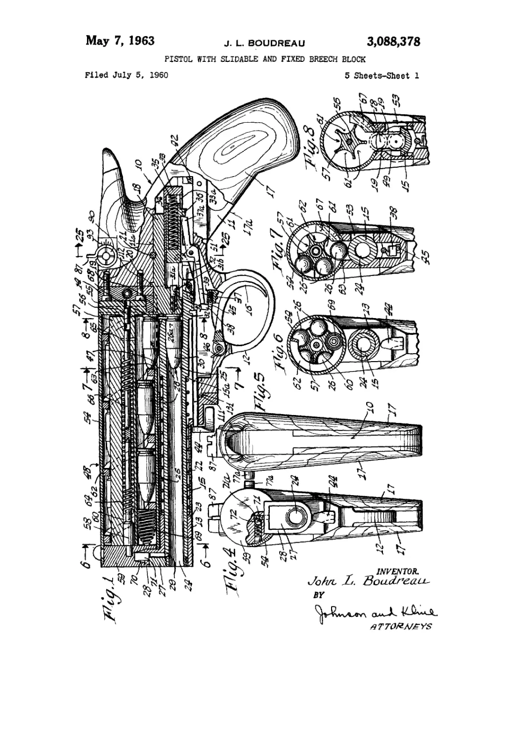
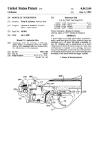
FIGURE 1 shows a longitudinal view of the pistol with
the pistol cocked and ready to be fired.
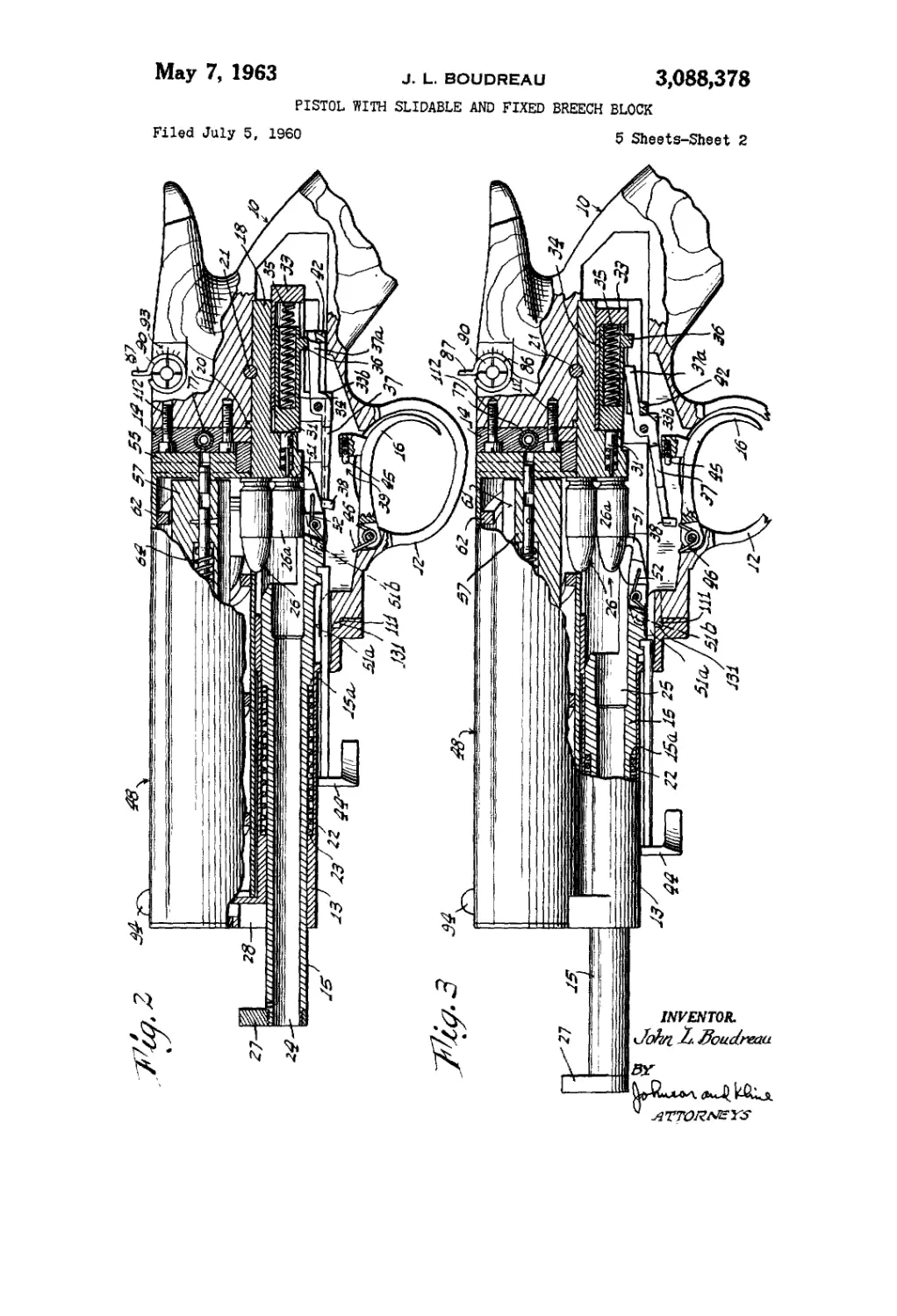
FIG. 2 is a view similar to FIG. 1 showing the pistol 60
immediately after firing and in which the barrel has
started its feed movement.
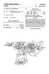
FIG. 3 is a view similar to FIG. 2 with the barrel
in its foremost position.
FIG. 4 is a front view, partly in section, of the pistol. 6t>
FIG. 5 is a rear view of the pistol.
FIG. 6 is a sectional view taken along line 6—6 of
FIG. 1.
FIG. 7 is a sectonal view taken along line 7—7 of
FIG. 1.
FIG. 8 is a view taken along line 8—8 of FIG. 1.
2
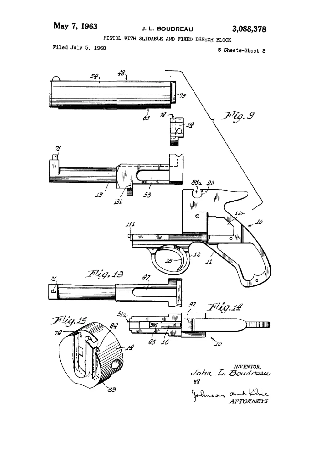
FIG. 9 is an exploded view of the frame and maga-
zine showing the component parts in their relationship
in preparation to being assembled.
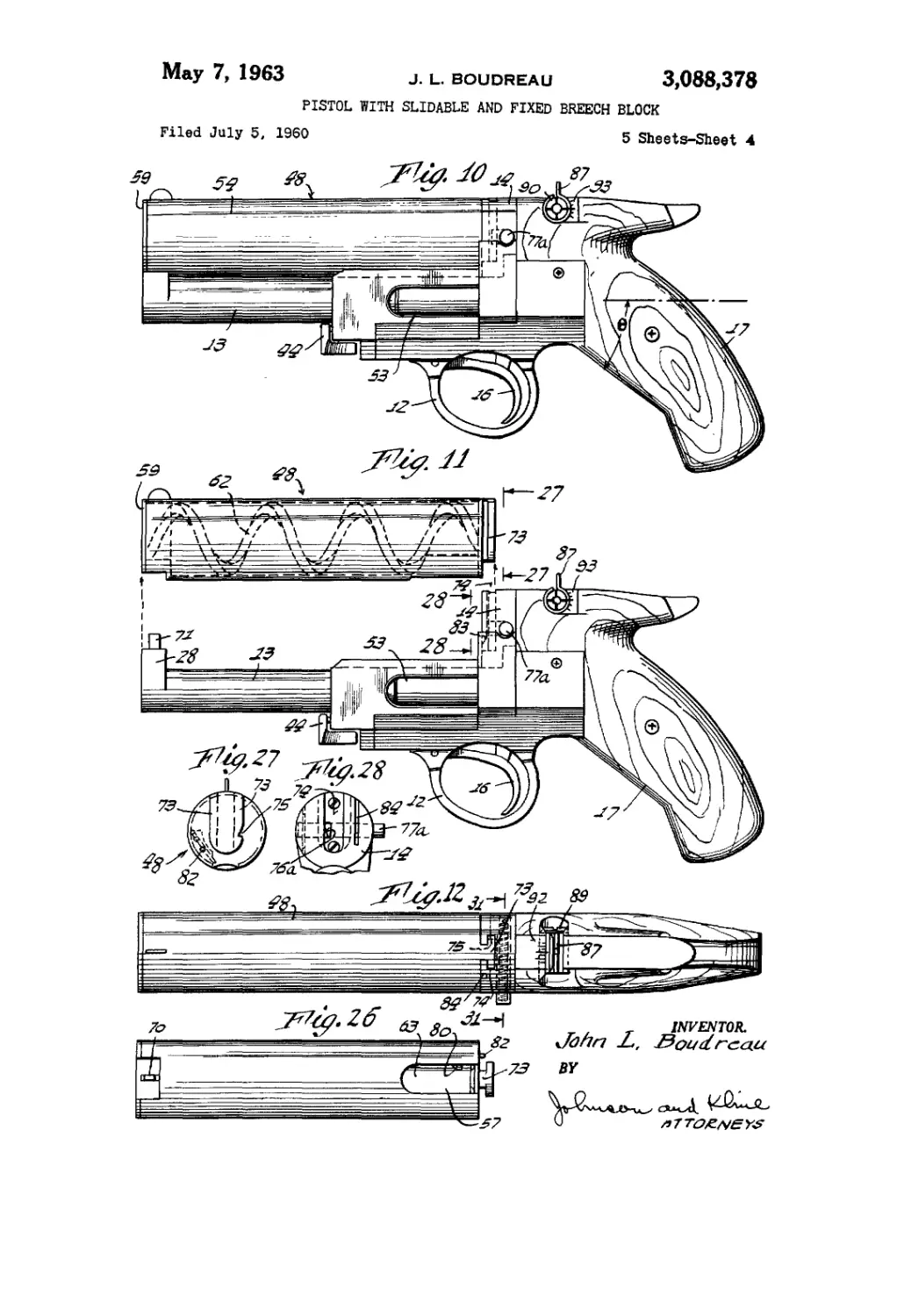
FIG. 10 is a side elevational view of the pistol in
assembled relation.
FIG. 11 is a view similar to FIG. 10 showing the
magazine being in position to be inserted into the pistol.
FIG. 12 is a top view of FIG. 10.
FIG. 13 is a top view of the barrel-receiving portion
of the frame.
FIG. 14 is a top view of the grip portion of the frame.
FIG. 15 is a perspective view of the magazine-receiv-
ing portion of the frame.
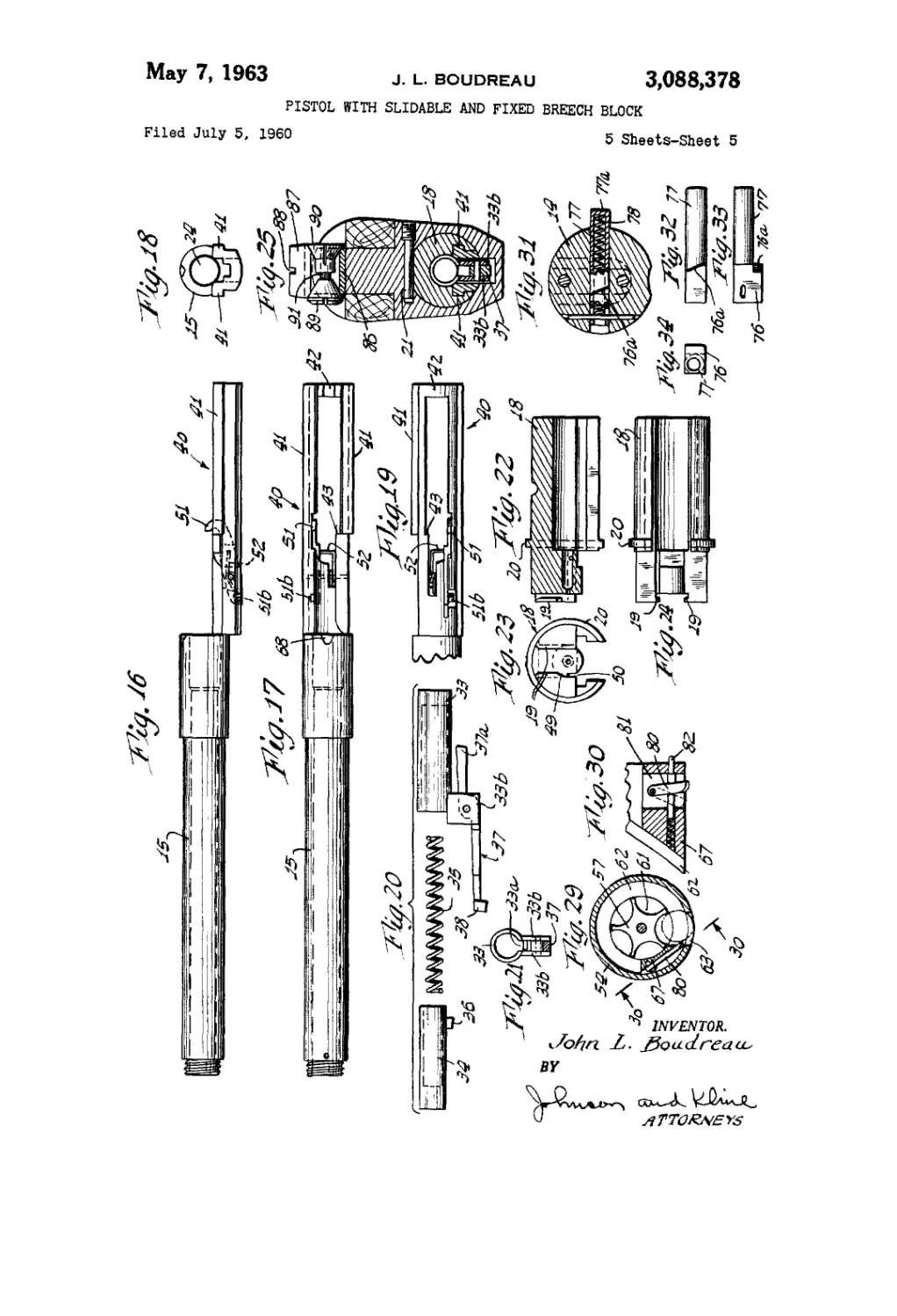
FIG. 16 is a side view of the barrel,
FIG. 17 is a top view of the barrel.
FIG. 18 is a rear view of the barrel.
FIG. 19 is a bottom view of the rear portion of the
barrel.
FIG. 20 is an exploded view of the striker means and
sear link.
FIG. 21 is an end view of the device of FIG. 20.
FIG. 22 is a sectional view of the breechblock.
FIG. 23 is an end view of the breechblock.
FIG. 24 is a bottom view of the breechblock.
FIG. 25 is a sectional view taken along line 25—25
of FIG. 1 showing the breechblock in position in the
grip section.
FIG. 26 is a bottom view of the magazine.
FIG. 27 is an end view of the magazine taken along
line 27—27 of FIG. 11.
FIG. 28 is a face view of the magazine-receiving por-
tion taken along line 28—28 of FIG. 11.
FIGS. 29 and 30 are fragmentary sectional views of the
means in the deflecting block for preventing passage of
cartridges from the magazine.
FIG. 31 is a sectional view taken along line 31—31
of FIG. 12.
FIG. 32 is a side view of the latch or detent for hold-
ing the magazine in position.
FIG. 33 is a top view of said detent.
FIG. 34 is an end view of said detent.
As shown in the drawings, the pistol comprises a frame
10 consisting of a grip portion 11 having a trigger
guard 12 integral therewith, a barrel-receiving portion
13 adapted to be secured to the grip portion and a maga-
zine-receiving portion or member 14, as shown in FIG. 9.
When these portions are assembled by inserting the
end 111 of frame 11 into socket 131 on frame 13 and
are locked in place by the interlocked portions of frame
portions 13 and member 14 secured to frame 11 by
bolts 112, as shown in FIG. 1, the barrel-receiving por-
tion 13 is located on the lower part of the frame so that
its axis is immediately above a trigger 16 disposed with-
in the trigger guard and has a barrel 15 slidably mounted
therein. The axis of the barrel, when extended, passes
through the grip intermediate the ends of the grip. The
grip has the usual side flakes 17 and is provided with
a gripping surface 17л adjacent the trigger guard which
forms an angle e, preferably of 38°, with the axis of
the barrel, though it may vary between 21°-41°, and
when gripped locates the barrel above the bottom three
fingers and passing through the palm of the hand grasp-
ing the same and in line with the forearm.
The frame portion 11 has a breechblock 18 fixed
therein in line with the barrel. The breechblock, as
shown in FIGS. 1 and 22 to 25, is mounted in a recess
Ila formed in the frame portion 11 and has a flange
20 engaging the face thereof and is held in place by a
pine 21 threaded in place.
In accordance with the illustrated form of the inven-
tion, the barrel 15 is of the blow forward type and is
slidably mounted in the frame portion 13 and is normally
3,088,378
С?
urged to the position of FIG. 1 by a spring 22 disposed
between a shoulder 23 on the frame and a shoulder 15a
on the barrel and is provided with a bore 24 having a
breech portion 25 at the rear end in which a cartridge
26 having the usual rimmed casing 26a is adapted to be
inserted.
The other end of the barrel is threaded or otherwise
secured to a piston 27 adapted to project upwardly into
a cylinder 28 formed integrally with the barrel-receiving
portion 13 when the barrel is in normal position. The
barrel has a passage 29 formed adjacent the piston and
opening into the cylinder 28 in back of the piston, as
shown in FIG. 1, so that when the cartridge is fired gases
will propel the bullet or nose portion 30 of the cartridge
along the barrel, and as the bullet passes the passage 29,
the gases will quickly pass into the cylinder and apply a
forward thrust on the barrel moving it against the spring
22 and forwardly to the position shown in FIG. 3. As
soon as the gases are expended, the spring returns the
barrel to its normal position.
The front face of the breechlock is provided with a
pair of cartridge-receiving tracks 19 for engaging the
rim on the cartridge case and holding the cartridge in
position to be inserted in the breech and for extracting
the empty cartridge case from the breech after the car-
tridge has been fired.
In order to fire the cartridge, the breechblock has a
firing pin 31 slidably mounted therein for limited move-
ment as controlled by cross pin 31a in slot 316 and is
normally urged by a spring 32 to a retracted position as
shown in FIG. I. A striker for the firing pin is mounted
on the breechblock and comprises a housing 33 slidably
mounted therein and having a striker member 34 slid-
able in a bore in the housing and urged by spring 35 in
striking direction. Referring to FIGS. 1, 20 and 21, the
striker is provided with a projecting sear 36 passing
through a slot 33a in the housing in position to be en-
gaged by the end 37a of a sear link 37, pivotally mounted
on depending flanges 336 on tire housing, and being held
thereby in cocked or retracted position. The other end
of the sear link has a shoulder 38 which cooperates with
an actuating member 39 on the trigger so that when the
trigger is depressed it causes the sear link to rotate about
the pivot to release the sear and permit the striker under
the urge of the spring 35 to move forward and strike
the firing pin driving it against the action of the spring
32 into firing contact with the base of the cartridge to
fire the same.
As shown in FIGS. 1 to 3 and 16 to 19, the barrel has
a rear extension 40 formed by a pair of side rails 41
slidable in the breechblock, as shown in FIG. 25, which
prevent rotation of the barrel in the frame and actuate
the cocking mechanism for the pistol. The rails are
connected at the rear end by a depending bridge 42.
When the barrel moves forward after the cartridge has
been fired, the bridge 42 will move into engagement with
the end 37a of the sear link and move it and the con-
nected housing forwardly as shown in FIG. 2. As soon
as the end of the sear link passes the sear 36, it pivots and
moves upwardly to a position, as shown in FIG. 3, in
which the end will engage the sear on the return stroke
of the barrel. As the barrel returns, the shoulder 43 on
the extension 49 engages the depending flanges 33b and
moves the housing and sear link into engagement with
the sear and, thereafter, moves the striker and housing
to the normal cocked position of FIG. 1. If it is desired
to manually cock the pistol, a finger-piece 44 connected
to the barrel may be moved forwardly to cause the ex-
tension of the barrel to properly position the sear link
and cock the striker.
If the trigger is in gripped position of FIG. 2 or FIG.
3, the shoulder 38 on the end of the sear link will en-
gage the actuating member in the form of a spring
plunger 45 of the actuating member 39 which yields but
does not pass under the shoulder. This will not permit
5
10
15
20
25
30
35
•10
45
50
65
60
65
70
75
4
firing of the next shot until the trigger is released, and
under the urge of a trigger spring 46, moves to a posi-
tion of FIG. 1 in which the plunger is disposed below the
shoulder on the sear link and is ready to pivot the sear
link to release the sear to fire the next shot upon the
pivoting of the trigger under finger pressure.
As noted above, the breechblock is provided with
guide tracks 19 for guiding and accurately locating the
cartridge in position to be fired. As shown in FIGS. 1
and 3, the tracks are disposed under an opening 47 in the
frame and through which the cartridges pass from a mag-
azine 48 to be guided to proper position. The guide
tracks also function to extract the cartridge case after
the cartridge has been fired.
In order to eject said extracted cartridge case, the
present invention provides a cut-away portion 49 at the
lower left-hand track, as shown in FIG. 23, and the
breechblock has an aligned groove 50 to receive a pivoted
ejector finger 51 pivotally mounted on the extension of
the barrel and normally urged by spring 52 to a position
to engage behind the rim of the cartridge casing and,
after the bullet has been fired and as the barrel moves for-
wardly, to tip the cartridge casing about the right-hand
edge of the rim held in the other guide track and eject
it through an ejector opening 53 in the side of the frame.
The cam 51a on the frame then engages the pin 516 on
the finger and retracts the finger so that on the return
stroke of the barrel, it will pass the cartridge which has
moved down the guide tracks to the lower cartridge in-
serting position, after which the spring moves the finger
to a position to engage the fired casing on the next for-
ward movement of the barrel.
The magazine 48 for the pistol is mounted to lie above
the barrel and forwardly of the grip portion. While it
may take many forms, in the preferred form of the in-
vention it comprises a tubular cylindrical casing 54 hav-
ing an integral closure 55 at the rear end. A pivot pin
56 is mounted in the closure for rotatably supporting a
cartridge carrier 57 at that end. A fixed pivot pin 58 is
mounted in a closure 59 for the forward end of the cas-
ing and projects into an axial bore 60 in the cartridge car-
rier. The cartridge carrier is provided with longitudinal
flutes 61 which are adapted to support a plurality of
cartridges 26 in end-to-end relation in each of the flutes
for sequential feeding to the barrel.
In order to feed the cartridges, the casing is provided
on its inner surface with a spiral feeding cam 62 adapted
to be positioned between each of the cartridges in the
flutes. As the carrier is rotated with respect to the cas-
ing, the cartridges cooperate with the feeding cams which
move them and sequentially feed them to an opening 63
in the side of the casing which is adapted to be mounted
over the cartridge-receiving opening 47 in the barrel-
carrying portion of the frame adjacent the end of the
breechblock. While the carrier may be rotated in many
ways, it is presently preferred tO' provide a spring 64 dis-
posed in the axial bore 60 and which has one end anchored
to the fixed pivot pin 58 and the other end anchored
at 65 to the carrier. A stabilizing pin 66 is secured to
the carrier and extends within the spring and cooperates
with pivot pin 58 to control the spring as it is wound up.
While the spring may be wound up and tensioned in
many ways, the most simple and convenient method is
by rotating the carrier as an incident to the insertion of
the cartridges into the magazine to load the same.
As the cartridges are fed into the magazine through
the opening 63 into the casing, they will cause the car-
rier to be displaced and rotated in the casing with the
feeding cam moving the inserted cartridges along the
flutes. This rotation will cause the spring to be wound
up and energized for rotating the carrier in a reverse di-
rection to deliver the cartridges sequentially to the open-
ing 63.
In order to cause the cartridges to be moved through
the opening and out of the magazine^ a deflecting block
3,088,378
5
67 is mounted in the casing at the end of the spiral cam
and extends along the side of the opening 63 so that as
the carrier rotates, the cartridges move sequentially into
the opening and engage the deflecting block 67 which
moves them downwardly and out of the casing and into
the opening in the frame to the guide tracks 19 to be
guided to the lowermost position to be inserted in the
breech.
As will be noted from FIGS. 1 to 3, two cartridges
carried by the tracks are fed therealong by subsequent
cartridges and by gravity into the lowermost position.
Also, it will be noted that the barrel adjacent the breech
is provided with a cam surface 68 which, upon the barrel
returning to normal position, will engage the cartridge
above the lowermost cartridge in the track and raise it
slightly, as shown in FIG. 1, so as to separate it from the
lowermost cartridge and prevent interference thereby
with the insertion of the lowermost cartridge into the
breech.
In order to insure that the last cartridge in the maga-
zine will be delivered, the last chamber in the magazine
is provided with a resilient spring unit 69 which fills the
space and which is larger than the opening so that it
cannot be discharged out of the magazine but will insure
the last cartridge being delivered and positioned in the
guide tracks for passage to the breech.
While the magazine may be mounted in various ways,
in the herein preferred form of the invention, as shown
in FIGS. 4, 12 and 26 to 27, the forward and of the
magazine has a recess 70 which is adapted to slip over
a projection 71 carried by the frame at the top of the
cylinder portion. A spring-pressed ball detent 72 is
carried by the closure 59 and cooperates with a recess
71a in the projection 71 to hold the forward end of the
magazine in position. The rear end of the magazine is
provided with a T-shaped rib 73 integral with the end
closure 55 which is adapted to be inserted into the T-
shaped slot 74 in the magazine-receiving portion 14 to
securely anchor and locate the magazine on the frame.
In order to lock the magazine in position, the rib 73
has a notch 75 which cooperates with a latch member
76, as shown in FIGS. 31 to 34, carried by a transversely
extending slide 77 mounted in the member 14. A spring
78 normally urges the slide into position in which the
latch member is in engagement with the notch with the
end portion 77a of the member projecting, as shown in
FIGS. 12 and 28, to be engaged to move the slide in-
wardly to release the magazine. Preferably, the latch
member is bevelled at 76a so as to be cammed back by
the rib as tbe magazine is moved into place and auto-
matically snaps into the notch when the magazine is in
proper position on the frame. It will be seen that the
magazine, therefore, can be readily applied to or removed
from, the pistol.
In order to retain the cartridges in the magazine and
hold them against the urge of the spring tending to rotate
the carrier, means are provided, as shown in FIGS. 29
and 30, for blocking the opening 63 in the casing to pre-
vent passage of the cartridge therethrough. This means
comprises a pivoted lever 80 mounted in a slot 81 in the
deflector block 67 and projecting into the opening 63 to
engage the cartridge and block the same. An actuator
pin 82 projects from the end of the magazine and is en-
gaged and actuated by the inclined end 83 of slot 84
formed in the magazine-receiving portion 14, as shown in
FIGS. 11, 15 and 28, to retract the lever 80 and release
the cartridge when the magazine is slipped into final
position, thus relieving the first cartridge. A novel rear
sight is provided in the top of the grip portion of the
frame. As shown in FIGS. 1, 4, 14 and 25, this com-
prises a split cylindrical sleeve 86 having a radial flange
87 projecting therefrom and provided with a sighting
notch 88. The sleeve is adapted to be inserted into a
transverse cylindrical recess 88a opening in the top of
the frame, as shown in FIGS. 1, 10 and 25, with the
5
10
15
20
25
30
35
40
45
50
55
GO
65
70
75
6
radial flange projecting above the top of the frame.
Means for locking the sleeve in adjusted position may
take many forms. In the illustrated form of the in-
vention it comprises a pair of opposed conical elements
89, 90 mounted within the sleeve, as shown in FIG. 25,
and connected by a threaded member 91 to draw them
together and expand the split sleeve into clamping rela-
tion with the walls of the recess. With this construction
the sight can readily be adjusted for windage by sliding
the sight laterally in the recess and for elevation by ro-
tating the sight in the recess. As noted in FIGS. 9 and
14, the frame can be provided with indicia 92 for aiding
in windage adjustment and with indicia 93 for the adjust-
ment for proper elevation. The magazine at the forward
end has a front sight 94 thereon to cooperate with sight-
ing notch 88 in aiming the pistol.
From the foregoing it will be seen that the present
invention provides a pistol which can be readily ma-
chined and quickly assembled and has an advantage in
that it eliminates the individual spring for actuating the
scar and improves the trigger-sear relation providing a
greater leverage and an improved trigger pull.
The construction of the barrel permits the barrel to
be manually moved forward and thus provides ready
access to the gas escape port in the barrel for cleaning
the same. Further, the location and compactness of the
magazine provides a maximum shot capacity without
interference with the design of the grip of the pistol or
unduly enlarging the overall dimensions of the pistol.
In addition, the feeding of the cartridges from the maga-
zine to the breech is controlled at all times and provides
for straight line insertion into the barrel, thus avoiding
a tendency to bend the cartridge as in prior guns where
the cartridges move through curved paths from the maga-
zine to the breech.
The magazine of the present invention not only pro-
vides for easy loading and positioning on the pistol but
also provides for quick automatic unloading of the car-
tridges from the magazine when removed from the pistol
and the cartridge release means is depressed.
With the pistol of the present invention greater accu-
racy is achieved since the tendency of the muzzle lift or
jump is substantially eliminated and the barrel is main-
tained in line with the target at all times; thus variations
in bullet delivery angle of the barrel occasioned by the
muzzle jump are eliminated even when heavy caliber
cartridges are used.
Variations and modifications may be made within the
scope of the claims and portions of the improvements
may be used without others.
I claim:
1. A pistol comprising a lightweight, elongate frame
having a trigger means, a grip depending from the frame
at the rear thereof, a barrel for firing cartridges slidably
carried by the lower part of the frame and disposed above
the trigger and normally urged to a retracted position,
said grip having a gripping surface forming an angle of
38° with the axis of the barrel, said axis being adapted
to be located immediately above the bottom three fingers
and passing through the palm of the hand grasping the
grip and in line with the forearm, said barrel having a
normally retracted position and having means for moving
the barrel forwardly of the frame upon the firing of a
cartridge, and a fixed breechblock slidably carrying a
firing pin and a housing having spring-urged striker
means, a sear on the striker means, a sear link pivotally
mounted on the housing and having one end movable
under the sear on the striker means and the other end
cooperating with the trigger means, said barrel having a
rearward extension provided with means operable on the
forward stroke thereof for moving the sear link and
housing relative to the striker means to cause said link
on the return stroke of the barrel to move into engage-
ment with the sear and cock the striker means.
2. A pistol comprising an elongate frame having a
3,088,378
7
trigger means, a grip depending from the frame at the
rear thereof, a barrel for firing cartridges slidably carried
by the lower part of the frame and disposed above the
trigger and normally urged to a retracted position, said
barrel having a piston at the forward end disposed in
a cylinder on the frame when the barrel is in retracted
position and having a passage in the barrel communi-
cating with the cylinder in the rear of the piston whereby
gases from the fired cartridge in the barrel pass into the
cylinder and force the piston and barrel forwardly of the
frame upon the passage of a bullet from the cartridge
beyond the passage, a fixed breechblock slidably carrying
a firing pin and a housing having spring-urged striker
means, a sear on the striker means, a sear link pivotally
mounted on the housing and having one end movable
under the sear on the striker means and the other end
cooperating with the trigger means, said barrel having
a rearward extension provided with means operable on
the forward stroke thereof for moving the sear link and
housing relative to the striker means to cause said link
on the return stroke of the barrel to move into engage-
ment with the sear and cock the striker means.
3. A pistol comprising a frame having a trigger, a grip
depending from the rear portion of the frame, a slidable
barrel carried by the lower part of the frame and dis-
posed above the trigger and located on an axis passing
through the grip intermediate the ends thereof, and a
magazine removably carried by the frame forwardly of
the grip and above the barrel to carry and supply a
plurality of cartridges each having a rimmed casing to
the barrel to be fired therethrough, said magazine com-
prising a tubular casing having a rotary cartridge car-
rier therein and having a spiral feeding cam on the
inner surface for sequentially guiding the cartridges to
an opening in the tubular casing disposed over a breech
opening in the frame, said frame having supporting tracks
engaging said rims to hold the cartridge in position in
the breech opening in position to be fired.
4. A pistol comprising a frame having a trigger, a grip
depending from the rear portion of the frame, a slidable
barrel carried by the lower part of the frame and disposed
above the trigger and located on an axis passing through
the grip intermediate the ends thereof, the gripping sur-
face of the grip adjacent the trigger forming an angle
of between 21° to 41° with the longitudinal axis of the
barrel, said axis being adapted to be located immediately
above the bottom three fingers and passing through the
palm of the hand grasping the grip and in line with the
forearm, and a magazine removably carried by the frame
forwardly of the grip and above the barrel to carry and
supply a plurality of cartridges each having a rimmed
casing to the barrel to the fired therethrough, said maga-
zine comprising a tubular casing having a rotary car-
tridge carrier therein and having a spiral feeding cam on
the inner surface for sequentially guiding the cartridges
to an opening in the tubular casing disposed over a breech
opening in the frame, said frame having supporting tracks
engaging said rims to hold the cartridge in position in
the breech opening in position to be fired.
5. A pistol comprising a frame having a trigger, a
grip depending from tire rear portion of the frame, a
slidable barrel provided with a breech carried by the
lower part of the frame and disposed above the trig-
ger, and a magazine to carry and supply a plurality of
cartridges each having a rimmed casing, means mount-
ing the magazine on the frame forwardly of the grip and
above the barrel, said means comprising a frame engaging
detent at the forward end, a T-shaped rib projecting from
the rear end of the magazine and slidable in a T slot
in the frame and latch means on the frame engaging the
rib to releasably lock the magazine to the frame, said
magazine comprising a tubular casing having a rotary
cartridge carrier therein and having a spiral feeding cam
on the inner surface for sequentially guiding the car-
tridges to an opening in the tubular casing disposed over
5
10
15
20
25
30
35
40
45
50
55
60
65
70
75
8
a breech opening in the frame, said frame having sup-
porting tracks engaging said rims to guide and hold the
cartridge in position in the breech in the barrel in posi-
tion to be fired.
6. A magazine for a pistol provided with a frame hav-
ing a trigger, a grip depending from the rear portion of
frame, and a barrel carried by the lower part of the
frame, said magazine comprising a tubular casing hav-
ing means for removably mounting the magazine on
the frame forwardly of the grip and above the barrel
to carry and supply a plurality of cartridges each having
a rimmed casing to the barrel to be fired therethrough,
a longitudinally fluted rotary cartridge carrier mounted
in the tubular casing for carrying a plurality of rows of
cartridges in end-to-end relation, means for rotating said
carrier, a spiral feeding cam on the inner surface of the
tubular casing for separating the cartridges in said rows
and sequentially guiding the cartridges to a discharge
opening in the tubular casing, and means within the tu-
bular casing at the end of the spiral cam and adjacent the
opening for deflecting the cartridges through said open-
ing, said last-named means having retractable means nor-
mally preventing passage of the cartridge through the
opening and being retracted as an incident to the mount-
ing thereof on the frame whereby said cartridges are
free to move into a breech opening in the barrel.
7. A magazine for a pistol provided with a frame hav-
ing a trigger, a grip depending from the rear portion of
the frame, barrel carried by the lower part of the frame,
said magazine comprising a tubular casing having a detent
at the forward end and a T-shaped rib cooperating with
a T slot in the frame for removably mounting the mag-
azine on the frame forwardly of the grip and above the
barrel to carry and supply a plurality of cartridges each
having a rimmed casing to the barrel to be fired there-
through, a longitudinally fluted rotary cartridge carrier
mounted in the tubular casing for carrying a plurality
of rows of cartridges in end-to-end relation, spring means
for rotating said carrier, a spiral feeding cam on the in-
ner surface of the tubular casing for separating the car-
tridges in said rows and sequentially guiding the cartridges
to a discharge opening in the wall of the tubular casing,
means within the tubular casing at the end of the spiral
cam and adjacent the opening for deflecting the cartridges
through said opening in the wall of the tubular casing,
said last-named means having retractable means normally
preventing passage of the cartridge through the opening
and being retracted as an incident to the mounting there-
of on the frame whereby said cartridges move into a
breech opening in the barrel.
8. A pistol comprising a frame having a trigger, a grip
depending from the rear portion of the frame, a barrel
provided with a breech slidably carried by the lower part
of the frame and disposed above the trigger, said barrel
being normally urged to a retracted position and moved
forwardly in response to the firing of a cartridge, and a
magazine to carry and supply a plurality of cartridges
each having a rimmed casing, means mounting the mag-
azine on the frame forwardly of the grip and above and
parallel with the barrel, said magazine comprising a
tubular casing having means for sequentially guiding the
cartridges to an opening in the tubular casing disposed
over a breech opening in the frame, a fixed breechblock
carried by the frame and having supporting tracks in the
face thereof aligned with the rear of said opening to
receive and engage said rims of the cartridges as they
pass through said opening to guide the cartridges into
position to be received in the breech of the barrel and
hold the lowermost cartridge in position in the breech
to be fired.
9. A pistol comprising a frame having a trigger, a grip
depending from the rear portion of the frame, a barrel
provided with a breech slidably carried by the lower part
of the frame and disposed above the trigger, said barrel
being normally urged to a retracted position and moved
3,088,378
9
forwardly in response to the firing of a cartridge having
a rimmed casing, and a magazine to carry and supply a
plurality of cartridges each having a rimmed casing,
means mounting the magazine on the frame forwardly
of the grip and above and parallel with the barrel, said 5
magazine comprising a tubular casing having means for
sequentially guiding the cartridges to an opening in the
tubular casing disposed over a breech opening in the
frame when the barrel is in retracted position, said frame
having supporting tracks disposed directly below the open-
ing in the tubular casing and engaging said rims of the
rimmed casing as the cartridges descend from said mag-
azine to guide the cartridges, and hold the lowermost car-
tridge in position to be inserted in the breech of the barrel
and to extract the fired cartridge casing, one of said
tracks in the lowermost position being cut away, and
said barrel having an ejector member for engaging the
cartridge casing adjacent the cut-away portion as the bar-
rel moves forward to eject the casing from the pistol.
10. A pistol comprising a frame having a trigger, a grip
depending from the rear portion of the frame, a barrel
provided with a breech slidably carried by the lower part
of the frame and disposed above the trigger, said barrel
being normally urged to a retracted position and moved
forwardly in response to the firing of a cartridge, and
a magazine to carry and supply a plurality of cartridges
each having a rimmed casing, means mounting the mag-
azine on the frame forwardly of the grip and above and
parallel with the barrel, said magazine comprising a
tubular casing having means for sequentially guiding the
cartridges to an opening in the tubular casing disposed
10
over a breech opening in the frame, a fixed breechblock
carried by the frame and having supporting tracks in
the face thereof aligned with the rear of said opening
to receive and engage said rims to guide the cartridges
as they pass through said opening and hold the lowermost
cartridge in position to be inserted in the breech of
the barrel as the barrel returns to retracted position, said
barrel having a portion adapted to engage the cartridge
positioned in said track and resting on the lowermost
cartridge when the barrel moves to retracted position to
raise the cartridge and separate the cartridge from said
lowermost cartridge to prevent interference with the in-
sertion thereof into the breech in the barrel.
References Cited in the file of this patent
UNITED STATES PATENTS
908,521 Trundle_________________________Jan. 5, 1909
918,380 Schwarzlose_________________Apr. 13, 1909
1,110,702 McClure___________________Sept. 15, 1914
1,285,263 Lohne_____________________Nov. 19, 1918
1,337,444 Douglas_____________________Apr. 20, 1920
1,874,952 Frank_______________________Aug. 30, 1932
2,147,208 Nolan_______________________Feb. 14, 1939
2,264,809 Pedersen_____________________Dec. 2, 1941
2,441,968 Henry_____________________May 25, 1948
2,628,536 Schaich_____________________Feb. 17, 1953
2,788,600 Pokorny_____________________Apr. 16, 1957
2,874,501 Koucky et al.---------------Feb. 24, 1959
2,883,911 Musgrave__________________Apr. 28, 1959
2,899,767 Boudreau__________________Aug. 18, 1959