/


Tags: weapons military affairs patent
Year: 1964


Text
Feb. 22, 1966
E. M. STONER
3,235,997
BIPOD GUN MOUNT
Feb. 22, 1966
E. M. STONER
BIPOD GUN MOUNT
3,235,997
4 Sheets-Sheet 3
Filed Dec. 16, 1964
^2.
Feb. 22, 1966
3,235,997
E. M. STONER
BIPOD GUN MOUNT
Filed Dec. 16. 1964 4 Sheets-Sheet 3
E. M. STONER
BIPOD GUN MOUNT
Feb. 22, 1966
Filed Dec. 16, 1964
3,235,997
4 Sheets-Sheet 4
United States Patent Office
3,235,997
Patented Feb. 22, 1966
1
3 235 997
BIPOD GUN MOUNT
Eugene M. Stoner, Rte. 1, Box 70, Port Clinton, Ohio
Filed Dec. 16,1964, Ser. No. 418,851
8 Claims. (Cl. 42—94)
This invention relates to gun mounts, especially bipods,
adapted for providing grounded support for small arms
weapons during firing.
Gun mounts are used for automatic weapons fired from
the sitting or prone position, where it is desirable to pro-
vide a grounded support to assist the gunner in holding
the weapon and in maintaining a steady aim in spite of
the rapid succession of intermittent recoils. A two-leg-
ged support, or bipod, is commonly used for automatic
rifles and light machine guns; whereas heavier gun mounts
such as tripods customarily are used for the heavier
weapons.
The bipods most commonly used fall into two cate-
gories, (1) those which are especially designed for and
are affixed to a particular weapon in a more or less per-
manent fashion, and (2) the snap-on type which are de-
signed to be carried as a separate item and detachably
clamped to a weapon when desired. This invention is
directed primarily to the snap-on type of bipod, but many
of its features are usable in either type of bipod and in
gun mounts generally.
The perfect bipod would have legs quickly and reliably
adjustable in length, and in the case of the snap-on type
bipod, would include a clamp which is reliably secure
and easily operated. The bipod would be simple and
inexpensive. Icing conditions, mud and dirt would not
interfere with the ease and reliability of leg adjustment
and clamping action. In order to withstand severe abuse
under field conditions, the bipod would be a very sub-
stantial, rugged structure. Yet it would neither be cum-
bersome nor too heavy to carry comfortably for long
periods.
Such a bipod is not presently and probably never will
be perfectly realized, because the desirable design charac-
teristics are competing and the solution to one problem
tends to defeat the solution to another. Furthermore, a
common problem encountered in gun mounts generally is
the tendency of the legs to lose their adjustment when
the weapon is fired. That is, the vibration transmitted
to the legs during firing causes the device which locks
the legs at selected lengths to loosen, thereby permitting
the legs to shorten or lengthen during firing.
The snap-on bipod of my invention affords a simple
but unique compromise in competing design characteris-
tics. It is easy to clamp and release, light weight, yet
rugged enough to withstand combat conditions. The legs
are easily and quickly adjustable in length, and include
a positive lock to prevent loss of adjustment during firing.
Yet, this bipod is inexpensive to manufacture, and, in its
preferred embodiment, may be made almost totally from
simple sheet metal stampings.
Generally, in accordance with my invention, a gun
mount has at least two adjustable legs. Each adjustable
leg includes first and second elongated hollow members,
the second being received in the first and adapted for
longitudinal sliding movement therein to form an adjust-
able extension of the first. One of the members has a
plurality of notches spaced along its length, and means
are mounted on the other member for selective releasable
engagement in said notches to lock the members against
extension and retraction.
In one embodiment of my invention, the first and second
elongated hollow mfembers of each leg are made from
sheet metal stampings. Both members have a substan-
tially rectangular cross-sectional configuration and have
2
four corresponding sides, three of which are substantially
flat and have a plurality of holes spaced along them to
lighten the member. In this embodiment, an elongated
opening is formed along the fourth side of one member
5 and the notches are spaced alongside this opening. The
other member has a transverse slot in its corresponding
fourth side which registers with the locus of the notches,
and has mounted thereon a spring loaded latch releasably
engageable through said transverse slot with the notches
10 for locking the members in selected extended positions.
A thumb tab extends from the latch and through the elon-
gated opening for manually releasing the latch.
To form a snap-on bipod, a pair of brackets are con-
nected to the upper ends of the legs. The brackets are piv-
15 otally connected for rotation about an axis perpendicular
to the legs, and have opposed jaws above said axis for en-
gaging a small arms weapon. Spring means urge the
brackets about the axis in the direction which moves the
jaws toward each other.
20 These brackets also may be made of simple sheet metal
stampings, each bracket having a back and two sides ex-
tending forward from opposite edges of the back. In this
embodiment, the two sides of each bracket have a circular
opening therein and a concave front perimeter disposed
25 above the opening. The brackets are arranged in front-to-
front relationship with all four of the circular openings
aligned on an axis perpendicular to the legs. Pin means
extend through the four circular openings to pivotally
connect the brackets for rotation about said axis.
30 My invention will be better understood by reference to
the following detailed description of a preferred embodi-
ment thereof and by reference to the accompanying draw-
ings, in which:
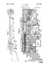
FIG. 1 is a perspective view showing the preferred em-
3° bodiment of the snap-on bipod of my invention connected
to an automatic rifle which is in firing position;
FIG. 2 is a fragmented elevation of the bipod, with por-
tions broken away to show the lock mechanism and with
dotted portions to illustrate extension of the legs;
4(? FIG. 3 is a perspective view of the upper member of
one leg and its associated bracket;
FIG. 4 is a perspective view of the lower member of the
leg;
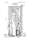
FIG. 5 is an elevation of a leg, partly in section, taken
45 along line 5—5 of FIG. 2;
FIG. 6 is a sectional view taken along line 6—6 of FIG.
5 and shows the locking mechanism;
FIG. 7 is a fragmentary perspective view showing the
locking mechanism;
FIG. 8 is a sectional view through the brackets of the
bipod taken along line 8—8 of FIG. 2, with the pin ar-
rangement connecting the brackets partly broken away;
and,
g5 FIG. 9 is a sectional view taken through the brackets
° along line 9—9 of FIG. 2, and illustarting the spring ar-
rangement for loading the brackets.
Referring now to FIG. 1, an automatic rifle 10 is shown
in firing position. A snap-on bipod 12 is connected to the
60 gas cylinder 14 of the rifle and rests on the ground to sup-
port and steady the rifle during firing. Alternatively, the
bipod 12 could be connected to the barrel 16 of the rifle.
The general construction of the bipod may be seen from
FIG. 2 wherein the bipod is shown removed from the rifle.
6- The bipod includes two identical legs 20, 22 which are ex-
tensible and retractable in length. Identical brackets 24,
26 are connected to the top of the legs 20, 22 respectively.
The brackets are disposed in front-to-front relationship,
and are connected together for rotation about an axis 28
perpendicular to the legs by means of a pivot pin structure
30. Near their upper ends, and above the pivot axis 28,
the brackets 24, 26 include opposed jaws 32, 34 respec-
3,235,997
tively, for detachably clamping the bipod to the rifle. The
jaws are urged toward one another and the legs away from
one another by a compression spring 36.
The legs 20, 22 are identical, hence only one of them
will be described. Typically, this leg 22 of the bipod
includes an upper elongated hollow member 37, and a
lower elongated hollow member 38 received in the upper
member and adapted for longitudinal sliding movement
therein to form an adjustable extension thereof.
As can be seen from FIGS. 2, 3, 5, and 7, the upper
hollow member 37 has a substantially rectangular cross-
sectional configuration defined by four sides 40, 42, 44, 46.
Three of these sides 40, 42, 44 are substantially flat and
have a plurality of holes 48 spaced along them to lighten
the member.
A central elongated opening 50 extends along the length
of the fourth side 46 of the upper member, and a plurality
of notches 52 are formed in pairs on opposite edges of
said elongated opening at spaced locations along the
length thereof. The upper and lower extremities of the
elongated opening 50 are defined by an upper tab 54 and
a lower tab 56, which extend across the opening and are
spot welded at their free ends to the wall 46 on the op-
posite side of the opening. Thus, the upper member 37
may be easily stamped from a single piece of sheet metal,
formed to its rectangular configuration, and stabilized by
spot welding the upper and lower tabs 54, 56.
The lower leg member 38 is similarly designed to be
stamped and formed from a single piece of sheet metal.
The lower member has a rectangular cross-sectional
configuration defined by four sides 58, 60, 62, 64, which
correspond respectively to the four sides of the upper
member 37. As is the case with the upper member, the
first three sides 58, 60, 62 of the lower member are sub-
stantially flat and have a plurality of openings shown
typically at 66 spaced along their length for the purpose
of lightening the member. Also to lighten the lower
member and to facilitate its manufacture, an elongated
opening 68 extends along the length of its fourth side 64.
A stamped sheet metal foot 69 having a curved horizon-
tal flange 70 and a vertical flange 72 is spot welded to
three out turned tabs 74, 76, 78 extending from the lower
end of the lower member 38, so as to provide a suitable
surface for engaging the ground.
Referring now to FIGS. 4, 6 and 7, a pair of depres-
sions 80, 82 are formed in the first and third opposite sides
58, 62 of the lower member adjacent the upper end there-
of. A transverse slot 84 intersects these depressions in
the opposite first and third sides of the member and as
well extends through the adjacent fourth side 64 of the
member.
As can be seen in the drawings, the transverse slot 84
at the upper end of the lower member 38 is positioned to
register with the locus of the notches 52 along the cor-
responding fourth side 46 of the upper member 37 as the
lower member 38 is slid within the upper member 37.
The upper and lower members 37, 38 are fixed against
rotation relative to one another about their longitudinal
axis by their corresponding rectangular cross sections.
This stabilizes the orientation of the foot 69 and main-
tains the registry of the transverse slot 84 with the loci
of the notches 52.
As indicated generally in FIG. 2, a spring loaded latch
86 is mounted in the lower member 38 and is releasably
engageable with the notches 52 in the upper member 37
for locking the members in selected extended positions.
The details of the spring loaded latch are best shown
in FIGS. 6 and 7. A latch blade 88 is slidably mounted
within the transverse slot 84 at the upper end of the
lower member 38. The latch blade is a simple sheet
metal stamping. It has a narrow rear extension 90, and
a helical compression spring 92 is caught on this rear
extension at one end and at its other end on a pronounced
dimple 94 formed on the second side 60 of the lower
4
member. The spring 92 urges the latch blade 88 for-
ward toward the corresponding fourth sides of the upper
and lower members. The latch blade 88 has opposite
forward shoulders 96, 98 which protrude through the slot
84 in the fourth wall 64 of the lower member 38 and
extend into an aligned pair of the notches 52 in the cor-
responding fourth wall 46 of the upper member 37, there-
by locking the upper and lower members against exten-
sion or retraction at a selected position. Forward move-
ment of the latch blade 88 is restricted by outer forward
shoulder portions 100, 102 on opposite sides thereof abut-
ting with the inner surface of the fourth wall 46 of the
upper member 37.
A central thumb tab 104 extends forward from the latch
blade and through the elongated opening 50 in the Upper
member 37, and serves as a means for manual opera-
tion to disengage the latch blade 88 with an aligned pair
of the notches 52 in order to extend or retract the lower
member 38 relative to the upper member 37. It will be
noted that the longitudinal opening 68 in the lower mem-
ber 38 is not necessary for this purpose, although the trans-
verse slot 84 in the lower member and the longitudinal
opening 50 in the upper member is necessary to permit
the protrusion of the thumb tab 104 and to permit slid-
ing of the lower member relative to the upper member.
Inadvertent removal of the lower member from the upper
member is prevented by engagement of the thumb tab
104 with the lower tab 56 formed at the bottom end of
the upper member.
The pair of brackets 24, 26 for clamping the legs to
the rifle are identical, and only one of the brackets 26
will be described in detail. The bracket 26 is a sheet
metal stamping having a back 106 and two sides 108, 110
extending forward from opposite edges of the back. The
back and two sides of the bracket correspond to the three
substantially flat sides 40, 42, 44 of the upper member
37 of the leg 22, and are spot welded to these flat sides.
Extending forward from the respective sides 108, 110 of
the bracket are a pair of ears 112, 114 having circular
openings 116, 118 therein respectively aligned on a com-
mon axis, which is the same axis 28 about which the
brackets will pivot. The jaw 34 of the bracket is lo-
cated immediately above the ears, and its clamping sur-
faces arc formed by concave front perimeters 120, 122 of
the respective sides 108, 110.
As best seen in FIGS. 5, 8 and 9, the cars 112, 114 of
the bracket 26 are offset laterally different distances, so
that when disposed face-to-face with the other bracket
24, the ears from both brackets will overlap with the cir-
cular openings aligned on the axis 28 perpendicular to
the legs. The pin structure 30 extends through the aligned
four circular openings to pivotally connect the brackets
for rotation about the axis 28. This pin structure com-
prises a first sleeve pin 124 inserted from one end, and
a center pin 126 inserted from the opposite end into
the sleeve pin. The center pin is counter-bored and
beveled over at its forward end to secure the two pins
together.
Referring now primarily to FIGS. 2 and 9, the compres-
sion spring 36 acts below the pivot pin structure 30 to
urge the legs 20, 22 apart, and therefore to urge the
jaws 32, 34 of the opposite brackets together. This
spring 36 is retained in place by a pair of simple retain-
ing cups 128, 130 disposed within the brackets and con-
nected to their back walls in any conventional manner.
From the above, it may be seen that the entire bipod is
easily constructed from two each of five pieces stamped
from sheet metal: the upper leg members, the lower leg
members, the feet, the brackets, and the latch blades. In
addition, three simple springs and four simple machine
parts, the cups and connector pins, are all that is re-
quired. Yet, the bipod is extremely rugged, light weight,
and easy to operate.
When the bipod is to be carried or stored, it is removed
from the weapon by moving the legs toward one another
5
10
15
20
25
30
35
40
45
50
55
CO
05
70
75
3,235,
5
to release the jaws, the lower leg members are retracted
into the upper leg members, and the bipod is inserted in
a sheath or holder (not shown). To attach the bipod to
a weapon, the legs are moved together to open the jaws,
the jaws are inserted over the barrel or gas cylinder of 5
the weapon and the legs are released so that the jaws
close under the urging of the compression spring 36,
thereby clamping the bipod to the weapon. The exposed
thumb tab of the latch mechanism on each leg is de-
pressed and the lower member of each leg is extended
to a selected position in accordance with the location of
the notches on the upper leg member whereupon the latch
blade is permitted to engage the aligned notches.
It is obvious that the above described preferred em-
bodiment may be modified in many respects within the
scope of this invention; hence, it should be considered
exemplary rather than limiting.
I claim:
1. A bipod adapted to be detachably connected to a
small arms weapon for supporting the weapon in firing
position, comprising a pair of extensible and retractable
legs, a pair of brackets connected to the upper ends of
said legs, means pivotally connecting said brackets and
said legs for rotation about an axis perpendicular to said
legs, the brackets having opposed jaws above said axis
for engaging a small arms weapon, and spring means urg-
ing said brackets and said legs about said axis in the di-
rection which moves said opposed jaws toward each other
and said legs away from one another, each of said legs
including first and second elongated hollow members, 30
the second being received in the first and adapted for
longitudinal sliding movement therein to form an adjust-
able extension of the first, one of said members having a
plurality of notches spaced along its length, and means
mounted on the other of said members for selective re- 35
leasable engagement in said notches to lock said members
against extension and retraction.
2. In a bipod having a pair of extensible and retract-
able legs for supporting a small arms weapon in firing
position, means for detachably connecting the legs of the 40
bipod to the weapon, comprising a pair of brackets con-
nected to the upper ends of said legs, each bracket having
a back and two sides extending forward from opposite
edges of the back and substantially perpendicular thereto,
each of said sides having a circular opening therein and
a concave front perimeter portion disposed above said
opening, said brackets being arranged in front-to-front
relationship with said concave front perimeter portions
opposite each other and with all four of said circular
openings aligned on an axis perpendicular to said legs, pin 60
means extending through said four circular openings to
pivotally connect the brackets for rotation about said
axis, and spring means urging said brackets about said
axis in the direction which moves said concave front
perimeter portions of the two brackets toward one another
to grip the weapon therebetween.
3. A gun mount adapted to support a small arms
weapon in firing position, the gun mount having at least
two adjustable legs, each adjustable leg comprising first
and second elongated hollow members, the second being
received in the first and adapted for longitudinal sliding
movement therein to form an adjustable extension of the
first, both of said members having a substantially rec-
tangular cross-sectional configuration and having four
corresponding sides, three of said corresponding sides be- 65
ing substantially flat and having a plurality of holes spaced
along them to lighten the member, one of said members
having a plurality of notches spaced along the length of
its fourth side, the other of said members having a slot
in its corresponding fourth side which registers with the
locus of the notches in the fourth side of the one member,
and a spring loaded latch mounted on said other mem-
ber, said latch being releasably engageable through said
slot with said notches for locking the members in selected
extended positions.
6
4. A gun mount having at least two adjustable legs,
each adjustable leg comprising a first elongated hollow
member having an elongated opening extending along the
length of one side thereof and having a plurality of notches
formed in pairs on opposite sides of said opening at spaced
locations along the length thereof, a second elongated
hollow member received in the first member and adapted
for longitudinal sliding movement therein to form an
adjustable extension of the first member, both the first and
second members having a substantially rectangular cross-
sectional configuration, the second member having a trans-
verse slot therein which registers with the locus of said
notches in the first member, and means for releasably
locking the second member to the first member, said
15 releasable locking means comprising a latch blade slide-
able within said transverse slot in the second member
between a protruding position which engages the blade
in any aligned pair of the notches and a retracted position
which disengages the blade, a thumb tab extending from
20 the latch blade and through the elongated opening in the
first member, and spring means urging the latch blade
toward its protruding position.
5. A bipod adapted to be detachably connected to a
small arms weapon for supporting the weapon in firing
25 position, comprising a pair of extensible and retractable
legs, each leg comprising first and second elongated hollow
sheet metal members, the second being received in the first
and adapted for longitudinal sliding movement therein to
form an adjustable extension of the first, both of said mem-
bers having a substantially rectangular cross-sectional con-
figuration and having four corresponding sides, three of
said corresponding sides being substantially flat and hav-
ing a plurality of holes spaced along them to lighten the
member, the first member having a central elongated open-
ing extending along the length of its fourth side and hav-
ing a plurality of notches formed in pairs on opposite
edges of said elongated opening at spaced locations along
the length thereof, the second member having a transverse
slot formed in its fourth and two adjacent sides at a posi-
tion near the upper end of the member and which registers
with the loci of the notches in the corresponding fourth
side of the first member, a latch blade slideable within said
transverse slot in the second member between a protruding
position which engages the blade in any aligned pair of
45 the notches and a retracted position which disengages the
blade, a thumb tab extending from the latch blade and
through the elongated opening in the first member, and
spring means urging the latch blade toward its protruding
position; and, means for detachably connecting the legs
of the bipod to the weapon, comprising a pair of sheet
metal brackets connected to the upper ends of the first
members of said legs respectively, each bracket having a
back and two sides extending forward from opposite edges
of the back, the back and two sides of each bracket corre-
55 spending to the three substantially flat sides of the first
members of each leg, the two sides of each bracket having
aligned circular openings therein and aligned concave front
perimeters disposed above said openings, said brackets be-
ing arranged in front-to-front relationship with all four of
60 said circular openings aligned on an axis perpendicular to
said legs, pin means extending through said four circular
openings to pivotally connect the brackets for rotation
about said axis, and spring means urging said brackets
about said axis in the direction which moves said concave
front perimeters of the two brackets toward one another
and said legs apart.
6. A gun mount adapted to support a small arms weapon
in firing position, the gun mount having at least two ad-
justable legs, each adjustable leg comprising first and sec-
ond elongated hollow members, the second being received
in the first and adapted for longitudinal sliding move-
ment therein to form an adjustable extension of the first,
and means for releasably locking the second member to
75 the first member, said releasable means comprising a
3,235,997
7
plurality of notches spaced along the length of one of
said members, transverse guide means associated with the
other of said members, which guide means registers with
the locus of notches in said one member, a latch plate
slideable within said transverse guide means between a
position in which a face of the latch plate engages in any
aligned one of the notches and a disengaged position,
spring means urging the latch toward its engaged position,
and means extending from the latch for manual operation
to disengage the latch.
7. A gun mount having at least two adjustable legs,
each adjustable leg comprising a first elongated hollow
member having an elongated opening extending along the
length of a side thereof and a plurality of notches formed
in a side thereof at spaced locations along its length, a
second elongated hollow member received in the first
member and adapted for longitudinal sliding movement
therein to form an adjustable extension of the first mem-
ber, the second member having a transverse slot therein
which registers with the locus of said notches in the first
member, and means for releasably locking the second
member to the first member, said releasable locking
means comprising a latch blade slideably within said
transverse slot in the second member between a protrud-
ing position which engages the blade in any aligned notch
and a retracted position which disengages the blade, means
extending from the latch through the elongated opening
in the first member for manual operation to disengage the
latch, and spring means urging the latch blade toward its
protruding position.
t)
10
15
20
25
30
8
8. A bipod adapted to be detachably connected to a
small arms weapon for supporting the weapon in firing
position, comprising a pair of extensible and retractable
legs, a pair of brackets connected to the upper ends of
said legs, means pivotally connecting said brackets and
said legs for rotation about an axis perpendicular to said
legs, the brackets having opposed jaws above said axis for
engaging a small arms weapon, and spring means urging
said brackets and said legs about said axis in the direction
which moves said opposed jaws toward each other and
said legs away from one another, each of said legs includ-
ing first and second elongated members, the second being
slideably attached to the first to form an adjustable exten-
sion of the first, and means associated with said members
for selective releasable engagement to lock said members
against extension and retraction.
References Cited by the Examiner
UNITED STATES PATENTS
1,890,423 12/1932 Teagarden_____________42—94
2,368,792 2/1945 Willman_________________42—94
2,807,904 10/1957 Kreske__________________42—94
FOREIGN PATENTS
25,122 7/1906 Austria.
31,385 11/1926 France.
720,365 5/1942 Germany.
274,106 3/1928 Great Britain.
BENJAMIN A. BORCHELT, Primary Examiner.