/


Tags: weapons military affairs patent
Year: 1965

Text
Aug. 3, 1965
3,198,076
E. M. STONER
CONVERTIBLE GUN
Filed March 22, 1963 6 Sheets-Sheet 1
Aug. 3, 1965
3,198,076
E. M. STONER
CONVERTIBLE GUN
А? on
Filed March 22, 1963
6 Sheets-Sheet 2
Aug. 3, 1965 E. M. stoner 3,198,076
CONVERTIBLE GUN
Filed March 22, 1963 6 Sheets-Sheet 3
Aug. 3, 1965
3,198,076
E. M. STONER
CONVERTIBLE GUN
Filed March 22, 1963
6 Sheets-Sheet 4
Aug. 3, 1965
3,198,076
E. M. STONER
CONVERTIBLE GUN
Filed March 22, 1963
6 Sheets-Sheet 5
Aug. 3, 1965
E. M. STONER
3,198,076
CONVERTIBLE GUN
6 Sheets-Sheet 6
Filed March 22, 1963
BY
МДА/ОААВУИДВВВВ7' &
Но/гмВА^е
A YS
3,198,076
Patented Aug. 3, 1965
United States Patent Office
1
3,198,076
CONVERTIBLE GUN
Eugene M. Stoner, Newport Beach, Calif., assignor of
one-half to Rhoda Jeanne Stoner, Malibu, Calif.
Filed Mar. 22, 1963, Ser. No. 267,183 5
15 Claims. (Cl. 89—128)
This invention relates to a convertible gun and, more
particularly, to a convertible gun characterized by the
fact that it may be utilized with various components as
a rifle, light machine gun or a fixedly mounted gun.
A great deal of needless duplication in armament arises
from the fact that conventional weapons are designed and
constructed to perform only one function. Therefore, a
typical tactical unit finds it necessary to equip itself with 15
both conventional rifles and light machine guns although
these weapons may not be utilized simultaneously and,
frquently, are essentially duplicatory of each other in
function.
It is, therefore, an object of my invention to provide a 20
convertible gun which includes, as a nuclear component,
a receiver which incorporates a bolt carrier adapted to be
utilized in all of the various applications of the gun and
which is provided with demountable barrels adapted to
be substituted for each other when the gun is utilized al- 25
ternatively as a rifle or light machine gun.
Also adapted to be demountably associated with the
receiver is a trigger group housing incorporating a trigger
group and a magazine adapted for use with the receiver
when the gun is utilized in the rifle configuration. 30
Another object of my invention is the provision of a
convertible gun which includes a receiver characterized by
the incorporation of fastener means adapted to permit
the demountable association therewith of various compo-
nents which alternatively permit the use of the gun as 35
either a rifle or a light machine gun.
In the rifle configuration, the receiver has demountably
associated therewith a rifle barrel, the aforementioned
trigger group housing and a magazine adapter and maga-
zine. The trigger group housing and magazine adapter 40
and magazine are disposed in juxtaposition to each other
and in proximity to an opening provided in the under-
side of the receiver and are demountably maintained in
operative relationship with said receiver by fastening
means adapted to facilitate the expeditious dismounting 45
of the components from the receiver and the mounting
thereof thereupon.
In the light machine gun configuration, the receiver is
inverted from the position in which it is disposed in the
rifle configuration. Prior to inverting the receiver, the 50
trigger group housing and magazine adapter and maga-
zine are dismounted from operative relationship with the
receiver by disengagement of the fastening means. Subse-
quently, the trigger group housing is operatively con-
nected by said fastening means to the lower portion of 55
the receiver in juxtaposition to the smaller opening in
said receiver while an automatic cartridge feed mech-
anism is operatively connected to the upper portion of
the receiver in overlying relationship with the opening
therein. 60
Another object of my invention is the provision, in a
convertible gun of the aforementioned character, of a
bolt carrier which includes a reversible drive and guide
means adapted, alternatively, to guide the bolt carrier
during its utilization in the rifle configuration of the gun 65
and to drive the aforementioned cartridge feed mech-
anism during the utilization of the gun in the light ma-
chine gun configuration.
Another object of my invention is the provision of a
convertible gun of the aforementioned character wherein 70
the aforesaid bolt carrier includes a firing pin longitudi-
nally movable therein and means for alternatively lock-
2
ing said pin against movement or releasing it for move-
ment in said bolt carrier. Therefore, when the convertible
gun is utilized in the rifle configuration in which a closed
battery condition is desirable, the pin is released for longi-
tudinal movement with respect to the bolt carrier. Con-
versely, when the gun is utilized as a light machine gun
wherein the open battery position of the bolt carrier is de-
sired, the firing pin is locked against movement with re-
spect to the bolt carrier.
As previously indicated, the receiver is adapted to have
rifle or light machine gun barrels demountably associated
therewith. An associated object of my invention is the
provision of securement means between the receiver and
the associated barrel adapted to facilitate the mounting or
dismounting of the barrel from operative relationship with
the receiver.
Another object of my inventtion is the provision of a
bolt carrier adapted to be actuated by a gas operated pis-
ton, said bolt carrier including shock absorbing means con-
stituting a portion of the operative connection to said pis-
ton whereby shock loads improsed upon said receiver
through said operative connection are absorbed by said
shock absorbing means.
An associated object of the inventtion is the provision
of shock absorbing means of the aforementioned char-
acter which is utilized as a means of maintaining the op-
erative components of the carrier in co-operative relation-
ship with one another and which serve to eliminate exces-
sive play and lost motion between said components.
Therefore, the close tolerances between the components
of the bolt carrier which are characteristic of prior art
constructions are eliminated because the shock absorbing
means accommodates tolerance variations between the
parts.
Other objects and advantages of the invention will be
apparent from the following specification and the accom-
panying drawings, which are for the purpose of illustra-
tion only and in which:
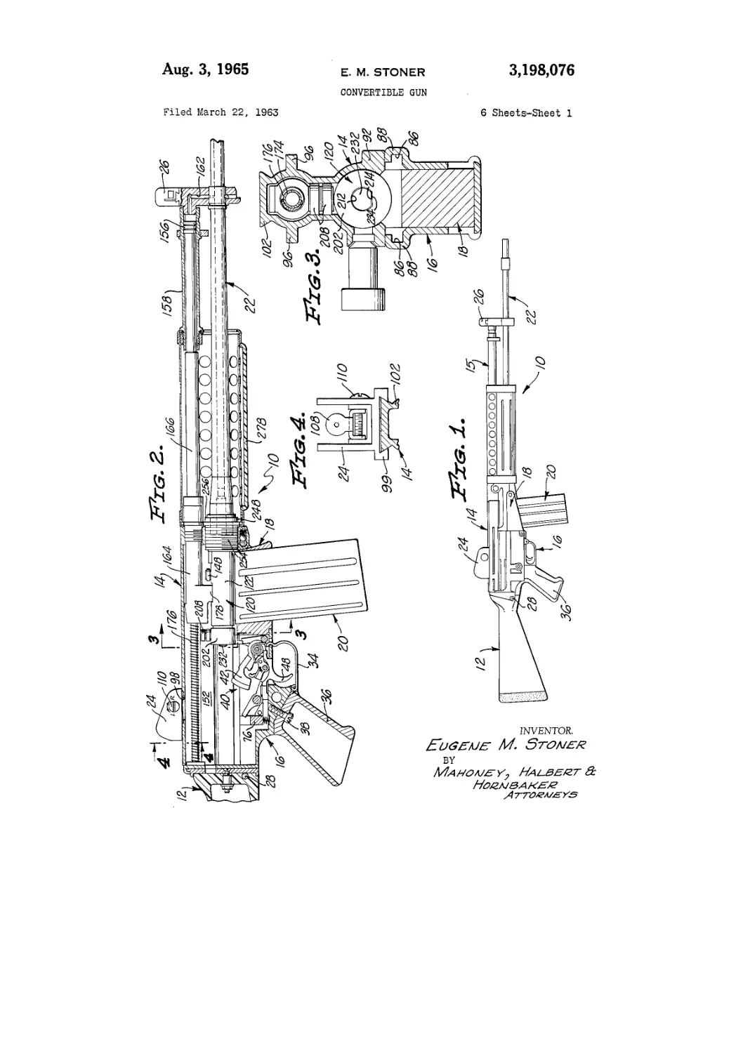
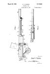
FIG. 1 is a side elevational view showing the con-
vertible gun of the invention in its rifle configuration;
FIG. 2 is an enlarged, fragmentary, sectional view
showing the convertible gun components in the orienta-
tion established for said components when the gun is uti-
lized in the rifle configuration;
FIG. 3 is an enlarged, fragmentary, vertical, sectional
view taken along .the broken line 3—3 of FIG. 2;
FIG. 4 is an enlarged, fragmentary, vertical, sectional
view taken along the broken line 4—4 of FIG.2;
FIG. 5 is an enlarged, fragmentary, sectional view
showing the details of the bolt carrier, trigger group, and
magazine adapter in the orientation assumed thereby when
the gun is utilized in the rifle configuration;
FIG. 6 is a vertical, sectional view taken along the
broken line 6—6 of FIG. 5;
FIG. 7 is an enlarged, fragmentary, sectional view
taken along the broken line 7—7 of FIG. 6 and showing
a latching mechanism utilized to maintain the receiver in
operative relationship with the trigger housing;
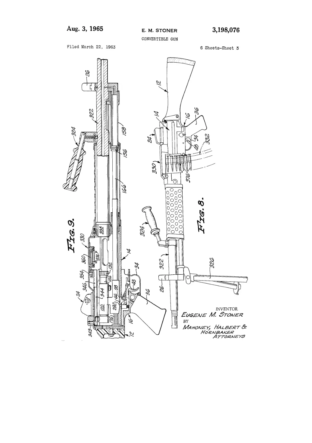
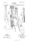
FIG. 8 is a side elevational view showing the compo-
nents of the gun assembled in the orientation assumed
thereby when said gun is utilized in the light machine gun
configuration;
FIG. 9 is an enlarged, fragemntary, sectional view
showing the various internal components of the gun in the
orientation assumed thereby when they are disposed in
the light machine gun attitude;
FIG. 10 is an enlarged, fragmentary, sectional view of
the receiver portion of the gun showing the various com-
ponents thereof in the orientation assumed thereby when
the gun is utilized in the light machine gun configuration;
FIG. 11 is a longitudinal, sectional view taken from
the broken line 11—11 of FIG. 10;
3,198,076
3
FIG. 12 is a vertical, sectional view taken from the
broken line 12—12 of FIG. 10;
FIG. 13 is a vertical, sectional view taken from the
broken line 13—13 of FIG. 10;
FIG. 14 is an exploded view showing the various com-
ponents utilized in the rifle configuration of the gun of
the invention;
FIG. 15 is an exploded view showing the various com-
ponents utilized in the light machine gun configuration
of the gun of the invention; and
FIG. 16 is an exploded view showing an alternative
fastening means utilized to maintain the receiver in oper-
ative relationship with the trigger housing of the gun.
Referring to the drawings, and particularly to FIGS. 1
through 7 and 14, I show the convertible gun 10 of my
invention with the components thereof disposed in the ori-
entation which is imparted thereto when said gun is
adapted to be utilized in a rifle configuration. In the
rifle configuration the gun, as best shown in FIGS. 1 and
14 includes a stock 12, a receiver 14, a trigger group hous-
ing 16 demountably secured to the stock 12, a magazine
adapted 18 and a magazine 20 adapted to be inserted into
operative relationship with said magazine adapter. In
addition, the components of the gun 10 in the rifle con-
figuration include a barrel 22 demountably associated with
the receiver 14, a rear sight 24, and a front sight 25.
The stock 12 has its forward extremity secured to the
rear extremity of the trigger group housing 16 by means of
a pin 28 which passes through the stock 12, as best shown
in FIGS. 1, 2, and 14 of the drawings, and has its opposite
extremities located in corresponding openings in the rear
portion 30 of the trigger group housing 16. Removal of
the pin 28 will permit the stock 12 to be dismounted from
operative relationship with the trigger group housing 16.
The trigger group housing 16, as best shown in FIGS.
’1-2, 5 and 14 of the drawings, includes an elongated, sub-
stantially rectangular body 32 which has a trigger guard 34
pivotally mounted thereupon and which has a handgrip 36
mounted thereupon by means of a screw 38. Located in the
trigger group housing 16 is a trigger group 4®. A hammer
42 is mounted as best shown in FIG. 5 of the drawings,
for rotation on a pivot pin 44 by means of a torsion spring
46. The hammer 42 is actually mounted in the magazine
adapter 18, as best shown in FIG. 14 of the drawings.
The trigger group 40 includes a trigger 48 which is mount-
ed for rotation about a pivot pin 52 and has its for-
ward extremity constitute a sear 54 engageable with a cor-
responding land 56 on the hammer 42 to maintain said
hammer in the inoperative position shown in FIG. 5 of the
drawings.
Mounted for rotation upon the pivot pin 52 is a sear 58
engageable with a corresponding detent 62 on the hammer
42 and rotatable by a torsion spring 64. A bolt carrier
sear 66 is mounted for rotation about a pivot pin 68 and
has a portion 72 thereof engageable by the trigger 48.
Also mounted in the trigger group housing 16 is a U-
shaped latch 76, FIG. 7, whose legs 77 are movable in
slots 78 in said housing and which is biased upwardly by
a compression spring 82, as best shown in FIG. 5 of the
drawings, into engagement with corresponding slots 84
in the receiver 14 to maintain said receiver and said trigger
group housing in operative relationship with each other.
The trigger group 40 is susceptible of being associated
with the gun 10 in first and second configurations corre-
sponding to first and second configurations of the gun 1®,
namely, the rifle and machine gun configurations. In the
rifle configuration of the gun 10, the trigger group 40 is
disclosed as being associated with the gun 10 in the first
configuration wherein it includes the trigger 48, the sear
54 and the sear 58 which are associated with the sear 65
in order that, as is well known in the art, the various sears
may be utilized to safety the gun or permit it to operate
in the semi-automatic or automatic conditions.
Formed in the trigger group housing 16 is a pair of
grooves 86, FIG. 12, which are constituted by longitudi-
5
10
15
20
25
30
35
40
45
50
55
60
65
70
75
4
nally oriented ribs 88 in the trigger group housing 16 and
which constitute a part of the fastening means adapted to
maintain the trigger group housing 16 and the receiver 14
in demountable relationship with each other.
The receiver 14, as best shown in FIG. 14 of the draw-
ings, includes a substantially rectangular body 92 which
is open at its lower extremity and which includes a pair
of oppositely directed flanges 94 adapted to be slidably
engaged in the corresponding grooves 86 of the trigger
group housing 16 to demountably connect the receiver
14 in operative relationship with the trigger group housing
16, said flanges constituting the co-operating portion of the
fastening means of the receiver 14 and trigger group hous-
ing 16. Therefore, in order to mount the receiver 14 in
operative relationship with the trigger group housing 16,
it is merely necessary to align the flanges 94 of the receiver
14 with the corresponding grooves 86 of the trigger group
housing 16 and to slide said flanges into the trigger group
housing grooves 86 until the rear extremity of the receiver
14 abuts on the rear extremity of the trigger group hous-
ing 16.
Also incorporated in the upper extremity of the receiver
14, as best shown in FIG. 3 of the drawings, are additional
flanges or ribs 96, for a purpose which will be described
in greater detail below. An opening 98 is formed in the
upper portion of the receiver 14 and the rear sight 24 is
mounted in overlying relationship therewith, as best shown
in FIGS. 2, 4, and 5 of the drawings, by means of a dove-
tail connection 99 between the base of the sight and the
corresponding upper extremity 102 of the receiver 14. The
rear sight 24 incorporates latch springs 104 which engage
in corresponding lands 106 in the upper portion 102 of the
receiver 14 to maintain the sight 24 in overlying relation-
ship with the opening 98. The springs 104 can be dis-
engaged by a suitable implement inserted through the open-
ing 98 in the receiver 14. The eyepiece 108 of the sight
is mounted upon a windage adjustment screw 110.
Located in the receiver 14 is a bolt carrier 120, said
bolt carrier being constituted by an elongated, cylindrical
body 122 having an axial bore 124 therein, as best shown
in FIG. 5 of the drawings. A bolt 126 is mounted for
rotation in the forward extremity of the bore 124 and
has its head 128 protruding beyond the forward extremity
of the body 122 so that the dogs 132 thereupon may engage
against corresponding surfaces 134 of the firing chamber
136.
A bolt actuator 140 is mounted in the bolt carrier 120
and includes an elongated pin 142 which, as best shown
in FIG. 5 of the drawings, is positioned in a transverse bore
144 in the bolt 126 and which extends into an inclined slot
146 formed in the wall of the bolt carrier 120. The pin
142 has a roller 148 mounted upon the outer extremity
thereof and engageable with a corresponding surface 152
in the interior of the receiver 14. A shell ejector 153
is mounted in the bolt 126 and is biased outwardly by a
compression spring 154.
An operative connection with a gas energizable piston
156, FIG. 2, located in a cylinder 158 maintained in com-
munication with the barrel 22 by a passage 162 is consti-
tuted by a link 164 connected to the rear extremity of a
piston rod 166. The piston rod 166 and link 164 are, as
best shown in FIG. 5 of the drawings, provided with
communicating axial bores 168 and 172. The bores 168
and 172 receive a guide rod 174 and a compression spring
176 adapted to return the link 164 and the associated
piston rod 166 to a position in which the link 164 will
locate the bolt carrier 120 in battery position.
The link 164, as best shown in FIG. 5 of the drawings,
has a depending arm 178 which is engaged in a corre-
sponding slot 181 in the wall of the body 122 of the bolt
carrier 120. The arm 178 includes a bore 182 and a
counterbore 184 which is adapted to receive the reduced
forward extremity 186 of a spacer collar 188, said spacer
collar having a locking lug 192 thereupon, for a purpose
which will be described in greater detail below. The lock-
3,198,076
s
ing lug or detent 192 projects radially into the bore 194 of
the spacer collar 188. A bank 196 of Belleville washers
is located in the bore 124 of the body 122 of the bolt car-
rier 120 and the rear extremity of said bank is engaged
by a spacer collar 198. Therefore, the bank 196 of Belle-
ville washers normally biases the spacer collar 188 into
operative engagement with the counterbore 184, but, as
best shown in FIGS. 5 and 10, is movable in the bore 124
of the bolt carrier body 122 relative to the link 178
against the compressive effect of the bank 196 of Belleville
washers, in a manner to be described in greater detail
below.
Mounted upon .the rear extremity of the body 122 of the
bolt carrier 120 is a rotatable cap 202 which is maintained
in operative relationship with said body by means of a
spirng ring 204. Formed integrally with the rotatable
cap 202 is an upwardly directed arm 206 upon which are
mounted guide rollers 208 adapted to engage the guide
surfaces 152 in the interior of the receiver 14. When the
gun 10 is used in the rifle configuration, the function of
the guide rollers 208 is limited to maintaining and guid-
ing the associated rotatable cap 202 in its predetermined
orientation on the bolt carrier 120, so that the orientation
of the cap 202, by being thus maintained, may maintain
the components of the bolt carrier 120 associated with
the cap 202 in the desired orientation for use of the gun
10 in the rifle configuration. The cap 202 is provided
with a centrally located opening 212 which, as best shown
in FIG. 3 of the drawings, incorporates a flat 214 for a
purpose which will be described in greater detail below.
Carried in the bolt carrier 120 is a firing pin 220, as
bet shown in FIG. 5 of the drawings. The forward ex-
tremity of the firing pin 220 is located in a bore 222 in the
bolt 126 and its forward extremity is adapted to be ex-
tended or driven through an opening 224 in said bolt for
engagement with a cartridge, not shown, located in the
firing chamber 136. The firing pin 220 also extends
through a corresponding bore 226 in the pin 142 of the
bolt actuator 140.
The intermediate portion of the firing pin 220 is located
in the bore 182 of the arm 178 of the link 164 and is
provided with an annular groove 227 which is enlarged
at 228, FIG. 5, for a purpose which will be described in
greater detail below. As will be readily apparent from
a study of FIG. 5 of the drawings, the locking detent 192
is of the same size as the annular groove 227, while it
is substantially smaller than the enlarged portion 228 of
.said groove.
Therefore, relative movement of the firing pin 220 in
the bolt carrier 120 can occur when the locking lug 192 is
located in the enlarged portion 228 of the groove 227.
The rearward extremity of the firing pin 220 extends
through corresponding openings in the bank 196 of Belle-
ville washers and is provided with a head 232 thereupon,
said head incorporating a flat 234 which corresponds with
and engages the flat 214 of the opening 212 in the cap 202.
The bolt carrier 120, the bolt 126 and the firing pin 220,
together with the various components associated there-
with are referred to hereinafter as the bolt carrier group.
The magazine adapter 18 is mounted at its rear extrem-
ity upon the forward extremity of the trigger group hous-
ing 16 by means of a land 238 whereupon which overlies
the corresponding forward extremity of the trigger group
housing 16, as best shown in FIG. 5 of the drawings. The
forward extremity of the magazine adapter 18 is mounted
in the lower portion of the receiver 14, as best shown in
FIG. 5 of the drawings, by means of a pin 242 which is
maintained in operative relationship with a corresponding
bore in the receiver 14 by means of a spring biased ball
detent 244. The magazine 20 is adapted to be shoved
upwardly into the magazine adapter 18 and to be fric-
tionally retained in operative relationship therewith so
that cartridges, not shown, can be fed into the firing cham-
ber 136.
The barrel 22 is, as best shown in FIGS. 5 and 6 of the
5
10
15
20
25
30
35
40
45
50
55
60
65
70
75
6
drawings, demountably associated with the forward ex-
tremity of the receiver housing 14. The barrel 22 has a
threaded rear extremity 246 which has a correspondingly
threaded collar 248 thereupon adapted to be slidably en-
gaged in a corresponding bore 252 provided in a fitting
254 in the forward extremity of the receiver 14. The rear
extremity of the barrel 22 and the associated collar 248
co-operate to define the firing chamber 136 for the recep-
tion and firing of a cartridge inserted therein. The barrel
collar 248 is provided with a flange 256 which, as best
shown in FIGS. 5 and 6 of the drawings, is engageable
by a latch 258 including a pivotally mounted latch dog 262
which is mounted for rotation on a piston bearing 264 by
an integral ring 266. The latch dog 262 is chamfered,
as at 268, so that it will be biased outwardly against the
action of an associated compression spring 272 when it
is engaged by the flange 256 on the barrel collar 248 dur-
ing the insertion of the barrel 22 into operative relation-
ship with the fitting 254 at the forward extremity of the
receiver 14.
Therefore, the barrel 22 can be assembled in operative
relationship with the forward extremity of the receiver
14 by merely sliding the collar 248 at the rear extremity
thereof into operative engagement with the corresponding
bore 252 in the fitting 254. As the collar 248 is inserted
in the bore 252, the flange 256 will engage the chamfered
portion 268 of the latch dog 262 to urge said latch dog
outwardly against the bias of the compression spring 272.
As soon as the flange 256 of the barrel collar 248 has
passed the chamfered portion 268 of the latch dog 262,
the spring 272 will urge said chamfered portion against
the face of the flange 256 and lock the barrel 22 in oper-
ative relationship with the receiver 14.
The latch dog 262 is provided, as best shown in FIG. 6
of the drawings, with a leg 274 which is engageable
through a corresponding opening 276 in a handgrip 278
which encompasses the barrel 22. Therefore, by the in-
sertion of a suitable instrument of reduced cross section,
such as a pin, or the like, the leg 274 can be rotated in
a counterclockwise direction, as viewed in FIG. 6, to bias
the latch dog 262 out of engagement with the flange 256
of the barrel collar 248 to permit the barrel 22 to be
released from operative engagement with the forward
extremity of the receiver 14.
The manner in which the operative components of the
gun 10 adapted for utilization in the rifle configuration can
be assembled is best illustrated by reference to FIGS. 1-7
and 14 of the drawings. Normally, the trigger group
housing 16 is maintained in operative relationship with the
stock 12 by means of the associated pin 28, and the maga-
zine adapter 18 is inserted into operative position within
the forward extremity of the trigger housing 16 to locate
the hammer 42 pivotally mounted thereupon in operative
relationship with the remainder of the trigger group 49.
Subsequently, the receiver 14 is mounted in operative
relationship with the trigger group housing 16 and the
magazine adapter 18 by sliding the flanges 94 thereupon
into the grooves 86 of the trigger group housing 16 until
the rear extremity of the receiver 14 engages the cor-
responding rear extremity of the trigger group housing
16, as best shown in FIG. 2 of the drawings. When
the gun 10 is utilized in the rifle configuration, the rotat-
able cap 202 on the bolt carrier 120 is rotated into a
position wherein the rollers 208 thereupon will engage
the corresponding guide surfaces 152 on the interior of
the receiver 14 and into a position in which the mutually
engaging flats 214 and 234 upon the collar 248 and firing
pin 220, respectively, will cause said firing pin to be
rotated within the bolt carrier 120 into the position in
which the detent lug 192 will be located in the elongated
or enlarged portion 228 of the annular groove 227 in
the firing pin 220. Therefore, relative movement be-
tween the firing pin 220 and the bolt carrier 120 may
be accomplished by the impingement of the hammer 42
upon the head 232 of the firing pin 220 causing a car-
3,198,076
7
tridge, not shown, in the firing chamber 136, to be fired.
After the assembly of the receiver 14 in operative re-
lationship with the trigger group housing 16 and maga-
zine adapter 18, the pin 242 is driven through correspond-
ing openings 282, FIG. 14, in the forward extremities of
the magazine adapter 18 and receiver 14, to lock said
receiver and said magazine adapter in operative relation-
ship with each other. The barrel 22 is then inserted into
the bore 252 in the fitting 254 in the forward extremity
of the receiver 14. The latch dog 262 engages the cor-
responding flange 256 on the barrel collar 248 and locks
the barrel 22 in operative relationship with the receiver
14. After a magazine 20 has been inserted in operative
relationship with the magazine adapter 18, the gun 10 is
ready to be fired in its rifle configuration. The assembly
of the handgrip and other components of the gun such
as the rear and front sights, has not been described be-
cause it will be obvious to those skilled in the art..
The dismounting of the various components of the
gun 10 utilized in the rifle configuration, illustrated in
FIGS. 1-5 of the drawings, is accomplished, initially, by
the insertion of a pin or similar elongated, slender mem-
ber through the opening 276 of the handgrip 278. The
extremity of the pin engages the leg. 274 of the latch dog
262 and urges said latch dog in a counterclockwise
direction, as viewed in FIG. 6 of the drawings, against
the bias of the spring 272 to release the flange 256 on
the barrel collar 248 and to permit the barrel 22 to be
released from operative engagement with the forward
extremity of the receiver 14.
The pin 242 can then be released from operative en-
gagement with the openings 282 in the receiver 14 and
the corresponding portion of the magazine adapter 18.
Before the receiver 14 can be dismounted from operative
relationship with the trigger group housing 16, the latch
76 must be disengaged from operative engagement with
the corresponding slots 84 in the flanges 94 on the re-
ceiver 14. Such disengagement is accomplished by mov-
ing the trigger 48 forwardly or counterclockwise, as
viewed in FIG. 5 of the drawings, to cause the sear 66
to engage the intermediate portion of the latch 76 be-
tween the legs 77 thereof and force it downwardly against
the bias of the spring 82. The receiver 14 can then be
slid from operative engagement with the trigger group
housing 16 and the magazine adapter 18 can be removed
from operative engagement with the trigger group hous-
ing 16 leaving said trigger group housing in operative
engagement with the stock 12.
When the gun 10 is to be utilized in the light machine
gun configuration illustrated in FIGS. 8-13 and 15 of
the drawings, the stock 12 and trigger group housing 16
are retained in the orientation assumed thereby when
the gun is utilized in the previously discussed rifle con-
figuration. However, the receiver 14 is inverted to locate
the open portion thereof in an upward orientation. When
the orientation of the receiver 14 is reversed in this
manner, the opening 98 is disposed in juxtaposition to
the bolt carrier sear 66 in order that said sear may en-
gage a corresponding land 292 on the bolt carrier 120,
as best shown in FIG. 1® of the drawings.
Prior to locating the receiver 14 in operative relation-
ship with the trigger group housing 16, the bolt carrier
120 is removed from the receiver 14 to permit the cap
292 thereupon to be rotated to orient the rollers 208
mounted upon said cap in an upward orientation, as
best shown in FIG. 10 of the drawings. If such rotation
of the cap 202 were not accomplished, the rollers 208
would, naturally, be oriented in a downward position
because of the inversion of the receiver 14 in which the
bolt carrier 120 is located. The rotation of the cap 202
in this manner causes corresponding rotation of the firing
pin 220 because of the engagement of the flats 214 and
234 provided on the cap 202 and the firing pin 220,
respectively. When such rotation of the firing pin 220
occurs, the annular groove 227 is correspondingly rotated
to cause it to engage the detent lug 192. When the
5
10
15
.20
.25
30
35
40
45
50
55
60
65
70
75
8
detent lug 192 is located in the annular groove 227, the
firing pin 220 is locked against movement with respect
to the bolt carrier 120 except for such movement as may
occur between the relative bolt parts of the bolt carrier
120 which is attributable to the provision of the bank
196 of Belleville washers in the bore 124 of the bolt
carrier 120.
Of course, the receiver 14 is, as best shown in FIG. 12
of the drawings, mounted in operative relationship with
the trigger group housing 16 by the engagement of the
flanges 96 thereupon with the. corresponding grooves 86
in the trigger group housing 16, as best shown in FIG. 12
of the drawings.
In addition to the utilization of the stock 12, the re-
ceiver 14, and the trigger group housing 16, the light
machine gun configuration of the gun 1® includes a heavy
barrel 322 which is mounted in the forward extremity
of the receiver 14, in a manner to be described in greater
detail below. In addition, a handgrip 324 is provided
which facilitates the carrying of the machine gun, and
there is also provided a bipod 326 which can be utilized
to support the machine gun during the firing thereof.
Furthermore, an automatic cartridge belt feed mecha-
nism 330 is adapted to be mounted upon the upper por-
tion of the receiver 14 in overlying relationship with the
opening therein in order that a belt 332 of cartridges may
be fed into the receiver 14, as best shown in FIG. 8
of the darwings. The rear sight 24 is, as best shown in
FIG. 10 of the drawings, mounted in operative relation-
ship with the belt feed mechanism 330.
Naturally, the inversion of the receiver 14 entails the
inversion of the cylinder 158 with the piston 156 disposed
therein. However, the operation of the piston 156 and
associated piston rod 166 and link 164 is identical with
the operation of the mechanism in the rifle configuration
of the gun so far as the movement of the bolt carrier 120
by gases generated by the firing of a cartridge in the
.Hiring chamber 136 is concerned. However, there is one
essential difference in the operation of the bolt carrier 129
in its utilization in the machine gun configuration of the
gun as distinguished from its utilization in the rifle config-
uration.
In the rifle configuration, the bolt carrier 120 and the
bolt 126 are disposed in the closed battery position prior
to the firing of the gun, and the firing pin 220 is adapted
to be driven by the action of the associated hammer 42
against a cartridge located in the firing chamber 135. The
spring 176 associated with the guide rod 174 serves to
drive the bolt carrier 120 into the closed battery position,
as best shown in FIG. 5 of the drawings, after the gun
has been fired.
In the machine gun configuration of the gun 10, the
bolt carrier 120 is maintained, as best shown in FIG. 10
of the drawings, in an open battery position wherein the
sear 66 engages the land 292 on the link 164 to maintain
the bolt carrier 120 in the open battery position against the
force of the spring 176. Moreover, the firing pin 220
is dogged against movement in the bolt carrier 120 by the
engagement of the detent 192 in the corresponding annular
groove 227.
It will be noted that the trigger group 40 is now asso-
ciated with the receiver 14 in its second configuration,
there being mounted in the trigger group housing 16 the
trigger 48 and the associated bolt carrier sear 66. All of
the other components of the trigger group 40 utilized in
its first configuration, namely, ths sear 58 and the asso-
ciated torsion spring 64 have been removed. The removal
of these trigger group components is accomplished by re-
moving the pivot pin 52 to dismount them from operative
association with the trigger 48. Of course, since the mag-
azine adapter 18 is not utilized in the machine gun con-
figuration of the gun 10, the hammer 42 is eliminated
from its cooperative relationship with the components of
the trigger group 40, as established in the first configura-
tion of said trigger group.
3,198,076
9
10
Therefore, when the trigger 48 releases the sear 66
to release the corresponding land 232 on the link 164,
the compressed spring 176 will urge the bolt carrier 120
to the right, as veiwed in FIG. 10 of the drawings, to
cause the bolt carrier to move into battery position. As _
the bolt 126 approaches battery position, it is retracted
into the bore 124 of the bolt carrier 120 to cause the pin
220 to protrude from the forward extremity of the bolt
126 and be driven into engagement with a cartridge located
in the firing chamber 136. 10
It will ba noted that the barrel 322 is mounted in opera-
tive relationship with the corresponding bore 252 at the
forward extremity of the receiver by means of a sliding fit
with a barrel collar 338 mounted thereupon. The latch
construction 258 described in the rifle configuration is
utilized to maintain the barrel 322 in operative engage-
ment with the receiver 14.
The belt feed mechanism 330, as best shown in FIG. 11
of the drawings, includes a cover 340 which is mounted
on a pin 242 and secured in closed position by the pins
331 at the rear extremity of the receiver 14. Mounted
upon tile underside of the cover 340 by means of a pivot
pin 343 is a lever 344 which, as best shown in FIG. 10 of
the drawings, is engaged by the uppermost roller 208 of
the cap 202 and which includes an angularly bent forward 25
extremity 346.
The forward extremity 346 of the lever 344 has an
actuating arm and bracket 348 secured thereto by means
of rivets 352. A guide roller 354 engages the underside
of the cover 340 as the forward extremity 346 of the lever 30
344 is moved on the pivot pin 343 by the action of the
drive roller 208. The arm portion 358 of the bracket
and arm 343 extends laterally into engagement with a
carriage 368 mounted, as best shown in FIGS. 10 and 12
of the drawings, on rollers 362 for movement on tracks 35
364 secured to the underside of the cover 348.
The forward extremity of the arm 358 is circular and
fits within a corresponding recess 368 in the carriage 360.
Mounted on the carriage 369 and biased downwardly by
a torsion spring 372 are cartridge advancing dogs 374, 40
said dogs being adapted to be reciprocated by movement
of the carriage 360' and to advance the cartridges 376
successively, as best shown in FIGS. 13 of the darwings.
A detent dog 382 is urged upwardly by a torsion spring
384 into engagement with an assoicated cartridge 376 to 45
prevent reverse movement of the cartridge belt 332. Also
mounted upon the carriage 360 is a spring biased tongue
388 adapted, as best shown in FIG. 13 of the drawings,
to force the cartridges 376 downwardly into a position
within the receiver in which they may be urged into the 50
firing chamber 136.
Therefore, when the gun 18 in the machine gun con-
figuration is fired, the gun 10 will fire so long as the
trigger 48 is depressed to move the sear 66 downwardly
out of engagement with the land 292 on the link 164. 55
The firing action entails return movement of the bolt
carrier 128 in the receiver 14 by the action of the gases
in the barrel 322 upon the piston 156. Therefore, after
the weapon is fired, the bolt carrier 120 is moved into the
open battery poistion of FIG. 10 of the drawings and will
be returned by the spring 176 into the firing position de-
scribed hereinabove so long as the trigger 48 is depressed.
If the trigger 43 is released, the sear 66 will engage the
corresponding land 292 upon the link 164 and will main-
tain the bolt carrier 120 in the open battery position of
FIG. 10 of the drawings.
When the spring 176 urges the bolt carrier 120 into fir-
ing position, the guide roller 354 moves within the chan-
nel shape of the lever 344 and, as it approaches the an-
gularly bent extremity 346 of said lever, causes the lever
to be shifted from one side of the cover 349 to the other
side of said cover to cause the arm 358 to be correspond-
ingly shifted. Movement of the arm 358 in this manner
induces movement of the carriage 360 upon the rollers
362 in the tracks 364 causing the dogs 374 to engage an
60
65
adjacent cartridge 376 and move it into a positioin in
which it will be driven into the firing chamber 136, as
best shown in FIG. 13 of the drawings.
When the gases generated by firing of the cartridge
376 cause rearward movement of the bolt carrier 120
against the bias of the spring 176, the guide roller 283
traverses the channel provided in the lever 344 to the
left-hand position, shown in FIG. 11 of the drawings,
wherein the carriage 368 is returned to the inoperative
position wherein it is ready to have the dogs 374 there-
upon urged into engagement with a cartridge 376 to be
fed into the firing chamber 136. Therefore, the entire
cartridge feeding mechanism 338 is mounted in the cover
34® and the guide roller 208 which serves to drive the
cartridge feeding mechanism 330.
The provision of the bank 196 of Belleville washers
within the bore 124 of the bolt carrier 120 facilitates both
70
the assembly of components with the bolt carrier 120 and
the elimination of shock loads upon said components.
Normally, as is well known to those skilled in the art,
it is necessary to manufacture the components assembled
in the bolt carrier with extreme accuracy to prevent rela-
tive movement therebetween which would result in dam-
age to or inoperativeness of said components. However,
by the provision of the bank 196 of Belleville washers,
tolerances can be permitted between the various compo-
nents carried by the bolt carrier 120 such as the link 164,
the collar 133 and the collar 198. This is due to the fact
that the expansion of the bank 196 of Belleville washers
accommodates any tolerances which might exist between
such component parts.
Moreover, during the firing of the gun, the return force
imposed upon the bolt carrier 129, and the shock loads in-
cident thereto, are absorbed by the bank 196 of Belleville
washers since a slight, relative movement of the link 164
with respect to the bolt carrier 120 is permitted due to
the fact that the bank 196 of the Belleville washers will
compress slightly as the arm 178 of the link 164 urges
the collar 183 to the left, as best shown in FIG. 10 of the
drawings.
Another important advange of the relationship between
the firing pin 22®, the spacer collar 188 and the bank of
Belleville washers 196 becomes most apparent during the
operation of the gun 10 in its machine gun configuration
when, as previously indicated, the firing pin 220 is held
against free relative movement with respect to the bolt
carrier 126 by the engagement of the detent lug 192 in
the annular groove 227. As previously explained, the
locking of the firing pin 220 in this manner causes the bolt
carrier 12S to drive the firing pin 220 against the cartridge
or shell in the chamber 136 since the bolt is operated from
the open battery position.
When this occurs, the firing pin 220 is subjected to high
axial loads which would ordinarily tend to cause crystal-
lization of the metal of the firing pin and subsequent shat-
tering thereof. However, because of the fact that the
firing pin 229 is locked to the spacer collar 188 and the
spacer collar 1S8 is subject to deflection against the bank
196 of the Belleville washers, the firing pin 220 may be
urged rearwardly for limited movement in the bore 124
of the bolt carrier 12®, thus preventing the imposition of
undue axial loads upon the firing pin 220 which would
occur if it were rigidly secured in the bolt carrier 120.
Alternative fastening means adapted to secure a receiver
414 in operative relationship with a trigger group housing
416 is illustrated in FIG. 16 of the drawings. Instead of
providing grooves 86 in the trigger group housing 416 and
flanges 94 and 96 engageable selectively therewith, the
receiver is provided with fastening lugs 418 which are
adapted to mate with corresponding openings 422 in the
trigger group housing 416. When so mated, pins, not
shown, may be driven through the corresponding openings
422 in the trigger group housing 416 and the lugs 418 to
demountably secure the receiver 414 in operative relation-
ship with the trigger group housing 416.
75
3,198,076
11
. I thus provide by my invention a convertible gun which
is adapted for use in a variety of configurations including
rifle and light machine gun configurations. In addition,
the convertible gun incorporates unique operating com-
ponents, among them being the bolt carrier and compo-
nents assembled therein, the cartridge belt feeding mech-
anism and the demountable components such as the trig-
ger group housing, magazine adapter and receiver itself.
Since all of the various components of the gun are inter-
changeable, the conversion from one configuration to the
other can be made in the field and the versatility of the
gun will be readily apparent to those skilled in the art.
I claim:
1. In a convertible gun, the combination of: a receiv-
er; a bolt carrier in said receiver; a reversible mount se-
cured to said bolt carrier; reversible guide and drive
means secured to said mount; a belt feed mechanism de-
mountably secured to said receiver for engagement by
said reversible guide and drive means; a firing pin in said
bolt carrier; and detent means on said bolt carrier for
holding said firing pin against movement with respect to
said bolt carrier when said reversible guide and drive
means is engaged with said belt feed mechanism, said
firing pin being operatively connected to said mount to
engage said detent means with said firing pin and prevent
relative movement between said bolt carrier and said
firing pin.
2. In a convertible gun, the combination of: a receiver
having openings in its top and bottom portions and mount-
ing means thereupon adjacent said openings; a barrel de-
mountably secured to the forward extremity of said re-
ceiver; a trigger group demountably securable to said
receiver adjacent one of said openings by said mounting
means; a cartridge belt feed means demountably secured
by said mounting means in overlying relationship with
the other of said openings; a bolt carrier in said receiver;
and reversible guide and drive means on said bolt carrier
engageable with said cartridge belt feed means to actuate
the same.
3. In a gun, the combination of: a receiver; a barrel
on said receiver; a bolt carrier mounted in said receiver
for reciprocatable movement therein; a firing pin in said
bolt carrier; and detent means in said bolt carrier engage-
able with said firing pin for alternatively holding said
firing pin against free longitudinal movement in said bolt
carrier so that the forward extremity of said firing pin
will automatically engage a round when said bolt carrier
is operated from open battery position and for permitting
free relative movement between said firing pin and bolt
carrier when said gun is operated from closed battery
position.
4. In a gun, the combination of: a receiver; a barrel
on said receiver; a bolt carrier mounted in said receiver
for reciprocatable movement therein; a firing pin in said
bolt carrier; a reversible mount on said bolt carrier; and
reversible guide and drive means on said mount for, alter-
natively, guiding said mount when said bolt carrier is
utilized in a rifle configuration of said gun and guiding
said mount and driving a cartridge belt feed means when
said bolt carrier is utilized in a machine gun configura-
tion of said gun.
5. In a gun, the combination of: a receiver; a barrel
on said receiver; a bolt carrier mounted in said receiver
for reciprocatable movement therein; a firing pin in said
bolt carrier; detent means in said bolt carrier engageable
with said firing pin for alternatively preventing or permit-
ting relative movement between said firing pin and said
bolt carrier; a reversible mount on said bolt carrier; and
reversible guide and drive means on said mount for, alter-
natively, guiding said mount when said bolt carrier is
utilized in a rifle configuration of said gun and guiding
said mount and driving a cartridge belt feed means when
said bolt carrier is utilized in a machine gun configura-
tion of said gun.
6. In a gun, the combination of: a receiver; a barrel
5
10
15
20
25
30
35
40
45
50
55
60
65
70
75
12
on said receiver; a bolt carrier mounted in said receiver
for reciprocatable movement therein; a firing pin in said
bolt carrier; detent means in said bolt carrier engageable
with said firing pin for alternatively preventing or per-
mitting relative movement between said firing pin and
said bolt carrier; a mount on said bolt carrier; reversible
guide and drive means on said mount for, alternatively,
guiding said bolt carrier when said bolt carrier is utilized
in a rifle configuration of said gun and guiding said bolt
carrier and driving automatic cartridge feed means when
said bolt carrier is utilized in the machine gun configura-
tion of said gun; and an operative connection between
said firing pin and said reversible guide and drive means
for freeing said firing pin from said detent means when
said guide and drive means is guiding said mount and for
engaging said firing pin with said detent means when
said guide and drive means is engaged in driving relation-
ship with said cartridge belt feed means.
7. In a convertible gun, the combination of: a receiv-
er having trigger group receiving openings in opposite
surfaces thereof; a bolt carrier group movable within the
receiver for chambering, firing and ejecting rounds of
ammunition; and a trigger group mountable in contiguity
to one of said receiving openings in a first configuration
and in contiguity to the other of said receiving openings
in a second configuration, said trigger group and said
receiver having co-operating fastening means for mount-
ing said trigger group at either opening.
8. In a convertible gun, the combination of: a receiv-
er having openings in the top and bottom thereof and be-
ing adapted to receive ammunition from said bottom
opening; a bolt carrier group movable within the said
receiver for chambering, firing and ejecting rounds of
ammunition; and a trigger group mountable adjacent said
top or bottom openings, said trigger group having a first
configuration when located adjacent said bottom opening
and a second configuration when located adjacent said top
opening after said receiver has been inverted, said trigger
group and receiver having co-operating fastening means
for demountably securing said trigger group adjacent
said top or bottom openings, to facilitate the inversion of
said receiver and bolt carrier group relative to said trig-
ger group and conversion of said gun from a bottom fed
rifle to a top fed machine gun.
9. In a convertible gun, the combination of: an in-
vertible receiver having top and bottom openings there-
in, said bottom opening, in a first configuration of said
gun, serving as a bottom rifle feed and, in a second con-
figuration of said gun, serving as a top machine gun feed;
a bolt carrier group movable within the receiver including
means for chambering, firing and ejecting rounds of
ammunition; and a trigger group mountable in a first
configuration adjacent said bottom opening of said re-
ceiver when said gun is disposed in its first configuration
and, when said receiver has been inverted to place said
gun in said second configuration, disposable adjacent said
top opening in a second configuration, whereby said gun
may function in its first configuration as a bottom fed
rifle and in its second configuration as a top fed machine
gun.
10. In a convertible gun, the combination of: a receiv-
er having oppositely disposed openings therein and adapt-
ed to receive ammunition through one of said openings;
a bolt carrier group mounted in said receiver for move-
ment therein to chamber, fire and eject rounds of ammuni-
tion; and a trigger group mountable adjacent one of said
openings of said receiver in a first configuration corre-
sponding to a first configuration of said gun, and when
said receiver has been inverted, mountable in a second
configuration corresponding to a second configuration of
said gun adjacent said other opening, said trigger group
and said receiver having co-operative fastener means
thereupon demountably securing said trigger group adja-
cent either of said openings.
11. In a convertible gun, the combination of: a receiv-
3,198,076
13
er having oppositely disposed openings therein and adapt-
ed to receive ammunition through one of said openings;
and a bolt carrier group including a bolt carrier movable
within said receiver for chambering, firing and ejecting
rounds of ammunition, said bolt carrier group including 5
a firing pin which is freely movable in said bolt carrier
when said gun is operated in the closed battery condition
and which is held against free relative movement when
said gun is operated in open battery condition, said bolt
carrier incorporating a detent for holding said pin against jq
free relative movement and shock absorbing means in-
terposed between said bolt carrier and said firing pin for
shock absorbing movement of said firing pin when said
firing pin is held against free relative movement in said
bolt carrier by said detent.
12. In a bolt carrier group, the combination of: a bolt
carrier having a bore therein; a firing pin mounted in said
bore; detent means in said bolt carrier engageable with
said firing pin for preventing free relative movement be-
tween said bolt carrier and said firing pin; and shock ab-
sorbing means operatively connected with said firing pin
for restricted shock absorbing movement of said firing
pin when said firing pin is held by said detent means
against free relative movement in said bolt carrier.
13. In a convertible gun, the combination of: a bolt
carrier; a firing pin mounted in said bolt carrier for free
relative longitudinal movement in said bolt carrier when
said bolt carrier is operated in a closed battery condition;
detent means in said bolt carrier engageable with said fir-
ing pin for preventing said free relative movement be- 30
tween said bolt carrier and said firing pin; and shock ab-
sorbing means interposed between said firing pin and said
bolt carrier for limited shock absorbing movement of said
firing pin when said firing pin is held 'by said detent
means against free relative movement in said bolt carrier 35
and said bolt carrier is operated from an open battery
position.
14. In a convertible gun, the combination of: a receiv-
er having openings in opposite portions thereof, one of
said openings serving as a bottom ammunition feed in a 40
first, rifle configuration of said gun and as a top ammuni-
14
tion feed in a second, machine gun configuration of said
gun; a bolt carrier group mounted for longitudinal move-
ment in said receiver and adapted to chamber, fire and
eject rounds of ammunition; a trigger group operatively
mounted adjacent said one opening in a first configura-
tion when said gun is disposed in its first configuration
and adjacent said other opening in a second configuration
when said gun is disposed in its second configuration; and
a demountable automatic belt feed mechanism securable
in operative relationship with said one opening when said
gun and said trigger group are disposed in said second
configurations by the inversion of said receiver.
15. In a convertible gun, the combination of: a receiver
having oppositely disposed openings therein and adapted
15 to receive ammunition through one of said openings; a
bolt carrier group mounted in said receiver for movement
therein to chamber, fire and eject rounds of ammunition,
said bolt carrier group including a bolt carrier and a firing
pin which is mounted for free longitudinal movement in
20 said bolt carrier when said bolt carrier is operated in a
closed condition and detent means in said bolt carrier
group engageable with said firing pin for preventing said
free relative longitudinal movement in said bolt carrier
and shock absorbing means interposed between said firing
25 pin and said bolt carrier for permitting limited shock ab-
sorbing movement of said firing pin When said firing pin
is held by said detent means against said free relative
movement in said bolt carrier and said bolt carrier is
operated from an open battery position.
References Cited by the Examiner
UNITED STATES PATENTS
695,882 3/02 Huntley________________42—17
853,715 5/07 Mondragon_____________89—191
933,098 9/09 McClean_______________89—191
2,548,622 4/51 Sampson et al__________89—140
2,655,753 10 53 Salas____________________42—6
2,875,671 3/59 Robinson________________89—33
BENJAMIN A. BORCHELT, Primary Examiner.