/


Tags: weapons military affairs machine gun patent
Year: 1947

Text
April 8, 1947. g. a. chadwick нт al 2,418,462
MACHINE GUN MAGAZINE AND CRADLE THEREFOR
Filed May 22, 1936 5 Sheets-Sheet 1
April 8, 1947. • g. a. chadwick etal 2,418,462
MACHINE GUN MAGAZINE AND CRADLE THEREFOR
Filed May 22, 1936
5 Sheets-Sheet 2
April 8, 1947. g. a. chadwick etal 2,418,462
MACHINE GUN MAGAZINE AND CRADLE THEREFOR
Filed May 22, 1936 5 Sheets-Sheet 3
April 8, 2947
°* “Ии,Е ™ raXsLTfIBis 2’418'462
«i.d ».у 22. 1йв®»»
5 Sheets_Sheet
April 8, 1947. g. a. chadwick et al 2,418,462
MACHINE GUN MAGAZINE AND CRADLE THEREFOR
Filed May 22, 1956
5 Sheets-Sheet 5
Patented Apr. 8, 1947
2,418,462
UNITED STATES PATENT OFFICE
2,418,462
MACHINE GUN MAGAZINE AND CRADLE
THEREFOR
George A. Chadwick and Paul W. Burk,
Washington, D. C.
Application May 22, 1936, Serial No. 81,156
15 Claims. (Cl. 42—18)
ct of March 3, 1883, as
1928; 370 O. G. 757)
2
is open on its upper and lower edges and the
walls thereof at the upper edge are folded over
to strengthen the cradle and are outwardly flared
to facilitate inserting magazines therein. A me-
5 dian wall 21 divides the cradle into two com-
partments, each of a size to receive one maga-
zine, and has secured to its lower edge a bar 22
to reinforce the wall and provide a positioning
stop for the magazine. The upper edge of the
10 cradle has formed in it at each end of each com-
partment a slot 23 to receive a lug carried by
the magazine, the slots at the forward ends being
of different width from those at the after ends,
and the cooperating lugs on the magazines being
15 of corresponding widths to prevent placing the
magazines in the cradle in the wrong position.
In each forward lower comer of each compart-
ment a member 24 having an inwardly facing
cam surface is secured to the cradle by means
20 of a tab 25 passed through the cradle and se-
cured thereto by upsetting or welding. These
members 24 release the cartridge retaining device
of the magazine when placed in the cradle, as
will be hereinafter described.
25 The forward end of bar 22 is expanded to form
at each side a surface 26 that downwardly and
outwardly slopes toward the opposite wall of the
compartment, and a member having a surface
27 that converges toward surface 26 is secured
30 to the outer wall of each compartment, the two
surfaces forming a guide for the projectile of a
cartridge into the slot of the feed plate. Secured
to the forward lower edge of the cradle 20 is a
hardened steel plate 28 having in it notches 29
3g respectively disposed substantially medially of
the transverse dimension of each magazine com-
partment to be engaged by a latch to hold the
cradle in the feeding position.
A lug 30 having an apertured, laterally turned
40 portion 31 is secured to each outer wall of cradle
20 substantially mid-way of the length thereof. A
rod 32 is passed through the aperture in portion
31 and is prevented from dropping downwardly
by a pin 33 therethrough. A spring 34 is dis-
45 posed around rod 32 and is held under compres-
sion between the head 35 of rod 32 and the upper
end portion 36 of magazine lifter 37 which ex-
tends downwardly and has a laterally turned por-
tion 38 that passes through a slot in the wall of
cradle 20 into the path of a magazine being in-
serted into the adjacent compartment. A hous-
ing 39 is fixed to cradle 20 to inclose the greater
portion of magazine lifter 37 and keep it from
swinging outwardly. When a magazine is pushed
55 down into the compartment the lower edge of
(Granted under the a
amended April 30,
1
This invention relates to means for continu-
ously feeding ammunition to a machine gun and
has among its numerous objects to provide an
improved magazine and a mounting therefor that
will automatically move an empty magazine from
the feeding position and replace it with a full
magazine, prevent the ready removal of a full
magazine from the mounting, automatically un-
lock the empty magazine from the mounting and
give an indication that the one magazine is emp-
ty. The present invention is particularly adapted
for use with the machine gun forming the sub-
ject of our со-pending application Serial No.
648,296, filed December 21, 1932.
In the drawings:
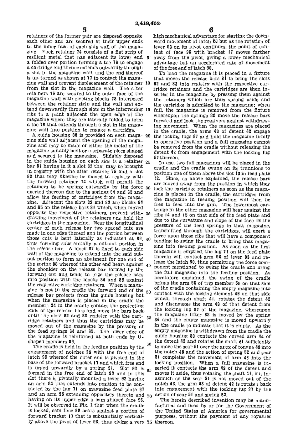
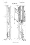
Fig. 1 is a fragmentary longitudinal vertical
section (on line I—I of Fig. 4) through a maga-
zine operatively positioned in the mounting,
showing the lower part of the magazine and ad-
jacent parts of the gun;
Fig. 2 is a similar section through the upper
portion of the magazine;
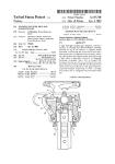
Fig. 3 is a longitudinal transverse section across
the magazine on line 3—3 of Fig. 1;
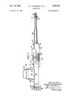
Fig. 4 is a vertical transverse section of the
magazine and the mounting on line 4—4 of Fig. 1;
The right-hand side of Fig. 5 is a partial ver-
tical transverse section on line &—5 of Fig. 1,
and the left-hand side of Fig. 5 is a partial verti-
cal transverse section on line 5'—5' of Fig. 1;
Fig. 6 is an elevational detail view of the means
for raising a magazine when empty;
Figs. 7 and 9 are fragmentary, vertical trans-
verse sections on lines 7—7 and 9—9, respectively,
of Fig. 1;
Fig. 8 is a detail sectional view on line 8—8 of
Fig. 1;
Fig. 10 is an elevational detail of a portion of
the means for locking the mounting; and
Fig. 11 is a fragmentary transverse sectional
view on line II—Il of Fig. 8.
Secured to the gun (not shown) in position
to transfer cartridges from the magazine to the
ramming mechanism is a feed plate 12 having
a slot 13 through which the cartridges pass. Up-
on the upper face of the feed plate are two pairs
of transverse ribs 14 and 15 whereof the upper
faces are curved and sloped toward slot 13, as
indicated at 16, the centers of curvature of such
faces 16 lying upon the side of the longitudinal 50
axis of slot 13 opposite from the respective face.
Mounted at the ends of feed plate 12 are for-
ward bracket 17 and after bracket 18 in which are
journaled the trunnions 19 of magazine cradle
20. AS is shown in Figs. 4 and 5, the cradle 20
2,418,482
3
the magazine engages portion 38 and further
compresses spring 34, and therefore, as soon as
the force retaining the magazine in the cradle is
released, it is lifted up by the expansion of spring
34.
Upon each side of the cradle adjacent its after
end are secured two lugs 48 having axially aligned
apertures therethrough in which a shaft 41 is
hiounted. To the forward end of each shaft 41
is secured a detent 42 having oppositely extending
arms 43 and 44, the extremities of which arms
may be moved into the adjacent magazine com-
partment through a slot 45 in the wall thereof
when shaft 41 is rotated. The free end of arm
43 is substantially square to engage a locking lug
upon a magazine and arm 44 is curved to cause
the detent 42 to rotate shaft 41 when arm 44 is
contacted by a magazine that is being withdrawn
from the cradle. The after end of each of the
shafts 41 carries a locking element 46, said lock-
ing elements extending toward each other across
the after end of the cradle and each has in the
edge thereof that faces the other, two V-shaped
notches 47 and 48, the adjacent walls of the two
notches intersecting to form a pointed tongue 49
between them, the distance between the outer
extremities of the walls of notch 48 being greater
than the corresponding dimension of notch 47.
Between locking elements 46 a member 59 hav-
ing a polygonal passage therein is secured to the
cradle and is disposed with the axis of the open-
ing therethrough intersecting the two shafts 41,
and in that opening are two sears 51 whereof the
outer ends are shaped and disposed to engage in
notches 47 and 43, a spring 52 being placed under
compression between the two sears to urge them
outwardly. Mounted upon pivots 53 carried by
lugs 54 secured to the edges of after bracket 18
are two trip members 55, the lower arm 56 of each
of the trip members being disposed to contact the
adjacent locking element 46 under certain condi-
tions of relative movement hereinafter to be ex-
plained, and the upper arm 57 of each trip mem-
ber being disposed to engage a stop 58 secured to
the after bracket 18, the spring 59 connected to
both the trip members under tension tending to
hold the trip members against their respective
stops.
Since trip members 55 are mounted on the
bracket and the locking elements 46 are carried
by cradle 20, it is evident that when cradle 20
swings on its trunnions there will be relative
movement between the trip members and the
locking elements.
Referring now to Fig. 8, it will be noted that the
bottom of cradle 20 is swung toward the left, that
the left-hand sear 51 engages notch 47 of the co-
acting locking element 46, that the arm 43 of de-
tent 42 on the left-hand side is outside of the
cradle 20, and that arm 56 of the left-hand trip
member 55 lies between the two locking elements;
also, that the right-hand sear 51 is in notch 48
of the coacting locking member, the lower arm 43
of detent 42 on that side extends within the cradle
and that arm 56 of the right-hand trip lies outside
the adjacent locking member, these being the
positions of the several parts when cartridges are
being fed from a magazine in the right-hand
compartment of cradle 20 as viewed in Fig. 8, the
magazine in the left-hand compartment having
just been emptied and the arm 43 of detent 42 dis-
engaged therefrom but the empty magazine not
yet withdrawn. In the removal of the left-hand
magazine the curved arm 44 of detent 42 on that
Side will be contacted by a portion of the maga-
10
15
20
25
30
35
40
45
50
55
60
65
70
75
4
zine and shaft 41 will be rotated, which will rotate
locking element 46 also and cause the coacting
sear 51 to ride up on the tongue 49 and as soon
as the edge of the sear has passed the apex of
tongue 49 the action of the sear upon the sloping
face of notch 48 will be to continue the rotation of
shaft 4! until the sear is seated in the bottom of
notch 48, at which time the arm 43 on the left-
hand side will occupy the same relative position
as does the like arm 43 on the right-hand side.
Insertion of another magazine into the left-
hand compartment will cause the arm 43 to be
moved out but owing to the relatively greater
width of the notch 48, the sear 51 will not be
moved over the apex of tongue 49 and the arm
43 will be rotated back into locking position by the
action of the sloping face of the sear against the
sloping face of notch 48. When the bottom of
cradle 26 is moved toward the right, the arm 56
of trip member 55 on the right-hand side will
engage the uppermost portion of locking member
46 on the right-hand side and rotate shaft 41
until the apex of tongue 49 has passed the edge
of sear 5! after which the sear will continue the
rotation of shaft 4! until the sear is seated in the
notch 47 and the magazine in the right-hand
compartment will be unlocked. It will be observed
that rotation of trip member 55 on the right-hand
side under the conditions just mentioned will be
prevented by contact of the arm 57 against stop
58 but that, on the left-hand side, the contact
of locking element 46 with the trip on that side
will rotate the trip member on its pivot and
stretch spring 39, but as soon as the locking
member has cleared the trip, the arm 57 of the
left-hand trip will be moved back aaginst its
stop 58.
The magazine consists of a box 60 of relatively
light metal with reinforcing ribs 61 formed in the
sides thereof and is completely closed except at
its lower edge which is left open for the passage
of cartridges into and from the magazine. Lugs
62 and 63 on the forward and after ends, respec-
tively, of the magazine fit in the slots 23 in cradle
29 and are of different widths to prevent improper
placing of the magazine as above explained.
Seated against the closed upper edge of the maga-
zine are two springs 64 and 65, the channel tie
members 66 being secured to approximately corre-
sponding turns of the two springs to prevent un-
due spreading and lateral flexion of the springs.
The two springs 64 and 65 may be wound opposite
to each other if desired. The lower ends of the
springs bear against a feed plate 67 that contacts
the base of the cartridge case and has a member
68 projecting therefrom to contact the cartridge
at another point and thus apply the force of the
springs 64 and 65 to feed the cartridges from
the magazine. The up-turned portions 69 at the
after end of the feed plate prevent lateral tilting
of the plate; the flanges 76 extending therefrom
engage another portion of the magazine when
empty and prevent the feed plate from being
forced out of the magazine by the springs; and
the downwardly extending lug 71 contacts the
cradle release latch when the magazine has been
emptied. The side walls of the magazine are
grooved as indicated at 72 to engage the rim of
the cartridge case and prevent forward movement
of the cartridges in the magazine while two mem-
bers 73 on each side wall serve as a guide for the
spring 64 and also hold the projectile ends of the
cartridges centered in the magazine.
The cartridges are held in the magazine by the
forward retainers 74 and after retainers 75. The
s
2,418,462
retainers of the former pair are disposed opposite
each other and are secured at their upper ends
to the inner face of each side wall of the maga-
zine. Each retainer 74 consists of a flat strip of
resilient metal that has adjacent its lower end 5
a folded over portion forming a toe 76 to engage
a cartridge and thence extends outwardly through
a slot in the magazine wall, and the end thereof
is up-turned as shown at 77 to contact the maga-
zine wall and prevent displacement of the retainer 10
from the slot in the magazine wall. The after
retainers 75 are secured to the outer face of the
magazine wall with riveting blocks 78 interposed
between the retainer strip and the wall and ex-
tend downwardly through slots in the intervening 15
ribs to a point adjacent the open edge of the
magazine where they are laterally folded to form
a toe 79 that extends through a slot in the maga-
zine wall into position to engage a cartridge.
A guide housing 89 is provided on each maga- 20
zine side wall adjacent the opening of the maga-
zine and may be made of either the metal of the
magazine suitably bent or a separate piece shaped
and secured to the magazine. Slidably disposed
in the guide housing on each side is a retainer 25
bar 81 having in it a slot 82 that may be brought
in registry with the after retainer 75 and a slot
83 that may likewise be moved to registry with
the forward retainer 74 which will permit the
retainers to be sprung outwardly by the force so
exerted thereon due to the springs 64 and 65 and
allow the feeding of cartridges from the maga-
zine. Adjacent the slots 82 and 83 are blocks 84
and 85 on the release bars 81 which, when moved
opposite the respective retainers, prevent with- 35
drawing movement of the retainers and hold the
cartridges in the magazine. Near the longitudinal
center of each release bar two spaced cuts are
made in one edge thereof and the portion between
those cuts is bent laterally as indicated at 86, 40
thus forming substantially a cut-out portion in
the release bar. A block 87 is fixed to each side
wall of the magazine to extend into the said cut-
out portion to form an abutment for one end of
the spring 88 whereof the other end bears against 45
the shoulder on the release bar formed by the
forward cut and tends to urge the release bars
into position with the blocks 84 and 85 against
the respective cartridge retainers. When a maga-
zine is not in the cradle the forward end of the 50
release bar projects from the guide housing but
when the magazine is placed in the cradle the
members 24 in the cradle contact the projecting
ends of the release bars and move the bars back
until the slots 82 and 83 register with the cart- 55
ridge retainers and thus the cartridges may be
moved out of the magazine by the pressure of
the feed springs 64 and 65. The lower edge of
the magazine is reinforced at both ends by U-
shaped members 89.
The cradle is held in the feeding position by the
engagement of notches 29 with the free end of
latch SO whereof the outer end is pivoted in the
base of the forward bracket 17 and which free end
is urged upwardly by a spring 91. Slot 92 is 65
formed in the free end of latch 92 and in this
slot there is pivotally mounted a lever 93 having
an arm 94 that extends into position to be con-
tacted by the lug 71 on magazine feed plate 67
and an arm 95 extending oppositely thereto and 70
having on its upper edge a cam shaped face 96.
It will be observed in Fig. 1 that when the cradle
is locked, cam face 96 bears against a portion of
forward bracket 17 that is substantially vertical-
ly above the pivot of lever 93; thus giving a very 75 thereon.
high mechanical advantage for starting the down-
ward movement of latch S3 but as the rotation of
lever 93 on its pivot continues, the point of con-
tact of face 96 with bracket 17 moves farther
away from the pivot, giving a lower mechanical
advantage but an accelerated rate of movement
of the free end of latch 99.
To load the magazine it is placed in a fixture
that moves the release bars 81 to bring the slots
82 and 83 into registry with the respective car-
tridge retainers and the cartridges are then in-
serted in the magazine by pressing them against
the retainers which are thus sprung aside and
the cartridge is admitted to the magazine; when
full, the magazine is removed from the fixture
whereupon the springs 88 move the release bars
forward and lock the retainers against withdraw-
ing movement. When the magazines are placed
in the cradle, the arms 43 of detent 42 engage
the locking lugs 97 and hold the magazine firmly
in operative position and a full magazine cannot
be removed from the cradle without releasing the
detent 42 from engagement with the locking lug
97 thereon.
In use, two full magazines will be placed in the
cradle and the cradle swung on its trunnions to
position one of them above the slot 13 in feed plate
12. Since, as above explained, the release bars
are moved away from the position in which they
lock the cartridge retainers as soon as the maga-
zine is placed in the cradle, the cartridges from
the magazine in feeding position will then be
free to feed into the gun. The lowermost car-
tridge in the other magazine will bear against the
ribs 14 and 15 on that side of the feed plate and
due to the curvature and slope of the face 16 the
pressure of the feed springs in that magazine,
transmitted through the cartridges, will exert a
force upon those ribs that will have a component
tending to swing the cradle to bring that maga-
zine into feeding position. As soon as the first
magazine is emptied, the lug 71 on the feed plate
therein will contact arm 94 of lever 93 and re-
lease the latch 99, thus permitting the force com-
ponent mentioned to swing the cradle and bring
the full magazine into the feeding position. As
heretofore explained, the swing of the cradle
brings the arm 56 of trip member 55 on that side
of the cradle containing the empty magazine into
contact with the locking element 46 on that side
which, through shaft 41, rotates the detent 42
and disengages the arm 43 of that detent from
the locking lug 97 of the magazine, whereupon
the magazine lifter 38 is moved by the spring
34 and the empty magazine is moved upwardly
in the cradle to indicate that it is empty. As the
empty magazine is withdrawn from the cradle the
guide housing 89 contacts the curved arm 44 of
the detent 42 and rotates the shaft 41 sufficiently
to move the sear 5! over the apex of tongue 49 into
the notch 48 and the action of spring 52 and sear
51 completes the movement of arm 43 into the
locking position. When a full magazine is in-
serted it contacts the arm 43 of the detent and
moves it aside, thus rotating the shaft 41, but in-
asmuch as the sear 5! is not moved out of the
notch 48, the arm 43 of detent 42 is rotated back
into engagement with the locking lug 97 by the
action of sear 51 and spring 52.
The herein described invention may be manu-
factured and used by or for the Government of
the United States of America for governmental
purposes, without the payment of any royalties
2,418,462
7
We claim:
1. A cartridge magazine, comprising a box of
thin metal open on one edge and having its sides
reinforced by being ribbed, U-shaped reinforcing
members secured to the ends thereof adjacent said
open edge, a positioning lug on each end, the two
lugs being of different width, a lug on one side
engageable by a locking detent to hold the maga-
zine in operative position, two forward retainers
disposed opposite each other and secured at their
upper ends to the inner face of the side of the
box, the lower portion of each retainer being
folded inwardly to form a toe to engage a portion
of a cartridge and extending thence outwardly
through a slot in the box wall and having its end
up-turned parallel to the outer face of said wall,
two after retainers disposed opposite each other
and secured at their upper ends to the outer face
of said wall and having their lower ends folded
and laterally turned to extend toward each other
through slots in said wall, a guide housing along
each side wall adjacent said open edge, a release
bar slidable in each of said housings, each of said
bars having slots positioned to be brought into
registry with said retainers and a cut-away por-
tion, a fixed block extending into each of said
cut-away portions, a spring in each of said cut-
away portions having one end abutting the fixed
block therein and the other end abutting the re-
lease bar to urge said bar forwardly and cause
said bar normally to hold said retainers against
outward swing, two spaced apart coiled springs
disposed with an end of each against the inner
face of the box opposite said open edge, means
tying together a plurality of substantially corre-
sponding turns of said springs, a feed bar dis-
posed against the other ends of said springs to
move cartridges out of said box’having a down-
wardly extending latch-releasing lug at its for-
ward end and two spaced apart guides for the
forward one of said springs secured to the inner
face of each of the side walls of said box.
2. In combination with forward and after
brackets secured to a gun, a magazine cradle hav-
ing compartments to receive two magazines, said
compartments being open on their upper and
lower edges and there being in each compartment
a slot in the upper edge of its forward end and
a slot of different width in the upper edge of its
after end, axially aligned trunnions on the two
ends of the cradle journalled in said brackets, a
Pair of lugs on each side of said cradle adjacent
its after end having aligned bores therethrough,
a shaft journalled in each pair of lugs, fixed to
the forward end of each shaft a detent having a
downwardly extending arm with a squared locking
end to engage a locking lug on a magazine in said
cradle and an upwardly extending arm having
a curved tripping end, said ends being movable
into the adjacent compartment through a slot in
the wall of said cradle, fixed on the after end of
each of said shafts a locking element, those ends
of said elements facing each other each having
two V-shaped notches separated by an inverted
V-shaped tongue, a member having a passage
therethrough fixed to said cradle between said
elements, two sear members slidably mounted in
said passage and having their outer ends shaped
and disposed to engage said V-shaped notches,
a spring between said sears to urge them out-
wardly, a pivoted trip member mounted on the
after bracket adjacent each of said locking ele-
ments to contact and rotate said elements under
certain conditions of relative movement there-
between to release said locking end from said
5
10
15
20
25
30
35
40
45
50
55
60
65
70
75
8
lug, a spring connected to said trips to draw them
toward each other, stops on the after bracket to
limit the movement of said trips toward each
other, a member secured to the lower forward
edge of said cradle having in it a locking notch
in each compartment, a pivoted latch under the
forward bracket engageable with said locking
notches and releasable therefrom by the action of
a member in a magazine when the magazine is
empty, and means acting in each of said compart-
ments to lift upwardly a magazine therein when
unlocked from the cradle after being emptied.
3. In combination with a gun, forward and after
brackets mounted thereon, a cartridge magazine,
a cradle having compartments to receive two such
magazines, axially aligned trunnions on said
cradle journalled in said brackets, inter-engaging
parts on said magazine and said cradle to insure
proper positioning of the magazine in the cradle,
means to lock the magazine in the cradle, means
operable by swinging of said cradle on its trun-
nions to release said locking means, means to
lock said cradle against swinging, means in said
magazine to release said cradle locking means
when the magazine is empty, means to retain
cartridges in said magazine, means carried by said
cradle to release said retaining means to permit
passage of cartridges from the magazine when op-
eratively positioned in the cradle, and means car-
ried by the cradle to be engaged by a magazine
and placed under stress when the magazine is
placed in the cradle and by release of said stress
to move the magazine upwardly when the maga-
zine is unlocked from the cradle.
4. A cartridge magazine, comprising a box open
on one edge, means to move cartridges out of said
box, and means normally to retain cartridges in
said box including two forward retainers disposed
opposite each other and secured at their upper
ends to the inner face of the side of the box, the
lower portion of each retainer being folded in-
wardly to form a toe to engage a portion of the
cartridge and extending thence outwardly through
a slot in the box wall and having its end up-turned
parallel to the outer face of said wall, two after
retainers disposed opposite each other and secured
at their upper ends to the outer face of said wall
and having their lower ends folded and laterally
turned to extend toward each other through
slots in said wall, a guide housing along each side
wall adjacent said open edge, a release bar slid-
able in each of said housings, each of said bars
having slots positioned to be brought into registry
with said retainers and a cut-away portion, a
fixed block extending into each of said cut-away
portions, and a spring in each of said cut-away
portions having one end abutting the fixed block
therein and the other end abutting the release
bar to urge said bar forwardly and cause said bar
to hold said retainers against outward swing, said
release bars being movable backwardly to bring
the slots therein in registry with said retainers
and so permit the retainers to be swung outwardly
to deliver cartridges from the magazine.
5. In combination with a gun, forward and
after brackets mounted thereon, a magazine
cradle swingably mounted between said brackets,
a locking plate carried by the forward lower edge
of said cradle having locking notches therein, a
latch pivoted at one end to said forward bracket
and having its free end disposed to engage said
locking notches, a lever pivoted in the free end
of said latch having an arm extending into said
cradle and an oppositely extending arm with a
cam-like face on its upper edge to contact a por-
2,418,483
0
tion of said bracket, a resilient means to urge
said free end of said latch upwardly, a shaft ro-
tatably mounted on each side of said cradle ad-
jacent its after end, a detent having a locking
arm to engage a portion of said magazine and
an oppositely extending curved tripping arm on
the forward end of each said shaft, a locking
element on the after end of each shaft, those
faces of said elements that are turned toward
each other having each two V-shaped notches
with the adjacent walls of the notches intersect-
ing, a member having a passage therethrough
mounted on said cradle between said elements,
two sear members slidably mounted in said pas-
sage having their outer ends shaped and disposed
to engage said notches, a spring between said
sears to urge them outwardly, a pivoted trip mem-
ber mounted on the after bracket adjacent each
of said locking elements to contact and rotate
said elements under certain conditions of rela-
tive movement therebetween thereby to disen-
gage said locking arm from said portion, a spring
connected to said trips to draw them toward
each other, stops on the after bracket to limit
the movement of the trips toward each other and
means at the forward edge of said cradle adja-
cent said open edge to release a cartridge retain-
ing device of a magazine when positioned in said
cradle.
6. In combination with a gun, forward and
after brackets mounted thereon, a magazine
cradle swingably mounted between said brackets,
a locking plate carried by the forward lower edge
of said cradle having locking notches therein,
a latch pivoted at one end to said forward bracket
and having its free end disposed to engage said
locking notches, a lever pivoted In the free end
of said latch having an arm extending into said
cradle and an oppositely extending arm with
a cam-like face on its upper edge to contact a
portion of said bracket, and resilient means to
urge the said free end of said latch upwardly. .
7. In combination with a gun, forward and
after brackets mounted thereon, a magazine
cradle swingably mounted between said brackets,
a locking plate carried by the forward lower
edge of said cradle having locking notches there-
in, a latch pivoted at one end to said forward
bracket and having Its free end disposed to en-
gage said locking notches, a lever pivoted in the
free end of said latch having an arm extending
into said cradle and an oppositely extending arm
with a cam-like face on Its upper edge to con-
tact a portion of said bracket, resilient means
to urge said free end of said latch upwardly, a
magazine in said cradle and means in said maga-
zine to depress said lever and release the latch
when the magazine is empty.
8. In combination with a gun having a longi-
tudinally slotted feed plate and a plurality of
curved faces transverse to the slot therein, the
center of curvature of each face being on the op-
posite side of the slot from the face, forward and
after brackets mounted adjacent said plate, a
cradle having compartments for two magazines
swingably mounted between said brackets, two
cartridge magazines in said cradle, means to lock
said cradle in position for either magazine to feed
Into said slot, means in each magazine to release
said locking means when the magazine Is empty
thereby permitting the pressure of the lowermost
cartridge in the other magazine exerted upon said
curved faces in contact with said cartridge to
swing said cradle, means to lock each magazine
in the cradle, means actuatable by swinging of
6
10
15
20
25
30
35
40
45
50
55
60
65
70
75
10
said cradle to release the magazine locking means,
means carried by said cradle having a portion en-
gageable by a magazine being inserted in the
cradle and an element connected thereto to store
up energy imparted thereto by movement of said
portion due to insertion of the magazine to raise
the magazine when unlocked from the cradle,
means in each magazine normally to retain car-
tridges therein and means in said cradle to release
said last mentioned means to permit cartridges
to be fed from the magazine.
9. In combination with a gun having a longi-
tudinally slotted feed plate and a plurality of
curved faces transverse to the slot therein, -the
center of curvature of each face being on the op-
posite side of the slot from the face, forward and
after brackets mounted adjacent said plate, a
cradle having compartments for two magazines
swingably mounted between said brackets, two
cartridge magazines in said cradle, means to lock
said cradle in position for either magazine to feed
Into said slot, and means in each magazine to re-
lease said locking means when the magazine is
empty thereby permitting the pressure of the low-
ermost cartridge in the other magazine exerted
upon said curved faces in contact with said car-
tridge to swing said cradle.
10. In combination with a gun having a longi-
tudinally slotted feed plate and a plurality of
curved faces transverse to the slot therein, the
center of curvature of each face being on the
opposite side of the slot from the face,'forward
and after brackets mounted adjacent said plate,
a cradle having compartments for two maga-
zines swingably mounted between said brackets,
two cartridge magazines in said cradle, means
to lock said cradle In position for either magazine
to feed into said slot, means in each magazine
to release said locking means when the magazine
is empty thereby permitting the pressure of the
lowermost cartridge in the other magazine ex-
erted upon said curved faces In contact with
said cartridge to swing said cradle, means to lock
each magazine in the cradle, and means actuat-
able by swinging of said cradle to release the
magazine locking means.
11. In combination with a gun having a longi-
tudinally slotted feed plate and a pluraltiy of
curved faces transverse to the slot therein, the
center of curvature of each face being on the
opposite side of the slot from the face, forward
and after brackets mounted adjacent said plate,
a cradle having compartments for two magazines
swingably mounted between said brackets, two
cartridge magazines In said cradle, means to lock
said cradle in position for either magazine to feed
into said slot, means in each magazine to release
said locking means when the magazine is empty
thereby permitting the pressure of the lowermost
cartridge in the other magazine exerted upon said
curved faces in contact with said cartridge to
swing said cradle, means to lock each magazine
in the cradle, means actuatable by swinging of
said cradle to release the magazine locking means,
and means carried by said cradle having a por-
tion engageable by a magazine being inserted in
the cradle and an element connected thereto to
store up energy imparted thereto by movement
of said portion due to Insertion of the magazine
to raise the magazine when unlocked from the
cradle.
12. In combination with a gun, a magazine
cradle swingably mounted on said gun, a shaft
rotatably mounted on each side of said cradle ad-
jacent it? after end, a detent having a locking
2,418,483
11
arm to engage a magazine in the cradle and an
oppositely extending curved tripping arm on the
forward end of each shaft, a locking element on
the after end of each shaft, those faces of said
elements that are turned toward each other hav- 5
ihg each two V-shaped notches with the adjacent
walls of the notches intersecting, a member hav-
ing a passage therethrough mounted on the cra-
dle between said elements, two sear members slid-
ably mounted in said passage having their outer 10
ends shaped and disposed to engage said notches,
a spring between said sears to urge them out-
wardly, a pivoted trip member mounted on a fixed
member adjacent each of said elements to con-
tact and rotate said elements under certain con-
ditions of relative movement therebetween there-
by to disengage said locking arm from said mag-
azine, a spring connected to said trips to draw
them toward each other, and stops on the said
fixed member to limit the movement of said trips 20
toward each other.
13. In combination with a gun, forward and
after brackets mounted thereon, a cartridge mag-
azine, a cradle having compartments to receive
two such magazines, axially aligned trunnions on 25
said cradle journalled in said brackets, means to
lock the magazine in the cradle, means operable
by swinging of said cradle on its trunnions to re-
lease said locking means, means to lock the cra-
dle against swinging, means in said magazine to 30
release said cradle locking means when the mag-
azine is* empty, means to retain cartridges in said
magazine, and means carried by said cradle to
release said retaining means to permit passage of
cartridges from the magazine when operatively 35
positioned in the cradle.
14. In combination with a gun, forward and
after brackets mounted thereon, a cartridge mag-
12
azine, a cradle having compartments to receive
two such magazines, axially aligned trunnions on
said cradle journalled in said brackets, means to
lock the magazine in the cradle, means operable
by swinging of said cradle on its trunnions to
release said locking means, means to lock the
cradle against swinging, and means in said mag-
azine to release said cradle locking means when
the magazine is empty.
15. In combination with a gun, forward and
after brackets mounted thereon, a cartridge mag-
azine, a cradle having compartments to receive
two such magazines, axially aligned trunnions on
said cradle journalled in said brackets, means to
15 lock the magazine in the cradle, and means op-
erable by swinging of said cradle on its trunnions
to release said locking means.
GEORGE A. CHADWICK.
PAUL W. BURK.
REFERENCES CITED
The following references are of record in the
file of this patent:
UNITED STATES PATENTS
Number Name Date
1,453,439 Cedillo__________________May 1, 1923
1,504,393 Sutton_________________Aug. 12, 1924
1,611,289 Soncini________________Dec. 21, 1926
1,709,399 Herlach___________Apr. 16,1929
1,227,439 Hilgendorf______________May 22, 1917
305,050 Cook__________________Sept. 16, 1884
273,448 Borchardt________________Mar. 6, 1883
1,878,039 Frommer_______________Sept. 20, 1932
468,394 Wehrstedt_______________Feb. 9, 1892
1,656,845 Sutter___________________Jan. 17, 1928