/


Tags: radio electronics technical documentation optoelectronics digital indicators
Year: 2005



Text
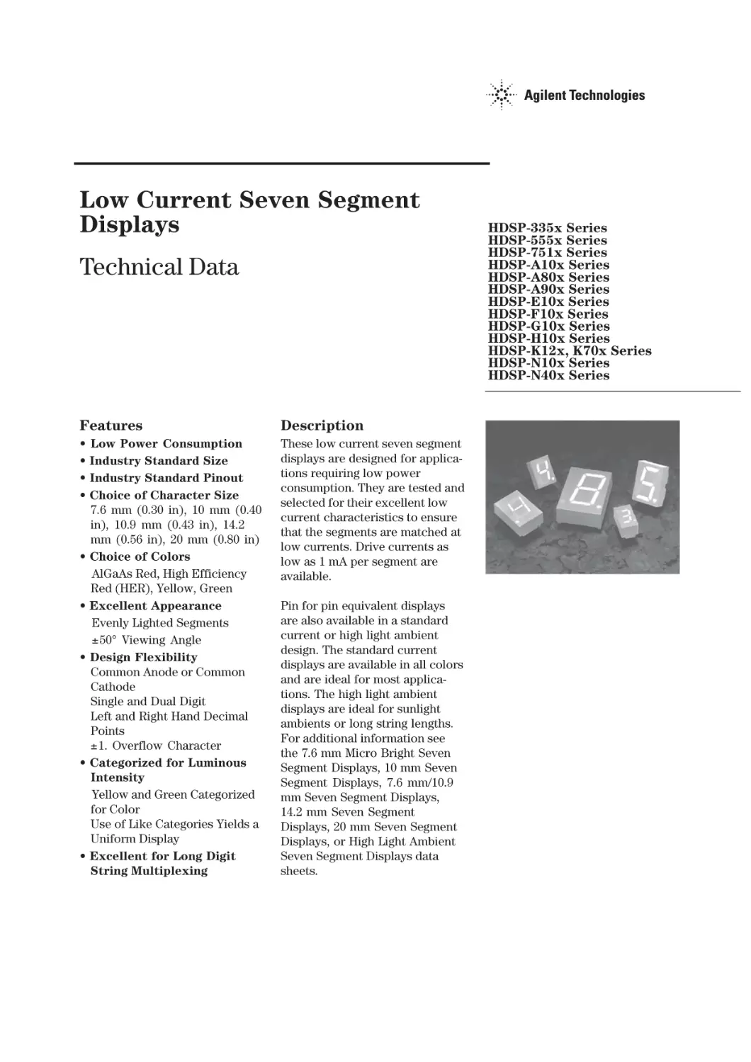
                    Low Current Seven Segment
Displays
Technical Data

Features

Description

•
•
•
•

These low current seven segment
displays are designed for applications requiring low power
consumption. They are tested and
selected for their excellent low
current characteristics to ensure
that the segments are matched at
low currents. Drive currents as
low as 1 mA per segment are
available.

•

•

•

•

•

Low Power Consumption
Industry Standard Size
Industry Standard Pinout
Choice of Character Size
7.6 mm (0.30 in), 10 mm (0.40
in), 10.9 mm (0.43 in), 14.2
mm (0.56 in), 20 mm (0.80 in)
Choice of Colors
AlGaAs Red, High Efficiency
Red (HER), Yellow, Green
Excellent Appearance
Evenly Lighted Segments
±50° Viewing Angle
Design Flexibility
Common Anode or Common
Cathode
Single and Dual Digit
Left and Right Hand Decimal
Points
±1. Overflow Character
Categorized for Luminous
Intensity
Yellow and Green Categorized
for Color
Use of Like Categories Yields a
Uniform Display
Excellent for Long Digit
String Multiplexing

Pin for pin equivalent displays
are also available in a standard
current or high light ambient
design. The standard current
displays are available in all colors
and are ideal for most applications. The high light ambient
displays are ideal for sunlight
ambients or long string lengths.
For additional information see
the 7.6 mm Micro Bright Seven
Segment Displays, 10 mm Seven
Segment Displays, 7.6 mm/10.9
mm Seven Segment Displays,
14.2 mm Seven Segment
Displays, 20 mm Seven Segment
Displays, or High Light Ambient
Seven Segment Displays data
sheets.

HDSP-335x Series
HDSP-555x Series
HDSP-751x Series
HDSP-A10x Series
HDSP-A80x Series
HDSP-A90x Series
HDSP-E10x Series
HDSP-F10x Series
HDSP-G10x Series
HDSP-H10x Series
HDSP-K12x, K70x Series
HDSP-N10x Series
HDSP-N40x Series

2

Devices
AlGaAs
HDSPA101
A103
A107
A108
F101
F103
F107
F108
G101
G103
E100
E101
E103
E106
H101
H103
H107
H108
K121
K123
N100
N101
N103
N105
N106

HER
HDSP7511
7513
7517
7518

3350
3351
3353
3356
5551
5553
5557
5558
K701
K703
N401
N403
N406

Yellow
HDSPA801
A803
A807
A808

Green
HDSPA901
A903
A907
A908

Description
7.6 mm Common Anode Right Hand Decimal
7.6 mm Common Cathode Right Hand Decimal
7.6 mm Common Anode ±1. Overflow
7.6 mm Common Cathode ±1. Overflow
10 mm Common Anode Right Hand Decimal
10 mm Common Cathode Right Hand Decimal
10 mm Common Anode ±1. Overflow
10 mm Common Cathode ±1. Overflow
10 mm Two Digit Common Anode Right Hand Decimal
10 mm Two Digit Common Cathode Right Hand Decimal
10.9 mm Common Anode Left Hand Decimal
10.9 mm Common Anode Right Hand Decimal
10.9 mm Common Cathode Right Hand Decimal
10.9 mm Universal ±1. Overflow[1]
14.2 mm Common Anode Right Hand Decimal
14.2 mm Common Cathode Right Hand Decimal
14.2 mm Common Anode ±1. Overflow
14.2 mm Common Cathode ±1. Overflow
14.2 mm Two Digit Common Anode Right Hand Decimal
14.2 mm Two Digit Common Cathode Right Hand Decimal
20 mm Common Anode Left Hand Decimal
20 mm Common Anode Right Hand Decimal
20 mm Common Cathode Right Hand Decimal
20 mm Common Cathode Left Hand Decimal
20 mm Universal ±1. Overflow[1]

Package
Drawing
A
B
C
D
E
F
G
H
X
Y
I
J
K
L
M
N
O
P
R
S
Q
T
U
V
W

Note:
1. Universal pinout brings the anode and cathode of each segment’s LED out to separate pins. See internal diagrams L or W.

3

Part Numbering System
5082 - x xx x - x x x xx
HDSP - x xx x - x x x xx
Mechanical Options[1]
00: No mechanical option

Color Bin Options[1,2]
0: No color bin limitation

Maximum Intensity Bin[1,2]
0: No maximum intensity bin limitation
Minimum Intensity Bin[1,2]
0: No minimum intensity bin limitation
Device Configuration/Color[1]
G: Green

Device Specific Configuration[1]
Refer to respective datasheet
Package[1]
Refer to Respective datasheet
Notes:
1. For codes not listed in the figure above, please refer to the respective datasheet or contact your nearest Agilent representative for
details.
2. Bin options refer to shippable bins for a part-number. Color and Intensity Bins are typically restricted to 1 bin per tube (exceptions may apply). Please refer to respective datasheet for specific bin limit information.

4

Package Dimensions

5

Package Dimensions (cont.)

6

Package Dimensions (cont.)

*The Side View of package indicates Country of Origin.

7

Package Dimensions (cont.)

8

Package Dimensions (cont.)

9

Package Dimensions (cont.)

10

Internal Circuit Diagram

11

Internal Circuit Diagram (cont.)

Absolute Maximum Ratings

Description
Average Power per Segment or DP

AlGaAs Red - HDSPHER
A10X/E10X/H10X
HDSP-751X/
K12X/N10X/N40X
335X/555X/
F10X, G10X Series K70X Series
37

52

Peak Forward Current per
Segment or DP
DC Forward Current per
Segment or DP
Operating Temperature Range
Storage Temperature Range
Reverse Voltage per Segment
or DP
Wave Soldering Temperature for 3
Seconds (1.60 mm [0.063 in.] below
seating body)

Yellow
HDSP-A80X
Series

45
15[1]
-20 to +100

Green
HDSP-A90X
Series

Units

64

mW
mA

15[2]

mA

-40 to +100

°C

-55 to +100
3.0

°C
V

250

°C

Notes:
1. Derate above 91°C at 0.53 mA/°C.
2. Derate HER/Yellow above 80°C at 0.38 mA/°C and Green above 71°C at 0.31 mA/°C.

12

Electrical/Optical Characteristics at TA = 25°C
AlGaAs Red
Device
Series
HDSP-

Parameter

Symbol

Min.

Typ.

Max.

Units

Test Conditions

315

600

IF = 1 mA

3600

IF = 5 mA

650

IF = 1 mA

3900

IF = 5 mA

A10x

330
F10x, G10x

390
E10x

Luminous Intensity/Segment[1,2]
(Digit Average)

650

IF = 1 mA
µcd

IV
400

3900

IF = 5 mA

700

IF = 1 mA

4200

IF = 5 mA

590

IF = 1 mA

3500

IF = 5 mA

1.6

IF = 1 mA

H10x, K12x

270
N10x, N40x

Forward Voltage/Segment or DP

VF

1.7
1.8

All Devices

nm

Dominant Wavelength[3]

λd

637

nm

Reverse Voltage/Segment or DP[4]

VR

15

V

-2 mV

mV/°C

∆VF/°C

3.0

255

F10x, G10x

320

E10x

340
Thermal Resistance LED
Junction-to-Pin

°C/W/Seg

RθJ-PIN
400
430

IF = 5 mA
IF = 20 mA Pk

645

A10x

N10x, N40x

2.2

λPEAK

Peak Wavelength

Temperature Coefficient of
VF /Segment or DP

H10x, K12x

V

IR = 100 µA

13

High Efficiency Red
Device
Series
HDSP-

Parameter

Symbol

Min.

Typ.

Max.

Units

Test Conditions

160

270

IF = 2 mA

1050

IF = 5 mA

751x

200
Luminous Intensity/Segment[1,2]
(Digit Average)
335x, 555x,
K70x

1200

IF = 5 mA

370

IF = 2 mA

1480

IF = 5 mA

1.6

IF = 2 mA

1.7

VF

2.1
All Devices

nm

Dominant Wavelength[3]

λd

626

nm

Reverse Voltage/Segment or DP[4]

VR

30

V

-2

mV/°C

∆VF /°C

3.0

200
Thermal Resistance LED
Junction-to-Pin

RθJ-PIN

280
345

IF = 5 mA
IF = 20 mA Pk

2.5

635

751x

555x, K70x

V

λPEAK

Peak Wavelength

Temperature Coefficient of
VF /Segment or DP

335x

IF = 2 mA
mcd

270

Forward Voltage/Segment or DP

300

IV

°C/W

IR = 100 µA

14

Yellow
Device
Series
HDSP-

Parameter
Luminous Intensity/Segment[1,2]
(Digit Average)

Forward Voltage/Segment or DP

Symbol

Min.

Typ.

250

420

Max.

Units

Test Conditions
IF = 4 mA

mcd

IV

VF

1300

IF = 10 mA

1.7

IF = 4 mA

1.8

V

IF = 5 mA

A80x
2.1
Peak Wavelength

λPEAK

IF = 20 mA Pk

2.5

583

nm

Dominant Wavelength[3,5]

λd

581.5

585

Reverse Voltage/Segment or DP[4]

VR

3.0

30

V

592.5

nm

Temperature Coefficient of
VF /Segment or DP

∆VF /°C

-2

mV/°C

Thermal Resistance LED
Junction-to-Pin

RθJ-PIN

200

°C/W

IR = 100 µA

Green
Device
Series
HDSP-

Parameter
Luminous Intensity/Segment[1,2]
(Digit Average)

Forward Voltage/Segment or DP

Symbol

Min.

Typ.

250

475

Max.

Units

Test Conditions
IF = 4 mA

mcd

IV
1500

IF = 10 mA

1.9

IF = 4 mA

2.0

VF

V

IF = 10 mA

A90x
2.1
λPEAK

566

Dominant Wavelength[3,5]

λd

571

Reverse Voltage/Segment or DP[4]

VR

Peak Wavelength

3.0

IF = 20 mA Pk

2.5
nm
577

nm

30

V

Temperature Coefficient of
VF /Segment or DP

∆VF /°C

-2

mV/°C

Thermal Resistance LED
Junction-to-Pin

RθJ-PIN

200

°C/W

IR = 100 µA

Notes:
1. Device case temperature is 25°C prior to the intensity measurement.
2. The digits are categorized for luminous intensity. The intensity category is designated by a letter on the side of the package.
3. The dominant wavelength, λd, is derived from the CIE chromaticity diagram and is the single wavelength which defines the color of the
device.
4. Typical specification for reference only. Do not exceed absolute maximum ratings.
5. The yellow (HDSP-A800) and Green (HDSP-A900) displays are categorized for dominant wavelength. The category is designated by a
number adjacent to the luminous intensity category letter.

15

AlGaAs Red

Figure 1. Maximum Allowable
Average or DC Current vs. Ambient
Temperature.

Figure 2. Forward Current vs.
Forward Voltage.

Figure 3. Relative Luminous Intensity
vs. DC Forward Current.

Figure 4. Relative Efficiency
(Luminous Intensity per Unit
Current) vs. Peak Current.

16

HER, Yellow, Green

Figure 5. Maximum Allowable
Average or DC Current vs. Ambient
Temperature.

Figure 6. Forward Current vs.
Forward Voltage.

Figure 7. Relative Luminous Intensity
vs. DC Forward Current.

Figure 8. Relative Efficiency
(Luminous Intensity per Unit
Current) vs. Peak Current.

17

Intensity Bin Limits (mcd)
AlGaAs Red
IV Bin Category
E
F
G
H
I
J
K
L

HDSP-A10x
Min.
0.315
0.428
0.621
0.945
1.40
2.10
3.14
4.70

Max.
0.520
0.759
1.16
1.71
2.56
3.84
5.75
8.55

HDSP-E10x/F10x/G10x
IV Bin Category
Min.
D
0.391
E
0.532
F
0.755
G
1.13
H
1.70

Max.
0.650
0.923
1.39
2.08
3.14

HDSP-H10x/K12x
IV Bin Category
Min.
C
0.415
D
0.565
E
0.810
F
1.20
G
1.80
H
2.73
I
4.09

Max.
0.690
0.990
1.50
2.20
3.30
5.00
7.50

IV Bin Category
A
B
C
D
E
F
G
H
I

HDSP-N10x
Min.
0.270
0.325
0.415
0.565
0.810
1.20
1.80
2.73
4.09

Max.
0.400
0.500
0.690
0.990
1.50
2.20
3.30
5.00
7.50

18

Intensity Bin Limits (mcd), continued
HER
IV Bin Category
B
C
D
E
F
G

HDSP-751x
Min.
0.160
0.200
0.250
0.315
0.428
0.621

Max.
0.240
0.300
0.385
0.520
0.759
1.16

IV Bin Category
B
C
D
E
F
G
H

HDSP-751x
Min.
0.240
0.300
0.391
0.532
0.755
1.13
1.70

Max.
0.366
0.477
0.650
0.923
1.39
2.08
3.14

HDSP-555x/K70x
IV Bin Category
Min.
A
0.270
B
0.325
C
0.415
D
0.565
E
0.810
F
1.20
G
1.80
H
2.73
I
4.09

Max.
0.400
0.500
0.690
0.990
1.50
2.20
3.30
5.00
7.50

19

Intensity Bin Limits (mcd), continued
Yellow
HDSP-A80x
Min.
0.250
0.315
0.425
0.625
0.940
1.40
2.10
3.14
4.71
7.07
10.60
15.90
23.90
35.80

Max.
0.385
0.520
0.760
1.14
1.70
2.56
3.84
5.76
8.64
13.00
19.40
29.20
43.80
65.60

HDSP-A90x
IV Bin Category
Min.
E
0.315
F
0.425
G
0.625
H
0.940
I
1.40
J
2.10
K
3.14
L
4.71
M
7.07
N
10.60
O
15.90
P
23.90
Q
35.80

Max.
0.520
0.760
1.14
1.70
2.56
3.84
5.76
8.64
13.00
19.40
29.20
43.80
65.60

IV Bin Category
D
E
F
G
H
I
J
K
L
M
N
O
P
Q

Green

Color Categories
Color
Yellow

Green

Bin
1
3
2
4
2
3
4
5

Dominant Wavelength (nm)
Min.
Max.
581.50
585.00
584.00
587.50
586.50
590.00
589.00
592.50
573.00
577.00
570.00
574.00
567.00
571.00
564.00
568.00

Note:
All categories are established for classification of products. Products
may not be available in all categories. Please contact your local
Agilent representatives for further clarification/information.

Electrical/Optical
For more information on
electrical/optical characteristics,
please see Application Note 1005.

Contrast Enhancement
For information on contrast
enhancement, please see
Application Note 1015.

Soldering/Cleaning
Cleaning agents from the ketone
family (acetone, methyl ethyl
ketone, etc.) and from the

chorinated hydrocarbon family
(methylene chloride, trichloroethylene, carbon tetrachloride,
etc.) are not recommended for
cleaning LED parts. All of these
various solvents attack or
dissolve the encapsulating
epoxies used to form the package
of plastic LED parts.
For information on soldering
LEDs, please refer to Application
Note 1027.

www.agilent.com/semiconductors
For product information and a complete list of
distributors, please go to our web site.
For technical assistance call:
Americas/Canada: +1 (800) 235-0312 or
(916) 788 6763
Europe: +49 (0) 6441 92460
China: 10800 650 0017
Hong Kong: (+65) 6271 2451
India, Australia, New Zealand: (+65) 6271 2394
Japan: (+81 3) 3335-8152(Domestic/International), or
0120-61-1280(Domestic Only)
Korea: (+65) 6271 2194
Malaysia, Singapore: (+65) 6271 2054
Taiwan: (+65) 6271 2654
Data subject to change.
Copyright © 2005 Agilent Technologies, Inc.
Obsoletes 5988-8412EN
January 19, 2005
5989-0080EN