/


Tags: weapons
Year: 1926


Text
MUN4
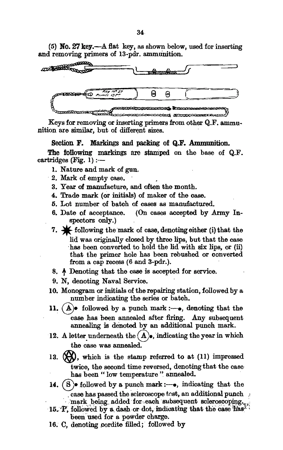
IMPORTANT
This book is invariably to be kept
under lock and key when not in use,-
and it is not to be taken outside the
Establishment without the express per-
mission of the Commanding Officer.
...._______________________________... _________________________ ._______________
-"' 1' ------ , , J..— » U-.-gl1 l-n, ............... '.liin.g... " -Mb 1 я=а»------------------------------------------------------
r insidH J the cover of O.U. 5267 after the necessary
v notatiwl; have been made in the book.)
/ —~7~------ji------------------------——----------
—4—— This. ЬпсЦ is invariably to be kept locked
Щэ'ХЪеп r.Jt in use and is not to be taken
outside the ship or establishment for which
it is issued without the express permission
of the Commanding Officer.
/V0/VA<6CU. 5267 (1).
Technical Lie
Ammunition Fa
£>•23-
( "VtJ
ADDENDUM N<L_L_c-«w^
TO
O.U. 5267.
AMMUNITION POCKET BOOK, 1924.
1926.
A note “ See Addendum ” should be inserted in the margin
of O.U. 5267 against the paragraphs affected by this Addendum,
and the words “ with Addendum No. 1 ” inserted after
O.U. 5267 on the outside of the cover.
admiralty, S.W.
Guhtnery Ввалси.
(G. 12864/26. September, 1926»)
FOR OFFICIAL USE ONLY.
This book is the property of H.M. Government.
Its contents are not to be communicated either directly or
indirectly to the Press, or to any person not holding an official
position in H.M. Service.
FOR OFFICIAL USE ONLY.
Attention is called to the penalties attaching to any infraction
of: the Official Secrets Acts.
ADDENDUM No. 1
TO
AMMUNITION POCKET BOOK, 1924.
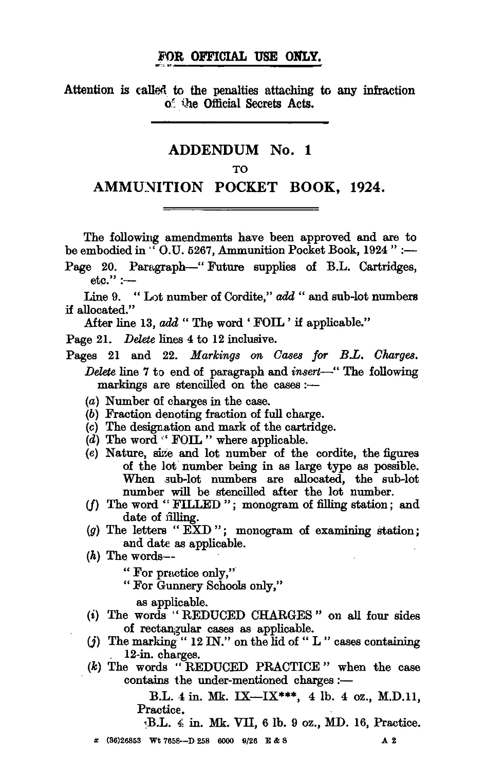
The following amendments have been approved and are to
be embodied in ' ‘ O.U. 6267, Ammunition Pocket Book, 1924 ” :—
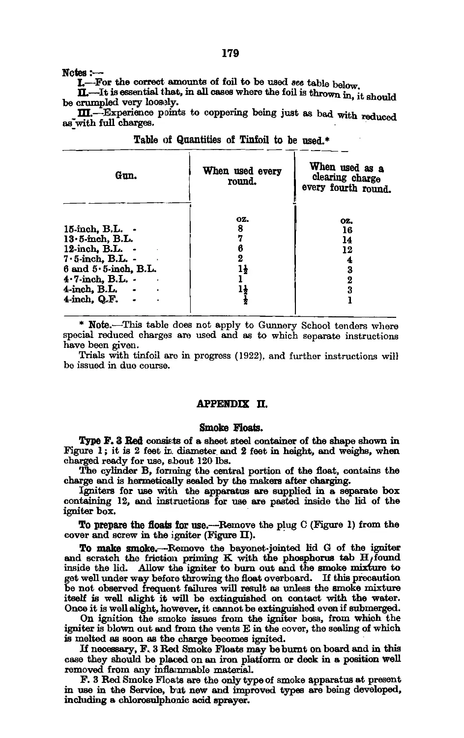
Page 20. Paragraph—“ Future supplies of B.L. Cartridges,
etc.” :—
Line 9. “ Lot number of Cordite,” add “ and sub-lot numbers
if allocated.”
After line 13, add “ The word ‘ FOIL ’ if applicable.”
Page 21. Delete lines 4 to 12 inclusive.
Pages 21 and 22. Markings on Cases for B.L. Charges.
Delete line 7 to end of paragraph and insert—“ The following
markings are stencilled on the cases :—
(a) Number of charges in the case.
(b) Fraction denoting fraction of full charge.
(c) The desigration and mark of the cartridge.
(d) The word ' " FOIL ” where applicable.
(e) Nature, sii’.e and lot number of the cordite, the figures
of the lot number being in as large type as possible.
When sub-lot numbers are allocated, the sub-lot
number wifi be stencilled after the lot number.
(/) The word “ FILLET) ”; monogram of filling station; and
date of filling.
(g) The letters “EXD”; monogram of examining station;
and date as applicable.
(Л) The words—
“ For practice only,”
“ For Gunnery Schools only,”
as applicable.
(i) The words ‘ ‘ REDUCED CHARGES ” on all four sides
of rectangular cases as applicable.
(J) The marking “ 12 IN.” on the lid of “ L ” cases containing
12-in. charges.
(k) The words “ REDUCED PRACTICE ” when the case
contains the under-mentioned charges:—
B.L. 4 in. Mk. IX—IX***, 4 lb. 4 oz., M.D.U,
Practice.
’B.L. 4- in. Mk. VH, 6 lb. 9 oz., MD. 16, Practice.
x (36)26853 Wt 7658—D 258 6000 0/26 E & 8 A 2
4
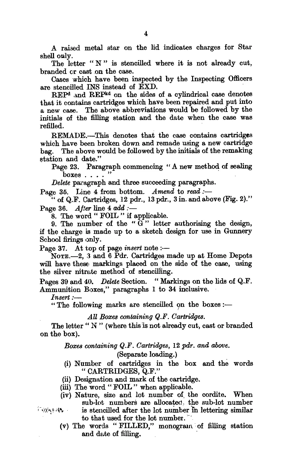
A raised metal star on the lid indicates charges for Star
shell only.
The letter “ N ” is stencilled where it is not already cut,
branded or cast on the case.
Cases which have been inspected by the Inspecting Officers
are stencilled INS instead of EXD;
REP1 and REPkd on the sides of a cylindrical case denotes
that it contains cartridges which have been repaired and put into
a new case. The above abbreviations would be followed by the
initials of the filling station and the date when the case was
refilled.
REMADE.—This denotes that the case contains cartridges
which have been broken down and remade using a new cartridge
bag. The above would be followed by the initials of the remaking
station and date.”
Page 23. Paragraph commencing " A new method of sealing
boxes . ... ”
Delete paragraph and three succeeding paragraphs.
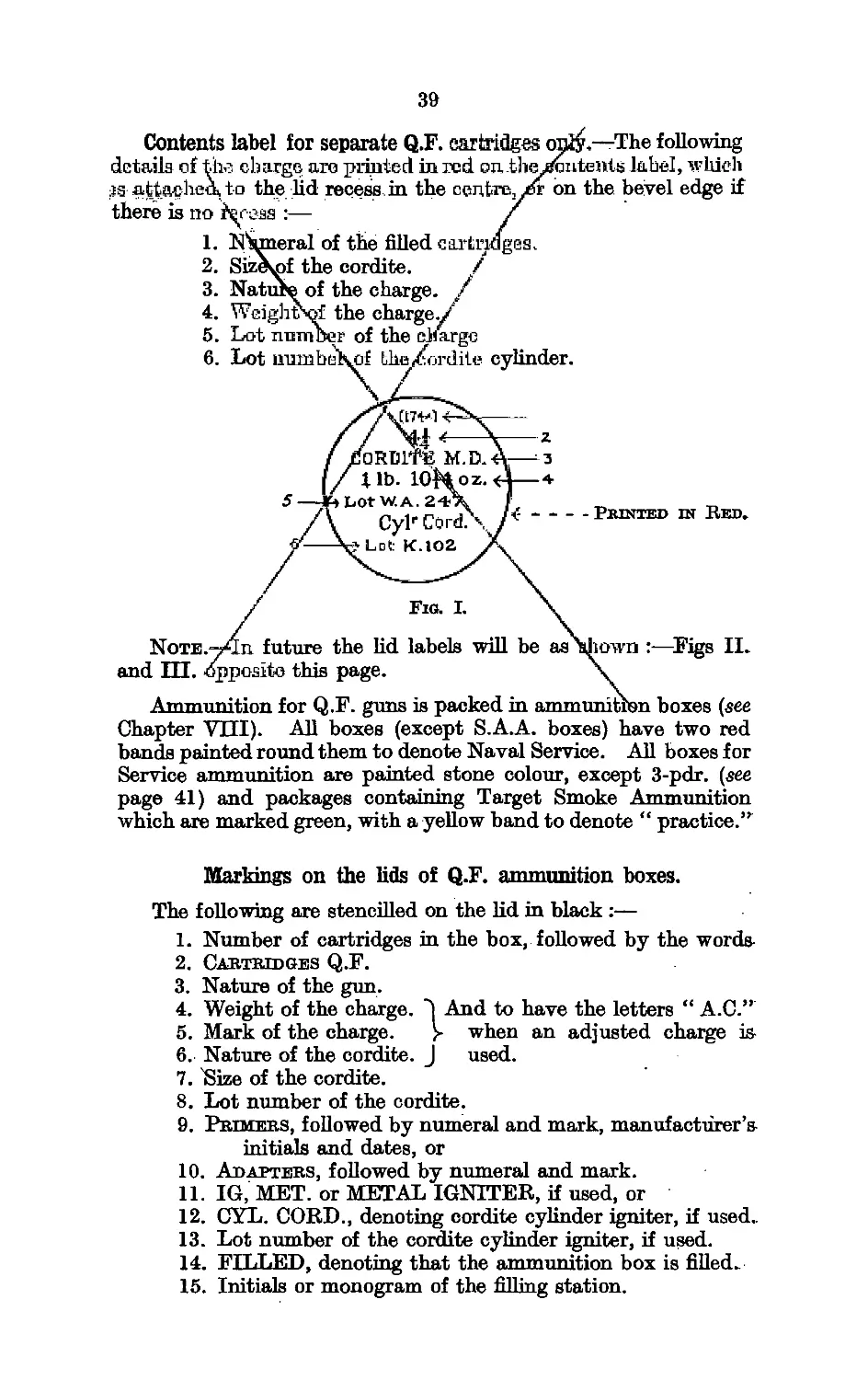
Page 36. Line 4 from bottom. Amend to read:—
“ of Q.F. Cartridges, 12 pdr., 13 pdr., 3 in. and above (Fig. 2).”
Page 36. After line 4 add :—
8. The word “ FOIL ” if applicable.
9. The number of the “ G ” letter authorising the design,
if the charge is made up to a sketch design for use in Gunnery
School firings only.
Page 37. At top of page insert note :—
Note.—2, 3 and 6 Pdr. Cartridges made up at Home Depots
win have these markings placed on the side of the case, using
the silver nitrate method of stencilling.
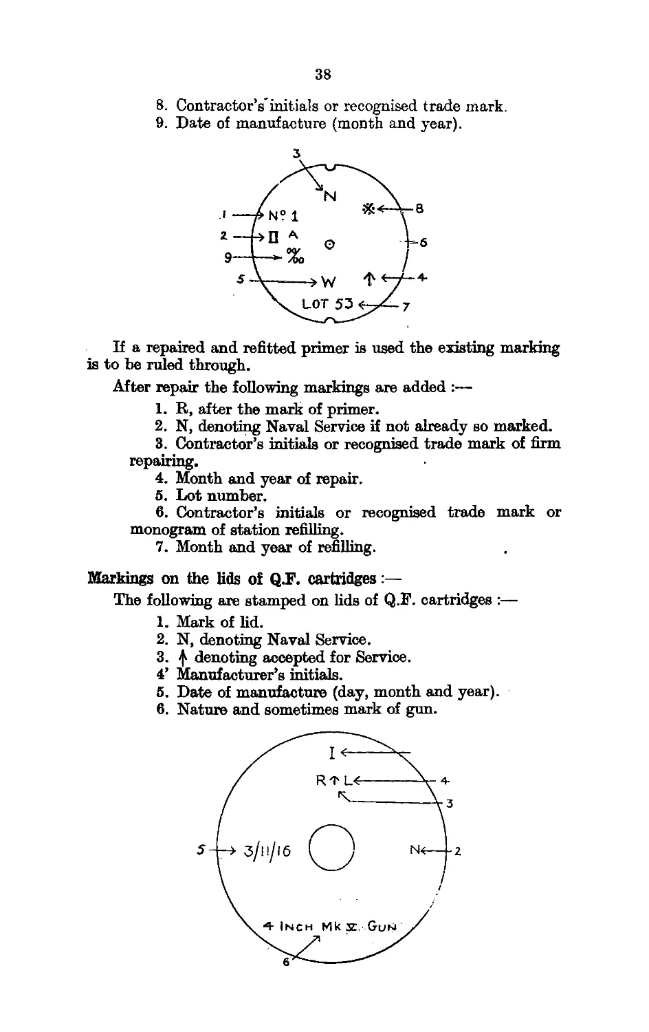
Pages 39 and 40. Delete Section. “ Markings on the lids of Q.F.
Ammunition Boxes,” paragraphs 1 to 34 inclusive.
Insert:—
“ The following marks are stencilled pn the boxes:—
All Boxes containing Q.F. Cartridges.
The letter “ N ” (where this is not already cut, cast or branded
on the box).
Boxes containing Q.F. Cartridges, 12 pdr. and above.
(Separate loading.)
(i) Number of cartridges in the box and the words
“ CARTRIDGES, Q.F.”
(ii) Designation and mark of the cartridge.
(iii) The word “ FOIL ” when applicable.
(iv) Nature, size and lot number of the cordite. When
sub-lot numbers are allocated, the sub-lot number
1 -ям-.4k is stencilled after the lot number in lettering similar
to that used for the lot number. "
(v) The words “ FILLED,” monogram of filling station
and date of filling.
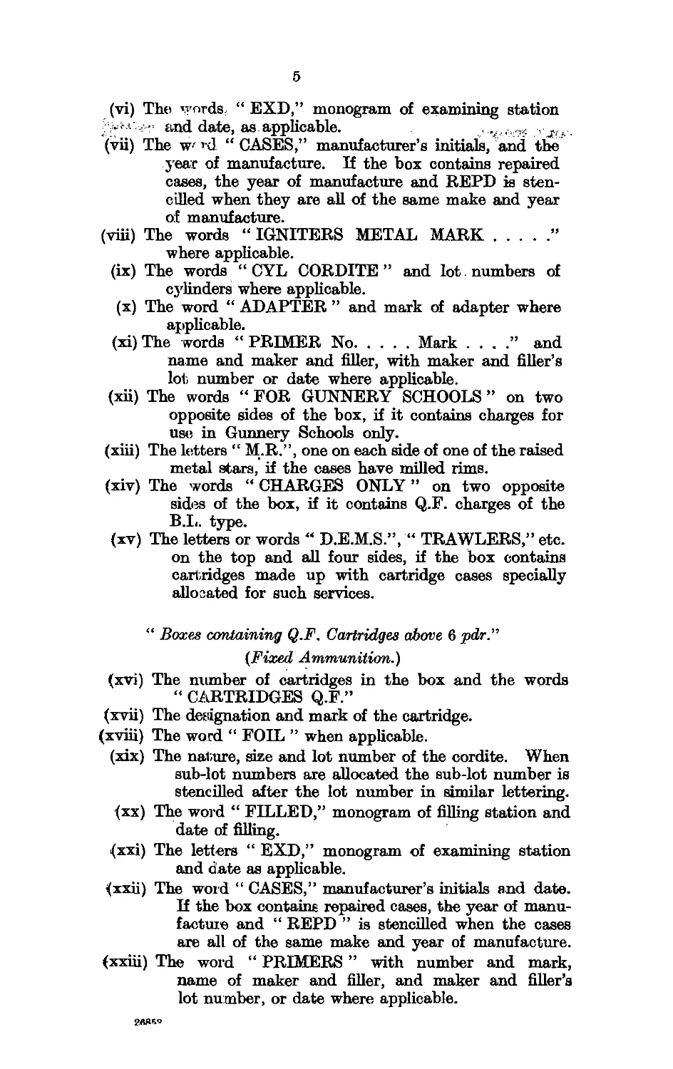
5
(vi) The* v;T>rds; “ EXD,” monogram of examining station
and date, as applicable. .!
(vii) The w< rd “ CASES,” manufacturer’s initials, and the
year of manufacture. If the box contains repaired
cases, the year of manufacture and REPD is sten-
cilled when they are all of the same make and year
of manufacture.
(viii) The words “ IGNITERS METAL MARK...................”
where applicable.
(ix) The words “ CYL CORDITE ” and lot. numbers of
cylinders where applicable.
(x) The word “ ADAPTER ” and mark of adapter where
applicable.
(xi) The words “ PRIMER No..........Mark . . . .” and
name and maker and filler, with maker and filler’s
lot number or date where applicable.
(xii) The words “ FOR GUNNERY SCHOOLS ” on two
opposite sides of the box, if it contains charges for
use in Gunnery Schools only.
(xiii) The letters “ M.R.”, one on each side of one of the raised
metal stars, if the cases have milled rims.
(xiv) The words “ CHARGES ONLY ” on two opposite
sides of the box, if it contains Q.F. charges of the
B.L. type.
(xv) The letters or words “ D.E.M.S.”, “ TRAWLERS,” etc.
on the top and all four sides, if the box contains
cartridges made up with cartridge cases specially
allocated for such services.
“ Boxes containing Q.F. Cartridges above 6 pdr.”
{Fixed Ammunition.)
(xvi) The number of cartridges in the box and the words
“ CARTRIDGES Q.F.”
(xvii) The designation and mark of the cartridge.
(xviii) The word “ FOIL ” when applicable.
(xix) The nature, size and lot number of the cordite. When
sub-lot numbers are allocated the sub-lot number is
stencilled after the lot number in similar lettering.
(xx) The word “ FILLED,” monogram of filling station and
date of filling.
(xxi) The letters “ EXD,” monogram of examining station
and date as applicable.
^xxii) The word “ CASES,” manufacturer’s initials and date.
If the box contains repaired cases, the year of manu-
facture and “ REPD ” is stencilled when the cases
are all of the same make and year of manufacture.
(xxiii) The word “ PRIMERS ” with number and mark,
name of maker and filler, and maker and filler’s
lot number, or date where applicable.
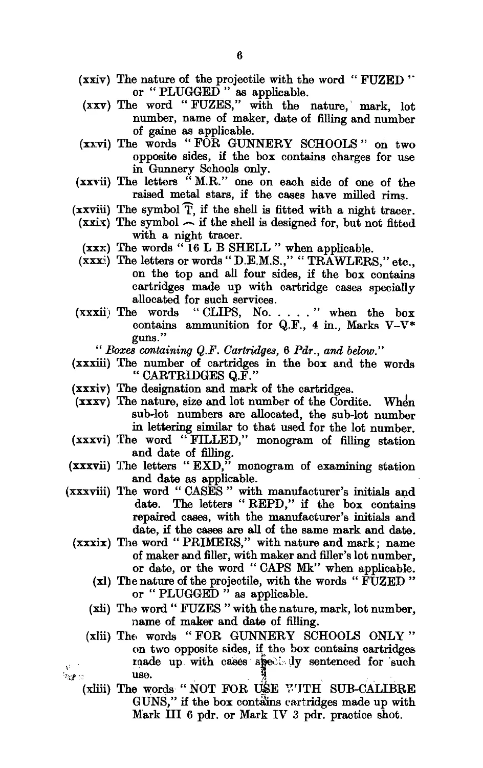
6
(xxiv) The nature of the projectile with the word “ FUZED ’’
or “ PLUGGED ” as applicable.
(xxv) The word “FUZES,” with the nature, mark, lot
number, name of maker, date of filling and number
of game as applicable.
(xxvi) The words “ FOR GUNNERY SCHOOLS ” on two
opposite sides, if the box contains charges for use
in Gunnery Schools only.
(xxvii) The letters “ M.R.” one on each side of one of the
raised metal stars, if the cases have milled rims.
(xxviii) The symbol T, if the shell is fitted with a night tracer.
(xxix) The symbol if the shell is designed for, but not fitted
with a night tracer.
(xxx) The words “ 16 L В SHELL ” when applicable.
(xxxi) The letters or words “ D.E.M.S.,” “ TRAWLERS,” etc.,
on the top and all four sides, if the box contains
cartridges made up with cartridge cases specially
allocated for such services.
(xxxiij The words “ CLIPS, No...............” when the box
contains ammunition for Q.F., 4 in., Marks V-V*
guns.”
“ Boxes containing Q.F. Cartridges, 6 Pdr., and below.”
(xxxiii) The number of cartridges in the box and the words
“ CARTRIDGES Q.F.”
(xxxiv) The designation and mark of the cartridges.
(xxxv) The nature, size and lot number of the Cordite. When
sub-lot numbers are allocated, the sub-lot number
in lettering similar to that used for the lot number.
(xxxvi) 'The word “ FILLED,” monogram of filling station
and date of filling.
(xxxvii) The letters “ EXD,” monogram of examining station
and date as applicable.
(xxxviii) The word “ CASES ” with manufacturer’s initials and
date. The letters “ REPD,” if the box contains
repaired cases, with the manufacturer’s initials and
date, if the cases are all of the same mark and date.
(xxxix) The word “PRIMERS,” with nature and mark; name
of maker and filler, with maker and filler’s lot number,
or date, or the word “ CAPS Mk” when applicable.
(xl) The nature of the projectile, with the words “ FUZED ”
or “ PLUGGED ” as applicable.
(xli) The word “ FUZES ” with the nature, mark, lot number,
name of maker and date of filling.
(xlii) The words “ FOR GUNNERY SCHOOLS ONLY ”
on two opposite sides, if the box contains cartridges
made up with cases spec.. dy sentenced for such
’гЛ:? use. .5
(xliii) The words “NOT FOR 1>E WITH SUB-CALIBRE
GUNS,” if the box contains cartridges made up with
Mark 1П 6 pdr. or Mark IV 3 pdr. practice shot.
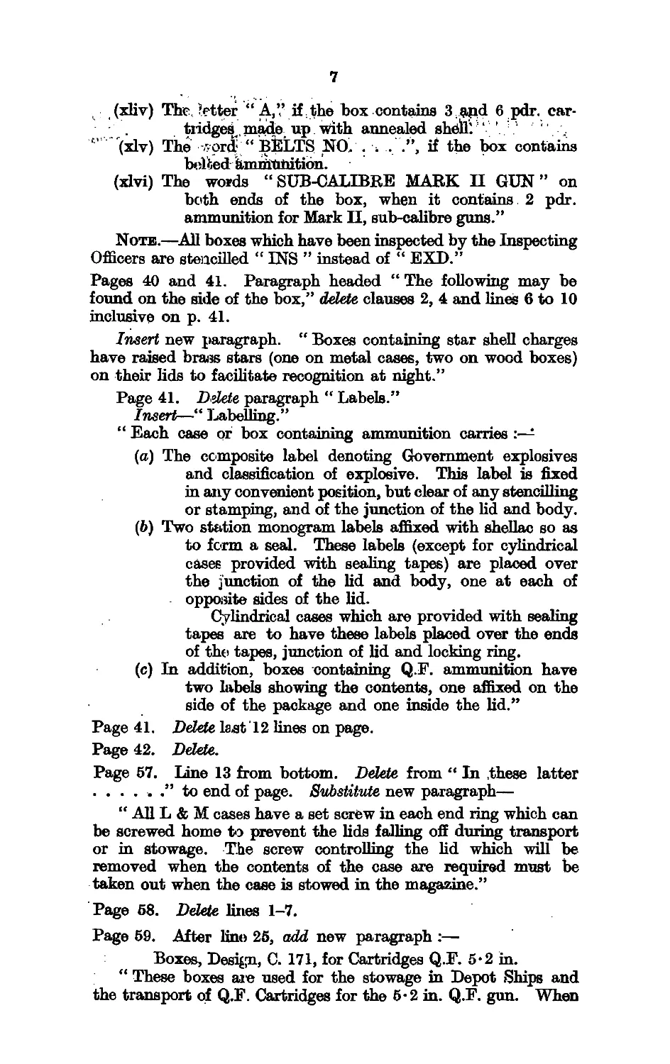
7
(xliv) The. letter “A,” if. the box contains 3apd 6 pdr. car-
tridges., made up with annealed shelly ‘ ’
° (xlv) The .vprdJ “ BfeliTS NO. . -4 . .”, if the box contains
beltedammunition.
(xlvi) The words “ SUB-CALIBRE MARK II GUN ” on
both ends of the box, when it contains 2 pdr.
ammunition for Mark II, sub-calibre guns.”
Note.—All boxes which have been inspected by the Inspecting
Officers are stencilled “ INS ” instead of “ EXD.”
Pages 40 and 41. Paragraph headed “ The following may be
found on the side of the box,” delete clauses 2, 4 and lines 6 to 10
inclusive on p. 41.
Insert new paragraph. “ Boxes containing star shell charges
have raised brass stars (one on metal cases, two on wood boxes)
on their lids to facilitate recognition at night.”
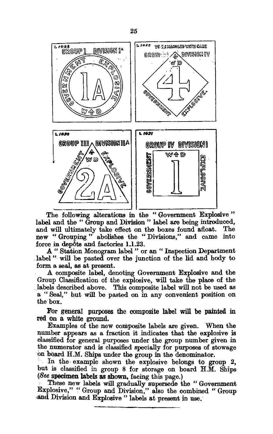
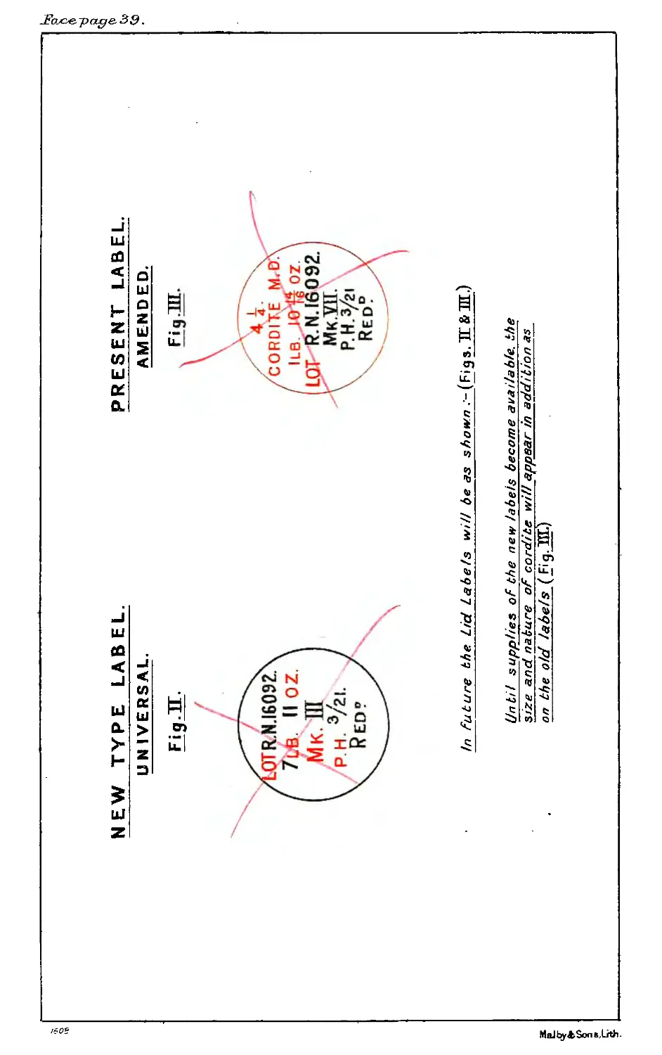
Page 41. Ddete paragraph " Labels.”
Insert—“ Labelling.”
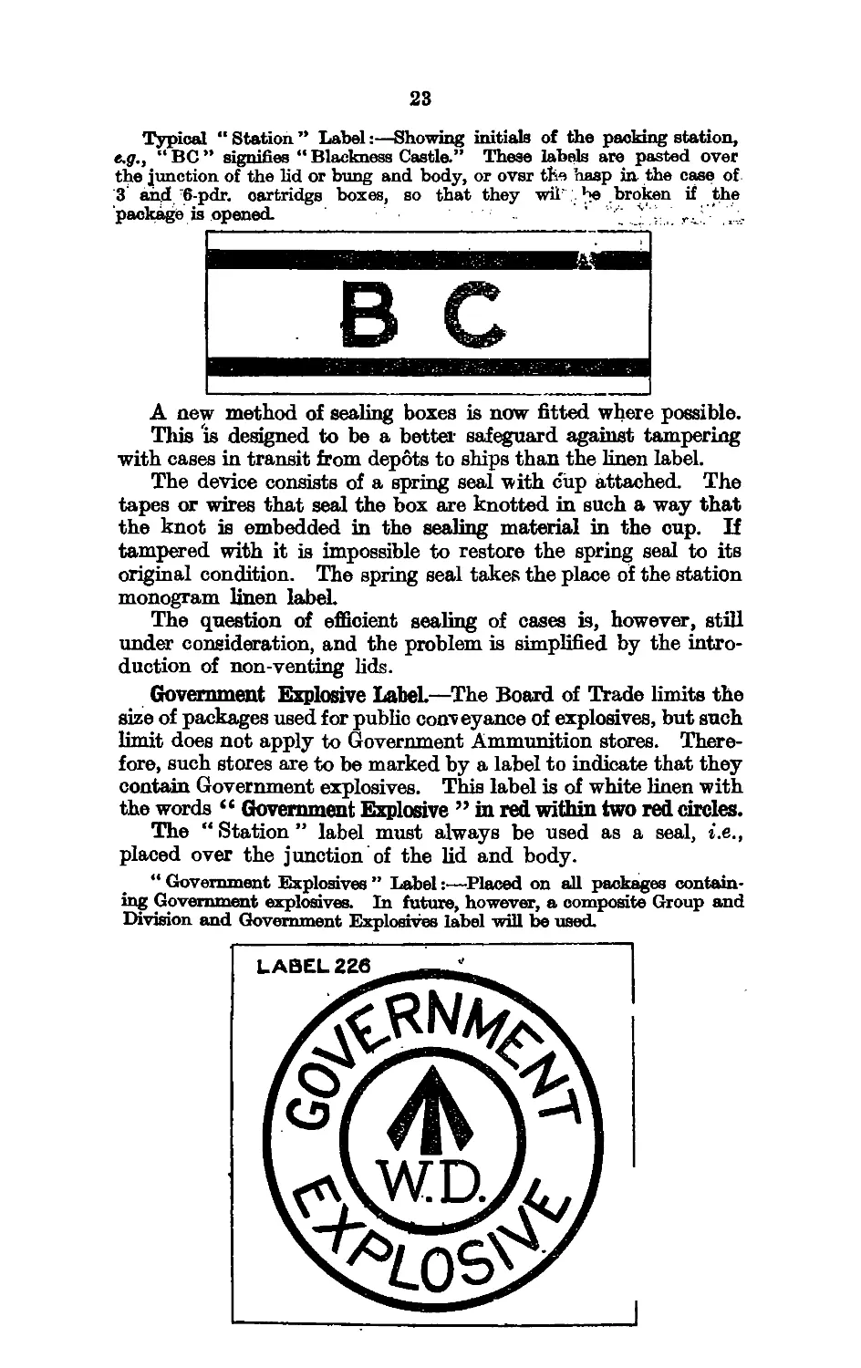
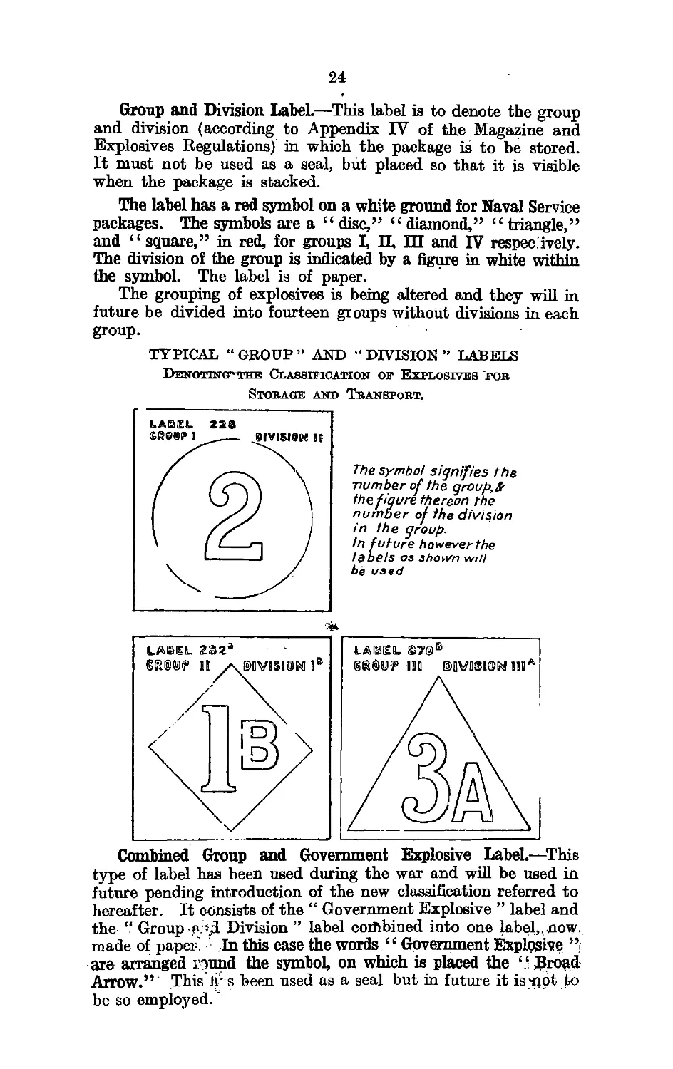
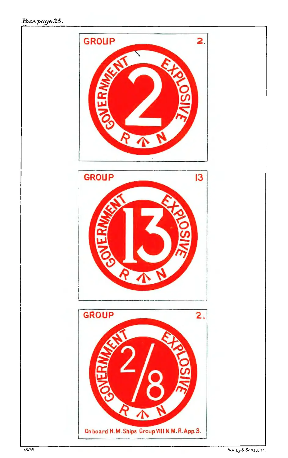
“ Each case or box containing ammunition carries
(a) The composite label denoting Government explosives
and classification of explosive. This label is fixed
in any convenient position, but clear of any stencilling
or stamping, and of the junction of the lid and body.
(6) Two station monogram labels affixed with shellac so as
to form a seal. These labels (except for cylindrical
cases provided with sealing tapes) are placed over
the junction of the lid and body, one at each of
opposite sides of the lid.
Cylindrical cases which are provided with sealing
tapes are to have these labels placed over the ends
of the tapes, junction of lid and locking ring.
(c) In addition, boxes containing Q.F. ammunition have
two labels showing the contents, one affixed on the
side of the package and one inside the lid.”
Page 41. Delete 18st l2 lines on page.
Page 42. Ddete.
Page 57. Line 13 from bottom. Ddete from “ In .these latter
......” to end of page. Substitute new paragraph—
“ All L & M cases have a set screw in each end ring which can
be screwed home to prevent the lids falling off during transport
or in stowage. The screw controlling the lid which will be
removed when the contents of the case are required must be
taken out when the case is stowed in the magazine.”
Page 58. Ddete lines 1-7.
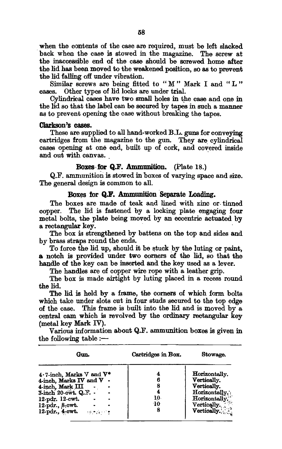
Page 59. After line 25, add new paragraph :—
Boxes, Desi^jn, C. 171, for Cartridges Q.F. 5*2 in.
“ These boxes aie used for the stowage in Depot Ships and
the transport of Q.F. Cartridges for the 5-2 in. Q.F. gun. When
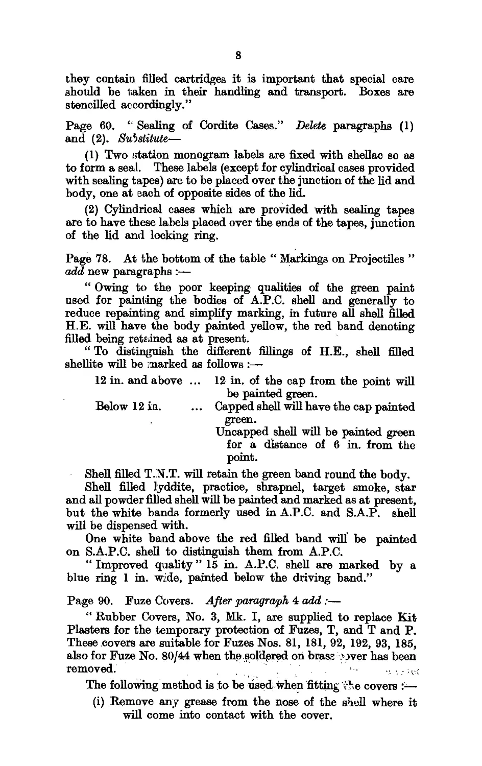
8
they contain filled cartridges it is important that special care
should be 1>aken in their handling and transport. Boxes are
stencilled accordingly.”
Page 60. ‘ Sealing of Cordite Cases.” Delete paragraphs (1)
and (2). Substitute—
(1) Two station monogram labels are fixed with shellac so as
to form a seal. These labels (except for cylindrical cases provided
with sealing tapes) are to be placed over the junction of the lid and
body, one at each of opposite sides of the lid.
(2) Cylindrical cases which are provided with sealing tapes
are to have these labels placed over the ends of the tapes, junction
of the lid and locking ring.
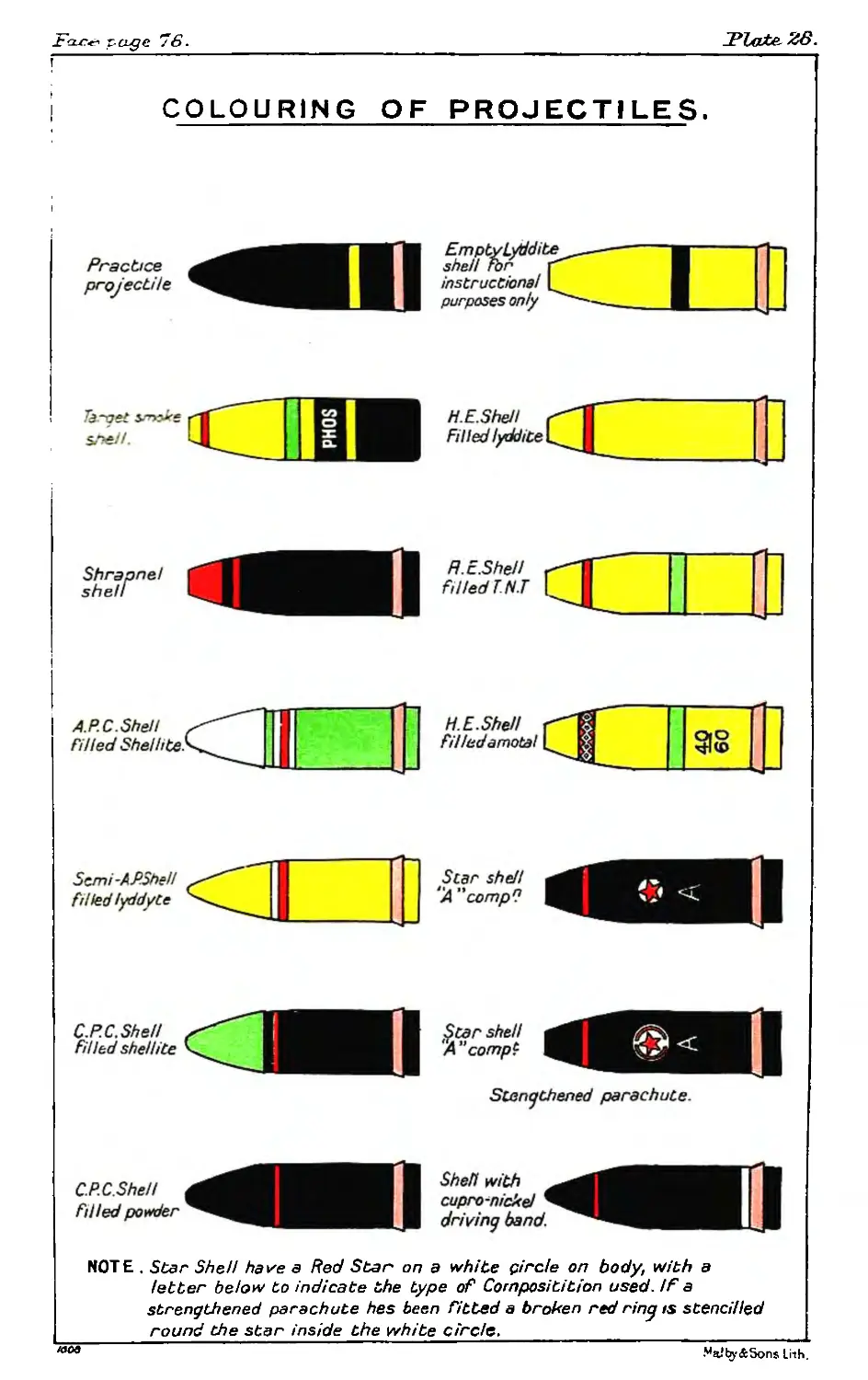
Page 78. At the bottom of the table “ Markings on Projectiles ”
add new paragraphs :—
“ Owing to the poor keeping qualities of the green paint
used for painting the bodies of A.P.C. shell and generally to
reduce repainting and simplify marking, in future all shell filled
H.E. will have the body painted yellow, the red band denoting
filled being retained as at present.
“ To distinguish the different fillings of H.E., shell filled
shellite will be ^marked as follows :—
12 in. and above ... 12 in. of the cap from the point will
be painted green.
Belo w 12 in. ... Capped shell will have the cap painted
green.
Uncapped shell will be painted green
for a distance of 6 in. from the
point.
Shell filled T.N.T. will retain the green band round the body.
Shell filled lyddite, practice, shrapnel, target smoke, star
and all powder filled shell will be painted and marked as at present,
but the white bands formerly used in A.P.C. and S.A.P. shell
will be dispensed with.
One white band above the red filled band will be painted
on S.A.P.C. shell to distinguish them from A.P.C.
“ Improved quality ” 15 in. A.P.C. shell are marked by a
blue ring 1 in. wide, painted below the driving band.”
Page 90. Fuze Covers. After paragraph 4 add :—
“ Rubber Covers, No. 3, Mk. I, are supplied to replace Kit
Plasters for the temporary protection of Fuzes, T, and T and P.
These covers are suitable for Fuzes Nos. 81, 181, 92, 192, 93, 185,
also for Fuze No. 80/44 when the.soldgred on brass .' Jver has been
removed. ' . .
The following method is to be used when fitting vhe covers t—
(i) Remove any grease from the nose of the shell where it
will come into contact with the cover.
9
(ii) PJ.aep the cover ovei; the fuze and press it well down into
position. The studs on the time ring and body should
r:w be under the thickened band.
(iii) Wliile holding the point of the cover firmly down on the
fuze, turn up the thin edge below the thickened band
and paint the under edge of the cover and the shell
with Pettman’s cement, care being taken that the
cement does not come in contact with the fuze itself.
It is specially important to ensure a good coating of
cement on the portion of the cover in the vicinity of
the tab, and on the corresponding surface of the shell.
(iv) Turn the thin edge down and then run the brush round
the joint between the cover and the shell.
(v) The operation should be carried out under dry conditions.
Covers which have been removed from fuzes are to be pre-
served and returned to store for reissue after renovation.”
Page 130. Paragraph “ Night signal box contains :—”
Delete, 4 green
4 red
4 white
Very’s lights.
Substitute 6 green
6 red
6 white
1" Signal Cartridges.
Paragraph “ Sea boats box contains :—”
Delete 10 Very’s lights, 5 green, 5 red.
Substitute 12 Г’ Signal Cartridges, 6 green, 6 red.
Page 131. Paragraph “ Steamboats are at all times ...”
Delete “ Very’s lights.”
Substitute 1" Signal Cartridges.
FOR OFFICIAL USE ONLY.
Attention is called, to the penalties attaching to any infraction
of the Official Secrets Act.
This book is the property of H.M. Government.
Its contents are not to be communicated, either directly
or indirectly to the Press, or to any person not holding an
official position in H.M. Service.
O.U. 5267.
AMMUNITION
POCKET BOOK.
1924.
ADMIRALTY, S.W.1
(Gvnneby Branch),
G. 837/24.
11
CONTENTS.
List OF Tables Page iii
List of Plates iv
Fobewobd ...................................................... v
Chapter. Subject.
I. High Explosives ....................................... 1
Nitroglycerine—Nitrocellulose—Picric Acid, Picric Pow-
der—Trotyl—Amatol—Tetryl.
П. Propellants ........................................... 8
Ballistite—Cordite Mark I—Cordite M.D.—Cordite M.C.
—Cordite B.D.B.—Nitrocellulose Powder—Gunpowder.
1П. Miscellaneous Explosives ... ...... ............ 15
Initiating Explosives—Illuminating and Signal Composi-
tions.
IV. Cartridges fob B.L. Guns....... ... ... ... 18
Manufacture—Marking of Cartridges—Marking of Cases—
Labels.
V. Cabtbidges fob Q.F. Guns........ .............. 26
General Remarks—Q.F. Fixed Ammunition—Q.F. Sepa-
rate Loading Cartridges—Adapters and Percussion
Primers—Keys—Marking.
VI. Tubes............................................. 43
Introduction—Detailed Descriptions of Tubes—Marking,
Identification and Packing.
VH. Blank Chabges ...................................... 49
Blank Cartridges for B.L. Guns—Blank Cartridges for x
Q.F. Guns—Marking on Blank Cartridges.
VUI. Cases, Boxes, &c.................................... 54
Weakening of Cases—Rectangular Cases—Cylindrical
Cases—Boxes for Q.F. Ammunition—Metal-lined Cases—
S.A.A. Boxes.
IX. Projectiles ....................................... 63
Form of Projectiles and Contour of Heads—Effect of
Capping—Bursters of Shell—Remarks on Different
Fillings—Night Tracers—Driving Bands—Transport of
Projectiles—Markings.
X. Fuzbs and Gaines .................................. 81
General Remarks—Description of Fuzes—Description
of Gaines—Description of Detonators.
XI. Small Arm Ammunition ..............................Ill
Linch A.R. Ammunition—Small Arm Ammunition—
• 303-inch Blank Ammunition—Webley Revolver Ammu-
nition—Aiming Tube Cartridges—Marking and Packing
of S.A.A.
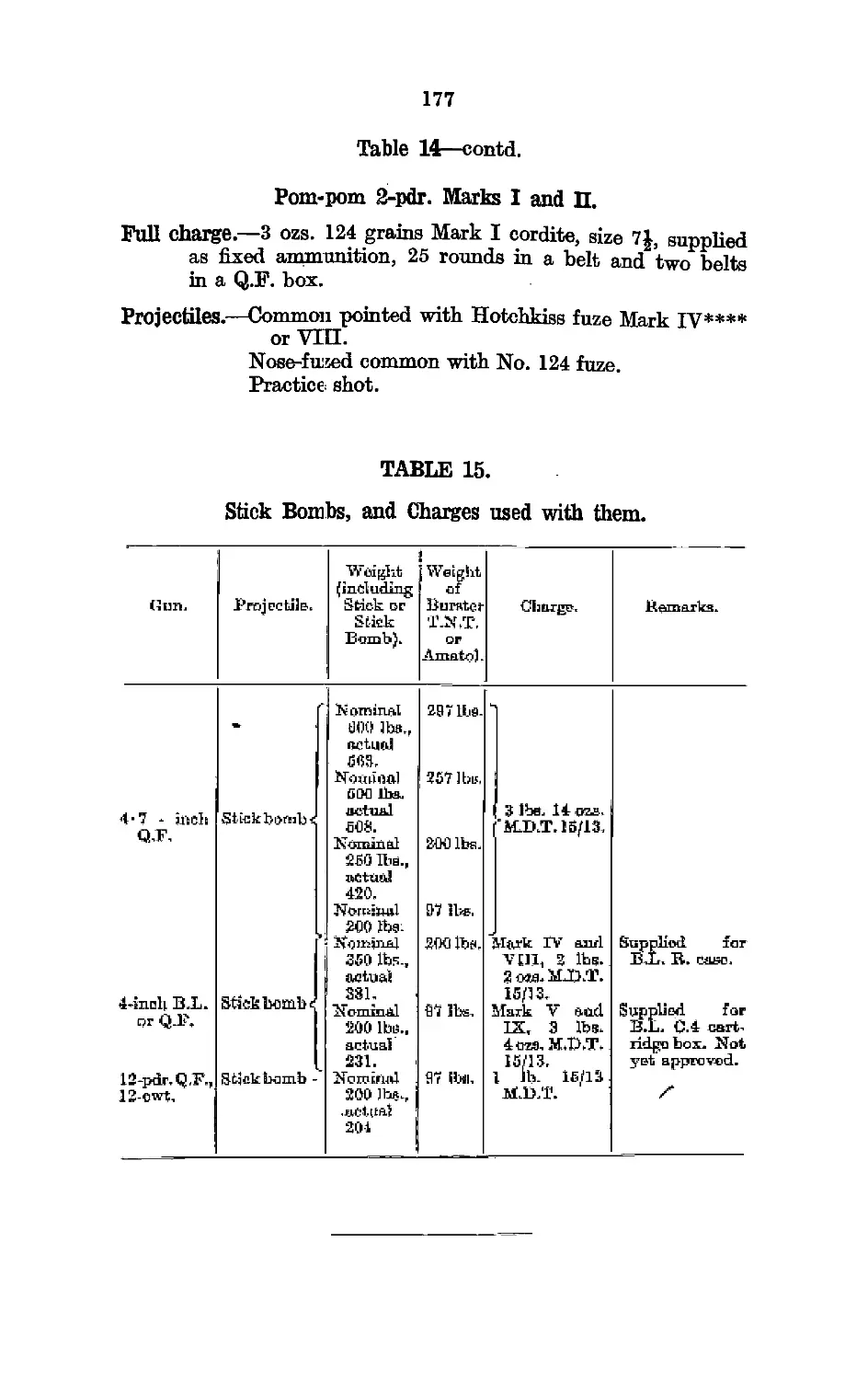
ХП. Stick Bombs, Sticks, Explodes and Cabtiu/ges fob 118
Anti-Submarine Use ... ...... ..............
Introduction—Stick Bombs—F uzes—Sticks—Exploder
and Cartridges. ' i
Chapter. Subject. Pa^e
ХП1, Pyrotechnics ... ...... .
Rockets—Lights andFlares—Grenades—Signal Cartridges
—Firework Boxes—Lifebuoys.. :
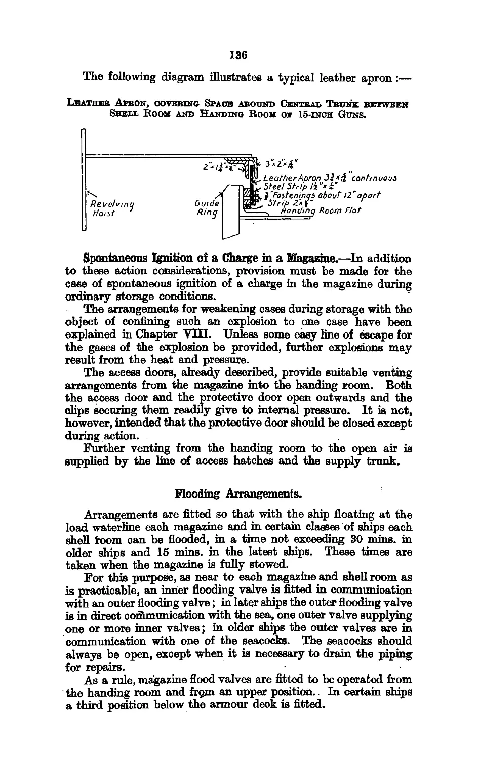
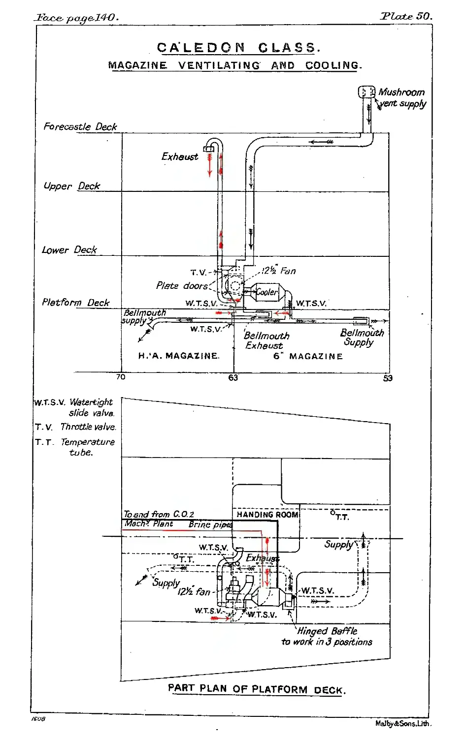
XIV. MAGAZINES AND SHELL ROOMS ............................133
Provision against Flash—Flooding Arrangements—Spray-
ing Arrangements—Ventilation and Cooling—Tempera-
ture Tubes.
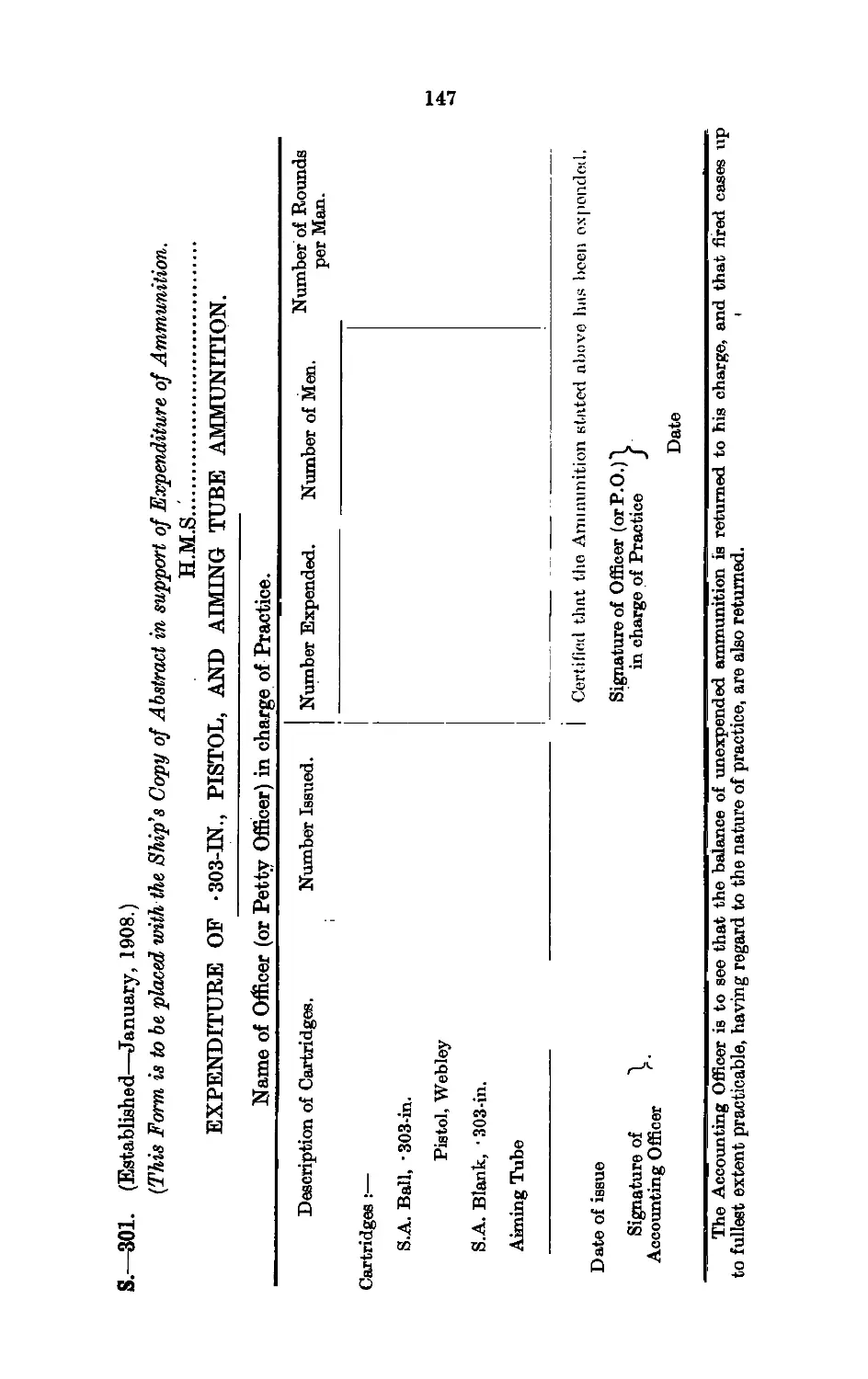
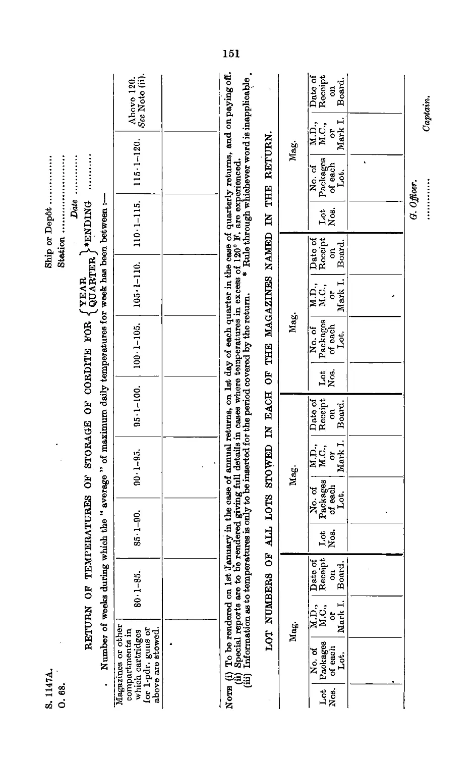
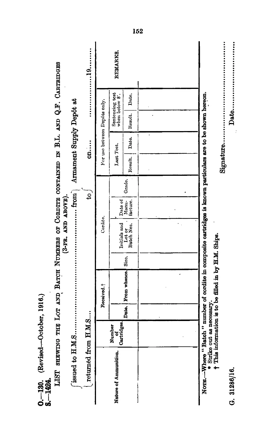
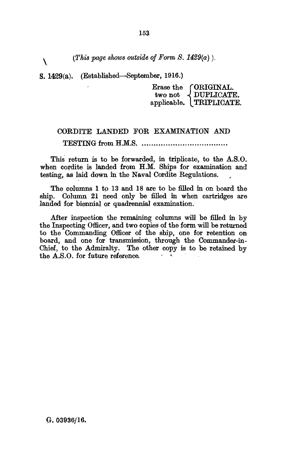
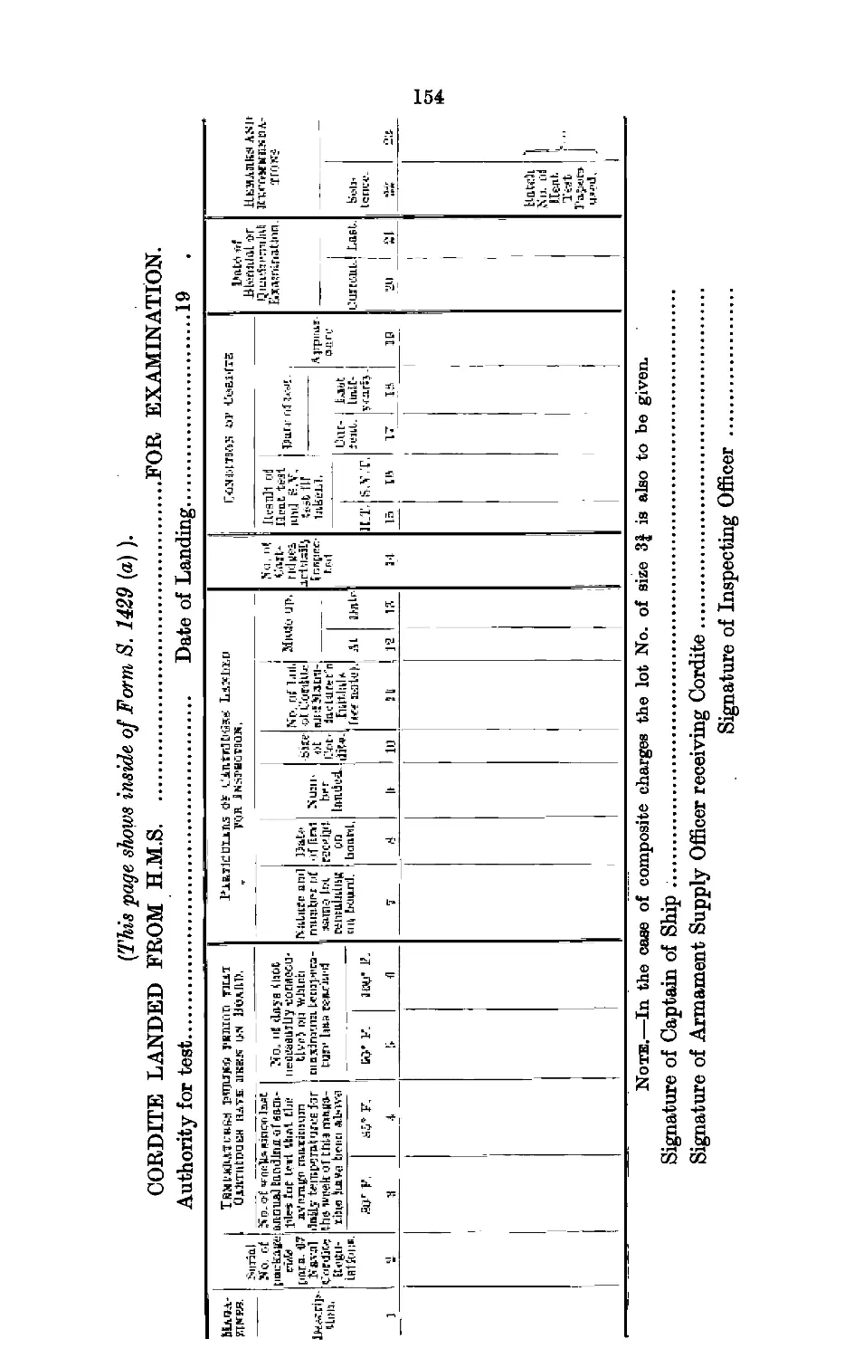
XV. Books and Forms used in Connection with: Naval
Ammunition...............................................145
Appendix.
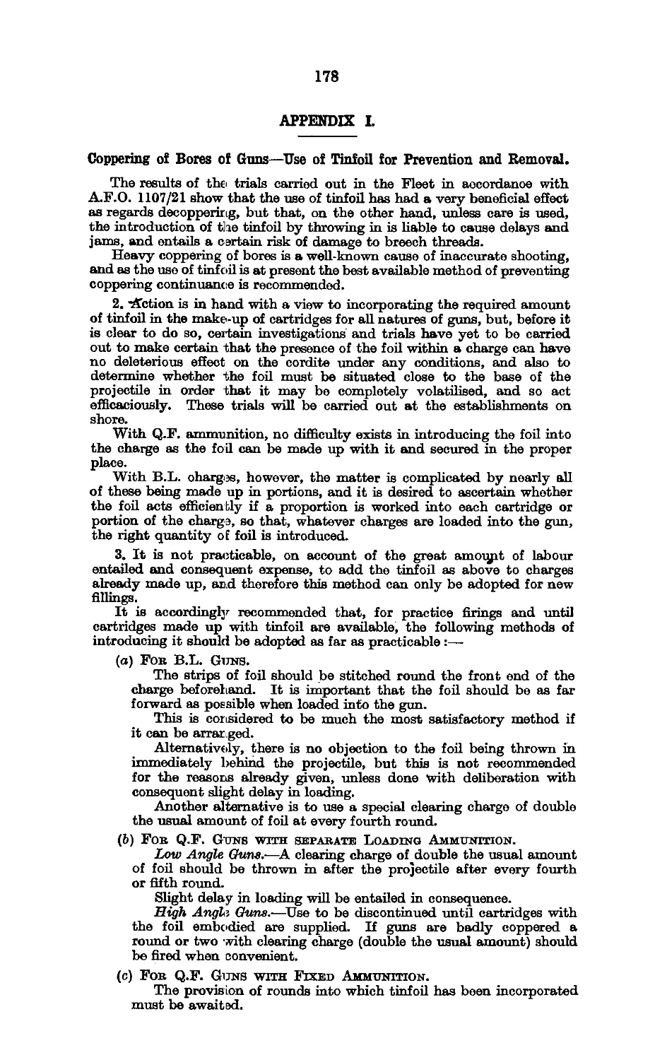
I. Tintoil tob Decoppebing Guns 178
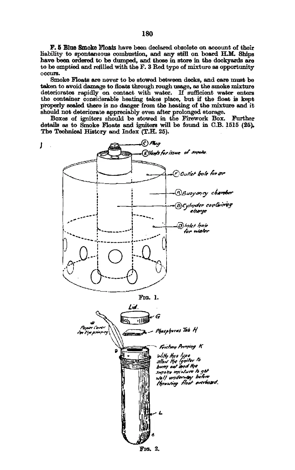
П. Smoke Floats....................................... 179
TABLES.
Subject.
Table. Page
1. A, B, and C. Explosives employed in the Naval Service .. 155
2. B.L. Charges .... ... .. 157
3. Q.F. Charges ... .. 158
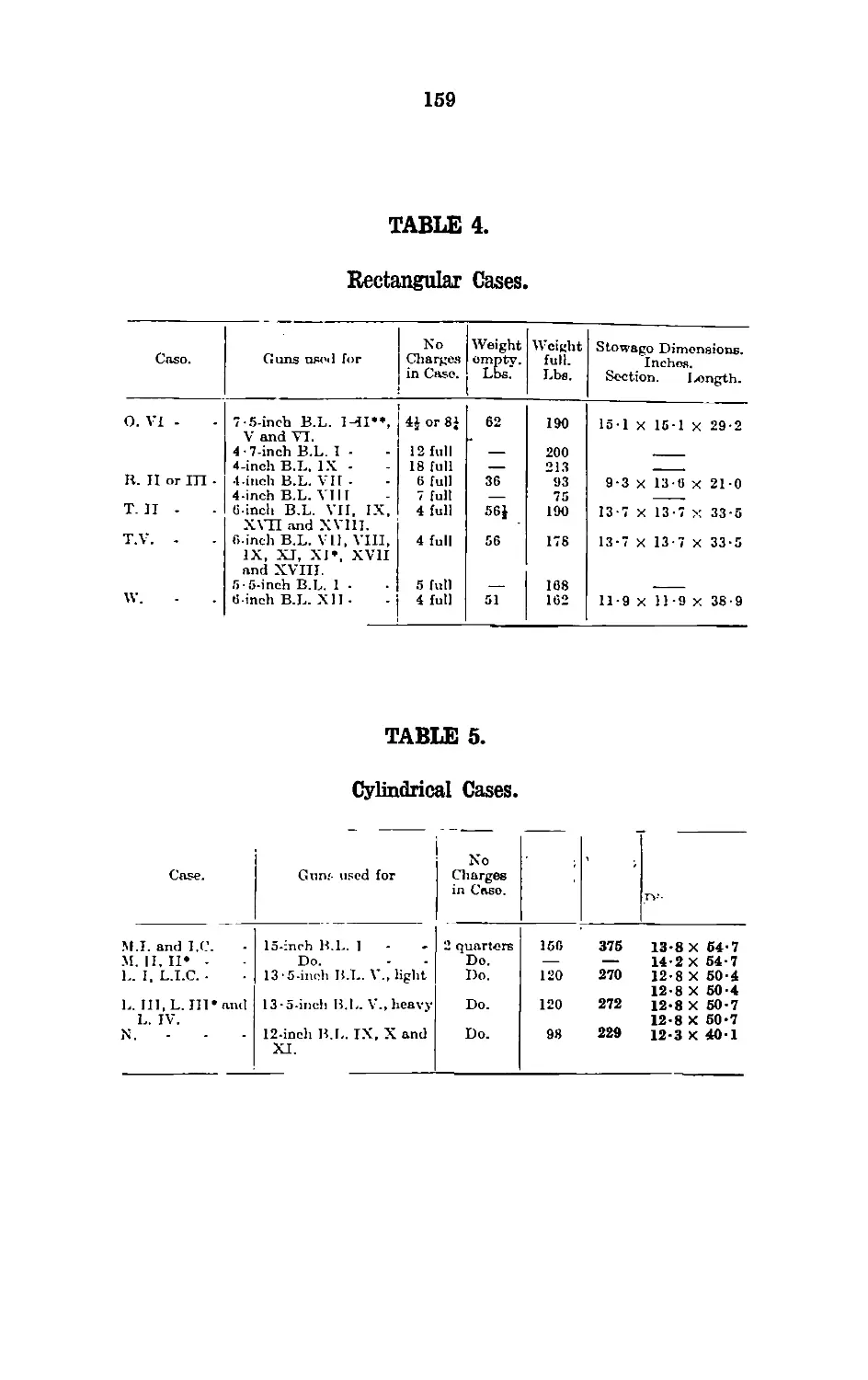
4. Rectangular Cases .. 159
5. Cylindrical Casas ... ... ... 159
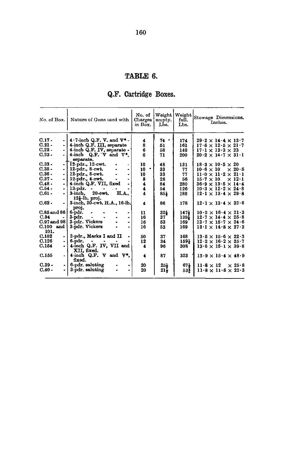
6. Q.F. Cartridge Boxes .. 160
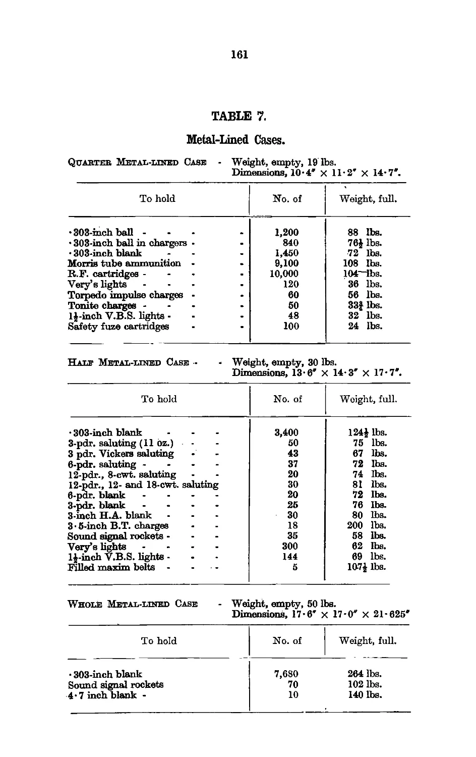
: 7. Metal-lined Cases ... ...,' ... .... .. 161
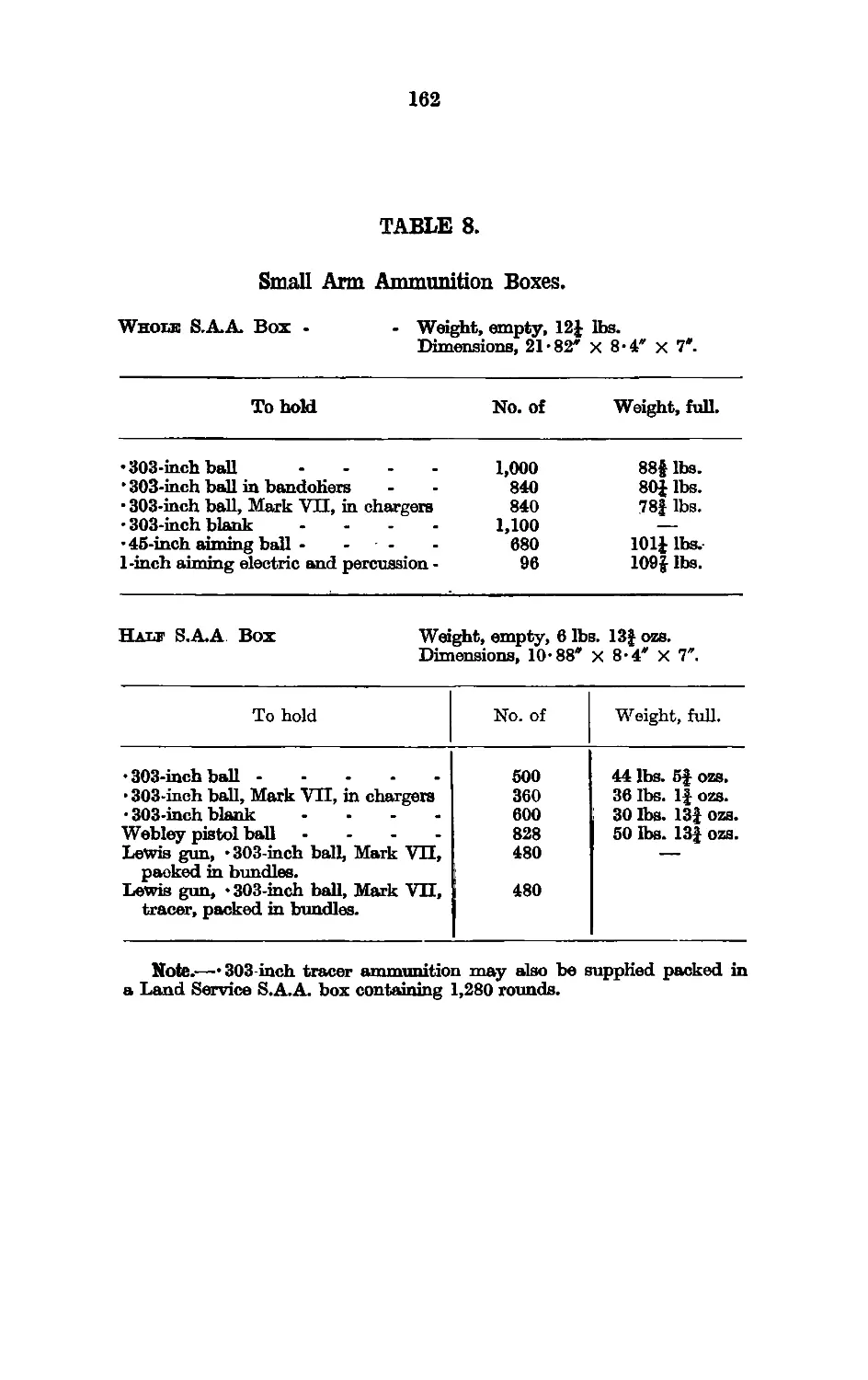
8. S.A.A. Boxes ' .. 162
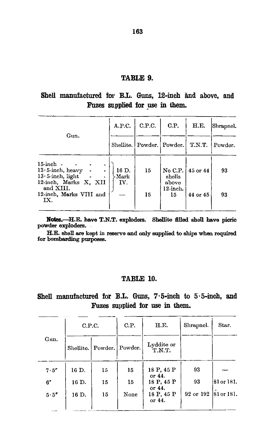
9. Shell for B.L. Guns, 12-inch and above .. 163
10. Shell for B.L. Gans, 7‘5-inch to 5-5-inch .. 163
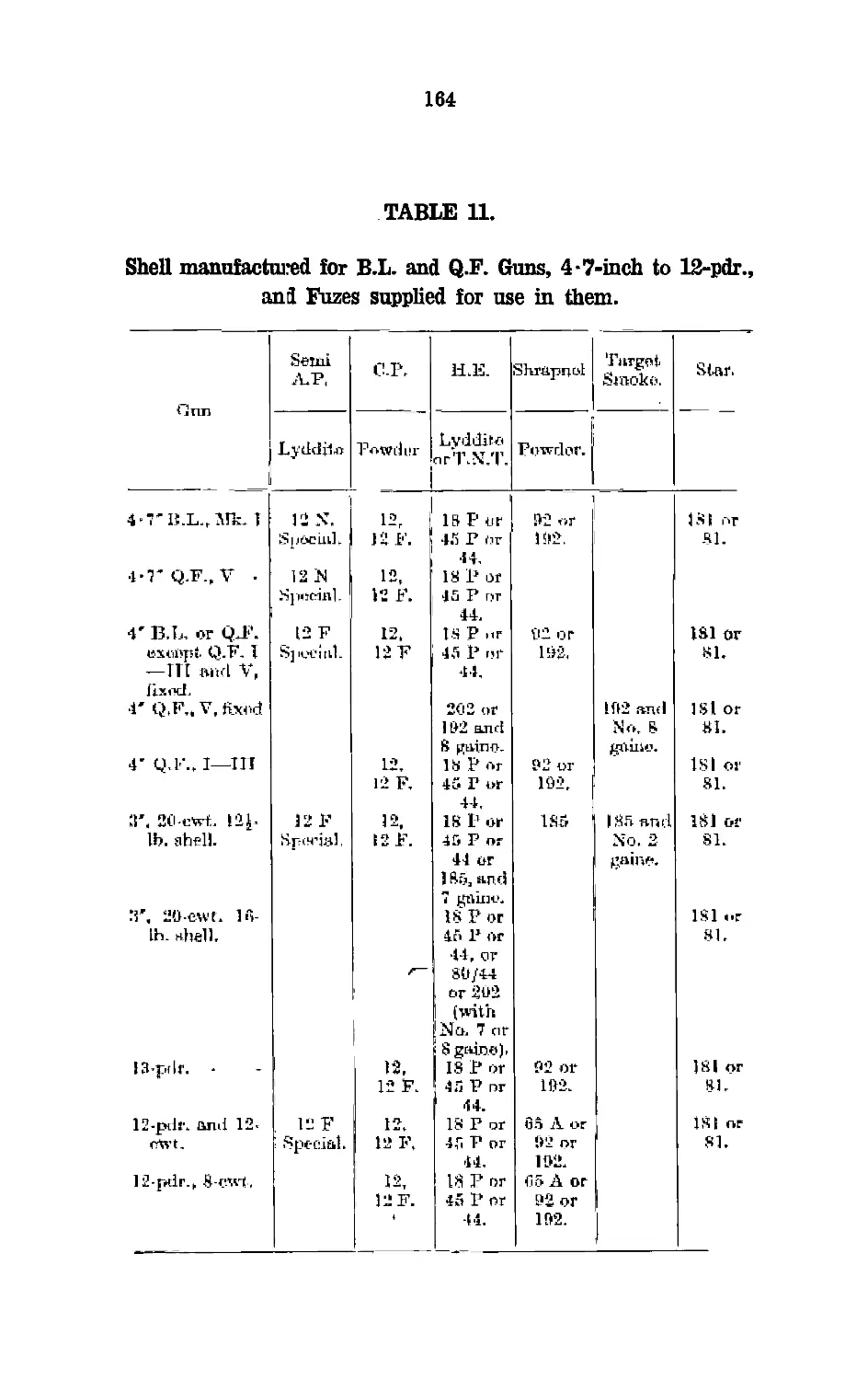
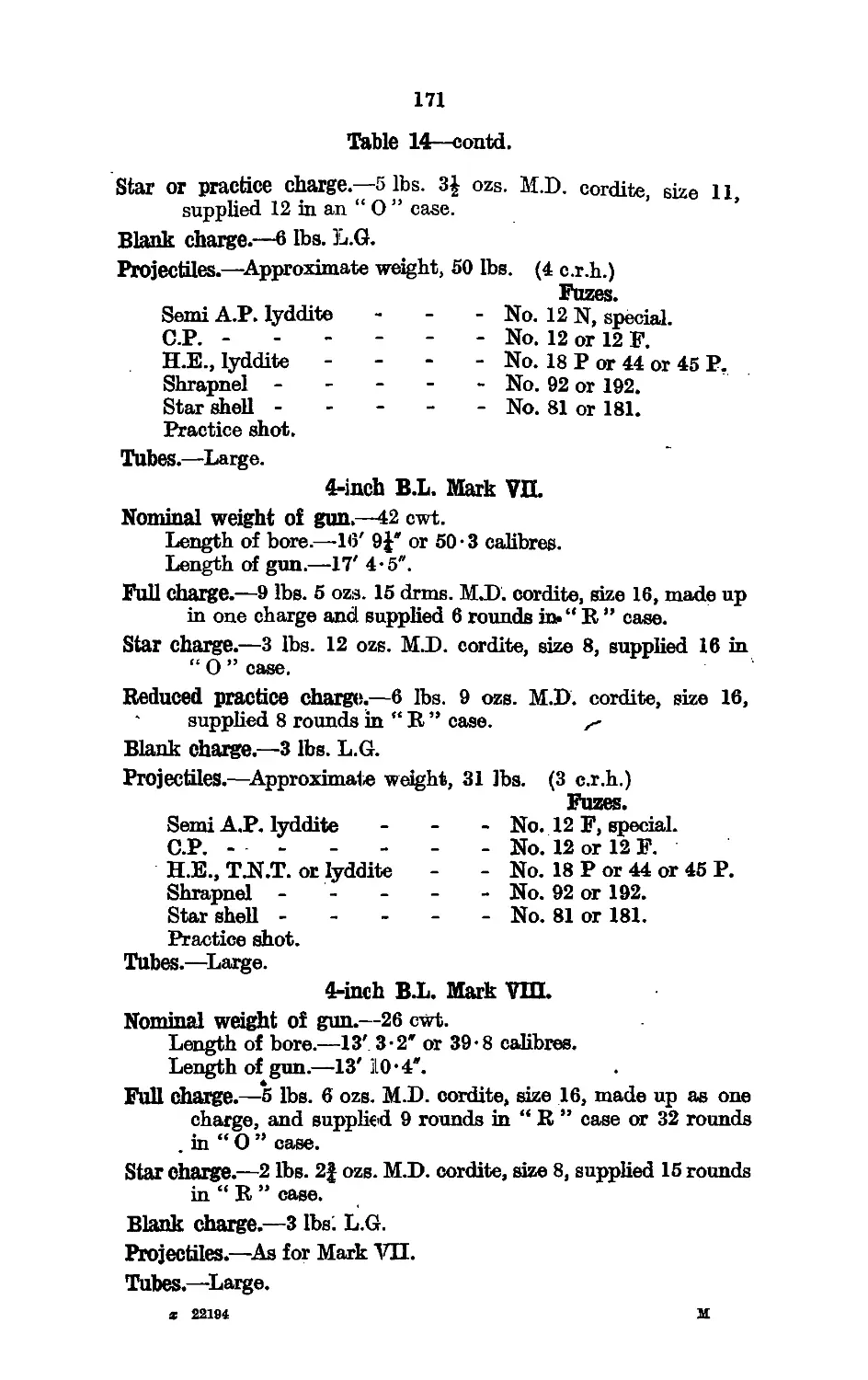
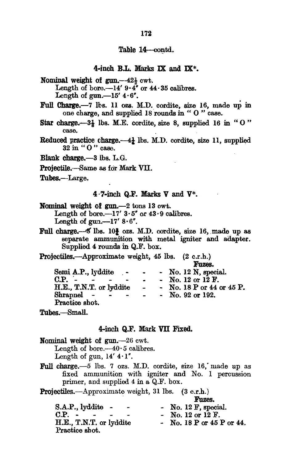
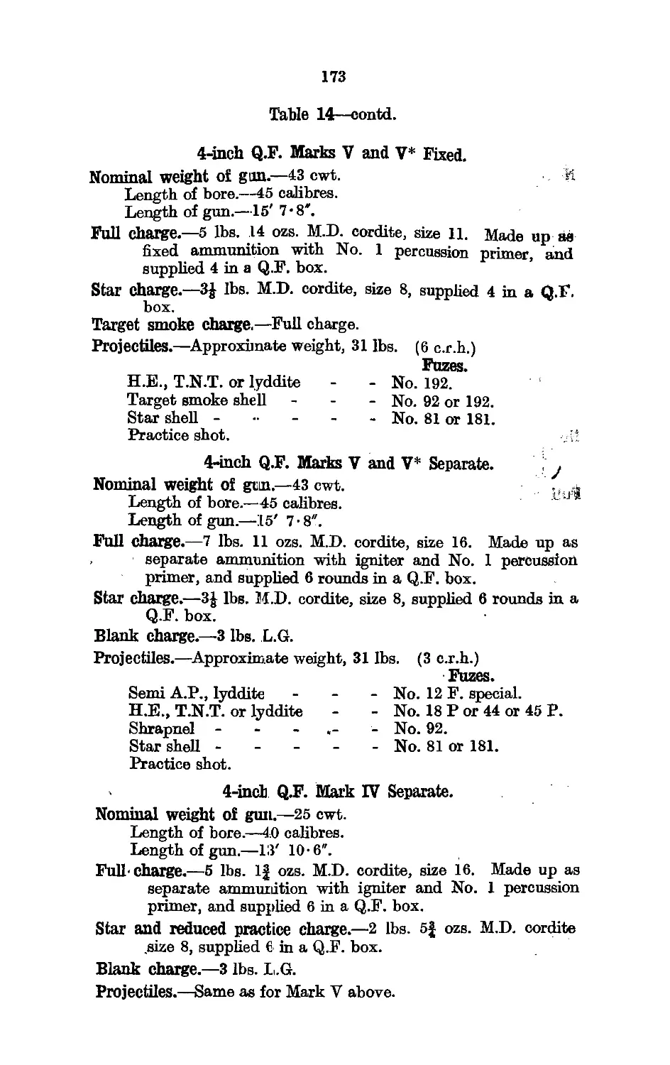
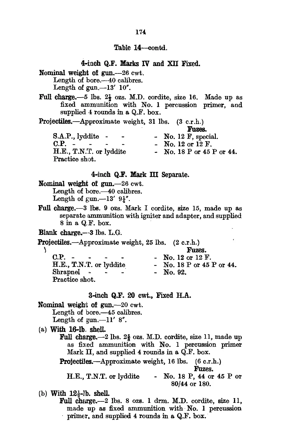
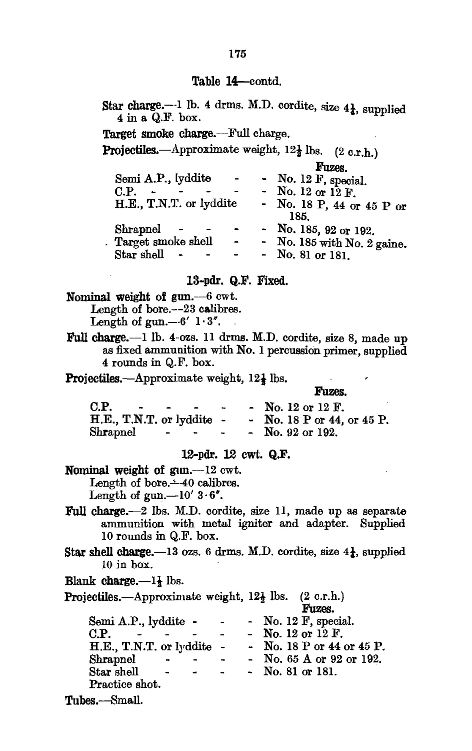
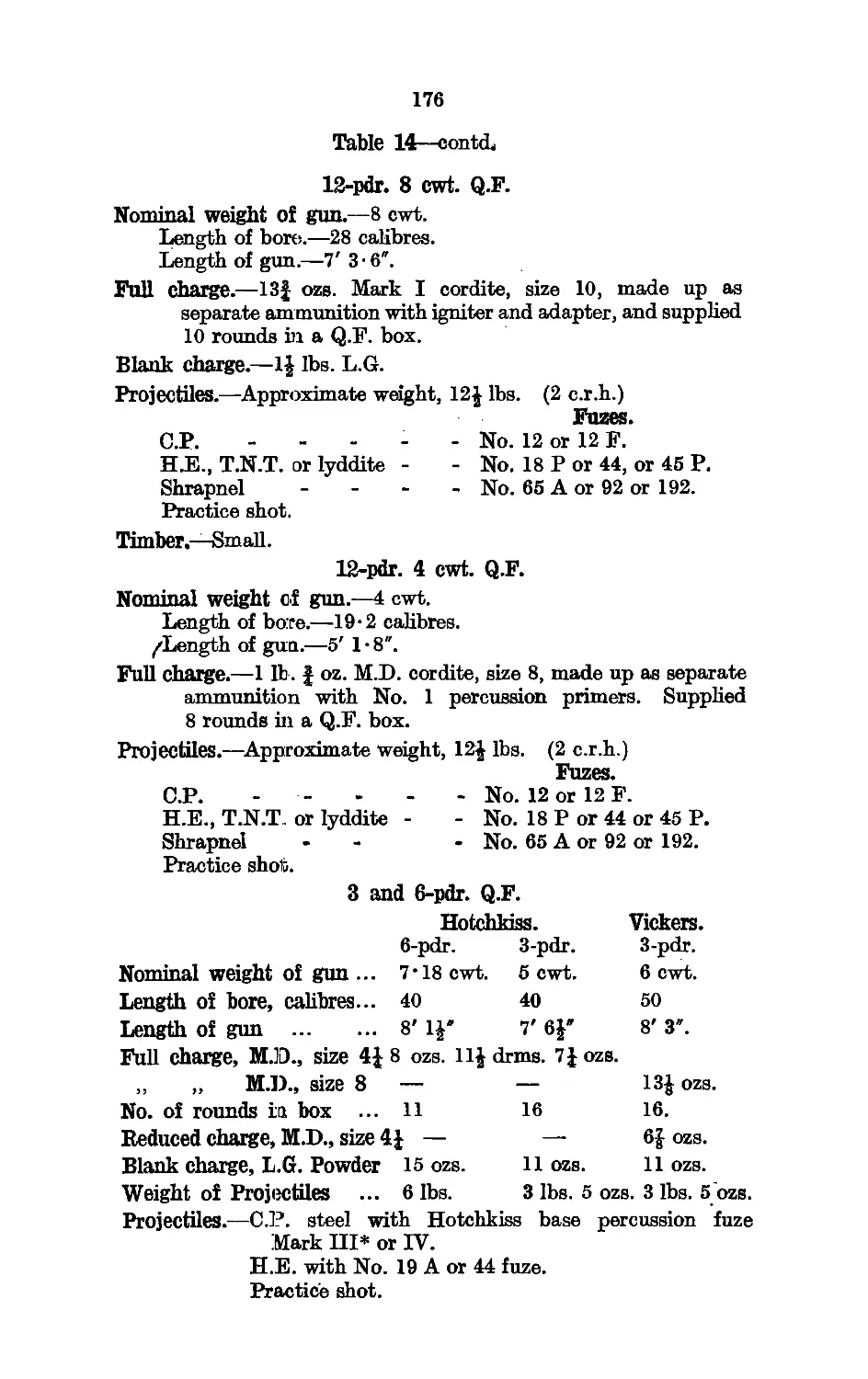
II. Shell for Guns 4 7-inch to 12-pdr. .. 164
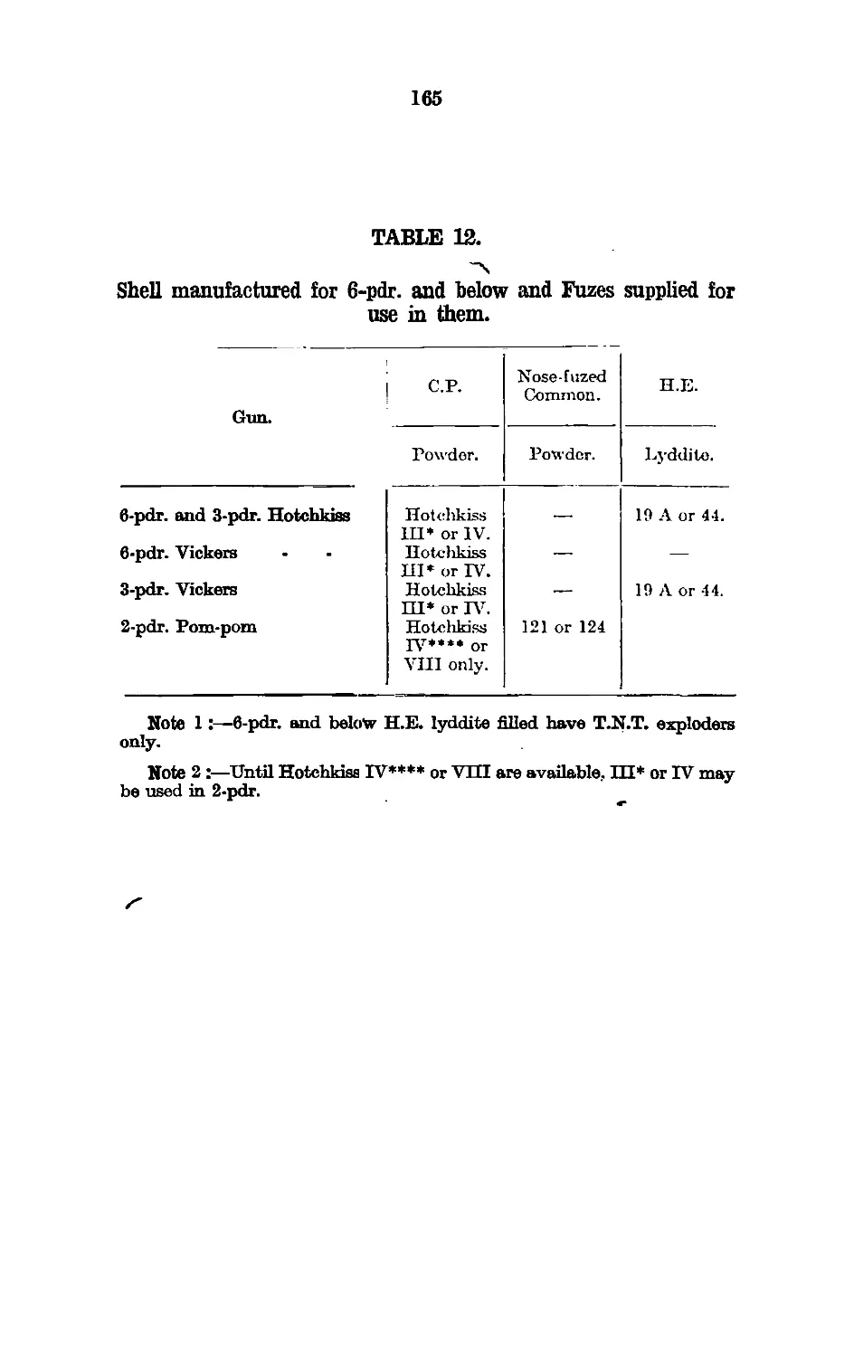
12. Shells for Guns, 3-pdr. and below .. 165
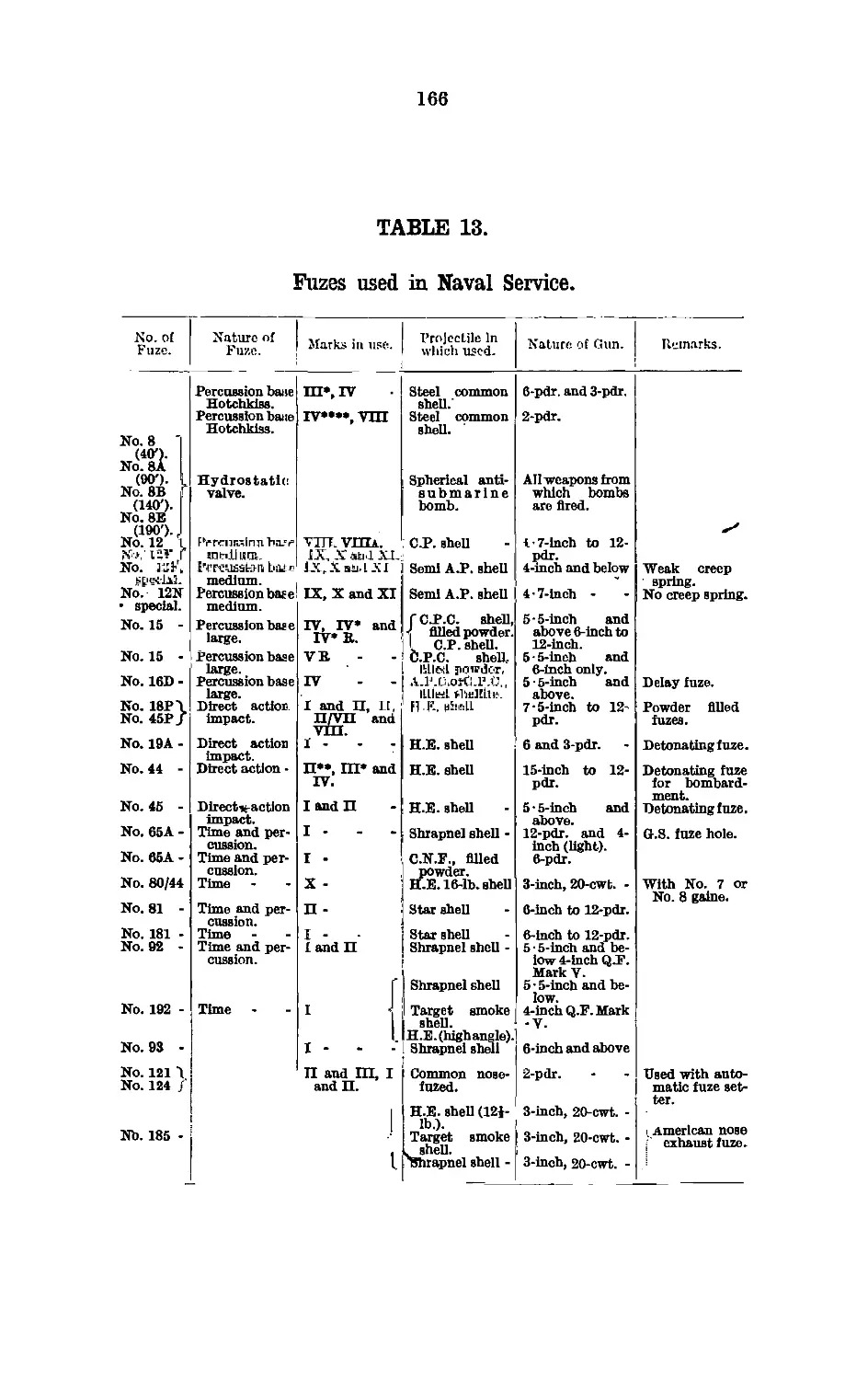
13. Fuses used in Naval Service .. 166
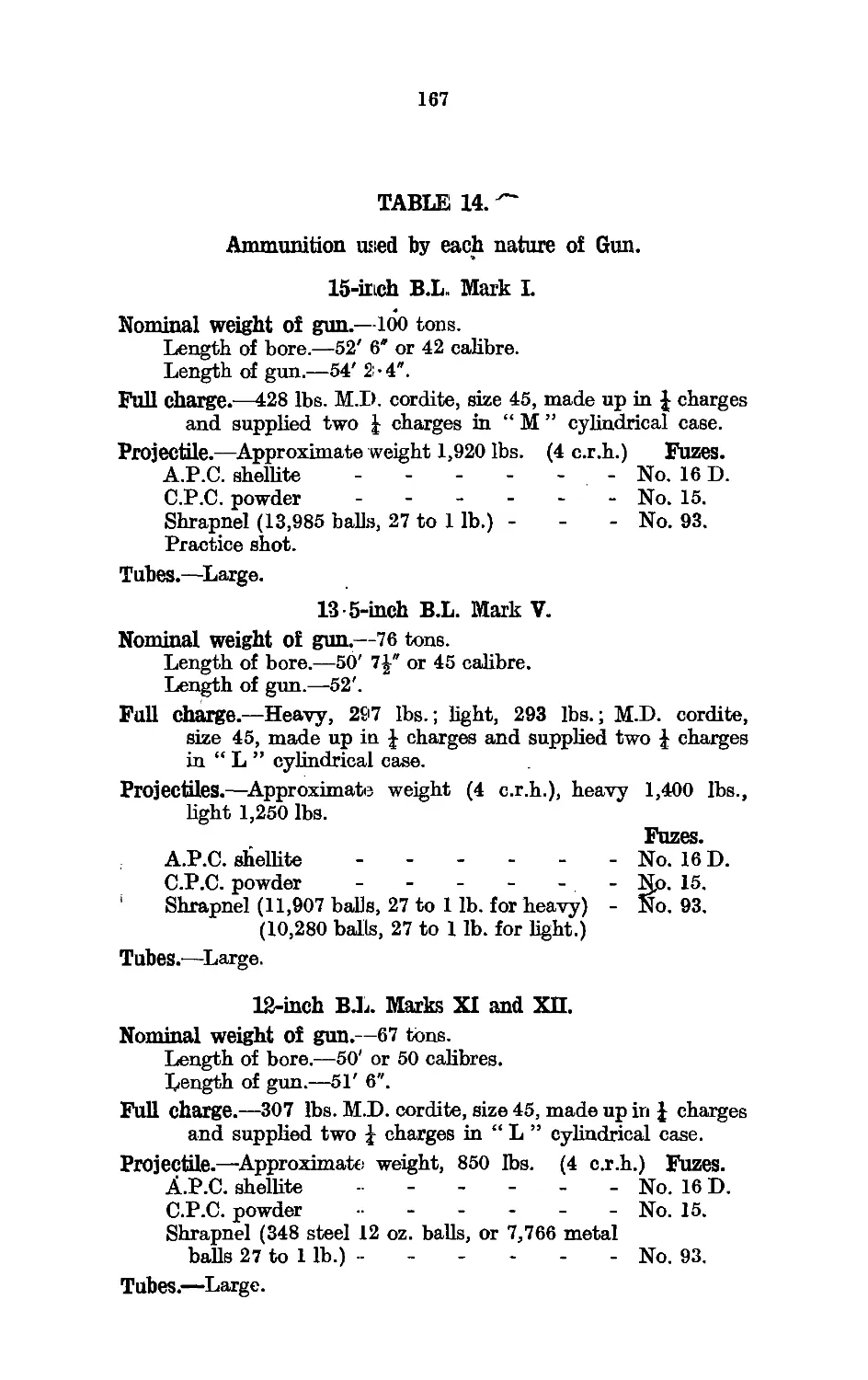
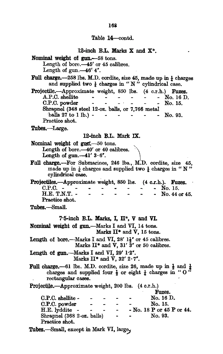
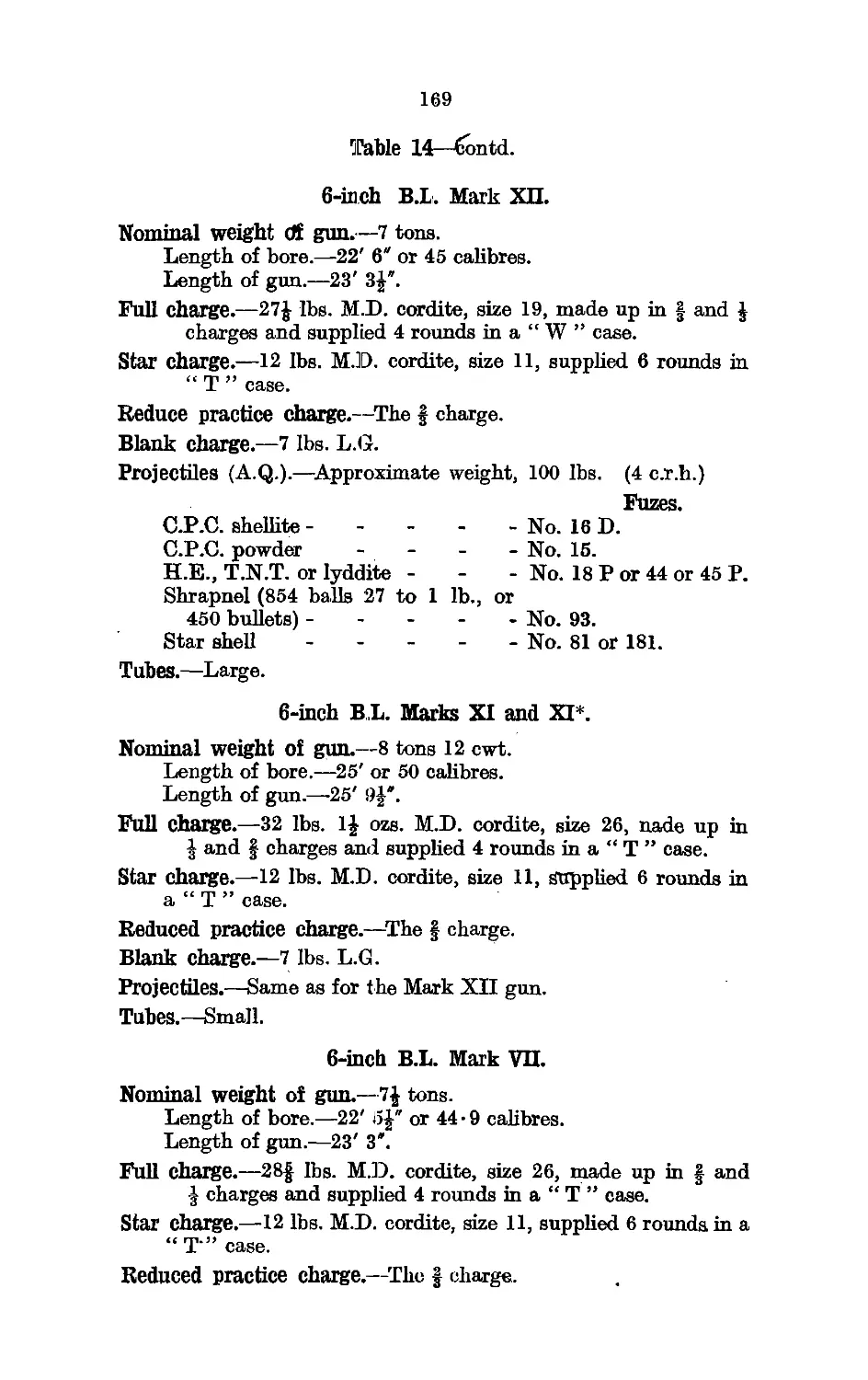
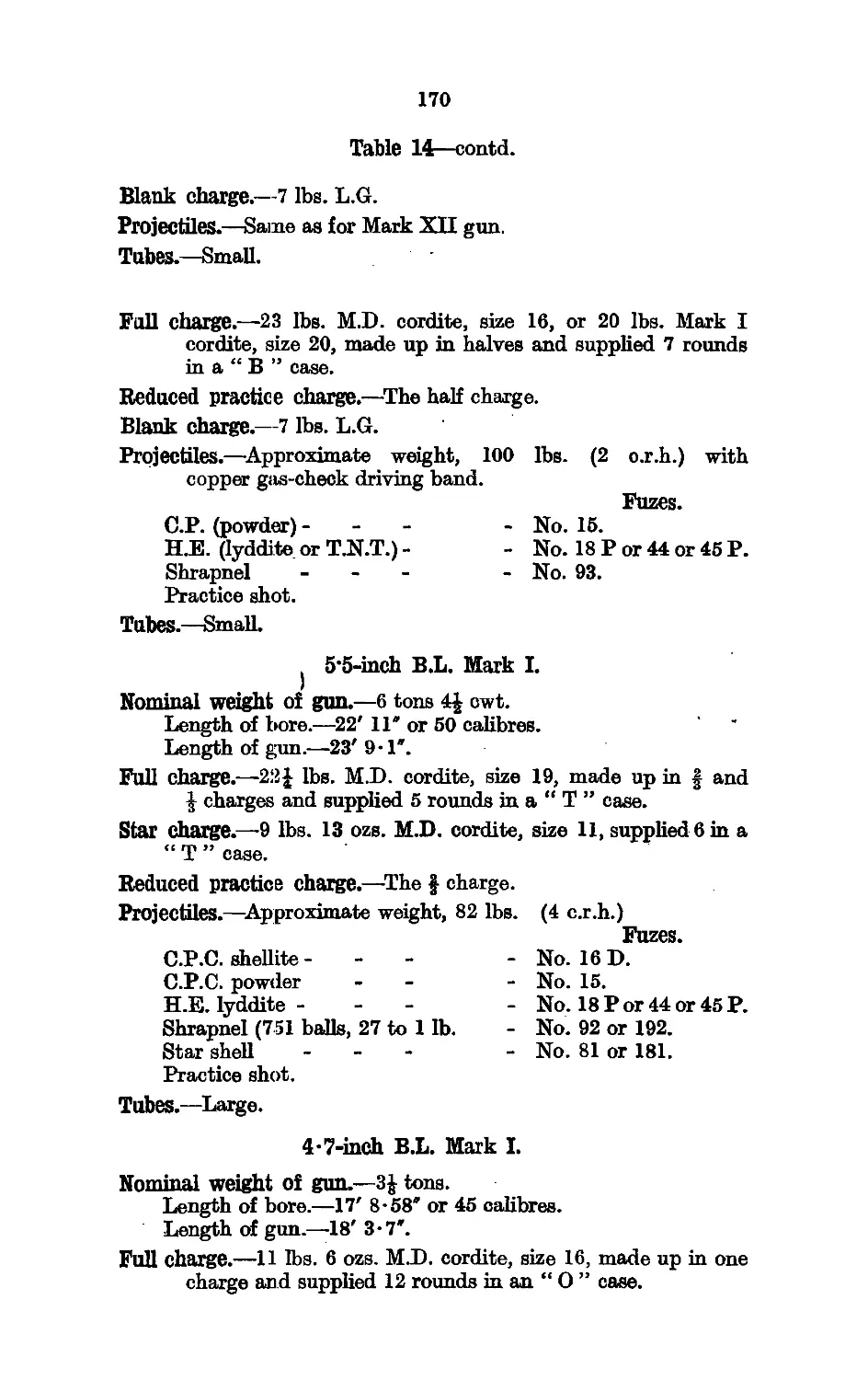
14. Ammunition used by Each Nature of Gun .. 167
.15. Stick Bombs and Charges used with them .. 177
(35)22194 Wt 29750—D 84 6000 8/24 E & S
A 2
iv
LIST OF PLATES.
Description.
Chapters I-III.
Sheets. Face page
1 and 2. Pictorial Representations of Cordite ... 11
Chapters IV and V.
No. of Plate.
1. Typical Igniter for B.L. Cartridges
2. Group of B.L. Cartridges (Photo)
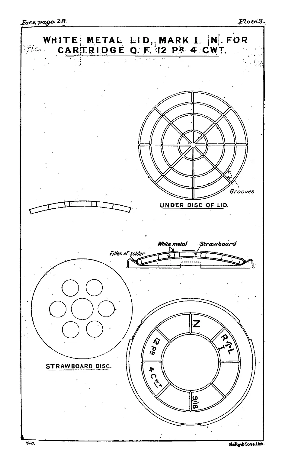
3. White Metal Lid, Mark I.........
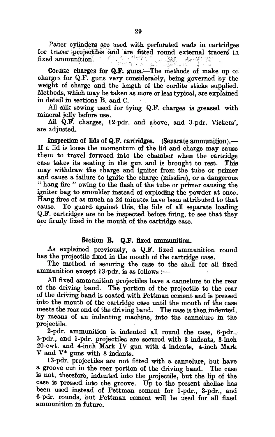
4. Metal Igniter and Adapter
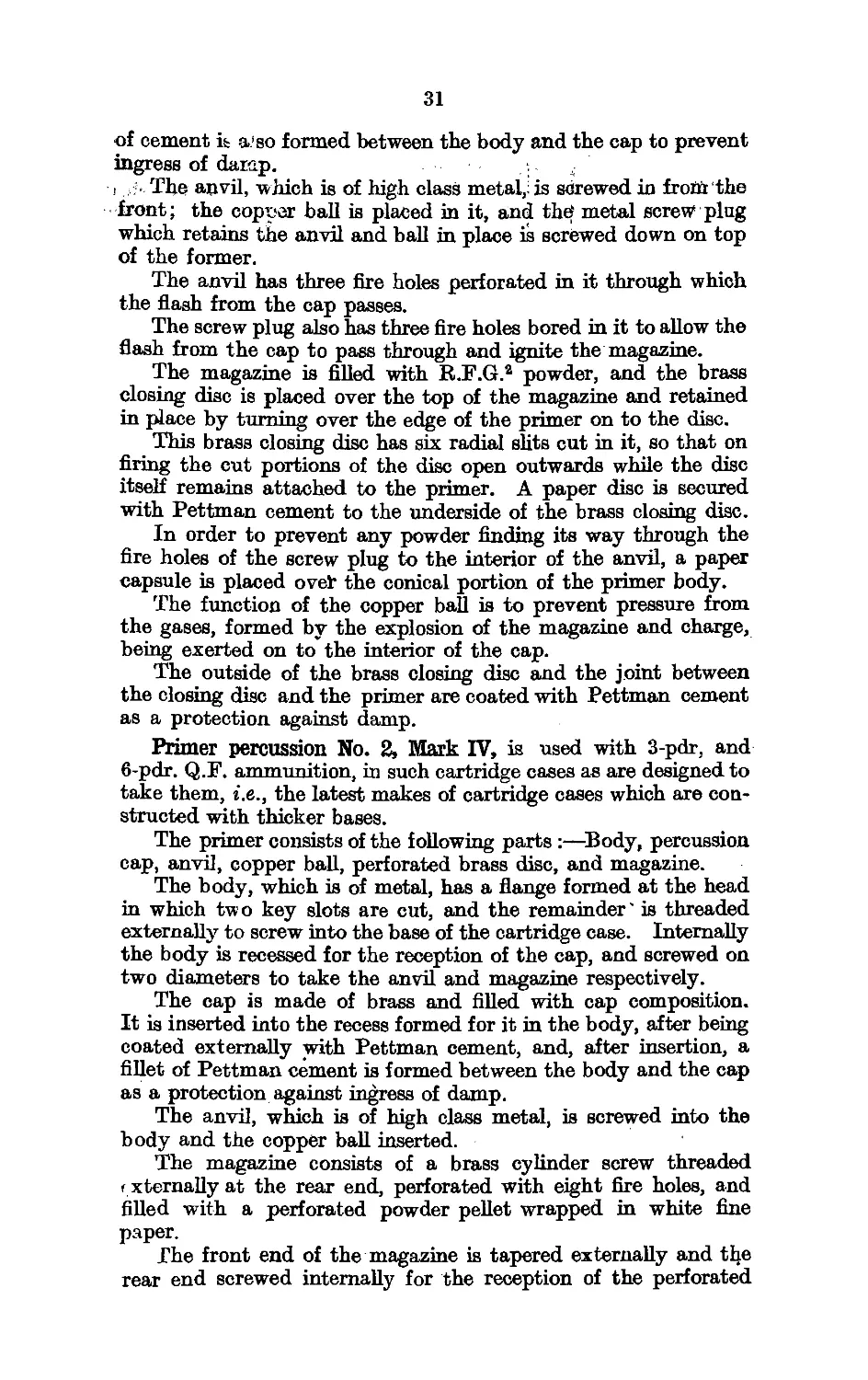
5. Primer Percussion No. 2, Mark VI
19
20
28
30
32
Chapter VI. (Tubes.)
6. Tube V.S., Electric S., Large, Mark I ... 44
7. Tube V.S., Electric, Large, Mark IV ... 45
8. Tube V.S., Percussion, Large, Mark II ... 46
Chapter VII. (Blank Charges.)
9. Cartridge Q.F. Blank, 4-inch Mark V and V* Guns 49
10. Cartridge Q.F. Blank, 12-pdr., 8-cwt., Mark П... 50
11. Cartridge Q.F. Blank, 3 and 6-pdr. ... ... 51
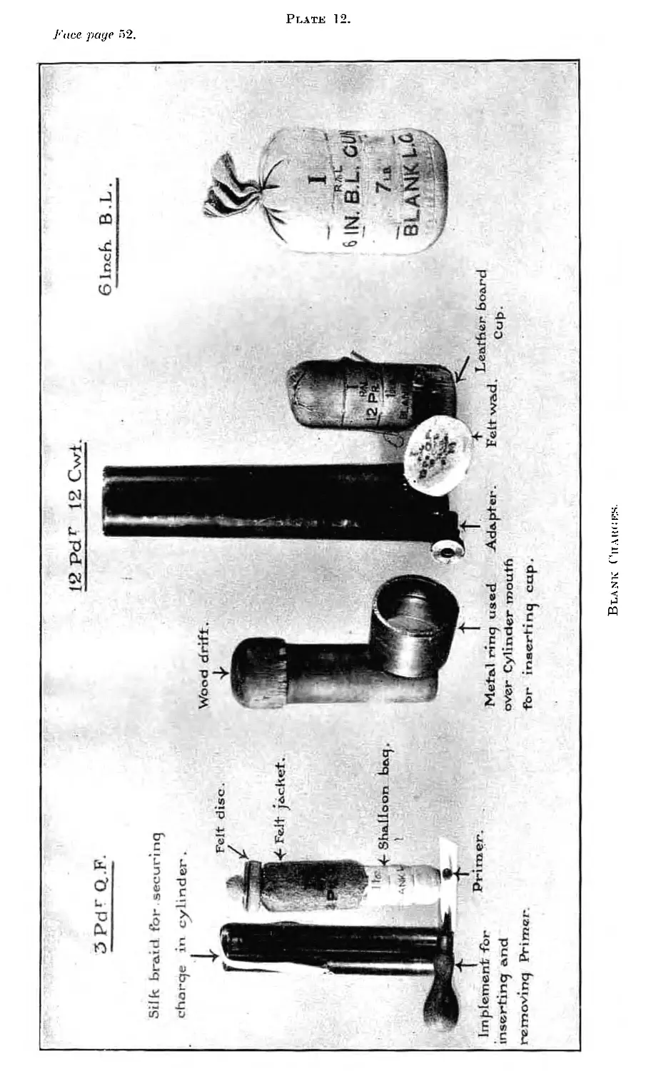
12. Blank Charges (Photo) ... ... ... ... 52
Chapter VIII. (Cases, Boxes, &c.)
13. Effect of Cordite Explosion in a Bay of Weakened Cases (Photo) 54
14. Effect of Cordite Explosion in a Bay of Unweakened Cases
(Photo) ... ........... ... ... ... ... 55
15. Rectangular Case showing Method of Attachment' of Top
and Bottom .......................... ... ... ... ... 56
16. Typical Rectangular Case (W) ... ... ... ... ... 56
17. Group of Cylindrical Cases (Photo) ;.. ... ... ... 57
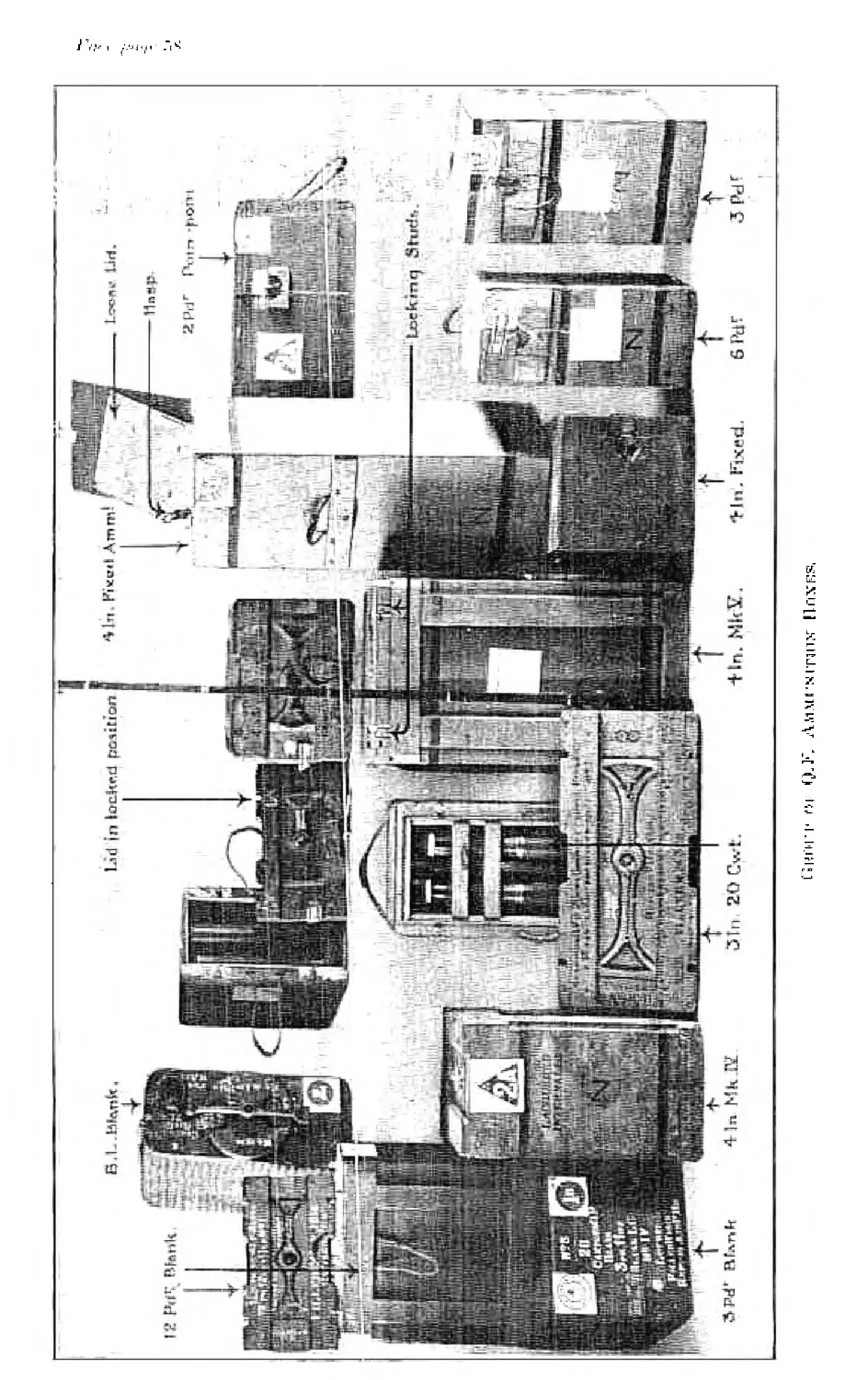
18. Group of Q.F. Ammunition Boxes (Photo) ... ... ... 58
Chapter IX. (Projectiles.)
19. 4-inch C.P. Shell filled Powder.......................1 ... 66
20. 15-inch A.P.C. Shell filled Shellite ... ... ......... 66
21. 4-7-inch S.A.P. filled Lyddite ... ... ... ......... 67
22. 6-inch H.E. Shell filled Lyddite (see para.—Remarks on ELE.
nose fused, Common Shells and their fuzing and use) ... 68
23. 12-inch Shrapnel Shell ... ... ... ... ... ... 70
24. 12-pdr. Shrapnel Shell ... ....... ... ... 70
25. 4-ii'.ch Star Shell ... .............. ... ... ... 71
26. Night Tracer, Internal,eMark III... ' ... ... ......... 72
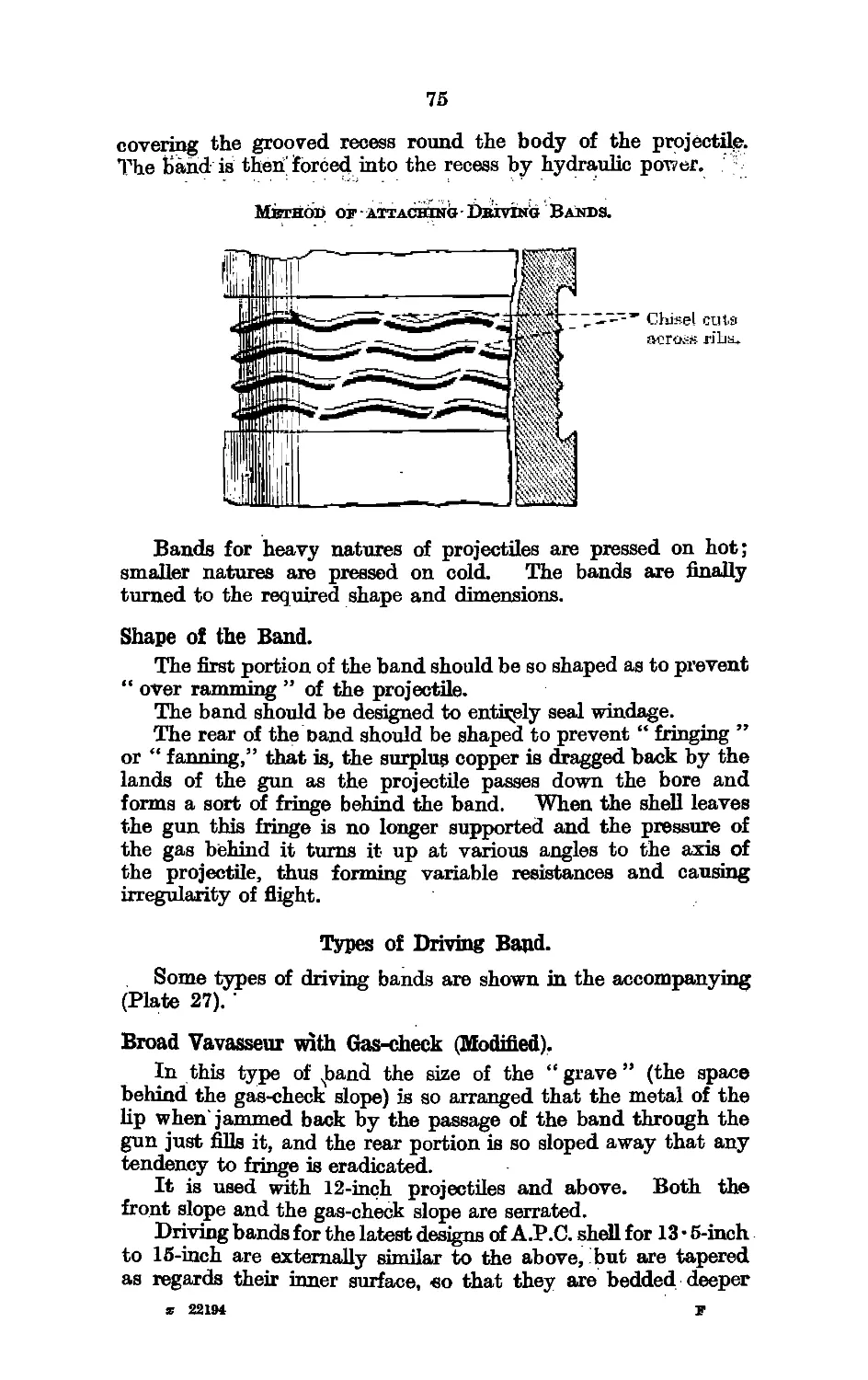
27. Types of Driving Bands ... ’ 5 ... ... ... 75
28. Colouring of Projectiles' v..-i;*? ... ... 78
Chapter X. (Fuzes.)
Nu, of Plate.
29?' Fuze, Percussion, Base, Hotchkiss, Mark IV ...
30. Fuze, Percussion, Base, Medium,. No.' Г2, Mark XI
31. ' Fuze T. and P., No. 92, Mark Ц... ...
32. Fuze Time, No. 185, Mark Г ...................
33. Fuze Hydrostatic Valve, No. 8, Mark I.........
Fac. page
... "93
... 95
... ,W1
... T05
... 106
Chapter XI. (8.A. Ammunition.)
34. 1-inch Electric A.R. Cartridge—Cordite................... ,. Ill
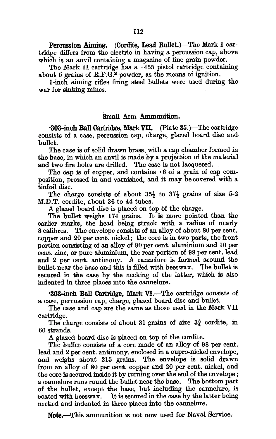
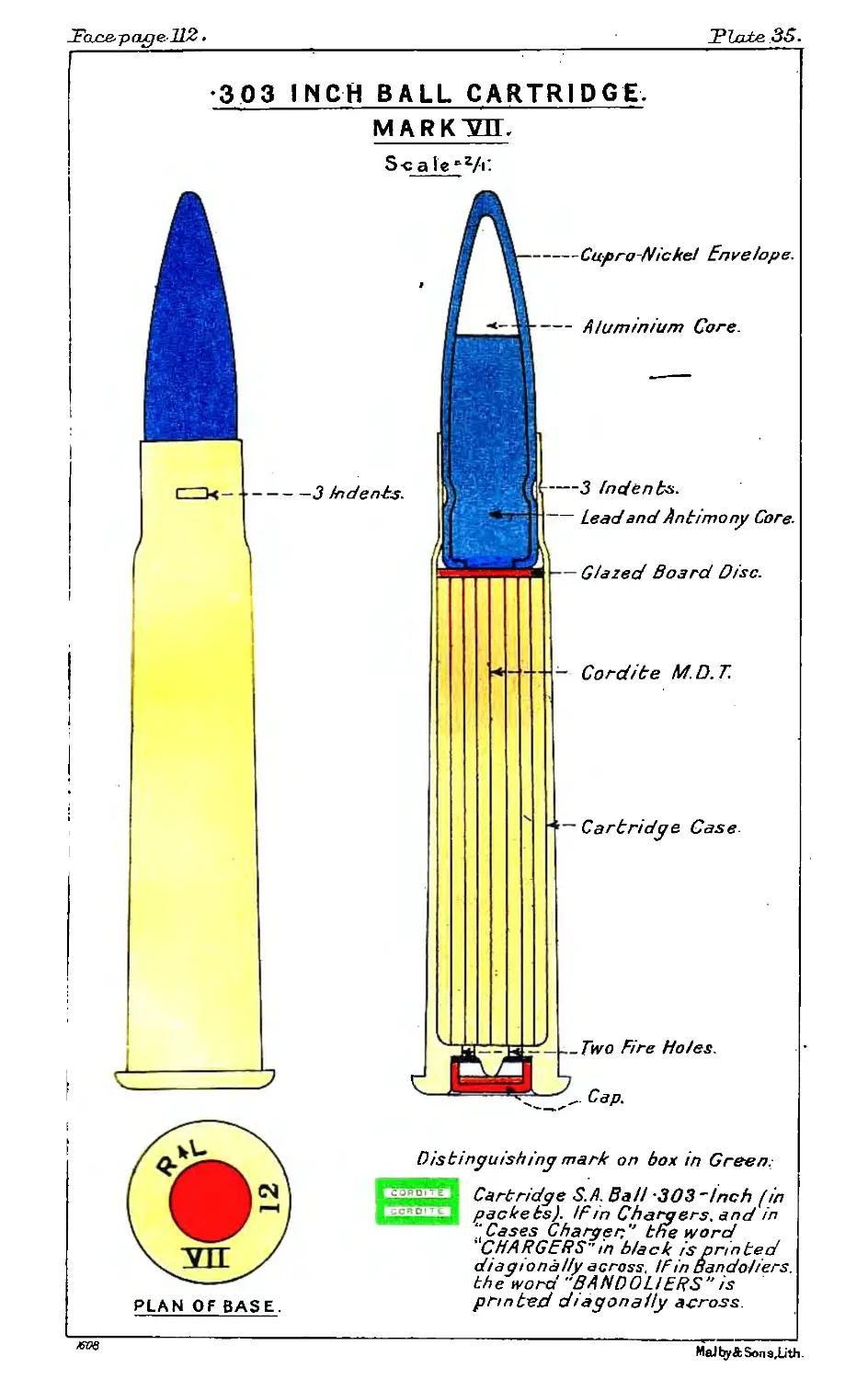
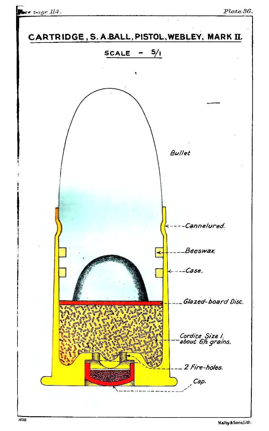
35. - 303-inch Ball Cartridge, Mark VH ...................... .. 112
36. * Webley Pistol Cartridge, Mark П ....................... ,. 114
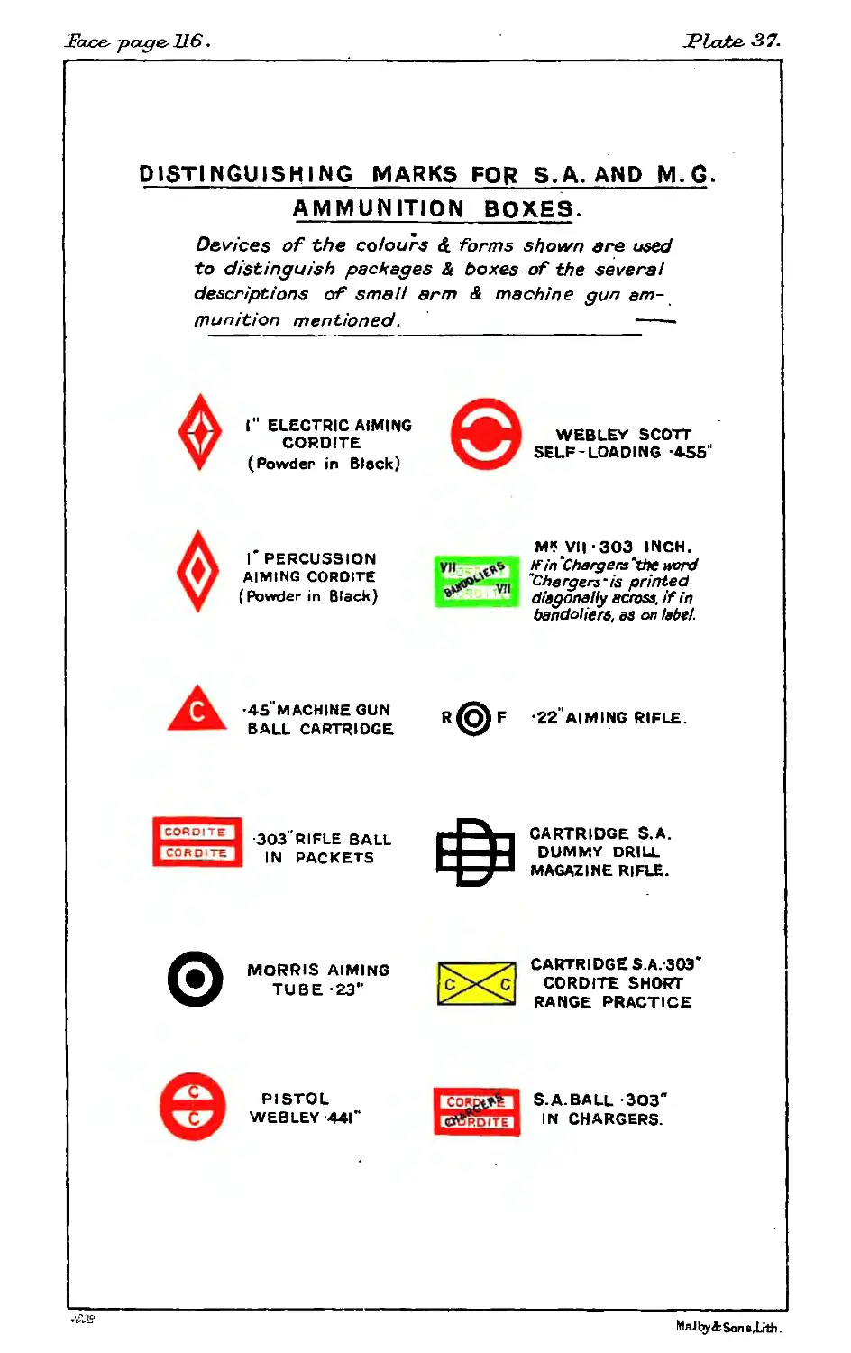
37. Distinguishing Marks for S.A. mid M.G. Ammunition Boxes .. 116
Chapter XU. (Bombs, &c.)
38. Naval Stick Bomb, 200-lb. ............... 118
39. 4-7 B.L. Cartridge for Stick Bomb ... . 119
40. 12-pdr., 12-cirt. Q.F. Cartridge for Stick Bomb 119
Chapter ХТП. (Pyrotechnics.;
41. Rocket, Signal, 1-lb., Service, Mark HI ... 121
42. Rocket, Sound £ lb.,: Mark П ... 122
43. Grenade, • 303-inch Rifle No. 32 ... 126
Chapter- XIV. (Magazine.)
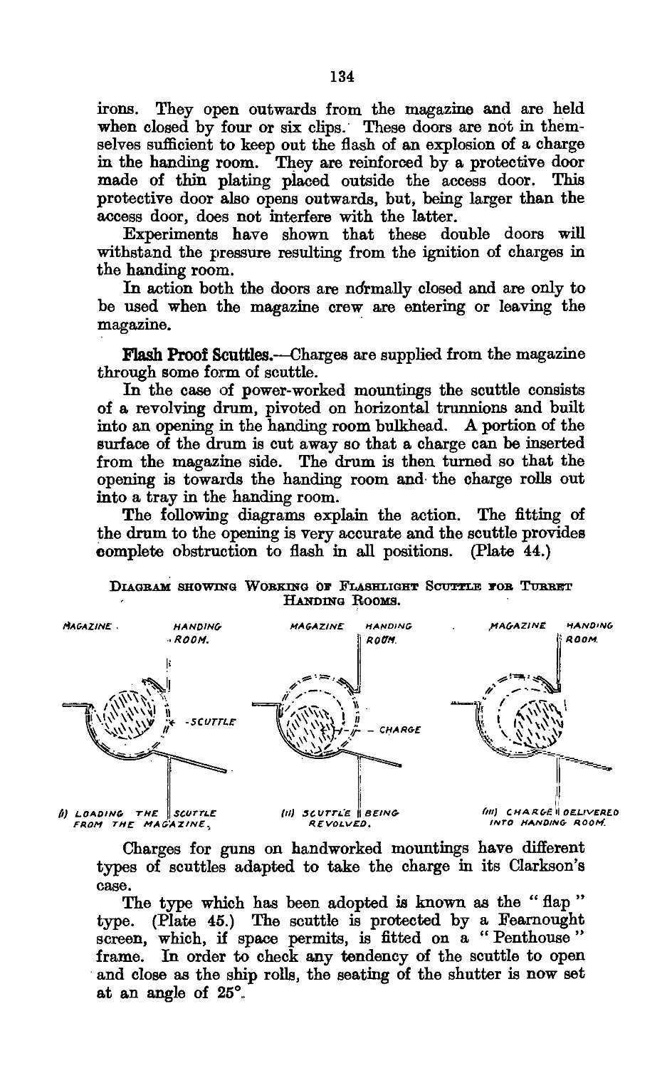
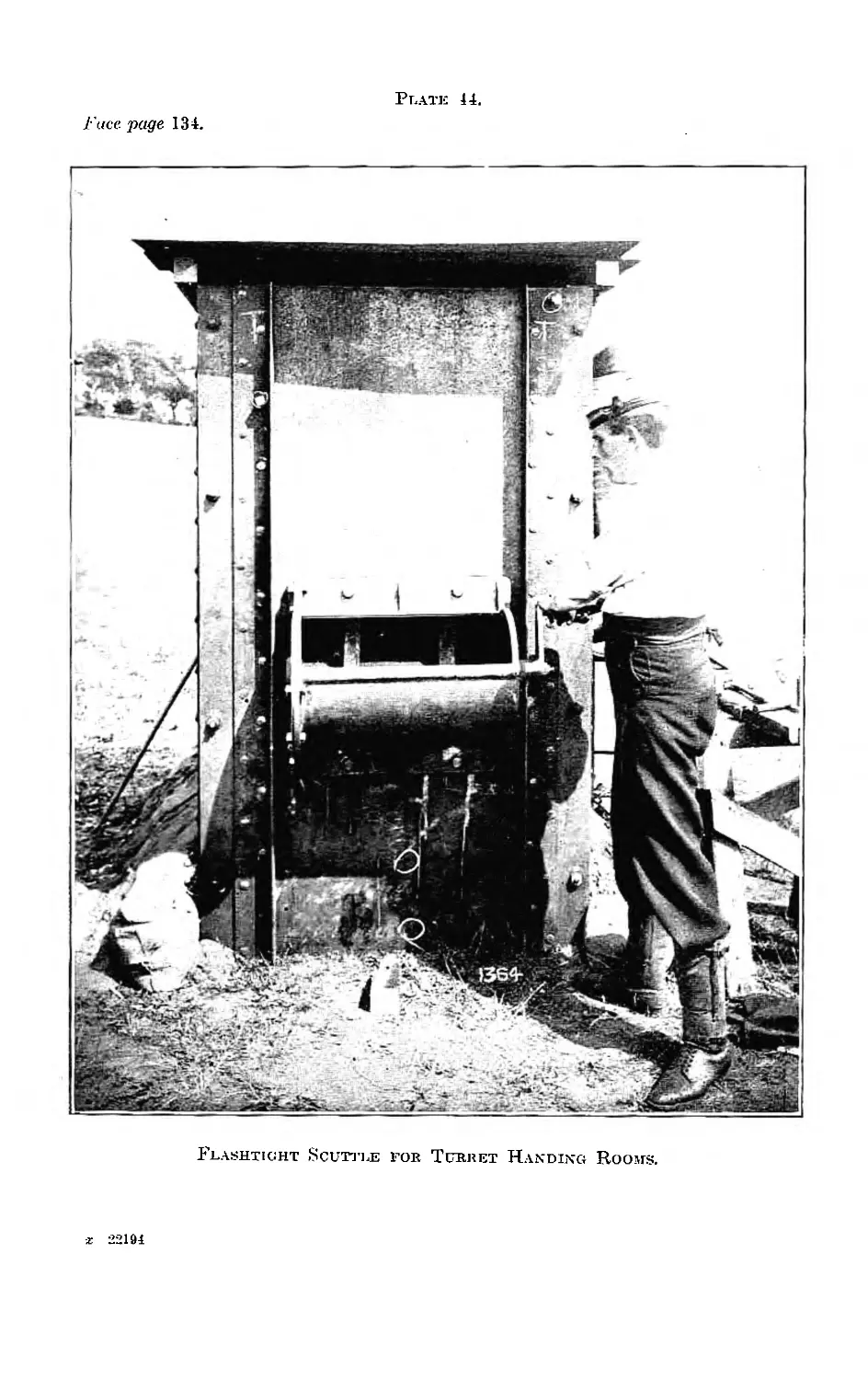
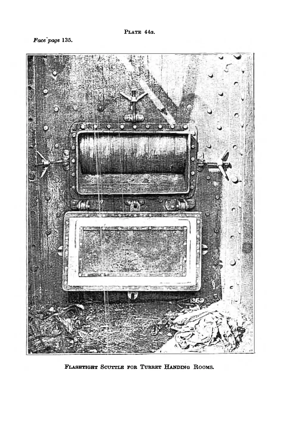
44. Flashlight Scuttle for Turret Handing Rooms (Photo) 134
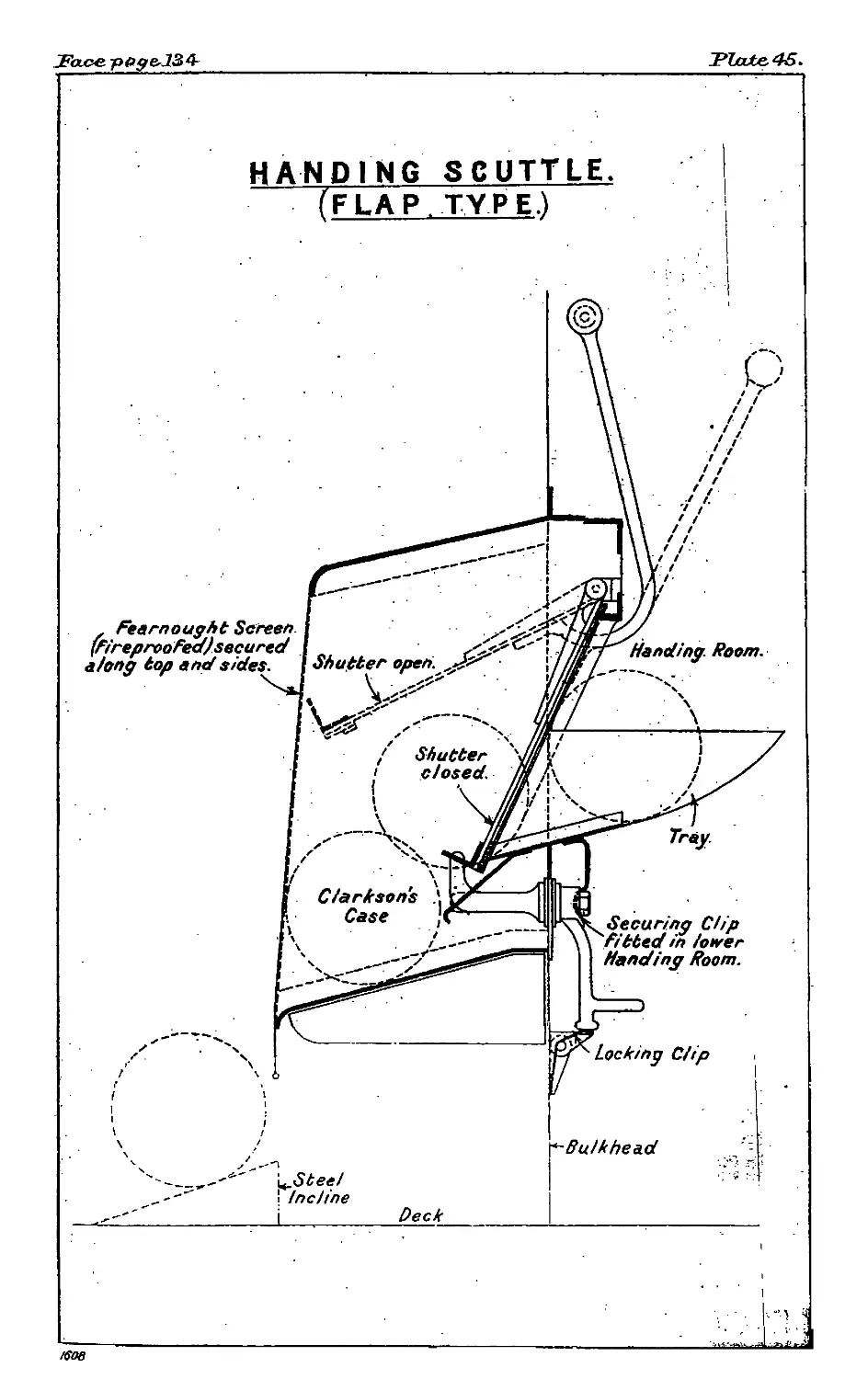
45. Handing Scuttle (Flap Type) ............................ 134
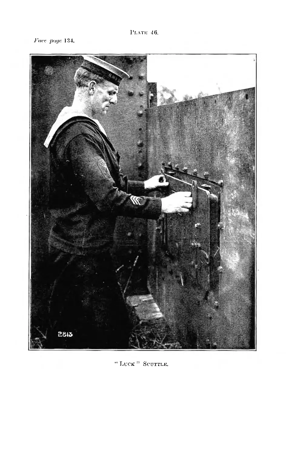
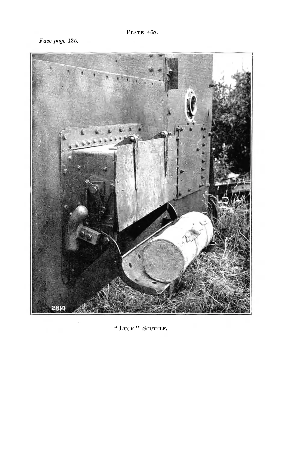
46. “ Luck'” Scuttle (Photo)... ... 135
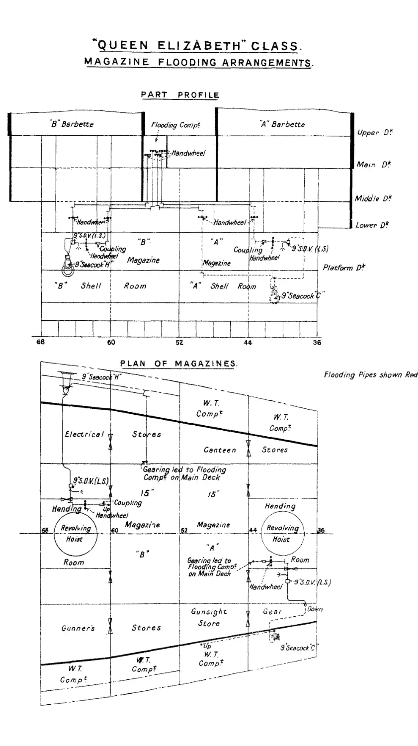
47. Flooding Arrangements, Q.E. Class ...................... 137
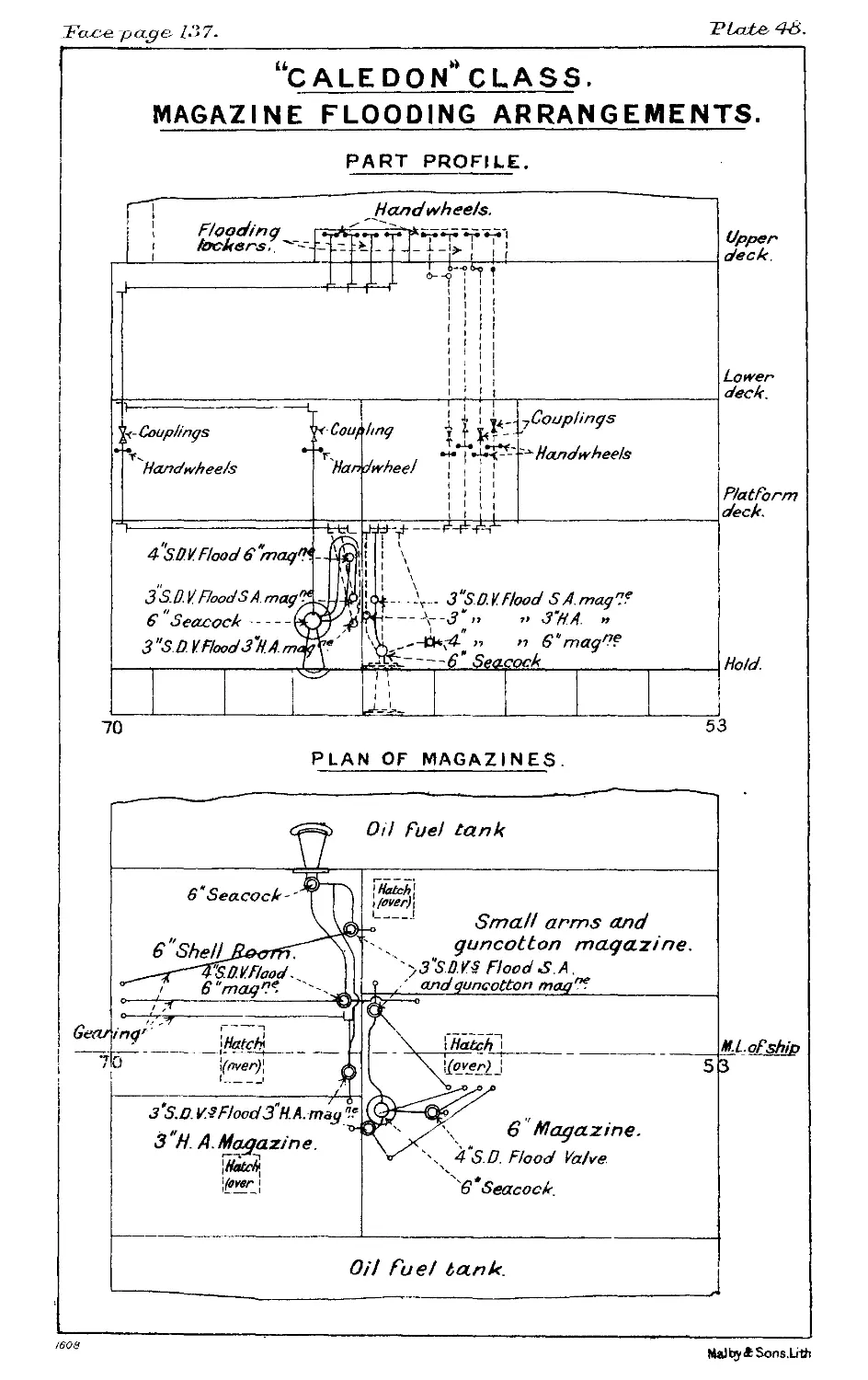
48. Flooding Arrangements for Light Cruisers ... 137
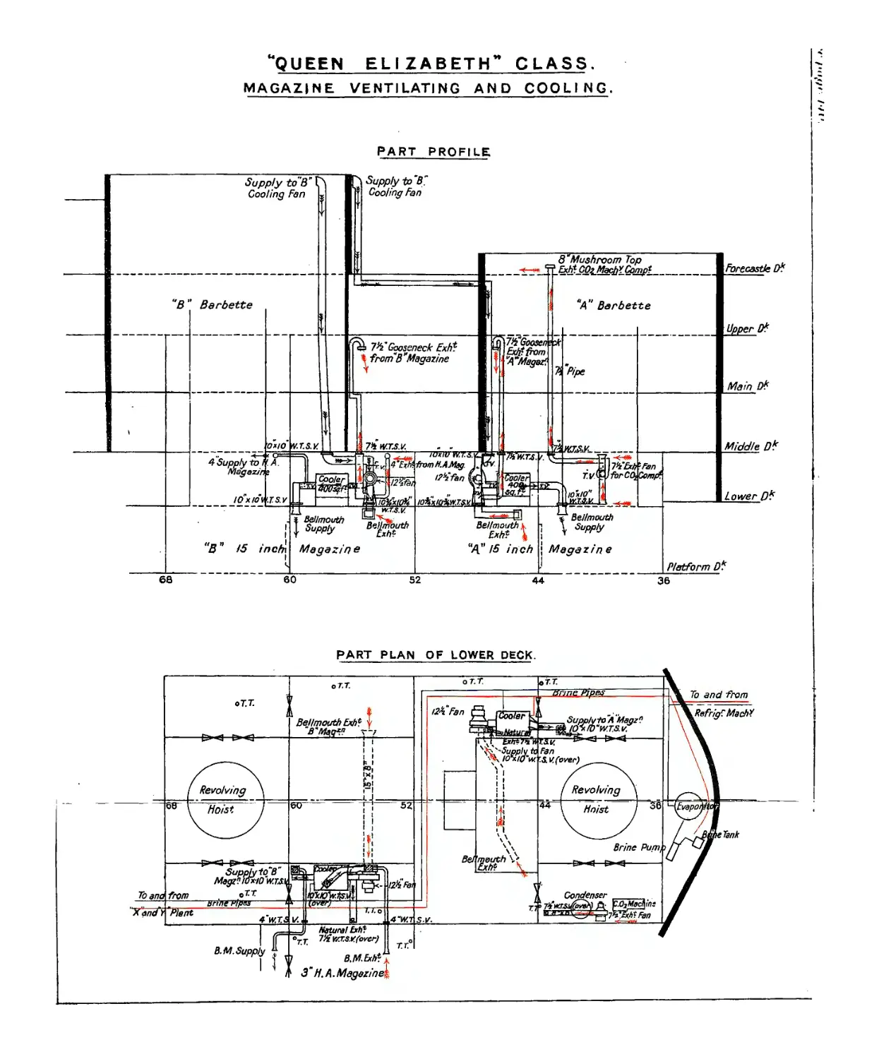
49. Ventilation mid Cooling for Q.E. Class.................. 140
50. Ventilation and'. Cooling for Light Cruisers ... . 140
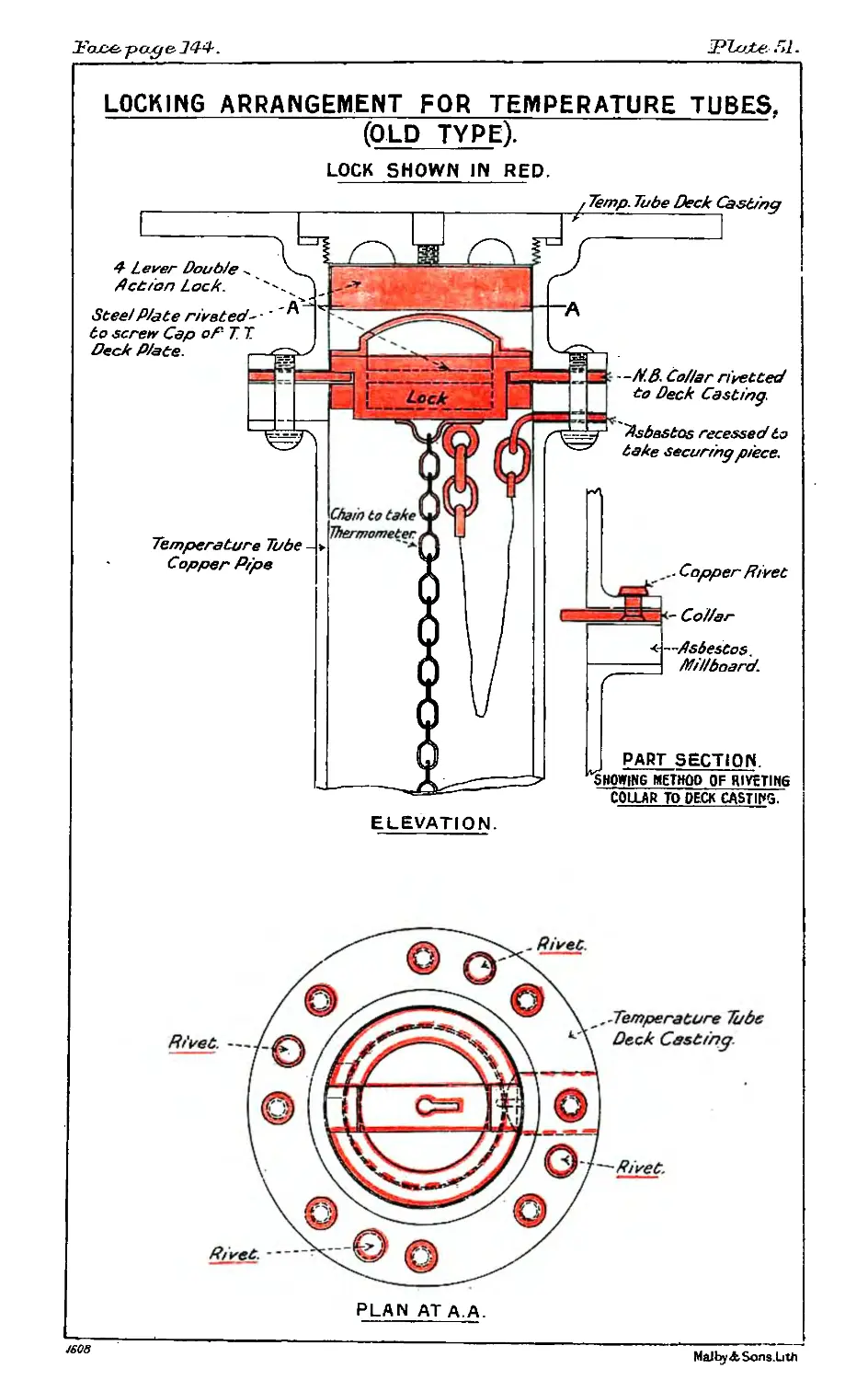
51. Locked Temperature Tube, Old Type....................... 144
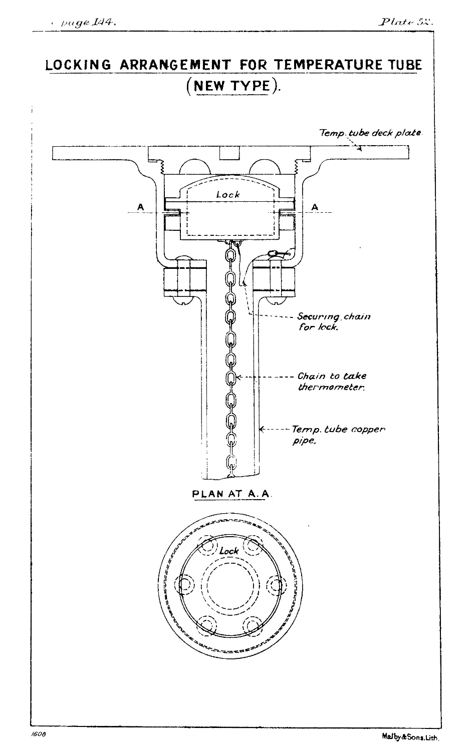
52. Locked Temperature Tube, New Type............ . 144
Chapter XV. (Forms.)
No Plates
146
AMMUNITION POCKET BOOK.
FOREWORD.
1. Nothing' in this book is to be considered as an authority
for disregarding the orders and regulations laid down in the
“ Naval Magazine and Explosives Regulations ” and the “ Naval
Cordite Regulations.”
2. These latter publications are the authority for the necessary
care and precautions in the stowage, handling and inspection of
Ammunition of all sorts.
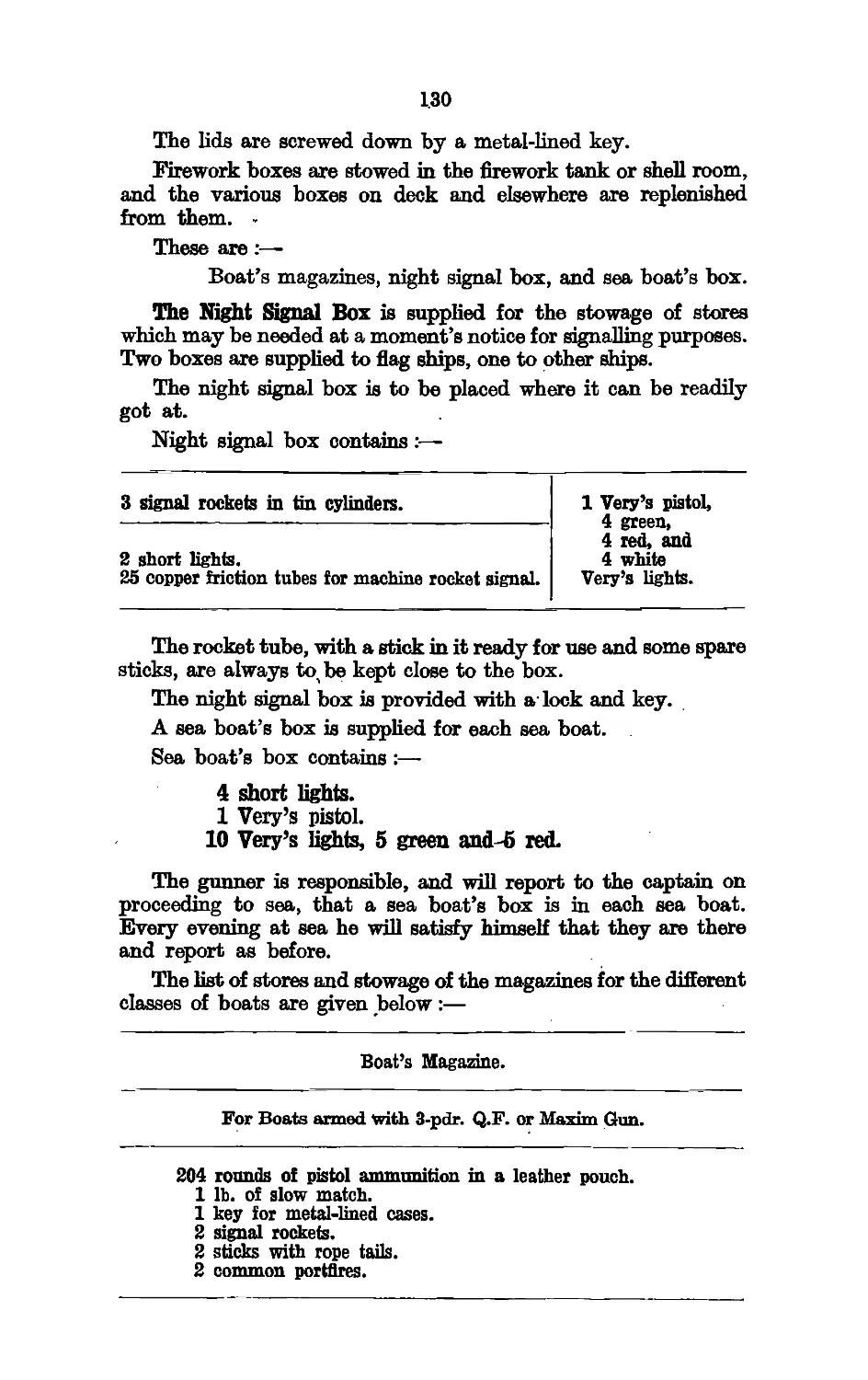
3. The, regulations for Life Buoys are contained on page 132
of this Handbook (see also K..R. and A.I., Art. 641 and 540 (20)).
4. K.B'n and A.I. Article 895 is the authority covering the
reports of accidents in general with Gunnery Material.
1
CHAPTER I.
NOTES ON HIGH EXPLOSIVES.
The notes, on different, explosives are arranged according
to the following plan :—
Introductory remarks.
, Service uses.
Manufacture.
Properties.
Stability and storage.
Tests.
(1) Nitroglycerine.
-Introduction.—Nitroglycerine is obtained by the action of
nitric acid on glycerine.
Service uses.—Nitroglycerine is used in the Service almost
entirely for the manufacture of propellants of the cordite type.
Blasting gelatine is occasionally used in the Service and consists
of about 93 per cent, of nitroglycerine, gelatinised with 7 per
cent, nitrocellulose, in which way the disadvantage of the liquid
condition of the nitroglycerine is overcome. Nitroglycerine
may be used also by absorbing 75 per cent, of it in 25 per cent,
of an infusoria], earth (called Kieselguhr), this forming what is
known as dynamite.
Properties.—Nitroglycerine is an oily colourless liquid, which
is odourless and only slightly soluble in water, but soluble in
organic solvents such as benzine and alcohol. It acts as a poison,
and even traces absorbed through the skin produce violent
headache. Workers in explosive factories, however, become
accustomed to it and experience no ill effect.
When heated, nitroglycerine decomposes actively as the
temperature approaches 180° C. (356° F.), and ignites at tempera-
tures in this neighbourhood. Nitroglycerine is liable to freeze
when cooled below 13° C. (55° F.).
When nitroglycerine is detonated the products are entirely
gaseous.
Nitroglycerine is an extremely powerful explosive, but suffers
from several disadvantages. It is very sensitive to impact and
friction, its application is difficult on account of its liquid
condition, and it is gradually decomposed or hydrolised by
moisture, especially if alkali is present.
Stability and storage.—Nitroglycerine is never stored as such
for any length of time. Its inherent stability is less than that
of guncotton, but. its effect in mixtures is largely dependent on
the ease with which its products of decomposition, which
2
accelerate further decomposition, can get away. This removal
of gaseous products is easy in the case of dynamite, for example.
In a horny explosive like cordite M.D. their escape is more
difficult, and unless absorbed by stabilisers they would lead to
an unstable condition on warm storage.
Tests.—The principal specification tests applied to nitro-
glycerine are the Abel Heat Test, and tests for alkalinity and
moisture.
(2) Nitrocellulose, guncotton, soluble nitrocellulose.
Nitrocellulose is made from cellulose by the action of nitric
and sulphuric acids in a manner analogous to the manufacture, of
nitroglycerine. Cellulose is the main constituent of the fibres of
many plants. Cotton is the purest natural form of cellulose.
Guncotton, the most highly nitrated cellulose used in the
Naval service, contains 12*9 to 13-2 per cent, of nitrogen.
By varying the conditions of nitration of cellulose, nitrocellu-
lose containing varying percentages of nitrogen can be obtained,
their properties varying with their nitrogen content: thus
guncotton is for the most part insoluble, but R.D.B. nitrocellulose
of 12 to 12- 3 per cent, of nitrogen is soluble in a mixed solvent
composed of ether and alcohol. Acetone, however, is a solvent
for both this type of nitrocellulose and for guncotton.
Service uses.—Nitrocellulose is used in the Service as gun-
cotton, and as soluble nitrocellulose.
Guncotton is chiefly used for incorporation with nitro-
glycerine and mineral jelly in the manufacture of cordites,
Mark I and M.D. The principal other uses for guncotton in the
Service are:—
Wet.—Slabs for torpedoes, mines and demolition work.
Dry.—Primers for detonating slabs, primers as a filling
for sound rockets; as an ingredient in the primiqg compo-
sition of electric tubes and detonators; as an ingredient of
tonite, which contains 50 per cent, of barium nitrate and is
used in sound rockets; and for various other minor purposes.
Soluble nitrocellulose is used in the manufacture of cordite
R.D.B. nitrocellulose powder and blasting gelatine.
Properties of the nitrocelluloses, (a) Guncotton.—Guncotton
when properly made and purified is inodorous and tasteless, and
neutral to acid or alkaline test papers. It is met with in the
Service in the form of compressed blocks made from pulped
guncotton, the fibrous character of the material being visible.
It is generally stored in bulk in the wet form as pressed slabs,
but small quantities are kept dry for use as primers, wet gun-
cotton not being satisfactorily detonated by a No. 8 detprie ior
without an intermediate primer which is usually madejo^ dry
guncotton. n
3
The use of wet guncotton for torpedoes and mines is, however,
obsolescent.
dry state guncotton is very sensitive to file lion or
vn&traiion, and should be handled with caution. It is also liable
го produce electric sparks’in dry weather when subjected'to
friction. It is readily ignited by a flame and burns into detonation
when ignited.
Wet guncotton containing about 17 per cent, of water (20
parts per 100 of guncotton) is only slightly sensitive to mechanical
shock, and smoiflders slowly, but does not inflame when a light
is applied to it.
Care must be taken that wet guncotton is kept wetted with the
necessary percentage of water, or it may become dry, and
•consequently dangerous. For this purpose the tins in which
the slabs are packed are fitted with re-wetting plugs, which can
be removed so that the necessary weighed amount of water can
be added. This quantity can be ascertained by subtracting the
weighty of the tin at the time of examination, from the weight
marked on the tin.
Guncotton is a powerful explosive, but as a high explosive
it has been to a large extent superseded by trotyl and amatol.
Wet guncotton has neither such a store of energy as trotyl and
40/60 amatol, nor is its rate of detonation as high as that of these
explosives, which moreover are more readily filled into torpedoes
and mines.
(в) Soluble nitrocellulose.—Soluble nitrocellulose, so called
because it is soluble in nitroglycerine (in which respect it differs
from guncotton) is a material very similar in appearance to
guncotton. When dry it is similar to guncotton in sensitiveness
and other characteristics.
Stability and storage of the nitrocelluloses.—Guncotton and
nitrocellulose prepared for making into propellants are not
required to be stored. Guncotton for wet slabs undergoes a
slow process of hydrolysis with the formation of salts of calcium
and an increase in the solubility in ether-alcohol. This is not
dangerous in the wet condition that is maintained.
The calcium carbonate in the dry guncotton of primers acts
as a stabiliser. Without it, primers have been found entirely
to decompose, while with calcium carbonate only a slow inter-
action takes place .
Tests.—Guncotton is subjected to the heat test and to a
special stability test.
(3) Picric Acid.
Introduction.—-Picric acid, or trinitrophenol, is obtained by
treating phenol (carbolic acid) with nitric acid.
‘It is not readily decomposed by the action of moisture and
is more stable then such explosives as cordite or nitroglycerine.
Service uses.—Picric acid was first used as a dye, but since
1893 it has been largely used for filling high explosive shell. -
By neutralising picric acid with ammonia, ammonium picrate
is formed and this is an ingredient of picric powder used in
exploders for shell. In the cast condition picric acid is known
in this country as lyddite, in France as melinite, in Japan as
shimose, and in Germany as granatfullung 88.
Properties.—As produced by the manufacturers, picric acid
is a fine lemon-coloured crystalline powder with a very bitter
taste. When pure it melts at 121-6° C. (250-9° F.) to an amber-
coloured liquid.
It is soluble in water to the extent of about one per cent,
at 15° 0., and seven per cent, at 100° C. It is not hygroscopic.
It does not appear to be poisonous, although it iinmediately dyes
the skin yellow.
Chemically, it is a fairly strong acid and reacts with metals-
and some of their compounds to form salts, the picrates. Some
of these are sensitive to shock, the most sensitive being lead
picrate, which is readily detonated by a light blow, or still more
readily by friction or by contact with a flame. The detonation
of certain of these picrates in sufficient quantity would reproduce
the effects of a fulminate detonator and cause the detonation of
any picric acid in contact with them.
For this reason great precautions need to be taken to prevent
picric acid from coming into contact with these metals and their
compounds, especially when it is in a molten or moist condition.
Lead picrate is the most dangerous, and paints containing lead
compounds are forbidden to be used on any articles which may
come in contact with picric acid; a limit for lead content is-
also put on all articles such as brass for fuzes, plugs, tools, &c.,
liable to come into contact with the acid. Oil used for cleaning
the shell should be lead-free.
Stability and storage.—Picric acid is chemically a stable
substance, and is capable of withstanding warm storage in the
hottest climates without being affected.
Ammonium picrate and picric powder.
Ammonium picrate is formed by neutralising the picric
acid with ammonia. It is an orange-yellow crystalline body,,
and is itself an explosive of considerable power, although an
insensitive one. A finely ground mixture of this with
potassium nitrate in the proportion of 43 to 57 is known as
picric powder. Picric powder ignites readily and burns with
violence. It is used as an exploder for certain shell filled with
lyddite or shellite when the explosion is brought about by means-
of a flash from gunpowder, and not by a detonating system
involving the use of fulminate, The. sei^i^iyene§§(of the ppxt‘.:te
is greatei than that of picnd it’is.itecess^ry to .l-^ёр it
«by- ‘ •’>J.
б
(4) Trinitrotoluene.
Introduction^—Trimtrotbluene, commonly known as-T.N.T.',.
'is? also sometimes called*'by its commercial name " Trotyl.’’ .
Service uses.—Before the war, trotyl was used as a Service
explosive to a limited extent as a filling for exploder bags, but
experimental methods of filling shell of the larger sizes with
T.N.T. had already been investigated.
Shortly after the war began it was adopted as a filling for
certain high e:rplosive shell and torpedoes, and early in 1915
mixtures of ammonium nitrate with trotyl, known as amatols,
came into use.
Properties.—Trotyl varies in colour from nearly white to a
reddish brown. It melts to a brown liquid which solidifies to a
crystalline mass at a temperature of 180° F. In the pure state
it has no smell. Crude trotyl sometimes has an irritating smell,
due to the presence of chemical impurities.
T.N.T. does not dissolve appreciably in water, and it is not
hygroscopic.
Trotyl is slightly poisonous, and precautions are taken in
manufacture and filling to protect the operators by preventing
contact with the skin and breathing in of dust as much as possible,
and by arranging for cleansing of the skin and the use of clean
clothing.
Trotyl is a violent and powerful high explosive, being in
these respects only slightly inferior to picric acid. It has a high
rate of detonation, 6,960 metres per second at a density of 1* 57.
Being deficient in oxygen for complete combustion, it gives a
black smoke of carbon particles on detonation, and carbon
monoxide gas, which is poisonous. It is less easily inflamed than
pierid acid, although that does not inflame readily, and is con-
siq^rdfeiy Jess sensitive to shock than that explosive.
i}'. Storage—The chemical stability of unmixed
₽Ucb ЯЙ to present no danger of spontaneous ignition
inwajm climate or condition that may be met with in the
Service»
(5) Amatol.
Introduction.—Amatol is an intimate mixture of ammonium
nitrate apd trotyl- Its use was proposed in 1915, with the object
of economising trotyl, at the same time taking advantage of the
of oxygen possessed by ammonium nitrate to compensate
Pflriwly or completely for the deficit of oxygen in trotyl.
amatols in use are 40/60, 50/50 and 80/20, the first-
named figure or numerator always referring to the percentage of
ammoniurn nitrate.
Service uses of amatoL—During the war amatol ultimately
became the principal high explosive used in the land service.
In the naval service it was used to a smaller extent, as, for
6
example, for filling mines, howitzer shell, depth charges, &c.; it
is also largely used in the air service for filling bombs.
Properties.—Amatol 40/60 when cast has the grains of
ammonium nitrate coated with trotyl and they are thereby
somewhat protected against moisture. Amatol 80/20 for shell
filling easily takes up moisture from the air. If the constituents
are pure no physical or chemical change goes on in. amatol, but
in supply various grades of both constituents have had to be
accepted containing small quantities of impurities.
The principal objection to the impurities liable to occur in
amatol is that they may cause “ exudation.” Although the
amatol is solid at ordinary temperatures some of these impurities
have a far lower melting point and may be liquid at ordinary
storage temperatures. Such liquid impurities may be more
sensitive to blows than amatol, and are also liable to soak into
exploder bags and deaden the exploders, thus causing “ blinds.”
The design of projectiles, bombs or other weapons which are
to be filled with amatol are complicated by the necessity of
providing precautions against such exudation.
The most common and most troublesome exudation from
amatol is the oily impurities which T.N.T. is Hable to carry. If
oily T.N.T. gets into a fuze hole thread, for instance, it might be
a source of danger, and it is particularly liable to soak into and
deaden an exploder.
The use of any but the highest grades of amatol for naval
purposes is not favourably regarded therefore, and this explosive
is not. likely to have an extended use in future for naval
weapons, except under the pressure of necessity and shortage of
other materials such as occurred in the recent war.
Explosive properties of amatol.—Amatol 40/60 gives less
smoke than trotyl when it is detonated, and since in 80/20
amatol the combustion is complete, very Httle smoke is produced.
In consequence, mixtures for producing smoke to indicate the
point of burst are introduced into large shell filled with 80/20
amatol. In rate of detonation and violence, 40/60 is Httle inferior
to trotyl, but 80/20 is distinctly lower, although the values are
stiH considerable. The total energy of 80/20 is higher than that
of either, and this, together with its lower rate of detonation,
makes it peculiarly suitable for land service sheH, since it frag-
ments the sheH sufficiently, and, byireason of a more prolonged
blow, projects them further; these properties, in addition, make
it useful for lifting earth.
Amatol 40/60 is of about the same sensitiveness to impact as
trotyl, amatol 80/20 slightly less sensitive and considerably
more difficult to bring to complete detonation, requiring special
initiating systems of violent intermediate explosives.
Ste'illty and storage.—The amatols are stable explosives v-
that ..Jey are not Hable to undergo spontaneous igmtloh?1
must not be exposed to damp; oh account of the hygrbsizipjc
nature \ л the ammonium nitrate. " ' !!
7
(6) Composition exploding. ,
• :2 -Introduction.—Composition exploding is briefly kriowhin tbW
iSbrvice as “С.ЕЛ’ Its principal use is as ifiienfi&diain^"
between the initiating fulminate detonator and ie niain charge ’
of explosive. Owing to its having a higher degree of sensitiveness
than the explosive constituting the main charge, it responds
readily to the impulse of the detonator, while its great power and
violence ensure effective detonation of the charge.
C.E. is used as a filling for the magazines of detonating fuzes
and gaines, and in primers for torpedoes, naval mines, depth
charges, bombs, &c. It is used for the exploders of shells when
these are liable to be contaminated by infiltration of trotyl
exudation from the filling, since it possesses the advantage over
trotyl for this purpose that its detonating properties are not
affected by the presence of this exudation.
Properties.—C.E. is a crystalline substance of a pale yellow
colour, and for Service purposes is in the form of fine crystals or
powder. It is not used in the cast condition on account of its
high melting point. It is practically insoluble in water and is not
hygroscopic. It is liable to produce skin inflammation in some
people, but is not poisonous.
C.E. is more readily ignited than picric acid or trotyl, and
more sensitive to shock and responsive to initiation by fulminate.
It is, however, still, insensitive enough to permit of its being used
in columns of short length in shells where it is subjected to severe
shock on set back. Owing to its high rate of detonation, high,
energy content and capability of producing very rapidly an
intense pressure, as well as to its readiness of response to detona-
tion, C.E. is very suitable for the purpose for which it is used,
i.e., to reinforce the effect of fulminate, which can be permitted
in small quantities only on account of its extreme sensitiveness.
Stability and storage.—Purified C.E., while less stable than
trotyl or picric acid, has a sufficiently high degree of stability
to free it from any suspicion of liability to undergo deterioration
or spontaneous decomposition under conditions of Service use.
This has been established by warm climatic trials, and is
confirmed by experience abroad.
8
CHAPTER П.
PROPELLANTS.
When Schoubein discovered guncotton it was hoped that the
question of a suitable smokeless powder for guns had been solved,
but attempts to use fibrous guncotton as a propellant were
attended by failure. No method of winding or compression was
found capable of regulating the rate of burning.
It was only when the control of the rate of combustion of
the explosive was made possible by gelatinisation that there
was progress. By gelatinisation the fibrous nature of the nitro-
cellulose is destroyed and converted into a jelly or dough, which
is capable of being worked into any convenient form. These
dense masses will bum comparatively slowly and regularly from
layer to layer even under the pressures set up during their com-
bustion in the gun.
Pressure increases the rate of burning, and high initial pressures
such as would strain or burst the gun are avoided by the use of a
suitable size of cord.
The usual method of gelatinising nitrocellulose is by means
of a volatile solvent, acetone being used for guncotton, and
ether-alcohol for the soluble nitrocelluloses. The gelatinisation
is performed in an incorporator, the dough is pressed into the
desired form, and the solvent is then dried off and a large pro-
portion of it recovered. In nitrocellulose powders soluble nitro-
cellulose is generally used and ether-alcohol is the solvent.
Cordite Mark I.
Sir Frederick Abel and Professor Dewar found that, if
guncotton and nitroglycerine were mutually taken up by a
liquid capable of dissolving them both, on evaporating off the
solvent (acetone), the guncotton and the nitroglycerine remained
behind in a completely incorporated condition as a gelatinous
mass.
The composition of the first British smokeless powder made
on this principle was :—
Nitroglycerine ... ... ... 58 per cent.
Guncotton............................. 37 „
Mineral jelly ......................... 5 „
Thia was originally called cordite on account of the cord-like
form into which it was pressed. Since the introdi1 ciion of
cordite M.D. the original cordite has been generally called cordite
The mirrer^.l jelly (a product of petroleum distilla/i On; was
Originally introduced'‘"for the purpose of reducing the wear on
9
the bore of the gun, but it was found subsequently by investiga-
tions on the keeping properties of cordite, that mineral jelly had
the important function of acting ash stabiliser;' ard prolonging
the life of cordite by reacting with'‘the acids produ.x'*1- by the
decomposition products of the cordite, thus preventing them
from accelerating decomposition.
Manufacture.—The manufacture of cordite Mark I is similar
to that of cordite MJ), (see below), except that the proportions
of the ingredients are different, and that Mark I cordite employs
only half as much solvent.
Properties.—Cordite Mark I is soft and pliable, owing to its
high content of nitroglycerine. For the same reason it produces
a very high temperature on explosion, and causes severe erosion
of the bore of the gun.
Cordite M.D.
Experience with cordite Mark I showed that, owing to the
excessive erosion of the bore which it produced, shooting was
rendered inaccurate after a comparatively small number of
rounds had been fired. This was clearly demonstrated during
the South African campaign.
Experiment led to the adoption of a modified cordite known
as cordite M.D. of the following composition:—
Guncotton ...............................65 per cent.
' 4 Nitroglycerine ......................... 30 „
Mineral jelly............................ 5 „
Qjwing to the smaller amount of heat developed on explosion
the nfe of a gun using M.D. cordite is much longer than with
cordite: Mark. I.
edt ii-ti A
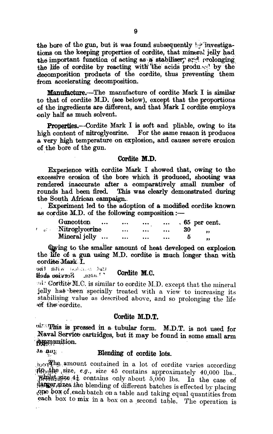
Ifeds ooivsoB : ' Cordite M.C.
>11 ’ Goriiit^ M.G. is similar to cordite M.D. except that the mineral
jelly haS’been specially treated with a view to increasing its
stabilising value as described above, and so prolonging the life
<of the cordite.
Cordite M.D.T.
ol’ This is pressed in a tubular form. M.D.T. is not used for
Naval Service cartridges, but it may be found in some small arm
ftgWjunition.
J/i Blending of cordite lots.
iooi?^',anioun-t contained in a lot of cordite varies according
,size, e.g., size 45 contains approximately 40,000 lbs..
contains only about 5,000 lbs. In the case of
ilcWg,er(Sizes. .the blending of different batches is effected by placing
thpo box pf,each batch on a table and taking equal quantities from
each box to mix in a box on a second table. The operation is
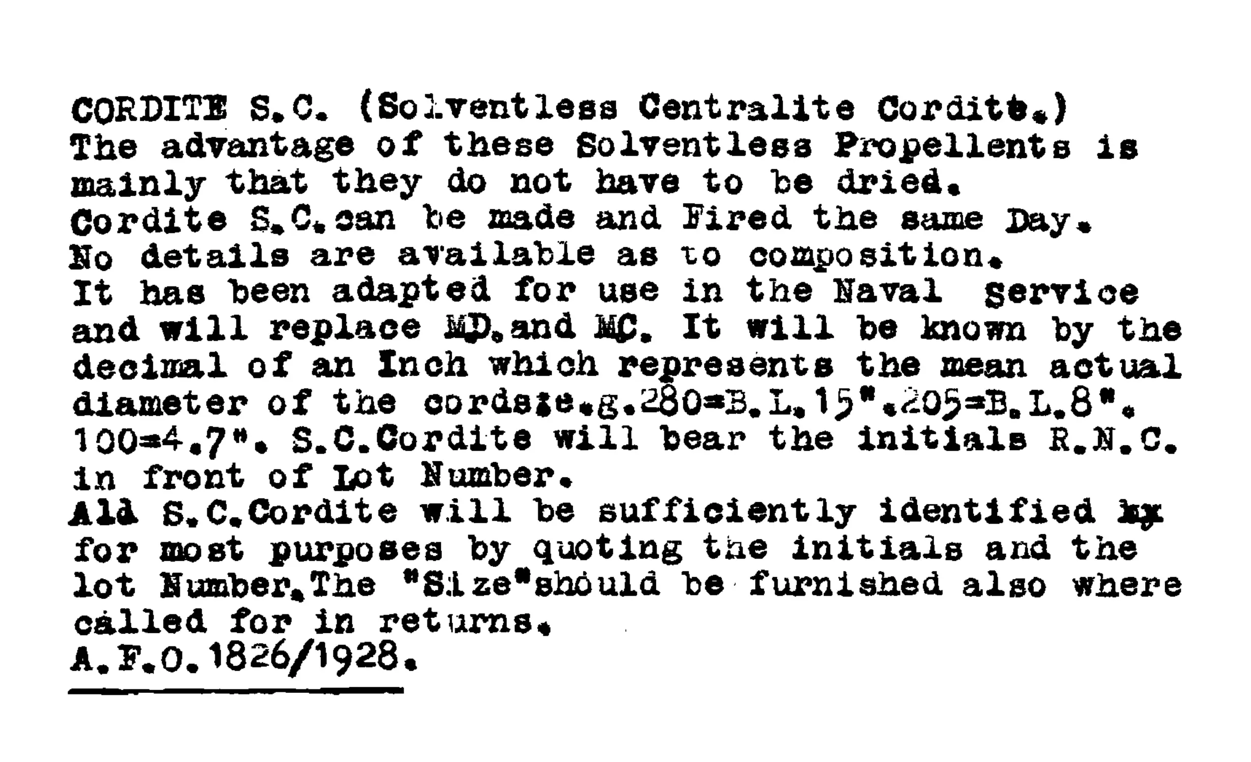
CORDITE S.C. (Solventless Centralite Corditto*)
The advantage of these Solventless Propellents is
mainly that they do not have to he dried.
Cordite S.C. can be made and Fired the same Day.
Ho details are available as to composition.
It has been adapted for use in the Naval service
and will replace KP.and It will be known by the
decimal of an Inch which represents the mean actual
diameter of the cordsie.g.280«S.L. 1>*.205aB.L.8w.
1004.7». S.C.Cordite will bear the initials R.N.C.
in front of Lot Number.
Aid S.C.Cordite will be sufficiently identified k£
for most purposes by quoting the initials and the
lot Number.The *Size*should be furnished also where
called for in returns.
A. P.O.1826/1928.
10
performed by a queue of men each taking a handful from
each box.
Blending is very necessary to compensate for the variations
in the diameter of the cords and thus to give uniform ballistics.
Delivery and selection for proof, examination and test.
The lots are numbered consecutively in order of manufacture.
Each lot is given a number which, prefixed by the distinguishing
letters of the firm, is used to designate the lot.
Each lot is subjected to the following inspection:—
(1) Firing proof ... ... To check correctness of the bal-
listics given by the lot against
the “ standard ” for that size
of cordite and to enable the
charges to be “ adjusted.”
(2) Chemical examination. Analysis and heat tests.
(3) Visual inspection ... To see that the cordite is dry,
homogeneous, and free from
visible defects and impurities.
Immediately on receipt of a lot a small sample is sent to the
chemist for heat test and chemical analysis, and a number of
boxes, sufficient to provide for firing proof, is selected and
despatched unopened to the proof butts at Woolwich.
At the proof butts the contents are made up into cartridges
of the specified weight for firing proof.
(1) Firing Proof.—This consists in firing five rounds of the
lot against two or more rounds of a standard lot in the nature of
gun laid down in the specification for the size of cordite.
Proof shot of the correct weight and banded with the
Service driving band, are used at the proof butts. Service shell
could be used, if the range were suitable, provided that the
same nature of projectile was used throughout the shoot.
Velocities are measured by chronograph.
Pressures are measured by copper cylinders contained in
crusher gauges. They are placed in the chamber in rear of the
charge in B.L. guns and inside the case for Q.F. guns.
The Proof and Experimental Officer calculates the muzzle
velocities of all rounds from these observed velocities.
System of proof.—The ballistics found by firing are corrected
to the ballistics that would be given in an average new gun at
80° F. at its ninth round.
Having obtained the corrected ballistics of a lot, the Proof
and Experimental Officer calculates the charge which should
give a pvecified velocity, usually the mean of the specification,
which is a?lied the velocity of adjustment. This charge is called
the adjusted charge of that lot and is the weight to which the
charges o . the lot are made up.
PICTORIAL REPRESENTATIONS OF CORDITI
SHEET 1.
1- 1
2. I NEWLY MADE CORDITE.
3. I SHOWING RANGE IN COLOUR.
4. I
5. EARLY STAGE OF CORROSION OF
CORDITE MD. SIZE 16.
(3578) Wl, ii759/P.'2O5 1-2190. 7>21 С.Л.Р. 7710.
PICTORIAL REPRESENTATIONS OF CORDITE.
SHEET 2.
6. INTERMEDIATE STAGE OF CORROSION
OF CORDITE MD. SIZE 19.
7. ADVANCED STAGE OF CORROSION OF
CORDITE MD. SIZE 16.
8. ADVANCED STAGE OF CORROSION OF
CORDITE MD. SIZE 8.
9. CORDITE CONTAINING AIR BUBBLES.
11
Guns for cordite proof are not as a rule used for other purposes,
as it is тез; desirable that the behaviour of the gun should be
watched throughout its proof life. If the gun becomes irregular
or worn, or ... the correction for ballistics becomes too big, the
gun is discarded and replaced by a fresh one.
(2) Visual examination.—This is carried out by the Inspection
Department.
In order to comply with the specification, the cordite must
be externally dry, homogeneous, and free from foreign matter;
the sticks must be straight, be within the limits of length laid
down, and must not show any splits, and the ends must be evenly
cut.
There should not be an excessive number of sticks containing
air bubbles. Further, the maximum difference in weight between
individual sticks, cut to a length of 10 inches, must not exceed
a certain amount. To ensure that the cordite complies with
the above conditions, it is subjected to a visual examination.
Finally.
The lot, having passed the firing proof, chemical examination,
including a second heat test and visual inspection, is then accepted
into the Service and delivered to the Filling Stations for making
up into cartridges.
Appearance of corroded cordite.
(Sheet 1 and Sheet 2.)
In newly made cordite of different manufacture the colour
varies from lemon yellow to a deep brown; the range in colour
is shown in Figs. 1 to 4. On account of the wide variations,
the colour cannot be taken as any indication of age, although
during the storage of cordite a slight darkening sometimes
occurs. This is, however, no indication of deterioration.
An early stage of corrosion is shown in Fig. 5. It is indicated
by a portion of the stick, when viewed by transmitted light,
being more translucent than the unaffected cordite. A nucleus
of foreign matter is generally present.
As the condition of corrosion progresses, the nucleus of foreign
matter becomes surrounded by an opaque region. An outer
region of greater translucency is still visible. This is shown in
Fig. 6.
Examples of corrosion in a more advanced stage are shown in
Figs. 7 and 8. In these, the opaque region surrounding the
nucleus of foreign matter increases in size and depth of opacity,
the nucleus of foreign matter becoming hidden. The corrosion
gradually progresses from this stage along the length' of the stick.
Occlusions of air in cordite have to some extent the appearance
of the condition of advanced corrosion. A stick of cordite
containing air bubbles is shown in Fig. 9. The dark portions
« 22194 в
12
show the appearance when viewed by transmitted light, and the
light portions when viewed by reflected light. The chief differ-
ence in appearance between air bubbles and an advanced
corrosion is that the air bubble is not surrounded by a region
of greater translucency than the unaffected cordite.
An air bubble can be definitely distinguished from a corrosion
spot by cutting down into the cordite at an angle with a sharp
clean knife, and applying to the region moistened blue Service
litmus paper under the usual precautions as regards handling.
In the case of a corrosion, the nuclear region reacts strongly
acid, turning the litmus paper locally bright red.
N.B.—The coloured representations of cordite are twice
natural size.
Properties of Cordite M.D.—Cordite M.D. is harder than
cordite Mark I, and more brittle, so that it breaks when bent
•to an excessive extent. The proportions of the ingredients are
arranged to give a lower temperature of explosion, and conse-
quently less erosion of the gun, than Mark I. It bums somewhat
more slowly than cordite Mark I in the gun, and its total energy
content (as measured by its heat of explosion) is lower, so that
larger charges of cordite M.D. are required than of cordite Mark I.
Ignition and rate of burning.—In its usual form of sticks made
up into a cartridge, cordite is more difficiilt to ignite than grain
gunpowder, which is used as an intermediary between the flash
of the primer and the cordite charge. The smaller the diameter
of the sticks the easier it is to ignite, and the quicker it will bum.
Cordite ignited in small quantities in the open bums fiercely.
When burning larger quantities there is danger of explosion if
it is packed close together.
Cordite of small diameter can be brought to explosion when
ignited in a close space or subjected to the action of a fulminate
detonator.
Gases from ignition of Cordite.—When cordite is fired under
high pressure, as in a gun, it is resolved into the gases carbon
dioxide, carbon monoxide, water vapour, nitrogen and hydrogen.
Of these, carbon monoxide is poisonous.
IVhen it is burned in the open, but without free access to air,
nitrous gases may also be formed, which are poisonous and also
irritating.
Sweating of Cordite.—Sweating of cordite due to exudation
of nitroglycerine may occur on subsequent warming, after storage
at temperatures below 45° F.
Cordite should not be handled when in a sweated condition
but should be kept at a moderate storage temperature (say 60° F.),
when the nitroglycerine will be re-absorbed.
Felt wads or other absorbent material should not be left in
actual contact with the cordite, ac after a prolonged period
nitroglycerine from the cordite may be absorbed by the wads;
rendering them highly explosive. It is tar this reason that wads
13
in Q.F. .ammunition have glazed board discs on the side next
the cordite.
Smoke developed by Cordite. —Although guncotton and nitro-
glycerine are perfectly smokeless, the rapid firing of cordite gives
rise to a fog or haze which,' when large charges are used, is
rather troublesome. This haze, which in some cases becomes a
thick yellow smoke, consists of condensed water vapour, smoke
from the powder primer and cartridge bag, together with oxide
of copper from the driving bands.
ВялкАяяЬ.—Of the gaseous products yielded by cordite M.D.
on firing, 70 per cent, are inflammable gases, and these mixed
with air in the gun after firing give an explosive mixture, which
sometimes ignites when the breach-block is opened and causes
the flame Imown as backflash. To prevent backflash a blast
of air is injected into the bore of large guns.
Stability and storage of Cordite M.D.—During the storage of
cordite M.D. and, in general, of nitro-compound explosives
a slow but continuous decomposition is going on. This de-
composition results in the formation of free nitric and nitrous
acids among other products, and these acids, if not neutralised,
greatly accelerate the rate of decomposition of the explosive. It
is- 'forSthe purpose of combining with the acids produced in
decomposition, and preventing them from exerting this deleterious
effect, that stabilisers, such as mineral jelly and diphenylamine,
ate addbd tb propellants.
1 'If the decomposition proceeds far enough sufficient heat
inny be generated by the process to ignite the cordite. To guard
against this, tests are earned out, from the results of
.winch the probable safe life of the cordite can be predicted.
’jUthofigh 'siich Leets may show that the cordite is unserviceable
of.lm hut n short safe siie, yet, the amount of decomposition
is small, and is nut, sufficient to uffect ballistics.
.At ihaiempriraturo laid duwn for ships1 magazines decomposi-
tion(Exceedingly.slow. It is of the greatest importance to keep
.tkE'0,,niagajdij<4 below the prescribed limit of temperature.
.......Gunpowder.
Introduction.—Gunpowder, or black powder, is one of the
oldest of explnsivea. Service gunpowder is a mixture of 76 parts
»by weight, of potassium nitrate (saltpetre), 15 of charcoal and
10 d£ Kiilphnr.
' 'Service uses.—As a propellant, gunpowder has been almost
by smokeless powders, but it is still used as
^priniiiig, and in the magazines and time rings for some fuzes
.hind ' ’for igniters of propellant charges. It is also used for
hurstiujT charges of certain types of projectiles. Varieties of
^gunpowder in which the proportions of the ingredients are
: somewhat different f re in the standard, are used as the propelling
J-charge in rockets.
14
Properties.—Gunpowder is a mixture whose efficiency depends
on the perfection with which its incorporation has been carried
out.
The hardness of the grains, their size and shape and the
condition of the glaze on their surfaces also affect the rate of
explosion of powder.
The explosive properties of gunpowder depend on its being
a mixture of bodies none of which are themselves explosive,
all interaction having to take place between particle and particle.
Thus it is slow in its action, its effects not being violent when
compared with high explosives. The porous nature of gun-
powder facilitates its easy ignition by a flash, and this is made
use of in many components of ammunition. It is somewhat
sensitive, being more sensitive to impact and friction than
picric acid. Tools for working with gunpowder are made of
copper or bronze.
Stability and storage.—Gunpowder when kept dry can be
stored indefinitely in any dry climate. If allowed to get damp
the potassium nitrate reacts readily with copper or metals
containing it, and may be absorbed from the gunpowder by
paper, unless this is varnished.
Tests.—Gunpowder is examined by analysis to ensure that the
ingredients are present in correct proportions.
The density of gunpowder and it# content of moisture are
important as affecting its rate of burning. Its tendency to
take up excess of moisture is made the subject of a special test
(hygroscopic test).
In grained gunpowder such as R.F.G.2 the uniformity of size
of grain is tested by sieving.
By flashing it on glass completeness of incorporation is
determined by the amount of residue left behind.
Forms of powder and other Service explosives.
A list of the principal powders, and other explosives, employed
in the Naval Service, and their uses, is given in Table I at the
end of this Book. It is under consideration, however, to do away
with all the different specifications for gunpowder and to use one
composition for all purposes, merely varying the dimensions.
15
CHAPTER Ш.
MISCELLANEOUS EXPLOSIVES.
Initiating explosives.
Introduction.—The class of initiating explosives or detonants
consists of explosives of a sensitive character, which are readily
brought to detonation by a flash or by friction or percussion.
Although there are numerous explosives of this type known,
most of them suffer from serious drawbacks, such as instability
or unreliability. In the Service at present, mercury fulminate
or mixtures containing it are the only explosives of this class
in use.
In ammunition the initiating explosive is always contained
in a metal sheath, forming a detonator, it being necessary to
prevent leakage of the explosive on account of its sensitiveness.
Mercury fulminate.
Service uses.—Mercury fulminate is used in the Service in
fillings for detonators and ignitory caps. In ignitory caps,
fulminate is used in various mixtures, of which examples are
given under the heading of “ Cap Compositions.” It is
sometimes compressed into the detonator and sometimes filled
without compression.
Manufacture.—Mercury fulminate is made by dissolving
mercury- in luf.nt: acid. It is stored in bulk in the wet condition,
unci- small qiitmtities are dried under precautions at a low
' ’лЬеп rcrpiiiT tl for use.
.1Properties.— Mercury fulminate consists of small crystals,
having-in balk the appearance of fine sand. Its colour is usually
giey or brown. mi less it has been bleached in the manufacture
.fiy the aildjiioii of copper salts, when it is white.
Tim stiluliil f y of fulminate in water is very small, and it is
iin>L liygri,.t>cupk. In common with other mercury salts, it is
, very j poisonous. It is dissolved and decomposed by a solution
1 pt sodium th ins.dp hate (“ hypo ”), which is the best reagent for
Odwiiiroying it uhen necessary.
fnluiiuate is characterised by having a considerably
sensitiveness to impact and friction than other Service
it is at the same time very violent, and though its
(about, 3,000 metres per second) is not high
th.ollier explosives, a small initial impulse brings it
ti'-11 »» atl extremely small period of time.
explosive decomposition in a substance of
*я favourable for giving the intense and
for bringing to detonation an explosive
16
in contact with it. To obtain the full effect of fulminate it is
necessary to have it well confined; a few grains in the loose
condition when ignited may bum without violence.
Stability and storage.—Warm damp storage has a deleterious
effect on fulminate, decomposing it and causing interaction
with its metallic envelope. Precautions such as varnishing are
therefore adopted to prevent moist air entering. But dry warm
storage also renders fulminate incapable of initiating detonation.
Detonators should be stored either housed in their appropriate
fuzes or specially packed in boxes. Great care should be
exercised in handling them, and no attempt should be made to
dissect them.
Cap compositions.
These mixtures are the primary means for starting off an
explosive reaction which proceeds from a process of burning
as distinct from the dynamic effects of a purely detonative
impulse.
These mixtures are used in various forms of percussion caps
which are either pierced by a needle or struck on an anvil, and
in friction tubes where they are actuated by a notched bar
working over a roughened surface. Nearly all these compositions
consist of potassium chlorate and antimony ^Iphide, and most
of them contain fulminate of mercury; others contain in addition
gunpowder, sulphur and ground glass.
Characteristic compositions are :—
Modes of ignition.
Composition.
Percussion ;5ЙМ1Ь7 i®«ctionbar
(S.A. cap). grain
detonator). tunes).
Mercury fulminate
Potassium chlorate
Antimony sulphide
Gunpowder -
Sulphur
Ground glass -
8
14
18
12
12
1
1
1
6
6
4
Illuminating and signal compositions.
The majority of the compositions designed for illuminating
purposes, such as those used iff star,-shell, night :tra. ers, &c.,
consist essentially of a mixture of magnesium or aluminium
powder with oxidising agents such as barium nitrate. Thia
type of mixture gives a very intense illumination. Other
17
ingredients ,are sometimes added for the purpose of modifying
the colour of the light; or for ^educing the sensitiveness of the'
mixture. ’
Compositions of: similar type, intended for signalling purposes
and not' required to give* an intense illumination, are made witlrc<uti
magnesium or aluminium, sufficient light for the purpose being
produced by the combustion of charcoal or organic material
such as shellac. Various colours are produced by the use of
suitable components in the mixture. These compositions are
used for “ Very ” signals.
Properties.—Illuminating compositions differ from explosives
in that they are intended to bum regularly at the surface in
a slow and controlled manner.
In general, illuminating compositions are more sensitive
than ordinary high explosives, the sensitiveness, especially to
friction, of mixtures containing chlorates being undesirably
high. They are also readily ignited by a spark or flame,
especially when in the loose condition.
Stability and storage.—Service compositions when perfectly
dry are extremely stable and suffer practically no deterioration
during storage under ordinary conditions. If, however, a small
quantity of moisture gains access to the composition, through
ineffective sealing for instance, deterioration may set in, especially
ip those compositions containing magnesium or aluminium,
18
CHAPTER IV.
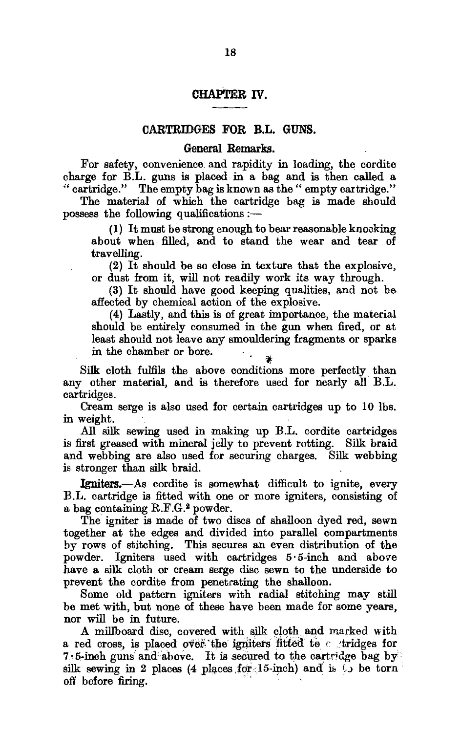
CARTRIDGES FOR B.L. GUNS.
General Remarks.
For safety, convenience and rapidity in loading, the cordite
charge for B.L. guns is placed in a bag and is then called a
“ cartridge.” The empty bag is known as the “ empty cartridge.”
The material of which the cartridge bag is made should
possess the following qualifications :—
(1) It must be strong enough to bear reasonable knocking
about when filled, and to stand the wear and tear of
travelling.
(2) It should be so close in texture that the explosive,
or dust from it, will not readily work its way through.
(3) It should have good keeping qualities, and not be
affected by chemical action of the explosive.
(4) Lastly, and this is of great importance, the material
should be entirely consumed in the gun when fired, or at
least should not leave any smouldering fragments or sparks
in the chamber or bore.
Silk cloth fulfils the above conditions more perfectly than
any other material, and is therefore used for nearly all B.L.
cartridges.
Cream serge is also used for certain cartridges up to 10 lbs.
in weight.
All silk sewing used in making up B.L. cordite cartridges
is first greased with mineral jelly to prevent rotting. Silk braid
and webbing are also used for securing charges. Silk webbing
is stronger than silk braid.
Igniters.—As cordite is somewhat difficult to ignite, every
B.L. cartridge is fitted with one or more igniters, consisting of
a bag containing R.F.G.2 powder.
The igniter is made of two discs of shalloon dyed red, sewn
together at the edges and divided into parallel compartments
by rows of stitching. This secures an even distribution of the
powder. Igniters used with cartridges 5-5-inch and above
have a silk cloth or cream serge disc sewn to the underside to
prevent the cordite from penetrating the shalloon.
Some old pattern igniters with radial stitching may still
be met with, but none of these have been made for some years,
nor will be in future.
A millboard disc, covered with silk cloth and marked with
a red cross, is placed over-'the igniters fitted to e 'tridges for
7'5-inch guns and1 above. It is secured to the cartridge bag by
Silk sewing in 2 places (4 places, f dr 15-inch) and is to be torn
off before firing.
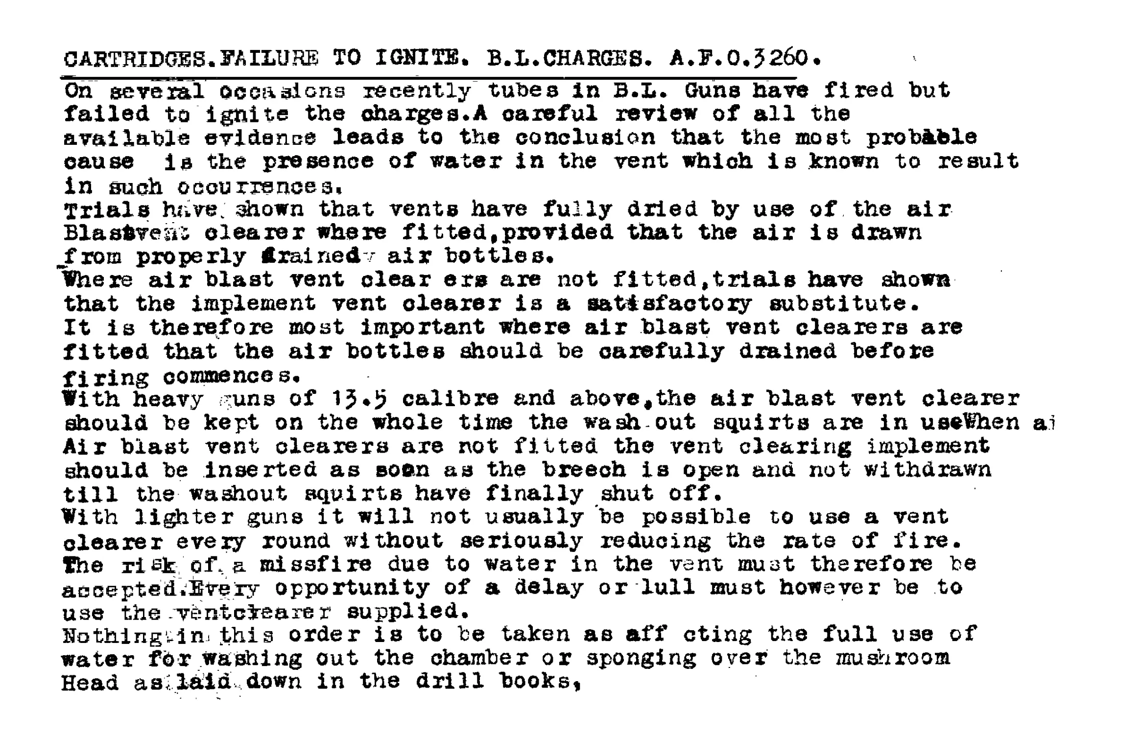
CARTRIDGES.FAILURE TO IGNITE. B.L.CHARGES. A.F.0.J260.
On several occasions recently tubes In B.L. Guns have fired but
failed to Ignite the charges.A careful review of all the
available evidence leads to the conclusion that the most probible
cause Is the presence of water in the vent which is known to result
in such occurrences.
Trials have, shown that vents have fully dried by use of the air
Blastvent clearer where fitted,provided that the air is drawn
.from properly trainedv air bottles.
Where air blast vent clear ers are not fitted,trials have shown
that the implement vent clearer is a satisfactory substitute.
It is therefore most important where air blast vent clearers are
fitted that the air bottles should be carefully drained before
firing commences.
With heavy uns of 15*5 calibre and above,the air blast vent clearer
should be kept on the whole time the wash out squirts are in useWhen ai
Air blast vent clearers are not fitted the vent clearing implement
should be inserted as softn as the breech is open and not withdrawn
till the washout squirts have finally shut off.
With lighter guns it will not usually ba possible to use a vent
clearer every round without seriously reducing the rate of fire.
The risk of & missfire due to water in the vent must therefore be
accepted.'Sve.iy opportunity of a delay or lull must however be to
use the vent clearer supplied.
Nothing^!n, this order is to be taken as aff cting the full use of
water fdr washing out the chamber or sponging over the mushroom
Head as; laid down in the drill books,
19
‘The “tear-off” disc is removed from the cartridge; at. the .
last sta^e of handling.. ; •
ijnylater pattern “ tear-off discs, the silk cloth' is sufficiently ^;
large to overlap the edge of the charge, as in РкЧ 1, and then'j
drawn in with a drawstring of white tape. . ’ ’
The igniters of some cartridges are protected from flash by
covering the igniter with a double silk cloth cover, which can
be removed before entering the charge in the gun, and the number
of igniters in B.L. charges above 6-inch is also being reduced.
These silk cloth covers will replace the “ tear-off ” covers.
Lifting bands and Handling beckets.—All B.L. cartridges
above 6-inch have fairleads of silk or shalloon braid, secured
to opposite sides, and another on the base. Through these a
length of 1-inch linen tape, bleached cotton webbing or silk
braid is passed and tied on the top, thus forming the lifting band
or becket for handling the cartridge. It is to be removed under
the same conditions as the “ tear-off ” cover. For B.L. 6-inch
cartridges the tape band is passed through the loops on the
cartridge bag.
AH cartridges B.L. 7-5 inch and above are fitted with braid
beckets sewn to the bag at the opposite end of the cartridge or
the igniter.
Full and Fractional Charges.—All charges for 4-irich and
4-7-inch B.L. guns, and star shell charges for B.L. 6-inch and
5*5-inch guns, are made up in one cartridge with an igniter at
each end.
Charges for the heavier guns are made up in fractions for
convenience in handling and transportation. Each fractional
charge is at present fitted with one igniter. The fractions used
are l> and % charges. All charges for B.L. 15-inch and
12-inch guns are supplied in J charges. Charges for B.L.
9-2-inch and 7-б-inch guns are supplied in J and | charges.
Charges for B.L. 6-inch Marks VII, XI, XII and XIV, and
5-5-inch guns are supplied in j and J charges laced together.
The j charges form practice charges (see below) and two J charges
can be laced together to form a f charge.
Reduced charges for practice, and star shell.—For certain
practice firings reduced charges are used to save the wear of
the gun. To differentiate from these, the Service charge is
known as the full charge. Special reduced charges are also
used for firing star shell.
All the guns, 7-5-inch to 15-inch, use charges equivalent to
three-quarters of the full charge as the practice charge. For
6-inch and 5 • 5-inch B.L. guns j charges are used, except in earlier
ships carrying 67inch charges made up in halves.
B.L. 4 • 7-inch and 4-inch guns are. supplied with special reduced
charges for practice or for use with star shell.
Special reduced charges are also provided for use in 6-inch
B.L. guns.
CHARGES ROR HAND-FORKED B.L. GUNS.
Da eigne of Charge with an Igniter at one end only have
recently been introduced for certain handworked B.L.
Guns,for which the charge is a single cartridge.The
number of such designs any be increased.
These charges can readily be loaded with the Igniter to
the rear,even in the Dark because they are bottle shaped
the diameter of the Igniter end being approximately
double that of of the front end.
The Guns already affected are:-
B.L.6.in.Mark XX11.Service Charge.
B.L. 6.in.all Marks.Star Shell Charge.(Newest Designs)
B.L.4.7.Mark.1.Practice Charge.
B.L.4.7.Mark.1.Star Shell Charge.(newest designs)
B.L.4.in Mark IX.Star Shell Chargefnewest designs).
When Charges of t is type are placed in Clarksons Cases
they are to be- entered with the Igniter down and the
Etalk up.
L v.o. 1426/1928.
B.b. ;CHARGES:- ' -S'
All J?.L. Charges of current Manufacture are fitted withoye.
lifting, bands to assist 1* the removal of of the charges ’.fc
th® cordite cases.
The overall lifting bands are made of linen tape,web1o®^g^
heal'd and the ends are secured by a bow hit ch.They
Ь.Й^р'ЙТused with either the lifting beckets sewn on
..W^gee or the igniter covers.
t^^^^BaEsto be removed when charges are withdrawn
'to the guns i.s.in the magazines except £or-oi^
daces-<t ready use positions.
^W^j^bye'd»the-overall lifting bands should be repiacedt^b|
-to"replacing them in their cases when thi^«
s-’^nder Articles,28.51 .J2.and 42.of the Kaval
1ол&-р!аде 19.
iPLatel.
TYPICAL IGNITER FOR B.L. CARTRIDGES.
Tear off loop.
Si/k doth or cream serge disc
Shalloon discs. Mill'board
(dyed red). ' disc.
Silk doth.or cream serge disc.
SECTION WITH COVER.
silk sewing
Drawstring doubled
silk sewing.
PLAN OF IGNITER WITH COVER REMOVED SHOWING MARKING.
IBOB.Z31SO°'U.B4. 6000. e.24-.
MaJ byA SbnxUlh-
20
Marking and packing of B.L. cartridges. (Plate 2.)
B.L. cartridge bags are marked as follows:—•
Numeral of the cartridge.
Initials or trade mark of maker of empty bag.
Nature of gun.
Weight of charge.
Nature of the cordite used.
Size of the cordite used.
Fraction denoting size of charge, e.g., &c.
REPd denotes that the cartridge has been repaired,
probably by retying charge, restitching or replacing bag,
or igniter.
Future supplies of B-L. cartridges will be marked as shown
below:—
B.L. Cartridges.
(1) Printed on both sides of bag ;—
Mark of cartridge.
Monogram of maker of bag.
Calibre (* Howitzer ” or “ Bomb Thrower ” where
applicable).
Letter “ N.”
Weight of charge.
Lot number of cordite:
Nature and size of cordite.
Fraction denoting fraction of full charge.
Monogram of filling' station.
Date of filling (month and year).
(2) Cartridges fitted with new bags are to have the original
markings stencilled on them in addition to the date and place of
remarking.
Marking for B.L. Gun Cartridges.
. Initials or recog-
nised Trade Mark
of Contractor for
Empty Cartridge.
Lot Ko. of Cordite.
Initials ot Firm
Alling or Monogram
of Filling Station. .
Date of Fflling. м
[(Month and Year).
Cthovi? оу B.L, Cartbidgbs.
Plate 2.
21
(3) Cartridges for use with Stick Bombs in B.L. guns will
be marked with the words “ Stick Bomb ” and the nature of the
j. im, contained in a rectangle.
The cartridges are marked as follows, on the opposite side :—
N. denoting the cartridge is for Naval Service.
The- lot number of the cordite used, followed by “ A.C.”
if the charge is adjusted.
Initials or monogram of filling station or the initials or
trade mark of the filling firm.
The date of filling (month and year).
The hot storage mark or sub-lot marking, when
applicable.
Note.—For the meaning of “ Hot Storage Mark ” or sub-lot
marking, see Naval Cordite .Regulations.
In future the letters “ A.C.” will not be shown.
Markings on igniters.
Igniters of standard type (parallel stitching) are marked as
follows :—
Contractors’ initials or Government mark.
Calibre of gun.
Letters “ LG.” followed by a letter denoting the pattern
of igniter.
Igniters of older design (radiating stitching) are marked with
tTic following :—
Mark of igniter.
Initials of factory.
Nature of gun.
Weight of charge;
and below
Weight and nature of powder used in igniter.
For cases and methods of packing used for B.L. charges,
'ce Chapter VIII.
Markings on cases for B.L. charges.
Designating letter and mark of case are stamped on the lid
г top of the case.
(’ases are painted stone colour, with two red bands denoting
'• \ al—Service—Explosives.
11octangular cases are marked on front ends. Cylindrical
- - are marked on both ends and on the sides.
; r- following markings are found :—
Number of cartridges in the case.
Nature of the gun.
Weight of charge.-
'•iark of charge.
d dure of cordite.
',/.e of cordite.
Lot number of cordite, followed by “A.C.” if the
Large is adjusted.
22
Date of filling of the case and monogram of station.
Nature of charge (i.e., full, reduced, | charge, &c.).
Hot storage mark, where applicable.
N. denoting Naval Service.
A blue diamond painted on the case indicates that the rosin
oil was used as flux when soldering the cases (this being free from
zinc chloride).
A raised metal star on the lid indicating charges for star
shell only.
The following markings may be found stencilled on the sides
of cylindrical cases for B.L. charges:—
REPd & REPM-: Denoting that it contains cartridges
which have been returned from a ship, repaired and put into a
new case because the original one was damaged. The above
abbreviations would be followed by the initials of the filling
station and the date when the case was refilled.
I.N.S. ANN1 EXAM”-:—Denotes that it contains cartridges
which have been examined by the I.N.O. from store, of which he
takes account annually. The above abbreviations would be
followed by the initials of the station where the examination
took place and the date.
EXD. Indicates that the package has been opened at a
depot but not submitted for I.N.O.’s inspection.
REMADE.—This denotes that it contains cartridges which
have been broken down and remade, using a new cartridge bag.
The above would be followed by the initials of the filling
station and the date.
The L. Mark I cylindrical case if used for the 13-5-inch V
“ light ” gun, has one hand-grip on the lid painted blue and the
word LIGHT stencilled on one of the red bands.
L. Marks I and III cylindrical case is used for the 13 • 5-inch
“ Heavy gun and has the word HEAVY stencilled on one of the
red bands.
L. & Q cylindrical cases contain a wooden stool or packing
piece to fill up the space. This is indicated by a symbol i
coloured red.
Labels.
All packages containing Government Explosives have the
following labels attached to them, viz., “ Station ” label, “ Govern-
ment Explosive ” label, and “ Group and Division ” label (or a
combined “ Group ” and “ Government Explosive ” label in lieu
of the last two).
Station Label.—This is a white linen label with two parallel
black stripes between which is placed the Station Monograms
This label is.plaeed on the box, as a seal, covering the joint between
the lid and body,-or <ver a hasp. - It is put on the box at thp ,
packing or repacking sfey. on to indicate the station at which the
package was sealed. Whilst the label is intact the contents may
be accepted as correct.
23
Typical “ Station ” Label:—Showing initials of the packing station,
e.g., “ BC ” signifies “ Blackness Castle.” These labels are pasted over
the junction of the lid or bung and body, or ovsr the hasp in the case of
'3 and 76-pdr. cartridge boxes, so that they wii' . he .broken if the
package is opened. J '
A new method of sealing boxes is now fitted where possible.
This is designed to be a better safeguard against tampering
with cases in transit from depots to ships than the linen label.
The device consists of a spring seal with cup attached. The
tapes or wires that seal the box are knotted in such a way that
the knot is embedded in the sealing material in the cup. If
tampered with it is impossible to restore the spring seal to its
original condition. The spring seal takes the place of the station
monogram linen label.
The question of efficient sealing of cases is, however, still
under consideration, and the problem is simplified by the intro-
duction of non-venting lids.
Government Explosive Label.—The Board of Trade limits the
size of packages used for public conveyance of explosives, but such
limit does not apply to Government Ammunition stores. There-
fore, such stores are to be marked by a label to indicate that they
contain Government explosives. This label is of white linen with
the words “ Government Explosive ” in red within two red circles.
The “ Station ” label must always be used as a seal, i.e.,
placed over the junction of the lid and body.
“ Government Explosives ” Label:—Placed on all packages contain-
ing Government explosives. In future, however, a composite Group and
Division and Government Explosives label will be used.
24
Group and Division Label.—This label is to denote the group
and division (according to Appendix IV of the Magazine and
Explosives Regulations) in which the package is to be stored.
It must not be used as a seal, but placed so that it is visible
when the package is stacked.
The label has a red symbol on a white ground for Naval Service
packages. The symbols are a “ disc,” “ diamond,” “ triangle,”
and “square,” in red, for groups I, П, Ш and IV respectively.
The division of the group is indicated by a figure in white within
the symbol. The label is of paper.
The grouping of explosives is being altered and they will in
future be divided into fourteen groups without divisions in each
group.
TYPICAL “ GROUP ” AND “ DIVISION ” LABELS
Denottnctthe Classification of Explosives fob
Storage and Transport.
LABEL 22Э
The symbol signifies the
number of the group, &
the figure thereon the
number of the division
in the group.
In future however the
labels os shown win
be used
Combined Group and Government Explosive Label.—This
type of label has been used during the war and will be used in
future pending introduction of the new classification referred to
hereafter. It consists of the “ Government Explosive ” label and
the “ Group id Division ” label combined into one label,,now,
made of paper’ ' In this case the words “ Government Explosive ”
are arranged nund the symbol, on which is placed the “ Broad
Arrow.” This 4' s been used as a seal but in future it is-not to
be so employed.
lace page 25.
tri.'ie
On board H.M.Ships Group VIII N M.R.App.3.
i_________________________________________
Кл I by & Sorts,LirK,
25
The following alterations in the “ Government Explosive ”
label and the “ Group and Division ” label are being introduced,
and will ultimately tabe effect on the boxes found afloat. The
new “ Grouping ” abolishes the “ Divisions,” and came into
force in depots and factories 1.1.23.
A “ Station Monogram label ” or an “ Inspection Department
label ” will be pasted over the junction of the lid and body to
form a seal, as at present.
A composite label, denoting Government Explosive and the
Group Classification of the explosive, will tabe the place of the
labels described above. This composite label will not be used as
a “ Seal,” but will be pasted on in any convenient position on
the box.
For general purposes the composite label will be painted in
red on a white ground.
Examples of the new composite labels are given. When the
number appears as a fraction it indicates that the explosive is
classified for general purposes under the group number given in
the numerator and is classified specially for purposes of stowage
on board H.M. Ships under the group in the denominator.
In the example shown the explosive belongs to group 2,
but is classified in group 8 for storage on board H.M. Ships
(£ee specimen labels as shown, facing this page.)
These new labels will gradually supersede the “ Government
Explosive,” “ Group and Division,” also the combined “ Group
and Division and Explosive ” labels at present in use.
26
CHAPTER V.
CARTRIDGES FOR Q.F. GUNS.
Section A.
A Q.F. gun, as regards its ammunition, differs from a B.L.
gun in having its charge and the means of ignition of the charge
contained in a brass case, which also acts as an obturator.
Q.F. guns are divided into two classes, viz. :—
(1) those which fire “ Fixed Ammimnicn,”
(2) those which fire “ Separate Ammunition.’
With “ Fixed Ammunition ” the projectile is secured in the
mouth of the brass cartridge case, the projectile and charge being
loaded in one operation.
With “ Separate Ammunition,” the projectile is not attached
to the cartridge case, but is packed and loaded separately.
Table 3 shows the type of ammunition fired by the various
natures of Q.F. guns, and also the means of ignition employed.
Q.F. cartridge cases.—All Q.F. cartridge canes are made
of brass, solid drawn, and coned to the front to facilitate loading
and extraction.
A flange is formed at the rear end to prevent the case being
forced too far into the gun chamber, and to facilitate extraction.
The flanges of all Q.F. cases containing the special reduced charges
for use with star shell are milled, as a means of identification at
night.
All Q.F. cases are lacquered internally with transparent
lacquer to prevent deterioration.
Cases for the following guns are lacquered both internally
and externally : —
13-pdr.
12-pdr. 12, 8 and 4 cwt.
6-pdr.
3-pdr.
2-pdr.
1-pdr.
Three tongues are cut in the mouths of cases used for separate
ammunition as a means of securing the lid (see under Lids Q.F.
Cartridge).
Fired Q.F. cases.—As soon after firing as [(..•riblc lhe adapters,
percussion primers, &c., are to be removed from Q.F. cases.
The cases should be cleaned with hot water and soda and slightly
lubricated with mineral jelly. They should be returned to the
Armament Supply Depot in their proper boxes.
27
These cases can be rectified and refilled for use some five
or six times, unless condemned through some defect appearing
during the rectifying process. This latter^consists of aimealing
tile case, knocking . out thb. indents amd' gSnerally restoring it
to its original shape. """ ’' ’ ' '
The history of a case can be read from the markings stamp
on its base. \8ee page 34.)
The removed adapters or primers are to be returned in
separate boxes from the empty Q.F. cases.
Clip, Cartridge, Q.F., 6-pr., Mark III | c |.
Clips, Q.F. cartridge.—Q.F. ammunition fitted with primers
percussion and percussion caps are supplied with brass three-
arm spring clips with central boss. The clips fit over the flange
of the cartridge case and the boss protects the cap from being
fired accidentally by a blow during transport and handling
Cartridge clips are removed before loading and are not supplied
with ammunition fitted with adapters, since, with this type of
ammunition, the means of ignition, i.e., the V.S. tube, is supplied
separately.
Q.F. 2-pdr. rounds supplied in belts are not fitted with clips.
During the war, steel clips were manufactured and issued, but
no more are to be made.
Lids, Q.F. cartridge.—In Q.F. separate loading cartridges,
the mouth of the cartridge case is closed by means of a circular
white metal fid fitted with a flange and with three slots cut in
the rim.
The lid is secured to the mouth of the case by bending over
the tongues of the case into the slots in the fid. The joint between
the flange of the lid and the case is sealed with Pettman cement.
There are two types of cartridge lids :—
(1) For cartridges for use with tracer projectiles.—A
typical lid of this nature is shown in (Plate 3). The lid
consists of a corrugated disc of white metal, perforated in
the centre, and weakened by a number of radial slits. The
outer portion is flanged, so as to form a lip to rest on the
X 22194 c
28
mouth of the cartridge case. Three notches are cut in the
rim to take the tongues of the cartridge case. To the upper
face of the disc is soldered a corrugated ring of white metal
which tends to strengthen the lid.
The central hole is closed by means of a disc of batiste
(waterproofed cambric) and a disc of paper secured to the
under side of the lid by shellac. The object ’of the central
hole is to ensure that, when the cartridge is fired, there may
be a free passage from the charge to the tracer.
(2) For cartridges not used with tracer projectiles.—This
type of lid, shown in Plate 3, is concave and consists of two
tfiscs of white metal soldered together, the space between
these discs being filled up with a perforated strawboard
disc. The strawboard disc tends to strengthen the lid and
the perforations are intended to allow the gas pressure free
access to the pressure plate of a base fuze when the cartridge
is fired.
To enable the lid to break up easily, it is weakened by
means of radial and concentric grooves.
Three notches are cut in the rim of the lid to take the
tongues on the mouth of the cartridge case.
In future all cartridges, except those for use in 12-pdr. 4-cwt.
gun, will be fitted? with lids of type (1).
Wads, felt.—Felt wads are used in Q.F. separate loading
cartridges to fill up the space between the top of the cordite
charge and the underside of the metal lid.
The underside of the wad next to the cordite is covered with
a glazed board disc, sewn to the felt, so that the cordite is not
in direct contact with the felt, which might absorb exudations
from the cordite. Felt wads and glazed board discs supplied with
cartridges for use with tracer projectiles have a central perforation,
1’4-inch in diameter, into which is secured a paper cylinder.
The projecting end of the paper cylinder fits into the upper end
of the cordite charge and is intended to allow a free passage, for
the gases from the fired charge.
Discs, centring, are discs of glazed board, • 05-inch thick,
slit in the centre so as to pass over the cordite charge. They are
intended to keep the charge central in the case. Small bundles
of short lengths of cordite—known as “fins”—fixed at right
angles to the main charge and to each other have been used in
certain 6- and 3-pdr. cartridges for centring purposes.
Distance pieces and paper cylinders.—Distance pieces in the
form of cylinders of millboard are sometimes used to fill up space
in a cartridge case containing a reduced charge. As it is desirable,
however, not to use substances which may cause debris in tbe
gun after firing, distance pieces have been avoided as far a§
possible in the more recent designs of cartridges.
Jedce.-pag& %& .Plate-3.
WHITE! METAL LID,, MARK! |n|. FOR
:;Л C ARTRIDGE Q. F. 12 PM CWT.
White metal Straw board
,soa- М«Иу4Ь&п>ДЛЬ.
29
Paper cylinders are used with perforated wads in cartridges
for tracer : projectiles and are fitted round external tracers in
fixed ammunition. . '
Cordite charges for Q.F. guns.—The methods of make up or
charges for Q.F. guns vary considerably, being governed by the
weight of charge and the length of the cordite sticks supplied.
Methods, which may be taken as more or less typical, are explained
in detail in sections B. and C.
AH silk sewing used for tying Q.F. charges is greased with
mineral jeUy before use.
All Q.F. charges, 12-pdr. and above, and 3-pdr. Vickers’,
are adjusted.
Inspection of lids of Q.F. cartridges. (Separate ammunition).—
If a lid is loose the momentum of the lid and charge may cause
them to travel forward into the chamber when the cartridge
case takes its seating in the gun and is brought to rest. This
may withdraw the charge and igniter from the tube or primer
and cause a failure to ignite the charge (missfire), or a dangerous
“ hang fire ” owing to the flash of the tube or primer causing the
igniter bag to smoulder instead of exploding the powder at once.
Hang fires of as much as 24 minutes have been attributed to that
cause. To guard against this, the lids of aH separate loading
Q.F. cartridges are to be inspected before firing, to see that they
are firmly fixed in the mouth of the cartridge case.
Section B. Q.F. fixed ammunition.
As explained previously, a Q.F. fixed ammunition round
has the projectile fixed in the mouth of the cartridge case.
The method of securing the case to the sheH for aH fixed
ammunition except 13-pdr. is as foHows :—
AU fixed ammunition projectiles have a cannelure to the rear
of the driving band. The portion of the projectHe to the rear
of the driving band is coated with Pettman cement and is pressed
into the mouth of the cartridge case until the mouth of the case
meets the rear end of the driving band. The case is then indented,
by means of an indenting machine, into the cannelure in the
projectile.
2-pdr. ammunition is indented aH round the case, 6-pdr.,
3-pdr., and 1-pdr. projectiles are secured with 3 indents, 3-inch
20-cwt. and 4-inch Mark IV gun with 4 indents, 4-inch Mark
V and V* guns with 8 indents.
13-pdr. projectiles are not fitted with a cannelure, but have
a groove cut in the rear portion of the driving band. The case
is not, therefore, indented into the projectile, but the lip of the
case is pressed into the groove. Up to the present shellac has
been used instead of Pettman cement for 1-pdr., 3-pdr., and
6-pdr. rounds, but Pettman cement wiH be used for aH fixed
ammunition in future.
Face- -pajQ& 3О.
i
METAL IGNITER AND ADAPTER.
। \
'Spring.
Tube retainer.
30
Section C. Q.F. separate loading cartridges.
A Q.F. separate loading cartridge consists of cartridge case,
percussion primer (or adapter and metal igniter) charge, wad or
wads, with or without paper cylinder, white metal lid and cart-
ridge clip (for primered cartridges). Some cartridges fitted with
primer percussion have, in addition, a small igniter, consisting
of a shalloon bag filled with R.F.G.2 powder, secured to the rear
end of the cordite charge. (For details of cartridge case, lid, wad,
paper cylinder and clip, see Section A.)
Section D. Adapters and percussion primers.
Adapters (Plate 4).—The Marks IV, IV*, V and VI are those
generally met with.
The Mark IV is made of aluminium bronze and bored out to
take a tube. The Mark IV* and Mark V have a small pin point
plunger at the side, kept up to its work by a small spring shown
in the section, which forms a tube retainer. They are threaded
on the outside and screwed into the base of the cartridge case;
the front end is coned, and closed by a paper disc, which is
shellaced on and painted over with Pettman cement to prevent
the ingress of damp into the cartridge.
The Mark VI is similar except that the front portion is threaded
to take a metal igniter.
All primers and adapters are to be inserted with luting under
the flange.
Igniters (Plate 4).—In cartridges fitted with Mark VI
adapters a hexagonal case of thin metal containing R.F.G.2 is
screwed on to the front of the adapter to form an igniter. This
type is referred to as the metal igniter.
In earlier Q.F. cartridges fitted with adapters the igniter
consisted of R.F.G.2 in a shalloon bag fitted in a cylinder of
cordite. This is held to the body of the charge by shalloon
braid and is so placed as to fit over the adapter.
Percussion primers.—Primers, percussion, No. 1, Mark II, are
used in the cartridges of Q.F. 13-pdr. 4-inch Marls IV, V, V*,
VII, and XII, 12-pdr. 4-cwt. and 3-inch 20-cwt. guns.
A No. 1. Mark П primer consists of the following components:—
Body, percussion cap, anvil plug, copper ball, screw plug
and brass closing disc.
The body is made of metal and is formed with a flanged head;
a portion of the body is threaded externally to screw into the
base of the cartridge case. Two key slots are cut in the head.
The interior of the primer is bored out and screwed as necessary
for the reception of the cap, anvil, and screw plug, and the fore
end is cupped to accommodate the powder which forms the
magazine.
The cap, which is made of copper and filled with oap
composition, is placed in the recess in the body, after having ’Ъёёп
first coated externally with Pettman cement. / An annular ring
31
of cement it a.'so formed between the body and the cap to prevent
ingress of damp. ,
) The anvil, which is of high class metal,; is screwed in froin the
front; the copper ball is placed in it, and the metal screw plug
which retains the anvil and ball in place is screwed down on top
of the former.
The anvil has three fire holes perforated in it through which
the flash from the cap passes.
The screw plug also has three fire holes bored in it to allow the
flash from the cap to pass through and ignite the magazine.
The magazine is filled with R.F.G.2 powder, and the brass
closing disc is placed over the top of the magazine and retained
in place by turning over the edge of the primer on to the disc.
This brass closing disc has six radial slits cut in it, so that on
firing the cut portions of the disc open outwards while the disc
itself remains attached to the primer. A paper disc is secured
with Pettman cement to the underside of the brass closing disc.
In order to prevent any powder finding its way through the
fire holes of the screw plug to the interior of the anvil, a paper
capsule is placed over the conical portion of the primer body.
The function of the copper ball is to prevent pressure from
the gases, formed by the explosion of the magazine and charge,
being exerted on to the interior of the cap.
The outside of the brass closing disc and the joint between
the closing disc and the primer are coated with Pettman cement
as a protection against damp.
Primer percussion No. 2, Mark IV, is used with 3-pdr, and
6-pdr. Q.F. ammunition, in such cartridge cases as are designed to
take them, i.e., the latest makes of cartridge cases which are con-
structed with thicker bases.
The primer consists of the following parts :—Body, percussion
cap, anvil, copper ball, perforated brass disc, and magazine.
The body, which is of metal, has a flange formed at the head
in which two key slots are cut, and the remainder’ is threaded
externally to screw into the base of the cartridge case. Internally
the body is recessed for the reception of the cap, and screwed on
two diameters to take the anvil and magazine respectively.
The cap is made of brass and filled with cap composition.
It is inserted into the recess formed for it in the body, after being
coated externally with Pettman cement, and, after insertion, a
fillet of Pettman cement is formed between the body and the cap
as a protection against ingress of damp.
The anvil, which is of high class metal, is screwed into the
body and the copper ball inserted.
The magazine consists of a brass cylinder screw threaded
f xternallyat the rear end, perforated with eight fire holes, and
filled with a perforated powder pellet wrapped in white fine
paper.
The front end of the magazine is tapered externally and the
rear end screwed internally for the reception of the perforated
32
brass disc. A paper disc is secured with shellac to the outside
of the brass disc.
The magazine, complete with disc, paper lining, and filling is
screwed into the front end of the body, and is prevented from
unscrewing by three punch dabs.
The anvil and brass disc are perforated each with three fire holes
to allow the flash from the cap to reach the magazine, and the
copper ball acts as a seal against pressures exerted by the gases
formed from the explosion of the magazine and charge.
In some primers of this Mark, the screw threading of the brass
disc and the internal screw threadihg of the magazine have been
omitted.
Primer percussion No. 2, Mark Ш, is used in 6-pdr. and 3-pdr.
cases which were originally fitted with a percussion cap and
subsequently converted to take a percussion primer.
There is some liability for these primers to blow out, as the
base of the cartridge case, having been originally made to take a
percussion cap, is not sufficiently strong to ensure the primers
always being held in place.
The body differs from that of the Mark IV primer in that the
flanged portion is screw threaded, the remainder of the external
portion of the body remaining plain.
A gas check is formed on the front end of the body.
A special type of anvil plug is fitted which is perforated with
two- fire holes only, and no ball seal is provided.
The magazine is similar to that of primer percussion No. 2,
Mark IV, but is smaller in diameter and of greater length, and
contains two perforated powder pellets.
Primer percussion No. 2, Mark V, is similar to primer per-
cussion, No. 2, Mark III, except that the fore end of the magazine
is not tapered to a point but cut off square with the magazine
body. The anvil also is of slightly different shape.
Primer percussion No. 2, Mark VI (Plate 32), is similar to
primer No. 2, Mark IV, from which it only differs in respect of
the 'magazine, which is identical with that of the primer No. 2,
Mark V.
Primer percussion No. 5, Mark I, is used in 2-pdr. ammuni-
tion, and is similar to, but smaller than, primer percussion No. 1,
Mark II. It is not, however, fitted with a ball seal, and has
therefore no plug above the anvil.
Some primers percussion No. 5 are fitted with a special form
of steel closing disc, and these are known as primer percussion
No. 5 S, Mark I.
Section E. Keys, &c.s for use with Q.F. cartridges.
The following keys are supplied for Q.F. guns. .
(1) Cartridge holder.—This is shown in the accompanying
sketch.- It is used to hold the case when the adapter is being
unscrewed.
§
PRIMER. PERCUSSION, Q. F. CARTRIDGES, N? 2, MARK SI.
tn
- --Pettman cement.
— Body.
— Cap, with 1'2 grains composition.
— Tinfoil disc.
— Anvil.
— Paper disc. .
- - Soft copper ball.
- - Disc.
— Powder pellets, weight about 30 grains.
Magazine.
— Paper secured with shellac.
33
TdiUndteil key, shown below
No. 24 key. Thi-=
inserting adapter
Implement for opening’ Q.F. cases. This used when
inserting; crusher gauges or when breaking down charges
34
(5) No. 27 key.—A flat key, as shown below, used for inserting
and removing primers of 13-pdr. ammunition.
Keys for removing or inserting primers from other Q.F. ammu-
nition are similar, but of different sizes.
Section F. Markings and packing of Q.F. Ammunition.
The following markings are stamped on the base of Q.F.
cartridges (Fig. 1):—
1. Nature and mark of gun.
2. Mark of empty case.
3. Year of manufacture, and often the month.
4. Trade mark (or initials) of maker of the case.
5. Lot number of batch of cases as manufactured.
6. Date of acceptance. (On cases accepted by Army In-
spectors only.)
7. following the mark of case, denoting either (i) that the
lid was originally closed by three lips, but that the case
has been converted to hold the lid with six lips, or (ii)
that the primer hole has been rebushed or converted
from a cap recess (6 and 3-pdr.).
8. Denoting that the case is accepted for service.
9. N, denoting Naval Service.
10. Monogram or initials of the repairing station, followed by a
number indicating the series or batch.
11. (A)* followed by a punch mark :—•, denoting that the
case has been annealed after firing. Any subsequent
annealing is denoted by an additional punch mark.
12. A letter underneath the (A)*, indicating the year in which
the case was annealed.
13. (^), which is the stamp referred to at (11) impressed
twice, the second time reversed, denoting that the case
has been " low temperature ” annealed.
14. followed by a punch mark:—•, indicating that the
. case has passed the scleroscope t.rst, an additional punch
mark being, added for each subsequent scleroscoping.^^
15..'P, followed by a.dash or dot, indicating that the case!hW ’
been used for a powder charge.
16. C, denoting .cordite filled; followed by
35
17. F,for every full charge with which the case has been filled,
and • . 1 ' . '
<5'18. ; R, fOr every reduced charge. . . ....
л । -<19 or'R. denotirig the cfiarge^lia^ been" remoyeci arid
not fired • ' ''
20. f Uhder the symbols at (17), (18) or (19), indicating that
the case has passed inspection, after repair, following
the firing or withdrawal of the charge.
21. (X) , denoting that the case has been condemned.
22. G, denoting allocation to Gunnery Schools.
23. ф(Е) 1, denoting that the case has been accepted with
reduced life, but without special allocation, the figure
indicating the number of Service rounds permissible.
24. H, denoting that the case has been headed under a
hammer.
25. on 6-pdr. and 3-pdr. cases, denoting that the case
. is fitted with a Mark II (thin) cap.
26. “ R.C. only,” denoting that the case is restricted for use
with reduced charges.
27. “ VICKERS,” on all 3-pdr. Vickers cases.
28. G, on 6-pdr. and 3-pdr. cases, denoting that the case is
restricted to reduced charges.
Note.—(i) Additional markings may be found, such as small
private marks.
(ii) On large numbers of small cases, the stampings will be
found incorrectly placed, owing to increased output and lack of
experienced labour during the war.
(iii) Of the above list, only a certain number of stampings
appropriate to the particular case, will be found in any one
cartridge.
The following markings are stencilled in black across the base
of Q.F. cartridges (Fig. 2) :-
1. Lot number of cordite, also sub lot where applicable.
2. Weight of charge (except for 3-pdr. and below).
3. Mark of cartridge.
36
4. Monogram or initials of the filling station.
5. Date of filling (month and year).
6. “ RED*1,’’ denoting “ Reduced Charge,” where applicable.
7. “ BLANK,” where applicable.
In addition, for separate loading ammunition, the same details
are printed in black on a label affixed in the lid recess. й.
Cartridges for use with Stick Bombs are marked with a blue
cross on the base of the case.
Cartridges are still in the Service stencilled and labelled by an
older method, as illustrated in Fig. 3.
FIG. 3.
STENCILLED MARKS ON THE BASE CF
Q.E. CARTRIDGE CASES.
1. Hot storage mark (when applicable).
2. Nature and size of cordite.
3. Lot number of cordite followed by A.C. if an
adjusted charge.
4. Initial or monogram of filling station, or trade
mark or initials of the firm filling the case.
5. Date of filling (month and year).
6. Mark of cartridge.
FIG. 2.
Q.F. AMMUNITION 3-INCH AND
ABOVE.
STENCILLING IN BLACK ON
BASE OF CARTRIDGE CASE.
Q.F. Ammunition above 3-pdr.:—
(1) For future supplies of Q.F. Separate Loading and Fixed
Ammunition cartridges, the stencilling on the base will be as
shown. (Fig. 4).
(2) . In addition for separate loading ammunition, details
will be shown on a label affixed in the lid recess.
FIG 4.
Q.F. AMMUNITION ABOVE 3-PDR. AND BELOW 3-INCH,
STENCILLING IN BLACK ON BASE OF CARTRIDGE CASE
1. Lot No. of cordite.
2. Monogram of firm or
station fining
3. Date of filling cartridge
(month and year).
4. KED^. (whereapplicable).
5. Weight of charge.
& Mark of Cartridge.
37
Q.F. Cartridges 3-pdr. and below;—
(3). The stencilling on the base of cartridges will be similar
except that the weighiof the charge: will be omitted. (Fig. 5).
Lot No. of cordite.
Mark of cartridge.
Date of filling cartridge
(month and year).
Monogram- of firm or
station filling.
FIG. 5.
Q.F. AMMUNITION 3-PDR. AND BELOW.
STENCILLING IN BLACK ON BASE OF CARTRIDGE CASE.
Markings on adapters.—The following marks are stamped on
the base of an adapter :—
1. Mark of the adapter.
2. N, denoting Naval Service.
3. f denoting accepted for Service.
4. Manufacturer’s initials.
•5. Date of manufacture (month and year).
6. Contractor’s initials or recognised trade mark.
7. Lot No.
Markings on percussion primers :—
1. Serial number of primer.
2. Mark of primer.
3. N, denoting Naval Service.
4. | denoting accepted for Service.
5. Initial or monogram of filling station, or trade mark
or initials of firm filling the case.
6. Date of filling (month and year).
7. Lot number of primer.
38
8. Contractor’s initials or recognised trade mark.
9. Date of manufacture (month and year).
If a repaired and refitted primer is used the existing marking
is to be ruled through.
After repair the following markings are added :—
1. R, after the mark of primer.
2. N, denoting Naval Service if not already so marked.
3. Contractor’s initials or recognised trade mark of firm
repairing.
4. Month and year of repair.
5. Lot number.
6. Contractor’s initials or recognised trade mark or
monogram of station refilling.
7. Month and year of refilling.
Markings on the lids of Q.F. cartridges:—
The following are stamped on lids of Q.F. cartridges :—
1. Mark of lid.
2. N, denoting Naval Service.
3. | denoting accepted for Service.
4’ Manufacturer’s initials.
5. Date of manufacture (day, month and year).
6. Nature and sometimes mark of gun.
6
suos^XqrBW
-йизе -page. 3 0.
39
Contents label for separate Q.F. cartridges only—The following
details of the charge are printed in red on the^ontents label, which
js• attached» to the lid recess in the centre,/Sr on the bevel edge if
Fig. I.
NoTE.yQn future the lid labels will be as\hown :—Figs II.
and III. Opposite this page. \
Ammunition for Q.F. guns is packed in ammunitren boxes (see
Chapter Vill). All boxes (except S.A.A. boxes) have two red
bands painted round them to denote Naval Service. All boxes for
Service ammunition are painted stone colour, except 3-pdr. (see
page 41) and packages containing Target Smoke Ammunition
which are marked green, with a yellow band to denote “ practice.”
Markings on the lids of Q.F. ammunition boxes.
The following are stencilled on the lid in black :—
1. Number of cartridges in the box, followed by the words
2. Cartridges Q.F.
3. Nature of the gun.
4. Weight of the charge. And to have the letters “ A.C.”
5. Mark of the charge. > when an adjusted charge is
6. Nature of the cordite. J used.
7. Size of the cordite.
8. Lot number of the cordite.
9. Primers, followed by numeral and mark, manufacturer’s
initials and dates, or
10. Adapters, followed by numeral and mark.
11. IG, MET. or METAL IGNITER, if used, or
12. CYL. CORD., denoting cordite cylinder igniter, if used..
13. Lot number of the cordite cylinder igniter, if used.
14. FILLED, denoting that the ammunition box is filled.
15. Initials or monogram of the filling station.
40
16. Date of filling of the box.
17. Serial number of the box.
18. N, denoting Naval Service.
19. For “ Gunnery School only ”—“ Not for use Sub-
calibre guns ” wifi be stencilled on the lid where
applicable.
20. T. fids, if designed, to be fired with night tracer.
Information as to the cartridge cases as follows :—
21. CASES, refers to the cartridge cases.
22. Manufacturer’s initials.
23. Date of manufacture of the cartridge cases.
24. or (a) denotes that the cartridge cases have been
repaired and annealed. .
25. REPD. denotes that the cartridge cases have been
repaired and not annealed.
26. (J) denotes that the cases have passed the scleroscope
test.
Information as to lids of cartridge cases as follows:—
27. S. LIDS, denotes lids with strawboard insertion, or
28. LIDS MK I, denotes the mark of lid.
29. • (|-inch diameter) denotes a circular hole in underside
of lid.
30. denotes dished fids with several holes in straw-
board. On boxes containing star shell ammunition
only.
31. M. * R. denotes Q.F. charges for star shell only, the
cartridge cases of which have milled rima.
32. Raised brass stars on the lid denote star shell charges
(one on metal cases, two on wood boxes) to facilitate
recognition at night.
33. ( S.P. ) may be found on older boxes denoting that
igniters are of sulphurless powder.
34. Hot storage mark will be found when applicable.
The following may be found on the side of the box:—
1. Contents label. A paper label giving the contents of the
box.
2. LACQUERED INTERNALLY. When the cylinders
have been so treated.
3. C. Denoting that there is a copper lining to the box.
4. FOR REDUCED PRACTICE. When the boxes contain
special charges of the; above description.
5. Boxes and cases containing cartridges for use with stair
* shell will have a 3-inch six-pointed star stencilled
(same colour as other markings) on all four sides and
lid.
41
Painted on the cleat under the handle.
6. EXD. Denoting that the handle has been examined and
may be used for lifting the box.
7. Initials of the station where handle was examined.
8. Date when handle was examined.
Boxes containing fixed ammunition, in addition to those of
the above which are appropriate, are . also marked FUZED (or
refuzed), monogram of station and date (day, month and year)
of fuzing, with the nature of the projectile and the type or numeral
and mark of the fuze.
Labels.
A label giving the packer’s name, and place and date of
packing, is to be placed inside the package, and a station label,
consisting of a strip of muslin, about 3 inches by 1| inches,
with the initials of the packing station in black, is to be pasted
over the junction of the lid (or bung) and the body of all packages
of cartridges, except in the case of 3 and 6-pdr., when it will be
placed over the hasp of the box. The group and station label
are also to be placed on each package, the latter being pasted
over the junction of the lid and body, so that it must be torn
if the lid is opened. This does not apply to labels on “ L ” Marks
I and IH and “ N ” Mark I cases, where the station label will be
pasted over the ends of the closing tape, and the explosive label
in any convenient position. These labels are to be attached so as
not to obscure any stencilling on the packages.
Boxes for 3 and 6-pdr. ammunition.
Ammunition for 3 and 6-pdr; Q.F. guns is packed in special
boxes (see Chapter VIII.).
Boxes are coloured as follows :—
6-pdr. Hotchkiss (except H.E.)
3-pdr. Hotchkiss or Vickers (except
H.E.).............................
H.E. (Hotchkiss or Vickers) ...
Practice (Hotchkiss or Vickers)
Drill or Dummy (Hotchkiss or Vickers)
Stone colour.
French Grey.
Yellow.
Yellow lid.
Black.
If the projectile is a plugged shell annealed for use as a
practice, SHELLS A is to be found on the lid.
If the ammunition is suitable for use in sub-calibre guns the
words, SUB-GAL are also found on the lid.
3-pdr. Vickers and 3-pdr. Hotchkiss can be readily differ-
entiated because Vickers boxes have the hasp on the top, while
Hotchkiss boxes have the hasp on the side.
Boxes containing 6 and 3-pdr. cartridges have the following
information on them :—
(A) Stencilled on the lid.
(i) Hotchkiss cartridges.
(a) Number and designation of cartridges.
In addition.boxes containing Q.F.ammunition
have a label showing the contents affixed on the
outside of the package.All packages of future
manufacture not protected by battens will be
provided with a recess for this label.
A.P.O.1712/1928.
42
(в) Mark and the word “ Fuzed ” or “ Plugged ” (as
the case may be).
(c) Weight of charge, “ Cordite,” and “ Lot No.”
(d) Cases’ manufacturer’s initials and date “ Primers/1
and manufacturer’s initials and numerals of same, or
“ Caps Mark.” If annealed shells are used, letter A
is also stencilled.
(e) “ Fuzes, Hotchkiss Mark — ” (for Service cartridges
only).
(f) Monogram of station and date of filling. Also, series
number.
(g) “ For Gunnery Schools only ” in the case of 3-pdr.
cartridges made up with cases specially sentenced
for such uses.
(h) Mark of igniter.
(ii) 3-pdr. Vickers cartridges.
(a) Number and designation of cartridge.
(в) “Vickers Mark —” and word “Fuzed” or “Prac-
tice ” (as the case may be).
(c) “ Full ” or “ Reduced charge,” as the case may be, for
boxes containing practice ammunition.
(d) Weight of charge “ Cordite ” and “ Lot No.”
(e) Cases’ manufacturer’s initials and date, “ Primers ”
and manufacturer’s initials and numerals of same, or
“ Caps Mark.” Also A if shells are annealed.
(f) “ Fuzes, Hotchkiss Mark — ” (For Service cartridges
only).
(g) Monogram of station and date of filling. Also series
number.
(h) “ For Gunnery Schools ” only if made up with cases
specially sentenced for use with reduced charges.
(к) Mark of igniter.
(B) Stencilled on front cleat:—Number of box.
(C) Inside of hd :—A descriptive label containing all information
stencilled on the top of the box.
(D) On outside of box, under front cleat:—Full descriptive label
as in (C).
For junction of lid and front box :—“ Station ” label.
On back of lox :—“ Group and Division ” label.
On side of box :—“ Government Explosives ” label in any
convenient position.
(E) On inside of lid and on the front of the box outside, of boxes
containing cartridges which have been re-inde.nted, a
manuscript label, as below, is to be pasted
Re-indented.
Station; !
Date. " '
43
CHAPTER VI.
TUBES.
Tubes are used for igniting the charges of :—
(a) B.L. guns.
(в) Q.F. guns where the cartridge cases are fitted with
adapters and not for primers.
The satisfactory action of tubes is of the greatest importance,
since not only does accuracy of shooting depend to a large extent
upon this, but also the whole fighting efficiency of the Fleet.
Two types of tubes are used for firing Naval Service Guns
(i) “ p ” tubes, so called because they were first used in
guns having percussion locks.
(ii) “ S ” tubes, used with guns which are fitted with
“ strikerless ” locks.
The tubes of both types are “ vent sealing.”
The “ seal ” is obtained by making the tube a close fit in
the vent (both vent and tube body being slightly tapered towards
the front), and by designing the tube so that on firing the front
portion expands and seals the escape of any gas between itself and
the vent, and also by constructing the interior of the tube so
as to prevent any gas escaping through the head.
The tube itself is prevented from coming to the rear by the
lock or breech mechanism of the gun.
There are two patterns of “ P ” type tubes in use in the
Service—electric and percussion; and there are two natures of
each pattern, one for use in guns having large tube chambers,
the other for use in guns having normal tube chambers.
There is, however, only one pattern of the “ 8 ” type tubes.
“ V.S. electric ‘ S ’ large,” for use in guns 13 -5-inch and above,
which are fitted with strikerless electric locks.
When testing electric tubes with one Daniell cell, the electrical
resistance should lie between 0-9 ohm and 1-1 ohm.
While “ electric ” tubes will not be fired or rendered dangerous
by rough usage, they may, as a result of such treatment, become
totally unserviceable, owing to the fragile wire “ bridge ” which
they contain being damaged, with the result that the continuity
of the electric circuit is broken, and the tubes cannot fire.
On the other hand “ percussion ” tubes are liable to fire or
become dangerous as the result of a shock, and every precaution
must be taken not only to ensure that the tubes are not subjected
to rough handling during transit, &c., but also to prevent “ jar ”
during loading, especially when closing the breech of the gun
when the tube is already in the vent or in the adapter of a Q.F.
cartridge.
a 22IS4 D
44
In order to assist extraction, the heads of all V.S. (vent sealing)
tubes are enlarged to a greater diameter than the body, and the
underside of the head is bevelled to seat in the vent and on the
extractor.
Tubes are stowed in a special locker.
Tubes for guns with large tube chambers.
These are commonly known as large tubes, and the following
natures are now being manufactured and issued to the Service :—
Tube V.S. electric “ S ” large, Mark I.
Tube V.S. electric large, Mark IV.
Tube V.S. percussion large, Mark II.
These three natures of tubes are used in the following guns
in the Naval Service :—
15-inch B.L. Mark I.
13 • 5-inch B.L. Mark V.
12-inch B.L. Marks XI and XII.
6-inch B.L. Mark XII and later.
5-5-inch B.L. Mark I.
4-7-inch B.L. Mark I.
4 inch B.L. Mark VII and later.
Note.—15-inch and 13-5-inch (“Iron Duke” Class and
“ Tiger ”) have strikerless electric locks, and therefore use the
“ S ” electric tube Mark I. The remaining guns enumerated
above use the large electric Mark IV tube.
Tubs V.S. electric “ S ” large, Mark I. (Plate 6.)
This may be regarded as one of the most important tubes in
the Naval Service, since it is used in the principal guns of the main
Fleet when firing is being carried out in the primary maimer, e.g.,
by director.
It consists of a body, ebonite insulating cup, contact piece,
copper plug, copper pole (tinned), wire bridge, insulated copper
wire, vulcanized paper washer, cork plug, paper and glazeboard
discs, and m agazine filling.
The body is made by a series of cold hollow drawing operations,
the magazine end being formed during this process, but the rear
end being left solid.
The head is enlarged and bevelled to seat in the vent and on
the extractor, and the body from immediately under the head
is slightly tapered to the front to secure a good fit in the vent.
The body is bored out to take the copper plug (which carries
the copper pole) and to form a passage for the insulated copper
wire.
The bore for the copper plug is slightly tapered, as s so is the
plug itself, so as to form a seal against the riish. of gas to the rear,
on firing. To improve this seal a gas check lip is formed on the
front end of the copper plug, and a ball seating formed at the
TUBE, VENT SEALING, ELECTRIC, S, LARGE, MARK I.
GENERAL ARRANGEMENT,
MaJ by<fcSon s.Lith
•4Hi‘eJosTA,n>ii east
TUBE,VENT SEALING, ELECTRIC, LARGE, MK.IV.
GENERAL ARRANGEMENT.
Insulated wire
---Ebonite Cap
-- Contact disc
— Composition priming, $ grains.
- - Glazed board disc, with paper diac attached.
--Perforated powder pellets, about 34 grains.
—Cork plug with paper
discs attached.
* Lot number.
Copper plug —
I. P. Bridge -
•|« Manufacturers Initials.
46
rdafbnd to fit into the body. The interior of the head is bored
'otitand screwed to take the ebonite cap, into which the contact
<lisc is screwed after placing the vulcanized paper washer in
position. The insulated copper wire passes through, and is
gripped by, the copper plug. The rear end of the insulated
wire is bared and passes through the contact disc, to which it is
secured by solder.
The front end of the insulated wire is also bared, and a bridge
of iridio platinum wire is formed from the bare end of the insulated
wire to the copper pole, the bridge being secured at both ends by
soldering.
The “ bridge ” is surrounded by a small quantity of priming
composition, which is secured in place by means of a paper disc
and a perforated glazeboard disc.
The magazine, which is lacquered internally, is filled with
perforated pellets and the tube closed by means of a cork plug
which has a paper disc shellaced to each side.
This plug is secured in place by burring over the metal of the
body of the tube on to it.
To fire the tube an electric current is passed through the
contact disc, down the insulated copper wire, across the I.P.
(iridio platinum) bridge, and so to earth. This current fuzes
the bridge, and ignites the priming composition, which in its turn
ignites the magazine of the tube.
Tube V.S. electric “ S ” large, Mark LC.
This tube is identical in construction with the “ S ” Mark I
tube except that the overall length is slightly less. The letter
“ C ” indicates that the tube; is either a repaired Mark I tube
or a converted and repaired Mark II tube. Tubes electric “ 8 ”
large Mark II were fitted with Nobel vulcan bridges.
These bridges proved unsatisfactory, and all Mark II tubes
have been withdrawn for repair and conversion to Mark LC.
Tube V.S. electric, large, Mark IV. (Plate 7.)
This tube is used for electric firing in all guns which have
large vents except 15-inch and 13-6-inch fitted with strikerless
locks. It is identical in construction with tube V.S. electric
“ 8 ” large, Mark I, except that it has a differently shaped ebonite
cup, in which the bared end of the insulated wire is coiled down on
to a copper washer, being secured in place by a plug of tin and
antimony, this plug also forming the contact disc.
Tube V.S. electric, large, Mark IV C.
This tube is identical in construction to the large Mark IV
tube except that the overall length is slightly less. The letter
“ C ” indicates that the tube is either a repaired Mark IV tube or
a repaired or converted Mark V tube.
Tube V.S. electric, large, Mark V was fitted with Nobel
vulcan bridge, and, like “ 8 ” Mark II tubes, these have all
been withdrawn for conversion and repair to Mark IV C.
D 2
46
Tube V.S. percussion, large, Mark П. (Plate 8.)
This tube is used in all guns which have large vents, when
fitted with percussion locks.
It consists of a body, in which a solid anvil is formed towards
the rear end, a percussion cap, cap holder, percussion holder,
striker, copper shearing wire, brass washer, cork plug, paper
discs, and a charge of perforated powder pellets.
The body is manufactured, as in the case of other tubes, by
a series of cold hollow drawing operations, and an enlarged and
bevelled head is formed.
The body from immediately under the head is slightly tapered
to ensure a good fit in the vent. The rear end of the body is
bored out and screwed for the reception of the cap holder and the
percussion holder.
A cap seating and anvil are formed in the body of the tube
and two holes are bored through the anvil, in order that the flash
from the cap may ignite the powder in the magazine.
The copper cap, filled with cap composition, is placed in its
seating and held there by the cap holder.
The bronze striker is secured to the percussion holder by
means of a copper shearing wire, and the brass washer is placed
on the end of the striker, the latter being rivetted over to hold
it in position.
The percussion holder, complete with striker, is screwed into
the tube.
The front end of the tube is closed by means of a cork plug
and paper discs, the metal of the tube being burred over to hold
it in position as before.
. Powder dust from the magazine is prevented from escaping
into the cap chamber by a paper disc being secured at the bottom
of the magazine.
On firing the gun striker delivers a blow to the head of the
tube striker which moves forward, shearing the copper shearing
wire, so firing the cap.
Tubes for guns with normal tube chambers and for Q.F. guns,
of which the cartridge cases are fitted with adapters and
not for primers.
These tubes are commonly known as “ small ” tubes, and the
following natures are now being manufactured and issued to
the Service:—
Tube V.S. electric, “ P,” Mark VI.
Tube V.S. percussion, Mark VII.
Tube V.S. electric, “P,” Mark VI.
This tube is identical in construction with tube V.S. electric,
large, Mark TV, but it; differs from +aat tube in being ..made ,
.smaller, so as to fit the normal tube chamber.
The magazine is felled ivith pistol powder in lieu of perforated
powder pellets.
SO9/
TUBE, VENT SEALING, PERCUSSION, LARGE, МК.И.
GENERAL ARRANGEMENT.
Surfaces to be blackened all over.
Solid anvil with •
two fire holes--1
-f- Manufacturers Initials.
* Lot Number.
‘---Secured by 2
centre punch stabs.
47
S Tube V.S. electric, ‘P,” Mark VI C. "
This tube is identical with the Mark VI tube except that it
is obtained either by repairing Mark VI tubes or by converting
and repairing Mark VH tubes.
Tube V.S. electric, “ P,” Mark VII, was fitted with a Nobel
vulcan bridge. This bridge having proved unsatisfactory, all
Mark VII tubes have been withdrawn for repair and conversion
to Mark VIC.
Tubes V.S. percussion, Mark VII.
This tube is identical with tube V.S., percussion, large, Mark
П except that it is made to a smaller diameter in order to fit
the normal vent.
The magazine is filled with pistol powder in lieu of perforated
powder pellets.
While the tubes described above are at present the latest
type in, and the standard types for, the Naval Service, tubes of
earlier marks may still be met with, namely:—
Tubes, V.S., electric, large, Marks 1-Ш.
Tubes, V.S., electric, “ P,” Marks IV and V.
Tubes, V.S., percussion, large, Mark I.
Tubes, V.S., percussion, Marks IV and VI.
Notes:—
(1) Tubes, V.S., percussion, Mark VI, were found liable to be
fired prematurely by a sudden jar, and, consequently, manu-
facture was discontinued.
(2) Improved methods of filling tubes.—An improved method
of filling the following tubes has been approved.
Apart from the filling, the tubes are identical with those
described above.
Present mark of tube.
Mark when filled by
improved method.
V.S. eleotric, large, Mark IV -
V.S. electric S., large, Mark I
V.S. electric, P., Mark VI
V.S. percussion, large, Mark П
V.S. percussion, Mark VH
Mark VL
Mark ITT.
Mark V11 i.
Mark 111
Mark IX.
Tubes for testing circuits, practice firing, &c.
The earlier marks of electric tubes will be found principally
in Gunnery Schools, since they are being supplied for practice
firing until stocks are exhausted.
Similar tubes will, however, also be found in the Fleet in
small quantities as they are supplied to ships for testing circuits.
Friction tubes.—These are dealt with under Fireworks.
Chapter XIII.
48
Drill tubes.—These tubes, which are similar externally to
Service tubes, are supplied for exercising percussion firing.
The head of the tube is recessed, and this recess is filled with
a hard rubber pad secured by a metal holder. The mouth of
the tube is closed by a wood plug.
Drill tubes representing both Large and Small Service per-
cussion tubes are supplied.
S.A.A. cartridge tube.—A percussion tube identical in shape
with a • 303-inch cartridge case is used with 7 • 5-inch and 11 inch
Howitzers. The tube contains a charge of 30 grains of short
milled powder, held in position by a glazed board disc, and the
mouth is sealed by a cork disc covered with shellac and water-
proofed.
Dummy tubes.—These are merely empty Service tubes with
their mouths closed, so that their appearances are identical with
the tubes they represent.
Dummy tubes are only supplied for instructional purposes.
Markings of tubes, identification and packing.
Markings.
The following markings will be found on the head of a tube:—
(i) Letter (i.e., “P” or“S”).
(ii) Mark of the tube.
(iii) Manufacturer’s initials or recognised trade mark.
(iv) Lot number.
(v) Acceptance mark (|).
Identification of tubes.
The exterior of the bodies of electric tubes are not lacquered
or coloured in any way, and are left plain and smooth.
Percussion tubes have the bodies blackened and lacquered,
and four notches are cut out of the rim of the head, so as to
enable percussion tubes to be differentiated from electric tubes
by the sense of touch.
Drill tubes do not have the bodies coloured, but four longitu-
dinal indents tire impressed on the body, and the heads of the
tubes are milled.
Dummy tulres have the word “ Dummy ” stamped on the
head.
Strikerless or “ S ” tubes can be recognised by the protruding
contact pieces.
Packing of tubes.
Tubes are packed 10 in a flat tin box, the box being sealed
by soldered tape. Labels are affixed to the lids of the boxes to
indicate their contents. The lettering on the labels is Red in
the case of percussion tubes, and Black in the case of electric
tubes. '
“ Operation papers ’’ are enclosed in each box of tubes, and;
should always accompany a report of failure. ;
MdtyASoncLrth.
J£06
49
CHAPTER VH.
BLANK CHARGES.
Powder charges are issued for saluting purposes and as signals
in special circumstances. These charges are used without pro-
jectiles and are termed blank cartridges.
Cordite is unsuitable for blank charges both because it is
smokeless and because it will not give a sufficient report without
a projectile to tamp the charge.
Saluting Ships.—All ships, except Destroyers, carrying'four or
more light Q.F. guns of the same calibre and commanded by a
Captain or Commander come under the category of saluting ships.
Ships which do not carry light Q.F. guns as part of their
fighting armament usually carry four 3-pdrs. for saluting purposes.
Supply of blank ammunition.--Blank cartridges are supplied
to saluting ships for the nature of gun that is used for this purpose.
In these ships the cartridges are supplied in the component
parts and have to be made up on board.
Blank cartridges supplied to ships for guns other than saluting
guns are already made up.
Blank cartridges for B.L. guns.
Blank cartridges for B.L. guns are only supplied when specially
required. They are made up for 6-inch, 6-5-inch, 4-7-inch and
4-inch B.L. guns.
The body of the bag is made of silk cloth or cream serge.
The bottom is shalloon.
After filling, the mouth of the bag is choked with doubled
silk sewing. The cartridge is hooped by means of silk or shalloon
braids passed through fairleads sewn to the bag.
Blank cartridges for Q.F. guns.
Cartridge, Q.F., blank, 4-inch, Mark V and V* guns. (Plate
9.)—The Service cartridge case is used to contain the charge,
which consists of 3 lbs. of blank L.G. powder enclosed in a silk
cloth bag. The rear end of the bag is closed with a shalloon
disc and the front end is choked with silk sewing. Hoops of
silk braid are threaded through three rows of fairleads sewn to
the outside of the bag; these hoops prevent the escape of powder
dust from the bag into the interior of the case. The bag is placed
inside a felt jacket, which is open at the rear end, the space between
the top of the bag and the jacket being filled with a felt disc.
The cartridge is prevented from moving forward by a leather-
board cup, which is pressed into place inside a split paper ring
50
and on to the top of the felt jacket. The ring and cup are secured
by three dabs of shellac on the top edge.
The charge is ignited by a percussion primer which is secured
in the base of the cartridge case in the usual manner.
Cartridge, Q.F. blank, 12-pdr., 12-CWt.—The Service cartridge
case is used and contains the charge, which consists of l|-lbs. of
blank L.G. powder, enclosed in a silk cloth bag. The bag is
hooped and choked similarly to the 4-inch Q.F. blank cartridge.
The rear end of the bag is recessed to fit over a calico and paper
dome, round the neck of which the bag is choked with a draw-
string. A shalloon igniter, containing 8|-drs. of new blank F.G.
or R.F.G.2 powder is secured to the top of the dome. The latter
fits over the adapter or primer, which is inserted in the base of the
cartridge case in the usual manner.
A felt wad is placed on top of the silk cloth bag and the whole
is retained in position by a leather-board cup, which is pressed
down hard on the felt wad and secured by three dabs of shellac.
Similar blank cartridges, of varying weights, are supplied for
3-inch and 12-pdr. 4-cwt. Q.F. guns.
Cartridge, Q.F., blank, 12-pdr. 8-cwt. (Plate 10.)—The charge
is the same as that for the 12-pdr. 12-cwt., but, owing to the
short length of the cartridge case, a different method is adopted
for retaining the cartridge in its case. The silk cloth bag is
enclosed in a felt jacket, which is open at the rear end, the
space between the top of the bag and the jacket being filled with
a felt disc. The whole is retained in position by a tightly-fitting
felt wad, which has a felt ring stitched to its under side. A
silk braid loop, which passes through the wad, is attached to the
felt disc inside the jacket, in order to facilitate removal of the
cartridge.
Blank cartridges for the 12-pdr. 8-cwt. gun, when required,
are supplied ready made up.
Method of filling 12-pdr. blank cartridges on board.
This operation is to be carried out in a place above the
waterline under the supervision of the Gunner.
Procedure.
(1) See cartridge case is perfectly clean and dry.
(2) Insert a metal adapter, or electric or percussion
primer. If percussion primer be fitted, a clip should be
placed over the base of the case to protect the cap.
(3) Stand the case vertically, so that it will remain steady
on its base.
(4) Insert the cartridge and felt wad.
(5) Place the met?1 guide ring over the mouth of the
cylinder. ! , >
(6) Insert the leather-board cup in the guide ring and
press hard home with the wooden drift.
Faae^pctge- 50.
Flaie-lO.
MallgrASenslith
51.
РЪаеИ.
CARTRIDGE Q. F. BLANK
3 PPR M* iv:
CARTRIDGE Q. F. BLANK
6 pp.R m* iv:
К - - ЗИк Braid —
---Felt wad
— Silk Braid Loop.
Felt Jacket.-
IV i
w
3Pr,Q.E
Felt Jacket Л-
Cartridge stitched
together-
11 oz
—Shalloon.
BLANK LG
IV
6Pr.Q.F.
15oz.
BLANK LG
Percussion Primer^
1608
Malty&Sonftlith.
61
Cartridge, Q.F., blank, 6-]>dr. and 3-pdr., filled, Mark IV.
(Plate IT.)—The cartridge case is of solid drawn brass, varnished
^iiibideA Two slots are made, ih th®,; case near the mout£. A
jhole isbored through,the centi^itof the base. The holc.is released
arid a spiral groove cut in the recess to take a removable primer.
The primer is of brass, with a cap chamber and anvil formed in
its rear end, three fire holes communicate the flash from the copper
percussion cap to about 5| grains of R.F.G.2 powder, with which
the body of the primer is filled. The front is closed with a glaze-
board disc spun over and coated with shellac. A small brass
pin projects from the head of the primer, by which it is secured
to the case. There are also two slots in the head to take the
screw-driver for inserting or removing it. The primers are issued
in hermetically-sealed cylinders, 20 in each cylinder.
The charge for the 6-pdr. is 15-oz. blank L.G. powder, and tbat
for the 3-pdr. is 11-oz. of the same powder. It is contained in
a shalloon bag, hooped with silk sewing. The shalloon bag is
sewn into a felt jacket, having a loop on the top. Over the charge
is placed a felt and a millboard wad, the loop on the jacket being
passed through holes in them; the whole is secured in the case
by a piece of narrow silk braid, which is passed through the loop,
then through the slots in the case, and finally tied on top, cutting
off unnecessary ends.
3-pdr. and 6-pdr. Mark V blank cartridges have now been
introduced, these differ from the corresponding Mark IV cartridges
in that the bags are hooped in the silk or shalloon braids passing
through fairleads on the cartridge bags. The felt jacket is secured
to one of these hoops.
Silk braid, 0-35-inch wide, is supplied (with the cartridges)
for securing the cartridges in the cases.
Thirty-seven 6-pdr. or fifty 3-pdr. charges for Hotchkiss
guns are stored in a half metal-lined case, with the necessary wads
and braid. Filled cartridges are also packed in half M.L. cases.
The empty cartridge cases are supplied 20 in a box painted
red. On the outside of the lid is a lithograph, and instructions
for making up.
The tools for repriming are issued in an ordinary wooden
packing ease.
In addition to the special screw-driver for inserting or removing
the primers, a 12 • 7-inch rod is supplied for driving out the primer
if set fast, or if the pin of it has been broken.
Method of filling 3-pdr. and 6-pdr. Hank cartridges on board.
(1) The case being perfectly clean and dry, insert a new primer
and place a clip over the base of the,case to protect the cap.
(2) Stand the case vertically on a small board, suitably re-
cessed for the clip, so that the case will stand steadily on its base.
(3) Insert the charge with felt and millboard discs attached
in the case, the felt wad being placed next to the jacket; then
52
pass a piece of silk braid through the loop on the jacket and the
slots in the case, and securely tie it across the mouth of the case.
If there is any difficulty in inserting the cartridge, it should be
slightly rolled on a bench or board by hand, to reduce the diameter,
but it is necessary that the cartridge should fit tightly in the
case.
Care is to be taken that the silk braid, after being passed
through the slot in the cylinder, is made to lie flat, as otherwise
a difficulty in entering the cartridge into the gun might be
experienced.
Procedure to be followed with all blank cartridges for Q.F
guns which are filled on board.—The cartridge cases are only to
be filled as required, but should a greater number have been
filled than are found necessary for immediate use, those not fired
are to be returned to their boxes for restorage in the magazine
where necessary, safety clips having first been placed on the
caps.
Cartridge cases, which have been filled on board, are to be
emptied before being returned into store, the cartridge being
restowed in the half metal-lined case.
For the stowage of a ready supply of blank ammunition for
saluting purposes, steel lockers, capable of being locked, are
fitted in most ships in a position conveniently situated to the
saluting guns.
Precautions to be observed with B.L. blank cartridges.
On all occasions of withdrawing a blank cartridge from a B.L.
gun it is to be passed overboard.
When firing blank charges from a B.L. gun, the cartridge is
to be kept in a waterproof duck bag and not to be uncovered
until the bore has been inspected.
Markings on blank cartridges. (Plate 12.',
B.L. blank cartridges have stencilled on one side:—
(1) Mark of cartridge.
(2) Contractor’s initials or recognised trade mark.
(3) Nature of gun.
(4) Weight of charge.
(5) Class of powder.
And, on tlie'btfier side :— . ' ' Add, i»u
’/-I’’ • r • j'-x ; • •'
'(6) N.i ’Denoting Naval Service. •. < * ’ ;
j 7 - :(7};irptials of firm filling or monogram of filling station.;
(8) Date of filling (year and month).
Blank ('itaucks.
Face page
53
trade mar’.. &W
?Q;F. blank cartridges have stencilled on one side of the bag «-?
(1) Mark of cartridge.'.
(2) Contractor’s initials or recognised
(3) Nature of gun.
(4) Weight of charge.
(5) Class of powder.
And on the other side:—
(6) N. for Naval Service.
(7) Initials of firm filling or monogram of filling station.
(8) Date of filling (year and month).
The word “ BLANK ” to be stencilled across the base of
Q.F. cartridges containing Blank L.G. powder.
Packing.—AU cases containing blank cartridges or cases con-
taining cartridge cylinders for making up blank charges (which
may subsequently be used for temporary stowage of these
charges), are painted red.
B.L. blank cartridges are supplied in M.L. cases.
Q.F. blank cartridges, when issued already made up, are
supplied in Q.F. ammunition boxes.
12-pdr. 8-cwt. blank carbridges, not made up in cylinders, are
issued in half metal-lined cases.
Other Q.F. blank cartridges not made up in cylinders are
issued in bulk in “ A ” rectangular or M.L. cases, the cylinders
in other ammunition boxes.
Wads, leather-board cups and filling pieces for making up
these charges are supplied in. wooden packing cases.
Cartridges for 3 and 6-pdr. blank are supplied in metal-lined
cases, cylinders in special blank cylinder boxes.
54
CHAPTER УШ.
CASES, BOXES, &c.
General remarks.—For markings on boxes and cases, see
sections at the end of chapters onB.L., Q.F., blank and S.A.
ammunition.
AH boxes and cases containing ammunition should be handled
with care to prevent injury to their contents.
Rough usage of ammunition cases and their contents is
calculated to cause miss-fires, hang-fires, or even premature
explosions; and, further, ammunition boxes so handled cannot
be expected to retain their airtightness or the contents their
efficiency.
Further, jambing of the lids is the most common result of
rough usage. This leads to loss of time in opening cases and a
slackening of the rate of fire in action.
When ammunition of any kind is being handled, precautions
should be taken to prevent damage to the cases in which it is
packed. These precautions are to apply to ammunition handled
either in lighters or on shore, as well as on board ship. Care
should be taken not to lower ammunition boxes too quickly,
and ample time is to be allowed for the receipt or discharge of
ammunition; moreover, such receipt or discharge should never
be treated as an evolution or as a matter of competition between
ships. Cylindrical cases should never be rolled along the deck.
Should cases occur in which combustibles of any kind appear
to have been handled roughly, full enquiry is to be made with a
view to the persons in fault being made responsible.
Ammunition for Naval Service is supplied from depots to the
ships in cases of various types. These ammunition cases them-
selves are stowed in the magazine and their contents are not
removed until required; except 6-inch and below in submarines.
The cases are so arranged that the charges can be withdrawn
while they are stacked in their stowage.
All cases for stowing in magazines are made of wood or brass.
Boxes of iron are sometimes used for the transport of explosives
such as detonators.
Luting-—Cases are made airtight either by luting, jute yarn
and luting, or dermatine rings.
Luting (Mark 111) consists of 80 parts by weight of whiting,
20 parts of mineral jelly, and one part of castor oil. It is issued
ready for use in tin cylinders containing 1-lb.
.Luting is a thick paste which does not easily dry, an
placed, between me'al surfaces it forms an airtight joint. , ,, ...
.Luting used for making powder or ammunition cases wat^-f**
ti^ht shguldjb^. examined as far as possible every six moiiths^J
Face page 54.
Plate 13.
Effect of Cobdite Explosion in a Bay of Weakened Cases.
22104
JSFFEl’J' OF t'OIWlTE ExFLOS
ЯWEAKENED I’ABBS,
55
to see that it is not dry, and whether it is still efficient. The
licjs^oj;,.cases are not, however, to be removed ^especially for this
purpose.
Dermatine.—Dermatine is a rubber Composition. A ring of
dermatine is pressed into a groove round the lid or opening of
the case so as to form an airtight seating for a flange.
AU metal cases are tested for airtightness either by being
immersed in warm water or by air testing pump, both on receipt
into store and after paclung. For tHis purpose a hole, threaded
and plugged, is to be found in the lid.
Designation.—All rectangular and cylindrical cases are desig-
nated by letters which denote the shape and dimensions.
Variations of manufacture and fittings of cases of the same
dimensions are given different marks.
Weakening of cases.—If a cordite charge becomes ignited inside
a closed case (from spontaneous decomposition or other causes),
if the case is sufficiently strong, the internal gas pressure wfll be
resisted and violent explosion wfll occur, which may endanger
the contents of neighbouring cases. The cases are therefore
arranged to present as little resistance as possible to internal
pressures, so that, should decomposition occur, the case may
open out and release the gases given off before a violent explosion
occurs.
Further, it has been experimentaUy established that if a
charge is fired in a case, by spontaneous ignition or other causes,
provided the case is sufficiently weak, the damage to the neigh-
bouring cases wfll not be serious, and the explosion of the other
charges in them wfll be avoided. In this connection, however,
it is pointed out that, if the Hds of neighbouring cases are not in
place for any reason, their contents wfll be fired and the advantage
obtained by the weakening of the cases wfll be lost.
Experiments have shown that if an unweakened case is ex-
ploded in a magazine, the damage to it and the surrounding cases
is such that the explosion of the entire magazine must certainly
follow. (Plates 13 and 14.)
As the cases have to be used for transport purposes as well
as for stowage, the cases must also be made to withstand rough
treatment. All cylindrical cases, and certain earlier types of
rectangular cases are therefore arranged so that they can be
strengthened during transport and weakened for stowage. Such
cases have some simple device, which was set to the stowage posi-
tion when the case was in the magazine, and to the strengthened
position while the case was in transport.
It was decided in the early months of 1923 to abandon the
venting principle in designs of cordite cases required for new
construction; by so doing it is hoped to be able to produce strong
flash and watertight cases, and designs are now being made on
these lines of cases required for new Capital Ships.
Modifications to existing cylindrical cases are under considera-
tion, but}it is thought probable that no alterations to rectangular
56
cases will be necessary, as experience has shown the latter to be
strong and able to retain their flash and watertight qualities after
normal treatment in the service.
Experiments on a small scale will be carried out in an endeavour
to obtain designs of cases which, whilst maintaining their flash
and watertight qualities under Service conditions, will also vent
if a charge becomes ignited under storage conditions.
Cases are now stowed in the transport position.
*
Rectangular Cases.
Rectangular cases are made of sheet brass, corrugated to
give strength. The ends are solid and secured to the sides by
various means.
The size, of the case and lids vary according to stowage
requirements.
Earlier rectangular cases have their top ends secured to
a flange, rivetted and sweated to the sides of the case, by an
arrangement of nuts and bolts. These nuts and bolts can be
screwed hard down for transport purposes and eased back for
weakening so that the flange and lid were only held by a small
quantity of solder. Special tools are supplied for this operation.
These systems are being abandoned in favour of that described
for use with later cases, and the old types are being converted
to the new design.
New rectangular cases are being made with the sides fitted
inside the flange of the bottom and outside the flange of the top
end. Consequently, if a charge goes off, the internal pressure
will open up the sides at the top in preference to the bottom of
the case. The sides are lightly rivetted to the top. (Plate 15.)
While tins arrangement gives httle resistance to the internal
pressure, the oases are strong enough for transport and no special
devices are necessary to prepare the cases for transport or stowage.
(Plate 16) shows the “ W ” rectangular corrugated case which
is typical of practically all cases of other sizes.
The “ R ” Mark II has a lid having two handles for removing
and a cross-bar with a screw bolt in the centre for tightening the
lid. The groove in the case is packed with jute yarn and luting.
The rim of the lid is pressed down into this and held firmly by
the bolt in the cross-bar, thus making the case airtight.
To open the case, the screw bolt in the centre of the bar is
eased back with a “ rectangular ” key; the cross-bar working
on a pivot at one end can then be revolved clear and the lid lifted
straight off.
lids of later cases are secured differently, being made in
two parts, the lid proper, and the locking ring, which is a device to
secure the lid in the same manner as, .the, cross-bar in the Mark П
case. This locking ring has three projections which take in
similar,'we$ge-shaped featherways around the opening ofthie
case, and two holes агё cut in. the upper surface of the locking
ring for the purpose of shipping a spanner. In revolving this
RECTANGULAR CASE.
SHOWING METHOD OF ATTACHMENT OF TOP AND BOTTOM.
Joint and rivet —
heads soldered over.
Riveted .and soldered.
huCe.-po£/& ЗЬ
16
RECTANGULAR СЛЭБУ.'
— TYPICAL.--
(603
Malby&Sons.Lith.
»>>ci туре or liq clofcQO toy cavus.
Face pa<je 57.
CIboui’ or Cylinphu'ai, Cashs.
67
locking ring, the lid does not revolve with it, so that the seating
of the dermatine ring is not disturbed.
The “ T ” case is similar to the “ W ,s case.
,t! ,AU these cases have handles of copper wire covered with
leather for slinging.
To prevent the irregular fittings of ends of cases causing injury
to cartridges, they are packed with wood linings.
Wooden packing pieces in the shape of stools, &c., are often
used in cases, for convenience of packing.
These rectangular cases are not intended to be moved when
in action.
When emptied, or partially emptied, the cases should be
clearly marked with a piece of chalk to show what remains in
them.
Most of the cases built on the principle of the “ R. ” Mark II
have been declared obsolete for future manufacture, but will,
of course, remain in the Service for many years. The differences
between those and the newer cases are only in the design of the
lid and weakening arrangement.
Cylindrical Cases. (Plate 17.)
Cylindrical cases are used for all B.L. cartridges for 12-inch
guns and above.
Cylindrical cases are fitted with a lid at each end. They are
made of sheet brass, rolled and jointed with rivets. Four
strengthening bands encircle the case, and handles made of copper
wire covered with leather are fitted. The lid of the case is
secured by feathers or lugs taking under recesses on the rim of
the case and made airtight by a dermatine ring.
These recesses are of two natures, the one being solid with
the case and the other being formed by lightly rivetting a metal
strip on to the case. When transporting the case, the lid is
revolved to the right so that the lugs engage under the solid or
strengthened portipn; for the weakened position the lid is revolved
to the left so that the lugs are merely held beneath the lightly
attached metal strip. Cases are stowed in the transport position.
Most cases have three such lugs, though certain larger ones
have six. In these latter, though all six lugs are in action when
the lid is locked in the transport position, only three lugs are
covered by the weakened strips for stowage, the remainder being
clear and inoperative.
All cylindrical cases have a red band across the lid and a
red mark on the side of the case. These are in line when the case
is locked for transport.
“ M ” Mark II cases have a set screw in each end ring which
can be screwed home to prevent the lids falling off during transport
or in stowage. These screws must be slacked back to enable
the lids to be turned from the “ Transport ” to the “ Weakened ”
position and vice versd, and the screw at the accessible end of the
case, i.e., the screw controlling the lid which will be removed
68
when the contents of the case are required, must be left slacked
back when the case is stowed in the magazine. The screw at
the inaccessible end of the case should be screwed home after
the lid has been moved to the weakened position, so as to prevent
the lid falling off under vibration.
Similar screws are being fitted to “ M ” Mark I and “ L ”
cases. Other types of lid locks are under trial.
Cylindrical cases have two small holes in the case and one in
the lid so that the label can be secured by tapes in such a manner
as to prevent opening the case without breaking the tapes.
Clarkson’s cases.
These are supplied to all hand-worked B.L. guns for conveying
cartridges from the magazine to the gun. They are cylindrical
cases opening at one end, built up of cork, and covered inside
and out with canvas.
Boxes for Q.F. Ammunition. (Plate 18.)
Q.F. ammunition is stowed in boxes of varying space and size.
The general design is common to all.
Boxes for Q.F. Ammunition Separate Loading.
The boxes are made of teak and lined with zinc or-tinned
copper. The lid is fastened by a locking plate engaging four
metal bolts, the plate being moved by an eccentric actuated by
a rectangular key.
The box is strengthened by battens on the top and sides and
by brass straps round the ends.
To force the lid up, should it be stuck by the luting or paint,
a notch is provided under two corners of the lid, so that the
handle of the key can be inserted and the key used as a lever.
The handles are of copper wire rope with a leather grip.
The box is made airtight by luting placed in a recess round
the lid.
The lid is held by a frame, the comers of which form bolts
which take under slots cut in four studs secured to the top edge
of the case, '.[bis frame is built into the lid and is moved by a
central cam which is revolved by the ordinary rectangular key
(metal key Mark IV).
Various information about Q.F. ammunition boxes is given in
the following table :—
Gun.
Cartridges in Box. Stowage.
4- 7-inch, Marks V and V* 4 Horizontally.
4-inch, Marks IV and V - 6 Vertically.
4-inch, Mark HI 8 Vertically.
3-inch 20-cwt. Q.2F. - 4 Horizontally,’:
12-pdr. 12-cwt. 10 Horizontally,’/
12-pdr., ,8-cwt. 10 Vertically. ; "
12-pdr., 4-cwt. • 8 Vertically.;/
Сшит ni QJr, Anu гм гппх Ппхея
59
. Wood and metal packing pieces are fitted to hold the cartridges
;steady in their, cases. Canvas bands or beckets are fitted to
extract 4-inch and 12-pdr. cartridges stowed horizontally—these
latter being stowed “ heads and tails.”
Boxes for 6-pdr. and 3-pdr. ammunition.
These boxes are made of teak. The lid works on hinges,
and is secured by a hasp and a turn buckle which is secured by
white line.
These boxes are passed up to the gun when in action. The
loose lining of tinned copper fits inside the box, having a groove
round its top edge to receive luting in order to make an airtight
joint; a lid of tinned copper having a flange to rest in the groove
closes the inner lining. There is a false top and bottom of tinned
copper with holes to take the cartridges base up, and a wooden
bottom with recesses to take the points of the shell.
The 6-pdr. box holds 11 cartridges and the 3-pdr. box holds
16 cartridges.
The Mark I boxes were not lined, and are used for dummy
cartridges. They are painted black.
Special boxes painted red are supplied to hold 20 cartridge
cases, empty, for making up blank.
Boxes for 4-inch Q.F. ammunition, Marks IV, V, VH and ХП
guns.
These boxes are very similar to the above, except that they
are much longer. They hold four cartridges each.
Metal-lined cases.
These cases are used for small combustible stores, and for
boat-work, as, after being opened, they can be made watertight
again.
They are made of wood, lined with tinned copper.
The lining is closed by a circular bung made watertight by
luting, and the case has a square hinged wooden lid over the bung.
The lid is secured by two screw bolts, which can be withdrawn
by a special key with two prongs to it.
There are three sizes of metal-lined cases :—
(1) The whole metal-lined case.
(2) The half metal-lined case.
(3) The quarter metal-lined case.
Whole metal-lined case may contain any one of the following:—
7,680 rounds of -J OS-inch blank ammunition.
70 sound signal rockets.
10 rounds of 4-7-inch blank ammunition.
Half metal-lined case may contain any one of the following :—
3,400 rounds of • 303-inch blank ammunition.
50 11-oz. saluting charges for the 3-pdr. Q.F. Hotchkiss
Mark I.
X 22194 E
60
43 saluting charges for the 3-pdr. Vickers Mark I.
37 15-oz. saluting charges for the 6-pdr. Q.F.
20 1-lb. 8-oz. blank charges for the 12-pdr. 8-cwt.
30 1-lb. 8-oz. saluting charges for the 12-pdr. 12 and 18-cwt.
20 6-pdr. blank charges made up for Destroyers.
25 3-pdr. blank charges made up for Torpedo Boats.
35 sound signal rockets.
30 blank charges for the 3-inch H.A.
18 changes for the 3- 5-inch bomb thrower.
5 filled maxim belts.
300 Very’s light cartridges.
144 IJ-inch V.B.S. cartridges.
Any one of the following kinds of ammunition or combustible
stores may be stowed in a quarter metal-lined case :—
1,200 rounds of -303-inch ball ammunition for boat service.
840 rounds of ’ 303-inch ball ammunition in chargers.
1,450 rounds of • 303-inch blank ammunition,
9,100 rounds of Morris tube ammunition.
10,000 rounds of rim fire cartridges No. 2.
120 cartridges for Very’s lights.
60 powder charges for torpedo impulse.
50 tonite charges.
48 l|-inch V.B.S. cartridges.
100 cartridges for safety fuze.
Sealing of cordite cases and ammunition boxes. See also p. 23.—
A method of sealing cordite cases is being introduced, consisting
of a tape sealed over its two ends with a special seal kept
at a Naval Armament Depot. This arrangement prevents the
lid of a case being removed without breaking the tape, and the
tape cannot be replaced and resealed without possession of the
proper seal.
(2) The lid can be turned from “ transport ” to “ stowage ”
positions and vice versd without cutting the tape, so that the
usual procedure carried out on board will not be affected by its
presence. Cases are now stowed in the transport position.
(3) Air testing plug holes in cordite cases are sealed with the
same seal as that used with the sealing device for the lid.
(4) Methods of sealing the locking arrangements of ammunition
boxes are also being introduced. These vary in detail to suit
the different types of boxes.
(5) The sealing devices of cases and boxes so fitted are to be
examined on receipt on board, and any cases or boxes with broken
seals or tapes are to be returned to the Naval Armament Depot
accompanied by a report of the circumstances.
- (6) When not returning cases of cordite or boxes of ammunitipn
to a Naval Armament Depot, any with broken seals are} to be
kept separate and the Naval Armament Depot is to be informed.
61
... ; . Small arm ammunition boxes. * '
i!j-' There are two kinds of small arm ammmy twm boxes ,for .use
in the Naval Service :—
(1) Large S.A.A. box (Mark XI) (which is technically
known as “ Box, G.S., S.A.”).
(2) Half S.A.A. box (Mark I) (which is technically
known as “ Box, half, naval ”).
The large S.A.A. box is made of wood with a tin lining. It
has a sliding lid, attached by whipcord to the box to prevent
its being lost when the box is open. When shut, the lid is secured
by a split pin which has a short length of twisted copper wire by
which to withdraw it. This wire lies in a groove which is covered
with a calico seal label; a loop of leather for the finger is attached
to the wire behind the seal, and the end of the wire is secured to
the lid of the box. Thus to open the box the seal label must be
broken.
The tin lining has a tin lid soldered to it, fitted with a wire
handle, by means of which it is torn off when the box is to be
opened, a sharp pull being given. Once opened, the box cannot
be made watertight again except by soldering down this lid.
Copper wire handles, part of which are covered with leather,
are fitted at each end for transport.
The half S.A.A. box is of similar construction to the above»
except that it is only of half the size and has a copper wire handle
at one end Only. The lid is secured by a brass split pin having a
T-shaped handle attached to it.
To open the boxes.—Take out the split pin, slide back the
lid, and then tear off the cover of the tin lining according to the
printed directions found there.
The tin lining of small arm ammunition boxes is liable to
deteriorate; in consequence—
(a) The oldest ammunition in the ship should be used
for target practice as far as possible.
(в) The tin lining of all boxes which are passed up for
target practice should be lifted out and examined by
unscrewing the wooden top. If the lining of any box
is found defective, others of the same date are to be
examined, and, if necessary, the ammunition to be exchanged
at the first opportunity.
Any one of the following quantities of ammunition may be
stowed in a large, small arm ammunition, box :—
960 rounds of • 303-inch cartridges for machine guns.
1,100 rounds of 3Q3-incb ball ammunition.
1,000 rounds of -303-inch ball ammunition in chargers.
840 rounds of • 303-inch ball ammunition in bandoliers.
E 2
62
850 rounds of • 303-inch ball Mark VII ammunition in
chargers.
1,100 rounds of -303-inch blank ammunition.
680 rounds of • 45 ball aiming ammunition G.G. chambered.
96 rounds of 1-inch aiming electric and percussion
ammunition.
Any one of the following quantities of ammunition may be
stowed in a half, small arm ammunition, box :—
828 rounds of Webley pistol ammunition.
500 rounds of • 303-inch ball ammunition.
350 rounds of -303-inch ball Mark VII ammunition in
chargers.
600 rounds of • 303-inch blank ammunition.
480 rounds of • 303-inch ball Mark VH ammunition in
cardboard packets for Lewis guns.
63
CHAPTER IX.
PROJECTILES.
A particular design of shell only gives its maximum effect
against a particular target and under particular conditions of
range and angle of impact. Purely theoretical considerations
therefore tend to introduce unlimited numbers of types of shell
to be used in various circumstances.
Practical considerations are, however, necessarily against
this; their tendency being rather towards the introduction of
an universal type of shell which can be used effectively against
any target.
Neither of these extremes are attainable in practice and a
compromise is effected between the two, resulting in a limited
number of special types of shell.
Practical considerations, including loading arrangements and
stability in flight, were influential in choosing the 4 calibres
radius head as the standard.
This was adopted for all heavy guns.
With the adoption of the 4 calibres radius a commencement
was made to design all natures of shell of any one calibre of
the same weight so that they would range as nearly as possible
alike at fighting ranges.
The actual contour of the heads of capped shells of the same
size but of different natures, for example, A.P.C. and C.P.C.
(for 12-inch guns and above), are not always exactly the same,
the length of the ballistic cap being so adjusted as to make the
A.P.C. shell range exactly the same at the selected range as the
C.P.C. shell, which were already in existence when the new
type A.P.C. were introduced. The weights of the A.P.C. shells
were also adjusted to give the' same muzzle velocity.
During the war H.E. common shells with false ballistic caps
of 8 c.r.h. contour were introduced for bombarding purposes,
e.y., for Monitors.
The present 3-inch H.E. 16-lb. shell (for the 20-cwt. H.A.
gun) and 4-inch Q.F. Mark V shell for H.A. are 6 c.r.h. shell.
With the exception of the special bombarding H.E. shells
and the H.E. shells mentioned above, 4 c.r.h. is still the standard
contour of Naval shells at present in supply.
Effect of capping projectiles and remarks on the piercing of
armour.—These matters are discussed in Volume I of the Gunnery
Manual, 1922, and will only be briefly referred to here.
A shell when it hits and perforates through a plate acts
mainly as a “ punch.”
If hard faced armour is hit the shell has first of all to destroy
the thin hard face of the plate and then punches out a way for
64
itself through the thick and tough back. The use of the cap
on shells is to assist the shell in the first part of this performance;
that is, to break up the hard face of the plate without the head
of the shell being shattered in the process.
Under certain conditions of action, caps are useful for this
purpose, and all guns down to 5-5-inch have a proportion of
capped shells either A.P.C. or C.P.C.
These A.P. caps are fixed over and firmly attached to the
point of the projectile in the various ways detailed below:—
Three methods are at present permitted on Admiralty designs.
(1) Notch or thumb mark method in which cap is
fixed by indenting portions of lower edge of cap into indents
on shell shoulder.
(2) Interrupted ribs on shoulder of the shell, over which
skirt of cap is pressed.
(3) A continuous groove is turned on the shoulder into
which the skirt of cap is pressed.
Ballistic caps.—The cap proper is surmounted by a thin
steel dome called the ballistic cap. This is secured on to the top
of the cap proper, and its sole duty is to bring the head to a
suitable shape for air resistance. For any particular calibre
the contour of the ballistic cap for the various natures of shell
may be slightly different to ensure the different natures ranging
alike at battle ranges.
Shells thus modified are not “ capped shells ” in the sense of
the A.P.C. or the C.P.C. shell. A ballistic cap of this metal has
nothing to do with perforation except indirectly in that it
increases the remaining velocity at any given range compared
with a blunter-headed projectile.
Bursters of shell.
Originally all bursters of shell were black powder.
High explosive shell fillings, capable of detonation, such as
lyddite, were introduced about 1900.
T.N.T. was substituted for some fillings instead of lyddite
at a time when difficulty was experienced in obtaining a varnish
for the interior of the shells that was free from lead. Lead
in the presence of picric acid (lyddite) produces dangerously sen-
sitive picrates of lead.
T.N.T. is used as the filling for H.E. shells, 12-inch and above.
These largest H.E. shells are only kept for special issue for
bombardment purposes. No guns larger than the 7-5-inch
carry H.E. shells for their outfits (except submarines).
Although the term H.E. was applied only to nose fuzed
common shells filled with >1.E. (lyddite or T.N.T.), the pointed
shells such as A.P.C. and 8. A .P., which are now filled with high ;,
explosives (shellite and lyddite) respectively, are equally
shells.”
65
Owing to the unsatisfactory behaviour of lyddite as a filling
foT’’'A;:P.Cr shells, & П6Х. filling known as “ shellite ” was-intro-
duce^ and; this ’.is now 'the.filling in general use for. all .H.E.
filled shell,.except S.A.P. and nose fuze S H.E. < < .
Remarks on the different fillings, fragmentation, &c.
Powder.—A very satisfactory fragmentation is obtained with
powder fillings in C.P. and C.P.C. shells. Large fragments
capable of doing severe damage within the cone of dispersal are
produced. The velocity of the fragments imparted by the
explosion of the powder is low compared with that obtained by
a burster of H.E. In consequence of this the effect of powder-
filled shells is entirely forward within a cone whose angle is
reduced as the striking velocity of the shell is increased. Also
powder fillings, as before stated, are not insensitive and therefore
will not carry through any but the thinnest armour.
High Explosive.—Effect of detonation of H.E. fillings in
A.P.C. or other shell in fragmentation into innumerable small
pieces which are propelled with a very high velocity.. Where
complete detonation is obtained an effect is produced all round
the point at which the shell bursts. The extreme violence of
the detonation produces immense shattering effect in the imme-
diate vicinity of the burst. The small size of the fragments,
however, results in their quickly losing their velocity, with the
result that their effect is very much localised. Also the sensi-
tiveness of lyddite to the shock of impact renders shell thus
filled ineffective for the attack of thick armour.
C.P.C. projectiles.
Common pointed capped shell (C.P.C.).—These are large
capacity shells used for 5-5-inch guns and above, and are for
use against unarmoured ships and other light targets. The caps
give a certain amount of penetrating power, but these shells
will not pass intact through any but thin side plating. If they
are filled with powder the filling will of$en explode on the shock
of impact. This type of shell is, however, now obsolescent.
Cracking of C.P.C. shells. Fitting of containers.—Owing to
the method of manufacture, spontaneous cracks are possible.
To avoid danger from this cause the bursting charge is put in
a container. This container is expanded into the cavity of the
shell. The base adapter is made the full width of the cavity
to facilitate this operation. Containers for powder-filled shells
are of copper, and for H.E. fillings of aluminium.
Powder-filling for C.P.C. shells.—This consists of a mixture
of pebble powder with fine grain powder called “ pebble mixture.”
The powder burster is contained in a dowlais cloth bag, the choke
of which is surrounded by 7-drm. primers, the whole fitting over
the fuze in the base of the shell.'
66
Shellite filling for C.P.C. shells, 7 ‘ 5-inch, 6-inch, and 5 ‘ 5 inch.
—C.P.C. shells for 7-5-inch to 5-5-inch guns for certain classes
of ships are being converted from powder to shellite filling.
Common pointed shell (C.P.). (Plate 19.)
These are obsolete for guns above 4-7-inch and are obsolescent
for guns 4-7-inch and below, as they will ultimately be replaced
by S.A.P. They are made of cast steel, with the exception of
3- and 6-pdr., which are forged.
In general, common pointed shell are about 3-5 calibres
long, ogival heads struck with a radius of 2 or 4 calibres, the
walls being about -|th the diameter in thickness.
They are coated internally with a special paint—earlier shell
•were lacquered.
With the exception of the 12-pdr. Q.F., they are fitted with
dowlais burster bags, the necks of which are primed with a number
of 7-dram primers.
In the latest C.P. shell the primer consists of a bag formed
of two thicknesses of red shalloon cross stitched, forming compart-
ments between the two thicknesses for powder. Thus the primer
fits over the head of the fuze and provides a complete layer of
powder round the magazine of the fuze.
They are filled with “ P. mixture,” with the following excep-
tions :—
12-pdr. to 6-inch may be filled with “ shell Q.F. and
shell F.G.” instead of “ P mixture.”
4-inch heavy Mark II is filled with “ Blank L.G.”
Armour piercing projectiles.
Armour piercing capped shell (AJ*.C.) (Plate 20.)—In these
shells a large bursting charge has to give way to the necessity
for strength in the body of the shell; hence the comparatively
small bursting charges used.
A.P.C. shells are shorter than the comparatively thin walled
C.P.C. shells of the same calibre and weight.
Within the limits laid down the exact overall length of the
shell is left to the contractor.
Spontaneous Cracking.—Hardened shells are liable to crack
spontaneously from the strains set up in the metal dining the
hardening processes. Should such a crack extend into the cavity
of the shell the heat engendered at the moment of cracking
might cause an explosion of the burster: for this reason A.P.C.
and O.P.C. shells are stored for three months before being filled
to allow latent cracks to develop. The firing of a shell already
cracked would be very liable to lead to the breaking up of the
shell in the bore, which would certainly destroy the inner A,” t ।
fubl£*$jT3ie gun and might; have very much more 'serious 'ii.
Hbncp7’^eat bare'is necessary that-the periodical 'ехат4ца11рп>. .,i
o? A.P.e; -and C.PiC; shells and caps is strictly and thoroughly
carried out.
JPlate 13
4 INCH C.P. SHELL.
FILLED POWDER.
Percussion N?I2.
•еоз.
MaJbyA Sons.Lrth
Ifttee- ptuqe, 6 6.
Р'лЬе 20
A.P. C. SHELL.
FILLED SHELLITE.
MalhyA* Son sit th
Tact-pay- 67.
Flxxte 21.
SHELL 4-7 INCH S. A. P, FILLED LYDDITE;
FUZED N9 12 N. SPECIAL.
.Aluminium
container.
Picnic powder
exploder 13 drs.
Composition
beeswax.
FuzeN°l2N.
special.
Pressed Lyddite
pellet with silk
cord fur removal.
------Lyddite
4-7. H.
MKI A
iah-------
7.7.21.___
EXPLDR.BAG.I3DRS
LOT 2<-----
FUZED WITH DELAY—
Stencilled--------
on reverse.
—I Contractors
1 initials.
Date of filling.
Deb?' stencj J led
fuze ts so fitted.
Following particulars
of ftrze are also
stencilled on shell
Senia! number.
Filled lot number.
Makers initials of
empty Fuze or mono-
gram of converting
station in cases of con -
verted fuzes date
of filling
Mk and mumeral
M aJ by & So i is.Uth.
/808.
67
Great care in handling these projectiles is necessary as rough
usage may damage the caps.
The cavit y , which jin most of these designs of shell is wider
near the base than elsewhere, is closed by an adapter which is
slightly larger than the maximum diameter of the cavity. This
arrangement simplifies the fitting of the container.
All A.P.C. and C.P.C. shells filled with lyddite or shellite
have an aluminium container expanded into a cavity to receive
the filling. This is provided to reduce the liability to explosion
due to “ set up ” on impact and to minimise the risk of ignition
of the burster by spontaneous cracking of the shell body after
filling.
(Jas check on the base.—In order to guard against the intrusion
of gases into the shell cavity past the threads of the base fuze,
all A.P.C. shells have a copper gas check fitted to the base,
completely covering the base fuze. This gas check is shaped to
the base of the fuze, an indentation being formed in it to bear
immediately on to the pressure plate.
The gas check is held in place by a “ base cover plate ” and
screwed ring.
Manufacture of A.P.C. shell.—The shell bodies are produced
from ingots of steel by forging and punching. The bodies are
then hardened, heat treated, tempered and annealed, &c., by
processes the details of which vary with each firm.
The shell bodies are then hot and cold water tested. This
weeds out any shell in which a liability to crack has been induced
by the strains set up under the treatment.
The shell bodies are then ground to correct dimensions,
grooved for the driving band, and prepared for the attachment of
the cap and are bonded into “ Lots.”
Adapters are made of forged or rolled bar steel so that the
axis of the shell is at right angles to the fibre of the original
ingot. They must comply with certain tensile tests.
The shell bodies with the caps separate and adapters are
bonded into lots of 400, divided into sub-lots for purposes of
“ proof.” The size of sub-lots varies with the calibre of the
shell.
Before being sent for filling the shells undergo a three months’
keeping test to eliminate any shells that crack during this period.
Semi A.P. shells.
These are pointed shells with a larger burster than the A.P.C.
capacity and are filled with H.E. They were introduced during
the war for use against submarines, from 4* 7-inch guns and below.
(Plate 21.)
Being filled with H.E. they have aluminium containers.
S.A.P. shells fired at trials have proved to be superior to
C.P. shells filled with shellite or powder for the 4* 7-inch, 4-inch,
68
and 12-pdr. guns against light targets such as destroyers, and
the C.P. shells are gradually being replaced by S.A.P. for these
guns.
They also have some power of preforating thin armour without
breaking up, which the C.P. has not.
Lyddite common shell (nose fuzed).
These shells are for use against unarmoured targets for
bombardment, or for H.A. fire, and until lately were all fuzed
with a detonating nose fuze. If complete detonation is obtained
the shell is broken up into a vast number of small fragments
very effective against personnel, but only of local effect on ships’
structures.
The effect of a lyddite common burst against a thin plate
is to blow a large hole in the plate.
There is little incendiary effect, and the effect of the fumes
is small.
Detonation is indicated by the bursting shell spreading its
fragments over a large area, giving an all-round effect, and by
the smoke being black to grey, or even nearly white. The latter
appearance is due to the steam produced, which shows up more
clearly under certain atmospheric conditions.
Yellow smoke denotes simple explosion, and the effect is
not so great as regards the spread of the fragments.
The proportion of yellow smoke to that of black, grey or
white may therefore be taken as a guide to the degree of the
detonation.
Certain so-called “ thick-walled ” designs of H.E. common
shells for 4-7-inch and 4-inch guns have been introduced during
the war. The idea of this is that the shell shall give larger
fragments than those obtained from the ordinary designs. Such
shells are therefore more likely to be efficient for damaging the
pressure hull of a submarine when the shell bursts inside the
superstructure, or for causing structural damage to a ship.
Remarks on H.E. nose fuzed, Common Shells and their fuzing
and use.
At present ships are only supplied with H.E. shells for 7 • 5-inch
guns and below (except submarines). With the exception of
shells supplied for H.A. purposes, bombarding or barrage fire
and H.E. shells for 6-pdr. and below, H.E. common shells are
now being fuzed with a powder-filled fuze. The powder-filled
fuze is used instead of the detonating nose fuze in order that the
shell may carry through and burst with violent explosion just
inside the ship’s side, instead of detonating immediately the plate
is struck. is
• J *&>. 18 R fuze was originally int^bducedr; 1огщве in H;E.
common for 4-7-inch and below, used' against-siibmarin^, but
its use has been extended to H.E. 7-5-inch, j6-inch, an^below
for the reasons stated above.
Ptate 22
6 IN. H.E,SHELL FILLED LYDDITE
AND FITTED FOR NIGHT TRACER
Malby&Sons.lith
>608
69
H.E. shells for 3 and 6-pdr. guns and below are not being
fuzed with powder fuzes but will retain their detonating type of
fuze. . / ? . • ' r
common shells for H.A. fire are fuzed with "time fuzes
such as the No. 80/44.
The No. 18 P fuzes are being replaced by No. 45 P.
TXT. Common Shell (nose fuzed).
These shells only differ from Lyddite Common in the filling,
and their effect is Rimilar when a detonating fuze is employed,
but inferior if a powder filled fuze is used.
H.E. Common Shell for guns above 7 • 5-inch are only filled
T.N.T. and are always fitted with detonating fuzes.
Shrapnel shells.
This shell is intended for use against exposed personnel of
destroyers or against troops ashore. It may also be used against
low flying aircraft by turret guns.
It consists of a steel case filled with balls, which are driven
out as from a gun when the shell bursts. These balls travel
on for one or two hundred yards after the shell has burst, spreading
out in the form of a cone. The shell case, checked by the explosion,
falls to the ground.
To obtain satisfactory effect with flat trajectory guns the
shell must be burst quite close above the ground within a hundred
yards of the target.
The size of the balls has been determined according to the
requirements of the shell, bearing in mind that large numbers
are needed for a dense distribution throughout the cone, and
that the heavier the balls the further they travel and the harder
they strike.
Spent shrapnel balls of small size have scarcely any penetrating
powers and are often stopped by the men’s clothing, canvas
weather screens, &c.
Shrapnel shell are manufactured for all 12-pdr. guns and above.
A certain number are issued for use with all guns from 12-pdr.
4-cwt. and above.
The remaining stock are kept at the Naval Ordnance Depots,
and are maintained in a serviceable condition for issue, if required,
for special operations.
Shrapnel shell are made of forged or cast steel. The shell
is burst by a time fuze which ignites a small burster situated
near the base of the body.
General construction.
Head.—Most shrapnel have the head made in a piece separate
from the body; this separate head is filled up with a block of
wood and is lightly secured to the body by a row of rivets and
70
a row of twisting pins, the head being slotted so that the twisting
pins offer no resistance to the head being blown off.
A band of solder round the outside of the shell at the junction
of the head and body covers the rivets and twisting pins.
Some small modem shrapnel have no separate head, e.g.,
the 12-pdr.
Socket or fuze hole bush.—All shrapnel have in the head a
socket for the fuze to screw into; this socket is secured to the
head by screwing in, or by solder or by both.
Bursting charge.—Shrapnel have the bursting charge in the
base. It is usually of loose fine grain powder in a tin cup. Some
of the latest small shrapnel for Naval Service have a burster of
compressed powder.
A central tube conveys the flash from the fuze to the charge.
In most shells this tube is empty, but in some small modem
shrapnel it is filled with perforated pellets of powder. This is
done with the object of increasing the angle of opening.
The powder is prevented from working up into the fuze
hole and threads by a small disc of cardboard, having a hole
in the centre covered with shalloon. This disc is placed im-
mediately under the fuze plug and is called the “ 2-inch fuze
hole wad.”
The walls of the shell are lined with brown paper, and the
balls are placed in. Melted rosin is then poured in between
the balls, which, when it solidifies, serves to hold them firm.
In all shrapnel the weight of the balls is taken on a steel or metal
disc, and not on the cup holding the bursting charge. The
latest heavy shrapnel shell have “ stepped walls,” i.e., the walls
decrease in thickness by steps as they approach the head. The
object is to give the greatest possible capacity for balls without
dangerously weakening the base.
Plate 23 shows a shrapnel shell for 12-inch. With the
exception of the stepped walls, this is representative of all shrapnel
down to the 6-inch.
The bursting charge consists of B.F.G.2 powder, the amount
varying according to the size of the shell.
Plate 24 shows the shrapnel shell for the 12-pdr. It has not
a detachable head, and the fuze hole bush is only secured
by a few threads. The central tube is filled by compressed
pellets of powder, and the bursting charge also consists of pressed
pellets. To allow of these being put in, the base is detachable,
being screwed on and held with a set screw.
It is designed for a 2-inch gauge fuze.
The 4-inch heavy Mark I is very similar to the 12-pdr. as
regardgthe screwed base and pressed pellets of powder.,>f. ( Д
has a detachable head, although ndt filled with wood, as in tner
larger ones. The head also has four saw outs in it to facilitate
breaking up.
70.
12 INCH SHRAPNEL SHELL.
!S9&
MalbyJbSons.Lith.
Fa*» jxtcr^'
2‘
12 PRR SHRAPNEL SHELL.
/508
Mai by Л Sons-Lrth
1604.
Mai by<£Sons.Lith
71
Star shell.
'Л'"’ These are designed to thrdw out;* mass of burning composition;
calculated to give put a brilliant light for as long a period , as
possible. The star is supported in the air by a parachute. ,
The shell shown in Plate 25 is typical of the new type of
parachute star shell issued for 6-inch guns and below.
The shell is fitted with a burster in the head, supported on
a baffle plate, which is held stationary in the shell by means of
set screws. Below the baffle plate is the star, consisting of
a steel case filled with star composition, with priming composition
at the top, into which are set igniting pellets containing strands
of quick match.
To the bottom of the star case is fitted a swivel, which forms
the means of attachment for the parachute below.
The parachute is made of fabric strengthened by means of
wire rope, and a series of wires are connected to a grommet
which is attached to the star case swivel.
In certain earlier shells these swivels failed, and in consequence
later designs have stronger swivels.
The parachute is folded up and pressed into the shell, the
base of wnich is closed by means of a steel-base, fixed with shearing
pins and prevented from rotating by a twisting pin. A lead
washer makes the joint between the base and the body of the
shell.
The set back of the star is taken on the base by means of a
steel support in halves.
The shell is fitted with a time and percussion fuze, No. 81,
or time fuze, No. 181, which is set to give the required range.
Action.—On the fuze functioning at the set time, the magazine
of the fuze ignites the powder burster below, which sets up
sufficient pressure to shear the copper shearing pins and at the
same time ignite the igniting pellets and priming composition of
the star. The star and parachute are ejected from the base of
the shell, and the parachute opens out, rights itself, and allows the
flaring star to fall gradually to the ground open end downwards.
Star shells vary slightly in weight.
Approximate times of burning of the present star shell in
supply are
6-inch..........................about 60 secs.
4-7-inch ........................ „ 45 „
4-inch........................... „ 40 „
3-inch........................... „ 24 „
The present designs of star shells are not strong enough to
stand the chamber pressure of full charges. Special reduced
charges are therefore used with them. It is probable that these
shells will be replaced by improved patterns which will enable
the ordinary full charge of the gun to be used and avoid the
present complication of charges.
72
Smoke sheik
Smoke shell were introduced during the war for the purpose
of creating an offensive or defensive smoke screen.
They were not very satisfactory and have been “ scrapped.”
Improved patterns are being considered but are not yet available
for supply.
Target smoke sheik
Target smoke shell are supplied to provide a puff of smoke
in the air which can be used as a target for high angle fire.
The 4-7-inch ahd 4-inch design are similar to the smoke
shell, but in the case of the 3-inch design there is no steel container.
The phosphorus in this design is held in a tinned plate annular
container, which is inserted into the shell and rests on a thick
felt washer. The game and exploder are inserted in a small
container, which fits into the central cavity formed by the апипТяг
container.
Practice projectiles.
Practice projectiles are manufactured for all guns; they are
made of iron or steel.
Certain 15-inch practice projectiles have been designed with
ballistic caps so as to make them range with Service projectiles.
Certain projectiles originally made as explosive shell are
condemned and used as practice. These shells are emptied,
brought up to weight by being filled with inert matter of the
same density as the original filling, and plugged.
Projectiles sentenced to be used for practice, having base
plugs, will, before being fired from 12-pdr. Q.F. guns and above,
have the keyhole filled with a wood plug to prevent the metal
lids of Q.F. cartridges adhering to the base of the projectiles.
Some practice projectiles are supplied for use as “ Loading
Teachers.” These should not be used for any other purpose.
Night tracers.
A night tracer consists of a device for fitting in the base of
a projectile, which, on discharge of the projectile from the gun,
bums with a bright light.
External night tracers are used with fixed ammunition, and
internal night tracers with separate ammunition. They are
similar in operation, only differing in the method of attachment
to the shell.
Experiments are being carried out to produce a combined
base fuze and tracer, and it is hoped shortly to be able to bring
out a successful design of this nature.
1Л 4 ЖфЙТгаее; Mark Щ. .(Plate 26.)^?his^. maifc^is
'Japproyed';desigii for both external and; internal .mght/tra^r^i^j
future manufacture. ' ''’jt-iie ii
The'tracer consists of a body, and cap with brass sealing' <tisc.,;
PAGE 72.practice projectilesj- !l!
A new type of practice projectile is being introdu
for the 1jjin.8in.and 7.5.guns for practice firings
against ships targets. a
yor 8in guns the new type of pro Jectile is supplil
all practice firings at which the use of practice I
projectiles is authorised, yor other guns affected,
of projectiles of the new type will be included as
the annual allowance of practice projectiles.
NOte;-rhe supply of I6in Target ship projectiles w
considered when experience has been gained with th
projectiles.
These projectiles will be designated "projectiles,1
Ship practioe"and will,be paihted and marked as fo
50DY,.51apk.
DISTINCTIVE MARKING.............2 yellow pan ds, one
side of centre of 31
" STENCILLING. ... to be fired with re<
(Where applicable) charges only .on cyl:
portion of body ok±jc
circumferentially imi
in front of driving 1
2jote;-Tjp to the present,the stencilling referred tc
only’to 1>in projectiles,Sin and 7.5,being firs
full charges. (Ammunition Pocket Book.)
A. P.O.8^0/1929.
Fcuc^-pape, 72.
ТЪа±е.26.
NIGHT TRACER INTERNAL МАЯКШ.
Brass diac;
\ MetaJ body.
Illuminating compo.
-Siecond priming.
' '—S.F.G? Powder.
Steel capS
TRACER, SHELL, NIGHT, EXTERNAL, MARKUT.
/608
Mai by«fcSons,Lrth.
73
, , The body is made of metal and is bored out to receive the
filling- The rear end is screw-threaded externally for the cap.
-The cap is made of steel and is bored out in three diameters.
The front end is threaded internally to screw on to the body.
In the case of internal night tracers the cap is threaded at
its front end to screw into the base of the shell. In external
night tracers, the body is threaded and screws into the shell.
A slight recess is formed in the base of the cap and into this
the brass sealing disc, -ООб-тсЬ thick, is lightly sweated. Two
holes are drilled in the base of the cap into which the inserting
key takes.
The filling consists of 83 grs. of tracing composition, S.R. 190,
which is inserted into the body under pressure.
On top of the tracing composition is pressed 4 grs. of priming
composition, which consists of an intimate mixture of 70 parts
tracing composition and 30 parts S.F.G. meal; 4 grs. of S.F.G.2
powder are then inserted on top of the priming composition,
also under a large pressure.
After filling, the exterior of the cap is painted black with a
lead-free paint, к
Action.
On the gun being fired, the gases generated break down the
brass sealing disc and ignite the S.F.G.2 powder. This in turn
ignites the priming composition, which starts the tracing
composition burning. The tracing composition burns slowly
away during flight and enables the path of the projectile to be
observed.
Note.—When projectiles, with which tracers are used, are not
fitted with tracers, the tracer recess is to be fitted with a plug.
Driving bands.
The system in use with all B.L. and Q.F. guns for rotating
the projectile is that of attaching a driving band of soft metal
to the projectile, near to its base. This band is larger in
diameter than the bore of the gun, and оц the gun being fired,
holds back the projectile until sufficient pressure is set up to
“ engrave ” the band—that is, for the band to force the surplus
metal, aside and backwards, into the cannelures or hollows
behind the gas-check or elsewhere; thus the bearing surface of
the band is broadened and compelled to take the shape of the
rifled bore of the gun when, as the projectile travels down the
bore, the driving edges of the grooves exert a pressure all round
the band and cause the projectile to rotate.
Bands must be made of ductileunaterial in order that this may
be correctly displaced when the band is engraved. The material
must also Ье sufficiently strong to stand the stress on it under the
highest pressure in the gun, and must, from round to round, offer
a uniform resistance to engraving so that the ballistics of the gun
>. - 0~ U- Ь2б7. unit ion gket hook. 1.9.24 .
,9Fi Line 20. Insert.
toers, iaarks V and VI,.These tracers are siitiljo
jht Tracers, hark III, hut are filled with a®<ved
apoeiyion,. S.B. 247, and are fer use as day or it
icere*.
74
are not altered. In addition, the design of the band must be such
that provision is made for the displaced material, as otherwise this
will be liable to project irregularly from the band and cause a
variable resistance in flight. In the earlier designs of gas-check
driving bands it frequently happened that on the escape of the
projectile from the muzzle sufficient pressure was set up under
the pressed down gas-cheek to raise this until in extreme cases
portions of the band stood out at right angles to the remainder.
This is termed “ fanning ” and tends to inaccuracy.
The material used should therefore possess the following
qualities :—
(1) It should be soft enough readily to engage the rifling.
(2) It should be sufficiently hard to withstand stripping.
(3) It should have a high melting point.
(4) It should not be so hard as to throw an excessive
strain on the base of the shell when it takes the rifling.
(5) It should not leave a deposit in the bore or cause
smoke.
See Appendix for “ decoppering.”
Various materials have been tried for driving bands, varying
from soft steel to india-rubber compound^, but SO far copper
remains the best material known and is used almost universally.
In some cases cupro-nickel is used. This was done to increase
the pressure behind the projectile. Cupro-nickel is much harder
than pure copper.
The driving band should be as near the base of the projectile
as possible, it being generally found that the more rearward
position of the band gives the more accurate shooting. In prac-
tice, however, this is limited by the thickness of the metal behind
the band, which is necessary to support the great strain thrown
upon the shell, when the band is forced through the grooves,
tending to tear off the base.
In fixed ammunition the amount the cartridge is required to
overlap the projectile to produce rigidity must also be considered.
Method of attachment.
A groove is cut in the projectile (width and depth, &c., accord-
ing to specification). Around this groove are waved ribs pro-
jecting as shown in the woodcut. This prevents the driving band
slipping round. A number of chisel cuts across these ribs allow
the escape of air when pressing the bands on. The edges of the
groove are undercut to make a firmer attachment for the driving
band. These waved ribs are not found in the 3 and 6-pdr.
project'les.
A length of metal from a solid drawn copper tube is cut-'off
and annealed. It is then slipped over the projectile into a position
Faxse.-pag& 75.
Plate. Z7.
TYPES OF DRIVING BANDS.
6 in. AND ABOVE
/Vote - Certain designs of new A PC shell have
tapered driving bands the outline of which
is shown by dotted /me This modification
was introduced to improve the strength of
the shell and does not affect action of the
band.
7 - 5 in. AND 9 2 in.
7 • 5 in. AND 9-2in. PRACTICE.
Reduced d/am m ...
rear of band
4- in. AND 4-7in. A- in. H
Sin .
J6VB
MalbyJbSonsJjth
75
covering the grooved recess round the body of the projectile.
The hand is then forced into the recess by hydraulic power.
Method of attaching - Dbjving Bands.
Bands for heavy natures of projectiles are pressed on hot;
smaller natures are pressed on cold. The bands are finally
turned to the required shape and dimensions.
Shape of the Band.
The first portion of the band should be so shaped as to prevent
“ over ramming ” of the projectile.
The band should be designed to entirely seal windage.
The rear of the band should be shaped to prevent “ fringing ”
or “ fanning,” that is, the surplus copper is dragged back by the
lands of the gun as the projectile passes down the bore and
forms a sort of fringe behind the band. When the shell leaves
the gun this fringe is no longer supported and the pressure of
the gas behind it turns it up at various angles to the axis of
the projectile, thus forming variable resistances and causing
irregularity of flight.
Types of Driving Band.
Some types of driving bands are shown in the accompanying
(Plate 27). '
Broad Vavasseur with Gas-cheek (Modified).
In this type of 4band the size of the “ grave ” (the space
behind the gas-check slope) is so arranged that the metal of the
lip when'jammed back by the passage of the band through the
gun just fills it, and the rear portion is so sloped away that any
tendency to fringe is eradicated.
It is used with 12-inch projectiles and above. Both the
front slope and the gas-check slope are serrated.
Driving bands for the latest designs of A.P.C. shell for 13 • 5-inch
to 15-inch are externally similar to the above, but are tapered
as regards their inner surface, «о that they are bedded deeper
s 22194 F
76
into the projectile near the base than on the forward edge of the
driving band. This modification is concerned with the strength
and build of the shell.
Cupro-Nickel Band.
The cupro-nickel band is now used with the latest marks of
6-inch B.L. projectiles only. (The 29-lb. cordite M.D. charge
was introduced for use with this driving band.)
The band is made of an alloy of 95 per cent, copper and
5 per cent, nickel. It has no cannelures, and the metal in rear
of the second slope is not grooved out to form a gas-check lip.
Projectiles banded with cupro-nickel are distinguished by having
a |-inch white band painted round the body immediately above
the driving band.
Broad Copper Band (“Hump”).
Projectiles fired from B.L. 7-5-inch, Marks I to II** and
V guns, are now fitted with this, new type of driving band. It
differs principally from the gas-check band in having no
cannelures, the front slopes are not serrated, the metal in rear
of the second slope is not grooved out to form a gas-check lip,
and the rear portion of the band is turned down to a diameter
slightly greater than the base of the shell.
Broad Copper Band (“ Hump ”). (For 7-5-inch Practice Shot.)
This band differs froin the above in having the cylindrical
portion, which is behind the rear slope in the above type, dispensed
with. This change in design is necessary with cast iron projectiles
so as to leave sufficient breadth of metal in rear of the band to
support the strain when the band takes the rifling.
The diameter of the projectile in rear of the band is also
reduced by l/10th of an inch, leaving more space for the jamming
back of the metal, so as to prevent the base of the projectile from
being tom off.
Plain Band.
This type was introduced to supersede the broad Vavasseur
band for all natures below the 6-inch calibre. It is of much
larger diameter in the centre than the broad Vavasseur band,
hence it has no cannelures. It slopes from a short cylindrical
portion to the front and rear. The front slope is serrated.
Projectile gauges.
Two gauges are supplied for projectiles of each calibre of gun.
They are both in the form of hoops.
(1) The body gauge should pass over the projectile as far
is the driving band, both from the nose and the base c"
the projectile. Д
w . - (2) The driving band gauge should pass down oyer ,the
' ’ driving band.
77
s Transport of projectiles.
, , projectiles 5,-б-inch, and above 'are supplied , in. bulk.;
Projectiles 4‘7-inch and below are packed in boxes which are'
returned to the depot when the shells are stowed in the bins of
the shell room.
To protect the driving bands of 4-inch projectiles and above,
rope grommets are placed over the driving bands. These
grommets should be kept in place until the projectiles are
required for firing.
Grabs.—Grabs of various designs are supplied for lifting 7 • 5-
inch projectiles and above, in a horizontal position. The supply of
lifting bands and the drilling of projectiles for lifting bolts has
been discontinued.
Grabs are not intended for embarking or disembarking ammuni-
tion except for projectiles over 12-inch calibre, special capstan
headed grabs being supplied for this purpose.
Slings.—Wire slings are supplied for the transport of projectiles
in cases where it may be required to carry them vertically. Special
grabs are supplied for transporting 13-5-inch and above in a
horizontal position; 12-inch to 7-5-inch are usually transported
horizontally by a hemp strop.
Short slings, which have the metal portioiis painted black, take
the practice shot and A.P. shells. Long slings, which have the
metal portions painted yellow, take the remaining natures of
projectiles.
Caution re Handling Capped Shells of all Sorts.
Whenever shells are being transported, whatever means are
used for slinging the shell, the greatest care must be taken that
no strain is borne by any part of the cap. The caps of shells are
liable to be damaged or their attachments to be loosened by any
rough usage. The results of such damage or loosening, on firing,
may be serious.
Compound' Slings.
E2
78
Marking on projectiles. (Plate 28.)
The colouring of various portions of projectiles is a guide
to the contents, fittings and uses of a projectile, as follows:—
Coloured portion. Colour. Signifi cation.
Tips - Red - Shrapnel
Caps - White Green ShelEtefilled A.P.C., 12-inch and above. Shellite filled C.P.C., 7•б-inch, 6-inch and 5 5-inch.
Heads - Y elfow Smoke shell and target smoke shell
Body - Black Grey - Green Y ellow C.P., C.P.C., powder filled. Shrapnel. C.P.C. shellite, 7-5-inch, to star. Target smoke shell and practice. Shrapnel and common for 12-pdr., 12 •and 8-cwt. only. Shellitefilled A.P.C., 12-inch and above. H.E. shell filled with lyddite, T.N.T. or amatol S.A.P. filled lyddite.
Rings round head White Red - Two white Green Red criss- cross band. Semi-A.P. Projectile is filled. Armour piercing. T.N.T. exploder. Amatol filling when pure T.N.T. is used. The fraction denoting the proportions of trotyl and ammonium nitrate is stencilled, e.g., 40/60. Practice (including target smoke shell).
Bands round Y ellow
A Green Black H.E. filled with T.N.T. or amatol. On ELE. means shell is empty, used for instruction.
Rings round body White On 15-inch and above, whose bodies are black or green. Joining up centre of gravity mark denotes position of C.G.
Ring above driving band. White Projectile is fitted with cupro-nickel driving band.
Ring below driving band. Blue - Improved quality shell.
Stamping on projectiles.
The following stampings are to be found on the sides of
projectiles for fixed ammunition and on the bases of the remainder.
1. Calibre and mark of shell (Gun or Howitzer, as the case
may be).
2. Manufacturer’s initials and Lot number.
. 3. Date of completion of manufacture.
4- “H.” or “L” denoting heavy or light.^ej^jwhere
applicable only on, separate .projectiles.
, 5. “ Q.S.,” “ B.S.” or "‘F.S.” for Cast Steel, Bar Steel
or Forged St^l r^ectively-.^jiEdi’,shell.) ,y
'8. “ CJ.” for Cast Iron. (For practice projectiles.)
page 78.
CPlMte 28.
COLOURING OF PROJECTILES.
Practice
projectile
EmptyLyddite
shell For Г
instructional
purposes only
H.E.Sheli
Filled lyddite
Target smoke
Shell-
Semi-AfiShell
Filled lyddyte
Star shell
'J4 "compl
C.P.C.Shell
Filled shellite
Star shell
"A "compt
Stengthened parachute.
C.P.C.Shell
Filled powder
Shell with
cupro-nickel
driving band.
NOTE , Star Shell have a Red Star on a white circle on body, with a
tetter below to indicate the type oF Cornpositition used. IF a
strengthened parachute hes been Fitted a broken red ring is stencilled
round the star inside the white circle.
юое
.Ma!by&Sons Lhh.
79
7. “ Р ” рг “ Д.Р.,” ^denoting Practice or Armour
.piercing.
g “ a ’’ after the mark of shell denoting 4-calibre radius
head. “ В ” -3-calibre, “ C 8Tcalibre radius head.
9. “ Q ” after the mark of shell denoting shell specially
made to stand pressure of 6-inch Mark XII gun.
10. “ N.T.” denoting shell is fitted for Night Tracer.
All shells have the following marks stencilled on their shoulders
or caps, if so fitted
Calibre and mark of shell. (In the case of fixed
ammunition the word “Shell” is stencilled before Mark.)
Initials of filling station.
Date of filling.
Nos. 4, 8 and 9 of the above, where applicable.
“ Dead W.T.,” when weight filled is within 0 -1 per cent,
of mean weight (except fixed ammunition), 12-inch shells
and above filled lyddite which are not dead W.T. are
stencilled with the actual weight to the nearest lb. This
weight marking is obsolescent. Shells for future supply
being restricted in weight variations, the marking is
rendered unnecessary.
“ P ” or “ L.G.” for powder filled shell indicating nature
of powder, Pebble or Large Grain. —
The following markings are stencilled on the body :—•
“ N ” for Naval Service.
“ Fuzed,” on shells which are fuzed, and the particulars
of the fuze. When fitted with a gaine the number is
also stencilled on, e.g., “1G.2 ” means No. 2 gaine. 9* 2-inch
and above have particulars of fuze stencilled on the base as
well as on the body.
j “ when fitted for a night tracer.
“Hl” when fitted with a night tracer.
” on J. an(j 6-pdr.. annealed shells.
Gin three places on all 12-inch projectiles and above
indicates the position of the centre of gravity, to assist in
placing on grabs or slings, 15-inch shell and above have
the three lines extended to form a line round the body.
“ Salt ” on plugged shell indicates they are filled with
salt for practice.
(P.S.) for powder substitute.
|h.E.S.| for H.E. substitute
“ Trotyl ” on the green band round the bodies of shells
filled with T.N.T.
“40/60” or other fraction: on a yellow shell with a
green band round body denotes amatol filling and the
composition.
On a shellite filled shell it denotes the composition of
the shellite.
Page- iHBert new Use
| *1^1* »4мма fitted with day and ni&nt teaoej?
80
On star shells :—
(I) A red star on a white disc will be found on all star
shells.
(II) A red broken circle round the white disc indicates
that a strengthened .parachute is fitted.
(Ill) A white letter below the disc indicates the star
composition used.
Markings referring to Exploders.—H.E. shell have exploder
markings on the lower part of the body as follows :—
“ Exploder T.N.T. Lot..For T.N.T. Exploders.
“ Exploder P.P. Lot....” For Picric Powder Ex-
ploder.
Painted markings on the base of shell.
Markings on shell fitted with the following fuzes :—
Non-delay -action fuzes, the base protecting plates
painted red.
Delay action fuzes, a blue ring is added outside the red
protecting plate.
Note.—In future the stencilling of fuze particulars will be
transferred from the shoulder to the caps of A.P.C. and C.P.C.
shell. The stencilling will be black on the white caps and white
on the green or black caps.
The markings on the bases of A.P.C. and C.P.C. filled shellite,
will be in white in future.
81
CHAPTER X.
FUZES AND GAINES.
Part 1.—General Remarks.
Caution.—Fuzing shells on board.-—The regulations to be
observed when fuzing or unfuzing shells are laid down in the
Naval Magazine and Explosives Regulations and are not repeated
in this handbook.
General remarks.—Shell fillings are ignited or detonated by
means of a fuze. This ignition or detonation may occur during
flight., on impact, or after impact, according to the type or fuze
used.
The following classes of fuzes are used in the Naval
Service :—
(i) Base -Percussion Fuzes.
(ii) Nose Percussion Fuzes.
(iii) Time Fuzes.
(iv) Time and Percussion Fuzes.
(v) Hydrostatic Fuzes.
Fuzes may be made to various screw gauges, the most common
of which are 2-inch and “ G.S. ” for nose fuzes, and the No. 16
fuze gauge or the No. 12 fuze gauge for base fuzes.
The G.S. fuze hole gauge tapers from 1 • 23-inch from the top.
Percussion Fuzes function as a result of the projectiles, in
which they are fitted, striking any object offering sufficient
resistance.
Time Fuzes.—The action of time fuzes is initiated by the shock
experienced on discharge of the gun, but the explosion of the
shell filling does not occur until the expiration of a definite
period of time dependent upon the position in which the fuze is
“ set ” before firing.
Time and Percussion Fuzes.—In time and percussion fuzes
both the above systems are embodied.
The percussion mechanism in T. & P. fuzes causes the shell
to burst, should it strike a target before the shell filling has
been ignited by the action of the time arrangement.
Percussion Fuzes.—There are two distinct types of percussion
fuzes:—
(a) Those which depend upon the forward movement of
a “ graze pellet ” relatively to the main body of the fuze.
Such fuzes are generally referred to as “ Graze Fuzes.”
(в) Those fuzes which only function as a result of a direct
blow on the nose, a hammer or needle being forced on to a
detonator. Such fuzes are generally known as “ Direct
Action,” or in some cases as “ Direct Action Impact ”
fuzes.
82
Graze Fuzes.
All base percussion fuzes and all time and percussion fuzes
embody the “ graze pellet ” type of percussion mechanism.
The type of percussion mechanism in question involves the
use of a comparatively heavy pellet of metal, which is enclosed
in a chamber in the fuze, in which it is capable of longitudinal
movement towards the front.
This pellet is usually situated in the centre of the fuze and
carries at its front end either a detonator or a needle. If the
pellet carries a detonator then a needle is fixed to the fuze at the
top of the chamber in which the pellet moves.
If the pellet carries a needle then the detonator is fixed to
the fuze.
The mechanism of the complete fuze is so arranged that on
graze or impact of the shell, the pellet moves forward so that
the needle fires the detonator, the flash from which ignites the
magazine of the fuze and thus explodes or detonates the filling
of the shell. Sometimes a “ Gaine ” is interposed between the
fuze and shell filling.
In order to guard against accidental or premature ignition
of the fuze or shell filling, it is essential to introduce certain
safety arrangements into such fuzes as are now being discussed.
These safety arrangements are so designed as :—
I. To prevent any possibility of the graze pellet moving
forward before the shell, to which the fuze is fitted, has
been fired.
II. To guard against ignition of the shell filling should
the detonator of the fuze be prematurely or accidentally
fired before the shell, to which the fuze is'fitted, has been
loaded and fired from the gun.
III. To prevent premature firing of the detonator during
flight of the projectile and before the target is struck.
In addition the safety arrangements embodied are designed
so as to be strong enough to withstand normal rough usage, such
as may be experienced during handling and transit of fuzes in
the Service.
With regard to (I), this is usually accomplished by locking
the pellet in the rear position by means of centrifugal bolts,
arrangements being included which do not permit of these
centrifugal bolts disengaging before the fuze is fired from a gun.
Other means, however, are also employed. For example, in some
time and percussion fuzes safety pins are employed which pass
through the fuze body and hold the percussion mechanism in
the rear position. Such safety pins can be removed immediately
before firing.
This system of obtaining safety by means of safety pins can
only be taken advantage of in nose fuzes.
Another method of preventing' forward movement of the
graze pellet before firing is that which is employed in base
83
Hotchkiss fuzes, and which consists essentially of a graze pellet
made up in two parts, one of which has to be forced back over
the other before the needle can move forward and reach the
detonator. Other devices, such as stirrup springs, ferrules and
balls are also made use of for ensuring safety before firing.
It should be remembered that even where safety pins are
employed as the main safeguard against forward movement of
the pellet, it is necessary to embody at the same time some
additional arrangement, which will prevent the pellet moving
forward after the safety pin has been removed, so that when the
safety pins have been pulled out from fuzes it does not mean
that the fuze is dangerous; but in such cases thos^ safety
arrangements which remain are not sufficiently robust to prevent
the possibility of accident if the fuzes are subjected to rough
treatment after removal of the safety pin.
With regard to (П), this is in some fuzes guarded against by
introducing a contrivance, such as a centrifugal shutter, which
prevents the flash from the detonator reaching the fuze filling.
Such contrivances are arranged so that the passage for the flash
of the detonator is not opened until the shell ceases to accelerate,
i.e., until the shell is clear of the muzzle of the gun.
With regard to (П1), the resistance of the air retards the shell
during its flight. But since the graze pellet is enclosed in the
fuze it is not acted upon by the same retarding forces, and unless
some artificial retarding force is introduced the pellet will acquire
a forward motion relative to the fuze. This might result in the
needle meeting the detonator during flight and so causing a
premature explosion of the shell. This forward motion of the
pellet, or “ creep action,” as it is usually termed, is prevented
by inserting a spring, usually termed the “ creep spring,”
though a more correct name would be “ anti-creep spring,”
between the front of the pellet and the fuze itself.
Thus, in order to move forward so as to enable the needle to
pierce the detonator, the pellet has to compress this “ creep
spring.”
The strength of the creep spring is arranged so that until
the forward motion of the shell is violently checked by graze or
impact, the graze pellet is always held back on to its seating
during the flight of the shell through the air.
In the case of fuzes in which the greatest possible degree of
sensitiveness is required, the creep spring is made only just
strong enough to hold the pellet back during flight.
The creep spring in some fuzes also assists to prevent premature
action due to rebound of the graze pellet on shock of discharge.
In any graze fuze the safety contrivances are so arranged that
the pellet is never entirely free to move forward until the fuze
has been fired from a gun, and they are made strong enough to
withstand successfully such jolts and jars in loading, accidental
drops, &c., as may be experienced during handling and transit
of ammunition.
84
It was at one time thought that unless the graze pellet was
locked to the body of the fuze circumferentially, there was a
tendency for the pellet to screw its way forward against the
creep spring during flight, and in some fuzes, therefore, e.g.,
No. 12, No. 15 and No. 16 types, it will be found that an anti-
twisting pin has been introduced, which ensures the pellet turning
with the remainder of the fuze.
Actually it has since been found unnecessary to include such
pins, but in the three types of fuzes quoted above they must be
retained for another reason, since the correct action of those
fuzes would not be obtained if the pellets were able to turn in
the fuzes.
Direction Action and Direction Action Impact Fuzes.
Both Direct Action (D.A.) and Direct Action Impact (D.A.
Impact) fuzes must receive a blow on the nose to cause them to
function.
D.A. Impact fuzes, however, require a much heavier blow
than D.A. fuzes to ensure the detonator being fired.
Some D.A. and D.A. Impact fuzes are fitted with “ shutters,”
which are interposed between the detonator and the magazine
of the fuze; the function of a shutter is to seal the flash of a
detonator from the magazine should the former ignite or
detonate prematurely.
Shutters are arranged to open under the action of the centri-
fugal force set up by the rotation given to the shell by the rifling
of the gun on firing, this force having to overcome the pressure
of a spring which tends to keep the shutter, closed but wherever
possible the additional precaution is taken of embodying a
safety pin to ensure the shutter being held in the closed position
until immediately before loading.
Time, and Time and Percussion Fuzes.
A Time fuze is a fuze which can be set so as to cause the
shell to biurst at a certain predetermined time after firing.
A Time and Percussion fuze embodies in addition to the above
a graze percussion mechanism, which will enable the fuze to
burst the shell should the latter strike the target before the time
at which the time mechanism has been set has elapsed, or in the
event of the time mechanism failing to function correctly.
As regards time fuzes there is at present only one class of
such fuze in the Service, and this consists essentially of a body,
which contains an igniting arrangement, and which has two
“ rings,” which are filled with time composition, surrounding a
central stem. Below the rings is situated a magazine, which on
exploding causes the shell to burst, either by direct ignition of
the shell filling or through the medium of a gaine.
The time composition is pressed into annular grooves in the
time rings, the composition of the powder and the pressure,
under which it is pressed into the ring, being adjusted so as to
85
give a certain definite time of burning, when the fuze is “ get
full”
One ring is capable of being revolved on the fuze body so
as to enable certain lengths of the fuze composition being burnt
through before the fuze magazine is ignited, and by this means
the fuzes can be set to burn for certain definite times.
The igniting arrangement consists of a’ pellet which carries
either a detonator or a needle (a needle or detonator being fitted
to the body of the fuze), and on firing this pellet sets back so
that the needle pierces the detonator and fires it. The flash
from the detonator ignites the time composition, a certain length
of which bums, this length being regulated by the position in
which the fuze is “ set.”
When the correct length of time composition has burnt
through, a flash is conveyed to the magazine of the fuze, and
the bursting of the shell is initiated.
Time Compositions or Fuze powders.
The compositions which are used for filling the time rings
of time fuzes are generally referred to as “ fuze powders.”
These powders usually consist of ordinary fine grain gunpowder,
in the manufacture of which specially prepared charcoal is used.
The powders are manufactured in batches, several of which
are blended together to form one main batch which, when pressed
into the time rings of a fuze under certain specified pressures,
gives a certain time of burning. Variations in the time of
binning are obtained by using charcoal made from different
kinds of wood, and which are converted into charcoal under
different conditions, and also by varying the proportions of the
three ingredients, charcoal, sulphur and saltpetre.
Charcoals made from hard wood and burnt at high tempera-
tures result in longer times of burning being obtained. A
higher proportion of sulphur also effects an increase in time of
binning.
The use of charcoal, made from the lighter classes of wood
more slackly burnt, results in a faster burning powder being
obtained.
Two classes of ordinary fuze powders are manufactured for
Naval Service, and are distinguished by being given names
indicating the time which such powders take to burn through
when filled into the time rings of a No. 80 fuze, the fuzes being
fired set full at rest.
The two powders are :—
(a) 22 second powder.
(в) 30 second powder.
In order to obtain longer times of burning than it was possible
to get using only 22 second or 30 second powders, a “ long-
burning ” powder of special composition is employed.
This special powder is known as “ R.D. Composition No. 202.”
86
The combination of 22 second powder and R.D. composition
No. 202 was found, however, to be considerably more reliable
in respect of absence of blinds when the fuzes were fired at high
angles, than was the case with original No. 121 fuzes, and,
therefore, all No. 121 fuzes are now being filled with this
combination of powders, such fuzes being known as No. 124.
All fuzes of which the lower ring is filled with R.D. 202
composition are distinguished by having that ring coloured red.
Generally, with the exception of R.D. 202 compositions the
slower burning powders are more difficult to ignite than the faster
burning powders, and also are more liable to stop burning during
flight, especially when fired at high angles.
22 second powder and R.D. composition No. 202 are fairly
satisfactory in this respect, but the use of 22 second powder alone
means a very short time of burning with the result that full
advantage cannot be taken of the power of modem guns, while
the use of R.D. 202 composition involves a loss of accuracy in
respect of the time of burning,
The rotational velocity of a shell and the attenuated pressures
experienced at high altitudes both have an effect upon the burning
of fuze powders. The higher the spin and the greater the angle
of elevation, the longer the time of burning obtained; at the
same time both these causes have the effect of increasing the
difficulty of the composition in keeping alight. Thus, it is
necessary, especially for fuzes for the smaller guns and for high
angle ammunition, to utilise either quick burning powders,
which contain a comparatively low percentage of carbon in the
charcoal used, or alternatively a powder which is very hot burning.
Igniting Pellets.
As explained above, the igniting pellet sets back on discharge
of the gun so that a detonator is fired, the flash from which
ignites the fuze powder and starts it burning.
This igniting pellet is suspended in its position of rest in
different ways in different fuzes.
In some fuzes, e..g., No. 65A, the pellet is supported by a
shearing wire, and this wire is sheared by the setback force
exerted by the pellet, when the gun fires.
For safety, in order to prevent accidental ignition of the
detonator due to rough usage before firing, a safety pin passes
through the body of the fuze and supports the pellet in its upper
position. This safety pin must be removed before loading.
In other fuzes, e.g., No. 81 and No. 124, the pellet is supported
by means of a stirrup spring. Safety pins are sometimes used
in conjunction with the stirrup springs, but this is only essential
when the stirrup springs are made weak so as to ensure the fuze
functioning when fired in heavy shells.
A third method of supporting the igniting pellet is to use a
spiral spring, and this method is adopted in No. 84 and No. 92
fuzes. A safety pin must be used in order to prevent the spring
being compressed by “ jar ” due to rough usage before firing.
87
Т. & Р. Fuze Percussion Mechanism.
The percussion mechanism of all T. & P. fuzes is of the
graze type, but two methods of “ arming ” mechanisms are
employed. For example, in the No. 93 type of fuze the
percussion pellet is prevented from going forward prematurely
by means of a ball which is interposed between the pellet and
the body of the fuze, and which does not allow the needle to
reach the detonator. This ball is held in position by means of
a “ ferrule,” and this ferrule in its turn is retained in place by
a stirrup spring.
On firing, the ferrule sets back, straightening the arms of
the stirrup spring, and leaves the ball free to move outwards
into a specially prepared seating. This it does under the action
of centrifugal force. There is then nothing to prevent the
percussion or graze pellet moving forward except the creep
spring.
In some fuzes, e.g., No. 65A, while the ball is still retained
to prevent premature movement of the graze pellet, the system
of locking and releasing it is slightly different. A “ safety
pellet ” retains the ball in position, and is itself supported by a
shearing wire. On firing the setback force causes the pellet to
shear the shearing wire, and it drops into a recess leaving the ball
free to move outwards. With this device it is necessary to include
a safety pin, in order to prevent accidental shearing of the
shearing wire.
In other fuzes, e.g., No. 84 and No. 92, the percussion pellet
is locked to the rear by means of centrifugal bolts, which become
disengaged due to the rotation of. the shell after firing.
This has been found an unsatisfactory method of retaining
the percussion mechanism in T. & P. fuzes and such mechanisms
are being eliminated from the Service. Percussion safety pins
are fitted to time and percussion fuzes which embody this type
of percussion mechanism.
Safety Pins.—Wherever the safety arrangements embodied in
the fuzes are insufficient to ensure that either the time or
percussion mechanism is incapable of being set in action before
the fuzes are fired from a gun, i.e., by rough handling, dropping,
&c., safety pins are inserted from the exterior of the fuze; these
pins pass either through components designed to move or between
moving parts, with the object of ensuring that no movement
can take place until the safety pins have been withdrawn; thus
safety pins may be briefly described as a definite means of
ensuring safety in storage and during handling or transport.
Clamping or tensioning of time rings.—In some fuzes, the
cap is screwed down so that the time rings can only be moved
by the application of a certain minimum torque.
At the same time the “ tension ” at which the cap is screwed
down is so adjusted that a certain definite turning moment does
not have to be exceeded to turn the rings. Such fuzes are known
as “ Tensioned Fuzes.”
88
Of Naval Service time or time and percussion fuzes the
following are tensioned :—
No. 84, No. 92 and No. 192.
No. 124.
No. 185.
Other fuzes are arranged so that the rings are tightly clamped
in position. Such fuzes are known as “ clamping fuzes.”
In order to move and set the rings of clamping fuzes the
top cap or nut must be eased up, the bottom ring then moved
to the required setting, and the top cap or nut then screwed down
tight.
The following Naval Service fuzes come under the heading
of clamping fuzes :—
No. 65a.
No. 81 and No. 93.
The object of tensioning or clamping the ring of time fuzes
is to ensure that the setting is not accidentally altered after having
once been put on, and also to guard against any movement of the
rings, which might occur on firing, when rotational velocity is
imparted to the shell by the rifling of the gun.
Setting of time fuzes.—The length of time composition to be
burnt through is regulated by the angle through which the
lower time ring is turned.
In order that the ring may be turned through any desired
angle, graduations are placed on the body of the fuze and an
arrow is placed on the exterior of the moving ring.
The graduations cut on the body do not necessarily represent
minutes or degrees of arc, nor do they represent seconds of time,
but are arbitrary divisions chosen,. so that the requisite degree
of fineness of setting may be obtained.
Fuze scales are prepared to indicate the time of flight
corresponding to the various settings.
The movement of the lower time ring may be accomplished
by hand, a suitable setting key being used, or in the case of
tensioned fuzes the setting may also be accomplished by means
of either a hand fuze setter or a fuze setting machine.
To enable the setting key or setter to be used slots are formed
in the ring, or alternatively, studs are screwed into it.
For hand fuze setting by means of a key the position of the
slot or stud is of Httle importance, but on the other hand, the
position of the studs in fuzes, with which either hand fuze setters
or fuze setting machines are to be used, is of the greatest
importance.
The setting studs, which are usually made of mild steel, are
very accurately inserted when the fuze is manufactured, one
in the movable ring, and the other in the body of the fuze, and
the greatest care must be taken not to damage or distort these
studs after issue of the fuzes to the Service. On no account should
89
the stud provided in the body be used for any other purpose than
that for which it is intended, e.g., it must not be used to form
a hold for the fuze fixing key.
It should be clearly understood that any damage or distortion
of the setting stud entirely destroys the accuracy with which a
fuze can be set by a fuze setter.
Exhaust.—A means must be provided for permitting the
escape into the atmosphere of the gases formed by the com-
bustion of the fuze powders.
In all time or time and percussion fuzes at present in the
Naval Service, with the exception of No. 185 fuze, radial exhaust
channels are provided in the time rings themselves, so that the
gases generated may escape through these channels into the
atmosphere.
Some difficulty was experienced in the past in providing an
efficient seal on the exterior of the exhaust channels, which
must be closed until the fuze powder actually starts to burn,
but this difficulty has been overcome.
Any blocking of the exhaust channels by slag, &c., resulting
from the combustion of fuze powder, seriously affects the regularity
of binning, so that one of the points to be borne in mind in pro-
ducing fuze powders is to ensure that the quantity of slag, &c.,
produced during cpmbustion is a minimum.
In fuze No. 185 an entirely different system of exhaust is
embodied, the gases from the burning rings being led through
the channels to an exhaust port situated in the nose of the fuze.
This system of exhaust was first introduced by the Americans
(No. 185 fuze is an American fuze, the entire stocks of which
were obtained from the United States).
It was at one time thought that the failure of British fuzes
to bum correctly, especially when fired at high angles of elevation
from small guns, was due to the method of exhaust employed.
This belief was strengthened by the comparatively satisfactory
results which were obtained with the American nose exhaust fuzes.
In the light of later information, however, this view has been
somewhat modified, and it has been more or less definitely proved
that the principal cause of failure of British fuzes, and also the
reason for the success of the American fuzes, was the quality and
composition of the powder used for filling the time rings.
Waterproofiing of Time Fuzes.
All time fuzes and time and percussion fuzes are supplied
with the spaces between the rings, between the cap and top
ring, and between the body and the bottom ring, set screw holes
and safety pin holes, and also the escape hole discs in time rings,
covered with “ waterproof composition,” and it is essential
that this waterproofing should not be destroyed, since it affords
a means of enabling the fuze to retain its serviceability for a
longer period than would otherwise be the case.
90
Should, therefore, the waterproofing of any fuze be impaired
by the removal of a safety pin or by the movement of a time
ring, or any other cause, if not immediately fired, that fuze should
at once be regarded as unfit for service, and steps should be taken
for it to be returned to the nearest Naval Armament Depot at
the earliest opportunity.
Fuze Covers.
In order to protect fuzes from the effect of damp, it is necessary
to cover them after they have been removed from cylinders
and fitted to shells, particularly when such shells are placed in
exposed positions on board ship.
The most successful device, and that in general use to-day,
is known as the “ Kit Plaster.” This consists essentially of a
conical cap of canvas, which is soaked in kit composition and
placed over the nose of the fuzed shell. It is provided with
beckets and is readily removed without the use of a key or other
instrument.
In order to prevent actual contact between the kit composition
and the fuze, a paper cap is first of all placed over the fuze.
Kit plasters are not only very cheap to manufacture, but
also are less perishable and liable to damage than either brass
or rubber covers, and have in addition the considerable advantage
that they can be readily replaced on board ship.
Hydrostatic Valve Fuzes.
At the present time there is only one nature of hydrostatic
valve fuze in the Naval Service, and this is described in detail
on page 106.
A hydrostatic valve fuze is actuated by water pressure and
the strength of the hydrostatic valve spring with which it is
fitted determines the depth of water through which the fuze
must sink before the spring is compressed sufficiently to release
the firing mechanism.
Failures and Accidents with Fuzes.
“ Blinds ” or “ Prematures ” may occur with any class of fuze.
A blind usually indicates that the main detonator of the
fuze has failed to fire in the case of percussion or hydrostatic
mechanisms, and in the case of time mechanisms it may mean
either that the detonator of the igniting arrangement has failed
to function, or that the time rings have failed to ignite, or that
having ignited the time ring composition has failed to continue
burning or to convey the flash to the magazine.
The nett result is the same in all cases—the shell does not
burst.
91
Blinds in fuzes may be due to any one of a large number of
causes, or even to a combination of two or more causes. Some
of the main reasons for blinds in fuzes are as follows :—
I. Omission to remove safety pin.
II. Failure of the mechanism to “ arm ” when discharged
from the gun.
III. A blunt or broken needle.
IV. Weak flash or weak disruption of the detonator.
V. Failure of the detonator due to deterioration, multiplica-
tion of the covering discs, or other cause.
VI. Empty or only partially filled magazine.
VJLL Insufficient check given to shell on impact, to enable the
graze pellet to overcome the strength of creep spring.
VIII. Failure to set a time fuze, i.e., the fuze is fired set “ on
the bridge ” (in the safety position).
IX. Failure of time rings to continue burning.
The term “ premature ” applied to a fuze indicates that some
portion of the fuze has functioned at an earlier period than is
intended, resulting in the shell filling being exploded prematurely.
“ Prematures ” may occur owing to faults in the shell itself or
its filling and apart from the behaviour of the fuze.
Owing to safety arrangements embodied in some fuzes, a
premature action of the fuzed detonator will not always result
in a premature explosion of the shell. In some fuzes, however,
where there is nothing to prevent the flash from the detonator
reaching the magazine, the premature action of the detonator
will result in the immediate explosion of the shell.
A premature ignition of a fuze detonator very often results
in a shell bursting when the gun is fired and before the shell has
had time to reach the muzzle.
A similar accident may occur due to a defective shell or filling.
Therefore, when reporting prematures great care should be
taken to ensure that full particulars both of the shell and fuze
and the charge used in the gun are reported to the Admiralty,
in order to enable the matter to be fully investigated, and to
avoid suspicion being thrown on the fuzes, or on the shells, when
the other is really responsible for the accident.
Some of the main causes of premature shell explosion attribut-
able to the fuze are asjfollows’:—
I. The premature functioning of a detonator, due to over-
sensitiveness, on shock of discharge.
П. Incorrect assembly or omission of the safety arrangement
of the fuze.
Ш. A “ flash over ” of the time rings of time fuzes, due to
incorrect assembly or loose tensioning.
IV. Omission of a creep spring (this may result in premature
explosion of the shell during flight).
Prematures have occurred due to numerous other causes
than those mentioned above, and it is impossible without thorough
investigation to determine the cause of any one accidental
explosion.
a 22104 G
92
Detonators for Fuzes.
The term “ detonator ” is now somewhat loosely applied.
A true detonator is an article which when fired communicates
a “ wave ” of detonation to a high explosive fuze filling.
It has now become customary, however, to refer to both
caps which are filled as true detonators, and caps which are filled
with an igniferous composition, as detonators.
In Naval Service fuzes, both true detonators and igniferous
detonators are used, and in this Handbook, in order to prevent
confusion or misapprehension, fuze detonators will be referred
to as “ Disruptive Detonators ” and “ Igniferous Detonators.”
Disruptive Detonators.—Disruptive detonators are used in
fuzes and gaines which have the magazine filled with high
explosive.
The function of these detonators is to communicate a wave
of detonation direct to the fuze or gaine filling.
The filling of disruptive detonators consists of a charge of
pure fulminate of mercury. When this substance receives a
hard, sharp blow, a molecular disruption takes place and a wave
of detonation is propagated to the fuze filling.
The necessary blow is given by the pressure and heat evolved
from the ignition of some gunpowder placed immediately above
the fulminate.
Igniferous Detonators.—Strictly speaking, it is not correct to
apply the term “ detonator ” to those caps which are filled with
a mixture of fulminate of mercury, potassium chlorate, and
antimony sulphide, usually in the proportion 6.6.4, though in
some special igniferous detonators the proportions of the
ingredients are slightly different. If filled as above, detonators
are usually known as “ 6.6.4 detonators.”
The function of an igniferous detonator is not to propagate
a wave of detonation, but by means of a flash to ignite gunpowder.
Igniferous detonators are used in fuzes, therefore, for all
purposes other than that of initiating a wave of detonation;
their Usual function is the ignition of the powder filling of a
fuze magazine.
Gaines.
It is sometimes necessary to use powder filled fuzes with
high explosive shells, while at the same time it is desired to ensure
detonation of the high explosive shell filling.
In such cases a “ gaine ” must be interposed between the
fuze and the shell filling.
A gaine, therefore, may be briefly described as a contrivance
which will enable a high explosive shell filling to be detonated
even though the fuze used is filled with powder.
Whenever gaines are handled,—for example, in fuzing H.E.
shells with time fuzes—they must be treated with the greatest
care.
FUZE, PERCUSSION, BASE, HOTCHKISS, MARK IV.
Malby&Sons.Lrth.
— Screwed cep.
-Screwed plug.
— Detonator.
— Spring.
— Needle (steel)
Needle holder.
Percussion pellet.
— Body
SECTION
ELEVATION
93
PAET П.
DETAILED DESCRIPTIONS OF CERTAIN FUZES.
Fuze Percussion Base, Hotchkiss, Mark IV. (Plate 29.)
This fuze is used in 6-pdr. and 3-pdr. steel pointed powder-
filled shells, and also in 2-pdr. common pointed shells.
It consists of the following parts :—
Body, percussion pellet, creep spring, screw cap, screw
plug, and an igniferous detonator.
The body is made of metal, screwed externally with a left-
handed screw (12 threads to the inch), and a flange is formed at
the base to act as a gas-check. A projection is also formed below
the gas-check to take the key by means of which the fuze is
screwed into the shell.
The body is bored out from the front for the reception of the
percussion pellet, and at the top the body is screwed internally
to receive the screwed cap.
At the bottom of the bore in the body an undercut recess
is formed.
The percussion pellet consists of a brass casing filled with an
alloy of 12 parts of lead and one part of tin. A roughened
needle holder of hard brass wire which carries a steel needle
at its front end is embedded in the lead alloy in such a position
that the point of the needle does not protrude beyond the level
of the top of the complete percussion pellet.
The needle holder has an enlarged base and rests in the undercut
recess in the body and supports the whole percussion pellet.
The upper portion of the brass casing is reduced in diameter
to accommodate the spiral creep spring.
The screw cap is screwed externally to fit into the body, and
internally to receive the screw plug which retains the detonator.
A fire hole is bored through the centre of the front end of the
cap to allow the flash from the detonator to pass out.
The igniferous detonator contains, enclosed in a -copper cap,
2 grains of 6.6.4 composition.
Action of the Fuze.—On shock of discharge the percussion
pellet sets back over the needle holder and so causes the needle
to project beyond it.
The alloy at the bottom of the pellet cushions against the
bottom of the fuze, and a portion of the alloy dovetails into the
undercut recess. This forms a weak connection between the
pellet and the body and assists in checking premature action
due to rebound.
G 2
94
On graze or impact the pellet sets forward, overcoming the
connection formed by the dovetailing, of alloy into the undercut
recess and the pressure exerted by the creep spring. In going
forward it carries with it the needle holder, so that the needle
pierces the detonator, the flash from which passes through the
fireholes in the cap and ignites the filling of the shell.
Note.—A more sensitive type of Hotchkiss base percussion
is being introduced to give more certainty of functioning in 2-pdr.
shells, and its use will be restricted to shells of. this calibre.
Fuze Percussion Base, Medium, No. 12.
Various marks and descriptions of No. 12 fuze will be found
in the Service. Marks earlier than Vlll are being withdrawn
and are obsolescent.
Ordinary No. 12 fuzes are used in common pointed powder-
filled shells 4-7-inch and below.
No. 12 Special Fuzes, i.e., fuzes of which the body and cap
are manufactured of lead-free metal, and which are fitted with a
steel ring instead of a steel protecting plate, are used in semi-
armour piercing shells, 4-7-inch and below, which are filled with
lyddite.
The letter “ D ” placed after the numeral of the fuze, e.p.,
No. 12D, indicates that the fuze is fitted with an additional
“ Delay ” beyond that inherent in the fuze itself.
The letters “ W,” “ F,” or “ N ” after the number of the
fuze relate to the nature of the creep spring fitted to the fuze.
The letter “ W ” indicates that the strength of creep spring
fitted is one-half the strength of the creep spring fitted to the
fuze as originally designed.
The letter “ F ” indicates that the strength of the creep spring
is one-fifth the strength of the original creep spring.
The letter “ N ” indicates that no creep spring is fitted.
In the latest mark of No. 12 fuze to be manufactured, i.e.,
the Mark XI, when creep springs are fitted they are invariably
of the “ F ” type.
Some fuzes No. 12 had about half the external body threads
removed so as to enable them to be used in certain special shells.
These fuzes are distinguished by the letter “ Q ” after the
numeral.
No. 12 fuzes with original, “W,” and “F” creep springs
may be found still in use in common pointed powder filled shells,
but all No. 12 special fuzes, with the exception of those used in
4- 7-inch semi-A.P. shells, are fitted with “ F ” creep springs.
The special fuzes issued for use in 4- 7-inch semi-A.P. shells are
of the “ N ” type, i.e., the creep spring has been omitted.
It was found necessary to do this in order to attain the
requisite degree of sensitiveness to ensure correct action of the
fuzes in 4-7-inch shells, when fired against thin plating.
It was found by trial that, on account of the eccentricity of
the centre of gravity of the graze pellet in No. 12 fuze, sufficient
/'/„/, ,'Л
FUZE, PERCUSSION, BASE, MEDIUM, N? 12, (MARK XI), METAL.
SECTION AT В
SECTION AT A.A.
- - Paper washer.
Compressed powder ring.
Creep spring.
Detonator.
- - Detonator pellet.
- — Retaining bolt.
----Centrifugal bolt.
-----Locking pellet.
Retaining bolt to be
released when fuze is
spun from IJOO to 1,400
revs, per minute------
Pressure plate.
- — Steel protecting plate.
PART SECTION PART SECTION
AT C.E. AT В! C!
C.P. SHELLS 4-7" AND BELOW.
“SPECIAL” FUZES-SEM1-A.P. SHELLS
4-7“ AND BELOW.
N? 12 N FOR 4-7 "S.A.P. ONLY.
SPECIAL Fuzes are fitted
with a steel ring in place
of the steel protecting plug.
When a creep spring is used
the number of the fuze is
N° 12 F. Mark 31.
When the creep spring is
omitted the number of the
fuze is N° /2 N. Mark 31.
—I—В
- - Guide Pin
PLAN OF BASE.
95
friction was set up to prevent creep action taking place during
flight in these shells.
Generally, however, the omission of a creep spring is most
undesirable, and resource would only be had to such an expedient
when the additional risk involved4 is considered justifiable on
account of war exigencies.
Fuze Percussion Base, Medium, No. 12, Mark XI. (Plate 30.)
The principal components of the fuze are :—
Body, pressure plate and spindle, steel protecting plate,
detonator pellet, centrifugal bolt, small retaining bolt,
locking pellet with spiral spring, detonator plug with
igniferous detonator, brass ball with retaining bolt and
spring, creep spring, screwed cap with needle.
The body is made of metal, a flange being formed at the lower
end. A portion of the body is screw-threaded externally with a
left-handed screw (12 threads per inch). The threading extends
for about 1| inches from the top of the flange.
The body is bored out centrally to receive the percussion
arrangement and is screw-threaded internally at the top to take
the screwcap.
The percussion chamber is coned towards the bottom and
terminates in a small seating for the brass ball.
A flash channel is bored radially through the body and forms
a communication between the underside of the ball seating
and the bottom of a vertical channel which is bored in the body
to one side of the bore for the percussion pellet.
The upper end of this vertical channel emerges into a circular
groove formed in the top face of the body.
The vertical channel is filled with perforated powder pellets
and the circular groove at the top of the body contains a ring of
compressed powder.
On another diameter, and slightly above the flash channel
mentioned above, is drilled a second radial hole which contains
a small bolt and spring, the function of which is to retain the
brass ball (commonly referred to as the pea ball) on its seating
until after the fuze is fired in a shell from a gun.
Another vertical bore is made in the body to one side of the
central bore, and in this bore the pressure plate spindle works.
The lower part of the bore is enlarged to form a seating for the
gas-check pressure plate and below the seating the hole is screwed
(left-handed) for the reception of the steel protecting plate.
Two key slots are provided in the base of the fuze, to take
the key for screwing the fuze into the shell.
The detonator pellet is made of metal and is cylindrical in
shape, but the lower part is coned to fit the bottom of the central
bore in the body of the fuze.
A circular flange is formed near the bottom of the pellet,
and this fits into a circular groove, especially prepared for it,
in the body.
96
The pellet is screw-threaded internally at the top for the
reception of the metal detonator plug. A flash hole is drilled
vertically from the detonator chamber for about two-thirds of
the total length of the pellet, when its direction is changed to
enable the flash from the dbtonator to emerge just above the
circular flange on the pellet.
Holes are also bored in the pellet in which the centrifugal
bolt and locking pellet are accommodated. The necessary holes
to permit of the free action of the components and also the small
retaining bolt are suitably bored in the body of the fuze.
A longitudinal groove is formed in the side of the detonator
pellet into which fits a small guide pin screwed in through the
body. The function of this pin and groove is to prevent the pellet
turning in the body.
The centrifugal bolt passes through the detonator pellet at
right angles to its axis. One end of the bolt is enlarged and the
other end projects, in the position of rest, through the detonator
pellet into a recess in the fuze body, so locking the pellet to the
fuze.
In this position, the bolt closes the passage through which
the flash of the detonator must pass to ignite the fuze filling.
A hole, however, is bored through the shank of the centrifugal
bolt in such a position that, when the fuze rotates and centrifugal
action causes the bolt to become unlocked from the fuze body,
this hole is in prolongation of the flash hole bored in the
detonator pellet.
The head of the centrifugal bolt is fitted with a small pin,
which enters into a hole in the detonator pellet, and this prevents
the centrifugal bolt from turning and ensures that when the bolt
moves outward the hole bored through the shank is correctly
placed in relation to the flash hole in the detonator pellet.
The small retaining bolt is situated between the pressure
plate spindle and the centrifugal bolt, and until the pressure
plate is forced forward this small retaining bolt is unable to
move outwards, and therefore prevents the centrifugal bolt from
becoming unlocked from the body of the fuze.
When the gun is fired and the pressure plate spindle forced
forward, that portion of the spindle which is reduced in diameter
is brought opposite the small retaining bolt, thus leaving it free
to move outward.
This it does under the action of centrifugal force assisted
by the pressure exerted on it by the head of the centrifugal bolt.
The igniferous detonator consists of 3 grains of 6.6.4 composi-
tion enclosed in a copper cap and covered both top and bottom
with a brass disc.
On the top of the upper brass disc is placed a copper washer
and the lower portion of the detonator shell is pierced with
4 holes through which the flash of the composition passes when
the detonator is fired.
A steel spiral spring rests on top of the pellet and is compressed
between the pellet and the underside of the cap of the fuze.
97
The pressure plate and spindle are made of copper in one
piece. At the lower end the plate is formed to fit into the
seating in the body specially prepared for it, and in conjunction
with which it forms a gas tight joint on firing of the gun, and
with which it normally forms a watertight joint.
The pressure plate spindle is cylindrical in shape and extends
for about 1-6 inches into the fuze. Near its upper end, it is
reduced in diameter to enable the small retaining bolt to move
outwards, when the whole pressure plate and spindle are forced
forward by the pressure of the gases generated when the gun is
fired.
Towards the lower end, the spindle is enlarged in diameter
and a boss is formed which prevents the whole component being
forced too far forward on firing, and which also forms an
additional safeguard against the entry of hot gases.
In the position of rest, the portion of the spindle above the
point where the spindle is reduced in diameter bears against the
small retaining bolt, and this in its turn bears against the head
of the centrifugal bolt, causing -the other end of the centrifugal
bolt to protrude into a recess in the body of the fuze and so lock
the pellet and prevent forward movement.
The shank of the centrifugal bolt when in the position just
described also performs the function of blocking the flash hole
in the pellet and so prevents a premature ignition of the fuze
filling should the detonator be accidentally fired.
The pressure plate is retained in position by a steel protecting
plate, which is screwed in left-handed on to its underside. This
protecting plate performs the function of protecting the copper
pressure plate from accidental blows, such as might force the
pressure plate and spindle forward, causing the small retaining
bolt to leave its position of safety and permit of the centrifugal
bolt becoming unlocked from the body of the fuze, thus rendering
the detonator pellet liable to move forward, only the action
of the creep spring preventing this taking place.
Four holes are bored through the steel protecting plate to
permit of pressure from the ga^es generated on firing the gun
being exerted on the base of the pressure plate.
The cap is made of metal and is screwed externally for
attachment to the body.
A steel needle is screwed in through the centre of the cap
from the top, and six holes are bored in the cap to allow, the
flash from the fuze filling, when fired, to pass into the shell.
A paper washer is secured with shellac to the under side of the
cap, and a fillet of Pettman cement is inserted into each flash
hole.
A seating for the upper end of the creep spring is formed on
the underside of the cap and the cap is prevented from unscrewing
by means of a set screw which passes vertically through it into
the body of the fuze.
98
Action of the fuze.
I. Safety Arrangements.—The fuze is specially designed to
withstand considerable rough usage without being rendered
dangerous or unserviceable, and also to prevent accidental
ignition of the fuze filling (and so a premature explosion of the
shell) should the fuze detonator fire accidentally before the fuze
is “ armed.”
The centrifugal bolt in the detonator pellet performs a double
function, since its strong shank which protrudes from the
detonator pellet into a specially prepared recess in the body
securely locks the whole percussion pellet in its rearmost position,
and also blocks the detonator flash channel in the detonator
pellet, until such time as the bolt becomes unlocked from the
body of the fuze.
Thus, the detonator is unable to reach the needle, and should
the detonator fire accidentally, due to rough usage or shock, the
flash should not pass beyond the centrifugal bolt.
There is, however, always a possibility that, owing to human
shortcomings, faults may occur either in manufacture or in
assembly, which might result.in the flash from a prematurely
fired detonator being able to pass beyond the position at which
it should be normally stopped by the centrifugal bolt.
For example : the small retaining bolt may be inadvertently
omitted. This would mean that the centrifugal bolt would be
able to pass across the detonator pellet so that the hole in the
shank of the bolt was placed in prolongation of the flash hole
in the detonator pellet at any time.
To guard against the possibility of accident due to the flash
of a prematurely fired detonator passing the point where it should
be stopped by the centrifugal bolt, additional safety arrangements
against premature ignition of the fuze filling are embodied.
Firstly, the flash from the detonator on emerging from the
lower portion of the flash channel in the detonator pellet is
blocked by the small flange formed on the conical portion of
the detonator pellet; and secondly, should the flash manage to
get past this flange, it is blocked by the pea ball covering the
entrance to the flash channel in*the base of the fuze.
Thus, unless the detonator pellet is raised off its seating, the
fuze is particularly safe against accidental ignition of its filling,
in the event of the detonator firing prematurely either at rest
or when the gun is first fired and before the shell leaves the muzzle.
That component known as the small retaining bolt may,
if it is possible to differentiate between any component con-
stituting one of the safety arrangements of a fuze, be regarded
as the most important of all, since if it is omitted the centrifugal
bolt can move across the detonator pellet, and not only open up
a free passage for the flash of the detonator through the pellet,
but also unlock the pellet from the body of the fuze, thus leaving
the former free to move forward off its seating and so destroying
the efficacy of the other safety arrangements.
99
As this small retaining bolt is a small component it is by no
means difficult for it to be dropped out during the assembly of
a fuze, and special tests are therefore carried out to ensure that
no fuze is issued to the Service in which it is absent.
II. Action on firing of gun and on impact with target.—
The pressure of the gases generated by the charge on firing
of the gun is exerted, through the four holes in the steel protecting
plate, on the base of the copper pressure plate.
The whole pressure plate and spindle are forced forward,
the spindle being prevented from going too far forward by the
boss formed at its lower end coming into contact with the seating
specially prepared for it in the body of the fuze.
In moving forward the portion of the pressure plate spindle,
which is reduced in diameter, is brought opposite the small
retaining bolt, and the latter is therefore free to move outward.
Under the action of centrifugal forces, resulting from the
rotation of the shell, both the small retaining bolt and the
centrifugal bolt move across the fuze, and the detonator pellet
becomes unlocked from the body of the fuze.
At the same time the detonator flash channel becomes
unblocked owing to the hole in the shank of the centrifugal bolt
being brought in line with the hole in the pellet.
By the action of centrifugal force, also, the small bolt, which
retains the pea ball in position, moves outward against its spring,
thus enabling the pea ball to move off its seating into the position
originally occupied by the bolt. (The pea ball seating is made
slightly eccentric in order to ensure the pea ball moving into
the retaining bolt recess.)
The creep spring assists to prevent rebound action of the
percussion pellet, should the latter become unlocked from the
fuze before the shell leaves the muzzle.
It is, however, improbable that the centrifugal forces set up
are strong enough to cause the small retaining bolt and centrifugal
bolt to move outwards before the shell leaves the gun, on account
of the friction set up by setback forces.
During flight the detonator pellet is prevented from moving
forward relatively to the shell by the creep spring, and it is pre-
vented from turning in the fuze body by the guide pin, which
fits into the groove formed on the pellet itself.
Apart from the prevention of any tendency of the pellet
to screw itself forward during flight, it is essential in this fuze,
and in other fuzes of the same type, that the pellet should be
prevented from turning, since otherwise the locking pellet might
be unable to function.
On the forward velocity of the shell being checked by graze
or impact the percussion pellet moves forward, overcoming the
resistance of the creep spring, and carries the detonator on to
the needle. The forward movement of the pellet also disengages
the flange formed at its rear end from the seating into which it
100
fits in the body, thus opening up a clear passage for the detonator
flash through the hole originally closed by the pea ball into the
lower flash channel, which communicates with the bottom of the
vertical powder pellets.
When the percussion pellet has moved forward a certain
distance, the locking pellet is forced outward by its spring into
the same recess that was originally occupied by the small end
of the centrifugal bolt.
This locking pellet prevents the percussion pellet moving to
the rear again under the action of the creep spring, so closing
the passage for the detonator flash.
The detonator is fired by the needle and its flash passes through
the flash channels in the pellet and centrifugal bolt, through
the hole originally closed by the pea ball, and into the flash
channel at the base of the fuze, and ignites the perforated powder
pellets in the vertical channel.
These burn and ignite the powder ring at the top of the fuze,
the flash from which , passes through the holes in the cap of the
fuze and ignites the filling of the shell.
A slight “ delay ” is inherent in the fuze owing to the time
taken for the pellet to move forward on to the needle for the
detonator flash to ignite the fuze filling, and for the burning of
the fuze filling itself.
Fuze Percussion Base, Large, No. 16, Mark IV.
This fuze is similar in construction to No. 12, Mark XI, but
is made on a larger scale.
The body is manufactured of a special alloy, and both the
body and the cap are made of “ lead free ” material, so as to
enable the fuzes to be used in shells filled with high explosive of
which picric forms an ingredient.
The copper pressure plate is retained in position by a steel
protecting ring (as in the case of No. 12 special fuzes) instead of
being covered by a steel protecting plate.
The cap is screwed for a longer distance and with a coarser
thread than in the case of No. 15 fuze, so as to form a stronger
connection between the cap and the body.
The interior of the cap is coned to receive the front end of
the detonator pellet, which is tapered.
The object of the coning of the cap and the tapering of the
front end of the detonator pellet is to cushion the blow of the
detonator pellet on the cap when the forward motion of the fuze
is checked, and so reduce the liability of the cap to be forced out
of its seating, when the shell in which the fuze is fired receives a
violent check on impact with heavy armour.
Notk.—“ Delay ” or “ D ” fuzes can be easily identified
by the colour marking of the base and cap of the fuzes.
MttJbyAIxxie bth
101
No. 16D fuzes are marked on the base thus :—
RED CENTRE
OUTSIDE CIRCLE
RED
INNER С I RCLE
BLUE
All No. 16 and No. 16D fuzes are only used in shells which are
fitted \rith base cover plates, and the fuzes themselves are covered
by a copper gas-check which is placed between the fuze and the
base cover plate.
(Refer to plate showing A.P.C. shell.)
Time, and Time and Percussion Fuzes.
Fuze, Time and Percussion, No, 81 Mark П.
This fuze is now only used in star shells.
It is similar in all respects to fuze No. 93 Mark I, except that
the time rings are filled with 30-sec. fuze powder.
Fuze, Time, No. 181.
This is No. 81 T. and P. fuze Mark П, with the percussion
arrangement removed. It is used with star shells.
Fuze, Time and Percussion, No. 84.
These fuzes were originally issued for use in shrapnel shells
7-5-inch and below, but have now been superseded by No. 93
fuze for 7-5 inch and 6-inch, and by No. 192 for 5‘5-inch and
below.
No. 84 fuzes are rapidly being withdrawn from the Service,
and after withdrawal will be converted to No. 192, which fuze is
similar in all respects to No. 84, but has the percussion mechanism
omitted and the time rings filled with compositions, which result
in long times of homing being obtained if desired. ,
Fuze, Time and Percussion, No. 92 Mark П. (Plate 31.)
Fuze, Time, No. 192 Mark L
These two fuzes differ only in that the former is fitted with a
percussion mechanism, while the latter has the percussion
mechanism removed, the space occupied by it being filled with a
wood plug.
No. 92 fuzes were originally approved for use in shrapnel
shells б’б-тсЬ and below, where such shells are screwed to the
2-inch fuze hole gauge.
No. 192 fuzes were approved for use in 4-inch H.E. shells in
conjunction with No. 8 gaine.
It has, however, been found that the type of percussion
mechanism fitted to No. 92 fuzes is not so Safe and reliable against
102
the possibility of premature action as is desirable in Naval Service
fuzes, so that all future fuzes of this type will have the percussion
mechanisms omitted and become time fuzes only under the
nomenclature No. 192.
Any No. 92 fuzes already issued to the Service will gradually
be withdrawn for conversion to No. 192 by removal of the
percussion mechanism.
Both No. 92 and No. 192 fuzes are “ tensioned ” fuzes, the
cap being screwed down so that the bottom ring turns under
a moment of 144 ± 12 in./oz.
The fuzes are provided with setting studs, one in the body
and one in the bottom ring to enable them to be used.with a
fuze setter.
No. 92 fuzes consist of the following principal parts :—Body
and top cap of aluminium alloy, two metal time rings, metal base
plug, a percussion needle plug and time needle pellet, a time
detonator holder with igniferous detonator, a metal percussion
pellet carrying an igniferous detonator and a perforated powder
pellet, 3 metal centrifugal bolts, metal tube liners, and the neces-
sary springs, guide pins, setting pins, &c. Two safety pins are also
provided which have beckets attached to them, that for the time
safety pin being knotted at |-inch intervals to enable it to be
easily identified by touch.
_ The lower part of the body is screwed externally to the 2-inch
fuze hole gauge, and internally for the reception of the base plug.
Above the external screw threading the body is enlarged and
a seating is formed on the underside to fit the shell into which the
fuze screws, and on the upper side a platform is formed on which
the bottom time ring rests.
Above the platform the body terminates in a stem, the upper
part of which is threaded to receive the cap.
The body is bored and screwed internally to form the magazine
and to receive the percussion mechanism and base plug. Two
screwed holes are formed to receive the percussion needle plug
and the time detonator pellet.
Above the latter, the hole is continued to receive the time
needle pellet and spring.
Holes as necessary are formed in the body to receive the
centrifugal bolts retaining the percussion pellet and the safety
pin, and to permit the flash from the detonator to reach the upper
time ring.
A small hole is also bored vertically to receive the percussion
safety pin, closing plug and spring, and the top of the stem of the
body is recessed out.
Holes are also bored in the body to receive the perforated
powder pellets, which convey the flash from the bottom ring to
the magazine.
The outside of the platform of the body is graduated from
0 to 22, the graduations being subdivided into tenths. A safety
mark is also provided, and a steel setting stud is screwed into the
body to enable the fuzes to be used with a fuze setter.
103
The top cap is screwed and shaped internally to fit the top of
the stem of the body. It is provided with a set screw to enable it
to be clamped in the correct position after the tensioning of the
time rings has been adjusted.
The metal time rings are provided with channels, that in the
top ring being filled with 22-sec. powder, and that in the lower
ring with R.D. 202 composition.
Washers of vegetable paper are shellaced to the bottom surface
of each ring after the powder has been pressed in position.
A hole is bored at an angle from the top of the bottom ring
to the commencement of the composition, and in this hole a
perforated powder pellet is placed to assist the ignition of the
fuze powder.
Holes are also bored to form a communication between the
commencement of the powder in the top ring to the interior of
the ring, the inner opening of the interior hole being positioned
so as to be opposite Hie flash hole bored in the stem of the body.
A perforated powder pellet is placed in the interior hole in the
top ring to assist in the flash from the detonator being conveyed
to the powder; the hole, in which this pellet of powder is placed,
is closed by a paper patch secured with shellac.
In each ring fire escape holes are provided so that the gases
formed by the combustion of the fuze powders can escape into
the atmosphere, and perforated pellets of powder are inserted into
each of these to ensure that the brass discs, with which these holes
are closed, are blown out when the fuze powder ignites.
The rings fit over the stem of the body, cloth washers being
secured to the platform of the body and the top of the bottom
ring with shellac varnish, holes being provided in the washers to
expose the powder pellets in the body and top of the bottom ring
respectively. ,
The percussion needle holder, which carries a steel needle, is
screwed into the centre of the bore in the base of the body in the
Mark I fuze. The Mark П fuze has a “ screwed needle ” which
screws into the body from the top.
The time needle pellet and spring are inserted in the bore made
to receive them, and are retained in position by the time detonator
holder, which, with the detonator, is screwed into the bottom of
that recess.
The percussion pellet has a seating formed in the top for the
percussion detonator, and a hole is bored through it centrally to
receive a perforated powder pellet, which is retained in position
by a linen disc and brass washer.
Three circular recesses are bored in the pellet to receive the
retaining bolts, and a perpendicular slot is also made in which
the guide pin works and prevents the pellet turning.
The creep spring is situated between the percussion pellet and
the top of the bore in the body, and the whole of the percussion
mechanism is covered with a linen disc.
The brass washer, which has a hole bored in it, so that the
flash from the perforated pellets in the body can pass into the
104
magazine, is secured in position by the base plug and the magazine
is filled with E.G. powder.
Holes are drilled through the top ring, stem of the body and
time needle pellet, through which passes the time safety pin.
Another hole is drilled through the lower portion of the body
for the percussion safety pin.
Action of the Fuze.
I. Safety Arrangement.—The time needle pellet is prevented
from compressing its spring prematurely and approaching the
detonator by the time safety pin, which holds it in its uppermost
position.
Should, however, the time detonator function prematurely and
ignite the time composition, the flash is prevented from reaching
the magazine by the fuze being set to “ safe,” in which position a
solid portion of the bottom ring is above the flash hole in the body.
The percussion pellet is prevented from moving forward by
the percussion safety pin which, passing across the top of the
pellet, holds it in the rearmost position.
After the percussion safety pin has been removed, the pellet
is still retained in its rearmost position by the three centrifugal
bolts.
II. Action on Firing.
(a) Time Portion.—Immediately before firing the time safety
pin is removed, and thp lower ring set in the desired position.
When the gun fires, the time needle pellet sets back and,
overcoming the resistance of the spring, fires the igniferous
detonator.
The flash from the detonator passes through the hole drilled
in the stem of the body, ignites the pellet in the top ring, which in
its turn ignites the fuze powder.
The powder in the top ring then bums round in the same way
as the shell is rotating until it arrives at the perforated pellet at
the beginning of the lower ring. The powder in the lower ring
then ignites and bums round in the opposite direction until it
arrives at the perforated pellet in the body, which it ignites,
causing the magazine to explode.
The flash and gases from the magazine enter the shell and either
fire the gaine below it or ignite directly the shell burster, according
as whether the fuze is used in H.E. or shrapnel shells.
(6) Percussion Portion.—The percussion pin is removed, and
the hole through which it passes is closed by the closing plug,
which moves forward under the action of its spring.
The percussion pellet is then prevented from moving forward
by the creep spring and the three centrifugal bolts.
When the shell is fired from the gun, the rotation causes the
three centrifugal bolts to become disengaged, so that the pellet
is then only held back by the creep spring, while the guide pin
prevents the pellet from turning. On graze or impact the forward
'асе pag&105.
105
velocity of the shell is checked, and the pellet moves forward,
overcoming the resistance of the creep spring, the needle pierces
the igniferous detonator, and ignites the powder pellet below it,
the flash from which passes into and explodes the magazine.
Both No. 92 and No. 192 fuzes, which are similar in appearance
to No. 84 fuzes, have the top ring lacquered green (indicating
22-sec. fuze powder), and the bottom red (indicating R.D. 202‘
composition), so that they can easily be distinguished from No. 84
fuzes. In addition the No. 192 fuze, which is a time fuze only, has
a large letter “ T ” stencilled on it in blue.
Fuze, Time, No. 185, Mark L (Plate 32.)
A stock of these fuzes were obtained from the United States of
America during the recent war, and the fuzes are used in 3-inch
(12|-lb.) H.E. shells, in 3-inch shrapnel Shells, and in 3-inch
target smoke shells. • • .
The fuzes were originally obtained on account of trials-showing
that, when fired from 3-inch high angle guns, the percentage of
blinds obtained were very much less than occurred when any
available British time fuze was used under the same conditions.
A fuze consists principally of a body of metal which terminates
in a stem, and which is screwed externally at the lower end
to the 2-inch fuze hole gauge. The interior is bored out, and
that portion of the bore, which would normally receive the
percussion mechanism, is filled with a wooden plug. A platform
is formed for the lower time ring to rest on, and the two time rings
are placed over the stem of the fuze, and held in position by the
metal cap.
Fuzes are of the “ tensioned»” type so that the cap, which is
fitted with a set screw, can be fixed in position after it has been
screwed down to the required degree, which is that the bottom
time ring can turn under a moment of 325 in./oz.
A recess is formed in the top of the stem in which works the
time detonator pellet. The pellet is suspended by a ring which
is sprung into a groove in the pellet itself, and which rests on top
of the stem. '
The cap is of a special type to enable the gases formed, when
the fuze powder burns, to escape through the nose of the fuze,
and the time rings are specially manufactured so that the gases
are led to the interior of the fuze instead of directly into the air,
as is the case in ordinary British time fuzes. (The British No.
069 fuze is based on No. 185 fuze.)
The bottom ring of the fuze carries graduations from 0 to 21,
each of which is subdivided into 5 smaller divisions.
A safety mark is also placed on the bottom ring and the
setting mark is placed on the body.
Studs are provided, one in the body and one in the bottom
ring, to enable the fuze to be set by means of a setter.
No safety arrangements are embodied in the fuze beyond the
“bridge” setting position and the spring ring suspending the
time pellet.
106
When the gun is fired the time pellet sets back through the
suspending ring, which opens out, and the detonator is fired by
being forced on to the finng pin. The flash from the detonator
ignites the upper time ring and the subsequent action of the fuze
is similar to that of ordinary British double ringed time fuzes.
As soon as existing stocks of No. 185 fuzes have been used
up the fuze will become obsolete.
Fuze, Hydrostatic Valve, No. 8, Mark I. (Plate 33.)
This fuze is used in anti-submarine bombs and is screwed into
the side of the bomb.
Four different types of fuzes are in use, but they differ only
from each other in respect of the strength of the spring which
governs the depth at which the fuze fires.
H.V. fuzes No. 8, fitted with the spring to cause them to
function at a depth of 40 feet, are known as No. 8 fuzes. Those
fitted with springs to function at a depth of 90 feet are known
as No. 8A fuzes, while those fitted with springs which cause func-
tioning to occur at depths of 140 feet and 190 feet are known as
No. 8B and No. 8E respectively.
The fuzes Consist of the following principal parts :—Body,
cover, pressure plate, plunger, hydrostatic valve spring, metal
washer, detonator holder with igniferous detonator, striker and
striker spring, tinned plate cup, safety pin with loop, rubber
diaphragm and washer, and leather washer.
The body is made of metal and has a square hole accurately
made through the centre in which slides the square portion of
the plunger spindle. Two holes are bored at right angles to the
axis, one of which is screwed to receive the detonator plug, and
in the other of which is situated the striker and spring. The
lower portion of the body is shaped to accommodate the bag of
powder which forms the magazine, and the upper portion has a
seating formed of the hydrostatic valve spring. Two vent holes
are drilled to form a communication between the upper and lower
parts of the body, and these prevent the formation of an unduly
strong air cushion.
The steel cover is secured to the body by twelve steel screws,
and between the cover and the body is gripped the rubber
diaphragm. Four water entry ports are drilled in the cover to
admit water to the top of the diaphragm and pressure plate.
To the phosphor bronze plunger is attached the pressure
plate and nut, and the upper portion of the plunger passes through
the centre of the rubber diaphragm, the latter being gripped
between the pressure plate and the nut, a brass washer and a
rubber washer being interposed between the diaphragm and
the nut to prevent damage to the former.
A safety pin passes through the boss of the cover and a hole
in the plunger, and until this is removed, the plunger cannot be
forced downwards.
FUZE . HYDROSTATIC , VALVE N? 8,MARK I.
Whipcord loop.
Striker
Brass disc.
Cup, tinned plate.
LOWER PART
OF PLUNGER.
Safety pin.
Cover.
- Meta! washer-
Rubber washer
Rubber diaphragm.
Pressure plate.
Leather washer.
Plunger.
Body
H. V. Spring, steel.
Detonator.
Detonator holder.
ISO grains R.F.61 powder
in muslin bag.
Brass stop pin.
Ч1Г|8ио§уЛ)|вц|
lode 33.
107
The tinned plate cup supports the powder charge and screws
on to the bottom of the body, and the empty space in the cup
itself prevents the formation of an air cushion.
The striker moves in a longitudinal groove in the plunger,
at the top of which a hole is bored, through which the striker can
move after the plunger has been depressed.
Safety Arrangements.—The only safety arrangement embodied
in the fuze is that of the safety pin, and it is most important to
ensure that this pin is not removed until immediately before the
fuze is required for firing.
When the pin has been removed, a very small drop on the base
is sufficient to cause the plunger to become depressed far enough
to allow the hole in the plunger to become placed opposite the
striker, with the result that a premature explosion occurs.
Action on Firing.—Immediately before firing the safety pin is
removed. No action takes place when the bomb thrower is fired,
but when the bomb strikes the water, water enters through the
entry ports in the cover, and as the bomb sinks and the pressure
becomes greater, the diaphragm and pressure plate are forced
downwards against the action of the H.V. spring until the hole
in the plunger is opposite the striker, which then flies forward
and fires the detonator. The detonator ignites the magazine, and
the bomb is detonated through the medium of an exploder.
Designs of H.V. fuzes which are adjustable for depth are
under trial, but these improved fuzes have not yet been introduced
into the Service.
22194
H
108
PAET Ш.
GAINES.
Gaine No. 2, Mark Ш.
This game is used with No. 185 fuze in 3-inch target smoke
shell.
It consists of a steel body screwed at the top to suit the
adapter, into which it fits below the fuze, and at the bottom for
the reception of a steel cap.
A large cavity is bored in the centre of the body from the
bottom in which are placed the detonator and the C.E. pellets
forming the magazine, and these are retained in position by the
steel cap, a paper disc being placed between the cap and the
bottom of the body.
A somewhat smaller bore is drilled from the top for the
reception of perforated powder pellets; the top and bottom bores
are connected by a small hole, and the top of the gaine is covered
by a paper disc.
When the fuze fires, the powder pellets in the gaine are ignited
and the gases formed pass through the small channel connecting
the top and bottom bores, and cause disruption of the 10-grain
fulminate detonator which initiates detonation of the C.E. pellets
in the gaine, these in their turn causing the shell filling to detonate.
Gaine No. 2, Mark П.
This gaine differs from the Mark III gaine in a few minor
details and also in being fitted with a slightly different type of
fulminate detonator.
Caution.—When it is necessary to handle games, the greatest
care is necessary to avoid knocking the gaine. Rough usage may
cause the detonator in the gaine to explode. If this happens
the safety shutter may prevent an explosion of the gaine, but
the risk is great of a serious accident.
109
PAET IV.
DETONATORS USED IN NAVAL SERVICE FUZES.
Description of a Typical Igniferous Detonator.
The shell consists of a copper cup which is pressed into shape,
and through the base of which four holes are pierced. Lugs are
formed at the top of the cupped shell.
A thin brass disc is placed at the bottom of the shell covering
the four holes, and on top of the brass disc is placed the charge
of detonating composition, which consists of a mixture of :—
Fulminate of mercury.......... 6 parts by weight.
Chlorate of potash ........... 6 parts by weight.
Antimony sulphide ............ 4 parts by weight.
This composition, which is put in dry, is pressed into the
detonator under a dead load of 600 lbs. and the surface of the
composition is then covered with shellac varnish.
A second brass disc is placed over the varnished composition,
and on top of that disc a copper washer rests; the lugs on the
shell are turned over on to the copper washer and retain it in
position.
Description of a 10-gram Disruptive Detonator.
The shell consists of a copper cup, into which is pressed, under
a dead load of 700 lbs., 10 grains of fulminate of mercury, and on
top of the fulminate'charge is pressed, also under a load of 700 lbs.,
4| grains of gunpowder.
The top surface of the gunpowder is then given a coating of
shellac.
General.
Before any detonators are issued for insertion into Naval
Service fuses, the greatest care is taken to ensure that they are
correctly made, that they are clean, and that no loose fulminate
or igniferous composition is present on the exterior of any
detonator. But, in spite of all the precautions which are taken,
it is quite impossible to ensure that over-sensitive detonators
are not sometimes passed into the Service.
It is, therefore, of the utmost importance that detonators or
fuzes containing detonators should be very carefully handled in
the Service.
Both pure fulminate of mercury and igniferous compositions
are liable to deteriorate with time, but the rate of deterioration
of igniferous composition is very much less than that of pure
fulminate.
и 2
110
While under ordinary Service conditions an igniferous
detonator filled with 6.6.4 composition may be expected to retain
its efficiency for probably 16 years, a pure fulminate detonator is
liable to become quite unserviceable in from 4 to 5 years, and the
necessary action to ensure that unserviceable detonators do not
remain in fuzes is being considered.
The speed at which any type of detonator deteriorates is, of
course, greatly affected by the temperature to which the detonators
are subjected, the higher the temperature the shorter the life of
the detonator.
Ласе. -радеЗИ.
Р1а1е34.
I INCH ELECTRIC AIMING RIFLE CARTRIDGE-
SCALE
Lead with 2%antimony.
-----3 Indents.
Brass Case
- One turn of silk sewing №2.
• Charge 160 gms. cordite Size 3.
- Primer.
-- 32 threads per inch R. H.
'about 14 grains pistol ponder
/608
M al by &Son B.LiTh
Ill
CHAPTER XI.
SMALL ARM AMMUNITION.
The term small arm ammunition generally includes ammunition
for aiming rifles in addition to rifle and pistol ammunition.
All such ammunition is fixed and is supplied in small arm
ammunition boxes and metal-lined cases.
1-inch Aiming Rifle Ammunition.
This ammunition was originally filled with powder. New
ammunition is now made filled with cordite.
It is manufactured either for percussion or for electric firing.
Some ammunition is now being made with steel bullets. This is
included in the designation.
Electric Aiming. (Cordite, Lead Bullet.) (Plate 34.)—The car-
tridge consists of a solid drawn brass case, lacquered internally
except that part which envelopes the bullet and the threads of
the primer hole.
The primer consists of a brass body having an enlarged head;
the body is threaded near the head to screw into the case; the
head fits into a recess, a fibre washer making a tight joint.
The body is bored out, the metal being thinned at the front end.
Fitted into the body is a brass contact pin, insulated from the
body by two ebonite plugs, the front plug being coned to suit the
coned seating in the primer.
An iridio-platinum wire bridge, resistance 1 to 1| ohms, is
soldered with pure tin to the front of the contact pin and front
edge of the body. Two slots are cut in the head for the key for
inserting or removing the primer.
A paper tube is secured outside the plain part of the body by
shellac varnish.
The body of the primer is filled with dry guncotton or cotton
powder dust, and the mouth is closed by a card disc pressed in.
The paper tube is charged with about 14 grains of pistol powder
and closed by a card disc, the end of the tube being turned over
and secured with shellac.
The charge consists of about 160 grains of cordite, size 3, cut
about 2-4 inches long and tied near the front end by a single tie
of silk sewing.
The bullet is made of an alloy composed of 98 parts lead
and 2 parts antimony; two cannelures are formed round it and
are filled with pure beeswax; the base is reduced in diameter to
receive a copper cup.
The cup is made of solid drawn copper and is pressed firmly
on and indented. The bullet weighs 10 ozs. with a tolerance of
70 grains.
112
Percussion Aiming. (Cordite, Lead Bullet.)—The Mark I car-
tridge differs from the electric in having a percussion cap, above
which is an anvil containing a magazine of fine grain powder.
The Mark II cartridge has a -455 pistol cartridge containing
about 5 grains of R.F.G.2 powder, as the means of ignition.
1-inch aiming rifles firing steel bullets were used during the
war for sinking mines.
Small Arm Ammunition.
•303-inch Ball Cartridge, Mark VII. (Plate 35.)—The cartridge
consists of a case, percussion cap, charge, glazed board disc and
bullet.
The case is of solid drawn brass, with a cap chamber formed in
the base, in which an anvil is made by a projection of the material
and two fire holes are drilled. The case is not lacquered.
The cap is of copper, and contains • 6 of a grain of cap com-
position, pressed in and varnished, and it may be covered with a
tinfoil disc.
The charge consists of about 35|. to 37| grains of size 5-2
M.D.T. cordite, about 36 to 44 tubes.
A glazed board disc is placed on top bf the charge.
The bullet weighs 174 grains. It is more pointed than the
earlier marks, the head being struck with a radius of nearly
8 calibres. The envelope consists of an alloy of about 80 per cent,
copper and 20 per cent, nickel; the core is in two parts, the front
portion consisting of an alloy of 90 per cent, aluminium and 10 per
cent, zinc, or pure aluminium, the rear portion of 98 per cent, lead
and 2 per cent, antimony. A cannelure is formed around the
bullet near the base and this is filled with beeswax. The bullet is
secured in the case by the necking of the latter, which is also
indented in three places into the cannelure.
•303-inch Ball Cartridge, Mark VI.—The cartridge consists of
a case, percussion cap, charge, glazed board disc and bullet.
The case and cap are the same as those used in the Mark VII
cartridge.
The charge consists of about 31 grains of size 3| cordite, in
60 strands.
A glazed board disc is placed on top of the cordite.
The bullet consists of a core made of an alloy of 98 per cent,
lead and 2 per cent, antimony, enclosed in a cupro-nickel envelope,
and weighs about 215 grains. The envelope is solid drawn
from an alloy of 80 per cent, copper and 20 per cent, nickel, and
the core is secured inside it by turning over the end of the envelope;
a cannelure runs round the bullet near the base. The bottom part
of the bullet, except the base, but including the cannelure, is
coated with beeswax. It is secured in the case by the latter being
necked and indented in three places into the cannelure.
Note.—This ammunition is not now used for Naval Service.
Jibjce-page llZ •
•3 0 3 INCH BALL CARTRIDGE.
M ARKTOT.
S-c a le '*/'.
CuproNicke! Envelope.
---Aluminium Core.
----3 fnc/ents.
—3 Indents.
— Glazed Board Disc.
Cordite M. D. T.
+— Cartridge Case
— Two Fire Holes.
.. Cap.
PLAN OF BASE.
Distinguishing mark on box m Green;
Cartridge S.A. Ball -303 'Inch (in
packets). IF in Chargers, and in
“Cases Charger," tne word
’ CHARGERS”in black is printed
diagionally across. IF in Bandoliers,
the word “BANDOLIERS" is
printed diagonally across.
MaJ by& Son ajj’th
113
Charger for '303-inch S.A.A.—The Mark II charger is made of
steel and holds five rounds. It has a spring stop formed at each
end to prevent the cartridges falling out, and is strengthened by
having three ridges on the base. The numeral II is shown on the
side of the charger.
The Mark I charger has neither the spring stops nor the
strengthening ribs on the base.
Plan.
Elevation.
Note.—A “ charger” is not loaded into a rifie; a “ clip ” on
the other hand is loaded with the cartridges, but clips are not used
in the British Service.
Bandoliers for '303-inch S.A.A.—Cotton Bandoliers, Mark II,
are used for packing • 303-inch Mark Vll ammunition in chargers.
They are made of khaki-coloured jean, and consist of a body
divided into five pockets and provided with a carrying strap.
The pockets, each of which holds ten rounds in chargers, are closed
by means of fasteners.
Mark I and I* bandoliers differ from the Mark II in being
made of drill and, in the case of the Mark I, in having larger
pockets divided by single rows of stitching. No more will be
made, and as soon as existing stocks are used up, they will be
regarded as obsolete.
•303-inch Tracer and Incendiary Ammunition.
S.P.G. Tracer Ammunition is supplied for use with the machine
guns of a ship against aircraft, and for aircraft armament.
The cartridges are stamped on the base with a letter G after
the Mark Vll.
The caps are coloured red.
114
Incendiary Ammunition.
This is kept in store at depots and may be issued to aircraft
carriers for use by the machine guns of aeroplanes.
These cartridges are stamped in the base with a letter В after
the Mark VII.
The caps are coloured blue. This ammunition is not to be
stowed below.
S.P.G. and incendiary • 303-inch cartridges are packed in
S.A.A. boxes. (480 rounds or 1,280 rounds.)
•303-inch Blank Ammunition.
In • 303 blank cartridge cases the numeral on the base may not
always be applicable to the pattern of cartridge. For instance,
any mark of case may be used for a Mark V blank cartridge. If
ball cartridge cases are emptied or rejected as unsuitable for filling
as ball, the numeral remains if the cases are used for blank.
•303-inch Blank Cartridge, Mark V, without Bullet.—The
Mark V blank cartridge consists of a Service pattern case and cap.
The case contains a charge of 10 grains of sliced cordite size 20,
on top of which is placed a strawboard wad. The mouth of the
case is then necked and crimped.
The Mark VI blank cartridge originally had a mock bullet, but
all mock bullets are ordered to be removed.
•303-inch Drill Cartridges.—The Mark III consists of a
Service case without the cap; the bullet is of boxwood secured
to the case by coning and three indents. Four holes are drilled
through the case. The bullet is coloured red.
These cartridges are issued as required, loose in a packing case.
The Mark VI differs from the Mark III in having a metal bullet,
and is supplied for use with Lewis Guns.
•303-inch Short Range Practice Cartridge, Mark IV.—This
cartridge is for use at certain coastguard ranges. It consists of a
Service pattern case and a percussion cap. The case is blackened
for a length of 1| inches from the mouth and contains a charge of
about 18 grains of size 4-2 M.D.T. cordite. A glazed board disc
is placed over the top of the charge. The bullet consists of a
cupro-nickel envelope having a lead core; it is 1 • 076 inches long,
and weighs 188 grains. It is secured in the case by 3 indents.
The total length of the cartridge is from 2 • 9 inches to 2 • 975 inches.
Webley Revolver Ammunition, Mark П. (Plate 36.)
The cartridge consists of a case, cap, glazed board disc and
bullet.
The case is made of solid drawn brass, with a cap chamber
formed in the base, in which is an anvil made by a projection of
the material, pierced with two fire holes. It has the manufac-
turer’s initials or recognised trade mark, the numeral and the
broad arrow stamped on the base.
C ARTRIDGE , S- A .BALL, PISTOL, WEBLEV, MARK П.
SCALE
--Cannelured.
— 2 Fire-holes.
__G/azed-board Disc.
Cordite Size Z
about grains.
у Qi
ISOB
Bullet
—Beeswax.
Malby&SonsJjth.
115
The cap is formed of copper and contains • 4 of a grain of cap
composition pressed in and varnished, and may be covered with
a tinfoil disc.
The charge consists of about 6| grains of size 1 cordite, length
• 05 inch. A glazed board disc is placed on top of the cordite.
The bullet is made of an alloy of 12 parts lead and one part
antimony, and weighs 265 grains. It has a cavity formed in the
base and three cannelures round the body; these cannelures are
filled with beeswax, and the bullet is secured in the case by choking
the latter into the front cannelure all round.
In the early issues the bullets were of tin and lead.
The Marks IV and V cartridges differ from the Mark II in the
bullet, which has a flat head and weighs 220 grains. A slightly
heavier charge is used.
The Mark V differs from the Mark IV in the bullet being made
of lead and antimony, instead of lead and tin.
Aiming Tube Cartridges.
•23-inch Aiming Tube Cartridge, C.F., Mark I.—The case is of
Solid drawn brass with the cap chamber and anvil formed in the
base. Two fire holes in the latter communicate from the brass
cap to the powder charge.
The charge is 3| grains of Curtis & Harvey’s Diamond No. 2.
The bullet is made of an alloy of 12 parts lead and one part tin,
and weighs 37 grains with a tolerance of 3 grains, and there are
two wads fastened to its base, that next the bullet being greased
and the other of grey cloth.
The Mark II differs from the Mark I only in the arrangement
of the wads and in having the base of the bullet slightly recessed.
Note.—This ammunition is not now used for Naval Service.
•23-inch Aiming Tube Cartridge, Mabe I.
Greased
Grey cloth wad.
> 3J- grains of b t>. 3
di мп г iti d pcwdi'i’
•22-inch Aiming Tube Cartridge, R.F., No. 1, Mark I.—The case
is made of solid drawn copper zinc alloy, the fold in the rim being
charged with cap composition.
116
The bullet is of lead with 1 to 1| per cent, of tin and weighs
about 40 grains, and has three cannelures round it to retain the
lubricant.
The charge is 4*7 grains of black powder.
This is the commercial * 22-inch long rim fire cartridge.
The No. 2 Mark I has been introduced for use in Webley pistol
aiming tubes and differs from the No. 1 cartridge in being shorter
and in having a 30-grain bullet. It corresponds to the commercial
•22-inch short rim fire cartridge.
•22-inch Aiming Tube Cabtbidgb, No. 1, Макс I.
4.7 grains of powder.
Composition.
Marking and Packing of S.A. Ammunition.
All cartridges have the following markings stamped on their
base:—
Initials of factory.
Mark of cartridge.
Year of manufacture (last two figures).
Service broad arrow.
All small arm ammunition, except rim fire aiming cartridges,
is supplied either in
Whole S.A.A. boxes,
Half S.A.A. boxes, or
Quarter metal-lined cases.
Rim fire cartridges are packed 10,000 in a packing case.
Markings on Boxes.—These have contents labels and labels
bearing special devices for each nature of ammunition. These
devices are intended for ready recognition and to enable ammuni-
tion to be picked out by native porters when such are employed
for operations ashore.
These labels are shown in Plate 37.
The date of packing and the initials of the factory are to be
found at the end of each box.
Ласе- page-116.
Plate. 37.
DISTINGUISHING MARKS FOR S.A. AND M.G.
AMMUNITION BOXES.
Devices of the colours 4 forms shown are used
to distinguish packages & boxes of the several
descriptions of small arm & machine gun am-
munition mentioned. ----
I" ELECTRIC AIMING
CORDITE
(Powder in Black)
WEBLEY SCOTT
SELP-LOADING •455''
Г PERCUSSION
AIMING CORDITE
(Powder in Black)
M" Vll-303 INCH.
If in Chargers 'the word
"Chergers-is printed
diagonally across, if in
bandoliers, as on label.
A -45 MACHINE GUN
BALL CARTRIDGE
R@F
•22AIMING RIFLE.
•303”RIFLE BALL
IN PACKETS
CARTRIDGE S.A.
DUMMY DRILL
MAGAZINE RIFLE.
MORRIS AIMING
TUBE -23"
CARTRIDGE S.A.-303*
CORDITE SHORT
RANGE PRACTICE
PISTOL
WEBLEY -441“
S.A.BALL -303"
IN CHARGERS.
©
MaJbyASone.Lith.
117
Identification of S.A. Cartridges.
1-incfi Aiming Rifle Cartridges.—All 1-inch cartridges, filled
cordite» are stamped with the letter “ C ” on the base.
Cordite filled cartridges have a strip of Orange paper showing
round the junction between the bullet and the cylinder.
Powder filled cartridges have this paper but it is White.
Electric aiming rifle cartridges can be recognised by the
insulating bush round the contact piece of the primer.
Packing.—All 1-inch cartridges are packed in bundles of 12
in brown paper. Eight bundles (96 rounds) go to a large
S.A.A. box.
•303-inch Cartridges, Marks VI and VII.—These cartridges are
easily distinguished by the shape of the bullet. The Mark VII
is the much more pointed.
Mark VJLL cartridges of the future make will have a dark purple
ring painted round the edge of the cap.
Packing—Marks VI and VII ammunition is packed in bundles
of 10 in brown paper, 1,100 rounds to a large S.A.A. box, 500 to
a half S.A.A. box and 1,200 to a quarter metal-lined case.
Mark VII ammunition is also supplied 5 rounds in a charger
(for use in short rifles), 840 rounds to a large S.A.A. box.
These chargers may be supplied 10 in a canvas bandolier, 850
rounds to a large S.A.A. box.
'303-inch Cartridges for Machine Guns.—These are packed
48 rounds in a cardboard box, 20 boxes 960 rounds in a large
S.A.A. box, and 480 rounds in half S.A.A. box.
The boxes are stained green and the labels are marked
MACHINE GUNS, BUNDLED.
"303-inch Blank Cartridges.—These are packed 10 in a blue
paper packet, 1,450 rounds to a quarter metal-lined case; 3,400
rounds to half metal-lined case, and 7,680 rounds to a whole
metal-lined case.
Webley Revolver Cartridges.—These can be distinguished from
Webley automatic pistol cartridges because the latter have a bright
nickel cased bullet and the rim of the case is countersunk.
Packing.—These are packed 6 in a brown paper packet, 828
rounds in a half S.A.A. box.
•23-inch Central Fire Aiming Tube Cartridges.—These can be
distinguished from rim fire cartridges (• 22-inch) by their brass
cases. Rim fire cartridges have copper alloy cases.
Packing.—They are supplied 100 in a cardboard box, 9,100
rounds in a quarter metal-lined case.
•22-inch Rim Fire Aiming Tube Cartridges (Nos. 1 and 2).—
No. 1 cartridge is a longer cartridge than the No. 2.
Packing.—Both types are supplied 100 in a cardboard box;
ten boxes go to a square tin, ten of which go to a wooden packing
case; 10,000 rounds in all.
118
CHAPTER ХП.
STICK BOMBS, STICKS, EXPLODER AND CARTRIDGES
FOR ANTI-SUBMARINE USE.
Introductory Remarks.
Against a submarine on the surface the flat trajectory fire of
ordinary high velocity guns is not a fully satisfactory means of
offence and against a submerged submarine it is useless. To
disable the enemy it is necessary to damage the “ pressure hull.”
During the war special weapons were developed, which fall
broadly into two types, both being designed to burst under water.
(1) Stick bombs of large capacity which can be thrown by
bomb throwers, howitzers or ordinary B.L. or Q.F.
guns. These are in the nature of “ depth charges ”
which can be thrown to a distance.
(2) Bombs or shells of high capacity which can be fired
from high trajectory bomb-throwers or howitzers.
Stick Bombs. (Plate 38.)
The stick and bomb are separate components.
There are four sizes of bombs, which are referred to by then-
nominal weights (the weight of the bomb together with the weight
of the normal stick used with it), known as 200-lb., 350-lb.,
500-lb. and 600-lb. stick bombs.
All these bombs are of similar design.
The 200-lb. bombs consist of a spherical cast steel body in
two parts welded together. Two holes are formed in the body,
one at the top and one at the side; the former being fitted with a
metal bush to receive a plug, and the latter being fitted with a
metal bush and tin container for the reception of an exploder and
the hydrostatic valve fuze. This bush is closed during transit by
a plug.
A cast steel socket for the stick is riveted and welded to the
bottom of the bomb. The bomb may be filled with trotyl, but the
majority are filled with amatol 40/60—that is, 60 per cent, of
pure trotyl and 40 per cent. 1st grade ammonium nitrate.
Exploder.
The Mark HI exploder consists of two G.E. pellets and a
30-grain detonator in a copper container.
Mark IV exploder with 2 C.E. pellets and 56-grain detonator
supersedes the Mark Ш exploder for 200-lb. bombs.
The Mark П bomb has an exploder container of steel which is
screwed into the metal bush.
MaJby&Sons.Lith.
Plug
ace page Л8 ЛЪхЬе- 38.
STICK BOMB CARTRIDGE,MARK I, FOR 4 7 INCH MARK I GUN.
3 LB. 14- QZ.CORDITE M O T 15-13.
Igniter f.
W1'’“°STxqre«
£
J?o.ce -pctrje 119.
JS08
MaJty&Sons.Gth.
119
Sticks.
Sticks for Stick Bombs.—They consist of a forged steel rod
carrying three piston-like discs. These discs have recessed into
their outer surfaces a copper band which fits closely into the bore
of the gun. A light gas-check disc is provided at breech end of
stick to reduce erosion.
The sticks also carry at the head a disc of greater diameter
than the bore of the gun, which thus serves to limit the distance
the stock can be inserted into the bore.
Cartridges for use with Stick Bombs.
(a) B.L. Guns used as Stick Bomb-Throwers. (Plate 39.)—The
cartridges used are of ordinary B.L. type. The Mark I cartridge
for B.L. 4-7-inch Mark I gun (3 lbs. 14 ozs. M.D.T. 15-13) is of
dumb-bell shape consisting of a cordite of bundles of 6- 3-inch
lengths (5 ozs.) and 19-inch lengths (15 ozs.) butted together.
Around one end of this is bundled 15 ozs. of 19-inch lengths and
around the other end is bundled 1 lb. of 6-3-inch lengths. This
latter bundle completes one end of the charge; the other is
completed by a bundle of 6-3-inch lengths (11 ozs.).
(b) Q.F. Guns used as Stick Bomb-Throwers.—Cartridges for
these guns consist of a charge of cordite contained in a silk cloth
bag and fitted with an igniter. The igniter end of the charge is
contained in a short brass cartridge case (usually ordinary Service
cases cut down to the required length) fitted with the means of
ignition, primer or adapter, particular to the gun. The charge is
secured to the case by a length of cotton tape tied to the clip for
primered cases or to the adapter and round the charge. The tape
must be removed before loading. As examples of the methods
of make up, one cartridge of each type, primered and adapter
fitted, will be described in detail.
(I) Cartridge Q.F. 4-inch Mark IV Gun, filled 2 lbs. 2 ozs.
Cordite, M.D.T. 15-13, Mark L—The charge consists of 1 lb. 9 ozs.
of cordite 19 inches long, round one end of which is bundled 9 ozs.
of 6 • 3-inch lengths. The charge is contained in a silk cloth bag
and an igniter containing 1 oz. of powder is secured to the larger
end of the cartridge. The cartridge is of ordinary Service pattern
cut down to a length of 7 inches and fitted with No. 1 primer.
The cartridge is secured to the case as described above.
(II) Cartridge Q.F. 12-pdr. 12 cwt. Mark П, filled 1 lb. Cordite
M.D.T. 15-13. (Plate 40.)—The charge consists of a core of 5 ozs.
of 17-inch lengths round which is bundled 8 ozs. of 19-inch lengths
leaving a recess of 2 inches at one end. Around the recessed end
is bundled 3 ozs. of 3 • 8-inch lengths. The charge is contained in a
silk cloth bag closed at the smaller end of the charge and partially
closed by means of a draw string at the larger end, leaving the
recess in the charge open. The cartridge case is of Service pattern
cut down to 4| inches and is fitted with Adapter Mark VI and
metal igniter. The cartridge is inserted in the case so that the
120
metal igniter enters the recess in the charge. The cartridge is
secured to the case as described above.
Marking on Bombs, Stick Bombs and Shell, and Cartridges.
Bombs, stick bombs and howitzer shell are painted yellow
with a green band round the body to denote H.E. filling.
Projectiles when filled have a red band round the nose or
upper part of the body. When filled with amatol the figures 40/60
are added in black below the green band and the filling ring is
made up of red crosses.
Cartridges.—Cartridges made up as B.L. cartridges are marked
with the usual stencilling on the bag.
Cartridges special for stick bombs have
Stick Bomb.
(Calibre and
Mark of Gun)
in red
on the same side as the weight of the charge and nature of gun.
Q.F. cartridges for stick bombs are marked by stencilling in
red on the projecting portion of the charge
Stick Bomb.
Q.F. 12-pdr.
and blue cross painted on the base of the case.
Packing.—Bombs are packed in skeleton packing cases.
Роьсе. page.121.
Plate. 41.
ROCKET, SIGNAL, I LB, SERVICE, MARK Ш.
1608
Ma> L-y A So n f.. •_ :
121
CHAPTER ХШ.
PYROTECHNICS.
Section 1.
Rockets are employed for signalling and for display.
A rocket consists of a cylinder, closed at the head and having
a vent at the rear end. This cylinder contains a quick burning
composition having a conical recess up the centre. The ignition
of the composition causes a pressure of gas in the rocket and this
gas, escaping through the vent, presses against the air and propels
the rocket.
It is necessary to provide some means of keeping a rocket
travelling in the direction in which it started, for if the rocket
were a simple cylinder it would tend to turn over and over, for
the centre of gravity is always altering as the composition burns
away. Therefore a long stick is secured to the rear end of the
rocket cylinder. The signal portion of a rocket is contained in a
cylinder and secured to the forward end of the rocket.
In order to reduce the area over which the destructive effect
of the accidental ignition of a store of rockets would extend, most
types of rockets are fitted with a beech-wood plug in the vent.
Rockets so fitted will burst on ignition instead of being projected.
The wooden plug must, of course, be removed when the rocket is
required for use.
Instructional labels are pasted on the bodies of all rockets.
The following types of rockets are used in N.S.;—
(a) Rockets containing coloured or white stars, such as
Service rockets, signal rockets.
(6) Rockets containing a charge of guncotton or tonite and
a detonator in the head. These are known as sound
rockets.
(c) A combination of (a) and (6) known as light and sound
rocket.
Rockets are supplied one in a tin cylinder, sealed with a
soldered strip. These tins are made in two diameters, so as to fit
the head and body of the rocket. They are supplied in wooden
packing cases.
Signal Rocket, 1-lb., Service Mark Ш. (Plate 41.)
The body of the rocket consists of a cylinder of brown paper
closed at the top by a perforated clay plug. A cylindrical brown
paper head with conical cap is secured to the front of the body
by glue, a strip of paper being pasted and wound round the
joint.
The body of the rocket is filled with rocket composition and
the head contains 28 white stars in tiers and some mealed powder
122
which serves to open the head and scatter the stars. The mouth
of the recess in the rocket composition is primed with powder and
the rocket is ignited in the vent by means of a portfire; no safety
fuze is provided. The copper socket that takes the end of the
rocket stick is secured to the rear end of the body by pack thread.
A screwed wood plug is provided for closing the end of the
rocket during transport and storage.
The exterior of the rocket is painted drab colour.
Signal Rockets, 1-lb., Red, Mark П.
Blue, Mark П.
Green, Mark П.
These rockets only differ from one another in the colour of the
stars and are similar in construction to the 1-lb. Service rocket
described above, except that the head is larger, fitted with a
rounded cap and filled with 49 coloured stars in seven tiers. The
stars are packed in with quick-match, which ignites them and
opens the head.
The body of the rocket is painted drab colour and the head
red, blue or green according to the colour of the stars contained
therein.
Signal Rockets, j-lb., Red, Mark П.
Blue, Mark П.
Green, Mark П.
These are similar in construction and are painted in the same
manner as the corresponding 1-lb. rockets, but are smaller and
contain 30 stars in 6 tiers.
Sound Rockets, i~lb., Mark П. (Plate 42.)
The body of the Mark II rocket is of similar construction to
that of the J-lb. Red, Blue, or Green rocket, but the head is closed
by means of a calico bag tied with tape.
The head contains a 2-oz. slab of guncotton perforated to take
a No. 1 or No. 3 detonator. The detonator is connected with the
rocket composition by quick-match.
Detonators, guncotton slabs and rockets are issued and stored
separately, the complete rocket being assembled for use when
required. A safety fuze is provided.
The Mark II rocket is painted drab colour.
Light and Sound Rocket, 1-lb., Mark I.
The general construction is the same as for Rocket Signal 1-lb.
Service Mark Ш. The head, which is closed by a wood plug,
bayonet jointed, contains a tonite charge in addition to the star.
The tonite charge is recessed to take the No. 2 or 3 detonator and
is separated from the star by a perforated felt wad. Tonite charge,
detonator and rocket are supplied and stored separately. A safety
fuze is provided.
The head of the rocket is painted red and the body drab.
Forepage-122.
Flate.42.
/60S
- N? I Detonator
---Guncotton
Fulminate of mercury
' Quickmatch
Rocket, composition
Paper case
Spring tongue
Copper socket for stick
Wood plug
- Cal.'co
Mai by A Sons liTh
123
Method of Firing Sound Rockets.
First place the rocket on the stick, being careful to see that
the tongue bites into one of the notches in the stick.
Take the guncotton charge and without force rectify the hole,
a wooden rectifier being supplied for the purpose; then place the
detonator carefully into the charge, turn the rocket and stick
upside down and enter the guncotton charge and detonator into
the rocket, holding the guncotton charge with the detonator on
top; next turn the rocket the right way up and secure the calico
covering with the tape. Place the rocket in the upright, keeping
the latter in a perpendicular position.
The rocket may be fired by igniting the priming of F.G. powder
in the base by any available means such as a portfire, &c., or by
igniting the safety fuze on the rocket. Before igniting by either
method, the wooden plug in the base of the rocket must be
removed.
On the flame reaching the composition inside the rocket the
latter will ascend into the air. The burning composition will
eventually reach the strands of quick-match, which will in turn
ignite the detonator and so detonate the guncotton charge, which
makes a loud report resembling the firing of a 3 or 6-pdr. gun.
Friction Tubes.
Friction tubes are used to fire signal rockets from a rocket
machine and also the Signal, Socket, Light and Sound.
Copper Friction Tube, Mark L for Machine Rocket Signal and
Signal, Socket, Light and Sound.
This consists of a solid drawn copper tube closed at the
head. It is filled with pistol powder and closed with a cork
plug. About a quarter of an inch below the head a small hole is
bored through the side; a bulge is made on the inside opposite it,
forming a seat for the crown of the solid drawn copper nib piece
which is inserted and soldered; a small hole is bored through the
underside of the nib piece inside the body to enable the flash from
the detonating composition to ignite the powder. The nib piece
contains a copper friction bar roughened on both sides and slightly
twisted at the ends and smeared with detonating composition
composed of chlorate of potash, sulphur and sulphide of antimony.
This composition is damped with shellac varnish while it is being
smeared on. The nib piece is pressed down on to the sides of the
friction bar. The projecting part of the friction bar has a vertical
eye, into which the hook of the rocket machine or the lanyard fits;
the junction of the nib piece and friction bar is sealed by shellac
varnish.
Note.—When used for firing Signal Rocket light and sound the
friction tube is enclosed in a paper wrapping.
Action.—On pulling the lanyard (which should be stretched
and then sharply pulled) the friction bar is drawn out, igniting the
composition and firing the tube.
x 22194 I
124
Copper Friction Tube, Mark I.
NIB PIECE FLATTENED AND SECURED WITH SOLDER
DETONATING COMPOSITION
COPPER FRICTION BAR
Pistol powder 75 grs
COPPER TUBE
PAPER Disc
CORR OR Su&ERlTE PLUG. SHELLACED
NIB PIECE.
Section 2. Lights and Flares.
Coastguard, Light, Mark П.
This consists of a brown paper cylinder closed at one end by
a clay plug and a partly coned beech-wood plug, on to which a
cone of tin is secured by three iron nails. The cylinder is filled
with six pellets of light composition. A layer of igniting com-
position is pressed in on top and the cylinder is closed by a paper
cap fitted with a stripping tape.
A wooden plug with igniting composition at one end is con-
tained in a paper cylinder attached to the side of the light.
The light is painted drab colour with “ Light Coastguard П ”
stencilled on the side. A label, giving directions for lighting, is
provided.
The light bums for about 5 minutes. The object of the tin
cone is to enable the light to be stuck in the ground.
Long Light, G.S., Mark Ш. *
This consists of a paper cylinder into which is pressed a column
of light-giving composition. The top of the composition is covered
with a calico disc, smeared with igniting composition, covered and
protected by a paper disc and a paper cap under which is glued a
piece of tape for stripping purposes. At the bottom of the com-
position is a plug ®f clay. A beech-wood handle is then inserted
126
into the bottom of the cylinder till it bears against the clay plug.
The handle is secured to the cylinder by shellac and has a recess
at the lower end into which fits a wooden plug, the top end of
which is coated with igniting composition. The light burns for
about 5 minutes. The light is painted drab with “ Light, long, G.S.
Ill ” stencilled on the side. A label, giving directions for use, is
provided.
To ignite the light, tear off the disc, pull out the plug, and draw
its primed end lightly across the prepared surface, holding the
light so that it points away from the body. On no account is the
prepared surface to be struck with the igniter.
Light, Long, G.S., Mark HI.
Short Light, G.S., Mark]!!.
This differs from the Light, Long, G.S., Mark Illjinjhaving a
shorter cylinder and less light composition. It burns for about
1| to 2 minutes with a very brilliant white flare. The painting and
marking is similar to that for the long light except that the sten-
cilling reads “ Light, short, G.S., II N.”
Light, Long, Red, Mark Ш.
„ ,, Blue, Mark Ш.
„ „ Green, Mark Ш.
These are made up similarly to the Light, Long, G.S., Mark III,
differing from it, and from one another, in the nature of the
composition used.
The bodies of these fights are painted the same colour as the
light produced.
The Red and Blue Lights burn from 2 to 2| minutes, and
the Green from 1| to If minutes.
The Long and Short Lights are supplied one in a sealed tin
cylinder.
Common Portfire.
This consists of a cylinder 16| inches long, and f-inch in
diameter. It is made of stout brown paper pasted, rolled, and,
when dry, turned in at one end to form a bottom. The case or
cylinder is filled with portfire composition in the form of pellets.
There is a small hole bored in the top pellet, and is primed
with mealed powder to make it light easily. A portfire burns
from 12 to 15 minutes, and is generally lit by slow-match, or any
other handy means, and is not extinguished by water. To put
it out, cut off the burning end.
It is used for incendiary purposes. A portfire holder is supplied.
I 2
126
Slow-Match.
This is made of pure hemp slightly twisted and boiled in a ley
of water and wood ashes. It may equally well be made by boiling
in a solution of 8-ozs. saltpetre to 1 gallon of water.
It burns at the rate of 1 yard in 8 hours, and is used for keeping
a light going in a boat, &c.
About 4 yards of it go to a pound. It should be demanded by
weight.
Quick-Match.
This is used particularly for priming and is made of cotton
wick boiled in a solution of mealed powder and gum, and
afterwards dusted over with mealed powder before it is quite dry.
When not enclosed it burns at the rate of about 1 yard in
13 seconds, but it is practically instantaneous when enclosed.
Safety Fuze.
This consists of a train of F.G. powder enclosed in jute yarn
contained in a tube of gutta-percha with an outer covering of
water-proof tape.
It bums at the rate of 1 yard in 60 to 100 seconds.
It is used for exploding charges, e.g., demolitions, and will
bum under water.
It can be easily ignited by a portfire, but there is a special
pistol supplied for the purpose. The pistol is breech-loading and
has a cartridge specially made for it. The charge is 3 grains of
R.F.G. powder.
( Section 3.
Grenades and Signal Cartridges.
Grenades are fired from the Service rifle by means of a blank
charge. V.B.S. lights, day and night grenades are supplied for
special signalling purposes, and either of present or future stocks
are only to be expended when on actual service or when specially
authorised by the Admiralty.
Their use for illuminatory purposes is forbidden under all
circumstances, owing to the fact that the arrangements of stars,
colours, &c., in the grenades and V.B.S. lights are secret.
When the grenades function, the signal portion is ejected and
displays a smoke candle or stars, suspended from a parachute.
*303-inch Rifle Grenade No. 32, Night Signal, Mark Ш. (Plate 43.)
The body is cylindrical and made of tin. The base cover, also
of tin, is a sliding fit over the rear end of the body, and after the
grenade has been filled, it is secured to the body by means of a
paper band pasted over the joint. A steel washer screwed to take
a steel rod 15 inches long is soldered to the outside of the base of the
cover. The top of the grenade is closed by means of a tin plate lid
soldered on, having a central hole. Over this hole is soldered a boss
threaded to take the striker chamber. The striker chamber is
tubular, enlarged at the base to form a recess for the head of the
Z’Zab > 43.
GRENADE.
-303 INCH, RIFLE, N?32, DAY or NIGHT.SIGNAL.
MARK HL
Body p
Quick Match.
Priming.
Star Composition.
— Parachute Strings
Folded Parachute.
- Felt Wad.
— S tee I Rod.
Cord.
Cardboard Disc.
Paper Disc primed
with Gunpowder
and attached to
Felt Wad.
Wood Plug.
— Card board Disc.
- Paper Tube
am ted Drab~*
л|,
'J
i
DAY or NIGHT to be stencilled
lengthways on body alongside
the White Patches, when G rsnadt.^-j.
is Filled with White illuminating
Composition.
lear-orr damp proor disc.
removed before inserting igniter.
Igniter Pitted hare before Firing.
— Metal Tube.
Mai br<fc Sorts, Lhh.
127
igniter and is threaded to suit the screwed boss on the head of the
grenade. The striker, which is made of brass, is held in position
by a copper shearing,wire which passes through holes drilled in the
striker and striker chamber. A brass cover is secured over the
striker chamber by means of solder, and a safety pin passes through
corresponding holes in the cover, striker chamber and striker. The
igniter, which is not placed in position until the grenade is ready
for firing, consists of a • 410 Ely cartridge case, cut down and fitted
with a percussion cap, secured to a length of safety fuze giving a
time of burning of about three seconds. When the igniter is not
in position the end of the igniter tube on the top of the grenade
is closed by means of a tear off “ damp-proof disc.”
The grenade is filled through the bottom. A primed disc
attached to a perforated felt wad is placed at the top of the
grenade with the primer disc next to the igniter chamber. Strands
of quick-match are passed through the perforation and connect
the igniter chamber with the interior of the grenade.
The stars consist of cardboard cylinders filled with composition,
and are inserted in the grenade so that the primed ends are in
contact with the felt wad and quick-match. The parachute cord^
and parachute are folded round a paper tube and inserted behind
the stars. Felt wad and cardboard discs are placed behind the
parachute to make a secure package; the base cover of the
grenade is then placed in position, so that the metal tube secured
to the base cover passes into the paper tube. The base cover is
then secured to the body of the grenade by means of a paper
band.
The body of the grenade is painted drab and has coloured dots
painted on the side to show the colour and order of the stars.
The dots are so placed that, when the grenade is in position for
firing, the order of the stars is indicated as they will appear on
functioning.
Action.
Before firing remove striker chamber with cover, tear off damp-
proof disc and insert igniter. Replace striker chamber with cover;
then withdraw safety pin.
On shock of discharge the striker sets back and fires the cap
and this in turn ignites the safety fuze. This burns for about
3 seconds before igniting the blowing charge; at the same time the
quick-match priming of the signalling device is lighted. Explosion
of the blowing charge blows out the base and the stars and para-
chute are ejected. At extreme height of trajectory, the parachute
opens out and supports the burning stars.
*303-inch Rifle Grenade No.,31, Daylight Signal, Mark IV.
This is similar to the Mark III night signal, except that a
different form of signal is used, viz., a smoke candle instead of
stars. The colour is indicated by serpentine lines stencilled on
the body of the grenade.
128
Section 4.
Signal Cartridges, 1-inch, Marks IV and V.
These are issued for signalling purposes and contain a single
red, green or white star. The Mark IV cartridge has a solid
drawn brass case lined with cardboard. The Mark V cartridge
has a cardboard case, but is fitted with a metal base.
The base of the case is fitted with a cap chamber, percussion
cap and anvil. When the cap is struck, it ignites the charge of
loose powder, which ejects the star, at the same time lighting the
quick-match would round the star composition. The star com-
position is contained in a calico wrapper, which is retained in
position by felt wads. A closing disc seals the mouth of the case,
which is turned over to hold the disc in place.
Distinguishing Marks.
(1) A coloured circular paper, denoting colour of star, with the
colour also printed on it, is attached to the closing disc.
(2) The paper portion projecting beyond the mouth of the
case is painted the colour of the star.
(3) In the Mark V cartridge, a j-inch band of the same colour
as the star is painted round the case.
(4) The rim of the case is milled all round in the.case of the
red star (R-ed feels R-ough), is plain in the case of a green star
(G-reen feels G-reasy), and is milled half the way round for a
white light.
Signal Cartridge, l|-inch.
These are similar to signal cartridges 1-inch.
The following cartridges are made up in a cardboard case fitted
with a metal base :—
/ Red Mark I.
Green Mark I.
White Mark II.
The following cartridges are made up in solid drawn brass
cases :—
Red Mark П.
Green Mark П.
White Mark III.
Signal Cartridge 1-inch are stowed in the firework tank, or in
the shell room if there be no firework tank. They are supplied six
in a brown paper packet, 120 rounds in a quarter metal-lined case.
Signal Cartridge, 1-inch, Yellow Smoke.—One-inch yellow
smoke signal cartridges are supplied to ships of the Atlantic
Fleet, they are to be stowed on the weather deck and not in the
firework tank or shell rooms. No more of the cartridges will
be made.
129
Signal T.ight Pistols are to be examined every six months and
Ehe pull-off of the trigger tested. When not cocked a pressure of
rom 7 to 10 lbs. should be necessary to compress the trigger
pring.
locket, Signal, Light and Sound, Mark I.
3 This is used for signalling purposes and contains a sound
(charge and either red or green stars.
It consists of a tinned steel cylinder, closed at the head, or
I top with a beech-wood plug, covered with a rubber bag, and at the
base or bottom end with a tinned steel cap to which is soldered
a cast iron plate. At the rear end over the cap is fitted a rubber
bag containing the propelling charge of blasting powder.
Down the centre rims a brass tube leading to the propelling
charge, the forward end of the central tube being fitted with a
beech-wood plug, which is only removed when signal is really
for firing and copper friction tube is to be inserted.
The head of the cylinder contains either five red or four green
stars, shaped in the form of rings round the central tube. The
rear star, in contact with the tonite charge, is recessed to take
a gunpowder priming ring. The priming ring is separated from
the star by means of a straw paper washer.
The rear part of the cylinder contains the sound producing
charge of 4-ozs. of tonite, two lengths of time fuze and a special
detonator, consisting of 8| grains of time fuze composition and
26 grains of fulminate of mercury.
The socket from which the cartridge is fired is a metal mortar,
into which it fits loosely.
The propelling charge is fired by means of a copper friction
tube inserted in the end of the central tube, from which the wood
plug has been removed.
On discharge, the time fuzes are ignited and they in turn
ignite the priming ring. The latter then lights the star cases and
by means of the detonator fires the tonite charge. The force of the
explosion splits up the base plate and ejects the stars.
The beech-wood plug in the head is painted according to the
colour of the signal.
A brass label marked “Explosive Dangerous” is soldered
round the cylinder.
Firework Boxes.
Signal Rockets, Portfires, and Tin Cylinders containing Lights
are packed in firework boxes; large and small.
These boxes will pack the following stores :—______________
Stores. Large Box. Small Box.
Lights, short ------ 24 16
Portfires, common ----- 14 10
Rockets, signal (1-lb.) - 24 12
1.30
The lids are screwed down by a metal-lined key.
Firework boxes are stowed in the firework tank or shell room,
and the various boxes on deck and elsewhere are replenished
from them.
These are:—
Boat’s magazines, night signal box, and sea boat’s box.
The Night Signal Box is supplied for the stowage of stores
which may be needed at a moment’s notice for signalling purposes.
Two boxes are supplied to flag ships, one to other ships.
The night signal box is to be placed where it can be readily
got at.
Night signal box contains :—
3 signal rockets in tin cylinders. 1 Very’s pistol,
-------------------------------------------------------- 4 green,
4 red, and
2 short lights. 4 white
25 copper friction tubes for machine rocket signal. Very’s lights.
The rocket tube, with a stick in it ready for use and some spare
sticks, are always to be kept close to the box.
The night signal box is provided with a lock and key.
A sea boat’s box is supplied for each sea boat.
Sea boat’s box contains :—
4 short lights.
1 Very’s pistol.
10 Very’s lights, 5 green and-5 red.
The gunner is responsible, and will report to the captain on
proceeding to sea, that a sea boat’s box is in each sea boat.
Every evening at sea he will satisfy himself that they are there
and report as before.
The list of stores and stowage of the magazines for the different
classes of boats are given below:—
Boat’s Magazine.
For Boats armed with 3-pdr. Q.F. or Maxim Gun.
204 rounds of pistol ammunition in a leather pouch.
1 lb. of slow match.
1 key for metal-lined cases.
2 signal rockets.
2 sticks with rope tails.
2 common portfires.
131
Gig’s Magazine.
As supplied to each boat armed with rifles only :—
1 signal rocket.
1 stick with rope tail.
1 common portfire.
96 rounds of
pistol ammunition
in leather pouch.
1 key for metal-lined cases.
1 strap for pouch.
1 lb. of slow match.
Steamboats are at all times to carry a Very’s pistol, six of
each coloured Very’s lights, and six short lights for signalling
purposes.
Night Life-Buoy.
; Life-Buoys.
The latest pattern of night life-buoy is shown in the woodcut.
To each buoy is attached an arrangement for carrying the
calcium light as shown, but to the earlier pattern of circular buoy
the light was attached to a float, which was connected by four
feet of chain to the buoy.
On the buoy being let go, the steel rod being held, the stopper
is tom out of the light, and water entering through a hole in the
132
bottom of the holder, gets access to the calcium, and causes
ignition. A flame will shortly appear and continue for about
half an hour at the top of each tube.
The following regulations are to be observed (КЛ. and A.L
1913, Arts. 540 and 641)
(a) Life buoys are to be tested once a week, by letting
go without the calcium lights being placed if in harbour,
or by lowering the buoy about a foot if at sea, first un-
screwing the steel rods from the lights. Also after coaling,
painting, or going alongside where hawsers, &c., are likely
to have bent the guide rods.
(6) The result is to be entered in the ship’s log book.
(c) The buoy should also be tried every six months
with lights and rods in place, and the results entered in the
ship’s log and gunnery log.
(d) The buoys are to be let go on all occasions of the
ship’s company bathing, so as to accustom the men to their
use, the calcium lights being first removed.
(e) The lights are always to be in place and the buoy
ready for service, except when testing as above; care is
to be taken when painting ship to avoid the trigger bolts
and other working parts.
(/) When the ship is in dry dock, the buoys are to be
lashed or 'unshipped.
(g) Lights are supplied 10 for each buoy but not to
exceed 20 per ship, and are always to be kept in the boxes
provided for them, which are not to be stowed in the
magazine, but kept in a dry store-room where they are
not likely to ignite by being damaged by coming into
contact with water.
Any leak may readily be detected by a strong odour.
Immediate notice is to be taken of this, and cases
found damaged are to be thrown overboard.
(Л) Means Of dropping Life Buoys. — Several means
have been devised of dropping life-buoys from the bridge,
but at present a sentry is to be placed on the buoys, who
would drop them when ordered or on seeing anybody
fall overboard. ' ”
(i) In torpedo boats and destroyers, which do not
carry the Service night life-buoys, a calcium light is to be
attached as follows to an ordinary Kisbe life-buoy.
An ordinary calcium light, as supplied for the Service
night life-buoy, is attached by a lanyard to a Kisbe life-
buoy; another lanyard is fitted, having one end secured
to the rail and the other attached to a screw eyebolt, which
is screwed into the plug of the calcium light so that on
throwing the buoy to a man the plug is automatically
drawn and the calcium light actuated.
Screw eyebolts are supplied for fitting into plugs of
the calcium light.
133
CHAPTER XIV.
MAGAZINE AND SHELL ROOMS.
The principal consideration in the design of magazines and
shell rooms in H.M. ships is to ensure their immunity in action.
A magazine may be exploded either by a direct hit or by the
flash of an enemy’s shell reaching the magazine by way of the
supply trunk. Such flash may be assisted and augmented by the
ignition of charges in the handing rpom or in the course of supply.
While shell must be protected from a direct hit, the danger
of their being ignited by flash is very remote. Consequently,
apart from placing shell rooms below the waterline and away
from the ship’s side, their position is mainly governed by the
convenience of supply. ,
Provision against Flash.
Provision against flash reaching the magazine is made in the
form of:—
(1) Armour protection to the gunhouse and trunk to
keep out shells.
(2) Flashtight arrangements in the gunhouse, working
chamber and trunk.
(3) Regulations limiting the number of charges in the
course of supply at any moment, from the magazine to
the guns.
(4) The provision of handing rooms at the bottom of the
trunk, separated from the magazine by flashtight bulkheads.
The first three do not come within the scope of this book.
Handing Rooms.—The handing room consists of a compart-
ment built at the bottom of the ammunition hoist. In some
cases (e.p., 6-inch hoists in “ Royal Sovereign ” Class), there is an
additional handing room at the top of the hoist.
In the case of power-worked mountings the handing room is
protected from flash passing down past the gap between the
revolving trunk and the fixed structure of the ship by leather
aprons.
The doors through which ammunition is loaded into the cages
of hoists are flashtight, so that flash can only pass at the moment
when the charge is passing from the handing room into the cage.
Communication between the handing room and magazine is
needed for access to the magazine and for the passage of charges
during action. Separate arrangements are made for each purpose.
Access Doors.—These are usually of a. standard type, 2 feet
6 inches by 2 feet 6 inches. They are strengthened with angle
134
irons. They open outwards from the magazine and are held
when closed by four or six clips. These doors are not in them-
selves sufficient to keep out the flash of an explosion of a charge
in the handing room. They are reinforced by a protective door
made of thin plating placed outside the access door. This
protective door also opens outwards, but, being larger than the
access door, does not interfere with the latter.
Experiments have shown that these double doors will
withstand the pressure resulting from the ignition of charges in
the handing room.
In action both the doors are ndrmally closed and are only to
be used when the magazine crew are entering or leaving the
magazine.
Flash Proof Scuttles.—Charges are supplied from the magazine
through some form of scuttle.
In the case of power-worked mountings the scuttle consists
of a revolving drum, pivoted on horizontal trunnions and built
into an opening in the handing room bulkhead. A portion of the
surface of the drum is cut away so that a charge can be inserted
from the magazine side. The drum is then turned so that the
opening is towards the handing room and the charge rolls out
into a tray in the handing room.
The following diagrams explain the action. The fitting of
the drum to the opening is very accurate and the scuttle provides
complete obstruction to flash in all positions. (Plate 44.)
Diagbam showing Working От Flashlight Scuttle tob Turret
Handing Rooms.
pA&AZINE
HAND>NG
ROOM.
Charges for guns on handworked mountings have different
types of scuttles adapted to take the charge in its Clarkson’s
case.
The type which has been adopted is known as the “ flap ”
type. (Plate 45.) The scuttle is protected by a Fearnought
screen, which, if space permits, is fitted on a “ Penthouse ”
frame. In order to check any tendency of the scuttle to open
and close as the ship rolls, the seating of the shutter is now set
at an angle of 25°.
Plate 44.
Face page 134.
Flashtight Scuttle for Turret Handing Rooms.
x 22194
Plate 44a.
Face раде 135.
Flashtight Scuttle for Turret Handing Rooms.
JTpLoe
Flate.45.
HANDING SCUTTLE.
(FLAP, TYPE.)
№oe
Plate 46.
J 'tici: рнце. 134.
“ Luck Scuttle.
Plate 4Ga.
Face page 135.
“ Luck ” Scuttle.
135
A new type of double-door scuttle known as the Luck Scuttle
(Plate 46) has been fitted to the 7-5-inch handing rooms of
“ Effingham ” Class, and some of the later light cruisers. This
consists of a box, worked into the bulkhead, fitted with two doors.
The doors are actuated by a cam arrangement, which prevents
one being opened before the other is shut. The scuttle is therefore
of the permanently closed type. The Clarkson’s case is passed
through horizontally and the action of the scuttle, which is auto-
matic and very rapid, is shown in the plate. It is proposed to fit
one scuttle for supply and a reverse one of the same type for the
return of cases.
To avoid congestion in the ammunition hoists, separate return
tubes, down which the empty cases are thrown, are fitted from
the gun decks, the fall of the cases at the bottom being broken by
fitting a canvas sleeve, which can be slightly triced up. In some
cases these return tubes are led direct into the handing room,
care being taken to keep the opening remote from the magazine
hatch. In these cases a scuttle is fitted on the gun deck, worked
by a pedal, and so arranged that it remains closed when not
actually in use.
Importance of Venting.—It has been very definitely established
by experiment that the explosive effect of a charge fired in the
handing room is greatly reduced, provided suitable arrangements
are made for the escape of the gases evolved.
In the case of an explosion in the handing room during action,
the line of access hatches leading to the upper deck will lift under
pressure from below, allowing the gases from the explosion to
reach the open air. Such hatches should be closed by their
ordinary clips, but on no account shored down.
Venting will also take place through the turret trunk, lookout
ports and gun ports of the turret.
Shell Room Aprons.
As the handing room floor in all ships is merely a platform,
which is not intended to be watertight, it is necessary to prevent
the flash from an explosion in the turret, which passes down the
trunk into the shell room, from getting into the handing room by
way of the hatch or through the spaces between the revolving
trunk and the fixed structure of the floor of the handing room.
Arrangements have therefore been made to fit light flashtight,
hatches to the hatch openings, these hatches being fitted with
through clips, so that they can be opened from either side, and
flashtight leather aprons have been fitted round the revolving
trunk on the handing room floor level; these prevent flash getting
through the spaces between the revolving trunk and the fixed
structure.
The hatches will vent upwards and the leather aprons either
way in the event of an explosion in the handing room or shell room.
136
The following diagram illustrates a typical leather apron :—
Leather Apron, covering Space around Centrat, Trunk between
Shell Room and Handing Room or 15-шсн Guns.
Revolving
Hoist
Guide
Ring
Leather Apron continuous
Steel Strip li "x i'
,1'Faste.ninqs about /2'apart
, Strip Z*l’ r
Handing Room Flat
Spontaneous Ignition of a Charge in a Magazine.—In addition
to these action considerations, provision must be made for the
case of spontaneous ignition of a charge in the magazine during
ordinary storage conditions.
The arrangements for weakening cases during storage with the
object of confining such an explosion to one case have been
explained in Chapter VLLL. Unless some easy line of escape for
the gases of the explosion be provided, further explosions may
result from the heat and pressure.
The access doors, already described, provide suitable venting
arrangements from the magazine into the handing room. Both
the access door and the protective door open outwards and the
clips securing them readily give to internal pressure. It is not,
however, intended that the protective door should be closed except
during action.
Further venting from the handing room to the open air is
supplied by the line of access hatches and the supply trunk.
Flooding Arrangements.
Arrangements are fitted so that with the ship floating at the
load waterline each magazine and in certain classes of ships each
shell loom can be flooded, in a time not exceeding 30 mins, in
older ships and 15 mins, in the latest ships. These times are
taken when the magazine is fully stowed.
For this purpose, as near to each magazine and shell room as
is practicable, an inner flooding valve is fitted in communication
with an outer flooding valve; in later ships the outer flooding valve
is in direct cofilmunication with the sea, one outer valve supplying
one or more inner valves; in older ships the outer valves are in
communication with one of the seacocks. The seacocks should
always be open, except when it is necessary to drain the piping
for repairs.
As a rule, magazine flood valves are fitted to be operated from
the handing room and frgm an upper position. In certain ships
a third position below the armour deok is fitted.
QUEEN ELIZABETH CLASS.
MAGAZINE FLOODING ARRANGEMENTS.
eg.
b'os-.^ 137.
~PLat& 4-H.
UC ALE DON** CLASS.
MAGAZINE FLOODING ARRANGEMENTS.
PART PROFILE.
PLAN OF MAGAZINES .
Oil Fuel bank.
/603
MaJbyA Sons.Li th
137
In heavy ships the upper position is on the main deck.
Plate 47 shows typical flooding arrangements for a battleship.
Plate 48 shows typical flooding arrangements for a light
cruiser.
In the case of some of the light cruisers the shell rooms are
fitted to flood from the mains through a hose connection in the
crown of the shell room.
Flooding Cabinets.
In the latest ships the upper positions for working the flood
valves are grouped together in a cabinet, in which the wheels for
operating the valves are kept shipped. These wheels (and conse-
quently the upper portion of the rod gear) are rigidly held by
locking pins, which can only be removed by getting access to the
cabinet. The cabinet, which can be reached either from the upper
deck or main deck, is watertight, and is always kept locked except
in action.
It is of the utmost importance that nothing should impede
ready access at all times to the doors leading to these cabinets.
This particularly applies to the access from the upper deck.
In light craft these cabinets are in the form of watertight
lockers, situated on the upper deck.
In older ships the upper position consisted of a deck plate.
The rod gear operating the valves terminates just below the deck.
A large sized “ T ” spanner has to be inserted over a squared head
to operate the rod gear.
The arrangement consists of a locking plate inserted over the
end of the rod gear. When the plate is locked (which is done by a
special key) the upper portion of the rod gear cannot be moved
either from below or from above. The locking plate is covered
by a protecting plate screwed into the deck socket.
To work the valve from such an upper position, the cover plate
must be removed and the locking plate unlocked and withdrawn.
The “ T ” shaped spanner is then fitted over the squared end of
the rod gear and revolved.
An indicator plate, operated by a screw thread cut on the rod
gear, shows when the rod gear is in the open or shut position.
The rod gear is also arranged so that it can be operated from
a hand-wheel in a lower position. A coupling is fitted immediately
above this hand-wheel. The coupling is held by a locked cotter.
The usual arrangement is that the same cotter pin is used to
couple up the handwheel as to connect the upper and lower
positions of the rod gear, and that when one is connected the
other is disconnected.
From this it will be seen that when the cotter pin is in such
a position as to connect the upper rod gear to the lower rod gear,
the valves can only be operated from the upper position and that
the whole system is held rigidly until the cabinet (or deck plate
in older ships) has been unlocked. In case of emergency, should
the upper position be unapproachable through fire, or unusable
138
through damage, the upper rod gear can be disconnected at the
lower position a,nd the valves operated from there.
Object of Locking.—Attention is called to the fact that the
locking arrangements of this system are designed to guard against
mistakes rather than evil intent, and that lengths of shafting can
be disconnected elsewhere by removing tapered pins. The valves
could then be operated by any form of pipe wrench that would
grip the lower part of the rod gear.
Air Escape.—To allow the air to escape when flooding, a small
air escape pipe is fitted to the crown of the magazine, leading to
just below the upper deck; in order to prevent water finding its
way below, these pipes terminate in a bend at the top, are
perforated, and have their ends closed.
Dry Dock Flooding.—For flooding when in dry dock an
adapter is supplied, which is fitted externally to the seacock and
connections made to the shore water mains by means of hoses,
the valves for flooding being worked as though the ship was afloat.
In older ships a special dry dock flooding pipe which joined the
system between the inner and outer flooding valves was per-
manently fitted for similar connection with the shore; in this
case the inner valve only had to be opened for flooding.
Draining.—Drains are usually fitted to shell rooms, but not to
magazines; the latter must therefore be cleared of water, if flooded,
by means of portable pumps or flexible leads off the main suction
pipe, where so fitted.
In the case of turret mountings the handing and shell rooms
must be regarded as one compartment from the flooding point of
view, since they are connected by the revolving trunk.
Spraying Arrangements.
Spraying arrangements are fitted to the magazines of all capital
ships and light cruisers. They provide a means of spraying the
cases and certain bulkheads of the magazine from the fire main
service system of the ship.
A branch is taken from the fire main service directly over the
magazine. This branch is controlled by a valve which is normally
locked “ open.” The pipe then leads directly to the spraying
valve in the magazine. This valve admits water to a system of
piping led over the ammunition cases, and along the bulkheads
common with the handing room, and any other compartments
where a fire may be generated. These pipes are either perforated
or fitted with roses so as to distribute the water in the most
efficient manner.
The spraying valve can be operated from either the magazine
itself, the handing room, or, in the latest ships, the flooding
cabinet. When it has been impossible to bring the rods close to
the flooding cabinet, a separate spraying cabinet has been fitted.
The valve wheel in the cabinet can be locked by a pin, and as
the rod gear can only be disconnected in the magazine itself,
139
provided the locking pin is in place, the valve can only be operated
by unlocking the cabinet or magazine. In action the cabinet is
unlocked and the pin is removed. The spraying gear can then be
operated from any position.
The coupling in the magazine (where fitted) enables the valve
to be opened from below if damage to the upper position has
jammed the gear. It also enables men in the magazine to dis-
connect the upper rod gear and close the spraying valve, if it
has been opened from the outside by mistake or unnecessarily.
The flooding gear, as well, will be arranged in a similar manner
to the above in all new Ships.
In order to provide a supply of salt water readily obtainable
in a magazine, a branch is led off the spraying service above the
spraying valve. This branch is controlled by a screw-down valve
in the magazine and fitted to take a hose connection. This
supplies a ready test for the system as far as the spraying valve.
Exposure to Enemy Fire.
The system, in that it is dependent on the fire main service
of the ship, is partly above armour and liable to be put out of
action by the enemy’s fire. This disadvantage must be accepted,
bearing in mind that the fire main service is the only system kept
constantly under pressure and that the spraying arrangements are
not solely for use in action, but that they may be needed at any
moment in peace or war.
Magazines as a rule are not deep enough below the waterline
to provide sufficient head of water to enable spraying to be carried
out direct from the sea, though this has been fitted in some foreign
ships.
Note.—The drenching system must not be confused with the
spraying system. The former is supplied from the hydraulic
pressure main of the ship and deals with the drenching of exposed
charges in the working chamber and handing room only.
Ventilation and Cooling.
Cooling apparatus is fitted in all heavy ships and light cruisers,
also in sloops which may be employed abroad.
Supply trunks lead from the weather decks to the magazine
exhaust trunks from either the weather or main decks.
When the cooling apparatus is not in use, a fan sucks the air
from the weather deck down the trunk and through the cooler
to the magazine.
When the cooler is in use, the supply and exhaust valves
leading to the weather or main decks are closed, and the course
of air is changed in the exhaust by means of a flap valve, so that
the fan draws the air from the magazine exhaust and delivers it
through the cooling tank and back to the magazine.
In ships where no cooler is fitted, the supply fan draws direct
from the supply shaft and forces air into the magazine. The air
escapes by means of the exhaust shaft.
X 22194 К
140
Plate 49 shows typical arrangement for battleships and
Plate 50 for light cruisers.
Notes on Ventilating Arrangements.—The important points to
be remembered in ventilating a magazine are :—
(1) That unless the air which is pumped in is cooler and
drier than the magazine itself, the tendency will be to
increase the damp rather than to dry it up.
(2) That the air pumped in should be as dry as possible.
The air on deck may be considered dry when the wet and
dry bulb thermometers differ by not less than 5°.
Therefore, the cool of the day, when the magazine will be
warmer than the outside air, is a good time for ventilating, also
when the magazine is especially hot owing to steam being up;
when, however, the outside air is very dry, as may frequently be
the case during the summer, the magazine may be ventilated with
advantage, although its temperature may be below that of the
outside air.
The magazines may need a good deal of drying after men have
been at work in them, as in taking in ammunition; also when a
magazine has cooled down after being heated, owing- to steam
trials, &c., the air is likely to become damp, and a favourable
opportunity should be seized to dry the air again.
The above remarks, which are especially applicable to maga-
zines not fitted with cooling apparatus, apply in certain circum-
stances to magazines which are so fitted.
Ventilating arrangements, both supply and exhaust, are
provided for all magazines and shell rooms, the fans drawing fresh
air from the open.
The ends of the supply and exhaust pipes are covered with
wire netting, to which attention is required, in order that the
ventilation may not be obstructed by the presence of dust; the
netting is fitted so as to be removable, and this should frequently
be done and the wire netting cleaned. These ends also have
watertight valves. Watertight valves are also fitted where the
supply and exhaust trunks pass through the protective deck.
In the case of magazines fitted with cooling apparatus the
supply and exhaust valves are geared off one rod, where possible,
and are protected by perforated brass coverings, which are to be
kept clean and bright, and are never to be painted.
The wheels for working the air supply and exhaust valves are
fitted outside the magazines, in order that they may be operated
without opening the doors. Plates giving instruction as to the
working of ventilation and magazine cooling valves are fitted near
the positions from which these valves are controlled.
Ventilating valves of magazines and shell rooms should be
kept closed when not in use.
In the ease of magazines to which cooling apparatus is fitted,
the same fan is used for circulating cooled air or blowing in fresh
air (see Plates 49 and 50). The valves in the exhaust to the open,
"QUEEN ELIZABETH" CLASS.
MAGAZINE VENTILATING AND COOLING.
PART PROFILE
Supply to 'B” 1?
Cooling Fan «
[Л Supply to ~B "
If Cooling Fan
io"xidvi.T.s.v
68
'B ” Barbette
й 7>*z Gooseneck Exh*
fromB‘'Magazine
В Mushroom Top
‘ £xtf COz MachT Comp!
Forecastle Dt
"A" Barbette
Upper D*
4Supply to I'. A.
Magazin г
ОНО"
L'±!B3>
'B ” IS incin
7hW.TiS.V.
:K 4^.
"i2%fHi
4^
Magazine
Pipe
—пягпгтетзлЯчг1
fromH.AMag. T tfv
/оямг£#.гы[± F=r
Goosen; zk
> Edstrom
T "A Magazf,
Bellmouth
Supply
Magazin e
Bellmouth к
Exhf \
“A” IS in ch
Ifrxh 'Fan
FbrCO^Comd.
Middle D*
Main D*
Lower D*
60
52
44
Platform D*
36
PART PLAN OF LOWER DECK.
Шсьс-е. раде-14-О
IPbjl.t- 50.
CALEDON CLASS.
MAGAZINE VENTILATING AND COOLING.
/sue
MaJty&Sons.Lrth,
141
and in the supply from the atmosphere, are closed when cooling
apparatus is at work.
In shell rooms special exhaust pipes are generally not fitted,
the hatches and revolving hoist forming the exhaust.
Cooling Arrangements for Magazines.
Machinery is fitted for the purpose of cooling brine; this
machinery is steam driven in the older ships and electrically driven
in all the later ships. As a general rule the machines are of the
carbonic anhydride type, placed under protection where possible,
but in the smaller classes of vessels machines of ammonia
anhydride type are used, placed on the weather deck. The latter
type is more efficient, but cannot be placed below decks on
account of the dangerous nature of the gas.
Instructions for working the machines are supplied by the
maker with the machinery, and should be carefully adhered to.
General Description.—The following is a general description of
the method by which magazines are cooled.
The method adopted is to cut off the ordinary ventilation to
the magazine, and by means of a fan to circulate artificially cooled
air through it.
The cooling process is based on the fact that substances such
as carbon dioxide (CO2) or ammonia (NH3) in passing from a
liquid to a gaseous state absorb heat.
Circulation of C02 or NH3.—The CO2 or NH3 is circulated by
the compressing machine through two sets of coils in two separate
tanks, i.e., the condenser and the evaporator. From the com-
pressor the CO2 or NH3 passes, at a temperature higher than sea
water, into the condenser. The condenser tank contains a series
of coils, copper in the case of CO2 and wrought iron or steel in the
case of NH3, through which the CO2 or NH3 passes, and in which
it is cooled and assumes the liquid condition. The actual removal
of heat out of the ship takes place in the sea water circulating
through the condenser.
The CO2 or NH3 leaves the condenser in liquid form and passes
through the regulating or expansion valve to the evaporator,
where the pressure is released; on being relieved of pressure it
returns to its gaseous state, the amount of heat being withdrawn
during this change being sufficient to cool the CO2 or NH3 to the
evaporator temperature, and also to cool the surrounding brine
which has been heated by contact with the air from the magazine.
From the evaporator the gas is returned to the compressor, in
which the pressure and temperature are raised before entering the
condenser; on its way to the latter it passes through a separator
to clear it of oil and other foreign matter.
From the condenser it is again admitted to the evaporator,
where it returns to its gaseous state and the above cycle is
repeated.
к 2
142
The carbon dioxide and anhydrous ammonia in liquid form
are supplied in flasks, from which the charge in the system is
replenished from time to time.
Circulation Of Brine.—The brine consist of fresh water and
calcium chloride, as this solution can be made with a very low
freezing point, and causes the least rapid deterioration of the
pipes and coils.
The brine pump draws the brine from the evaporator, where
the expanding CO2 or NH3 has oooled it, and discharges it through
the tubes of the air-cooling tank and back to the evaporator. The
air cooler is similar to a marine condenser, the brine flowing
through the tubes at a temperature of not less than 34° F. and
the air circulating around them. Each cooling tank is fitted with
a tap for drawing off condensed moisture from the air side of
tubes, and a save-all for collecting this drainage, which should be
thrown overboard and not allowed to pass into the bilges.
When several cooling tanks are fitted in connection with one
machine, the brine is apt to find its way more readily through one
tank than through the others; in this case the temperatures of
brine and air must be carefully observed, and any such action
rectified by the proper manipulation of the brine valves. In some
oases, where one magazine is much more difficult to cool than
another, it will be necessary at times partly or completely to close
the brine cocks at some of the cooling tanks in order to circulate
the brine more rapidly, where the cooling effect is most required.
Every effort must be made to discover the best means of regulating
the brine and cold air supply, so as to keep all the magazines at
as even a temperature as possible.
Circulation of Air.—The ordinary ventilation being suspended,
a fan now circulates the air through the magazine and cooling
tank on “ closed circuit.” The air is delivered in the upper part
of the magazine in a horizontal direction or slightly inclined
towards the floor, and to permit of free circulation a 3-inch
clearance is allowed between the cartridge oases and the bulkheads
and floors. When actually stowing the magazines care should be
taken to leave plenty of room near the inlets and outlets for the
cold air to move freely.
Arrangements are provided so that, if desired, the cooling effect
can be concentrated on any one magazine in a group of magazines
connected to the same cooling system.
Danger of C02.—CO2 is a colourless gas considerably heavier
than air, and, being irrespirable, accumulations of it in mines and
other places have been the cause of numberless fatal accidents.
The CO2 machines are therefore placed in separate, well-
ventilated compartments, as far as possible from sleeping quarters,
and exhaust fans are used to remove any small leakage of gas.
The bulkheads are not perforated for a height of 12 inches from
the deck, and the sill of the door is carried up a similar amount.
143
A candle lamp is always kept burning below this level so that
it would give warning of any considerable leakage by the flame
becoming small or being extinguished.
The ammonia apparatus is invariably fitted above the upper
deck on account of the extremely dangerous nature of the gas.
Each apparatus is fitted with drenching arrangements to enable
the cylinders of the compressor and all valves and joints, i.e.,
places where leakage might occur, to be drenched with water,
which has a strong affinity for the ammonia. This prevents the
gas spreading to a very large extent. The drenching apparatus
can be worked from outside the machinery room as well as inside.
Storage of Flasks.—It is undesirable to expose the flasks
containing CO2 or NH3 to a temperature exceeding 90° F., and if
the temperature of the storage position exceeds this, arrangements
should be made for stowing flasks in a tank of water.
Notes on Use of Apparatus.—When magazine cooling arrange-
ments are in use, all valves and doors not necessarily open should
be completely closed. In ships which have handing rooms to the
magazines, the handing room doors and scuttles should be closed
and the handing rooms should be ventilated to keep them as cool
as possible.
Magazines should not be opened unnecessarily, as trials have
shown that the temperature of the air in a magazine being cooled
will rise appreciably should the door or scuttle be opened for a few
seconds even.
When the cooling operations are suspended, particular care is
to be exercised that all slide valves, &c., are properly closed.
The temperature to which brine should be cooled depends
upon the temperatures of the magazines, sea water and air
prevailing at the time, but the temperature should not be allowed
to fall below 34° F.
The success of the installation in reducing the magazine
temperatures must depend to a great extent on the temperature
of the brine, and also on the amount circulated. To ensure the
best possible results the brine in circulation should be reduced to
a low temperature before starting the fans, and whilst the fans
are running, this temperature should be maintained as near as
possible, while the quantity of brine circulated is kept as large as
possible. A temperature of brine of about 34° F. at the evaporator,
with a difference of two or three degrees between the brine inlets
and outlets at the evaporator, appears to give good results in
temperate regions. In tropical regions it is probable that a higher
mean temperature must be accepted, but the difference between
the temperatures at the brine inlet and outlet at the evaporator
should be kept as small as possible by maintaining a rapid brine
circulation.
When working the installation for short periods daily, it is
found best to continue to run brine pumps and fans after the
engine is stopped and until the brine has warmed up.
144
In ordinary working, valves on the air trunks should be so
worked as to distribute the cold air in the right proportions to
each magazine. Experience is required in order to determine this.
Arrangements are made for replenishing the air in the maga-
zines as required. In some of the older ships the present air supply
and exhaust arrangements remain, but in new ships, and others
where practicable, the fresh air is supplied either through the
cooling tanks or passed directly into the magazines by means of
byepasses on the cooling tanks.
When men are at work in magazines, the cooling arrangements
may be worked as desired at the discretion of the Commanding
Officer, and in these circumstances fresh air may be drawn from
the weather deck or the air may be returned from the magazines,
but, in either case, the water condensed at the cooling tank may be
considerably increased, and water so condensed should be drawn
off and thrown overboard without entering any of the drainage
systems of the ship.
When ventilating magazines, which are colder than the open
air, the brine should be cooled and circulated, and the fresh air
should be passed through the cooling system to cool and dry it.
There should then be no sweating in the magazines.
Temperature Tubes. (Plates 51 and 52,)
’ Temperature tubes are provided to take the temperatures of
a magazine without opening the access doors.
'The tubes lead in amongst the ammunition cases stowed in
the bays. The bottom of the tube is closed. The thermometer
hangs in the tube, 18 inches below the level of the top of the
magazine, and is suspended by a chain. The chain is attached to
a lock, which fits in the upper end of the tube and when locked in
place completely blocks the tube.
A protecting plate screws over the upper end of the tube and
is fitted with locking arrangements.
•. .The upper end of the tube is flush with the deck and is situated
directly over the magazine on a deck convenient to access,
page 144.
Flajte. id.
LOCKING ARRANGEMENT FOR TEMPERATURE TUBES.
(OLD TYPE).
LOCK SHOWN IN RED.
Chain to take
Thermometer
... Copper Rivet
Collar
4 Lever Double
Action Lock.
Asbestos recessed to
take securing piece.
Temperature Tube -
Copper Pipa
-Asbestos.
Millboard.
Steel P/ate riveted-
to screw Cap of- T. T
Deck Plate.
Lock_
f Temp. Tube Deck Casting
" Ei - -MB. Collar rivetted
to Deck Casting.
PART SECTION.
SHOWING METHOD OF RIVETING
COLLAR TO DECK CASTING.
ELEVATION.
teoe
MaJby&Sons.Litli
рцда
5А‘.
LOCKING ARRANGEMENT FOR TEMPERATURE TUBE
(NEW TYPE).
Temp, tube deck pfcde
PLAN AT A. A.
/608
MaJtyASons.Lith,
145
CHAPTER XV.
BOOKS AND FORMS USED IN CONNECTION WITH NAVAL
AMMUNITION.
Ordnance Stores.
Ammunition forms a section of the ordnance stores in charge
of the gunner of a ship. Consequently the notes that follow apply
to ammunition as well as other ordnance store articles.
Warrant S. 1411.—This is received on board on commissioning
from the A.S.O. It is a full list of the principal ordnance stores
which should be carried in the ship. It includes ammunition of
all kinds.
This warrant should be corrected by the gunner of the ship in
accordance with any alterations authorised by Admiralty Orders.
Ordnance Ledger.—This is issued to the ship on commissioning
from the A.S.O. with the establishment filled in.
A column with printed headline is given for each particular
form of store.
Issues made to the ship by the gunner should be entered from
the expense book every quarter. Issues to other ships and returns
to the Armament Supply Depot (which are not shown in the
expense book) should be entered as they occur. Receipts should
always be entered immediately the notes are received.
Complete instructions for accounting for Ordnance Stores are
given in the beginning of the book.
Expense Book, S. 1418.—This is used to record expenditure of
the current quarter. Expenditure should be entered daily. The
total expenditure for each quarter should be transferred to the
Ordnance Ledger at the end of each quarter.
Complete instructions for keeping this book are given on the
first page.
Demands S. 1403.—These are made out in triplicate giving full
details. The original and duplicate copies are sent to the armament
supply depot. The triplicate copy is retained in the ship for
reference in case of loss of the originals. •
Armament Supply Depot supplies the stores accompanied by
two S.1401 forms; of these one is given back to the armament
supply depot signed as a receipt, the other is retained on board
in the guard book for supply vouchers.
No two sections of stores are to be entered on the same demand.
146
Returns and Issues S. 1401.—All returns and issues to other
establishments or ships are made out in triplicate on form S.1401.
the copies being dealt with as follows :—
The original and duplicate are signed and sent with the stores.
The triplicate is kept in the ship for reference. ‘ One copy is
returned to the ship signed by the receiving officer. This is kept
in the guard book supplied for reeceipt notes.
All vouchers are to be numbered in sequence, dated and entered
in the column provided in the ordnance ledger.
No two sections of stores are to be entered on the same return
and issue note.
Landing of Shell for examination, S. 1146 and S. 1146A —-
Instructions will be found on the form and in the Naval Magazine
and Explosives Regulations.
S.—801. (Established—January, 1908.)
(This Form is to be placed with the Ship's Copy of Abstract in support of Expenditure of Ammunition.
H.M.S..'......................
EXPENDITURE OF -303-IN., PISTOL, AND AIMING TUBE AMMUNITION.
Name of Officer (or Petty Officer) in charge of Practice.
Description of Cartridges. Number Issued. Cartridges :— S.A. Ball, '303-in. Pistol, Webley S.A. Blank, 303-in. Aiming Tube Number Expended. Number of Men. Number of Rounds per Man.
1 Certified that the Ammunition stated above has been expended. Date of issue Signature of Officer (orP.O.)"! Signature of \ in charge of Practice j Accounting Officer r' Date
The Accounting Officer is to see that the balance of unexpended ammunition is returned to his charge, and that fired cases up
to fullest extent practicable, having regard to the nature of practice, are also returned. <
148
Forms used in connection with Cordite.
These forms giving information are used when dealing with
cordite, in addition to the ordinary forms and books used with
other ordnance stores.
Cordite Records. S. 1147 and S. 1431.—These are for keeping
cordite records on board ship. The directions for use are printed
on the cover.
A specimen of 8. 1147 (Cordite Records) is pasted on the
inside as a guide to uniform method of keeping the records.
It is important that the record should be corrected on every
occasion of receipt, issue or expenditure of cordite, information
being taken from form 8.1424 (late 0-130).
All forms 8. 1424 and the ship’s oopy of 8. 1429(a) are to be
filed for record in the space provided in the portfolio.
Form S. 1147a. Special return of Magazine Temperatures.—
Full instructions for rendering will be found on the form and in
the Naval Cordite Regulations.
Form S. 1424. List of Lot Numbers, &c.—Whenever supplies
of cordite are received on board the details will be found on form
0-130 which should accompany or precede the supplies. These
details should be entered in the Cordite Records by the Accounting
Officer.
Form S. 1429(a). Cordite landed for Examination.—Full
instructions for the use of this form are shown on the coyer.
The form gives full particulars of cartridges and the result of
examination.
One copy is retained on board for reference. ?'
(Specimen Form
S.—1147. (Inside,) (Revised—January, 1917.)
H.M.S. “ ...............................................
♦Adjusted or do not require adjustment
Bate of Nature of \r, .. r „
Lot If. jL 2567. Size 7.9. Manufacture J ' Cartridge J
1 SirillO DUt ПЗ TH'CfiSKtLFJ’.
Far n&s with Q.K or «ortipo&ito CnTbrlrfgrttj Ohly* l.nt Xl7. Ill corclito cylinder ar Bfifech Nn, til r?i z.-п cordite, t Whnm ntawLkJ, ТгапзвсИалв. No. oi Cartridges rv'Bmioing. To bo used whoti Cartridges rvrn landed for inspcctinn- KEMARKfi. (Mngsv.ina truifi which CartridgcF for rnBpiXrticjli. nrt* taken to bo ehown ham.) CP
No. of Cttrc-dd^ua sj’i *Mtoh, {Tn he shown in pencil ikx.il ainosidtid as пчосмлгу.} Thito, RciooipUi find Issuto, No* oi Cartridges. Authority io? ГпвросНй-й* Rosnlt of T<wl.
Rwoivrxl. JuHiUwL Hint. a.v.
X 3.7/3/14 2''r^n* /’Hriity'a Hard. — — — — —
Sty fit Id (hi.nlayi’.r'tt 7'twf — 10 — - . — — —
'iOifilH SuSib:. Pravtir-e - — 50 — — — —
75/19,.77 To Pul! PoitU - — 4 — С’.Л.О. 2 40147 IP-IO1’ — X
3/ 70/77 Trom Pull Pnini 4 — so — — —
•] Allow a nnmhrr of lines for each Lot nr Bnfeh.
G, 17215/12, G. 31286/16.
Sta. 604a/16. Sta. 04/18.
No. of Sheet 14.
Nature of Cti Lid. N-i?r nf Sheet- Nature ».?f Curtrnli^M Lot Xu., Ncl of SI-OWl. Nature ci Г Cartridgi'. Lot No. No. of SIlwM- Nr* turn Clf f ’лг'Иг.Ери, AJJL Nn, Mu. id NntMtr »»( Cur|.ri rl/jn J-лЛ K" Nu. »f yhiMTl.
150
G. 17215/12. Sta. 78/16. Sta. 571/16.
S. 1147A.
О. 68.
Ship or Dep6t...........
Station.................
Date ............
RETURN OF TEMPERATURES OF STORAGE OF CORDITE FOR {^uARTEr}*ENDING .............................
Number of weeks during which the “ average ” of maximum daily temperatures for week has been between :—
Magazines or other compartments in which cartridges for 1-pdr. guns or above are stowed. 80-1-85. 85-1-90. 90-1-95. 95-1-100. 100-1-105. 105'1-110. 1101-115. 115-1-120. Above 120. See Note (ii).
Noth (i) To be rendered on 1st January in the case of annual returns, on 1st day of each quarter in the case of quarterly returns, and on paying off.
(ii) Special reports are to be rendered giving full details in cases where temperatures in excess of 120° F. are experienced.
(iii) Information as to temperatures is only to be inserted for the period covered by the return. * Rule through whichever word is inapplicable .
151
LOT NUMBERS OF ALL LOTS STOWED IN EACH OF THE MAGAZINES NAMED IN THE RETURN.
Mag. Mag. Mag. Mag.
Lot Nos. No. of Packages of each Lot. M.D., M.C., or Mark I. Date of Receipt on Board. Lot Nos. No. of Packages of each Lot. M.D., M.C., or Mark I. Date of Receipt on Board. Lot Nos. No. of Packages of each Lot. M.D., M.C., or Mark I. Date of Receipt on Board. Lot Nos. No. of Packages of each Lot. M.D., M.C., or Mark I. Date of Receipt on Board.
4
G. Officer.
............. Captain.
О.—130. (Revised—October, 1916.)
S.—1424.
LIST shewing the Lot and Batch Nvmbebs of Cordite contained in B.L. and Q..F. Cabtbidges
(3-PB. AND ABOVE).
^issued to H.M.S.................................fronTj Armament Supply Depot at
ireturnfed from H.M.S.... to J on..... ..............19.......
Nature of Ammunition. Number of Cartridges. Becei ved. | Cordite, For uho between Dep6te only. BEMARKS.
Date. From whence. Size. Initials and Lot or Batch Nob. Date of Manu- facture. Grade. Last Teat. Sentencing teat when below 8'.
Result. Date. Result. Date.
•
1&2
Note.—Where “ Batch ” number of cordite in composite cartridges is known particulars are to be shown hereon.
♦ Strike out as necessary.
j* This information is to be filled in by H.M. Ships.
Signature.................................
G. 31286/16.
Date...................
153
(This page shows outside of Form 8. 1429(a)).
S. 1429(a). (Established—September, 1916.)
Erase the ГORIGINAL,
two not J DUPLICATE,
applicable. ^TRIPLICATE.
CORDITE LANDED FOR EXAMINATION AND
TESTING from H.M.S.........................
This return is to be forwarded, in triplicate, to the A.S.O.
when cordite is landed from H.M. Ships for examination and
testing, as laid down in the Naval Cordite Regulations.
The columns 1 tp 13 and 18 are to be filled in on board the
ship. Column 21 need only be filled in when cartridges are
landed for biennial or quadrennial examination.
After inspection the remaining columns will be filled in by
the Inspecting Officer, and two copies of the form will be returned
to the Commanding Officer of the ship, one for retention on
board, and one for transmission, through the Commander-in-
Chief, to the Admiralty. The other copy is to be retained by
the A.S.O. for future reference. л
G. 03936/16.
{This page shows inside of Form S. 1429 (a) ).
CORDITE LANDED FROM H.M.S.................................FOR EXAMINATION.
Authority for test....................... Date of Landing.............19
ЫЛЧА- этккя. Surin.! TMiNOlimW L’OJJSfji ГКШир । OlltTHCDULH L1A7E UKsJN UN UWAlLP. PAbTlCDUIhS tf-F UAntTiWGSa! x Kin iNSTBCTaON. CCiXIMTBrtJi Of Cgbi4 rS butl*’ frf -BLntiftlill -or
Xc. c.f [larkatfij rVi1? [HIT#. <17 «FflftltfcMUOrdaflC. &ЛП11*] E□.FidInH <JT бЗ-ЕП- Jllrt -tcif" ti’it ItiM t1 л? лАпга^л гшипнищп 1 No. ив с1луя (isdfi. i leoiJaa utLJ у iXiriflK.uj Uvn) up 4-hLnh rtlLkltrn unil Dal-?' N usij. brr No. nf Lui. •nt Cunlii.ij4 Mudu up. Jia, n< гНкйь lUsaJl cd Ilrat teH iihd f?.V- ПГ 1лкёЫ. JjU.f-11 Of QiL-LiSrfnnhi.fi ExiunfiriaUnn.
Crjrdjt-5 iJutly ^пфспйогсе f-зг the- wnek of tills mima- пидЭгиит Lccnpnra- tUD1 hits raw'nrd mluitirx nf *мпа кч • if Ural re cd 14 d>t Cot’ uJitlMaiiTb Sac Lute-t'n — — fnn[!f’r- r.riil AjrpiniT is л re —
EtflJliJ' ritwi tiT-rsci a.biV\i №ГР111к1|Щ co tn-niSud. di?*- Enll.IllU Cur- taut
LhIJoi airF, Si’ F. Ю' F. iw p. ki i!| tbJixnJ. batihl, SbO-ti! |>. AL IMU-- П.Т. S.V.T. teiLl. Lin.lt- HAriy- iJuircaik I LaFt.
) и a 4 r. fl 7 я II 1IJ It ia 34 In w 1,7 I-S IB •ill st
tcncr-
lUttfSl
Xll Liu
Пел!.
Teat
fSI
Note.—In the case of composite charges the lot No. of size 3j is also to be given.
Signature of Captain of Ship ..............................................................
Signature of Armament Supply Officer receiving Cordite.....................................
Signature of Inspecting Officer ..............
155
TABLE 1.
Explosives employed in the Naval Service, excluding Special
Firework and Signal Compositions.
A.—Gunpowder.
Nature of Powder. Where used. Remarks.
E.X.E. Cartridges, Impulse, Torpedo The only form of
Pebble - Shell filling for C.P., C.P.C. moulded powder still remaining. Will prob- ably be replaced by cordite. May be replaced by H.E.
R.L.G.’ - and C.N.F. shell. (C.N.F. — Common Nose Fuzed.) Cartridges, impulse, torpedo - (shellite) in some shells. Used mixed with pebble
L.G. (blank) Blank ammunition
R.F.G.2 - Bursters for shrapnel, igniters
Mealed powder Pistol powder - Time composi- tions. of cordite cartridges, signal cartridges, 1-inch aiming, percussion primers, tube pefiets. S.A.A., delay fuzes, primers, pyrotechnics. Fuzes, 1-inch aiming, tubes - Time rings of T. & T. & P fuzes.
Note.—It is under consideration to do away with all different specifica-
tions for powder and use one composition for all, merely varying the
dimensions of the grain, except for delay pellets and time compositions.
x 22194
L
156
Table 1—contd.
В.—High Explosives.
Nature of Explosive. Where used. Remarks.
Nitroglycerine Gun cotton As a constituent of cordite - As a constituent of cordite. For demolition charges
Lyddite - ' Demolition charges, &c. Killing for H.E. shells - usually Wet guncotton is used, “ primed ” with dry guncotton. Lyddite is also called
Shellite - Filling shells ... picric acid.
Picric powder T.N.T. (trotyl or trinitrotoluene). Ammonium ni. trate. Amatol - Exploders for priming H.E. shells. Filling for H.E. shells, torpedo heads, &c., and as a consti- tuent of amatol exploders for H.E. shells. A constituent of amatol Filling bombs, stick bombs, A mixture of T.N.T. and
C.E. depth charges, mines, &c. Filling magazines of detonating ammonium nitrate. “ Composition explod-
Mercury fulmi- nate. Cap composition fuzes and games—primers for mines, depth charges, &c., and exploders for shells filled T.N.T. Detonators and caps Igniferous caps and “ detona- tors.” ing.”
C.—Propellants.
Nature of Propellant. Where used. Remarks.
Cordite, Mark I Cordite, M.D. - Cordite, M.C. - Cordite, M.D.T. (tubular). Cordite, N.C.T. Gunpowder | Charges for guns - Some Army S.A. ammunition Some S.AiA. charges See Table A ... Cordite, M.C., is a slight modification of M.D., see page 9. Very little used in N.S., but may be found in some S.A. anmiunition.
157
TABLE 2.
B.L. Charges.
Weigh
Nature of Gun and Mark, Service < of Powde Diameter Cases in Number of Charges
Charge unless otherwise stated. stated in Col. 1). j or M.C. Cordite. in Ignitor and Length of Charge. which supplied supplied in ono case.
How Charge is made up. (ozs.)
1 б-inch I - 428 lbs., ! 45 16 ’ 11-7* x26* M cyL 2 quarters.
quarters.
13-5-inch V, 297 lbs., 45 16 10*5* X22-5' L. cyL 2 quarters.
heavy. 13* 5-inch V, light quarters. 293 lbs., quarters. 258 lbs., quarters. 307 lbs., 45 16 10 • 25'X 22 • 5* L. cyL 2 quarters.
12-inch X - 1 <6 16 10-5' X19-0* N. cyL 2 quarters.
12-inch XI and 45 16 10-4' X 24' L. cyL 2 quarters.
XU. quarters.
12-inch IX for 246 lbs., 45 16 10-4' X18-4' N. cyL 2 quarters.
*’ M ” submar- ines. quarters.
7 5-inchI-n** V 61 lbs., 26 6 7'x22-5' O. rect. 4 halves or
and VI. land J. 7'x 11-35' 8 quarters. 4 mil.
6-inch Vll, XVII 28J lbs., 26 2 6-1' X28-5' T. rect.
and XVIII. J and j. full.
6-inch XIII, 11 lbs. 11 2 5-25'x30' T. rect. 6 star.
xvn, xvin,
star charge. 6-inch XVI, 33 lbs.. 26 2 6-2' X31-2’ T. rect.
“ Erin.” i and j
6-inch XI and 32 lbs., 26 2 6-2* X31' T. rect.
XI*. 1J ozs. i and j.
6-inch XU - 274 lbs., 19 2 5-25'x36-2'
i and
6-inch Vll - 23 lbs., 16 2 6* X25-5'
halves. 6' X12-75'
6-inch VII - 20 lbs.. 20 2 5-7' X23-6'4
halves. Mark I 5-75'xll-75*
6-inch VII, XI. 12 lbs. 11 2 5-25'x30'
XII and XVI, star charge. 5-25'X29-1'
5 - 5-inch I - 22J lbs., 19 2 T. rect. 5 fulL
i and j.
5 5-inch I, star 9 lbs.. 11 2 5-25'x31' T. rect. 6 star.
charge. 4-7-inchI - 13 ozs. 11} lbs. 16 1 4-25'x25-2' O. rect., 12 full.
1 • W.rect.
4-7-inch I, star 5 lbs., 11 1 4-25’x25-2' O. rect. 12 star.
charge. 3} ozs.
4-inch vUI 5| lbs. 16 1 3-84'xl3-2' R. rect. 7 full.
or O.
4-inch VIII, star 2 lbs., 8 1 3-5' X15' R. rect. 15 star.
and practice charge. 2} ozs.
4-inch VII - 9 lbs., 16 1 4-3' X17-2' R. rect. 6 full.
5j} ozs.
4-inch VII, star 3J lbs. 8 1 3-5' X26' O. rect. 16 star.
charge. •
4-inch Vll, prac- 6 lbs., 16 1 4' X17-5' R. rect. 8 practice.
tice charge 9 ozs.
4-inch IX - 7 lbs., 16 1 3-6' X22-7* O. rect. 18 full.
4-inch IX, star charge. 4-inch IX, prac- 11 ozs. 3} lbs. 8 1 3-5* X25-25' O. rect. 16 star.
Ц lbs. 11 1 4' X12' O. rect. 32 practice.
tioe charge.
L 2
158
TABLE 3.
Q.F. Charges.
Nature of Q.F. Gun. Weight of Charge. Size of M.D. or M.C. Cordite (or Mark I as shown). Means of ignition. Maximum Dimension of Cartridge. Diam. Length. Q.F. Boxes in which supplied. No. of Charges in Box.
4-7'V and V* - 8 lbs., 10| ozs. 16 Adapter VI, Met. ig. 6-l'x26-l' C. 17 - 4
4-inch VII, fixed 6 lbs., 7 ozs. 16 No. 1 PP, 1} oz. ig. 5-6'x35-l' (C.P. II). C.48 or C.154. 4
4-inch V and V*, fixed. 6 lbs., 14 ozs. 11 No. 1 PP. 5-7*x43-2* (H.E. fuzed). C.155 - 4
4-inch V and Vй, вер. 7 lbs., 11 ozs. 16 No. 1 PP. 4 drm. ig. 5-7'x27-6' C.23 - 6
4-inch V and V. 3 lbs., 8 No. 1 PP. 5-7'x42-4’ C.155 - 4
fixed and вера- 2 ozs. 3 drm. ig. 5-7'x27-e* C.23 - 6
rate star and practice.
4-inch IV, sepa- rate. 5 lbs., 1-f ozs. 16 No. 1 PP - 5-4'X 19-5' CL22 6
4-inch IV, sepa- rate star and 2 lbs., 5f ozs. 8 No. 1 PP - 5-4*X19-5' C.22 6
practice.
4-inch IV and ХП, fixed. 5 lbs., 2$ ozs. 16 No. 1 PP 5-4'X 34-8* (C.P.). C.154 - 4
4-inch HI - 3 lbs., 9 ozs. - 15 Mark I Adapter, 1$ oz. ig. 5-5*X14-6* C.21 - 8
3-inch, 20-cwt. 16-lbs. proj. 2 lbs., 2$ ozs. 11 No. 1 PP 4-6*x27-8* (H.E. fuzed). C.62 - 4
3-inch, 20-cwt. 12$-lbs. proj. 2 lbs., 8-^ ozs. 11 No. 1 PP 4-6’x27-4' C.61 or C.62. 4
3-inch, 20-cwt», star. lib., i oz. n No. 1 PP 4-6'x26-3* C.62 - 4
3-pdr. 1 lb., 4}| ozs. 8 No. 1 PP 3-6'x21-5' (C.P.). C.54 - 4
12-pdr., 12-cwt. - 2 lbs. 11 Adapter, met. ig. 4-ГХ15-5' C.33 - 10
Do. do. 13$ ozs. Й Adapter, met. ig. 4-1'x 15-5* C.33 - 10
Reduced star shell charge. 13 ozs. 6 drs. • Й do. 4-1'x 15-5* C.33 - 10
12-pdr., 8-cwt. - 13$ ozs. * 10 _ Marki Adapter, met. ig. 4-1'x 7-9' C.35 - 10
12-pdr., 4-cwt. - 11b., f oz. 8 No. 1 PP 3-5*x8-6* C.37 - 8
6-pdr. 8 ozs., 11$ drm. Й No. 2 PP 3'x20-5' C.85, 86 or C. 126. 11 12
3-pdr. 7$ ozs. tl No. 2 PP 2-6'x21-0* (H.E. fuzed). C.94 - 16
3-pdr. Vickers 13$ ozs. - 8 No. 2 PP 2-7'x23-4" (C.N.F. fuzed). C.97, 98 orC.101. 16 12
3-pdr. Vickers, 76$ ozs. - 4J No. 2 PP 2-7*x22* C.98 • 16
reduced.
2-pdr,, Marks I and П. 3 ozs., 124 grs. Ц Marki No. 6 PP l-9'Xll-8’ C.102 - 50
159
TABLE 4.
Rectangular Cases.
Caso. Guns urm! for No Charges in Caso. Weight omptv. Lbs." Weight full. Lbs. Stowage Dimcnsionp, Inches, Section. Length.
O. VI - 7-5-inch B.L. HI", V and VI. 4 • 7-inch B.L. I - 4-inch B.L. IX - ii or 8} 12 full 18 full 62 190 200 213 151 x 15-1 x 29-2
R. и or m - 4.inch B.L. VII - 4-inch B.L. VI It 6 full 7 full 36 93 9-3 x 13 0 x 21-0
T. II - б-inch B.L. VH. IX. XVH and XV11I. 4 full 56} 190 13-7 X 13-7 x 33-5
T.V. - 6-inch B.L. VI). VIII. IX, XJ, XI*. XVII and XVIII. 5• 5-inch B.L. 1 • 4 full 5 full 56 178 168 13-7 X 13-7 X 33-5
w. 6-inch B.L. XII - 4 full 51 162 11-9 X 11-9 x 38-9
TABLE 5.
Cylindrical Cases.
Case. Gum- used for No Charges in Caso. ' TV-
M.I. and I.C. M. II, II» - L. I, L.I.C. L. Ill, L. Ill» and L. IV. N. 15-inch B.L. I Do. 13 • 5-inch B.L. V., light 13-5-inch B.L. V.» heavy 12-inch B.L. IX, X and XI. 2 quarters Do. Do. Do. Do. 156 120 120 98 375 270 272 229 13-8 X 64-7 14-2 X 54-7 12-8 X 50-4 12-8 X 50-4 12-8 X 50-7 12-8 X 50-7 12-3 X 40-1
160
TABLE 6.
Q.F. Cartridge Boxes.
No. of Box. Nature of Сипя used with No. of Charges in Box. Weight °ЖУ‘ Weight full. Lbs. Stowage Dimensions. Inches.
C.17 - 4 • 7-inch Q.F. V. and V* - 4 1 74 . 174 29-2 X 14-4 X 13-7
C.21 - 4-inch Q.F. HI, separate 8 51 161 17-5 X 12-5 X 21-7
0.22 - 4-inch Q.F. IV, separate • 6 58 140 171 X 13-3 X 23
0.23 - 4-inch Q.F.'V and V*. 6 71 200 20-2 X 14-7 X 311
0.33- separate. 12-pdr., 12-cwt. 10 48 131 18-3 X 10-5 X 20
0.35 - 12-pdr., 8-cwt. 10 • 33 77 10-6 X 10 X 20-5
0.36 - 12-pdr., 8-cwt. 10 33 77 110 X 11-2 X 211
0.37 - 12-pdr., 4-cwt. 8 28 56 15-7 X 10 X 12-1
0.48 - 4-inch Q.F. Vll, fixed 4 84 280 36-9 X 13-5 X 14-4
0.54 - 13-pdr. - - . - 4 54 126 10-3 X 12-2 X 24-8
0.61 - 3-inch, 20-cwt. H.A., 4 1 85) 188 12-1 X 13-4 X 29-8
0.62 - 12|-lb. proj. 3-inch, 20-cwt. H.A., 16-lb. proj. 6-pdr. .... 4 86 178 12-1 X 13-4 X 32-6
0.85 and 86 11 32) 147) 10-2 X 16-4 X 21-3
C.94 3-pdr. .... 16 37 139$ 12-7 X 14-4 X 25-8
C.97and98 3-pdr. Vickers 16 53 169 13-7 X 15-7 X 24-6
C.100 and 3-pdr. Vickers 16 53 169 131 X 14-8 X 273
101. 0.102 2-pdr., Marks I and П 50 37 168 13-5 X 15-6 X 22-3
0.126 6-pdr. .... 12 34 159) 12-2 X 16-2 X 25-7
0.154 4-inch Q.F. IV, Vll and 4 96 308 13-6 X 151 X 39-8
C.155 XU, fixed. 4-inch Q.F. V and Vй, 4 87 323 ' 13-9 X 15-4 X 48-9
0.39 - fixed. 6-pdr. saluting 20 254 67) 11-8 X 12 X 25-8
0.40 - 3-pdr. saluting 20 2Ц 53) 11-8 X 11-5 X 22-3
161
TABLE 7.
Metal-Lined Cases.
Quarteb Metal-lined Case - Weight, empty, 19 lbs.
Dimensions, 10-4* x 11-2* x 14-7*.
To hold No. of Weight, full.
• 303-inch ball - - - 1,200 88 lbs.
* 303-inch ball in chargers - 840 76} lbs.
* 303-inch blank - - 1,450 72 lbs.
Morris tube ammunition - 9,100 108 lbs.
R.F. cartridges - Very’s lights ... 10,000 104—lbs.
120 36 lbs.
Torpedo impulse charges - 60 56 lbs.
Tonite charges - - . 50 33} lbs.
IJ-inch V.B.S. lights - 48 32 lbs.
Safety fuze cartridges 100 24 lbs.
Half Metal-lined Case - - Weight, empty, 30 lbs.
Dimensions, 13-6* X 14-3* X 17-7*.
To hold No. of Weight, full.
• 303-inch blank ... 3,400 124} lbs.
3-pdr. saluting (11 oz.) 50 75 lbs.
3 pdr. Vickers saluting 43 67 lbs.
6-pdr. saluting ... - 37 72 lbs.
12-pdr., 8-cWt. saluting 20 74 lbs.
12-pdr., 12- and 18-cwt. saluting 30 81 lbs.
6-pdr. blank - - - - 20 72 lbs.
3-pdr. blank .... 25 76 lbs.
3-inch H.A. blank 30 80 lbs.
3 • 5-inch B.T. charges 18 200 lbs.
Sound signal rockets - - - 35 58 lbs.
Very’s lights - - - - 300 62 lbs.
lj-inch V.B.S. lights - 144 69 lbs.
Filled maxim belts - - 5 10-7} lbs.
Whole Metal-lined Case - Weight, empty, 50 lbs.
Dimensions, 17 •6* x 17-0* X 21-625*
To hold No. of Weight, full.
• 303-inch blank 7,680 264 lbs.
Sound signal rockets 70 102 lbs.
4-7 inch blank - 10 140 lbs.
162
TABLE 8.
Small Arm Ammunition Boxes.
Whole S.A.A. Box -
Weight, empty, 12} lbs.
Dimensions, 21-82* X 8-4* x 7*.
To hold No. of Weight, full.
• 303-inch ball .... 1,000 88} lbs.
* 303-inch ball in bandoliers 840 80} lbs.
• 303-inch ball, Mark VII, in chargers 840 78} lbs.
- 303-inch blank .... 1,100 —
• 45-inch aiming ball - - - 680 101} lbs.
1-inch aiming electric and percussion - 96 109} lbs.
TTattf S.A.A Box
Weight, empty, 6 lbs. 13} ozs.
Dimensions, 10-88' X 8-4' X 7".
To hold No. of Weight, full.
• 303-inch ball 500 44 lbs. 5} ozs.
• 303-inch ball, Mark VH, in chargers 360 36 lbs. 1} ozs.
• 303-inch blank .... 600 j 30 lbs. 13} ozs.
Webley pistol ball .... 828 50 lbs. 13} ozs.
Lewis gun, -303-inch ball, Mark Vll, 480 ——
packed in bundles. Lewis gun, * 303-inch ball, Mark VH, 480
tracer, packed in bundles.
Note.—-303-inch tracer ammunition may also be supplied packed in
a Land Service S.A.A. box containing 1,280 rounds.
163
TABLE 9.
Shell manufactured for B.L. Guns, 12-inch and above, and
Fuzes supplied for use in them.
Gun. A.P.C. C.P.C. C.P. H.E. Shrapnel.
Shellite. Powder. Powder. T.N.T. Powder.
15-inch - 13-5-inch, heavy 13-5-inch, light 12-inch, Merits X, XII and XIII- 12-inch, Marks VIII and LX. 16 D. >Mark TV. 15 15 No C.P. shells above 12-inch. 15 45 or 44 44 or 45 93 93
Notes.—H.E. have T.N.T. exploders. Shellite filled shell have picric
powder exploders.
H.E. shell are kept in reserve and only supplied to ships when required
for bombarding purposes.
TABLE 10.
Shell manufactured for B.L. Guns, 7*5-inch to 5-5-inch, and
Fuzes supplied for use in them.
C.P .C. C.P. H.E. Shrapnel. Star.
Gun. Shellite. Powder. Powder. Lyddite or T.N.T.
7-5' 16 D. 15 15 18 P, 45 P or 44. 93 —
6' 16 D. 15 15 18 P, 45 P or 44. 93 81 or 181.
5- 5ff 16 D. 15 None 18 P, 45 P 92 or 192 81 or 181.
or 44.
164
TABLE И.
Shell manufactured for B.L. and Q.F. Guns, 4-7-inch to 12-pdr.,
and Fuzes supplied for use in them.
Semi Л.Р, C-P, H.E. Shrapnel Target Smoko. Star.
Lydddu Powd ur Lyddite, о г T.N.T. Powdor.
4-7* ILL.. ML. I 4-7’Q.F., V • 12 X. SpaciiiL 12 M Special. 12. 12 F. 12. 12 F. IS P or 4fi Г hr 44. IS P or 45 P r.r 44. 92 or 192. 1S| nr -41.
4' B.L. or Q.F. 12 F 12. IS P nr 92 or 181 or
exiilspt Q.F. 1 —ТП and V, lixocJ. 4' Q,F,„ V. fixed 4' Q.F.. I—Ш S] lecinL 12F 12F, 45 P or 44, 202 or 102 and 8 Rainn. IS P or 45 P or 44, 192. 92 or 192, 192 and No, 8 grtine. 81. 181 or HL 181 or 81.
3'. 20-uVrli. Щ. 12 F 12. 18 F or 185 185 нт! 18) or
lb. ahell. 15'. 20-ewt. bl- Ih. nhel), 13-ptlr. - SptH’ia!, B2 F. r~ 12, 12 F. 45 P or 44 or 185, an.d 7 gaine. 18 P or 45 P or 44, or 80/44 t>r 202 (with No. 7 ar Sgaine), IS P or 45 P nr 44. 92 or Ng. 2 gain*. 81. 181 or 81, 181 or 81.
12-pdr. and 12- 12 F 12. IS P or 65 A or 181 or
cwt. 12-pdr., B-frtrt, Special. 12 F, 12. 12 F. 4 45 P or 44, 18 P or 45 P nr 44. !)2 or 192. <io A or 92 or 192. 81.
165
TABLE 12.
~x
Shell manufactured for 6-pdr. and below and Fuzes supplied for
use in them.
Gun. C.P. Nose-fuzed Common. H.E.
Powder. Powder. Lyddite.
6-pdr. and 3-pdr. Hotchkiss 6-pdr. Vickers 3-pdr. Vickers 2-pdr. Pom-pom Hotchkiss HI* or IV. Hotchkiss HI* or IV. Hotchkiss П1* or IV. Hotchkiss IV**** or VIII only. 121 or 124 19 A or 44. 19 A or 44.
Note 1:—6-pdr. and below H.E. lyddite filled have T.N.T. exploders
only.
Note 2 :—Until Hotchkiss IV**** or VJL11 are available. Ш* or IV may
be used in 2-pdr.
166
TABLE 13.
Fuzes used in Naval Service.
No. of Fuze. Nature of Fuze. Marks in use. Projectile In which used. Nature of Gun. Remarks.
No. 8 'I N<ffi’ N<ffi' № (190'). J No. 12 I No,- Г No. a’, No. 12N special. No. 15 - No. 15 - No. 16D - No. 18P\ No. 45P J No. 19A - No. 44 - No. 45 - No. 65A - No. 65A - No. 80/44 No. 81 - No. 181 - No. 92 - No. 192 - No. 93 - No. 121 1 No. 124 f Nb. 185 - Percussion base Hotchkiss. Percussion bane Hotchkiss. Hydrostatic valve. Fki*rciiRslnn ha-’f mr-iJJ и гв_ iTrcUfiSkJIlbtUc medium. Percussion base medium. Percussion base large. Percussion base large. Percussion base large. Direct actios, impact. Direct action impact. Direct action • Direct«-action impact. Time and per- cussion. Time and per- cussion. Time Time and per- cussion. Time Time and per- cussion. Time Ш», IV IV»»»», vm ПП. VUIA. IX, X Mid XI. IX.XatidXI LX, X and XI IV, IV* and IV* B. VE - IV I and П, П, П/УП and I - * - П**, Ш* and IV. I and П I - - - I - X - П - I - 1 and П I I - П and Ш, I and П. 1 I Steel common shell.' Steel common shell. Spherical anti- submarine bomb. C.P. sheU Semi A.P. sheU Semi A.P. sheU f C.P.C. sheh, Л fiUed powder. 1 C.P. sheU. fc.P.C. sheU. iHlcsl powdor, A.FXuorCLF.C., R.F.. «1 H.E.sheU H.E.sheU H.E.sheU Shrapnel sheU - C.N.F., fiUed powder. H.E. 16-lb. sheU Star sheU Star sheU Shrapnel sheU - Shrapnel sheU Target smoke sheU. H.E.(highangle). Shrapnel shell Common nose- fuzed. H.E. sheU (12}- 1b.). Target smoke .sheU. shrapnel shell - в-pdr, and 3-pdr. 2-pdr. All weapons from which bombs are fired. V 7-inch to 12- pdr. 4-inch and below 4-7-inch - 5* 5-inch and above 6-inch to 12-inch. 5 - 5-inch and 6-inch only. 5-5-inch and above. 7-5-inch to 12- pdr. 6 and 3-pdr. 15-inch to 12- pdr. 5 - 5-inch and above. 12-pdr. and 4- inch (light). 6-pdr. 3-inch, 20-cwt. - 6-inch to 12-pdr. 6-inch to 12-pdr. 5 - 5-inch and be- low 4-inch Q T. Mark V. 5-5-inch and be- low. 4-inch Q.F. Mark •V. 6-inch and above 2-pdr. 3-inch, 20-cwt. - 3-inch, 20-cwt. • 3-inch, 20-cwt. - Weak creep spring. No creep spring. Delay fuze. Powder fiUed fuzes. Detonating fuze. Detonating fuze for bombard- ment. Detonating fuze. G.S. fuze hole. With No. 7 or No. 8 gaine. Used with auto- matic fuze set- ter. I American nose ' exhaust fuze.
167
TABLE 14.
Ammunition used by each nature of Gun.
15-iiich B.L. Mark I.
Nominal weight of gun.—100 tons.
Length of bore.—52' 6' or 42 calibre.
Length of gun.—54' 2-4".
Full charge.—428 lbs. M.D. cordite, size 45, made up in J charges
and supplied two J charges in “ M ” cylindrical case.
Projectile.—Approximate weight 1,920 lbs. (4 c.r.h.) Fuzes.
A.P.C. shellite - - - - - - No. 16 D.
C.P.C. powder ______ No. 15.
Shrapnel (13,985 balls, 27 to 1 lb.) - - - No. 93.
Practice shot.
Tubes.—Large.
13 5-inch B.L. Mark V.
Nominal weight of gun.—76 tons.
Length of bore.—50' 7|" or 45 calibre.
Length of gun.—52'.
Full charge.—Heavy, 297 lbs.; light, 293 lbs.; M.D. cordite,
size 45, made up in | charges and supplied two | charges
in “ L ” cylindrical case.
Projectiles.—Approximate weight (4 c.r.h.), heavy 1,400 lbs.,
light 1,250 lbs.
Fuzes.
A.P.C. shellite - - - - - - No. 16 D.
C.P.C. powder - - - - - - Np. 15.
1 Shrapnel (11,907 balls, 27 to 1 lb. for heavy) - No. 93.
(10,280 balls, 27 to 1 lb. for light.)
Tubes.—Large.
12-inch B.L. Marks XI and ХП.
Nominal weight of gun.—67 tons.
Length of bore.—50' or 50 calibres.
Length of gun.—51' 6".
Full charge.—307 lbs. M.D. cordite, size 45, made up in J charges
and supplied two J charges in “ L ” cylindrical case.
Projectile.—Approximate weight, 850 lbs. (4 c.r.h.) Fuzes.
A.P.C. shellite - - - - - No. 16 D.
C.P.C. powder ------ No. 15.
Shrapnel (348 steel 12 oz. balls, or 7,766 metal
balls 27 to 1 lb.) ----- - - No. 93.
Tubes.—Large.
168
Table 14—contd.
12-inch B.L. Marks X and X*.
Nominal weight of gun.—58 tons.
Length of bore.—45' or 45 calibres.
Length of gun.—46'4".
Full charge.—258 lbs. M.D. cordite, size 45, made up in J charges
and supplied two J charges in “ N ” cylindrical case.
Projectile.—Approximate weight, 850 lbs. (4 c.r.h.) Fuzes.
A.P.C. shellite ------ No. 16 D.
C.P.C. powder - - - - - - No. 15.
Shrapnel (348 steel 12-oz. balls, or 7,766 metal
balls 27 to 1 lb.) ------ No. 93.
Practice shot.
Tubes.—Large.
12-inch B.L. Mark IX.
Nominal weight of guff.—50 tons.
Length of bore.—40' or 40 calibres. \
Length of gun.—41'3-6'. I
Full charge.—For Submarines, 246 lbs., M.D. cordite, size 45,
made up in | charges and supplied two J charges in “ N ”
cylindrical case.
Projectiles.—Approximate weight, 850 lbs. (4 c.r.h.). Fuzes.
C.P.C.............................- - - No. 15.
H.E. T.N.T. ------- No. 44 or 45.
Practice shot.
Tubes.—Small.
7-5-inch B.L. Marks, I, П*, V and VI.
Nominal weight of gun.—Marks I and VI, 14 tons.
Marks П* and V, 15 tons.
Length of bore.—Marks I and VI, 28' 1|' or 45 calibres.
Marks П* and V, 31' 3" or 50 calibres.
Length of gun.—Marks I and VI, 29' 1-2'.
Marks П* and V, 32' 2-7".
Full charge.—61 lbs.. M.D. cordite, size 26, made up in | and J
charges and supplied four | or eight J charges in “ О ”
rectangular cases.
Projectile.—Approximate weight, 200 lbs. (4 c.r.h.)
Fuzes.
C.P.C. shellite ----- No. 16 D.
C.P.C. powder _ _ - - No. 15.
H.E. lyddite ----- No. 18 P or 45 P or 44.
Shrapnel (368 2-oz. balls) - - No. 93.
Practice shot.
Tubes.—Small, except in Mark VI, large^
169
^Cable 14—6ontd.
6-inch B.L. Mark ХП.
Nominal weight df gun.—7 tons.
Length of bore.—22' 6" or 45 calibres.
Length of gun.—23' 3|".
Full charge.—27J lbs. M.D. cordite, size 19, made up in j and |
charges and supplied 4 rounds in a “ W ” case.
Star charge.—12 lbs. M.D. cordite, size 11, supplied 6 rounds in
“ T ” case.
Reduce practice charge.—The f charge.
Blank charge.—7 lbs. L.G.
Projectiles (A.Q.).—Approximate weight, 100 lbs. (4 c.r.h.)
Fuzes.
C.P.C. shellite ----- No. 16 D.
C.P.C. powder - - - No. 15.
H.E., T.N.T. or lyddite - - - No. 18 P or 44 or 45 P.
Shrapnel (854 balls 27 to 1 lb., or
450 bullets) ----- No. 93.
Star shell - - _ _ _ No. 81 or 181.
Tubes.—Large.
6-inch B.L. Marks XI and XI*.
Nominal weight of gun.—8 tons 12 cwt.
Length of bore.—25' or 50 calibres.
Length of gun.—25' 9|*.
Full charge.—32 lbs. 1| ozs. M.D. cordite, size 26, nade up in
j and f charges and supplied 4 rounds in a “ T ” case.
Star charge.—12 lbs. M.D. cordite, size 11, supplied 6 rounds in
a “ T ” case.
Reduced practice charge.—The f charge.
Blank charge.—7 lbs. L.G.
Projectiles.—Same as for the Mark XII gun.
Tubes.—Small.
6-inch B.L. Mark VII.
Nominal weight of gun.—7| tons.
Length of bore.—22' 5or 44 • 9 calibres.
Length of gun.—23' 3'.
Full charge.—28f lbs. M.D. cordite, size 26, made up in j and
| charges and supplied 4 rounds in a “ T ” case.
Star charge.—12 lbs. M.D. cordite, size 11, supplied 6 rounds in a
“ T'” case.
Reduced practice charge.—The j charge.
170
Table 14—contd.
Blank charge.—7 lbs. L.G.
Projectiles.—Same as for Mark XII gun.
Tubes.—Small.
Full charge.—23 lbs. M.D. cordite, size 16, or 20 lbs. Mark I
cordite, size 20, made up in halves and supplied 7 rounds
in a “ В ” case.
Reduced practice charge.—The half charge.
Blank charge.—7 lbs. L.G.
Projectiles.—Approximate weight, 100 lbs. (2 o.r.h.) with
copper gits-check driving band.
Fuzes.
C.P. (powder) - - - - No. 15.
H.E. (lyddite, or T.N.T.) - - No. 18 P or 44 or 45 P.
Shrapnel - - - - No. 93.
Practice shot.
Tubes.—Small.
I 5'5-inch B.L. Mark I.
Nominal weight of gun.—6 tons 4| cwt.
Length of bore.—22' 11* or 50 calibres.
Length of gun.—23'9-1*.
Full charge.—22| lbs. M.D. cordite, size 19, made up in f and
| charges and supplied 5 rounds in a “ T ” case.
Star charge.—9 lbs. 13 ozs. M.D. cordite, size 11, supplied 6 in a
“ T ” case.
Reduced practice charge.—The f charge.
Projectiles.—Approximate weight, 82 lbs. (4 c.r.h.)
Fuzes.
C.P.C. shellite - - - - No. 16 D.
C.P.C. powder - - - No. 15.
H.E. lyddite - - - - No. 18 P or 44 or 45 P.
Shrapnel (751 balls, 27 to 1 lb. - No. 92 or 192.
Star shell - - No. 81 or 181.
Practice shot.
Tubes.—Large.
4*7-inch B.L. Mark I.
Nominal weight of gun.—tons.
Length of bore.—17' 8-58' or 45 calibres.
Length of gun.—18' 3-7'.
Full charge.—11 lbs. 6 ozs. M.D. cordite, size 16, made up in one
charge and supplied 12 rounds in an “ 0 ” case.
171
Table 14—contd.
Star or practice charge—5 lbs. 3| ozs. M.D. cordite, size 11,
supplied 12 in an “ О ” case. ’
Blank charge.—6 lbs. L.G.
Projectiles.—Approximate weight, 50 lbs. (4 c.r.h.)
Fuzes.
Semi A.P. lyddite - - - No. 12 N, special.
C.P. - - - - - - No. 12 or 12 F.
H.E., lyddite - - - - No. 18 P or 44 or 45 P.
Shrapnel ----- No. 92 or 192.
Star shell ----- No. 81 or 181.
Practice shot.
Tubes.—Large.
4-inch B.L. Mark VII.
Nominal weight of gun.—42 cwt.
Length of bore.—16' 9|" or 50 • 3 calibres.
Length of gun.—17' 4-5".
Full charge.—9 lbs. 5 ozs. 15 drms. MJ), cordite, size 16, made up
in one charge and supplied 6 rounds in» “ R ” case.
Star charge.—3 lbs. 12 ozs. M.D. cordite, size 8, supplied 16 in
“ О ” case.
Reduced practice charge.—6 lbs. 9 ozs. M.D. cordite, size 16,
supplied 8 rounds in “ R ” case.
Blank charge.—3 lbs. L.G.
Projectiles.—Approximate weight, 31 lbs. (3 c.r.h.)
Fuzes.
Semi A.P. lyddite - - - No. 12 F, special.
C.P. - - - - - - No. 12 or 12 F.
H.E., T.N.T. or lyddite - - No. 18 P or 44 or 45 P.
Shrapnel ----- No. 92 or 192.
Star shell ----- No. 81 or 181.
Practice shot.
Tubes.—Large.
4-inch B.L. Mark VUI.
Nominal weight of gun.—26 cwt.
Length of bore.—13' 3-2' or 39-8 calibres.
Length of gun.—13' 10 • 4".
Full charge.—5 lbs. 6 ozs. M.D. cordite, size 16, made up as one
charge, and supplied 9 rounds in “ R ” case or 32 rounds
. in “ О ” case.
Star charge.—2 lbs. 2| ozs. M.D. cordite, size 8, supplied 15 rounds
in “ R ” case.
Blank charge.—3 lbs. L.G.
Projectiles.—As for Mark VII.
Tubes.—Large.
X 22194 M
172
Table 14—contd.
4-inch B.L. Marks IX and IX*.
Nominal weight of gun.—42| cwt.
Length of bore.—14' 9-4' or 44-35 calibres.
Length of gun.—15' 4 • 6'.
Full Charge.—7 lbs. 11 ozs. M.D. cordite, size 16, made up in
one charge, and supplied 18 rounds in “ О ” case.
Star charge.—3| lbs. M.E. cordite, size 8, supplied 16 in “ О ”
case.
Reduced practice charge.—4J lbs. M.D. cordite, size 11, supplied
32 in “ О ” case.
Blank charge.—3 lbs. L.G.
Projectile.—Same as for Mark VII.
Tubes.—Large.
4-7-inch Q.F. Marks V and V*.
Nominal weight of gun.—2 tons 13 owt.
Length of bore.—17' 3-5' or 43-9 calibres.
Length of gun.—17' 8-6".
Full charge.—"S’ lbs. 10J ozs. M.D. cordite, size 16, made up as
separate ammunition with metal igniter and adapter.
Supplied 4 rounds in Q.F. box.
Projectiles.—Approximate weight, 45 lbs. (2 c.r.h.)
Fuzes.
Semi A.P., lyddite . - - - No. 12 N, special.
C.P. - - - - - - No. 12 or 12 F.
H.E., T.N.T. or lyddite - - No. 18 P or 44 or 45 P.
Shrapnel ----- No. 92 or 192.
Practice shot.
Tubes.—Small.
4-inch Q.F. Mark VII Fixed.
Nominal weight of gun.—26 cwt.
Length of bore.—40-5 calibres.
Length of gun, 14' 4-1".
Full charge.—5 lbs. 7 ozs. M.D. cordite, size 16/ made up as
fixed ammunition with igniter and No. 1 percussion
primer, and supplied 4 in a Q.F. box.
Projectiles.—Approximate weight, 31 lbs. (3 c.r.h.)
Fuzes.
S.A.P., lyddite - - - No. 12 F, special.
C.P. - - - - - No. 12 or 12 F.
H.E., T.N.T. or lyddite - No. 18 P or 45 P or 44.
Practice shot.
173
Table 14—contd.
4-inch Q.F. Marks V and V* Fixed.
Nominal weight of gun.—43 cwt. И
Length of bore.—45 calibres.
Length of gun.—15' 7- 8".
Full charge.—5 lbs. 14 ozs. M.D. cordite, size 11. Made up as
fixed ammunition with No. 1 percussion p rimer; and
supplied 4 in a Q.F. box.
Star charge.—3j lbs. M.D. cordite, size 8, supplied 4 in a Q.F.
box.
Target smoke charge.—Full charge.
Projectiles.—Approximate weight, 31 lbs. (6 c.r.h.)
Fuzes.
H.E., T.N.T. or lyddite - - No. 192.
Target smoke shell - No. 92 or 192.
Star shell ----- No. 81 or 181.
Practice shot. . i
4-inch Q.F. Marks V and V* Separate. ? j
Nominal weight of gun.—43 cwt.
Length of bore.—45 calibres. ’
Length of gun.—15' 7 • 8".
Full charge.—7 lbs. 11 ozs. M.D. cordite, size 16. Made up as
, separate ammunition with igniter and No. 1 percussion
primer, and supplied 6 rounds in a Q.F. box.
Star charge.—3J lbs. M.D. cordite, size 8, supplied 6 rounds in a
Q.F. box.
Blank charge.—3 lbs. L.G.
Projectiles.—Approximate weight, 31 lbs. (3 c.r.h.)
Fuzes.
Semi A.P., lyddite - No. 12 F. special.
H.E., T.N.T. or lyddite - - No. 18 P or 44 or 45 P.
Shrapnel - No. 92.
Star shell - No. 81 or 181.
Practice shot.
' 4-inch Q.F. Mark IV Separate.
Nominal weight of gun.—25 cwt.
Length of bore.—40 calibres.
Length of gun.—13' 10-6".
Full-charge.—5 lbs. If ozs. M.D. cordite, size 16. Made up as
separate ammunition with igniter and No. 1 percussion
primer, and supplied 6 in a Q.F. box.
Star and reduced practice charge.—2 lbs. 5| ozs. M.D. cordite
.size 8, supplied 6 in a Q.F. box.
Blank charge.—3 lbs. L.G.
Projectiles.—Same as for Mark V above.
174
Table 14—contd.
4-inch Q.F. Marks IV and ХП Fixed.
Nominal weight of gun.—26 cwt.
Length of bore.—40 calibres.
Length of gun.—13' 10".
Full charge.—5 lbs. 2| ozs. M.D. cordite, size 16. Made up as
fixed ammunition with No. 1 percussion primer, and
supplied 4 rounds in a Q.F. box.
Projectiles.—Approximate weight, 31 lbs. (3 c.r.h.)
Fuzes.
S.A.P., lyddite - - - No. 12 F, special.
C.P. - - - - - No. 12 or 12 F.
H.E., T.N.T. or lyddite - No. 18 P or 45 P or 44.
Practice shot.
4-inch Q.F. Mark Ш Separate.
Nominal weight of gun.—26 cwt.
Length of bore.—40 calibres.
Length of gun.—13' 9|".
Full charge.—3 lbs. 9 ozs. Mark I cordite, size 15, made up as
separate ammunition with igniter and adapter, and supplied
8 in a Q.F. box.
Blank charge.—3 lbs. L.G.
Projectiles.—Approximate weight, 25 lbs. (2 c.r.h.)
) Fuzes.
C.P. - - - - - No. 12 or 12 F.
H.E., T.N.T. or lyddite - No. 18 P or 45 P or 44.
Shrapnel - - - _ No. 92.
Practice shot.
3-inch Q.F. 20 cwt., Fixed H.A.
Nominal weight of gun.—20 cwt.
Length of bore.—45 calibres.
Length of gun.—11' 8".
(a) With 16-lb. shell.
Full charge.—2 lbs. 2f ozs. M.D. cordite, size 11, made up
as fixed ammunition with No. 1 percussion primer
Mark П, and supplied 4 rounds in a Q.F. box.
Projectiles.—Approximate weight, 16 lbs. (6 c.r.h.)
Fuzes.
H.E., T.N.T. or lyddite - No. 18 P, 44 or 45 P or
80/44 or 180.
(b) With 12|-lb. shell.
Full charge.—2 lbs. 8 ozs. 1 drm. M.D. cordite, size 11,
made up as fixed ammunition with No. 1 percussion
primer, and supplied 4 rounds in a Q.F. box.
175
Table 14—contd.
Star Charge.—1 lb. 4 drms. M.D. cordite, size 4J sunnlied
4 in a Q.F. box. ’ 1
Target smoke charge.—Full charge.
Projectiles.—Approximate weight, 12| lbs. (2 c.r.h.)
Fazes.
Semi A.P., lyddite - - No. 12 F, special.
C.P. - - - - - No. 12 or 12 F.
H.E., T.N.T. or lyddite - No. 18 P, 44 or 45 P or
185.
Shrapnel - - - - No. 185, 92 or 192.
. Target smoke shell - - No. 185 with No. 2 gaine.
Star shell - - - - No. 81 or 181.
13-pdr. Q.F. Fixed.
Nominal weight of gun.—6 cwt.
Length of bore.—23 calibres.
Length of gun.—6' 1-3".
Full charge.—1 lb. 4-ozs. 11 drms. M.D. cordite, size 8, made up
as fixed ammunition with No. 1 percussion primer, supplied
4 rounds in Q.F. box.
Projectiles.—Approximate weight, 12| lbs.
Fuzes.
C.P. - - - - - No. 12 or 12 F.
H.E., T.N.T. or lyddite - - No. 18 P or 44, or 45 P.
Shrapnel - No. 92 or 192.
12-pdr. 12 cwt. Q.F.
Nominal weight of gun.—12 cwt.
Length of bore.—-40 calibres.
Length of gun.—10' 3-6'.
Full charge.—2 lbs. M.D. cordite, size 11, made up as separate
ammunition with metal igniter and adapter. Supplied
10 rounds in Q.F. box.
Star shell charge—13 ozs. 6 drms. M.D. cordite, size 4|, supplied
10 in box.
Blank charge.—1| lbs.
Projectiles.—Approximate weight, 12| lbs. (2 c.r.h.)
Fuzes.
Semi A.P., lyddite - - - No. 12 F, special.
C.P. - - - - - No. 12 or 12 F.
H.E., T.N.T. or lyddite - - No. 18 P or 44 or 45 P.
Shrapnel . - _ - No. 65 A or 92 or 192.
Star shell - No. 81 or 181.
Practice shot.
Tubes.—Small.
176
Table 14—contd*
12-pdr. 8 cwt. Q.F.
Nominal weight of gun.—8 cwt.
Length of bore.—28 calibres.
Length of gun.—7' 3-6".
Full charge.—13f ozs. Mark I cordite, size 10, made up as
separate ammunition with igniter and adapter, and supplied
10 rounds in a Q.F. box.
Blank charge.—1J lbs. L.G.
Projectiles.—Approximate weight, 12| lbs. (2 c.r.h.)
Fuzes.
C.P. - - - - - No. 12 or 12 F.
H.E., T.N.T. or lyddite - - No. 18 P or 44, or 45 P.
Shrapnel - No. 65 A or 92 or 192.
Practice shot.
Timber.—Small.
12-pdr. 4 cwt. Q.F.
Nominal weight of gun.—4 cwt.
Length of bore.—19-2 calibres.
/Length of gun.—5' 1-8".
Full charge.—1 lb. | oz. M.D. cordite, size 8, made up as separate
ammunition with No. 1 percussion primers. Supplied
8 rounds in a Q.F. box.
Projectiles.—Approximate weight, 12| lbs. (2 c.r.h.)
Fuzes.
C.P. ----- No. 12 or 12 F.
H.E., T.N.T. or lyddite - - No. 18 P or 44 or 45 P.
Shrapnel - - - No. 65 A or 92 or 192.
Practice shot.
3 and 6-pdr. Q.F.
Hotchkiss. Vickers.
6-pdr. 3-pdr. 3-pdr.
Nominal weight of gun ... 7-18 cwt. 5 cwt. 6 cwt.
Length of bore, calibres... 40 40 50
Length of gun ........ 8' Ц* 7' 6}" 8' 3".
Full charge, M.D., size 4J 8 ozs. 11| drms. 7 J ozs.
,, „ M.D., size 8 — — 13J ozs.
No. of rounds ia box ... 11 16 16.
Reduced charge, M.D., size 4| — — 6| ozs.
Blank charge, L.G. Powder 15 ozs. 11 ozs. 11 ozs.
Weight of Projectiles ... 6 lbs. 3 lbs. 5 ozs. 3 lbs. 5 ozs.
Projectiles.—C.P. steel with Hotchkiss base percussion fuze
Mark III* or IV.
H.E. with No. 19 A or 44 fuze.
Practice shot.
177
Table 14—contd.
Pom-pom 2-pdr. Marks I and П.
Full charge—3 ozs. 124 grains Mark I cordite, size 7supplied
as fixed ammunition, 25 rounds in a belt and two belts
in a Q.F. box.
Projectiles.—Common pointed with Hotchkiss fuze Mark jy****
or VIH.
Nose-fuzed common with No. 124 fuze.
Practice shot.
TABLE 15.
Stick Bombs, and Charges used with them.
Gun. Prajrctfle. Weight (including Stick or Stick Bomb). Weight of Burate? ’ГЛТД\ or Amato! r CIlELTgC. Ramarks
4-7 - inch Q-F. 4-inch B.L. pr Q J?. 12-pdr. (J,F„ 12-cwt, Sti-ckb&tabJ > Stick bomb Stick bomb - Naminal aw ibs., actual 503. Nbaiiiial GlM !be. actual 608. Nominal 260 lbs., actual 420. Nwuitml 200 lbs; Seminal 350 lbs-, actual 381, Nominal 200 Ibis., actual 231. Ncurdnal 200 Ibj?., .actual 204 297 lie- 257 ibu, 200 lbs. 971b®. 200 lbs. 07 lbs, 97 Ita, - 3 Ibe. 14 Dc.a, ’MhD.T. 15/13, Mark IV and VUI, 2 lbs. 2 они. M-I1.T. 15/13. Mark V and IX. 3 lbs- 4 ftza, M.I1.T. 15/13, 1 ib. 16/13 М.Ю.Т. Supplied far Вi. В. С4Ц4Ч?, Supplied far B.L, C.4 cart- ridgo box- yet approved.
178
APPENDIX I.
Coppering of Bores of Guns—Use of Tinfoil for Prevention and Removal.
The results of the trials carried out in the Fleet in accordance with
A.F.O. 1107/21 show that the use of tinfoil has had a very beneficial effect
as regards decoppering, but that, on the other hand, unless care is used,
the introduction of the tinfoil by throwing in is liable to cause delays and
jams, and entails a certain risk of damage to breech threads.
Heavy coppering of bores is a well-known cause of inaccurate shooting,
and as the use of tinfoil is at present the best available method of preventing
coppering continuance is recommended.
2. Action is in hand with a view to incorporating the required amount
of tinfoil in the make-up of cartridges for all natures of guns, but, before it
is clear to do so, certain investigations and trials have yet to be carried
out to make certain that the presence of the foil within a charge can have
no deleterious effect on the cordite under any conditions, and also to
determine whether the foil must be situated close to the base of the
projectile in order that it may be completely volatilised, and so act
efficaciously. These trials will be carried out at the establishments on
shore.
With Q.F. ammunition, no difficulty exists in introducing the foil into
the charge as the foil can be made up with it Mid secured in the proper
place.
With B.L. oharges, however, the matter is complicated by nearly all
of these being made up in portions, and it is desired to ascertain whether
the foil acts efficiently if a proportion is worked into each cartridge or
portion of the charge, so that, whatever charges are loaded into the gun,
the right quantity of foil is introduced.
3. It is not practicable, on account of the great amoqpt of labour
entailed Mid consequent expense, to add the tinfoil as above to charges
already made up, and therefore this method can only be adopted for new
fillings.
It is accordingly recommended that, for practice firings and until
cartridges made up with tinfoil are available, the following methods of
introducing it should be adopted as far as practicable :—-
(a) Fob B.L. Guns.
The strips of foil should be stitched round the front end of the
charge beforehand. It is important that the foil should be as far
forward as possible when loaded into the gun.
This is considered to be much the most satisfactory method if
it can be arranged.
Alternatively, there is no objection to the foil being thrown in
immediately behind the projectile, but this is not recommended
for the reasons already given, unless done with deliberation with
consequent slight delay in loading.
Another alternative is to use a special clearing charge of double
the usual amount of foil at every fourth round.
(b) Fob Q.F. Guns with separate Loading Ammunition.
Low Angle Guns.—A clearing charge of double the usual amount
of foil should be thrown in after the projectile after every fourth
or fifth round.
Slight delay in loading will be entailed in consequence.
High Angle Guns.—Use to be discontinued until cartridges with
the foil embodied are supplied. If guns are badly coppered a
round or two 'with clearing charge (double the usual amount) should
be fired when convenient.
(c) Fob Q.F. Guns with Fixed Ammunition.
The provision of rounds into which tinfoil has been incorporated
must be awaited.
179
Notes:—
L—For the correct amounts of foil to be used see table below
П.—It is essential that, in all cases where the foil is thrown in it sh uld
be crumpled very loosely. ’
Ш.— Experience points to coppering being just as bad with reduced
as'with full charges.
Table of Quantities of Tinfoil to be used.*
Gun.
When used every
round.
When used as a
clearing charge
every fourth round.
15-inch, B.L. -
13*б-inch, B.L.
12-inch, B.L. -
7 • 6-inch, B.L. -
6 and 5 5-inch, B.L.
4-7-inch, B.L. -
4-inch, B.L.
4-inch, Q.F.
oz.
oz.
16
14
12
4
3
2
3
1
* Note.—This tabic does not apply to Gunnery School tenders where
special reduced charges are used and as to which separate instructions
have been given.
Trials with tinfoil are in progress (1922), and further instructions will
be issued in duo course.
APPENDIX П.
Smoke Floats.
Type F. 3 Bed consists of a sheet steel container of the shape shown in
Figure 1; it is 2 feet in. diameter and 2 feet in height, and weighs, when
charged ready for use, ebout 120 lbs.
The cylinder B, forming the central portion of the float, contains the
charge and is hermetically sealed by the makers after charging.
Igniters for use with the apparatus are supplied in a separate box
containing 12, and instructions for use are pasted inside the lid of the
igniter box.
To prepare the floats for use.—Remove the plug C (Figure 1) from the
cover and screw in the igniter (Figure П).
To make smoke.—Remove the bayonet-jointed lid G of the igniter
and scratch the friction priming К with the phosphorus tab Hy found
inside the lid. Allow the igniter to burn out and the smoke mixture to
get well under way before throwing the float overboard. If this precaution
be not observed frequent failures will result as unless the smoke mixture
itself is well alight it will be extinguished on contact with the water.
Once it is well alight, however, it cannot be extinguished even if submerged.
On ignition the smoke issues from the igniter boss, from which the
igniter is blown out and from the vents E in the cover, the sealing of which
is melted as soon as the charge becomes ignited.
If necessary, F. 3 Red Smoke Floats may be burnt on board and in this
case they should be placed on an iron platform or deck in a position well
removed from any inflammable material.
F. 3 Red Smoke Floats are the only type of smoke apparatus at present
in use in the Service, but new and improved types are being developed,
including a chlorosulpho:nic acid sprayer.
180
F. 5 Blue Smoke Moats have been declared obsolete on account of their
liability to spontaneous combustion, and any still on board ELM. Ships
have been ordered to be dumped, and those in store in the dockyards are
to be emptied and reiilled with the F. 3 Bed type of mixture as opportunity
occurs.
Smoke Floats are never to be stowed between decks, and care must be
taken to avoid damage to floats through rough usage, as the smoke mixture
deteriorates rapidly on contact With water. If sufficient water enters
the container considerable heating takes place, but if the float is kept
properly sealed there is no danger from the heating of the mixture and it
should not deteriorate appreciably even after prolonged storage.
Boxes of igniters should be stowed in the Firework Box. Further
details as to Smoke Floats and igniters will be found in C.B. 1515 (25).
The Technical History and Index (T.H. 25).
rtrus 7ah I/
Fie. 2.
frtefnoe Pnefiiy К
VflH? Ups fyps
athrf tie tyv'ter ti
bun? out and tt?e
Sn?o!fo frflr/ure it yef
u»t/ undenaiy benre
/foot
Fra. 1.
Lidl.
G
J®'*?
issue of argute.
&ofe for an"
efarye
181
INDEX.
A.
Access doors •
Accidents ....
Acetone ....
Adapters for Q.F. cartridges -
Adapters for shells
Aiming rifle ammunition, 1-inch
Aiming tube cartridges -
Amatol.....................
Ammonium picrate
Appearance of corroded cordite
Aprons, shell room
Armour, piercing of
B.
Backflash ........
Bags, silk doth for B.L. cartridges ...
Ballistic caps .......
Blank cartridges for B.L. guns ....
„ „ for Q.F. guns ....
„ „ marking on.....................
Bombs, stick (for guns) ......
Books and Forms used :in connection With ammunition
Bores, of guns, decoppering.....................
Boxes, Q.F. ammunition..........................
,, small arm ammunition ....
,, 3- and 6-pdr............................
,, firework...................................
Bursters of shell...............................
C.
Cap ballistic......................................
,, compositions .......
Caps, for shell....................................
„ „ care required in handling and transport
„ percussion.....................................
Cartridge, Q.F. Blank 4-inch Marks V and V* guns
„ ,, ,, 12-pdr. 12-cWt. ...
„ „ „ 12-pdr. 8-cwt. ...
,, ,, ,, 6- and 3-pdr. — - .
,, Signal 1-inch.....................
„ „ IJ-inch..........................
Cartridges, B.L. ........
„ Q-F....................................
„ for stick bombs in guns ...
„ marking of .................................
Cases, cartridge Q.F. - -
,, cylindrical ------
„ fibred ..... ...........................
,, metal-Mned ..................................
,, rectangular ........
„ weakening of cordite cases -
Centring discs in Q.F. cartridges ....
Chargers, * 303-inch cartridge ....
PACK
- 133
vi
8
- 30
65, 67
- Ill
- 115
5
4
- 11
- 135
- 63
- 13
- 18
.- 64
- 49
- 49
- 52
- 118
- 145'
- 178
- 58
. 61
. 41
- 129
- 64
- 64
- 16
- 63
- 77
- 16
- 49
- 50
- 50
- 51
- 128
- 128
- 18
- 26
- 119
- 20
- 26
- 57
- 26
- 59
- 56
55
- 28
- 113
182
Clips, cartridge, Q.F......................
CO, machines...............................
Composition, exploding or C.E. - - .
,, R.D. No. 202 (fuze powder)
Cooling of magazin es......................
Cordite, Mark I............................
„ M.D...................................
„ r, backflash......................
„ „ chemical analysis
„ ,, ignition.......................
„ ,, rate of burning
„ „ smoke developed by
„ „ stability and storage
,, ,, sweating - - ...
„ ,, system of proof
„ ,, visual examination -
„ use of forms..........................
,, corroded ------
„ cylinders for Q.F. igniters
Covers, silk cloth for B.L. igniters -
Cups, leatherboard for wadding blank charges
D.
Decoppering (tinfoil) ...
Demands .....
Dermatine........................
Detonators, disruptive -
„ for fuses
„ igniferous - - -
Distance pieces in Q.F. cartridges -
Drill tubes......................
Driving bands ....
Dummy tubes ....
глав.
- 27
- 141
7
- 85
- 139
8
9
- 13
- 10
- 12
- 12
- 13
- 13
- 12
- 10
- 11
9
- 11
- 30
- 18
- 49
- 178
- 145
- 55
- 109
- 109
- 109
- 28
. 48
- 73
- 48
E.
Expense book .... - 145
Explosion, initiation of - - - - 15
Exudation from T.N.T. or amatol - - 6
F.
Fillings for shell - 65
Fixed ammunition - - 29
Flap-type scuttle - 134
Flash-proof scuttle - 134
Flash, provisions against ... - 133
Flasks COa, storage of - - 143
Floats, smoke - 179
Flooding arrangements - - - - - 136
Foreword ------ vi
Forms used with cordite - 148
Fulminate of mercury - - - - - 15
Fuze covers - 90
,, powders (time compositions) - - 85
„ hydrostatic No. 8 - - 106
,, percussion base Hotchkiss, Mark IV - 93
» >> >, large No. 16 - 100
,, ,, ,, ,, No. 16D - 101
„ „ „ medium, No. 12 - - 94
183
PAGE
Fuze, T. Mid P. No. 81........................... -101
„ „ No. 84.................... - 84
„ ,, No. 92 (or 192)........... - 101
„ time, No. 181......................... . Ю1
,, ,, No. 185 - - - • . 105
„ „ No. 192 (or 92).............................101
,, detonators for.................................92
„ failures, blinds and. prematures...............90
„ -graze .........................................82
„ hydrostatic....................................90
„ percussion.....................................81
„ time.......................................... 84
„ time and percussion............................84
G.
Gaine No. 2--------... igg
Gaines --------....92
Gauges, projectile..................................7g
Grabs.................................................
Grenade • 303-inch rifle No. 32 night signal.......126
„ „ No. 31 day signal.....................127
Grenades...........................................126
Gunpowder...........................................13
H.
Hang fires (Q.F. guns) - 29
High explosive shell - 68
L
Igniters, B.L. charges - - - - - 18
„ marking of, for B.L. cartridges . 21
„ Q.F. cartridges ... - 30
Igniting pellets.............. - 86
Illuminating compositions ... - 16
Initiating explosives .... - 15
Issues, returns and .... . 14g
K.
Keys and tools for use with Q.F. cartridges - 32
Kit plasters....................................... 90
L.
Labels, ammunition package:; and mines..............22
„ B.L. cartridge case............................23
„ Q.F. cartridge lids............................41
Lids, Q.F., cartridge...............................27
,, ,, marking on............................38
,, „ precautions before firing - - - - 29
Lifebuoys, night...................................131
Light, coastguard..................................124
„ long...........................................124
„ short .........................................125
Luck scuttle ......................................135
Luting .............................................54
Lyddite . ........ -3
184
PAGE.
M,
Markings on adapters ..... - 37
,, ammunition boxes - 39
„ B.L, cartridges .... - 20
„ bomb cartridges - 120
„ bombs - 120
„ boxte for Q.F, cartridges - - 39
„ „ 3- and 6-pdr. cartridges - 41
„ cases for B.L. cartridges - 21
„ Q.F. cartridge cases - - 34
„ igniters - 21
„ lids Q.F. ammunition boxes - 39
„ lids Q.F. cartridges ... - 38
„ percussion primers - - . - 37
„ projectiles (and stampings) - 78
„ Q.F. ammunition ... - 34
„ S.A. ammunition ... - 116
„ tubes - 48
Missfires (Q.F. cartridge lids) - 29
N.
NH3 machines - 141
Night tracers . 72
0.
Ordnance ledger - - 145
„ Stores - - 145
„ Warrant . 145
Packing of B.L. cartridges - 20
„ Q.F. ammunition - - 34
S.A. „ - 116
,, tubes ...... - 48
Picric powder 4
Portfire , - - 125
Prematures (shells or fuzes) - 91
Primer, percussion No. 1 Mark II - - 30
,, „ No. 2 Mark III ... - 32
„ „ No. 2 Mark IV - - 31
„ „ No. 2 Mark V - - 32
„ „ No. 2 Mark VI - - 32
„ „ No. 5 Mark I • - 32
Projectile gauges - 76
Projectiles, cracking of - 65
„ (general'/ ...... - 63
„ marking of - 78
„ practice - 72
„ transport of - ..... Propellants - 77 8
Quick-match
Q.
126
185
PAGE.
R.
R.D. composition No. 202 -
Returns and issues...............................
Revolver ammnnitinn ......
Rocket, Light and Sound, 1-lb., Mark I -
„ Signal, 1-lb., Red, Blue, and Green, Mark II
„ „ J-lb., Red, Blue, and Green, Mark II
„ „ 1-lb., Se:rvice, Mark III -
,, Sound, J-lb., Mark II - - -
- 85
- 146
• 114
- 122
- 122
• 122
- 121
- 122
S.
S.A. ammunition, • 303-inch ... - 112
S.A.A. boxes • 61
,, marking of - - - - 116
Safety fuze - 126
Saltpetre (see Gunpowder) ... - 13
Saluting ships - 49
Scuttles, flash proof .... - 134
Separate ammunition .... - 30
Shell A.P.C. - 66
,, „ liability to crack - 66
„ C.P. - 66
„ C.B.C. - 65
,, „ liability to crack - 65
» H.E. - 68
,, lyddite, common .... - 68
„ Precautions in handling - 77
,, semi A.P. - 67
„ shrapnel ..... - 69
,, smoke - 72
,, star - - - 71
,, target smoke .... - 72
,, T.N.T. common shell (nose fuzed) • - 69
,, room aprons - - - . . - 135
Shot practice - 72
Signal compositions .... - 16
Silk cloth for B.L. charges ... - 18
,, ,, covers for B.L. igniters - - 18
Slings - 77
Slow match ...... - 126
Smoke composition .... • 128
,, floats ...... - 179
„ of cordite ..... - 13
,, signals - - 128
Socket signal: light and sound - - 129
Spraying arrangements .... - 138
Star composition - - 127
„ shell - 71
Stick bombs - 118
Sticks for bombs - 119
T.
Tables......................................................... -155
Temperature tubes ... . 144
Tinfoil (decoppering) ... - 178
Tracers, night .... - 72
Trinitrotoluene (T.N.T. or trotyl) - 5
186
PAGE
Tube, V.S. electric “ S ” large, Mark I - - 44
,, „ „ large, Mark IV - - 45
„ „ „ “ P ” Mark VI - - - 46
,, ,, percussion, large, Mark И - - 46
„ „ „ Mark VII - - 47
Tubes, drill....................... - 48
,, dummy . . - . . - 48
„ for testing circuits ... - 47
„ friction..................... - 123
,, identification .... - 48
„' large........................ - 44
,, small ...... -46
„ S.A.A. cartridge .... - .48
V.
Ventilation arrangements - - - 139
Venting magazines, importance of - - 135
Very’s light (signa] cartridge) - - 128
W.
Wads, felt, in Q.F. cartridges 28
„ in Blank charges - - 49
Waterproofing of time fuzes - 89