/


Tags: weapons military affairs


Text
The
VICKERS GUN
SIMPLIFIED
POCKET BOOK AND
ILLUSTRATED GUIDE
Robertson & Mullens Ltd.
MELBOURNE
Priqe: one Shilling and sixpence
The Vickers Gun
.303" VICKERS MACHINE GUN.
Weight (with water )about 40 lbs. Rate of fire, about 500 rounds
per minute. Belt fed.
System — recoil, assisted by muzzle gases — return action by spring.
Automatic.
1. GENERAL
The Machine Gun is the most powerful of all infantry weapons in
defence.
Full and intelligent use only possible when capabilities and
limitations thoroughly understood.
It is capable of producing concentrated, accurate and sustained
fire beyond the usual range of rifles and light machine guns and does
not present much of a target itself.
The concentrated effect of its fire is due to the nature of the mounting.
The pattern made by the bullets hitting the ground fired at (beaten
zone) is a long and narrow one, making the gun particularly suitable
for enfilade fire, flanking protective fire (fixed line) and deep
targets. The fire has limited effect on shallow targets, except at
very close ranges.
The fire is accurate on account of the stability of the mounting and the
reduction of the personal factor. To maintain this accuracy,
however, the effect of side winds must be considered; good fire
orders must be given by the leader; the gunners must have a high
standard of fire discipline and ranges must be measured within a
low percentage of error. At long ranges, a rangetaker is essential.
By virtue of the instruments issued, accuracy can be produced and
maintained when shooting by indirect means, when firing at night
or when smoke, etc., obscures the target. The accuracy of the fire
ensures that fire over the heads of our own troops can be produced
safely and efficiently.
The fire can be sustained for a long period if required, on account of
the strongly constructed mechanism of the gun; the length of belt
issued and the fact that the gun is cooled by a supply of water.
Cases have been recorded where guns have fired practically a belt
per minute for one hour continuously.
The gun makes only a small target when suitably concealed, and only
needs few men to maintain it in action — one man can manage for
a period if ammunition, etc., is conveniently placed for him. To
achieve the required concealment implies that the leader must study
the ground carefully and select the most suitable position, and that
the men at the gun must be fully trained to make the best use of
the ground selected.
Limitations — Being a mechanical weapon, it is liable to suffer from
a mechanical breakdown. The delay so caused can be reduced to a
minimum by care of the gear and a high standard of efficiency on the
part of the gunners. Training in applying remedies for such break-
1
downs must also be carried out under night conditions to ensure
complete success.
The water cooling system may, under extreme conditions, produce
an emission of steam which would disclose the position of the gun.
This effect can be eliminated by proper use of the condenser can and
the exercise of initiative on the part of the gunners or the leader.
If parts which are in contact with the explosive gases — barrel,
muzzle cup, muzzle attachment — are oiFy, smoke w.il be produced
when fire is opened and nullify the efforts made to conceal the gun.
The noise made when the gun is firing s distinctive and liable to
attract attention. A great deal of practice, however, is required to
definitely locate a gun by this means. The frictional noise of the
bullet's travel through the air ("crack") frequently misleads any but
a highly trained observer.
B.
N.
G.
H.
D.
E.
Muzzle Attachment.
Barrel casing.
Breech casing.
Crank handle.
Sliding shutter catch.
Pointer.
Elevating screws.
Elevating wheel.
Crosshead.
Pivot.
K. Direction dial.
L. Traversing clamp.
M. Socket.
N. Shoes.
O. Jamming Handles.
The muzzle gases may disturb the earth below and in front of the
gun muzzle if the gun is set close to the ground surface, and so draw
an observer's attention. Dust may be raised on soft ground or "blast
marks" produced on hard ground. The use of wet bags, loose foliage
or water on the ground affected, will normally prevent this happening.
The flash from the muzzle at night may be picked up by enemy
observers when fire is opened at close ranges. The use of suitable
screens and initiative on the part of the leader in selecting suitable
positions, should adequately cater for this.
2
DESCRIPTION OF PARTS.
(A) Non-recoiling —
Barrel casing — cylindrical, with 2 end caps. Contains about 7 pints
of water. End caps screwed on. Front cap contains internally,
guide for barrel, seating for front packing, steam escape tube.
Externally, screwed head of steam tube and fixing screw, steam
escape boss and adapter, screwed emptying plug, foresight and
protectors. A Gland screws into the front of the cap and positions
the front barrel packing. Rear Cap contains internally, seating for
rear end of steam tube, barrel bearing assembly. A steam
tube is fitted inside the barrel casing (its rear end resting in
a seating in the rear cap — its front screwed into the front cap),
holes are drilled to enable steam to pass to the steam escape tube
— a sliding valve (tube) preventing the water from entering the
steam tube when the gun is depressed or elevated. A filling hole
with screwed plug is arranged on the exterior of the rear end cap,
to fill the barrel casing. A bracket is formed beneath the cap to
accept the crosshead joint pin when the gun is attached to the
mounting.
The muzzle attachment is attached to the Gland by means
of interrupted flange engagement, being secured by a split pin
inserted in corresponding upper holes in each component. The split
pin is secured to the body of the attachment by a chain. Vents
are formed in the body to permit exhaust gas being discharged.
It is screw-threaded at the front end to accept the front cone. The
front cone is a shaped steel internal cone fitted with an expendable
metal disc on its rear face. The cone is drilled to allow the bullet
free exit. Later patterns of front cone have a bullet proof facing.
Both the Gland and the Front Cone are recessed to accept a
combination tool, which ensures their correct tightness and
adjustment.
Breech casing — rectangular — comprising Right and Left Side Plates,
Front and Rear Covers, Bottom Plate, Sliding Shutter and Rear
Crosspiece. Breech casing assembly is pinned to rear end cap of
barrel casing assembly.
Right side plate is formed at forward end to receive the Feed Block.
A Check Lever bracket is riveted on and carries the Check Lever.
A slot is formed at the rear of the side plate for the movement of
the Crank bearings; a grooved slide fitting into the rear of the slot.
The slide carries the Roller which is held on by a Collar and Pin.
The side plate is threaded to take the end of the "T" fixing pin.
Left side plate also formed to receive the Feed Block. 2 studs are
formed to hold the front end of the fuzee spring box. A similar slot
is formed for the Crank bearings and a similar slide is fitted. The
slide carries a stud for the rear end of the fuzee spring box. A "T"
fixing pin passes through the rear of the side plate. A front cover
catch is fitted at the forward end of the side plate.
Internally, both side plates carry a solid cam fitted with a step.
Front Cover. A stop is formed on its under side to act in conjunc-
tion with the Extractor. Front cover is hinged at its rear end to the
rear cover by a screwed axis pin which also serves to connect the
side plates. At its front end it is formed with 2 claws which connect
with the front cover catch stem. The stem is formed with "flats"
3
and when the catch is turned up the cover can be raised. A reverse
movement locks the cover.
Rear cover carries the Tangent Sight with its Spring and Housing.
At its rear end it carries a rear cover lock, formed with 2 claws,
which connect with slots in the rear crosspiece. The lock is screwed
to the rear cover by its screwed axis pin.
The rear cover is grooved on its under edges to fit over the side
plates.
Internally, the rear cover carries the Trigger Bar in a prepared
seating, the trigger bar Spring in its housing and the rear cover lock
Spring in a housing. 2 ramps are fitted also under the rear cover
to function in connection with the Extractors when the action of
recoil occurs.
The Rear Crosspiece is in the form of a frame with 2 grips (or
handles). It is attached to the bottom rear ends of the side
plates by a screwed joint pin; its grooved lugs engage with the rear
of each plate and is secured finally in assembly by the "T" fixing
pin passing through the grooved lugs and the engagement of the
rear cover lock of the rear cover. The rear crosspiece externally
has fitted to it the Firing Lever with thumbpiece and pawl, safety
catch with piston and spring, 2 wooden grips covering cylindrical
oil bottles. The oil bottles are fitted with screwed caps to which
oil brushes are fitted.
Breech Casing — Left Side.
A. Crosshead bracket.
B. Sliding shutter — on opposite side.
C. Elevating stop.
D. Elevating bracket.
E. Rear crosspiece.
F. Fuzee and spring assembly — cut view.
The Bottom Plate is pinned to the side plates. It is shaped to
accommodate a Sliding Shutter fitted with a catch and spring. The
shutter is kept closed (forward) when the gun is not required for
use. A bracket is formed on the bottom plate to accept the
elevatir.g joint pin of the mounting when the gun is attached to the
latter. A shaped Stop projects below the left side plate and prevents
the fuzee spring box from being displaced or damaged when the
gun is attached to the mounting and elevated.
(B) Recoiling —
Muzzle Cup — Screws on to threads at muzzle of barrel, collects
rebounded gases from front cone of muzzle attachment.
4
Barrel — Grooved on rear face of breech to accommodate Extractor
Grooves and shaped to form a bullet “lead." Formed with circular
trunnions at each side of breech barrel block to connect with right
and left inside plates. A cannelure is formed round the barrel
forward of this point into which is packed asbestos packing, which
in conjunction with the shape of the barrel bearing in the rear end
cap of the barrel casing, prevents the escape of water when the
barrel recoils. The muzzle end is screwed to connect with the
muzzle cup. Similar asbestos packing is packed around the forward
end of the barrel (after assembly to the gun) and held in position
by the gland in the front cap of the barrel casing.
Right and Left inside Plates — Both are similarly shaped except that
the left carries an extension which functions in connection with the
feed block assembly.
Shaped forward to attach to barrel trunnions; near the rear ends,
to accept the crank and have extensions to prevent entry of dust,
mud, etc. They are both formed with guides along which the lock
moves. The guides are interrupted so as to permit of the removal
and assembly of the lock. Each plate also carries a small shaped
spring which engages with the lock extractor and ensure its height.
Crank — Connected to bearings in each inside plate; on right side has
attached to it a curved crank handle secured by a screwed pin; on
left side it is slotted to accept the fuzee. The crank is fitted with
a crank pin to which is attached a connecting rod. A hole is bored
in later patterns of the crank, to enable the use of a pullthrough
with the gun assembled. A curved spring is also fitted in later
patterns to hold the connecting rod vertical when attaching or
removing the lock.
PORTION OF RECOILING PARTS.
A. Lock, D. Crank.
B. Barrel. E. Crank Handle.
C, Side Plates.
Crank Handle — Fitted on shaped end of crank axle and secured by
screwed pin. The crank handle is fitted with a circular knob at its
forward end to facilitate handling. Its upper side is shaped and,
working in contact with the Roller on the right slide, imparts an
upward throw to the crank during the recoil action of the gun.
Fuzee — Fitted with a flat linked chain. Shaped to allow the chain
to wind and formed with a stem to engage with recess in left side
of crank axle. The stem has lugs to engage with internal recesses
5
in the crank axle. The forward link of the chain is fitted with
2 trunnions which connect to hooks on the fuzee spring.
Fuzee Spring — A strong coiled spring fitted at rear end with 2 hooks;
at front end is inserted a screwed plug which connects with a
screwed stem to which is attached a vice pin. The fuzee and fuzee
spring are covered by a shaped metal box formed with hooks to
engage studs on the front end of the left side plate and a shaped
recess at the rear end to engage against the stud on the left slide.
The screwed stem passes through the front end of the fuzee spring
box and is attached to the screwed plug in the front end of the fuzee
spring. The vice pin is positioned against the front end of the
outside of the box.
Connecting Rod — Attached to the crank by the crank pin. A shaped
head with 3 lugs is formed to connect with the side lever head of the
lock. An adjusting nut is assembled to the stem of the connecting
rod. The fitting of prepared washers under the adjusting nut takes
up loss of length due to wear. The connecting rod is milled on its
upper side to facilitate handling when removing or replacing the
lock.
Lock — Comprises a casing containing the Trigger, Tumbler, Lock
Spring, Firing Pin, Sear and Spring, Trigger and Tumbler axis pins.
The casing has guides formed at each lower side which work in
conjunction with similar guides on each inside plate. The lock
guides are similarly interrupted to facilitate removal or assembly.
It is shaped to accept the Extractor and is formed with an extractor
stop. At each side of the casing an Extractor Lever is attached to
the Tumbler axis pin. Side Levers, attached to a shaped head,
connect to the casing by means of a Bush which is in turn held by
a split axis pin. An Extractor component slides on the face of the
lock casing and is held up by the Extractor levers. The Extractor
is formed with side flanges which are grooved to control the
cartridge rim. Into the Extractor face is fitted a shaped Gib, the
rear of the Gib housing being closed by a sliding cover which forms
a seating for a shaped gib spring. The Gib holds the round during
LOCK.
A. Side lever and head.
B. Left extractor lever.
C. Lock casing.
D. Tail of tumbler.
E. Extractor.
F. Tail of trigger.
G. Tail of Sear.
1. Sear with spring.
2. Firing pin.
3. Tumbler.
4. Trigger.
5. Lock spring.
6. Gib with spring.
6
the action of the gun's recoil and forward movement. The lock
casing and extractor are drilled to allow the firing pin to contact
the cartridge cap. The lock casing internally is shaped to accept
its components and permit their functioning.
Feed Block — Comprising a shaped body fitted with guides; an upper
lever; a lower lever; a slide fitted with pawls and spring; bottom
pawls and spring. The cartridge belt is fed into the feed block and
is controlled thereafter by the actions of the slide and pawls. The
lower lever is formed with a stud which engages in the recess formed
on the extension of the left inside plate and is therefore influenced
by it. The lever fits through a housing on the body of the feed
block and is shaped to connect with the top lever, the two levers
being secured together by a split fixing pin entered from the top.
The top lever is also formed with a stud which engages in a slot in
the slide and imparts movement to the latter. The slide, on its
under side, carries a pair of pawls mounted on small studs. A flat
spring with two arms is fitted to control the pawls. Finger pieces
project beyond the slide to enable pawls to be released from contact
with the belt. A bent metal component, forming a pair of pawls
and finger piece, are fitted into the bottom of the feed block on
the right side. A curved spring is fitted in connection, the whole
assembly being held by a long axis pin with a split shank and shaoed
head. Pressure on the finger piece releases the bottom pawls from
contact with the belt. Cartridge and bullet stop are formed inside
the feed block, preventing over-movement of the cartridge in
feeding. The body of the feed block is made either in gun metal
or steel, all components being interchangeable.
THE MACHINE GUN MOUNTING.
(Mounting, tripod, Mk. IV) Weight—about 50 lbs.
Crosshead —Curved gunmetal arms formed with a shaped pivot at the
forward end and a arm at the rear end into which the elevating gear
assembles. The pivot fits into the socket and is controlled by the
pressure of a traversing clamp in the latter. The crosshead has
bearings above the pivot, and guides beneath the bearings, for the
reception of a joint pin which secures the gun to the crosshead. An
engraved spring plunger is fitted to the right forward side of the
crosshead, to function against an engraved dial on the socket.
Elevating Gear — Consists of an inner and outer screw (right and
left handed respectively) working in a nut which is fixed inside a
large metal tumbler. The latter is split and fitted with a jamming
bolt to tighten it. A chain connects the inner screw and crosshead
to prevent loss of the former. The elevating gear is moved by an
engraved wheel marked off in suitable divisions up to 4 degrees.
The wheel is attached by a circular nut and a feather.
An elevating joint pin and a crosshead joint pin are secured to the
crosshead (and elevating gear) by means of chains. The head of
the inner screw is formed to fit between the elevating bracket on
the breech casing and to accept the joint pin.
Socket — A solid metal casting bored to accept the pivot and formed
with 3 lugs to which the 3 legs of the tripod are attached. On the
front of the socket is fitted a jamming block with screw and handle
(traversing clamp) which operates in a shaped groove on the pivot
and controls the lateral movement of the crosshead and gun. The
7
faces of the lugs are fitted with serrated clutch plates which agree
with similar fittings on the leg joint faces.
An engraved dial is fitted on the top of the socket and secured by
set screws. The dial is marked to 180 degrees each side of zero
and is fitted with an underneath clamp which controls the rotateable
engraved ring of the dial.
Legs — Both front legs are similar in shape and attach to the forward
lugs of the socket on either side. A jamming handle and disc spring
ensure their engagement with the socket clutch plates. The rear
leg is fitted with a forked end to engage both sides of the rear lug
on the socket and has a tubular jamming handle free to move. All
legs are fitted with suitable shoes to grip the ground surface, and
have graduated marks at their forward ends to register against a
zero mark on the socket lugs.
ELEMENTARY TRAINING.
To load the gun (the sliding shutter having been drawn to the rear).
Raise the crank handle and hold it fully back. Draw the belt
through the feed block until the 1st round is against the cartridge and
bullet stop. Let the crank handle fly forward. Draw the crank handle
again to the rear and hold it. Draw the belt again as before. Let the
crank handle fly forward.
The withdrawal of the crank handle draws back the lock and cocks
it, the action also allows the cartridges to pass to their correct position.
The release of the crank handle allows the lock to go forward and the
extractor is now gripping the 1st round. Repeating the action
withdraws the 1st round, feeds the 2nd round into position and finally
results in the 1st round being placed in the chamber and the 2nd
round gripped by the extractor.
When loading without the assistance of another person, the end of
the belt is first passed through the feed block and held with the left
hand, before withdrawing the crank handle. The belt must pass
through the feed block at right angles. Do not retain tension on the
belt after the round has been correctly positioned. All actions should
be smooth and in above sequence.
To fire the gun.
Holding the rear wooden handles (traversing handles) with the
forefingers over the top arms of the frame, raise the safety catch with
the 2nd fingers and press the thumbpiece of the firing lever with
both thumbs. The gun will now fire automatically and continue until
(a) the pressure on the thumbpiece is released — in which case the
gun will stop firing and remain loaded. A further pressure will
again initiate firing.
(b) the allotted rounds have been fired — in which case the gun will
stop firing and be clear.
To unload the gun.
Draw the crank handle to the rear and release it. Repeat the same
action. Place the fingers of the right hand on the finger pieces of
the upper pawls of the feed block, whilst the thumb is placed on the
finger-piece of the lower pawls. Pressing the finger-pieces frees the
belt which is withdrawn and repacked in its box. The safety catch
being kept raised, the thumbpiece is pressed, releasing the lock spring.
When unloading without assistance, the belt is withdrawn by using
8
the left hand. Do not pull the belt in any direction whilst the crank
handle is being manipulated.
The first withdrawal of the crank handle clears the round from the
breech and withdraws another round from the belt. Releasing the
crank handle places the latter round in the breech. Repetition of the
actions removes the round from the breech and clears the gun. The
belt not having been pulled, no rounds are fed into the feed block.
STRIPPING AND ASSEMBLING.
(A) THE GUN.
Gun first unloaded.
Draw crank handle on to roller— raise rear cover — hold the lock
casing between thumb and fingers, with one finger pushing the
extractor down — ease the crank handle forward gently until the lock
guides are freed from the side plate guides— lift the lock upwards —
turn it slightly to release it from the connecting rod, and remove it.
Ease crank handle forward on to check lever.
Move to the front of the gun. Withdraw the muzzle attachment
split pin — turn the outer casing to disengage the interrupted flanges
and remove the outer casing. Unscrew the muzzle cup and remove it.
Come to the rear of the gun. Turn the front cover catch up and
raise the front cover. Lift out the feed block — close the front cover
and turn the catch.
With the right hand at the rear of the fuzee spring box and the left
hand near the front, press the box forward until the hooks, etc., are
clear of the studs on the side plate and slide. Unhook the fuzee chain
from the spring. Turn the fuzee towards the rear until the stem lugs
are clear and remove it from the crank axle. Place it in the open box
for convenience.
Raise the rear cover—unscrew the "T" fixing pin — lower the
rear crosspiece carefully — slide off both sides — swing the crank
handle back so that the connecting rod lies in the crank arms — grasp
each side of the crank axle and withdraw the remaining recoiling
portions — when the barrel trunnions are clear of the breech casing,
lift off the side plates from the crank axle and barrel trunnions, taking
off the left one first. Remove the barrel.
Replace in reverse order.
When replacing the barrel, ensure that the groove ("bullet lead")
is uppermost and that the side plates are correctly fitted. Use no
force. Everything should assemble smoothly. If there is any check,
there is something being done wrongly.
(B) COMPONENTS.
i. The Lock — Fully cock the lock, e.g., engage sear and firing pin
bents. Using a suitable tool ("T" fixing pin or No. 5 Punch) push
out the split axis pin of the side levers — push out the bush — take
off the side levers and extractor levers — slide off the extractor.
Take out the axis pin of the tumbler and remove the tumbler.
Holding the casing so that no part of the hand is in front of the
firing pin hole, press down the tail of the sear. Push out the axis
pin of the trigger — remove the trigger, firing pin, lock spring and
sear. Push off the sliding gib spring cover and take out the gib
spring and gib.
To assemble — reverse the above operations, except that the
9
tumbler is replaced before the trigger and the lock spring goes in
last when all other parts are correctly fitted. When putting in the
lock spring, have the side lever head fully down, tumbler tail down
and trigger tail back. The long arm inserted first, care being taken
not to raise the side lever head when pressing the spring down
otherwise the spring will not seat correctly behind the projection on
the firing pin. Best done with the lock resting on a flat base, the
left hand holding the top rear corner of the casing, whilst the spring
is forced down by the palm of the right hand. After spring is
assembled, test by cocking the lock, holding the extractor fully up,
depressing the sear and tripping the tail of the trigger by hand (or
suitable tool).
ii. The Feed Block — Using a suitable tool ("T" fixing pin or No. 5
Punch) push out the split pin securing the top and bottom levers.
Separate the two levers (this may need a slight tap with a wooden
handle). Take out the slide — ease off the pawls and remove the
spring. Draw out the axis pin holding the bottom pawls and spring.
Assemble in reverse order. Use no force.
iii. Sliding Shutter — Press in the catch and draw the shutter forward
to its stop, then press in the plunger on the reverse side and ease
the shutter forward until clear. Assemble in reverse order.
iv. Front cover catch — Push the plug inwards and give it !/4 turn to
free it, it should be forced out by its spring — remove the spring
— turn the plunger so it is free to move past the inner lugs, and
remove it. Assemble in reverse order.
v. Rear cover lock — Unscrew the screwed axis pin and remove it.
Ease off the cover lock and, using a punch or blunt drift, ease the
spring from its housing. When assembling the spring, guide the
legs into their housing and tap the spring down gently with a wooden
handle. Ease the blade of the cover lock under the head of the
spring and position the lock correctly for the screwed pin.
vi. Trigger Bar — Take off the rear cover lock. Remove the trigger
bar spring from its housing and draw out the trigger bar. Reverse
operations to assemble.
vii. Roller — Remove the split fixing pin — take off the collar and
remove the roller.
viii. Tangent Sight— Have sight horizontal — keep pressure on rear
of sight and unscrew axis pin and remove tangent sight, piston and
spring. <
ijy’ 5,7-
CARE AND MAINTENANCE.
Cleaning the barrel — gun mounted.
Remove the lock, take off the muzzle attachment and cup. Using
a dry piece of flannellette (4 in. by 2 in.) in the eye of the cleaning
rod and placing the bush over the muzzle, insert the rod from the
muzzle end and clean the barrel with successive pieces of cloth until
satisfied by inspection, that the barrel is clean.
When oiling the barrel after use, a smaller piece of flannellette well
soaked in oil, is used.
Cleaning the barrel — out of the gun.
Similar procedure but ensuring that barrel is firmly held. Rod to be
inserted from breech, end of rod covered by cleaning material.
10
Using the pullthrough.
The pullthrough provided in the spare parts kit can be used either
when the gun is mounted or when the barrel is out of the gun.
Essential to ensure that the cord is free from dirt and in good
condition; that the brass weight is not bent; that the gauze is slightly
oiled and fits the bore and that the cord is kept taut whilst being
pulled backwards and forwards through the barrel. If the barrel is
out of the gun it must be held firmly. If the barrel is in the gun it
will first be necessary to remove the lock, lower the rear crosspiece
and temporarily release the elevating connection to allow the cord to
be passed through the barrel.
Weighing, etc. — the Fuzee Spring (to be between 7 to 9 lbs.).
Remove the lock. Attach a loop of the spring balance to the crank
handle knob. Draw the spring balance directly upwards until the
crank handle commences to move from the check lever. To increase
the weight recorded, turn the vice pin at the fuzee spring box outwards
— 6 half turns (clicks) equal about 1 lb. To reduce the weight
recorded — reverse the procedure.
To weigh the recoiling portions (not to exceed 4 lbs.).
Remove the fuzee spring and box. Raise the crank handle to a
vertical position or nearly so. Attach a loop of the spring balance to
the right crank axle and draw slowly to the rear. Read scale at time
of first movement of parts backwards. If above 4 lbs. it is necessary
to work the friction down — probably due to tight packing. Oil the
packing (front and rear positions), hold the crank axle at each side
and work the recoiling portions backwards and forwards frequently.
Test and adjust until weight reduced.
To weigh the lock spring (to be between 12 to 14 lb.).
Fully cock the lock and place it upright on a flat surface. Attach
the loop of the spring balance to the side lever head and rest the other
hand on the top of the lock. Slowly draw the balance upwards, when
the tumbler commences to move read the scale.
Preparing the gun for firing.
Examine and clean all parts before assembly — dry out the barrel,
muzzle cup and the muzzle attachment — ensure muzzle cup screwed
on correctly, also front cone — fill the barrel casing with water — oil
the recoiling portions, cover ramps and trigger bar—weigh the
recoiling portions, fuzee spring, lock spring.
Ensure oil in traversing handles and spare parts case.
Ensure spare parts correct.
Check over Condenser can, fill with water — Condenser tube
(attach to gun) — tripod mounting and belt boxes.
During firing pauses.
Watch water supply in barrel casing — keep belt box in line with
feed block and close up — oil bearings of barrel — recoiling portions
— cover ramps and trigger bar — ensure that front cone, muzzle cup
and tripod jamming handles are tight and sufficient water in condenser
can. Ensure that all repairs adjusted where necessary.
After firing finished (on firing range).
Unload—take off the lock, muzzle cup and muzzle attachment.
Clean the barrel with the rod, first with dry then with oiled
1 1
flannellette, then with dry. Use the pul (through to get rid of any
"nickelling" in the barrel.
Oil the lock, muzzle cup and attachment.
Oil the barrel with the rod — it should now be cool enough to hold
the oil.
Re-assemble the gun and pick up the empty cases and unfired
cartridges — separate each.
When back in camp, etc.
Strip and clean all parts — take weight off fuzee spring — release
the water from the barrel casing and allow the air to circulate through
the casing. Check up on the belts, mounting and all stores.
Notes— Special oil is now issued which, when used in the barrel and
other gas-affected parts, obviates continual cleaning after firing.
It is applied to the parts affected by gas immediately after firing
and counteracts the corrosive effect of the gas. It will not prevent
"nickelling."
Graphited grease will probably be issued for lubricating the working
surfaces of the gun instead of lubricating oil.
Water can be released from the barrel casing after firing, whenever
considered most suitable.
INSTRUCTION IN AIMING.
Instructor demonstrates and explains how to adjust the tangent sight.
Adjusted in multiples of 50 yds.
Top edge of slide in line with the line under the range figure
required.
Practise the men making a variety of adjustments, i.e., "800" —
"1,150", etc.
Instructor explains and illustrates the Fules for aiming:—
Sights to be upright — this is decided by the correct mounting of
the tripod.
Eye close to the aperture as possible—both eyes may be open if
desired.
Look through the aperture and not at it.
Tip of foresight to be in centre of aperture and aligned on centre
of target (when aiming at targets which are fitted with an aiming
mark, e.g., range practice targets, aiming post or aiming lamp
the aim will be layed at the centre of the lowest edge of the aiming
mark).
Instructor explains and demonstrates the following (aim layed at
clear aiming mark) :—
Correct Aim
Lamp or Post
(6 o'clock).
Correct Aim
Natural Target
(Centre).
12
i. Laying without holding — chin supported by the hand, arms rested
on belt box. Direction obtained by tapping the traversing
handles; elevation obtained by turning the elevating wheel.
All men look over the sights and appreciate the aim — then practise
laying.
ii. Laying with holding — all play taken up by pressure on traversing
handles. Men look over sights, supporting their heads by suitable
means so as to get a steady view. Each man then practised.
iii. Laying on natural objects in a landscape (or on a landscape target).
iv. Noting a point of aim off a target— Instructor taps the gun off
a natural target and men look over sights and describe where the
gun is now laid. Explain that this point is known as an "auxiliary
aiming mark."
v. How to pick up a "gun aiming mark" above or below a given target.
The gun is layed on a natural target; the gunner holds the gun
correctly with one hand whilst with the other he manipulates the
slide up or down until the line of sight is on a suitable mark on the
gun's line. Gun elevation or direction not to be altered. He then
indicates the "gun aiming mark" and reports the tangent sight
setting.
Instructor explains the use of the Battle Sight — for short ranges and
emergency.
If men do not appreciate their laying error — hold a piece of paper in
front of their foresight and ask them to adjust their view so as to
get the sights correctly aligned, then quickly lower the paper and
after a slight pause, obscure the view again. The first "flash" they
get of the aligned sights against the target should convince them.
SUGGESTED INITIAL TRAINING FOR MACHINE GUNNERS.
1st Period.
Introduction to the gun and gear — brief explanation, e.g., name of
gun, weight of major parts, system, rate of fire, etc.
Explain — the Belt, how it is filled and packed in belt box, etc.
Practise each man with a few rounds, placing them in the belt.
Demonstrate and explain how the gun is correctly held —
Demonstrate and explain — how to load the gun (individual effort) —
Demonstrate and explain how to unload the gun (individual effort) —
Practise all men at the above actions.
Illustrate and explain how the tangent sight is set at various settings.
Practise a few men.
Illustrate and explain what a correct aim looks like — without holding.
All men study diagram and gun aim.
Demonstrate how the gun is fired — practise men in necessary action.
Question and practise men in any of the above until time limit of
lesson.
Whenever necessary, name the gun part being handled or affected
during the lesson, e.g., when teaching how to load "seize the knob
of the crank handle—this is the crank handle and this is the knob."
2nd Period.
Firing on a short range — no target required — suitable stopbutt
necessary.
Arrange previously for a prepared gun and ammunition — arrange
belt so that cartridges are in groups of 10 with a space between
each 10.
13
Instructor demonstrates the full action required of the men —
Loading the gun.
Setting sight and laying (at a central spot in a suitable stop butt).
Firing a burst of 10 rounds.
Loading the gun again.
Checking aim again.
Firing another burst of 1 0 rounds.
Unloading the gun.
Each man now goes through the above programme, guided by the
Instructor.
3rd Period.
Stripping, Cleaning and description of the gun and its parts.
The firing having been completed, the Instructor should demonstrate
and explain how the gun is stripped down — mentioning each part
by name as he handles it and questioning the squad — he should
then demonstrate how the gun is cleaned after firing and finally,
how the gun is assembled again.
Men now have an interest in the gun and can appreciate more of its
action. The normal detailed instruction can now be undertaken.
B.
D
Connection — Left Inside Plate
and Feed Block Slide, etc.
Crank bearing.
Barrel trunnion recess.
Extension to side plate.
Lower lever of feed block.
Upper lever of feed block.
Feed block slide with pawls.
GENERAL MECHANISM.
The recoil from the 1st round fired, acting against the lock face,
causes the recoiling portions to travel to the rear, this movement is
assisted by the action of the gas at the muzzle which is caused to
rebound off the front cone on to the muzzle cup.
The curved tail of the crank handle, acting on the roller, imparts a
lifting action to the crank, withdrawing the lock, cocking it and
winding the fuzee chain around the fuzee and so extending the fuzee
spring further. The extension of the left inside plate draws the lower
lever of the feed block to the rear thus imparting a movement to the
top lever which moves the slide to the right, allowing the pawls
attached to the slide to ride over and engage behind the next cartridge
in the belt which is held by the bottom pawls.
The movement back of the lock ensures the empty case being
withdrawn from the breech and a round (already gripped by the
extractor) from the feed block. Horns formed on the extractor travel
on the upper surfaces of the cams formed on the inside of the breech
casing side plates, and are then forced to drop by the influence of the
14
curved ramps on the under side of the rear cover. The dropping of the
extractor releases the empty case from the gun normally, and brings
the "gripped round" into line with the breech chamber.
The cocking of the lock is effected by the upward lift of the crank,
connecting rod and side lever head. The side lever head, pressing
upwards the tail of the tumbler, causes the tumbler to rotate, thus
withdrawing the firing pin. The action continues until the bent under
the firing pin is brought to engagement with the bent on the sear.
During this action, the nose of the trigger has been forced by the short
arm of the lock spring, over the bent of the rotating tumbler and the
lock spring has been compressed by the backward movement of the
firing pin, the long arm of the lock spring being against the projection
on the forward end of the firing pin. The sear spring ensures that
the bent of the sear will engage against the bent of the firing pin.
The momentum of the recoil action, the continued rolling of the
crank handle surface against the roller and the tension of the fuzee
spring, causes a "throw" to the crank which forces the recoiling
portions forward again unwinding the fuzee chain from the fuzee.
The lock continues to move back slightly owing to the "throw" before
joining the forward movement.
The movement forward of the recoiling portions causes the left
side plate extension to act again on the lower lever of the feed block,
drawing it forward. The result is that the slide is moved back to its
original position again. The movement of the slide brings another
cartridge into position correctly in the feed block, being carried over
in the belt by the upper pawls attached to the slide. The belt in
moving depresses and rides over the bottom pawls (the belt passing
between the pawls, the cartridge controlled by the upper pawls acting
on the bottom pawls). The bottom pawls rise again under the
influence of their spring and engage behind the next cartridge, holding
it and preventing the belt from "running back."
The "throw" or forward rotation of the crank forces the lock
forward and the crank handle on to the check lever. The lock
extractor places the "gripped round" into the chamber and is then
forced to rise under the influence of the extractor levers, which are in
turn actuated by the side levers, i.e., the crank rotating forward,
lowers the connecting rod and side lever head, causing the side levers
to act on the extractor levers. During this rising movement of the
extractor, the round in the chamber is slipped off the gib as the latter
rises, being still held by its rim riding in the extractor cartridge
grooves. The rising extractor engages the cartridge brought into
position in the face of the feed block, the upper projection of the gib
riding under the base of the cartridge and finally engaging it. When
the extractor is fully "up," the side plate springs engage in lower
recesses of the extractor and ensure its height (particularly in the case
where no rounds were held, e.g., an empty gun) and the steps of the
side levers engage over the bents of the extractor levers. By this
time the lock has been forced fully home against the breech, the firing
pin hole in the extractor is opposite the cap of the cartridge in the
chamber and the side lever head has gone down slightly below the
horizontal.
This last movement of the side lever head depresses the tail of the
sear, releasing the bent of the sear from the bent of the firing pin.
This depression is timed to occur only when the lock is fully home and
15
ready for firing. The nose of the trigger comes in contact with the
bent of the tumbler.
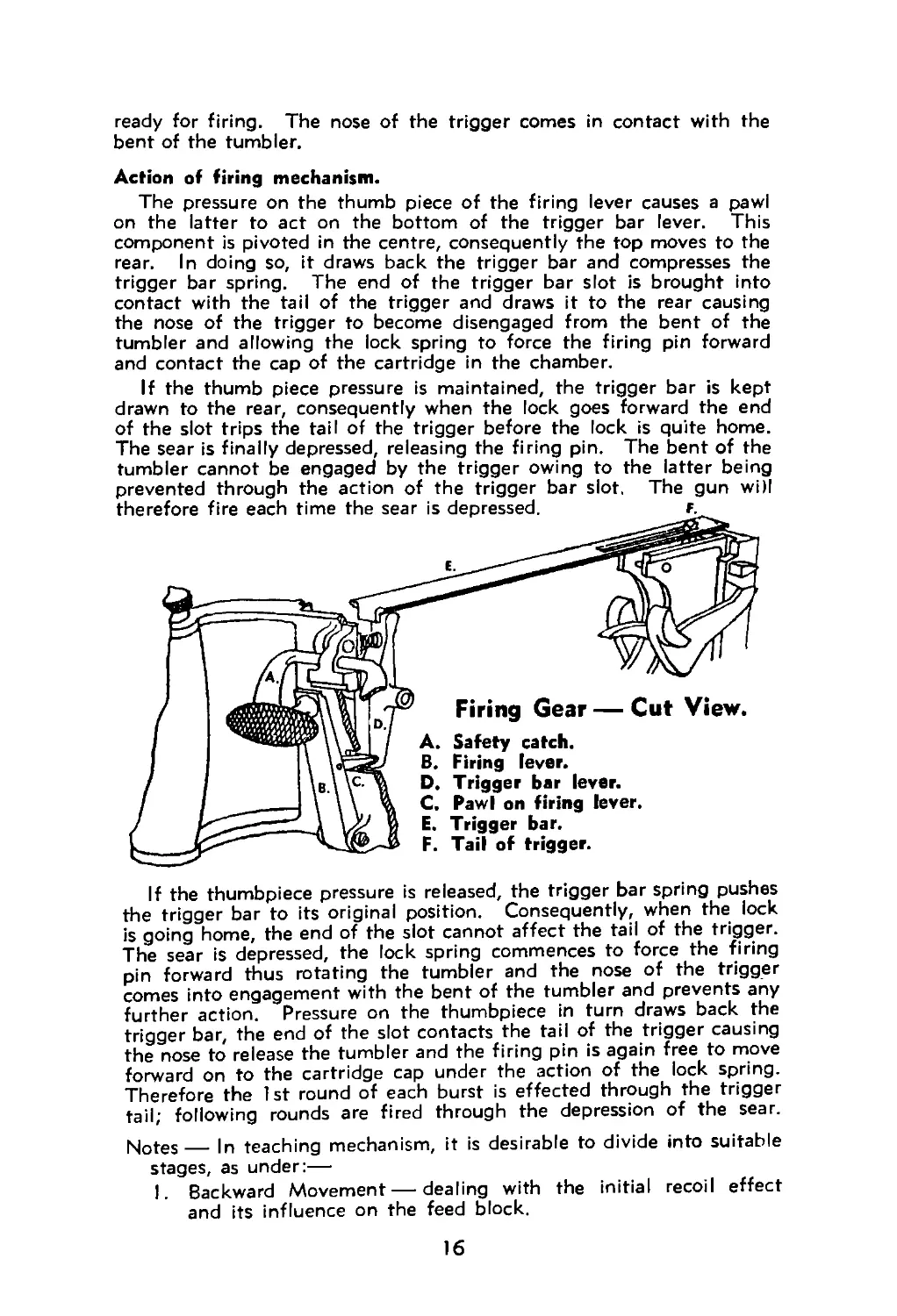
Action of firing mechanism.
The pressure on the thumb piece of the firing lever causes a pawl
on the latter to act on the bottom of the trigger bar lever. This
component is pivoted in the centre, consequently the top moves to the
rear. In doing so, it draws back the trigger bar and compresses the
trigger bar spring. The end of the trigger bar slot is brought into
contact with the tail of the trigger and draws it to the rear causing
the nose of the trigger to become disengaged from the bent of the
tumbler and allowing the lock spring to force the firing pin forward
and contact the cap of the cartridge in the chamber.
If the thumb piece pressure is maintained, the trigger bar is kept
drawn to the rear, consequently when the lock goes forward the end
of the slot trips the tail of the trigger before the lock is quite home.
The sear is finally depressed, releasing the firing pin. The bent of the
tumbler cannot be engaged by the trigger owing to the latter being
prevented through the action of the trigger bar slot. The gun will
therefore fire each time the sear is depressed. f.
Firing Gear — Cut View.
A. Safety catch.
B. Firing lever.
D. Trigger bar lever.
C. Pawl on firing lever.
E. Trigger bar.
F. Tail of trigger.
If the thumbpiece pressure is released, the trigger bar spring pushes
the trigger bar to its original position. Consequently, when the lock
is going home, the end of the slot cannot affect the tail of the trigger.
The sear is depressed, the lock spring commences to force the firing
pin forward thus rotating the tumbler and the nose of the trigger
comes into engagement with the bent of the tumbler and prevents any
further action. Pressure on the thumbpiece in turn draws back the
trigger bar, the end of the slot contacts the tail of the trigger causing
the nose to release the tumbler and the firing pin is again free to move
forward on to the cartridge cap under the action of the lock spring.
Therefore the 1st round of each burst is effected through the trigger
tail; following rounds are fired through the depression of the sear.
Notes— |n teaching mechanism, it is desirable to divide into suitable
stages, as under:—
I. Backward Movement — dealing with the initial recoil effect
and its influence on the feed block.
16
2. Rotation of the Crank — dealing with the effect of the crank
handle on the roller with respect to the crank, lock, fu±ee —
also the forward "throw" of the crank and the effect on the
recoiling portions and feed block.
3. Backward Movement of Lock — the effect of the lock's move-
ment on the cartridge and empty case held by the extractor,
also the cocking action inside the lock (a skeleton lock or
diagram is desirable if available).
4. Forward Movement of Lock — how it effects the movement
upwards of the extractor and cartridges — effect on fuzee when
lock moves forward.
5. Firing Action — the effect inside the lock and the chain of
communication from thumbpiece to tail of trigger.
To deal with
(1) An empty case and full cartridge on face of extractor.
Fuzee spring and muzzle attachment removed after above
preparation and lock spring released.
Push recoiling parts back by pressure on muzzle cup — rear
cover raised.
Use spare feed block and cartridge.
(2) Similar preparation, then complete action by pressure on crank
handle.
(3) Similar preparation but draw recoiling portions back slowly.
(4) Half load — take off fuzee spring box and spring — crank
handle on to roller and pull belt — raise rear cover.
Force the crank handle down on to the check lever.
(5) Half load — remove trigger bar— pull crank handle on to the
roller and pull the belt — raise the rear cover.
Lay trigger bar in position over tail of trigger.
Always demonstrate actions clearly and advise the men what they
are to watch. Repeat demonstrations with necessary explanations and
continually question men as to action.
ELEMENTARY GUN DRILL.
Gear laid out facing suitable direction, as under —
Tripod, folded and with legs to rear and crosshead over rear leg.
A short distance to the right the gun is placed with the muzzle to the
front, the gun rested on its left side (crank handle uppermost), the
condenser tube (or dummy tube) attached and laying along the gun.
The spare parts case against the gun. A short distance in rear of the
gun and tripod are placed the condenser can and 2 belt boxes. The
condenser can being on the right and about a pace from the boxes.
The detachment of 3 men "fall in" a few paces in rear of the
condenser and belt boxes. They are numbered off. Any remaining
personnel are placed so that they can see all actions.
The instructor demonstrates and explains whatever action he wishes
carried out.
TAKE POST.
No. 1 moves quickly to the tripod and assumes a position on Its left
(lying). He examines the tripod to see that the pins are in and
both turned down, the elevating screws are equally exposed, the
17
traversing clamp sufficiently tight to prevent the crosshead swing-
ing when being carried, direction dial securely fitted, all 3 legs
together and clamped and the crosshead over the rear leg. When
both the other Nos. have reported to him, he reports "All Correct"
(or otherwise) to the Instructor.
No. 2 turns to the right and moves quickly to his position on the right
of the gun. After lying down he puts the strap of the spare parts
case over his right shoulder and inspects the gun to see that the
muzzle attachment is correctly attached, condenser tube fitted,
feed block is in the gun, front cover locked, sliding shutter closed,
tangent sight set at 600, that the lock is in the gun and the "T"
fixing pin home and vertical. He reports to No. 1 "Gun Correct"
(or otherwise) on completion of his inspection.
No. 3 turns to the right and moves quickly to his position, lying
between the condenser and belt boxes. He inspects the belts to
see that they are correctly loaded and pointing the correct way. He
closes and fastens the boxes. He inspects the condenser to see that
the cap is screwed on and that the filler is secure. He reports to
No. 1 "Ammunition and Condenser Can Correct" (or otherwise)
on completion of his inspection.
All Nos. now lie facing forward with arms folded. To change the
numbers round the Instructor orders "Fall Out 1." No. 1 then
becomes No. 3 and so on, the detachment re-numbering. When
explaining an action, the order "Rest" should be given. The order
"Position" will bring the detachment back to their original condition.
Duties of No. 1 should first be taught and practised by all before
dealing with those of Nos. 2 and 3.
The Instructor will indicate the position over which the mounting is
to be erected and the direction in which the gun will point. The
position should be only a few yards in front of No. 1.
MOUNT GUN (Tripod).
No. 1 jumps to his feet, grasps the crosshead with the right hand
near the pivot and carries the tripod forward to the spot indicated by
the Instructor. He places the tripod on the ground, stands astride
the legs, loosens the jamming handles simultaneously and, grasping
the crosshead near the pivot with both hands, with a forward and
upward movement he spreads the front legs. He keeps the shoe of
the rear leg on the ground, holds the crosshead with the left hand
(supported by the left thigh) and tightens each jamming handle with
the right hand. He then sits down behind the tripod and removes
both joint pins, turning them up towards himself before withdrawing
them.
DISMOUNT GUN (Tripod).
No. 1 replaces both pins, turning the handles down towards him.
He stands up astride the rear leg, releases both jamming handles
simultaneously and allows the tripod to collapse. Grasping the cross-
head with both hands near the pivot, with an upward and forward
movement he folds up the front legs and tightens the jamming handles.
He then assumes his position lying on the left of the tripod and
re-conditions it. When working in rooms where the floor would be
damaged or in bad ground or at night a suggested method is to hold
the crosshead with the left hand, loosen the jamming handles and
18
swing the tripod back, pivoting it on the rear leg, then clamp the
jamming handles and place the tripod in suitable position according
to conditions.
The tripod is left mounted after all numbers have been practised
in the above. One number is left in position behind the tripod,
holding both pins out.
MOUNT GUN (Gun).
No. 2 opens the sliding shutter, jumps to his feet and picks up the
gun with the left hand at the right traversing handle (also including
the condenser tube) and with the right arm over the barrel casing.
He doubles forward to the tripod, sinks on the left knee and places
the gun in position. He takes the crosshead joint pin from No. 1 and
secures the gun to the crosshead, turning the handle of the joint pin
down. He then releases the traversing handle with his left hand,
swings the condenser tube forward and lies down on the right of the
gun, looking towards it with his head in line with the feedblock but
below it.
Further Duties of No. 1.
No. 1 hands No. 2 the crosshead joint pin and grasps the left
traversing handle with his left hand. When No. 2 has secured the
gun to the crosshead, No. 1 inserts the elevating joint pin and turns
the handle down towards himself. He then levels the gun and tests
by tapping the handles whether the traversing clamp is reasonably
tight. He holds the gun with both hands correctly, elbows inside his
thighs and feet braced and looks at the target or direction the gun is
pointing. No part of his body should be in contact with the tripod.
DISMOUNT GUN (Gun).
No. 2 jumps to his feet and after No. 1 has removed the pins he
seizes the gun in the same manner as when mounting, also including
the control of the condenser tube, and lifts it clear of the tripod.
Moving slightly to the right, he closes the sliding shutter and places
the gun on the ground and assumes his original position beside it,
re-conditioning it as necessary. All numbers should be practised in
carrying out mounting and dismounting gun.
Two numbers now act as Nos. I and 2 and mount the gun on the
tripod.
MOUNT GUN (Condenser and Belt Boxes).
No. 3 disengages the quick release straps of the belt boxes and
unscrews the cap of the condenser can except for a half turn. He
jumps to his feet and doubles to the right side of the gun, carrying
with him the condenser can and both belt boxes, the condenser can
being in his right hand. He places the Can near the front of the
tripod in a suitable position for No. 2, and the belt boxes in an easy
position for No. 2, with the fastenings towards the gun. He unscrews
the cap of the condenser can and doubles back to a suitable position
in the right rear of the gun and lies down.
Further Duties of No. 2.
No. 2 positions a belt box in line with the feed block and close to it
and inserts the end of the condenser tube in the can.
19
DISMOUNT GUN (Condenser and Belt Boxes).
No. 3 doubles forward, seizes the condenser can and belt boxes as
before and retires with them a few paces in rear of the other numbers.
He lies down between them and re-conditions them to their original
condition.
Further Duties of No. 2.
No. 2 pushes the belt boxes clear and withdraws the condenser tube
from the can before attending to the gun.
All numbers are practised in handling the condenser can and belt
boxes.
With 3 numbers in position, order "Dismount Gun."
When completed, the order "Replace Stores" ensures that all gear
is returned to the "Take Post" position.
Detachments are then practised in carrying out complete actions
in sequence on the orders "Mount Gun" and "Dismount Gun."
LOAD.
No. 1 pulls crank handle on to roller with right hand and extends
the left hand opposite the left side of the feed block.
No. 2 throws the lid of the belt box open, seizes the tag of the
belt and pushes it through the feed block.
No. 1 grasps the belt, pulls it until the 1st cartridge is positioned,
releases tension on the belt and lets go the crank handle. He repeats
the action again with crank handle and belt.
No. 1 must pull belt straight through and not towards himself.
No force is necessary, the actions should be smooth and in above
sequence.
No. 2 must push the tag as far through as possible so that No. 1 can
grasp it firmly. The forefinger along the tag is a suitable method.
Recruits may have to be taught by numbers, e.g., "Crank handle"
— "Pull Belt" — "Let Go" (repeat).
UNLOAD.
No. I pulls the crank handle on to the roller and releases it. He
repeats the action. He extends his right hand to the right side of the
feedblock, placing the fingers on the finger-pieces of the top pawls
and the thumb on the finger-piece of the bottom pawls, pressing both,
taking care to keep his hand clear of the feed block opening.
When the belt is withdrawn with the top round clear of the feed
block opening, he presses the thumbpiece with the left thumb, holding
the traversing handle with remaining fingers.
No. 2 withdraws the belt with his right hand, steadying it with his
left and replaces the belt correctly in the box, closing the lid with the
right hand, but not fastening it.
Should the sight have been in use when ordered to "Unload," No. 1
will knock it down with his left hand at the same time as he functions
with the crank handle. He then regains control of the gun with his
left hand ready to release the lock spring.
ACTION.
On the order "Action" the sequence of actions taught in "Mount
Gun" and "Load" are carried out.
20
CEASE FIRING.
On this order, the sequence of actions taught in “Unload" and
“Dismount Gun“ are carried out.
CLEAR GUN (the gun being mounted and unloaded).
No. 1 pulls the crank handle on to the roller, opens and raises the
rear cover, removes the lock from its guides, eases the crank handle on
to the check lever and allows the lock to rest upright against the hinge
of the cover. He then reports “Gun Clear."
Should gun be loaded, order “Unload" before giving “Clear Gun."
STAND CLEAR.
Nos. 1, 2 and 3 jump to their feet and "stand at ease."
Order "Take Post" for gun numbers to resume former positions.
Order "Lock In — Cover Down" or "Load" (Lock must be properly
down before cover is lowered).
SETTING SIGHTS AND LAYING (Lessons in Aiming must have been
taught prior to this stage).
3 simple targets made known to all — e.g., "Track" "Corner"
"Shed."
Gun loaded and Nos. 1 and 2 at gun.
Order "1,000 — Comer—Lay" (or similar order).
No. I raises and sets the tangent sight. When "Lay" is ordered
he begins to lay his gun at the target named (by tapping the traversing
handles with one hand whilst the other keeps control of the gun)
until direction is obtained. He then moves the elevating wheel until
the sights are correctly "on". He then calls out “ON" and No. 2
places his left hand out behind the shoulders of No. 1 and watches
the fire controller.
Should No. 1 not understand the order he calls out "Repeat."
FIRE, STOP and GO ON.
On the order "Fire," No. 1 (who should have the correct holding
with safety catch raised) will press in the thumbpiece without altering
the gun's line or elevation. He must look directly at the target and
fire in bursts of about 4 to 5 seconds, releasing pressure on the thumb-
piece after each burst and checking his aim. No. 2 will lower his
hand on the order "Fire."
On the order "Stop," No. 1 releases the pressure on the thumbpiece
and lets the safety catch drop. He should check his aim and relay
on the point taken for the first burst. The instructor should disturb
the gun's line and elevation when ordering "Stop" so as to ensure
that No. 1 does relay the gun.
GO ON.
No. 1 goes on firing again.
Tests for proficiency (portion only).
Mount Gun . .. 20 secs. Stores not be carried forward more than 5 yds.
Load 5 secs. Belt box closed but not fastened.
Unload 5 secs. Belt correctly packed.
Dismount Gun Setting sights 15 secs. Time taken until all Numbers are still.
and Laying .. 1 2 secs. Time taken from "range ordered" until No. 2's hand is up.
21
Further Lessons (Gun always loaded before each Lesson begins).
1. To teach men to develop a consistent "tap" and to adjust the
traversing clamp.
Instructor demonstrates and explains how to produce a consistent
"tap" when hitting a traversing handle, to move the gun's line
the same amount each time. The handle should be struck with
a glancing blow from the open hand, the other hand maintaining
correct holding on the other handle. Men to be practised
"tapping" to the right and also to the left. A strong tap with a
tight clamp is better than the reverse. Men must not look at
the gun whilst tapping.
2. To adjust the traversing clamp.
Instructor demonstrates and explains how to test and adjust the
tightness of the clamp so that the gun's line is displaced 1 5 minutes
each time the gunner produces his consistent "tap." Marks which
subtends I 5 minutes at the distance used, are necessary to enable
men to obtain this facility. Men are to be reminded that having
learnt the tightness necessary, they must always test a gun when-
ever they take up position as No. 1 and that the marks will
seldom be available for this purpose.
3. Combination of (1) and (2).
Instructor orders the No. 1 to lay on one end of a series of marks
which are 15 minutes apart at the distance used, e.g., 4 inches
apart at 25 yds. distance from the gun.
A suitable order would be "1,100—left mark (or bullseye) —
Lay."
On the order "Fire" the gunner fires a burst, releases pressure,
taps in the required direction once, fires another burst and so on
until ordered to stop.
Men are warned (in this case) not to relay on the order "Stop"
so that their proficiency in "tapping" can be checked.
Men to be trained also to "tap" right and left of a point. A
suitable order being "1,100—left mark — right and left one
tap — Lay" the gunner being told whether he is to regard himself
as "No. 1 gun" or "No. 2," e.g., as No. 1 gun he will do his first
tap to the left; if acting as No. 2 gun, the first tap will be to the
right.
4. Traversing.
Instructor demonstrates and explains how to deal with a target
which is not horizontal, e.g., production of the same consistent
"tap" and then elevating or depressing the gun until it is "on"
the line of the target. The sequence of actions being Fire — Tap
— Elevate (or Depress) —Fire, etc. Men not to relay on order
"Stop," so that results can be checked.
5. Swinging Traverse.
Instructor explains the method adopted when firing ball ammuni-
tion, to "sew" a line of bullets across a suitable target. Only
used at relatively close range against emergency targets when
"tapping" would be too slow. Difficult to teach without actual
firing. Gun must move slowly — approx. 1 yard in 2 secs, at a
target 25 yds. away — and clamp must not be very loose, just
22
sufficient to move the gun. Should the clamp be slackened right
off the vibration may cause the gunner to lose control of the gun.
IMMEDIATE ACTION AND STOPPAGES.
The men under instruction should be placed so that they can see
the position of the crank handle and the actions of the instructor.
The instructor will deal with one position until all are proficient in
correcting the stoppage concerned.
Method — Indicate a simple target and notify the range to all.
Instructor orders the men to look away from the gun. He takes
position as No. 1, adjusts the gun to simulate the stoppage position
and covers the breech casing and crank handle with a suitable cloth.
He then orders the men to watch his actions. He commences firing,
removes the crank handle covering with one hand and proceeds with
the immediate action necessary. When completed, he states "Gun
is firing all right" and rests. He should question the men as to
the position, actions, etc. It will be necessary to repeat the
demonstration and explanation to ensure that all men understand.
He does not tell them the cause of the stoppage.
Two men are then ordered to assume position as Nos. 1 and 2 and
to look away. The Instructor "sets up" the stoppage again and
covers the crank handle. The gun is swung in the general direction
of the target. He orders "Position," when the No. 1 and 2 assume
their correct positions as if ready to fire. He then orders "Fire"
and after a pause, removes the covering. The No. 1, assisted as
necessary by the No. 2, corrects the stoppage and finally lays on
the target and fires. The Instructor checks the aim (No. 1
continuing to hold the gun) and his decision, i.e., "I.A. incorrect
— Aim correct" and discusses actions of the gun numbers, ques-
tioning the remainder of the men also. The remainder of the men
are then practised in the same way. When dealing with a
recurring phases, e.g., 1st and 3rd positions, the Instructor should
lean over the gun and position the crank handle, saying "Gun
fires a few rounds and stops again."
When men are proficient in all positions, the Instructor can then
explain the causes of the stoppage and how they affect the working
of the gun with regard to the mechanism actions.
All men should be exercised in correcting stoppages blindfolded or
in darkness. In this case the aim of the man cannot be checked
but he should go through the actions necessary.
Before commencing instruction the following must be understood
by the men:—
Rear cover not to be opened or closed with the tangent sight up.
If the crank handle will not come back in 3rd position, the front
cover is to be opened and the extractor forced down.
Covers when lowered, must be fastened correctly.
Never change a lock with cartridges on the extractor — always
slide them off before removing the lock from the connecting rod.
When releasing a lock spring with the lock out of the gun, ensure
that the extractor is held fully up so that firing pin is opposite
its hole.
A dirty gun and careless gun numbers breed stoppages.
23
Crank Handle.
Action of Gunner.
Puli crank handle on to roller.
Pull the belt.
Let go the crank handle.
Aim and fire.
Probable Cause.
Weak cartridge charge.
1st position.
Lock cannot
come back
far enough
for extractor
to drop.
The gun may fire and stop
again in the same position
after one or more rounds.
Should it do so
Pull crank handle on to roller.
Pull the belt.
Let go the crank handle.
Turn the vice pin attached to
the fuzee spring upwards
3 half turns. Aim and fire.
Too heavy weight on fuzee
spring.
Oil needed on working parts.
Grit on working surfaces.
Packing too tight.
Barrel worn — recoil reduced.
Pockets tight — wet belt.
Friction due to cold weather.
When the crank handle is "let
go" it may stop upright —
should It do so —
Pull the crank handle on to
roller.
Open the rear cover.
Lift up the lock—keeping the
extractor down.
Ease the crank handle on to
the check lever.
Slide the cartridge down off
the extractor with right
hand.
Change the lock and replace
in gun. Lower the rear
cover — keeping the crank
handle back.
Load — Aim and fire.
Weak or broken gib spring
allowing the cartridge to slip
down and meet the face of
the barrel breech.
Prevention of occurrence — Attend carefully to all the points necessary
before firing.
2nd position.
Lock cannot
go fully
home after
recoiling.
With upward movement of
cupped hand, force crank,
handle on to roller and call
for the "clearing plug."
Raise the rear cover.
Lift up the lock, keeping the
extractor down and exa-
mine the cartridge on the
extractor.
If it is damaged or with a
portion of another cartridge
Case adhering to it —
Calt out — "don't want It."
Slide the cartridge down off
the extractor.
Replace the lock in the gun
and load. Aim and fire.
If the cartridge is correct.
Slide the cartridge off — re-
place the lock in the gun,
keeping the crank handle
back, put the clearing plug
in the chamber, let the
lock go forward. Keeping
the lock hard forward, rock
the handle of the clearing
plug from side to side, pull
the crank handle back and
A damaged certridge or one
which nas brought out part
of a previous cartridge which
has separated, adhering to
its front end.
A cartridge case which has
become separated and left a
portion of itsetf In the
chamber.
24
Crank Handle.
Action of Gunner.
Probable Cause.
remove the clearing plug.
Repeat until the separated
portion of the case is with-
drawn. Close the rear
cover.
Load. Aim and fire.
Prevention of recurrence — If a number of separations occur — change
the lock. Should this not suffice, place 2 washers on the connecting
rod above the adjusting nut until time available to place them under
it.
3rd position.
Extractor
cannot iise
to highest
position.
If slide of
feed block
is jammed—
a fault in
the feed is
indicated.
Raise crank handle slightly Slight fault in the feed,
and hold it.
Pull the belt.
Let go the crank handle and
knock it down once to the
check lever.
Aim and fire.
Prevention of recurrence — Watch the condition of the
cartridges in the belt and ensure that they are kept in
line and regular.
The same condition may Friction on the lock and
occur after the gun fires guides, working parts, etc.
one or more rounds.
Raise the crank handle
slightly and hold it.
Pull the belt.
Let go the crank handle and
strike it down once to the
check lever.
Unload the gun — pull the
crank handle on to the
roller—raise the rear cover
and oil the working parts.
Lower the rear cover.
Load, Aim and fire.
Prevention of occurrence — Whenever opportunity offers, keep the
gun correctly oiled, etc.
When the crank handle is
struck down It may not re-
turn to the check lever,
in that case —
Feel the slide of the feed
block to see if it is jam-
med, e.g., cannot move
laterally. Should it be jam-
med—call "Feed block."
Pull the crank handle on to
the roller — raise the rear
cover — set the horns of
the extractor in the steps
on the side plate cams, i.e.,
"Hang the lock." With
the right thumb behind
the crank handle knob and
the fingers on the front
of the tail, lever back the
Badly filled belt.
Worn or loose pockets In the
belt.
Belt box not in lino with the
feed block.
Torn pockets in belt.
Bent or broken brass strip in
belt.
25
Crank Handle.
Action of Gunner.
Probable Cause.
recoiling portions. No. 2
should then depress the
finger pieces of the pawls
and withdraw the belt until
rounds clear.
He adjusts the rounds and the
belt. No. 1, as soon as the
belt moves, allows the parts
to go forward by releasing
his pressure.
No. 1 then pulls the crank
handle on to the roller
again, lowers the rear
cover, pulls the belt and
lets the crank handle go.
Aim and fire.
Notes —To get the crank handle back it may sometimes be necessary
for No. 2 to force down the extractor, No. 1 opening the front cover.
Recruits frequently mistake the position for a 2nd. In the case of
a 2nd position the crank handle is very hard to lift up. A "'high
3rd" gives a free crank handle.
Prevention of recurrence — Watch condition of belts and fitting of
cartridges in the belts, also position of belt box. Badly filled belts
generally the cause, or badly conditioned belts.
Should the slide not be jam-
med—call "Extractor" and
open front cover and hold
crank handle whilst No. 2
forces down the extractor,
allowing No. 1 to get the
crank handle back on to
roller. No. 1 opens the rear
cover, lifts up the lock and
slides the cartridge off.
No. 2 meanwhile withdraw-
ing the belt and taking out
the 1 st cartridge. No. 1
then replaces the lock in
the gun, closes and locks
the front cover, lowers the
rear cover and loads.
Aim and fire.
Thick cartridge rim. (May be
the one on the extractor or
in the feed block — there-
fore deal with both.)
4th position.
No explosion
or little if
any recoil
from the ex-
plosion. The
lock remain-
ing forward.
Pull the crank handle on to
the roller.
Pull the belt.
Let go the crank handle.
Aim and fire.
When the thumb piece Is
pressed the gun may not
fire. In that case —
Unload, without taking the
belt out of the feed block.
Pull crank handle on to roller
—raise rear cover — take
off the lock and replace it
with another — close the
rear cover — load.
Aim and fire.
A round misfired.
Broken lock spring.
Broken or demagea firing pin.
26
Crank Handle. Action of Gunner. Probable Cause.
When pulling the belt it may Empty pocket in belt,
be seen (or felt) that more
than normal comes through.
In that case —
Carry out full loading actions.
Aim and fire.
Prevention of recurrence in last case — Carefully inspect belts before
firing and during any opportunity.
Other stoppages may abo occur.
Crank Handle. Action of Gunner. Probable Cause.
A. Crank handle resting on the roller. Remove the fuzee spring box. Pull the belt. Return crank handle to check lever. Re pl ace the broken fuzee or spring. Aim and fire. (if the spring is broken, make sure the new one is adjusted for weight.) Broken fuzee or fuzee spring.
B. When correcting for a thick rimmed cartridge the crank handle will not go down when loading. Carry out the I.A. for 3rd position (thick rim). Unload the gun and change the lock. Load. Aim and fire. Unload. Damaged extractor grooves or Broken gib spring or Broken gib.
C. Crank handle in 4th Change the feed block. i. Broken upper lever or
I.A. applied as for Load. Aim and fire, broken lock spring. Gun now only fires 2 rounds and stops in 4th position. D. Gun will not stop firing Remove a round from when thumbpiece pres- the belt. When the sure released. gun stops, pull the May also occur on 2nd crank handle on to action in loading. roller. Remove the belt. Let go the crank handle. Change the lock. Load. Aim and fire. lower lever or top pawls or spring in feecj block. it. Broken bottom pawls or spring. Broken trigger nose or bent on tumbler or either worn badly. Short arm of lock spring broken towards the bend.
27
ADVANCED MACHINE GUN HANDLING.
I. HOW TO HANDLE M.G. LOADS — at service weights.
Instructor to demonstrate suggested methods — others also suitable.
Tripod —
When walking or running — under the armpit or in front of body.
When crawling — the man to lie on his left side, using his left elbow
and toes to lever himself forward, dragging the tripod with the
right hand on the rear leg. Watch that the dial is not damaged.
Gun —
When walking or running — carried across the body with the bar--’
casing resting on right forearm, left hand holding left traversing
handle and condenser tube. Another way is to carry the gun with
muzzle up, at the right side of the body, holding with the right
hand at the crosshead bracket, free end of tube pushed through
handles.
When crawling — man to lie on right side, gun resting on inside of
right thigh, muzzle forward. He holds the gun with his left hand
and works forward levering with right elbow and left leg.
Condenser Can and Belt Boxes —
When walking or running — a belt box under each armpit and the
condenser can held in one hand.
When crawling — put the toe of each boot inside the leather handles
of a belt box, hold the condenser can in one hand and lever himself
along using the elbow of the free arm and his heels. Normally lie
on left side with legs apart.
To move a mounted gun which is unloaded, a short distance —
When walking or running —
No. 1 — right hand holds rear leg, left hand holds left front leg
and one belt box.
No. 2 — left hand holds one belt box and right front leg, right
hand holds condenser can.
When crawling — one number on each front leg, each levering
himself forward and dragging the mounted gun, returning for other
gear — or tripod turned about, one number drag forward by rear
leg whilst other brings remaining stores.
Similar action when getting a gun down from exposed position.
Note—All articles to be at correct weights, barrel casing filled with
water. Any comfortable way to move the gear may be tried as
long as the nature of the load does not become obvious to the
enemy or the gear damaged.
2. HOW TO MOUNT THE GUN ON EXPOSED POSITIONS.
Instructor demonstrates and explains all actions necessary.
(a) To mount and dismount the tripod.
To Mount — Crawl forward with the tripod to the indicated position.
Keeping low down and on the left with his head to the front, undo
the front leg jamming handles and get the front legs opened forward
28
by rocking the tripod. Undo the rear jamming handle and set it
to get a low angle. Raise the socket upright and clamp the left
front leg; The tripod will now lean to the right.
To Dismount—Loosen the left and rear jamming handles and set
the rear leg to the usual sitting position angle. Work the front
legs back again to their folded up position and tighten the jamming
handles.
Another method is to allow the man to set his legs before crawling
forward, i.e., rear leg set at suitable angle and clamped, front legs
swung forward and back to a position near the elevating wheel and
clamped. The.man can drag the tripod by the rear leg or pass one
arm under the crosshead and lever it forward to position.
(b) To mount and dismount the gun.
To Mount — The No. 1 will have removed both joint pins. The No. 2
should arrive just when this has been done and will then open the
sliding shutter. Both men assist each other to put the gun the
mounting, No. 1 supporting the barrel casing and putting in the
crosshead joint pin; No. 2 holding the traversing handle nearest
him and putting in the elevating joint pin. No. 1 then puts his
arm around the socket under the crosshead and pulls the socket
upright whilst No. 2 tightens up the right jamming handle. (No. 2
may have to assist No. 1 by pushing against the socket also).
No. 1 swings around, keeping low and lies with his legs forward,
right leg over the left and over the left forward leg of the tripod.
No. 2 lies on his right side with his legs behind No. 1 and supports
him with his right thigh and left knee.
No. 3 brings his gear forward without undoing the belt boxes or
the cap of the condenser can. He brings the gear forward just
far enough for No. 2 to reach it and keeps himself screened behind
Nos. 1 and 2 whilst doing so, finally crawling away to a suitable
position under cover nearby. No. 2 puts the stores in suitable
places, takes off the cap of the condenser can and puts in the tube.
He also unfastens the belt box quick releases.
To Dismount—No. 3 crawls up behind the gun numbers and
receives the stores from No. 2, who has fastened all articles. No. 3
crawls clear with the stores.
No. 2 then loosens the right jamming handle. No. 1 takes out
both joint pins until the gun is taken off by No. 2, he then replaces
them and adjusts the tripod as already taught. No. 2 lifts the gun
off and, lying on his back, passes the gun over his body on to the
ground and closes the sliding shutter. He then either rolls over
the gun to his correct position or crawls around the gun. He crawls
clear of the position with the gun.
If cover is available nearby, Nos. 1 and 2 can crawl to it, dragging
the mounted gun and dismount it comfortably under cover.
3. MOUNTING THE GUN ON UNEVEN GROUND.
Instructor to demonstrate and explain any necessary actions.
(a) Working under cover to a position and adjusting the legs of the
tripod to suit the ground and putting the gun.
29
(b) Mounting the gun under cover and working it forward mounted,
to the ground indicated.
(c) Dragging the mounted gun down under cover and dismounting it.
When the men are practising, the following points are watched:—
The mounting to be as low as possible consistent with being able to
deal with targets expected.
The rear leg must be down any slope met with on a gun position.
The socket must be upright and mounted over the position indicated.
Only the shoes of any leg to be in contact with the ground.
Ground under each shoe must be firm enough to support the
mounting and not give way under the gun's vibration.
When mounted, no part of the tripod to interfere with the
elevating wheel.
All variations of ground to be dealt with. Variation of position of
gun numbers and stores brought out — essential that No. 1 can
control gun and be reasonably comfortable whilst concealed; that
No. 2 can position himself and stores effectively and attend to the
belt feed, etc.
After a gun has been mounted to deal with a particular piece of ground,
take it off and put the adjusted tripod on some level ground to let
the men see the effect on the setting of the legs. They should
then learn to judge a piece of ground by eye and set the legs
accordingly beforehand.
The final stage is to teach how to bring the gun in action against
a specified target (or to cover a specified amount of country) using
the full team. In this stage an N.C.O. directs the various numbers
where to go and how to move. An Orderly indicates the gun position
when the numbers arrive with their gear and assists them to mount
the gun and then indicates the target, etc., by laying the gun. He
should not leave the gun to report it in action until it is loaded and
ready. All numbers concerned must ensure that they conceal them-
selves and their gear to the fullest extent. On completion the
Instructor checks up and discusses —
Whether the gun as mounted, can do the task set.
Whether the mounting is suitable for the position.
How the various stores are disposed at the gun — condenser can
protected, etc.
Position of No. 1 — concealment, can he handle and control the
gun?
Position of No. 2 — concealment, can he help No. I properly, see
signals, etc.
Position of other numbers — concealment, etc.
Was the task done with regard to concealment, time factor, etc.?
Did the Orderly do his part efficiently?
How the position could be improved by digging, camouflage, etc.
OTHER MACHINE GUN EQUIPMENT.
Spare Parts Case—Oblong leather case fitted with a strap, lid and
buckle. A long shoulder strap is also fitted and held to the case
by sewn-on strips. The case contains, in addition to a spare lock,
the tools necessary for gun adjustments and a proportion of spare
30
parts, considered as a " I st Aid" kit for the gun in action. A tin
of oil is also fitted in the case.
Belt box — Rectangular steel box fitted with double loop handles of
leather. The lid fits snugly over box sides and is secured by a
quick release strap working under a retaining staple on the front of
the box. The lid is jointed in the middle and may be operated half
open only, in bad weather.
Belt — Fabric connected by brass strips which form pockets in the
fabric and act as guides for the cartridges. Service belts contain
250 pockets. Drill belts are made up of damaged service belts and
contain 25 pockets. Belts are fitted at each end with a brass tag
to facilitate loading into feed block. Stripless belts are also on
issue, the pockets being sewn or formed in the belt fabric. These
belts are fitted with long wire loops at the ends instead of brass
tags. They are factory filled and issued in sealed-down tin
containers with pul I-off lids. Two containers fit in a special wooden
box which has carrying handles of web and a quick opening lid.
A filled belt of 250 rounds in the normal metal belt box weighs
approx. 21 lbs.
Condenser Can — Normal 2 gal. petrol can fitted with metal filler
which is clipped to the top of the can and secured by a chain.
Weight — filled, approx. 25 lbs.
Condenser Tube — 6 ft. length of strong hose fitted at one end with
a quick release device for attachment to the adapter on the steam
escape boss of the barrel casing. The free end of the tube is placed
in the condenser can below the level of the water.
Spare Parts Box—Issued on scale of 1 per section (2 guns).
Contains, in addition to 2 spare feed blocks, various spare parts
and tools, including a spare tangent sight.
Bar Foresight — An engraved flat bar graduated to 7 degrees each
side of a zero and fitted with legs and a clamping screw for
attachment to the gun foresight protectors. A sliding foresight
with protectors is attached to the bar and clamped in position by a
wing nut. Divisions on the bar are in multiples of 1 0 minutes. The
bar foresight is used to give deflection allowances in indirect and
night firing series. The bar foresight is carried in a web pouch,
normally attached to the sling of the clinometer case.
Clinometer — A graduated arc, fitted with a bubble and operated by
milled and engraved collars and mounted on a base which conforms
to the breech casing top edges when the rear cover is raised.
Degrees are shown on the arc and minutes on the end collars, one
of which is read for elevation; the other for depression. An
indicating arrow on the base shows the direction in which the
clinometer should be fitted to the gun. No. 1 maintains correct
holding (with the rear cover raised) whilst No. 2 places the
clinometer on the gun and operates the elevating wheel to bring
the bubble central in its run. The gun elevation can also be checked
in a similar manner, except that the operating collar is turned to
control the bubble. The clinometer is carried in a special case,
fitted with a leather sling. It is mainly used to place the necessary
elevation on the gun for indirect and night firing series. It should
always be set at zero when not required for use.
31
Night Firing Lamp — Two patterns are issued. ( I ) A box containing
2 lamps, a reel with the necessary lengths of flex for each lamp
and control devices. Two aiming posts of an extendable type form
portion of the lamp set when issued. (2) A box containing a single
lamp with a short flex connection; a "pull" switch is fitted and a
length of cord on a reel included. Anchoring devices are incor-
porated on the box. In this type, the box is positioned close to the
"planted" aiming post and anchored; the cord is attached to the
switch and the reel brought back close to the N.C.O. in charge at
the gun, and controlled by a spare gun number. In the case of the
former type, the flex and lamp are reeled out to (or with) the
aiming post, the control being at the box itself, positioned centrally
between the guns. Very great care is essential, in the case of the
first-mentioned type, to ensure that connection is maintained
between the lamp, flex and control box.
In both types, dry cell batteries provide the necessary power for
illuminant.
Aiming Post — Two types are issued. (I) A vertically extendable
type fitted with an aiming mark and a lamp bracket in rear.
(2) A hinged type fitted with a plain white disc and carrying a
fitting to accept the lamp bracket. The latter type is the more
recent and more efficient. Aiming posts are used to maintain line
and elevation in indirect and night firing series.
Zero Post — A plain circular steel post with a ring top and sharpened
point. Used in connection with indirect fire arrangements.
Other items of a more technical nature are also issued — e.g., Director,
Field Plotter, Slide Rule.
32